OPERATOR MANUALOME44870E_TZTL12F_15F_TZT2BB.pdf
341
-
Upload
khangminh22 -
Category
Documents
-
view
0 -
download
0
Transcript of OPERATOR MANUALOME44870E_TZTL12F_15F_TZT2BB.pdf
i
IMPORTANT NOTICES
General• This manual has been authored with simplified grammar, to meet the needs of international users.• The operator of this equipment must read and follow the descriptions in this manual.
Wrong operation or maintenance can cancel the warranty or cause injury.• Do not copy any part of this manual without written permission from FURUNO.• If this manual is lost or worn, contact your dealer about replacement.• The contents of this manual and equipment specifications can change without notice.• The example screens (or illustrations) shown in this manual can be different from the screens you
see on your display. The screens you see depend on your system configuration and equipment settings.
• Save this manual for future reference.• Any modification of the equipment (including software) by persons not authorized by FURUNO will
cancel the warranty.• The microSDXC logo is a trademark of the SD Card Association.• The SD, SDHC and SDXC logos are trademarks of SD-3 LCC.• Apple, App Store, iPhone, iPod, iPad are registered trademarks of Apple Inc, registered in the USA
and other countries.• Android, Google and Google Play are registered trademarks of Google, Inc.• FLIR is a registered trademark of FLIR Systems, Inc.• Fusion-Link is a registered trademark of FUSION Electronics, Ltd.• The following concern acts as our importer in Europe, as defined in DECISION No 768/2008/EC.
- Name: FURUNO EUROPE B.V.- Address: Ridderhaven 19B, 2984 BT Ridderkerk, The Netherlands
• All brand and product names are trademarks, registered trademarks or service marks of theirrespective holders.
How to discard this productDiscard this product according to local regulations for the disposal of industrial waste. For disposal in the USA, see the homepage of the Electronics Industries Alliance (http://www.eiae.org/) for thecorrect method of disposal.
How to discard a used batterySome FURUNO products have a battery(ies). To see if your product has a battery, see the chapter on Maintenance. Follow the instructions below if a battery is used. Tape the + and - terminals of bat-tery before disposal to prevent fire, heat generation caused by short circuit.
In the European UnionThe crossed-out trash can symbol indicates that all types of batteries must not be discarded in standard trash, or at a trash site. Take the used bat-teries to a battery collection site according to your national legislation and the Batteries Directive 2006/66/EU.
In the USAThe Mobius loop symbol (three chasing arrows) indicates thatNi-Cd and lead-acid rechargeable batteries must be recycled.Take the used batteries to a battery collection site according tolocal laws.
In the other countriesThere are no international standards for the battery recycle symbol. The number of symbols can in-crease when the other countries make their own recycle symbols in the future.
Cd
SAFETY INSTRUCTIONS
WARNING
CAUTIONWarning, Caution Prohibitive Action Mandatory Action
WARNING
CAUTION
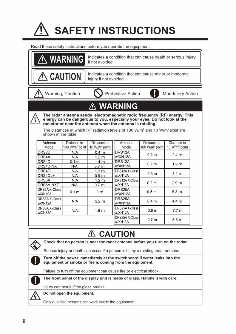
The front panel of the display unit is made of glass. Handle it with care.
Injury can result if the glass breaks.
Read these safety instructions before you operate the equipment.
Indicates a condition that can cause death or serious injury if not avoided.
Indicates a condition that can cause minor or moderate injury if not avoided.
The radar antenna sends electromagnetic radio frequency (RF) energy. This energy can be dangerous to you, especially your eyes. Do not look at the radiator or near the antenna when the antenna is rotating. The distances at which RF radiation levels of 100 W/m2 and 10 W/m2 exist are shown in the table.
Check that no person is near the radar antenna before you turn on the radar.
Serious injury or death can occur if a person is hit by a rotating radar antenna.
Turn off the power immediately at the switchboard if water leaks into the equipment or smoke or fire is coming from the equipment.
Failure to turn off the equipment can cause fire or electrical shock.
Do not open the equipment.
Only qualified persons can work inside the equipment.
DRS2DDRS4ADRS4D
DRS4DL
DRS6A
DRS12A w/XN12ADRS12Aw/XN13A
DRS25Aw/XN12ADRS25Aw/XN13A
DRS4D-NXT
DRS6A X-Classw/XN10ADRS6A X-Classw/XN12ADRS6A X-Classw/XN13A
DRS12A X-Classw/XN12ADRS12A X-Classw/XN13A
DRS25A X-Classw/XN12ADRS25A X-Classw/XN13A
AntennaModel
Distance to 100 W/m2 point
Distance to10 W/m2 point
AntennaModel
Distance to 100 W/m2 point
Distance to10 W/m2 point
N/AN/A
0.4 m1.2 m
0.1 m 1.4 m
N/A 1.1 mDRS4DL+ N/A 0.9 m
N/A 1.2 m
0.2 m 2.4 m
0.2 m 1.9 m
0.5 m 5.3 m
0.4 m 4.4 m
N/A 0.7 m
DRS6A-NXT N/A 0.7 m0.1 m 3 m
N/A 2.2 m
N/A 1.9 m
0.3 m 3.1 m
0.2 m 2.9 m
0.8 m 7.7 m
0.7 m 6.8 m
ii
SAFETY INSTRUCTIONS
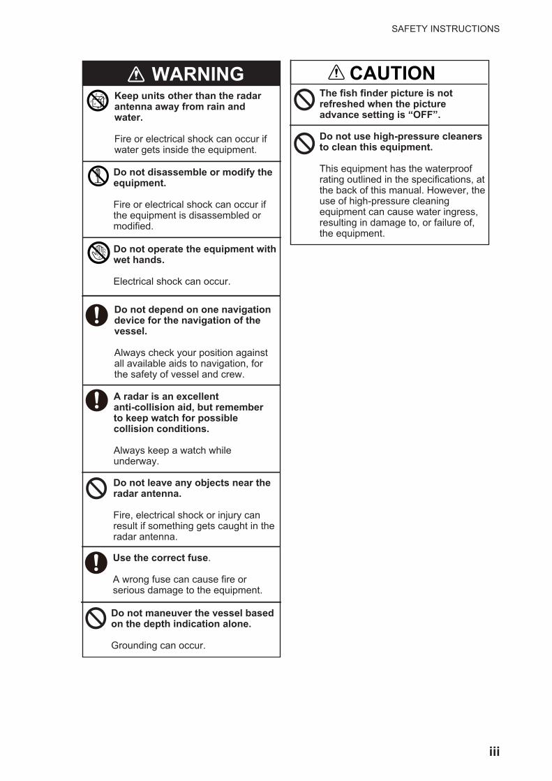
WARNINGKeep units other than the radar antenna away from rain and water.
Fire or electrical shock can occur if water gets inside the equipment.
Do not disassemble or modify the equipment.
Fire or electrical shock can occur if the equipment is disassembled or modified.
Do not operate the equipment with wet hands.
Electrical shock can occur.
Do not depend on one navigation device for the navigation of the vessel.
Always check your position against all available aids to navigation, for the safety of vessel and crew.
A radar is an excellent anti-collision aid, but remember to keep watch for possible collision conditions.
Always keep a watch while underway.
Do not leave any objects near the radar antenna.
Fire, electrical shock or injury can result if something gets caught in the radar antenna.
Use the correct fuse.
A wrong fuse can cause fire or serious damage to the equipment.
Do not maneuver the vessel based on the depth indication alone.
Grounding can occur.
CAUTIONThe fish finder picture is not refreshed when the picture advance setting is “OFF”.
Do not use high-pressure cleaners to clean this equipment.
This equipment has the waterproof rating outlined in the specifications, at the back of this manual. However, the use of high-pressure cleaning equipment can cause water ingress, resulting in damage to, or failure of, the equipment.
iii
SAFETY INSTRUCTIONS
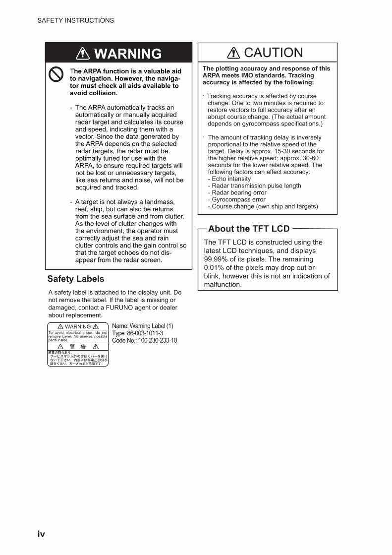
The ARPA function is a valuable aid to navigation. However, the naviga-tor must check all aids available to avoid collision.
- The ARPA automatically tracks an automatically or manually acquired radar target and calculates its course and speed, indicating them with a vector. Since the data generated by the ARPA depends on the selected radar targets, the radar must be optimally tuned for use with the ARPA, to ensure required targets will not be lost or unnecessary targets, like sea returns and noise, will not be acquired and tracked.
- A target is not always a landmass, reef, ship, but can also be returns from the sea surface and from clutter. As the level of clutter changes with the environment, the operator must correctly adjust the sea and rain clutter controls and the gain control so that the target echoes do not dis- appear from the radar screen.
WARNINGThe plotting accuracy and response of this ARPA meets IMO standards. Tracking accuracy is affected by the following:
• Tracking accuracy is affected by course change. One to two minutes is required to restore vectors to full accuracy after an abrupt course change. (The actual amount depends on gyrocompass specifications.)
• The amount of tracking delay is inversely proportional to the relative speed of the target. Delay is approx. 15-30 seconds for the higher relative speed; approx. 30-60 seconds for the lower relative speed. The following factors can affect accuracy: - Echo intensity - Radar transmission pulse length - Radar bearing error - Gyrocompass error - Course change (own ship and targets)
CAUTION
The TFT LCD is constructed using the latest LCD techniques, and displays 99.99% of its pixels. The remaining 0.01% of the pixels may drop out or blink, however this is not an indication of malfunction.
About the TFT LCD
A safety label is attached to the display unit. Do not remove the label. If the label is missing or damaged, contact a FURUNO agent or dealer about replacement.
Name: Warning Label (1) Type: 86-003-1011-3Code No.: 100-236-233-10
Safety Labels
WARNINGTo avoid electrical shock, do not remove cover. No user-serviceable parts inside.
iv
TABLE OF CONTENTS
FOREWORD................................................................................................................. xiiiSYSTEM CONFIGURATION ......................................................................................... xv
1. SYSTEM INTRODUCTION ....................................................................................1-11.1 Controls ......................................................................................................................1-21.2 Remote Control Units (option) ....................................................................................1-5
1.2.1 Remote Control MCU-002..............................................................................1-51.2.2 Remote Control Unit MCU-004 ......................................................................1-61.2.3 Control Unit MCU-005 ....................................................................................1-71.2.4 Remote Control Unit group settings ...............................................................1-9
1.3 How to Turn the Power On or Off .............................................................................1-111.4 How to Adjust the Brilliance of the Display and Power Switch and Hue...................1-121.5 Home Screen............................................................................................................1-131.6 How to Select a Display............................................................................................1-14
1.6.1 How to select a display from the home screen.............................................1-141.6.2 How to select a display from the quick page ................................................1-15
1.7 How to Edit the Display Icons...................................................................................1-161.7.1 How to add a new display icon.....................................................................1-161.7.2 How to edit a display icon.............................................................................1-17
1.8 Hidden Functions......................................................................................................1-181.9 Data Area .................................................................................................................1-20
1.9.1 How to change the order of the data ............................................................1-201.9.2 How to change the contents of a data box ...................................................1-211.9.3 How to add data to a data area ....................................................................1-211.9.4 How to delete a data box..............................................................................1-221.9.5 How to switch an indication between analog (graphic) and digital ...............1-231.9.6 How to adjust the transparency of the data area..........................................1-23
1.10 MicroSD Cards/SD Cards.........................................................................................1-241.11 Plotter Introduction ...................................................................................................1-271.12 Radar Introduction ....................................................................................................1-281.13 Sounder (Fish Finder) Introduction...........................................................................1-291.14 Settings Menu...........................................................................................................1-301.15 Function Gesture ......................................................................................................1-331.16 Language..................................................................................................................1-341.17 Man Overboard (MOB) .............................................................................................1-351.18 Wireless LAN Settings..............................................................................................1-36
1.18.1 How to connect the existing LAN .................................................................1-361.18.2 How to create a local wireless network ........................................................1-38
1.19 How to Create and Login to Your My TimeZero™ Account ......................................1-391.20 Dual Monitor Configurations .....................................................................................1-40
2. PLOTTER...............................................................................................................2-12.1 Chart Type..................................................................................................................2-12.2 Display Range ............................................................................................................2-22.3 Orientation Mode........................................................................................................2-32.4 How to Move the Chart...............................................................................................2-32.5 The Boat Icon .............................................................................................................2-4
2.5.1 Description .....................................................................................................2-42.5.2 How to show or hide the COG vector, heading line .......................................2-42.5.3 COG vector length..........................................................................................2-52.5.4 Boat icon orientation.......................................................................................2-6
v
TABLE OF CONTENTS
2.6 How to Information About a Chart Object, Chart........................................................ 2-62.6.1 Chart object information................................................................................. 2-62.6.2 Chart information............................................................................................ 2-7
2.7 How to Find the Range and Bearing Between Two Locations................................... 2-82.8 Multiple Plotter Displays............................................................................................. 2-92.9 Cartographic Text and Objects on Vector Charts .................................................... 2-10
2.9.1 Control visibility of text and object information in vector charts.................... 2-102.9.2 Control visibility of cartographic objects in S-52 charts................................ 2-11
2.10 Alarms ...................................................................................................................... 2-132.10.1 XTE alarm .................................................................................................... 2-142.10.2 Depth alarm.................................................................................................. 2-142.10.3 SST alarm .................................................................................................... 2-142.10.4 Speed alarm................................................................................................. 2-152.10.5 Anchor watch alarm ..................................................................................... 2-162.10.6 Low fuel alarm.............................................................................................. 2-162.10.7 Other Alarm menu items .............................................................................. 2-162.10.8 Alarms list..................................................................................................... 2-17
2.11 Track ........................................................................................................................ 2-172.11.1 How to start, stop recording the track .......................................................... 2-172.11.2 How to show or hide the track display.......................................................... 2-172.11.3 Track recording interval................................................................................ 2-182.11.4 Track color ................................................................................................... 2-182.11.5 Track thickness ............................................................................................ 2-212.11.6 How to create a route with past track........................................................... 2-212.11.7 How to create a route with track currently being recorded (track back) ....... 2-222.11.8 How to delete tracks..................................................................................... 2-232.11.9 How to find the number of track points used................................................ 2-23
2.12 Plotter Menu............................................................................................................. 2-242.13 NAVpilot Series Auto Pilot........................................................................................ 2-25
2.13.1 How to enable use of the NAVpilot .............................................................. 2-252.13.2 How to show the NAVpilot control box in the data area ............................... 2-26
2.14 ActiveCaptain ........................................................................................................... 2-262.14.1 How to activate ActiveCaptain ..................................................................... 2-262.14.2 How to hide or show the ActiveCaptain display ........................................... 2-272.14.3 How to find a marina .................................................................................... 2-272.14.4 How to show or hide ActiveCaptain items.................................................... 2-272.14.5 How to update the ActiveCaptain database................................................. 2-28
2.15 My Friends (Social Network) .................................................................................... 2-282.15.1 How to setup My Friends ............................................................................. 2-282.15.2 How to show or hide the My Friends display................................................ 2-29
3. 3D DISPLAY, OVERLAYS.....................................................................................3-13.1 3D Display..................................................................................................................3-1
3.1.1 How to activate the 3D display....................................................................... 3-23.1.2 How to make the 3D view clearer .................................................................. 3-3
3.2 Overlays ..................................................................................................................... 3-43.2.1 Depth shading overlay ................................................................................... 3-43.2.2 Satellite photo overlay.................................................................................... 3-63.2.3 Radar overlay................................................................................................. 3-63.2.4 Tide info overlay............................................................................................. 3-83.2.5 Tidal current overlay..................................................................................... 3-10
4. POINTS, EVENT MARKS ......................................................................................4-14.1 About Points, Event Marks......................................................................................... 4-14.2 How to Enter a Point, Event Mark .............................................................................. 4-2
4.2.1 How to enter a point (plotter and radar displays only).................................... 4-2
vi

TABLE OF CONTENTS
4.2.2 How to enter an event mark ...........................................................................4-34.3 How to Display Point, Event Mark Information ...........................................................4-44.4 Event Mark Comment.................................................................................................4-54.5 Default Point, Event Mark Settings.............................................................................4-5
4.5.1 Default point settings......................................................................................4-54.5.2 Default event mark settings............................................................................4-7
4.6 How to Find Number of Points Used ..........................................................................4-74.7 Points List ...................................................................................................................4-8
4.7.1 How to show the points list .............................................................................4-84.7.2 How to sort the points list ...............................................................................4-84.7.3 How to search the points list ..........................................................................4-84.7.4 How to view and edit point details ..................................................................4-94.7.5 How to edit a point on the screen.................................................................4-10
4.8 How to Move a Point ................................................................................................4-114.8.1 How to move a point on the screen..............................................................4-114.8.2 How to move a point from the points list ......................................................4-12
4.9 How to Delete a Point...............................................................................................4-124.9.1 How to delete a point on the screen.............................................................4-124.9.2 How to delete a point from the points list .....................................................4-124.9.3 How to delete all points ................................................................................4-12
4.10 How to Move a Point to the Screen Center ..............................................................4-134.11 How to Show or Hide All Points or Points Names ....................................................4-134.12 How to Set Point Density..........................................................................................4-134.13 How to Go to a Point ................................................................................................4-14
4.13.1 How to go to an on-screen point ..................................................................4-144.13.2 How to go to a position selected on screen..................................................4-154.13.3 How to go to a point selected from the points list .........................................4-164.13.4 How to use the NAVpilot to steer to a point..................................................4-164.13.5 How to display the point information for the active goto point ......................4-17
4.14 How to Restart or Cancel Navigation to a Point .......................................................4-184.14.1 How to restart navigation to a point ..............................................................4-184.14.2 How to cancel navigation to a point..............................................................4-18
4.15 Boundary Lines.........................................................................................................4-184.15.1 How to show or hide boundary lines ............................................................4-194.15.2 How to find boundary lines data ...................................................................4-194.15.3 How to find the number of boundary points used.........................................4-194.15.4 How to delete boundary lines .......................................................................4-194.15.5 How to edit boundary lines ...........................................................................4-20
5. ROUTES ................................................................................................................5-15.1 What is a Route?........................................................................................................5-15.2 How to Create a Route ...............................................................................................5-2
5.2.1 How to create a new route from the plotter screen ........................................5-25.2.2 How to create a new route with points ...........................................................5-35.2.3 How to create a route from the points list .......................................................5-4
5.3 How to Edit a Route....................................................................................................5-45.3.1 How to insert a route point on a route ............................................................5-45.3.2 How to move a route point on a route ............................................................5-45.3.3 How to delete a point (incl. route point) on a route.........................................5-55.3.4 How to remove a point from a route ...............................................................5-55.3.5 How to extend a route ....................................................................................5-5
5.4 Routes List..................................................................................................................5-65.5 How to Find Number of Routes Created ....................................................................5-85.6 How to Find a Route on the Chart ..............................................................................5-85.7 How to Delete a Route ...............................................................................................5-9
5.7.1 How to delete a route on the screen ..............................................................5-9
vii

TABLE OF CONTENTS
5.7.2 How to delete a route from the routes list ...................................................... 5-95.7.3 How to delete all routes.................................................................................. 5-9
5.8 How to Show or Hide All Routes ................................................................................ 5-95.9 How to Set Route Density .......................................................................................... 5-95.10 How to Follow a Route ............................................................................................. 5-10
5.10.1 How to follow an on-screen route................................................................. 5-105.10.2 How to follow a route selected from the routes list....................................... 5-115.10.3 How to start navigation from a route point ................................................... 5-115.10.4 How to show the detailed information about a route .................................... 5-12
5.11 Operations When You Follow a Route..................................................................... 5-125.11.1 How to restart navigation ............................................................................. 5-125.11.2 How to follow a route in the reverse direction .............................................. 5-125.11.3 How to stop following a route ....................................................................... 5-125.11.4 How to skip a point on a route...................................................................... 5-125.11.5 Waypoint switching mode ............................................................................ 5-135.11.6 Route auto zoom.......................................................................................... 5-135.11.7 XTE lines...................................................................................................... 5-145.11.8 Waypoint arrival notification ......................................................................... 5-145.11.9 End of route notification ............................................................................... 5-145.11.10Steering a route with the NAVpilot ............................................................... 5-15
5.12 Fuel Level Indicators ................................................................................................ 5-155.13 Routes Menu............................................................................................................ 5-16
6. RADAR...................................................................................................................6-16.1 How to Transmit, Set the Radar in Stand-by.............................................................. 6-16.2 Tuning ........................................................................................................................ 6-16.3 How to Adjust the Gain .............................................................................................. 6-26.4 How to Reduce the Sea Clutter.................................................................................. 6-46.5 How to Reduce the Rain Clutter................................................................................. 6-46.6 Range Scale............................................................................................................... 6-56.7 Orientation Mode........................................................................................................ 6-56.8 How to Measure the Range and Bearing from Your Ship to a Target........................ 6-6
6.8.1 How to display the range rings....................................................................... 6-66.8.2 How to set the number of the range rings to show......................................... 6-76.8.3 How to select the range rings mode............................................................... 6-76.8.4 How to measure the range and bearing to an object ..................................... 6-86.8.5 How to measure the range with the VRM ...................................................... 6-96.8.6 How to measure the bearing with the EBL................................................... 6-116.8.7 How to select the EBL reference.................................................................. 6-12
6.9 How to Measure the Range and Bearing Between Two Targets ............................. 6-136.10 How to Off-center the Picture................................................................................... 6-136.11 Heading Line ............................................................................................................ 6-146.12 How to Reduce Radar Interference.......................................................................... 6-146.13 Echo Average........................................................................................................... 6-156.14 Guard Zone .............................................................................................................. 6-15
6.14.1 How to set the guard zone ........................................................................... 6-156.14.2 How to activate or deactivate the guard zone.............................................. 6-166.14.3 How to hide the guard zone ......................................................................... 6-16
6.15 Watchman ................................................................................................................ 6-166.16 Echo Trail .................................................................................................................6-17
6.16.1 How to show, hide echo trails ...................................................................... 6-176.16.2 How to clear echo trails................................................................................ 6-176.16.3 How to select echo trail length ..................................................................... 6-176.16.4 How to select the echo trail mode (reference) ............................................. 6-186.16.5 How to select echo trail color ....................................................................... 6-186.16.6 How to select echo trail shading .................................................................. 6-19
viii

TABLE OF CONTENTS
6.17 How to Show, Hide or Cancel an Active Route ........................................................6-196.18 How to Show or Hide the Own Ship Icon .................................................................6-196.19 Echo Color................................................................................................................6-206.20 Background Color.....................................................................................................6-206.21 Dual-Range Display..................................................................................................6-216.22 Bird Mode .................................................................................................................6-226.23 Target Analyzer ........................................................................................................6-23
6.23.1 How to activate or deactivate the target analyzer ........................................6-256.23.2 How to emphasize rain clutter or target echoes ...........................................6-25
6.24 RezBoost™ ...............................................................................................................6-256.25 Radar Menu..............................................................................................................6-266.26 How to Interpret the Radar Display ..........................................................................6-28
6.26.1 False echoes ................................................................................................6-286.26.2 Search and rescue transponder (SART) ......................................................6-306.26.3 RACON (Radar Beacon) ..............................................................................6-30
6.27 ARPA Operation .......................................................................................................6-316.27.1 How to show or hide the ARPA display........................................................6-316.27.2 How to manually acquire a target.................................................................6-326.27.3 How to automatically acquire a target ..........................................................6-326.27.4 How to automatically acquire targets by Doppler .........................................6-326.27.5 How to display target data............................................................................6-336.27.6 How to stop tracking targets.........................................................................6-336.27.7 ARPA list ......................................................................................................6-346.27.8 How to clear lost targets...............................................................................6-356.27.9 CPA/TCPA alarm .........................................................................................6-356.27.10CPA graphic display .....................................................................................6-36
7. FISH FINDER (SOUNDER) ...................................................................................7-17.1 How the Fish Finder Operates....................................................................................7-17.2 How to Transmit, Go to Stand-by ...............................................................................7-17.3 How to Select a Display..............................................................................................7-2
7.3.1 Single frequency display ................................................................................7-27.3.2 Dual frequency display ...................................................................................7-37.3.3 Zoom displays ................................................................................................7-37.3.4 A-scope display (display only) ........................................................................7-47.3.5 Bottom discrimination display.........................................................................7-5
7.4 Automatic Fish Finder Operation................................................................................7-67.4.1 How the automatic fish finder operates ..........................................................7-67.4.2 How to select an automatic fish finder mode..................................................7-6
7.5 Manual Fish Finder Operation ....................................................................................7-67.5.1 How to select the manual mode .....................................................................7-67.5.2 How to select the display range .....................................................................7-67.5.3 How to shift the range ....................................................................................7-77.5.4 How to adjust the gain....................................................................................7-77.5.5 How to reduce the clutter ...............................................................................7-8
7.6 Picture Advance Speed..............................................................................................7-87.7 How to Reduce Interference.......................................................................................7-97.8 How to Measure Range, Depth to an Object..............................................................7-97.9 Echo History Display ................................................................................................7-107.10 How to Balance Echo Strength.................................................................................7-107.11 Fish Finder Alarms ...................................................................................................7-11
7.11.1 How to set an alarm .....................................................................................7-117.11.2 How to activate or deactivate an alarm ........................................................7-127.11.3 Alarm sensitivity ...........................................................................................7-12
7.12 ACCU-FISH™ ...........................................................................................................7-137.12.1 How to set ACCU-FISH™ .............................................................................7-13
ix
TABLE OF CONTENTS
7.12.2 Fish size correction ...................................................................................... 7-147.12.3 How to turn the fish symbol indication on or off ........................................... 7-147.12.4 How to display the fish information .............................................................. 7-157.12.5 How to set the minimum size of ACCU-FISH™ symbols ............................. 7-15
7.13 RezBoost™............................................................................................................... 7-157.14 Temperature Graph.................................................................................................. 7-167.15 Sounder Menu ......................................................................................................... 7-177.16 Interpreting the Display ............................................................................................ 7-20
8. MULTI BEAM SONAR DFF-3D .............................................................................8-18.1 Display Screens Overview ......................................................................................... 8-18.2 Multi-Sounder Display Operations ............................................................................. 8-4
8.2.1 How to switch between TX and STBY ........................................................... 8-48.2.2 How to switch between single beam and triple beam presentations.............. 8-48.2.3 How to set the TX beam angle....................................................................... 8-48.2.4 How to set the TX beam width ....................................................................... 8-48.2.5 How to show or hide the scale box ................................................................ 8-48.2.6 Availability of points and event marks registration, and go to a point ............ 8-5
8.3 Side Scan Display Operations ................................................................................... 8-68.3.1 How to switch between TX and STBY ........................................................... 8-68.3.2 How to change echo color.............................................................................. 8-68.3.3 How to show or hide the scale box ................................................................ 8-68.3.4 Availability of points and event marks registration, and go to a point ............ 8-6
8.4 Cross Section Display Operations ............................................................................. 8-78.4.1 How to switch between TX and STBY ........................................................... 8-78.4.2 How to show or hide the grid.......................................................................... 8-78.4.3 Zoom display.................................................................................................. 8-78.4.4 How to smooth echoes (distance).................................................................. 8-88.4.5 How to smooth echoes (time) ........................................................................ 8-88.4.6 How to apply correction to the speed of sound.............................................. 8-88.4.7 How to show or hide the scale box ................................................................ 8-98.4.8 Availability of points and event marks registration, and go to a point ............ 8-9
8.5 3D Sounder History Display Operations .................................................................. 8-108.5.1 How to switch between TX and STBY ......................................................... 8-108.5.2 How to move, zoom in, zoom out the viewpoint position ............................. 8-108.5.3 How to mark school of fish ........................................................................... 8-108.5.4 How to stop advancement of the display ..................................................... 8-118.5.5 How to adjust the echo detection level......................................................... 8-118.5.6 How to calibrate the seabed echo................................................................ 8-118.5.7 How to use the noise filter............................................................................ 8-118.5.8 How to use terrain shading .......................................................................... 8-128.5.9 Depth/Color Shading display........................................................................ 8-128.5.10 How to show or hide the scale box .............................................................. 8-168.5.11 Availability of points and event marks registration, and go to a point .......... 8-16
9. FILE OPERATIONS ...............................................................................................9-19.1 File Format .................................................................................................................9-19.2 How to Export Points and Routes .............................................................................. 9-29.3 How to Import Points, Routes, and Boundary Lines .................................................. 9-39.4 How to Export, Import Track ...................................................................................... 9-49.5 How to Backup the Equipment Settings..................................................................... 9-59.6 How to Load the Equipment Settings......................................................................... 9-69.7 My TimeZero™ Cloud Data Service ........................................................................... 9-6
9.7.1 How to save settings data to the cloud .......................................................... 9-69.7.2 How to retrieve settings data from the cloud.................................................. 9-7
9.8 How to Convert NavNet vx2 Data .............................................................................. 9-7
x
TABLE OF CONTENTS
9.9 My TimeZero™ Cloud Data Service ...........................................................................9-89.9.1 How to backup settings to the cloud...............................................................9-89.9.2 How to restore settings from the cloud...........................................................9-8
10. CAMERA/VIDEO/FUSION-Link ..........................................................................10-110.1 How to Display a Video Image .................................................................................10-110.2 Video Signal Type ....................................................................................................10-210.3 How to Set the Video Display ...................................................................................10-2
10.3.1 How to set the video signal ..........................................................................10-210.3.2 How to adjust the image size .......................................................................10-610.3.3 How to switch your video inputs ...................................................................10-610.3.4 How to adjust the video image .....................................................................10-7
10.4 Control of FLIR Camera ...........................................................................................10-710.5 Tracking Active Waypoint, MOB...............................................................................10-710.6 Touch Control on the Camera Display .....................................................................10-810.7 FUSION-Link ............................................................................................................10-9
10.7.1 How to access the FUSION screen and controls .........................................10-910.7.2 FUSION settings ........................................................................................10-11
10.8 Operating External Equipment ...............................................................................10-12
11. SPECIALIZED DISPLAYS...................................................................................11-111.1 Instrument Display....................................................................................................11-1
11.1.1 Instrument display examples........................................................................11-211.1.2 How to switch between instrument displays.................................................11-811.1.3 How to edit the instrument display ...............................................................11-911.1.4 Instrument theme .......................................................................................11-1411.1.5 Fuel management system ..........................................................................11-14
11.2 CZone.....................................................................................................................11-1611.2.1 How to use CZone......................................................................................11-1611.2.2 CZone control .............................................................................................11-1711.2.3 CZone modes.............................................................................................11-1911.2.4 CZone monitoring.......................................................................................11-22
11.3 Yamaha Engine Status Display ..............................................................................11-2411.3.1 How to show the display.............................................................................11-2411.3.2 Display examples .......................................................................................11-2511.3.3 How to switch between displays.................................................................11-2611.3.4 How to select the data to display in a data box ..........................................11-2611.3.5 Troll mode ..................................................................................................11-2711.3.6 Trouble codes.............................................................................................11-2811.3.7 Alarm list.....................................................................................................11-28
12. SIRIUS/XM SATELLITE WEATHER RECEIVER (BBWX3) OPERATIONS.......12-112.1 Marine Weather Display Introduction .......................................................................12-112.2 NavCenter Weather..................................................................................................12-2
12.2.1 How to set up for NavCenter weather ..........................................................12-212.2.2 How to download the NavCenter weather data............................................12-412.2.3 How to display the NavCenter data..............................................................12-512.2.4 How to load a weather file ............................................................................12-6
12.3 Sirius Weather ..........................................................................................................12-612.3.1 How to set up for Sirius weather ..................................................................12-612.3.2 How to display the Sirius data ......................................................................12-8
12.4 Weather Icons (Sirius Weather) ...............................................................................12-912.5 Weather Data (NavCenter or Sirius).......................................................................12-1012.6 Sirius Weather Diagnostics ....................................................................................12-1312.7 Sirius Satellite Radio ..............................................................................................12-14
12.7.1 How to enable the radio .............................................................................12-14
xi
TABLE OF CONTENTS
12.7.2 How to operate the radio controls .............................................................. 12-1512.7.3 Radio diagnostics....................................................................................... 12-16
13. AIS, DSC MESSAGE ...........................................................................................13-113.1 What is AIS? ............................................................................................................ 13-113.2 How to Show or Hide the AIS Symbols.................................................................... 13-113.3 AIS Target Symbols ................................................................................................. 13-113.4 Proximity AIS Target Alarm...................................................................................... 13-313.5 How to Ignore Slow Moving AIS Targets ................................................................. 13-313.6 How to Hide AIS Targets.......................................................................................... 13-313.7 How to Display an AIS Safety Message................................................................... 13-513.8 How to Display AIS Target Data .............................................................................. 13-513.9 How to Show or Hide the Target IDs........................................................................ 13-613.10AIS List .................................................................................................................... 13-613.11When an AIS SART is Received... .......................................................................... 13-813.12CPA/TCPA Alarm .................................................................................................... 13-813.13How to Register an AIS or DSC Target to the Buddies List .................................... 13-913.14CPA Graphic Display............................................................................................. 13-1013.15AIS Transponder FA-30, FA-50............................................................................. 13-1113.16DSC Message Information .................................................................................... 13-12
13.16.1DSC distress message notification ............................................................ 13-1213.16.2How to go to a DSC point........................................................................... 13-1213.16.3How to display DSC information ................................................................ 13-1313.16.4The DSC list ............................................................................................... 13-14
14. OTHER FUNCTIONS ...........................................................................................14-114.1 General Menu .......................................................................................................... 14-114.2 Units Menu ............................................................................................................... 14-314.3 Initial Setup Menu .................................................................................................... 14-514.4 Facsimile Receiver FAX-30.................................................................................... 14-1014.5 Software Update .................................................................................................... 14-1114.6 How to Manage Your Charts.................................................................................. 14-12
14.6.1 How to view your charts ............................................................................. 14-1214.6.2 How to hide unnecessary charts on the chart catalog list .......................... 14-1314.6.3 How to update or add charts ...................................................................... 14-1314.6.4 How to delete charts .................................................................................. 14-14
15. MAINTENANCE, TROUBLESHOOTING.............................................................15-115.1 Maintenance............................................................................................................. 15-115.2 Fuse Replacement ................................................................................................... 15-215.3 Life of Parts ..............................................................................................................15-215.4 Troubleshooting ....................................................................................................... 15-3
15.4.1 General troubleshooting............................................................................... 15-315.4.2 Radar troubleshooting.................................................................................. 15-415.4.3 Plotter troubleshooting ................................................................................. 15-415.4.4 Fish finder troubleshooting........................................................................... 15-4
APPENDIX 1 MENU TREE .......................................................................................AP-1APPENDIX 2 RADIO REGULATORY INFORMATION ..........................................AP-14SPECIFICATIONS .....................................................................................................SP-1INDEX.......................................................................................................................... IN-1
xii

FOREWORD
A Word to the Owner
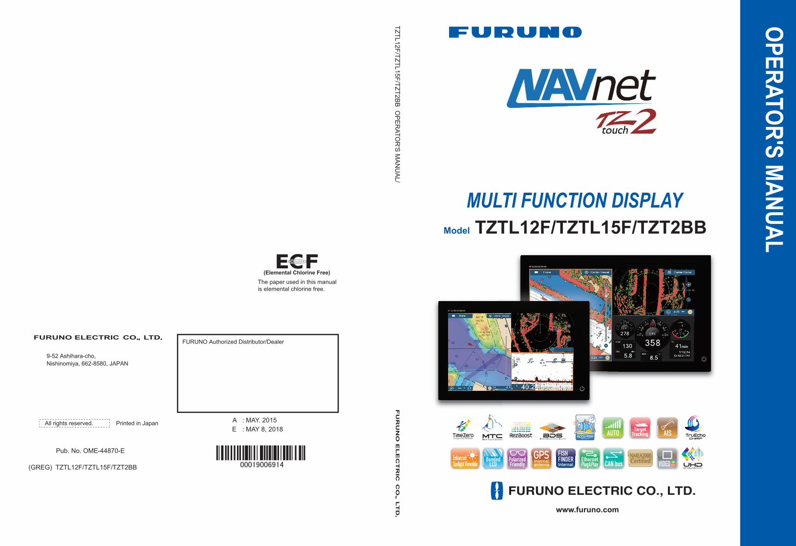
Congratulations on your choice of Multi Function Display, a member of the NavNet TZtouch2 fam-ily of multi-function displays. We are confident you will see why the FURUNO name has become synonymous with quality and reliability.
Since 1948, FURUNO Electric Company has enjoyed an enviable reputation for innovative and dependable marine electronics equipment. This dedication to excellence is furthered by our ex-tensive global network of agents and dealers.
Your equipment is designed and constructed to meet the rigorous demands of the marine envi-ronment. However, no machine can perform its intended function unless properly installed and maintained. Please carefully read and follow the operation and maintenance procedures set forth in this manual.
We would appreciate feedback from you, the end-user, about whether we are achieving our pur-poses.
Thank you for considering and purchasing FURUNO.
Features
The NavNet TZtouch2, equipped with a touch screen with multi touch capacity, is a networked navigation system that gives you functions such as radar, plotter, fish finder and AIS. Information is transferred between NavNet TZtouch2 units through Ethernet or NMEA 2000. The plug-and-play format allows expansion and you can connect a maximum of four NavNet TZtouch2 units.
Also, you can control the NavNet TZtouch2 units and display their data on an iOS or Android™ device.
Main features
• Intuitive touch control operation.
• The NavNet TZtouch2 units can be controlled and monitored from the following applications*.
* Check compatibility with your OS version in the store before downloading. Applications are
available from the App Store (iOS) or Google Play™ (Android) at no cost.
• Instrument display provides comprehensive navigation data with connection of appropriate sen-sors.
• Built in wireless LAN to update program and download weather data via the internet. (NavNet TZtouch2 units sold in China do not have wireless LAN capability.)
• Points (waypoints) and routes are transferred and shared between NavNet TZtouch2 units via Ethernet.
Application* Capability iOS AndroidNavNet Remote(NavNet software version 4.01 or higher)
Monitor or operate NavNet TZtouch2
iPad only Other than 7 inchOther than iPad Less than 7 inch
NavNet Viewer Display nav data, sounder picture.
Yes Yes
NavNet Controller Remote control of NavNet TZtouch2.
Yes Yes
TM
xiii
FOREWORD
• Large memory stores 30,000 track points, 30,000 points, and 200 routes (500 points per route).
• Able to write and read data (points, routes, tracks, etc.).
• Built in GPS receiver and antenna (TZTL12F/TZTL15F).
• Built in fish finder.
• AIS function (requires connection of AIS transponder) receives AIS data from AIS equipped vessels, shore stations and navigational aids and displays relevant data.
• ACCU-FISH™ provides at-a-glance estimation of length and depth of individual fish.
• Bottom discrimination display helps identify probable bottom composition with graphics and col-ors.
• RezBoost™ raises echo resolution to see fish echoes clearly. (Requires RezBoost™ capable transducer. Not available when the transducer is installed with the inside hull installation meth-od.)
• Dual-range radar display for watch on short and long distances at the same time.
• DSC (Digital Selective Calling) message information feature provides the MMSI no. and posi-tion of vessels that have transmitted a DSC message to you. (Requires DSC capable radiotele-phone.)
• Control audio of FUSION-Link™equipment (MS-700, MS-750 or MS-755 series).
• HDMI output (type A receptacle).
• Monitoring of the inside/outside of your ship via analog camera (FLIR™ or AXIS®).
• Monitoring around the vessel with pan-tilt-zoom capable (PTZ) cameras (FLIR™ or AXIS®).
• Control of all software applications from an external monitor, connected via the HDMI IN and USB for HDMI OUT ports (TZT2BB only).
• View separate screens on connected dual monitors (TZT2BB only.)
Software used in this product
This equipment uses the following open source software.
• Ubiquitous QuickBoot Copyright© 2015 Ubiquitous Corp. All rights reserved.
• This product includes software to be licensed under the GNU General Public License (GPL) ver-sion 2.0, GNU Lesser General Public Software License (LGPL) version 2.0, Apache, BSD and others. The program(s) is/are free software(s), and you can copy it and/or redistribute it and/or modify it under the terms of the GPL version 2.0 or LGPL version 2.0 as published by the Free Software Foundation. Please access to the following URL if you need source codes: https://www.furuno.co.jp/contact/cnt_oss01.html.
Program no.
1950152-05.**** denotes minor modifications.
CE declaration
With regards to CE declarations, please refer to our website (www.furuno.com), for further infor-mation about RoHS conformity declarations.
xiv
SYSTEM CONFIGURATION
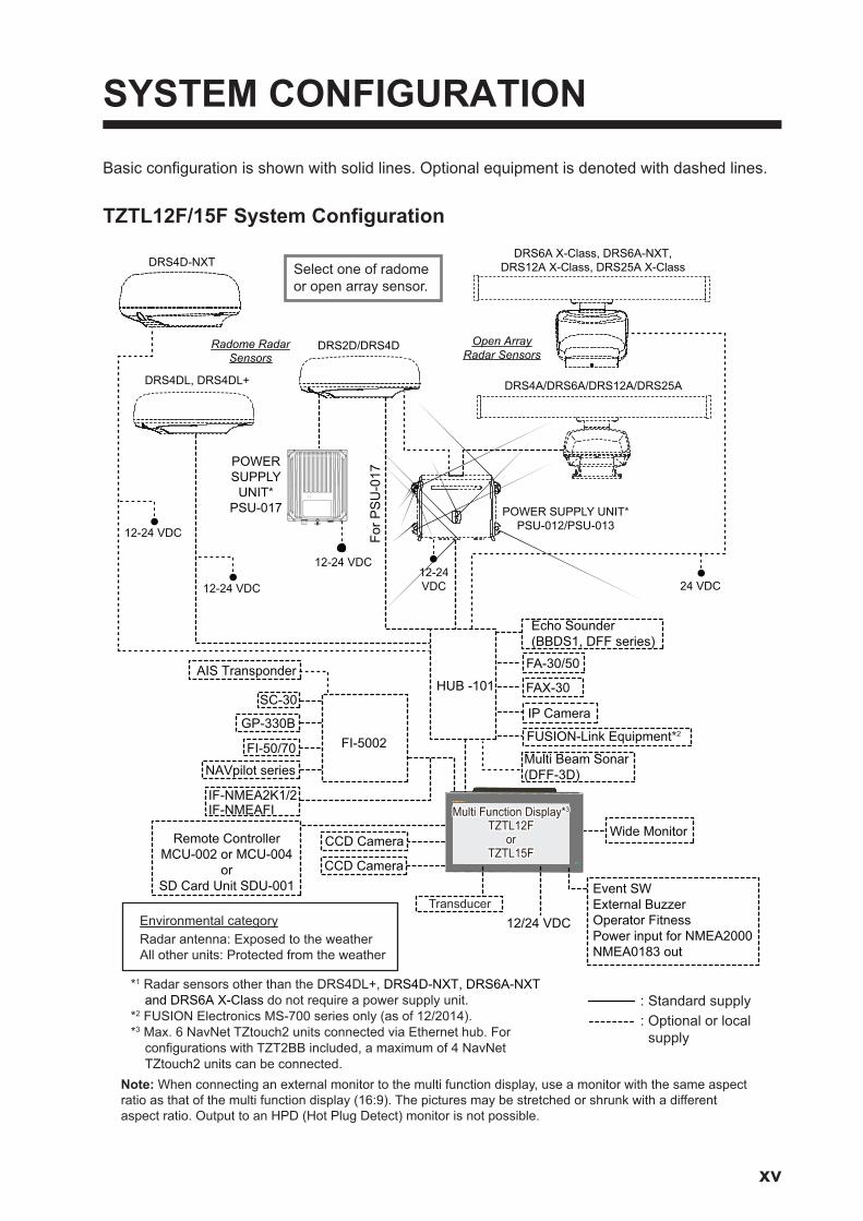
Basic configuration is shown with solid lines. Optional equipment is denoted with dashed lines.
TZTL12F/15F System Configuration
CCD Camera
CCD Camera
FI-5002
SC-30
GP-330B
NAVpilot series
FI-50/70
IF-NMEA2K1/2IF-NMEAFI
12/24 VDC
Event SWExternal BuzzerOperator FitnessPower input for NMEA2000NMEA0183 out
Echo Sounder(BBDS1, DFF series)
Environmental categoryRadar antenna: Exposed to the weatherAll other units: Protected from the weather
AIS Transponder
*1 Radar sensors other than the DRS4DL+, DRS4D-NXT, DRS6A-NXT and DRS6A X-Class do not require a power supply unit.
*2 FUSION Electronics MS-700 series only (as of 12/2014).*3 Max. 6 NavNet TZtouch2 units connected via Ethernet hub. For
configurations with TZT2BB included, a maximum of 4 NavNet TZtouch2 units can be connected.
HUB -101
FA-30/50
FAX-30
FUSION-Link Equipment*2
Wide MonitorRemote ControllerMCU-002 or MCU-004
orSD Card Unit SDU-001
Multi Function Display*3 TZTL12F
orTZTL15F
Multi Function Display*3 TZTL12F
orTZTL15F
Transducer
Open Array Radar Sensors
12-24VDC
DRS2D/DRS4D
POWER SUPPLY UNIT*PSU-012/PSU-013
Radome Radar Sensors
DRS4A/DRS6A/DRS12A/DRS25A
POWER SUPPLY
UNIT*PSU-017
For P
SU
-017
DRS4DL, DRS4DL+
12-24 VDC
DRS4D-NXT
24 VDC
Select one of radomeor open array sensor.
: Standard supply: Optional or local supply
Multi Beam Sonar(DFF-3D)
IP Camera
12-24 VDC
12-24 VDC
Note: When connecting an external monitor to the multi function display, use a monitor with the same aspect ratio as that of the multi function display (16:9). The pictures may be stretched or shrunk with a different aspect ratio. Output to an HPD (Hot Plug Detect) monitor is not possible.
DRS6A X-Class, DRS6A-NXT, DRS12A X-Class, DRS25A X-Class
xv
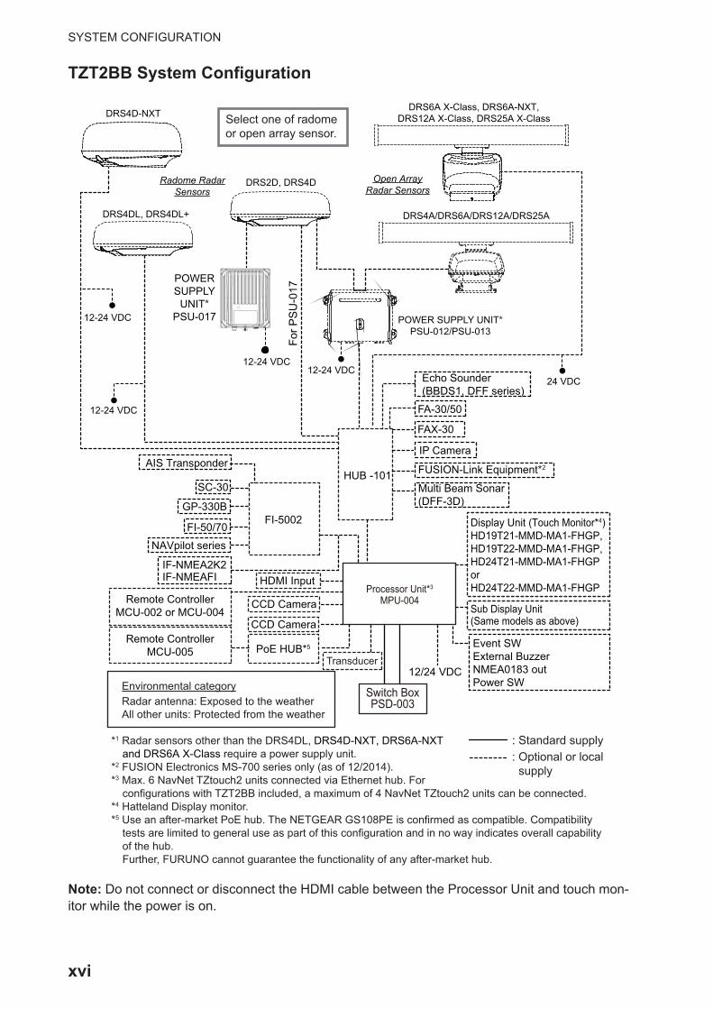
SYSTEM CONFIGURATION
TZT2BB System Configuration
Note: Do not connect or disconnect the HDMI cable between the Processor Unit and touch mon-itor while the power is on.
CCD Camera
CCD Camera
HDMI Input
FI-5002
SC-30
GP-330B
NAVpilot series
FI-50/70
IF-NMEA2K2IF-NMEAFI
12/24 VDC
Event SWExternal BuzzerNMEA0183 outPower SW
Echo Sounder(BBDS1, DFF series)
Environmental categoryRadar antenna: Exposed to the weatherAll other units: Protected from the weather
AIS Transponder
*1 Radar sensors other than the DRS4DL, DRS4D-NXT, DRS6A-NXT and DRS6A X-Class require a power supply unit.
*2 FUSION Electronics MS-700 series only (as of 12/2014).*3 Max. 6 NavNet TZtouch2 units connected via Ethernet hub. For
configurations with TZT2BB included, a maximum of 4 NavNet TZtouch2 units can be connected.*4 Hatteland Display monitor.*5 Use an after-market PoE hub. The NETGEAR GS108PE is confirmed as compatible. Compatibility
tests are limited to general use as part of this configuration and in no way indicates overall capability of the hub. Further, FURUNO cannot guarantee the functionality of any after-market hub.
HUB -101
FA-30/50
FAX-30
FUSION-Link Equipment*2
Display Unit (Touch Monitor*4)HD19T21-MMD-MA1-FHGP, HD19T22-MMD-MA1-FHGP, HD24T21-MMD-MA1-FHGPorHD24T22-MMD-MA1-FHGP
Sub Display Unit(Same models as above)
Remote ControllerMCU-002 or MCU-004
Processor Unit*3 MPU-004
Processor Unit*3 MPU-004
Transducer
Open Array Radar Sensors
12-24 VDC
12-24 VDC
12-24 VDC
DRS2D, DRS4D
POWER SUPPLY UNIT*PSU-012/PSU-013
Radome Radar Sensors
DRS4A/DRS6A/DRS12A/DRS25A
POWER SUPPLY
UNIT*PSU-017
For P
SU
-017
DRS4DL, DRS4DL+
12-24 VDC
DRS4D-NXT
24 VDC
Select one of radomeor open array sensor.
DRS6A X-Class, DRS6A-NXT, DRS12A X-Class, DRS25A X-Class
: Standard supply: Optional or local supply
Multi Beam Sonar(DFF-3D)
IP Camera
Switch BoxPSD-003
Switch BoxPSD-003
Remote ControllerMCU-005 PoE HUB*5
xvi
1. SYSTEM INTRODUCTION
This chapter provides the information necessary to get you started using your system.
Standards used in this manual
• Key names are shown in boldface type. For example, ENT key (on the MCU-002, MCU-004 or MCU-005).
• Menu items, on-screen indications, and pop-up menus and pop-up windows names are shown in brackets. For example, the [Settings] menu.
• Messages shown on the screen (including the Status bar) are enclosed in quota-tions. For example, "No Network Connected".
• The [Settings] menu is comprised of several sub menus. When you are asked to se-lect one of its sub menus, “[Settings]” is followed by a hyphen and the sub menu name. For example, “Tap [Settings] - [General]”.
• The colors mentioned in this manual are the default colors. Your colors may be dif-ferent.
• Most of the screenshots in this manual are taken from the TZTL12F. Layouts may be slightly different on the TZTL15F/TZT2BB.
1-1
1. SYSTEM INTRODUCTION
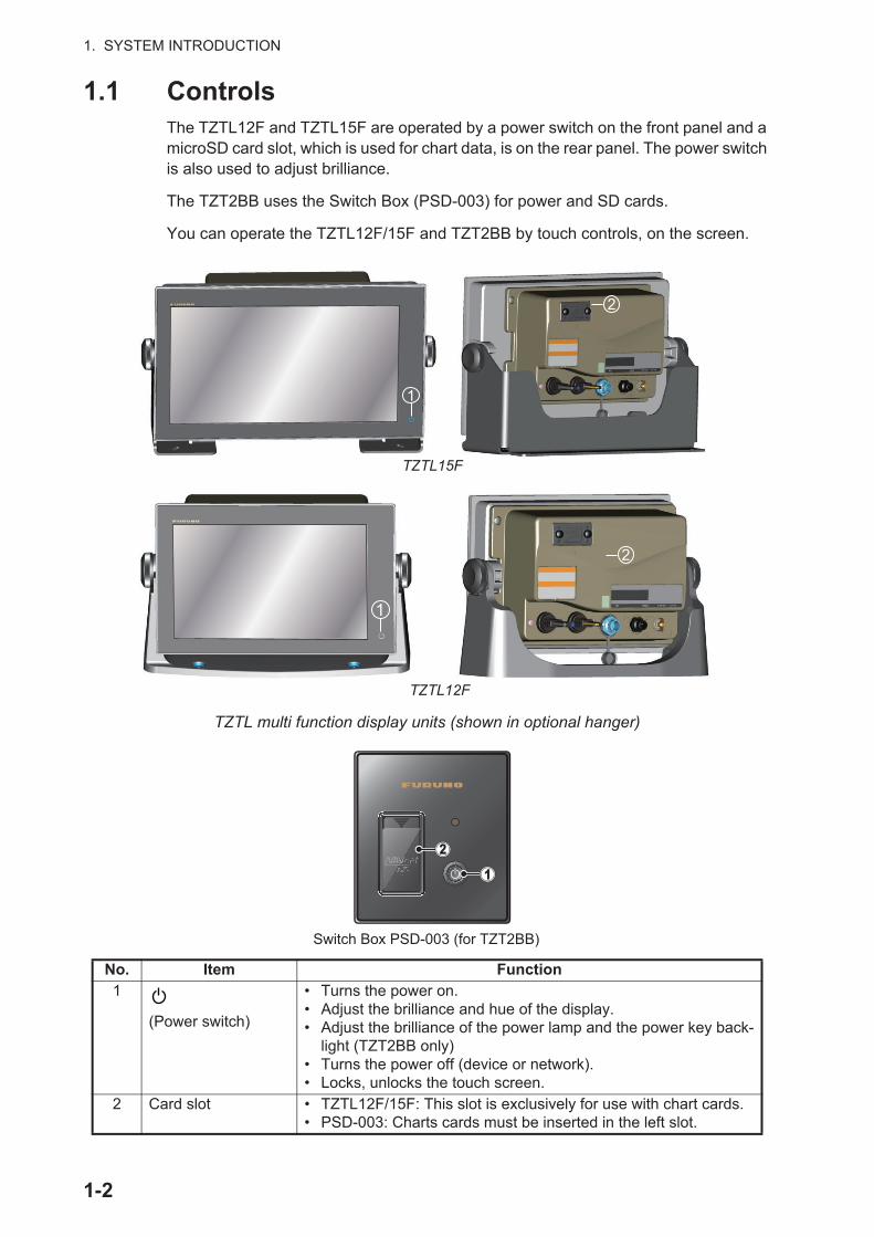
1.1 ControlsThe TZTL12F and TZTL15F are operated by a power switch on the front panel and a microSD card slot, which is used for chart data, is on the rear panel. The power switch is also used to adjust brilliance.
The TZT2BB uses the Switch Box (PSD-003) for power and SD cards.
You can operate the TZTL12F/15F and TZT2BB by touch controls, on the screen.
TZTL multi function display units (shown in optional hanger)
No. Item Function1
(Power switch)
• Turns the power on.• Adjust the brilliance and hue of the display.• Adjust the brilliance of the power lamp and the power key back-
light (TZT2BB only)• Turns the power off (device or network).• Locks, unlocks the touch screen.
2 Card slot • TZTL12F/15F: This slot is exclusively for use with chart cards.• PSD-003: Charts cards must be inserted in the left slot.
1
2
TZTL15F
TZTL12F
1
2
Switch Box PSD-003 (for TZT2BB)
1-2
1. SYSTEM INTRODUCTION
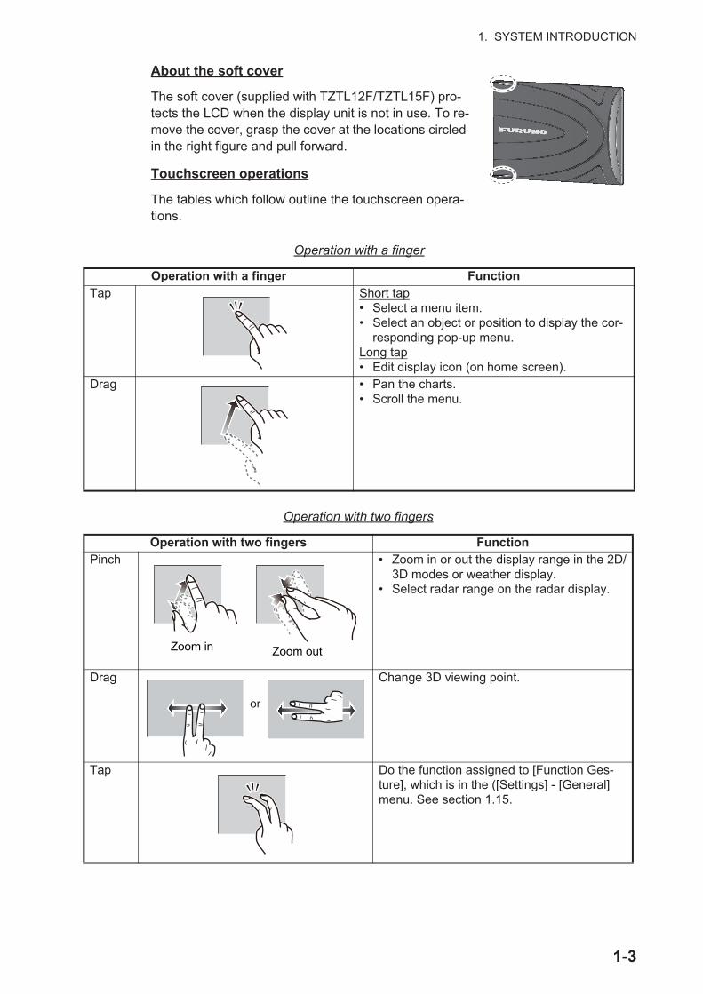
About the soft cover
The soft cover (supplied with TZTL12F/TZTL15F) pro-tects the LCD when the display unit is not in use. To re-move the cover, grasp the cover at the locations circled in the right figure and pull forward.
Touchscreen operations
The tables which follow outline the touchscreen opera-tions.
Operation with a finger
Operation with two fingers
Operation with a finger FunctionTap Short tap
• Select a menu item.• Select an object or position to display the cor-
responding pop-up menu.Long tap• Edit display icon (on home screen).
Drag • Pan the charts.• Scroll the menu.
Operation with two fingers FunctionPinch • Zoom in or out the display range in the 2D/
3D modes or weather display.• Select radar range on the radar display.
Drag Change 3D viewing point.
Tap Do the function assigned to [Function Ges-ture], which is in the ([Settings] - [General] menu. See section 1.15.
Zoom in Zoom out
or
1-3

1. SYSTEM INTRODUCTION
Notes on touch control operations
• Waterdrops on the screen can cause mis-operation and slow touch response. Wipe the screen with a dry cloth to remove the water.
• This equipment uses a capacitive touch screen. Tap the screen with your fingertips directly. Do not use sharp objects (needle, pen, nail) or a stylus pen. Be careful not to scratch the screen.
• The touchscreen cannot be operated while wearing gloves.
• Do not put objects (adhesive-backed paper, etc.) on the screen. Mis-operation can result.
• Keep the equipment away from a radio antenna, fluorescent light, solenoid valve and electronic devices to prevent unintended operation by noise.
• The front panel is made of glass. If the front panel is damaged, do not try to repair it yourself. Unauthorized repair will void the warranty. Contact your dealer about re-pair or replacement.
• The touch screen can be locked to prevent operation of the equipment. See the pro-cedure below.
• For TZT2BB configurations, see the manual for your touch monitor.
How to lock the touch screen
The touch screen can be locked to prevent unintentional operation.
With the power applied, press to show the [Power & Brilliance] window. Set the tog-gle box for [Lock Touch Screen] to the [ON] position to lock the touch screen, or the [OFF] position to unlock the touch screen.
1-4
1. SYSTEM INTRODUCTION
1.2 Remote Control Units (option)The Remote Control Units MCU-002/MCU-004/MCU-005 let you operate the system without touching the screen. When the power is applied and a Remote Control Unit is connected, an orange cursor (selection cursor) marks current selection in menus.
Note: When you switch the steering mode with the STBY•AUTO key on the Remote Control Unit, a beep sounds and then one of the messages shown below appears. The message does not appear on the home screen.- STBY mode AUTO mode: "NAVpilot is engaged."- AUTO mode STBY mode: "NAVpilot is disengaged."
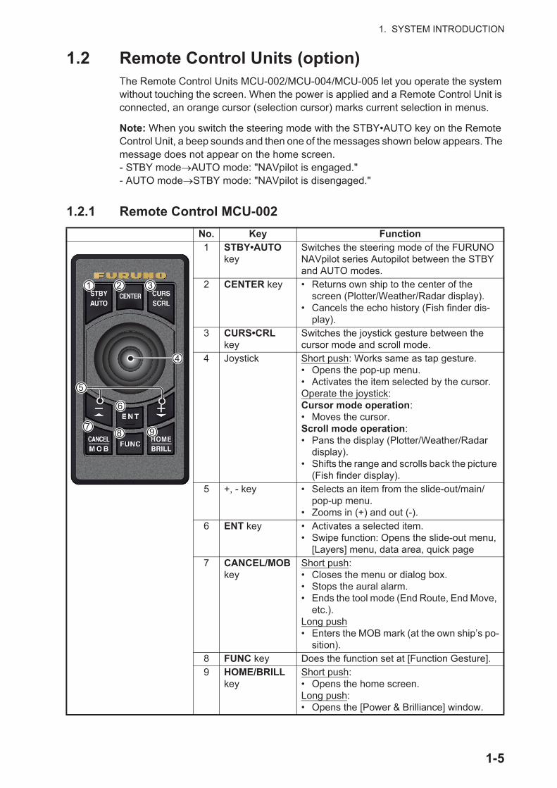
1.2.1 Remote Control MCU-002
No. Key Function1 STBY•AUTO
keySwitches the steering mode of the FURUNO NAVpilot series Autopilot between the STBY and AUTO modes.
2 CENTER key • Returns own ship to the center of the screen (Plotter/Weather/Radar display).
• Cancels the echo history (Fish finder dis-play).
3 CURS•CRL key
Switches the joystick gesture between the cursor mode and scroll mode.
4 Joystick Short push: Works same as tap gesture.• Opens the pop-up menu.• Activates the item selected by the cursor.Operate the joystick:Cursor mode operation:• Moves the cursor.Scroll mode operation:• Pans the display (Plotter/Weather/Radar
display).• Shifts the range and scrolls back the picture
(Fish finder display).5 +, - key • Selects an item from the slide-out/main/
pop-up menu.• Zooms in (+) and out (-).
6 ENT key • Activates a selected item.• Swipe function: Opens the slide-out menu,
[Layers] menu, data area, quick page7 CANCEL/MOB
keyShort push:• Closes the menu or dialog box.• Stops the aural alarm.• Ends the tool mode (End Route, End Move,
etc.).Long push• Enters the MOB mark (at the own ship’s po-
sition).8 FUNC key Does the function set at [Function Gesture].9 HOME/BRILL
keyShort push:• Opens the home screen.Long push:• Opens the [Power & Brilliance] window.
1 2 3
4
5
6
78 9
1-5

1. SYSTEM INTRODUCTION
1.2.2 Remote Control Unit MCU-004
No. Key Function
Edge key operations:
1 STBY•AUTO key
Switches the steering mode of the FURUNO NAVpilot series Autopilot between the STBY and AUTO modes.
2 HOME/BRILL key
• Short push: Opens the home screen.• Long push: Opens the Brilliance/Power win-
dow.3 CONTROL
keySwitches between displays that can be con-trolled with the MCU-004 when multiple displays are installed in the same network.
4 FUNC key Activates the function set at [Function Gesture] in the [General] menu.
5 CURS•SCRL key
Switches the function of the joystick between the Cursor and Scroll modes.
6 CENTER key • Returns own ship to center of screen (Plotter/Weather/Radar display).
• Cancels the echo history (Fish finder display).7 Rotary knob • Selects an item from the menu and dialog
box.• Zooms in (+) and out (-).• Raises (+) and lowers (-) the brilliance on the
Brilliance/Power window.• Controls the slider bar.
8 Joystick Short push: Works same as tap gesture.• Opens the pop-up menu.• Activates the item selected by the cursor.Operate the joystick:Cursor mode operation:• Moves the cursor.Scroll mode operation:• Pans the display (Plotter/Weather/Radar dis-
play).• Shifts the range and scrolls back the picture
(Fish finder display).9 EDGE key Press the EDGE key and operate the Joystick to
activate the Edge Swipe function.• EDGE key and upward swipe: [Layers] menu• EDGE key and downward swipe: Quick page• EDGE key and leftward swipe: slide-out
menu• EDGE key and rightward swipe: Data area
10 CANCEL/MOB key
Short push:• Closes the menu or dialog box.• Stops the aural alarm.• Ends the tool mode (End Route, End Move,
etc.).Long push:• Enters the MOB mark (at the own ship’s posi-
tion).
7
8
HOMEBRILL
STBY•AUTOSTBY•AUTO
FUNC
1 2
43
CURS•SCRLCENTER
5 6
9
CANCELMOB
10
- Layers menu
Push
- Quick page Push
- Slide-out menu Push
- Data area Push
1-6
1. SYSTEM INTRODUCTION
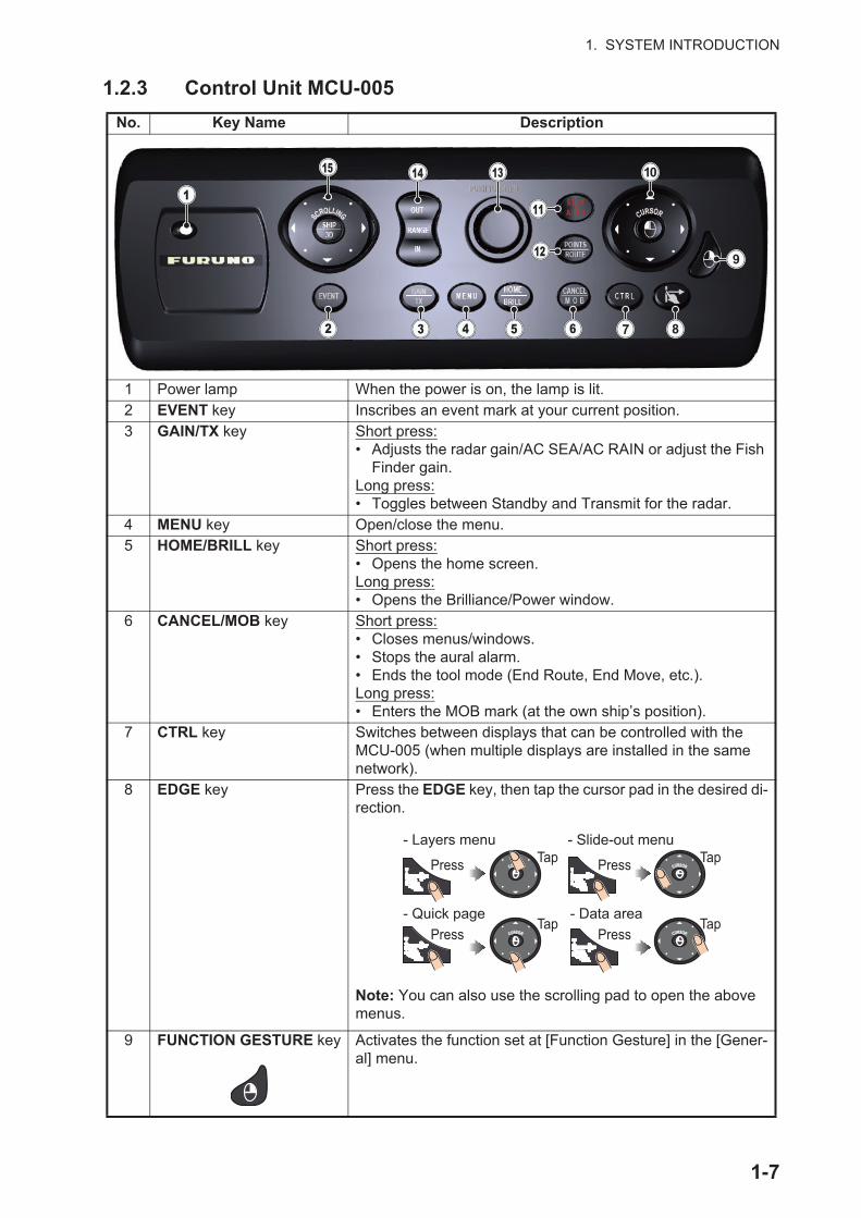
1.2.3 Control Unit MCU-005
No. Key Name Description
1 Power lamp When the power is on, the lamp is lit.2 EVENT key Inscribes an event mark at your current position.3 GAIN/TX key Short press:
• Adjusts the radar gain/AC SEA/AC RAIN or adjust the Fish Finder gain.
Long press:• Toggles between Standby and Transmit for the radar.
4 MENU key Open/close the menu.5 HOME/BRILL key Short press:
• Opens the home screen.Long press:• Opens the Brilliance/Power window.
6 CANCEL/MOB key Short press:• Closes menus/windows.• Stops the aural alarm.• Ends the tool mode (End Route, End Move, etc.).Long press:• Enters the MOB mark (at the own ship’s position).
7 CTRL key Switches between displays that can be controlled with the MCU-005 (when multiple displays are installed in the same network).
8 EDGE key Press the EDGE key, then tap the cursor pad in the desired di-rection.
Note: You can also use the scrolling pad to open the above menus.
9 FUNCTION GESTURE key Activates the function set at [Function Gesture] in the [Gener-al] menu.
- Layers menu
- Quick page
- Slide-out menu
- Data area
Press Tap Tap
Tap Tap
Press
Press Press
1-7

1. SYSTEM INTRODUCTION
10 CURSOR key and cursor pad
CURSOR key short press:• Opens pop up menus.• Activates/confirms the item selected by the cursor.CURSOR key long press:• Edit display icon (on home screen).Cursorpad operation:• Moves the selection cursor. Selected items are highlighted.Note: CURSOR key “short press” and “long press” operations are the same as “tap” and “long tap” operations respectively.
11 STBY/AUTO key Switches the steering mode of the connected FURUNO NAVpilot series between the STBY and AUTO modes.
12 POINTS/ROUTE key Short press:• Sets the cursor location as a point.Long press:• Starts a route from the cursor location.
13 Rotary knob Short press:• Opens pop up menus.• Activates/confirms the item selected by the cursor.Long press:• Edit display icon (on home screen).Rotate:• Moves the selection cursor. Selected items are highlighted.• Zooms in/out.Note: Rotary knob “short press” and “long press” operations are the same as “tap” and “long tap” operations respectively.
14 RANGE OUT/IN key • Moves the selection cursor. Selected items are highlighted.• Zoom in/out.• Changes the range for the radar/fish finder.
15 SHIP/3D key and scrolling pad
SHIP/3D key short press:• Returns own ship to center of screen (Plotter/Weather/Ra-
dar display).• Cancels the echo history (Fish finder display).SHIP/3D key long press:• Switches between 2D and 3D display.Scrolling pad:• Moves the selection cursor. Selected items are highlighted.• Zooms in/out.
No. Key Name Description
Cursorpad
CURSOR keyCURSOR key
SCROLLING
SHIP3D
Scrolling pad
Scrolling pad
SHIP/3D button
SHIP/3D button
1-8

1. SYSTEM INTRODUCTION
1.2.4 Remote Control Unit group settings
If multiple NavNet TZtouch2 units are installed in the network, you can the select the display to show on a unit, using the MCU-004 or MCU-005. Additionally, you can se-lect the order in which to cycle through the displays.
Note: Confirm that there are no duplicate unit nicknames in the network. If a duplicate name is found, change the name on the Sensor List ([Initial Setup] [Sensor List]).
1. From the Home page, select [Settings] [Initial Setup].
2. Tap the item [Remote Controller Configuration] twice.
Example remote configuration - MCU-004
*: For configurations with an MCU-005 connected, the nickname for the MCU-005 appears.
No. Description1 The nickname automatically assigned to the MCU-004/MCU-005.2 The nickname assigned to the NavNet TZtouch2 unit currently being operated.3 Setting for the unit connected to TZTL12F_FB_LEFT*, controlled by MCU1.4 Set the cycling order of units controlled by MCU1. To skip a unit, select it to [Off].5 Setting for the unit connected to TZTL12F_MB_LEFT*, controlled by MCU2.6 Set the cycling order of units controlled by MCU2. To skip a unit, select it to [Off].
1-9

1. SYSTEM INTRODUCTION
Based on the menu settings shown on the previous page, the installed configura-tion should look similar to the following image.
3. Select the displays to cycle.
4. Set the order. To skip a display, select it to [Off].
5. Tap “<“ on the title bar to return to the [REMOTE CONTROLLER CONFIGURA-TION] menu.
6. Tap the [Confirm] button on the title bar to save settings and close the menu.
HOMEBRILL
STBY•AUTOSTBY•AUTO
FUNC
CURS•SCRLCENTER
CANCELMOB
HOMEBRILL
STBY•AUTOSTBY•AUTO
FUNC
CURS•SCRLCENTER
CANCELMOB
FLYBRIDGE(A) and (B) can be controlled from MCU1.
FLYBRIDGE(C) and (D) can be controlled from MCU2. HUB
(A) TZTL12F_FB_LEFT (B) TZTL12F_FB_RIGHT
(C) TZTL15F_MB_LEFT (D) TZTL15F_MB_RIGHT
MCU1
MCU2
1-10
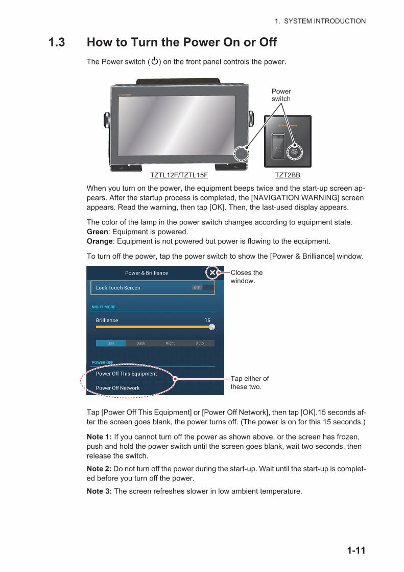
1. SYSTEM INTRODUCTION
1.3 How to Turn the Power On or Off
The Power switch ( ) on the front panel controls the power.
When you turn on the power, the equipment beeps twice and the start-up screen ap-pears. After the startup process is completed, the [NAVIGATION WARNING] screen appears. Read the warning, then tap [OK]. Then, the last-used display appears.
The color of the lamp in the power switch changes according to equipment state.Green: Equipment is powered.Orange: Equipment is not powered but power is flowing to the equipment.
To turn off the power, tap the power switch to show the [Power & Brilliance] window.
Tap [Power Off This Equipment] or [Power Off Network], then tap [OK].15 seconds af-ter the screen goes blank, the power turns off. (The power is on for this 15 seconds.)
Note 1: If you cannot turn off the power as shown above, or the screen has frozen, push and hold the power switch until the screen goes blank, wait two seconds, then release the switch.
Note 2: Do not turn off the power during the start-up. Wait until the start-up is complet-ed before you turn off the power.
Note 3: The screen refreshes slower in low ambient temperature.
Power switch
TZTL12F/TZTL15F TZT2BB
Tap either of these two.
Closes the window.
1-11

1. SYSTEM INTRODUCTION
1.4 How to Adjust the Brilliance of the Display andPower Switch and Hue
With the power applied, press to show the [Power & Brilliance] window.
TZTL12F/15F: Tap the power switch, tap the slider bar, or drag the slider icon (circle) to adjust the brilliance of both the display and the power indicator.
TZT2BB: Tap the power switch, tap the slider bar, or drag the slider icon (circle) to adjust the brilliance of both the power lamp and the power key backlight.
The [Day], [Dusk], [Night] and [Auto] options (below the slider bar) set the hue accord-ing to selection. The [Auto] option automatically sets the hue according to time of day.
How to synchronize brilliance of units in the network
Turn on [Brilliance Synchronization] in the [Settings] - [General] menu to synchronize the brilliance among units in the network.
Hue options
TZTL12F/15F: Adjust the display brilliance.TZT2BB: Adjust the power lamp and power
key backlight brilliance.
1-12
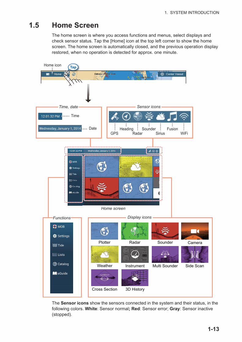
1. SYSTEM INTRODUCTION
1.5 Home ScreenThe home screen is where you access functions and menus, select displays and check sensor status. Tap the [Home] icon at the top left corner to show the home screen. The home screen is automatically closed, and the previous operation display restored, when no operation is detected for approx. one minute.
The Sensor icons show the sensors connected in the system and their status, in the following colors. White: Sensor normal; Red: Sensor error; Gray: Sensor inactive (stopped).
Plotter Radar Sounder Camera
Weather Instrument Multi Sounder Side Scan
Cross Section 3D History
Time
DateGPS
HeadingRadar
SounderSirius
FusionWiFi
FunctionsFunctions
Tap
Home screenHome screen
Time, dateTime, date Sensor iconsSensor icons
Display iconsDisplay icons
Home icon
Lists
Lists
Settings
Tide
Lists
Catalog
1-13
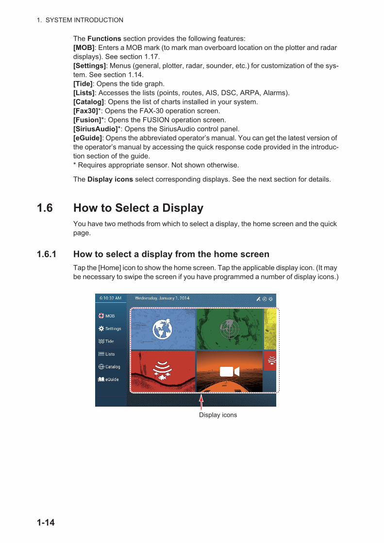
1. SYSTEM INTRODUCTION
The Functions section provides the following features:[MOB]: Enters a MOB mark (to mark man overboard location on the plotter and radar displays). See section 1.17.[Settings]: Menus (general, plotter, radar, sounder, etc.) for customization of the sys-tem. See section 1.14.[Tide]: Opens the tide graph.[Lists]: Accesses the lists (points, routes, AIS, DSC, ARPA, Alarms).[Catalog]: Opens the list of charts installed in your system.[Fax30]*: Opens the FAX-30 operation screen. [Fusion]*: Opens the FUSION operation screen.[SiriusAudio]*: Opens the SiriusAudio control panel.[eGuide]: Opens the abbreviated operator’s manual. You can get the latest version of the operator’s manual by accessing the quick response code provided in the introduc-tion section of the guide.* Requires appropriate sensor. Not shown otherwise.
The Display icons select corresponding displays. See the next section for details.
1.6 How to Select a DisplayYou have two methods from which to select a display, the home screen and the quick page.
1.6.1 How to select a display from the home screen
Tap the [Home] icon to show the home screen. Tap the applicable display icon. (It may be necessary to swipe the screen if you have programmed a number of display icons.)
Display icons
Lists
1-14

1. SYSTEM INTRODUCTION
1.6.2 How to select a display from the quick page
The quick page, which carries all the display icons set for large size on the home screen, lets you change the display from the current display.
To show the quick page, swipe the top of the screen downward. Tap desired display icon to change the display. (It may be necessary to scroll the display icons if you have there are several icons.)
SwipeSwipe
Quick page
1-15
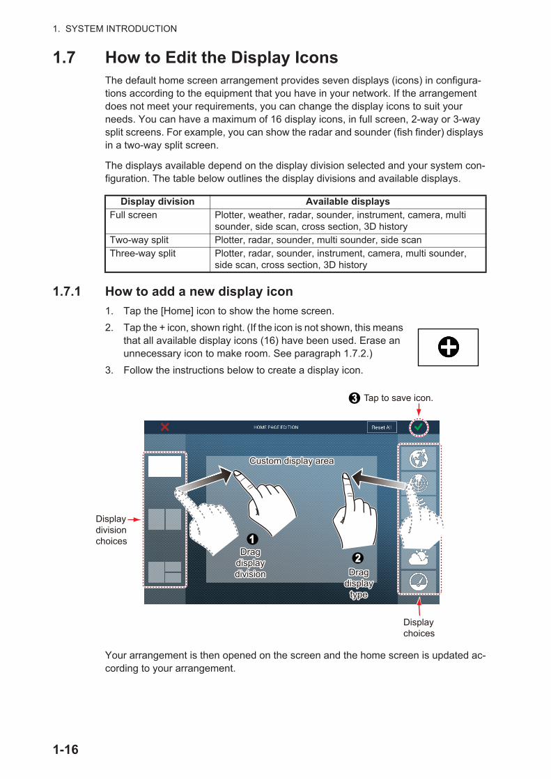
1. SYSTEM INTRODUCTION
1.7 How to Edit the Display IconsThe default home screen arrangement provides seven displays (icons) in configura-tions according to the equipment that you have in your network. If the arrangement does not meet your requirements, you can change the display icons to suit your needs. You can have a maximum of 16 display icons, in full screen, 2-way or 3-way split screens. For example, you can show the radar and sounder (fish finder) displays in a two-way split screen.
The displays available depend on the display division selected and your system con-figuration. The table below outlines the display divisions and available displays.
1.7.1 How to add a new display icon
1. Tap the [Home] icon to show the home screen.
2. Tap the + icon, shown right. (If the icon is not shown, this means that all available display icons (16) have been used. Erase an unnecessary icon to make room. See paragraph 1.7.2.)
3. Follow the instructions below to create a display icon.
Your arrangement is then opened on the screen and the home screen is updated ac-cording to your arrangement.
Display division Available displaysFull screen Plotter, weather, radar, sounder, instrument, camera, multi
sounder, side scan, cross section, 3D historyTwo-way split Plotter, radar, sounder, multi sounder, side scanThree-way split Plotter, radar, sounder, instrument, camera, multi sounder,
side scan, cross section, 3D history
Displaychoices
Display divisionchoices
Custom display areaCustom display area
Dragdisplay division
Dragdisplay division Drag
display type
Dragdisplay
type
Tap to save icon.
1-16

1. SYSTEM INTRODUCTION
1.7.2 How to edit a display icon
Long tap the display icon to edit to show the editing icons on the display icon. Tap the applicable editing icon. Refer to the figure and instructions below.
Edit icon content: Tap the icon at the upper left corner. See the illustration in paragraph 1.7.1 for how to set the icon.Remove icon: Tap the icon at the upper right corner to remove the icon from the home screen (and quick page if the icon size is selected to "large".Change icon size: Tap the icon at the lower right corner to switch the size between large and small. (Icons set for large size appear on the quick page.)
Longtap
Remove icon
Change icon size
Edit icon content
1-17

1. SYSTEM INTRODUCTION
1.8 Hidden FunctionsThis equipment has five functions that are normally hidden from view: quick page, slide-out menu, pop-up menu, [Layers] menu, and data area (navdata). Swipe or tap the screen at the locations shown below to access the hidden functions.
A function window is automatically erased from the screen when it is not operated within the time specified with [User Interface Auto-Hide] in the [General] - [Settings] menu. You can erase the window at any time by tapping the screen.
Function description
The quick page selects displays. The display icons set to large size appear on the quick page. (See paragraph 1.6.2.)
The slide-out menu provides quick access to often-used functions in the active dis-play. The color of the function name changes according to function status. Unavailable functions are grayed out.
Swipe
SwipeSwipe SwipeSwipe
SwipeSwipe
SwipeSwipe
Tap
Slide-out menu
Pop-up menu
Layers menu*
Quick page
Data area
* Plotter display, radar sensor connected. [Radar Overlay], [Radar Rings], [Guard Zone 1] and [Guard Zone 2] do not appear with no radar sensor connection.
1-18
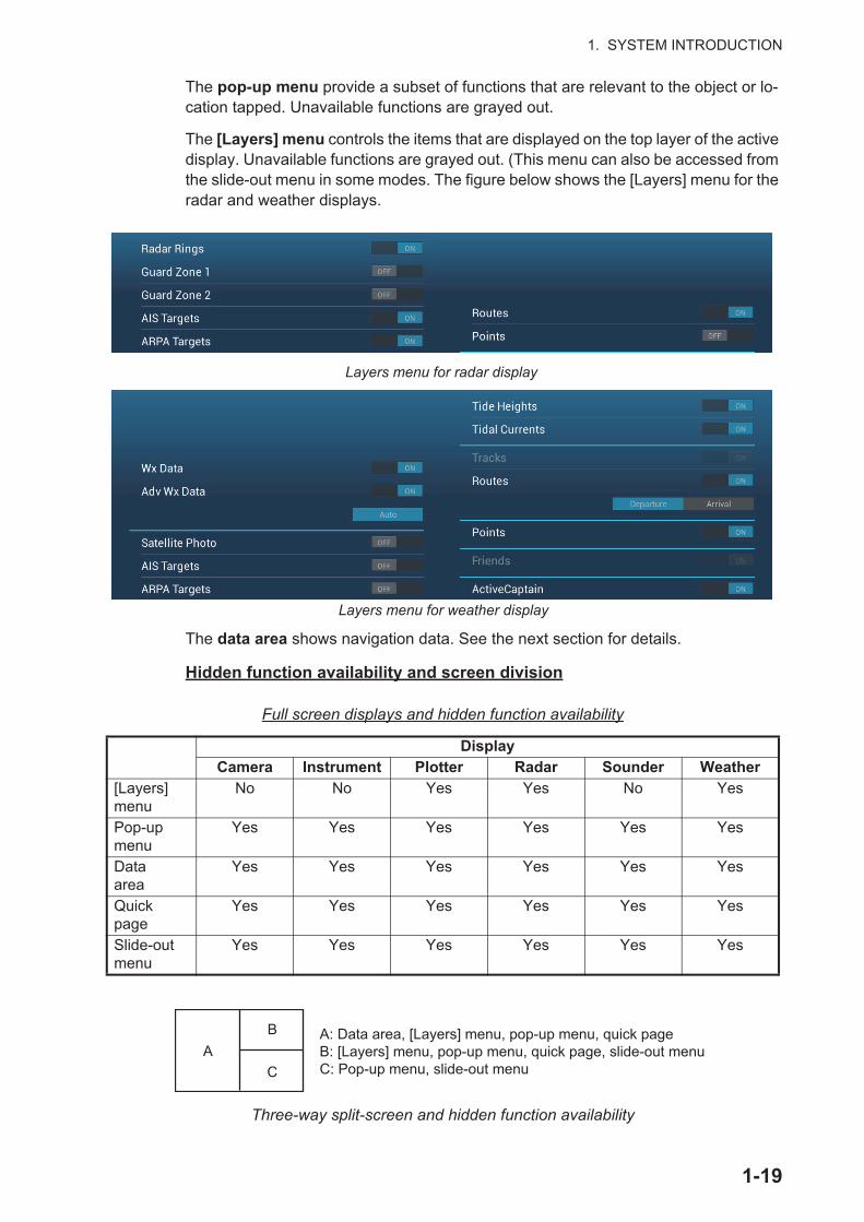
1. SYSTEM INTRODUCTION
The pop-up menu provide a subset of functions that are relevant to the object or lo-cation tapped. Unavailable functions are grayed out.
The [Layers] menu controls the items that are displayed on the top layer of the active display. Unavailable functions are grayed out. (This menu can also be accessed from the slide-out menu in some modes. The figure below shows the [Layers] menu for the radar and weather displays.
The data area shows navigation data. See the next section for details.
Hidden function availability and screen division
Full screen displays and hidden function availability
Three-way split-screen and hidden function availability
DisplayCamera Instrument Plotter Radar Sounder Weather
[Layers] menu
No No Yes Yes No Yes
Pop-up menu
Yes Yes Yes Yes Yes Yes
Dataarea
Yes Yes Yes Yes Yes Yes
Quick page
Yes Yes Yes Yes Yes Yes
Slide-out menu
Yes Yes Yes Yes Yes Yes
Layers menu for radar display
Layers menu for weather display
AB
C
A: Data area, [Layers] menu, pop-up menu, quick page B: [Layers] menu, pop-up menu, quick page, slide-out menuC: Pop-up menu, slide-out menu
1-19

1. SYSTEM INTRODUCTION
1.9 Data AreaThe data area at the left side of the screen shows various navigation data, in movable and editable data boxes. You can select the data to display, select format (analog or digital) for data and change the order of the data. Data availability depends on your system configuration.
Note: The data display is also available in the two- and three-way split screens, on the left screen.
Two types of data sets* are available, navigation data, route data, and radar. Select the desired set with [DATA], [ROUTE] or [RADAR]* at the bottom of the data area.* With connection of radar sensor.
1.9.1 How to change the order of the data
Drag and drop the data boxes to change their order.
DataareaDataarea
1-20
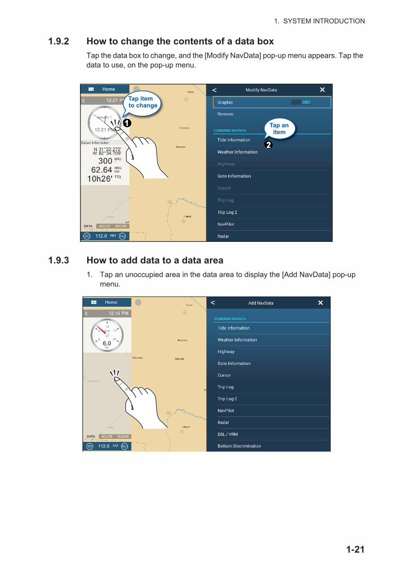
1. SYSTEM INTRODUCTION
1.9.2 How to change the contents of a data box
Tap the data box to change, and the [Modify NavData] pop-up menu appears. Tap the data to use, on the pop-up menu.
1.9.3 How to add data to a data area
1. Tap an unoccupied area in the data area to display the [Add NavData] pop-up menu.
Tap itemto change
Tap an item
<
<
1-21
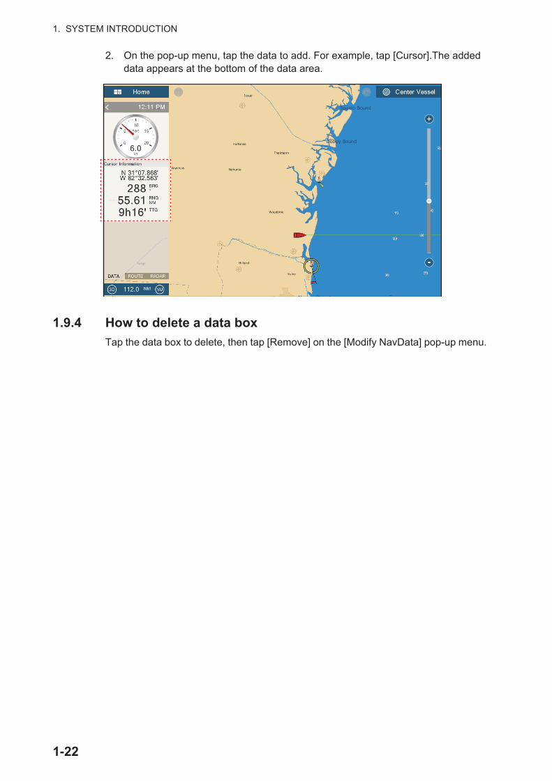
1. SYSTEM INTRODUCTION
2. On the pop-up menu, tap the data to add. For example, tap [Cursor].The added data appears at the bottom of the data area.
1.9.4 How to delete a data box
Tap the data box to delete, then tap [Remove] on the [Modify NavData] pop-up menu.
1-22
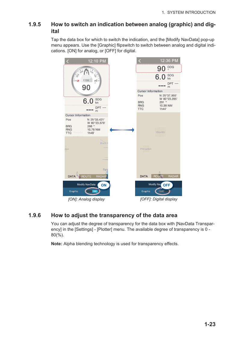
1. SYSTEM INTRODUCTION
1.9.5 How to switch an indication between analog (graphic) and dig-ital
Tap the data box for which to switch the indication, and the [Modify NavData] pop-up menu appears. Use the [Graphic] flipswitch to switch between analog and digital indi-cations. [ON] for analog, or [OFF] for digital.
1.9.6 How to adjust the transparency of the data area
You can adjust the degree of transparency for the data box with [NavData Transpar-ency] in the [Settings] - [Plotter] menu. The available degree of transparency is 0 - 80(%).
Note: Alpha blending technology is used for transparency effects.
[ON]: Analog display
ON
[OFF]: Digital display
N
ONModify NavData Modify NavDataavvvvvDvDvDvDvDvDvDvDDDaDataOFF
1-23
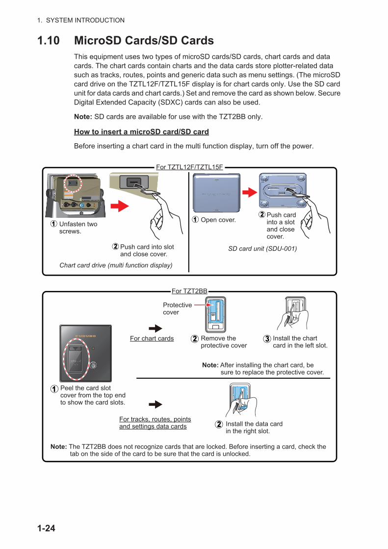
1. SYSTEM INTRODUCTION
1.10 MicroSD Cards/SD CardsThis equipment uses two types of microSD cards/SD cards, chart cards and data cards. The chart cards contain charts and the data cards store plotter-related data such as tracks, routes, points and generic data such as menu settings. (The microSD card drive on the TZTL12F/TZTL15F display is for chart cards only. Use the SD card unit for data cards and chart cards.) Set and remove the card as shown below. Secure Digital Extended Capacity (SDXC) cards can also be used.
Note: SD cards are available for use with the TZT2BB only.
How to insert a microSD card/SD card
Before inserting a chart card in the multi function display, turn off the power.
Unfasten two screws.
Push card into slot and close cover.
SD card unit (SDU-001)
Chart card drive (multi function display)
Open cover.Push card into a slot and close cover.
Protective cover
Remove the protective cover
Install the chart card in the left slot.
Install the data card in the right slot.
Note: After installing the chart card, be sure to replace the protective cover.
Note: The TZT2BB does not recognize cards that are locked. Before inserting a card, check the tab on the side of the card to be sure that the card is unlocked.
Peel the card slot cover from the top end to show the card slots.
For chart cards
For tracks, routes, points and settings data cards
For TZTL12F/TZTL15FFor TZTL12F/TZTL15F
For TZT2BBFor TZT2BB
1-24

1. SYSTEM INTRODUCTION
How to format a microSD card/SD card
You do not normally need to format a data microSD card/SD card. If the card becomes unreadable, format the card with a formatting program that is compatible with the specifications of the card.
How to remove a microSD card/SD card
About the microSD cards/SD cards
• Handle the cards carefully. Improper use can damage the card and destroy its contents.
• Make sure the slot lid (cover) is closed at all times.
• Remove a card with only your fingers. Do not use metal instruments (like tweezers) to remove the card.
• Do not remove a card during the reading of or writing to the card.
• Make sure the lock, located on the side of the card, is not enabled. If the card is locked, data cannot be read/written.
Note: Use a class 6 or higher card for storing chart data.
Compatible microSD cards/SD cards
The tables below list the cards that have been verified for use with this equipment.
MicroSD cards
1) Open the card drive cover.2) Push the card to release the card from the card drive.3) Remove the card with your fingers then close the lid (cover).
Note 1: The cards were verified using basic functions. All functions were not verified. FURUNO does not guarantee card operations.Note 2: Cards other than those listed below have not been verified.Note 3: Use a class 6 or higher card for storing chart data.
Maker Model Capacity (GB) ClassKINGMAX KM-MCSDHC10X32GUHS1P 32 10
KM-MCSDXC6X64G 64 6Kingston SDC4/8GB 8 4
SDCA10/16GB 16 10SDC4/16GB 16 4SDCA10/32GB 32 10SDC4/32GB 32 4SDCA10/64GB 64 10
Panasonic RP-SMKC08FR0 8 2SANDISK SDSDQ-008G-J35U 8 4
SDSDQ-016G-J35U 16 4SDSDQUAN-032G-G4A 32 10SDSDQ-032G-J35U 32 4
SDSDQUAN-128G-G4A 128 10
Silicon Power SP008GBSTH004V10SP 8 4SP016GBSTH004V10SP 16 4SP032GBSTHBU1V20SP 32 10SP032GBSTH004V10SP 32 4
1-25

1. SYSTEM INTRODUCTION
SD cards
Silicon Power SP064GBSTXBU1V20SP 64 10SP128GBSTXBU1V20SP 128 10
Transcend TS8GUSDU1 8 10TS8GUSDHC4 8 4TS16GUSDU1 16 10TS16GUSDHC4 16 4TS32GUSDU1 32 10TS32GUSDHC4 32 4TS64GUSDU1 64 10TS128GUSDU1 128 10
Maker Model Capacity (GB) ClassKINGMAX KM-MCSDHC10X32GUHS1P 32 10
KM-MCSDHC10X16GUHS1P 16 10Kingston SDA10/128GB 128 10
SDCX10/64GB 64 10SDC10/32GB 32 10SDC4/32GB 32 4SDC10/16GB 16 10SDC4/16GB 16 4SDC4/8GB 8 4
SANDISK SDSDXPA-128G-G46 128 10SDSDXPA-064G-JU3 64 10SDSDXPA-032G-JU3 32 10SDSDB-032G-J35U 32 4
SDSDXPA-016G-EPK2 16 10
SDSDB-016G-J35U 16 4SDSDB-008G-J01 8 4
Silicon Power SP128GBSDXAU1V10 128 10SP064GBSDXAU1V10 64 10SP032GBSDHAU1V10 32 10SP032GBSDH004V10 32 4SP016GBSDHAU1V10 16 10SP016GBSDH004V10 16 4SP008GBSDH004V10 8 4
Transcend TS128GSDU3 128 10TS64GSDU3 64 10TS32GSDU3X 32 10TS32GSDHC4 32 4TS16GSDHC10U1 16 10TS16GSDHC4 16 4TS8GSDHC10U1 8 10TS8GSDHC4 8 4
Maker Model Capacity (GB) Class
1-26

1. SYSTEM INTRODUCTION
1.11 Plotter IntroductionThe plotter provides a small world map in raster format. A vector chart for the US coastline (with Alaska and Hawaii) is provided also. The plotter section has functions to enter points, and create and plan routes.
The plotter receives position data fed from the built in GPS receiver (TZTL12F/TZ-TL15F only), or from the connected EPFS device (TZT2BB). Your position is marked on the screen with the boat icon.
The points and routes you have entered are shown on the screen. You can move, de-lete and edit the points and routes from a pop-up menu.
The plotter also:
The status bar, common to all modes, alerts you to equipment status. The color of both the bar and the status message change according to message category.• Red bar, yellow characters: warning (alarm violation, equipment error, etc.)• Yellow bar, black characters: caution (system message, etc.)When an alert condition occurs, the equipment beeps (if enabled), the name of the alert appears in the bar, and the bar flashes. You can stop the flashing and silence the beep by tapping the bar. The alert indication remains in the status bar until the cause for the alert is removed.
The redo icon has the following functions with points and routes.
• Plots the track of your ship• Measures distances and bearings• Marks man overboard (MOB) position
• Controls alarm functions• Follows routes
• Undo icon: Reverse the last change done.• Redo icon: Restore the undo action.
Undo icon Redo icon
Slider bar
Orientation mode switch
2D/3D switchChart range
Inactive route(expanded)
Point
Track
COGCOG
Return own ship to screencenter
Boat iconBoat iconDataareaDataarea
Home icon
Inactive route(sleeping)*
HeadinglineHeadingline
Depth Alarm
Status bar
* Arrival or departure position,selectable on [Layers] menu.
1-27

1. SYSTEM INTRODUCTION
1.12 Radar IntroductionA radar system operates in the microwave part of the radio frequency (RF) range. The radar detects the position and movement of objects. Objects are shown on the radar display at their measured distances and bearings in intensities according to echo strength.
A guard zone tells you when the radar targets are in the area you indicate.
Own ship positionOwn ship position
Home icon
Undo icon
Guard zoneGuard zone North markNorth mark
Sliderbar
Return ownship icon toscreen center.
DataareaDataarea
Heading lineHeading line
Redo icon
0
10
20
30
40
50
607080
90100
110
120
200
230
240250
260270
280
290
300
310
320
330
340
350
210
180
170
160
140
220
190
150
130
340
TX/Standbyswitch
Orientation mode switch
Fixed range rings
DataareaDataarea
TXRADARDATA ROUTE
Radar Control
2:01 PM
1-28
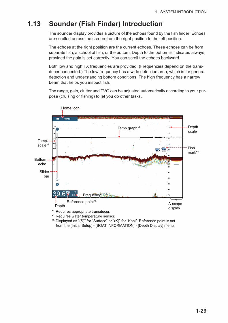
1. SYSTEM INTRODUCTION
1.13 Sounder (Fish Finder) IntroductionThe sounder display provides a picture of the echoes found by the fish finder. Echoes are scrolled across the screen from the right position to the left position.
The echoes at the right position are the current echoes. These echoes can be from separate fish, a school of fish, or the bottom. Depth to the bottom is indicated always, provided the gain is set correctly. You can scroll the echoes backward.
Both low and high TX frequencies are provided. (Frequencies depend on the trans-ducer connected.) The low frequency has a wide detection area, which is for general detection and understanding bottom conditions. The high frequency has a narrow beam that helps you inspect fish.
The range, gain, clutter and TVG can be adjusted automatically according to your pur-pose (cruising or fishing) to let you do other tasks.
Home icon
Bottomecho
Depthscale
A-scopedisplayDepth
Sliderbar
*1 Requires appropriate transducer.*2 Requires water temperature sensor.*3 Displayed as “(S)” for “Surface” or “(K)” for “Keel”. Reference point is set
from the [Initial Setup] - [BOAT INFORMATION] - [Depth Display] menu.
29.8 ft 29.6 ft
Fishmark*1
ft HF39.6
Temp.scale*2
Temp graph*2
(S)
Reference point*3
FrequencyFrequency
1-29
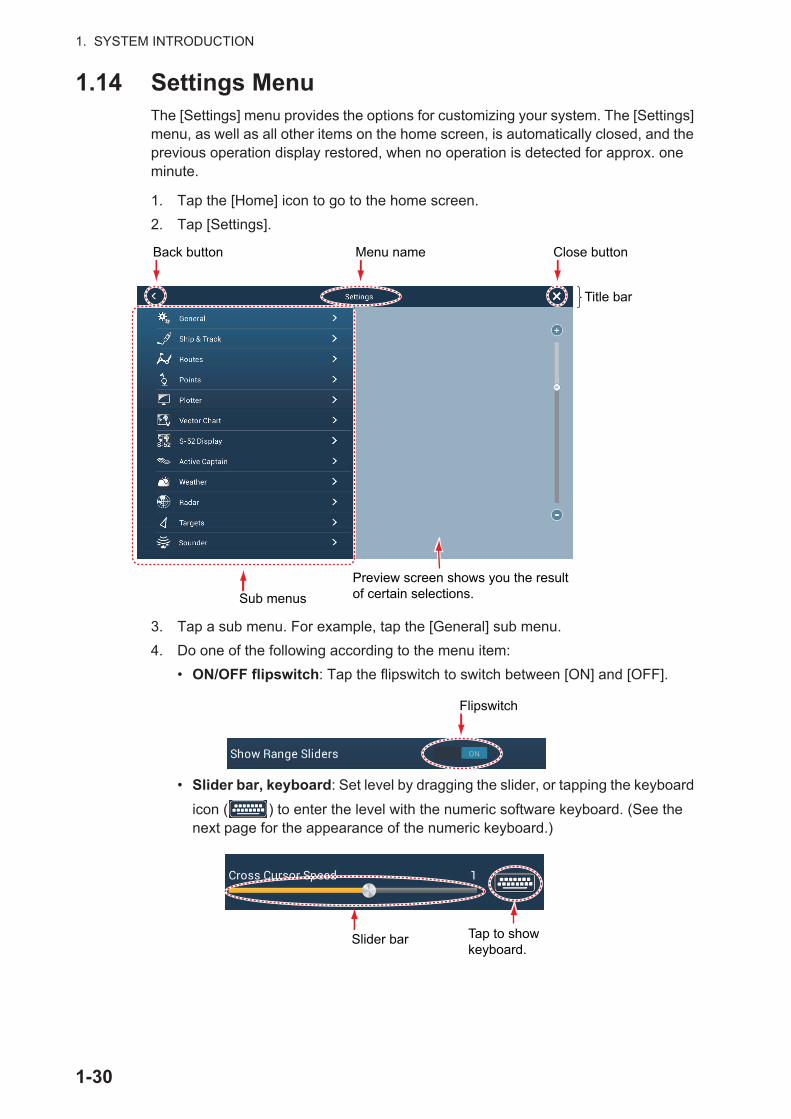
1. SYSTEM INTRODUCTION
1.14 Settings MenuThe [Settings] menu provides the options for customizing your system. The [Settings] menu, as well as all other items on the home screen, is automatically closed, and the previous operation display restored, when no operation is detected for approx. one minute.
1. Tap the [Home] icon to go to the home screen.
2. Tap [Settings].
3. Tap a sub menu. For example, tap the [General] sub menu.
4. Do one of the following according to the menu item:
• ON/OFF flipswitch: Tap the flipswitch to switch between [ON] and [OFF].
• Slider bar, keyboard: Set level by dragging the slider, or tapping the keyboard
icon ( ) to enter the level with the numeric software keyboard. (See the next page for the appearance of the numeric keyboard.)
Sub menus
Menu name
Preview screen shows you the result of certain selections.
Back button Close button
Title bar
Flipswitch
Slider bar Tap to showkeyboard.
1-30
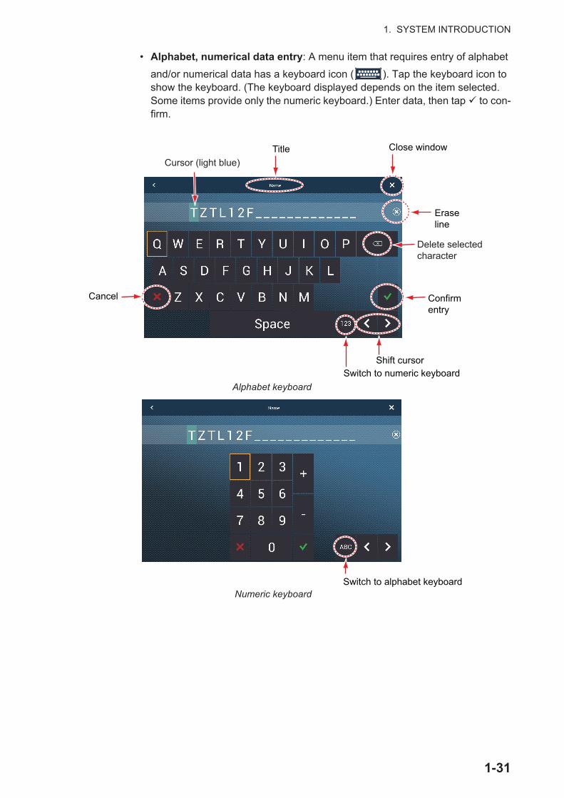
1. SYSTEM INTRODUCTION
• Alphabet, numerical data entry: A menu item that requires entry of alphabet
and/or numerical data has a keyboard icon ( ). Tap the keyboard icon to show the keyboard. (The keyboard displayed depends on the item selected. Some items provide only the numeric keyboard.) Enter data, then tap to con-firm.
Confirmentry
Switch to numeric keyboard
Eraseline
Close windowTitle
Delete selectedcharacter
Cancel
Alphabet keyboard
Cursor (light blue)
Shift cursor
Numeric keyboardSwitch to alphabet keyboard
1-31

1. SYSTEM INTRODUCTION
• Color selection: A menu item that requires selection of color shows the current color selection to the right of the name of the menu item. Tap the menu item to show the color options. Tap color option desired. Current selection is highlight-ed with a light blue square.
• Option selection: A menu item that requires selection of an option shows the current selection on the menu. Tap the option desired. The current selection has a checkmark.
5. Tap the close button to finish.
Note: The title bar (top of menus) does not appear in menu illustrations hereafter un-less its inclusion is necessary in a description.
Tap menu item.
Current selection ishighlighted in light blue.
Current selection
Current selection has a checkmark.
Tap menu item. Current selection
1-32

1. SYSTEM INTRODUCTION
1.15 Function GestureThe function gesture controls what occurs when you tap the screen with two fingers. Select the function as below.
1. Open the home screen, then select [Settings] - [General].
2. Tap [Function Gesture].
3. Tap a function among the following:[None]: Nothing happens.[Screen Capture]: Capture the screen and save it to a microSD card (or USB memory). The message shown below appears. Tap [OK] to save the screen cap-ture. The information following "TZT2SCREENSHOT" is the year, month, day, hour, minute and second the screenshot was captured.[Event]: Record an event. Select a mark from the pop-up menu, and the mark is put at the position at the time the screen was tapped (see paragraph 4.2.2). The posi-tion, etc. is saved to the points list.[Home]: Open the home screen (see section 1.6).[Settings]: Open the [Settings] menu (see section 1.14).[Lists]: Open the lists menu (see section 1.14 and section 4.7).[Tide]: Open the tide graph (see section 1.14 and paragraph 3.2.4).[Fusion]: Open the Fusion screen (see section 10.7).[Fusion Bar]: Show the Fusion operation bar (see section 10.7).
4. Tap the close button to finish.
None
Screen Capture
Event
Home
Settings
Lists
Tide
Fusion BarAppears with connection of FUSION-LinkTM equipment.
1-33
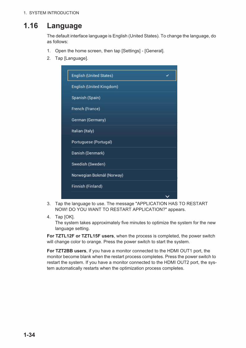
1. SYSTEM INTRODUCTION
1.16 LanguageThe default interface language is English (United States). To change the language, do as follows:
1. Open the home screen, then tap [Settings] - [General].
2. Tap [Language].
3. Tap the language to use. The message "APPLICATION HAS TO RESTART NOW! DO YOU WANT TO RESTART APPLICATION?" appears.
4. Tap [OK]. The system takes approximately five minutes to optimize the system for the new language setting.
For TZTL12F or TZTL15F users, when the process is completed, the power switch will change color to orange. Press the power switch to start the system.
For TZT2BB users, if you have a monitor connected to the HDMI OUT1 port, the monitor become blank when the restart process completes. Press the power switch to restart the system. If you have a monitor connected to the HDMI OUT2 port, the sys-tem automatically restarts when the optimization process completes.
1-34
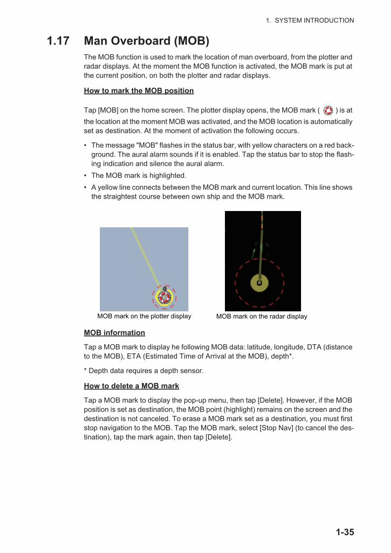
1. SYSTEM INTRODUCTION
1.17 Man Overboard (MOB)The MOB function is used to mark the location of man overboard, from the plotter and radar displays. At the moment the MOB function is activated, the MOB mark is put at the current position, on both the plotter and radar displays.
How to mark the MOB position
Tap [MOB] on the home screen. The plotter display opens, the MOB mark ( ) is at
the location at the moment MOB was activated, and the MOB location is automatically set as destination. At the moment of activation the following occurs.
• The message "MOB" flashes in the status bar, with yellow characters on a red back-ground. The aural alarm sounds if it is enabled. Tap the status bar to stop the flash-ing indication and silence the aural alarm.
• The MOB mark is highlighted.
• A yellow line connects between the MOB mark and current location. This line shows the straightest course between own ship and the MOB mark.
MOB information
Tap a MOB mark to display he following MOB data: latitude, longitude, DTA (distance to the MOB), ETA (Estimated Time of Arrival at the MOB), depth*.
* Depth data requires a depth sensor.
How to delete a MOB mark
Tap a MOB mark to display the pop-up menu, then tap [Delete]. However, if the MOB position is set as destination, the MOB point (highlight) remains on the screen and the destination is not canceled. To erase a MOB mark set as a destination, you must first stop navigation to the MOB. Tap the MOB mark, select [Stop Nav] (to cancel the des-tination), tap the mark again, then tap [Delete].
MOB mark on the plotter display MOB mark on the radar display
1-35
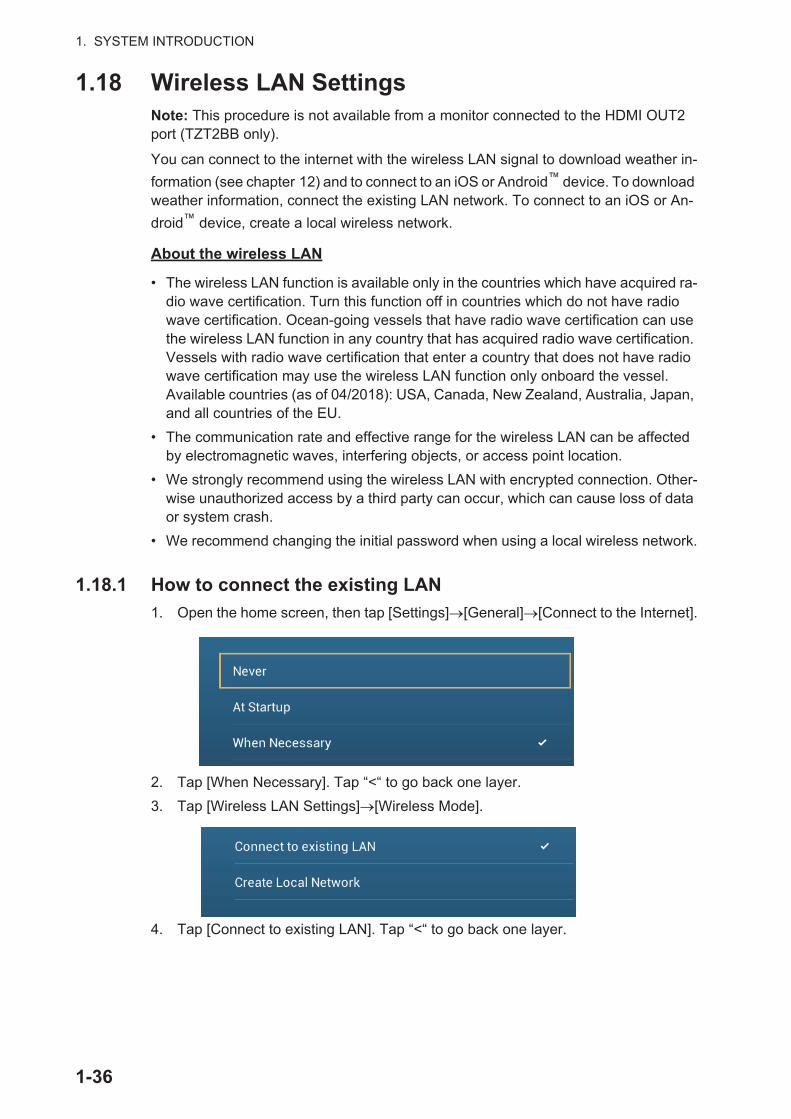
1. SYSTEM INTRODUCTION
1.18 Wireless LAN SettingsNote: This procedure is not available from a monitor connected to the HDMI OUT2 port (TZT2BB only).
You can connect to the internet with the wireless LAN signal to download weather in-
formation (see chapter 12) and to connect to an iOS or Android™ device. To download weather information, connect the existing LAN network. To connect to an iOS or An-
droid™ device, create a local wireless network.
About the wireless LAN
• The wireless LAN function is available only in the countries which have acquired ra-dio wave certification. Turn this function off in countries which do not have radio wave certification. Ocean-going vessels that have radio wave certification can use the wireless LAN function in any country that has acquired radio wave certification. Vessels with radio wave certification that enter a country that does not have radio wave certification may use the wireless LAN function only onboard the vessel.Available countries (as of 04/2018): USA, Canada, New Zealand, Australia, Japan, and all countries of the EU.
• The communication rate and effective range for the wireless LAN can be affected by electromagnetic waves, interfering objects, or access point location.
• We strongly recommend using the wireless LAN with encrypted connection. Other-wise unauthorized access by a third party can occur, which can cause loss of data or system crash.
• We recommend changing the initial password when using a local wireless network.
1.18.1 How to connect the existing LAN
1. Open the home screen, then tap [Settings] [General] [Connect to the Internet].
2. Tap [When Necessary]. Tap “<“ to go back one layer.
3. Tap [Wireless LAN Settings] [Wireless Mode].
4. Tap [Connect to existing LAN]. Tap “<“ to go back one layer.
1-36
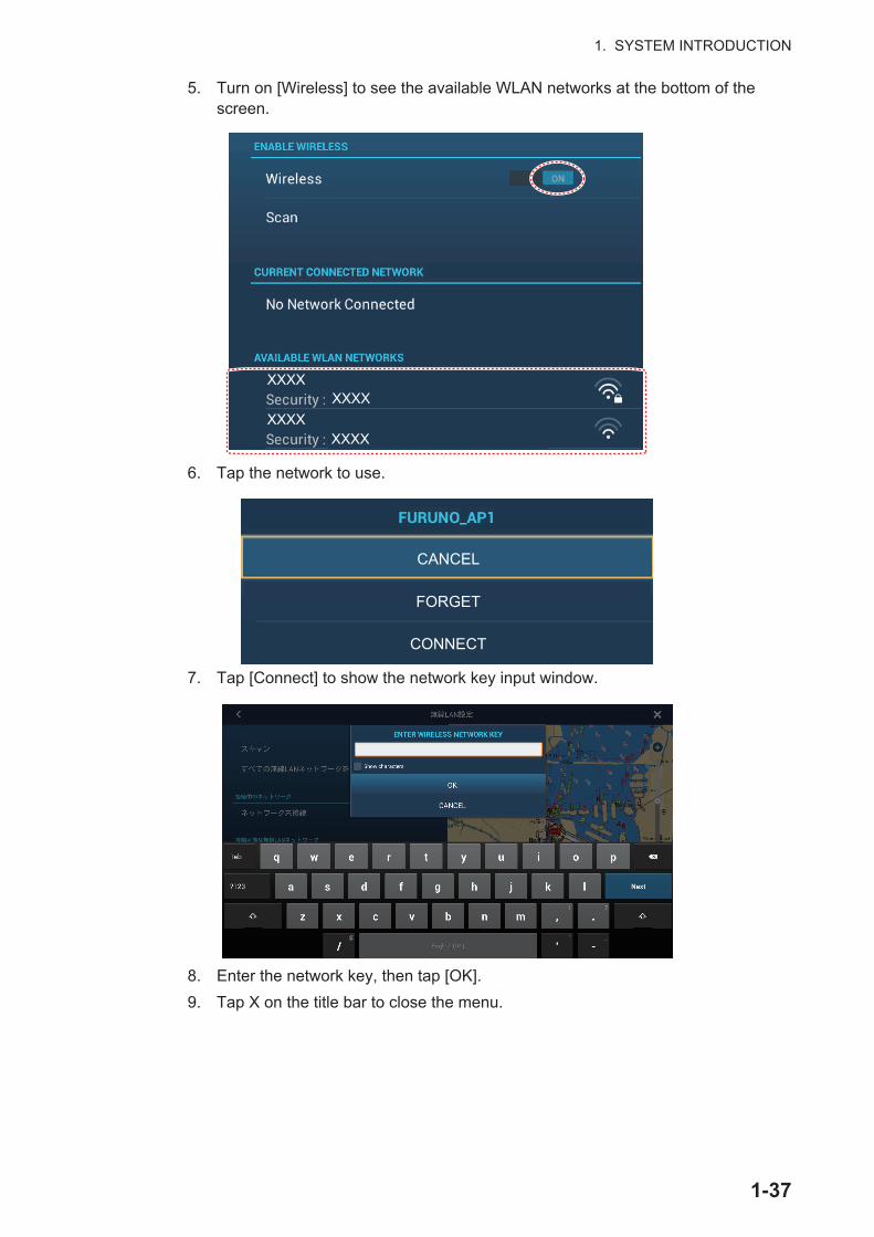
1. SYSTEM INTRODUCTION
5. Turn on [Wireless] to see the available WLAN networks at the bottom of the screen.
6. Tap the network to use.
7. Tap [Connect] to show the network key input window.
8. Enter the network key, then tap [OK].
9. Tap X on the title bar to close the menu.
XXXXXXXX
XXXXXXXX
CANCEL
FORGET
CONNECT
1-37
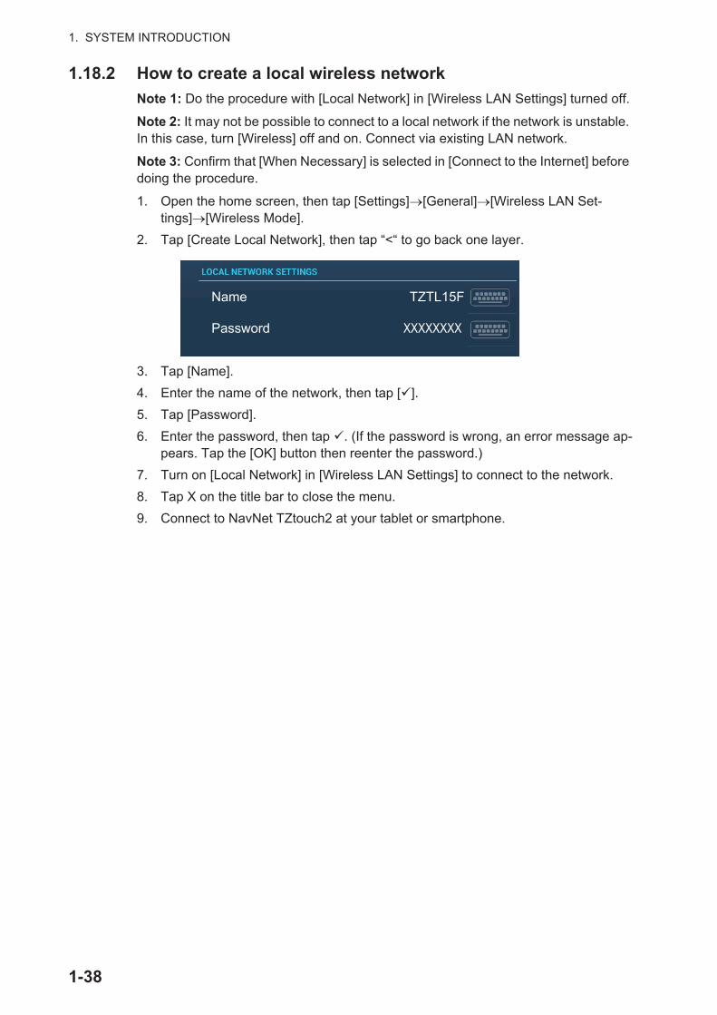
1. SYSTEM INTRODUCTION
1.18.2 How to create a local wireless network
Note 1: Do the procedure with [Local Network] in [Wireless LAN Settings] turned off.
Note 2: It may not be possible to connect to a local network if the network is unstable. In this case, turn [Wireless] off and on. Connect via existing LAN network.
Note 3: Confirm that [When Necessary] is selected in [Connect to the Internet] before doing the procedure.
1. Open the home screen, then tap [Settings] [General] [Wireless LAN Set-tings] [Wireless Mode].
2. Tap [Create Local Network], then tap “<“ to go back one layer.
3. Tap [Name].
4. Enter the name of the network, then tap [ ].
5. Tap [Password].
6. Enter the password, then tap . (If the password is wrong, an error message ap-pears. Tap the [OK] button then reenter the password.)
7. Turn on [Local Network] in [Wireless LAN Settings] to connect to the network.
8. Tap X on the title bar to close the menu.
9. Connect to NavNet TZtouch2 at your tablet or smartphone.
Name TZTL15F
Password XXXXXXXX
1-38
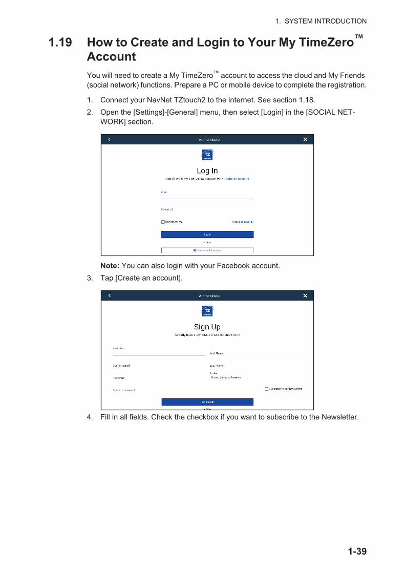
1. SYSTEM INTRODUCTION
1.19 How to Create and Login to Your My TimeZero™ Account
You will need to create a My TimeZero™ account to access the cloud and My Friends (social network) functions. Prepare a PC or mobile device to complete the registration.
1. Connect your NavNet TZtouch2 to the internet. See section 1.18.
2. Open the [Settings]-[General] menu, then select [Login] in the [SOCIAL NET-WORK] section.
Note: You can also login with your Facebook account.
3. Tap [Create an account].
4. Fill in all fields. Check the checkbox if you want to subscribe to the Newsletter.
1-39

1. SYSTEM INTRODUCTION
5. Click [Get started!] to finish.
6. From a PC or mobile device, follow the link provided in the e-mail to log into your account. Leave the NavNet TZtouch2 as is.
7. Tap [Go to Log in page] on this equipment.
8. Enter the e-mail address used to register the account, and your password.
9. Tap [Log in].
The name used to create the account appears in the [Logged As] field. The Status bar shows (in yellow) “You are logged as (your name)” and several beeps sound.
1.20 Dual Monitor ConfigurationsThe TZT2BB supports dual monitor display, provided that the monitors are connected to the HDM1 OUT and HDMI2 OUT ports on the MPU-004. Monitors connected in this manner can be operated individually of each other.
Your nameYour e-mail address
1-40

2. PLOTTER
This chapter shows you how to do the following:
• Use and prepare the plotter display
• Set plotter related alarms
• Control the track
2.1 Chart TypeA world map in raster chart format is included in your unit. A vector chart for the US coastline (Alaska and Hawaii included) is provided also. To use this plotter as a navi-gational aid, have electronic charts (stored in the hard disk) for the area you navigate. Contact your dealer about charts for your area.
There are two types of charts available with this equipment.
[Raster]: Raster charts are digitized scans of NOAA paper charts. Raster charts have information like notes, source diagrams, tidal diamonds, horizontal and vertical datum, etc.[HO]: HO charts are S-57 format vector charts (digital files) that contain marine fea-tures and information created for marine navigation. These charts are made according to the International Hydrographic Organization (IHO). HO charts are available from C-MAP, Navionics, Mapmedia, and NOAA (National Oceanic and Atmospheric Admin-istration).
How to select a chart type
1. Select the plotter display.
2. Open the [Layers] menu.
3. Tap the chart type from among [Auto], [Raster] or [HOs].
*: [Auto] automatically switches the chart type according to chart availability and prior-ity.
2-1

2. PLOTTER
2.2 Display RangeYou can change the display range to change the amount of information shown. The selected range appears in the box at the bottom left-hand corner of the screen.
How to zoom in or out the display range
Method 1: Pinch the plotter display.
Method 2: Operate the slider to bar to adjust the display range, using one of the meth-ods shown below.1) Drag the slider.2) Tap the bar.3) Tap the “+” or “-” icon on the slider.
(The slider bar is shown in the default setting. The slider bar can be shown or hidden with [Show Scale Slider] in the [Settings] - [Plotter] menu.)
Note: You can zoom in or out the display range on the preview screen.
Display range
Range areaRange area
Zoom in Zoom out
Drag the slider (or tap bar or +, - icons)
Zoom in
Zoom outSlider bar
2-2
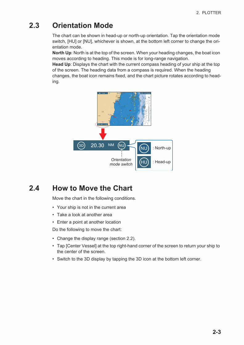
2. PLOTTER
2.3 Orientation ModeThe chart can be shown in head-up or north-up orientation. Tap the orientation mode switch, [HU] or [NU], whichever is shown, at the bottom left corner to change the ori-entation mode.North Up: North is at the top of the screen. When your heading changes, the boat icon moves according to heading. This mode is for long-range navigation.Head Up: Displays the chart with the current compass heading of your ship at the top of the screen. The heading data from a compass is required. When the heading changes, the boat icon remains fixed, and the chart picture rotates according to head-ing.
2.4 How to Move the ChartMove the chart in the following conditions.
• Your ship is not in the current area
• Take a look at another area
• Enter a point at another location
Do the following to move the chart:
• Change the display range (section 2.2).
• Tap [Center Vessel] at the top right-hand corner of the screen to return your ship to the center of the screen.
• Switch to the 3D display by tapping the 3D icon at the bottom left corner.
Orientationmode switch
: North-up
: Head-up
2-3
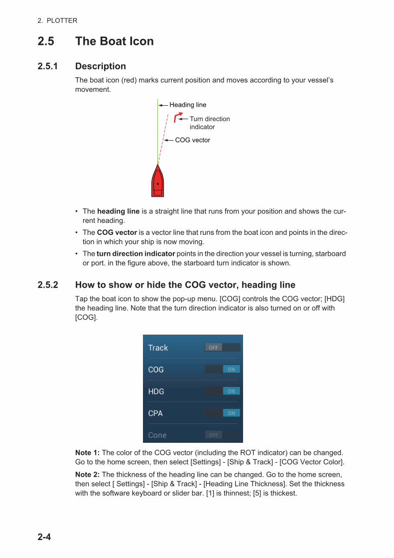
2. PLOTTER
2.5 The Boat Icon
2.5.1 Description
The boat icon (red) marks current position and moves according to your vessel’s movement.
• The heading line is a straight line that runs from your position and shows the cur-rent heading.
• The COG vector is a vector line that runs from the boat icon and points in the direc-tion in which your ship is now moving.
• The turn direction indicator points in the direction your vessel is turning, starboard or port. in the figure above, the starboard turn indicator is shown.
2.5.2 How to show or hide the COG vector, heading line
Tap the boat icon to show the pop-up menu. [COG] controls the COG vector; [HDG] the heading line. Note that the turn direction indicator is also turned on or off with [COG].
Note 1: The color of the COG vector (including the ROT indicator) can be changed. Go to the home screen, then select [Settings] - [Ship & Track] - [COG Vector Color].
Note 2: The thickness of the heading line can be changed. Go to the home screen, then select [ Settings] - [Ship & Track] - [Heading Line Thickness]. Set the thickness with the software keyboard or slider bar. [1] is thinnest; [5] is thickest.
COG vector
Heading line
Turn directionindicator
2-4
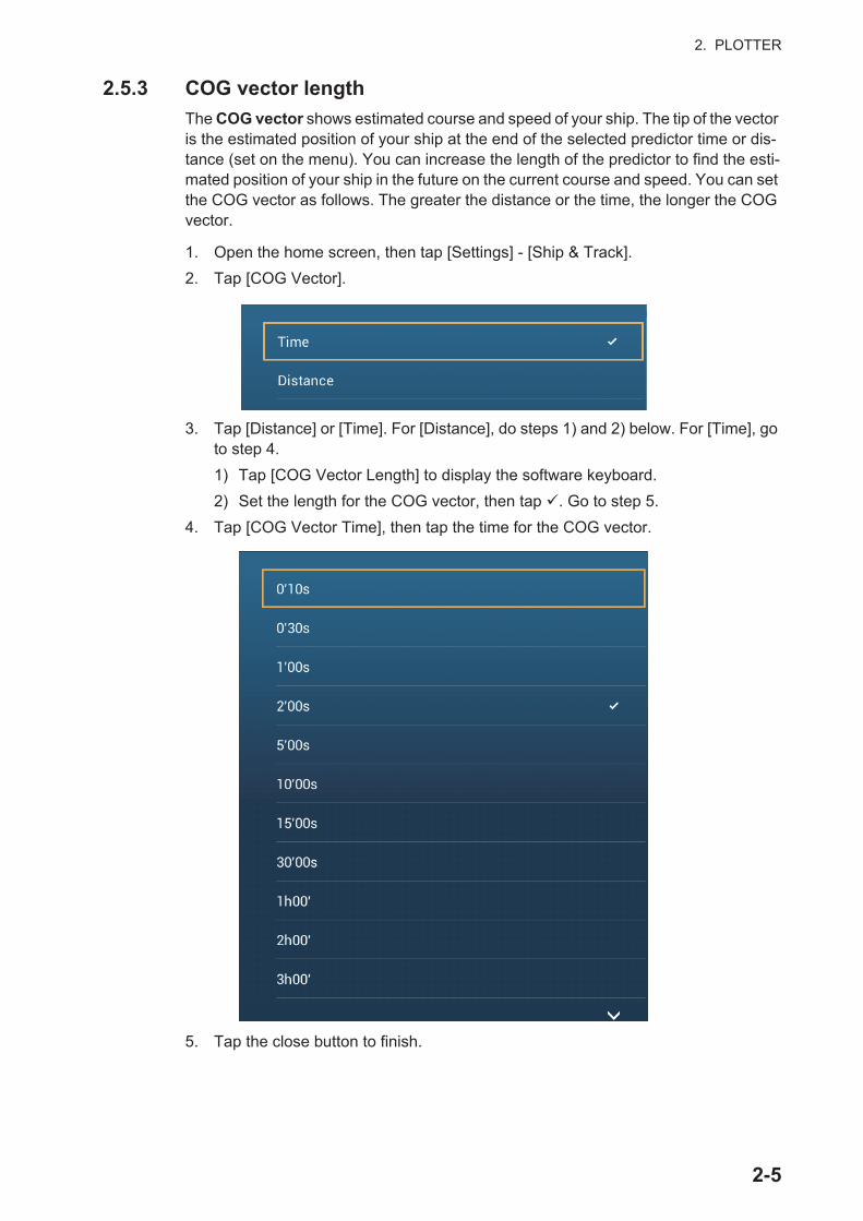
2. PLOTTER
2.5.3 COG vector length
The COG vector shows estimated course and speed of your ship. The tip of the vector is the estimated position of your ship at the end of the selected predictor time or dis-tance (set on the menu). You can increase the length of the predictor to find the esti-mated position of your ship in the future on the current course and speed. You can set the COG vector as follows. The greater the distance or the time, the longer the COG vector.
1. Open the home screen, then tap [Settings] - [Ship & Track].
2. Tap [COG Vector].
3. Tap [Distance] or [Time]. For [Distance], do steps 1) and 2) below. For [Time], go to step 4.
1) Tap [COG Vector Length] to display the software keyboard.
2) Set the length for the COG vector, then tap . Go to step 5.
4. Tap [COG Vector Time], then tap the time for the COG vector.
5. Tap the close button to finish.
2-5

2. PLOTTER
2.5.4 Boat icon orientation
You can select the orientation of the boat icon to heading or COG.
1. Open the home screen, then tap [Settings] - [Ship & Track].
2. Tap [Vessel Icon Orientation].
3. Tap [Heading] or [COG].
4. Tap the close button to finish.
2.6 How to Information About a Chart Object, ChartYou can find chart object and chart information from the pop-up menu.
2.6.1 Chart object information
Simple information
Tap an object to show its name, specifications, position, and range and bearing, in the pop-up menu.
Latitude and longitude position of object
Range and bearing to object
Name and specifications of object
2-6
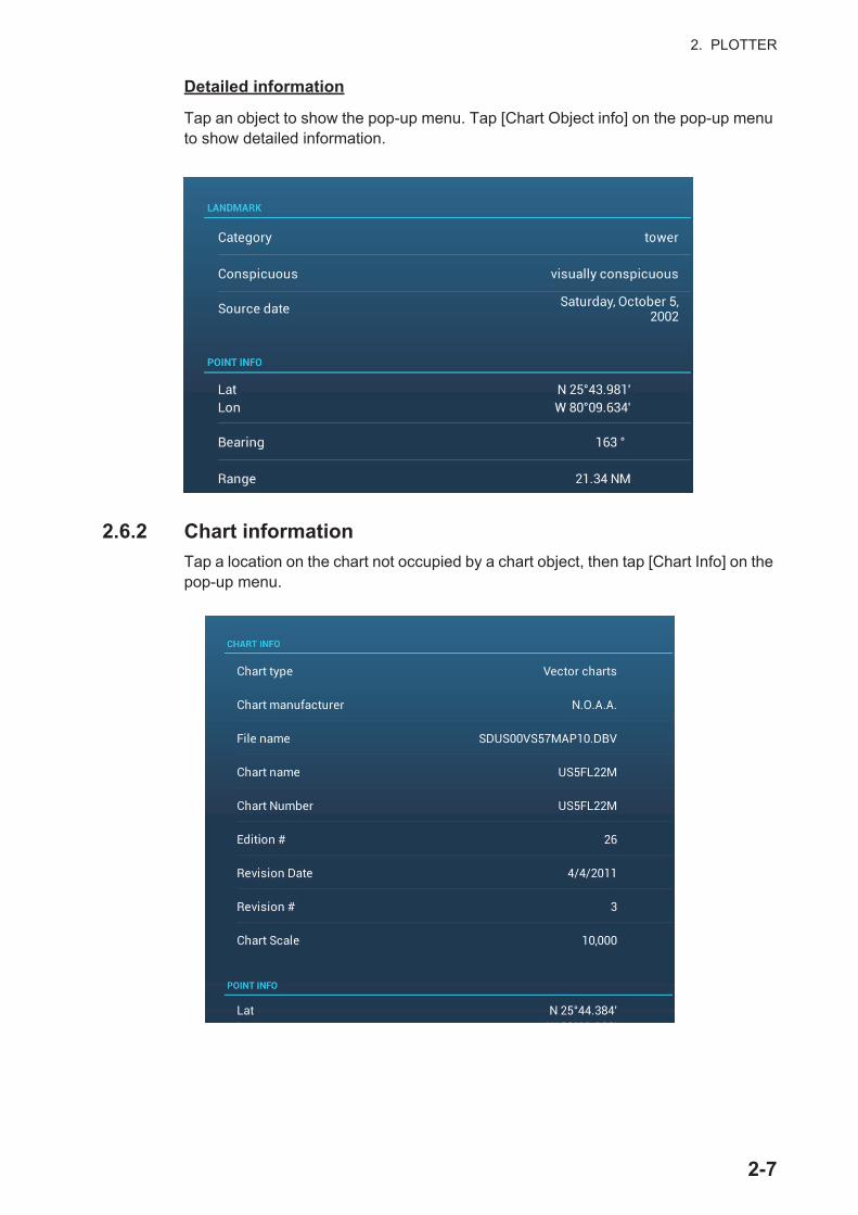
2. PLOTTER
Detailed information
Tap an object to show the pop-up menu. Tap [Chart Object info] on the pop-up menu to show detailed information.
2.6.2 Chart information
Tap a location on the chart not occupied by a chart object, then tap [Chart Info] on the pop-up menu.
2-7
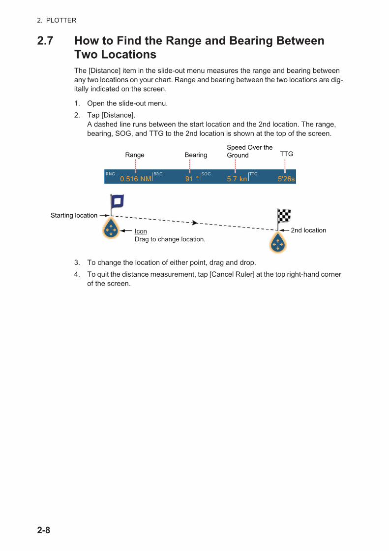
2. PLOTTER
2.7 How to Find the Range and Bearing Between Two LocationsThe [Distance] item in the slide-out menu measures the range and bearing between any two locations on your chart. Range and bearing between the two locations are dig-itally indicated on the screen.
1. Open the slide-out menu.
2. Tap [Distance].A dashed line runs between the start location and the 2nd location. The range, bearing, SOG, and TTG to the 2nd location is shown at the top of the screen.
3. To change the location of either point, drag and drop.
4. To quit the distance measurement, tap [Cancel Ruler] at the top right-hand corner of the screen.
IconDrag to change location.
2nd location
Range BearingSpeed Over the Ground TTG
Starting location
2-8

2. PLOTTER
2.8 Multiple Plotter DisplaysThree plotter displays can be shown on one screen. With three plotter displays, you can see the conditions around your ship on both short and long ranges. Also, you can see how your ship moves toward your destination from more than one angle. For ex-ample, you can show one display in 3D and the other two in 2D.
The following features can be adjusted individually.
• AIS • ARPA • Display range• Chart orientation • Chart type • Scroll the chart
• Overlays (radar, sat photo, depth shading, tide icon, tidal current, ACCU-FISH&™
(see section 7.12), points, routes, tracks)• 2D and 3D: Independent orientation (2D, 3D) and view point (3D) are possible.
Plotter display 1Display range: 26.09 NMOrientation: North-upPerspective: 3D
Plotter display 3Display range: 51.93 NMOrientation: North-upPerspective: 2DOverlay: Depth shading
Plotter display 2Display range: 80.03 NMOrientation: Head-upPerspective: 2D
2-9
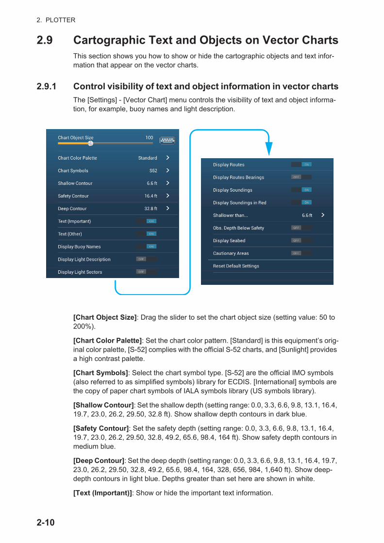
2. PLOTTER
2.9 Cartographic Text and Objects on Vector ChartsThis section shows you how to show or hide the cartographic objects and text infor-mation that appear on the vector charts.
2.9.1 Control visibility of text and object information in vector charts
The [Settings] - [Vector Chart] menu controls the visibility of text and object informa-tion, for example, buoy names and light description.
[Chart Object Size]: Drag the slider to set the chart object size (setting value: 50 to 200%).
[Chart Color Palette]: Set the chart color pattern. [Standard] is this equipment’s orig-inal color palette, [S-52] complies with the official S-52 charts, and [Sunlight] provides a high contrast palette.
[Chart Symbols]: Select the chart symbol type. [S-52] are the official IMO symbols (also referred to as simplified symbols) library for ECDIS. [International] symbols are the copy of paper chart symbols of IALA symbols library (US symbols library).
[Shallow Contour]: Set the shallow depth (setting range: 0.0, 3.3, 6.6, 9.8, 13.1, 16.4, 19.7, 23.0, 26.2, 29.50, 32.8 ft). Show shallow depth contours in dark blue.
[Safety Contour]: Set the safety depth (setting range: 0.0, 3.3, 6.6, 9.8, 13.1, 16.4, 19.7, 23.0, 26.2, 29.50, 32.8, 49.2, 65.6, 98.4, 164 ft). Show safety depth contours in medium blue.
[Deep Contour]: Set the deep depth (setting range: 0.0, 3.3, 6.6, 9.8, 13.1, 16.4, 19.7, 23.0, 26.2, 29.50, 32.8, 49.2, 65.6, 98.4, 164, 328, 656, 984, 1,640 ft). Show deep-depth contours in light blue. Depths greater than set here are shown in white.
[Text (Important)]: Show or hide the important text information.
6.0 ft
2-10
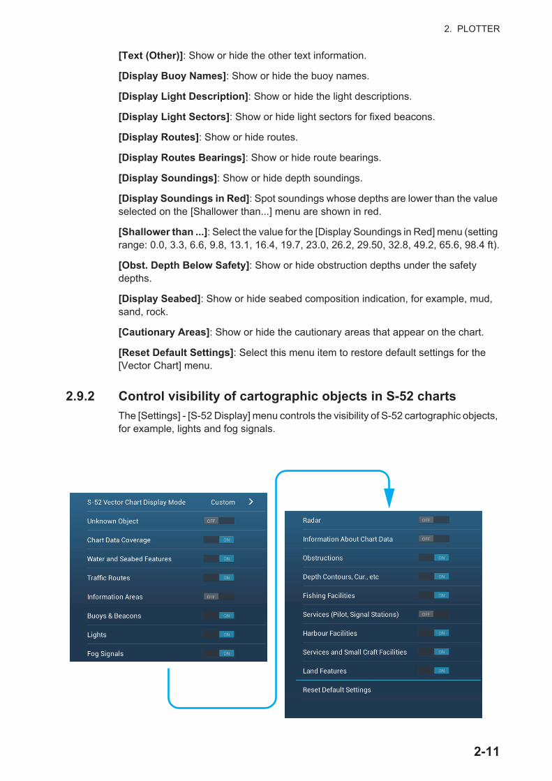
2. PLOTTER
[Text (Other)]: Show or hide the other text information.
[Display Buoy Names]: Show or hide the buoy names.
[Display Light Description]: Show or hide the light descriptions.
[Display Light Sectors]: Show or hide light sectors for fixed beacons.
[Display Routes]: Show or hide routes.
[Display Routes Bearings]: Show or hide route bearings.
[Display Soundings]: Show or hide depth soundings.
[Display Soundings in Red]: Spot soundings whose depths are lower than the value selected on the [Shallower than...] menu are shown in red.
[Shallower than ...]: Select the value for the [Display Soundings in Red] menu (setting range: 0.0, 3.3, 6.6, 9.8, 13.1, 16.4, 19.7, 23.0, 26.2, 29.50, 32.8, 49.2, 65.6, 98.4 ft).
[Obst. Depth Below Safety]: Show or hide obstruction depths under the safety depths.
[Display Seabed]: Show or hide seabed composition indication, for example, mud, sand, rock.
[Cautionary Areas]: Show or hide the cautionary areas that appear on the chart.
[Reset Default Settings]: Select this menu item to restore default settings for the [Vector Chart] menu.
2.9.2 Control visibility of cartographic objects in S-52 charts
The [Settings] - [S-52 Display] menu controls the visibility of S-52 cartographic objects, for example, lights and fog signals.
2-11
2. PLOTTER
[S-52 Vector Chart Display Mode]: Set the level of information to show on the chart. The selections are [Custom], [Base], [Standard], [Other], and [Fishing]. The chart fea-tures are turned on or off according to setting.Note: The following menu items except [Reset Default Settings] are unavailable when you select the mode other than [Custom]
[Unknown Object]: Show or hide unknown objects that appear on the chart.
[Chart Data Coverage]: Show or hide the geographic names and geographic objects.
[Water and Seabed Features]: Show or hide the water and seabed presentation.
[Traffic Routes]: Show or hide the marine traffic routes.
[Information Areas]: Show or hide the information areas that appear on the chart.
[Buoys & Beacons]: Show or hide the buoys and beacons.
[Lights]: Show or hide the sector of light that a fixed beacon shines.
[Fog Signals]: Show or hide the structure that sends a fog signal.
[Radar]: Show or hide the radar buoy.
[Information About Chart Data]: Show or hide the chart data information.
[Obstructions]: Show or hide obstructions (wrecks, etc.)
[Depth Contours, Cur., etc]: Show or hide the depth contours, tidal currents and magnetics.
[Fishing Facilities]: Show or hide the location of fishing facilities.
[Services (Pilot, Signal Stations)]: Show or hide the location of pilots and signal sta-tions.
[Harbour Facilities]: Show or hide the location of harbour facilities.
[Services and Small Craft Facilities]: Show or hide the services for ship and small craft.
[Land Features]: Show or hide the cartographic features that are shown on land.
[Reset Default Settings]: Select this menu item to restore default settings for the [S-52 Display] menu.
2-12
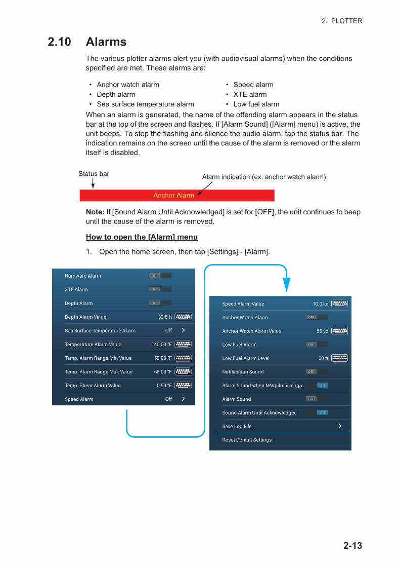
2. PLOTTER
2.10 AlarmsThe various plotter alarms alert you (with audiovisual alarms) when the conditions specified are met. These alarms are:
When an alarm is generated, the name of the offending alarm appears in the status bar at the top of the screen and flashes. If [Alarm Sound] ([Alarm] menu) is active, the unit beeps. To stop the flashing and silence the audio alarm, tap the status bar. The indication remains on the screen until the cause of the alarm is removed or the alarm itself is disabled.
Note: If [Sound Alarm Until Acknowledged] is set for [OFF], the unit continues to beep until the cause of the alarm is removed.
How to open the [Alarm] menu
1. Open the home screen, then tap [Settings] - [Alarm].
• Anchor watch alarm • Speed alarm• Depth alarm • XTE alarm• Sea surface temperature alarm • Low fuel alarm
Anchor Alarm
Status bar Alarm indication (ex. anchor watch alarm)
2-13
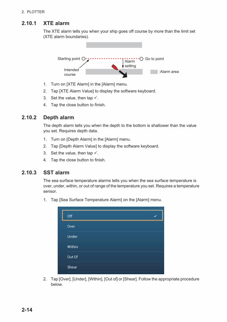
2. PLOTTER
2.10.1 XTE alarm
The XTE alarm tells you when your ship goes off course by more than the limit set (XTE alarm boundaries).
1. Turn on [XTE Alarm] in the [Alarm] menu.
2. Tap [XTE Alarm Value] to display the software keyboard.
3. Set the value, then tap .
4. Tap the close button to finish.
2.10.2 Depth alarm
The depth alarm tells you when the depth to the bottom is shallower than the value you set. Requires depth data.
1. Turn on [Depth Alarm] in the [Alarm] menu.
2. Tap [Depth Alarm Value] to display the software keyboard.
3. Set the value, then tap .
4. Tap the close button to finish.
2.10.3 SST alarm
The sea surface temperature alarms tells you when the sea surface temperature is over, under, within, or out of range of the temperature you set. Requires a temperature sensor.
1. Tap [Sea Surface Temperature Alarm] on the [Alarm] menu.
2. Tap [Over], [Under], [Within], [Out of] or [Shear]. Follow the appropriate procedure below.
Alarm setting
Go to point
Intended course
:Alarm area
Starting point
2-14

2. PLOTTER
[Over] or [Under]The [Over] or [Under] alarm sounds when the temperature is over or under the set value, respectively.
1) Tap [Temperature Alarm Value] to display the software keyboard.
2) Set the value, then tap . Go to step 3.
[Within] or [Out of]The [Within] or [Out of] alarm sounds when the temperature is within or out of the temperature range set, respectively.
1) Tap [Temp. Alarm Range Min Value] to display the software keyboard.
2) Set the minimum value, then tap .
3) Tap [Temp. Alarm Range Max Value] to display the software keyboard.
4) Set the minimum value, then tap . Go to step 3.
[Shear]The shear alarm sounds when the temperature exceeds the alarm setting for one minute.
1) Tap [Temp. Shear Alarm Value] to display the software keyboard.
2) Set the value, then tap . Go to step 3.
3. Tap the close button to finish.
2.10.4 Speed alarm
The speed alarm tells you when the speed of your ship is over or under the limit set. Set the value at [Speed Alarm Value].
1. Tap [Speed Alarm] on the [Alarm] menu.
2. Tap [Over] or [Under].
3. Tap [Speed Alarm Value] to display the software keyboard.
4. Set the value for [Over] or [Under] then tap .
5. Tap the close button to finish.
2-15

2. PLOTTER
2.10.5 Anchor watch alarm
The anchor watch alarm tells you that your ship has moved a distance greater than the set value when the ship must not be moving.
1. Turn on [Anchor Watch Alarm] in the [Alarm] menu.
2. Tap [Anchor Watch Alarm Value] to display the software keyboard.
3. Set the value, then tap .
4. Tap the close button to finish.
2.10.6 Low fuel alarm
The low fuel alarm informs to a low fuel situation.
1. Turn on [Low Fuel Alarm] in the [Alarm] menu.
2. Tap [Low Fuel Alarm Value] to display the software keyboard.
3. Set the value, then tap .
4. Tap the close button to finish.
The low fuel alarm can be deactivated by selecting [OFF] at step 1 in the above pro-cedure.
2.10.7 Other Alarm menu items
The followings are the alarm menu items not previously mentioned.
[Hardware Alarm]: The [OFF] setting disables hardware-related alarms.
[Notification Sound]: Activate or deactivate the notification sound (for "Waypoint Crossing" (see section 5.10), "End of Route" (section 4.13) or fish finder alarms (section 7.11)).
[Alarm Sound when NAVpilot is engaged]: Activate or deactivate the notification sound when the autopilot is engaged to or disengaged from this system.
[Alarm Sound]: Disable or enable the buzzer.
[Sound Alarm Until Acknowledged]: Turn this item on to sound the aural alarm until an alarm is acknowledged (see paragraph 2.10.8).
[Save Log File]: Save alert list to microSD card.
[Reset Default Settings]: Select this menu item to restore default settings for the [Alarm] menu.
Your ship's position where you start the anchor watch alarm.
Alarm setting
: Alarm area
2-16

2. PLOTTER
2.10.8 Alarms list
When an alarm is violated, you can see the name of the offending alarm on the [Alarms] list. The list stores both warning and system messages. Open the home screen, then tap [Lists] followed by [Alarms]. Active alarms are flashing and have a red vertical bar at the let margin. Tap an active alarm to acknowledge it and stop the flash-ing. After the cause of an alarm is removed, the alarm message is moved to [HISTOR-IC] section. Tap the close button to close the list.
2.11 TrackThe track (or movement) of your ship is plotted on the screen with position data fed from the internal GPS navigator. Your track lets you see how your ship has moved over time.
The track is saved to the hard disk if track recording is activated. A line runs between each track point. The hard disk stores a maximum of 30,000 track points.
Track can be shared with other NavNet TZtouch2 units via LAN. Data is shared auto-matically; no operation is required.
Track is saved when the power is turned off. Unnecessary track can be deleted. Track can also be used to create a route.
2.11.1 How to start, stop recording the track
Start recording
Open the slide-out menu or tap the boat icon, then turn [Track] on.
Stop recording
Method 1: Tap the track, then tap [Stop Track].Method 2: Open the slide-out menu or tap the boat icon, then turn [Track] off.
2.11.2 How to show or hide the track display
Open the [Layers] menu and turn [Tracks] on or off.
Depth Alarm
Color on Status bar
Message Date, time alarm generated
Track
2-17
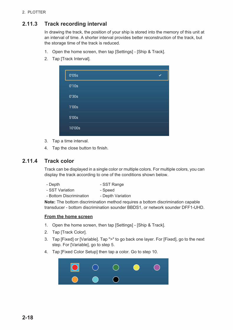
2. PLOTTER
2.11.3 Track recording interval
In drawing the track, the position of your ship is stored into the memory of this unit at an interval of time. A shorter interval provides better reconstruction of the track, but the storage time of the track is reduced.
1. Open the home screen, then tap [Settings] - [Ship & Track].
2. Tap [Track Interval].
3. Tap a time interval.
4. Tap the close button to finish.
2.11.4 Track color
Track can be displayed in a single color or multiple colors. For multiple colors, you can display the track according to one of the conditions shown below.
Note: The bottom discrimination method requires a bottom discrimination capable transducer - bottom discrimination sounder BBDS1, or network sounder DFF1-UHD.
From the home screen
1. Open the home screen, then tap [Settings] - [Ship & Track].
2. Tap [Track Color].
3. Tap [Fixed] or [Variable]. Tap ">" to go back one layer. For [Fixed], go to the next step. For [Variable], go to step 5.
4. Tap [Fixed Color Setup] then tap a color. Go to step 10.
- Depth - SST Range- SST Variation - Speed- Bottom Discrimination - Depth Variation
2-18
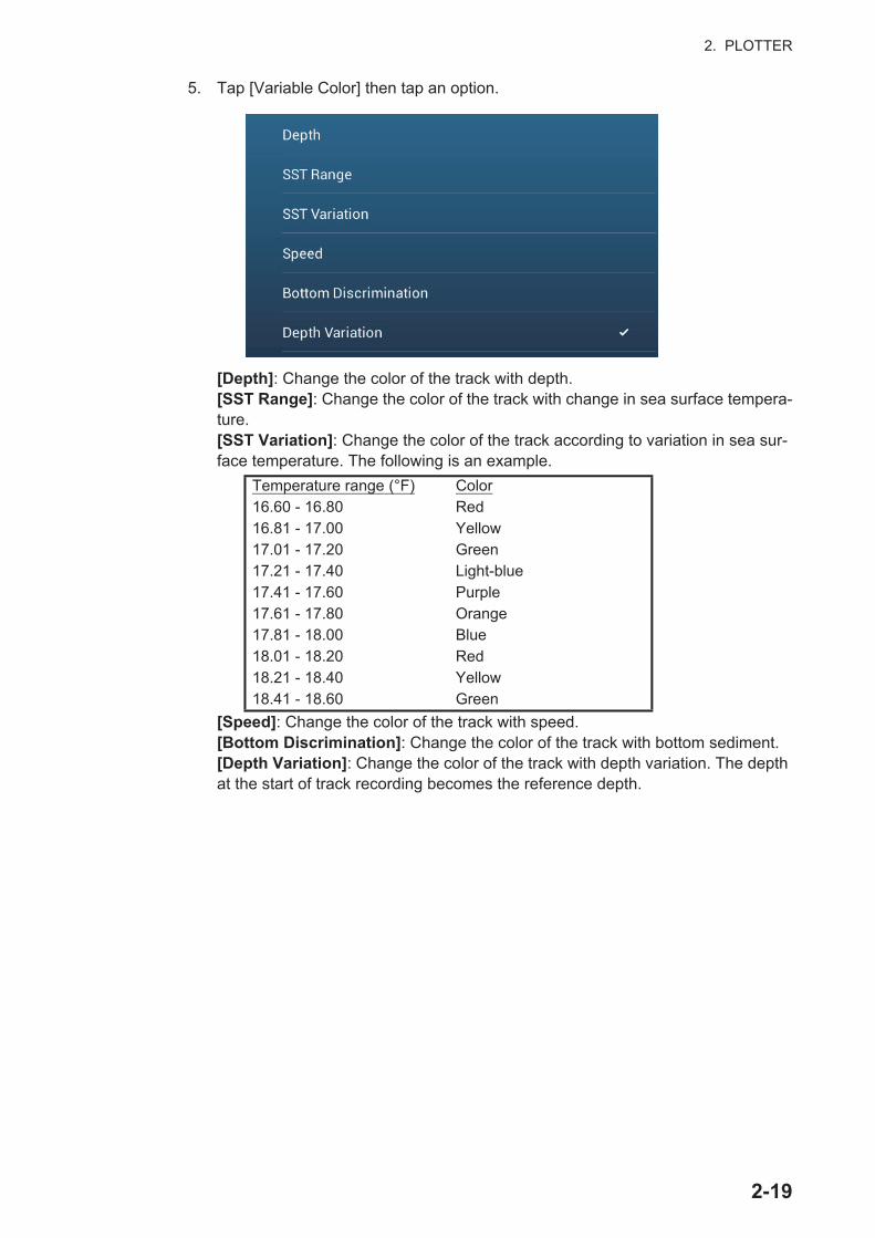
2. PLOTTER
5. Tap [Variable Color] then tap an option.
[Depth]: Change the color of the track with depth.[SST Range]: Change the color of the track with change in sea surface tempera-ture.[SST Variation]: Change the color of the track according to variation in sea sur-face temperature. The following is an example.
[Speed]: Change the color of the track with speed.[Bottom Discrimination]: Change the color of the track with bottom sediment.[Depth Variation]: Change the color of the track with depth variation. The depth at the start of track recording becomes the reference depth.
Temperature range (°F) Color16.60 - 16.80 Red16.81 - 17.00 Yellow17.01 - 17.20 Green17.21 - 17.40 Light-blue17.41 - 17.60 Purple17.61 - 17.80 Orange17.81 - 18.00 Blue18.01 - 18.20 Red18.21 - 18.40 Yellow18.41 - 18.60 Green
2-19
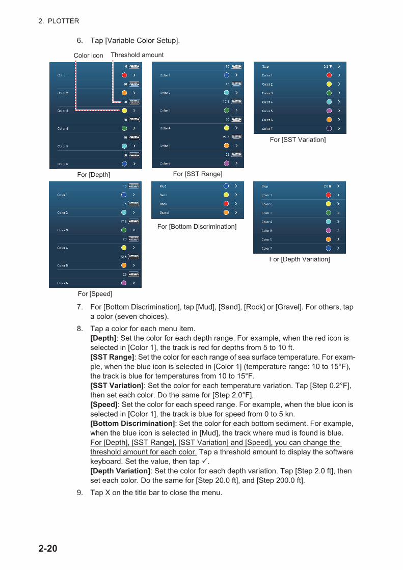
2. PLOTTER
6. Tap [Variable Color Setup].
7. For [Bottom Discrimination], tap [Mud], [Sand], [Rock] or [Gravel]. For others, tap a color (seven choices).
8. Tap a color for each menu item.[Depth]: Set the color for each depth range. For example, when the red icon is selected in [Color 1], the track is red for depths from 5 to 10 ft.[SST Range]: Set the color for each range of sea surface temperature. For exam-ple, when the blue icon is selected in [Color 1] (temperature range: 10 to 15°F), the track is blue for temperatures from 10 to 15°F.[SST Variation]: Set the color for each temperature variation. Tap [Step 0.2°F], then set each color. Do the same for [Step 2.0°F].[Speed]: Set the color for each speed range. For example, when the blue icon is selected in [Color 1], the track is blue for speed from 0 to 5 kn.[Bottom Discrimination]: Set the color for each bottom sediment. For example, when the blue icon is selected in [Mud], the track where mud is found is blue.For [Depth], [SST Range], [SST Variation] and [Speed], you can change the threshold amount for each color. Tap a threshold amount to display the software keyboard. Set the value, then tap .[Depth Variation]: Set the color for each depth variation. Tap [Step 2.0 ft], then set each color. Do the same for [Step 20.0 ft], and [Step 200.0 ft].
9. Tap X on the title bar to close the menu.
For [Depth] For [SST Range]
For [Bottom Discrimination]
Threshold amountColor icon
For [SST Variation]
For [Depth Variation]
For [Speed]
2-20
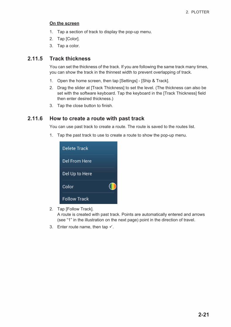
2. PLOTTER
On the screen
1. Tap a section of track to display the pop-up menu.
2. Tap [Color].
3. Tap a color.
2.11.5 Track thickness
You can set the thickness of the track. If you are following the same track many times, you can show the track in the thinnest width to prevent overlapping of track.
1. Open the home screen, then tap [Settings] - [Ship & Track].
2. Drag the slider at [Track Thickness] to set the level. (The thickness can also be set with the software keyboard. Tap the keyboard in the [Track Thickness] field then enter desired thickness.)
3. Tap the close button to finish.
2.11.6 How to create a route with past track
You can use past track to create a route. The route is saved to the routes list.
1. Tap the past track to use to create a route to show the pop-up menu.
2. Tap [Follow Track].A route is created with past track. Points are automatically entered and arrows (see “1” in the illustration on the next page) point in the direction of travel.
3. Enter route name, then tap .
2-21
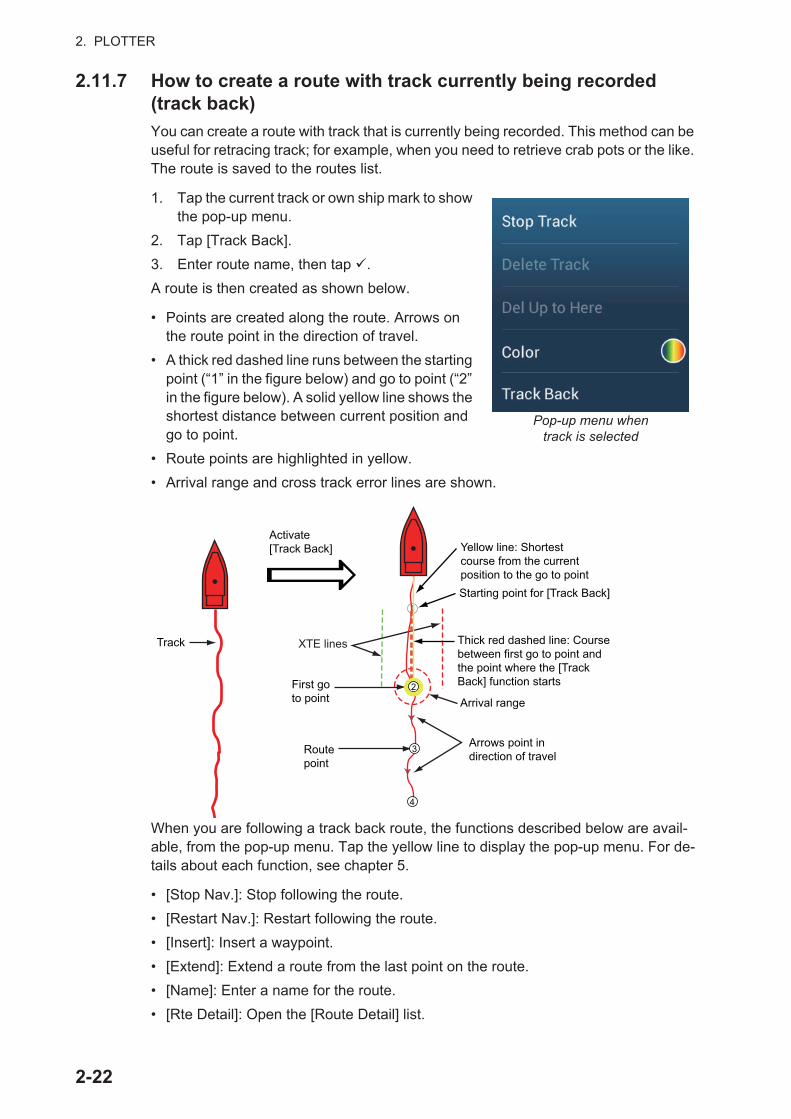
2. PLOTTER
2.11.7 How to create a route with track currently being recorded (track back)
You can create a route with track that is currently being recorded. This method can be useful for retracing track; for example, when you need to retrieve crab pots or the like. The route is saved to the routes list.
1. Tap the current track or own ship mark to show the pop-up menu.
2. Tap [Track Back].
3. Enter route name, then tap .
A route is then created as shown below.
• Points are created along the route. Arrows on the route point in the direction of travel.
• A thick red dashed line runs between the starting point (“1” in the figure below) and go to point (“2” in the figure below). A solid yellow line shows the shortest distance between current position and go to point.
• Route points are highlighted in yellow.
• Arrival range and cross track error lines are shown.
When you are following a track back route, the functions described below are avail-able, from the pop-up menu. Tap the yellow line to display the pop-up menu. For de-tails about each function, see chapter 5.
• [Stop Nav.]: Stop following the route.
• [Restart Nav.]: Restart following the route.
• [Insert]: Insert a waypoint.
• [Extend]: Extend a route from the last point on the route.
• [Name]: Enter a name for the route.
• [Rte Detail]: Open the [Route Detail] list.
Pop-up menu whentrack is selected
Track
Activate [Track Back]
First go to point
Route point
Yellow line: Shortest course from the current position to the go to point
Arrows point in direction of travel
Thick red dashed line: Course between first go to point and the point where the [Track Back] function starts
XTE lines
Starting point for [Track Back]11
22
33
44
Arrival range
2-22
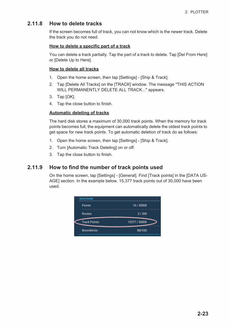
2. PLOTTER
2.11.8 How to delete tracks
If the screen becomes full of track, you can not know which is the newer track. Delete the track you do not need.
How to delete a specific part of a track
You can delete a track partially. Tap the part of a track to delete. Tap [Del From Here] or [Delete Up to Here].
How to delete all tracks
1. Open the home screen, then tap [Settings] - [Ship & Track].
2. Tap [Delete All Tracks] on the [TRACK] window. The message "THIS ACTION WILL PERMANENTLY DELETE ALL TRACK..." appears.
3. Tap [OK].
4. Tap the close button to finish.
Automatic deleting of tracks
The hard disk stores a maximum of 30,000 track points. When the memory for track points becomes full, the equipment can automatically delete the oldest track points to get space for new track points. To get automatic deletion of track do as follows:
1. Open the home screen, then tap [Settings] - [Ship & Track].
2. Turn [Automatic Track Deleting] on or off.
3. Tap the close button to finish.
2.11.9 How to find the number of track points used
On the home screen, tap [Settings] - [General]. Find [Track points] in the [DATA US-AGE] section. In the example below. 15,377 track points out of 30,000 have been used.
99/100
2-23
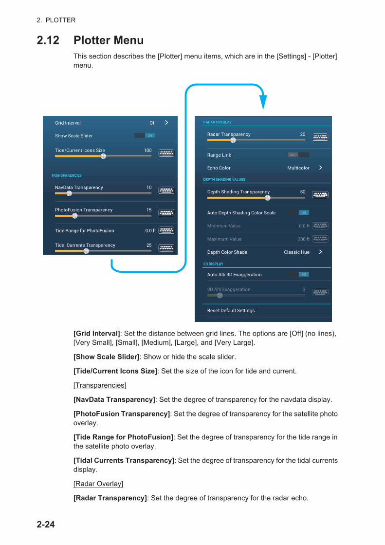
2. PLOTTER
2.12 Plotter MenuThis section describes the [Plotter] menu items, which are in the [Settings] - [Plotter] menu.
[Grid Interval]: Set the distance between grid lines. The options are [Off] (no lines), [Very Small], [Small], [Medium], [Large], and [Very Large].
[Show Scale Slider]: Show or hide the scale slider.
[Tide/Current Icons Size]: Set the size of the icon for tide and current.
[Transparencies]
[NavData Transparency]: Set the degree of transparency for the navdata display.
[PhotoFusion Transparency]: Set the degree of transparency for the satellite photo overlay.
[Tide Range for PhotoFusion]: Set the degree of transparency for the tide range in the satellite photo overlay.
[Tidal Currents Transparency]: Set the degree of transparency for the tidal currents display.
[Radar Overlay]
[Radar Transparency]: Set the degree of transparency for the radar echo.
2-24

2. PLOTTER
[Range Link]: Activate or deactivate matching the overlay with radar ranges.
[Echo Color]: Tap the color for the radar echo.
Depth Shading Values
[Depth Shading Transparency]: Set the degree of transparency for the depth shad-ing overlay.
For the menu items shown in the table, see the mentioned section.
[Reset Default Settings]: Tap this menu item to restore default settings for the [Plot-ter Display] menu.
2.13 NAVpilot Series Auto PilotThis section shows you to how to enable use of the NAVpilot with your system. For how to use the NAVpilot to steer to a point, see paragraph 4.13.4.
The FURUNO NAVpilot Series Auto Pilot installs in the NavNet TZtouch2 network to get automatic steering when going to a point or a route. The following NAVpilot func-tions can be controlled from a NavNet TZtouch2 display:
• Control operation of the NAVpilot from this equipment.
• Select the NAVpilot steering mode (Auto or Nav).
Note: When an alarm message for the NAVpilot appears, check the control unit of the NAVpilot.
2.13.1 How to enable use of the NAVpilot
Open the [Settings] - [Routes] menu, then turn on [Navigate with AutoPilot]. When you set a route or point as destination, the message" Do you want to navigate using the NAVpilot?" appears.
If [Alarm Sound when NAVpilot is Engaged] is turned on in the [Alarm] menu, a beep sounds to tell you that the NAVpilot is engaged or disengaged. Note that the beep sounds regardless of the [Alarm Sound] setting.
Note: The following PGN sentences should be turned on (in the [Initial Setup] menu) the to enable use of the autopilot with this system.
Menu item Reference
[3D Display]• [Auto 3D Alti Exaggeration]• [3D Alti Exaggeration]
See paragraph 3.1.2.
[Depth Shading Values]• [Auto Depth Shading Color Scale]• [Minimum Value]• [Maximum Value]• [Depth Color Shade]
See paragraph 3.2.1.
• 129283: Cross Track Error• 129284: Navigation Data• 129285: Navigation - Route/WP Information
2-25

2. PLOTTER
2.13.2 How to show the NAVpilot control box in the data area
1. Tap [DATA] or [ROUTE] on the data area to select where to show the NAVpilot control box.
2. Tap a data box or an unoccupied area to select where to show the NAVpilot con-trol box. A pop-up menu appears.
3. Tap [NavPilot] to show the NAVpilot control box in the area selected.
2.14 ActiveCaptainActiveCaptain is a community-based sailing website that contains user-generated in-formation about marinas, anchorages, marine hazards and local points of interest for sailing grounds around the world. On the NavNet TZtouch2 you can show or hide in-formation about the above-mentioned data. You can also update the active captain database.
Register (free) at activecaptain.com (with PC or mobile device) to access the Active-Captain features on this unit.
2.14.1 How to activate ActiveCaptain
1. Connect your NavNet TZtouch2 to the WLAN.
2. Open the [Settings] [ActiveCaptain] menu, then tap [Activate] at the top of the menu.
3. Tap [Activate] at the top of the menu to show the [Login] window.
4. Enter the e-mail and password you used to register with ActiveCaptain.
5. Click the [Ok] button to finish. [Account Activated] replaces [Activate] in the menu.
2-26
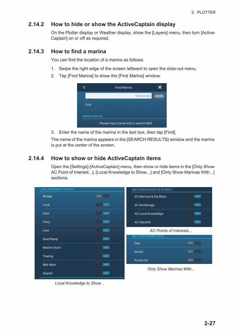
2. PLOTTER
2.14.2 How to hide or show the ActiveCaptain display
On the Plotter display or Weather display, show the [Layers] menu, then turn [Active-Captain] on or off as required.
2.14.3 How to find a marina
You can find the location of a marina as follows.
1. Swipe the right edge of the screen leftward to open the slide-out menu.
2. Tap [Find Marina] to show the [Find Marina] window.
3. Enter the name of the marina in the text box, then tap [Find].
The name of the marina appears in the [SEARCH RESULTS] window and the marina is put at the center of the screen.
2.14.4 How to show or hide ActiveCaptain items
Open the [Settings]-[ActiveCaptain] menu, then show or hide items in the [Only Show AC Point of Interest...], [Local Knowledge to Show...] and [Only Show Marinas With...] sections.
AC Points of Interests...
Local Knowledge to Show...
Only Show Marinas With...
2-27

2. PLOTTER
2.14.5 How to update the ActiveCaptain database
It is a good idea to keep the ActiveCaptain database up-to-date to ensure that you will always have the latest data.
Connect your NavNet TZtouch2 to the WLAN. Login to ActiveCaptain in the [Settings]-[ActiveCaptain] menu. Select [Update Database] to update the database. The mes-sage "Connecting" appears in the [Step] field. After you are connected to the data-base, [Step] displays the item being updated. [Progression] show update progress in percentage. It takes approx. 10 minutes to complete the update. Updating is done in the background so you can operate the equipment as necessary, although there may be some lag.
2.15 My Friends (Social Network)The My Friends feature marks (with a symbol), on the Plotter and Weather displays, the locations of the vessels registered to the My Friends function (see 2.15.1). A ves-sel must be equipped with NavNet TZ Touch 2 version 3.01 or higher, be logged into
its My TimeZero™ accounts and have My Friends activated. Only friends within the WLAN range are shown.
2.15.1 How to setup My Friends
1. Open the [Settings]-[General] menu.
2. Login to your My TimeZero™ account at the [SOCIAL NETWORK] section.
3. At the [Nickname] field in the [MY FRIENDS] section, the name used to register
your My TimeZero™ account is shown. If desired you can change the name. Tap the keyboard, then enter a name.
4. Tap [Manage My Friends] in the [MY FRIENDS] section.
5. Tap [+ Add].
6. Enter friend’s e-mail address then tap [Send].
7. When the friend approves your invitation, The “You have xx friend” will reflect the addition.
Hello, John Smith
2-28

2. PLOTTER
2.15.2 How to show or hide the My Friends display
On the Plotter display or Weather display, open the [Layers] menu, then turn [My Friends] on or off as required.
When the My Friends display is active, the vessels that you have registered (see paragraph 2.15.1) are marked with a symbol, as shown in the figure below. Tap the symbol to show detailed information about the vessel.
Furuno
Lat N 34°26.400’Lon E 135°07.104’
COG 179.7°
SOG 20.0 kn
Furuno
My Friends symbol
Vessel’s data(Name, geographical position,COG, SOG)
2-29

2. PLOTTER
This page is intentionally left blank.
2-30
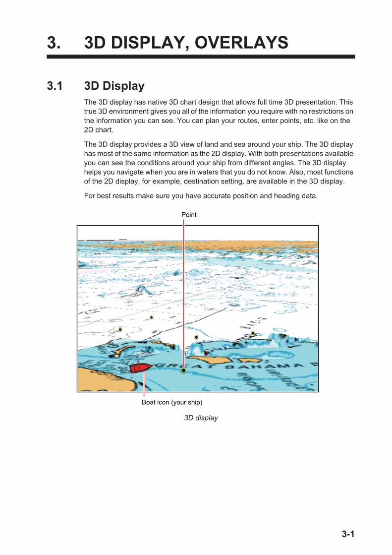
3. 3D DISPLAY, OVERLAYS
3.1 3D DisplayThe 3D display has native 3D chart design that allows full time 3D presentation. This true 3D environment gives you all of the information you require with no restrictions on the information you can see. You can plan your routes, enter points, etc. like on the 2D chart.
The 3D display provides a 3D view of land and sea around your ship. The 3D display has most of the same information as the 2D display. With both presentations available you can see the conditions around your ship from different angles. The 3D display helps you navigate when you are in waters that you do not know. Also, most functions of the 2D display, for example, destination setting, are available in the 3D display.
For best results make sure you have accurate position and heading data.
3D display
Boat icon (your ship)
Point
3-1

3. 3D DISPLAY, OVERLAYS
3.1.1 How to activate the 3D display
1. To switch between the 2D and 3D displays, tap the 2D/3D switch at the bottom left corner on the screen or drag upward as shown below. The icon is filled in white when the 3D display is active.
2. Tap the orientation mode switch to select an orientation mode.
3. Orientate the 3D display by dragging leftward or rightward with two fingers.
The 2D/3D display switch, orientation mode switch
The 2D/3D display switch alternates the 2D and 3D displays. The orientation mode switch selects the orientation, North up or Head up. In the North up mode, North is at 0°. When you change the viewpoint on the 3D display, the orientation mode switch shows the "North" icon. The arrow on the icon points toward North. To switch to North-up orientation, tap the switch.
Drag upward.
or
Orientationmode switch
: North-up
: Head-up
2D display:
3D display:
: North
2D/3Ddisplayswitch
3-2
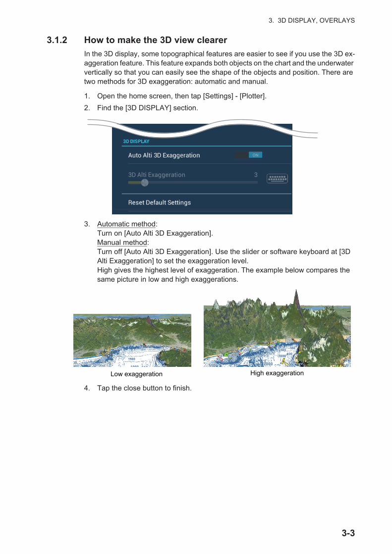
3. 3D DISPLAY, OVERLAYS
3.1.2 How to make the 3D view clearer
In the 3D display, some topographical features are easier to see if you use the 3D ex-aggeration feature. This feature expands both objects on the chart and the underwater vertically so that you can easily see the shape of the objects and position. There are two methods for 3D exaggeration: automatic and manual.
1. Open the home screen, then tap [Settings] - [Plotter].
2. Find the [3D DISPLAY] section.
3. Automatic method:Turn on [Auto Alti 3D Exaggeration].Manual method:Turn off [Auto Alti 3D Exaggeration]. Use the slider or software keyboard at [3D Alti Exaggeration] to set the exaggeration level.High gives the highest level of exaggeration. The example below compares the same picture in low and high exaggerations.
4. Tap the close button to finish.
High exaggerationLow exaggeration
3-3

3. 3D DISPLAY, OVERLAYS
3.2 OverlaysFive overlays are available for the plotter display: depth shading, satellite, radar, tide information, and tidal current.
3.2.1 Depth shading overlay
The depth shading overlay shows the depths in different color (the default settings are red (shallow), yellow (medium) and blue (deep)). This overlay is available in both 2D and 3D presentations. Use this overlay to find depths. To show the depth shading overlay, open the [Layers] menu then turn [Depth Shading] on or off.
Depth shading
You can turn the automatic depth shading color scale adjustment on or off (auto, manual) by tapping the “A”.Automatic mode:Depth shading is set according to the depth shading values set in the menu (Settings→Plotter).Manual mode: 1) Tap the minimum value (maximum value) at left side (right side) of scale.2) Drag the slider bar at right side of screen to set value.3) Tap [End] to complete.
Automode
Manualmode
Maximumvalue
Minimumvalue
3-4

3. 3D DISPLAY, OVERLAYS
Depth shading settings
The depth shading settings are in the [Plotter] menu.
[Auto Depth Shading Color Scale]: Turn automatic depth shading color scale selec-tion on or off.
[Minimum Value]: Set the minimum depth range for which to show depth shading, with the software keyboard. This is available when [Auto Depth Shading Color Scale] is set to [OFF].
[Maximum Value]: Set the maximum depth range for which to show depth shading, with the software keyboard. This is available when [Auto Depth Shading Color Scale] is set to [OFF].
[Depth Color Shade]: Select how to display the depth colors among [Classic Hue], [Inverted Classic Hue], [Red Hue], [Blue Hue], [Green Hue] and [Yellow Hue].
[Depth Shading Transparency]: Adjust the degree of transparency of the depth shading overlay.
Colors of the rainbow
Shades of red
3-5
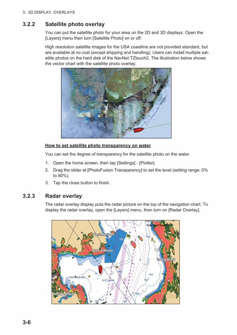
3. 3D DISPLAY, OVERLAYS
3.2.2 Satellite photo overlay
You can put the satellite photo for your area on the 2D and 3D displays. Open the[Layers] menu then turn [Satellite Photo] on or off.
High resolution satellite images for the USA coastline are not provided standard, but are available at no cost (except shipping and handling). Users can install multiple sat-ellite photos on the hard disk of the NavNet TZtouch2. The illustration below shows the vector chart with the satellite photo overlay.
How to set satellite photo transparency on water
You can set the degree of transparency for the satellite photo on the water.
1. Open the home screen, then tap [Settings] - [Plotter].
2. Drag the slider at [PhotoFusion Transparency] to set the level (setting range: 0% to 80%).
3. Tap the close button to finish.
3.2.3 Radar overlay
The radar overlay display puts the radar picture on the top of the navigation chart. To display the radar overlay, open the [Layers] menu, then turn on [Radar Overlay].
3-6

3. 3D DISPLAY, OVERLAYS
How to switch between stand-by and TX; match overlay and radar ranges
Tap the [TX] icon at the bottom right corner to set the radar in transmit or stand-by state. The icon is filled in white when the radar is transmitting; blue in stand-by.
To match overlay and radar ranges, open the home screen, tap [Settings] - [Plotter], then turn on [Range Link]. You can sync the ranges with the Sync icon (at the lower right corner) when [Range Link] is turned off.
How to set the level of the radar echo transparency
Open the home screen, then tap [Settings] - [Plotter]. Drag the slider at [Radar Trans-parency] to set the transparency level.
How to adjust radar gain, sea, rain
The gain and sea and rain clutters can be adjusted from the navigation data display. See sections 6.3 - 6.5.
How to select the echo color
Open the home screen, then tap Settings - [Plotter] - [Echo Color]. Tap [Multicolor], [Green] or [Yellow].
How to acquire a target for ARPA
A target can be acquired for ARPA. See paragraph 6.27.2.
Note: The radar picture can look "out of focus" on long ranges when the range link is active. This out of focus appearance does not indicate a problem, because it is a char-acteristic of the digital zoom.
: Stand-by
: TXTap to sync radar and overlay ranges.
TX
TXTX
24 NM
3-7

3. 3D DISPLAY, OVERLAYS
3.2.4 Tide info overlay
Your system carries worldwide tide information, shown with tide icons, which you can
overlay on the plotter display. The tide icon ( ) appears at the locations of tidal record-
ing stations.
How to display the tide info overlay
Open the [Layers] menu, then tap [Tide Heights].
The arrow on the tide icon is up when the tide is high; down when the tide is low. The tide icon is gray and yellow according to the tide state. The tide icon is all yellow when the tide is high completely and all gray when the tide is low completely.
How to change the size of the tide icon
1. Open the home screen, then tap [Settings] - [Plotter].
2. Drag the slider at [Tide/Current Icons Size] to set size (setting range: 50% to 150%).
3. Tap the close button to finish.
How to show the tide information
Tap a tide icon to display the tide height graphic in a pop-up window, an exam-ple of which is show in the right figure.
Tide icon (yellowand/orgray)
: Up arrow indicates the tide is going high. : Down arrow indicates the tide is going low.
: No arrow indicates no change in tide.
3-8
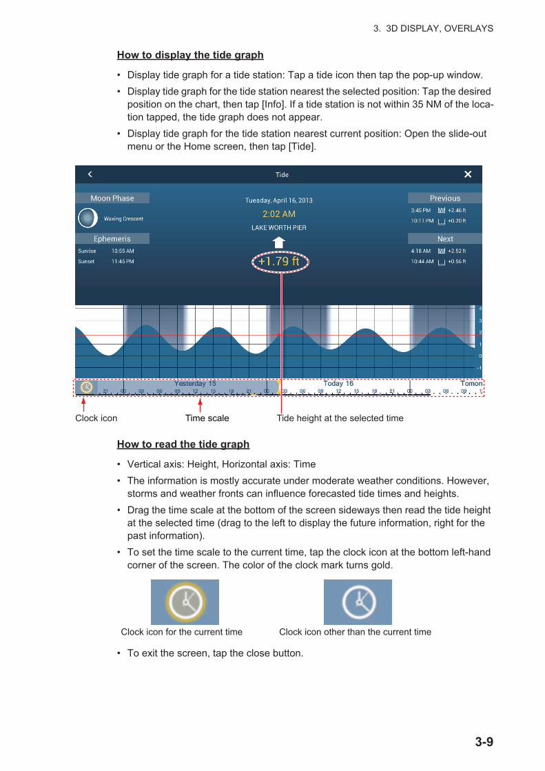
3. 3D DISPLAY, OVERLAYS
How to display the tide graph
• Display tide graph for a tide station: Tap a tide icon then tap the pop-up window.
• Display tide graph for the tide station nearest the selected position: Tap the desired position on the chart, then tap [Info]. If a tide station is not within 35 NM of the loca-tion tapped, the tide graph does not appear.
• Display tide graph for the tide station nearest current position: Open the slide-out menu or the Home screen, then tap [Tide].
How to read the tide graph
• Vertical axis: Height, Horizontal axis: Time
• The information is mostly accurate under moderate weather conditions. However, storms and weather fronts can influence forecasted tide times and heights.
• Drag the time scale at the bottom of the screen sideways then read the tide height at the selected time (drag to the left to display the future information, right for the past information).
• To set the time scale to the current time, tap the clock icon at the bottom left-hand corner of the screen. The color of the clock mark turns gold.
• To exit the screen, tap the close button.
Time scale Tide height at the selected timeClock icon
Clock icon for the current time Clock icon other than the current time
3-9
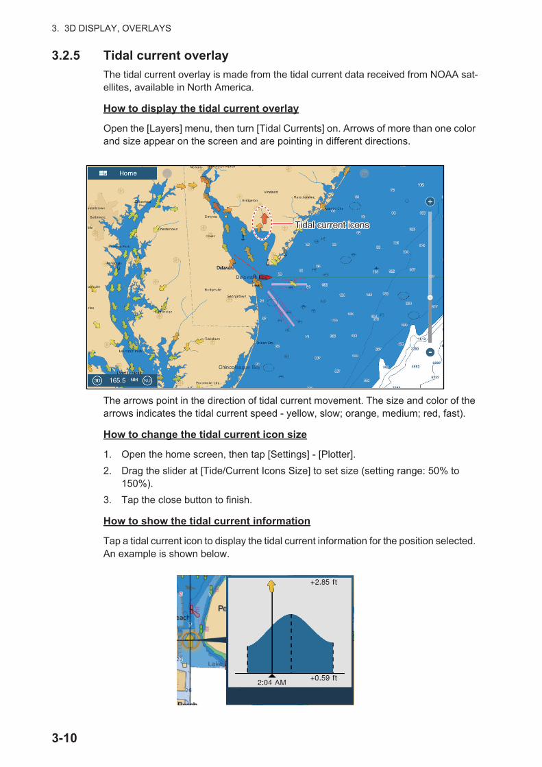
3. 3D DISPLAY, OVERLAYS
3.2.5 Tidal current overlay
The tidal current overlay is made from the tidal current data received from NOAA sat-ellites, available in North America.
How to display the tidal current overlay
Open the [Layers] menu, then turn [Tidal Currents] on. Arrows of more than one color and size appear on the screen and are pointing in different directions.
The arrows point in the direction of tidal current movement. The size and color of the arrows indicates the tidal current speed - yellow, slow; orange, medium; red, fast).
How to change the tidal current icon size
1. Open the home screen, then tap [Settings] - [Plotter].
2. Drag the slider at [Tide/Current Icons Size] to set size (setting range: 50% to 150%).
3. Tap the close button to finish.
How to show the tidal current information
Tap a tidal current icon to display the tidal current information for the position selected. An example is shown below.
Tidal current iconsTidal current icons
3-10
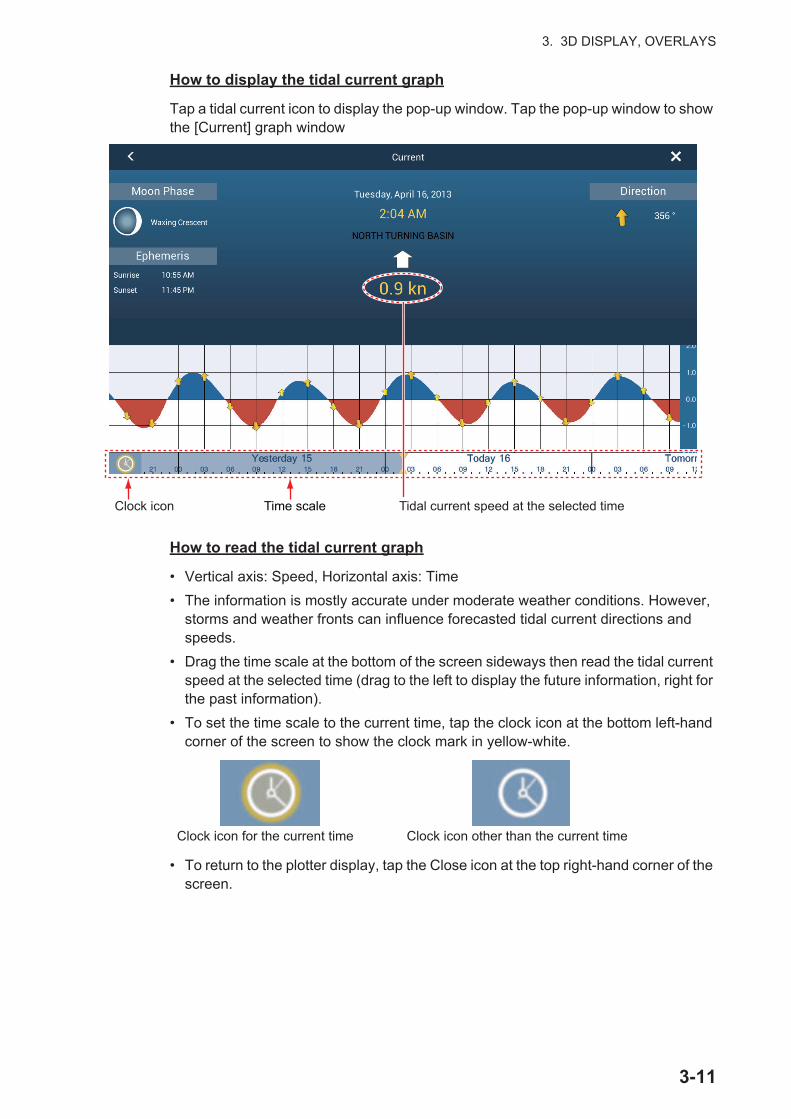
3. 3D DISPLAY, OVERLAYS
How to display the tidal current graph
Tap a tidal current icon to display the pop-up window. Tap the pop-up window to show the [Current] graph window
How to read the tidal current graph
• Vertical axis: Speed, Horizontal axis: Time
• The information is mostly accurate under moderate weather conditions. However, storms and weather fronts can influence forecasted tidal current directions and speeds.
• Drag the time scale at the bottom of the screen sideways then read the tidal current speed at the selected time (drag to the left to display the future information, right for the past information).
• To set the time scale to the current time, tap the clock icon at the bottom left-hand corner of the screen to show the clock mark in yellow-white.
• To return to the plotter display, tap the Close icon at the top right-hand corner of the screen.
Time scale Tidal current speed at the selected timeClock icon
Clock icon for the current time Clock icon other than the current time
3-11

3. 3D DISPLAY, OVERLAYS
This page is intentionally left blank.
3-12
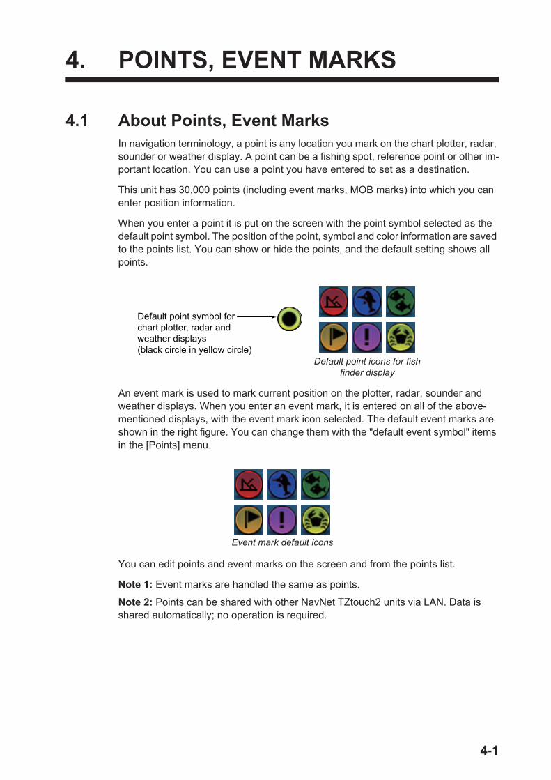
4. POINTS, EVENT MARKS
4.1 About Points, Event MarksIn navigation terminology, a point is any location you mark on the chart plotter, radar, sounder or weather display. A point can be a fishing spot, reference point or other im-portant location. You can use a point you have entered to set as a destination.
This unit has 30,000 points (including event marks, MOB marks) into which you can enter position information.
When you enter a point it is put on the screen with the point symbol selected as the default point symbol. The position of the point, symbol and color information are saved to the points list. You can show or hide the points, and the default setting shows all points.
An event mark is used to mark current position on the plotter, radar, sounder and weather displays. When you enter an event mark, it is entered on all of the above-mentioned displays, with the event mark icon selected. The default event marks are shown in the right figure. You can change them with the "default event symbol" items in the [Points] menu.
You can edit points and event marks on the screen and from the points list.
Note 1: Event marks are handled the same as points.
Note 2: Points can be shared with other NavNet TZtouch2 units via LAN. Data is shared automatically; no operation is required.
Default point symbol for chart plotter, radar and weather displays(black circle in yellow circle)
Default point icons for fish finder display
Event mark default icons
4-1
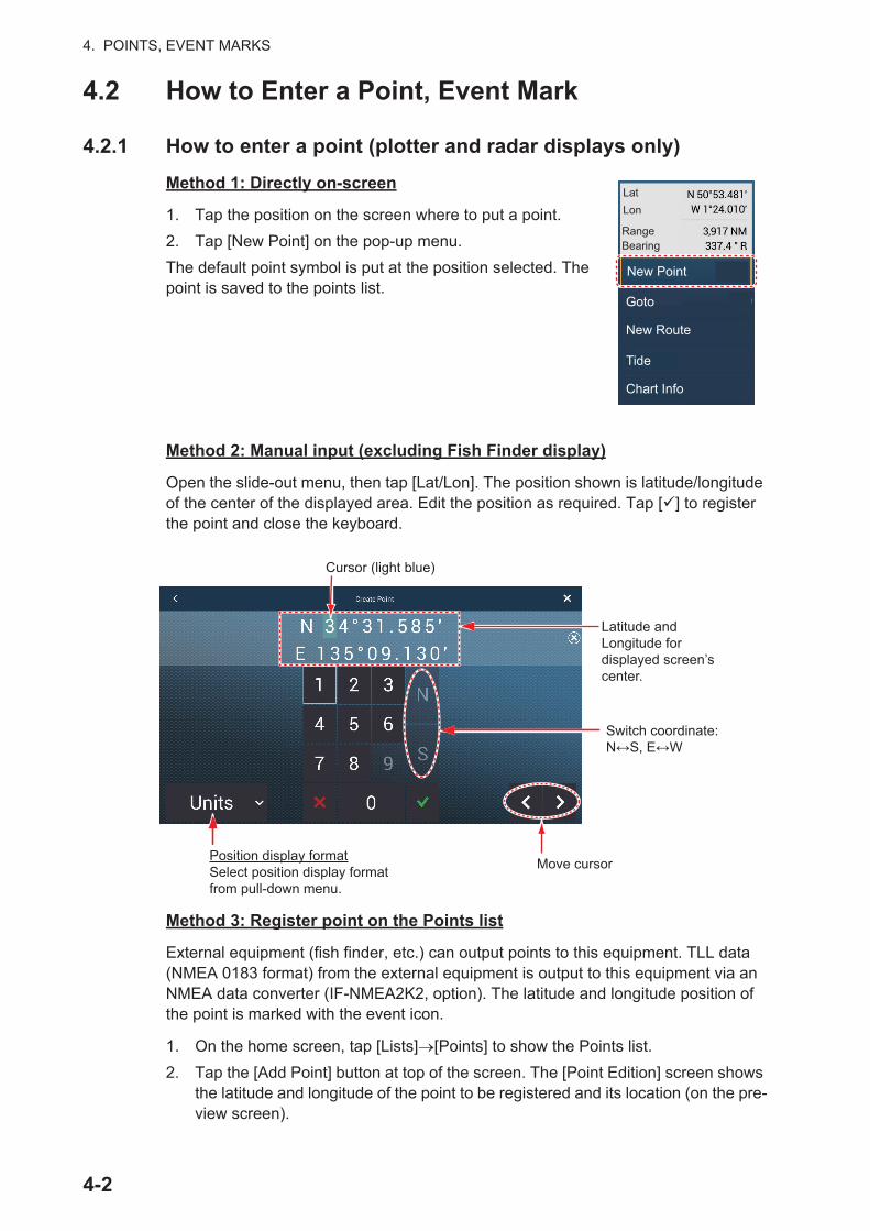
4. POINTS, EVENT MARKS
4.2 How to Enter a Point, Event Mark
4.2.1 How to enter a point (plotter and radar displays only)
Method 1: Directly on-screen
1. Tap the position on the screen where to put a point.
2. Tap [New Point] on the pop-up menu.
The default point symbol is put at the position selected. The point is saved to the points list.
Method 2: Manual input (excluding Fish Finder display)
Open the slide-out menu, then tap [Lat/Lon]. The position shown is latitude/longitude of the center of the displayed area. Edit the position as required. Tap [ ] to register the point and close the keyboard.
Method 3: Register point on the Points list
External equipment (fish finder, etc.) can output points to this equipment. TLL data (NMEA 0183 format) from the external equipment is output to this equipment via an NMEA data converter (IF-NMEA2K2, option). The latitude and longitude position of the point is marked with the event icon.
1. On the home screen, tap [Lists] [Points] to show the Points list.
2. Tap the [Add Point] button at top of the screen. The [Point Edition] screen shows the latitude and longitude of the point to be registered and its location (on the pre-view screen).
LatLon
RangeBearing
New Point
Goto
New Route
Tide
Chart Info
Cursor (light blue)
Latitude and Longitude for displayed screen’s center.
Move cursor
Switch coordinate:N↔S, E↔W
Position display formatSelect position display format from pull-down menu.
4-2
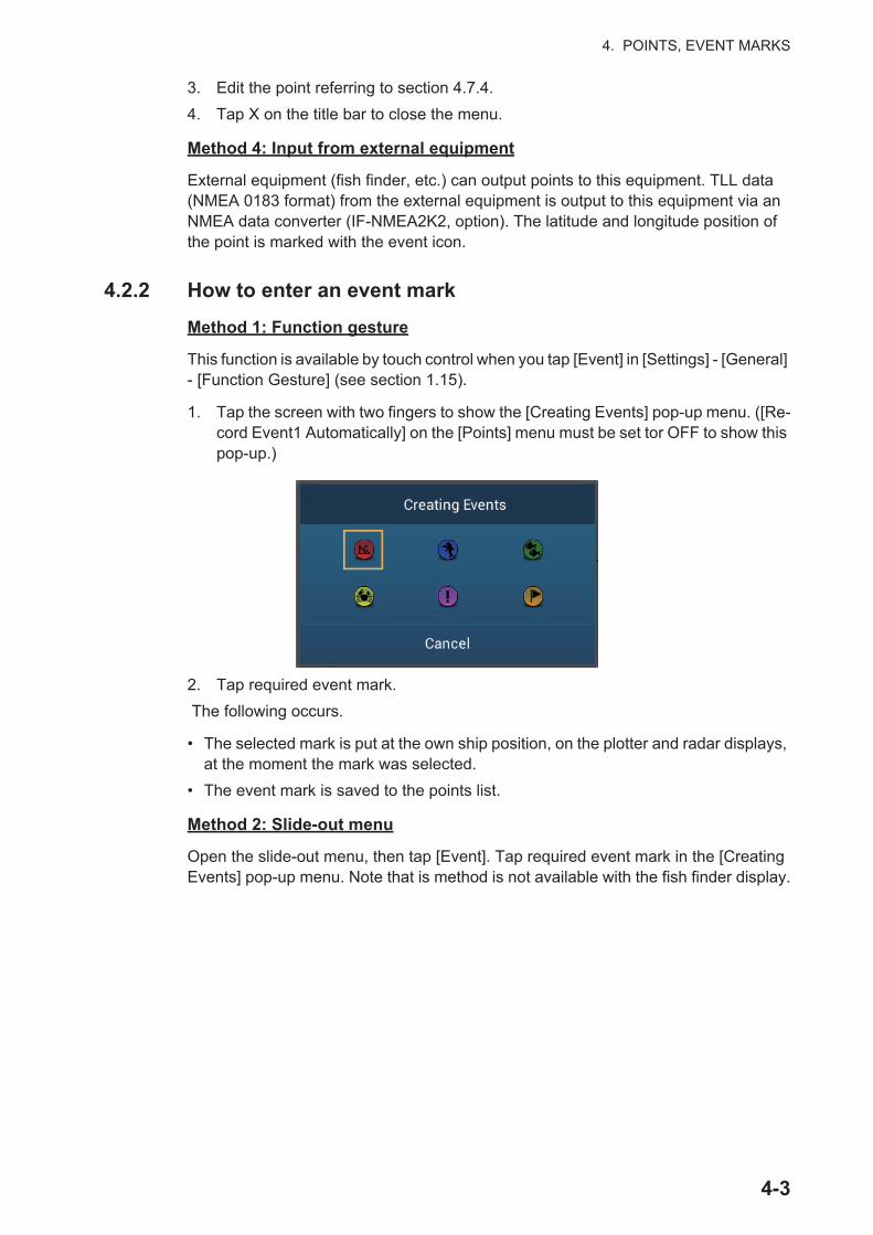
4. POINTS, EVENT MARKS
3. Edit the point referring to section 4.7.4.
4. Tap X on the title bar to close the menu.
Method 4: Input from external equipment
External equipment (fish finder, etc.) can output points to this equipment. TLL data (NMEA 0183 format) from the external equipment is output to this equipment via an NMEA data converter (IF-NMEA2K2, option). The latitude and longitude position of the point is marked with the event icon.
4.2.2 How to enter an event mark
Method 1: Function gesture
This function is available by touch control when you tap [Event] in [Settings] - [General] - [Function Gesture] (see section 1.15).
1. Tap the screen with two fingers to show the [Creating Events] pop-up menu. ([Re-cord Event1 Automatically] on the [Points] menu must be set tor OFF to show this pop-up.)
2. Tap required event mark.
The following occurs.
• The selected mark is put at the own ship position, on the plotter and radar displays, at the moment the mark was selected.
• The event mark is saved to the points list.
Method 2: Slide-out menu
Open the slide-out menu, then tap [Event]. Tap required event mark in the [Creating Events] pop-up menu. Note that is method is not available with the fish finder display.
4-3

4. POINTS, EVENT MARKS
4.3 How to Display Point, Event Mark InformationTap a point or event mark to display its information. The information shown depends on the display in use and the object tapped.
Point, event mark information(Plotter and radar displays) Event mark information
(Sounder display)
4-4
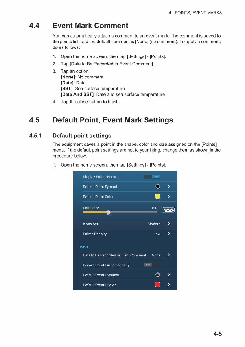
4. POINTS, EVENT MARKS
4.4 Event Mark CommentYou can automatically attach a comment to an event mark. The comment is saved to the points list, and the default comment is [None] (no comment). To apply a comment, do as follows:
1. Open the home screen, then tap [Settings] - [Points].
2. Tap [Data to Be Recorded in Event Comment].
3. Tap an option.[None]: No comment[Date]: Date[SST]: Sea surface temperature[Date And SST]: Date and sea surface temperature
4. Tap the close button to finish.
4.5 Default Point, Event Mark Settings
4.5.1 Default point settings
The equipment saves a point in the shape, color and size assigned on the [Points] menu. If the default point settings are not to your liking, change them as shown in the procedure below.
1. Open the home screen, then tap [Settings] - [Points].
4-5

4. POINTS, EVENT MARKS
2. Tap [Default Point Symbol], [Default Point Color], or [Icons Set].
3. Tap required option.To change the point size, operate the slider bar (or software keyboard) for [Points Size].
4. Tap the close button to finish.
Icons Set[Default Point Symbol]
[Default Point Color]
[Icons Set]
4-6

4. POINTS, EVENT MARKS
4.5.2 Default event mark settings
1. Open the home screen, then tap [Settings] - [Points].
2. Tap [Default Event1 Symbol], [Default Event1 Color], or [Icons Set].
3. Tap required option.To change the point size, operate the slider bar (or software keyboard) for [Points Size].
4. Tap the close button to finish.
Note: If you do not require event marks 2 - 6, turn on [Record Event1 Automatically] in the [Points] menu. In this case, the pop-up menu does not appear when you register an event mark. See section 4.2.2.
4.6 How to Find Number of Points UsedOpen the home screen, then tap [Settings] - [General]. Find [Points] in the [DATA USAGE] section. In the example below, 16 of 30,000 points have been used.
Icons Set[Default Event1 Symbol]
[Default Event1 Color]
99/100
4-7

4. POINTS, EVENT MARKS
4.7 Points ListYou can check and edit all created points in the points list. The following point data is saved for each point.
4.7.1 How to show the points list
1. Open the home screen, then tap [Lists].
2. Tap [Points] to open the points list.
4.7.2 How to sort the points list
The points list can be sorted by [Name], [Icon], [Color] or [Distance] (from own ship).
1. Open the home screen, then tap [Lists].
2. Tap [Points] to open the points list.
3. Tap the appropriate sort button, at the top of the list.
4.7.3 How to search the points list
You can search the points list by [Name], [Icon], [Color].
1. Open the home screen, then tap [Lists].
2. Tap [Points] to open the points list.
3. Tap the appropriate sort button, at the top of the list. This will be the main method for the search.
4. Tap the name, icon or color as appropriate, from the above-left of a point in the list (see the figure below for reference). For the purpose of this example, the list in the following figure is sorted by name.
• Name• Icon
• Location (latitude/longitude)• Comment
• Color• Distance from own ship.
Sort buttonsSort buttonsPoint informationPoint information
4-8
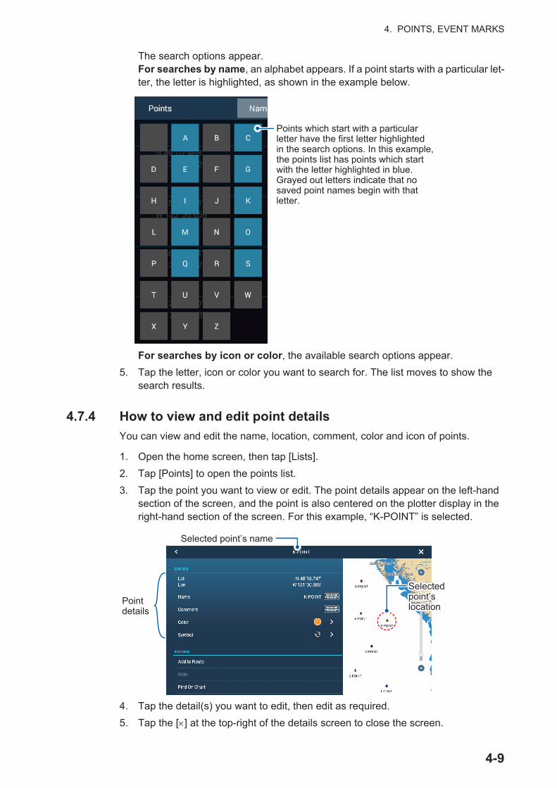
4. POINTS, EVENT MARKS
The search options appear.For searches by name, an alphabet appears. If a point starts with a particular let-ter, the letter is highlighted, as shown in the example below.
For searches by icon or color, the available search options appear.
5. Tap the letter, icon or color you want to search for. The list moves to show the search results.
4.7.4 How to view and edit point details
You can view and edit the name, location, comment, color and icon of points.
1. Open the home screen, then tap [Lists].
2. Tap [Points] to open the points list.
3. Tap the point you want to view or edit. The point details appear on the left-hand section of the screen, and the point is also centered on the plotter display in the right-hand section of the screen. For this example, “K-POINT” is selected.
4. Tap the detail(s) you want to edit, then edit as required.
5. Tap the [ ] at the top-right of the details screen to close the screen.
Points which start with a particular letter have the first letter highlighted in the search options. In this example, the points list has points which start with the letter highlighted in blue.Grayed out letters indicate that no saved point names begin with that letter.
Selected point’s name
Point details
Selected point’s location
Selected point’s location
4-9

4. POINTS, EVENT MARKS
4.7.5 How to edit a point on the screen
1. Tap the point to edit to show the pop-up menu.
2. To change the name of the point, tap [Name] to display the software keyboard. Change the name as follows:
1) Tap the character to edit.
2) Tap an alphanumeric character on the software keyboard.
3) Repeat steps 1) and 2) to complete the name. The maximum length of the name is 20 alphanumeric characters.
4) Tap to confirm.
Point editing tools
Switch to the numeric software keyboard.
Clear all characters.
Cursor
Switch to the alphabet software keyboard.
Shift cursor.
Delete character selected.
Confirm entry.
Close keyboardwithout saving.
4-10

4. POINTS, EVENT MARKS
3. To change the position, tap [Edit Pos] to display the software keyboard. Set the position referring to the instructions in step 2.
4. Tap [Color] to change the color of the point symbol.
5. Tap [Symbol] to change the point symbol.
6. Tap [Comment] to enter a comment, with the software keyboard.
7. Tap to confirm.
4.8 How to Move a PointYou can move a point by two methods, on the screen and from the points list.
4.8.1 How to move a point on the screen
1. Tap the point to move, then select [Move] from the pop-up menu. The icon shown right is put on the point.
2. Drag and drop the point to its new location.
3. Tap [End Move] at the top right-hand corner of the screen to finish.
Note 1: If [Move Tool on Long Push] is set to ON (in the [Settings]-[General] menu, a point can be moved by long-pushing on the point for three seconds.
Note 2: A point can be moved to the position you specify. Tap the point and [Edit Pos], then enter the position from the keyboard.
Switch latitude andlongitude coordinates.
TapPosition display formatSelect position display format from pull-down menu.
4-11
4. POINTS, EVENT MARKS
4.8.2 How to move a point from the points list
1. Open the home screen, then tap [Lists]
2. Tap [Points] to open the points list.
3. Tap the point to move to show the editing window.You can also edit the position of a point from the screen. Tap the point then tap [Edit Pos] on the pop-up menu.
4. Tap [Lat Lon] to display the numeric keyboard.
5. Enter the position then tap [ ] to confirm.
6. Tap the close button to finish.
4.9 How to Delete a PointYou can delete points by two methods, on the screen and from the points list.
Note: The point currently set as a go to point cannot be deleted.
4.9.1 How to delete a point on the screen
Tap the point to delete then tap [Delete] on the pop-up menu.
4.9.2 How to delete a point from the points list
1. Open the home screen, then tap [Lists].
2. Tap [Points] to open the points list.
3. Tap the point to delete then tap [Delete]. The point disappears from both the screen and the points list.
4. Tap the close button to finish.
4.9.3 How to delete all points
You can delete points and routes collectively except for points included in the active route.
1. Open the home screen, then tap [Settings] - [Points].
2. Tap [Delete All Points & Routes].
3. You are asked if you are sure to delete all points and routes. Tap [OK].
4. Tap the close button to finish.
4-12
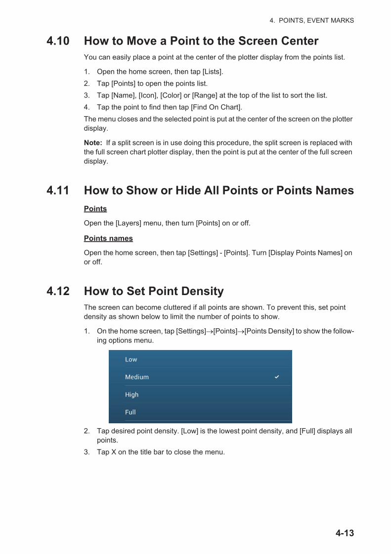
4. POINTS, EVENT MARKS
4.10 How to Move a Point to the Screen CenterYou can easily place a point at the center of the plotter display from the points list.
1. Open the home screen, then tap [Lists].
2. Tap [Points] to open the points list.
3. Tap [Name], [Icon], [Color] or [Range] at the top of the list to sort the list.
4. Tap the point to find then tap [Find On Chart].
The menu closes and the selected point is put at the center of the screen on the plotter display.
Note: If a split screen is in use doing this procedure, the split screen is replaced with the full screen chart plotter display, then the point is put at the center of the full screen display.
4.11 How to Show or Hide All Points or Points Names
Points
Open the [Layers] menu, then turn [Points] on or off.
Points names
Open the home screen, then tap [Settings] - [Points]. Turn [Display Points Names] on or off.
4.12 How to Set Point DensityThe screen can become cluttered if all points are shown. To prevent this, set point density as shown below to limit the number of points to show.
1. On the home screen, tap [Settings] [Points] [Points Density] to show the follow-ing options menu.
2. Tap desired point density. [Low] is the lowest point density, and [Full] displays all points.
3. Tap X on the title bar to close the menu.
4-13

4. POINTS, EVENT MARKS
4.13 How to Go to a PointTap the point (including MOB mark) to go to among the three methods shown below.
• Select the point on the screen
• Select a position on the screen
• Select the point from the points list
After you have selected a point, you can do the following.
• Restart the cross-track error (XTE) indication.
• Stop and restart Goto. (Tap the boat icon to display the pop-up menu. Tap [Stop Nav] and [Restart Nav] respectively.)
Note: Before you try to go to a point, make sure that the path to the point is clear. Make sure to zoom your chart to check for hazards which appear on a smaller scale.
4.13.1 How to go to an on-screen point
1. Tap the desired point to show the pop-up menu.
2. Tap [Goto].
The following occurs:
Go to point
XTE (Cross-track Error)
Boat icon (current position)
How arrival is “judged”
Arrival area
[Circle and Cross Line]
Cross line
Ship arrives to arrival area or ship passes an imaginary perpendicular line passing through center of destination waypoint.
[Circle]Ship arrives to arrival area.
Cross line
[Cross Line]Ship passes an imaginary perpendicular line passing through center of destina-tion waypoint.
Yellow line: Shortest course from the current position to the go to point.
Thick red dashed line: Course between the go to point and the point where the [Go To] function starts.
Arrival area (Appears when you select [Circle and Cross Line] or [Circle] in the [Routes] - [Waypoint Switching Mode].)
XTE lines (Red: port, Green: starboard)
00
4-14

4. POINTS, EVENT MARKS
• The go to point is highlighted.
• A thick red dashed line and a yellow line appear. The thick red dashed line is the course to follow to get to the point. The yellow line is the shortest course from the current position to the go to point.
• The arrival area marker appears if activated on the menu (see paragraph 5.11.5).
• The XTE lines, red for port side, green for starboard side, appear. You can show or hide these lines with [Display XTE Lines] in the [Settings] - [Routes] menu.
• The route is saved to the routes list.
Note: If you want to be notified when you reach the go to point (the end of a route), turn on [End of Route Notification] in the [Routes] menu (see paragraph 5.11.9). The message "End of Route" appears when you reach the end of a route. For the arrival timing, see paragraph 5.11.5.
4.13.2 How to go to a position selected on screen
You can set a position as a point to go to without saving the point. The point is erased when the navigation is canceled or the power is turned off.
1. Tap the position to set as the go to point to show the pop-up menu.
2. Tap [Goto].
The following occurs:
• The go to point is highlighted.
• A thick red dashed line and a yellow line appear. The thick red dashed line is the course to follow to get to the point. The yellow line is the shortest course from the current position to the go to point.
• The arrival area marker appears if activated on the menu (see paragraph 5.11.5).
• The XTE lines, red for port side, green for starboard side, appear. You can show or hide these lines with [Display XTE Lines] in the [Settings] - [Routes] menu.
Note: If you want to be notified when you reach the go to point (the end of a route), turn on [End of Route Notification] in the [Routes] menu (see paragraph 5.11.9). Then the message "End of Route" appears when you reach the end of a route. For the ar-rival timing, see paragraph 5.11.5.
Go to point
XTE (Cross-track Error)
Boat icon (current position)
Yellow line: Shortest course from the current position to the go to point.
Thick red dashed line: Course between the go to point and the point where the [Go To] function starts.
Arrival area (Appears when you select [Circle and Cross Line] or [Circle] in the [Routes] - [Waypoint Switching Mode].)
XTE lines (Red: port, Green: starboard)
00
4-15

4. POINTS, EVENT MARKS
4.13.3 How to go to a point selected from the points list
1. Open the home screen, then tap [Lists].
2. Tap [Points] to open the points list.
3. Tap [Name], [Icon], [Color] or [Range] at the top of the list to sort the list.
4. Tap the point to go to, then tap [Goto].
5. Tap the close button to close the points list.
The following occurs:
• The go to point is highlighted.
• A thick red dashed line and a yellow line appear. The thick red dashed line is the course to follow to get to the point. The yellow line is the shortest course from the current position to the go to point.
• The arrival area marker appears if activated on the menu (see paragraph 5.11.5).
• The XTE lines, red for port side, green for starboard side, appear. You can show or hide these lines with [Display XTE Lines] in the [Settings] - [Routes] menu.
Note: If you want to be notified when you reach the go to point (the end of a route), turn on [End of Route Notification] in the [Routes] menu (see paragraph 5.11.9). Then the message "End of Route" appears when you reach the end of a route. For the ar-rival timing, see paragraph 5.11.5.
4.13.4 How to use the NAVpilot to steer to a point
When you select a point to follow and the NAVpilot is engaged and activated in the system, the message "DO YOU WANT TO NAVIGATE USING THE NAVPILOT?" ap-pears. Tap [Yes] to have the NAVpilot steer the vessel, then the NAVpilot automati-cally goes into the Nav mode.
NAV mode indicator
Goto point
Heading(digital)
Heading(analog)
Tap [Auto] or [Nav].Tap NAVpilot control box to switch mode.
4-16

4. POINTS, EVENT MARKS
Auto mode
* Selectable between 2° and 30° with [Autopilot Step] in the [Routes] menu.
Use the course adjustment buttons to set the course to steer. Tap the double arrow for coarse adjustment, and single arrow for adjustment in 1° steps. The course to steer indicator moves with adjustment.
To go to the stand-by mode, tap the NAVpilot control box.
4.13.5 How to display the point information for the active goto point
1. Tap the line between own ship and the goto point to show the pop-up menu.
2. Tap [Detail] to show the [Route Detail] window.
3. Tap the close button to finish.
Description of Route Detail window
Colored vertical bars: The bars at the left edge of the screen are colored according to the status of the goto point. Gray: Starting pointYellow: Goto point
[ID]: Point no. ([Start] or [Goto])[BTW]: Bearing to goto point[SPEED]: Speed to goto point[DISTANCE]: Distance from starting point[TOTAL]: Total distance from start to goto point[TTG]: Time to go to the goto point, using speed shown in [SPEED] column.[TOTAL]: The time from start to the goto point.
Blue arrow: Course to steerGray arrow: Heading
Set course
Heading
Coarse adj. button*Red: minus, Green: plus
Fine adj. button(1°)Red: minus, Green: plus
4-17
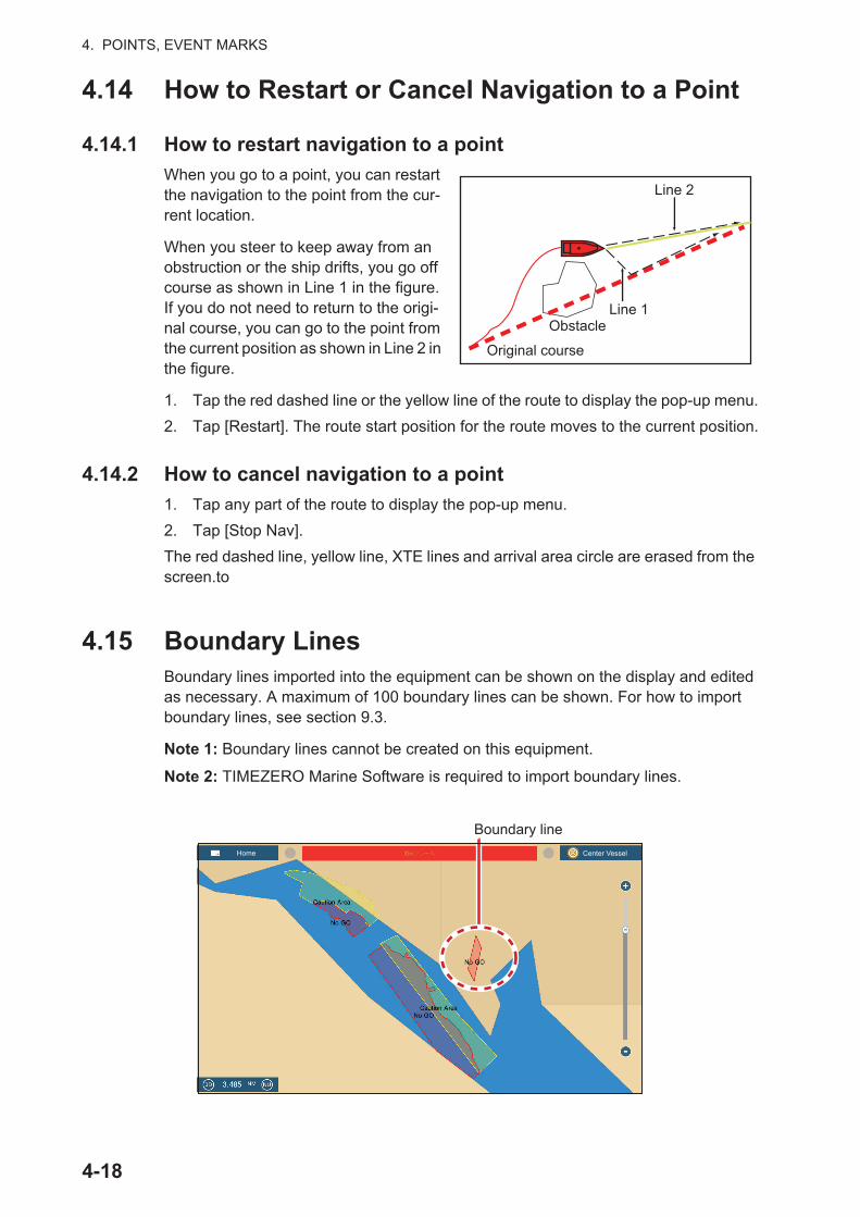
4. POINTS, EVENT MARKS
4.14 How to Restart or Cancel Navigation to a Point
4.14.1 How to restart navigation to a point
When you go to a point, you can restart the navigation to the point from the cur-rent location.
When you steer to keep away from an obstruction or the ship drifts, you go off course as shown in Line 1 in the figure. If you do not need to return to the origi-nal course, you can go to the point from the current position as shown in Line 2 in the figure.
1. Tap the red dashed line or the yellow line of the route to display the pop-up menu.
2. Tap [Restart]. The route start position for the route moves to the current position.
4.14.2 How to cancel navigation to a point
1. Tap any part of the route to display the pop-up menu.
2. Tap [Stop Nav].
The red dashed line, yellow line, XTE lines and arrival area circle are erased from the screen.to
4.15 Boundary LinesBoundary lines imported into the equipment can be shown on the display and edited as necessary. A maximum of 100 boundary lines can be shown. For how to import boundary lines, see section 9.3.
Note 1: Boundary lines cannot be created on this equipment.
Note 2: TIMEZERO Marine Software is required to import boundary lines.
Line 2
Line 1Obstacle
Original course
Boundary lineHome Center Vessel
4-18

4. POINTS, EVENT MARKS
4.15.1 How to show or hide boundary lines
On the Layers menu, turn [Points] [ON] or [OFF].
4.15.2 How to find boundary lines data
Tap a boundary line to show its data. The data includes latitude and longitude position of the boundary line, and range and bearing from own ship to the boundary line.
4.15.3 How to find the number of boundary points used
On the home screen, tap [Settings] - [General]. Find [Boundaries] in the [DATA US-AGE] section. In the example below, 99 boundary points out of 100 have been used.
4.15.4 How to delete boundary lines
How to delete an on-screen boundary line
Tap a boundary line to show the pop-up menu. Tap [Delete] to delete the line from the screen.
How to delete all boundary lines
1. At the home screen, tap [Settings] [Points] [Delete All Boundaries]. The mes-sage "THIS ACTION WIL DELETE PERMANENTLY ALL BOUNDARIES ARE YOU SURE TO CONTINUE?" appears.
2. Tap [OK].
3. Tap X on the title bar to close the menu.
LatLon
RangeBearing
Name
Color
Pattern
Comment
Delete
99/100
4-19
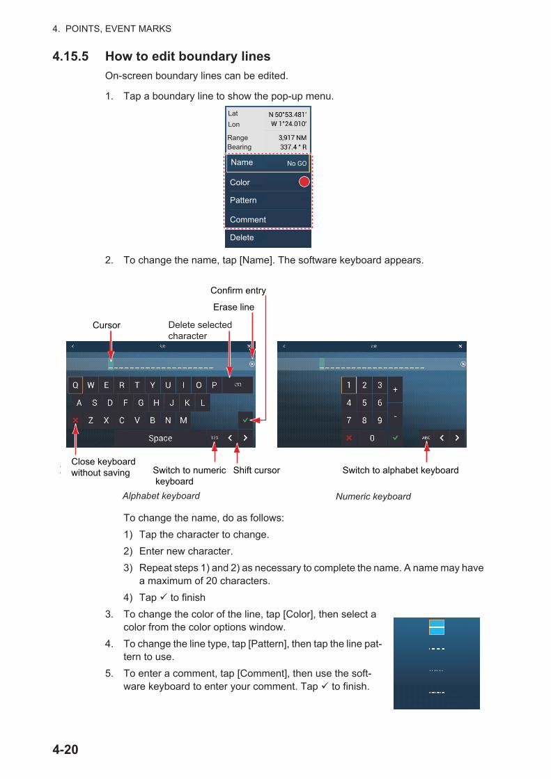
4. POINTS, EVENT MARKS
4.15.5 How to edit boundary lines
On-screen boundary lines can be edited.
1. Tap a boundary line to show the pop-up menu.
2. To change the name, tap [Name]. The software keyboard appears.
To change the name, do as follows:
1) Tap the character to change.
2) Enter new character.
3) Repeat steps 1) and 2) as necessary to complete the name. A name may have a maximum of 20 characters.
4) Tap to finish
3. To change the color of the line, tap [Color], then select a color from the color options window.
4. To change the line type, tap [Pattern], then tap the line pat-tern to use.
5. To enter a comment, tap [Comment], then use the soft-ware keyboard to enter your comment. Tap to finish.
LatLon
RangeBearing
Name
Color
Pattern
Comment
Delete
Confirmentry
Alphabet keyboard
Numeric keyboard
Switch to alphabet keyboardShift cursorSwitch to numeric keyboard
Close keyboard without saving
Cursor Delete selectedcharacter
Erase line
Confirm entry
Alphabet keyboard
4-20
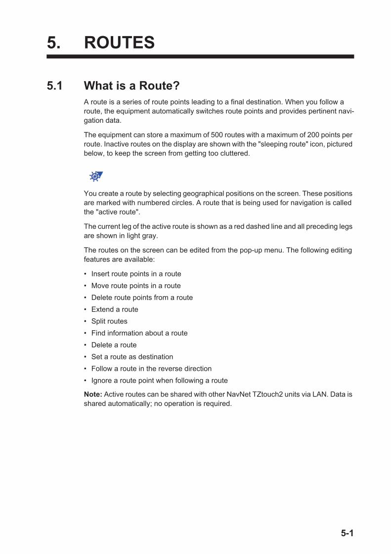
5. ROUTES
5.1 What is a Route?A route is a series of route points leading to a final destination. When you follow a route, the equipment automatically switches route points and provides pertinent navi-gation data.
The equipment can store a maximum of 500 routes with a maximum of 200 points per route. Inactive routes on the display are shown with the "sleeping route" icon, pictured below, to keep the screen from getting too cluttered.
You create a route by selecting geographical positions on the screen. These positions are marked with numbered circles. A route that is being used for navigation is called the "active route".
The current leg of the active route is shown as a red dashed line and all preceding legs are shown in light gray.
The routes on the screen can be edited from the pop-up menu. The following editing features are available:
• Insert route points in a route
• Move route points in a route
• Delete route points from a route
• Extend a route
• Split routes
• Find information about a route
• Delete a route
• Set a route as destination
• Follow a route in the reverse direction
• Ignore a route point when following a route
Note: Active routes can be shared with other NavNet TZtouch2 units via LAN. Data is shared automatically; no operation is required.
5-1
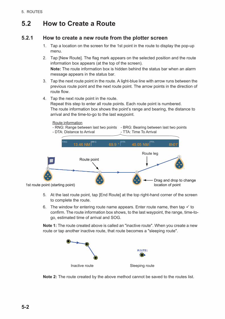
5. ROUTES
5.2 How to Create a Route
5.2.1 How to create a new route from the plotter screen
1. Tap a location on the screen for the 1st point in the route to display the pop-up menu.
2. Tap [New Route]. The flag mark appears on the selected position and the route information box appears (at the top of the screen).Note: The route information box is hidden behind the status bar when an alarm message appears in the status bar.
3. Tap the next route point in the route. A light-blue line with arrow runs between the previous route point and the next route point. The arrow points in the direction of route flow.
4. Tap the next route point in the route.Repeat this step to enter all route points. Each route point is numbered.The route information box shows the point’s range and bearing, the distance to arrival and the time-to-go to the last waypoint.
5. At the last route point, tap [End Route] at the top right-hand corner of the screen to complete the route.
6. The window for entering route name appears. Enter route name, then tap to confirm. The route information box shows, to the last waypoint, the range, time-to-go, estimated time of arrival and SOG.
Note 1: The route created above is called an "inactive route". When you create a new route or tap another inactive route, that route becomes a "sleeping route".
Note 2: The route created by the above method cannot be saved to the routes list.
Route point
1st route point (starting point)
Route leg
Drag and drop to change location of point
Route information- RNG: Range between last two points - BRG: Bearing between last two points- DTA: Distance to Arrival - TTA: Time To Arrival
Inactive route Sleeping route
5-2
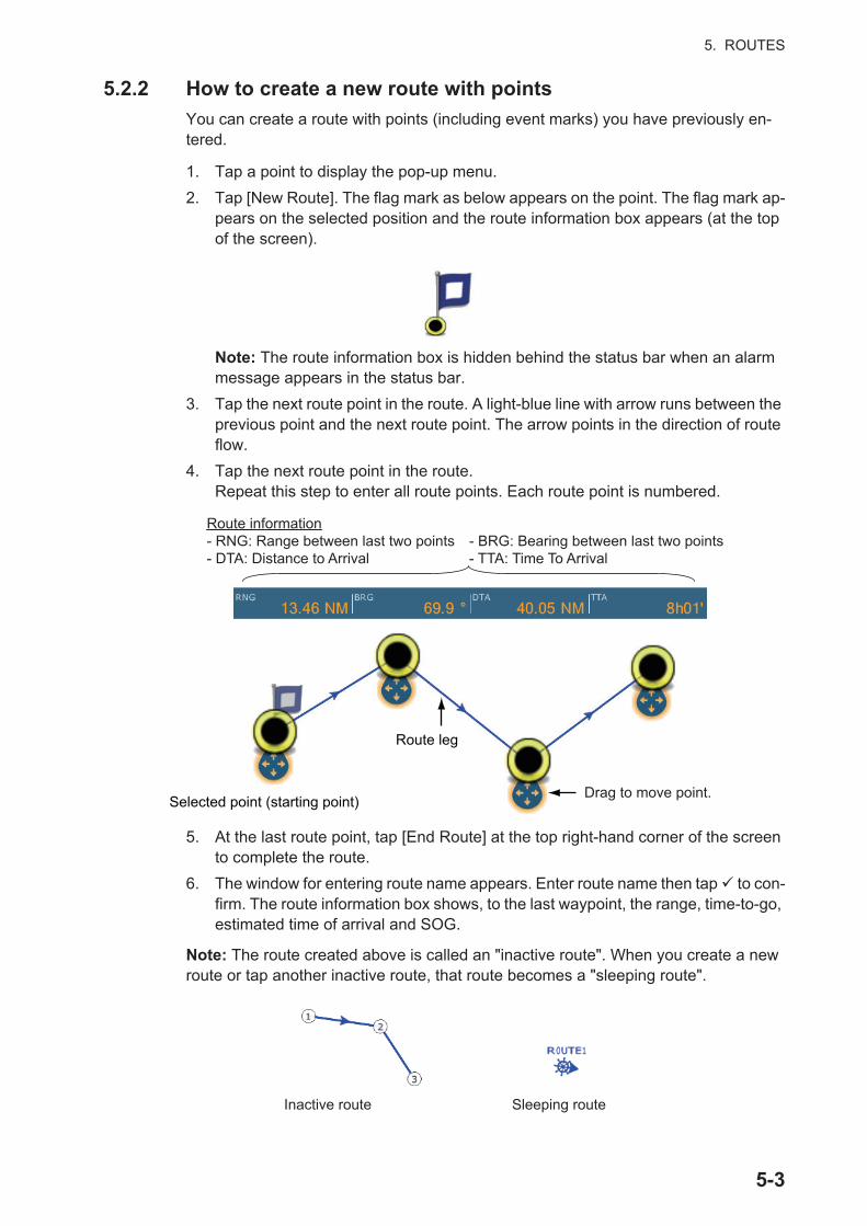
5. ROUTES
5.2.2 How to create a new route with points
You can create a route with points (including event marks) you have previously en-tered.
1. Tap a point to display the pop-up menu.
2. Tap [New Route]. The flag mark as below appears on the point. The flag mark ap-pears on the selected position and the route information box appears (at the top of the screen).
Note: The route information box is hidden behind the status bar when an alarm message appears in the status bar.
3. Tap the next route point in the route. A light-blue line with arrow runs between the previous point and the next route point. The arrow points in the direction of route flow.
4. Tap the next route point in the route.Repeat this step to enter all route points. Each route point is numbered.
5. At the last route point, tap [End Route] at the top right-hand corner of the screen to complete the route.
6. The window for entering route name appears. Enter route name then tap to con-firm. The route information box shows, to the last waypoint, the range, time-to-go, estimated time of arrival and SOG.
Note: The route created above is called an "inactive route". When you create a new route or tap another inactive route, that route becomes a "sleeping route".
Drag to move point.
Route information- RNG: Range between last two points - BRG: Bearing between last two points- DTA: Distance to Arrival - TTA: Time To Arrival
Route leg
Selected point (starting point)
Inactive route Sleeping route
5-3

5. ROUTES
5.2.3 How to create a route from the points list
1. Open the points list.
2. Tap the point to be the first point in the route then tap [Add to Route]. Repeat to add all required points. The route is drawn on the plotter screen.
3. Tap the Close button to close the points list.
4. Tap any line on the route, tap [Name] on the pop-up menu, and then enter a name for the route.
5.3 How to Edit a Route
5.3.1 How to insert a route point on a route
You can insert a new route point on a route leg as follows.
1. Tap a position on a route leg where to insert a route point.
2. Tap [Insert] on the pop-up menu. The compass symbol marks the position select-ed. The route point is numbered according to its position in the route, and the suc-ceeding route points are renumbered.
3. Tap [End Move] at the top right-hand corner of the screen.
5.3.2 How to move a route point on a route
You can move a route point on a route as follows.
1. Tap a route point on a route to display the pop-up menu.
2. Tap [Move]. The selected route point is highlighted.
33
1144
22
1133 22
22
1133
44
22
11
44
33
5-4
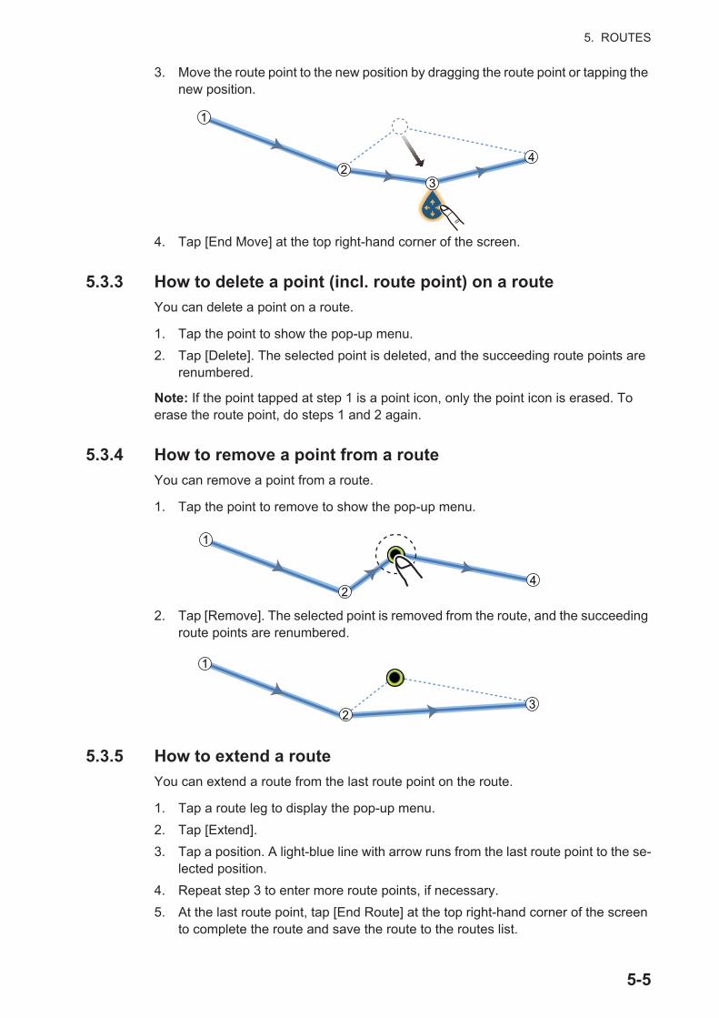
5. ROUTES
3. Move the route point to the new position by dragging the route point or tapping the new position.
4. Tap [End Move] at the top right-hand corner of the screen.
5.3.3 How to delete a point (incl. route point) on a route
You can delete a point on a route.
1. Tap the point to show the pop-up menu.
2. Tap [Delete]. The selected point is deleted, and the succeeding route points are renumbered.
Note: If the point tapped at step 1 is a point icon, only the point icon is erased. To erase the route point, do steps 1 and 2 again.
5.3.4 How to remove a point from a route
You can remove a point from a route.
1. Tap the point to remove to show the pop-up menu.
2. Tap [Remove]. The selected point is removed from the route, and the succeeding route points are renumbered.
5.3.5 How to extend a route
You can extend a route from the last route point on the route.
1. Tap a route leg to display the pop-up menu.
2. Tap [Extend].
3. Tap a position. A light-blue line with arrow runs from the last route point to the se-lected position.
4. Repeat step 3 to enter more route points, if necessary.
5. At the last route point, tap [End Route] at the top right-hand corner of the screen to complete the route and save the route to the routes list.
22
11
44
33
22
11
44
11
3322
5-5

5. ROUTES
5.4 Routes ListThe created routes are stored in the routes list, where you can edit or see the route data. The list stores the following route data for each route:
To open the routes list:
1. Open the home screen, then tap [Lists].
2. Tap [Routes] to open the routes list. You can sort the list with the route sort buttons on the title bar.
3. Tap the route to view.
• Name of route• Length of route• Names of starting route point and last route point (Enter them with the software key-
board.)• Color of route• Comment for route• Each number of each route point• Bearing to steer• Planning route speed (see section 5.13)• Distance between legs and total distance• TTG between legs and total TTG
Route sort buttons
5-6
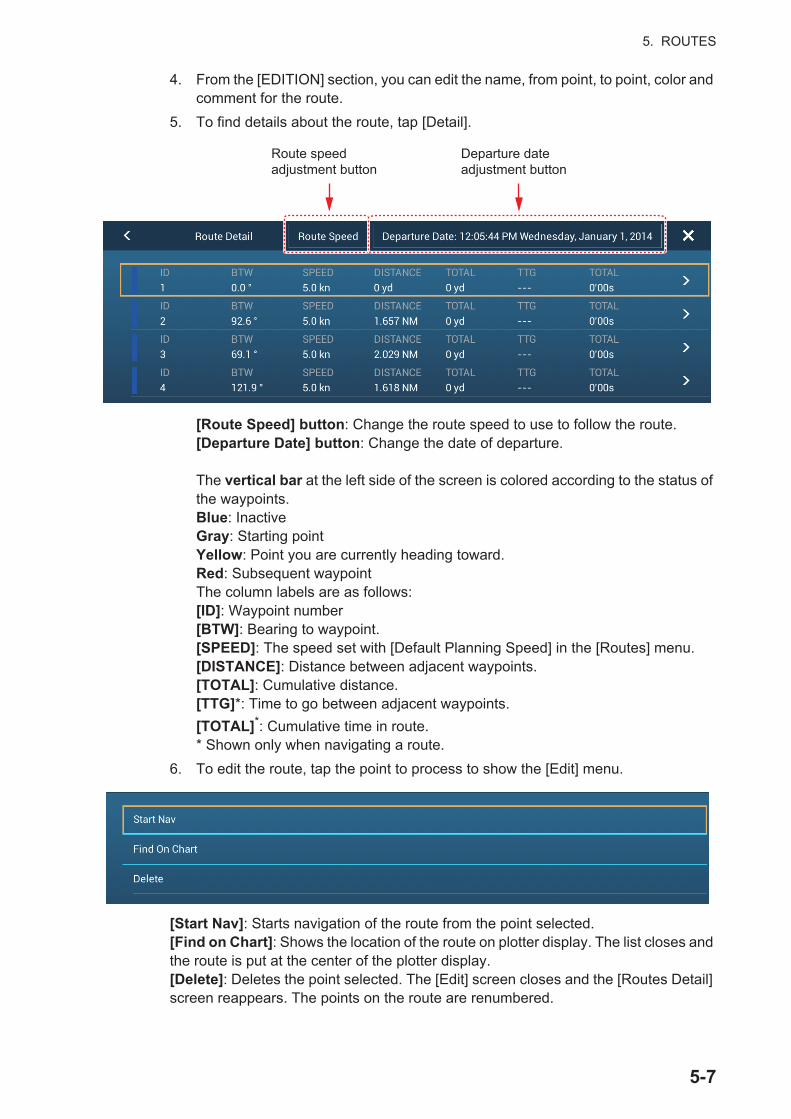
5. ROUTES
4. From the [EDITION] section, you can edit the name, from point, to point, color and comment for the route.
5. To find details about the route, tap [Detail].
[Route Speed] button: Change the route speed to use to follow the route.[Departure Date] button: Change the date of departure.
The vertical bar at the left side of the screen is colored according to the status of the waypoints.Blue: InactiveGray: Starting pointYellow: Point you are currently heading toward.Red: Subsequent waypoint The column labels are as follows:[ID]: Waypoint number[BTW]: Bearing to waypoint.[SPEED]: The speed set with [Default Planning Speed] in the [Routes] menu.[DISTANCE]: Distance between adjacent waypoints.[TOTAL]: Cumulative distance.[TTG]*: Time to go between adjacent waypoints.
[TOTAL]*: Cumulative time in route.* Shown only when navigating a route.
6. To edit the route, tap the point to process to show the [Edit] menu.
[Start Nav]: Starts navigation of the route from the point selected.[Find on Chart]: Shows the location of the route on plotter display. The list closes and the route is put at the center of the plotter display.[Delete]: Deletes the point selected. The [Edit] screen closes and the [Routes Detail] screen reappears. The points on the route are renumbered.
Route speed adjustment button
Departure date adjustment button
5-7
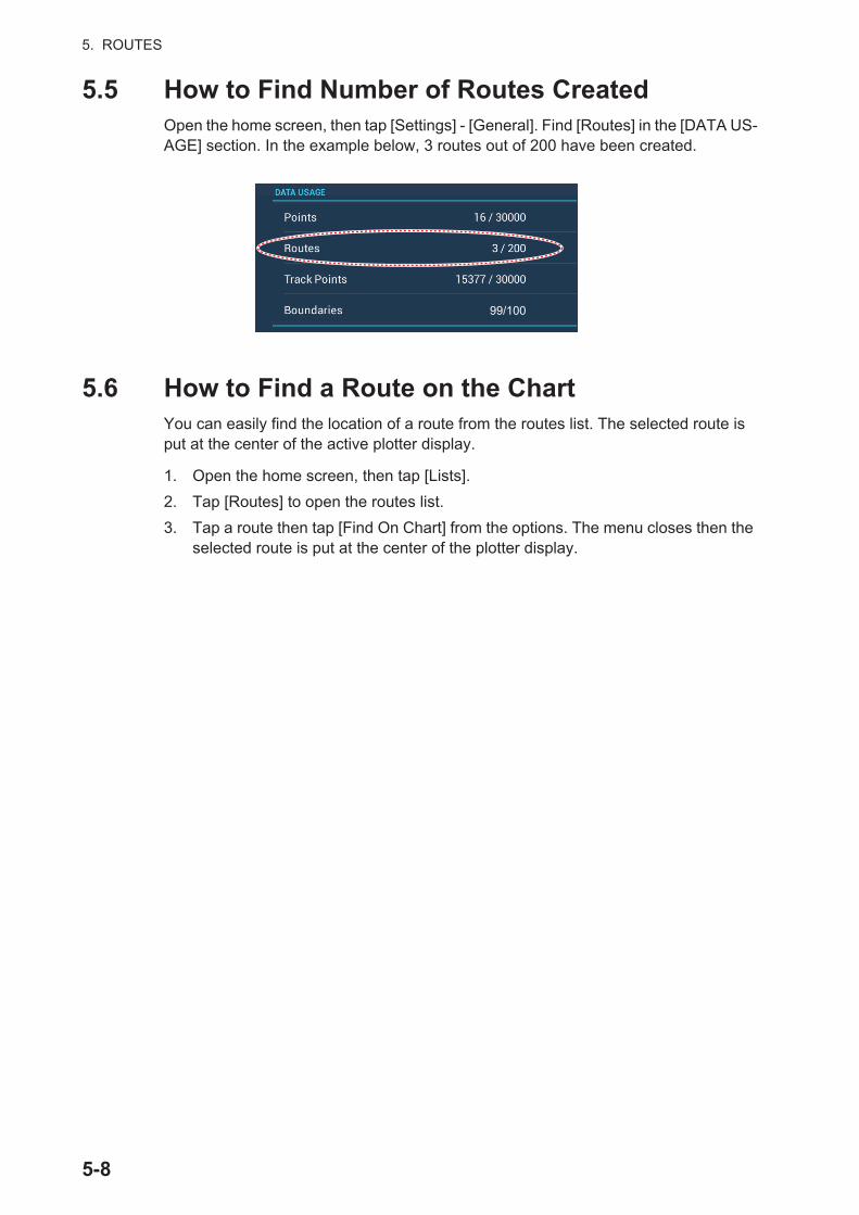
5. ROUTES
5.5 How to Find Number of Routes CreatedOpen the home screen, then tap [Settings] - [General]. Find [Routes] in the [DATA US-AGE] section. In the example below, 3 routes out of 200 have been created.
5.6 How to Find a Route on the ChartYou can easily find the location of a route from the routes list. The selected route is put at the center of the active plotter display.
1. Open the home screen, then tap [Lists].
2. Tap [Routes] to open the routes list.
3. Tap a route then tap [Find On Chart] from the options. The menu closes then the selected route is put at the center of the plotter display.
99/100
5-8

5. ROUTES
5.7 How to Delete a RouteYou can delete routes individually or collectively. An active route cannot be deleted.
5.7.1 How to delete a route on the screen
Tap a route leg of the route to delete to show the pop-up menu, then tap [Delete].
5.7.2 How to delete a route from the routes list
1. Open the home screen, then tap [Lists] - [Routes].
2. Tap the route to delete then tap [Delete]. The route disappears from both the screen and the routes list.
3. Tap the close button to finish.
5.7.3 How to delete all routes
1. Open the home screen, then tap [Settings] - [Points].
2. Tap [Delete All Points & Routes] menu.
3. You are asked if you are sure to delete all routes (and points). Tap [OK].
4. Tap the close button to finish.
5.8 How to Show or Hide All RoutesAll routes (including the route information box) can be shown or hidden. Open the [Layers] menu, the turn [Routes] on or off as required.
Note 1: An active route cannot be hidden from the screen unless route following is stopped.
Note 2: Inactive routes can be placed at either the arrival or departure location. Open the Layers menu, then activate [Departure] or [Arrival] (below the [Routes] flipswitch).
5.9 How to Set Route DensityIf you display all your routes, the screen can become cluttered with routes. To prevent this, set route density as shown below to limit the number of routes to show.
1. On the home screen, tap [Settings] [Points] [Routes Density] to show the fol-lowing options menu.
2. Tap desired route density. [Low] is the lowest route density, and [Full] displays all routes. Tap X on the title bar to close the menu.
5-9
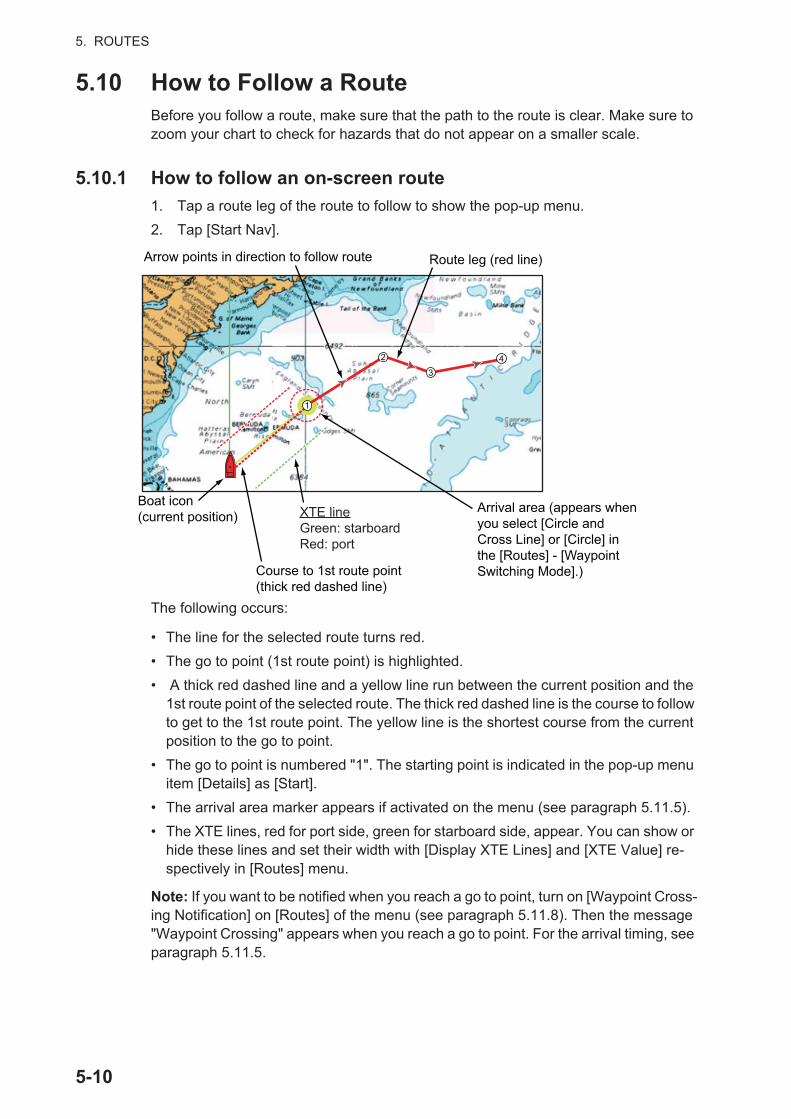
5. ROUTES
5.10 How to Follow a RouteBefore you follow a route, make sure that the path to the route is clear. Make sure to zoom your chart to check for hazards that do not appear on a smaller scale.
5.10.1 How to follow an on-screen route
1. Tap a route leg of the route to follow to show the pop-up menu.
2. Tap [Start Nav].
The following occurs:
• The line for the selected route turns red.
• The go to point (1st route point) is highlighted.
• A thick red dashed line and a yellow line run between the current position and the 1st route point of the selected route. The thick red dashed line is the course to follow to get to the 1st route point. The yellow line is the shortest course from the current position to the go to point.
• The go to point is numbered "1". The starting point is indicated in the pop-up menu item [Details] as [Start].
• The arrival area marker appears if activated on the menu (see paragraph 5.11.5).
• The XTE lines, red for port side, green for starboard side, appear. You can show or hide these lines and set their width with [Display XTE Lines] and [XTE Value] re-spectively in [Routes] menu.
Note: If you want to be notified when you reach a go to point, turn on [Waypoint Cross-ing Notification] on [Routes] of the menu (see paragraph 5.11.8). Then the message "Waypoint Crossing" appears when you reach a go to point. For the arrival timing, see paragraph 5.11.5.
Arrow points in direction to follow route Route leg (red line)
Course to 1st route point (thick red dashed line)
Boat icon (current position)
Arrival area (appears when you select [Circle and Cross Line] or [Circle] in the [Routes] - [Waypoint Switching Mode].)
22
11
3344
XTE lineGreen: starboardRed: port
5-10
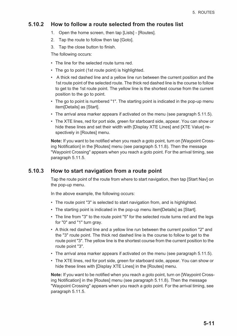
5. ROUTES
5.10.2 How to follow a route selected from the routes list
1. Open the home screen, then tap [Lists] - [Routes].
2. Tap the route to follow then tap [Goto].
3. Tap the close button to finish.
The following occurs:
• The line for the selected route turns red.
• The go to point (1st route point) is highlighted.
• A thick red dashed line and a yellow line run between the current position and the 1st route point of the selected route. The thick red dashed line is the course to follow to get to the 1st route point. The yellow line is the shortest course from the current position to the go to point.
• The go to point is numbered "1". The starting point is indicated in the pop-up menu item[Details] as [Start].
• The arrival area marker appears if activated on the menu (see paragraph 5.11.5).
• The XTE lines, red for port side, green for starboard side, appear. You can show or hide these lines and set their width with [Display XTE Lines] and [XTE Value] re-spectively in [Routes] menu.
Note: If you want to be notified when you reach a goto point, turn on [Waypoint Cross-ing Notification] in the [Routes] menu (see paragraph 5.11.8). Then the message "Waypoint Crossing" appears when you reach a goto point. For the arrival timing, see paragraph 5.11.5.
5.10.3 How to start navigation from a route point
Tap the route point of the route from where to start navigation, then tap [Start Nav] on the pop-up menu.
In the above example, the following occurs:
• The route point "3" is selected to start navigation from, and is highlighted.
• The starting point is indicated in the pop-up menu item[Details] as [Start].
• The line from "3" to the route point "5" for the selected route turns red and the legs for "0" and "1" turn gray.
• A thick red dashed line and a yellow line run between the current position "2" and the "3" route point. The thick red dashed line is the course to follow to get to the route point "3". The yellow line is the shortest course from the current position to the route point "3".
• The arrival area marker appears if activated on the menu (see paragraph 5.11.5).
• The XTE lines, red for port side, green for starboard side, appear. You can show or hide these lines with [Display XTE Lines] in the [Routes] menu.
Note: If you want to be notified when you reach a goto point, turn on [Waypoint Cross-ing Notification] in the [Routes] menu (see paragraph 5.11.8). Then the message "Waypoint Crossing" appears when you reach a goto point. For the arrival timing, see paragraph 5.11.5.
5-11
5. ROUTES
5.10.4 How to show the detailed information about a route
Tap a route leg of the route, then Tap [Detail] to show the [Route Detail] window.
5.11 Operations When You Follow a Route
5.11.1 How to restart navigation
When you follow a route, you can re-start the navigation to the next route point on the route from current location.
When you steer to keep away from an obstruction or the ship drifts, you go off course as shown in Line 1 in the figure. If you do not need to return to the origi-nal course, you can go to the route point from the current position as shown in Line 2 in the figure.
Tap a route leg, the red dashed line or the yellow line of the route to display the pop-up menu. Tap [Restart]. The route start position for the route moves to the current po-sition.
5.11.2 How to follow a route in the reverse direction
You can follow a route in reverse order. This helps you return along the same path.
Note: This function is not available for an active route.
Tap a route leg to display the pop-up menu, then tap [Reverse]. The arrows on the route legs are in reverse direction and the numbers of the route points are in reverse order.
5.11.3 How to stop following a route
Tap a route leg, a route point or a thick red dashed line on an active route to display the pop-up menu, then tap [Stop Nav]. The arrival area, XTE lines, set course (thick red dashed line) and yellow line are erased from the screen. The red line for the route turns the default color you set.
5.11.4 How to skip a point on a route
There are times when you do not need to follow all legs in an active route. You can
skip a point (highlighted) as shown in the procedure below. After you tap the point to skip, the skipped route leg turns from red to gray.
• Tap a point on the active route: Open the slide-out menu, then tap [Routes] and [Skip Wpt]. The selected go to point is skipped then the next route point is marked as the go to point.
• Tap a route leg of the active route: Open the slide-out menu, tap [Routes] and [Skip Wpt]. The go to point on the route is skipped then the next route point is marked as the go to point.
Line 2
Line 1Obstacle
Original course
5-12

5. ROUTES
5.11.5 Waypoint switching mode
When you arrive to a route point, your unit automatically changes to the next route point according to the waypoint switching mode selected on the menu.
[Cross Line]: Change the waypoint when the ship moves through an imaginary cross line (vertical line) that passes through the center of the destination point.[Circle]: Change the waypoint when the ship comes within the circle.[Circle and Cross Line]: Change the waypoint when one of the above two conditions is met.
A red dashed circle appears when you tap [Circle and Cross Line] or [Circle].
1. Open the home screen, then tap [Settings] - [Routes].
2. Tap [WPT Switch Mode].
3. Tap [Circle and Cross Line], [Circle] or [Cross Line]. For [Circle and Cross Line] or [Circle], do 1) and 2) below. For [Cross Line], go to step 4.
1) Tap [Switching Circle Radius] to display the software keyboard.
2) Set the arrival area (circle radius) then tap confirm.
4. Tap the close button to finish.
5.11.6 Route auto zoom
You can get automatic range change after you have moved past the go to point. Use this feature to find the next go to point in the route when the next go to point is not within the current display range.
1. Open the home screen, then tap [Settings] - [Routes].
2. Turn [Route Auto Zoom] on or off.
3. Tap the close button to finish.
[Circle and Cross Line]
Arrival area Cross line
[Circle] [Cross Line]
Cross lineThe value for the circle radius is set in [Switching Circle Radius].
5-13

5. ROUTES
5.11.7 XTE lines
The color of the XTE line is red for the port side, green for the starboard side. You can show or hide these lines and set their distance from own ship as follows.
1. Open the home screen, then tap [Settings] - [Routes].
2. Turn [Display XTE Lines] on or off. For [ON], go to the next step. For [OFF], tap the close button to finish.
3. Tap [XTE Value] to display the software keyboard
4. Set the distance of the XTE lines from your ship then tap . The XTE alarm sounds (if active) when your ship veers off course by the amount set here.
5. Tap the close button to finish.
5.11.8 Waypoint arrival notification
The waypoint arrival notification feature releases audio and visual notifications when your ship reaches a go to point. For the arrival timing, see paragraph 5.11.5. The no-tification message "Waypoint Crossing" appears. Activate or deactivate this feature as follows.
1. Open the home screen, then tap [Settings] - [Routes].
2. Turn [Waypoint Crossing Notification] on or off.
3. Tap the close button to finish.
5.11.9 End of route notification
The end of route notification feature releases audio and visual notifications when your ship reaches the end of a route. For the arrival timing, see paragraph 5.11.5. The no-tification message "End of Route" appears. Activate or deactivate this feature as fol-lows.
1. Open the home screen, then tap [Settings] - [Routes].
2. Turn [End of Route Notification] on or off.
3. Tap the close button to finish.
XTE lines(Red: port,
Green: starboard)
5-14
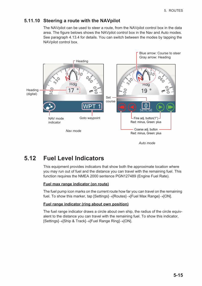
5. ROUTES
5.11.10 Steering a route with the NAVpilot
The NAVpilot can be used to steer a route, from the NAVpilot control box in the data area. The figure belows shows the NAVpilot control box in the Nav and Auto modes. See paragraph 4.13.4 for details. You can switch between the modes by tapping the NAVpilot control box.
5.12 Fuel Level IndicatorsThis equipment provides indicators that show both the approximate location where you may run out of fuel and the distance you can travel with the remaining fuel. This function requires the NMEA 2000 sentence PGN127489 (Engine Fuel Rate).
Fuel max range indicator (on route)
The fuel pump icon marks on the current route how far you can travel on the remaining fuel. To show this marker, tap [Settings] [Routes] [Fuel Max Range] [ON].
Fuel range indicator (ring about own position)
The fuel range indicator draws a circle about own ship, the radius of the circle equiv-alent to the distance you can travel with the remaining fuel. To show this indicator, [Settings] [Ship & Track] [Fuel Range Ring] [ON].
NAV modeindicator
Goto waypoint
Heading(digital)
Heading
Setcourse
Auto mode
Nav mode Coarse adj. buttonRed: minus, Green: plus
Fine adj. button(1°)Red: minus, Green: plus
Blue arrow: Course to steerGray arrow: Heading
5-15

5. ROUTES
5.13 Routes MenuThis section provides descriptions for the items in the [Routes] menu not previously mentioned.
[Default Route Color]: Select the color of the routes. The options are red, blue, green, yellow, magenta, orange, cyan, or black & white.
[Route Thickness]: Select the thickness of the routes.
[Navigate with Autopilot]: A message asks if you want to navigate with the autopilot, after setting a destination. Requires NAVpilot. Not shown otherwise.
[Autopilot Step]: Controls the amount of course change set with the coarse adjust-ment buttons in the NAVpilot display. Requires NAVpilot. Not shown otherwise.
[Ask to Enter Route Name]: Show the software keyboard to enter route name after you create a route. The default setting is "ON".
[Fuel Max Range]: Provides a visual indication of vessel range based on tank levels and live fuel consumption.
[Intelligent Route Waypoint Centering]: When you create a route, center a route point each time it is selected on the screen.
Coarse adj. buttonRed: minus, Green: plus
5-16

5. ROUTES
[Cruising Speed for Planning]: Set the default cruising speed for routes (see section 5.4).
[Reset Default Settings]: Select this menu item to restore default settings for the [Routes] menu.
5-17

5. ROUTES
This page is intentionally left blank.
5-18

6. RADAR
This chapter provides the information necessary for radar operation, which requires a radar sensor.
Note: To change the radar source, go to the Home screen, tap [Settings] - [Radar] - [Radar Source], then tap desired radar source.
6.1 How to Transmit, Set the Radar in Stand-byTap the [TX] icon at the bottom right corner of the screen to put the radar in transmit or stand-by state. The icon is filled in white when the radar is in transmit state. (Trans-mit, stand-by can also be controlled from the pop-up menu with [TX/STBY].)
If you do not require the radar for some time, set the radar in stand-by to save the mag-netron from unnecessary use.
TX channel selection (w/DRS4D-NXT radar sensor)
In the default setting, the best TX channel is automatically selected at random among three channels. However, if interference is received from the radar of a nearby ship, open the [Radar] menu, then set [TX Channel] to [1], [2] or [3], the channel where the interference is smallest.
6.2 TuningBy design the radar receiver is tuned automatically after the radar is set to transmit. If you require fine tuning, do the following to tune manually:
1. Open the home screen, then tap [Settings] - [Radar].
2. The default tuning method is automatic. Turn off [Auto Tuning] to enable manual tuning.
3. Drag the slider at [Manual Tuning] to set the value.
4. Tap the close button to finish.
TX/STBY switch
: Stand-by
: TXTX
TX
TX
6-1
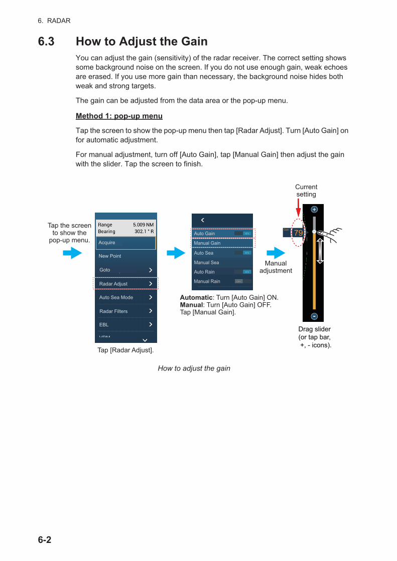
6. RADAR
6.3 How to Adjust the GainYou can adjust the gain (sensitivity) of the radar receiver. The correct setting shows some background noise on the screen. If you do not use enough gain, weak echoes are erased. If you use more gain than necessary, the background noise hides both weak and strong targets.
The gain can be adjusted from the data area or the pop-up menu.
Method 1: pop-up menu
Tap the screen to show the pop-up menu then tap [Radar Adjust]. Turn [Auto Gain] on for automatic adjustment.
For manual adjustment, turn off [Auto Gain], tap [Manual Gain] then adjust the gain with the slider. Tap the screen to finish.
How to adjust the gain
Tap the screento show the
pop-up menu.
Tap [Radar Adjust].
Auto Gain
Manual Gain
Auto Sea
Manual Sea
Auto Rain
Manual Rain
Automatic: Turn [Auto Gain] ON.Manual: Turn [Auto Gain] OFF.Tap [Manual Gain].
Drag slider(or tap bar, +, - icons).
79
Manualadjustment
Currentsetting
Gain
Acquire
New Point
Radar Adjust
Auto Sea Mode
Radar Filters
EBL
VRM
Goto
6-2

6. RADAR
Method 2: Radar Control data box in data area
The gain can be adjusted from the data area, with the [Radar Control] box in the [RA-DAR] data box. On the box, tap the [M/A] part of the [Gain] flipswitch to switch between manual and automatic adjustment. For manual adjustment, drag the slider to adjust. Tap [End] to finish.
All items set for manual adjustment
Tap “A” to alternatebetween auto and manual.
Drag slider(or tapbar or +, - icons).
797979
RADARDATA ROUTE
Manual adjustment
Current setting
Gain
6-3
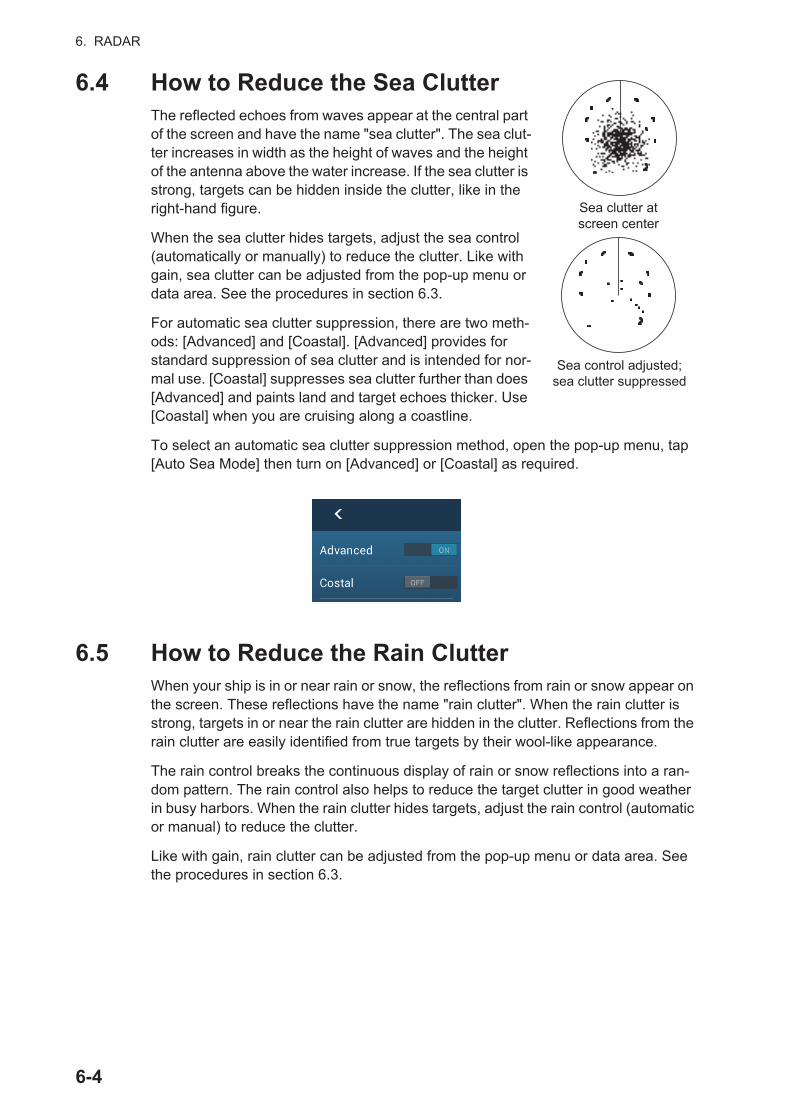
6. RADAR
6.4 How to Reduce the Sea ClutterThe reflected echoes from waves appear at the central part of the screen and have the name "sea clutter". The sea clut-ter increases in width as the height of waves and the height of the antenna above the water increase. If the sea clutter is strong, targets can be hidden inside the clutter, like in the right-hand figure.
When the sea clutter hides targets, adjust the sea control (automatically or manually) to reduce the clutter. Like with gain, sea clutter can be adjusted from the pop-up menu or data area. See the procedures in section 6.3.
For automatic sea clutter suppression, there are two meth-ods: [Advanced] and [Coastal]. [Advanced] provides for standard suppression of sea clutter and is intended for nor-mal use. [Coastal] suppresses sea clutter further than does [Advanced] and paints land and target echoes thicker. Use [Coastal] when you are cruising along a coastline.
To select an automatic sea clutter suppression method, open the pop-up menu, tap [Auto Sea Mode] then turn on [Advanced] or [Coastal] as required.
6.5 How to Reduce the Rain ClutterWhen your ship is in or near rain or snow, the reflections from rain or snow appear on the screen. These reflections have the name "rain clutter". When the rain clutter is strong, targets in or near the rain clutter are hidden in the clutter. Reflections from the rain clutter are easily identified from true targets by their wool-like appearance.
The rain control breaks the continuous display of rain or snow reflections into a ran-dom pattern. The rain control also helps to reduce the target clutter in good weather in busy harbors. When the rain clutter hides targets, adjust the rain control (automatic or manual) to reduce the clutter.
Like with gain, rain clutter can be adjusted from the pop-up menu or data area. See the procedures in section 6.3.
Sea clutter at screen center
Sea control adjusted; sea clutter suppressed
6-4
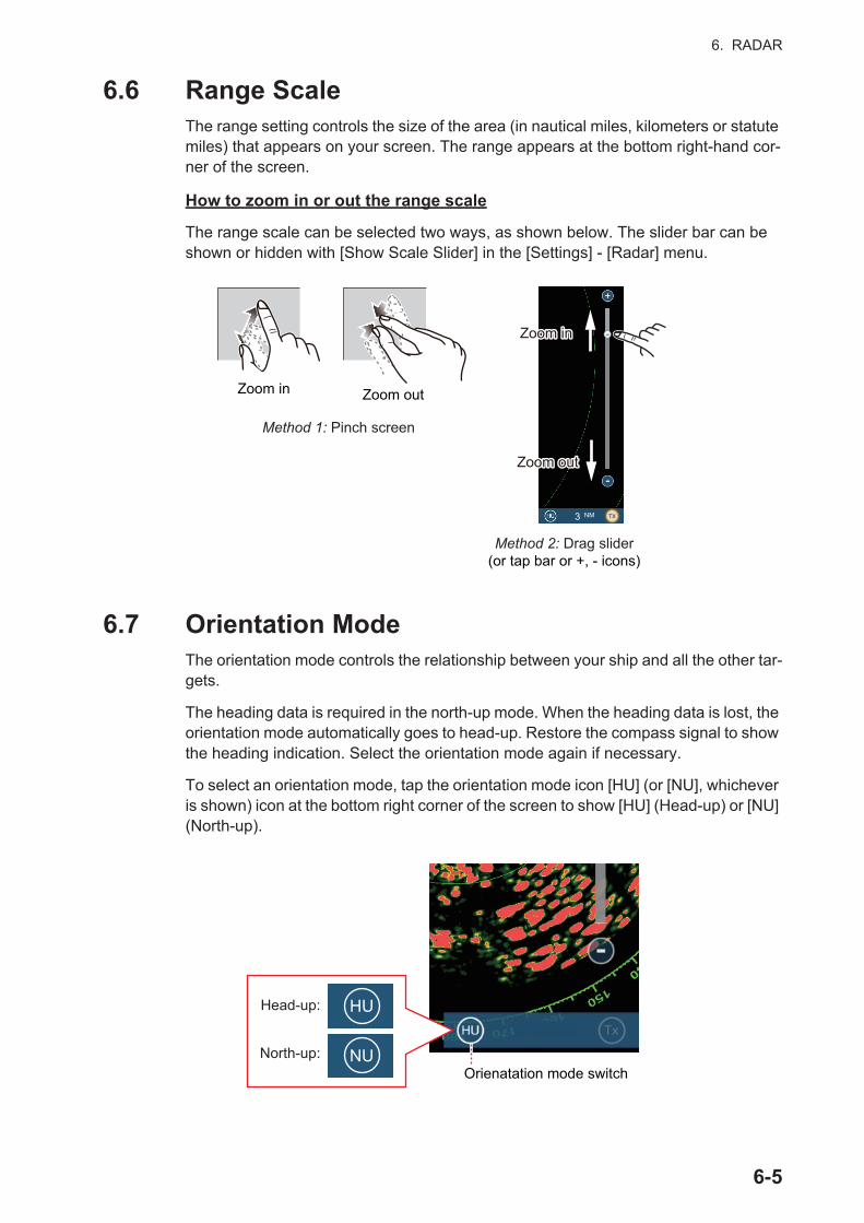
6. RADAR
6.6 Range ScaleThe range setting controls the size of the area (in nautical miles, kilometers or statute miles) that appears on your screen. The range appears at the bottom right-hand cor-ner of the screen.
How to zoom in or out the range scale
The range scale can be selected two ways, as shown below. The slider bar can be shown or hidden with [Show Scale Slider] in the [Settings] - [Radar] menu.
6.7 Orientation ModeThe orientation mode controls the relationship between your ship and all the other tar-gets.
The heading data is required in the north-up mode. When the heading data is lost, the orientation mode automatically goes to head-up. Restore the compass signal to show the heading indication. Select the orientation mode again if necessary.
To select an orientation mode, tap the orientation mode icon [HU] (or [NU], whichever is shown) icon at the bottom right corner of the screen to show [HU] (Head-up) or [NU] (North-up).
Zoom in Zoom out
Method 1: Pinch screen
Method 2: Drag slider(or tap bar or +, - icons)
3 NM
Zoom inZoom in
Zoom outZoom out
TX
Orienatation mode switch
HU
NU
Head-up:
North-up:
6-5
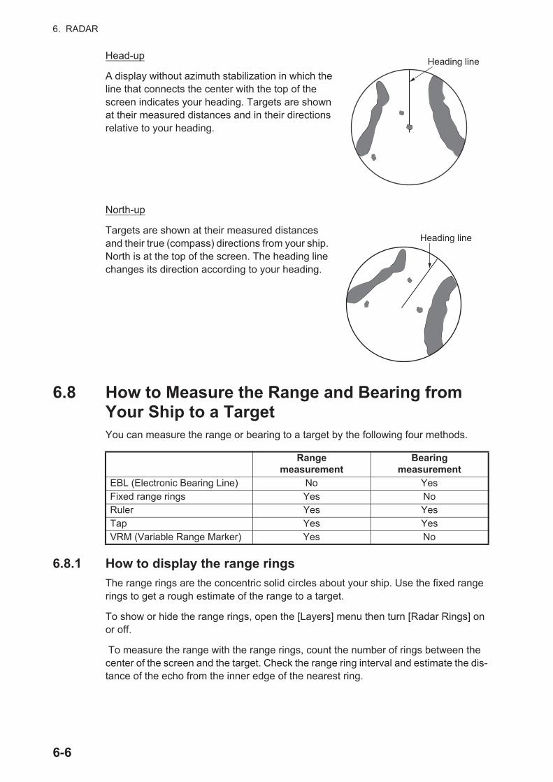
6. RADAR
Head-up
A display without azimuth stabilization in which the line that connects the center with the top of the screen indicates your heading. Targets are shown at their measured distances and in their directions relative to your heading.
North-up
Targets are shown at their measured distances and their true (compass) directions from your ship. North is at the top of the screen. The heading line changes its direction according to your heading.
6.8 How to Measure the Range and Bearing from Your Ship to a TargetYou can measure the range or bearing to a target by the following four methods.
6.8.1 How to display the range rings
The range rings are the concentric solid circles about your ship. Use the fixed range rings to get a rough estimate of the range to a target.
To show or hide the range rings, open the [Layers] menu then turn [Radar Rings] on or off.
To measure the range with the range rings, count the number of rings between the center of the screen and the target. Check the range ring interval and estimate the dis-tance of the echo from the inner edge of the nearest ring.
Rangemeasurement
Bearingmeasurement
EBL (Electronic Bearing Line) No YesFixed range rings Yes NoRuler Yes YesTap Yes YesVRM (Variable Range Marker) Yes No
Heading line
Heading line
6-6

6. RADAR
6.8.2 How to set the number of the range rings to show
1. Open the home screen, then tap [Settings] - [Radar].
2. Tap [Rings Interval].
3. Tap a number. [Automatic] automatically selects the number of rings according to the range scale.
4. Tap the close button to finish.
6.8.3 How to select the range rings mode
To select the range rings mode, open the home screen, then tap [Settings] [Radar]. Set [Bearing Scale Mode] to [True] or [Relative].
6-7

6. RADAR
6.8.4 How to measure the range and bearing to an object
Tap an object to get its range and bearing from own ship. Read the range and bearing in the pop-up menu.
Relative: Bearing scale is fixed and “0” is at the top of the screen.
Boat icon
0 1020
3040
50
60
70
80
90
100
110
120
130
140150
160170180190200
210220
230
240
250
260
270
280
290
300
310
320
330340 350
0
10
2030
4050 60 70
8090
100
110
120
130
140
150
160
170
180
190
200210
220230240250260
270280
290
300
310
320
330
340
350
0 1020
3040
50
60
70
80
90
100
110
120
130
140150
160170180190200
210220
230
240
250
260
270
280
290
300
310
320
330340 350
0
10
2030
4050 60 70
8090
100
110
120
130
140
150
160
170
180
190
200210
220230240250260
270280
290
300
310
320
330
340
350
North (“0”)
Heading line
Bearing scale
True: Bearing scale rotates according to the movement of your ship.
Head-up mode
North-up mode
Relative: Bearing scale rotates according to the movement of your ship.
True: Bearing scale is fixed and “0” is at the top of the screen.
Boat icon
Bearing scale
Heading line
Object
Range and bearingto object
Acquire
New Point
Radar Adjust
Auto Sea Mode
Radar Filters
EBL
VRM
Goto
6-8
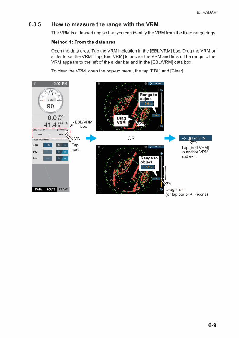
6. RADAR
6.8.5 How to measure the range with the VRM
The VRM is a dashed ring so that you can identify the VRM from the fixed range rings.
Method 1: From the data area
Open the data area. Tap the VRM indication in the [EBL/VRM] box. Drag the VRM or slider to set the VRM. Tap [End VRM] to anchor the VRM and finish. The range to the VRM appears to the left of the slider bar and in the [EBL/VRM] data box.
To clear the VRM, open the pop-up menu, the tap [EBL] and [Clear].
Taphere.
OR
Drag slider(or tap bar or +, - icons)Drag slider(or tap bar or +, - icons)
Tap [End VRM] to anchor VRM and exit.
Drag VRMEBL/VRM
box
DragVRMDragVRM
Range to object
Range to object
RADARDATA ROUTE
VRM
VRM
VRM
VRM
6-9

6. RADAR
Method 2: From the pop-up menu
Tap the screen to show the pop-up menu, then tap [VRM]. Drag the VRM or slider to set the VRM. Tap [End VRM] to anchor the VRM and finish. The range to the VRM appears to the left of the slider bar.
To clear the VRM, open the pop-up menu, the tap [VRM] and [Clear].
OR
Drag VRM
DragVRMDragVRM
Tap screen to show pop-up menu.
Tap [VRM].
Tap [Adjust].
Tap [End VRM] to anchor VRM and exit.
Range to object
Range to object
Drag slider(or tap bar or +, - icons)Drag slider(or tap bar or +, - icons)
VRM
VRM
VRM
VRM
Acquire
New Point
Radar Adjust
Auto Sea Mode
Radar Filters
EBL
VRM
Goto
6-10

6. RADAR
6.8.6 How to measure the bearing with the EBL
Method 1: From the data area
Open the data area. Tap the EBL indication in the [EBL/VRM] data box. Drag the EBL or slider to set the EBL. Tap [End EBL] to anchor the EBL and finish. The bearing of the EBL appears to the left of the slider bar and in the [EBL/VRM] data box.
To clear the EBL, open the pop-up menu, then tap [EBL] and [Clear].
OR
Tap [End EBL] to anchor EBL and exit.
Drag VRMEBL/VRM
box
84.7°
84.7°
Bearing to object
84.7°
DragEBL
Bearing to object
84.7°
End EBL
End EBL
End EBL
Drag slider(or tap bar or +, - icons)Drag slider(or tap bar or +, - icons)
RADARDATA ROUTE
EBL
EBL
EBL
EBL
6-11
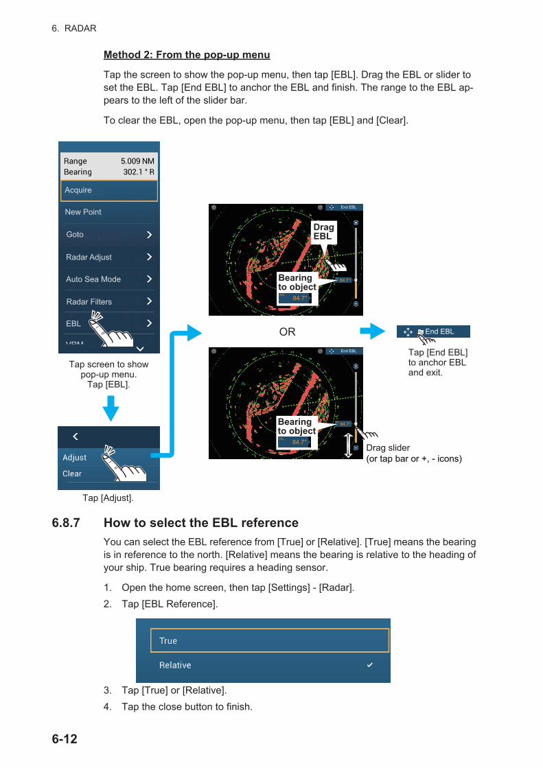
6. RADAR
Method 2: From the pop-up menu
Tap the screen to show the pop-up menu, then tap [EBL]. Drag the EBL or slider to set the EBL. Tap [End EBL] to anchor the EBL and finish. The range to the EBL ap-pears to the left of the slider bar.
To clear the EBL, open the pop-up menu, then tap [EBL] and [Clear].
6.8.7 How to select the EBL reference
You can select the EBL reference from [True] or [Relative]. [True] means the bearing is in reference to the north. [Relative] means the bearing is relative to the heading of your ship. True bearing requires a heading sensor.
1. Open the home screen, then tap [Settings] - [Radar].
2. Tap [EBL Reference].
3. Tap [True] or [Relative].
4. Tap the close button to finish.
Acquire
New Point
Radar Adjust
Auto Sea Mode
Radar Filters
EBL
VRM
Goto
Tap screen to show pop-up menu.
Tap [EBL].
Tap [Adjust].
OR
Tap [End EBL] to anchor EBL and exit.
Drag VRM
84.7°
84.7°
Bearing to object
84.7°
DragEBL
Bearing to object
84.7°
End EBL
End EBL
End EBL
Drag slider(or tap bar or +, - icons)Drag slider(or tap bar or +, - icons)
EBL
EBL
EBL
EBL
6-12

6. RADAR
6.9 How to Measure the Range and Bearing Between Two TargetsYou can measure the range and bearing between any two targets with the ruler.
1. Open the slide-out menu then tap [Distance] to display the ruler, which has two drag-able circles connected with a line.
2. Drag the circles to set them on the objects for the measurement. The range and bearing between the objects, SOG and TTG appear at the top of the screen.
3. Tap [Cancel Ruler] at the top right-hand corner of the screen to erase the ruler and the indications.
6.10 How to Off-center the PictureYou can off-center your position to expand the view field without selecting a larger range scale. The position can be off-centered in the bow, stern, port or starboard di-rection, but not more than 75% of the range in use.
Pan the radar display by dragging with a finger. To return your ship to the center of the screen, tap [Center Radar] at the top right-hand corner of the screen.
IconDrag to change location.
2nd location
Range BearingSpeed Over the Ground TTG
Starting location
Normal picture Picture off-centered in stern direction
30
40
50
60
70
80
90
100
110
120
130
140
150210
220
230
240
250
260
270
280
290
300
310
320
330
0 1020
30
40
50
60
70
80
90
100
110250
260
270
280
290
300
310
320
330
340350
6-13
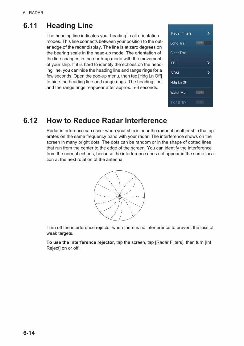
6. RADAR
6.11 Heading LineThe heading line indicates your heading in all orientation modes. This line connects between your position to the out-er edge of the radar display. The line is at zero degrees on the bearing scale in the head-up mode. The orientation of the line changes in the north-up mode with the movement of your ship. If it is hard to identify the echoes on the head-ing line, you can hide the heading line and range rings for a few seconds. Open the pop-up menu, then tap [Hdg Ln Off] to hide the heading line and range rings. The heading line and the range rings reappear after approx. 5-6 seconds.
6.12 How to Reduce Radar InterferenceRadar interference can occur when your ship is near the radar of another ship that op-erates on the same frequency band with your radar. The interference shows on the screen in many bright dots. The dots can be random or in the shape of dotted lines that run from the center to the edge of the screen. You can identify the interference from the normal echoes, because the interference does not appear in the same loca-tion at the next rotation of the antenna.
Turn off the interference rejector when there is no interference to prevent the loss of weak targets.
To use the interference rejector, tap the screen, tap [Radar Filters], then turn [Int Reject] on or off.
6-14

6. RADAR
6.13 Echo AverageThe sea clutter reduction circuit can remove wanted echoes. If this occurs, use the echo average feature. Echo average reduces the brilliance of targets within sea clutter to allow you to better discriminate targets from sea clutter.
Note 1: Echo average requires heading and position data.
Note 2: Do not use echo average during heavy pitching and rolling, to prevent loss of targets.
Note 3: Before using echo average, properly adjust the sea clutter.
Note 4: In the dual radar display, echo average works only on the left side screen, (1) in the figure below.
To turn the echo average feature on or off, show the pop-up menu, select [Radar Fil-ters], then turn [Average] off or on as required.
6.14 Guard ZoneThe guard zone provides aural and visual alarms against targets (ships, islands, land-masses, etc.) that enter the area you set.
6.14.1 How to set the guard zone
Note: You can not set the guard zone with a remote control unit (MCU-002, MCU-004 or MCU-005). Use the touch operation to set the guard zone. The available range changes with the radar sensor - DRS4D-NXT, 0-24 NM; X-class radar sensors, 0-16 NM.
1. Open the [Layers] menu.
2. Turn on [Guard Zone 1] or [Guard Zone 2]. A dotted white line guard zone appears.
3. Tap on a line of the guard zone, and the pop-up menu appears.
(1) (2)
Dual display
Echo Average OFF Echo Average ON
6-15
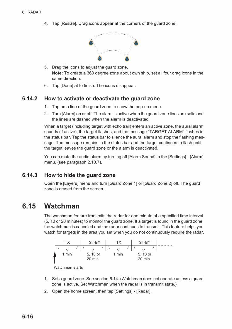
6. RADAR
4. Tap [Resize]. Drag icons appear at the corners of the guard zone.
5. Drag the icons to adjust the guard zone.Note: To create a 360 degree zone about own ship, set all four drag icons in the same direction.
6. Tap [Done] at to finish. The icons disappear.
6.14.2 How to activate or deactivate the guard zone
1. Tap on a line of the guard zone to show the pop-up menu.
2. Turn [Alarm] on or off. The alarm is active when the guard zone lines are solid and the lines are dashed when the alarm is deactivated.
When a target (including target with echo trail) enters an active zone, the aural alarm sounds (if active), the target flashes, and the message "TARGET ALARM" flashes in the status bar. Tap the status bar to silence the aural alarm and stop the flashing mes-sage. The message remains in the status bar and the target continues to flash until the target leaves the guard zone or the alarm is deactivated.
You can mute the audio alarm by turning off [Alarm Sound] in the [Settings] - [Alarm] menu. (see paragraph 2.10.7).
6.14.3 How to hide the guard zone
Open the [Layers] menu and turn [Guard Zone 1] or [Guard Zone 2] off. The guard zone is erased from the screen.
6.15 WatchmanThe watchman feature transmits the radar for one minute at a specified time interval (5, 10 or 20 minutes) to monitor the guard zone. If a target is found in the guard zone, the watchman is canceled and the radar continues to transmit. This feature helps you watch for targets in the area you set when you do not continuously require the radar.
1. Set a guard zone. See section 6.14. (Watchman does not operate unless a guard zone is active. Set Watchman when the radar is in transmit state.)
2. Open the home screen, then tap [Settings] - [Radar].
1 min 1 min
TX TXST-BY ST-BY
Watchman starts
5, 10 or 20 min
5, 10 or 20 min
6-16
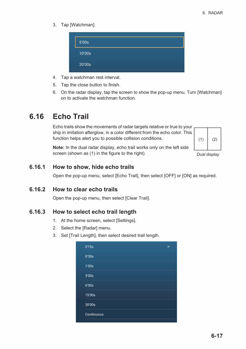
6. RADAR
3. Tap [Watchman].
4. Tap a watchman rest interval.
5. Tap the close button to finish.
6. On the radar display, tap the screen to show the pop-up menu. Turn [Watchman] on to activate the watchman function.
6.16 Echo TrailEcho trails show the movements of radar targets relative or true to your ship in imitation afterglow, in a color different from the echo color. This function helps alert you to possible collision conditions.
Note: In the dual radar display, echo trail works only on the left side screen (shown as (1) in the figure to the right).
6.16.1 How to show, hide echo trails
Open the pop-up menu, select [Echo Trail], then select [OFF] or [ON] as required.
6.16.2 How to clear echo trails
Open the pop-up menu, then select [Clear Trail].
6.16.3 How to select echo trail length
1. At the home screen, select [Settings].
2. Select the [Radar] menu.
3. Set [Trail Length], then select desired trail length.
(1) (2)
Dual display
6-17
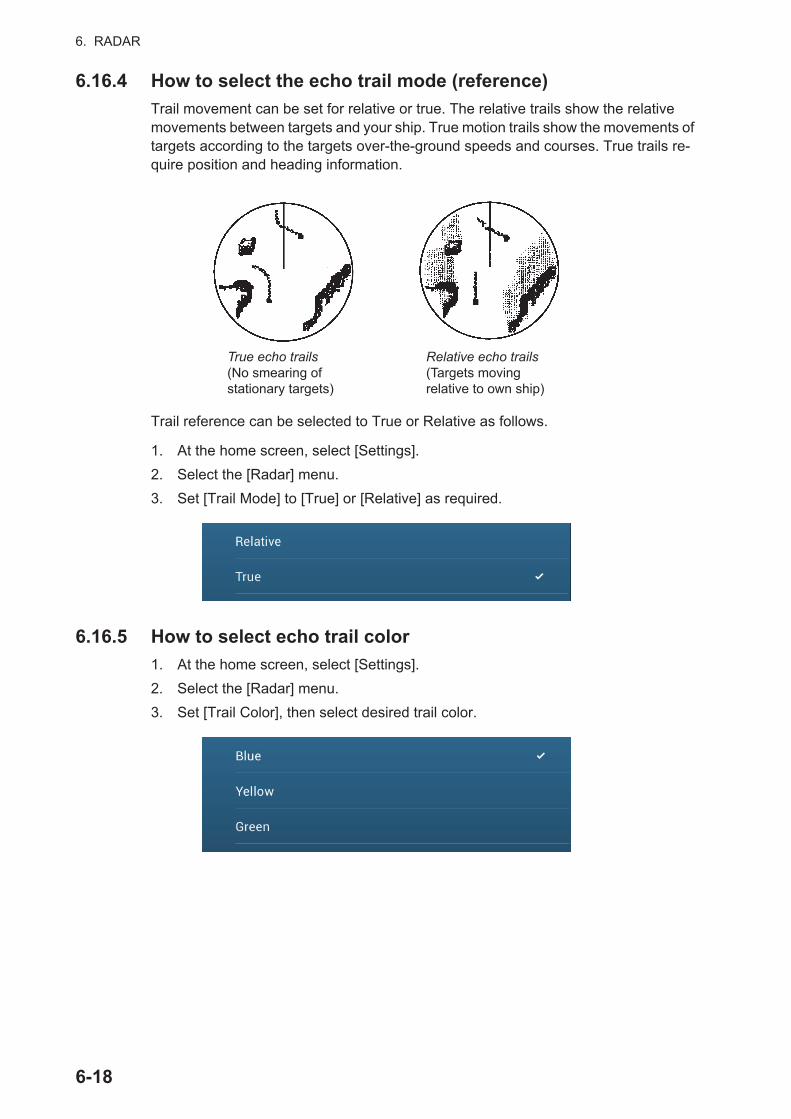
6. RADAR
6.16.4 How to select the echo trail mode (reference)
Trail movement can be set for relative or true. The relative trails show the relative movements between targets and your ship. True motion trails show the movements of targets according to the targets over-the-ground speeds and courses. True trails re-quire position and heading information.
Trail reference can be selected to True or Relative as follows.
1. At the home screen, select [Settings].
2. Select the [Radar] menu.
3. Set [Trail Mode] to [True] or [Relative] as required.
6.16.5 How to select echo trail color
1. At the home screen, select [Settings].
2. Select the [Radar] menu.
3. Set [Trail Color], then select desired trail color.
True echo trails(No smearing ofstationary targets)
Relative echo trails(Targets moving relative to own ship)
6-18

6. RADAR
6.16.6 How to select echo trail shading
The afterglow of the target trails can be shown in a single tone or gradual shading.
1. At the home screen, select [Settings].
2. Select the [Radar] menu.
3. Set [Trail Shade], then select [Single] or [Multi] as appropriate.
6.17 How to Show, Hide or Cancel an Active RouteYou can show, hide the active route on the radar display. Open the [Layers] menu then turn [Routes] on or off.
To cancel route navigation, tap any part of the route then tap [Stop Nav] on the pop-up menu.
6.18 How to Show or Hide the Own Ship IconYou can show or hide the boat icon on the radar display.
1. Open the home screen, then tap [Settings] - [Radar].
2. Turn [Own Ship Icon] on or off.
3. Tap the close button to finish.
Target
[Multi] trail[Single] trail
40
50
60
70
80
90
100
110
120
130
140
150
160170180190
200
210
220
230
240
250
260
270
280
290
300
310
320
Your shipYour ship’s positions position
6-19
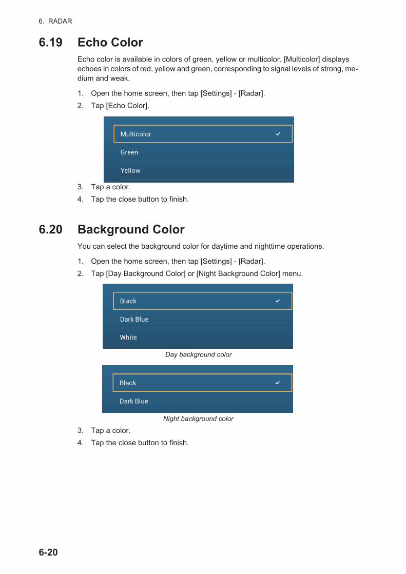
6. RADAR
6.19 Echo ColorEcho color is available in colors of green, yellow or multicolor. [Multicolor] displays echoes in colors of red, yellow and green, corresponding to signal levels of strong, me-dium and weak.
1. Open the home screen, then tap [Settings] - [Radar].
2. Tap [Echo Color].
3. Tap a color.
4. Tap the close button to finish.
6.20 Background ColorYou can select the background color for daytime and nighttime operations.
1. Open the home screen, then tap [Settings] - [Radar].
2. Tap [Day Background Color] or [Night Background Color] menu.
3. Tap a color.
4. Tap the close button to finish.
Day background color
Night background color
6-20
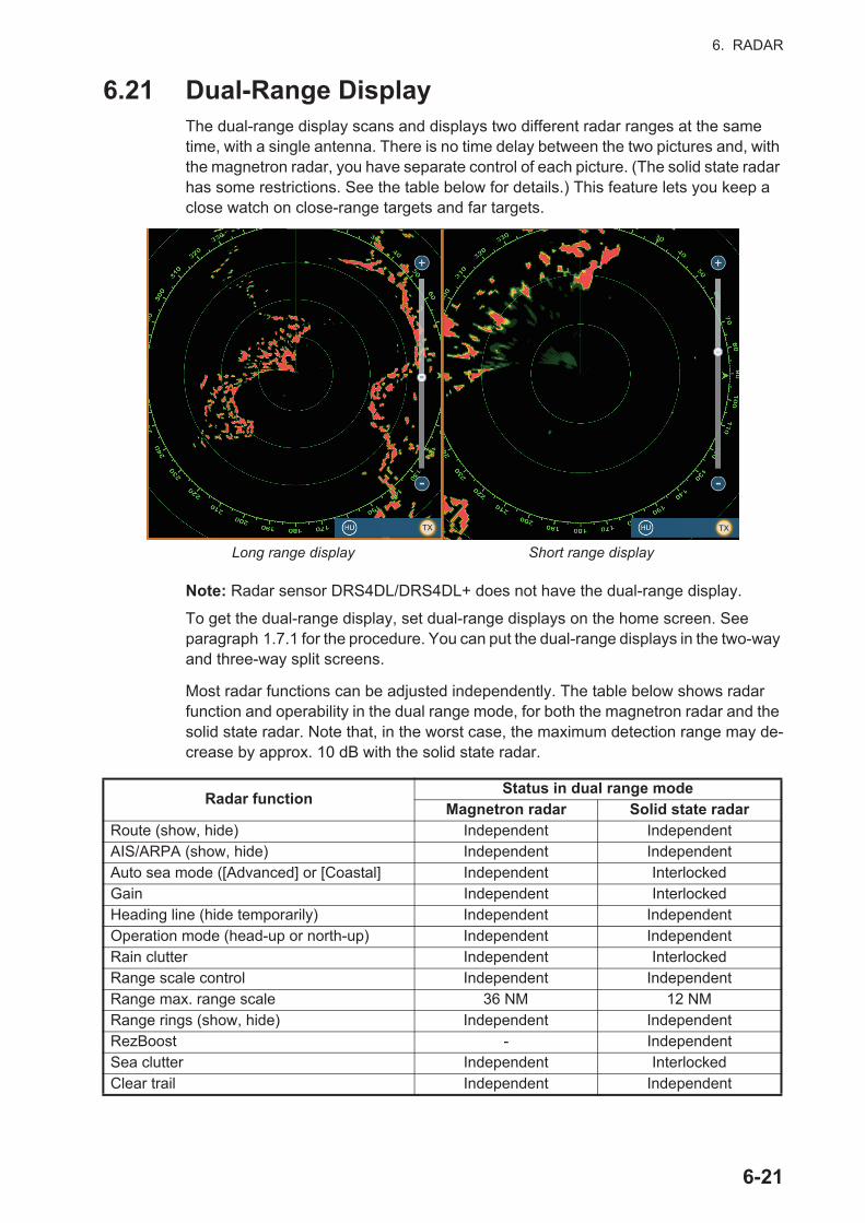
6. RADAR
6.21 Dual-Range DisplayThe dual-range display scans and displays two different radar ranges at the same time, with a single antenna. There is no time delay between the two pictures and, with the magnetron radar, you have separate control of each picture. (The solid state radar has some restrictions. See the table below for details.) This feature lets you keep a close watch on close-range targets and far targets.
Note: Radar sensor DRS4DL/DRS4DL+ does not have the dual-range display.
To get the dual-range display, set dual-range displays on the home screen. See paragraph 1.7.1 for the procedure. You can put the dual-range displays in the two-way and three-way split screens.
Most radar functions can be adjusted independently. The table below shows radar function and operability in the dual range mode, for both the magnetron radar and the solid state radar. Note that, in the worst case, the maximum detection range may de-crease by approx. 10 dB with the solid state radar.
Radar functionStatus in dual range mode
Magnetron radar Solid state radarRoute (show, hide) Independent IndependentAIS/ARPA (show, hide) Independent IndependentAuto sea mode ([Advanced] or [Coastal] Independent InterlockedGain Independent InterlockedHeading line (hide temporarily) Independent IndependentOperation mode (head-up or north-up) Independent IndependentRain clutter Independent InterlockedRange scale control Independent IndependentRange max. range scale 36 NM 12 NMRange rings (show, hide) Independent IndependentRezBoost - IndependentSea clutter Independent InterlockedClear trail Independent Independent
Short range displayLong range display
TX TX
6-21
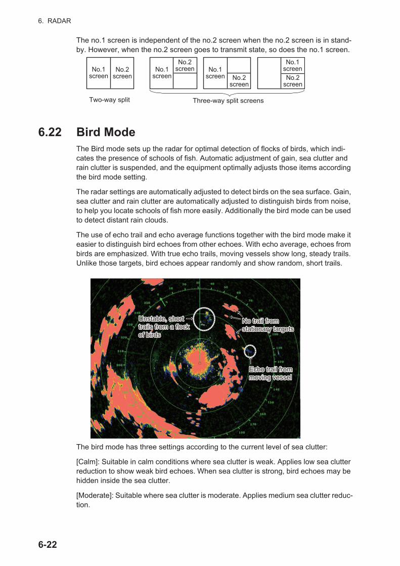
6. RADAR
The no.1 screen is independent of the no.2 screen when the no.2 screen is in stand-by. However, when the no.2 screen goes to transmit state, so does the no.1 screen.
6.22 Bird ModeThe Bird mode sets up the radar for optimal detection of flocks of birds, which indi-cates the presence of schools of fish. Automatic adjustment of gain, sea clutter and rain clutter is suspended, and the equipment optimally adjusts those items according the bird mode setting.
The radar settings are automatically adjusted to detect birds on the sea surface. Gain, sea clutter and rain clutter are automatically adjusted to distinguish birds from noise, to help you locate schools of fish more easily. Additionally the bird mode can be used to detect distant rain clouds.
The use of echo trail and echo average functions together with the bird mode make it easier to distinguish bird echoes from other echoes. With echo average, echoes from birds are emphasized. With true echo trails, moving vessels show long, steady trails. Unlike those targets, bird echoes appear randomly and show random, short trails.
The bird mode has three settings according to the current level of sea clutter:
[Calm]: Suitable in calm conditions where sea clutter is weak. Applies low sea clutter reduction to show weak bird echoes. When sea clutter is strong, bird echoes may be hidden inside the sea clutter.
[Moderate]: Suitable where sea clutter is moderate. Applies medium sea clutter reduc-tion.
Two-way split Three-way split screens
No.1 screen
No.2 screen
No.1 screen
No.2 screen No.1
screen No.2 screen
No.2 screen
No.1 screen
Echo trail from moving vesselEcho trail from moving vessel
Unstable, short trails from a flock of birds
Unstable, short trails from a flock of birds
No trail fromstationary targetsNo trail fromstationary targets
6-22
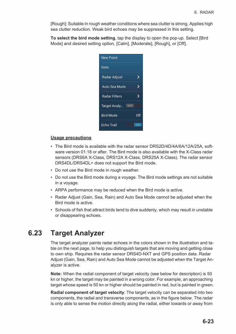
6. RADAR
[Rough]: Suitable in rough weather conditions where sea clutter is strong. Applies high sea clutter reduction. Weak bird echoes may be suppressed in this setting.
To select the bird mode setting, tap the display to open the pop-up. Select [Bird Mode] and desired setting option, [Calm], [Moderate], [Rough], or [Off].
Usage precautions
• The Bird mode is available with the radar sensor DRS2D/4D/4A/6A/12A/25A, soft-ware version 01.18 or after. The Bird mode is also available with the X-Class radar sensors (DRS6A X-Class, DRS12A X-Class, DRS25A X-Class). The radar sensor DRS4DL/DRS4DL+ does not support the Bird mode.
• Do not use the Bird mode in rough weather.
• Do not use the Bird mode during a voyage. The Bird mode settings are not suitable in a voyage.
• ARPA performance may be reduced when the Bird mode is active.
• Radar Adjust (Gain, Sea, Rain) and Auto Sea Mode cannot be adjusted when the Bird mode is active.
• Schools of fish that attract birds tend to dive suddenly, which may result in unstable or disappearing echoes.
6.23 Target AnalyzerThe target analyzer paints radar echoes in the colors shown in the illustration and ta-ble on the next page, to help you distinguish targets that are moving and getting close to own ship. Requires the radar sensor DRS4D-NXT and GPS position data. Radar Adjust (Gain, Sea, Rain) and Auto Sea Mode cannot be adjusted when the Target An-alyzer is active.
Note: When the radial component of target velocity (see below for description) is 50 kn or higher, the target may be painted in a wrong color. For example, an approaching target whose speed is 50 kn or higher should be painted in red, but is painted in green.
Radial component of target velocity: The target velocity can be separated into two components, the radial and transverse components, as in the figure below. The radar is only able to sense the motion directly along the radial, either towards or away from
6-23
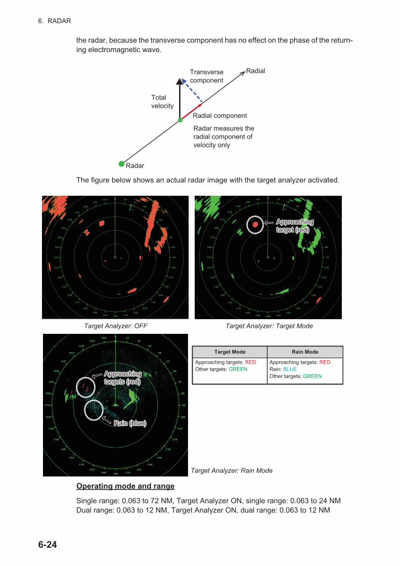
6. RADAR
the radar, because the transverse component has no effect on the phase of the return-ing electromagnetic wave.
The figure below shows an actual radar image with the target analyzer activated.
Operating mode and range
Single range: 0.063 to 72 NM, Target Analyzer ON, single range: 0.063 to 24 NMDual range: 0.063 to 12 NM, Target Analyzer ON, dual range: 0.063 to 12 NM
Radar
Total velocity
Transverse component
Radial component
Radial
Radar measures theradial component of velocity only
Target Analyzer: OFF Target Analyzer: Target Mode
Target Analyzer: Rain Mode
Approachingtarget (red)Approachingtarget (red)
Approachingtargets (red)Approachingtargets (red)
Rain (blue)Rain (blue)
Target Mode Rain Mode
Approaching targets: REDOther targets: GREEN
Approaching targets: REDRain: BLUEOther targets: GREEN
6-24
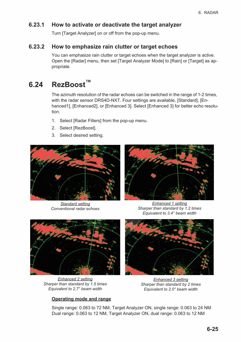
6. RADAR
6.23.1 How to activate or deactivate the target analyzer
Turn [Target Analyzer] on or off from the pop-up menu.
6.23.2 How to emphasize rain clutter or target echoes
You can emphasize rain clutter or target echoes when the target analyzer is active. Open the [Radar] menu, then set [Target Analyzer Mode] to [Rain] or [Target] as ap-propriate.
6.24 RezBoost™
The azimuth resolution of the radar echoes can be switched in the range of 1-2 times, with the radar sensor DRS4D-NXT. Four settings are available, [Standard], [En-hanced1], [Enhanced2], or [Enhanced 3]. Select [Enhanced 3] for better echo resolu-tion.
1. Select [Radar Filters] from the pop-up menu.
2. Select [RezBoost].
3. Select desired setting.
Operating mode and range
Single range: 0.063 to 72 NM, Target Analyzer ON, single range: 0.063 to 24 NMDual range: 0.063 to 12 NM, Target Analyzer ON, dual range: 0.063 to 12 NM
Standard settingConventional radar echoes
Enhanced 1 settingSharper than standard by 1.2 times
Equivalent to 3.4° beam width
Enhanced 2 settingSharper than standard by 1.5 times
Equivalent to 2.7° beam width
Enhanced 3 settingSharper than standard by 2 times
Equivalent to 2.0° beam width
6-25
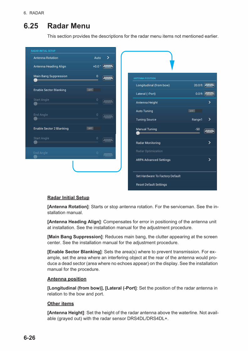
6. RADAR
6.25 Radar MenuThis section provides the descriptions for the radar menu items not mentioned earlier.
Radar Initial Setup
[Antenna Rotation]: Starts or stop antenna rotation. For the serviceman. See the in-stallation manual.
[Antenna Heading Align]: Compensates for error in positioning of the antenna unit at installation. See the installation manual for the adjustment procedure.
[Main Bang Suppression]: Reduces main bang, the clutter appearing at the screen center. See the installation manual for the adjustment procedure.
[Enable Sector Blanking]: Sets the area(s) where to prevent transmission. For ex-ample, set the area where an interfering object at the rear of the antenna would pro-duce a dead sector (area where no echoes appear) on the display. See the installation manual for the procedure.
Antenna position
[Longitudinal (from bow)], [Lateral (-Port]: Set the position of the radar antenna in relation to the bow and port.
Other items
[Antenna Height]: Set the height of the radar antenna above the waterline. Not avail-able (grayed out) with the radar sensor DRS4DL/DRS4DL+.
6-26
6. RADAR
[Auto Tuning]: Activate or deactivate auto tuning for the connected radar. Not avail-able (grayed out) with the radar sensor DRS4D-NXT
[Tuning Source]: For dual range display, select the range to use as the manual tuning source. Not available (grayed out) with the radar sensor DRS4DL/DRS4DL+, DRS4D-NXT.
[Manual Tuning]: Manually tune. Not available (grayed out) with the radar sensor DRS4D-NXT.
[Radar Monitoring]: Show various voltage levels, and ARPA data. For the service technician.
[Radar Optimization]: Automatically adjust magnetron output and tuning for the con-nected radar. Be sure to do this function after replacing the magnetron. Not avail-able (grayed out) with the radar sensor DRS4D-NXT.
[ARPA Advanced Settings]: Sets ARPA parameters. For the service technician only. Do not change the settings. Set [TX/STBY] to [ON] to access. Not available (grayed out) with the radar sensor DRS4DL, FAR-2xx7 series radar antenna.
[Set Hardware to Factory Default]: For the service technician only.
[Reset Default Settings]: Restore default settings for items other than those in the [RADAR INITIAL SETUP] section.
6-27
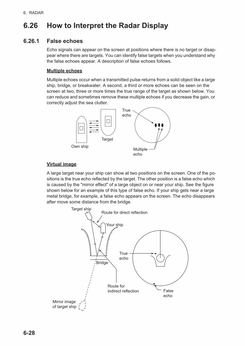
6. RADAR
6.26 How to Interpret the Radar Display
6.26.1 False echoes
Echo signals can appear on the screen at positions where there is no target or disap-pear where there are targets. You can identify false targets when you understand why the false echoes appear. A description of false echoes follows.
Multiple echoes
Multiple echoes occur when a transmitted pulse returns from a solid object like a large ship, bridge, or breakwater. A second, a third or more echoes can be seen on the screen at two, three or more times the true range of the target as shown below. You can reduce and sometimes remove these multiple echoes if you decrease the gain, or correctly adjust the sea clutter.
Virtual image
A large target near your ship can show at two positions on the screen. One of the po-sitions is the true echo reflected by the target. The other position is a false echo which is caused by the "mirror effect" of a large object on or near your ship. See the figure shown below for an example of this type of false echo. If your ship gets near a large metal bridge, for example, a false echo appears on the screen. The echo disappears after move some distance from the bridge.
Own ship
Target
True echo
Multiple echo
Target ship
Your ship
True echo
False echo
Mirror image of target ship
Route for direct reflection
Bridge
Route forindirect reflection
6-28

6. RADAR
Sector blanking
Funnels, stacks, masts, or derricks in the path of the antenna stop the radar beam. If the angle opposite the antenna is more than one or two degrees, a sector or shadow sector appears on the screen. Targets are not displayed within the sector.
Sidelobe echoes
Each time the radar transmits, some radiation leaves on each side of the beam. This lost energy has the name "sidelobes" If a target is detected by both the sidelobes and the mainlobe, the sidelobe echoes can appear at both sides of the true echo at the same range. Sidelobes normally show only on short ranges and from strong targets. You can reduce sidelobes if you reduce the gain, or correctly adjust the sea clutter.
Radar position
Large ship
Wharf and its echo
Sector blanking occurs because wharf is hidden behind ship.
Radar positionWharf and its echo
Sector blanking occurs because obstruction (like mast) is in path of radar beam.
Size of blanking sector depends on size of obstruction and range.
Mainlobe (beam)
Sidelobe Sidelobe
Antenna
True target
False echoes by sidelobes
6-29
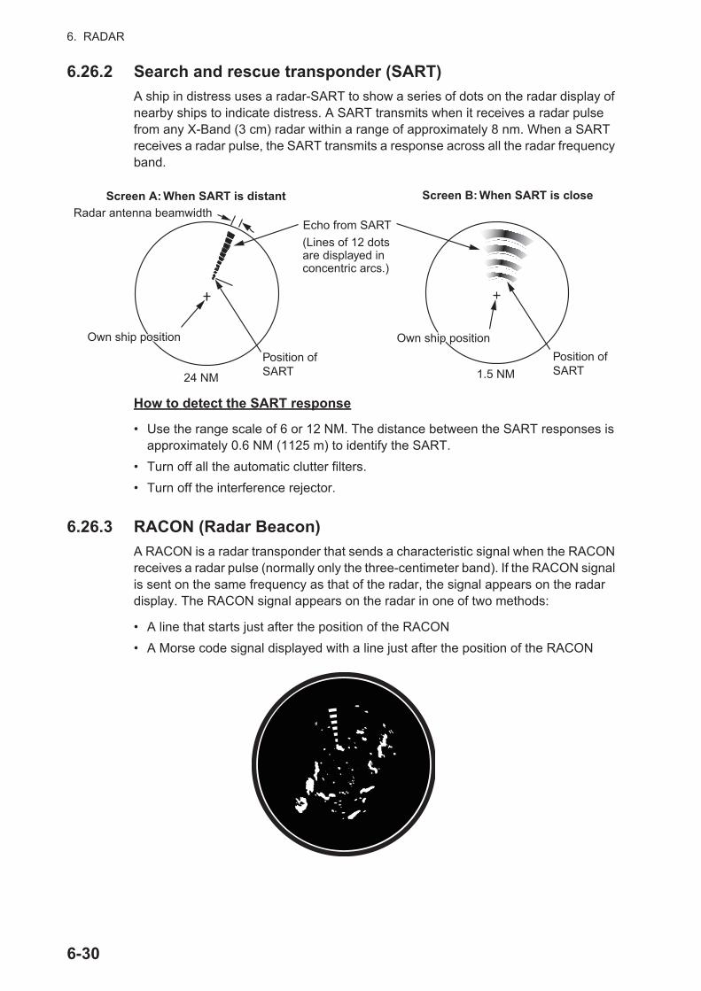
6. RADAR
6.26.2 Search and rescue transponder (SART)
A ship in distress uses a radar-SART to show a series of dots on the radar display of nearby ships to indicate distress. A SART transmits when it receives a radar pulse from any X-Band (3 cm) radar within a range of approximately 8 nm. When a SART receives a radar pulse, the SART transmits a response across all the radar frequency band.
How to detect the SART response
• Use the range scale of 6 or 12 NM. The distance between the SART responses is approximately 0.6 NM (1125 m) to identify the SART.
• Turn off all the automatic clutter filters.
• Turn off the interference rejector.
6.26.3 RACON (Radar Beacon)
A RACON is a radar transponder that sends a characteristic signal when the RACON receives a radar pulse (normally only the three-centimeter band). If the RACON signal is sent on the same frequency as that of the radar, the signal appears on the radar display. The RACON signal appears on the radar in one of two methods:
• A line that starts just after the position of the RACON
• A Morse code signal displayed with a line just after the position of the RACON
Radar antenna beamwidthScreen A: When SART is distant Screen B: When SART is close
Position of SART24 NM 1.5 NM
Own ship positionOwn ship position
Echo from SART(Lines of 12 dots are displayed in concentric arcs.)
Own ship positionOwn ship positionPosition of SART
6-30
6. RADAR
6.27 ARPA OperationThe ARPA (Automatic Radar Plotting Aid) shows the movement of a maximum of 30 radar targets. The targets can be acquired manually or automatically. All 30 targets can be acquired manually when the ARPA acquisition area is not active. If the ARPA acquisition area is active, that total is equally divided between manual and auto acqui-sition.
ARPA requires speed and heading data.
Note 1: The DRS4DL radar sensor does not have the ARPA function.
Note 2: For configurations using DRS4D-NXT or DRS6A-NXT sensors, the maximum number of targets that can be acquired is 100.
6.27.1 How to show or hide the ARPA display
Open the [Layers] menu, then turn [ARPA Targets] on or off.
WARNING CAUTIONCAUTIONNo one navigational aid should be relied upon for the safety of vessel and crew. The navigator has the responsibility to check all aids available to confirm position. Electronic aids are not a substitute for basic navigational principles and common sense.
· This auto plotter automatically tracks an automatically or manually acquired radar target and calculates its course and speed, indicating them by a vector. Since the data generated by the auto plotter are based on what radar targets are selected, the radar must always be optimally tuned for use with the auto plotter, to ensure required targets will not be lost or unwanted targets such as sea returns and noise will not be acquired and tracked.
· A target does not always mean a landmass, reef, ships or other surface vessels but can imply returns from sea surface and clutter. As the level of clutter changes with environment, the operator should properly adjust the Sea, Rain and Gain to be sure target echoes are not eliminated from the radar screen.
The plotting accuracy and response of this auto plotter meets IMO standards. Tracking accuracy is affected by the following:
· Tracking accuracy is affected by course change. One to two minutes is required to restore vectors to full accuracy after an abrupt course change. (The actual amount depends on gyrocompass specifications.)
· The amount of tracking delay is inversely proportional to the relative speed of the target. Delay ranges from 15 - 30 seconds for high relative speed; 30 - 60 seconds for low relative speed.
Display accuracy is affected by the following:
· Echo intensity· Radar transmission pulsewidth· Radar bearing error· Gyrocompass error· Course change (your ship or target)
6-31

6. RADAR
6.27.2 How to manually acquire a target
You can manually acquire a target from both the radar display and the radar display overlay. Up to 30 targets can be acquired manually. Tap the target to acquire to show the pop-up menu, then tap [Acquire].
Note: For configurations using DRS4D-NXT or DRS6A-NXT sensors, the maximum number of targets that can be acquired is 100.
After you acquire a target, the radar marks the target with a broken square and a vec-tor appears within 30 s (default setting). The vector indicates the direction of the target. Within 90 s after you acquire the target, the first tracking step is finished and the target is tracked continuously. At this point, the broken square changes to a solid circle.
Note 1: For successful acquisition, the target must be within 0.05 to 16 NM from your ship and not hidden in sea or rain clutter.
Note 2: When the capacity for manual acquisition is reached, you cannot acquire more targets. Cancel tracking of non-threatening targets to acquire additional targets manually.
6.27.3 How to automatically acquire a target
Any target that enters the ARPA acquisition area is acquired and tracked automatical-ly. When a target enters the area, the buzzer sounds. To disable the buzzer, set [Alarm] to [OFF] in the pop-up menu at step 2 in the below procedure.
1. Create a guard zone referring to section 6.14.
2. Tap a line on the guard zone to show the pop-up menu. Turn on [Auto Acquire]. The dotted lines for the guard zone turn into solid lines.
6.27.4 How to automatically acquire targets by Doppler
With acquisition by Doppler active, you can track up to 100 targets in total as follows.- 40 targets by auto acquire by Doppler- 30 targets by auto acquire by guard zones- 30 targets by manual tracking
When automatic acquisition by Doppler is activated, approaching targets (ships, rain clutter, etc.) within 3 NM from own ship are automatically acquired by the Doppler cal-culated from the radar echo.
ARPA Symbol Meaning ARPA Symbol Meaning
At acquisition of the tar-get.
30 s after the acquisi-tion, the plotting symbol changes to a small cir-cle, which indicates steady-state tracking. A vector (dashed line) shows the direction of the target.
A lost target is indicated by a diamond symbol, created from two equal triangles.
A target that meets the criteria of the CPA/TCPA alarm is changed to a dangerous target.
Color: green Color: green
Vector
Color: greenColor: red
6-32
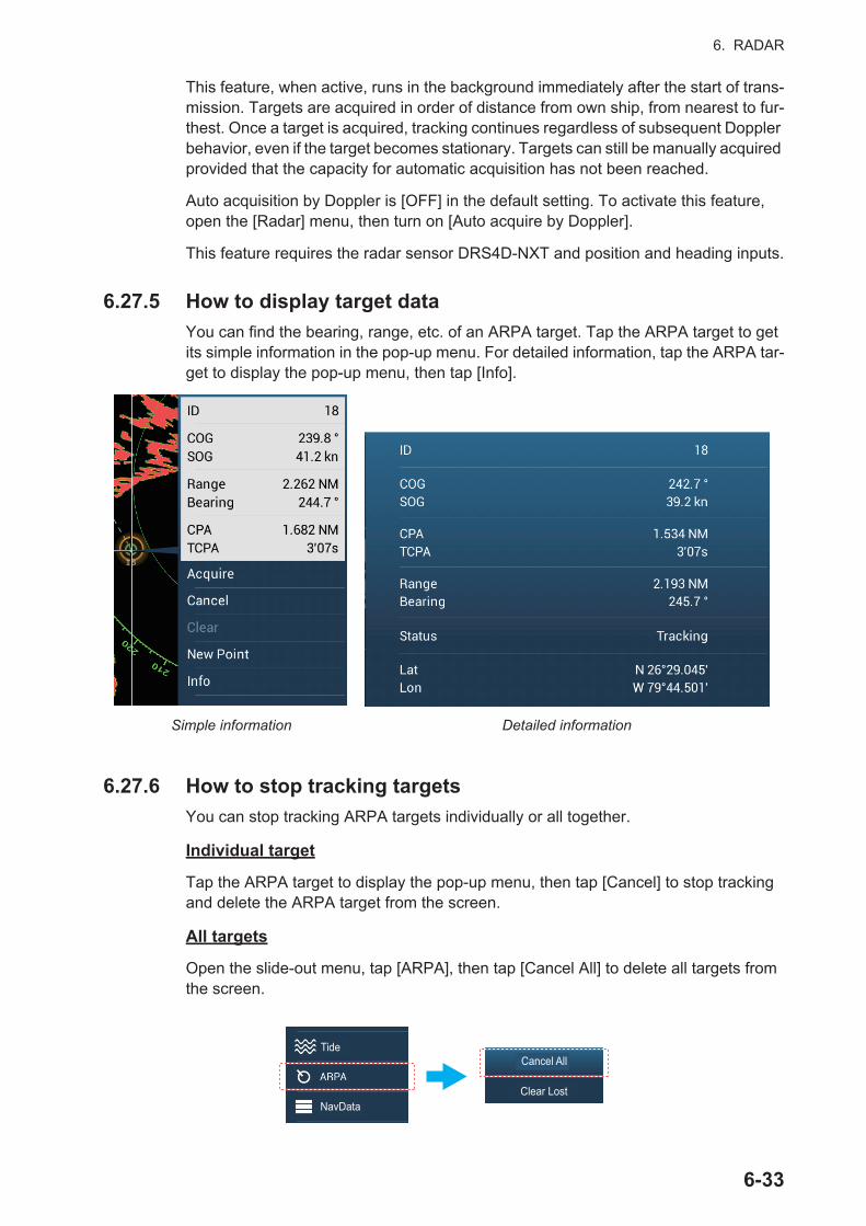
6. RADAR
This feature, when active, runs in the background immediately after the start of trans-mission. Targets are acquired in order of distance from own ship, from nearest to fur-thest. Once a target is acquired, tracking continues regardless of subsequent Doppler behavior, even if the target becomes stationary. Targets can still be manually acquired provided that the capacity for automatic acquisition has not been reached.
Auto acquisition by Doppler is [OFF] in the default setting. To activate this feature, open the [Radar] menu, then turn on [Auto acquire by Doppler].
This feature requires the radar sensor DRS4D-NXT and position and heading inputs.
6.27.5 How to display target data
You can find the bearing, range, etc. of an ARPA target. Tap the ARPA target to get its simple information in the pop-up menu. For detailed information, tap the ARPA tar-get to display the pop-up menu, then tap [Info].
6.27.6 How to stop tracking targets
You can stop tracking ARPA targets individually or all together.
Individual target
Tap the ARPA target to display the pop-up menu, then tap [Cancel] to stop tracking and delete the ARPA target from the screen.
All targets
Open the slide-out menu, tap [ARPA], then tap [Cancel All] to delete all targets from the screen.
Simple information Detailed information
S
Tide
NavDataClear Lost
Cancel All
6-33

6. RADAR
6.27.7 ARPA list
The ARPA list displays data for all ARPA targets being tracked.
How to show the ARPA list
To show the list, go the Home screen, then tap [Lists] - [ARPA]. The color bars at the left side of the list denote ARPA symbol status, green for tracking or lost target, red for dangerous target.
To sort the list, tap appropriate sort method button at the top of the list. ID: Sort by ID no. Range: Sort by range, closest to furthest from own ship. CPA: Sort in CPA order.
The [Refresh] button updates target data.
How to show detailed ARPA target information
Tap the target on the ARPA list to see its information.
How to put an ARPA target at the center of the plotter display
Tap a target on the list. Tap [Find on Chart] to put the ARPA target at the center of the plotter display.
Refresh
Sort methods
Range
ID/Status
ID/Status
ID/Status
ID/Status
ID/Status
Tracking
Tracking
Tracking
Lost
Range/Bearing
Range/Bearing
Range/Bearing
Range/Bearing
Range/Bearing
Bar
Find on Chart
6-34
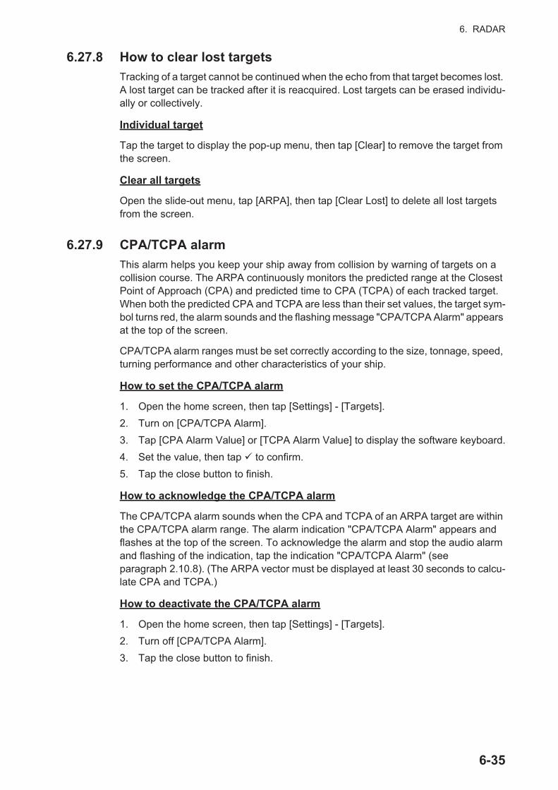
6. RADAR
6.27.8 How to clear lost targets
Tracking of a target cannot be continued when the echo from that target becomes lost. A lost target can be tracked after it is reacquired. Lost targets can be erased individu-ally or collectively.
Individual target
Tap the target to display the pop-up menu, then tap [Clear] to remove the target from the screen.
Clear all targets
Open the slide-out menu, tap [ARPA], then tap [Clear Lost] to delete all lost targets from the screen.
6.27.9 CPA/TCPA alarm
This alarm helps you keep your ship away from collision by warning of targets on a collision course. The ARPA continuously monitors the predicted range at the Closest Point of Approach (CPA) and predicted time to CPA (TCPA) of each tracked target. When both the predicted CPA and TCPA are less than their set values, the target sym-bol turns red, the alarm sounds and the flashing message "CPA/TCPA Alarm" appears at the top of the screen.
CPA/TCPA alarm ranges must be set correctly according to the size, tonnage, speed, turning performance and other characteristics of your ship.
How to set the CPA/TCPA alarm
1. Open the home screen, then tap [Settings] - [Targets].
2. Turn on [CPA/TCPA Alarm].
3. Tap [CPA Alarm Value] or [TCPA Alarm Value] to display the software keyboard.
4. Set the value, then tap to confirm.
5. Tap the close button to finish.
How to acknowledge the CPA/TCPA alarm
The CPA/TCPA alarm sounds when the CPA and TCPA of an ARPA target are within the CPA/TCPA alarm range. The alarm indication "CPA/TCPA Alarm" appears and flashes at the top of the screen. To acknowledge the alarm and stop the audio alarm and flashing of the indication, tap the indication "CPA/TCPA Alarm" (see paragraph 2.10.8). (The ARPA vector must be displayed at least 30 seconds to calcu-late CPA and TCPA.)
How to deactivate the CPA/TCPA alarm
1. Open the home screen, then tap [Settings] - [Targets].
2. Turn off [CPA/TCPA Alarm].
3. Tap the close button to finish.
6-35
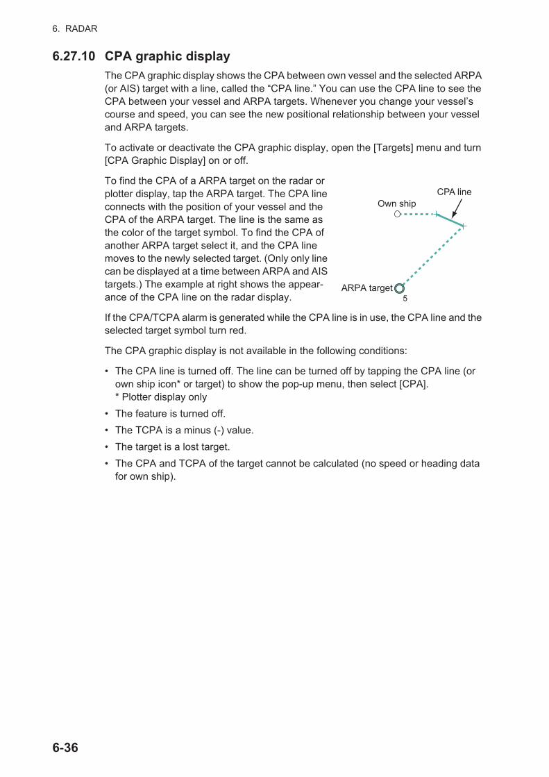
6. RADAR
6.27.10 CPA graphic display
The CPA graphic display shows the CPA between own vessel and the selected ARPA (or AIS) target with a line, called the “CPA line.” You can use the CPA line to see the CPA between your vessel and ARPA targets. Whenever you change your vessel’s course and speed, you can see the new positional relationship between your vessel and ARPA targets.
To activate or deactivate the CPA graphic display, open the [Targets] menu and turn [CPA Graphic Display] on or off.
To find the CPA of a ARPA target on the radar or plotter display, tap the ARPA target. The CPA line connects with the position of your vessel and the CPA of the ARPA target. The line is the same as the color of the target symbol. To find the CPA of another ARPA target select it, and the CPA line moves to the newly selected target. (Only only line can be displayed at a time between ARPA and AIS targets.) The example at right shows the appear-ance of the CPA line on the radar display.
If the CPA/TCPA alarm is generated while the CPA line is in use, the CPA line and the selected target symbol turn red.
The CPA graphic display is not available in the following conditions:
• The CPA line is turned off. The line can be turned off by tapping the CPA line (or own ship icon* or target) to show the pop-up menu, then select [CPA].* Plotter display only
• The feature is turned off.
• The TCPA is a minus (-) value.
• The target is a lost target.
• The CPA and TCPA of the target cannot be calculated (no speed or heading data for own ship).
CPA lineOwn ship
5ARPA target
6-36
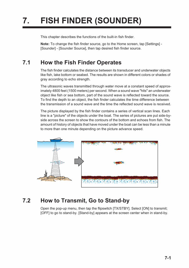
7. FISH FINDER (SOUNDER)
This chapter describes the functions of the built-in fish finder.
Note: To change the fish finder source, go to the Home screen, tap [Settings] - [Sounder] - [Sounder Source], then tap desired fish finder source.
7.1 How the Fish Finder OperatesThe fish finder calculates the distance between its transducer and underwater objects like fish, lake bottom or seabed. The results are shown in different colors or shades of gray according to echo strength.
The ultrasonic waves transmitted through water move at a constant speed of approx-imately 4800 feet (1500 meters) per second. When a sound wave "hits" an underwater object like fish or sea bottom, part of the sound wave is reflected toward the source. To find the depth to an object, the fish finder calculates the time difference between the transmission of a sound wave and the time the reflected sound wave is received.
The picture displayed by the fish finder contains a series of vertical scan lines. Each line is a "picture" of the objects under the boat. The series of pictures are put side-by-side across the screen to show the contours of the bottom and echoes from fish. The amount of history of objects that have moved under the boat can be less than a minute to more than one minute depending on the picture advance speed.
7.2 How to Transmit, Go to Stand-byOpen the pop-up menu, then tap the flipswitch [TX/STBY]. Select [ON] to transmit; [OFF] to go to stand-by. [Stand-by] appears at the screen center when in stand-by.
7-1

7. FISH FINDER (SOUNDER)
7.3 How to Select a DisplayYour fish finder has six display modes. These modes are single frequency, dual fre-quency, bottom zoom, bottom lock, A-scope, and bottom discrimination.
7.3.1 Single frequency display
The single frequency display shows either the low-fre-quency or high-frequency picture on all the screen. Se-lect a frequency according to your purpose.
How to select a single frequency display
Tap the screen to show the pop-up menu. Tap [Mode] [Single Freq.].
How to switch between the low and high frequency displays
You can switch between the high and low frequency displays by two methods.
Method 1: Tap the depth indication box.
Method 2: Tap the screen to show the pop-up menu. Tap [Fre-quency], then tap the flipswitch of [HF] or [LF] as appropriate.
Note: The above two methods can also be used to reverse the location of the high and low frequency pictures in the dual fre-quency display and switch between low and high frequency pictures in a zoom display.
• A low frequency gives a wide detection area. Use the low frequency for general search and to find bottom conditions.
• A high frequency gives better resolution. Use the high frequency to inspect a school of fish.
High freq.Low
freq.
Depth 18.8 ft
Range 427 yd
LF(S) (S)
7-2
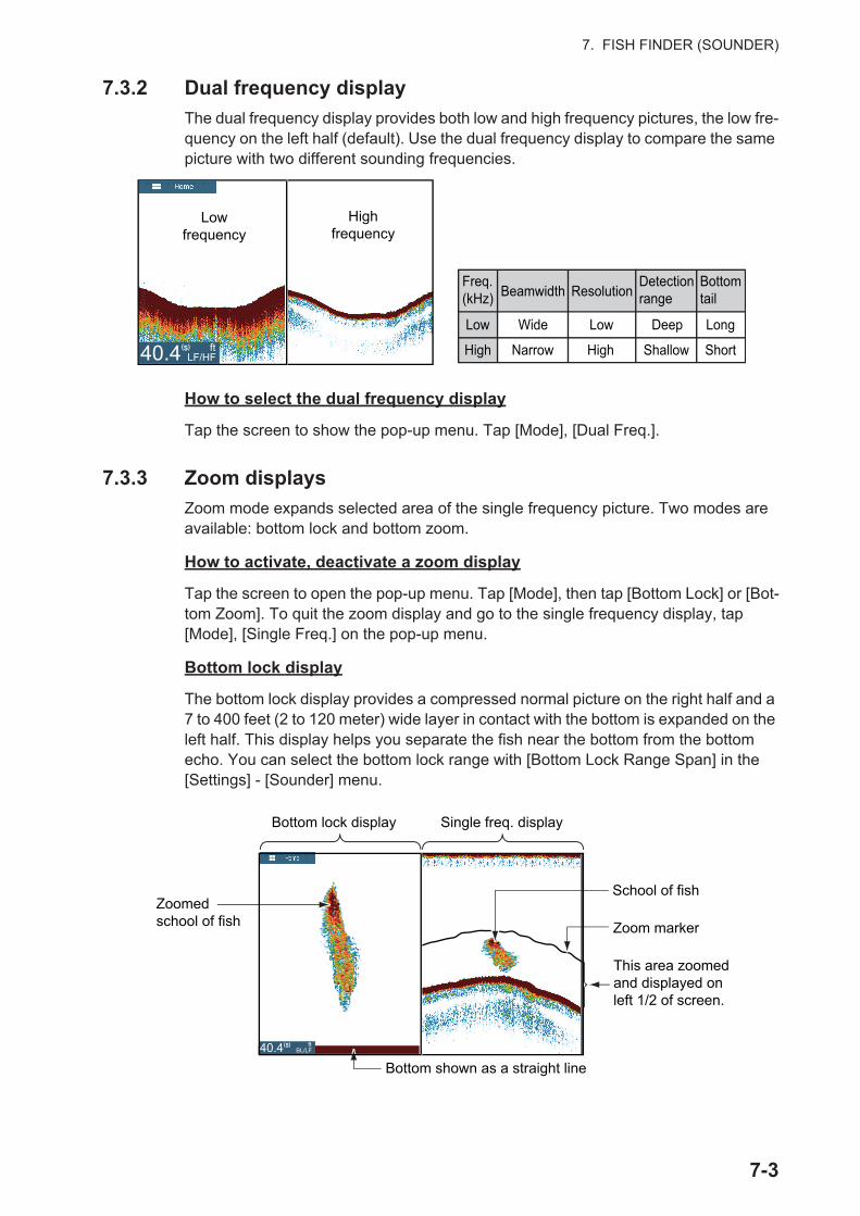
7. FISH FINDER (SOUNDER)
7.3.2 Dual frequency display
The dual frequency display provides both low and high frequency pictures, the low fre-quency on the left half (default). Use the dual frequency display to compare the same picture with two different sounding frequencies.
How to select the dual frequency display
Tap the screen to show the pop-up menu. Tap [Mode], [Dual Freq.].
7.3.3 Zoom displays
Zoom mode expands selected area of the single frequency picture. Two modes are available: bottom lock and bottom zoom.
How to activate, deactivate a zoom display
Tap the screen to open the pop-up menu. Tap [Mode], then tap [Bottom Lock] or [Bot-tom Zoom]. To quit the zoom display and go to the single frequency display, tap [Mode], [Single Freq.] on the pop-up menu.
Bottom lock display
The bottom lock display provides a compressed normal picture on the right half and a 7 to 400 feet (2 to 120 meter) wide layer in contact with the bottom is expanded on the left half. This display helps you separate the fish near the bottom from the bottom echo. You can select the bottom lock range with [Bottom Lock Range Span] in the [Settings] - [Sounder] menu.
Lowfrequency
Highfrequency
RA
DA
RD
AR
DA
RA
RA
RRRRRRRR
Freq. (kHz)
Low
High
Beamwidth ResolutionDetection range
Bottom tail
Wide
Narrow
Low
High
Deep
Shallow
Long
Short ftLF/HF40.4(S)
Zoomed school of fish
Bottom lock display Single freq. display
Zoom marker
School of fish
This area zoomed and displayed on left 1/2 of screen.
Bottom shown as a straight line
ft BL/LF40.4(S)
7-3
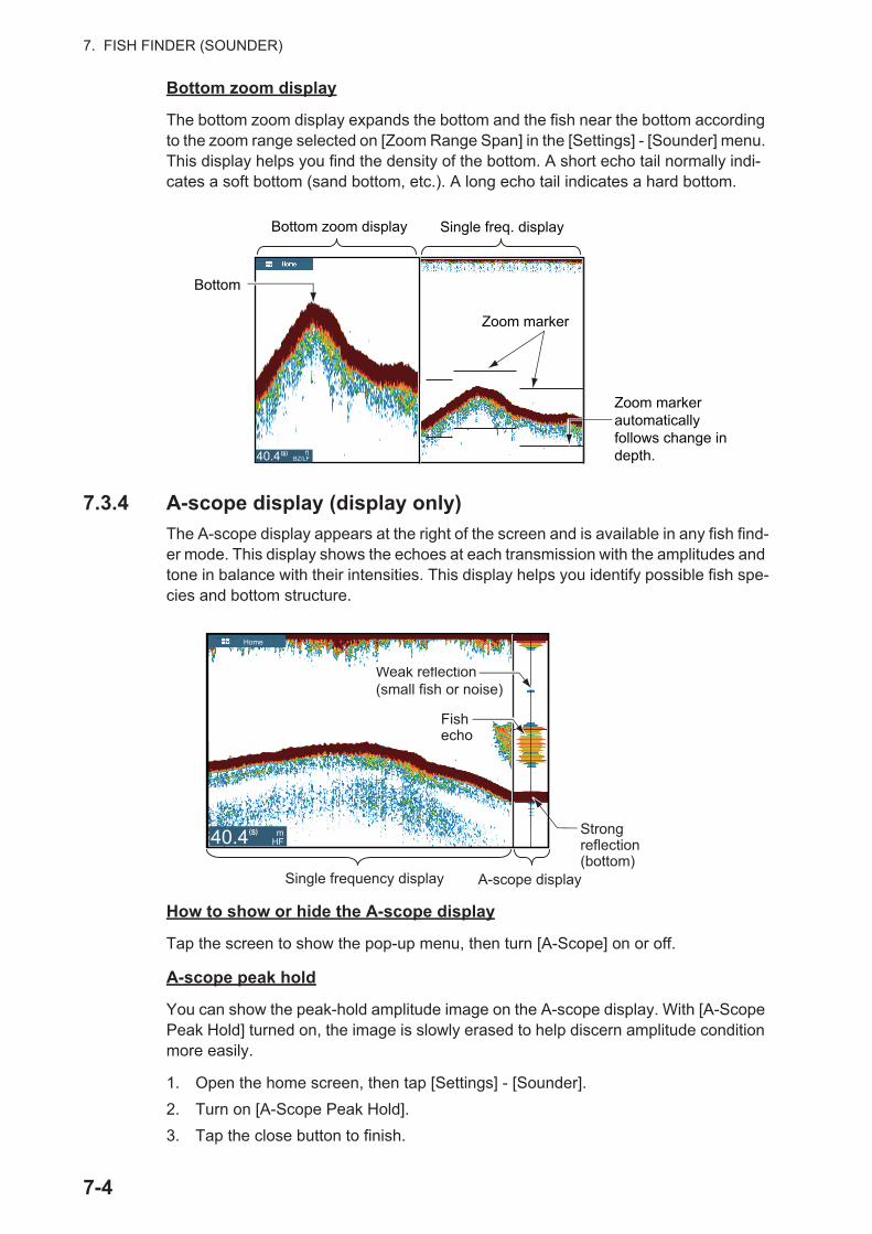
7. FISH FINDER (SOUNDER)
Bottom zoom display
The bottom zoom display expands the bottom and the fish near the bottom according to the zoom range selected on [Zoom Range Span] in the [Settings] - [Sounder] menu. This display helps you find the density of the bottom. A short echo tail normally indi-cates a soft bottom (sand bottom, etc.). A long echo tail indicates a hard bottom.
7.3.4 A-scope display (display only)
The A-scope display appears at the right of the screen and is available in any fish find-er mode. This display shows the echoes at each transmission with the amplitudes and tone in balance with their intensities. This display helps you identify possible fish spe-cies and bottom structure.
How to show or hide the A-scope display
Tap the screen to show the pop-up menu, then turn [A-Scope] on or off.
A-scope peak hold
You can show the peak-hold amplitude image on the A-scope display. With [A-Scope Peak Hold] turned on, the image is slowly erased to help discern amplitude condition more easily.
1. Open the home screen, then tap [Settings] - [Sounder].
2. Turn on [A-Scope Peak Hold].
3. Tap the close button to finish.
Zoom marker automatically follows change in depth.
Bottom zoom display
Bottom
Single freq. display
Zoom marker
ft BZ/LF40.4(S)
A-scope displaySingle frequency display
Weak reflection (small fish or noise)
Strong reflection (bottom)
Fish echoFish echo
Home
mHF40.4(S)
7-4
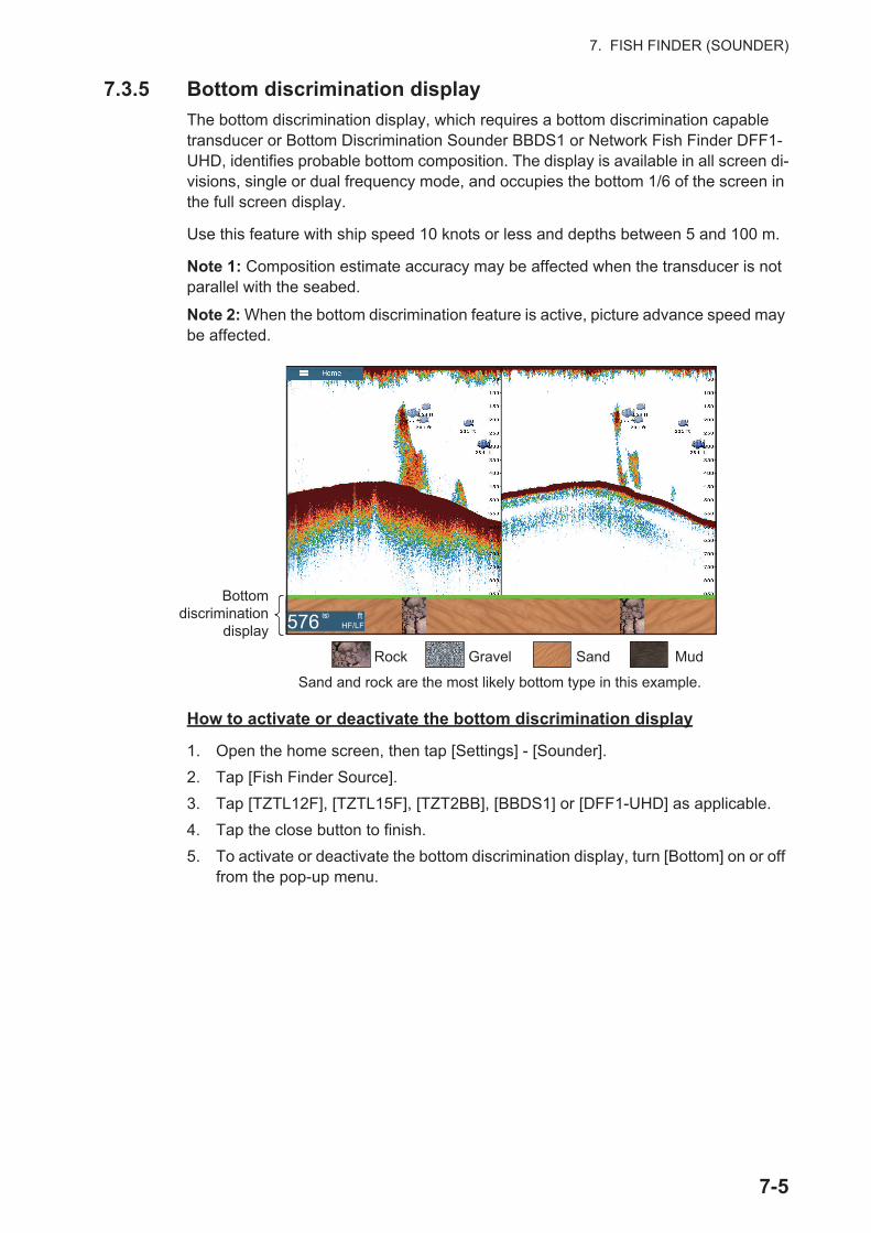
7. FISH FINDER (SOUNDER)
7.3.5 Bottom discrimination display
The bottom discrimination display, which requires a bottom discrimination capable transducer or Bottom Discrimination Sounder BBDS1 or Network Fish Finder DFF1-UHD, identifies probable bottom composition. The display is available in all screen di-visions, single or dual frequency mode, and occupies the bottom 1/6 of the screen in the full screen display.
Use this feature with ship speed 10 knots or less and depths between 5 and 100 m.
Note 1: Composition estimate accuracy may be affected when the transducer is not parallel with the seabed.
Note 2: When the bottom discrimination feature is active, picture advance speed may be affected.
How to activate or deactivate the bottom discrimination display
1. Open the home screen, then tap [Settings] - [Sounder].
2. Tap [Fish Finder Source].
3. Tap [TZTL12F], [TZTL15F], [TZT2BB], [BBDS1] or [DFF1-UHD] as applicable.
4. Tap the close button to finish.
5. To activate or deactivate the bottom discrimination display, turn [Bottom] on or off from the pop-up menu.
Bottomdiscrimination
display
Rock Gravel Sand Mud
Sand and rock are the most likely bottom type in this example.
ftHF/LF576 (S)
7-5
7. FISH FINDER (SOUNDER)
7.4 Automatic Fish Finder OperationYour fish finder can be adjusted automatically to let you do other tasks.
7.4.1 How the automatic fish finder operates
The automatic fish finder function automatically adjusts the gain, clutter, TVG, echo offset and range. The main features of the automatic mode are as shown below.
• Gain adjusts the sensitivity of the receiver to show the bottom echo in reddish-brown (default color arrangement).
• Clutter automatically reduces low-level noise like plankton.
• The TVG function is automatically adjusted.
• The echo offset balances the gain on high and low frequencies.
• Range is adjusted automatically to show the bottom echo.
7.4.2 How to select an automatic fish finder mode
There are two types of automatic fish finder modes: [Auto Fishing] and [Auto Cruising]. [Auto Fishing] searches for schools of fish, and [Auto Cruising] tracks the bottom.[Auto Cruising] uses a higher clutter removal setting than [Auto Fishing]. Do not use [Auto Cruising] when your purpose is to find fish, because the clutter removal circuit can erase weak echoes.
To select an automatic fish finder mode, tap the screen to open the pop-up menu, tap [Adjust] then tap [Auto Fishing] or [Auto Cruising]
7.5 Manual Fish Finder OperationUse the manual operation to see schools of fish and the bottom echo with a fixed gain setting. The gain, range and range shift functions let you select the depth you can see on the screen.
7.5.1 How to select the manual mode
Tap the screen to open the pop-up menu. Tap [Adjust] then tap [Manual].
7.5.2 How to select the display range
Manual range setting
Pinch the fish finder screen or use the slider bar. The slider bar can be shown or hid-den with [Show Scale Slider] in the [Settings] - [Sounder] menu.
How to turn on or off the auto range
The range can be selected automatically or manually. tap the screen to open the pop-up menu, then turn [Auto Range] on or off.
7-6
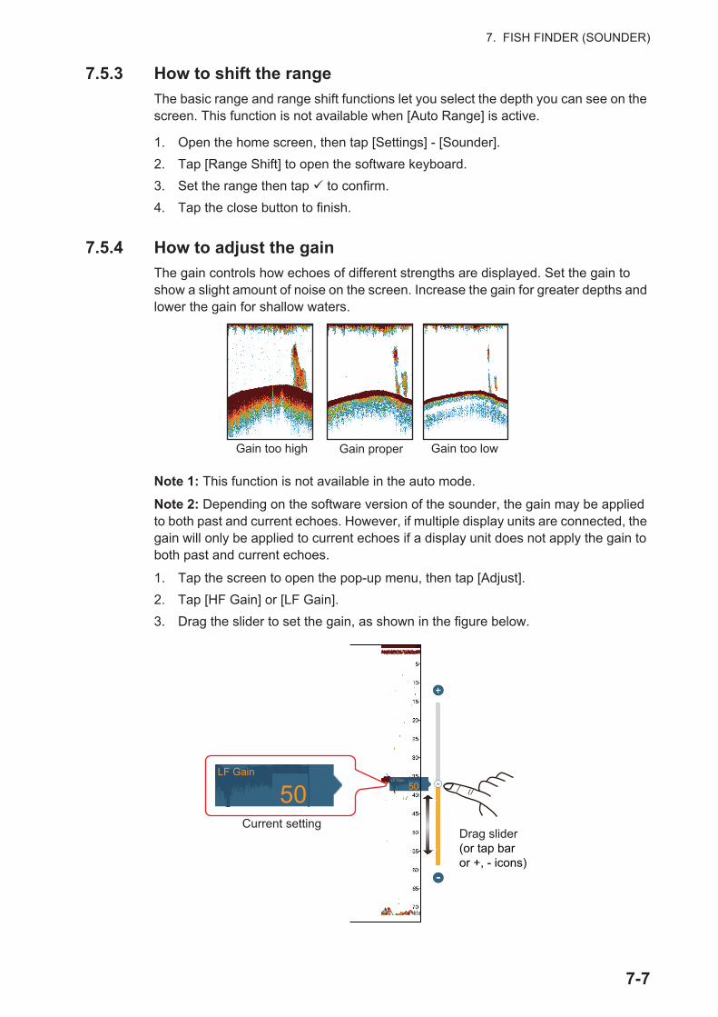
7. FISH FINDER (SOUNDER)
7.5.3 How to shift the range
The basic range and range shift functions let you select the depth you can see on the screen. This function is not available when [Auto Range] is active.
1. Open the home screen, then tap [Settings] - [Sounder].
2. Tap [Range Shift] to open the software keyboard.
3. Set the range then tap to confirm.
4. Tap the close button to finish.
7.5.4 How to adjust the gain
The gain controls how echoes of different strengths are displayed. Set the gain to show a slight amount of noise on the screen. Increase the gain for greater depths and lower the gain for shallow waters.
Note 1: This function is not available in the auto mode.
Note 2: Depending on the software version of the sounder, the gain may be applied to both past and current echoes. However, if multiple display units are connected, the gain will only be applied to current echoes if a display unit does not apply the gain to both past and current echoes.
1. Tap the screen to open the pop-up menu, then tap [Adjust].
2. Tap [HF Gain] or [LF Gain].
3. Drag the slider to set the gain, as shown in the figure below.
Gain too high Gain proper Gain too low
Drag slider(or tap bar or +, - icons)
LF Gain
Current setting
LF Gain5050
7-7

7. FISH FINDER (SOUNDER)
7.5.5 How to reduce the clutter
Low intensity "spots" of noise appear over most of the screen like in the illustration shown below. These spots are caused by sediment in the water or noise. You can reduce this type of noise.
Note: This function is not available in the auto mode.
1. Open the home screen, then tap [Settings] - [Sounder].
2. Drag the slider at [Clutter] to set the level. The larger the setting value, the greater the degree of reduction.
3. Tap the close button to finish.
7.6 Picture Advance SpeedThe picture advance speed controls how quickly the vertical scan lines move across the screen. A fast advance speed expands the size of a school of fish horizontally on the screen. A slow advance speed shortens the school of fish. Use a fast advance speed to see the hard bottom. Use a slow advance speed to see the smooth bottom.
1. Open the home screen, then tap [Settings] - [Sounder].
2. Tap [Picture Advance].
3. Tap a picture advance speed. The options in the window indicate the number of scan lines made per transmission. For example, [1/2] creates one scan line per two transmissions. [1/16] is the slowest advance speed and [4] is the fastest speed. [Stop] stops picture advance, and is useful for taking a photo of the screen.
4. Tap the close button to finish.
CAUTIONThe picture is not refreshed when picture
advancement is stopped.
Cruising in this state in shallow waters may ground the vessel.
Fast Slow
7-8
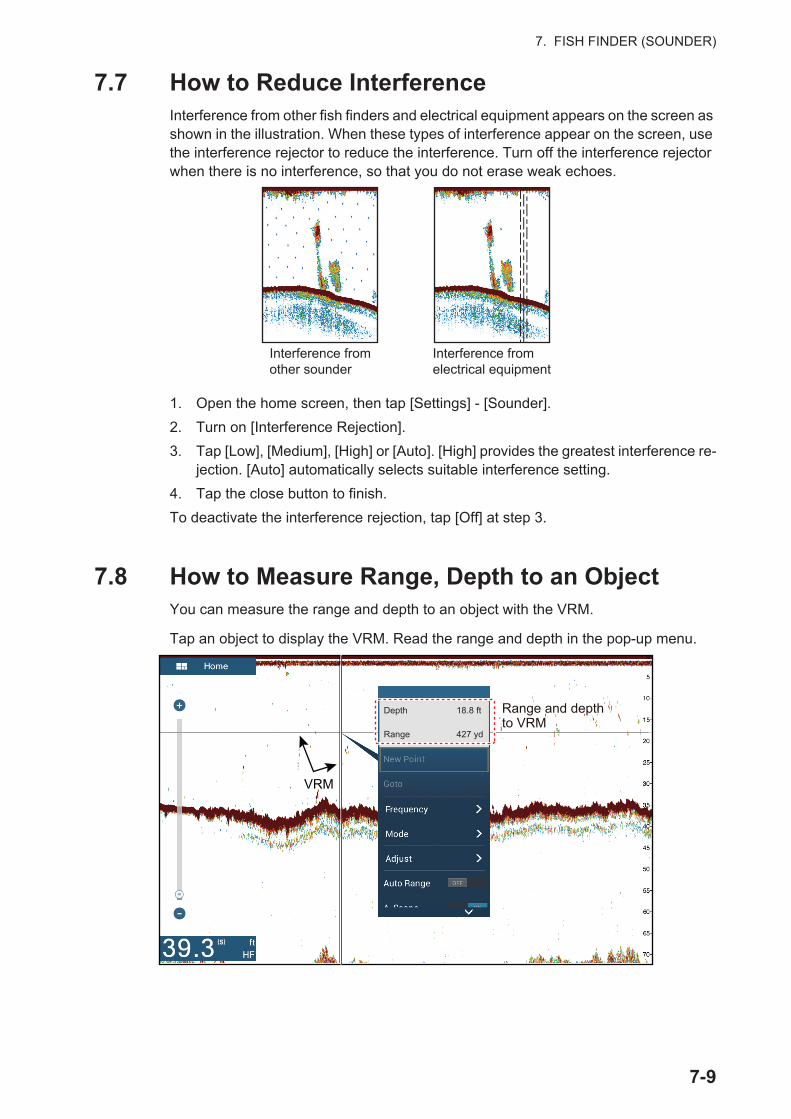
7. FISH FINDER (SOUNDER)
7.7 How to Reduce InterferenceInterference from other fish finders and electrical equipment appears on the screen as shown in the illustration. When these types of interference appear on the screen, use the interference rejector to reduce the interference. Turn off the interference rejector when there is no interference, so that you do not erase weak echoes.
1. Open the home screen, then tap [Settings] - [Sounder].
2. Turn on [Interference Rejection].
3. Tap [Low], [Medium], [High] or [Auto]. [High] provides the greatest interference re-jection. [Auto] automatically selects suitable interference setting.
4. Tap the close button to finish.
To deactivate the interference rejection, tap [Off] at step 3.
7.8 How to Measure Range, Depth to an ObjectYou can measure the range and depth to an object with the VRM.
Tap an object to display the VRM. Read the range and depth in the pop-up menu.
Interference from other sounder
Interference from electrical equipment
Range and depthto VRM
VRM
(S)
Depth 18.8 ft
Range 427 yd
7-9
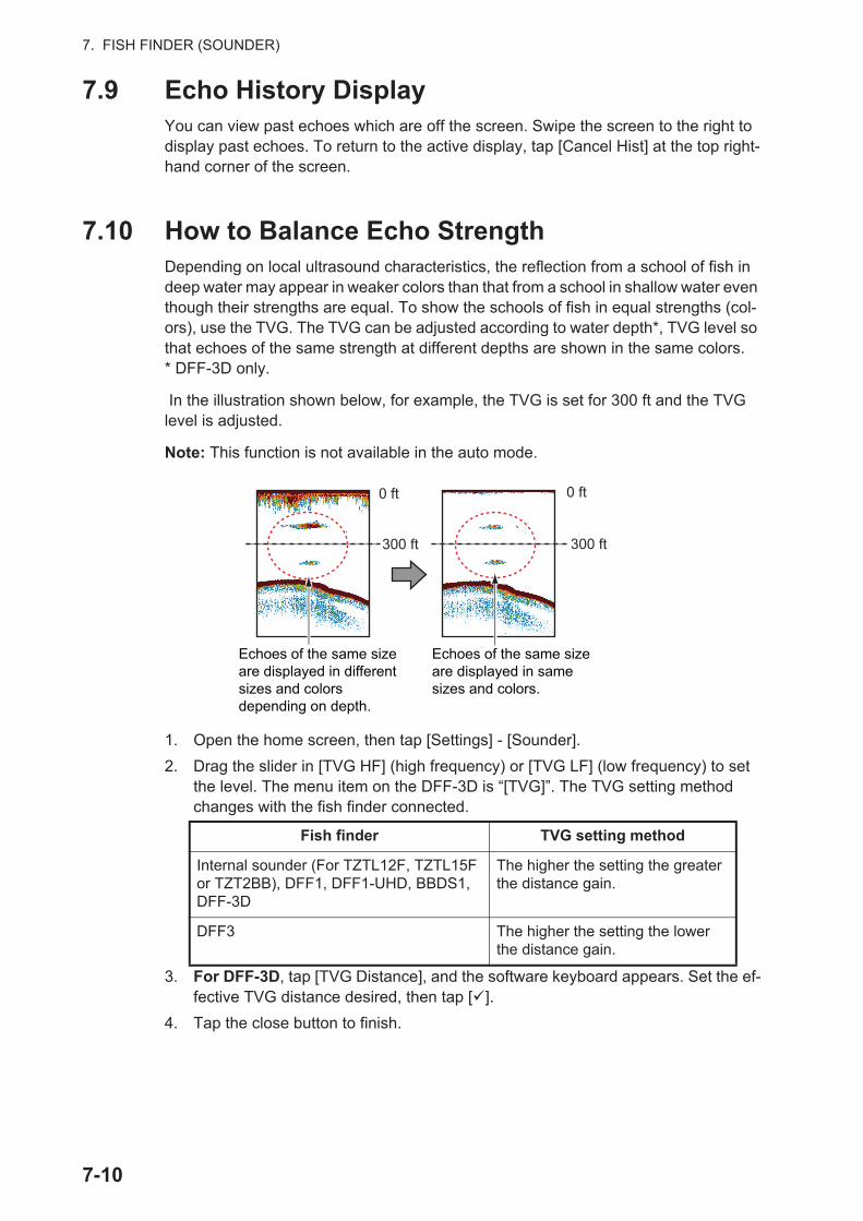
7. FISH FINDER (SOUNDER)
7.9 Echo History DisplayYou can view past echoes which are off the screen. Swipe the screen to the right to display past echoes. To return to the active display, tap [Cancel Hist] at the top right-hand corner of the screen.
7.10 How to Balance Echo StrengthDepending on local ultrasound characteristics, the reflection from a school of fish in deep water may appear in weaker colors than that from a school in shallow water even though their strengths are equal. To show the schools of fish in equal strengths (col-ors), use the TVG. The TVG can be adjusted according to water depth*, TVG level so that echoes of the same strength at different depths are shown in the same colors.* DFF-3D only.
In the illustration shown below, for example, the TVG is set for 300 ft and the TVG level is adjusted.
Note: This function is not available in the auto mode.
1. Open the home screen, then tap [Settings] - [Sounder].
2. Drag the slider in [TVG HF] (high frequency) or [TVG LF] (low frequency) to set the level. The menu item on the DFF-3D is “[TVG]”. The TVG setting method changes with the fish finder connected.
3. For DFF-3D, tap [TVG Distance], and the software keyboard appears. Set the ef-fective TVG distance desired, then tap [ ].
4. Tap the close button to finish.
Fish finder TVG setting method
Internal sounder (For TZTL12F, TZTL15F or TZT2BB), DFF1, DFF1-UHD, BBDS1, DFF-3D
The higher the setting the greater the distance gain.
DFF3 The higher the setting the lower the distance gain.
Echoes of the same size are displayed in different sizes and colors depending on depth.
Echoes of the same size are displayed in same sizes and colors.
0 ft
300 ft 300 ft
0 ft
7-10

7. FISH FINDER (SOUNDER)
7.11 Fish Finder AlarmsTwo types of fish alarms release audio and visual alarms to tell you that echoes from fish are in the area you selected. These alarms are [Fish Alarm] and [Fish Alarm for Bottom Lock].
The [Fish Alarm] function tells you when an echo above some strength (selectable) is within the alarm range you specify.
The [Fish Alarm for Bottom Lock] function tells you when fish are within some distance from the bottom. The bottom lock display must be active to use this alarm.
7.11.1 How to set an alarm
1. Open the home screen, then tap [Settings] - [Sounder]. Scroll the menu to show the fish finder alarms section.
2. Fish alarm: Tap [Range Minimum Value] or [Range Maximum Value] below [Fish Alarm] to display the software keyboard.Bottom lock fish alarm: Tap [Range Minimum Value] or [Range Maximum Val-ue] below [Fish Alarm for Bottom Lock] to display the software keyboard.
3. Set the start depth in [Range Minimum Value], the end depth in [Range Maximum Value].
4. Tap the close button to finish.
[Range Minimum Value] (from sea surface)
[Range Maximum Value] (from sea surface)
[Range Maximum Value] (from bottom)
[Range Minimum Value] (from bottom)
Fish Alarm for Bottom Lock
Alarm Range
Fish Alarm
Surface
Bottom
Alarm RangeAlarm Range
Alarm R
Fish
7-11
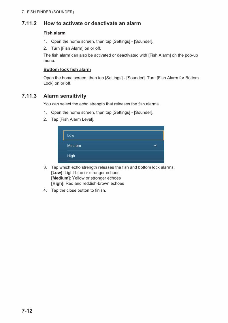
7. FISH FINDER (SOUNDER)
7.11.2 How to activate or deactivate an alarm
Fish alarm
1. Open the home screen, then tap [Settings] - [Sounder].
2. Turn [Fish Alarm] on or off.
The fish alarm can also be activated or deactivated with [Fish Alarm] on the pop-up menu.
Bottom lock fish alarm
Open the home screen, then tap [Settings] - [Sounder]. Turn [Fish Alarm for Bottom Lock] on or off.
7.11.3 Alarm sensitivity
You can select the echo strength that releases the fish alarms.
1. Open the home screen, then tap [Settings] - [Sounder].
2. Tap [Fish Alarm Level].
3. Tap which echo strength releases the fish and bottom lock alarms.[Low]: Light-blue or stronger echoes[Medium]: Yellow or stronger echoes[High]: Red and reddish-brown echoes
4. Tap the close button to finish.
7-12

7. FISH FINDER (SOUNDER)
7.12 ACCU-FISH™
The ACCU-FISH™ feature, which requires an ACCU-FISH™ capable transducer or Bottom Discrimination Sounder BBDS1 or Network Fish Finder DFF1-UHD, calculates the length of each fish and shows a fish symbol and depth value or fish length.
Usage guidelines
• The information given by this feature is intended for reference only.
• This feature cannot be used with the inside-hull transducer since a fish may not be detected depending on the frequency of the transducer. Even if a fish is detected, the fish length indicated may be smaller than the actual length.
• ACCU-FISH™ uses both low and high frequency echoes for the measurements re-gardless of the frequency mode in use.
• The intensity of an echo depends on fish species. If the indicated length is different from the true length, you can apply an offset in the [Sounder] - [ACCU-FISH Size Correction] menu of the menu.
• 50 kHz and 200 kHz beams are transmitted alternately without reference to the cur-rent display mode.
• Use this feature with ship speed of 10 knots or less and depth between 2 and 100 m.
• Echoes from a school of fish can be in more than one layer, which can cause wrong length indication.
• The fish symbol indication is not shown when the bottom echo does not appear on the screen.
7.12.1 How to set ACCU-FISH™
1. Open the home screen, then tap [Settings] - [Sounder].
2. Tap [ACCU-FISH Info].
3. Tap [Fish Size] or [Depth].
4. Tap [ACCU-FISH Symbols].
7-13
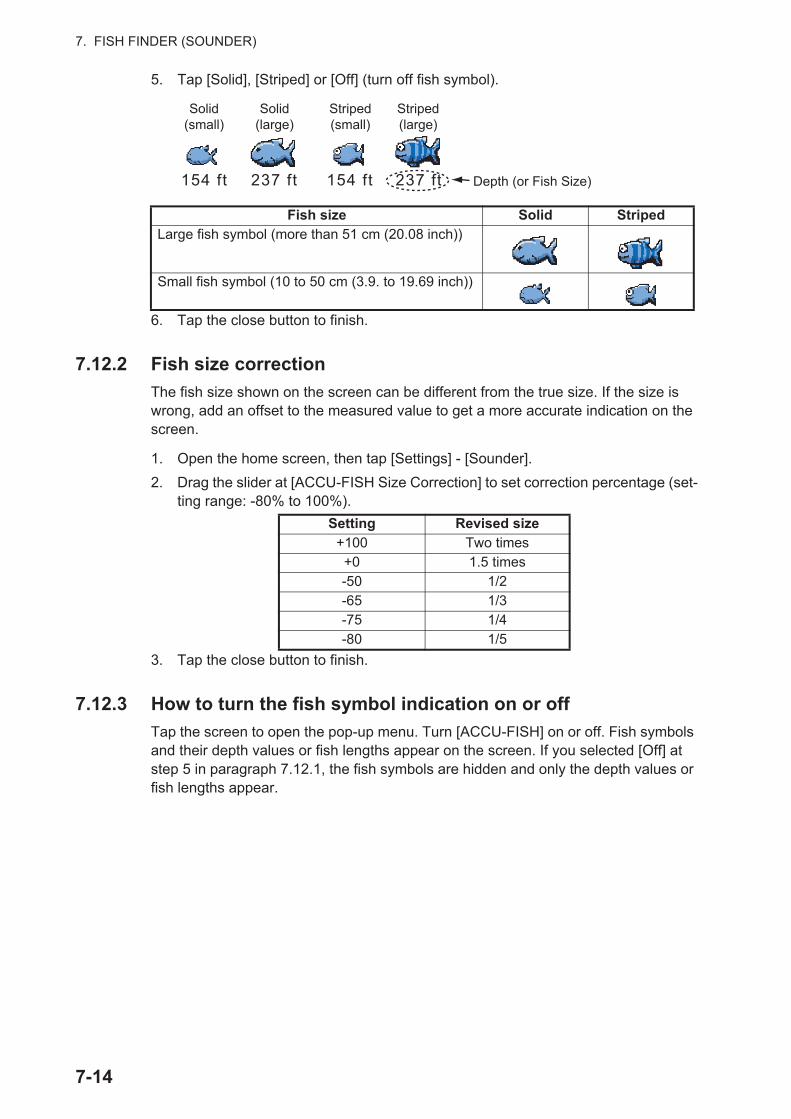
7. FISH FINDER (SOUNDER)
5. Tap [Solid], [Striped] or [Off] (turn off fish symbol).
6. Tap the close button to finish.
7.12.2 Fish size correction
The fish size shown on the screen can be different from the true size. If the size is wrong, add an offset to the measured value to get a more accurate indication on the screen.
1. Open the home screen, then tap [Settings] - [Sounder].
2. Drag the slider at [ACCU-FISH Size Correction] to set correction percentage (set-ting range: -80% to 100%).
3. Tap the close button to finish.
7.12.3 How to turn the fish symbol indication on or off
Tap the screen to open the pop-up menu. Turn [ACCU-FISH] on or off. Fish symbols and their depth values or fish lengths appear on the screen. If you selected [Off] at step 5 in paragraph 7.12.1, the fish symbols are hidden and only the depth values or fish lengths appear.
Fish size Solid StripedLarge fish symbol (more than 51 cm (20.08 inch))
Small fish symbol (10 to 50 cm (3.9. to 19.69 inch))
Setting Revised size+100 Two times+0 1.5 times-50 1/2-65 1/3-75 1/4-80 1/5
Depth (or Fish Size)
Solid (small)
237 ft154 ft 237 ft154 ft
Solid (large)
Striped (small)
Striped (large)
7-14

7. FISH FINDER (SOUNDER)
7.12.4 How to display the fish information
Tap a fish symbol to display the information (size, depth, bearing and range) about the fish.
7.12.5 How to set the minimum size of ACCU-FISH™ symbols
If you are in an area where there are many fish, the screen may become congested
with ACCU-FISH™ symbols. To prevent this, you can set the minimum size for the symbols. Open the [Sounder] menu. Tap [ACCU-FISH Minimum Size] to show the software keyboard. Enter the minimum size (0 to 79.98 (inch)) then tap . Tap the close button (x) to finish.
7.13 RezBoost™
With connection of a RezBoost™ capable transducer, echo resolution can be im-proved. In the example below, it is difficult to distinguish fish from the bottom. With [En-
hanced] RezBoost™, however, fish near the bottom are clearly seen.
RezBoost™ is available with the following transducers.
To use RezBoost™, set the fish finder source (with [Fish Finder Source] on the [Sounder] menu) to [TZTL12F], [TZTL15F] or [TZT2BB] as appropriate.
Transducer (option)600 W 520-5PSD, 520-5MSD, 520-PLD, 525-5PWD, 525T-PWD, 525T-BSD,
525T-LTD/12, 525T-LTD/20, 525STID-MSD, 525STID-PWD,SS60-SLTD/12, SS60-SLTD/20
1 kW 50/200-1T, 526TID-HDD
Enhanced mode Standard mode
7-15
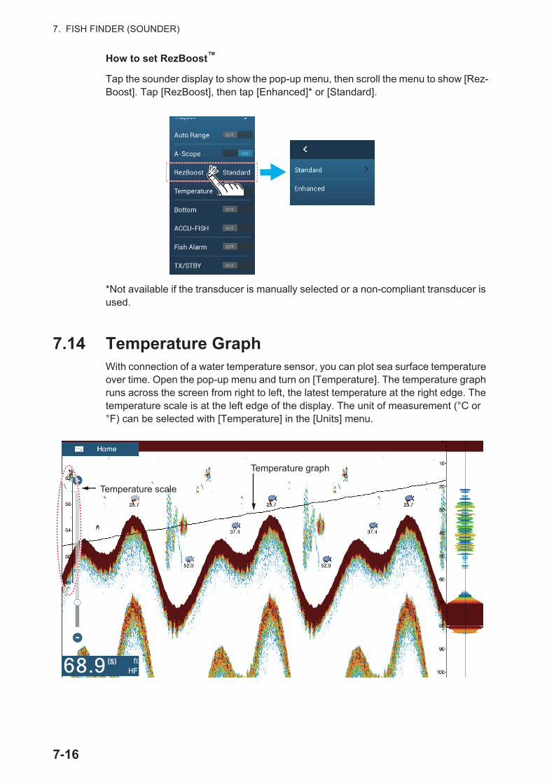
7. FISH FINDER (SOUNDER)
How to set RezBoost™
Tap the sounder display to show the pop-up menu, then scroll the menu to show [Rez-Boost]. Tap [RezBoost], then tap [Enhanced]* or [Standard].
*Not available if the transducer is manually selected or a non-compliant transducer is used.
7.14 Temperature GraphWith connection of a water temperature sensor, you can plot sea surface temperature over time. Open the pop-up menu and turn on [Temperature]. The temperature graph runs across the screen from right to left, the latest temperature at the right edge. The temperature scale is at the left edge of the display. The unit of measurement (°C or °F) can be selected with [Temperature] in the [Units] menu.
Temperature scale
Temperature graph
(S)
7-16
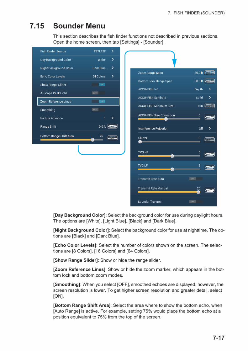
7. FISH FINDER (SOUNDER)
7.15 Sounder Menu This section describes the fish finder functions not described in previous sections. Open the home screen, then tap [Settings] - [Sounder].
[Day Background Color]: Select the background color for use during daylight hours. The options are [White], [Light Blue], [Black] and [Dark Blue].
[Night Background Color]: Select the background color for use at nighttime. The op-tions are [Black] and [Dark Blue].
[Echo Color Levels]: Select the number of colors shown on the screen. The selec-tions are [8 Colors], [16 Colors] and [64 Colors].
[Show Range Slider]: Show or hide the range slider.
[Zoom Reference Lines]: Show or hide the zoom marker, which appears in the bot-tom lock and bottom zoom modes.
[Smoothing]: When you select [OFF], smoothed echoes are displayed, however, the screen resolution is lower. To get higher screen resolution and greater detail, select [ON].
[Bottom Range Shift Area]: Select the area where to show the bottom echo, when [Auto Range] is active. For example, setting 75% would place the bottom echo at a position equivalent to 75% from the top of the screen.
ACCU-FISH Info
ACCU-FISH Symbols
ACCU-FISH Size Correction
7-17
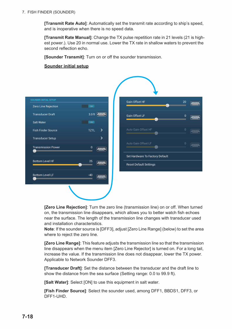
7. FISH FINDER (SOUNDER)
[Transmit Rate Auto]: Automatically set the transmit rate according to ship’s speed, and is inoperative when there is no speed data.
[Transmit Rate Manual]: Change the TX pulse repetition rate in 21 levels (21 is high-est power.). Use 20 in normal use. Lower the TX rate in shallow waters to prevent the second reflection echo.
[Sounder Transmit]: Turn on or off the sounder transmission.
Sounder initial setup
[Zero Line Rejection]: Turn the zero line (transmission line) on or off. When turned on, the transmission line disappears, which allows you to better watch fish echoes near the surface. The length of the transmission line changes with transducer used and installation characteristics.Note: If the sounder source is [DFF3], adjust [Zero Line Range] (below) to set the area where to reject the zero line.
[Zero Line Range]: This feature adjusts the transmission line so that the transmission line disappears when the menu item [Zero Line Rejector] is turned on. For a long tail, increase the value. If the transmission line does not disappear, lower the TX power. Applicable to Network Sounder DFF3.
[Transducer Draft]: Set the distance between the transducer and the draft line to show the distance from the sea surface (Setting range: 0.0 to 99.9 ft).
[Salt Water]: Select [ON] to use this equipment in salt water.
[Fish Finder Source]: Select the sounder used, among DFF1, BBDS1, DFF3, or DFF1-UHD.
7-18
7. FISH FINDER (SOUNDER)
[Transducer Setup]: Select the method to setup the transducer, by model, manually, or TDID (transducer ID). See the installation manual for details.
[Transmission Power]: Interference can appear on the screen when the fish finder on your ship and another ship have the same TX frequency. To prevent this interfer-ence, lower your TX power and ask the other ship to lower their TX power. (Internal sounder and external sounder other than DFF1-UHD)
[External KP]: Turn on to sync with external keying pulse. (For external sounder)
[Bottom Level HF (LF)]: The default bottom level setting (0) determines that two strong echoes received in sequence are bottom echoes. If the depth indication is not stable in the default setting, adjust the bottom level here.
[Gain Offset HF (LF)]: If the gain setting is wrong, or there is a difference in the gain between the low and high frequencies, you can balance the gain for the two frequen-cies here.
[Auto Gain Offset HF (LF)]: If the auto gain offset is wrong, or there is a difference in the gain between the low and high frequencies, set an offset here to balance auto gain for the two frequencies.
[STC HF (LF)]: Delete unnecessary echoes (plankton, air bubbles, etc.) near the sur-face that hide the fish near the surface. The setting range is 0 to 10, and 0 is off. 10 deletes unnecessary echoes from the surface to approximately 16 ft. Make sure you do not use more STC than necessary, because you can erase the small echoes near the surface. (For DFF3, DFF1-UHD)
[Frequency Adjust HF (LF)]: You can adjust the TX frequency of both the low- and high-frequency transducers. Use this feature when your fish finder and another fish finder operate on the same frequency, causing interference. Change the frequency of your transducer by enough percentage points to remove the interference. (For DFF3)
[TX Pulse HF (LF)]: The pulse length is automatically set according to range and shift.Use a short pulse for better resolution and a long pulse when detection range is important. To improve resolution on zoom displays, use [Short 1] or [Short 2]. [Short 1] improves the detection resolution, but the detection range is shorter than with [Std] (pulse length is 1/4 of [Std]). [Short 2] raises the detection resolution, however detec-tion range is shorter (pulse length is about 1/2 of [Std]) than [Std]. [Std] is the standard pulse length, and is suitable for general use. [Long] increases the detection range but lowers the resolution (about 1/2 compared to the [Std] pulse length). (For DFF3)
[Rx Band HF (LF)]: The RX bandwidth is automatically set according to pulse length.To decrease noise, select [Narrow]. For better resolution, select [Wide]. (For DFF3)
[Temperature Port]: Select the data source for water temperature.? (For DFF3, DFF1-UHD)[MJ]: The water temperature data from the water temperature/speed sensor?[Low Frequency]: The low frequency measured water temperature?[High Frequency]: The high frequency measured water temperature
[Sounder Demo Mode]: Activates, deactivates the sounder demo mode, which al-lows operation of the sounder with data stored in the memory. Connection of the trans-ducer is not required. Requires connection to DFF1, BBDS1, DFF3 or DFF1-UHD.
7-19
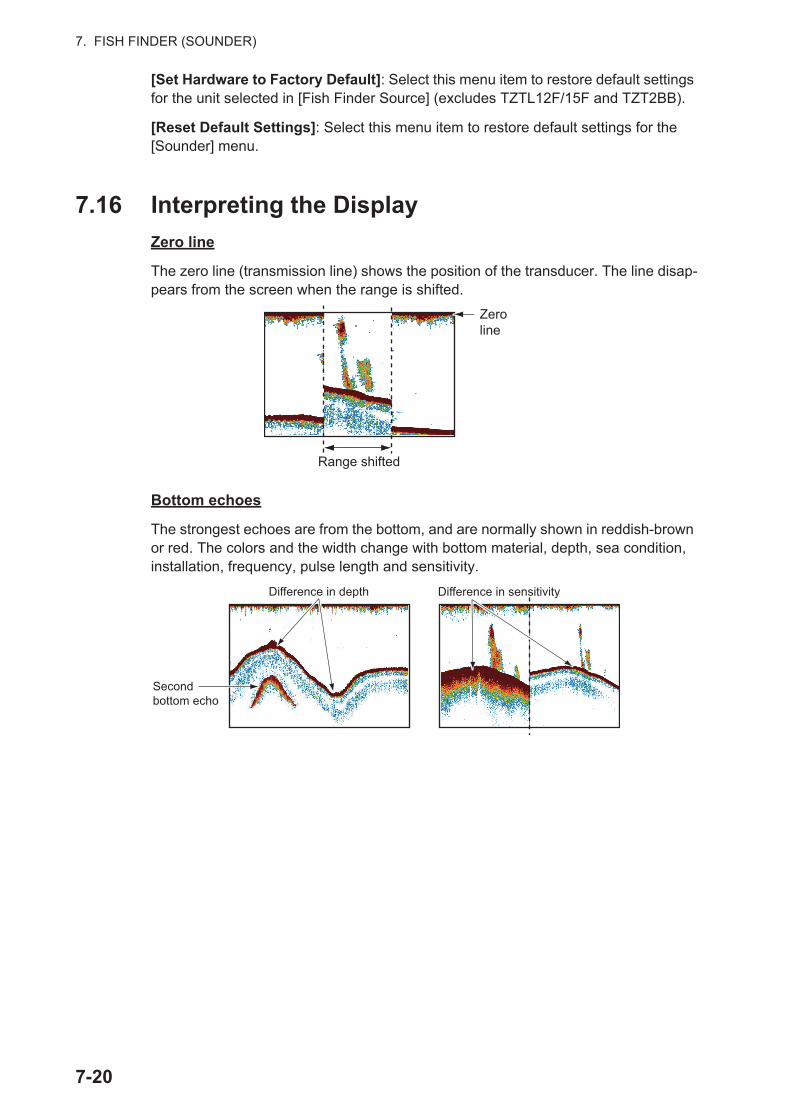
7. FISH FINDER (SOUNDER)
[Set Hardware to Factory Default]: Select this menu item to restore default settings for the unit selected in [Fish Finder Source] (excludes TZTL12F/15F and TZT2BB).
[Reset Default Settings]: Select this menu item to restore default settings for the [Sounder] menu.
7.16 Interpreting the Display
Zero line
The zero line (transmission line) shows the position of the transducer. The line disap-pears from the screen when the range is shifted.
Bottom echoes
The strongest echoes are from the bottom, and are normally shown in reddish-brown or red. The colors and the width change with bottom material, depth, sea condition, installation, frequency, pulse length and sensitivity.
Zero line
Range shifted
Second bottom echo
Difference in sensitivityDifference in depth
7-20
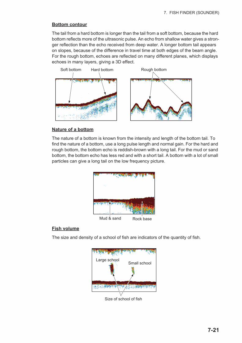
7. FISH FINDER (SOUNDER)
Bottom contour
The tail from a hard bottom is longer than the tail from a soft bottom, because the hard bottom reflects more of the ultrasonic pulse. An echo from shallow water gives a stron-ger reflection than the echo received from deep water. A longer bottom tail appears on slopes, because of the difference in travel time at both edges of the beam angle. For the rough bottom, echoes are reflected on many different planes, which displays echoes in many layers, giving a 3D effect.
Nature of a bottom
The nature of a bottom is known from the intensity and length of the bottom tail. To find the nature of a bottom, use a long pulse length and normal gain. For the hard and rough bottom, the bottom echo is reddish-brown with a long tail. For the mud or sand bottom, the bottom echo has less red and with a short tail. A bottom with a lot of small particles can give a long tail on the low frequency picture.
Fish volume
The size and density of a school of fish are indicators of the quantity of fish.
Soft bottom Hard bottom Rough bottom
Rock baseMud & sand
Large schoolLarge schoolSmall schoolSmall school
Size of school of fish
7-21
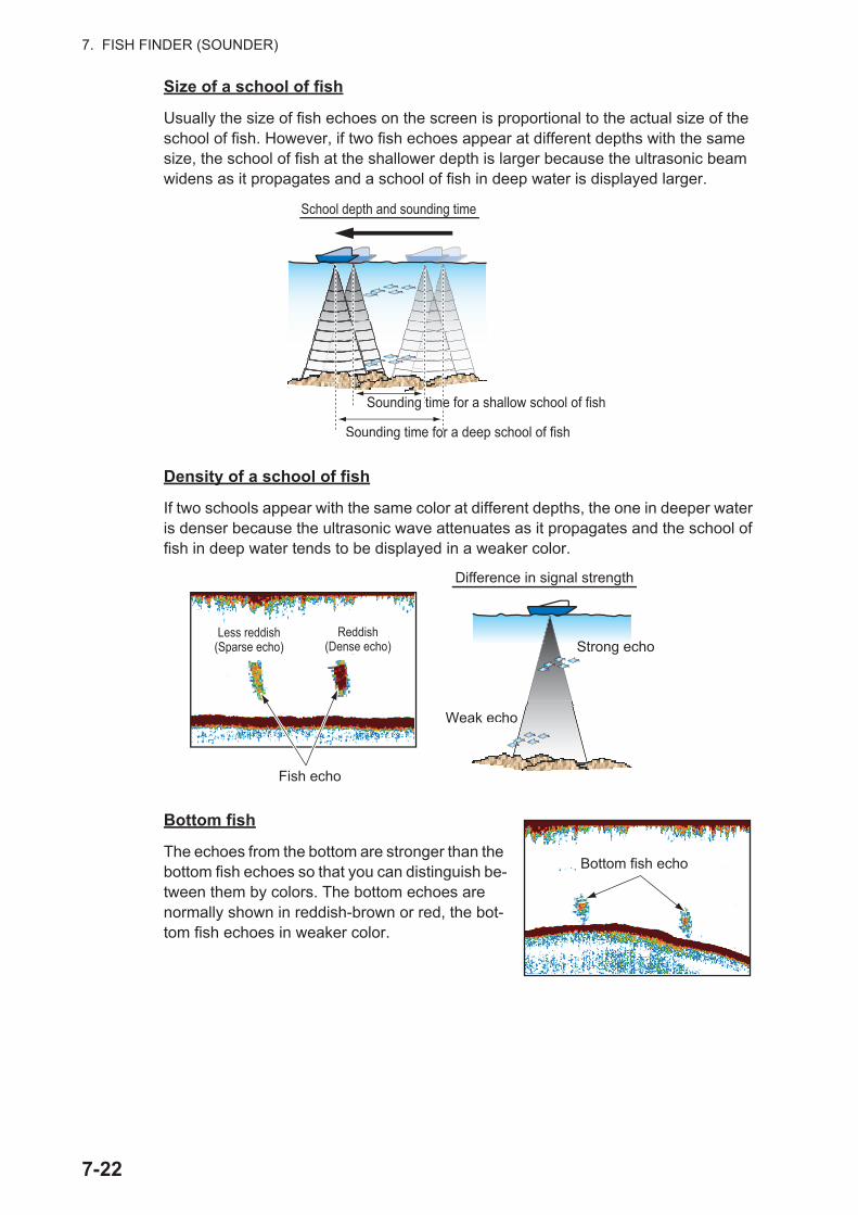
7. FISH FINDER (SOUNDER)
Size of a school of fish
Usually the size of fish echoes on the screen is proportional to the actual size of the school of fish. However, if two fish echoes appear at different depths with the same size, the school of fish at the shallower depth is larger because the ultrasonic beam widens as it propagates and a school of fish in deep water is displayed larger.
Density of a school of fish
If two schools appear with the same color at different depths, the one in deeper water is denser because the ultrasonic wave attenuates as it propagates and the school of fish in deep water tends to be displayed in a weaker color.
Bottom fish
The echoes from the bottom are stronger than the bottom fish echoes so that you can distinguish be-tween them by colors. The bottom echoes are normally shown in reddish-brown or red, the bot-tom fish echoes in weaker color.
Sounding time for a deep school of fishp school oe for a deepe for S gSounding time
Sounding time for a shallow school of fishSounding time for a shallow school of fish
School depth and sounding time
Fish echo
Weak echo
Less reddish (Sparse echo)
Reddish (Dense echo)
ak echoo
Strong echo
Difference in signal strength
Bottom fish echo
7-22
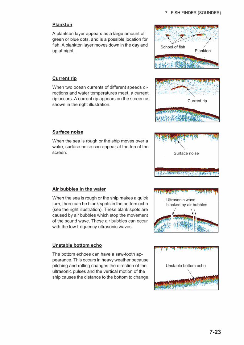
7. FISH FINDER (SOUNDER)
Plankton
A plankton layer appears as a large amount of green or blue dots, and is a possible location for fish. A plankton layer moves down in the day and up at night.
Current rip
When two ocean currents of different speeds di-rections and water temperatures meet, a current rip occurs. A current rip appears on the screen as shown in the right illustration.
Surface noise
When the sea is rough or the ship moves over a wake, surface noise can appear at the top of the screen.
Air bubbles in the water
When the sea is rough or the ship makes a quick turn, there can be blank spots in the bottom echo (see the right illustration). These blank spots are caused by air bubbles which stop the movement of the sound wave. These air bubbles can occur with the low frequency ultrasonic waves.
Unstable bottom echo
The bottom echoes can have a saw-tooth ap-pearance. This occurs in heavy weather because pitching and rolling changes the direction of the ultrasonic pulses and the vertical motion of the ship causes the distance to the bottom to change.
PlanktonSchool of fish
Current rip
Surface noise
Ultrasonic wave blocked by air bubbles
Unstable bottom echo
7-23

7. FISH FINDER (SOUNDER)
False echo
When an ultrasonic pulse is transmitted, some energy leaves from each side of the beam. This energy has the name "sidelobe". Echoes from sidelobes show on the screen as false images like in the illustration shown below.
MainlobeMainlobe
SidelobeSidelobe False image
7-24

8. MULTI BEAM SONAR DFF-3D
This chapter describes the display screens (modes) available with the Multi Beam So-nar DFF-3D, which displays images of the underwater and the ocean floor with high precision. Four display screens are provided, multi-sounder, side scan, cross section, and 3D sounder history.
8.1 Display Screens Overview
Multi-sounder display
From the Home screen, tap the [Multi Sounder] icon to show the Multi-sounder dis-play.
The multi-sounder display operates similar to the conventional fish finder, providing in-formation about the seabed and underwater conditions. The video display scrolls from the right to left with the passing of time.
The echoes appearing at the right edge of the display are the latest echoes. Echoes from individual fish, schools of fish and the seabed are shown. With the gain set prop-erly, the distance to the seabed appears on the screen.
The gain, clutter suppressor and TVG are adjusted according to the mode selected, auto fishing or auto cruising. Manual adjustment of those controls is also possible.
The single beam presentation displays the information detected by the downward-looking beam. The triple beam presentation displays the information detected by the port beam, starboard beam, and downward-looking beam.
Single beam display
Bottom echo
A-scope
Depth
Frequency
Depth scaleDepth scale
Transducer downTransducer down
21.0
Home
8-1
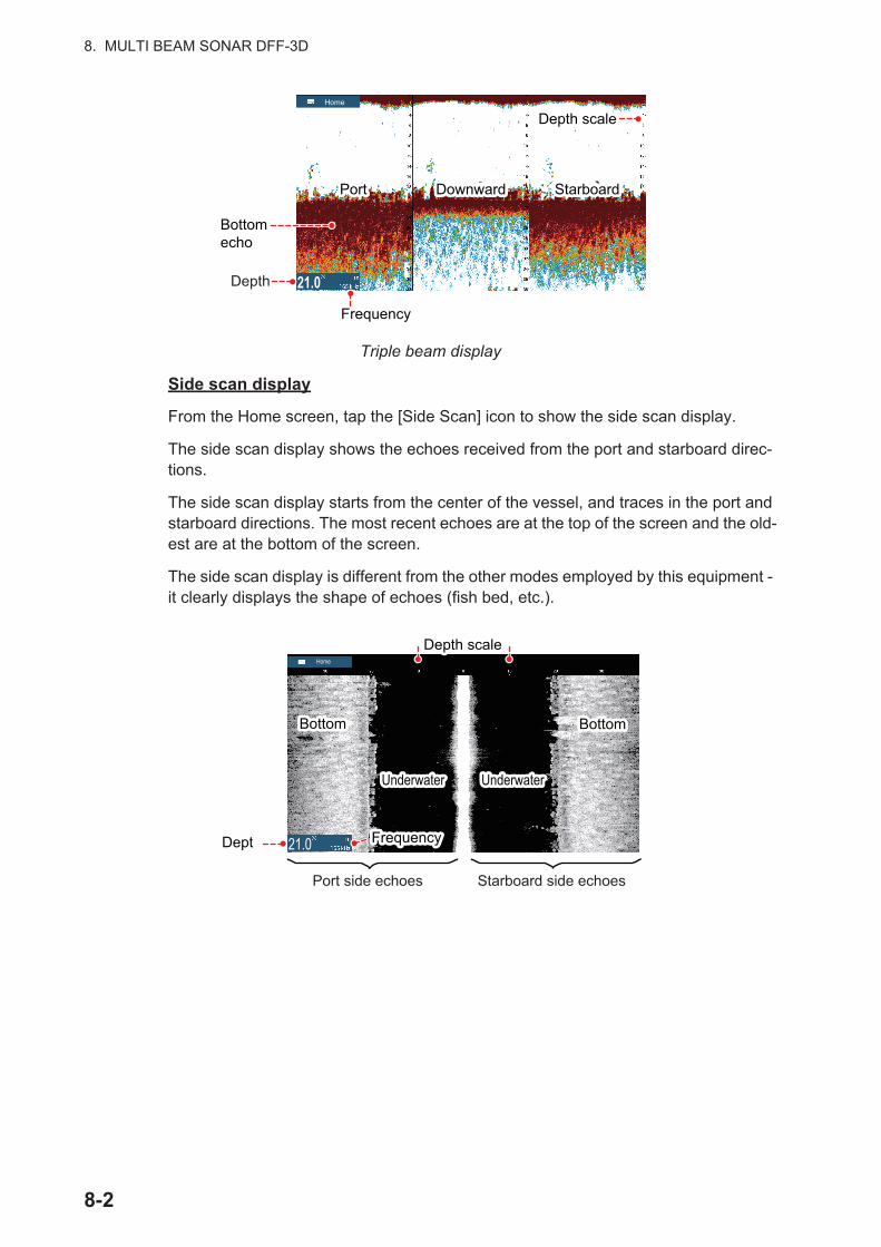
8. MULTI BEAM SONAR DFF-3D
Triple beam display
Side scan display
From the Home screen, tap the [Side Scan] icon to show the side scan display.
The side scan display shows the echoes received from the port and starboard direc-tions.
The side scan display starts from the center of the vessel, and traces in the port and starboard directions. The most recent echoes are at the top of the screen and the old-est are at the bottom of the screen.
The side scan display is different from the other modes employed by this equipment - it clearly displays the shape of echoes (fish bed, etc.).
PortPort DownwardDownward StarboardStarboard
21.0
Home
Depth
BottomechoBottomecho
Depth scaleDepth scale
FrequencyFrequency
Dept
BottomBottom BottomBottom
UnderwaterUnderwater UnderwaterUnderwater
FrequencyFrequency
Port side echoes Starboard side echoes
Depth scaleDepth scale
21.0
Home
8-2

8. MULTI BEAM SONAR DFF-3D
Cross section display
From the Home screen, tap the [Cross Section] icon to show the cross section display.
The cross section display, shows seabed and underwater conditions.
This multi beam sonar uses a 120° beam (downward to port 60°; downward to starboard 60°), providing highly accurate underwater images.
3D sounder history display
From the Home screen, tap the [3D History] icon to show the 3D sounder history dis-play.
The 3D sounder history provides a 3D graphic of the past seabed and underwater echoes detected by your vessel. The display can be used to detect schools of fish.
School of fish
Seabed
OwnShipOwnShip STBDPORT
Depth
Horizontal range Horizontal range
DepthscaleDepthscale
BottomechoBottomecho
FrequencyFrequency
PortPort DownwardDownward StarboardStarboard
UnderwaterUnderwaterTransducer positionTransducer position
GridGrid21.0
Home
Depth
Horizontal rangescaleHorizontal rangescale
Depth scaleDepth scale
Own shipOwn ship
FrequencyFrequency
BottomBottom
School of fishSchool of fish
Depth/Colorcolor scale
21.0
Home
8-3

8. MULTI BEAM SONAR DFF-3D
8.2 Multi-Sounder Display OperationsThis section covers the functions available with the multi-sounder display. For the menu items shared with the conventional fish finder, see chapter 7. To show the menu for this function, tap the screen to show the pop up menu; or from the [Home] screen, tap [Settings] [Multi-Beam Sonar].
8.2.1 How to switch between TX and STBY
Tap the multi-sounder display to show the pop-up menu. Select [TX] to start transmit-ting. [ST-BY] appears at the center of the screen when transmission is stopped.
8.2.2 How to switch between single beam and triple beam presenta-tions
1. Tap the multi-sounder display to show the pop-up menu.
2. Select [Mode].
3. Select [Single Beam] or [Triple Beam] as required.
4. Select [Close] to close the pop-up menu.
8.2.3 How to set the TX beam angle
You can set the TX beam angle for the port, starboard and downward beams.
1. Tap the multi-sounder display to show the pop-up menu.
2. Select [Beam Angle].
3. Set the beam angle as required.
8.2.4 How to set the TX beam width
You can set the TX beam width for the port, starboard and downward beams.
1. Tap the multi-sounder display to show the pop-up menu.
2. Select [Beam Width].
3. Set the beam width as required.
8.2.5 How to show or hide the scale box
The scale box, shown at the bottom left corner on the display, shows depth, current range, and TX frequency. You can show the box as follows.
1. Tap the multi-sounder display to show the pop-up menu.
2. Select [Scale Box] to show the scale box.
8-4
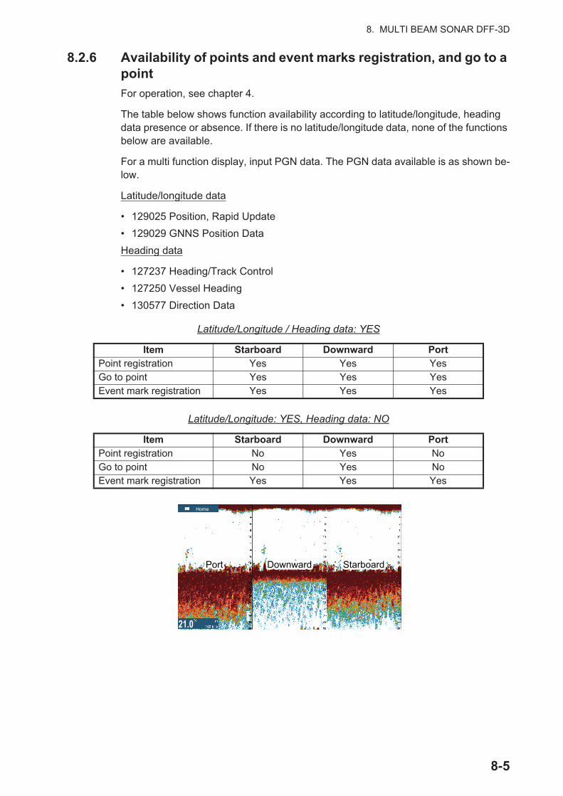
8. MULTI BEAM SONAR DFF-3D
8.2.6 Availability of points and event marks registration, and go to a point
For operation, see chapter 4.
The table below shows function availability according to latitude/longitude, heading data presence or absence. If there is no latitude/longitude data, none of the functions below are available.
For a multi function display, input PGN data. The PGN data available is as shown be-low.
Latitude/longitude data
• 129025 Position, Rapid Update
• 129029 GNNS Position Data
Heading data
• 127237 Heading/Track Control
• 127250 Vessel Heading
• 130577 Direction Data
Latitude/Longitude / Heading data: YES
Latitude/Longitude: YES, Heading data: NO
Item Starboard Downward PortPoint registration Yes Yes YesGo to point Yes Yes YesEvent mark registration Yes Yes Yes
Item Starboard Downward PortPoint registration No Yes NoGo to point No Yes NoEvent mark registration Yes Yes Yes
PortPort DownwardDownward StarboardStarboard
21.0
Home
8-5

8. MULTI BEAM SONAR DFF-3D
8.3 Side Scan Display OperationsThis section covers the functions available with the side scan display. For the menu items shared with the conventional fish finder, see chapter 7. To show the menu for this function, tap the screen to show the pop up menu; or from the [Home] screen, tap [Settings] [Multi-Beam Sonar].
8.3.1 How to switch between TX and STBY
Tap the side scan display to show the pop-up menu. Select [TX] to start transmitting. [ST-BY] appears at the center of the screen when transmission is stopped.
8.3.2 How to change echo color
1. Select [Settings] on the home screen.
2. Select [Multibeam Sonar] - [Side Scan].
3. Select [Echo Color].
4. Select [White], [Blue] or [Brown] as required.
5. Select [Close] to close the pop-up menu.
8.3.3 How to show or hide the scale box
The scale box, shown at the bottom left corner on the display, shows depth, current range, and TX frequency. You can show the box as follows.
1. Tap the side scan display to show the pop-up menu.
2. Select [Scale Box] to show the scale box.
8.3.4 Availability of points and event marks registration, and go to a point
For how to register points and event marks, see chapter 4.
The table below shows function availability according to latitude/longitude, heading data presence or absence. If there is no latitude/longitude data, none of the functions below are available.
For NavNet TZtouch or NavNet TZtouch2, input PGN data. The PGN data available is as shown below.
Latitude/longitude data
• 129025 Position, Rapid Update
• 129029 GNNS Position Data
Heading data
• 127237 Heading/Track Control
• 127250 Vessel Heading
• 130577 Direction Data
8-6

8. MULTI BEAM SONAR DFF-3D
Latitude/Longitude / Heading data: YES
Latitude/Longitude: YES, Heading data: NO
8.4 Cross Section Display OperationsThis section covers the functions available with the cross section display. For the menu items shared with the conventional fish finder, see chapter 7. To show the menu for this function, tap the screen to show the pop up menu; or from the [Home] screen, tap [Settings] [Multi-Beam Sonar].
8.4.1 How to switch between TX and STBY
Tap the cross section display to show the pop-up menu. Select [TX] to start transmit-ting. [ST-BY] appears at the center of the screen when transmission is stopped.
8.4.2 How to show or hide the grid
The grid, which is useful for measuring the distance to a target, can be shown or hid-den as follows.
1. Tap the cross section display to show the pop-up menu.
2. Select [Grid] to show the grid.
8.4.3 Zoom display
The seabed echo can be zoomed.
1. Tap the cross section display to show the pop-up menu.
2. Select [Zoom] to zoom the seabed echo. Select [Zoom] again to restore the nor-mal display.
Item Starboard PortPoint registration Yes YesGo to point Yes YesEvent mark registration Yes Yes
Item Starboard PortPoint registration No NoGo to point No NoEvent mark registration Yes Yes
[Zoom] selected [Zoom] not selected21.0 21.0
Home Home
8-7
8. MULTI BEAM SONAR DFF-3D
8.4.4 How to smooth echoes (distance)
If echoes are “disconnected” because of an undulating seabed, change the setting to [Low], [Medium] or [High] as necessary. Smoothing is done in the range direction to smooth the echo presentation.
1. Select [Settings] on the home screen.
2. Select [Multibeam Sonar] - [Cross Section].
3. Select [Echo Smoothing (Distance)].
4. Select [Low], [Medium] or [High] as required. The default setting is [Medium]. Se-lect [OFF] to stop smoothing.
5. Select [Close] to close the pop-up menu.
8.4.5 How to smooth echoes (time)
If echoes are difficult to see because they appear “speckled,” use the echo smoothing feature to suppress the speckling by time.
1. Select [Settings] on the home screen.
2. Select [Multibeam Sonar] - [Cross Section].
3. Select [Echo Smoothing (Time)].
4. Select [Low], [Medium] or [High] as required. The default setting is [Medium]. Se-lect [OFF] to stop smoothing.
5. Select [Close] to close the pop-up menu.
8.4.6 How to apply correction to the speed of sound
Even though the sea bottom is flat, the left or right edge, up or down may be distorted. To compensate for this problem, adjust the speed of sound.
Manual correction
1. Select [Settings] on the home screen.
2. Select [Multibeam Sonar] - [Cross Section].
3. Select [Sound Speed Correction], then enter a correction. The setting range is -200 to +200.
4. Select [Close] to close the menu.
Automatic correction
1. Select [Settings] on the home screen.
2. Select [Multibeam Sonar] - [Cross Section].
3. Select [Temp.-based Correction], then select [ON].Select [OFF] to remove the correction.
4. Select [Close] to close the menu.
8-8

8. MULTI BEAM SONAR DFF-3D
8.4.7 How to show or hide the scale box
The scale box, shown at the bottom-left corner on the display, shows depth, current range, and TX frequency. You can show the box as follows.
1. Tap the cross section display to show the pop-up menu.
2. Select [Scale Box] to show the scale box.
8.4.8 Availability of points and event marks registration, and go to a point
For how to register points and event marks, see section 4.2.
The table below shows function availability according to latitude/longitude, heading data presence or absence. If there is no latitude/longitude data, none of the functions below are available.
For a multi function display, input PGN data. The PGN data available is as shown be-low.
Latitude/longitude data
• 129025 Position, Rapid Update
• 129029 GNNS Position Data
Heading data
• 127237 Heading/Track Control
• 127250 Vessel Heading
• 130577 Direction Data
Latitude/Longitude / Heading data: YES
Latitude/Longitude: YES, Heading data: NO
Item Cross sectionPoint registration YesGo to point NoEvent mark registration Yes
Item StarboardPoint registration NoGo to point NoEvent mark registration Yes
8-9

8. MULTI BEAM SONAR DFF-3D
8.5 3D Sounder History Display OperationsThis section covers the functions available with the 3D sounder history display. The 3D sounder history is able to display up to 1024 past transmissions.
For the menu items shared with the conventional fish finder, see chapter 7. To show the menu for this function, tap the screen to show the pop up menu; or from the [Home] screen, tap [Settings] [Multi-Beam Sonar].
8.5.1 How to switch between TX and STBY
Tap the 3D sounder history display to show the pop-up menu. Select [TX] to start transmitting. [ST-BY] appears at the center of the screen when transmission is stopped.
8.5.2 How to move, zoom in, zoom out the viewpoint position
How to move the viewpoint
The viewpoint can be moved by dragging.
How to zoom in, zoom out
How to restore default view
If you get lost in viewpoint or zoom, you can restore the default view as follows.
1. Tap the 3D sounder history display to show the pop-up menu.
2. Select [Default View] to show the depth/frequency box.
8.5.3 How to mark school of fish
A detected school of fish can be marked with a “dot” mark for easy identification.
1. Tap the 3D sounder history display to show the pop-up menu.
2. Select [Fish School Icon] to mark the detected school of fish with the dot mark.
Zoom in Zoom out
8-10
8. MULTI BEAM SONAR DFF-3D
8.5.4 How to stop advancement of the display
You can stop advancement of the history display to observe the distribution of sea floor topography and school of fish.
1. Tap the 3D sounder history display to show the pop-up menu.
2. Select [Pause] to stop the display.
8.5.5 How to adjust the echo detection level
Adjust the echo detection level if schools of fish are detected unstably.
1. Select [Settings] on the home screen.
2. Select [Multibeam Sonar] - [3D Sounder History].
3. Select [Fish Detection Level].
4. Select [Low], [Medium] or [High] as required. The default setting is [Medium]. If too many schools of fish are being detected, select [Low]. If too few schools are de-tected, select [High].
5. Select [Close] to close the menu.
8.5.6 How to calibrate the seabed echo
If schools of fish or a fish reef are detected and displayed as the seabed echo, adjust the strength of the seabed echo as shown below to correctly identify the seabed echo.
1. Select [Settings] on the home screen.
2. Select [Multibeam Sonar] - [3D Sounder History].
3. Select [Seabed Echo Calibration]. Drag the slider bar to adjust.The setting range is -15 to +15. A large figure helps distinguish bottom fish from the seabed echo; however, it is difficult to distinguish a fish bed. Use a small figure to distinguish a fish bed; however, it is difficult to distinguish bottom fish from the seabed echo.
4. Select [Close] to close the menu.
8.5.7 How to use the noise filter
If the seabed echo is displayed with undulations, use the noise filter to smooth the sea-bed echo.
1. Select [Settings] on the home screen.
2. Select [Multibeam Sonar] - [3D Sounder History].
3. Select [Noise Filter].
4. Select [Low], [Medium] or [High] as required. The default setting is [Medium].
5. Select [Close] to close the menu.
8-11

8. MULTI BEAM SONAR DFF-3D
8.5.8 How to use terrain shading
The thickness of the shading for the seabed terrain can be adjusted.
1. Select [Settings] on the home screen.
2. Select [Multibeam Sonar] - [3D Sounder History].
3. Select [Terrain Shading]. Drag the slider bar to adjust.The default setting is 50. See the figure below for setting and resulting terrain shading
4. Select [Close] to close the menu.
8.5.9 Depth/Color Shading display
The seabed echo and schools of fish can be shown in shades of colors according to depth, to help you see the differences in depths more easily.
Color shading display
Color shading can be applied to the seabed echo or schools of fish. For the seabed display, the seabed color can be multi tone or single tone, and schools of fish can be shown in single tone or single color. For the schools of fish display, schools can be shown in multi tone or single tone and the bottom color is in a single tone.
1. Tap the 3D sounder history display to show the pop-up menu.
2. Select [Color Mode].
3. Select [Seabed] or [Fish] as required.
Setting: 0 Setting: 50 Setting: 100
Depth/Color Shading displayDepth/Color Shading display
Depth/Color Shading displayColor Scale
[Color Mode] selected to [Seabed] [Color Mode] selected to [Fish]
Depth/Color Shading displayDepth/Color Shading display
Depth/Color Shading displayColor Scale
8-12

8. MULTI BEAM SONAR DFF-3D
How to set color shading
Open the menu, select Multi Beam to show the menu for setting color shading.
[Color Mode] selected to [Seabed]
Menu item Description Setting options[Seabed Color] For setting multi tone or single tone. [Classic Hue]
[Inverted Classic Hue][Red Hue][Blue Hue][Green Hue][Yellow Hue]
[Fish Monochrome Color] For setting single tone or single color. [Gray Hue][Brown Hue][Red][Green][Blue][Cyan][Magenta][Black Or White][Pink][Light Green][Yellow]
[Color Mode] selected to [Seabed] [Color Mode] selected to [Fish]
Seabed Color Classic Hue
Fish Monochrome Color Gray Hue
Minimum Value 0 m
Auto Seabed Shading
Maximum Value 50 m
Auto Fish Shading
Minimum Value 0 m
Maximum Value 50 m
Fish Color Classic Hue
Seabed Monochrome Color Gray Hue
Minimum Value 0 m
Auto Seabed Shading
Maximum Value 50 m
Auto Fish Shading
Minimum Value 0 m
Maximum Value 50 m
8-13
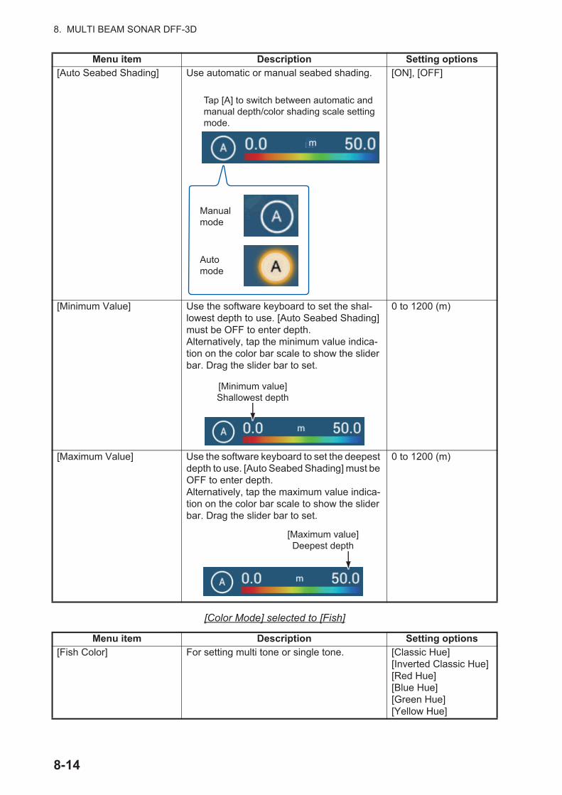
8. MULTI BEAM SONAR DFF-3D
[Color Mode] selected to [Fish]
[Auto Seabed Shading] Use automatic or manual seabed shading. [ON], [OFF]
[Minimum Value] Use the software keyboard to set the shal-lowest depth to use. [Auto Seabed Shading] must be OFF to enter depth.Alternatively, tap the minimum value indica-tion on the color bar scale to show the slider bar. Drag the slider bar to set.
0 to 1200 (m)
[Maximum Value] Use the software keyboard to set the deepest depth to use. [Auto Seabed Shading] must be OFF to enter depth.Alternatively, tap the maximum value indica-tion on the color bar scale to show the slider bar. Drag the slider bar to set.
0 to 1200 (m)
Menu item Description Setting options[Fish Color] For setting multi tone or single tone. [Classic Hue]
[Inverted Classic Hue][Red Hue][Blue Hue][Green Hue][Yellow Hue]
Menu item Description Setting options
Manual mode
Automode
m
Tap [A] to switch between automatic and manual depth/color shading scale setting mode.
[Minimum value]Shallowest depth
[Maximum value]Deepest depth
8-14
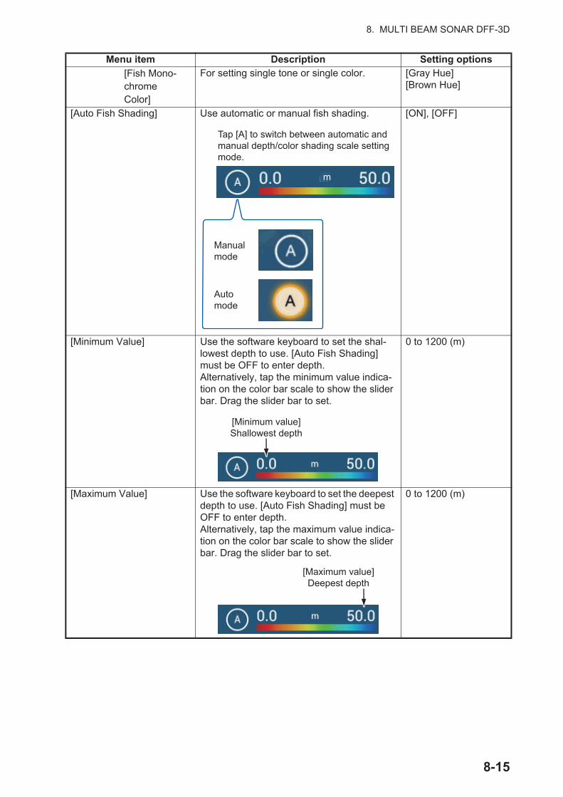
8. MULTI BEAM SONAR DFF-3D
[Fish Mono-chromeColor]
For setting single tone or single color. [Gray Hue][Brown Hue]
[Auto Fish Shading] Use automatic or manual fish shading. [ON], [OFF]
[Minimum Value] Use the software keyboard to set the shal-lowest depth to use. [Auto Fish Shading] must be OFF to enter depth.Alternatively, tap the minimum value indica-tion on the color bar scale to show the slider bar. Drag the slider bar to set.
0 to 1200 (m)
[Maximum Value] Use the software keyboard to set the deepest depth to use. [Auto Fish Shading] must be OFF to enter depth.Alternatively, tap the maximum value indica-tion on the color bar scale to show the slider bar. Drag the slider bar to set.
0 to 1200 (m)
Menu item Description Setting options
Manual mode
Automode
m
Tap [A] to switch between automatic and manual depth/color shading scale setting mode.
[Minimum value]Shallowest depth
[Maximum value]Deepest depth
8-15

8. MULTI BEAM SONAR DFF-3D
8.5.10 How to show or hide the scale box
The scale box, shown at the bottom left corner on the display, shows depth, current range, and TX frequency. You can show the box as follows.
1. Tap the 3D sounder history display to show the pop-up menu.
2. Select [Scale Box] to show the scale box.
8.5.11 Availability of points and event marks registration, and go to a point
For how to register points and event marks, see section 4.2.
The table below shows function availability according to latitude/longitude, heading data presence or absence. If there is no latitude/longitude data, none of the functions below are available.
For a multi function display, input PGN data. The PGN data available is as shown be-low.
Latitude/longitude data
• 129025 Position, Rapid Update
• 129029 GNNS Position Data
Heading data
• 127237 Heading/Track Control
• 127250 Vessel Heading
• 130577 Direction Data
Latitude/Longitude / Heading data: YES
Latitude/Longitude: YES, Heading data: NO
Item Fish SeabedOther than Fish
or SeabedPoint registration Yes Yes NoGo to point Yes Yes NoEvent mark registration No No Yes
Item Fish SeabedOther than Fish
or SeabedPoint registration No No NoGo to point No No NoEvent mark registration No No Yes
8-16
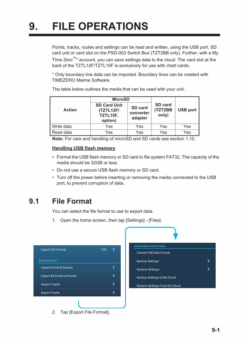
9. FILE OPERATIONS
Points, tracks, routes and settings can be read and written, using the USB port, SD card unit or card slot on the PSD-003 Switch Box (TZT2BB only). Further, with a My
Time Zero™* account, you can save settings data to the cloud. The card slot at the back of the TZTL12F/TZTL15F is exclusively for use with chart cards.
* Only boundary line data can be imported. Boundary lines can be created with TIMEZERO Marine Software.
The table below outlines the media that can be used with your unit.
Note: For care and handling of microSD and SD cards see section 1.10.
Handling USB flash memory
• Format the USB flash memory or SD card to file system FAT32. The capacity of the media should be 32GB or less.
• Do not use a secure USB flash memory or SD card.
• Turn off the power before inserting or removing the media connected to the USB port, to prevent corruption of data.
9.1 File FormatYou can select the file format to use to export data.
1. Open the home screen, then tap [Settings] - [Files].
2. Tap [Export File Format].
Action
MicroSDSD card (TZT2BB
only)USB port
SD Card Unit (TZTL12F/TZTL15F, option)
SD card converter adapter
Write data Yes Yes Yes YesRead data Yes Yes Yes Yes
9-1
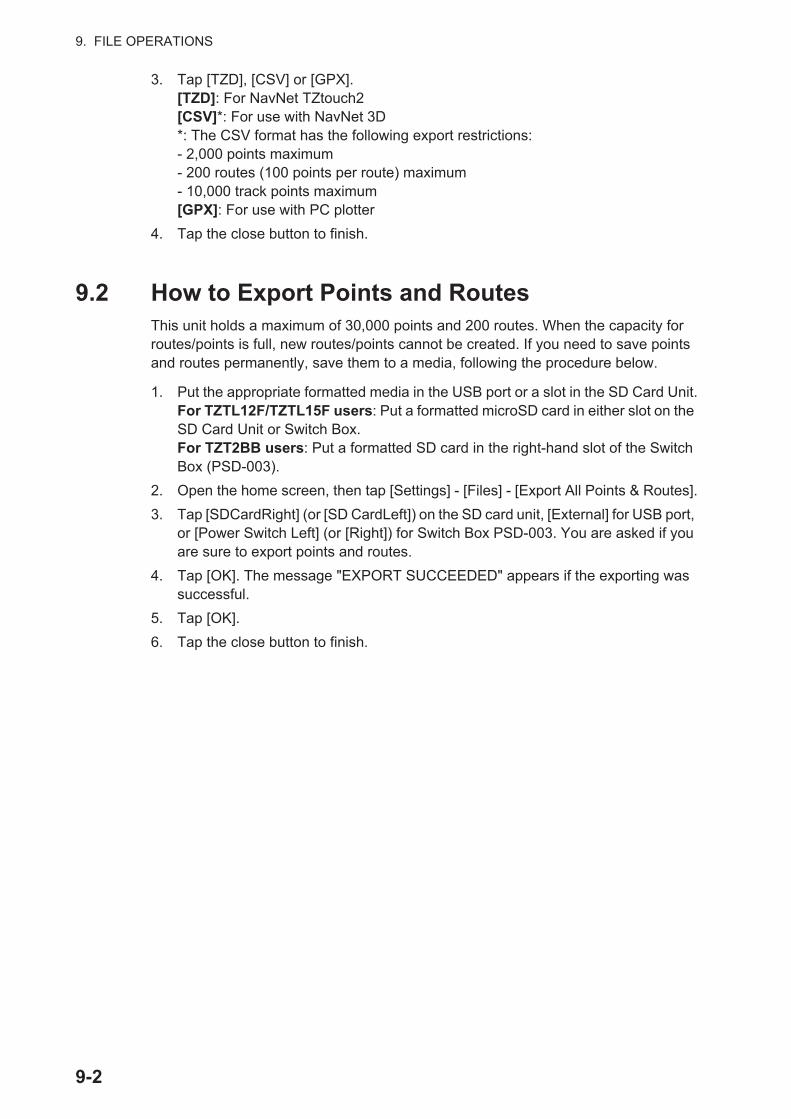
9. FILE OPERATIONS
3. Tap [TZD], [CSV] or [GPX].[TZD]: For NavNet TZtouch2[CSV]*: For use with NavNet 3D*: The CSV format has the following export restrictions:- 2,000 points maximum- 200 routes (100 points per route) maximum- 10,000 track points maximum[GPX]: For use with PC plotter
4. Tap the close button to finish.
9.2 How to Export Points and RoutesThis unit holds a maximum of 30,000 points and 200 routes. When the capacity for routes/points is full, new routes/points cannot be created. If you need to save points and routes permanently, save them to a media, following the procedure below.
1. Put the appropriate formatted media in the USB port or a slot in the SD Card Unit.For TZTL12F/TZTL15F users: Put a formatted microSD card in either slot on the SD Card Unit or Switch Box.For TZT2BB users: Put a formatted SD card in the right-hand slot of the Switch Box (PSD-003).
2. Open the home screen, then tap [Settings] - [Files] - [Export All Points & Routes].
3. Tap [SDCardRight] (or [SD CardLeft]) on the SD card unit, [External] for USB port, or [Power Switch Left] (or [Right]) for Switch Box PSD-003. You are asked if you are sure to export points and routes.
4. Tap [OK]. The message "EXPORT SUCCEEDED" appears if the exporting was successful.
5. Tap [OK].
6. Tap the close button to finish.
9-2

9. FILE OPERATIONS
9.3 How to Import Points, Routes, and Boundary LinesYou can import points, routes and boundary lines to the internal memory of this unit, using a SD card, microSD card or USB flash memory.
1. Put the appropriate media in the USB port or a slot in the SD Card Unit.For TZTL12F/TZTL15F users: Put a microSD card in either slot on the SD Card Unit or Switch Box.For TZT2BB users: Put a SD card in the right-hand slot of the Switch Box (PSD-003).
2. Open the home screen, then tap [Settings] - [Files] - [Import Points & Routes]. A list of files stored on the inserted media appears.
3. Tap the points, routes, boundary lines file to import. You are asked if you are sure to import points and routes.
4. Tap the [OK] button. The message "IMPORT SUCCEEDED" appears if the im-porting was successful.
5. Tap the [OK] button.
6. Tap the close button to finish.
Points and routes files
SDCARDRIGHT
9-3

9. FILE OPERATIONS
9.4 How to Export, Import Track
How to export track
This unit saves up to 30,000 points of track data. If [Automatic Track Deleting] is OFF, new track points are not saved when the capacity for track points is reached. You can export all tracks to a SD card, microSD card or USB flash memory.
1. Put the appropriate formatted media in the USB port or a slot in the SD Card Unit.For TZTL12F/TZTL15F users: Put a formatted microSD card in either slot on the SD Card Unit or Switch Box.For TZT2BB users: Put a formatted SD card in the right-hand slot of the Switch Box (PSD-003).
2. Open the home screen, then tap [Settings] - [Files] - [Export Tracks]. A list of files stored on the SD card or USB flash memory appears.
3. Tap [SDCardRight] (or [SD CardLeft]) on the SD card unit, [External] for USB port, or [Power Switch Left] (or [Right]) for Switch Box PSD-003. You are asked if you are sure to export points and routes.
4. Tap a tracks file. You are asked if you are sure to export tracks.
5. Tap the [OK] button. The message "EXPORT SUCCEEDED" appears if the ex-porting was successful.
6. Tap the [OK] button.
7. Tap the close button to finish.
Tracks file
SDCARDRIGHT
9-4
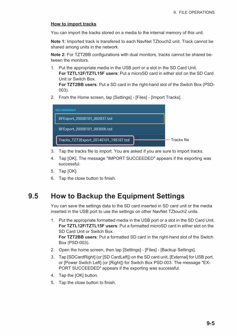
9. FILE OPERATIONS
How to import tracks
You can import the tracks stored on a media to the internal memory of this unit.
Note 1: Imported track is transfered to each NavNet TZtouch2 unit. Track cannot be shared among units in the network.
Note 2: For TZT2BB configurations with dual monitors, tracks cannot be shared be-tween the monitors.
1. Put the appropriate media in the USB port or a slot in the SD Card Unit.For TZTL12F/TZTL15F users: Put a microSD card in either slot on the SD Card Unit or Switch Box.For TZT2BB users: Put a SD card in the right-hand slot of the Switch Box (PSD-003).
2. From the Home screen, tap [Settings] - [Files] - [Import Tracks].
3. Tap the tracks file to import. You are asked if you are sure to import tracks.
4. Tap [OK]. The message "IMPORT SUCCEEDED" appears if the exporting was successful.
5. Tap [OK].
6. Tap the close button to finish.
9.5 How to Backup the Equipment SettingsYou can save the settings data to the SD card inserted in SD card unit or the media inserted in the USB port to use the settings on other NavNet TZtouch2 units.
1. Put the appropriate formatted media in the USB port or a slot in the SD Card Unit.For TZTL12F/TZTL15F users: Put a formatted microSD card in either slot on the SD Card Unit or Switch Box.For TZT2BB users: Put a formatted SD card in the right-hand slot of the Switch Box (PSD-003).
2. Open the home screen, then tap [Settings] - [Files] - [Backup Settings].
3. Tap [SDCardRight] (or [SD CardLeft]) on the SD card unit, [External] for USB port, or [Power Switch Left] (or [Right]) for Switch Box PSD-003. The message "EX-PORT SUCCEEDED" appears if the exporting was successful.
4. Tap the [OK] button.
5. Tap the close button to finish.
SDCARDRIGHT
Tracks file
9-5

9. FILE OPERATIONS
9.6 How to Load the Equipment SettingsYou can load saved settings data from an appropriate media to this unit, and share them with the NavNet TZtouch2 units in the NavNet network.
1. Put the appropriate media in the USB port or a slot in the SD Card Unit.For TZTL12F/TZTL15F users: Put a microSD card in either slot on the SD Card Unit or Switch Box.For TZT2BB users: Put a SD card in the right-hand slot of the Switch Box (PSD-003).
2. Open the home screen, then tap [Settings] - [Files] - [Restore Settings]. A list of user settings stored on the card in the SD card unit or media in the USB port ap-pears.
3. Tap the file to load. A confirmation message appears.
4. Tap the [OK] button. The message "IMPORT SUCCEEDED" appears if the im-porting was successful.
5. Tap the [OK] button.
6. Tap the close button to finish.
9.7 My TimeZero™ Cloud Data Service
With the TimeZero™ cloud data service, you can share the settings data stored in your
TimeZero™ cloud account with another NavNet TZtouch2 (requires software version
3.01 or after). To use the TimeZero™ cloud data service, connect to the internet and
create a TimeZero™ account.
9.7.1 How to save settings data to the cloud
Do as follows to save settings data to the cloud.
1. Open the home screen, then tap [Settings] [General].
2. Tap [Login] at the SOCIAL NETWORK section and login to your TimeZero™ ac-count.
3. Tap “<“ on the title bar to return to the [Settings] menu.
4. Tap [Files] [Backup Settings in the Cloud]. If a message announces that there is settings data in the cloud, tap the [OK] button to write over the settings data in the cloud.
SDCARDRIGHT
9-6

9. FILE OPERATIONS
9.7.2 How to retrieve settings data from the cloud
Do as follows to retrieve settings data from the cloud.
1. Open the home screen, then tap [Settings] [General].
2. Tap [Login] at the SOCIAL NETWORK section and login to your TimeZero™ ac-count.
3. Tap “<“ on the title bar to return to the [Settings] menu.
4. Tap [Files] [Restore Settings From the Cloud]. If there is no data in the cloud, an appropriate message appears. Tap the "OK" button to erase the message.
9.8 How to Convert NavNet vx2 DataNavNet vx2 data (points, routes, tracks) can be converted for use with NavNetTZtouch2. Save the data to a microSD card or USB flash memory then do as follows:
1. Put the appropriate media in the USB port or a slot in the SD Card Unit.
2. From the Home screen, tap [Settings] - [Files] - [Convert Old Format Data]. The message "YOUR APPLICATION WILL RESTART AFTER THE CONVERSION. DO YOU WANT TO CONVERT OLD DATA" appears.
3. Tap the [OK] button. The equipment restarts and upon completion the [Data Con-verter] window appears.
4. Select the location of the source data ([External], [SD Right], or [SD Left]) at [Navnet vx2 Data].
5. At [Navnet vx2 Datum], select the geographical datum under which to convert the data.
6. At [Save File Location], select where to save the converted files ([SDCardRight] or [SD CardLeft] for the SD card unit, [External] for the USB port, [Power Switch Left] or [Power Switch Right]) for the Switch Box).
7. Tap the [Convert] button to convert the data.
Tracks, points and routes are converted and saved to separate .csv” files. You can now import the data files to NavNet TZtouch2. See section 9.3 (points and routes) or section 9.4 (tracks).
9-7
9. FILE OPERATIONS
9.9 My TimeZero™ Cloud Data Service
My TimeZero™ cloud data service allows you to back up your data and synchronize it
among your My TimeZero™ devices, as well as sharing it with your friends. Create a
My TimeZero™ account, connect your NavNet TZtouch2 to the internet, then backup or restore settings as required.
9.9.1 How to backup settings to the cloud
Do the following to back up your settings to the cloud.
1. Open the [Settings]-[General] menu.
2. Find the [Social Network] section, then select [Login] to login to your My TimeZe-
ro™ account.
3. Tap < to return to the [Settings] menu.
4. Open the [Files] menu, then select [Backup Settings in the Cloud] to backup your settings to the cloud.
If a configuration file exists in the cloud, the message "A previously recorded configu-ration file is already available; do you want to replace it?" appears. Select "OK" to write over the file.
9.9.2 How to restore settings from the cloud
Do the following to restore settings from the cloud.
1. Open the [Settings]-[General] menu.
2. Find the [Social Network] section, then select [Login] to login to your My TimeZe-
ro™ account.
3. Tap < to return to the [Settings] menu.
4. Open the [Files] menu, then select [Restore Settings from the Cloud].
The message "Are you sure that you want to apply the recorded configuration setups to this device?" appears. Select OK to write over the configuration currently in the de-vice.
If no configuration file exists in the cloud, the message "No configuration file available" appears.
9-8
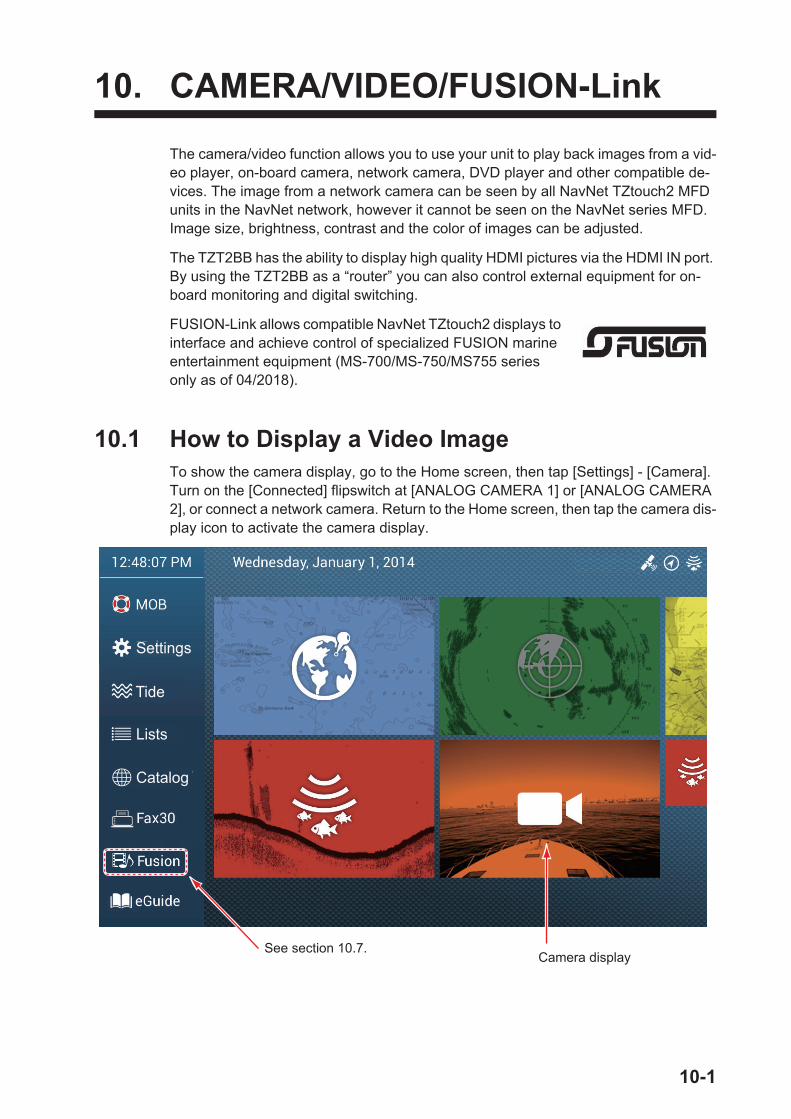
10. CAMERA/VIDEO/FUSION-Link
The camera/video function allows you to use your unit to play back images from a vid-eo player, on-board camera, network camera, DVD player and other compatible de-vices. The image from a network camera can be seen by all NavNet TZtouch2 MFD units in the NavNet network, however it cannot be seen on the NavNet series MFD. Image size, brightness, contrast and the color of images can be adjusted.
The TZT2BB has the ability to display high quality HDMI pictures via the HDMI IN port. By using the TZT2BB as a “router” you can also control external equipment for on-board monitoring and digital switching.
FUSION-Link allows compatible NavNet TZtouch2 displays to interface and achieve control of specialized FUSION marine entertainment equipment (MS-700/MS-750/MS755 series only as of 04/2018).
10.1 How to Display a Video ImageTo show the camera display, go to the Home screen, then tap [Settings] - [Camera]. Turn on the [Connected] flipswitch at [ANALOG CAMERA 1] or [ANALOG CAMERA 2], or connect a network camera. Return to the Home screen, then tap the camera dis-play icon to activate the camera display.
Camera display
Settings
Tide
Lists
Catalog
See section 10.7.
10-1

10. CAMERA/VIDEO/FUSION-Link
10.2 Video Signal TypeThere are five types of video signals which can be connected to this equipment.
• Digital signal (HDMI): Images from surveillance cameras, on-board cameras and video playback.Note 1: This feature is only available for the TZT2BB.
Note 2: For TZT2BB configurations with dual monitors, only one monitor can dis-play the HDMI input at any time.
• Analog signal: Images from surveillance cameras, on-board cameras and video playback.
• Digital signal (IP): Images from a network camera.Note: Turn on the network camera first, then turn on the MFD.
• Axis Quad Server: The image from an Axis Quad Server, which can feed up to four lines of video signals simultaneously.
• FLIR: Images from a FLIR brand infrared camera
10.3 How to Set the Video Display
10.3.1 How to set the video signal
HDMI Input
Note: This feature is only available for the TZT2BB.
HDMI Input: Set to [ON] when video equipment is connected to the HDMI IN ports.
Touch Output: See section 10.8.
Video Input 1/Video Input 2 (analog, FLIR)
Connected: Turn on to use the device (video equipment, FLIR camera) connected to the VIDEO-IN1, VIDEO-IN2 port.
Nickname: If desired, you change the name of the analog camera(s). The default names are [CAMERA1], [CAMERA 2]. You can use a maximum of 20 characters. To change a name, tap [NickName] to show the software keyboard. Change the name, then tap to finish. The name is reflected to the following locations.
• The name that appears at the bottom right corner of the camera display.
10-2
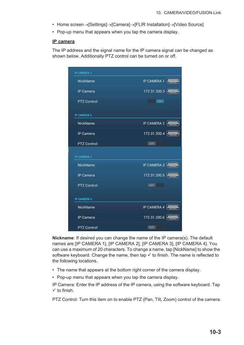
10. CAMERA/VIDEO/FUSION-Link
• Home screen [Settings] [Camera] [FLIR Installation] [Video Source]
• Pop-up menu that appears when you tap the camera display.
IP camera
The IP address and the signal name for the IP camera signal can be changed as shown below. Additionally PTZ control can be turned on or off.
Nickname: If desired you can change the name of the IP camera(s). The default names are [IP CAMERA 1], [IP CAMERA 2], [IP CAMERA 3], [IP CAMERA 4]. You can use a maximum of 20 characters. To change a name, tap [NickName] to show the software keyboard. Change the name, then tap to finish. The name is reflected to the following locations.
• The name that appears at the bottom right corner of the camera display.
• Pop-up menu that appears when you tap the camera display.
IP Camera: Enter the IP address of the IP camera, using the software keyboard. Tap to finish.
PTZ Control: Turn this item on to enable PTZ (Pan, Tilt, Zoom) control of the camera.
10-3

10. CAMERA/VIDEO/FUSION-Link
Axis Quad Server digital signal
A maximum of two Axis Quad Servers can be connected. Each server can be set in-dividually with the menus [AXIS QUAD SERVER] and [SECOND AXIS QUAD SERV-ER], respectively.
Server: Turn this item on to receive the signal from the Axis Quad Server.
IP Server: Enter the IP address of the server, using the software keyboard. Tap to finish.
Quad Mode: Turn this item on to feed four channels simultaneously to one display.
Input 1 (2, 3, 4): Turn this item on to feed each of the four channels of the server indi-vidually.
Nickname: If desired you change the name of the Axis Quad Server(s). The default names are [VIDEO 1], [VIDEO 2], [VIDEO 3], [VIDEO 4]. You can use a maximum of 20 characters. To change a name, tap [Nickname Input 1] (2, 3, 4) to show the soft-ware keyboard. Change the name, then tap to finish. The name is reflected to the following locations.
10-4
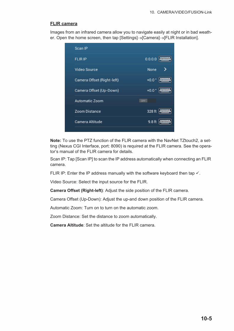
10. CAMERA/VIDEO/FUSION-Link
FLIR camera
Images from an infrared camera allow you to navigate easily at night or in bad weath-er. Open the home screen, then tap [Settings] [Camera] [FLIR Installation].
Note: To use the PTZ function of the FLIR camera with the NavNet TZtouch2, a set-ting (Nexus CGI Interface, port: 8090) is required at the FLIR camera. See the opera-tor’s manual of the FLIR camera for details.
Scan IP: Tap [Scan IP] to scan the IP address automatically when connecting an FLIR camera.
FLIR IP: Enter the IP address manually with the software keyboard then tap .
Video Source: Select the input source for the FLIR.
Camera Offset (Right-left): Adjust the side position of the FLIR camera.
Camera Offset (Up-Down): Adjust the up-and down position of the FLIR camera.
Automatic Zoom: Turn on to turn on the automatic zoom.
Zoom Distance: Set the distance to zoom automatically.
Camera Altitude: Set the altitude for the FLIR camera.
10-5
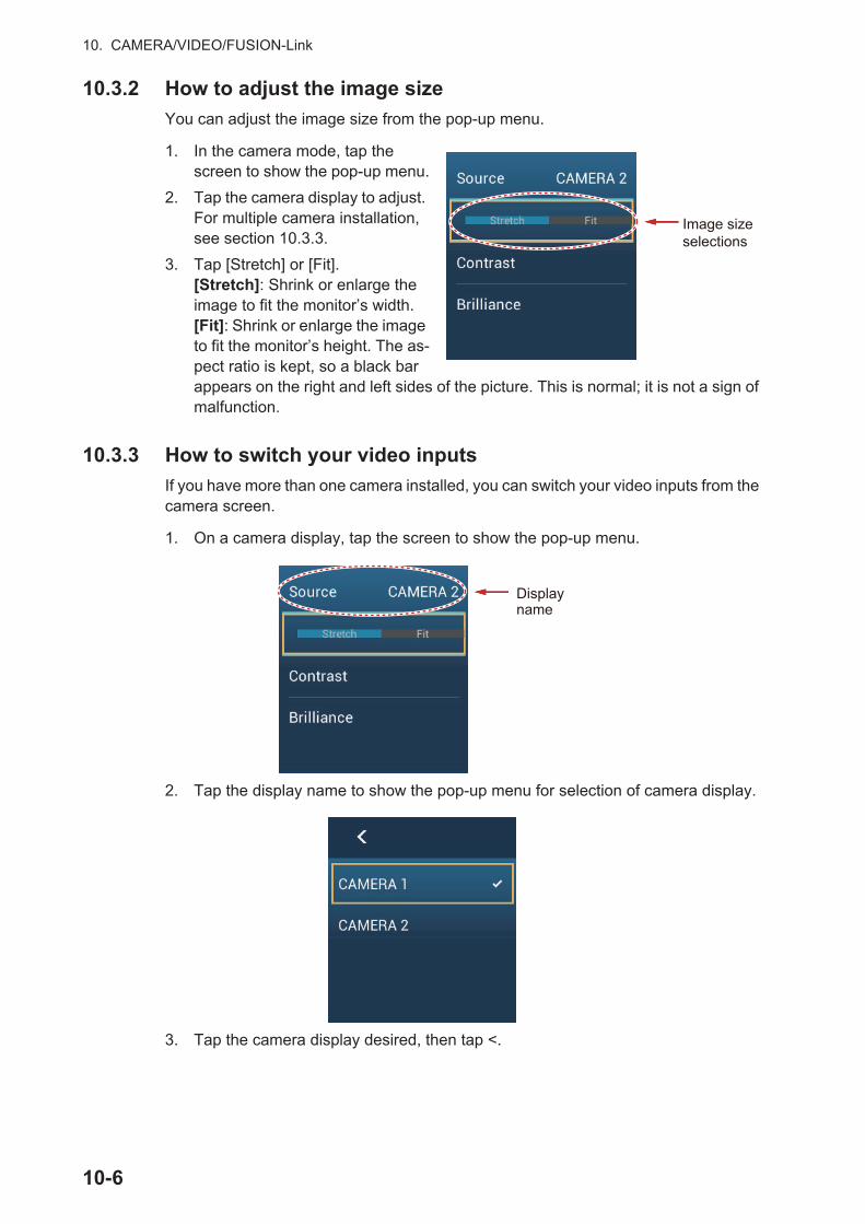
10. CAMERA/VIDEO/FUSION-Link
10.3.2 How to adjust the image size
You can adjust the image size from the pop-up menu.
1. In the camera mode, tap the screen to show the pop-up menu.
2. Tap the camera display to adjust. For multiple camera installation, see section 10.3.3.
3. Tap [Stretch] or [Fit].[Stretch]: Shrink or enlarge the image to fit the monitor’s width.[Fit]: Shrink or enlarge the image to fit the monitor’s height. The as-pect ratio is kept, so a black bar appears on the right and left sides of the picture. This is normal; it is not a sign of malfunction.
10.3.3 How to switch your video inputs
If you have more than one camera installed, you can switch your video inputs from the camera screen.
1. On a camera display, tap the screen to show the pop-up menu.
2. Tap the display name to show the pop-up menu for selection of camera display.
3. Tap the camera display desired, then tap <.
Image size selections
Display name
10-6

10. CAMERA/VIDEO/FUSION-Link
10.3.4 How to adjust the video image
Tap the screen to show the pop-up menu. Tap [Contrast] or [Brilliance] on the pop-up, then drag the slider to adjust.
10.4 Control of FLIR Camera
[Camera FoV] menu
You can display the field of view by the FLIR camera on the plotter display.
1. Tap the boat icon to display the pop-up menu.
2. Tap [Cone]. The boat icon is put inside a red translucent circle.
[Move Camera] and [Lock Camera] menus
You can rotate the FLIR camera about the position you select (touch) on the plotter or radar display. Open the pop-up menu then tap [Lock Camera]. To track the position, tap [Move Camera] on the pop-up menu.
10.5 Tracking Active Waypoint, MOBThe camera can be set to automatically track the active waypoint and/or MOB. Open the [Settings] - [Camera] menu and then turn on [Automatic Lock on Active Waypoint] or [Automatic Lock on MOB].
Drag slider (or tap bar, +, - icons)
Current setting (ex. Contrast)
Tap screen to show pop-up menu. Tap [Contrast] or [Brilliance].
10-7

10. CAMERA/VIDEO/FUSION-Link
10.6 Touch Control on the Camera Display
Operations available with connection of an analog camera, Axis Server 241Q
Operations available with connection of a FLIR camera
Operation Function
Tap Opens the pop-up menu.
Operation Function
Tap Points camera to direction tapped.
Long tap Opens the pop-up menu.
Drag Rotates camera while drag-ging.
Pinch Zoom in/zoom out the cam-era image (infrared only).
Zoom in Zoom out
10-8

10. CAMERA/VIDEO/FUSION-Link
10.7 FUSION-LinkFUSION-Link allows compatible NavNet TZtouch2 displays to interface and achieve control of specialized FUSION marine entertainment equipment.
10.7.1 How to access the FUSION screen and controls
The FUSION controls can be accessed three ways:
• From the home screen (full screen)
• Slide-out menu (minimized screen)
• Gesture ([Fusion] option)
Method 1: Tap [Fusion] on the home screen to get the full screen FUSION display.
Example1: iPod in the full screen
Dragslider to adjust volume.
Show or hide [ZONES] panel.
Show or hide[MENU] panel.
Tap: Goto previous title.Hold down: Go back.
Closebutton
Tap: Goto next number.Hold down: Fast forward.
Swipe to change source.
Show or hide [TONES] panel(tone controls).
Playback
Lower volume.
Raise volume.
Mute/unmute.
: Select tracks or albums.
: Repeat one or all.
Globallyadjustvolume.
Zones 1 and 2 volumes synched.
Zones 1 and 2 volumes independent.
10-9
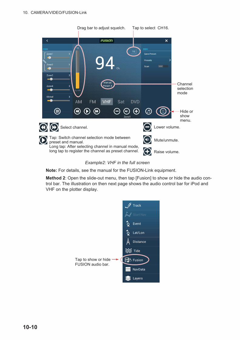
10. CAMERA/VIDEO/FUSION-Link
Example2: VHF in the full screen
Note: For details, see the manual for the FUSION-Link equipment.
Method 2: Open the slide-out menu, then tap [Fusion] to show or hide the audio con-trol bar. The illustration on then next page shows the audio control bar for iPod and VHF on the plotter display.
Tap: Switch channel selection mode between preset and manual.Long tap: After selecting channel in manual mode, long tap to register the channel as preset channel.
Select channel. Lower volume.
Raise volume.
Mute/unmute.
Drag bar to adjust squelch. Tap to select CH16.
Channel selection mode
Hide or show menu.
Tap to show or hideFUSION audio bar.
10-10
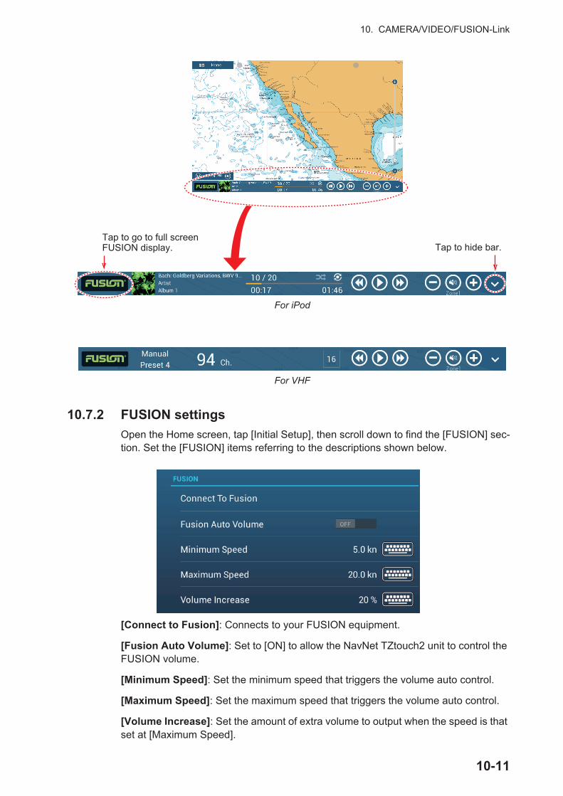
10. CAMERA/VIDEO/FUSION-Link
10.7.2 FUSION settings
Open the Home screen, tap [Initial Setup], then scroll down to find the [FUSION] sec-tion. Set the [FUSION] items referring to the descriptions shown below.
[Connect to Fusion]: Connects to your FUSION equipment.
[Fusion Auto Volume]: Set to [ON] to allow the NavNet TZtouch2 unit to control the FUSION volume.
[Minimum Speed]: Set the minimum speed that triggers the volume auto control.
[Maximum Speed]: Set the maximum speed that triggers the volume auto control.
[Volume Increase]: Set the amount of extra volume to output when the speed is that set at [Maximum Speed].
Tap to go to full screen FUSION display. Tap to hide bar.
For iPod
For VHF
10-11
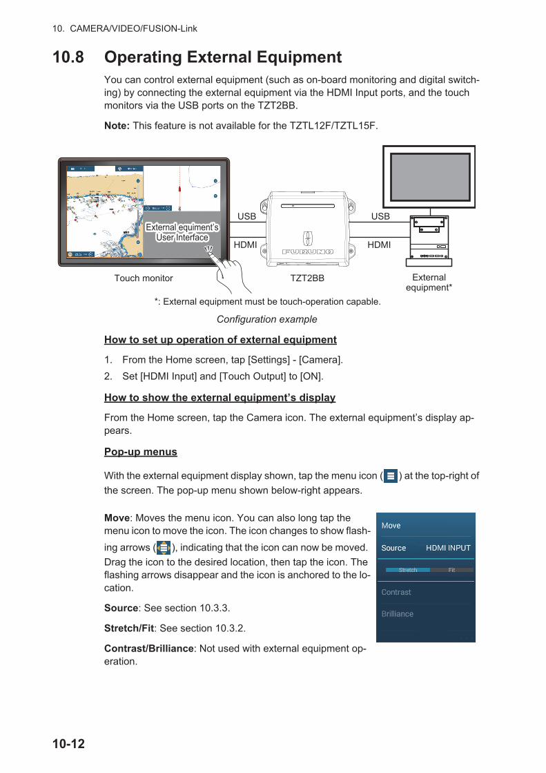
10. CAMERA/VIDEO/FUSION-Link
10.8 Operating External EquipmentYou can control external equipment (such as on-board monitoring and digital switch-ing) by connecting the external equipment via the HDMI Input ports, and the touch monitors via the USB ports on the TZT2BB.
Note: This feature is not available for the TZTL12F/TZTL15F.
Configuration example
How to set up operation of external equipment
1. From the Home screen, tap [Settings] - [Camera].
2. Set [HDMI Input] and [Touch Output] to [ON].
How to show the external equipment’s display
From the Home screen, tap the Camera icon. The external equipment’s display ap-pears.
Pop-up menus
With the external equipment display shown, tap the menu icon ( ) at the top-right of
the screen. The pop-up menu shown below-right appears.
Move: Moves the menu icon. You can also long tap the menu icon to move the icon. The icon changes to show flash-
ing arrows ( ), indicating that the icon can now be moved.
Drag the icon to the desired location, then tap the icon. The flashing arrows disappear and the icon is anchored to the lo-cation.
Source: See section 10.3.3.
Stretch/Fit: See section 10.3.2.
Contrast/Brilliance: Not used with external equipment op-eration.
Touch monitor TZT2BB
*: External equipment must be touch-operation capable.
USB
HDMI
USB
HDMI
External equipment*
External equiment’s User Interface
External equiment’s User Interface
10-12
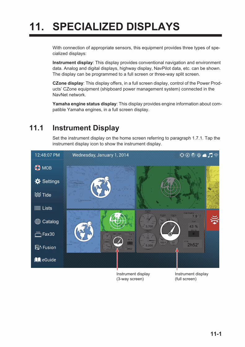
11. SPECIALIZED DISPLAYS
With connection of appropriate sensors, this equipment provides three types of spe-cialized displays:
Instrument display: This display provides conventional navigation and environment data. Analog and digital displays, highway display, NavPilot data, etc. can be shown. The display can be programmed to a full screen or three-way split screen.
CZone display: This display offers, in a full screen display, control of the Power Prod-ucts’ CZone equipment (shipboard power management system) connected in the NavNet network.
Yamaha engine status display: This display provides engine information about com-patible Yamaha engines, in a full screen display.
11.1 Instrument DisplaySet the instrument display on the home screen referring to paragraph 1.7.1. Tap the instrument display icon to show the instrument display.
Instrument display(full screen)
Instrument display(3-way screen)
Settings
Tide
Lists
Catalog
11-1
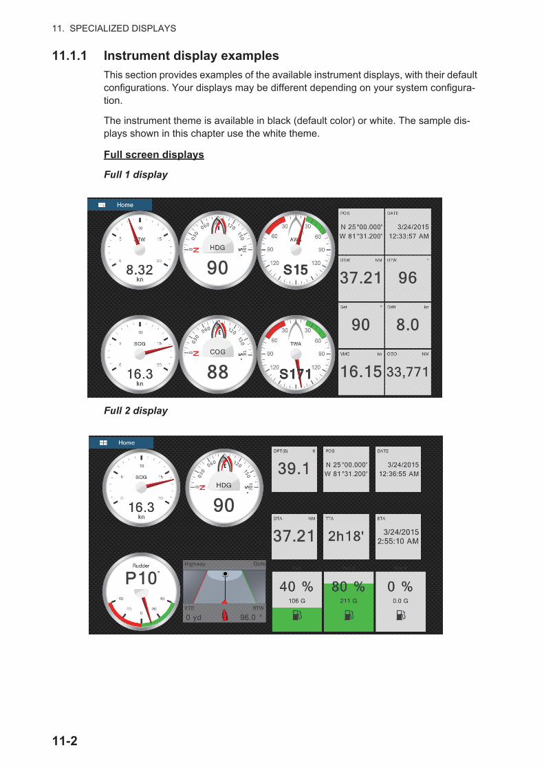
11. SPECIALIZED DISPLAYS
11.1.1 Instrument display examples
This section provides examples of the available instrument displays, with their default configurations. Your displays may be different depending on your system configura-tion.
The instrument theme is available in black (default color) or white. The sample dis-plays shown in this chapter use the white theme.
Full screen displays
Full 1 display
Full 2 display
11-2
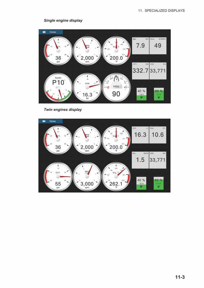
11. SPECIALIZED DISPLAYS
Single engine display
Twin engines display
11-3

11. SPECIALIZED DISPLAYS
Triple engines display
Quad engines display
11-4

11. SPECIALIZED DISPLAYS
Split screen displays
Navigation display
Environment display
Wind display
11-5
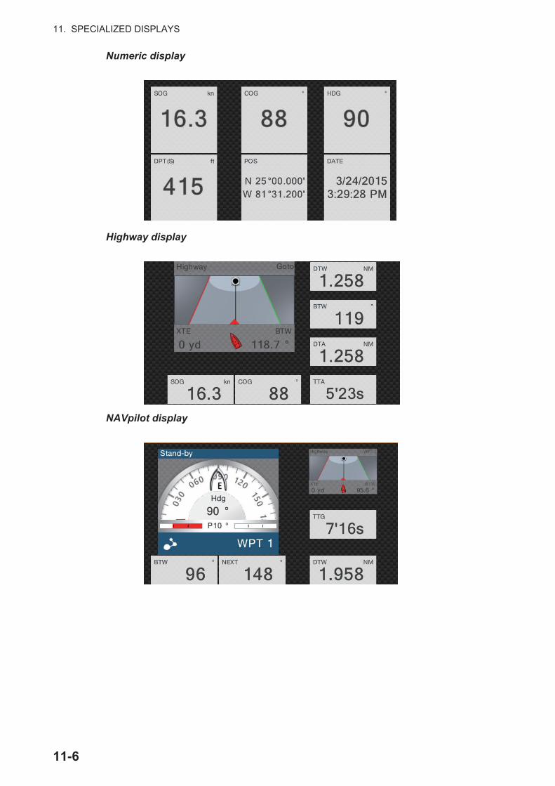
11. SPECIALIZED DISPLAYS
Numeric display
Highway display
NAVpilot display
11-6
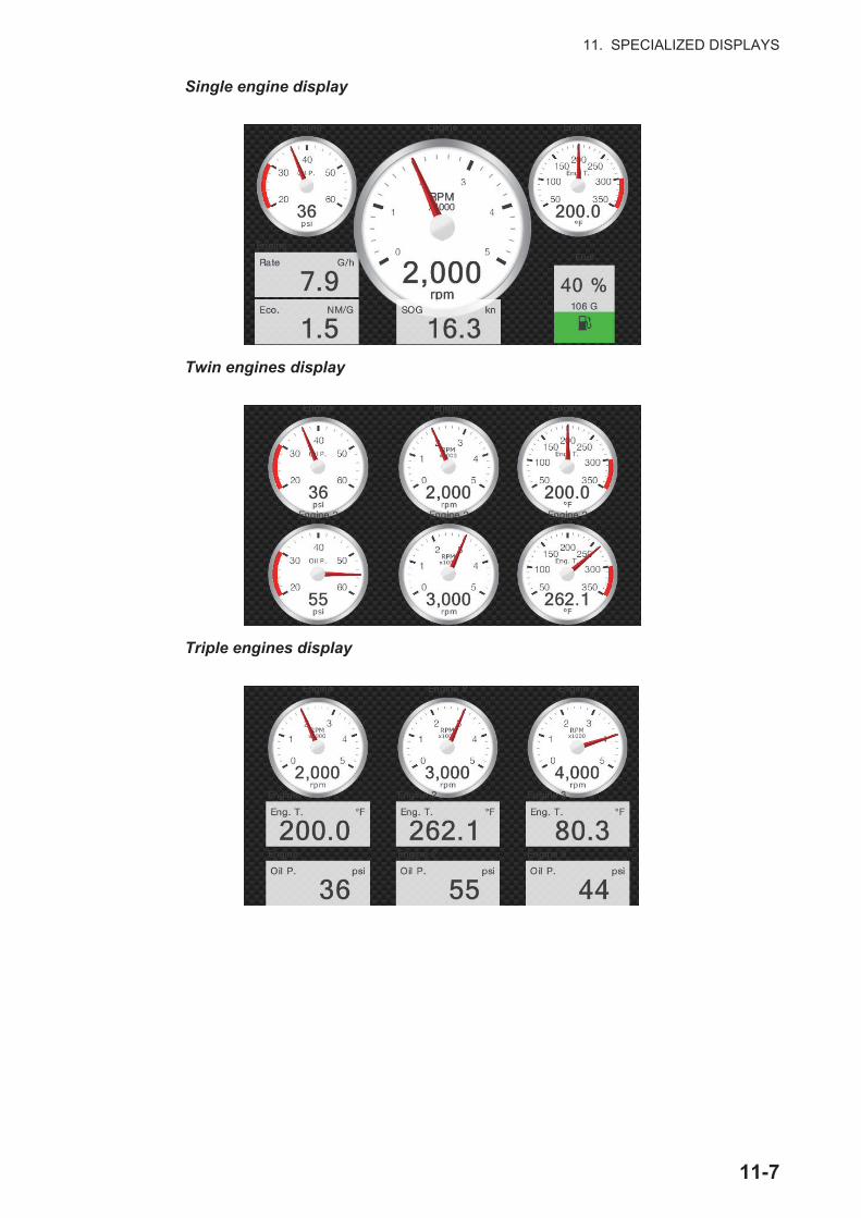
11. SPECIALIZED DISPLAYS
Single engine display
Twin engines display
Triple engines display
11-7

11. SPECIALIZED DISPLAYS
Tank display
The tank indication shows fuel level in both analog and digital formats. The analog in-dicator rises or lowers with fuel level and the color changes according to the percent-age of fuel remaining.Green: 10% - 100%Red: 0% - 10%
11.1.2 How to switch between instrument displays
3-way split screen
The default display screens in the 3-way split screen are environment, wind, numeric, highway, NAVpilot, single engine, twin engines, triple engines, and tank. The availabil-ity of a display depends on your system configuration.
You can switch between the displays by swiping downward at the bottom of the dis-play, or tapping the screen to display the pop-up menu shown below and tapping the display of your choice.
11-8
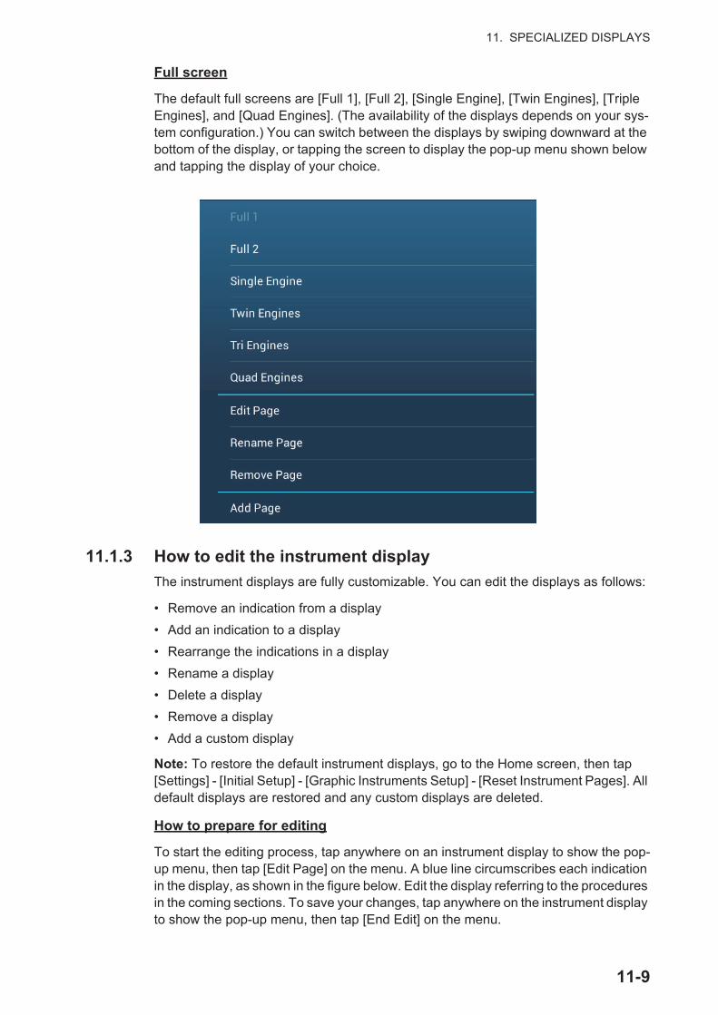
11. SPECIALIZED DISPLAYS
Full screen
The default full screens are [Full 1], [Full 2], [Single Engine], [Twin Engines], [Triple Engines], and [Quad Engines]. (The availability of the displays depends on your sys-tem configuration.) You can switch between the displays by swiping downward at the bottom of the display, or tapping the screen to display the pop-up menu shown below and tapping the display of your choice.
11.1.3 How to edit the instrument display
The instrument displays are fully customizable. You can edit the displays as follows:
• Remove an indication from a display
• Add an indication to a display
• Rearrange the indications in a display
• Rename a display
• Delete a display
• Remove a display
• Add a custom display
Note: To restore the default instrument displays, go to the Home screen, then tap [Settings] - [Initial Setup] - [Graphic Instruments Setup] - [Reset Instrument Pages]. All default displays are restored and any custom displays are deleted.
How to prepare for editing
To start the editing process, tap anywhere on an instrument display to show the pop-up menu, then tap [Edit Page] on the menu. A blue line circumscribes each indication in the display, as shown in the figure below. Edit the display referring to the procedures in the coming sections. To save your changes, tap anywhere on the instrument display to show the pop-up menu, then tap [End Edit] on the menu.
11-9
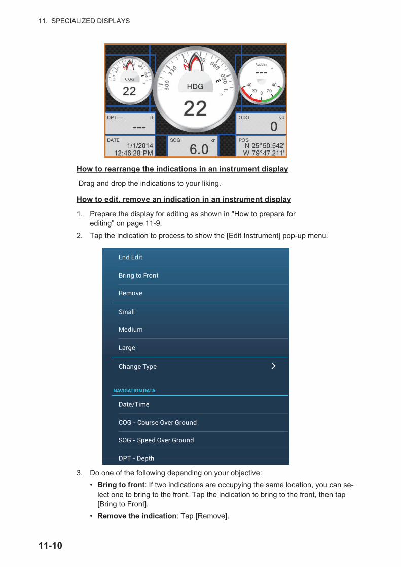
11. SPECIALIZED DISPLAYS
How to rearrange the indications in an instrument display
Drag and drop the indications to your liking.
How to edit, remove an indication in an instrument display
1. Prepare the display for editing as shown in "How to prepare for editing" on page 11-9.
2. Tap the indication to process to show the [Edit Instrument] pop-up menu.
3. Do one of the following depending on your objective:
• Bring to front: If two indications are occupying the same location, you can se-lect one to bring to the front. Tap the indication to bring to the front, then tap [Bring to Front].
• Remove the indication: Tap [Remove].
11-10
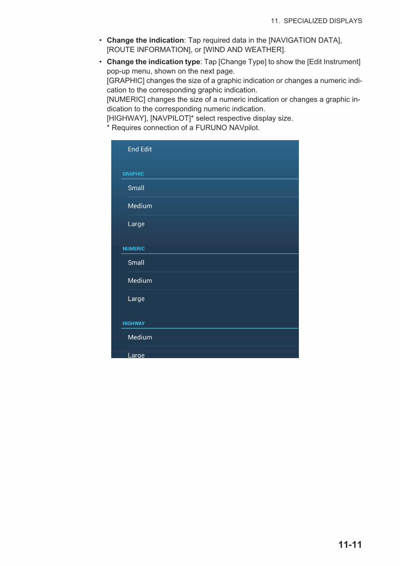
11. SPECIALIZED DISPLAYS
• Change the indication: Tap required data in the [NAVIGATION DATA], [ROUTE INFORMATION], or [WIND AND WEATHER].
• Change the indication type: Tap [Change Type] to show the [Edit Instrument] pop-up menu, shown on the next page. [GRAPHIC] changes the size of a graphic indication or changes a numeric indi-cation to the corresponding graphic indication.[NUMERIC] changes the size of a numeric indication or changes a graphic in-dication to the corresponding numeric indication.[HIGHWAY], [NAVPILOT]* select respective display size.* Requires connection of a FURUNO NAVpilot.
11-11
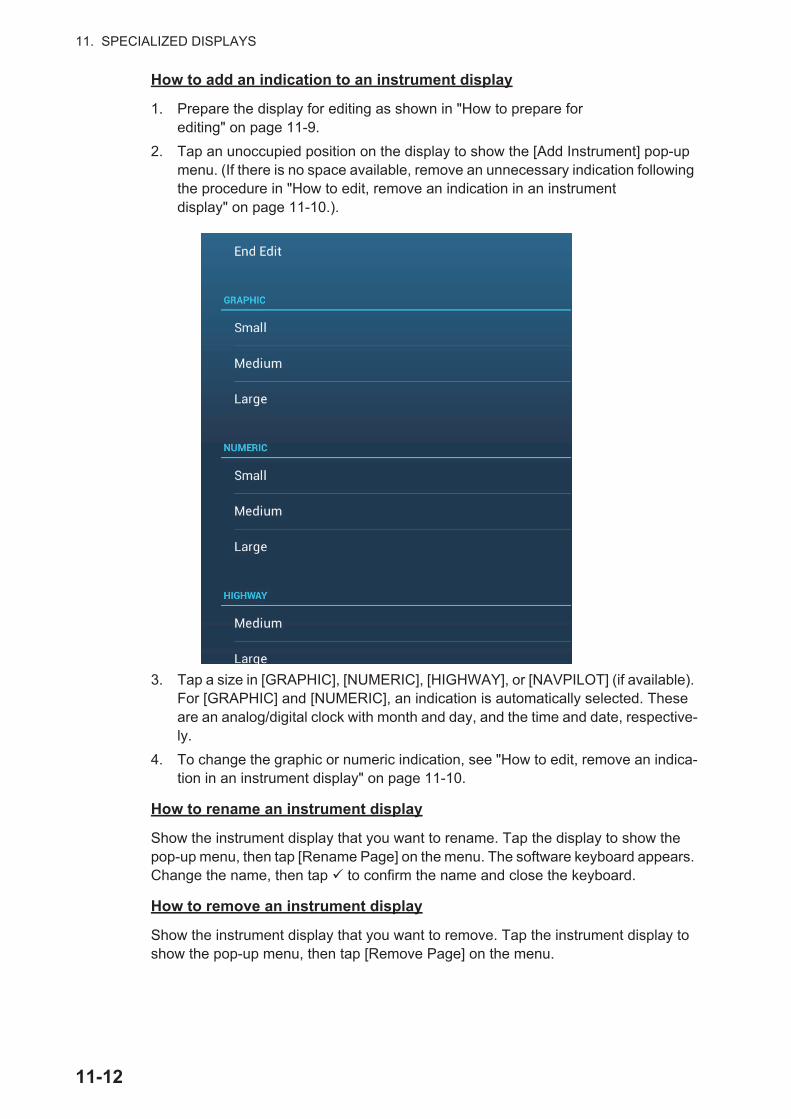
11. SPECIALIZED DISPLAYS
How to add an indication to an instrument display
1. Prepare the display for editing as shown in "How to prepare for editing" on page 11-9.
2. Tap an unoccupied position on the display to show the [Add Instrument] pop-up menu. (If there is no space available, remove an unnecessary indication following the procedure in "How to edit, remove an indication in an instrument display" on page 11-10.).
3. Tap a size in [GRAPHIC], [NUMERIC], [HIGHWAY], or [NAVPILOT] (if available). For [GRAPHIC] and [NUMERIC], an indication is automatically selected. These are an analog/digital clock with month and day, and the time and date, respective-ly.
4. To change the graphic or numeric indication, see "How to edit, remove an indica-tion in an instrument display" on page 11-10.
How to rename an instrument display
Show the instrument display that you want to rename. Tap the display to show the pop-up menu, then tap [Rename Page] on the menu. The software keyboard appears. Change the name, then tap to confirm the name and close the keyboard.
How to remove an instrument display
Show the instrument display that you want to remove. Tap the instrument display to show the pop-up menu, then tap [Remove Page] on the menu.
11-12
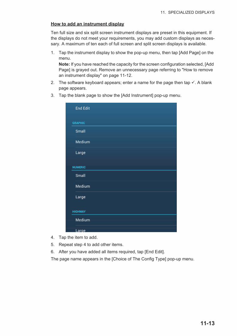
11. SPECIALIZED DISPLAYS
How to add an instrument display
Ten full size and six split screen instrument displays are preset in this equipment. If the displays do not meet your requirements, you may add custom displays as neces-sary. A maximum of ten each of full screen and split screen displays is available.
1. Tap the instrument display to show the pop-up menu, then tap [Add Page] on the menu.Note: If you have reached the capacity for the screen configuration selected, [Add Page] is grayed out. Remove an unnecessary page referring to "How to remove an instrument display" on page 11-12.
2. The software keyboard appears; enter a name for the page then tap . A blank page appears.
3. Tap the blank page to show the [Add Instrument] pop-up menu.
4. Tap the item to add.
5. Repeat step 4 to add other items.
6. After you have added all items required, tap [End Edit].
The page name appears in the [Choice of The Config Type] pop-up menu.
11-13

11. SPECIALIZED DISPLAYS
11.1.4 Instrument theme
The instrument theme is available in black or white. To change the theme, go to the home screen and tap [Settings] - [General]. Set [Instrument Theme] to [Black] or [White]. The setting also controls the graphic format navigation data displays in the data area.
11.1.5 Fuel management system
This equipment can calculate the remaining fuel from the total fuel and the fuel con-sumption rate. This function requires the NMEA 2000 sentence PGN127489 (Engine Fuel Rate).
Note: The remaining fuel calculation is for reference purposes. Do not use the results for navigation planning or emergency purposes. During an entire voyage, select one NavNet Ztouch2 unit for the calculation at start-up. The calculation of remaining fuel is not done when the unit is powered off.
How to manually enter fuel tank capacity
1. From the home screen, tap [Settings] [Initial Setup].
2. At [Total Fuel Capacity], enter your vessel’s total fuel capacity.
3. Set the flipswitch of [Manual Fuel Management] to [ON].
4. Tap [OK] to finish.
WhiteBlack
11-14
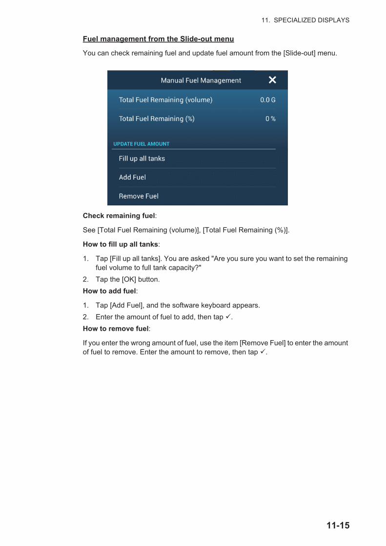
11. SPECIALIZED DISPLAYS
Fuel management from the Slide-out menu
You can check remaining fuel and update fuel amount from the [Slide-out] menu.
Check remaining fuel:
See [Total Fuel Remaining (volume)], [Total Fuel Remaining (%)].
How to fill up all tanks:
1. Tap [Fill up all tanks]. You are asked "Are you sure you want to set the remaining fuel volume to full tank capacity?"
2. Tap the [OK] button.
How to add fuel:
1. Tap [Add Fuel], and the software keyboard appears.
2. Enter the amount of fuel to add, then tap .
How to remove fuel:
If you enter the wrong amount of fuel, use the item [Remove Fuel] to enter the amount of fuel to remove. Enter the amount to remove, then tap .
11-15

11. SPECIALIZED DISPLAYS
11.2 CZoneThe NavNet TZtouch2 can control Power Products’ CZone equipment connected in the NavNet network. CZone is a shipboard power management system.
This equipment controls [CZone Control], [CZone Modes] and [CZone Monitoring].
• CZone Control: Controls the power of individual CZone equipment.
• CZone Modes: Controls the power of multiple CZone equipment.
• CZone Monitoring: Shows temperature, pressure, fuel tank and battery state of CZone equipment.
The table below shows the points of control of each CZone system.
11.2.1 How to use CZone
After confirming the following two items, set up your NavNet system to use CZone.C
• This equipment is connected to the CZone system and NavNet network by NMEA 2000 interface.
• CZone equipment have been properly set.
How to add/edit CZone pages
Add or edit CZone pages in the following instances:
• First use of CZone
• Setting changed at the CZone system
1. From the home screen, tap [Settings] [Initial Setup] [Graphic Instruments Set-up] [Add Default CZone Pages]. You are asked if it is OK to add or edit CZone pages.
2. Tap the [OK] button.
3. Tap the X button on the title bar to close the menu.
About the DIP switches
For the serviceman. Do not change the settings.
System name Instrument display Data area Slide-out menuCZone Control Yes No YesCZone Modes Yes Yes YesCZone Monitoring Yes
(display only)Yes
(display only)No
11-16
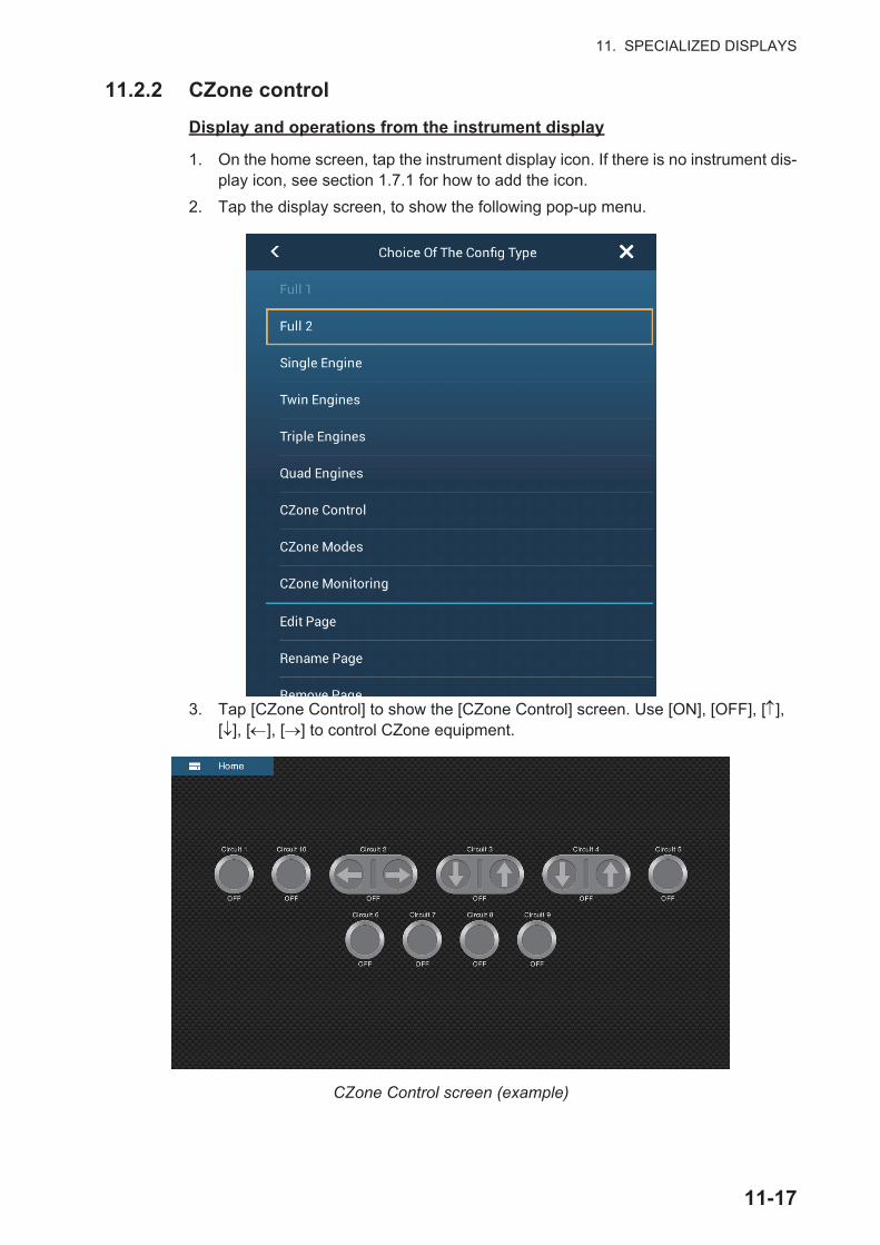
11. SPECIALIZED DISPLAYS
11.2.2 CZone control
Display and operations from the instrument display
1. On the home screen, tap the instrument display icon. If there is no instrument dis-play icon, see section 1.7.1 for how to add the icon.
2. Tap the display screen, to show the following pop-up menu.
3. Tap [CZone Control] to show the [CZone Control] screen. Use [ON], [OFF], [ ], [ ], [ ], [ ] to control CZone equipment.
CZone Control screen (example)
11-17
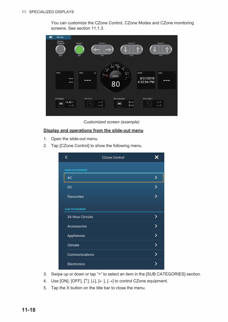
11. SPECIALIZED DISPLAYS
You can customize the CZone Control, CZone Modes and CZone monitoring screens. See section 11.1.3.
Customized screen (example)
Display and operations from the slide-out menu
1. Open the slide-out menu.
2. Tap [CZone Control] to show the following menu.
3. Swipe up or down or tap “>” to select an item in the [SUB CATEGORIES] section.
4. Use [ON], [OFF], [ ], [ ], [ ], [ ] to control CZone equipment.
5. Tap the X button on the title bar to close the menu.
11-18
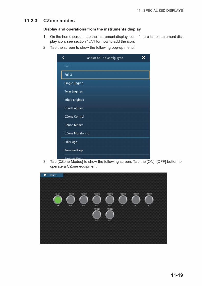
11. SPECIALIZED DISPLAYS
11.2.3 CZone modes
Display and operations from the instruments display
1. On the home screen, tap the instrument display icon. If there is no instrument dis-play icon, see section 1.7.1 for how to add the icon.
2. Tap the screen to show the following pop-up menu.
3. Tap [CZone Modes] to show the following screen. Tap the [ON], [OFF] button to operate a CZone equipment.
11-19

11. SPECIALIZED DISPLAYS
You can customize the CZone Control, CZone Modes and CZone monitoring screens. See section 11.1.3.
Customized screen (example)
4. Tap the X button on the title bar to close the menu.
Display and operations from the data area
1. Show the data area.
2. Tap a vacant area in the data area to show the [Add Nav Data] menu.
11-20
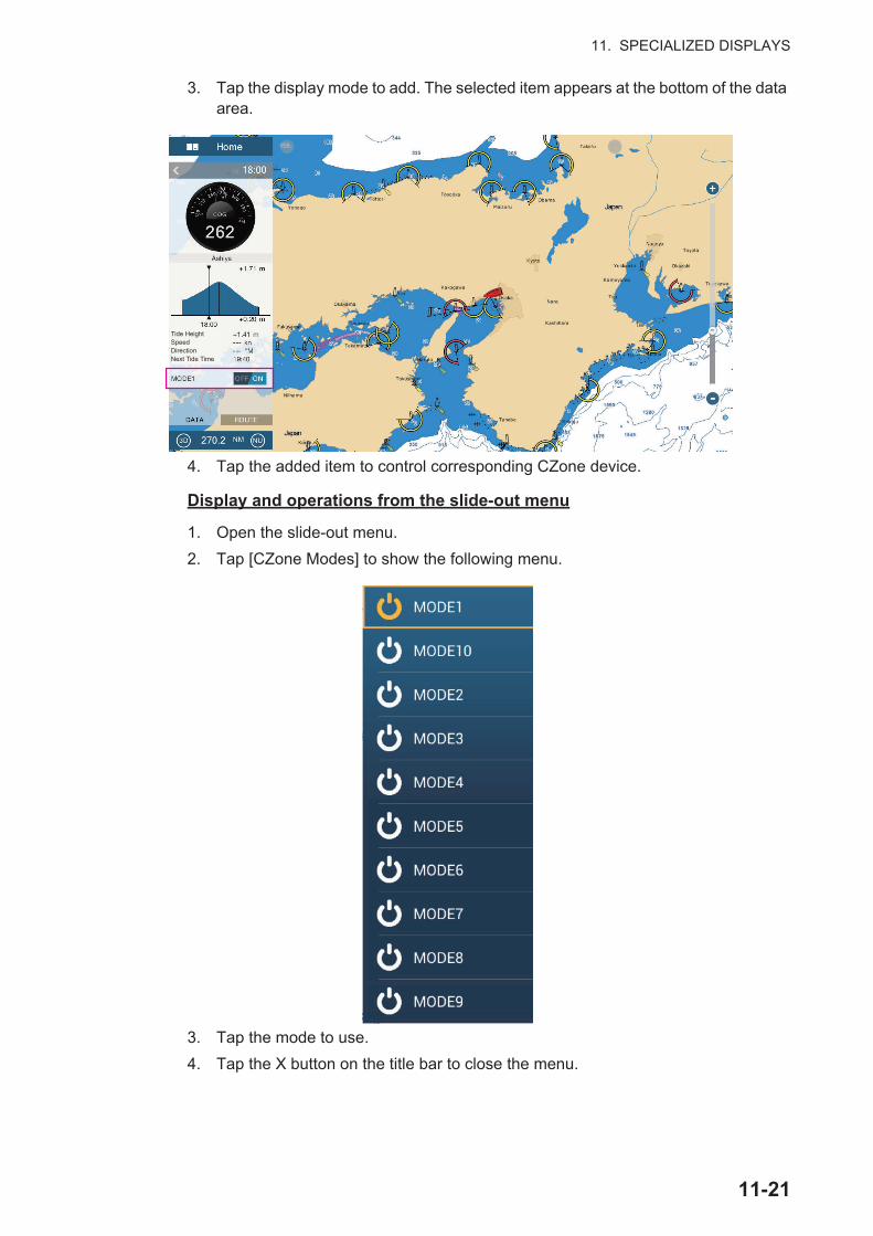
11. SPECIALIZED DISPLAYS
3. Tap the display mode to add. The selected item appears at the bottom of the data area.
4. Tap the added item to control corresponding CZone device.
Display and operations from the slide-out menu
1. Open the slide-out menu.
2. Tap [CZone Modes] to show the following menu.
3. Tap the mode to use.
4. Tap the X button on the title bar to close the menu.
Tide HeightSpeedDirectionNext Tide Time
11-21
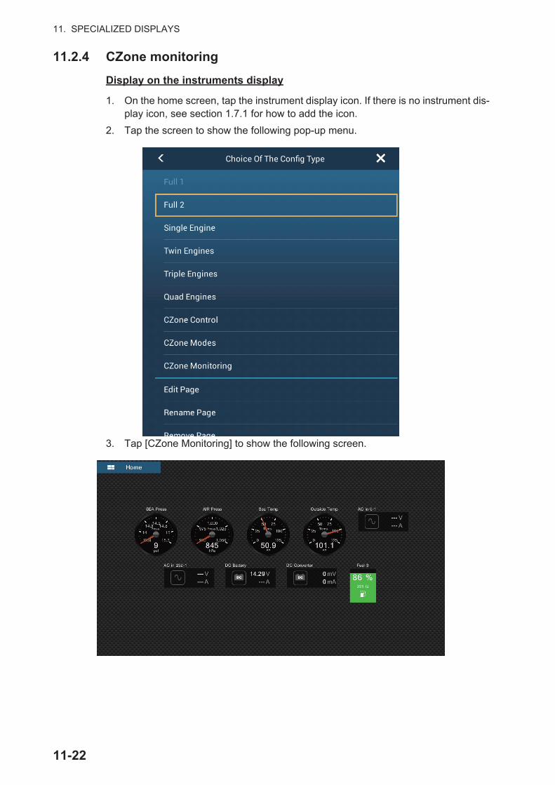
11. SPECIALIZED DISPLAYS
11.2.4 CZone monitoring
Display on the instruments display
1. On the home screen, tap the instrument display icon. If there is no instrument dis-play icon, see section 1.7.1 for how to add the icon.
2. Tap the screen to show the following pop-up menu.
3. Tap [CZone Monitoring] to show the following screen.
11-22
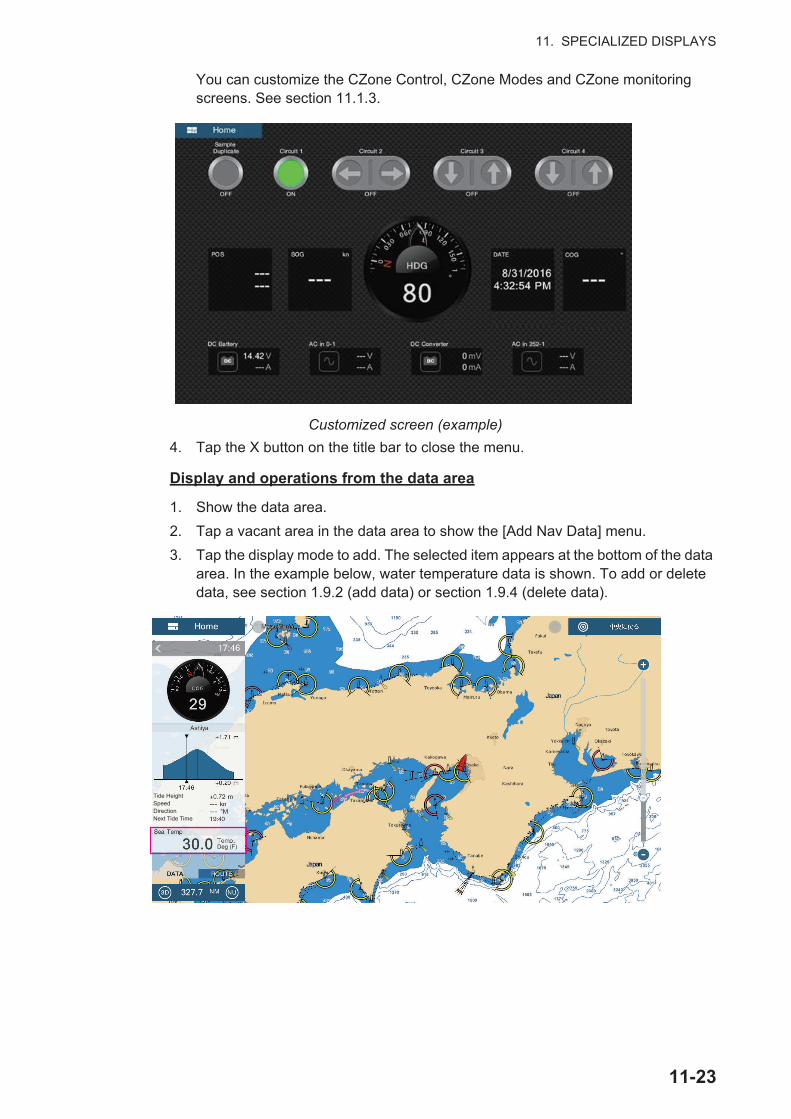
11. SPECIALIZED DISPLAYS
You can customize the CZone Control, CZone Modes and CZone monitoring screens. See section 11.1.3.
Customized screen (example)
4. Tap the X button on the title bar to close the menu.
Display and operations from the data area
1. Show the data area.
2. Tap a vacant area in the data area to show the [Add Nav Data] menu.
3. Tap the display mode to add. The selected item appears at the bottom of the data area. In the example below, water temperature data is shown. To add or delete data, see section 1.9.2 (add data) or section 1.9.4 (delete data).
Tide HeightSpeedDirectionNext Tide Time
Deg (F)
11-23
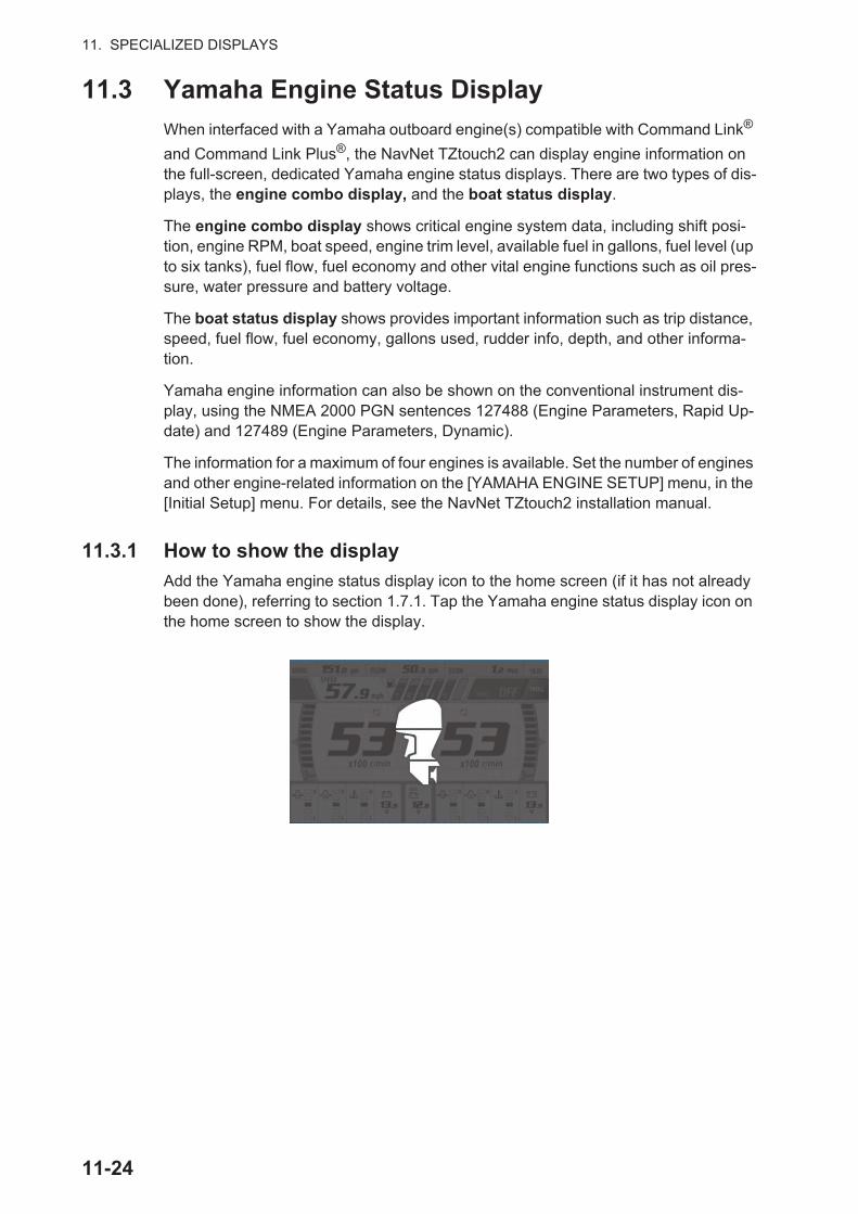
11. SPECIALIZED DISPLAYS
11.3 Yamaha Engine Status Display
When interfaced with a Yamaha outboard engine(s) compatible with Command Link®
and Command Link Plus®, the NavNet TZtouch2 can display engine information on the full-screen, dedicated Yamaha engine status displays. There are two types of dis-plays, the engine combo display, and the boat status display.
The engine combo display shows critical engine system data, including shift posi-tion, engine RPM, boat speed, engine trim level, available fuel in gallons, fuel level (up to six tanks), fuel flow, fuel economy and other vital engine functions such as oil pres-sure, water pressure and battery voltage.
The boat status display shows provides important information such as trip distance, speed, fuel flow, fuel economy, gallons used, rudder info, depth, and other informa-tion.
Yamaha engine information can also be shown on the conventional instrument dis-play, using the NMEA 2000 PGN sentences 127488 (Engine Parameters, Rapid Up-date) and 127489 (Engine Parameters, Dynamic).
The information for a maximum of four engines is available. Set the number of engines and other engine-related information on the [YAMAHA ENGINE SETUP] menu, in the [Initial Setup] menu. For details, see the NavNet TZtouch2 installation manual.
11.3.1 How to show the display
Add the Yamaha engine status display icon to the home screen (if it has not already been done), referring to section 1.7.1. Tap the Yamaha engine status display icon on the home screen to show the display.
11-24

11. SPECIALIZED DISPLAYS
11.3.2 Display examples
Each display type is divided into three sections: upper, middle and lower. The error message area at the top of a display shows engine error messages.
For detailed descriptions of the displays, see the Operator’s Manual for the Yamaha engine.
Engine combo display (example: twin engine)
Upper section 1
Middle section(layout depends on no. of engines)
Lower section
Upper section 2
CHECK SYSTEM! Starboard Engine
Error message area
Boat status display
Upper section
Middle section
Lower section
Error message area
11-25
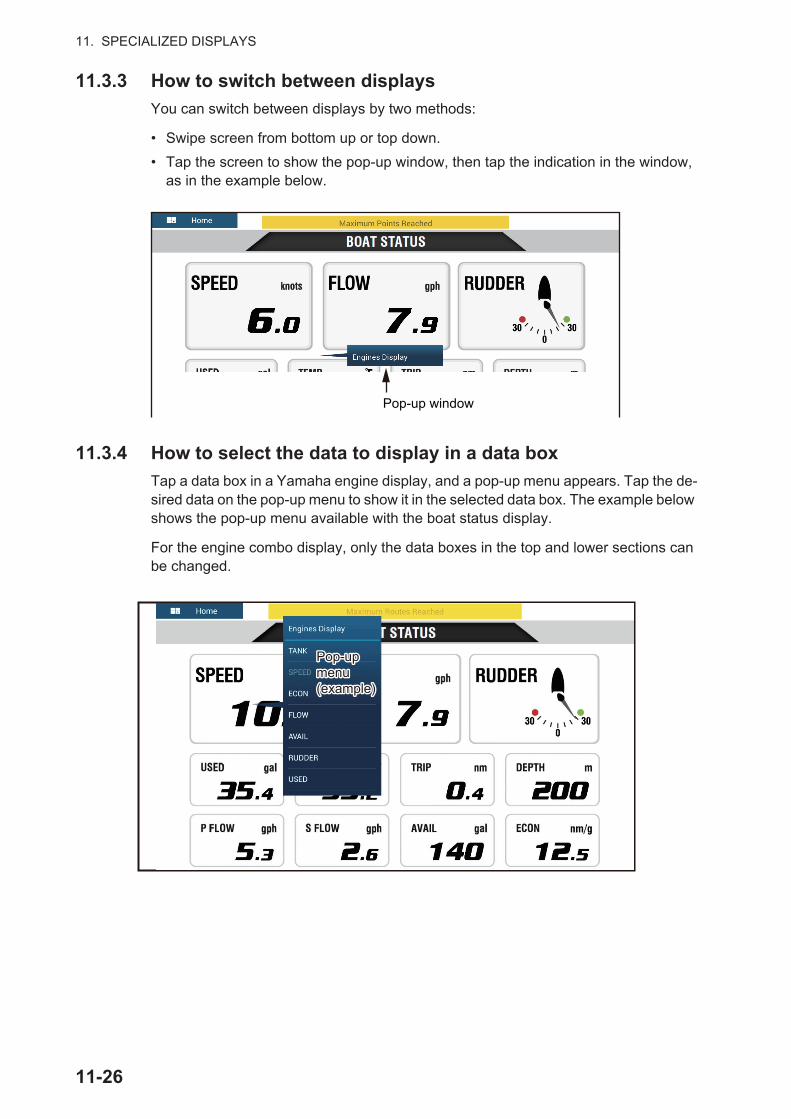
11. SPECIALIZED DISPLAYS
11.3.3 How to switch between displays
You can switch between displays by two methods:
• Swipe screen from bottom up or top down.
• Tap the screen to show the pop-up window, then tap the indication in the window, as in the example below.
11.3.4 How to select the data to display in a data box
Tap a data box in a Yamaha engine display, and a pop-up menu appears. Tap the de-sired data on the pop-up menu to show it in the selected data box. The example below shows the pop-up menu available with the boat status display.
For the engine combo display, only the data boxes in the top and lower sections can be changed.
Pop-up window
Pop-upmenu(example)
Pop-upmenu(example)
11-26
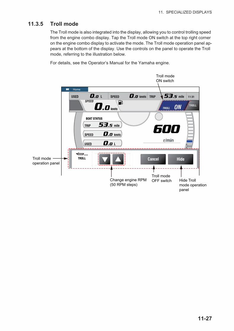
11. SPECIALIZED DISPLAYS
11.3.5 Troll mode
The Troll mode is also integrated into the display, allowing you to control trolling speed from the engine combo display. Tap the Troll mode ON switch at the top right corner on the engine combo display to activate the mode. The Troll mode operation panel ap-pears at the bottom of the display. Use the controls on the panel to operate the Troll mode, referring to the illustration below.
For details, see the Operator’s Manual for the Yamaha engine.
Change engine RPM (50 RPM steps)
Home
Troll modeON switch
Troll modeoperation panel
Troll mode OFF switch Hide Troll
mode operation panel
11-27

11. SPECIALIZED DISPLAYS
11.3.6 Trouble codes
Trouble codes generated by the engine can be reviewed on the [YAMAHA ENGINE SETUP] menu, in the [Initial Setup] menu. For detailed information, see the Operator’s Manual for the Yamaha engine.
11.3.7 Alarm list
When an engine alarm is violated, you can see the name of the offending alarm on the [Alarms] list. See section 2.10.8 for details.
11-28

12. SIRIUS/XM SATELLITE WEATH-ER RECEIVER (BBWX3) OPERA-TIONS
The FURUNO BBWX3 Sirius/XM Satellite Weather Receiver provides the marine weather information (Sirius (only U.S.) and NavCenter (worldwide)), in analog and dig-ital forms. The Sirius satellite radio is also available with a Sirius Satellite Radio sub-scription.
Before using your Sirius/XM satellite weather receiver...
• Purchase a Sirius weather service subscription. Contact Sirius Satellite Radio INC., for additional information.
• Purchase a Sirius satellite radio subscription. Contact Sirius Satellite Radio INC., for additional information.
• During the installation of the equipment, the Installation Wizard checks if the Sirius receiver is connected to this NavNet TZtouch2 unit. Check the [Sensor List] for the presence of the receiver.
If the receiver does not appear in the list, check the Antenna LED on the BBWX3 and the connection between the two units. The LED is solid green when a normal antenna connection is detected, and off or flashing green in case of antenna short circuit.
• Connect the Sirius receiver and the NavNet TZtouch2 displays then turn on both of those units. Your unit then receives WX data from the weather receiver, which takes approximately 30 minutes.
12.1 Marine Weather Display IntroductionYour system displays the current and forecasted marine weather information for your area. The weather information is updated in real time so that you have current weather information for your area and any area in the U.S.
Information provided by the Sirius Marine Weather service is advisory in nature. You, the customer, agree to release FURUNO ELECTRIC CO., LTD., Sirius Satellite Radio Inc., Navcast Inc. and WSI Corporation from any problems that occur from this ser-
12-1

12. SIRIUS/XM SATELLITE WEATHER RECEIVER (BBWX3) OPERATIONS
vice. And you acknowledge that you have read the conditions of your subscription agreement and agree to all the conditions of the subscription. If you do not have the subscription agreement, got to www.sirius.com/marineweatheragreement or call 1-800-869-5480 to have a copy sent to you.
You can put a point on the weather display. Tap the screen where to put a point, then tap [New Point] on the pop-up menu.
How to select the weather display
The weather display is overlaid on the 2D plotter display. Select the marine weather display on the home screen.
12.2 NavCenter WeatherYou can download the NavCenter data from the internet via Wireless LAN. See section 1.18 for how to connect to the internet.
12.2.1 How to set up for NavCenter weather
1. Open the home screen, then tap [Settings] - [Weather].
2. Tap [Load Weather File].Note: The option [Sirius] appears when connecting BBWX3.
3. Tap [NavCenter] then tap < to return to the menu.
Weather display
Settings
Tide
Lists
Catalog
12-2
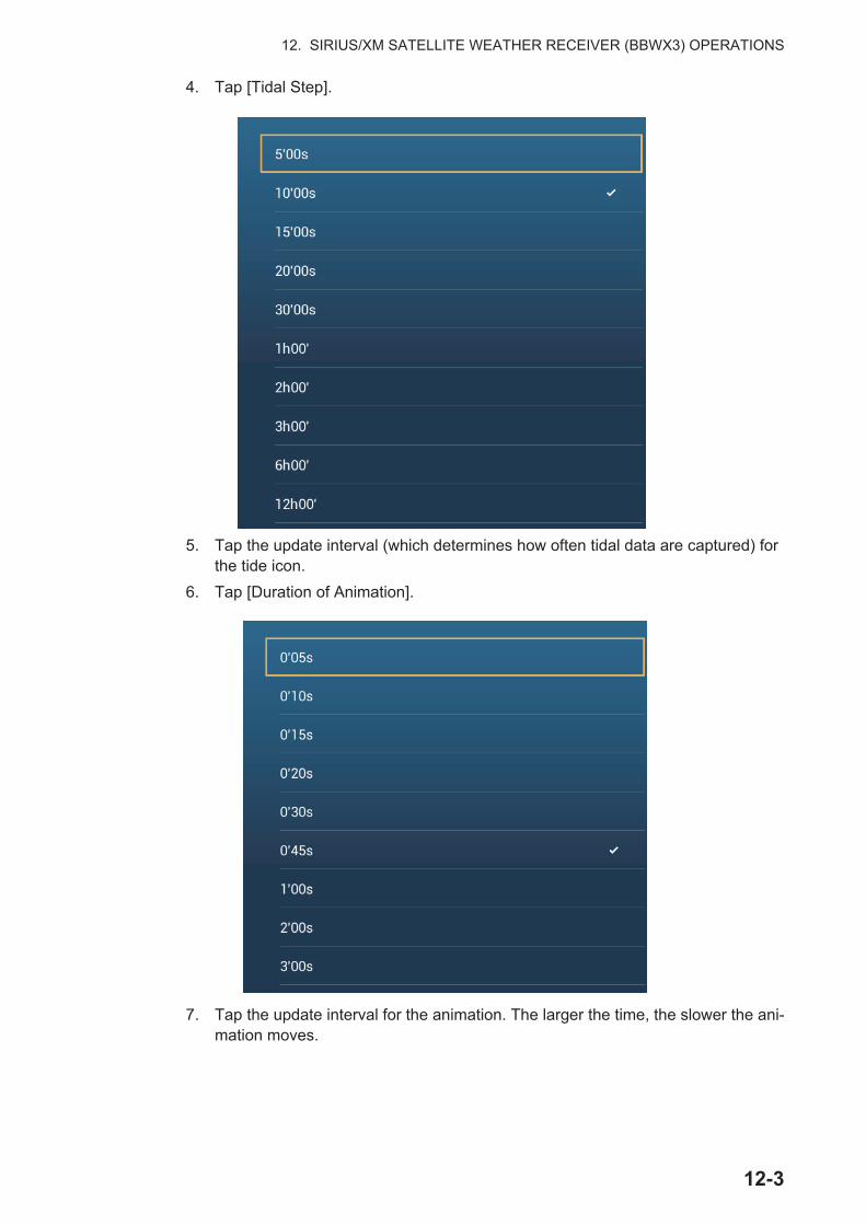
12. SIRIUS/XM SATELLITE WEATHER RECEIVER (BBWX3) OPERATIONS
4. Tap [Tidal Step].
5. Tap the update interval (which determines how often tidal data are captured) for the tide icon.
6. Tap [Duration of Animation].
7. Tap the update interval for the animation. The larger the time, the slower the ani-mation moves.
12-3
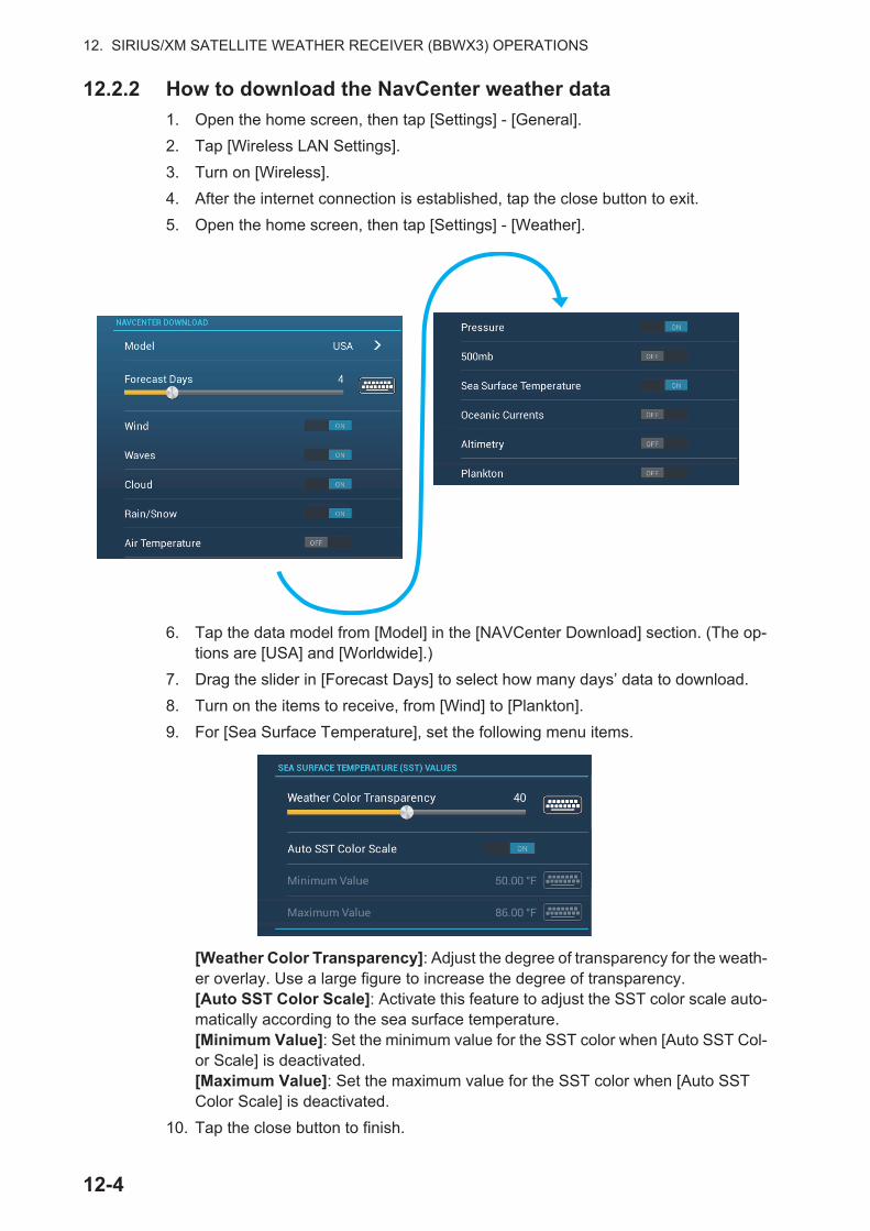
12. SIRIUS/XM SATELLITE WEATHER RECEIVER (BBWX3) OPERATIONS
12.2.2 How to download the NavCenter weather data
1. Open the home screen, then tap [Settings] - [General].
2. Tap [Wireless LAN Settings].
3. Turn on [Wireless].
4. After the internet connection is established, tap the close button to exit.
5. Open the home screen, then tap [Settings] - [Weather].
6. Tap the data model from [Model] in the [NAVCenter Download] section. (The op-tions are [USA] and [Worldwide].)
7. Drag the slider in [Forecast Days] to select how many days’ data to download.
8. Turn on the items to receive, from [Wind] to [Plankton].
9. For [Sea Surface Temperature], set the following menu items.
[Weather Color Transparency]: Adjust the degree of transparency for the weath-er overlay. Use a large figure to increase the degree of transparency.[Auto SST Color Scale]: Activate this feature to adjust the SST color scale auto-matically according to the sea surface temperature.[Minimum Value]: Set the minimum value for the SST color when [Auto SST Col-or Scale] is deactivated.[Maximum Value]: Set the maximum value for the SST color when [Auto SST Color Scale] is deactivated.
10. Tap the close button to finish.
12-4
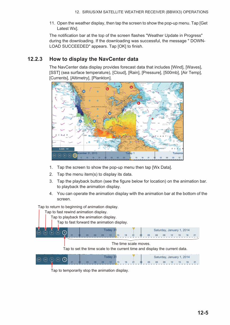
12. SIRIUS/XM SATELLITE WEATHER RECEIVER (BBWX3) OPERATIONS
11. Open the weather display, then tap the screen to show the pop-up menu. Tap [Get Latest Wx].
The notification bar at the top of the screen flashes "Weather Update in Progress" during the downloading. If the downloading was successful, the message " DOWN-LOAD SUCCEEDED" appears. Tap [OK] to finish.
12.2.3 How to display the NavCenter data
The NavCenter data display provides forecast data that includes [Wind], [Waves], [SST] (sea surface temperature), [Cloud], [Rain], [Pressure], [500mb], [Air Temp], [Currents], [Altimetry], [Plankton].
1. Tap the screen to show the pop-up menu then tap [Wx Data].
2. Tap the menu item(s) to display its data.
3. Tap the playback button (see the figure below for location) on the animation bar. to playback the animation display.
4. You can operate the animation display with the animation bar at the bottom of the screen.
6,695
The time scale moves.
Tap to playback the animation display.
Tap to temporarily stop the animation display.
Tap to set the time scale to the current time and display the current data.
Saturday, January 1, 2014
Saturday, January 1, 2014
Tap to return to beginning of animation display.Tap to fast rewind animation display.
Tap to fast forward the animation display.
12-5

12. SIRIUS/XM SATELLITE WEATHER RECEIVER (BBWX3) OPERATIONS
12.2.4 How to load a weather file
You can load a weather file saved on a microSD card, SD Card (TZT2BB only) or USB flash memory.
1. Put the appropriate formatted media in the USB port or a slot in the SD Card Unit.For TZTL12F/TZTL15F users: Put a formatted microSD card in either slot on the SD Card Unit or Switch Box.For TZT2BB users: Put a formatted SD card in the right-hand slot of the Switch Box (PSD-003).
2. Open the home screen, then tap [Settings] - [Weather] - [Load Weather File].
3. Tap the data to load then tap [OK].
4. After the equipment has loaded the selected data, tap the close button to finish.
12.3 Sirius WeatherSirius weather radar information and advanced weather information are available in North America with connection of the Sirius Marine Weather Receiver BBWX3.
12.3.1 How to set up for Sirius weather
1. Open the home screen, then tap [Settings] - [Weather] - [Weather Data Server].
2. Tap [Sirius] then tap < to return to the menu.
3. Tap [Sirius Weather Radar].
4. Tap the Sirius weather radar to use, [US Now Radar] (USA) or [CanadRad] (Can-ada). [US Now Radar] shows the type and level of precipitation. The amount of precipitation increases with level.
Precipitation indication on USNowRadar.
Precipitation indication on CanadianRadar
Weather radar color Precipitation type LevelLight green Rain 15-19 dBzMedium green Rain 20-29 dBzDark green Rain 30-39 dBzYellow Rain 40-44 dBzOrange Rain 45-49 dBzLight red Rain 50-54 dBzDark red Rain over 55 dBzLight blue Snow 5-19 dBzDark blue Snow over 20 dBzLight pink Mixed 5-19 dBzDark pink Mixed over 20 dBz
Weather radar color Level (mm per hour)Transparent (low precipitation) 0.00 to 0.20 mm/hrLight green 0.21 to 1.00 mm/hrMedium green 1.01 to 4.00 mm/hrDark green 4.01 to 12.00 mm/hrYellow 12.01 to 24.00 mm/hrOrange 24.01 to 50.00 mm/hr
12-6
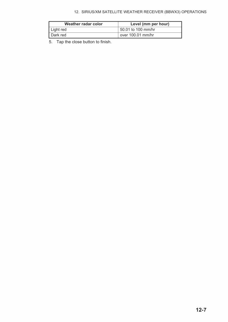
12. SIRIUS/XM SATELLITE WEATHER RECEIVER (BBWX3) OPERATIONS
5. Tap the close button to finish.
Light red 50.01 to 100 mm/hrDark red over 100.01 mm/hr
Weather radar color Level (mm per hour)
12-7
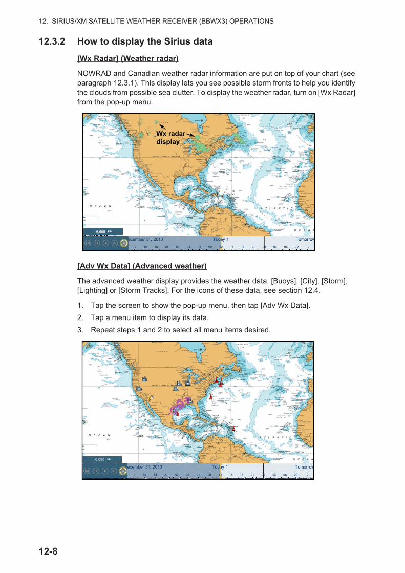
12. SIRIUS/XM SATELLITE WEATHER RECEIVER (BBWX3) OPERATIONS
12.3.2 How to display the Sirius data
[Wx Radar] (Weather radar)
NOWRAD and Canadian weather radar information are put on top of your chart (see paragraph 12.3.1). This display lets you see possible storm fronts to help you identify the clouds from possible sea clutter. To display the weather radar, turn on [Wx Radar] from the pop-up menu.
[Adv Wx Data] (Advanced weather)
The advanced weather display provides the weather data; [Buoys], [City], [Storm], [Lighting] or [Storm Tracks]. For the icons of these data, see section 12.4.
1. Tap the screen to show the pop-up menu, then tap [Adv Wx Data].
2. Tap a menu item to display its data.
3. Repeat steps 1 and 2 to select all menu items desired.
Wx radar display
6,695
6,695
12-8
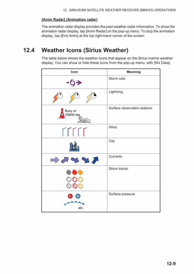
12. SIRIUS/XM SATELLITE WEATHER RECEIVER (BBWX3) OPERATIONS
[Anim Radar] (Animation radar)
The animation radar display provides the past weather radar information. To show the animation radar display, tap [Anim Radar] on the pop-up menu. To stop the animation display, tap [End Anim] at the top right-hand corner of the screen.
12.4 Weather Icons (Sirius Weather)The table below shows the weather icons that appear on the Sirius marine weather display. You can show or hide these icons from the pop-up menu, with [Wx Data].
Icon Meaning
Storm cast
Lightning
Surface observation stations
Wind
City
Currents
Storm tracks
Surface pressure
Buoy or CMAN sta.
etc.
12-9
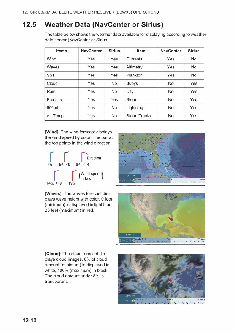
12. SIRIUS/XM SATELLITE WEATHER RECEIVER (BBWX3) OPERATIONS
12.5 Weather Data (NavCenter or Sirius)The table below shows the weather data available for displaying according to weather data server (NavCenter or Sirius).
[Wind]: The wind forecast displays the wind speed by color. The bar at the top points in the wind direction.
[Waves]: The waves forecast dis-plays wave height with color. 0 foot (minimum) is displayed in light blue, 35 feet (maximum) in red.
[Cloud]: The cloud forecast dis-plays cloud images. 8% of cloud amount (minimum) is displayed in white, 100% (maximum) in black. The cloud amount under 8% is transparent.
Items NavCenter Sirius Item NavCenter Sirius
Wind Yes Yes Currents Yes No
Waves Yes Yes Altimetry Yes No
SST Yes Yes Plankton Yes No
Cloud Yes No Buoys No Yes
Rain Yes No City No Yes
Pressure Yes Yes Storm No Yes
500mb Yes No Lightning No Yes
Air Temp Yes No Storm Tracks No Yes
1,621
<5 5<, <9= 9<, <14=
14<, <19= 19<=
Direction
Wind speed in knot( )
5.003
4,979
12-10
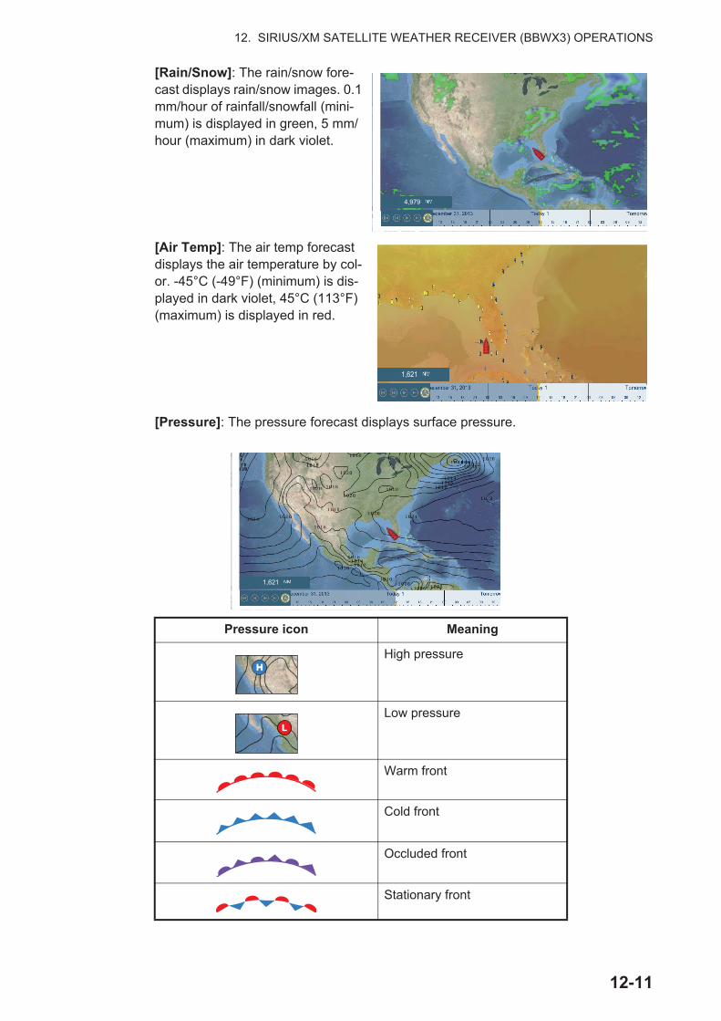
12. SIRIUS/XM SATELLITE WEATHER RECEIVER (BBWX3) OPERATIONS
[Rain/Snow]: The rain/snow fore-cast displays rain/snow images. 0.1 mm/hour of rainfall/snowfall (mini-mum) is displayed in green, 5 mm/hour (maximum) in dark violet.
[Air Temp]: The air temp forecast displays the air temperature by col-or. -45°C (-49°F) (minimum) is dis-played in dark violet, 45°C (113°F) (maximum) is displayed in red.
[Pressure]: The pressure forecast displays surface pressure.
Pressure icon Meaning
High pressure
Low pressure
Warm front
Cold front
Occluded front
Stationary front
4,979
1,621
1 0 2 01 8
1,621
12-11

12. SIRIUS/XM SATELLITE WEATHER RECEIVER (BBWX3) OPERATIONS
[500mb]: The 500mb forecast dis-plays the contour lines over 500 mb.
[SST] (Sea surface tempera-ture): This data layer shows the temperature of the sea surface in shades. Lower temperatures are in dark blue, higher in red.On the screen, you can turn on or off the automatic SST scale with tapping [A].Set the minimum or maximum value for which to show SST. See page 3-5 for how to set the value. This is available when [Auto] is off.
Trough
Squall line
Dry line
Isobars
Pressure icon Meaning
1010980
4,898
4,984
SST scale
Tap “A” to select automatic or manual adjustment fo the SST scale.Manual mode: Use the slider bar to set scale.Auto mode: SST scale automatically set accord-ing to the depth shading selection set in the menu ([Settings]→[Plotter]).
Minimumvalue
Manualmode
Maximumvalue
Automode
12-12
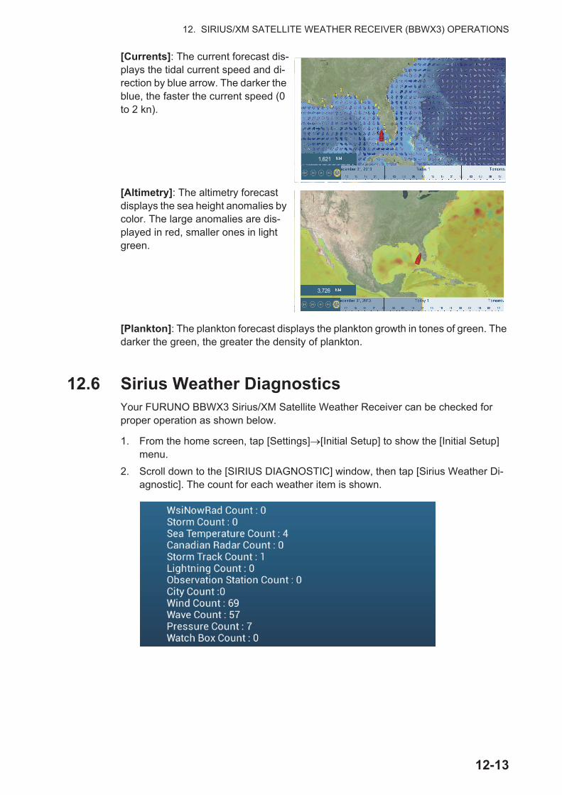
12. SIRIUS/XM SATELLITE WEATHER RECEIVER (BBWX3) OPERATIONS
[Currents]: The current forecast dis-plays the tidal current speed and di-rection by blue arrow. The darker the blue, the faster the current speed (0 to 2 kn).
[Altimetry]: The altimetry forecast displays the sea height anomalies by color. The large anomalies are dis-played in red, smaller ones in light green.
[Plankton]: The plankton forecast displays the plankton growth in tones of green. The darker the green, the greater the density of plankton.
12.6 Sirius Weather DiagnosticsYour FURUNO BBWX3 Sirius/XM Satellite Weather Receiver can be checked for proper operation as shown below.
1. From the home screen, tap [Settings] [Initial Setup] to show the [Initial Setup] menu.
2. Scroll down to the [SIRIUS DIAGNOSTIC] window, then tap [Sirius Weather Di-agnostic]. The count for each weather item is shown.
1,621
3,726
12-13

12. SIRIUS/XM SATELLITE WEATHER RECEIVER (BBWX3) OPERATIONS
12.7 Sirius Satellite RadioThe Sirius satellite radio provides round-the-clock, 100% commercial-free music from every genre plus sports, news, talk and comedy.
12.7.1 How to enable the radio
Method 1: From the home screen
Go to the home screen and tap the Sirius icon to show the full screen Sirius radio con-trols. See the next page.
Method 2: From the home screen
Open the slide-out menu, then tap the [Sirius Audio] icon to show or hide the audio control bar. See the next page.
Settings
Tide
Lists
Catalog
Sirius icon
Sirius Audioicon
12-14
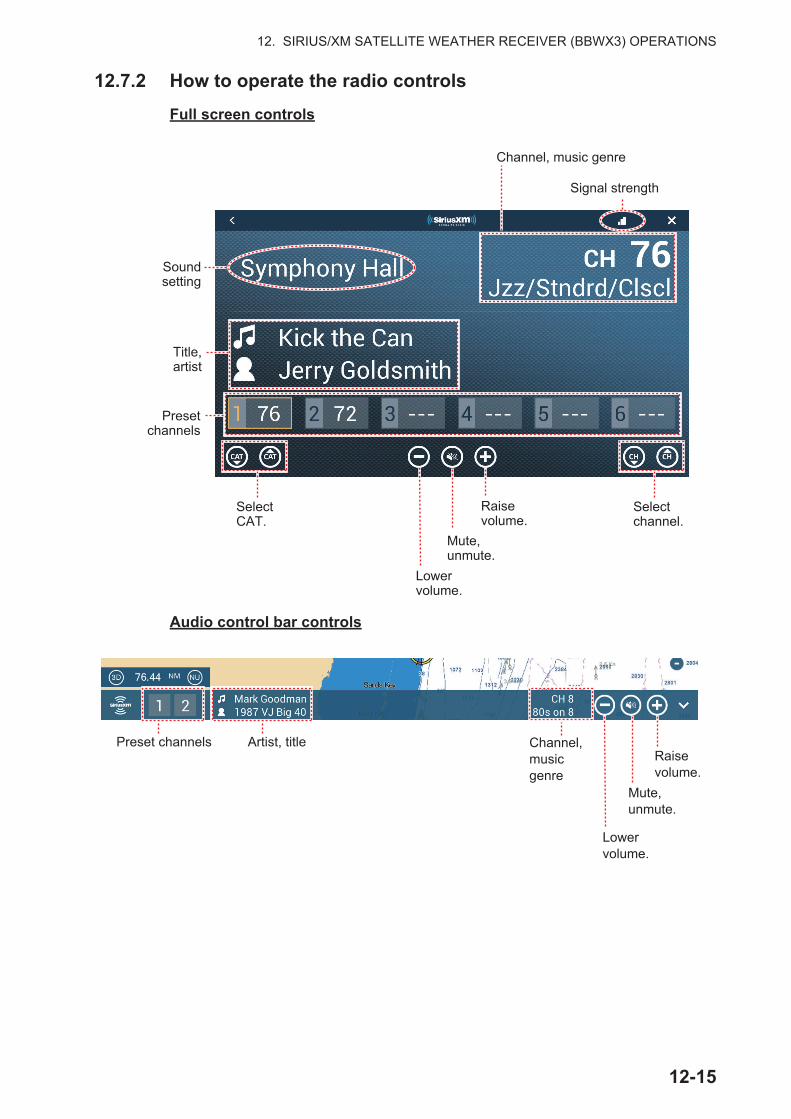
12. SIRIUS/XM SATELLITE WEATHER RECEIVER (BBWX3) OPERATIONS
12.7.2 How to operate the radio controls
Full screen controls
Audio control bar controls
Raise volume.
Mute,unmute.
Channel, music genre
Soundsetting
Title,artist
Presetchannels
Signal strength
Lower volume.
Selectchannel.
SelectCAT.
Raise volume.
Mute,unmute.
Channel, music genre
Artist, title
Lowervolume.
Preset channels
12-15
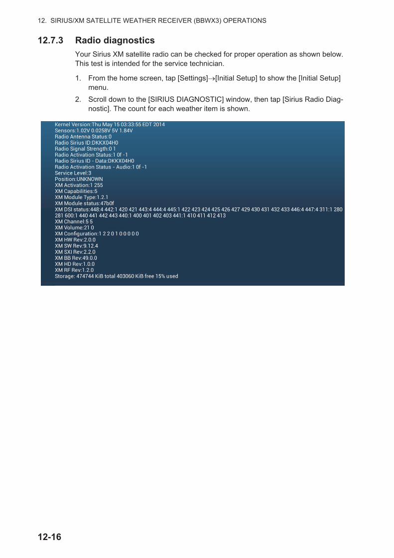
12. SIRIUS/XM SATELLITE WEATHER RECEIVER (BBWX3) OPERATIONS
12.7.3 Radio diagnostics
Your Sirius XM satellite radio can be checked for proper operation as shown below. This test is intended for the service technician.
1. From the home screen, tap [Settings] [Initial Setup] to show the [Initial Setup] menu.
2. Scroll down to the [SIRIUS DIAGNOSTIC] window, then tap [Sirius Radio Diag-nostic]. The count for each weather item is shown.
12-16
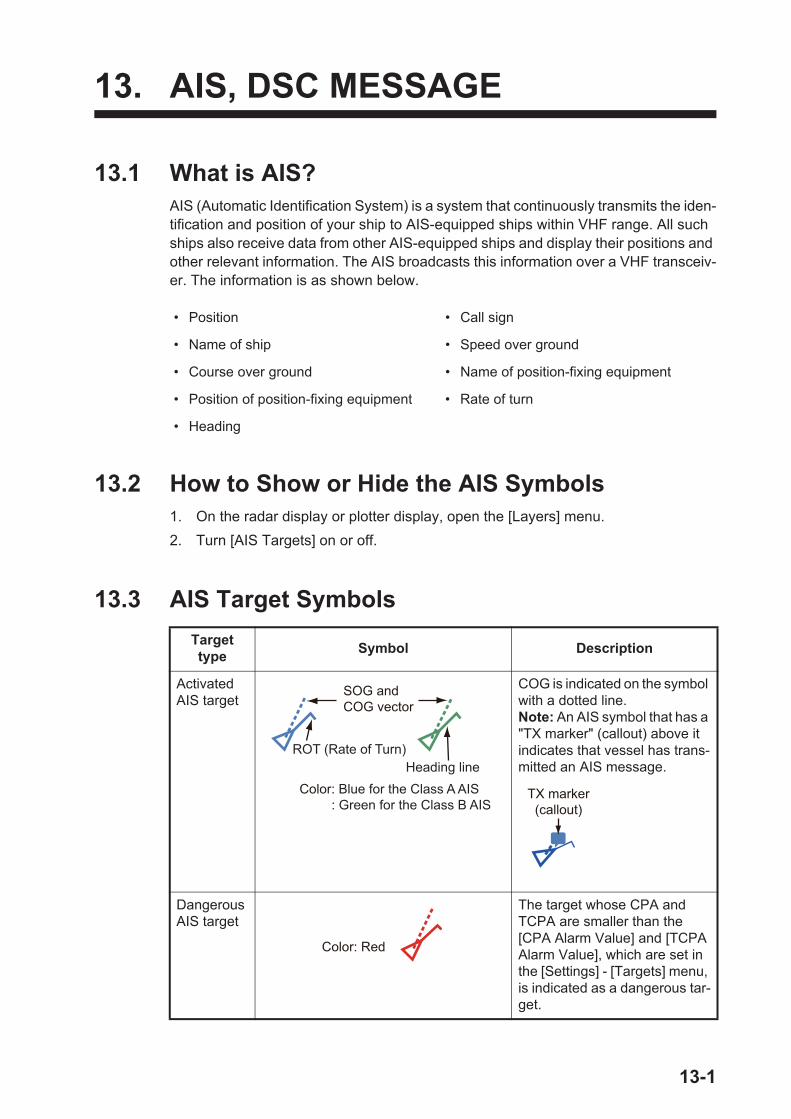
13. AIS, DSC MESSAGE
13.1 What is AIS?AIS (Automatic Identification System) is a system that continuously transmits the iden-tification and position of your ship to AIS-equipped ships within VHF range. All such ships also receive data from other AIS-equipped ships and display their positions and other relevant information. The AIS broadcasts this information over a VHF transceiv-er. The information is as shown below.
13.2 How to Show or Hide the AIS Symbols1. On the radar display or plotter display, open the [Layers] menu.
2. Turn [AIS Targets] on or off.
13.3 AIS Target Symbols
• Position • Call sign
• Name of ship • Speed over ground
• Course over ground • Name of position-fixing equipment
• Position of position-fixing equipment • Rate of turn
• Heading
Target type
Symbol Description
Activated AIS target
COG is indicated on the symbol with a dotted line.Note: An AIS symbol that has a "TX marker" (callout) above it indicates that vessel has trans-mitted an AIS message.
Dangerous AIS target
The target whose CPA and TCPA are smaller than the [CPA Alarm Value] and [TCPA Alarm Value], which are set in the [Settings] - [Targets] menu, is indicated as a dangerous tar-get.
Color: Blue for the Class A AIS: Green for the Class B AIS
SOG and COG vector
ROT (Rate of Turn)Heading line
TX marker(callout)
Color: Red
13-1
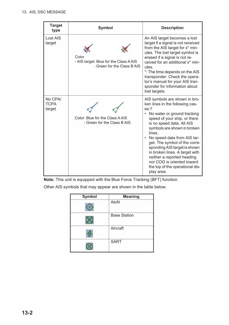
13. AIS, DSC MESSAGE
Note: This unit is equipped with the Blue Force Tracking (BFT) function.
Other AIS symbols that may appear are shown in the table below.
Lost AIS target
An AIS target becomes a lost target if a signal is not received from the AIS target for x* min-utes. The lost target symbol is erased if a signal is not re-ceived for an additional x* min-utes.*: The time depends on the AIS transponder. Check the opera-tor’s manual for your AIS tran-sponder for information about lost targets.
No CPA/TCPAtarget
AIS symbols are shown in bro-ken lines in the following cas-es:?• No water or ground tracking
speed of your ship, or there is no speed data. All AIS symbols are shown in broken lines.
• No speed data from AIS tar-get. The symbol of the corre-sponding AIS target is shown in broken lines. A target with neither a reported heading nor COG is oriented toward the top of the operational dis-play area.
Symbol MeaningAtoN
Base Station
Aircraft
SART
Target type
Symbol Description
Color- AIS target: Blue for the Class A AIS
: Green for the Class B AIS
Color: Blue for the Class A AIS: Green for the Class B AIS
13-2
13. AIS, DSC MESSAGE
13.4 Proximity AIS Target AlarmThe proximity AIS target alarm alerts you when an AIS target is within the distance you specify, and is applicable to both displayed and not displayed targets. When an AIS target is within the distance set, the alarm indication "Proximity AIS Alarm" flashes in the status bar and the audio alarm sounds. (See paragraph 2.10.8).
1. Open the home screen, then tap [Settings] - [Targets].
2. Turn on [Proximity AIS Target Alarm].
3. Tap [Proximity AIS Target Alarm Value] to open the software keyboard.
4. Set the alarm value, then tap .
5. Tap the close button to finish.
13.5 How to Ignore Slow Moving AIS TargetsThe proximity AIS target alarm may often sound in areas of heavy vessel traffic. You can prevent frequent release of the alarm against slow, non-threatening targets by specifying the maximum target speed that triggers the alarm. Any target whose speed is lower than set here does not trigger the alarm.
1. Open the home screen, then tap [Settings] - [Targets].
2. Tap [Ignore Alarms for AIS Slower than...] to open the software keyboard.
3. Set a speed, then tap . The setting range is 0.0 - 9.9 (knots).
4. Tap the close button to finish.
13.6 How to Hide AIS TargetsYou can hide the AIS symbols that are beyond the distance you set here.
1. Open the home screen, then tap [Settings] - [Targets].
13-3
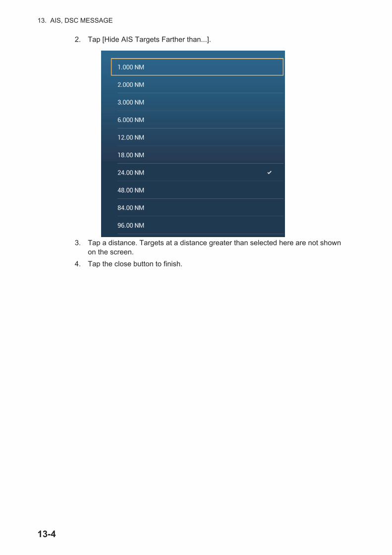
13. AIS, DSC MESSAGE
2. Tap [Hide AIS Targets Farther than...].
3. Tap a distance. Targets at a distance greater than selected here are not shown on the screen.
4. Tap the close button to finish.
13-4
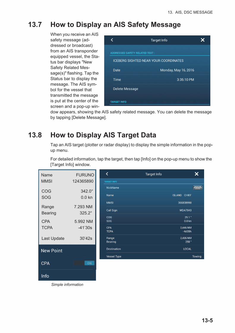
13. AIS, DSC MESSAGE
13.7 How to Display an AIS Safety MessageWhen you receive an AIS safety message (ad-dressed or broadcast) from an AIS transponder equipped vessel, the Sta-tus bar displays "New Safety Related Mes-sage(s)" flashing. Tap the Status bar to display the message. The AIS sym-bol for the vessel that transmitted the message is put at the center of the screen and a pop-up win-dow appears, showing the AIS safety related message. You can delete the message by tapping [Delete Message].
13.8 How to Display AIS Target DataTap an AIS target (plotter or radar display) to display the simple information in the pop-up menu.
For detailed information, tap the target, then tap [Info] on the pop-up menu to show the [Target Info] window.
Detailed information
Simple information
GALE WARNING 27.16N 82.40W
Name FURUNOMMSI 124365890
COG 342.0°SOG 0.0 kn
Range 7.293 NMBearing 325.2°
CPA 5.992 NMTCPA -41’30s
Last Update 30’42s
Info
13-5
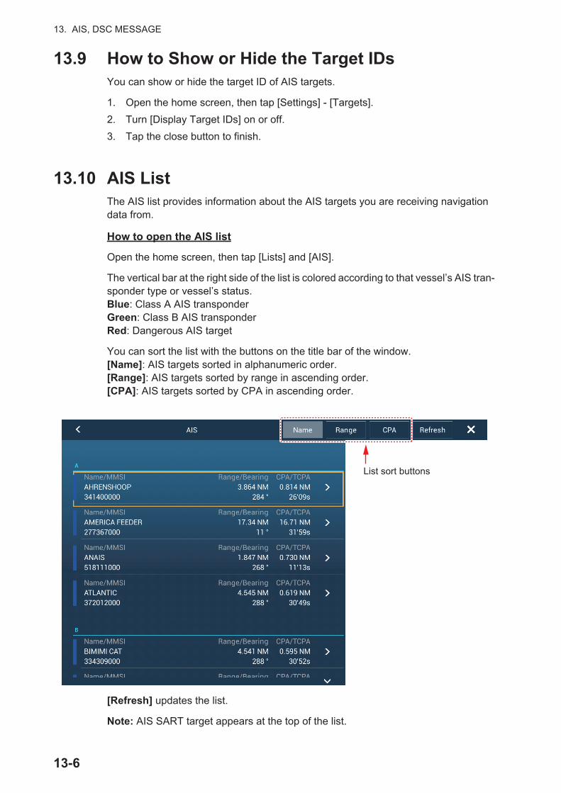
13. AIS, DSC MESSAGE
13.9 How to Show or Hide the Target IDsYou can show or hide the target ID of AIS targets.
1. Open the home screen, then tap [Settings] - [Targets].
2. Turn [Display Target IDs] on or off.
3. Tap the close button to finish.
13.10 AIS ListThe AIS list provides information about the AIS targets you are receiving navigation data from.
How to open the AIS list
Open the home screen, then tap [Lists] and [AIS].
The vertical bar at the right side of the list is colored according to that vessel’s AIS tran-sponder type or vessel’s status.Blue: Class A AIS transponderGreen: Class B AIS transponderRed: Dangerous AIS target
You can sort the list with the buttons on the title bar of the window.[Name]: AIS targets sorted in alphanumeric order.[Range]: AIS targets sorted by range in ascending order.[CPA]: AIS targets sorted by CPA in ascending order.
[Refresh] updates the list.
Note: AIS SART target appears at the top of the list.
List sort buttons
13-6

13. AIS, DSC MESSAGE
How to display the detailed information for an AIS target
Tap the AIS target on the AIS list then tap [Detail]. The name of the AIS is shown in the title bar and navigation data appears in the [TARGET INFO] section.
How to find an AIS target on the plotter display
Tap the AIS target on the AIS list, then tap [Find On Chart]. The plotter display opens and the selected AIS target is zoomed in.
How to edit an AIS nickname
1. Tap the AIS target to edit its nickname.
2. Tap [Edit Nickname] to display the software keyboard.
3. Enter the nickname. You can use a maximum of 20 alphanumeric characters.
4. Tap .
5. Tap the close button to finish.
FURUNO
FURUNO
000886617
13-7
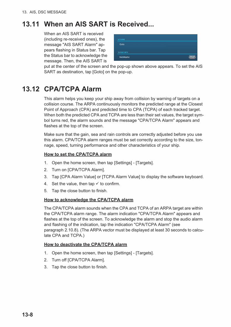
13. AIS, DSC MESSAGE
13.11 When an AIS SART is Received...When an AIS SART is received (including re-received ones), the message "AIS SART Alarm" ap-pears flashing in Status bar. Tap the Status bar to acknowledge the message. Then, the AIS SART is put at the center of the screen and the pop-up shown above appears. To set the AIS SART as destination, tap [Goto] on the pop-up.
13.12 CPA/TCPA AlarmThis alarm helps you keep your ship away from collision by warning of targets on a collision course. The ARPA continuously monitors the predicted range at the Closest Point of Approach (CPA) and predicted time to CPA (TCPA) of each tracked target. When both the predicted CPA and TCPA are less than their set values, the target sym-bol turns red, the alarm sounds and the message "CPA/TCPA Alarm" appears and flashes at the top of the screen.
Make sure that the gain, sea and rain controls are correctly adjusted before you use this alarm. CPA/TCPA alarm ranges must be set correctly according to the size, ton-nage, speed, turning performance and other characteristics of your ship.
How to set the CPA/TCPA alarm
1. Open the home screen, then tap [Settings] - [Targets].
2. Turn on [CPA/TCPA Alarm].
3. Tap [CPA Alarm Value] or [TCPA Alarm Value] to display the software keyboard.
4. Set the value, then tap to confirm.
5. Tap the close button to finish.
How to acknowledge the CPA/TCPA alarm
The CPA/TCPA alarm sounds when the CPA and TCPA of an ARPA target are within the CPA/TCPA alarm range. The alarm indication "CPA/TCPA Alarm" appears and flashes at the top of the screen. To acknowledge the alarm and stop the audio alarm and flashing of the indication, tap the indication "CPA/TCPA Alarm" (see paragraph 2.10.8). (The ARPA vector must be displayed at least 30 seconds to calcu-late CPA and TCPA.)
How to deactivate the CPA/TCPA alarm
1. Open the home screen, then tap [Settings] - [Targets].
2. Turn off [CPA/TCPA Alarm].
3. Tap the close button to finish.
Goto
13-8
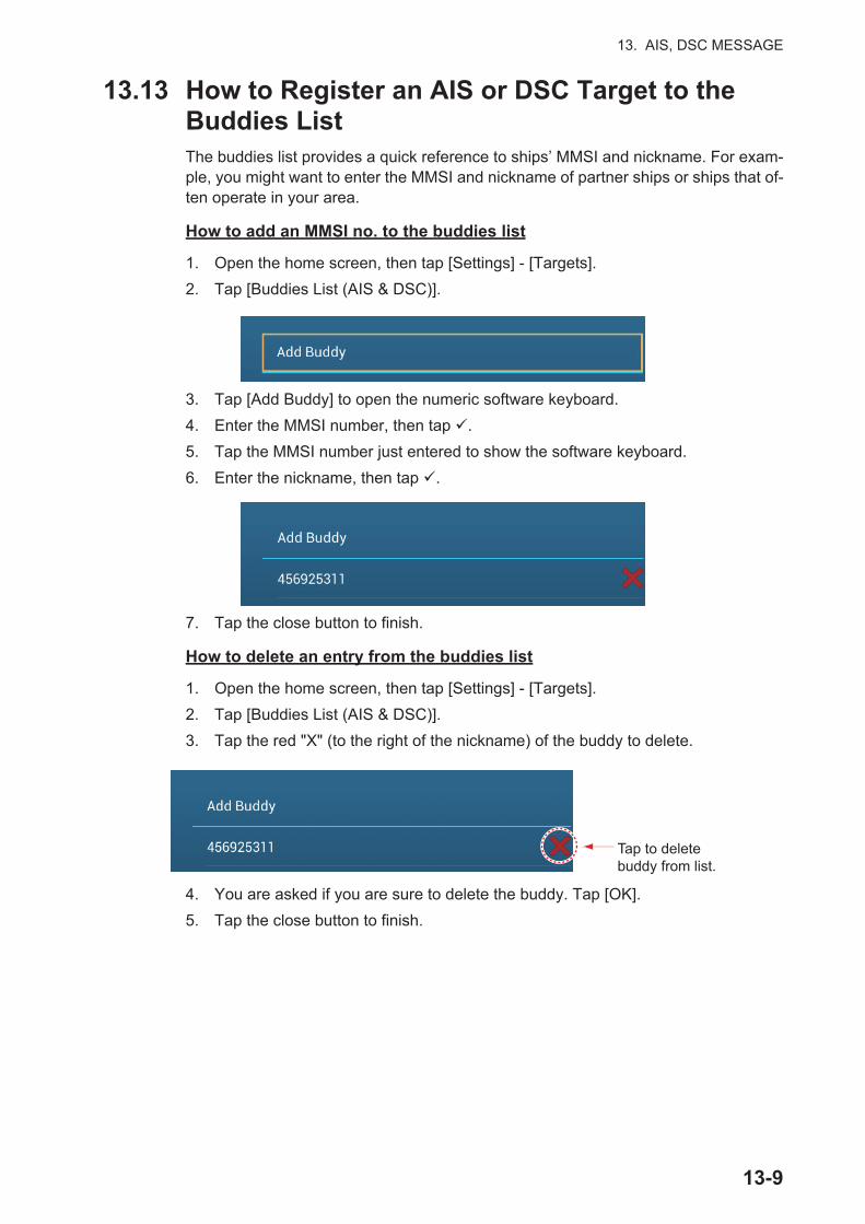
13. AIS, DSC MESSAGE
13.13 How to Register an AIS or DSC Target to the Buddies ListThe buddies list provides a quick reference to ships’ MMSI and nickname. For exam-ple, you might want to enter the MMSI and nickname of partner ships or ships that of-ten operate in your area.
How to add an MMSI no. to the buddies list
1. Open the home screen, then tap [Settings] - [Targets].
2. Tap [Buddies List (AIS & DSC)].
3. Tap [Add Buddy] to open the numeric software keyboard.
4. Enter the MMSI number, then tap .
5. Tap the MMSI number just entered to show the software keyboard.
6. Enter the nickname, then tap .
7. Tap the close button to finish.
How to delete an entry from the buddies list
1. Open the home screen, then tap [Settings] - [Targets].
2. Tap [Buddies List (AIS & DSC)].
3. Tap the red "X" (to the right of the nickname) of the buddy to delete.
4. You are asked if you are sure to delete the buddy. Tap [OK].
5. Tap the close button to finish.
Tap to delete buddy from list.
13-9
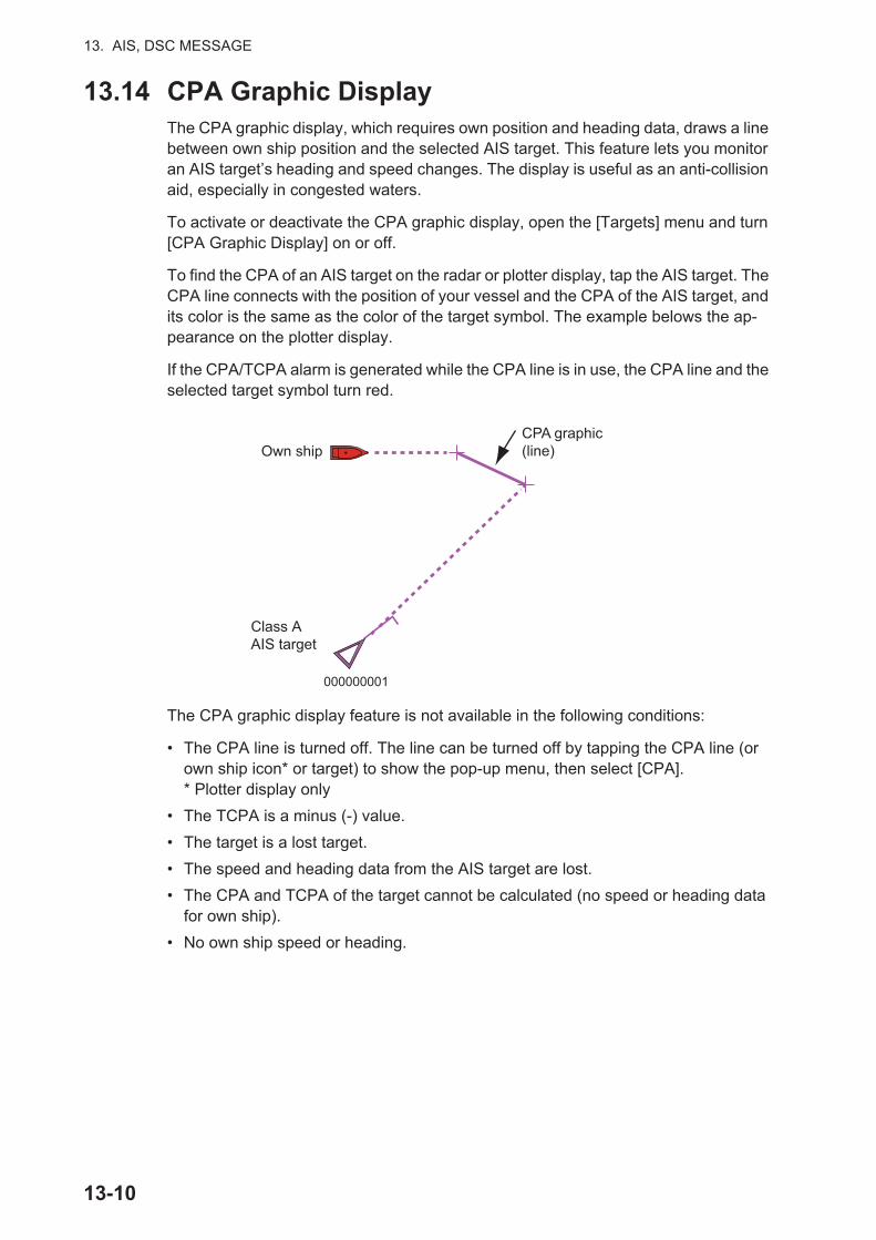
13. AIS, DSC MESSAGE
13.14 CPA Graphic DisplayThe CPA graphic display, which requires own position and heading data, draws a line between own ship position and the selected AIS target. This feature lets you monitor an AIS target’s heading and speed changes. The display is useful as an anti-collision aid, especially in congested waters.
To activate or deactivate the CPA graphic display, open the [Targets] menu and turn [CPA Graphic Display] on or off.
To find the CPA of an AIS target on the radar or plotter display, tap the AIS target. The CPA line connects with the position of your vessel and the CPA of the AIS target, and its color is the same as the color of the target symbol. The example belows the ap-pearance on the plotter display.
If the CPA/TCPA alarm is generated while the CPA line is in use, the CPA line and the selected target symbol turn red.
The CPA graphic display feature is not available in the following conditions:
• The CPA line is turned off. The line can be turned off by tapping the CPA line (or own ship icon* or target) to show the pop-up menu, then select [CPA].* Plotter display only
• The TCPA is a minus (-) value.
• The target is a lost target.
• The speed and heading data from the AIS target are lost.
• The CPA and TCPA of the target cannot be calculated (no speed or heading data for own ship).
• No own ship speed or heading.
CPA graphic(line)Own ship
Class AAIS target
000000001
13-10
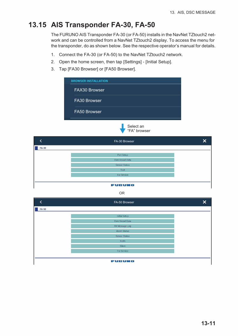
13. AIS, DSC MESSAGE
13.15 AIS Transponder FA-30, FA-50The FURUNO AIS Transponder FA-30 (or FA-50) installs in the NavNet TZtouch2 net-work and can be controlled from a NavNet TZtouch2 display. To access the menu for the transponder, do as shown below. See the respective operator’s manual for details.
1. Connect the FA-30 (or FA-50) to the NavNet TZtouch2 network.
2. Open the home screen, then tap [Settings] - [Initial Setup].
3. Tap [FA30 Browser] or [FA50 Browser].
OR
FAX30 Browser
FA30 Browser
FA50 Browser
FA-30 Browser
FA-50 Browser
Select an“FA” browser
13-11

13. AIS, DSC MESSAGE
13.16 DSC Message InformationThe DSC (Digital Selective Calling) message information feature provides, on the plot-ter and radar displays, the MMSI no. and position* of the ships that have transmitted a DSC message to you. A hexagon-shaped marker marks the position of the ship at the time the DSC was transmitted to you. The marker is color-coded according to the type of DSC message sent, red for distress and green for non-distress.
* Position at the time of message transmission. Position information is not updated.
This feature requires connection of a DSC capable radiotelephone that outputs the DSC sentence in NMEA0183 or NMEA2000 format.
13.16.1 DSC distress message notification
When a DSC distress message is received, the message "DSC Distress Call re-ceived" appears in red on the status bar at the top of the screen. To delete the distress message, tap the status bar.
13.16.2 How to go to a DSC point
Tap the DSC marker to go then tap [Go To] on the pop-up menu.
Red: DSC marker for a distress message
Green: DSC marker for a non-distress message
333336789 333335678MMSI no.
13-12

13. AIS, DSC MESSAGE
13.16.3 How to display DSC information
Tap a DSC marker to display the simple information (position, MMSI no. of the ship that transmitted a DSC message, etc.). To get detailed information, tap a DSC marker, then tap [Info] on the pop-up menu.
Simple information Detailed information
CPA 5.992 NMTCPA 41’30s
Range 7.293 NMBearing 325.2°
FURUNO
13-13
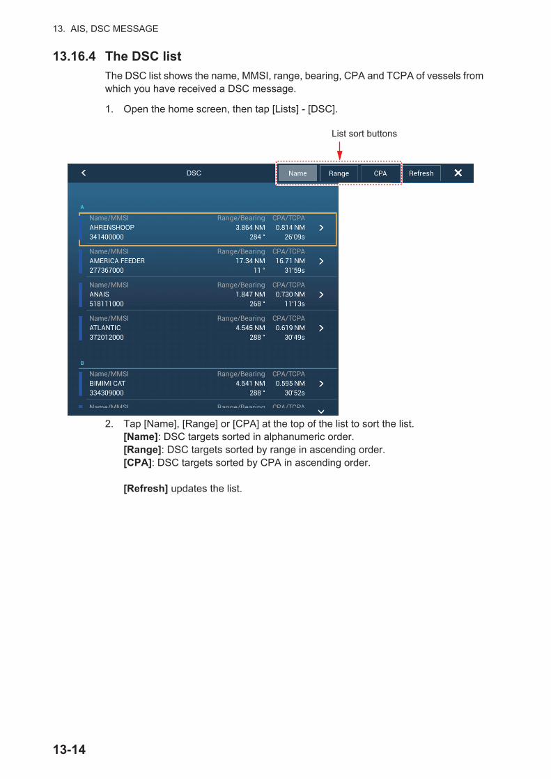
13. AIS, DSC MESSAGE
13.16.4 The DSC list
The DSC list shows the name, MMSI, range, bearing, CPA and TCPA of vessels from which you have received a DSC message.
1. Open the home screen, then tap [Lists] - [DSC].
2. Tap [Name], [Range] or [CPA] at the top of the list to sort the list. [Name]: DSC targets sorted in alphanumeric order.[Range]: DSC targets sorted by range in ascending order.[CPA]: DSC targets sorted by CPA in ascending order.
[Refresh] updates the list.
DSC
List sort buttons
13-14

13. AIS, DSC MESSAGE
To see the detailed information for a DSC target, tap a DSC then tap [Detail]. To put a DSC marker at the center of the plotter display, tap the DSC target, then tap [Find On Chart].
13-15

13. AIS, DSC MESSAGE
This page is intentionally left blank.
13-16

14. OTHER FUNCTIONS
Once you have become acquainted with your equipment, you can set it according to your needs. You can change system configuration, change how the equipment oper-ates and displays information, etc.
14.1 General MenuThe [General] menu contains items that once preset do not require frequent adjust-ment. The below example menu is taken from the TZTL12F/15F, some menu items may differ, or not appear, on the TZT2BB.
Note: For monitors connected to the TZT2BB via the HDMI OUT2 port, the menu items [Connect to the Internet] and [Wireless LAN Settings] do not appear in the [General] menu.
14-1

14. OTHER FUNCTIONS
Menu item Function Options[Move Tool on Long Push]
Enable the “move” function with long-push of an object. Applicable to points (excluding Sounder), temporary waypoints, route waypoints, guard zone, EBL, VRM and external equipment menu
icon ( ).
[ON], [OFF]
[User Interface Auto-Hide]
Select the timeout for the home icon on the [Lay-ers] menu, slide-out menu, pop-up menu, and camera screen (full screen).Note: The home icon always appears on the split screen camera display and other displays.
[0’03 s], [0’05 s], [0’10 s], [0‘15 s]
[Auto Scroll] In the [ON] setting, the chart is appropriately and automatically scrolled when the cursor goes out of the display area.
[ON], [OFF]
[Cross Cursor Speed]
Adjust the cross cursor speed. -7 to +7
[Allow Remote Control]
Sets the permission level for NavNet Remote.[Off]: Connection with NavNet Remote not al-lowed.[View Only]: Can view the screen remotely, but cannot operate and functions.[Full Control]: Can operate the entire system by remote.
[Off], [View Only], [Full Con-trol]
[Local Time Off-set]
Select the time difference between local time and UTC time.
UTC -12:00 to UTC +13:00 (at one-hour intervals)
[Time Format] Select how to display time, in 12 or 24 hour format. [Auto] automatically inserts AM, PM indication in 24 hour clock, when the language is English.
[Auto], [24 Hours], [12 Hours]
[Demo File] Select the demo file (internal or external) to use in the demo mode. For external data, set the appli-cable media in the SD Card Unit or the USB port.
[Manual Demo]* [OFF]: Use the data file selected at [Demo File]. Your vessel moves according the data in the data file.[ON]: Your vessel moves at the speed set at [De-mo Speed] below.
[ON], [OFF]
[Demo Slide Show]
No use.
[Demo Speed] Set the ship’s speed to use in the demo mode, when [Manual Demo] is [ON].
0 to 20 kn
[View Angle Ad-justment]Note: Not avail-able for TZT2BB.
Automatically adjust the display contrast, etc.according to your viewing angle.
[Most Downward], [Down-ward], [Slightly Downward], [Normal], [Slightly Upward], [Upward], [Most Upward]Most Downward
DownwardSlightly Downward
NormalSlightly Upward
Upward
Most Upward
14-2

14. OTHER FUNCTIONS
* In the demo mode, plotter display, you can relocate the boat icon to the location tapped. Tap the screen where you want to relocate the boat icon, then tap [Move Boat] on the pop-up menu.
14.2 Units MenuThe [Units] menu sets the unit of measurement for speed, distance, depth, etc.
[Check for Soft-ware Update]
Update the software. See section 14.5. -
[Reset Default Settings]
Restore default settings for the items of the [Gen-eral] menu.
-
Menu item Options[Bearing Display] [Magnetic], [True]
The mode (magnetic or true) of all heading and bearing data.[True Wind Calculation Reference]
[Ground], [Surface]Select wind value to display from speed over ground or speed through water (surface).
[Position Format] [DDD°MM.mmmm’], [DDD°MM.mmm’], [DDD°MM.mm’], [DDD°MM’SS.ss’], [DDD.dddddd°], [Loran-C], [MGRS].
[Loran C Station &GRI] Enter Loran C Station and GRI. Available when [Position Format] is se-lected to [Loran-C].
[Short/Long Change Over] Set the distance at which to switch between short and long range (set-ting range: 0.0 to 2.0 NM). If the setting is 0.5, for example, short range is automatically selected when the long range unit is 0.4 or less. The setting “0.0” fixes the unit to long range.
[Range (Long)] [Nautical Mile], [Kilometer], [Mile][Range (Short)] [Foot], [Meter], [Yard][Depth] [Foot], [Meter], [Fathom], [Passi Braza][Height/Length] [Foot], [Meter][Fish Size] [Inch], [Centimeter][Temperature] [Fahrenheit Degree], [Celsius Degree][Boat Speed] [Knot], [Kilometer per Hour], [Mile per Hour], [Meter per Second][Wind Speed] [Knot], [Kilometer per Hour], [Mile per Hour], [Meter per Second]
Menu item Function Options
14-3
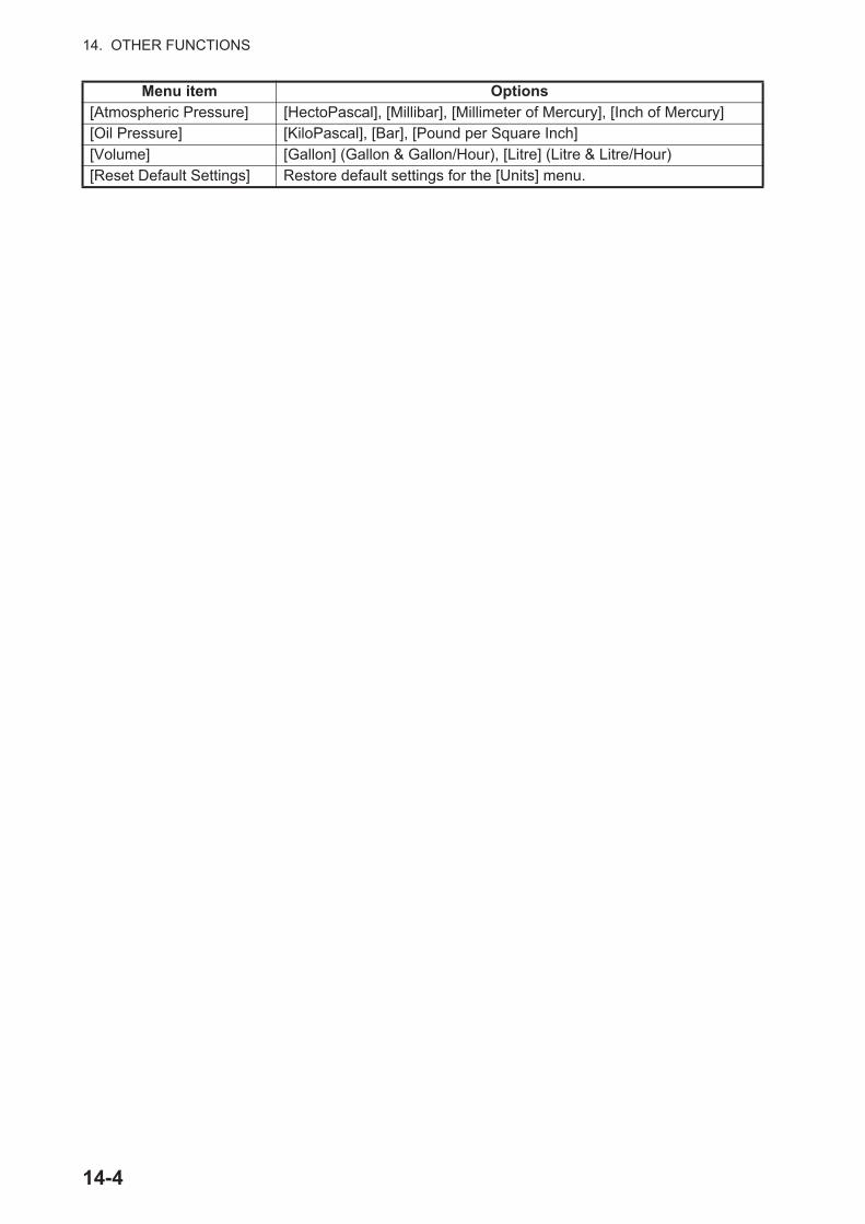
14. OTHER FUNCTIONS
[Atmospheric Pressure] [HectoPascal], [Millibar], [Millimeter of Mercury], [Inch of Mercury][Oil Pressure] [KiloPascal], [Bar], [Pound per Square Inch][Volume] [Gallon] (Gallon & Gallon/Hour), [Litre] (Litre & Litre/Hour)[Reset Default Settings] Restore default settings for the [Units] menu.
Menu item Options
14-4

14. OTHER FUNCTIONS
14.3 Initial Setup MenuThe [Initial Setup] menu, which is mainly for use by the installer of the equipment, sets up the system according to the sensors connected. These adjustments require some knowledge of marine electronics equipment. If you are unsure of your abilities, have a qualified marine electronics technician make the adjustments. Inadequate adjustment can affect performance.
GPS POSITION section
BOAT INFORMATION section
INSTRUMENTS SETUP section
[Engine & Tank Automatic Setup]: The system will automatically detect engines and tanks connected to the same network. This is the recommended method for setting up engines and tanks.
[Engine & Tank Manual Setup]:
Menu item Description Options (setting range)[Longitudinal (from bow]
Enter the GPS antenna posi-tioning bow-stern (Longitudi-nal) and port-starboard (Lateral) position from the origin.
0 m to 999 m
[Lateral GPS Position (-Port)]
-99 m to +9 m
Menu item Description Options (setting range)[Boat Length] Set the length of your boat. 0 (m) to 999 (m)[Size of Static Icon] Set the size of static (such as own ship)
icons.50 to 150
[Depth Display] Select the start point for depth measure-ment. Selection is indicated in the depth box as “(K)” for [Under Keel] and “(S)” for [Under Sea Level].
[Under Keel], [Under Sea Level]
[External Transducer Draft]
Set the draft of the external transducer (if applicable).
0.0 (m) to 99.9 (m)
[Keel Draft] Set the keel draft. 0.0 (m) to 99.9 (m
Menu item Description Options (setting range)
[Engine & Tank Automatic Setup]
See “Engine & Tank Automatic Setup” below.
[Engine & Tank Manual Setup]
See “Engine & Tank Automatic Setup” on the next page.
[Graphic Instruments Setup]
See “Graphic Instruments Setup” below.
Menu Item Description Options (setting range)[Nickname] Change the nickname for the engine or tank.[Used For Propulsion] Select which engine/tank is used to
calculate the distance which may be traveled using the remaining fuel. [ON] uses the engine/tank for calculations, [OFF] ignores the engine/tank.
[ON], [OFF]
[Reset] Resets the engine/tank details to default [OK], [Cancel]
OriginOrigin
14-5

14. OTHER FUNCTIONS
Graphic Instruments Setup:
[Graphic Instruments Setup] - [Maximum Boat Speed], [Maximum Wind Speed]
[Graphic Instruments Setup] - [Depth]
[Graphic Instruments Setup] - [Sea Surface Temperature]
[Graphic Instruments Setup] - [Propulsion Engine]
[Graphic Instruments Setup] - [Other Engine]
Menu Item Description Options (setting range)[Maximum Boat Speed] Set the transducer’s maximum detectable
speed.1 kn to 99 kn
[Maximum Wind Speed] Set the transducer’s maximum detectable speed.
1 kn to 99 kn
Menu Item Description Options (setting range)[Minimum Depth] Set the transducer’s minimum detectable
depth.1 m to 19 m
[Maximum Depth] Set the transducer’s maximum detectable depth.
20 m to 2000 m
Menu Item Description Options (setting range)[Minimum Sea Surface Temperature]
Set the transducer’s minimum detectable temperature.
0.00°C to 99.99°C
[Maximum Sea Surface Temperature]
Set the transducer’s maximum detectable temperature.
0.01°C to 99.99°C
Menu Item Description Options (setting range)[Max. RPM] Set the maximum rpm of your engine to
show on the RPM display.1 rpm to 20,000 rpm
[Red Zone Oil Pressure] Set the starting value for the red zone area of the oil pressure meter.
0 kPa to 998 kPa
[Max. Oil Pressure] Set the maximum oil pressure of your engine.
1 kPa to 999 kPa
[Min. Temperature] Set the minimum temperature for your engine.
0.00°C to 99.00°C
[Red Zone Temperature] Set the starting value for the red zone area of the engine temperature indicator.
0.01°C to 999.00°C
Menu Item Description Options (setting range)[Max. RPM] Set the maximum rpm of your engine to
show on the RPM display.0 rpm to 20,000 rpm
[Red Zone Oil Pressure] Set the starting value for the red zone area of the oil pressure meter.
0 kPa to 999 kPa
[Max. Oil Pressure] Set the maximum oil pressure of your engine.
0 kPa to 999 kPa
[Min. Temperature] Set the minimum temperature for your engine.
0°C to 99°C
[Red Zone Temperature] Set the starting value for the red zone area of the engine temperature indicator.
0°C to 999°C
14-6
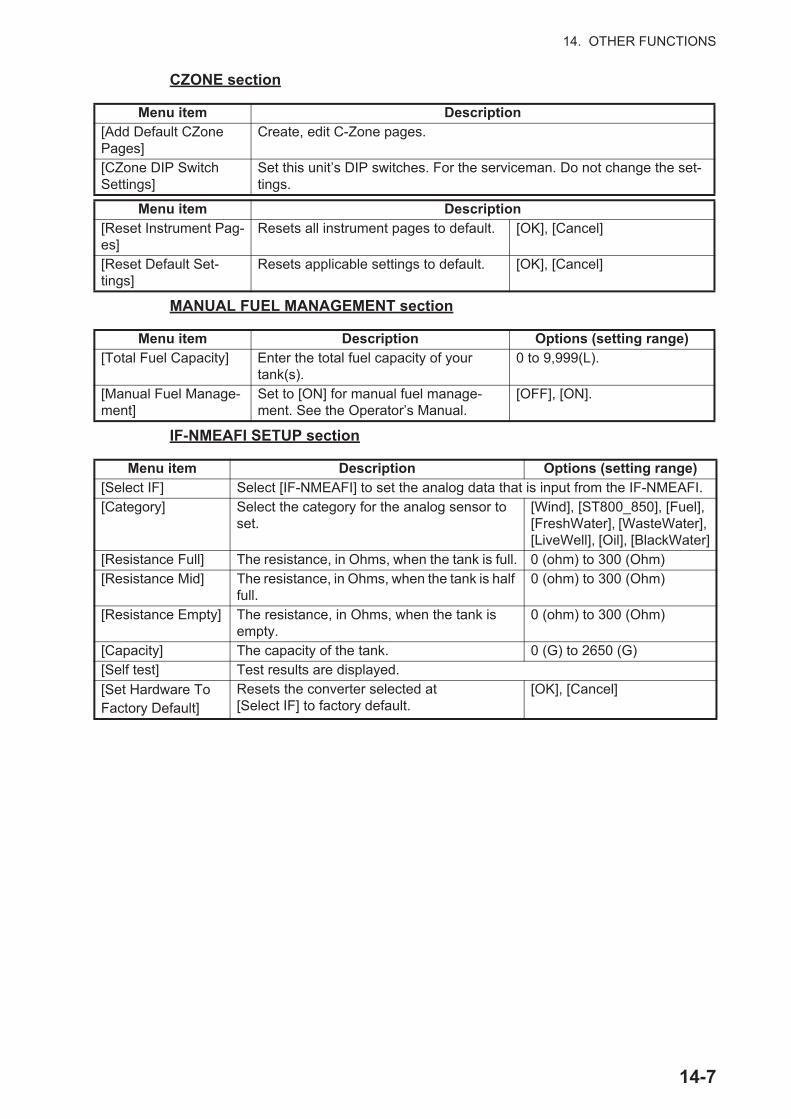
14. OTHER FUNCTIONS
CZONE section
MANUAL FUEL MANAGEMENT section
IF-NMEAFI SETUP section
Menu item Description[Add Default CZone Pages]
Create, edit C-Zone pages.
[CZone DIP Switch Settings]
Set this unit’s DIP switches. For the serviceman. Do not change the set-tings.
Menu item Description[Reset Instrument Pag-es]
Resets all instrument pages to default. [OK], [Cancel]
[Reset Default Set-tings]
Resets applicable settings to default. [OK], [Cancel]
Menu item Description Options (setting range)[Total Fuel Capacity] Enter the total fuel capacity of your
tank(s).0 to 9,999(L).
[Manual Fuel Manage-ment]
Set to [ON] for manual fuel manage-ment. See the Operator’s Manual.
[OFF], [ON].
Menu item Description Options (setting range)[Select IF] Select [IF-NMEAFI] to set the analog data that is input from the IF-NMEAFI.[Category] Select the category for the analog sensor to
set.[Wind], [ST800_850], [Fuel], [FreshWater], [WasteWater], [LiveWell], [Oil], [BlackWater]
[Resistance Full] The resistance, in Ohms, when the tank is full. 0 (ohm) to 300 (Ohm)[Resistance Mid] The resistance, in Ohms, when the tank is half
full.0 (ohm) to 300 (Ohm)
[Resistance Empty] The resistance, in Ohms, when the tank is empty.
0 (ohm) to 300 (Ohm)
[Capacity] The capacity of the tank. 0 (G) to 2650 (G)[Self test] Test results are displayed.
[Set Hardware To Factory Default]
Resets the converter selected at [Select IF] to factory default.
[OK], [Cancel]
14-7
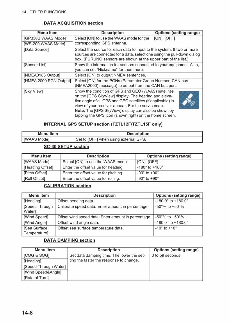
14. OTHER FUNCTIONS
DATA ACQUISITION section
INTERNAL GPS SETUP section (TZTL12F/TZTL15F only)
SC-30 SETUP section
CALIBRATION section
DATA DAMPING section
Menu Item Description Options (setting range)[GP330B WAAS Mode] Select [ON] to use the WAAS mode for the
corresponding GPS antenna.[ON], [OFF]
[WS-200 WAAS Mode][Data Source] Select the source for each data to input to the system. If two or more
sources are connected for a data, select one using the pull-down dialog box. (FURUNO sensors are shown at the upper part of the list.)
[Sensor List] Show the information for sensors connected to your equipment. Also, you can set “Nickname” for them here.
[NMEA0183 Output] Select [ON] to output NMEA sentences.[NMEA 2000 PGN Output] Select [ON] for the PGNs (Parameter Group Number, CAN bus
(NMEA2000) message) to output from the CAN bus port.[Sky View] Show the condition of GPS and GEO (WAAS) satellites
on the [GPS SkyView] display. The bearing and eleva-tion angle of all GPS and GEO satellites (if applicable) in view of your receiver appear. For the serviceman.Note: The [GPS SkyView] display can also be shown by tapping the GPS icon (shown right) on the home screen.
Menu Item Description[WAAS Mode] Set to [OFF] when using external GPS.
Menu item Description Options (setting range)[WAAS Mode] Select [ON] to use the WAAS mode. [ON], [OFF][Heading Offset] Enter the offset value for heading. -180° to +180°[Pitch Offset] Enter the offset value for pitching. -90° to +90°[Roll Offset] Enter the offset value for rolling. -90° to +90°
Menu item Description Options (setting range)[Heading] Offset heading data. -180.0° to +180.0°[Speed Through Water]
Calibrate speed data. Enter amount in percentage. -50°% to +50°%
[Wind Speed] Offset wind speed data. Enter amount in percentage. -50°% to +50°%[Wind Angle] Offset wind angle data. -180.0° to +180.0°[Sea Surface Temperature]
Offset sea surface temperature data. -10° to +10°
Menu item Description Options (setting range)[COG & SOG] Set data damping time. The lower the set-
ting the faster the response to change.0 to 59 seconds
[Heading][Speed Through Water][Wind Speed&Angle][Rate of Turn]
14-8

14. OTHER FUNCTIONS
FUSION section
BROWSER INSTALLATION section
Others menu items
Menu item Description Options (setting range)[Connect to Fu-sion]
Connect to your Fusion equipment.
[Fusion Auto Volume]
Set to [ON] to allow this unit to control the Fusion volume.
[Minimum Speed]
Set the minimum speed threshold. Exceeding this speed activates volume auto control.
0.0 kn to 19.9 kn
[Maximum Speed]
Set the maximum speed threshold. 0.1 kn to 99.0 kn
[Volume In-crease]
Set the amount of extra volume to output. 10% to +50%
Menu item Description Option (setting range)[FAX30 Browser] Show the Facsimile Receiver FAX-30 display.[FA30 Browser] Show the AIS Receiver FA-30 display.[FA50 Browser] Show the AIS Receiver FA-50 display.
Menu item Description Option (setting range)[Chart Master Device] Set to ON to set this equipment as the chart master and share one System
ID and chart unlock code in the network.Note: For monitors connected to the TZT2BB via the HDMI OUT2 port, the menu items [Connect to the Internet] and [Wireless LAN Settings] do not ap-pear in the [General] menu.
[System ID] The system ID for this device within the network.[IP Address] IP address for this unit within the network.[Quick Self Test] Test the equipment.[Certification Mark] Show the certification marks this equipment has received.[ServiceMan] Requires login password. For the service technician only.
[Event Input Configuration]
These menu items are not used.
[Update Network Equipments]
Updates all NavNet equipment in the network. For the service technician.
[Remote Controller Configuration]
When there are multiple units in the NavNet network, the Remote Controller MCU-004/MCU-005 can select the display to show on the unit with Remote Controller connection. Further, the cycling order of displays can be set. See section 1.2.2 (MCU-004) and section 1.2.3 (MCU-005).
[Adjust Display Resolution]
Adjust the output resolution from the TZT2BB to match the connected mon-itor’s resolution.Note: This menu item does not appear for TZTL12F/TZTL15F systems.
[Sirius Radio Diagnostic]
Check the satellite radio of the FURUNO BBWX3 Sirius/XM Satellite Weather Receiver for proper operation. See section 12.7.3.
[Sirius Weather Diagnostic]
Check the weather section of the FURUNO BBWX3 Sirius/XM Satellite Weather Receiver for proper operation. See section 12.6.
[Reset Default Settings]
Reset the system to default settings.
14-9

14. OTHER FUNCTIONS
14.4 Facsimile Receiver FAX-30The FURUNO Facsimile Receiver FAX-30 installs in the NavNet TZtouch2 network and can be controlled from a NavNet TZtouch2 display. Below are the steps to start fax operation.
1. Connect the FAX-30 to the NavNet TZtouch2 network.
2. Open the home screen, then tap "Fax30" (left side of screen).
3. Tap [WX FAX] or [NAVTEX].
4. Refer to the Operator’s Manual of the FAX-30 for operation information.
The FAX-30 display can only be accessed by one NavNet TZtouch2 unit at a time. When another NavNet TZtouch2 display accesses the FAX-30, control of the FAX-30 is given to that display after the picture has stopped completely. This sequence takes approximately one minute.
FAX-30 Browser
FAX-30 Browser
14-10
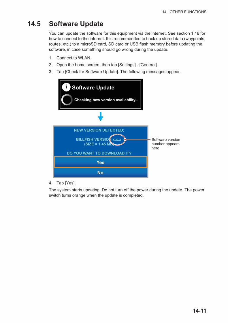
14. OTHER FUNCTIONS
14.5 Software UpdateYou can update the software for this equipment via the internet. See section 1.18 for how to connect to the internet. It is recommended to back up stored data (waypoints, routes, etc.) to a microSD card, SD card or USB flash memory before updating the software, in case something should go wrong during the update.
1. Connect to WLAN.
2. Open the home screen, then tap [Settings] - [General].
3. Tap [Check for Software Update]. The following messages appear.
4. Tap [Yes].
The system starts updating. Do not turn off the power during the update. The power switch turns orange when the update is completed.
i Software Update
Checking new version availability...
NEW VERSION DETECTED:
BILLFISH VERSION x.x.x (SIZE = 1.45 MB)
DO YOU WANT TO DOWNLOAD IT?
Yes
No
Software version number appears here
14-11

14. OTHER FUNCTIONS
14.6 How to Manage Your ChartsThe NavNet TZtouch2 uses the same Mapmedia charts as NavNet 3D. Even though NavNet TZtouch2 is a master-less system in networking, for charts one NavNetTZtouch2 unit should be set as Chart Master to share the System ID, which will be necessary to obtain a chart unlock code from Mapmedia.
14.6.1 How to view your charts
Tap the Home icon to show the home screen, then tap [Catalog] to display your charts catalog.
Chart status icon Meaning Chart status icon MeaningFree chart. An unlock code is not necessary.
Unlock code entered.
Unlock code is neces-sary to use the chart. Tap the [Insert Code] button at the top of the [Charts Catalog] screen. Enter the un-lock code then tap to finish.
Chart cannot be used because it is corrupted.
System ID display
Tap to enter unlock code
Chart manufacturer
Chart file name Chart file type
See tablebelow.
Tap to show [FIlter charts] pop-up menu.
Chart version no. Trash icon
14-12
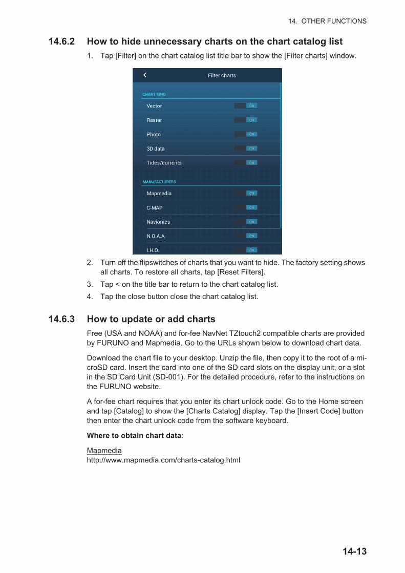
14. OTHER FUNCTIONS
14.6.2 How to hide unnecessary charts on the chart catalog list
1. Tap [Filter] on the chart catalog list title bar to show the [Filter charts] window.
2. Turn off the flipswitches of charts that you want to hide. The factory setting shows all charts. To restore all charts, tap [Reset Filters].
3. Tap < on the title bar to return to the chart catalog list.
4. Tap the close button close the chart catalog list.
14.6.3 How to update or add charts
Free (USA and NOAA) and for-fee NavNet TZtouch2 compatible charts are provided by FURUNO and Mapmedia. Go to the URLs shown below to download chart data.
Download the chart file to your desktop. Unzip the file, then copy it to the root of a mi-croSD card. Insert the card into one of the SD card slots on the display unit, or a slot in the SD Card Unit (SD-001). For the detailed procedure, refer to the instructions on the FURUNO website.
A for-fee chart requires that you enter its chart unlock code. Go to the Home screen and tap [Catalog] to show the [Charts Catalog] display. Tap the [Insert Code] button then enter the chart unlock code from the software keyboard.
Where to obtain chart data:
Mapmediahttp://www.mapmedia.com/charts-catalog.html
C-MAP
14-13
14. OTHER FUNCTIONS
14.6.4 How to delete charts
Before replacing a chart you should delete the old chart data on every NavNetTZtouch2 unit. Only delete the chart data that you intend to replace or no longer re-quire.
Open the charts catalog. Tap the trashcan icon of the chart to delete. You are asked "ARE YOU SURE YOU WANT TO DELETE THIS FILE?" Tap [OK] to delete the file.
14-14
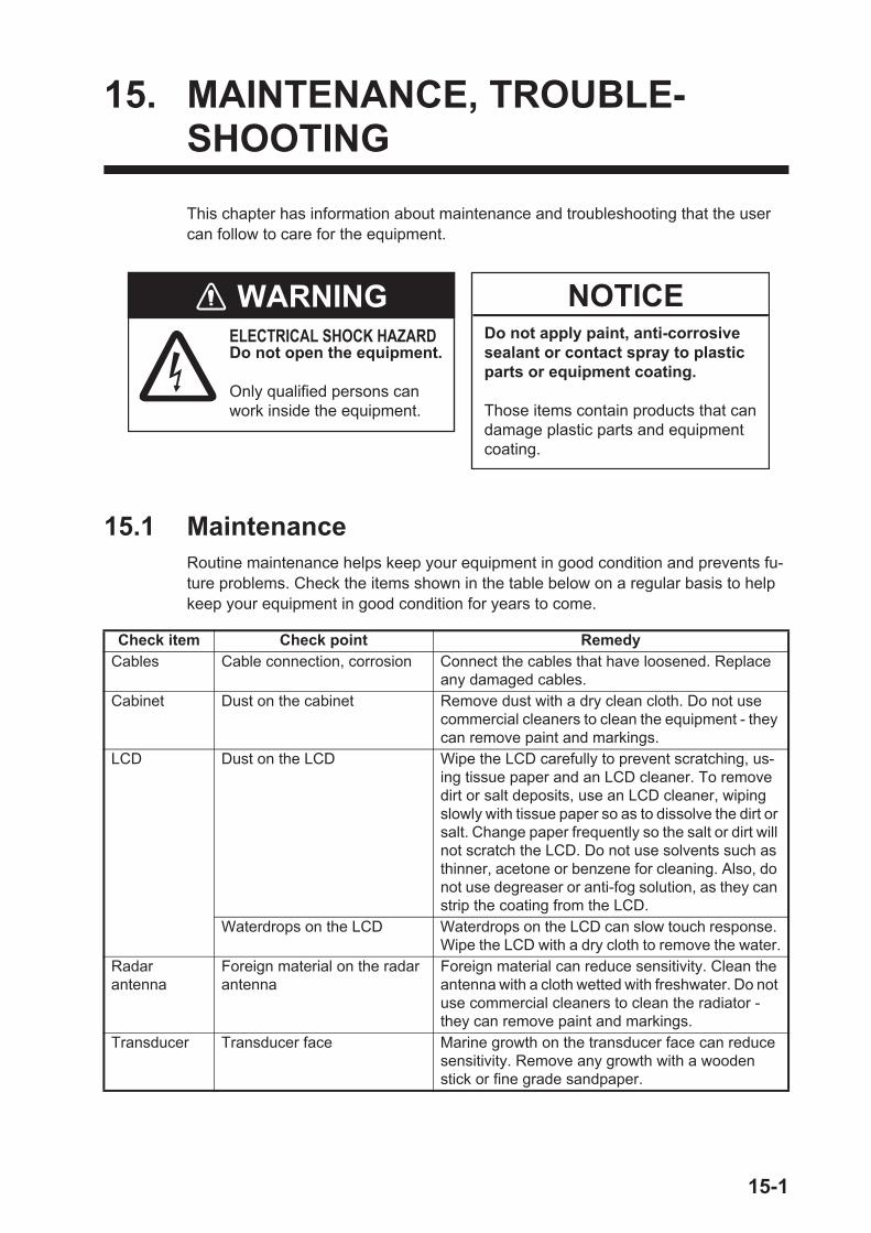
15. MAINTENANCE, TROUBLE-SHOOTING
This chapter has information about maintenance and troubleshooting that the user can follow to care for the equipment.
15.1 MaintenanceRoutine maintenance helps keep your equipment in good condition and prevents fu-ture problems. Check the items shown in the table below on a regular basis to help keep your equipment in good condition for years to come.
Check item Check point RemedyCables Cable connection, corrosion Connect the cables that have loosened. Replace
any damaged cables.Cabinet Dust on the cabinet Remove dust with a dry clean cloth. Do not use
commercial cleaners to clean the equipment - they can remove paint and markings.
LCD Dust on the LCD Wipe the LCD carefully to prevent scratching, us-ing tissue paper and an LCD cleaner. To remove dirt or salt deposits, use an LCD cleaner, wiping slowly with tissue paper so as to dissolve the dirt or salt. Change paper frequently so the salt or dirt will not scratch the LCD. Do not use solvents such as thinner, acetone or benzene for cleaning. Also, do not use degreaser or anti-fog solution, as they can strip the coating from the LCD.
Waterdrops on the LCD Waterdrops on the LCD can slow touch response. Wipe the LCD with a dry cloth to remove the water.
Radarantenna
Foreign material on the radar antenna
Foreign material can reduce sensitivity. Clean the antenna with a cloth wetted with freshwater. Do not use commercial cleaners to clean the radiator - they can remove paint and markings.
Transducer Transducer face Marine growth on the transducer face can reduce sensitivity. Remove any growth with a wooden stick or fine grade sandpaper.
WARNINGELECTRICAL SHOCK HAZARD Do not open the equipment.
Only qualified persons can work inside the equipment.
NOTICEDo not apply paint, anti-corrosive sealant or contact spray to plastic parts or equipment coating.
Those items contain products that can damage plastic parts and equipment coating.
15-1
15. MAINTENANCE, TROUBLESHOOTING
15.2 Fuse ReplacementThe fuse in the fuse holder in the power cable protects the equipment from high elec-tric current and equipment fault. If you cannot turn on the power, check the fuse to see if it has blown. Find the reason for the blown fuse before you replace the fuse. If the fuse blows again after the replacement, contact your dealer for advice.
15.3 Life of Parts
Magnetron
When a magnetron reaches the end of its life, targets do not appear on the radar dis-play. If long-range performance appears to have declined, contact your dealer about replacement of the magnetron.
The total time of power-on ("ON TIME") and transmission ("TX TIME") are displayed on the radar screen during the stand-by mode.
LCD (TZTL12F/TZTL15F only)
The life of the LCD for the TZTL15F is approximately 18,000 hours; for the TZTL12F it is approximately 25,000 hours. The actual life of the LCD is affected by the operating environment (temperature, humidity, etc.). When nearing the end of its life-span, the LCD brilliance does not adjust correctly. When this occurs, contact your local dealer for advice.
Name Type Code No. RemarksFuse FGBO-A 125V 5A PBF 000-155-853-10 12 VDC, 24 VDC
Radar Sensor Magnetron Code No. Approx. LifeDRS2D E3590 000-164-574-11 5,000 hoursDRS4D E3571 000-146-867-11 5,000 hoursDRS4DL/DRS4DL+
80-0691 001-266-460 5,000 hours
DRS4A MAF1421B 000-158-786-11 5,000 hoursDRS6A MAF1422B 000-158-788-12 5,000 hoursDRS6A X-Class MAF1422B 000-158-788-12 5,000 hoursDRS12A MAF1565N 000-174-559-10 5,000 hoursDRS12A X-Class FNE1201 001-245-890 5.000 hoursDRS25A MG5436(E2V) 000-140-762-10 5,000 hoursDRS25A X-Class MG5436 001-205-570 5,000 hours
WARNINWARNINGUse the proper fuse.Use of the wrong fuse can cause fire or electrical shock.
15-2
15. MAINTENANCE, TROUBLESHOOTING
Fan
The approximate life of the fan is as shown in the table below, and the actual life de-pends on ambient temperature. When the fan does not rotate sufficiently, an applica-ble message appears in the status bar. Turn off the power and contact your dealer about replacement of the fan.
15.4 TroubleshootingThis section provides simple troubleshooting procedures that the user can follow to re-store normal operation. If you cannot restore normal operation, do not check inside the unit. Have a qualified technician check the equipment.
15.4.1 General troubleshooting
Item Type Code No. Estimated Life RemarksFAN MOTOR MFB52A-12HA-002 000-175-998-10 Approx. 21,000 hours For TZTL12F,
TZTL15F, TZT2BB(Internal fan)
LF50C12FFR02A 000-194-101-10 Approx. 40,000 hours For TZT2BB(External fan)
Problem RemedyYou can not turn on the power. • Check for blown fuse.
• Check that the power connector is tightly fastened.• Check for corrosion on the power cable connector.• Check for the power cable for damage.• Check battery for correct voltage output.• For TZTL12F/TZTL15F, use a bare finger to turn on the pow-
er. (The power cannot be turned with gloved hands.)Picture is not displayed properly. Turn the power off, then on again. If the picture is still improper,
contact your local dealer for instructions.Nothing appears on the screen after you press the power switch.
Check if the unit is plugged into the power source.
The display has frozen. Push the power switch until the power goes off. Turn the power on again.
TZT2BB monitor does not display images correctly.
Turn the power off then on again. If the picture is still improper, contact your dealer for instructions.
Nothing appears on the TZT2BB monitor screen after you press the power switch.
• Check the monitor power.• Check connections between the monitor and the processor
unit.
15-3

15. MAINTENANCE, TROUBLESHOOTING
15.4.2 Radar troubleshooting
15.4.3 Plotter troubleshooting
15.4.4 Fish finder troubleshooting
Problem RemedyThe radar cannot transmit. • Tap the [TX] icon again. (The icon is filled in white when the ra-
dar is in transmit state.)• Check that the antenna cable is tightly fastened.• Check if the radar source is correct.
Marks and characters appear, but echoes do not appear.
• Check the antenna cable for damage and loose connection.• If the picture is frozen, turn the power off and on again.
Picture is not updated or the picture freezes.
• Check the antenna cable for damage and loose connection.• If the picture has frozen, turn the power off and on again.
You adjusted the receiver gain, but radar echoes are too weak.
The life span of the magnetron in the radar sensor is over. Have a technician check the magnetron.
You changed the range, but the radar picture does not change.
• Try to change the range again.• Turn the power off and on again.
Poor discrimination in range. Adjust the sea control.Range rings are not displayed. Check if [Range Rings] is turned on in the [Layers] menu.You tapped the [TX] icon to transmit. The "TX screen" ap-pears momentarily, but the ra-dar soon goes into stand-by.
The overload protection has activated. To restore normal opera-tion, turn off all equipment in the network. Wait a few seconds then turn on all the equipment.
Problem RemedyPosition is not fixed. Check for interfering objects near the display unit that might be
blocking reception.The track of your ship is not plotted.
Check if [Tracks] is turned on in the [Layers] menu.
Problem RemedyYou selected a fish finder dis-play, but no picture appears.
• Check that the transducer cable is tightly fastened.• Check that the fish finder source is correct.• If you are using a network fish finder, check that it is properly
connected.Marks and characters appear, but no picture appears.
Check if the transducer cable is tightly connected.
Picture appears but zero line does not appear.
• The picture is shifted. Check the shift setting.• Check if the draft setting ([Settings] - [Sounder] - [Transducer
Draft]) is zero or higher.The picture sensitivity is too low.
• If you are in the manual mode, check the gain setting.• Check the transducer face for marine life and air bubbles.• Bottom is too soft to return an acceptable echo.
The depth indication does not appear.
• For manual operation, adjust the gain and range to display the bottom echo in reddish-brown.
• Adjust the bottom level HF/LF.Noise or interference shows on the display.
• Make sure the transducer cable is not near the engine.• Check the ground for tight connection, corrosion.• Check if another fish finder near your boat has the same fre-
quency as your fish finder.• Try to reject the interference with [Interference Rejection] in the
[Settings] - [Sounder] menu.
15-4
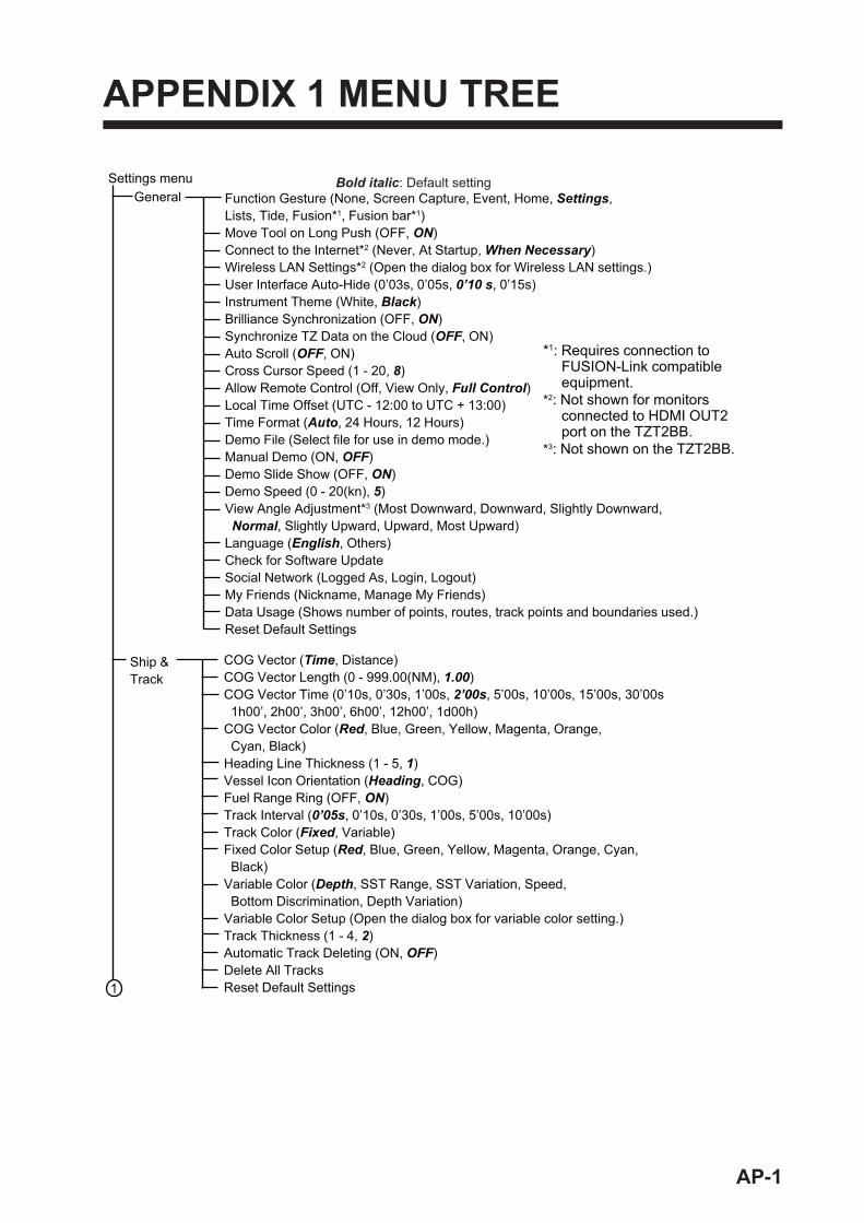
APPENDIX 1 MENU TREE
1
Settings menu
*1: Requires connection to FUSION-Link compatible equipment.
*2: Not shown for monitors connected to HDMI OUT2 port on the TZT2BB.
*3: Not shown on the TZT2BB.
General Function Gesture (None, Screen Capture, Event, Home, Settings,Lists, Tide, Fusion*1, Fusion bar*1)Move Tool on Long Push (OFF, ON)Connect to the Internet*2 (Never, At Startup, When Necessary)Wireless LAN Settings*2 (Open the dialog box for Wireless LAN settings.)User Interface Auto-Hide (0’03s, 0’05s, 0’10 s, 0’15s)Instrument Theme (White, Black)Brilliance Synchronization (OFF, ON)Synchronize TZ Data on the Cloud (OFF, ON)Auto Scroll (OFF, ON)Cross Cursor Speed (1 - 20, 8)Allow Remote Control (Off, View Only, Full Control)Local Time Offset (UTC - 12:00 to UTC + 13:00)Time Format (Auto, 24 Hours, 12 Hours)Demo File (Select file for use in demo mode.)Manual Demo (ON, OFF)Demo Slide Show (OFF, ON)Demo Speed (0 - 20(kn), 5)View Angle Adjustment*3 (Most Downward, Downward, Slightly Downward, Normal, Slightly Upward, Upward, Most Upward)Language (English, Others)Check for Software UpdateSocial Network (Logged As, Login, Logout)My Friends (Nickname, Manage My Friends) Data Usage (Shows number of points, routes, track points and boundaries used.)Reset Default Settings
Bold italic: Default setting
COG Vector (Time, Distance)COG Vector Length (0 - 999.00(NM), 1.00)COG Vector Time (0’10s, 0’30s, 1’00s, 2’00s, 5’00s, 10’00s, 15’00s, 30’00s 1h00’, 2h00’, 3h00’, 6h00’, 12h00’, 1d00h)COG Vector Color (Red, Blue, Green, Yellow, Magenta, Orange, Cyan, Black)Heading Line Thickness (1 - 5, 1)Vessel Icon Orientation (Heading, COG)Fuel Range Ring (OFF, ON)Track Interval (0’05s, 0’10s, 0’30s, 1’00s, 5’00s, 10’00s)Track Color (Fixed, Variable)Fixed Color Setup (Red, Blue, Green, Yellow, Magenta, Orange, Cyan, Black)Variable Color (Depth, SST Range, SST Variation, Speed, Bottom Discrimination, Depth Variation)Variable Color Setup (Open the dialog box for variable color setting.)Track Thickness (1 - 4, 2)Automatic Track Deleting (ON, OFF)Delete All TracksReset Default Settings
Ship & Track
AP-1
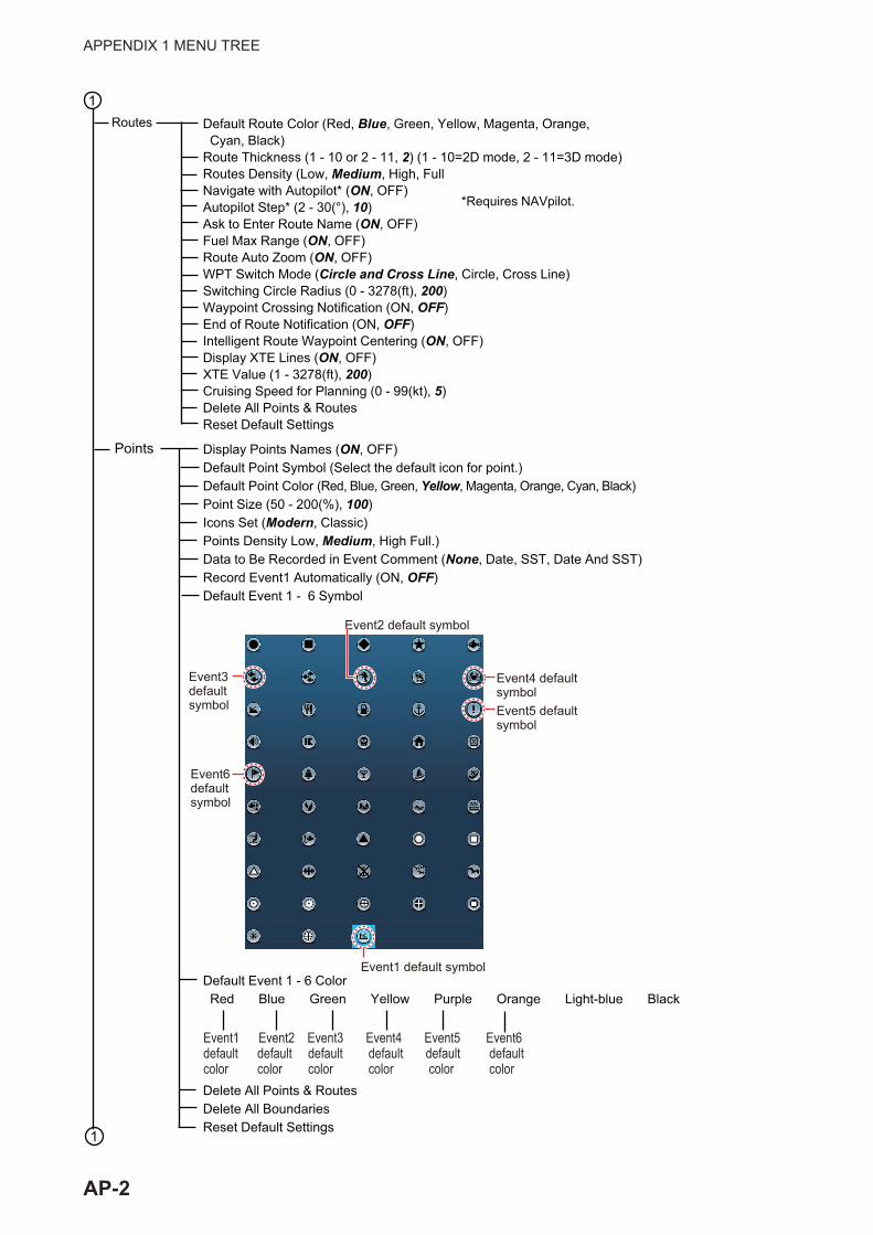
APPENDIX 1 MENU TREE
Default Route Color (Red, Blue, Green, Yellow, Magenta, Orange, Cyan, Black)Route Thickness (1 - 10 or 2 - 11, 2) (1 - 10=2D mode, 2 - 11=3D mode)Routes Density (Low, Medium, High, FullNavigate with Autopilot* (ON, OFF) Autopilot Step* (2 - 30(°), 10)Ask to Enter Route Name (ON, OFF)Fuel Max Range (ON, OFF)Route Auto Zoom (ON, OFF)WPT Switch Mode (Circle and Cross Line, Circle, Cross Line) Switching Circle Radius (0 - 3278(ft), 200)Waypoint Crossing Notification (ON, OFF)End of Route Notification (ON, OFF)Intelligent Route Waypoint Centering (ON, OFF)Display XTE Lines (ON, OFF)XTE Value (1 - 3278(ft), 200)Cruising Speed for Planning (0 - 99(kt), 5)Delete All Points & RoutesReset Default Settings
Routes
*Requires NAVpilot.
Display Points Names (ON, OFF)Default Point Symbol (Select the default icon for point.)Default Point Color (Red, Blue, Green, Yellow, Magenta, Orange, Cyan, Black)Point Size (50 - 200(%), 100)Icons Set (Modern, Classic)Points Density Low, Medium, High Full.)Data to Be Recorded in Event Comment (None, Date, SST, Date And SST)Record Event1 Automatically (ON, OFF)Default Event 1 - 6 Symbol
Default Event 1 - 6 Color Red Blue Green Yellow Purple Orange Light-blue Black
Delete All Points & RoutesDelete All BoundariesReset Default Settings
1
Points
Event1 Event2 Event3 Event4 Event5 Event6default default default default default defaultcolor color color color color color
Event1 default symbolEvent1 default symbol
Event3defaultsymbol
Event3defaultsymbol
Event2 default symbolEvent2 default symbol
Event4 defaultsymbolEvent4 defaultsymbolEvent5 defaultsymbolEvent5 defaultsymbol
Event6defaultsymbol
Event6defaultsymbol
1
AP-2
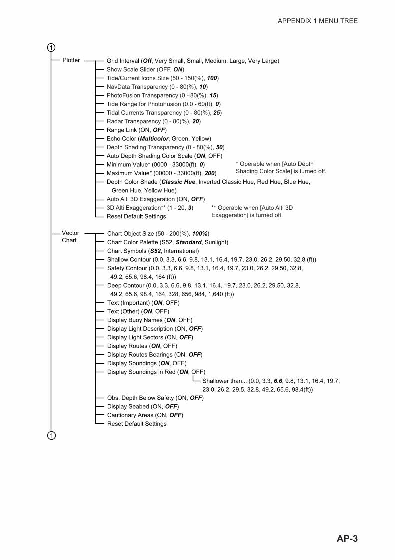
APPENDIX 1 MENU TREE
Grid Interval (Off, Very Small, Small, Medium, Large, Very Large)Show Scale Slider (OFF, ON)Tide/Current Icons Size (50 - 150(%), 100)NavData Transparency (0 - 80(%), 10)PhotoFusion Transparency (0 - 80(%), 15)Tide Range for PhotoFusion (0.0 - 60(ft), 0)Tidal Currents Transparency (0 - 80(%), 25)Radar Transparency (0 - 80(%), 20)Range Link (ON, OFF)Echo Color (Multicolor, Green, Yellow)Depth Shading Transparency (0 - 80(%), 50)Auto Depth Shading Color Scale (ON, OFF)Minimum Value* (0000 - 33000(ft), 0)Maximum Value* (00000 - 33000(ft), 200)Depth Color Shade (Classic Hue, Inverted Classic Hue, Red Hue, Blue Hue, Green Hue, Yellow Hue)Auto Alti 3D Exaggeration (ON, OFF)3D Alti Exaggeration** (1 - 20, 3)Reset Default Settings
Chart Object Size (50 - 200(%), 100%)Chart Color Palette (S52, Standard, Sunlight)Chart Symbols (S52, International)Shallow Contour (0.0, 3.3, 6.6, 9.8, 13.1, 16.4, 19.7, 23.0, 26.2, 29.50, 32.8 (ft))Safety Contour (0.0, 3.3, 6.6, 9.8, 13.1, 16.4, 19.7, 23.0, 26.2, 29.50, 32.8, 49.2, 65.6, 98.4, 164 (ft))Deep Contour (0.0, 3.3, 6.6, 9.8, 13.1, 16.4, 19.7, 23.0, 26.2, 29.50, 32.8, 49.2, 65.6, 98.4, 164, 328, 656, 984, 1,640 (ft))Text (Important) (ON, OFF)Text (Other) (ON, OFF)Display Buoy Names (ON, OFF)Display Light Description (ON, OFF)Display Light Sectors (ON, OFF)Display Routes (ON, OFF)Display Routes Bearings (ON, OFF)Display Soundings (ON, OFF)Display Soundings in Red (ON, OFF)
Obs. Depth Below Safety (ON, OFF)Display Seabed (ON, OFF)Cautionary Areas (ON, OFF)Reset Default Settings
Shallower than... (0.0, 3.3, 6.6, 9.8, 13.1, 16.4, 19.7, 23.0, 26.2, 29.5, 32.8, 49.2, 65.6, 98.4(ft))
Plotter
1
1
* Operable when [Auto DepthShading Color Scale] is turned off.
VectorChart
** Operable when [Auto Alti 3D Exaggeration] is turned off.
AP-3

APPENDIX 1 MENU TREE
S-52 Vector Chart Display Mode (Custom, Base, Standard, Other, Fishing)Unknown Object (ON, OFF)Chart Data Coverage (ON, OFF)Water and Seabed Features (ON, OFF)Traffic Routes (ON, OFF)Information Areas (ON, OFF)Buoys & Beacons (ON, OFF)Lights (ON, OFF)Fog Signals (ON, OFF)Radar (ON, OFF)Information About Chart Data (ON, OFF)Obstructions (ON, OFF)Depth Contours, Cur., etc (ON, OFF)Fishing Facilities (ON, OFF)Services (Pilot, Signal Stations) (ON, OFF)Harbour Facilities (ON, OFF)Services and Small Craft Facilities (ON, OFF)Land Features (ON, OFF)Reset Default Settings
1
1
S-52 Display
ActiveCaptain
Activate (Activate the Active Captain.)Automatic Update (ON, OFF)Last Update Update DatabaseAC Marinas & Facilities (ON, OFF)AC Anchorage (ON, OFF)AC Local Knowledge (ON, OFF)AC Hazards (ON, OFF)Gas (ON, OFF)Diesel (ON, OFF)Pump Out (ON, OFF)Bridge (ON, OFF)Lock (ON, OFF)Dam (ON, OFF)Ferry (ON, OFF)Inlet (ON, OFF)Boat Ramp (ON, OFF)Marine Store (ON, OFF)Towing (ON, OFF)Wal-Mart (ON, OFF)Airport (ON, OFF)Reset Default Settings
AP-4
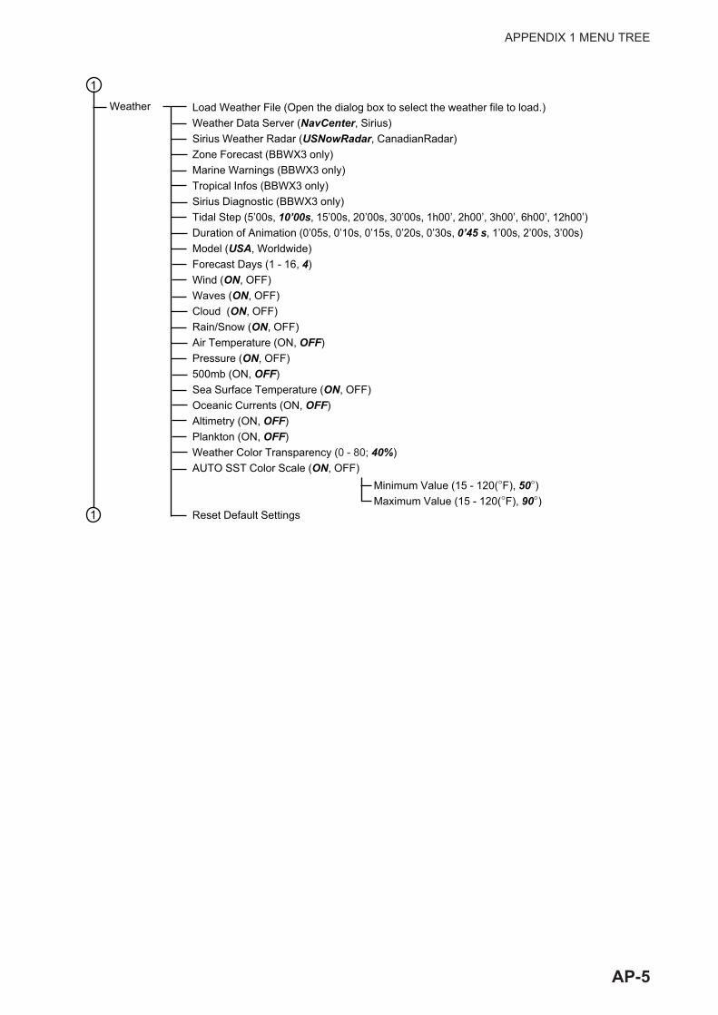
APPENDIX 1 MENU TREE
1
1
Weather Load Weather File (Open the dialog box to select the weather file to load.)Weather Data Server (NavCenter, Sirius)Sirius Weather Radar (USNowRadar, CanadianRadar)Zone Forecast (BBWX3 only)Marine Warnings (BBWX3 only)Tropical Infos (BBWX3 only)Sirius Diagnostic (BBWX3 only)Tidal Step (5’00s, 10’00s, 15’00s, 20’00s, 30’00s, 1h00’, 2h00’, 3h00’, 6h00’, 12h00’)Duration of Animation (0’05s, 0’10s, 0’15s, 0’20s, 0’30s, 0’45 s, 1’00s, 2’00s, 3’00s)Model (USA, Worldwide)Forecast Days (1 - 16, 4)Wind (ON, OFF)Waves (ON, OFF)Cloud (ON, OFF)Rain/Snow (ON, OFF)Air Temperature (ON, OFF)Pressure (ON, OFF)500mb (ON, OFF)Sea Surface Temperature (ON, OFF)Oceanic Currents (ON, OFF)Altimetry (ON, OFF)Plankton (ON, OFF)Weather Color Transparency (0 - 80; 40%)AUTO SST Color Scale (ON, OFF)
Reset Default Settings
Minimum Value (15 - 120(°F), 50°)Maximum Value (15 - 120(°F), 90°)
AP-5
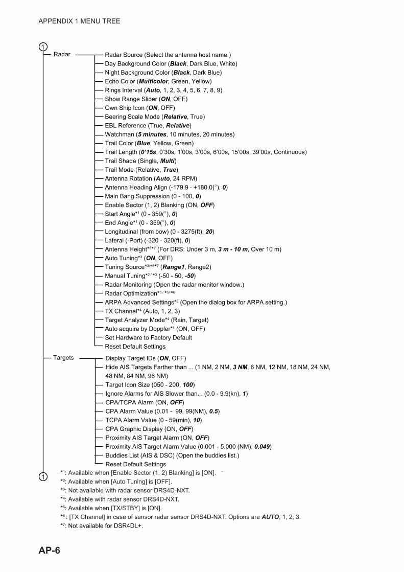
APPENDIX 1 MENU TREE
Radar Source (Select the antenna host name.)Day Background Color (Black, Dark Blue, White)Night Background Color (Black, Dark Blue)Echo Color (Multicolor, Green, Yellow)Rings Interval (Auto, 1, 2, 3, 4, 5, 6, 7, 8, 9)Show Range Slider (ON, OFF)Own Ship Icon (ON, OFF)Bearing Scale Mode (Relative, True)EBL Reference (True, Relative)Watchman (5 minutes, 10 minutes, 20 minutes)Trail Color (Blue, Yellow, Green)Trail Length (0’15s, 0’30s, 1’00s, 3’00s, 6’00s, 15’00s, 39’00s, Continuous)Trail Shade (Single, Multi)Trail Mode (Relative, True)Antenna Rotation (Auto, 24 RPM)Antenna Heading Align (-179.9 - +180.0(°), 0)Main Bang Suppression (0 - 100, 0)Enable Sector (1, 2) Blanking (ON, OFF)Start Angle*1 (0 - 359(°), 0)End Angle*1 (0 - 359(°), 0)Longitudinal (from bow) (0 - 3275(ft), 20)Lateral (-Port) (-320 - 320(ft), 0)Antenna Height*6*7 (For DRS: Under 3 m, 3 m - 10 m, Over 10 m)Auto Tuning*3 (ON, OFF)Tuning Source*3/*6*7 (Range1, Range2)Manual Tuning*2 / *3 (-50 - 50, -50)Radar Monitoring (Open the radar monitor window.)Radar Optimization*3 / *5/ *6
ARPA Advanced Settings*6 (Open the dialog box for ARPA setting.)TX Channel*4 (Auto, 1, 2, 3)Target Analyzer Mode*4 (Rain, Target)Auto acquire by Doppler*4 (ON, OFF)Set Hardware to Factory DefaultReset Default Settings
1
1
Radar
*1: Available when [Enable Sector (1, 2) Blanking] is [ON].*2: Available when [Auto Tuning] is [OFF].*3: Not available with radar sensor DRS4D-NXT.*4: Available with radar sensor DRS4D-NXT.*5: Available when [TX/STBY] is [ON].*6 : [TX Channel] in case of sensor radar sensor DRS4D-NXT. Options are AUTO, 1, 2, 3.*7: Not available for DSR4DL+.
Display Target IDs (ON, OFF)Hide AIS Targets Farther than ... (1 NM, 2 NM, 3 NM, 6 NM, 12 NM, 18 NM, 24 NM, 48 NM, 84 NM, 96 NM)Target Icon Size (050 - 200, 100)Ignore Alarms for AIS Slower than... (0.0 - 9.9(kn), 1)CPA/TCPA Alarm (ON, OFF)CPA Alarm Value (0.01 - 99. 99(NM), 0.5)TCPA Alarm Value (0 - 59(min), 10)CPA Graphic Display (ON, OFF)Proximity AIS Target Alarm (ON, OFF)Proximity AIS Target Alarm Value (0.001 - 5.000 (NM), 0.049)Buddies List (AIS & DSC) (Open the buddies list.)Reset Default Settings
Targets
AP-6
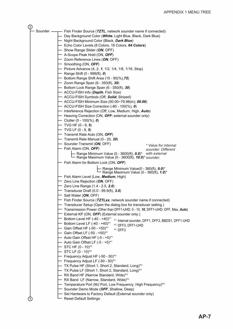
APPENDIX 1 MENU TREE
Fish Finder Source (TZTL, network sounder name if connected)Day Background Color (White, Light Blue, Black, Dark Blue)Night Background Color (Black, Dark Blue)Echo Color Levels (8 Colors, 16 Colors, 64 Colors)Show Range Slider (ON, OFF)A-Scope Peak Hold (ON, OFF)Zoom Reference Lines (ON, OFF)Smoothing (ON, OFF)Picture Advance (4, 2, 1, 1/2, 1/4, 1/8, 1/16, Stop)Range Shift (0 - 999(ft), 0)Bottom Range Shift Area (15 - 85(%),75)Zoom Range Span (6 - 350(ft), 30)Bottom Lock Range Span (6 - 350(ft), 30)ACCU-FISH Info (Depth, Fish Size)ACCU-FISH Symbols (Off, Solid, Striped)ACCU-FISH Minimum Size (00.00~79.98(in); 00.00)ACCU-FISH Size Correction (-80 - 100(%), 0)Interference Rejection (Off, Low, Medium, High, Auto)Heaving Correction (ON, OFF; external sounder only)Clutter (0 - 100(%), 0)TVG HF (0 - 9, 5)TVG LF (0 - 9, 5)Transmit Rate Auto (ON, OFF)Transmit Rate Manual (0 - 20, 20)Sounder Transmit (ON, OFF)Fish Alarm (ON, OFF)
Fish Alarm for Bottom Lock (ON, OFF)
Fish Alarm Level (Low, Medium, High)Zero Line Rejection (ON, OFF)Zero Line Range (1.4 - 2.5, 2.0)Transducer Draft (0.0 - 99.9(ft), 3.0)Salt Water (ON, OFF)Fish Finder Source (TZTLxx, network sounder name if connected)Transducer Setup (Open the dialog box for transducer setting.)Transmission Power (Other than DFF1-UHD: 0 - 10, 10, DFF1-UHD: OFF, Max, Auto) External KP (ON, OFF) (External sounder only.)Bottom Level HF (-40 - +40)*1
Bottom Level LF (-40 - +40)*1
Gain Offset HF (-50 - +50)*1
Gain Offset LF (-50 - +50)*1
Auto Gain Offset HF (-5 - +5)*1
Auto Gain Offset LF (-5 - +5)*1
STC HF (0 - 10)*2
STC LF (0 - 10)*2
Frequency Adjust HF (-50 - 50)*3
Frequency Adjust LF (-50 - 50)*3
TX Pulse HF (Short 1, Short 2, Standard, Long)*3
TX Pulse LF (Short 1, Short 2, Standard, Long)*3
RX Band HF (Narrow Standard, Wide)*3
RX Band LF (Narrow, Standard, Wide)*3
Temperature Port (MJ Port, Low Frequency, High Frequency)*3
Sounder Demo Mode (OFF, Shallow, Deep)Set Hardware to Factory Default (External sounder only)Reset Default Settings
1
1
Sounder
Range Minimum Value (0 - 3600(ft), 0.0)*Range Maximum Value (0 - 3600(ft), 10.0)*
Range Minimum Value(0 - 360(ft), 0.0)*Range Maximum Value (0 - 360(ft), 1.0)*
* Value for internal sounder. Different with external sounder.
*1 Internal sounder, DFF1, DFF3, BBDS1, DFF1-UHD*2 DFF3, DFF1-UHD*3 DFF3
AP-7

APPENDIX 1 MENU TREE
Day Background Color (White, Light Blue, Black, Blue)Night Background Color (Black, Dark Blue)Bottom Range Shift Area (15~85(%); 50)Transmit Rate Auto (OFF, ON)Transmit Rate Manual (0~21; 20)Sounder Transmit (OFF, ON)Multi-Sounder
Side Scan
Cross Section
3D Sounder History
Multi-beamSonar
*1 Settable when Color Mode is set to Seabed.*2 Settable when Color Mode is set to Fish.*3 Settable when Auto Seabed Shading is set to ON.*4 Settable when Auto Fish Shading is set to ON.
Fish Detection Level (Low, Medium, High)Seabed Echo Calibration (-15~15; 0)Temp.-Based Correction (OFF; ON)Noise Filter (Off, Low, Medium, High)Terrain Shading (~100(%); 50)Color Mode (Bottom, Fish)Seabed Color*1 (Classic Hue, Inverted Classic Hue, Red Hue, Blue Hue, Green Hue, Yellow Hue)Fish Monochrome Color*1 (Gray Hue, Brown Hue, Red, Green, Blue, Cyan, Magenta, BlackOrWhite, Pink, Light Green, Yellow)Auto Bottom Shading (OFF, ON)Minimum Value*3 (0~1200; 0m)Maximum Value*3 (0~1200; 50m)Auto Fish Shading (OFF, ON)Minimum Value*4 (0~1200; 0m)Maximum Value*4 (0~1200; 50m)
A-Scope Peak Hold (OFF, ON)HIgh Resolution (OFF, ON)Picture Advance (4/1, 2/1, 1/1, 1/2,1/4, 1/8, 1/16, Stop)Clutter (0~100(%); 0)TVG (0~9; 5)TVG Distance (10~1000; 400m)
Echo Color (White, Blue, Brown)Picture Advance (4/1, 2/1, 1/1, 1/2, 1/4, 1/8, 1/16, Stop)Clutter (0~100(%); 0)TVG (0~9; 5)
Clutter (0~100(%); 0)TVG (0~9; 5)Echo Width (2~10; 8)Echo Smoothing (Distance) (OFF, Low, Medium, High)Echo Smoothing (Time) (OFF, Low, Medium, High)Sound Speed Correction (-15~15; 0)
1
1 2
AP-8
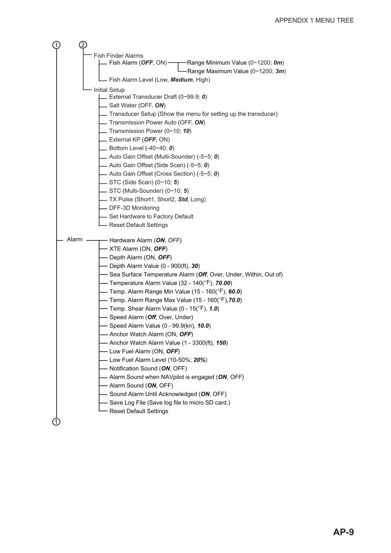
APPENDIX 1 MENU TREE
Alarm Hardware Alarm (ON, OFF)XTE Alarm (ON, OFF)Depth Alarm (ON, OFF)Depth Alarm Value (0 - 900(ft), 30)Sea Surface Temperature Alarm (Off, Over, Under, Within, Out of)Temperature Alarm Value (32 - 140(°F), 70.00)Temp. Alarm Range Min Value (15 - 160(°F), 60.0)Temp. Alarm Range Max Value (15 - 160(°F),70.0)Temp. Shear Alarm Value (0 - 15(°F), 1.0)Speed Alarm (Off, Over, Under)Speed Alarm Value (0 - 99.9(kn), 10.0)Anchor Watch Alarm (ON, OFF)Anchor Watch Alarm Value (1 - 3300(ft), 150)Low Fuel Alarm (ON, OFF)Low Fuel Alarm Level (10-50%; 20%)Notification Sound (ON, OFF)Alarm Sound when NAVpilot is engaged (ON, OFF)Alarm Sound (ON, OFF)Sound Alarm Until Acknowledged (ON, OFF)Save Log File (Save log file to micro SD card.)Reset Default Settings
Fish Finder Alarms
Initial Setup
Fish Alarm (OFF, ON) Range Minimum Value (0~1200; 0m) Range Maximum Value (0~1200; 3m)Fish Alarm Level (Low, Medium, High)
External Transducer Draft (0~99.9; 0)Salt Water (OFF, ON)Transducer Setup (Show the menu for setting up the transducer)Transmission Power Auto (OFF, ON)Transmission Power (0~10; 10)External KP (OFF, ON)Bottom Level (-40~40; 0)Auto Gain Offset (Multi-Sounder) (-5~5; 0)Auto Gain Offset (Side Scan) (-5~5; 0)Auto Gain Offset (Cross Section) (-5~5; 0)STC (Side Scan) (0~10; 5)STC (Multi-Sounder) (0~10; 5)TX Pulse (Short1, Short2, Std, Long)DFF-3D MonitoringSet Hardware to Factory DefaultReset Default Settings
1 2
1
AP-9
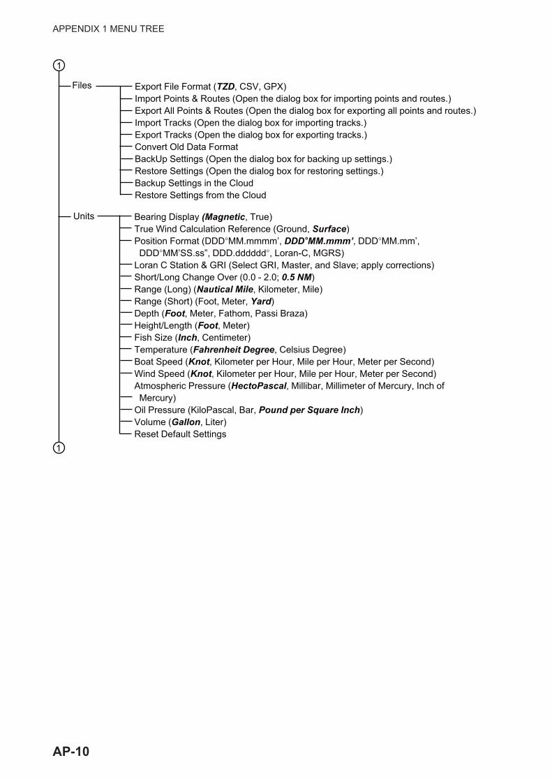
APPENDIX 1 MENU TREE
1
Export File Format (TZD, CSV, GPX)Import Points & Routes (Open the dialog box for importing points and routes.)Export All Points & Routes (Open the dialog box for exporting all points and routes.)Import Tracks (Open the dialog box for importing tracks.)Export Tracks (Open the dialog box for exporting tracks.)Convert Old Data FormatBackUp Settings (Open the dialog box for backing up settings.)Restore Settings (Open the dialog box for restoring settings.)Backup Settings in the CloudRestore Settings from the Cloud
Bearing Display (Magnetic, True)True Wind Calculation Reference (Ground, Surface)Position Format (DDD°MM.mmmm’, DDD°MM.mmm’, DDD°MM.mm’, DDD°MM’SS.ss”, DDD.dddddd°, Loran-C, MGRS)Loran C Station & GRI (Select GRI, Master, and Slave; apply corrections) Short/Long Change Over (0.0 - 2.0; 0.5 NM)Range (Long) (Nautical Mile, Kilometer, Mile)Range (Short) (Foot, Meter, Yard)Depth (Foot, Meter, Fathom, Passi Braza)Height/Length (Foot, Meter)Fish Size (Inch, Centimeter)Temperature (Fahrenheit Degree, Celsius Degree)Boat Speed (Knot, Kilometer per Hour, Mile per Hour, Meter per Second)Wind Speed (Knot, Kilometer per Hour, Mile per Hour, Meter per Second)Atmospheric Pressure (HectoPascal, Millibar, Millimeter of Mercury, Inch of Mercury)Oil Pressure (KiloPascal, Bar, Pound per Square Inch)Volume (Gallon, Liter)Reset Default Settings
1
Files
Units
AP-10

APPENDIX 1 MENU TREE
HDMI*
ANALOG CAMERA 1~2
IP CAMERA 1~4
AXIS QUAD SERVER
SECOND AXIS QUAD SERVER (same choices as AXIS QUAD SERVER)CONTROLLABLE CAMERA
TRACKING
Camera
Connected (ON, OFF)NickName (Camera 1)
HDMI Input (ON, OFF)Touch Output (ON, OFF)
Automatic Lock on Active Waypoint (ON, OFF)Automatic Lock on MOB (ON, OFF)
Scan IPFLIR IPVideo Source (None, Camera 1, Camera 2)Camera Offset (Right-left) (0°)Camera Offset (Up-Down) (0°)Automatic Zoom (ON, OFF)Zoom Distance (300 ft)Camera Altitude (30 ft)
FLIR Installation
Reset Default Settings
NickName (IP CAMERA1)IP Camera (IP address)PTZ Control (ON, OFF)
Server (ON, OFF)IP ServerQuad Mode (ON, OFF)Input 1~4 (ON, OFF)Nickname Input 1~4 (VIDEO1~VIDEO4)
1
GPS POSITION Longitudinal (from bow) Lateral (-Port)BOAT INFORMATION
InitialSetup(seeInst.Manualfordetails) 2
Boat LengthSize of Static IconDepth DisplayExternal Transducer DraftKeel Draft
*: Not shown for monitors connected to HDMI OUT2 port on the TZT2BB.
AP-11

APPENDIX 1 MENU TREE
IF NMEAFI SETUP Select IFDATA ACQUISITION GP330B WAAS Mode WS200 WAAS Mode Data Source Sensor List NMEA 0183 Output NMEA 2000 PGN Output Sky ViewINTERNAL GPS SETUP WAAS ModeSC-30 SETUP WAAS Mode Heading Offset Pitch Offset Roll Offset
2
Maximum Boat SpeedMaximum Wind SpeedDEPTH Minimum Depth Maximum DepthSEA SURFACE TEMPERATURE Minimum Sea Surface Temperature Maximum Sea Surface TemperaturePROPULSION ENGINE Max. RPM Red Zone Oil Pressure Max. Oil Pressure Min. Temperature Red Zone TemperatureOTHER ENGINE (same options as PROPULSION ENGINE) Reset Instrument Pages Reset Default Settings
Engine & Tank Automatic SetupEngine & Tank Manual SetupGraphic Instruments Setup
CZONE SETUPAdd Default CZone PagesCZone DIP Switch Settings
INSTRUMENTS SETUP
MANUAL FUEL MANAGEMENTTotal Fuel Capacity (0,000 - 9,999 (gallons)Manual Fuel Management (OFF, ON)
YAMAHA ENGINE SETUPTrip & Maintenance (Reset trip fuel and distance, and trip and maintenance hours.)Trim Level Calibration (Set trim to “0” (zero).Fuel Flow Level Calibration (-7 to +7(%); 0)Engine Interface Software Ver. & ID)Reset Engine InterfaceReset Engine InstanceReset Number of EnginesTrouble Codes
2
AP-12
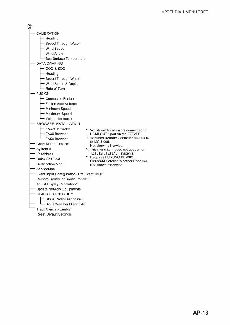
APPENDIX 1 MENU TREE
*1: Not shown for monitors connected to HDMI OUT2 port on the TZT2BB.
*2: Requires Remote Controller MCU-004 or MCU-005. Not shown otherwise.
*3: This menu item does not appear for TZTL12F/TZTL15F systems.
*4: Requires FURUNO BBWX3Sirius/XM Satellite Weather Receiver.Not shown otherwise.
CALIBRATION Heading Speed Through Water Wind Speed Wind Angle Sea Surface TemperatureDATA DAMPING COG & SOG Heading Speed Through Water Wind Speed & Angle Rate of TurnFUSION Connect to Fusion Fusion Auto Volume Minimum Speed Maximum Speed Volume IncreaseBROWSER INSTALLATION FAX30 Browser FA30 Browser FA50 BrowserChart Master Device*1
System IDIP AddressQuick Self TestCertification MarkServiceManEvent Input Configuration (Off, Event, MOB)Remote Controller Configuration*2
Adjust Display Resolution*3
Update Network EquipmentsSIRIUS DIAGNOSTIC*4
SIrius Radio Diagnostic Sirius Weather DiagnosticTrack Synchro EnableReset Default Settings
2
AP-13
APPENDIX 2 RADIO REGULATORY INFORMATION
Wireless Interoperability
This product is designed to be interoperable with any wireless LAN product that is based on direct sequence spread spectrum (DSSS) and orthogonal frequency division multiplexing (OFDM) radio technology and to comply with the following standards.
• IEEE Std 802.11b Standard on 2.4 GHz Wireless LAN
• IEEE Std 802.11g Standard on 2.4 GHz Wireless LAN
• IEEE Std 802.11n Standard on 2.4 GHz Wireless LAN
Safety
This product, like other radio devices, emits radio frequency electromagnetic energy. The level of energy emitted by this device, however, is less than the electromagnetic energy emitted by other wireless devices such as mobile phones. This product operates within the guidelines found in ra-dio frequency safety standards and recommendations. These standards and recommendations reflect the consensus of the scientific community and result from deliberations of panels and com-mittees of scientists who continually review and interpret the extensive research literature. In some situations or environments, the use of this product may be restricted by the proprietor of the building or responsible representatives of the applicable organization. Examples of such situa-tions include the following:
• Using this product onboard airplanes, or
• Using this product in any other environment where the risk of interference with other devices or services is perceived or identified as being harmful.
If uncertain of the policy that applies to the use of wireless devices in a specific organization or environment (an airplane, for example), ask for authorization to use this product before turning it on.
Export Regulation
Radio wave certification is necessary at the export destination. The Wireless LAN of this product operates in the 2.4 GHz band, which does not require a license in most countries. However, the conditions for use of the wireless LAN depend on the country or the area.
AP-14
APPENDIX 2 RADIO REGULATORY INFORMATION
USA-Federal Communications Commission (FCC)
Below are descriptions for built-in Wireless LAN module.
This equipment has been tested and found to comply with the limits for a Class B digital device, pursuant to Part 15 of FCC Rules. These limits are designed to provide reasonable protection against harmful interference in a residential installation. This equipment generates, uses, and can radiate radio frequency energy. If not installed and used in accordance with the instructions, it may cause harmful interference to radio communications. However, there is no guarantee that interfer-ence will not occur in a particular installation.
If this equipment does cause harmful interference to radio or television reception, which can be determined by tuning the equipment off and on, the user is encouraged to try and correct the in-terference by one or more of the following measures:
• Reorient or relocate the receiving antenna.
• Increase the distance between the equipment and the receiver.
• Connect the equipment to outlet on a circuit different from that to which the receiver is connect-ed.
• Consult the dealer or an experienced radio/TV technician for help.
This device complies with part 15 of the FCC Rules. Operation is subject to the following two con-ditions: (1) This device may not cause harmful interference, and (2) this device must accept any interference received, including interference that may cause undesired operation.
Any changes or modifications not expressly approved by the party responsible for compliance could void the user's authority to operate the equipment.
Caution: Exposure to Radio Frequency Radiation.
This equipment complies with FCC radiation exposure limits set forth for an uncontrolled environ-ment and meets the FCC radio frequency (RF) Exposure Guidelines in Supplement C to OET65.
This equipment should be installed and operated keeping the radiator at least 20cm or more away from person's body.
This device must not be co-located or operating in conjunction with any other antenna or transmit-ter.
AP-15

APPENDIX 2 RADIO REGULATORY INFORMATION
Canada-Industry Canada (IC)
Below are descriptions for built-in Wireless LAN module.
This device complies with RSS 210 of Industry Canada.
Operation is subject to the following two conditions:
(1) This device may not cause interference, and
(2) This device must accept any interference, including interference that may cause undesired op-eration of this device.
L'utilization de ce dispositif est autorisée seulement aux conditions suivantes :
(1) il ne doit pas produire de brouillage et
(2) l'utilisateur du dispositif doit étre prêt à accepter tout brouillage radioélectrique reçu, même si ce brouillage est susceptible de compromettre le fomctionnement du dispositif.
Caution: Exposure to Radio Frequency Radiation.
This equipment complies with IC radiation exposure limits set forth for an uncontrolled environ-ment and meets RSS-102 of the IC radio frequency (RF) Exposure rules. This equipment should be installed and operated keeping the radiator at least 20cm or more away from person's body.
Cet équipement est conforme aux limites d'exposition aux rayonnements énoncées pour un envi-
ronnement non contr êolé et respecte les règles d'exposition aux fréquences radioélectriques (RF) CNR-102 de l'IC. Cet équipement doit etre installé et utilise en gardant une distance de 20 cm ou plus entre le dispositif rayonnant et le corps.
To reduce potential radio interference to other users, the antenna type and its gain should be so chosen that the equivalent isotropically radiated power (EIRP) is not more than that required for successful communication.
AP-16
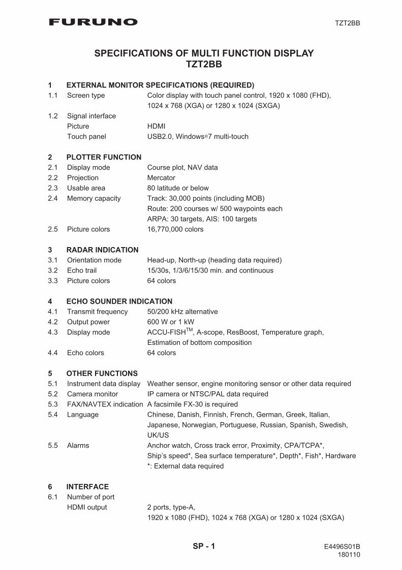
FURUNO TZT2BB
SPECIFICATIONS OF MULTI FUNCTION DISPLAY TZT2BB
1 EXTERNAL MONITOR SPECIFICATIONS (REQUIRED) 1.1 Screen type Color display with touch panel control, 1920 x 1080 (FHD),
1024 x 768 (XGA) or 1280 x 1024 (SXGA)
1.2 Signal interface
Picture HDMI
Touch panel USB2.0, Windows 7 multi-touch
2 PLOTTER FUNCTION 2.1 Display mode Course plot, NAV data
2.2 Projection Mercator
2.3 Usable area 80 latitude or below
2.4 Memory capacity Track: 30,000 points (including MOB)
Route: 200 courses w/ 500 waypoints each
ARPA: 30 targets, AIS: 100 targets
2.5 Picture colors 16,770,000 colors
3 RADAR INDICATION 3.1 Orientation mode Head-up, North-up (heading data required)
3.2 Echo trail 15/30s, 1/3/6/15/30 min. and continuous
3.3 Picture colors 64 colors
4 ECHO SOUNDER INDICATION 4.1 Transmit frequency 50/200 kHz alternative
4.2 Output power 600 W or 1 kW
4.3 Display mode ACCU-FISHTM, A-scope, ResBoost, Temperature graph,
Estimation of bottom composition
4.4 Echo colors 64 colors
5 OTHER FUNCTIONS 5.1 Instrument data display Weather sensor, engine monitoring sensor or other data required
5.2 Camera monitor IP camera or NTSC/PAL data required
5.3 FAX/NAVTEX indication A facsimile FX-30 is required
5.4 Language Chinese, Danish, Finnish, French, German, Greek, Italian,
Japanese, Norwegian, Portuguese, Russian, Spanish, Swedish,
UK/US
5.5 Alarms Anchor watch, Cross track error, Proximity, CPA/TCPA*,
Ship’s speed*, Sea surface temperature*, Depth*, Fish*, Hardware
*: External data required
6 INTERFACE 6.1 Number of port
HDMI output 2 ports, type-A,
1920 x 1080 (FHD), 1024 x 768 (XGA) or 1280 x 1024 (SXGA)
SP - 1 E4496S01B 180110
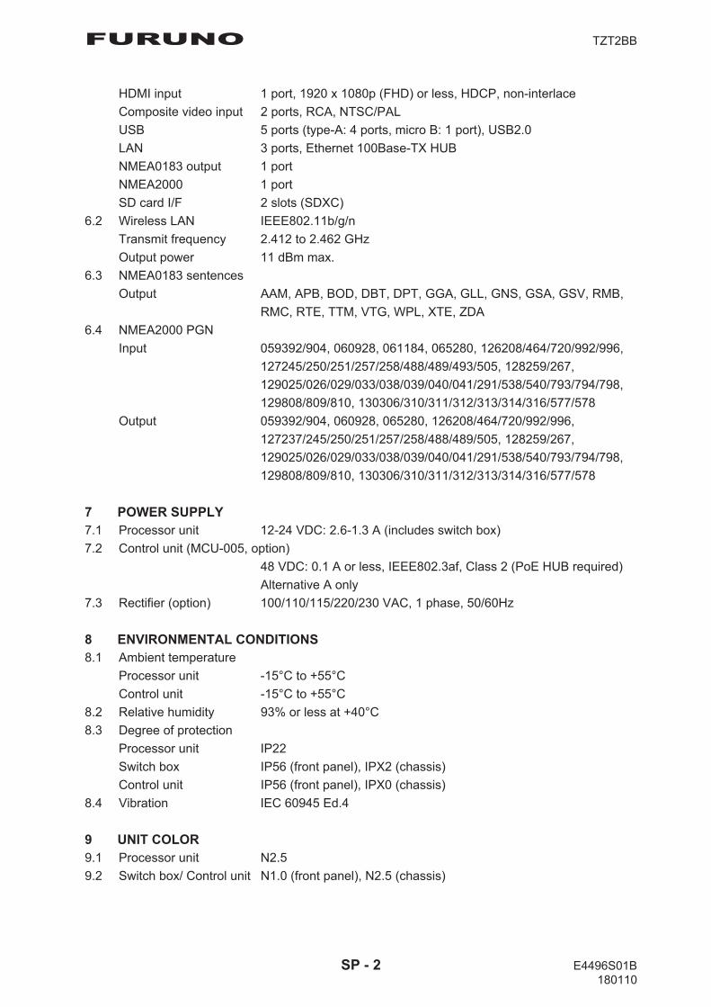
FURUNO TZT2BB
HDMI input 1 port, 1920 x 1080p (FHD) or less, HDCP, non-interlace
Composite video input 2 ports, RCA, NTSC/PAL
USB 5 ports (type-A: 4 ports, micro B: 1 port), USB2.0
LAN 3 ports, Ethernet 100Base-TX HUB
NMEA0183 output 1 port
NMEA2000 1 port
SD card I/F 2 slots (SDXC)
6.2 Wireless LAN IEEE802.11b/g/n
Transmit frequency 2.412 to 2.462 GHz
Output power 11 dBm max.
6.3 NMEA0183 sentences
Output AAM, APB, BOD, DBT, DPT, GGA, GLL, GNS, GSA, GSV, RMB,
RMC, RTE, TTM, VTG, WPL, XTE, ZDA
6.4 NMEA2000 PGN
Input 059392/904, 060928, 061184, 065280, 126208/464/720/992/996,
127245/250/251/257/258/488/489/493/505, 128259/267,
129025/026/029/033/038/039/040/041/291/538/540/793/794/798,
129808/809/810, 130306/310/311/312/313/314/316/577/578
Output 059392/904, 060928, 065280, 126208/464/720/992/996,
127237/245/250/251/257/258/488/489/505, 128259/267,
129025/026/029/033/038/039/040/041/291/538/540/793/794/798,
129808/809/810, 130306/310/311/312/313/314/316/577/578
7 POWER SUPPLY 7.1 Processor unit 12-24 VDC: 2.6-1.3 A (includes switch box)
7.2 Control unit (MCU-005, option)
48 VDC: 0.1 A or less, IEEE802.3af, Class 2 (PoE HUB required)
Alternative A only
7.3 Rectifier (option) 100/110/115/220/230 VAC, 1 phase, 50/60Hz
8 ENVIRONMENTAL CONDITIONS 8.1 Ambient temperature
Processor unit -15°C to +55°C
Control unit -15°C to +55°C
8.2 Relative humidity 93% or less at +40°C
8.3 Degree of protection
Processor unit IP22
Switch box IP56 (front panel), IPX2 (chassis)
Control unit IP56 (front panel), IPX0 (chassis)
8.4 Vibration IEC 60945 Ed.4
9 UNIT COLOR 9.1 Processor unit N2.5
9.2 Switch box/ Control unit N1.0 (front panel), N2.5 (chassis)
SP - 2 E4496S01B 180110

FURUNO TZTL12F/15F
SPECIFICATIONS OF MULTI FUNCTION DISPLAY TZTL12F/15F
1 GENERAL 1.1 Display
TZTL12F 12.1-inch wide TFT color LCD, 1280 x 800 (WXGA)
TZTL15F 15.6-inch full-wide TFT color LCD, 1366 x 768(FWXGA)
1.2 Brightness 1300 cd/m2 typical (TZTL12F), 1000 cd/m2 typical (TZTL15F)
1.3 Display colors 16,770,000 colors (plotter), 64 colors (echo), 16 colors (radar)
2 PLOTTER FUNCTION 2.1 Display mode Course plot, NAV data (includes instrument and engine data)
2.2 Projection Mercator
2.3 Usable area 85° latitude or below
2.4 Memory capacity Track: 30,000 points, Point/MOB: 30,000 point
Route: 200 courses w/500 points each
ARPA: 30 targets, AIS: 100 targets
2.5 GPS receiver
Receiving frequency 1575.42 MHz
Number of channel GPS: 56 ch, SBAS: 1 ch
Accuracy (approx.) GPS: 10 m (2drms, HDOP<4),
WAAS: 3 m (2drms, HDOP<4), MSAS: 7 m (2drms, HDOP<4)
Ship’s speed range 500 m/s max. (all satellites at -130dBm)
Position fixing time Cold start: 100 s typical
Position update interval 1 s
3 RADAR FUNCTION 3.1 Orientation mode Head-up, North-up (heading data required)
4 SOUNDER INDICATION 4.1 Output power 600 Wrms or 1 kWrms
4.2 Frequency 50/200 kHz alternative output
4.3 Display mode ACCU-FISHTM, A-scope, Auto (Fishing/ Cruising),
Temperature graph, Estimation of bottom composition
5 OTHER FUNCTIONS 5.1 Instrument display Instrument data required
5.2 Camera monitor NTSC/PAL data required
5.3 Language Chinese, Danish, English (USA/UK), Finnish, French, German,
Greek, Italian, Japanese, Norwegian, Portuguese, Russian,
Spanish, Swedish
5.4 AIS information AIS receiver required
5.5 DSC display Target data required
5.6 Alarm School of fish*, School of fish for bottom lock*, Anchor Watch, XTE,
Speed, Sea surface temperature*, Depth*, CPA/TCPA*, Hardware
*: option
SP - 3 E4487S01F-M 180424
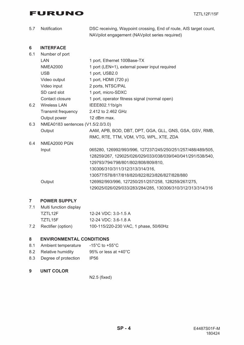
FURUNO TZTL12F/15F
5.7 Notification DSC receiving, Waypoint crossing, End of route, AIS target count,
NAVpilot engagement (NAVpilot series required)
6 INTERFACE 6.1 Number of port
LAN 1 port, Ethernet 100Base-TX
NMEA2000 1 port (LEN=1), external power input required
USB 1 port, USB2.0
Video output 1 port, HDMI (720 p)
Video input 2 ports, NTSC/PAL
SD card slot 1 port, micro-SDXC
Contact closure 1 port, operator fitness signal (normal open)
6.2 Wireless LAN IEEE802.11b/g/n
Transmit frequency 2.412 to 2.462 GHz
Output power 12 dBm max.
6.3 NMEA0183 sentences (V1.5/2.0/3.0)
Output AAM, APB, BOD, DBT, DPT, GGA, GLL, GNS, GSA, GSV, RMB,
RMC, RTE, TTM, VDM, VTG, WPL, XTE, ZDA
6.4 NMEA2000 PGN
Input 065280, 126992/993/996, 127237/245/250/251/257/488/489/505,
128259/267, 129025/026/029/033/038/039/040/041/291/538/540,
129793/794/798/801/802/808/809/810,
130306/310/311/312/313/314/316,
130577/578/817/818/820/822/823/826/827/828/880
Output 126992/993/996, 127250/251/257/258, 128259/267/275,
129025/026/029/033/283/284/285, 130306/310/312/313/314/316
7 POWER SUPPLY 7.1 Multi function display
TZTL12F 12-24 VDC: 3.0-1.5 A
TZTL15F 12-24 VDC: 3.6-1.8 A
7.2 Rectifier (option) 100-115/220-230 VAC, 1 phase, 50/60Hz
8 ENVIRONMENTAL CONDITIONS 8.1 Ambient temperature -15°C to +55°C
8.2 Relative humidity 95% or less at +40°C
8.3 Degree of protection IP56
9 UNIT COLOR N2.5 (fixed)
SP - 4 E4487S01F-M 180424
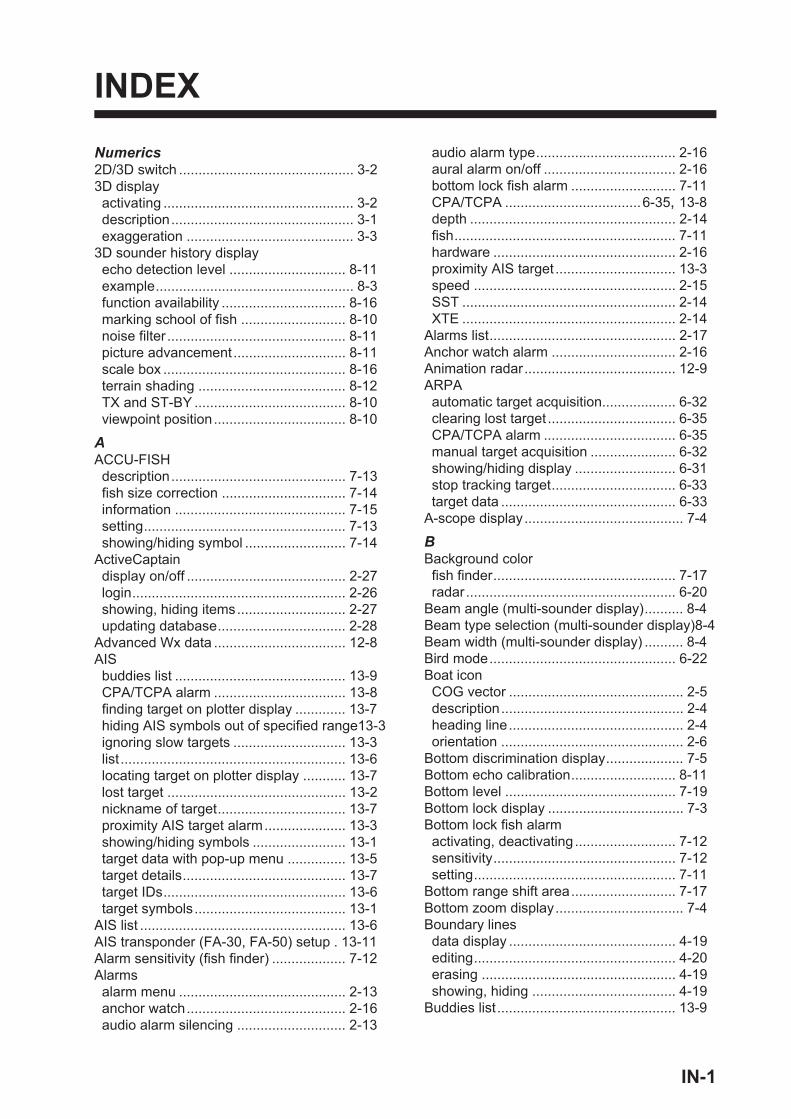
INDEX
Numerics2D/3D switch ............................................. 3-23D displayactivating ................................................. 3-2description............................................... 3-1exaggeration ........................................... 3-3
3D sounder history displayecho detection level .............................. 8-11example................................................... 8-3function availability ................................ 8-16marking school of fish ........................... 8-10noise filter .............................................. 8-11picture advancement............................. 8-11scale box ............................................... 8-16terrain shading ...................................... 8-12TX and ST-BY ....................................... 8-10viewpoint position.................................. 8-10
AACCU-FISHdescription............................................. 7-13fish size correction ................................ 7-14information ............................................ 7-15setting.................................................... 7-13showing/hiding symbol .......................... 7-14
ActiveCaptaindisplay on/off ......................................... 2-27login....................................................... 2-26showing, hiding items............................ 2-27updating database................................. 2-28
Advanced Wx data .................................. 12-8AISbuddies list ............................................ 13-9CPA/TCPA alarm .................................. 13-8finding target on plotter display ............. 13-7hiding AIS symbols out of specified range13-3ignoring slow targets ............................. 13-3list .......................................................... 13-6locating target on plotter display ........... 13-7lost target .............................................. 13-2nickname of target................................. 13-7proximity AIS target alarm..................... 13-3showing/hiding symbols ........................ 13-1target data with pop-up menu ............... 13-5target details.......................................... 13-7target IDs............................................... 13-6target symbols....................................... 13-1
AIS list ..................................................... 13-6AIS transponder (FA-30, FA-50) setup . 13-11Alarm sensitivity (fish finder) ................... 7-12Alarmsalarm menu ........................................... 2-13anchor watch......................................... 2-16audio alarm silencing ............................ 2-13
audio alarm type.................................... 2-16aural alarm on/off .................................. 2-16bottom lock fish alarm ........................... 7-11CPA/TCPA ...................................6-35, 13-8depth ..................................................... 2-14fish......................................................... 7-11hardware ............................................... 2-16proximity AIS target ............................... 13-3speed .................................................... 2-15SST ....................................................... 2-14XTE ....................................................... 2-14
Alarms list................................................ 2-17Anchor watch alarm ................................ 2-16Animation radar....................................... 12-9ARPAautomatic target acquisition................... 6-32clearing lost target ................................. 6-35CPA/TCPA alarm .................................. 6-35manual target acquisition ...................... 6-32showing/hiding display .......................... 6-31stop tracking target................................ 6-33target data ............................................. 6-33
A-scope display......................................... 7-4
BBackground colorfish finder............................................... 7-17radar...................................................... 6-20
Beam angle (multi-sounder display).......... 8-4Beam type selection (multi-sounder display)8-4Beam width (multi-sounder display) .......... 8-4Bird mode................................................ 6-22Boat iconCOG vector ............................................. 2-5description............................................... 2-4heading line............................................. 2-4orientation ............................................... 2-6
Bottom discrimination display.................... 7-5Bottom echo calibration........................... 8-11Bottom level ............................................ 7-19Bottom lock display ................................... 7-3Bottom lock fish alarmactivating, deactivating.......................... 7-12sensitivity............................................... 7-12setting.................................................... 7-11
Bottom range shift area........................... 7-17Bottom zoom display................................. 7-4Boundary linesdata display ........................................... 4-19editing.................................................... 4-20erasing .................................................. 4-19showing, hiding ..................................... 4-19
Buddies list .............................................. 13-9
IN-1
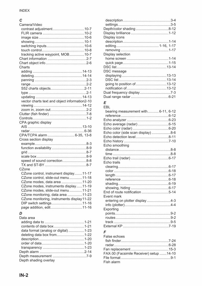
INDEX
CCamera/Videocontrast adjustment................................10-7FLIR camera ..........................................10-2image size ..............................................10-6showing..................................................10-1switching inputs......................................10-6touch control...........................................10-8tracking active waypoint, MOB...............10-7
Chart information .......................................2-7Chart object info .........................................2-6Chartsadding ..................................................14-13deleting.................................................14-14panning ....................................................2-3range........................................................2-2S52 charts objects..................................2-11type ..........................................................2-1updating ...............................................14-13vector charts text and object information2-10viewing .................................................14-12zoom in, zoom out....................................2-2
Clutter (fish finder) .....................................7-8Controls......................................................1-2CPA graphic displayAIS .......................................................13-10radar.......................................................6-36
CPA/TCPA alarm ........................... 6-35, 13-8Cross section displayexample....................................................8-3function availability ...................................8-9grid ...........................................................8-7scale box..................................................8-9speed of sound correction........................8-8TX and ST-BY..........................................8-7
CZoneCZone control, instrument display........11-17CZone control, slide-out menu.............11-18CZone modes, data area .....................11-20CZone modes, instruments display......11-19CZone modes, slide-out menu.............11-21CZone monitoring, data area ...............11-23CZone monitoring, instruments display11-22DIP switch settings...............................11-16page addition, edit................................11-16
DData areaadding data to ........................................1-21contents of data box...............................1-21data format (analog or digital) ................1-23deleting data box from............................1-22description..............................................1-20order of data...........................................1-20transparency ..........................................1-23
Depth alarm .............................................2-14Depth measurement ..................................7-9Depth shading overlay
description................................................3-4settings.....................................................3-5
Depth/color shading .................................8-12Display brilliance ......................................1-12Display iconsdescription..............................................1-14editing........................................... 1-16, 1-17removing ................................................1-17
Display selectionhome screen ..........................................1-14quick page..............................................1-15
DSC list ..................................................13-14DSC messagedisplaying .............................................13-13DSC list ................................................13-14going to position of ...............................13-12notification of ........................................13-12
Dual frequency display...............................7-3Dual range radar ......................................6-21
EEBLbearing measurement with........... 6-11, 6-12reference ................................................6-12
Echo analyzer ..........................................6-23Echo average (radar) ...............................6-15Echo color (radar) ....................................6-20Echo color (side scan display) ...................8-6Echo detection level .................................8-11Echo history .............................................7-10Echo smoothingdistance....................................................8-8time ..........................................................8-8
Echo trail (radar) ......................................6-17Echo trailsclearing...................................................6-17color .......................................................6-18length .....................................................6-17reference ................................................6-18shading...................................................6-19showing, hiding ......................................6-17
End of route notification ...........................5-14Event markentering on plotter display ........................4-3info (plotter) ..............................................4-4
Exportingpoints........................................................9-2routes .......................................................9-2track .........................................................9-5
External KP ..............................................7-19
FFalse echoesfish finder................................................7-24radar.......................................................6-28
Fan replacement ......................................15-3FAX-30 (Facsimile Receiver) setup .......14-10File format ..................................................9-1Fish alarm
IN-2

INDEX
activating, deactivating.......................... 7-12activating/deactivating........................... 7-12setting.................................................... 7-11
Fish finder automatic operation................. 7-6Fish finder manual operation..................... 7-6FLIR cameracontrolling.............................................. 10-7setting.................................................... 10-5
Fuel management ................................. 11-14Function availability3D sounder history display .................... 8-16cross section display ............................... 8-9multi-sounder display .............................. 8-5side scan display..................................... 8-6
Function gesture ..................................... 1-33Fuse replacement ................................... 15-2FUSION-Link........................................... 10-9
GGainfish finder................................................. 7-7offset (fish finder) .................................. 7-19radar........................................................ 6-2
Gain offset (fish finder)............................ 7-19General menu ......................................... 14-1Grid (cross section display)....................... 8-7Guard zoneactivating, deactivating.......................... 6-16setting.................................................... 6-15showing/hiding ...................................... 6-16
HHardware alarm....................................... 2-16Heading lineboat icon.................................................. 2-4radar...................................................... 6-14
Heaving correction .................................. 7-17High resolution (fish finder) ..................... 7-17Home icon ......................................1-13, 1-30Home screendisplay selection.................................... 1-14editing display icons .............................. 1-16introduction............................................ 1-13
Hue.......................................................... 1-12
IImportingboundary lines.. 9-2, 9-3, 9-4, 9-5, 9-6, 12-6points....................................................... 9-3routes ...................................................... 9-3track ........................................................ 9-4
Initial setup menu .................................... 14-5Instrument displayadding indication ................................. 11-12changing position of data .................... 11-10editing indication ................................. 11-10full screen.............................................. 11-2showing ................................................. 11-1split screen ............................................ 11-5steering ................................................. 11-2
switching between displays................... 11-8theme .................................................. 11-14
Interferencefish finder................................................. 7-9radar...................................................... 6-14
LLanguage ................................................ 1-34Layers menu ........................................... 1-19Low fuel alarm......................................... 2-16
MMagnetron replacement .......................... 15-2Maintenance............................................ 15-1Menu tree ................................................AP-1MOB (Man OverBoard) ........................... 1-35MOB mark ............................................... 1-35Multiple echoes (radar) ........................... 6-28Multi-sounder displaybeam angle ............................................. 8-4beam type selection ................................ 8-4beam width.............................................. 8-4example................................................... 8-1function availability .................................. 8-5scale box ................................................. 8-4TX and ST-BY ......................................... 8-4
My TimeZerobacking up settings to cloud.................... 9-8creating ................................................. 1-39logging in to account ............................. 1-39restoring settings from cloud ................... 9-8
NNavCenter weatherdata availability.................................... 12-10data description................................... 12-10displaying .............................................. 12-5downloading .......................................... 12-4file loading ............................................. 12-6setting.................................................... 12-2
NAVpilotenabling use.......................................... 2-25NAVpilot control box.............................. 2-25steering to a point.................................. 4-16
Noise filter ............................................... 8-11
OOff center ................................................ 6-13Orientation modeplotter ...................................................... 2-3radar........................................................ 6-5
Orientation mode switch............................ 2-3plotter ...................................................... 2-3radar........................................................ 6-5
Overlaysdepth shading.......................................... 3-4radar........................................................ 3-6tidal current ........................................... 3-10tide info.................................................... 3-8
Own ship icon (radar) .............................. 6-19
IN-3
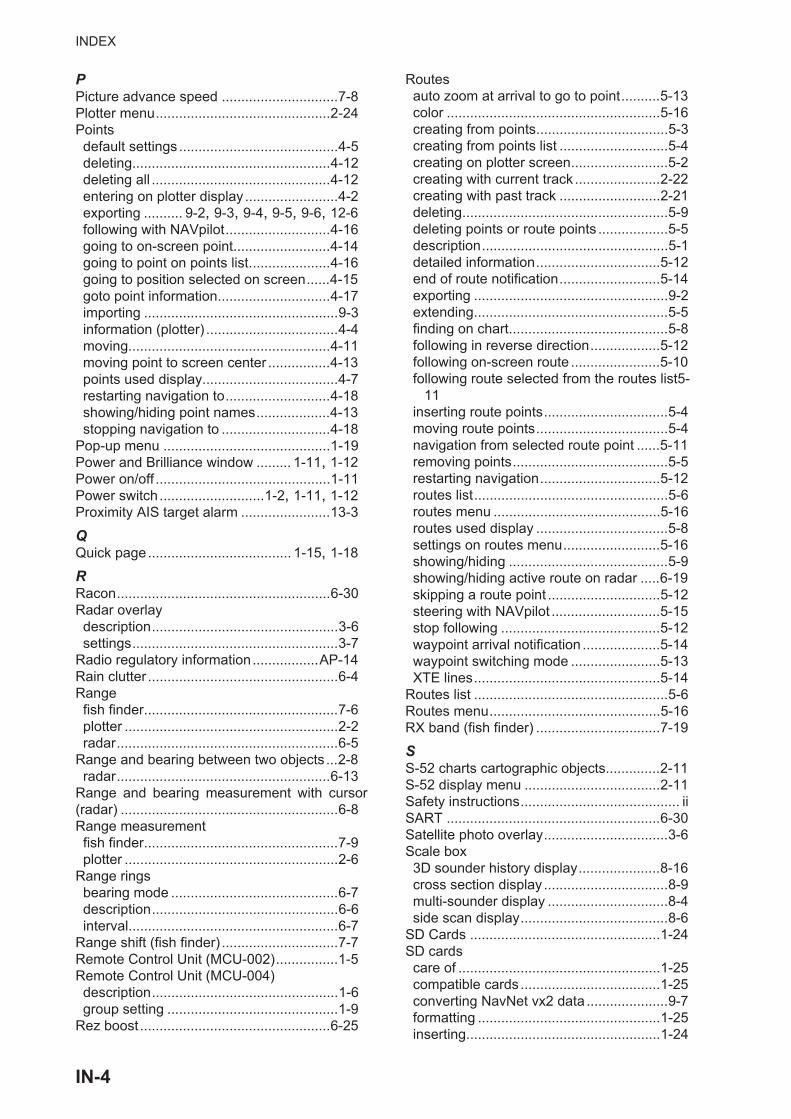
INDEX
PPicture advance speed ..............................7-8Plotter menu.............................................2-24Pointsdefault settings .........................................4-5deleting...................................................4-12deleting all ..............................................4-12entering on plotter display ........................4-2exporting .......... 9-2, 9-3, 9-4, 9-5, 9-6, 12-6following with NAVpilot...........................4-16going to on-screen point.........................4-14going to point on points list.....................4-16going to position selected on screen......4-15goto point information.............................4-17importing ..................................................9-3information (plotter) ..................................4-4moving....................................................4-11moving point to screen center ................4-13points used display...................................4-7restarting navigation to...........................4-18showing/hiding point names...................4-13stopping navigation to ............................4-18
Pop-up menu ...........................................1-19Power and Brilliance window ......... 1-11, 1-12Power on/off .............................................1-11Power switch...........................1-2, 1-11, 1-12Proximity AIS target alarm .......................13-3
QQuick page..................................... 1-15, 1-18
RRacon.......................................................6-30Radar overlaydescription................................................3-6settings.....................................................3-7
Radio regulatory information.................AP-14Rain clutter .................................................6-4Rangefish finder..................................................7-6plotter .......................................................2-2radar.........................................................6-5
Range and bearing between two objects ...2-8radar.......................................................6-13
Range and bearing measurement with cursor(radar) ........................................................6-8Range measurementfish finder..................................................7-9plotter .......................................................2-6
Range ringsbearing mode ...........................................6-7description................................................6-6interval......................................................6-7
Range shift (fish finder) ..............................7-7Remote Control Unit (MCU-002)................1-5Remote Control Unit (MCU-004)description................................................1-6group setting ............................................1-9
Rez boost .................................................6-25
Routesauto zoom at arrival to go to point..........5-13color .......................................................5-16creating from points..................................5-3creating from points list ............................5-4creating on plotter screen.........................5-2creating with current track ......................2-22creating with past track ..........................2-21deleting.....................................................5-9deleting points or route points ..................5-5description................................................5-1detailed information................................5-12end of route notification..........................5-14exporting ..................................................9-2extending..................................................5-5finding on chart.........................................5-8following in reverse direction..................5-12following on-screen route .......................5-10following route selected from the routes list5-
11inserting route points................................5-4moving route points..................................5-4navigation from selected route point ......5-11removing points........................................5-5restarting navigation...............................5-12routes list..................................................5-6routes menu ...........................................5-16routes used display ..................................5-8settings on routes menu.........................5-16showing/hiding .........................................5-9showing/hiding active route on radar .....6-19skipping a route point .............................5-12steering with NAVpilot ............................5-15stop following .........................................5-12waypoint arrival notification ....................5-14waypoint switching mode .......................5-13XTE lines................................................5-14
Routes list ..................................................5-6Routes menu............................................5-16RX band (fish finder) ................................7-19
SS-52 charts cartographic objects..............2-11S-52 display menu ...................................2-11Safety instructions......................................... iiSART .......................................................6-30Satellite photo overlay................................3-6Scale box3D sounder history display.....................8-16cross section display ................................8-9multi-sounder display ...............................8-4side scan display......................................8-6
SD Cards .................................................1-24SD cardscare of ....................................................1-25compatible cards ....................................1-25converting NavNet vx2 data .....................9-7formatting ...............................................1-25inserting..................................................1-24
IN-4
INDEX
loading equipment settings ..................... 9-6removing ............................................... 1-25saving equipment settings....................... 9-5
Sea clutter ................................................. 6-4Sector blanking ....................................... 6-29Sensor icons ........................................... 1-13Settings menu ......................................... 1-30Side scan displayecho color................................................ 8-6example................................................... 8-2function availability .................................. 8-6scale box ................................................. 8-6TX and ST-BY ......................................... 8-6
Sidelobe echoes...................................... 6-29Single frequency display ........................... 7-2Sirius radiocontrols................................................ 12-15diagnostics .......................................... 12-16enabling............................................... 12-14
Sirius weatheradvanced Wx data ................................ 12-8animation radar ..................................... 12-9data availability.................................... 12-10data description................................... 12-10diagnostics .......................................... 12-13icons overview....................................... 12-9setup ..................................................... 12-6Wx radar................................................ 12-8
Slide-out menu ........................................ 1-18Soft cover .................................................. 1-3Software update .................................... 14-11Sounder menu......................................... 7-17Speed alarm............................................ 2-15SST alarm ............................................... 2-14Stand-by (radar) ........................................ 6-1STC (fish finder) ...................................... 7-19System configuration................................... xv
TTemperature graph ................................. 7-16Terrain shading ....................................... 8-12Tidal current graph .................................. 3-11Tidal current overlaydisplaying .............................................. 3-10icon size ................................................ 3-10information display ................................ 3-10
Tide graph ................................................. 3-9Tide info overlaydisplaying ................................................ 3-8tide graph ................................................ 3-9tide icon size ........................................... 3-8tide information display ........................... 3-8
Touchscreen operations............................ 1-3Trackcolor .............................................2-18, 2-21creating route with current track............ 2-22creating route with past track ................ 2-21deleting.................................................. 2-23deleting all ............................................. 2-23
description............................................. 2-17exporting ................................................. 9-5importing ................................................. 9-4interval................................................... 2-18points used display................................ 2-23recording ............................................... 2-17showing/hiding ...................................... 2-17thickness ............................................... 2-21
Track back............................................... 2-22Transducer draft ...................................... 7-18Transducer setup .................................... 7-19Transmit (radar) ........................................ 6-1Transmit rate (fish finder) ........................ 7-18Troubleshootingfish finder............................................... 15-4general .................................................. 15-3plotter .................................................... 15-4radar...................................................... 15-4
Tuning ....................................................... 6-1TVG......................................................... 7-10TX and ST-BY3D sounder history display.................... 8-10cross section display ............................... 8-7multi-sounder display .............................. 8-4side scan display..................................... 8-6
TX pulse (fish finder) ............................... 7-19TX/Standby switch .................................... 6-1
UUnits menu .............................................. 14-3
VVector charts text and objects................. 2-10Viewpoint position (3D sounder history display)8-10Virtual image ........................................... 6-28VRMrange measurement with................ 6-9, 6-10
WWatchman ............................................... 6-16Waypoint arrival notification .................... 5-14Waypoint switching mode ....................... 5-13Weather displayadvanced Wx data ................................ 12-8animation radar ..................................... 12-9introduction............................................ 12-1NavCenter data display......................... 12-5NavCenter data download..................... 12-4NavCenter weather file.......................... 12-6NavCenter weather setup...................... 12-2selecting ................................................ 12-2Sirius ..................................................... 12-6Wx radar................................................ 12-8
Wireless LANconnect to existing ................................ 1-36creating network.................................... 1-38
Wx radar weather.................................... 12-8
IN-5

INDEX
XXTE alarm ................................................2-14XTE lines..................................................5-14
YYamaha engine displayalarm list...............................................11-28data box ...............................................11-26example displays..................................11-25showing................................................11-24switching displays ................................11-26troll mode .............................................11-27trouble codes........................................11-28
ZZero line ...................................................7-20Zoom display..............................................8-7Zoom display selection (fish finder)............7-3Zoom reference lines ...............................7-17
IN-6
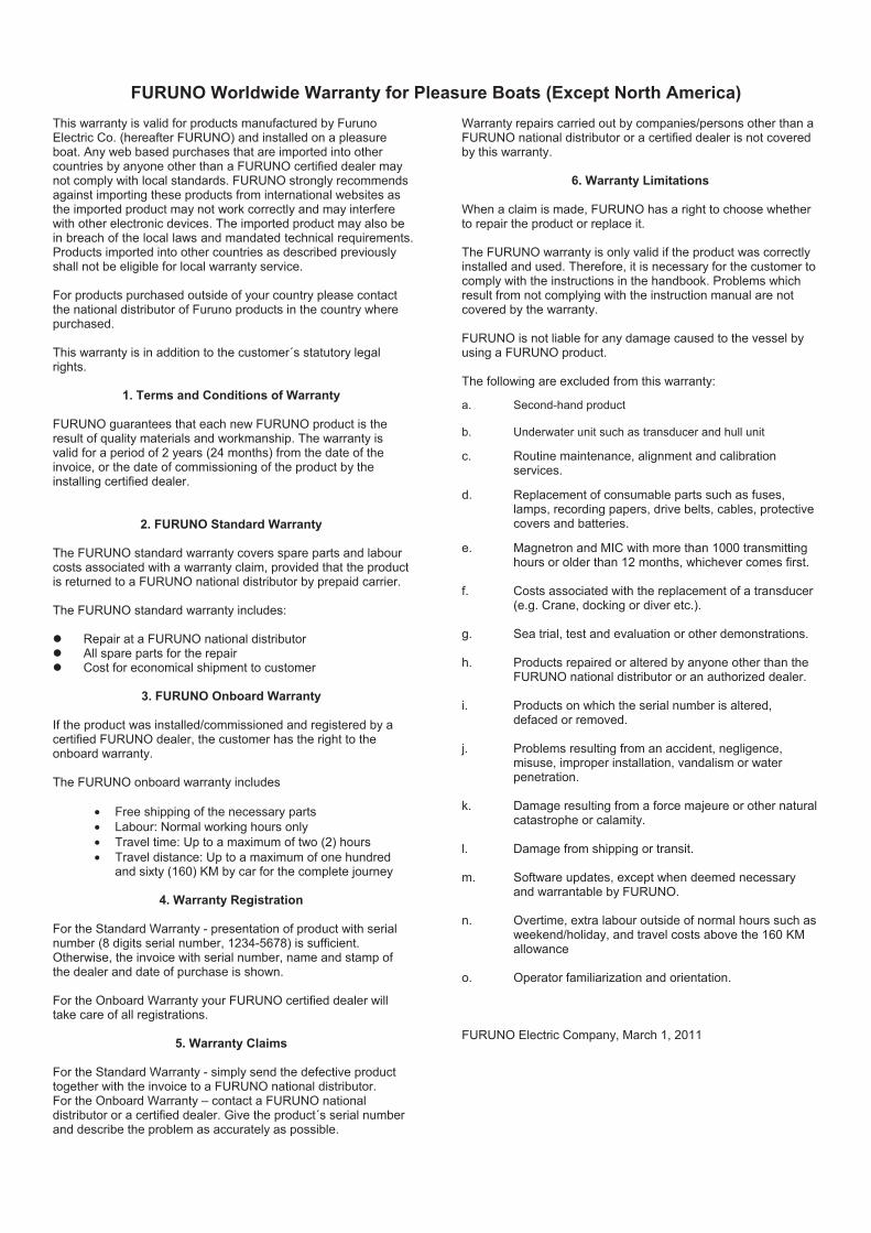
FURUNO Worldwide Warranty for Pleasure Boats (Except North America)
This warranty is valid for products manufactured by Furuno Electric Co. (hereafter FURUNO) and installed on a pleasure boat. Any web based purchases that are imported into other countries by anyone other than a FURUNO certified dealer may not comply with local standards. FURUNO strongly recommends against importing these products from international websites as the imported product may not work correctly and may interfere with other electronic devices. The imported product may also be in breach of the local laws and mandated technical requirements. Products imported into other countries as described previously shall not be eligible for local warranty service. For products purchased outside of your country please contact the national distributor of Furuno products in the country where purchased. This warranty is in addition to the customer´s statutory legal rights.
1. Terms and Conditions of Warranty
FURUNO guarantees that each new FURUNO product is the result of quality materials and workmanship. The warranty is valid for a period of 2 years (24 months) from the date of the invoice, or the date of commissioning of the product by the installing certified dealer.
2. FURUNO Standard Warranty The FURUNO standard warranty covers spare parts and labour costs associated with a warranty claim, provided that the product is returned to a FURUNO national distributor by prepaid carrier. The FURUNO standard warranty includes:
Repair at a FURUNO national distributor All spare parts for the repair Cost for economical shipment to customer
3. FURUNO Onboard Warranty
If the product was installed/commissioned and registered by a certified FURUNO dealer, the customer has the right to the onboard warranty. The FURUNO onboard warranty includes
• Free shipping of the necessary parts • Labour: Normal working hours only • Travel time: Up to a maximum of two (2) hours • Travel distance: Up to a maximum of one hundred
and sixty (160) KM by car for the complete journey
4. Warranty Registration For the Standard Warranty - presentation of product with serial number (8 digits serial number, 1234-5678) is sufficient. Otherwise, the invoice with serial number, name and stamp of the dealer and date of purchase is shown. For the Onboard Warranty your FURUNO certified dealer will take care of all registrations.
5. Warranty Claims For the Standard Warranty - simply send the defective product together with the invoice to a FURUNO national distributor. For the Onboard Warranty – contact a FURUNO national distributor or a certified dealer. Give the product´s serial number and describe the problem as accurately as possible.
Warranty repairs carried out by companies/persons other than a FURUNO national distributor or a certified dealer is not covered by this warranty.
6. Warranty Limitations
When a claim is made, FURUNO has a right to choose whether to repair the product or replace it. The FURUNO warranty is only valid if the product was correctly installed and used. Therefore, it is necessary for the customer to comply with the instructions in the handbook. Problems which result from not complying with the instruction manual are not covered by the warranty. FURUNO is not liable for any damage caused to the vessel by using a FURUNO product. The following are excluded from this warranty: a. Second-hand product b. Underwater unit such as transducer and hull unit c. Routine maintenance, alignment and calibration
services. d. Replacement of consumable parts such as fuses,
lamps, recording papers, drive belts, cables, protective covers and batteries.
e. Magnetron and MIC with more than 1000 transmitting
hours or older than 12 months, whichever comes first. f. Costs associated with the replacement of a transducer
(e.g. Crane, docking or diver etc.). g. Sea trial, test and evaluation or other demonstrations. h. Products repaired or altered by anyone other than the
FURUNO national distributor or an authorized dealer. i. Products on which the serial number is altered,
defaced or removed. j. Problems resulting from an accident, negligence,
misuse, improper installation, vandalism or water penetration.
k. Damage resulting from a force majeure or other natural
catastrophe or calamity. l. Damage from shipping or transit. m. Software updates, except when deemed necessary
and warrantable by FURUNO. n. Overtime, extra labour outside of normal hours such as
weekend/holiday, and travel costs above the 160 KM allowance
o. Operator familiarization and orientation. FURUNO Electric Company, March 1, 2011

FURUNO Warranty for North America
FURUNO U.S.A., Limited Warranty provides a twenty-four (24) months LABOR and twenty-four (24) months PARTS warranty on products from the date of installation or purchase by the original owner. Products or components that are represented as being waterproof are guaranteed to be waterproof only for, and within the limits, of the warranty period stated above. The warranty start date may not exceed eighteen (18) months from the original date of purchase by dealer from Furuno USA and applies to new equipment installed and operated in accordance with Furuno USA’s published instructions. Magnetrons and Microwave devices will be warranted for a period of 12 months from date of original equipment installation. Furuno U.S.A., Inc. warrants each new product to be of sound material and workmanship and through its authorized dealer will exchange any parts proven to be defective in material or workmanship under normal use at no charge for a period of 24 months from the date of installation or purchase. Furuno U.S.A., Inc., through an authorized Furuno dealer will provide labor at no cost to replace defective parts, exclusive of routine maintenance or normal adjustments, for a period of 24 months from installation date provided the work is done by Furuno U.S.A., Inc. or an AUTHORIZED Furuno dealer during normal shop hours and within a radius of 50 miles of the shop location. A suitable proof of purchase showing date of purchase, or installation certification must be available to Furuno U.S.A., Inc., or its authorized dealer at the time of request for warranty service. This warranty is valid for installation of products manufactured by Furuno Electric Co. (hereafter FURUNO). Any purchases from brick and mortar or web-based resellers that are imported into other countries by anyone other than a FURUNO certified dealer, agent or subsidiary may not comply with local standards. FURUNO strongly recommends against importing these products from international websites or other resellers, as the imported product may not work correctly and may interfere with other electronic devices. The imported product may also be in breach of the local laws and mandated technical requirements. Products imported into other countries, as described previously, shall not be eligible for local warranty service. For products purchased outside of your country please contact the national distributor of Furuno products in the country where purchased.
WARRANTY REGISTRATION AND INFORMATION To register your product for warranty, as well as see the complete warranty guidelines and limitations, please visit www.furunousa.com and click on “Support”. In order to expedite repairs, warranty service on Furuno equipment is provided through its authorized dealer network. If this is not possible or practical, please contact Furuno U.S.A., Inc. to arrange warranty service.
FURUNO U.S.A., INC. Attention: Service Coordinator 4400 N.W. Pacific Rim Boulevard
Camas, WA 98607-9408 Telephone: (360) 834-9300
FAX: (360) 834-9400 Furuno U.S.A., Inc. is proud to supply you with the highest quality in Marine Electronics. We know you had several choices when making your selection of equipment, and from everyone at Furuno we thank you. Furuno takes great pride in customer service.

Declaration of Conformity
Bulgarian(BG)
Spanish(ES)
Czech(CS)
Danish(DA)
German(DE)
Estonian(ET)
Greek(EL)
English(EN)
French(FR)
Croatian(HR)
Italian(IT)
Latvian(LV)
Pilns ES atbilst bas deklar cijas teksts ir pieejams š d interneta vietn :
Furuno Electric Co., Ltd., 2014/53/ .
:
Hereby, Furuno Electric Co., Ltd. declares that the above-mentioned radioequipment type is in compliance with Directive 2014/53/EU.The full text of the EU declaration of conformity is available at the followinginternet address:
Le soussigné, Furuno Electric Co., Ltd., déclare que l'équipement radioélectriquedu type mentionné ci-dessusest conforme à la directive 2014/53/UE.Le texte complet de la déclaration UE de conformité est disponible à l'adresseinternet suivante:
Furuno Electric Co., Ltd. ovime izjavljuje da je gore re eno radijska oprema tipau skladu s Direktivom 2014/53/EU.Cjeloviti tekst EU izjave o sukladnosti dostupan je na sljede oj internetskojadresi:
Il fabbricante, Furuno Electric Co., Ltd., dichiara che il tipo di apparecchiaturaradio menzionato sopra è conforme alla direttiva 2014/53/UE.Il testo completo della dichiarazione di conformità UE è disponibile al seguenteindirizzo Internet:
Ar šo Furuno Electric Co., Ltd. deklar , ka augst k min ts radioiek rta atbilstDirekt vai 2014/53/ES.
[TZTL12F/TZTL15F/TZT2BB]
ELi vastavusdeklaratsiooni täielik tekst on kättesaadav järgmiselinternetiaadressil:
Furuno Electric Co., Ltd. , 2014/53/ .
:
Por la presente, Furuno Electric Co., Ltd. declara que el tipo de equiporadioeléctrico arriba mencionado es conforme con la Directiva 2014/53/UE.El texto completo de la declaración UE de conformidad está disponible en ladirección Internet siguiente:
Tímto Furuno Electric Co., Ltd. prohlašuje, že výše zmín né typ rádiovéhoza ízení je v souladu se sm rnicí 2014/53/EU.Úplné zn ní EU prohlášení o shod je k dispozici na této internetové adrese:
Hermed erklærer Furuno Electric Co., Ltd., at ovennævnte radioudstyr er ioverensstemmelse med direktiv 2014/53/EU.EU-overensstemmelseserklæringens fulde tekst kan findes på følgendeinternetadresse:
Hiermit erklärt die Furuno Electric Co., Ltd., dass der oben genannteFunkanlagentyp der Richtlinie 2014/53/EU entspricht.Der vollständige Text der EU-Konformitätserklärung ist unter der folgendenInternetadresse verfügbar:
Käesolevaga deklareerib Furuno Electric Co., Ltd., et ülalmainitud raadioseadmetüüp vastab direktiivi 2014/53/EL nõuetele.
Lithuanian(LT)
Hungarian(HU)
Maltese(MT)
Dutch(NL)
Polish(PL)
Portuguese(PT)
Romanian(RO)
Slovak(SK)
Slovenian(SL)
Finnish(FI)
Swedish(SV)
Online Resourcehttp://www.furuno.com/en/support/red_doc
Furuno Electric Co., Ltd. vakuuttaa, että yllä mainittu radiolaitetyyppi ondirektiivin 2014/53/EU mukainen.EU-vaatimustenmukaisuusvakuutuksen täysimittainen teksti on saatavillaseuraavassa internetosoitteessa:
Härmed försäkrar Furuno Electric Co., Ltd. att ovan nämnda typ avradioutrustning överensstämmer med direktiv 2014/53/EU.Den fullständiga texten till EU-försäkran om överensstämmelse finns påföljande webbadress:
Prin prezenta, Furuno Electric Co., Ltd. declar c men ionat mai sus tipul deechipamente radio este în conformitate cu Directiva 2014/53/UE.Textul integral al declara iei UE de conformitate este disponibil la urm toareaadres internet:
Furuno Electric Co., Ltd. týmto vyhlasuje, že vyššie spomínané rádiovézariadenie typu je v súlade so smernicou 2014/53/EÚ.Úplné EÚ vyhlásenie o zhode je k dispozícii na tejto internetovej adrese:
Furuno Electric Co., Ltd. potrjuje, da je zgoraj omenjeno tip radijske opremeskladen z Direktivo 2014/53/EU.Celotno besedilo izjave EU o skladnosti je na voljo na naslednjem spletnemnaslovu:
O texto integral da declaração de conformidade está disponível no seguinteendereço de Internet:
Aš, Furuno Electric Co., Ltd., patvirtinu, kad pirmiau min ta radijo rengini tipasatitinka Direktyv 2014/53/ES.Visas ES atitikties deklaracijos tekstas prieinamas šiuo interneto adresu:
Furuno Electric Co., Ltd. igazolja, hogy fent említett típusú rádióberendezésmegfelel a 2014/53/EU irányelvnek.Az EU-megfelel ségi nyilatkozat teljes szövege elérhet a következ internetescímen:
B'dan, Furuno Electric Co., Ltd., niddikjara li msemmija hawn fuq-tip ta' tag mirtar-radju huwa konformi mad-Direttiva 2014/53/UE.It-test kollu tad-dikjarazzjoni ta' konformità tal-UE huwa disponibbli f'dan l-indirizztal-Internet li ej:
Hierbij verklaar ik, Furuno Electric Co., Ltd., dat het hierboven genoemde typeradioapparatuur conform is met Richtlijn 2014/53/EU.De volledige tekst van de EU-conformiteitsverklaring kan worden geraadpleegdop het volgende internetadres:
Furuno Electric Co., Ltd. niniejszym o wiadcza, e wy ej wymieniony typurz dzenia radiowego jest zgodny z dyrektyw 2014/53/UE.Pe ny tekst deklaracji zgodno ci UE jest dost pny pod nast puj cym adreseminternetowym:
O(a) abaixo assinado(a) Furuno Electric Co., Ltd. declara que o mencionadoacima tipo de equipamento de rádio está em conformidade com a Diretiva2014/53/UE.