M0215 - OPERATOR & PARTS MANUAL
402
1/08 This manual is applicable to: Model: 3800 And 3800 SDS Forward Folding Planters Serial Number: 755215 And On Record the model number and serial number of your planter along with date purchased: Model Number Serial Number Date Purchased Monitor Serial Number Measured Pulses Per Mile/Km (Radar Distance Sensor) Measured Pulses Per Mile/Km (Magnetic Distance Sensor) SERIAL NUMBER The serial number plate is located on the center portion of the planter frame to be readily available. It is suggested that your serial number and purchase date also be recorded above. The serial number provides important information about your planter and may be required to obtain the correct replacement part. Always provide the model number and serial number to your KINZE ® Dealer when ordering parts or anytime correspondence is made with KINZE Manufacturing, Inc. D01050701 KINZE ® , the KINZE ® logo, Interplant ® and EdgeVac ® are registered trademarks of KINZE Manufacturing, Inc. MODEL 3800 AND 3800 SDS FORWARD FOLDING PLANTER OPERATOR & PARTS MANUAL PRELIMINARY M0215 Rev. 4/08 (EdgeVac ® Seed Metering) 3800 Planter With Conventional Seed Hoppers Shown
-
Upload
khangminh22 -
Category
Documents
-
view
0 -
download
0
Transcript of M0215 - OPERATOR & PARTS MANUAL

1/08
This manual is applicable to: Model: 3800 And 3800 SDS Forward Folding PlantersSerial Number: 755215 And On
Record the model number and serial number of your planter along with date purchased:
Model Number
Serial Number
Date Purchased
Monitor Serial Number
Measured Pulses Per Mile/Km (Radar Distance Sensor)
Measured Pulses Per Mile/Km (Magnetic Distance Sensor)
SERIAL NUMBER
The serial number plate is located on the center portionof the planter frame to be readily available. It is suggestedthat your serial number and purchase date also berecorded above.
The serial number provides important information aboutyour planter and may be required to obtain the correctreplacement part. Always provide the model number andserial number to your KINZE® Dealer when orderingparts or anytime correspondence is made with KINZEManufacturing, Inc.
D01050701
KINZE®, the KINZE® logo, Interplant® and EdgeVac® are registered trademarks of KINZE Manufacturing, Inc.
MODEL 3800 AND 3800 SDSFORWARD FOLDING PLANTER
OPERATOR & PARTS MANUAL
PRELIMINARY M0215 Rev. 4/08
(EdgeVac® Seed Metering)
3800 Planter With Conventional Seed HoppersShown


PREDELIVERY/DELIVERY CHECKLIST
TO THE DEALER
Predelivery service includes assembly, lubrication, adjustment and test. This service helps to ensure that the planterwill be delivered to the customer ready for field use.
PREDELIVERY CHECKLIST
After the planter has been completely assembled, use the following checklist and inspect the planter. Check off eachitem as it is found satisfactory or after proper adjustment is made.
Recheck to be sure row units are properly spaced and optional attachments are correctly assembled.
The closing wheels have been installed. See “Row Unit Assembly And Installation Instructions”.
Row markers are set at the correct length (If Applicable). See “Row Marker Length Adjustment” in the MachineOperation section of the Operator & Parts Manual.
Be sure all grease fittings are in place and lubricated.
Check planter and make sure all working parts are moving freely, bolts are tight and cotter pins are spread.
Check all drive chains for proper tension and alignment.
Check for oil leaks and proper hydraulic operation.
Check to be sure hydraulic hoses are routed correctly to prevent damage.
Inflate tires to specified PSI air pressure. Tighten wheel lug bolts and lug nuts to specified torques.
Check to be sure all safety decals and SMV sign are correctly located and legible. Replace if damaged.
Check to be sure safety/warning lights are installed correctly and working properly.
Check to be sure the reflective decals are correctly located and visible when the planter is in transport position.
Paint all parts scratched in shipment or assembly.
Be sure all safety lockup devices are on the planter and correctly located.
Vacuum fan PTO drive pump is attached correctly to the tractor. Reservoir is filled to capacity and system isinspected for leaks.
PTO shaft meets specifications for tractor being used with planer.
This planter has been thoroughly checked and to the best of my knowledge is ready for delivery to thecustomer.
(Signature Of Set-Up Person/Dealer Name/Date)
1/08
OWNER REGISTER
Name Delivery Date
Street Address Model No. Serial No.
City, State/Province Dealer Name
ZIP/Postal Code Dealer No.

DELIVERY CHECKLIST
At the time the planter is delivered, the following checklist is to be used as a reminder of very important information whichshould be conveyed to the customer. Check off each item as it is fully explained to the customer.
Check for proper operation of vacuum fan, PTO driven pump and PTO asembly with tractor to be used with planter.
Advise the customer that the life expectancy of this or any other machine is dependent on regular lubrication asdirected in the Operator & Parts Manual.
Tell the customer about all applicable safety precautions.
Along with the customer, check to be sure the reflective decals and SMV sign are clearly visible with the planter intransport position and attached to the tractor. Check to be sure safety/warning lights are in working condition. Tellthe customer to check federal, state/provincial and local regulations before towing or transporting on a road or highway.
Give the Operator & Parts Manual to the customer and explain all operating adjustments.
Read warranty to customer.
Complete Warranty And Delivery Report form.
To the best of my knowledge this machine has been delivered ready for field use and customer has been fullyinformed as to proper care and operation.
(Signature Of Delivery Person/Dealer Name/Date)
AFTER DELIVERY CHECKLIST
The following is a list of items we suggest to check during the first season of use of the equipment.
Check with the customer as to the performance of the planter.
Check with the customer as to the performance of the EdgeVac® Seed Metering System.
Review with the customer the importance of proper maintenance and adherence with all safety precautions.
Check for parts that may need to be adjusted or replaced.
Check to be sure all safety warning signs (decals), SMV sign and reflective decals are correctly located and thatdecals are legible. Replace if damaged or missing.
Check to be sure safety/warning lights are working properly.
(Signature Of Follow-Up Person/Dealer Name/Date)
RETURN THIS COMPLETED FORM TO KINZE® IMMEDIATELY along with Warranty And Delivery Report.Retain photocopy of this form at dealership for After Delivery Check.
Tear Along Perforation
1/08

TO THE OWNER .............................................................................................. 1-1
WARRANTY ..................................................................................................... 1-2
INTRODUCTION .............................................................................................. 2-1
SPECIFICATIONS............................................................................................ 3-1
SAFETY PRECAUTIONS................................................................................. 4-1
SAFETY WARNING SIGNS ............................................................................. 5-1
MACHINE OPERATIONAnalog Vacuum Gauges .................................................................... 6-14Checking Granular Chemical Application Rate................................... 6-64Checking Seed Population ................................................................. 6-63Contact Wheel Idler Adjustment ........................................................... 6-9Contact Wheel Spring Adjustment ....................................................... 6-9Contact Wheel Drive Sprockets ......................................................... 6-10Depth Gauge Wheel Attachment For Notched Single Disc Fertilizer Opener ............................................................................................ 6-57Digital Vacuum Gauge Operation ....................................................... 6-14Electronic Seed Monitor System
KPM III .................................................................................. 6-25Planter Monitor Module (PMM) ............................................. 6-55
Field AdjustmentsSeed Rate Transmission Adjustment .................................... 6-10
Field Operation .................................................................................. 6-18Field Test ........................................................................................... 6-62Field To Transport Sequence ............................................................. 6-19Hydraulic/Electric Operation ............................................................... 6-13Initial Preparation Of The Planter ......................................................... 6-2Leveling The Planter ............................................................................ 6-8Liquid Fertilizer Attachment ................................................................ 6-58Liquid Fertilizer Rate Charts ............................................................... 6-60Metric Conversion Table .................................................................... 6-62Notched Single Disc Fertilizer Opener ............................................... 6-56Planting Speed ................................................................................... 6-62Point Row Clutches ............................................................................ 6-24Rear Trailer Hitch ............................................................................... 6-61Row Marker Length Adjustment ......................................................... 6-23Row Marker Operation ....................................................................... 6-22Row Marker Speed Adjustment ......................................................... 6-23Shear Protection ................................................................................ 6-12Tire Pressure ....................................................................................... 6-9Tractor Preparation And Hookup.......................................................... 6-3Tractor Requirements .......................................................................... 6-2Transport Lockup, 24 Row 30" Only .................................................... 6-1Transport To Field Sequence ............................................................. 6-15Transporting The Planter ................................................................... 6-62U-Joint Shaft Assemblies ................................................................... 6-11Vacuum Fan Motor Valve Block ......................................................... 6-14Wing Latch Hook Safety Pin(s) ............................................................ 6-1Wrap Spring Wrench Operation ......................................................... 6-11
TABLE OF CONTENTS
a 1/08

b 1/08
TABLE OF CONTENTS
SEED METER OPERATION/MAINTENANCEField Adjustments
General Planting Rate Information ................................................ 7-1Planting And Application Rate Charts ............................................ 7-7Seed Meter Singulator Brush And Vacuum Level Adjustment ..... 7-26
Seed Meter .......................................................................................... 7-2Seed Meter Cleanout ........................................................................... 7-5Seed Meter Drive Release ................................................................. 7-28Seed Meter Maintenance ................................................................... 7-29Seed Metering System Troubleshooting ............................................ 7-30Vacuum Manifold Maintenance .......................................................... 7-29
SDS SEED DELIVERY SYSTEM OPERATIONAdjustment Of Limit (Safety) Switches And Proximity Switches ........... 8-2Introduction .......................................................................................... 8-1Mini-Hopper Latch ................................................................................ 8-3Operation ............................................................................................. 8-1SDS Troubleshooting ........................................................................... 8-4Seed Lubrication .................................................................................. 8-4
ROW UNIT OPERATIONClosing Wheel Shield ........................................................................... 9-2Coulter Mounted Residue Wheels ...................................................... 9-15Covering Discs/Single Press Wheel Adjustment .................................. 9-2Drag Closing Attachment ..................................................................... 9-3Frame Mounted Coulter ..................................................................... 9-10Granular Chemical Bander Shield ...................................................... 9-17Granular Chemical Banding Options .................................................. 9-16Granular Chemical Hopper And Drive ................................................ 9-16Planting Depth ..................................................................................... 9-1Pneumatic Down Presure Package...................................................... 9-8Quick Adjustable Down Force Springs ................................................. 9-6Residue Wheels (For Use With Frame Mounted Coulter) .................. 9-11Row Unit Chain Routing ....................................................................... 9-5Row Unit Extension Brackets ............................................................... 9-4Row Unit Mounted Disc Furrower ...................................................... 9-12Row Unit Mounted No Till Coulter ...................................................... 9-14Row Unit Mounted Residue Wheel .................................................... 9-10Seed Hopper (Conventional Seed Hoppers) ........................................ 9-4Spring Tooth Incorporator .................................................................. 9-17“V” Closing Wheel Adjustment (Rubber And Cast Iron) ........................ 9-1
LUBRICATIONBushings ............................................................................................ 10-3Drive Chains ...................................................................................... 10-1Grease Fittings .................................................................................. 10-5Hitch Slide Assembly ......................................................................... 10-4Liquid Fertilizer Piston Pump Crankcase Oil Level ............................. 10-5Lubrication Symbols ........................................................................... 10-1PTO Pump Shaft Coupling ................................................................. 10-4Sealed Bearings ................................................................................. 10-1Wheel Bearings .................................................................................. 10-4Wrap Spring Wrench Assembly ......................................................... 10-4
MAINTENANCE15" Seed Opener Disc Blade/Bearing Assembly ................................ 11-6Chain Tension Adjustment ................................................................. 11-2Coulter Mounted Residue Wheels .................................................... 11-10Counter Balance Valve (Located At Center Of Rear H-Frame) ........ 11-15Drag Closing Attachment ................................................................... 11-4Electrical Control Console Schematic (Planter Functions) ............... 11-26Electrical Light Harness Schematics ................................................ 11-24Electrical Wiring Diagram For 7-Terminal Light Connector ............... 11-23Electrical Wiring Harness Schematic (On Tractor) ........................... 11-27Electrical Wiring Harness Schematics (On Planter) ......................... 11-28Electrical Wiring Harness Schematic (Vacuum Fan Gauges) .......... 11-33Electrical Wiring Schematic (SDS) ................................................... 11-32Flow Control Valve ........................................................................... 11-15Flow Regulator Valve ....................................................................... 11-16Frame Mounted Coulter ..................................................................... 11-8Gauge Wheel Adjustment .................................................................. 11-4Gauge Wheel Arm Bushing And/Or Seal Replacement ...................... 11-5Gauge Wheel Arm Pivot Spindle Replacement .................................. 11-5Granular Chemical Attachment ........................................................ 11-11Hydraulic System Schematics .......................................................... 11-36Hydraulic Schematics (SDS) ............................................................ 11-42Hydraulic Schematic (Vacuum Fan System)) ................................... 11-34Lift/Ground Drive Wheel Bearing Lubrication Or Replacement ......... 11-19Mounting Bolts And Hardware............................................................ 11-1Piston Pump Storage ....................................................................... 11-21Point Row Clutches .......................................................................... 11-13Preparation For Storage ................................................................... 11-22Pressure Relief Valve (Located At Each Row Marker) ..................... 11-16Pressure Relief Valve (Located On Center Of Rear H-Frame) ...................................................................................... 11-15PTO Pumps And Oil Coolers ............................................................. 11-3Residue Wheels (For Use With Frame Mounted Coulter) .................. 11-8Row Marker Bearing Lubrication Or Replacement ........................... 11-19Row Unit Mounted Disc Furrower ...................................................... 11-9Row Unit Mounted No Till Coulter .................................................... 11-10Row Unit Mounted Residue Wheel .................................................... 11-9Seed Tube Guard/Inner Scraper ........................................................ 11-7Solenoid Valve ................................................................................. 11-15Spring Tooth Incorporator ................................................................ 11-11
(Continued On Following Page)
TABLE OF CONTENTS
c 1/08

TABLE OF CONTENTS
MAINTENANCE (Continued)Tire Pressure ..................................................................................... 11-2Torque Values Chart .......................................................................... 11-1Transport Wheel Bearing Replacement ........................................... 11-20Troubleshooting
Closing Wheel Troubleshooting ............................................ 11-4KPM III Electronic Seed Monitor Troubleshooting ............... 11-12Lift/Fold Circuit Troubleshooting .......................................... 11-17Piston Pump Troubleshooting ............................................. 11-21Point Row Clutch Troubleshooting ...................................... 11-14PTO Pumps And Oil Coolers Troubleshooting ...................... 11-3Row Marker Circuit Troubleshooting ................................... 11-18Solenoid Valve Troubleshooting .......................................... 11-17
PARTS LIST INDEX .......................................................................................... P1
PARTS SECTION NUMERICAL INDEX ....................................................... P191
d 1/08

1-1 1/08
TO THE OWNER
KINZE Manufacturing, Inc. would like to thank you for your patronage. We appreciate your confidence in KINZE® farmmachinery. Your KINZE® planter has been carefully designed to provide dependable operation in return for yourinvestment.
This manual has been prepared to aid you in the operation and maintenance of the planter. It should beconsidered a permanent part of the machine and remain with the machine when you sell it.
It is the responsibility of the user to read and understand the Operator & Parts Manual in regards to safety, operation,lubrication and maintenance before operation of this equipment. It is the user’s responsibility to inspect and servicethe machine routinely as directed in the Operator & Parts Manual. We have attempted to cover all areas of safety,operation, lubrication and maintenance; however, there may be times when special care must be taken to fit yourconditions.
Throughout this manual the symbol and/or the words NOTE, IMPORTANT, CAUTION, WARNING or DANGERare used to call your attention to important information. The definition of each of these terms follows:
NOTE: Indicates a special point of information or addresses a machine adjustment.
IMPORTANT: Indicates an operation or maintenance condition which, if not corrected, could result in damageto the machine, property, crops or the environment.
CAUTION: Indicates a potentially hazardous situation which, if not avoided, may result in minor ormoderate personal injury.
WARNING: Indicates a potentially hazardous situation which, if not avoided, could result in death orserious personal injury.
DANGER: Indicates an imminently hazardous situation which, if not avoided, will result in death orserious personal injury.
WARNING: Some photos in this manual may show safety covers, shields or lockup devices removedfor visual clarity. NEVER OPERATE the machine without all safety covers, shields and lockup devicesin place.
NOTE: Some photos in this manual may have been taken of prototype machines or similar models and varyslightly in appearance.
NOTE: Some photos and illustrations in this manual show optional attachments installed. Contact your KINZE®
Dealer for purchase of optional attachments.

WARRANTY
The KINZE® Limited Warranty for your new machine is stated on the back of the retail purchaser’s copy of the WarrantyAnd Delivery Report form. Additional copies of the Limited Warranty can be obtained through your KINZE® Dealer.
Warranty, within the warranty period, is provided as part of KINZE’s support program for registered KINZE® productswhich have been operated and maintained as described in this manual. Evidence of equipment abuse or modificationbeyond original factory specifications will void the warranty. Normal maintenance, service and repair is not coveredby KINZE® warranty.
To register your KINZE® product for warranty, a Warranty And Delivery Report form must be completed by the KINZE®
Dealer and signed by the retail purchaser, with copies to the Dealer, to the retail purchaser and to KINZEManufacturing, Inc. Registration must be completed and sent to KINZE Manufacturing, Inc. within 30 days of deliveryof the KINZE® product to the retail purchaser. KINZE Manufacturing, Inc. reserves the right to refuse warranty on serialnumbered products which have not been properly registered.
If service or replacement of failed parts which are covered by the Limited Warranty are required, it is the user’sresponsibility to deliver the machine along with the retail purchaser’s copy of the Warranty And Delivery Report to theKINZE® Dealer for service. KINZE® warranty does not include cost of travel time, mileage, hauling or labor. Any priorarrangement made between the Dealer and the retail purchaser in which the Dealer agrees to absorb all or part of thisexpense should be considered a courtesy to the retail purchaser.
KINZE® warranty does not include cost of travel time, mileage, hauling or labor.
1-2 1/08
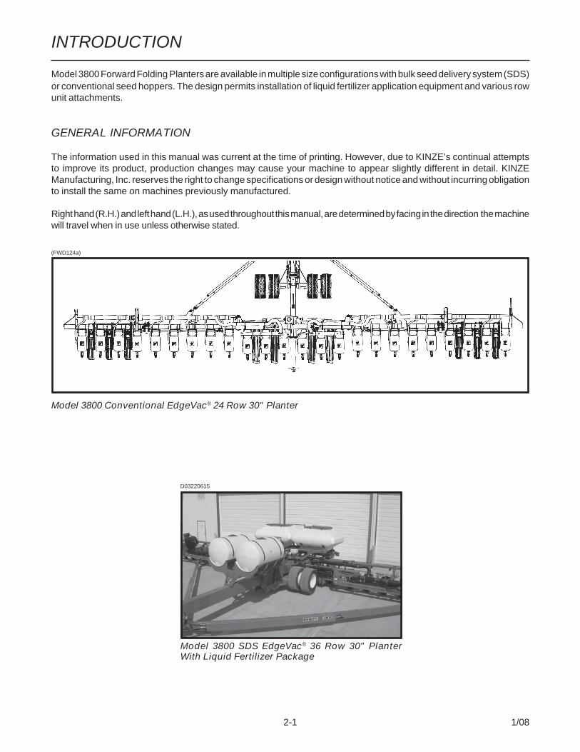
Model 3800 Forward Folding Planters are available in multiple size configurations with bulk seed delivery system (SDS)or conventional seed hoppers. The design permits installation of liquid fertilizer application equipment and various rowunit attachments.
GENERAL INFORMATION
The information used in this manual was current at the time of printing. However, due to KINZE’s continual attemptsto improve its product, production changes may cause your machine to appear slightly different in detail. KINZEManufacturing, Inc. reserves the right to change specifications or design without notice and without incurring obligationto install the same on machines previously manufactured.
Right hand (R.H.) and left hand (L.H.), as used throughout this manual, are determined by facing in the direction the machinewill travel when in use unless otherwise stated.
2-1 1/08
INTRODUCTION
(FWD124a)
Model 3800 Conventional EdgeVac® 24 Row 30" Planter
D03220615
Model 3800 SDS EdgeVac® 36 Row 30" PlanterWith Liquid Fertilizer Package

2-2 1/08
INTRODUCTION
SPECIFICATIONS
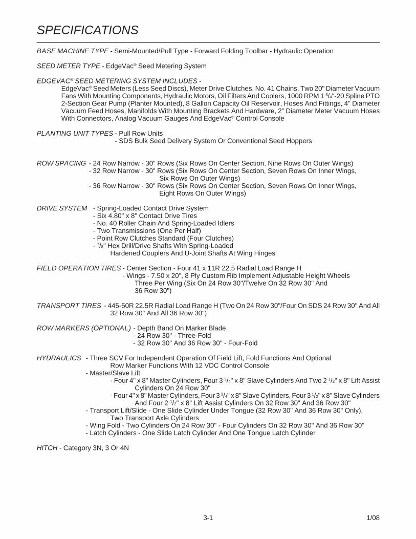
BASE MACHINE TYPE - Semi-Mounted/Pull Type - Forward Folding Toolbar - Hydraulic Operation
SEED METER TYPE - EdgeVac® Seed Metering System
EDGEVAC® SEED METERING SYSTEM INCLUDES -EdgeVac® Seed Meters (Less Seed Discs), Meter Drive Clutches, No. 41 Chains, Two 20" Diameter VacuumFans With Mounting Components, Hydraulic Motors, Oil Filters And Coolers, 1000 RPM 1 3/4"-20 Spline PTO2-Section Gear Pump (Planter Mounted), 8 Gallon Capacity Oil Reservoir, Hoses And Fittings, 4" DiameterVacuum Feed Hoses, Manifolds With Mounting Brackets And Hardware, 2" Diameter Meter Vacuum HosesWith Connectors, Analog Vacuum Gauges And EdgeVac® Control Console
PLANTING UNIT TYPES - Pull Row Units- SDS Bulk Seed Delivery System Or Conventional Seed Hoppers
ROW SPACING - 24 Row Narrow - 30" Rows (Six Rows On Center Section, Nine Rows On Outer Wings)- 32 Row Narrow - 30" Rows (Six Rows On Center Section, Seven Rows On Inner Wings,
Six Rows On Outer Wings)- 36 Row Narrow - 30" Rows (Six Rows On Center Section, Seven Rows On Inner Wings,
Eight Rows On Outer Wings)
DRIVE SYSTEM - Spring-Loaded Contact Drive System- Six 4.80" x 8" Contact Drive Tires- No. 40 Roller Chain And Spring-Loaded Idlers- Two Transmissions (One Per Half)- Point Row Clutches Standard (Four Clutches)- 7/8" Hex Drill/Drive Shafts With Spring-Loaded
Hardened Couplers And U-Joint Shafts At Wing Hinges
FIELD OPERATION TIRES - Center Section - Four 41 x 11R 22.5 Radial Load Range H- Wings - 7.50 x 20", 8 Ply Custom Rib Implement Adjustable Height Wheels
Three Per Wing (Six On 24 Row 30"/Twelve On 32 Row 30" And36 Row 30")
TRANSPORT TIRES - 445-50R 22.5R Radial Load Range H (Two On 24 Row 30"/Four On SDS 24 Row 30" And All32 Row 30" And All 36 Row 30")
ROW MARKERS (OPTIONAL) - Depth Band On Marker Blade- 24 Row 30" - Three-Fold- 32 Row 30" And 36 Row 30" - Four-Fold
HYDRAULICS - Three SCV For Independent Operation Of Field Lift, Fold Functions And OptionalRow Marker Functions With 12 VDC Control Console
- Master/Slave Lift- Four 4" x 8" Master Cylinders, Four 3 3/4" x 8" Slave Cylinders And Two 2 1/2" x 8" Lift Assist
Cylinders On 24 Row 30"- Four 4" x 8" Master Cylinders, Four 3 3/4" x 8" Slave Cylinders, Four 3 1/2" x 8" Slave Cylinders
And Four 2 1/2" x 8" Lift Assist Cylinders On 32 Row 30" And 36 Row 30"- Transport Lift/Slide - One Slide Cylinder Under Tongue (32 Row 30" And 36 Row 30" Only),
Two Transport Axle Cylinders- Wing Fold - Two Cylinders On 24 Row 30" - Four Cylinders On 32 Row 30" And 36 Row 30"- Latch Cylinders - One Slide Latch Cylinder And One Tongue Latch Cylinder
HITCH - Category 3N, 3 Or 4N
3-1 1/08

3-2 1/08
SPECIFICATIONS
MACHINE OPTIONS• Electronic Seed Monitor
- KPM III With Magnetic Distance Sensor Or Radar Distance Sensor- Planter Monitor Module (PMM)
• Liquid Fertilizer Package• Piston Pump Mount And Drive Package• Notched Single Disc Fertilizer Openers• Low Rate Check Valve Packages• Rear Trailer Hitch• Dual Transport Tire Option (Conventional 24 Row 30" Only)
ROW UNIT OPTIONS/ATTACHMENTS• Seed Meter Discs• Closing Wheel Options
Rubber “V” Closing WheelsCast Iron “V” Closing WheelsCovering Discs/Single Press WheelDrag Closing Attachment
• Down PressureOptionsQuick Adjustable Down Force SpringsPneumatic Down Pressure Package
• Granular Chemical Application• Hopper Panel Extension Package• Spring Tooth Incorporator• Row Unit Extension Brackets• Row Unit Mounted No Till Coulter• Coulter Mounted Residue Wheels• Row Unit Mounted Disc Furrowers• Row Unit Mounted Residue Wheel• Frame Mounted Coulter• Residue Wheels For Frame Mounted Coulter

MODEL 3800 CONVENTIONAL DIMENSIONS/WEIGHTS
PLANTER SIZE 24 Row 30" 32 Row 30" 36 Row 30"
PLANTING WIDTH 62' 6" 82' 6" 92' 6"
PLANTING LENGTH 24' 9" 29' 9" 29' 9"
TRANSPORT WIDTH (See NOTE Below) 14' 7" 14' 7" 14' 7"
TRANSPORT LENGTH 39' 0" 51' 0" 56' 0"
TRANSPORT HEIGHT (With Markers) 13' 6" 13' 6" 13' 6"
WEIGHT* (Base Machine) 25,159 Lbs. 32,324 Lbs. 36,156 Lbs.
MODEL 3800 SDS DIMENSIONS/WEIGHTS
PLANTER SIZE 24 Row 30" 32 Row 30" 36 Row 30"
PLANTING WIDTH 62' 6" 82' 6" 92' 6"
PLANTING LENGTH 24' 9" 29' 9" 29' 9"
TANK HEIGHT (Planting Position) 9' 4" 9' 4" 9' 4"
TRANSPORT WIDTH (See NOTE Below) 14' 7" 14' 7" 14' 7"
TRANSPORT LENGTH 39' 0" 51' 0" 56' 0"
TRANSPORT HEIGHT (With Markers) 13' 6" 13' 6" 13' 6"
WEIGHT* (Base Machine) 25,434 Lbs. 35,034 Lbs. 39,331 Lbs.
* Estimated base machine weights include planter frame, drive components, tires and wheels, hydraulic cylinders andhoses, 12VDC control console, KINZE® pull row units (closing wheel arms less closing wheels), seed hoppers andlids on conventional planters or bulk seed hoppers and seed delivery system on SDS planters, dual quick-adjustabledown force springs and point row clutches.
NOTE: Truck shipping width is 13' 9". Transport widths with optional granular chemical attachments are 15' 9".
SPECIFICATIONS
3-3 1/08

SPECIFICATIONS
3-4 1/08

Use a tractor equipped with a roll-over-protective-system and fasten your seat beltprior to starting the engine.
Before operating the planter for the first timeand periodically thereafter, check to be surethe lug bolts (and cap screws if applicable)on the transport wheels are torqued properly.This is especially important if the planter isto be transported for a long distance.
Never work under the planter while in raisedposition without installing safety lockupdevices.
Watch for obstructions such as wires, treelimbs, etc. when folding row markers.
To avoid serious injury or death, care mustbe taken when operating row markers aroundoverhead power lines.
The seed and fertilizer metering systems ofthis planter are designed to be driven byground tires. A PTO pump and hydraulicmotors power the vacuum fans. Hydraulicmotors power the bulk seed distributionsystem. The use of aftermarket hydraulic,electric or PTO drives may create serioussafety hazards to you and the people nearby.If you install such drives you must follow allappropriate safety standards and practicesto protect you and others near this planterfrom injury.
This machine has been designed and builtwith your safety in mind. Do not make anyalterations or changes to this machine. Anyalteration to the design or construction maycreate safety hazards.
Check to be sure all safety/warning lights areworking properly before transporting themachine on public roads.
Avoid transporting planter with hoppersloaded whenever possible. When it isnecessary to transport the planter with thehoppers loaded, the added weight should bedistributed evenly on the planter frame beforefolding the planter.
Safe and careful operation of the tractor and planter atall times will contribute significantly to the prevention ofaccidents.
Since a large portion of farm accidents occur as a resultof fatigue or carelessness, safety practices shouldbe of utmost concern. Read and understand theinstructions provided in this manual and on the warningsigns. Review these instructions frequently! Listedbelow are other safety suggestions that should becomecommon practice.
Never allow the planter to be operated byanyone who is unfamiliar with the operationof all functions of the unit. All operatorsshould read and thoroughly understand theinstructions given in this manual prior tomoving the unit.
Never permit any persons other than theoperator to ride on the tractor.
Never ride on the planter or allow others todo so.
Always make sure there are no persons nearthe planter when row marker assemblies arein operation or when folding the planter.
Always keep hands, feet and clothing awayfrom moving parts. Do not wear loose-fitting clothing which may catch in movingparts.
Always wear protective clothing, substantialshoes and suitable hearing and eye sightprotectors applicable for the situation.
Do not allow anyone to stand between thetongue or hitch and the towing vehicle whenbacking up to the planter.
Be aware of bystanders, particularly children!Always look around to make sure it is safe tostart the engine of the towing vehicle ormove the planter. This is particularlyimportant with higher noise levels and quietcabs, as you may not hear people shouting.
4-1 1/08
SAFETY PRECAUTIONS

4-2 1/08
SAFETY PRECAUTIONS
Limit towing speed to 15 MPH.
Transport stability is critical. The grossweight of the tractor must be greater than thegross weight of the planter. Gross weightvaries with planter attachments. Tow24 Row 30" planters with 200 HP farm tractor(minimum HP). Tow 32 Row 30" or 36 Row30" planters with 250 HP farm tractor(minimum HP).
Always make sure safety/warning lights,reflective decals and SMV sign are in placeand visible prior to transporting the machineon public roads. In this regard, check federal,state/provincial and local regulations.
Allow for unit length when making turns.
Always drive at a safe speed relative to localconditions and ensure your speed is lowenough for an emergency stop to be safeand secure. Keep speed to a minimum.
Reduce speed prior to turns to avoid the riskof overturning.
Always keep the tractor in gear to provideengine braking when going downhill. Donot coast.
Avoid sudden uphill turns on steep slopes.
Be a safe and courteous driver. Always yieldto oncoming traffic in all situations, includingnarrow bridges, intersections, etc.
Rim and tire servicing can be dangerous.Explosive separation of a tire and rim partscan cause serious injury or death.
Agricultural chemicals used with this unitcan be dangerous. Improper selection oruse can seriously injure persons, animals,plants, soil and other property. BE SAFE:Select the right chemical for the job. Handleit with care. Follow the instructions on thecontainer and of the equipment manufacturer.
Store the planter in an area away fromhuman activity. DO NOT permit children toplay on or around the stored unit.
Make sure the parked machine is on a hard,level surface. Wheel chocks may be neededto prevent unit from rolling.
Good maintenance is your responsibility.Poor maintenance is an invitation to trouble.
Never operate vacuum fans with coverremoved.
Always wear ear protection when workingaround operating vacuum fans.

5-1 1/08
SAFETY WARNING SIGNS
The “WARNING” signs illustrated on these pages are placed on the machine to warn of hazards. The warnings foundon these signs are for your personal safety and the safety of those around you. OBSERVE THESE WARNINGS!
• Keep these signs clean so they can be readily observed. Wash with soap and water or cleaning solutionas required.
• Replace “WARNING” signs should they become damaged, painted over or if they are missing.
• Check reflective decals and SMV sign periodically. Replace if they show loss of any of their reflectiveproperties.
• When replacing decals, clean the machine surface thoroughly using soap and water or cleaningsolution to remove all dirt and grease.
NOTE: Style and locations of SMV sign, reflective decals and safety/warning lights conform to ANSI/ASAES279.13 DEC2005 and ANSI/ASAE S276.6 JAN2005.
D032404100
Part No. G7100-68 (Qty. 2 - Located OnForward Toolbars On Both Sides Of Planter)
D032404114
Part No. G7100-68 (Qty. 2 - Located On StubWings On Both Sides Of Planter)

5-2 1/08
SAFETY WARNING SIGNS
Part No. G7100-56 (Qty. 1 - LocatedOn Planter Hitch)
(FWD162)
Part No. G7100-46 (Qty. 1 - LocatedOn Planter Hitch)
Part No. G7100-117 (Qty. 1 -Located On Planter Hitch)
Part No. G7100-89 (Qty. 2 - One Located OnSeed Rate Transmissions On Each Side OfPlanter)
9
D01050736
Part No. G7100-90 (Qty. 1)
Part No. G7100-259 Amber ReflectiveDecal (Qty. 2 - One Located On EachSide Of Hitch)

5-3 1/08
SAFETY WARNING SIGNS
D06039901
Part No. G7100-115 (Qty. 1 Per Row Unit - LocatedOn Underside Of Each Optional Granular ChemicalHopper Lids)
D040204101
Part No. G7100-219 (Qty. 4 - One Per 41 x 11R22.5"Center Section Lift/Gauge Tire)
Part No. GD2199 (Qty. 1 - Located On RearCenter Section Of Planter)
D02270807

5-4 1/08
SAFETY WARNING SIGNS
Part No. G7100-262 Amber Re-flective Decal (Located On TheHopper Support On Every OtherRow Unit Beginning On The 2ndRow Unit In On The L.H. End OfThe Planter - Side-Facing In Trans-port Position)(Standard) (If Applicable)
Part No. G7100-259 Amber Reflec-tive Decal (Located On The Granu-lar Chemical Hopper Panel Exten-sion On Every Other Row Unit Be-ginning On The 2nd Row Unit In OnThe L.H. End Of The Planter - Side-Facing In Transport Position) (WithOptional Granular Chemical)(If Applicable)
D062300102
D060800114
(FWD124a
Conventional 24 Row 30" Planter Shown
Part No. G7100-261 RedReflective DecalPart No. G7100-260 OrangeReflective Decal(Located As Shown Above)(Standard) (If Applicable)
Part No. G7100-258 RedReflective DecalPart No. G7100-260 OrangeReflective Decal(Located As Shown Above)(With Optional GranularChemical)(If Applicable)
AmberRed Orange
NOTE: Eight decals used on 24 Row 30", twelve decals used on 32 Row 30" and fourteen decals used on36 Row 30".

5-5 1/08
SAFETY WARNING SIGNS
RedOrangeAmber
Part No. G7100-261 RedReflective DecalPart No. G7100-260 OrangeReflective Decal(Located As Shown Above)(Standard) (If Applicable)
Part No. G7100-258 RedReflective DecalPart No. G7100-260 OrangeReflective Decal(Located As Shown Above)(With Optional GranularChemical)(If Applicable)
D062300102
D060800114 Part No. G7100-262 Amber Re-flective Decal (Located On TheHopper Support On Every OtherRow Unit Beginning On The 2ndRow Unit In On The R.H. End OfThe Planter - Side-Facing In Trans-port Position)(Standard) (If Applicable)
Part No. G7100-259 Amber Reflec-tive Decal (Located On The Granu-lar Chemical Hopper Panel Exten-sion On Every Other Row Unit Be-ginning On The 2nd Row Unit In OnThe R.H. End Of The Planter - Side-Facing In Transport Position) (WithOptional Granular Chemical)(If Applicable)

5-6 1/08
SAFETY WARNING SIGNSD040604130a
Part No. G7100-259 Amber Reflective Decal(Qty. 2 - Located On Each End Row Unit - Forward-Facing In Transport Position)
D081905111
Part No. G7100-42 (Qty. 4 - Two Per Optional RowMarker)
FWD118
Part No. G7100-322 (Qty. 2 - Located On SlideAssembly Flap)

5-7 1/08
SAFETY WARNING SIGNS
Part No. G7100-172 (Qty. 4)(SDS Planters Only)
D01050731D03060601
(FWD121)
Part No. G7100-301 (Qty. 4 - One On EachSide Of Each Vacuum Fan)

5-8 1/08
SAFETY WARNING SIGNS
Part No. G7100-319 (Qty. 2) (SDS Planters Only)
(FWD104)
Part No. G7100-266 (Qty. 2) (SDS Planters Only)

MACHINE OPERATION
6-1 1/08
The following information is general in nature and waswritten to aid the operator in preparation of the tractor andplanter for use, and to provide general operatingprocedures. The operator’s experience, familiarity withthe machine and the following information should combinefor efficient planter operation and good working habits.
IMPORTANT: Always raise the planter out of theground when making sharp turns or backing up.
The KINZE EdgeVac® Seed Metering System includesseed meters, seed discs and an air system consistingof hydraulic driven vacuum fans which draw air throughthe manifolds and hoses and the seed meters on eachrow unit.
WARNING: Never operate vacuum fans withthe cover removed.
WING LATCH HOOK SAFETY PIN(S)
The wing latch hook safety pin(s) when installed willprevent the latch bar from disengaging and allowing theplanter frame to swing away. Never transport the planterwithout installing the wing latch hook safety pin(s). Onewing latch hook safety pin is used on the 24 Row 30"size; two pins are used on 32 Row 30" and 36 Row 30"sizes.
For field operation remove the wing latch hook safetypin(s) and store in the storage location(s) provided.
D081905131
Transport Location
Storage Location
Rev. 12/07
D02270802
TRANSPORT LOCKUP, 24 ROW 30" ONLY
Install transport lock when transporting or workingaround the planter. When lockups are not in use, storein the storage position provided on the transport axleassembly.
D02070821
In Transport Position
In Stored Field Operation Position
MACHINE OPERATION
6-2 1/08
TRACTOR REQUIREMENTS
Consult your dealer for information on horsepower re-quirements and tractor compatibility. Requirements willvary with planter options, tillage and terrain. Three dualremote hydraulic outlets (SCV) are required on all sizes ofconventional planters equipped with row markers. Fourdual remote hydraulic outlets (SCV) are required on allsizes of SDS planters equipped with row markers. A 12volt DC electrical system is required on all sizes.
Transport stability is critical. The grossweight of the tractor must be greater thanthe gross weight of the planter. Gross weightvaries with planter attachments. Tow24 Row 30" planters with 200 HP farm tractor(minimum HP). Tow 32 Row 30" or 36 Row30" planters with 250 HP farm tractor(minimum HP).
NOTE: A 3-point quick hitch adapter is required.
D03200631
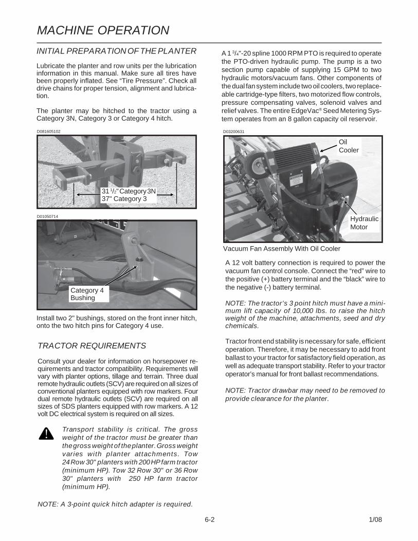
Vacuum Fan Assembly With Oil Cooler
OilCooler
HydraulicMotor
A 12 volt battery connection is required to power thevacuum fan control console. Connect the “red” wire tothe positive (+) battery terminal and the “black” wire tothe negative (-) battery terminal.
NOTE: The tractor’s 3 point hitch must have a mini-mum lift capacity of 10,000 lbs. to raise the hitchweight of the machine, attachments, seed and drychemicals.
Tractor front end stability is necessary for safe, efficientoperation. Therefore, it may be necessary to add frontballast to your tractor for satisfactory field operation, aswell as adequate transport stability. Refer to your tractoroperator’s manual for front ballast recommendations.
NOTE: Tractor drawbar may need to be removed toprovide clearance for the planter.
A 1 3/4"-20 spline 1000 RPM PTO is required to operatethe PTO-driven hydraulic pump. The pump is a twosection pump capable of supplying 15 GPM to twohydraulic motors/vacuum fans. Other components ofthe dual fan system include two oil coolers, two replace-able cartridge-type filters, two motorized flow controls,pressure compensating valves, solenoid valves andrelief valves. The entire EdgeVac® Seed Metering Sys-tem operates from an 8 gallon capacity oil reservoir.
Install two 2" bushings, stored on the front inner hitch,onto the two hitch pins for Category 4 use.
D081605102
31 1/2" Category 3N37" Category 3
D01050714
Category 4Bushing
INITIAL PREPARATION OF THE PLANTER
Lubricate the planter and row units per the lubricationinformation in this manual. Make sure all tires havebeen properly inflated. See “Tire Pressure”. Check alldrive chains for proper tension, alignment and lubrica-tion.
The planter may be hitched to the tractor using aCategory 3N, Category 3 or Category 4 hitch.

MACHINE OPERATION
6-3 1/08
TRACTOR PREPARATION AND HOOKUP
Correct adjustment and operation of the tractor’s 3point hitch is very important for peak performance of theplanter.
A 3-point quick hitch adapter is required.
The tractor’s 3 point hitch must be operated in POSI-TION mode, not DRAFT mode. Operation in DRAFTmode can cause the hitch to move up and down causingunlevel operation of the planter.
The tractor’s 3 point hitch response sensitivity settingsshould be adjusted for the correct reaction speed forraising/controlling the hitch of the planter for the fold andunfold functions.
IMPORTANT: Movement of the tractor’s 3 pointhitch (during field operation) is undesirable andmay cause poor planter performance and/or dam-age to the planter. Consult your tractor dealer ifnecessary.
1. Install planter control console, digital vacuum gaugescontrol console and SDS control console (If Appli-cable) on tractor in convenient locations withinreach of the operator and close to the hydrauliccontrols. Mount control consoles securely and routepower cords to the power source.
The control consoles operate on 12 volt DC only. Iftwo 12 volt batteries are connected in series,ALWAYS make power connection on the batterywhich is grounded to the tractor chassis.
2. Set tractor rear wheel spacing at 60" or double theplanter row spacing. Dual tires should center on120". Check tractor operator’s manual for correctfront and rear tire pressures. (If Applicable)
3. Adjust lower lift links on tractor so planter will liftlevel from side to side and raise high enough forplanter transport clearance. Set the sway blocks onthe tractor in position to prevent side sway.
4. Back tractor up to planter and connect planter.
D10060618
D10060627
D10060624
Planter Control Console
SDS Control Console (If Applicable)
Digital Vacuum Gauges Control Console
MACHINE OPERATION
6-4 1/08
5. Install applicable PTO shaft assembly betweentractor PTO output shaft and hydraulic pump gear-box on planter.
CAUTION: A tractor model-specific PTO shaftassembly is required. The procedure describedin the following steps MUST be followed everytime a different tractor is attached to determineif the correct length PTO shaft assembly isbeing used. FAILURE TO FOLLOW THESEGUIDELINES WILL RESULT IN SEVERE DAM-AGE TO THE IMPLEMENT AND/OR THE TRAC-TOR.
IMPORTANT: The tractor must be equippedwith a 1 3/4"-20 spine PTO.
NOTE: A 3-point quick hitch adapter is requiredon all Model 3800 EdgeVac® Planters.
IMPORTANT: The tractor drawbar must be re-moved prior to attaching planter to tractor.Failure to remove drawbar will cause damage toplanter and/or tractor.
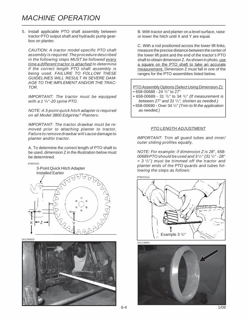
A. To determine the correct length of PTO shaft tobe used, dimension Z in the illustration below mustbe determined.
(FWD152)
D01290829
(FWD151a)
3-Point Quick Hitch AdapterInstalled Earlier
X Z Y
Example 3 1/2"
PTO Assembly Options (Select Using Dimension Z):• 658-00688 - 24 1/2" to 27"• 658-00689 - 31 1/2" to 34 1/2" (If measurement is
between 27" and 31 1/2", shorten as needed.)• 658-00690 - Over 34 1/2" (Trim to fit the application
as needed.)
B. With tractor and planter on a level surface, raiseor lower the hitch until X and Y are equal.
C. With a rod positioned across the lower lift links,measure the precise distance between the center ofthe lower lift point and the end of the tractor’s PTOshaft to obtain dimension Z. As shown in photo, usea square on the PTO shaft to take an accuratemeasurement. Dimension Z must fall in one of theranges for the PTO assemblies listed below.
PTO LENGTH ADJUSTMENT
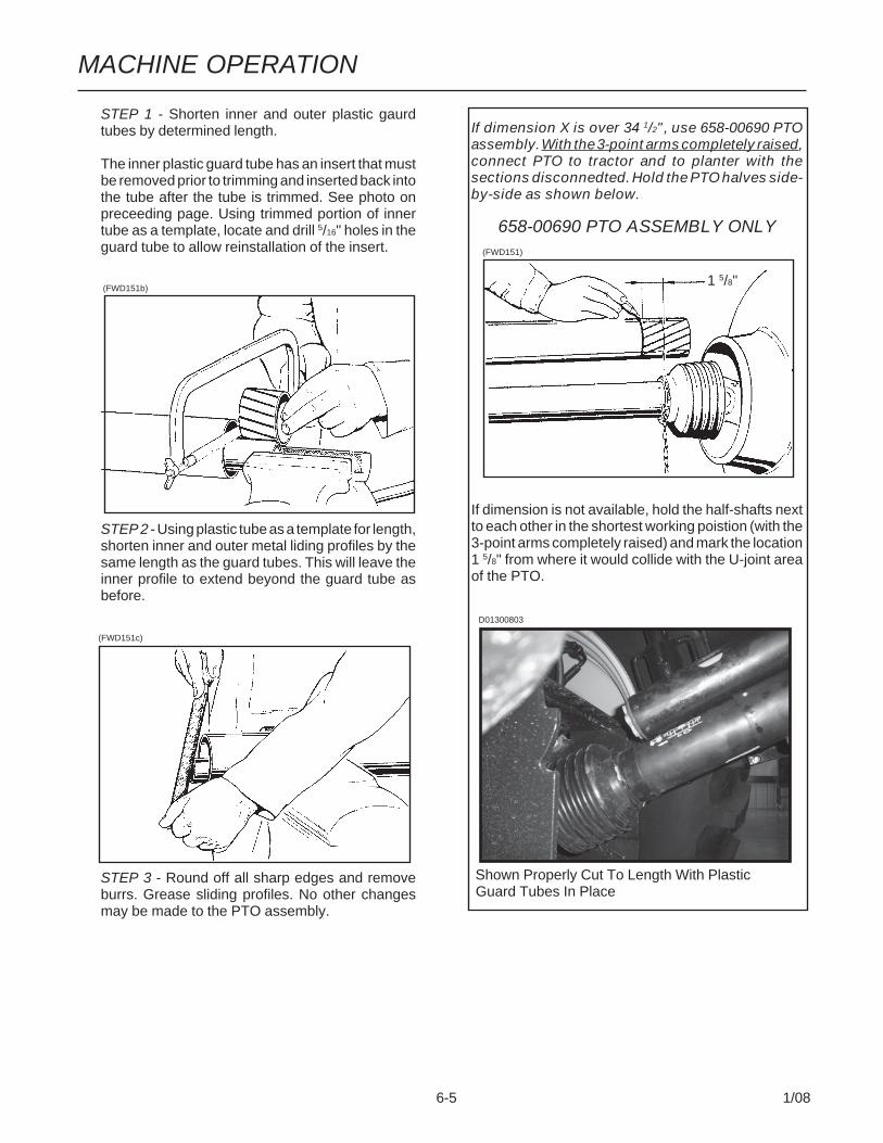
IMPORTANT: Trim all guard tubes and inner/outer sliding profiles equally.
NOTE: For example: if dimension Z is 28", 658-00689 PTO should be used and 3 1/2" (31 1/2" - 28"= 3 1/2") must be trimmed off the tractor andplanter ends of the PTO quards and tubes fol-lowing the steps as follows:
D01130801
MACHINE OPERATION
6-5 1/08
If dimension X is over 34 1/2", use 658-00690 PTOassembly. With the 3-point arms completely raised,connect PTO to tractor and to planter with thesections disconnedted. Hold the PTO halves side-by-side as shown below.
658-00690 PTO ASSEMBLY ONLY
If dimension is not available, hold the half-shafts nextto each other in the shortest working poistion (with the3-point arms completely raised) and mark the location1 5/8" from where it would collide with the U-joint areaof the PTO.
Shown Properly Cut To Length With Plastic Guard Tubes In Place
(FWD151)
STEP 1 - Shorten inner and outer plastic gaurdtubes by determined length.
The inner plastic guard tube has an insert that mustbe removed prior to trimming and inserted back intothe tube after the tube is trimmed. See photo onpreceeding page. Using trimmed portion of innertube as a template, locate and drill 5/16" holes in theguard tube to allow reinstallation of the insert.
STEP 2 - Using plastic tube as a template for length,shorten inner and outer metal liding profiles by thesame length as the guard tubes. This will leave theinner profile to extend beyond the guard tube asbefore.
STEP 3 - Round off all sharp edges and removeburrs. Grease sliding profiles. No other changesmay be made to the PTO assembly.
(FWD151b)
(FWD151c)
1 5/8"
D01300803
MACHINE OPERATION
6-6 1/08
6. Connect hydraulic hoses to tractor ports in a se-quence which is both familiar and comfortable tothe operator.
Before attaching hoses, move tractor control leversback and forth to relieve any pressure in the tractorhydraulic system.
The hydraulic hoses are color coded as follows:
Red AA - Field Raise Function (Return)Red BB - Field Raise Function (Pressure)
Blue AA - Fold/UnFold Functions (Return)Blue BB - Fold/UnFold Functions (Pressure)
Black AA - Row Marker Functions (Return)Black BB - Row Marker Functions (Pressure)
White AA - 5/8" Hose - Bulk Seed Delivery System(SDS) Functions (Return)
White BB - 1/2" Hose - Bulk Seed Delivery System(SDS) Functions (Pressure)
DANGER: Before applying pressure to thehydraulic system, make sure all connec-tions are tight and hoses and fittings havenot been damaged. Hydraulic fluid escapingunder pressure can have sufficient force topenetrate skin, causing injury or infection.
IMPORTANT: Always wipe hose ends to removeany dirt before connecting couplers to tractor ports.
IMPORTANT: The PTO shaft coupling shouldbe cleaned and greased each time the pump isinstalled.
IMPORTANT: To extend life of shaft splines,apply a coating of high-speed industrial cou-pling grease, such as Chevron® CouplingGrease, that meets AGMA CG-1 and CG-2 Stan-dards.
(The Chevron® trademark is owned by ChevronProducts Company. AGMA is the acronym for theAmerican Gear Manufacturers Association)
Fill reservoir with hydraulic fluid. A SAE 10W-20multigrade wide temperature range transmissionhydraulic fluid is recommended.
Start system. Allow to run with tractor at idle and thefans turned off for 1-2 minutes.
Allow to run with tractor at idle and the fans at fullspeed for 1-2 minutes.
Check fluid level in reservoir and fill as required.
To allow the fluid to expand, when heated, fluid levelin each tank should be within 1"-2" from the top ofthe tank after the pump has run and hydraulic hoseshave been primed.
Bring tractor to PTO speed and adjust flow controlto the desired vacuum level using the switches onthe vacuum fan control console.

MACHINE OPERATION
6-7 1/08
D040604100
D040604101a
9. For proper operation of the planter and row units, itis important that the planter toolbars and row unitparallel arms be level side-to-side and front-to-rear. The toolbar should operate at 20"-22" heightfrom planting surface. Tire pressure must be main-tained at pressures specified and toolbar heightsmust be adjusted equally. Check to be sure plantertoolbars are level and at correct operating heights.See “Leveling The Planter”.
NOTE: The transport axle cylinders are equippedwith counter balance valves which hydraulicallylock the cylinders when not in use.
7. Connect cable on planter to planter control consolecable on tractor. Connect cable on planter to vacuumfan control console and cable on planter to SDScontrol console (If Applicable). Connect ASAE Stan-dards 7 terminal connector for safety/warning lightson planter to ASAE Standards receptacle on tractor.If your tractor is not equipped with an ASAE Stan-dards receptacle, check with your tractor manufac-turer for availability. Check to be sure safety/warn-ing lights on planter are working in conjunction withwarning lights on tractor.
Connect harness on planter to digital vacuum gaugeconsole on tractor. Connect power lead to powersource. A power lead adapter may be required.
8. Raise planter slowly and watch for any interfer-ence. Remove pin from jack stand and swing jackstand to the horizontal position. Install pin in stor-age position.

MACHINE OPERATION
6-8 1/08
LEVELING THE PLANTER
With the planter lowered to proper operating height,check to be sure the toolbars and row unit parallel armsare level fore and aft. Recheck when planter is in thefield.
It is important for the planter to operate level laterally.Tire pressure must be maintained at pressures speci-fied. See “Tire Pressure”.
Field and actual planting conditions will dictate which ofthe wheel settings to use to ensure row unit parallelarms are approximately parallel with the planting sur-face.
(RU113h)
ApproximatelyParallelWithPlanting Surface
When the planter has been fully loaded with seed,granular chemicals, etc.; a field check should be madeto be sure the wings are level with the center frame. Ifthe wings are not level with the center frame, the lift/gauge wheels can be raised or lowered in the wheelarms to increase or decrease planter toolbar height.Hitch height should be positioned to ensure level opera-tion.D040604201
Center Section Lift/Gauge Wheel (Rock ShaftAxle) - Initial Setting Shown
D033104202
Wing Lift/Gauge Wheel - Initial Setting Shown

MACHINE OPERATION
6-9 1/08
TIRE PRESSURE(FWD124a)
Tire pressure should be checked regularly and main-tained as follows:
(4) 41 x 11R22.5" Radial Load Range H(Center Section Lift/Gauge) ............... 75 PSI
(6-12) 7.50" x 20" 8 Ply Custom Rib Implement(Wing Lift/Gauge) .............................. 40 PSI
(2-4) 445-50R22.5R Radial Load Range H(Transport) ....................................... 120 PSI
(6) 4.80" x 8" (Contact Drive) .......................... 50 PSI(2) 20.5 x 8.0-10 (Marker) ............................... 35 PSI(2) 7.60" x 15" Rib Implement
(Liquid Fertilizer Piston Pump) ........... 40 PSI
DANGER: Rim and tireservicing can bedangerous. Explosiveseparation of tire and rimparts can cause seriousinjury or death.
Do not attempt to mount a tire unless you have theproper equipment and experience to perform thejob. This should only be done by persons properlytrained and equipped to do the job.
Always maintain the correct tire pressures. Do notinflate tires above the recommended pressures.
When inflating tires, use a clip-on air chuck andextension hose long enough to allow you to standto one side and NOT in front of or over the tireassembly. Use a safety cage to enclose the tire andrim assembly when inflating.
Inspect tires and wheels daily. Do not operate withlow pressure, cuts, bubbles, damaged rims or miss-ing lug bolts and nuts.
CONTACT WHEEL SPRINGADJUSTMENT
There are two down pressure springs on each contactdrive wheel. The spring tension is factory preset andshould require no further adjustment.
The tension is set leaving 2 1/4" between the spring plugand the bolt head.
CONTACT WHEEL IDLER ADJUSTMENT
The 3/8" nut on the bolt that attaches the contact wheelidler must be tightened so the idler is free to rotate underspring load but tight enough so the carriage bolt isstable.
NOTE: See “Contact Wheel Drive Sprockets” foradditional information when using 54 cell sun-flower discs.
D102704100
2 1/4"
Transport
Contact Drive
Center Section Lift/GaugeWing Lift/Gauge
ConventionalPlanterShown
D01050743

MACHINE OPERATION
6-10 1/08
SEED RATE TRANSMISSIONADJUSTMENT
Planting population rate changes are made at the twotransmission assemblies. The seed rate transmissionsare designed to allow simple, rapid changes of sprock-ets to obtain the desired planting population. By remov-ing the lynch pins on the hexagon shafts, sprockets canbe interchanged with those from the sprocket storagerod bolted to each transmission.
Chain tension is controlled by spring-loaded, dual-sprocket idlers. The idler assembly is adjusted with aeasy-release idler arm. See “Wrap Spring WrenchOperation”. This arm has a release position to removespring tension for replacing sprockets. The amount ofspring tension on the chain is controlled by the idler arm.
A decal positioned on the transmission module illus-trates proper chain routing. The planting rate chartsfound at the back of this section will aid you in selectingthe correct sprocket combinations.
Seed rate transmisions should be set equally.
D01050736
DriveSprocket
CONTACT WHEEL DRIVE SPROCKETS
NOTE: 15 tooth, 19 tooth or 38 tooth sprockets ateach contact drive wheel can be interchanged fromthe sprocket storage rod bolted near the wheel mod-ule on each side of the planter. 38 tooth sprocketsrequire use of 168 pitch chains. 15 and 19 toothsprockets required use of 160 pitch chains.
Chain tension is controlled by a spring-loaded sprocketidler. The amount of spring tension on the chain iscontrolled by the idler arm.
The planting rate charts found in Seed Meter Operation/Maintenance section will aid you in selecting the correctsprockets.
NOTE: 15, 19 and 38 tooth drive sprockets are NOTapplicable to all rate charts. Check chart titles toensure proper rate charts are selected.
NOTE: When using the 54 cell sunflower disc, makechanges at contact wheel assembly using sprock-ets, chains, hex shafts, etc. supplied in G1K472Sunflower Rate Reduction Kit. Each kit containscomponents for two contact wheel assemblies.Order kits according to number of contact wheelassemblies on the planter.
NOTE: After each sprocket combination adjust-ment, make a field test to be sure you are plantingat the desired rate.
DrivenSprocket
D01050743
D012508111

MACHINE OPERATION
6-11 1/08
U-JOINT SHAFT ASSEMBLIES
A U-joint shaft assembly is used between the centersection of the planter and the wing assembly on eachhalf of the planter to allow up and down wing move-ment.
On 32 Row 30" and 36 Row 30" planters a U-joint shaftassembly is used to span the space between the innerand outer wing assemblies and allow up and downwing movement of the wings on each half of the planter.
36 Row 30" Planter Shown
See “Grease Fittings” in the Lubrication Section of thismanual.
D021406101
D021406102D020206109
D081905101
WRAP SPRING WRENCH OPERATION
The chain idlers are equipped with wrap springwrenches. Chain tension is released and/or added asshown below.
To release chain tension, rotate the knurled collar onthe wrap spring wrench while rotating the chain idleraway from the chain.
To add chain tension, rotate the chain idler into thechain while rotating the handle to tension idler spring.
The wrap spring wrenches are made in L.H. and R.H.configurations, which can be identified by the silver orgold release collars, respectively.
MACHINE OPERATION
6-12 1/08
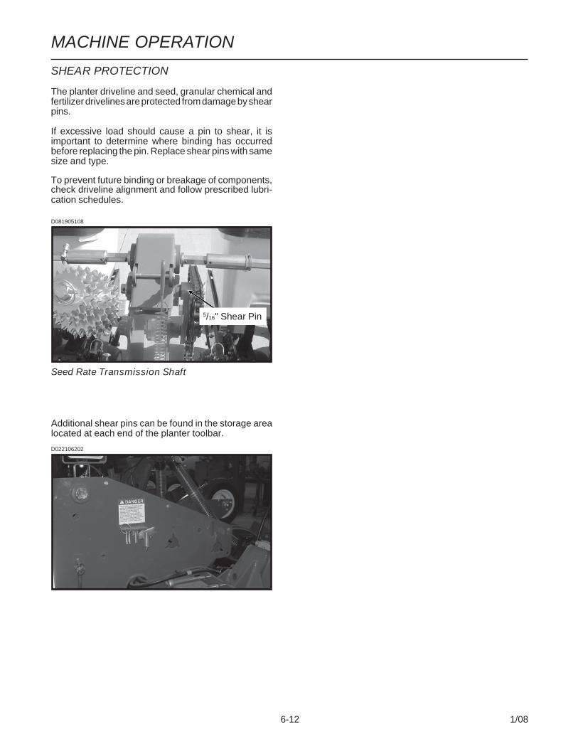
SHEAR PROTECTION
The planter driveline and seed, granular chemical andfertilizer drivelines are protected from damage by shearpins.
If excessive load should cause a pin to shear, it isimportant to determine where binding has occurredbefore replacing the pin. Replace shear pins with samesize and type.
To prevent future binding or breakage of components,check driveline alignment and follow prescribed lubri-cation schedules.
Seed Rate Transmission Shaft
5/16" Shear Pin
D081905108
Additional shear pins can be found in the storage arealocated at each end of the planter toolbar.
D022106202
MACHINE OPERATION
6-13 1/08
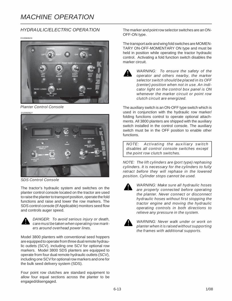
HYDRAULIC/ELECTRIC OPERATION
D10060624
The marker and point row selector switches are an ON-OFF-ON type.
The transport axle and wing fold switches are MOMEN-TARY ON-OFF-MOMENTARY ON type and must beheld in position while operating the tractor hydrauliccontrol. Activating a fold function switch disables themarker circuit.
WARNING: To ensure the safety of theoperator and others nearby, the markerselector switch should be placed in its OFF(center) position when not in use. An indi-cator light on the control box panel is ONwhenever the marker circuit or point rowclutch circuit are energized.
The auxiliary switch is an ON-OFF type switch which isused in conjunction with the hydraulic row marker/folding functions control to operate optional attach-ments. All 3800 planters are shipped with the auxiliaryswitch installed in the control console. The auxiliaryswitch must be in the OFF position to enable otherfunctions.
NOTE: Activating the auxiliary switchdisables all control console switches exceptthe point row clutch switches.
NOTE: The lift cylinders are (port type) rephasingcylinders. It is necessary for the cylinders to fullyretract before they will rephase in the loweredposition. Cylinder stops cannot be used.
WARNING: Make sure all hydraulic hosesare properly connected before operatingthe planter. Never connect or disconnecthydraulic hoses without first stopping thetractor engine and moving the hydraulicoperating controls in both directions torelieve any pressure in the system.
WARNING: Never walk under or work onplanter when it is raised without supportingthe frames with additional supports.
Planter Control Console
The tractor’s hydraulic system and switches on theplanter control console located on the tractor are usedto raise the planter to transport position, operate the foldfunctions and raise and lower the row markers. TheSDS control console (If Applicable) monitors seed flowand controls auger speed.
DANGER: To avoid serious injury or death,care must be taken when operating row mark-ers around overhead power lines.
Model 3800 planters with conventional seed hoppersare equipped to operate from three dual remote hydrau-lic outlets (SCV), including one SCV for optional rowmarkers. Model 3800 SDS planters are equipped tooperate from four dual remote hydraulic outlets (SCV),including one SCV for optional row markers and one forthe bulk seed delivery system (SDS).
Four point row clutches are standard equipment toallow four equal sections across the planter to beengaged/disengaged.
SDS Control Console
D10060627
MACHINE OPERATION
6-14 1/08
DIGITAL VACUUM GAUGE OPERATION
The digital vacuum gauge control console is equippedwith a power toggle switch, run/stop (fans) toggleswitch and two fan speed control toggle switches for thevacuum fans. The power switch provides power to thecontrol console. The run/stop toggle switch will turnboth fans on when the power switch is ON.The fanspeed control switches allow fan speed adjustment oneach fan (left or right).
NOTE: The power switch should be left in OFFposition when the planter is not in use. If left in ONposition, the tractor battery will be drained.
The digital vacuum gauge is calibrated at the factory,however, vacuum will vary throughout the manifoldsystem and it may be necessary to adjust the digitalreadout so it agrees with the actual vacuum at themeter. With the seed discs loaded with seed, comparethe digital vacuum gauge readouts to the reading takenfrom the analog gauges or a hand held gauge at severalmeters along the length of the planter. The elbowconnections located on the covers of the seed metersallow testing of meter vacuum levels without removingthe vacuum hoses. If there is more difference than 1" or2" (H
2O), the digital gauge can be adjusted by inserting
a small flat bladed screwdriver into the opening on theback of the digital gauge housing and turning thepotentiometer until the digital gauge displays the vacuumthat is present at the meter. Compare readings at 10"and 20" of vacuum.
VACUUM FAN MOTOR VALVE BLOCKASSEMBLY
A pressure relief valve in the hydraulic circuit on eachside of the planter prevents build up of oil pressure over35 PSI in the case drain line when the vacuum fan motoris in operation. This valve will vent oil to the outside ofthe valve block through a drain hole in the aluminumvalve block. This can occur whenever the case drain isconnected improperly or pressure in the motor circuitbuilds.
See “Hydraulic Diagram - Vacuum Fan Motor System”in Maintenance section.
The valve block also contains a check valve that servestwo purposes. This valve (a) prevents the vacuum fanfrom operating in the wrong direction if pressure isapplied to the return side of the motor and (b) allows thefan to coast to a stop when the tractor hydraulic controlis returned to the neutral position.
NOTE: If reverse pressure is applied the fan willturn at a reduced speed.
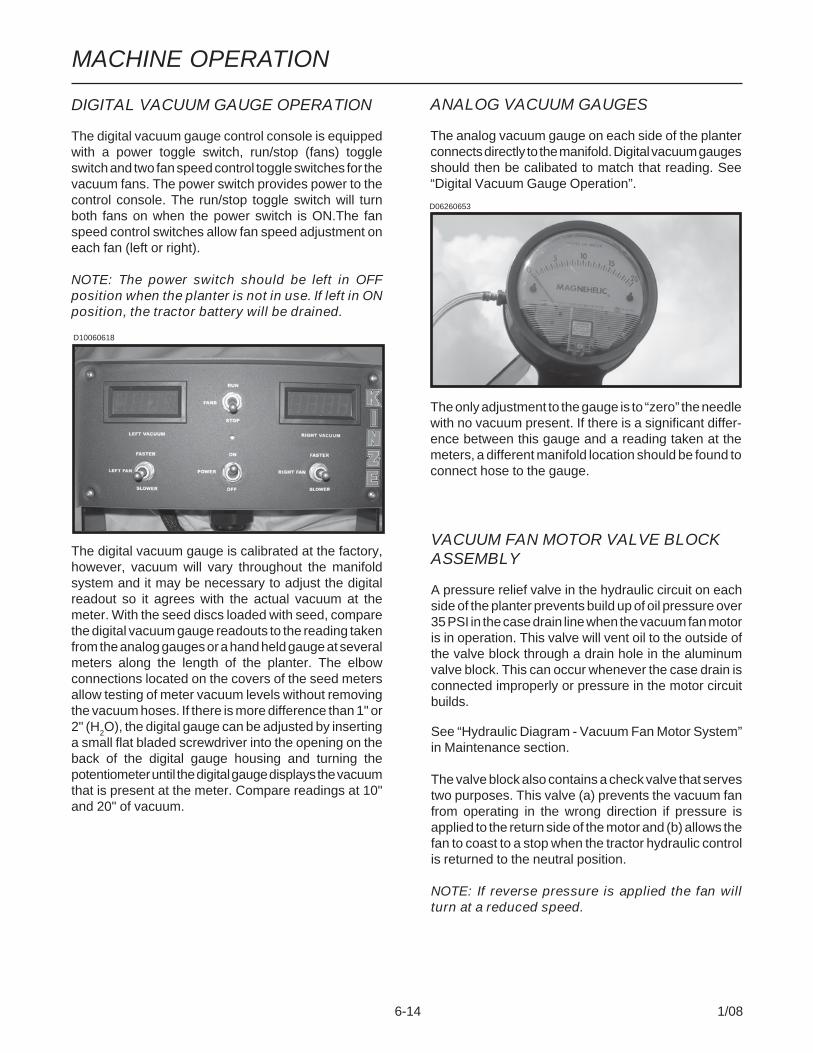
ANALOG VACUUM GAUGES
The analog vacuum gauge on each side of the planterconnects directly to the manifold. Digital vacuum gaugesshould then be calibated to match that reading. See“Digital Vacuum Gauge Operation”.
The only adjustment to the gauge is to “zero” the needlewith no vacuum present. If there is a significant differ-ence between this gauge and a reading taken at themeters, a different manifold location should be found toconnect hose to the gauge.
D06260653
D10060618

MACHINE OPERATION
6-15 1/08
TRANSPORT TO FIELD SEQUENCE
Position the planter in a relatively flat open area. Try toavoid an area with furrows, etc.
SUMMARIZED TRANSPORT TO FIELD SEQUENCE• Remove wing latch hook safety pin(s) from trans-
port (locked) positions and place in storage loca-tions provided.
• Raise field tires/wheels and hold to rephase.• Fully raise planter using transport axle.• Slide transport axle to rear position. (32/36 Row
Only)• Lower field tires/wheels.• Lower rear of planter using transport axle until field
tires touch the ground.• Partially lower tractor 3 point hitch to release wing
latch hooks.• Unfold planter to planting position.• Fully raise transport axle tires/wheels.• Lower 3 point to level hitch position.NOTE: Read the following information for moredetailed instructions.
1. Remove wing latch hook safety pin(s) from trans-port positions and place in storage locations pro-vided.
D081905131
D012507128
Transport Location
Storage Location
D012507128
2. (32/36 Row Only) Hold the control console switchlabeled TRANSPORT AXLE in SLIDE and operatethe fold/unfold functions hydraulic control to movethe transport axle to the rear position.
(FWD30bb)

MACHINE OPERATION
6-16 1/08
3. Operate the field raise function hydraulic control tolower the field tires/wheels.
D012507125
4. Hold the control console switch labeled TRANS-PORT AXLE in RAISE/LOWER and operate thefold/unfold functions hydraulic control to raise thetransport axle, lowering the rear of the planter, untilthe field tires touch the ground.
IMPORTANT: DO NOT retract the transport cyl-inders completely or damage will occur to thedriveline and transport tires. The weight of theplanter should be on the field tires, but thetransport axle tires should remain on the groundduring folding.
D012507123
(FWD30bb)
MACHINE OPERATION
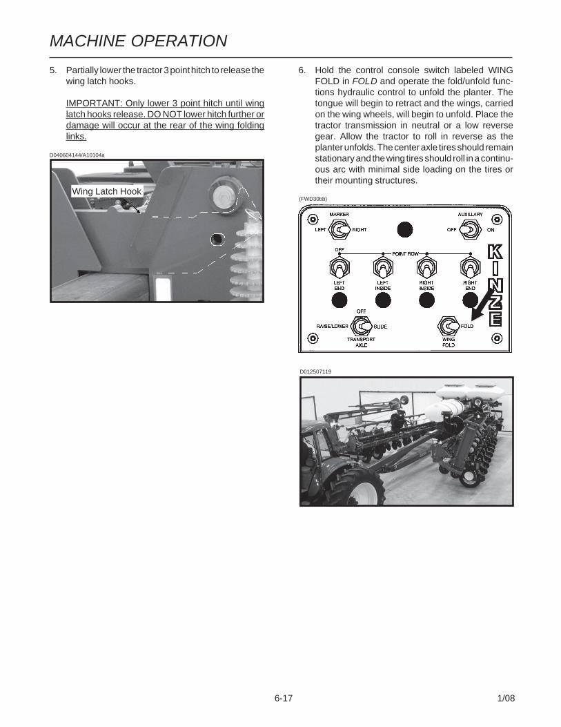
6-17 1/08
6. Hold the control console switch labeled WINGFOLD in FOLD and operate the fold/unfold func-tions hydraulic control to unfold the planter. Thetongue will begin to retract and the wings, carriedon the wing wheels, will begin to unfold. Place thetractor transmission in neutral or a low reversegear. Allow the tractor to roll in reverse as theplanter unfolds. The center axle tires should remainstationary and the wing tires should roll in a continu-ous arc with minimal side loading on the tires ortheir mounting structures.
D012507119
5. Partially lower the tractor 3 point hitch to release thewing latch hooks.
IMPORTANT: Only lower 3 point hitch until winglatch hooks release. DO NOT lower hitch further ordamage will occur at the rear of the wing foldinglinks.
D040604144/A10104a
Wing Latch Hook(FWD30bb)

MACHINE OPERATION
6-18 1/08
7. Hold the control console switch labeled TRANS-PORT AXLE in RAISE/LOWER and operate thefold/unfold functions hydraulic control to raise thetransport axle wheels to the fully raised plantingposition.
D012507111
FIELD OPERATION
Normal planting operation in the field requires the useof the tractor’s hydraulic control to raise and lower theplanter frame when making field turn arounds.
Operate row markers with the control console switchfor that marker in the ON (LEFT or RIGHT) position andthe tractor’s hydraulic control. After markers are low-ered to the ground, move the hydraulic control tooperate markers in float position. Marker speed iscontrolled with flow control valves located in the valveblock on the planter hitch. One valve controls the raisespeed of both markers while the other valve controlsthe lower speed of both markers. See “Row MarkerSpeed Adjustment” and “Row Marker Operation”.
IMPORTANT: Operate row markers in float posi-tion to prevent damage to row markers.
8. Lower the 3 point to level hitch position.
D040604100
D012507111
WARNING: Never walk under or work onplanter when it is raised without supportingthe frames with additional supports.
(FWD30bb)

MACHINE OPERATION
6-19 1/08
FIELD TO TRANSPORT SEQUENCE
Position the planter in a relatively flat open area. Try toavoid an area with furrows, etc.
SUMMARIZED FIELD TO TRANSPORT SEQUENCE• Raise planter to field turn height.• Lower transport axle to the ground.• Fold planter to transport position.• Raise front of planter using tractor 3 point hitch.• Raise rear of planter using transport axle.• Slide transport axle forward into transport position.
32/36 Row Only)• Raise field tires/wheels.• Remove wing latch hook safety pin(s) from stor-
age location(s) and install in locked position(s).NOTE: Read the following information for moredetailed instructions.
1. Operate the field raise function hydraulic control toraise the planter to raised field height.
2. Hold the control console switch labeled TRANS-PORT AXLE in RAISE/LOWER and operate thefold/unfold functions hydraulic control to lower thetransport axle wheels until they touch the ground.
IMPORTANT: Lower transport axle tires untilweight begins to transfer onto transport axletires. DO NOT carry the full weight of the planteron the transport axle tires during folding.
D012507113
D012507111
(FWD30bb)
MACHINE OPERATION
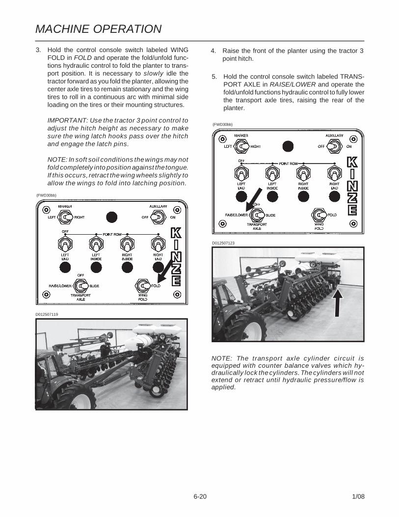
6-20 1/08
3. Hold the control console switch labeled WINGFOLD in FOLD and operate the fold/unfold func-tions hydraulic control to fold the planter to trans-port position. It is necessary to slowly idle thetractor forward as you fold the planter, allowing thecenter axle tires to remain stationary and the wingtires to roll in a continuous arc with minimal sideloading on the tires or their mounting structures.
IMPORTANT: Use the tractor 3 point control toadjust the hitch height as necessary to makesure the wing latch hooks pass over the hitchand engage the latch pins.
NOTE: In soft soil conditions the wings may notfold completely into position against the tongue.If this occurs, retract the wing wheels slightly toallow the wings to fold into latching position.
5. Hold the control console switch labeled TRANS-PORT AXLE in RAISE/LOWER and operate thefold/unfold functions hydraulic control to fully lowerthe transport axle tires, raising the rear of theplanter.
D012507119
D012507123
4. Raise the front of the planter using the tractor 3point hitch.
NOTE: The transport axle cylinder circuit isequipped with counter balance valves which hy-draulically lock the cylinders. The cylinders will notextend or retract until hydraulic pressure/flow isapplied.
(FWD30bb)
(FWD30bb)
MACHINE OPERATION
6-21 1/08
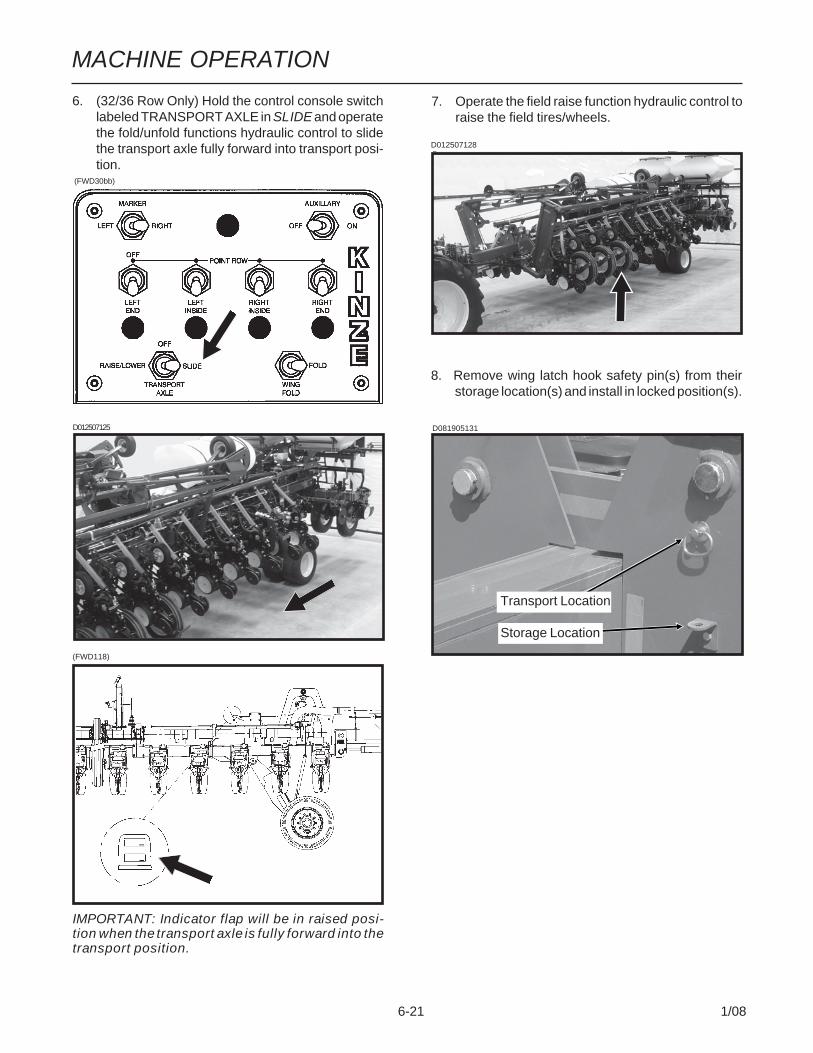
6. (32/36 Row Only) Hold the control console switchlabeled TRANSPORT AXLE in SLIDE and operatethe fold/unfold functions hydraulic control to slidethe transport axle fully forward into transport posi-tion.
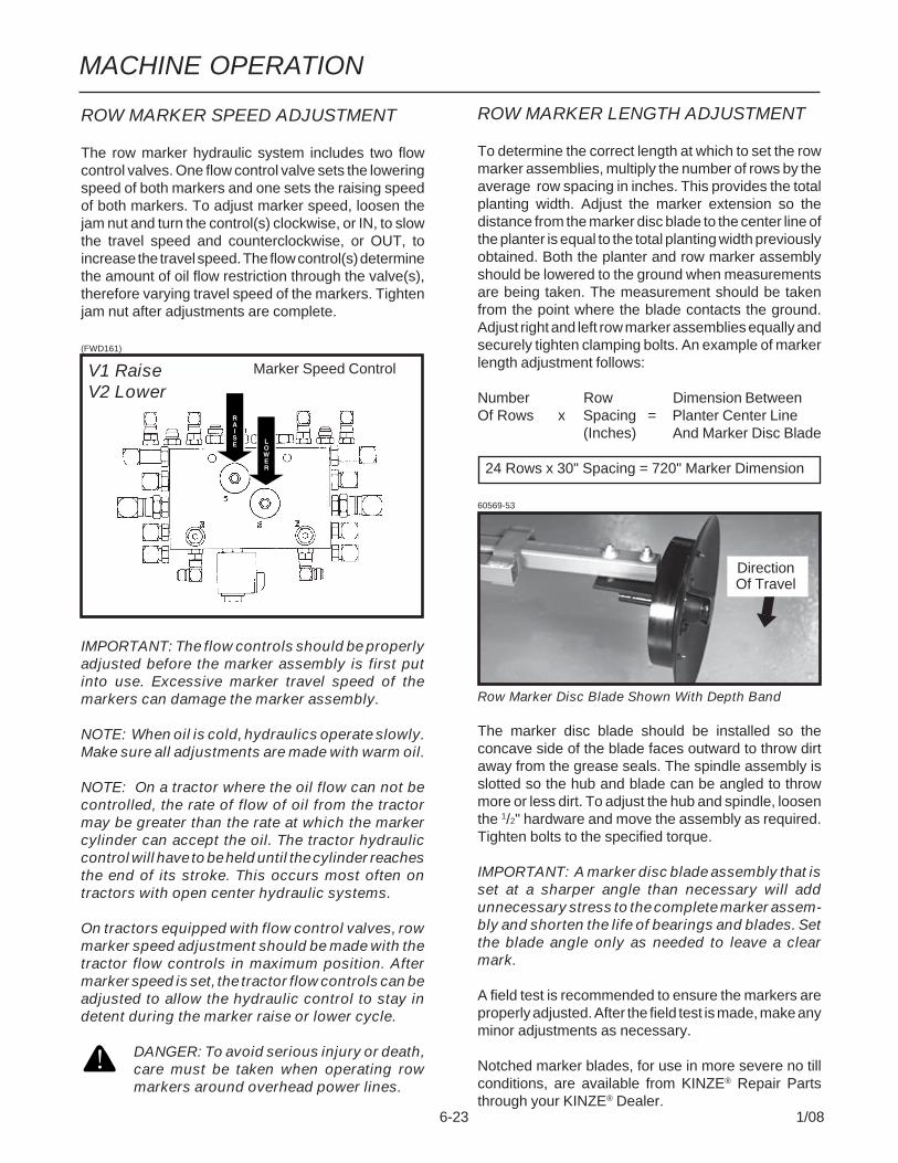
7. Operate the field raise function hydraulic control toraise the field tires/wheels.
8. Remove wing latch hook safety pin(s) from theirstorage location(s) and install in locked position(s).
D012507125
D012507128
D081905131
Transport Location
Storage Location
IMPORTANT: Indicator flap will be in raised posi-tion when the transport axle is fully forward into thetransport position.
(FWD118)
(FWD30bb)

MACHINE OPERATION
6-22 1/08
Two solenoid valves, located on the valve block at thefront of the planter, along with a three position selectorswitch on the control console permit the operator tolower or raise the desired row marker.
See “Row Marker Speed Adjustment”.
1. On the control console, select the row marker youwant to lower.
2. Operate hydraulic control to lower marker.3. If opposite marker is to be used next, change switch
to the opposite position.4. At end of field, using hydraulic control, raise the
down marker.5. After making the turn, using the hydraulic control,
lower the pre-selected marker.6. Continue to follow this procedure.
NOTE: Both row markers can be lowered by oper-ating the switch in each position and operating thehydraulic control twice. The markers will raisesimultaneously when the hydraulic control is movedto the raise position.
NOTE: Control console switch should be left inOFF position when planter is not in use. If left in ONposition, it will discharge the tractor battery.
If the electrical system fails to operate properly:Check fuse.Check wiring connections.Check control switch.Check solenoid. SOLENOID HOUSING SHOULDBE MAGNETIZED WHEN ENERGIZED.
DANGER: To avoid serious injury or death,care must be taken when operating row mark-ers around overhead power lines.
IMPORTANT: Row markers MUST be operatedwith hydraulic circuit in float position to preventdamage to marker assemblies.
Marker Switch
Three Position Selector Switch On ControlConsole
ROW MARKER OPERATION
(FWD30bb)
MACHINE OPERATION
6-23 1/08
ROW MARKER SPEED ADJUSTMENT
The row marker hydraulic system includes two flowcontrol valves. One flow control valve sets the loweringspeed of both markers and one sets the raising speedof both markers. To adjust marker speed, loosen thejam nut and turn the control(s) clockwise, or IN, to slowthe travel speed and counterclockwise, or OUT, toincrease the travel speed. The flow control(s) determinethe amount of oil flow restriction through the valve(s),therefore varying travel speed of the markers. Tightenjam nut after adjustments are complete.
(FWD161)
IMPORTANT: The flow controls should be properlyadjusted before the marker assembly is first putinto use. Excessive marker travel speed of themarkers can damage the marker assembly.
NOTE: When oil is cold, hydraulics operate slowly.Make sure all adjustments are made with warm oil.
NOTE: On a tractor where the oil flow can not becontrolled, the rate of flow of oil from the tractormay be greater than the rate at which the markercylinder can accept the oil. The tractor hydrauliccontrol will have to be held until the cylinder reachesthe end of its stroke. This occurs most often ontractors with open center hydraulic systems.
On tractors equipped with flow control valves, rowmarker speed adjustment should be made with thetractor flow controls in maximum position. Aftermarker speed is set, the tractor flow controls can beadjusted to allow the hydraulic control to stay indetent during the marker raise or lower cycle.
DANGER: To avoid serious injury or death,care must be taken when operating rowmarkers around overhead power lines.
ROW MARKER LENGTH ADJUSTMENT
To determine the correct length at which to set the rowmarker assemblies, multiply the number of rows by theaverage row spacing in inches. This provides the totalplanting width. Adjust the marker extension so thedistance from the marker disc blade to the center line ofthe planter is equal to the total planting width previouslyobtained. Both the planter and row marker assemblyshould be lowered to the ground when measurementsare being taken. The measurement should be takenfrom the point where the blade contacts the ground.Adjust right and left row marker assemblies equally andsecurely tighten clamping bolts. An example of markerlength adjustment follows:
Number Row Dimension BetweenOf Rows x Spacing = Planter Center Line
(Inches) And Marker Disc Blade
24 Rows x 30" Spacing = 720" Marker Dimension
60569-53
Row Marker Disc Blade Shown With Depth Band
The marker disc blade should be installed so theconcave side of the blade faces outward to throw dirtaway from the grease seals. The spindle assembly isslotted so the hub and blade can be angled to throwmore or less dirt. To adjust the hub and spindle, loosenthe 1/2" hardware and move the assembly as required.Tighten bolts to the specified torque.
IMPORTANT: A marker disc blade assembly that isset at a sharper angle than necessary will addunnecessary stress to the complete marker assem-bly and shorten the life of bearings and blades. Setthe blade angle only as needed to leave a clearmark.
A field test is recommended to ensure the markers areproperly adjusted. After the field test is made, make anyminor adjustments as necessary.
Notched marker blades, for use in more severe no tillconditions, are available from KINZE® Repair Partsthrough your KINZE® Dealer.
DirectionOf Travel
Marker Speed ControlV1 RaiseV2 Lower

MACHINE OPERATION
6-24 1/08
PRC019(PLTR48)
Control Tang
The point row clutch consists of a wrap spring riding onan input hub and an output hub. During operation thewrap spring is wrapped tightly over the hubs connectingthem in a positive engagement. The greater the force ofrotation the tighter the grip of the spring on the hubs.
Rotation in the opposite direction or stopping the springfrom rotating prevents the transmission of torque fromthe input hub to the output hub, stopping the planterdrive.
The input end of the spring is bent outward and isreferred to as the control tang. The control tang fits intoa slot in the stop collar that is located between the inputand output hubs and over the wrap spring. If the stopcollar is allowed to rotate with the input hub, the clutchis engaged. If the stop collar is stopped from rotating,the control tang connected to it is forced back and thespring opens. This allows the input hub to continuerotating without transmitting torque to the output hub;therefore, stopping the planter drive.
The stop collar is controlled by the use of an electricsolenoid and an actuator arm. When the selector switchon the tractor control console is in the OFF position thesolenoid coil is NOT ENERGIZED and the actuator armwill not contact the stop on the stop collar allowing it torotate with the hubs and drive the planter.
When the operational switch is in the “DISENGAGE”(right or left) position the solenoid coil is ENERGIZEDand the plunger in the solenoid coil retracts, allowing theactuator arm to contact the stop on the stop collar,disengaging the wrap spring and stopping the planterdrive.
POINT ROW CLUTCHES
D081905107
All Model 3800 planters are equipped with four pointrow clutches. With the use of electric-activated clutches,which disengage the drive, various sections of theplanter may be shut off for finishing up fields or longpoint row situations.
The selector switches for the clutches are located onthe planter control console.
NOTE: Switches should be left in OFF positionwhen planter is not in use. If left in ON position, itwill discharge the tractor battery.
NOTE: Since the liquid fertilizer piston pumps usededicated drive wheels, liquid fertilizer applicationwill not be controlled by use of the point rowclutches.
InputHub
OutputHub
WrapSpring
StopCollar
(FWD30bb)

6-25 1/08
MACHINE OPERATION KPM III
The monitor system is powered by the tractor battery(requires 12 volts DC). The console receives informationfrom each of the sensors and translates this information.
The KPM III console uses a single backlit Liquid CrystalDisplay (LCD) to show, the number of monitored rows,the relative seed rate for each row (using bargraphdisplays) and displays various alarm and warningmessages when an alarm condition exists. A continuousaudible alarm will sound upon system malfunction orunderflow conditions for any monitored row. Alarms mustbe acknowledged by the user. Various warnings maysound the alarm or flash one or more messages. TheLCD also shows alphanumeric data such as row spacing,units (Metric or English), speed (MPH or KM/H), volume,seed population, seed spacing, field area and total area.
The monitor system will power down if no activity isdetected within one hour. No activity means there hasbeen no new seed flow and no operator push key input.
The KPM III electronic seed monitor system consists of(a) a KPM III console, which is mounted on the tractor;(b) seed tubes with sensors, one of which is installed ineach planter row unit; (c) a magnetic distance sensor,which is installed on the planter, or a radar distancesensor, which is installed on the tractor; (d) shaftrotation sensors (if applicable), which are installed onthe planter drill shafts; and (e) planter harnesses (junc-tion Y-harness and/or extension harness where appli-cable), to which the individual seed tube sensors con-nect. The primary harness, which connects the monitorconsole to the planter harness, is hard-wired into thesafety/warning light harness or control console harnessincluded as standard equipment with the planter.
The software design of the KPM III console allowssimultaneous viewing of seed flow bargraphs for stan-dard and/or Interplant® System rows (up to 36 rows).
KPM III ELECTRONIC SEED MONITOR
D10190501
Monitor Key Functions .................................... 6-26Configuring Planter Monitor ........................... 6-27Programming/Connecting Seed Tubes,Shaft Rotation Sensors And/OrRadar/Magnetic Distance Sensors ................. 6-29Changing Volume, Contrast AndBacklighting ..................................................... 6-31Programming Interplant® Condition, RowSpacing And Units (Metric Or English) .......... 6-32Programming Row Unit Alarms Levels .......... 6-33Speed Sensor Calibration/Programming ....... 6-34Reprogramming Speed Sensor ...................... 6-35Adding Interplant® Rows (If Rear RowsHave Previously Been Programmed) ............. 6-39Adding Even-Row Package (If Front RowsHave Previously Been Programmed) ............. 6-41Enabling/Disabling Interplant® Rows ............. 6-43Warnings And Alarms ..................................... 6-46Field Operation ................................................ 6-48Area Management ............................................ 6-49Area Counters .................................................. 6-51Clearing Field Area .......................................... 6-52Acre Count Mode ............................................. 6-52Replacing Faulty Sensor(s) ............................ 6-54

6-26 1/08
MACHINE OPERATION KPM III
PHYSICAL KEYS• Located on R.H. side of
console and referred to as F1,F2, F3, F4, F5 and F6
• Keys are referenced indescending order with F1 atthe top and F6 at the bottom.
ON/OFF KEY• Powers the unit on and off.
ESC KEY• Used as the CANCEL
(escape) key.
ENTER KEY• Confirms or accepts the
highlighted selection.
MONITOR KEY FUNCTIONS
Push keys allow the user to select or change theoperating mode, the active displays or the currentconfiguration. Depending on the operating mode or thecurrent display selected, some keys may not be active.Each key press, if valid, is acknowledged by a shortbeep and an action is taken. If the key press has noaction associated, the key press is considered invalid,and the user will not receive feedback.
PhysicalKeys
RotaryEncoder Knob
AV Key
ON/OFF
D10190501
ROTARY ENCODER KNOB• Turn knob clockwise to increase
or counterclockwise todecrease value of item.
• Turn knob clockwise to scroll upor counterclockwise to scrolldown.
• Press knob to enter selection.
AV (AUDIO/VIDEO) KEY• Set alarm volume.• Adjust the contrast.• Adjust backlighting of the LCD
display.
ACK (ACKNOWLEDGE) KEY• Used to silence (acknowledge)
the warning alarm when variouserror conditions occur.NOTE: Alarms can be viewedby pressing the STATUS key.
ARROW KEYS• UP arrow key is used to
increase the value of an item byone or to scroll up.
• DOWN arrow key is used todecrease the value of an itemby one or to scroll down.
• LEFT arrow key multiplies thenumeric value of the item by 10.
• RIGHT arrow key divides thenumeric value of the item by 10.
ENTER
NOTE: Within the LCD, the black box around thesmaller box as shown below indicates which fieldis selected/highlighted. Turning the rotary encoderknob or pressing the UP or DOWN arrow keysmoves the black box. When the black box ispositioned on a programmable item, such as ShaftSensors, Speed Sensor, Front Row Units or RearRow Units, pressing the knob or ENTER key willhighlight the programmable item. A programmableitem may only be changed when it is highlighted.D02140616
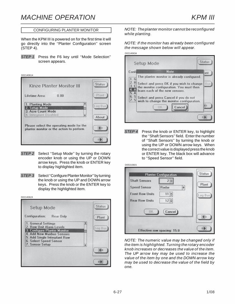
6-27 1/08
MACHINE OPERATION KPM III
CONFIGURING PLANTER MONITOR
When the KPM III is powered on for the first time it willgo directly into the ‘‘Planter Configuration’’ screen(STEP 4).
STEP 1 Press the F6 key until ‘‘Mode Selection’’screen appears.
STEP 4 Press the knob or ENTER key, to highlightthe ‘‘Shaft Sensors’’ field. Enter the numberof ‘‘Shaft Sensors’’ by turning the knob orusing the UP or DOWN arrow keys. Whenthe correct value is displayed press the knobor ENTER key. The black box will advanceto ‘‘Speed Sensor’’ field.
NOTE: The numeric value may be changed only ifthe item is highlighted. Turning the rotary encoderknob increases or decreases the value of the item.The UP arrow key may be used to increase thevalue of the item by one and the DOWN arrow keymay be used to decrease the value of the field byone.
D02140614
STEP 2 Select ‘‘Setup Mode’’ by turning the rotaryencoder knob or using the UP or DOWNarrow keys. Press the knob or ENTER keyto display highlighted item.
STEP 3 Select ‘‘Configure Planter Monitor’’ by turningthe knob or using the UP and DOWN arrowkeys. Press the knob or the ENTER key todisplay the highlighted item.
NOTE: The planter monitor cannot be reconfiguredwhile planting.
NOTE: If the monitor has already been configuredthe message shown below will appear.D02140634
D02140624
D05310601

6-28 1/08
MACHINE OPERATION KPM III
NOTE: To prevent the configuration from beingsaved press ESC or select the CANCEL button,then press the rotary encoder knob or ENTER key.
STEP 6 If there are front rows on the planter, pressthe knob or ENTER key to highlight the‘‘Front Row Units’’ field. Turn the knob oruse the UP or DOWN arrow keys to obtaincorrect number of push row units. Press theknob or ENTER key when desired quantityis displayed. The black box will advance to‘‘Rear Row Units’’ field. If no front rows needto be entered simply turn the knob or pressthe DOWN arrow key to advance to ‘‘RearRow Units’’.
STEP 5 Press the knob or ENTER key and a dropdown menu will appear; select either ‘‘Radar’’or ‘‘Coil Pick-Up’’ (MDS) by turning the knobor using the UP or DOWN arrow keys. Whenthe desired selection is highlighted press theknob or ENTER key. The black box willadvance to ‘‘Front Row Units’’ field.
D05310604
STEP 7 Press the knob or ENTER key to highlightthe ‘‘Rear Row Units’’ field. Turn the knob oruse the UP or DOWN arrow keys to obtaincorrect number of pull row units. Press theknob or ENTER key when desired quantityis displayed. The black box will advance tothe OK key.
STEP 8 Press the knob or the ENTER key to savethe information.
D05310606
D05310607
D05310605
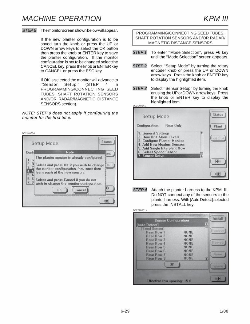
6-29 1/08
MACHINE OPERATION KPM III
PROGRAMMING/CONNECTING SEED TUBES,SHAFT ROTATION SENSORS AND/OR RADAR/
MAGNETIC DISTANCE SENSORS
STEP 9 The monitor screen shown below will appear.
If the new planter configuration is to besaved turn the knob or press the UP orDOWN arrow keys to select the OK buttonthen press the knob or ENTER key to savethe planter configuration. If the monitorconfiguration is not to be changed select theCANCEL key, press the knob or ENTER keyto CANCEL or press the ESC key.
If OK is selected the monitor will advance to‘‘Sensor Setup’’ (STEP 4 inPROGRAMMING/CONNECTING SEEDTUBES, SHAFT ROTATION SENSORSAND/OR RADAR/MAGNETIC DISTANCESENSORS section).
NOTE: STEP 9 does not apply if configuring themonitor for the first time.
STEP 1 To enter ‘‘Mode Selection’’, press F6 keyuntil the ‘‘Mode Selection’’ screen appears.
STEP 2 Select ‘‘Setup Mode’’ by turning the rotaryencoder knob or press the UP or DOWNarrow keys. Press the knob or ENTER keyto display the highlighted item.
STEP 3 Select ‘‘Sensor Setup’’ by turning the knobor using the UP or DOWN arrow keys. Pressthe knob or ENTER key to display thehighlighted item.
D02140641
D02210601a
STEP 4 Attach the planter harness to the KPM III.Do NOT connect any of the sensors to theplanter harness. With [Auto Detect] selectedpress the INSTALL key.
D02140634
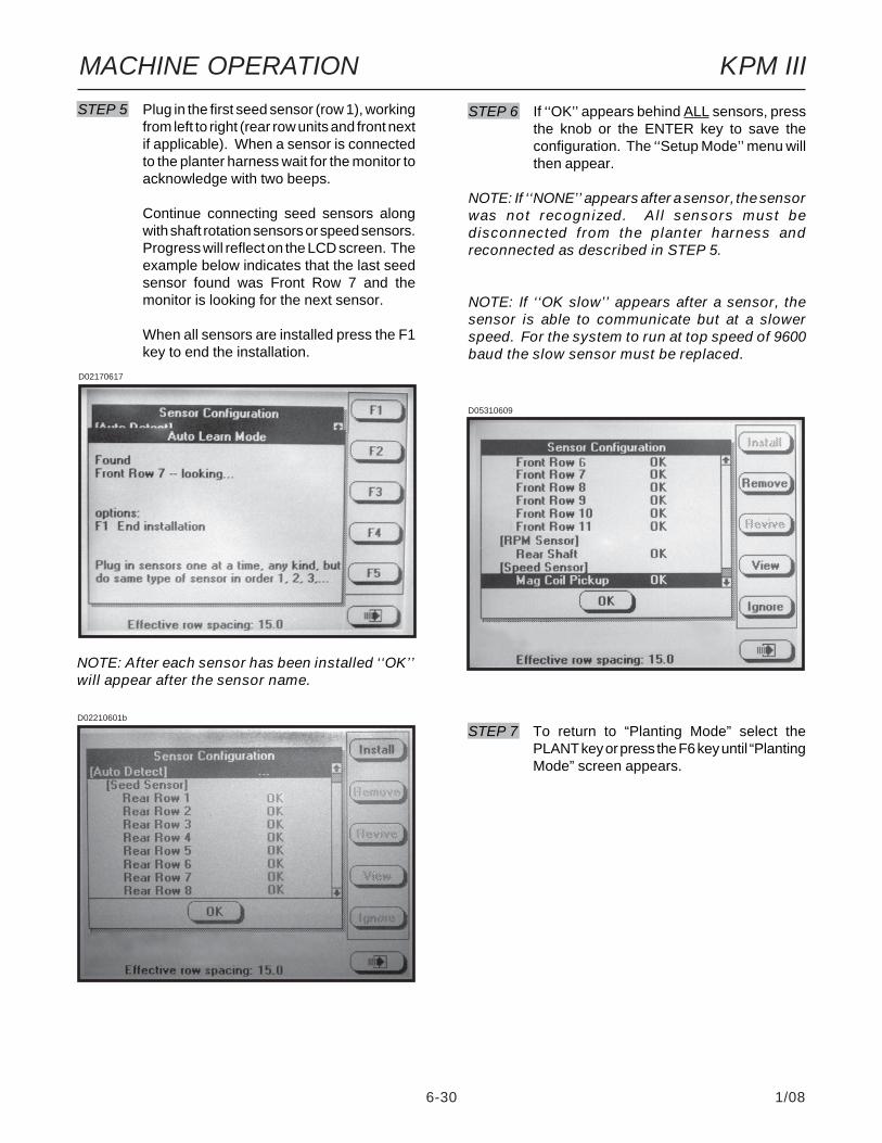
6-30 1/08
MACHINE OPERATION KPM III
NOTE: After each sensor has been installed ‘‘OK’’will appear after the sensor name.
STEP 6 If ‘‘OK’’ appears behind ALL sensors, pressthe knob or the ENTER key to save theconfiguration. The ‘‘Setup Mode’’ menu willthen appear.
NOTE: If ‘‘NONE’’ appears after a sensor, the sensorwas not recognized. All sensors must bedisconnected from the planter harness andreconnected as described in STEP 5.
NOTE: If ‘‘OK slow’’ appears after a sensor, thesensor is able to communicate but at a slowerspeed. For the system to run at top speed of 9600baud the slow sensor must be replaced.
D02210601b
STEP 5 Plug in the first seed sensor (row 1), workingfrom left to right (rear row units and front nextif applicable). When a sensor is connectedto the planter harness wait for the monitor toacknowledge with two beeps.
Continue connecting seed sensors alongwith shaft rotation sensors or speed sensors.Progress will reflect on the LCD screen. Theexample below indicates that the last seedsensor found was Front Row 7 and themonitor is looking for the next sensor.
When all sensors are installed press the F1key to end the installation.
D02170617
STEP 7 To return to “Planting Mode” select thePLANT key or press the F6 key until “PlantingMode” screen appears.
D05310609

6-31 1/08
MACHINE OPERATION KPM III
CHANGING VOLUME, CONTRAST ANDBACKLIGHTING
The alarm volume and LCD screen contrast andbacklighting may be adjusted at anytime, regardless ofwhat is displayed on the screen.
STEP 1 Press the AV key. The speaker adjustmentdialog box will appear in the lower L.H. cornerof the display.
STEP 2 Use the LEFT and RIGHT arrows or turn therotary encoder knob to adjust the volume.The volume of the sound emitted from thespeaker changes as the adjustment is beingmade.
STEP 3 To adjust contrast or backlight, go to STEP 4.If finished press ENTER to save and exit.
STEP 4 Press the AV button a second time. Thecontrast adjustment dialog box will appear inthe lower portion of the display.
D05310611
STEP 5 Use the LEFT and RIGHT arrows or turn theknob to adjust contrast. The effect of theadjustment will be visible on the display.
STEP 6 To adjust backlighting go to STEP 7. Iffinished press ENTER to save and exit.
STEP 7 Press the AV button a third time. The backlightadjustment dialog box will appear in the lowerL.H. corner of the display.
D05310612
STEP 8 Use the LEFT and RIGHT arrows or turn theknob to adjust backlighting. The effect of theadjustment will be visible on the display.
STEP 9 Press the knob, ENTER or press the AVbutton a fourth time to save the volume,contrast and backlight settings. The backlightadjustment dialog box will disappear.
D05310610
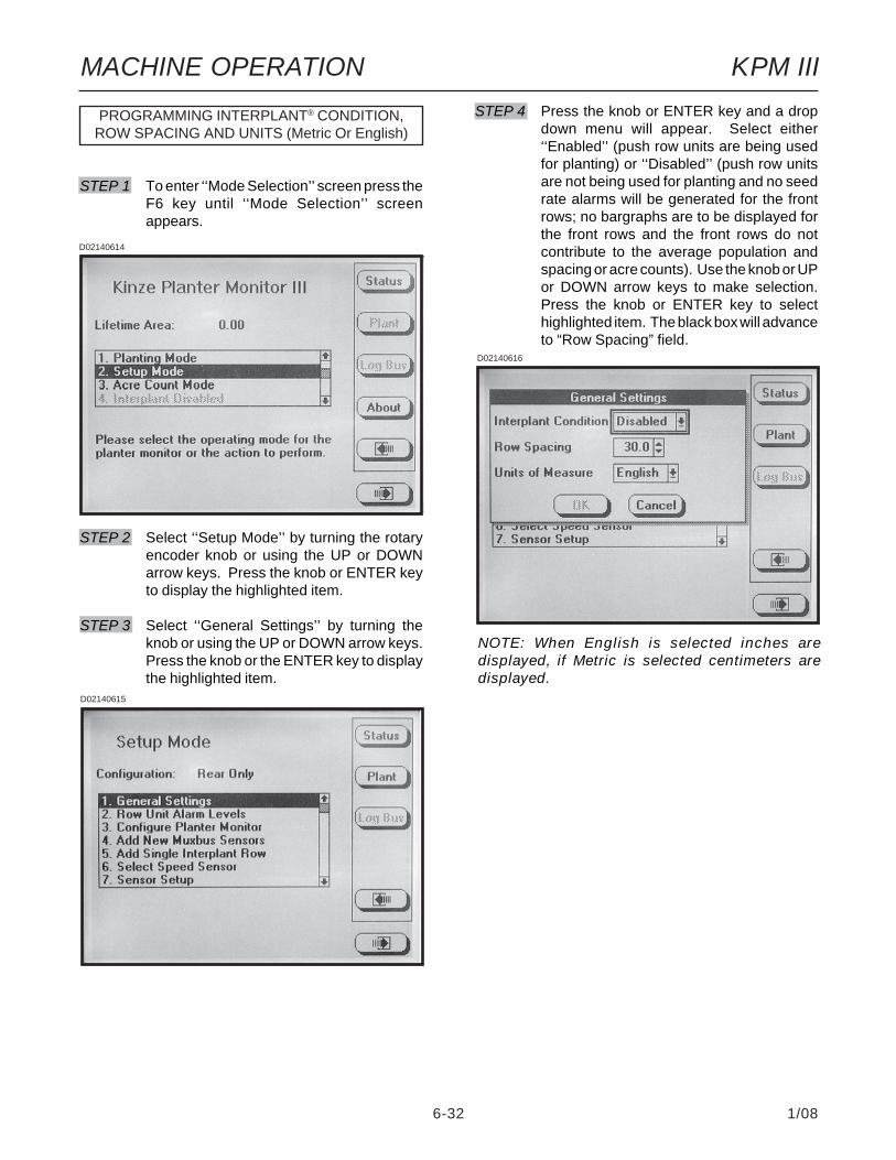
6-32 1/08
MACHINE OPERATION KPM III
PROGRAMMING INTERPLANT® CONDITION,ROW SPACING AND UNITS (Metric Or English)
STEP 1 To enter ‘‘Mode Selection’’ screen press theF6 key until ‘‘Mode Selection’’ screenappears.
STEP 2 Select ‘‘Setup Mode’’ by turning the rotaryencoder knob or using the UP or DOWNarrow keys. Press the knob or ENTER keyto display the highlighted item.
STEP 3 Select ‘‘General Settings’’ by turning theknob or using the UP or DOWN arrow keys.Press the knob or the ENTER key to displaythe highlighted item.
D02140614
D02140615
NOTE: When English is selected inches aredisplayed, if Metric is selected centimeters aredisplayed.
D02140616
STEP 4 Press the knob or ENTER key and a dropdown menu will appear. Select either‘‘Enabled’’ (push row units are being usedfor planting) or ‘‘Disabled’’ (push row unitsare not being used for planting and no seedrate alarms will be generated for the frontrows; no bargraphs are to be displayed forthe front rows and the front rows do notcontribute to the average population andspacing or acre counts). Use the knob or UPor DOWN arrow keys to make selection.Press the knob or ENTER key to selecthighlighted item. The black box will advanceto “Row Spacing” field.

6-33 1/08
MACHINE OPERATION KPM III
PROGRAMMING ROW UNIT ALARM LEVELS
The Row Unit Alarm Levels allow the thresholds for theseed rate alarms to be set. The default is 50% orAverage. If the average population drops below 50%for a given row a seed rate alarm will be generated forthat row unit. The alarm threshold can be set to 70%,50%, 10% or disabled for any row.
NOTE: When the alarm threshold is disabled forany row no seed rate alarm will be generated.
The alarm thresholds can be set for the whole planter,any planter section or individual rows.
NOTE: A section is determined by a set of rowsdriven by one or more shafts, designated to asingle shaft sensor.
STEP 1 To enter ‘‘Mode Selection’’, press F6 keyuntil the ‘‘Mode Selection’’ screen appears.
STEP 2 Select ‘‘Setup Mode’’ by turning the rotaryencoder knob or using the UP or DOWNarrow keys. Press the knob or ENTER keyto display the highlighted item.
STEP 3 Select ‘‘Row Unit Alarm Levels’’ by turningthe knob or using the UP or DOWN arrowkeys. Press the knob or ENTER key todisplay the highlighted item.
STEP 4 To set alarm thresholds for whole planter,select “Whole Planter”. Press the key nextto the desired threshold. When the desiredthreshold has been specified for all rowunits, press the knob or ENTER key.
To set alarm thresholds for all the rows inone section, select rear section or frontsection. Press the key next to the desiredthreshold. When the desired threshold hasbeen specified for all row units, press theknob or ENTER key.
To set alarm thresholds for individual rows,select the desired row. Press the key next tothe desired threshold. When the desiredthreshold has been specified for all rowunits, press the knob or ENTER key.
STEP 5 To return to “Planting Mode” press the PLANTkey.
D02140623STEP 5 Press the knob or ENTER key to enter thecorrect value for ‘‘Row Spacing’’. Turn theknob to increase or decrease the number.The UP arrow key is used to increase thevalue of the item by one and the DOWNarrow key is used to decrease the value ofthe field by one. The LEFT arrow keymultiplies the value of the item by 10 and theRIGHT arrow key divides the value of theitem by 10. When the correct number hasbeen entered press the knob or ENTER key.The black box will advance to ‘‘Units ofMeasure’’ field.
NOTE: The narrowest row spacing the planter isequipped to plant should be entered for “RowSpacing”. Example: 12 Row 30" with Interplant,row spacing would be set to 15".
STEP 6 Select ‘‘Units Of Measure’’ field by pressingthe knob or ENTER key and a drop downmenu will appear. Select either ‘‘English’’ or‘‘Metric’’ by turning the knob or using the UPor DOWN arrow keys. Press the knob or theENTER key. The black box will advance toOK.
STEP 7 Press the knob or ENTER key, when correctvalues are entered.
STEP 8 To return to “Planting Mode” press the PLANTkey.
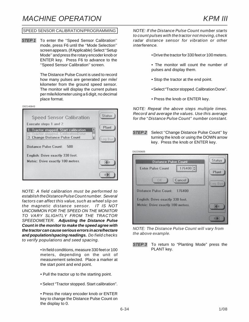
6-34 1/08
MACHINE OPERATION KPM III
NOTE: If the Distance Pulse Count number startsto count pulses with the tractor not moving, checkradar distance sensor for vibration or otherinterference.
• Drive the tractor for 330 feet or 100 meters.
• The monitor will count the number ofpulses and display them.
• Stop the tractor at the end point.
• Select “Tractor stopped. Calibration Done”.
• Press the knob or ENTER key.
NOTE: Repeat the above steps multiple times.Record and average the values. Use this averagefor the “Distance Pulse Count” number constant.
SPEED SENSOR CALIBRATION/PROGRAMMING
STEP 1 To enter the ‘‘Speed Sensor Calibration’’mode, press F6 until the ‘‘Mode Selection’’screen appears. (If Applicable) Select ‘‘SetupMode’’ and press the rotary encoder knob orENTER key. Press F6 to advance to the‘‘Speed Sensor Calibration’’ screen.
The Distance Pulse Count is used to recordhow many pulses are generated per mile/kilometer from the ground speed sensor.The monitor will display the current pulsesper mile/kilometer using a 6 digit, no decimalplace format.
D02140643
NOTE: A field calibration must be performed toestablish the Distance Pulse Count number. Severalfactors can affect this value, such as wheel slip onthe magnetic distance sensor. IT IS NOTUNCOMMON FOR THE SPEED ON THE MONITORTO VARY SLIGHTLY FROM THE TRACTORSPEEDOMETER. Adjusting the Distance PulseCount in the monitor to make the speed agree withthe tractor can cause serious errors in acre/hectareand population/spacing readings. Do field checksto verify populations and seed spacing.
• In field conditions, measure 330 feet or 100meters, depending on the unit ofmeasurement selected. Place a marker atthe start point and end point.
• Pull the tractor up to the starting point.
• Select “Tractor stopped. Start calibration”.
• Press the rotary encoder knob or ENTERkey to change the Distance Pulse Count onthe display to 0.
D02200605
STEP 2 Select ‘‘Change Distance Pulse Count’’ byturning the knob or using the DOWN arrowkey. Press the knob or ENTER key.
STEP 3 To return to “Planting Mode” press thePLANT key.
NOTE: The Distance Pulse Count will vary fromthe above example.
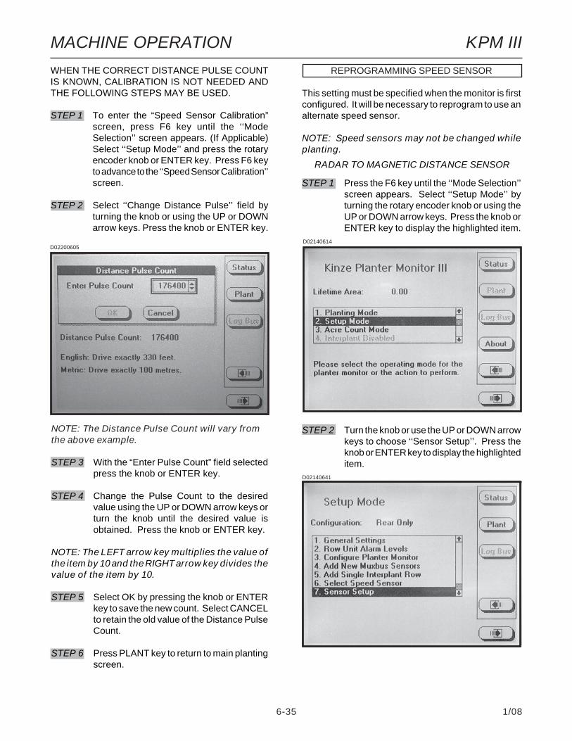
6-35 1/08
MACHINE OPERATION KPM III
REPROGRAMMING SPEED SENSOR
This setting must be specified when the monitor is firstconfigured. It will be necessary to reprogram to use analternate speed sensor.
NOTE: Speed sensors may not be changed whileplanting.
STEP 1 Press the F6 key until the ‘‘Mode Selection’’screen appears. Select ‘‘Setup Mode’’ byturning the rotary encoder knob or using theUP or DOWN arrow keys. Press the knob orENTER key to display the highlighted item.
STEP 2 Turn the knob or use the UP or DOWN arrowkeys to choose ‘‘Sensor Setup’’. Press theknob or ENTER key to display the highlighteditem.
D02140614
NOTE: The Distance Pulse Count will vary fromthe above example.
STEP 3 With the “Enter Pulse Count” field selectedpress the knob or ENTER key.
STEP 4 Change the Pulse Count to the desiredvalue using the UP or DOWN arrow keys orturn the knob until the desired value isobtained. Press the knob or ENTER key.
NOTE: The LEFT arrow key multiplies the value ofthe item by 10 and the RIGHT arrow key divides thevalue of the item by 10.
STEP 5 Select OK by pressing the knob or ENTERkey to save the new count. Select CANCELto retain the old value of the Distance PulseCount.
STEP 6 Press PLANT key to return to main plantingscreen.
WHEN THE CORRECT DISTANCE PULSE COUNTIS KNOWN, CALIBRATION IS NOT NEEDED ANDTHE FOLLOWING STEPS MAY BE USED.
STEP 1 To enter the “Speed Sensor Calibration”screen, press F6 key until the ‘‘ModeSelection’’ screen appears. (If Applicable)Select ‘‘Setup Mode’’ and press the rotaryencoder knob or ENTER key. Press F6 keyto advance to the ‘‘Speed Sensor Calibration’’screen.
STEP 2 Select ‘‘Change Distance Pulse’’ field byturning the knob or using the UP or DOWNarrow keys. Press the knob or ENTER key.
D02200605
RADAR TO MAGNETIC DISTANCE SENSOR
D02140641

6-36 1/08
MACHINE OPERATION KPM III
D02140639
STEP 3 Turn the knob or use the UP or DOWN arrowkeys to highlight ‘‘Mag Coil Pickup’’. Plug inMagnetic Distance Sensor and press theINSTALL key. Press the knob or ENTERkey to save information.
D05310609a
STEP 4 Turn the knob or use the UP or DOWN arrowkeys to select ‘‘Select Speed Sensor’’andpress the knob or ENTER key. Press theknob or ENTER key to select the ‘‘SpeedSensor’’ field and a drop down menu willappear. Turn the knob or use the UP orDOWN arrow keys to select ‘‘Coil Pick-Up’’and press the knob or ENTER key to makeselection. The black box will advance to OKpress the knob or ENTER key to save theinformation.
D05310609
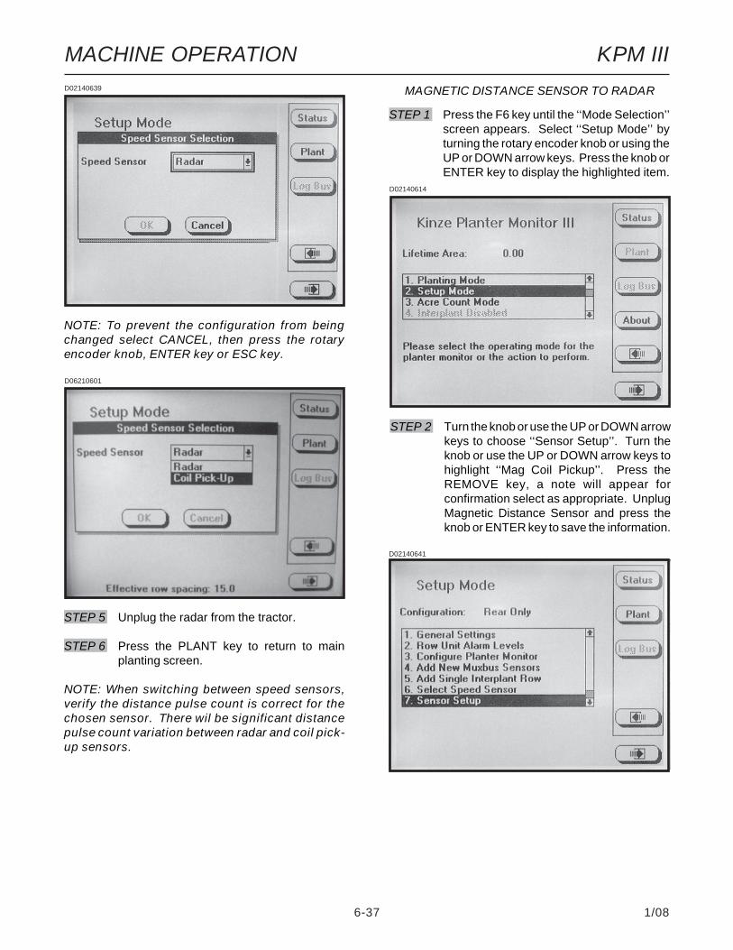
6-37 1/08
MACHINE OPERATION KPM III
STEP 1 Press the F6 key until the ‘‘Mode Selection’’screen appears. Select ‘‘Setup Mode’’ byturning the rotary encoder knob or using theUP or DOWN arrow keys. Press the knob orENTER key to display the highlighted item.
D02140614
MAGNETIC DISTANCE SENSOR TO RADAR
D02140641
STEP 2 Turn the knob or use the UP or DOWN arrowkeys to choose ‘‘Sensor Setup’’. Turn theknob or use the UP or DOWN arrow keys tohighlight ‘‘Mag Coil Pickup’’. Press theREMOVE key, a note will appear forconfirmation select as appropriate. UnplugMagnetic Distance Sensor and press theknob or ENTER key to save the information.
D02140639
D06210601
STEP 5 Unplug the radar from the tractor.
STEP 6 Press the PLANT key to return to mainplanting screen.
NOTE: When switching between speed sensors,verify the distance pulse count is correct for thechosen sensor. There wil be significant distancepulse count variation between radar and coil pick-up sensors.
NOTE: To prevent the configuration from beingchanged select CANCEL, then press the rotaryencoder knob, ENTER key or ESC key.

6-38 1/08
MACHINE OPERATION KPM III
D02140639
D02140640
D02140639
STEP 3 Turn the knob or use the UP or DOWN arrowkeys to select ‘‘Select Speed Sensor’’ andpress the knob or ENTER key. Press theknob or ENTER key to select the ‘‘SpeedSensor’’ field and a drop down menu willappear. Turn the knob or use the UP orDOWN arrow keys to select ‘‘Radar’’ andpress the knob or ENTER key to makeselection.
STEP 5 Press the PLANT key to return to mainplanting screen.
NOTE: When switching between speed sensors,verify the distance pulse count is correct for thechosen sensor. There wil be significant distancepulse count variation between radar and magneticdistance sensors.
NOTE: To prevent the configuration from beingchanged select CANCEL, then press the knob,ENTER key or ESC key.
D05310609
STEP 4 Plug in the Radar and the black box willadvance to OK. Press the knob or ENTERkey to save the information.

6-39 1/08
MACHINE OPERATION KPM IIISTEP 4 The note shown below will appear. Select
OK by turning the knob or using the UP orDOWN arrow keys. Press the knob orENTER key to make the selection.
STEP 5 Turn the knob or use the UP or DOWN arrowkeys to select the ‘‘Front Row Units’’ fieldand press the knob or ENTER key to highlightthe field. Turn the knob or use the UP orDOWN arrow keys to obtain the desirednumber of rows. When the correct value hasbeen entered press the knob or ENTER key.The black box will advance to the OK key.Press the knob or ENTER key to save theinformation.
NOTE: To prevent the configuration from beingchanged select CANCEL, then press the knob,ENTER key or ESC key.D02220674
D03010601
ADDING INTERPLANT® ROWS (If Rear RowsHave Previously Been Programmed)
STEP 1 Press the F6 key until ‘‘Mode Selection’’screen appears.
STEP 2 Select ‘‘Setup Mode’’ by turning the rotaryencoder knob or using the UP or DOWNarrow keys. Press the knob or ENTER keyto display the highlighted item.
D02140614
STEP 3 Select ‘‘Add New Muxbus Sensors’’ byturning the knob or using the UP and DOWNarrow keys. Press the knob or ENTER keyto display the highlighted item.
D02140633
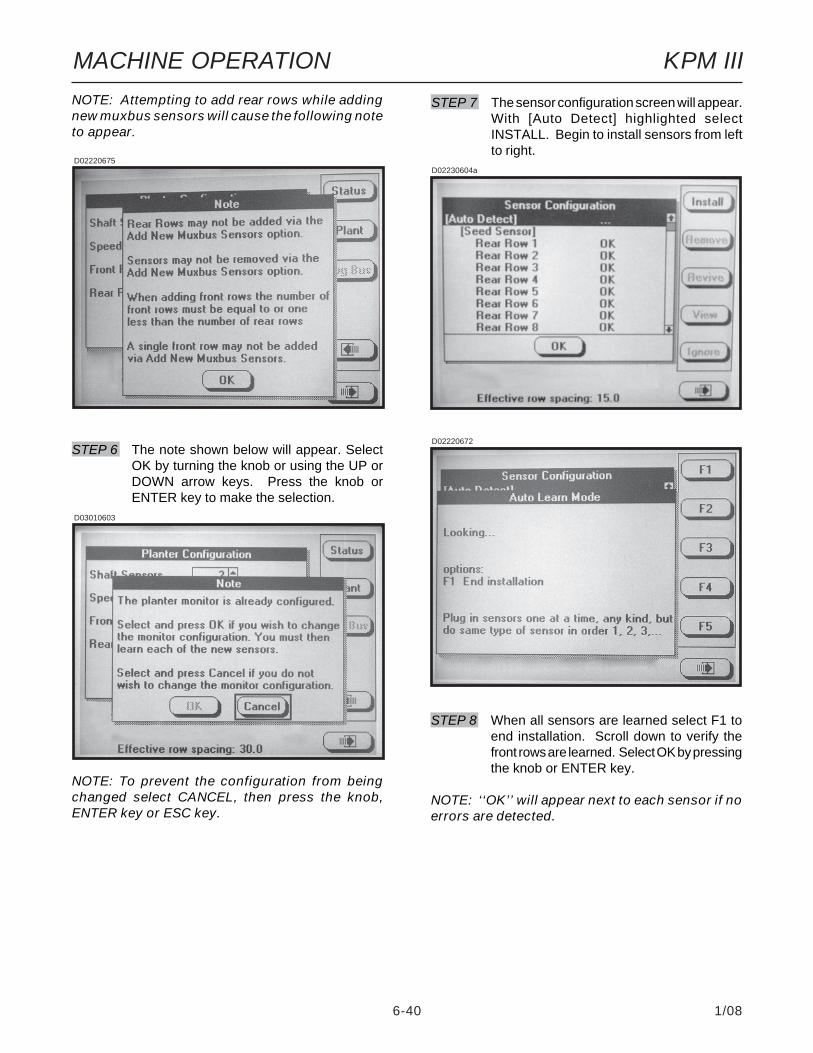
6-40 1/08
MACHINE OPERATION KPM III
STEP 6 The note shown below will appear. SelectOK by turning the knob or using the UP orDOWN arrow keys. Press the knob orENTER key to make the selection.
D03010603
NOTE: To prevent the configuration from beingchanged select CANCEL, then press the knob,ENTER key or ESC key.
NOTE: Attempting to add rear rows while addingnew muxbus sensors will cause the following noteto appear.
D02220675
D02220672
STEP 8 When all sensors are learned select F1 toend installation. Scroll down to verify thefront rows are learned. Select OK by pressingthe knob or ENTER key.
NOTE: ‘‘OK’’ will appear next to each sensor if noerrors are detected.
D02230604a
STEP 7 The sensor configuration screen will appear.With [Auto Detect] highlighted selectINSTALL. Begin to install sensors from leftto right.
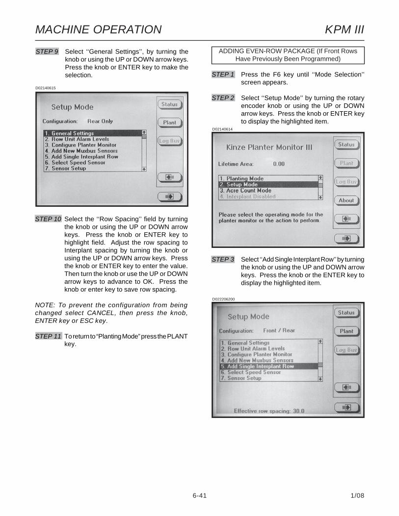
6-41 1/08
MACHINE OPERATION KPM III
ADDING EVEN-ROW PACKAGE (If Front RowsHave Previously Been Programmed)
STEP 1 Press the F6 key until ‘‘Mode Selection’’screen appears.
STEP 2 Select ‘‘Setup Mode’’ by turning the rotaryencoder knob or using the UP or DOWNarrow keys. Press the knob or ENTER keyto display the highlighted item.
STEP 3 Select ‘‘Add Single Interplant Row’’ by turningthe knob or using the UP and DOWN arrowkeys. Press the knob or the ENTER key todisplay the highlighted item.
D02140614
D022206200
STEP 10 Select the ‘‘Row Spacing’’ field by turningthe knob or using the UP or DOWN arrowkeys. Press the knob or ENTER key tohighlight field. Adjust the row spacing toInterplant spacing by turning the knob orusing the UP or DOWN arrow keys. Pressthe knob or ENTER key to enter the value.Then turn the knob or use the UP or DOWNarrow keys to advance to OK. Press theknob or enter key to save row spacing.
NOTE: To prevent the configuration from beingchanged select CANCEL, then press the knob,ENTER key or ESC key.
STEP 11 To return to “Planting Mode” press the PLANTkey.
D02140615
STEP 9 Select ‘‘General Settings’’, by turning theknob or using the UP or DOWN arrow keys.Press the knob or ENTER key to make theselection.

6-42 1/08
MACHINE OPERATION KPM III
STEP 4 To confirm the following note turn the knobor use the UP or DOWN arrow keys to selectOK and then press the knob or ENTER keyto confirm. If the single Interplant row is notto be added select the CANCEL key andpress the knob or ENTER key to cancel orpress the ESC key.
D022206202
D022206201
STEP 5 To ‘‘Add Single Interplant Row’’ the followingscreen will appear.
If the single Interplant row is to be added turnthe knob or use the UP or DOWN arrow keysto select OK and then press the knob orENTER key to add the Interplant row. If thesingle Interplant row is not to be addedselect the CANCEL key and press the knobor ENTER key to cancel or press the ESCkey.
D02220670
STEP 6 The ‘‘Sensor Configuration’’ screen willappear. Plug in the new sensor then scrolldown to highlight “Front Row 1” by turningthe knob or using the UP or DOWN arrowkeys. Select INSTALL to learn the newsensor. Press the knob or ENTER key toreturn to setup mode.
STEP 7 To return to “Planting Mode” press the PLANTkey.

6-43 1/08
MACHINE OPERATION KPM III
Either select the ‘‘Planting Mode’’ by turning the knobor using the UP arrow key and press the knob orENTER key or press F6 to return to the ‘‘PlantingMode’’.
ROW POPULATION• Press the ROW POP key to display rowpopulation. Average planter population will beshown in the lower L.H. corner of the display.
D02240604
ENABLING/DISABLING INTERPLANT® ROWS
To Enable or Disable Interplant (a) press the F6 keyuntil the ‘‘Mode Selection’’ screen appears, (b) turn therotary encoder knob or use the UP or DOWN arrowkeys to highlight ‘‘Disable/Enable Interplant’’, (c) pressthe knob or ENTER key to ‘‘Disable’’ or ‘‘Enable’’Interplant. To verify selection, the row spacing isdisplayed on the bottom of the screen.
D03010605a
D05310614
• Press the SCAN key and the monitor will scanthrough each row in ascending order displayingthe average seed population for each row. Afterall rows have been scanned the averagepopulation is displayed and scan function willcontinue with the first rear row.
D02240602

6-44 1/08
MACHINE OPERATION KPM III
ROW SPACING• Press the SPACING key to display seedspacing keys. Seed spacing will appear in thebottom L.H. corner of the display.
• Press the SCAN key and the monitor will scanthrough each row in ascending order displayingthe average seed spacing for each row. Scanappears in the L.H. corner to indicate the displayis scanning. After all rows have been scanned theaverage population is displayed and scanning willcontinue with the first rear row.
• Press the FREEZE key to stop scanning andthe left display item will be frozen on a particularrow. “Frzn” appears to indicate the display isfrozen. To resume scan press the SCAN key.
D02240605
D02240602
• Press the FREEZE key to stop scanning, theleft display item will be frozen on a particular row.“Frzn” appears in the lower L.H. corner to indicatethe display is frozen. To resume scan press theSCAN key.
EXAMPLE: When average row population isshown, R3 indicates rear row 3, F2 indicatesfront row 2, etc.
• When either Scan or Frzn is displayed in theL.H. corner the SECTION and arrow keys functionas follows: (a) SECTION or RIGHT arrow keyadvances to the first row of the next section; (b)SECTION or LEFT arrow key selects the first rowof the previous section, wrapping around to thefirst row of the last section when moving past thefirst section; (c) UP arrow key moves forward tothe next row of the planter, wrapping around to thefirst row when moving past the last row; (d)DOWN arrow key moves backward to the previousrow of the planter, wrapping around to the last rowof the planter when moving past the first row.
• Press the AVERAGE key to display the averagepopulation in the bottom L.H. corner.
• Press the NORMAL key to display the normalscreen for planting mode.
NOTE: If the rows are being scanned and theAVERAGE key is selected the scan function willstop.
D05310615

6-45 1/08
MACHINE OPERATION KPM III
NOTE: The appropriate units of measure will bedisplayed (English or Metric).
• Press NORMAL to bring back the standardkey labels.
• Press the SHAFT key to view the averagemeter shaft RPM. The value will appear in thebottom R.H. corner of the display.
NOTE: Applicable to planters with shaft rotationsensors installed.
• Press the SPEED key to view the groundspeed. The value will appear in the bottom R.H.corner of the display.
D02240607
D02240608
SPEED/SHAFT ROTATION• Press the OTHER key to display items availableto display in the bottom R.H. corner.
D02240606
• When either “Scan” or “Frzn” is displayed in theleft display item the SECTION and arrow keysfunction as follows: (a) SECTION and RIGHTarrow key advances to the first row of the nextsection; (b) LEFT arrow key selects the first rowof the previous section, wrapping around to thefirst row of the last section when moving past thefirst section; (c) UP arrow key moves forward tothe next row of the planter, wrapping around to thefirst row when moving past the last row; (d)DOWN arrow key moves backward to the previousrow of the planter, wrapping around to the last rowof the planter when moving past the first row.
• Press the AVERAGE key to display the averageseed spacing in the bottom L.H. corner.
• Press the NORMAL key to display the mainplanting mode.
NOTE: If the rows are being scanned and theAVERAGE key is selected the scan function willstop.
D02240602
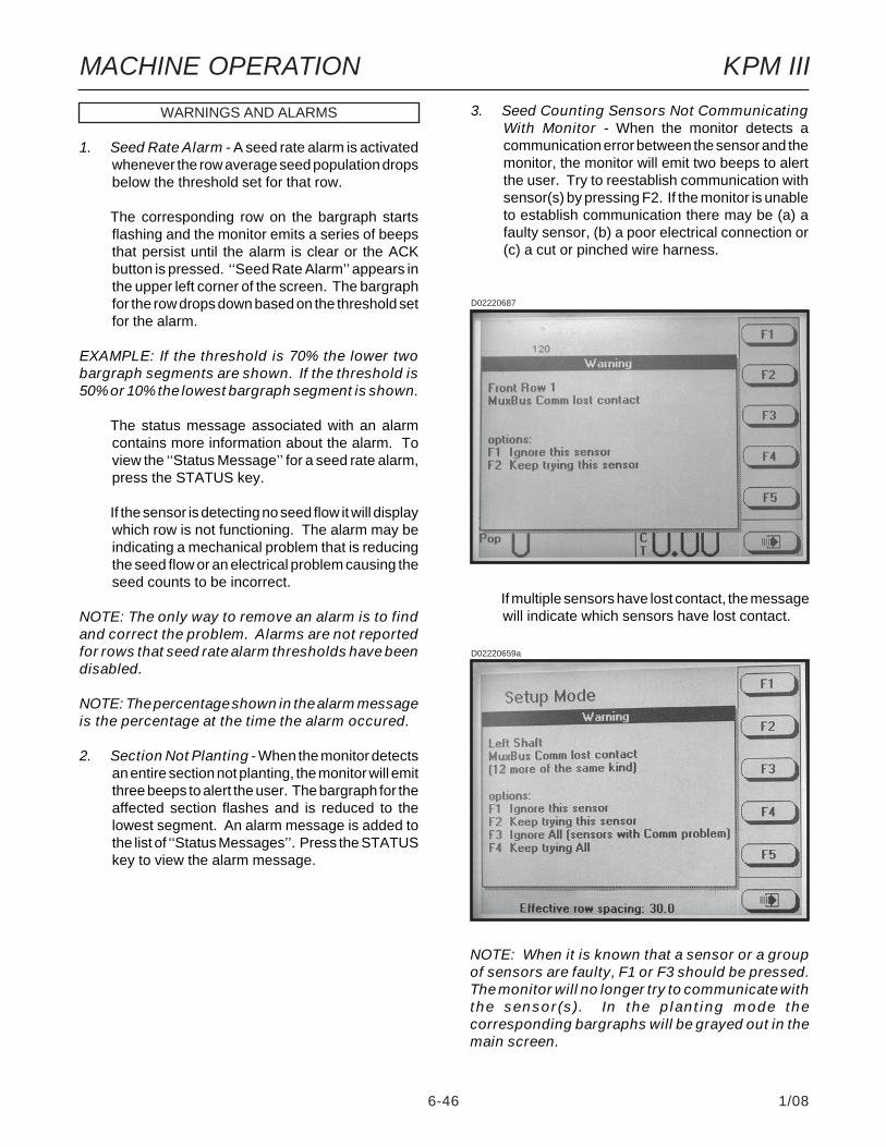
6-46 1/08
MACHINE OPERATION KPM III
WARNINGS AND ALARMS
1. Seed Rate Alarm - A seed rate alarm is activatedwhenever the row average seed population dropsbelow the threshold set for that row.
The corresponding row on the bargraph startsflashing and the monitor emits a series of beepsthat persist until the alarm is clear or the ACKbutton is pressed. ‘‘Seed Rate Alarm’’ appears inthe upper left corner of the screen. The bargraphfor the row drops down based on the threshold setfor the alarm.
EXAMPLE: If the threshold is 70% the lower twobargraph segments are shown. If the threshold is50% or 10% the lowest bargraph segment is shown.
The status message associated with an alarmcontains more information about the alarm. Toview the ‘‘Status Message’’ for a seed rate alarm,press the STATUS key.
If the sensor is detecting no seed flow it will displaywhich row is not functioning. The alarm may beindicating a mechanical problem that is reducingthe seed flow or an electrical problem causing theseed counts to be incorrect.
NOTE: The only way to remove an alarm is to findand correct the problem. Alarms are not reportedfor rows that seed rate alarm thresholds have beendisabled.
NOTE: The percentage shown in the alarm messageis the percentage at the time the alarm occured.
2. Section Not Planting - When the monitor detectsan entire section not planting, the monitor will emitthree beeps to alert the user. The bargraph for theaffected section flashes and is reduced to thelowest segment. An alarm message is added tothe list of ‘‘Status Messages’’. Press the STATUSkey to view the alarm message.
NOTE: When it is known that a sensor or a groupof sensors are faulty, F1 or F3 should be pressed.The monitor will no longer try to communicate withthe sensor(s). In the planting mode thecorresponding bargraphs will be grayed out in themain screen.
3. Seed Counting Sensors Not CommunicatingWith Monitor - When the monitor detects acommunication error between the sensor and themonitor, the monitor will emit two beeps to alertthe user. Try to reestablish communication withsensor(s) by pressing F2. If the monitor is unableto establish communication there may be (a) afaulty sensor, (b) a poor electrical connection or(c) a cut or pinched wire harness.
D02220687
D02220659a
If multiple sensors have lost contact, the messagewill indicate which sensors have lost contact.
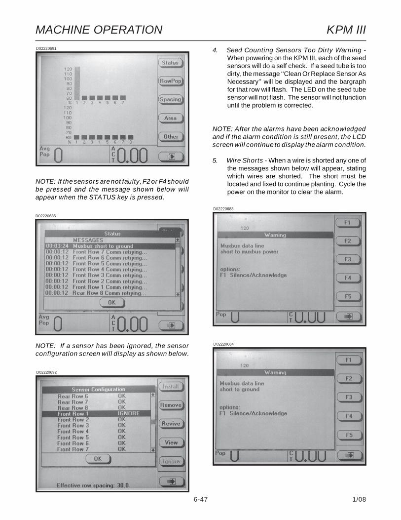
6-47 1/08
MACHINE OPERATION KPM III
4. Seed Counting Sensors Too Dirty Warning -When powering on the KPM III, each of the seedsensors will do a self check. If a seed tube is toodirty, the message ‘‘Clean Or Replace Sensor AsNecessary’’ will be displayed and the bargraphfor that row will flash. The LED on the seed tubesensor will not flash. The sensor will not functionuntil the problem is corrected.
NOTE: After the alarms have been acknowledgedand if the alarm condition is still present, the LCDscreen will continue to display the alarm condition.
5. Wire Shorts - When a wire is shorted any one ofthe messages shown below will appear, statingwhich wires are shorted. The short must belocated and fixed to continue planting. Cycle thepower on the monitor to clear the alarm.
D02220684
D02220683
D02220692
D02220691
D02220685
NOTE: If the sensors are not faulty, F2 or F4 shouldbe pressed and the message shown below willappear when the STATUS key is pressed.
NOTE: If a sensor has been ignored, the sensorconfiguration screen will display as shown below.

6-48 1/08
MACHINE OPERATION KPM III
FIELD OPERATION
Press the ON/OFF key to turn the monitor ON.
If the monitor has been configured, it will enter thenormal planting mode and attempt to communicatewith the seed sensors.
If the monitor does not detect any sensors the messageshown below will appear.
NOTE: Selecting OK will reconfigure the monitorrequiring all sensors to be re-learned. SelectingCANCEL will maintain the current configurationand the monitor will continue trying tocommunicate with the sensors.
D02200627
NOTE: Do not attempt planting before the ‘‘WaitFor Calibration’’ message disappears. If planter ismoving while sensors are calibrating alarms willbe generated.
D02200606
NOTE: If the monitor can communicate with thesensors the normal planting mode screen will bedisplayed.
D02220689a
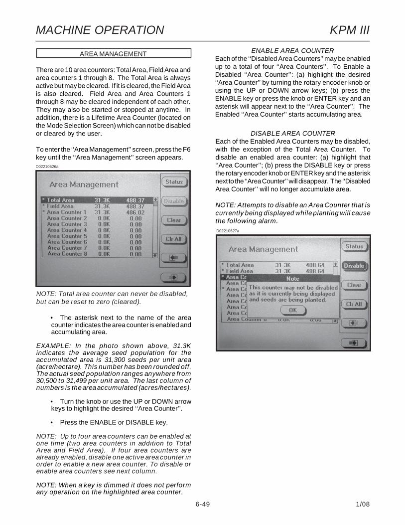
6-49 1/08
MACHINE OPERATION KPM III
NOTE: Total area counter can never be disabled,but can be reset to zero (cleared).
• The asterisk next to the name of the areacounter indicates the area counter is enabled andaccumulating area.
EXAMPLE: In the photo shown above, 31.3Kindicates the average seed population for theaccumulated area is 31,300 seeds per unit area(acre/hectare). This number has been rounded off.The actual seed population ranges anywhere from30,500 to 31,499 per unit area. The last column ofnumbers is the area accumulated (acres/hectares).
• Turn the knob or use the UP or DOWN arrowkeys to highlight the desired ‘‘Area Counter’’.
• Press the ENABLE or DISABLE key.
NOTE: Up to four area counters can be enabled atone time (two area counters in addition to TotalArea and Field Area). If four area counters arealready enabled, disable one active area counter inorder to enable a new area counter. To disable orenable area counters see next column.
NOTE: When a key is dimmed it does not performany operation on the highlighted area counter.
ENABLE AREA COUNTEREach of the ‘‘Disabled Area Counters’’ may be enabledup to a total of four ‘‘Area Counters’’. To Enable aDisabled ‘‘Area Counter’’: (a) highlight the desired‘‘Area Counter’’ by turning the rotary encoder knob orusing the UP or DOWN arrow keys; (b) press theENABLE key or press the knob or ENTER key and anasterisk will appear next to the ‘‘Area Counter’’. TheEnabled ‘‘Area Counter’’ starts accumulating area.
DISABLE AREA COUNTEREach of the Enabled Area Counters may be disabled,with the exception of the Total Area Counter. Todisable an enabled area counter: (a) highlight that‘‘Area Counter’’; (b) press the DISABLE key or pressthe rotary encoder knob or ENTER key and the asterisknext to the ‘‘Area Counter’’ will disappear. The ‘‘DisabledArea Counter’’ will no longer accumulate area.
NOTE: Attempts to disable an Area Counter that iscurrently being displayed while planting will causethe following alarm.D02210627a
AREA MANAGEMENT
There are 10 area counters: Total Area, Field Area andarea counters 1 through 8. The Total Area is alwaysactive but may be cleared. If it is cleared, the Field Areais also cleared. Field Area and Area Counters 1through 8 may be cleared independent of each other.They may also be started or stopped at anytime. Inaddition, there is a Lifetime Area Counter (located onthe Mode Selection Screen) which can not be disabledor cleared by the user.
To enter the ‘‘Area Management’’ screen, press the F6key until the ‘‘Area Management’’ screen appears.D02210626a
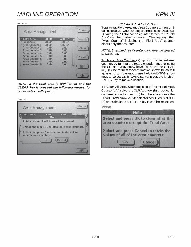
6-50 1/08
MACHINE OPERATION KPM III
CLEAR AREA COUNTERTotal Area, Field Area and Area Counters 1 through 8can be cleared, whether they are Enabled or Disabled.Clearing the ‘‘Total Area’’ counter forces the ‘‘FieldArea’’ counter to also be cleared. Clearing any other‘‘Area Counter’’ including the ‘‘Field Area’’ counterclears only that counter.
NOTE: Lifetime Area Counter can never be clearedor disabled.
To clear an Area Counter: (a) highlight the desired areacounter, by turning the rotary encoder knob or usingthe UP or DOWN arrow keys, (b) press the CLEARkey, (c) the request for confirmation shown below willappear, (d) turn the knob or use the UP or DOWN arrowkeys to select OK or CANCEL, (e) press the knob orENTER key to make selection.
To Clear All Area Counters except the ‘‘Total AreaCounter’’: (a) select the CLR ALL key; (b) a request forconfirmation will appear; (c) turn the knob or use theUP or DOWN arrow keys to select either OK or CANCEL;(d) press the knob or ENTER key to confirm selection.
NOTE: If the total area is highlighted and theCLEAR key is pressed the following request forconfirmation will appear.
D02210626a
D02200612
D02210628

6-51 1/08
MACHINE OPERATION KPM III
NOTE: The abbreviation for the selected areacounter numerical value will appear in the bottomR.H. corner of the screen. In the above photo‘‘ACF’’ represents ‘‘Area Counter Field’’.
STEP 4 Press the knob or ENTER key to select OK.The planting screen will then be displayed.Press NORMAL to display main plantingscreen.
D02240610
AREA COUNTERS STEP 3 To select the desired active ‘‘Area Counter’’turn the knob or use the UP or DOWNarrows to highlight the desired ‘‘AreaCounter’’.
D02240602
D02240603
D02240609
STEP 2 Press the SELECT key to display the list ofthe Enabled Area Counters.
STEP 1 On the main planting screen press the AREAkey.

6-52 1/08
MACHINE OPERATION KPM III
NOTE: If no radar unit is detected a warning willappear.
NOTE: If using acre count mode, acre (acres orhectares) is accumulated in “Lifetime AreaCounter”.
Acre Count Mode
STEP 1 Press the F6 key until the ‘‘Mode Selection’’screen appears. Turn the rotary encoderknob or use the UP or DOWN arrow keys toselect ‘‘Acre Count Mode’’. Press the knobor ENTER key.
ACRE COUNT MODE
When a tractor is equipped with a radar distancesensor, accumulating area without a planter attachedis possible. Two routes are provided to enter acrecount mode: (a) Installation of an Acre Count Switch Kitor (b) entry into Acre Count Mode.
Acre Count Switch KitSTEP 1 With the monitor OFF, attach an Acre Count
Switch Kit to the Muxbus connector and thenturn monitor ON and advance to STEP 2.
D02200618
CLEARING FIELD AREA
To reset the counter, display the main planting screenby pressing the F6 key until it appears. Press theAREA key then select the CLEAR key, a dialog box willappear requesting confirmation to clear. Select OK orCANCEL key by turning the rotary encoder knob orusing the UP or DOWN arrow keys. Press the knob orENTER key to verify the selection.
NOTE: Only the displayed Area Counter can bedisabled.
D02210625
D02210625

6-53 1/08
MACHINE OPERATION KPM III
NOTE: DO NOT BEGIN ACCUMULATING AREA IFTHE RADAR UNIT HAS NOT BEEN CALIBRATED.Always check the distance pulse count valueimmediately after entering acre count mode andbefore pressing start.
STEP 2 In the menu, ‘‘Units & Width’’ will behighlighted. Press the knob or ENTER key.
STEP 3 A drop down menu will appear. Select thecorrect units of measure ‘‘English’’ or ‘‘Metric’’by turning the knob or using the UP orDOWN arrow keys. Press the knob orENTER key to make the selection. Theblack box will advance to ‘‘Implement Width’’field showing implement width in feet.
D02200621
D02200619
STEP 4 Press the knob or ENTER key to highlightthe field. Turn the knob or use the UP orDOWN arrow keys to select desired numberin feet. When desired number is obtainedpress the knob or ENTER key. The blackbox will advance to OK key.
NOTE: The implement width entered in acre countmode has no effect on planting mode settings.
STEP 5 Press the knob or ENTER key when done.
NOTE: Tractor should be at a complete stop beforestarting.
STEP 6 To begin accumulating area press the STARTkey.
STEP 7 To stop accumulating area or to move to adifferent location, press the STOP key.
There are two counters in the Acre Count Mode (FieldArea Counter and Total Area Counter). The ‘‘FieldArea’’ counter can be cleared independent of the‘‘Total Area’’ counter. Clearing the ‘‘Total Area’’ countercauses the ‘‘Field Area’’ counter to also be cleared.
• To Clear Field Area. Highlight ‘‘Clear FieldArea’’ and press the knob or ENTER key. Anote will appear verifying the decision to resetthe field area to zero. Select OK and press theknob or ENTER key to clear the field to zero.Select Cancel and press the knob or the ENTERkey to retain the current field value.
• To Clear Both Field Area And Total Area.Highlight the ‘‘Clear Field Area & Total Area’’and press the knob or ENTER key. A note willappear to verify the decision to reset the fieldarea and the total area to zero. Select OK andpress the knob or ENTER key to clear the fieldto zero. Select CANCEL and press the knobor ENTER key to retain the current field value.
With planter reconnected to monitor return to normalplant screen by pressing the F6 key until the ‘‘ModeSelection’’ screen appears. Select ‘‘Planting Mode’’ byturning the knob or using the UP or DOWN arrow keys,press the knob or ENTER key.

6-54 1/08
MACHINE OPERATION KPM III
D02140641
D02210601a
STEP 4 Highlight faulty sensor. Press REMOVE keyand unplug sensor. Plug in new sensor andpress INSTALL key.
Repeat above procedure for each faultysensor being replaced.
NOTE: Highlighting a sensor and pressing VIEWgives additional information when troubleshootinga problem. If a faulty sensor has been ignored itmay be highlighted in the list of sensors, pressREVIVE. The monitor will try to communicate withthe sensor. If successful, ‘‘OK’’ will appear next tothe sensor.
REPLACING FAULTY SENSOR(S)
To replace a single faulty sensor: (a) turn OFF themonitor, (b) replace the sensor, (c) turn monitor ON. Itwill then recognize that a single sensor has beenreplaced.
NOTE: Monitor will beep twice when the newsenor(s) is learned.
To replace more than one faulty sensor:
STEP 1 Press F6 key until the ‘‘Mode Selection’’screen appears.
STEP 2 Select ‘‘Setup Mode’’ by turning the knob orpress the UP or DOWN arrow keys. Pressthe knob or ENTER key to display thehighlighted item.
STEP 3 Select ‘‘Sensor Setup’’ by turning the knobor using the UP or DOWN arrow keys. Pressthe knob or ENTER key to display thehighlighted item.
STEP 5 Press the knob or ENTER key to return to‘‘Setup Mode’’ screen.
STEP 6 To return to “Planting Mode” press the PLANTkey.
See “KPM III ElectronicSeed Monitor
Troubleshooting” in theMaintenance Section.

MACHINE OPERATION
6-55 1/08
PLANTER MONITOR MODULE (PMM)
The PMM Magnetic Distance Sensor Package includesa planter-mounted module enclosure with cover andmounting hardware, seed tubes w/sensors, planter harnes,planter monitor cable, shaft rotation sensors and mag-netic distance sensor components. A customer-sup-plied Ag Leader Insight display and associated cabharnesses are also required.
NOTE: See information supplied with Ag LeaderInsight display for installation and programming.
D11200710a
PLANTER MONITOR MODULE
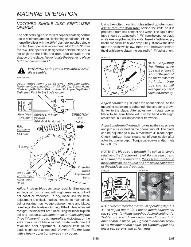
MACHINE OPERATION
6-56 1/08
NOTCHED SINGLE DISC FERTILIZEROPENER
The notched single disc fertilizer opener is designed foruse in minimum and no till planting conditions. Place-ment of fertilizer with the 16 3/4" diameter notched singledisc fertilizer opener is recommended at 2 1/2"- 3" fromthe row. The opener is designed to hold the blade at aset-angle so the knife and drop tube operate in theshadow of the blade. Never locate the opener to placefertilizer closer than 2".
WARNING: Spring under pressure. DO NOTdisassemble.
Adjust knife-to-blade contact on each fertilizer openerso blade will turn by hand with slight resistance, but willnot coast or freewheel. In dry, loose soil the knifeadjustment is critical. If adjustment is not maintained,soil or residue may wedge between knife and blade,resulting in the blade not turning. If the knife is adjustedtoo tight, the blade will not turn causing the blade to pushsoil and residue. Knife adjustment is made using thethree 3/8" mounting carriage bolts and pivot pad on theknife. Because of blade runout, rotate blade one fullrevolution after adjustment. Readjust knife to theblade’s tight spot as needed. Never strike the knifewith a heavy object or damage may occur.
Using the slotted mounting holes in the drop tube mount,adjust fertilizer drop tube behind the knife so it isprotected from soil contact and wear. The liquid droptube should be adjusted 1/4"- 3/8" from the opener bladewhile keeping it behind the knife. Insert a flat bladed prybar between the knife and drop tube just above the droptube tab as shown below. Bend the tube inward towardthe disc blade to obtain the desired 1/4"- 3/8" adjustment.
Adjust scraper to just touch the opener blade. As themounting hardware is tightened, the scraper is drawntighter to the blade. After adjustment, rotate openerblade to be sure blade will turn by hand with slightresistance, but will not coast or freewheel.
Adjust blade depth on each row using the cap screwsand jam nuts located on the opener mount. The bladecan be adjusted to allow a maximum 4" blade depth.Check fertilizer hose clearance (If Applicable) afteradjusting opener depth. Torque cap screws and jam nutsto 57 ft. lbs.
NOTE: The blade cuts through the soil at an anglerelative to the direction of travel. For this reason andto ensure proper operation, the cast mount shouldbe oriented so the double ribs are on the same sideof the blade as the drop tube.
(B0297/A12422)
Depth Adjustment Cap Screws - RecommendedMaximum Operating Depth 4" (Middle Cap Screw HoldsBlade Angle But Must Be Loosened To Adjust Depth AndTightened First To Set Blade Angle)
Knife
Drop TubeAnd ScraperAdjustmentBolts
Rear View Of Mount
Knife-To-Blade
Adjustment Bolts
Scraper
DIRECTIONOF
TRAVELR.H.OPENERSHOWN
NOTE: Recommended maximum operating depth is4". To adjust depth: (a) Loosen depth adjustmentcap screws. (b) Adjust depth to desired setting. (c)Tighten upper and lower cap screws slightly to holdopener arm in place. (d) Tighten middle cap screwto set the opener arm angle. (e) Tighten upper andlower cap screws and all jam nuts.
FRTZ296 D070103100
D01040702
NOTE: Adjustingthe liquid droptube will ensure itis out of the path ofthe soil flow acrossthe knife. Droptube and tab willwear quickly if notadjusted correctly.
GB0399 L.H. Mount(Shown)GB0404 R.H. Mount

MACHINE OPERATION
6-57 1/08
DEPTH/GAUGE WHEEL ATTACHMENTFOR NOTCHED SINGLE DISC FERTILIZEROPENER
D061101202a
The depth/gauge wheel attachment for the notchedsingle disc fertilizer opener is designed for use insituations where additional gauging is required to main-tain desired fertilizer opener depth. The depth/gaugewheel is attached to the notched single disc fertilizeropener using a mounting block fastened to the pivot armusing 5/8" hardware through the disc blade hub w/bearing.
Depth adjustment is made by us-ing the adjustment holes in thedepth/gauge wheel mounting block.Moving the depth/gauge wheel in-creases/decreases depth in ap-proximate 1" increments in rela-tion to the blade depth settingmade at the vertical mounting post.
(FRTZ256a)

MACHINE OPERATION
6-58 1/08
LIQUID FERTILIZER ATTACHMENT
To Opener
To Pump
(FRTZ208)
PISTON PUMP
If the machine is equipped with the piston pump option,the rate of liquid fertilizer application is determined bythe piston pump settings.
The delivery rate chart found at the end of this sectionprovides an approximate application rate only. Actualdelivery will vary with temperature and the particularfertilizer being used.
To adjust delivery rate, loosen the 3/8" lock nut thatsecures the arm with the pointer and rotate the scaleflange until the pointer is over the desired scale setting.The adjustment wrench will facilitate rotation of thescale flange. Tighten the 3/8" lock nut being careful notto over tighten.
Model 3800 SDS EdgeVac® 24 Row 30" With LiquidFertilizer Package
D01050702
NOTE: An optional low rate checkvalve is available for installation in-line between the liquid fertilizer pis-ton pump and the liquid fertilizeropeners to ensure equal distributionof product at low rates. The checkvalves also eliminate the need foranti-siphon loops if the valves areinstalled as close as possible to thefertilizer opener drop tubes.
(A12330b)
The operator and instruction manual shipped with thepump and flow divider should be kept and stored with thismanual for future reference.
NOTE: Periodically check flow to all rows. If one ormore lines are plugged, set rate will be delivered toremaining rows.

MACHINE OPERATION
6-59 1/08
CLEANING
The tanks and all hoses are made of sturdy plastic andrubber to resist corrosion. However, the tanks, hosesand metering pump should be thoroughly cleaned withwater at the end of the planting season or prior to anextended period of non-use. Do not allow fertilizer tocrystalize due to cold temperature or evaporation.
The strainer, located between the piston pump and ballvalve (machines equipped with the piston pump), shouldbe taken apart and cleaned daily. Remove the end capto clean the screen.(INS220)
See “Piston Pump Storage” (If Applicable) in theMaintenance section of this manual.
Screen
End Cap
PISTON PUMP GROUND DRIVE WHEEL SPRINGADJUSTMENT
Initial spring tension of the down pressure spring on thepiston pump ground drive wheel is set leaving 12 1/4"between the bottom of the mounting plate and the plugon top of the spring. This dimension is taken with theplanter in raised position (tire not contacting the ground).Further adjustment can be made to fit conditions.
NOTE: The piston pump ground drive wheel assem-bly is designed to allow the assembly to be lockedin raised position when not in use. Remove the twocap screws that attach the upper end of the springto the spring mount. Reattach the spring using theupper holes in the spring mount. Reverse proce-dure to reset for field use.
(TWL219tt)
12 1/4"

MACHINE OPERATION
6-60 1/08
LIQUID FERTILIZER PISTON PUMP APPLICATION RATESGALLONS PER ACRE
Applies To Model NGP-7055 Pump With 18 Tooth Sprocket(Planter Equipped With Two Piston Pumps)
PumpSetting 1 2 3 4 5 6 7 8 9 10
24 Row 30" 3.7 7.4 11.1 14.8 18.5 22.1 25.8 29.5 33.2 36.9
32 Row 30" 2.8 5.5 8.3 11.1 13.9 16.6 19.4 22.2 24.9 27.7
36 Row 30" 2.5 4.9 7.3 9.8 12.2 14.6 17.0 19.5 21.9 24.4
Above chart is for planters equipped with 7.60" x 15" drive wheel, based on 91" forward travel per wheelrevolution, 48 tooth drive sprocket and 18 tooth driven sprocket on metering pump. Chart is based on averagewheel slippage and liquid viscosities.
Measure and weigh one gallon of actual fertilizer solution to determine exact application rate. This chart wascalculated based on a solution weighing ten pounds per gallon.
NOTE: Fertilizer application rates can vary from the above chart. To prevent application miscalculations,make field checks to be sure you are applying fertilizer to all rows at the desired rate.
NOTE: Flow to all rows should be checked periodically. If one or more lines are plugged, the desired ratewill be delivered to the remaining rows keeping total application rate at desired rate.
To check the exact number of gallons your fertilizer attachment will actually deliver on a 30" row spacing,proceed as follows:
Remove the hose from one of the fertilizer openers and insert it into a collection container which has beensecured to the planter frame. Engage the fertilizer attachment and drive forward for 174'. Measure the fluidounces caught in the container and multiply that amount by 100. Divide that amount by 128. The result will bethe gallons of fertilizer delivered per acre when planting in 30" rows. Rinse the collection container and repeattest on other rows if necessary.

MACHINE OPERATION
6-61 1/08
REAR TRAILER HITCH
The Rear Trailer Hitch is used to tow a 3 or 4 wheelwagon behind the planter. Any hoses routed to the reartrailer hitch should follow hydraulic hose routings on theplanter to allow the planter to be raised and folded toand from the transport position without stretching thehoses.
IMPORTANT: Maximum allowable hitch weight is200 lbs. Gross towing weight should not exceed16,000 lbs. or the equivalent of a loaded 1000 gallontank and running gear.
IMPORTANT: Connection points are provided on therear trailer hitch for connection of customer-suppliedtransport safety chains.
NOTE: Periodically check feed hose for kinks toprevent restricted delivery rate.
Note: Tank hitch length must be long enough to accommodate when hitch raises as the planter is folded totransport position.
(A11210/FWD159)
Note: The lower section of the ladder at the rear of the SDS tanks can not be folded down when using therear trailer hitch. (Ladder applicable to 3800 SDS only.)
Remove endcap from rear of outerhitch assembly and insert tube intoend of outer hitch assembly.
Planter H-Frame Assembly
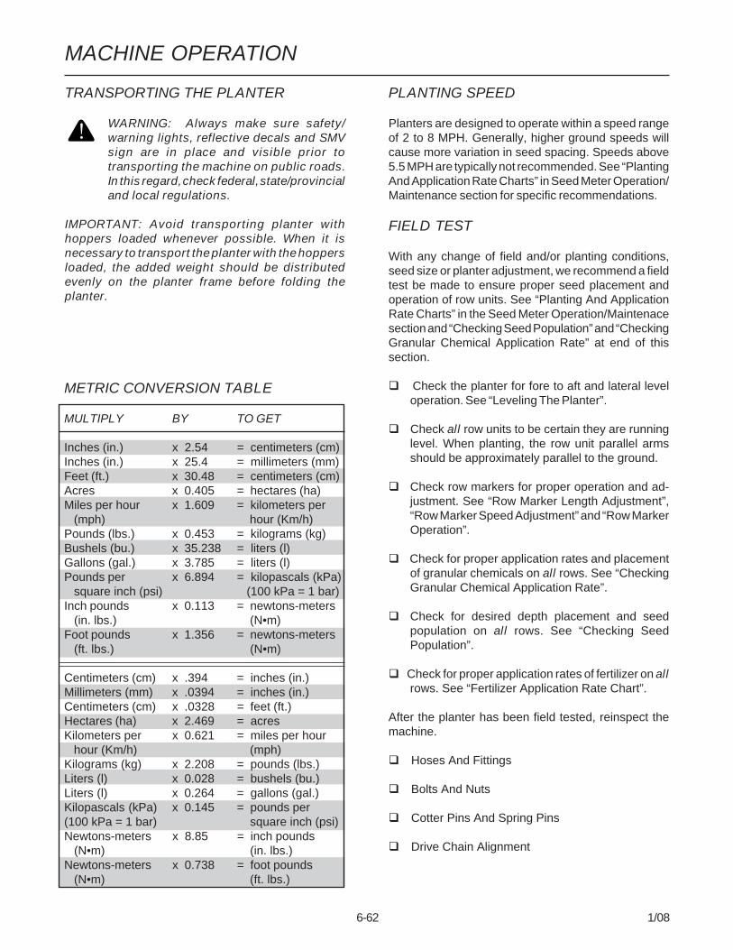
MACHINE OPERATION
6-62 1/08
FIELD TEST
With any change of field and/or planting conditions,seed size or planter adjustment, we recommend a fieldtest be made to ensure proper seed placement andoperation of row units. See “Planting And ApplicationRate Charts” in the Seed Meter Operation/Maintenacesection and “Checking Seed Population” and “CheckingGranular Chemical Application Rate” at end of thissection.
Check the planter for fore to aft and lateral leveloperation. See “Leveling The Planter”.
Check all row units to be certain they are runninglevel. When planting, the row unit parallel armsshould be approximately parallel to the ground.
Check row markers for proper operation and ad-justment. See “Row Marker Length Adjustment”,“Row Marker Speed Adjustment” and “Row MarkerOperation”.
Check for proper application rates and placementof granular chemicals on all rows. See “CheckingGranular Chemical Application Rate”.
Check for desired depth placement and seedpopulation on all rows. See “Checking SeedPopulation”.
Check for proper application rates of fertilizer on allrows. See “Fertilizer Application Rate Chart”.
After the planter has been field tested, reinspect themachine.
Hoses And Fittings
Bolts And Nuts
Cotter Pins And Spring Pins
Drive Chain Alignment
PLANTING SPEED
Planters are designed to operate within a speed rangeof 2 to 8 MPH. Generally, higher ground speeds willcause more variation in seed spacing. Speeds above5.5 MPH are typically not recommended. See “PlantingAnd Application Rate Charts” in Seed Meter Operation/Maintenance section for specific recommendations.
TRANSPORTING THE PLANTER
WARNING: Always make sure safety/warning lights, reflective decals and SMVsign are in place and visible prior totransporting the machine on public roads.In this regard, check federal, state/provincialand local regulations.
IMPORTANT: Avoid transporting planter withhoppers loaded whenever possible. When it isnecessary to transport the planter with the hoppersloaded, the added weight should be distributedevenly on the planter frame before folding theplanter.
METRIC CONVERSION TABLE
MULTIPLY BY TO GET
Inches (in.) x 2.54 = centimeters (cm)Inches (in.) x 25.4 = millimeters (mm)Feet (ft.) x 30.48 = centimeters (cm)Acres x 0.405 = hectares (ha)Miles per hour x 1.609 = kilometers per (mph) hour (Km/h)Pounds (lbs.) x 0.453 = kilograms (kg)Bushels (bu.) x 35.238 = liters (l)Gallons (gal.) x 3.785 = liters (l)Pounds per x 6.894 = kilopascals (kPa) square inch (psi) (100 kPa = 1 bar)Inch pounds x 0.113 = newtons-meters (in. lbs.) (N•m)Foot pounds x 1.356 = newtons-meters (ft. lbs.) (N•m)
Centimeters (cm) x .394 = inches (in.)Millimeters (mm) x .0394 = inches (in.)Centimeters (cm) x .0328 = feet (ft.)Hectares (ha) x 2.469 = acresKilometers per x 0.621 = miles per hour hour (Km/h) (mph)Kilograms (kg) x 2.208 = pounds (lbs.)Liters (l) x 0.028 = bushels (bu.)Liters (l) x 0.264 = gallons (gal.)Kilopascals (kPa) x 0.145 = pounds per(100 kPa = 1 bar) square inch (psi)Newtons-meters x 8.85 = inch pounds (N•m) (in. lbs.)Newtons-meters x 0.738 = foot pounds (N•m) (ft. lbs.)
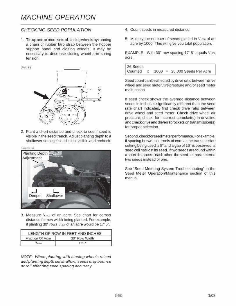
MACHINE OPERATION
6-63 1/08
4. Count seeds in measured distance.
5. Multiply the number of seeds placed in 1/1000 of anacre by 1000. This will give you total population.
EXAMPLE: With 30" row spacing 17' 5" equals 1/1000
acre.
26 Seeds Counted x 1000 = 26,000 Seeds Per Acre
Seed count can be affected by drive ratio between drivewheel and seed meter, tire pressure and/or seed metermalfunction.
If seed check shows the average distance betweenseeds in inches is significantly different than the seedrate chart indicates, first check drive ratio betweendrive wheel and seed meter. Check drive wheel airpressure, check for incorrect sprocket(s) in drivelineand check drive and driven sprockets on transmission(s)for proper selection.
Second, check for seed meter performance. For example,if spacing between kernels of corn at the transmissionsetting being used is 8" and a gap of 16" is observed, aseed cell has lost its seed. If two seeds are found withina short distance of each other, the seed cell has meteredtwo seeds instead of one.
See “Seed Metering System Troubleshooting” in theSeed Meter Operation/Maintenance section of thismanual.
CHECKING SEED POPULATION
1. Tie up one or more sets of closing wheels by runninga chain or rubber tarp strap between the hoppersupport panel and closing wheels. It may benecessary to decrease closing wheel arm springtension.
(RU113b)
2. Plant a short distance and check to see if seed isvisible in the seed trench. Adjust planting depth to ashallower setting if seed is not visible and recheck.
3. Measure 1/1000 of an acre. See chart for correctdistance for row width being planted. For example,if planting 30" rows 1/1000 of an acre would be 17' 5".
LENGTH OF ROW IN FEET AND INCHESFraction Of Acre 30" Row Width
1/1000 17' 5"
NOTE: When planting with closing wheels raisedand planting depth set shallow, seeds may bounceor roll affecting seed spacing accuracy.
Planting DepthAdjustment
Deeper Shallower
D020705102
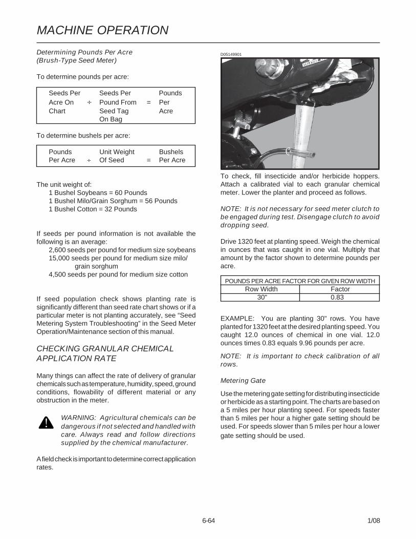
MACHINE OPERATION
6-64 1/08
D05149901
To check, fill insecticide and/or herbicide hoppers.Attach a calibrated vial to each granular chemicalmeter. Lower the planter and proceed as follows.
NOTE: It is not necessary for seed meter clutch tobe engaged during test. Disengage clutch to avoiddropping seed.
Drive 1320 feet at planting speed. Weigh the chemicalin ounces that was caught in one vial. Multiply thatamount by the factor shown to determine pounds peracre.
POUNDS PER ACRE FACTOR FOR GIVEN ROW WIDTHRow Width Factor
30" 0.83
EXAMPLE: You are planting 30" rows. You haveplanted for 1320 feet at the desired planting speed. Youcaught 12.0 ounces of chemical in one vial. 12.0ounces times 0.83 equals 9.96 pounds per acre.
NOTE: It is important to check calibration of allrows.
Metering Gate
Use the metering gate setting for distributing insecticideor herbicide as a starting point. The charts are based ona 5 miles per hour planting speed. For speeds fasterthan 5 miles per hour a higher gate setting should beused. For speeds slower than 5 miles per hour a lowergate setting should be used.
Determining Pounds Per Acre(Brush-Type Seed Meter)
To determine pounds per acre:
Seeds Per Seeds Per PoundsAcre On ÷ Pound From = PerChart Seed Tag Acre
On Bag
To determine bushels per acre:
Pounds Unit Weight BushelsPer Acre ÷ Of Seed = Per Acre
The unit weight of:1 Bushel Soybeans = 60 Pounds1 Bushel Milo/Grain Sorghum = 56 Pounds1 Bushel Cotton = 32 Pounds
If seeds per pound information is not available thefollowing is an average:
2,600 seeds per pound for medium size soybeans15,000 seeds per pound for medium size milo/
grain sorghum4,500 seeds per pound for medium size cotton
If seed population check shows planting rate issignificantly different than seed rate chart shows or if aparticular meter is not planting accurately, see “SeedMetering System Troubleshooting” in the Seed MeterOperation/Maintenance section of this manual.
CHECKING GRANULAR CHEMICALAPPLICATION RATE
Many things can affect the rate of delivery of granularchemicals such as temperature, humidity, speed, groundconditions, flowability of different material or anyobstruction in the meter.
WARNING: Agricultural chemicals can bedangerous if not selected and handled withcare. Always read and follow directionssupplied by the chemical manufacturer.
A field check is important to determine correct applicationrates.
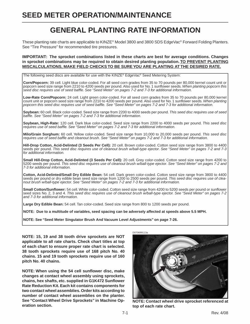
7-1 Rev. 4/08
SEED METER OPERATION/MAINTENANCE
GENERAL PLANTING RATE INFORMATIONThese planting rate charts are applicable to KINZE® Model 3800 and 3800 SDS EdgeVac® Forward Folding Planters. See “Tire Pressure” for recommended tire pressures.
IMPORTANT: The sprocket combinations listed in these charts are best for average conditions. Changes in sprocket combinations may be required to obtain desired planting population. TO PREVENT PLANTING MISCALCULATIONS, MAKE FIELD CHECKS TO BE SURE YOU ARE PLANTING AT THE DESIRED RATE.
The following seed discs are available for use with the KINZE® EdgeVac® Seed Metering System:
Corn/Popcorn: 39 cell. Light blue color-coded. For all seed corn grades from 35 to 70 pounds per 80,000 kernel count unit or popcorn seed size range from 2210 to 4200 seeds per pound. Also used for No. 1 sunflower seeds. When planting popcorn this seed disc requires use of seed baffle. See “Seed Meter” on pages 7-2 and 7-3 for additional information.
Low-Rate Corn/Popcorn: 24 cell. Light green color-coded. For all seed corn grades from 35 to 70 pounds per 80,000 kernel count unit or popcorn seed size range from 2210 to 4200 seeds per pound. Also used for No. 1 sunflower seeds. When planting popcorn this seed disc requires use of seed baffle. See “Seed Meter” on pages 7-2 and 7-3 for additional information.
Soybean: 60 cell. Black color-coded. Seed size range from 2200 to 4000 seeds per pound. This seed disc requires use of seed baffle. See “Seed Meter” on pages 7-2 and 7-3 for additional information.
Soybean, High-Rate: 120 cell. Dark blue color-coded. Seed size range from 2200 to 4000 seeds per pound. This seed disc requires use of seed baffle. See “Seed Meter” on pages 7-2 and 7-3 for additional information.
Milo/Grain Sorghum: 60 cell. Yellow color-coded. Seed size range from 10,000 to 20,000 seeds per pound. This seed disc requires use of seed baffle and cleanout brush. See “Seed Meter” on pages 7-2 and 7-3 for additional information.
Hill-Drop Cotton, Acid-Delinted (3 Seeds Per Cell): 20 cell. Brown color-coded. Cotton seed size range from 3800 to 4400 seeds per pound. This seed disc requires use of cleanout brush w/ball-type ejector. See “Seed Meter” on pages 7-2 and 7-3 for additional information.
Small Hill-Drop Cotton, Acid-Delinted (3 Seeds Per Cell): 20 cell. Grey color-coded. Cotton seed size range from 4200 to 5200 seeds per pound. This seed disc requires use of cleanout brush w/ball-type ejector. See “Seed Meter” on pages 7-2 and 7-3 for additional information.
Cotton, Acid-Delinted/Small Dry Edible Bean: 54 cell. Dark green color-coded. Cotton seed size range from 3800 to 4400 seeds per pound or dry edible bean seed size range from 1200 to 2500 seeds per pound. This seed disc requires use of clea-nout brush w/ball-type ejector. See “Seed Meter” on pages 7-2 and 7-3 for additional information.
Small Cotton/Sunflower: 54 cell. White color-coded. Cotton seed size range from 4200 to 5200 seeds per pound or sunflower seed sizes No. 2, 3 and 4. This seed disc requires use of cleanout brush w/ball-type ejector. See “Seed Meter” on pages 7-2 and 7-3 for additional information. Large Dry Edible Bean: 54 cell. Tan color-coded. Seed size range from 800 to 1200 seeds per pound.
NOTE: Due to a multitude of variables, seed spacing can be adversely affected at speeds above 5.5 MPH.
NOTE: See “Seed Meter Singulator Brush And Vacuum Level Adjustments” on page 7-26.
NOTE: Contact wheel drive sprocket referenced at top of each rate chart.
NOTE: 15, 19 and 38 tooth drive sprockets are NOT applicable to all rate charts. Check chart titles at top of each chart to ensure proper rate chart is selected. 38 tooth sprockets require use of 168 pitch No. 40 chains. 15 and 19 tooth sprockets require use of 160 pitch No. 40 chains.
NOTE: When using the 54 cell sunflower disc, make changes at contact wheel assembly using sprockets, chains, hex shafts, etc. supplied in G1K472 Sunflower Rate Reduction Kit. Each kit contains components for two contact wheel assemblies. Order kits according to number of contact wheel assemblies on the planter. See “Contact Wheel Drive Sprockets” in Machine Op-eration section.
D070699113a

SEED METER OPERATION/MAINTENANCE
7-2 Rev. 4/08
SEED METER
The seed discs below and at right are available for use with the KINZE® EdgeVac® Seed Metering System:
(METR70/D14467a)
Install the selected seed disc. Position the vacuum cover on the meter by aligning the keyhole slots over the bolt heads. Push the cover on the meter and turn counter clockwise to lock in place. See following page for additional components required with specific seed discs.
Corn/Popcorn: 39 cell. For all seed corn grades from 35 to 70 pounds per 80,000 kernel count unit. Popcorn seed size range from 2210 to 4200 seeds per pound. Also used for No. 1 sunflower seeds. (Light blue color-coded.) (D14465)
Low-Rate Corn/Popcorn: 24 cell. For all seed corn grades from 35 to 70 pounds per 80,000 kernel count unit. Popcorn seed size range from 2210 to 4200 seeds per pound. Also used for No. 1 sunflower seeds. (Light green color-coded.) (D16734a)
Soybean: 60 cell. Seed size range from 2200 to 4000 seeds per pound. (Black color-coded.) (D14467a)
Soybean, High-Rate: 120 cell. Seed size range from 2200 to 4000 seeds per pound. (Dark blue color-coded.) (D14468a)
Milo/Grain Sorghum: 60 cell. Seed size range from 10,000 to 20,000 seeds per pound. (Yellow color-coded.) (D17050)
Hill-Drop Cotton, Acid-Delinted (3 Seeds Per Cell): 20 cell. Cotton seed size range from 3800 to 4400 seeds per pound. (Brown color-coded.) (D17187)
Small Hill-Drop Cotton, Acid-Delinted (3 Seeds Per Cell): 20 cell. Cotton seed size range from 4200 to 5200 seeds per pound. (Grey color-coded.) (D17187)
Cotton, Acid-Delinted/Small Dry Edible Bean: 54 cell. Cotton seed size range from 3800 to 4400 seeds per pound. Dry edible bean seed size range from 1200 to 2500 seeds per pound. (Dark green color-coded.) (D17186)
Small Cotton/Sunflower: 54 cell. Cotton seed size range from 4200 to 5200 seeds per pound. Sunflower seed sizes No. 2, 3 and 4. (White color-coded.) (D17186)
Large Dry Edible Bean: 54 cell. Seed size range from 800 to 1200 seeds per pound. (Tan color-coded.) (D14477)
(METR71/METR71a)

7-3 Rev. 4/08
SEED METER OPERATION/MAINTENANCE
SEED BAFFLE• Milo/Grain Sorghum• Soybeans• Popcorn
The seed baffle is designed to prevent excessive seed in the meter from restricting air flow though the seed. Used with 60 Cell Milo/Grain Sorghum Disc, 60 Cell Soybean Disc, 120 Cell High-Rate Soybean Disc and 39 Cell and 24 Cell Popcorn Discs.
CLEANOUTBRUSH• Milo/Grain Sorghum
The cleanout brush is designed to remove foreign material and seed remnants to help prevent plugging of seed disc orifices. Used with 60 Cell Milo/Grain Sorghum Disc.
CLEANOUTBRUSHW/BALL-TYPEEJECTOR• Cotton• Small Edible Beans• No. 2, No. 3 And No. 4 Sunflowers
The cleanout brush w/ball-type ejector is designed to eject seed remnants from the seed disc orifices. Used with 20 Cell Hill-Drop Cotton, Acid-Delinted (3 Seeds Per Cell) Discs; 54 Cell Acid-Delinted Cotton/ Small Dry Edible Bean; and Small Cotton/Sunflower Discs.
(METR70)
The crowder brush aids in the singulation of small flat seeds by (a) crowding seeds to the outer perimeter of the seed disc and (b) orienting seeds to allow the singulator brush to be more effective.
The air inlet screens allow air to enter the system and aids in keeping field residue or other foreign material out of the meter.
The foam spacer gently preloads the seed disc against the vacuum cover when no vacuum is present.
The 3∕16" hose barb elbow on the seed meter vacuum cover allows measurement of vacuum level at each meter. A customer-supplied vacuum gauge is required.
See “Seed Meter Singulator Brush And Vacuum Level Adjustments”, “Seed Meter Maintenance” and “Preparation For Storage” for additional EdgeVac® Seed Metering System information.
Crowder Brush
Air InletScreens
Foam Spacer
NOTE: Foreign material in seed disc orifices, such as seed chips, hulls, stems, etc., may affect seed delivery. Clean seed is required to ensure accurate seed metering from the vacuum seed meter. Seed discs should be removed daily to check for buildup of foreign material in the seed disc orifices.
(MTER74)
(A12154a/A12133a)
Singulator Brush
(METR71)
(A12133c/A12133aa)
NOTE: Use of damaged seed or seed containing foreign material will cause plugging of seed disc orifices and require more frequent seed meter cleanout to prevent underplanting.
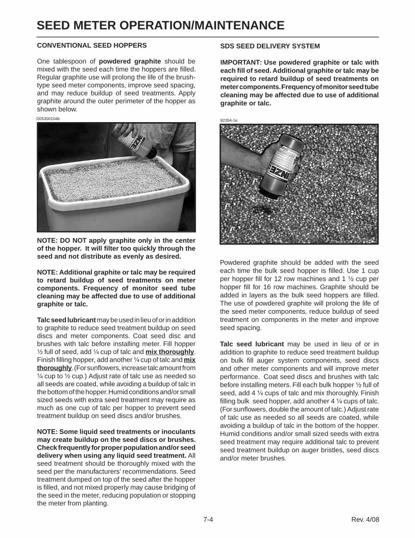
SEED METER OPERATION/MAINTENANCE
7-4 Rev. 4/08
SDS SEED DELIVERY SYSTEM
IMPORTANT: Use powdered graphite or talc with each fill of seed. Additional graphite or talc may be required to retard buildup of seed treatments on meter components. Frequency of monitor seed tube cleaning may be affected due to use of additional graphite or talc.
82354-1e
Powdered graphite should be added with the seed each time the bulk seed hopper is filled. Use 1 cup per hopper fill for 12 row machines and 1 ½ cup per hopper fill for 16 row machines. Graphite should be added in layers as the bulk seed hoppers are filled. The use of powdered graphite will prolong the life of the seed meter components, reduce buildup of seed treatment on components in the meter and improve seed spacing.
Talc seed lubricant may be used in lieu of or in addition to graphite to reduce seed treatment buildup on bulk fill auger system components, seed discs and other meter components and will improve meter performance. Coat seed discs and brushes with talc before installing meters. Fill each bulk hopper ½ full of seed, add 4 ¼ cups of talc and mix thoroughly. Finish filling bulk seed hopper, add another 4 ¼ cups of talc. (For sunflowers, double the amount of talc.) Adjust rate of talc use as needed so all seeds are coated, while avoiding a buildup of talc in the bottom of the hopper. Humid conditions and/or small sized seeds with extra seed treatment may require additional talc to prevent seed treatment buildup on auger bristles, seed discs and/or meter brushes.
D05300104b
CONVENTIONAL SEED HOPPERS
One tablespoon of powdered graphite should be mixed with the seed each time the hoppers are filled. Regular graphite use will prolong the life of the brush-type seed meter components, improve seed spacing, and may reduce buildup of seed treatments. Apply graphite around the outer perimeter of the hopper as shown below.
NOTE: DO NOT apply graphite only in the center of the hopper. It will filter too quickly through the seed and not distribute as evenly as desired.
NOTE: Additional graphite or talc may be required to retard buildup of seed treatments on meter components. Frequency of monitor seed tube cleaning may be affected due to use of additional graphite or talc.
Talc seed lubricant may be used in lieu of or in addition to graphite to reduce seed treatment buildup on seed discs and meter components. Coat seed disc and brushes with talc before installing meter. Fill hopper ½ full of seed, add ¼ cup of talc and mix thoroughly. Finish filling hopper, add another ¼ cup of talc and mix thoroughly. (For sunflowers, increase talc amount from ¼ cup to ½ cup.) Adjust rate of talc use as needed so all seeds are coated, while avoiding a buildup of talc in the bottom of the hopper. Humid conditions and/or small sized seeds with extra seed treatment may require as much as one cup of talc per hopper to prevent seed treatment buildup on seed discs and/or brushes.
NOTE: Some liquid seed treatments or inoculants may create buildup on the seed discs or brushes. Check frequently for proper population and/or seed delivery when using any liquid seed treatment. All seed treatment should be thoroughly mixed with the seed per the manufacturers’ recommendations. Seed treatment dumped on top of the seed after the hopper is filled, and not mixed properly may cause bridging of the seed in the meter, reducing population or stopping the meter from planting.
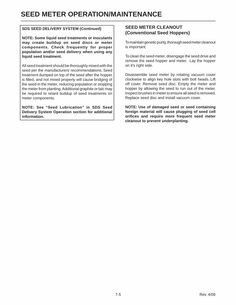
7-5 Rev. 4/08
SEED METER OPERATION/MAINTENANCE
SEED METER CLEANOUT(Conventional Seed Hoppers)
To maintain genetic purity, thorough seed meter cleanout is important.
To clean the seed meter, disengage the seed drive and remove the seed hopper and meter. Lay the hopper on it’s right side.
Disassemble seed meter by rotating vacuum cover clockwise to align key hole slots with bolt heads. Lift off cover. Remove seed disc. Empty the meter and hopper by allowing the seed to run out of the meter. Inspect brushes in meter to ensure all seed is removed. Replace seed disc and install vacuum cover.
NOTE: Use of damaged seed or seed containing foreign material will cause plugging of seed cell orifices and require more frequent seed meter cleanout to prevent underplanting.
SDS SEED DELIVERY SYSTEM (Continued)
NOTE: Some liquid seed treatments or inoculants may create buildup on seed discs or meter components. Check frequently for proper population and/or seed delivery when using any liquid seed treatment.
All seed treatment should be thoroughly mixed with the seed per the manufacturers’ recommendations. Seed treatment dumped on top of the seed after the hopper is filled, and not mixed properly will cause bridging of the seed in the meter, reducing population or stopping the meter from planting. Additional graphite or talc may be required to retard buildup of seed treatments on meter components.
NOTE: See “Seed Lubrication” in SDS Seed Delivery System Operation section for additional information.

SEED METER OPERATION/MAINTENANCE
7-6 Rev. 4/08
SEED METER CLEANOUT (SDS Seed Delivery System)
To maintain genetic purity, thorough seed meter cleanout is important.
To clean the seed meter, remove locking pin and release latch that secures seed meter and mount.
D011006301
Disassemble vacuum cover and remove seed disc from seed meter. Allow all seed to exit meter and inspect for complete clean-out.
Reassemble.
Follow procedure on all rows.
D011006308
D011006305
Disconnect drop hose from seed meter and seed meter drive and remove assembly from row unit.
D011006303
D011006304

7-7 Rev. 4/08
SEED METER OPERATION/MAINTENANCE
IMPORTANT: See “General Planting Rate Information” and “Checking Seed Population” pages for additional information. Always check seed population in the field to ensure planting rates are correct.
PLANTING RATES FOR CORN/POPCORN 39 CELL DISC 15 TOOTH CONTACT WHEEL DRIVE SPROCKET (See Page 7-1)
APPROXIMATE SEEDS/ACRE FOR VARIOUS ROW WIDTHS Recomm. Average Transmission Speed Seed Sprockets Range Spacing 30" Rows Drive Driven (MPH) In Inches 13689 15 25 4 to 6 15.3 14365 17 27 4 to 6 14.6 14917 17 26 4 to 6 14.0 15514 17 25 4 to 6 13.5 16055 19 27 4 to 6 13.0 16672 19 26 4 to 6 12.5 16863 17 23 4 to 6 12.4 17339 19 25 4 to 6 12.1 18012 15 19 4 to 6 11.6 18062 19 24 4 to 6 11.6 18847 19 23 4 to 6 11.1 19435 23 27 4 to 6 10.8 20131 15 17 4 to 6 10.4 20182 23 26 4 to 6 10.4 20280 24 27 4 to 6 10.3 20413 17 19 4 to 6 10.2 20990 23 25 4 to 6 10.0 21060 24 26 4 to 6 9.9 21125 25 27 4 to 6 9.9 21294 14 15 4 to 6 9.8 21864 23 24 4 to 6 9.6 21902 24 25 4 to 6 9.5 21937 25 26 4 to 6 9.5 21970 26 27 4 to 6 9.5 22815 23 23 4 to 6 9.2 23692 27 26 4 to 6 8.8 23727 26 25 4 to 6 8.8 23765 25 24 4 to 6 8.8 23807 24 23 4 to 6 8.8 24444 15 14 4 to 6 8.6 24640 27 25 4 to 6 8.5 24716 26 24 4 to 6 8.5 24799 25 23 4 to 6 8.4 25499 19 17 4 to 6 8.2 25667 27 24 4 to 6 8.1 25791 26 23 4 to 6 8.1 25857 17 15 4 to 6 8.1 26783 27 23 4 to 6 7.8 27618 23 19 4 to 6 7.6 27704 17 14 4 to 6 7.5 28819 24 19 4 to 6 7.3 28899 19 15 4 to 6 7.2 30020 25 19 4 to 6 7.0 30867 23 17 4 to 6 6.8 30963 19 14 4 to 6 6.8 31220 26 19 4 to 6 6.7 32209 24 17 4 to 6 6.5 32421 27 19 4 to 6 6.4 33551 25 17 4 to 6 6.2 34893 26 17 4 to 6 6.0 34983 23 15 4 to 6 6.0 36235 27 17 4 to 6 5.8 36504 24 15 4 to 6 5.7 37482 23 14 4 to 6 5.6 38025 25 15 4 to 6 5.5
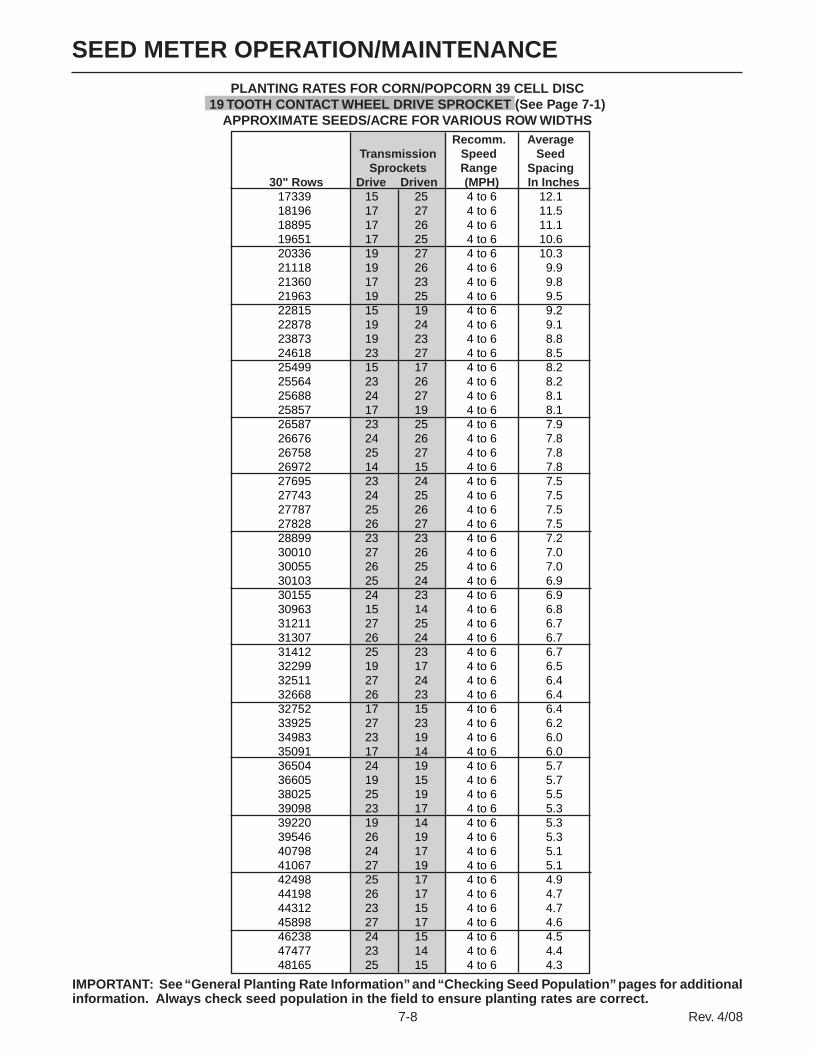
SEED METER OPERATION/MAINTENANCE
7-8 Rev. 4/08
PLANTING RATES FOR CORN/POPCORN 39 CELL DISC 19 TOOTH CONTACT WHEEL DRIVE SPROCKET (See Page 7-1)
APPROXIMATE SEEDS/ACRE FOR VARIOUS ROW WIDTHS
IMPORTANT: See “General Planting Rate Information” and “Checking Seed Population” pages for additional information. Always check seed population in the field to ensure planting rates are correct.
Recomm. Average Transmission Speed Seed Sprockets Range Spacing 30" Rows Drive Driven (MPH) In Inches 17339 15 25 4 to 6 12.1 18196 17 27 4 to 6 11.5 18895 17 26 4 to 6 11.1 19651 17 25 4 to 6 10.6 20336 19 27 4 to 6 10.3 21118 19 26 4 to 6 9.9 21360 17 23 4 to 6 9.8 21963 19 25 4 to 6 9.5 22815 15 19 4 to 6 9.2 22878 19 24 4 to 6 9.1 23873 19 23 4 to 6 8.8 24618 23 27 4 to 6 8.5 25499 15 17 4 to 6 8.2 25564 23 26 4 to 6 8.2 25688 24 27 4 to 6 8.1 25857 17 19 4 to 6 8.1 26587 23 25 4 to 6 7.9 26676 24 26 4 to 6 7.8 26758 25 27 4 to 6 7.8 26972 14 15 4 to 6 7.8 27695 23 24 4 to 6 7.5 27743 24 25 4 to 6 7.5 27787 25 26 4 to 6 7.5 27828 26 27 4 to 6 7.5 28899 23 23 4 to 6 7.2 30010 27 26 4 to 6 7.0 30055 26 25 4 to 6 7.0 30103 25 24 4 to 6 6.9 30155 24 23 4 to 6 6.9 30963 15 14 4 to 6 6.8 31211 27 25 4 to 6 6.7 31307 26 24 4 to 6 6.7 31412 25 23 4 to 6 6.7 32299 19 17 4 to 6 6.5 32511 27 24 4 to 6 6.4 32668 26 23 4 to 6 6.4 32752 17 15 4 to 6 6.4 33925 27 23 4 to 6 6.2 34983 23 19 4 to 6 6.0 35091 17 14 4 to 6 6.0 36504 24 19 4 to 6 5.7 36605 19 15 4 to 6 5.7 38025 25 19 4 to 6 5.5 39098 23 17 4 to 6 5.3 39220 19 14 4 to 6 5.3 39546 26 19 4 to 6 5.3 40798 24 17 4 to 6 5.1 41067 27 19 4 to 6 5.1 42498 25 17 4 to 6 4.9 44198 26 17 4 to 6 4.7 44312 23 15 4 to 6 4.7 45898 27 17 4 to 6 4.6 46238 24 15 4 to 6 4.5 47477 23 14 4 to 6 4.4 48165 25 15 4 to 6 4.3

7-9 Rev. 4/08
SEED METER OPERATION/MAINTENANCE
IMPORTANT: See “General Planting Rate Information” and “Checking Seed Population” pages for additional information. Always check seed population in the field to ensure planting rates are correct.
PLANTING RATES FOR LOW-RATE CORN/POPCORN 24 CELL DISC 15 TOOTH CONTACT WHEEL DRIVE SPROCKET (See Page 7-1)
APPROXIMATE SEEDS/ACRE FOR VARIOUS ROW WIDTHS Recomm. Average Transmission Speed Seed Sprockets Range Spacing 30" Rows Drive Driven (MPH) In Inches
8424 15 25 4 to 6 24.8 8840 17 27 4 to 6 23.7 9180 17 26 4 to 6 22.8 9547 17 25 4 to 6 21.9 9880 19 27 4 to 6 21.2 10260 19 26 4 to 6 20.4 10377 17 23 4 to 6 20.1 10670 19 25 4 to 6 19.6 11084 15 19 4 to 6 18.9 11115 19 24 4 to 6 18.8 11598 19 23 4 to 6 18.0 11960 23 27 4 to 6 17.512388 15 17 4 to 6 16.912420 23 26 4 to 6 16.812480 24 27 4 to 6 16.812562 17 19 4 to 6 16.612917 23 25 4 to 6 16.212960 24 26 4 to 6 16.113000 25 27 4 to 6 16.113104 14 15 4 to 6 16.013455 23 24 4 to 6 15.513478 24 25 4 to 6 15.513500 25 26 4 to 6 15.513520 26 27 4 to 6 15.514040 23 23 4 to 6 14.914580 27 26 4 to 6 14.314602 26 25 4 to 6 14.314625 25 24 4 to 6 14.314650 24 23 4 to 6 14.315043 15 14 4 to 6 13.915163 27 25 4 to 6 13.815210 26 24 4 to 6 13.715261 25 23 4 to 6 13.715692 19 17 4 to 6 13.315795 27 24 4 to 6 13.215871 26 23 4 to 6 13.215912 17 15 4 to 6 13.116482 27 23 4 to 6 12.716996 23 19 4 to 6 12.317048 17 14 4 to 6 12.317735 24 19 4 to 6 11.817784 19 15 4 to 6 11.818474 25 19 4 to 6 11.318995 23 17 4 to 6 11.019054 19 14 4 to 6 11.019213 26 19 4 to 6 10.919821 24 17 4 to 6 10.519951 27 19 4 to 6 10.520647 25 17 4 to 6 10.121473 26 17 4 to 6 9.721528 23 15 4 to 6 9.722299 27 17 4 to 6 9.422464 24 15 4 to 6 9.323066 23 14 4 to 6 9.123400 25 15 4 to 6 8.9

SEED METER OPERATION/MAINTENANCE
7-10 Rev. 4/08
IMPORTANT: See “General Planting Rate Information” and “Checking Seed Population” pages for additional information. Always check seed population in the field to ensure planting rates are correct.
PLANTING RATES FOR LOW-RATE CORN/POPCORN 24 CELL DISC 19 TOOTH CONTACT WHEEL DRIVE SPROCKET (See Page 7-1)
APPROXIMATE HILLS/ACRE FOR VARIOUS ROW WIDTHS Recomm. Average Transmission Speed Seed Sprockets Range Spacing 30" Rows Drive Driven (MPH) In Inches
10670 15 25 4 to 6 19.611197 17 27 4 to 6 18.711628 17 26 4 to 6 18.012093 17 25 4 to 6 17.312515 19 27 4 to 6 16.712996 19 26 4 to 6 16.113145 17 23 4 to 6 15.913516 19 25 4 to 6 15.514040 15 19 4 to 6 14.914079 19 24 4 to 6 14.914691 19 23 4 to 6 14.215149 23 27 4 to 6 13.815692 15 17 4 to 6 13.315732 23 26 4 to 6 13.315808 24 27 4 to 6 13.215912 17 19 4 to 6 13.116361 23 25 4 to 6 12.816416 24 26 4 to 6 12.716467 25 27 4 to 6 12.716598 14 15 4 to 6 12.617043 23 24 4 to 6 12.317073 24 25 4 to 6 12.217100 25 26 4 to 6 12.217125 26 27 4 to 6 12.217784 23 23 4 to 6 11.818468 27 26 4 to 6 11.318495 26 25 4 to 6 11.318525 25 24 4 to 6 11.318557 24 23 4 to 6 11.319054 15 14 4 to 6 11.019207 27 25 4 to 6 10.919266 26 24 4 to 6 10.919330 25 23 4 to 6 10.819876 19 17 4 to 6 10.520007 27 24 4 to 6 10.520104 26 23 4 to 6 10.420155 17 15 4 to 6 10.420877 27 23 4 to 6 10.021528 23 19 4 to 6 9.721595 17 14 4 to 6 9.722464 24 19 4 to 6 9.322526 19 15 4 to 6 9.323400 25 19 4 to 6 8.924061 23 17 4 to 6 8.724135 19 14 4 to 6 8.724336 26 19 4 to 6 8.625107 24 17 4 to 6 8.325272 27 19 4 to 6 8.326153 25 17 4 to 6 8.027199 26 17 4 to 6 7.727269 23 15 4 to 6 7.728245 27 17 4 to 6 7.428454 24 15 4 to 6 7.329216 23 14 4 to 6 7.229640 25 15 4 to 6 7.1

7-11 Rev. 4/08
SEED METER OPERATION/MAINTENANCE
IMPORTANT: See “General Planting Rate Information” and “Checking Seed Population” pages for additional information. Always check seed population in the field to ensure planting rates are correct.
PLANTING RATES FOR SOYBEAN AND MILO/GRAIN SORGHUM 60 CELL DISCS 15 TOOTH CONTACT WHEEL DRIVE SPROCKET (See Page 7-1)
APPROXIMATE SEEDS/ACRE FOR VARIOUS ROW WIDTHS Recomm. Average Transmission Speed Seed Sprockets Range Spacing 30" Rows Drive Driven (MPH) In Inches
21060 15 25 4 to 6 9.922100 17 27 4 to 6 9.522950 17 26 4 to 6 9.123868 17 25 4 to 6 8.824700 19 27 4 to 6 8.525650 19 26 4 to 6 8.225943 17 23 4 to 6 8.126676 19 25 4 to 6 7.827710 15 19 4 to 6 7.527787 19 24 4 to 6 7.528995 19 23 4 to 6 7.229900 23 27 4 to 6 7.030970 15 17 4 to 6 6.831050 23 26 4 to 6 6.731200 24 27 4 to 6 6.731405 17 19 4 to 6 6.732292 23 25 4 to 6 6.532400 24 26 4 to 6 6.532500 25 27 4 to 6 6.432760 14 15 4 to 6 6.433637 23 24 4 to 6 6.233696 24 25 4 to 6 6.233750 25 26 4 to 6 6.233800 26 27 4 to 6 6.235100 23 23 4 to 6 6.036450 27 26 4 to 6 5.736504 26 25 4 to 6 5.736562 25 24 4 to 6 5.736626 24 23 4 to 6 5.737607 15 14 4 to 6 5.637908 27 25 4 to 6 5.538025 26 24 4 to 6 5.538152 25 23 4 to 6 5.539229 19 17 4 to 6 5.339487 27 24 4 to 6 5.339678 26 23 4 to 6 5.339780 17 15 4 to 6 5.341204 27 23 4 to 6 5.142489 23 19 4 to 6 4.942621 17 14 4 to 6 4.944337 24 19 4 to 6 4.744460 19 15 4 to 6 4.746184 25 19 4 to 6 4.547488 23 17 4 to 6 4.447635 19 14 4 to 6 4.448031 26 19 4 to 6 4.449553 24 17 4 to 6 4.249879 27 19 4 to 6 4.251617 25 17 4 to 6 4.153682 26 17 4 to 6 3.953820 23 15 4 to 6 3.955747 27 17 4 to 6 3.856160 24 15 4 to 6 3.757664 23 14 4 to 6 3.658500 25 15 4 to 6 3.6
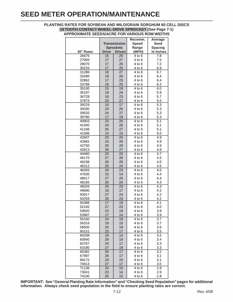
SEED METER OPERATION/MAINTENANCE
7-12 Rev. 4/08
PLANTING RATES FOR SOYBEAN AND MILO/GRAIN SORGHUM 60 CELL DISCS 19 TOOTH CONTACT WHEEL DRIVE SPROCKET (See Page 7-1)
APPROXIMATE SEEDS/ACRE FOR VARIOUS ROW WIDTHS
IMPORTANT: See “General Planting Rate Information” and “Checking Seed Population” pages for additional information. Always check seed population in the field to ensure planting rates are correct.
Recomm. Average Transmission Speed Seed Sprockets Range Spacing 30" Rows Drive Driven (MPH) In Inches
26676 15 25 4 to 6 7.827993 17 27 4 to 6 7.529070 17 26 4 to 6 7.230233 17 25 4 to 6 6.931286 19 27 4 to 6 6.732490 19 26 4 to 6 6.432862 17 23 4 to 6 6.433789 19 25 4 to 6 6.235100 15 19 4 to 6 6.035197 19 24 4 to 6 5.936728 19 23 4 to 6 5.737873 23 27 4 to 6 5.539229 15 17 4 to 6 5.339330 23 26 4 to 6 5.339520 24 27 4 to 6 5.339780 17 19 4 to 6 5.340903 23 25 4 to 6 5.141040 24 26 4 to 6 5.141166 25 27 4 to 6 5.141496 14 15 4 to 6 5.042607 23 24 4 to 6 4.942681 24 25 4 to 6 4.942750 25 26 4 to 6 4.942813 26 27 4 to 6 4.944460 23 23 4 to 6 4.746170 27 26 4 to 6 4.546238 26 25 4 to 6 4.546312 25 24 4 to 6 4.546393 24 23 4 to 6 4.547635 15 14 4 to 6 4.448017 27 25 4 to 6 4.448165 26 24 4 to 6 4.348326 25 23 4 to 6 4.349690 19 17 4 to 6 4.250017 27 24 4 to 6 4.250259 26 23 4 to 6 4.250388 17 15 4 to 6 4.152192 27 23 4 to 6 4.053820 23 19 4 to 6 3.953987 17 14 4 to 6 3.956160 24 19 4 to 6 3.756316 19 15 4 to 6 3.758500 25 19 4 to 6 3.660151 23 17 4 to 6 3.560338 19 14 4 to 6 3.560840 26 19 4 to 6 3.462767 24 17 4 to 6 3.363180 27 19 4 to 6 3.365382 25 17 4 to 6 3.267997 26 17 4 to 6 3.168172 23 15 4 to 6 3.170613 27 17 4 to 6 3.071136 24 15 4 to 6 2.973041 23 14 4 to 6 2.974100 25 15 4 to 6 2.8

7-13 Rev. 4/08
SEED METER OPERATION/MAINTENANCEPLANTING RATES FOR SOYBEAN 60 CELL DISC
38 TOOTH CONTACT WHEEL DRIVE SPROCKET (See Page 7-1) APPROXIMATE SEEDS/ACRE FOR VARIOUS ROW WIDTHS
IMPORTANT: See “General Planting Rate Information” and “Checking Seed Population” pages for additional information. Always check seed population in the field to ensure planting rates are correct.
Recomm. Average Transmission Speed Seed Sprockets Range Spacing 30" Rows Drive Driven (MPH) In Inches
53352 15 25 4 to 6 3.955986 17 27 4 to 6 3.758140 17 26 4 to 6 3.660465 17 25 4 to 6 3.562573 19 27 4 to 6 3.364980 19 26 4 to 6 3.265723 17 23 4 to 6 3.267579 19 25 4 to 6 3.170200 15 19 4 to 6 3.070395 19 24 4 to 6 3.073455 19 23 4 to 6 2.875746 23 27 4 to 6 2.878458 15 17 4 to 6 2.778660 23 26 4 to 6 2.779040 24 27 4 to 6 2.679560 17 19 4 to 6 2.681806 23 25 4 to 6 2.682080 24 26 4 to 6 2.582333 25 27 4 to 6 2.582991 14 15 4 to 6 2.585214 23 24 4 to 6 2.585363 24 25 4 to 6 2.485499 25 26 4 to 6 2.485626 26 27 4 to 6 2.488919 23 23 4 to 6 2.492339 27 26 4 to 6 2.392476 26 25 4 to 6 2.392624 25 24 4 to 6 2.392786 24 23 4 to 6 2.395271 15 14 4 to 6 2.296033 27 25 4 to 6 2.296329 26 24 4 to 6 2.296652 25 23 4 to 6 2.299381 19 17 4 to 6 2.1100034 27 24 4 to 6 2.1100518 26 23 4 to 6 2.1100775 17 15 4 to 6 2.1104384 27 23 4 to 6 2.0107639 23 19 4 to 6 1.9107974 17 14 4 to 6 1.9112319 24 19 4 to 6 1.9112631 19 15 4 to 6 1.9116999 25 19 4 to 6 1.8120303 23 17 4 to 6 1.7120676 19 14 4 to 6 1.7121679 26 19 4 to 6 1.7125533 24 17 4 to 6 1.7126359 27 19 4 to 6 1.7130764 25 17 4 to 6 1.6135994 26 17 4 to 6 1.5136343 23 15 4 to 6 1.5141225 27 17 4 to 6 1.5142271 24 15 4 to 6 1.5146082 23 14 4 to 6 1.4148199 25 15 4 to 6 1.4

SEED METER OPERATION/MAINTENANCE
7-14 Rev. 4/08
PLANTING RATES FOR HIGH-RATE SOYBEAN 120 CELL DISC 15 TOOTH CONTACT WHEEL DRIVE SPROCKET (See Page 7-1)
APPROXIMATE SEEDS/ACRE FOR VARIOUS ROW WIDTHS
IMPORTANT: See “General Planting Rate Information” and “Checking Seed Population” pages for additional information. Always check seed population in the field to ensure planting rates are correct.
Recomm. Average Transmission Speed Seed Sprockets Range Spacing 30" Rows Drive Driven (MPH) In Inches
42120 15 25 4 to 6 5.044200 17 27 4 to 6 4.745900 17 26 4 to 6 4.647736 17 25 4 to 6 4.449400 19 27 4 to 6 4.251300 19 26 4 to 6 4.151887 17 23 4 to 6 4.053352 19 25 4 to 6 3.955421 15 19 4 to 6 3.855575 19 24 4 to 6 3.857991 19 23 4 to 6 3.659800 23 27 4 to 6 3.561941 15 17 4 to 6 3.462100 23 26 4 to 6 3.462400 24 27 4 to 6 3.462810 17 19 4 to 6 3.364584 23 25 4 to 6 3.264800 24 26 4 to 6 3.265000 25 27 4 to 6 3.265520 14 15 4 to 6 3.267275 23 24 4 to 6 3.167392 24 25 4 to 6 3.167500 25 26 4 to 6 3.167600 26 27 4 to 6 3.170200 23 23 4 to 6 3.072900 27 26 4 to 6 2.973008 26 25 4 to 6 2.973125 25 24 4 to 6 2.973252 24 23 4 to 6 2.975214 15 14 4 to 6 2.875816 27 25 4 to 6 2.876050 26 24 4 to 6 2.776304 25 23 4 to 6 2.778458 19 17 4 to 6 2.778975 27 24 4 to 6 2.679356 26 23 4 to 6 2.679560 17 15 4 to 6 2.682408 27 23 4 to 6 2.584978 23 19 4 to 6 2.585242 17 14 4 to 6 2.588673 24 19 4 to 6 2.488919 19 15 4 to 6 2.492368 25 19 4 to 6 2.394976 23 17 4 to 6 2.295271 19 14 4 to 6 2.296063 26 19 4 to 6 2.299105 24 17 4 to 6 2.199757 27 19 4 to 6 2.1103235 25 17 4 to 6 2.0107364 26 17 4 to 6 1.9107639 23 15 4 to 6 1.9111493 27 17 4 to 6 1.9112319 24 15 4 to 6 1.9115328 23 14 4 to 6 1.8116999 25 15 4 to 6 1.8
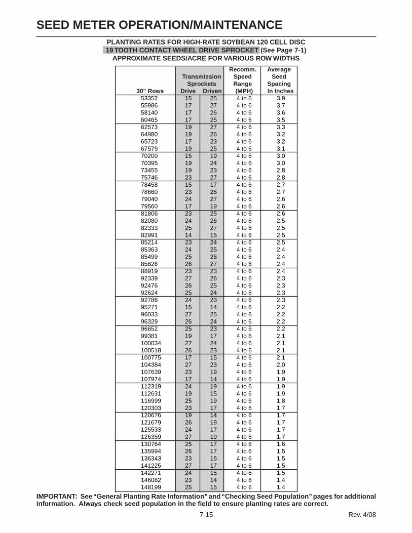
7-15 Rev. 4/08
SEED METER OPERATION/MAINTENANCEPLANTING RATES FOR HIGH-RATE SOYBEAN 120 CELL DISC 19 TOOTH CONTACT WHEEL DRIVE SPROCKET (See Page 7-1)
APPROXIMATE SEEDS/ACRE FOR VARIOUS ROW WIDTHS
IMPORTANT: See “General Planting Rate Information” and “Checking Seed Population” pages for additional information. Always check seed population in the field to ensure planting rates are correct.
Recomm. Average Transmission Speed Seed Sprockets Range Spacing 30" Rows Drive Driven (MPH) In Inches
53352 15 25 4 to 6 3.955986 17 27 4 to 6 3.758140 17 26 4 to 6 3.660465 17 25 4 to 6 3.562573 19 27 4 to 6 3.364980 19 26 4 to 6 3.265723 17 23 4 to 6 3.267579 19 25 4 to 6 3.170200 15 19 4 to 6 3.070395 19 24 4 to 6 3.073455 19 23 4 to 6 2.875746 23 27 4 to 6 2.878458 15 17 4 to 6 2.778660 23 26 4 to 6 2.779040 24 27 4 to 6 2.679560 17 19 4 to 6 2.681806 23 25 4 to 6 2.682080 24 26 4 to 6 2.582333 25 27 4 to 6 2.582991 14 15 4 to 6 2.585214 23 24 4 to 6 2.585363 24 25 4 to 6 2.485499 25 26 4 to 6 2.485626 26 27 4 to 6 2.488919 23 23 4 to 6 2.492339 27 26 4 to 6 2.392476 26 25 4 to 6 2.392624 25 24 4 to 6 2.392786 24 23 4 to 6 2.395271 15 14 4 to 6 2.296033 27 25 4 to 6 2.296329 26 24 4 to 6 2.296652 25 23 4 to 6 2.299381 19 17 4 to 6 2.1100034 27 24 4 to 6 2.1100518 26 23 4 to 6 2.1100775 17 15 4 to 6 2.1104384 27 23 4 to 6 2.0107639 23 19 4 to 6 1.9107974 17 14 4 to 6 1.9112319 24 19 4 to 6 1.9112631 19 15 4 to 6 1.9116999 25 19 4 to 6 1.8120303 23 17 4 to 6 1.7120676 19 14 4 to 6 1.7121679 26 19 4 to 6 1.7125533 24 17 4 to 6 1.7126359 27 19 4 to 6 1.7130764 25 17 4 to 6 1.6135994 26 17 4 to 6 1.5136343 23 15 4 to 6 1.5141225 27 17 4 to 6 1.5142271 24 15 4 to 6 1.5146082 23 14 4 to 6 1.4148199 25 15 4 to 6 1.4
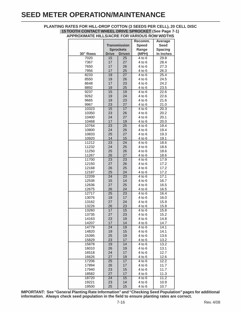
SEED METER OPERATION/MAINTENANCE
7-16 Rev. 4/08
IMPORTANT: See “General Planting Rate Information” and “Checking Seed Population” pages for additional information. Always check seed population in the field to ensure planting rates are correct.
PLANTING RATES FOR HILL-DROP COTTON (3 SEEDS PER CELL), 20 CELL DISC 15 TOOTH CONTACT WHEEL DRIVE SPROCKET (See Page 7-1)
APPROXIMATE HILLS/ACRE FOR VARIOUS ROW WIDTHS Recomm. Average Transmission Speed Seed Sprockets Range Spacing 30" Rows Drive Driven (MPH) In Inches
7020 15 25 4 to 6 29.87367 17 27 4 to 6 28.47650 17 26 4 to 6 27.37956 17 25 4 to 6 26.38233 19 27 4 to 6 25.48550 19 26 4 to 6 24.58648 17 23 4 to 6 24.28892 19 25 4 to 6 23.59237 15 19 4 to 6 22.69262 19 24 4 to 6 22.69665 19 23 4 to 6 21.69967 23 27 4 to 6 21.010323 15 17 4 to 6 20.310350 23 26 4 to 6 20.210400 24 27 4 to 6 20.110468 17 19 4 to 6 20.010764 23 25 4 to 6 19.410800 24 26 4 to 6 19.410833 25 27 4 to 6 19.310920 14 15 4 to 6 19.111212 23 24 4 to 6 18.611232 24 25 4 to 6 18.611250 25 26 4 to 6 18.611267 26 27 4 to 6 18.611700 23 23 4 to 6 17.912150 27 26 4 to 6 17.212168 26 25 4 to 6 17.212187 25 24 4 to 6 17.212209 24 23 4 to 6 17.112536 15 14 4 to 6 16.712636 27 25 4 to 6 16.512675 26 24 4 to 6 16.512717 25 23 4 to 6 16.413076 19 17 4 to 6 16.013162 27 24 4 to 6 15.913226 26 23 4 to 6 15.813260 17 15 4 to 6 15.813735 27 23 4 to 6 15.214163 23 19 4 to 6 14.814207 17 14 4 to 6 14.714779 24 19 4 to 6 14.114820 19 15 4 to 6 14.115395 25 19 4 to 6 13.615829 23 17 4 to 6 13.215878 19 14 4 to 6 13.216010 26 19 4 to 6 13.116518 24 17 4 to 6 12.716626 27 19 4 to 6 12.617206 25 17 4 to 6 12.217894 26 17 4 to 6 11.717940 23 15 4 to 6 11.718582 27 17 4 to 6 11.318720 24 15 4 to 6 11.219221 23 14 4 to 6 10.919500 25 15 4 to 6 10.7

7-17 Rev. 4/08
SEED METER OPERATION/MAINTENANCE
PLANTING RATES FOR HILL-DROP COTTON (3 SEEDS PER CELL), 20 CELL DISC19 TOOTH CONTACT WHEEL DRIVE SPROCKET (See Page 7-1)
APPROXIMATE HILLS/ACRE FOR VARIOUS ROW WIDTHS
IMPORTANT: See “General Planting Rate Information” and “Checking Seed Population” pages for additional information. Always check seed population in the field to ensure planting rates are correct.
Recomm. Average Transmission Speed Seed Sprockets Range Spacing 30" Rows Drive Driven (MPH) In Inches
8892 15 25 4 to 6 23.59331 17 27 4 to 6 22.49690 17 26 4 to 6 21.610078 17 25 4 to 6 20.710429 19 27 4 to 6 20.010830 19 26 4 to 6 19.310954 17 23 4 to 6 19.111263 19 25 4 to 6 18.611700 15 19 4 to 6 17.911732 19 24 4 to 6 17.812243 19 23 4 to 6 17.112624 23 27 4 to 6 16.613076 15 17 4 to 6 16.013110 23 26 4 to 6 15.913173 24 27 4 to 6 15.913260 17 19 4 to 6 15.813634 23 25 4 to 6 15.313680 24 26 4 to 6 15.313722 25 27 4 to 6 15.213832 14 15 4 to 6 15.114202 23 24 4 to 6 14.714227 24 25 4 to 6 14.714250 25 26 4 to 6 14.714271 26 27 4 to 6 14.714820 23 23 4 to 6 14.115390 27 26 4 to 6 13.615413 26 25 4 to 6 13.615437 25 24 4 to 6 13.515464 24 23 4 to 6 13.515878 15 14 4 to 6 13.216006 27 25 4 to 6 13.116055 26 24 4 to 6 13.016109 25 23 4 to 6 13.016563 19 17 4 to 6 12.616672 27 24 4 to 6 12.516753 26 23 4 to 6 12.516796 17 15 4 to 6 12.417397 27 23 4 to 6 12.017940 23 19 4 to 6 11.717996 17 14 4 to 6 11.618720 24 19 4 to 6 11.218772 19 15 4 to 6 11.119500 25 19 4 to 6 10.720050 23 17 4 to 6 10.420113 19 14 4 to 6 10.420280 26 19 4 to 6 10.320922 24 17 4 to 6 10.021060 27 19 4 to 6 9.921794 25 17 4 to 6 9.622666 26 17 4 to 6 9.222724 23 15 4 to 6 9.223538 27 17 4 to 6 8.923712 24 15 4 to 6 8.824347 23 14 4 to 6 8.624700 25 15 4 to 6 8.5

SEED METER OPERATION/MAINTENANCE
7-18 Rev. 4/08
PLANTING RATES FOR COTTON/SMALL DRY EDIBLE BEAN/SUNFLOWER, 54 CELL DISC 15 TOOTH CONTACT WHEEL DRIVE SPROCKET (See Page 7-1)
APPROXIMATE SEEDS/ACRE FOR VARIOUS ROW WIDTHS
IMPORTANT: See “General Planting Rate Information” and “Checking Seed Population” pages for additional information. Always check seed population in the field to ensure planting rates are correct.
Recomm. Average Transmission Speed Seed Sprockets Range Spacing 30" Rows Drive Driven (MPH) In Inches
18954 15 25 4 to 6 11.019890 17 27 4 to 6 10.520655 17 26 4 to 6 10.121481 17 25 4 to 6 9.722230 19 27 4 to 6 9.423085 19 26 4 to 6 9.123349 17 23 4 to 6 9.024008 19 25 4 to 6 8.724939 15 19 4 to 6 8.425009 19 24 4 to 6 8.426096 19 23 4 to 6 8.026910 23 27 4 to 6 7.827873 15 17 4 to 6 7.527945 23 26 4 to 6 7.528080 24 27 4 to 6 7.428265 17 19 4 to 6 7.429063 23 25 4 to 6 7.229160 24 26 4 to 6 7.229250 25 27 4 to 6 7.129484 14 15 4 to 6 7.130274 23 24 4 to 6 6.930326 24 25 4 to 6 6.930375 25 26 4 to 6 6.930420 26 27 4 to 6 6.931590 23 23 4 to 6 6.632805 27 26 4 to 6 6.432853 26 25 4 to 6 6.432906 25 24 4 to 6 6.432963 24 23 4 to 6 6.333846 15 14 4 to 6 6.234117 27 25 4 to 6 6.134222 26 24 4 to 6 6.134337 25 23 4 to 6 6.135306 19 17 4 to 6 5.935539 27 24 4 to 6 5.935710 26 23 4 to 6 5.935802 17 15 4 to 6 5.837084 27 23 4 to 6 5.638240 23 19 4 to 6 5.538359 17 14 4 to 6 5.539903 24 19 4 to 6 5.240014 19 15 4 to 6 5.241566 25 19 4 to 6 5.042739 23 17 4 to 6 4.942872 19 14 4 to 6 4.943228 26 19 4 to 6 4.844597 24 17 4 to 6 4.744891 27 19 4 to 6 4.746456 25 17 4 to 6 4.548314 26 17 4 to 6 4.348438 23 15 4 to 6 4.350172 27 17 4 to 6 4.250544 24 15 4 to 6 4.151898 23 14 4 to 6 4.052650 25 15 4 to 6 4.0

7-19 Rev. 4/08
SEED METER OPERATION/MAINTENANCEPLANTING RATES FOR COTTON/SMALL DRY EDIBLE BEAN/SUNFLOWER, 54 CELL DISC
19 TOOTH CONTACT WHEEL DRIVE SPROCKET (See Page 7-1) APPROXIMATE SEEDS/ACRE FOR VARIOUS ROW WIDTHS
IMPORTANT: See “General Planting Rate Information” and “Checking Seed Population” pages for additional information. Always check seed population in the field to ensure planting rates are correct.
Recomm. Average Transmission Speed Seed Sprockets Range Spacing 30" Rows Drive Driven (MPH) In Inches
24008 15 25 4 to 6 8.725194 17 27 4 to 6 8.326163 17 26 4 to 6 8.027209 17 25 4 to 6 7.728158 19 27 4 to 6 7.429241 19 26 4 to 6 7.229575 17 23 4 to 6 7.130410 19 25 4 to 6 6.931590 15 19 4 to 6 6.631678 19 24 4 to 6 6.633055 19 23 4 to 6 6.334086 23 27 4 to 6 6.135306 15 17 4 to 6 5.935397 23 26 4 to 6 5.935568 24 27 4 to 6 5.935802 17 19 4 to 6 5.836813 23 25 4 to 6 5.736936 24 26 4 to 6 5.737050 25 27 4 to 6 5.637346 14 15 4 to 6 5.638347 23 24 4 to 6 5.538413 24 25 4 to 6 5.438475 25 26 4 to 6 5.438532 26 27 4 to 6 5.440014 23 23 4 to 6 5.241553 27 26 4 to 6 5.041614 26 25 4 to 6 5.041681 25 24 4 to 6 5.041753 24 23 4 to 6 5.042872 15 14 4 to 6 4.943215 27 25 4 to 6 4.843348 26 24 4 to 6 4.843493 25 23 4 to 6 4.844721 19 17 4 to 6 4.745015 27 24 4 to 6 4.645233 26 23 4 to 6 4.645349 17 15 4 to 6 4.646973 27 23 4 to 6 4.548438 23 19 4 to 6 4.348588 17 14 4 to 6 4.350544 24 19 4 to 6 4.150684 19 15 4 to 6 4.152650 25 19 4 to 6 4.054136 23 17 4 to 6 3.954304 19 14 4 to 6 3.954756 26 19 4 to 6 3.856490 24 17 4 to 6 3.756862 27 19 4 to 6 3.758844 25 17 4 to 6 3.661198 26 17 4 to 6 3.461354 23 15 4 to 6 3.463551 27 17 4 to 6 3.364022 24 15 4 to 6 3.365737 23 14 4 to 6 3.266690 25 15 4 to 6 3.1

SEED METER OPERATION/MAINTENANCE
7-20 Rev. 4/08
PLANTING RATES FOR SUNFLOWER, 54 CELL DISC 15 TOOTH TO 30 TOOTH TO 15 TOOTH CONTACT WHEEL DRIVE SPROCKETS (See Page 7-1)
APPROXIMATE SEEDS/ACRE FOR VARIOUS ROW WIDTHS
IMPORTANT: See “General Planting Rate Information” and “Checking Seed Population” pages for additional information. Always check seed population in the field to ensure planting rates are correct.
Recomm. Average Transmission Speed Seed Sprockets Range Spacing 30" Rows Drive Driven (MPH) In Inches
9477 15 25 4 to 6 22.19945 17 27 4 to 6 21.010327 17 26 4 to 6 20.210741 17 25 4 to 6 19.511115 19 27 4 to 6 18.811542 19 26 4 to 6 18.111674 17 23 4 to 6 17.912004 19 25 4 to 6 17.412470 15 19 4 to 6 16.812504 19 24 4 to 6 16.713048 19 23 4 to 6 16.013455 23 27 4 to 6 15.513937 15 17 4 to 6 15.013972 23 26 4 to 6 15.014040 24 27 4 to 6 14.914132 17 19 4 to 6 14.814531 23 25 4 to 6 14.414580 24 26 4 to 6 14.314625 25 27 4 to 6 14.314742 14 15 4 to 6 14.215137 23 24 4 to 6 13.815163 24 25 4 to 6 13.815187 25 26 4 to 6 13.815210 26 27 4 to 6 13.715795 23 23 4 to 6 13.216402 27 26 4 to 6 12.716427 26 25 4 to 6 12.716453 25 24 4 to 6 12.716482 24 23 4 to 6 12.716923 15 14 4 to 6 12.417058 27 25 4 to 6 12.317111 26 24 4 to 6 12.217168 25 23 4 to 6 12.217653 19 17 4 to 6 11.817769 27 24 4 to 6 11.817855 26 23 4 to 6 11.717901 17 15 4 to 6 11.718542 27 23 4 to 6 11.319120 23 19 4 to 6 10.919180 17 14 4 to 6 10.919951 24 19 4 to 6 10.520007 19 15 4 to 6 10.520783 25 19 4 to 6 10.121370 23 17 4 to 6 9.821436 19 14 4 to 6 9.821614 26 19 4 to 6 9.722299 24 17 4 to 6 9.422445 27 19 4 to 6 9.323228 25 17 4 to 6 9.024157 26 17 4 to 6 8.724219 23 15 4 to 6 8.625086 27 17 4 to 6 8.325272 24 15 4 to 6 8.325949 23 14 4 to 6 8.126325 25 15 4 to 6 7.9

7-21 Rev. 4/08
SEED METER OPERATION/MAINTENANCEPLANTING RATES FOR LARGE DRY EDIBLE BEAN, 54 CELL DISC
15 TOOTH CONTACT WHEEL DRIVE SPROCKET (See Page 7-1) APPROXIMATE SEEDS/ACRE FOR VARIOUS ROW WIDTHS
IMPORTANT: See “General Planting Rate Information” and “Checking Seed Population” pages for additional information. Always check seed population in the field to ensure planting rates are correct.
Recomm. Average Transmission Speed Seed Sprockets Range Spacing 30" Rows Drive Driven (MPH) In Inches 28,490 15 25 4 to 6 7.3 29,897 17 27 4 to 6 7.0 31,047 17 26 4 to 6 6.7 32,289 17 25 4 to 6 6.5 33,414 19 27 4 to 6 6.3 34,700 19 26 4 to 6 6.0 35,097 17 23 4 to 6 6.0 36,088 19 25 4 to 6 5.8 37,487 15 19 4 to 6 5.6 37,591 19 24 4 to 6 5.6 39,226 19 23 4 to 6 5.3 40,449 23 27 4 to 6 5.2 41,897 15 17 4 to 6 5.0 42,005 23 26 4 to 6 5.0 42,208 24 27 4 to 6 5.0 42,485 17 19 4 to 6 4.9 43,685 23 25 4 to 6 4.8 43,831 24 26 4 to 6 4.8 43,966 25 27 4 to 6 4.8 44,318 14 15 4 to 6 4.7 45,505 23 24 4 to 6 4.6 45,584 24 25 4 to 6 4.6 45,657 25 26 4 to 6 4.6 45,725 26 27 4 to 6 4.6 47,484 23 23 4 to 6 4.4 49,310 27 26 4 to 6 4.2 49,383 26 25 4 to 6 4.2 49,462 25 24 4 to 6 4.2 49,548 24 23 4 to 6 4.2 50,875 15 14 4 to 6 4.1 51,282 27 25 4 to 6 4.1 51,441 26 24 4 to 6 4.1 51,613 25 23 4 to 6 4.1 53,070 19 17 4 to 6 3.9 53,419 27 24 4 to 6 3.9 53,677 26 23 4 to 6 3.9 53,815 17 15 4 to 6 3.9 55,742 27 23 4 to 6 3.8 57,480 23 19 4 to 6 3.6 57,659 17 14 4 to 6 3.6 59,979 24 19 4 to 6 3.5 60,146 19 15 4 to 6 3.5 62,478 25 19 4 to 6 3.3 64,242 23 17 4 to 6 3.3 64,442 19 14 4 to 6 3.2 64,978 26 19 4 to 6 3.2 67,036 24 17 4 to 6 3.1 67,477 27 19 4 to 6 3.1 69,829 25 17 4 to 6 3.0 72,622 26 17 4 to 6 2.9 72,808 23 15 4 to 6 2.9 75,415 27 17 4 to 6 2.8 75,974 24 15 4 to 6 2.8 78,009 23 14 4 to 6 2.7 79,139 25 15 4 to 6 2.6

SEED METER OPERATION/MAINTENANCE
7-22 Rev. 4/08
PLANTING RATES FOR LARGE DRY EDIBLE BEAN, 54 CELL DISC 19 TOOTH CONTACT WHEEL DRIVE SPROCKET (See Page 7-1)
APPROXIMATE SEEDS/ACRE FOR VARIOUS ROW WIDTHS
IMPORTANT: See “General Planting Rate Information” and “Checking Seed Population” pages for additional information. Always check seed population in the field to ensure planting rates are correct.
Recomm. Average Transmission Speed Seed Sprockets Range Spacing 30" Rows Drive Driven (MPH) In Inches 36,088 15 25 4 to 6 5.8 37,870 17 27 4 to 6 5.5 39,326 17 26 4 to 6 5.3 40,899 17 25 4 to 6 5.1 42,325 19 27 4 to 6 4.9 43,953 19 26 4 to 6 4.8 44,456 17 23 4 to 6 4.7 45,711 19 25 4 to 6 4.6 47,484 15 19 4 to 6 4.4 47,615 19 24 4 to 6 4.4 49,686 19 23 4 to 6 4.2 51,235 23 27 4 to 6 4.1 53,070 15 17 4 to 6 3.9 53,206 23 26 4 to 6 3.9 53,463 24 27 4 to 6 3.9 53,815 17 19 4 to 6 3.9 55,334 23 25 4 to 6 3.8 55,519 24 26 4 to 6 3.8 55,691 25 27 4 to 6 3.8 56,136 14 15 4 to 6 3.7 57,640 23 24 4 to 6 3.6 57,740 24 25 4 to 6 3.6 57,833 25 26 4 to 6 3.6 57,918 26 27 4 to 6 3.6 60,146 23 23 4 to 6 3.5 62,459 27 26 4 to 6 3.3 62,552 26 25 4 to 6 3.3 62,652 25 24 4 to 6 3.3 62,761 24 23 4 to 6 3.3 64,442 15 14 4 to 6 3.2 64,958 27 25 4 to 6 3.2 65,158 26 24 4 to 6 3.2 65,376 25 23 4 to 6 3.2 67,222 19 17 4 to 6 3.1 67,664 27 24 4 to 6 3.1 67,991 26 23 4 to 6 3.1 68,165 17 15 4 to 6 3.1 70,606 27 23 4 to 6 3.0 72,808 23 19 4 to 6 2.9 73,034 17 14 4 to 6 2.9 75,974 24 19 4 to 6 2.8 76,185 19 15 4 to 6 2.7 79,139 25 19 4 to 6 2.6 81,374 23 17 4 to 6 2.6 81,627 19 14 4 to 6 2.6 82,305 26 19 4 to 6 2.5 84,912 24 17 4 to 6 2.5 85,470 27 19 4 to 6 2.4 88,450 25 17 4 to 6 2.4 91,988 26 17 4 to 6 2.3 92,224 23 15 4 to 6 2.3 95,526 27 17 4 to 6 2.2 96,233 24 15 4 to 6 2.2 98,811 23 14 4 to 6 2.1 100,243 25 15 4 to 6 2.1

7-23 Rev. 4/08
SEED METER OPERATION/MAINTENANCE
30" Rows
DRY INSECTICIDE APPLICATION RATES
APPROXIMATE POUNDS/ACRE AT 5 MPH FOR 30" ROW WIDTH
Meter Setting
CLAY GRANULES 10 4.9 11 5.4 12 6.1 13 6.9 14 7.7 15 8.5 16 9.6 17 10.7 18 11.4 19 13.1 20 14.2 21 15.5 22 16.4 23 17.2 24 18.8 25 20.9 26 23.0 27 24.1 28 25.4 29 27.8 30 29.6 SAND GRANULES 5 2.9 6 4.9 7 5.3 8 6.3 9 7.8 10 8.9 11 10.2 12 11.2 13 12.6 14 14.1 15 15.5 16 17.5 17 19.4 18 21.8 19 24.3 20 25.7 21 27.6 22 29.6 23 32.0 24 34.4 25 36.9NOTE: The above chart represents average values and should be used only as a starting point. The granular chemical flows through the given meter opening at a nearly uniform rate regardless of roller speed. Your actual rate will vary depending upon the insecticide you are using, your planting speed and your plant population. Planting speed/ground speed has the greatest effect on application rate.
Your actual rate must be checked in the field with the actual insecticide that you are using and at the speed and population at which you will be planting. See “Checking Granular Chemical Application Rate” page for additional information.
WARNING: Agricultural chemicals can be dangerous if not selected and handled with care. Always read and follow directions supplied by the chemical manufacturer.

SEED METER OPERATION/MAINTENANCE
7-24 Rev. 4/08
DRY HERBICIDE APPLICATION RATES
APPROXIMATE POUNDS/ACRE AT 5 MPH FOR 30" ROW WIDTH
CLAY GRANULES
Meter Setting 30" Rows
10 4.7 11 5.2 12 5.8 13 6.5 14 7.3 15 8.2 16 9.0 17 9.9 18 10.7 19 11.6 20 12.6 21 13.6 22 14.6 23 15.7 24 17.0 25 18.1 26 19.4 27 20.9 28 22.6 29 24.3 30 26.7
NOTE: The above chart represents average values and should be used only as a starting point. The granular chemical flows through the given meter opening at a nearly uniform rate regardless of roller speed. Your actual rate will vary depending upon the herbicide you are using, your planting speed and your plant popu-lation. Planting speed/ground speed has the greatest effect on application rate.
Your actual rate must be checked in the field with the actual herbicide that you are using and at the speed and population at which you will be planting. See “Checking Granular Chemical Application Rate” page for additional information.
WARNING: Agricultural chemicals can be dangerous if not selected and handled with care. Always read and follow directions supplied by the chemical manufacturer.

7-25 Rev. 4/08
SEED METER OPERATION/MAINTENANCE
See “Liquid Fertilizer Rate Chart” in Machine Operation section.

SEED METER OPERATION/MAINTENANCE
7-26 Rev. 4/08
EDGEVAC® INITIAL SETTINGS SINGULATOR VACUUM BRUSH SETTING CROP SIZE SEED DISC SETTING (H2O) SEE NOTES Corn 35-45 Lbs./80K Corn/Popcorn 7 20 4, 5 45-60 Lbs./80K Corn/Popcorn 6 20 4, 5 60-70 Lbs./80K Corn/Popcorn 5 20 4, 5Popcorn 2210-4200 Seeds/Lb. Corn/Popcorn 9 18 1, 4, 5Soybeans 2200-4000 Seeds/Lb. Soybean 5 10 1Milo/Grain Sorghum 10,000-20,000 Seeds/Lb. Milo/Grain Sorgrum 7 18 1, 2Hill-Drop Cotton 3800-5200 Seeds/Lb. Hill-Drop Cotton 8 23 3Cotton 3800-5200 Seeds/Lb. Cotton 8 20 3Edible Beans 800-1200 Seeds/Lb. Large Edible Bean 5 18 5 1200-2500 Seeds/Lb. Small Edible Bean 6 18 3, 5
SEED DISC SELECTIONCROP CELLS SEED SIZE RANGE COLOR-CODE Corn 39 35 To 70 Lbs./80,000 Kernel Count Unit Light BlueLow-Rate Corn 24 35 To 70 Lbs./80,000 Kernel Count Unit Light GreenPopcorn 39 2210 To 4200 Seeds/Lb. Light Blue Low-Rate Popcorn 24 2210 To 4200 Seeds/Lb. Light Green Soybean 60 2200 To 4000 Seeds/Lb. BlackHigh-Rate Soybean 120 2200 To 4000 Seeds/Lb. Dark BlueMilo/Grain Sorghum 60 10,000 To 20,000 Seeds/Lb. Yellow Hill-Drop Cotton, Acid-Delinted 20 3800 To 5200 Seeds/Lb. Brown (3 Seeds Per Cell) Cotton, Acid-Delinted 54 3800 To 5200 Seeds/Lb. Dark GreenDry Edible Bean (Small) 54 1200 To 2500 Seeds/Lb. Dark Green Dry Edible Bean (Large) 54 800 To 1200 Seeds/Lb. Tan
NOTES: 1. Requires use of seed meter baffle. Refer to page 7-3 for additional information.2. Requires use of cleanout brush. Refer to page 7-3 for additional information.3. Requires use of cleanout brush w/ball-type ejector. Refer to page 7-3 for additional information.4. For flat seeds, higher vacuum level may be required. 5. Larger seeds may require a lower numbered singulator brush setting from the initial setting. Smaller seeds may
require a higher numbered setting.
Refer to the planting rate charts in this manual for seed drive transmission sprocket combinations.
IMPORTANT: See “General Planting Rate Information” and “Checking Seed Population” pages for additional information. Always check seed population in the field to ensure planting rates are correct.
NOTE: Singulator brush settings are marked from 1 thru 11. The lower the singulator brush setting, the less aggressive. The higher singulator brush settings are the most aggressive. Refer to illustrations on page 7-27.
NOTE: Optimum meter performance will be attained with consistent seed size and shape. A mixture of seed sizes and shapes will affect meter performance. NOTE: Use 1 tablespoon powdered graphite with each hopper fill of seed. Seed treatment, foreign material, dirt or seed chaff may cause gradual reduction of seed disc fill (population). See “Seed Meter”. NOTE: Excessive seed treatment, humidity and light-weight seed can affect meter performance. Use ½ cup of talc with each hopper fill of seed and mix thoroughly so that all seeds are coated, adjust rates as needed. Use of talc will aid the seed flow into the meter, singulation and seed drop from the disc.
SEED METER SINGULATOR BRUSH AND VACUUM LEVEL ADJUSTMENTS

7-27 Rev. 4/08
SEED METER OPERATION/MAINTENANCE
STEP 1 Select seed disc (and seed meter baffle, cleanout brush and/or cleanout brush w/ball-type ejector if applicable) to match crop and population.
STEP 2 Adjust the singulator brush to initial setting. Note that seed size, seed shape, seed treatments, travel speed and planting rate will all affect meter performance.
D10240583
See “Digital Vacuum Gauge Operation” in Machine Operation section
D06260660
SingulatorBrush
See “Seed Metering System Troubleshooting” at the end of this section.
Singulator Brush Set On 1 - Least Aggressive
Singulator Brush Set On 11 - Most Aggressive
(METR13/D03060702)
Brushes
Brushes
STEP 3 With vacuum fan running, lower planter to planting position and drive forward a short distance to load seed into the seed disc cells.
Adjust vacuum level to the initial setting
according to the tables on preceding page. Note that seed size, seed shape, seed treatments, travel speed and planting rate will all affect meter performance.
NOTE: Vacuum reading will be much lower
when seed disc cells are empty. Prior to setting vacuum level, load all seed cells.
NOTE: Operate vacuum fan 3-5 minutes to bring oil up to normal operating temperature prior to making the final vacuum level adjustment.
STEP 4 Perform optional seed disc fill check.
With vacuum hose connected and vacuum fan operating, remove vacuum cover and seed disc as an assembly. Inspect seed discs for proper seed fill.
D101906132 D101906130

SEED METER OPERATION/MAINTENANCE
7-28 Rev. 4/08
SEED METER DRIVE RELEASE
The seed meter drive is equipped with a clutch release mechanism that allows the drive to be disengaged from the seed metering unit for removal of the seed meter and mount or hopper. Disconnecting the drive allows the operator to check granular chemical application rates without dropping seed. It also allows the drive to one or more of the rows to be disconnected when finishing fields.
To disengage the drive, turn the knob ¼ turn counter-clockwise. To engage the drive, turn the knob ¼ turn clockwise.
D011006101

7-29 Rev. 4/08
SEED METER OPERATION/MAINTENANCE
SEED METER MAINTENANCE
Clean, high quality seed should be used for maximum meter accuracy. Damaged or cracked seed, hulls or foreign material may become lodged in the seed disc orifices and greatly reduce meter accuracy.
It is suggested that the seed disc be inspected and cleaned daily, checking for any buildup of foreign material or any blocked orifices. Clean the seed disc by washing it with soap and water as needed. Dry thoroughly.
Inspect singulator brush for wear and replace if neces-sary following every 200 acres per row of operation.
The seed disc and/or vacuum cover should be replaced if abnormally high vacuum is required for consistent operation or if consistent operation can not be achieved. If adjustment of the singulator brush does not affect performance of the meter or if the brushes appear frayed, the singulator brush may need to be replaced. If the seed disc orifices are plugged frequently with seed remnants, the cleanout brush or cleanout brush with ball-type ejector (if applicable) may need to be replaced. High quality seed should be used to attain best performance.
Vacuum Cover
(METR71)
Singulator Brush
Air Inlet Screens
Wall Brush
Crowder Brush
Prior to each planting season, inspect seed discs, sin-gulator brush, crowder brush, wall brush and air inlet screens and clean or replace as needed.
See “Preparation For Storage” for additional EdgeVac® Seed Metering System maintenance.
IMPORTANT: Replace hopper lids after hoppers are filled to prevent accumulation of dust or dirt in the seed meter which will cause premature wear.
NOTE: Remove seed discs from meters for annual storage and store the seed discs vertically on a dowel or pipe.
(METR70)
VACUUM MANIFOLD MAINTENANCE
In the course of normal operation, dust will accumulate in manifolds and hoses. Manifolds should be cleaned annually. More frequent cleaning may be necessitated by abnormally dusty planting conditions.
Remove vacuum hose from each seed meter. Operate the vacuum fan at full hydraulic flow from the tractor for two minutes to clear manifolds, hoses and fittings of dust and debris.

SEED METER OPERATION/MAINTENANCE
7-30 Rev. 4/08
PROBLEM POSSIBLE CAUSE SOLUTION Low seed count. Meter RPM too high. Reduce planting rate or planting speed. Singulator brush setting too Adjust singulator brush. aggressive. Vacuum level too low. Increase fan speed. Seed sensor not picking up all Clean seed tube. Move meter to different seeds dropped. row. Seeds sticking to seed disc. Use graphite or talc to aid release. Seed treatment buildup in seed Reduce amount of treatment used and or disc recesses. mix thoroughly. Add talc. Seed size too large for disc used. Use appropriate disc for seed size. Wrong transmission setting. Change transmission to desired rate. Wrong seed disc. Use appropriate disc for seed type and size. Drive wheel slipage. Compensate by adjusting transmission sprockets. Low tire pressure. Adjust tire pressure to correct level. Failed/worn drive components. Inspect and replace parts as required. Plugged orifices in seed disc. Inspect and clean disc. Check cleanout brush. (If Applicable) Loss of vacuum at meter. Check for foreign material between vacuum cover and disc. Inspect parts for wear/ damage. Clean or replace as required. Seed bridging in hopper. Add graphite to improve seed flow. Faulty vacuum gauge reading. Repair/replace gauge. Dirt in vacuum manifold. Check vacuum manifold for dirt and clean. Seed baffle (If Applicable) not Thoroughly mix talc to coat all seeds. allowing seed flow due to bridging Remove seed baffle. See “Seed Meter” in of seed. Seed Meter Operation/Maintenance section. 60 cell soybean disc not filling Replace with 120 cell soybean disc. properly due to excessive RPM. Seed disc worn. Replace. Vacuum cover worn. Replace.
Not planting seed. Seed hoppers empty. Fill seed hopper. Seed tube plugged/damaged. Clean or replace tube. Meter drive damaged. Repair/replace drive components. Low/no vacuum. Inspect vacuum system and repair as necessary. Singulator brush setting too Adjust singulator brush. aggressive. Faulty vacuum gauge. Repair/replace vacuum gauge. Seed bridging in hopper. Add graphite to improve seed flow. Loss of vacuum at meter. Check for foreign material between vacuum cover and disc. Inspect parts for wear/ damage. Clean and/or replace as required. Wrong seed disc. Use appropriate disc for seed type and size. Meter drive clutch not engaged. Engage drive clutch. Fan not running. Start fan. Dirt in vacuum manifold. Check vacuum manifold for dirt and clean.
(Continued On Following Page)
SEED METERING SYSTEM TROUBLESHOOTING

7-31 Rev. 4/08
SEED METER OPERATION/MAINTENANCE
PROBLEM POSSIBLE CAUSE SOLUTIONNot planting seed. Seed baffle (If Applicable) Thoroughly mix talc to coat all seeds.(Continued) not allowing seed flow due to Remove seed baffle. See “Seed Meter” in bridging of seed. Seed Meter Operation/Maintenance section. 60 cell soybean disc not filling Replace with 120 cell soybean disc. properly due to excessive RPM.
High seed count. Wrong transmission setting. Change transmission to desired rate. High vacuum. Adjust vacuum level to appropriate level. Wrong seed disc. Replace seed disc. Singulator brush setting not Adjust singulator brush. aggressive enough. Worn singulator brush. Inspect brush and replace as required. Seed leaking past wall brush. Inspect wall brush condition and installation. Replace as necessary. Faulty vacuum gauge. Check gauge line for dirt/obstruction. Repair/replace vacuum gauge.
Poor seed spacing. Obstruction in seed tube. Clean seed tube. Dirty/damaged seed disc. Inspect seed disc for damage, foreign material in orifices or seed treatment buildup in recesses. Clean or replace as required. Wrong vacuum setting. Adjust vacuum to appropriate level. Excess foreign material in seed. Inspect and clean meter and seed discs. Use clean, undamaged seed. Incorrect singulator brush Adjust singulator brush to appropriate setting. setting. Inconsistent driveline. Inspect drive components for rust, misalignment, worn or damaged parts. Replace/repair as required. Toolbar not level or wrong height. Adjust hitch to level toolbar and row units. Planting too fast for conditions. Reduce speed. Rough field conditions. Reduce speed.
Irregular seed population. Driving too fast. Reduce speed. Drive wheels slipping. Reduce speed. Decrease row unit down pressure spring settings.
Unable to achieve desired Tractor hydraulic flow set too low. Increase flow to fan motor.vacuum level. Incorrect hydraulic connections. Check all hydraulic connections and hose routings. Damaged fan components. Inspect motor and impeller for wear/damage and repair/replace as necessary. Vacuum hose pinched/kinked/ Inspect air lines for any damage or blocked. obstruction. Clean air lines and manifold by removing end cap from manifold and running fan at high speed. Vacuum hose loose/disconnected. Inspect and reattach all air hoses. Tractor not producing required Have tractor serviced by qualified technician. hydraulic flow/pressure. Dirt in vacuum gauge line. Check gauge line for dirt/obstruction and clean.
SEED METERING SYSTEM TROUBLESHOOTING (Continued)

SEED METER OPERATION/MAINTENANCE
7-32 Rev. 4/08

8-1 1/08
SDS SEED DELIVERY SYSTEM OPERATION
INTRODUCTION
The seed delivery system consists of two bulk seedhoppers with removable lids that each service half of theplanter. Approximate capacity of each hopper is 55bushels for a total of 110 bushels. Seed hoppers areaccessible via a rear-mounted ladder and access deck.Individual mini-hoppers are filled from the central-mountedseed hoppers with 3 1/2" diameter augers in steel tubeswhich flex to match wing flex and fold requirements. Theauger system is hydraulic driven with two variable speedmotors controlled from a cab mounted console. Thecontrol console includes two electronic tachometersand switches for master shut-off and variable speedcontrol by section. The system is driven on-demand toensure constant supply to all rows. Limit switchesdisable the system when the planter is in folded position.
The mini-hoppers are used in lieu of conventional seedhoppers. The row units and seed meters are the sameas used on other KINZE® planters.
NOTE: After all row outlets are filled to capacity,seed will continue to be evenly distributed to allrows until the bulk seed hopper is empty. When thebulk seed hopper is empty or the auger system isshut off, all drop hoses will “plant out” equally andall rows should run out of seed at approximately thesame time.
D01050702
D10060627
OPERATION
To operate the Seed Delivery System (SDS) the tractormust be equipped with a closed center hydraulic sys-tem.
Position the main power switch on the control consoleto ON. The left and right side of the planter useindependent systems that operate the same, except forauger flighting direction. Toggle switches are used tocontrol the auger systems on each half of the planter.To operate, place switches in RUN position. Placehydraulic lever in ON position. The auger systems willcontinue to run until they have charged the system. Theoperator can increase or decrease the speed by utilizingthe FASTER/SLOWER switches positioned to the rightof each RUN switch. Auger RPM is displayed for eachside using an LCD tachometer. Recommended startingspeed is 100 RPM. Adjust for the type and weight ofseed and population being planted.
The outermost drop on each side of the planter isequipped with a proximity sensor that will stop thesystem when the drop tube is full. When the seed leveldrops away from the sensor, the system will automati-cally start after a short time delay (approximately 2minutes). The augers will then restart and run until thesystem is fully recharged. If the system does notrecharge fast enough, a light on the display will illumi-nate. Increase the auger RPM to ensure adequate seedavailability
In the event of a sensor failure, the system will notoperate. Hold the MANUAL/AUTO switch in theMANUAL position to override the sensor and run thesystem. This override is intended ONLY for emergencyoperation until the system can be repaired. An addi-tional shut-off switch (limit switch) on each outboardend is designed to keep the system from stuffing if theproximity sensor fails and the MANUAL run switch isengaged too long.(Continued On Following Page)
(FWD83)
Bulk Seed Hopper
Drop Hoses
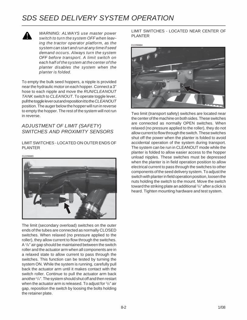
8-2 1/08
SDS SEED DELIVERY SYSTEM OPERATION
WARNING: ALWAYS use master powerswitch to turn the system OFF when leav-ing the tractor operator platform, as thesystem can start and run at any time if seeddemand occurs. Always turn the systemOFF before transport. A limit switch oneach half of the system at the center of theplanter disables the system when theplanter is folded.
To empty the bulk seed hoppers, a nipple is providednear the hydraulic motor on each hopper. Connect a 3"hose to each nipple and move the RUN/CLEANOUTTANK switch to CLEANOUT. To operate toggle lever,pull the toggle lever out and reposition it to the CLEANOUTposition. The auger below the hopper will run in reverseto empty the hopper. The rest of the system will not runin reverse.
ADJUSTMENT OF LIMIT (SAFETY)SWITCHES AND PROXIMITY SENSORS
LIMIT SWITCHES - LOCATED ON OUTER ENDS OFPLANTER
The limit (secondary overload) switches on the outerends of the tubes are connected as normally CLOSEDswitches. When relaxed (no pressure applied to theroller), they allow current to flow through the switches.A 1/8" air gap should be maintained between the switchroller and the actuator arm when all components are ina relaxed state to allow current to pass through theswitches. This function can be tested by turning thesystem ON. While the system is running, carefully pullback the actuator arm until it makes contact with theswitch roller. Continue to pull the actuator arm backanother 1/4". The system should shut off and then restartwhen the actuator arm is released. To adjust for 1/8" airgap, reposition the switch by loosing the bolts holdingthe retainer plate.
LIMIT SWITCHES - LOCATED NEAR CENTER OFPLANTER
Two limit (transport safety) switches are located nearthe center of the machine on both sides. These switchesare connected as normally OPEN switches. Whenrelaxed (no pressure applied to the roller), they do notallow current to flow through the switch. These switchesshut off the power when the planter is folded to avoidaccidental operation of the system during transport.The system can be run in CLEANOUT mode while theplanter is folded to allow easier access to the hopperunload nipples. These switches must be depressedwhen the planter is in field operation position to allowelectrical current to pass through the switches to othercomponents of the seed delivery system. To adjust theswitch with planter in field operation position, loosen thenuts holding the switch to the mount. Move the switchtoward the striking plate an additional 1/8" after a click isheard. Tighten mounting hardware and test system.
D12200683
D12200684
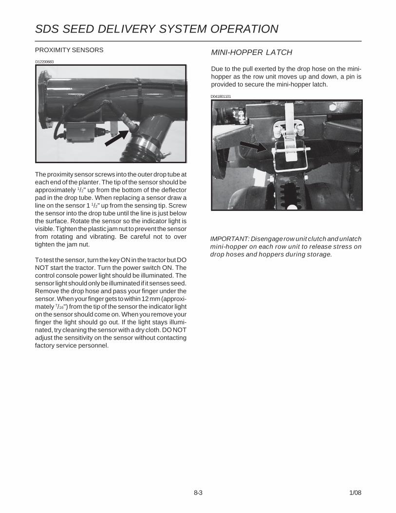
8-3 1/08
SDS SEED DELIVERY SYSTEM OPERATION
PROXIMITY SENSORS
The proximity sensor screws into the outer drop tube ateach end of the planter. The tip of the sensor should beapproximately 1/2" up from the bottom of the deflectorpad in the drop tube. When replacing a sensor draw aline on the sensor 1 1/2" up from the sensing tip. Screwthe sensor into the drop tube until the line is just belowthe surface. Rotate the sensor so the indicator light isvisible. Tighten the plastic jam nut to prevent the sensorfrom rotating and vibrating. Be careful not to overtighten the jam nut.
To test the sensor, turn the key ON in the tractor but DONOT start the tractor. Turn the power switch ON. Thecontrol console power light should be illuminated. Thesensor light should only be illuminated if it senses seed.Remove the drop hose and pass your finger under thesensor. When your finger gets to within 12 mm (approxi-mately 7/16") from the tip of the sensor the indicator lighton the sensor should come on. When you remove yourfinger the light should go out. If the light stays illumi-nated, try cleaning the sensor with a dry cloth. DO NOTadjust the sensitivity on the sensor without contactingfactory service personnel.
MINI-HOPPER LATCH
Due to the pull exerted by the drop hose on the mini-hopper as the row unit moves up and down, a pin isprovided to secure the mini-hopper latch.
D041801101
D12200683
IMPORTANT: Disengage row unit clutch and unlatchmini-hopper on each row unit to release stress ondrop hoses and hoppers during storage.
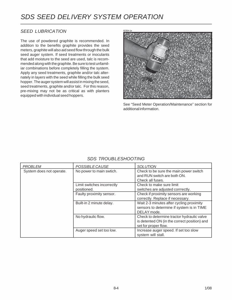
8-4 1/08
SDS SEED DELIVERY SYSTEM OPERATION
PROBLEM POSSIBLE CAUSE SOLUTION System does not operate. No power to main swtich. Check to be sure the main power switch
and RUN switch are both ON.Check all fuses.
Limit switches incorrectly Check to make sure limitpositioned. switches are adjusted corrrectly.Faulty proximity sensor. Check if proximity sensors are working
correctly. Replace if necessary.Built-in 2 minute delay. Wait 2-3 minutes after cycling proximity
sensors to determine if system is in TIMEDELAY mode.
No hydraulic flow. Check to determine tractor hydraulic valveis detented ON (in the correct position) andset for proper flow.
Auger speed set too low. Increase auger speed. If set too slowsystem will stall.
SDS TROUBLESHOOTING
SEED LUBRICATION
The use of powdered graphite is recommended. Inaddition to the benefits graphite provides the seedmeters, graphite will also aid seed flow through the bulkseed auger system. If seed treatments or inoculantsthat add moisture to the seed are used, talc is recom-mended along with the graphite. Be sure to test unfamil-iar combinations before completely filling the system.Apply any seed treatments, graphite and/or talc alter-nately in layers with the seed while filling the bulk seedhopper. The auger system will assist in mixing the seed,seed treatments, graphite and/or talc. For this reason,pre-mixing may not be as critical as with plantersequipped with individual seed hoppers.
82354-1e
See “Seed Meter Operation/Maintenance” section foradditional information.

9-1 1/08
ROW UNIT OPERATION
PLANTING DEPTH
Planting depth is maintained by the row unit gaugewheels. To increase or decrease the planting depth, firstraise the planter to remove weight from the wheels.Then push down on the depth adjustment handle andreposition it forward to decrease depth or rearward toincrease planting depth. Adjust all units to the samesetting initially. Then lower the planter and check opera-tion and planting depth of all row units. It may benecessary to readjust some rows to obtain uniformoperation. Available depth adjustment range isapproximately 1/2" to 3 1/2".
WARNING: Never work under the planterwhile in raised position without using safetylockup devices.
“V” CLOSING WHEEL ADJUSTMENT(Rubber And Cast Iron)
WARNING: Raise planter and install safetylockup devices before making closing wheeladjustments.
After adjusting planting depth, check the operation of the“V” closing wheels. The “V” closing wheels should haveenough down pressure to close the seed trench andensure good soil to seed contact. To increase springpressure on the closing wheels, move the 5-positionquick adjustable down force lever located on the top ofthe closing wheel arm to the rear. Moving the leverforward decreases spring tension.
Adjust all row units to a similar setting.
LF212299-15
Light soil usually requires less down force at averagedepth (approximately 2") while heavy soil requires in-creased down force.
Eccentric bushings in the wheel arm stop allow for lateraladjustment of the “V” closing wheel assembly. Using a3/4" wrench, loosen the hardware which attaches theclosing wheel arm to the wheel arm stop. Using another3/4" wrench turn the eccentric bushings until the closingwheels are aligned with the seed trench. Tightenhardware.LF2122299-15
Lever
The closing wheels can be installed in two locationseither “offset” (to improve residue flow) or “directly”opposite. If set “directly” opposite, the forward instal-lation holes should be used.(RU83k)
5/8" Lock Washer
1/4" Bushing
Installation Holes
5/8" Hardened Washer
Stepped Bushing
EccentricBushing
Planting DepthAdjustment
Deeper Shallower
D020705102

9-2 1/08
ROW UNIT OPERATION
COVERING DISCS/SINGLE PRESSWHEEL ADJUSTMENT
WARNING: Raise planter and install safetylockup devices before making coveringdiscs/single press wheel adjustments.
72359-31
After adjusting planting depth, check the operation of thecovering discs/single press wheels.
Initial press wheel down force setting should be with 2 1/2"between mounting arm tab and locking nut. To adjustdown force spring, loosen 1/2" locking nut and turnadjusting bolt in to increase down force or out todecrease down force. Tighten locking nut against springplug. Adjust all row units to a similar setting.
RH993(PLTR12)
2 1/2"
Adjusting Bolt Tab 1/2" Locking Nut
CLOSING WHEEL SHIELD(Rubber And Cast Iron “V” Closing Wheels)
Shown With Closing Wheel Removed For VisualClarity
The optional closing wheel shield is designed to beinstalled onto the underside of the closing wheel arm tohelp prevent root balls and stalks from plugging theclosing wheels.
D11090208a
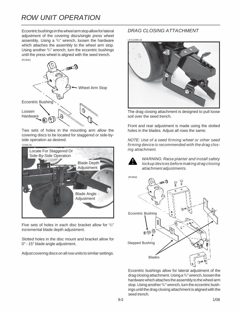
9-3 1/08
ROW UNIT OPERATION
(RU90d)
Eccentric bushings allow for lateral adjustment of thedrag closing attachment. Using a 3/4" wrench, loosen thehardware which attaches the assembly to the wheel armstop. Using another 3/4" wrench, turn the eccentric bush-ings until the drag closing attachment is aligned with theseed trench.
DRAG CLOSING ATTACHMENT
LF212299-18
The drag closing attachment is designed to pull loosesoil over the seed trench.
Front and rear adjustment is made using the slottedholes in the blades. Adjust all rows the same.
NOTE: Use of a seed firming wheel or other seedfirming device is recommended with the drag clos-ing attachment.
WARNING: Raise planter and install safetylockup devices before making drag closingattachment adjustments.
Eccentric bushings in the wheel arm stop allow for lateraladjustment of the covering discs/single press wheelassembly. Using a 3/4" wrench, loosen the hardwarewhich attaches the assembly to the wheel arm stop.Using another 3/4" wrench, turn the eccentric bushingsuntil the press wheel is aligned with the seed trench.(RU94b)
Wheel Arm Stop
Eccentric Bushing
LoosenHardware
Two sets of holes in the mounting arm allow thecovering discs to be located for staggered or side-by-side operation as desired.72359-35
Five sets of holes in each disc bracket allow for 1/2"incremental blade depth adjustment.
Slotted holes in the disc mount and bracket allow for0° - 15° blade angle adjustment.
Adjust covering discs on all row units to similar settings.
Locate For Staggered OrSide-By-Side Operation
Blade DepthAdjustment
Blade AngleAdjustment
Eccentric Bushing
Stepped Bushing
Blades

9-4 1/08
ROW UNIT OPERATION
ROW UNIT EXTENSION BRACKETS(RU145)
Model 3800 and 3800 SDS planters are equipped withrow unit extension brackets on the the six center sectionrows to provide clearance at the axle rock shaft.
Row unit extension brackets are required on all row unitsif 3800 planters are equipped with coulter mountedresidue wheels and notched single disc fertilizer open-ers.
SEED HOPPER(Conventional Seed Hoppers)LF212199-7a
The seed hopper has a capacity of 1.9 bushels.
When filling the seed hopper use clean seed and makecertain there are no foreign objects in the hopper.Replace hopper lids after hoppers are filled toprevent the accumulation of dust or dirt in the seedmeter which will cause premature wear. See “SeedMeter” in Seed Meter Operation/Maintenance section.
Periodically empty the hoppers completely to removeany foreign objects and to ensure proper seed meteroperation. To empty hopper, disengage meter drive andhopper latch and lift hopper off the hopper support. See“Seed Meter Drive Release”.
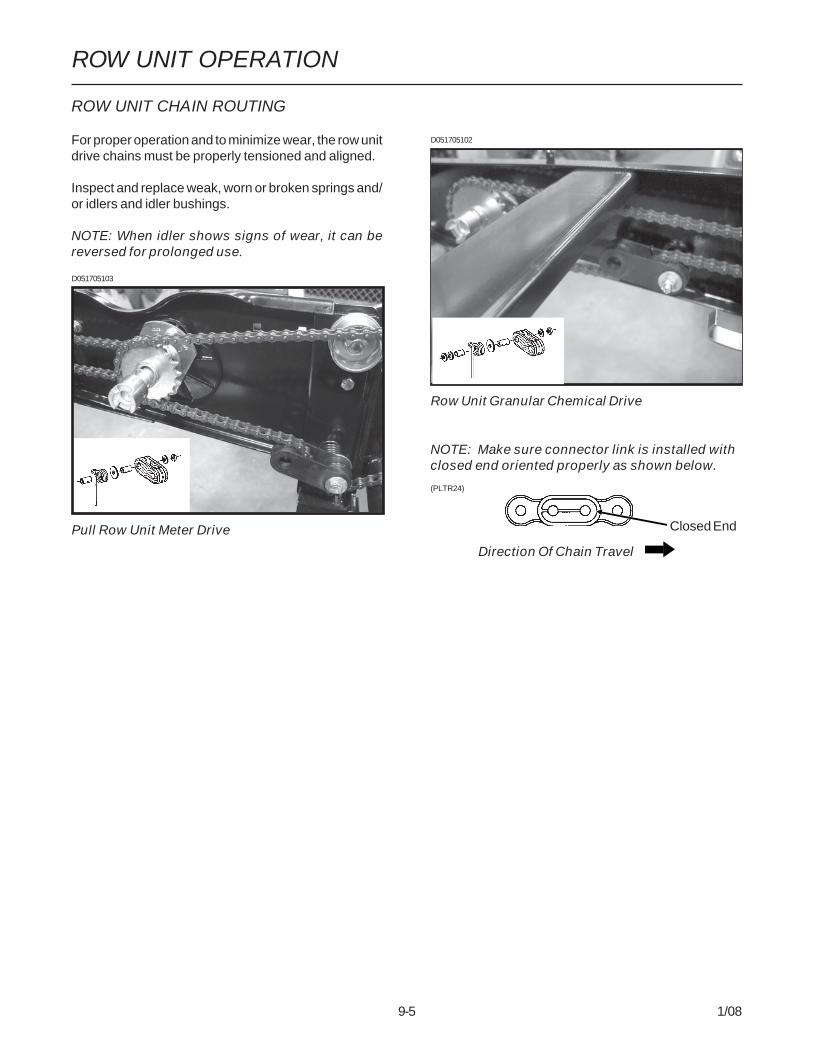
9-5 1/08
ROW UNIT OPERATION
D051705102
Row Unit Granular Chemical Drive
ROW UNIT CHAIN ROUTING
For proper operation and to minimize wear, the row unitdrive chains must be properly tensioned and aligned.
Inspect and replace weak, worn or broken springs and/or idlers and idler bushings.
NOTE: When idler shows signs of wear, it can bereversed for prolonged use.
NOTE: Make sure connector link is installed withclosed end oriented properly as shown below.
(PLTR24)
Closed End
Direction Of Chain Travel )$&725<7285
D051705103
Pull Row Unit Meter Drive
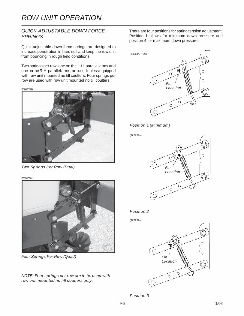
9-6 1/08
ROW UNIT OPERATION
QUICK ADJUSTABLE DOWN FORCESPRINGS
Quick adjustable down force springs are designed toincrease penetration in hard soil and keep the row unitfrom bouncing in rough field conditions.
Two springs per row, one on the L.H. parallel arms andone on the R.H. parallel arms, are used unless equippedwith row unit mounted no till coulters. Four springs perrow are used with row unit mounted no till coulters.
D06300305
Two Springs Per Row (Dual)
D07010301
Four Springs Per Row (Quad)
NOTE: Four springs per row are to be used withrow unit mounted no till coulters only.
There are four positions for spring tension adjustment.Position 1 allows for minimum down pressure andposition 4 for maximum down pressure.
L0096(PLTR27e)
Position 1 (Minimum)
(PLTR28e)
Position 2
(PLTR29e)
Position 3
PinLocation
PinLocation
PinLocation

9-7 1/08
ROW UNIT OPERATION
(PLTR30e)
Position 4 (Maximum)
To adjust spring tension, raise planter and removespring mount pin at top of spring. Slide mount to desiredposition and install pin.
NOTE: It is necessary for the operator to adjustsprings according to field conditions. If springs areadjusted for too much down pressure for fieldconditions, it is possible for the row units to lift theplanter to the extent that the drive wheels do notmake sufficient contact. Too much down pressurein soft field conditions can cause the row unit to runtoo deep.
WARNING: Always install safety lockupdevices or lower machine to the groundbefore working under or around the ma-chine.
IMPORTANT: Springs must always be installed withopen side of spring hooks toward the seed hoppersto prevent binding on spring mount adjustmentpins.
PinLocation

9-8 1/08
ROW UNIT OPERATION
PNEUMATIC DOWN PRESSUREPACKAGE
With pneumatic down pressure option, the operator canvary row unit down pressure on-the-go as field condi-tions change. A cab-mounted digital readout displaysdown force (lbs.) applied. A planter-mounted 12 VDCair compressor, with 3 gallon capacity air tank, sup-plies air for the down pressure system.
Packages also include upper and lower air spring mount-ing castings for pull row units, 150 psi rated air springs,3/8" O.D. nylon hoses, dual solenoid air valve and stain-less steel, 160 psi, 2" liquid-filled gauge and planterwiring harness.
Pneumatic down pressure row unit extension bracketsare required in some applications.
Pull Row Unit Air Spring
(PNE07)
Air Compressor With Dual Solenoid Assembly
(PNE01)
(A12644a)
Control Console Assembly

9-9 1/08
ROW UNIT OPERATION
FIELD OPERATION
NOTE: For the most accurate adjustment, adjustdown pressure with planter lowered and row unitsin the ground. Pressure can be adjusted from trac-tor using the control console, or at planter usingthe manual control valves.
To adjust down pressure from cab:
To INCREASE pressure, push toggle switch up.
To DECREASE pressure, push toggle switch down.
The readout value on the control console is pounds ofdown pressure force.
To adjust down pressure from planter:
To INCREASE pressure, press and hold button on sole-noid as shown below.
To DECREASE pressure, press and hold button on so-lenoid as shown below.
The readout value on the air pressure gauge is NOT thedown pressure force value. To calculate the force value,multiply the air pressure (psi) by four (4).
NOTE: If additional down pressure is needed withthe Pneumatic Down Pressure Package, assistsprings are available through your KINZE® dealer.One spring is installed on the outer side of the par-allel arms on each side of the row unit as shownbelow.
Pull Row Unit Assist Springs
D11280153a
D112907100
D112907101
Control Console
Toggle Switch Pneumatic DownForce Readout
To IncreasePressure
To DecreasePressure
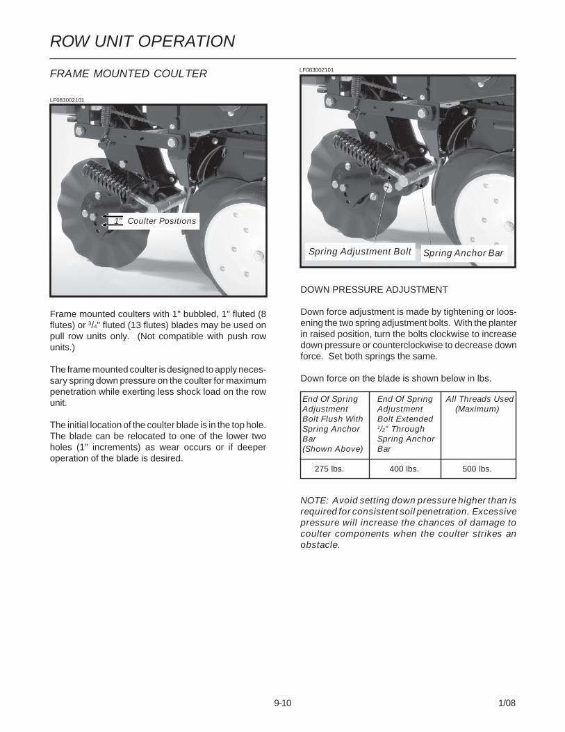
9-10 1/08
ROW UNIT OPERATION
LF083002101
FRAME MOUNTED COULTER
Frame mounted coulters with 1" bubbled, 1" fluted (8flutes) or 3/4" fluted (13 flutes) blades may be used onpull row units only. (Not compatible with push rowunits.)
The frame mounted coulter is designed to apply neces-sary spring down pressure on the coulter for maximumpenetration while exerting less shock load on the rowunit.
The initial location of the coulter blade is in the top hole.The blade can be relocated to one of the lower twoholes (1" increments) as wear occurs or if deeperoperation of the blade is desired.
DOWN PRESSURE ADJUSTMENT
Down force adjustment is made by tightening or loos-ening the two spring adjustment bolts. With the planterin raised position, turn the bolts clockwise to increasedown pressure or counterclockwise to decrease downforce. Set both springs the same.
Down force on the blade is shown below in lbs.
NOTE: Avoid setting down pressure higher than isrequired for consistent soil penetration. Excessivepressure will increase the chances of damage tocoulter components when the coulter strikes anobstacle.
Spring Adjustment Bolt
LF083002101
Spring Anchor Bar
End Of Spring End Of Spring All Threads UsedAdjustment Adjustment (Maximum)Bolt Flush With Bolt ExtendedSpring Anchor 1/2" ThroughBar Spring Anchor(Shown Above) Bar
275 lbs. 400 lbs. 500 lbs.
1" Coulter Positions

9-11 1/08
ROW UNIT OPERATION
RESIDUE WHEELS(For Use With Frame Mounted Coulter)
The residue wheels for use with the frame mountedcoulter may be used on pull row units only.
The residue wheels are attached to the frame mountedcoulter with two cap screws and sleeves allowing theunit to free-float. A 2-position spindle bolt mountingallows the tined wheels to be mounted interlocked orstaggered. Depth adjustment is made using a spring-loaded cam and pin with 11 positions in 1/4" increments.A high point on the cam allows the wheels to be lockedup so they do not contact the ground. A weed guard,located on the inboard side of each wheel, aids in theprevention of weed wrap which can cause prematurebearing failure.
(RU135l)
Weed Guard
STYLE A
(RU135m)
Weed Guard
STYLE B
NOTE: Opening in weed guard must point down.
LF083002102
STYLE A Shown

9-12 1/08
ROW UNIT OPERATION
Vertical adjustment in 1/3" increments is possible byremoving the lynch pin which secures the verticalsupport arm and moving the support arm up or down asrequired. Reinstall lynch pin. Finer adjustment can beattained by removing the lynch pin and using the5/8" x 2 1/4" set screw to clamp the support arm in therequired position.
(RU98e)
Slotted holes in the support arm where the blades aremounted allow fore and aft adjustment of the discblades. Blades can be adjusted so the front edges meetor one blade can be moved to the rear and the other tothe front of the slot so the cutting edge of one bladeoverlaps the edge of the other blade. The dust cap mustbe removed to make these adjustments.
ROW UNIT MOUNTED DISC FURROWER
The row unit mounted disc furrower is for use on pullrow units only (not compatible with Interplant® push rowunits). The disc furrower may be equipped with either12" solid blades or 12" notched blades.
Disc furrowers are used to clear crop residue, dirt clodsand dry soil from in front of the row units for a clean andsmooth seed bed. Notched blades are used for heavierresidue conditions. The notched blades cut crop resi-due and move it aside to prevent plugging or pushing.LF212299-22
Lynch Pin
Set Screw
Slotted Holes
Dust Cap
ROW UNIT MOUNTED RESIDUE WHEEL
The row unit mounted residue wheel may be used on pullrow units and push row units.
D101701113
STYLE A
(A12685)
STYLE B

9-13 1/08
ROW UNIT OPERATIOND101701112
A full threaded bolt and jam nut located on the upper linkallows maximum depth to be set for loose soil conditions.Initial setting should be 1 3/4" above the depth of the rowunit double disc opener.
Three holes in the upper link allow for wheel angleadjustment. With the wheel mount in the most verticalposition, using the rear hole in the upper link, the residuewheel is most aggressive. Moving the wheel mount toone of the forward holes reduces the aggressiveness ofthe wheel for use in mulch till applications where the soilis loose.D101701202
To lock the residue wheel up out of the ground, removethe 1/2" x 5" lockup bolt, raise the residue wheel andinstall bolt.D011701203
Locked Up Position
Least Aggressive
Two adjustable springs on the parallel links on eachresidue wheel allow for down force adjustment. Position1 as shown below provides minimum down pressure andposition 3 maximum down pressure.
Position 1 (Minimum) (PLTR31a)
Position 2 (PLTR32a)
Position 3 (Maximum) (PLTR33a)
For additional uplift or float, position springs as shownbelow.
(PLTR34a)
To adjust down force springs, raise the row unit out of theground and reposition springs as shown for the desireddown pressure.
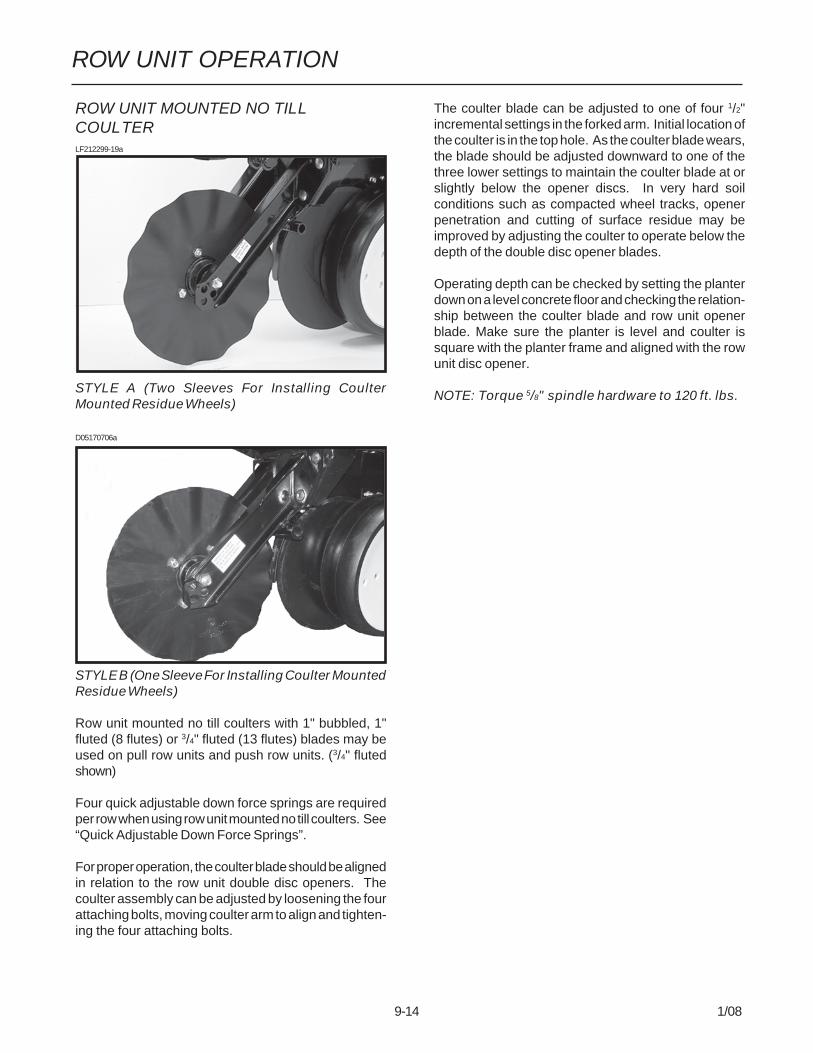
9-14 1/08
ROW UNIT OPERATION
ROW UNIT MOUNTED NO TILLCOULTERLF212299-19a
STYLE A (Two Sleeves For Installing CoulterMounted Residue Wheels)
D05170706a
STYLE B (One Sleeve For Installing Coulter MountedResidue Wheels)
Row unit mounted no till coulters with 1" bubbled, 1"fluted (8 flutes) or 3/4" fluted (13 flutes) blades may beused on pull row units and push row units. (3/4" flutedshown)
Four quick adjustable down force springs are requiredper row when using row unit mounted no till coulters. See“Quick Adjustable Down Force Springs”.
For proper operation, the coulter blade should be alignedin relation to the row unit double disc openers. Thecoulter assembly can be adjusted by loosening the fourattaching bolts, moving coulter arm to align and tighten-ing the four attaching bolts.
The coulter blade can be adjusted to one of four 1/2"incremental settings in the forked arm. Initial location ofthe coulter is in the top hole. As the coulter blade wears,the blade should be adjusted downward to one of thethree lower settings to maintain the coulter blade at orslightly below the opener discs. In very hard soilconditions such as compacted wheel tracks, openerpenetration and cutting of surface residue may beimproved by adjusting the coulter to operate below thedepth of the double disc opener blades.
Operating depth can be checked by setting the planterdown on a level concrete floor and checking the relation-ship between the coulter blade and row unit openerblade. Make sure the planter is level and coulter issquare with the planter frame and aligned with the rowunit disc opener.
NOTE: Torque 5/8" spindle hardware to 120 ft. lbs.

9-15 1/08
ROW UNIT OPERATION
COULTER MOUNTED RESIDUEWHEELS
LF212299-23
STYLE A - Used With Style A Row Unit Mounted NoTill Coulter
D05170708a
STYLE B - Used With Style B Row Unit Mounted NoTill Coulter
Coulter mounted residue wheels are designed for use onpull row units and push row units. Row unit extensionbrackets are required on the four center pull row units ifthe planter is equipped with coulter mounted residuewheels.
The coulter mounted residue wheels are attached to therow unit mounted no till coulter with one cap screw andsleeve allowing the unit to free-float. A 2-position spindlebolt mounting allows the tined wheels to be mountedinterlocked or staggered. A lock nut on the inside of themount locks the spindle cap screw. Depth adjustment ismade using a spring-loaded cam and pin with 11 posi-tions in 1/4" increments. A high point on the cam allowsthe wheels to be locked up so they do not contact theground. A weed guard, located on the inboard side ofeach wheel, aids in the prevention of weed wrap whichcan cause premature bearing failure.
(RU104tt)
Weed Guard
STYLE A
(RU153a)
Weed Guard
STYLE B
NOTE: Opening in weed guard must point down.
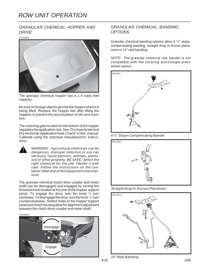
9-16 1/08
ROW UNIT OPERATION
GRANULAR CHEMICAL BANDINGOPTIONS
Granular chemical banding options allow 4 1/2" slope-compensating banding, straight drop in-furrow place-ment or 14" rear banding.
NOTE: The granular chemical rear bander is notcompatible with the covering discs/single presswheel option.
(RU101r)
(RU101b)
Straight Drop In-Furrow Placement
(RU101s)
14" Rear Banding
4 1/2" Slope-Compensating Bander
GRANULAR CHEMICAL HOPPER ANDDRIVELF212299-6
The granular chemical hopper has a 1.4 cubic feetcapacity.
Be sure no foreign objects get into the hopper when it isbeing filled. Replace the hopper lids after filling thehoppers to prevent the accumulation of dirt and mois-ture.
The metering gate located on the bottom of the hopperregulates the application rate. See “Dry Insecticide AndDry Herbicide Application Rate Charts” in this manual.Calibrate using the chemical manufacturers’ instruc-tions.
WARNING: Agricultural chemicals can bedangerous. Improper selection or use canseriously injure persons, animals, plants,soil or other property. BE SAFE: Select theright chemical for the job. Handle it withcare. Follow the instructions on the con-tainer label and of the equipment manufac-turer.
The granular chemical clutch drive coupler and metershaft can be disengaged and engaged by turning thethrowout knob located at the rear of the hopper supportpanel. To engage the drive, turn the knob 1/4 turnclockwise. To disengage the drive, turn the knob 1/4 turncounterclockwise. Slotted holes in the hopper supportpanel and clutch housing allow for alignment adjustmentbetween the clutch drive coupler and meter shaft.
LF212299-4
(RU101c)Engage
Disengage

9-17 1/08
ROW UNIT OPERATION
SPRING TOOTH INCORPORATOR
The spring tooth incorporator smoothes the soil behindthe row unit and incorporates granular chemicals. Thetwo mounting chains on each spring tooth incorporatorshould be adjusted so there is approximately 1/8" slackin the chain when the unit is lowered to planting position.
NOTE: The spring tooth incorporator is not compat-ible with the covering discs/single press wheeloption.
LF212299-26
GRANULAR CHEMICAL BANDERSHIELD
The optional granular chemical bander shield is de-signed to be installed onto the underside of the wheelarm stop to shield crop residue from lodging in thegranular chemical bander.
(RU83m)
3/8"-16 x 1 1/2"Cap Screw AndHardened Washer
Wheel Arm StopBander Shield

9-18 1/08
ROW UNIT OPERATION
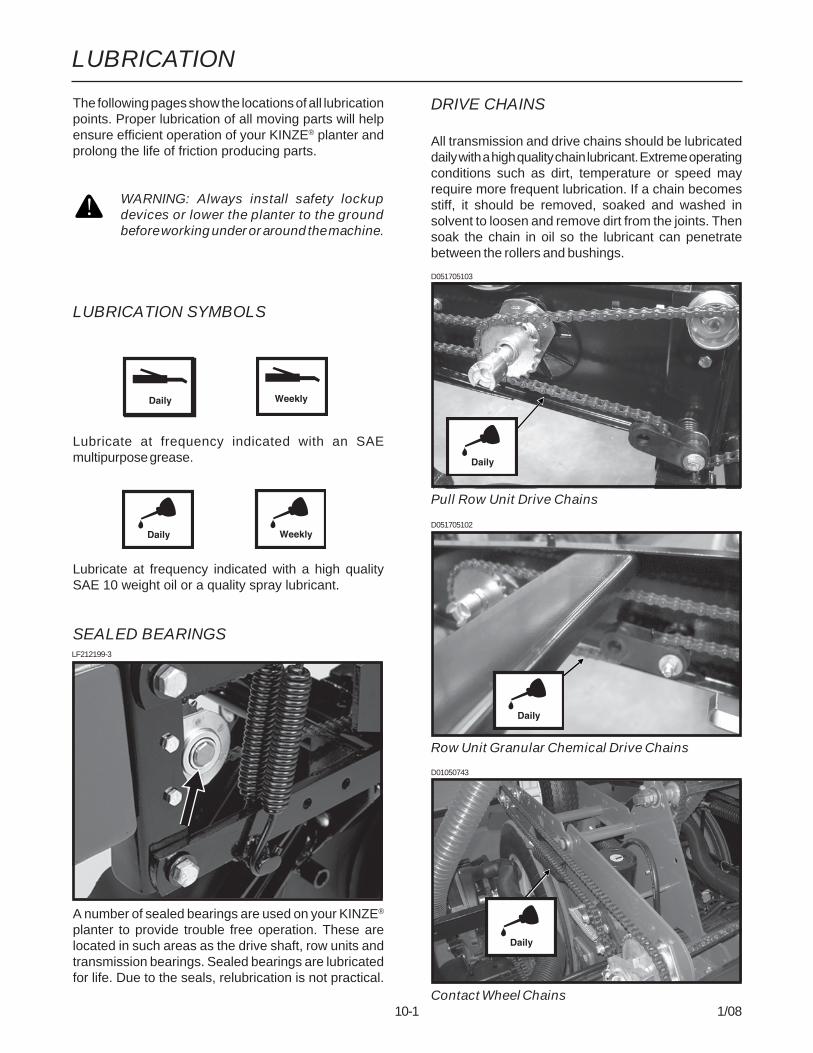
LUBRICATION
10-1 1/08
The following pages show the locations of all lubricationpoints. Proper lubrication of all moving parts will helpensure efficient operation of your KINZE® planter andprolong the life of friction producing parts.
WARNING: Always install safety lockupdevices or lower the planter to the groundbefore working under or around the machine.
LUBRICATION SYMBOLS
Lubricate at frequency indicated with an SAEmultipurpose grease.
Lubricate at frequency indicated with a high qualitySAE 10 weight oil or a quality spray lubricant.
SEALED BEARINGS
A number of sealed bearings are used on your KINZE®
planter to provide trouble free operation. These arelocated in such areas as the drive shaft, row units andtransmission bearings. Sealed bearings are lubricatedfor life. Due to the seals, relubrication is not practical.
DRIVE CHAINS
All transmission and drive chains should be lubricateddaily with a high quality chain lubricant. Extreme operatingconditions such as dirt, temperature or speed mayrequire more frequent lubrication. If a chain becomesstiff, it should be removed, soaked and washed insolvent to loosen and remove dirt from the joints. Thensoak the chain in oil so the lubricant can penetratebetween the rollers and bushings.
LF212199-3
D01050743
Contact Wheel Chains
D051705102
Row Unit Granular Chemical Drive Chains
D051705103
Pull Row Unit Drive Chains

LUBRICATION
10-2 1/08
D01050736
Seed Rate Transmission Drive Chains
D01050740
Row Unit Drill Shaft Drive Chains
(FWD149)
SDS Drive Chains
D05230703(TWL219c)
Liquid Fertilizer Drive Chain (Piston Pump)

LUBRICATION
10-3 1/08
LF212299-22
Row Unit Mounted Disc Furrower ParallelLinkages (6 Per Row)
Row Unit “V” Closing Wheel, Covering Discs/Single Press Wheel And/Or Drag Closing WheelEccentric Bushings (2 Per Row)
BUSHINGS
Lubricate bushings at the frequency indicated.
Using a torque wrench, check each bolt for propertorque. If bolt is loose, it should be removed and thebushing inspected for cracks and wear. Replace bush-ing if necessary. Only hardened flat washers shouldbe used. Replace damaged flat washers with properpart. Torque hardware to 130 ft. lbs.
D06300305
Pull Row Unit Parallel Linkages (8 Per Row)
LF212199-2

LUBRICATION
10-4 1/08
WHEEL BEARINGS
The transport wheel hubs are equipped with greasefittings. Pump grease into the hub until grease comesout around the seals. See “Grease Fittings” for lubrica-tion frequency.
All wheel bearings should be repacked annually andchecked for wear. This applies to all drive wheels,transport wheels and marker hubs.
To check for wear, lift the wheel off the ground. Checkfor endplay in the bearings by moving the tire in and out.Rotate the tire to check for roughness in the bearings.If bearings sound rough, the hub should be removedand the bearings inspected and replaced if necessary.See Maintenance section.
To repack wheel hubs, follow the procedure outlinedfor wheel bearing replacement with the exception thatbearings and bearing cups are reused.
WRAP SPRING WRENCH ASSEMBLY
The chain idler is equipped with a wrap spring wrench.The wrench components may require occasional lubri-cation to operate correctly. Disassembly is required tolubricate. (a) Remove the cap screw that secures theidler with sprockets to the wrench tightener shaft. (b)Remove the wrap spring wrench from the planter. (c) Tipthe wrap spring wrench on its side and lubricate using ahigh quality spray lubricant. Lubricant must be absorbedinto the wrap spring area. (d) Reinstall wrench on planter.
D101303102
HITCH SLIDE ASSEMBLY (If Applicable)
If the hitch does not extend or retract smoothly, extendthe hitch and spray the inner slide area using a heavyduty aerosol grease lubricant.
PTO SHAFT ASSEMBLY
IMPORTANT: The PTO assembly should be cleanedand greased each time the PTO is installed.
IMPORTANT: To extend life of shaft splines, apply acoating of high-speed industrial coupling grease,such as Chevron® Coupling Grease, that meetsAGMA CG-1 and CG-2 Standards.
(The Chevron® trademark is owned by Chevron Prod-ucts Company. AGMA is the acronym for the AmericanGear Manufacturers Association)
D01290844

LUBRICATION
10-5 1/08
GREASE FITTINGS
Those parts equipped with grease fittings should be lubricated at the frequency indicated with an SAE multipurposegrease. Be sure to clean the fitting thoroughly before using grease gun. The frequency of lubrication recommended isbased on normal operating conditions. Severe or unusual conditions may require more frequent attention.
WARNING: Always install safety lockup devices or lower the planter to the ground before working underor around the machine.
LIQUID FERTILIZER PISTON PUMPCRANKCASE OIL LEVEL
Check crankcase oil daily and maintain at plug level. Fillas needed with EP 90 weight gear oil. Total oil capacityis approximately 3/4 pint.
Refer to operator and instruction manual supplied withthe pump and flow divider for additional information.
(A12330a)
Plug
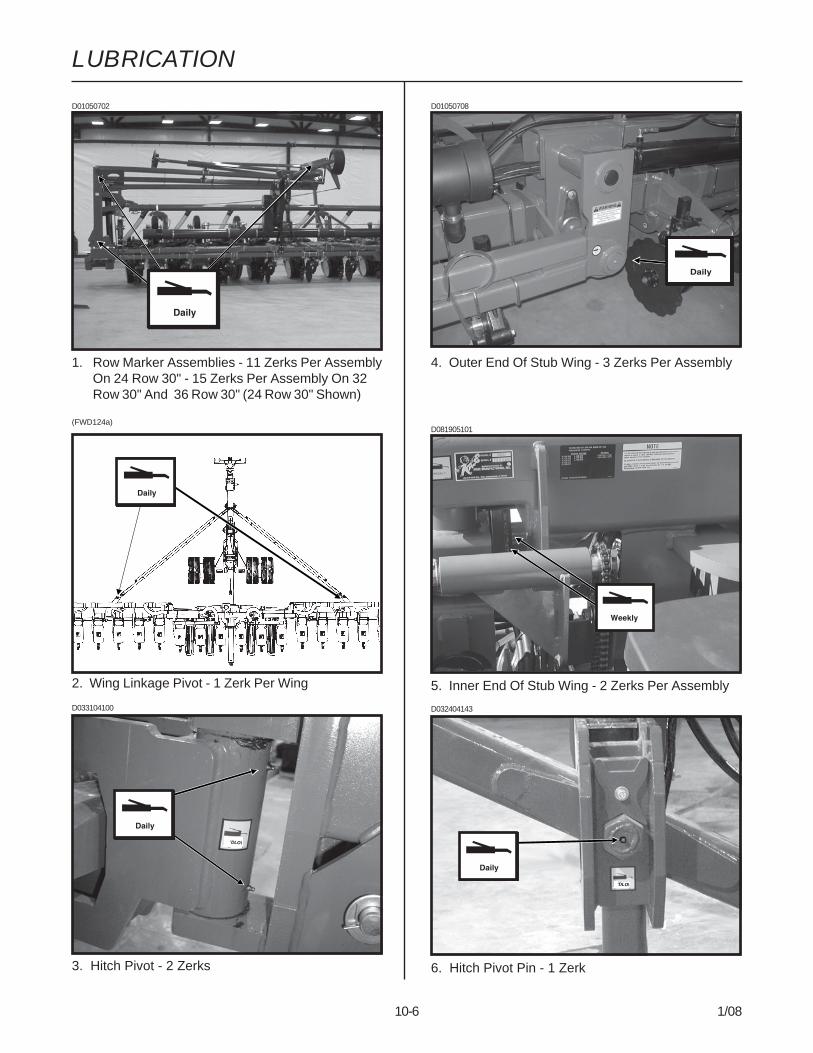
LUBRICATION
10-6 1/08
'DLO\
'DLO\
D01050702
1. Row Marker Assemblies - 11 Zerks Per AssemblyOn 24 Row 30" - 15 Zerks Per Assembly On 32Row 30" And 36 Row 30" (24 Row 30" Shown)
D01050708
4. Outer End Of Stub Wing - 3 Zerks Per Assembly
(FWD124a)
2. Wing Linkage Pivot - 1 Zerk Per Wing
D033104100
3. Hitch Pivot - 2 Zerks
D032404143
6. Hitch Pivot Pin - 1 Zerk
D081905101
5. Inner End Of Stub Wing - 2 Zerks Per Assembly
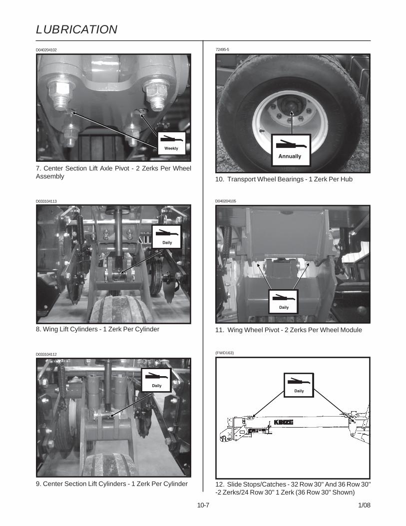
LUBRICATION
10-7 1/08
(FWD163)
12. Slide Stops/Catches - 32 Row 30" And 36 Row 30"-2 Zerks/24 Row 30" 1 Zerk (36 Row 30" Shown)
10. Transport Wheel Bearings - 1 Zerk Per Hub
D040204105
11. Wing Wheel Pivot - 2 Zerks Per Wheel Module
D033104113
D033104112
9. Center Section Lift Cylinders - 1 Zerk Per Cylinder
8. Wing Lift Cylinders - 1 Zerk Per Cylinder
7. Center Section Lift Axle Pivot - 2 Zerks Per WheelAssembly
D040204102 72495-5

LUBRICATION
10-8 1/08
(FWD163)
18. Slide Assembly Lockup Stand - 2 Zerks (32 Row 30"And 36 Row 30" Only)
D032404124
13. Transport Axle Pivot - 4 Zerks
(FWD52)
14. Outer Wing Hinge - 3 Zerks Per Assembly(32 Row 30" And 36 Row 30" Only)
D021406100
15. Seed Rate Transmission Assembly - 2 Zerks PerTransmission
(FWD124a
16. Rock Shaft Wheel Hub Assembly - 1 Zerk Per Hub
D081905101
17. U-Joint Shaft Between Center Section And Wing -1 Zerk On Each End Of U-Joint Shafts (2 Per U-JointShaft)
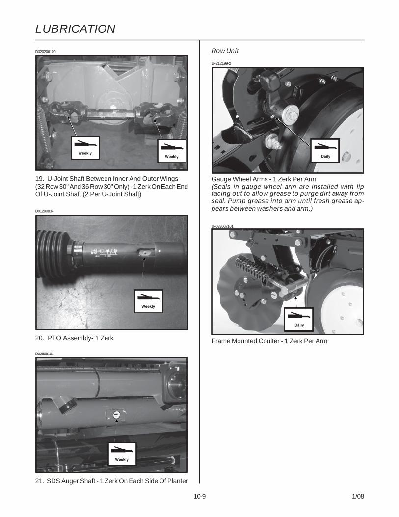
LUBRICATION
10-9 1/08
D02808101
21. SDS Auger Shaft - 1 Zerk On Each Side Of Planter
D01290834
20. PTO Assembly- 1 Zerk
Row Unit
Gauge Wheel Arms - 1 Zerk Per Arm(Seals in gauge wheel arm are installed with lipfacing out to allow grease to purge dirt away fromseal. Pump grease into arm until fresh grease ap-pears between washers and arm.)
LF212199-2
LF083002101
Frame Mounted Coulter - 1 Zerk Per Arm
D020206109
19. U-Joint Shaft Between Inner And Outer Wings(32 Row 30" And 36 Row 30" Only) - 1 Zerk On Each EndOf U-Joint Shaft (2 Per U-Joint Shaft)

LUBRICATION
10-10 1/08
Liquid Fertilizer Piston PumpFertilizer Openers
Notched Single Disc Fertilizer Opener - 1 Zerk
D040704104 (A12330a)
Liquid Fertilizer Piston Pump - 4 Zerks (Fill zerk onoutboard stuffing box until lubricant seeps out ofdrain hole in bottom.)

MAINTENANCE
11-1 1/08
IMPORTANT: Over tightening hardware can causeas much damage as under tightening. Tighteninghardware beyond the recommended range can re-duce its shock load capacity.
WARNING: Before operating the planter for thefirst time and periodically thereafter, check to besure the lug nuts on the transport wheels aretight. This is especially important if the planteris to be transported for a long distance.
MOUNTING BOLTS AND HARDWARE
Before operating the planter for the first time, check tobe sure all hardware is tight. Check all hardware againafter approximately the first 50 hours of operation andat the beginning of each planting season thereafter.
All hardware used on the KINZE® planter is Grade 5(high strength), unless otherwise noted. Grade 5 capscrews are marked with three radial lines on the head.If hardware must be replaced, be sure to replace it withhardware of equal size, strength and thread type. Referto the torque values chart when tightening hardware.
Row Unit Parallel Linkage Bushing Hardware - 130 Ft.Lbs. (See “Bushings” in the Lubrication Section of thismanual.)5/8" No Till Coulter Spindle Hardware - 120 Ft. Lbs.Transport Tire Flange Nuts - 350 Ft. Lbs.Transport Tire (W/Duals) Cap Screws - 125 Ft. Lbs.Center Section Lift/Gauge Tire Lug Nuts - 90 Ft. Lbs.Wing Lift/Gauge Tire Lug Bolts - 125 Ft. Lbs.3 Point Hitch Adapter Pin And Pivot Bolt - 550 Ft. Lbs.
BoltDiameter Coarse Fine Coarse Fine Coarse Fine
1/4" 50 In. Lbs. 56 In. Lbs. 76 In. Lbs. 87 In. Lbs. 9 Ft. Lbs. 10 Ft. Lbs.5/16" 8 Ft. Lbs. 9 Ft. Lbs. 13 Ft. Lbs. 14 Ft. Lbs. 18 Ft. Lbs. 20 Ft. Lbs.3/8" 15 Ft. Lbs. 17 Ft. Lbs. 23 Ft. Lbs. 26 Ft. Lbs. 33 Ft. Lbs. 37 Ft. Lbs.
7/16" 25 Ft. Lbs. 27 Ft. Lbs. 37 Ft. Lbs. 41 Ft. Lbs. 52 Ft. Lbs. 58 Ft. Lbs.1/2" 35 Ft. Lbs. 40 Ft. Lbs. 57 Ft. Lbs. 64 Ft. Lbs. 80 Ft. Lbs. 90 Ft. Lbs.
9/16" 50 Ft. Lbs. 60 Ft. Lbs. 80 Ft. Lbs. 90 Ft. Lbs. 115 Ft. Lbs. 130 Ft. Lbs.5/8" 70 Ft. Lbs. 80 Ft. Lbs. 110 Ft. Lbs. 125 Ft. Lbs. 160 Ft. Lbs. 180 Ft. Lbs.3/4" 130 Ft. Lbs. 145 Ft. Lbs. 200 Ft. Lbs. 220 Ft. Lbs. 280 Ft. Lbs. 315 Ft. Lbs.7/8" 125 Ft. Lbs. 140 Ft. Lbs. 320 Ft. Lbs. 350 Ft. Lbs. 450 Ft. Lbs. 500 Ft. Lbs.1" 190 Ft. Lbs. 205 Ft. Lbs. 480 Ft. Lbs. 530 Ft. Lbs. 675 Ft. Lbs. 750 Ft. Lbs.
1 1/8" 265 Ft. Lbs. 300 Ft. Lbs. 600 Ft. Lbs. 670 Ft. Lbs. 960 Ft. Lbs. 1075 Ft. Lbs.1 1/4" 375 Ft. Lbs. 415 Ft. Lbs. 840 Ft. Lbs. 930 Ft. Lbs. 1360 Ft. Lbs. 1500 Ft. Lbs.1 3/8" 490 Ft. Lbs. 560 Ft. Lbs. 1100 Ft. Lbs. 1250 Ft. Lbs. 1780 Ft. Lbs. 2030 Ft. Lbs.1 1/2" 650 Ft. Lbs. 730 Ft. Lbs. 1450 Ft. Lbs. 1650 Ft. Lbs. 2307 Ft. Lbs. 2670 Ft. Lbs.
GRADE 2No Marks
GRADE 53 Marks
GRADE 86 Marks
NOTE: Unplated hardware and bolts with lock nuts should be torqued approximately 1/3 higher than the abovevalues. Bolts lubricated prior to installation should be torqued to 70% of value shown in chart.
TORQUE VALUES CHART - PLATED HARDWARE
Grade 2 Grade 5 Grade 8
IMPORTANT: Torque setting for 5/8"-18 hex jamnut that secures fan impellor assembly to motorshaft is 50 ft. lbs.

MAINTENANCE
11-2 1/08
CHAIN TENSION ADJUSTMENT
The drive chains have spring loaded idlers and there-fore are self-adjusting. The only adjustment needed isto shorten the chain if wear stretches the chain andreduces spring tension. The pivot point of these idlersshould be checked periodically to ensure they rotatefreely. See “Wrap Spring Wrench Assembly” in Lubrica-tion Section for additional information.
(FWD56)
Additional chain links can be found in the storage areaslocated at each planter transmission assembly.
Additional Chain Links
TIRE PRESSURE(FWD124a)
Tire pressure should be checked regularly and main-tained as follows:
(4) 41 x 11R22.5" Radial Load Range H(Center Section Lift/Gauge) ................ 75 PSI
(6-12) 7.50" x 20" 8 Ply Custom Rib Implement(Wing Lift/Gauge) ............................... 40 PSI
(2-4) 445-50R22.5R Radial Load Range H(Transport) ....................................... 120 PSI
(6) 4.80" x 8" (Contact Drive) .......................... 50 PSI(2) 20.5 x 8.0-10 (Marker) ................................ 35 PSI(2) 7.60" x 15" Rib Implement
(Liquid Fertilizer Piston Pump) ........... 40 PSI
DANGER: Rim and tireservicing can be dangerous.Explosive separation of tireand rim parts can causeserious injury or death.
Do not attempt to mount a tire unless you have theproper equipment and experience to perform thejob. This should only be done by persons properlytrained and equipped to do the job.
Always maintain the correct tire pressures. Do notinflate the tires above the recommended pressures.
When inflating tires, use a clip-on air chuck andextension hose long enough to allow you to stand toone side and NOT in front of or over the tire assem-bly. Use a safety cage to enclose the tire and rimassembly when inflating.
Inspect tires and wheels daily. Do not operate withlow pressure, cuts, bubbles, damaged rims or miss-ing lug bolts and nuts.
Transport
Contact Drive
Center Section Lift/GaugeWing Lift/Gauge
ConventionalPlanterShown

MAINTENANCE
11-3 1/08
PTO PUMPS AND OIL COOLERS
Drain the reservoirs and change filters annually.
Refill system with a SAE 10W-20 multigrade widetemperature range transmission hydraulic fluid.
Reservoirs are supplied with a drain hose to allow easydraining.
PROBLEM POSSIBLE CAUSE SOLUTION
Pump is squealing. Lack of oil to pump. Check oil level.
Oil temperature is high. Low oil level. Check oil level and add as required.Coolers plugged not allowing oil Wash or blow off coolers.to flow across them.
Desired fan speed cannot Low oil level. Check oil level and add as required.be achieved. Plugged filter. Check and change as required.
Vacuum level is not Digital vacuum gauge console Turn ON.displayed. power is OFF.
Cable not plugged in. Check connection.Digital vacuum gauge console Check fuse.has no power.
PTO PUMPS AND OIL COOLERS TROUBLESHOOTING
Replace filters with high quality 10 micron filters.
Start the system and allow to run with tractor at idle andthe fans turned off for 1-2 minutes. Allow to run withtractor at idle and the fans at full speed for 1-2 minutes.Check reservoir fluid level and fill as required. Hydraulicfluid level should be within 2" from the top of the reservoirafter the pumps have run and hydraulic hoses have beenprimed to allow the fluid to expand when heated. Bringtractor to PTO speed and adjust flow control to thedesired vacuum level using the switches on the vacuumfan control console.

MAINTENANCE
11-4 1/08
DRAG CLOSING ATTACHMENTLF212299-18
Prior to storage of the planter, inspect each drag closingattachment and replace any worn or broken parts. Checkfor loose hardware and tighten as needed.
MachineBushings
LF212199-2
(RU113g)
Shim Gauge Wheel To Lightly Contact The
Opener DiscBlade - CheckAdjustment InField Position
GAUGE WHEEL ADJUSTMENT
To prevent an accumulation of dirt or trash, gaugewheels should lightly contact the opener blades. Gaugewheels and opener blades should turn with only slightresistance.
To adjust clearance between gauge wheels and openerblades, add or remove machine bushings between theshank and gauge wheel arm. Store remaining machinebushings between gauge wheel arm and flat washer onouter side of gauge wheel arm.
NOTE: It may be desirable to space gauge wheelfurther from blade when operating in sticky soils.
CLOSING WHEEL TROUBLESHOOTING
PROBLEM POSSIBLE CAUSE SOLUTIONClosing wheel(s) leave Too much closing wheel Adjust closing wheel pressure.severe imprint in soil. down pressure.
Closing wheel(s) not firming Insufficient closing wheel Adjust closing wheel pressure. Severesoil around seed. down pressure. no till conditions may require use of
cast iron closing wheels.
“V” closing wheel running on Improper centering. Align. See “V Closing Wheeltop of seed furrow. Adjustment”.
Single closing wheel not directly Improper centering. Align. See “Covering Discs/Single Pressover seed. Wheel Adjustment”.

MAINTENANCE
11-5 1/08
GAUGE WHEEL ARM BUSHINGAND/OR SEAL REPLACEMENT
(RU113g)
Gauge Wheel Arm
Bushings/Seals
NOTE: A Gauge Wheel Arm Bushing And Seal DriverKit (G1K296), for use in bushing and seal replace-ment, is available through your KINZE® Dealer.
To replace gauge wheel arm assembly bushing(s)and/or seal(s):1. Remove gauge wheel from arm.2. Remove the gauge wheel arm assembly from the
shank assembly.3. Remove seal and bushing and discard. Clean and
dry inner bore.(A7975/RU122)
4. Drive/press replacement bushing inside bore of armto a depth of .125" below flush.
5. Coat wiping edge of seal with grease.6. Drive/press seal into place with lip to the outside as
shown above.
NOTE: Use extra care to protect the sealing lipduring installation. Apply uniform pressure toassemble the seal into the bore of the arm. Neverapply a direct hammer blow to the seal surface.
7. Inspect gauge wheel pivot spindle.8. Reinstall gauge wheel arm assembly and gauge
wheel.NOTE: Special machine bushing between gaugewheel arm and gauge wheel.
9. Shim for proper gauge wheel tire/disc blade clear-ance.
10. Lubricate with an SAE multipurpose grease.
GAUGE WHEEL ARM PIVOTSPINDLE REPLACEMENT
(RU113g)
Gauge Wheel
Pivot Spindle
To replace gauge wheel pivot spindle:1. Remove the gauge wheel and arm assemblies from
the shank assembly.2. Remove 1/2" x 3/4" cap screw that locks the pivot
spindle in place and remove the spindle.D06189902
3. Install the replacement spindle and position asshown below. Exact centering is critical.
(A7966)
4. Install 1/2" x 3/4" cap screw and torque to lock pivotspindle in place.
5. Install gauge wheel and arm assemblies. Shim forproper gauge wheel tire/disc blade clearance.
2 7/8"
Seal Seal
Bushing Bushing

MAINTENANCE
11-6 1/08
5. Install machine bushing(s), new disc blade/bearingassembly, washer and cap screw. Torque 5/8"-11Grade 5 cap screw to value shown in “Torque ValuesChart”.
NOTE: Replace disc blades only with disc bladesof equal thickness.
6. Replace bearing dust cap.7. Install scraper.8. Install gauge wheel.
It may be necessary to replace only the bearing if thereis excessive endplay or if the bearing sounds or feelsrough when the disc blade is rotated.
To replace bearing:1. Remove gauge wheel, scraper, bearing cap, cap
screw, washer and disc blade/bearing assembly.2. Remove 1/4" rivets from bearing housing to expose
bearing.3. After installing new bearing, install three evenly
spaced 1/4" cap screws into three of the six holesin the bearing housing to hold the bearing andbearing housing in place. Install rivets in the otherthree holes. Remove 1/4" cap screws and installrivets in those three holes.
4. Reinstall disc blade/bearing assembly, washer andcap screw. Torque 5/8"-11 cap screw to value shownin “Torque Values Chart” at the beginning of thissection.
5. Replace bearing dust cap.6. Install scraper and gauge wheel.
15" SEED OPENER DISC BLADE/BEARING ASSEMBLY
Approximately 1" - 1 1/2" of blade-to-blade contact shouldbe maintained to properly open and form the seedtrench. As the blade diameter decreases, due to wear,it will be necessary to relocate machine bushings frominside to outside to maintain approximately 1" - 1 1/2" ofcontact.
NOTE: If proper blade-to-blade contact cannot bemaintained after relocating machine bushings or ifblade diameter wears below 14 1/2", the bladesshould be replaced.
IMPORTANT: Excessive blade contact may result inpremature disc opener bearing/hub failures andexcessive wear on seed tube guard/inner scraper.When properly adjusted, if one blade is held in fixedposition, the opposite blade should be able to berotated with minimal force (Less than 5 pounds forceat outer edge of blade).
(RU113g)
To replace disc blade/bearing assembly:1. Remove gauge wheel.2. Remove scraper.3. Remove bearing dust cap.4. Remove cap screw, washer and disc blade/bearing
assembly. The machine bushings between the shankand disc blade are used to maintain the approximate1" - 1 1/2" of blade-to-blade contact.
IMPORTANT: Left hand side of opener uses a lefthand threaded cap screw. DO NOT OVER TIGHTEN.Damage to shank threads will require replacementof row unit shank assembly.
Approximately1" - 1 1/2" Of Blade-To-Blade Contact

MAINTENANCE
11-7 1/08
IMPORTANT: No till planting or planting in hardground conditions, especially when the planter is notequipped with no till coulters, and/or excessive blade-to-blade contact will increase seed tube guard wearand necessitate more frequent inspection and/or re-placement.
To replace the seed tube guard, remove the seed tubeand the two hex socket head cap screws which attachthe seed tube guard. Hold the replacement seed tubeguard centered between the seed opener disc blades.Install, but DO NOT tighten, the hex socket head capscrews. Using a clamp or vise-grip, squeeze the openerblades together in front of the seed tube guard. Tightenthe seed tube guard retaining screws. Remove theclamps. The distance between the seed tube guard andopener blades should be equal on both sides. Reinstallseed tube.
IMPORTANT: Over tightening the hex socket headcap screws may damage the threads in the shankand require replacement of the shank. A seed tubeguard that is worn excessively may allow the bladesto wear into the row unit shank, also requiringreplacement of the shank.
SEED TUBE GUARD/INNER SCRAPER
The seed tube guard protects the seed tube and actsas the inner scraper for the seed opener disc blades.
Remove the seed tube and check for wear. Exces-sive wear on the seed tube indicates a worn seed tubeguard. Replace the seed tube guard if it measures 5/8"or less at the lower end. A new seed tube guardmeasures approximately 7/8".
LF212199-12
Shown With Gauge Wheel And Seed Opener Disc BladeRemoved For Visual Clarity
Seed Tube Guard/Inner Scraper

MAINTENANCE
11-8 1/08
FRAME MOUNTED COULTER
NOTE: Torque 5/8" spindle hardware to 120 ft. lbs.
See “Frame Mounted Coulter” in Row Unit Operationsection of this manual for depth and spring adjustment.
When the 16" diameter coulter blade (1" fluted, 1"bubbled or 3/4" fluted) is worn to 14 1/2" (maximumallowable wear), it should be replaced.
LF083002101
RESIDUE WHEELS (For Use With FrameMounted Coulter)
STYLE A
STYLE B
The wheel hub is equipped with sealed bearings. If abearing sounds or feels rough when the wheel is rotated,replace the bearings.
LF083002102
(RU154)

MAINTENANCE
11-9 1/08
ROW UNIT MOUNTED DISC FURROWER
LF212299-22
Lubricate the bushings in the support arm and mountingbracket at the frequency indicated in the LubricationSection of this manual. Using a torque wrench, checkeach bolt for proper torque. If the bolt is loose, it shouldbe removed and the bushing inspected for cracks andwear. Replace bushings as necessary. Only hardenedflat washers should be used. Replace damaged flatwashers with proper part. Torque cap screws to 57ft. lbs.
The blade hubs are equipped with sealed bearings. Ifbearings sound or feel rough when the blade is rotated,replace the bearings.
When the 12" diameter blades (solid or notched) areworn to 11", they should be replaced.
ROW UNIT MOUNTED RESIDUE WHEEL
D101701113
STYLE A
(A12685)
STYLE B
The wheel hub is equipped with sealed bearings. If abearing sounds or feels rough when the wheel is rotated,replace the bearings.

MAINTENANCE
11-10 1/08
ROW UNIT MOUNTED NO TILLCOULTER
LF212299-19a
STYLE A (Two Sleeves For Installing CoulterMounted Residue Wheels)
D05170706a
STYLE B (One Sleeve For Installing Coulter MountedResidue Wheels)
Check periodically to be sure nuts and hardware aretightened to proper torque specification.
NOTE: Torque 5/8" spindle hardware to 120 ft. lbs.
Be sure the coulter is positioned square with the row unitand aligned in front of row unit disc opener.
The coulter blade can be adjusted to one of four settings.Initially the blade is set in the highest position. As theblade wears it can be adjusted to one of the three lowersettings. See “Row Unit Mounted No Till Coulter” in RowUnit Operation section of this manual.
When the 16" diameter coulter blade is worn to 14 1/2"(maximum allowable wear), it should be replaced.
COULTER MOUNTED RESIDUE WHEELS
LF212299-23
STYLE A - Used With Style A Row Unit Mounted NoTill Coulter
D05170708a
STYLE B - Used With Style B Row Unit Mounted NoTill Coulter
The wheel hubs are equipped with sealed bearings. Ifbearings sound or feel rough when the wheel is rotated,replace the bearings.

MAINTENANCE
11-11 1/08
GRANULAR CHEMICAL ATTACHMENT
Prior to storage of the planter, disengage the granularchemical drive by rotating the throwout knob 1/4 turncounterclockwise. Remove the drive chain and emptyand clean all granular chemical hoppers. Clean thedrive chains and coat them with a rust preventive sprayor submerge chains in oil. Inspect and replace anyworn or broken parts.
Install hoppers and chains. Check chain alignment.
LF212299-4
Disengage
Engage
SPRING TOOTH INCORPORATOR
Prior to storage of the planter, inspect each spring toothincorporator and replace any worn or broken parts.Check for loose hardware and tighten as needed.
LF212299-26
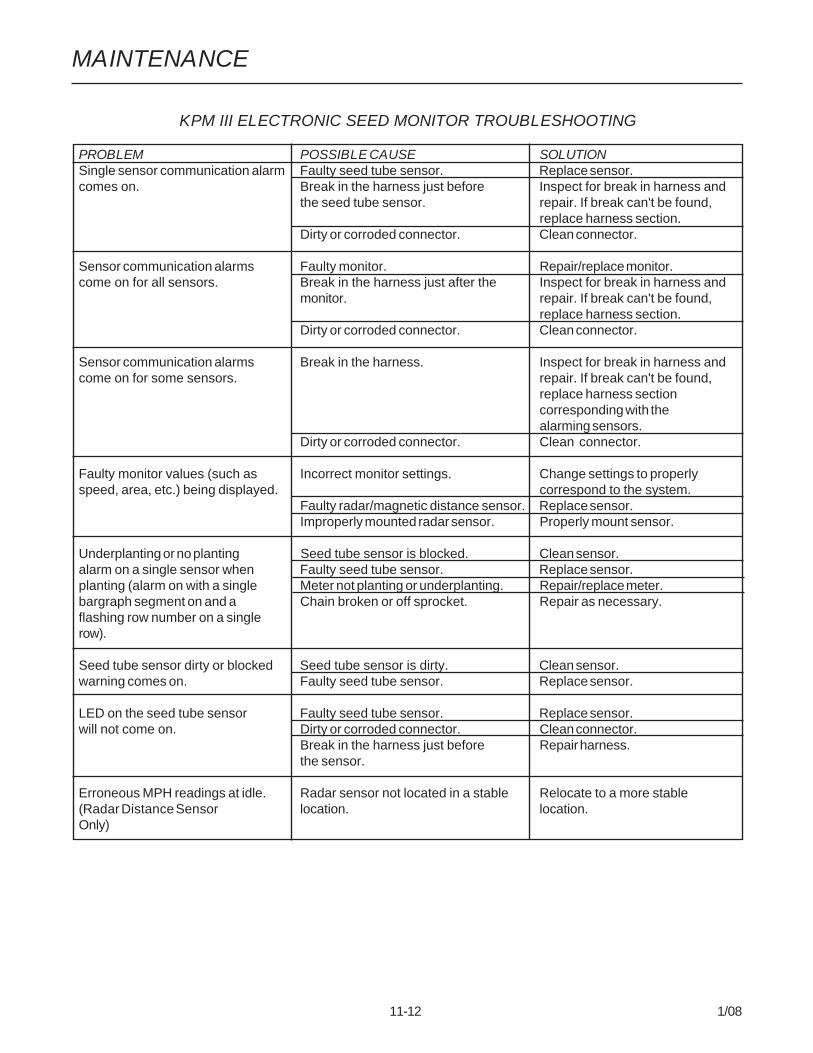
MAINTENANCE
11-12 1/08
KPM III ELECTRONIC SEED MONITOR TROUBLESHOOTING
PROBLEM POSSIBLE CAUSE SOLUTIONSingle sensor communication alarm Faulty seed tube sensor. Replace sensor.comes on. Break in the harness just before Inspect for break in harness and
the seed tube sensor. repair. If break can't be found,replace harness section.
Dirty or corroded connector. Clean connector.
Sensor communication alarms Faulty monitor. Repair/replace monitor.come on for all sensors. Break in the harness just after the Inspect for break in harness and
monitor. repair. If break can't be found,replace harness section.
Dirty or corroded connector. Clean connector.
Sensor communication alarms Break in the harness. Inspect for break in harness andcome on for some sensors. repair. If break can't be found,
replace harness sectioncorresponding with thealarming sensors.
Dirty or corroded connector. Clean connector.
Faulty monitor values (such as Incorrect monitor settings. Change settings to properlyspeed, area, etc.) being displayed. correspond to the system.
Faulty radar/magnetic distance sensor. Replace sensor.Improperly mounted radar sensor. Properly mount sensor.
Underplanting or no planting Seed tube sensor is blocked. Clean sensor.alarm on a single sensor when Faulty seed tube sensor. Replace sensor.planting (alarm on with a single Meter not planting or underplanting. Repair/replace meter.bargraph segment on and a Chain broken or off sprocket. Repair as necessary.flashing row number on a singlerow).
Seed tube sensor dirty or blocked Seed tube sensor is dirty. Clean sensor.warning comes on. Faulty seed tube sensor. Replace sensor.
LED on the seed tube sensor Faulty seed tube sensor. Replace sensor.will not come on. Dirty or corroded connector. Clean connector.
Break in the harness just before Repair harness.the sensor.
Erroneous MPH readings at idle. Radar sensor not located in a stable Relocate to a more stable(Radar Distance Sensor location. location.Only)
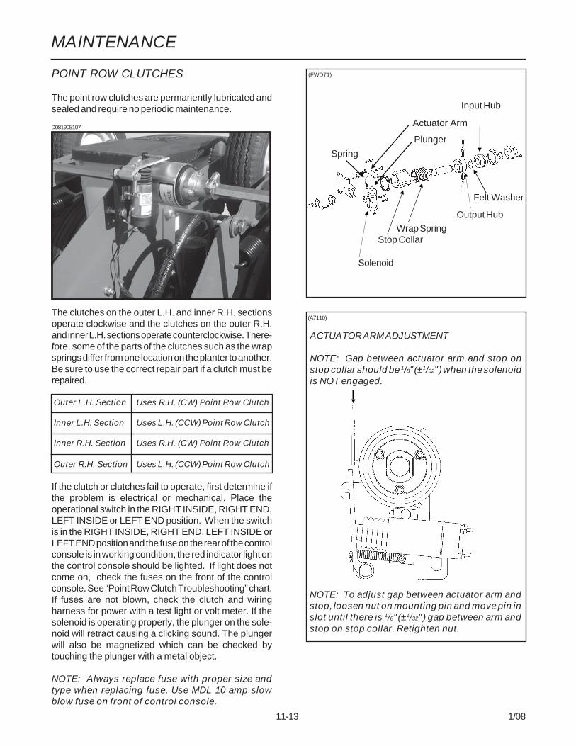
MAINTENANCE
11-13 1/08
POINT ROW CLUTCHES
The point row clutches are permanently lubricated andsealed and require no periodic maintenance.
The clutches on the outer L.H. and inner R.H. sectionsoperate clockwise and the clutches on the outer R.H.and inner L.H. sections operate counterclockwise. There-fore, some of the parts of the clutches such as the wrapsprings differ from one location on the planter to another.Be sure to use the correct repair part if a clutch must berepaired.
Outer L.H. Section Uses R.H. (CW) Point Row Clutch
Inner L.H. Section Uses L.H. (CCW) Point Row Clutch
Inner R.H. Section Uses R.H. (CW) Point Row Clutch
Outer R.H. Section Uses L.H. (CCW) Point Row Clutch
If the clutch or clutches fail to operate, first determine ifthe problem is electrical or mechanical. Place theoperational switch in the RIGHT INSIDE, RIGHT END,LEFT INSIDE or LEFT END position. When the switchis in the RIGHT INSIDE, RIGHT END, LEFT INSIDE orLEFT END position and the fuse on the rear of the controlconsole is in working condition, the red indicator light onthe control console should be lighted. If light does notcome on, check the fuses on the front of the controlconsole. See “Point Row Clutch Troubleshooting” chart.If fuses are not blown, check the clutch and wiringharness for power with a test light or volt meter. If thesolenoid is operating properly, the plunger on the sole-noid will retract causing a clicking sound. The plungerwill also be magnetized which can be checked bytouching the plunger with a metal object.
NOTE: Always replace fuse with proper size andtype when replacing fuse. Use MDL 10 amp slowblow fuse on front of control console.
(FWD71)
Plunger
(A7110)
ACTUATOR ARM ADJUSTMENT
NOTE: Gap between actuator arm and stop onstop collar should be 1/8"(±1/32") when the solenoidis NOT engaged.
NOTE: To adjust gap between actuator arm andstop, loosen nut on mounting pin and move pin inslot until there is 1/8"(±1/32") gap between arm andstop on stop collar. Retighten nut.
Felt Washer
D081905107
Solenoid
Spring
Actuator Arm
Stop CollarWrap Spring
Output Hub
Input Hub

MAINTENANCE
11-14 1/08
POINT ROW CLUTCH TROUBLESHOOTING
PROBLEM POSSIBLE CAUSE SOLUTIONNone of the clutches will Main fuse blown in control console. Replace defective fuse.disengage. Poor terminal connection in Repair or replace.
wiring harness.Wiring damage in wiring Repair or replace.harness.Low voltage at coil. Check battery connections.(12 volts required)
One section of planter will not Shear pin at seed drive Replace pin with one of equal sizere-engage. transmission(s) sheared. and grade.One clutch will not engage. Fuses blown. Replace defective fuses.
Actuator arm and plunger stuck Remove, free up and reinstall.in disengaged position.Actuator arm out of Adjust actuator arm mounting pin inadjustment. slot so that actuator arm clears stop
on stop collar by approximately1/8" when clutch is rotated.
Wrap spring broken or stretched. Disassemble clutch and replacespring.
Something touching the stop Check to ensure collar is free tocollar. turn with clutch.Clutch assembled incorrectly. Check clutch and diagram for
correct assembly.Clutch slipping. Wrap spring stretched. “Lock” clutch output shaft from turning.
Place torque wrench on input shaftand rotate in direction of drive. Afterinput shaft has rotated a shortdistance the wrap spring shouldtighten onto the input hub. If slippageoccurs at less than 100 ft. lbs.replace spring. If spring still slipsafter installing new spring,replace input hub.
Planter section will not re-engage Spring in actuator arm not Remove spring from inside solenoidwhile planter is moving forward. strong enough to push arm and stretch spring slightly or replace.
away from stop collar when Reinstall spring. If that fails, file theoperational switch is turned to stop on the stop collar slightly so thatthe ON position. the stop is not as aggressive.
Frequent solenoid burnout. Fuses too large. Replace fuses on front panel with 10amp slow blow fuses.
Frequent fuse burnout. Low voltage (12 volts required). Check power source voltage forpartially discharged battery, etc.
Damage to wiring harness. Locate damage and repair orreplace harness.
Clutch or clutches will not Input and output shafts out Align input and output shaftsdisengage. of alignment. to prevent drag.
Input or output shaft is pushed Reposition input and outputin too far creating a coupler. shafts.

MAINTENANCE
11-15 1/08
VVB019(PLTR55)
SOLENOID VALVE
The solenoid valve consists of a chambered bodycontaining a cartridge valve which is activated by anelectrical coil.
If the solenoid or solenoids fail to operate, first deter-mine if the problem is electrical or hydraulic. If the valveis working properly, a click will be heard when thesolenoid coil is energized. This will be the valve stemopening up. If no sound is heard, check the solenoid coilby touching the top of the coil housing with a metallicobject such as a pliers or screwdriver. If the coil isworking properly, the coil housing will be stronglymagnetized when energized. If the voltage to the coil islow, the coil will be weakly magnetized when energizedand no click will be heard.
Coil
Cartridge
FLOW CONTROL VALVE
(FWD157)
The flow control valves should be adjusted for rowmarker raise and lower speed as part of the assemblyprocedure or upon initial operation. If the valve fails tofunction properly or requires frequent adjustment, itshould be removed for inspection. Check for foreignmaterial and contamination on both the valve and theseating area of the valve body. Replace any compo-nents found to be defective.
PRESSURE RELIEF VALVE(Located At Center Of Rear H-Frame -32 Row 30" And 36 Row 30")
(FWD23)
The pressure relief valve limits the available hydraulicpressure to the transport axle cylinder when the cylin-der is retracting. Consult your KINZE® Dealer for ser-vice.
COUNTER BALANCE VALVE(Located At Center Of Rear H-Frame)
(FWD21)
The counter balance valve is used for hydraulic loadholding. This is a safety feature to prevent the planterfrom being unintentionally lowered. The valve is factoryset and should require no additional adjustments. Con-sult your KINZE® Dealer for service.
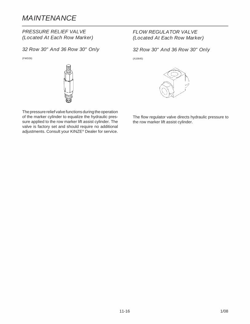
MAINTENANCE
11-16 1/08
PRESSURE RELIEF VALVE(Located At Each Row Marker)
32 Row 30" And 36 Row 30" Only
(FWD26)
The pressure relief valve functions during the operationof the marker cylinder to equalize the hydraulic pres-sure applied to the row marker lift assist cylinder. Thevalve is factory set and should require no additionaladjustments. Consult your KINZE® Dealer for service.
FLOW REGULATOR VALVE(Located At Each Row Marker)
32 Row 30" And 36 Row 30" Only
(A10645)
The flow regulator valve directs hydraulic pressure tothe row marker lift assist cylinder.
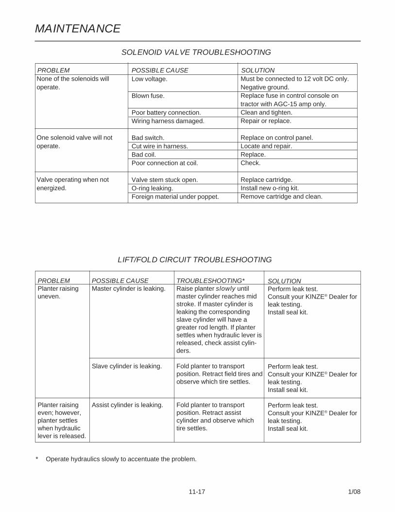
MAINTENANCE
11-17 1/08
None of the solenoids willoperate.
One solenoid valve will notoperate.
Valve operating when notenergized.
Low voltage.
Blown fuse.
Poor battery connection.Wiring harness damaged.
Bad switch.Cut wire in harness.Bad coil.Poor connection at coil.
Valve stem stuck open.O-ring leaking.Foreign material under poppet.
Must be connected to 12 volt DC only.Negative ground.Replace fuse in control console ontractor with AGC-15 amp only.Clean and tighten.Repair or replace.
Replace on control panel.Locate and repair.Replace.Check.
Replace cartridge.Install new o-ring kit.Remove cartridge and clean.
SOLENOID VALVE TROUBLESHOOTING
PROBLEM POSSIBLE CAUSE SOLUTION
LIFT/FOLD CIRCUIT TROUBLESHOOTING
PROBLEMPlanter raisinguneven.
Planter raisingeven; however,planter settleswhen hydrauliclever is released.
POSSIBLE CAUSEMaster cylinder is leaking.
Slave cylinder is leaking.
Assist cylinder is leaking.
TROUBLESHOOTING*Raise planter slowly untilmaster cylinder reaches midstroke. If master cylinder isleaking the correspondingslave cylinder will have agreater rod length. If plantersettles when hydraulic lever isreleased, check assist cylin-ders.
Fold planter to transportposition. Retract field tires andobserve which tire settles.
Fold planter to transportposition. Retract assistcylinder and observe whichtire settles.
SOLUTIONPerform leak test.Consult your KINZE® Dealer forleak testing.Install seal kit.
Perform leak test.Consult your KINZE® Dealer forleak testing.Install seal kit.
Perform leak test.Consult your KINZE® Dealer forleak testing.Install seal kit.
* Operate hydraulics slowly to accentuate the problem.

MAINTENANCE
11-18 1/08
ROW MARKER CIRCUIT TROUBLESHOOTING
PROBLEMRight marker lowering slower thanleft marker.
Left marker lowering slower than rightmarker.
Both markers lowering.
Neither marker will lower.
Neither marker will raise.
Right marker will not lower.
Left marker will not lower.
Markers traveling too fast and dam-aging row marker stands and/or dam-aging pivot at rod end of markercylinders.
SOLUTIONSwitch cartridge with one in port V4.If problem follows cartridge, replacecartridge.Inspect hose routing. Replace or re-pair hoses as required.
Switch cartridge with one in port V3.If problem follows cartridge, replacecartridge.Inspect hose routing. Replace or re-pair hoses as required.
Replace solenoid valve cartridge.
Check red light on control console. Itshould be on if switch is ON. If light isnot on, switch to opposite markerposition. If light comes on, switchmay be defective. Replace switch.Otherwise replace fuse.Poor ground on wire, bad wire con-nection or damaged wire. Repair asrequired.See “Machine Operation” for adjust-ment.
See “Machine Operation” for adjust-ment.
Check switch on control console. Re-place if defective. Check coil groundwire. Check for poor connection ordamaged wire.Switch cartridge with one on theplanter you know is operating prop-erly. If right marker lowers, replacedefective cartridge.
Check switch on control console. Re-place if defective. Check coil groundwire. Check for poor connection ordamaged wire.Switch cartridge with one on theplanter you know is operating prop-erly. If right marker lowers, replacedefective cartridge.
See “Machine Operation” for adjust-ment.
POSSIBLE CAUSESolenoid valve cartridge in port V3not opening completely.
Hose pinched or collapsed.
Solenoid valve cartridge in port V4not opening completely.
Hose pinched or collapsed.
Solenoid valve cartridge stuck open.If marker switch is in the left markerposition, the right cartridge (V3) isdefective. If the marker switch is inthe right marker position, the leftcartridge (V4) is defective.
Blown fuse.
Coils at V3 and V4 not energized.
Marker flow control valve closedtoo far.
Marker flow control valve closedtoo far.
Solenoid coil in port V3 notenergized.
Solenoid cartridge in port V3 stuckclosed.
Solenoid coil in port V4 notenergized.
Solenoid cartridge in port V4 stuckclosed.
Marker flow control valve out ofadjustment.

MAINTENANCE
11-19 1/08
LIFT/GROUND DRIVE WHEEL BEARINGLUBRICATION OR REPLACEMENT
1. Raise tire clear of ground and remove wheel.
2. Remove double jam nuts and slide hub from spindle.
3. Remove bearings, seals (Where Applicable) andcups and discard if bearings are being replaced.Clean hub and dry. Remove bearings only and notcups if repacking.
4. Press in new bearing cups with thickest edgefacing in. (Bearing replacement procedure only.)
5. Pack bearings with heavy duty wheel bearing greasethoroughly forcing grease between roller cone andbearing cage. Also fill the space between the bear-ing cups in the hub with grease.
6. Place inner bearing and seal (If Applicable) inplace.
7. Clean spindle and install hub.
8. Install outer bearing, seal (If Applicable) and steppednut. Tighten jam nut while rotating hub until there issome drag. This assures that all bearing surfacesare in contact. Back off jam nut 1/4 turn or until thereis only slight drag when rotating the hub. Installsecond jam nut to lock against first.
9. Install wheel on hub and tighten evenly and se-curely. Torque lug bolts or nuts to specified torque.
Seal
Hub OuterBearing
BearingCup
InnerBearing
Spindle
JamNut
(EF35e/PLTR56)
ROW MARKER BEARING LUBRICATIONOR REPLACEMENT
1. Remove row marker blade.2. Remove dust cap from hub.3. Remove cotter pin, nut and washer.4. Slide hub from spindle.5. Remove bearings and cups and discard if bearings
are being replaced. Clean hub and dry. Removebearings only and not cups if repacking.
6. Press in new bearing cups with thickest edgefacing in. (Bearing replacement procedure only.)
7. Pack bearings with heavy duty wheel bearing greasethoroughly forcing grease between roller cone andbearing cage. Also fill the space between thebearing cups in the hub with grease.
8. Install rubber seal into grease seal. Place innerbearing in place and press in new rubber seal/grease seal.
9. Clean spindle and install hub.10. Install outer bearing, washer and slotted hex nut.
Tighten slotted hex nut while rotating hub until thereis some drag. This assures that all bearing surfacesare in contact. Back off slotted nut to nearest lockingslot and install cotter pin.
11. Fill dust caps approximately 3/4 full of wheel bearinggrease and install on hub.
12. Install blade and dust cap retainer on hub andtighten evenly and securely.
(PLTR45/PLTR99/PLTR98/PLTR102)
Dust Cotter Inner GreaseCap Pin Hub Bearing Seal
OuterBearing Rubber Seal
Nut SpindleWasher Bearing
Cup

MAINTENANCE
11-20 1/08
TRANSPORT WHEEL BEARINGREPLACEMENT
1. Raise tires clear of ground and remove wheels.
2. Remove dust cap attachment hardware and re-move cap from wheel hub.
3. Remove cotter pin, axle nut and 2" washer.
4. Slide hub from axle spindle, using a hub puller ifnecessary.
5. Remove bearings and cups from hub and discard.Thoroughly clean and dry wheel hub.
6. Press in new bearing cups with thickest edgesfacing in.
7. Pack bearing with heavy-duty wheel bearing grease,thoroughly forcing grease between roller cone andbearing cage. Also fill the space between the bear-ing cups in the hub with grease.
8. Place inner bearing in hub and press in new greaseseal with lip pointing towards bearing.
9. Clean axle spindle and install hub.
10. Install outer bearing, 2" washer and slotted hex nut.Tighten slotted hex nut while rotating the hub untilthere is some drag. This assures that all bearingsurfaces are in contact. Back off slotted nut tonearest locking slot and install cotter pin. Check forendplay in bearings.
11. Fill dust cap half full of wheel bearing grease andinstall on hub with attachment bolts.
12. Install wheels and remove jack. Torque wheel nuts(and cap screws if applicable) to specified torque.
(FWD60c)
2" WasherHub
3/4"-16 Flange Nut Inner Bearing Spindle
Dust Cap
OuterBearing
Bearing Cups
Seal
Cotter Pin
2" SlottedNut
Screw

MAINTENANCE
11-21 1/08
PISTON PUMP STORAGE
IMPORTANT: KEEP AIR OUT OF PUMP! This is theonly way to prevent corrosion. Even for short peri-ods of storage, the entrance of air into the pump,will cause RAPID AND SEVERE CORROSION.
Overnight StorageSUSPENSION FERTILIZER must be flushed from thepump for ANY storage period.
Winter Storage1. Flush pump thoroughly with 5 to 10 gallons of fresh
water and circulate until all corrosive salts aredissolved in the pump.
2. With the pump set on 10, draw in a mixture of halfdiesel fuel and half 10 weight oil until the dischargeis clean. Then plug inlet and outlet.
(A12330a)
PISTON PUMP TROUBLESHOOTING
PROBLEM POSSIBLE CAUSE SOLUTIONPump hard or impossible to Valves fouled or in wrong place. Inspect and clean valves.prime. Air leak in suction line. Repair leak.
Pump set too low. Adjust pump setting.Packing washers worn out. Replace.
Low metering. Valves fouled or in wrong place. Inspect and clean valves.Air leak in suction line. Repair leak.Pump set too low. Adjust pump setting.Broken valve spring. Replace spring.
Over meters. Broken discharge valve spring. Replace spring.Trash under valves. Inspect and clean valves.Improper rate setting. Adjust pump setting.
Leaks through when stopped. Broken discharge valve spring. Replace spring.Trash under valves. Inspect and clean valves.
Fertilizer solution leaking Packing washers worn out. Replace.under stuffing box.
Pump using excessive oil. Oil seals or o-ring worn and leaking. Replace.
Pump operates noisily. Crankcase components worn Inspect and replace if necessary.excessively.

MAINTENANCE
11-22 1/08
PREPARATION FOR STORAGE
Store the planter in a dry sheltered area if possible.
Remove all trash that may be wrapped on sprockets orshafts and remove dirt that can draw and hold moisture.
Clean all drive chains and coat with a rust preventativespray, or remove chains and submerge in oil.
Lubricate planter and row units at all lubrication points.
Inspect the planter for parts that are in need of replace-ment and order during the “off” season.
Make sure all seed and granular chemical hoppers areempty and clean.
Remove seed discs from seed meters, clean and storemeters in a rodent-free, dry area with discs removed.Store seed discs vertically on a dowel or pipe.
Remove vacuum hose from each seed meter. Operatevacuum fans at full hydraulic flow from the tractor fortwo minutes to clear manifolds, hoses and fittings ofdust and debris.
Clean breather on analog vacuum gauges.
Disassemble, clean and grease all U-joint slides.
Grease or paint disc openers/blades and row markerdisc blades to prevent rust.
Flush liquid fertilizer metering pump with clean water.See “Piston Pump Storage”.
Disengage row unit clutch and unlatch mini-hopper oneach row unit to release stress on drop hoses andhoppers during storage. (SDS Only)

MAINTENANCE
11-23 1/08
ELECTRICAL WIRING DIAGRAM FOR7-TERMINAL LIGHT CONNECTOR(WGN66a)
* Optional customer-supplied auxiliary lights and wiresmay be wired into existing plug terminals.
** Rear and side flashers.
The light packages supplied on Model 3800 SDS and3800 Conventional Forward Folding Planters meetASAE Standards. For the correct wiring harness to bewired into the lights on your tractor, check with thetractor manufacturer.
69922-35**
** Marker L
igh
ts

MAINTENANCE
11-24 1/08
ELECTRICAL LIGHT HARNESS SCHEMATICS
Primary Harness
ExtensionBetween PrimaryHarness And LightHarness On R.H.Wing
Pin “A” WHITE (Ground)Pin “B” BLACK (Marker Light)Pin “C” YELLOW (L.H. Turn Signal)
Pin “A” WHITE (Ground)Pin “B” BLACK (Marker Light)Pin “C” GREEN (R.H. Turn Signal)
Pin “A” WHITE (Ground)Pin “B” BROWN (Brake)Pin “C” GREEN (R.H. Turn Signal)Pin “D” YELLOW (L.H. Turn Signal)
(A10315/A10316/A10317/A10318/A10319)
32 Row 30" And 36 Row 30"Planters - Amber Light Mid-Wing
To Lights On H-Frame
Pin “A” WHITE (Ground)Pin “B” RED (Power)

MAINTENANCE
11-25 1/08
To Marker Light AndAmber Light On L.H.Wing
Pin “A” WHITE (Ground)Pin “B” BROWN (Brake)Pin “C” GREEN (R.H. Turn Signal)
Pin “A” WHITE (Ground)Pin “B” BROWN (Brake)Pin “C” YELLOW (L.H. Turn Signal)
Pin “A” WHITE (Ground)Pin “B” GREEN (R.H. Turn Signal)
Pin “A” WHITE (Ground)Pin “B” YELLOW (L.H. Turn Signal)
To Marker Light AndAmber Light On R.H.Wing
Pin “A” WHITE (Ground)Pin “B” BLACK (Marker Light)
Pin “A” WHITE (Ground)Pin “B” GREEN (R.H. Turn Signal)
Pin “A” WHITE (Ground)Pin “B” BLACK (Marker Light)
Pin “A” WHITE (Ground)Pin “B” YELLOW (L.H. Turn Signal)
32 Row 30" And 36 Row 30"Planters - Amber Light Mid-Wing
Pin “A” WHITE (Ground)Pin “B” RED (Power)
To Limit Switch On Marker Mount
To Limit Switch On Marker Mount

MAINTENANCE
11-26 1/08
ELECTRICAL CONTROL CONSOLE SCHEMATIC (Planter Functions)
IMPORTANT: Before doing any electrical work, disconnect the control console from the tractor battery. Keepwiring harnesses away from high temperature areas or sharp edges. DO NOT route the wiring harnesses alongbattery cables. Use tie straps to keep wire harnesses away from moving parts on tractor and planter. Be sureground connections to the tractor frame are clean to provide good electrical contact.
NOTE:1. Operating marker or point row switches in either direction lights panel light.2. Point row clutch switches operate independently of the rest of the control console.3. Power to the marker switch is fed through the auxiliary switch and the two transport function switches. Operating
any of the switches in the lower row disables the marker function and turns off the panel light. (If the point row clutchswitches are in the “OFF” position.)
(FWD30bb/FWD36a/FWD30c/FWD36) To Left Outer Point Row Clutch SwitchTo Left Inner Point Row Clutch Switch
Jumper To Main FuseTo Right Inner Point Row Clutch Switch
To Right Outer Point Row Clutch Switch
Red From PowerCord And FromTransformer
A. 6" White JumperB.-D., Q. 4" White Jumper (4)E. 4" Red JumperF. 7" Orange JumperG.-J. 3" White Jumper (4)K. 5" Black JumperL.-P. 7" Purple Jumper (5)R. 4" White Jumper
MAIN FUSE
Aux. RowMarker
PointRowClutches
FoldFieldRaise
L M N O
P
Pin “A” ORANGE/RED (Slide)Pin “R” BROWN (L.H. Outer Point Row Clutch)Pin “G” ORANGE (R.H. Inner Point Row Clutch)Pin “H” BLUE (L.H. Marker)Pin “B” BLUE/RED (Fold)Pin “U” RED/BLACK (R.H. Outer Point Row Clutch)Pin “S” YELLOW (L.H. Inner Point Row Clutch)Pin “O” RED (R.H. Marker)Pin “V” BLUE/BLACK (Raise To Transport)Pin “T” BLACK (Ground)(12 Gauge)Pin “C” BLACK/RED (Ground)Pin “W” ORANGE/BLACK (Auxiliary)* To Point Row Clutch Fuses** To Main FuseA
BR C D
G
H
FI K E
J
Q
Aux. RowMarker
PointRowClutches
FoldFieldRaise
W S O H R
*UG
B A***V*

MAINTENANCE
11-27 1/08
ELECTRICAL WIRING HARNESS SCHEMATIC (On Tractor)
(ELC10c/ELC13)
Pin “F
” YE
LLOW
/RE
D (N
OT
US
ED
)
Pin “A
” OR
AN
GE
/RE
D (S
lide)
Pin “R
” BR
OW
N (L.H
. Outer P
oint Row
Clutch)
Pin “G
” OR
AN
GE
(R.H
. Inner Point R
ow C
lutch)
Pin “H
” BLU
E (L.H
. Marker)
Pin “B
” BLU
E/R
ED
(Fold)
Pin “U
” RE
D/B
LAC
K (R
.H. O
uter Point R
ow C
lutch)
Pin “S
” YE
LLOW
(L.H. Inner P
oint Row
Clutch)
Pin “O
” RE
D (R
.H. M
arker)
Pin “V
” BLU
E/B
LAC
K (R
aise)
Pin “T
” BLA
CK
(Ground)(12 G
auge)
Pin “C
” BLA
CK
/RE
D (G
round)
Pin “W
” OR
AN
GE
/BLA
CK
(Auxiliary)
RE
D (+
12 VD
C)
BLA
CK
(-12 VD
C)(14 G
auge)
BROWNORANGERED
23 Socket Capacity
TO BATTERY
Pin “L” GREEN (“C” MONITOR DATA)Pin “M” BLACK (“B” MONITOR GROUND)Pin “K” WHITE (“A” MONITOR +12V)

MAINTENANCE
11-28 1/08
ELECTRICAL WIRING HARNESSES SCHEMATIC(On Planter)
23 Pin Capacity
(ELC13/A10308)
TERMINAL STRIP - Located On Hitch
Pin “A
” OR
AN
GE
/RE
D (S
lide)
Pin “C
” BLA
CK
/RE
D (G
round)
Pin “W
” OR
AN
GE
/BLA
CK
(Auxiliary)
Pin “T
” BLA
CK
(Ground)(12 G
auge)
Pin “V
” BLU
E/B
LAC
K (R
aise)
Pin “O
” RE
D (R
.H. R
ow M
arker)
Pin “S
” YE
LLOW
(L.H. Inner P
oint Row
Clutch)
Pin “U
” RE
D/B
LAC
K (R
.H. O
uter Point R
ow C
lutch)
Pin “B
” BLU
E/R
ED
(Fold)
Pin “H
” BLU
E (L.H
. Row
Marker)
Pin “G
” OR
AN
GE
(R.H
. Inner Point R
ow C
lutch)
Pin “R
” BR
OW
N (L.H
. Outer P
oint Row
Clutch)
Pin “F
” YE
LLOW
/RE
D (N
OT
US
ED
)
Pin “K” WHITE (“A” MONITOR +12V)Pin “M” BLACK (“B” MONITOR GROUND)
Pin “L” GREEN (“C” MONITOR DATA)

MAINTENANCE
11-29 1/08
Page intentionally left blank.
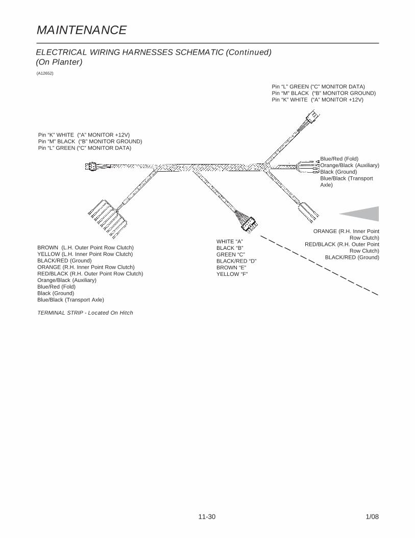
MAINTENANCE
11-30 1/08
Pin “L” GREEN (“C” MONITOR DATA)Pin “M” BLACK (“B” MONITOR GROUND)Pin “K” WHITE (“A” MONITOR +12V)
(A12652)
WHITE “A”BLACK “B”GREEN “C”BLACK/RED “D”BROWN “E”YELLOW “F”
BROWN (L.H. Outer Point Row Clutch)YELLOW (L.H. Inner Point Row Clutch)BLACK/RED (Ground)ORANGE (R.H. Inner Point Row Clutch)RED/BLACK (R.H. Outer Point Row Clutch)Orange/Black (Auxiliary)Blue/Red (Fold)Black (Ground)Blue/Black (Transport Axle)
TERMINAL STRIP - Located On Hitch
ORANGE (R.H. Inner Point Row Clutch)
RED/BLACK (R.H. Outer Point Row Clutch)
BLACK/RED (Ground)
Pin “K” WHITE (“A” MONITOR +12V)Pin “M” BLACK (“B” MONITOR GROUND)Pin “L” GREEN (“C” MONITOR DATA)
ELECTRICAL WIRING HARNESSES SCHEMATIC (Continued)(On Planter)
Blue/Red (Fold)Orange/Black (Auxiliary)Black (Ground)Blue/Black (TransportAxle)

MAINTENANCE
11-31 1/08
Pin “L” GREEN (“C” MONITOR DATA)Pin “M” BLACK (“B” MONITOR GROUND)Pin “K” WHITE (“A” MONITOR +12V)
(A10311/A9510/A10310)
YELLOW (L.H. Inner Point Row Clutch)BROWN (L.H. Outer Point Row Clutch)BLACK/RED (Ground)
ELECTRICAL WIRING HARNESSES SCHEMATIC (Continued)(On Planter)
TERMINAL STRIP - Located On R.H. Wing
TERMINAL STRIP - Located On L.H. Wing
REDORANGE
OPEN
RED/BLACK
BLACK
OPEN
RED/BLACK
DUAL BLACK
WHITERED
BROWN
OPEN
DUAL BLACK
BROWN
OPEN
BLACK
YELLOW
BLACK/RED
BROWN
BLACK/RED
ORANGE
BLACK/RED
RED/BLACK
BLACK/RED

MAINTENANCE
11-32 1/08
(FWD102)
ELECTRICAL WIRING SCHEMATIC (SDS)
ProximitySensor
LimitSwitch
LimitSwitch
LimitSwitch
LimitSwitch
ProximitySensor
Open
Open
Red/Blue
Red
Blue
Black
Red
Open
Open
Yellow
Red
Red/Blue
Green
Brown
Purple
Open
Open
Yellow
Red/Blue
Red
Green
Brown
Purple
Open
Open
Open
Red/Blue
Red
Blue
Black
Red
Open
Yel
low
Ope
nR
ed/B
lue
2 R
eds
Red
Bla
ckR
edW
hite
Whi
te S
leev
eG
reen
Bro
wn
Pur
ple
Ope
nO
pen
Ope
nW
hite
Red
Bla
ckR
edO
rang
eB
lue
Yel
low
Gra
yG
reen
Bro
wn
Pur
ple
Ope
nO
pen
Yel
low
Ope
nR
ed/B
lue
2 R
eds
Red
Bla
ckR
edW
hite
Whi
te S
leev
eG
reen
Bro
wn
Pur
ple
Ope
nO
pen
Ope
nO
rang
e/W
hite
Red
Bla
ckR
ed/W
hite
Ora
nge/
Red
Blu
e/R
edY
ello
w/R
edG
ray/
Whi
teG
reen
/Whi
teB
row
n/W
hite
Pur
ple/
Whi
teO
pen
Ope
n

MAINTENANCE
11-33 1/08
ELECTRICAL WIRING HARNESS SCHEMATIC (Vacuum Fan Gauges)(A11689)
To DigitalVacuum GaugeOn R.H. SIde OfPlanter
To DigitalVacuum GaugeOn L.H. SIde OfPlanter
To Vacuum FanValve Block OnL.H. SIde OfPlanter
To Vacuum FanValve Block OnR.H. SIde OfPlanter
Red (Power)Black (Ground)Orange (VacuumSignal)
Black (Ground)Yellow (Coil Power)
Brown (Motor Up)Green (Motor Down)
Orange/Black (Vacuum Signal)Black (Ground)Red (Power)
Yellow (Coil Power)Black (Ground)
White (Motor Up)Blue (Motor Down)

MAINTENANCE
11-34 1/08
HYDRAULIC SCHEMATIC (24 Row 30" Vacuum Fan System)
(A12484-2a)
Tank
VacuumFan ValveBlock
VacuumFan
Oil Cooler
PTO Pump
VacuumFan ValveBlock
VacuumFan
Oil Cooler
PlanetaryGearbox

MAINTENANCE
11-35 1/08
Tank
VacuumFan ValveBlock Vacuum
Fan
Oil Cooler
HydraulicPump
HYDRAULIC SCHEMATIC (32 Row 30" And 36 Row 30" Vacuum Fan System)
(A13054-2a)
VacuumFan ValveBlock
VacuumFan
Oil Cooler
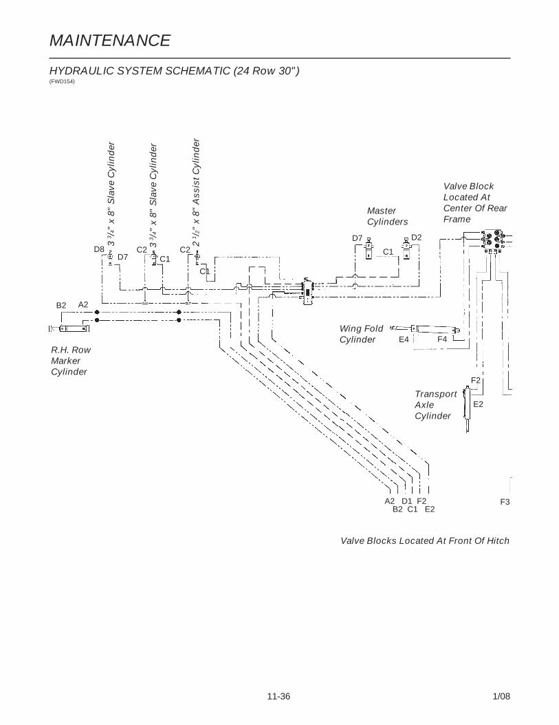
MAINTENANCE
11-36 1/08
Valve BlockLocated AtCenter Of RearFrame
F3
HYDRAULIC SYSTEM SCHEMATIC (24 Row 30")(FWD154)
TransportAxleCylinder
Wing FoldCylinder
R.H. RowMarkerCylinder
MasterCylinders
3 3 /
4" x
8"
Sla
ve C
ylin
der
2 1 /
2" x
8"
Ass
ist C
ylin
der
F2
E2
F4E4
A2B2
D7 C1
C1
D8 C2 C2 C1
D2D73 3 /
4" x
8"
Sla
ve C
ylin
der
A2 D1 F2B2 C1 E2
Valve Blocks Located At Front Of Hitch

MAINTENANCE
11-37 1/08
Tongue LatchCylinder
TransportAxleCylinder
Wing FoldCylinder
L.H. RowMarkerCylinder
MasterCylinders
3 3 /
4" x
8"
Sla
ve C
ylin
der
2 1 /
2" x
8"
Ass
ist C
ylin
der
E3
E5F5A3
B3
C1
C2 D8C2
D2 D7C1
D7D2
3 3 /
4" x
8"
Sla
ve C
ylin
der
E7 C1 B3F7 D1 A3

MAINTENANCE
11-38 1/08
HYDRAULIC SYSTEM SCHEMATIC (32 Row 30")(FWD155)
Valve BlockLocated AtCenter Of RearFrame
TransportAxleCylinders
Wing FoldCylinderR.H. Row
MarkerCylinder
MasterCylinders
F4 E4
A2 D1 F2B2 C1 E2
4" x
8"
Sla
ve C
ylin
der
2 1 /
2" x
8"
Ass
ist C
ylin
der
3 3 /
4" x
8"
Sla
ve C
ylin
der
4" x
8"
Sla
ve C
ylin
der
3 3 /
4" x
8"
Sla
ve C
ylin
der
2 1 /
2" x
8"
Ass
ist C
ylin
der
SlideCylinder
Valve Blocks Located At Front Of Hitch
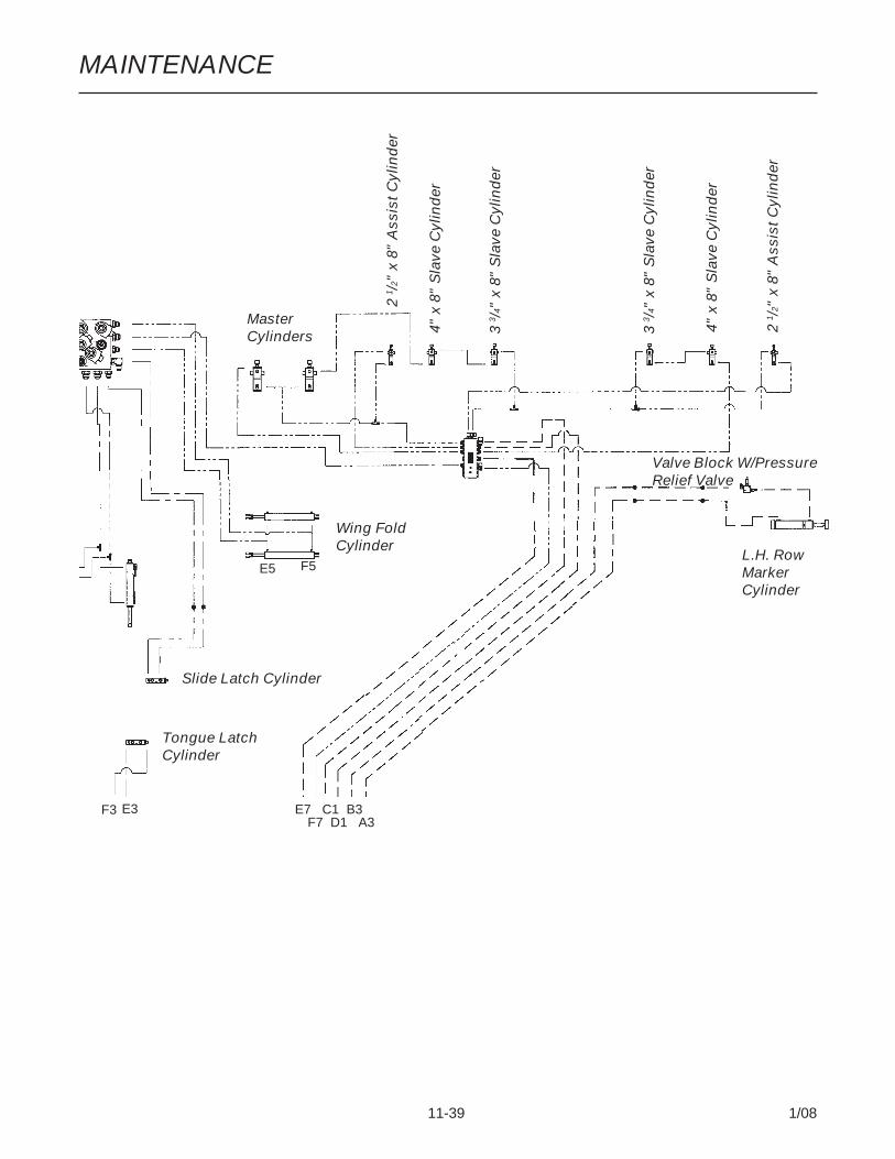
MAINTENANCE
11-39 1/08
Tongue LatchCylinder
Wing FoldCylinder
L.H. RowMarkerCylinder
MasterCylinders
E3F3
E5 F5
E7 C1 B3F7 D1 A3
4" x
8"
Sla
ve C
ylin
der
3 3 /
4" x
8"
Sla
ve C
ylin
der
2 1 /
2" x
8"
Ass
ist C
ylin
der
4" x
8"
Sla
ve C
ylin
der
2 1 /
2" x
8"
Ass
ist C
ylin
der
3 3 /
4" x
8"
Sla
ve C
ylin
der
Slide Latch Cylinder
Valve Block W/PressureRelief Valve
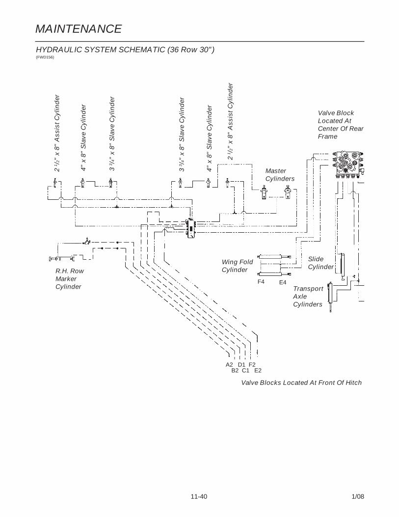
MAINTENANCE
11-40 1/08
HYDRAULIC SYSTEM SCHEMATIC (36 Row 30")(FWD156)
Valve BlockLocated AtCenter Of RearFrame
TransportAxleCylinders
Wing FoldCylinderR.H. Row
MarkerCylinder
MasterCylinders
F4 E4
A2 D1 F2B2 C1 E2
4" x
8"
Sla
ve C
ylin
der
2 1 /
2" x
8"
Ass
ist C
ylin
der
3 3 /
4" x
8"
Sla
ve C
ylin
der
4" x
8"
Sla
ve C
ylin
der
3 3 /
4" x
8"
Sla
ve C
ylin
der
2 1 /
2" x
8"
Ass
ist C
ylin
der
SlideCylinder
Valve Blocks Located At Front Of Hitch

MAINTENANCE
11-41 1/08
Tongue LatchCylinder
Wing FoldCylinder
L.H. RowMarkerCylinder
MasterCylinders
E3F3 E7 C1 B3F7 D1 A3
4" x
8"
Sla
ve C
ylin
der
3 3 /
4" x
8"
Sla
ve C
ylin
der
2 1 /
2" x
8"
Ass
ist C
ylin
der
4" x
8"
Sla
ve C
ylin
der
2 1 /
2" x
8"
Ass
ist C
ylin
der
3 3 /
4" x
8"
Sla
ve C
ylin
der
Slide LatchCylinder
E5 F5
Valve Block W/Pressure Relief Valve

MAINTENANCE
11-42 1/08
(FWD103/FWD101a)
HYDRAULIC SCHEMATIC (SDS)
Valve Block Located At FrontOf Hitch
HydraulicMotor
HydraulicMotor
SDS Manifold Block
Red/Blue
Blue
To Motor B
To Motor A
Red/Blue
Blue/Red
To Motor A
To Motor B
E2 E4
A1 B1
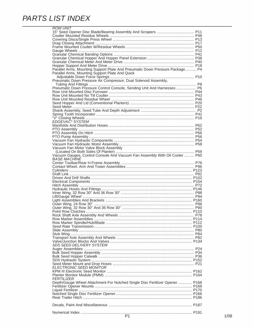
P1 1/08
PARTS LIST INDEXROW UNIT15" Seed Opener Disc Blade/Bearing Assembly And Scrapers .................................... P11Coulter Mounted Residue Wheels ................................................................................. P48Covering Discs/Single Press Wheel .............................................................................. P13Drag Closing Attachment ............................................................................................... P17Frame Mounted Coulter W/Residue Wheels ................................................................. P50Gauge Wheels ............................................................................................................... P12Granular Chemical Banding Options ............................................................................. P41Granular Chemical Hopper And Hopper Panel Extension ............................................. P38Granular Chemical Meter And Meter Drive .................................................................... P40Hopper Support And Meter Drive ................................................................................... P18Parallel Arms, Mounting Support Plate And Pneumatic Down Pressure Package .......... P4Parallel Arms, Mounting Support Plate And Quick Adjustable Down Force Springs ................................................................................. P10Pneumatic Down Pressure Air Compressor, Dual Solenoid Assembly, Tubing And Fittings ....................................................................................................... P8Pneumatic Down Pressure Control Console, Sending Unit And Harnesses ................... P6Row Unit Mounted Disc Furrower .................................................................................. P44Row Unit Mounted No Till Coulter .................................................................................. P43Row Unit Mounted Residue Wheel ................................................................................ P46Seed Hopper And Lid (Conventional Planters) .............................................................. P20Seed Meter ..................................................................................................................... P22Shank Assembly, Seed Tube And Depth Adjustment ..................................................... P2Spring Tooth Incorporator .............................................................................................. P42“V” Closing Wheels ........................................................................................................ P16EDGEVAC® SYSTEMManifolds And Distribution Hoses .................................................................................. P62PTO Assembly ............................................................................................................... P52PTO Assembly On Hitch ................................................................................................ P66PTO Pump Assembly ..................................................................................................... P56Vacuum Fan Hydraulic Components ............................................................................. P54Vacuum Fan Hydraulic Motor Assembly ........................................................................ P58Vacuum Fan Motor Valve Block Assembly (Located On Both Sides Of Planter) ........................................................................... P59Vacuum Gauges, Control Console And Vacuum Fan Assembly With Oil Cooler ......... P60BASE MACHINECenter Toolbar/Rear H-Frame Assembly ...................................................................... P76Contact Wheel, Arm And Tower Assemblies ................................................................. P96Cylinders ...................................................................................................................... P123Draft Link ........................................................................................................................ P92Driven And Drill Shafts ................................................................................................. P102Electrical Components ................................................................................................. P154Hitch Assembly .............................................................................................................. P72Hydraulic Hoses And Fittings ....................................................................................... P146Inner Wing, 32 Row 30" And 36 Row 30" ...................................................................... P88Lift/Gauge Wheel ........................................................................................................... P94Light Assemblies And Brackets ................................................................................... P160Outer Wing, 24 Row 30" ................................................................................................ P86Outer Wing, 32 Row 30" And 36 Row 30" ..................................................................... P90Point Row Clutches ...................................................................................................... P110Rock Shaft Axle Assembly And Wheels ........................................................................ P78Row Marker Assemblies .............................................................................................. P114Row Marker Spindle/Hub/Blade ................................................................................... P112Seed Rate Transmission .............................................................................................. P100Slide Assembly ............................................................................................................... P80Stub Wing ....................................................................................................................... P84Transport Axle Assembly And Wheels .......................................................................... P82Valve/Junction Blocks And Valves ............................................................................... P134SDS SEED DELIVERY SYSTEMAuger Assemblies .......................................................................................................... P24Bulk Seed Hopper Assembly ......................................................................................... P34Bulk Seed Hopper Catwalk ............................................................................................ P36SDS Hydraulic System ................................................................................................. P152Seed Meter Mount and Drop Hoses .............................................................................. P21ELECTRONIC SEED MONITORKPM III Electronic Seed Monitor .................................................................................. P162Planter Monitor Module (PMM) .................................................................................... P164FERTILIZERDepth/Gauge Wheel Attachment For Notched Single Disc Fertilizer Opener ............. P168Fertilizer Opener Mounts ............................................................................................. P169Liquid Fertilizer ............................................................................................................. P170Notched Single Disc Fertilizer Opener ......................................................................... P166Rear Trailer Hitch ......................................................................................................... P186
Decals, Paint And Miscellaneous ................................................................................ P187
Numerical Index ........................................................................................................... P191

P2 1/08
(D17014/METR29cc/A12650a/D16245)
SHANK ASSEMBLY, SEED TUBE ANDDEPTH ADJUSTMENT

P3 1/08
SHANK ASSEMBLY, SEED TUBE ANDDEPTH ADJUSTMENTITEM PART NO. QTY. DESCRIPTION
(Per Row)
1. G11015 2 Hex Washer Head Cap Screw, 3/8"-16 x 1 1/4"2. GB0274 1 Cover, Depth Adjustment3. GB0266 1 Handle, Depth Adjustment4. GB0267 1 Lever, Depth Adjustment5. GD3612 1 Cap Plug6. GD10993 1 Spring7. GD13361 1 Pin, 3/8" x 1 2/3"8. GD11259 1 Sleeve, 3/8" I.D. x 5/8" O.D. x 1 25/32" Long9. G11008 1 Hex Head Cap Screw, 3/8"-24 x 2 1/2", Grade 8
G11007 1 Lock Nut, 3/8"-24, Grade C10. G3303-104 1 Chain, No. 41, 104 Pitch Including Connector Link
G3303-16 1 Chain, No. 41, 16 Pitch Including Connector Link(Used W/Row Unit Extension Brackets)
GR0196 1 Connector Link, No. 4111. GD1026 1 Sleeve, 1 3/16" Long12. G10201 1 Special Washer, 3/8" x 1 1/2" O.D.13. GD1065 1 Idler Spring14. GD7318 1 Sleeve, 1" Long15. G10108 1 Lock Nut, 3/8"-1616. G10210 1 Washer, 3/8" USS17. GD11962 1 Idler18. G10003 3 Hex Head Cap Screw, 3/8"-16 x 1 1/2"
G10108 3 Lock Nut, 3/8"-1619. GD10867 2 Stop20. G10326 1 Hex Head Cap Screw, 3/8"-16 x 3 3/4"21. G10551 1 Clevis Pin, 1/4" x 2 1/2"
G10669 1 Hair Pin Clip, No. 2222. G10312 2 Carriage Bolt, 5/16"-18 x 3/4"
G10620 2 Serrated Flange Nut, 5/16"-1823. GD1033 1 Shield24. - Wheel Arm, See “Gauge Wheels”, Pages P12 And P1325. GA10157 1 Shank W/Gauge Wheel Pivot Spindle And Set Screw
GD11001 - SpindleG10438 - Hex Head Cap Screw, 1/2"-13 x 3/4"
26. G10207 2 Washer, 7/8" O.D. x 13/32" I.D. x .134" (If Applicable)27. GD11845 1 Dust Cap28. See “KPM III Electronic Seed Monitor” And
“Planter Monitor Module (PMM)”, Pages P160-P16329. GB0285 1 Collar, Depth Adjustment30. GB0265 1 Pivot Link, Depth Adjustment31. GD15970 1 Sun Shade32. G10304 1 Carriage Bolt, 3/8"-16 x 3"
G10108 1 Lock Nut, 3/8"-1633. GD17014 1 Hose Guide34. G10047 1 Hex Head Cap Screw, 3/8"-16 x 1 3/4"
G10203 2-3 Washer, 3/8" SAEG10108 1 Lock Nut, 3/8"-16
35. GD16245 - Sun Shade (Rubber)

P4 1/08
(RU157a/RU159/RU157aa)
PARALLEL ARMS, MOUNTING SUPPORT PLATE ANDPNEUMATIC DOWN PRESSURE PACKAGE
NOTE: Item 18 link not usedwhen extension brackets areused.

P5 1/08
ITEM PART NO. QTY. DESCRIPTION(Per Row)
1. GD1114 2 U-Bolt, 7" x 7" x 5/8"-11G10230 4 Lock Washer, 5/8"G10104 4 Hex Nut, 5/8"-11
2. GD10036 1 Mounting Support Plate3. GB0218 4 Bushing, 21/32" I.D. x 7/8" O.D. x 19/32" Long4. GD11422 2 Upper Parallel Arm5. G10732 4 Hex Head Cap Screw, 5/8"-18 x 2"
GD7805 4 Special Washer, 5/8", HardenedG10412 4 Lock Nut, 5/8"-18
6. GA5651 1 Lower Parallel Arm7. GA1720 1 Bearing/Sprocket, 7/8" Hex Bore8. G10001 2 Hex Head Cap Screw, 3/8"-16 x 1"
G10229 2 Lock Washer, 3/8"G10101 2 Hex Nut, 3/8"-16
9. - See “Hopper Support And Meter Drive”, Page P1810. GA11982 1 Air Spring Assembly11. GB0394 1 Saddle12. G11018 2 Hex Head Cap Screw, 5/8"-18 x 1 1/4"
GD7805 2 Special Washer, 5/8", HardenedGD3180-30 2 Sleeve, 7/8" O.D. x 5/8" I.D. x 21/32"
13. GB0396 1 Head Mount14. GB0397 1 Shoulder Nut, 3/4"-1615. GB0395 2 Bracket16. G11220 4 Hex Socket Cap Screw, 1/2"-13 x 1 1/2"
G10071 4 Serrated Flange Nut, 1/2"-1317. G10004 2 Hex Head Cap Screw, 3/8"-16 x 1 1/4"
G10203 2 Washer, 3/8" SAEGD11963-04 2 Spacer, 1/4"G10108 2 Lock Nut, 3/8"-16
18. GD17794 1 Link19. GB0393 1 Plate20. G10037 7 Hex Head Cap Screw, 1/2"-13 x 1 1/4"
G10206 2 Washer, 1/2" SAE (Lower Two Holes Only)G10228 7 Lock Washer, 1/2"
21. G10007 4 Hex Head Cap Screw, 5/8"-11 x 1 1/2"G10230 4 Lock Washer, 5/8"G10104 4 Hex Nut, 5/8"-11
22. GB0366 2 Extension Bracket23. GB0398 1 Extension24. G10039 4 Hex Head Cap Screw, 1/2"-13 x 1 3/4"
G10206 4 Washer, 1/2" SAEG10111 4 Lock Nut, 1/2"-13
25. GD8249 2 Spring26. G10438 2 Hex Head Cap Screw, 1/2"-13 x 3/4"
G10216 2 Washer, 1/2" USS
A. G6326X - U-Bolt Package For 7" x 7" Toolbar, Includes: (2) GD1114, (4) G10230,(4) G10104
B. G1K465 - Pull Row Unit Assist Springs Package, Includes: (2) G10438, (2) G10216And (2) GD8249
PARALLEL ARMS, MOUNTING SUPPORT PLATE ANDPNEUMATIC DOWN PRESSURE PACKAGE
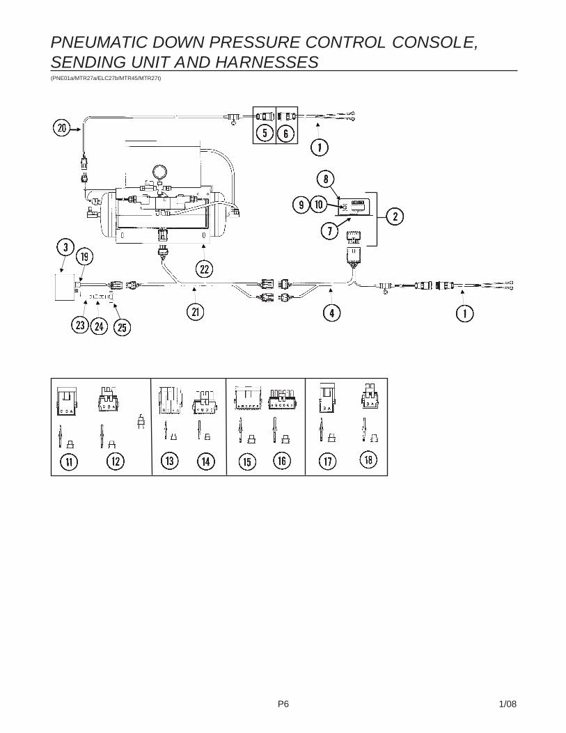
P6 1/08
(PNE01a/MTR27a/ELC27b/MTR45/MTR27t)
PNEUMATIC DOWN PRESSURE CONTROL CONSOLE,SENDING UNIT AND HARNESSES
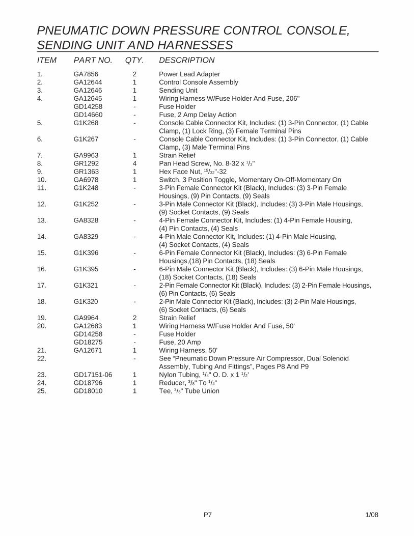
P7 1/08
ITEM PART NO. QTY. DESCRIPTION
1. GA7856 2 Power Lead Adapter2. GA12644 1 Control Console Assembly3. GA12646 1 Sending Unit4. GA12645 1 Wiring Harness W/Fuse Holder And Fuse, 206"
GD14258 - Fuse HolderGD14660 - Fuse, 2 Amp Delay Action
5. G1K268 - Console Cable Connector Kit, Includes: (1) 3-Pin Connector, (1) CableClamp, (1) Lock Ring, (3) Female Terminal Pins
6. G1K267 - Console Cable Connector Kit, Includes: (1) 3-Pin Connector, (1) CableClamp, (3) Male Terminal Pins
7. GA9963 1 Strain Relief8. GR1292 4 Pan Head Screw, No. 8-32 x 1/2"9. GR1363 1 Hex Face Nut, 15/32"-3210. GA6978 1 Switch, 3 Position Toggle, Momentary On-Off-Momentary On11. G1K248 - 3-Pin Female Connector Kit (Black), Includes: (3) 3-Pin Female
Housings, (9) Pin Contacts, (9) Seals12. G1K252 - 3-Pin Male Connector Kit (Black), Includes: (3) 3-Pin Male Housings,
(9) Socket Contacts, (9) Seals13. GA8328 - 4-Pin Female Connector Kit, Includes: (1) 4-Pin Female Housing,
(4) Pin Contacts, (4) Seals14. GA8329 - 4-Pin Male Connector Kit, Includes: (1) 4-Pin Male Housing,
(4) Socket Contacts, (4) Seals15. G1K396 - 6-Pin Female Connector Kit (Black), Includes: (3) 6-Pin Female
Housings,(18) Pin Contacts, (18) Seals16. G1K395 - 6-Pin Male Connector Kit (Black), Includes: (3) 6-Pin Male Housings,
(18) Socket Contacts, (18) Seals17. G1K321 - 2-Pin Female Connector Kit (Black), Includes: (3) 2-Pin Female Housings,
(6) Pin Contacts, (6) Seals18. G1K320 - 2-Pin Male Connector Kit (Black), Includes: (3) 2-Pin Male Housings,
(6) Socket Contacts, (6) Seals19. GA9964 2 Strain Relief20. GA12683 1 Wiring Harness W/Fuse Holder And Fuse, 50'
GD14258 - Fuse HolderGD18275 - Fuse, 20 Amp
21. GA12671 1 Wiring Harness, 50'22. - See “Pneumatic Down Pressure Air Compressor, Dual Solenoid
Assembly, Tubing And Fittings”, Pages P8 And P923. GD17151-06 1 Nylon Tubing, 1/4" O. D. x 1 1/2'24. GD18796 1 Reducer, 3/8" To 1/4"25. GD18010 1 Tee, 3/8" Tube Union
PNEUMATIC DOWN PRESSURE CONTROL CONSOLE,SENDING UNIT AND HARNESSES

P8 1/08
(PNE06/PNE02/PNE29b/A13169/PNE09/PNE08)
PNEUMATIC DOWN PRESSURE AIR COMPRESSOR, DUALSOLENOID ASSEMBLY, TUBING AND FITTINGS

P9 1/08
ITEM PART NO. QTY. DESCRIPTION
1. GD18112 1 Cover2. G11066 8 Phillips Pan Head Machine Screw, No. 10-24 x 3/4", Stainless Steel
G10992 8 Serrated Flange Nut, No. 10-243. GA12102 1 Air Compressor4. GA12404 1 Filter Assembly
GR1809 - Filter5. GA12358 1 Mount6. G10019 8 Hex Head Cap Screw, 5/16"-18 x 1"
G10219 8 Washer, 5/16" USSG10232 8 Lock Washer, 5/16"G10106 8 Hex Nut, 5/16"-18
7. GD17298 2 Manifold, 1/4" NPT8. GD18081 2 Close Nipple, 1/4" NPT9. GD17156 3 Plug, 1/4" NPT10. GD17144 1 Reducer, 1/8" Male To 1/4" Female11. GA11988 1 Tank, 3 Gallon12. GA11991 1 Drain, 1/4" NPT13. GR1778 1 Pressure Switch14. GA11989 1 Valve Stem, 1/8" NPT15. G11247 4 Slotted Pan Head Machine Screw, M4-0.7 x 816. GA11992 1 Shutoff Valve, 1/4" NPT17. GD17156 2 Plug, 1/4" NPT18. GA11997 1 Breather, 1/4" NPT19. GD17154 1 Connector, 1/4" Male NPT20. GA11993 1 Block21. GD17141 3 Connector, 1/4" Male NPT22. GA11994 2 Solenoid23. GD18078 1 Female Cross, 1/4" NPT24. GA12104 1 Pressure Gauge, 1/4" NPT25. GD17143 1 Swivel Elbow, 1/4" NPT x 3/8"26. G10341 3 Hex Head Cap Screw, 5/8"-11 x 8"27. GD18173 2 Bracket28. G10021 2 Hex Head Cap Screw, 1/4"-20 x 1 1/2"
G10227 2 Lock Washer, 1/4"G10209 2 Washer, 1/4" USS
29. GD18010 - Tee, 3/8" Tube Union30. GD17150-05 - Nylon Tubing, 3/8" O.D. x 112', 24 Row
GD17150-06 - Nylon Tubing, 3/8" O.D. x 150', 32 RowGD17150-07 - Nylon Tubing, 3/8" O.D. x 168', 36 Row
31. GD18011 - Elbow, 3/8" x 1/8" NPT Extended32. - See “Parallel Arms, Mounting Support Plate And Pneumatic Down
Pressure Package”, Pages P4 And P533. GA13169 1 Tube Cutter W/Blade
GR1843 - Blade34. G10171 4 Hex Head Cap Screw, 5/16"-18 x 1 1/4"
G10219 4 Washer, 5/16" USSG10232 4 Lock Washer, 5/16"G10106 4 Hex Nut, 5/16"-18
35. GD3180-33 1 Sleeve, 7"36. GD18901 1 Tap Block, Long
A. GA12626 - Air Compresor Assembly (Items 1-14)B. GA11995 - Dual Solenoid Assembly (Items 15-25)
PNEUMATIC DOWN PRESSURE AIR COMPRESSOR, DUALSOLENOID ASSEMBLY, TUBING AND FITTINGS
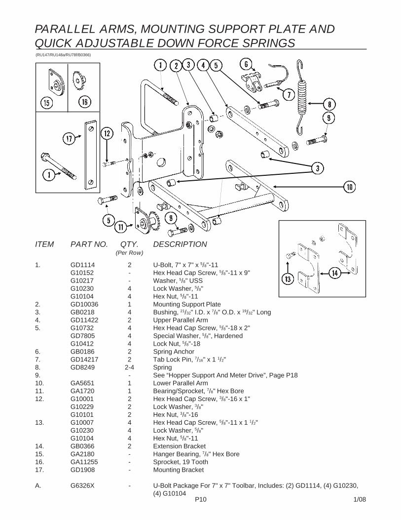
P10 1/08
(RU147/RU148a/RU78f/B0366)
ITEM PART NO. QTY. DESCRIPTION(Per Row)
1. GD1114 2 U-Bolt, 7" x 7" x 5/8"-11G10152 - Hex Head Cap Screw, 5/8"-11 x 9"G10217 - Washer, 5/8" USSG10230 4 Lock Washer, 5/8"G10104 4 Hex Nut, 5/8"-11
2. GD10036 1 Mounting Support Plate3. GB0218 4 Bushing, 21/32" I.D. x 7/8" O.D. x 19/32" Long4. GD11422 2 Upper Parallel Arm5. G10732 4 Hex Head Cap Screw, 5/8"-18 x 2"
GD7805 4 Special Washer, 5/8", HardenedG10412 4 Lock Nut, 5/8"-18
6. GB0186 2 Spring Anchor7. GD14217 2 Tab Lock Pin, 7/16" x 1 1/2"8. GD8249 2-4 Spring9. - See “Hopper Support And Meter Drive”, Page P1810. GA5651 1 Lower Parallel Arm11. GA1720 1 Bearing/Sprocket, 7/8" Hex Bore12. G10001 2 Hex Head Cap Screw, 3/8"-16 x 1"
G10229 2 Lock Washer, 3/8"G10101 2 Hex Nut, 3/8"-16
13. G10007 4 Hex Head Cap Screw, 5/8"-11 x 1 1/2"G10230 4 Lock Washer, 5/8"G10104 4 Hex Nut, 5/8"-11
14. GB0366 2 Extension Bracket15. GA2180 - Hanger Bearing, 7/8" Hex Bore16. GA11255 - Sprocket, 19 Tooth17. GD1908 - Mounting Bracket
A. G6326X - U-Bolt Package For 7" x 7" Toolbar, Includes: (2) GD1114, (4) G10230,(4) G10104
PARALLEL ARMS, MOUNTING SUPPORT PLATE ANDQUICK ADJUSTABLE DOWN FORCE SPRINGS

P11 1/08
ITEM PART NO. QTY. DESCRIPTION(Per Row)
1. G10328 2 Hex Head Cap Screw, 3/8"-16 x 5/8"G10622 2 Serrated Flange Nut, 3/8"-16
2. GA2012R 1 Disc Scraper, R.H.GA2012L - Disc Scraper, L.H. (Shown)
3. G10427 12 Rivet, 1/4" x 1/2"4. GD11017 1 Special Hex Head Cap Screw, 5/8"-11 x 1 1/2", L.H. Threads
G10007 1 Hex Head Cap Screw, 5/8"-11 x 1 1/2"5. GD11845 2 Dust Cap6. G10204 2 Special Machine Bushing, 5/8" x 1" O.D.7. GD10473 2 Bearing Housing8. GA2014 2 Bearing9. GD11306 2 Disc Blade, 3.5 mm x 15"10. G10213 - Machine Bushing, 5/8" (.030" Thick)(As Required)11. - See “Shank Assembly”, Pages P2 And P312. GB0301 1 Seed Tube Guard/Inner Scraper13. G10912 2 Hex Socket Head Cap Screw, 5/16"-18 x 1", Grade 814. G10325 1 Hex Head Cap Screw, 3/8"-16 x 2 3/4"
G10622 1 Serrated Flange Nut, 3/8"-1615. GD11259 1 Sleeve, 3/8" I.D. x 5/8" O.D. x 1 25/32" Long
A. GA8324 - Disc Blade/Bearing Assembly, Less Dust Cap (Items 3 And 7-9)
(RU139)
15" SEED OPENER DISC BLADE/BEARING ASSEMBLYAND SCRAPERS
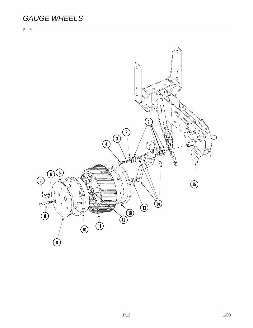
P12 1/08
GAUGE WHEELS(RU140)
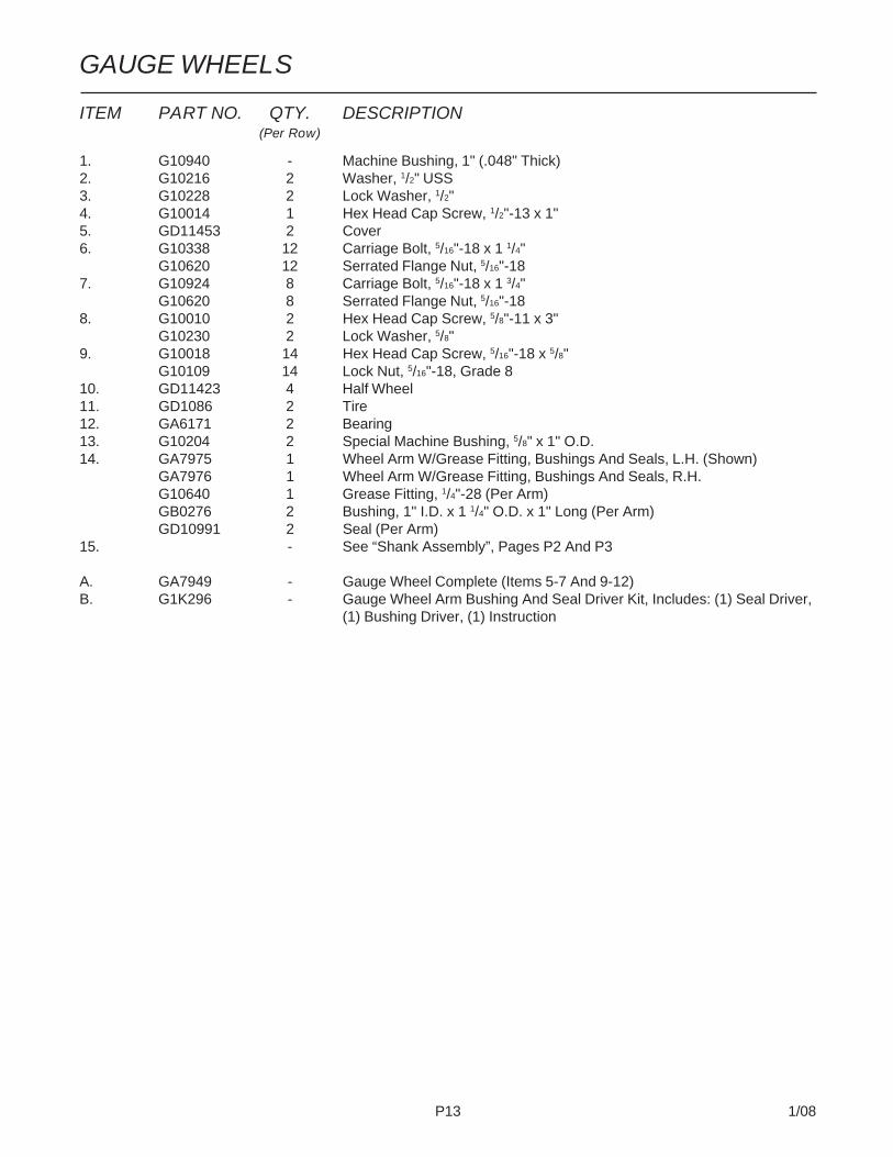
P13 1/08
GAUGE WHEELS
ITEM PART NO. QTY. DESCRIPTION(Per Row)
1. G10940 - Machine Bushing, 1" (.048" Thick)2. G10216 2 Washer, 1/2" USS3. G10228 2 Lock Washer, 1/2"4. G10014 1 Hex Head Cap Screw, 1/2"-13 x 1"5. GD11453 2 Cover6. G10338 12 Carriage Bolt, 5/16"-18 x 1 1/4"
G10620 12 Serrated Flange Nut, 5/16"-187. G10924 8 Carriage Bolt, 5/16"-18 x 1 3/4"
G10620 8 Serrated Flange Nut, 5/16"-188. G10010 2 Hex Head Cap Screw, 5/8"-11 x 3"
G10230 2 Lock Washer, 5/8"9. G10018 14 Hex Head Cap Screw, 5/16"-18 x 5/8"
G10109 14 Lock Nut, 5/16"-18, Grade 810. GD11423 4 Half Wheel11. GD1086 2 Tire12. GA6171 2 Bearing13. G10204 2 Special Machine Bushing, 5/8" x 1" O.D.14. GA7975 1 Wheel Arm W/Grease Fitting, Bushings And Seals, L.H. (Shown)
GA7976 1 Wheel Arm W/Grease Fitting, Bushings And Seals, R.H.G10640 1 Grease Fitting, 1/4"-28 (Per Arm)GB0276 2 Bushing, 1" I.D. x 1 1/4" O.D. x 1" Long (Per Arm)GD10991 2 Seal (Per Arm)
15. - See “Shank Assembly”, Pages P2 And P3
A. GA7949 - Gauge Wheel Complete (Items 5-7 And 9-12)B. G1K296 - Gauge Wheel Arm Bushing And Seal Driver Kit, Includes: (1) Seal Driver,
(1) Bushing Driver, (1) Instruction

P14 1/08
COVERING DISCS/SINGLE PRESS WHEELRUA054/RUB026(RU94d)

P15 1/08
COVERING DISCS/SINGLE PRESS WHEEL
ITEM PART NO. QTY. DESCRIPTION(Per Row)
1. G10001 1 Hex Head Cap Screw, 3/8"-16 x 1"G10210 1 Washer, 3/8" USS
2. GB0268 1 Wheel Arm Stop3. G10801 2 Carriage Bolt, 1/2"-13 x 2 1/4"
G10315 - Carriage Bolt, 1/2"-13 x 2 1/2" (Used W/Straight Drop In-FurrowGranular Chemical Bracket)
G10102 2 Hex Nut, 1/2"-134. GA2054 1 Spring5. GB0239 2 Eccentric Bushing6. G10102 1 Hex Nut, 1/2"-137. G10015 1 Adjusting Bolt, 1/2"-13 x 5"8. GA6619 1 Mounting Arm9. G10463 2 Cotter Pin, 1/4" x 1 1/2"10. G10171 4 Hex Head Cap Screw, 5/16"-18 x 1 1/4"
G10232 4 Lock Washer, 5/16"G10106 4 Hex Nut, 5/16"-18
11. GA6620 2 Bracket12. GA6618 2 Mount13. G10303 2 Carriage Bolt, 5/16"-18 x 1"
G10219 2 Washer, 5/16" USSG10232 2 Lock Washer, 5/16"G10106 2 Hex Nut, 5/16"-18
14. G10107 3 Lock Nut, 5/8"-1115. GD1109 2 Bushing, 41/64" I.D. x 7/8" O.D. x 1/4" Long16. GD9290 2 Disc Blade, 8"17. G10018 7 Hex Head Cap Screw, 5/16"-18 x 5/8"
G10109 7 Lock Nut, 5/16"-18, Grade 818. G10152 1 Hex Head Cap Screw, 5/8"-11 x 9"19. GD3180-12 2 Sleeve, 5/8" I.D. x 7/8" O.D. x 2 7/8" Long20. GD9562 2 Half Wheel21. GA6171 1 Bearing22. GD9305 1 Tire23. GA2014 2 Bearing24. GD10473 2 Bearing Housing25. G10427 12 Rivet, 1/4" x 1/2"26. G10006 2 Hex Head Cap Screw, 5/8"-11 x 2 1/4"27. GD11845 2 Dust Cap
A. GA6733 - Single Press Wheel Complete W/Bearing (Items 17 And 20-22)B. GA6801 - Covering Disc Blade Complete W/Bearing (Items 16 And 23-25)
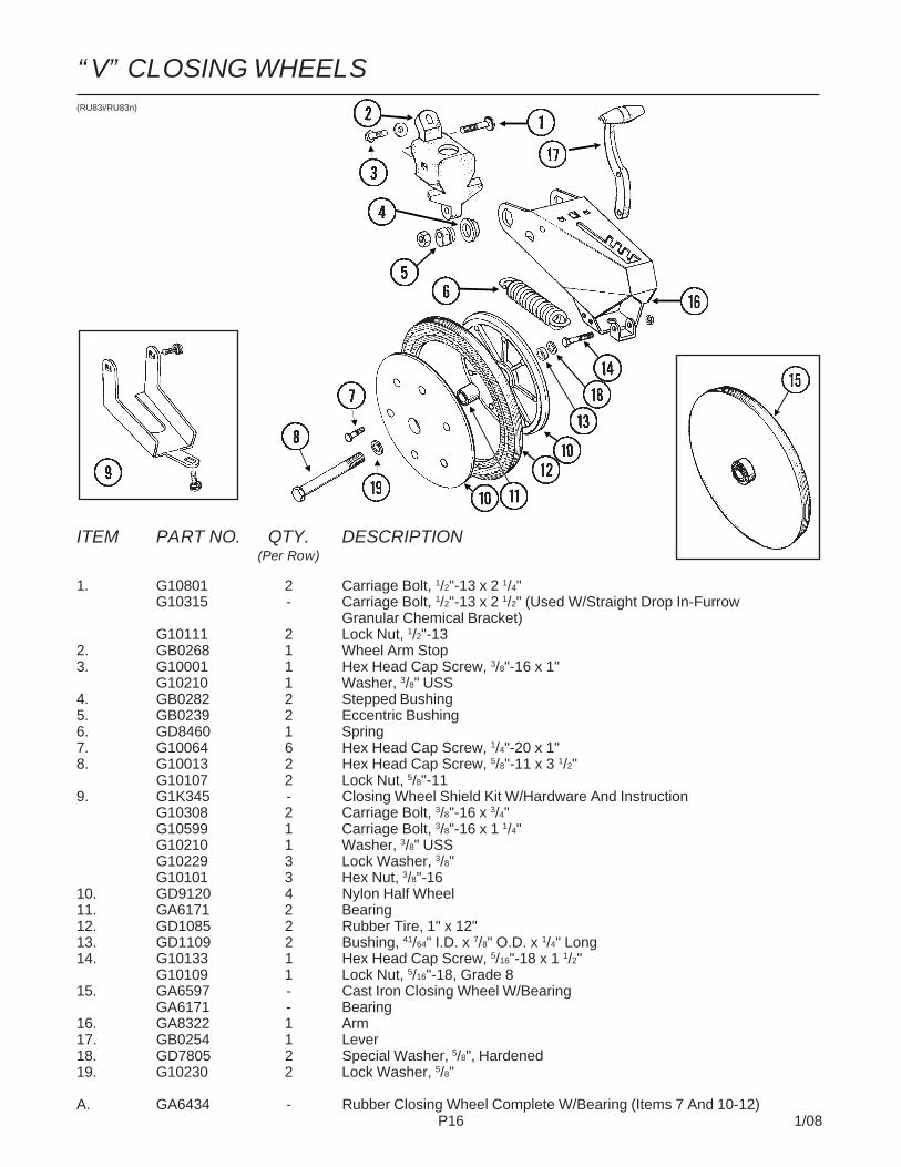
P16 1/08
ITEM PART NO. QTY. DESCRIPTION(Per Row)
1. G10801 2 Carriage Bolt, 1/2"-13 x 2 1/4"G10315 - Carriage Bolt, 1/2"-13 x 2 1/2" (Used W/Straight Drop In-Furrow
Granular Chemical Bracket)G10111 2 Lock Nut, 1/2"-13
2. GB0268 1 Wheel Arm Stop3. G10001 1 Hex Head Cap Screw, 3/8"-16 x 1"
G10210 1 Washer, 3/8" USS4. GB0282 2 Stepped Bushing5. GB0239 2 Eccentric Bushing6. GD8460 1 Spring7. G10064 6 Hex Head Cap Screw, 1/4"-20 x 1"8. G10013 2 Hex Head Cap Screw, 5/8"-11 x 3 1/2"
G10107 2 Lock Nut, 5/8"-119. G1K345 - Closing Wheel Shield Kit W/Hardware And Instruction
G10308 2 Carriage Bolt, 3/8"-16 x 3/4"G10599 1 Carriage Bolt, 3/8"-16 x 1 1/4"G10210 1 Washer, 3/8" USSG10229 3 Lock Washer, 3/8"G10101 3 Hex Nut, 3/8"-16
10. GD9120 4 Nylon Half Wheel11. GA6171 2 Bearing12. GD1085 2 Rubber Tire, 1" x 12"13. GD1109 2 Bushing, 41/64" I.D. x 7/8" O.D. x 1/4" Long14. G10133 1 Hex Head Cap Screw, 5/16"-18 x 1 1/2"
G10109 1 Lock Nut, 5/16"-18, Grade 815. GA6597 - Cast Iron Closing Wheel W/Bearing
GA6171 - Bearing16. GA8322 1 Arm17. GB0254 1 Lever18. GD7805 2 Special Washer, 5/8", Hardened19. G10230 2 Lock Washer, 5/8"
A. GA6434 - Rubber Closing Wheel Complete W/Bearing (Items 7 And 10-12)
(RU83i/RU83n)
“V” CLOSING WHEELS

P17 1/08
ITEM PART NO. QTY. DESCRIPTION(Per Row)
1. G10599 6 Carriage Bolt, 3/8"-16 x 1 1/4"G10210 6 Washer, 3/8" USSG10229 6 Lock Washer, 3/8"G10101 6 Hex Nut, 3/8"-16
2. GD11508 1 Front Bracket3. GD11313 2 Blade4. G10007 1 Hex Head Cap Screw, 5/8"-11 x 1 1/2"
G10230 1 Lock Washer, 5/8"G10104 1 Hex Nut, 5/8"-11
5. GD11509 1 Rear Bracket
A. G7566X - Drag Closing Attachment Complete (Items 1-5)
RUB050(RU90c)
DRAG CLOSING ATTACHMENT

P18 1/08
HOPPER SUPPORT AND METER DRIVE(METR22f)
SDS Only
SDS Only
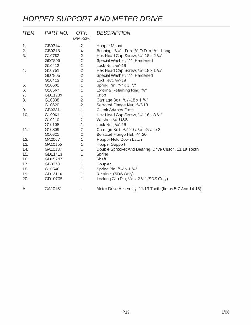
P19 1/08
ITEM PART NO. QTY. DESCRIPTION(Per Row)
1. GB0314 2 Hopper Mount2. GB0218 4 Bushing, 21/32" I.D. x 7/8" O.D. x 19/32" Long3. G10752 2 Hex Head Cap Screw, 5/8"-18 x 2 1/4"
GD7805 2 Special Washer, 5/8", HardenedG10412 2 Lock Nut, 5/8"-18
4. G10751 2 Hex Head Cap Screw, 5/8"-18 x 1 3/4"GD7805 2 Special Washer, 5/8", HardenedG10412 2 Lock Nut, 5/8"-18
5. G10602 1 Spring Pin, 1/4" x 1 1/2"6. G10567 1 External Retaining Ring, 5/8"7. GD11239 1 Knob8. G10338 2 Carriage Bolt, 5/16"-18 x 1 1/4"
G10620 2 Serrated Flange Nut, 5/16"-189. GB0331 1 Clutch Adapter Plate10. G10061 1 Hex Head Cap Screw, 3/8"-16 x 3 1/2"
G10210 2 Washer, 3/8" USSG10108 1 Lock Nut, 3/8"-16
11. G10309 2 Carriage Bolt, 1/4"-20 x 5/8", Grade 2G10621 2 Serrated Flange Nut, 1/4"-20
12. GA2007 1 Hopper Hold Down Latch13. GA10155 1 Hopper Support14. GA10137 1 Double Sprocket And Bearing, Drive Clutch, 11/19 Tooth15. GD11413 1 Spring16. GD15747 1 Shaft17. GB0278 1 Coupler18. G10546 1 Spring Pin, 3/16" x 1 1/4"19. GD13110 1 Retainer (SDS Only)20. GD10705 1 Locking Clip Pin, 1/4" x 2 1/2" (SDS Only)
A. GA10151 - Meter Drive Assembly, 11/19 Tooth (Items 5-7 And 14-18)
HOPPER SUPPORT AND METER DRIVE
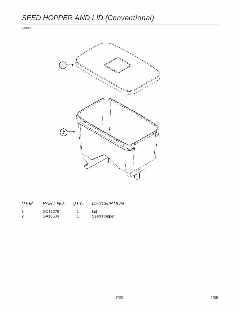
P20 1/08
SEED HOPPER AND LID (Conventional)(METR12)
ITEM PART NO. QTY. DESCRIPTION
1. GD11279 1 Lid2. GA10634 1 Seed Hopper

P21 1/08
(D16399/METR63bb)
ITEM PART NO. QTY. DESCRIPTION(Per Row)
1. GD12797-02 1 Drop Hose, 3 1/4" x 30"GD12797-04 - Drop Hose, 3 1/4" x 32"GD12797-05 - Drop Hose, 3 1/4" x 36"GD12797-09 - Drop Hose, 3 1/4" x 39"
2. G10999 2 T-Bolt Hose Clamp, 3 1/4"3. G10047 2 Hex Head Cap Screw, 3/8"-16 x 1 3/4"
G10229 2 Lock Washer, 3/8"4. GB0371 1 Inlet, Short5. GA11392 1 Meter Mount6. GD16399-01 - Sleeve, 3" x 10"7. GD2117 - Tie Strap, 14 1/2"8. GD13412 1 View Cap
SEED METER MOUNT AND DROP HOSES (SDS)

P22 1/08
SEED METER(METR69/METR65/A12133)
Used With 60 Cell Milo/GrainSorghum Disc
Used With 20 Cell Hill-DropAcid-Delinted Cotton Discs;54 Cell Acid-Delinted Cotton/Small Dry Edible Bean Disc;And Small Cotton/SunflowerDisc
Used With 60 CellMilo/Grain Sor-ghum Disc, 60 CellSoybean Disc, 120Cell High-RateSoybean Disc And39 Cell And 24 CellPopcorn Discs

P23 1/08
SEED METER
ITEM PART NO. QTY. DESCRIPTION
1. GA11911 1 Vacuum Cover W/Elbow And CapGD17099 - 3/16" Hose Barb ElbowGD17152 - Cap
2. GA12133 1 Cleanout Brush (Used With 60 Cell Milo/Grain Sorghum Disc)3. GD17049 - Seed Disc, Corn/Popcorn, 39 Cell, Light Blue Color-Coded
GD17048 - Seed Disc, Low-Rate Corn/Popcorn, 24 Cell, Light Green Color-CodedGD14467 - Seed Disc, Soybean, 60 Cell, Black Color-CodedGD14468 - Seed Disc, High-Rate Soybean, 120 Cell, Dark Blue Color-CodedGD17050 - Seed Disc, Milo/Grain Sorghum, 60 Cell, Yellow Color-CodedGD17187 - Seed Disc, Hill-Drop Cotton, Acid-Delinted, 20 Cell (3 Seeds Per Cell),
Brown Color-CodedGD18095 - Seed Disc, Small Hill-Drop Cotton, Acid-Delinted, 20 Cell (3 Seeds Per
Cell), Grey Color-CodedGD17186 - Seed Disc, Cotton, Acid-Delinted/Small Dry Edible Bean,
54 Cell, Dark Green Color-CodedGD18098 - Seed Disc, Small Cotton/Sunflower, 54 Cell, White Color-CodedGD14477 - Seed Disc, Large Dry Edible Bean, 54 Cell, Tan Color-Coded
4. GD17028 1 Wall Brush/Vent5. GD17021 1 Foam Spacer6. GB0328 1 Mount7. GA5698 1 Bearing8. GD14541 1 Discharge Cover9. G10602 1 Spring Pin, 1/4" x 1 1/2"10. G10603 1 Spring Pin, 1/4" x 1 1/4"11. G11213 1 Hex Socket Head Cap Screw, 1/4"-20 x 3/4"12. GA11935 1 Crowder Brush13. G10260 1 Hex Socket Head Cap Screw, 1/4"-20 x 1/2" (Conventional Planters)
G10252 1 Hex Socket Head Cap Screw, 1/4"-20 x 7/8" (SDS Planters)G10209 1 Washer, 1/4" USS (SDS Planters)G10110 1 Lock Nut, 1/4"-20, Grade B (SDS Planters)
14. GD17047 1 Air Inlet Screen15. GD17162 3 Push Nut, 1/8" I.D.16. GA10755 1 Singulator Brush17. GD14592 1 Spring18. GB0358 1 Cap19. GD15663 1 Brush Adjustment Lever20. G11173 1 Hex Socket Head Cap Screw, No. 10-24 x 3/8", Stainless Steel21. G11172 4 Hex Socket Head Shoulder Screw, 1/4"-20 x 3/8", Stainless Steel22. GB0319 1 Housing23. G11009 2 Locking Thumbscrew, 5/16"-18 x 3/4" (Conventional Planters)
G10171 2 Hex Head Cap Screw, 5/16"-18 x 1 1/4" (SDS Planters)G10232 2 Lock Washer, 5/16" (SDS Planters)
24. GD17104 1 Seed Baffle (Used With 60 Cell Milo/Grain Sorghum Disc,60 Cell Soybean Disc, 120 Cell High-Rate Soybean Disc And 39 CellAnd 24 Cell Popcorn Discs)
25. G11210 1 Rib Neck Bolt, 1/4"-20 x 3/4"G10323 1 Hex Flange Nut, 1/4"-20, No Serrations
26. GD15700 1 Shank Cover, EdgeVac® Meter27. GA12154 - Cleanout Brush W/Ball-Type Ejector (Used With 20 Cell Hill-Drop
Acid-Delinted Cotton Discs And 54 Cell Acid-Delinted Cotton/SmallDry Edible Bean And Small Cotton/Sunflower Discs)
28. GD15923 1 Meter Cover (SDS Only)
A. G1K472 - Sunflower Rate Reduction Kit, Includes: (2)122 Pitch Chains, (2)94 PitchChains, (2)Bars, (4)Spacers, (4)Lynch Pins, (2)Hex Shafts, (1)HardwareBag, (4)Hanger Bearings, (2)30Tooth Sprockets, (4)15 Tooth Sprockets,(4)18 Tooth Sprockets And (1) Instruction (For Two Contact WheelAssemblies)

P24 1/08
ITEM PART NO. QTY. DESCRIPTION(Per Assy.)
1. GA11395 1 Upper Tube, L.H. (Shown)GA11396 - Upper Tube, R.H.
2. G11192 22 Bolt, 5/16"-18 x 1"G10221 22 Washer, 5/16" SAEG11182 22 Lock Nut W/Nylon Insert, 5/16"-18
3. G10064 10 Hex Head Cap Screw, 1/4"-20 x 1"G10110 10 Lock Nut, 1/4"-20, Grade B
4. GA11623 1 Screen5. G10018 8 Hex Head Cap Screw, 5/16"-18 x 5/8"
G10232 8 Lock Washer, 5/16"6. - See “SDS Hydraulic System”, Pages P150 And P1517. GD16766 1 Ring8. G10021 4 Hex Head Cap Screw, 1/4"-20 x 1 1/2"
G10110 4 Lock Nut, 1/4"-20, Grade B9. GA11391 1 Transfer Plate10. G10001 - Hex Head Cap Screw, 3/8"-16 x 1"
G10622 - Serrated Flange Nut, 3/8"-1611. GA11389 1 Lower Tube, L.H. (Shown)
GA11390 - Lower Tube, R.H.12. GA11625 1 Auger Assembly, 61 5/8", L.H. (Shown)
GA11624 1 Auger Assembly, 61 5/8", R.H.G10403 - Hex Head Cap Screw, 1/4"-20 x 2 1/2"G10110 - Lock Nut, 1/4"-20, Grade BGD16401 - Auger Section, L.H.GD16400 - Auger Section, R.H.GA11584 - Hex Tube, 61 5/8"
(FWD93b/FWD116/FWD113/FWD111)
CENTER AUGER ASSEMBLIES (SDS)

P25 1/08
CENTER AUGER ASSEMBLIES (SDS)ITEM PART NO. QTY. DESCRIPTION
(Per Assy.)13. G10233 3 Machine Bushing, 1", 10 Gauge14. GA11627 1 Auger Assembly, 63 3/8", L.H. (Shown)
GA11626 1 Auger Assembly, 63 3/8", R.H.G10403 - Hex Head Cap Screw, 1/4"-20 x 2 1/2"G10110 - Lock Nut, 1/4"-20, Grade BGD16401 - Auger Section, L.H.GD16400 - Auger Section, R.H.GA11585 - Hex Tube, 63 3/8"
15. GD16547 1 Bearing Plate16. GD16707 1 Shaft17. G2100-03 5 Bearing, 7/8" Hex Bore, Spherical18. G3400-01 - Flangette19. G10312 - Carriage Bolt, 5/16"-18 x 3/4"
G10620 - Serrated Flange Nut, 5/16"-1820. G10019 8 Hex Head Cap Screw, 5/16"-18 x 1"
G10620 8 Serrated Flange Nut, 5/16"-1821. GD16550 1 Shim22. GA11763 1 Screen23. GD16542 2 Guard24. G10001 - Hex Head Cap Screw, 3/8"-16 x 1"
G10210 - Washer, 3/8" USSG10229 - Lock Washer, 3/8"
25. G10001 - Hex Head Cap Screw, 3/8"-16 x 1"G10229 - Lock Washer, 3/8"
26. GD16539 1 Plate27. GD16540 1 Lower Plate28. GD11394-23 1 Hex Shaft, 7/8" x 23" (2 Holes)29. GA5106 1 Sprocket, 17 Tooth30. GD11045 5 Lock Clamp31. G10130 5 Square Head Machine Bolt, 5/16"-18 x 1 3/4"
G10923 5 Flange Nut, 5/16"-18, No Serration32. GA7154 2 Sprocket W/Bearing, 18 Tooth33. G10581 2 Hex Head Cap Screw, 1/2"-13 x 2 1/4"
GD4887-10 2 SleeveG10216 3 Washer, 1/2" USSG10111 2 Lock Nut, 1/2"-13
34. GD16705 1 Hex Shaft35. GD16706 1 Shaft36. GA5108 1 Sprocket, 23 Tooth37. GD17002 2 Hex Shaft, 7/8" x 8 1/2"38. GA11375 1 Sensor Wheel39. G10602 1 Spring Pin, 1/4" x 1 1/2"40. GD2962 1 Spring41. GB0283 1 Coupler42. GD11395 2 Bushing, 1/2"43. G10880 1 Hex Head Cap Screw, 1/4"-20 x 2 1/4"
G10110 1 Lock Nut, 1/4"-20, Grade B44. G10464 2 Cotter Pin, 3/16" x 1"45. GD1256 2 Spring46. GA0378 1 Block And Hub Assembly47. GD1255 2 L-Pin48. GA5165 1 Sprocket, 30 Tooth49. G10430 1 External Retaining Ring, 1 1/4"50. G3310-112 1 Chain, No. 40, 112 Pitch Including Connector Link
GR0912 - Connector Link, No. 4051. GA11515 1 Guard, L.H.
GA11513 - Guard, R.H. (Shown)52. GD16535 1 Sensor Mount53. GD14257 2 Nut, M12 x 1"54. G10305 2 Carriage Bolt, 3/8"-16 x 1"
G10622 2 Serrated Flange Nut, 3/8"-1655. - Proximity Sensor, See “Electrical Components (SDS Control Console)”,
Pages P154 And P15556. G10002 4 Hex Head Cap Screw, 3/8"-16 x 3/4"
G10108 4 Lock Nut, 3/8"-1657. GA11393 1 Coupler
A. GA5164 - Ratchet/Sprocket Assembly, L.H. Hopper (Items 44-49)GA9843 - Ratchet/Sprocket Assembly, R.H. Hopper (Items 44-49)

P26 1/08
(FWD99a)
WING AUGER ASSEMBLIES, 24 ROW 30" (SDS)

P27 1/08
WING AUGER ASSEMBLIES, 24 ROW 30" (SDS)
ITEM PART NO. QTY. DESCRIPTION
1. GA11539 2 Link2. G10183 4 Hex Socket Head Set Screw, 5/16"-18 x 3/8"3. GA11538 2 Lid4. GD16983 4 Spring5. G10880 - Hex Head Cap Screw, 1/4"-20 x 2 1/4"
G10110 - Lock Nut, 1/4"-20, Grade B6. GA11540 2 Link Mount7. GA11541 2 Plate8. G10305 - Carriage Bolt, 3/8"-16 x 1"
G10622 - Serrated Flange Nut, 3/8"-169. G11197 6 Slotted Flat Head Machine Screw, 5/16"-18 x 3 1/2"
GD16634 12 SleeveGD16982 6 SpringG11182 6 Lock Nut W/Nylon Insert, 5/16"-18
10. G10309 8 Carriage Bolt, 1/4"-20 x 5/8", Grade 2G10621 8 Serrated Flange Nut, 1/4"-20
11. GA11555 1 Transfer Chute, L.H.GA11556 - Transfer Chute, R.H.
12. G11205 8 Hex Socket Head Cap Screw, No. 10-32 x 2"G10243 8 Washer, No. 10 SAEG11206 8 Lock Nut, No. 10-32
13. - Limit Switch, See “Electrical Components (SDS Control Console),Pages P154 And P155
14. G10019 8 Hex Head Cap Screw, 5/16"-18 x 1"G10620 8 Serrated Flange Nut, 5/16"-18
15. GA11548 2 Mount16. GD16672 2 Plate17. G10001 6 Hex Head Cap Screw, 3/8"-16 x 1"
G10622 6 Serrated Flange Nut, 3/8"-1618. GA11531 4 Mount19. GD16320 4 U-Bolt, 8" x 8" x 5/8"-11
G10230 4 Lock Washer, 5/8"G10104 4 Hex Nut, 5/8"-11
20. G10305 8 Carriage Bolt, 3/8"-16 x 1"G10622 8 Serrated Flange Nut, 3/8"-16
21. GA11563 1 Outer Auger Tube, L.H.GA11562 - Outer Auger Tube, R.H.
22. GA12673 1 Auger Assembly, L.H. (Shown)GA12672 - Auger Assembly, R.H.G10403 - Hex Head Cap Screw, 1/4"-20 x 2 1/2"G10110 - Lock Nut, 1/4"-20, Grade BGD16674 - SpacerGD16401 - Auger Section, L.H.GD16400 - Auger Section, R.H.GA11581 - Hex Tube, 64"
23. GD16675 2 Pad24. G11180 2 Hex Head Cap Screw, 1/4"-20 x 1"
G10110 2 Lock Nut, 1/4"-20, Grade B25. GA11580 2 Shaft26. G10602 2 Spring Pin, 1/4" x 1 1/2"
(Continued On Following Page)

P28 1/08
WING AUGER ASSEMBLIES, 24 ROW 30" (SDS)
ITEM PART NO. QTY. DESCRIPTION
27. G10880 4 Hex Head Cap Screw, 1/4"-20 x 2 1/4"GD11395 8 Bushing, 1/2"G10110 4 Lock Nut, 1/4"-20, Grade B
28. G3400-01 4 Flangette29. G2100-03 2 Bearing, 7/8" Hex Bore, Spherical30. GB0283 2 Coupler31. G10043 6 Hex Head Cap Screw, 5/16"-18 x 3/4"
G10232 6 Lock Washer, 5/16"32. GA11705 1 Inner Auger Tube, L.H. (Shown)
GA11706 - Inner Auger Tube, R.H.33. GD16556 2 Pivot Tube34. G10055 8 Hex Head Cap Screw, 5/8"-11 x 1 1/4"
GD7805 8 Special Washer, 5/8", HardenedGB0218 8 Bushing, 21/32" I.D. x 7/8" O.D. x 19/32" Long
35. GD16788 8 Hose Keeper36. GD16913 4 Hose, 5"37. GA11551 1 Auger Tube, L.H. (Shown)
GA11552 - Auger Tube, R.H.38. GA11575 4 U-Joint39. GA11631 1 Auger Assembly, L.H. (Shown)
GA11630 - Auger Assembly, R.H.G10403 - Hex Head Cap Screw, 1/4"-20 x 2 1/2"G10110 - Lock Nut, 1/4"-20, Grade BGD16401 - Auger Section, L.H.GD16400 - Auger Section, R.H.GD16385-04 - Hex Tube, 97 1/4"
40. GA11549 1 Auger Tube, L.H. (Shown)GA11550 - Auger Tube, R.H.
41. GD16631 2 Strap42. GA11518 2 Strap43. G10014 4 Hex Head Cap Screw, 1/2"-13 x 1"
G10228 4 Lock Washer, 1/2"44. GA11517 4 Support45. GD7145 4 U-Bolt, 7" x 7" x 1/2"-13
G10228 8 Lock Washer, 1/2"G10102 8 Hex Nut, 1/2"-13
46. GA11633 1 Auger Assembly, L.H. (Shown)GA11632 - Auger Assembly, R.H.G10403 - Hex Head Cap Screw, 1/4"-20 x 2 1/2"G10110 - Lock Nut, 1/4"-20, Grade BGD16401 - Auger Section, L.H.GD16400 - Auger Section, R.H.GA11582 - Hex Tube, 125 7/8"GA11583 - Hex Tube, 118 7/8"
47. GA11778 2 Auger Stop48. GD14559 2 U-Bolt, 7" x 7" x 5/8"-11 (9" Long)
G10230 4 Lock Washer, 5/8"G10102 4 Hex Nut, 5/8"-11
49. G10064 4 Hex Head Cap Screw, 1/4"-20 x 1"G10110 4 Lock Nut, 1/4"-20, Grade B
50. GD16466 1 Bracket, R.H. Side (Shown)GD16467 - Bracket, L.H. Side
(Continued On Following Page)

P29 1/08
ITEM PART NO. QTY. DESCRIPTION
51. G10005 4 Hex Head Cap Screw, 5/8"-11 x 1 3/4"G10205 4 Washer, 5/8" SAEG10107 4 Lock Nut, 5/8"-11
52. GD16602 2 Brace53. GD16601 2 Brace54. G10008 4 Hex Head Cap Screw, 5/8"-11 x 2"
GD3180-29 4 Sleeve, 7/8" O.D. x 5/8" I.D. x 1 5/16"55. GA11684 2 Pivot Mount56. GD16680 2 Mount57. GD16701 2 Arm, 3/4" x 3/4" x 2"58. G10303 2 Carriage Bolt, 5/16"-18 x 1"
G10620 2 Serrated Flange Nut, 5/16"-1859. G10049 2 Hex Head Cap Screw, 3/8"-16 x 2 1/2"
G10229 2 Lock Washer, 3/8"60. G10005 4 Hex Head Cap Screw, 5/8"-11 x 1 3/4"
G10107 4 Lock Nut, 5/8"-1161. G11167 4 Hex Socket Head Cap Screw, No. 10-32 x 1 1/2", Grade 8
WING AUGER ASSEMBLIES, 24 ROW 30" (SDS)

P30 1/08
(FWD100a)
WING AUGER ASSEMBLIES, 32 ROW 30" AND 36 ROW 30"(SDS)
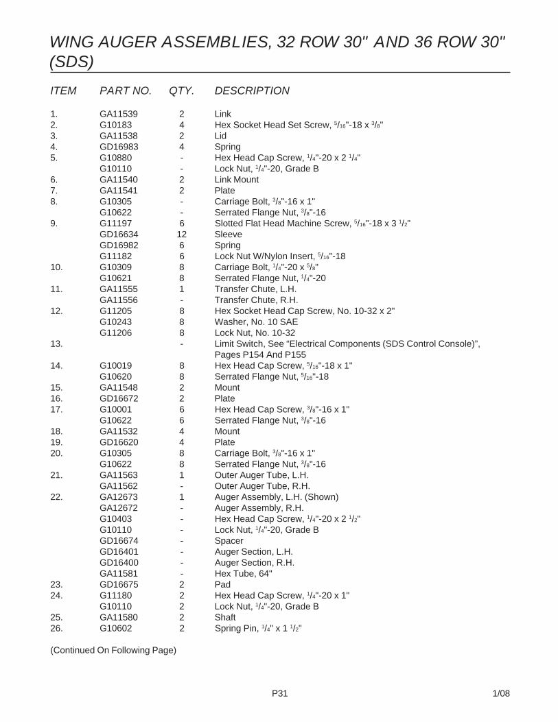
P31 1/08
ITEM PART NO. QTY. DESCRIPTION
1. GA11539 2 Link2. G10183 4 Hex Socket Head Set Screw, 5/16"-18 x 3/8"3. GA11538 2 Lid4. GD16983 4 Spring5. G10880 - Hex Head Cap Screw, 1/4"-20 x 2 1/4"
G10110 - Lock Nut, 1/4"-20, Grade B6. GA11540 2 Link Mount7. GA11541 2 Plate8. G10305 - Carriage Bolt, 3/8"-16 x 1"
G10622 - Serrated Flange Nut, 3/8"-169. G11197 6 Slotted Flat Head Machine Screw, 5/16"-18 x 3 1/2"
GD16634 12 SleeveGD16982 6 SpringG11182 6 Lock Nut W/Nylon Insert, 5/16"-18
10. G10309 8 Carriage Bolt, 1/4"-20 x 5/8"G10621 8 Serrated Flange Nut, 1/4"-20
11. GA11555 1 Transfer Chute, L.H.GA11556 - Transfer Chute, R.H.
12. G11205 8 Hex Socket Head Cap Screw, No. 10-32 x 2"G10243 8 Washer, No. 10 SAEG11206 8 Lock Nut, No. 10-32
13. - Limit Switch, See “Electrical Components (SDS Control Console)”,Pages P154 And P155
14. G10019 8 Hex Head Cap Screw, 5/16"-18 x 1"G10620 8 Serrated Flange Nut, 5/16"-18
15. GA11548 2 Mount16. GD16672 2 Plate17. G10001 6 Hex Head Cap Screw, 3/8"-16 x 1"
G10622 6 Serrated Flange Nut, 3/8"-1618. GA11532 4 Mount19. GD16620 4 Plate20. G10305 8 Carriage Bolt, 3/8"-16 x 1"
G10622 8 Serrated Flange Nut, 3/8"-1621. GA11563 1 Outer Auger Tube, L.H.
GA11562 - Outer Auger Tube, R.H.22. GA12673 1 Auger Assembly, L.H. (Shown)
GA12672 - Auger Assembly, R.H.G10403 - Hex Head Cap Screw, 1/4"-20 x 2 1/2"G10110 - Lock Nut, 1/4"-20, Grade BGD16674 - SpacerGD16401 - Auger Section, L.H.GD16400 - Auger Section, R.H.GA11581 - Hex Tube, 64"
23. GD16675 2 Pad24. G11180 2 Hex Head Cap Screw, 1/4"-20 x 1"
G10110 2 Lock Nut, 1/4"-20, Grade B25. GA11580 2 Shaft26. G10602 2 Spring Pin, 1/4" x 1 1/2"
(Continued On Following Page)
WING AUGER ASSEMBLIES, 32 ROW 30" AND 36 ROW 30"(SDS)
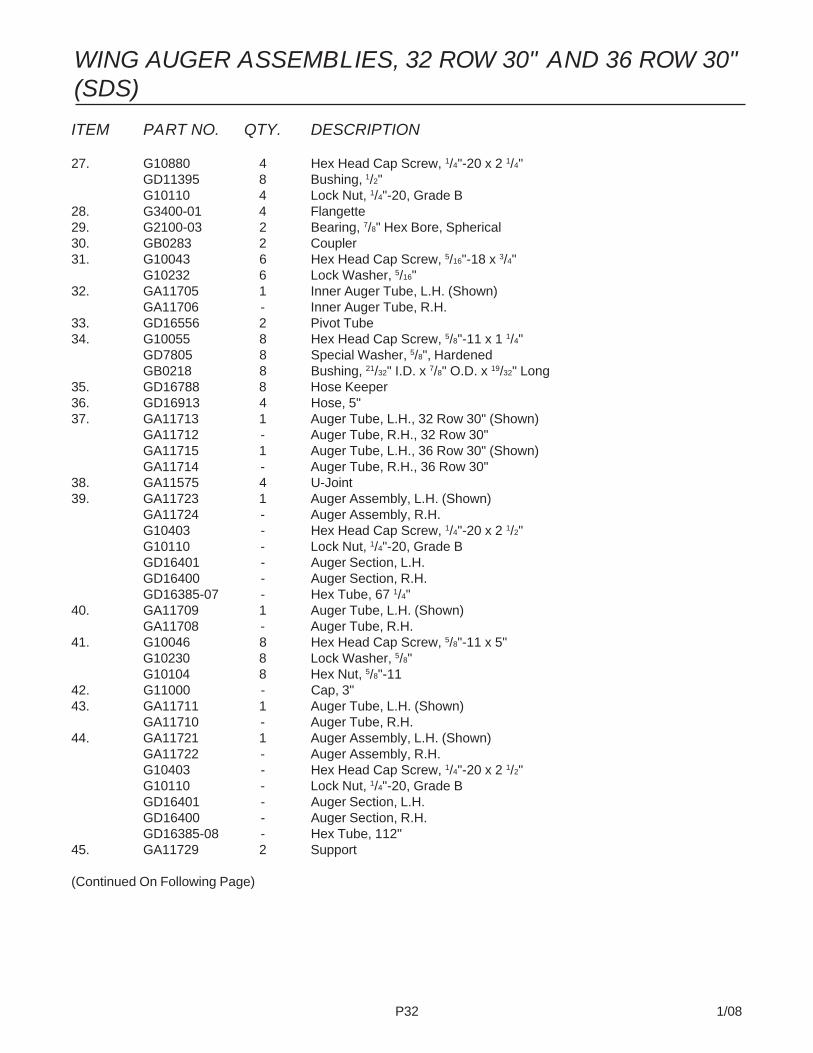
P32 1/08
ITEM PART NO. QTY. DESCRIPTION
27. G10880 4 Hex Head Cap Screw, 1/4"-20 x 2 1/4"GD11395 8 Bushing, 1/2"G10110 4 Lock Nut, 1/4"-20, Grade B
28. G3400-01 4 Flangette29. G2100-03 2 Bearing, 7/8" Hex Bore, Spherical30. GB0283 2 Coupler31. G10043 6 Hex Head Cap Screw, 5/16"-18 x 3/4"
G10232 6 Lock Washer, 5/16"32. GA11705 1 Inner Auger Tube, L.H. (Shown)
GA11706 - Inner Auger Tube, R.H.33. GD16556 2 Pivot Tube34. G10055 8 Hex Head Cap Screw, 5/8"-11 x 1 1/4"
GD7805 8 Special Washer, 5/8", HardenedGB0218 8 Bushing, 21/32" I.D. x 7/8" O.D. x 19/32" Long
35. GD16788 8 Hose Keeper36. GD16913 4 Hose, 5"37. GA11713 1 Auger Tube, L.H., 32 Row 30" (Shown)
GA11712 - Auger Tube, R.H., 32 Row 30"GA11715 1 Auger Tube, L.H., 36 Row 30" (Shown)GA11714 - Auger Tube, R.H., 36 Row 30"
38. GA11575 4 U-Joint39. GA11723 1 Auger Assembly, L.H. (Shown)
GA11724 - Auger Assembly, R.H.G10403 - Hex Head Cap Screw, 1/4"-20 x 2 1/2"G10110 - Lock Nut, 1/4"-20, Grade BGD16401 - Auger Section, L.H.GD16400 - Auger Section, R.H.GD16385-07 - Hex Tube, 67 1/4"
40. GA11709 1 Auger Tube, L.H. (Shown)GA11708 - Auger Tube, R.H.
41. G10046 8 Hex Head Cap Screw, 5/8"-11 x 5"G10230 8 Lock Washer, 5/8"G10104 8 Hex Nut, 5/8"-11
42. G11000 - Cap, 3"43. GA11711 1 Auger Tube, L.H. (Shown)
GA11710 - Auger Tube, R.H.44. GA11721 1 Auger Assembly, L.H. (Shown)
GA11722 - Auger Assembly, R.H.G10403 - Hex Head Cap Screw, 1/4"-20 x 2 1/2"G10110 - Lock Nut, 1/4"-20, Grade BGD16401 - Auger Section, L.H.GD16400 - Auger Section, R.H.GD16385-08 - Hex Tube, 112"
45. GA11729 2 Support
(Continued On Following Page)
WING AUGER ASSEMBLIES, 32 ROW 30" AND 36 ROW 30"(SDS)

P33 1/08
ITEM PART NO. QTY. DESCRIPTION
46. GA11719 1 Auger Assembly, L.H., 32 Row 30" (Shown)GA11720 - Auger Assembly, R.H., 32 Row 30"GA11717 1 Auger Assembly, L.H., 36 Row 30" (Shown)GA11718 - Auger Assembly, R.H., 36 Row 30"G10403 - Hex Head Cap Screw, 1/4"-20 x 2 1/2"G10110 - Lock Nut, 1/4"-20, Grade BGD16401 - Auger Section, L.H.GD16400 - Auger Section, R.H.GA11725 - Hex Tube, 155 3/8", 32 Row 30"GA11726 - Hex Tube, 162 3/8", 32 Row 30"GA11728 - Hex Tube, 222 3/8", 36 Row 30"GA11727 - Hex Tube, 215 3/8", 36 Row 30"
47. GA11778 2 Auger Stop48. G10035 4 Hex Head Cap Screw, 1/2"-13 x 4"
G10111 4 Lock Nut, 1/2"-1349. G10064 8 Hex Head Cap Screw, 1/4"-20 x 1"
G10110 8 Lock Nut, 1/4"-20, Grade B50. G11207 8 Carriage Bolt, 1/2"-13 x 8 1/2"
G10216 8 Washer, 1/2" USSG10111 8 Lock Nut, 1/2"-13
51. GA11733 4 Clamp52. GD16972 1 Mount, L.H. Only53. GA11731 2 Support54. G10008 4 Hex Head Cap Screw, 5/8"-11 x 2"
GD3180-29 4 Sleeve, 7/8" O.D. x 5/8" I.D. x 1 5/16"55. GA11684 2 Pivot Mount56. GD16680 2 Mount57. GD16701 2 Arm, 3/4" x 3/4" x 2"58. G10303 2 Carriage Bolt, 5/16"-18 x 1"
G10620 2 Serrated Flange Nut, 5/16"-1859. G10049 2 Hex Head Cap Screw, 3/8"-16 x 2 1/2"
G10229 2 Lock Washer, 3/8"60. GA11732 2 Support61. G11167 4 Hex Socket Head Cap Screw, No. 10-32 x 1 1/2", Grade 862. GD16973 4 Pin, 1" x 13 1/2"63. G10082 8 Washer, 1" SAE64. G10004 - Hex Head Cap Screw, 3/8"-16 x 1 1/4"
G10622 - Serrated Flange Nut, 3/8"-1665. GA11730 2 Support66. G10909 4 Hex Head Cap Screw, 1/2"-13 x 9"
G10111 4 Lock Nut, 1/2"-1367. GD16957 2 Bracket68. GA11716 2 Hook Plate Mount69. G10348 2 Hex Head Cap Screw, 1/2"-13 x 5"
G10111 2 Lock Nut, 1/2"-13
WING AUGER ASSEMBLIES, 32 ROW 30" AND 36 ROW 30"(SDS)

P34 1/08
(FWD93a)
BULK SEED HOPPER ASSEMBLY (SDS)

P35 1/08
BULK SEED HOPPER ASSEMBLY (SDS)
ITEM PART NO. QTY. DESCRIPTION(Per Assy.)
1. GD17308 1 Hopper, R.H.GD17309 - Hopper, L.H.
2. GA11579 1 Lid3. GA11381 2 Hopper Stiffener4. G10003 16 Hex Head Cap Screw, 3/8"-16 x 1 1/2"
G10203 16 Washer, 3/8" SAEG10108 16 Lock Nut, 3/8"-16
5. G10003 2 Hex Head Cap Screw, 3/8"-16 x 1 1/2"GD11963-03 2 Tube, 1/2" O.D. x 25/64" I.D. x 9/16"G10203 2 Washer, 3/8" SAEG10108 2 Lock Nut, 3/8"-16
6. GA11635 1 Latch Cover7. G10064 2 Hex Head Cap Screw, 1/4"-20 x 1"
G10211 2 Washer, 1/4" SAEG10110 2 Lock Nut, 1/4"-20, Grade B
8. GA11617 1 Rear Mount, L.H.GA11616 - Rear Mount, R.H.
9. GA11615 1 Front Mount10. GD16979 1 Latch11. G10020 2 Hex Head Cap Screw, 1/4"-20 x 5/8"
G10110 2 Lock Nut, 1/4"-20, Grade B12. G10047 2 Hex Head Cap Screw, 3/8"-16 x 1 3/4"
G10203 2 Washer, 3/8" SAEGD16694 2 BushingG11226 2 Tee Nut, 3/8"-16
13. GA11587 1 Hinge14. GD16692 2 Bar15. GD16693 2 Spacer16. GD16691 2 Shim17. G10301 4 Carriage Bolt, 3/8"-16 x 1 1/2"
G10622 4 Serrated Flange Nut, 3/8"-1618. GD13575-05 - Tube, 1" x 43" (If Applicable)
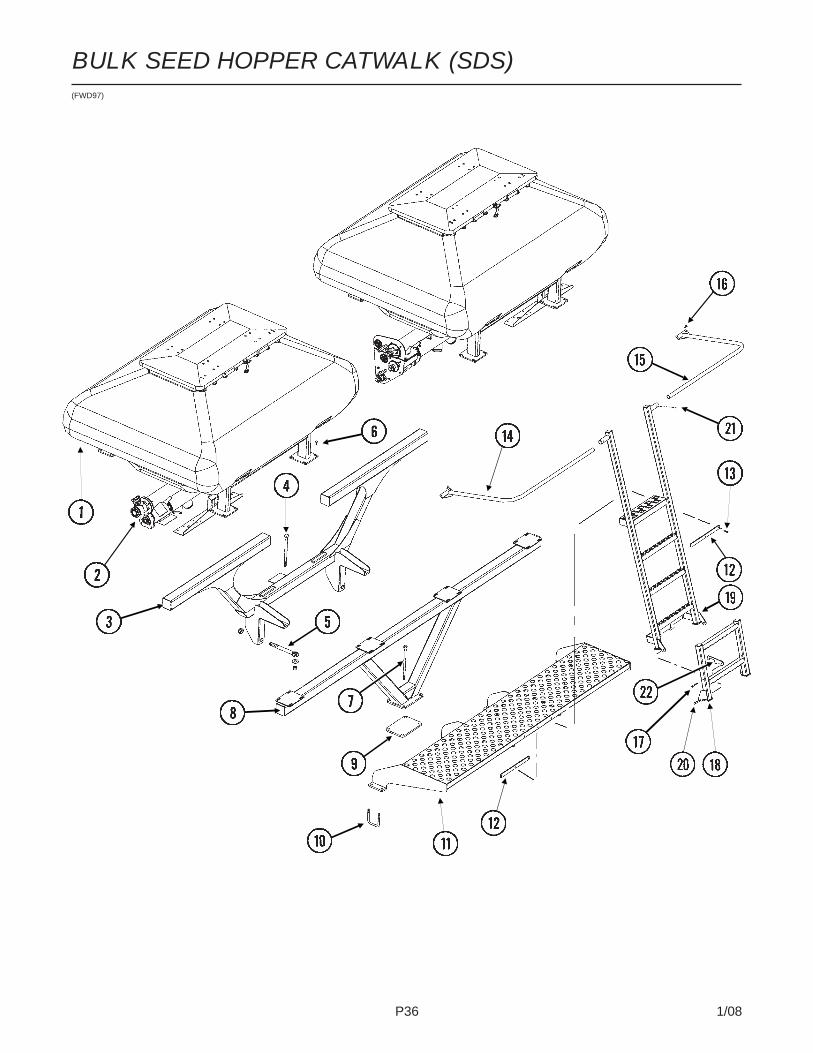
P36 1/08
(FWD97)
BULK SEED HOPPER CATWALK (SDS)

P37 1/08
BULK SEED HOPPER CATWALK (SDS)
ITEM PART NO. QTY. DESCRIPTION
1. - See “Bulk Seed Hopper Assembly (SDS)”,Pages P34 And P35
2. - See “Center Auger Assemblies (SDS)”,Pages P24 And P25
3. GA11355 1 Hopper Mount, Front, 24 Row 30"GA11536 - Hopper Mount, Front, 32 Row 30" And 36 Row 30"
4. G10541 1 Hex Head Cap Screw, 3/4"-10 x 11"G10218 1 Washer, 3/4" USSG10112 1 Lock Nut, 3/4"-10
5. GD15283 1 Eyebolt, 1"-14 x 10"G11108 1 Lock Nut, 1"-14
6. G10599 4 Carriage Bolt, 3/8"-16 x 1 1/4", 24 Row 30"G10301 - Carriage Bolt, 3/8"-16 x 1 1/2", 32 Row 30" And 36 Row 30"G10622 4 Serrated Flange Nut, 3/8"-16
7. G11122 4 Hex Head Cap Screw, 5/8"-11 x 12", 24 Row 30"GA11775 - Special Bolt, 5/8"-11 x 18 1/2", 32 Row 30" And 36 Row 30"G10205 4 Washer, 5/8" SAEG10107 4 Lock Nut, 5/8"-11
8. GA11356 1 Hopper Mount, Rear, 24 Row 30"GA11537 - Hopper Mount, Rear, 32 Row 30" And 36 Row 30"
9. GD16530 1 Plate10. GD16356 4 U-Bolt, 3 1/2" x 3 1/2" x 1/2"-13
G10228 8 Lock Washer, 1/2"G10102 8 Hex Nut, 1/2"-13
11. GA11638 1 Catwalk12. GD16778 2 Bracket13. G10171 3 Hex Head Cap Screw, 5/16"-18 x 1 1/4"
G10109 3 Lock Nut, 5/16"-18, Grade 814. GA11639 1 Railing, L.H.15. GA11640 1 Railing, R.H.16. G10303 4 Carriage Bolt, 5/16"-18 x 1"
G10219 4 Washer, 5/16" USSG10109 4 Lock Nut, 5/16"-18, Grade 8
17. G10403 1 Hex Head Cap Screw, 1/4"-20 x 2 1/2"G10110 1 Lock Nut, 1/4"-20, Grade B
18. GA11637 1 Lower Ladder19. GA11636 1 Ladder20. G10001 2 Hex Head Cap Screw, 3/8"-16 x 1"
G10108 2 Lock Nut, 3/8"-1621. G10040 2 Hex Head Cap Screw, 1/4"-20 x 1 3/4"
G10110 2 Lock Nut, 1/4"-20, Grade B22. GD16779 1 Hook

P38 1/08
(METR14d)
GRANULAR CHEMICAL HOPPER ANDHOPPER PANEL EXTENSION
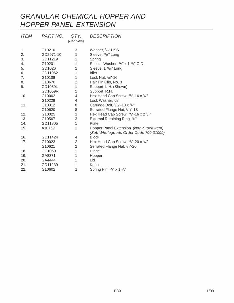
P39 1/08
ITEM PART NO. QTY. DESCRIPTION(Per Row)
1. G10210 3 Washer, 3/8" USS2. GD2971-10 1 Sleeve, 9/16" Long3. GD11219 1 Spring4. G10201 1 Special Washer, 3/8" x 1 1/2" O.D.5. GD1026 1 Sleeve, 1 3/16" Long6. GD11962 1 Idler7. G10108 1 Lock Nut, 3/8"-168. G10670 2 Hair Pin Clip, No. 39. GD1059L 1 Support, L.H. (Shown)
GD1059R 1 Support, R.H.10. G10002 4 Hex Head Cap Screw, 3/8"-16 x 3/4"
G10229 4 Lock Washer, 3/8"11. G10312 8 Carriage Bolt, 5/16"-18 x 3/4"
G10620 8 Serrated Flange Nut, 5/16"-1812. G10325 1 Hex Head Cap Screw, 3/8"-16 x 2 3/4"13. G10567 3 External Retaining Ring, 5/8"14. GD11305 1 Plate15. A10759 1 Hopper Panel Extension (Non-Stock Item)
(Sub Wholegoods Order Code 700-01099)16. GD11424 4 Block17. G10023 2 Hex Head Cap Screw, 1/4"-20 x 3/4"
G10621 2 Serrated Flange Nut, 1/4"-2018. GD1060 1 Hinge19. GA8371 1 Hopper20. GA4444 1 Lid21. GD11239 1 Knob22. G10602 1 Spring Pin, 1/4" x 1 1/2"
GRANULAR CHEMICAL HOPPER ANDHOPPER PANEL EXTENSION

P40 1/08
GRANULAR CHEMICAL METER AND METER DRIVERUA051/RUB028(RU91a)
ITEM PART NO. QTY. DESCRIPTION(Per Row)
1. G10567 3 External Retaining Ring, 5/8"2. GD11239 1 Knob3. G10602 1 Spring Pin, 1/4" x 1 1/2"4. - See “Granular Chemical Hopper And Hopper Panel Extension”,
Pages P38 And P395. GA8364 1 Sprocket And Bearing, Drive Clutch, 24 Tooth6. GD11413 1 Spring7. GD11240 1 Shaft8. GB0278 1 Coupler9. G10546 2 Spring Pin, 3/16" x 1 1/4"10. GD11297 1 Shaft11. G10921 4 Hex Socket Head Cap Screw, No. 10-24 x 7/8"
G10257 4 Lock Washer, No. 1012. GD7148 1 Feed Roller, Hex Bore13. GB0115 2 Bearing14. GD7258 2 Hex Bushing15. G3303-114 1 Chain, No. 41, 114 Pitch Including Connector Link
GR0196 1 Connector Link, No. 4116. G10660 1 Wave Washer, 1/2"17. G10209 1 Washer, 1/4" USS18. G10570 1 Slotted Hex Self-Tapping Screw, 1/4"-20 x 3/4"19. G11073 2 Slotted Hex Self-Tapping Screw, No. 10 x 3/8"20. GD1061 1 Support Strap21. GD1063 1 Metering Gate22. GB0116 1 Granular Housing
A. GA8326 - Granular Chemical Meter Complete (Items 1, 9, 10, 12-14 And 16-22)
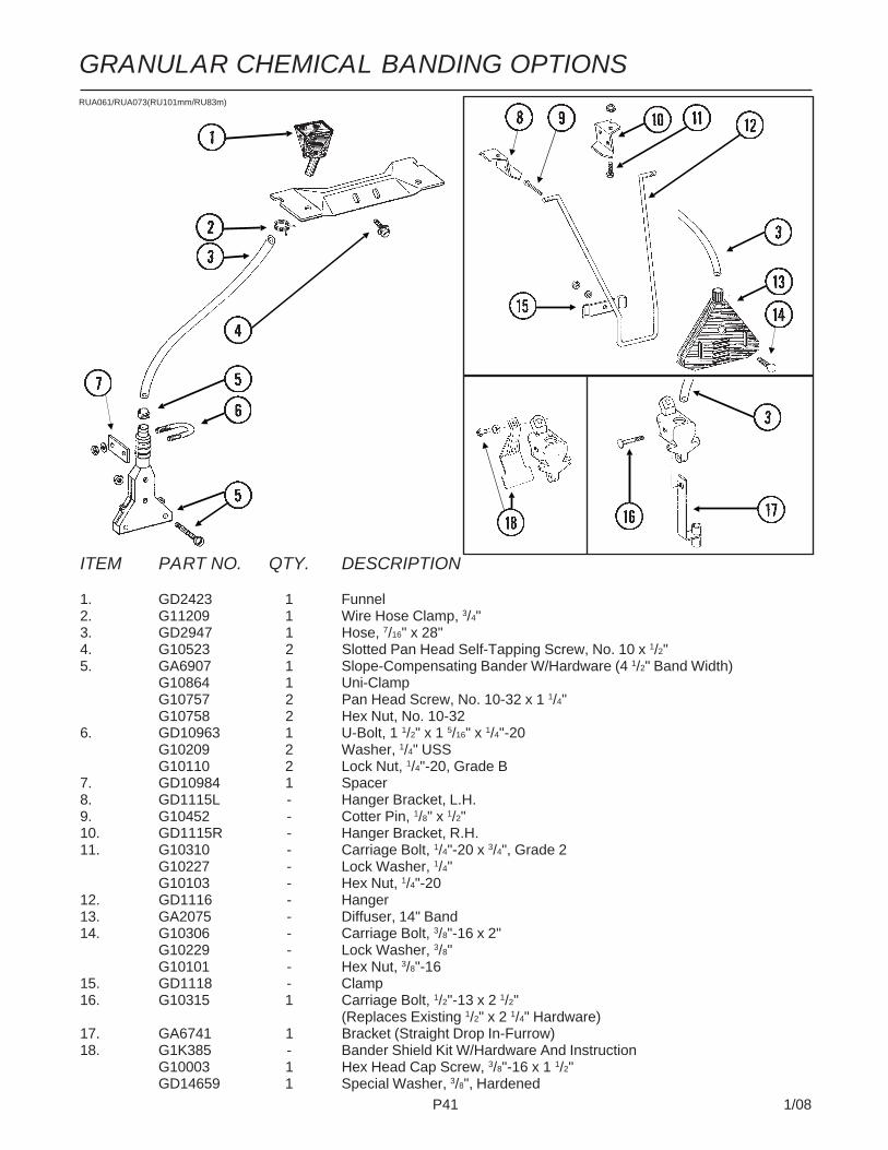
P41 1/08
ITEM PART NO. QTY. DESCRIPTION
1. GD2423 1 Funnel2. G11209 1 Wire Hose Clamp, 3/4"3. GD2947 1 Hose, 7/16" x 28"4. G10523 2 Slotted Pan Head Self-Tapping Screw, No. 10 x 1/2"5. GA6907 1 Slope-Compensating Bander W/Hardware (4 1/2" Band Width)
G10864 1 Uni-ClampG10757 2 Pan Head Screw, No. 10-32 x 1 1/4"G10758 2 Hex Nut, No. 10-32
6. GD10963 1 U-Bolt, 1 1/2" x 1 5/16" x 1/4"-20G10209 2 Washer, 1/4" USSG10110 2 Lock Nut, 1/4"-20, Grade B
7. GD10984 1 Spacer8. GD1115L - Hanger Bracket, L.H.9. G10452 - Cotter Pin, 1/8" x 1/2"10. GD1115R - Hanger Bracket, R.H.11. G10310 - Carriage Bolt, 1/4"-20 x 3/4", Grade 2
G10227 - Lock Washer, 1/4"G10103 - Hex Nut, 1/4"-20
12. GD1116 - Hanger13. GA2075 - Diffuser, 14" Band14. G10306 - Carriage Bolt, 3/8"-16 x 2"
G10229 - Lock Washer, 3/8"G10101 - Hex Nut, 3/8"-16
15. GD1118 - Clamp16. G10315 1 Carriage Bolt, 1/2"-13 x 2 1/2"
(Replaces Existing 1/2" x 2 1/4" Hardware)17. GA6741 1 Bracket (Straight Drop In-Furrow)18. G1K385 - Bander Shield Kit W/Hardware And Instruction
G10003 1 Hex Head Cap Screw, 3/8"-16 x 1 1/2"GD14659 1 Special Washer, 3/8", Hardened
RUA061/RUA073(RU101mm/RU83m)
GRANULAR CHEMICAL BANDING OPTIONS

P42 1/08
ITEM PART NO. QTY. DESCRIPTION(Per Row)
1. G10621 4 Serrated Flange Nut, 1/4"-202. GD2460 2 Eyebolt, 1/4"-203. G3305-01 4 Twin Loop Chain, 9 Links4. GD1143 1 Front Bracket5. G10305 4 Carriage Bolt, 3/8"-16 x 1"
G10529 4 External Tooth Lock Washer, 3/8"G10622 4 Serrated Flange Nut, 3/8"-16
6. GD1145 7 Spring Tooth7. G10308 9 Carriage Bolt, 3/8"-16 x 3/4"
G10622 9 Serrated Flange Nut, 3/8"-168. GD1144 1 Rear Bracket9. GA2094 2 Cable Assembly
RUA055(RU95)
SPRING TOOTH INCORPORATOR
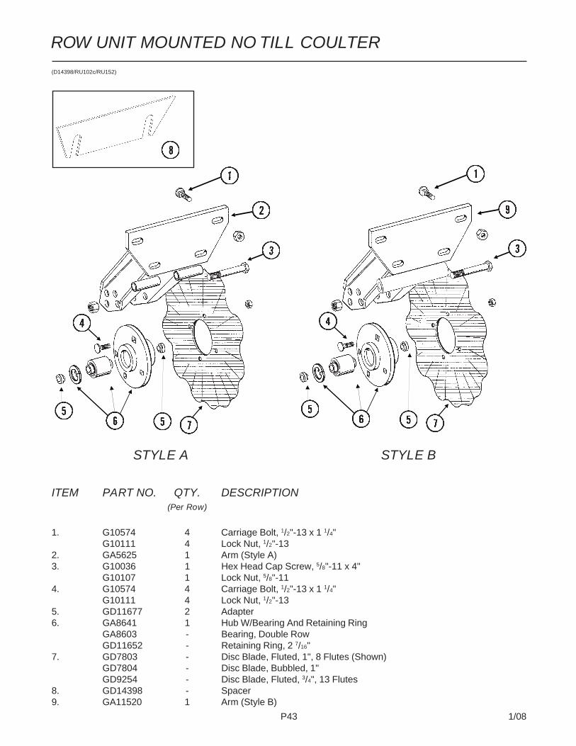
P43 1/08
ROW UNIT MOUNTED NO TILL COULTER
(D14398/RU102c/RU152)
ITEM PART NO. QTY. DESCRIPTION(Per Row)
1. G10574 4 Carriage Bolt, 1/2"-13 x 1 1/4"G10111 4 Lock Nut, 1/2"-13
2. GA5625 1 Arm (Style A)3. G10036 1 Hex Head Cap Screw, 5/8"-11 x 4"
G10107 1 Lock Nut, 5/8"-114. G10574 4 Carriage Bolt, 1/2"-13 x 1 1/4"
G10111 4 Lock Nut, 1/2"-135. GD11677 2 Adapter6. GA8641 1 Hub W/Bearing And Retaining Ring
GA8603 - Bearing, Double RowGD11652 - Retaining Ring, 2 7/16"
7. GD7803 - Disc Blade, Fluted, 1", 8 Flutes (Shown)GD7804 - Disc Blade, Bubbled, 1"GD9254 - Disc Blade, Fluted, 3/4", 13 Flutes
8. GD14398 - Spacer9. GA11520 1 Arm (Style B)
STYLE A STYLE B

P44 1/08
RUA059/RUA058(RU99/RU98g)
ROW UNIT MOUNTED DISC FURROWER

P45 1/08
ROW UNIT MOUNTED DISC FURROWER
ITEM PART NO. QTY. DESCRIPTION(Per Row)
1. G10536 1 Detent Pin, 1/2" x 2 1/2" Grip2. G10597 1 Square Head Set Screw, 5/8"-11 x 2 1/4"3. G10503 1 Hex Jam Nut, 5/8"-11, Grade 24. GA5719 1 Mounting Bracket5. GD7889 6 Bushing, 1" O.D. x 9/16" I.D. x 7/16" Long6. G10039 2 Hex Head Cap Screw, 1/2"-13 x 1 3/4"
GD14674 2 Special Washer, 1/2", HardenedG10111 2 Lock Nut, 1/2"-13
7. G10585 1 Hex Head Cap Screw, 1/2"-13 x 3 1/4"G10216 2 Washer, 1/2" USSG10111 1 Lock Nut, 1/2"-13
8. GD7890 2 Link9. G10017 2 Hex Head Cap Screw, 1/2"-13 x 1 1/2"
G10216 2 Washer, 1/2" USSG10111 2 Lock Nut, 1/2"-13
10. GA5715 1 Anchor11. G10017 2 Hex Head Cap Screw, 1/2"-13 x 1 1/2"
G10111 2 Lock Nut, 1/2"-1312. GA5718 1 Support Arm13. G10572 6 Truss Head Slotted Machine Screw, 5/16"-18 x 7/8"
G10106 6 Hex Nut, 5/16"-1814. GD1132 2 Dust Cap15. G10318 2 Hex Head Cap Screw, 5/8"-11 x 4 1/2"
GD7805 2 Special Washer, 5/8", HardenedG10107 2 Lock Nut, 5/8"-11
16. GA5654 2 Hub W/BearingsGA2014 - Bearing
17. GD7823 - Disc Blade, Solid, 12" (Shown)GD8307 - Disc Blade, Notched, 12"
18. GD7817-01 2 Spacer, 11/16" I.D. x 3/4" LongGD7817-04 2 Spacer, 11/16" I.D. x 1/2" Long

P46 1/08
ROW UNIT MOUNTED RESIDUE WHEEL(RU103dd/RU103d)
STYLE B
STYLE A

P47 1/08
ROW UNIT MOUNTED RESIDUE WHEEL
ITEM PART NO. QTY. DESCRIPTION(Per Row)
1. GD1132 1 Dust Cap2. GD10552 1 Wheel, 12 Tine, 3/8" x 12"3. G10006 1 Hex Head Cap Screw, 5/8"-11 x 2 1/4"4. GD9724 1 Backing Plate5. G10133 6 Hex Head Cap Screw, 5/16"-18 x 1 1/2"
G10109 6 Lock Nut, 5/16"-18, Grade 86. GD9720 2 Spacer, 1/2" x 2 3/16" Long7. GA6838 1 Wheel Mount8. G10033 2 Hex Head Cap Screw, 1/2"-13 x 3 1/2"
G10228 2 Lock Washer, 1/2"G10102 2 Hex Nut, 1/2"-13
9. GD5857 2 Spring10. G10045 2 Hex Head Cap Screw, 1/2"-13 x 4 1/2"
G10228 2 Lock Washer, 1/2"G10102 2 Hex Nut, 1/2"-13
11. G10348 1 Hex Head Cap Screw, 1/2"-13 x 5" (Lockup Bolt)G10111 1 Lock Nut, 1/2"-13
12. GD9715 2 Spacer, 1/2" x 3" Long13. GA6834 1 Lower Link14. GA6832 1 Mount15. G10574 4 Carriage Bolt, 1/2"-13 x 1 1/4"
G10111 4 Lock Nut, 1/2"-1316. GA6833 1 Upper Link17. G10371 1 Hex Head Cap Screw, 1/2"-13 x 3", Full Thread
G10501 1 Hex Jam Nut, 1/2"-13, Grade 218. GA5654 1 Hub W/Bearings
GA2014 - Bearing19. GD12534 - Cover20. GB0387 1 Wheel, 12 Tine, 3/8" x 12"
A. GA7446 - Wheel Assembly, 12 Tine, R.H. (Items 2, 4, 5 And 18)B. GA12236 - Wheel Assembly, 12 Tine, R.H. (Items 4, 5, 18 And 20)

P48 1/08
COULTER MOUNTED RESIDUE WHEELS(RU104uuu/RU153)
STYLE A - Used With Style A Row Unit Mounted No Till Coulter
STYLE B - Used With Style B Row Unit Mounted No Till Coulter

P49 1/08
COULTER MOUNTED RESIDUE WHEELS
ITEM PART NO. QTY. DESCRIPTION(Per Row)
1. GD1132 2 Dust Cap2. G10010 2 Hex Head Cap Screw, 5/8"-11 x 3"
G10503 2 Hex Jam Nut, 5/8"-11, Grade 23. GD10552 2 Wheel, 12 Tine, 3/8" x 12"4. GA5654 2 Hub W/Bearings
GA2014 - Bearing5. GA7412 1 Cam6. GD10519 1 Spring7. G10206 1 Washer, 1/2" SAE8. G10974 1 Lock Nut W/Nylon Insert, 1/2"-139. G11098 1 Hex Head Cap Screw, 1/2"-13 x 9 1/2", Grade 8
GD14674 2 Special Washer, 1/2", HardenedG10974 1 Lock Nut W/Nylon Insert, 1/2"-13
10. GA7271 1 Mount11. GD10526 1 Sleeve, 7 1/2"12. G10213 2-4 Machine Bushing, 5/8" (.030" Thick)13. GA8760 2 Weed Guard W/Spring Pin
G10765 - Spring Pin, 1/4" x 1"14. G10133 12 Hex Head Cap Screw, 5/16"-18 x 1 1/2"
G10109 12 Lock Nut, 5/16"-18, Grade 815. GD9724 2 Backing Plate16. GB0387 2 Wheel, 12 Tine, 3/8" x 12"17. GB0401 1 Mount18. G11236 1 Hex Head Cap Screw, 3/4"-10 x 10 1/2"
GB0383 2 Bushing, 1 1/8" O.D. x 25/32" I.D. x 3/4" LongG10194 2 Washer, 3/4" SAEG11228 1 Lock Nut, 3/4"-10
19. GA12256 1 Locking Pin20. G10003 2 Hex Head Cap Screw, 3/8"-16 x 1 1/2"
G10229 2 Lock Washer, 3/8"
A. GA7446 - Wheel Assembly, 12 Tine, R.H. (Items 3, 4, 14 And 15) (Shown)GA7445 - Wheel Assembly, 12 Tine, L.H. (Items 3, 4, 14 And 15)
B. GA12236 - Wheel Assembly, 12 Tine, R.H. (Items 4, 14, 15 And 16) (Shown)GA12235 - Wheel Assembly, 12 Tine, L.H. (Items 4, 14, 15 And 16)
C. G1K467 - Residue Wheel Mount Kit (Items 17-20)
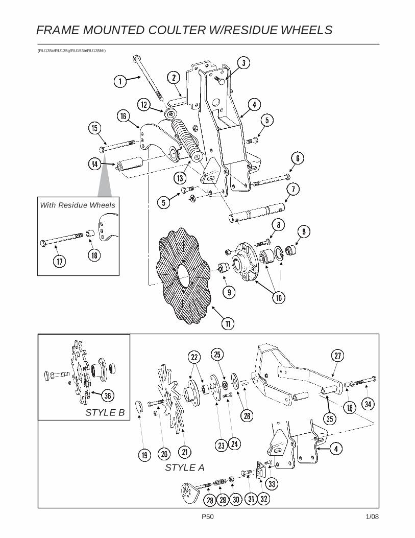
P50 1/08
FRAME MOUNTED COULTER W/RESIDUE WHEELS(RU135c/RU135g/RU153b/RU135hh)
With Residue Wheels
STYLE A
STYLE B

P51 1/08
FRAME MOUNTED COULTER W/RESIDUE WHEELS
ITEM PART NO. QTY. DESCRIPTION(Per Row)
1. G11010 2 Hex Head Cap Screw, 3/4"-10 x 12"2. GA9844 1 Plate W/Angle3. G10039 4 Hex Head Cap Screw, 1/2"-13 x 1 3/4"4. GA9131 1 Coulter Frame5. G10007 4 Hex Head Cap Screw, 5/8"-11 x 1 1/2"
G10107 4 Lock Nut, 5/8"-116. G10400 1 Hex Head Cap Screw, 3/4"-10 x 6 1/2"
G10112 1 Lock Nut, 3/4"-107. GD12826 1 Spring Anchor Bar8. G10574 4 Carriage Bolt, 1/2"-13 x 1 1/4"
G10111 4 Lock Nut, 1/2"-139. GD12827 2 Adapter10. GA8641 1 Hub W/Bearing And Retaining Ring
GA8603 1 Bearing, Double RowGD11652 1 Retaining Ring, 2 7/16"
11. GD7803 1 Disc Blade, Fluted, 1", 8 Flutes (Shown)GD7804 - Disc Blade, Bubbled, 1"GD9254 - Disc Blade, Fluted, 3/4", 13 Flutes
12. GB0213 2 Spring Seat13. GD12817 2 Compression Spring14. GD12829 1 Sleeve15. G10046 1 Hex Head Cap Screw, 5/8"-11 x 5"
G10107 1 Lock Nut, 5/8"-1116. GA9845 1 Coulter Arm W/Grease Fitting
G10643 - Grease Fitting, 45°, 1/4"-2817. G10011 1 Hex Head Cap Screw, 5/8"-11 x 5 1/2"
G10107 1 Lock Nut, 5/8"-1118. GB0218 3 Bushing, 21/32" I.D. x 7/8" O.D. x 19/32" Long19. GD1132 2 Dust Cap20. G10010 2 Hex Head Cap Screw, 5/8"-11 x 3"
G10503 2 Hex Jam Nut, 5/8"-11, Grade 221. GD10552 2 Wheel, 12 Tine, 3/8" x 12"22. GA5654 2 Hub W/Bearings
GA2014 - Bearing23. GD9724 2 Backing Plate24. G10133 12 Hex Head Cap Screw, 5/16"-18 x 1 1/2"
G10109 12 Lock Nut, 5/16"-18, Grade 825. G10213 2 Machine Bushing, 5/8" (.030" Thick)26. GA9862 2 Weed Guard W/Spring Pin
G10765 - Spring Pin, 1/4" x 1"27. GA9865 1 Mount28. GA9861 1 Cam29. GD10519 1 Spring30. G10974 1 Lock Nut W/Nylon Insert, 1/2"-1331. G10005 1 Hex Head Cap Screw, 5/8"-11 x 1 3/4"
G10107 4 Lock Nut, 5/8"-1132. GA9864 1 Support33. G10014 1 Hex Head Cap Screw, 1/2"-13 x 1"
G10102 1 Hex Nut, 1/2"-1334. G10011 2 Hex Head Cap Screw, 5/8"-11 x 5 1/2"
G10205 2 Washer, 5/8" SAEG10730 2 Lock Nut W/Nylon Insert, 5/8"-11
35. GD14170 2 Sleeve, 3"36. GB0386 2 Wheel, 12 Tine, 3/8" x 12"
A. GA7446 - Wheel Assembly, 12 Tine, R.H. (Items 21-24) (Shown)GA7445 - Wheel Assembly, 12 Tine, L.H. (Items 21-24)
B. GA12236 - Wheel Assembly, 12 Tine, R.H. (Items 22, 23, 24 And 36) (Shown)GA12235 - Wheel Assembly, 12 Tine, L.H. (Items 22, 23, 24 And 36)

P52 1/08
(A13248/A13249/A13250/FWD165))
PTO ASSEMBLY
24 1/2" TO 27"
OVER 34 1/2"
31 1/2" TO 34 1/2"

P53 1/08
PTO ASSEMBLY
ITEM PART NO. QTY. DESCRIPTION
1. GR1220 2 Bearing Ring2. GR1246 1 Quick Disconnect Kit3. GR1430 1 Grease Fitting, 3/16" Drive-In4. GR1850 1 Yoke, 1 3/4"-20 Spline5. GR1851 2 Cross & Bearing Kit6. GR1852 1 Spring Pin, 10mm x 80mm7. GR1853 1 Inboard Yoke8. GR1855 1 Inner Profile9. GR1858 1 Outer Profile10. GR1861 1 Yoke, 1 3/8"11. GR1862 1 Shield Cone12. GR1864 1 Outer Shield Tube13. GR1867 1 Inner Shield Tube14. GR1869 1 Shield Cone15. GR1870 1 Outer Decal16. GR1871 1 Inner Decal17. GR1872 1 Support Bearing18. GR1874 1 Cover19. GR1875 1 Safety Chain20. GR1856 1 Inner Profile21. GR1859 1 Outer Profile22. GR1960 1 Inboard Yoke23. GR1865 1 Outer Shield Tube24. GR1868 1 Inner Shield Tube25. GR1854 1 Inner Profile26. GR1857 1 Outer Profile27. GR1863 1 Outer Shield Tube28. GR1866 1 Inner Shield Tube29. G10062 1 Hex Head Cap Screw, 3/8"-16 x 3"
G10108 1 Lock Nut, 3/8"-1630. GD13226-02 1 Key, 5/16" Square x 1 3/4"

P54 1/08
VACUUM FAN HYDRAULIC COMPONENTS(A12484-2a/A13054-2a)
ITEM PART NO. QTY. DESCRIPTION1. - See “Vacuum Fan Hydraulic Motor Assembly”, Page P582. - See “Vacuum Gauges, Control Console And Vacuum Fan Assembly
With Oil Cooler”, Pages P58 And P593. - See “Vacuum Fan Motor Valve Block Assembly (Located On Both Sides
Of Planter)”, Page P594. See PTO Pump Assembly, Page P565. *A3292 1 Hose Assembly, 3/8" x 22"6. *A12704 1 Hose Assembly, 1/2" x 32"7. *A11805 2 Hose Assembly, 1 1/4" x 24"8. G304-C-10 1 Cap Nut, 7/8"-14 JIC9. G6801-12 2 Elbow W/O-Ring, 90°, 1 1/16"-12 Male JIC To O-Ring
GR1467 - O-Ring
24 ROW 30"
32 ROW 30" AND 36 ROW 30"

P55 1/08
VACUUM FAN HYDRAULIC COMPONENTS
ITEM PART NO. QTY. DESCRIPTION10. G6801-10 1 Elbow W/O-Ring, 90°, 7/8"-14 Male JIC To O-Ring
GR1466 - O-Ring11. G2603-08 1 Tee, 3/4"-16 Male JIC12. G6400-20 2 Adapter, 1 5/8"-12 JIC To O-Ring
GR1787 - O-Ring13. G6701-L-12 2 Tube L, 90°, 1 1/16"-12 JIC To Swivel14. *A3201 1 Hose Assembly, 3/8" x 176"15. *A3283 1 Hose Assembly, 3/8" x 108"16. *A12048 1 Hose Assembly, 3/8" x 76"17. GA11427 1 Hose Assembly, 5/8" x 218"18. *A11426 1 Hose Assembly, 5/8" x 224"19. *A12903 1 Hose Assembly, 3/4" x 246"20. *A12902 1 Hose Assembly, 3/4" x 262"21. *A3290 1 Hose Assembly, 3/8" x 98"22. *A3381 2 Hose Assembly, 3/4" x 26"23. *A3384 1 Hose Assembly, 3/4" x 122"24. *A11410 1 Hose Assembly, 5/8" x 98"25. G6801-20 1 Elbow W/O-Ring, 90°, 1 5/8"-12 Male JIC To O-Ring
GR1787 - O-Ring26. G6801-06 2 Elbow W/O-ing, 90°, 9/16"-18 Male JIC To O-Ring
GR1045 - O-Ring27. GD16994 1 Special Elbow W/O-Ring, 90°, 1 5/8"-12 Male JIC To O-Ring
GR1787 - O-Ring28. G6400-12 8 Connector W/O-Ring, 1 1/16"-12 Male JIC To O-Ring
GR1467 - O-Ring29. G6502-12 2 Swivel Elbow, 45°, 1 1/16"-12 Male JIC To Female30. GA12845 1 Tank, 8 Gallon31. *A3385 1 Hose Assembly, 3/4" x 182"32. *A11409 1 Hose Assembly, 5/8" x 170"33. *A3291 1 Hose Assembly, 3/8" x 168"34. *A3392 1 Hose Assembly, 3/4" x 50"35. *A11435 1 Hose Assembly, 5/8" x 28"36. *A12014 1 Hose Assembly, 3/8" x 34"37. *A12055 1 Hose Assembly, 3/8" x 275"38. *A11436 1 Hose Assembly, 5/8" x 326"39. *A11806 1 Hose Assembly, 1 1/4" x 60"40. *A11807 1 Hose Assembly, 1 1/4" x 78"41. *A3222 1 Hose Assembly, 3/8" x 18"42. *A11437 1 Hose Assembly, 5/8" x 348"43. *A12056 1 Hose Assembly, 3/8" x 323"44. *A12907 1 Hose Assembly, 3/4" x 323"45. *A3290 1 Hose Assembly, 3/8" x 98"46. *A11410 1 Hose Assembly, 5/8" x 98"47. G6500-12 2 Swivel Elbow, 90°, 1 1/16"-12 Male JIC To Female48. G6801-LL-20 2 X-Long Elbow W/O-Ring, 90°, 1 5/8"-12 Male JIC To O-Ring
GR1787 - O-Ring49. 6400-20-16 1 Connector W/O-Ring, 1 5/8"-12 JIC To 1 5/16"-12 O-Ring
GR1786 - O-Ring50. G5406-08P 1 Pipe Plug, 1/2" NPT51. G6801-L-20 1 Long Elbow W/O-Ring, 90°, 1 5/8"-12 Male JIC To O-Ring
GR1787 - O-Ring52. G6801-08-10 1 Elbow W/O-Ring, 90°, 3/4"-16 Male JIC To 7/8"-14 O-Ring
GR1468 - Seal Kit, Includes: (4)O-Rings, (5) BU Rings53. *A3398 1 Hose Assembly, 3/4" x 274"54. GA13245 1 Hydraulic Pump
* Hydraulic hose is not stocked by KINZE® Repair Parts, but can be made available on a special order basis. Call for quote.

P56 1/08
(FWD123)
PTO PUMP ASSEMBLY
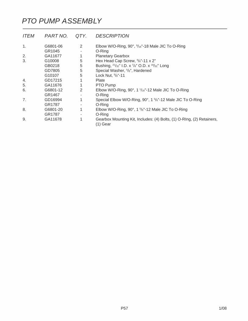
P57 1/08
ITEM PART NO. QTY. DESCRIPTION
1. G6801-06 2 Elbow W/O-Ring, 90°, 9/16"-18 Male JIC To O-RingGR1045 - O-Ring
2. GA11677 1 Planetary Gearbox3. G10008 5 Hex Head Cap Screw, 5/8"-11 x 2"
GB0218 5 Bushing, 21/32" I.D. x 7/8" O.D. x 19/32" LongGD7805 5 Special Washer, 5/8", HardenedG10107 5 Lock Nut, 5/8"-11
4. GD17215 1 Plate5. GA11676 1 PTO Pump6. G6801-12 2 Elbow W/O-Ring, 90°, 1 1/16"-12 Male JIC To O-Ring
GR1467 - O-Ring7. GD16994 1 Special Elbow W/O-Ring, 90°, 1 5/8"-12 Male JIC To O-Ring
GR1787 - O-Ring8. G6801-20 1 Elbow W/O-Ring, 90°, 1 5/8"-12 Male JIC To O-Ring
GR1787 - O-Ring9. GA11678 1 Gearbox Mounting Kit, Includes: (4) Bolts, (1) O-RIng, (2) Retainers,
(1) Gear
PTO PUMP ASSEMBLY
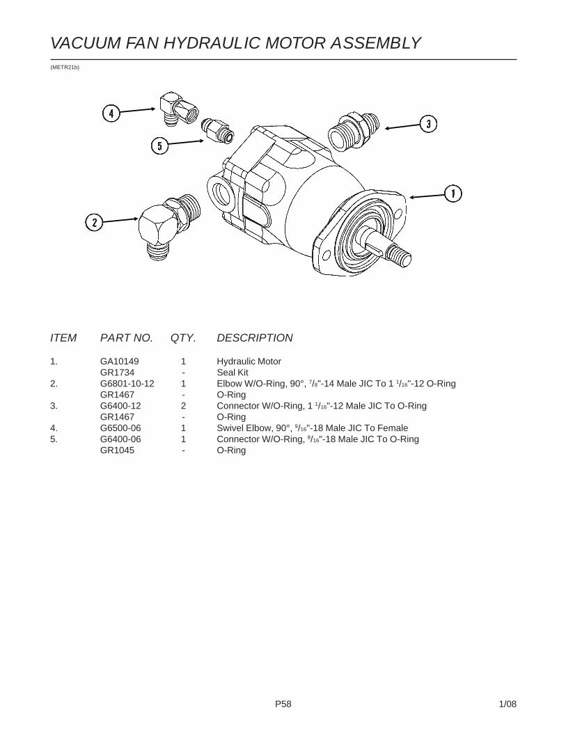
P58 1/08
(METR21b)
ITEM PART NO. QTY. DESCRIPTION
1. GA10149 1 Hydraulic MotorGR1734 - Seal Kit
2. G6801-10-12 1 Elbow W/O-Ring, 90°, 7/8"-14 Male JIC To 1 1/16"-12 O-RingGR1467 - O-Ring
3. G6400-12 2 Connector W/O-Ring, 1 1/16"-12 Male JIC To O-RingGR1467 - O-Ring
4. G6500-06 1 Swivel Elbow, 90°, 9/16"-18 Male JIC To Female5. G6400-06 1 Connector W/O-Ring, 9/16"-18 Male JIC To O-Ring
GR1045 - O-Ring
VACUUM FAN HYDRAULIC MOTOR ASSEMBLY

P59 1/08
(FWD126a)
VACUUM FAN MOTOR VALVE BLOCK ASSEMBLY(Located On Both Sides Of Planter)
ITEM PART NO. QTY. DESCRIPTION
1. GA11682 1 Pressure Compensating Element2. GA11934 1 Relief Valve Cartridge3. G6408-10 4 Plug W/O-Ring, 7/8"-14 O-Ring
GR1466 - O-Ring4. G6400-10 2 Connector W/O-Ring, 7/8"-14 Male JIC To O-Ring
GR1466 - O-Ring5. G6400-06 2 Connector W/O-Ring, 9/16"-18 Male JIC To O-Ring
GR1045 - O-Ring6. G6400-12 2 Connector W/O-Ring, 1 1/16"-12 Male JIC To O-Ring
GR1467 - O-Ring7. GD16873 1 Valve Block8. GA11799 1 Flow Control Cartridge W/Terminals9. GD6279-05 1 Clear Plastic Tubing, 9/16" O.D. x 60"10. G10681 1 Hose Clamp, No. 611. GD11700 1 Adapter, 1/4" NPT To 3/8" Barb12. G6403-NWO-12 1 Adjustable Union, 1 1/16"-12 O-Ring
GR1467 - O-Ring13. GA11900 1 Coil W/Terminals14. GA11680 1 Cartridge15. GA11679 1 Relief Valve16. G6408-H06-O 1 Hex Socket Head Plug W/O-Ring, 9/16"-18 O-Ring
GR1045 - O-Ring17. GD16038 1 Filter Head18. GD16037 1 Oil Filter, 10 Micron19. G11260 1 Elbow, 1/4" NPT Male To Female
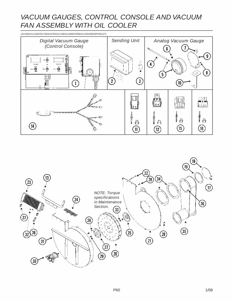
P60 1/08
VACUUM GAUGES, CONTROL CONSOLE AND VACUUMFAN ASSEMBLY WITH OIL COOLER(A11692/A11156/GR1736/A10765/A11158/A11699/A7856/A11155/A8329/FWD127)
Digital Vacuum Gauge(Control Console)
Analog Vacuum GaugeSending Unit
NOTE: Torquespecificationsin MaintenanceSection.
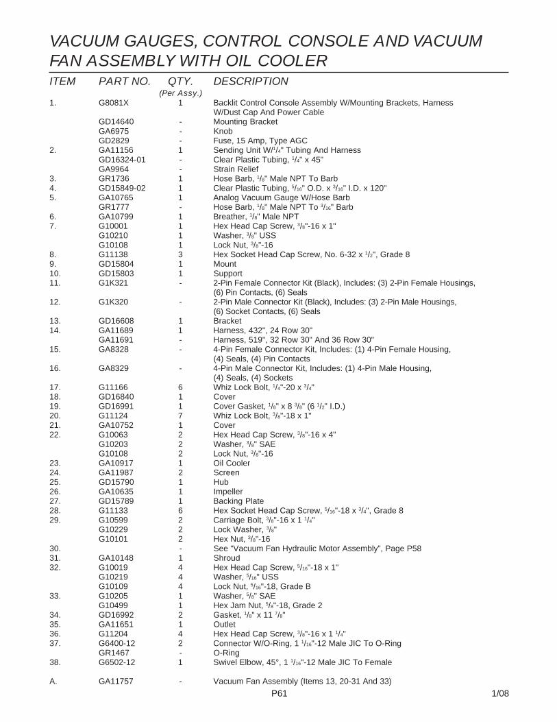
P61 1/08
ITEM PART NO. QTY. DESCRIPTION(Per Assy.)
1. G8081X 1 Backlit Control Console Assembly W/Mounting Brackets, HarnessW/Dust Cap And Power Cable
GD14640 - Mounting BracketGA6975 - KnobGD2829 - Fuse, 15 Amp, Type AGC
2. GA11156 1 Sending Unit W/1/4" Tubing And HarnessGD16324-01 - Clear Plastic Tubing, 1/4" x 45"GA9964 - Strain Relief
3. GR1736 1 Hose Barb, 1/8" Male NPT To Barb4. GD15849-02 1 Clear Plastic Tubing, 5/16" O.D. x 3/16" I.D. x 120"5. GA10765 1 Analog Vacuum Gauge W/Hose Barb
GR1777 - Hose Barb, 1/8" Male NPT To 3/16" Barb6. GA10799 1 Breather, 1/8" Male NPT7. G10001 1 Hex Head Cap Screw, 3/8"-16 x 1"
G10210 1 Washer, 3/8" USSG10108 1 Lock Nut, 3/8"-16
8. G11138 3 Hex Socket Head Cap Screw, No. 6-32 x 1/2", Grade 89. GD15804 1 Mount10. GD15803 1 Support11. G1K321 - 2-Pin Female Connector Kit (Black), Includes: (3) 2-Pin Female Housings,
(6) Pin Contacts, (6) Seals12. G1K320 - 2-Pin Male Connector Kit (Black), Includes: (3) 2-Pin Male Housings,
(6) Socket Contacts, (6) Seals13. GD16608 1 Bracket14. GA11689 1 Harness, 432", 24 Row 30"
GA11691 - Harness, 519", 32 Row 30" And 36 Row 30"15. GA8328 - 4-Pin Female Connector Kit, Includes: (1) 4-Pin Female Housing,
(4) Seals, (4) Pin Contacts16. GA8329 - 4-Pin Male Connector Kit, Includes: (1) 4-Pin Male Housing,
(4) Seals, (4) Sockets17. G11166 6 Whiz Lock Bolt, 1/4"-20 x 3/4"18. GD16840 1 Cover19. GD16991 1 Cover Gasket, 1/8" x 8 3/8" (6 1/2" I.D.)20. G11124 7 Whiz Lock Bolt, 3/8"-18 x 1"21. GA10752 1 Cover22. G10063 2 Hex Head Cap Screw, 3/8"-16 x 4"
G10203 2 Washer, 3/8" SAEG10108 2 Lock Nut, 3/8"-16
23. GA10917 1 Oil Cooler24. GA11987 2 Screen25. GD15790 1 Hub26. GA10635 1 Impeller27. GD15789 1 Backing Plate28. G11133 6 Hex Socket Head Cap Screw, 5/16"-18 x 3/4", Grade 829. G10599 2 Carriage Bolt, 3/8"-16 x 1 1/4"
G10229 2 Lock Washer, 3/8"G10101 2 Hex Nut, 3/8"-16
30. - See “Vacuum Fan Hydraulic Motor Assembly”, Page P5831. GA10148 1 Shroud32. G10019 4 Hex Head Cap Screw, 5/16"-18 x 1"
G10219 4 Washer, 5/16" USSG10109 4 Lock Nut, 5/16"-18, Grade B
33. G10205 1 Washer, 5/8" SAEG10499 1 Hex Jam Nut, 5/8"-18, Grade 2
34. GD16992 2 Gasket, 1/8" x 11 7/8"35. GA11651 1 Outlet36. G11204 4 Hex Head Cap Screw, 3/8"-16 x 1 1/4"37. G6400-12 2 Connector W/O-Ring, 1 1/16"-12 Male JIC To O-Ring
GR1467 - O-Ring38. G6502-12 1 Swivel Elbow, 45°, 1 1/16"-12 Male JIC To Female
A. GA11757 - Vacuum Fan Assembly (Items 13, 20-31 And 33)
VACUUM GAUGES, CONTROL CONSOLE AND VACUUMFAN ASSEMBLY WITH OIL COOLER

P62 1/08
MANIFOLDS AND DISTRIBUTION HOSES, 24 ROW 30"(FWD134)
ITEM PART NO. QTY. DESCRIPTION
1. GD16842 4 Manifold Gasket, 1/8" x 8 3/8" (6 5/8" I.D.)2. GD16844 - Support3. G10574 - Carriage Bolt, 1/2"-13 x 1 1/4"
G10071 - Serrated Flange Nut, 1/2"-134. GD15854 10 Clamp5. G10312 - Carriage Bolt, 5/16"-18 x 3/4"
G10620 - Serrated Flange Nut, 5/16"-186. GD15850 4 Manifold, 21" (Open One End)7. G11145 - T-Bolt Clamp, 7"
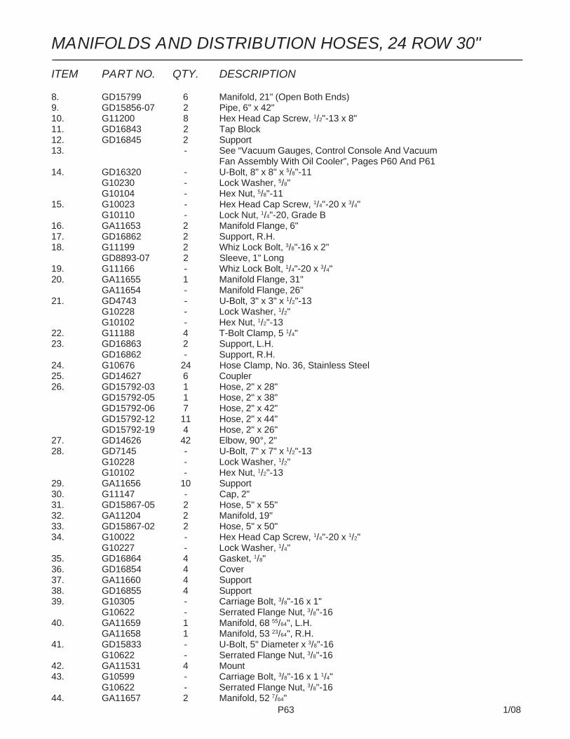
P63 1/08
ITEM PART NO. QTY. DESCRIPTION
8. GD15799 6 Manifold, 21" (Open Both Ends)9. GD15856-07 2 Pipe, 6" x 42"10. G11200 8 Hex Head Cap Screw, 1/2"-13 x 8"11. GD16843 2 Tap Block12. GD16845 2 Support13. - See “Vacuum Gauges, Control Console And Vacuum
Fan Assembly With Oil Cooler”, Pages P60 And P6114. GD16320 - U-Bolt, 8" x 8" x 5/8"-11
G10230 - Lock Washer, 5/8"G10104 - Hex Nut, 5/8"-11
15. G10023 - Hex Head Cap Screw, 1/4"-20 x 3/4"G10110 - Lock Nut, 1/4"-20, Grade B
16. GA11653 2 Manifold Flange, 6"17. GD16862 2 Support, R.H.18. G11199 2 Whiz Lock Bolt, 3/8"-16 x 2"
GD8893-07 2 Sleeve, 1" Long19. G11166 - Whiz Lock Bolt, 1/4"-20 x 3/4"20. GA11655 1 Manifold Flange, 31"
GA11654 - Manifold Flange, 26"21. GD4743 - U-Bolt, 3" x 3" x 1/2"-13
G10228 - Lock Washer, 1/2"G10102 - Hex Nut, 1/2"-13
22. G11188 4 T-Bolt Clamp, 5 1/4"23. GD16863 2 Support, L.H.
GD16862 - Support, R.H.24. G10676 24 Hose Clamp, No. 36, Stainless Steel25. GD14627 6 Coupler26. GD15792-03 1 Hose, 2" x 28"
GD15792-05 1 Hose, 2" x 38"GD15792-06 7 Hose, 2" x 42"GD15792-12 11 Hose, 2" x 44"GD15792-19 4 Hose, 2" x 26"
27. GD14626 42 Elbow, 90°, 2"28. GD7145 - U-Bolt, 7" x 7" x 1/2"-13
G10228 - Lock Washer, 1/2"G10102 - Hex Nut, 1/2"-13
29. GA11656 10 Support30. G11147 - Cap, 2"31. GD15867-05 2 Hose, 5" x 55"32. GA11204 2 Manifold, 19"33. GD15867-02 2 Hose, 5" x 50"34. G10022 - Hex Head Cap Screw, 1/4"-20 x 1/2"
G10227 - Lock Washer, 1/4"35. GD16864 4 Gasket, 1/8"36. GD16854 4 Cover37. GA11660 4 Support38. GD16855 4 Support39. G10305 - Carriage Bolt, 3/8"-16 x 1"
G10622 - Serrated Flange Nut, 3/8"-1640. GA11659 1 Manifold, 68 55/64", L.H.
GA11658 1 Manifold, 53 23/64", R.H.41. GD15833 - U-Bolt, 5" Diameter x 3/8"-16
G10622 - Serrated Flange Nut, 3/8"-1642. GA11531 4 Mount43. G10599 - Carriage Bolt, 3/8"-16 x 1 1/4"
G10622 - Serrated Flange Nut, 3/8"-1644. GA11657 2 Manifold, 52 7/64"
MANIFOLDS AND DISTRIBUTION HOSES, 24 ROW 30"

P64 1/08
MANIFOLDS AND DISTRIBUTION HOSES, 36 ROW 30"(FWD135)
ITEM PART NO. QTY. DESCRIPTION1. GD16842 4 Manifold Gasket, 1/8" x 8 3/8" (6 5/8" I.D.)2. GD16844 - Support3. G10574 - Carriage Bolt, 1/2"-13 x 1 1/4"
G10071 - Serrated Flange Nut, 1/2"-134. GD15854 14 Clamp5. G10312 - Carriage Bolt, 5/16"-18 x 3/4"
G10620 - Serrated Flange Nut, 5/16"-18

P65 1/08
ITEM PART NO. QTY. DESCRIPTION6. GD15850 4 Manifold, 21" (Open One End)7. G11145 - T-Bolt Clamp, 7"8. GD15799 10 Manifold, 21" (Open Both Ends)9. GD15856-09 1 Pipe, 6" x 45 1/2", L.H.
GD15856-12 - Pipe, 6" x 67", R.H.10. G11200 8 Hex Head Cap Screw, 1/2"-13 x 8"11. GD16843 2 Tap Block12. GD16845 2 Support13. - See “Vacuum Gauges, Control Console And Vacuum
Fan Assembly With Oil Cooler”, Pages P60 And P6114. GD15856-08 1 Pipe, 6" x 43 1/2", L.H.
GD15856-07 - Pipe, 6" x 42", R.H.15. G10023 - Hex Head Cap Screw, 1/4"-20 x 3/4"
G10110 - Lock Nut, 1/4"-20, Grade B16. GA11673 2 Manifold Flange, 5"17. GD17016 4 Plate, 1 1/4" x 10"18. G11199 2 Whiz Lock Bolt, 3/8"-16 x 2"
GD8893-07 2 Sleeve, 1" Long19. G11166 - Whiz Lock Bolt, 1/4"-20 x 3/4"20. GA11675 1 Manifold Flange, 37 41/64", L.H.
GA11674 - Manifold Flange, 11 9/64", R.H.21. GD4743 - U-Bolt, 3" x 3" x 1/2"-13
G10228 - Lock Washer, 1/2"G10102 - Hex Nut, 1/2"-13
22. G11188 4 T-Bolt Clamp, 5 1/4"23. GD16898 4 Support24. G10676 36 Hose Clamp, No. 36, Stainless Steel25. GD14627 8 Coupler26. GD15792-05 2 Hose, 2" x 38"
GD15792-06 17 Hose, 2" x 42"GD15792-14 5 Hose, 2" x 46"GD15792-16 1 Hose, 2" x 55"GD15792-20 5 Hose, 2" x 32"GD15792-21 4 Hose, 2" x 52"GD15792-22 2 Hose, 2" x 58"
27. GD14626 64 Elbow, 90°, 2"28. GD7145 - U-Bolt, 7" x 7" x 1/2"-13
G10228 - Lock Washer, 1/2"G10102 - Hex Nut, 1/2"-13
29. GA11656 10 Support30. G11147 - Cap, 2"31. GD15867-03 2 Hose, 5" x 36"32. GA11204 2 Manifold, 19"33. GD15867-04 2 Hose, 5" x 42"34. G10022 - Hex Head Cap Screw, 1/4"-20 x 1/2"
G10227 - Lock Washer, 1/4"35. GD16864 4 Gasket, 1/8"36. GD16854 4 Cover37. GA11660 4 Support38. GD16855 4 Support39. G10305 - Carriage Bolt, 3/8"-16 x 1"
G10622 - Serrated Flange Nut, 3/8"-1640. GA11671 1 Manifold, 68 55/64", L.H.
GA11672 1 Manifold, 53 23/64", R.H.41. GD15833 - U-Bolt, 5" Diameter x 3/8"-16
G10230 - Lock Washer, 5/8"G10104 - Hex Nut, 3/8"-11
42. GD17317-01 2 Hose, 7" x 21"43. G10045 - Hex Head Cap Screw, 1/2"-13 x 4 1/2"
G10216 - Washer, 1/2" USSG10071 - Serrated Flange Nut, 1/2"-13
44. GD16119-12 2 Tube, 5" O.D. x 72"45. GD15856-08 1 Pipe, 6" x 43 1/2", L.H.
GD15856-09 - Pipe, 6" x 44 1/2", R.H.46. GD15856-10 1 Pipe, 6" x 55", L.H.
GD15856-11 - Pipe, 6" x 60", R.H.
MANIFOLDS AND DISTRIBUTION HOSES, 36 ROW 30"

P66 1/08
PTO ASSEMBLY ON HITCH, 24 ROW 30"(FWD166)
NOTE: See “Vacuum Fan Hydraulic Components, pages P54 and P55 for PTO pump andplanetery gearbox.

P67 1/08
ITEM PART NO. QTY. DESCRIPTION
1. - See “Inner/Outer Fixed Hitch, 24 Row 30"”, Pages P70 And P712. G11122 2 Hex Head Cap Screw, 5/8"-11 x 12"
GD7805 2 Special Washer, 5/8", HardenedG10107 2 Lock Nut, 5/8"-11
3. GD18279 - Plate4. GA12843 - Pump Mount5. GD18282 - Plate6. GA12844 1 Bearing Mount7. G10002 8 Hex Head Cap Screw, 3/8"-16 x 3/4"
G10210 8 Washer, 3/8" USS8. GA12863 1 PTO Knuckle Assembly9. GA12850 1 Rear PTO Shaft10. GA12819 1 Rear Shaft Cover11. GD18193 1 Front PTO Shaft12. GD18194 2 Door13. G10002 8 Hex Head Cap Screw, 3/8"-16 x 3/4"
G10108 5 Lock Nut, 3/8"-1614. GD18319 1 Guide Pad15. GD18190 1 Coupler16. GD18191 1 Coupler17. GD18324 1 Lock Sleeve18. GA12849 1 Front PTO Shaft19. GD18309 1 Upper Front PTO Cover20. G10043 4 Hex Head Cap Screw, 5/16"-18 x 3/4"
G10219 4 Washer, 5/16" USS21. GD18308 1 Lower Front PTO Cover22. GD18307 2 Shim23. GD18318 4 Coupling24. G10599 4 Carriage Bolt, 3/8"-16 x 1 1/4"
G10622 6 Serrated Flange Nut, 3/8"-1625. GA12851 1 Shaft Guide Mount26. GD18321 1 Pad27. G10039 12 Hex Head Cap Screw, 1/2"-13 x 1 3/4"
G10216 8 Washer, 1/2" USS28. GD18320 1 Mount
PTO ASSEMBLY ON HITCH, 24 ROW 30"

P68 1/08
PTO ASSEMBLY ON HITCH, 32 ROW 30" AND 36 ROW 30"
Information not available.

P69 1/08
PTO ASSEMBLY ON HITCH, 32 ROW 30" AND 36 ROW 30"
Information not available.

P70 1/08
INNER/OUTER FIXED HITCH, 24 ROW 30"(FWD9b/D14812/FWD153/FWD164/FWD112)
Inner HitchWear Pad
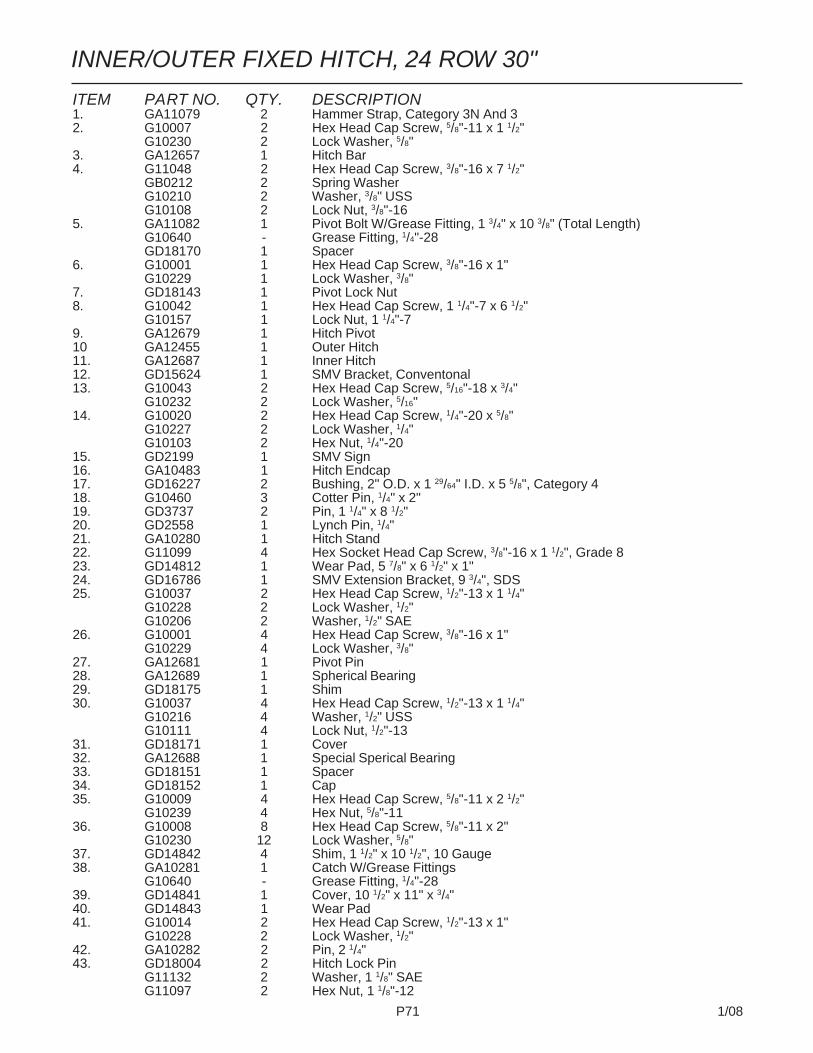
P71 1/08
INNER/OUTER FIXED HITCH, 24 ROW 30"
ITEM PART NO. QTY. DESCRIPTION1. GA11079 2 Hammer Strap, Category 3N And 32. G10007 2 Hex Head Cap Screw, 5/8"-11 x 1 1/2"
G10230 2 Lock Washer, 5/8"3. GA12657 1 Hitch Bar4. G11048 2 Hex Head Cap Screw, 3/8"-16 x 7 1/2"
GB0212 2 Spring WasherG10210 2 Washer, 3/8" USSG10108 2 Lock Nut, 3/8"-16
5. GA11082 1 Pivot Bolt W/Grease Fitting, 1 3/4" x 10 3/8" (Total Length)G10640 - Grease Fitting, 1/4"-28GD18170 1 Spacer
6. G10001 1 Hex Head Cap Screw, 3/8"-16 x 1"G10229 1 Lock Washer, 3/8"
7. GD18143 1 Pivot Lock Nut8. G10042 1 Hex Head Cap Screw, 1 1/4"-7 x 6 1/2"
G10157 1 Lock Nut, 1 1/4"-79. GA12679 1 Hitch Pivot10 GA12455 1 Outer Hitch11. GA12687 1 Inner Hitch12. GD15624 1 SMV Bracket, Conventonal13. G10043 2 Hex Head Cap Screw, 5/16"-18 x 3/4"
G10232 2 Lock Washer, 5/16"14. G10020 2 Hex Head Cap Screw, 1/4"-20 x 5/8"
G10227 2 Lock Washer, 1/4"G10103 2 Hex Nut, 1/4"-20
15. GD2199 1 SMV Sign16. GA10483 1 Hitch Endcap17. GD16227 2 Bushing, 2" O.D. x 1 29/64" I.D. x 5 5/8", Category 418. G10460 3 Cotter Pin, 1/4" x 2"19. GD3737 2 Pin, 1 1/4" x 8 1/2"20. GD2558 1 Lynch Pin, 1/4"21. GA10280 1 Hitch Stand22. G11099 4 Hex Socket Head Cap Screw, 3/8"-16 x 1 1/2", Grade 823. GD14812 1 Wear Pad, 5 7/8" x 6 1/2" x 1"24. GD16786 1 SMV Extension Bracket, 9 3/4", SDS25. G10037 2 Hex Head Cap Screw, 1/2"-13 x 1 1/4"
G10228 2 Lock Washer, 1/2"G10206 2 Washer, 1/2" SAE
26. G10001 4 Hex Head Cap Screw, 3/8"-16 x 1"G10229 4 Lock Washer, 3/8"
27. GA12681 1 Pivot Pin28. GA12689 1 Spherical Bearing29. GD18175 1 Shim30. G10037 4 Hex Head Cap Screw, 1/2"-13 x 1 1/4"
G10216 4 Washer, 1/2" USSG10111 4 Lock Nut, 1/2"-13
31. GD18171 1 Cover32. GA12688 1 Special Sperical Bearing33. GD18151 1 Spacer34. GD18152 1 Cap35. G10009 4 Hex Head Cap Screw, 5/8"-11 x 2 1/2"
G10239 4 Hex Nut, 5/8"-1136. G10008 8 Hex Head Cap Screw, 5/8"-11 x 2"
G10230 12 Lock Washer, 5/8"37. GD14842 4 Shim, 1 1/2" x 10 1/2", 10 Gauge38. GA10281 1 Catch W/Grease Fittings
G10640 - Grease Fitting, 1/4"-2839. GD14841 1 Cover, 10 1/2" x 11" x 3/4"40. GD14843 1 Wear Pad41. G10014 2 Hex Head Cap Screw, 1/2"-13 x 1"
G10228 2 Lock Washer, 1/2"42. GA10282 2 Pin, 2 1/4"43. GD18004 2 Hitch Lock Pin
G11132 2 Washer, 1 1/8" SAEG11097 2 Hex Nut, 1 1/8"-12

P72 1/08
INNER SLIDE HITCH, 32 ROW 30" AND 36 ROW 30"(FWD58a)

P73 1/08
INNER SLIDE HITCH, 32 ROW 30" AND 36 ROW 30"
ITEM PART NO. QTY. DESCRIPTION
1. GA11079 2 Pin, Category 3N And 32. G10007 2 Hex Head Cap Screw, 5/8"-11 x 1 1/2"
G10230 2 Lock Washer, 5/8"3. GA12657 1 Hitch Bar4. G10686 2 Hex Head Cap Screw, 3/8"-16 x 8"
GB0212 2 Spring WasherG10210 2 Washer, 3/8" USSG10108 2 Lock Nut, 3/8"-16
5. GA11082 1 Pivot Bolt W/Grease Fitting, 1 3/4" x 10 3/8" (Total Length)G10640 - Grease Fitting, 1/4"-28GD18170 1 Spacer
6. G10001 1 Hex Head Cap Screw, 3/8"-16 x 1"G10229 1 Lock Washer, 3/8"
7. GD18143 1 Pivot Lock Nut8. - See “Outer Slide Hitch”, Pages P74 And P759. GA12679 1 Hitch Pivot10. GD16227 2 Bushing, 2" O.D. x 1 29/64" I.D. x 5 5/8", Category 411. GA13006 - Inner Hitch, 348 1/2", 32 Row 30"
GA13007 - Inner Hitch, 373 1/2", 36 Row 30"12. GD18175 1 Shim13. G10809 1 Hex Head Cap Screw, 3/8"-16 x 3 1/4"
G10108 1 Lock Nut, 3/8"-1614. GD7137 1 Pin, 3/4" x 3 3/8"15. GD2971-09 1 Sleeve, 2" Long16. G10457 2 Cotter Pin, 5/32" x 1 1/2"17. 1 See “Tongue Latch Cylinder”, Page P13018. G10460 3 Cotter Pin, 1/4" x 2"19. GD3737 2 Pin, 1 1/4" x 8 1/2"20. GD2558 1 Lynch Pin, 1/4"21. GA10280 1 Hitch Stand22. G11099 4 Hex Socket Head Cap Screw, 3/8"-16 x 1 1/2", Grade 823. GD14812 1 Wear Pad, 5 7/8" x 6 1/2" x 1"24. G10001 4 Hex Head Cap Screw, 3/8"-16 x 1"
G10229 4 Lock Washer, 3/8"25. GA12681 1 Pivot Pin26. GA12689 1 Spherical Bearing27. GA12688 1 Special Sperical Bearing28. GD18151 1 Spacer29. GD18152 1 Cap30. G10009 4 Hex Head Cap Screw, 5/8"-11 x 2 1/2"
G10239 4 Hex Nut, 5/8"-11

P74 1/08
(FWD9a/FWD112a)
OUTER SLIDE HITCH, 32 ROW 30" AND 36 ROW 30"
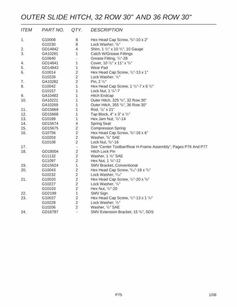
P75 1/08
ITEM PART NO. QTY. DESCRIPTION
1. G10008 8 Hex Head Cap Screw, 5/8"-10 x 2"G10230 8 Lock Washer, 5/8"
2. GD14842 4 Shim, 1 1/2" x 10 1/2", 10 Gauge3. GA10281 1 Catch W/Grease Fittings
G10640 - Grease Fitting, 1/4"-284. GD14841 1 Cover, 10 1/2" x 11" x 3/4"5. GD14843 1 Wear Pad6. G10014 2 Hex Head Cap Screw, 1/2"-13 x 1"
G10228 2 Lock Washer, 1/2"7. GA10282 2 Pin, 2 1/4"8. G10042 1 Hex Head Cap Screw, 1 1/4"-7 x 6 1/2"
G10157 1 Lock Nut, 1 1/4"-79. GA10483 1 Hitch Endcap10. GA10221 1 Outer Hitch, 325 5/8", 32 Row 30"
GA10269 1 Outer Hitch, 355 5/8", 36 Row 30"11. GD15669 1 Rod, 7/8" x 21"12. GD15668 1 Tap Block, 4" x 3" x 1/2"13. G10189 1 Hex Jam Nut, 7/8"-1414. GD15674 4 Spring Seat15. GD15675 2 Compression Spring16. G10756 2 Hex Head Cap Screw, 3/8"-16 x 6"
G10203 2 Washer, 3/8" SAEG10108 2 Lock Nut, 3/8"-16
17. - See “Center Toolbar/Rear H-Frame Assembly”, Pages P76 And P7718. GD18004 2 Hitch Lock Pin
G11132 2 Washer, 1 1/8" SAEG11097 2 Hex Nut, 1 1/8"-12
19. GD15624 1 SMV Bracket, Conventional20. G10043 2 Hex Head Cap Screw, 5/16"-18 x 3/4"
G10232 2 Lock Washer, 5/16"21. G10020 2 Hex Head Cap Screw, 1/4"-20 x 5/8"
G10227 2 Lock Washer, 1/4"G10103 2 Hex Nut, 1/4"-20
22. GD2199 1 SMV Sign23. G10037 2 Hex Head Cap Screw, 1/2"-13 x 1 1/4"
G10228 2 Lock Washer, 1/2"G10206 2 Washer, 1/2" SAE
24. GD16787 - SMV Extension Bracket, 15 3/4", SDS
OUTER SLIDE HITCH, 32 ROW 30" AND 36 ROW 30"
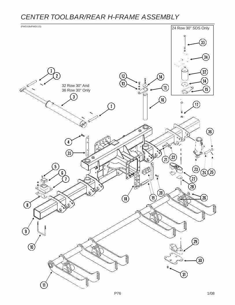
P76 1/08
CENTER TOOLBAR/REAR H-FRAME ASSEMBLY(FWD10b/FWD115) 24 Row 30" SDS Only
32 Row 30" And36 Row 30" Only

P77 1/08
ITEM PART NO. QTY. DESCRIPTION1. GD15051 2 Pin, 1 1/4" x 9 1/4"2. G10460 4 Cotter Pin, 1/4" x 2"3. - See “Axle Slide Cylinder”, Page P1294. G10027 8 Hex Head Cap Screw, 3/4"-10 x 2 1/2"
G10026 - Hex Head Cap Screw, 3/4"-10 x 2"G10025 - Hex Head Cap Screw, 3/4"-10 x 1 1/2"G10231 8 Lock Washer, 3/4"G10105 8 Hex Nut, 3/4"-10
5. G11099 8 Hex Socket Head Cap Screw, 3/8"-16 x 1 1/2", Grade 86. GD15169 2 Wear Block7. GA10343 2 Mount, 8" x 10"8. GD15170 - Shim, 3 1/4" x 10", 16 Gauge (As Required)9. GA11210 1 H-Frame Assembly, 24 Row 30"
GA11215 - H-Frame Assembly, 32 Row 30" And 36 Row 30"10. GD17039 4 U-Bolt, 7" x 7" x 5/8"-11
G10230 8 Lock Washer, 5/8"G10104 8 Hex Nut, 5/8"-11
11. See “Rock Shaft Axle Assembly And Wheels”, Pages P78 And P7912. G10008 4 Hex Head Cap Screw, 5/8"-11 x 2"
G10230 4 Lock Washer, 5/8"13. G10217 2 Washer, 5/8" USS14. GD15046 2 Washer, 21/32" I.D. x 4" O.D. x 1/4"15. GD15045 2 Capture Plate16. GD15369 2 Pivot Pin, 3" x 22 1/2", 24 Row 30"
GD15047 2 Pivot Pin, 3" x 28 1/2", 32 Row 30" And 36 Row 30"17. G11095 16 Hex Head Cap Screw, 7/8"-9 x 9"
GD10063 16 Washer, 7/8", HardenedG10418 16 Lock Nut, 7/8"-9
18. GB0357 2 Keeper, 24 Row 30"GB0356 - Keeper, 32 Row 30" And 36 Row 30"
19. GB0355 2 Keeper20. G10026 16 Hex Head Cap Screw, 3/4"-10 x 2"
G10231 16 Lock Washer, 3/4"G10105 16 Hex Nut, 3/4"-10
21. G10016 8 Hex Head Cap Screw, 1/2"-13 x 2"G10216 8 Washer, 1/2" USSG10111 8 Lock Nut, 1/2"-13
22. GA6761 8 Pin, 1 3/4"GA5121 - Pin, 2 1/8"
23. - See “Master Cylinder”, Pages P123 And P12424. GD5841 4 Pin, 1 1/4" x 5 5/8"25. G10460 8 Cotter Pin, 1/4" x 2"26. G10226 8 Washer, 1 1/4" SAE27. GB0332 8 Bearing28. GD15172 16 Shim29. GD14941 8 Bearing30. GD14926 4 Clamp Plate31. G10640 8 Grease Fitting, 1/4"-2832. GA11385 1 Pivot Post, 24 Row 30"33. G10953 1 Hex Head Cap Screw, 5/8"-11 x 10"
G10230 1 Lock Washer, 5/8"34. - See “Wing Auger Assemblies, 24 Row 30" (SDS)”, Pages P176 And P17735. GD15451 3 Shim, 2 3/4" x 18", 16 Gauge, 24 Row 30"
GD15780 3 Shim, 1 7/8" x 18", 22 Gauge, 24 Row 30"GD14842 - Shim, 1 1/2" x 10 1/2", 10 Gauge, 32 Row 30" And 36 Row 30"GD15450 - Shim, 2 3/4" x 24", 16 Gauge, 32 Row 30" And 36 Row 30"GD15796 - Shim, 2 3/4" x 24", 22 Gauge, 32 Row 30" And 36 Row 30"
36. G10139 8 Washer, 1 1/4" USS
CENTER TOOLBAR/REAR H-FRAME ASSEMBLY

P78 1/08
ROCK SHAFT AXLE ASSEMBLY AND WHEELS(FWD10c)

P79 1/08
ITEM PART NO. QTY. DESCRIPTION
1. GA11174 1 Rock Shaft Axle, 133 1/2"2. G10448 8 Hex Head Cap Screw, 7/8"-9 x 2 1/2", Grade 8
G10330 8 Lock Washer, 7/8"3. G11071 4 Hex Head Cap Screw, 3/4"-10 x 2 1/4"
G10194 8 Washer, 3/4" SAEG10231 4 Lock Washer, 3/4"G10105 4 Hex Nut, 3/4"-10
4. GA11227 4 Scraper Mount5. G10636 8 Carriage Bolt, 1/2"-13 x 1 1/2"
G10216 8 Washer, 1/2" USSG10228 8 Lock Washer, 1/2"G10102 8 Hex Nut, 1/2"-13
6. GD12543 4 Scraper7. GA9544 4 Rim, 5.5" x 22.5"8. GD15406 4 Tire, 41 x 11 R22.5" W/O Center Rib (Specify Brand*)9. GA10139 4 Spindle W/Retaining Ring, 1 3/4"
G10913 - External Retaining Ring, 2 1/2"10. GA4722 8 Seal11. GA4723 8 Bearing12. GA4729 4 Hub W/Cups, Bolts, Nuts And Grease Fitting, 8 Bolt, 1 3/4" Bore
G10640 - Grease Fitting, 1/4"-28GD7079 - CupGR0528 - Stud, 5/8"-12 x 2 1/4", Grade 8GR0531 - Lug Nut, 5/8"-18 UNF
13. GD7089 4 Special Nut, 1 3/4"-12 UNF14. GD7864 4 Special Hex Nut, 1 3/4"-12 UNF15. GA7434 4 Valve Stem
A. GA10553 - Tire And Rim Assembly (Items 7, 8 And 15) (Specify Brand*)
* Specific brand requests will be supplied only as available from current KINZE® Repair Parts stock. If a specific brandrequested is not in stock, the brand available will be supplied.
ROCK SHAFT AXLE ASSEMBLY AND WHEELS
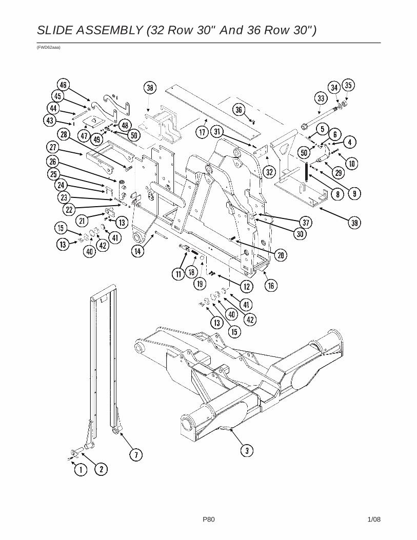
P80 1/08
SLIDE ASSEMBLY (32 Row 30" And 36 Row 30")(FWD62aaa)
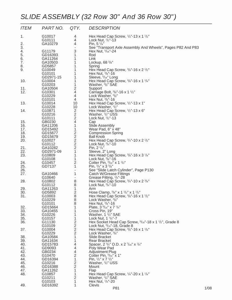
P81 1/08
SLIDE ASSEMBLY (32 Row 30" And 36 Row 30")
ITEM PART NO. QTY. DESCRIPTION
1. G10017 4 Hex Head Cap Screw, 1/2"-13 x 1 1/2"G10111 4 Lock Nut, 1/2"-13
2. GA10279 4 Pin, 5 1/4"3. - See “Transport Axle Assembly And Wheels”, Pages P82 And P834. G11179 3 Hex Nut, 5/16"-245. GD16393 1 Rod6. GA11264 1 Link7. GA10503 1 Lockup, 68 3/8"8. GD5857 1 Spring9. G10049 1 Hex Head Cap Screw, 3/8"-16 x 2 1/2"
G10101 1 Hex Nut, 3/8"-16GD2971-15 1 Sleeve, 5/16" Long
10. G10004 1 Hex Head Cap Screw, 3/8"-16 x 1 1/4"G10203 1 Washer, 3/8" SAE
11. GA10504 2 Support12. G10301 4 Carriage Bolt, 3/8"-16 x 1 1/2"
G10229 4 Lock Washer, 3/8"G10101 4 Hex Nut, 3/8"-16
13. G10014 10 Hex Head Cap Screw, 1/2"-13 x 1"G10228 10 Lock Washer, 1/2"
14. G10871 2 Hex Head Cap Screw, 1/2"-13 x 6"G10216 2 Washer, 1/2" USSG10111 2 Lock Nut, 1/2"-13
15. GB0230 4 Cap16. GA11206 1 Slide Assembly17. GD15492 1 Wear Pad, 6" x 48"18. GD15677 2 Compression Spring19. GD15679 2 Ball Knob20. G10027 2 Hex Head Cap Screw, 3/4"-10 x 2 1/2"
G10112 2 Lock Nut, 3/4"-1021. GA10282 2 Pin, 2 1/4"22. GD2971-09 1 Sleeve, 2" Long23. G10809 1 Hex Head Cap Screw, 3/8"-16 x 3 1/4"
G10108 1 Lock Nut, 3/8"-1624. G10457 2 Cotter Pin, 5/32" x 1 1/2"25. GD7137 1 Pin, 3/4" x 3 3/8"26. - See “Slide Latch Cylinder”, Page P13027. GA10466 1 Catch W/Grease Fittings
G10640 - Grease Fitting, 1/4"-2828. G10802 8 Hex Head Cap Screw, 3/4"-10 x 2 3/4"
G10112 8 Lock Nut, 3/4"-1029. GA11263 1 Arm30. GD5892 2 Hose Clamp, 5/8" x 1 1/2" x 1 1/2"31. G10003 8 Hex Head Cap Screw, 3/8"-16 x 1 1/2"
G10229 8 Lock Washer, 3/8"G10101 8 Hex Nut, 3/8"-16
32. GD15664 1 Plate, 3 9/16" x 7 1/4"33. GA10455 1 Cross Pin, 19"34. G10226 1 Washer, 1 1/4" SAE35. G10157 1 Lock Nut, 1 1/4"-736. G11130 2 Hex Socket Head Cap Screw, 5/16"-18 x 1 1/2", Grade 8
G10109 2 Lock Nut, 5/16"-18, Grade 837. G10004 2 Hex Head Cap Screw, 3/8"-16 x 1 1/4"
G10229 2 Lock Washer, 3/8"38. GA10584 1 Slide Bracket39. GA11634 1 Rear Bracket40. GD15783 4 Spacer, 2 3/4" O.D. x 2 7/16" x 1/4"41. GD9093 4 Poly Wear Pad42. GB0234 4 Adjustment Plug43. G10470 2 Cotter Pin, 5/32" x 1"44. GD16394 1 Pin, 1/2" x 7 1/2"45. G10216 2 Washer, 1/2" USS46. GD16388 2 Mount47. GA11262 1 Flap48. G10857 1 Hex Head Cap Screw, 1/4"-20 x 1 1/4"
G10211 2 Washer, 1/4" SAEG10103 1 Hex Nut, 1/4"-20
49. GD16392 1 Clevis

P82 1/08
(A12501/FWD60d/FWD61/A7434)
TRANSPORT AXLE ASSEMBLY AND WHEELS
24 Row 30" SDS, All32 Row 30" And All36 Row 30" (Standard) -24 Row 30" Conventional(Optional)
24 Row 30"
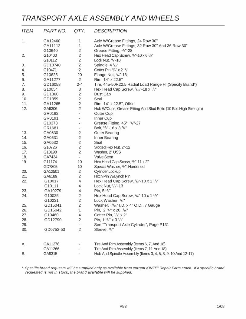
P83 1/08
ITEM PART NO. QTY. DESCRIPTION
1. GA12460 1 Axle W/Grease Fittings, 24 Row 30"GA11112 1 Axle W/Grease Fittings, 32 Row 30" And 36 Row 30"G10640 2 Grease Fitting, 1/4"-28
2. G10400 2 Hex Head Cap Screw, 3/4"-10 x 6 1/2"G10112 2 Lock Nut, 3/4"-10
3. GD13740 2 Spindle, 4 1/2"4. G10471 2 Cotter Pin, 3/8" x 2 1/2"5. G10625 20 Flange Nut, 3/4"-166. GA11277 2 Rim, 14" x 22.5"7. GD16058 2-4 Tire, 445-50R22.5 Radial Load Range H (Specify Brand*)8. G10054 8 Hex Head Cap Screw, 5/16"-18 x 1/2"9. GD1360 2 Dust Cap10. GD1359 2 Seal11. GA11265 2 Rim, 14" x 22.5", Offset12. GA9306 2 Hub W/Cups, Grease Fitting And Stud Bolts (10 Bolt High Strength)
GR0192 - Outer CupGR0191 - Inner CupG10373 - Grease Fitting, 45°, 1/8"-27GR1681 - Bolt, 3/4"-16 x 3 7/8"
13. GA0530 2 Outer Bearing14. GA0531 2 Inner Bearing15. GA0532 2 Seal16. G10726 2 Slotted Hex Nut, 2"-1217. G10198 2 Washer, 2" USS18. GA7434 - Valve Stem19. G11174 10 Hex Head Cap Screw, 5/8"-11 x 2"
GD7805 10 Special Washer, 5/8", Hardened20. GA12501 2 Cylinder Lockup21. GA6189 2 Hitch Pin W/Lynch Pin22. G10017 4 Hex Head Cap Screw, 1/2"-13 x 1 1/2"
G10111 4 Lock Nut, 1/2"-1323. GA10279 4 Pin, 5 1/4"24. G10025 2 Hex Head Cap Screw, 3/4"-10 x 1 1/2"
G10231 2 Lock Washer, 3/4"25. GD15041 2 Washer, 13/16" I.D. x 4" O.D., 7 Gauge26. GD15042 1 Pin, 2 1/4" x 20 1/16"27. G10460 4 Cotter Pin, 1/4" x 2"28. GD12790 2 Pin, 1 1/4" x 3 1/2"29. - See “Transport Axle Cylinder”, Page P13130. GD0752-53 2 Sleeve, 3/8"
A. GA11278 - Tire And Rim Assembly (Items 6, 7, And 18)GA11266 - Tire And Rim Assembly (Items 7, 11 And 18)
B. GA9315 - Hub And Spindle Assembly (Items 3, 4, 5, 8, 9, 10 And 12-17)
* Specific brand requests will be supplied only as available from current KINZE® Repair Parts stock. If a specific brandrequested is not in stock, the brand available will be supplied.
TRANSPORT AXLE ASSEMBLY AND WHEELS
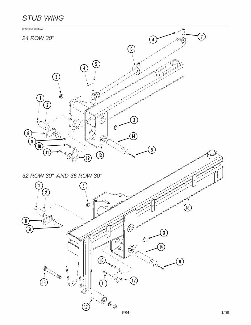
P84 1/08
STUB WING(FWD13/FWD47a)
24 ROW 30"
32 ROW 30" AND 36 ROW 30"
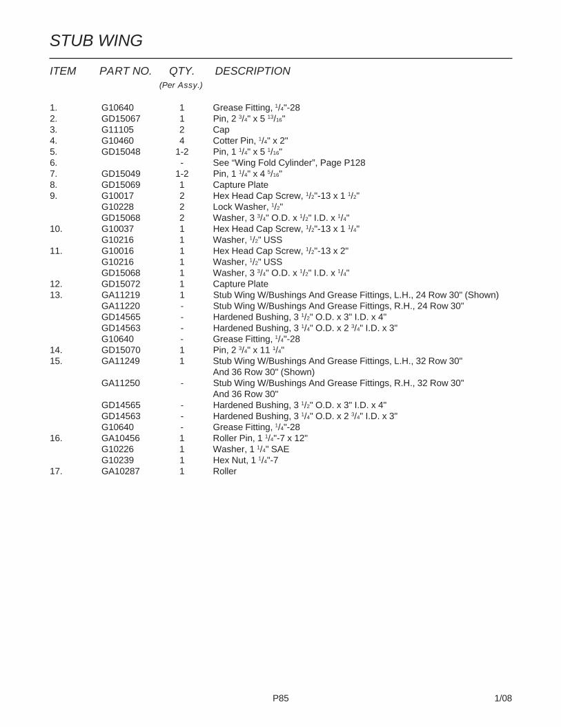
P85 1/08
STUB WING
ITEM PART NO. QTY. DESCRIPTION(Per Assy.)
1. G10640 1 Grease Fitting, 1/4"-282. GD15067 1 Pin, 2 3/4" x 5 13/16"3. G11105 2 Cap4. G10460 4 Cotter Pin, 1/4" x 2"5. GD15048 1-2 Pin, 1 1/4" x 5 1/16"6. - See “Wing Fold Cylinder”, Page P1287. GD15049 1-2 Pin, 1 1/4" x 4 5/16"8. GD15069 1 Capture Plate9. G10017 2 Hex Head Cap Screw, 1/2"-13 x 1 1/2"
G10228 2 Lock Washer, 1/2"GD15068 2 Washer, 3 3/4" O.D. x 1/2" I.D. x 1/4"
10. G10037 1 Hex Head Cap Screw, 1/2"-13 x 1 1/4"G10216 1 Washer, 1/2" USS
11. G10016 1 Hex Head Cap Screw, 1/2"-13 x 2"G10216 1 Washer, 1/2" USSGD15068 1 Washer, 3 3/4" O.D. x 1/2" I.D. x 1/4"
12. GD15072 1 Capture Plate13. GA11219 1 Stub Wing W/Bushings And Grease Fittings, L.H., 24 Row 30" (Shown)
GA11220 - Stub Wing W/Bushings And Grease Fittings, R.H., 24 Row 30"GD14565 - Hardened Bushing, 3 1/2" O.D. x 3" I.D. x 4"GD14563 - Hardened Bushing, 3 1/4" O.D. x 2 3/4" I.D. x 3"G10640 - Grease Fitting, 1/4"-28
14. GD15070 1 Pin, 2 3/4" x 11 1/4"15. GA11249 1 Stub Wing W/Bushings And Grease Fittings, L.H., 32 Row 30"
And 36 Row 30" (Shown)GA11250 - Stub Wing W/Bushings And Grease Fittings, R.H., 32 Row 30"
And 36 Row 30"GD14565 - Hardened Bushing, 3 1/2" O.D. x 3" I.D. x 4"GD14563 - Hardened Bushing, 3 1/4" O.D. x 2 3/4" I.D. x 3"G10640 - Grease Fitting, 1/4"-28
16. GA10456 1 Roller Pin, 1 1/4"-7 x 12"G10226 1 Washer, 1 1/4" SAEG10239 1 Hex Nut, 1 1/4"-7
17. GA10287 1 Roller

P86 1/08
(FWD63/FWD63a)
L.H. Wing
R.H. Wing
OUTER WING, 24 ROW 30"
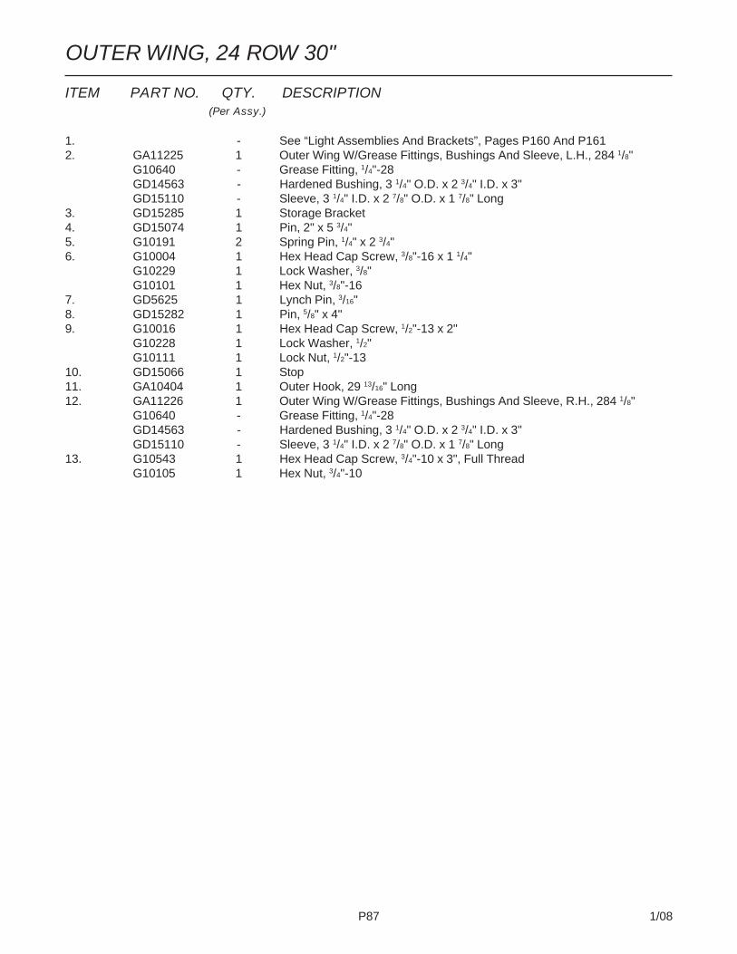
P87 1/08
ITEM PART NO. QTY. DESCRIPTION(Per Assy.)
1. - See “Light Assemblies And Brackets”, Pages P160 And P1612. GA11225 1 Outer Wing W/Grease Fittings, Bushings And Sleeve, L.H., 284 1/8"
G10640 - Grease Fitting, 1/4"-28GD14563 - Hardened Bushing, 3 1/4" O.D. x 2 3/4" I.D. x 3"GD15110 - Sleeve, 3 1/4" I.D. x 2 7/8" O.D. x 1 7/8" Long
3. GD15285 1 Storage Bracket4. GD15074 1 Pin, 2" x 5 3/4"5. G10191 2 Spring Pin, 1/4" x 2 3/4"6. G10004 1 Hex Head Cap Screw, 3/8"-16 x 1 1/4"
G10229 1 Lock Washer, 3/8"G10101 1 Hex Nut, 3/8"-16
7. GD5625 1 Lynch Pin, 3/16"8. GD15282 1 Pin, 5/8" x 4"9. G10016 1 Hex Head Cap Screw, 1/2"-13 x 2"
G10228 1 Lock Washer, 1/2"G10111 1 Lock Nut, 1/2"-13
10. GD15066 1 Stop11. GA10404 1 Outer Hook, 29 13/16" Long12. GA11226 1 Outer Wing W/Grease Fittings, Bushings And Sleeve, R.H., 284 1/8"
G10640 - Grease Fitting, 1/4"-28GD14563 - Hardened Bushing, 3 1/4" O.D. x 2 3/4" I.D. x 3"GD15110 - Sleeve, 3 1/4" I.D. x 2 7/8" O.D. x 1 7/8" Long
13. G10543 1 Hex Head Cap Screw, 3/4"-10 x 3", Full ThreadG10105 1 Hex Nut, 3/4"-10
OUTER WING, 24 ROW 30"
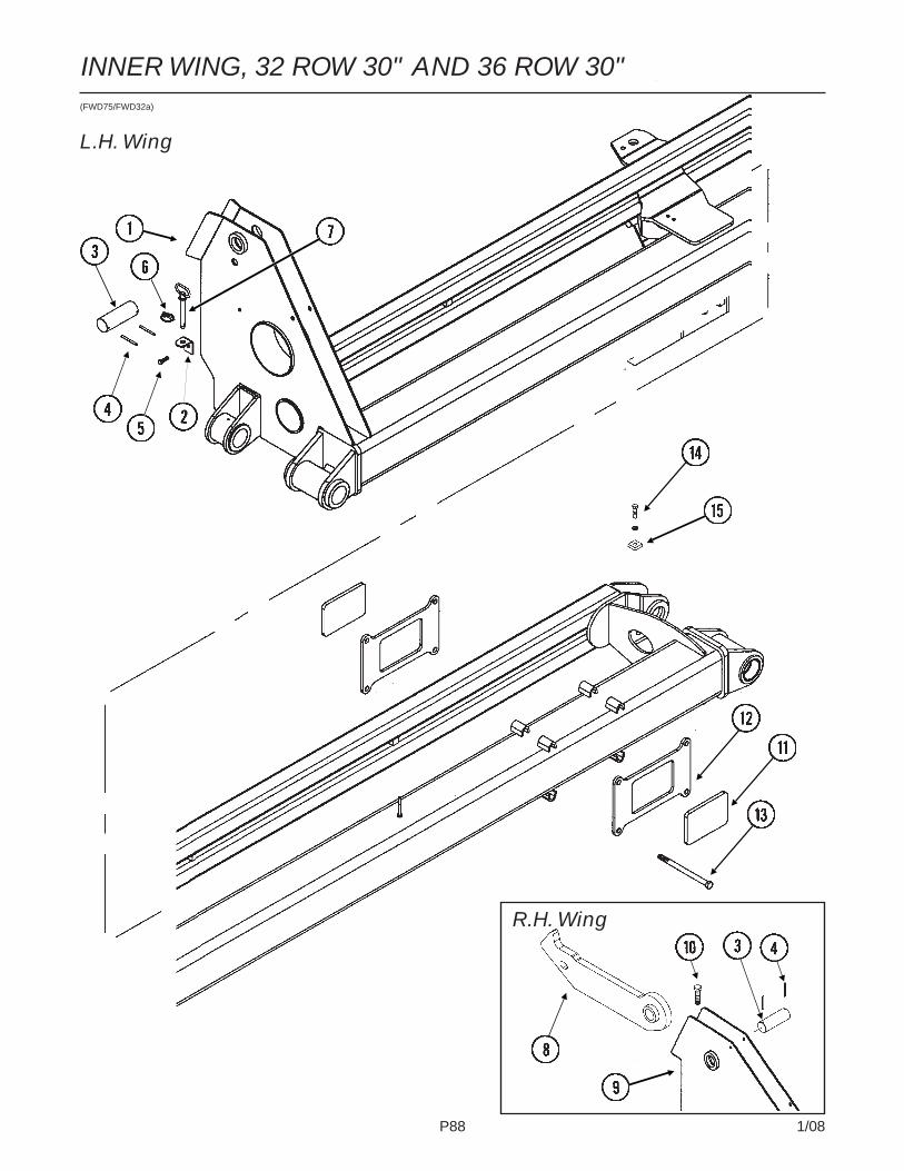
P88 1/08
INNER WING, 32 ROW 30" AND 36 ROW 30"(FWD75/FWD32a)
L.H. Wing
R.H. Wing

P89 1/08
ITEM PART NO. QTY. DESCRIPTION(Per Assy.)
1. GA11307 1 Inner Wing W/Grease Fittings, Bushings, Spacer And Sleeve,L.H., 209 5/8", 32 Row 30"
GA11323 - Inner Wing W/Grease Fittings, Bushings, Spacer And Sleeve,L.H., 209 5/8", 36 Row 30"
G10640 - Grease Fitting, 1/4"-28GD14564 - Hardened Bushing, 2 3/4" O.D. x 2 1/4" I.D. x 4 1/2"GD15109 - Spacer, 2 3/4" O.D. x 2 3/8" I.D. x 2 3/8"GD14562 - Hardened Bushing, 2 3/4" O.D. x 2 1/4" I.D. x 3"GD15110 - Sleeve, 3 1/4" O.D. x 2 7/8" I.D. x 1 7/8" LongGD14563 - Hardened Bushing, 3 1/4" O.D. x 2 3/4" I.D. x 3"
2. GD15285 1 Storage Bracket3. GD15074 1 Pin, 2" x 5 3/4"4. G10191 2 Spring Pin, 1/4" x 2 3/4"5. G10004 1 Hex Head Cap Screw, 3/8"-16 x 1 1/4"
G10229 1 Lock Washer, 3/8"G10101 1 Hex Nut, 3/8"-16
6. GD5625 1 Lynch Pin, 3/16"7. GD15282 1 Pin, 5/8" x 4"8. GA10378 1 Inner Hook, 29 1/4" Long9. GA11308 - Inner Wing W/Grease Fittings, Bushings, Spacer And Sleeve,
R.H., 209 5/8", 32 Row 30"GA11324 - Inner Wing W/Grease Fittings, Bushings, Spacer And Sleeve,
R.H., 209 5/8", 36 Row 30"G10640 - Grease Fitting, 1/4"-28GD14564 - Hardened Bushing, 2 3/4" O.D. x 2 1/4" I.D. x 4 1/2"GD15109 - Spacer, 2 3/4" O.D. x 2 3/8" I.D. x 2 3/8" (If Applicable)GD14562 - Hardened Bushing, 2 3/4" O.D. x 2 1/4" I.D. x 3" (If Applicable)GD17450 - Hardened Bushing, 2 3/4" O.D. x 2 1/4" I.D. x 4 3/16" (If Applicable)GD15110 - Sleeve, 3 1/4" O.D. x 2 7/8" I.D. x 1 7/8" LongGD14563 - Hardened Bushing, 3 1/4" O.D. x 2 3/4" I.D. x 3"
10. G10543 1 Hex Head Cap Screw, 3/4"-10 x 3", Full ThreadG10105 1 Hex Nut, 3/4"-10
11. GD15720 2 Bronze Pad, 5" x 7 1/2"12. GD15719 2 Capture Plate13. G10152 4 Hex Head Cap Screw, 5/8"-11 x 9"
G10217 4 Washer, 5/8" USSG10107 4 Lock Nut, 5/8"-11
14. G10016 1 Hex Head Cap Screw, 1/2"-13 x 2"G10228 1 Lock Washer, 1/2"G10111 1 Lock Nut, 1/2"-13
15. GD15066 1 Stop
INNER WING, 32 ROW 30" AND 36 ROW 30"
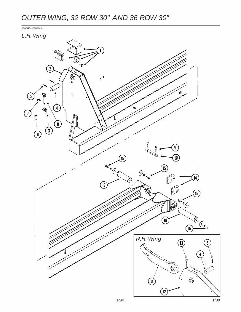
P90 1/08
(FWD48aa/FWD49)
L.H. Wing
R.H. Wing
OUTER WING, 32 ROW 30" AND 36 ROW 30"

P91 1/08
OUTER WING, 32 ROW 30" AND 36 ROW 30"
ITEM PART NO. QTY. DESCRIPTION(Per Assy.)
1. - See “Light Assemblies And Brackets”, Pages P148 And P1492. GA10353 1 Outer Wing W/Grease Fittings, Bushings And Sleeve, L.H.,
194 1/2", 32 Row 30"GA10413 1 Outer Wing W/Grease Fittings, Bushings And Sleeve, L.H.,
254 1/2", 36 Row 30"G10640 - Grease Fitting, 1/4"-28GD14563 - Hardened Bushing, 3 1/4" O.D. x 2 3/4" I.D. x 3"GD15110 - Sleeve, 3 1/4" O.D. x 2 7/8" I.D. x 1 7/8" Long
3. GD15285 1 Storage Bracket4. GD15074 1 Pin, 2" x 5 3/4"5. G10191 2 Spring Pin, 1/4" x 2 3/4"6. G10004 1 Hex Head Cap Screw, 3/8"-16 x 1 1/4"
G10229 1 Lock Washer, 3/8"G10101 1 Hex Nut, 3/8"-16
7. GD5625 1 Lynch Pin, 3/16"8. GD15282 1 Pin, 5/8" x 4"9. G10016 2 Hex Head Cap Screw, 1/2"-13 x 2"
G10228 2 Lock Washer, 1/2"G10111 2 Lock Nut, 1/2"-13
10. GD15065 1 Capture Plate11. GA10743 - Outer Hook, 29 15/16" Long12. GA10352 1 Outer Wing W/Grease Fittings, Bushings And Sleeve, R.H.,
194 1/2", 32 Row 30"GA10414 1 Outer Wing W/Grease Fittings, Bushings And Sleeve, R.H.,
254 1/2", 36 Row 30"G10640 - Grease Fitting, 1/4"-28GD14563 - Hardened Bushing, 3 1/4" O.D. x 2 3/4" I.D. x 3"GD15110 - Sleeve, 3 1/4" O.D. x 2 7/8" I.D. x 1 7/8" Long
13. G10543 1 Hex Head Cap Screw, 3/4"-10 x 3", Full ThreadG10105 1 Hex Nut, 3/4"-10
14. GD15064 2 Capture Plate15. G10026 4 Hex Head Cap Screw, 3/4"-10 x 2"
G10231 4 Lock Washer, 3/4"GD17180 4 Washer, 3 1/2" O.D. x 13/16" I.D. x 3/8"
16. GA12128 1 Pin, 2 1/4" x 11 1/8"17. GA12127 1 Pin, 2 1/4" x 7 1/8"

P92 1/08
DRAFT LINK(FWD129/D16890/FWD16aaa/FWD128/FWD74)
SDS Only

P93 1/08
ITEM PART NO. QTY. DESCRIPTION(Per Assy.)
1. GA11015 1 Draft Link, L.H., 202 3/8", 24 Row 30"GA11016 1 Draft Link, R.H., 202 3/8", 24 Row 30"GA11025 1 Draft Link, L.H., 277", 32 Row 30"GA11026 1 Draft Link, R.H., 277", 32 Row 30"GA11027 1 Draft Link, L.H., 314 1/8", 36 Row 30"GA11028 1 Draft Link, R.H., 314 1/8", 36 Row 30"
2. GA10276 1 Pin, 3 5/8"3. G10014 1 Hex Head Cap Screw, 1/2"-13 x 1"
G10228 1 Lock Washer, 1/2"4. G10039 1 Hex Head Cap Screw, 1/2"-13 x 1 3/4"
G10228 1 Lock Washer, 1/2"G10102 1 Hex Nut, 1/2"-13
5. GA10277 1 Pin, 4"6. GA10275 1 Link Yoke7. G10640 1 Grease Fitting, 1/4"-288. GA10278 1 Pin, 6"9. G10039 1 Hex Head Cap Screw, 1/2"-13 x 1 3/4"
G10228 1 Lock Washer, 1/2"GD15235 1 Washer, 2 1/4" O.D. x 1/2" I.D. x 1/4"
10. G10585 - Hex Head Cap Screw, 1/2"-13 x 3 1/4"G10111 - Lock Nut, 1/2"-13
11. GD0740 - Hose Clamp, 3/4" x 4" x 3 1/2"12. GD8188 - Hose Clamp, 7/8" x 3" x 5 3/8"13. GA11667 1 Hose Tube, 168", 24 Row 30" SDS
GA11669 1 Hose Tube, 111", 36 Row 30" SDSGA11670 1 Hose Tube, 287 3/4", 36 Row 30" SDS
14. GD16887 2-4 Support15. G10301 8 Carriage Bolt, 3/8"-16 x 1 1/2"
G10210 8 Washer, 3/8" USSG10108 8 Lock Nut, 3/8"-16
16. GD16890 - Clamp17. G10599 - Carriage Bolt, 3/8"-16 x 1 1/4"
G10622 - Serrated Flange Nut, 3/8"-16
DRAFT LINK

P94 1/08
LIFT/GAUGE WHEEL(FWD64)

P95 1/08
LIFT/GAUGE WHEEL
ITEM PART NO. QTY. DESCRIPTION(Per Assy.)
1. G10009 2 Hex Head Cap Screw, 5/8"-11 x 2 1/2"G10230 2 Lock Washer, 5/8"G10104 2 Hex Nut, 5/8"-11
2. GA5122 1 Wheel Tower Clamp3. G10008 4 Hex Head Cap Screw, 5/8"-11 x 2"
GD7805 6 Special Washer, 5/8", HardenedG10230 4 Lock Washer, 5/8"G10104 4 Hex Nut, 5/8"-11
4. - See “Master/Slave/Lift Assist Cylinders”, Pages P123-P1275. GD5841 1 Pin, 1 1/4" x 5 5/8"
G10460 2 Cotter Pin, 1/4" x 2"6. GA7376 1 Scraper Mount7. GD12543 1 Scraper8. G11081 2 Hex Jam Nut, 1 1/2"-12, Grade 29. GA0895 2 Bearing10. GA2148 1 Hub W/Cups, 6 Bolt
GR0434 - Cup11. GR0270 6 Lug Bolt, 9/16"-1812. GA2558 1 Spindle W/Round External Retaining Ring, 9 1/2"
GD11490 - Round External Retaining Ring13. GD13401 - Tire, 7.50" x 20", 8 Ply, Tubeless W/O Center Rib (Specify Brand*)14. GA2142 1 Rim, 5.50" x 20"15. GA7434 1 Valve Stem16. G10025 2 Hex Head Cap Screw, 3/4"-10 x 1 1/2"
G10231 2 Lock Washer, 3/4"G10105 2 Hex Nut, 3/4"-10
17. G10026 2 Hex Head Cap Screw, 3/4"-10 x 2"G10231 2 Lock Washer, 3/4"
18. G10636 4 Carriage Bolt, 1/2"-13 x 1 1/2"G10228 4 Lock Washer, 1/2"G10216 4 Washer, 1/2" USSG10102 4 Hex Nut, 1/2"-13
19. G10139 2 Washer, 1 1/4" USS20. G10159 - Machine Bushing, 1 1/4", 10 Gauge (As Required)21. G10581 2 Hex Head Cap Screw, 1/2"-13 x 2 1/4"
G10111 2 Lock Nut, 1/2"-1322. GA5121 2 Pin, 2 1/8"23. GA11276 1 Arm24. GD11695 1 Pin, 1 1/4" x 13 1/4"25. G10610 2 Spring Pin, 3/8" x 2"26. GA9877 1 Clamp W/Grease Fittings
G10640 2 Grease Fitting, 1/4"-28
A. GA2147 - Hub And Spindle Assembly (Items 8-10 And 12)B. GA7409 - Scraper Assembly (Items 6, 7, 16 And 18)
* Specific brand requests will be supplied only as available from current KINZE® Repair Parts stock. If a specific brandrequested is not in stock, the brand available will be supplied.

P96 1/08
CONTACT WHEEL, ARM AND TOWER ASSEMBLIES(FWD65)
ITEM PART NO. QTY. DESCRIPTION(Per Assy.)
1. GA11281 1 Tower, Inner Module On 24 Row 30"/Inner And Center Module On32 Row 30" And 36 Row 30"
2. GA11280 1 Tower, Center Module On 24 Row 30"/Outer Module On 32 Row 30"And 36 Row 30"
3. GA11279 1 Tower, Outer Module On 24 Row 30" Only4. G3400-01 - Flangette5. G2100-03 - Bearing, 7/8" Hex Bore, Spherical6. G10303 - Carriage Bolt, 5/16"-18 x 1"
G10232 - Lock Washer, 5/16"G10106 - Hex Nut, 5/16"-18
7. G10233 - Machine Bushing, 1", 10 Gauge8. GA10173 3 Ratchet/Sprocket Assembly, L.H.
GD1256 2 SpringG10453 2 Cotter Pin, 3/16" x 1"GA0378 1 Block And Hub AssemblyGD1255 2 L-PinGA7572 1 Sprocket, 34 ToothG10430 1 External Retaining Ring, 1 1/4"
9. GD11045 - Lock Clamp10. G10130 - Square Head Machine Bolt, 5/16"-18 x 1 3/4"
G10923 - Flange Nut, 5/16"-18, No Serration11. GD2548-93 1 Hex Shaft, 7/8" x 93", L.H. Side (1 Hole)
GD2548-104 - Hex Shaft, 7/8" x 104", R.H. Side (1 Hole)12. GD15532 1 Bronze Bushing, 1"

P97 1/08
ITEM PART NO. QTY. DESCRIPTION(Per Assy.)
13. GD15538 1 Spacer, 3/8" I.D. x 7/8" O.D., 7 Gauge14. GA11287 1 Idler W/Sprockets, Sleeves And Hardware
GD7426 2 Sprocket, 12 ToothGD1026 2 Sleeve, 1 3/16" LongG10047 2 Hex Head Cap Screw, 3/8"-16 x 1 3/4"G10210 2 Washer, 3/8" USSG10229 2 Lock Washer, 3/8"
15. G11119 1 Carriage Bolt, 3/8"-16 x 2 1/4"G10203 1 Washer, 3/8" SAEG10108 1 Lock Nut, 3/8"-16
16. G11118 1 Clevis Pin, 3/8" x 3/4"G10860 1 Retaining Ring, 3/8"
17. GD5857 1 Spring18. G10939 1 Hex Head Cap Screw, 3/8"-16 x 2 1/4"
G10210 1 Washer, 3/8" USSG10101 1 Hex Nut, 3/8"-16G10108 1 Lock Nut, 3/8"-16
19. G10953 1 Hex Head Cap Screw, 5/8"-11 x 10"G10235 6 Machine Bushing, 7/8", 14 GaugeGD7805 2 Special Washer, 5/8", HardenedG10107 1 Lock Nut, 5/8"-11
20. GB0218 2 Bushing, 21/32" I.D. x 7/8" O.D. x 19/32" Long21. G10004 7 Hex Head Cap Screw, 3/8"-16 x 1 1/4"
G10229 7 Lock Washer, 3/8"G10101 7 Hex Nut, 3/8"-16
22. GD16438 1 Shim23. GD16437 1 Shim24. GA7372 1 Wheel Arm25. GA2068 2 Spring W/Plug26. G10602 2 Spring Pin, 1/4" x 1 1/2"27. GD6775 1 Hex Shaft, 7/8" x 11 3/4" (2 Holes)28. GA9846 - Flanged Bearing, 7/8" Hex Bore29. GD4700 1 Tire, 4.80" x 8", 4 Ply, Rib Implement (Specify Brand*)30. GA3553 1 Rim, 3.75" x 8"31. GD4701 - Valve Stem32. G10890 2 Hex Head Adjusting Bolt, 1/2"-13 x 4", Grade 2
G10501 2 Hex Jam Nut, 1/2"-13, Grade 233. GA5105 1 Sprocket, 15 Tooth
GA5107 1 Sprocket, 19 ToothGA11285 1 Sprocket, 38 Tooth
34. GD2558 1 Lynch Pin, 1/4"35. G3310-160 1 Chain, No. 40, 160 Pitch Including Connector Link
(Used With 15 And 19 Tooth Sprockets)G3310-168 1 Chain, No. 40, 168 Pitch Including Connector Link
(Used With 38 Tooth Sprocket)GR0912 - Connector Link, No. 40
A. G1K324 - Contact Wheel Arm Replacement Kit, (Items 6, 7, 24, 26-28, 32 And 34)B. GA3552 - Tire And Rim Assembly (Items 29-31)
* Specific brand requests will be supplied only as available from current KINZE® Repair Parts stock. If a specific brandrequested is not in stock, the brand available will be supplied. Different brand tires may have different diameters.Change in tire brand may affect rates. Field checks are recommended after any change in contact tires.
CONTACT WHEEL, ARM AND TOWER ASSEMBLIES

P98 1/08
CONTACT WHEEL, ARM AND TOWER ASSEMBLIES(When Using G1K472 Sunflower Rate Reduction Kit)(FWD65a)
ITEM PART NO. QTY. DESCRIPTION(Per Assy.)
1. GA11281 1 Tower, Inner Module On 24 Row 30"/Inner And Center Module On32 Row 30" And 36 Row 30"
2. GA11280 1 Tower, Center Module On 24 Row 30"/Outer Module On 32 Row 30"And 36 Row 30"
3. GA11279 1 Tower, Outer Module On 24 Row 30" Only4. G3400-01 - Flangette5. G2100-03 - Bearing, 7/8" Hex Bore, Spherical6. G10303 - Carriage Bolt, 5/16"-18 x 1"
G10232 - Lock Washer, 5/16"G10106 - Hex Nut, 5/16"-18
7. G10233 - Machine Bushing, 1", 10 Gauge8. GA10173 3 Ratchet/Sprocket Assembly, L.H.
GD1256 2 SpringG10453 2 Cotter Pin, 3/16" x 1"GA0378 1 Block And Hub AssemblyGD1255 2 L-PinGA7572 1 Sprocket, 34 ToothG10430 1 External Retaining Ring, 1 1/4"
9. GD11045 - Lock Clamp10. G10130 - Square Head Machine Bolt, 5/16"-18 x 1 3/4"
G10923 - Flange Nut, 5/16"-18, No Serration11. GD2548-93 1 Hex Shaft, 7/8" x 93", L.H. Side (1 Hole)
GD2548-104 - Hex Shaft, 7/8" x 104", R.H. Side (1 Hole)12. GD15532 1 Bronze Bushing, 1"13. GD15538 1 Spacer, 3/8" I.D. x 7/8" O.D., 7 Gauge

P99 1/08
ITEM PART NO. QTY. DESCRIPTION(Per Assy.)
* Specific brand requests will be supplied only as available from current KINZE® Repair Parts stock. If a specific brandrequested is not in stock, the brand available will be supplied. Different brand tires may have different diameters.Change in tire brand may affect rates. Field checks are recommended after any change in contact tires.
CONTACT WHEEL, ARM AND TOWER ASSEMBLIES(When Using G1K472 Sunflower Rate Reduction Kit)

P100 1/08
SEED RATE TRANSMISSION(FWD66/FWD70)
ITEM PART NO. QTY. DESCRIPTION(Per Assy.)
1. GA11297 1 Transmission Plate W/Grease FittingsG10640 2 Grease Fitting, 1/4"-28
2. GD8175 2 U-Bolt, 7" x 7" (Diamond) x 5/8"-11GD7805 4 Special Washer, 5/8", HardenedG10230 8 Lock Washer, 5/8"G10104 8 Hex Nut, 5/8"-11
3. - See “Contact Drive Wheel, Arm And Tower Assemblies”,Pages P94 And P95
4. G10049 1 Hex Head Cap Screw, 3/8"-16 x 2 1/2"G10101 2 Hex Nut, 3/8"-16
5. GD5857 1 Spring6. G10303 3 Carriage Bolt, 5/16"-18 x 1"
G10232 3 Lock Washer, 5/16"G10106 3 Hex Nut, 5/16"-18
L.H. SIDE SHOWN

P101 1/08
SEED RATE TRANSMISSION
ITEM PART NO. QTY. DESCRIPTION(Per Assy.)
7. G3400-01 2 Flangette8. G2100-03 1 Bearing, 7/8" Hex Bore, Spherical9. G100581 1 Hex Head Cap Screw, 1/2"-13 x 2 1/4"
G10527 2 Lock Washer, 1/2", Internal/ExternalGD10356 1 Bushing, 3/4" LongG10111 1 Lock Nut, 1/2"-13
10. GA11245 1 Sprocket Storage Rod11. GD2558 3 Lynch Pin, 1/4"12. GD16449 1 Cover13. G10063 1 Hex Head Cap Screw, 3/8"-16 x 4"
G10108 1 Lock Nut, 3/8"-1614. G10581 1 Hex Head Cap Screw, 1/2"-13 x 2 1/4"
G10206 3 Washer, 1/2" SAEG10111 1 Lock Nut, 1/2"-13
15. GD16446 1 Idler Plate16. GA11244 2 Idler Sprocket, 17 Tooth17. GD16440 1 Shoulder Bolt, 1/2" x 3/8"-16 x 1"18. G10233 - Machine Bushing, 1", 10 Gauge (As Required)19. GA11235 1 Sprocket, 14 Tooth
GA11236 1 Sprocket, 15 ToothGA11237 1 Sprocket, 17 ToothGA11238 1 Sprocket, 19 ToothGA11239 2 Sprocket, 23 ToothGA11240 1 Sprocket, 24 ToothGA11241 1 Sprocket, 25 ToothGA11242 1 Sprocket, 26 ToothGA11243 1 Sprocket, 27 Tooth
20. GA11394 1 Cylindrical Bearing21. GD7127 1 Shear Coupler22. G10069 1 Hex Head Cap Screw, 5/16"-18 x 2 1/4"
G10109 1 Lock Nut, 5/16"-18, Grade 823. G3316-80 1 Chain, No. 50, 80 Pitch Including Connector Link
GR1743 - Connector Link, No. 5024. GD16448 1 Shaft, 8 1/4"25. GD16447 1 Shaft, 14"26. G11103 1 Spring Pin, 1/4" x 1 3/4"27. GD16370 2 Gear, 18 Tooth28. GA5116 3 Bearing, 7/8" Hex Bore, Cylindrical29. G11075 2 External Inverted Snap Ring, 7/8"30. GD14432 1 Sleeve, 1 1/4"31. GD14414 1 Torsion Spring, R.H. (Used On L.H. Wrap Spring Wrench)
GD14413 - Torsion Spring, L.H. (Used On R.H. Wrap Spring Wrench) (Shown)32. GD14429 - Release Collar, Silver, L.H.
GD14430 1 Release Collar, Gold, R.H. (Shown)33. GD16439 1 Tightener Shaft, 7 5/16"34. GD14431 1 Handle35. G10496 2 External Inverted Snap Ring, 1 1/2"36. G11078 1 Vinyl Cap37. G10235 8 Machine Bushing, 7/8", 14 Gauge
A. GA11311 - Wrap Spring Wrench Assembly, Silver Collar, L.H. (Items 29-35)GA11312 1 Wrap Spring Wrench Assembly, Gold Collar, R.H. (Items 29-35) (Shown)

P102 1/08
DRIVEN AND DRILL SHAFTS ON WINGS, 24 ROW 30"(FWD147)
L.H. SIDE SHOWN
ITEM PART NO. QTY. DESCRIPTION
1. GA5106 4 Sprocket, 17 Tooth2. - See “Seed Rate Transmission”, Pages P100 And P1013. G10233 - Machine Bushing, 1", 10 Gauge4. GD11045 - Lock Clamp5. G10130 - Square Head Machine Bolt, 5/16"-18 x 1 3/4"
G10923 - Flange Nut, 5/16"-18, No Serration6. GD16417 2 Bracket7. - See “Point Row Clutches”, Pages P110 And P1118. G10001 4 Hex Head Cap Screw, 3/8"-16 x 1"
G10108 4 Lock Nut, 3/8"-169. GD0914-46 1 Hex Shaft, 7/8" x 46" (No Holes), L.H. Side
GD0914-30 - Hex Shaft, 7/8" x 30" (No Holes), R.H. Side10. GD0914-13.5 1 Hex Shaft, 7/8" x 13 1/2" (No Holes), L.H. Side
GD0914-21 - Hex Shaft, 7/8" x 21" (No Holes), R.H. Side

P103 1/08
ITEM PART NO. QTY. DESCRIPTION
11. GD10126 4 Coupler, 4"12. GA5202 4 Sprocket, 34 Tooth13. G3310-108 4 Chain, No. 40, 108 Pitch Including Connector Link
GR0912 - Connector Link, No. 4014. GD0914-156 2 Hex Shaft, 7/8" x 156" (No Holes)15. GD0914-108.5 2 Hex Shaft, 7/8" x 108 1/2" (No Holes)16. G10017 2 Hex Head Cap Screw, 1/2"-13 x 1 1/2"
G10216 2 Washer, 1/2" USSG10228 2 Lock Washer, 1/2"G10111 2 Lock Nut, 1/2"-13
17. GD1114 8 U-Bolt, 7" x 7" x 5/8"-11G10230 8 Lock Washer, 5/8"G10104 8 Hex Nut, 5/8"-11
18. GD18080 1 Flangette19. GD0914-68 2 Hex Shaft, 7/8" x 68" (No Holes)20. GA11258 2 Chain Mount W/Bearings And Rings
GA5116 - Bearing, 7/8" Hex Bore, CylindricalGD6551 - Ring
21. GD16405 2 Shaft, 7/8" x 11" (1 Hole)22. G10007 3 Hex Head Cap Screw, 5/8"-11 x 1 1/2"
G10107 2 Lock Nut, 5/8"-1123. GD15114 1 Hex Shaft Spacer24. G10053 2 Hex Head Cap Screw, 1/2"-13 x 2 1/2"
GD10356 2 Bushing, 3/4" LongG10111 2 Lock Nut, 1/2"-13
25. GA7154 2 Sprocket W/Bearing, 18 Tooth26. GD18079 1 Mount27. GD18082 1 Brace28. G10062 2 Hex Head Cap Screw, 3/8"-16 x 3"
G10108 2 Lock Nut, 3/8"-16G10101 2 Hex Nut, 3/8"-16
29. G10047 1 Hex Head Cap Screw, 3/8"-16 x 1 3/4"G10101 1 Hex Nut, 3/8"-16
30. G10016 2 Hex Head Cap Screw, 1/2"-13 x 2"GD10356 4 Bushing, 3/4" LongG10206 4 Washer, 1/2" SAEG10111 2 Lock Nut, 1/2"-13
31. GD17051 2 Idler32. G10560 2 Clevis Pin, 1/2" x 1 3/4"
G10456 2 Cotter Pin, 1/8" x 3/4"33. GD5857 2 Spring34. GD17095 1 Bar, 21", L.H.
GD17094 - Bar, 19 3/4", R.H.35. G10007 2 Hex Head Cap Screw, 5/8"-11 x 1 1/2"
G10230 2 Lock Washer, 5/8"G10104 2 Hex Nut, 5/8"-11
36. GA11964 2 Mount37. G10003 2 Hex Head Cap Screw, 3/8"-16 x 1 1/2"
G10229 2 Lock Washer, 3/8"G10101 2 Hex Nut, 3/8"-16
38. G2100-03 1 Bearing, 7/8" Hex Bore, Spherical39. G3400-01 2 Flangette40. G10303 3 Carriage Bolt, 5/16"-18 x 1"
G10232 3 Lock Washer, 5/16"G10106 3 Hex Nut, 5/16"-18
DRIVEN AND DRILL SHAFTS ON WINGS, 24 ROW 30"

P104 1/08
DRIVEN AND DRILL SHAFTS ON WINGS,32 ROW 30" AND 36 ROW 30"(FWD67aaFWD67a)
L.H. SIDE SHOWN

P105 1/08
ITEM PART NO. QTY. DESCRIPTION
1. GA5106 4 Sprocket, 17 Tooth2. - See “Seed Rate Transmission”, Pages P100 And P1013. G10233 - Machine Bushing, 1", 10 Gauge4. GD11045 - Lock Clamp5. G10130 - Square Head Machine Bolt, 5/16"-18 x 1 3/4"
G10923 - Flange Nut, 5/16"-18, No Serration6. GD16417 2 Bracket7. - See “Point Row Clutches”, Pages P110 And P1118. G10001 4 Hex Head Cap Screw, 3/8"-16 x 1"
G10108 4 Lock Nut, 3/8"-169. GD0914-76 1 Hex Shaft, 7/8" x 76" (No Holes), L.H. Side
GD0914-60 - Hex Shaft, 7/8" x 60" (No Holes), R.H. Side10. GD0914-13.5 1 Hex Shaft, 7/8" x 13 1/2" (No Holes), L.H. Side
GD0914-21 - Hex Shaft, 7/8" x 21" (No Holes), R.H. Side11. GD10126 4 Coupler, 4"12. GA5202 4 Sprocket, 34 Tooth13. G3310-108 4 Chain, No. 40, 108 Pitch Including Connector Link
GR0912 - Connector Link, No. 4014. GD0914-36 1 Hex Shaft, 7/8" x 36" (No Holes), L.H. Side, 32 Row 30"
GD0914-48 - Hex Shaft, 7/8" x 48" (No Holes), R.H. Side, 32 Row 30"GD0914-20 - Hex Shaft, 7/8" x 20" (No Holes), L.H. Side, 36 Row 30"GD0914-36 - Hex Shaft, 7/8" x 36" (No Holes), R.H. Side, 36 Row 30"
15. GD16451 1 Shaft, 7/8" x 56" (1 Hole), L.H. SideGD16450 1 Shaft, 7/8" x 44" (1 Hole), R.H. Side
16. GD16467 1 Bracket, L.H. SideGD16466 - Bracket, R.H. Side
17. GD1114 8 U-Bolt, 7" x 7" x 5/8"-11G10230 8 Lock Washer, 5/8"G10104 8 Hex Nut, 5/8"-11
18. GA11257 1 Support W/Bearings And Rings, L.H. SideGA11256 - Support W/Bearings And Rings, R.H. SideGA5116 - Bearing, 7/8" Hex Bore, CylindricalGD6551 - Ring
19. GD0914-132 2 Hex Shaft, 7/8" x 132" (No Holes), 32 Row 30"GD0914-156 - Hex Shaft, 7/8" x 156" (No Holes), 36 Row 30"
20. GA11258 2 Chain Mount W/Bearings And RingsGA5116 - Bearing, 7/8" Hex Bore, CylindricalGD6551 - Ring
21. GD0914-10.5 1 Hex Shaft, 7/8" x 10 1/2" (No Holes), L.H. SideGD0914-21 - Hex Shaft, 7/8" x 21" (No Holes), R.H. Side
22. G10001 1 Hex Head Cap Screw, 3/8"-16 x 1"G10229 1 Lock Washer, 3/8"
23. GD15114 1 Hex Shaft Spacer24. G10053 2 Hex Head Cap Screw, 1/2"-13 x 2 1/2"
GD10356 2 Bushing, 3/4" LongG10111 2 Lock Nut, 1/2"-13
(Continued On Following Page)
DRIVEN AND DRILL SHAFTS ON WINGS,32 ROW 30" AND 36 ROW 30"

P106 1/08
ITEM PART NO. QTY. DESCRIPTION
25. GA7154 2 Sprocket W/Bearing, 18 Tooth26. GD16362 2 Plate27. G10016 2 Hex Head Cap Screw, 1/2"-13 x 2"
GD10356 4 Bushing, 3/4" LongG10527 4 Lock Washer, 1/2", Internal/ExternalG10111 2 Lock Nut, 1/2"-13
28. G10062 2 Hex Head Cap Screw, 3/8"-16 x 3"G10108 2 Lock Nut, 3/8"-16G10101 2 Hex Nut, 3/8"-16
29. G10047 1 Hex Head Cap Screw, 3/8"-16 x 1 3/4"G10101 1 Hex Nut, 3/8"-16
30. GD0914-166 1 Hex Shaft, 7/8" x 166" (No Holes), L.H. Side, 32 Row 30"GD0914-156 - Hex Shaft, 7/8" x 156" (No Holes), R.H. Side, 32 Row 30"GD0914-228 - Hex Shaft, 7/8" x 228" (No Holes), L.H. Side, 36 Row 30"GD0914-218 - Hex Shaft, 7/8" x 218" (No Holes), R.H. Side, 36 Row 30"
31. - See “Parallel Arms, Mounting Support Plate And Quick AdjustableDown Force Springs”, Page P10
32. GA7051 2 U-Joint W/Grease Fitting, Male, 12 1/4" LongGR1557 - Grease Fitting, 45°, MetricGR1296 - Inner ProfileGR1295 - Inboard YokeGR1301 - Spring Pin, 8 mm x 50 mmGR1294 - Cross And Bearing KitGR1293 - Yoke, 7/8" Hex
33. G10688 4 Square Head Set Screw, 3/8"-16 x 5/8"34. GA7052 2 U-Joint W/Grease Fitting, Female, 10 1/4" Long
GR1557 - Grease Fitting, 45°, MetricGR1298 - Inboard Yoke And Outer Profile (18 1/4" U-Joint)GR1297 - Inboard Yoke And Outer Profile (10 1/4" U-Joint)GR1294 - Cross And Bearing KitGR1293 - Yoke, 7/8" Hex
35. G10016 2 Hex Head Cap Screw, 1/2"-13 x 2"GD10356 4 Bushing, 3/4" LongG10206 4 Washer, 1/2" SAEG10111 2 Lock Nut, 1/2"-13
36. GD17051 2 Idler37. G10560 2 Clevis Pin, 1/2" x 1 3/4"38. GD5857 2 Spring39. GD17095 - Bar, 21", L.H.
GD17094 1 Bar, 19 3/4", R.H.40. G10007 2 Hex Head Cap Screw, 5/8"-11 x 1 1/2"
G10230 2 Lock Washer, 5/8"G10104 2 Hex Nut, 5/8"-11
41. GA11964 2 Mount42. G10003 2 Hex Head Cap Screw, 3/8"-16 x 1 1/2"
G10229 2 Lock Washer, 3/8"G10101 2 Hex Nut, 3/8"-16
DRIVEN AND DRILL SHAFTS ON WINGS,32 ROW 30" AND 36 ROW 30"

P107 1/08
This page intentionally left blank.

P108 1/08
(A12114/FWD73c)
L.H. SIDE SHOWN
DRIVEN AND DRILL SHAFTS ON CENTER SECTION
ITEM PART NO. QTY. DESCRIPTION(Per Side)
1. GA11187 1 Mount W/Bearings And Rings, L.H. Side (Shown)GA11186 - Mount W/Bearings And Rings, R.H. SideGA5116 - Bearing, 7/8" Hex Bore, CylindricalGD6551 - Ring
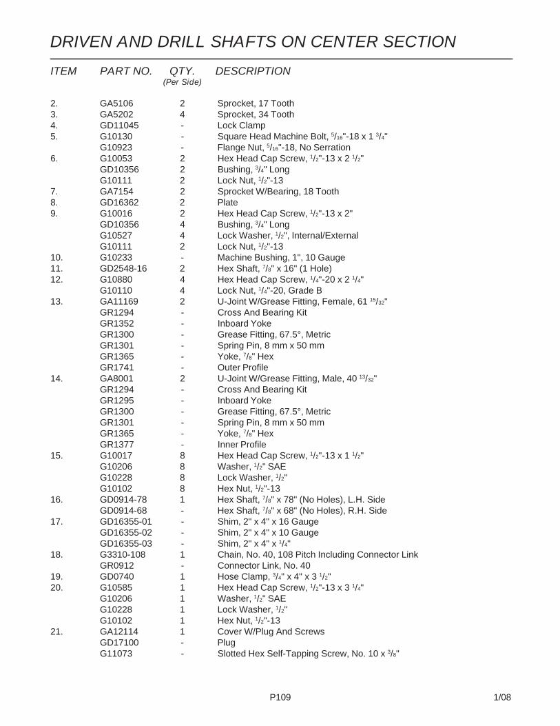
P109 1/08
ITEM PART NO. QTY. DESCRIPTION(Per Side)
2. GA5106 2 Sprocket, 17 Tooth3. GA5202 4 Sprocket, 34 Tooth4. GD11045 - Lock Clamp5. G10130 - Square Head Machine Bolt, 5/16"-18 x 1 3/4"
G10923 - Flange Nut, 5/16"-18, No Serration6. G10053 2 Hex Head Cap Screw, 1/2"-13 x 2 1/2"
GD10356 2 Bushing, 3/4" LongG10111 2 Lock Nut, 1/2"-13
7. GA7154 2 Sprocket W/Bearing, 18 Tooth8. GD16362 2 Plate9. G10016 2 Hex Head Cap Screw, 1/2"-13 x 2"
GD10356 4 Bushing, 3/4" LongG10527 4 Lock Washer, 1/2", Internal/ExternalG10111 2 Lock Nut, 1/2"-13
10. G10233 - Machine Bushing, 1", 10 Gauge11. GD2548-16 2 Hex Shaft, 7/8" x 16" (1 Hole)12. G10880 4 Hex Head Cap Screw, 1/4"-20 x 2 1/4"
G10110 4 Lock Nut, 1/4"-20, Grade B13. GA11169 2 U-Joint W/Grease Fitting, Female, 61 15/32"
GR1294 - Cross And Bearing KitGR1352 - Inboard YokeGR1300 - Grease Fitting, 67.5°, MetricGR1301 - Spring Pin, 8 mm x 50 mmGR1365 - Yoke, 7/8" HexGR1741 - Outer Profile
14. GA8001 2 U-Joint W/Grease Fitting, Male, 40 13/32"GR1294 - Cross And Bearing KitGR1295 - Inboard YokeGR1300 - Grease Fitting, 67.5°, MetricGR1301 - Spring Pin, 8 mm x 50 mmGR1365 - Yoke, 7/8" HexGR1377 - Inner Profile
15. G10017 8 Hex Head Cap Screw, 1/2"-13 x 1 1/2"G10206 8 Washer, 1/2" SAEG10228 8 Lock Washer, 1/2"G10102 8 Hex Nut, 1/2"-13
16. GD0914-78 1 Hex Shaft, 7/8" x 78" (No Holes), L.H. SideGD0914-68 - Hex Shaft, 7/8" x 68" (No Holes), R.H. Side
17. GD16355-01 - Shim, 2" x 4" x 16 GaugeGD16355-02 - Shim, 2" x 4" x 10 GaugeGD16355-03 - Shim, 2" x 4" x 1/4"
18. G3310-108 1 Chain, No. 40, 108 Pitch Including Connector LinkGR0912 - Connector Link, No. 40
19. GD0740 1 Hose Clamp, 3/4" x 4" x 3 1/2"20. G10585 1 Hex Head Cap Screw, 1/2"-13 x 3 1/4"
G10206 1 Washer, 1/2" SAEG10228 1 Lock Washer, 1/2"G10102 1 Hex Nut, 1/2"-13
21. GA12114 1 Cover W/Plug And ScrewsGD17100 - PlugG11073 - Slotted Hex Self-Tapping Screw, No. 10 x 3/8"
DRIVEN AND DRILL SHAFTS ON CENTER SECTION

P110 1/08
POINT ROW CLUTCHES
Connects ToClutch Solenoid
Connects To PlanterHarness At Valve BlockOn Wing
(FWD71/TWL71d/TWL71/TWL18/A10054)
On Point Row Clutch
L.H. POINT ROW CLUTCH SHOWN

P111 1/08
POINT ROW CLUTCHES
ITEM PART NO. QTY. DESCRIPTION(Per Assy.)
1. G10900 1 Hex Socket Head Cap Screw, 1/4"-20 x 1 3/4", Grade 8G10227 1 Lock Washer, 1/4"G10103 2 Hex Nut, 1/4"-20
2. G10496 2 External Inverted Snap Ring, 1 1/2"3. G10253 3 Hex Socket Head Screw, No. 10-32 x 1/2"
G10257 3 Lock Washer, No. 104. GD9667 1 Bushing5. GD10103 1 Mounting Plate6. G10859 1 Spring Pin, 3/16" x 2 1/4"7. GA9068 1 Hex Coupler8. GD11120 1 Rue Ring Cotter, 5/16"9. GD10510 1 Actuator Arm10. G10049 1 Hex Head Cap Screw, 3/8"-16 x 2 1/2"
G10101 1 Hex Nut, 3/8"-16G10203 1 Washer, 3/8" SAEG10229 2 Lock Washer, 3/8"G10497 1 Hex Jam Nut, 3/8"-16, Grade 2
11. GD10123 1 Spring12. GD10104 1 Input Hub13. G10023 1 Hex Head Cap Screw, 1/4"-20 x 3/4"
G10227 1 Lock Washer, 1/4"G10103 1 Hex Nut, 1/4"-20
14. GA8393 1 Solenoid CompleteGR1306 1 Snap RingGR1303 1 SpringGR1304 1 BootGR1305 1 Plunger
15. G10374 3 Hex Socket Head Cap Screw, 1/4"-20 x 1"G10227 3 Lock Washer, 1/4"
16. GD14512 2 V-Ring Seal17. GD14513 1 Felt Washer18. GA7137 1 Hub/Sleeve Assembly W/Spring Pins
G10804 - Spring Pin, 5/32" x 7/8"G10765 - Spring Pin, 1/4" x 1"
19. GD9672 1 Spring, R.H. (Used In GA11268)GD9671 - Spring, L.H. (Used In GA11267)
20. GD10102 1 Stop Collar21. GA10054 - Ground Cable, Green22. GA11361 1 Wiring Harness, 96" (Brown-Black/Red Ends), 24 Row 30" (L.H. Outer PRC)
GA11362 1 Wiring Harness, 96" (Yellow-Black/Red Ends), 24 Row 30", 32 Row 30" And36 Row 30" (L.H. Inner PRC)
GA11363 1 Wiring Harness, 96" (Orange-Black/Red Ends), 24 Row 30", 32 Row 30" And36 Row 30" (R.H. Inner PRC)
GA11364 1 Wiring Harness, 96" (Red/Black-Black/Red Ends), 24 Row 30" (R.H. Outer PRC)GA11619 1 Wiring Harness, 42" (Brown-Black/Red Ends), 32 Row 30" And 36 Row 30"
(L.H. Outer PRC)GA11620 1 Wiring Harness, 36" (Red/Black-Black/Red Ends), 32 Row 30" And 36 Row 30"
(R.H. Outer PRC)23. GD9530 - Contact24. GD9529 - Housing, Black
GD12726 - Housing, Red25. G10996 - Fork Terminal
A. GA11267 - Point Row Clutch Assembly, L.H., (Used On Outer R.H. Wing And Inner)(Items 1-21)
GA11268 - Point Row Clutch Assembly, R.H., (Used On Outer L.H. Wing And Inner)(Items 1-21)

P112 1/08
ROW MARKER SPINDLE/HUB/BLADEMKR020(MKR4)

P113 1/08
ROW MARKER SPINDLE/HUB/BLADE
ITEM PART NO. QTY. DESCRIPTION(Per Assy.)
1. G10722 4 Hex Head Cap Screw, 1/2"-20 x 1"G10228 4 Lock Washer, 1/2"
2. GD2597 1 Retainer3. GD0746 1 Disc Blade, Solid, 16" (Shown)
GD10283 - Disc Blade, Notched, 16" (Optional)4. GD0840 1 Dust Cap5. G10725 1 Slotted Hex Nut, 5/8"-186. G10544 1 Cotter Pin, 5/32" x 1"7. G10724 1 Washer, 5/8" SAE8. GA0257 1 Bearing9. GA0167 1 Hub W/Cups, 4 Bolt
GR0151 - Outer CupGR0150 - Inner Cup
10. GA0245 1 Bearing11. GA0243 1 Grease Seal12. GA0899 1 Rubber Seal13. GA1676 1 Spindle, R.H.
GA1677 - Spindle, L.H. (Shown)14. G10844 2 Carriage Bolt, 1/2"-13 x 3 1/2"
G11162 - Carriage Bolt, 1/2"-13 x 1 3/4"G10168 2 Machine Bushing, 1/2", 7 GaugeG10228 2 Lock Washer, 1/2"G10102 2 Hex Nut, 1/2"-13
15. GA5853 1 Depth Band16. G10019 4 Hex Head Cap Screw, 5/16"-18 x 1"
G10109 4 Lock Nut, 5/16"-18, Grade 8
A. GA1679 - Hub And Spindle Assembly, L.H. (Items 1, 2 And 4-13)GA1678 - Hub And Spindle Assembly, R.H. (Items 1, 2 And 4-13)

P114 1/08
ROW MARKER ASSEMBLY, 24 ROW 30"
ITEM PART NO. QTY. DESCRIPTION(Per Assy.)
1. GD0453-07 1 Extension Tube, 45"2. GA10458 1 Valve Stem3. GD2721 1-3 U-Bolt, 2" x 2" x 1/2"-13
G10228 2-6 Lock Washer, 1/2"G10102 2-6 Hex Nut, 1/2"-13
4. GD0704 1 Pin, 1 1/4" x 14"G10460 2 Cotter Pin, 1/4" x 2"
5. G10033 3 Hex Head Cap Screw, 1/2"-13 x 3 1/2"G10038 - Hex Head Cap Screw, 1/2"-13 x 3"G10581 - Hex Head Cap Screw, 1/2"-13 x 2 1/4"G10111 3 Lock Nut, 1/2"-13
6. GA6860 1 Bracket7. GD10186 1 Pin, 1 1/4" x 9 1/2"
G10979 - Special Washer, 1 1/4" (If Applicable)G10460 2 Cotter Pin, 1/4" x 2"
8. GA8172 1 Safety Lockup W/Detent Pins, 20"G10536 - Detent Pin, 1/2" x 2 1/2" Grip
9. G10047 1 Hex Head Cap Screw, 3/8"-16 x 1 3/4"G10108 1 Lock Nut, 3/8"-16
10. - See “Row Marker Cylinder”, Page P13211. GA6870 1 Arm, First Stage
(FF18h/A10458)
L.H. SIDE SHOWN

P115 1/08
ITEM PART NO. QTY. DESCRIPTION(Per Assy.)
12. GA4031 1 Mount W/Grease FittingsG10640 - Grease Fitting, 1/4"-28
13. GD0677 2 Pin, 2 1/8" x 15 3/4"G10461 4 Cotter Pin, 3/8" x 3"
14. GA12476 1 Tire Support15. GD17967 1 Plate, 7 1/2" x 11 1/4"16. GD16356 2 U-Bolt, 3 1/2" x 3 1/2" x 1/2"-13
G10228 4 Lock Washer, 1/2"G10102 4 Hex Nut, 1/2"-13
17. G10027 8 Hex Head Cap Screw, 3/4"-10 x 2 1/2"G10194 8 Washer, 3/4" SAEG10112 8 Lock Nut, 3/4"-10
18. GD15489 1 Tire, 20.5 x 8.0-10 (Specify Brand*)19. GA10457 1 Rim, 6" x 10"20. G3302-05 1 Coil Chain, No. 9/0, 79 Links21. GD9964 1 Pin, 1 1/4" x 10 1/2"
G10979 - Special Washer, 1 1/4" (If Applicable)G10460 2 Cotter Pin, 1/4" x 2"
22. G10063 8 Hex Head Cap Screw, 3/8"-16 x 4"G10210 - Washer, 3/8" USS (As Required)G10229 8 Lock Washer, 3/8"G10101 8 Hex Nut, 3/8"-16
23. GD0692 2 Mounting Plate, 5" x 4"24. GA0160R 1 Support, R.H.
GA0160L - Support, L.H. (Shown)25. GD0840 1 Dust Cap26. G10544 1 Cotter Pin, 5/32" x 1"27. G10722 4 Hex Head Cap Screw, 1/2"-20 x 1"
G10228 4 Lock Washer, 1/2"28. GA0245 1 Bearing29. GA0243 1 Grease Seal30. GA0899 1 Rubber Seal31. GA0167 1 Hub W/Cups, 4 Bolt
GR0151 - Outer CupGR0150 - Inner Cup
32. GA0257 1 Bearing33. G10724 1 Washer, 5/8" SAE34. G10725 1 Slotted Hex Nut, 5/8"-1835. GD10674-01 1 Nylon Cover, 141"36. GA9103 - Arm W/Grease Fittings, Third Stage, 117"
G10640 - Grease Fitting, 1/4"-2837. GA9101 1 Stop Weld, 24 Row 22", 24 Row 30" And 36 Row 20"38. GA9102 1 Arm W/Grease Fittings, Second Stage, 185"
G10640 - Grease Fitting, 1/4"-2839. G10764 2 Hex Head Cap Screw, 5/16"-18 x 5"
G10221 2 Washer, 5/16" SAEG10109 2 Lock Nut, 5/16"-18, Grade 8
40. G11167 4 Hex Socket Head Cap Screw, No. 10-32 x 1 1/2", Grade 841. GA13474 1 Limit Switch42. GD16175 1 Mount43. GD2597 1 Retainer44. GD14559 2 U-Bolt, 7" x 7" x 5/8"-11 (9" Long)
G10230 4 Lock Washer, 5/8"G10104 4 Hex Nut, 5/8"-11
45. G10045 1 Hex Head Cap Screw, 1/2-13 x 4 1/2"G10111 1 Lock Nut, 1/2"-13
46. GA12475 1 Mount, L.H. (Shown)GA12474 - Mount, R.H.
47. G10477 4 Hex Head Cap Screw, 3/4"-10 x 10"GD2169 4 Special Washer, 25/32" I.D. x 1 1/4" O.D., HardenedG10112 4 Lock Nut, 3/4"-10
48. GD15283 4 Eyebolt, 1"-14 x 2 1/2" x 2"GD10231 4 Special Washer, 1 1/16" I.D. x 2" O.D.G11108 4 Lock Nut, 1"-14
49. GD5875 1 Hose Clamp
A. GA10409 - Tire And Rim Assembly (Items 2, 18 And 19)
* Hydraulic hose is not stocked by KINZE® Repair Parts, but can be made available on a special order basis. Call for quote.
ROW MARKER ASSEMBLY, 24 ROW 30"

P116 1/08
ROW MARKER ASSEMBLY (Mount And First Stage),32 ROW 30" AND 36 ROW 30"(FWD167)

P117 1/08
ROW MARKER ASSEMBLY (Mount And First Stage),32 ROW 30" AND 36 ROW 30"ITEM PART NO. QTY. DESCRIPTION
(Per Assy.)
1. GA10395 1 Mount, L.H. (Shown)GA10394 - Mount, R.H.
2. GA10493 1 Arm W/Grease Fittings And Bushings, 66", First StageGD15131 - Bushing, 2 1/4" O.D. x 1 3/4" I.D. x 4"G10640 - Grease Fitting, 1/4"-28
3. GD15140 2 Bumper Pad4. GD15194 1 Pin, 1 3/4" x 19 1/4"5. GD15192 1 Capture Plate6. G10008 2 Hex Head Cap Screw, 5/8"-11 x 2"
G10230 2 Lock Washer, 5/8"GD15193 2 Washer, 2 3/8" O.D. x 21/32" I.D. x 3/8"GD15742 2 Thrust Washer, 2 1/2" O.D. x 1 3/4" I.D. x 1/8"
7. G10037 1 Hex Head Cap Screw, 1/2"-13 x 1 1/4"G10228 1 Lock Washer, 1/2"G10216 1 Washer, 1/2" USS
8. GA9145 1 Rubber Stop9. G10644 2 Hex Head Cap Screw, 7/16"-14 x 1 1/2"
G10199 2 Washer, 7/16" SAEG10113 2 Lock Nut, 7/16"-14
10. - See “Row Marker Assembly (Second Stage), 32 Row 30" And36 Row 30”, Pages P118 And P119
11. GD15228 1 Pin, 1 3/4" x 26"12. G10477 4 Hex Head Cap Screw, 3/4"-10 x 10"
G10112 4 Lock Nut, 3/4"-1013. GD15283 4 Eyebolt, 1"-14 x 10"
G11108 4 Lock Nut, 1"-1414. G11110 2 Hex Socket Cap Screw, 5/16"-18 x 1 1/4", Grade 8
G10109 2 Lock Nut, 5/16"-18, Grade 815. GD15227 2 Pin, 1 1/4" x 8 3/8"16. G10460 4 Cotter Pin, 1/4" x 2"17. G10356 2 Machine Bushing, 1 3/4", 10 Gauge
GD15742 2 Thrust Washer, 2 1/2" O.D. x 1 3/4" I.D. x 1/8"18. G10362 2 Cotter Pin, 1/4" x 3"19. G10008 2 Hex Head Cap Screw, 5/8"-11 x 2"
GD7805 2 Special Washer, 5/8", HardenedG10107 2 Lock Nut, 5/8"-11
20. GB0218 2 Bushing, 21/32" I.D. x 7/8" O.D. x 19/32" Long21. GA10401 1 Mount22. - See “Row Marker Cylinder”, Pages P132 And P13323. GD5875 1 Hose Clamp, 9/16" x 2 1/2" x 2"24. G10047 1 Hex Head Cap Screw, 3/8"-16 x 1 3/4"
G10108 1 Lock Nut, 3/8"-1625. G10862 1 Hex Head Cap Screw, 5/8"-11 x 3 ¼"
D3180-35 1 Sleeve, 7/8" O.D. x 5/8" I.D. x 1 1/2"G10107 1 Lock Nut, 5/8"-11
26. - See “Row Marker Assembly (Third And Fourth Stages), 32 Row 30" And36 Row 30"”, Pages P120 And P121
27. G10019 4 Hex Head Cap Screw, 5/16"-18 x 1"G10232 4 Lock Washer, 5/16"G10221 4 Washer, 5/16" SAE
28. GA13474 1 Limit Switch29. G10019 2 Hex Head Cap Screw, 5/16"-18 x 1"
G10106 2 Lock Nut, 5/16"-1830. GD18957 1 Mount
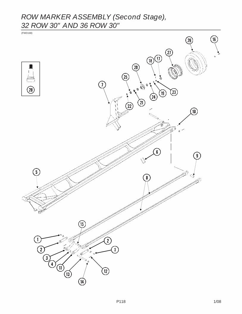
P118 1/08
ROW MARKER ASSEMBLY (Second Stage),32 ROW 30" AND 36 ROW 30"(FWD168)

P119 1/08
ROW MARKER ASSEMBLY (Second Stage),32 ROW 30" AND 36 ROW 30"
ITEM PART NO. QTY. DESCRIPTION(Per Assy.)
1. G10037 2 Hex Head Cap Screw, 1/2"-13 x 1 1/4"GD15234 2 Washer, 1 1/2" O.D. x 1/2" I.D. x 7 Gauge
2. GA10383 2 Short Link3. GA10384 1 Long Link4. GD5900-21 1 Sleeve, 2 3/8"5. GA10720 1 Arm W/Grease Fittings And Bushings, Second Stage, 164"
GD15131 - Bushing, 2 1/4" O.D. x 1 3/4" I.D. x 4"G10640 - Grease Fitting, 1/4"-28
6. GD4743 6 U-Bolt, 3" x 3" x 1/2"-13G10228 6 Lock Washer, 1/2"G10102 6 Hex Nut, 1/2"-13
7. GA13477 1 Wheel Mount, L.H. (Shown)GA13478 1 Wheel Mount, R.H.GD18939 6 Wheel Marker Washer
8. GA10386 2 Link, 143 3/4"9. GD5900-20 1 Sleeve, 3 3/16"10. G10640 4 Grease Fitting, 1/4"-2811. GA10385 1 Long Link12. G10460 4 Cotter Pin, 1/4" x 2"13. GD15230 2 Pin, 1" x 10 3/4"14. G10233 3 Machine Bushing, 1", 10 Gauge15. GD15233 2 Pin, 1 1/2" x 2 19/64"16. G10722 4 Hex Head Cap Screw, 1/2"-20 x 1"
G10228 4 Lock Washer, 1/2"17. GD0840 1 Dust Cap18. G10544 1 Cotter Pin, 5/32" x 1"19. G10724 1 Washer, 5/8" SAE20. GA0167 1 Hub W/Cups, 4 Bolt
GR0151 - Outer CupGR0150 - Inner Cup
21. GA0245 1 Bearing22. GA0899 1 Rubber Seal23. G10725 1 Slotted Hex Nut, 5/8"-1824. GA0257 1 Bearing25. GA0243 1 Grease Seal26. GD15489 1 Tire, 20.5" x 8.0-10 (Specify Brand*)27. GA10457 1 Rim, 6" x 10"28. GA10458 - Valve Stem
A. GA10409 - Tire And Rim Assembly (Items 26-28)

P120 1/08
ROW MARKER ASSEMBLY (Third And Fourth Stages),32 ROW 30" AND 36 ROW 30"(FWD169)
ITEM PART NO. QTY. DESCRIPTION(Per Assy.)
1. GA10507 1 Cable, 132 1/2"2. GD2721 7 U-Bolt, 2" x 2" x 1/2"-13
G10228 14 Lock Washer, 1/2"G10102 14 Hex Nut, 1/2"-13
3. GD0453-07 1 Extension Tube, 45"4. GA10375 1 Arm W/Grease Fittings, Third Stage, 148 1/2"
G10640 - Grease Fitting, 1/4"-285. GA10376 1 Arm, Fourth Stage, 70 5/32", 32 Row 30"
GA10426 - Arm, Fourth Stage, 130", 36 Row 30"6. G11034 2 Hex Head Cap Screw, 1/2"-13 x 7"
G10111 2 Lock Nut, 1/2"-137. GD15235 4 Washer, 2 1/4" O.D. x 1/2" I.D. x 1/4"

P121 1/08
ROW MARKER ASSEMBLY (Third And Fourth Stages),32 ROW 30" AND 36 ROW 30"ITEM PART NO. QTY. DESCRIPTION
(Per Assy.)
8. GD12613 4 Spring Bushing, 1 1/2" O.D. x 1 1/4" I.D. x 2"9. GD18934 1 Marker Wheel Mount Plate, R.H.
GD18935 Marker Wheel Mount Plate, L.H.10. GD15229 2 Sleeve, 1 1/4" O.D. x 1/2" I.D. x 5 15/16"11. G10036 1 Hex Head Cap Screw, 5/8"-11 x 4"
G10107 1 Lock Nut, 5/8"-11GD3180-36 1 Sleeve, 7/8" O.D. x 5/8" I.D. x 2"
12. G10013 1 Hex Head Cap Screw, 5/8"-11 x 3 ½"G10107 1 Lock Nut, 5/8"-11GD3180-35 1 Sleeve, 7/8" O.D. x 5/8" I.D. x 1 1/2"
13. GA10382 1 Swing Link14. GD15290 6 Spring Bushing, 1 1/2" Long15. GD15231 1 Pin, 1 1/4" x 14 7/8"16. G10159 2 Machine Bushing, 1 1/4", 10 Gauge17. G10460 4 Cotter Pin, 1/4" x 2"18. G10233 2 Machine Bushing, 1", 10 Gauge19. G10722 4 Hex Head Cap Screw, 1/2"-20 x 1"
G10228 4 Lock Washer, 1/2"20. GA13476 1 Gauge Wheel Mount21. GD0840 1 Dust Cap22. G10544 1 Cotter Pin, 5/32" x 1"23. G10724 1 Washer, 5/8" SAE24. GA0167 1 Hub W/Cups, 4 Bolt
GR0151 - Outer CupGR0150 - Inner Cup
25. GA0245 1 Bearing26. GA0899 1 Rubber Seal27. G10725 1 Slotted Hex Nut, 5/8"-1828. GA0257 1 Bearing29. GA0243 1 Grease Seal30. GD15489 1 Tire, 20.5" x 8.0-10 (Specify Brand*)31. GA10457 1 Rim, 6" x 10"32. GA10458 - Valve Stem33. GD15232 1 Pin, 1" x 12 3/4"34. G10644 4 Hex Head Cap Screw, 7/16"-14 x 1 1/2"
G10199 4 Washer, 7/16" SAEG10113 4 Lock Nut, 7/16"-14
35. GD15649 2 Wear Pad36. GA10496 1 Support37. G10640 1 Grease Fitting, 1/4"-2838. G10033 2 Hex Head Cap Screw, ½"-13 x 3 ½"
GD18939 2 Marker Wheel WasherG10111 2 Lock Nut, ½"-13
39. GD18904 1 Plate Mount40. GD18905 1 Pad Mount41. GA9145 1 Pad42. G10062 4 Hex Head Cap Screw, 3/8"-16 x 3"
G10101 4 Hex Nut, 3/8"-16G10299 4 Washer, 3/8"
43. G10644 2 Hex Head Cap Screw, 7/16"-14 x 1 ½"G10113 2 Lock Nut, 7/16"-14G10199 2 Washer, 7/16" SAE
A. GA10409 - Tire And Rim Assembly (Items 30-32)
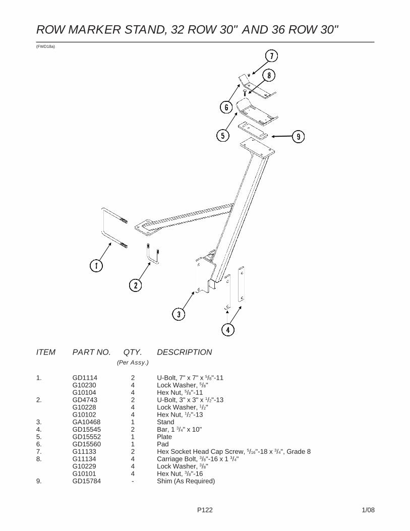
P122 1/08
ITEM PART NO. QTY. DESCRIPTION(Per Assy.)
1. GD1114 2 U-Bolt, 7" x 7" x 5/8"-11G10230 4 Lock Washer, 5/8"G10104 4 Hex Nut, 5/8"-11
2. GD4743 2 U-Bolt, 3" x 3" x 1/2"-13G10228 4 Lock Washer, 1/2"G10102 4 Hex Nut, 1/2"-13
3. GA10468 1 Stand4. GD15545 2 Bar, 1 3/4" x 10"5. GD15552 1 Plate6. GD15560 1 Pad7. G11133 2 Hex Socket Head Cap Screw, 5/16"-18 x 3/4", Grade 88. G11134 4 Carriage Bolt, 3/8"-16 x 1 3/4"
G10229 4 Lock Washer, 3/8"G10101 4 Hex Nut, 3/8"-16
9. GD15784 - Shim (As Required)
(FWD18a)
ROW MARKER STAND, 32 ROW 30" AND 36 ROW 30"
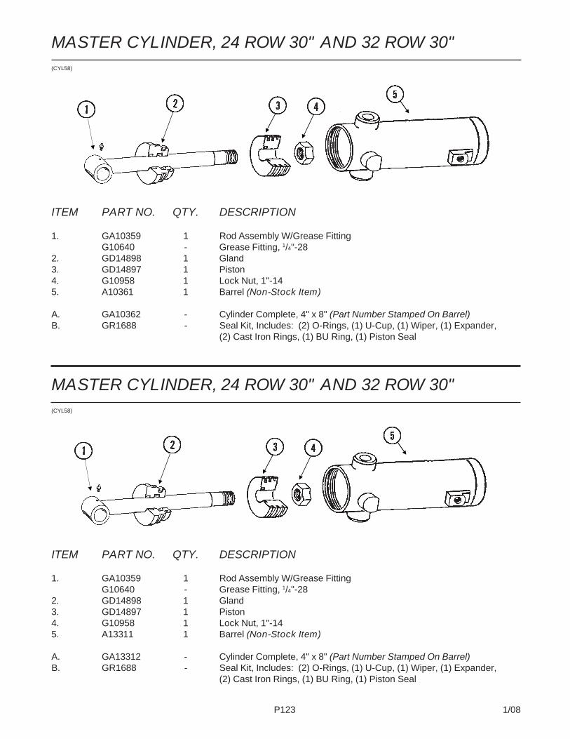
P123 1/08
MASTER CYLINDER, 24 ROW 30" AND 32 ROW 30"(CYL58)
ITEM PART NO. QTY. DESCRIPTION
1. GA10359 1 Rod Assembly W/Grease FittingG10640 - Grease Fitting, 1/4"-28
2. GD14898 1 Gland3. GD14897 1 Piston4. G10958 1 Lock Nut, 1"-145. A13311 1 Barrel (Non-Stock Item)
A. GA13312 - Cylinder Complete, 4" x 8" (Part Number Stamped On Barrel)B. GR1688 - Seal Kit, Includes: (2) O-Rings, (1) U-Cup, (1) Wiper, (1) Expander,
(2) Cast Iron Rings, (1) BU Ring, (1) Piston Seal
MASTER CYLINDER, 24 ROW 30" AND 32 ROW 30"(CYL58)
ITEM PART NO. QTY. DESCRIPTION
1. GA10359 1 Rod Assembly W/Grease FittingG10640 - Grease Fitting, 1/4"-28
2. GD14898 1 Gland3. GD14897 1 Piston4. G10958 1 Lock Nut, 1"-145. A10361 1 Barrel (Non-Stock Item)
A. GA10362 - Cylinder Complete, 4" x 8" (Part Number Stamped On Barrel)B. GR1688 - Seal Kit, Includes: (2) O-Rings, (1) U-Cup, (1) Wiper, (1) Expander,
(2) Cast Iron Rings, (1) BU Ring, (1) Piston Seal

P124 1/08
MASTER CYLINDER, 36 ROW 30"(CYL58)
ITEM PART NO. QTY. DESCRIPTION
1. GA11370 1 Rod Assembly W/Grease FittingG10640 - Grease Fitting, 1/4"-28
2. GD12522 1 Gland3. GA11374 1 Piston W/Rephasing Valve
GR1169 - Rephasing Valve Replacement Kit (Set Screw, Guide, 2 Springs And Ball)4. G10958 1 Lock Nut, 1"-145. A11368 1 Barrel (Non-Stock Item)
A. GA11367 - Cylinder Complete, 4 1/2" x 8" (Part Number Stamped On Barrel)B. GR1757 - Seal Kit, Includes: (2) O-Rings, (1) U-Cup, (1) Wiper, (1) BU Ring,
(1) Wear Ring, (1) T-Seal

P125 1/08
SLAVE/LIFT ASSIST CYLINDERS, 24 ROW 30", 32 ROW 30"AND 36 ROW 30"
ITEM PART NO. QTY. DESCRIPTION
1. GA10363 1 Rod Assembly W/Grease FittingG10640 - Grease Fitting, 1/4"-28
2. GD14902 1 Gland3. GD14901 1 Piston4. G10958 1 Lock Nut, 1"-145. A10365 1 Barrel (Non-Stock Item)
A. GA10366 - Cylinder Complete, 3 3/4" x 8" (Part Number Stamped On Barrel)B. GR1689 - Seal Kit, Includes: (2) O-Rings, (1) U-Cup, (1) Wiper, (1) Seal,
(2) Cast Iron Rings, (1) BU Ring, (1) Expander
(CYL59)
SLAVE/LIFT ASSIST CYLINDERS, 24 ROW 30", 32 ROW 30"AND 36 ROW 30"
ITEM PART NO. QTY. DESCRIPTION
1. GA8831 1 Rod Assembly W/Grease FittingG10640 - Grease Fitting, 1/4"-28
2. GD11985 1 Gland3. GD11986 1 Piston4. G10969 1 Lock Nut, 7/8"-145. A8827 1 Barrel (Non-Stock Item)
A. GA8828 - Cylinder Complete, 2 1/2" x 8" (Part Number Stamped On Barrel)B. GR1522 - Seal Kit, Includes: (1) T-Seal, (2) O-Rings, (1) BU Ring, (1) U-Cup,
(1) Wiper
CYL026(CYL4d)

P126 1/08
ITEM PART NO. QTY. DESCRIPTION
1. GA10367 1 Rod Assembly W/Grease FittingG10640 - Grease Fitting, 1/4"-28
2. GD12507 1 Gland3. GD14907 1 Piston4. G10958 1 Lock Nut, 1"-145. A10369 1 Barrel (Non-Stock Item)
A. GA10370 - Cylinder Complete, 3 1/2" x 8" (Part Number Stamped On Barrel)B. GR1690 - Seal Kit, Includes: (2) O-Rings, (1) U-Cup, (1) Wiper, (1) Seal,
(2) Cast Iron Rings, (1) BU Ring, (1) Expander
SLAVE CYLINDER, 32 ROW 30"(CYL59)

P127 1/08
ITEM PART NO. QTY. DESCRIPTION
1. GA10359 1 Rod Assembly W/Grease FittingG10640 - Grease Fitting, 1/4"-28
2. GD14898 1 Gland3. GD14897 1 Piston4. G10958 1 Lock Nut, 1"-145. A11372 1 Barrel (Non-Stock Item)
A. GA11371 - Cylinder Complete, 4" x 8" (Part Number Stamped On Barrel)B. GR1688 - Seal Kit, Includes: (2) O-Rings, (1) U-Cup, (1) Wiper, (1) Seal,
(2) Cast Iron Rings, (1) BU Ring, (1) Expander
SLAVE CYLINDER, 36 ROW 30"(CYL59)

P128 1/08
WING FOLD CYLINDER, ALL SIZES(CYL15e)
ITEM PART NO. QTY DESCRIPTION
1. GA8130 1 Clevis W/Bushings, Hex Head Cap Screw And Hex NutGD11751 2 Steel Bushing, 1" WideG10939 1 Hex Head Cap Screw, 3/8"-16 x 2 1/4"G10101 1 Hex Nut, 3/8"-16
2. GD14908 1 Rod3. GD12522 1 Gland4. GD14910 1 Piston5. G10972 1 Lock Nut, 1 1/4"-126. A10372 1 Barrel (Non-Stock Item)
A. GA10373 - Cylinder Complete, 4 1/2" x 30" (Part Number Stamped On Barrel)B. GR1691 - Seal Kit (For Cylinder And Counter Balance Valve), Includes:
(1) Wiper, (1) U-Cup, (3) O-Rings, (1) BU Ring, (1) T-Seal, (1) Wear Ring

P129 1/08
AXLE SLIDE CYLINDER, 32 ROW 30" AND 36 ROW 30"(CYL12g)
ITEM PART NO. QTY. DESCRIPTION
1. GA10243 1 Rod Assembly2. GD12670 1 Gland3. GD14915 1 Sleeve, 6 1/2"4. GD12672 1 Piston5. G10972 1 Lock Nut, 1 1/4"-126. G6400-08-04 1 Connector W/O-Ring, 3/4"-16 Male JIC To 7/16"-20 O-Ring
GR1465 - O-Ring7. GA10245 1 Barrel8. GA10242 1 Steel Hydraulic Line, 66 7/16"9. G306-08 1 Lock Nut, 3/4"-1610. GD12597 1 Bracket11. G2701-08 1 Bulkhead Elbow, 90°, 3/4"-16 Male JIC12. G10328 1 Hex Head Cap Screw, 3/8"-16 x 5/8"
G10229 1 Lock Washer, 3/8"
A. GA10246 - Cylinder Complete, 4" x 60" (Part Number Stamped On Barrel)B. GR1552 - Seal Kit, Includes: (2) O-Rings, (1) BU Ring, (1) Wear Ring, (1) Wiper,
(1) U-Cup, (1) T-Seal
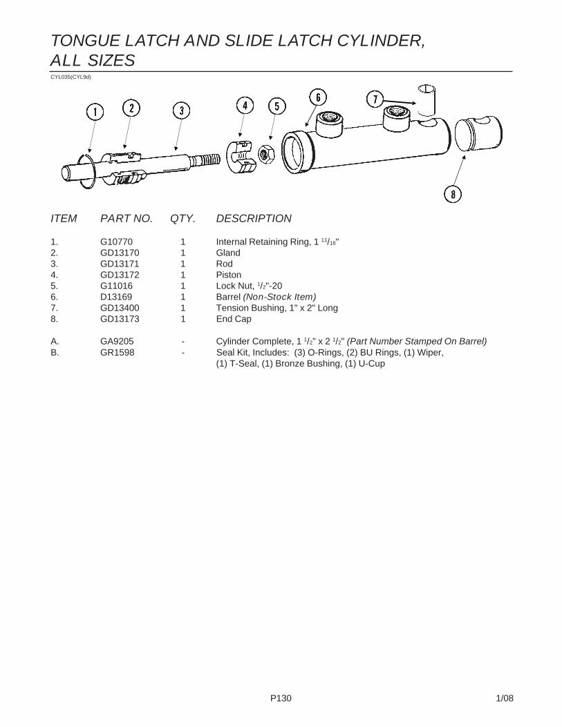
P130 1/08
CYL035(CYL9d)
ITEM PART NO. QTY. DESCRIPTION
1. G10770 1 Internal Retaining Ring, 1 11/16"2. GD13170 1 Gland3. GD13171 1 Rod4. GD13172 1 Piston5. G11016 1 Lock Nut, 1/2"-206. D13169 1 Barrel (Non-Stock Item)7. GD13400 1 Tension Bushing, 1" x 2" Long8. GD13173 1 End Cap
A. GA9205 - Cylinder Complete, 1 1/2" x 2 1/2" (Part Number Stamped On Barrel)B. GR1598 - Seal Kit, Includes: (3) O-Rings, (2) BU Rings, (1) Wiper,
(1) T-Seal, (1) Bronze Bushing, (1) U-Cup
TONGUE LATCH AND SLIDE LATCH CYLINDER,ALL SIZES
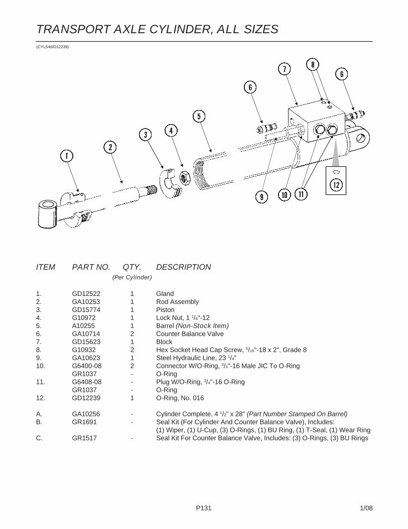
P131 1/08
TRANSPORT AXLE CYLINDER, ALL SIZES
ITEM PART NO. QTY. DESCRIPTION(Per Cylinder)
1. GD12522 1 Gland2. GA10253 1 Rod Assembly3. GD15774 1 Piston4. G10972 1 Lock Nut, 1 1/4"-125. A10255 1 Barrel (Non-Stock Item)6. GA10714 2 Counter Balance Valve7. GD15623 1 Block8. G10932 2 Hex Socket Head Cap Screw, 5/16"-18 x 2", Grade 89. GA10623 1 Steel Hydraulic Line, 23 1/4"10. G6400-08 2 Connector W/O-Ring, 3/4"-16 Male JIC To O-Ring
GR1037 - O-Ring11. G6408-08 - Plug W/O-Ring, 3/4"-16 O-Ring
GR1037 - O-Ring12. GD12239 1 O-Ring, No. 016
A. GA10256 - Cylinder Complete, 4 1/2" x 28" (Part Number Stamped On Barrel)B. GR1691 - Seal Kit (For Cylinder And Counter Balance Valve), Includes:
(1) Wiper, (1) U-Cup, (3) O-Rings, (1) BU Ring, (1) T-Seal, (1) Wear RingC. GR1517 - Seal Kit For Counter Balance Valve, Includes: (3) O-Rings, (3) BU Rings
(CYL54d/D12239)
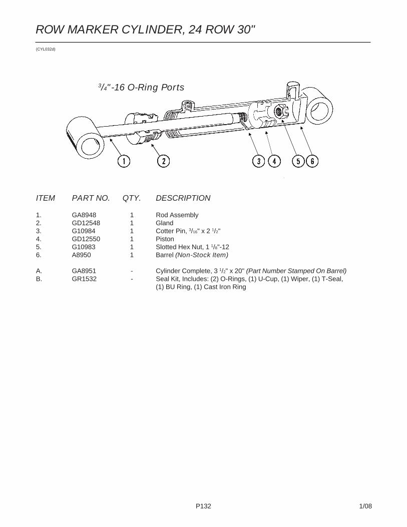
P132 1/08
ROW MARKER CYLINDER, 24 ROW 30"(CYL032d)
ITEM PART NO. QTY. DESCRIPTION
1. GA8948 1 Rod Assembly2. GD12548 1 Gland3. G10984 1 Cotter Pin, 3/16" x 2 1/2"4. GD12550 1 Piston5. G10983 1 Slotted Hex Nut, 1 1/8"-126. A8950 1 Barrel (Non-Stock Item)
A. GA8951 - Cylinder Complete, 3 1/2" x 20" (Part Number Stamped On Barrel)B. GR1532 - Seal Kit, Includes: (2) O-Rings, (1) U-Cup, (1) Wiper, (1) T-Seal,
(1) BU Ring, (1) Cast Iron Ring
3/4"-16 O-Ring Ports

P133 1/08
(A11021)
ITEM PART NO. QTY. DESCRIPTION
1. GD16147 1 Rod2. GD12539 1 Gland3. GD14089 1 Piston4. G10983 1 Slotted Hex Nut, 1 1/8"-125. G10984 1 Cotter Pin, 3/16" x 2 1/2"6. A11020 1 Barrel (Non-Stock Item)7. G10640 2 Grease Fitting, 1/4"-288. GD16184 1 Clamp9. GD16060 1 Sleeve10. G11099 1 Hex Socket Head Cap Screw, 3/8"-16 x 1 1/2", Grade 8
A. GA11021 - Cylinder Complete, 4" x 32" (Part Number Stamped On Barrel)B. GR1630 - Seal Kit, Includes: (2) O-Rings, (1) BU Ring, (1) Wiper,
(1) T-Seal, (1) Cast Iron Ring, (1) U-Cup Seal
ROW MARKER CYLINDER, 32 ROW 30" AND 36 ROW 30"

P134 1/08
(FWD157)
VALVE BLOCKS - LOCATED ON HITCH, 24 ROW 30"

P135 1/08
ITEM PART NO. QTY. DESCRIPTION
1. G6400-08 6 Connector W/O-Ring, 3/4"-16 Male JIC To O-RingGR1037 - O-Ring
2. GA3413 2 Flow Control ValveGR0764 - Seal Kit, Includes: (2) O-Rings, (1) BU Ring
3. G6408-08 2 Plug W/O-Ring, 3/4"-16 O-RingGR1037 - O-Ring
4. G11067 2 Phillips Pan Head Machine Screw, No. 8-32 x 3/4", Stainless SteelG10928 2 Hex Nut, No. 8-32, Stainless Steel
5. G6408-H06-0 6 Hex Socket Head Plug W/O-Ring, 9/16"-18 O-RingGR1045 - O-Ring
6. G6801-08 6 Elbow W/O-Ring, 90°, 3/4"-16 Male JIC To O-RingGR1037 - O-Ring
7. GR0761 3 Special Hex Nut, 1/2"-208. GD18096 1 Block9. GD15187-01 2 Threaded Rod, 3/8"-16 x 13"
G10203 2 Washer, 3/8" SAEG10108 2 Lock Nut, 3/8"-16
10. GR0763 3 Cartridge11. GR1445 3 Coil12. GD15634 1 Mount13. G10002 1 Hex Head Cap Screw, 3/8"-16 x 3/4"
G10622 1 Serrated Flange Nut, 3/8"-1614. GA3584 1 Ground Clamp15. GA9097 1 Terminal Strip W/Screws, No. 6, 14 Terminal
GR1635 - Screw, No. 6-32 x 1/4"16. G11067 2 Phillips Pan Head Machine Screw, No. 8-32 x 3/4", Stainless Steel17. G10996 3 Fork Terminal18. G6500-08 4 Swivel Elbow, 90°, 3/4"-16 Male JIC To Female19. G6400-L-08 2 Long Connector W/O-Ring, 3/4"-16 Male JIC To O-Ring
GR1037 - O-Ring20. G6801-06 2 ElbowW/O-Ring, 90°, 9/16"-18 Male JIC To O-Ring
GR1045 - O-Ring21. GD16146 1 Cover22. G6500-10 4 Swivel Elbow, 90°, 7/8"-14 Male JIC To Female23. GD14923 1 Block24. G6400-10 2 Connector W/O-Ring, 7/8"-14 Male JIC To O-Ring
GR1466 - O-Ring25. G6400-10-08 4 Connector W/O-Ring, 7/8"-14 Male JIC To 3/4"-16 O-Ring
VALVE BLOCKS - LOCATED ON HITCH, 24 ROW 30"

P136 1/08
VALVE BLOCKS - LOCATED ON HITCH, 32 ROW 30" AND36 ROW 30"(FWD158)

P137 1/08
VALVE BLOCKS - LOCATED ON HITCH, 32 ROW 30" AND36 ROW 30"ITEM PART NO. QTY. DESCRIPTION
1. G6400-08 2 Connector W/O-Ring, 3/4"-16 Male JIC To O-RingGR1037 - O-Ring
2. GA3413 2 Flow Control ValveGR0764 - Seal Kit, Includes: (2) O-Rings, (1) BU Ring
3. G6408-08 2 Plug W/O-Ring, 3/4"-16 O-RingGR1037 - O-Ring
4. G11067 2 Phillips Pan Head Machine Screw, No. 8-32 x 3/4", Stainless SteelG10928 2 Hex Nut, No. 8-32, Stainless Steel
5. G6408-H06-0 6 Hex Socket Head Plug W/O-Ring, 9/16"-18 O-RingGR1045 - O-Ring
6. G6801-08 4 Elbow W/O-Ring, 90°, 3/4"-16 Male JIC To O-RingGR1037 - O-Ring
7. GR0761 3 Special Hex Nut, 1/2"-208. GD18096 1 Block9. GD15187-01 2 Threaded Rod, 3/8"-16 x 13"
G10203 2 Washer, 3/8" SAEG10108 2 Lock Nut, 3/8"-16
10. GR0763 3 Cartridge11. GR1445 3 Coil12. GD15634 1 Mount13. G10002 1 Hex Head Cap Screw, 3/8"-16 x 3/4"
G10622 1 Serrated Flange Nut, 3/8"-1614. GA3584 1 Ground Clamp15. GA9097 1 Terminal Strip W/Screws, No. 6, 14 Terminal
GR1635 - Screw, No. 6-32 x 1/4"16. G11067 2 Phillips Pan Head Machine Screw, No. 8-32 x 3/4", Stainless Steel17. G10996 3 Fork Terminal18. G6500-08 4 Swivel Elbow, 90°, 3/4"-16 Male JIC To Female19. G6400-L-08 2 Long Connector W/O-Ring, 3/4"-16 Male JIC To O-Ring
GR1037 - O-Ring20. G6801-06 2 ElbowW/O-Ring, 90°, 9/16"-18 Male JIC To O-Ring
GR1045 - O-Ring21. GD16146 1 Cover22. G6500-10 4 Swivel Elbow, 90°, 7/8"-14 Male JIC To Female23. GD14923 1 Block24. G6400-10 2 Connector W/O-Ring, 7/8"-14 Male JIC To O-Ring
GR1466 - O-Ring25. G6400-10-08 6 Connector W/O-Ring, 7/8"-14 Male JIC To 3/4"-16 O-Ring

P138 1/08
VALVE BLOCK - LOCATED AT CENTER OF REARH-FRAME, 24 ROW 30"(A12639a/A9481/D18137)
ITEM PART NO. QTY. DESCRIPTION
1. GD18097 1 Block2. GR1445 4 Coil3. G6801-06 2 Elbow W/O-Ring, 90°, 9/16"-18 Male JIC To O-Ring
GR1045 - O-Ring4. G6400-06 6 Connector W/O-Ring, 9/16"-18 Male JIC To O-Ring
GR1045 - O-Ring5. GD18100 2 Clip6. G11067 4 Phillips Pan Head Machine Screw, No. 8-32 x 3/4", Stainless Steel7. GA10632 1 Counter Balance Valve8. GR0761 4 Special Hex Nut, 1/2"-209. G6408-H06-0 6 Hex Socket Head Plug W/O-Ring, 9/16"-18 O-Ring
GR1045 - O-Ring10. GA9510 1 Terminal Strip W/Screws, No. 6, 4 Terminal
GR1635 - Screw, No. 6-32 x 1/4"11. G6400-08 2 Connector W/O-Ring, 3/4"-16 Male JIC To O-Ring
GR1037 - O-Ring12. GR0763 4 Cartridge13. G6500-06 2 Swivel Elbow, 90°, 9/16"-18 Male JIC To Female14. G10996 4 Fork Terminal15. GD18101 1 Cover16. G10171 2 Hex Head Cap Screw, 5/16"-18 x 1 1/4"
G10232 2 Lock Washer, 5/16"G10221 2 Washer, 5/16" SAE
17. GD18137 1 Plate, 5" x 7 3/4"
A. GR1517 - Seal Kit For Counter Balance Valve, Includes: (3) O-Rings, (3) BU Rings
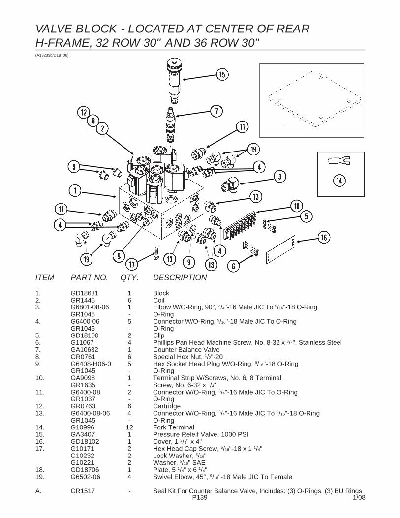
P139 1/08
VALVE BLOCK - LOCATED AT CENTER OF REARH-FRAME, 32 ROW 30" AND 36 ROW 30"(A13233b/D18706)
ITEM PART NO. QTY. DESCRIPTION
1. GD18631 1 Block2. GR1445 6 Coil3. G6801-08-06 1 Elbow W/O-Ring, 90°, 3/4"-16 Male JIC To 9/16"-18 O-Ring
GR1045 - O-Ring4. G6400-06 5 Connector W/O-Ring, 9/16"-18 Male JIC To O-Ring
GR1045 - O-Ring5. GD18100 2 Clip6. G11067 4 Phillips Pan Head Machine Screw, No. 8-32 x 3/4", Stainless Steel7. GA10632 1 Counter Balance Valve8. GR0761 6 Special Hex Nut, 1/2"-209. G6408-H06-0 5 Hex Socket Head Plug W/O-Ring, 9/16"-18 O-Ring
GR1045 - O-Ring10. GA9098 1 Terminal Strip W/Screws, No. 6, 8 Terminal
GR1635 - Screw, No. 6-32 x 1/4"11. G6400-08 2 Connector W/O-Ring, 3/4"-16 Male JIC To O-Ring
GR1037 - O-Ring12. GR0763 6 Cartridge13. G6400-08-06 4 Connector W/O-Ring, 3/4"-16 Male JIC To 9/16"-18 O-Ring
GR1045 - O-Ring14. G10996 12 Fork Terminal15. GA3407 1 Pressure Releif Valve, 1000 PSI16. GD18102 1 Cover, 1 3/8" x 4"17. G10171 2 Hex Head Cap Screw, 5/16"-18 x 1 1/4"
G10232 2 Lock Washer, 5/16"G10221 2 Washer, 5/16" SAE
18. GD18706 1 Plate, 5 1/4" x 6 1/4"19. G6502-06 4 Swivel Elbow, 45°, 9/16"-18 Male JIC To Female
A. GR1517 - Seal Kit For Counter Balance Valve, Includes: (3) O-Rings, (3) BU Rings
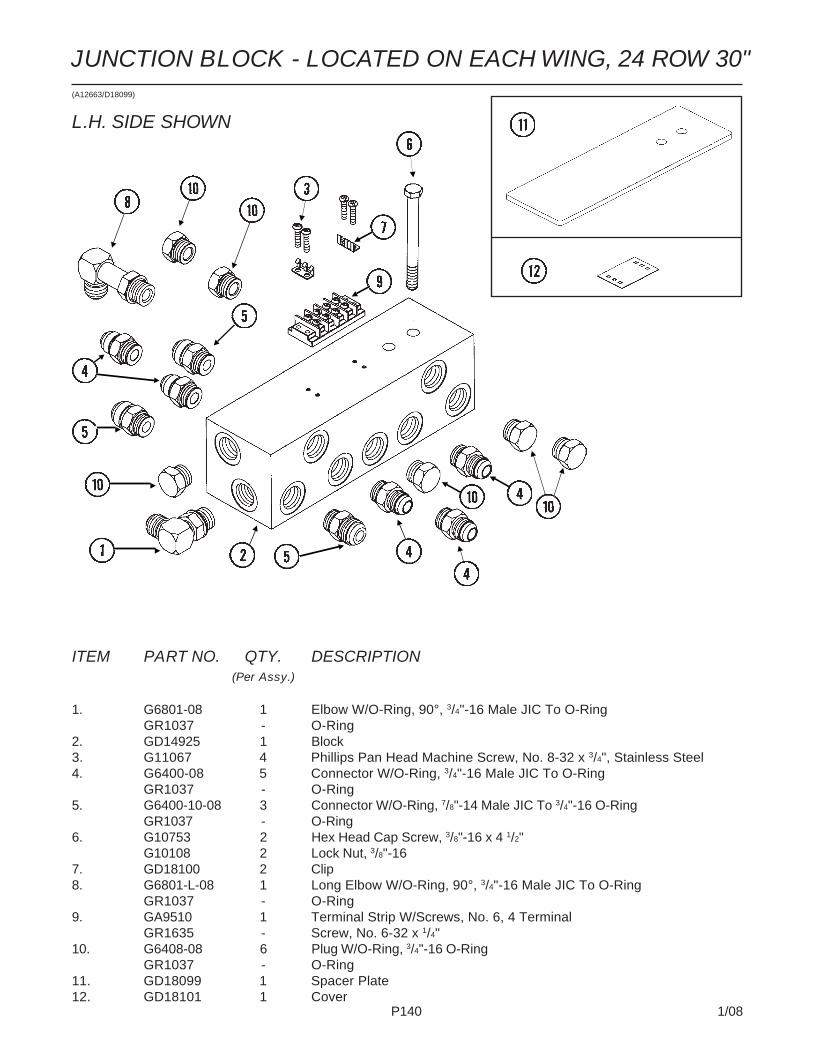
P140 1/08
ITEM PART NO. QTY. DESCRIPTION(Per Assy.)
1. G6801-08 1 Elbow W/O-Ring, 90°, 3/4"-16 Male JIC To O-RingGR1037 - O-Ring
2. GD14925 1 Block3. G11067 4 Phillips Pan Head Machine Screw, No. 8-32 x 3/4", Stainless Steel4. G6400-08 5 Connector W/O-Ring, 3/4"-16 Male JIC To O-Ring
GR1037 - O-Ring5. G6400-10-08 3 Connector W/O-Ring, 7/8"-14 Male JIC To 3/4"-16 O-Ring
GR1037 - O-Ring6. G10753 2 Hex Head Cap Screw, 3/8"-16 x 4 1/2"
G10108 2 Lock Nut, 3/8"-167. GD18100 2 Clip8. G6801-L-08 1 Long Elbow W/O-Ring, 90°, 3/4"-16 Male JIC To O-Ring
GR1037 - O-Ring9. GA9510 1 Terminal Strip W/Screws, No. 6, 4 Terminal
GR1635 - Screw, No. 6-32 x 1/4"10. G6408-08 6 Plug W/O-Ring, 3/4"-16 O-Ring
GR1037 - O-Ring11. GD18099 1 Spacer Plate12. GD18101 1 Cover
JUNCTION BLOCK - LOCATED ON EACH WING, 24 ROW 30"(A12663/D18099)
L.H. SIDE SHOWN

P141 1/08
ITEM PART NO. QTY. DESCRIPTION(Per Assy.)
1. G6801-L-08 1 Long Elbow W/O-Ring, 90°, 3/4"-16 Male JIC To O-RingGR1037 - O-Ring
2. G6801-08 5 Elbow W/O-Ring, 90°, 3/4"-16 Male JIC To O-RingGR1037 - O-Ring
3. G6400-10-08 4 Connector W/O-Ring, 7/8"-14 Male JIC To 3/4"-16 O-RingGR1037 - O-Ring
4. GD14925 1 Block5. G6400-08 6 Connector W/O-Ring, 3/4"-16 Male JIC To O-Ring
GR1037 - O-Ring6. G10063 2 Hex Head Cap Screw, 3/8"-16 x 4"
G10203 2 Washer, 3/8" SAEG10108 2 Lock Nut, 3/8"-16
7. GA9510 1 Terminal Strip W/Screws, No. 6, 4 TerminalGR1635 - Screw, No. 6-32 x 1/4"
8. G11067 2 Phillips Pan Head Machine Screw, No. 8-32 x 3/4", Stainless Steel9. GD18100 2 Clip10. GD18099 1 Spacer Plate11. GD18101 1 Cover
JUNCTION BLOCK - LOCATED ON EACH WING, 32 ROW 30"(A11195a)
L.H. SIDE SHOWN

P142 1/08
ITEM PART NO. QTY. DESCRIPTION(Per Assy.)
1. G6801-LL-08 1 X-Long Elbow W/O-Ring, 90°, 3/4"-16 Male JIC To O-RingGR1037 - O-Ring
2. G6801-08 5 Elbow W/O-Ring, 90°, 3/4"-16 Male JIC To O-RingGR1037 - O-Ring
3. G6400-10-08 4 Connector W/O-Ring, 7/8"-14 Male JIC To 3/4"-16 O-RingGR1037 - O-Ring
4. GD14925 1 Block5. G6400-08 6 Connector W/O-Ring, 3/4"-16 Male JIC To O-Ring
GR1037 - O-Ring6. G10063 2 Hex Head Cap Screw, 3/8"-16 x 4"
G10203 2 Washer, 3/8" SAEG10108 2 Lock Nut, 3/8"-16
7. GA9510 1 Terminal Strip W/Screws, No. 6, 4 TerminalGR1635 - Screw, No. 6-32 x 1/4"
8. G11067 2 Phillips Pan Head Machine Screw, No. 8-32 x 3/4", Stainless Steel9. G6500-10 1 Swivel Elbow, 90°, 7/8"-14 Male JIC To Female10. GD18100 2 Clip11. GD18099 1 Spacer Plate12. GD18101 1 Cover
JUNCTION BLOCK - LOCATED ON EACH WING, 36 ROW 30"(A11197a)
L.H. SIDE SHOWN

P143 1/08
SDS MANIFOLD BLOCK(FWD96/A9481)
ITEM PART NO. QTY. DESCRIPTION
1. GD16500 1 Block2. G6400-L-10 1 Long Connector W/O-Ring, 7/8"-14 Male JIC To O-Ring
GR1466 - O-Ring3. G6500-10 2 Swivel Elbow, 90°, 7/8"-14 Male JIC To Female4. GA11360 1 Check Valve5. G6408-H06-0 2 Hex Socket Head Plug W/O-Ring, 9/16"-18 O-Ring
GR1045 - O-Ring6. G6801-08 2 Elbow W/O-Ring, 90°, 3/4"-16 Male JIC To O-Ring
GR1037 - O-Ring7. G6400-08 2 Connector W/O-Ring, 3/4"-16 Male JIC To O-Ring
GR1037 - O-Ring8. G6500-08 2 Swivel Elbow, 90°, 3/4"-16 Male JIC To Female9. G6408-08 2 Plug W/O-Ring, 3/4"-16 O-Ring
GR1037 - O-Ring10. GR1748 4 Coil11. GA10987 2 Flow Control Cartridge12. GA11365 2 Spool Valve13. G11203 2 Hex Head Cap Screw, 1/4"-20 x 4 1/2"
G10227 2 Lock Washer, 1/4"14. G10996 - Fork Terminal
A. GR1756 - Seal Kit For Coil, Includes: (6) BU Rings, (4) O-Rings
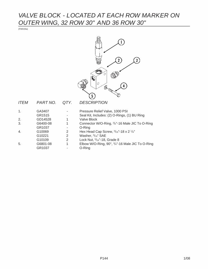
P144 1/08
VALVE BLOCK - LOCATED AT EACH ROW MARKER ONOUTER WING, 32 ROW 30" AND 36 ROW 30"(FWD26a)
ITEM PART NO. QTY. DESCRIPTION
1. GA3407 - Pressure Relief Valve, 1000 PSIGR1515 - Seal Kit, Includes: (2) O-Rings, (1) BU Ring
2. GD14528 1 Valve Block3. G6400-08 1 Connector W/O-Ring, 3/4"-16 Male JIC To O-Ring
GR1037 - O-Ring4. G10069 2 Hex Head Cap Screw, 5/16"-18 x 2 1/4"
G10221 2 Washer, 5/16" SAEG10109 2 Lock Nut, 5/16"-18, Grade 8
5. G6801-08 1 Elbow W/O-Ring, 90°, 3/4"-16 Male JIC To O-RingGR1037 - O-Ring

P145 1/08
Page intentionally left blank.

P146 1/08
See “ValveBlock -Located AtCenter OfRearH-Frame”,Page P136
ITEM PART NO. QTY. DESCRIPTION
1. G6801-08 12 Elbow W/O-Ring, 90°, 3/4"-16 Male JIC To O-RingGR1037 - O-Ring
2. *A11424 1 Hose Assembly, 5/8" x 342"3. *A12046 2 Hose Assembly, 3/8" x 348"4. *A1020 2 Hose Assembly, 3/8" x 48"5. *A3247 4 Hose Assembly, 3/8" x 156" (Male To Female)6. *A1090 2 Hose Assembly, 3/8" x 162"7. G2603-08 4 Tee, 3/4"-16 Male JIC8. *A1079 4 Hose Assembly, 3/8" x 24"9. *A1086 2 Hose Assembly, 3/8" x 28"10. *A3249 2 Hose Assembly, 3/8" x 132"11. *A3136 2 Hose Assembly, 3/8" x 100"12. G6400-08 10 Connector W/O-Ring, 3/4"-16 Male JIC To O-Ring
GR1037 - O-Ring13. *A12702 2 Hose Assembly, 1/2" x 348"14. *A12701 2 Hose Assembly, 1/2" x 438"15. *A12043 4 Hose Assembly, 3/8" x 356"16. *A12700 1 Hose Assembly, 1/2" x 342"17. *A1170 4 Hose Assembly, 1/4" x 90"18. G6801-06-08 6 Elbow W/O-Ring, 90°, 9/16"-18 Male JIC To 3/4"-16 O-Ring
GR1037 - O-Ring
HYDRAULIC HOSES AND FITTINGS, 24 ROW 30"(FWD154/D4086)
R.H. RowMarkerCylinder
MasterCylinders
WingFoldCylinder
A2 B2 D1 C1 F2 E2
3 3 /
4" x
8"
Sla
veC
ylin
der
2 1 /
2" x
8"
Ass
ist
Cyl
ind
er
* Hydraulic hose is not stocked by KINZE®
Repair Parts, but can be made available ona special order basis. Call for quote.
3 3 /
4" x
8"
Sla
veC
ylin
der
F3
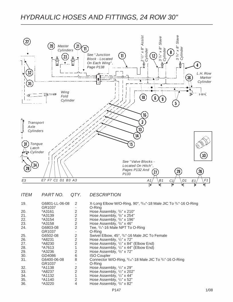
P147 1/08
HYDRAULIC HOSES AND FITTINGS, 24 ROW 30"
See “Valve Blocks -Located On Hitch”,Pages P132 AndP133
ITEM PART NO. QTY. DESCRIPTION
19. G6801-LL-06-08 2 X-Long Elbow W/O-Ring, 90°, 9/16"-18 Male JIC To 3/4"-16 O-RingGR1037 - O-Ring
20. *A3161 2 Hose Assembly, 3/8" x 210"21. *A3139 2 Hose Assembly, 3/8" x 254"22. *A3154 2 Hose Assembly, 3/8" x 196"23. *A3158 2 Hose Assembly, 3/8" x 46"24. G6803-08 2 Tee, 3/4"-16 Male NPT To O-Ring
GR1037 - O-Ring25. G6502-08 2 Swivel Elbow, 45°, 3/4"-16 Male JIC To Female26. *A8231 2 Hose Assembly, 1/2" x 72"27. *A8230 2 Hose Assembly, 1/2" x 84" (Elbow End)28. *A7613 1 Hose Assembly, 1/4" x 44" (Elbow End)29. *A3236 2 Hose Assembly, 3/8" x 72"30. GD4086 6 ISO Coupler31. G6400-06-08 8 Connector W/O-Ring, 9/16"-18 Male JIC To 3/4"-16 O-Ring
GR1037 - O-Ring32. *A1138 2 Hose Assembly, 1/4" x 29"33. *A8237 2 Hose Assembly, 1/2" x 202"34. *A1132 1 Hose Assembly, 1/4" x 44"35. *A1140 2 Hose Assembly, 1/4" x 52"36. *A3220 4 Hose Assembly, 3/8" x 82"
L.H. RowMarker
Cylinder
MasterCylinders
WingFoldCylinder
TongueLatchCylinder
E7 F7 C1 D1 B3 A3E3
See “JunctionBlock - LocatedOn Each Wing”,Page P138
F1E1D1C1B1A13
3 /4"
x 8
" S
lave
Cyl
ind
er
2 1 /
2" x
8"
Ass
ist
Cyl
ind
er
3 3 /
4" x
8"
Sla
veC
ylin
der
TransportAxleCylinders

P148 1/08
(FWD155/D4086)
2 1 /
2" x
8"
Ass
ist
Cyl
ind
er
3 3 /
4" x
8"
Sla
ve C
ylin
der
3 1 /
2" x
8"
Sla
ve C
ylin
der
3 3 /
4" x
8"
Sla
ve C
ylin
der
3 1 /
2" x
8"
Sla
ve C
ylin
der
R.H. RowMarkerCylinder
MasterCylinders
WingFoldCylinders
TransportAxleCylinders
A2 B2 D1 C1 F2 E2
* Hydraulic hose is not stocked by KINZE®
Repair Parts, but can be made available ona special order basis. Call for quote.
2 1 /
2" x
8"
Ass
ist
Cyl
ind
er
SlideCylinder
HYDRAULIC HOSES AND FITTINGS, 32 ROW 30"
ITEM PART NO. QTY. DESCRIPTION1. G6801-08 29 Elbow W/O-Ring, 90°, 3/4"-16 Male JIC To O-Ring
GR1037 - O-Ring2. *A11438 1 Hose Assembly, 5/8" x 410"3. *A12064 2 Hose Assembly, 3/8" x 410"4. *A12067 2 Hose Assembly, 3/8" x 190"5. *A8225 4 Hose Assembly, 1/2" x 209"6. *A1039 2 Hose Assembly, 3/8" x 76"7. G2603-08 4 Tee, 3/4"-16 Male JIC8. *A1082 2 Hose Assembly, 3/8" x 19"9. *A3199 2 Hose Assembly, 3/8" x 132"10. *A1018 2 Hose Assembly, 3/8" x 40"11. *A8226 2 Hose Assembly, 1/2" x 208"12. G6400-08 12 Connector W/O-Ring, 3/4"-16 Male JIC To O-Ring
GR1037 - O-Ring13. *A12724 2 Hose Assembly, 1/2" x 410"14. *A12725 2 Hose Assembly, 1/2" x 410"15. *A8260 4 Hose Assembly, 1/2" x 424"16. *A12723 1 Hose Assembly, 1/2" x 410"17. *A3225 2 Hose Assembly, 3/8" x 56"18. G2603-10 2 Tee, 7/8"-14 Male JIC19. G6502-06 2 Swivel Elbow, 45°, 9/16"-18 Male JIC To Female20. *A1031 2 Hose Assembly, 3/8" x 234"21. *A3259 2 Hose Assembly, 3/8" x 122"22. *A1033 2 Hose Assembly, 3/8" x 250"23. *A3158 2 Hose Assembly, 3/8" x 46"24. G6803-08 2 Tee, 3/4"-16 Male NPT To O-Ring
GR1037 - O-Ring25. *A1055 4 Hose Assembly, 3/8" x 66"

P149 1/08
HYDRAULIC HOSES AND FITTINGS, 32 ROW 30"
3 3 /
4" x
8"
Sla
ve C
ylin
der
3 1 /
2" x
8"
Sla
ve C
ylin
der
2 1 /
2" x
8"
Ass
ist C
ylin
der
3 3 /
4" x
8"
Sla
ve C
ylin
der
3 1 /
2" x
8"
Sla
ve C
ylin
der
See “Valve Blocks -Located On Hitch”,Pages P132 AndP133
L.H. RowMarker
Cylinder
MasterCylinders
WingFoldCylinder
TongueLatchCylinder
E7 F7 C1 D1 B3 A3
See “Valve Block - LocatedAt Center OfRearH-Frame”,Page P136
F3 E3
See “JunctionBlock - LocatedOn Each Wing”,Page P138
F1E1D1C1B1A1
2 1 /
2" x
8"
Ass
ist
Cyl
ind
er
Slide Latch Cylinder
ITEM PART NO. QTY. DESCRIPTION26. *A3236 2 Hose Assembly, 3/8" x 72"27. *A8230 2 Hose Assembly, 1/2" x 84"28. *A1192 3 Hose Assembly, 1/4" x 20"29. *A8231 2 Hose Assembly, 1/2" x 72"30. GD4086 6 ISO Coupler31. G6400-06-08 7 Connector W/O-Ring, 9/16"-18 Male JIC To 3/4"-16 O-Ring
GR1037 - O-Ring32. *A12053 4 Hose Assembly, 3/8" x 46"33. *A12729 2 Hose Assembly, 1/2" x 82"34. *A7613 1 Hose Assembly, 1/4" x 44"35. *A8229 2 Hose Assembly, 1/2" x 15"36. *A12730 2 Hose Assembly, 1/2" x 52"37. G6500-08 4 Swivel Elbow, 90°, 3/4"-16 Male JIC To Female38. G2700-06-06 2 Bulkhead Tube Union, 9/16"-18 Male JIC
G306-06 4 Lock Nut, 9/16"-1839. *A1098 2 Hose Assembly, 3/8" x 26"40. G6602-08 4 Swivel Tee, 3/4"-16 JIC41. *A7614 2 Hose Assembly, 1/4" x 17"42. *A1132 2 Hose Assembly, 1/4" x 44"43. *A7615 2 Hose Assembly, 1/4" x 122"44. *A3153 4 Hose Assembly, 3/8" x 22"45. G6502-08 2 Swivel Elbow, 45°, 3/4"-16 Male JIC To Female46. *A1057 2 Hose Assembly, 3/8" x 216"47. *A1076 2 Hose Assembly, 3/8" x 30"48. *A3223 2 Hose Assembly, 3/8" x 24"49. *A3228 2 Hose Assembly, 3/8" x 306"50. G2704-06 2 Bulkhead Tee, 9/16"-18 JIC51. *A12041 1 Hose Assembly, 3/8" x 244"
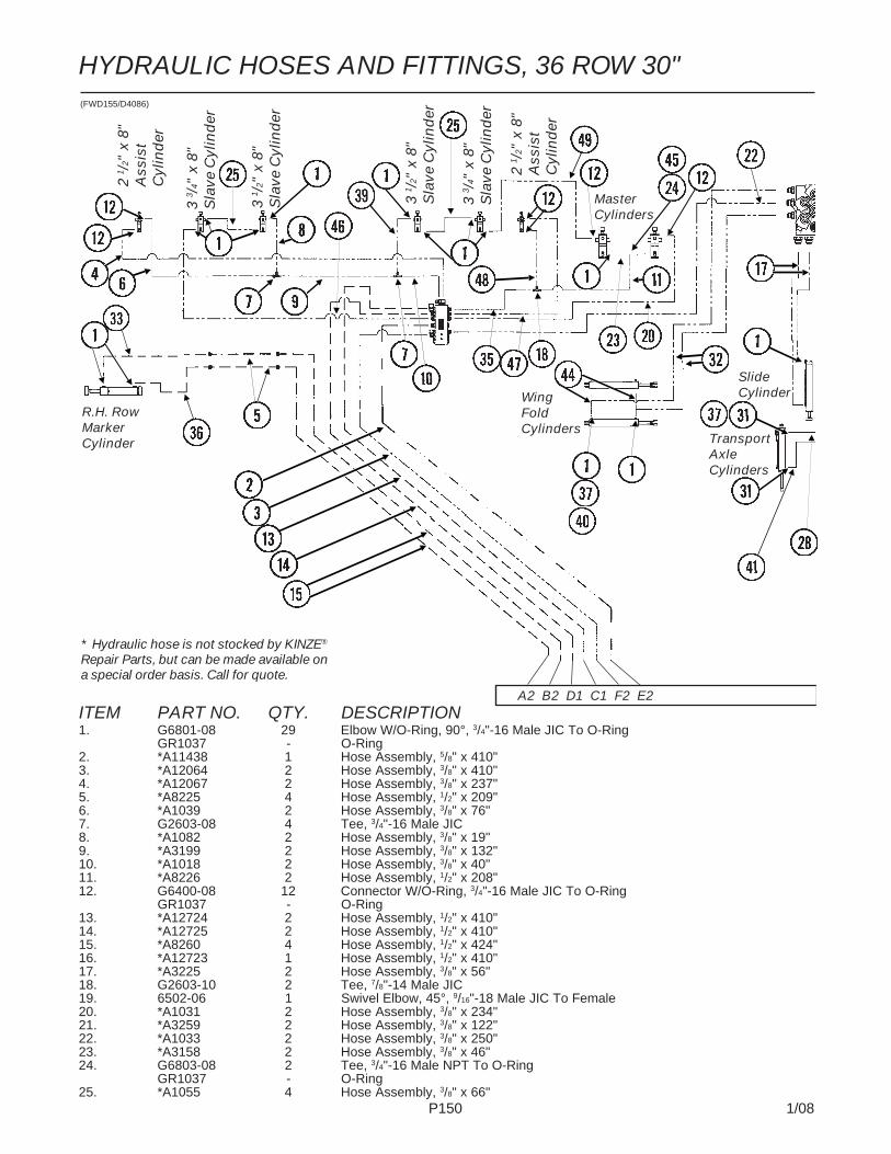
P150 1/08
HYDRAULIC HOSES AND FITTINGS, 36 ROW 30"(FWD155/D4086)
2 1 /
2" x
8"
Ass
ist
Cyl
ind
er
3 3 /
4" x
8"
Sla
ve C
ylin
der
3 1 /
2" x
8"
Sla
ve C
ylin
der
3 3 /
4" x
8"
Sla
ve C
ylin
der
3 1 /
2" x
8"
Sla
ve C
ylin
der
R.H. RowMarkerCylinder
MasterCylinders
WingFoldCylinders
TransportAxleCylinders
A2 B2 D1 C1 F2 E2
* Hydraulic hose is not stocked by KINZE®
Repair Parts, but can be made available ona special order basis. Call for quote.
2 1 /
2" x
8"
Ass
ist
Cyl
ind
er
SlideCylinder
ITEM PART NO. QTY. DESCRIPTION1. G6801-08 29 Elbow W/O-Ring, 90°, 3/4"-16 Male JIC To O-Ring
GR1037 - O-Ring2. *A11438 1 Hose Assembly, 5/8" x 410"3. *A12064 2 Hose Assembly, 3/8" x 410"4. *A12067 2 Hose Assembly, 3/8" x 237"5. *A8225 4 Hose Assembly, 1/2" x 209"6. *A1039 2 Hose Assembly, 3/8" x 76"7. G2603-08 4 Tee, 3/4"-16 Male JIC8. *A1082 2 Hose Assembly, 3/8" x 19"9. *A3199 2 Hose Assembly, 3/8" x 132"10. *A1018 2 Hose Assembly, 3/8" x 40"11. *A8226 2 Hose Assembly, 1/2" x 208"12. G6400-08 12 Connector W/O-Ring, 3/4"-16 Male JIC To O-Ring
GR1037 - O-Ring13. *A12724 2 Hose Assembly, 1/2" x 410"14. *A12725 2 Hose Assembly, 1/2" x 410"15. *A8260 4 Hose Assembly, 1/2" x 424"16. *A12723 1 Hose Assembly, 1/2" x 410"17. *A3225 2 Hose Assembly, 3/8" x 56"18. G2603-10 2 Tee, 7/8"-14 Male JIC19. 6502-06 1 Swivel Elbow, 45°, 9/16"-18 Male JIC To Female20. *A1031 2 Hose Assembly, 3/8" x 234"21. *A3259 2 Hose Assembly, 3/8" x 122"22. *A1033 2 Hose Assembly, 3/8" x 250"23. *A3158 2 Hose Assembly, 3/8" x 46"24. G6803-08 2 Tee, 3/4"-16 Male NPT To O-Ring
GR1037 - O-Ring25. *A1055 4 Hose Assembly, 3/8" x 66"

P151 1/08
HYDRAULIC HOSES AND FITTINGS, 36 ROW 30"
3 1 /
2" x
8"
Sla
ve C
ylin
der
3 3 /
4" x
8"
Sla
ve C
ylin
der
See “Valve Blocks -Located On Hitch”,Pages P132 AndP133
L.H. RowMarker
Cylinder
MasterCylinders
WingFoldCylinder
TongueLatchCylinder
E7 F7 C1 D1 B3 A3
See “Valve Block - LocatedAt Center OfRearH-Frame”,Page P136
F3 E3
See “JunctionBlock - LocatedOn Each Wing”,Page P138
F1E1D1C1B1A1
Slide Latch Cylinder
ITEM PART NO. QTY. DESCRIPTION26. *A3236 2 Hose Assembly, 3/8" x 72"27. *A8230 2 Hose Assembly, 1/2" x 84"28. *A1192 3 Hose Assembly, 1/4" x 20"29. *A8231 2 Hose Assembly, 1/2" x 72"30. GD4086 6 ISO Coupler31. G6400-06-08 7 Connector W/O-Ring, 9/16"-18 Male JIC To 3/4"-16 O-Ring
GR1037 - O-Ring32. *A12053 4 Hose Assembly, 3/8" x 46"33. *A12729 2 Hose Assembly, 1/2" x 82"34. *A7613 1 Hose Assembly, 1/4" x 44"35. *A8229 2 Hose Assembly, 1/2" x 15"36. *A12730 2 Hose Assembly, 1/2" x 52"37. G6500-08 4 Swivel Elbow, 90°, 3/4"-16 Male JIC To Female38. G2700-06-06 2 Bulkhead Tube Union, 9/16"-18 Male JIC
G306-06 4 Lock Nut, 9/16"-1839. *A1098 2 Hose Assembly, 3/8" x 26"40. G6602-08 4 Swivel Tee, 3/4"-16 JIC41. *A7614 2 Hose Assembly, 1/4" x 17"42. *A1132 2 Hose Assembly, 1/4" x 44"43. *A7615 2 Hose Assembly, 1/4" x 122"44. *A3153 4 Hose Assembly, 3/8" x 22"45. G6502-08 2 Swivel Elbow, 45°, 3/4"-16 Male JIC To Female46. *A1057 2 Hose Assembly, 3/8" x 216"47. *A1076 2 Hose Assembly, 3/8" x 30"48. *A3223 2 Hose Assembly, 3/8" x 24"49. *A3228 2 Hose Assembly, 3/8" x 306"50. G2704-06 2 Bulkhead Tee, 9/16"-18 JIC51. *A12041 1 Hose Assembly, 3/8" x 244"
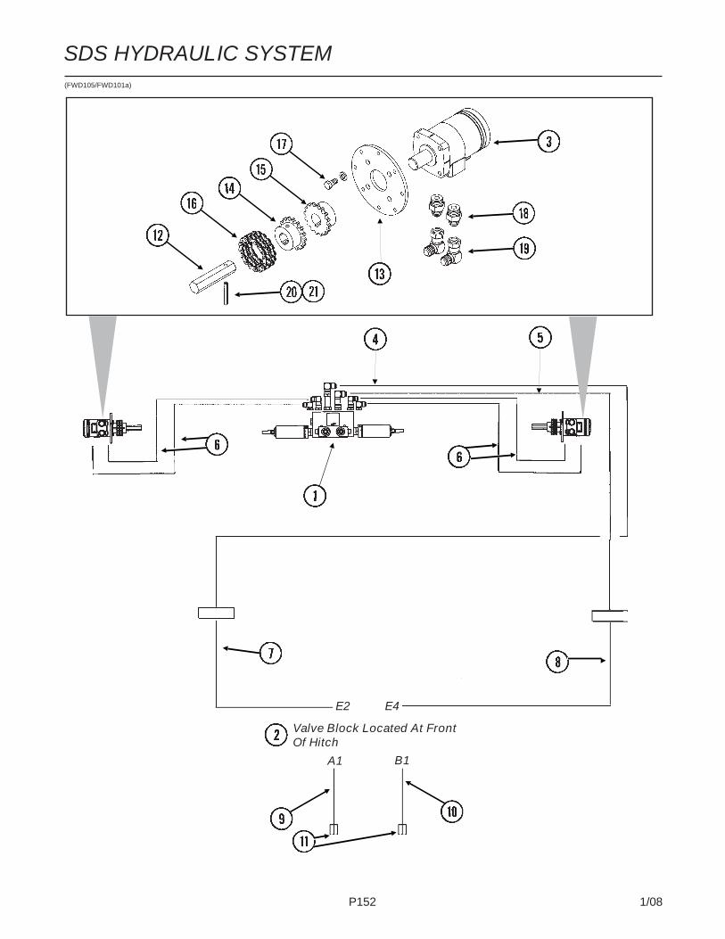
P152 1/08
SDS HYDRAULIC SYSTEM(FWD105/FWD101a)
Valve Block Located At FrontOf Hitch
E2 E4
A1 B1
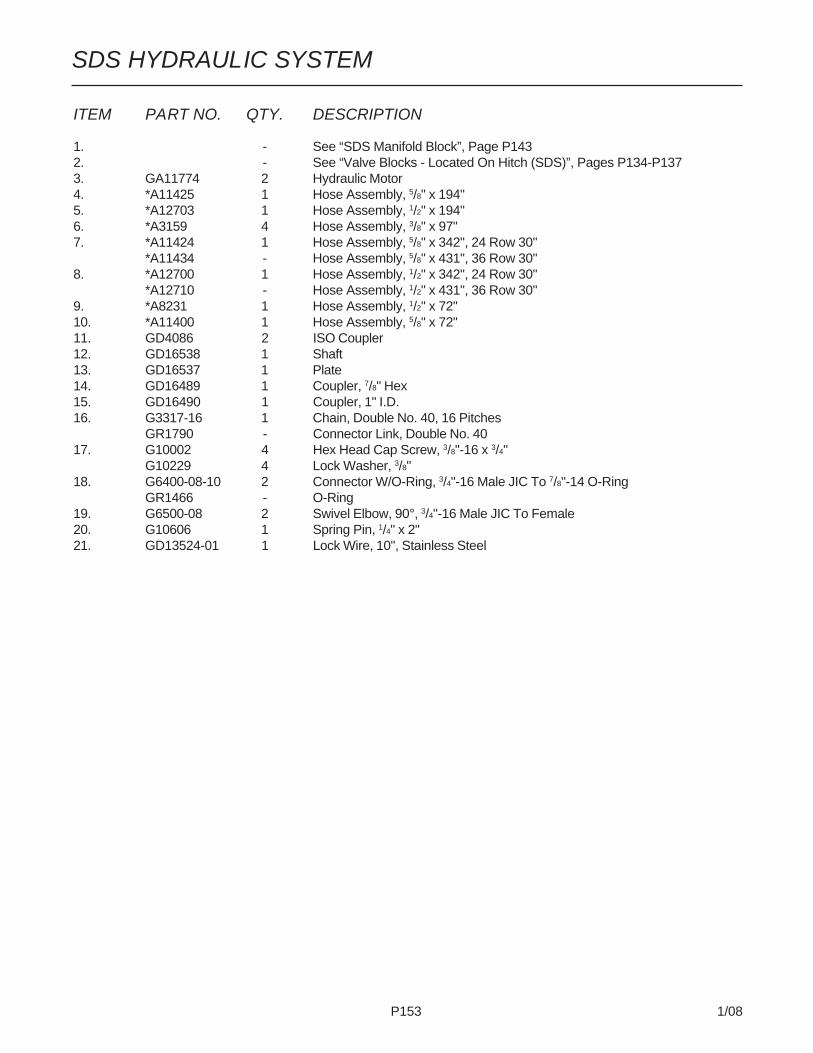
P153 1/08
SDS HYDRAULIC SYSTEM
ITEM PART NO. QTY. DESCRIPTION
1. - See “SDS Manifold Block”, Page P1432. - See “Valve Blocks - Located On Hitch (SDS)”, Pages P134-P1373. GA11774 2 Hydraulic Motor4. *A11425 1 Hose Assembly, 5/8" x 194"5. *A12703 1 Hose Assembly, 1/2" x 194"6. *A3159 4 Hose Assembly, 3/8" x 97"7. *A11424 1 Hose Assembly, 5/8" x 342", 24 Row 30"
*A11434 - Hose Assembly, 5/8" x 431", 36 Row 30"8. *A12700 1 Hose Assembly, 1/2" x 342", 24 Row 30"
*A12710 - Hose Assembly, 1/2" x 431", 36 Row 30"9. *A8231 1 Hose Assembly, 1/2" x 72"10. *A11400 1 Hose Assembly, 5/8" x 72"11. GD4086 2 ISO Coupler12. GD16538 1 Shaft13. GD16537 1 Plate14. GD16489 1 Coupler, 7/8" Hex15. GD16490 1 Coupler, 1" I.D.16. G3317-16 1 Chain, Double No. 40, 16 Pitches
GR1790 - Connector Link, Double No. 4017. G10002 4 Hex Head Cap Screw, 3/8"-16 x 3/4"
G10229 4 Lock Washer, 3/8"18. G6400-08-10 2 Connector W/O-Ring, 3/4"-16 Male JIC To 7/8"-14 O-Ring
GR1466 - O-Ring19. G6500-08 2 Swivel Elbow, 90°, 3/4"-16 Male JIC To Female20. G10606 1 Spring Pin, 1/4" x 2"21. GD13524-01 1 Lock Wire, 10", Stainless Steel
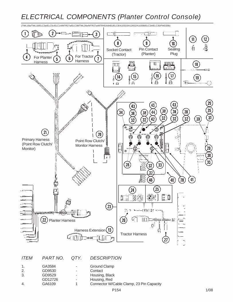
P154 1/08
ITEM PART NO. QTY. DESCRIPTION
1. GA3584 - Ground Clamp2. GD9530 - Contact3. GD9529 - Housing, Black
GD12726 - Housing, Red4. GA6109 1 Connector W/Cable Clamp, 23 Pin Capacity
For PlanterHarness
(TWL19a/TWL18/ELC3a/ELC5c/ELC14/MTR27a/ELC39/TWL26e/MTR27a/MTR45/A9481/ELC8/A10310/A12652/A10308/ELC34/ELC35/FWD30b)
Planter Harness
Tractor Harness
Socket Contact(Tractor)
Pin Contact(Planter)
SealingPlug
For TractorHarness
Primary Harness(Point Row Clutch/Monitor)
Point Row Clutch/Monitor Harness
Harness Extension
ELECTRICAL COMPONENTS (Planter Control Console)
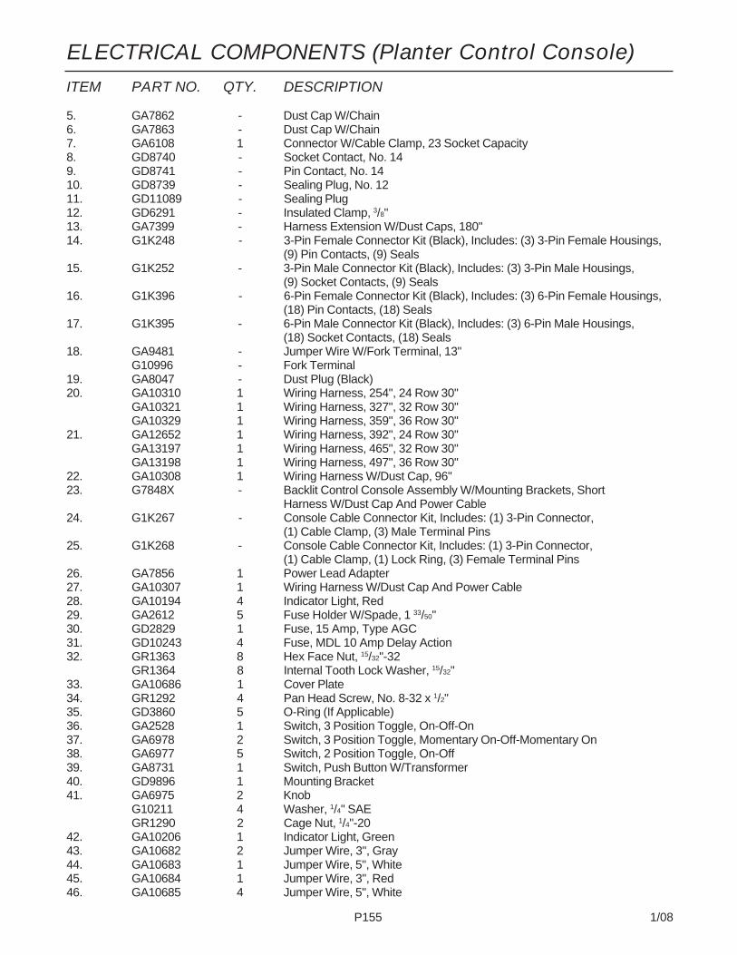
P155 1/08
ELECTRICAL COMPONENTS (Planter Control Console)
ITEM PART NO. QTY. DESCRIPTION
5. GA7862 - Dust Cap W/Chain6. GA7863 - Dust Cap W/Chain7. GA6108 1 Connector W/Cable Clamp, 23 Socket Capacity8. GD8740 - Socket Contact, No. 149. GD8741 - Pin Contact, No. 1410. GD8739 - Sealing Plug, No. 1211. GD11089 - Sealing Plug12. GD6291 - Insulated Clamp, 3/8"13. GA7399 - Harness Extension W/Dust Caps, 180"14. G1K248 - 3-Pin Female Connector Kit (Black), Includes: (3) 3-Pin Female Housings,
(9) Pin Contacts, (9) Seals15. G1K252 - 3-Pin Male Connector Kit (Black), Includes: (3) 3-Pin Male Housings,
(9) Socket Contacts, (9) Seals16. G1K396 - 6-Pin Female Connector Kit (Black), Includes: (3) 6-Pin Female Housings,
(18) Pin Contacts, (18) Seals17. G1K395 - 6-Pin Male Connector Kit (Black), Includes: (3) 6-Pin Male Housings,
(18) Socket Contacts, (18) Seals18. GA9481 - Jumper Wire W/Fork Terminal, 13"
G10996 - Fork Terminal19. GA8047 - Dust Plug (Black)20. GA10310 1 Wiring Harness, 254", 24 Row 30"
GA10321 1 Wiring Harness, 327", 32 Row 30"GA10329 1 Wiring Harness, 359", 36 Row 30"
21. GA12652 1 Wiring Harness, 392", 24 Row 30"GA13197 1 Wiring Harness, 465", 32 Row 30"GA13198 1 Wiring Harness, 497", 36 Row 30"
22. GA10308 1 Wiring Harness W/Dust Cap, 96"23. G7848X - Backlit Control Console Assembly W/Mounting Brackets, Short
Harness W/Dust Cap And Power Cable24. G1K267 - Console Cable Connector Kit, Includes: (1) 3-Pin Connector,
(1) Cable Clamp, (3) Male Terminal Pins25. G1K268 - Console Cable Connector Kit, Includes: (1) 3-Pin Connector,
(1) Cable Clamp, (1) Lock Ring, (3) Female Terminal Pins26. GA7856 1 Power Lead Adapter27. GA10307 1 Wiring Harness W/Dust Cap And Power Cable28. GA10194 4 Indicator Light, Red29. GA2612 5 Fuse Holder W/Spade, 1 33/50"30. GD2829 1 Fuse, 15 Amp, Type AGC31. GD10243 4 Fuse, MDL 10 Amp Delay Action32. GR1363 8 Hex Face Nut, 15/32"-32
GR1364 8 Internal Tooth Lock Washer, 15/32"33. GA10686 1 Cover Plate34. GR1292 4 Pan Head Screw, No. 8-32 x 1/2"35. GD3860 5 O-Ring (If Applicable)36. GA2528 1 Switch, 3 Position Toggle, On-Off-On37. GA6978 2 Switch, 3 Position Toggle, Momentary On-Off-Momentary On38. GA6977 5 Switch, 2 Position Toggle, On-Off39. GA8731 1 Switch, Push Button W/Transformer40. GD9896 1 Mounting Bracket41. GA6975 2 Knob
G10211 4 Washer, 1/4" SAEGR1290 2 Cage Nut, 1/4"-20
42. GA10206 1 Indicator Light, Green43. GA10682 2 Jumper Wire, 3", Gray44. GA10683 1 Jumper Wire, 5", White45. GA10684 1 Jumper Wire, 3", Red46. GA10685 4 Jumper Wire, 5", White

P156 1/08
ELECTRICAL COMPONENTS (SDS Control Console)(A11377/A9954/A11502/A11906/FWD102/A11376/A11378/A11348a/A11736)

P157 1/08
ELECTRICAL COMPONENTS (SDS Control Console)
ITEM PART NO. QTY. DESCRIPTION
1. GA11348 1 SDS Control Console Assembly2. GA7856 1 Power Lead Adapter3. GA11376 1 Wiring Harness, 648", 24 Row 30"
GA11506 - Wiring Harness, 756", 32 Row 30" And 36 Row 30"4. GA9097 2 Terminal Strip W/Screws, No. 6, 14 Terminal
GR1635 - Screw, No. 6-32 x 1/4"5. GA9954 2 Speed Sensor Assembly6. GA11502 2 Voltage Stabilizer, 8 1/2"7. GA11377 2 Wiring Harness, 360", 24 Row 30"
GA11507 - Wiring Harness, 576", 32 Row 30" And 36 Row 30"8. GA11906 2 4-Pin Connector, 48"9. GA11387 2 Proximity Sensor10. GA11378 2 Wiring Harness, 48"11. GA11066 4 Limit Switch12. GA9098 2 Terminal Strip W/Screws, No. 6, 8 Terminal
GR1635 - Screw, No. 6-32 x 1/4"13. GR1292 4 Pan Head Screw, No. 8-32 x 1/2"14. GA2612 3 Fuse Holder W/Spade, 1 33/50"15. GD2829 1 Fuse, 15 Amp, Type AGC16. GD3860 3 O-Ring17. GR1363 4 Hex Face Nut, 15/32"-32
GR1364 4 Internal Tooth Lock Washer, 15/32"18. GA12171 1 Cover Plate19. GA6978 2 Switch, 3 Position Toggle, Momentary On-Off-Momentary On20. GA6977 1 Switch, 2 Position Toggle, On-Off21. GA12173 2 Switch, 2 Position Locking Toggle22. GD14640 1 Mounting Bracket23. GA6975 2 Knob
G10211 4 Washer, 1/4" SAEGR1290 2 Cage Nut, 1/4"-20
24. GA10195 2 Indicator Light, Amber25. GA12174 1 Switch, 2 Position Toggle, Momentary-On26. GA9965 2 Tachometer27. GA12180 1 Wiring Harness W/Dust Cap And Power Cable28. G11112 1 Plug, 3/8"29. GA11736 - Harness Extension W/Dust Caps, 180"

P158 1/08
ELECTRICAL COMPONENTS (Lights)(MTR27t/MTR27a/ELC27b/MTR27a/A10315/A10318/A10317/A10316/A10452/A11042)
To Lights On RearH-Frame
Primary Harness
To Marker LightAnd Amber LightOn L.H. Wing
Extension BetweenPrimary HarnessAnd Light HarnessOn L.H. Wing
To Marker LightAnd Amber LightOn R.H. Wing
To Amber Light Mid-Wing, 32 Row 30" And36 Row 30"
To Amber Light Mid-Wing, 32 Row 30" And36 Row 30"
To Limit Switch OnRow Marker Mount(See “Row MarkerAssembly”)
To Limit Switch OnRow Marker Mount(See “Row MarkerAssembly”)

P159 1/08
ELECTRICAL COMPONENTS (Lights)
ITEM PART NO. QTY. DESCRIPTION
1. G1K321 - 2-Pin Female Connector Kit (Black), Includes: (3) 2-Pin Female Housings,(6) Pin Contacts, (6) Seals
2. G1K320 - 2-Pin Male Connector Kit (Black), Includes: (3) 2-Pin Male Housings,(6) Socket Contacts, (6) Seals
3. G1K248 - 3-Pin Female Connector Kit (Black), Includes: (3) 3-Pin Female Housings,(9) Pin Contacts, (9) Seals
4. G1K252 - 3-Pin Male Connector Kit (Black), Includes: (3) 3-Pin Male Housings,(9) Socket Contacts, (9) Seals
5. GA8328 - 4-Pin Female Connector Kit, Includes: (1) 4-Pin Female Housing,(4) Pin Contacts, (4) Seals
6. GA8329 - 4-Pin Male Connector Kit, Includes: (1) 4-Pin Male Housing,(4) Socket Contacts, (4) Seals
7. GD11089 - Sealing Plug8. GA10315 1 Wiring Harness, 414", 24 Row 30"
GA10323 1 Wiring Harness, 487", 32 Row 30"GA10334 1 Wiring Harness, 543", 36 Row 30"
9. GA10318 1 Wiring Harness, 156", 24 Row 30"GA10326 1 Wiring Harness, 231", 32 Row 30"GA10338 1 Wiring Harness, 276", 36 Row 30"
10. GA10317 1 Wiring Harness, 198", 24 Row 30"GA10325 1 Wiring Harness, 243", 32 Row 30"GA10336 1 Wiring Harness, 258", 36 Row 30"
11. GA10316 1 Wiring Harness, 254", 24 Row 30"GA10324 1 Wiring Harness, 327", 32 Row 30"GA10335 1 Wiring Harness, 359", 36 Row 30"
12. GA10319 1 Wiring Harness, 156", 24 Row 30"GA10327 1 Wiring Harness, 231", 32 Row 30"GA10337 1 Wiring Harness, 276", 36 Row 30"
13. GA10452 2 Wiring Harness, 63", 32 Row 30" And 36 Row 30"14. GA11299 2 Wiring Harness, 63", All Sizes
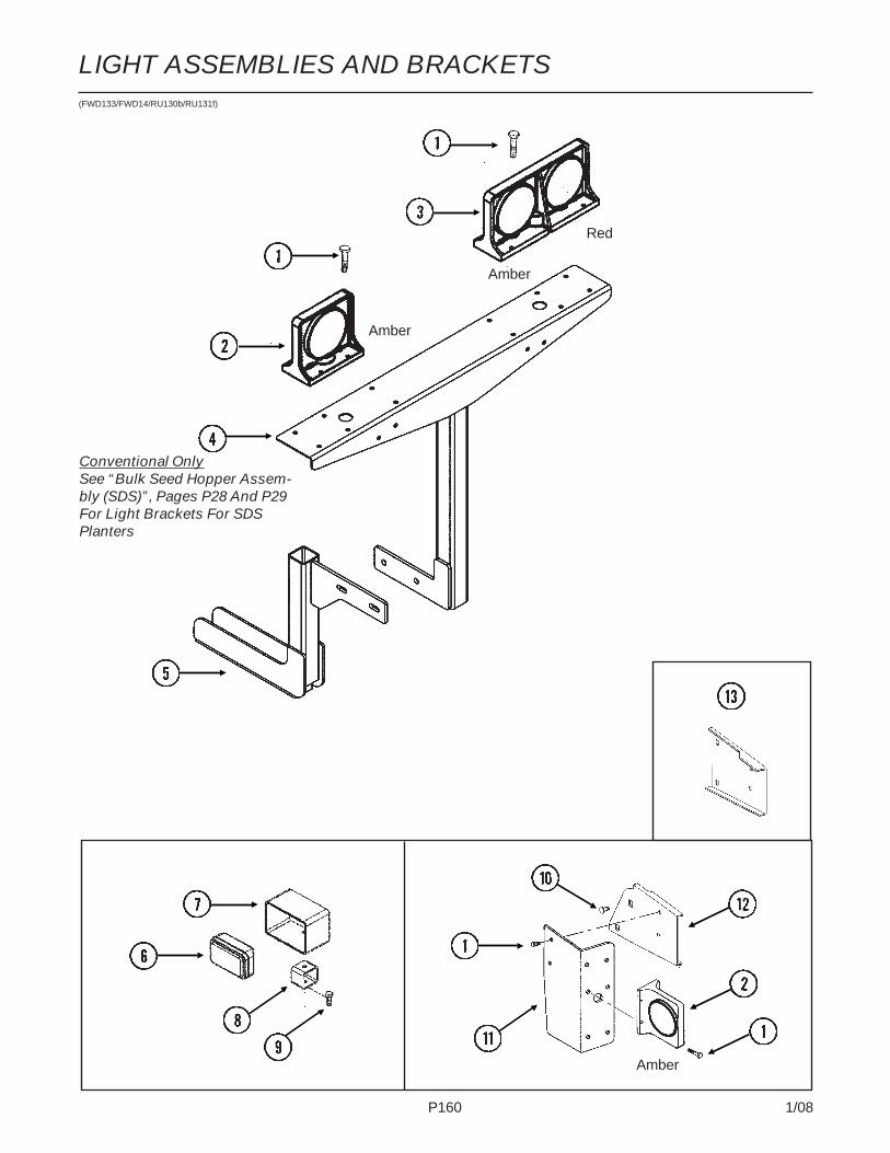
P160 1/08
LIGHT ASSEMBLIES AND BRACKETS(FWD133/FWD14/RU130b/RU131f)
Amber
Amber
Amber
Red
Conventional OnlySee “Bulk Seed Hopper Assem-bly (SDS)”, Pages P28 And P29For Light Brackets For SDSPlanters

P161 1/08
ITEM PART NO. QTY. DESCRIPTION
1. G10064 - Hex Head Cap Screw, 1/4"-20 x 1"G10227 - Lock Washer, 1/4"G10103 - Hex Nut, 1/4"-20
2. GA10576 4 Single Amber Light AssemblyGR1731 - Amber LensGR1208 - Bulb
3. GA10571 1 Double Light AssemblyGA10572 - Double Light Assembly (Shown)GR1733 - Red LensGR1731 - Amber LensGR1732 - CoverGR1208 - Bulb
4. GA11771 1 Light Bracket, L.H. (Conventional Planters) (Shown)GA11772 - Light Bracket, R.H. (Conventional Planters)
5. - See “Manifolds And Distribution Hoses”, Pages P52-P556. GA10297 2 Work Light Assembly W/Halogen Lamp
GR1707 - Halogen Lamp, 3" x 5"7. GD15582 1 Light Protector8. GD14987 1 Light Bracket9. G10017 1 Hex Head Cap Screw, 1/2"-13 x 1 1/2"
G10228 1 Lock Washer, 1/2"G10102 1 Hex Nut, 1/2"-13
10. G10312 - Carriage Bolt, 5/16"-18 x 3/4"G10620 - Serrated Flange Nut, 5/16"-18
11. GD12725 1 Bracket (Shown)GD12724 1 Bracket
12. GD15968 1 Light Mount Extension13. GD12723 1 Light Mount Extension
LIGHT ASSEMBLIES AND BRACKETS

P162 1/08
KPM III ELECTRONIC SEED MONITOR(MTR43w)
Radar Y-Cable Adapter Harness
ExtensionHarness
JunctionY-Harness
Acre Counter Switch Kit
PlanterHarness
Power Lead Adapter
Radar Distance SensorShaft Rotation Sensor
Blue
ShaftRotationSensor
TEM PART NO. QTY. DESCRIPTION
1. GA7858 - Radar Distance Sensor W/20' Cable2. GA8026 - Radar Sensor Pipe/Mounting Bracket Package3. G1K323 - 4-Pin Connector Kit W/Female Housing, Includes: (4) Pins, (1) Cable Clamp4. GA5600 1 Magnetic Distance Sensor5. GD8751 - Magnetic Distance Sensor Pulse Wheel6. GD6291 - Insulated Clamp, 3/8"7. GD8770 1 Bracket8. G10001 2 Hex Head Cap Screw, 3/8"-16 x 1"
G10229 2 Lock Washer, 3/8"G10101 2 Hex Nut, 3/8"-16
Magnetic Distance Sensor (MDS)
MagneticDistanceSensor(MDS)Adapter
Blue

P163 1/08
KPM III ELECTRONIC SEED MONITOR
ITEM PART NO. QTY. DESCRIPTION
9. GD8771 1 Spring Wave Washer10. GA7856 1 Power Lead Adapter11. GA9144 - Monitor/Radar Adapter Cable, 10"12. G1K267 - Console Cable Connector Kit, Includes: (1) Cable Clamp,
(1) 3-Pin Connector, (3) Male Terminal Pins13. G1K268 - Console Cable Connector Kit, Includes: (1) Cable Clamp,
(1) 3-Pin Connector, (1) Lock Ring, (3) Female Terminal Pins14. GA11039 1 KPM III Backlit Console W/Brush (Item 23), Dust Plug (Item 34), Mounting
Bracket Assembly, Console Mounting Bracket Hardware And Power HarnessGA12403 - Mounting Bracket Assembly, Includes: (2) Mounting Brackets, (2) Connector
Halves, (1) Compression Spring, (1) Tension Knob, (1) 1/4"-20 x 1 3/4" HexHead Cap Screw, (1) 1/4" Plastic Washer, (1) 1/4" Steel Washer
GR1762 - Console Mounting Bracket Hardware Package, Includes: (3) No. 10-32 x 5/8" HexSocket Pan Head Screws, (3) No. 10 Lock Washers
GR1764 - Power Harness15. G1K322 - 4-Pin Connector Kit W/Male Housing, (4) Female Socket Contacts And
(1) Cable Clamp16. - Included In Tractor/Planter Wiring Harnesses, See Pages P154 And P15517. GA8022 - Planter Harness W/Dust Caps, 6 Row (9 Connectors)
GA7851 - Planter Harness W/Dust Caps, 12 Row (16 Connectors)GA7852 - Planter Harness W/Dust Caps, 16 Row (20 Connectors)GD11993 - Dust Cap
18. GA12650 - Seed Tube W/Computerized Sensor, EdgeVac®
GR1737 - Sensor Only, EdgeVac®
GA12636 - Seed Tube (With Holes For Sensor Installation), EdgeVac®
19. GA7859 1 Magnetic Distance Sensor Adapter (Analog To Digital)20. GR0594 - Brush21. GR0586 1 Radar Y-Cable (Used To Connect Radar Distance Sensor For Multiple
Functions)22. GA7849 - Extension Harness, 15'23. GA7854 - Extension Harness W/Dust Cap, 15'
GA7855 - Extension Harness W/Dust Cap, 30'GD11993 - Dust Cap
24. GA7853 - Junction Y-Harness W/Dust CapGD11993 - Dust Cap
25. G1K321 - 2-Pin Female Connector Kit (Black), Includes: (3) 2-Pin FemaleHousings, (6) Pin Contacts, (6) Seals
26. G1K320 - 2-Pin Male Connector Kit (Black), Includes: (3) 2-Pin Male Housings,(6) Socket Contacts, (6) Seals
27. G1K248 - 3-Pin Female Connector Kit (Black), Includes: (3) 3-Pin FemaleHousings, (9) Pin Contacts, (9) Seals
G1K362 - 3-Pin Female Connector Kit (Blue), Includes: (3) 3-Pin FemaleHousings, (9) Pin Contacts, (9) Seals
28. G1K252 - 3-Pin Male Connector Kit (Black), Includes: (3) 3-Pin Male Housings,(9) Socket Contacts, (9) Seals
G1K363 - 3-Pin Male Connector Kit (Blue), Includes: (3) 3-Pin Male Housings,(9) Socket Contacts, (9) Seals
29. GD11089 - Sealing Plug30. G1K249 - Acre Counter Switch Kit31. GA8046 - Dust Plug (Black)
GA9978 - Dust Plug (Blue)32. GA8047 - Dust Plug (Black)
GA9979 - Dust Plug (Blue)33. G1K364 - Rotation Sensor Mount Kit, Includes: (2) Mounts, (2) GD11721
5" x 7" U-Bolts, (4) G10228 Lock Washers, (4) G10102 Hex Nuts, (1) Instruction34. GD11169 1 Mount35. GD11170 1 Spring Mount36. GD5857 2 Spring37. GD18168 2 Mount38. G10686 4 Hex Head Cap Screw, 3/8"-16 x 8"
G10229 4 Lock Washer, 3/8"G10101 4 Hex Nut, 3/8"-16
39. GD18118 2 Shaft Sensor Mount40. G10757 4 Pan Head Screw, No. 10-32 x 1 ¼"
G10243 4 Washer, No. 10 SAEG10758 4 Hex Nut, No. 10-32
41. GR1415 1 Rotation Sensor42. GR1414 1 Actuator43. GD11474 4 Cover44. G10927 4 Pan Head Machine Screw, No. 8-32 x 1 1/4", Stainless Steel
G10931 4 Lock Washer, No. 8, Internal/External, Stainless SteelG10928 4 Hex Nut, No. 8-32, Stainless Steel
A. GA6147 - Magnetic Distance Sensor And Mounting Package (Items 4-9)

P164 1/08
PLANTER MONITOR MODULE (PMM)(MTR60/MTR63/PMM01/MTR65/MTR61/MTR64/MTR62/PMM02)
Shaft Rotation Sensor
NOTE: See Ag Leader manual for Ag Leader Insight display and associated cab harnesscomponents.
ITEM PART NO. QTY. DESCRIPTION
1. G10686 4 Hex Head Cap Screw, 3/8"-16 x 8"G1-229 4 Lock Washer, 3/8"G10101 4 Hex Nut, 3/8"-16
2. GD18118 2 Shaft Sensor Mount3. GR1415 1 Rotation Sensor4. GR1414 1 Actuator5. GD18168 2 Mount
PlanterHarness
MagneticDistanceSensor(MDS)Adapter
Magnetic Distance Sensor (MDS)
Blue
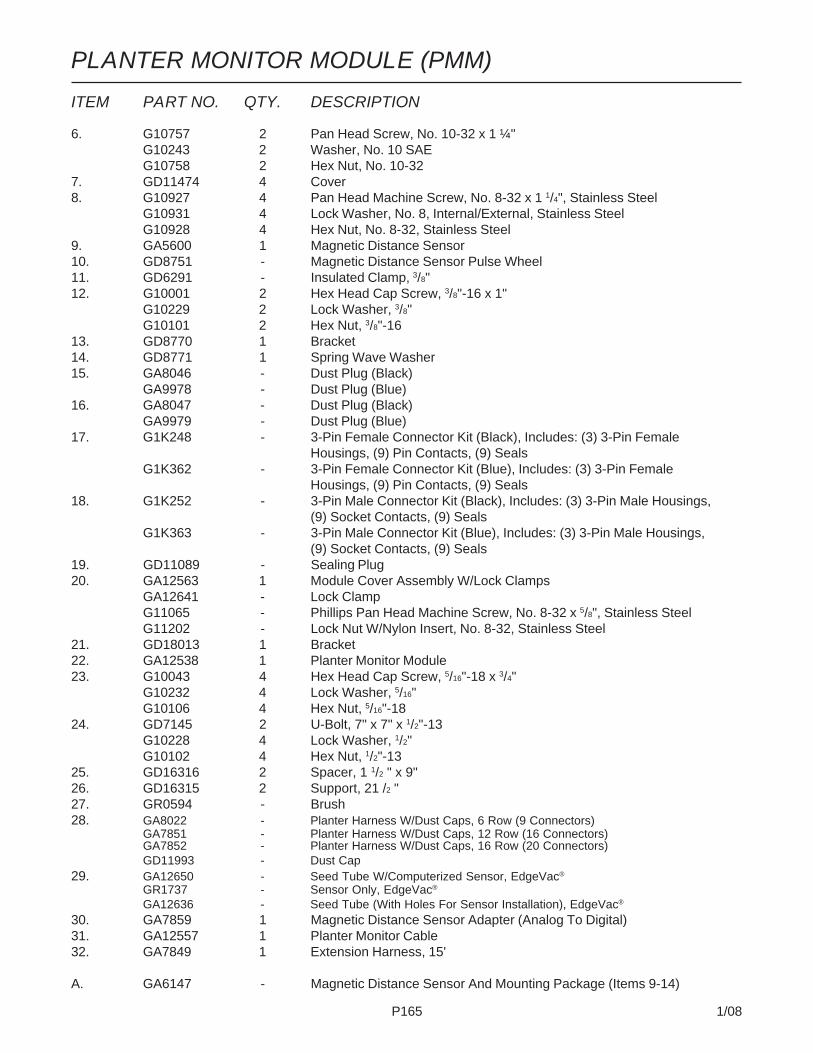
P165 1/08
ITEM PART NO. QTY. DESCRIPTION
6. G10757 2 Pan Head Screw, No. 10-32 x 1 ¼"G10243 2 Washer, No. 10 SAEG10758 2 Hex Nut, No. 10-32
7. GD11474 4 Cover8. G10927 4 Pan Head Machine Screw, No. 8-32 x 1 1/4", Stainless Steel
G10931 4 Lock Washer, No. 8, Internal/External, Stainless SteelG10928 4 Hex Nut, No. 8-32, Stainless Steel
9. GA5600 1 Magnetic Distance Sensor10. GD8751 - Magnetic Distance Sensor Pulse Wheel11. GD6291 - Insulated Clamp, 3/8"12. G10001 2 Hex Head Cap Screw, 3/8"-16 x 1"
G10229 2 Lock Washer, 3/8"G10101 2 Hex Nut, 3/8"-16
13. GD8770 1 Bracket14. GD8771 1 Spring Wave Washer15. GA8046 - Dust Plug (Black)
GA9978 - Dust Plug (Blue)16. GA8047 - Dust Plug (Black)
GA9979 - Dust Plug (Blue)17. G1K248 - 3-Pin Female Connector Kit (Black), Includes: (3) 3-Pin Female
Housings, (9) Pin Contacts, (9) SealsG1K362 - 3-Pin Female Connector Kit (Blue), Includes: (3) 3-Pin Female
Housings, (9) Pin Contacts, (9) Seals18. G1K252 - 3-Pin Male Connector Kit (Black), Includes: (3) 3-Pin Male Housings,
(9) Socket Contacts, (9) SealsG1K363 - 3-Pin Male Connector Kit (Blue), Includes: (3) 3-Pin Male Housings,
(9) Socket Contacts, (9) Seals19. GD11089 - Sealing Plug20. GA12563 1 Module Cover Assembly W/Lock Clamps
GA12641 - Lock ClampG11065 - Phillips Pan Head Machine Screw, No. 8-32 x 5/8", Stainless SteelG11202 - Lock Nut W/Nylon Insert, No. 8-32, Stainless Steel
21. GD18013 1 Bracket22. GA12538 1 Planter Monitor Module23. G10043 4 Hex Head Cap Screw, 5/16"-18 x 3/4"
G10232 4 Lock Washer, 5/16"G10106 4 Hex Nut, 5/16"-18
24. GD7145 2 U-Bolt, 7" x 7" x 1/2"-13G10228 4 Lock Washer, 1/2"G10102 4 Hex Nut, 1/2"-13
25. GD16316 2 Spacer, 1 1/2 " x 9"26. GD16315 2 Support, 21 /2 "27. GR0594 - Brush28. GA8022 - Planter Harness W/Dust Caps, 6 Row (9 Connectors)
GA7851 - Planter Harness W/Dust Caps, 12 Row (16 Connectors)GA7852 - Planter Harness W/Dust Caps, 16 Row (20 Connectors)GD11993 - Dust Cap
29. GA12650 - Seed Tube W/Computerized Sensor, EdgeVac®
GR1737 - Sensor Only, EdgeVac®
GA12636 - Seed Tube (With Holes For Sensor Installation), EdgeVac®
30. GA7859 1 Magnetic Distance Sensor Adapter (Analog To Digital)31. GA12557 1 Planter Monitor Cable32. GA7849 1 Extension Harness, 15'
A. GA6147 - Magnetic Distance Sensor And Mounting Package (Items 9-14)
PLANTER MONITOR MODULE (PMM)

P166 1/08
NOTCHED SINGLE DISC FERTILIZER OPENER(A10216aa)
To Pump
Optional - Liquid Fertilizer Only
To Opener
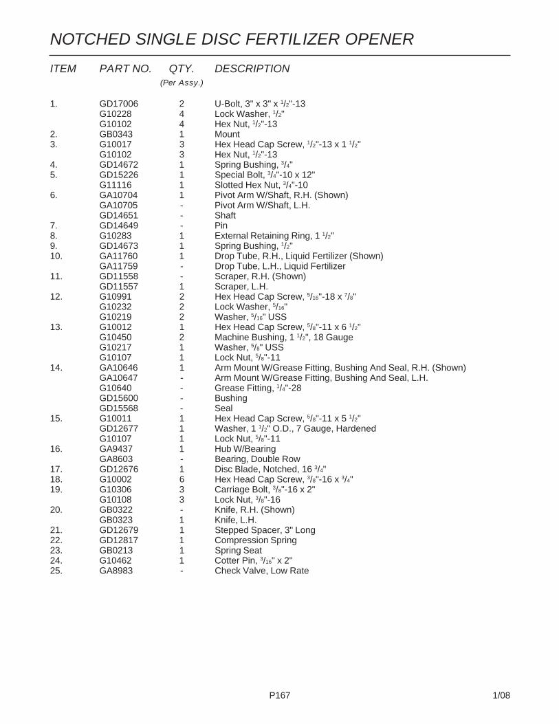
P167 1/08
ITEM PART NO. QTY. DESCRIPTION(Per Assy.)
1. GD17006 2 U-Bolt, 3" x 3" x 1/2"-13G10228 4 Lock Washer, 1/2"G10102 4 Hex Nut, 1/2"-13
2. GB0343 1 Mount3. G10017 3 Hex Head Cap Screw, 1/2"-13 x 1 1/2"
G10102 3 Hex Nut, 1/2"-134. GD14672 1 Spring Bushing, 3/4"5. GD15226 1 Special Bolt, 3/4"-10 x 12"
G11116 1 Slotted Hex Nut, 3/4"-106. GA10704 1 Pivot Arm W/Shaft, R.H. (Shown)
GA10705 - Pivot Arm W/Shaft, L.H.GD14651 - Shaft
7. GD14649 - Pin8. G10283 1 External Retaining Ring, 1 1/2"9. GD14673 1 Spring Bushing, 1/2"10. GA11760 1 Drop Tube, R.H., Liquid Fertilizer (Shown)
GA11759 - Drop Tube, L.H., Liquid Fertilizer11. GD11558 - Scraper, R.H. (Shown)
GD11557 1 Scraper, L.H.12. G10991 2 Hex Head Cap Screw, 5/16"-18 x 7/8"
G10232 2 Lock Washer, 5/16"G10219 2 Washer, 5/16" USS
13. G10012 1 Hex Head Cap Screw, 5/8"-11 x 6 1/2"G10450 2 Machine Bushing, 1 1/2", 18 GaugeG10217 1 Washer, 5/8" USSG10107 1 Lock Nut, 5/8"-11
14. GA10646 1 Arm Mount W/Grease Fitting, Bushing And Seal, R.H. (Shown)GA10647 - Arm Mount W/Grease Fitting, Bushing And Seal, L.H.G10640 - Grease Fitting, 1/4"-28GD15600 - BushingGD15568 - Seal
15. G10011 1 Hex Head Cap Screw, 5/8"-11 x 5 1/2"GD12677 1 Washer, 1 1/2" O.D., 7 Gauge, HardenedG10107 1 Lock Nut, 5/8"-11
16. GA9437 1 Hub W/BearingGA8603 - Bearing, Double Row
17. GD12676 1 Disc Blade, Notched, 16 3/4"18. G10002 6 Hex Head Cap Screw, 3/8"-16 x 3/4"19. G10306 3 Carriage Bolt, 3/8"-16 x 2"
G10108 3 Lock Nut, 3/8"-1620. GB0322 - Knife, R.H. (Shown)
GB0323 1 Knife, L.H.21. GD12679 1 Stepped Spacer, 3" Long22. GD12817 1 Compression Spring23. GB0213 1 Spring Seat24. G10462 1 Cotter Pin, 3/16" x 2"25. GA8983 - Check Valve, Low Rate
NOTCHED SINGLE DISC FERTILIZER OPENER

P168 1/08
ITEM PART NO. QTY. DESCRIPTION(Per Assy.)
1. G10010 2 Hex Head Cap Screw, 5/8"-11 x 3"2. GD7805 1 Special Washer, 5/8", Hardened3. - See “Notched Single Disc Fertilizer Opener”, Pages P166 And P1674. GA9472 1 Blade Mount5. G10233 1 Machine Bushing, 1", 10 Gauge6. GA10037 1 Wheel Mount, L.H. (Shown)
GA10036 1 Wheel Mount, R.H.7. GD13309 1 Spacer8. GD11423 1 Half Wheel9. GD11953 1 Offset Tire10. GA6171 1 Bearing11. GD11954 1 Half Wheel Cover, Nylon12. G10961 11 Flanged Whiz-Lock Screw, 5/16"-18 x 3/4", No Serration
G10620 11 Serrated Flange Nut, 5/16"-1813. G10204 - Special Machine Bushing, 5/8" x 1" O.D. (As Required)
A. GA8877 - Gauge Wheel Complete (Items 8-12)
DEPTH/GAUGE WHEEL ATTACHMENT FOR NOTCHEDSINGLE DISC FERTILIZER OPENER(FRTZ257)

P169 1/08
FERTILIZER OPENER MOUNTS(FWD28/FWD138/FWD29a)
ITEM PART NO. QTY. DESCRIPTION
1. GD14671 - U-Bolt, 3" x 3" x 5/8"-11G10230 - Lock Washer, 5/8"G10104 - Hex Nut, 5/8"-11
2. GD17039 - U-Bolt, 7" x 7" x 5/8"-11G10230 - Lock Washer, 5/8"G10104 - Hex Nut, 5/8"-11
3. GB0365 - Brace, L.H. (Shown)GB0370 - Brace, R.H.
4. G10177 - Hex Head Cap Screw, 5/8"-11 x 9 1/2"G10230 - Lock Washer, 5/8"G10104 - Hex Nut, 5/8"-11
5. GA10923 2 Mount6. - See “Parallel Arms, Mounting Support Plate And Quick Adjustable
Down Force Springs”, Page P47. - See “Center Toolbar/Rear H-Frame Assembly”, Pages P76 And P778. GD17973 2 Tap Block9. GA12487 1 Opener Mount, L.H. (Shown)
GA12488 - Opener Mount, R.H.10. G10016 8 Hex Head Cap Screw, 1/2"-13 x 2"
G10228 8 Lock Washer, 1/2"
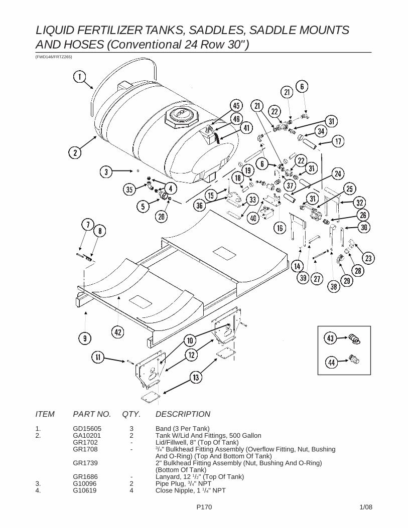
P170 1/08
(FWD146/FRTZ265)
ITEM PART NO. QTY. DESCRIPTION
1. GD15605 3 Band (3 Per Tank)2. GA10201 2 Tank W/Lid And Fittings, 500 Gallon
GR1702 - Lid/Fillwell, 8" (Top Of Tank)GR1708 - 3/4" Bulkhead Fitting Assembly (Overflow Fitting, Nut, Bushing
And O-Ring) (Top And Bottom Of Tank)GR1739 2" Bulkhead Fitting Assembly (Nut, Bushing And O-Ring)
(Bottom Of Tank)GR1686 - Lanyard, 12 1/2" (Top Of Tank)
3. G10096 2 Pipe Plug, 3/4" NPT4. G10619 4 Close Nipple, 1 1/4" NPT
LIQUID FERTILIZER TANKS, SADDLES, SADDLE MOUNTSAND HOSES (Conventional 24 Row 30")

P171 1/08
ITEM PART NO. QTY. DESCRIPTION
5. GA4976 2 Shutoff Valve, 1 1/4" NPTGR1015 - Body O-RingGR1016 - Stem O-RingGR1017 - Teflon SeatGR1018 - BallGR1019 - Handle
6. G10629 4 Elbow, 90°, 1 1/4" NPT To Barb7. G10485 6 Hex Head Tap Bolt, 3/8"-16 x 5" (6 Per Tank)
G10901 6 Lock Nut W/Nylon Insert, 3/8"-16 (6 Per Tank)8. GD11123 6 Anchor (Sub GA8114)9. GA10356 1 Tank Mount10. G11122 12 Hex Head Cap Screw, 5/8"-11 x 12"
G10205 12 Washer, 5/8" SAEG10107 12 Lock Nut, 5/8"-11
11. G10046 12 Hex Head Cap Screw, 5/8"-11 x 5"G10205 12 Washer, 5/8" SAEG10107 12 Lock Nut, 5/8"-11
12. GA12503 2 Mounting Bracket13. GD17995 2 Plate, 8 3/4" x 10 1/2"14. G10599 8 Carriage Bolt, 3/8"-16 x 1 1/4"
G10203 8 Washer, 3/8" SAEG10108 8 Lock Nut, 3/8"-16
15. G11193 8 Hex Head Cap Screw, 3/8"-16 x 9 1/2", 24 Row 30"G10753 - Hex Head Cap Screw, 3/8"-16 x 4 1/2", 32 Row 30" And 36 Row 30"G10108 8 Lock Nut, 3/8"-16
16. GA8768 2 Clamp, 3"17. G4206-01 1 Hose, 2" x 18'18. G4200-05 2 Hose, 1 1/4" x 50'19 G10674 48 Hose Clamp, No. 2420. G10626 2 Adapter, 1 1/4" NPT To Barb21. G10616 6 Reducing Bushing, 2" Male NPT To 1 1/4" Female22. G10888 3 Tee, 2" Female NPT23. G10287 1 Elbow, 90°, 2" Male NPT To Female24. G4201-02 1 Hose, 2" x 12'25. GA2660 1 Shutoff Valve, 2" NPT26. G10623 3 Close Nipple, 2" NPT27. G10148 2 Hex Head Cap Screw, 1/2"-13 x 9 1/2"
G10216 2 Washer, 1/2" USSG10228 2 Lock Washer, 1/2"G10102 2 Hex Nut, 1/2"-13
28. GD3622 1 Adapter, 2" Female NPT To Cam Lock29. GD3951 1 Dust Cap, 2" Cam Lock30. GD15703 1 Bracket, 1 1/2" x 12 1/2", 24 Row 30"
GD15706 - Bracket, 1 1/2" x 18 1/2", 32 Row 30" And 36 Row 30"31. G10628 4 Adapter, 2" NPT To Barb32. GA11064 2 Hose Support, 24 Row 30"
GA11063 - Hose Support, 32 Row 30" And 36 Row 30"33. GD16478 4 Bracket34. G10676 4 Hose Clamp, No. 36, Stainless Steel35. G10897 2 Elbow, 90°, 1 1/4" Female NPT36. GD16479 4 Mount37. G11165 2 T-Bolt Clamp, 2 1/2", Stainless Steel38. GA10509 1 Straight Mount, Quick Fill, 14 19/32", 24 Row 30"
GA10510 - Straight Mount, Quick Fill, 20 19/32", 32 Row 30" And 36 Row 30"39. GD16189 4 Tie Bracket40. GD16210 1 Bracket41. G4205-10 1 Hose, 3/4" x 200" (100" Per Tank)42. GD1862 2 Pad, 8" x 14'43. GD10777 2 Dust Plug, 2" Male Cam Lock44. GD3623 1 Adapter, 2" Male NPT To Cam Lock45. G10917 2 Elbow, 90°, 3/4" NPT To Barb46. G10278 10 Hose Clamp. No. 16
LIQUID FERTILIZER TANKS, SADDLES, SADDLE MOUNTSAND HOSES (Conventional 24 Row 30")

P172 1/08
(FWD78a/FRTZ265)
ITEM PART NO. QTY. DESCRIPTION
1. GD15605 3 Band (3 Per Tank)2. GA10201 2 Tank W/Lid And Fittings, 500 Gallon
GR1702 - Lid/Fillwell, 8" (Top Of Tank)GR1708 - 3/4" Bulkhead Fitting Assembly (Overflow Fitting, Nut, Bushing
And O-Ring) (Top And Bottom Of Tank)GR1739 2" Bulkhead Fitting Assembly (Nut, Bushing And O-Ring) (Bottom Of Tank)GR1686 - Lanyard, 12 1/2" (Top Of Tank)
3. G10096 2 Pipe Plug, 3/4" NPT4. G10619 4 Close Nipple, 1 1/4" NPT5. GA4976 2 Shutoff Valve, 1 1/4" NPT
GR1015 - Body O-RingGR1016 - Stem O-RingGR1017 - Teflon SeatGR1018 - BallGR1019 - Handle
LIQUID FERTILIZER TANKS, SADDLES, SADDLE MOUNTSAND HOSES (Conventional 32 Row 30" And 36 Row 30")

P173 1/08
ITEM PART NO. QTY. DESCRIPTION
6. G10629 4 Elbow, 90°, 1 1/4" NPT To Barb7. G10485 6 Hex Head Tap Bolt, 3/8"-16 x 5" (6 Per Tank)
G10901 6 Lock Nut W/Nylon Insert, 3/8"-16 (6 Per Tank)8. GD11123 6 Anchor (Sub GA8114)9. GA10356 1 Tank Mount10. G10058 7 Hex Head Cap Screw, 3/4"-10 x 5 1/2"
G10112 7 Lock Nut, 3/4"-1011. GD14645 8 Eyebolt, 3/4"-10 x 8"
G10112 8 Lock Nut, 3/4"-1012. GA10358 1 Tank Mount13. G10044 6 Hex Head Cap Screw, 3/4"-10 x 4"
G10112 6 Lock Nut, 3/4"-1014. GD15472 3 Shim, 3/8"15. GA10357 1 Tank Mount16. GD15474 2 Shim, 3/8"17. GD15475 2 Shim, 12 Gauge18. G4200-05 2 Hose, 1 1/4" x 50'19 G10674 48 Hose Clamp, No. 2420. G10626 2 Adapter, 1 1/4" NPT To Barb21. G10616 6 Reducing Bushing, 2" Male NPT To 1 1/4" Female22. G10888 3 Tee, 2" Female NPT23. G10287 1 Elbow, 90°, 2" Male NPT To Female24. G4201-02 1 Hose, 2" x 12'25. GA2660 1 Shutoff Valve, 2" NPT26. G10623 3 Close Nipple, 2" NPT27. G10148 2 Hex Head Cap Screw, 1/2"-13 x 9 1/2"
G10216 2 Washer, 1/2" USSG10228 2 Lock Washer, 1/2"G10102 2 Hex Nut, 1/2"-13
28. GD3622 1 Adapter, 2" Female NPT To Cam Lock29. GD3951 1 Dust Cap, 2" Cam Lock30. GD15703 1 Bracket, 1 1/2" x 12 1/2", 24 Row 30"
GD15706 - Bracket, 1 1/2" x 18 1/2", 32 Row 30" And 36 Row 30"31. G10628 4 Adapter, 2" NPT To Barb32. GA11064 2 Hose Support, 24 Row 30"
GA11063 - Hose Support, 32 Row 30" And 36 Row 30"33. GD16478 4 Bracket34. G10676 4 Hose Clamp, No. 36, Stainless Steel35. GA10663 1 Hose Support36. GD16479 4 Mount37. G10014 2 Hex Head Cap Screw, 1/2"-13 x 1"
G10228 2 Lock Washer, 1/2"38. GA10509 1 Straight Mount, Quick Fill, 14 19/32", 24 Row 30"
GA10510 - Straight Mount, Quick Fill, 20 19/32", 32 Row 30" And 36 Row 30"39. GD15473 2-3 Shim, 12 Gauge40. G10028 2 Hex Head Cap Screw, 3/4"-10 x 3"
G10112 2 Lock Nut, 3/4"-1041. G10056 2 Hex Head Cap Screw, 3/4"-10 x 3 1/2"
G10112 2 Lock Nut, 3/4"-1042. GD1862 2 Pad, 8" x 14'43. GD10777 2 Dust Plug, 2" Male Cam Lock44. GD3623 1 Adapter, 2" Male NPT To Cam Lock45. G10917 2 Elbow, 90°, 3/4" NPT To Barb46. G10278 10 Hose Clamp, No. 1647. G4205-10 1 Hose, 3/4" x 200" (100" Per Tank)48. GD16210 1 Bracket49. GD16189 4 Tie Bracket50. G11165 2 T-Bolt Clamp, 2 1/2", Stainless Steel51. G10897 2 Elbow, 90°, 1 1/4" Female NPT52. G4206-01 1 Hose, 2" x 18'53. GA8768 2 Clamp, 3"54. G11193 8 Hex Head Cap Screw, 3/8"-16 x 9 1/2", 24 Row 30"
G10753 - Hex Head Cap Screw, 3/8"-16 x 4 1/2", 32 Row 30" And 36 Row 30"G10108 8 Lock Nut, 3/8"-16
55. G10599 8 Carriage Bolt, 3/8"-16 x 1 1/4"G10203 8 Washer, 3/8" SAEG10108 8 Lock Nut, 3/8"-16
LIQUID FERTILIZER TANKS, SADDLES, SADDLE MOUNTSAND HOSES (Conventional 32 Row 30" And 36 Row 30")
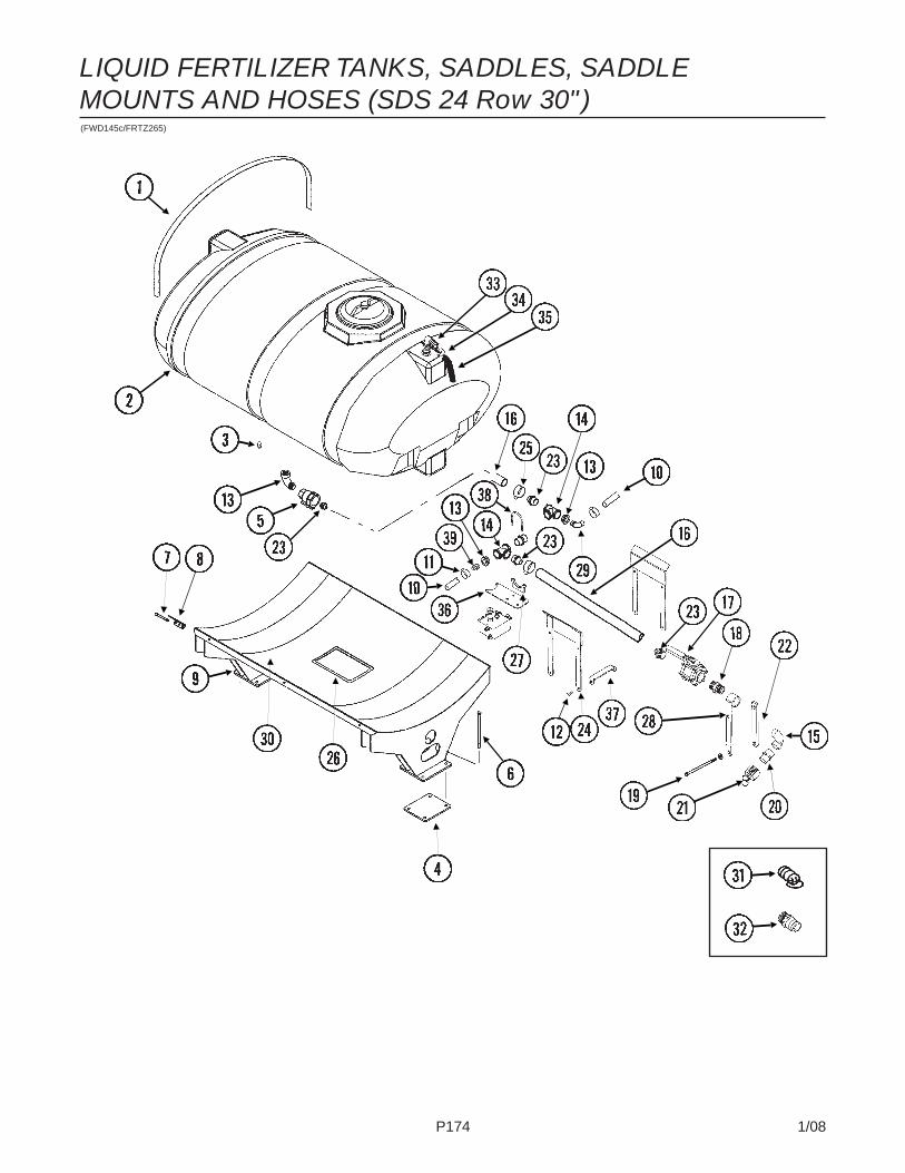
P174 1/08
LIQUID FERTILIZER TANKS, SADDLES, SADDLEMOUNTS AND HOSES (SDS 24 Row 30")(FWD145c/FRTZ265)

P175 1/08
LIQUID FERTILIZER TANKS, SADDLES, SADDLEMOUNTS AND HOSES (SDS 24 Row 30")ITEM PART NO. QTY. DESCRIPTION
1. GD15605 3 Band (3 Per Tank)2. GA10201 1 Tank W/Lid And Fittings, 500 Gallon
GR1702 - Lid/Fillwell, 8" (Top Of Tank)GR1708 - 3/4" Bulkhead Fitting Assembly (Overflow Fitting, Nut, Bushing
And O-Ring) (Top And Bottom Of Tank)GR1739 2" Bulkhead Fitting Assembly (Nut, Bushing And O-Ring) (Bottom
Of Tank)GR1686 - Lanyard, 12 1/2" (Top Of Tank)
3. G10096 2 Pipe Plug, 3/4" NPT4. GD17992 2 Plate5. GA11399 2 Shutoff Valve, 2" NPT
GR1769 - HandleGR1768 - BallGR1017 - Teflon SeatGR1767 - Stem O-RingGR1766 - Body O-Ring
6. G11122 8 Hex Head Cap Screw, 5/8"-11 x 12"G10205 8 Washer, 5/8" SAEG10107 8 Lock Nut, 5/8"-11
7. G10485 6 Hex Head Tap Bolt, 3/8"-16 x 5" (6 Per Tank)G10901 6 Lock Nut W/Nylon Insert, 3/8"-16 (6 Per Tank)
8. GD11123 6 Anchor (Sub GA8114)9. GA12520 1 Tank Mount10. G4200-05 1 Hose, 1 1/4" x 50'11. G10674 46 Hose Clamp, No. 2412. G10599 8 Carriage Bolt, 3/8"-16 x 1 1/4"
G10203 8 Washer, 3/8" SAEG10108 8 Lock Nut, 3/8"-16
13. G10616 2 Reducing Bushing, 2" Male NPT To 1 1/4" Female14. G10888 2 Tee, 2" Female NPT15. G10287 2 Elbow, 90°, 2" Male NPT To Female16. G4201-03 1 Hose, 2" x 18'17. GA2660 1 Shutoff Valve, 2" NPT18. G10623 6 Close Nipple, 2" NPT19. G10148 2 Hex Head Cap Screw, 1/2"-13 x 9 1/2"
G10216 2 Washer, 1/2" USSG10228 2 Lock Washer, 1/2"G10102 2 Hex Nut, 1/2"-13
20. GD3622 1 Adapter, 2" Female NPT To Cam Lock21. GD3951 1 Dust Cap, 2" Cam Lock22. GD15703 1 Bracket, 1 1/2" x 12 1/2", 24 Row 30"23. G10628 4 Adapter, 2" NPT To Barb24. GA11064 2 Hose Support, 24 Row 30"25. G10676 4 Hose Clamp, No. 36, Stainless Steel26. G4427-01 - Edge Molding, 1/8" x 12"
G4427-02 - Edge Molding, 1/8" x 7"27. GA8768 2 Clamp, 3"28. GA10509 1 Straight Mount, Quick Fill, 14 19/32"29. G10629 1 Elbow, 90°, 1 1/4" NPT To Barb30. GD1862 1 Pad, 8" x 14'31. GD10777 2 Dust Plug, 2" Male Cam Lock32. GD3623 1 Adapter, 2" Male NPT To Cam Lock33. G10917 2 Elbow, 90°, 3/4" NPT To Barb34. G10278 10 Hose Clamp. No. 1635. G4205-10 1 Hose, 3/4" x 200" (100" Per Tank)36. GD16210 1 Bracket37. GD16189 4 Tie Bracket38. G11165 2 T-Bolt Clamp, 2 1/2", Stainless Steel39. G10626 1 Adapter, 1 1/4" NPT To Barb
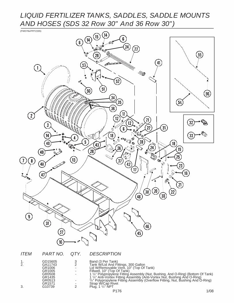
P176 1/08
LIQUID FERTILIZER TANKS, SADDLES, SADDLE MOUNTSAND HOSES (SDS 32 Row 30" And 36 Row 30")(FWD78e/FRTZ265)
ITEM PART NO. QTY. DESCRIPTION
1. GD15605 3 Band (3 Per Tank)2. GA11743 2 Tank W/Lid And Fittings, 300 Gallon
GR1006 - Lid W/Removable Vent, 10" (Top Of Tank)GR1005 - Fillwell, 10" (Top Of Tank)GR0508 - 1 1/4" Polypropylene Fitting Assembly (Nut, Bushing, And O-Ring) (Bottom Of Tank)GR1435 1 1/4" Anti-Vortex Fitting Assembly (Anti-Vortex Nut, Bushing And O-Ring)GR0513 - 3/4" Polypropylene Fitting Assembly (Overflow Fitting, Nut, Bushing And O-Ring)GR1571 - Strap W/Cap Rivet
3. G10739 2 Plug, 1 1/4" NPT
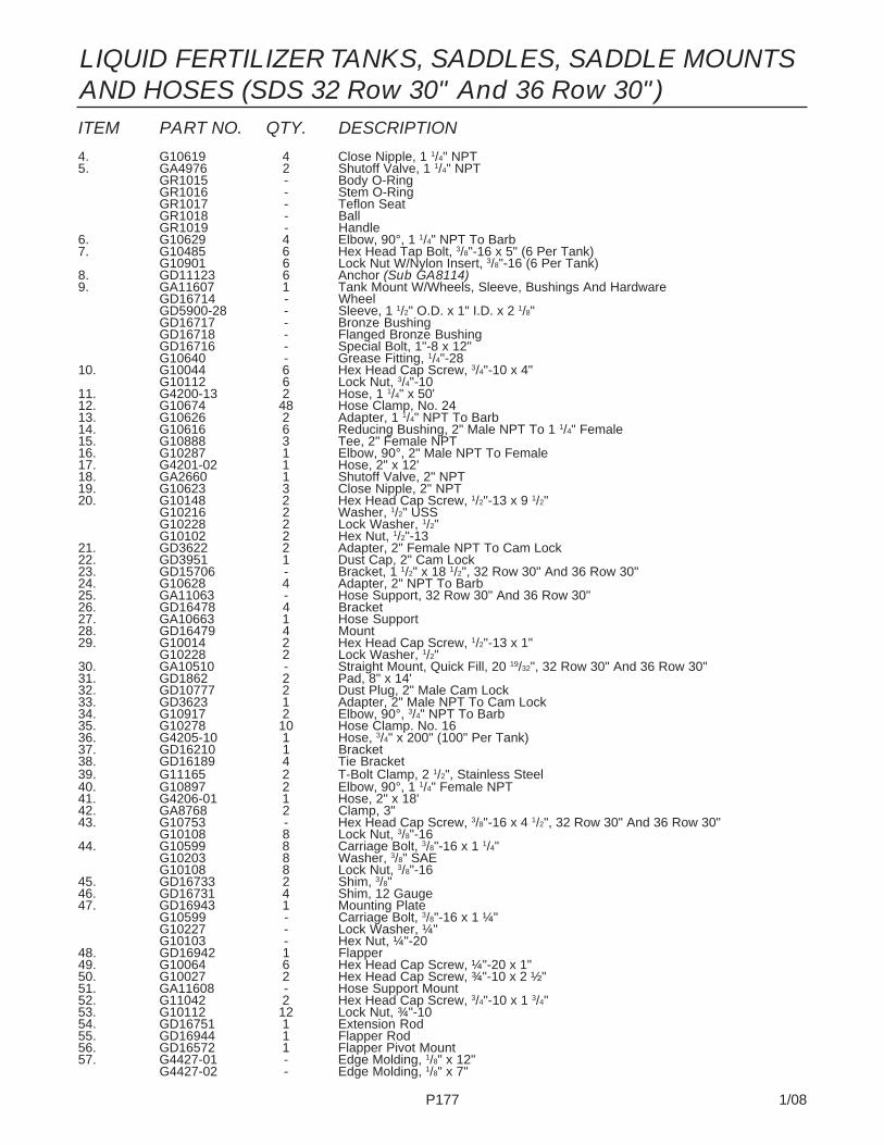
P177 1/08
LIQUID FERTILIZER TANKS, SADDLES, SADDLE MOUNTSAND HOSES (SDS 32 Row 30" And 36 Row 30")ITEM PART NO. QTY. DESCRIPTION
4. G10619 4 Close Nipple, 1 1/4" NPT5. GA4976 2 Shutoff Valve, 1 1/4" NPT
GR1015 - Body O-RingGR1016 - Stem O-RingGR1017 - Teflon SeatGR1018 - BallGR1019 - Handle
6. G10629 4 Elbow, 90°, 1 1/4" NPT To Barb7. G10485 6 Hex Head Tap Bolt, 3/8"-16 x 5" (6 Per Tank)
G10901 6 Lock Nut W/Nylon Insert, 3/8"-16 (6 Per Tank)8. GD11123 6 Anchor (Sub GA8114)9. GA11607 1 Tank Mount W/Wheels, Sleeve, Bushings And Hardware
GD16714 - WheelGD5900-28 - Sleeve, 1 1/2" O.D. x 1" I.D. x 2 1/8"GD16717 - Bronze BushingGD16718 - Flanged Bronze BushingGD16716 - Special Bolt, 1"-8 x 12"G10640 - Grease Fitting, 1/4"-28
10. G10044 6 Hex Head Cap Screw, 3/4"-10 x 4"G10112 6 Lock Nut, 3/4"-10
11. G4200-13 2 Hose, 1 1/4" x 50'12. G10674 48 Hose Clamp, No. 2413. G10626 2 Adapter, 1 1/4" NPT To Barb14. G10616 6 Reducing Bushing, 2" Male NPT To 1 1/4" Female15. G10888 3 Tee, 2" Female NPT16. G10287 1 Elbow, 90°, 2" Male NPT To Female17. G4201-02 1 Hose, 2" x 12'18. GA2660 1 Shutoff Valve, 2" NPT19. G10623 3 Close Nipple, 2" NPT20. G10148 2 Hex Head Cap Screw, 1/2"-13 x 9 1/2"
G10216 2 Washer, 1/2" USSG10228 2 Lock Washer, 1/2"G10102 2 Hex Nut, 1/2"-13
21. GD3622 2 Adapter, 2" Female NPT To Cam Lock22. GD3951 1 Dust Cap, 2" Cam Lock23. GD15706 - Bracket, 1 1/2" x 18 1/2", 32 Row 30" And 36 Row 30"24. G10628 4 Adapter, 2" NPT To Barb25. GA11063 - Hose Support, 32 Row 30" And 36 Row 30"26. GD16478 4 Bracket27. GA10663 1 Hose Support28. GD16479 4 Mount29. G10014 2 Hex Head Cap Screw, 1/2"-13 x 1"
G10228 2 Lock Washer, 1/2"30. GA10510 - Straight Mount, Quick Fill, 20 19/32", 32 Row 30" And 36 Row 30"31. GD1862 2 Pad, 8" x 14'32. GD10777 2 Dust Plug, 2" Male Cam Lock33. GD3623 1 Adapter, 2" Male NPT To Cam Lock34. G10917 2 Elbow, 90°, 3/4" NPT To Barb35. G10278 10 Hose Clamp. No. 1636. G4205-10 1 Hose, 3/4" x 200" (100" Per Tank)37. GD16210 1 Bracket38. GD16189 4 Tie Bracket39. G11165 2 T-Bolt Clamp, 2 1/2", Stainless Steel40. G10897 2 Elbow, 90°, 1 1/4" Female NPT41. G4206-01 1 Hose, 2" x 18'42. GA8768 2 Clamp, 3"43. G10753 - Hex Head Cap Screw, 3/8"-16 x 4 1/2", 32 Row 30" And 36 Row 30"
G10108 8 Lock Nut, 3/8"-1644. G10599 8 Carriage Bolt, 3/8"-16 x 1 1/4"
G10203 8 Washer, 3/8" SAEG10108 8 Lock Nut, 3/8"-16
45. GD16733 2 Shim, 3/8"46. GD16731 4 Shim, 12 Gauge47. GD16943 1 Mounting Plate
G10599 - Carriage Bolt, 3/8"-16 x 1 ¼"G10227 - Lock Washer, ¼"G10103 - Hex Nut, ¼"-20
48. GD16942 1 Flapper49. G10064 6 Hex Head Cap Screw, ¼"-20 x 1"50. G10027 2 Hex Head Cap Screw, ¾"-10 x 2 ½"51. GA11608 - Hose Support Mount52. G11042 2 Hex Head Cap Screw, 3/4"-10 x 1 3/4"53. G10112 12 Lock Nut, ¾"-1054. GD16751 1 Extension Rod55. GD16944 1 Flapper Rod56. GD16572 1 Flapper Pivot Mount57. G4427-01 - Edge Molding, 1/8" x 12"
G4427-02 - Edge Molding, 1/8" x 7"

P178 1/08
LIQUID FERTILIZER PISTON PUMP MOUNT ANDGROUND DRIVE WHEEL
ITEM PART NO. QTY. DESCRIPTION
1. G10152 6 Hex Head Cap Screw, 5/8"-11 x 9"G10230 6 Lock Washer, 5/8"G10104 6 Hex Nut, 5/8"-11
2. GA10355 1 Wheel Arm Mount3. GB0218 2 Bushing, 21/32" I.D. x 7/8" O.D. x 19/32" Long4. G10005 2 Hex Head Cap Screw, 5/8"-11 x 1 3/4"
GD7805 2 Special Washer, 5/8", HardenedG10107 2 Lock Nut, 5/8"-11
5. GA9712 1 Spring Mount6. GD2681 1 Pin, 1 1/4" x 13 1/2"
G10460 2 Cotter Pin, 1/4" x 2"7. GA10621 1 Arm W/Grease Fittings
G10641 2 Grease Fitting, 1/8" NPT8. GA0241 1 Wheel, 5" x 15"9. GD1166 1 Valve Stem
(TWL317a)
18 ToothSprocket
48 ToothSprocket

P179 1/08
LIQUID FERTILIZER PISTON PUMP MOUNT ANDGROUND DRIVE WHEEL
* Specific brand requests will be supplied only as available from current KINZE® Repair Parts stock. If aspecific brand requested is not in stock, the brand available will be supplied. Different brand tires may havedifferentdiameters. Change in tire brand may affect rates. Field checks are recommended after any changein tires.
ITEM PART NO. QTY. DESCRIPTION
10. G10012 1 Hex Head Cap Screw, 5/8"-11 x 6 1/2"GD7805 1 Special Washer, 5/8", Hardened
11. GA10908 1 Spring Mount12. GB0196 1 Washer13. GD7831 1 Compression Spring14. GA10907 1 Spring Guide15. G11122 1 Hex Head Cap Screw, 5/8"-11 x 12"
G10107 1 Lock Nut, 5/8"-1116. G10026 2 Hex Head Cap Screw, 3/4"-10 x 2"
G10231 2 Lock Washer, 3/4"17. G11042 2 Hex Head Cap Screw, 3/4"-10 x 1 3/4"
G10231 2 Lock Washer, 3/4"G10105 2 Hex Nut, 3/4"-10
18. GD13744 1 Hose Holder19. GR1146 1 Sprocket, 18 Tooth20. - See “Liquid Fertilizer Piston Pump”, Pages P182 And P18321. GD2558 1 Lynch Pin, 1/4"22. G10007 2 Hex Head Cap Screw, 5/8"-11 x 1 1/2"
G10217 2 Washer, 5/8" USSG10230 2 Lock Washer, 5/8"G10104 2 Hex Nut, 5/8"-11
23. GA10894 1 Pump Mount24. G10017 2 Hex Head Cap Screw, 1/2"-13 x 1 1/2"
G10216 2 Washer, 1/2" USSG10228 2 Lock Washer, 1/2"G10102 2 Hex Nut, 1/2"-13
25. GD13328 1 Scraper26. G10013 1 Hex Head Cap Screw, 5/8"-11 x 3 1/2"
G10205 1 Washer, 5/8" SAEG10230 1 Lock Washer, 5/8"G10104 1 Hex Nut, 5/8"-11
27. GA0262 1 Idler Sprocket W/Bearing, 15 Tooth28. GD7817-05 1 Spacer, 11/16" I.D. x 1 1/4" Long29. GD0844 1 Tire, 7.60" x 15", 8 Ply (Specify Brand*)30. GA2559 1 Spindle31. GA0252 2 Seal32. GA0251 2 Bearing33. GR0267 5 Lug Nut, 1/2"-2034. G2500-84 1 Sprocket, 48 Tooth35. G10019 4 Hex Head Cap Screw, 5/16"-18 x 1"
G10232 4 Lock Washer, 5/16"36. GD0831 2 Shoulder Nut, 1 1/4"-12 UNF-2A37. GA0547 1 Hub W/Cups And Studs, 5 Bolt
GR0190 2 CupGR0204 5 Stud
38. G3200-63 1 Chain, No. 2050, 63 Pitch Including Connector LinkGR0195 1 Connector Link, No. 2050GR0200 1 Offset Link, No. 2050

P180 1/08
LIQUID FERTILIZER FLOW DIVIDER MOUNT AND HOSES(FRTZ299)
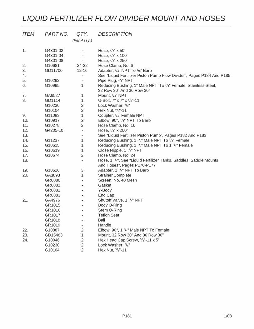
P181 1/08
ITEM PART NO. QTY. DESCRIPTION(Per Assy.)
1. G4301-02 - Hose, 3/8" x 50'G4301-04 - Hose, 3/8" x 100'G4301-08 - Hose, 3/8" x 250'
2. G10681 24-32 Hose Clamp, No. 63. GD11700 12-16 Adapter, 1/4" NPT To 3/8" Barb4. - See “Liquid Fertilizer Piston Pump Flow Divider”, Pages P184 And P1855. G10292 - Pipe Plug, 1/4" NPT6. G10995 1 Reducing Bushing, 1" Male NPT To 3/4" Female, Stainless Steel,
32 Row 30" And 36 Row 30"7. GA6527 1 Mount, 3/4" NPT8. GD1114 1 U-Bolt, 7" x 7" x 5/8"-11
G10230 2 Lock Washer, 5/8"G10104 2 Hex Nut, 5/8"-11
9. G11083 1 Coupler, 3/4" Female NPT10. G10917 2 Elbow, 90°, 3/4" NPT To Barb11. G10278 2 Hose Clamp, No. 1612. G4205-10 - Hose, 3/4" x 200"13. - See “Liquid Fertilizer Piston Pump”, Pages P182 And P18314. G11237 1 Reducing Bushing, 1 1/2" Male NPT To 3/4" Female15. G10615 1 Reducing Bushing, 1 1/2" Male NPT To 1 1/4" Female16. G10619 1 Close Nipple, 1 1/4" NPT17. G10674 2 Hose Clamp, No. 2418. - Hose, 1 1/4", See “Liquid Fertilizer Tanks, Saddles, Saddle Mounts
And Hoses”, Pages P170-P17719. G10626 3 Adapter, 1 1/4" NPT To Barb20. GA3893 1 Strainer Complete
GR0880 - Screen, No. 40 MeshGR0881 - GasketGR0882 - Y-BodyGR0883 - End Cap
21. GA4976 - Shutoff Valve, 1 1/4" NPTGR1015 - Body O-RingGR1016 - Stem O-RingGR1017 - Teflon SeatGR1018 - BallGR1019 - Handle
22. G10887 2 Elbow, 90°, 1 1/4" Male NPT To Female23. GD15483 1 Mount, 32 Row 30" And 36 Row 30"24. G10046 2 Hex Head Cap Screw, 5/8"-11 x 5"
G10230 2 Lock Washer, 5/8"G10104 2 Hex Nut, 5/8"-11
LIQUID FERTILIZER FLOW DIVIDER MOUNT AND HOSES

P182 1/08
LIQUID FERTILIZER PISTON PUMP(Uses 18 Tooth Sprocket)
Model NGP-7055(A12335a/GR1808)

P183 1/08
ITEM PART NO. QTY. DESCRIPTION
1. GR1804 1 Flange Cover AssemblyG10991 4 Hex Head Cap Screw, 5/16"-18 x 7/8"
2. GR1803 1 Connecting Rod Assembly3. GR1801 1 Spacer Assembly
G10693 3 Hex Socket Head Set Screw, 5/16"-18 x 3/8"4. GR1123 2 Plug5. GR1543 1 Vent Plug6. GR1112 1 Woodruff Key7. GR1120 1 Eccentric Pin8. GR1124 1 Pin9. GR1104 1 Bearing10. GR1805 1 Setting Hub Assembly11. GR1134 1 Stuffing Box Insert12. GR1146 1 Sprocket, 18 Tooth13. GR1808 1 Adjustment Wrench14. GR1806 1 Setting Pointer Assembly15. GR1796 1 Repair Kit, Includes: (6) Gaskets, (9) O-Rings, (4) Washers,
(1) Retaining Ring, (2) Oil Seals, (1) Snap Ring, (1) Thrust Washer,(1) Rod Bushing, (2) Flange Plunger Packings, (2) Packing Springs,(2) Rod Vee Packing Sets
16. GR1800 2 Discharge Valve Assembly17. GR1798 2 Suction Valve Assembly18. GR1118 3 Setting Arm Key19. GR1116 1 Bearing20. G10306 1 Carriage Bolt, 3/8"-16 x 2"
G10108 1 Lock Nut, 3/8"-1621. G10003 4 Hex Head Cap Screw, 3/8"-16 x 1 1/2"
G10210 4 Washer, 3/8" USSG10229 4 Lock Washer, 3/8"G10101 4 Hex Nut, 3/8"-16
A. GA12335 - Piston Pump Complete W/18 Tooth Sprocket (Model NGP-7055)
LIQUID FERTILIZER PISTON PUMP(Uses 18 Tooth Sprocket)
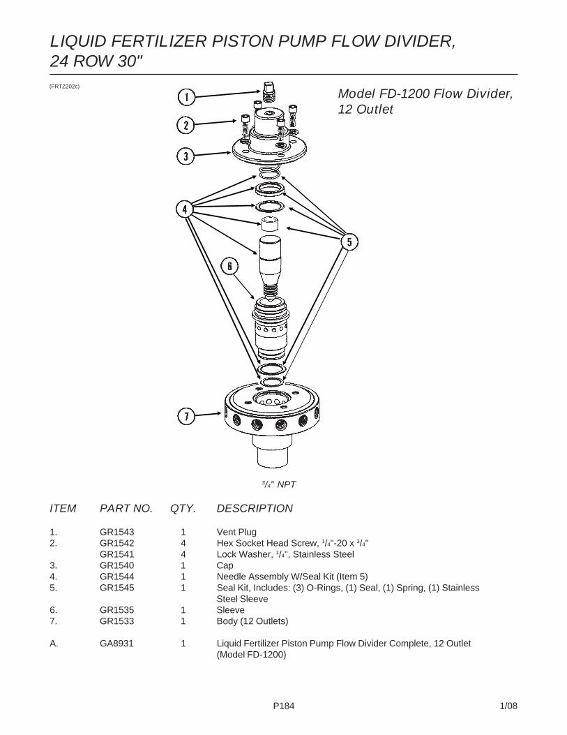
P184 1/08
ITEM PART NO. QTY. DESCRIPTION
1. GR1543 1 Vent Plug2. GR1542 4 Hex Socket Head Screw, 1/4"-20 x 3/4"
GR1541 4 Lock Washer, 1/4", Stainless Steel3. GR1540 1 Cap4. GR1544 1 Needle Assembly W/Seal Kit (Item 5)5. GR1545 1 Seal Kit, Includes: (3) O-Rings, (1) Seal, (1) Spring, (1) Stainless
Steel Sleeve6. GR1535 1 Sleeve7. GR1533 1 Body (12 Outlets)
A. GA8931 1 Liquid Fertilizer Piston Pump Flow Divider Complete, 12 Outlet(Model FD-1200)
(FRTZ202c)
3/4" NPT
Model FD-1200 Flow Divider,12 Outlet
LIQUID FERTILIZER PISTON PUMP FLOW DIVIDER,24 ROW 30"
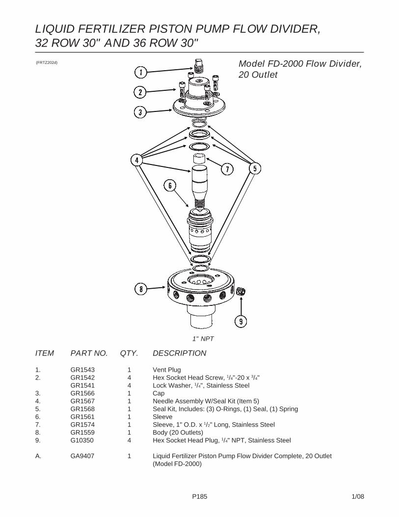
P185 1/08
ITEM PART NO. QTY. DESCRIPTION
1. GR1543 1 Vent Plug2. GR1542 4 Hex Socket Head Screw, 1/4"-20 x 3/4"
GR1541 4 Lock Washer, 1/4", Stainless Steel3. GR1566 1 Cap4. GR1567 1 Needle Assembly W/Seal Kit (Item 5)5. GR1568 1 Seal Kit, Includes: (3) O-Rings, (1) Seal, (1) Spring6. GR1561 1 Sleeve7. GR1574 1 Sleeve, 1" O.D. x 1/2" Long, Stainless Steel8. GR1559 1 Body (20 Outlets)9. G10350 4 Hex Socket Head Plug, 1/4" NPT, Stainless Steel
A. GA9407 1 Liquid Fertilizer Piston Pump Flow Divider Complete, 20 Outlet(Model FD-2000)
LIQUID FERTILIZER PISTON PUMP FLOW DIVIDER,32 ROW 30" AND 36 ROW 30"(FRTZ202d)
1" NPT
Model FD-2000 Flow Divider,20 Outlet

P186 1/08
REAR TRAILER HITCH
(FWD159)
ITEM PART NO. QTY. DESCRIPTION
1. G11264 4 Hex Head Cap Screw, 1/2"-13 x 1 3/4"GD14674 4 Special Washer, 1/2", Hardened
2. G10460 2 Cotter Pin, 1/4" x 2"3. GD19148 1 Pin, 1 1/4" x 9 1/4"4. GA13238 1 Hitch Mount5. GA10859 1 Pintle Hitch6. G10159 2 Machine Bushing, 1 1/4", 10 Gauge

P187 1/08
9
DECALS, PAINT AND MISCELLANEOUS
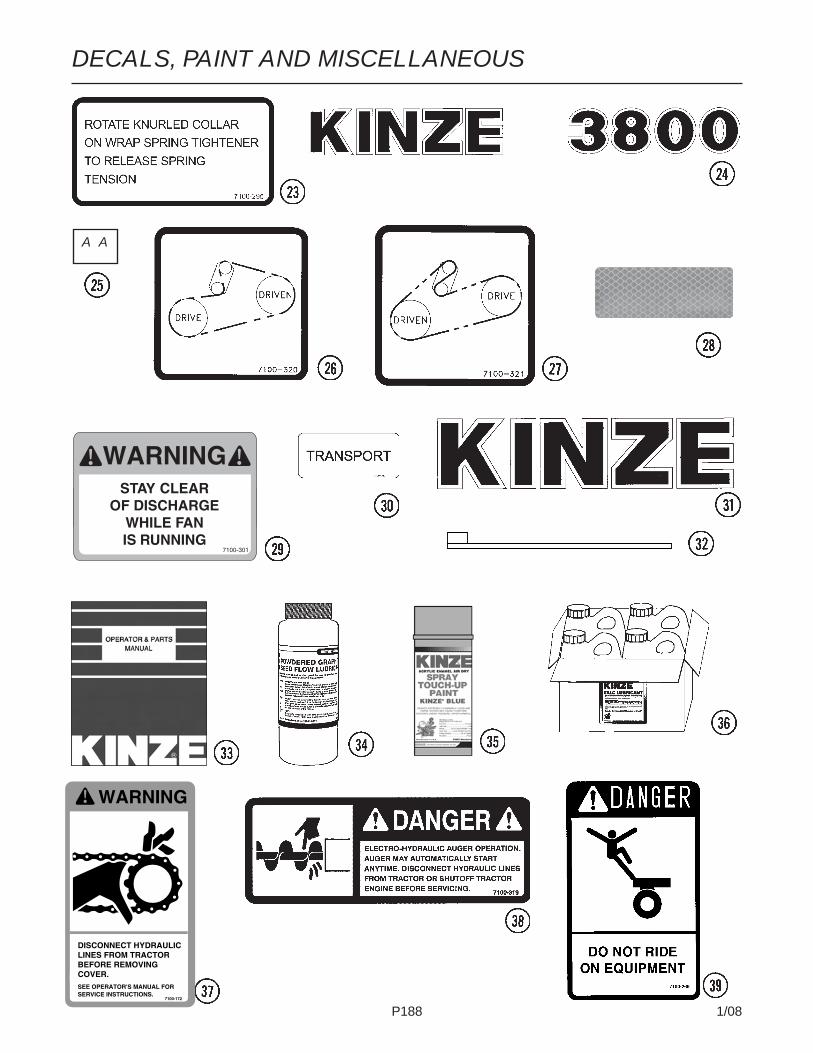
P188 1/08
DECALS, PAINT AND MISCELLANEOUS
A A
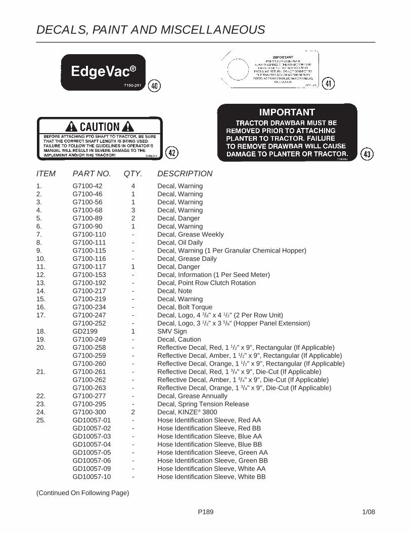
P189 1/08
DECALS, PAINT AND MISCELLANEOUS
ITEM PART NO. QTY. DESCRIPTION1. G7100-42 4 Decal, Warning2. G7100-46 1 Decal, Warning3. G7100-56 1 Decal, Warning4. G7100-68 3 Decal, Warning5. G7100-89 2 Decal, Danger6. G7100-90 1 Decal, Warning7. G7100-110 - Decal, Grease Weekly8. G7100-111 - Decal, Oil Daily9. G7100-115 - Decal, Warning (1 Per Granular Chemical Hopper)10. G7100-116 - Decal, Grease Daily11. G7100-117 1 Decal, Danger12. G7100-153 - Decal, Information (1 Per Seed Meter)13. G7100-192 - Decal, Point Row Clutch Rotation14. G7100-217 - Decal, Note15. G7100-219 - Decal, Warning16. G7100-234 - Decal, Bolt Torque17. G7100-247 - Decal, Logo, 4 3/8" x 4 1/2" (2 Per Row Unit)
G7100-252 - Decal, Logo, 3 1/2" x 3 5/8" (Hopper Panel Extension)18. GD2199 1 SMV Sign19. G7100-249 - Decal, Caution20. G7100-258 - Reflective Decal, Red, 1 1/2" x 9", Rectangular (If Applicable)
G7100-259 - Reflective Decal, Amber, 1 1/2" x 9", Rectangular (If Applicable)G7100-260 - Reflective Decal, Orange, 1 1/2" x 9", Rectangular (If Applicable)
21. G7100-261 - Reflective Decal, Red, 1 3/4" x 9", Die-Cut (If Applicable)G7100-262 - Reflective Decal, Amber, 1 3/4" x 9", Die-Cut (If Applicable)G7100-263 - Reflective Decal, Orange, 1 3/4" x 9", Die-Cut (If Applicable)
22. G7100-277 - Decal, Grease Annually23. G7100-295 - Decal, Spring Tension Release24. G7100-300 2 Decal, KINZE® 380025. GD10057-01 - Hose Identification Sleeve, Red AA
GD10057-02 - Hose Identification Sleeve, Red BBGD10057-03 - Hose Identification Sleeve, Blue AAGD10057-04 - Hose Identification Sleeve, Blue BBGD10057-05 - Hose Identification Sleeve, Green AAGD10057-06 - Hose Identification Sleeve, Green BBGD10057-09 - Hose Identification Sleeve, White AAGD10057-10 - Hose Identification Sleeve, White BB
(Continued On Following Page)

P190 1/08
ITEM PART NO. QTY. DESCRIPTION
26. G7100-320 - Decal, Transmission, R.H.27. G7100-321 - Decal, Transmission, L.H.28. G7100-322 - Reflective Decal, Orange-Red, 1 1/2" x 4"29. G7100-301 - Decal, Warning30. G7100-317 - Decal, Transport31. G7100-310 - Decal, KINZE®, 6 11/16" x 28 5/16"32. GD1512 - Tie Strap, 7 1/2"
GD2117 - Tie Strap, 14 1/2"GD1162 - Tie Strap, 28"GD2984 - Tie Strap, 34"
33. GM0215 - Operator & Parts Manual, Model 3800 And 3800 SDS (EdgeVac® SeedMetering)
34. GR0146MPP - Powdered Graphite, Twenty-Four 1 Pound Containers35. GR0155MPP - Blue Paint, Twelve Aerosol Cans36. GR1570MPP - Talc Lubricant, Four 8 Pound Containers37. G7100-172 - Decal, Warning38. G7100-319 - Decal, Danger39. G7100-266 - Decal, Danger40. G7100-311 - Decal, EdgeVac®
41. G7100-329 - Tag, Fan Motor Case Drain42. G7100-344 - Decal, Caution43. G7100-336 - Decal, Important
DECALS, PAINT AND MISCELLANEOUS

NUMERICAL INDEXPart No. Page Part No. Page Part No. Page
P191 1/08
*A12902 .................................. P55*A12903 .................................. P55*A12907 .................................. P55*A3136 ................................ P146*A3139 ................................ P147*A3153 ..................... P149, P151*A3154 ................................ P147*A3158 ........... P147, P148, P150*A3159 ................................ P153*A3161 ................................ P147*A3199 ..................... P148, P150*A3201 .................................. P55*A3220 ................................ P147*A3222 .................................. P55*A3223 ..................... P149, P151*A3225 ..................... P148, P150*A3228 ..................... P149, P151*A3236 ........... P147, P149, P151*A3247 ................................ P146*A3249 ................................ P146*A3259 ..................... P148, P150*A3283 .................................. P55*A3290 .................................. P55*A3291 .................................. P55*A3292 .................................. P54*A3381 .................................. P55*A3384 .................................. P55*A3385 .................................. P55*A3392 .................................. P55*A3398 .................................. P55*A7613 ........... P147, P149, P151*A7614 ..................... P149, P151*A7615 ..................... P149, P151*A8225 ..................... P148, P150*A8226 ..................... P148, P150*A8229 ..................... P149, P151*A8230 ........... P147, P149, P151*A8231 .................... P147, P149,
..................... P151, P153*A8237 ................................ P147*A8260 ..................... P148, P1506400-20-16 ............................. P556502-06 ................................ P150A10255 ................................ P131A10361 ................................ P123A10365 ................................ P125A10369 ................................ P126A10372 ................................ P128A10759 .................................. P39A11020 ................................ P133A11368 ................................ P124A11372 ................................ P127A13311 ................................ P123A8827 ................................ P125A8950 ................................ P132
G1K364 ................................ P163*A1018 ..................... P148, P150*A1020 ................................ P146*A1031 ..................... P148, P150*A1033 ..................... P148, P150*A1039 ..................... P148, P150*A1055 ..................... P148, P150*A1057 ..................... P149, P151*A1076 ..................... P149, P151*A1079 ................................ P146*A1082 ..................... P148, P150*A1086 ................................ P146*A1090 ................................ P146*A1098 ..................... P149, P151*A1132 ................................ P147*A1132 ..................... P149, P151*A1138 ................................ P147*A1140 ................................ P147*A11400 ................................ P153*A11409 .................................. P55*A11410 .................................. P55*A11424 ..................... P146, P153*A11425 ................................ P153*A11426 .................................. P55*A11434 ................................ P153*A11435 .................................. P55*A11436 .................................. P55*A11437 .................................. P55*A11438 ..................... P148, P150*A1170 ................................ P146*A11805 .................................. P54*A11806 .................................. P55*A11807 .................................. P55*A1192 ..................... P149, P151*A12014 .................................. P55*A12041 ..................... P149, P151*A12043 ................................ P146*A12046 ................................ P146*A12048 .................................. P55*A12053 ..................... P149, P151*A12055 .................................. P55*A12056 .................................. P55*A12064 ..................... P148, P150*A12067 ..................... P148, P150*A12700 ..................... P146, P153*A12701 ................................ P146*A12702 ................................ P146*A12703 ................................ P153*A12704 .................................. P54*A12710 ................................ P153*A12723 ..................... P148, P150*A12724 ..................... P148, P150*A12725 ..................... P148, P150*A12729 ..................... P149, P151*A12730 ..................... P149, P151
D13169 ................................ P130D3180-35 .............................. P117G10001 ..........P5, P10, P15, P16,
....... P24, P25, P27, P31,
....... P37, P61, P71, P73,
............ P99, P102, P105,
..................... P162, P165G10002 ..... P25, P39, P67, P135,
........... P137, P153, P167G10003 ..........P3, P35, P41, P49,
...... P81,103, P106, P183G10004 ..........P5, P33, P81, P87,
........ P89, P91, P97, P99G10005 ............... P29, P51, P178G10006 ......................... P15, P47G10007 ..........P5, P10, P11, P17,
................ P51, P71, P73,
........... P103, P106, P179G10008 ....... P29, P33, P57, P71,
...... P75, P77, P95, P117G10009 ................. P71, P73, P95G10010 ...... P13, P49, P51, P168G10011 ....................... P51, P167G10012 ..................... P167, P179G10013 ............. P16, P121, P179G10014 ................ P13, P28, P51,
................ P71, P75, P81,
............. P93, P173, P177G10015 .................................. P15G10016 ................ P77, P85, P87,
.............. P89, P91, P103,
........... P106, P109, P169G10017 ................ P45, P81, P83,
............ P85, P103, P109,
........... P161, P167, P179G10018 ................. P13, P15, P24G10019 ..........P9, P25, P27, P31,
.. P61, P113, P117, P179G10020 ................. P35, P71, P75G10021 ........................... P9, P24G10022 ......................... P63, P65G10023 ...... P39, P63, P65, P111G10025 ................. P77, P83, P95G10026 ...... P77, P91, P95, P179G10027 .... P77, P81, P115, P177G10028 ................................ P173G10033 ............. P47, P114, P121G10035 .................................. P33G10036 ....................... P43, P121G10037 .................. P5, P71, P75,
............. P85, P117, P119G10038 ................................ P114G10039 .. P5, P45, P51, P67, P93G10040 .................................. P37G10042 ......................... P71, P75
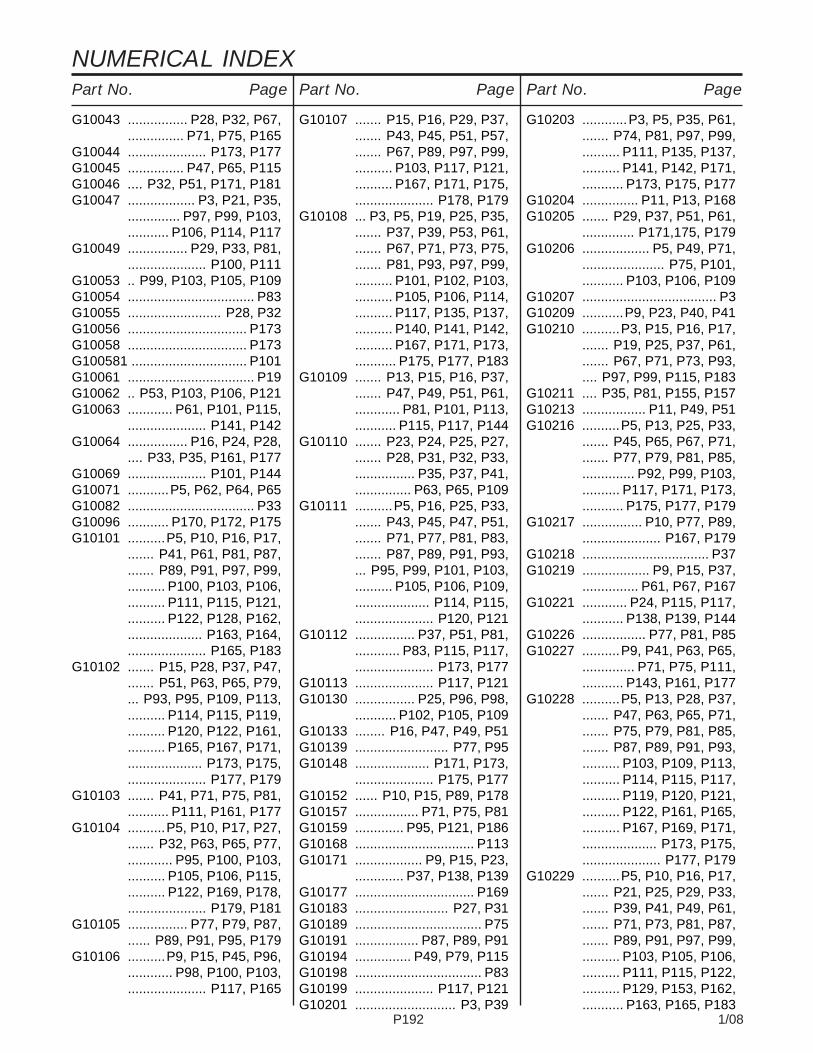
NUMERICAL INDEXPart No. PagePart No. PagePart No. Page
P192 1/08
G10043 ................ P28, P32, P67,............... P71, P75, P165
G10044 ..................... P173, P177G10045 ............... P47, P65, P115G10046 .... P32, P51, P171, P181G10047 .................. P3, P21, P35,
.............. P97, P99, P103,
........... P106, P114, P117G10049 ................ P29, P33, P81,
..................... P100, P111G10053 .. P99, P103, P105, P109G10054 .................................. P83G10055 ......................... P28, P32G10056 ................................ P173G10058 ................................ P173G100581 ............................... P101G10061 .................................. P19G10062 .. P53, P103, P106, P121G10063 ............ P61, P101, P115,
..................... P141, P142G10064 ................ P16, P24, P28,
.... P33, P35, P161, P177G10069 ..................... P101, P144G10071 ...........P5, P62, P64, P65G10082 .................................. P33G10096 ........... P170, P172, P175G10101 ..........P5, P10, P16, P17,
....... P41, P61, P81, P87,
....... P89, P91, P97, P99,
.......... P100, P103, P106,
.......... P111, P115, P121,
.......... P122, P128, P162,
.................... P163, P164,
..................... P165, P183G10102 ....... P15, P28, P37, P47,
....... P51, P63, P65, P79,
... P93, P95, P109, P113,
.......... P114, P115, P119,
.......... P120, P122, P161,
.......... P165, P167, P171,
.................... P173, P175,
..................... P177, P179G10103 ....... P41, P71, P75, P81,
........... P111, P161, P177G10104 ..........P5, P10, P17, P27,
....... P32, P63, P65, P77,
............ P95, P100, P103,
.......... P105, P106, P115,
.......... P122, P169, P178,
..................... P179, P181G10105 ................ P77, P79, P87,
...... P89, P91, P95, P179G10106 ..........P9, P15, P45, P96,
............ P98, P100, P103,
..................... P117, P165
G10107 ....... P15, P16, P29, P37,....... P43, P45, P51, P57,....... P67, P89, P97, P99,.......... P103, P117, P121,.......... P167, P171, P175,..................... P178, P179
G10108 ... P3, P5, P19, P25, P35,....... P37, P39, P53, P61,....... P67, P71, P73, P75,....... P81, P93, P97, P99,.......... P101, P102, P103,.......... P105, P106, P114,.......... P117, P135, P137,.......... P140, P141, P142,.......... P167, P171, P173,........... P175, P177, P183
G10109 ....... P13, P15, P16, P37,....... P47, P49, P51, P61,............ P81, P101, P113,........... P115, P117, P144
G10110 ....... P23, P24, P25, P27,....... P28, P31, P32, P33,................ P35, P37, P41,............... P63, P65, P109
G10111 ..........P5, P16, P25, P33,....... P43, P45, P47, P51,....... P71, P77, P81, P83,....... P87, P89, P91, P93,... P95, P99, P101, P103,.......... P105, P106, P109,.................... P114, P115,..................... P120, P121
G10112 ................ P37, P51, P81,............ P83, P115, P117,..................... P173, P177
G10113 ..................... P117, P121G10130 ................ P25, P96, P98,
........... P102, P105, P109G10133 ........ P16, P47, P49, P51G10139 ......................... P77, P95G10148 .................... P171, P173,
..................... P175, P177G10152 ...... P10, P15, P89, P178G10157 ................. P71, P75, P81G10159 ............. P95, P121, P186G10168 ................................ P113G10171 .................. P9, P15, P23,
............. P37, P138, P139G10177 ................................ P169G10183 ......................... P27, P31G10189 .................................. P75G10191 ................. P87, P89, P91G10194 ............... P49, P79, P115G10198 .................................. P83G10199 ..................... P117, P121G10201 ........................... P3, P39
G10203 ............P3, P5, P35, P61,....... P74, P81, P97, P99,.......... P111, P135, P137,.......... P141, P142, P171,........... P173, P175, P177
G10204 ............... P11, P13, P168G10205 ....... P29, P37, P51, P61,
.............. P171,175, P179G10206 .................. P5, P49, P71,
...................... P75, P101,
........... P103, P106, P109G10207 .................................... P3G10209 ...........P9, P23, P40, P41G10210 ..........P3, P15, P16, P17,
....... P19, P25, P37, P61,
....... P67, P71, P73, P93,
.... P97, P99, P115, P183G10211 .... P35, P81, P155, P157G10213 ................. P11, P49, P51G10216 ..........P5, P13, P25, P33,
....... P45, P65, P67, P71,
....... P77, P79, P81, P85,
.............. P92, P99, P103,
.......... P117, P171, P173,
........... P175, P177, P179G10217 ................ P10, P77, P89,
..................... P167, P179G10218 .................................. P37G10219 .................. P9, P15, P37,
............... P61, P67, P167G10221 ............ P24, P115, P117,
........... P138, P139, P144G10226 ................. P77, P81, P85G10227 ..........P9, P41, P63, P65,
.............. P71, P75, P111,
........... P143, P161, P177G10228 ..........P5, P13, P28, P37,
....... P47, P63, P65, P71,
....... P75, P79, P81, P85,
....... P87, P89, P91, P93,
.......... P103, P109, P113,
.......... P114, P115, P117,
.......... P119, P120, P121,
.......... P122, P161, P165,
.......... P167, P169, P171,
.................... P173, P175,
..................... P177, P179G10229 ..........P5, P10, P16, P17,
....... P21, P25, P29, P33,
....... P39, P41, P49, P61,
....... P71, P73, P81, P87,
....... P89, P91, P97, P99,
.......... P103, P105, P106,
.......... P111, P115, P122,
.......... P129, P153, P162,
........... P163, P165, P183

NUMERICAL INDEXPart No. Page Part No. Page Part No. Page
P193 1/08
G10230 ..........P5, P10, P13, P16,....... P17, P27, P28, P32,....... P63, P65, P71, P73,..... P75, P77, P95, P100,.......... P103, P105, P106,.......... P115, P117, P122,.................... P169, P178,..................... P179, P181
G10231 ................ P77, P79, P83,............... P91, P95, P179
G10232 ..........P9, P15, P23, P24,....... P28, P32, P71, P75,... P96, P98, P100, P103,.......... P117, P138, P139,........... P165, P167, P179
G10233 ..... P25, P96, P98, P101,.......... P102, P105, P109,........... P119, P121, P168
G10235 ............... P97, P99, P101G10239 ................. P71, P73, P85G10243 .... P27, P31, P163, P165G10252 .................................. P23G10253 ................................ P111G10257 ....................... P40, P111G10260 .................................. P23G10278 .......... P171, P173, P175,
..................... P177, P181G10283 ................................ P167G10287 .................... P171, P173,
..................... P175, P177G10292 ................................ P181G10299 ................................ P121G10301 ........ P35, P37, P81, P93G10303 ....... P15, P29, P33, P37,
.... P96, P98, P100, P103G10304 .................................... P3G10305 ................ P25, P27, P31,
................. P42, P63, P65G10306 ............. P41, P167, P183G10308 ......................... P16, P42G10309 ................. P19, P27, P31G10310 .................................. P41G10312 .................. P3, P25, P39,
............... P62, P64, P161G10315 ................. P15, P16, P41G10318 .................................. P45G10323 .................................. P23G10325 ......................... P11, P39G10326 .................................... P3G10328 ....................... P11, P129G10330 .................................. P79G10338 ......................... P13, P19G10341 .................................... P9G10348 ......................... P33, P47G10350 ................................ P185
G10356 ................................ P117G10362 ................................ P117G10371 .................................. P47G10373 .................................. P83G10374 ................................ P111G10400 ......................... P51, P83G10403 ....... P24, P25, P27, P28,
........ P31, P32, P33, P37G10412 ................... P5, P10, P19G10418 .................................. P77G10427 ......................... P11, P15G10430 ................. P25, P96, P98G10438 ..............................P3, P5G10448 .................................. P79G10450 ................................ P167G10452 .................................. P41G10453 ......................... P96, P98G10456 ................................ P103G10457 ......................... P73, P81G10460 ....... P71, P73, P77, P83,
.............. P85, P95, P114,
.......... P115, P117, P119,
........... P121, P178, P186G10461 ................................ P115G10462 ................................ P167G10463 .................................. P15G10464 .................................. P25G10470 .................................. P81G10471 .................................. P83G10477 ..................... P115, P117G10485 .................... P171, P173,
..................... P175, P177G10496 ..................... P101, P111G10497 ................................ P111G10499 .................................. P61G10501 ................. P47, P97, P99G10503 ................. P45, P49, P51G10523 .................................. P41G10527 ........... P101, P106, P109G10529 .................................. P42G10536 ....................... P45, P114G10541 .................................. P37G10543 ................. P87, P89, P91G10544 .................... P113, P115,
..................... P119, P121G10546 ......................... P19, P40G10551 .................................... P3G10560 ..................... P103, P106G10567 ................. P19, P39, P40G10570 .................................. P40G10572 .................................. P45G10574 ........................ P43, P47,
................. P51, P62, P64G10581 .... P25, P95, P101, P114G10585 ............... P45, P93, P109
G10597 .................................. P45G10599 ....... P16, P17, P37, P61,
..... P63, P67, P93, P171,
........... P173, P175, P177G10602 ................ P19, P23, P25,
................ P27, P31, P39,
................. P40, P97, P99G10603 .................................. P23G10606 ................................ P153G10610 .................................. P95G10615 ................................ P181G10616 .................... P171, P173,
..................... P175, P177G10619 .................... P170, P172,
..................... P177, P181G10620 ..........P3, P13, P19, P25,
....... P27, P29, P31, P33,
................ P39, P62, P64,
..................... P161, P168G10621 ................ P19, P27, P31,
......................... P39, P42G10622 ....... P11, P24, P25, P27,
....... P31, P33, P35, P37,
....... P42, P63, P65, P67,
............. P93, P135, P137G10623 .................... P171, P173,
..................... P175, P177G10625 .................................. P83G10626 .................... P171, P173,
........... P175, P177, P181G10628 .................... P171, P173,
..................... P175, P177G10629 .................... P171, P173,
..................... P175, P177G10636 ......................... P79, P95G10640 ....... P13, P71, P73, P75,
....... P77, P79, P81, P83,
....... P85, P87, P89, P91,
.............. P93, P95, P100,
.......... P115, P117, P119,
.......... P120, P121, P123,
.......... P124, P125, P126,
.................... P127, P133,
..................... P167, P177G10641 ................................ P178G10643 .................................. P51G10644 ..................... P117, P121G10660 .................................. P40G10669 .................................... P3G10670 .................................. P39G10674 .................... P171, P173,
........... P175, P177, P181G10676 .............. P63, P65, P171,
..................... P173, P175G10681 ....................... P59, P181
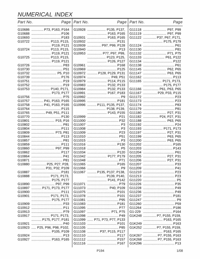
NUMERICAL INDEXPart No. PagePart No. PagePart No. Page
P194 1/08
G10686 ............. P73, P163, P164G10688 ................................ P106G10693 ................................ P183G10722 .................... P113, P115,
..................... P119, P121G10724 .................... P113, P115,
..................... P119, P121G10725 .................... P113, P115,
..................... P119, P121G10726 .................................. P83G10730 .................................. P51G10732 ........................... P5, P10G10739 ................................ P176G10751 .................................. P19G10752 .................................. P19G10753 .................... P140, P171,
..................... P173, P177G10756 .................................. P75G10757 ............. P41, P163, P165G10758 ............. P41, P163, P165G10764 ................................ P115G10765 ............... P49, P51, P111G10770 ................................ P130G10801 ......................... P15, P16G10802 .................................. P81G10804 ................................ P111G10809 ......................... P73, P81G10844 ................................ P113G10857 .................................. P81G10859 ................................ P111G10860 ......................... P97, P99G10862 ................................ P117G10864 .................................. P41G10871 .................................. P81G10880 ................ P25, P27, P28,
............... P31, P32, P109G10887 ................................ P181G10888 .................... P171, P173,
..................... P175, P177G10890 ......................... P97, P99G10897 ........... P171, P173, P177G10900 ................................ P111G10901 .................... P171, P173,
..................... P175, P177G10909 .................................. P33G10912 .................................. P11G10913 .................................. P79G10917 .................... P171, P173,
........... P175, P177, P181G10921 .................................. P40G10923 ..... P25, P96, P98, P102,
..................... P105, P109G10924 .................................. P13G10927 ..................... P163, P165
G10928 .................... P135, P137,..................... P163, P165
G10931 ..................... P163, P165G10932 ................................ P131G10939 ............... P97, P99, P128G10940 .................................. P13G10953 ................ P77, P97, P99,
.................... P123, P125,
..................... P126, P127G10961 ................................ P168G10969 ................................ P125G10972 ........... P128, P129, P131G10974 ......................... P49, P51G10979 ..................... P114, P115G10983 ..................... P132, P133G10984 ..................... P132, P133G10991 ..................... P167, P183G10992 .................................... P9G10995 ................................ P181G10996 .......... P111, P135, P137,
.................... P138, P139,
..................... P143, P155G10999 .................................. P21G11000 .................................. P32G11007 .................................... P3G11008 .................................... P3G11009 .................................. P23G11010 .................................. P51G11015 .................................... P3G11016 ................................ P130G11018 .................................... P5G11034 ................................ P120G11042 ..................... P177, P179G11048 .................................. P71G11065 ................................ P165G11066 .................................... P9G11067 .......... P135, P137, P138,
.................... P139, P140,
..................... P141, P142G11071 .................................. P79G11073 ....................... P40, P109G11075 ................................ P101G11078 ................................ P101G11081 .................................. P95G11083 ................................ P181G11095 .................................. P77G11097 ......................... P71, P75G11098 .................................. P49G11099 ...... P71, P73, P77, P133G11103 ................................ P101G11105 .................................. P85G11108 ............. P37, P115, P117G11110 ................................ P117G11112 ................................ P157G11116 ................................ P167
G11118 ......................... P97, P99G11119 ......................... P97, P99G11122 .............. P37, P67, P171,
..................... P175, P179G11124 .................................. P61G11130 .................................. P81G11132 ......................... P71, P75G11133 ....................... P61, P122G11134 ................................ P122G11138 .................................. P61G11145 ......................... P62, P65G11147 ......................... P63, P65G11162 ................................ P113G11165 .................... P171, P173,
..................... P175, P177G11166 ................. P61, P63, P65G11167 ............... P29, P33, P115G11172 .................................. P23G11173 .................................. P23G11174 .................................. P83G11179 .................................. P81G11180 ......................... P27, P31G11182 ................. P24, P27, P31G11188 ......................... P63, P65G11192 .................................. P24G11193 ..................... P171, P173G11197 ......................... P27, P31G11199 ......................... P63, P65G11200 ......................... P63, P65G11202 ................................ P165G11203 ................................ P143G11204 .................................. P61G11205 ......................... P27, P31G11206 ......................... P27, P31G11207 .................................. P33G11209 .................................. P41G11210 .................................. P23G11213 .................................. P23G11220 .................................... P5G11226 .................................. P35G11228 .................................. P49G11236 .................................. P49G11237 ................................ P181G11247 .................................... P9G11260 .................................. P59G11264 ................................ P186G1-229 ................................ P164G1K248 .............. P7, P155, P159,
..................... P163, P165G1K249 ................................ P163G1K252 .............. P7, P155, P159,
..................... P163, P165G1K267 ............... P7, P155, P163G1K268 ............... P7, P155, P163G1K296 .................................. P13

NUMERICAL INDEXPart No. Page Part No. Page Part No. Page
P195 1/08
G1K320 ...... P7, P61, P159, P163G1K321 ...... P7, P61, P159, P163G1K322 ................................ P163G1K323 ................................ P162G1K324 .................................. P97G1K345 .................................. P16G1K362 ..................... P163, P165G1K363 ..................... P163, P165G1K385 .................................. P41G1K395 ......................... P7, P155G1K396 ......................... P7, P155G1K465 .................................... P5G1K467 .................................. P49G1K472 .................................. P23G2100-03 .............. P25, P28, P32,
.... P96, P98, P101, P103G2500-84 .............................. P179G2603-08 .................... P55, P146,
..................... P148, P150G2603-10 ................... P148, P150G2700-06-06 .............. P149, P151G2701-08 .............................. P129G2704-06 ................... P149, P151G304-C-10 .............................. P54G306-06 ..................... P149, P151G306-08 ................................ P129G3200-63 .............................. P179G3302-05 .............................. P115G3303-104 ................................ P3G3303-114 .............................. P40G3303-16 .................................. P3G3305-01 ................................ P42G3310-108 ....... P103, P105, P109G3310-112 .............................. P25G3310-122 .............................. P99G3310-160 .............................. P97G3310-168 .............................. P97G3310-94 ................................ P99G3316-80 .............................. P101G3317-16 .............................. P153G3400-01 .............. P25, P28, P32,
.... P96, P98, P101, P103G4200-05 ......... P171, P173, P175G4200-13 .............................. P177G4201-02 ......... P171, P173, P177G4201-03 .............................. P175G4205-10 .................. P171, P173,
........... P175, P177, P181G4206-01 ......... P171, P173, P177G4301-02 .............................. P181G4301-04 .............................. P181G4301-08 .............................. P181G4427-01 ................... P175, P177G4427-02 ................... P175, P177G5406-08P.............................. P55
G6326X ........................... P5, P10G6400-06 .. P58, P59, P138, P139G6400-06-08 .... P147, P149, P151G6400-08 ........ P131, P135, P137,
.......... P138, P139, P140,
.......... P141, P142, P143,
.................... P144, P146,
..................... P148, P150G6400-08-04 ......................... P129G6400-08-06 ......................... P139G6400-08-10 ......................... P153G6400-10 ........... P59, P135, P137G6400-10-08 ............. P135, P137,
........... P140, P141, P142G6400-12 ...... P55, P58, P59, P61G6400-20 ................................ P55G6400-L-08 ................ P135, P137G6400-L-10 ........................... P143G6403-NWO-12 ...................... P59G6408-08 ........ P131, P135, P137,
..................... P140, P143G6408-10 ................................ P59G6408-H06-0 .... P59, P135, P137,
........... P138, P139, P143G6500-06 ..................... P58, P138G6500-08 ........ P135, P137, P143,
........... P149, P151, P153G6500-10 .................. P135, P137,
..................... P142, P143G6500-12 ................................ P55G6502-06 ................... P139, P148G6502-08 ......... P147, P149, P151G6502-12 ....................... P55, P61G6602-08 ................... P149, P151G6701-L-12 ............................. P55G6801-06 ...................... P55, P57,
........... P135, P137, P138G6801-06-08 ......................... P146G6801-08 ........ P135, P137, P140,
.......... P141, P142, P143,
........... P146, P148, P150G6801-08-06 ......................... P139G6801-08-10 ........................... P55G6801-10 ................................ P55G6801-10-12 ........................... P58G6801-12 ....................... P54, P57G6801-20 ....................... P55, P57G6801-L-08 ................ P140, P141G6801-L-20 ............................. P55G6801-LL-06-08 ................... P147G6801-LL-08 ......................... P142G6801-LL-20 ........................... P55G6803-08 ......... P147, P148, P150G7100-110 ............................ P189G7100-111 ............................ P189
G7100-115 ............................ P189G7100-116 ............................ P189G7100-117 ............................ P189G7100-153 ............................ P189G7100-172 ............................ P190G7100-192 ............................ P189G7100-217 ............................ P189G7100-219 ............................ P189G7100-234 ............................ P189G7100-247 ............................ P189G7100-249 ............................ P189G7100-252 ............................ P189G7100-258 ............................ P189G7100-259 ............................ P189G7100-260 ............................ P189G7100-261 ............................ P189G7100-262 ............................ P189G7100-263 ............................ P189G7100-266 ............................ P190G7100-277 ............................ P189G7100-295 ............................ P189G7100-300 ............................ P189G7100-301 ............................ P190G7100-310 ............................ P190G7100-311 ............................ P190G7100-317 ............................ P190G7100-319 ............................ P190G7100-320 ............................ P190G7100-321 ............................ P190G7100-322 ............................ P190G7100-329 ............................ P190G7100-336 ............................ P190G7100-344 ............................ P190G7100-42 .............................. P189G7100-46 .............................. P189G7100-56 .............................. P189G7100-68 .............................. P189G7100-89 .............................. P189G7100-90 .............................. P189G7566X .................................. P17G7848X ................................ P155G8081X .................................. P61GA0160L ............................... P115GA0160R .............................. P115GA0167 .................... P113, P115,
..................... P119, P121GA0241 ................................ P178GA0243 .................... P113, P115,
..................... P119, P121GA0245 .................... P113, P115,
..................... P119, P121GA0251 ................................ P179GA0252 ................................ P179GA0257 .................... P113, P115,
..................... P119, P121

NUMERICAL INDEXPart No. PagePart No. PagePart No. Page
P196 1/08
GA0262 ................................ P179GA0378 ................. P25, P96, P98GA0530 .................................. P83GA0531 .................................. P83GA0532 .................................. P83GA0547 ................................ P179GA0895 .................................. P95GA0899 .................... P113, P115,
..................... P119, P121GA10036 ............................... P168GA10037 ............................... P168GA10054 ............................... P111GA10137 ................................. P19GA10139 ................................. P79GA10148 ................................. P61GA10149 ................................. P58GA10151 ................................. P19GA10155 ................................. P19GA10157 ................................... P3GA10173 ........................ P96, P98GA10194 ............................... P155GA10195 ............................... P157GA10201 .......... P170, P172, P175GA10206 ............................... P155GA10221 ................................. P75GA10242 ............................... P129GA10243 ............................... P129GA10245 ............................... P129GA10246 ............................... P129GA10253 ............................... P131GA10256 ............................... P131GA10269 ................................. P75GA10275 ................................. P93GA10276 ................................. P93GA10277 ................................. P93GA10278 ................................. P93GA10279 ........................ P81, P83GA10280 ........................ P71, P73GA10281 ........................ P71, P75GA10282 ................ P71, P75, P81GA10287 ................................. P85GA10297 ............................... P161GA10307 ............................... P155GA10308 ............................... P155GA10310 ............................... P155GA10315 ............................... P159GA10316 ............................... P159GA10317 ............................... P159GA10318 ............................... P159GA10319 ............................... P159GA10321 ............................... P155GA10323 ............................... P159GA10324 ............................... P159GA10325 ............................... P159GA10326 ............................... P159GA10327 ............................... P159
GA10329 ............................... P155GA10334 ............................... P159GA10335 ............................... P159GA10336 ............................... P159GA10337 ............................... P159GA10338 ............................... P159GA10343 ................................. P77GA10352 ................................. P91GA10353 ................................. P91GA10355 ............................... P178GA10356 .................... P171, P173GA10357 ............................... P173GA10358 ............................... P173GA10359 .................... P123, P127GA10362 ............................... P123GA10363 ............................... P125GA10366 ............................... P125GA10367 ............................... P126GA10370 ............................... P126GA10373 ............................... P128GA10375 ............................... P120GA10376 ............................... P120GA10378 ................................. P89GA10382 ............................... P121GA10383 ............................... P119GA10384 ............................... P119GA10385 ............................... P119GA10386 ............................... P119GA10394 ............................... P117GA10395 ............................... P117GA10401 ............................... P117GA10404 ................................. P87GA10409 .......... P115, P119, P121GA10413 ................................. P91GA10414 ................................. P91GA10426 ............................... P120GA10452 ............................... P159GA10455 ................................. P81GA10456 ................................. P85GA10457 .......... P115, P119, P121GA10458 .......... P114, P119, P121GA10466 ................................. P81GA10468 ............................... P122GA10483 ........................ P71, P75GA10493 ............................... P117GA10496 ............................... P121GA10503 ................................. P81GA10504 ................................. P81GA10507 ............................... P120GA10509 .......... P171, P173, P175GA10510 .......... P171, P173, P177GA10553 ................................. P79GA10571 ............................... P161GA10572 ............................... P161GA10576 ............................... P161GA10584 ................................. P81
GA10621 ............................... P178GA10623 ............................... P131GA10632 .................... P138, P139GA10634 ................................. P20GA10635 ................................. P61GA10646 ............................... P167GA10647 ............................... P167GA10663 .................... P173, P177GA10682 ............................... P155GA10683 ............................... P155GA10684 ............................... P155GA10685 ............................... P155GA10686 ............................... P155GA10704 ............................... P167GA10705 ............................... P167GA10714 ............................... P131GA10720 ............................... P119GA10743 ................................. P91GA10752 ................................. P61GA10755 ................................. P23GA10765 ................................. P61GA10799 ................................. P61GA10859 ............................... P186GA10894 ............................... P179GA10907 ............................... P179GA10908 ............................... P179GA10917 ................................. P61GA10923 ............................... P169GA10987 ............................... P143GA11015 ................................. P93GA11016 ................................. P93GA11021 ............................... P133GA11025 ................................. P93GA11026 ................................. P93GA11027 ................................. P93GA11028 ................................. P93GA11039 ............................... P163GA11063 .......... P171, P173, P177GA11064 .......... P171, P173, P175GA11066 ............................... P157GA11079 ........................ P71, P73GA11082 ........................ P71, P73GA11112 ................................. P83GA11156 ................................. P61GA11169 ............................... P109GA11174 ................................. P79GA11186 ............................... P108GA11187 ............................... P108GA11204 ........................ P63, P65GA11206 ................................. P81GA11210 ................................. P77GA11215 ................................. P77GA11219 ................................. P85GA11220 ................................. P85GA11225 ................................. P87GA11226 ................................. P87
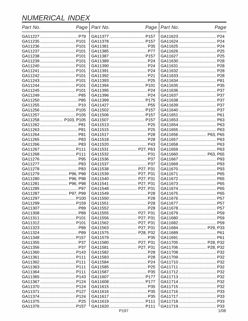
NUMERICAL INDEXPart No. Page Part No. Page Part No. Page
P197 1/08
GA11227 ................................. P79GA11235 ............................... P101GA11236 ............................... P101GA11237 ............................... P101GA11238 ............................... P101GA11239 ............................... P101GA11240 ............................... P101GA11241 ............................... P101GA11242 ............................... P101GA11243 ............................... P101GA11244 ............................... P101GA11245 ............................... P101GA11249 ................................. P85GA11250 ................................. P85GA11255 ................................. P10GA11256 ............................... P105GA11257 ............................... P105GA11258 .................... P103, P105GA11262 ................................. P81GA11263 ................................. P81GA11264 ................................. P81GA11265 ................................. P83GA11266 ................................. P83GA11267 ............................... P111GA11268 ............................... P111GA11276 ................................. P95GA11277 ................................. P83GA11278 ................................. P83GA11279 ........................ P96, P98GA11280 ........................ P96, P98GA11281 ........................ P96, P98GA11285 ................................. P97GA11287 ........................ P97, P99GA11297 ............................... P100GA11299 ............................... P159GA11307 ................................. P89GA11308 ................................. P89GA11311 ............................... P101GA11312 ............................... P101GA11323 ................................. P89GA11324 ................................. P89GA11348 ............................... P157GA11355 ................................. P37GA11356 ................................. P37GA11360 ............................... P143GA11361 ............................... P111GA11362 ............................... P111GA11363 ............................... P111GA11364 ............................... P111GA11365 ............................... P143GA11367 ............................... P124GA11370 ............................... P124GA11371 ............................... P127GA11374 ............................... P124GA11375 ................................. P25GA11376 ............................... P157
GA11377 ............................... P157GA11378 ............................... P157GA11381 ................................. P35GA11385 ................................. P77GA11387 ............................... P157GA11389 ................................. P24GA11390 ................................. P24GA11391 ................................. P24GA11392 ................................. P21GA11393 ................................. P25GA11394 ............................... P101GA11395 ................................. P24GA11396 ................................. P24GA11399 ............................... P175GA11427 ................................. P55GA11502 ............................... P157GA11506 ............................... P157GA11507 ............................... P157GA11513 ................................. P25GA11515 ................................. P25GA11517 ................................. P28GA11518 ................................. P28GA11520 ................................. P43GA11531 ........................ P27, P63GA11532 ................................. P31GA11536 ................................. P37GA11537 ................................. P37GA11538 ........................ P27, P31GA11539 ........................ P27, P31GA11540 ........................ P27, P31GA11541 ........................ P27, P31GA11548 ........................ P27, P31GA11549 ................................. P28GA11550 ................................. P28GA11551 ................................. P28GA11552 ................................. P28GA11555 ........................ P27, P31GA11556 ........................ P27, P31GA11562 ........................ P27, P31GA11563 ........................ P27, P31GA11575 ........................ P28, P32GA11579 ................................. P35GA11580 ........................ P27, P31GA11581 ........................ P27, P31GA11582 ................................. P28GA11583 ................................. P28GA11584 ................................. P24GA11585 ................................. P25GA11587 ................................. P35GA11607 ............................... P177GA11608 ............................... P177GA11615 ................................. P35GA11616 ................................. P35GA11617 ................................. P35GA11619 ............................... P111GA11620 ............................... P111
GA11623 ................................. P24GA11624 ................................. P24GA11625 ................................. P24GA11626 ................................. P25GA11627 ................................. P25GA11630 ................................. P28GA11631 ................................. P28GA11632 ................................. P28GA11633 ................................. P28GA11634 ................................. P81GA11635 ................................. P35GA11636 ................................. P37GA11637 ................................. P37GA11638 ................................. P37GA11639 ................................. P37GA11640 ................................. P37GA11651 ................................. P61GA11653 ................................. P63GA11654 ................................. P63GA11655 ................................. P63GA11656 ........................ P63, P65GA11657 ................................. P63GA11658 ................................. P63GA11659 ................................. P63GA11660 ........................ P63, P65GA11667 ................................. P93GA11669 ................................. P93GA11670 ................................. P93GA11671 ................................. P65GA11672 ................................. P65GA11673 ................................. P65GA11674 ................................. P65GA11675 ................................. P65GA11676 ................................. P57GA11677 ................................. P57GA11678 ................................. P57GA11679 ................................. P59GA11680 ................................. P59GA11682 ................................. P59GA11684 ........................ P29, P33GA11689 ................................. P61GA11691 ................................. P61GA11705 ........................ P28, P32GA11706 ........................ P28, P32GA11708 ................................. P32GA11709 ................................. P32GA11710 ................................. P32GA11711 ................................. P32GA11712 ................................. P32GA11713 ................................. P32GA11714 ................................. P32GA11715 ................................. P32GA11716 ................................. P33GA11717 ................................. P33GA11718 ................................. P33GA11719 ................................. P33
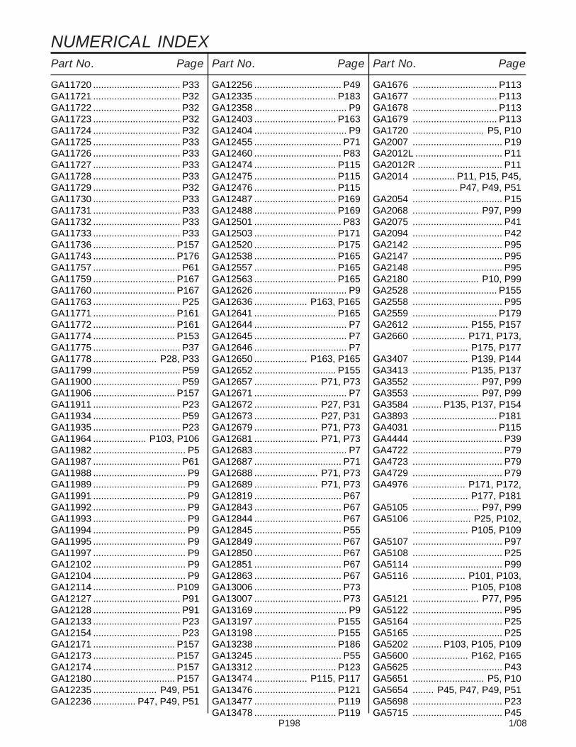
NUMERICAL INDEXPart No. PagePart No. PagePart No. Page
P198 1/08
GA11720 ................................. P33GA11721 ................................. P32GA11722 ................................. P32GA11723 ................................. P32GA11724 ................................. P32GA11725 ................................. P33GA11726 ................................. P33GA11727 ................................. P33GA11728 ................................. P33GA11729 ................................. P32GA11730 ................................. P33GA11731 ................................. P33GA11732 ................................. P33GA11733 ................................. P33GA11736 ............................... P157GA11743 ............................... P176GA11757 ................................. P61GA11759 ............................... P167GA11760 ............................... P167GA11763 ................................. P25GA11771 ............................... P161GA11772 ............................... P161GA11774 ............................... P153GA11775 ................................. P37GA11778 ........................ P28, P33GA11799 ................................. P59GA11900 ................................. P59GA11906 ............................... P157GA11911 ................................. P23GA11934 ................................. P59GA11935 ................................. P23GA11964 .................... P103, P106GA11982 ................................... P5GA11987 ................................. P61GA11988 ................................... P9GA11989 ................................... P9GA11991 ................................... P9GA11992 ................................... P9GA11993 ................................... P9GA11994 ................................... P9GA11995 ................................... P9GA11997 ................................... P9GA12102 ................................... P9GA12104 ................................... P9GA12114 ............................... P109GA12127 ................................. P91GA12128 ................................. P91GA12133 ................................. P23GA12154 ................................. P23GA12171 ............................... P157GA12173 ............................... P157GA12174 ............................... P157GA12180 ............................... P157GA12235 ........................ P49, P51GA12236 ................ P47, P49, P51
GA12256 ................................. P49GA12335 ............................... P183GA12358 ................................... P9GA12403 ............................... P163GA12404 ................................... P9GA12455 ................................. P71GA12460 ................................. P83GA12474 ............................... P115GA12475 ............................... P115GA12476 ............................... P115GA12487 ............................... P169GA12488 ............................... P169GA12501 ................................. P83GA12503 ............................... P171GA12520 ............................... P175GA12538 ............................... P165GA12557 ............................... P165GA12563 ............................... P165GA12626 ................................... P9GA12636 .................... P163, P165GA12641 ............................... P165GA12644 ................................... P7GA12645 ................................... P7GA12646 ................................... P7GA12650 .................... P163, P165GA12652 ............................... P155GA12657 ........................ P71, P73GA12671 ................................... P7GA12672 ........................ P27, P31GA12673 ........................ P27, P31GA12679 ........................ P71, P73GA12681 ........................ P71, P73GA12683 ................................... P7GA12687 ................................. P71GA12688 ........................ P71, P73GA12689 ........................ P71, P73GA12819 ................................. P67GA12843 ................................. P67GA12844 ................................. P67GA12845 ................................. P55GA12849 ................................. P67GA12850 ................................. P67GA12851 ................................. P67GA12863 ................................. P67GA13006 ................................. P73GA13007 ................................. P73GA13169 ................................... P9GA13197 ............................... P155GA13198 ............................... P155GA13238 ............................... P186GA13245 ................................. P55GA13312 ............................... P123GA13474 .................... P115, P117GA13476 ............................... P121GA13477 ............................... P119GA13478 ............................... P119
GA1676 ................................ P113GA1677 ................................ P113GA1678 ................................ P113GA1679 ................................ P113GA1720 ........................... P5, P10GA2007 .................................. P19GA2012L ................................. P11GA2012R ................................ P11GA2014 ................ P11, P15, P45,
................. P47, P49, P51GA2054 .................................. P15GA2068 ......................... P97, P99GA2075 .................................. P41GA2094 .................................. P42GA2142 .................................. P95GA2147 .................................. P95GA2148 .................................. P95GA2180 ......................... P10, P99GA2528 ................................ P155GA2558 .................................. P95GA2559 ................................ P179GA2612 ..................... P155, P157GA2660 .................... P171, P173,
..................... P175, P177GA3407 ..................... P139, P144GA3413 ..................... P135, P137GA3552 ......................... P97, P99GA3553 ......................... P97, P99GA3584 ........... P135, P137, P154GA3893 ................................ P181GA4031 ................................ P115GA4444 .................................. P39GA4722 .................................. P79GA4723 .................................. P79GA4729 .................................. P79GA4976 .................... P171, P172,
..................... P177, P181GA5105 ......................... P97, P99GA5106 ...................... P25, P102,
..................... P105, P109GA5107 .................................. P97GA5108 .................................. P25GA5114 .................................. P99GA5116 .................... P101, P103,
..................... P105, P108GA5121 ......................... P77, P95GA5122 .................................. P95GA5164 .................................. P25GA5165 .................................. P25GA5202 ........... P103, P105, P109GA5600 ..................... P162, P165GA5625 .................................. P43GA5651 ........................... P5, P10GA5654 ........ P45, P47, P49, P51GA5698 .................................. P23GA5715 .................................. P45

NUMERICAL INDEXPart No. Page Part No. Page Part No. Page
P199 1/08
GA5718 .................................. P45GA5719 .................................. P45GA5853 ................................ P113GA6108 ................................ P155GA6109 ................................ P154GA6147 ..................... P163, P165GA6171 ...... P13, P15, P16, P168GA6189 .................................. P83GA6434 .................................. P16GA6527 ................................ P181GA6597 .................................. P16GA6618 .................................. P15GA6619 .................................. P15GA6620 .................................. P15GA6733 .................................. P15GA6741 .................................. P41GA6761 .................................. P77GA6801 .................................. P15GA6832 .................................. P47GA6833 .................................. P47GA6834 .................................. P47GA6838 .................................. P47GA6860 ................................ P114GA6870 ................................ P114GA6907 .................................. P41GA6975 ............. P61, P155, P157GA6977 ..................... P155, P157GA6978 ............... P7, P155, P157GA7051 ................................ P106GA7052 ................................ P106GA7137 ................................ P111GA7154 ........................ P25, P99,
........... P103, P106, P109GA7271 .................................. P49GA7372 ......................... P97, P99GA7376 .................................. P95GA7399 ................................ P155GA7409 .................................. P95GA7412 .................................. P49GA7434 ................. P79, P83, P95GA7445 ......................... P49, P51GA7446 ................. P47, P49, P51GA7572 ......................... P96, P98GA7849 ..................... P163, P165GA7851 ..................... P163, P165GA7852 ..................... P163, P165GA7853 ................................ P163GA7854 ................................ P163GA7855 ................................ P163GA7856 .... P7, P155, P157, P163GA7858 ................................ P162GA7859 ..................... P163, P165GA7862 ................................ P155GA7863 ................................ P155GA7949 .................................. P13GA7975 .................................. P13
GA7976 .................................. P13GA8001 ................................ P109GA8022 ..................... P163, P165GA8026 ................................ P162GA8046 ..................... P163, P165GA8047 ........... P155, P163, P165GA8130 ................................ P128GA8172 ................................ P114GA8322 .................................. P16GA8324 .................................. P11GA8326 .................................. P40GA8328 ................. P7, P61, P159GA8329 ................. P7, P61, P159GA8364 .................................. P40GA8371 .................................. P39GA8393 ................................ P111GA8603 ............... P43, P51, P167GA8641 ......................... P43, P51GA8731 ................................ P155GA8760 .................................. P49GA8768 .................... P171, P173,
..................... P175, P177GA8828 ................................ P125GA8831 ................................ P125GA8877 ................................ P168GA8931 ................................ P184GA8948 ................................ P132GA8951 ................................ P132GA8983 ................................ P167GA9068 ................................ P111GA9097 ........... P135, P137, P157GA9098 ..................... P139, P157GA9101 ................................ P115GA9102 ................................ P115GA9103 ................................ P115GA9131 .................................. P51GA9144 ................................ P163GA9145 ..................... P117, P121GA9205 ................................ P130GA9306 .................................. P83GA9315 .................................. P83GA9407 ................................ P185GA9437 ................................ P167GA9472 ................................ P168GA9481 ................................ P155GA9510 .................... P138, P140,
..................... P141, P142GA9544 .................................. P79GA9712 ................................ P178GA9843 .................................. P25GA9844 .................................. P51GA9845 .................................. P51GA9846 ......................... P97, P99GA9861 .................................. P51GA9862 .................................. P51GA9864 .................................. P51
GA9865 .................................. P51GA9877 .................................. P95GA9954 ................................ P157GA9963 .................................... P7GA9964 ........................... P7, P61GA9965 ................................ P157GA9978 ..................... P163, P165GA9979 ..................... P163, P165GB0115 .................................. P40GB0116 .................................. P40GB0186 .................................. P10GB0196 ................................ P179GB0212 ......................... P71, P73GB0213 ....................... P51, P167GB0218 ..........P5, P10, P19, P28,
....... P32, P51, P57, P97,
............. P99, P117, P178GB0230 .................................. P81GB0234 .................................. P81GB0239 ......................... P15, P16GB0254 .................................. P16GB0265 .................................... P3GB0266 .................................... P3GB0267 .................................... P3GB0268 ......................... P15, P16GB0274 .................................... P3GB0276 .................................. P13GB0278 ......................... P19, P40GB0282 .................................. P16GB0283 ................. P25, P28, P32GB0285 .................................... P3GB0301 .................................. P11GB0314 .................................. P19GB0319 .................................. P23GB0322 ................................ P167GB0323 ................................ P167GB0328 .................................. P23GB0331 .................................. P19GB0332 .................................. P77GB0343 ................................ P167GB0355 .................................. P77GB0356 .................................. P77GB0357 .................................. P77GB0358 .................................. P23GB0365 ................................ P169GB0366 ........................... P5, P10GB0370 ................................ P169GB0371 .................................. P21GB0383 .................................. P49GB0386 .................................. P51GB0387 ......................... P47, P49GB0393 .................................... P5GB0394 .................................... P5GB0395 .................................... P5GB0396 .................................... P5GB0397 .................................... P5

NUMERICAL INDEXPart No. PagePart No. PagePart No. Page
P200 1/08
GB0398 .................................... P5GB0401 .................................. P49GD0453-07 ................ P114, P120GD0677 ................................ P115GD0692 ................................ P115GD0704 ................................ P114GD0740 ....................... P93, P109GD0746 ................................ P113GD0752-53 ............................. P83GD0831 ................................ P179GD0840 .................... P113, P115,
..................... P119, P121GD0844 ................................ P179GD0914-10.5 ........................ P105GD0914-108.5 ...................... P103GD0914-13.5 ............. P102, P105GD0914-132 ......................... P105GD0914-156 .... P103, P105, P106GD0914-166 ......................... P106GD0914-20 ........................... P105GD0914-21 ................ P102, P105GD0914-218 ......................... P106GD0914-228 ......................... P106GD0914-30 ........................... P102GD0914-36 ........................... P105GD0914-46 ........................... P102GD0914-48 ........................... P105GD0914-60 ........................... P105GD0914-68 ................ P103, P109GD0914-76 ........................... P105GD0914-78 ........................... P109GD10036.......................... P5, P10GD10057-01 ......................... P189GD10057-02 ......................... P189GD10057-03 ......................... P189GD10057-04 ......................... P189GD10057-05 ......................... P189GD10057-06 ......................... P189GD10057-09 ......................... P189GD10057-10 ......................... P189GD10063................................. P77GD10102............................... P111GD10103............................... P111GD10104............................... P111GD10123............................... P111GD10126.................... P103, P105GD10186............................... P114GD10231............................... P115GD10243............................... P155GD1026 ...........P3, P39, P97, P99GD10283............................... P113GD1033 .................................... P3GD10356................... P101, P103,
........... P105, P106, P109GD10473........................ P11, P15GD10510............................... P111
GD10519........................ P49, P51GD10526................................. P49GD10552................ P47, P49, P51GD1059L................................. P39GD1059R ................................ P39GD1060 .................................. P39GD1061 .................................. P40GD1063 .................................. P40GD1065 .................................... P3GD10674-01 ......................... P115GD10705................................. P19GD10777................... P171, P173,
..................... P175, P177GD1085 .................................. P16GD1086 .................................. P13GD10867................................... P3GD10963................................. P41GD10984................................. P41GD10991................................. P13GD10993................................... P3GD11001................................... P3GD11017................................. P11GD11045............... P25, P96, P98,
........... P102, P105, P109GD11089................... P155, P159,
..................... P163, P165GD1109 ......................... P15, P16GD11120............................... P111GD11123................... P171, P173,
..................... P175, P177GD11125................................. P99GD1114 ................ P5, P10, P103,
........... P105, P122, P181GD11158................................. P99GD1115L................................. P41GD1115R ................................ P41GD1116P41GD11169............................... P163GD11170............................... P163GD1118P41GD11219................................. P39GD11239................ P19, P39, P40GD11240................................. P40GD11259.......................... P3, P11GD11279................................. P20GD11297................................. P40GD11305................................. P39GD11306................................. P11GD11313................................. P17GD1132 ........ P45, P47, P49, P51GD11394-23 ........................... P25GD11395................ P25, P28, P32GD11413........................ P19, P40GD11422.......................... P5, P10GD11423...................... P13, P168
GD11424................................. P39GD1143 .................................. P42GD1144 .................................. P42GD1145 .................................. P42GD11453................................. P13GD11474.................... P163, P165GD11490................................. P95GD11508................................. P17GD11509................................. P17GD11557............................... P167GD11558............................... P167GD1162 ................................ P190GD11652........................ P43, P51GD1166 ................................ P178GD11677................................. P43GD11695................................. P95GD11700...................... P59, P181GD11751............................... P128GD11845.................. P3, P11, P15GD11953............................... P168GD11954............................... P168GD11962.......................... P3, P39GD11963-03 ........................... P35GD11963-04 ............................. P5GD11985............................... P125GD11986............................... P125GD11993.................... P163, P165GD12239............................... P131GD12507............................... P126GD12522.......... P124, P128, P131GD12534................................. P47GD12539............................... P133GD12543........................ P79, P95GD12548............................... P132GD1255 ................. P25, P96, P98GD12550............................... P132GD1256 ................. P25, P96, P98GD12597............................... P129GD12613............................... P121GD12670............................... P129GD12672............................... P129GD12676............................... P167GD12677............................... P167GD12679............................... P167GD12723............................... P161GD12724............................... P161GD12725............................... P161GD12726.................... P111, P154GD12790................................. P83GD12797-02 ........................... P21GD12797-04 ........................... P21GD12797-05 ........................... P21GD12797-09 ........................... P21GD12817...................... P51, P167GD12826................................. P51GD12827................................. P51

NUMERICAL INDEXPart No. Page Part No. Page Part No. Page
P201 1/08
GD12829................................. P51GD13110................................. P19GD13170............................... P130GD13171............................... P130GD13172............................... P130GD13173............................... P130GD13226-02 ........................... P53GD13309............................... P168GD13328............................... P179GD13361................................... P3GD13400............................... P130GD13401................................. P95GD13412................................. P21GD13524-01 ......................... P153GD13575-05 ........................... P35GD1359 .................................. P83GD1360 .................................. P83GD13740................................. P83GD13744............................... P179GD14089............................... P133GD14170................................. P51GD14217................................. P10GD14257................................. P25GD14258................................... P7GD14398................................. P43GD14413............................... P101GD14414............................... P101GD14429............................... P101GD14430............................... P101GD14431............................... P101GD14432............................... P101GD14467................................. P23GD14468................................. P23GD14477................................. P23GD14512............................... P111GD14513............................... P111GD14528............................... P144GD14541................................. P23GD14559...................... P28, P115GD14562................................. P89GD14563....... P85, P87, P89, P91GD14564................................. P89GD14565................................. P85GD14592................................. P23GD14626........................ P63, P65GD14627........................ P63, P65GD14640...................... P61, P157GD14645............................... P173GD14649............................... P167GD14651............................... P167GD14659................................. P41GD14660................................... P7GD14671............................... P169GD14672............................... P167GD14673............................... P167GD14674.............. P45, P49, P186
GD14812........................ P71, P73GD14841........................ P71, P75GD14842................ P71, P75, P77GD14843........................ P71, P75GD14897.................... P123, P127GD14898.................... P123, P127GD14901............................... P125GD14902............................... P125GD14907............................... P126GD14908............................... P128GD14910............................... P128GD14915............................... P129GD14923.................... P135, P137GD14925.......... P140, P141, P142GD14926................................. P77GD14941................................. P77GD14987............................... P161GD15041................................. P83GD15042................................. P83GD15045................................. P77GD15046................................. P77GD15047................................. P77GD15048................................. P85GD15049................................. P85GD15051................................. P77GD15064................................. P91GD15065................................. P91GD15066........................ P87, P89GD15067................................. P85GD15068................................. P85GD15069................................. P85GD15070................................. P85GD15072................................. P85GD15074................ P87, P89, P91GD15109................................. P89GD15110................ P87, P89, P91GD15114.................... P103, P105GD1512 ................................ P190GD15131.................... P117, P119GD15140............................... P117GD15169................................. P77GD15170................................. P77GD15172................................. P77GD15187-01 .............. P135, P137GD15192............................... P117GD15193............................... P117GD15194............................... P117GD15226............................... P167GD15227............................... P117GD15228............................... P117GD15229............................... P121GD15230............................... P119GD15231............................... P121GD15232............................... P121GD15233............................... P119GD15234............................... P119
GD15235...................... P93, P120GD15282................ P87, P89, P91GD15283............ P37, P115, P117GD15285................ P87, P89, P91GD15290............................... P121GD15369................................. P77GD15406................................. P79GD15450................................. P77GD15451................................. P77GD15472............................... P173GD15473............................... P173GD15474............................... P173GD15475............................... P173GD15483............................... P181GD15489.......... P115, P119, P121GD15492................................. P81GD15532........................ P96, P98GD15538........................ P97, P98GD15545............................... P122GD15552............................... P122GD15560............................... P122GD15568............................... P167GD15582............................... P161GD15600............................... P167GD15605................... P170, P172,
..................... P175, P176GD15623............................... P131GD15624........................ P71, P75GD15634.................... P135, P137GD15649............................... P121GD15663................................. P23GD15664................................. P81GD15668................................. P75GD15669................................. P75GD15674................................. P75GD15675................................. P75GD15677................................. P81GD15679................................. P81GD15700................................. P23GD15703.......... P171, P173, P175GD15706.......... P171, P173, P177GD15719................................. P89GD15720................................. P89GD15742............................... P117GD15747................................. P19GD15774............................... P131GD15780................................. P77GD15783................................. P81GD15784............................... P122GD15789................................. P61GD15790................................. P61GD15792-03 ........................... P63GD15792-05 .................. P63, P65GD15792-06 .................. P63, P65GD15792-12 ........................... P63GD15792-14 ........................... P65

NUMERICAL INDEXPart No. PagePart No. PagePart No. Page
P202 1/08
GD15792-16 ........................... P65GD15792-19 ........................... P63GD15792-20 ........................... P65GD15792-21 ........................... P65GD15792-22 ........................... P65GD15796................................. P77GD15799........................ P63, P65GD15803................................. P61GD15804................................. P61GD15833........................ P63, P65GD15849-02 ........................... P61GD15850........................ P62, P65GD15854........................ P62, P64GD15856-07 .................. P63, P65GD15856-08 ........................... P65GD15856-09 ........................... P65GD15856-10 ........................... P65GD15856-11 ........................... P65GD15856-12 ........................... P65GD15867-02 ........................... P63GD15867-03 ........................... P65GD15867-04 ........................... P65GD15867-05 ........................... P63GD15923................................. P23GD15968............................... P161GD15970................................... P3GD16037................................. P59GD16038................................. P59GD16058................................. P83GD16060............................... P133GD16119-12 ........................... P65GD16146.................... P135, P137GD16147............................... P133GD16175............................... P115GD16184............................... P133GD16189................... P171, P173,
..................... P175, P177GD16210................... P171, P173,
..................... P175, P177GD16227........................ P71, P73GD16245................................... P3GD16315............................... P165GD16316............................... P165GD16320........................ P27, P63GD16324-01 ................ P61, P109GD16355-02 ......................... P109GD16355-03 ......................... P109GD16356...................... P37, P115GD16362.................... P106, P109GD16370............................... P101GD16385-04 ........................... P28GD16385-07 ........................... P32GD16385-08 ........................... P32GD16388................................. P81GD16392................................. P81GD16393................................. P81
GD16394................................. P81GD16399-01 ........................... P21GD16400............... P24, P25, P27,
........ P28, P31, P32, P33GD16401............... P24, P25, P27,
........ P28, P31, P32, P33GD16405............................... P103GD16417.................... P102, P105GD16437........................ P97, P99GD16438........................ P97, P99GD16439............................... P101GD16440............................... P101GD16446............................... P101GD16447............................... P101GD16448............................... P101GD16449............................... P101GD16450............................... P105GD16451............................... P105GD16466...................... P28, P105GD16466............................... P105GD16467...................... P28, P105GD16478.......... P171, P173, P177GD16479.......... P171, P173, P177GD16489............................... P153GD16490............................... P153GD16500............................... P143GD16530................................. P37GD16535................................. P25GD16537............................... P153GD16538............................... P153GD16539................................. P25GD16540................................. P25GD16542................................. P25GD16547................................. P25GD16550................................. P25GD16556........................ P28, P32GD16572............................... P177GD16601................................. P29GD16602................................. P29GD16608................................. P61GD16620................................. P31GD16631................................. P28GD16634........................ P27, P31GD16672........................ P27, P31GD16674........................ P27, P31GD16675........................ P27, P31GD16680........................ P29, P33GD16691................................. P35GD16692................................. P35GD16693................................. P35GD16694................................. P35GD16701........................ P29, P33GD16705................................. P25GD16706................................. P25GD16707................................. P25
GD16714............................... P177GD16716............................... P177GD16717............................... P177GD16718............................... P177GD16731............................... P177GD16733............................... P177GD16751............................... P177GD16766................................. P24GD16778................................. P37GD16779................................. P37GD16786................................. P71GD16787................................. P75GD16788........................ P28, P32GD16840................................. P61GD16842........................ P62, P64GD16843........................ P63, P65GD16844........................ P62, P64GD16845........................ P63, P65GD16854........................ P63, P65GD16855........................ P63, P65GD16862................................. P63GD16862................................. P63GD16863................................. P63GD16864........................ P63, P65GD16873................................. P59GD16887................................. P93GD16890................................. P93GD16898................................. P65GD16913........................ P28, P32GD16942............................... P177GD16943............................... P177GD16944............................... P177GD16957................................. P33GD16972................................. P33GD16973................................. P33GD16979................................. P35GD16982........................ P27, P31GD16983........................ P27, P31GD16991................................. P61GD16992................................. P61GD16994........................ P55, P57GD17002................................. P25GD17006............................... P167GD17014................................... P3GD17016................................. P65GD17021................................. P23GD17028................................. P23GD17039...................... P77, P169GD17047................................. P23GD17048................................. P23GD17049................................. P23GD17050................................. P23GD17051.................... P103, P106GD17094.................... P103, P106GD17095.................... P103, P106

NUMERICAL INDEXPart No. Page Part No. Page Part No. Page
P203 1/08
GD17099................................. P23GD17100............................... P109GD17104................................. P23GD17141................................... P9GD17143................................... P9GD17144................................... P9GD17150-05 ............................. P9GD17150-06 ............................. P9GD17150-07 ............................. P9GD17151-06 ............................. P7GD17152................................. P23GD17154................................... P9GD17156................................... P9GD17162................................. P23GD17180................................. P91GD17186................................. P23GD17187................................. P23GD17215................................. P57GD17298................................... P9GD17308................................. P35GD17309................................. P35GD17317-01 ........................... P65GD17450................................. P89GD17794................................... P5GD17967............................... P115GD17973............................... P169GD17992............................... P175GD17995............................... P171GD18004........................ P71, P75GD18010.............................P7, P9GD18011................................... P9GD18013............................... P165GD18078................................... P9GD18079............................... P103GD18080............................... P103GD18081................................... P9GD18082............................... P103GD18095................................. P23GD18096.................... P135, P137GD18097............................... P138GD18098................................. P23GD18099.......... P140, P141, P142GD18100................... P138, P139,
........... P140, P141, P142GD18101................... P138, P140,
..................... P141, P142GD18102............................... P139GD18112................................... P9GD18118.................... P163, P164GD18137............................... P138GD18143........................ P71, P73GD18151........................ P71, P73GD18152........................ P71, P73GD18168.................... P163, P164GD18170........................ P71, P73GD18171................................. P71
GD18173................................... P9GD18175........................ P71, P73GD18190................................. P67GD18191................................. P67GD18193................................. P67GD18194................................. P67GD18275................................... P7GD18279................................. P67GD18282................................. P67GD18307................................. P67GD18308................................. P67GD18309................................. P67GD18318................................. P67GD18319................................. P67GD18320................................. P67GD18321................................. P67GD18324................................. P67GD1862 .................... P171, P173,
..................... P175, P177GD18631............................... P139GD18706............................... P139GD18796................................... P7GD18901................................... P9GD18904............................... P121GD18905............................... P121GD18934............................... P121GD18935............................... P121GD18939.................... P119, P121GD18957............................... P117GD1908 .................................. P10GD19148............................... P186GD2117 ....................... P21, P190GD2169 ................................ P115GD2199 ............... P71, P75, P189GD2423 .................................. P41GD2460 .................................. P42GD2548-104 .................. P96, P98GD2548-16 ........................... P109GD2548-93 .................... P96, P98GD2558 ................ P71, P73, P97,
............. P99, P101, P179GD2597 ..................... P113, P115GD2681 ................................ P178GD2721 ..................... P114, P120GD2829 ............. P61, P155, P157GD2947 .................................. P41GD2962 .................................. P25GD2971-09 .................... P73, P81GD2971-10 ............................. P39GD2971-15 ............................. P81GD2984 ................................ P190GD3180-12 ............................. P15GD3180-29 .................... P29, P33GD3180-30 ............................... P5GD3180-33 ............................... P9GD3180-35 ........................... P121
GD3180-36 ........................... P121GD3612 .................................... P3GD3622 .................... P171, P173,
..................... P175, P177GD3623 .................... P171, P173,
..................... P175, P177GD3737 ......................... P71, P73GD3860 ..................... P155, P157GD3951 .................... P171, P173,
..................... P175, P177GD4086 .................... P147, P149,
..................... P151, P153GD4700 ......................... P97, P99GD4701 ......................... P97, P99GD4743 .... P63, P65, P119, P122GD4887-10 ............................. P25GD5625 ................. P87, P89, P91GD5841 ......................... P77, P95GD5857 ................ P47, P81, P97,
............ P99, P100, P103,
..................... P106, P163GD5875 ..................... P115, P117GD5892 .................................. P81GD5900-20 ........................... P119GD5900-21 ........................... P119GD5900-28 ........................... P177GD6279-05 ............................. P59GD6291 ........... P155, P162, P165GD6551 ........... P103, P105, P108GD6775 ......................... P97, P99GD6825-12.75 ........................ P99GD7079 .................................. P79GD7089 .................................. P79GD7127 ................................ P101GD7137 ......................... P73, P81GD7145 ...... P28, P63, P65, P165GD7148 .................................. P40GD7258 .................................. P40GD7318 .................................... P3GD7426 ......................... P97, P99GD7803 ......................... P43, P51GD7804 ......................... P43, P51GD7805 ..........P5, P10, P16, P19,
....... P28, P32, P45, P57,
....... P67, P83, P95, P97,
............ P99, P100, P117,
........... P168, P178, P179GD7817-01 ............................. P45GD7817-04 ............................. P45GD7817-05 ........................... P179GD7823 .................................. P45GD7831 ................................ P179GD7864 .................................. P79GD7889 .................................. P45GD7890 .................................. P45

NUMERICAL INDEXPart No. PagePart No. PagePart No. Page
P204 1/08
GD8175 ................................ P100GD8188 .................................. P93GD8249 ........................... P5, P10GD8307 .................................. P45GD8460 .................................. P16GD8739 ................................ P155GD8740 ................................ P155GD8741 ................................ P155GD8751 ..................... P162, P165GD8770 ..................... P162, P165GD8771 ..................... P163, P165GD8893-07 .................... P63, P65GD9093 .................................. P81GD9120 .................................. P16GD9254 ......................... P43, P51GD9290 .................................. P15GD9305 .................................. P15GD9529 ..................... P111, P154GD9530 ..................... P111, P154GD9562 .................................. P15GD9667 ................................ P111GD9671 ................................ P111GD9672 ................................ P111GD9715 .................................. P47GD9720 .................................. P47GD9724 ................. P47, P49, P51GD9896 ................................ P155GD9964 ................................ P115GM0215 ................................ P190GR0146MPP ......................... P190GR0150 .................... P113, P115,
..................... P119, P121GR0151 .................... P113, P115,
..................... P119, P121GR0155MPP ......................... P190GR0190 ................................ P179GR0191 .................................. P83GR0192 .................................. P83GR0195 ................................ P179GR0196 ........................... P3, P40GR0200 ................................ P179GR0204 ................................ P179GR0267 ................................ P179GR0270 .................................. P95GR0434 .................................. P95GR0508 ................................ P176GR0513 ................................ P176GR0528 .................................. P79GR0531 .................................. P79GR0586 ................................ P163GR0594 ..................... P163, P165GR0761 .................... P135, P137,
..................... P138, P139GR0763 .................... P135, P137,
..................... P138, P139
GR0764 ..................... P135, P137GR0880 ................................ P181GR0881 ................................ P181GR0882 ................................ P181GR0883 ................................ P181GR0912 ................ P25, P97, P99,
........... P103, P105, P109GR1005 ................................ P176GR1006 ................................ P176GR1015 .................... P171, P172,
..................... P177, P181GR1016 .................... P171, P172,
..................... P177, P181GR1017 .................... P171, P172,
........... P175, P177, P181GR1018 .................... P171, P172,
..................... P177, P181GR1019 .................... P171, P172,
..................... P177, P181GR1037 .......... P131, P135, P137,
.......... P138, P139, P140,
.......... P141, P142, P143,
.......... P144, P146, P147,
.................... P148, P149,
..................... P150, P151GR1045 ....... P55, P57, P58, P59,
.......... P135, P137, P138,
..................... P139, P143GR1104 ................................ P183GR1112 ................................ P183GR1116 ................................ P183GR1118 ................................ P183GR1120 ................................ P183GR1123 ................................ P183GR1124 ................................ P183GR1134 ................................ P183GR1146 ..................... P179, P183GR1169 ................................ P124GR1208 ................................ P161GR1220 .................................. P53GR1246 .................................. P53GR1290 ..................... P155, P157GR1292 ............... P7, P155, P157GR1293 ................................ P106GR1294 ..................... P106, P109GR1295 ..................... P106, P109GR1296 ................................ P106GR1297 ................................ P106GR1298 ................................ P106GR1300 ................................ P109GR1301 ..................... P106, P109GR1303 ................................ P111GR1304 ................................ P111GR1305 ................................ P111GR1306 ................................ P111
GR1352 ................................ P109GR1363 ............... P7, P155, P157GR1364 ..................... P155, P157GR1365 ................................ P109GR1377 ................................ P109GR1414 ..................... P163, P164GR1415 ..................... P163, P164GR1430 .................................. P53GR1435 ................................ P176GR1445 .................... P135, P137,
..................... P138, P139GR1465 ................................ P129GR1466 .............. P55, P59, P135,
........... P137, P143, P153GR1467 ................ P54, P55, P57,
................. P58, P59, P61GR1468 .................................. P55GR1515 ................................ P144GR1517 ........... P131, P138, P139GR1522 ................................ P125GR1532 ................................ P132GR1533 ................................ P184GR1535 ................................ P184GR1540 ................................ P184GR1541 ..................... P184, P185GR1542 ..................... P184, P185GR1543 ........... P183, P184, P185GR1544 ................................ P184GR1545 ................................ P184GR1552 ................................ P129GR1557 ................................ P106GR1559 ................................ P185GR1561 ................................ P185GR1566 ................................ P185GR1567 ................................ P185GR1568 ................................ P185GR1570MPP ......................... P190GR1571 ................................ P176GR1574 ................................ P185GR1598 ................................ P130GR1630 ................................ P133GR1635 .......... P135, P137, P138,
.......... P139, P140, P141,
..................... P142, P157GR1681 .................................. P83GR1686 ........... P170, P172, P175GR1688 ..................... P123, P127GR1689 ................................ P125GR1690 ................................ P126GR1691 ..................... P128, P131GR1702 ........... P170, P172, P175GR1707 ................................ P161GR1708 ........... P170, P172, P175GR1731 ................................ P161GR1732 ................................ P161

NUMERICAL INDEXPart No. Page Part No. Page Part No. Page
P205 1/08
GR1733 ................................ P161GR1734 .................................. P58GR1736 .................................. P61GR1737 ..................... P163, P165GR1739 ........... P170, P172, P175GR1741 ................................ P109GR1743 ................................ P101GR1748 ................................ P143GR1756 ................................ P143GR1757 ................................ P124GR1762 ................................ P163GR1764 ................................ P163GR1766 ................................ P175GR1767 ................................ P175GR1768 ................................ P175GR1769 ................................ P175GR1777 .................................. P61GR1778 .................................... P9GR1786 .................................. P55GR1787 ......................... P55, P57GR1790 ................................ P153GR1796 ................................ P183GR1798 ................................ P183GR1800 ................................ P183GR1801 ................................ P183GR1803 ................................ P183GR1804 ................................ P183GR1805 ................................ P183GR1806 ................................ P183GR1808 ................................ P183GR1809 .................................... P9GR1843 .................................... P9GR1850 .................................. P53GR1851 .................................. P53GR1852 .................................. P53GR1853 .................................. P53GR1854 .................................. P53GR1855 .................................. P53GR1856 .................................. P53GR1857 .................................. P53GR1858 .................................. P53GR1859 .................................. P53GR1861 .................................. P53GR1862 .................................. P53GR1863 .................................. P53GR1864 .................................. P53GR1865 .................................. P53GR1866 .................................. P53GR1867 .................................. P53GR1868 .................................. P53GR1869 .................................. P53GR1870 .................................. P53GR1871 .................................. P53GR1872 .................................. P53GR1874 .................................. P53
GR1875 .................................. P53GR1960 .................................. P53