
TECHNICAL MANUAL OPERATOR HANDBOOK - AFM Safety
283
NSN 761 0-66-145-3217 TECHNICAL MANUAL OPERATOR HANDBOOK TRUCK, WRECKER, MEDIUM, MC2 MERCEDES-BENZ UNIMOG U2450L NSN 2320-66-1 45-0422 (LIABILITY CODE No. 75005) Specification Army (Aust) 6620 AUTHORISED FOR USE WITHIN THE AUSTRALIAN ARMY BY COMMAND OF THE CHIEF OF ARMY RlEN CSC
-
Upload
khangminh22 -
Category
Documents
-
view
7 -
download
0
Transcript of TECHNICAL MANUAL OPERATOR HANDBOOK - AFM Safety
NSN 761 0-66-145-3217
TECHNICAL MANUAL
OPERATOR HANDBOOK
TRUCK, WRECKER, MEDIUM, MC2
MERCEDES-BENZ UNIMOG U2450L
NSN 2320-66-1 45-0422 (LIABILITY CODE No. 75005)
Specification Army (Aust) 6620
AUTHORISED FOR USE WITHIN THE AUSTRALIAN ARMY BY COMMAND OF THE CHIEF OF ARMY
RlEN CSC

AMENDMENT RECORD

SYNOPSIS
The Truck, Wrecker, Medium MC2 with Crane is intended for the recovery of Truck Medium MC2, Truck Light MC2 and, Truck Lightweight MC2 vehicles. This includes assistance over difficult going, extrication of bogged equipment, battlefield clearance and backloading of equipment to repair facilities.

WARNINGS WARNING
At 8 pressure below 1.1 BAR (110 kP8) 8 tym can roll off the rim if the wheel is turned.
WARNING 36,54,56,81,92,116
If the engine is switched off during winching opentlons the six-wheel bnke will release m d the MRV may mow.
WARNING
When opn t ing with the PTO engaged, the main tnnsmksion shift lever must bo in the neutral position (7th - 8th gear), the forwardlnverse gear lever in the neutral position, and the splitter transmission in LOW mtlo.
WARNING
Braking efficiency is reduced when the engine brake is isolated from the service brake padal. The engine brakeisewice brake switch is only to be activated during testing of the service brakes. Do not disconnect the engine brake from the sewice brake pedal when driving on public roads.
WARNING
The MRV must not be driven if a bnke warning light or low air pressure warning light is operating. These warning devices indicate that the brake system is not functioning correctly.
WARNING
Do not operate the central tym inflation system when driving on public roads. Lowlunrven tyrt pressures make the MRV dimcult to control and dangerous in traffic.

WARNING
The refrigeration system components and copper pipework used in the air conditioning system are under high pressure and can cause serious injury if the air conditioning system is opened.
The mfrigeration system components and copper pipoworlr contain liquid-vrpour mixtures under pressure, which on contact can freeze, and cold-bum human body tissue resulting in permanent damage. This damage can occur within l(one) second. If refrigerant does enter the eye, fmzing of the eye can occur and blindness could resuk
WARNING When operating, the air conditioning system has several hot (> 60%) and cold (>S°C) areas. When working on the vehicle be welt aware of these areas to avoid injuries.
WARNING Welding tasks are not to be performed on the refrigerant circuit or in the immediate vicinity. The refrigerant gas is non-tlammable, however ensure that them are no naked flames within the vicinity as toxic gas is produced when the refrigerant gas comes in contact with fire.
WARNING 67
Do not ckan the air conditioning condenser with steam cleaning equipment, as the expansion of the refrigerant gas within, may cause excessively high pressures in the air conditioning system that may result in an explosion.
WARNING 74 The maximum static load that can be placed on the side step Is 15Okg.
WARNING 74 Ensure the side.rtep It stowed and the safety locking pin inserted before moving the MRV.

WARNING 75
The air supply pressure at the tyn inflation point is unmonitored. Take can not to exceed the mcommended tyre pressure. Over inflation could result in tyn damagehlowout and injury to personnel.
Ensum the accelerator pedal is not depmssed after the engine has been shut down as this action will release the positive engine stop allowing the engine to be roll started.
WARNING Do not drive the MRV on a firm surface with the differential locks engaged as there is no differential operation between the whclals when cornering. This leads to increased tyre war, poor steering behaviour and severe loads being placed on drive line components.
To prevent severe tyre vibration and possible loss of steering control remove all mud from the front wheels and tyms after cross country operation.
WARNING
When slave starting the MRV ensure that a 24V source is used and slave lead polarity connections are correct. Incorrect voltage or polarity connections m y result in battery explosion and injury to personnel.
WARNING
The MRV is equipped with six-wheel drive and differential locks. Do not attempt to apply drive to a wheel that has been jacked up off the ground if either six wheel drive or the differential locks are engaged. Serious injury to personnel and damage to the vehicle could result.
WARNING
Before changing a wheel secure the MRV to prevent movement.

WARNING
If 8 casualty MRV has no brakes, then it cannot be towed by another MRV on public road$.
WARNING
P~ior to mechanically releasing the park brakes the wheels must be chocked to prevent any movement of the MRV.
WARNING
Chock the whmk of the MRV to prevent it from rolling when the towing device is removed.
WARNING
When installing the batteries in the MRV ensure that connections with the battery leads an af the correct polarity i.e. (+) to (+) and (-) to (-). Incorrect polarity ~4#bnections will cause damage to the vcrhiclr electrical system and may result in battery explosion and injury to personnel.
WARNING
Do not stand in front of a tyrs whilst inflating it.
WARNING 117
During all recovrw operations, take care in the presence of overhead power lines,
WARNING
Ensure personnel a n clear before operating main boom.
WARNING
Keep clear of the main and folding boom when operating tM main boom locking pins.
Ensure personnel an clear before operating the folding or the extension boom.

WARNING 126
Ensure that the extension boom is locked prior to towing.
WARNING
On completion of lowering the load the two M I X 20 screws must be removed and the plugs must be refitted to the winch brake end plate. If this is not done, an accident can occur since the winch brake is completely out of action.
WARNING
Ensure personnel are clear before operating earth anchors.
WARNING 1 34
Removal of the valves mounted on the top of the earth anchor leg cylinder may result in sudden movement of the earth anchor leg and explosive release of hydraulic fluid.
WARNING
Removal of the valve adjacent to the hydraulic cylinder port marked 'R' (stamped on the top face of the cylinder end cap) may result in the earth anchor leg dropping i f it is unrestrained.
WARNING
If the MRV is supported on the earth anchor legs the hydraulic valve immediately adjacent to the hydraulic cylinder port marked 'E' (stamped on the top face of the cylinder end cap) must not be removed.
WARNING 1 35
Attempting to lower the MRV by large movements on each side may result in overturning of the vehicle.

WARNING
The Unimog U1700L rear lift towing adaptam are suitable only for rear lift towing of an unladen Unimog U1700L vehicle.
During all -tic lifting opontions, take cam in the pmmnce of werhead powr lines.
WARNINO
Do not allow bystanders to stand inside the risk area of the ropa when a winch it operating.
WARNING
Leather glows mud always be worn when handlina steel w i n rope m d siingt.
WARNING
A vehicle mounted cram Is dangerous If operated incorrectly. M e operator must exercise extreme caution to avoid mistakes which may result in personal injury or property damage. The crane should be operated by trained personnel.
WARNING
Do not operate the cnne until both stabiliser legs have been l o ~ n n d and the stabilioer feet a n on firm standing.
WARNING
Do not driw the MRV with damaged or incorrectly inflated tyros.

WARNING
Do not remove the coolant expansion tank filkr cap while the engine is hot. The cooling system is pressurised and sudden reteaoe of p n s s u n may cause boiling coolant to be ejected, If the engine has overheated and steam is escaping from the coolant expansion tank, allow the engine t o cool befon adding mom water to the coolant expansion tank When the engine k quite cool, the filltr cap can k removed. Place a thick cloth ovsr the cap and slowly unscnw it until a sudden drop in resistance is felt. At this point, if the engine and eoolant is still hot, rapour will be heard escaping. Only when this ceases should the cap be fully removed.
WARNING 193
Do not remove the coolant expansion trnk filler cap while the engine is hot. t he cooling system is prassurfred and sudden release of pmssum may cause boiling coolant to be ejected. m e n the engine is quite cool, the filler cap can be removed.
WARNING
Bawars of the rotating cooling fan behind the radiator when checking the power steering fluid level.

LIST OF CONTENTS Preliminary Pages Page No .
................................................................................... Front Page i
Amendment Record ............................................................... ii ... Synopsis ..................................................................................... III Warnings .................................................................................... iv
List of Contents ........................................................................... xi ...
List of Illustrations .............................................................. x x l ~
List of Tables ............................................................................ xxvii
Associated Publications ........................................................... xxviii
Frontispjece ................................ .. .......................................... xxxi
Maintenance Supply Items ........................................................ xxxii
Title Para No . Chapter 1 General Description
Chapter 1 Section 1 . Data Summary
. General ................................................................... 1 1 ................................ Engine .. ............................... 1 . 2
Air Cleaner ............................................................... 1.3 ................................................................ Fuel System 1.4
Cooling System ...................................................... 1.5 Engine Starter ............................................................ 1.6 Clutch ......................................................................... 1.7 Splitter Transmission .................................................. 1.8 Transmission .............................................................. 1.9 PTO ............................................. .............................. 1.10 Front Axle ................................................................ 1.11 Intermediate Rear Axle .............................................. 1 . 12
. .............................................................. Rear Axle 1 13 Front Suspension ....................................................... 1.14 Rear Suspension ....................................................... 1 . 15 Propeller Shafts ......................................................... 1-16 Steering System ......................................................... 1.17 Brakes ....................................................................... 1.18
.................................................. Trailer Brake System 1.19 Chassis .................................................................... 1.20 Tyres ........................................................................ 1.21

LIST OF CONTENTS (Continued) Title Para No .
.......................................................................... Rims 1.22 Central Tyre Inflation System (CTIS) ......................... 1.23
....................................................... Electrical System 1.24 Audio Kit .................................................................... 1.25
................................ .................... Air Conditioner .. 1.26 ................................................. Hydraulic System 1 . 2 7
......................................................... Recovery Boom 1.28 .................................................................... Winches 1.29 .................................................................... Fairleads 1.30
Earth Anchors ............................................................ 1.31 ......................................................................... Crane 1.32
........................ ................................. Accessories .. 1.33 ......................................................... Performance .....1.34
Chapter 1 Section 2 . Shipping and Transportation Data
............................................................... Dimensions 1.35 .................................................................. Capacities 1.36
............................................................. Fording depth 1-37 .................................................. Bridge Classification 1.38
...................................................... Ground Clearance 1.39 ............................. ................... Transportability .. ....1.40
..................................... Slinging and Tie-down Points 1.41 ....................................................... Shipping Volume .1.42
................................ Approach and Departure Angles 1.43
Chapter 1 Section 3 . Equipment Description ........................................................... Introduction ....1.44
......................................................... Main Features 1 . 4 5 .............................. . Operational and Logistic Concept 1 46
Engine ............................................................ General 1.47
Lubrication .......................................................... 1.48 Oil Filter ............................................................ 1.49
.......................................................... Oil Cooler 1.50 ......................................................... Air Cleaner 1.51
............................................... Engine Cooling 1 . 5 2 Fuel System
.............................................................. General 1.53 Diesel Engine Exhaust Smoke Emission
................................................................ Control 1.54 ....................................................................... Clutch 1.55
xii

LIST OF CONTENTS (Continued) Title Para No .
................................................. Splitter Transmission 1.56 Transmission
......................................... Main Transmission 1 . 5 7 .... . Auxiliary Transmission (Working Gear Group) 1 58
Transfer Case ..................................................... 1.59 Drivelines and Axles
............................................................ General 1.60 ................................................ Differential Locks 1.61
.................................................................... Chassis 1.62 Suspension
............................................... Front Suspension 1.63 ............................................... Rear Suspension 1.64
......................................................... Steering System 1.65 Brake System
............................................................. General 1.66 .................................................... Exhaust Brake 1.67
.......................................................... Foot Brake 1.68
.......................................................... Park Brake 1.69 Trailer Brake ....................................................... 1.70
....................................... Six-Wheel Work Brake 1.71 Controls
Accelerator Pedal Linkage .................................. 1.72 Speed Limiting Device ....................................... 1.73
................................................... Hand Throttle 1 . 7 4 ...................................................... Clutch Pedal 1.75
Foot Brake Pedal ............................................. 1.76 ......................................... Trailer Brake Lever 1 . 7 7
Forward/Reverse Selector Lever ........................ 1.78 Gear Selector Lever .......................................... 1.79 Gear Shift Gate Position Indicator ...................... 1.80 Splitter Transmission Selector Lever .................. 1.81 Park Brake Lever ................................................ 1.82 Auxiliary Transmission (Working Gear Group) Selector Switch .................................................. 1.83 PTO Selector Switch .......................................... 1.84 Steering WheeVColumn ...................................... 1.85 All Wheel Drive, Transfer Case and Differential Lock Controls ................................... 1.86 Instrument Panel All Wheel Drive and Power Divider Control Switch .............................. 1.87 Control Panel Differential Lock Control Switch .... 1.88

LIST OF CONTENTS (Continued) Title Para No . Electrical System
General ........................................................ .....1.89 Alternator ........ ........ ......................................... 1.90 Circuit Breakers .................................................. 1.91 Battery Mains Switch .......................................... 1.92 Auxiliary Start Socket .......................................... 1.93 Starter Motor ..................................................... 1.94 Windscreen Wipers ........................................... 1.95 Windscreen Washers ........................................ 1.96
................................................................... Horn 1.97 Lighting System
Normal Lights ..................................................... 1.98 Blackout Lights ................................................. 1.99 Cabin Lighting ................................................... 1 . 100
.................................................................. . Audio Kit 1 101 Communications .................................................. 1 . 102 Switches
................................................... Ignition Switch 1 . 103 Indicator Control Combination Switch ................ 1 . 104 Turn Indicator Control (Fig 1-1 5(A)) ................... 1.105 Headlight Beam Control (Fig 1-1 5(B)) ................ 1 . 106 Headlight Flasher Control (Fig 1-1 5(C)) ............. 1 . 107
................................. . Horn Control (Fig 1-1 5(D)) 1 108 ............ Windscreen Wiper Control (Fig 1-1 5(E)) 1.1 09
......... Windscreen Washer Control (Fig 1-15(F)) 1.1 10 ............................ Headlight Adjustment Control 1.1 11
................................. MainIMasked Light Switch 1.1 12 Instrument Panel
............................................................. . General 1 113 . .................................................... Speedometer 1 114
....................................................... Tachometer 1.1 15 ................................... Dual Air Pressure Gauge 1.1 16
Coolant Temperature Gauge ............................. 1.1 17 ............................................... Fuel Gauge .......1 18
Oil Pressure Gauge ........................................... 1 . 119 . ............................... GPS Power Supply Sockets 1 120
........................... Six-Wheel Work Brake Switch 1.1 21 . ................... Engine BrakeIService Brake Switch 1 122
........,.................... . Hazard Warning Light Switch 1 123

LIST OF CONTENTS (Continued) Title Para No .
..................................... Warning Beacon Switch 1.124 All Wheel Drive and Power Divider
................................................... Control Switch 1 -125 .......................... Warningtlndicator Light Cluster 1 -126
... . Central Tyre Inflation System (CTIS) Control Panel 1 127 Heating, Cooling and Ventilation
............................................................. General 1 -128 ................................................... . Air Conditioner 1 129
.............................. . Air Conditioner Compressor 1 130 ................................. Air Conditioner Condenser 1 -131 ............................... Air Conditioner Evaporator 1.1 32
............................................... Climatic Controls 1 -133 Cabin and Fittings
............................................................. Cabin 1 -134 ....................................................... Cabin Seats 1.1 35
................................................ Cabin Seat Belts 1 -136 ........................................................... Windows 1 . 137
.............................................. Rear View Mirrors 1 -138 ........................................... Observation Hatch 1 -139
Weapon Clips and Butt Boxes ........................... 1 . 140 Chassis and Body Fittings
...................................................... Construction 1.1 41 .................................................... Climbing Bars 1.1 42
................................................. . Bonnet Release 1 143 ......................................................... Stowage 1 . 1 44
.............................................. Fire Extinguishers 1 . 145 ................................................... . POL Stowage 1 146
........................................................... Side Step 1 -147 .................................................. . Towing Pintle 1 148
.................. Electrical Trailer Connection Socket 1.1 49 ............................................. Tyre Inflation Point 1 . 150
Camouflage Nets Stowage ............................. 1. 151 ....................................... . Spare Wheel Stowage 1 152
Auxiliary Wire Rope Stowage ............................ 1.1 53 Personal Equipment Stowage ............................ 1 . 154 Bridge Classification Sign .................................. 1 . 155
......................................... Unit Formation Signs 1.1 56 ............... Vehicle Nomenclature Plate (Fig 1-29) 1.1 57
Centre of Gravity Plate (Fig 1-30) ...................... 1 . 158

LIST OF CONTENTS (Continued) Title Para No .
Servicing Data Decal (Fig 1-31) ......................... 1 . 159 Recovery Equipment and Controls
Lifting and Towing Gear ................................... 1 -160 Hydraulic System ............................................... 1.1 61 Winches ...................................................... 1.162 Earth Anchors .................................................... 1 -163 Recovery and Towing Hydraulic Systems Controls ............................................................. 1 . 164 Six-Wheel Work Brake ...................................... 1.1 65 Exhaust Brake .................................................. 1.166 CTIS .................................................................. 1.167
................................................................ . Crane 1 168 Crane Hydraulic Systems Control ...................... 1.1 69 Recovery Unit Lighting ..................................... 1 . I70
.................................................................. Audio Kit 1.171 ........................................................................ Tools 1 ,172
Chapter 2 Operating Instructions
Chapter 2 Section 1 - Vehicle Operation
New Vehicle ...................................... Pre-Operational Check 2.1
........................................................... Running-In 2.2 Normal Operation
General ............................................................. 2.3 ............... Before Starting ................................. .. 2.4
Before Starting the Engine ................................... 2.5 Starting the Engine (Hot Or Cold) ........................ 2.6
................................... Shutting Down the Engine 2.7 ........................... EngaginglDisengaging the PTO 2.8
Driving Procedures Moving Off - Normal Conditions ........................... 2.9 Moving Off - Slippery Road Conditions and Rough Terrain .............................................. 2.10 Cross Country Driving ......................................... 2.11
............................................................... Fording 2 . 2
............................................................... Braking 2.13 Parking ............................................................... 2.14
....................................... Six-W heel Work Brake 2.15 .................................................. Towing a Trailer 2.16

LIST OF CONTENTS (Continued) Title Para No .
........................................... Engine Temperature 2.17 ......................................................... Instruments 2.18
................................................................. Clutch 2.19 .............. ................................. Gear Changing .. 2.20
Emergency Procedures ...................................................... Brake Failure 2.21
..................................................................... Fire 2.22 Breakdown Procedures
...................................................... Flat Batteries 2.23 ............................................................ Flat Tyre 2.24
Removing the Spare Wheel ................................ 2.25 Changing a Wheel .............................................. 2.26 Stowing the Spare Wheel ................................... 2.27
Towing Towing a Casualty MRV ................................... 2.28
...... MRV to MRV Towing Preparation - Option 1 2.29 MRV to MRV Towing Preparation - Option 2 ...... 2.30 Emergency Park Brake Release ......................... 2.31
Electrical System Battery Removal ................................................. 2.32 Battery Installation .......................................... .2.33 Circuit Breakers .................................................. 2.34
Central Tyre Inflation System (CTIS) Inflate Front Axle Tyres ....................................... 2.35 Deflate Front Axle Tyres ..................................... 2.36 inflate Intermediate and Rear Axle Tyres ............ 2.37 Deflate Intermediate and Rear Axle Tyres ........... 2.38 Inflate/Deflate Front and Rear Axles Tyres .......... 2.39 Inflating a Tyre from an External Source ............. 2.40
MRV Loading onto C-130 Aircraft Operators Preparation Procedure ....................... 2.41
Cleaning Vehicle Washing ................................................ .2.42
Chapter 2 Section 2 . Recovery System Operation
Precautions Prior to Use ............................................ 2.43 Precautions During Use ............................................. 2.44 Preparation for Recovery ........................................... 2.45

LIST OF CONTENTS (Continued) Title Para No . Layout and Operation of Controls
Vehicle Mounted Recoveryrrowing Controls ....... 2.46 Winch Pressurflension Gauges ....................... 2.47 Remote Control .................................................. 2.48 Remote Control Function Switch ......................... 2.49 Front Winching ................................................... 2.50
Main Boom Main Boom Operation ......................................... 2-51
Folding Boom and Extension Boom Lowering the Folding Boom ................................ 2.52 Extending the Extension Boom ........................... 2.53 Retracting the Extension Boom .......................... 2.54 Raising the Folding Boom ................................... 2.55
Winches ............................ Precautions Prior to Winching 2.56 ............................. Precautions During Winching 2.57
Operation of Winches ................................................ 2.50 ..................................................... Free Spooling 2.59
Paying OutMlinching In Under Power ....................................... using the Control Panel 2.60
Paying OuVWinching In Under Power ............................ using the Remote Control Unit 2.61
................................. Disconnecting the Casualty 2.62 ...................... Lowering a Load in an Emergency 2.63
Earth Anchors ................................... Precautions Prior to Use 2.64 .................................... Precautions During Use 2.65
.................................................... Soil Conditions 2.66 ...................................... Earth Anchor Operation 2.67
Earth Anchor Emergency ............................................. Retract Procedure 2-68
Tackle Attachment Points ..................................... Precautions Prior to Use 2.69
.................................. Boom Head Anchor Points 2.70 ....................... Earth Anchor Leg Reeving Points 2.71
............................... Emergency Towing Points ..2.72 ......................................................... Pintle Hook 2.73
Front Winching Anchor Points ............................ 2.74

LIST OF CONTENTS (Continued) Title Para No . Travelling Empty
...................................... Boom Stowed Positions 2.75 Towing
Towing Precautions ............................................ 2.76 .......................................... Towing Attachments .2.77
.......................... Fitting of Adapter Unimog Rear 2.78 Lift Towing
Lifting the Casualty ............................................. 2.79 Releasing the Load ............................................. 2-80
Flat Towing .......... Connecting a Trailer/Casualty to the MRV 2.81
Towing Pintle ...................................................... 2.82 ...... Attaching the Towing Pintle to the MRV 2.83
Removing the Towing Pintk from the MRV ...................................................... 2.84
Static Lifting ............................. Main Boom Static Lifting 2.85
Rear Winching Precautions Prior to Use ..................................... 2.86 Unloading Effect (front of MRV lifting off ground) .......................................................... 2.87 Increasing Boom Height to Gain Winching Advantage ......................................................... .2.88
Side Winching Stabilised Pull ..................................................... 2.89 Unstabilised Pull ................................................. 2.90 Side Winching Layouts ....................................... 2.91
Front Self Recovery and Front Winching Front Winch Components Layout ....................... 2.93 Front Winching Controls .................................... 2.94 Maximum Fleet Angles ..................................... 2.95 Reeving to the Front of the MRV ........................ 2.96 Changing from Reeving to the Front to Reeving to the Rear ........................................ 2.97
Rear Self Recovery Precautions Prior to and During Use ................... 2-98
Self Recovery and Driving Precautions Prior to and During Use ................... 2.99 Winching and Driving Simultaneously ................ 2.100

LIST OF CONTENTS (Continued) Title Para No . Winch Ropes
................................... Replacing a Winch Rope 2.101
Chapter 2 Section 3 . Crane Operation
.................................................. Safety Precautions 2.1 02 Crane Operation
............................................ Crane Preparation 2.104 ..................................... Lowering the Stabilisers 2.1 05
......................................... Unstowing the Crane 2.1 06 ................................................. Lifting a Load 2.1 07
.............................. Overload Protection System 2.108 ............................................... Releasing a Load 2.1 09
Stowing the Crane ............................................ 2 1 10 ...................................... Stowing the Stabilisers 2.1 11
........................................ Prior to Moving Off ....2.12 ....................................... Operating in Darkness 2.1 13
CHAPTER 3 - Operator Servicing
Chapter 3 Section 1 . Parade Servicing
................................................................. Introduction 3.1 ................................................. Lubricants and Fluids 3.2
Daily Servicing General ............................................................... 3.3
First Parade Service ................................................... 3-4 ............................................................ Start the MRV 3.11
............................................ Moving Off and Running 3.12 ................................................... Halt Parade Service 3.13 ................................................... Last Parade Service 3 . 14
Opening the Bonnet and Grille for Servicing Access .. 3.15 Operator Check Procedures
Cooling System Coolant Expansion Tank Coolant
................................................ Level Check 3.16 Radiator Core and Hoses ............................ 3.17
Engine ............................... Engine Oil Level Check 3.18
Fuel System .................................... fuel Tank Filler Cap 3.19
...................... Fuel Lift Pump and Pre-Filter 3.20

LIST OF CONTENTS (Continued) Title Para No .
...................... Fuel Filter and Priming Pump 3.21 ..................................... Priming the Fuel System 3.22
................................................................. Air Cleaner 3.23 ...................................... Steering Hydraulic Reservoir 3.25
........................................................ Clutch Reservoir 3.26 Brake System
Brake Master Cylinders ..................................... 3.27 ..................................................................... Wheels .3.28
............................................................. Accessories .3.29 Drive Belts (Fig 3-6) ................................................... 3.30
..................................................... Main Transmission 3.31 ................................................................ Splitter Box 3.32
Drive Lines and Axles ................................................ 3.33 ............................................... Compressed Air Tanks 3.34
Chapter 3 Section 2 . Periodic Servicing
................................................................ Introduction 3.35 Lubricants and Fluids ................................................. 3.37 Periodic Servicing . CaWChassis
Introduction ...................................................... .3.38 Special Requirements ....................................... .3.40
Periodic Servicing - Recovery Unit ........................................................ Introduction .3.43
Special Requirements ......................................... 3.45 Periodic Servicing - Crane
Introduction ......................................................... 3.46 Special Requirements ......................................... 3.47
Chapter 3 Section 3 . Lubrication
Introduction .............................................................. .3.50 Lubricants and Fluids ................................................. 3.52 Service and Lubrication Points CabJChassis (Fig 3.8) ................................................ 3.53
Engine Oil Level Check ....................................... 3.54 Engine Oil and Filter Change Procedure .................... 3.55 Transmissions
Splitter Transmission ......................................... 3.61 Main ~ransmission Group ................................... 3.62 Clutch Reservoir .............................................. 3.64

LIST OF CONTENTS (Continued) Title Para No . Power Divider and Axles
Power Divider ................................................... 3.65 ................................................ Intermediate Axle 3.66
Rear Axle ........................................................... .3.67 Front Axle ........................................................... 3.68 Propeller Shafts ................................................. .3.69 Reduction Hub Drives ......................................... 3.70
Steering System Steering Hydraulic Reservoir ....................... .... 3.71
Brake System Brake Master Cylinders ...................................... .3.72
Service and Lubrication Points - Recovery ............................................................ Unit (Fig 3.21) 3.73
..... Service and Lubrication Points - Crane (Fig 3.22) 3.74
Chapter 3 Section 4 . Fault Finding
................................................................ Introduction 3.75 .................................................. Fault Finding Tables .3.77
CHAPTER 4 . Warranty
Chapter 4 Section I . Warranty and Repair
.................................................... Warranty Provisions 4.1 .......................................................... Warranty Rights 4.6
....................................................... Special Provisions 4.8 Application of Warranty .............................................. 4.13
..................................................... Prior Consultation 4.19 Obtaining Warranty Service ....................................... 4.22
................................................. Warranty Procedures 4.23
............................................... Recording of Repairs .4.24 .................................................. Reporting of Defects 4.25
Replacement Parts and Accessories during ....................................................... Vehicle Warranty 4.26
............................................................. List of Agents 4.27
Page No . ........................................................................................ Index -251 ........................................................................................ Notes -257

Fig. No.
LIST OF ILLUSTRATIONS Title
Truck Wrecker Medium MC2 - Front View
Truck Wrecker Medium MC2 - Rear View
Slinging and Tie-Down Points
FrontILeft Hand Side View of Engine
Chassis and Suspension
Steering System
Controls
Trailer Brake Lever
Control Panel
Gate Position Indicator
Park Brake Lever
lnstrument Panel All Wheel Drive and Power Divider Control Switch
Control Panel Differential Lock Switch
Circuit Breakers
lndicator Control Combination Switch
Headlight Adjustment Control
MainIMasked Light Switch
Instrument Panel
Warningllndicator Light Cluster
CTlS Control Panel
Heating, Cooling and Ventilation Controls
Air Conditioner Condenser
Cool Mode
Vent Mode
Heat Mode
Demist Mode
Page No.
xxxi
xxxi
27
3 1
34
35
37
38
39
40
4 1

LIST OF ILLUSTRATIONS (Continued) Fig. No. Title Page No.
1-27 Observation Hatch 72
1-28 Climbing Bar 73
1-29 Vehicle Nomenclature Plate 76
1-30 Centre of Gravity Plate 76
1-31 Servicing Data Decal 77
1-32 Winches 78
1-33 Recoveryflowing Controls (Right Hand) 79
1-34 Winch Pressureflension Gauge 79
1-35 Remote Control Unit 80
1-36 Remote Control Function Switch 80
1-37 Crane - General Arrangement 82
1-38 Crane Control Levers (Viewed from Cab) 83
2- 1 Transmission Shift Cylinder 101
2-2 Casualty M RV Front Wheels - Stowage 104
2-3 Emergency Parking Brake Release 106
2-4 Battery Connection Diagram 107
2-5 CTlS Control Panel 109
2-6 Control Lever Lay Out (Right Hand Side) 118
2-7 Winch Pressureflension Gauge 119
2-8 Remote Control Unit 120
2-9 Remote Control Function Switch 121
2-1 0 Front Winch Control 122
2-1 1 Boom Locks 123
2-12 Folding Boom - Lowered 125
2-1 3 Extension Boom Positions 125
2-1 4 Winch Emergency - Lowering of Load 131

LIST OF ILLUSTRATIONS (Continued) Fig. No.
2-1 5
Title
Boom Head Tackle Anchor Points - Maximum Operating Angles
Earth Anchor Leg Tackle Attachment Points
Earth Anchor Reeving Points - Operating Angle Limits
Emergency Towing Points
Pintle Hook Anchor Point - Maximum Operating Angles
Front Anchor Points
Towing Attachments
Unimog U1700 Rear Lift Towing Adapter - Fitted
Lift Tow T-bar Position
A-Frame Operating Limitations
Clamping Straps - Installation
Towing Pintle - Installed
Static Lift
Side Winching - Single Line Pull
Side Winching - 2:1 Tackle Layout
Side Winching - 3: 1 Tackle Layout
Side Winching - 2:1 Tackle Layout
Side Winching - 3:1 Tackle Layout
Front Winch Components - Layout
Front Winch Roller Fleet Angles
Rope Guide - Dismantling
Left Hand Fairlead - Locking
Top, Horizontal and Vertical Rollers - Winch Rope - Attachment
Layout of Stowage
Removal
Page No.

LIST OF ILLUSTRATIONS (Continued) Fig. No. Title Page No.
2-40 177
2-41 179
2-42 180
3- 1 193
3-2 194
3-3 195
3-4 197
3-5 199
3-6 200
3-7 200
3-8 21 5
3-9 217
3-1 0 21 9
3-1 1 21 9
3-12 220
3-1 3 220
3-1 4
Stabiliser
Crane Control Levers (Viewed from Cab)
Crane Safe Working Loads
Expansion Tank
Engine Dipstick and Filler
Fuel Lift Pump and Pre-Filter
Air Cleaner
Brake Master Cylinders
Drive Belts
Drive Belt Adjustment
Service and Lubrication Points - CabIChassis
Engine Dipstick and Filler
Engine Oil Filter
Splitter Transmission FillerILevel and Drain Plug
Transmission FillerILevel Plug
Transmission Group Drain Plugs
Power Divider and Intermediate Axle Oil Filler Level and Drain Plugs
Rear Axle Housing Oil FillerILevel and Drain Plug
Front Axle Housing Oil FillerILevel and Drain Plug 222
Rear Axle Reduction Hub Drain and FillerILevel Plugs 223
Front Axle Reduction Hub Drain and FillerILevel Plugs 223
Steering Hydraulic Reservoir 224
Brake Master Cylinders 224
Service and Lubrication Points - Recovery Unit 225
Service and Lubrication Points - Crane 227

Fig. No.
1-1
2- 1
2-2
2-3
2-4
2-5
3- 1
3-2
3-3
3-4
3-5
LIST OF TABLES Title Page No.
Location of Identification Numbers on MSl's xxxi i
Remote Control Functions 120
Remote Control Switch Functions 121
Earth Anchor Holding Power 133
Boom Positions When Lift Towing 1 48
Driving and Winching - MRV and Winch Speeds 171
Daily Tasks - CabIChassis 205
Weekly Task - Air Conditioning System 206
Fortnightly Tasks - CabIChassis 206
Monthly Service - Cab/Chassis 207
Daily Tasks - Recovery Unit 209
Monthly Tasks - Recovery Unit 209
Daily Tasks - Crane
Weekly Tasks - Crane
Monthly Tasks - Crane
List of Lubricants and Fluids
Engine Faults and Probable Causes
Drive Line Faults and Probable Causes
Steering, Brake and Suspension Faults and Probable Causes
Electrical Faults and Probable Causes
Air Conditioning System Faults and Probable Causes 235
Recovery Unit Hydraulics Faults and Probable Causes 237
Crane System Faults and Probable Causes
DaimlerChrysler AustraliaIPacific Pty. Ltd. Dealers 245

ASSOCIATED PUBLICATIONS Defence Road Transport Instructions (DRTI)
MEMA Vol3
Australian Army Books: GM 120 Record Book for Servicing Equipment - Army
EMEl GENERAL R 008 lnspection of Recovery Equipment
EMEI MISCELLANEOUS EQUIPMENT 0 Series
EMEl MISCELLANEOUS EQUIPMENT 0 018 Cranes, Hoists and Winches - lnspection Data
EMEl VEHICLE A 029 Servicing of B Vehicles, Trailers, Stationary Equipment, Auxiliary and Small Engines
EMEl VEHICLE A 1 19-1 8 Repair of Vehicles Under Warranty Agreement, General Instruction.
EMEl VEHICLE A 119-24 Truck, Wrecker, Medium, MC2 (UNIMOG U2450L) 6x6, - Repair of Vehicle Under Warranty Agreement.
EMEl VEHICLE A 591-1 Servicing of Dry Type Air Cleaners
EMEl VEHICLE D 390 Data Summary
EMEl VEHICLE D 391
EMEl VEHICLE D 392
EMEl VEHICLE D 393
EMEl VEHICLE D 394
Operator Instruction
Technical Description
Light Repair
Medium Repair
EMEl VEHICLE D 394-1 Heavy Repair (Not Issued)
EMEl VEHICLE D 395
EMEl VEHICLE D 396
EMEl VEHICLE D 397
Preparation for Special Purpose (TBA)
Workshop Manual (TBA)
Modification Instruction (TBA)
EMEl VEHICLE D 398 Equipment lnspection and Examination Data (TBA)
,-'
EMEI VEHICLE D 398- t Inspection for Serviceability (TBA) 'W
EMEl VEHICLE D 398-2 lnspection after Repair (TBA)

ASSOCIATED PUBLICATIONS (Continued) 23. EMEl VEHICLE D 399 Servicing lnstruction EMEl
24. EMEl VEHICLE G 619-10 Fitting of Caution Label and Manufacture and use of Selector Lever Locking Bracket
25. EMEl WORKSHOP E652 Use of Polyurethane Paints and Solvents
26. EMEl WORKSHOP EQUIPMENT H 031 Tyre Changing
27. Complete Equipment Schedule (CES) No. 19634
28. Repair Parts Scale 02229
29. NSN 761G-66-133-5220 - User Handbook for Single Channel Radio System Raven B Vehicles and Ground Installation
30. MRV Integrated Logistic Support lnstruction (ILSI) ALI-MM 10-6 dated Aug 99


FRONTISPIECE
Figure 1-1 Truck Wrecker Medium MC2 - Front View
JJ- Figure 1-2 Truck Wrecker Medium MC2 - Rear View

MAINTENANCE SUPPLY ITEMS (MSI)
Table 1-1 Location of Identification Numbers on MSl's
Chassis No. - On the outside of the right hand chassis rail, just forward of the front wheel.
Body No. - Right hand end corner of dash.
Engine No. - Right hand side of the engine behind fuel pump injection pump identification - Side of the pump.
Transmission and transfer case - Rear of transfer case adjacent to the fillerllevel plug.
Hydraulic pump - Opposite end to drive shaft connection (suction end).
Front axle No. - Plate fitted to centre of the differential housing.
Intermediate axle No. - Plate fitted to centre of the differential housing.
Rear axle No. - Plate fitted to centre of the differential housing.
Frame - Top face, rear left hand side.
Subframe - Front left hand side running vertically along crane bolt housing.
Winches - External face, left hand side.
Main boom - End of boom between fairleads, top of end plate.
Boom, lifting, folding, extension and spade cylinders - Cylinder body.
Boom extension - Top, rear, left hand face on left hand side of vehicle.
Towing Pintle - Front face, top of locking jaw.
Towbar - Left hand front face, beside towing pintle.
Crane - Crane post, left hand side.
Front LHS cabinet assembly - Front left upright for storage platform (inside face).
Front RHS cabinet assembly - Front right upright for storage platform (inside face).
Rear LHS and RHS cabinet assemblies - Rear end bin on bottom door sill.

CHAPTER 1
GENERAL DESCRIPTION
SECTION 1 - DATA SUMMARY
SECTION 2 - SHIPPING AND TRANSPORTATION DATA
SECTION 3 - EQUIPMENT DESCRIPTION
NOTE
For clarity and brevity the Truck, Wrecker, Medium, MC2, Unimog U2450L is referred to throughout this document as the MRV (Medium Recovery Vehicle).

SECTION 1 DATA SUMMARY
Vehicle Model No. 356.980
1 .I. General
Crew
Driving position
1.2. Engine
ManufacturerIModel
Make
Displacement
Bore
Stroke
Compression ratio
Compression pressure
Output to DIN
Nominal engine speed
Torque max.
Valve clearance (Engine temperature under 50°C)
Inlet
Exhaust
Oil pressure
Mercedes-Benz U2450L
Unimog
One driver and one passenger
Right hand side
OM 366 LA series, six cylinder in-line, diesel, direct injection, turbocharged with intercooler
5.958 litres
97.5 mm
133 mm
17:1
28 bar
177 kW at 2600 RPM
2600 RPM
660 Nm at 1400 - 1700 RPM
Normal 2 - 5 bar (200 - 500 kPa)
At idling (min) 0.6 bar (60 kPa)

1.3. Air Cleaner
Type
Location
1.4. Fuel System
Fuel pump
Governor
Injection timer
Start of delivery
Injectors
Injection sequence
Transfer pump
Main filter
Fuel tank
1.5. Cooling System
Type
Circulation
Operating range
Operating pressure
Mercedes-Benz - cyclonic
Engine compartment, right side of engine
Diesel (Bosch EP3807), 6- plunger in-line type with smoke limiter fitted
Bosch RS3807, centrifugal, mechanical
Segment, centrifugal mechanical
1 1 " before TDC
Bosch, four hole spray type
Bosch FPIKG 24 MW301, mechanical. Driven by fuel pump camshaft. Hand primer incorporated
Cylindrical, felt type, replaceable cartridge. Engine mounted (RH side)
One, 302 litre capacity,, welded steel tank
Water cooled with twin thermostat control, coolant to air fin and heat exchanger
Centrifugal, engine belt driven water pump
0.7 bar (70 kPa)

Capacity
Corrosion protection
Cooling fan
1.6. Engine Starter
Manufacturer
TYPe
Rated voltage
Output
1.7. Clutch
TYPe
Actuation
1.8. Splitter Transmission
Make
Number of ratios
Lubrication method
Location
1.9. Transmission
Manufacturer
Model No.
20 litres
50% Glycol base anti-boil, anti- freeze
Viscous clutch type
Bosch
Waterproof, gear reduction, electric powered
24V
4KW
Model GFM 360X. Single dry- plate clutch 360 mm dia. with automatic adjustment
Hydraulic by central clutch operator
Daimler-Benz G 09/SA 36 855
2 (High and low ratio)
Splash feed
Mounted to rear of clutch bell housing
Daimler-Benz
71 8.81 5 (UG 3165-811 3.01 GPA)

Number of ratios
Ratios
Forward
Reverse
Lubrication type
Cooling
1 st gear
2nd gear
3rd gear
4th gear
5th gear
6th gear
7th gear
8th gear
I st gear
2nd gear
3rd gear
4th gear
5th gear
6th gear
7th gear
8th gear
8 speed, all synchromesh, spur-gear, manually-shifted with auxiliary transmission SA 35.736 (working gear group), and integrated transfer case for six-wheel drive operation
8 forward
8 reverse
Main gears Working gears
12.60:l
8.74:1
5.78:l
4.24: 1
2.88:l
2.00:1
1.32:l
0.97:1
Pressure fed
Oil to air heat exchanger

1.10. PTO
Manufacturer
Model No.
Design
Ratio
1.1 1. Front Axle Manufacturer
Model No.
Design
Ratios
Differential
Hub reduction drive
Overall
Track width
Maximum loading (unladen)
1.12. Intermediate Rear Axle Manufacturer
Model No.
Design
Mercedes-Benz
U 3/65 - 8/13 GPA
Externally mounted on the transmission. A spur gear on the transmission input shaft is connected via a pneumatically operated sliding collar to the PTO gear which drives the hydraulic pump
Mercedes-Benz
737.207 (UG 3165-811 3 CS-7.0)
Rigid incorporating portal hub reduction with pneumatically operated differential locks
Mercedes-Benz
747.470 (HU 315 CS 6.5)
Rigid incorporating, an interaxle drive, portal hub reduction with pneumatically operated differential locks

Overall ratio
Track width
Maximum loading (unladen)
1.1 3. Rear Axle Manufacturer
Model No.
Design
Overall ratio
Track width
Maximum loading (unladen)
1.14. Front Suspension
Type
Load rating
1.1 5. Rear Suspension
Type
Load rating
Mercedes-Benz
747.480 (HU 315 CS 6.5)
Rigid incorporating portal hub reduction with pneumatically operated differential locks
Torque tube and struts located live axle with anti-roll bar. Double acting telescopic shock absorbers and singie rate coil springs with progressive rubber bump stops mounted beside each coil spring
5300 kg
Two U2150L Unimog type live axles located by longitudinal struts, a torque tube, lateral Panhard rods and anti-roll bars. Double acting telescopic shock absorbers and single coil springs with progressive rubber bump stops mounted beside the springs at each wheel station
13700 kg
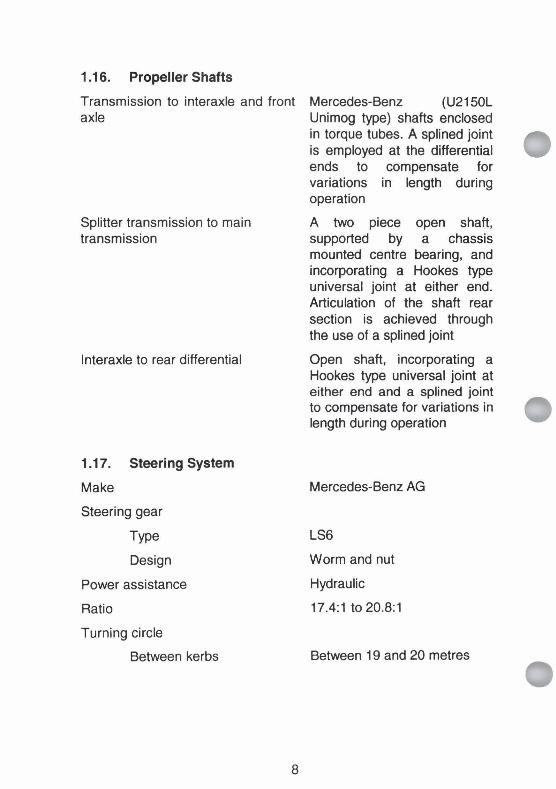
1.1 6. Propeller Shafts
Splitter transmission to main transmission
Transmission to interaxle and front Mercedes-Benz (U2150L axle Unimog type) shafts enclosed
in torque tubes. A splined joint is employed at the differential ends to compensate for variations in length during operation
A two piece open shaft, supported by a chassis mounted centre bearing, and incorporating a Hookes type universal joint at either end. Articulation of the shaft rear section is achieved through the use of a splined joint
Interaxle to rear differential
1.17. Steering System
Make
Steering gear
Type
Design
Power assistance
Ratio
Turning circle
Between kerbs
Open shaft, incorporating a Hookes type universal joint at either end and a splined joint to compensate for variations in length during operation
Mercedes-Benz AG
LS6
Worm and nut
Hydraulic
17.4:1 to 20.8:1
Between 19 and 20 metres

1.18. Brakes
Operating system
Supply pressure
Operating pressure
Service brakes
Actuation
Control
Modulation
Parking brake
Method of actuation
Six wheel work brake
Method of actuation
Engine exhaust brake
Method of actuation
Dual circuit air over hydraulic with pneumatic controlled ALB and ratio valve load proportioning system
18.3 bar (1830 kPa)
7.3 bar (730 kPa)
Twin caliper disc brakes on the front wheels and single caliper disc brakes on the intermediate and rear wheels
Hydraulic
Pneumatic
Automatic load dependent control on primary system.
Spring-applied actuation on intermediate and rear disc brakes. Mechanical over-ride, pneumatically released
Park brake valve in cab
Air pressure actuated to hydraulic cylinders on all wheels
Switch on dash couples the service and parking brakes electro-pneumatically
Pneumatically operated engine brake valve.
Electro/pneumatic; actuated by brake light switch on brake pedal in cab or button on cab floor

1.1 9. Trailer Brake System
Design
Operating pressure
Method of actuation
1.20. Chassis
Type
Pneumatically controlled dual circuit brake system with dual- line trailer brake front and rear
7.3 bar (730 kPa) • Brake valve on steering column
U section rails with six circular and U section cross members
Wheelbase
Front to intermediate axle 3895 mm
Intermediate axle to rear axle 1392 mm
1.21. Tyres Make
Type
Size
Michelin
Radial, tubeless with 4 steel plies
365185 R20 XZL 164G
Speed rating
Nominal (164G) 90 kmlh Q 5000 kgltyre
Dispensation for increased 100 kmlh @ 4750 kgltyre speed (ETRTO std)
1.22. Rims
Make
Type
Mercedes-Benz
Two piece with split flange locking ring and rubber bead lock

1.23. Central Tyre Inflation System (C'I'IS)
Manufacturer and model Mercedes-Benz U2150L
Operating system Dual circuit automatic tyre inflationldeflation system
WARNING
At a pressure below 1.1 bar (1 10 kPa) a tyre can roll off the rim if the wheel is turned.
Tyre pressures (cold). Adjust pressure for warm tyres as follows: First class road add 20%. Formed road 10%. Loose ground as indicated below.
First class road - unladen Front axle 6.0 bar (600 kPa) (max speed 100 kmlh) Rear axles 6.0 bar (600 kPa)
First class road - up to % capacity Front axle 6.0 bar (600 kPa) of hook load ( m a speed 100 km/h) Rear axles 6.0 bar (600 kPa)
First class road - %to rnax capaaty Front axle 6.0 bar (350 kPa) of hook load ( m a speed 100 kmlh) Rear axles 6.0 bar (590 kPa)
Formed road - unladen Front axle 3.4 bar (340 kPa) (max speed 60 kmlh) Rear axles 2.7 bar (270 kPa)
Formed road - up to l/2 capacity Front axle 2.8 bar (280 kPa) of hook load (max speed 60 kmlh) Rear axles 3.6 bar (360 kPa)
Formed road - %to max capacity Front axle 2.5 bar (250 kPa) of hook load (max speed 60 kmlh) Rear axles 4.7 bar (470 kPa)
Cross country - unladen Front axle 1.9 bar (1 90 kPa) (max speed 20 kmlh) Rear axles 1.4 bar (140 kPa)
Cross country - up to % capacity Front axle 1.5 bar (1 50 kPa) of hook load (max speed 20 km/h) Rear axles 2.0 bar (200 kPa)
Cross country - l/2 to rnax capacity Front axle 1.3 bar (1 30 kPa) of hook load (max speed 20 km/h) Rear axles 2.6 bar (260 kPa)
Emergency - unladen Front axle 1.3 bar (1 30 kPa) (max speed 10 kmlh) Rear axles 1.1 bar (1 10 kPa)
Emergency - up to % capacity of Front axle 1.1 bar (1 10 kPa) hook load (max speed 10 km/h) Rear axles 1.3 bar (1 30 kPa)
1
Emergency - % to rnax capacity Front axle 1.1 bar (1 10 kPa) of hook load (max speed 10 kmlh) Rear axles 1.8 bar (180 kPa)
C130 Loading - unladen Front axle 3.5 bar (350 kPa) Rear axles 3.5 bar (350 kPa)
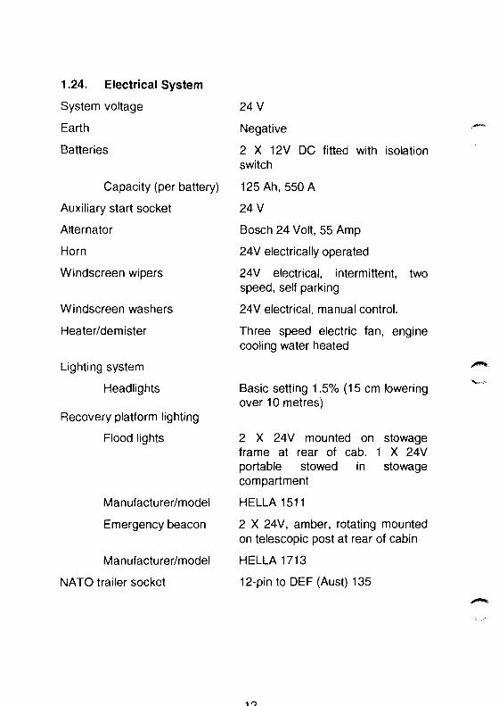
1.24. Electrical System
System voltage
Earth
Batteries
Capacity (per battery)
Auxiliary start socket
Alternator
Horn
Windscreen wipers
Windscreen washers
Heaterldemister
Lighting system
Headlights
Recovery platform lighting
Flood lights
Manufacturerlmodel
Emergency beacon
Manufacturerlmodel
NATO trailer socket
Negative
2 X 12V DC fitted with isolation switch
125 Ah, 550 A
24 V
Bosch 24 Volt, 55 Amp
24V electrically operated
24V electrical, intermittent, two speed, self parking
24V electrical, manual control.
Three speed electric fan, engine cooling water heated
n b. +
Basic setting 1.5% (1 5 cm lowering over 10 metres)
2 X 24V mounted on stowage frame at rear of cab. 1 X 24V portable stowed in stowage compartment
HELLA 151 1
2 X 24V, amber, rotating mounted on telescopic post at rear of cabin
HELLA 1713
12-pin to DEF (Aust) 135

CabIChassis Bulbs
Lighting Front
Front lights
High beamllow beam head lights
Parking lights
Turn indicator lights
Outer Indicator
Lighting Internal
Control indicator lights
Map reading light
Dome light
Military Lighting
Black-out head lights
Reduced head light
Black-out tail lights
Black-out stop light
Convoy cross lights
Wattage Base Shape to DIN 720601
18 W
18W
L.E.D.
L.E.D.
2 W
Recovery System Bulbs Wattage Base ADR 51/00 Category
Lighting Rear
Reversinglwork lights 21W BAl5s P21W
Rear position lights 10W BA15s R 1OW
Stoplrear directional lights 21 W BA15s P 21W
Side clearance lights 5 W SV8.5 C 5W
Rear end outline lights 10W BAl5s R 1OW

Lighting Recovery System
Beacon lights 70 W P14.5
Flood lights 70 W PK22s
Spot lights 70W PK22s
Control cabinet lights 10W BAl5s
CabIChassis Fuses Fuse No.
Fuse Fuse Box A Box B
Low beam, near side F1
Low beam, far side F2
Spare F3
Spare, auxiliary headlamp F4
Stop lamp, relay (56), independent F5 trailer brake
Horn, starter lockout F6
Splitter transmission solenoid valve F7
Windshield wiper, windshield F8 washer, auxiliary heater coolant Pump
Blowerlheater ventilation F9
Instruments, indicator lights, F10 blackout lights relay, terminal connection (15), tyre inflation control system
High beam F11
Spare F12
Park lamp near side, tail lamp far F13 side, license plate lamp
Park lamp far side, tail lamp near F14 side
Instruments F15
Current (Amps)

CabiChassis Fuses (Cont'd)
Shift gate indicator, terminal connection (58), hazard warning flasher switch
Ignition switch, blackout switch
Accessories socket (dash), engine shut-off, terminal connection (D+), six-wheel work brake
Blackout headlights
Blackout tail lights
Masked convoy lights (marker lamps)
Spare
Spare
Fuse No. Fuse Fuse Box A Box B
Current (Amps)
4
Spare F24 8
Recovery System Fuses and Fuse No. Relay No. Relays
Not used 1
Spare 2
Cooling fan
Hydraulics
Work lights
Flood lights
Blackout control
Beacon lights
Throttle control
Current (Amps)

1.25. Audio Kit
Radiolcassette player
Speakers
1.26. Air Conditioner
Manufacturer
Type
Models
Evaporator
Condenser
Refrigerant
Cooling capacity
Hotldry
Hotlwet
Vents
Supply voltage
1.27. Hydraulic System
Hydraulic circuits
Independent circuits for:
Hydraulic system capacity
Hydraulic pump
AMIFM 24V - Eurovox
2 X Eurovox TX91 OV
Air International
Sigma D-Series (24V-R134a version). Split medium duty AIC system
3.3 kW (nominal)
3.6 kW (nominal)
2 directional in dash
24 V DC
I. Left winch and earth anchors
2. Lifting boom, folding boom and right winch
3. Crane
135 litres
Triple element pump driven P---
from P.T.O.

Hydraulic system working pressure 175 bar (17.5 MPa) (except crane)
Crane hydraulic system working 280 bar (28 MPa) pressure
1.28. Recovery Boom
Manufacturer
Type
EDI, Gecko-D8
Underlift
Maximum static lifting capacity
First hole (extension boom 7 tonnes fully retracted)
Second hole 6 tonnes
Third hole 5 tonnes
Fourth hole (extension 4 tonnes boom fully extended)
Safe working load, lift towing
First hole (extension boom 4.3 tonnes fully retracted)
Second hole 3.7 tonnes
Third hole 3.2 tonnes
Fourth hole (extension 2.5 tonnes boom fully extended)
Reach
First hole (extension boom 540 mm fully retracted)
Fourth hole (extension 1040 mm boom fully extended)
Maximum lifting height 1.8 metres
Recovery boom hydraulic system 175 bar (17.5 MPa) working pressure
Oil supply Common with winches, earth anchors and crane

1.29. Winches
Manufacturer/model
TY pe
Maximum pulling capacity (limited)
Winch drum
Diameter
Length
Rope layers
Winch rope
Winch rope diameter
Winch rope working length (max.)
Winch rope breaking strain
Pulling force controlled to
Manufacturers maximum rated tension
Pulling force, inner winch rope layer
High speed
Low speed
Pulling force, outer winch rope layer
High speed
Low speed
Sepson H120P (63.01 -043)
2 X hydraulic 11 tonne, 2 - speed, under wound with automatic safety brake and pneumatically operated free- spooling
8 tonnes per winch rope
2 X Casar, Superplast c/w solid thimble and latch-lock safety hook
13 mm
90 metres
16.27 tonne
8 tonne
15 kN (1.5 tonne)
110 kN (1 1 tonne) flat rated to 80 kN (8 tonne)
12 kN (1.2 tonne)
80 kN (8 tonne)

Cable speed, bottom winch rope layer
High speed 14.5 mlmin
Low speed
Cable speed, top winch rope layer
High speed
Low speed
Pulling force, front winching
Winch hydraulic system working pressure
Oil flow
Oil supply
Setting pressure
Overcentre valve in
Overcentre valve out
Sequence valve changing pressure
Winch mass (including rollers, excluding rope)
1.30. Fairleads
Maximum fairlead angles
Rear recovery
Front recovery
Elevation and depression
Left and right
1.31. Earth Anchors
Spade hydraulic system working pressure
Oil supply
5.3 mlmin
18.2 mlmin
6.6 mlmin
7.5 tonne
175 bar (1 7.5 MPa)
75 Vmin
Common with boom and crane
75 bar (7.5 MPa)
85 bar (8.5 MPa)
100 bar (1 0 M Pa)
297 kg
330 degrees
45 degrees
45 degrees
175 bar (17.5 MPa)
Common with boom, winches and crane

1.32. Crane
Manufacturer
Model
Typellocation
Slewing torque
Palfinger
PK 3700 PO67
Hydraulically driven, mounted F.
behind cab
4.4 kN
Slewing range 180"
Crane hydraulic system working 280 bar (28 MPa) pressure
Pump capacity 20 Vmin
Oil supply Common with boom and winches
Dead weight (excluding tie down 590 kg bolts)
Crane Maximum Safe Working Loads
Radius (hook to support column) Load
1.7 m 2140 kg
1.33. Accessories
Fire extinguishers 1 X 1.5 kg dry chemical beside drivers seat, 1 X 4.5 kg dry chemical front left hand side of recovery platform, 1 X 91 foam front right hand side of recovery platform

1.34. Performance
Maximum gradient (no casualty)
Climb 1:1.67 (60%) 31 " Start 1 : 1.67 (60%) 31 "
Maximum gradient lift towing a cross country laden UL1700 cargo
Climb 1:3 (33%) 18.4 " Maximum gradient lift towing an unladen LIL1700 cargo
Climb 1 :2 (50%) 26.5
Maximum gradient lift towing all LR 6x6 cargo
Climb 1:2 (50%) 26.5"
Range of operation (MRV solo)
First class roads 1000 km approx.
Formed roads 650 km approx.
Fuel consumption (MRV solo) Fuel tank capacity 302 1
First class road laden 32 litres per 100 km
Formed road laden 44 litres per 100 km
Maximum towing speed
MRV with casualty 100 kmlhr (first class road, fine weather)
MRV with casualty 60 kmlhr (formed road, fine weather)
MRV with/without casualty (cross country, any weather)
Discretionary dependent on terrain but no more than 20 kmlhr..
Towing capacity (total towbarlpintlel . 12%500 kg, vehicle capability) (A'TM)
#." A' NOTE
Observe the maximum lifting capacity listed in para. 1.28.
Recommended lift towing capacity 4,300 kg (total boomrr-barlvehicle capability) ( A-r M )
21/(22 blank)


SECTION 2 SHIPPING AND TRANSPORTATION DATA
1.35. Dimensions
Overall length 7990 mm
Overall width - over mirrors 2695 mm
- Reduced 2386 mm
- Parts removed RH crane extension cylinder, hub caps and mirrors folded
- Limiting feature LH fuel cap
Overall height - laden 3034 mm
- Limiting feature Emergency light, snorkel
Reducible height
NOTE
Ensure, all aerials are removed or tied down, and no item on the working platform protrudes above the cupola ring.
Reducible height - laden - Parts removed - Limiting feature
Reducible height - laden (suspension lock on front axle)
- Parts removed - Limiting feature
Reducible height - laden (suspension lock on front axle)
- Parts removed
- Limiting feature
Reducible height (all tyres 1.4 bar (1 40 kPa))
- Parts removed
- Limiting feature
2819 mm Emergency light, snorkel, cupola post
2725 mm
Emergency light, snorkel, cupola post
2597 mm
Emergency light, cupola and post, snorkel, crane lever caps Cupola ring
2606 mm
Emergency light, cupola and post, snorkel, crane lever caps Cupola ring

Wheelbase overall
- Front to intermediate axle
- lntermediate to rear axle
Track - Front - lntermediate - Rear
Middle distance between intermediate and rear axles to rear of vehicle overhang
Towing pintle height -laden
Mass ( combat laden), includes the MRV, all CES, two personnel, personal equipment, weapons, ammunition, rations, all fuels and lubricants, full jerry cans and defence stores, no casualty on tow
- Front
- lntermediate
- Rear
- Total
Maximum gross combination mass
- Highway
- Cross country
Shipping Cubage
- Overall
- Height reduced

1.36 Capacities
System
Fuel
Cooling system (with inhibitor)
- Inhibitor (Castrol Antifreeze DB or BP Coolant 007/400F) mix %(with water)
DEF (AUST) 206
Diesel fuel auto
Engine system (including filter) OMD 115
Main transmission Castrol Syntrans (incl. transfer case and PTO) 75W/85
Splitter transmission
Interaxle drive
Front axle
Castrol Syntrans 75\1\1185
OEP 220
OEP 220
Intermediate axle OEP 220
Rear axle
Hub drives (all)
Steering system
Brake system
Clutch system
Hydraulic system capacity
At ambient temperatures 5°C to 42°C (maximum oil temperature 80°C)
At ambient temperatures -6" to 25°C (maximum oil temperature 60°C)
Capacity (Litres)
OEP 220 2.5
OEP 220 0.25
OX 47 3.2 Grade 10
OX (AUST)-8 1 .O
Hydraulic fluid, 135 Petroleum, Antiwear Grade 68 (Tellus 68)
Hydraulic fluid, 135 Petroleum, OM -33

1.37 Fording Depth
Unprepared vehicle 1200 mm
Limiting feature (over 1200 fan mm)
Prepared vehicle No facility available, as for *
unprepared vehicle
1.38 Bridge Classification
Combat laden 13
Combat laden (lift towing a combat 25 laden MRV)
1.39 Ground Clearance
Combat laden (limiting feature earth 430 mm anchor spades)
1.40 Transportability
Railway loading gauges local authorities must be consulted
Rail Authority Gauge Maximum rolling F"
stock height k
Commonwealth 1435 mm 2532 mm
Commonwealth 1067 mm 2532 mm
New South Wales 1435 mm 2182 mm
Queensland 1067 mm 1806 mm
South Australia 1600 mm 2075 mm
South Australia 1435 mm 2075 mm
Tasmania 1067 mm 1992 mm
Victoria 1435 mm 2182 mm
Western Australia 1435 mm 2532 mm
Western Australia 1067 mm 1973 mm

1.41 Slinging and Tie-Down Points
Slinging and tie-down points are illustrated in Fig 1-3
Figure 1-3 Slinging and Tie-Down Points
1.42 Shipping Volume
Overall 54.3 m3
Height reduced 51.9 m3
1.43 Approach and Departure Angles
Approach angle - combat laden 42 degrees (limiting features front towing lugs)
Departure angle - combat laden 35 degrees with boom raised and locked in 2nd quadrant hole from bottom (limiting features folding boom)
Ramp breakover angle - combat 143 degrees laden (limiting features side equipment bins)
27/(28 blank)


SECTION 3 EQUIPMENT DESCRIPTION
Introduction
1.44. The Truck, Wrecker, Medium, MC2, Unimog U2450L (MRV) is built to Specification Army (Aust) 6620 and has been specifically designed for military use to meet operational requirements. To meet these requirements the vehicle has been fitted with a recovery system capable of recovering vehicles of the mobility capability MC2.
Main Features
1.45. The main features of the MRV are as follows:
a. A cablchassis based on a proven UNIMOG U2450L 6x6 chassis providing commonality with the UNIMOG vehicles in service.
A 5.958 litre, in-line six cylinder, turbocharged, diesel engine fitted with an intercooler.
An eight speed, all synchromesh transmission with integrated transfer gearcase providing permanent four- wheel drive on the rear wheels, with selective six-wheel drive for negotiating difficult terrain. An auxiliary transmission (working gear group) is also fitted to provide a lower range of ratios when towing heavy loads and for negotiating heavy going.
A splitter transmission to enable gear splits in the main transmission to optimise vehicle performance under all conditions.
Differential locks on each axle.
A central tyre inflation system.
A hydraulically operated underlift extendable towing boom. The towing boom is provided with a mechanical support, independent of the hydraulic system, for towing of casualty vehicles.
Hydraulically operated earth anchors.
Self recovery from the front using the on-board winching system.

j. Two, 2-speed, drum type hydraulically operated, winches for recovery operations. Each winch has a free spooling capability
k. A hydraulically operated crane for material handling. e**
Operational and Logistic Concept \a
1.46. The MRV assists in the maintenance of the mobility of deployed forces and contributes to the ability of those forces to sustain operation in areas remote from industrial and logistic infrastructure.
ENGINE (Fig 1-4)
1.47. General
The vehicle is fitted with a Mercedes-Benz 5.958 litre OM 366 LA, six cylinder in-line, direct injection, turbocharged intercooler engine, which produces 177 Kw of power at 2600 rpm and 760 Nm of torque at 1400 - 1700 rpm.
1.48. Lubrication
The engine lubrication pressure feed system consists of a gear type oil pump with a built-in pressure relief valve. The pump is driven from the engine crankshaft. Oil under pressure, is fed through a filter and an ~ a p
engine mounted 011 cooler before being delivered to the main bearings, bs
camshaft assembly, piston assemblies and valve lifters. The timing gears, air compressor, injection pump and turbocharger are lubricated from the same supply.
1.49. Oil Filter
The engine oil filter is externally mounted, full-flow type, fitted with a replaceable element.
1 .SO. Oil Cooler
The labyrinth-type oil cooler is mounted on the left-hand side of the crankcase casting.
1.51. Air Cleaner
The air cleaner outlet is connected to the turbocharger inlet. The air cleaner housing contains an element that must be cleaned andlor replaced at specified intervals. A

Water pump
Thermostat
Filler cap
Hand primer
Engine breather
Intake manifold
Exhaust manifold
Oil cooler
Engine brake manifold
Clutch bell houslng
Flywheel
Main bearing cap
Big end bearing
Oil pump
Sump plug
Crankshaft pulley
Fuel filter
Injector
011 feed line (turbocharger)
Turbocharger
Oil return line (turbocharger)
Starter motor
Crankshaft
Sump
Oil pump pick-up
Oil filter
Camshaft
Rear engine mount
Hand primer
Fuel injection pump
15 25 24
Figure 1-4 FrontILeft Hand Side View of Engine

1.52. Engine Cooling
The engine (Fig 1-4) is water-cooled by a thermo-syphon system assisted by a centrifugal water pump and a viscous clutch cooling fan. The fan and water pump are driven by belts from the crankshaft pulley.
F, The expansion tank is fitted with a pressure cap that operates at 0.7 bar (70 kPa). A turbocharger charge air cooling radiator (intercooler) is fitted to the front of the radiator to cool the engine intake air. The vehicle heater utilises waste heat from the engine cooling system.
FUEL SYSTEM
1.53. General
The fuel system consists of a 302 litre fuel tank, a fuel pump, a disposable pre-filter, a fuel filter, and an in-line injection pump delivering fuel to direct injection nozzles mounted in the cylinder head. The fuel is delivered into the injectors at a pressure of approximately 2000 kPa. Excess fuel is returned to the fuel tank.
1.54. Diesel Engine Exhaust Smoke Emission Control
A smoke limiter rated to ADR 36/00 is fitted between the fuel injection pump governor and the fuel rack. The smoke limiter senses inlet manifold pressure and decreases fuel delivery at full throttle openings, - thereby preventing the engine from operating with an excessively rich .*.-
fueVair mixture.
CLUTCH
1.55. The clutch is hydraulically actuated by a slave cylinder connected via an in-line booster cylinder to the master cylinder at the clutch pedal.
SPLITTER TRANSMISSION
1.56. A splitter transmission is mounted on the rear of the clutch housing. The transmission provides a highllow ratio in all gears effectively providing another eight speeds to the drive. The greater range of gear selection permits the driver to optimise the performance capabilities of the vehicle, particularly when operating cross country and on second class roads.
TRANSMISSION /ra
1.57. Main Transmission b..
The manually-shifted main transmission comprises of a four speed gearbox with a forward/reverse change, together with a set of planetary gears. The planetary gear set is engaged and disengaged pneumatically to allow the selection of a total of eight forward or eight reverse ratios.

1.58. Auxiliary Transmission (Working Gear Group)
An auxiliary transmission (working gear group) is mounted on the front of the main transmission and provides a lower range of ratios than the main transmission when towing heavy loads.
1.59. Transfer Case
The transfer case is mounted on the left hand side of the main transmission group. Six-wheel drive may be selected for adverse terrain. A pneumatically operated dog clutch enables six-wheel or four-wheel drive to be selected at the transfer gearcase.
DRIVELINES AND AXLES
1.60. General
The MRV drivelines consist of open type drive shafts and drive shafts enclosed in torque tubes.
The transmission to interaxle and front axle drivelines employ Mercedes- Benz (Unimog type) shafts enclosed in torque tubes. Splined joints at the differential ends compensate for variations in length during operation.
-.. The splitter transmission to main transmission and the interaxle to rear , differential drives use an open shaft, incorporating a Hookes type
universal joint at either end. A splined joint is employed to compensate for variations in length during operation
The front axles include constant velocity joints to the front wheels.
1.61. Differential Locks
Cross locks are incorporated in the front, rear and intermediate (power divider) axle differentials to enable power to be divided equally to each wheel when difficult terrain is encountered. The differential lock, locks one half shaft to the crown wheel causing the road wheels to rotate at the same speed irrespective of unequal grip of the road wheels.
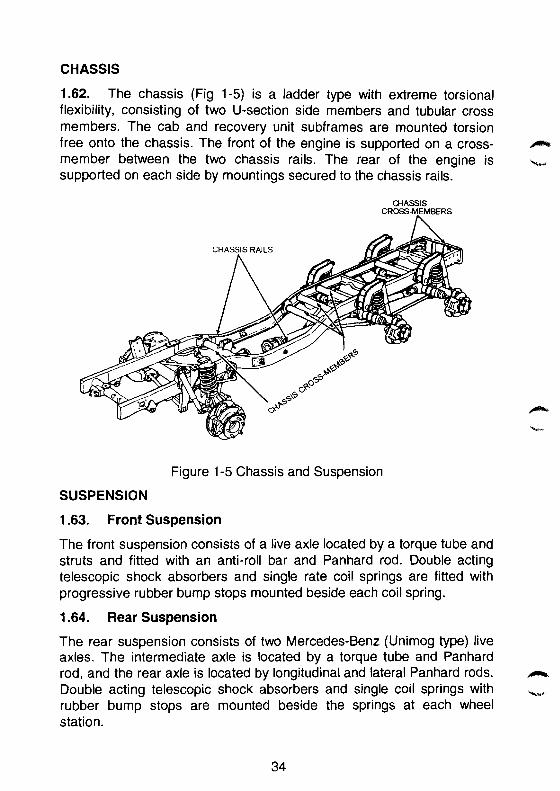
CHASSIS
1.62. The chassis (Fig 1-5) is a ladder type with extreme torsional flexibility, consisting of two U-section side members and tubular cross members. The cab and recovery unit subframes are mounted torsion free onto the chassis. The front of the engine is supported on a cross- n member between the two chassis rails. The rear of the engine is L,
supported on each side by mountings secured to the chassis rails.
CHASSIS CROSS-MEMBERS n
Figure 1-5 Chassis and Suspension
SUSPENSION
1.63. Front Suspension
The front suspension consists of a live axle located by a torque tube and struts and fitted with an anti-roll bar and Panhard rod. Double acting telescopic shock absorbers and single rate coil springs are fitted with progressive rubber bump stops mounted beside each coil spring.
1.64. Rear Suspension
The rear suspension consists of two Mercedes-Benz (Unimog type) live axles. The intermediate axle is located by a torque tube and Panhard rod, and the rear axle is located by longitudinal and lateral Panhard rods. &-k
Double acting telescopic shock absorbers and single coil springs with - rubber bump stops are mounted beside the springs at each wheel station.

STEERING SYSTEM
1.65. The MRV is fitted with a power assisted steering system (Fig 1- 6). The steering system employs a hydraulically boosted worm and nut steering box linked to a two spoke steering wheel by universal joints, shafts and angle drives. Mechanical linkage to the wheel hubs from the
' steering box is via the Pitman arm, drag link, steering arms and tie rod. The steering hydraulic circuit comprises of a belt driven (from the engine crankshaft pulley) hydraulic pump, connected to a hydraulic reservoir, and the steering box via hydraulic lines.
DRA LINk
ti-
= /TIE ROD
IYUHAULIG PUMP \STEE%ING BOX
Figure 1-6 Steering System
BRAKE SYSTEM
1.66. General
The front wheels are fitted with two sets of calliper disc brakes and the intermediate and rear wheels are fitted with a single set of calliper disc brakes. Two single circuit brake master cylinders hydraulically operate the callipers. One brake master cylinder operates the intermediate and rear callipers and the other master cylinder operates the two sets of front callipers. If a malfunction occurs in one brake system, the remaining system provides sufficient braking effort to enable the vehicle to be driven safely, at a reduced speed, to a suitable repair facility.
1.67. Exhaust Brake
The engine exhaust manifold is fitted with an engine brake that restricts exhaust gas flow, so retarding the engine. The exhaust brake consists of

a cylinder and piston pneumatically operated which is connected to a throttle valve at the exhaust manifold. The brake is controlled via a switch on the dash and applied either by the brake pedal through the stop light switch, or a foot operated valve fitted in the floor in front of the drivers seat. FZ%
1.68. FootBrake 'b, .--
The foot brake pedal (Fig 1-7(2)) is connected to a pneumatic valve that directs compressed air, at variable pressure, to the sirlgle circuit diaphragm-actuating cylinders. This variable pressure is also available at the trailer brake control valve, so that when the vehicle brakes are applied the trailer brakes are also applied to assist in the braking application.
1.69. Park Brake
A park brake is provided by the intermediate and rear wheel callipers. The callipers are fitted with mechanical over-rides and operated by spring-retracted pneumatic cylinders. The park brake is controlled by the park brake control valve mounted adjacent to the left hand side of the driver's seat. The system is fail-safe, as the park brake cannot be released unless there is a pressure of at least 6 bar (600 kPa) in the compressed air receivers. -
'.% ". 1.70. Trailer Brake
The trailer brake lever applies a pneumatic signal to the trailer brake control valve, proportional to the position of the brake lever. Only the trailer brakes are applied.
WARNING
If the engine is switched off during winching operations the six-wheel brake will release and the MRV may move.
1.71. Six-Wheel Work Brake
When performing recovery operations the service brakes and the park brake can be coupled electro-pneumatically to apply the brakes to all wheels. A switch, located on the left-hand corner of the dash, when pressed activates the front and rear brakes in the same way the foot P-
brake valve does. The system only operates when the engine is running, - the park brake is applied and there is an air supply pressure of 7.5 bar (750 kPa) or more in the system. The work brake is not to be used as a park brake.

CONTROLS
CLUTCH PEDAL
FOOT B R A K Y v7~
Figure 1-7 Controls
1.72. Accelerator Pedal Linkage
The accelerator pedal linkage is the manual control from the accelerator pedal to the fuel injection pump and receives input from the accelerator pedal, the hand throttle, the speed limiter, and input from the recovery throttle control switches (control cabinets and remote control) via a pneumatic cylinder connected to the throttle linkage. The accelerator pedal (Fig 1-7(1)) controls the setting of the fuel delivery mechanism at the fuel injection pump. An integral governor on the injection pump controls the idle and maximum engine speeds.
1.73. Speed Limiting Device
The MRV is fitted with a speed limiter, which consists of an electronic control unit that operates an electric motor in an actuator connected via a Bowden cable to the accelerator pedal linkage. Maximum speed of the vehicle is limited to 100 kmlh.
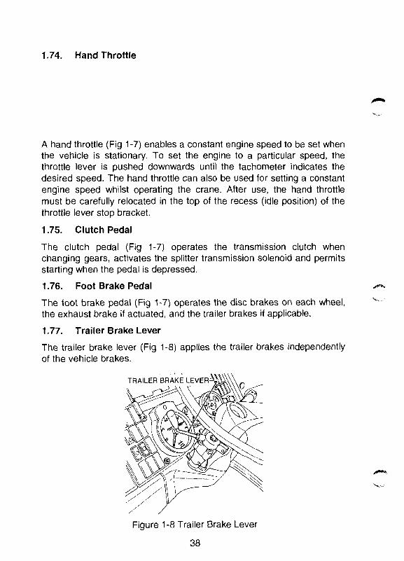
1.74. Hand Throttle
A hand throttle (Fig 1-7) enables a constant engine speed to be set when the vehicle is stationary. To set the engine to a particular speed, the throttle lever is pushed downwards until the tachometer indicates the desired speed. The hand throttle can also be used for setting a constant engine speed whilst operating the crane. After use, the hand throttle must be carefully relocated in the top of the recess (idle position) of the throttle lever stop bracket.
1.75. Clutch Pedal
The clutch pedal (Fig 1-7) operates the transmission clutch when changing gears, activates the splitter transmission solenoid and permits starting when the pedal is depressed.
1.76. Foot Brake Pedal
The foot brake pedal (Fig 1-7) operates the disc brakes on each wheel, k..
the exhaust brake if actuated, and the trailer brakes if applicable.
1.77. Trailer Brake Lever
The trailer brake lever (Fig 1-8) applies the trailer brakes independently of the vehicle brakes.
Figure 1-8 Trailer Brake Lever

1. Front panel connectors (Comrns) 6. Main gear shift lever 2. Front winch control switch 7. Splitter transmission selector switch 3. ForwardIReverse lever 8. Park brake lever 4. Auxiliary transmission (working 9. Cold start control
gear group) selector switch 10. PTO control switch 5. Differential lock selector switch
Figure 1-9 Control Panel
1.78. ForwardReverse Selector Lever
The forwardlreverse selector lever (Figl-9(3)) selects either forward or reverse drive direction.
1.79. Gear Selector Lever
The main gear shift lever (Fig 1-9(6)) selects the desired gear ratio. The eight available ratios are shifted on a 2 x 4 principle. When changing from 4th up to 5th gear, a pneumatic control valve automatically disengages the auxiliary planetary gear set in the transmission and automatically engages the planetary gear set when changing down from 5th to 4th gear. The neutral positions between the individual ratios, e.g. shifting from 1st and 2nd or 5th and 6th gears are provided with detents to prevent inadvertent gear selection, e.g. shifting from 7th to 4th gear. All gear shifts, including forward and reverse selection, are fully synchronised.

1.80. Gear Shift Gate Position Indicator
The gear shift gate position indicator (Fig 1-10) is located at the centre of the dashboard and indicates the position of the gear selector lever within the gear gate. The gear shift gate position indicator is not illuminated under blackout conditions. m
GEAR RATIOS
GEAR RATIOS
Figure 1-10 Gate Position Indicator
1.81. Splitter Transmission Selector Lever
The splitter transmission selector switch (Fig 1-9(7)) is located on the main gear shift lever and is used to engage and disengage the splitter transmission in each ratio e.g., 1st gear low ratio (splitter transmission - direct drive), 1st gear high ratio (splitter transmission - overdrive). - Engaging the splitter transmission effectively gives an extra selection of
'+#
eight ratio's in forward or reverse, whilst driving. To engage the splitter transmission, depress the clutch pedal to the floor, hold the pedal down momentarily (min of 0.5 seconds), raise the selector switch on the main gear change lever and then release the clutch pedal. The splitter transmission engaged indicator light (Fig 1-1 9(10)) will be illuminated.
1.82. Park Brake Lever
The park brake lever (Fig 1-9(8)) is located to the right of the main gear shift lever. The park brakes are released by lifting the collar on the hand brake lever and pushing the park brake lever forward (Position 1, see Fig 1-11). The park brake indicator light will then extinguish, provided that the supply of air pressure is above 6 bar (600 kPa). A test position (Position 2, see Fig 1-1 1) is incorporated in the park brake circuit. The test position is utilised only when towing a trailer and is activated by movirlg the park brake lever to position 0, depressing the lever firmly and moving it backwards. This action releases the trailer brakes only, F-C
allowing the driver to check that the vehicle brakes alone will hold the k..'
vehicleltrailer combination on a gradient when parked. The park brake lever automatically returns to position 0 when released from test position 2.

1 - Park brakes released 0 - Park brakes applied 2 - Test position (vehicleltrailer combination)
Figure 1-1 1 Park Brake Lever
1.83. Auxiliary Transmission (Working Gear Group) Selector Switch
The auxiliary transmission (working gear group) selector switch (Fig 1- 9(4)) is located beside the forwardlreverse selector iever and operates the auxiliary transmission (working gear group) mounted at the front of the transfer case. The auxiliary transmission (working gear group) is employed to increase the traction power of the vehicle during operation on formed roads and over cross country.
To engage the auxiliary transmission (working gear group), stop the vehicle, declutch and turn the selector switch (Fig 1-9(4)). To disengage, stop the vehicle, declutch and turn the selector switch. Only select the working gear group when the vehicle is stationary.
1.84. PTO Selector Switch
WARNING
When operating with the PTO engaged, the main transmission shift lever must be in the neutral position (7th - 8th gear), the forwardlreverse gear lever in the neutral position, and the splitter transmission in LOW ratio.
The PTO control switch (Fig 1 -9(10)) is located at the bottom right corner of the centre control plate. The PTO can only be engaged when the

vehicle is stationary. EngagernenVdisengagement is effected by a pneumatic control valve mounted on top of the PTO housing.
To engage the PTO, disengage the clutch, rotate the control switch to right until it lines up with the "PTO on" symbol and engage the clutch. Ensure the PTO light is illuminated. To disengage the PTO, disengage P-
the clutch, rotate the control switch to the left until it lines up with the "0" *1
symbol and engage the clutch. Ensure the PTO indicator light is extinguished.
1.85. Steering WheelIColumn
The two spoke steering wheel operates a hydraulically boosted steering box. The stalk control switch, trailer brake control switch and ignition switch housing are clamped to a tube bolted to the steering column housing.
1.86. All Wheel Drive, Power Divider and Differential Lock Controls
All wheel drive, power divider and differential lock control is provided by two switches. One switch is located on the top right hand side of the instrument panel (Fig 1-12) and the other is mounted on the centre control panel (Fig 1-9(5)). Both switches are used in conjunction with ~b each other to provide varying combinations of differential locks and
b.
engagements depending on terrain. The MRV is to be stationary prior to engaging the all wheel drive, power divider and differential lock control switches.
For normal highway driving, only rear four wheel drive is necessary. When driving over difficult terrain, six-wheel drive and differential locks can be engaged to ensure that the vehicle movement is maintained.
1.87. Instrument Panel All Wheel Drive and Power Divider Control Switch (Fig 1-12)
The instrument panel all wheel drive and power divider control switch operating positions are:
a. Position 0 - the intermediate and rear axles are in constant drive.

Figure 1-12 Instrument Panel All Wheel Drive and Power Divider Control Switch
b. Position (I) - the front axle is engaged (six-wheel drive) and the front axle all wheel drive indicator light (Fig 1- 19(16)) is illuminated. Pressurisation of all axles occurs at this point to facilitate fording.
c. Position (11) - the inter-axle power divider lock is engaged and the power divider differential lock indicator light (Fig 1-1 9(13)) is illuminated.
1.88. Control Panel Differential Lock Control Switch (Fig 1-13)
Note
To engage the control panel differential lock control switch the instrument panel all wheel drive and power divider control position (11) must be selected
Figure 1-1 3 Control Panel Differential Lock Switch
The control panel differential lock control switch operatirlg positions are:
a. Position (Ill) - the intermediate and rear axle differential locks are engaged and the power divider and rear axle differential lock indicator lights (Fig 1-1 9(13) and (1 4)) are illuminated.

b. Position (IV) - the front axle differential lock is engaged and the front axle differential lock indicator light (Fig 1- 19(15)) is illuminated.
ELECTRICAL SYSTEM
1.89. General
The electrical system is a 24V DC negative to earth system using two 12 volt, 125 Ah capacity wet cell batteries. The batteries are mounted on the right-hand chassis under the drivers' side door, in a lockable battery box. The electrical system controls and monitors the electrical components of various systems of the vehicle via harnesses and electrical boxes.
1.90. Alternator
The three-phase alternator supplies rectified and regulated direct current (DC) to the batteries. The alternator is bolted on the lower left hand side of the engine and is belt driven. Fins mounted on the pulley cool the alternator.
1.91. Circuit Breakers
The electrical system is protected from overload conditions by two main circuit breaker panels (Fig 1-14) fitted to the top of the dashboard immediately forward of the steering wheel. Relays located on the inner wall of the remote control stowage bin isolate the load of the recovery system devices from the cablchassis circuits. Refer to Section 1 - Data Summary for ratings and circuit information.
Figure 1-1 4 Circuit Breakers

1.92. Battery Mains Switch
The battery mains switch is a rotary switch, located on top of the battery compartment, and is used to isolate the vehicle electrical system from the batteries. When the switch is rotated anti-clockwise, the vehicle electrical system is isolated from the batteries. When the switch is rotated to clockwise, electrical power is restored to the vehicle electrical system.
1.93. Auxiliary Start Socket
The auxiliary start socket is located next to the battery mains switch and enables power to be supplied to another vehicle from the MRV batteries via an interconnecting slave lead. The MRV can also be slaved from another vehicle.
1.94. Starter Motor
The starter motor is an electrically operated DC motor fitted with an integral, pre-engaged drive operated by a solenoid. The starting circuit includes the ignitionlstart key-operated switch, the start solenoid and, a starter interlock switch.
1.95. Windscreen Wipers
Two windscreen wiper arms are driven via linkages by a two-speed, self- parking electric motor mounted under the dashboard. The wipers are controlled by the indicator control combination switch mounted on the steering column.
1.96. Windscreen Washers
The windscreen washer tank and electric pump assembly is mounted at the right hand front side of the engine compartment between the air cleaner and cab body. The wiper washer motor drives the pump to deliver water from the water tank via plastic hoses to the nozzles on the windscreens. A switch, incorporated in the wiper controls on the combination switch stalk, operates the washer pump.
1.97. Horn
An electric horn is mounted behind the left-hand headlight. The horn is operated by depressing a button on the end of the indicator control combination switch mounted on the steering column. The maximum period of operation at any one time should not exceed 5 seconds.

LIGHTING SYSTEM
1.98. Normal Lights
Exterior lighting consists of:
a. Two headlights, each with a double-filament bulb, one F- filament for high beam and the other for low beam. kr-
Headlight aiming is adjustable, to compensate for different chassis heights, due to varying load conditions. A height control switch is located on top of the vehicle dash to the right of the steering wheel.
b. Turn indicators at front and rear. The turn indicator lights are also utilised as hazard warning lights. The turn indicator lightslhazard lights will not operate under blackout conditions.
c. Two front marker lights.
d. Two double-filament rear taiVbrake lights. The right hand rear tail light illuminates the license plate.
e. Two reversing lights that can also be employed as work lights at the rear of the MRV. The reversing lights will not operate under blackout conditions. ,@-
f. Two floodlights mounted on the cargo platform supports \C
for crane and recovery operations. The floodlights are controlled by a switch located within the recovery control panels.
9. A portable floodlight. The floodlight is stowed in an equipment bin and is installed in a custom made fitting on the top or side of a rear bin if required.
h. Two rotating warning beacons mounted on the recovery unit.
I . Clearance lights on the side and on top of the recovery unit.
1.99. Blackout Lights
The black out exterior lighting consists of a reduced headlight, two masked front markers, two masked rear markers, a convoy cross light ~ " a and two masked brake lights. Under blackout conditions, the cabin dome light, headlight flasher, reversing lights, turn indicator lights, gear shift gate position indicator lights, hazard warning lights and the radiolcassette player illumination and audio are all inoperative.

1.100. Cabin Lighting
Cabin lighting consists of:
a. A dome light in the cab roof. In addition to the three position switch (ONIOFFIDOOW) at the light, switches on the both cabin door pillars operate the light when either door is opened. The cabin door pillars switches are isolated when the dome light is switched to OFF. The cabin dome light will not operate under blackout conditions.
b. A map light is fitted to the glove box door. The light is illuminated when the cover over the light is opened.
c. Instrument panel lighting.
d. Central Tyre Inflation System (CTIS) control panel lighting.
e. A trouble light on a flexible lead is also provided.
1 .I 01. Audio Kit
An AMIFM radiolcassette unit is centrally mounted to the front of the roof in the vehicle cab. Speakers are mounted at each rear corner of the cab, and the antenna is mounted to the outside right hand rear corner of the cab roof.
1 .I 02. Communications
Provision for a HF low powered station and a VHF medium powered station is made in the top, front right hand equipment bin on the vehicle body. The stations are connected via shielded control cables to an extended front panel situated between the seats in the cab. The extended front panel provides mountings for two LSF 300 speakers, two MF301 microphones, two CF307 remote channel selectors and a power supply socket. Provision is also made for aerial mountings on the storage platform support.
SWITCHES
1 .I 03. Ignition Switch
The key operated ignition switch has three positions - OFF, ON and START. When rotating the ignition switch from the ON position to the
'
START position, the starter motor is energised. As soon as the engine fires, the key must be released to allow it to return to the ON position. If the engine does not start immediately, return the key to the lock position and wait before repeating the starting procedure.

1.104. lndicator Control Combination Switch
An indicator control combination switch (Fig 1-15) is mounted on the steering column and selects the following functions:
a. Left and right turn indicator control,
b. Headlight highllow beam control,
c. Headlight flasher control,
d. Horn control,
e. Windscreen wiper control, and
f. Windscreen washer control.
A. Left and right turn indicator control D. Horn control
8. Headlight highllow beam control E. Windscreen wiper control
C. Headlight flasher control F. Windscreen washer control
Figure 1-1 5 lndicator Control Combination Switch
1.1 05. Turn lndicator Control (Fig 1-15(A))
The self-cancelling turn indicators operate only when the ignition is switched ON. The combination switch lever is moved forwards for left - hand turn indication and backwards for right hand turn indication. Slight pressure in either forward or rearwards direction operates the indicator lights when lane changing on highway or freeway. The steering wheel must be rotated up to one quarter of a turn before the turn indicator cancels automatically from the normal turn position.

1.106. Headlight Beam Control (Fig 1-15(B))
The headlights are switched on with the main light switch (see para 1.1 12). To select high beam the combination switch lever is moved downwards. The reverse movement cancels high beam and selects low beam. The turn indicators can be operated with high beam selected.
1.107. Headlight Flasher Control (Fig 1-15(C))
By gently lifting the combination switch lever towards the steering wheel, the headlights can be flashed on high beam with the ignition or light switch in either the ON or the OFF positions.
1.108. Horn Control (Fig 1-15(D))
To operate the horn, depress the button on the end of the combination switch.
1.109. Windscreen Wiper Control (Fig 1-15(E))
The combination switch is rotated to operate the windscreen wipers and the following speeds are available:
a. Intermittent wiper operation - wiper arrow symbol aligned with the intermittent symbol (I) at the base of the switch.
b. Slow speed - wiper arrow symbol aligned with the slow symbol (11) on the switch base.
c. Fast speed - wiper arrow symbol aligned with the fast symbol (Ill) on the switch base.
1.110. Windscreen Washer Control (Fig 1-15(F))
To operate the windscreen washer control, push the combination switch body towards the steering column. This action activates the windscreen washer pump and four jets of water will be directed at the windscreen. Release the switch body to turn the pump off. Before operating the windscreen washers, ensure that the washer bottle has fluid inside.
1.1 11. Headlight Adjustment Control
The MRV is fitted with a headlight adjustment control switch (Fig 1-16) located at the top right corner of the dash. The headlight beams can be adjusted by the driver to compensate for the vehicle load. In this way maximum visibility at night can be maintained irrespective of the load. The headlights can be adjusted (depending on vehicle load) as follows:
0 - for basic position vehicle unladen, and
1 - for vehicle fully ladenltowing (max permissible rear axle load).

Figure 1-1 6 Headlight Adjustment Control
1.1 12. MainJMasked Light Switch
A maintmasked light switch (Fig 1-17) is situated on the lower right-hand side of the instrument panel and has seven functional positions:
a. Position 0: all lights off. e-
b. Position Tag (Day): The switch detent can be released in b
this position.
c. Position 1: The front and rear marker clearance lights are illuminated.
d. Position 2: The headlights, front and rear markers, clearance lights and instrument lights are illuminated.
e. Position S1: The masked front and rear markers and the convoy cross lights are illuminated.
f. Position S2: This position is used when driving without lights.
9. Position S3: The reduced headlight, masked front and rear markers and the convoy cross are illuminated.

0 - All lights off Tag - Switch detent released 1 - Front and rear markers, clearance lights 2 - Headlights, front and rear markers, clearance lights and
instrument lights S1 - Masked front and rear markers, convoy cross lights 52 - No lights S3 - Reduced headlight, masked front and rear markers,
convoy cross lights
Figure 1-1 7 - MainIMasked Light Switch
Normal brake lights are available in position Tag, positions 1 and 2 and masked brake lights in positions S1 and S3.
To change positions between Tag 1 and 2 move the detent lever to the right and rotate the switch as required.
To change positions from Tag to 0 move the detent lever to the left, push the switch in and rotate switch to 0.
To change positions between 0 to Tag push in switch and rotate switch to Tag.
To change between 0, S1, S2 and S3 move the detent lever to the left and rotate the switch as required.
To change positions between 0 and position 1 move detent to right and rotate switch to 1.

INSTRUMENT PANEL
1.1 13. General
The instrument panel (Fig 1-18) is mounted on the dashboard in front of the driver and combines electrical switches, gauges, indicating and - warning lights, and auxiliary power sockets. The switches (with the L, z
exception of the all wheel drive power divider control switch) are a rocker type located on both sides of the indicatorlwarning light cluster. Function symbols are etched on the switches, and the switches are illuminated when the driving lights are switched on. A dimmer switch mounted below the instrument panel controls the level of illumination of the gauges.
1. Indicatorlwarning light cluster (see Fig 1-19) 2. Warning beacon switch 3. All wheel drive and power divider control switch 4. 24V Auxiliary socket 5. Coolant temperature gauge 6. Dual air pressure gauge 7. Fuel gauge 8. Oil pressure gauge 9. Tachometer 10. Speedometer 11. GPS power supply socket 12. Six-wheel work brake switch 13. Engine brakelservice brake switch 14. Hazard warning light switch
Figure 1-1 8 Instrument Panel
1.1 14. Speedometer
The speedometer (Fig 1-1 8(10)) is calibrated from 10 to 120 km/h in 10 kmlh increments and at the last increment to 125 kmlh in 5 kmlh. A six figure odometer that indicates total kilometres travelled by the vehicle is also housed in the speedometer.
1.1 15. Tachometer
The tachometer (Fig 1-18(9)), mounted in the centre of the instrument panel is calibrated from 0 to 3000 RPM at 100 RPM intervals. A green band indicates the economic speed range. The cut-off speed range (commencing at the maximum continuous engine speed limit of 2600 RPM) is indicated by a red warning band, on the gauge face.
1.1 16. Dual Air Pressure Gauge
The dual pressure gauge (Fig 1-18(6)) is mounted in the centre of the gauge cluster and is calibrated from 0 to 25 bar in increments of 2 bar. Two pointers indicate the compressed air pressure in brake circuits 1 and 2. If either gauge shows less than 12 bar the low air indicator light will be illuminated.
1.1 17. Coolant Temperature Gauge
The coolant temperature gauge (Fig 1-18(5)) is mounted to the right of the instrument cluster and is calibrated from 40°C to 120°C in increments of 20°C. The gauge indicates the temperature of the coolant in the cooling system. At normal operating temperature the gauge should indicate 80°C to 95°C. If the temperature reaches 100°C during a long uninterrupted drive on a highway or freeway, the engine revolutions should be increased, (but not at the maximum 2600 RPM) for a short distance by changing to a lower gear ratio. If the higher engine revolutions do not lower the coolant temperature, the vehicle should be stopped, well clear of the road and the reason for the high coolant temperature investigated. The engine should be run at a fast idle for 2 or 3 minutes before stopping it.
1.1 18. Fuel Gauge
The fuel gauge (Fig 1-18(7)) is located at the bottom of the instrument cluster and is calibrated in four divisions from reserve (R) to 111 with increments of 114. Each division indicates about 75 litres of fuel in the tank.

1.1 19. Oil Pressure Gauge
The oil pressure gauge (Fig 1-18(8)) is mounted to the left of the gauge cluster calibrated from 0 bar to 5 bar in increments of 1 bar. When the engine oil is hot and the engine at low idle speed, the oil pressure gauge should indicate a minimum of 0.6 bar. When driving, the oil pressure "E5
gauge should indicate an engine oil pressure of 2 to 5 bar. ' * a ~
1.1 20. GPS Power Supply Sockets
Two connections (Fig 1 -18(11)) are provided on the left hand side of the instrument panel to supply power to the GPS unit.
WARNING If the engine is switched off during winching operations the six-wheel brake will release and the MRV may move.
1.1 21. Six-Wheel Work Brake Switch
The six-wheel work brake switch (Fig 1-18(12)) is a rocker type located on the left hand side of the instrument panel. When pressed, the front and rear brakes are applied in the same manner as the application of the park and service brake. The six-wheel work brake only operates when the engine is running, the park brake is applied and there is an air supply #-
pressure of 7.5 bar (750 kPa) or more in the system. The work brake is '.-.
not to be used as a park brake.
To engage the six-wheel work brake, apply the park brake, operate the six-wheel work brake switch and ensure that the indicator light (Fig 1- 19(1)) illuminates. If the vehicle is off road, engage the differential locks and ensure the differential lock indicator light is illuminated. To disengage the six-wheel work brake:
a. Release the park brake (park brake and six-wheel parking brake are released simultaneously), or
b. Rotate the ignition switch to position " 0 where the park brake only will remain on.
WARNING
Braking efficiency is reduced when the engine brake is isolated from the service brake pedal. The engine brakeiservice brake switch is only to be activated during testing of the service brakes. Do not disconnect the engine brake from the service brake pedal when driving on public roads.
1.122. Engine BrakeJService Brake Switch
The engine brakelservice brake switch (Fig 1-18(13)) is a rocker type located on the left hand side of the instrument panel outboard of the six- wheel work brake switch. During normal operation the engine brakelservice brake switch is disengaged, the warning light is not illuminated and the engine brake can be activated by:
a. The service brake pedal where the engine brake operates in conjunction with the service brakes, or
b. By a foot operated valve on the floor
When the engine brakelservice brake switch is pressed and the red warning light is illuminated, the engine brake is disconnected from the service brakes and the engine brake can only be operated via the foot operated valve on the floor.
1.123. Hazard Warning Light Switch
The hazard warning light switch (Fig 1-18(14)) is located at the left hand side of the instrument panel, above the engine brakelservice brake switch, and is coloured red. The switch, when turned on, initiates simultaneous flashing of both front and rear turn indicator lights. The vehicle must not be driven on any public road with the hazard switch turned on.
1.124. Warning Beacon Switch
The warning beacon switch (Fig 1-1 8(2)) is located on the top right hand corner of the instrument panel. The switch activates two amber rotating lights mounted on the recovery unit frame. The beacons are normally turned on when operation of the MRV may present a hazard.
1.125. All Wheel Drive and Power Divider Control Switch
The all wheel drive and power divider lock control switch (Fig 1-18(3)) activates the all wheel drive dog clutch and power divider lock.

WARNING If the engine is switched off during winching operations the six-wheel brake will release and the MRV may move.
1.126. Warningllndicator Light Cluster
The warninglindicator light cluster (Fig 1-19) is mounted at the top of the instrument panel in three rows of apertures. Function symbols are etched to the respective warninglindicator light cover, which are illuminated when activated or de-activated. The warninglindicator lights provide a visual indication that a fault has occurred, or a system has been activated, in the component represented by the warninglindicator lights.
The warninglindicator lights that will illuminate when activated are:
a. Six-Wheel Work Brake Indicator Light. The six-wheel work brake indicator light (Fig 1-19(1)) will illuminate when the six-wheel parking brake switch is activated. The system only operates when the engine is running, the park brake is applied and there is a minimum supply pressure of 7.5 bar (750 kPa) or more in the brake system. The six-wheel work brake is not to be used for normal park brake operation.
b. Brake Pad Wear Indicator Light. The brake pad wear indicator light (Fig 1-19(2)) will illuminate when the brake pads have been worn down to a safety margin of about 5%. Wires embedded in the brake pads on the left hand wheels contact the brake disc and an electrical circuit is completed illuminating the indicator light. Brake pad wear indicators are provided for on the front, intermediate and rear axles. The MRV can still be operated normally without taking any extra safety precautions, however the vehicle should be fitted with new disc brake pads, by a qualified mechanic, as soon as possible.

WARNING
The MRV must not be driven if a brake warning light or low air pressure warning light i s operating. These warning devices indicate that the brake system is not functioning correctly.
c. Low Brake Fluid/Supply Pressure Warning Light. 'The low brake fluidlsupply pressure warning light (Fig 1- 19(3)) will illuminate when the brake fluid in the brake master cylinder reservoirs is low or if the operating pressure in either or both of the brake circuits is low. When the light illuminates the brake master cylinder reservoirs level should be checked and topped up, if required. If the warning light is still ~lluminated the vehicle should be recovered to the nearest repair facility immediately, and checked by a qualified mechanic.
d. Park Brake Indicator Light. The park brake indicator light (Fig 1-19(4)) will illuminate when the park brake is applied and when the air pressure in the park brake supply line falls below 4.2 bar (420 kPa). The vehicle must not be moved if the light is illuminated. When the park brake indicator light is illuminated, a bulb check circuit illuminates the differential pressure and brake pad wear warning lights. All the lights should be extinguished when the park brake is released and before moving off.
e. Alternator Charge Indicator Warning Light. The alternator charge indicator warning light (Fig 1-19(5)) will illuminate when the ignition switch is turned on and will remain illuminated until the engine is started and the alternator starts to operate and charge over 24V. If the light becomes illuminated during driving operations, check the alternator drive belt adjustment and that the battery connections are tight and clean. If the light remains illuminated, the vehicle charging system must be checked by a qualified tradesperson.
f . PTO Engaged Indicator Light. The PTO engaged indicator light (Fig 1-19(6)) will be illuminated when the PTO is engaged and extinguished when the PTO is disengaged.

9. Headlight High Beam Indicator Light. The headlight high beam indicator light (Fig 1-19(7)) will illuminate when high beam or the high beam flasher is selected on the combination switch stalk.
m h. Speed Limiter Malfunction and Overspeed Indicator
Light. When the ignition switch is turned on the road speed limiter malfunction indicator light (Fig 1-1 9(17)) will be illuminated. After the MRV speed reaches approx. 7 kmlh the light will extinguish. 'The light w~ll illuminate if a speed of approximately 10% over limited speed is reached to indicate over speeding. The vehicle top speed is programmed by an electronic regulator to be limited to 100 kmlh. At a road speed of 100 kmlh the engine speed is controlled by an actuator connected between the electronic regulator and the fuel injection pump throttle linkage. If the indicator light is illuminated during driving operations, indicating a malfunction in the speed limiter, the system must be checked by a qualified tradesperson.
I . All Wheel DriveIFront Axle Drive Engaged Indicator Light. The all wheel dr~velfront axle drive engaged ,, indicator light (Fig 1-19(16)) will illuminate when all wheel drive is selected by engaging front wheel drive.
1. Power Divider Differential Lock Indicator Light. The power divider differential lock indicator light (Fig 1- 19(13)) will illuminate when the power divider differential lock is engaged.
k. Rear Axle Differential Lock Indicator Light. The rear axle differential lock indicator light (Fig 1-1 9(14)) will illuminate when the rear axle differential lock is engaged.
I. Front Axle Differential Lock Indicator Light. The front axle differential lock indicator light (Fig 1-1 9(15)) will illuminate when the front axle differential lock is engaged.
m. Air Filter lndicator Light. The air filter indicator light PR'
(Fig 1-19(9)) will illuminate if the filter is partially blocked ,
and requires a service.

n. Turn Signal Indicator Light. The turn signal indicator light (Fig 1-1 9(12)) flashes synchronoiisly with the turn indicator lights on the vehicle. If a turn signal globe fails the turn signal indicator light will cease flashing.
0. Trailer Turn Signal Indicator Light. The trailer turn signal indicator light (Fig 1-19(11)) flashes synchronously with the trailer and MRV turn indicator lights, when a trailer is connected. If a trailer turn signal globe fails the trailer turn signal indicator light will cease flashing.
P. Instrument Light Switch and Dimmer Control. The control for the instrument panel lights is located on the lower right corner of the dash next to the mainlmask light switch. The rheostat switch controls the intensity of the instrument panel lights. The switch is rotated clockwise to turn on and brighten, and anticlockwise to dim and turn off, the instrument lights.
9. Instrument Panel Bulb Replacement. The instrument cluster bulbs are bayonet types and are replaced from the rear of the instrument panel. The remainder of the bulbs are replaced from the front after removing the lens assemblies. When replacing any bulb, the glass must not be touched with the fingers, as any grease or dirt tends to reduce the effectiveness of the bulb.
591(60 blank)


Six-wheel work brake indicator light Brake pad wear indicator light
Brake fluid/supply pressure warning light Park brake indicator light Alternator charge indicator light PTO indicator light Headlight high beam indicator light Exhaust brake warning light Air filter indicator light
10. Splitter gear engaged indicator light 11. Trailer connected turn signal indicator light 12. Turn signal indicator light 13. Power divider differential lock indicator light 14. Rear axle differential lock indicator light 15. Front axle differential lock indicator light 16. All wheel drive indicator light 17. Speed limiter malfunction and overspeed
indicator light
Figure 1-19 Warningllndicator Light Cluster
61 /(62 blank)

1.127. Central Tyre Inflation System (CTIS) Control Panel
NOTE
Refer to CHAPTER 2, SECTION 1 for the CTlS Operating Instructions.
WARNING
Do not opomto the wntnl tyn InflatJon system whon dMng on public roads. Low/umn tyro pnuures make MRV control dmlcult and dangsroua In traffic.
The CTIS control panel is located, centrally above the driver's windscreen. The CTlS is designed to improve off-road manoeuvrability and traction. The system can be activated whilst the vehicle is on the move and has a fail-safe system where the maximum and minimum tyre pressures are limited by a safety device. The control panel consists of the following controls and indicator lights:
a. An indicator light (Fig 1-20(1)) that is illuminated when tyres are being deflated.
An indicator light (Fig 1-20(2)) that is illuminated when the tyres are being inflated.
A three position switch (Fig 1-20(3)) (inflate (I), off(m),and deflate (11) that permits adjustment of the vehicle tyre pressures.
A gauge (Fig 1-20(4)) indicating the air pressure in the front axle tyres.
A three position axle selection switch (Fig 1-20(5)) that permits selection of either the front axle (-), all axles (m), or rear axles (=) when inflatingldeflating tyres.
An indicator light (Fig 1-20(6)) that is illuminated when the front axle tyres are being inflatedldeflated.
An indicator light (Fig 1-20(7)) that is illuminated when the intermediate and rear axle tyres are being inflatedldeflated.

1. Indicator light "deflate tyres" 2. lndicator light "inflate tyres" 3. Selector switch "inflateloffldeflate" tyres 4. Pressure gauge, front axle 5. Selector switch, frontlalllrear axles 6. lndicator light front axle "deflatelinflate tyres" 7. lndicator light rear axles "deflatelinflate tyres" 8. Pressure gauge, rear axles 9. Instrument lights, brightness control
Figure 1-20 CTlS Control Panel
A gauge (Fig 1 -20(8)) with twin pointers indicating the air pressure in the intermediate and rear axle tyres.
A rheostat switch (Fig 1-20(9)) that controls the intensity of the tyre inflation control panel lights. The control is rotated clockwise to brighten, and anticlockwise to dim the panel lights.

HEATING, COOLING AND VENTILATION
1.1 28. General
The heating, cooling and ventilation controls (Fig 1-21) permit fresh air to be drawn from outside the vehicle or recirculate air in the cabin. Regardless of the operation mode selected filtered air is delivered to the cab to provide a positive cab pressure and prevent the ingress of dust through cab seals. The operator has control over air direction within the cab by means of adjustable dampers fitted to the cabin supply air duct. A three-speed fan is provided to obtain adequate ventilation in the cabin. Air can be directed to the body, feet, windscreen and side windows as required.
1. Heater: (left - cold, right - heat)
5. Vent or heat windscreen and windows: (left - open, right - closed)
2. Vent leg space: 6. Vent or heat leg space: (left open, right - closed) (left - open, right - closed)
3. Nozzle regulation (demister): 7. Cabin heating (down - open, up - (down - open, up - closed) closed)
4. Vent nozzles
Figure 1-21 Heating, Cooling and Ventilation Controls
Optimum ventilation is obtained by selecting fresh air and opening one
0 side window about 10 mrn.
The heating system utilises heat from the engine coolant system. The amount of heat can be varied to achieve the desired air temperature.

1.129. Air Conditioner
All mrlntonance md np.lr p W u r e a to the ddgemth compcwnta and coppor pip work u8od In tho d r condltlonlng symtom muat k performod by a Tdnlckn Ekctrlcal (ECN 418) or a cMl lm oquhnkrrt tochnlclrn worlrlng to tho c u m coda of .thb.
WARNING
The rrmgantion ayatmm oomponenta md coppor pipa work uud In tha alr conditioning ryrtHn m undw high pnuuro md cur mum awlom Injury If the alr codtlonlng system la opened.
NOTE
Refrigerant R134a is transparent and colourless in both gaseous and liquid states. At normal temperatures and pressures it will be a vapour. The vapour is heavier than air and is non-flammable, non-explosive, non-poisonous and non- corrosive (except when in contact with moisture or fire).
WARNlNQ
Tho Wdgmth system compomntr and copper plp work contaln llquid-vapour m l x b m und.r pmrun, whlch on amtad tan frwzo, and wfd- bum human body tluur mult lng In pannanont drrnaga. Thls damage un occur wlthln l(m) ucond. It rofrlgonnt d m enter th# eya, f m d n g of tho aye can occur m d bllndnoaa could result
WARNING
When operating, tho alr condttionlng system hr, 8ovoml hot (> W C ) and cold (e) areas. When warklng on th. vehlcle k wmll w a n d tb80 m u to avoid Injuries.

WARNING
Do not clom tho air conditioning condonur with stoam cleanlng equipment, as the oxpansion of the retrlgmnt gas within, may cruse excessively high prossurer In tho air condttioning systom that may resuit in an explosion.
The Sigma D-Series air conditioner is a split configuration utilising a remote mounted condenser, and an engine mounted, belt driven, compressor. The air conditioner system is designed specifically for the MRV and includes integration with the Mercedes Benz cab heatinglventilation system to provide complete climate control of the cabin. The air conditioner will only operate with the engine running and the system is filled with CFC-free refrigerant R134a gas.
1.130. Air Conditioner Compressor
m AVOID COYPRES~OR DAYAGE ME AIR C O N D ~ ~ N E F I MUST BE OPERATED W A MINIMUM PERIOD OF 5 MINUTESAT W O M C E A W E E K
Fhe compressor is a rotary cam type mounted to the engine and driven via a V-belt from the water pump pulley. The compressor compresses the R134a refrigerant through the system for air conditioning and continues to operate during the heating mode.

1.131. Air Conditioner Condenser
Figure 1-22 Air Conditioner Condenser
The air conditioner condenser unit (Fig 1-22) is housed on the top right hand rear section of the recovery unit and the receiverldrier is included at this position. The condenser coil is constructed from heavy duty copper tubing with aluminium cooling fins and acts as a heat exchanger for the refrigerant passing through the coils. Three electric fans mounted against the condenser draw air upwards over the condenser core to:
a. Provide the heat rejection necessary for the refrigeration circuit, and
b. Prevent lightweight fallen debrislfoliage from entering the condenser fans and coil whilst in operation.
A heavy duty metal frame covers the condenser unit to protect it from physical abuse during operation in close country and rough terrain. The frame is fitted with a fine mesh to prevent foliage, and other foreign material from entering the condenser fans and coil.
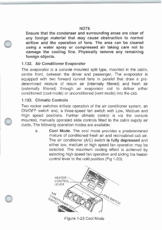
NOTE Ensure that the condenser and surrounding areas are clear of any foreign material that may cause obstruction to normal airflow and the operation of fans. The area can be cleared using a water spray or compressed air taking care not to damage the cooling fins. Physically remove any remaining foreign objects.
1.132. Air Conditioner Evaporator The evaporator is a console mounted split type, mounted in the cabin, centre front, between the driver and passenger. The evaporator is equipped with two forward curved fans in parallel that draw a pre- determined mixture of return air (internally filtered) and fresh air (externally filtered) through an evaporator coil to deliver either conditioned (cool mode) or unconditioned (vent mode) into the cab.
1.133. Climatic Controls Two rocker switches initiate operation of the air conditioner system, an ONIOFF switch and, a three-speed fan switch with Low, Medium and High speed positions. Further climatic control is via the console mounted, manually operated slide controls fitted to the cabin supply air 0 ducts. The following operation modes are available:
a. Cool Mode. The cool mode provides a predetermined mixture of conditioned fresh air and recirculated cab air. The air conditioner (A/C) switch is fully depressed and either low, medium or high speed fan operation may be selected. The maximum cooling effect is achieved by selecting high speed fan operation and sliding the heater control lever to the cold position (Fig 1-23).
Figure 1-23 Cool Mode

Vent Mode. The vent mode provides a predetermined mixture of unconditioned fresh air and recirculated cab air. The A/C switch is not depressed and either low, medium or high speed fan operation may be selected. The heater control lever may be placed anywhere between the cold and heat positions (Fig 1-24).
Figure 1-24 Vent Mode
Heat Mode. The heat mode provides a predetermined mixture of conditioned fresh air and recirculated cab air. The air conditioner switch is not depressed and either low, medium or high speed fan operation may be selected. The heater control lever may be placed anywhere between the cold and heat positions. Maximum heating effect is achieved by sliding the heater control lever fully across to the heat position (Fig 1-25).
Figure 1-25 Heat Mode

Demist Mode. The demist mode provides a pre- determined mixture of conditioned fresh air and recirculated cab air for rapid demisting. The AIC switch must be fully depressed and either low, medium or high speed fan operation may be selected. The vent nozzle regulator lever must be in the up position. The heater control lever may be placed anywhere between the cold or heat positions (Fig 1-26).
\ T E N T NOZZLE
Figure 1-26 Demist Mode
CABIN AND FITTINGS
1.134. Cabin
The vehicle cabin is mounted on the chassis with anti-vibration mountings and dampeners. The cabin can be tilted forwards to provide access to the engine/transmission area. The cabin tilting operation is to be carried out only in conjunction with a qualified mechanic. Refer to EMEI VEHICLE D 393.
1.135. Cabin Seats
An individual seat is provided for the driver and a single seat for the passenger. The driver's seat is provided with the following adjustments:
a. Fore and aft adjustment;
The back rest can be tilted forwards and backwards; and
The front and rear of the driver's seat squab is adjustable up and down.
The back of the passenger's seat may be folded forward to create a platform for the observer.

1.136. Cabin Seat Belts
All seating positions are fitted with inertial reel, emergency lock, laplsash type seat belts. Seat belts are to be worn at all times when the vehicle is in motion and should not be twisted or too loose. When the belt latch tongue is pushed into the lock mechanism, it should be pushed in firmly until a click is heard.
1.137. Windows
The side windows, which are fitted in the doors, can be opened with a manual regulating mechanism. The windscreen and rear cabin windows cannot be opened.
1.138. Rear View Mirrors
The external rear vision mirrors may be adjusted by moderate hand pressure. The mirrors are hinged to avoid damage during operation in close country.
1.139. Observation Hatch
An observation hatch (Fig 1-27) is fitted in the cabin roof above the passenger's seat. To open the hatch, release the two twist catches on the roof of the cabin, then rotate the hatch towards the right and lock with the lever. The crane can be operated from the observer's position.
Figure 1-27 Observation Hatch

1.140. Weapon Clips and Butt Boxes
Facilities for mounting the driver's and passenger's personal weapons and a Minimi weapon are provided in the cabin.
0 CHASSIS AND BODY FITTINGS
1.1 41. Construction
The vehicle cab is fabricated from steel and is mounted on the chassis with anti-vibration mountings. The recovery unit is mounted to a subframe, which in turn is secured to the vehicle chassis. The subframe absorbs stresses associated with recovery operations without placing excess strain on the vehicle chassis. Two independently operated anchor legs are fitted at the rear of the subframe. Tie down and anchor lugs are provided at the rear of the subframe and on the front of the chassis.
1.142. Climbing Bars
A climbing bar (Fig 1-28) is located under the front bumper bar beneath the left hand headlight. The bar is used to enable personnel to access the vehicle bonnet. To unfold grasp the bar, pull out firmly until it clears the spring clip then slide fully out. To stow the bar lift up and push in 0 firmly until the bar is engaged in the spring clip. A climbing bar is also fitted to the side step and is deployed in a similar manner.
Figure 1-28 Climbing Bar
1.1 43. Bonnet Release
0 Access to the engine compartment is obtained by unlocking the bonnet catches at the left and right hand side of the bonnet. When opened the bonnet is to be supported by engaging the bonnet support strut. After closing the bonnet always check that the bonnet latches have locked by attempting to lift the bonnet.

1.144. Stowage
Weatherproof equipment bins with lockable doors are mounted on the subframe either side of the main boom. The bins are fitted with plywood dampers on the floor and brackets to secure items of CES when required. A stowage plan is depicted in Chapter 2, Section 2, Fig 2-39.
1.1 45. Fire Extinguishers
Three fire extinguishers are mounted on the MRV. In the event of a fire, remove the extinguisher from the mounting bracket, read the instructions and use the extinguisher accordingly. Fire extinguishers are mounted in the following positions:
One X 1.5 kg dry chemical fire extinguisher beside the drivers seat between the seat and the door.
One X 4.5 kg dry chemical fire extinguisher on the front left hand side of the recovery platform, and
One X 9 litre foam fire extinguisher on the front right hand side of the recovery platform.
1.1 46. POL Stowage
A jerrican holder, mounted on top of the left hand front equipment b ~ n of the recovery unit, provides stowage for 3 X Cans, Water, Plastic, 22 litres or 3 X Cans, Fuel, Military, Steel, 20 litre, or a combination of each.
1.147. Side Step
WARNING
The maxlmum statlc bad that can bo placed on the slde step Is 150kg.
WARNING
Ensure the side step Is atowed and the safety locking pin Inserted beton moving tho MRV.
A side step is fitted to the fuel tank mounts to aid in the removal of the water cans and jerricans. To unfold the step, remove the safety pin from the rear hinge, lift the entire step up until it has cleared the two catches then pull out. To stow the step, fold up the climbing bar, fold in, lift up and iower the step into the two catches, Insert the safety pin in the rear hinge.

1.148. Towing Pintle An approved towing pintle with mounting fame is stowed in the LHS front top equipment bin and is fitted to the rear of the vehicle on an as required basis. 1.149. Electrical Trailer Connection Socket
A 12-pin. 24V, NATO trailer socket connector is fitted adjacent to the left hand rear mudguard. With the exception of the blackout stoplight circuit, which is connected through terminal F, the connector is wired in accordance with DEF (AUST) 5101.
WARNING
Tho air supply p m u n at thm tyn Inflation palnt is unmonltorad. Take can not to ax& tho recommendad tyro p u n . Over Infl8tton could result In tyro drmago/blowout and injwy to personnel.
1.1 50. Tyre Inflation Point
NOTE Run the engine during the tyre inflation procedure.
A tyre inflation connection is located on the right hand side of the vehicle in front of the intermediate axle. Prior to connecting the tyre inflation hose first reduce the supply pressure to below the cut-in pressure of the pressure regulator (1 5.8 bar (1 580 kPa)) by stopping the engine and draining air from both brake air reservoirs or actuating the brake pedal several times. 1.151. Camouflage Nets Stowage A purpose built stowage platform, with tie down points, and the capacity to stow three camouflage nets, is mounted on the vehicle body behind the cabin.
1 .I 52. Spare Wheel Stowage The spare wheel is mounted on the main boom and can only be removed with the aid of a crane.
0 1.1 53. Auxiliary Wire Rope Stowage
A circular frame is attached to the rim of the spare wheel to accommodate the storage of the auxiliary wire ropes and slings.

1.1 54. Personal Equipment Stowage
A platform located on the main boom in front of the spare wheel provides stowage space for crew personal equipment. The platform also provides a secondary location for stowage of the spare wheel.
1.1 55. Bridge Classification Sign
A bridge classification sign with the number 13/25 is attached to the brushguard.
1.156. Unit Formation Signs
Four unitlformation sign holders are fitted to the vehicle.
1.1 57. Vehicle Nomenclature Plate (Fig 1-29)
The vehicle manufacturer's identification number is stamped on a plate that is riveted to the driver's door pillar. The identification number is also stamped on the outside of the right-hand chassis rail just forward of the front wheel.
0 O TRUCK, WRECKER, MEDIUM, MC2
NOMENCLATURE PLATE
SK;C m W 1 3 MANUFACTUREROFCABi*)MASSIS MERCEDES BEN2 IAUSTRALIAI Ply Lld MODEL UNlMOG U 2&0 L 6x6 U M F A r m R U I O F ~ R f E W I F M E N l EVANS DEAKlN ENGINEERING Ry Lld W E L GECKO DB CHASStSNo. I I CONTRACTNO. 6450217 DATE OF ACCEPTANCE I I WARRANTY 40 monlhsl4O.m km mrh ever mars I~ml ARMY REGISTEREDNUMBER I I
0 "..,7~m?.o
1.1 58. Centre of Gravity Plate (Fig 1-30)
A "C of G" plate designating the longitudinal point of balance of the unladen MRV is fitted to the bottom rear corner of the left hand front equipment bin.
Figure 1-30 Centre of Gravity Plate

1.159. Servicing Data Decal (Fig 1-31)
The servicing data decal listing the lubricants used in the MRV is affixed
0 to the glove box lid.
0 0 TRUCK, WRECKER, MEDIUM, MC2
~ H Q M r A . w M O ~ U ~ L m
L U B R W S FOR (IERVICIWG AMD MP W OF LEVELS
0
Figure 1-31 Servicing Data Decal
RECOVERY EQUIPMENT AND CONTROLS
1.1 60. Lifting and Towing Gear
The lifting and towing equipment is an underlift system and consists of a main boom which is mounted by pivot bushes to the subframe at the front end, with two hydraulic cylinders at the rear to provide the lifting capacity. Attached to the main boom is a folding boom with an extension boom. The extension boom is equipped with a cross bar (T-bar) with various forks and connections for attaching a casualty. The folding boom can be raised and lowered independently of the main boom and the extension boom can be extended and retracted independently of the folding boom. All operations of the main and extension booms are hydraulic.
1.1 61. Hydraulic System @ A triple element pump driven bv the transmission PTO is used to provide . - hydraulic fluid, under pressure, to three independent hydraulic circuits for:
The left winch and the earth anchor legs,

The lifting boom, folding boom and the right winch, and The material handling crane and stabilisers.
1.162. Winches
Two hydraulic, dual speed winches (Fig 1-32) are mounted on the main boom. The winches are independently driven and fitted with an automatic safety brake and spring loaded pressure rollers that maintain rope tension on the drums. The winches can be operated together without the loss of capacity. The winch drums are fitted with a pneumatically operated free spooling control and each drum contains 95 metres of 13 mm wire rope which is fed permanently through two swivelling (360°), self aligning fairleads mounted at the rear of the main boom. The winches are factory sealed/lubricated.
W~NCH DRUMS
Figure 1-32 Winches , Earth Anchors
Two hydraulically operated, telescopic earth anchor legs are located on each side of the recovery subframe at the rear. The anchor legs are independently operated each fitted with spade attachments and provide stability to recovery operations when deployed.
1.164. Recovery and Towing Hydraulic Systems Controls Controls for recovery and towing (Fig 1-34) are provided as follows:
Directional Control Valves. Two sets of heavy duty, spring loaded control levers (connected by cables to a centrally located directional control valve bank) are fitted in the rearmost left and right equipment bins, permitting

operation of the recovery equipment from either side of the vehicle. Switches for engine speed control, winch free spooling, cabinet lights, work lights and flood lights are also fitted to both control panels.
Figure 1-33 Recoverynowing Controls (Right Hand)
Figure 1-34 Winch Pressureflension Gauge
b The control stations are equipped with pressure gauges that indicate the load on each winch. Each gauge has two scales, an outer scale indicating system hydraulic pressure in bar, and an inner scale that indicates the winch load for each rope layer in tonnes (Fig 1-34). The winch load gauges carry out the following functions: (1) Monitor the hydraulic system condition, e.g.
indicate low system pressure at winch cut-out.
During winching provide a general indication of the load on the winch.

(3) At winch cut-out provide an accurate indication of the load on the winch.
(4) The gauges can also be used to calibrate the flat - rating devices on the winches.
Winch Remote Control. A multi-function remote control unit (Fig 1-35), with 30 metres of cable, is carried in the left hand side equipment bin, second from the rear of the vehicle. The remote control lead is connected to a socket located on the wall of the same equipment bin. The remote control unit is of a pendant style and permits an operator to initiate winch, boom, earth anchor and engine throttle control functions whilst standing a distance from the MRV. A low oil warning lamp and remote control disable switch is also fitted.
Figure 1-35 Remote Control Unit Remote Control Function Switch. A function switch (Fig 1-36) is located above the remote control unit socket. The switch controls the operation of the remote control unit and front winching from the cab. Table 2-2 in Chapter 2 details the switch positions and functions available at each position.
Figure 1-36 Winch Remote Control Function Switch

WARNING
If the engine is switched off during winching operations tha six-whoel brake will release and the MRV may mow.
1.165. Six-Wheel Work Brake
When performing static recovery operations the service brakes and the park brake can be coupled electro-pneumatically by applying the six- wheel work brake switch, located on the left-hand corner of the dash. The six-wheel work brake system only operates when the engine is running, the park brake is applied and there is an air supply pressure of 7.5 bar (750 kPa) or more in the system. The work brake is not to be used as a park brake.
1.166. Exhaust Brake
The exhaust brake is controlled via a switch on the dash and applied either by the brake pedal or a foot operated valve fitted in the floor in front of the drivers seat. The exhaust brake provides assistance to the service brakes when slowing/stopping the vehicle, especially under heavy load conditions during mobile recovery operations.
1.167. CTlS
The CTlS provides options to improve vehicle traction during recovery operations. Refer to Chapter 1, Section 1 for optimum tyre pressures over a range of recovery tasks.

1.168. Crane
A material handling, hydraulic crane is mounted eastiwest on the sub- frame between the recovery unit and the cabin. The crane is operated independently of other hydraulic equipment.
The assembly is made up of a crane main boom (Fig 1-37(3)), a crane outer boom (Fig 1-37(4)), and a crane extension boom (Fig 1-37(6)) mounted on a vertical support column (Fig 1-37(12)). The booms may be operated individually or simultaneously by double-acting hydraulic control cylinders mounted between each assembly.
The crane controls may be operated to lift or lower the crane main boom and the crane outer boom, to extend and retract the crane extension boom and to slew, clockwise or anticlockwise through an arc of 180". The crane is stabilised by two hydraulically operated legs (Fig 1-37(11)). The legs are controlled independently of the crane.
1. Crane control levers 5. Crane extension boom cylinder 9. Crane inner boom cylinder
2. Outer boom lock 6. Crane extension boom 1O.Slew cylinder 3. Crane main boom 7. Crane hook 11 .LH stabiliser 4. Crane outer boom 8. Crane outer boom cylinder 12.Support column
Figure 1-37 Crane - General Arrangement

1.169. Crane Hydraulic Systems Controls
A set of heavy duty spring loaded control levers (Fig 1-38) is mounted on a column at the left rear of the vehicle cab to enable operation of the crane and stabilisers from the observer's position in the cab. The controls are connected via rods to a directional control valve bank mounted on the crane base. Controls are provided as follows:
a. Crane Control Levers. The controls consist of four levers, slew, main boom, outer boom and boom extension. A label fixed above the levers indicates each lever operation and function. The crane lifting capacity at various radii is shown on a label fixed to the cab roof.
Figure 1-38 Crane Control Levers (Viewed from Cab)
Stabiliser Control Lever (Fig 1-38). The left-hand and right-hand stabilisers are raised or lowered using a control lever at the crane operator's station. Each stabiliser is retained in the vertical position (operational and stowed) by a locking pin.
1 .I 70. Recovery Unit Lighting The lighting equipment fitted to the recovery unit consists of:
a. Clearance lights on the recovery unit.

A portable floodlight to illuminate recovery operations is normally carried stowed in an equipment bin. Power is provided by an unswitched connection (two jacks) on the facia panel of the left and right control cabinets. Custom- made fittings located on the top of the rear equipment bins are provided to locate the floodlight when it is required to illuminate the recovery area.
Two floodlights for crane and recovery operations are mounted permanently on a recovery unit frame behind the cabin. The floodlights are controlled by individual switches located on each light and, the floodlight switches on the recovery equipment control panel.
d. Two rotating hazard warning beacons mounted on the recovery unit frame.
1.171. Audio Unit
A radiotcassette unit is fitted in the vehicle cabin for the comfort of the crew during protracted recovery tasks.
TOOLS
1.172. Tools supplied with the cab/chassis are stored on or in compartments on either side of the MRV. For all CES items and stowage location refer to Figure 2-39.

CHAPTER 2
OPERATING INSTRUCTIONS
SECTION 1 - VEHICLE OPERATION
SECTION 2 -RECOVERY SYSTEM OPERATION
SECTION 3 -CRANE OPERATION
NOTE
For clarity and brevity the Truck, Wrecker, Medium, MC2, Unimog U2450L is referred to throughout this document as the MRV (Medium Recovery Vehicle).

SECTION 1 VEHICLE OPERATION
NEW VEHICLE
2.1. Pre-Operational Check
Before operating a new MRV for the first time, carry out the daily and fortnightly service as detailed in Chapter 3 Section 1.
2.2. Running In.
When "running in" the MRV observe the following procedures and precautions:
Up to 1500 Kilometres. Until the engine is at operating temperature, restrict MRV speed to below 50 kmlh. Otherwise any reasonable speed within legal limits IS
permissible to a governed speed of 100 kmlh. Avoid sudden, hard stops whenever possible. The brakes bed in more uniformly if slow, gradual stops from various speeds are made.
Beyond 1500 Kilometres. If traffic conditions permit, deliberately vary the speed from fast to slow and back again. Any steady unchanging speed during this period tends to cause uneven wear of precisely fitted parts. Accelerate moderately up to legal speed limits for short bursts. Provided the engine speed is below 2600 RPM, any legal speed is allowable. Six-wheel drive may be used. Travel slowly over extremely rough terrain when the MRV is fully laden to minimise shock loads on the driveline components.

NORMAL OPERATION
2.3. General
Proper driving techniques and operation determines the service life and operating economy of the MRV. This includes, careful driving, normal road speeds, reasonable rates of acceleration and braking, and shifting controls in a manner to avoid shock loading and labouring.
2.4. Before Starting
Carry out a first parade service as detailed in Chapter 3 Section 1.
2.5. Before Starting the Engine
NOTE
Ensure that the crane and any loose fittings are stowed and the equipment bin doors on the recovery unit are secured. If a casualty is undertow, ensure that i t is secured.
Before starting the engine carry out the following:
Apply the parking brake.
Ensure the PTO selector switch is in the "OFF' position.
Select the four-wheel drive position on the all wheel drive and power divider switch at the instrument panel.
Set the hand throttle and the winch engine speed control to the engine idle position and leave it in that position whilst driving.
Depress the clutch pedal, to disengage the clutch and select neutral with the gear change lever.

2.6. Starting the Engine (Hot Or Cold)
NOTE
The MRV is equipped with a starter interlock feature and therefore before the starter circuit can be activated, the clutch pedal must be depressed as far as the stop before starting can be achieved.
Start the engine as follows:
Depress the clutch pedal to the stop (starter interlock).
Move the accelerator pedal and the hand throttle to the engine idle position. C Slightly depress the accelerator pedal to release the engine stop mechanism.
Turn the ignition key clockwise to the START position. Release the key as soon as the engine starts. If the engine does not start after five seconds slowly depress the accelerator pedal.
Release the accelerator pedal as soon as the engine is running smoothly.
When the engine is running, allow the air pressure (displayed on the dual pressure gauge) to build up to 12 bar (120 kPa), (7 bar (70 kPa) in an emergency). Check that the parking brake warning light is illuminated, and the brake fluid/supply pressure and the brake pad wear warning lights are not illuminated. 0

2.7. Shutting Down the Engine
WARNING
Ensure the accelerator pedal Is not depressed after the engine has been shut down as this actlon will release the porltiva englno stop allowing the onglno to be roll started.
NOTE
Before shutting down the engine, allow it to idle for about 1-2 minutes.
Ensun tho coolant tmpnhrm h nat hlghor than 90% W o n turning tho anglm M. U tho tunp.ntun b htghrr t n # l W C , r u n ~ ~ r r h i g h M f a r r c w p k d m i n W to allow uw mgiw to cool.
To shut down the engine proceed as follows:
a. Switch the engine speed control lever ta "IDLEn at the recovery unit control panel and ensure the hand throttle in the cab is in the engine idle position.
Disengage the clutch and select neutral with the gear change lever, and turn the PTO switch to the "OFF' position if engaged.
Turn the ignition switch key to the 'On (engine off) position.
2.8. Engaginflisengaging the PTO CAUTION
To avoid o v m w l n g tho hydnulk pump, tha +plittor mmnlulon mud k In LOW rrngr prior to ongaging thr ?TO.
To engage the PTO proceed as follows:
a. Apply the hand brake.
Apply the six-wheel work brake.

Move the hand throttle to the engine idle position.
Disengage the clutch, position the gear change lever in neutral in gate between 7th and 81h and ensure the fwdlrev shift lever is in neutral and the splitter transmission is in LOW ratio.
Turn the PTO switch to the right until the indicator is aligned with the "PTO ON" symbol. Ensure the PTO engaged indicator light is illuminated.
f. Engage the clutch slowly.
To d~sengage the PTO proceed as follows:
Switch the engine speed control lever to "IDLE" at the recovery unit control panel and ensure the hand throttle in the cab is in the engine idle position.
Disengage the clutch and turn the PTO switch to the "OFF position. Ensure the PTO indicator light is extinguished.
DRIVING PROCEDURES WARNING
Do not drlw tho MRV on 8 flrm surface with the dltfwentlal locks ongaged ar them I8 no dmonntlrl opontlon betwoon tho whwis whon camring. Thls leads to increased tyro wear, poor stooling khrviour and u w r e loads k l n g placed on drhm line compomnb.
2.9. Moving Off - Normal Conditions
Depress the clutch and engage the desired gear: Steadily depress the accelerator and simultaneously release the clutch and parking brake. Check that the parking brake, differential pressure and brake pad wear warning lights, are extinguished.

2.10. Moving Off - Slippery Road Conditions and Rough Terrain
Select the appropriate all wheel drive and power divider lock control switch position to suit the terrain conditions. Depress the clutch and 0 engage the appropriate gear for the vehicle load conditions. Steadily depress the accelerator and simultaneously release the clutch and parking brake. Check that the parking brake, differential pressure and brake pad wear warning lights, are extinguished.
NOTE
To provide the maximum departure angle when operating over rough terrain the boom should be raised and secured at minimum height (second hole from bottom of quadrant).
If the road wheels commence to slip stop the MRV and select the appropriate all wheel drive and power divider lock control switch position. When using the six-wheel drive mode, the differential locks can be engaged if one or more wheels tend to slip due to poor ground conditions. When the six-wheel drive and differential lock functions are engaged, two separate indicator lights on the instrument panel light - illuminate. Tyre pressures may be altered to suit terrain conditions. Refer
u to Chapter 1. Section 1.
2.1 1. Cross Country Driving
WARNING
To provent aowra tyro vibration md porrlblo lorn of stoorlng control toinow all mud from the front whwls and tynr after crou country o m o n .
Stop the vehicle. Select the appropriate drive selector switch position for the driving conditions. When using the six-wheel drive mode, the differential locks can be engaged if one or more wheels tend to slip during cross country operation. When the six-wheel drive and differential lock functions are engaged, two separate indicator lights on the instrument panel light illuminate. Disconnect the differential locks before attempting to corner on a hard surface. During cross country driving maintain a safe speed for the conditions encountered. The mobility of the MRV is greatly enhanced if the recommended tyre
0 pressures are adhered to, refer to Chapter 1, Section 1.
2.12. Fording
~ ~ ~ ~ b d o n k r d l n g . The MRV can be forded unprepared to a depth of 1200 mm, the limiting feature being the cooling fan. When fording is undertaken select six- wheel drive mode and avoid excessive speed. When six-wheel drive is selected the axles housings are automatically pressurised thus preventing the ingress of water into the housings.
Once the crossing has been accomplished ensure the brakes are dry and fully effective before proceeding.
2.13. Braking
To brake the MRV, release the accelerator and progressively apply the brakes. The brakes may be applied in four ways:
a. Applying the service brake (foot brake);
Applying the exhaust brake (exhaust brake button on floor);
Applying the service brake (foot brake) and the exhaust brake (engine brakelservice brake switch on dash switched); or
Applying the trailer brake when towing a trailer (trailer brake control on steering column).
2.14. Parking
When stationary the parking brake is used to park the MRV.
2.15. Six-Wheel Work Brake
WARNING n tha mglm Is switched off d m winching opwatiom tho a - w w m a wlll nkrw 8nd tlw MRV my nlouu.
NOTE
The six-wheel work brake is not to be used as a park brake.
When stationary and the MRV is employed on a recovery task the six- wheel work brake should be applied.

2.16. Towing a Trailer
When connecting a trailer to the MRV, ensure that the trailer towing eye is fully seated in the towing pintle, the pintle locking device is fully closed and the pintle safety pin is inserted and secured. Connect the two trailer brake lines and ensure that there is no leakage at the couplings. Connect the trailer lighting cable and check the trailer lights. Release the trailer brake before moving off.
Good Driving Habits
2.17. Engine Temperature
Before entering high speed traffic conditions, allow the engine to reach operating temperature (80 to 95 degrees C).
2.1 8. Instruments
Check the readings of the instruments frequently. When trouble is indicated, take prompt action to correct.
2.19. Clutch
To avoid damage, engage the clutch without "shock loading" the drive .- line, especially on grades with loads. w
2.20. Gear Changing
Upward and downward gear changes should be made to keep the engine operating in the green band (1500 RPM to 2000 RPM range) on the tachometer. When driving down long grades, the braking effect of the engine should be employed by shifting to a lower gear.
Ensure that the correct gear is selected for the terrain, vehicle load and speed. Use the same gear down hill as up hill. Avoid gear clashing by synchronising engine and vehicle speeds and by double de-clutching. Do not permit the load to drive the engine above governed speed. Shift gears smartly and smoothly, do not actuate the clutch for too long as undue wear on the clutch throw-out bearing will result.
The splitter transmission can be used in all gears on-road or off-road. To change the splitter transmission gears, depress the clutch pedal all the way to the floor and hold down momentarily (min of 0.5 seconds), select
0 overdrive (up) or direct drive (down) on the switch on the gear change lever then release the clutch pedal.
To engage reverse gear, stop the MRV, declutch, shift the fwdlrev selector to reverse and then accelerate normally, after engaging the

clutch. All eight main transmission gears and the splitter transmission gears are available in reverse.
EMERGENCY PROCEDURES
The URV must not bo ddwn It a brake warning lQht or low air prarrun wamlng tlght Is opomtlng. Them warning d d c e r Indicate that the h k e system 18 not tunctienlng correctly.
2.21. Brake Failure
If a brake warning device IS actuated when the brakes are applied or braking effectiveness is in doubt, the MRV must be stopped immediately and the cause investigated. With a partial failure of the system, it is still possible to bring the MRV to rest by applying the footbrake, although the stopping distance will be increased. The engine may be used to assist braking by selection of a lower gear ratio or by actuating the engine brake.
In an emergency the hand brake may be progressively applied to stop the MRV,
2.22. Fire
If a fire occurs, stop the MRV immediately and stop the engine. Switch off all electrical services and the battery isolation switch. Evacuate all personnel from the vehicle and attempt to put out the fire with the extinguishers provided. Operating instructions are printed on the body of the fire extinguishers. Allow all fumeseto dissipate before re-entering the vehicle. The fire is to be reported immediately so that the cause can be determined.

BREAKDOWN PROCEDURES
WARNING
When slave starting the MRV ensure that a 24V source Is used and slaw lard polarity connoctlons are correct. lncornct wltage or polarity connections may result in battery explosion and injury to personnel.
2.23. Fiat Batteries
If the batteries are flat start the engine using an inter-vehicle slave start when the MRV is stationary or a rolling jump start with the MRV attached to a tow vehicle by a rigid inter-vehicle A-frame.
2.24. Flat Tyre
If a tyre deflates, stop the MRV as soon as possible, avoid harsh breaking or steering manoeuvres. If possible, bring the vehicle to rest on a hard level surface, well clear of the road. Turn on the hazard warning lights if the tactical situation allows.
Apply the parking brake, stop the engine and chock the wheels to prevent movement of the MRV when it is jacked up.

WARNING
The MRV is oqulppod with six-wheel dr lw and dlffonntial locks. Do not attmpt to apply drive to a whwl that has boon jacked up off tho ground. If oithor SIX-who01 drlvo or thm dlfferentlal locks m ongrgod aerlous Injury to pononnol and damrgo to
2.25. Removing the Spare Wheel
Remove the spare wheel from the stowed position on the main boom as follows:
NOTE
The approximate mass to be lifted is 220 kg. Use a suitable crane.
Position the main boom in 'fully down' position.
Remove the spare wheel cover.
Release spare wheel locking screw and remove the screw and clamping bar from centre of spare wheel.
Attach the sling to the wire rope spool lifting lugs and lift the wheel clear of locating dowels on main boom.
Lower the spare wheel to ground and stand upr~ght (still attached to crane), then remove the two locking pins securing the rope spool supports and lower the wheel to lie flat on bolting face of rim.
Remove the wire rope spool and support brackets (2).
NOTE
Before proceeding with changing the wheel, ensure that the MRV is on flat, firm level ground and not obstructing traffic.
Bobrm chrnglng a who01 w c v n tho MRV to p m n t mowmmt.

2.26. Changing a Wheel
Change the wheel as follows:
a. Apply the parking brake and chock the wheels.
Ensure there are no passengers in the MRV.
NOTE
The jack, operating handle and wheel brace are located in an equipment bin on the left hand side of the MRV.
Place the jack under the outboard end of the axle tube adjacent to the faulty wheel.
Remove any dirt from the wheel nut cover and remove the cover.
Unstow the crane. Refer to Section 3.
Remove the locking screw securing the spare tyre to the recovery boom and lift the spare wheel into a position adjacent to the wheel to be changed, with the crane.
Loosen the wheel nuts a couple of turns and jack up the axle until the wheel is clear of the ground.
Remove the wheel nuts, the two hub cap mounting brackets, and the four bevelled washers located underneath the brackets.
Disconnect the central tyre inflation quick release coupling and then remove the wheel.

Check the spare wheel and tyre for serviceability before fitting.
Check that the wheel nuts and studs are clean.
Fit the spare wheel ensuring that the lyre valve stem is aligned with the slot in the wheel hub and taking care not to damage the stud threads.
Fit the four bevelled washers, two hub cap mounting brackets and four wheel nuts with flat ends so that the brackets are located diagonally opposite on the wheel. Fit the remaining wheel nuts with the bevelled ends inwards.
Tighten the wheel nuts evenly in a criss-cross pattern around the wheel.
NOTE
Tighten the wheel nuts using a torque wrench. Check the wheel nuts again after 50 km of travel or at the next Last Parade Service whichever occurs first.
o. Lower the MRV to the ground and torque the wheel nuts to 400 Nm in a criss-cross pattern (diagonally opposite) around the wheel.
NOTE
Tighten the union nuts of the tyre inflation hose by hand (2-3 Nm). Do not overtighten.
Refit the central tyre inflation quick release coupling and refit the wheel nut cover.
NOTE
To inflate the tyre from an external source connect the air hose to the Schraeder valve at the central tyre inflation quick release coupling and inflate the tyre to the desired pressure.
Check the tyre pressure (refer to Chapter 1, Section 1) and if required, inflate the tyre using the central tyre inflation system, see paras 2.35 to 2.40.

Stow the crane (refer to Section 3), the jack, operating handle and wheel brace.
Remove the chocks from the wheels.
NOTE
Check the wheel nuts torque after 50 km of travel, or at the next Last Parade Service whichever occurs first.
t. Report the occurrence so that the necessary repair action to the defective tyre can be taken.
2.27. Stowing the Spare Wheel
Stow the spare wheel on the recovery boom, using the crane, as follows:
NOTE
The approximate mass to be lifted is 220 kg. Use a suitable crane.
Lay the spare wheel flat with the bolting face of the rim on the ground.
Attach the wire rope spool and support brackets (2) to the spare wheel with the two locking pins.
Attach the sling to the wire rope spool lifting lugs and lift the wheel into position on the locating dowels on the main boom.
Install the clamping bar at the centre of spare wheel and secure with the spare wheel locking screw.
Install the spare wheel cover, tighten and tie-off the securing rope.

TOWING
2.28. Towing a Casualty MRV
WARNING
H a casualty MRV has no brakes, then It cannot be towed by another MRV on public rods.
CAvnOw
#thoYFlVIr8okOawdw#hthrrwr~onIlwgmund, t h r ~ m t ~ n d r r l l h n o r l r ~ ~ ~ krltr8yamrnuab.--
NOTES
1. If there is no compressed air supply to the MRV (casualty) it is necessary to provide an auxiliary air supply from the towing vehicle to maintain the park brake in the released position during towing. Using the hoses supplied with the MRV CES connect the supply and control couplings at the rear of the towing vehicle to the couplings at the front of the casualty. With no air supply the park brakes must be released manually, see para 2.31
2. If the MRV (casualty) is to be flat towed without the engine running the hydraulically assisted steering system will not operate and manual forces will be considerably higher than normal for steering.
3. If the MRV is to be lift towed, refer to Section 2 Table 2-4 Boom Positions for Llft Towing.
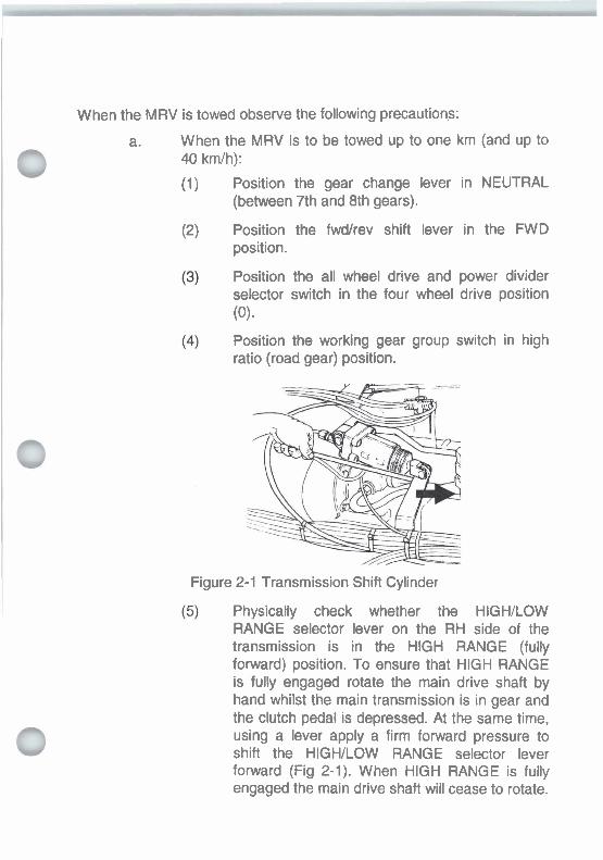
When the MRV is towed observe the following precautions:
When the MRV is to be towed up to one km (and up to 40 kmlh):
(1) Position the gear change lever in NEUTRAL (between 7th and 8th gears).
Position the fwdtrev shift lever in the FWD position.
Position the all wheel drive and power divider selector switch in the four wheel drive position (0).
Position the working gear group switch in high ratio (road gear) position.
Figure 2-1 Transmission Shift Cylinder
Physically check whether the HIGHJLOW RANGE selector lever on the RH side of the transmission is in the HlGH RANGE (fully forward) position. To ensure that HlGH RANGE is fully engaged rotate the main drive shaft by hand whilst the main transmission is in gear and the clutch pedal is depressed. At the same time, using a lever apply a firm forward pressure to shift the HIGHILOW RANGE selector lever forward (Fig 2-1). When HIGH RANGE is fully engaged the main drive shaft will cease to rotate.

(6) Secure the HIGHILOW RANGE selector lever in the high range position by fitting the selector lever locking bracket between the underside of the selector lever shift cylinder clevis and over the head of the transmission housing mounting bolt below and approximately horizontal to the shift cylinder clevis. Refer to EMEl VEHICLE G 619-1 0 for more details.
(7) Secure the Working Gear Group selector lever in the high range (road gear) position with the working gear group locking bracket. Refer to EMEl VEHICLE G 61 9-10 for more details.
(8) Release the spring loaded park brakes, manually if the air supply is exhausted, see para 2.31.
When the MRV is to be towed over one km (or when 40 kmlh will be exceeded):
(1) Remove the engine to transmission drive shaft.
(2) Position the gear change lever in 8th gear.
(3) Position the fwdtrev shift lever in the FWD position.
(4) Position the working gear group switch in high ratio (road gear) position.
(5) Physically check whether the HIGWLOW RANGE selector lever on the RH side of the transmission is in the HlGH RANGE (fully forward) position. To ensure that HlGH RANGE is fully engaged rotate the main drive shaft by hand whilst the main transmission is in gear and the clutch pedal is depressed. At the same time, using a lever apply a firm forward pressure to shift the HIGHILOW RANGE selector lever forward (Fig 2-1). When HlGH RANGE is fully engaged the main drive shaft will cease to rotate.
(6) Secure the HIGHILOW RANGE selector lever in the high range position by fitting the selector lever locking bracket between the underside of

the selector lever shift cylinder clevis and over the head of the transmission housing mounting bolt below and approximately horizontal to the shift cylinder clevis. Refer to EMEl VEHICLE G 61 9-1 0 for more details.
(7) Secure the Working Gear Group selector lever in the high range (road gear) position with the working gear group locking bracket. Refer to EMEl VEHICLE G 619-10 for more details.
Release the spring loaded. park brakes, manually if the air supply is exhausted, see para 2.31.
2.29. MRV to MRV Towing Preparation - Option 1
To prepare a casualty MRV, that has the engine and hydraulic system operable, for towing, proceed as follows:
Make the MRV casualty safe i.e. on level ground and with wheels chocked.
Prepare the MRV for towing.
Connect the casualty MRV to recovery MRV.
NOTE
Loosen both sets of front wheel nuts before raising the casualty MRV.
d. Fit the front axle spring compressors. Ensure the compressors are tightened sufficiently to bring the axle to the bump stops.
Loosen both sets of front wheel nuts.
Lift the casualty MRV clear of the ground, remove both front wheels and position the wheels near the casualty rear wheel group. Position the recovery MRV boom to provide the minimum possible clearance under the casualty front axle. Lock the recovery MRV main boom not higher than the fourth hole from the bottom of the boom support quadrant.
Cover the exposed front wheel disc and brake calipers of the casualty MRV.

Unstow the casualty MRV crane.
Relocate the casualty MRV spare wheel in the alternate stowage position on top of the personal equipment platform (Fig 2-2), using the crane. Secure the wheel.
Stow the two wheels of the casualty MRV on either side of the casualty MRV main boom (Fig 2-2), using the crane.
TEMPORARY STOWAGE POSITION - FRONT WHEELS OF CASUALTY
ALTERNATE STOWAGE POSITION - MRV SPARE
WHEEL 8 WIRE ROPE HOLDER
Figure 2-2 Casualty MRV Front Wheels - Stowage
Lash the two wheels together through the main boom section using chains or other suitable equipment.
Stow the casualty crane.
Complete the preparations for towing.
2.30. MRV to MRV Towing Preparation - Option 2
When the casualty MRV does not have an operable engine and hydraulic system prepare for towing as follows:
Make the MRV casualty safe i.e. on level ground and with wheels chocked.
Position the recovery MRV so the crane is within reach of the spare wheel and one of the front wheels on the casualty MRV.
Unstow the recovery MRV crane.

Relocate the casualty MRV spare wheel in the alternate stowage position on top of the personal equipment platform (Fig 2-2), using the crane. Secure the wheel.
Relocate the spare wheel on the recovery MRV on one side of the main boom of the casualty MRV (Fig 2-2), using the crane. Secure the wheel.
Fit the front axle spring compressors to the casualty MRV. Ensure the compressors are tightened sufficiently to bring the axle to the bump stops.
Remove a front wheel from the casualty MRV, using the vehicle jack, see para 2.26.
With the recovery MRV crane, position the removed front wheel beside the casualty MRV main boom. Lash it to the wheel located there previously using chains or other suitable equipment.
Prepare the recovery MRV for towing.
Secure and lift the casualty MRV. Position the recovery MRV boom to provide the minimum possible clearance under the casualty front axle. Lock the recovery MRV main boom not higher than the fourth hole from the bottom of the boom support quadrant.
Cover the exposed front wheel disc and brake calipers of the casualty MRV.
Retrieve and stow the vehicle jack.
Remove the remaining front wheel of the casualty MRV, and stow the wheel on the main boom of the recovery MRV in the normal spare wheel position. Secure the wheel with the locking screw.
Stow the recovery MRV crane.
Complete the preparations for towing.

2.31. Emergency Park Brake Release
WARNING
Prior to mdunlcrlly ralaulng tha pulr b n b tho w M a must k chockod to provent any mawmont OfthOMRV.
To mechanically release the park brakes on the intermediate and rear wheels, use a hammer or tyre lever (if there is no room to use the hammer) to move the park brake release latches towards the wheels (Figure 2-3). The emergency release mechanism should disengage with a click.
WARNlNO
Chock tha whmb of tha MRV to pmmt it Irom rdllng whan tho towlng dovfw I8 ramowl.
Figure 2-3 Emergency Parking Brake Release
To reapply the park brake charge the system with air pressure then release and reapply the handbrake.

ELECTRICAL SYSTEM
2.32. Battery Removal
To remove the batteries proceed as follows:
a. Rotate the battery isolation switch to isolate the batteries from the MRV electrical system.
b. Unlock the battery box door with the square bonnet key, and lower the door.
c. Unlock the battery cradle and slide out the cradle with batteries.
d. Disconnect the lead from the MRV chassis to the negative (-) terminal and then the lead from the vehicle electrical system to the positive (+) terminal.
e. Remove the connector cable between the two batteries.
TO VEHICLE
= O - - l
Figure 2-4 Battery Connection Diagram

2.33. Battery Installation
When lnrtrlllng th. brtkrkrr in tho MRV enrun that canrnctions wlth th, brtbry k d s m d the comct poktity id. (+) to (+) and (-) to (-). Income! polarity conmctlom will catma dunrgr to the vmhick mkcMul system and may mult in m r y explosion md injury to pmonml.
To install the batteries proceed as follows:
Install the batteries into position on the cradle. See Figure 2-4 for the battery connection diagram.
Connect the lead from the MRV to the positive (+) terminal and then the lead from the vehicle electrics to the negative (-) terminal. Tighten the battery terminals firmly.
Connect the connector cable between the two batteries and tighten the battery terminals firmly.
Slide the cradle, with batteries into the battery box and lock the battery cradle.
e. Rotate the battery isolation switch to connect the batteries to the MRV electrical system.
2.34. Circuit Breakers
The cablchassis electrical system is protected from overload conditions by two main circuit breaker panels (Fig 1-14) fitted to the top of the dashboard immediately forward of the steering wheel. A failure in an electrical circuit could be indicated by the black button on top of the relevant circuit breaker being raised, to reset push the button down. If the button is raised a second time report the fault and have it rectified before using the equipment again. Relays and fuses that isolate and protect the load of the recovery system from the cablchassis circuits are located behind the inner wall of the remote control equipment bin. A failure of an electrical circuit could be indicated by a recovery system blown fuse.

CENTRAL TY RE INFLATION SYSTEM (CTIS)
Do not operate the central tyro Inflation system whan drMng on public roads Wuneven tym pnoruras make whlcla control difficult and dangarous In traffic.
1. Indicator light "deflate tyren 2. lndicator light "inflate tyres" 3. Selector switch "inflate/off/deflate" tyre 4. Front axle pressure gauge, 5. Selector switch, frontlalllrear axles 6. lndicator light front axle "deflatetinf late tyres" 7. lndicator light rear axles "deflate/inflate tyres" 8. Rear axles pressure gauge 9. Instrument lights, brightness control
Figure 2-5 CTIS Control Panel
2.35. Inflate Front Axle Tyres
To inflate the front axle tyres push the selector switch, frontfalllrear axles (Figure 2-5(5)) marked "-" to the left (indicator light front axle 'deflatetinflate tyres" (Figure 2-5(6)) should illuminate) and then press
0 the selector switch 'inflate/off/deflate" tyre (Figure 2-5(3)) marked '-" at the top (indicator light "inflate tyres" (Figure 2-5(2)) should illuminate).

The front axle tyres will inflate to the pressure indicated on the front axle pressure gauge (Figure 2-5(4)). When the desired tyre pressure is reached, turn the selector switch "inflateloff/deflate" tyre (Figure 2-5 (3)) to the central " I " (off) position and the selector switch, frontlalllrear axles (Figure 2-5(5)) to the central " I " (all) position. Check that the tyre pressure indicated on the pressure gauge is being maintained and all the indicator lights are extinguished.
2.36. Deflate Front Axle Tyres
To deflate the front axle tyres push the selector switch, front/all/rear axles (Figure 2-5(5)) marked "-" to the left (indicator light front axle "deflatelinflate tyres" Figure 2-5(6)) should illuminate) and then press the selector switch "inflate/offldeflate" tyre (Figure 2-5(3)) marked '=" at the bottom (indicator light "deflate tyre" (Figure 2-5(1)) should illuminate).
The front axle tyres will deflate to the pressure indicated on the front axle pressure gauge (Figure 2-5(4)). When the desired tyre pressure is reached, turn the selector switch "inflateloff/deflate" tyre (Figure 2-5(3)) to the central " I " (off) position and the selector switch, frontlalllrear axles (Figure 2-5(5)) to the central "I" (all) position. Check that the tyre pressure indicated on the front axle pressure gauge is being maintained and all the indicator lights are extinguished.
2.37. Inflate lntermediate and Rear Axle Tyres
To inflate the rear and intermediate axle tyres push the selector switch, front/all/rear axles (Figure 2-5(5)) marked "=" to the right (indicator light rear axles "deflatelinflate tyres" (Figure 2-5(7)) should illuminate) and then press the selector switch "inflateloffldeflate" tyre (Figure 2-5(3)) marked "-" at the top (indicator light "inflate tyres" (Figure 2-5(2)) should illuminate).
The rear axles tyres will inflate to the pressure indicated on the rear axle pressure gauge (Figure 2-5(8)). When the desired tyre pressure is reached, turn the selector switch "inflateloffldeflate" tyre (Figure 2-5(3)) to the central "B" (off) position and the selector switch, frontlalllrear axles (Figure 2-5(5)) to the central " I " (all) position. Check that the tyre pressure indicated on the rear axle pressure gauge is being maintained and all the indicator lights are extinguished.
2.38. Deflate Intermediate and Rear Axle Tyres To deflate the rear and intermediate axle tyres push the selector switch, frontlalllrear axles (Figure 2-5(5)) marked "=" to the right (indicator light

rear axles "deflatelinflate tyres" (Figure 2-5(7)) should illuminate) and then press the selector switch "inflateloffldeflate" tyre (Figure 2-5(3)) marked "=" at the bottom (indicator light "deflate tyre" (Figure 2-5(1)) should illuminate).
The rear axles tyres will deflate to the pressure indicated on the rear axle pressure gauge (Figure 2-5(8)). When the desired tyre pressure is reached, turn the selector switch "inflateloffldeflate" tyre (Figure 2-5(3)) to the central "M" (off) position and the selector switch, front/all/rear axles (Figure 2-5(5)) to the central "W" (all) position. Check that the tyre pressure indicated on the pressure gauge is being maintained and the indicator lights are extinguished.
2.39. InflateJDeflate Front and Rear Axle Tyres To inflateldeflate front and rear axle tyres at the same time, place the selector switch, frontlalllrear axles (Figure 2-5(5)) at the central position "M" (all). Operate the selector switch "inflateloffldeflate" tyre (Figure 2- 5(3)) to either inflate or deflate all the tyres to the desired pressure. Depending on selection the indicator light "inflate tyres" (Figure 2-5(1)) or indicator light "deflate tyres" (Figure 2-5(2)) should illuminate. The indicator light front axle "deflatelinflate tyres" Figure 2-5(6)) and indicator light rear axles 'deflatelinflate tyresn (Figure 2-5(7)) should also illuminate. When the desired tyre pressure is reached, turn the selector switch "inflateloffldeflate" tyre (Figure 2-5(3)) to the central "W" (off) position and leave the selector switch, frontlalllrear axles (Figure 2-5(5)) in the central "m" (all) position. Check that the tyre pressures indicated on the front and rear axle pressure gauges are being maintained and the indicator lights are extinguished.
2.40. Inflating a Tyre from an External Source
WARNING
Do not stand in front of a tyre whilst inflating it.
To inflate the tyre on the MRV from an external source proceed as follows:
Remove the wheel hub cap.
Remove the valve cap from the Schraeder valve on the CTlS connection at the wheel hub.

Connect the external air hose to tyre inflation connection at the pressure regulator and inflate the tyre to the desired pressure.
Replace the valve cap and the wheel hub cap.
MRV LOADING ONTO C-130 AIRCRAFT
2.41. Operators Preparation Procedure
To prepare the MRV for air transportation in a C-130 aircraft, the vehicle operator must carry out the following procedure:
a. Check that the recovery boom is in the lowered position, and the folding boom is secure.
Check the contents of the MRV to ensure that only those items defined within the vehicle CCES and MRV personal stores list are on the vehicle.
Check that all contents of the vehicle are stored and secured in accordance with the MRV CES layout plan as detailed in the ILSI.
Remove the following equipment from the vehicle and store:
(1 ) Cupola hatch and hinge,
(2) Snorkel filter.
(3) Beacon lights (amber rotating lights),
(4) Crane operating lever caps,
(5) All radio/communication aerials if fitted, and
(6) GPS antennae if fitted.
Inflateldeflate all MRV tyres to 3.5 bar (3500 kPa).
Confirm that axle clamps will be fitted to the front axle in accordance with the Approved Tie-Down Procedures once the MRV is loaded into the C130. Show the Unit Emplaning Officer (UEO) where the axle clamps are stored.

CLEANING
2.42. Vehicle Washing
The MRV consists of sensitive electrical, mechanical and pneumatic components that are prone to damage if care is not taken when cleaning, particularly high pressure cleaning.
fhr Ingm oi w8tmr Into thm hydmulk dl tan&, tha dlnctlo~l cmtd vlhnr (lncludhg th. w#l. cmltrnk) d, ttn w m dnrmr admnt to tho dght hand M o mrln ml will kd to aqulpnnnt fallran.
When washing the vehicle, using high pressure water blast cleaning, the following must be observed:
NOTE
Cabinet seals and latches will not seal against a direct water jet blast.
High pressure water blasts must not be directed at the top of the hydraulic oil tank, the hydraulic directional control valves (including crane controls), the winch drums adjacent to the right hand side main seal and cabinet seals and latches.
Tha inqnu d water crur+r Nil and lubicrrrt corrtrrnlnation and m y n w l t In thm prnnrtwr Wun of aquipmmt
Use pH neutral, biodegradable cleaning agents to avoid damage to chrome parts.
When cleaning the crane and recovery equipment with a high pressure cleaning device the temperature of the cleaning agent must not exceed 60°C.
Protect the PTFE diaphragm on the speed limiter actuator (situated under the gear shift control panel) against h~gh pressure water jet.

After water blast cleaning all lubrication points on the recovery system are to be serviced to expel water from bushes, bearings and seals.

SECTION 2 RECOVERY SYSTEM OPERATION
NOTE
The information contained In this Section details the use of specific MRV recovery equipment. Where applicable, warnings, precautions, cautions and llmitations on the use of the equipment are included. This Section does not provide information on the application of general recovery techniques. For information on the application of general recovery techniques, including warnings, precautions, cautions and limitations on equipment refer to the Recovery Manual, EMEl's and Training Precis.
2.43. Precautions Prior To Use
Prior to operating the recovery system on this vehicle observe the following precautions:
a. Ensure the hydraulic system is filled with the approved .I 1 'I grade of oil as detailed in EMEl Vehicle D 399 Servicing
Instructions.
NOTE
The left hand winch is used for self recovery.
b. Ensure equal use is made of both winches. This action will ensure wear is evenly distributed across both winch systems.

Under normal conditions and after engaging the PTO allow five (5) minutes for the hydraulic oil to warm up prior to operating the system. In extremely cold conditions, and if after the normal five (5) minute warm up period the oil still has not reached operating temperature the following procedure is the only one to be used to assist in warming the oil:
(1) Set the engine at idle speed.
NOTE
Care must be exercised to ensure the engine is not stalled.
(2) Partially and very gradually push in an earth anchor control lever allowing oil to flow over the control valve spool.
2.44. Precautions During Use
The following precautions are to be observed when operating the recovery system:
If a hydraulic oil leak is detected or the low oil level warning light for the hydraulic system is illuminated during recovery operations switch the throttle to idle speed and disengage the PTO immediately. A delay of more than one minute can allow the system to be pumped dry and damage to the pump may occur.
If the onglw Is mrhchd off during wlnchlng opontlonr tho sbr-wheel brake wlll nkru and tho MRV may mow.
CMmOll
Always operate the hydraulic contrgl levers with slow even pressure. Never jerk any control lever and never suddenly release a control lever to stop a function. Always return the lever to neutral in a smooth, even manner.

Liftingltie down lugs are not to be used for the return of tackle during winching operations.
When winching to the front or rear, compensating bridles are to be used on all return of tackle including single line return of tackle.
Always engage the lifting boom safety lock pins after the casualty has been lifted for towing and before the safety chainslstraps are attached.
WARNING
During all recovery operations, take care in the presence of overhead power lines.
When travelling with the boom raised, be particularly watchful for overhead obstructions, i.e. power lines and low bridges.
PREPARATION FOR RECOVERY
2.45. To prepare the MRV for recovery operations proceed as follows:
Position the MRV so that the casualty can be recovered with a straight pull, where possible.
If a side pull is necessary select the lowest position possible for the main boom. Refer to Side Winching paras 2.89 to 2.92.
NOTE
Prior to engaging the PTO apply the handbrake and the six- wheel work brake.
Engage the PTO (refer to Chapter 2, Section 1) and warm up the hydraulic oil.

LAYOUT AND OPERATION OF CONTROLS
2.46. Vehicle Mounted RecoveryKowing Controls
Two sets of heavy duty spring loaded control levers (connected by cables to a centrally located directional control valve bank) and winch pressure tension gauges are fitted in the rearmost left and right equipment lockers, permitting operation of the recovery equipment from either side of the vehicle (Fig 2-6).
I
1. Winch pressurdtension gauge-left winch
2. Free spool switch-left winch
3. Engine throttle switch
4. Work lights switch
5. Floods light switch
6. Free spool switch- right winch
7. Winch pressurdtension gaugeright winch
8. Cabinet light switch
Control lever-right winch inlout
Contrd lever-right earth anchor dowdup
Contrd lever-teft earth anchor dowdup
Control lever-left winch inlout
Control lever-main boom up/down
Control lever-folding boom upldown
Control lever-extension boom inlout
Unswitched 24V power supply jacks
Figure 2-6 Control Lever Lay Out (Right Hand Side)

2.47. Winch Pressurflension Gauges
The control stations are equipped with pressure gauges that indicate the load on each winch. Each gauge has two scales, an outer scale indicating system hydraulic pressure in bar, and an inner scale that indicates the winch load for each rope layer in tonnes (Fig 2-6). During winching the operator should monitor the appropriate scale on the pressure/tension gauge to:
a. Monitor the hydraulic system condition, e.g. indicate low system pressure at winch cut-out;
Get a general indication of the load on the winch, during winching;
Obtain an accurate indication of the load on the winch at winch cut-out; and
Relate the reading on the appropriate scale on the gauge to the number of layers of rope on the drum.
Figure 2-7 Winch Pressure~Tension Gauge
2.48. Remote Control
The remote control unit (Fig 2-8) is a pendant style and permits an operator to initiate recovery control functions whilst standing a distance 0 from the MRV. A throttle control switch, a remote control disable switch and, a low oil level warning lamp is also fitted. The recovery functions that can be initiated using the remote control are listed in Table 2-1.

Table 2-1 Remote Control Functions
14 13 121.1 1 0 9
Figure 2-8 Remote Control Unit
I
Function
Pendant disable switch
Winch out the left hand winch rope
Lower the left hand earth anchor leg
Lower the main boom
Lower the right hand earth anchor leg
Extend the extension boom
Winch out the right hand winch rope
Winch in the right hand winch rope
Retract the extension boom
Raise the right hand earth anchor leg
Raise the main boom
Raise the left hand earth anchor leg
Winch in the left hand winch rope
Throttle control switch
Low hydraulic oil level warning light
Serial
1. 2.
3. 4.
5.
6.
7.
8.
9.
10.
11.
12.
13.
14.
15.
Symbol
LHS WINCH OUT
LHS SPD DOWN
BOOM DOWN
RHS SPD DOWN
EXTENSOUT
RHS WINCH OUT
RHS WINCH IN
EXTENS IN
RHSSPDUP
BOOMUP
LHS SPD UP
LHS WINCH IN
LOW OIL

2.49. Remote Control Function Switch
A function switch (Fig 2-9) is located above the remote control unit socket in the equipment locker. The switch controls the operation of the remote control unit and front winching from the cab. Table 2-2 details the switch positions and functions available at each position.
\ / ~ A Y ~ ~ E W ~ ~ ~ N O D E 1 ro \
OFF
J'
Figure 2-9 Remote Control Function Switch
Table 2-2 Remote Control Switch Functions
Tow
Recover
No
No
Yes
Yes
No
Yes
No
Yes
Yes
Yes
Yes
No
Yes
No
Yes
Yes
No
No

2.50. Front Winching
A function switch is located on a pedestal mount on the control panel in the MRV cab (Fig 2-10). The switch initiates the operation of the front winch when carrying out front winchinglself recovery operations.
Figure 2-10 Front Winch Control
MAIN BOOM
2.51. Main Boom Operation
Prepare the main boom for operation as follows:
a. Prepare the vehicle for recovery, see para 2.45.
WARNING
Ensure penonnel are clear baton opentlng main boom.
Operate the main boom lever to slightly raise the boom and release the weight off the boom locking pins (Fig 2-1 1).

WARNING
Keep clear of the main and folding boom when operating the maln boom locklng pins.
LOWING PIN LOCKING PIN
Figure 2-1 1 Boom Locks
c. Rotate the locking pins (Fig 2-1 1) through 90" so the pin handles are horizontal and withdraw both pins fully.
CAUTION
Ensure the top cabinet IIds are closed prior to lowering the maln boom. Lowering We boom with the lids o p n may rrsutl In the llds bolng crushed.
Batore raising the maln boom 8 n w n loedm carried on the boom platform wlli not foul stowago bin h c l n g .
d. Raise/lower the boom as required.
e. Align the locking pin holes on the main boom and the quadrant. -. . Insert the boom locking pins fully and rotate 90" until the handles are vertical and pointing down.
g. Lower the main boom onto the locking pins.

FOLDING BOOM AND EXTENSION BOOM
WARNING
Ensure p o m n d are char more oporatlng the toldlng or the axtenston boom.
2.52. Lowering the Folding Boom
To lower the folding boom proceed as follows:
a. Prepare the MRV for recovery, see para 2.45.
b. Prepare the main boom for operation, see para 2.51
Disengage the extension boom lock by rotating the fixed handle on the left hand side of the folding boom body (Fig 2-1 1 ) .
Regulate the engine at idle speed w~th the appropriate throttle control switch.
Using the appropriate control lever at the recovery unit control panel extend the extension boom slightly; this action should disconnect the automatic lock.
Operate the folding boom control lever and lower the boom until it rests against the stops (Fig 2-12).
Manually stow the automatic lock locking arm.

Figure 2-12 Folding Boom - Lowered
2.53. Extending the Extension Boom
NOTE
Refer to Table 2-4 Boom Positions when Lift Towing for recommended extension boom positions for varying loads.
To extend the extension boom proceed as follows:
a. Disengage the spring loaded extension boom locking pin.
Using the appropriate control leverlbutton extend the extension boom until the desired position is achieved (Fig 2-13).
Engage the spring loaded extension boom locking pin.
- 7 1 RETRACTED EXTENDED
Figure 2-13 Extension Boom Positions

Ensure that the oxtenslon boom Is locked prlor to towing.
2.54. Retracting the Extension Boom
To retract the extension boom proceed as follows:
a. Disengage the spring loaded extension boom locking pin.
Using the appropriate control leverlbutton control panel retract the extension boom until all inwards movement ceases (Fig 2-1 3).
c. Engage the spring loaded extension boom locking pin.
2.55. Raising the Folding Boom
To raise the folding boom proceed as follows:
Lower the locking arm against its stop.
Disengage the spring loaded extension boom locking pin by rotating the folding boom lock (Fig 2-1 I ) , on the left hand side of the folding boom body.
Fully retract the extension boom.
Regulate the engine using the throttle control at the control panel to high speed.
Operate the folding boom control lever and raise the folding boom until it has lifted approximately 400 mm.
Regulate the engine at idle speed with the appropriate throttle control switch.
Extend the extension boom slightly (about 60-80 mm).
Operate the folding boom control lever and raise the folding boom until it engages the automatic lock arm. Using the control lever at the recovery unit control panel retract the extension boom; this action should close the automatic lock.
Engage the spring loaded extension boom locking pin.
When the task is completed prepare the MRV for travel.

WINCHES
2.56. Precautions Prior to Winching
Prior to rear winching the following precautions are to be observed:
When rear winching the MRV should be positioned so that the casualty can be recovered with a direct pull.
If a side pull is necessary the main boom should be locked in the lowest position practicable to maintain the stability of the MRV.
The winch rope must be aligned in the fairlead rope guide during winching operations. To minimise side loads being applied to the winch rope by the rope guide the operator is to ensure the main boom fairleads are aligned in the direction of pull. For example the fairleads must be rotated:
(1) When making pulls directly to the rear of the MRV; and
(2) When winching to the rear and the hitching point of a casualty or an anchor point is above the height of the main boom fairleads.
2.57. Precautions During Winching
In the event of the winch rope fouling on the drum it may be necessary to lever the pressure roller away from the winch drum, using a crow bar or other suitable lever, to release the rope.
Operation of Winches
2.58. The winch ropes can be paid outlwinched in using the following methods:
Pulled out by hand independently (free spooling); or
b. Paid out or winched in under power independently using the control levers, or the remote control unit.
2.59. Free Spooling
To pull a winch rope out by hand proceed as follows:
Prepare the MRV for recovery, see para 2.45.
NOTE
For ease of access to the winch rope ends lower the main boom to its stop.
b. Prepare the main boom for operation. Position the boom at the required winching height and engage the mairi boom locking pins, see para 2.51 .
NOTE
Ensure that the free spool switch that is selected to release the winch drum is the one that was selected to re-engage the winch drum.
Lift the respective free spool switch guard and push the ' toggle switch up to the disengaged position. Pull the
winch rope out by hand to the desired length. The speed of the free spooling drum is controlled by a drum brake.
Engage the winch drum by lowering the free spool switch guard. The winch drum may need to rotate slightly before the free spool dog clutch engages. Select the appropriate winch control levers and pull Out to winch in slightly until the drum dog clutch is engaged.
When the task is completed prepare the MRV for travel.

2.60. Paying OutMIinching In Under Power using the Control Panel
To pay ouvwinch in from the operator stations, proceed as follows:
a. Prepare the vehicle for recovery, see para 2.45.
NOTE
For ease of access to the winch rope ends lower the main boom to its stop.
b. Regulate the speed of the engine with throttle control at the control panel.
Prepare the main boom for operation.
Lower the folding boom until it rests against its stops, see para 2.52.
e. Position the main boom at the required winching height and engage the main boom locking pins, see para 2.51.
Move to the operator station that affords the best view of the crew commander and the recovery operation.
9. Select the appropriate winch control levers winching idout as required.
h. When the task is completed prepare the MRV for travel.
2.61. Paying OutMIinching In Under Power using the Remote Control Unit
To pay ouvwinch in using the remote control, proceed as follows:
a. Prepare the MRV for recovery, see para 2.45.
b. Connect the remote control unit to the socket in the left hand side equipment bin and select RECOVER at the remote control unit function switch located above the socket.
Regulate the speed of the engine with throttle control.
NOTE
For ease of access to the winch rope ends lower the main boom to its stop.
d. Prepare the main boom for operation. Position the boom at the required winching height and engage the main boom locking pins, see para 2.51.
C Lower the folding boom until it rests against its stops, see para 2.52.
Move to a position that affords the best view of the crew commander and the recovery operation.
Push the appropriate button to pay outlwinch in.
When the task is completed prepare the MRV for travel.
2.62. Disconnecting the Casualty
When the casualty is able to be disconnected, briefly operate the winch control leverlbutton, to run out sufficient winch rope to relieve the load on the tackle layout then disconnect the winch rope from the chains or slings.

2.63. Lowering a Load in an Emergency
NOTE
If this procedure does not provide sufficient tolerance to lower the load, or if the load cannot be removed by use of alternative means, then the task is to be referred to support workshop element. EMEl Veh D 393 details an alternative method of lowering and this procedure is to be performed by unit tradesman (ECN 229 or civilian equivalent.
In the event of hydraulic hose rupture or engine failure; the winch brake can be released and a suspended load lowered, using the following procedure:
. WARNING
On completion of lowerlng tho load tho two M8 X 20 acnwr must ba removed and the plug8 must ba r o M to tho wlnch brake ond plate. If this b not done, m accident can occur rim tho wlnch brake Is wmpletclly out of action.
Remove the two plugs on the winch brake end plate (Fig 2-14).
Figure 2-14 Winch Emergency - Lowering of Load
Fit two M8 x 20 screws with flat washers and tighten the screws evenly to disengage the brake. Note that the load will begin to creep once the brake is disengaged.

NOTE
In an emergency two of the M8 x 20 screws fitted with flat washers securing either, the cover plate on top of either earth anchor leg, or the stanchion support brackets adjacent to the LH winch, can be used.
Remove the cap from the counterbalance valve immediately above the port in the winch hydraulic manifold block which is stamped "V2.
Insert a 3/16" Allen key into the adjustment screw of the valve, and note its position. Release the lock nut by four turns.
Screw the adjustment screw IN, on the counterbalance valve, noting its position including number of full turns from the original position. As the rope begins paying off the drum, control the rate at which the rope pays out by adjusting the screw in to increase the rate, and out to decrease the rate.
Controlled lowering of the load is possible until there is approximately 1400kg rope tension remaining when the screw is adjusted in to its limit. While the load remains on the rope, the load will creep slowly.
After the load is released from the winch rope, withdraw the two M8 x 20 screws from the winch brake.
Refit the two plugs in the winch end plate and tighten securely
Reset the counterbalance valve to its original position using a 3/16" Allen key and secure with the lock nut. Replace the valve cap.
If the above procedure is not sufficient to allow removal of the load from the rope use alternative means to restrain the load and disconnect the rope. A more detailed procedure is given in EMEI Vehicle D 393.

EARTH ANCHORS WARNING
Enrun personnel are clear befor. operating earth anchors.
2.64. Precautions Prior to Use
Prior to using the earth anchors the following should be considered:
The spades are likely to break up paved road surfaces. Careful consideration should be given to the use of the earth anchors in that application.
The tackle attachment points on the earth anchor legs have restrictions on the type of returns and their angles of use. Refer to the information contained in Tackle Attachment Points paras 2.69 to 2.71.
2.65. Precautions During Use
During use of the earth anchors the following precaution should be observed:
All return of tackle to the tackle attachment points on the earth anchor legs must be removed prior to raising the legs.
2.66. Soil Conditions
NOTES
1. In soft soil the holding power of the earth anchors may be increased by elevating the main boom. 2. Elevation of the main boom may cause the front wheels ot the MRV to lift off the ground.
The maximum holding power of the earth anchors is about 32 tonnes but will change with varying soil conditions. Refer to Table 2-3.
Table 2-3 Earth Anchor Holding Power
Soil Type
Hard clay
Hard soil
Wet soil
Approximate Holding Capacity
320 kN
160 kN
80 kN

2.67. Earth Anchor Operation To operate the earth anchors proceed as follows:
a. Prepare the vehicle for recovery, see para 2.45.
b. Prepare the main boom for operation. Ensure the main boom locking pins are engaged, see para 2.51.
Regulate the speed of the engine with the appropriate throttle control.
d. Move to a control panel, or with the remote control unit to a position that affords the best view of the operation.
e. Operate the appropriate leverlbutton to operate the earth anchor legs.
2.68. Earth Anchor Emergency Retract Procedure
WARNING
If thr MRV Is ruppotted on t)w mth rnchor la@s th. hydrrulk wlw i- rdJasnt w the hydrrullc yllmbr port markad 'E' (mmpod on t?m top faem ot the cyllndm end up) muat not k nmowd.
CAUTION
Vdw 8dJustmonts made urlng ttrb emng.noy procodurn alters the ullbmtlon of the load hddlng vahnr, whlch mm factory set. Tho load holdlng wtws of thr wRh .rrchor hydmullc cyllnden mutt k replacod to nhrm tha MRV to .n opomtlond condltlon. "ma removed valve8 or0 to k reblned tor ncrllbntlon.

To retract the earth anchors in an emergency proceed as follows:
a. Ensure that the remote control and front winching control switch (in cab) is set to OFF. Set the Remote Control Selector Switch to OFF.
Ensure that the hydraulic control levers are in a neutral position.
If the rear of the MRV is supported by the earth anchors, place packing under the rear wheels so that when the vehicle is lowered the weight at the rear is immediately transferred to the packing.
Remove the four M8 X 20 hex head setscrews, fitted with flat and spring washers, securing the cover plates on the top of the left and right hand earth anchor legs housings, then remove the cover plates. Stow the bolts and washers for re-use.
Insert a 3/16 inch Allen key into the valve stem (the (threaded shaft extending from the top of the hydraulic cylinder) immediately adjacent to the port marked 'E'. Mark the Allen key initial position relative to the valve stem and the earth anchor leg housing. Loosen the 9/16 inch lock nut and ensure that there is approximately 4mm clearance between the bottom of the nut and the top of the valve body, Ensure that the Allen key is not allowed to rotate. Repeat this procedure on the other earth anchor cylinder.
Attempting to lower tha MRV by largo movoment8 on -oh ddo may result In ovrrhrmlng of tho vahlcl..
Slowly screw in the threaded valve stem, permitting one side of the MRV to be lowered. The operation can be halted by unscrewing the valve stem. Note the number of turns from the initial position to the final position. If no movement occurs, screw in the valve stem until it is firm.

NOTE
It may be necessary to release the brakes to release longitudinal loads on the earth anchor legs and fully lower the MRV. However no attempt should be made to release the brakes until after the MRV can be lowered no further. Return the valve stems to their original position prior to releasing the brakes.
Lower the MRV onto the wheel packing by small movements of the earth anchor legs on alternate sides. Limit each movement to approximately 150mm of travel at each earth anchor leg.
When a valve stem is screwed in until firm, and no further movement of the earth anchor k g occurs, push down on the valve stem to continue lowering the MRV. The operation can be halted by releasing the valve stem.
NOTE
The valve stems must be returned to their original position (sub-para e.) to retain the earth anchor legs in the raised position.
I Raise the earth anchor legs using mechanical means (such as manual jacking) to a height sufficient to recover the vehicle. Push in the valve stems to release the hydraulic pressure in the cylinders as each leg is raised. With the earth anchor legs supported, unscrew the valve stems to their original position and secure with the lock nuts. This action should retain the legs in the raised position. If it does not, the legs must be secured using chains.
Install the left and right hand earth anchor leg housing cover plates and secure each plate with four M8 X 20 hex head setscrews, fitted with flat and spring washers. Tighten the bolts securely.

TACKLE AlTACHMENT POINTS
Prior to the selecti611 of tackle attachment points on the MRV the following precautions are to be observed:
a. Liftingltie down lugs on the MRV are not to be used for the return of tackle during winching operations.
A compensating bridle must be used on all front and rear tackle attachment points even when using a single line return of tackle.
The angle between the legs of the compensating bridle is not to exceed 60" (Fig 2-1 7).
The boom head anchor points must never be used during a balanced pull where a component of the rope load is perpendicular to the vehicle centre line. The maximum operating angles for the main boom and earth anchor legs (see Figs 2-1 5 and 2-1 7) are not to be exceeded.

Figure 2-1 5 Boom Head Tackle Anchor Points - Maximum Operating Angles
2.70. Boom Head Anchor Points
Attachment (reeving) points for return of tackle are attached on either side of the boom head below the fairlead swivels. No more than two falls of rope are to be attached to the boom head anchors at one time. The boom head tackle attachment points are rated at 16 tonnes RLL. Operating angle limits for single line and two part return of tackle are shown in Figure 2-1 5.

2.71. Earth Anchor Leg Reeving Points
Attachment (reeving) mounting holes for return of tackle lugs are provided in the earth anchor legs (Fig 2-16). The tackle lugs are normally carried in the equipment bins and are fitted when rear winching is to be carried out. The lugs must be fitted to the outside of the earth anchor legs to prevent undue strain on the legs. The earth anchor points are only to be used for rear winching.
Figure 2-16 Earth Anchor Leg Tackle Attachment Points
The operating angle limits for the earth anchor points are shown in Figure 2-17.
160 KN - MAX
tackle attachment
Figure 2-17 Earth Anchor Reeving Points - Operating Angle Limits

2.72. Emergency Towing Points
Two emergency towing lugs are welded to the earth anchor leg housings above the earth anchor leg anchor points (Fig 2-18). The lugs are only for use when carrying out self recovery and a compensating bridle must be used.
€d (& :
EMERGENCY TOWlNG LUG
Figure 2-1 8 Emergency Towing Points
2.73. Pintle Hook
The pintle hook may be used for a tackle attachment point under the following conditions:
The return of tackle is limited to a single line.
The angle of the return line to the pintle hook is not to exceed 10" off the centre line of the MRV (Fig 2-19).
PINTLE HOOK
SINGLE LINE
RETURN ONLY
Figure 2-19 Pintle Hook Anchor Point - Maximum Operating Angles

The total pull on the line to the pintle hook is not to exceed 8 tonnes.
Refer to paras 2.82 to 2.84 for the pintle hook assembly fitting and removal procedures.
0 2.74. Front Winching Anchor Points
Two attachment (reeving) points on the front of the MRV are provided for return of tackle when winching to the front (Fig 2-20). The RLL of each point is 6.1 tonnes (straight pull) and a compensating bridle must be used in conjunction with the front winching anchor points.
Figure 2-20 Front Anchor Points
TRAVELLING EMPTY
2.75. Boom Stowed Positions
When the MRV is travelling empty, the main, folding and extension booms should be stowed. All safety locks and lock pins should be engaged.
1 OWING
2.76. Towing Precautions
When towing vehicles observe the following precautions:
a. When lift towing a vehicle ensure the extension boom lock is engaged.
When towing heavy vehicles, where provision is made connect the air-brake system of the casualty to the MRV so that the casualty's brake system is operational.

When towing casualties lifted at the front, it is advisable to disconnect the tail shaft to avoid transmission damage. Most heavy gearboxes have an engine driven oil pump. If the vehicle is towed with the engine not running, the gearbox will not receive lubrication and extensive damage could result. If the differential is damaged remove all the drive shafts in the axle(s).
2.77. Towing Attachments
0 Towing attachments that are used with the MRV to lift tow in-service vehicles are:
a. Fork, Crescent (Fig 2-2111). b. Fork, Long (Fig 2-2112). c. Extension Bars, MRV Front LHIRH (Fig 2-2113). d. Adapter, LighVMedium (Fig 2-2114). e. Adapter Unimog Rear (Fig 2-2115). f. Adapter, Chain (Fig 2-2116).
9. Adapter, Fork (Fig 2-2117). h. Adapter, Fork Extension (Fig 2-2118). I. Adapter, Land Rover 6x6, Rear (Fig 2-2119).
j- Spacer, T-bar (Fig 2-2111 0).
k. Pin, Drawbar (Fig 2-2111 1).
3 Figure 2-21 Towing Attachments

Figure 2-2 1 Towing Attachments (Continued)

2.78. Fitting of Adapter Unimog Rear
WARNING
Tho Unlmog U1T00t rear lift towing @tiaptam m rubble only for mar IHt towing of an unladen Unimog U1700L vehklm.
To install the Unimog U1700L rear lift towing adapter to a casualty proceed as follows:
Retrieve the Unimog U1700L rear lift towing adapter assemblies from the storage locations on the MRV.
If fitted, remove the pins fixing the rigging screws to the adapter.
Unscrew the rigging screw so that there is at least 460mm between the bearing points of the eyes.
Hook the lip on the bottom of each adapter over the lower flange of the U1700L towing plate, and slide the adapter to the outside until the chamfered edge on the hook is butted against the corner gusset of the Unimog U1700L towing plate.
Using the adapter shackle fitted to the chain, attach the chain with rigging screw to the rear of the adapter.
Pass the rigging screw from the rear and up and over the towing plate, and locate the chains adjacent to the inside face of the slingingltie down eyes.
Lift the rear of the adapter so that the plate angle is located against the back and bottom of the Unimog U1700L towing plate. Ensuring that the chain is not twisted, pin the free end of the rigging screw to the front of the adapter, and insert the lynch pin to lock the assembly around the Unimog towing plate (Fig 2-19).
Tighten the rigging screw using a tommy bar of not less than 300mm length, ensuring that the chain and rigging screw are neatly aligned, and that the adapter is firmly located against the towing plate corner gusset without being twisted.

NOTE
LightIMedium towing adapters on the T-bar must be pinned to ensure that the U1700L rear lift tow adapters are securely located and to prevent movement of the adapters towards the centre of the MRV.
Attach the vehicle to be towed to the MRV using the LightIMedium towing adapters fitted to the T-bar.
-
REAR VlEW FRONT VlEW
Figure 2-22 Unimog U1700 Rear Lift Towing Adapter - Fitted

Lift Towing
Uring tha fork set rxtmnrlonr plrcrr Incnautd load6 on towing rttschrnmntr end the extrnrlonn rhwld only b. used when r b d u t b l y nacalsrry.
CAUTION
When urlng t h m fork wt oxtenalona ulwoyr Inspect the lifi extmnrlon mdrpten for drmqp after c rou cwntry ofmrrtlort and prlor to hlgh s p a d oprrrllon on urld roads.
NOTES
1. The fork adapters can be fitted on to the T-bar before the boom has been extended under the casualty, or later depending on circumstances. If there are a lot of obstructions at the front of the vehicle it is sometimes easier to fit forks and fork adapters after the boom has been extended under the casualty. It may be necessary to raise and block the casualty to provide sufficient clearance.
2. If the towing clevises of the casualty are damaged, select the towing attachments most suited for the job.
3. - If the T-bar is not centralized along the centre line of the casualty the earth anchors can be used to jack the MRV sideways to align it.
4. Lifting points on the chassis rails or any other part of the vehicle strong enough to take the weight can be used.
5. The fork adapters can be moved to any position on the T- bar and the forks can be turned to the most suitable position.
6. Chain and fork adapters are only to be used as a last resort to attach a casualty to the T-bar. If the adapters have to be used additional 13 mm chains must also be used.

Figure 2-23 Lift Tow T-bar Position
2.79. Lifting the Casualty
When a casualty requires to be lifted at one end for towing proceed as follows:
Prepare the MRV for operation, taking care to line the two vehicles up, see para 2.45.
Prepare the main boom for operation, see para 2.51.
Lower the folding boom, see para 2.52.
Extend the extension boom halfway out.
Reverse the MRV until the T-bar is adjacent to the towing lugs or the selected point of attachment (Fig 2- 21).
Select the appropriate towing attachmentls and connect them to the T-bar.
Carefully raise the main boom until the towing attachments are close to making contact with the casualty. Check the position of the towing attachments and adjust if necessary.
NOTE
Both T-bar safety pins must be positioned to prevent the T-bar adapters and attached casualty vehicle from sliding to the right or left on the T-bar. Both pins must be positioned either on the outside or the inside of the adapters on the T-bar.
h. Fit spacers as required and insert the T-bar safety pins in the hole closest to the edge of the T-bar adapterlspacer.

Raise the main boom to a towing height that will suit the road conditions. When using the Adapter, LightlMedium or the Adapter, Unimog Rear refer to Table 2-4 Boom Positions when Lift Towing for recommended boom positions. When using any other attachment method a suitable height to raise the casualty off the ground is 300 mm to 500 mm for cross country operation and 150 mm to 200 mm for sealed road operation.
NOTE
When lift towing the lower the boom height the greater the stability of the vehicles.
Table 2-4 Boom Positions When Lift Towing
Vehicle & Condition Lift Boom Extension Desirable Boom from Retracted Height
Unimog 1700 Front 2nd lock position 7th hole from bottom (Unladen)
Rear 3rd lock position 5th hole from bottom
Unimog 1700 (Cross Front 2nd lock position 7th hole from bottom
country laden) Rear No lift, must be No lift, must be unladen unladen
Unimog 1700 (Front Front 1 st lock position 7th hole from bottom axle load > 5000 kg)
MRV (Combat Mass) Front 1st lock position 3rd hole from bottom
Rear Rear lift not Rear lift not permitted permitted
Land Rover 6x6 Cargo Front 1 st lock position 5th hole from bottom (Unladen and Cross country laden) Rear 3rd lock position 6th hole from bottom
Land Rover 4x4 Cargo Front 1 st lock position 4th hole from bottom (Unladen and Cross country laden) Rear 3rd lock position 5th hole from bottom
Engage the main boom locking pins.

Lower the boom slightly so that the load of the boom is taken, via the boom locking pins, on the quadrants.
NOTES
1. When using forks and adapters, securing chains must be fitted to both the casualty and the T-bar so that the chains prevent the casualty lifting out of or sliding in the forks or the adapters sliding on the T-bar.
2. When using fork adapters secure the casualty to the T-bar using 8 mm chain and load binders.
3. The tension on the securing chains should be checked regularly during cross country operation.
Attach securing chains around the T-bar and around the part on the casualty that is providing the lifting point.
m. Retract the extension boom to the shortest position suitable for towing; allow enough clearance between the vehicles for negotiating corners.
n. Prepare the MRV and casualty for travel. If necessary adjust the MRV tyre pressures, and if operating at night, the headlights, to compensate for the load. Refer to Section 1 and Chapter 1, Section 2.
2.80. Releasing the Load
To release a casualty after a lift tow proceed as follows:
Prepare the MRV for operation, see para 2.45.
Prepare the main boom for operation. see para 2.51.
If using fork securing chains, disconnect and remove other securing chains.

Operate the main boom to release the boom locking pins.
Unlock and extend the extension boom to halfway.
Lower the casualty to the ground until all connection points are not under load. Do not release the connections at this stage. It may be necessary to extend or retract the extension boom to achieve the desired position.
Chock the wheels andlor apply the -handbrake of the casualty.
Release the connections between the MRV and the casualty.
Prepare the MRV for travel. If necessary adjust tyre pressures, and if operating at night, the headlights, to compensate for the release of the load. Refer to Section 1 and Chapter 1, Section 2.
Flat Towing CAUTmN
NOTES
1. Trailerlcasualty articulation is restricted and is less than that available when lift towing.
2. During cross-country operation it may be necessary to adjust the height of the main boom to provide greater vertical articulation.
3. Safety chain attachment points for 13-mm chains are located beneath the sub-frame circular cross member on the MRV.

CAUTION
Should any part of ttte towing pintle, towing pintk adapter assmbly, clamps or stays be dunrgod they must be m p k d . fho clamp bands must not be bent during fitting to thr urbfmw. Straightening of damawd ckmp bands is not pnmi-•
2.81. Connecting a TrailerICasualty to the MRV
When connecting a trailerlcasualty to the MRV, ensure that:
The trailer1A-frame towing eye is fully seated in the towing pintle.
The pintle locking device is fully closed and the pintle safety pin is inserted and secured.
The two trailerlcasualty brake lines are connected and do not leak at the couplings.
The trailerlcasualty lighting cable is connected and the trailer/casualty/on tow board lights work.
The trailerlcasualty brakes are released before moving off.
A FRAME
p Figure 2-24 A-Frame Operating Limitations

2.82. Towing Pintle
m towino pl@4 -8 -pa* 8tw md mw - ~ t O ~ ; r i n d ( l c Y R V . U m w p u b r n I r # b # d ~ t ) n towinqpltrtkwmoontingp-mmrppld- umhktu, thr adJr#trbk stmy mwt k dbmd to mlah tho towlng plntk amombty to t)n YIW.
The towing pintle, adapter, clamps, stays and fittings are normally carried in the LHS rear equipment bin (front, inner, top opening) and are fitted on an as required basis. When mounted, the towing pintle assembly is secured on the rear circular cross member and supported with stays connected to the recovery platform. The towing pintle assembly, when fitted, will restrict the movement of the main boom during recovery operations. It is recommended that the assembly is not permanently mounted.
2.83. Attaching the Towing Pintle to the MRV
To attach the towing pintle to the MRV proceed as follows:
a. Prepare the MRV for operation, see para 2.45.
b. Prepare the main boom for operation and ensure the folding boom is in the stowed position, see para 2.51.
Raise the main boom and insert the boom locking pins in the sixth hole from the bottom of the locking quadrant.
NOTE
A crane will need to be employed in this operation. Mass to be lifted will be about 54 kg.
d. Retrieve all towing pintle components from stowage in the LHS inner equipment bin.
Position the pintle unit centrally between quadrant rails at rear of vehicle and vertically in line with the centre of the rear cross member (Fig 2-26).
C A m

NOTE
Clamp straps can only be installed adjacent to the LHS chassis rail (Fig 26(9)). Push the two straps over the flats on the cross member and rotate them until the threaded ends face rearwards (Fig 2-25).
REAR OF VEHICLE
I 1 I '
I
Figure 2-25 Clamping Straps - Installation
Install both clamp straps onto the rear cross member. Guide the straps along the crossmember, rotating each strap as required to clear the stop blocks (Fig 2-26(6)) and the safety chain clevises, until each strap lays outside each stop block.
Install the fixed stay bar (Fig 2-26(5)) to the RHS lug on the subframe with the upper pivot pin. Secure the pin with the lock pin.
Install the adjustable stay bar (Fig 2-26(3)) to the LHS lug on the subframe with the upper pivot pin. Secure the pin with the lock pin.
Guide the pintle unit into position between the lower ends of the stay bars and attach the stay bars to the pintle unit with the lower stay bar pivot pins. Secure the pins with the lock pins.
Detach the crane. Guide the pintle unit into position between the stop blocks (Fig 2-26(6)) on the crossmem ber.

Slide the clamp straps (Fig 2-26(11)) into recesses provided in the pintle unit and install the four (4) MI6 x 65 bolts fitted with flat washers. Tighten the bolts finger tight at this stage.
NOTES
1. If the towing pintle has not been fitted to the MRV previously, or replacement parts are being used, remove the lower pivot pin of the adjustable stay before tightening the clamp strap bolts. 2. The four (4) MI6 x 65 clamp strap mounting bolts must be as tight as possible using a standard hand spanner (not less than 105 Nm).
I. Tighten the four (4) MI6 x 65 clamp strap mounting bolts securing the pintle unit to the rear cross member (Fig 2- 26(12)) by sequentially tightening each bolt by equal part turns. The gap between the end of the threaded faces on the clamp straps and the mounting frame must be equal at the completion of tightening. Install the bolt head anti- turn dates and secure with lock ins.
m. If the adjustable stay is not connected to the towing 0 frame remove the M8 self locking nuts, flat washers and clevis lock bolts at each clevis.
Adjust the length of the stay by rotating the central section of the stay until the lower pivot pin mounting holes are aligned.
Insert the lower pivot pin and secure with the lock pin.
Install the clevis lock bolts and flat washers at each clevis and secure with the M8 self locking nuts. The M8 locking nuts must be tightened to a stage that will prevent the clevis end from being turned by hand (i.e. tight enough to require a lever to rotate the clevis end).
0 Prepare the MRV and trailerlcasualty for flat towing, see para 2.78.


2.84. Removing the Towing Pintle from the MRV
To remove the towing pintle from the MRV proceed as follows:
a. Prepare the MRV for operation, see para 2.45.
Prepare the main boom for operation and ensure the folding boom is in the stowed position, see para 2.51.
Raise the main boom and insert the boom locking pins in the sixth hole from the bottom of the locking quadrant.
NOTE
A crane will need to be employed in this operation. Mass to be lifted will be about 54 kg.
CAUTION
f h r ~ 6 1 # n p b g b r i c k r t m d ~ m u t l b p r r w d ~ m nm#rm~r~#m#nkrwHhwtM~h~
-I Support the we~ght of the pintle unit with a crane and remove the bolt head anti-turn plates locking the four - clamp strap bolts.
Remove the four bolts with washers securing the clamp 0 straps (Fig 2-26(11)) to the rear cross member (Fig 2- 26(12)).
Remove the pins securing the fixed and adjustable stays (Fig 2-26(5) and (3)) to the sub-frame.
Lift the pintle unit off the rear cross member and stow in the LHS rear equipment bin (front, inner, top opening).
Dismount the two clamp straps from the rear cross member and stow in the LHS rear equipment bin (front, inner, top opening).
NOTE
If the towing pintle is to be replaced ensure the four bolts and nuts (Fig 2-26(7)) securing the pintle to the pintle mounting frame (Fig 2-26(8)) are replaced. Torque the mounting bolts to 95 Nm.
Stow all components in the LHS rear equipment bin (front, inner, top opening).

STATIC LIFTING
WARNING
During all static lifting operations, take care In the presence of overhead power Ilnes.
2.85. Main Boom Static Lifting
The main boom can be used for static lifting tasks. Refer to Chapter 1, Section 1 - Data Summary for boom lifting limits. To prepare the MRV for static lifting tasks proceed as follows:
a. Position the MRV so that the maximum lift can be obtained.
Prepare the MRV for operation, see para 2.45.
Prepare the main boom for operation, see para 2.51.
Prepare the folding and extension booms for operation, see paras 2.52 to 2.55.
NOTE
Ensure that adequate packing is used under the earth anchor spades.
Deploy the earth anchors to level and stabilise the MRV.
Fit the Adapters, LightlMedium to the T-bar with the lugs facing downwards (Fig 2-27). Secure the adapters to the T-bar with the locking pins.

Figure 2-27 Static Lift
Attach an appropriate size shackle or oblong link to the Adaptors, LightIMedium lift tow adapter pins.
Sling the load from the adapter pins ensuring an equal load is placed on each side of the T-bar.
Raise and lower the main boom as required, using the appropriate main boom control levedbutton. The load may also be extended and retracted providing the load remains within the limits contained in Chapter 1, Section 1 - Data Summary.

REAR WINCHING
2.86. Precautions Prior to Use
When winching to the rear observe the following:
a. All generally used tackle layouts can be applied using the M RV.
b Rear winching is carried out with the right hand winch when the left hand winch is required for front winchinglself recovery. However, ensure equal use is made of both winches to ensure wear is evenly distributed across both winch systems.
2.87. Unloading Effect (front of MRV lifting off ground)
When winching to the rear the following should be taken into consideration:
When winching with the boom completely lowered and a 2:1 mechanical advantage using both winch ropes a load of 16 tonnes can be applied to the MRV. This will tend to lift the front wheels of the MRV off the ground.
With the boom elevated, the tendency to lift the front wheels of the MRV off the ground is much greater.
The unloading effect on the front axle can be reduced by anchoring return of tackle where possible to the earth anchor attachment points.
2.88. Increasing Boom Height to Gain Winching Advantage
Rear winching can be conducted with the main boom elevated providing the following precautions are observed:
a If the winch rope is off-line to the centre line of the MRV, that is pulling to one side, then there will be a tendency to overturn the vehicle. Ensure that the winch rope is pulling directly to the rear of the MRV.
With the boom elevated, the tendency the lift the front wheels of the MRV off the ground is much greater.

When righting a vehicle with the boom elevated, vehicle stability becomes critical.
SIDE WINCHING
2.89. Stabilised Pull
All normally used side winching tackle layouts can be applied using the MRV providing the following precautions are observed:
During side winching operations the earth anchors on the MRV are to be lowered for stability.
To enhance stability and improve load transfer between the earth anchors and the ground, adequate packing must be placed between the spade tips and the ground.
Side winching is only to be conducted when the MRV is stabilised with an appropriate tackle layout on the opposite side to the pull.
When side winching, care must be taken to ensure that the steadying tackle is sufficiently tensioned to prevent undue side lean of the MRV.
Side winching can be conducted with the boom at any height, however with the boom elevated the tendency to lift the one side of the MRV off the ground is much greater.
2.90. Unstabilised Pull
In an emergency when side winching has to be carried out without the use of steadying tackle then the maximum safe loads listed below are not to be exceeded:
BOOM DOWN - 3 Tonnes.
BOOM UP - 1.5 Tonnes.

Side Winching Layouts NOTE
Once a light load has been applied to the tackle the position of the MRV can be adjusted to prevent tackle fouling the rear of the vehicle.
2.91. Figures 2-28 to 2-30 illustrate examples of simple indirect layouts using one winch rope as a service line and the other as an anchor line. The 2:l and 3:1 layouts utilise the boom head tackle attachment points for the return of tackle. The same layout is used on both sides of the MRV to stabilise the vehicle and ensure loads and forces exerted are equal on both sides.
ANCHOR MRV REAR VlEW
EARTH LINE LINE
Figure 2-28 Side Winching - Single Line Pull
EARTH ANCHOR MRV REAR 'IEW SERVICE ANCHOR LINE LINE
- Figure 2-29 Side Winching - 2:1 Tackle Layout
MRV REAR VlEW SERVICE ANCHOR
BLOCK
Figure 2-30 Side Winching - 3:l Tackle Layout

2.92. Figures 2-31 and 2-32 illustrate examples of a 2:1 and 3:1 indirect layout where both winch ropes can be employed as service lines during recovery.
EARTH ANCHOR
SNATCH I / BLOCK
SNATCH BLOCK
EARTH ANCHOR
SNATCH BLOCK
MRV TOP VIEW
Figure 2-31 Side Winching - 2:1 Tackle Layout
EARTH SNATCH BLOCK
MRV TOP VIEW
Figure 2-32 Side Winching - 3:1 Tackle Layout

FRONT SELF RECOVERY AND FRONT WINCHING
Do not u n ttn YRV momtod nrth anchon wlun faectvmtlnq r c # d t y urlng IrOnt wlnchlq.
NOTE
The RLL of each of the front winching anchor points on the MRV is 6.1 tonnes (straight pull) and a compensating bridle must be used i n conjunction with the anchor points.
2.93. Front Winch Components Layout
Front winching is achieved by utilising the left hand winch rope reeved through a series of sheaves, rollers and guides along the left hand chassis member to the front of the vehicle (Fig 2-33).
Figure 2-33 Front Winch Components - Layout
2.94. Front Winching Controls
Front winching can be controlled by:
A toggle switch on the drivers control panel. If operating from the drivers position set the remote control function switch to FRONT RECOVER; or
The remote control unit. If using the remote control unit, set the remote control function switch to TOW or RECOVER.

2.95. Maximum Fleet Angles
The maximum fleet angles formed by the front rollers are depicted in Figure 2-34.
TOP VlEW
MAX. ROPE FLEET ANGLE
SIDE VlEW
ROPE T ANGLE
Figure 2-34 Front Winch Roller Fleet Angles
2.96. Reeving to the Front of the MRV
To reeve the winch rope to the front of the MRV proceed as follows:
a. Prepare the MRV for operation, see para 2.45.
b. Prepare the main boom for operation and ensure the folding boom is in the stowed position, see para 2.51.
Position the main boom to a minimum height of the second hole from the bottom of the locking quadrants. Ensure the boom locking pins are engaged.
Prepare the MRV for winching, see para 2.58.
Disengage the left winch for free spooling.
Remove the latchlock hook and shackle from left hand winch rope.

9. Remove the self locking nut and bolt retaining the wear inserts in the rope guide end, and slide the inserts out of the guide mouth (Fig 2-35). Stow the guide inserts and retaining bolt and nut in a secure place e.g. the glove box.
Figure 2-35 Rope Guide - Dismantling
h. Remove the left hand winch rope from the rope guide end, and rotate the rope guide towards the rear.
Rotate the left hand fairlead and insert the fairlead locking pin in the front face to align the fairlead sheave to the left hand side of the main boom (Fig 2-36).
Figure 2-36 Left Hand Fairlead - Locking

Guide the rope end under the boom left hand side stay, detach the rat line from the rope support under the boom storage platform, then attach the rat line to end of the winch rope.
At the front of the vehicle, detach the rat line from the front rope window anchor point and gradually pull the winch rope through the sheaves, rollers and guides to the front of the vehicle.
Remove the top horizontal and vertical rollers from the rope window and pull the rope end through the window (Fig 2-37).
Figure 2-37 Top Horizontal and Vertical Rollers - Removal
m. Check the alignment of the winch rope on the sheaves, guides and rollers.
Replace the front rope window top horizontal and vertical rollers.

0. Detach the rat line from the rope end and stow on the vehicle.
p. Engage the left hand winch for winching.
CIS Prepare the MRV for winching.
2.97. Changing from Reeving to the Front to Reeving to the Rear
To reeve the winch rope to the rear of the MRV proceed as follows:
a. Prepare the MRV for operation, see para 2.45.
b. Prepare the main boom for operation and ensure the folding boom is in the stowed position, see para 2.51.
c. Operate the main'boom and insert the boom locking pins in the second hole from the bottom of the locking quadrants.
d. Prepare the MRV for winching, see para 2.58.
e. Winch the left hand rope in until the hook is just short of the front rollers.
Remove the latchlock hook and shackle from left hand winch rope.
g. Attach the rat line to the rope end.
Remove the front rope window top horizontal and vertical rollers.
To piwent damga to oqulpmmt Md mrkrtrln control, the winch rope wtth nt llrn atbchd Im to k pulkd thrwgh the m ~ , r o l k n r r r d g u b b y ~ T ) n w I n d r I r M t o k wrd*
From the recovery platform pull the rope in slowly, guiding the rope end with rat line attached through the sheaves, rollers and guides to the left hand fairlead on the main boom.
Detach the rat line from the winch rope and attach the rat line to the rope support under the boom storage platform.

Feed the left hand winch rope through the rope guide end.
Fit the inserts in the guide mouth of the rope guide end and secure with the retaining bolt. Tighten the bolt securely.
Install the shackle and the latchlock hook on the left hand winch rope end.
Remove the fairlead locking pin locking the front left hand fairlead (Fig 2-30).
At the front of the vehicle, replace the front rope window top horizontal and vertical rollers, and attach the rat line to the front rope window anchor point.
Prepare the MRV for travel.
REAR SELF RECOVERY WARNING
Do not allow bystandom to stand In8ldo tho risk a m of tho rop. when 8 wlmh I8 opmtlng.
NOTE
The main boom should be kept as low as possible to maximise the lifting effect during rear self recovery.
2.98. Precautions Prior To and During Use
Self recovery to the rear is carried out using tackle layouts calculated to suit the prevailing situation and observing the following precautions:
When carrying out self recovery to the rear, fully lower the boom and ensure the winch rope remains close to horizontal as possible.
Select an anchor point so a straight pull can be used for self recovery, where possible.
Rear winching is carried out with the right hand winch when the left hand winch may be required for front winching/self recovery.

SELF RECOVERY AND DRIVING
2.99. Precautions Prior To and During Use
During self recovery it may be necessary to winch and drive simultaneously to extricate the MRV. When carrying out this procedure the following precautions are to be observed:
a. Ensure that only splitter LOW range and working gear group LOW ratio is used during winching and driving.
Ensure that the engine revolutions do not exceed 1500 revolutions per minute when the winch is engaged.
Note that the hydraulic pump will very quickly slow the gearbox and drive train if the clutch is depressed while the PTO is engaged. Attempt to change gears only when the vehicle and pump have stopped.
The winch is engaged only when the remote control function switch is switched to FRONT RECOVER, and then the cab mounted switch is held in the forward or reverse positions.
Winch speed is controlled by engine speed except where clutch slip occurs. When clutch slip occurs it is not possible to know pump speed and wheel speed.
If the winch rope becomes slack during winching and driving, it may become entangled under, within or around vehicle components, resulting in damage or failure of the vehicle. At all times take care to ensure the rope does not become slack. If the rope becomes slack, check the location of the rope through the vehicle.
The only gears to be used for front winching are 1st and 2nd gear. The ground speed of the vehicle on firm ground exceeds the high speed winching rope speed in both 1st and 2nd gear and overrunning the winch rope is possible. The speed of the periphery of the tyre in 2nd gear is about twice the high speed winching speed.
Ensure that winching in is only attempted with the forwardlreverse lever in forward or neutral.
Ensure that winching out is only attempted with the forward/reverse lever in reverse or neutral.

2.100. Winching and Driving Simultaneously
To winch and drive simultaneously proceed as follows:
a. Prepare the vehicle for winching, with reeving of the winch to the front, see para 2.96.
Engage the PTO.
Engage the working gear group.
Ensure splitter LOW range (direct drive) is selected, see Section 1.
Set the remote control function switch to FRONT RECOVER mode.
Using the cab mounted winch control switch or the remote control unit take up the slack in the winch rope, ensuring that no part of the vehicle is fouled by the rope.
Select 1st or 2nd gear, refer to Table 2-5 Driving and Winching - MRV and Winch Speeds.
Gradually release the clutch, while engaging the winch using the cab mounted control switch.
If a gear change is required, disengage the' winch by releasing the cab mounted control switch prior to attempting the gear change. Change gears when the MRV has ceased movement and the hydraulic pump has stopped.
Drive while winching to recover to firm ground.
Position the forward/neutral/reverse selector to the neutral position.
Retrieve the winch rope, see para 2.97.
Disengage the PTO, refer to Section 1.
Prepare the MRV for travel.

Table 2-5 Driving and Winching - MRV and Winch Speeds
WINCH ROPES WARNING
Leather gloves must always be worn when handling steel w i n rope and slings.
Maximum/Minimum winch speed available
Between 5.3 mlmin and 18.2 m/min depending on rope layer and load
Gear
I st gear
2nd gear
NOTE
NOTE
Refer to Chapter 1, Section 1 - Data Summary for winch speeds
Ground speed at full tyre inflation and engine speed of 1500 RPM
25.2 rnlmin
36.4 mlmin
When being rewound onto the drum, a tension equal to 50 kg should be maintained on the winch rope at all times.
2.1 01. Replacing a Winch Rope
To replace a winch rope proceed as follows:
Release winch free spool lock at the control panel and run out old wire rope.
Release any tension on the drum and knock the rope wedge (Fig 2-38) out of the drum. Detach the wire rope from drum.
NOTE
The winch rope must be fitted underwound i.e. the rope is layed on from underneath the drum (Fig 2-38).
c. Lever the pressure roller away from the drum.

Feed the end of the new wire rope underneath the winch drum.
Thread the end of the wire rope through the wedge rope pocket from its narrow end.
Bend the wire rope and thread it back through the wedge rope pocket to form a loop, with the rope free end adjacent to the drum flange.
Figure 2-38 Winch Rope - Attachment
Place the wedge inside the loop (Fig 2-38).
Hold the end of the wire rope firmly inside the rope pocket and pull on the other end of the rope; the wire rope and wedge should fill up the pocket in the winch drum.
NOTE
If the wire rope is not layed on correctly initially then it will be damaged subsequently when placed under load.
I. Winch in the rope carefully with a weight of about 50 kg on the rope, ensuring the turns lay on to the drum together and spool evenly.

Figure 2-39 Layout of Stowage
173/(174 blank)

SECTION 3 CRANE OPERATION
SAFETY PRECAUTIONS
2.102. The crane operator is the vital link in the safe accident-free performance of crane and lifting operations. Written rules can never cover all situations that may arise when operating a crane. Most hazards can be avoided by the exercise of intelligence, care and common sense.
2.103. To ensure the Palfinger crane is operated safely, observe the following instructions:
a. The crane should only be operated by trained personnel.
Never interfere with fitted safety devices.
Always operate the crane control levers with slow even pressure. Never jerk any control lever and never suddenly release a control lever to stop a function. Always return the lever to neutral in a smooth, even manner.
When operating the crane the inclination of the MRV must not exceed 5" in any direction.
If operating the crane when the MRV is parked on a gradient, ensure that the vehicle is facing uphill and not along it.
The MRV must be level if the crane is lifting to full capacity otherwise the centre of gravity will alter.
Do not use the stabilisers to lift the MRV.
Never use the crane without first deploying the stabilisers.
If support plates are used under the crane foot, ensure they are of adequate construction for the job.
When operating in confined spaces take extreme care.
Never travel with a suspended load or boom over the side of the MRV.
Never stand under a load or between the load and the MRV.

Always ensure you observe the load while it is being moved. If you have to look in another direction, stop the operation immediately.
Check that the hook, shackles and slings are correctly fitted.
Keep booms away from any overhead electrical lines (minimum distance 6m).
Never slew a load if it is not clear of the ground.
Do not lift heavy loads with the boom fully extended, especially over the side of the MRV.
Keep heavy loads as close as possible to the ground.
Ensure the crane is folded down correctly, the stabiliser feet are stowed, and the stabiliser legs are stowed vertically up before resuming driving operations.
Ensure the PTO is disengaged before moving the MRV.
Only operate the crane from the standing position in the cupola area.
CRANE OPERATION WARNING
A which maunteU crane is danperous if operatad incomctly. The opentor must exercise extreme trutIon to avoid mi8t8k.s which may moult in p.nonol injury or proparty damage. The crane should ba opemtmd by trained prrsonnel.
2.104. Crane Preparation
Prepare the MRV and crane for use as follows:
Position the MRV so that the crane is within reach of the load. Check that the ground below the stabiliser leg position is firm, ensuring that the maximum vehicle inclination is below 5".
Apply the park brake and MRV work brake. Ensure that the transmission is in neutral, the gear shift lever is at the 7-8 gate, the splitter transmission is in low range, and the FWDIREV lever is in neutral.

Engage the PTO (refer to Section 1) and set the hand throttle at 1500 RPM or activate the recovery equipment throttle control (refer to Section 2).
Position the passenger seat in the collapsed position ready for standing on by lifting the seat cushion up to the vertical position, releasing the back rest and folding down flat, exposing the foot tread for standing.
Release the cupola hatch on the passenger side ceiling using the two locking handles.
Slide the cupola lid across the top of the cab roof and lock in position.
Access to the crane controls is available from the standing position on the passenger side seat.
2.105. Lowering the Stabilisers
Figure 2-40 Stabiliser
NOTE If the standing under the stabillsers is soft or of doubtful stability, lower the stabiliser on the side of the softer ground first. This action saves time should i t become necessary to r e site the MRV to gain stability for crane operation. If required reinforce the standing by laying steel mesh or sand bags under the stabiliser feet.

NOTE
Each stabiliser is retained in the operational or the stowed positions, by a lock pin.
Lower the stabilisers as follows: a. Remove the stabiliser leg end cap and stow in a safe
place.
Select the right hand or left hand stabiliser leg as appropriate, then to unstow remove the lock pin (Fig 2- 40).
Rotate the stabiliser leg 180" until it is vertical and the ram is pointing down then insert the lock pin.
Position the foot on the stabiliser cylinder ram and secure the foot with the bolt and nut
NOTE
The first stabiliser leg operated will raise the MRV chassis about 50-100 mm. The second stabiliser when lowered is used to level the vehicle.
e. Set the stabiliser control lever (Fig 2-41(1) or (7)), to the down position and lower the stabiliser to the ground.
f. Repeat the steps listed in sub-paras a. to e. for the stabiliser leg on the other side of the MRV.
2.1 06. Unstowing the Crane
WARNING
Do not ol;nmta the c m e until both ttrbilirsr leg8 haw k .n lowrrrd and thr stabiliur feet m on fin standing.
Unstow the crane and prepare it for use as follows:
Move the crane main boom control lever to the RAISE position and raise the boom to its full extent at full speed, then release the lever to neutral. The overload protection should respond when the cylinder reaches its full extent (avoid this configuration while working).
Briefly press the overload bypass button and lower the main boom to approximately 45".

Move the crane extension boom control lever to the RETRACT position to disengage tha boom from the locking block, then release the lever to neutral.
Move the crane outer boom control lever to the LOWER position to lift the boom off the lock, then release the lever to neutral.
Move the crane extension boom lever to the EXTEND position until the boom lock is disengaged, then release the lever to neutral.
1. Stabiliser control lever (right hand) 2. Crane slew control lever 3. Main boom control lever 4. Overload bypass button 5. Outer boom control lever 6. Extension boom control lever 7. Stabiliser control lever (left hand)
Figure 2-41 Crane Control Levers (Viewed from Cab)
Move the crane outer boom control lever to the RAISE position. Hold the lever in that position until the outer boom is raised to the position required, then release the lever to neutral.
Move the crane extension boom control lever to the EXTEND position. Hold the lever in that position until the boom is extended to the position required, then release the lever to neutral.
Fit crane hook and shackle with pin.

2.107. Lifting a Load
Enrum thit Um muhum sah wo- h d for ttm tmrlous mdU ir not oxcoedad. Rofor-to th. 8WL dKll an thm cab mM (ma 2 4 ) .
Figure 2-42 Crane Safe Working Loads
Carry out the following procedures to lift a load with the crane:
NOTE
Set the crane main boom angle to 16" above the horizontal for maximum lift.
a. Slew the crane so that the booms are aligned directly above the load to be lifted.
Adjust the height of the booms so that the crane may be slewed in the desired direction without contacting obstructions.
Fit the hook to the boom for the load (Fig 2-42) and using the control levers as necessary position the hook to engage the sling around the load.
Attach the hook to the load and ensure that the safety catch on the hook is fully closed and secure.

e. ' Take up the load gently by raising the appropriate boom.
2.1 08. Overload Protection System
NOTE
Type OS is used on the P 067 crane
When an overload situation is encountered, the levers controlling movements which effect the load moment of the crane are blocked from movements which would increase the load moment.
Movements which are no longer possible are;
a. Main Boom Lower
b. Outer Boom Lift
Extension boom Extend
The functions remain blocked until the crane is out of the overload range. If a blocked function is required to get out of the overload situation, press the overload bypass button to unblock the function.
2.1 09. Releasing a Load
Carry out the following procedures to release a load from the crane:
a. Using the appropriate boom and slewing controls, position the crane, and lower the load gently and accurately into place.
NOTE
Raise the appropriate boom until the crane is clear of the load and any obstructions before slewing the crane.
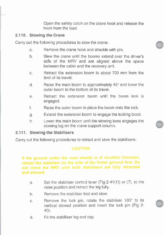
Open the safety catch on the crane hook and release the hook from the load.
2.1 10. Stowing the Crane
Carry out the following procedures to stow the crane:
a. Remove the crane hook and shackle with pin.
Slew the crane until the booms extend over the driver's side of the MRV and are aligned above the space between the cabin and the recovery unit.
Retract the extension boom to about 700 mm from the limit of its travel.
Raise the main boom to approximately 45" and lower the outer boom to the bottom of its travel.
Retract the extension boom until the boom lock is engaged.
Raise the outer boom to place the boom onto the lock.
Extend the extension boom to engage the locking block.
h. Lower the main boom until the stowing boss engages the stowing lug on the crane support column.
2.1 11. Stowing the Stabilisers
Carry out the following procedures to retract and stow the stabilisers:
Set the stabiliser control lever (Fig 2-41(1)) or (7), to the raise position and retract the leg fully.
Remove the stabiliser foot and stow.
Remove the lock pin, rotate the stabiliser 180" to its vertical stowed position and insert the lock pin (Fig 2- 40).
Fit the stabiliser leg end cap.

Repeat the steps listed in sub-paras a. to d. for the stabiliser leg on the other side of the MRV.
f. Disengage the PTO (refer to Section 1).
2.1 12. Prior to Moving Off
~ t ) w ~ m a b ~ b # l d d o m ~ ~ t h r h r p r --rwunJlrOdrMnOop#rtlanr.
a. Disengage the PTO (refer to Section I ) .
Set the hand throttle and/or the recovery equipment throttle control to the engine idle position (refer to Section 2).
Disengage the MRV work brake.
2.1 13. Operating in Darkness
If the operational situation prevents the use of light, use an assistant to call boom and slewing instructions. If there are no lighting restrictions, use the recovery floodlights.
183/(184 blank)


CHAPTER 3
OPERATOR SERVICING
SECTION 1 - PARADE SERVICING
SECTION 2 - PERIODIC SERVICING
SECTION 3 - LUBRICATION
SECTION 4 - FAULT FINDING
NOTE
For clarity and brevity the Truck, Wrecker, Medium, MC2, Unimog U2450L is referred to throughout this document as the MRV (Medium Recovery Vehicle).

SECTION 1 PARADE SERVICING
Introduction
3.1. Parade servicing must be carried out in accordance with EMEl VEHICLE A 029, EMEl VEHICLE D 399, and as detailed this Section. If servicing cannot be performed when it is due, the fact is to be reported immediately.
Lubricants and Fluids
3.2. Lubricants and fluids required for servicing the MRV are listed in Section 3, however, refer to EMEl VEHICLE D 399 for the approved list of lubricants.
Daily Servicing
3.3. General. The purpose of the Daily Servicing is to ensure the safety and reliability of the MRV for the day's running. Defects, damage and malfunctions must be reported daily by the driver on the Transport Work Ticket or on a Defective Vehicle Report.
First Parade Service
NOTE
Report all defectsldamage.
3.4. Before moving off with a laden or unladen MRV, carry out the inspections, checks and tests as laid down in this section. Inspect for damage, security and serviceability.
NOTES
1. Wheel nuts are to be checked for security using a tension wrench set at 400 Nm. If a tension wrench is unavailable, care must be taken not to overtighten the wheel nuts. 2. Signs of uneven or excessive wear, which indicates a fault in the tyre, wheel or suspension alignment, must be reported.
Check the wheels and tyres for the following:
a. Loose wheel nuts.
b. Correct tyre pressures (visual).

c. lnspect the treads and sidewalls for weak spots, uneven wear, cuts, exposed cords, or clogged tyres. Remove any material found.
d. Security and condition of the wheel split rim C-clips, safety pins and CTlS hub fittings.
e. Hub caps security.
3.6. Check the following fittings:
a. All cabin and body fittings.
b. Windscreen, driving mirrors, door windows, hinges, catches and latches for security.
c. Check light lenses, driving mirrors and windows for cleanliness.
d. lnspect the air conditioner return air filter, replacelclean as necessary.
e. Spare wheel, security and pressure.
f. Exterior equipment lockers locked.
g. lnspect the MRV for any damage, and loose or missing parts.
3.7. Check and service the recovery unit as follows:
a. Rear boom in the travelling position and locked.
b. Winch ropes security.
c . Pintle hook, coupling and security (if fitted).
d. Check for any visible damage of the recovery unit. Repair or replace any defective parts.
e. Check for any oil leakage. Tighten connections or repair any defective parts.
. Check that recovery unit control levers automatically return to neutral when released.
J. Check the oil level in the hydraulic reservoir, top up if required.
h. Lubricate the T-bar pivot pins and folding boom pivot pin.

Check the crane as follows: a. Inspect for oil leaks at hose and pipe connections and
tighten if required. b. Check load carrying parts such as hooks, hook
attachments, chains, pulleys, swivels, lines, clips, cables and other tools used for lifting are serviceable.
c. Check that control levers automatically return to neutral when released.
d. Check that the crane has suffered no other damage that could affect its safe operation.
e. Check that the stabilisers are stowed and locked. Check the stowed items as follows:
a. Completeness of equipment and correct stowage. b. For loose items in cabin or recovery unit. c. Fuel and water jerricans security.
d. Fire extinguishers (3) fully charged and correctly stowed. 3.10. Check the fuel, lubricants, cooling system and batteries as follows:
a. Fuel level, refuel if necessary.
b. Fuel jerricans, refill as necessary.
c. Engine oil level, top up if required. d. Check the disposable fuel pre-filter for contamination.
e. Check the battery electrolyte level (10 mm above the plates).
f. Rotate the viscous fan by hand to ensure that a residual drag is present.
g. Check the cleanliness and security of the battery terminals. Lubricate terminals if required.
h. Coolant level in radiator expansion tank, top up if required.
i. Windscreen washer reservoir, check water level and top up if necessary.
j. Water jerricans, refill as necessary.
k. Check for fuel, lubricant and coolant leaks. Examine major assemblies and the ground below the MRV for evidence.

Start the MRV
3.11. Start the MRV as detailed in Chapter 2, Section 1 and check the following:
a. Clutch Pedal. Check for free travel.
b. Air Pressure Check. When the engine is running smoothly, check that the air pressure warning lamp extinguishes.
. Accessories. Check the following accessories for operation:
NOTE
Switch off all lights not required.
Head-lights Horn
Indicator lights
Hazard lights Windshield wipers/washers Air conditioner
Heater
WARNING
Do not drfve thm MRV with damrgod or lncmmoctly Inn- tynr.
NOTES
1. Tyres must be inflated to the pressures detailed in Chapter 1, Section 1.
2. Tyre pressures will increase when the tyres become hot. If the tyres are checked immediately after driving, the pressures may be higher than those recommended. Under these circumstances, do not bleed off the extra pressure.
3. Periodically during the day, feel the temperature of the tyres. If any tyre is excessively hot, check thoroughly for the cause.
4. Check the spare tyre pressure daily.

d. Tyre Pressures. Check the tyre pressure readouts on the CTlS control panel gauges. Adjust tyre pressures if required. Refer to Chapter 2, Section 1.
e. Park Brake. Check release, holding ability and application.
Moving Off and Running
3.12. Check the following:
a. Load - Make a final check of the security of the casualty/trailer and lashings if applicable.
b. Moving off - Release the park brake. DO NOT move off if the park brake warning light remains illuminated.
c. Whilst Moving Slowly - Allow the MRV to move forward slowly and check that the foot brake operates. Check that the steering is free and responsive without any undue slack or sponginess.
Halt Parade Service
3.13. A Halt Parade Service must be carried out after each four hours of continuous operation. The service may be made at shorter intervals
0 during scheduled stops. Check the following:
a. The security of the casualty or trailer if attached.
b. The engine oil level.
c. The fuel level.
d. The tyres for damage/ clogged treadsloverheating.
e. Test all lights (prior to night operation).
f. Security of stowed items.
g. Fuel oil, or coolant leaks.

WARNING
Do not remove the coolant expansion tank filler cap while the engine is hot. The cooling system is pressurised and sudden release of pressure may cause boiling coolant to be ejected. If the engine has overheated and steam is escaping from the coolant expansion tank, allow the engine to cool before adding more water to the coolant expansion tank. When the engine is quite cool, the filler cap can be removed. Place a thick cloth over the cap and slowly unscrew it until a sudden drop in resistance is felt. At this point, if the engine and coolant is still hot, vapour will be heard escaping. Only when this ceases should the cap be fully removed.
h. The coolant expansion tank water level.
Last Parade Service
3.14. At the end of each day of operation the driver must:
a. Fill the fuel tank.
b. Check the coolant expansion tank water level.
NOTE
The engine oil level can be checked either hot or cold. For the most accurate reading, check the oil level at least three minutes after stopping the engine at operating temperature, and with the MRV on level ground.
c. Check the engine oil level.
d. If operating under very dusty conditions, service the air cleaner.
e. If the MRV has been subject to deep water crossings during daily exercise, the oil in the reduction hub housings, the front, intermediate and rear axles, the transmissions and the power divider should be checked for water contamination. If any traces are found, the oil should be drained and replenished with the correct type as soon as possible.

D o n o t w # I O # l j V I ~ ~ n m w m n ~ ~ @ k s n f n g - ~ ~ ~ r k w w r b r , & ~ t o U # w h n ~ m l d - .
f. Check the engine radiator, inter-cooler, transmission oil cooler, air conditioner condenser and hydraulic oil cooler cores for insects, mud, foliage, rubbish or any other material which may cause obstruction to normal air flow. Clear with a water spray or compressed air if required.
g. Check the condition of the hydraulic oil filters, replace as required.
h. Ensure that the MRV is correctly parked with the park brake engaged, the transmission in neutral and the fwdlrev selector in the fwd position.
Ensure that the MRV is left in a clean condition.
Report any servicing due.
k. Report any malfunctions andlor damage.
I. Ensure that the windows are closed and the MRV cabin and equipment bins are locked.
Opening the Bonnet and Grille for Servicing Access
NOTE
After closing the bonnet check that the bonnet latches are locked by attempting to lift the bonnet.
3.15. Access to the engine compartment is gained by unlocking the bonnet catches at the left hand and right hand sides of the hood. A climbing step is provided underneath the left hand headlight. When the bonnet has been raised, it is to be held in the open position by the bonnet support. The front grille can be removed after unlocking the catches at the left hand side and right hand side of the grille.

Operator Check Procedures
Cooling System m e
Do not remove the coolant expansion tank filter cap while the engine is hot. The ooollng system is pressurised and sudden releaso af pressure may oruse boiling coolant to be ejected. When the engine Is quite cool, the tlller cap can be removed.
Figure 3-1 Expansion Tank
3.16. Coolant Expansion Tank Coolant Level Check. Normal cooling system replenishment is via the coolant expansion tank (Fig 3-1). The tank is mounted on top of the engine rocker cover beside the engine oil filler cap. The expansion tank coolant level must be checked at the beginning of each day and at intervals during the day.
a. Fill Procedure - Cold Engine. Remove the coolant expansion tank cap and add the coolant mixture until the level reaches the FULL mark on the side of the tank. Replace the tank cap securely.
b. Fill Procedure - Warm Engine. Place a thick cloth over the cap and slowly unscrew it until a sudden drop in resistance is felt. At this point, if the engine and coolant is still hot, vapour will be heard escaping. Only when the vapour ceases to escape should the cap be fully removed. Remove the coolant expansion tank cap and add the

coolant mixture until the level reaches the FULL mark on the side of the tank. Replace the tank cap securely.
3.17. Radiator Core and Hoses. The radiator core, radiator and heater hoses should be checked daily and any leaks reported. If the water level falls at an abnormal rate between checks, the fault must be reported. Leaves, insect bodies and other debris must be removed from the radiator cores.
Figure 3-2 Engine Dipstick and Filler
Engine
3.18. Engine Oil Level Check. The engine oil level must be checked at the start and the finish of each day of operation and at the Halt Parade Service. The engine oil dipstick (Fig 3-2) is located on the right hand side of the engine. Check the engine oil level as follows:
a. Park the MRV on level ground, stop the engine and wait for at least three minutes.
b. Remove the dipstick and wipe it with a clean cloth.
c. Replace the dipstick ensuring that it is pushed fully home. Remove the dipstick and check the oil level. The oil level must be between the ADD and FULL marks on the dipstick.

NOTE
When pouring engine oil into the filler (Fig 3-2), do not spill oil on the engine. Check for evidence of engine oil leaks and report any faults.
d. The engine oil filler cap (Fig 3-2) is located rearwards of the dipstick and is fitted with a dust cap. Top-up the engine oil if necessary, do not overfill. Refer to Section 3 for the list of lubricants and fluids.
Fuel System
3.19. Fuel Tank Filler Cap. The fuel tank filler cap is on the left hand side of the MRV, in the vicinity of the intermediate wheel. The area around the fuel tank filler cap must be kept clean. Use only the correct grade of diesel fuel. Ensure that the filler cap is fitted securely after refuelling. Clean off any spilt fuel from the tank.
Figure 3-3 Fuel Lift Pump and Pre-Filter
NOTE
The prefilter (Fig 3-3) should be checked when carrying out inspection or maintenance on the fuel system.

3.20. Fuel Lift Pump and Pre-Filter. The fuel lift pump, fitted with a hand priming pump (Fig 3-3) is bolted to the side of the fuel injection pump. The lift pump and injection pump are located on the right-hand side of the engine. The lift pump pre-filter is located directly above the lift pump.
3.21. Fuel Filter and Priming Pump. The fuel filter assembly (Fig 3- 3) is located on the right-hand side of the engine above the fuel injection pump. The fuel filter assembly is bolted to a support bracket on the engine block. An additional hand operated priming pump for the fuel system is fitted next to the fuel filter. The priming pump has the same function as the priming pump fitted to the fuel lift pump.
Priming the Fuel System
3.22. The fuel system is self bleeding, however it must be primed to expel air that may have entered during routine maintenance or repairs to the fuel system that involved a break in the fuel system circuit, or if an airlock has occurred in the fuel system for any other reason. Prime the fuel system as follows:
NOTE
Ensure the fuel tank has sufficient fuel.
a. Raise and secure the bonnet.
NOTE
If access to the priming pump on the lift pump is difficult use the priming pump at the fuel filter.
b. Unscrew and release the priming pump handle on the lift Pump-
c. Pump the priming pump until the overflow valve inside the injection pump opens (at this point a rattling noise will be heard).
d. Continue pumping for a few more strokes to ensure all the air is cleared.
e. Fully depress the priming pump handle and screw it & clockwise to lock it in the depressed position.
f. Start and run the engine for a brief period checking for any leaks (report any leaks).

g. Lower and secure the bonnet.
3.23. Air Cleaner. The air cleaner (Fig 3-4) is mounted above the front right-hand wheel in the upper right-hand side engine compartment. A two piece flexible hose with a mid-mounted aluminium tube insert connects the outlet of the air cleaner to the turbocharger inlet on the left- hand side of the engine. A dust ejection valve is located on the lower front of the air cleaner housing.
Figure 3-4 Air Cleaner
3.24. The air cleaner will require cleaning or replacement when the indicator light on the dash panel illuminates. To clean or replace the air cleaner element, proceed as follows:
a. Remove the bonnet and the grille.
b. Release the clips securing the air cleaner base to the air cleaner housing and remove the base.
c. Remove the wing nut and washer securing the filter element to the head of the filter housing, then remove the element.
d. Wipe out the air cleaner housing with a clean damp cloth. Remove and clean the dust valve.
e. Clean or discard the element. If the element is to be cleaned, use compressed air to blow from inside to outside of element.

f. Install the dust ejection valve on the air cleaner housing.
g. Install the air cleaner element and secure with the wing nut and washer.
h. Install the air cleaner base, aligning the arrows and secure with the four clips.
i. Start the engine and check the air cleaner indicator light on the dash panel extinguishes, rectify as required.
j. Replace the grille and the bonnet.
Steering Hydraulic Reservoir
WARNING
Beware of the rotating codling tan khind the radiator when checking the power st~ring fluid iewi.
3.25. The steering system hydraulic fluid reservoir with filter is mounted above the front left-hand wheel in the engine compartment. The reservoir is to be filled with oil ( 0 x 4 7 Grade 10) to the prescribed 0 mark on the dipstick. The power steering fluid level is checked with the engine running.
Clutch Reservoir
3.26. The clutch reservoir is located on the firewall in the engine compartment behind the air cleaner. To check the level remove the reservoir cap and ensure that the fluid level is between the maximum and minimum levels marked on the reservoir. If required, top up with clean brake fluid (OX (Aust) 8).

Brake System
3.27. Brake Master Cylinders. Dual hydraulic brake system master cylinders are mounted on the MRV chassis immediately forward of the left hand intermediate wheel. Check the fluid in the brake reservoirs against the maximum and minimum levels marked on each of the reservoirs. To remove the reservoir cap, unscrew the small cap securing the wiring harness, lift the harness plug from the terminals then remove the reservoir cap. Top up with clean brake fluid (OX (Aust) 8) (Fig 3-5).
Brake Master Cylinder - Brake Actuatina
Figure 3-5 Brake Master Cylinders Wheels
3.28. The spare wheel is mounted on top of the main boom, at the rear of the MRV. The spare tyre pressure is to be checked daily.
Accessories
3.29. The windscreen washer reservoir is located at the front right- hand side of the engine compartment.
3.30. Drive Belts (Fig 3-6). The alternator, coolant pump, cooling fan, air compressor, air conditioner compressor and power steering pump drive belt tensions must be checked monthly or when indications in the electrical, cooling, braking or steering systems suggest that they may be incorrect. Check the tension of new drive belts after the first hour of operation and adjust if necessary. Medium thumb pressure exerted in the middle of the longest run of the belt should give a deflection of about

5 mm to 10 mm (Fig 3-7) depending upon belt length. If the belt is incorrectly tensioned, the fault must be rectified.
1 2 3
1. Air conditioner drive belt 4. Alternator drive belt 2. Intermediate drive belt 5. Steering pump drive belt 3. Cooling fan drive belt 6. Air compressor drive belt
Figure 3-6 Drive Belts
Figure 3-7 Drive Belt Adjustment
Main Transmission
3.31. Driver maintenance of the transmission is restricted to checking for leaks at drive shaft and shift seals. Any faults must be reported.

Splitter Box
3.32. Driver maintenance of the splitter box is restricted to checking for leaks at the drive shaft.
Drive Lines and Axles
3.33. The drive shafts and front, intermediate and rear axles require no maintenance by the driver. Vibration, noise, oil leaks or other faults in the drivelines and axles must be reported.
Compressed Air Tanks
3.34. Operate the drain valves on all air tanks and check if water condensation flows out. If water condensation is expelled the dehumidifier element must be replaced.
201 /(202 blank)


SECTION 2 PERIODIC SERVICING
Introduction
3.35. Periodic servicing must be carried out in accordance with EMEl Vehicle A 029, EMEl Vehicle D 399, and as detailed in this section. If servicing cannot be performed when it is due, the fact is to be reported immediately.
3.36. This section lists all the periodic maintenance procedures that must be performed on the MRV, and specifies the frequency at which they are to be carried out.
Lubricants and Fluids
3.37. Lubricants and fluids required for sewicing the MRV are listed in Section 3, however, refer to EMEl Vehicle D 399 for the approved list of lubricants.
Periodic Servicing - CabIChassis
Introduction
3.38. The driverfoperator is responsible for carrying out the daily, weekly, fortnightly and monthly servicing tasks on the cablchassis of the MRV: All other servicing tasks are to be carried out by a vehicle mechanic (or where applicable an accredited refrigeration mechanic), unless otherwise specified. The driverloperator is to check the periodic and distance servicing lists and to report each servicing as it becomes due.
3.39. Cawchassis servicing is to be carried out at the following intervals:
a. Daily Tasks. Daily tasks are listed in Table 3-1.
b. Weekly Tasks - Air Conditioning System. The servicing tasks that are to be carried out weekly are listed in Table 3- 2.
c. Fortnightly Tasks. The servicing tasks that are to be carried out fortnightly are listed in Table 3-3.
d. Monthly Tasks. The servicing tasks that are to be carried out monthly are listed in Table 3-4.

e. Minor Service -. A minor service is to be carried out every 12 months or 10,000 km of operation after a major service, whichever occurs first. Refer to EMEl Vehicle D 399.
f. Major Service. A major service is to be carried out every 24 months or 20,000 km of operation after the last minor 0 service, whichever occurs first. Refer to EMEl Vehicle D 399.
g. Alternate Major Service. An alternate major service is to be carried out every 48 months or 40,000 km of operation after the last major service. Refer to EMEl Vehicle D 399.
Special Requirements
3.40. During the early life of a vehicle the working parts settle down, with the result that various clearances and adjustments need to be corrected. Operators should report problems for rectification at the earliest opportunity.
3.41. The Initial Service for the cablchassis is to be performed by an authorised Mercedes Benz AgencyIDealer. The service will include all servicing and repair rectification action required, and will be accompanied by an Inspection Report to be handed to the Owner Unit.
3.42. The MRV is to be inspected by a qualified tradesperson prior to the expiry date of the warranty.

Table 3-1 Daily Tasks - CabJChassis
The following operations are to be carried out by the driverloperator:
1. Check the fuel supply (refuel if necessary).
2. Check the engine oil level (top up if required).
3. Check the fuel filter pre-filter for contamination (replace if necessary).
4. Check the coolant level in radiator expansion tank (top up if required).
5. Check the operation of the windshield wipers/washers, and the washer reservoir water level (top up if necessary).
6. Check the viscous clutch on the cooling fan by rotating it to ensure residual drag is present.
7. Check the operation of all gauges and warning lights, report any defects.
8. Check tyres and wheels. Inflate tyres if necessary. Inspect wheel nuts, CTlS hub fittings, hub caps, split rim C-clips and safety pins for security and condition.
9. Check the operation of the steering.
10. Check the operation of the footbrake, parking brake and clutch.
11. Check the operation of all lights and report any defects.
12. Check the operation of the horn.
13. Check for fuel, lubricant and coolant contamination if the vehicle has been subject to deep water crossings during daily operation.
14. Check the fluid level in the clutch and both brake master cylinder reservoirs (top-up if required).
15. Check the engine radiator, transmission oil cooler and inter-cooler cores for any material that may cause obstruction to normal air flow (clean if required).
16. Check the cab fire extinguisher is fully charged and correctly stowed.
17. Check all cabin and body fittings, seats and seat belts, windscreen, driving mirrors, door windows, hinges, catches and latches and stowed items for operation and security.

18. Check light lenses, driving mirrors and windows for cleanliness.
19. Check the operation of the air conditioner and heater; inspect the return air filter (replace/clean as necessary).
20. Inspect the vehicle for any damage, fuel, lubricant and coolant leaks and loose or missing parts.
21. Report any malfunctions and/or damage and any servicing due.
22. Ensure that the vehicle is left in a clean condition, correctly parked with the park brake engaged, the transmission in neutral and the fwdlrev selector in the fwd position.
Table 3-2 Weekly Task - Air Conditioning System
The following operation is to be carried out weekly by the driverloperator:
1. Run the air conditioning system for a minimum period of five (5) minutes.
Table 3-3 Fortnightly Tasks - CablChassis
The following operations are to be carried out by the driverloperator:
1. The fortnightly servicing includes all of the operations listed in the daily and weekly tasks (refer to Tables 3-1 and 3-2) and the following operations:
2. Check the electrolyte level in both batteries, top-up if necessary. Examine the battery terminals for cleanliness, security, and that they are lubricated. Check for leaks and security, clean outside of batteries if required.

Table 3-4 Monthly Tasks - CablChassis
The following operations are to be carried out by the driverloperator:
1. The monthly servicing tasks include all of the operations listed in daily, weekly and fortnightly tasks (refer to Tables 3-1, 3-2 and 3-3) and the following operations.
2. Check the engine air filter, clean according to the indicator: replace the filter after five cleanings: replace the filter if it has any holes in it.
3. Check the cooling fan viscous coupling control spring. Clean if required.
4. Check the compressed air system for correct function and leaks. Open the drain valves on air tanks. If condensation discharges at the drain valves replace the dehumidifier element.
5. Check the front suspension and steering linkage for damage or wear.
6. Check the condition of the front winch rope guide tube and report any defects.
7. Inspect the externally mounted fire extinguisher mounts for security. Tighten if required.
8. Lubricate the front rope window guide rollers.
9. Lubricate the rear recovery platform to chassis mounting pin.
10. Check the operation of all lights and report any defects.
11. Check the condition of the tyres; retorque the wheel nuts.

Periodic Servicing - Recovery Unit
Introduction
3.43. The driverloperator is responsible for
a. Carrying out the daily, and monthly servicing and tasks in the minor and major services to the recovery unit as indicated.
b. Carrying out the daily and monthly inspections on the recovery unit.
c. Checking the periodic servicing list for the recovery unit and reporting each service as it becomes due.
3.44. Recovery unit servicing is to be carried out at the following intervals:
a. Daily Tasks. Daily tasks are listed in Table 3-5 and are carried out to ensure the recovery unit is fit for operation.
b. Monthly Tasks. Tasks to be performed monthly are listed in Table 3-6 and are carried out to ensure the recovery unit is in a serviceable condition.
c. Minor Service. A minor service is to be carried out every 12 months or 10,000 km of vehicle operation after the last major service, whichever occurs first. Refer to EMEl Vehicle
C D 399.
d. Major Service. A major service is to be carried out every 24 months or 20,000 km of vehicle operation after last major service, whichever occurs first. Refer to EMEl Vehicle D 399.
e. Alternate Major Service. An alternate major service is to be carried out every 48 months or 40,000 km of operation after the last major service. Refer to EMEl Vehicle D 399.
Special Requirements
3.45. During the early life of the recovery unit the working parts settle down, with the result that various clearances and adjustments need to be corrected. Operators should report problems for rectification at the earliest opportunity.

Table 3-5 Daily Tasks - Recovery Unit
The following operations are to be carried out daily by the driverloperator:
1. Check for any visible damage of towing unit and lifting equipment. Repair or replace any defective parts.
2. Check for oil leaks. Tighten connections and repair any defective parts.
3. Check the oil level in the hydraulic tank (top up if required).
4. Lubricate the folding boom pivot pin (2 nipples), the T-bar pivot pin (1 nipple) and the T-bar yoke (1 nipple).
5. Lubricate the main boom lock pins and the extension boom lock pin (3 nipples).
6. Lubricate the rear sheaves and fairleads (4 nipples).
7. Check the condition and security of the fire extinguishers stowed at the front of the recovery platform (2).
Table 3-6 Monthly Tasks - Recovery Unit
The following operations are to performed by the driverloperator:
1. Carry out daily servicing tasks. Refer to Table 3-5.
2. Lubricate all fittings as per the lubrication guide. Refer to Section 3.
3. Check for loose bolts, pipes or hose clamps, etc. Tighten if required.
4. Cleanlinspect the main boom cylinder rod wipers.
5. Cleanllubricate the quadrant slides and locking pin mounting holes. 6. Cleanloil the upper ball joint on the winch flat rating device. 7. lnspect the rope guide wear inserts, replace if required.
8. Remove and inspect the T-bar yoke for cracks and excessive wear.
9. Clean/lubricate the directional control valve cable clevis pins.
10. Clean/inspect the towbar mounting clamps, screws, and towbar stop blocks.
11. Pull out the winch ropes. lnspect for broken wires, kinks and other damage. Clean off any rust or mud and lubricate the ropes. Rewind each winch rope. Refer to Chapter 2, Section 2
12. CleanJinspect front, second, main and rear subframe structure mountings to cablchassis
13. Clean/lubricate cabinet door locks and hinges.

Periodic Servicing - Crane
Introduction
3.46. The drivedoperator is responsible for carrying out the daily, weekly, monthly servicing and tasks in the minor and major services as indicated. All other tasks are to be carried out by a qualified mechanic. The driverloperator is to check the periodic servicing list and report each servicing as it becomes due. Crane servicing is to be carried out at the following intervals:
a. Daily Tasks. Daily tasks are listed in Table 3-7 and are carried out to ensure the crane is fit for operation.
b. Weekly Tasks. Tasks that are to be performed weekly are listed in Table 3-8 and are carried out to ensure the crane is in a serviceable condition.
c. Monthly Tasks. Tasks that are to be performed monthly are listed in Table 3-9 and are carried out to ensure the crane is in a serviceable condition.
d. Minor Service. A minor service is to be carried out every 12 months of vehicle operation. Refer to EMEl Vehicle D 399. 0
e. Major Service. A major service is to be carried out every 24 months of vehicle operation. Refer to EMEl Vehicle D 399.
f. Alternate Major Service. An alternate major service is to be carried out every 48 months or 40,000 km of operation after the last major service. Refer to EMEl Vehicle D 399.
Special Requirements
3.47. During the early life of the crane the working parts settle down, with the result that various clearances and adjustments need to be corrected. Operators should report problems for rectification at the earliest opportunity.

Table 3-7 Daily Tasks - Crane
The following operations are to be carried out daily by the driverloperator:
1. Check the hydraulic oil level (top up if required).
2. Inspect for oil leaks at hose and pipe connections and tighten if required.
3. Check load carrying parts such as hooks, hook attachments, chains, pulleys, swivels, lines, clips, cables, and other tools used for lifting are in a serviceable condition.
4. Check that the crane controls automatically go back to neutral when released.
5. Check that the crane has suffered no other damage which could affect its safe operation.
Table 3-8 Weekly Tasks - Crane
The following operations are to be carried out weekly by the driverloperator:
1. Lubricate the stabiliser ram leg end.
2. Check for hydraulic leaks and report if any.
3. Check the hydraulic oil level, top up if required.
4. Lubricate the control levers.

Table 3-9 Monthly Tasks - Crane
The following operations are to be carried out monthly by the driver/operator:
1. Lubricate the stabiliser ram leg end.
2. Lubricate the support column.
3. Lubricate the slewing rack.
4. Lubricate the main boom pivot.
5. Lubricate the main and outer boom cylinder and link pivots.
6. Lubricate the outer boom pivot.
7. Lubricate the boom extension cylinder guide parts.
8. Lubricate the boom extension guide blocks.
9. Inspect and lubricate the cargo hook and shackle.
10. Lubricate the control levers.
11. Check the hydraulic oil reservoir level (top up if required).
12. Check pipelines and hoses for chafing, leaks and security of connections.
13. Operate the crane and inspect for leaks, correct operation, and serviceability of hoses.

SECTION 3 LUBRICATION
Introduction
3.50. This section details the lubricants and fluids required for servicing and illustrates the locati6n of various lubrication and oil drainagehefill points around the MRV.
3.51. Parade and periodic servicing must be carried out in accordance with EMEI Vehicle A 029, EMEI Vehicle D 399, and as detailed in Sections 1 and 2 of this Chapter. If servicing cannot be performed when it is due, the fact is to reported immediately.
Lubricants and Fluids
3.52. Lubricants and fluids required for servicing the recovery vehicle are listed in Table 3-10 however, refer to EMEI Vehicle D 399 for the approved list of lubricants.

Table 3-10 List of Lubricants and Fluids

Service and Lubrication Points - CabIChassis (Fig 3-8) 3.53. The servicing points pertaining to the cablchassis are as follows:
a. Coolant expansion tank; b. Coolant pumplalternator drive belt; c. Fan drive belt;
d. Steering pump drive belt; e. Air compressor drive belt; f. Engine oil filler cap;
g. Batteries; h. Steering system reservoir; i. Air cleaner;
j. Main transmission level and filler plug;
k. Power take-off; I. Splitter box level and drain plugs; m. Brake master cylinders;
n. Steering linkage lubrication points; o. Inter-axle differential (power divider) drain and filler plugs;
p. lntermediate and rear differential level and drain plugs;
q. lntermediate and rear wheel hub drive level and drain plugs; r. Front differential level and drain plugs; s. Front wheel hub drive level and filler plugs; t. Inter-axle to rear differential drive shaft universal joints; u. Windscreen washer reservoir; v. Engine dipstick; w. Engine oil filter; x. Fuel fitter and pre-fitter; y. Engine throttle linkage lubrication; z. Compressed air reservoirs; aa. Dehumidifier element; ab. Engine brake linkage lubrication; and ac. Fire extinguishers.
Engine oil filler cap
Fuel pre-filter Fuel filter Air cleaner Engine oil drain Engine oil filter Windscreen washer reservoir
Steering knuckle bearing Wheel hub drive Clutch reservoir Splitter box
12. Fire extinguisher 13. Battery box 14. Main transmission group drain plugs (3)
15. Power take-off 16. Main transmission group filler plug 17. Dehumidifier cartridge 18. Compressed air tanks 19. Power divider 20. Inter-axle differential housing 21. CTlS air tanks 22. Rear axle differential housing 23. Rear propeller shaft grease nipple 24. Brake reservoirs 25. Fuel tank and cap
26. Engine throttle control linkage 27. Front axle differential housing 28. Power steering box 29. Power steering system reservoir 30. Coolant expansion tank 31. Front winch rollers and guide
Figure 3-8 Service and Lubrication Points - Cab/Chassis
21 5/(216 blank)

3.54. Engine Oil Level Check. The engine oil level must be checked at the start and the finish of each day of operation and at the Halt Parade Service. The engine oil dipstick (Fig 3-9) is located on the right hand side of the engine. Check the engine oil level as follows:
a. Park the vehicle on level ground, stop the engine and wait for at least three minutes.
b. Remove the dipstick and wipe it with a clean cloth.
c. Replace the dipstick ensuring that it is pushed fully home. Remove the dipstick and check the oil level. The oil level must be between the ADD and FULL marks on the dipstick.
NOTE
When pouring engine oil into the filler (Fig 3-9), do not spill oil on the engine.
d. The engine oil filler cap (Fig 3-9) is located rearwards of the dipstick. Top-up the engine oil if necessary; do not overfill. Refer to Table 3-1 for approved lubricants.
Figure 3-9 Engine Dipstick and Filler

Engine Oil and Filter Change Procedure
NOTE
The engine oil filter (Fig 3-10) is located at the lower right hand side of the engine.
3.55. Run the engine until the engine coolant reaches normal operating temperature then shut down the engine. Remove the sump plug and drain all the engine oil. Discard the oil and the sealing washer from the sump plug. Clean off any dirt and metal particles adhering to the sump plug. Fit a new sealing washer on the drain plug and install the drain plug. Torque the drain plug to 80-90 Nm.
3.56. Remove the oil filter bowl drain plug and drain all oil from the assembly into a suitable container. Discard the drain plug sealing washer and the oil. Remove the retaining bott securing the oil filter bowl to the filter head. Discard the sealing washer on the bolt and remove the oil filter bowl and the filter element from the filter head. Discard the filter element.
3.57. Remove and discard the O-ring from the groove in the filter head. Clean and inspect the oil filter head and the oil filter bowl for cracks. Replace the filter bowl if it is damaged. ?
b NOTE
Ensure that the oil filter bowl O-ring is not twisted in the filter head groove.
3.58. Lightly lubricate the new O-ring with clean engine oil and fit the O-ring into the groove in the oil filter head. Insert a new filter element into the oil filter bowl and position the filter bowl against the O-ring in the filter head. Fit a new sealing washer to the filter bowl retaining bolt. Install the bolt and torque the retaining bolt to 40 - 45 Nm.
3.59. Fit the filter bowl drain plug with a new sealing washer and install the plug. Torque the drain plug to 17 Nm.
3.60. Fill the engine with the correct quantity of the recommended lubricant. Do not overfill. Check the level on the dipstick, then run the engine at low idle speed for a brief period to allow the engine oil pressure to build up to operating pressure and check for oil leaks around the filter head area. Stop 'b the engine and check the oil level on the dipstick, top-up if required.

Figure 3-10 Engine Oil Filter
Transmissions
3.61. Splitter Transmission. The splitter transmission oil fillerllevel plug is located at the upper left of the rear of the splitter box transmission housing and the drain plug on the bottom of the housing (Fig 3-11). The splitter transmission is vented via the common ventilation filter. Fill the splitter transmission with the recommended lubricant to the bottom of the filler/level hole. Tighten the filler plug securely.
L ~ r a i n Plug
Figure 3-1 1 Splitter Transmission FillerILevel and Drain Plug
3.62. Main Transmission Group. A common oil filler/level plug (for the main transmission, transfer case and working gear group) is located at the upper centre of the rear of the housing (Fig 3-12). The transmission is

vented via the common ventilation filter. Fill the transmission with the recommended lubricant to the bottom of the fillerllevel hole. Tighten the filler plug securely.
Figure 3-1 2 Transmission FillerILevel Plug
3.63. The main transmission group has three oil drain plugs, all of which must be removed to completely drain the oil. The drain plug for the main transmission is located on the bottom right hand side of the transmission housing. The transfer case drain plug is located on the front lower side of the transfer case housing right hand. The drain plug for the working gear group is located on the lower right hand side of the working gear group housing (Fig 3-1 3).
DrainPiug--/
Figure 3-13 Transmission Group Drain Plugs

Clutch Reservoir
3.64. The clutch reservoir is located on the firewall in the engine compartment behind the air cleaner. To check the level remove the reservoir cap and ensure that the fluid level is up to the level marked on the reservoir. If required, top up with clean brake fluid (OX(Aust) 8).
Power Divider and Axles
3.65. Power Divider. The power divider oil fillerllevel plug is located half- way up the left-hand side of the power divider whilst the drain plug is located on the bottom of the housing (Fig 3-14). The power divider is vented via the common ventilation filter. Fill the power divider with the recommended lubricant to the bottom of the fill hole. Tighten the IeveVfiller plug securely.
3.66. Intermediate Axle. The intermediate axle oil filler/level plug is located adjacent to the torque tubeldrive shaft mounting and the drain plug is on the bottom of the differential housing (Fig 3-14). The intermediate axle is vented via the common ventilation filter. Fill the intermediate axle with the recommended lubricant to the bottom of the fill hole. Tighten the filler plug securely.
Figure 3-14 Power Divider and lntermediate Axle Oil FillerILevel and Drain Plugs

3.67. Rear Axle. The rear axle oil fillerllevel plug is located adjacent to the right hand axle housing and the drain plug on the bottom of the differential housing. (Fig 3-15). The rear axle is vented via the common ventilation filter. Fill the rear axle with the recommended lubricant to the bottom of the fill hole. Tighten the filler plug securely.
1
Plug
Figure 3-1 5 Rear Axle Housing Oil FillerILevel and Drain Plug
3.68. Front Axle. The front axle oil fillerllevel plug is located adjacent to the torque tubeldrive shaft mounting and the drain plug is on the bottom of the differential housing (Fig 3-16). The front axle is vented via the common ventilation filter. Fill the front axle with the recommended lubricant to the bottom of the fill hole. Tighten the filler plug securely.
Figure 3-1 6 Front Axle Housing Oil FillerILevel and Drain Plug

3.69. Propeller Shafts. The propeller shaft connecting the rear axle to the interaxle drive is fitted with grease nipples at both universal joints.
3.70. Reduction Hub Drives. The wheel reduction hub drive housing oil filler/level plugs, are located just below the axle entry points (Figs 3-17 and 3-18). Fill the reduction hub drives with the recommended lubricant to the bottom of the fill hole. Tighten the filler plug securely.
Figure 3-17 Rear Axle Reduction Hub Drain and FillerILevel Plugs
. .
I vel
Drain Plug / Figure 3-1 8 Front Axle Reduction Hub Drain and Filler/Level Plugs

Steering System 3.71. Steering Hydraulic Reservoir. The steering system hydraulic fluid reservoir with filter is mounted above the front left-hand wheel in the engine compartment. Ensure the reservoir lid and vent hose plug are clean before removing. The oil level is checked by removing the vent hose plug which has a dipstick attached. The reservoir is filled by unscrewing the lid and
C adding oil (OX-47 Grade 10) to the prescribed mark on the dipstick (Fig 3- 19). The reservoir is vented via the common ventilation filter.
Figure 3-1 9 Steering Hydraulic Reservoir Brake System 3.72. Brake Master Cylinders. Dual hydraulic brake master cylinders (Fig 3-20) are mounted on the vehicle chassis immediately forward of the left hand intermediate wheel. Check the fluid in the brake reservoirs against the level marked on each reservoir. Top up with clean brake fluid (OX (Aust) 8) if required. To remove the reservoir cap first unscrew the smaller cap securing the wiring harness, disconnect the harness then remove the cap.
Figure 3-20 Brake ~ & e r ~ i l inders

Service and Lubrication Points - Recovery Unit (Fig 3-21)
3.73. The service and lubrication points pertaining to the recovery unit are as follows: 4'- t,
a. Hydraulic system;
b. Hydraulic tank filter;
c. Pipes and hoses;
d. Winch system oil filters;
e. Winch ropes;
f. Winch flat rating device and pressure rollers;
g. Main boom lifting cylinder upper and lower pins;
h. Main boom crosshead support pins;
i. Main boom and main boom side stay pivots;
j. Folding boom linkage, hinge pins and lock;
k. Extension boom cylinder pins and lock;
I. T-bar yoke and bearing;
m. Earth anchor legs: upper and lower pins;
n. Rope sheaves and deflector roller - front winching;
o. Recovery plalform mounts; and
p. Cabinet door locks and hinges. Rope sheaves - front winching Hydraulic tank filter Flat rating device Winch pressure rollers Winch ropes Spare wheel locking screw Main boom cylinder uppertlower pins Rope fairleads and sheaves
23 22 9. Earth anchor legs upperllower pins
10. Extension boom lock 11. Main boom locking pins 12. Folding boom linkage 13. Quadrant slide and locking pin holes
14. T-bar pivot pin 15. Extension boom yoke bearing 16. Extension boom cylinder pins
21 20 7 20 19 17. Extension boom lock 18. Towing pintle
19. Rear sub-frame mount 20. Directional control valve and control lever clevis pins 21. Deflector roller - front winching
22. Winch system oil filters 23. Main boom and main boom side stay pivots
Figure 3-21 - Service and Lubrication Points - Recovery Unit
225/(226 blank)

Service and Lubrication Points - Crane (Fig 3-22)
3.74. The service and lubrication points pertaining to the crane are as follows:
f $ a. Crane hydraulic oil filter,
b. Control levers,
c. Crane base,
d. Support column and bearing,
e. Extension boom guide blocks,
f. Boom extension cylinder guide parts,
g. Cargo hook and shackle,
h. Stabiliser cylinders,
i. Slewing rack and cylinder mountings,
j. Main boom pivot, cylinder and link pivots,
k. Outer boom pivot, cylinder and link pivots,
I. Extension boom pivot,
m. Stabiliser leg pivots and leg ends, and
n. Hydraulic hoses and connections.
1. Crane hook and shackle 6. Outer boom pivot (1 nipple) 1 1. Slew gearbox central lube station (3 nipples)
2. Crane control levers 7. Outer boom cylinder pivot and link pivot (3 nipples) 12. Extension boom guide blocks 3. Stabiliser leg extension 8. Crane slew cylinder 13. Extension boom hook pivot (1 nipple) 4. Main boomlouter boom cylinder pivots (3 nipples) 9. Oil filter 14. Main boom cylinder pivot (1 nipple) 5. Stabiliser leg pivot (1 nipple per side) 10. Crane base mounting bolts (3) 15. Main boom pivot (1 nipple)
Figure 3-22 - Service and Lubrication Points - Crane
227/(228 blank)

SECTION 4 FAULT FINDING
Introduction
3.75. When a fault occurs commence checking known failure modes or components that from operator experience point to the area at fault. Check the easy to get at items first (e.g. without raising the cab). After that, proceed to the more complex items. This method may save a considerable amount of time in the long term.
3.76. Before consulting the fault finding tables check the following items:
a. Batteries fully charged.
b. All electrical connections clean and tight.
c. Starter motor in good condition.
d. Correct fuel in the tank and the system primed.
e. Lubricating oil at the correct level and not contaminated.
f. No restrictions in the air intake system, and the air cleaner element not clogged.
g. Engine coolant at correct level, water pump operating, belts correctly adjusted and radiator cores clean.
h. All fuel line connections tight and not leaking.
i. All gauges, indicating and warning lights operating. Fault Finding Tables
3.77. The fault finding tables indicate some of the probable causes for the symptoms shown. The causes listed are common and as such, should be examined prior to major overhaul work. The following areas are covered in the fault finding tables.
a. Engine (Refer to Table 3-1 1).
b. Drive lines (Refer to Table 3-12).
c. Steering, brakes and suspension (Refer to Table 3-13).
d. Electrical (Refer to Table 3-14).
e. Air conditioning (Refer to Table 3-1 5).
f. Recovery unit hydraulics (Refer to Table 3-16).
g. Crane (Refer to Table 3-17).
229//230 blank)


Table 3-1 1 - Engine Faults and Probable Causes
CODE AMPLIFICATION LIST - ENGINE PROBABLE CAUSES FUEL SYSTEM LUBRICATION SYSTEM
1 a. Fuel shut-off valve closed, or partly closed. 12. Restriction in oil galleries or faulty gauge
1 b. Air intake system blocked, or partly blocked. 13. Pressure relief valve stuck or faulty
1c. Fuel tank vent blocked, or partly blocked. TURBOCHARGER
Id. Injector pump stop lever sticking. 14a. Turbocharger passing oil.
2. Fuel pump inoperative or leaking. 14b Restriction or blockage in air intake line
3a. Air leaks or restriction on suction side. 14c Low turbocharger r.p.m.
3b. Fuel filters clogged. 14d Binding turbocharger impeller
4. Injection pump relief valve leaking, stuck open or closed. 14e Intercooler or intercooler hoses leaking.
5a. Injection pump relief valve leaking, stuck open or closed. 15a Incorrect valve clearance camshaft or lifters worn
5b. Injection pump shaft bearings worn. 1% Broken or weak valve springs
5c. Injection pump drive assembly loose, timing incorrect. 15c Worn or binding valve guides
6a. Incorrect setting of governor or high speed stop. 15d Valves sticking or burnt, poor seat contact
6b. Incorrect setting of governor idle speed. 16a. Leaking cylinder head gasket.
7. Fuel return line blocked or partly blocked. 16b. Leaking gaskets and seals.
8. Delivery valve stuck or leaking. 17a. Piston rings sticking or worn.
9a. Faulty nozzle spray, leaking or opening pressure setting incorrect. l7b. Piston rings broken or incorrectly fitted.
9b. Nozzle cap nut improperly torqued. 18. Poor compression (see low compression).
9c. Nozzle valve(s) stuck. 19. Blocked crankcase breather or pipe.
9d. Bent or broken spindle or spring. 20. Blow-by.
90. Nozzle incorrectly installed in cylinder head. 21. Scuffed pistons or cylinders bores.
10a. Injection pump pistons stuck. 22. Excessive clearance in main or connecting rod bearings.
10b lnjection pump rack stuck 23. Coolant leak into combustion chamber, cracked head gasket.
10c. Injection pump pistons worn. 24. Alternator not charging.
1 la. Governor throttle shaft linkage binding, or sticking governor parts. 25. No air pressure.
11 b Incorrect setting of governor throttle linkage. 26. Radiator blocked.
1 l c Governor drive assembly binding 27. Viscous fan faulty.
1 1 d Broken or weak timing springs 28. Thermostats faulty.
29. Coolant pump belt broken or loose.
30. Coolant pump faulty.
31. Coolant level low.
32. Faulty relay.
231 l(232 blank)

Table 3-12 - Drive Line Faults and Probable Causes
CODE AMPLIFICATION - DRIVE LINE PROBABLE CAUSES CLUTCH 2j. Damaged transfer case gears. 1 a. Sticking actuating mechanism. 2k. Loose bolts on gear lever. 1 b. Worn or damaged clutch plate. 21. Gearstick damper faulty. lc. Worn or damaged throw-out bearing. 3a. Loose housing covers or attachments. Id. Clutch housing not firmly bolted to engine. 3b. Worn or damaged shaft seals and gaskets. 1 e. Warped or damaged pressure plate. 3c. Blocked or partly blocked breather line. If. Torsional vibration being transmitted by clutch. PROPELLER SHAFTS lg. Bell housing filled with oil. 4a. Damaged universal joints. 1 h Clutch hydraulics faulty. 4b. Worn or damaged torque ball assembly. MAIN TRANSMlSSlON 4c. Unbalanced propeller shaft. 2a. lncorrect shift adjustment. 4d. Worn or damaged splines. 2b. Incorrect oil level. 4e. Power divider broken. 2c. Incorrect oil in transmission. 4f. Half shaft broken. 2d. Sticking shift fingers. AXLE ASSEMBLIES 2e. Weak or broken detent springs. 5a. Parking brakes not releasing. 2f. Bent or broken shift forks. 5b. Damaged differential gears. 29. Broken snap rings on gear shafts. 5c. Damaged hub drive gears. 2h. Worn or damaged bearings. 5d. Differential lock control malfunction. 2i. Sticking shift valve 5e. Diff lock gears broken.
Table 3-13 - Steering, Brake and Suspension Faults and Probable Causes
233/(234 blank)

Table 3-14 - Electrical Faults and Probable Causes
CODE AMPLIFICATION - ELECTRICAL PROBABLE CAUSES 1 a. Faulty alternator belt drive. 1 j. Battery discharged. 1 b. Faulty alternator. 1 k. Poor bulb contact. lc. Faulty rectifier. 11. Incorrect bulb rating. 1 d. Faulty regulator. 1 m. intermittent short or broken wire. le. Incorrect battery electrolyte level. In. Ignition switch left in ON position. 1 f. Faulty battery. lo. Too many devices on at once. 1 g. Loose battery connections. lp. Short circuit in wiring. lh. Faulty ignition switch. lq. Faulty starter motor-short circuit. 1 i. Tripped circuit breaker/s.
SYMPTOMS I PROBABLE CAUSES CODES Check probable causes codes listed below against the probable causes listed in code amplification Ilst.
Table 3-15 - Air Conditioning System Faults and Probable Causes
Battery not charging No power available Poor or flickering lights Rapid battery discharge
- ~
CODE AMPLIFICATION - AIR CONDITIONING SYSTEM PROBABLE I
la, lb, lc, Id, le, l f le, If, lg, li, l j lg , lk, 11, lm, I n I f , lo, lp, l q
CAUSES la. System low on refrigerant. 3f. Compressor shaft leak.
1 j. TX valve jammed shut. 4d. Defective thermostat. 2a. Electrical fault. 4e. Faulty TX valve sensing bulb. 2b. Complete loss of charge. LP switch 4f. lncorrect TX valve superheat adjustment.
trinnnd. 2c. Compressor clutch coil burnt out. 4p. Thermostat adjusted too low. 2d. Thermostat inactive due to tripped 4h. Defective coil windina. l m ~ r o ~ e r coil connection. . . - . .
I circuit breaker. I 2e. Loose or broken drive belt. 5a. Worn bearings or motor brushes. 2f. Receiverldrier is saturated with 5b. Loose or worn drive belts.
3a. Faulty condenser fan. 5c. Loose or worn compressor. 3b. Sluggish or faulty evaporator fan 5d. Loose panels. Hoses or oioes vibratina. Loose . .
motb;. components inside unit. -
3c. Blocked return air filter. 5e. Damaged or loose fan blades or fan cowling. 3d. Air or moisture in system. 5f. Low compressor oil. 313. Heating system not correctly shut off. 59. HP service valve closed.
235/(236 blank)

Table 3-16 - Recovery Unit Hydraulics Faults and Probable Causes
Table 3-17 - Crane System Faults and Probable Causes
CODE AMPLIFICATION - CRANE FAULTS PROBABLE CAUSES la. Pumpworn. 1 b. Pump damaged. 1 c. Pump drive faulty. Id. Pump running too fast. 2a. Suction line ball valve not fully open. 2b. Hydraulic oil level low. 2c. Air in hydraulic system. 2d. Tank fillerlbreather faulty. 2e. Incorrect oil viscosity. 3a. Hydraulic connection leaking. 3b. Gauge hydraulic line fractured. 4a. Main relief valve faulty.
237/(238 blank)
4b. Counterbalance valve unserviceable 4c. Counterbalance valve incorrectly set. 4d. Sequence valve incorrectly set 46. Winch torque control requires calibration 4f. Hydraulic throttle valve incorrectly set or blocked. 5a. Cylinder seals worn or damaged. 5b. Winch motors faulty.
5c. Directional control valve or control cables faulty. 5d. Hydraulic lines incorrectly connected. 6a. Electrical fault. 7a. Hydraulic oil unserviceable. &. Mechanical fault.
CODE AMPLIFICATION - CRANE FAULTS PROBABLE CAUSES 1. Pump worn or damaged. 2. External dl leaks. 3. Flow control set too high. 4. Air in dl system. 5. Contaminaid oii. 6. No oil pressure. 7. Low dl pressure.
8. Oil viscosity too high.
9. Oil viscosity too low. 10. Lack of lubrication. 11. Oil pump running too fast. 12. Oil overheated. 13. Oil pressure too high. 14. Excessive load. 15. Flow contrd valve faulty or Incorrectly adjusted.

CHAPTER 4
WARRANTY
SECTION 1 - WARRANTY AND REPAIR

SECTION 1 WARRANTY AND REPAIR
Warranty Provisions
4.1. DaimlerChrysler AustraliaIPacific Pty. Ltd. (The Contractor) 0 warrants that all precautions, which are usual and reasonable, have been taken to ensure the quality of materials and workmanship in the U2450L Unimog.
4.2. Should any defect or fault develop within 48 months or 40000km. whichever occurs first, after acceptance of supplies by the Commonwealth and upon examination by the Contractor or one of their authorised distributors or dealers, such defect or fault be found to be due to defective material or workmanship, the contractor undertakes to repair or exchange or to have repaired or exchanged such defective or fautty part or parts free of charge. This warranty is given on condition that the vehicle is operated and maintained in accordance with the user handbook and relevant EMEI.
4.3. The foregoing warranty does not cover normal wear and tear resulting from regular usage nor does it cover defects or faults arising out of misuse, or neglect; and shall not apply to vehicles that have been altered without the Contractor's approval.
0 4.4. The Contractor's liability in all other circumstances shall, wherever permitted by law, be limited to the replacement of any defective or faulty part or parts or the payment of the cost of such repair or replacement as appropriate.
4.5. All claims against the foregoing warranty shall be made by presenting the vehicle, with the vehicle's GM 120 and a contractor's claim for warranty to the nearest authorised contractor's representative or in accordance with the current instructions in respect of warranty administration between the Contractor and the Commonwealth.
Warranty Rights
4.6. The warranty coverage of 48 months or 40,000 kilometres, whichever occurs first, applies to the entire vehicle with the exception of tyres and tubes. Warranty service provided by DaimlerChrysler AustraliaIPacific Pty Ltd will cover the total cost of the work performed, including labour and parts, to rectify any items of defective materials or
0 workmanship within the warranty period.

4.7. Tyres and tubes are excluded from the DaimlerChrysler AustralidPacific Pty Ltd warranty as they are warranted by the tyre manufacturer.
Special Provisions
4.8. The warranty will not apply where failure arises from:
a. The vehicle not being maintained in accordance with the User Handbook or EMEl manuals.
b. Incorrect tuning, adjustments or maintenance operations that are associated with periodic servicing operations.
c. The use of incorrect lubricants, oils or fuels.
d. EMEl storage procedures not being effectively applied.
e. Misuse or neglect of the vehicle.
f. A change to the vehicle specifications without the prior approval of DaimlerChrysler AustralialPacific Pty Ltd.
g. The specified gross vehicle weight or gross combined weight being exceeded.
h. The fitting of non-genuine parts, and where it is mutually agreed as a contributing factor.
i. The use of equipment not normally or reasonably associated with the operation of supplies.
j. Supplies that have been altered in form or function without consultation with and approval of the Contractor.
k. Any part or parts from which the identification marks or numbers have been altered or removed by the Commonwealth.
I. Repairs which involved or resulted from either direct or indirect use of non-genuine parts.
m. Parts or equipment which have not been supplied by the Contractor or by a supplier approved by the Contractor and any problems which may arise, either directly or indirectly, from the fitment of such equipment.
n. The consequences of the supplies having been repaired by a non-approved repairer. For the purpose of this clause approved repairer shall include Army vehicle maintenance personnel.
4.9. Neither DaimlerChrysler Australia/Pacific Pty Ltd nor its authorised Dealers shall be responsible for any consequential loss suffered as a result of, or arising out of, or in connection with, any defective workmanship or materials.
4.10. DaimlerChrysler AustralidPacific Pty Ltd reserve the right to inspect and test any parts considered defective, or inspect those items subject to environmental deterioration, prior to accepting a claim. This specifically applies to paint, soft trim or glass repairs/replacements.
4.1 1. Where a part is to be provided for a Vehicle at a greater distance than forty (40) kilometres from a representative of the Contractor, the part or parts shall be delivered to the designated unit or address nominated by the Project Authority. Installation of the part(s) shall be by the Contractor's nominated representative or if such representative is not available by Army tradespersons (after approval has been granted by the Contractor) at cost to the Contractor and at the Contractor's standard warranty repair time and prevailing warranty labour rate.
4.12. For further details on warranty conditions, refer to Electrical and Mechanical Engineering Instructions Vehicle A 1 19-24.
Application of Warranty
4.13. The application of the warranty will be by repair or replacement of the defective component at no cost to the Commonwealth.
4.14. Provision is made for warranty repairs to be carried out by DaimlerChrysler AustralidPacific Pty Ltd authorised dealers.
4.15. However, if for reasons of distance, location etc., it is not practical to have the necessary repairs carried out by a DaimlerChrysler AustralidPacific Pty Ltd authorised dealer, then an Army tradesperson is approved to carry out the repair. This procedure should be adopted in the case of emergency or essential repairs only (e.g. for safety, prevention of further damage or an operational requirement). 4.16. In such circumstances, DaimlerChrysler AustralidPacific Pty Ltd will reimburse the Army for parts used at cost and labour at standard repair times and the prevailing DaimlerChrysler AustraliaJPacific Pty Ltd dealer warranty hourly labour rate.
4.17. The information required to be documented by the Army unit in such circumstances is:
a. Identify the vehicle by Army registration number.
b. ldentify the vehicle by chassis number.
c. ldentify the engine number.

d. Date vehicle entered service (if known).
e. Current odometer reading.
f. Nature of failure (brief explanation).
g. Nature of repair necessary.
h. Part replaced by designation and part number.
i. Time taken or Standard Repair Time (SRT) and EMEFIX number (refer to EMEl VEH A 11424).
j. If parts were procured through a DaimlerChrysler AustralidPacific Pty Ltd dealer, then documentation identifying purchase and price paid.
k. DaimlerChrysler AustralialPacific Pty Ltd Authority Number (if applicable).
4.18. The procedure for submitting a claim to DaimlerChrysler AustralidPacific Pty Ltd to obtain reimbursement is defined in EMEl VEH A 1 1 9-24.
Prior Consultation 4.19. Where a vehicle is presented to an authorised DaimlerChrysler Australia/Pacific Pty Ltd dealer for warranty repairs, the Unit is not to be further involved as the dealer has adequate authority, and the necessary procedures, to obtain authority from the Regional Fleet Manager in the case of major repairs. 4.20. In circumstances where the Army are themselves undertaking a warranty repair, this may proceed without authority provided the estimated total material and labour cost is less than $500. If the cost is estimated to be in excess of $500, then the appropriate DaimlerChtysler AustralidPacific Pty Ltd Regional Office listed in Table 4-1 should be contacted for authority and guidance.
4.21. The person making the contact should have the following information available:
a. Vehicle chassis and Army registration number.
b. Date in service (if known).
c. Current odometer reading.
d. Knowledge of the problem encountered.

Obtaining Warranty Service
4.22. While any authorised Dealer may carry out warranty repairs or replacements, the primary responsibility for performing warranty repairs and replacements rests with DaimlerChrysler AustralidPacific Pty Ltd.
Warranty Procedures
4.23. Vehicles having defects or malfunctions considered warrantable are to be processed in accordance with the procedures listed in EMEl VEH A 1 19-24.
Recording of Repairs
4.24. Details of all repairs carried out under warranty are to be recorded in the Record Book for Service Equipment GM 120.
Reporting of Defects
4.25. All defects, which occur during the warranty period, are to be reported using the RODUM in accordance with ALI POL7-10.
Replacement Parts and Accessories during Vehicle Warranty
4.26. Parts fitted under the terms of this warranty are covered for the remaining part of the new vehicle warranty. No warranty will apply if non- genuine or non-approved parts are used. List of Agents
4.27. Table 4-1 details the DaimlerChrysler AustralidPacific Pty Ltd Regional Offices and a directory of Unimog service centres throughout Australia. This list was correct at the time of printing.

Table 4-1 DaimlerChrysler AustralialPacific Pty Ltd Dealers
Queensland
Regional Office: Brisbane (Rocklea) 0 DaimlerChrysler Commercial Vehicles 1699 lpswich Rd, Rocklea 41 06 Tel: (07) 3275 871 1, Fax: (07) 3275 8770
Metropolitan Brisbane (Rocklea) DaimlerChrysler Commercial Vehicles 1699 lpswich Rd, Rocklea 41 06 Tel: (07) 3275 871 1 (BH)
(07) 3275 8745 (AH) 015 596 144 (AH)
Fax: (07) 3275 8770
Regional Cairns Trucks North Pty Ltd Cnr Bunda St and Hartley St, Cairns 4870 Tel: (07) 4031 631 8 (BH)
041 2 587 809 (AH) 0412 779 479 (AH) (07) 4075 8393 (AH)
Fax: (07) 4051 4831 Mackay Central Coast Truck Sales Pty Ltd 33 Victoria St, Mackay 4740 Tel: (07) 4951 4066 (BH)
01 8 185 574 (AH) 0408 775 062 (AH)
Fax: (07) 4951 1966 Nambour (Woombye) Ray Grace Truck Centre Bruce Highway, Woombye 4559 Tel: (07) 5442 191 1 (BH)
(07) 5445 9871 (AH) 01 9 342 654 (AH)
Fax: (07) 5442 1595 Toowoomba Westco Truck Sales (Qld) 9 Carrington Rd, Toowoomba 4350 Tel: (07) 4634 381 1 (BH)
(07) 4634 381 1 (AH) Service: 01 5 134 205 (AH) Fax: (07) 4634 6622

Queensland (Continued)
Townsville Trucks North (Qld) Pty Ltd 593 lngham Rd, Mount St John 481 4 Tel: (07) 4774 5366 (BH)
041 7 794 932 (AH) (07) 4778 6361 (AH) (07) 4774 1627 (AH)
Fax: (07) 4774 5928
Northern Territory
Regional Office: Melbourne (Mulgrave) DaimlerChrysler AustraliaJPacific Pty Ltd - Southern Region Lexia Place, Mulgrave 31 70 Tel: (03) 9566 9266 Fax: (03) 9566 9323
Metropolitan Darwin Western Motors 1 143 Stuart Highway, Berrimah 0828 Tel: (08) 8924 91 00 (BH)
(08) 8924 91 50 (AH) Fax: (08) 8924 91 01
Regional Alice Springs Western Diesel Pty Ltd 275 North Stuart Highway, Alice Springs 0871 Tel: (08) 8952 1377 (BH)
(08) 8952 5919 (AH) 0418 802 681 (AH)
Fax: (08) 8953 0822
New South Wales
Regional Office: Sydney (Milperra) DaimlerChrysler Australia/Pacific Pty Ltd - New South Wales Region 75 Ashford Avenue, Milperra 221 4 Tel: (02) 9774 0777, Fax: (02) 9774 0723

New South Wales (Continued)
Metropolitan Regional Milperra Albury DaimlerChrysler Commercial Southend Truck & Trailer Pty Ltd a Vehicks Cnr Hume Highway and 90-1 04 Ashford Avenue, Thurgoona Drive, Lavington Milperra 2214 (Approx May 2001 2641 relocating l o Decker Place Tel: (02) 6025 2566 (BH) Huntingwood) (02) 6021 6252(AH) Tel(24 hr service): (02) 6021 6724(AH)
(02) 9774 0777 Fax: (02) 6025 8852 041 7 292 470
Fax: (02) 9774 1535 Gosford West Atchison Truck Repairs Pty Ltd 1 Bowen Crescent, Gosford West 2250 Tel: (02) 4324 5358 (BH)
(02) 4324 3790 (AH) Fax: (02) 4324 7401 Kempsey South Mavin & McNamara Pty Ltd Lot 5, Woolford Crescent. Kempsey South 2440 Tel: (02) 6562 621 1 (BH)
(02) 6562 4776 (AH) (02) 6565 4525 (AH)
Fax: (02) 6562 6487 Lismore South Southside Agencies (Lismore) Pty Ltd Cnr Krauss Avenue & Three Chain Rd, Lismore South 2480 Tel: (02) 6621 7474 (BH)
(02) 6624 1 91 5 (AH) (02) 6624 8530 (AH)
Fax: (02) 6621 91 93

New South Wales (Continued) Newcastle (Thornton) DaimlerChrysler Commercial Vehicles 2 Glenwood Drive, Thornton 2322 Tel: (02) 4966 8062 (BH)
0409 992 497 (AH) Fax: (02) 4966 8604 Orange West Orange Motors Pty Ltd 32 Forbes Rd. Orange 2800 Tel: (02) 6362 2988 (BH)
0 18 288 883 (AH) Fax: (02) 6361 381 5 Queanbeyan (Canberra) lntermotors Pty Ltd 156 Uriarra Rd, Queanbeyan 2620 Tel: (02) 6297 2888 (BH)
041 8 624 81 5 (AH) 041 9 447 061 (AH)
Fax: (02) 6297 5606 Parts: 01 8 620 578
Victoria
Regional Office: Melbourne (Mulgrave) DaimlerChrysler AustraliaIPacific Pty Ltd - Southern Region Lexia Place, Mulgrave 31 70 Tel: (03) 9566 9266, Fax: (03) 9566 9323
Metropolitan Footscray - Melbourne West DaimlerChrysler Commercial Vehicles 2-1 0 Appleton Dock Rd, Footscray 301 1 Tel: (03) 9687 2800 (24 hour) Fax: (03) 9687 5800 Parts: (03) 9687 2939
Regional Mildura Mildura Truck Centre 1055 Benetook Avenue, Mildura 3500 Tel: (03) 5021 21 22 (BH)
(03) 5022 1052 (AH) (03) 5022 1 1 10 (AH) (03) 5032 2573 (AH)
Fax: (03) 5022 2897

Victoria (Continued) Somerton - Melbourne North DaimlerChrysler Commercial Vehicles 24-38 Hume Highway, C Somerton 3062 Tel: (03) 9305 41 52 (BH)
01 4 407 530 (AH) Fax: (03) 9305 3553
South Australia Regional Office: Melbourne (Mulgrave) DaimlerChrysler Australia/Pacific Pty Ltd - Southern Region Lexia Place, Mulgrave 31 70 Tel: (03) 9566 9266, Fax: (03) 9566 9323
Metropolitan Regional Adelaide - Angle Park DaimlerChrysler Commercial Vehicles 526 Grand Junction Rd, Angle Park 501 0 Tel: (08) 8268 5555 (BH)
(08) 8256 9693 (AH) (08) 8262 3948 (AH) (08) 8336 3829 (AH)
Fax: (08) 8445 691 4 Parts Fax: (08) 8347 4580
Port Augusta Butlers Mechanical Services 2 Woodcock St, Port Augusta 5700 Tel: (08) 8642 21 88 (BH)
(08) 8642 6389 (AH) (08) 8642 3346 (AH)
Fax: (08) 8642 4498
Port Lincoln Duns Bros. Cnr Blackman Place & Porter St, Port Lincoln 5606 Tel: (08) 8682 1495 (BH)
(08) 8682 41 32 (AH) (08) 8682 1263 (AH)

Western Australia Regional Office: Perth (Belmont) DaimlerChrysler AustraliaIPacific Pty Ltd - Western Australian Region Unit 1, 1 12 Belgravia St, Belmont 6104 Tel(24 hr service): (08) 9479 6888, Fax: (08) 9479 51 55
Metropolitan Bentley Diesel Motors 1 089-1 091 Albany Highway, Bentley 6 1 02 Tel: (08) 931 1 7344 (BH)
(08) 931 1 7344 (AH) Fax: (08) 9458 1252
Regional Albany Northcott Auto Engineering 173 Chester Pass Rd, Albany 6330 Tel: (08) 9841 3203 (BH)
(08) 9841 591 3 (AH) Fax: (08) 9841 3937
Tasmania Regional Office: Melbourne (Mulgrave) DaimlerChrysler AustraliaJPacific Pty Ltd - Southern Region Lexia Place, Mulgrave 31 70 Tel: (03) 9566 9266 Fax: (03) 9566 9323
Metropolitan Regional Hobart Launceston Midland Truck and Bus Repairs C and I Transport Repairs 11 Midland Highway, 430 Hobart Rd, Brighton 7030 Youngtown 7250 Tel: (03) 6268 0722 (BH) Tel: (03) 6344 7944 (BH)
(03) 6263 58 1 0 (AH) (03) 6393 6394 (AH)
Fax: (03) 6268 0723 Fax: (03) 6344 7955

INDEX Para
A ....... 0 Accelerator pedal linkage 1.72
.......................... Accessories 1.33 ....................... Air cleaner 1.3. 1.51
Air conditioner compressor .. 1 . 130 .... . Air conditioner condenser 1 131 .... Air conditioner evaporator 1.1 32
............. Air conditioner 1.26. 1.1 29 Air filter indicator light .......... 1.126 All wheel drive and power divider control switch ....................... 1.1 25 All wheel drivdfront axle drive engaged indicator light 1 . 126 Alternator charge indicator warning light .......... 1 . 126
. Alternator ........................... ... 1.90 Application of warranty ........... 4.13 Approach and departure angles .................................. 1.43 Attaching the towing pintle to the MRV ............................ 2.83 Audio kit ........... 1.25. 1.101. 1.171 Auxiliary start socket .............. 1.93 Auxiliary transmission (working gear group) ............................ 1.58 Auxiliary transmission (working gear group) selector switch .... 1.83 Auxiliary wire rope stowage .. 1.1 53
B Battery installation ................. 2.33 Battery mains switch .............. 1.92 Battery removal ..................... 2.32
........ .........................
Before starting the engine 2.5 Before starting 2.4
........................ Blackout lights 1.99 Bonnet release ..................... 1.1 43
...... Boom head anchor points 2.70 .......... Boom stowed positions 2.75
Para
.......................... Brake failure 2.21 .......... Brake master cylinders 3.72
Brake pad wear indicator light ................................... 1 . 126
................. Brake system 1.66. 3.72 Brakes ................................... 1.18
.................................. Braking 2.13 Breakdown procedures .......... 2.23 Bridge classification sign ...... 1 . 155 Bridge classification ............... 1.38
C Cabin and fittings .................. 1.1 34 Cabin lighting ........................ 1.100 Cabin seat belts .................... 1 . 136
. .......................... Cabin seats 1 135
. ................................... Cabin 1 134 Camouflage nets stowage ..... 1 . 151 Capacities .............................. 1.36 Central tyre inflation system (CTIS) ...... 1.23. 1.127. 1.167. 2.35 Centre of gravity plate ........... 1 . 158 Changing a wheel .................. 2.26 Changing from reeving to the front to reeving to the rear ............. 2.97 Chassis and body fittings ...... 1 . 141 Chassis ......................... 1.20. 1.62 Circuit breakers ............. 1.91. 2.34 Climatic controls ................... 1.1 33 Climbing bars ........................ 1.1 42 Clutch pedal ..................... 1.7. 1.75 Clutch reservoir ..................... 3.64 Clutch .............................. 1.7. 2.19 Communications .................. 1 -102 Connecting a trailerlcasuatty to the MRV ............................ 2.81 Construction ....................... 1 . 141 Control panel differential lock control switch .................. 1.88

Para Para
Controls ................................. 1.72 Cool mode ........................... 1 . 133 Coolant expansion tank coolant level check ............................. 3.16 Coolant temperature gauge . 1.1 17 Cooling system ........................ 1.5
. ............. Crane control levers 1 169 Crane hydraulic systems
. controls ................................ 1 169 Crane operation ................... 2.1 04
. Crane .......................... 1.32, 1 168 ............. Cross country driving 2.1 1
D
Daily servicing ......................... 3.3 Data Summary ......................... 1 . 1 Demist mode ....................... 1.1 33 Diesel engine exhaust smoke emission control ..................... 1.54 Differential locks .................... 1.61 Dimensions ............................ 1.35 Disconnecting the casualty .... 2.62 Drivelines and axles ............... 1.60
.................. Driving procedures 2.9 ....... Dual air pressure gauge 1.1 16
E
Earth anchor emergency retract .............................. procedure 2.68
Earth anchor leg reeving point limitations ...................... 2.72 Earth anchor leg reeving
..................................... points 2.71 .......... Earth anchor operation 2.67 . ..... Earth anchors 1.31, 1 163. 2.64
Electrical system ............ 1.24. 1.89 Electrical trailer connection socket .................................. 1 . 149
Emergency park brake release ................................... 2.31 Emergency procedures .......... 2.21 Emergency towing points ....... 2.72 Engagingdisengaging the PTO ........................................ 2 . 8 Engine brakelservice brake switch ................................... 1 . 122 Engine cooling ....................... 1.52 Engine oil and filter change procedure .............................. 3.55 Engine oil level check .... 3.18, 3.54 Engine starter .......................... 1.6 Engine temperature ............... 2.17 Engine ............................. 1.2, 1.47
................ Exhaust brake 1.66, 1.67 Extending the extension
..................................... boom 2.53
F
................................ Fairleads 1.30 Fault finding tables ................. 3.77 Fire extinguishers ................. 1.1 45
....................................... Fire 2.22 First parade service ................. 3.4 Fitting of Adapter. Unimog Rear ................................... 2.78
.......................... Flat batteries 2.23 ............................. Flat towing 2.81
Flat tyre ................................. 2.24 Fokling boom and extension
..................................... boom 2.52 ................... Foot Brake pedal 1.76
............................. Foot Brake 1.68 Fording depth ........................ 1.37
.................................. Fording 2.12 Forwardreverse selector
...................................... lever 1.78

Para Para
.......................... . ......................... Free spooling 2.59 Horn control 1 108 ...................................... Front axle differential Horn 1.97
................ ......... lock indicator light 1 -126 Hydraulic system 1.27. 1.1 61 ...................... . Front axle 1.1 1 3.68 I
Front self recovery and ........................ front winching 2.93
Front suspension ................... 1.14 Front winch components
.................................... layout 2.93 Front winching controls .......... 2.94 Front winching anchor points . 2.74 Front winching ....................... 2.50 Fuel fitter and priming pump ... 3.21
........................... Fuel gauge 1.1 18 Fuel lift pump and pre-filter .... 3.20
............ Fuelsystem 1.4, 1.53, 3.19 Fuel tank filler cap .................. 3.19
G
....................... Gear changing 2.20 Gear selector lever ................ 1.79 Gear shift gate position indicator ............................... 1.80 General .................................... 1.1 Good driving habits ................ 2.1 7 GPS power supply sockets .. 1 . 120 Ground clearance .................. 1.39
. .
Hat parade service .. Hand throttle ............ Hazard warning light
.............. 3.13
.............. 1.74 switch .. 1 . 123
Headlight adjustment control 1.1 11 Headlight beam control ........ 1.1 06 Headlight flasher control ...... 1.1 07 Headlight high beam indicator light ...................................... 1.1 26 Heat mode ........................... 1.1 33 Heating. cooling and ventilation ............................ 1 . 128
....................... Ignition switch 1.1 03 Increasing boom height to gain
............... winching advantage 2.88 Indicator control combination
................................... switch 1.104 Inflateldeflate intermediate
........ and rear axle tyres .2.37. 2.38 Inflateldeflate front and rear axle
...................................... tyres 2.39 Inflate/deflate front axle
............................ tyres ..2.35. 2.36 Inflating a tyre from an external
................................. source 2.40 lnstrument light switch and dimmer control ...................... 1.126 lnstrument panel all wheel drive and power divider control switch ......................... 1.87 lnstrument panel bulb replacement .......................... 1. 126 Instrument panel ................... 1 . 113 Instruments ............................ 2.18 Inter-axle differential lock indicator light ........................ 1 . 126 Intermediate rear axle ... 1 .12. 3.67 Introduction ............................ 1.44
L ............... Last parade service 3.14
Layout and operation of controls ................................. 2.46 Lift towing .............................. 2.79 Lifting a load ......................... 2.107 Lifting and towing gear .......... 1 . 160 Lifting the casualty ................. 2.79
INDEX Para Para
Lighting system ...................... 1.98 List of agents ......................... 4.27 Low brake fluidtdifferential pressure warning light .......... 1 . 126 Lowering a load in an emergency ............................. 2.63 Lowering the folding boom ..... 2.52 Lowering the stabilisers ....... 2.105 Lubricants and fluids ...... 3.37, 3.52 Lubrication ............................. 1.48
M Main boom operation ............. 2.51 Main boom static lifting .......... 2.85 Main boom ............................. 2.51 Main features ......................... 1.45 Main transmission group ........ 3.62 Main transmission .................. 1.57 Mainlmasked light switch ..... 1 . 1 12 Maximum fleet angles ............ 2.95 Moving off slippery road conditions and rough terrain .. 2.10 Moving off and running .......... 3.1 2 Moving off - normal conditions ................................ 2.9 MRV loading onto C-130 aircraft ................................... 2.41 MRV to MRV towing preparation - Option 1 .............................. 2.29 MRV to MRV towing preparation
.............................. - Option 2 2.30
N
......................... Normal lights 1.98 ..................... Normal operation 2.3
0
Observation hatch ............... 1 . 139 .... Obtaining warranty service 4.22
............................... Oil cooler 1.50
Oil filter ....... Oil pressure Opening the servicing
........................... 1.49 gauge ............... 1. 119 bonnet and grille for
0 access .................... 3.15
Operating in darkness ........... 2.113 Operation of winches ............. 2.58 Operational and logistic concept ................................. 1.46 Operator check procedures ... 3.16 Overload protection system .. 2.108
P Park brake ............................. 1.69 Park brake indicator light ...... 1.126 Park brake lever .................... 1.82 Parking .................................. 2.14 Paying outlwinching in under power using the control panel 2.60 Paying outfwinching in under power using the remote control unit ........................................ 2.61 Performance .......................... 1.34 Periodic servicing - crane ...... 3.46 Periodic servicing
........................ - recovery unit 3.43 Periodic servicing . cablchassis ......................... 3.38 Personal equipment stowage 1.154
............................. Pintle hook 2.73 . ........................ POL stowage 1 146
......... Power divider and axles 3.65 ....................... Power divider 3.65
Precautions during use ..2.44. 2.65 Precautions during winching . 2.57 Precautions prior to and
.................... during use 2.99, 2.100 Precautions prior to use
0 .................... 2.43, 2.64. 2.69, 2.86 Precautions prior to winching . 2.56

INDEX Para Para
.............. Pre-operational check 2.1 ........ Preparation for recovery 2.45
Priming the fuel system .......... 3.22 ................... Prior consultation 4.1 9 ............... Prior to moving off 2.1 12
Propeller shafts .............. 1 .16. 3.69 PTO engaged indicator light 1.126 PTO selector switch ............... 1.84 PTO ....................................... 1.10
R ........ Radiator core and hoses 3.17 ....... Raising the folding boom 2.55
Rear axle differential lock ....................... . indicator light 1 126
....................... Rear axle 1 -1 3. 3.67 Rear self recovery .................. 2.98
................ Rear view mirrors 1.1 38 Rear winching ........................ 2.86 Recording of repairs .............. 4.24 Recovery and towing hydraulic
.................. systems controls 1.1 64 Recovery boom ..................... 1.28 Recovery equipment and controls ................................ 1.1 60 Recovery system operation .... 2.43 Recovery unit lighting .......... 1.1 70 Reduction hub drives ............. 3.70 Reeving to the front of the MRV ...................................... 2.96 Releasing a load .................. 2.109 Releasing the load ................. 2.80 Remote control ...................... 2.48 Remote control function switch .................................... 2.49 Removing the towing pintle from the MRV ................................ 2.84 Replacement parts and accessories during vehicle warranty ................................. 4.26
......... Replacing a winch rope 2.101 .............. Reporting of defects 4.25
Retracting the extension ..................................... boom 2.54
Rims ................................... 1.22 Rotating beacon indicator
...................................... light 1 . 126 ............................... Running-in 2.2
S
................ Safety precautions 2.1 02 ....... Self recovery and driving 2.99
Service and lubrication points . cablchassis ............................ 3.53 Service and lubrication points . crane ..................................... 3.74 Service and lubrication points . recovery unit .......................... 3.73
............. Servicing data decal 1.1 59 .................... Shipping volume 1.42
........ Shutting down the engine 2.7 Side step .............................. 1 -147
............ Side winching layouts 2.91 ........................ Side winching 2.89
Six-wheel work brake . ........................ indicator light 1 126
Six-wheel work .................. brake 1.71. 1.165. 2.15
Six-wheel work brake switch . 1.121 Slinging and tie-down points .. 1.41 Soil conditions ....................... 2.66 Spare wheel stowage ............ 1 . 152 Special provisions .................... 4.8 Speed limiter malfunction and overspeed indicator light ....... 1.126
............. Speed limiting device 1.73 ........ . ........... Speedometer .. 1 114
Splitter transmission 1.8, 1.56, 3.61 ...............................

INDEX Para Para
Splitter transmission selector lever ......................... 1.81 Stabilised pull ......................... 2.89
. Stabiliser control lever .......... 1 169 ........................ Start the MRV 3.1 1 ......................... Starter motor 1.94
Starting the engine (hot or cold) ............................. 2.6 Static lifting ............................ 2.85
... Steering hydraulic reservoir 3.71 .... Steering system 1.17. 1.65. 3.71
steering whee~column .......... 1.85 Stowage .............................. 1 . 144 Stowing the crane ................ 2.1 10
........ Stowing the spare wheel 2.27 Stowing the stabilisers ......... 2.1 10
............................ Suspension 1.63
Turn signal indicator light ...... I . 126 Tyre inflation point ................ 1 . 150 Tyres ..................................... 1.21
U
Unit formation signs .............. I . 156 Unloading effect (front of MRV lifting off ground) .................... 2.87 Unstabilised pull ..................... 2.90
............. Unstowing the crane 2.1 06
v Vehicle mounted recoveryltowing
.................................. controls 2.46 ... Vehicle nomenclature plate 1.157
..................... Vehicle washing 2.42 . ............................ Vent mode 1 133
Switches .............................. 1 . 103 W
T Warning beacon switch ......... 1 . 124
Tachometer ......................... 1 . 1 15 Tackle attachment points ....... 2.68
................................. Tools 1 . 172 Towing a casualty MRV ......... 2.28 Towing a trailer ...................... 2.16 Towing attachments ............... 2.77
......................... Towing pintle 2.82 Towing precautions ................ 2.76
......................... Towing ..2.28, 2.76 Trailer brake lever .................. 1.77 Trailer brake system .............. 1 . 19 Trailer brake .......................... 1.70 Trailer turn signal indicator
. light ...................................... 1 126 ....................... Transfer case 1.59
................... Transmission 1.9, 1.57 Transportability ...................... 1.40 Travelling empty .................... 2.75
........... . Turn indicator control 1 105
~arninaindicator light ................................... cluster 1 . 126
Warranty procedures ............. 4.23 Warranty provisions ................. 4.1 Warranty rights ........................ 4.6 Weapon clips and butt
.................................... boxes 1. 140 Winch pressureltension
.................................. gauges 2.47 Winch ropes ......................... 2.101
............. Winches 1.29, 1.162, 2.56 Winching and driving
...................... simultaneously 2.1 00 ............................... . Windows 1 137
... Windscreen washer control 1 1 0 .I ............. Windscreen washers 1.96
..... . Windscreen wiper control 1 109 ................ Windscreen wipers 1.95

NOTES

NOTES

NOTES

NOTES