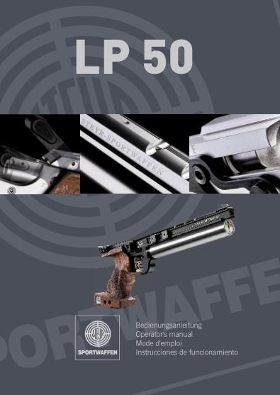
operator´s manual - Steyr Sport
13
-
Upload
khangminh22 -
Category
Documents
-
view
0 -
download
0
Transcript of operator´s manual - Steyr Sport

EN
GL
ISH
23
Attention:
This operator's manual should be read carefully before using the pistol!
03-2003

EN
GL
ISH
24
EN
GL
ISH
25
Important measures when using arms:
All firearms are dangerous objects, they should be used and storedwith utmost caution!
Always treat an unloaded weapon as if it were loaded. Never put yourfinger on the trigger, except when actually firing a shot. Always ensurethat the weapon is pointing in a safe direction. Keeping the weapon inperfect condition ensures safety.
Weapons always have to be stored out of the reach of unauthori-sed persons, particularly children and juveniles.
TABLE OF CONTENTS
1 Technical data........................................................................ 26
2 Filling the magazine.............................................................. 27
3 Cocking, inserting the magazine (loading), firing.............. 28
4 Removing the magazine (unloading) .................................. 29
5 Sight adjustment .................................................................. 30
5.1 Moving or exchanging the front sight ...................................... 30
5.2 Rear sight adjustment ............................................................ 31
5.3 Relocate rear sight .................................................................. 31
6 Trigger adjustment ................................................................ 32
6.1 Trigger blade adjustment ........................................................ 32
6.2 Adjusting the trigger stop ........................................................ 33
6.3 Adjusting the trigger pull force ................................................ 34
6.4 Adjusting the first stage travel ................................................ 35
6.5 Replacing the trigger assembly .............................................. 36
7 Grip readjustment ................................................................ 37
8 Replacing and refilling the compressed-air cylinder ...... 38
9 Cleaning and care ................................................................ 39
10 Guarantee clauses ................................................................ 39
11 Illustration of spare parts .................................................... 41

EN
GL
ISH
27
EN
GL
ISH
26
1 TECHNICAL DATA
Calibre ..........................................4.5 mm (.177)
Overall height of weapon ..............148 mm
Overall length of weapon ..............398 mm
Overall width of weapon (without magazine)......................................................50 mm
Total weight of weapon ................ca. 1050 g
Sight length ..................................307 - 350 mm adjustable
Front sight ....................................relocatable front
Rear sight......................................Rear sight continuously adjustable ......................................................from 2 - 7 mm
Barrel length..................................235 mm
Maximum filling pressure ..............200 bar
2 FILLING THE MAGAZINE
Place pellets one after the other,as shown, into the magazinechambers provided in such away that the pellet is completelyflush with the magazine.

EN
GL
ISH
29
EN
GL
ISH
28
3 COCKING, INSERTING THE MAGAZINE (LOADING), FIRING
Cock the system by pushing the left and right slides simultaneouslybackward with thumb and index finger. The magazine may be insertedonly when the pistol is cocked. It is impossible to insert the magazinethe wrong way because the recess on the magazine and the springsleeve in the magazine housing must match.
4 REMOVING THE MAGAZINE (UNLOADING)
After five shots are fired the magazine is empty. The system is stillcocked. If the magazine catch located at the bottom left of the magazi-ne tube is pressed, the magazine can be removed. Should the triggerhave been pulled a sixth time the system has to be cocked again inorder to be able to remove the magazine.
The magazine may also be removed without emptying it. Whenpressing the magazine catch, ensure the magazine, which isunder spring pressure, does not fly out.

EN
GL
ISH
31
EN
GL
ISH
30
5 SIGHT ADJUSTMENT
The setscrews have to be turned as follows:
High hit - turn height-adjusting screw in direction H Low hit - turn height-adjusting screw in direction T
Right hit - turn side-adjusting screw in direction R Left hit - turn side-adjusting screw in direction L
One click of the side-adjusting screw changes the point of impact posi-tion by 1.2 mm at a target distance of 10 m.
5.1 Moving or exchanging the front sight:
After loosening the countersunk screw the front sight can be movedbackwards and forwards.
5.2 Rear sight adjustment:
Turning the screws n¡ 79 or 80, the rear sight can be adjusted from 1.5 mm to 4.5 mm.
The depth of the rear sight is adjustable from 1.5 mm to 3.2 mm. Loo-sen the cover plate screws, move into desired position and then retigh-ten screws.
5.3 Relocate rear sight:
Loosing screw, move sight carrier to the desired position and tightenscrew.

EN
GL
ISH
33
EN
GL
ISH
32
6 TRIGGER ADJUSTMENT
PLEASE NOTE! Before making any changes to the trigger, ensu-re that the weapon IS UNLOADED.
6.1 Trigger blade adjustment:
Loosen countersunk screw. The trigger blade may then be moved eit-her to the left or to the right and moved in a longitudinal direction.
6.2 Adjusting the trigger stop:
Turning the screw clockwise shortens the "aftertravel" of the trigger bla-de after shot release. Turning the screw anticlockwise lengthens the"aftertravel" after shot release.

EN
GL
ISH
34
EN
GL
ISH
35
6.3 Adjusting the trigger pull force:
Turning the screw anticlockwise reduces the trigger pull force. Turning the screw clockwise increases the trigger pull force.
6.4 Adjusting the first stage travel:
Turning the screw clockwise reduces the dead travel. Turning the screw anticlockwise increases the dead travel.

EN
GL
ISH
37
EN
GL
ISH
36
6.5 Replacing the trigger assembly:
Remove grip by loosening the cheese head screw on bottom side ofgrip. Remove fastening screw. Remove clamping screw. Remove com-plete trigger assembly from casing. With the slides retracted insert trig-ger assembly into the pistol casing and place it against the stop up tothe front of the casing. Fasten clamping and fastening screw.
7 GRIP ADJUSTMENT
The grip is adjustable and pivotable to the weapon system in all direc-tions and may be widely adapted to the shooters stance. For this pur-pose the grip has to be removed. Adjustment is achieved by means ofthe screws located at the bottom and the rear of the casing.
PLEASE NOTE! The two countersunk screws on the rear of thecasing must always protrude at least 2.5 mm, toassure the velocity screw is clear of the grip.
EN
GL
ISH
39
EN
GL
ISH
38
8 REPLACING AND REFILLING THE COMPRES-SED-AIR CYLINDER
The legal requirements and rules of the respective country must beadhered to. Compressed-air cylinders have to be inspected after 10years exclusively by the manufacturer. It is the responsibility of thecustomer to return the cylinders to the manufacturer. For reasons ofsafety the magazine has to be removed before exchanging the com-pressed-air cylinder. The compressed-air cylinder may be unscrewedand removed at any time without being emptied.
WARNING! Do not tamper with compressed-air cylinder and val-ve. It may cause injury!
The compressed-air cylinder is to be charged with a maximum fillingpressure of 200 bar.
For recharging the cylinder proceed as follows:
l either mount the compressed-air cylinder on a recharging bottle
l or mount the compressed-air cylinder on a hand pump
l or mount the compressed-air cylinder on a compressor
9 CLEANING AND CARE
In standard use the weapon operates maintenance-free and no oilingis required.
The only maintenance required is to slightly grease the O-ring in theloading port and the O-ring at the threaded adapter socket for the com-pressed-air cylinder with a special lubricant (acid-free silicone grease)every 1000 shots. This will increase the service life of the O-rings.
To clean the barrel shoot some dry (not greased) felt pellets throughthe barrel.
10 GUARANTEE CLAUSES
If within one year from the day of purchase any cracks or breaks shouldoccur on this weapon that are due to material failure we undertakerepair the defective parts free of charge. (except breakage or crackingof the stock/pistol grip or O-rings).
Guarantee will be given by either replacing or repairing the weapon orparts of it at our sole discretion. The guarantee is only valid if the ful-ly completed guarantee card is returned immediately after purcha-sing the weapon.
No guarantee claims will be accepted by the Steyr-SportwaffenGmbH if:
a) the weapon has been damaged or destroyed by force majeur orenvironmental influences;
b) in case of damages/defects having been caused by impropertreatment, or handling or by lack of care;
c) if the weapon has been repaired, machined or altered by anyperson or workshop other than an authorised Steyr SportwaffenGmbH workshop.

EN
GL
ISH
41
Claims for damages and product liability:
No claims for direct or indirect damages will be accepted. Liability for material damages resulting from the product liability law,BGBL 99/1988, as well as any product liability claims that could bederived from other provisions are excluded. The object of purchase warrants only that type of safety which may beexpected in accordance with the homologation rules, service manual,manufacturer's instructions as well as any other pertinent informationreceived.The above clauses govern the full customer/manufacturer relationshipwith our company. Any additional claims, in particular for any kind ofdamages or losses caused by the weapon or its use, are excluded.
Guaranteed Steyr Sportwaffen accuracy:
Our barrels are made from high quality barrel steel and are producedaccording to the latest findings in barrel production technology. Ourweapons are well known for their outstanding accuracy. However, theaccuracy of a weapon depends on several factors; one of the mostimportant factors is the ammunition used. Not every ammunition "fits"every barrel equally good.
If you follow our suggestion, we guarantee that you will achieve out-standing accuracy with your new product. Claims regarding inconsi-stent accuracy must be reported to us in written within 20 (twenty) daysafter purchasing the weapon.
To check precision with a clamped weapon, it is advisable to clamp thepistol around the area of the trigger guard.
EN
GL
ISH
40
11 PARTS LIST LP 50Pos Designation
1 Housing2 Barrel3 Housing pressure reducing valve4 O-ring5 O-ring6 Adjusting screw pressure red. Valve7 Guiding sleeve8 Cover9 Screw
10 Piston12 O-ring13 Disc spring14 Filter15 Adapter for pressure reducing valve16 O-ring17 Compressed air cylinder18 O-ring19 Valve body20 Valve head21 Pressure spring22 Supporting ring23 O-ring24 O-ring25 Cylinder valve tappet27 Pressure gage28 Trigger housing29 Trigger blade carrier30 Trigger lever31 Disconnector lever32 Trigger33 Nut34 Screw35 Parallel pin36 Slottet set screw37 Slottet set screw38 First stage screw39 Pressure spring40 First stage pressure spring

EN
GL
ISH
43
EN
GL
ISH
42
Pos Designation
41 Pressure spring42 Slottet set screw43 Grip44 Rest plate46 Grip weight47 Slotted cheese head screw48 Washer49 O-ring50 Magazine block51 Magazine notch52 Spring sleeve53 Spring lock54 Parallel pin55 Spring56 Pressure spring57 Cover58 Magazine cut-off spring59 Striker60 Slide, left61 Slide, right62 Trigger sear63 Valve housing64 Piston65 Valve housing67 Screw68 Setscrew69 Screw for housing70 O-ring71 Grip locking rod72 Slottet set screw73 Slottet set screw74 Pressure spring75 Pressure spring76 Pressure spring77 Barrel casing78 Front sight79 Countersunk screw80 Slottet set screw81 Slottet set screw
Pos Designation
82 Compensator cone83 Pressure spring84 Screw85 Countersunk screw86 Slottet set screw87 Parallel pin88 Parallel pin89 Slotted cheese head screw90 Screw91 Slottet set screw92 Lock93 Sight carrier94 Spindle left95 Spindle right96 Clamp97 Rear sight leaf, right98 Rear sight leaf, left99 Cover plate
100 Slotted cheese head screw101 Slide setscrew102 Rear sight adjusting plate103 Sliding block104 Height setscrew105 Rear sight plate106 Slotted cheese head screw107 Washer108 Pressure spring109 Lock screw110 Plunger spring111 Ball112 Pressure spring113 O-ring114 Screw115 O-ring116 Magazine117 O-ring118 Pressure spring119 Compressed air cylinder120 Trigger Assembly complete

LP-50