Operation-Manual-Steyr-SE.pdf - Univa
130
1 www.steyr-motors.com STEYR MOTORS GmbH Im Stadtgut B1, A-4407 Steyr-Gleink, AUSTRIA STEYR MOTORS MARINE ENGINES OPERATION, MAINTENANCE AND WARRANTY MANUAL P/N Z001140-0 3rd Edition December 2014 4 CYLINDERS + 6 CYLINDERS 4 CYLINDERS + 6 CYLINDERS
-
Upload
khangminh22 -
Category
Documents
-
view
0 -
download
0
Transcript of Operation-Manual-Steyr-SE.pdf - Univa

1www.steyr-motors.com
STEYR MOTORS GmbHIm Stadtgut B1, A-4407 Steyr-Gleink, AUSTRIA
STEYR MOTORS MARINE ENGINES
OPERATION, MAINTENANCE AND WARRANTY MANUALP/N Z001140-0 3rd Edition December 2014
4 CYLINDERS+ 6 CYLINDERS
4 CYLINDERS+ 6 CYLINDERS

This Page is intentionaly blank

WELCOME ABOARD
Congratulations on your decision of choosing a STEYR MOTORS marine engine for your boat, and we hope you will enjoy it.
STEYR MOTORS GmbH has developed a high-speed diesel engine with two stage high-pressure fuel injection specifically for the marine environ-ment. STEYR MOTORS marine engines are designed to be adapted to various propulsion systems.
To come up to your expectations, please study thoroughly this manual for your new STEYR MOTORS marine engine to get sufficient information on its operation and handling and to permit an optimal use of the various built-in functions.
With kind regards, STEYR MOTORS GmbH
STEYR MOTORS GmbHAfter Sales Service
Im Stadtgut B14407 Steyr, Austria
www.steyr-motors.com 3rd Edition, December 2014 P/N Z001140-0
YOUR STEYR MOTORS MARINE DEALER
3

4
How to use this manual
Table of Contents
GENERAL PART PAGE 5 – 19
This section contains user instructions and general notes on safety for STEYR MOTORS marine engines.
START-UP AND FUNCTIONS PAGE 20 – 47
This section contains brief instruction, function description and normal operation, as well as correct start-up and handling of STEYR MOTORS marine engines.
FUEL AND LUBRICANTS PAGE 48 – 51
This section defines the requirements as to fuel and lubricants for STEYR MOTORS marine engines.
TECHNICAL DATA PAGE 52 – 63
This section contains technical data and product description of STEYR MOTORS marine engines.
MAINTENANCE, TROUBLE SHOOTING PAGE 64 – 99
This section contains instructions for required maintenance and notes on the fault finding on your STEYR MOTORS marine engine.
DEALER´S RESPONSIBILITIES PAGE 100 – 117
This section contains instructions for installation acceptance tests, propeller selection, removal from service, start-up after storage, adequate disposal and dealer´s test list.
WARRANTY, DISTRIBUTORS PAGE 118 – 130
This section contains warranty conditions (services and obligations) for owners and manufacturers of STEYR MOTORS marine engines.
6
GENERAL PART
General ........................................................................................................6
MARINE ENGINE OVERVIEW ...................................................................7
Product References, Illustrations and Specifications ................................14
Insurance ...................................................................................................14
Stolen Unit .................................................................................................14
Owner Identification Card ..........................................................................14
Installation and pre-delivery inspection log ...............................................15
Dealer Service – Maintenance ..................................................................15
Illustration Symbols ...................................................................................15
Repair Service ...........................................................................................16
Replacement Parts ....................................................................................16
Before Casting Off .....................................................................................16
Engine Submersion ...................................................................................17
Bottom Painting .........................................................................................17
Boat Bottom ...............................................................................................17
Boating Responsibilities ............................................................................18
Safety ........................................................................................................18
WARNING .................................................................................................18
Symbols .....................................................................................................19

7
General
This MANUAL is published by STEYR MOTORS GmbH with the main intention to provide information in form of technical data and know-how based on our experience in the marine diesel engine business, which will enable you, after thorough study to operate and check the engines on your boat, ensuring their operating safety, reliability and long service life.
CE conformity:Under regular maintenance, as described in the chapter “Maintenance and Trouble Shooting”, the exhaust gas emis-sion levels adhere to the limits stipulated, for pleasure boat operation, throughout the life time of the engine.
All warranty claims to be addressed to your local STEYR MOTORS Marine Dealer.(We have to rely on your assistance however) For continuous improvement with regard to form and contents of the information required.
Your comments on the following questions would be much appreciated
– Which descriptions or terms are not understandable? – Which enlargements or complements do you suggest? – Where did content-related mistakes slip in?
Please address your comments and ideas to your STEYR MOTORS – Marine Dealer.
Since this manual covers the whole family of STEYR MOTORS marine engines, differing sections are marked as follows:
1.)
whole page applies to all engines
2.)MO144K33
whole page applies to specified engine types only
3.)GENERAL
MO114K33 <3700 rpm whole page applies in principle for all engine types, but different data, e.g. technical data, is marked.

8
MARINE ENGINE OVERVIEW
MAKE STEYR MOTORS M 14 TCAM
engine typedisplace-
ment[cm³]
rated power[kW]
exhaust back
pressure[mbar]
tolerance exhaust
back pressure± [mbar]
charge-air pressure[mbar]*
charge-air pressure tolerance± [mbar]
max. intake depression
@ rated power[mbar]
MO114K33 2100 81 100 ±50 1900 ±100 50MO144V38 2100 106 100 ±50 2280 ±100 50MO144M38 2100 106 100 ±50 2250 ±100 50MO164M40 2100 120 100 ±50 2740 ±100 50MO174V40 2100 125 150 +0/–50 3100 ±50 50SE164E40 2133 118 100 ±50 2640 ±100 50SE144E38 2133 106 100 ±50 2540 ±100 50
MAKE STEYR MOTORS M 14 TCM
engine typedisplace-
ment[cm³]
rated power[kW]
exhaust back
pressure[mbar]
tolerance exhaust
back pressure± [mbar]
charge-air pressure[mbar]*
charge-air pressure tolerance± [mbar]
max. intake depression
@ rated power[mbar]
MO84K32 2100 55 100 ±50 1900 ±100 50MO94K33 2100 66 100 ±50 1900 ±100 50
MAKE STEYR MOTORS M 14 NAM
engine typedisplace-
ment[cm³]
rated power[kW]
exhaust back
pressure[mbar]
tolerance exhaust
back pressure± [mbar]
charge-air pressure[mbar]*
charge-air pressure tolerance± [mbar]
max. intake depression
@ rated power[mbar]
MO54NA33 2100 40 80 +0/–50 – – 50
* at standard reference conditions according to ISO 15550

9
ENG
INE
TYPE
SE12
6E25
SE15
6E26
SE15
6E32
SE19
6E35
SE23
6E40
SE23
6S36
SE26
6E40
SE26
6S36
SE28
6E40
SE30
6J38
NU
MB
ER O
F C
YLIN
DER
S6
66
66
66
66
6
BO
RE
(MM
)85
8585
8585
8585
8585
85
STR
OK
E (M
M)
9494
9494
9494
9494
9494
DIS
PLA
CEM
ENT
(CM
³)32
0032
0032
0032
0032
0032
0032
0032
0032
0032
00
RAT
ED P
OW
ER
(KW
)88
110
110
140
170
170
190
190
205
215
RAT
ED S
PEED
(R
PM)
2500
2600
3200
3500
4000
3600
4000
3600
4000
3800
PRO
PPED
SP
EED
RA
NG
E23
00-2
550
2400
-265
030
00 -
3250
3300
-355
039
00-4
100
3400
-365
038
50-4
050
3300
-365
039
00-4
150
3500
-385
0
MA
X. T
OR
QU
E (N
M)
390
450
450
445
470
540
530
600
570
588
MA
X. T
OR
QU
E (L
B-F
T)28
836
036
032
834
739
839
144
342
043
4
SPEE
D A
T M
AXI
MU
M
TOR
QU
E (R
PM)
1800
1800
1800
2050
2550
1800
2300
1800
2550
3300
MA
XIM
UM
TES
T SP
EED
(RPM
)25
0026
0032
0035
0040
0036
0040
0036
0040
0038
00
TOR
QU
E AT
M
AXI
MU
M T
EST
SPEE
D (N
M)
336
404
329
382
406
451
454
504
489
540
LOW
ER
TOLE
RA
NC
E O
F M
AXI
MU
M
POW
ER (%
)
55
55
55
55
55
UPP
ER
TOLE
RA
NC
E O
F M
AXI
MU
M
POW
ER (%
)
55
55
55
55
55
FUEL
RAT
E AT
R
ATED
SPE
ED
(MM
³/STR
OK
E)54
,565
,954
,565
,271
,375
,981
,186
,486
,393
,4
FUEL
RAT
E AT
MA
XIM
UM
TO
RQ
UE
(MM
³/ST
RO
KE)
5866
,868
,365
7278
,980
,589
,885
,996
,3

10
ENG
INE
TYPE
SE12
6E25
SE15
6E26
SE15
6E32
SE19
6E35
SE23
6E40
SE23
6S36
SE26
6E40
SE26
6S36
SE28
6E40
SE30
6J38
MEA
N
EFFE
CTI
VE
PRES
SUR
E (B
AR
)
13,2
15,9
0,0
1515
,917
,717
,819
,819
,221
,2
SPEC
IFIC
PO
WER
(LB
S/H
P)6,
265,
010,
003,
943,
243,
242,
92,
92,
692,
56
DRY
WEI
GH
T
(KG
)34
034
034
034
034
034
034
034
034
034
0
SPEC
IFIC
PO
WER
(KG
/PS)
2,84
2,27
0,00
1,79
1,47
1,47
1,32
1,32
1,22
1,16
IDLE
SPE
ED
(RPM
)63
063
063
063
063
063
063
063
063
063
0
ASP
IRAT
ION
TCA
TCA
TCA
TCA
TCA
TCA
TCA
TCA
TCA
TCA
TUR
BO
SYS
TEM
WG
WG
WG
WG
GE
OM
VTG
WG
VTG
WG
WG
FUEL
CO
NS.
AT
IDLE
SPE
ED
(KG
/H)
0,52
0,52
0,52
0,52
0,52
0,52
0,52
0,52
0,52
0,52
AIR
MA
SS
FLO
W @
RAT
ED
POW
ER (K
G/H
)49
052
071
071
096
580
898
086
010
4010
20
FUEL
CO
NS.
@
RAT
ED P
OW
ER
(KG
/H)
20,1
25,4
25,8
33,7
42,5
40,9
47,3
46,1
5152
,2
EXH
AU
ST M
ASS
FL
OW
@ R
ATED
PO
WER
(KG
/H)
510,
154
5,4
735,
874
3,7
1007
,584
8,9
1027
,390
6,1
1091
1072
,2
MA
X. IN
LET
DEP
RES
SIO
N A
T R
ATED
PO
WER
(M
BA
R)
AIR
FILT
ER
: N
EW
30
U
SE
D 5
0
AIR
FILT
ER
: N
EW
30
U
SE
D 5
030
/51
AIR
FILT
ER
: N
EW
30
U
SE
D 5
0
AIR
FILT
ER
: N
EW
30
U
SE
D 5
0
AIR
FILT
ER
: N
EW
30
U
SE
D 5
0
AIR
FILT
ER
: N
EW
30
U
SE
D 5
0
AIR
FILT
ER
: N
EW
30
U
SE
D 5
0
AIR
FILT
ER
: N
EW
30
U
SE
D 5
0
AIR
FILT
ER
: N
EW
30
U
SE
D 5
0
SPEC
. FU
EL
CO
NSU
MPT
ION
AT
RAT
ED
POW
ER
(G/
KW
H)
228
230
233
240
249
240
249
243
248
243
MIN
SPE
C. F
UEL
C
ON
SUM
PTIO
N
(G/K
WH
)20
520
520
320
521
020
220
520
521
021
0

11
ENG
INE
TYPE
SE12
6E25
SE15
6E26
SE15
6E32
SE19
6E35
SE23
6E40
SE23
6S36
SE26
6E40
SE26
6S36
SE28
6E40
SE30
6J38
CO
MPR
ESSO
R
OU
TLET
TE
MPE
RAT
UR
E AT
RAT
ED
POW
ER (°
C)
130
140
155
145
200
160
165
175
180
180
BO
OST
PR
ESSU
RE
AD
JUST
MEN
T VA
LUE
1MM
D
EFLE
CTI
ON
(M
BA
R)
1680
1680
1880
1880
GE
OM
ETR
ICA
L E
LEC
TRO
NIC
C
ON
TRO
LLE
D19
20E
LEC
TRO
NIC
C
ON
TRO
LLE
D20
4020
40
BO
OST
PR
ESSU
RE
AD
JUST
MEN
T VA
LUE
3MM
D
EFLE
CTI
ON
(M
BA
R)
1880
1880
2020
2020
GE
OM
ETR
ICA
L E
LEC
TRO
NIC
C
ON
TRO
LLE
D21
00E
LEC
TRO
NIC
C
ON
TRO
LLE
D22
4022
40
MA
P AT
RAT
ED
POW
ER (M
BA
R)
2130
2200
2280
2280
2790
2560
2840
2740
2990
3060
MA
P TO
LER
AN
Z (+
/-) [M
BA
R]
7575
7575
100
5075
5075
75
MA
P M
AX.
(M
BA
R)
2180
2240
2380
2440
2900
2690
2840
2800
3000
3060
SPEE
D @
MA
X.
MA
P (1
/MIN
)22
0023
5032
0028
0035
5030
5040
0033
0038
0038
00
CO
MPR
ESSI
ON
R
ATIO
Ε =
17,
0Ε
= 1
7,0
Ε =
17,
0Ε
= 1
7,0
Ε =
17,
0Ε
= 1
7,0
Ε =
17,
0Ε
= 1
7,0
Ε =
17,
0Ε
= 1
7,0
MA
X. E
XHA
UST
15
015
015
015
015
015
015
015
015
015
0
0 / -
50
0 / -
50
+0/-
500
/ - 5
00
/ - 5
00
/ - 5
00
/ - 5
00
/ - 5
00
/ - 5
00
/ - 5
0
GO
VER
NED
SP
EED
(RPM
)25
5026
5032
5035
5041
0036
5041
0036
5041
5038
50
MIN
. EN
GIN
E C
OM
PAR
T- M
ENT
PRES
SUR
E (M
BA
R)
1010
1010
1010
1010
1010
MIN
. FU
EL
SUPP
LY
PRES
SUR
E B
LOC
K IN
LET
[MB
AR
] - R
EL.
3500
3500
3500
3500
3500
3500
3500
3500
3500
3500
12
ENG
INE
TYPE
SE12
6E25
SE15
6E26
SE15
6E32
SE19
6E35
SE23
6E40
SE23
6S36
SE26
6E40
SE26
6S36
SE28
6E40
SE30
6J38
MA
X. E
NG
INE
CO
OLA
NT
OU
TLET
TE
MPE
RAT
UR
E [°
C]
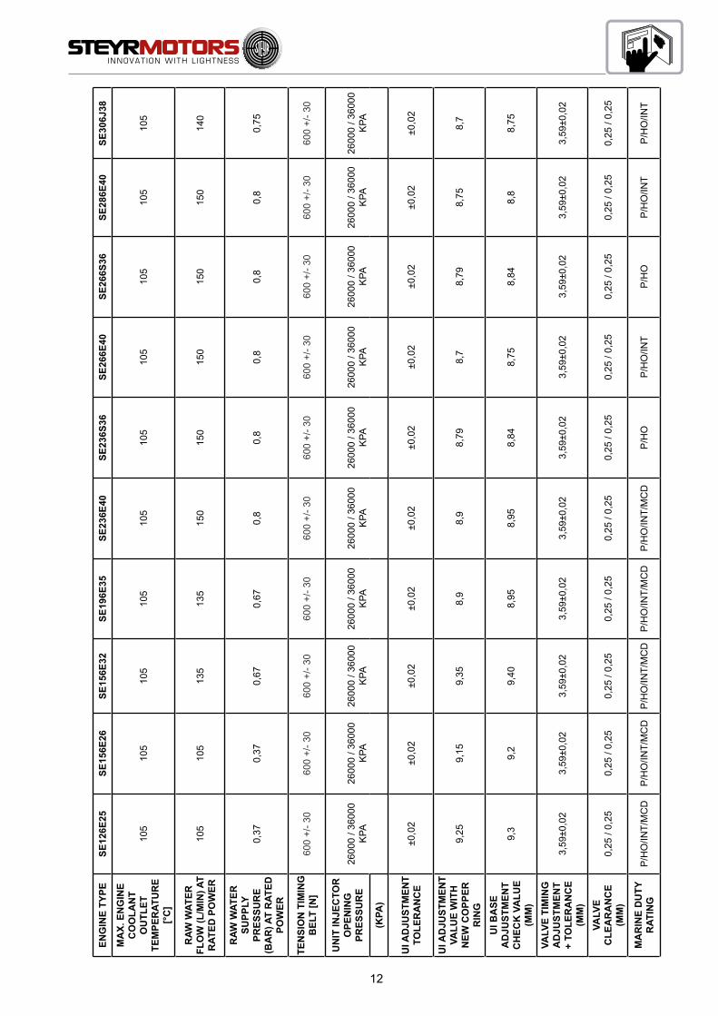
105
105
105
105
105
105
105
105
105
105
RAW
WAT
ER
FLO
W (L
/MIN
) AT
RAT
ED P
OW
ER10
510
513
513
515
015
015
015
015
014
0
RAW
WAT
ER
SUPP
LY
PRES
SUR
E (B
AR
) AT
RAT
ED
POW
ER
0,37
0,37
0,67
0,67
0,8
0,8
0,8
0,8
0,8
0,75
TEN
SIO
N T
IMIN
G
BEL
T [N
]60
0 +/
- 30
600
+/- 3
060
0 +/
- 30
600
+/- 3
060
0 +/
- 30
600
+/- 3
060
0 +/
- 30
600
+/- 3
060
0 +/
- 30
600
+/- 3
0
UN
IT IN
JEC
TOR
O
PEN
ING
PR
ESSU
RE
2600
0 / 3
6000
K
PA26
000
/ 360
00
KPA
2600
0 / 3
6000
K
PA26
000
/ 360
00
KPA
2600
0 / 3
6000
K
PA26
000
/ 360
00
KPA
2600
0 / 3
6000
K
PA26
000
/ 360
00
KPA
2600
0 / 3
6000
K
PA26
000
/ 360
00
KPA
(KPA
)
UI A
DJU
STM
ENT
TOLE
RA
NC
E±0
,02
±0,0
2±0
,02
±0,0
2±0
,02
±0,0
2±0
,02
±0,0
2±0
,02
±0,0
2
UI A
DJU
STM
ENT
VALU
E W
ITH
N
EW C
OPP
ER
RIN
G
9,25
9,15
9,35
8,9
8,9
8,79
8,7
8,79
8,75
8,7
UI B
ASE
A
DJU
STM
ENT
CH
ECK
VA
LUE
(MM
)
9,3
9,2
9,40
8,95
8,95
8,84
8,75
8,84
8,8
8,75
VALV
E TI
MIN
G
AD
JUST
MEN
T +
TOLE
RA
NC
E (M
M)
3,59
±0,0
23,
59±0
,02
3,59
±0,0
23,
59±0
,02
3,59
±0,0
23,
59±0
,02
3,59
±0,0
23,
59±0
,02
3,59
±0,0
23,
59±0
,02
VALV
E C
LEA
RA
NC
E (M
M)
0,25
/ 0,
250,
25 /
0,25
0,25
/ 0,
250,
25 /
0,25
0,25
/ 0,
250,
25 /
0,25
0,25
/ 0,
250,
25 /
0,25
0,25
/ 0,
250,
25 /
0,25
MA
RIN
E D
UTY
R
ATIN
GP
/HO
/INT/
MC
DP
/HO
/INT/
MC
DP
/HO
/INT/
MC
DP
/HO
/INT/
MC
DP
/HO
/INT/
MC
DP
/HO
P/H
O/IN
TP
/HO
P/H
O/IN
TP
/HO
/INT

13
Engine type SE144E38 SE164E40
Number of Cylinders 4 4Bore (mm) 85 85Stroke (mm) 94 94Displacement (cm³) 2133 2133Rated power (kW) 106 118Rated speed (rpm) 3800 4000
Full power speed range (rpm) 3300-3800 3550-4000
Propeller Selection Range (rpm) 3700-3900 3900-4100Jet Selection Range (rpm) 3300-3800 3550-4000max. torque (Nm) 315 330max. torque (lb-ft) 232 243
Speed at Maximum Torque (rpm) 2050 2300Maximum test speed (rpm) 3800 4000
Torque at maximum test speed (Nm) 266,4 281,7
Lower tolerance of maximum power (%) 5 5
Upper tolerance of maximum power (%) 5 5
Fuel rate at rated speed (mm³/stroke) 72,5 75,5
Fuel rate at Maximum Torque (mm³/stroke) 76 80Mean effective Pressure (bar) 15,69 19,44Specific power (lbs/HP) 5,06 4,55
Dry weight (kg) 244 244Specific power (kg/PS) 1,69 1,52Idle speed (rpm) 750 750Aspiration TCA TCATurbo system WG WGFuel Cons. at idle speed (kg/h) 0,43 0,43
Air mass flow @ rated power (kg/h) 563 610
Fuel cons. @ rated power (kg/h) 27 29,7
Exhaust mass flow @ rated power (kg/h) 590 639,7
max. inlet depression at rated Power (mbar)Airfilter new 30used 51
Airfilter new 30used 51
Spec. fuel consumption at rated power (g/kWh) 255 252
min spec. fuel consumption (g/kWh) 215 220
Compressor outlet temperature at rated power (°C) 178 164Boost pressure adjustment value 1mm deflection (mbar) 1420 mm 1830 mmBoost pressure adjustment value 3mm deflection (mbar) 1620 mm 2050 mmMAP at rated power (mbar) 2520 2650Map Toleranz (+/-) [mbar] 50 50MAP (mbar) 2560 2710Speed @ max. MAP (1/min) 3550 3550Compression ratio ε = 17,0 ε = 17,0
max. exhaust backpressure (mbar) 150 150

14
Engine type SE144E38 SE164E40
Backpressure tolerance (mbar) +0/- 50 +0/- 50
max. engine cooling water outlet temp. (°C) 83 83Exhaust gas temperature (°C) 512 554Oil sump temperature (°C) 100 100Governed speed (rpm) 3950 4100min. engine compart- ment pressure (mbar) 10 10
min. fuel supply pressure block inlet [mbar] - rel. 3500 3500
max. engine coolant outlet temperature [°C] 105 105
Raw water flow at rated power (l/min) 150 150
Raw water supply pressure at rated power (bar) 0,8 0,8Oil quantity first filling [lt.] 8,4 8,4
Coolant water filling quantity [lt.] 9 9Tension timing belt [N] 600 +/- 30 600 +/- 30
Unit injector opening pressure (kPa) 26001 / 36000 kPa 26001 / 36000 kPa
UI adjustment (mm) 8,75 8,92UI adjustment tolerance ±0,02 ±0,02
UI adjustment check value after engine braking-in 8,8 8,97UI base adjustment value (mm) 8,85 9,02
Valve timing adjustment + tolerance (mm) 3,59±0,02 3,59±0,02
Valve clearancy (mm) 0,25 / 0,25 0,25 / 0,25
SW version nr. 50000 50000SW revision 11 11SW calibration 14002 16002
Performance Rating PR, HO, INT, MCD PR, HO, INT, MCD
Propeller Shaft X X
Jet-Powertrain X X
Z-Powertrain X X

15
Product References, Illustrations and Specifications
When reference is made in this manual to a brand name, number, product or specific tool, an equivalent product may be used in place of the product referred to unless specifically stated otherwise. Equivalent products which are used must meet all current local regulations and standards to avoid hazards.
Some countries may apply additional internal regulation. Please follow their advices appropriately, example:
Austria: Bundesamt für Schiffahrt Sweden: Navigation Office Finland: Navigation Office Norway: DNV = Det Norske Veritas USA: USCG = United States Coast Guard USA: ABYC = American Boat Yacht Council USA: NMMA = National Marine Manufacturers Association England: LR = Lloyds Register of Shipping France: BV = Bureau Veritas Germany: GL = GERMANISCHER Lloyd Italy: RINA = Registro Italiano Navale
All information, illustrations and specifications contained in this manual are based on the latest product informa-tion available at the time of printing. STEYR MOTORS GmbH reserves the right to make changes at any time, without notice, to specifications and models and also to discontinue models, as well as the right to change specifications or parts at any time without incurring any obligation to equip same on models manufactured prior to date of such change.
Continual accuracy of this manual cannot be guaranteed.
All illustrations used in this manual may not depict actual models or equipment and are intended as representative views for reference only.
Insurance
Insurance on your STEYR MOTORS Marine Engine and boat should be obtained as soon as practical for protection against loss by fire, theft, etc. Consult your local insurance agent.
Stolen Unit
The model and serial numbers on your engine are important for you. As to the location of these important numbers, refer to Model and Serial Numbers in the section Technical Data.
Record each of these numbers in the spaces provided at the end of this manual and on a separate sheet. Store the separate sheet in a safe place other than your boat.
In case of theft, report the model and serial numbers to your local authorities and your insurance agent.
Owner Identification Card
When you purchases your boat, your dealer was obliged to issue an owner identification card for your STEYR MOTORS Marine Engine.
This owner identification card gives proof and is to be submitted in case of warranty claims.

16
Installation and pre-delivery inspection log
Your STEYR MOTORS Marine dealer is also obliged to complete the installation and pre-delivery inspection log (Chapter “DEALER’S RESPONSIBILITIES”). Required tests and measurements are to be carried out accordingly.
A copy of the installation and pre-delivery inspection log and engine registration card are to be forwarded to STEYR MOTORS GmbH.
Dealer Service – Maintenance
NOTE: Please do not forget to have confirmed in your manual that the installation and maintenance have been carried out in accordance with the guidelines.
This is also an opportunity to clarify with your STEYR MOTORS marine dealer possible questions arisen during the first running hours on your boat, and to establish a service- and maintenance routine.
Services will be performed by STEYR MOTORS Marine Dealers at local rates.
Costs for service material to be paid by the owner.
Illustration Symbols
Refer to the photograph or drawing described in that paragraph.
Refer to specific items or features described in the text and illustrated on the photograph.Refer to the general subject of the text.
Refer to an item or feature not clearly visible on the photograph.
17
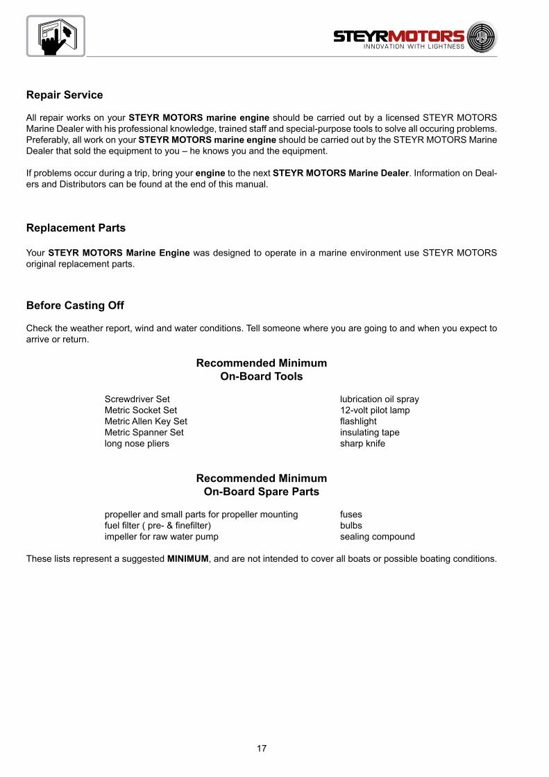
Repair Service
All repair works on your STEYR MOTORS marine engine should be carried out by a licensed STEYR MOTORS Marine Dealer with his professional knowledge, trained staff and special-purpose tools to solve all occuring problems. Preferably, all work on your STEYR MOTORS marine engine should be carried out by the STEYR MOTORS Marine Dealer that sold the equipment to you – he knows you and the equipment.
If problems occur during a trip, bring your engine to the next STEYR MOTORS Marine Dealer. Information on Deal-ers and Distributors can be found at the end of this manual.
Replacement Parts
Your STEYR MOTORS Marine Engine was designed to operate in a marine environment use STEYR MOTORS original replacement parts.
Before Casting Off
Check the weather report, wind and water conditions. Tell someone where you are going to and when you expect to arrive or return.
Recommended MinimumOn-Board Tools
Screwdriver Set lubrication oil spray Metric Socket Set 12-volt pilot lamp Metric Allen Key Set flashlight Metric Spanner Set insulating tape long nose pliers sharp knife
Recommended MinimumOn-Board Spare Parts
propeller and small parts for propeller mounting fuses fuel filter ( pre- & finefilter) bulbs impeller for raw water pump sealing compound
These lists represent a suggested MINIMUM, and are not intended to cover all boats or possible boating conditions.

18
Engine Submersion
Remove engine from water as quickly as possible and contact your local STEYR MOTORS Marine dealer for service.
It is imperative that your dealer removes all water from the engine and immediately relubricates all internal parts. Electrical devices must be replaced. Delay in completing these actions may allow extensive engine damage.
Frequently check engine compartment for excessive water accumulation; water depth in bilge should be kept well below flywheel housing. Engine compartment must enable proper venting to avoid condensation to build up on inner surfaces.
Bottom Painting
If your boat is in water where marine growth is a problem, the use of an antifouling paint will reduce the growth rate.
* Tin base antifouling paint (TBTA or TBTF) is recommended where its use is permitted.
* Copper base antifouling paint may be used, but will require more frequent inspection and replacement of sacrificial anodes. DO NOT PAINT any part of the drive unit with copper base antifouling paint.
NOTE: Painting the drive unit with copper base paint will accelerate galvanic corrosion.
* Vinyl-butyl base antifouling paint is a recommended alternative.
* DO NOT USE any graphite base antifouling paint.
NOTE: Never paint anti-corrosion anodes, or their effectiveness will be lost. See your STEYR MOTORS Marine contract partner for an antifouling paint that is suitable for
your area.
Boat Bottom
The condition of the boat bottom can affect your boat’s performance. Marine growth, present in fresh water as well as salt water, will reduce boat speed. A boat bottom with evidence of marine growth causes a reduction in top speed of 20 percent or more. Periodically clean the bottom of your boat following the manufacturer’s recommendations.

19
Boating Responsibilities
As a boat owner, you have certain responsibilities to others. Be sure that all operators read this manual.
You are legally responsible for all occupants of your boat. Instruct at least one of your passengers in the basic fun-damentals of handling your boat in case of an emergency. Show all hands the location of emergency equipment and how to use it. You are required by law to have one locally approved life jacket for each person aboard, plus one ap-proved throwable device for man overboard protection.
Learn the waterway rules of the location in which you are going to operate your boat. Navigable waterways are con-trolled by Federal regulations while inland lakes are controlled by local jurisdictions. Obey these regulations to protect yourself, your passengers and fellow boating enthusiasts.Thoroughly familiarize yourself with weather station warning system signals and waterway traffic signs.
Contact your local Coast Guard station and take advantage of their seasonal boat inspections and training courses.
Safety
This manual contains certain information related to the personal safety of you the operator, your passengers and bystanders.
The Safety symbol ATTENTION: appears next to important information to prevent you and others from being hurt.
The symbol NOTE: appears next to important information to keep machinery from being damaged.
Observe all notes and safety warnings contained in this manual.
WARNING
CALIFORNIA: PROPOSITION 65 WARNING
Diesel engine exhaust and some of its constituents are known to the state of California to cause cancer, birth defects, and other reproductive harm.
20
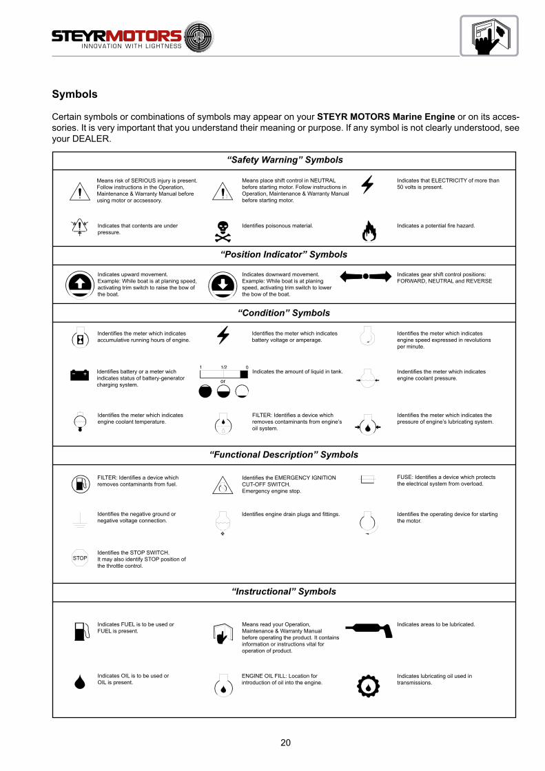
Symbols
Certain symbols or combinations of symbols may appear on your STEYR MOTORS Marine Engine or on its acces-sories. It is very important that you understand their meaning or purpose. If any symbol is not clearly understood, see your DEALER.
“Safety Warning” Symbols
“Position Indicator” Symbols
“Condition” Symbols
“Functional Description” Symbols
“Instructional” Symbols
Means risk of SERIOUS injury is present. Follow instructions in the Operation, Maintenance & Warranty Manual before using motor or accsessory.
Indicates that contents are under pressure.
Indicates upward movement.Example: While boat is at planing speed, activating trim switch to raise the bow of the boat.
Means place shift control in NEUTRAL before starting motor. Follow instructions in Operation, Maintenance & Warranty Manual before starting motor.
Identifies poisonous material.
Indicates that ELECTRICITY of more than 50 volts is present.
Indicates a potential fire hazard.
Indicates gear shift control positions: FORWARD, NEUTRAL and REVERSE
Indentifies the meter which indicates accumulative running hours of engine.
Identifies battery or a meter wich indicates status of battery-generator charging system.
Identifies the meter which indicates engine coolant temperature.
Identifies the meter which indicates battery voltage or amperage.
Indicates the amount of liquid in tank.
FILTER: Identifies a device which removes contaminants from engine’s oil system.
Identifies the meter which indicates engine speed expressed in revolutions per minute.
Indentifies the meter which indicates engine coolant pressure.
Identifies the meter which indicates the pressure of engine’s lubricating system.
FILTER: Identifies a device which removes contaminants from fuel.
Identifies the negative ground or negative voltage connection.
Identifies the STOP SWITCH.It may also identify STOP position of the throttle control.
Identifies the EMERGENCY IGNITION CUT-OFF SWITCH. Emergency engine stop.
Identifies engine drain plugs and fittings.
FUSE: Identifies a device which protects the electrical system from overload.
Identifies the operating device for starting the motor.
Indicates FUEL is to be used or FUEL is present.
Indicates OIL is to be used or OIL is present.
Means read your Operation, Maintenance & Warranty Manual before operating the product. It contains information or instructions vital for operation of product.
ENGINE OIL FILL: Location for introduction of oil into the engine.
Indicates areas to be lubricated.
Indicates lubricating oil used in transmissions.
Indicates downward movement.Example: While boat is at planing speed, activating trim switch to lower the bow of the boat.
or

20
START-UP AND FUNCTIONS
Before Starting ......................................................................................... 22
Starting the Engine (key switch version) ................................................. 23
Stopping the Engine ................................................................................ 23
Starting the Engine (push button version) ............................................... 24
Stopping the Engine (push button version) ............................................. 24
Run In Procedure After Major Overhaul .................................................. 25
Definitions ................................................................................................ 25
Procedure, Work steps ............................................................................ 25
Engine Break-In procedure ...................................................................... 26
First Ten Hours ........................................................................................ 26
Final Ten Hours of Break-in ..................................................................... 26
Operation after Break-In .......................................................................... 27
Shifting ..................................................................................................... 28
Remote Control Operating Instructions ................................................... 29
How to Shift and Control Speed .............................................................. 30
Fuel Economy .......................................................................................... 30
Gear Box – Information ........................................................................... 30
High Altitude Operation ............................................................................ 30
Instrument panel (key switch version) ..................................................... 31
Instrument panel, standard ...................................................................... 31
Instrument indication during normal operation ........................................ 32
Instrument panel (push button version) ................................................... 33
Instrument indication during normal operation (push button version) ..... 34
Emergency cut off switch (Lanyard) ........................................................ 35
Warning lights and audible alarm ............................................................ 36
Electronic Engine Control Unit (ECU) ...................................................... 37

21
START-UP AND FUNCTIONS
Diagnostic system ................................................................................... 38
Twin Installations ..................................................................................... 39
Optional Propellers .................................................................................. 39
Propellers ................................................................................................ 39
Propeller Torque ...................................................................................... 40
Propeller care .......................................................................................... 40
Water Jet ................................................................................................. 40
Operating Procedure for Freezing Temperatures .................................... 40
Salt Water Operation ............................................................................... 40
High Altitude Operation ............................................................................ 40
Fuel Pump ............................................................................................... 41
Fuel System Checks ................................................................................ 41
Fuel Contamination ................................................................................. 41
Cooling System ...................................................................................... 42
Electrical Equipment ................................................................................ 44
Alternator ................................................................................................. 44
Battery ..................................................................................................... 44
Circuit Breakers & Fuses 4 Cylinder Marine Engine ............................... 45
Circuit Breakers & Fuses 6 Cylinder SE Marine Engine .......................... 45
Inversion Switch (optional) ...................................................................... 46
Interrupt crankshaft housing ventilation (optional) ................................... 46
Instrument Panel ..................................................................................... 46

22
Before Starting
Familiarize yourself with the handling of the boat, in particular how to use transmission, and then proceed as follows:
1. Check the bilge for excessive water accumulation. Always keep the bilge clean and dry. Never allow the water level in the engine compartment to exceed the bottom of the oil pan. If water accumulation is unavoidable, install a bilge pump with an automatic control switch.
NOTE: The water level in the boat’s engine compartment will increase when the boat is operated at a high incline before planing speed is reached. Excessive water accumulation in the engine compartment/bilge may cause engine failures.
2. Open the raw water intake valve.
NOTE: Operate the engine only while the raw water supply is assured or the cooling system is equipped with a flushing device. The raw water pump will be damaged and/or the engine will overheat if operated without cooling water.
3. Open the fuel stop valve.
NOTE: Only start the engine when a bubble-free fuel supply is guaranteed. Prior to first start-up of the engine (after installation, after storage etc.), purge the fuel system by “ignition ON” for 6 x 10 sec.
If the suction height of the fuel-pump is more than 0.5m, the fuel supply line must be filled before first start-up of the engine.
4. Check the operating levels of:
* coolant* oil* hydraulic oil* transmission oil* fuel
5. Control of electric system:
* Charge and charge state of battery.
23
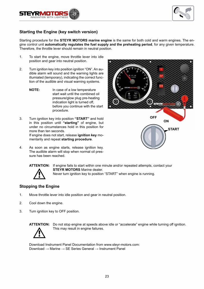
Starting the Engine (key switch version)
Starting procedure for the STEYR MOTORS marine engine is the same for both cold and warm engines. The en-gine control unit automatically regulates the fuel supply and the preheating period, for any given temperature. Therefore, the throttle lever should remain in neutral position.
1. To start the engine, move throttle lever into idle position and gear into neutral position.
2. Turn ignition key into position ignition “ON”. An au-dible alarm will sound and the warning lights are illumiated (temporary), indicating the correct func-tion of the audible and visual warning systems.
NOTE: In case of a low temperature start wait until the combined oil pressure/glow plug pre-heating indication light is turned off, before you continue with the start procedure.
3. Turn ignition key into position “START” and hold in this position until “starting” of engine, but under no circumstances hold in this position for more than ten seconds.
If engine does not start, release ignition key mo-mentarily and repeat starting procedure.
4. As soon as engine starts, release ignition key. The audible alarm will stop when normal oil pres-sure has been reached.
ATTENTION: If engine fails to start within one minute and/or repeated attempts, contact your STEYR MOTORS Marine dealer.Never turn ignition key to position “START” when engine is running.
Stopping the Engine
1. Move throttle lever into idle position and gear in neutral position.
2. Cool down the engine.
3. Turn ignition key to OFF position.
ATTENTION: Do not stop engine at speeds above idle or “accelerate” engine while turning off ignition. This may result in engine failures.
Download Instrument Panel Documentation from www.steyr-motors.com: Download → Marine → SE Series General → Instrument Panel
OFFON
START

24
F
G
Starting the Engine (push button version)
Starting procedure for the STEYR MOTORS marine engine is the same for cold or warm operating condition. The engine control unit automatically regulates the fuel supply and the preheating period, for any given temperature. Therefore, the throttle lever should remain in neutral position.
1. To start the engine, move throttle lever into idle position and gear into neutral position.
2. Press the push button for ignition (ill.F; red) (push button lock in place); An audible alarm will sound and the warning lights are illumiated (temporary), indicating the correct function of the audible and visual warning system.
NOTE: In case of a low temperature start, wait until the combined oil pressure/glow plug pre-heating indication light is turned off, then continue with the start procedure.
3. Press the button START (ill.G; green) and hold in this position until “starting” of engine, but under no circumstances hold in this position for more than ten seconds.
If engine does not start, release start – push button momentarily and repeat starting procedure.
4. As soon as engine starts, release start button. The audible alarm will stop when normal oil pressure has been reached.
ATTENTION: If engine fails to start within one minute and/or repeated attempts, contact your STEYR MOTORS Marine dealer.Never push start button when engine is running.
Stopping the Engine (push button version)
1. Move throttle lever into idle position and gear in neutral position.
2. Cool down the engine.
3. Press push button ignition ON/OFF (ill.F) to disengage from locking position and to shut OFF the engine.
ATTENTION: Do not stop engine at speeds above idle or “accelerate” engine while turning off engine. This may result in engine failures.
Download Instrument Panel Documentation from www.steyr-motors.com: Download → Marine → SE Series General → Instrument Panel

25
Run In Procedure After Major Overhaul
The following run in procedure must be used on STEYR MOTORS engines following a major overhaul, where a major overhaul is defined as a replacement of any or all of the following:
Crank Shaft, Piston(s), Con rod(s), Monoblock
Definitions
* Rated speed … Engine speed with maximum power* Half engine speed … Half of rated speed
Procedure, Work steps
Preparation* Engine filled with oil and coolant to max. levels* STEYR High Performance Diesel-Engine Oil 5W30* Coolant GLYCOSHELL – 50/50 % water/coolant* STEYR MOTORS engine diagnostic tool connected to the ECU
Test method* Remove the expansion tank pressure cap for degassing the system* Start the engine* Run at idle speed for 20 min* Stop the engine* Check coolant and oil level, top up to max. level if necessary* Close the expansion tank with the pressure cap* Start the engine* Warm up the engine (~15 mins.)* Run the boat minimum for 4 hrs at no more than half engine speed* Check oil level, top up to max level* Check the error list in the ECU using the diagnostic programme, if no errors continue run in. If errors occurred,
contact STEYR MOTORS authorized Service-Partner for further decisions* Warm up the engine (~15 mins.)* Run the boat minimum for 2 hrs at no more than 75 % engine speed* Check the service code list in the ECU using the diagnostic program, if no errors continue run in. If errors
occurred, contact STEYR MOTORS authorized Service-Partner for further decisions* Warm up the engine (~15 mins.)* Start the STEYR MOTORS diagnostic tool data logger* Run the boat minimum for 20 mins. at full rated speed* Stop diagnostic tool data logger and save the file (filename: engine number and date
e.g. 68225765_20080910.dat)* Check the service code list in the ECU. If errors occurred, contact STEYR MOTORS authorized Service-Partner
for further decisions* Send the data Log file to STEYR MOTORS authorized Service-Partner * Check coolant and oil level at cold engine, top up to max. level if necessary* Continue using the engine acc. to STEYR MOTORS Operator Manual

26
Engine Break-In procedure
All STEYR MOTORS Marine engines have been run for a short period as a final test at the factory. You must fol-low the Engine Break-In instructions during the first 20 running hours to ensure maximum performance and longest engine life.
NOTE: Non-observance of break-in instructions may cause severe engine failure.
First Ten Hours
Maximum Engine Speed: 75 % of rated speedMaximum Throttle Position: 75 %
For the first five to ten minutes of operation, run the engine at low speed (below 1500 RPM). For the remaining first ten hours of operation, accelerate to bring boat onto plane quickly. After reaching planing reduce throttle to remain at minimum planing. For displacement or semi displacement boats the throttle position of 75 % must not be tran-scended. Occasionally reduce throttle to idle speed for cooling down.
ATTENTION: Warning indication engine over load during break – in via ECU (Engine Control Unit) The ECU monitors, during the first two hours of engine operation, the load on the engine. If the engine is overloaded (during the first 2 hours of running) the “Check Engine Light” will automatically illuminate. If the warning light illuminates (CEL light – ON), the throttle position must be reduced until this signals are extinguish.
Final Ten Hours of Break-in
Maximum Short Term Speed: 100 % of rated speedMaximum Short Term Throttle Position: 100 %
During the final ten hours of break-in, the engine may run at full speed for max. 2 minutes. The remaining hours should be operated up to 75 % throttle position. For displacement or semi displacement boats the throttle position of 75 % must not be transcended Occasionally reduce the engine speed to cool is down.
NOTE: During the break-in period, the engine must not be operated at high rpm for longer periods.
During break-in period, be particularly observant of the following:A. Check motor oil level daily. Always maintain oil level in the desired range between the “MIN” and “MAX” marks
on dipstick. When refilling motor oil, refer to information “Engine Lubrication – Motor Oil” (page 49).B. Check oil pressure control lamp. If the lamp lights up as soon as the boat changes its position (while turning,
straightening up the boat or planing), check the oil level in the engine housing by means of dipstick. If neces-sary, add oil (DO NOT OVERFILL). In case that the oil pressure control lamp is still illuminated with correct oil level, have the engine checked by your STEYR MOTORS Marine dealer as to malfunction of signal or oil pump.
NOTE: During normal operation of engine, oil pressure will rise as RPM increases and fall as RPM decreases. In general, oil pressure will be higher with cold engine oil and specific RPM than with hot motor oil.
C. Check engine temperature indication. Normal operation between 75° – 95 °C (part heat up to full load, at idle speed the engine temperature will be between 68° and 80 °C depending on ambient temp. and raw water
temperature). In case of audible alarm, check coolant level in expansion tank (only with cold engine).D. Deviations from normal operating conditions will be indicated by warning lights and audible alarm. As to exact
meanings see section Error Indication on Instrument Panel.

27
ATTENTION: In case of non-observance of break-in instructions, warranty may expire.
Engine to be filled with recommended oil quality only. See chapter “Engine Lubrication”.
Operation after Break-In
The engines specified in this manual are intended to be operated at different speeds and loads, but not allowing full-load of the engine for more than one hour per 12 running hours. Economic driving may be achieved at the following speeds:
4 Cylinder Marine Engines (series MO) 6 Cylinder SE- Marine Engines:
MO54NA33 3000 rpm SE126E25 2300 rpm
MO84K32 3000 rpm SE156E26 2400 rpm
MO94K33 3000 rpm SE156E32 3000 rpm
MO114K33 3000 rpm SE196E35 3200 rpm
MO144M38 3200 rpm SE236E40 3800 rpm
MO164M40 3400 rpm SE236S36 3400 rpm
MO174V40 3400 rpm SE266E40 3800 rpm
SE266S36 3400 rpm
SE286E40 3800 rpm
SE306J38 3600 rpm4 Cylinder Marine Engines (series SE):
SE144E38 3400 rpm
SE164E40 3600 rpm
Which will prolong engine life and reduce sound emissions.When starting a cold engine, always allow the engine to warm up slowly. Never run the engine at full speed until operating temperature is reached. During the first 50 running hours, check the oil level frequently.

28
Shifting
Example: single lever shift control system
1. If the gear shift mechanism is disengaged, move the control lever to neutral position. The shift mechanism will automatically engage.
2. To go FORWARD – press the neutral lock button if fitted, and move the control lever forward. Throttle move-ment will begin after forward gear engagement.
3. To go in REVERSE – press the neutral lock button if fitted, and move the control lever backwards. Throttle movement will begin after reverse gear engagement.
4. To go from FORWARD to REVERSE, or REVERSE to FORWARD, always pause at NEUTRAL and allow en-gine speed to return to idle and vessel speed below 1kn.
5. After shifting is completed, continue to move the control lever slowly in the desired direction to increase speed.
NOTE: A sudden increase in shifting torque on the remote control lever indicates a possible problem in the shifting system. If so, see your STEYR MOTORS dealer as soon as possible for proper diagnosis and and necessary service adjustment. Continued operation under this condition could result in damage to the shifting mechanism.
29
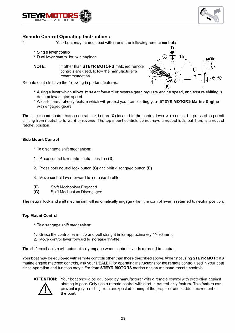
Remote Control Operating Instructions1 Your boat may be equipped with one of the following remote controls:
* Single lever control* Dual lever control for twin engines
NOTE: If other than STEYR MOTORS matched remote controls are used, follow the manufacturer’s recommendation.
Remote controls have the following important features: 1* A single lever which allows to select forward or reverse gear, regulate engine speed, and ensure shifting is
done at low engine speed.* A start-in-neutral-only feature which will protect you from starting your STEYR MOTORS Marine Engine
with engaged gears.
The side mount control has a neutral lock button (C) located in the control lever which must be pressed to permit shifting from neutral to forward or reverse. The top mount controls do not have a neutral lock, but there is a neutral ratchet position.
Side Mount Control
* To disengage shift mechanism:
1. Place control lever into neutral position (D)
2. Press both neutral lock button (C) and shift disengage button (E)
3. Move control lever forward to increase throttle
(F) Shift Mechanism Engaged (G) Shift Mechanism Disengaged
The neutral lock and shift mechanism will automatically engage when the control lever is returned to neutral position.
Top Mount Control
* To disengage shift mechanism:
1. Grasp the control lever hub and pull straight in for approximately 1/4 (6 mm).2. Move control lever forward to increase throttle.
The shift mechanism will automatically engage when control lever is returned to neutral.
Your boat may be equipped with remote controls other than those described above. When not using STEYR MOTORS marine engine matched controls, ask your DEALER for operating instructions for the remote control used in your boat since operation and function may differ from STEYR MOTORS marine engine matched remote controls.
ATTENTION: Your boat should be equipped by manufacturer with a remote control with protection against starting in gear. Only use a remote control with start-in-neutral-only feature. This feature can prevent injury resulting from unexpected turning of the propeller and sudden movement of the boat.

30
How to Shift and Control Speed
NOTE: Do not shift into FORWARD or REVERSE unless engine is running. Damage to the shift mechanism could result from trying to shift without the engine running.
2 Move the control lever to neutral position (D). The shift mechanism will automatically engage. Press neutral lock button (C) on some single side mount control and move the control lever to shift into forward or reverse. The throttle will begin to advance after gear engagement. Continue to move the control lever slowly in the de-sired direction to increase speed.
(H) Reverse Shift Range (I) Reverse Throttle Range (D) Neutral position (J) Forward Throttle Range (K) Forward Shift Range
Fuel Economy
Using the fuel economy throttle range (M) can save fuel depending on boat load and hull design. When the boat reaches top speed, reduce engine speed slightly. Make sure the boat maintains to plane when reducing engine speed. Continue to reduce engine speed slightly while maintaining to plane. Do not allow boat to fall off plane. This will give a comfortable ride and help to save fuel at the same time.
Gear Box – Information
NOTE: You are requested to follow the instructions and recommendations provided by the marine gear box manufacturer.
High Altitude Operation
Your STEYR MOTORS Marine Engine is turbocharged, and there should not be any noticeable performance loss at high altitudes.
2

31
B
A E D
F
H
G
J
A1
I
CA1
Instrument panel (key switch version)
Instrument panel, standard
A tachometer F ignition keyA1 function buttons G blind plug – installation option for key
switch constant revolutionB engine parameter displayC warning light – battery charge H audible warning device
(installed on rear side of panel)D combined light preheating control & warning light engine oil pressure I emergency cut off switch (lanyard)
E warning light check engine J circuit breaker (10 amp)
If you should need additional instruments or accessories, please contact your STEYR MOTORS Marine dealer.

32
Instrument indication during normal operation
1. ignition ON (… before starting) System check – see light indication
NOTE: At low temperature condition (cold weather) the
combined light for glow plug preheating & engine oil pressure will not extinguish after 0,7 sec. (glow plug preheating phase).
In this case start engine immediately after the light extinguishes.
2. ignition ON (… before starting) Indication active error
3. engine running (after start) Normal condition
NOTE: For further information see: “Table – Error indication on Instrument Panel”
ON (0,7 sec.)
ON (5 sec.)
OFF
ON
ON (0.7 sec.)
ON (0.7 sec.)
OFF
OFF
OFF
ON (0.7 sec.)
ON (5 sec.)
ON

33
I
H
A
GB A1A1 C
H
J
E DF
Instrument panel (push button version)
A tachometer F push button – ignition ON/OFF (red)A1 function buttons G push button START (green)B engine parameter display H audible warning device
(installed on rear side of panel)C warning light – battery chargeD combined light preheating control &
warning light engine oil pressureI emergency cut off switch (lanyard)J circuit breaker (10 amp)
E warning light check engine
NOTE: Instrument gauges are automatically illuminated if ignition is turned ON.
NOTE: In the case of inversion the engine will be automatically shut off, in order to allow normal operation later. The ignition push button (F) must be switched OFF and ON again, then the engine can be restarted via
the push button START (G).

34
START
ON
OFF
START
ON
OFF
Instrument indication during normal operation (push button version)
1. ignition ON (… before starting) System check – see light indication
NOTE: At low temperature condition (cold weather) the
combined light for glow plug preheating & warning light engine oil pressure will not extinguish after 0,7 sec. (glow plug preheating phase).
In this case start engine immediately after the light extinguishes.
2. ignition ON (… before starting) Indication active error
3. engine running (after start) Normal condition
NOTE: For further information see: “Table – Error indication on Instrument Panel”
ON (0,7 sec.)
ON (0.7 sec.)
ON (0.7 sec.)
ON
ON (0.7 sec.)
ON (5 sec.)
ON
OFF
OFF
OFF

35
1
Emergency cut off switch (Lanyard)
An emergency cut off switch is a feature on the instrument panel. Use of this switch is highly recommended. To prop-erly use this feature, attach the lanyard securely to your clothing. Do not attach the lanyard to clothing that will tear away before the lanyard is pulled from switch to stop the engine. Using this switch is simple and should not interfere with normal operation of the boat. Care must be taken to avoid accidental pulling of lanyard during normal operation. Unexpected loss of forward motion will occur. This could allow occupants to be thrown forward. In case the emer-gency cut off switch had been activated (lanyard pulled) the engine can be restarted by a person if; the pull knob (ill. pos. 1) of the emergency switch is being pulled and held in this position. While holding the pull knob proceed with the normal start procedure and start engine. The engine will immediately stop if the pull knob is released under this circumstances.
ATTENTION: The emergency cut off switch can only be effective when in good working condition. Observe the following:* Lanyard must always be free of entaglements that could hinder its operation.* Once a month, check switch for proper operation. With engine running, pull lanyard. If
engine does not stop, see your STEYR MOTORS DEALER for replacement of switch.

36
Warning lights and audible alarm
Your boat with the STEYR MOTORS Marine Engine engine is equipped with three warning lights and one audible alarm (mounted behind the instrument panel) to indicate the following operation condition or system deficiencies. (The ECU will also reduce the engine power in case an important operating parameter limit has been exceeded).
* Indication Pre-warming Phase (combined indication through oil pressure light. Becomes affective if ambient engine coolant temperature is below 20 °C/68 °F)
* Break – In; over load warning
* Engine oil pressure too low
* High coolant temperature
* Sensors or sensor circuit defect
After ignition is turned “ON” the indication/warning lights are illuminated and the warning horn will sound for less then a second (0,7 sec.) this serves as a functional check for the optical/audible warning system.
The indication light and the warning horn remain switched on for 5 sec. after ignition “ON” if a sensor or sensor circuit defect have been detected and stored in the Engine Control Unit (ECU) (see section Instrument Panel).Please contact your nearest STEYR MOTORS Marine Dealer to get proffesional assistance to verify the deficiency and to correct any possible failure.
If the engine oil pressure is too low, the warning light “engine oil pressure” lights and the audible alarm sounds. The engine power will be limited. In this case proceed as follows:
* Check engine oil level, respectively add engine oil if necessary (refer to chapter Fuel and Lubricants)
* Restart engine and watch the oil pressure light. The warning light has to extinguish within 3 or 4 second after the start. If this does not happen the engine must be stopped immediately. (Ignition “OFF”)
In case of an overheating of the exhaust gas cooling system, the warning light “engine control” flashes and the au-dible alarm sounds (2 times per second); the engine power is reduced. In this case, proceed as follows:
* IMMEDIATELY reduce the engine to idle speed.
* Check an clean the raw water filter.
* Check the coolant temperature gauge for overheating of engine coolant. If the coolant temperature gauge indicates overheating of engine coolant, switch for a short time to REVERSE to remove a possible clogging of the raw water inlet through large plastic parts etc., and then to FORWARD. Let the engine run at idle speed for some minutes. If the temperature gauge still indicates an overheating of the engine, the engine is to be stopped. Restart the engine only after having found and eliminated the cause for alarm. See “loss of power” in Trouble Shooting Chart, Technical Data and in section Maintenance. Check coolant level and if necessary, refill coolant until an adequate coolant level is achieved. If the cause for optical/audible alarm cannot be found, consult your STEYR MOTORS Marine dealer.

37
Electronic Engine Control Unit (ECU)
The STEYR MOTORS Marine engine is equipped with an Electronic Engine Control Unit (ECU) that performs the following:
* controls engine functions to ensure maximum efficiency.
* self-diagnostic to protect the engine from damage if operating parameter are exceeded.
* stores diagnostic data of ECU server circuits for maintenance and service.
* stores abuse data
Engine power is reduced if:
Operating Parameter
Effect noticed
Panel Indication
Additional Tool-Readings
Action or possible reason
High engine coolant temperature limit exceeded
Reduction of engine speed
Horn ON 2x p. sec. Gauge reading >107 °C
Steyr Diag Power limitation
See table trouble shooting: Cooling system
Defect – engine coolant sensor or sensor connection
Reduction of engine speed
Horn ON 2x p. sec. Steyr Diag Service code
Sensor or connector failure; see service code table
Exhaust temperature limit exceeded
Reduction of engine speed
Horn and indication light “CEL” ON 2x p. sec.
Steyr Diag Power limitation
See table trouble shooting: Raw water cooling system
Defect – Exhaust temperature sensor or sensor connection
Reduction of engine speed
Horn and indication light “CEL” ON 2x p. sec
Steyr Diag Service code
Sensor or connector failure; see service code table
Oil pressure below limit
Reduction of engine speed
Horn continuous and Oil indication light continous switched ON
Steyr Diag Power limitation
See table trouble shooting: Engine oil system
Defect – Oil pressure sensor or sensor connection
Reduction of engine speed
Oil pressure indication light switched ON 1x p. sec.
Steyr Diag Service code
Sensor or connector failure; see service code table
Insufficient boost pressure or defective sensor
Reduction of engine speed
Steyr Diag Power limitation
See table trouble shooting: Air charge system
Engine speed sensor fault
Irregular engine speed or stalled engine
No RPM indication on tachometer
Steyr Diag Service code
See table trouble shooting: Speed sensor
Engine speed remains at idle
No increase of engine speed if throttle is moved to max.
Steyr Diag Service code
See table trouble shooting: Accelerator potentiometer failure
Governor position system
Irregular engine speed or stalled engine
Steyr Diag Service code
See table trouble shooting: Governing system

38
Diagnostic system
The electronic engine control unit monitors the following engine parameters:oil pressure, boost pressure, coolant temperature, exhaust pipe temperature (Hi-riser), sensor control rack, potenti-ometer accelerator, speed signal
The ECU carries out self-diagnostic and/or plausibility checks for all input values and sensor connections. In case of irregularities, there is an optical or audible warning signal. (see page 79)
Stored service codes can be selected and cleared after elimination of deficiency via SCC P/No: 2179497-0Please consult authorized STEYR MOTORS service partners to assist in faultfinding procedure if necessary.
Malfunction during operation is ranked in three different categories intermittent failure, non essential failure and es-sential failure.
39
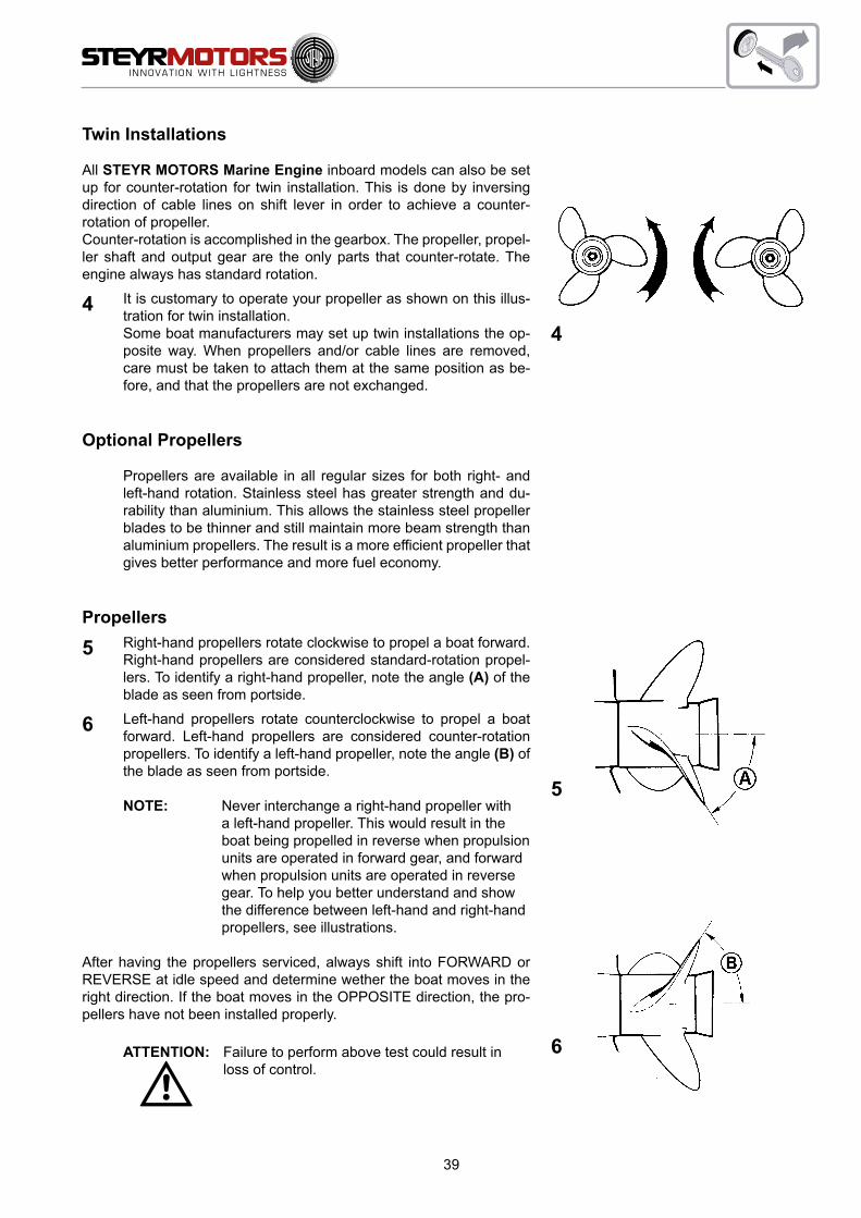
Twin Installations
All STEYR MOTORS Marine Engine inboard models can also be set up for counter-rotation for twin installation. This is done by inversing direction of cable lines on shift lever in order to achieve a counter-rotation of propeller.Counter-rotation is accomplished in the gearbox. The propeller, propel-ler shaft and output gear are the only parts that counter-rotate. The engine always has standard rotation.
4 It is customary to operate your propeller as shown on this illus-tration for twin installation.
Some boat manufacturers may set up twin installations the op-posite way. When propellers and/or cable lines are removed, care must be taken to attach them at the same position as be-fore, and that the propellers are not exchanged.
Optional Propellers
Propellers are available in all regular sizes for both right- and left-hand rotation. Stainless steel has greater strength and du-rability than aluminium. This allows the stainless steel propeller blades to be thinner and still maintain more beam strength than aluminium propellers. The result is a more efficient propeller that gives better performance and more fuel economy.
Propellers
5 Right-hand propellers rotate clockwise to propel a boat forward. Right-hand propellers are considered standard-rotation propel-lers. To identify a right-hand propeller, note the angle (A) of the blade as seen from portside.
6 Left-hand propellers rotate counterclockwise to propel a boat forward. Left-hand propellers are considered counter-rotation propellers. To identify a left-hand propeller, note the angle (B) of the blade as seen from portside.
NOTE: Never interchange a right-hand propeller with a left-hand propeller. This would result in the boat being propelled in reverse when propulsion units are operated in forward gear, and forward when propulsion units are operated in reverse gear. To help you better understand and show the difference between left-hand and right-hand propellers, see illustrations.
After having the propellers serviced, always shift into FORWARD or REVERSE at idle speed and determine wether the boat moves in the right direction. If the boat moves in the OPPOSITE direction, the pro-pellers have not been installed properly.
ATTENTION: Failure to perform above test could result in loss of control.
4
5
6

40
Propeller Torque
The torque of the propeller creates forces that are transmitted to the boat. This can cause the boat to lean to one side (list).
The forces created by the counter-rotating propeller are opposite to the forces created by the standard rotating pro-peller. When the vertical drives are trimmed equal, these opposite forces balance each other.
Propeller care
A damaged or unbalanced propeller will cause excessive vibration and a loss of boat speed. Under these conditions, stop the engine and check the propeller for damage. If the propeller seems to be damaged, have it checked and repaired by your local STEYR MOTORS Marine dealer. Always carry a spare propeller and replace the damaged propeller as soon as possible.
NOTE: Never run with a damaged propeller. Running with a damaged propeller can result in damage to drive components and engine.
Water Jet
When using water jet drives, please contact your STEYR MOTORS Marine dealer. As to information on function and application, please refer to respective documents and documentation of the drive manufacturer.
Operating Procedure for Freezing Temperatures
When freezing temperatures are forecast and the boat will be operated and left in the water, the propeller must re-main in the tilted down (submerged) position at all times to prevent water in the vertical drive from freezing. Upon completion of engine operation, drain the engine as described in Off-Season Storage Preparations.
Salt Water Operation
Fresh water to flush the raw water circuit is recommended after use in salt, polluted, or brackish water to prevent deposits from clogging and corroding the cooling passages. Contact your STEYR MOTORS Marine dealer to obtain an Engine Flushing Kit that allows flushing of the engine when in or out of the water.
NOTE: Use in salt or brackish water may require additional anti-corrosion protection.
NOTE: START and RUN Diesel-Engine while raw water circuit is flushed with fresh water!
High Altitude Operation
Your STEYR MOTORS Marine Engine is specified to operate within an altitude from a sea level of 1000 meters with-out any performance loss. Operation in altitude above 1000 meter are not recommended.

41
Fuel Pump
The STEYR MOTORS Marine Engine is equipped with an electric fuel pump. It is turned “ON” and “OFF” with the key switch. If the engine is not started within 10 seconds after turning the key switch “ON”, the fuel pump is automati-cally turned off.
Fuel System Checks
Fill the tank with the recommended fuel. Keeping tanks full reduces water condensation and helps keep fuel cool, which is important to engine performance.
Make sure that fuel supply valves (if used) are open, and valve cock seals are absolutely (gas) tight.
To insure a prompt start and an even run of the engine, the fuel system is to be rinsed by means of the electric fuel pump (ignition “ON” several times for app. 10 sec.) before starting the engine the first time and/or after every replace-ment of a fuel filter.
Refill fuel at the end of each day's operation to prevent condensation build up in tank. Condensation formed in a partially filled tank contaminates the fuel and promotes the growth of microbial organisms that can block fuel filters and restrict fuel flow.
If the engine is equipped with a fuel/water separator, drain off any water that has accumulated. Water in fuel can seri-ously affect engine performance and damage injection equipment reducing engine life expectancy.STEYR MOTORS recommends installing a pre-fuel filter with water separating capability. The filter flow rate must allow a flow rate of 350 l/h with a maximum permissible pressure drop rate of laess than 200 mBar.
Fuel Contamination
In the marine environment, the most likely fuel contaminants are water and microbial growth (black “slime”). Gener-ally, this type of contamination is the result of poor fuel handling practices. Black “slime” requires water in the fuel to form and grow; the best prevention is to keep water content in storage tank to a minimum.Treating fuel with microbial growth requires the use of fuel additive.
STEYR MOTORS does recommend the use of fuel additives such as Biobor JF, or equivalent, for treatment of mi-crobiological fuel contamination. Follow the manufacturers instructions for use. If treating fuel, frequent fuel filter changes will be necessary until fuel system is purged.
NOTE: A galvanized steel tank should never be used for fuel storage, because the fuel reacts chemically with the zinc coating forming powdery flakes which can quickly clog the fuel filters and damage the fuel pump and injectors.
NOTE: Do not dry run fuel pump.

42
906009
A
806008
A
Cooling System (Function Description 4 Cylinder Marine Engine)
STEYR MOTORS Marine Engines are equipped with a closed (internal) and an open (external cooling circuit).
7 Closed Cooling Circuit
The closed cooling circuit includes monoblock as well as exhaust manifold, heat exchanger and expansion tank. Temperature in the closed cooling circuit is precisely controlled by means of thermo-stat. The thermostat determines the amount of coolant circulating through the heat exchanger, thus controlling the operating tem-perature of the engine.
A temperature sensor (7/A) controls the cooling temperature. An excessive temperature rise of the coolant will cause an optical and audible alarm (see table “Error indication on Panel Section”). In this case, engine power will be reduced.
The temperature gauge on the instrument panel indicates the coolant temperature of the engine
8 Open Cooling Circuit (Raw Water Circuit)
Thermal energy transfered by the engine and absorbed by the engine coolant is drained via the (external) raw water circuit. Raw water is sucked by the pump via the raw water intake, constantly pumped through intercooler and heat exchanger, and discharged together with the exhaust gas inside the exhaust elbow. In this passage the raw water exits through the exhaust pipe system.
A temperature sensor (8/A) monitors the raw water- and exhaust gas mix-temperature. An excessive rise will cause an optical and audible alarm (see table “Error indication on Panel Section”). In this case, the engine power will be reduced.
INFO: If there is no elbow exhaust assembly exhaust available, for example tie strap it to a secure area with the existing harness, or contact your STEYR MOTORS Marine dealer.
7
8

43
Cooling System (Function Description 6 cylinder SE Marine Engine)
STEYR MOTORS Marine Engines are equipped with a closed (internal) and an open (external cooling circuit).
9 Closed Cooling CircuitThe closed cooling system consist of pressurized circuit and a expansion vessel. The pressurized circuit consists of coolant distribution manifold, monoblock coolant jacket, exhaust manifold with thermostat and heat exchanger. The system pressure is controlled by a pressure cap on the expansion vessel. The level of coolant in the expansion ves-sel differes between cold and warmed up engine in a range of the min- & max-indicating marks. Temperature in the closed cooling circuit is controlled by means of thermostat. The thermostat determines the amount of coolant circulat-ing through the heat exchanger, thus controlling the operating temperature of the engine.
A temperature sensor (9/A) controls the cooling temperature. An excessive temperature rise of the coolant will cause an optical and audible alarm (see table “Error indication on Panel Section”). In this case, engine power will be reduced.
The temperature gauge on the instrument panel indicates the coolant temperature of the engine.
10 Open Cooling Circuit (Raw Water Circuit)
Thermal energy transfered by the engine and absorbed by the engine coolant is drained via the (external) raw water circuit. Raw water is sucked by the pump via the raw water intake, constantly pumped through intercooler and heat exchanger, and discharged together with the exhaust gas inside the exhaust elbow. In this passage the raw water exits through the exhaust pipe system.
A temperature sensor (10/A) monitors the raw water- and exhaust gas mix-temperature. An excessive rise will cause an optical and audible alarm (see table “Error indication on Panel Section”). In this case, the engine power will be reduced.
NOTE: Should engine overheat at high speeds, slowly reduce RPM to idling to prevent damages to the engine. In case of overheating problems, contact your STEYR MOTORS Marine dealer.
9
10

44
Electrical Equipment
The electrical equipment of your STEYR MOTORS Marine engine primarily consists of an alternator with transistorized voltage regulator, battery and all necessary connecting cables and leads.
NOTE: 24 V on board system requires a specified dc/dc-converter to supply the entire Engine Management System EMS with 12V. For detailed instructions consult your autorized STEYR MOTORS Service Partner.
Alternator
The alternator is driven via a poly-V-belt resp. serpentine belt charges the battery at all engine speeds. Output at idle speed is limited to low amparage/voltage values and will rise with an engine speed to maximum output above 3000revs.
Optional:Alternators are available with different outputs and voltages.
Battery
FOR ALL 4 CYL. MARINE ENGINESUse a 12-volt battery with a cold testing circuit of 450 A at –18 °C and a minimum capacity of 92 Ah at 27 °C, to ensure the supply of the electric and electronic components at all operating conditions.
FOR ALL 6 CYL. MARINE ENGINESUse a 12-volt battery with a cold testing circuit of 650 A at –18 °C and a minimum capacity of 115 Ah at 27 °C, to ensure the supply of all electric and electronic components.
ATTENTION: * Do not use jumper cables and a booster battery to start engine. Remove battery from boat and recharge.
– WRONG CONNECTION WILL DESTROY ELECTRONIC SYSTEM –
* Do not charge battery in boat. Fumes vented during battery charging can lead to an explosion.
* Battery electrolyte is a corrosive acid and should be handled with care. If electrolyte is spilled or splashed on any part of the body, immediately flush the exposed area with liberal amounts of water and obtain medical aid as soon as possible.
High resistance in the charging circuit can seriously affect the operation of the electrical system. Unless there is definite malfunction in the electrical system, high resistance is sometimes caused by corroded or loose connections. Wherever practical, the electrical connections on your engine have been sealed. However, we recommend that you make periodic inspections to ensure clean, tight connections throughout the electrical system.
NOTE: It is important that the battery connections are correct. The negative battery cable must be attached to the negative terminal (–) on the battery and the engine’s positive cable must be attached to the positive terminal (+) on the battery. If these connections are reversed, the regulating unit may be immediately damaged.
Inspect your battery at regular intervals for specific gravity (state of charge), individual cell water level, cleanliness and clean, tight connections.
If the battery has become discharged for no apparent reason, check all electrical system components for malfunction, or a switch left in ON position prior to installing recharged battery.

45
Circuit Breakers & Fuses 4 Cylinder Marine Engine
STEYR MOTORS Marine Engine models are protected against overload by circuit breakers.
11 On the base plate of the E-box three thermical triggered 50 amp. circuit breakers are installed. (F2) protects the electric circuit of the glow plugs of cylinder 1 & 2 ; (F3) protects the electric circuit for the glow plugs of cylinder 3 & 4 ; (F1) protects electric system and electronic management.
The ignition key and instruments are protected by a 10 amp. Fuse located in the main wiring harness beneath instrument panel (location ignition key).
F4 Fuse supply module F5 Fuse main circuit supply F6 Fuse fuel-pump circuit F7 Fuse glow-plug circuit F9 Fuse ignition switch circuit (instrument panel)
NOTE: Fuses for fuel, ECU-supply, glow plug-relay are inside the E-box cover.
Circuit Breakers & Fuses 6 Cylinder SE Marine Engine
STEYR MOTORS Marine Engine models are protected against overload by circuit breakers.
12 The base plate of the E-box carries 6 different thermal triggered circuit breakers.
Fuse Protection Level and Function
F1 20 Amp Fuse VBatt Main Relay F2 25 Amp Fuse fuel-pump circuit F3 20 Amp Fuse ECU circuits F4 50 Amp Fuse glow-plug circuit F5 50 Amp Fuse glow-plug circuit F6 12,5 Amp Fuse D+ Alternator Terminal
NOTE: Avoid sparks that will damage the alternator or ECU. Do not attempt to connect or disconnect any part of the electrical system while the engine is running.
NOTE: The installation of any additional electrical accessories requires the protection of individual circuits. Consumption of current should occur directly at the battery.
1006011
F4
F5
F6
F7
F2
F1
F311
12
F1F2
F3
F4
F5F6
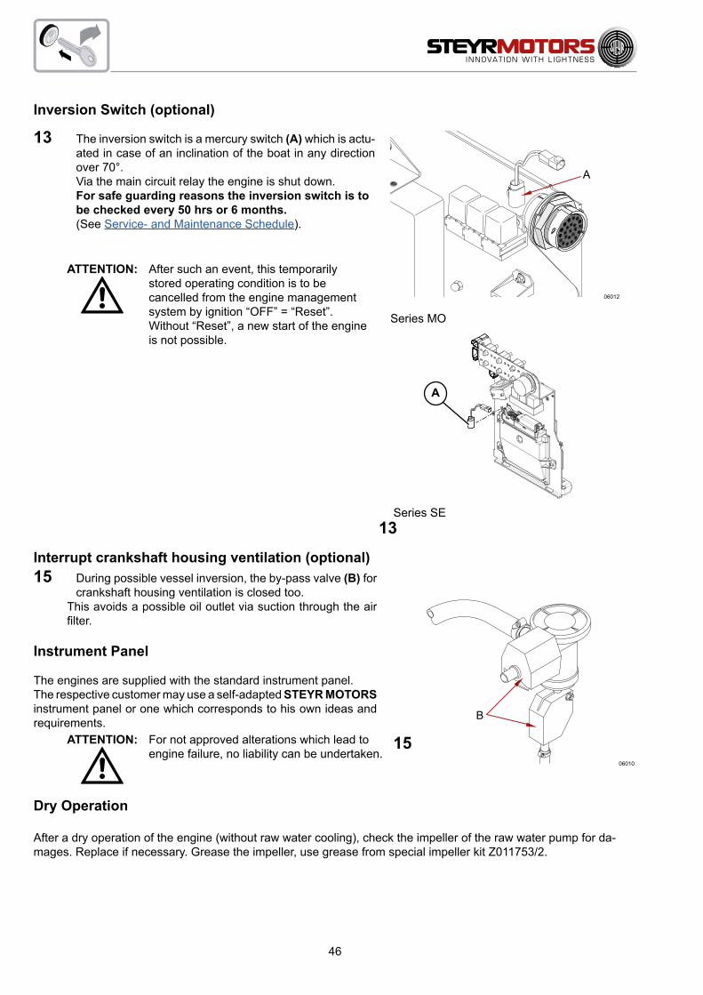
46
1106012
A
1206010
B
15
Inversion Switch (optional)
13 The inversion switch is a mercury switch (A) which is actu-ated in case of an inclination of the boat in any direction over 70°.
Via the main circuit relay the engine is shut down. For safe guarding reasons the inversion switch is to
be checked every 50 hrs or 6 months. (See Service- and Maintenance Schedule).
ATTENTION: After such an event, this temporarily stored operating condition is to be cancelled from the engine management system by ignition “OFF” = “Reset”.Without “Reset”, a new start of the engine is not possible.
Interrupt crankshaft housing ventilation (optional)15 During possible vessel inversion, the by-pass valve (B) for
crankshaft housing ventilation is closed too. This avoids a possible oil outlet via suction through the air
filter.
Instrument Panel
The engines are supplied with the standard instrument panel.The respective customer may use a self-adapted STEYR MOTORS instrument panel or one which corresponds to his own ideas and requirements.
ATTENTION: For not approved alterations which lead to engine failure, no liability can be undertaken.
Dry Operation
After a dry operation of the engine (without raw water cooling), check the impeller of the raw water pump for da-mages. Replace if necessary. Grease the impeller, use grease from special impeller kit Z011753/2.
13
Series MO
Series SE
A

47
This Page is intentionaly blank

48
FUEL AND LUBRICANTS
Fuel Requirements .................................................................................. 49
How to Select Fuel .................................................................................. 49
Filter Maintenance & Service ................................................................... 49
Engine Lubrication ................................................................................... 50
Motor Oil .................................................................................................. 50
Oil Identification Symbol .......................................................................... 50
Disposal of Automotive Waste Products .................................................. 51

49
Fuel Requirements
The STEYR MOTORS Marine Engines are designed for maximum fuel economy. To maintain specified per-formance, use diesel fuel according to EN590 or equivalent.
How to Select Fuel
Fuel quality is an important factor in obtaining satisfactory engine performance, long engine life, and accep-table exhaust emission levels. Direct injected diesel engines are designed to operate with most diesel fuels marketed today.
For more details refer to our downloadlink:
http://www.steyr-motors.com/marine-diesel-engines/2-4-and-6-cylinder
Click to "here" in the sentence:
"Click here to learn more about the STEYR MOTORS M1 multi fuel capability"
Filter Maintenance & Service
Check for Service Intervalls on pre- & finefilter as specified on the maintenance table or if neccessary due to fuel contamination.
Pre-Filter Specification:Flow rate: 350 l/hMin Water separation efficiency: 93 %(acc. ISO 4020, out of emulsified water, at max. flow rate)Min particle filtration efficiency: 10 %( acc. ISO TR13353:1994 3-5μm @max. pump flow rate)max pressure loss at filter(new): 50 mbarmax pressure loss at filter(used): 200 mbarSTEYR MOTORS recommends the use of Fuel Prefilter / Water Separator (Kit-No.: MS1203010)for SE-Engine Series.
Specification for Fuel-line diameters has to be considered. For detailed installation specification of the corresponding engine, please contact STEYR MOTORS Authorized Dealers.

50
API SERVICE SYMBOL
Engine Lubrication
If you choose to lubricate your STEYR MOTORS Marine En-gine yourself, refer to the Lubrication and Inspection Chart for lubrication points and recommended lubricants. Use only STEYR MOTORS recommended lubricants or lubricants of equiv-alent quality and viscosity. See your STEYR MOTORS dealer for recommended lubricants.
If you choose to have your STEYR MOTORS Marine Engine lu-bricated, see your local dealer.
Motor Oil
To obtain the best engine performance and engine life,STEYR MOTORS High Performance Diesel Engine Oil SAE 5W-30 (Z010059-0) is recommended. Engine oils are specified by ACEA, API service codes and SAE viscosity numbers. If STEYR MOTORS High Performance Diesel Engine Oil is not available, it is required to use a reputable brand of engine oil labelled for ACEA C3 and API CF and SAE 5W-30. Refer to oil identification symbol on the container.
During the break-in period (initial 20 hours), frequently check the oil level. Higher oil consumption is normal until cylinder system is sta-bilized. The oil level should be maintained between the minimum and maximum mark on the dipstick. The space between the marks represents approximately 3.7 quarts (3.5 litres). For oil level dip-stick location, refer to your authorized STEYR MOTORS-dealer.
NOTE:Optional there are two different oil dip sticks available according to the engine storage inclination. After first 50 hours of operation change the engine oil and replace the oil filter. Refer to Service and Maintenance Schedule.
Oil Identification SymbolEngine oils are specified by ACEA, API service code and SAE viscosity numbers. These may be found on the label, top of can, or API service symbol.
NOTE: Some engine oils have several ACEA / API quality ratings. The recommended ACEA / API service letter code must be among these quality ratings.STEYR MOTORS has no values regarding the oil- & fuel- consumption, when a not known oil is in use. Refer to F1 - List of operating material
Content 5 lt
EXCEEDS: ACEA: C3, API: CM/CFBMW LL04; MB Approval 229.51;VW 504.00/507.00; Porsche C30
STEYR HIGH PERFORMANCE DIESEL
STEYR HIGH PERFORMANCE DIESEL ENGINE OIL OIL FOR UNIT INJECTOR
Premium protection for engine and exhaustafter treatment systems Full syntheticLonger life for all high performance enginesMaximum wear protection under all conditions

51
Disposal of Automotive Waste Products
Used fuel and oil is to be collected in separate containers to permit an eventual subsequent treatment.
The disposal of any fuel and oil for the engine is subject to the special waste act. The “special waste catalogue” önorm s2100 refers to the necessary disposal in austria. Please follow the local regulations of your country.
The operating and maintenance personnel has to take care that fuel and oil as well as other material ranking as spe-cial waste are deposited at the respective collecting points.
Code No. Designation
31 423 oil contaminated ground or oil binder54 102 waste oil54 104 fuel54 202 grease54 207 vaseline54 917 compact sealing material54 927 oil contaminated scouring cloth54 928 usel oil- and air filters55 510 colour- or varnish containing waste

52
full loadspeedrange
100%
90%
80%
70%
60%
50%
40%
30%
B
C D
RPM
A
OUTPUT
POWER
TECHNICAL DATA
Model and Serial Numbers ...................................................................... 53
Technical Data and Overview MO54NA33 .............................................. 54
Technical Data and Overview MO84K32, MO94K33, MO114K33 ........... 56
Technical Data and Overview MO144M38, MO164M40, MO174V40 ..... 58
Technical Data and Overview SE164E40, SE144E38 ............................ 60
Technical Data and Overview SE-Engines .............................................. 62
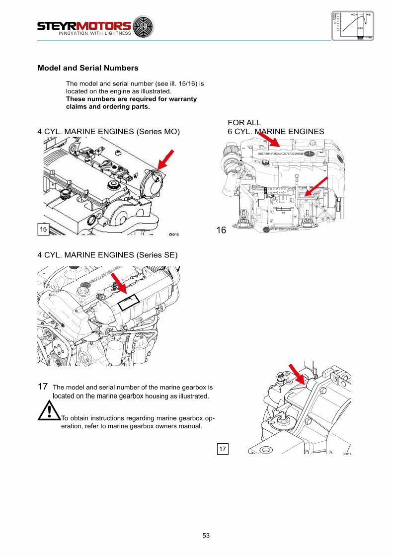
53
1706014
full loadspeedrange
100%
90%
80%
70%
60%
50%
40%
30%
B
C D
RPM
A
OUTPUT
POWER
Model and Serial Numbers
The model and serial number (see ill. 15/16) is located on the engine as illustrated. These numbers are required for warranty claims and ordering parts.
FOR ALL 4 CYL. MARINE ENGINES (Series MO) 6 CYL. MARINE ENGINES
4 CYL. MARINE ENGINES (Series SE)
17 The model and serial number of the marine gearbox is located on the marine gearbox housing as illustrated.
To obtain instructions regarding marine gearbox op-eration, refer to marine gearbox owners manual.
16

54
full loadspeedrange
100%
90%
80%
70%
60%
50%
40%
30%
B
C D
RPM
A
OUTPUT
POWER
Technical Data and Overview MO54NA33
MAKE STEYR MOTORS M 14 M
type MO54NA33
displacement 2133 cm³
piston displacement 85,0 x 94,0 mm
rated power acc. EN ISO 8665:2006 (impeller*) KW/HPJet – Drive/InboardZ – Drive
39/5238/52
number of cylinders 4-cylinder in-line engine (position of cyl. 1 at vibration damper side)
ignition order 1 – 3 – 4 – 2
sense of rotation, seen from front right
compression ratio 17,0:1
propped speed range (rpm) 3300 rpm (+0 rpm/–200 rpm)
idle speed 700 rpm (adjustable)
injection Plunger activated, two stage, high pressure with electronically controlled injection rate
fuel acc. to CEC RF-03-A-84 (DIN 51601) Cetan >45; diesel fuel No. 2-D, temperature above –7 °C; No.1-D, temperature below –7 °C
fuel filter refer to spare part catalogue
fuel filter location intake-sided
air filter refer to spare part catalogue
oil pressure above 2000 rpm 400 – 700 kPa (58 – 101 PSI) microprocessor controlled
filling capacity motor oil approx. 8,0 l engine housing (incl. approx. 1 l oil filter contents)
specification motor oil SAE 5W-50/ACEA B4-02/API CF or 10W-40/ACEA E4, E5, E7/API CF P/N0. Z010058/0
oil and oil filter change intervals**) every 150 operating hours and/or once per season
oil filter refer to spare part catalogue
oil filter location pressure-sided
electric charging system 14 V/90 A alternator with transistorized voltage regulator
cooling system dual cooling circuit; thermostat-controlled, pressurized cooling circuit; circulating pump with heat exchanger on engine; governor pump, external raw water circuit to heat exchange
coolant capacity 11,5 liters
coolant STEYR MOTORS engine coolant –36 °CP/No. Z011785/0
*) Efficiency of gearbox = 97,0 %, efficiency of Z-Drive = 95,5 %**) Extended periods to be evaluated upon application and type of usage STEYR MOTORS GmbH.
Reserves the right to make changes without notice or obligations.

55
19
2 3 5 6
1817
14
12
11
13
7
8
45
2031
30
2928
22
21
24
252627
1
44
43
3332 34 35 36 37 38 39
42
41
40
151
5247
48
495150
16 10 9
full loadspeedrange
100%
90%
80%
70%
60%
50%
40%
30%
B
C D
RPM
A
OUTPUT
POWER
*) This sensor is magnetism sensitive. All external magnets must be kept away.
Overview for all STEYR MOTORS 4 Cyl. Marine Engines
Item Designation 1 Zinc Anode (2 Units) 2 Model and Serial Number 3 Intake Manifold 5 Fuel Pump 6 Oil Seperator 7 Raw Water Drain Plug 8 Valve Crankshaft Housing Ventilation (only SOLAS) 9 Oil Drain Plug 10 Fuel Filter1 11 Oil Filter 12 Hydraulic Pump 13 Raw Water Inlet Fitting 14 Raw Water Pump 15 Coolant Drain Plug (2 Units) 16 Engine Oilcooler 17 Oil Suction Pipe 18 Oil Dipstick 19 Hydraulic Oil Tank 20 Cooler Cap 21 Potentiometer Accelerator 22 Motor Oil Filler Cap 24 Rack Position Sensor*) 25 Drive Belt 26 Cover T-Belt, Lower 27 Engine Mount 28 Drive Belt Tensioner 29 Vibration Damper 30 Cover T-Belt, Upper 31 Engine Lifting Eye 32 Speed Sensor 33 Valve Cover 34 Heat Exchanger 35 Coolant Expansion Tank 36 Diagnostic Outlet 37 Inversion Switch (only for SOLAS) 38 Connector Instrument Panel 39 Coolant Temperature Sensor 40 Thermostat Housing 41 Alternator 42 Circuit Breakers 43 Engine Management System/Fuses 44 Exhaust Temperature Sensor 45 Air Filter 47 Exhaust Elbow 48 Starter Relais (Backside E-Box Ground Plate) 49 Starter Motor 50 Flywheel 51 Flywheel Housing 52 Oil Pressure Sensor

56
full loadspeedrange
100%
90%
80%
70%
60%
50%
40%
30%
B
C D
RPM
A
OUTPUT
POWER
Technical Data and Overview MO84K32, MO94K33, MO114K33
MAKE STEYR MOTORS M 14 TCM, TCAM
type MO84K32 MO94K33 MO114K33
displacement 2133 cm³
piston displacement 85,0 x 94,0 mm
rated power acc. EN ISO 8665:2006 (impeller*) KW/HPJet – Drive/InboardZ – Drive
53/7152/70
64/8663/84
78/10577/104
number of cylinders 4-cylinder in-line engine (position of cyl. 1 at vibration damper side)
ignition order 1 – 3 – 4 – 2
sense of rotation, seen from front right
compression ratio 17,5:1
propped speed range (rpm) 3200 rpm (+0 rpm/–200 rpm)
3300 rpm(+0 rpm/–200 rpm)
3300 rpm(+0 rpm/–200 rpm)
idle speed 700 rpm (adjustable)
injection Plunger activated, two stage, high pressure with electronically controlled injection rate
fuel acc. to CEC RF-03-A-84 (DIN EN 590) Cetan >49; diesel fuel No. 2-D, temperature above –7 °C; No.1-D, temperature below –7 °C
fuel filter refer to spare part catalogue
fuel filter location intake-sided
air filter refer to spare part catalogue
oil pressure above 2000 rpm 400 – 700 kPa (58 – 101 PSI) microprocessor controlled
filling capacity motor oil approx. 8,0 l engine housing (incl. approx. 1 l oil filter contents)
specification motor oil SAE 5W-30/ACEA C3/API CF P/No. Z010059-0
oil and oil filter change intervals**) every 150 operating hours and/or once per season
oil filter refer to spare part catalogue
oil filter location pressure-sided
electric charging system 14 V/90 A alternator with transistorized voltage regulator
cooling system dual cooling circuit; thermostat-controlled, pressurized cooling circuit; circulating pump with heat exchanger on engine; governor pump, external raw water circuit to heat exchange
coolant capacity 11,5 liters
coolant STEYR MOTORS engine coolant –36 °CP/No. Z011785/0
*) Efficiency of gearbox = 97,0 %, efficiency of Z-Drive = 95,5 %**) Extended periods to be evaluated upon application and type of usage STEYR MOTORS GmbH.
Reserves the right to make changes without notice or obligations.

57
06001
191817161514131211
1 5
1
4
78
2 3 6
10 9
38
06003
44
43
1 36
15
34
40
41
13932 33 37
42
35
06004
45
52
5150
4647
4849
06002
31
30
22
23
24
21
25
26
27
20
29
28
full loadspeedrange
100%
90%
80%
70%
60%
50%
40%
30%
B
C D
RPM
A
OUTPUT
POWER
Overview for all STEYR MOTORS 4 Cyl. Marine Engines
*) This sensor is magnetism sensitive. All external magnets must be kept away.
Item Designation 1 Zinc Anode (4 Units) 2 Model and Serial Number 3 Intercooler 4 Fuel/Oil Cooler with Raw Water Drain Plug 5 Fuel Pump 6 Oil Seperator 7 Raw Water Drain Plug 8 Valve Crankshaft Housing Ventilation (only SOLAS) 9 Oil Drain Plug 10 Fuel Filter 11 Oil Filter 12 Hydraulic Pump 13 Raw Water Inlet Fitting 14 Raw Water Pump 15 Coolant Drain Plug (2 Units) 16 Engine Oilcooler 17 Oil Suction Pipe 18 Oil Dipstick 19 Hydraulic Oil Tank 20 Cooler Cap 21 Potentiometer Accelerator 22 Motor Oil Filler Cap 23 Boost Pressure Sensor 24 Rack Position Sensor*) 25 Drive Belt 26 Cover T-Belt, Lower 27 Engine Mount 28 Drive Belt Tensioner 29 Vibration Damper 30 Cover T-Belt, Upper 31 Engine Lifting Eye 32 Speed Sensor 33 Valve Cover 34 Heat Exchanger 35 Coolant Expansion Tank 36 Diagnostic Outlet 37 Inversion Switch (only for SOLAS) 38 Connector Instrument Panel 39 Coolant Temperature Sensor 40 Thermostat Housing 41 Alternator 42 Circuit Breakers 43 Engine Management System/Fuses 44 Exhaust Temperature Sensor 45 Air Filter 46 Turbo Charger 47 Exhaust Elbow 48 Starter Relais (Backside E-Box Ground Plate) 49 Starter Motor 50 Flywheel 51 Flywheel Housing 52 Oil Pressure Sensor

58
Technical Data and Overview MO144M38, MO164M40, MO174V40
MAKE STEYR MOTORS M 14 TCAM
type MO144M38 MO164M40 MO174V40
displacement 2133 cm³
piston displacement 85,0 x 94,0 mm
rated power acc. EN ISO 8665:2006 (impeller*) KW/HPJet – Drive/InboardZ – Drive
103/138101/136
116/156114/154
121/165119/162
number of cylinders 4-cylinder in-line engine (position of cyl. 1 at vibration damper side)
ignition order 1 – 3 – 4 – 2
sense of rotation, seen from front right
compression ratio 17.5:1 17.0:1
propped speed range (rpm) 3800 rpm (+0 rpm/–300 rpm)
4000 rpm (+0 rpm/–300 rpm)
4000 rpm (+0 rpm/–300 rpm)
idle speed 700 rpm (adjustable)
injection Plunger activated, two stage, high pressure with electronically controlled injection rate
fuel acc. to CEC RF-03-A-84 (DIN EN 590) Cetan >49; diesel fuel No. 2-D, temperature above –7 °C; No.1-D, temperature below –7 °C
fuel filter refer to spare part catalogue
fuel filter location intake-sided
air filter refer to spare part catalogue
oil pressure above 2000 rpm 400 – 700 kPa (58 – 101 PSI) microprocessor controlled
filling capacity motor oil approx. 8,0 l engine housing (incl. approx. 1 l oil filter contents)
specification motor oil SAE 5W-30/ACEA C3/API CF P/No. Z010059-0
oil and oil filter change intervals**) every 150 operating hours and/or once per season
oil filter refer to spare part catalogue
oil filter location pressure-sided
electric charging system 14 V/90 A alternator with transistorized voltage regulator
cooling system dual cooling circuit; thermostat-controlled, pressurized cooling circuit; circulating pump with heat exchanger on engine; governor pump, external raw water circuit to heat exchange
coolant capacity 11,5 liters
coolant STEYR MOTORS engine coolant –36 °CP/No. Z011785/0
*) Efficiency of gearbox = 97,0 %, efficiency of Z-Drive = 95,5 %**) Extended periods to be evaluated upon application and type of usage STEYR MOTORS GmbH.
Reserves the right to make changes without notice or obligations.
full loadspeedrange
100%
90%
80%
70%
60%
50%
40%
30%
B
C D
RPM
A
OUTPUT
POWER

59
Overview for all STEYR MOTORS 4 Cyl. Marine Engines
*) This sensor is magnetism sensitive. All external magnets must be kept away.
Item Designation 1 Zinc Anode (4 Units) 2 Model and Serial Number 3 Intercooler 4 Fuel/Oil Cooler with Raw Water Drain Plug 5 Fuel Pump 6 Oil Seperator 7 Raw Water Drain Plug 8 Valve Crankshaft Housing Ventilation (only SOLAS) 9 Oil Drain Plug 10 Fuel Filter 11 Oil Filter 12 Hydraulic Pump 13 Raw Water Inlet Fitting 14 Raw Water Pump 15 Coolant Drain Plug (2 Units) 16 Engine Oilcooler 17 Oil Suction Pipe 18 Oil Dipstick 19 Hydraulic Oil Tank 20 Cooler Cap 21 Potentiometer Accelerator 22 Motor Oil Filler Cap 23 Boost Pressure Sensor 24 Rack Position Sensor*) 25 Drive Belt 26 Cover T-Belt, Lower 27 Engine Mount 28 Drive Belt Tensioner 29 Vibration Damper 30 Cover T-Belt, Upper 31 Engine Lifting Eye 32 Speed Sensor 33 Valve Cover 34 Heat Exchanger 35 Coolant Expansion Tank 36 Diagnostic Outlet 37 Inversion Switch (only for SOLAS) 38 Connector Instrument Panel 39 Coolant Temperature Sensor 40 Thermostat Housing 41 Alternator 42 Circuit Breakers 43 Engine Management System/Fuses 44 Exhaust Temperature Sensor 45 Air Filter 46 Turbo Charger 47 Exhaust Elbow 48 Starter Relais (Backside E-Box Ground Plate) 49 Starter Motor 50 Flywheel 51 Flywheel Housing 52 Oil Pressure Sensor
06001
191817161514131211
1 5
1
4
78
2 3 6
10 9
06036
31
30
22
23
24
21
25
26
27
20
29
28
38
06003
44
43
1 36
15
34
40
41
13932 33 37
42
35
06004
45
52
5150
4647
4849
full loadspeedrange
100%
90%
80%
70%
60%
50%
40%
30%
B
C D
RPM
A
OUTPUT
POWER

60
Technical Data and Overview SE164E40, SE144E38
MAKE STEYR MOTORS
type SE164E40 SE144E38
displacement 2133 cm³
piston displacement 85,0 x 94,0 mm
rated power acc. EN ISO 8665:2006 (impeller*) KW/HPJet – Drive/InboardZ – Drive
118/160114,5/155.7116,2/158
106/144102,8/139.8104,4/142
number of cylinders 4-cylinder in-line engine (position of cyl. 1 at vibration damper side)
ignition order 1 – 3 – 4 – 2
sense of rotation, seen from front right
compression ratio 17.0:1
propped speed range (rpm) 3800 rpm (+0 rpm/–300 rpm)
4000 rpm (+0 rpm/–300 rpm)
idle speed 750 rpm (adjustable)
injection Plunger activated, two stage, high pressure with electronically controlled injection rate, timing
fuel EN 590
fuel filter 2203710-0
fuel filter location intake-sided
air filter refer to spare part catalogue
oil pressure above 2000 rpm 400 – 700 kPa (58 – 101 PSI) microprocessor controlled
filling capacity motor oil approx. 8,4 l engine housing (incl. approx. 1 l oil filter contents)
specification motor oil SAE 5W-30/ACEA C3/API CF P/No. Z010059-0
oil and oil filter change intervals**) every 150 operating hours and/or once per season
oil filter refer to spare part catalogue
oil filter location pressure-sided
electric charging system 14 V/120 A alternator with transistorized voltage regulator
cooling system dual cooling circuit; thermostat-controlled, pressurized cooling circuit; circulating pump with heat exchanger on engine; governor pump, external raw water circuit to heat exchange
coolant capacity 9 liters
coolant STEYR MOTORS engine coolant –36 °CP/No. Z011785/0v
*) Efficiency of gearbox = 97,0 %, efficiency of Z-Drive = 95,5 %**) Extended periods to be evaluated upon application and type of usage STEYR MOTORS GmbH.
Reserves the right to make changes without notice or obligations.
full loadspeedrange
100%
90%
80%
70%
60%
50%
40%
30%
B
C D
RPM
A
OUTPUT
POWER

61
Overview for all STEYR MOTORS 4 Cyl. Marine Engines
Item Designation 1 Zinc Anode (2 Units) 2 Model and Serial Number 3 Intercooler 4 Fuel/Oil Cooler with Raw Water Drain Plug 5 Fuel Pump 6 Oil Seperator 7 Raw Water Drain Plug 8 Crankshaft Housing Ventilation 9 Oil Drain Plug 10 Fuel Filter 11 Oil Filter 12 Raw Water Inlet Fitting 13 Water Pump 14 Coolant Drain Plug 15 Engine Oilcooler 16 Oil Dipstick 17 Cooler Cap 18 Potentiometer Accelerator 19 Motor Oil Filler Cap 20 Boost Pressure Sensor 21 Rack Position Sensor*) 22 Drive Belt 23 Cover T-Belt, Lower 24 Engine Mount 25 Drive Belt Tensioner 26 Vibration Damper 27 Cover T-Belt, Upper 28 Engine Lifting Eye 29 Speed Sensor 30 Valve Cover 31 Heat Exchanger 32 Coolant Expansion Tank 33 Diagnostic Outlet 34 Inversion Switch (only for SOLAS) 35 Connector Instrument Panel 36 Coolant Temperature Sensor 37 Thermostat Housing 38 Alternator 39 Circuit Breakers 40 Engine Management System/Fuses 41 Air Filter 42 Turbo Charger 43 Exhaust Elbow 44 Starter Relais (Backside E-Box Ground Plate) 45 Starter Motor 46 Flywheel 47 Oil Pressure Sensor 48 Exhaust Temperature Sensor (without illustration) 49 Raw water outlet
*) This sensor is magnetism sensitive. All external magnets must be kept away.
12
13
1
9
6
78
10
11
143617
2 3 54
31 32
1819302728
28 29
20 21
1415
16
22
2324
3537
38
24
2526
334349
42
47
45
46
3444
40
41
39
full loadspeedrange
100%
90%
80%
70%
60%
50%
40%
30%
B
C D
RPM
A
OUTPUT
POWER

62
full loadspeedrange
100%
90%
80%
70%
60%
50%
40%
30%
B
C D
RPM
A
OUTPUT
POWER
Technical Data and Overview SE-Engines
MAKE STEYR MOTORS M 16 TCM, TCAM
type SE-Engines
displacement 3200 cm³
piston displacement 85,0 x 94,0 mm
number of cylinders 6-cylinder in-line engine (position of cyl. 1 at vibration damper side)
ignition order 1 – 5 – 3 – 6 – 2 – 4
sense of rotation, seen from front right
compression ratio 17:1
propped speed range (rpm) refer to chapter 1 – marine engine overview
idle speed 630 rpm (adjustable)
injection Plunger activated, two stage, high pressure with electronically controlled injection rate
fuel acc. to CEC RF-03-A-84 (DIN EN 590) Cetan >49; diesel fuel No. 2-D, temperature above –7 °C; No.1-D, temperature below –7 °C
pre- & main fuel filter refer to spare part catalogue
fuel filter location pressure-sided
air filter refer to spare part catalogue
filling capacity motor oil approx. 16,0 l engine housing (incl. approx. 1 l oil filter contents)
specification motor oil SAE 5W-30/ACEA C3/API CF P/No. Z010059-0
oil and oil filter change intervals**) every 300 operating hours and/or once per season
oil filter refer to spare part catalogue
oil filter location pressure-sided
cooling system dual cooling circuit; thermostat-controlled, pressurized cooling circuit; circulating pump with heat exchanger on engine; governor pump, external raw water circuit to heat exchange
coolant capacity 13,2 liters
coolant STEYR MOTORS engine coolant –36 °CP/No. Z011785/0
*) Efficiency of gearbox = 97,0 %, efficiency of Z-Drive = 95,5 %**) Extended periods to be evaluated upon application and type of usage STEYR MOTORS GmbH.
Reserves the right to make changes without notice or obligations.
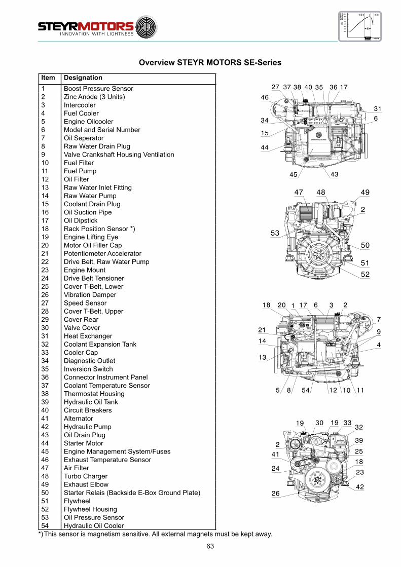
63
Item Designation1 Boost Pressure Sensor2 Zinc Anode (3 Units)3 Intercooler4 Fuel Cooler5 Engine Oilcooler6 Model and Serial Number7 Oil Seperator8 Raw Water Drain Plug9 Valve Crankshaft Housing Ventilation10 Fuel Filter11 Fuel Pump12 Oil Filter13 Raw Water Inlet Fitting14 Raw Water Pump15 Coolant Drain Plug16 Oil Suction Pipe17 Oil Dipstick18 Rack Position Sensor *)19 Engine Lifting Eye20 Motor Oil Filler Cap21 Potentiometer Accelerator22 Drive Belt, Raw Water Pump23 Engine Mount24 Drive Belt Tensioner25 Cover T-Belt, Lower26 Vibration Damper27 Speed Sensor28 Cover T-Belt, Upper29 Cover Rear30 Valve Cover31 Heat Exchanger32 Coolant Expansion Tank33 Cooler Cap34 Diagnostic Outlet35 Inversion Switch36 Connector Instrument Panel37 Coolant Temperature Sensor38 Thermostat Housing39 Hydraulic Oil Tank40 Circuit Breakers41 Alternator42 Hydraulic Pump43 Oil Drain Plug44 Starter Motor45 Engine Management System/Fuses46 Exhaust Temperature Sensor47 Air Filter48 Turbo Charger49 Exhaust Elbow50 Starter Relais (Backside E-Box Ground Plate)51 Flywheel52 Flywheel Housing53 Oil Pressure Sensor54 Hydraulic Oil Cooler
full loadspeedrange
100%
90%
80%
70%
60%
50%
40%
30%
B
C D
RPM
A
OUTPUT
POWER
Overview STEYR MOTORS SE-Series
*) This sensor is magnetism sensitive. All external magnets must be kept away.

64
MAINTENANCE AND TROUBLE SHOOTING
Owner Service Log ....................................................................................65
FOREWORD .............................................................................................65
IMPORTANT NOTE ...................................................................................65
Service- and Maintenance Schedule (Series MO) ....................................66
MAINTENANCE LOG ................................................................................69
Service- and Maintenance Schedule (Series SE) .....................................70
Table – Error Indication on Instrument Panel ............................................74
Table – Error Indication on Instrument Panel (for SOLAS only) ................76
Principle service code list ..........................................................................79
Principle service code list ..............................................................................
Principle service code list ..........................................................................81
Principle service code list ..............................................................................
Trouble Check Chart .................................................................................85
Wiring harness 4-cylinder engine ..............................................................87
Wiring diagram M0 12 V ............................................................................88
Wiring diagram M0 24 V ............................................................................89
Wiring diagram M0 E-Box external ............................................................90
WIRING DIAGRAM/MARINE, 4/6 CYLINDER, 2-POLE, 24 V, COMPLETE SYSTEM 91
Description – Wiring harness instrument panels 4 cyl. marine engines ....92
Wiring diagram Instument CAN Panel 12/24V ..........................................93
Wiring diagram Instument CAN Panel Solas 12/24V ................................94
Wiring diagram SE E-Box 12V ..................................................................95
Wiring diagram SE E-Box 24V ..................................................................96
Wiring diagram external E-Box ..................................................................97
Wiring diagram E-Box 12 V (4 cylinder, series SE) ...................................98
Wiring diagram external E-Box 12 V (4 cylinder, series SE) .....................99

65
Owner Service Log
FOREWORD
On receipt of your new STEYR MOTORS Marine Engine, the authorised dealer has signed the pre-delivery inspec-tion log thus confirming to have carried out a pre-delivery service according to the manufacturers specifications.
Future service requirements are indicated in this OWNER SERVICE LOG. When these services are carried out, the STEYR MOTORS Marine dealer will stamp the respective stubs. This servicing will assist in maintaining the value and satisfactory operation of your STEYR MOTORS Marine Engine.
It lies in the owner’s interest that for maintaining warranty and best performance of his STEYR MOTORS Marine Engine he always insists on the sole utilization of STEYR MOTORS – ORIGINAL replacement parts, operational fluids and lubricants as well as STEYR MOTORS proved service procedures!
It is important that you study this booklet carefully as it will assist you in achieving satisfaction from your STEYR MOTORS Marine Engine. Please retain this manual in the boat as it MUST be presented to the STEYR MOTORS Marine dealer whenever you require WARRANTY and/or SERVICE.
IMPORTANT NOTE
This manual contains all service activities required for your engine. Checks and maintenance for the other parts of a complete drive system still need to be completed. Any such procedures are to be found in sepa-rate, attached booklet(s) of the individual manufacturer’s literature provided with the gearbox or similar drive components.Whenever this manual refers to components like Manual Operation, Hydraulic Pump, etc., such instructions only apply where applicable since they are not used on every engine model.

66
Service- and Maintenance Schedule
(Series MO)Daily
After first 50 hours or 6 months
Every 150 h. or 12 months
Every 300 h. or 24 months
notes
Engine Lubrica-tion
Check-For leakage
-oil level
Change-oil filter
-motor oil
Engine Cooling System
Check
-for leakage
-fluid level
-hoses, hose clamps
-antifreeze temperature condition
Change -antifreeze Every 24 months
Raw Water Sys-tem
Check
-hoses, hose clamps
-zinc anodes periodically
- raw water pump V-belt
-impeller
Clean -intercooler Every 750hours or every 48 months
Change
-raw water pump V-belt If required
-impeller If required
-zinc anodes
If sacrificial prog-ress reaches a material corrosion of 50%
Preserve - raw water circuit After season
Raw Water Cool-er (Oil-Fuel-Aux.
Lubricant)
Check -raw water passages Clean out despos-its in pipelines
Change -zinc anodes
If sacrificial prog-ress reaches a material corrosion of 50%
Air Filter
Check -contamination
Change -air filter element
Preserve - After season
Fuel System
Check
-for leakage
-hoses
-prefilter
Change-fuel filters
-prefilter
Preserve -fuel system After season
Battery Battery-acid level
-density
Electronics Check -connections After season

67
Service- and Maintenance Schedule
(Series MO)Daily
After first 50 hours or 6 months
Every 150 h. or 12 months
Every 300 h. or 24 months
notes
Electrical Equip-ment check
-connections Tighten loose con-nections. Renew cables, if required-insulation
Inversion Switch Check -switch Every 50hours or every 6 months
Driving System Re-center -driving unit See manufacturers specifications
V-Belt
For 6 cyl.models
Check-generator & impeller pump Adjust tension
-power steering Adjust tension
Change-generator If required
-power steering If required
Poly-V-Belt
(Serpentine Belt) for 4 cyl. And 286, 306, 126, 156 models
Check -belt, pulleys and tight-eners for wear
Change -Poly-V-Belt Every 1500 hours or 48 months
Poly V-Belt Ten-sioner
Check -
Change -
Glow Plugs Change -plugsEvery 1500 hours or every 48 months
Timing Belt
Check -belt tension
Change
-timing belt
-idler pully
Every 1500 hours or every 48 months
-water pump, tensionerEvery 1500 hours or every 48 months
Valves Check -valve clearance Every 750 h. or every 24 months
Engine Timing Check -set timing Every 750 h. or every 24 months
Unit Injector Check
-recalibrate levers set-ting
Every 750 h. or every 24 months
-set point Every 750 h. or every 24 months
-tightening torques Every 750 h. or every 24 months
Power steering pump or load sensing hydr.
pump
Check-oil level
-for leakage
Change -hydraulic oil (ATF) Every 750 h. or every 24 months

68
Service- and Maintenance Schedule
(Series MO)Daily
After first 50 hours or 6 months
Every 150 h. or 12 months
Every 300 h. or 24 months
notes
Gearbox- Stern-drive
Check-oil level
-for leakage
Change-gear oil (ATF) See Manufactur-
er’s specification-oil filter
Front Vibration Damper Check -tightening torque
Engine Com-partment and
BilgeCheck
-leakage waterRepair or consult your STEYR Ma-rine Dealer
-leakage fuel
-leakage exhaust gas
Shifting Check-smooth action If required, to be
replaced by your STEYR Marine Dealer
-adjustment
Steering Check-lubrication See Manufactur-
er’s specification-oil level
Safety equip-ment Check
-remote control Local rules and consultation of your STEYR MO-TORS Marine Dealer
-emergency cutout
-completeness
-condition
Shaft Bearing Gland Check
-lubrication Consult STEYR Marine Dealer-sealing
Engine mount screws Check -torque Every 750 hours
Warning Device Check -function Safety relevant
*refer to manufacturer specification.
*drain/clean water from separator bowl.
NOTE: Oil exchange interval must be adapted acc. application and utilisation of vehicle, respec-tively quality of engine lubricant in use.

6969
Sticker of 1st preservation (refer to Installation Manual P/N Z001007-0/
Chapter 18/Installation and pre-delivery inspection report)
Date:
50 h Service Made by:
Date:
300 h Service Made by:
Date:
600 h Service Made by:
Date:
900 h Service Made by:
Date:
MAINTENANCE LOG
Sticker of 2nd preservation
Date:
Commissioning
Date:
150 h Service Made by:
Date:
450 h Service Made by:
Date:
750 h Service Made by:
Date:
1050 h Service Made by:
Date:
Sticker of 3rd preservation
Date:

70
Service- and Maintenance Schedule
(Series SE)Daily
After first 50 hours or 6 months
Every 300 h. or 12 months
Every 600 h. or 24 months
notes
Engine Lubri-cation
Check-For leakage
-oil level
Change-oil filter
-motor oil
Engine Coo-ling System
Check
-for leakage
-fluid level
-hoses, hose clamps
-antifreeze temperature condition
Change -antifreeze Every 24 months
Raw Water System
Check
-hoses, hose clamps
-zinc anodes periodically
-impeller
Clean -intercooler Every 900 hours or every 48 months
Change
-impeller If required
-zinc anodes
If sacrificial prog-ress reaches a material corrosion of 50%
Preserve - raw water circuit After season
Raw Water Cooler (Fuel-Aux. Lubri-
cant)
Check -raw water passages Clean out despos-its in pipelines
Air Filter
Check -contamination
Change -air filter element
Preserve - After season
Fuel System
Check
-for leakage
-hoses
-prefilter *
Change-fuel filters
-prefilter
Preserve -fuel system After season
Battery Battery-acid level
-density
Electronics Check -connections After season
Electrical Equipment check
-connections Tighten loose con-nections. Renew cables, if required-insulation
Inversion Switch Check -switch

71
Service- and Maintenance Schedule
(Series SE)Daily
After first 50 hours or 6 months
Every 300 h. or 12 months
Every 600 h. or 24 months
notes
Driving Sys-tem Re-center -driving unit See manufacturers
specifications
Turbo ChargerCheck -actuation
lubricate -
Warning De-vice Check -function Safety relevant
Engine Mount Screws Check -torque Every 900 hours
Safety Equip-ment
Check
-Condition
-remote control
Local rules and consultion of your STEYR Marine Dealer
-emergency cutout
-completeness
-
Poly V-Belt
Poly V-Belt
Check -belt, pulleys and tight-eners for wear
Change
* Poly V-Belt System with standard equipment
e.g.: alternator, raw wa-ter pump and hydraulic pump
* Every 1800 hours or every 48 months
** Poly V-Belt System with
optional equipment
e.g. 2nd additional alter-nator, high power hydru-alic pump etc.
* Every 900 hours or every 48 months
Poly V-Belt Tensioner Check -
Glow Plugs Change -plugsEvery 1800 hours or every 48 months
Timing Belt
Check -belt tension
Change
-timing belt
-idler pully (2x pieces)
Every 1800 hours or every 48 months
-water pump
-idler pully tensioner
Every 3600 hours or every 48 months
Valves Check -valve clearance
Engine Timing Check -set timing
Unit Injector Check
-recalibrate levers set-ting
-set point
-tightening torques

72
Service- and Maintenance Schedule
(Series SE)Daily
After first 50 hours or 6 months
Every 300 h. or 12 months
Every 600 h. or 24 months
notes
Hydraulic Pump
Check-oil level
-for leakage
Change -hydraulic oil (ATF) Every 900 h. or every 24 months
Gearbox- Sterndrive
Check-oil level
-for leakage
Change-gear oil (ATF) See Manufactur-
er’s specification-oil filter
Torsional Cou-pler
Check -Tightness of bolts Every 48 months
Change -boltsIf required, replace bolts by using loc-tite 243
Front Vibration Damper Check -tightening torque
Engine Com-partment and
BilgeCheck
-leakage waterRepair or consult your STEYR Ma-rine Dealer
-leakage fuel
-leakage exhaust gas
Shifting Check-smooth action If required, to be
replaced by your STEYR Marine Dealer
-adjustment
Steering Check-lubrication See Manufactur-
er’s specification-oil level
Shaft Bearing Gland Check
-lubrication Consult STEYR Marine Dealer-sealing
*refer to manufacturer specification.
*drain/clean water from separator bowl.
NOTE: Oil exchange interval must be adapted acc. application and utilisation of vehicle, respec-tively quality of engine lubricant in use.

73
1200 h Service Made by:
Date:
1500 h Service Made by:
Date:
1800 h Service Made by:
Date:
2100 h Service Made by:
Date:
2400 h Service Made by:
Date:
2700 h Service Made by:
Date:
1350 h Service Made by:
Date:
1650 h Service Made by:
Date:
1950 h Service Made by:
Date:
2250 h Service Made by:
Date:
2550 h Service Made by:
Date:
2850 h Service Made by:
Date:

74
D
C
B
A
Table – Error Indication on Instrument Panel
A audible warning device C combined light preheating control & warning light engine oil pressure
B warning light – battery charge D warning light check engine
Operating condition: During normale engine operation, or indication in case of sensor defect while ignition is switched ON.
Event: Speed resp. performance limitation during engine operation
Indication status Fault Remarks80° – 90 °C
OFF
ON
OFF
oil pressure below min. limit
check oil level, contact authorized
workshopON
80° – 90 °COFFFLAS-HING (1x per sec.)
OFF
fault oil pressure sensor or
sensor connection
check oil level, contact authorized
workshop
OFF
ONON engine overload during
break-in periodreduce throttle position until light
goes OFF (indication during first 2 hours of operation) see “engine break in procedure”

75
Indication status Fault Remarks80° – 90 °C FLASHING
(2x per sec.)OFF
OFF
high exhaust temperature (over 80 °C)
or defect exhaust temperature sensor or bad connection
check raw water system,
strainer, impeller pump contact authorized workshop
ON
(2x per sec.)high approx 108 °C OFF
OFF
OFF
engine coolant temperature too high
after cooling down, check engine coolant
level contact authorized workshop
ON
(2x per sec.)120 °C
OFF
OFF
OFF
defect engine coolant sensor or
bad connection
after cooling down, check engine coolant
level contact authorized workshopON
(2x per sec.)80° – 90 °C
OFF
OFF
OFF
unstable idle speed, no indication on tachometer
defect speed sensor or
sensor connection contact authorized workshopOFF
80° – 90 °CON
OFF
OFF
Trouble in governing loop, involved components: control
solenoid, rack, control gear of unit injector, rack position
sensor
contact authorized workshop
ON
(2x per sec.)

76
D
C
B
A
Table – Error Indication on Instrument Panel (for SOLAS only)
A audible warning device C combined light preheating control & warning light engine oil pressure
B warning light – battery charge D warning light check engine
Operating condition: During normale engine operation, or indication in case of sensor defect while ignition is switched ON.
Event: Speed resp. performance limitation during engine operation
Indication status Fault Remarks80° – 90 °C
OFF
ON
OFF
oil pressure below min. limit
check oil level, contact authorized
workshopON
80° – 90 °COFFFLAS-HING (1x per sec.)
OFF
fault oil pressure sensor or
sensor connection
check oil level, contact authorized
workshopOFF
ONON engine overload during
break-in periodreduce throttle position until light
goes OFF (indication during first 2 hours of operation) see “engine break in procedure”

77
Indication status Fault Remarks80° – 90 °C FLASHING
(2x per sec.)OFF
OFF
high exhaust temperature (over 80 °C)
or defect exhaust temperature sensor or bad connection
check raw water system,
strainer, impeller pump contact authorized workshop
ON
(2x per sec.)high approx 105 °C OFF
OFF
OFF
engine coolant temperature too high
after cooling down, check engine coolant
level contact authorized workshop
ON
(2x per sec.)120 °C
OFF
OFF
OFF
defect engine coolant sensor or
bad connection
after cooling down, check engine coolant
level contact authorized workshop
ON
(2x per sec.)80° – 90 °C
ON
OFF
OFF
Trouble in governing loop, involved components: control
solenoid, rack, control gear of unit injector, rack position
sensor
contact authorized workshop
ON

78
This Page is intentionaly blank

79
DTC
Lis
t / E
rror
Cod
e Li
st -
SE E
ngin
es V
5000
0.11
Dec
.H
ex.
AB
BR
EV.
INVO
LVED
DEV
ICE
POSS
IBLE
CA
USE
Varia
ble
Lim
its
7046
VTG
HB
RID
GE
_E-F
ER
Turb
ocha
rger
out
put c
ontro
lfu
nctio
nal e
rror
on
EC
U- H
-Brid
ge
7147
VTG
HB
RID
GE
_E-M
INTu
rboc
harg
er o
utpu
t con
trol
sign
al v
olta
ge to
o lo
w, p
ossi
ble
shor
t circ
uit t
o gr
ound
(X25
)
7248
VTG
HB
RID
GE
_E-M
AX
Turb
ocha
rger
out
put c
ontro
lsi
gnal
vol
tage
too
high
, pos
sibl
e sh
ort c
ircui
t to
batte
ry (X
25)
263
107
BA
RO
_FP
_E-M
INB
arom
etric
Pre
ssur
e S
enso
rsi
gnal
vol
tage
too
low
, pos
sibl
e sh
ort c
ircui
t to
grou
ndA
dcC
ount
BA
RO
_u16
20 c
nts
0,09
8 V
264
108
BA
RO
_FP
_E-M
AX
Bar
omet
ric P
ress
ure
Sen
sor
sign
al v
olta
ge to
o hi
gh, p
ossi
ble
shor
t circ
uit t
o ba
ttery
10
00 c
nts
4,88
8 V
275
113
AC
T_E
-MA
XA
ir C
harg
e Te
mpe
ratu
re S
enso
rsi
gnal
vol
tage
too
high
, pos
sibl
e sh
ort c
ircui
t to
batte
ry (B
7)
Adc
Cou
ntA
CT_
u16
1007
cnt
s4,
922
V
276
112
AC
T_E
-MIN
Air
Cha
rge
Tem
pera
ture
Sen
sor
sign
al v
olta
ge to
o lo
w, p
ossi
ble
shor
t circ
uit t
o gr
ound
50 c
nts
0,24
4 V
279
117
EC
T_E
-MIN
Eng
ine
Coo
lant
Tem
pera
ture
Sen
sor
sign
al v
olta
ge to
o lo
w, p
ossi
ble
shor
t circ
uit t
o gr
ound
Adc
Cou
ntE
CT_
u16
22 c
nts
0,10
8 V
280
118
EC
T_E
-MA
XE
ngin
e C
oola
nt T
empe
ratu
re S
enso
rsi
gnal
vol
tage
too
high
, pos
sibl
e sh
ort c
ircui
t to
batte
ry (B
6)10
00 c
nts
4,88
8 V
288
120
PE
D_E
-NP
LP
oten
tiom
eter
acc
eler
ator
1 &
2P
ossi
bly
wro
ng p
edal
use
d (B
9)P
ED
1 +
2≠
5 V
290
122
PE
D1_
E-M
INP
oten
tiom
eter
acc
eler
ator
1si
gnal
vol
tage
too
low
, pos
sibl
e sh
ort c
ircui
t to
grou
ndA
dcC
ount
PE
D1_
u16
20 c
nts
0,09
8 V
291
123
PE
D1_
E-M
AX
Pot
entio
met
er a
ccel
erat
or 1
sign
al v
olta
ge to
o hi
gh, p
ossi
ble
shor
t circ
uit t
o ba
ttery
(B9)
950
cnts
4,64
3 V
374
176
FUE
L_D
EN
SIT
Y_E
-NP
LFu
el d
ensi
ty s
enso
rFu
el D
ensi
tiy v
alue
out
of r
ange
> 11
60 k
g/m
³ or <
480
kg
/m³
375
177
FUE
L_D
EN
SIT
Y_E
-FE
RFu
el d
ensi
ty s
enso
rTi
meo
ut o
f fue
l den
sity
sen
sor -
che
ck c
onne
ctio
n an
d se
nsor
no
sig
nal f
or 9
0s
395
18B
PF2
0_R
AN
GE
_E-F
ER
PF2
0 - F
uel P
ress
ure
Sen
sor
fuel
pre
ssur
e is
bel
ow th
e lim
it<
2 ba
r for
10s
396
18C
PF2
0_E
-MIN
PF2
0 - F
uel P
ress
ure
Sen
sor
sign
al v
olta
ge to
o lo
w, p
ossi
ble
shor
t circ
uit t
o gr
ound
Adc
Cou
ntP
F20_
u16
20 c
nts
0,09
8 V
397
18D
PF2
0_E
-MA
XP
F20
- Fue
l Pre
ssur
e S
enso
rsi
gnal
vol
tage
too
high
, pos
sibl
e sh
ort c
ircui
t to
batte
ry (B
10)
1000
,5 c
nts
4,89
0 V
544
220
RE
M_P
AD
_E-S
IGR
emot
e P
edal
time
out o
f can
mes
sage
rece
ived
from
rem
ote
acce
lera
tor p
edal
545
221
RE
M_P
AD
_E-N
PL
Rem
ote
Ped
alin
put s
igna
l out
of v
alid
rang
e
546
222
PE
D2_
E-M
INP
oten
tiom
eter
acc
eler
ator
2si
gnal
vol
tage
too
low
, pos
sibl
e sh
ort c
ircui
t to
grou
ndA
dcC
ount
PE
D2_
u16
20 c
nts
0,09
8 V
547
223
PE
D2_
E-M
AX
Pot
entio
met
er a
ccel
erat
or 2
sign
al v
olta
ge to
o hi
gh, p
ossi
ble
shor
t circ
uit t
o ba
ttery
(B9)
1000
cnt
s4,
888
V
SE-Series
Principle service code list

80
DTC
Lis
t / E
rror
Cod
e Li
st -
SE E
ngin
es V
5000
0.11
Dec
.H
ex.
AB
BR
EV.
INVO
LVED
DEV
ICE
POSS
IBLE
CA
USE
Varia
ble
Lim
its
594
252
FMS
_MA
LF_E
-SIG
Fuel
Met
erin
g S
olen
oid
FMS
mal
func
tion
erro
r det
ecte
d
595
253
FMS
_E-M
INFu
el M
eter
ing
Sol
enoi
dra
ck c
alib
ratio
n po
sitio
n is
bel
ow th
e m
inim
um
SR
PO
S v
alue
(Y1)
<30/
>135
cnt
s
596
254
FMS
_E-M
AX
Fuel
Met
erin
g S
olen
oid
rack
cal
ibra
tion
posi
tion
is b
eyon
d th
e m
axim
um
SR
PO
S v
alue
<894
/>99
9 cn
ts
600
258
RP
OS
_E-M
AX
Rac
k P
ositi
on S
enso
rsi
gnal
vol
tage
too
high
, pos
sibl
e sh
ort c
ircui
t to
batte
ry (B
1)A
dcC
ount
RP
OS
_u16
1020
cnt
s4,
985
V
601
259
RP
OS
_E-M
INR
ack
Pos
ition
Sen
sor
sign
al v
olta
ge to
o lo
w, p
ossi
ble
shor
t circ
uit t
o gr
ound
24 c
nts
0,11
7 V
899
383
TLE
_OU
TL2_
GP
R_E
-MIN
Glo
w P
lug
RE
LAY
sign
al v
olta
ge to
o lo
w, p
ossi
ble
shor
t circ
uit t
o gr
ound
900
384
TLE
_OU
TL2_
GP
R_E
-MA
XG
low
Plu
g R
ELA
Ysi
gnal
vol
tage
too
high
, pos
sibl
e sh
ort c
ircui
t to
batte
ry (K
3)
1029
405
EX
T_E
-MIN
Exh
aust
Tem
pera
ture
Sen
sor
sign
al v
olta
ge to
o lo
w, p
ossi
ble
shor
t circ
uit t
o gr
ound
Adc
Cou
ntE
XT_
u16
22 c
nts
0,10
8 V
1030
406
EX
T_E
-MA
XE
xhau
st T
empe
ratu
re S
enso
rsi
gnal
vol
tage
too
high
, pos
sibl
e sh
ort c
ircui
t to
batte
ry (B
8)10
00cn
ts4,
888
V
1298
512
TPC
B_E
-MA
XP
CB
tem
pera
ture
sen
sor
Sen
sor f
ault
for P
CB
tem
pera
ture
- re
plac
e E
CU
Adc
Cou
ntTP
CB
_u16
1314
522
LPS
_E-M
INLu
bric
ant P
ress
ure
Sen
sor
sign
al v
olta
ge to
o lo
w, p
ossi
ble
shor
t circ
uit t
o gr
ound
Adc
Cou
ntLP
S_u
1620
cnt
s0,
098
V
1315
523
LPS
_E-M
AX
Lubr
ican
t Pre
ssur
e S
enso
rsi
gnal
vol
tage
too
high
, pos
sibl
e sh
ort c
ircui
t to
batte
ry (B
5)10
00 c
nts
4,88
8 V
1349
545
T30_
E-M
INT3
0- E
xhau
st T
empe
ratu
re S
enso
rsi
gnal
vol
tage
too
low
, pos
sibl
e sh
ort c
ircui
t to
grou
ndA
dcC
ount
T30_
u16
50 c
nts
0,25
V
1350
546
T30_
E-M
AX
T30-
Exh
aust
Tem
pera
ture
Sen
sor
sign
al v
olta
ge to
o hi
gh, p
ossi
ble
shor
t circ
uit t
o ba
ttery
(X21
.1)
700
cnts
3,42
1V
1378
562
VB
ATTI
N_E
-MIN
Bat
tery
Vol
tage
Det
ectio
n S
enso
rB
atte
ry v
olta
ge is
too
low
Adc
Cou
ntV
Bat
tIn_u
1613
7956
3V
BAT
TIN
_E-M
AX
Bat
tery
Vol
tage
Det
ectio
n S
enso
rB
atte
ry v
olta
ge is
too
high
1540
604
RA
ME
CC
_E-F
ER
EC
Uer
ror o
n ec
u R
AM
, rep
lace
EC
U w
ith n
ew o
ne
1576
628
TLE
_RL1
_FP
R_E
-MIN
Fuel
Pum
p R
elay
Out
put
sign
al v
olta
ge to
o lo
w, p
ossi
ble
shor
t circ
uit t
o gr
ound
1577
629
TLE
_RL1
_FP
R_E
-MA
XFu
el P
ump
Rel
ay O
utpu
tsi
gnal
vol
tage
too
high
, pos
sibl
e sh
ort c
ircui
t to
batte
ry (K
2)
1581
62D
FMS
_E-F
ER
Fuel
Met
erin
g S
olen
oid
rack
is n
ot c
alib
rate
d ye
t
1592
638
FMS
_E-S
IGFu
el M
eter
ing
Sol
enoi
dno
n pl
ausi
ble
sign
al fr
om fm
s
SE-Series

81
DTC
Lis
t / E
rror
Cod
e Li
st -
SE E
ngin
es V
5000
0.11
Dec
.H
ex.
AB
BR
EV.
INVO
LVED
DEV
ICE
POSS
IBLE
CA
USE
Varia
ble
Lim
its
1602
642
VR
EF1
_E-M
INV
RE
F1 S
enso
rsi
gnal
vol
tage
too
low
, pos
sibl
e sh
ort c
ircui
t to
grou
ndA
dcC
ount
VR
ef1_
u16
20 c
nts
0,09
8 V
1603
643
VR
EF1
_E-M
AX
VR
EF1
Sen
sor
sign
al v
olta
ge to
o hi
gh, p
ossi
ble
shor
t circ
uit t
o ba
ttery
10
00 c
nts
4,88
8 V
1618
652
VR
EF2
_E-M
INV
RE
F2 S
enso
rsi
gnal
vol
tage
too
low
, pos
sibl
e sh
ort c
ircui
t to
grou
ndA
dcC
ount
VR
ef2_
u16
20 c
nts
0,09
8 V
1619
653
VR
EF2
_E-M
AX
VR
EF2
Sen
sor
sign
al v
olta
ge to
o hi
gh, p
ossi
ble
shor
t circ
uit t
o ba
ttery
10
00 c
nts
4,88
8 V
1688
698
VR
EF3
_E-M
INV
RE
F3 S
enso
rsi
gnal
vol
tage
too
low
, pos
sibl
e sh
ort c
ircui
t to
grou
ndA
dcC
ount
VR
ef3_
u16
20 c
nts
0,09
8 V
1689
699
VR
EF3
_E-M
AX
VR
EF3
Sen
sor
sign
al v
olta
ge to
o hi
gh, p
ossi
ble
shor
t circ
uit t
o ba
ttery
10
00 c
nts
4,88
8 V
1796
704
HY
B_C
LUTC
H_E
-FE
RH
ybrid
Tra
nsm
issi
on C
lutc
hcl
utch
is n
ot e
ngag
ed ri
ght
1829
725
RP
M_P
RE
CR
AN
K_E
-FE
RR
PM
Sen
sor /
Sta
rter
RP
M s
igna
l not
OK
dur
ing
star
t or f
unct
iona
l err
or
on s
tarte
r
1831
727
FM_F
P_R
PM
_SIG
_E-E
-S
IGR
PM
Sen
sor
RP
M S
enso
r def
ect,
sign
al v
olta
ge n
ot c
orre
ct,
wiri
ng n
ot o
k
2586
A1A
HC
U_E
RR
OR
_E-F
ER
Hyb
rid C
ontro
l Uni
tfu
nctio
nal e
rror
on
HC
U
2673
A71
HC
U_O
VE
RLO
AD
_E-F
ER
Hyb
rid C
ontro
l Uni
tto
o hi
gh v
olta
ge o
n H
CU
2684
A7C
HC
U_O
VE
RTE
MP
_E-F
ER
Hyb
rid C
ontro
l Uni
tov
erte
mpe
ratu
re o
n H
CU
4097
1001
ITP
_E-M
INIn
ject
ion
Tim
ing
Dev
ice
Pos
ition
Sen
sor
sign
al v
olta
ge to
o lo
w, p
ossi
ble
shor
t circ
uit t
o gr
ound
Adc
Cou
ntIT
P_u
1620
cnt
s0,
098
V
4098
1002
ITP
_E-M
AX
Inje
ctio
n Ti
min
g D
evic
e P
ositi
on S
enso
rsi
gnal
vol
tage
too
high
, pos
sibl
e sh
ort c
ircui
t to
batte
ry (B
2)10
00 c
nts
4,88
8 V
4112
1010
ITD
_IN
VC
ALI
B_E
-FE
RIn
ject
ion
Tim
ing
Dev
ice
inva
lid c
alib
ratio
n va
lue,
reca
libra
te th
e IT
D<1
5/>2
00 c
nts
4113
1011
ITD
_FP
_E-F
ER
Inje
ctio
n Ti
min
g D
evic
eIT
D is
pos
sibl
y no
t mov
ing
(Y2)
ITP
devi
atio
n >
3° fo
r min
. 10
s if
EC
T >
80°C
and
LP
S
> 5b
ar
4181
1055
T30F
B_E
-MIN
T30
feed
back
feed
back
cur
rent
err
orA
dcC
ount
T30F
b_u1
641
8210
56T3
0FB
_E-M
AX
T30-
Exh
aust
Tem
pera
ture
Sen
sor
Inva
lid s
igna
l lev
el
8191
1FFF
FAU
LPAT
H-F
ER
EC
U fa
ults
unex
pect
ed e
rror
det
ecte
d
8744
2228
MA
P_E
-MIN
Man
ifold
Air
Pre
ssur
e S
enso
r (B
oost
pre
ssur
e S
enso
r)si
gnal
vol
tage
too
low
, pos
sibl
e sh
ort c
ircui
t to
grou
ndA
dcC
ount
MA
P_u
1615
0 cn
ts0,
733
V
8745
2229
MA
P_E
-MA
XM
anifo
ld A
ir P
ress
ure
Sen
sor
(Boo
st p
ress
ure
Sen
sor)
sign
al v
olta
ge to
o hi
gh, p
ossi
ble
shor
t circ
uit t
o ba
ttery
(B4)
980
cnts
4,79
0 V
SE-Series
Principle service code list

82
DTC
Lis
t / E
rror
Cod
e Li
st -
SE E
ngin
es V
5000
0.11
Dec
.H
ex.
AB
BR
EV.
INVO
LVED
DEV
ICE
POSS
IBLE
CA
USE
Varia
ble
Lim
its
8805
2265
WIF
_E-F
ER
Wat
er in
fuel
sen
sor
Ther
e‘s
too
muc
h w
ater
in th
e w
ater
sep
arat
or.
Ser
vice
requ
ired
leve
l too
hig
h fo
r min
. 3s
*
9572
2564
VTG
PO
SFB
_E-M
INTu
rboc
harg
er P
ositi
on F
eedb
ack
sign
al v
olta
ge to
o lo
w, p
ossi
ble
shor
t circ
uit t
o gr
ound
(X25
)A
dcC
ount
VTG
PO
S_
u16
9573
2565
VTG
PO
SFB
_E-M
AX
Turb
ocha
rger
Pos
ition
Fee
dbac
ksi
gnal
vol
tage
too
high
, pos
sibl
e sh
ort c
ircui
t to
batte
ry (X
25)
4981
1C
293
HC
U_O
FFLI
NE
_E-F
ER
Hyb
rid C
ontro
l Uni
tH
CU
is o
fflin
e, o
r con
nect
ion
is b
roke
n

83
Principle failure code listNOTE: Some codes may not apply due to different application!
CODE
12
13
14
17
18
21
22
23
24
25
26
27
28
29
31
32
33
34
35
36
37
38
53
54
55
56
ABBREV.
Control code
LoMap
HiMap
LoEXH
HiEXH
LoECT
HiECT
LoPed1
HiPed1
LoVPWR
HiVPWR
LoVREF
HiVREF
PedS
LoLPS
HiLPS
LoPed2
HiPed2
LoRPos
HiRPos
LoLOP
HiLOP
N_RFI
BadSta
NoPuls
Srpos
REFER TO CIR-
CUIT INVOLVED DEVICE POSSIBLE CAUSE
X12/B12
X12/B12
X17/B17
X17/B17
X16/B16
X16/B16
X13/B13
X13/B13
F5/K27
F5/K27
X5/Z3
X5/Z1
X13/B13
X18/B18
X18/B18
X13/B13
X13/B13
X14/B14
X14/B14
X18/B18
X18/B18
X15/B15
M1-Pin50
X15/B15
Y14(B14)
boost pressure sensor
boost pressure sensor
air charge temp. sensor
air charge temp. sensor
water temp. sensor
water temp. sensor
potentiometer accelerator
potentiometer accelerator
main relay
main relay
module, connector
module, connector
accelerator potentiometer
lubricant pressure sensor
lubricant pressure sensor
potentiometer accelerator
potentiometer accelerator
rack position potentiometer
rack position potentiometer
lubricant pressure sensor
lubricant pressure sensor
RPM-sensor
K28 start assist relay
RPM-sensor
refer to setting rack pos.
this code is designated for beginning or end of loop
signal level too low (short circuit or missing contact)
signal level too high (missing connection)
signal level too low (short circuit or missing contact)
signal level too high (missing connection)
signal level too low (short circuit or missing contact)
signal level too high (missing connection)
signal level entry too low
signal level entry too high
low voltage supply to ECU, F5, K27
too high voltage on VPROT input
too low voltage on sensor supply, possible short circuit
too high voltage on sensor supply
defect on pedal safety switch, pin 1-2
signal level too low (short circuit or missing contact)
signal level too high (missing connection)
signal level too low
signal level too high (missing connection)
signal level too low (short circuit or missing contact)
signal level too high (missing connection)
signal level too low (short circuit)
signal level too high (missing connection)
radio interference / sensor input
no start signal from assist solenoid
no speed signal during crank
rack calibration bad/rack position outside tolerance field
MO-Series

84
CODE
57
99
161
162
164
165
167
168
177
178
181
182
186
187
188
193
194
195
201
202
203
251
252
253
254
255
ABBREV.
Rack0
FMSpwm
HiVTGc
LoVTGc
CELs
CELo
FPR_s
FPR_o
MR_s
MR_o
WarnLs
WarnLo
BadPos
HiFMSC
LoFMSc
VTG_Bad
GPR_s
GPR_o
HiTEMP
Lop
Manop
ITSL_Bad
ITV_LoCur
ITV_HiCur
SpvP_Bad
Spv_INI
REFER TO CIR-
CUIT INVOLVED DEVICE POSSIBLE CAUSEY14(B14)
X20/Y20
Y28
Y28
L2
L2
K24
K24
K27
K27
L3
L3
Y20
X20/X20
X20
Y28
K26
K26
--
--
--
B30
Y29
Y29
B30
B30
refer to setting rack pos.
actuator / solenoid
REA unit at turbo charger
REA unit at turbo charger
check engine lamp
check engine lamp
fuel pump relay
fuel pump relay
main relay
main relay
oil pressure lamp
oil pressure lamp
governor solenoid
governor solenoid
governor solenoid
REA unit at turbo charger
glow assist relay
glow assist relay
operation limit exceeded -
operation limit exceeded -
operation limit exceeded -
position sensor - ITD
proportional valve - ITD
proportional valve - ITD
position sensor or ITD
reference-position
bad rack zero position
defect in circuit of actuator turbo charger (short circuit)
defect in circuit of actuator turbo charger (missing connection)
Current limit exceeded (short circuit)
missing connection or bulb blown
Current limit exceeded in relay circuit (short circuit)
no current detected in relay circuit (disconnection)
no current detected in main relay circuit (short circuit)
no current detected in main relay circuit (disconnection)
Current limit exceeded (short circuit)
no current in circuit of oil pressure lamp
Nominal-actual value difference (rack pos. error, rack jammed)
defect in governor wire circuit (resistance too high)
defect in governor wire circuit (resistance too low)
defect in output circuit (short circuit or missing connection)
current limit exceeded in glow plug relay circuit (short circuit)
no current detected in glow plug relay circuit (disconnection)
engine was operated with too high coolant temperature
engine was operated with too low lubricant pressure
engine operated with manual movement of rack
signal level too low (short circuit) on injection timing sensor
defect in circuit of valve (no current flow)
defect in circuit of valve (current value too high)
commanded timing position can not be achieved
timing position calibration bad (position out of tolercance)
defect in governor solenoid wire circuit (Y20, main relay K27-no frequency sent or govenor solenoid circuit connected)
(bulb blown or missing connection)
engine overheated
lubricant pressure too low
rack position too high
sensor ITD
(sensor or injection timing device defect, eccenter shaft jammed)
MO-Series

85
Trouble Check Chart
ATTENTION: After following the “Action” described in chart, and before cranking the engine, make sure there are no loose fuel connections. Make sure engine compartment is free of fuel vapours. Failure to do so could result in fire.
SYMPTOM POSSIBLE CAUSE ACTIONEngine won’t start 1. No fuel in tank or shut-off valve
closedFill tank or open valve.
2. Air leak in suction lines Bleed fuel system and check for leaks.3. Fuel line plugged or pump defective Fuel pump may be defective. See your
STEYR MOTORS Marine dealer.4. Poor fuel quality Replace fuel.5. Water in fuel filter Replace or drain water from fuel filter.
Check fuel supply for water contamina-tion. If water is present, drain fuel tank and flush with fresh fuel.
6. System error or failure Check Engine Management System display for service code.
7. Battery output insufficient Charge or replace battery.Only for SOLAS ==> 8. Inversion switch actuated Cancelled by ignition “OFF – ON”Starter won’t crank engine 1. Battery connections loose or corro-
dedCheck for loose connections and corro-sions. Clean connections and thighten.
2. Battery is dead Check level of electrolyte and charge battery.
3. Starter connections loose Check connections and tighten. If solenoid clicks when attempting to start engine, see your STEYR MOTORS Marine dealer.
4. Ignition switch If inoperative, see your STEYR MO-TORS Marine dealer.
5. Fuse blown on panel Check and replace if defect. 6. Starter auxiliary relay Check terminal connection and func-
tion of relay.Engine runs erratically 1. Water, air and/or dirt in fuel filter Replace filter. Inspect fuel supply line.
2. Anti-siphon valve stuck Clean and inspect or replace. (Tank)3. Fuel pump Check operation of pump. Replace
fuel pump. See your STEYR MOTORS Marine dealer.

86
Trouble Check Chart – Continued
SYMPTOM POSSIBLE CAUSE ACTIONEngine vibrates Propeller condition Check for bent, broken, or damaged
propeller Check for weeds on propeller or sterndrive gearcase. Check for bent propeller shaft.
Unit injector See your STEYR MOTORS Marine dealer.
Engine runs but boat makes little or no progress
Fouled propeller etc. Check:1. Propeller for weeds, remove as
required.
2. Propeller for spun hub, repair or replace.
3. Hull for excessive marine growth, clean as required.
Performance loss 1. System error or failure Check: using diagnostics for errors or limitations. Engine coolant temperatu-re; audible and or visual alarms.
2. Boat overloaded Reduce load.3. Boat trim Distribute boat load evenly. Adjust trim.4. Excessive water in bilge Drain bilge.5. Boat hull condition See your STEYR MOTORS Marine
dealer.6. Improper propeller selection Select proper propeller pitch and dia-
meter.7. Fuel incorrect Fill tank with correct fuel. Check fuel
filter and fuel flow condition.8. Throttle not fully open Check throttle command lever for full
travel.9. Overheating Check cooling system. Remove debris
from water intake. Check belt tension.Check condition of impeller.Check for clogged heat exchanger tubing (in raw water circuit).
10. Air intake troubles Check intake air filter.Check ventilation of engine compartment.
Excessive free play in steering wheel
Steering cable loose See your STEYR MOTORS Marine dealer.
High shift effort 1. Remote control or transom bracket shift cable
Replace and adjust.See your STEYR MOTORS Marine dealer.
2. Remote control binding See your STEYR MOTORS Marine dealer.
3. Engine/drive mechanism binding See your STEYR MOTORS Marine dealer.
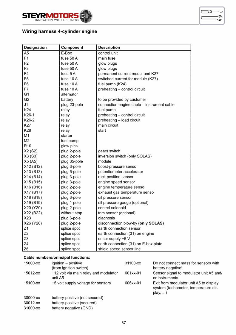
87
Wiring harness 4-cylinder engine
Designation Component DescriptionA5 E-Box control unitF1 fuse 50 A main fuseF2 fuse 50 A glow plugsF3 fuse 50 A glow plugsF4 fuse 5 A permanent current modul and K27F5 fuse 10 A switched current for module (K27)F6 fuse 10 A fuel pump (K24)F7 fuse 10 A preheating – control circuitG1 alternatorG2 battery to be provided by customerJ1 plug 23-pole connection engine cable – instrument cableK24 relay fuel pumpK26-1 relay preheating – control circuitK26-2 relay preheating – load circuitK27 relay main circuitK28 relay startM1 starterM2 fuel pumpR10 glow pinsX2 (S2) plug 2-pole gears switchX3 (S3) plug 2-pole inversion switch (only SOLAS)X5 (A5) plug 35-pole moduleX12 (B12) plug 3-pole boost-pressure sensoX13 (B13) plug 5-pole potentiometer acceleratorX14 (B14) plug 3-pole rack position sensorX15 (B15) plug 3-pole engine speed sensorX16 (B16) plug 2-pole engine temperature sensoX17 (B17) plug 2-pole exhaust gas temperature sensoX18 (B18) plug 3-pole oil pressure sensorX19 (B19) plug 1-pole oil pressure gauge (optional)X20 (Y20) plug 2-pole control solenoidX22 (B22) without stop trim sensor (optional)X23 plug 6-pole diagnosisX26 (Y26) plug 2-pole disconnection blow-by (only SOLAS)Z1 splice spot earth connection sensorZ2 splice spot earth connection (31) on engineZ3 splice spot ensor supply +5 VZ4 splice spot earth connection (31) on E-box plateZ6 splice spot shield speed sensor line
Cable numbers/principal functions:15000-xx ignition – positive
(from ignition switch)31100-xx Do not connect mass for sensors with
battery negative!15012-xx +12 volt via main relay and modulator
unit A5601xx-01 Sensor signal to modulator unit A5 and/
or instruments.15100-xx +5 volt supply voltage for sensors 606xx-01 Exit from modulator unit A5 to display
system (tachometer, temperature dis-play, ...)
30000-xx battery-positive (not secured)30012-xx battery-positive (secured)31000-xx battery negative (GND)

88
Wiring diagram M0 12 V
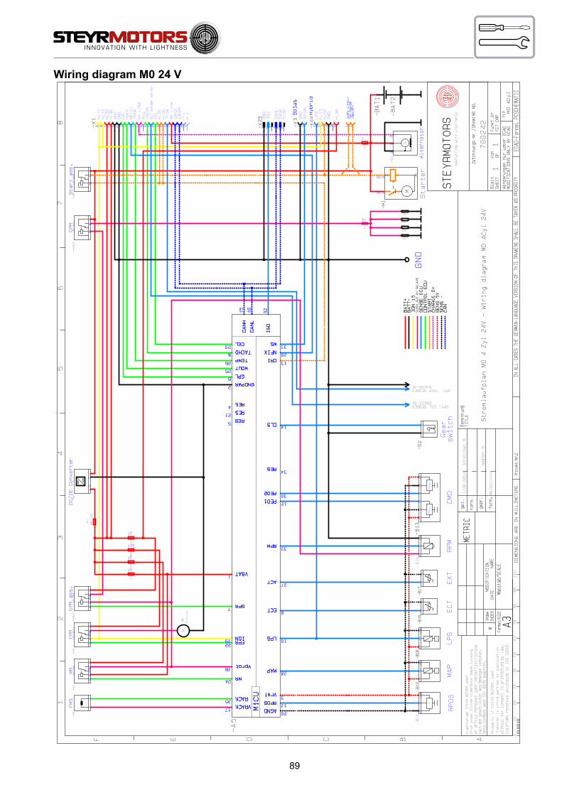
89
Wiring diagram M0 24 V
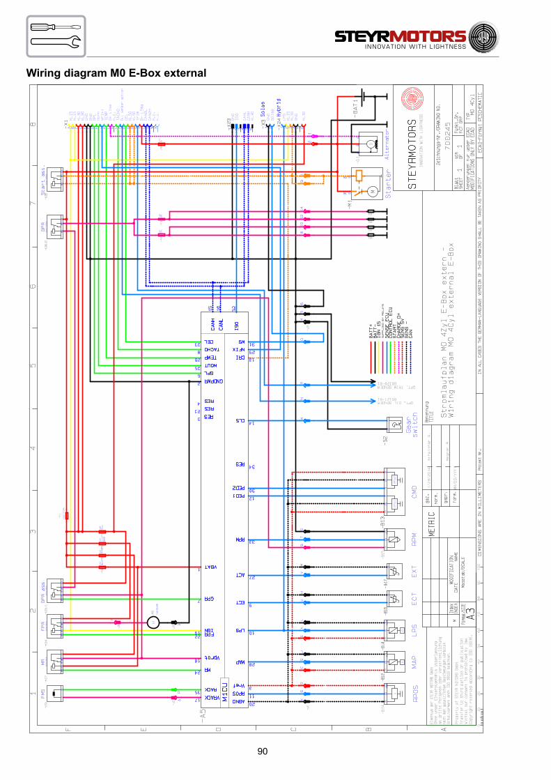
90
Wiring diagram M0 E-Box external

91
R10
/5
R10
/1
R10
/2
R10
/3
R10
/4
R10
/6
6 C
YL.
6 C
YL.
4 C
YL.
4 C
YL.
WIR
ING
DIA
GR
AM
/ M
AR
INE
- 4/6
CYL
IND
ER -
2-PO
LE -
24V
CO
MPL
ETE
SYST
EM
2179
729_
D-0
1-10
0222
ww
w.s
teyr
-mot
ors.
com
Z5
Z660
900-
02
6090
1-02
6080
8-01
ISO
6090
0-01
CA
N-H
6090
1-01
CA
N-L
60 123
-01
WS
Bat
t +B
att -
Ign
15S
uppl
ied
by R
elai
sS
ens
EC
UC
ontro
l EC
UD
IAG
Sta
rtC
harg
e D
+S
ens
5VS
ens
-B
+ 24
VC
AN
Wiri
ng L
PS /
All e
ngin
es b
efor
e 20
07
A
31100-10
15100-07
6011
7-01
EXCE
PTIO
NS:
ONL
Y FO
R TY
P:
MO
164
M40
M
O 1
74V4
0
MO
246
K41
M
O 2
56H4
5
MO
256
K43
M
O 2
66K4
3
A
31100-08
15100-05
6011
0-01
Wiri
ng M
AP /
All e
ngin
es b
efor
e 20
07
31100-08
15100-05
6011
0-01
ALL
ENG
INE
TYPE
S W
ITH
FOLL
OW
ING
EXCE
PTIO
NS
Eng
ine
oil
pres
sure
se
nder
Gea
rbox
pres
sure
se
nder
Sta
rter
3102
4-01
3002
4-01
J1 /
X
J1 /
W
Con
verte
r 12/
24V
=
=
VTG Y50
WIR
ING
DIA
GR
AM
/MA
RIN
E, 4
/6 C
YLIN
DER
, 2-P
OLE
, 24
V, C
OM
PLET
E SY
STEM
CO
NN
EC
TOR
“A5”
(EN
GIN
E-C
ON
TRO
L-U
NIT
)6
CY
L.
6 C
YL.
4 C
YL.
4 C
YL.
Sol
asIn
vers
Bat
t +
(Cl. 3
0 abo
ut F4
)(C
l. 31)
CAN
“L”
CAN
“H”
To fu
se
F4
Bat
t –
yello
w/g
reen
Cm
dE
XT
Ect
LPS
Rac
kM
apS
peed
Gea
r sw
itch
Eng
ine
oil
pres
sure
sen
der
Frei
Frei
Frei
Frei
EXCE
PTIO
NS:
ONLY
FOR
TYP
:
Wiri
ng L
PS
/All
engi
nes
befo
re 2
007
ALL E
NGIN
E TY
PES
WIT
H FO
LLOW
ING
EXCE
PTIO
NS
Wiri
ng M
AP
/All
engi
nes
befo
re 2
007
Fuel
Bat
t +
pres
sure
se
nder
B
22
STA
RTE
R
Akt
or
Glo
w A
ss.
Mai
nK
24 F
UE
L
Glo
w-
Sta
rt-
Bat
t –
Bat
t +B
att –
Ign
15S
uppl
ied
by R
elai
sS
ens
EC
UC
ontro
l EC
UD
IAG
Sta
rtC
harg
e D
+S
ens
5 V
Sen
s –
B+
24 V
CA
NG
low
Con
verte
r 12/
24 V
VTG
Gea
rbox
Sta
rt A
ss.

92
Description – Wiring harness instrument panels 4 cyl. marine engines
Designation Component DescriptionF9 fuse 10 AJ1 23-pin plug connection engine cable – instrument
cableS1 switch ignition (red)S2 switch start (green)S3 switch emergency cut off (orange)S7 switch key switch constant revolution (optional)L1 lamp charge controlL2 lamp cel – check engine lampL3 lamp oil pressure/preheating conrolP1 gauge engine coolant temperatureP2 gauge oil pressure (optional)P3 gauge tachometer with running-time meterH22 warning hornE10 lighting engine coolant temperature gaugeE11 lighting oil pressure gauge (optional)E12 lighting tachometer gaugeX8 1-pin plug connector illumination switchX24 8-pin plug connector STEYR MOTORS – displayZ1 splice battery +Z2 splice battery –Z3 splice ignition (+)Z4 splice key switch constant revolution24 V interm. cable charge indicator

93
Wiring diagram Instument CAN Panel 12/24V

94
Wiring diagram Instument CAN Panel Solas 12/24V
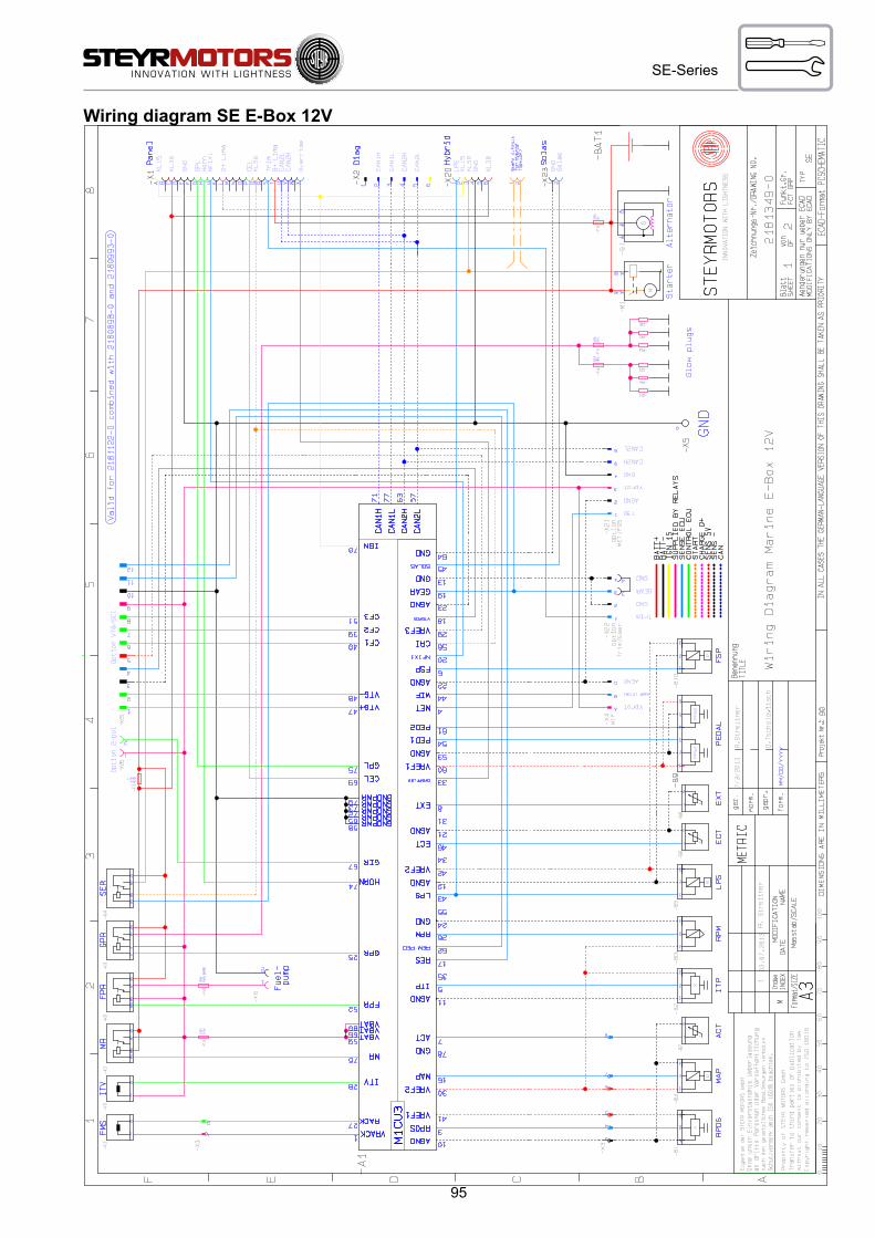
95
SE-Series
Wiring diagram SE E-Box 12V

96
SE-Series
Wiring diagram SE E-Box 24V

97
SE-Series
Wiring diagram external E-Box

98
Wiring diagram E-Box 12 V (4 cylinder, series SE)

99
Wiring diagram external E-Box 12 V (4 cylinder, series SE)
100
DEALER’S RESPONSIBILITIES
Check motor oil level ...............................................................................101
Refill motor oil ..........................................................................................101
Oil level for Power Steering .....................................................................101
Oil level for Transmission ........................................................................101
Check coolant (closed cooling circuit) .....................................................102
Drain the raw water circuit of the engine .................................................103
Check raw water connection ...................................................................103
Drain the cooling water circuit of the engine............................................104
Cooling System Anodes ..........................................................................105
Anti-Corrosion Anodes.............................................................................106
Propeller Selection ..................................................................................109
STEYR MOTORS – Dealer – Check-List ................................................110
COMMISSIONING REPORT ...................................................................112
Preparations for Off-Season Storage ......................................................114
Start-up after Storage ..............................................................................114
ENGINE LOG ..........................................................................................115

101
06005
19
A
B
06006
21
2206007
Check motor oil level
ATTENTION: Check with cooled down engine only, or after a shut down period of app. 3 to 5 min.
19 Then remove oil dipstick (19/A), clean it and insert again into oil dipstick tube (19/A), then remove again and check oil level on marker.
Refill motor oil
Remove motor oil filler cap (19/B) and add STEYR MOTORS HIGH PERFORMANCE DIESEL ENGINE OIL up to specified maximum marker on oil dipstick.
ATTENTION: Motor oil must not exceed maximum marker. An overfilling results in high operating temperatures, foaming (air in oil), loss in efficiency and reduced engine life.
Put on the motor oil filler cap.
NOTE: Remove possible oil contaminations. The use motor oil with other quality than
specified warranty canexpire.
Oil level for Power Steering21 Whenever you check motor oil level, also check oil level of
power steering. If required, add automatic transmission oil (available with your STEYR MOTORS Marine dealer). Other approved oils, such as GM Servo or Dexron II, may also be used. Do not overfill pump reservoir.
Oil level for Transmission22 Whenever you check motor oil level, also check oil level of
transmission. If required, add automatic transmission oil (available with your STEYR MOTORS Marine dealer). Other approved oils, such as GM Servo or Dexron II, may also be used. Do not overfill transmission.
NOTE: Consider specifications of respective transmission manufacturer

102
B
A
06020
u
Check coolant (closed cooling circuit)
ATTENTION: With hot engine, the closed cooling circuit is under pressure. Do not try to open the radiator cap or the drain plugs when engine is hot. This may cause severe injuries by hot coolant. As soon as the engine has cooled down, the cap may be opened.
23 Remove radiator cap (23/A). Coolant level should reach the “MAX” marking (23/B) in the expansion tank. Refilling of coolant only at the expansion tank.
ATTENTION: Only add STEYR MOTORS engine coolant.Do not refill at the pressure cap.
NOTE: When not using the original STEYR MOTORS coolant, severe damage to the cooling system of your engine may occur.
Drain points of coolant circuit: 1) Engine Block 2) Oil Cooler 3) Heat Exchanger Housing
Check Coolant SE-Series
Do not open Pressure Cap if the engine is hot.Fill in the coolant until you see it in the upper bullseye
min
max

103
A
Drain the raw water circuit of the engine
ATTENTION: Not draining the raw water circuit in time before the winter season and/or daily when running the engine during the winter season, may lead to freeze demage on the engine.
24 Remove drain plug (24/A). Engine empties itself via exhaust system.
NOTE: Drain plug (24/A) is not availabe for all types, in that case remove the hose.
25 Loosen 2 hose clamps (25/A) and remove raw water hoses, quickly start the engine so that raw water pump empties itself.
NOTE: As to procedure for draining the remaining equipment on your boat, see your STEYR MOTORS Marine dealer.
Check raw water connection
Filling is done automatically via raw water pump after having started the engine.
2406015
A
2506016
A
Inlet raw water
4 cylinder
6 cylinder

104
Drain the cooling water circuit of the engine
ATTENTION: Not draining the cooling water circuit in time before the winter season and/or daily when running the engine during the winter season, may lead to freeze demage on the engine.
Remove drain plug (A).Quickly start the engine so that cooling water pump empties itself.To fill or refill see chapter check coolant.
NOTE: As to procedure for draining the remaining equipment on your boat, see your STEYR MO-TORS Marine dealer.
A
4 cylinder (series SE and MO)
A
6 cylinder
A

105
2606017
1
2
2706018
43
5 (option)
Cooling System Anodes
26/27/27A/27BFor all 4 cylinder (Series MO and SE)There are 4 sacrificial zinc anodes in the raw water cooling system normally, although if an exhaust high riser is used there is one extra fit in it. Which are installed as per ill. 26, 27 and 27a.Remove and inspect anodes for galvanic erosion according to the maintenance schedule.Replace anode when material loss is 50 – 75 %.
serie MO
serie SE
serie SE
A
A
A
A
27A
27B
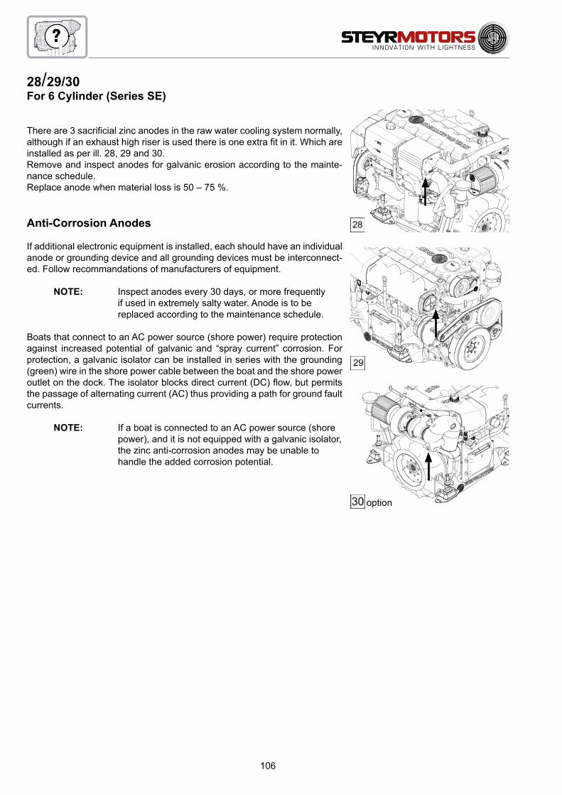
106
28/29/30For 6 Cylinder (Series SE)
There are 3 sacrificial zinc anodes in the raw water cooling system normally, although if an exhaust high riser is used there is one extra fit in it. Which are installed as per ill. 28, 29 and 30.Remove and inspect anodes for galvanic erosion according to the mainte-nance schedule.Replace anode when material loss is 50 – 75 %.
Anti-Corrosion Anodes
If additional electronic equipment is installed, each should have an individual anode or grounding device and all grounding devices must be interconnect-ed. Follow recommandations of manufacturers of equipment.
NOTE: Inspect anodes every 30 days, or more frequently if used in extremely salty water. Anode is to be replaced according to the maintenance schedule.
Boats that connect to an AC power source (shore power) require protection against increased potential of galvanic and “spray current” corrosion. For protection, a galvanic isolator can be installed in series with the grounding (green) wire in the shore power cable between the boat and the shore power outlet on the dock. The isolator blocks direct current (DC) flow, but permits the passage of alternating current (AC) thus providing a path for ground fault currents.
NOTE: If a boat is connected to an AC power source (shore power), and it is not equipped with a galvanic isolator, the zinc anti-corrosion anodes may be unable to handle the added corrosion potential.
option

107
3106023
64 Z011840-0_01
TA 0505
DRIVE BELTS, PULLEYS, TENSIONER
32a
Air Filter
All STEYR MOTORS Marine Engine models are equipped with an air filter at the turbocharger inlet; as to specifications, see Specifica-tions and Maintenance.31 Loosen clamp to exchange air filter. Remove air filter. Place
clamp on filter neck and mount air filter onto flange. Tighten clamp. (3 Nm)
Maintainance Poly – V – belt resp. Serpentine Belt
FOR 4 CYL. MARINE ENGINES
32 Occassionally check components for excessive wear and/or clearance on tension bearing.
NOTE*): It is recommended to spray frequently some corrosion inhibiting spray into the spring hous-ing of the belt tensioner.
FOR 6 CYL. MARINE ENGINES
Occassionally check components for excessive wear and/or clearance on tension bearing.
NOTE: It is recommended to spray frequently some corrosion inhibiting spray into the spring housing of the belt tensioner
Engine alignment
Engine alignment requires special tools. The output coupler must be disengaged from the take-off shaft. This should be rechecked during off-season storage preparations. Because of the special tools required, engine alignment is to be performed by a STEYR MOTORS Marine dealer.
NOTE: Failure to check the engine alignment could result in premature failure of engine coupler or universal joints.
32a
*)

108
FOR 6 CYL. MARINE ENGINES WITH AC-Compressor (optional)
33/34To tension the poly v-belt: Loosen hexagon screw (33/F). Turn the clamping bolt (34/G) clockwise in order to in-crease the belt tension to 200 ± 25 Nm. Tighten hexagon screw (35/F) with a Torque of 23 Nm ± 2 to secure idle pulley bracket. Check belt tension.
33 34
F
G

109
Propeller Selection35 Your STEYR MOTORS Marine dealer has chosen a propeller designed to deliver top performance and econ-
omy under most conditions. To obtain the maximum percentage of available output ( A ), the engine RPM at Full Throttle should be in the specified Propped Speed Range ( B ). As to specifications, see Technical Data and Maintenance.
If the engine’s full throttle RPM with normal load is below the specified range, use a propeller with less pitch to in-crease the RPM. Should the engine’s full throttle RPM exceed the specified range, the engine RPM and output is limited by the governor. Use a propeller of higher pitch to achieve a RPM reduction in the specified range ( B ).
NOTE: Engine damage can result from incorrect propeller selection if
• The engine RPM does not attain the specified “Propped Speed Range”. The engine thus runs in RPM range ( C ).
Therefore, use a propeller with a lower pitch.
• The engine RPM exceeds the specified “Propped Speed Range”. Engine speed is therefore above the admissible range ( D ).
Therefore, use a propeller with a higher pitch.
engine modelPropped Speed Range “B”
rated rpm range of tolerance
4 cy
linde
r MO
MO54NA33 3300 rpm +0 rpm/–200 rpmMO84K32 3200 rpm +0 rpm/–200 rpmMO94K33 3300 rpm +0 rpm/–200 rpmMO114K33 3300 rpm +0 rpm/–200 rpmMO144V38 3800 rpm +0 rpm/–300 rpmMO144M38 3800 rpm +0 rpm/–300 rpmMO164M40 4000 rpm +0 rpm/–300 rpmMO174V40 4000 rpm +0 rpm/–300 rpm
4 cy
lin-
der S
E SE144E38 3800 rpm -300 rpm/+50 rpm
SE164E40 4000 rpm +150 rpm/–150 rpm
6 cy
linde
r
SE126E25 2500 rpm +50 rpm/–200 rpmSE156E26 2600 rpm +50 rpm/–200 rpmSE156E32 3200 rpm +50 rpm/–200 rpmSE196E35 3500 rpm +50 rpm/–200 rpmSE236E40 4000 rpm +100 rpm/–100 rpmSE236S36 3600 rpm +50 rpm/–200 rpmSE266E40 4000 rpm +50 rpm/–150 rpmSE266S36 3600 rpm +50 rpm/–300 rpmSE286E40 4000 rpm +150 rpm/–100 rpmSE306J38 3800 rpm +50 rpm/–300 rpm
4 cy
linde
r SE
engine model Z / Propeller Speed Range Jet Speed RangeSE144E38 3700-3900 rpm 3300-3800 rpmSE164E40 3900-4100 rpm 3550-4000 rpm
OUTPUT
POWER
A
RPM
FullLoadSpeedRange
30%
40%
50%
60%
70%
80%
90%
100%
B
C D
35
Propped
110
STEYR MOTORS – Dealer – Check-List
NOTE: If STEYR MOTORS HYBRID SYSTEM is in use, check below mentioned points but also START UP OF HYBRID SYSTEM (see HYBRID INSTALLATION MANUAL P/N Z001044-0/chapter 5) before ignition is turned on or engine is started!
1. Remove carton from palette and check the separately packed components are complete and undamaged.
2. Visual inspection of engine for transit damage and finish.
3. Check coolant and oil level. If required add operational fluids as specified in Operation, Maintenance & War-ranty Manual and Service Manual.
4. Inform customer about important guidelines in the Installation Manuals and instruct him as to safety regulations.
5. Inform customer about break-in procedure in the Operation, Maintenance & Warranty Manual.
6. Advise customer what to do when the engine’s self-diagnostic management system reduces the power. See Electronic Engine Control Unit (ECU) in section Start-up and Operation of Operation, Maintenance & Warranty Manual.
7. Check tightness of all cooling water hose clamps.
8. Check fuel hoses for correct size and safe routing to and from engine.
9. Check battery units for correct polarity and battery for correct capacity.
10. Check all electrical connections (engine harness, main connector, accessories, instrument panel)
11. Check level of all operational fluids: Motor oil Coolant Power steering fluid Drive or gear Reservoir of trim pump
12. Fill fuel tank for engine test run.
13. Check function of displays on instrument panel.
14. Check function of bilge pump and blower.
15. Check fuel system for free flow and leaks.
16. Check function of trim installation.
17. Check function of anchor light, navigation lights and instrument panel lights.
18. Install drain plug of bilge.

111
19. Steering – Lubricate
20. Check condition and tension of all drive belts.
21. Check all engine mount screws for tight seat.
22. Check for any leaks, deficiencies, signs of wrong use etc.
23. Check function of all warning devices installed.
24. Read out memorized service codes and make necessary corrective actions.
25. Start engine and check for normal instrument display and normal operating noise.
26. Obtain propeller load absorption.
27. Check installation and fill in commissioning report (Installation Manual P/N Z001007-0, chapter 9 Appendix).
28. Grease raw water pump impeller at BUKH-STEYR MOTORS SOLAS engine with original grease of P/N Z011753/2.
29. Carry out Start-Idle-Test and check engine operation. Check behavior of the boat when engine is in idle gear. If there are unpleasant vibrations, adjust the engine speed to a vibration-free operation (see Service Manual)
30. Check correct function of gearshift.
31. Stop engine and check again the levels of all operational fluids during test run a certain loss operation fluids may occur.
(Mechanic’s Signature) (Dealer’s Signature)
DEALER: ......................................................................................................................................................................
ADDRESS AND DATE: ................................................................................................................................................
ENGINE TYPE/SERIAL NUMBER: ..............................................................................................................................
ENGINE RUNNING HOURS: .......................................................................................................................................
SIGNATURE: ................................................................................................................................................................
A copy of the “installation and pre-delivery inspection log” is to be sent to STEYR MOTORS GmbH, After Sales Service!

112
Commissioning REPORT
AS010.DOT 02.08 / Kundendienst Seite 1 von 2
Type of boat: Dimension of propellers:
Model No.: Special Equipment from STEYR MOTORS (SCC, IFG, Cabin Heating etc.):Boat length: m
Boat weight: kg
Driving system: *) Hybrid- Battery specification:
Gear reduction:
Extended Storage Preservation Procedure (acc. SERVICE Manual / GENERAL / D3 )
Date of Preservation: #1 #2
ENGINE- CHECK POINTS:
Installation checked according to the installation guide. Following points are in compliance:1 2 3 4 5 6 7 8 9 10 11Notes:
*) HYBRIDELECTRICAL CONNECTIONS according schematic “CONNECTION SCHEMATIC- HYBRID”(see Hybrid Installation Manual- schematic with art.nr. 2180526-0)Notes (e.g.: wiring extensions etc.):
SYSTEM GROUNDS connected ( see Hybrid Installation Manual- schematic with art.nr. 2180526-0)
PROTECTION COVERS mounted on: HCU(U,V,W and B+,B-) Generator(U,V,W) Hybrid battery(+/-)
END POSITON / FREE MOVEMENT of Coupling Actuator (D-Mode, E-Mode) ensured
MAIN SWITCH capacity(between Hybrid battery+ and HCU+) : Amp (min. 400Amp)CONSUMERS mounted to Hybrid battery (only to 48V, max. 100Amp):
Hybrid –Cooling: Raw water cooling Dual circuit cooling Keel cooling
Engine- serial number: Engine- model:
*) Hybrid- serial number:Boat Owner:
Company/Name:
Address/Phone:
Dealer:
Company:
Address/Phone:
COMMISSIONING REPORT
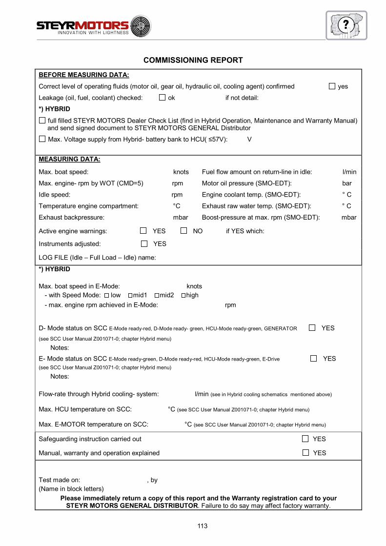
113
Commissioning REPORT
AS010.DOT 02.08 / Kundendienst Seite 2 von 2
BEFORE MEASURING DATA:
Correct level of operating fluids (motor oil, gear oil, hydraulic oil, cooling agent) confirmed yes
Leakage (oil, fuel, coolant) checked: ok if not detail:
*) HYBRID
full filled STEYR MOTORS Dealer Check List (find in Hybrid Operation, Maintenance and Warranty Manual) and send signed document to STEYR MOTORS GENERAL Distributor Max. Voltage supply from Hybrid- battery bank to HCU( ≤57V): V
MEASURING DATA:
Max. boat speed: knots Fuel flow amount on return-line in idle: l/min
Max. engine- rpm by WOT (CMD=5) rpm Motor oil pressure (SMO-EDT): bar
Idle speed: rpm Engine coolant temp. (SMO-EDT): ° C
Temperature engine compartment: °C Exhaust raw water temp. (SMO-EDT): ° C
Exhaust backpressure: mbar Boost-pressure at max. rpm (SMO-EDT): mbar
Active engine warnings: YES NO if YES which:
Instruments adjusted: YES
LOG FILE (Idle – Full Load – Idle) name:
*) HYBRID
Max. boat speed in E-Mode: knots - with Speed Mode: low mid1 mid2 high- max. engine rpm achieved in E-Mode: rpm
D- Mode status on SCC E-Mode ready-red, D-Mode ready- green, HCU-Mode ready-green, GENERATOR YES (see SCC User Manual Z001071-0; chapter Hybrid menu)
Notes: E- Mode status on SCC E-Mode ready-green, D-Mode ready-red, HCU-Mode ready-green, E-Drive YES (see SCC User Manual Z001071-0; chapter Hybrid menu)
Notes:
Flow-rate through Hybrid cooling- system: l/min (see in Hybrid cooling schematics mentioned above)
Max. HCU temperature on SCC: °C (see SCC User Manual Z001071-0; chapter Hybrid menu)
Max. E-MOTOR temperature on SCC: °C (see SCC User Manual Z001071-0; chapter Hybrid menu)
Safeguarding instruction carried out YES
Manual, warranty and operation explained YES
Test made on: , by (Name in block letters)
Please immediately return a copy of this report and the Warranty registration card to yourSTEYR MOTORS GENERAL DISTRIBUTOR. Failure to do say may affect factory warranty.
COMMISSIONING REPORT

114
Preparations for Off-Season Storage
An adequate preservation of the engine will contribute to an efficient and troublefree operation in the long term.Consult your STEYR MOTORS Marine Dealer to get professional assistance in performing a proper off season storage.
NOTE: If engine is stored above 1 year, advise your STEYR MOTORS Marine Dealer to the Extended Preservation Procedure (Service Manual Z001138-0, chapter GENERAL D4).
1. Change motor oil and oil filter.2. Change fuel filter.3. Check air filter.4. Check coolant (closed circuit).5. Add fuel stabilizer to fuel.6. Drain engine’s raw water system.
NOTE: If the raw water is not completely removed from the engine, expensive freeze damage may be the result.
7. Drain raw water system from boat and driving system (consider manufacturer’s instructions as to storage).8. Change gear oil or lubricant.9. Disconnect battery and store it.10. Spray engine outside with corrosion prevention oil.11. Ventilate engine compartment and bilge.
Start-up after Storage
An correct start-up of the engine will contribute to an efficient and troublefree operation in the long term.Your STEYR MOTORS Marine Dealer will gladly be available as consultant or for an expert performance.
1. Check condition of hoses and hose clamps.2. Clean battery terminals.
ATTENTION: Connect RED cable to positive terminal and then BLACK cable to negative terminal. Wrong connection of battery terminals may damage the electronic system.
3. Grease outer sides of terminals.4. Open fuel stop valve and check all fuel lines for leakage.5. Thoroughly check the boat and engine for slack or missing screws or nuts.6. Pump the bilge dry and clean the engine compartment.7. Complete the raw water system.8. Open the raw water inlet.
ATTENTION: Insufficient raw water supply may damage the engine and the raw water pump.
9. Test run. Start engine. Check voltmeter, oil pressure- and water temperature gauge. (Make sure that all sys-tems function properly.)
10. Check all parts for oil-, fuel- or water leakage.
NOTE: For additional Information regarding engine preperation for long term preservation please consult your STEYR MOTORS Marine Service Partner.

115
Date Destination Number Abord
Engine Started
Engine Stopped
Service RecordInspection Tune-up Lubrication

116
Date Destination Number Abord
Engine Started
Engine Stopped
Service RecordInspection Tune-up Lubrication

117
Date Destination Number Abord
Engine Started
Engine Stopped
Service RecordInspection Tune-up Lubrication

118
WARRANTY
STEYR MOTORS ...................................................................................119
LIMITED ENGINE WARRANTY ..............................................................119
Products Warranted .................................................................................119
What You Must Do to Activate the Warranty ............................................119
Extended Major Components Warranty ..................................................122
Summary of Warranty Coverage .............................................................123
Additional Coverage for Parts Replaced or Repaired Under Warranty ...123
Warranty Coverage for genuine Spare Parts ..........................................123
Conditions of Warranty Coverage ...........................................................123
Limitations and Exclusions ......................................................................125
Procedure for Making a Warranty Claim .................................................126
Venue and Applicable Law ......................................................................127
Miscellaneous ..........................................................................................127
If You Do Not Receive Satisfactory Warranty Service .............................127
Engine, Gearbox, Boat Model and Hull Identification Numbers ..............128
Steyr Owner Identification Card...............................................................129
SERVICE NETWORK ..............................................................................................130

119
STEYR MOTORS
LIMITED ENGINE WARRANTY
STEYR MOTORS, GmbH (“STEYR MOTORS”) warrants to the original retail purchaser of a product covered under this Warranty (“the Product”), and to any other person to whom the Product is transferred during the duration of this Warranty, that in the event of a failure of the Product occurring during the applicable warranty period resulting from a defect in materials or factory workmanship, STEYR MOTORS will, at its option, repair or replace the defective Product according to the terms and conditions set forth herein.
Products Warranted
This Limited Warranty applies to all new marine engines manufactured by STEYR MOTORS, GmbH and sold by STEYR MOTORS or by a STEYR MOTORS approved distributor or dealer until such time as this Warranty may be subsequently updated or revised. This Warranty also applies to the following engine accessories when approved and supplied by STEYR MOTORS and when installed by STEYR MOTORS or by a STEYR MOTORS approved distributor or dealer:
• acc. To enlisted distributor as stated in STEYR MOTORS Service Network (refer to website at www.steyr-motors.com)
This Warranty does not apply to any component manufactured by a third party and supplied by STEYR MOTORS as part of a package. Such non-covered components include, but are not limited to, any MerCruiser Bravo Series stern drive, ZF Marine transmissions, sail drives, water jet, control lever and commander systems, etc., that may be sold together with a Steyr engine. Buyers of a package that includes a MerCruiser Bravo Series stern drive should consult the product literature accompanying the stern drive for details on the warranty provided by its manufacturer, Mercury Marine. The provided warranty registration card with the Mercury Marine/MerCruiser product needs to be returned to STEYR MOTORS for registration in their system.
What You Must Do to Activate the Warranty
Owner Registration
IMPORTANT: In order to obtain the full benefit of this Warranty, your new Steyr engines must be timely registered at the factory, latest within 3 years from the date of sales document. The engines you have purchased have been shipped from the factory together with a Warranty Registration Card, a copy of which is included in your Operation, Maintenance and Warranty Manual. It is your responsibility to insure that the distributor or dealer from whom you purchased the engines fills out the Warranty Registration Card in its entirety and that it is immediately forwarded to STEYR MOTORS. The Registration Card must include your name and address, the product number and serial number(s), date of sale, and type of use, as well as the seller’s name, address, code number and a properly obtained commissioning report. It must also contain the selling distributor/dealer’s certification that you are the original purchaser and user of the Product.
In case of an engine doesn’t get put into operation within the first year from production, the STEYR MOTORS long-term preservation and conservation procedure must be followed and documented as described in this procedure to prove proper storage handling and re-commissioning of the product.
A copy of the Warranty Registration Card, designated “Purchaser’s Copy,” MUST be given to you immediately after the card has been completely filled out by the selling distributor/dealer. Your copy of the Warranty Registration Card should be retained together with your Owner Identification Card and kept in a safe place. In the event that you ever require warranty service, you will be required to present your copy of the Warranty Registration Card

120
along with your Owner Identification Card so that the date of purchase and delivery may be verified and so that the Warranty Claim Form can be properly completed.
Failure to register the Product with the factory within 60 days of the date on which you take delivery of the Product will cause the warranty period to begin running from the date on which the Product is shipped from STEYR MOTORS in Austria, rather than on the date of delivery to you. It is to your benefit to have all Products timely registered at the factory so that you receive the maximum available coverage under the Warranty and so that STEYR MOTORS has a means of identifying and contacting you in the event of product updates or service notifications.
Commissioning ReportYour new Steyr engines have been shipped together with a form entitled “Commissioning Report,” a copy of which is included in the installation manual that accompanies your engines. It is your responsibility to insure that this form is completed by the seller (distributor, dealer, or boat builder) at the time of installation and that it is immediately returned to STEYR MOTORS. Keep a copy of the completed form for your records, as you will be required to present it in the event you ever require warranty service. Failure to complete and immediately return the Commissioning Report to STEYR MOTORS will cause your warranty to be voided.
Note:Individual report documents are additional available for reference via steyr-motors.com extranet access.(for assistance contact your authorized dealer)
Base Engine WarrantyThe Base Engine Warranty covers any failure of the Product under normal use and service that occurs during the applicable period of coverage and that results from a defect in STEYR MOTORS material or factory workmanship (a “Warrantable Failure”).
STEYR MOTORS’ Responsibilities under the Base Engine Warranty
During the applicable period of coverage under the Base Engine Warranty, and subject to all conditions, limitations and exclusions herein, STEYR MOTORS will, at its option, either repair or replace the defective Product. In the event that STEYR MOTORS elects to repair the Product, STEYR MOTORS will do the following:
• STEYR MOTORS will pay for all parts and labor reasonably required to repair the defect responsible for the Warrantable Failure.
• STEYR MOTORS will pay for all lubricating oil, antifreeze, filter elements, and other similar maintenance items replaced during a warranty repair when such items are not reusable due to a Warrantable Failure.
• STEYR MOTORS will pay for the usual and customary labor costs for engine removal and reinstallation when necessary to repair a Warrantable Failure.
Labor costs will be paid by STEYR MOTORS only for work pre-authorized by STEYR MOTORS and performed by an approved service facility during normal business hours. Labor costs will be paid in accordance with STEYR MOTORS’ published standard repair time guidelines. Parts used in warranty repairs may be new STEYR MOTORS parts, STEYR MOTORS-approved rebuilt parts, or repaired parts.

121
Duration of Coverage
The duration of coverage under the Base Engine Warranty depends upon whether your engine application and use are rated for “Pleasure Duty” or for “Commercial Duty.”
• For engines rated “Pleasure Duty,” the Base Engine Warranty extends for a period of 24 months or until the engines have been operated for 1,000 hours, whichever occurs first.
• For engines rated “Commercial or Government Duty,” the Base Engine Warranty extends for a period of 12 months or until the engines have been operated for 1,000 hours, whichever occurs first.
The period of coverage commences on the date on which the Product is delivered to the first retail purchaser, or the date on which the unit is first leased, rented or loaned, or when the Product has been operated for 30 hours, whichever occurs first.

122
Extended Major Components Warranty
The Extended Major Components Warranty covers any failure under normal use and service of any of the below-listed parts or castings1 that occurs during the extended warranty period and that is caused by a defect in material of original manufacturer:
Engine Monoblock Casting Engine Camshaft Engine Crankshaft Engine Connecting Rods Crankshaft Sprocket Camshaft Sprocket Engine Housing Flywheel Housing
STEYR MOTORS’ Responsibilities under the Extended Major Components Warranty
During the applicable period of coverage under the Extended Major Components Warranty, and subject to the conditions, limitations and exclusions herein, STEYR MOTORS will, at its option, either repair or replace the defective component. STEYR MOTORS’ responsibilities in the event of a repair shall be the same as provided with respect to the Base Engine Warranty, except that the cost of labor for removal and reinstallation is not covered under the Extended Major Components Warranty.
Duration of Coverage for specific major engine components
The Extended Major Components Warranty extends for a period of 60 months or until the engine has been operated for 1,800 hours, whichever occurs first. As with the Base Engine Warranty, the period of coverage commences on the date on which the Product is delivered to the first retail purchaser or on the date on which the unit is first leased, rented or loaned, or when the Product has been operated for 30 hours, whichever occurs first.
1 Bushing and bearing failures are not covered.

123
Summary of Warranty Coverage
Repair Costs Paid by STEYR MOTORS
Type of Coverage Duration (Months)*
Duration(Hours or KM)*
Parts Labor Laborfor Removal & Reinstallation
Base Engine Warranty — PLEASURE
24 1,000 Yes Yes Yes
Base Engine Warranty --COMMERCIAL
12 1,000 Yes Yes Yes
Extended Major Components Warranty
60 1,800 Yes Yes No
*whichever occurs first
Additional Coverage for Parts Replaced or Repaired Under Warranty
Any STEYR MOTORS product or part replaced or repaired under the Base Engine Warranty will be covered under the Base Engine Warranty for the remaining period of warranty.
Warranty Coverage for genuine Spare PartsSTEYR MOTORS warrants genuine spare parts for extent of 6 month beginning from the date of repair.
Conditions of Warranty Coverage
This Warranty is expressly conditioned upon proper application, installation, commissioning, operation, and maintenance of the Product in accordance with the specifications and guidelines set forth by STEYR MOTORS in its Operations, Maintenance and Warranty Manual and in its installation and service manuals. Proper use and operation of the Product entails, among other things, use of the Product in strict compliance with the following power ratings:
Pleasure Duty (PD). This power rating is intended for use in variable load applications where full power is limited to one (1) hour out of every eight (8) hours of operation. Reduced power operations must be at or below cruise speed (rpm). Cruise speed (rpm) is 200 rpm below the engine rated speed (rpm). Also, the defined propped speed range must be met and is specified in table propped speed range (Operator Manual, chapter Propeller selection) for each engine model. This rating (ISO3046 Fuel Stop Power Rating) is for application operating less than 300 hours per year and is intended exclusively for pleasure/non-revenue generating applications. Engines rated “Pleasure Duty” may not be used for any commercial application without voiding the product warranty. A “commercial or governmental application” includes any work or employment-related use of the Product, or any use of the Product that creates income, even if the Product is only occasionally used for such purpose. A “commercial application” also includes charter, naval, police, and other similar applications.
Commercial or Governmental Duty according to Marine Duty Rating. If an engine is intent to be used for commercial operation the application must comply with below described duty rating conditions. The duty ratings are defined in three different engine operation pattern and annual use of the unit. The operation pattern defines a ratio between full power-speed-range and cruising-speed-range, wherein cruising speed must be maintained on a specified reduced rpm below the engine rated speed. The specified reduced speeds are mentioned in the Marine Duty Ratings below.

124
High Output (HO). This power rating is intended for intermittent use in variable load applications where full power is limited to one (1) hours out of every eight (8) hours of operation. Reduced power operations must be at or below cruise speed (rpm). Cruise speed (rpm) is 300 rpm below the engine rated speed (rpm). Also, the defined propped speed range must be met and is specified in table propped speed range (Operator Manual, chapter Propeller selection) for each engine model. This rating (ISO3046 Fuel Stop Power Rating) is for application operating less than 300 hours per year.
Intermittent Rating (INT). This power rating is intended for intermittent use in variable load applications where full power is limited to two (2) hours out of every eight (8) hours of operation. Reduced power operations must be at or below cruise speed (rpm). Cruise speed (rpm) is 200 rpm below the engine rated speed (rpm). Also, the defined propped speed range must be met and is specified in table propped speed range (Operator Manual, chapter Propeller selection) for each engine model. This rating (ISO3046 Fuel Stop Power Rating) is for application operating less than 1,500 hours per year.
Medium Continuous Rating (MCD). This power rating is intended for intermittent use in variable load applications where full power is limited to three (3) hours out of every twelve (12) hours of operation. Reduced power operations must be at or below cruise speed (rpm). Cruise speed (rpm) is 400 rpm below the engine rated speed (rpm). Also, the defined propped speed range must be met and is specified in table propped speed range (Operator Manual, chapter Propeller selection) for each engine model. This rating (ISO3046 Fuel Stop Power Rating) is for application operating less than 3,000 hours per year.
STEYR MOTORS’ duty of performance under this Warranty is expressly conditioned upon the purchaser’s maintenance of the following documentation and records which must be made available to STEYR MOTORS in the event that warranty service is required:
• You are responsible for keeping complete and accurate records of all service performed on the engines and for maintaining a log of all regularly scheduled maintenance in the Owner Service Log included in your Operations, Maintenance and Warranty Manual.
• You are responsible for assuring that at all times the engine hour meter on your Steyr engines is in good working order and in a condition that accurately reflects the total hours that the engines have been operated.
• You are responsible for keeping copies of the completed Warranty Registration Form and of the Commissioning Report.

125
Limitations and Exclusions
STEYR MOTORS is not responsible for any engine failure or other problem attributable in whole or in part to any of the following:
• Any application or installation inconsistent with STEYR MOTORS’ published application and installation guidelines.
• Abuse or neglect, including but not limited to operation without adequate coolants or lubricants, over-fueling, over-speeding, lack of maintenance of cooling, lubricating or intake systems, improper storage, preservation, rust or corrosion, improper starting, warm-up, run-in or shutdown practices, or failures caused by incorrect oil or by water, dirt or other contaminants in the fuel or oil.
• Unauthorized modifications of the engine.• Use of a service facility not approved by STEYR MOTORS, or use of parts not supplied or approved
by Steyr Motors. For information on approved service partner in your area, please contact STEYR MOTORS or refer to the list of approved service facilities posted on STEYR MOTORS’ website at www.steyr-motors.com.
• Prolonged or incorrect storage. Prolonged storage, for purposes of this Warranty, is storage for a period of over one (1) year from the date of shipment from the STEYR MOTORS factory.
• Normal wear or wearout of parts.
• Faulty workmanship, whether or not performed by an approved dealer or distributor of STEYR MOTORS, and whether or not occurring in conjunction with a warranty repair.
STEYR MOTORS will not pay for any of the following costs, which shall be the sole responsibility of the Owner:
• The cost of transporting any STEYR MOTORS engine or product to or from the place of warranty service.
• The cost of haulage, launch, docking, or cranes.
• The cost of lubricating oil, antifreeze, filter elements, and other maintenance items replaced during warranty repairs unless such items are not reusable because of the Warrantable Failure.
• The cost of any part supplied, or labor performed, by a service facility not approved by STEYR MOTORS.
• The cost of any part supplied, or labor performed, by a service facility without the prior authorization of STEYR MOTORS.
STEYR MOTORS does not warrant any product or component not specifically identified in the “Products Warranted” section of this document. Please note in particular the following:
• STEYR MOTORS does not warrant any product or component not manufactured by STEYR MOTORS, except for those accessories specifically identified in the “Products Warranted” section of this document that are supplied by STEYR MOTORS and installed by STEYR MOTORS or by a STEYR MOTORS approved distributor or dealer. Examples of items not warranted are stern drives, sail drives, gear boxes, and water jets, control lever, etc.
• STEYR MOTORS does not warrant maintenance components supplied by STEYR MOTORS after 90 days of the date on which warranty coverage commences. Maintenance components include, but are not limited to, sea water pump impellers, zinc plugs, oil filters, fuel filters, air filters, water filters, fuel/water separator filters, belts, automatic belt tensioner, timing belt and idler, gaskets, hoses, fuses, brushes and accommodator, fuel injection nozzle valves, expansion tank pressure caps, and thermostats.
126
• STEYR MOTORS product doesn’t get entitled to describe limited warranty condition if the provided product warranty registration card will not be submitted and received by STEYR MOTORS within 3 years from the date of manufacturing.
IN NO EVENT SHALL STEYR MOTORS BE RESPONSIBLE FOR INCIDENTAL OR CONSEQUENTIAL DAMAGES. Such excluded damages include, but are not limited to, loss of use (including “down time”), loss of income or business revenue, costs of travel, costs of transport, extra costs required to make the Product accessible as a result of particular vessel designs and/or installations (including the removal and/or replacement of partitions or material), personal injury, loss of property, cargo damage, fines, taxes, damages to parts or goods other than products specifically covered by this Warranty, and any other indirect or consequential loss resulting from a Warrantable Failure. Some states do not allow limitations on how long an implied warranty lasts, so the above limitation may not apply to you.
THE WARRANTIES SET FORTH HEREIN ARE THE ONLY WARRANTIES MADE BY STEYR MOTORS WITH RESPECT TO THE PRODUCT. NO DEALER OR DISTRIBUTOR OF STEYR MOTORS IS AUTHORIZED TO MAKE ANY ADDITIONAL WARRANTY, PROMISE, OR REPRESENTATION ON BEHALF OF STEYR MOTORS OR TO MODIFY OR EXTEND THE TERMS OR DURATION OF THIS WARRANTY. ANY WARRANTY IMPLIED BY LAW, INCLUDING ANY IMPLIED WARRANTY OF MERCHANTABILITY OR OF FITNESS FOR A PARTICULAR PURPOSE, SHALL BE LIMITED IN DURATION TO THE TERM OF THIS WARRANTY.
Procedure for Making a Warranty Claim
Warranty service may be obtained from any approved STEYR MOTORS distributor or dealer. For a list of approved service locations, please refer to Steyr Motors’ website at www.steyr-motors.com or contact STEYR MOTORS’ After sales Division, the contact information for which is provided on the final page of this document.
In the event of a Warrantable Failure arising during the applicable warranty period, a warranty claim must be submitted promptly IN WRITING. A warranty claim must be made immediately upon discovery of facts that would lead a reasonably prudent owner to believe that the Product is defective in materials or factory workmanship, but in no event more than 30 days after such discovery.
To make a warranty claim, contact any approved STEYR MOTORS distributor or dealer and present your STEYR MOTORS identification card and your copy of the Warranty Registration Form and Owner Service Log. You may also be required to present your copy of the Commissioning Report all maintenance and service records.
A STEYR MOTORS Warranty Claim Form (a sample copy of which is available from STEYR MOTORS’ website at www.steyr-motors.com) must be completed by the dealer or distributor and returned to STEYR MOTORS in Austria. It is your responsibility to insure that the Warranty Form is properly completed and to retain a copy for your records as proof of the making of a timely warranty claim.
All warranty claims MUST be approved by STEYR MOTORS before any warranty work is undertaken. No distributor or dealer of STEYR MOTORS is authorized to approve, or to guarantee approval of, a warranty claim. Any work performed prior to obtaining authorization from STEYR MOTORS will be at the risk of the owner and/or service facility undertaking the work. Upon approval of a warranty claim, you are responsible for making the Product available for repair at the place designated by STEYR MOTORS within a reasonable period of time.
Important: The foregoing procedures for making a warranty claim are mandatory. Failure to comply with the requirements for submitting a warranty claim shall be presumed to have deprived STEYR MOTORS of adequate and timely notice of a defect and shall relieve STEYR MOTORS of any duty of performance under this Warranty.

127
Venue and Applicable Law
This Limited Warranty and the rights and obligations of STEYR MOTORS and of the Owner as they relate to any product supplied by Steyr Motors shall be governed by and construed in accordance with Austrian law, and any legal action instituted against STEYR MOTORS as a result of this Warranty shall be brought in Vienna, Austria. In the event of a legal action commenced against Steyr Motors in the United States, Steyr Motors shall have the option to consent to jurisdiction and to require that the action be submitted to binding arbitration according to the commercial rules of the American Arbitration Association.
Miscellaneous
This Warranty document consists of the complete and final expression of the intent of the parties with respect to the warranty obligations of STEYR MOTORS. The terms of this Warranty may not be modified except by a writing signed by an authorized representative of STEYR MOTORS. Dealers and distributors of Steyr Motors engines (whether or not approved by Steyr Motors) are not agents of STEYR MOTORS and have no authority to alter the terms of this Warranty or to waive any condition or requirement stated herein.
Should any portion of this Warranty be determined unenforceable in a court of law, the validity and legal effect of the remainder of the document shall not be affected.STEYR MOTORS may in certain circumstances, and at its sole discretion, provide for service outside the scope of this Warranty to update, modify, or repair a product. In that event, Steyr Motors shall not be deemed to have assumed any additional obligation to the owner or to have modified or waived any of the provisions of this Warranty.
The owner shall be responsible for the cost of investigating complaints found not to be attributable to a defect in STEYR MOTORS material or factory workmanship.
Any STEYR MOTORS product or part replaced under warranty will automatically become the property of STEYR MOTORS.
This warranty gives you specific legal rights, and you may also have other rights which vary from state to state.
If You Do Not Receive Satisfactory Warranty Service
STEYR MOTORS strives, through an extensive network of independent distributors and dealers, to provide prompt, courteous, and competent warranty service to owners of Steyr engines. If you fail to receive satisfactory warranty service from a STEYR MOTORS distributor or dealer, please contact STEYR MOTORS after sales division directly.Its contact information is as follows:
STEYR MOTORS, GmbHIm Stadtgut B1, 4407
Steyr, Austria
Phone: +43 7252 222-52Fax: +43 7252 222-29
e-mail: [email protected]
Erstellt / Issued: 10.04.2014 Kundendienst / After Sales Service
Geprüft und freigegeben / Approved: 10.04.2014 / Ing. Rudolf Mandorfer (Datum, Name / Date, Name)

128
STEYR MOTORS GMBH 2007All rights reserved to changes or modifications.
Engine, Gearbox, Boat Model and Hull Identification Numbers
Record your engine and gearbox model and serial numbers immediately after purchase.This will enable you to have them available for quick reference when ordering parts or literature.
Engine Model No.: __________________________________________________________
Engine Serial No.: ___________________________________________________________
Gearbox or Stern Drive Model No.: _____________________________________________
Gearbox or Stern Drive Serial No.: _____________________________________________
Ignition Key No.: ____________________________________________________________
Boat Model No.: ____________________________________________________________
Hull Identification No. (HIN): __________________________________________________
Recommended Propeller Size: ________________________________________________
Replacement Parts
Never use parts of unknown quality on your STEYR MOTORS Marine Engine.Insist on GENUINE-STEYR MOTORS Marine parts.
See your local STEYR MOTORS Marine dealer.
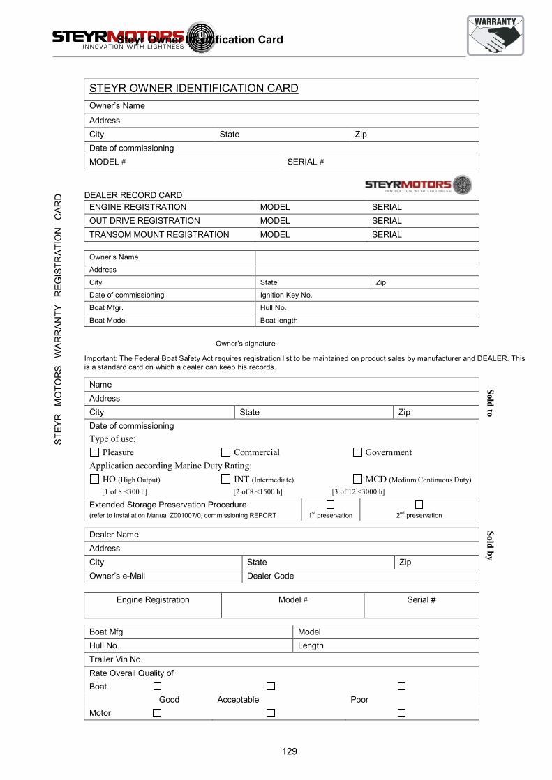
129
WARRANTY REGISTRATION CARDAS001.DOT 06.06 / Kundendienst Druckdatum: 10.09.2013 Seite 1 von 1
WARRANTY REGISTRATION CARD
STEYR OWNER IDENTIFICATION CARDOwner’s Name
Address City State ZipDate of commissioningMODEL # SERIAL #
DEALER RECORD CARDENGINE REGISTRATION MODEL SERIALOUT DRIVE REGISTRATION MODEL SERIALTRANSOM MOUNT REGISTRATION MODEL SERIAL
Owner’s Name
Address
City State Zip
Date of commissioning Ignition Key No.
Boat Mfgr. Hull No.
Boat Model Boat length
Owner’s signature
Important: The Federal Boat Safety Act requires registration list to be maintained on product sales by manufacturer and DEALER. This is a standard card on which a dealer can keep his records.
Name AddressCity State ZipDate of commissioningType of use:
Pleasure Commercial GovernmentApplication according Marine Duty Rating:
HO (High Output) INT (Intermediate) MCD (Medium Continuous Duty) [1 of 8 <300 h] [2 of 8 <1500 h] [3 of 12 <3000 h]
Extended Storage Preservation Procedure(refer to Installation Manual Z001007/0, commissioning REPORT 1st preservation 2nd preservation
Dealer Name Address City State ZipOwner’s e-Mail Dealer Code
Engine Registration Model # Serial #
Boat Mfg Model Hull No. Length Trailer Vin No. Rate Overall Quality ofBoat Good Acceptable PoorMotor
Sold toSold by
STE
YR
M
OTO
RS
W
AR
RA
NTY
R
EG
ISTR
ATI
ON
C
AR
D
Steyr Owner Identification Card

130
Authorised Service Partner & Dealer
SERVICE
NETWORK
Easy access to established Service Partner network can be found on the STEYR MOTORS homepage:
http://www.steyr-motors.com/network
STEYR MOTORS GmbHAfter Sales Service
Im Stadtgut B14407 Steyr, Austria
www.steyr-motors.com