OPERATION MANUAL - Equip4Vets.com
69
FULLY AUTO VET HEMATOLOGY ANALYZER OPERATION MANUAL
-
Upload
khangminh22 -
Category
Documents
-
view
3 -
download
0
Transcript of OPERATION MANUAL - Equip4Vets.com

FULLY AUTO VET HEMATOLOGY ANALYZER
OPERATION MANUAL

1
Preface
Thank you for purchasing Fully Auto Hematology Analyzer manufactured by Prokan.
Please read and understand the operation manual before operate this device. Store the operation
manual properly for future reference.
Product name: Fully Auto Hematology Analyzer
Product model: PE-7010VET
Product Components: The module which operated by user. Blood Aspiration Module,
Dilution Unit, Cleaning Unit, Analyzing and Measuring Unit.
Scope of Use: blood cell counting, white blood cell 5-part classification and hemoglobin
concentration measurement in clinical examinations.
Manufacturer: Shenzhen Prokan Electronics Inc.
Registered address: No. 1002, Building 4, Fantasia MIC Plaza, Pengji Pioneering Park, the west
of Nanhai Road, Nanshan District, Shenzhen, China
Production address:The 2nd floor, Yanda Tech-park, FengHuangGang, XiXiang, Bao’An District,
Shenzhen, China
Manufacturing License No: GD-FDA No.20051090
After sales service:
Tel: (+86) 755 2695 5166
E-mail: [email protected]
Website: http://www.prokanmed.com

2
Copyright
Copyright ©Shenzhen Prokan Electronics Inc. 2019, all rights reserved.
This document contains proprietary information. No part of this document may be reproduced,
copied, modified, disclosed, or transmitted in any form or by any means without prior written
consent. This document is intended for users whom are authorized to use this document as they
purchase the equipment. Unauthorized persons are not allowed to use this document.
All information in this document does not constitute a warranty of any kind, express or implied,
including, but not limited to, the implied warranties of commerce and rationality for a particular
purpose. Every effort has been made in the preparation of this document to ensure accuracy of the
contents. However, we assume no liability or responsibility for any errors or omissions in the
contents of this document. We reserve the right to improve any products to enhance product
reliability, functionality, or design.
is trademark registered by Shenzhen Prokan Electronics Inc..
Statement
This operation manual may be modified without notice. We reserve the right of final interpretation of
this operation manual.
The pictures in this operation manual are for reference only. If there is inconsistency between the
pictures and the actual product, the actual product shall prevail. Do not use the pictures for other
than intended use.
We shall be responsible for the safety, security, and performance of the product only when all of the
following conditions are met:
The assembly, re-commissioning, extension, modification, and repair of the product are performed
by the authorized personnel.
The product is operated based on this operation manual.
The electrical appliances in the relevant working room comply with applicable national and local
requirements.

3
Contents Preface ............................................................................................................................................ 1
1 Manual Overview ................................................................................................................................ 1
1.1 Introduction ............................................................................................................................... 1
1.2 Scope ........................................................................................................................................ 1
1.3 Conventions ............................................................................................................................. 1
1.4 Symbol ...................................................................................................................................... 1
1.5 Safety Information .................................................................................................................. 3
2 Instrument Overview ....................................................................................................................... 4
2.1 Introduction ............................................................................................................................... 4
2.2 Scope ........................................................................................................................................ 4
2.3 Measurement Parameters ..................................................................................................... 4
2.4 Structure of the Analyzer ....................................................................................................... 5
2.5 Main interface .......................................................................................................................... 8
2.6 Reagents, Controls and Calibrators ..................................................................................... 9
3 Working Principle .............................................................................................................................. 10
3.1 Introduction ............................................................................................................................. 10
3.2 Aspiration ................................................................................................................................ 10
3.3 Dilution .................................................................................................................................... 10
3.4 WBC Measurement ............................................................................................................... 12
3.5 HGB measurement ............................................................................................................... 14
3.6 RBC/PLT Measurement ....................................................................................................... 14
3.7 Flushing .................................................................................................................................. 16
4 Installation .......................................................................................................................................... 17
4.1 Introduction ............................................................................................................................. 17
4.2 Installation Personnel ........................................................................................................... 17
4.3 Installation Requirements .................................................................................................... 17
4.4 Damage Inspection ............................................................................................................... 18
4.5 Unpacking ............................................................................................................................... 18
4.6 Connecting Analyzer System .............................................................................................. 19
4.7 Packing List ............................................................................................................................ 22
5 Daily operation .................................................................................................................................. 23
5.1 Introduction ............................................................................................................................. 23
5.2 Pre-operation Preparation ..................................................................................................... 23
5.3 Startup ..................................................................................................................................... 24
5.4 Daily Quality Control ............................................................................................................. 25
5.5 Sample Collection and Handling ......................................................................................... 25
5.6 Sample Analysis .................................................................................................................... 26
5.7 Shutdown ................................................................................................................................ 26
6 Sample Analysis ............................................................................................................................... 28
6.1 Introduction ............................................................................................................................. 28
6.2 Interface Introduction ............................................................................................................ 28
6.3 Entering Sample Information ............................................................................................... 28
6.4 Running Samples .................................................................................................................. 28
6.5 Dealing with Analysis Results ............................................................................................. 29
6.6 Print ......................................................................................................................................... 30
6.7 Patient Information ................................................................................................................ 30
6.8 Customized Parameters ....................................................................................................... 31
6.9 Microscopic Exam. Parameters .......................................................................................... 31
7 Result Review ................................................................................................................................... 32

4
7.1 Introduction ............................................................................................................................. 32
7.2 Interface Introduction ............................................................................................................ 32
7.3 Functions of the Buttons ...................................................................................................... 32
8 Quality Control................................................................................................................................... 34
8.1 Introduction ............................................................................................................................. 34
8.2 L-J Quality Control ................................................................................................................ 34
8.3 X-B Quality Control .............................................................................................................. 39
9 Calibration .......................................................................................................................................... 43
9.1 Introduction ............................................................................................................................. 43
9.2 When to Calibrate.................................................................................................................. 43
9.3 How to Calibrate .................................................................................................................... 43
9.4 Verifying Calibration Coefficients ........................................................................................ 46
10 Service ............................................................................................................................................. 47
10.1 Introduction .......................................................................................................................... 47
10.2 Maintenance ........................................................................................................................ 47
10.3 Self-test ................................................................................................................................. 49
10.4 Log ......................................................................................................................................... 50
11 Settings ............................................................................................................................................ 51
11.1 Introduction .......................................................................................................................... 51
11.2 Interface Introduction .......................................................................................................... 51
11.3 General Setting.................................................................................................................... 51
11.4 Hospital Info ......................................................................................................................... 52
11.5 User Setting ......................................................................................................................... 52
11.6 About ..................................................................................................................................... 52
11.7 Parameter Settings ............................................................................................................. 52
11.8 Host Settings........................................................................................................................ 52
12 Troubleshooting .............................................................................................................................. 54
12.1 Introduction .......................................................................................................................... 54
12.2 Dealing with Error Message .............................................................................................. 54
12.3 Error Message Reference.................................................................................................. 54
Appendix A Specifications ................................................................................................................ 57
A.1 Classification.......................................................................................................................... 57
A.2 Reagents ................................................................................................................................ 57
A.3 Parameters ............................................................................................................................ 57
A.4 Performance .......................................................................................................................... 58
A.5 Input/output Device ............................................................................................................... 59
A.6 EMC Description ................................................................................................................... 60
A.7 Environment Conditions ....................................................................................................... 61
A.8 Dimensions and Weight ....................................................................................................... 61
A.9 Service Life ............................................................................................................................ 61
A.10 Contraindications ................................................................................................................ 61
Appendix B Key Components ........................................................................................................... 62
B.1 Component list ...................................................................................................................... 62
Appendix C Terms and Abbreviations ............................................................................................. 63

Chapter 1 Manual Overview
1
1 Manual Overview
1.1 Introduction
This chapter explains how to use this operator's manual of Auto Hematology Analyzer, which is
shipped with the auto hematology analyzer and contains reference information about the analyzer
and procedures for operating, troubleshooting and maintaining the analyzer.
Read this manual carefully before operating the analyzer and operate your analyzer in strict
accordance with this manual.
1.2 Scope
This manual contains information written for clinical laboratory professionals to:
Learn about the hardware and software of the analyzer.
Customize system settings.
Perform daily operations.
Perform system maintenance and troubleshooting.
1.3 Conventions
The texts with special meaning in the Manual are highlighted by different fonts and formats.
Format Meanings
[××] ××means the name of a key on the analyzer or the external
keyboard
“××” ××means the text displayed on the screen,,or chapter titles in this
operation manual
×× ××variables and the specific content depends on the actual
situation.。
1.4 Symbol
The following symbols are used to indicate danger and alert messages in this manual.
Symbol Meaning
Biohazard Follow the instruction below the symbol to avoid potential risk for
biology of infectious
Warning Follow the instruction below the symbol to avoid personnel injury.
Caution Follow the instruction below the symbol to avoid analyzer
damage and failure, or unreliable analysis results.
Note
Follow the instruction below the symbol.The symbol highlights the
important information in operating procedures that calls for
special attention.。
Puncture Warning:
The sampling probe is sharp and may contain biohazardous
materials. Special care should be taken when working with it.
Laser Warning:
This sign serves as a reminder of laser radiation.
The analyzer or the outer packaging may have the following labels or symbols.

Chapter 1 Manual Overview
2
the labels are damaged or missing, please contact us or our agents for replacement.
All illustrations in this manual are provided as references only. All illustrations in this manual are
provided as references only. They may not necessarily reflect actual analyzer configuration or
display.
Symbol Meaning
Warning
Biohazard
Network interface
Protective grounding
Alternating current (AC)
In vitro diagnosis medical device
Lot No.
Exercise caution to prevent puncture
Serial No.
European CE declaration of conformity
Date of manufacture
Manufacturer
Storage temperature
Humidity level for storage
Atmospheric pressure level for storage
Consult the operation manual
Service life
Avoid sunlight
Keep dry
No rolling
No Stacking
Let this side face upward
Fragile, handle with care
Recyclable materials

Chapter 1 Manual Overview
3
1.5 Safety Information
Biohazard
All the samples, controls, calibrators, reagents, wastes and areas in contact with them have
potential biohazard. Wear proper personal protective equipment (e.g. gloves, lab uniforms, etc.) and
follow laboratory safety procedures when handling them and the relevant areas in the laboratory.
If leak happens to the analyzer, the leak liquid has potential biohazard.
Warning
Please check the firmness of all the door/ covers/panels before running the analyzer to prevent
unexpected opening or loosening when the analyzer is working.
Make sure all the safety measures are taken. Do not disable any safety device or sensor.
Please respond to any alarm and error message immediately.
Do not touch the moving parts.
Contact us or authorized agents upon the identification of any damaged part.
Be careful when opening/closing and removing/installing the doors, covers and panels of the
analyzer.
Dispose the analyzer according to government regulations.
Caution
use the analyzer in strict accordance with this manual.
Please take proper measures to prevent the reagents from being polluted.

Chapter 2 Instrument Overview
4
2 Instrument Overview
2.1 Introduction Auto Hematology Analyzer is a quantitative, automated hematology analyzer and 5-part differential
counter used in clinical laboratories.
This section describes in details the intended use, measurement parameters, structure, user
interface and compatible reagents of the analyzer.
2.2 Scope It’s intended for blood cell counting, 5-differential of white blood cell and hemoglobin concentration
measurement in clinical examinations.
The analyzer is intended for screening in the clinical examination. When making clinical judgment
based on the analysis results, the doctors should also take into consideration the clinical
examination results or other test results.
2.3 Measurement Parameters The analyzer performs sample analysis for different parameters according to different measurement
modes (CBC or CBC+DIFF).
In CBC+DIFF mode, the analyzer provides quantitative analysis results for 23 hematology
parameters and 4 research parameters, 3 histograms, and 4 DIFF scattergrams (including one
BASO scattergram and three DIFF scattergrams).
In CBC mode, the analyzer provides quantitative analysis results for 13 hematology parameters, 3
histograms, and one BASO scattergram.
Refer to the table below for the detailed parameters.
Type Parameter Name Abbreviation CBC CBC+DIFF
WBC
White Blood Cell count WBC * *
Percentage of Neutrophils Neu% / *
Percentage of Lymphocytes Lym% / *
Percentage of Monocytes Mon% / *
Percentage of Eosinophils Eos% / *
Percentage of Basophils Bas% / *
Number of Neutrophils Neu# / *
Number of Lymphocytes Lym# / *
Number of Monocytes Mon# / *
Number of Eosinophils Eos# / *
Number of Basophils Bas# / *
RBC
Red Blood Cell count RBC * *
Hemoglobin Concentration HGB * *
Mean Corpuscular Volume MCV * *
Mean Corpuscular
Hemoglobin MCH * *
Mean Corpuscular Hemoglobin
Concentration MCHC * *

Chapter 2 Instrument Overview
5
Type Parameter Name Abbreviation CBC CBC+DIFF
RBC
Red Blood Cell Distribution
Width - Coefficient of
Variation RDW-CV * *
Red Blood Cell
Distribution Width -
Standard Deviation RDW-SD * *
Hematocrit HCT * *
PLT
Platelet count PLT * *
Mean Platelet Volume MPV * *
Platelet Distribution Width PDW * *
Plateletcrit PCT * *
Histogram
White Blood Cell Histogram WBC Histogram * *
Red Blood Cell Histogram RBC Histogram * *
Platelet Histogram PLT Histogram * *
Scattergram
Differential Scattergram DIFF
Scattergram * *
BASO Scattergram BASO
Scattergram * *
“*” means the parameter is provided in the mode. “/” means the parameter is not provided.
2.4 Structure of the Analyzer The main unit of analyzer consists of touch screen display, Aspirate key,power/status indicator,
Power switch, USB interface, Network interface etc.
Warning
Please check the firmness of all the doors, covers and boards before running the analyzer.
The analyzer is heavy, so moving by one person alone may cause injury. It is advisable for two
people to move it together when the transportation is necessary, and make sure you follow the
instructions and use the proper tools.
Connect only to a properly grounded outlet.
To avoid electrical shocks, disconnect the power supply before opening the cover.
To prevent fire, use the fuses with specified model number and working current.
The sampling probe is sharp and may contain biohazardous materials. Special care should
be taken when working with it
This sign warns of laser radiation. Do not look directly at the laser beams or see through the
optical instrument.

Chapter 2 Instrument Overview
6
2.4.1 Main Unit
The main unit is the main part for analysis and data processing.
Front of the analyzer
1:Aspirate key 2:Sample needle
3:Power/Status indicator 4:Touch screen
Back of the analyzer
1 - Power swi tch 2 - AC input
3 - Fan 4 - Waste out let connector
5 - Diluent inlet connector
6 - Waste ful l detect ion connector
7 - Di luent detect ion connector
8 - Ground wire stud
Side of the analyzer
1 - Network interface 2 - USB interface
3 - Right door buck le. 4 - Left door buck le

Chapter 2 Instrument Overview
7
2.4.2 Touch Screen The touch screen is located on the front side of the analyzer for performing interface operations and
displaying the information.
2.4.3 Aspirate Key The aspirate key is located in the middle of the front side (behind the sample needle) to start the
sample analysis, to add diluent, or to cancel sleep.
2.4.4 Power/Status Indicator The status indicator is located in the middle section of the right part of the analyzer (front side). It
shows the status of the analyzer including ready, running, error, sleep and on/off, etc.
The indicators change with the status of the main unit.
Main Unit Status Indicators
Instrument Status Indicator Status Remarks
Shutdown Off The main unit has been shut down.
Stopped running
with error Red light on Stopped running with the occurrence of
errors Running with error
conditions Red light flickering Running with the occurrence of errors
Time sequence
deactivated Yellow light on Initialization or sleep status irrelevant to
running Running Green light
flickerin Execution of the sequence actions is in
process. Ready Green light on Execution of the sequence actions is
allowed
While the analyzer is running, if the indicator turns dim or off, please contact us or our agent for
maintenance.
2.4.5 Power Switch
A power switch is located in the bottom back of the analyzer.It turns on or shuts down the analyzer.
To avoid damage, do not power on/off the analyzer repetitively within a short time.
2.4.6 USB Interface The USB interface is located on the right side of the main unit. There are 4 interfaces in total for
external equipment (printer, barcode scanner, mouse or keyboard, and so on) connection or data
transmission.
2.4.7 Network Interface The network interface is located on the right side of the main unit. There is 1 network interface in total
for connecting with the Ethernet.
2.4.8 External Equipment (Optional)
The analyzer can be connected with the following external equipment:
Keyboard
The keyboard is connected with the USB interface on the right side of the analyzer for controlling the
analyzer.

Chapter 2 Instrument Overview
8
Mouse
The mouse is connected with the USB interface on the right side of the analyzer for operations on
the analyzer.
Printer
The printer is connected with the USB interface on the right side of the analyzer for printing reports
and other information displayed on the screen.
Barcode Scanner
The barcode scanner is connected with the USB interface on the right side of the analyzer for
entering barcode information in an easy and fast way.
USB flash disk
The USB flash disk is connected with the USB interface on the right side of the analyzer for exporting
sample data.
2.5 Main interface After the startup procedure, you will enter the main interface (Sample Analysis)
Main interface
The interface can be divided into several areas as follows according to their functions:
1— On the top of the screen is the menu navigation area. Once a menu button is pressed, the
System goes immediately to the corresponding screen.
2— Current user, date and time of the analyzer.
3— Upon the occurrence of a system failure, the corresponding error message will appear in this
area. You can check the details by clicking the message.
4— This area displays the information about the sample ID, blood mode and measurement mode of the
next sample.
5— Parameters result display area can slide down to display the remaining parameters.
6— Another 3 scattergrams can be displayed when click DIFF scattergrams.
6
1
2 3 4
5
7
8

Chapter 2 Instrument Overview
9
7— BASO histogram can be displayed when click RBC histogram.
8—The upper right graph indicates the current animal species.
2.6 Reagents, Controls and Calibrators
Because the analyzer, reagents, controls, and calibrators are components of the system, system
performance depends on the combined integrity of all the components. You should only use the
reagents specified by manufacturer. Or the analyzer may be damaged and can not achieve the
performance specified in this manual. Operate the analyzer with non-specified reagents can not
guarantee to get reliable analysis results. All references to “reagents” in this manual refer to the
reagents specifically formulated for this analyzer.
Each reagent package should be examined before use Package damage may affect the quality of
reagent. Confirm that there are no signs of moisture or leakage in the packaging. If such cases
occur, please do not use the reagent.
After long-distance transportation, the reagent must be allowed to settle for more than one day
before use.
Store and use the reagents by following the instructions for use of the reagents.
When you have changed the diluent or lyse, run a background check to see if the results meet the
requirement.
Pay attention to the expiration dates and open-container stability days of all the reagents. Be
sure not to use expired reagents.
2.6.1 Reagents
The following reagents are intended to be used with the analyzer for 5-part diff counting, daily
cleaning and other operations.
Diluent: This product is intended for sample dilution and preparation of cell suspension before
running the samples.
DIFF Lyse: The product is intended for lysing the red blood cells and white blood cell classification.
LH Lyse: This product is intended for lysing the red blood cells, determining the hemoglobin, white
blood cell classification and counting the total number of white blood cells.
Strong Cleaner: This product is intended for cleaning the fluidic system of the analyzer and regular
instrument cleaning.
2.6.2 Controls and Calibrators
The controls and calibrators are used for quality control and analyzer calibration.
The controls are commercially prepared whole-blood products used to verify that the analyzer is
functioning properly. They are available in low, normal, and high levels. Daily use of all levels
verifies the normal operation of the analyzer and ensures the acquisition of reliable results. The
calibrators are commercially prepared whole-blood products used to calibrate the analyzer.
Read and follow the instructions to use the controls and calibrators.
The "calibrators" and "controls" mentioned in this manual refer to specified calibrators and controls
and need to be purchased from us or our specified agent

Chapter 3 Working Principle
10
3 Working Principle 3.1 Introduction
The measurement methods used in this analyzer are: the electrical Impedance method for
determining the RBC and PLT data; the colorimetric method for determining the HGB; laser-based
flow cytometry for determining the WBC data. During each analysis cycle, the sample is aspirated,
diluted and mixed before the determination for each parameter is performed.
3.2 Aspiration
The analyzer supports Whole Blood mode (including Venous Whole Blood and Capillary Whole
Blood) and Prediluted mode.
In Whole Blood mode, the analyzer will aspirate quantitative whole blood sample.
In Prediluted mode, the analyzer will aspirate the prediluted sample (with the dilution ratio of
1:25) which is a mixture of 20μL of whole blood/capillary blood sample and 480μL of diluent the
diluted sample thus prepared is then delivered to the analyzer for sampling and aspiration.
3.3 Dilution
After being aspirated into the analyzer, the sample is divided into two parts. After the reaction with
reagents in parallel dilution procedures, each part forms the sample for red blood cell/platelet, white
blood cell count/hemoglobin measurement and white blood cell differential measurement.
To meet different needs, the analyzer offers two working modes (Whole Blood and Prediluted), and
two measurement modes (CBC and CBC+DIFF).
Taking CBC+DIFF mode as an example, this section introduces the dilution procedures of the test
sample in Whole Blood mode and Prediluted mode separately. (The dilution procedure in CBC
mode is not introduced here since it’s the same as that in CBC+DIFF mode.)
CBC mode, namely whole blood cell count, is intended for counting only, not for white blood cell
classification. CBC+DIFF mode is intended for both counting and white blood cell classification

Chapter 3 Working Principle
11
3.3.1 Dilution Procedures in Whole-Blood CBC+DIFF Mode
Dilution Procedures in Whole-Blood CBC+DIFF Mode
Where:
①is the dilution procedure for white blood cell diff, namely DIFF;
②is the dilution procedure for white blood cell count/hemoglobin
③is the dilution procedure for red blood cell and platelet。

Chapter 3 Working Principle
12
3.3.2 Dilution Procedure in Prediluted CBC+DIFF Mode
In CBC+DIFF mode, the dilution procedure for the prediluted sample
Where:
① is the dilution procedure for white blood cell diff, namely DIFF。
② is the dilution procedure for white blood cell count/hemoglobin
③ is the dilution procedure for red blood cell and platelet;
3.4 WBC Measurement
The analyzer obtains the white blood cell 5-part classification results and white blood cell
count/basophils count using a semiconductor-laser-based flow cytometry, and eventually calculates
the parameters relevant to white blood cells.
3.4.1 Principles of Laser-based flow cytometry
The principle of laser-based flow cytometry as figure.

Chapter 3 Working Principle
13
After a predetermined volume of blood is aspirated and diluted by a certain amount of reagent, it is
injected into the flow chamber. Surrounded with sheath fluid (diluent), the blood cells pass through
the center of the flow chamber in a single column at a faster speed. When the blood cells
suspended in the diluent pass through the flow chamber, they are exposed to a laser beam. The
intensity of scattered light reflects the blood cell size and intracellular density. The low-angle
scattered light signal shows cell size, while the middle-angel and high-angle scattered light signal
show intracellular information (nucleus and cytoplasm information). The optical detector receives
this scattered signal and converts it into electrical pulses. Pulse data thus collected can be used to
draw four 2-dimensional distributions (scattergrams) as shown following figure.
DIFF channel scattergram
Conduct dual channel detection to the
white blood cells (WBCs). Use three-
angle laser scattering and flow cytometry
for the count and classification of various
kinds of WBCs in dual channels.
By analyzing the DIFF channel
scattergram, the analyzer presents the
Lym%, Mon%, Eos% and Neu%.
The independent WBC/Baso channel
shall use a specific kind of hemolytic
agent that can extract the Baso cell
specificity, so as to reserve the complete
information of Baso cells. Conduct
precise and reliable WBC/Baso cell
counting combined with three-angle
laser scattering and flow cytometry.
3.4.2 Derivation of WBC-Related Parameters
Based on the DIFF scattergram and the analysis for the Lym zone, Neu zone, Mon zone and Eos
zone, the analyzer can get the percentage of lymphocytes (Lym%), the percentage of neutrophils
(Neu%), the percentage of monocytes (Mon%) and the percentage of eosinophils (EOS%), and
then get the number of basophils (Bas#), the number of lymphocytes (Lym#), the number of
neutrophils (Neu#), the number of monocytes (Mon#) and the number of eosinophils (EOS#) based
on the calculation with the white blood cell count obtained with the working principle of laser-based
flow cytometry. The unit of the number of cells is 109/L. WBC count is the number of leukocytes
measured directly by counting the leukocytes passing through the flow chamber.
Chapter 3 Working Principle
14
3.5 HGB measurement
HGB is determined by the colorimetric method.
3.5.1 Colorimetric Method
The WBC/HGB diluent is delivered to the HGB bath where it is mixed with a certain amount of lyse,
which converts hemoglobin to a hemoglobin complex that is measurable at 525 nm. An LED is
mounted on one side of the bath and emits a beam of monochromatic light with a central
wavelength of 525nm. The light passes through the sample and is then measured by an optical
sensor mounted on the opposite side. The signal is then amplified and the voltage is measured and
compared with the blank reference reading (readings taken when there is only diluent in the bath).
3.5.2 HGB
The HGB is calculated using the following equation and expressed in g/L.
ntphotocurreSample
ntphotocurreBlankLntConsHGB
tan
3.6 RBC/PLT Measurement
The analyzer detects the red blood cell count and platelet count and their volume distribution by
impedance method and eventually obtains the results of related parameters.
3.6.1 Electrical Impedance Method
RBC/PLT are counted and sized by the Electrical Impedance method. This method is based on the
measurement of changes in electrical resistance produced by a particle, which in this case is a
blood cell, suspended in a conductive diluent as it passes through an aperture of known
dimensions. An electrode is submerged in the liquid on both sides of the aperture to create an
electrical pathway. As each particle passes through the aperture, a transitory change in the
resistance between the electrodes is produced. This change produces a measurable electrical
pulse. The number of pulses thus generated is equal to the number of particles that passed through
the aperture
Each pulse is amplified and compared to the internal reference voltage channel, which only accepts
the pulses of a certain amplitude. If the pulse generated is above the WBC/BAS lower threshold
value, it is counted as a WBC/BAS. The analyzer presents the RBC/PLT histogram, where the
x-coordinate represents the cell volume (fL) and the y-coordinate represents the number of the cells.

Chapter 3 Working Principle
15
3.6.2 RBC Red Blood Cell count
RBC (1012
/L) is the number of erythrocytes measured directly by counting the erythrocytes passing
through the aperture.
Mean Corpuscular Volume (MCV)
Based on the RBC histogram, this analyzer calculates the MCV and expresses the result in fL.
Hematocrit (HCT), Mean Corpuscular Hemoglobin (MCH), Mean Corpuscular Hemoglobin
Concentration (MCHC)
This analyzer calculates the HCT (%), MCH (pg) and MCHC (g/L) as follows, where the RBC is
expressed in 1012
/L, MCV in fL and HGB in g/L.
10
MCVRBCHCT
RBC
HGBMCH
100HCT
HGBMCHC
12/L, MCV in fL, HGB in g/L.
Red Blood Cell Distribution Width - Coefficient of Variation (RDW-CV)
Based on the RBC histogram, this analyzer calculates the CV (Coefficient of Variation, %) of the
erythrocyte distribution width.
Red Blood Cell Distribution Width - Standard Deviation ( RDW-SD)
RDW-SD (RBC Distribution Width – Standard Deviation, fL) is obtained by calculating the
standard deviation of the red blood cell size distribution.

Chapter 3 Working Principle
16
3.6.3 PLT Platelet count
PLT is measured directly by counting the platelets passing through the aperture.
Mean Platelet Volume (MPV, fL)
Based on the PLT histogram, this analyzer calculates the MPV.
Platelet Distribution Width (PDW)
PDW is the geometric standard deviation (GSD) of the platelet size distribution. Each PDW result
is derived from the platelet histogram data and is reported as 10(GSD).
Plateletcrit (PCT)
This analyzer calculates the PCT as follows and expresses it in %, where the PLT is expressed
in 109/L and the MPV in fL.
10000
MPVPLTPCT
3.7 Flushing After each analysis cycle, each component of the analyzer is flushed.

Chapter 4 Installation
17
4 Installation 4.1 Introduction
Warning
Installation by personnel not authorized or trained by us may cause personal injury or damage to the
analyzer. Do not install the analyzer without the presence of authorized personnel.
Your analyzer has passed strict tests before it is shipped from the factory. Internationally-recognized
symbols and instructions show the carrier how to properly handle this electronic instrument in
transportation. When you receive your analyzer, carefully inspect the packaging. If you see any sign
of mishandling or damage, contact our customer service department or your local agent
immediately.
4.2 Installation Personnel The analyzer should only be installed by us or our authorized agents. You need to provide the
appropriate environment and space. When the analyzer needs to be relocated, please contact us
or your local agents.
When you receive the analyzer, please notify us or your local agent immediately.
4.3 Installation Requirements
Warning
Connect only to a properly grounded outlet.
Before turning on the analyzer, make sure the input voltage meets the requirements
Using a patch board may introduce electrical interference and generate incorrect analysis
results.
Please place the analyzer near the electrical outlet to avoid using the patch board.
Please use the original electrical wires shipped with the analyzer. Using other electrical wires may
damage the analyzer or generate incorrect analysis results.
Using analyzer in a dry environment especially dry environment with artificial materials (artificial
fabrics, carpets etc.),may cause destructive electromagnetic discharge and wrong results.
Installation requirements for the analyzer are as follows.
Installation Environment
Requirements
Site
Level ground and stable workbench with load capacity ≥50kg.
Free of dust, mechanical vibration, heat and wind sources, contamination,
heavy-noise source or electrical interference.
Avoid direct sunlight and keep good ventilation.
It’s recommended to evaluate the electromagnetic environment of the
laboratory before operating the analyzer. Keep the analyzer away from sources of strong electromagnetic
interference, otherwise, its proper functioning may be affected.

Chapter 4 Installation
18
Space
At least 50 cm from each side, which is the preferred access to perform
service procedures.
At least 20 cm from the back for cabling and ventilation.
Enough room on and below the countertop to accommodate for the
diluent and waste containers. Place the analyzer near the electrical outlet and avoid being blocked by any
objects, so that you can disconnect the power plug easily as required.
Temperature 10°C~30°C
Relative
humidity ≤70%
Operating
atmospheric 70kPa~106kPa
Ventilation Keep air exchange to ensure good air circulation. The wind should not blow
directly at the analyzer.
Power AC100V~240V, Input Power ≤200VA, 50/60HZ.
Electromagneti
c Wave
It is suggested to evaluate electromagnetic environment of laboratory before
operating the analyzer, make sure the analyzer working properly.
Keep the analyzer away from sources of strong electromagnetic
interference, otherwise, its proper functioning may be affected. Keep the analyzer away from electric-brush motors, flashing fluorescent and
electric-contact equipment which is switched on/off frequently.
Waste
Disposal Dispose of the waste as per the requirements of the local environment
protection authorities.
Sterilization
and
disinfection
methods
Clean and sterilize the surface of analyzer regularly. 75% alcohol is suggested.
Wipe the swab baffle regularly with 75% alcohol.
4.4 Damage Inspection Before packing and shipping, we have applied rigid inspection on the analyzer. Upon receiving
the analyzer, please check carefully before unpacking to see if there are any of the following
damages:
The outer packaging is placed upside down or distorted.
The outer packaging shows obvious signs of having been exposed to humid conditions.
The outer packaging shows obvious signs of having been crashed.
The outer packaging shows signs of having been opened.
Once you find the above damages, please notify your local agent immediately.
If the packaging is intact, please open the packaging in the presence of personnel from us or our
agents and apply the following inspections:
Check if all the items listed in the packing list are in the packaging.
Carefully inspect the appearance of all the items to check if they are damaged or distorted.
4.5 Unpacking
Please unpack the analyzer by taking the following steps:
1. Open the outer packing box; take out the accessory pack to check “Packing List” inside
accessory pack ;
2. Take out the analyzer together with the protective and cushioning materials.
3. Remove the foam and the protective PE bag.

Chapter 4 Installation
19
4 Open the right door (open the linear-shaped cam lock on the right door with a slotted
screwdriver).
5 Remove the binder clips, which are used for fixating sampling assembly.
4.6 Connecting Analyzer System
4.6.1 Electrical Connections Please refer to Figure 4-1 for the electrical connections of the analyzer.
F i g u r e 4-1 Connecting the electrical devices
4.6.2 Reagent Connection
Warning
Be sure to dispose of reagents, waste, samples, consumables, etc. according to local
legislations and regulations.
Reagents can be irritating to the eyes, skin, and mucosa. Wear proper personal protective
equipment (e.g. gloves, lab uniforms, etc.) and follow laboratory safety procedures when
handling them in the laboratory.
If the reagent accidentally comes in contact with your skin, wash it off immediately with plenty of
water and see a doctor if necessary. Do the same if you accidentally get any of the reagent in your
eyes.
Caution
Please make sure the length of the diluent pipe and the waste pipe should be no longer than
1500mm
Tighten the panel connector of the fluidic line so that the overall fluidic line is closed to prevent
leakage and seepage caused by siphonage, etc.
Refer to Figure as following for the connection of the reagents placed outside the analyzer.
Ethernet
Optional:External keyboard and mouse. Printer.
Power connector

Chapter 4 Installation
20
Connecting reagents placed outside the analyzer
Refer to Figure as following for the connection of the reagent placed inside the analyzer.
Connecting reagents placed inside the analyzer (left door opened)
4.6.3 Installing the Diluent Float Sensor and Replacing the Reagents
Please install the diluent float sensor and replace the diluent as per the approaches stated in this
section.
4.6.3.1 Installing the Diluent Float Sensor Install the diluent float sensor according to the following steps.
1.Press down and remove the round cardboard with dotted cutting line on the top side of the
diluent box so as to reveal a round hole.
2.Pull out the cover of the container so that the cardboard around the round hole can seize the
neck under the vial cap to prevent invagination.
3.Turn and open the cap (keep the cap) and prevent any foreign objects from getting into the
container.
4.Install the diluent float sensor assembly in the accessory pack. The float sensor shall be kept as
vertical as possible during installation and the self-contained cap of the sensor shall be tightened.

Chapter 4 Installation
21
4.6.3.2 Replacing Reagents
Steps for the replacing the diluent are the same as that for installing the sensor. Please keep the
empty diluent container and the cap for future use.
4.6.4 Installing the Waste Float Sensor
The float sensors used in the analyzer are only applicable to supplied waste containers or the
containers with the same specification and model
1.Take a proper waste container (it can be a vacant diluent container, the opening of which is
required to be pulled out of the hole of the box to expose the opening) and open the vial cap.
2.Install the waste float sensor assembly in the accessory pack as shown following figure. The float
sensor shall be kept as vertical as possible during installation and the self-contained cap of the sensor
shall be tightened at the same time to prevent the spilling of the waste.
The waste container can be replaced according to the steps mentioned above. The replaced waste
shall be properly disposed to avoid contamination.
Warning
Be sure to dispose of reagents, waste, samples, consumables, etc. according to local
legislations and regulations.
4.6.5 Connect LIS
If the analyzer needs to be connected to laboratory information system (hereinafter referred to as
LIS), you can complete the connection by following the steps in this section.
4.6.5.1 Installing LIS Workstation
1.Install LIS workstation and set instrument type and model.
2.Enter LIS workstation network setup interface after installation and set monitoring IP address and port number.
3.Keep enabled after finishing LIS connection settings
4.6.5.2 LAN Connection To LIS
1.Use a network cable to connect the analyzer to LIS local area network.
2.Please log on the auto hematology analyzer software as the administrator; if the analyzer is turned
on, skip this step.
The whole process lasts for 4 to 12 minutes. Please be patient.

Chapter 4 Installation
22
3.Click Function--Setting--General.
4.Set the IP address and other network information of the analyzer according to the actual situation.
please place “Host Network Static IP
Address” switch on the “OFF” option.
he network is accessed through a network switch, or the analyzer is directly connected to the LIS
on the site, please place “Host Network Static IP Address” switch on the “ON” option, so as to
manually set the IP address and subnet mask of the analyzer. The IP addresses of the analyzer and
LIS must be in the same network segment. Furthermore, their subnet masks shall be the same, while
other parameters can maintain null.
5.Place LIS switch on the “ON” option. Set the IP address of LIS to IP address of LIS workstation. Set
the port of LIS to the port of LIS workstation.
6.Click “OK” to save the settings. Click “LIS Reconnect” After saving successfully.
7.Check if the connection is successful.
The LIS icon in the upper right side on the analyzer screen turns from gray to dark green, which
indicates that auto hematology analyzer software is connected to LIS successfully.
If the icon stays gray, the connection fails. Please check if the IP address and port of LIS is correct
and reconnect as the steps above; if the problem still exists, please contact the hospital network
administrator or our customer service engineer to handle it.
4.6.5.3 WLAN Connection To LIS
1.Insert a USB wireless network adapter to USB port of the analyzer.
2.Please log on the auto hematology analyzer software as the administrator; if the analyzer is turned
on, skip this step.
The whole process lasts for 4 to 12 minutes. Please be patient.
3.Click Function--Setting--General.
4.Click the line of ”WLAN”, and place the switch on the “ON” option.
5. After opening the WLAN successfully, the available WIFI points are searched to display line by line
in the list below (if the WIFI points are encrypted, the lock mark will be displayed in the lower right
corner of the icon).
6. Select an encrypted WIFI point, enter the password of the WIFI point (the password of 8 digits or
more must be set for WIFI point), and connect the WIFI point.
7. Return to the general interface, the name of the connected WiFi point is displayed in the line of
”WLAN”, indicating that the WiFi point has been successfully connected.
8.Place LIS switch on the “ON” option. Set the IP address of LIS to IP address of LIS workstation. Set
the port of LIS to the port of LIS workstation.
9.Click “OK” to save the settings. Click “LIS Reconnect” After saving successfully.
10.Check if the connection is successful.
The LIS icon in the upper right side on the analyzer screen turns from gray to dark green, which
indicates that auto hematology analyzer software is connected to LIS successfully.
If the icon stays gray, the connection fails. Please check if the IP address and port of LIS is
correct and reconnect as the steps above; if the problem still exists, please contact the hospital
network administrator or our customer service engineer to handle it.
4.7 Packing List Refer to “PE-7100 Packing List” which inside carton box.

Chapter 5 Daily operation
23
5 Daily operation
5.1 Introduction
This chapter introduces the daily operations from the startup to the shutdown of the analyzer.
A flow chart indicating the common daily operation process is presented below.
5.2 Pre-operation Preparation
Biohazard
All the samples, controls, calibrators, reagents, wastes and areas in contact with them are
potentially biohazardous. Wear proper personal protective equipment (e.g. gloves, lab uniforms,
etc.) and follow laboratory safety procedures when handling them and the relevant areas in the
laboratory.
Warning
Be sure to dispose of reagents, waste, samples, consumables, etc. according to local
legislations and regulations.
Reagents can be irritating to the eyes, skin, and mucosa. Wear proper personal protective
equipment (e.g. gloves, lab uniforms, etc.) and follow laboratory safety procedures when
handling them in the laboratory.
If the reagent accidentally comes in contact with your skin, wash it off immediately with plenty of
water and see a doctor if necessary. Do the same if you accidentally get any of the reagent in your
eyes.
Keep your clothes, hairs and hands away from the moving parts to avoid injury.
The sample probe tip is sharp and may contain biohazardous materials.Exercise caution to
avoid contact with the probe when working around it.

Chapter 5 Daily operation
24
You should only use the specified reagents. Store and use the reagents as specified in
instructions for use of the reagents.
Check if the reagents are connected correctly before using the analyzer.
After long-distance transportation, the reagent must be allowed to settle for more than one day
before use.
Be sure to use clean K2EDTA vacutainer blood collection tubes with anticoagulant, fused silica
glass/plastic test tubes, centrifugal tubes and borosilicate glass capillary tubes.
Be sure to use the specified disposable products including vacutainer blood collection tube,
vacutainer blood collection tubes with anticoagulant and capillary tubes etc.
Perform the following checks before turning on the analyzer.
Check and make sure the waste container is empty.
Check and make sure the reagents and waste tubing are properly connected and not bent.
Check and make sure the power cord of the analyzer is properly plugged into the power outlet.
Check and make sure enough paper is installed.
Check and make sure the power cord of the printer is properly plugged into power outlet, and the
printer is properly connected to the peripheral computer.
Check and make sure the network cable is properly connected to the analyzer.
5.3 Startup This section introduces the operations related to the startup of the analyzer.
If you failed to start the analyzer continuously, please contact our customer service department or
your local agent immediately.
After startup, please make sure the data/time displayed on the screen is correct.
1. Place the power switch at the back of the analyzer in the [I] position.
The power indicator light will be on.
2. Check the indicator light on the analyzer.
If the indicator light is on, it indicates the analyzer has been started up. The analyzer will perform
self-test and initialization in sequence. The whole process will last for 4 to 10 minutes. (Time
needed for initializing the fluidic systems depends on how the analyzer was previously shut
down.)
3. Enter the correct user name and password in the Login dialog box. The initial user name
and password of administrator are admin. 1 to 12 digits of numeric characters can be
entered for the user name and the password. No Chinese character is allowed.
4. Enter the user interface. The system will display the Sample Analysis screen by default and
display the test result of the background when the analyzer is started.
The background test is designed for detecting particle interference and electrical interference。
The sample ID for the background test is “background”.
If the background results exceed the Ref. Range for the first time during fluidics initialization,
then the analyzer will run the background test one more time.
Running a test when there is a Background abnormal, you would obtain an unreliable testing
result.
To lock or switch a user, click “ Log out” on the menu screen and click Yes on the pop-up dialog
box.The system will return to the login dialog box. Enter the user name and password, click
“ Login” , then you can login again or login the software interface with another user identity.
Chapter 5 Daily operation
25
5.4 Daily Quality Control
To ensure reliable analysis results, conduct daily QC analysis on the analyzer before running
samples. For details, see chapter Quality Control.
5.5 Sample Collection and Handling
Biohazard
All the samples, controls, calibrators, reagents, wastes and areas in contact with them are potentially
biohazardous. Wear proper personal protective equipment (e.g. gloves, lab uniforms, etc.) and follow
laboratory safety procedures when handling them and the relevant areas in the laboratory.
Warning
Do not touch the patients' blood sample directly.
Caution
1,Do not re-use such disposable products as collection tubes, test tubes, capillary tubes, etc.
2,Prepare the samples as per the procedures recommended by the reagent manufacturer.
。
Be sure to use clean K2EDTA vacutainer blood collection tubes with anticoagulant, fused silica
glass/plastic test tubes, centrifugal tubes and borosilicate glass capillary tubes.
sure to use the specified disposable products including vacutainer blood collection tube,
vacutainer blood collection tubes with anticoagulant and capillary tubes etc.
the whole blood samples to be used for WBC classification or PLT count, store them at room
temperature and run them within 8 hours after collection.
If you do not need the PLT, MCV and WBC differential results, you can store the samples in a
refrigerator (2°C - 8°C) for 24 hours. You need to warm the keep samples at room temperature for
at least 30 minutes before running them.
Be sure to mix any sample that has been prepared for a while before running it.
5.5.1 Running the Venous Whole Blood Samples
The procedure for preparing capillary whole blood sample is as follows:
1,Use clean K2EDTA (1.5~2.2mg/mL) vacutainer blood collection tubes with anticoagulant to
collect venous blood samples.
2,Mix the venous blood with the anticoagulant well in the tube immediately.
Caution
For vacutainer blood collection tube (Ф12X75, cap excluded), please make sure the volume of the
whole blood sample is not less than 0.5mL.
5.5.2 Capillary Whole Blood Samples Collect the capillary whole blood sample with a vacuum blood collection tube specified by the

Chapter 5 Daily operation
26
manufacturer.
Caution
To ensure the accuracy of the analysis, make sure the volume of the capillary whole blood sample is
not less than 100μL.
1. Run the capillary whole blood sample within 3 minutes to 2 hours after its collection.
2. The tube shall be placed vertically upward, not tilted or upside down. Otherwise, the inner wall of
the tube may be stained with excessive sample, resulting in waste. Moreover, it may cause
unevenly mixed sample and unreliable analysis results.
5.5.3 Prediluted Samples The procedure for preparing prediluted sample is as follows:
1.Enter into counting menu.
2. Click More and find “Diluent” Icon.
3.Take a clean centrifugal tube, uncap it and present it to the
sample probe in a manner as shown in the following picture in
which the probe tip is vertically in contact with the bottom of
the tube so as to avoid bubbles, liquid attached to the inner
wall or spatter.
4.Press the aspirate key and add the diluent (480μL at a time).
After the diluent is added and you hear a beep, you can
remove the centrifugal tube.
5.If more portions of diluent are needed, repeat steps 3~4.
6.Add 20μL of blood to the diluent, close the tube cap and
shake the tube to mix the sample.
7.After the prediluted sample is prepared, click Cancel to exit
dispensing the diluent.
You can also dispense 480μL of diluent by pipette into the tube, then mix well with 20μL blood
sample.
Be sure to keep dust from the prepared diluent, or the testing results may be not reliable.
Be sure to run the prediluted samples within 30 minutes after the mixing, or the testing results
may be not reliable.
Be sure to mix any sample that has been prepared for a while before running it
Be sure to evaluate prediluted stability based on your laboratory’s sample population and sample
collection techniques or methods.
The centrifugal tube shall be placed vertically upward, not tilted or upside down. Otherwise, the
inner wall of the tube would be stained with excessive sample, resulting in waste. Moreover, it may
cause unevenly mixed sample and unreliable analysis results.
5.6 Sample Analysis After the sample is prepared, you can perform the operations for sample analysis.
For details, see chapter 6 Sample Analysis.
5.7 Shutdown

Chapter 5 Daily operation
27
All the samples, controls, calibrators, reagents, wastes and areas in contact with them are potentially
biohazardous. Wear proper personal protective equipment (e.g. gloves, lab uniforms, etc.) and follow
laboratory safety procedures when handling them and the relevant areas in the laboratory.
Warning
The sample probe is sharp and potentially biohazardous. Exercise caution to avoid contact with the
probe when working around it.
Caution
Do not turn on the analyzer immediately after its shutdown. Wait at least 30 seconds before
power-on to avoid damage to the machine
To ensure stable analyzer performance and accurate analysis results, be sure to perform the
Shutdown procedure to shut down the analyzer after it has been running continuously for 24
hours.
When the analyzer is running or performing other fluidics sequence, do not force shutdown the
analyzer.
If any error is detected during shutdown procedure, the analyzer will return to the status before
the shutdown procedure is performed, and then activate the alarm.
Be sure to shut down the analyzer in strict accordance with the instruction below.
Procedures for shutting down the analyzer are as follows:
1.Click “shutdown” button on main menu screen.
2.Click Yes.The system starts to execute the shutdown sequence and a message box pops up
showing the procedures for cleaning maintenance
3.Follow the instructions and set the cleanser under the sample probe, and press the aspirate key
on the analyzer or click Aspirate to run the cleanser aspiration.
Upon the completion of cleanser maintenance, you'll be prompted that the cleanser maintenance is
completed.
4.Place the [O/I] switch at the back of the main unit in the [O] position.

Chapter 6 Sample Analysis
28
6 Sample Analysis
6.1 Introduction Sample analysis is the most important function of the auto hematology analyzer. You can get the
blood cell count, HGB concentration and the 5-part classification counting results of the white blood
cells by performing the sample analysis.
The summary of sample analysis procedures are as follows: Entering the sample information,
Performing the sample analysis, Processing the analysis results.
6.2 Interface Introduction
The Sample Analysis interface is the main interface of the analyzer (Figure 7-1). You can complete the
operations such as entering the sample information, performing sample analysis, reviewing/printing
analysis results in the Sample Analysis interface.
6.3 Entering Sample Information
You can enter the worklist information of the samples to be tested before the analysis. Click the Pre-
entry button in the function button area, enter patient information.
6.4 Running Samples
All the samples, controls, calibrators, reagents, wastes and areas in contact with them are potentially
biohazardous. Wear proper personal protective equipment (e.g. gloves, lab uniforms, etc.) and follow
laboratory safety procedures when handling them and the relevant areas in the laboratory.
Warning
The sample probe tip is sharp and may contain biohazardous materials. Exercise caution to avoid
contact with the probe when working around it.
Caution
Do not re-use such disposable products
Make sure that the entered sample ID and mode exactly match those of the samples to be run.
The tube (or centrifugal tube) shall be placed vertically upward, not tilted or upside down.
Otherwise, the inner wall of the tube may be stained with excessive sample, resulting in waste.
Moreover, it may cause unevenly mixed sample and unreliable analysis results.
During aspiration, the tip of the probe should be kept at a certain distance from the bottom of the
sample container, otherwise the accuracy of aspiration volume will be affected.
Keep the tip of the probe from contacting with the wall of the test tube to avoid blood splashing.
Proper reference range shall be selected on the Setup interface before analysis. Otherwise, the results may be flagged erroneously。
Take the following steps to perform sample analysis:

Chapter 6 Sample Analysis
29
1. Prepare samples as instructed by 5.5 Sample Collection and Handling.
For details about the preparation of venous whole blood samples, see 5.5.1 Running the Venous
Whole Blood Samples.
For details about the preparation of capillary whole blood samples, see 5.5.2 Capillary Whole Blood
Samples.
For details about the preparation of Prediluted samples, see 5.5.3 Prediluted Samples
2. Shake the capped tube of sample for a homogeneous specimen.
3. When the green indicator light is steady-on, click Mode in Sample Analysis interface. The analyzer
supports six counting modes: venous whole blood (VWB)-CBC+DIFF, venous whole blood (VWB)-CBC,
capillary whole blood (CWB)-CBC+DIFF, capillary whole blood (CWB)-CBC, Prediluted(PD)-CBC+DIFF,
and Prediluted(PD)-CBC
4. Select the blood sample mode Venous Whole Blood (VWB), Capillary Whole Blood (CWB) or
Prediluted (PD) of the sample.
5. Select the measurement mode CBC or CBC+DIFF according to the actual test case, and enter
the Sample ID.
Sample Analysis Parameter Descriptions
Parameter Meaning Operation
CBC
Complete Blood Count with no
differential count for white blood cells.
The counting results comprise 13
parameters, 3 histograms (including
WBC, RBC and PLT).
Selected from the radio box.
CBC+DIFF
Complete Blood Count plus
differential count for white blood cells.
The counting results comprise 23
measurement parameters, 3 DIFF
scattergram, 1 BASO scattergram,
and three histograms (including
WBC, RBC and PLT).
Selected from the radio box.
Sample ID Identification number for the samples
to be run.
Enter in the textbox directly。
• Chinese is not supported to enter in
sample ID.
•The length of the entries ranges from 1
to 20 and the entries shall not be empty。
•The last character of a sample ID must
be numeric, but a string of "0" only is not
an acceptable sample ID.
6.Click “OK”
7.Remove the tube cap carefully and place the sample under the probe so that the probe can aspirate
the well-mixed sample。
8.Press the aspirate key on the analyzer to start running the sample.The sample will be automatically
aspirated by the sample probe.
9.The analyzer will automatically run the sample and the analysis status icon and analyzer indicator is
flickering in green. When the analysis is complete, the analyzer indicator returns to constantly-on green.
10.Repeat steps 1~9 to run the remaining samples.
6.5 Dealing with Analysis Results 6.5.1 Saving of analysis results
This analyzer automatically saves sample results. When the maximum number has been reached,

Chapter 6 Sample Analysis
30
the newest result will overwrite the oldest (already backed up).
6.5.2 Parameters flags If parameter is followed by a “↑” or “↓”, it means the analysis result has exceeded the upper or
lower limit of the reference range but still within the display range.
If the parameter is followed by a “?”, it means the analysis result is suspicious.
If you see “***” instead of a result, it means the result is either invalid or beyond the display
range.
6.5.3 Flags of Abnormal Blood Cell Differential or Morphology
The analyzer will flag abnormal or suspicious WBC, RBC and PLT according to the scattergrams and
histograms。
The system shows flags for abnormal or suspicious items in different samples and measurement modes
in accordance with the impact of the abnormal or suspicious WBC, RBC or PLT items on the results of
the parameters. You can modify the flags range by following steps: Setting--Parameter setting--Parameter
range.
6.6 Print Click “Print” to print the report of the sample result.
6.7 Patient Information You can browse and edit the patient information of the selected sample in the Sample Analysis interface.
The operation procedures are as shown below:
1. Click “Pre-entry”
2. Enter patient information
3.Click “OK” to save the information.
Parameter Description
Parameter Meaning Operation
Sample ID Number of the selected sample. It will be displayed automatically, and
you can modify it manually.
Sample
Type Type of selected sample: Venous
blood,Capillary,Cord blood,Blood Select from the dropdown list.
Nickname Name of patient. Input in the textbox directly.
Gender Gender of patient Select from the dropdown list.
Birthday Birthday of a patient. Select from the date control
Age Age of a patient. Calculate automatically according to
Birthday
Ref. Group
Reference group of the sample under
analysis.
The result is judged according to the
reference range of the reference group and
the result beyond the normal range will be
flagged
Select from the Animal list.
Patient
Type
Type of patient: Inpatient, Physical,
Examination, STAT, Outpatient Select from the dropdown list.
Med Rec.
No. Med Rec. No. of patient. Input in the textbox directly.
Department Department receiving the patient. Select from the dropdown list.
Area Ward area of patient. Select from the dropdown list.

Chapter 6 Sample Analysis
31
Bed No. Bed No. of inpatient. The bed No. is required to be filled only
for inpatients. Input in the textbox
directly.
Sampling
Time Date and time when the sample is collected. Select from the dropdown list
Delivery
Time Date and time when the sample is delivered.
Date and time when the sample is
delivered.
6.8 Customized Parameters You can browse and edit the customized parameters results of the selected sample in the Sample
Analysis interface. The procedures are shown as below:
1. Click “More” button under main interface, click ”Custom Parm.” Button, then click “Edit result” button.
2.Click the cell corresponding to its Value column of the parameter, and enter the value.
6.9 Microscopic Exam. Parameters
You can perform the microscopic exam. settings as per the following steps.
1.Click “More” button under main interface, find “Edit result” button
2.Enter the data of microscopic exam. Parameters.

Chapter 7 Result Review
32
7 Result Review
7.1 Introduction Upon the completion of each sample analysis, the analyzer will automatically save the sample information,
result data, flag messages, histograms and scattergrams to the Review Database. In the Review Interface,
you can browse the saved sample information, result data, flag messages, histograms and scattergrams,
and can search, compare or export the saved sample information.
7.2 Interface Introduction You can browse, search, compare, print, and export the existing results in the Review interface.
7.3 Functions of the Buttons 7.3.1 Validate
After validating, you can not edit the sample/patient information and the result.
After running samples, you can validate the samples as per the following steps.
1. Select the sample which needs to be validated.
2. Click Validate.
3. Click OK. The system will prompt the validation results, click OK.
7.3.2 Cancel Validation
After canceling the validation, you can edit the sample/patient information and the result.
You can cancel the validation of validated samples. Detailed steps are shown below:
1. Select the sample which needs to be validated.
2. Click Cancel Validation.
3. Click OK to close the message box.
7.3.3 Print Click Print to print the result report of the selected sample.
7.3.4 Delete (Administrators Permissions)
Validated samples are not allowed to be deleted.
1. Select one or several sample records to be deleted.
2. Click Delete.
3. Select one or several sample records to be deleted according to the actual situation.
4. Click OK to delete the selected record.
7.3.5 Export The operator can export the sample data to the USB flash disk for backup. There are two ways of
exporting the sample data: exporting selected records and exporting records of specified dates. (
The file will be exported to the root directory of the USB flash disk (/udisk/sda1) and named in the
format of SampleInfo_YYYYMMDD_hhmmss.csv. Among which, YYYYMMDD_hhmmss means
data export year, month, date, hour, minute, and second).
7.3.6 Edit Result You can edit the parameter result of the selected sample as per the following steps.
1. Select a row of record from the result list and click the Edit Result button. The Edit Result dialog

Chapter 7 Result Review
33
box will pop up.
2. Modify the counting results of the corresponding sample parameters.
3. Click Apply or OK to save the changes. If the sum of the percentage of the diff parameters is not
equal to 100.00% or the WBC value is invalid after modification, the system will prompt in a message
box that the entered value is invalid. Please re-enter after confirmation.
7.3.7 Patient Info. You can browse and edit sample/patient information after the sample analysis is completed. Detailed
steps are shown below:
1、Click Patient Info.
2、Enter patient information.
3、Click Apply or OK to save the configuration.
7.3.8 Query You can view the test results of a patient within a certain test date range by entering the query
conditions. The procedures are shown as below:
1、Click the Query button to enter the query dialog box.
2、Determine the query conditions as needed.
3、Click Query. The system will display all the query results which meet the conditions.
7.3.9 Microscopic Exam. Parameters
You can perform the microscopic examination settings as per the following steps.
1. Click Microscopic Exam. Para.
2. Set the microscopic examination parameters by referring to Table 7-3.
7.3.10 Customized Parameters You can browse and edit the customized parameters results of the selected sample in the Review
interface. The procedures are shown as below:
1. Select one sample.
2. Click Menu button to unfold all function buttons.
3. Click Custom Para, then click Edit Result. 4. To enter the customized parameters, click Save.
7.3.11 Run Chart Operators can check and review run charts of sample parameter results in the database. There are
two view modes: selected samples and samples on specified run dates.
1. Check no fewer than three sample records.
2. Click OK. The screen will show the parameter result run chart of the selected sample.

Chapter 8 Quality Control
34
8 Quality Control
8.1 Introduction Quality Control (QC) consists of strategies and procedures that measure the precision and stability of
the analyzer. The results imply the reliability of the sample results. QC involves measuring materials
with known, stable characteristics at frequent intervals. Analysis of the results with statistical methods
allows the inference that sample results are reliable. We recommend running the QC program on a
daily basis with low, normal and high level controls. A new lot of controls should be analyzed in parallel
with the current lot prior to their Exp. dates. This may be accomplished by running the new lot of
controls twice a day for five days using any empty QC file.
You should only use the specified controls and reagents. Store and use the controls and reagents
by following the instructions for use of the controls and reagents.
Controls beyond their Exp. date shall not be used. Controls (similar to standard blood samples) must
be well mixed before use.
General users only have the access for browsing and executing the QC analysis other than editing.
8.2 L-J Quality Control
8.2.1 QC Principle
In the L-J quality control, quality control can be applied to 23 parameters. You can set the QC
information by setting the QC file before performing the QC analysis. Each QC file can be assigned 1
Lot number for high, normal and low level controls. Each QC file can store up to 500 QC results.
When there are more than 500 QC results, the new QC results will overwrite the oldest results in
sequence.
8.2.2 QC Settings
Biohazard
All the samples, controls, calibrators, reagents, wastes and areas in contact with them are
potentially biohazardous. Wear proper personal protective equipment (e.g. gloves, lab uniforms,
etc.) and follow laboratory safety procedures when handling them and the relevant areas in the
laboratory.
Only users with administrator-level access can edit the L-J settings.
Before running a new batch of controls, you need to assign a QC file to each batch of controls. You
can complete the QC settings by setting QC information in the QC files.
8.2.3 Entering QC Information
8.2.3.1 Setting QC File The administrator can set the QC files by operations such as Copy, New, and Edit. Detailed steps are
shown below:
1. Click Function to access the QC interface, click L-J.
2. Click L-J Settings to enter the QC Settings interface.
3. Click the New button, or select a QC file (Existing/Total is 0/500) without QC counting results
and click the Edit button.
4. Set related information of the controls with reference.
5. According to the target list of the corresponding lot No., enter the target and limits into the
textboxes of the parameters to be included in the QC run.

Chapter 8 Quality Control
35
6. Click the Save button to save all the settings of the QC.
8.2.3.2 Deleting QC File If you want to delete the QC files which will not be used any more, please take the following
steps:
1. Click Function to access the QC interface, click L-J.
2. Click L-J Settings to enter the QC Settings interface.
3. Select the QC file to be deleted, and click Delete.
4. Click Yes. All selected QC files together with their QC results will be completely deleted.
QC File Information
Parameter Parameter Description Operation Description
File No. QC file No. The system provides 60
QC files in total for users to set the
parameters.
Not editable.
In use ON/OFF It’s ON by default.
Existing/Total
The existing data and total QC
results in the current QC file. Up to
500 QC results can be saved for
each QC file.
Not editable.
Setter Record setter’s account Not editable.
QC Sample ID
1. Users need to set the number of
the controls here if he/she is used to
performing the analysis with the
controls placed among the daily
samples.
2. If the user performs the analysis in
the QC Analysis interface, the ID
cannot be entered.
Enter into the drop-down list:
Note:Sample ID can be only input by
English letters and numbers.
Lot No. Lot number of controls.
Enter into the textbox directly. The last
character of a sample ID must be
numeric.
Exp. Date Exp. date of the controls.
The default Exp.Date is the current
system date and needs to be
changed to the actual Exp. date of
the controls.
QC Mode QC mode of the controls, including
Whole Blood-DIFF and Prediluted-
DIFF.
Select from the drop-down list.
Level Level of the controls, including 3
levels, i.e. High, Normal and Low. Select from the drop-down list.
Deviation Limits Calculate by absolute value. System default.
Target Target of the QC parameter.
Enter the targets in the cell
corresponding to the expected QC
parameter according to the control
target list with the corresponding lot
No.
Deviation Limits
(#) Limits (#) of the QC parameter. Allowable deviation.
Chapter 8 Quality Control
36
8.2.3.3 Clearing QC results If you want to delete QC results of a specified file, please take the following steps:
1. Click Function to access the QC interface, click L-J.
2. Click L-J Settings to enter the QC Settings interface.
3. Select the QC file in which the QC results are expected to be cleared, and click Clear.
4. Click Yes. QC results in the selected QC file will be deleted.
8.2.4 Quality Control Analysis
Biohazard All the samples, controls, calibrators, reagents, wastes and areas in contact with them are potentially
biohazardous. Wear proper personal protective equipment (e.g. gloves, lab uniforms, etc.) and follow
laboratory safety procedures when handling them and the relevant areas in the laboratory.
Warning
The sample probe is sharp and potentially biohazardous. Exercise caution to avoid contact
with the probe when working around it.
The sample may spill from the unclosed collection tubes and cause biohazard. Exercise
caution to the unclosed collection tubes.
collection tubes in the right adapter before running, otherwise, the collection tubes may be
broken and cause biohazard.
Keep your clothes, hairs and hands away from the moving parts to avoid injury.
Reagents can be irritating to the eyes, skin, and mucosa. Wear proper personal protective
equipment (e.g. gloves, lab uniforms, etc.) and follow laboratory safety procedures when
handling them in the laboratory.
If the reagent accidentally comes in contact with your skin, wash it off immediately with
plenty of water and see a doctor if necessary. Do the same if you accidentally get any of the
reagent in your eyes.
Caution
Running quality controls in presence of errors may lead to incorrect analysis results. If you
see the error alarms when running the quality controls, please stop and resume the analysis
until the errors are removed.
Do not re-use such disposable products as collection tubes, test tubes, capillary tubes, etc.
Sample clump may lead to incorrect analysis results. Check if clump exists before running
the controls; if it does, handle it as per the related laboratory procedures.
You should only use the specified controls and reagents. Store and use the controls and
reagents as instructed by instructions for use of the controls and reagents. Using other controls
may lead to incorrect QC results.
Before being used for analysis shake well the controls that have been settled for a while.
Be sure to use the specified disposable products including vacutainer blood collection tube,
vacutainer blood collection tubes with anticoagulant and capillary tubes etc.
8.2.4.1 QC analysis After completing the QC settings, users can perform the QC analysis in the QC Analysis interface.
Detailed steps are shown below:
1. Click Function → QC → L-J → L-J Analysis.

Chapter 8 Quality Control
37
2. Select the QC file No. to be run.
3. Be sure that the level of the control to be run is the same with the current QC file, and the control
to be run is not expired.
4. Prepare the controls according to the set control mode and control instructions.
5. Shake the prepared control as shown below to mix it well.
6. Place the controls under the sample probe
7. Press the aspirate key and start running the controls.
8. Upon the completion of the aspiration, you’ll hear a beep and you can remove the controls. When
the running of QC analysis is complete, the QC results will be displayed in the current screen and
saved in the QC file automatically.
9. Perform the above procedures to continue running the controls if necessary.
If the QC file is outdated, its valid period will be displayed in red.
“↑” or “↓” alarm symbol will be displayed next to the results with deviations exceeding the set
limits.
8.2.4.2 Edit Result
Clicking Edit will allow you to edit the QC analysis result after the QC analysis is performed.
8.2.4.3 Restore Result Clicking Restore will allow the QC analysis results to be restored to the original results. After the data
is restored, the E mark will disappear.
8.2.5 QC Result Review After running controls, you can review the QC results.
8.2.5.1 QC Graph
Biohazard
All the samples, controls, calibrators, reagents, wastes and areas in contact with them are
potentially biohazardous. Wear proper personal protective equipment (e.g. gloves, lab uniforms,
etc.) and follow laboratory safety procedures when handling them and the relevant areas in the
laboratory.
You can review the result of L-J QC graph as per the following steps.
1. Click ‘QC’ - ‘L-J’ - ‘L-J Graph’.
2. Select the QC file No. you want to review. The screen will display the corresponding information
and the graph.
8.2.5.2 Delete
In administrator model, select QC result that you want to delete, click Delete.
8.2.5.3 Entering the Reasons for the Outliers Do as follows to enter the reasons for the outliers:
1. Move the Green line to the desired QC point, and then click Outliers.
2. You can select the reason from the given ones or manually enter the reasons (up to 200
characters) into the textbox after selecting Others.
3. Click OK to save the reasons for the outliers and exit.
If you enter the reason for the group of QC points whose results are actually within the limits, then
their corresponding QC data both in the QC Graph and QC Table will be displayed in red. And the
data will return in black if you cancel the reason and then save the changes.
8.2.5.4 Print

Chapter 8 Quality Control
38
You can have the QC data of the current page or all QC data in the QC file printed by clicking the
Print button.
The printed QC graph will not show any parameters which are not involved in the quality control.
8.2.6 QC Table
Biohazard
All the samples, controls, calibrators, reagents, wastes and areas in contact with them are
potentially biohazardous. Wear proper personal protective equipment (e.g. gloves, lab uniforms,
etc.) and follow laboratory safety procedures when handling them and the relevant areas in the
laboratory.
1. Click ‘QC’ - ‘L-J’ - ‘L-J Table’.
2. Select the QC file No. you want to review. The screen will display the corresponding
information and the table.
3. Click the buttons on the right of the table to browse the QC results.
8.2.6.1 Editing
Choose a row in the QC table and click Edit, then you can edit the selected QC data. The edited
data will be marked with an E.
8.2.6.2 Restoring Click Restore to cancel the editing of the QC results. After the data is restored, the E mark will
disappear.
8.2.6.3 Delete With the administrator-level access, users can delete the selected QC data, QC data on the current
page and all QC data.
Delete a selected QC result
a. Click the column containing the desired QC result, and then click Delete.
b. Select Current Data in the pop-up dialog box
c. Click OK. Delete QC data on the current page
a. Click Delete
b. Select All Data in the pop-up dialog box.
c. Click OK.
d. Click Yes to delete all the QC results in the current QC file.
Please be careful to perform this operation as it will delete all QC data of the selected QC file and
cannot be reverted.
8.2.6.4 Print You can print all the QC data or the data within the specified date range of the selected QC file.
Detailed steps are shown below:
1. Select a QC file No. to be printed.
2. Click Print.
3. Select the QC data to be printed: all data or specified data.
4. Click OK to print the data.
8.2.6.5 Export If you wish to export the information and the result of the current QC file, do as follows: 1. Insert a USB flash disk in the USB interface on the analyzer.
2. Click Export.
3. Select an export path for the data and enter the file name.
The file will be exported to the root directory of the USB flash disk (/udisk/sda1)
4. Click Save. When the export is
finished, a message box as shown
below will pop up.

Chapter 8 Quality Control
39
5. Click OK to close the message box.
8.3 X-B Quality Control
8.3.1 QC Principle
The X-B analysis is a weighted moving average analysis that uses values obtained from patient
samples. It uses the 3 red cell indices, MCV, MCH and MCHC to indicate the hematology instrument
performance. This is QC with no controls, which is a method of performance control like QC with
controls. Both methods reflect the analysis performance of the analyzer from different perspective.
Thus, one method should not be replaced with the other.
It is recommended the X-B analysis be activated when the sample volume of your laboratory is
greater than 100 samples per day. Effective use of X-B requires randomization of samples and a
normal cross section of patients to prevent skewing of indices. A reference range is established by
the given reference values as well as lower and upper limits for the purpose of observing the
variation of QC results within the reference range.
The analyzer performs X-B QC for three parameters, MCV, MCH, and MCHC. Twenty to two
hundred samples can be grouped together for X-B numerical analysis. The samples are derived from
the results of normal analyzer counting, with no distinction of whole-blood or prediluted mode. The
analyzer can save maximum 1000 X-B QC results. When the saved QC results have reached the
maximum number, the newest result will overwrite the oldest.
8.3.2 QC Settings
Biohazard
All the samples, controls, calibrators, reagents, wastes and areas in contact with them are
potentially biohazardous. Wear proper personal protective equipment (e.g. gloves, lab uniforms,
etc.) and follow laboratory safety procedures when handling them and the relevant areas in the
laboratory.
Only users with administrator-level access can edit the QC settings.
Perform the QC Settings before running the controls. You can complete the QC settings by entering
the QC information.
8.3.2.1 Entering QC Information You can complete the X-B QC settings as per the following steps:
1. Click ‘Function’ - ‘QC’ - ‘X-B’ - ‘X-B Setting’.
2. In the Samples/Group edit box, enter the amount of samples to be included in calculating for an
X-B QC point. The range is between 20 and 200 and the recommended value is 20.
Once the Samples/Group is changed, the number of valid sample results will be recalculated.
3. Click the Open button of X-B to open the X-B quality control. The samples results will be included
to calculate the X-B.
4. Enter the targets and limits in ‘Target/Limits’. You can set the display form of the limits or the
calculation method of the limits among the preset values.
All the targets and limits for the QC parameters must be entered.
When first use, the default setting will provide the Initial values for the targets and limits of the
three QC parameters.

Chapter 8 Quality Control
40
5. Set the valid upper and lower limits for the QC parameter in Sample Validity Setting field. Setting
sample validity is to set the valid range of four QC parameters, RBC, MCV, MCH and MCHC. To be
incorporated into X-B QC calculation, the sample results should satisfy the validity ranges of all these
four parameters.
Once the Samples/Group is changed, the number of valid sample results will be recalculated. For
example, if 20 valid samples are needed for the X-B QC calculation, when you change the value of
Samples/Group after 10 group of valid sample results have been acquired, these 10 group of
results will be discarded, and only valid sample results generated afterwards will be used in the QC
calculation.
6. Click the Save button to save all the settings of the QC. If the entered value exceeds the
acceptable range or the upper limit is lower than the lower limit, a reminder message will pop up and
you will be prompted to re-enter the correct data and save the entry again.
8.3.2.2 Setting Limits
You can take the following steps to adjust the display format of the limits and the calculation method
of the preset limits.
1. Click Set Limits.
2. Select By SD or By CV according to the actual needs.
If By SD is selected, the limits will be displayed in form of absolute value. Click 2SD or 3SD to
select either double or triple standard deviation to be the limits.
If By CV is selected, the limits will be displayed in form of percentage. Click 2CV or 3CV to select
either double or triple coefficient of variation to be the limits.
3. Click OK to save all the settings for the limits.
8.3.2.3 Restoring Defaults In QC setting, click Restores Defaults button to restore the parameter reference values, limits and
sample validity to the default settings.
If the QC data have existed in the QC file, you are not allowed to restore the parameters.
Clicking Restores Defaults can only store the default settings of Target, Limits and Sample Validity
Setting, while Samples/Group, X-B QC switch and limit settings cannot be restored.
8.3.3 Quality Control Analysis
Biohazard
All the samples, controls, calibrators, reagents, wastes and areas in contact with them are
potentially biohazardous. Wear proper personal protective equipment (e.g. gloves, lab uniforms,
etc.) and follow laboratory safety procedures when handling them and the relevant areas in the
laboratory.
After the QC settings, the analyzer will automatically start the X-B QC analysis.
After every 20~200 results (determined by the setting) are obtained, the system will perform the X-B
calculation once automatically. You can review the result in X-B graph or X-B table.
In X-B QC, sample results conforming to any of the following conditions will be considered as invalid
and can not be used in the QC calculation.
Sample results exceeding the linearity range
Background results
Sample results not conforming to the Sample Validity Setting
X-B data for other QC programs (such as L-J QC)
Calibration data
Results generated while there are errors which could affect the accuracy of the results
(insufficient aspiration volume or clogging for example).

Chapter 8 Quality Control
41
8.3.4 QC Result Review After running controls, you can review the QC results in the
following two forms:
QC Graph
QC Table
8.3.4.1 Graph
Biohazard
All the samples, controls, calibrators, reagents, wastes and areas in contact with them are
potentially biohazardous. Wear proper personal protective equipment (e.g. gloves, lab uniforms,
etc.) and follow laboratory safety procedures when handling them and the relevant areas in the
laboratory.
Access the X-B QC Graph interface by taking the following steps:
1. Click ‘Function’ - ‘QC’ - ‘X-B’ - ‘X-B Table’.
2. You can also drag the scroll bar down to the graph horizontally to browse all the QC results.
8.3.4.2 Delete The administrator can delete the QC results by the following steps:
Delete a single QC result
a. Move the green line to the desired QC result, and click Delete.
b. Select Current Data in the pop-up dialog box.
c. Click OK.
Deleting all the QC results in the current QC file Click Delete, select All Data in the pop-up dialog
box, then click OK.
8.3.4.3 Print Click the Print button to print the QC graph.
8.3.5 Table
Biohazard
All the samples, controls, calibrators, reagents, wastes and areas in contact with them are
potentially biohazardous. Wear proper personal protective equipment (e.g. gloves, lab uniforms,
etc.) and follow laboratory safety procedures when handling them and the relevant areas in the
laboratory.
Access the X-B QC Graph interface by taking the following steps: ‘Function’ - ‘QC’ - ‘X-B’ - ‘X-B Table’.
8.3.5.1 Delete With the administrator-level access, users can delete the selected QC data, QC data on the current
page and all QC data.
Delete QC data on the current page
a. Click Delete on the page which contains the QC results expected to be deleted.
b. Select Current Page Data in the pop-up dialog box.
c. Click OK.
Delete all QC results
a. Click Delete.
b. Select All Data in the pop-up dialog box.
c. Click OK.
d. Click Yes to delete all the QC results in the current QC file.
Please be careful to perform this operation as it will delete all QC data of the selected QC file
and cannot be reverted.

Chapter 8 Quality Control
42
8.3.5.2 Print You can print all the QC data or the data within the specified date range of the selected QC file.
Detailed steps are shown below:
1. Select a QC file No. to be printed.
2. Click Print.
3. Select the QC data to be printed.
4. Click OK to print the data.
8.3.5.3 Export If you wish to export the information and the result of the current QC file, do as follows:
1. Insert a USB flash disk in the USB interface on the analyzer.
2. Click Export.
3. Select an export path for the data and enter the file name.
The file will be exported to the root directory of the USB flash disk (/udisk/sda1) and named in the
format of SampleInfo_yyyyMMdd_hhmmss.csv. Among which, yyyyMMdd_hhmmss means data
export year, month, date, hour, minute, and second.
4. Click Save. When the export is finished, a message box as shown below will pop up.
5. Click OK to close the message box.

Chapter 9 Calibration
43
9 Calibration
9.1 Introduction Calibration is a procedure to standardize the analyzer by determining its deviation, if any, from
calibration references and to apply any necessary correction factors. To get accurate blood analysis
results, perform calibration of the analyzer following the procedures given in this chapter when it’s
needed.
Calibration procedures can only be performed by users with the administrator-level access. The login
users with the access level of general users can not perform the calibration procedures but only
browse the calibration coefficients.
You should only use the specified calibrators and reagents. Store and use the calibrator and
reagents following the instructions for use of the calibrations and reagents.
The analyzer identifies a sample as a calibration sample only if the analysis is started from the Cal
interface.
The calculation of repeatability is included in the calibration procedure.
9.2 When to Calibrate This analyzer is calibrated at the factory just before shipment. It is electronically stable and does not
require frequent recalibration if you operate and maintain it as instructed by this manual. You need to
recalibrate this analyzer if:
It is the first time this analyzer has been used (usually done by a authorized representative when
installing the analyzer).
An analytical component has been changed.
The quality control results indicate that there may be a problem.
The operating environment (such as the temperature) has changed significantly.
At least one calibration a month for laboratory.
9.3 How to Calibrate There are three calibration programs available on this analyzer: manual calibration, auto calibration
using calibrators and auto calibration using fresh blood samples. All or part of the parameters of
WBC, RBC, HGB, MCV and PLT can be calibrated by the calibration procedure.
9.3.1 Preparation
Biohazard All the samples, controls, calibrators, reagents, wastes and areas in contact with them are
potentially biohazardous. Wear proper personal protective equipment (e.g. gloves, lab uniforms,
etc.) and follow laboratory safety procedures when handling them and the relevant areas in the
laboratory.
Warning
probe tip is sharp and may contain biohazardous materials.Exercisematerials.
Exercise caution to avoid contact with the probe when working around it.
equipment (e.g. gloves, lab uniforms, etc.) and follow laboratory safety procedures when
handling them in the laboratory.

Chapter 9 Calibration
44
plenty of water and see a doctor if necessary. Do the same if you accidentally get any of
the reagent in your eyes.
legislation.
Caution
Do not re-use such disposable products as collection tubes, test tubes, capillary tubes, etc.
You should only use the specified controls and reagents. Store and use the controls and reagents
by following the instructions for use of the controls and reagents.
Be sure to use the specified disposable products including vacutainer blood collection tube,
vacutainer blood collection tubes with anticoagulant and capillary tubes etc.
Carry out the calibration only when the background range, repeatability and carryover are within the
specified limits given in the manual, otherwise, the problems must be identified and solved before
you determine if calibration is needed. If you cannot solve the problems, please contact our service
department.
1. Check and make sure enough reagents have been prepared for the calibration. You need to
start over the calibration if the reagents run out during the process.
2. Do the background check.
3. Run the median controls in whole blood-CBC+DIFF mode consecutively for 11 times, take and
view repeatability of the counting results from the 2nd run through the 11th run in the Review
interface and make sure they are within the range.
4. Run the corresponding diluent for 3 times immediately after running the high-level controls for 3
times and calculate the carryover by the following formulae
%100result sample level-low Third -result sample value-high Third
result sample level-low Third -result sample value-lowFirst %Carryover )(
5. It is recommended that you create a log table for your analyzer. The suggested items that you
may want to include in the log table are: calibration date, supplier of calibrator, lot number, expected
results and limits, and result of background check.
9.3.2 Manual Calibration Complete the manual calibration as per the following procedure:
1. Click Calibrate in the menu page to access the calibration interface.
2. Click Manual to access the manual calibration interface.
The calibration coefficients of whole blood mode and prediluted mode are displayed on the Manual
interface.
The login users with the access level of general users can not perform the calibration procedures but
only browse the calibration coefficients on the current screen. To perform the calibration, please log
out and then login as users with administrator-level access.
3. Check the calibration coefficient and calculate the new coefficient using the following equation.
Mean
fenrenceCurrentN
valueRefactorn calibratio factorn calibratio ew
The calculated calibration coefficients shall be between 75%~125%. In case of an invalid calibration
coefficient
4. Enter the new calibration coefficients into the factor cell of the parameter that requires calibration.
5. Click Save. If the new calibration coefficient is valid and different from the original value,the
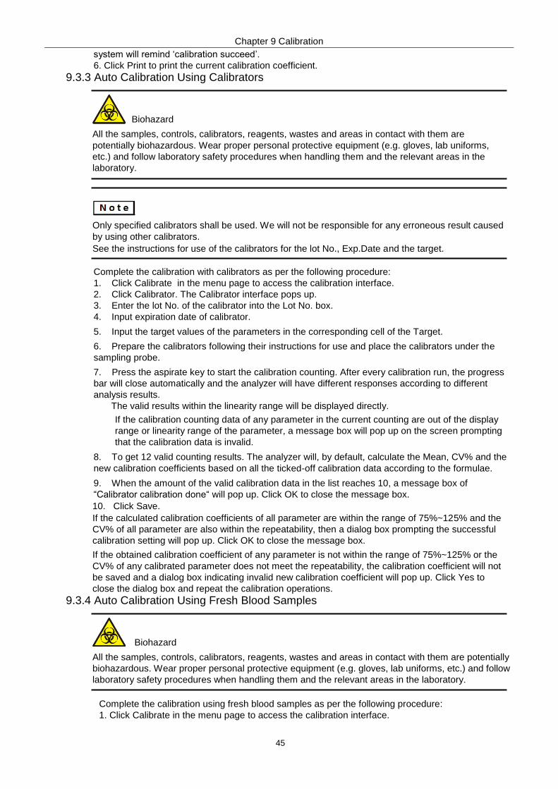
Chapter 9 Calibration
45
system will remind ‘calibration succeed’.
6. Click Print to print the current calibration coefficient.
9.3.3 Auto Calibration Using Calibrators
Biohazard
All the samples, controls, calibrators, reagents, wastes and areas in contact with them are
potentially biohazardous. Wear proper personal protective equipment (e.g. gloves, lab uniforms,
etc.) and follow laboratory safety procedures when handling them and the relevant areas in the
laboratory.
Only specified calibrators shall be used. We will not be responsible for any erroneous result caused
by using other calibrators.
See the instructions for use of the calibrators for the lot No., Exp.Date and the target.
Complete the calibration with calibrators as per the following procedure:
1. Click Calibrate in the menu page to access the calibration interface.
2. Click Calibrator. The Calibrator interface pops up.
3. Enter the lot No. of the calibrator into the Lot No. box.
4. Input expiration date of calibrator.
5. Input the target values of the parameters in the corresponding cell of the Target.
6. Prepare the calibrators following their instructions for use and place the calibrators under the
sampling probe.
7. Press the aspirate key to start the calibration counting. After every calibration run, the progress
bar will close automatically and the analyzer will have different responses according to different
analysis results.
The valid results within the linearity range will be displayed directly.
If the calibration counting data of any parameter in the current counting are out of the display
range or linearity range of the parameter, a message box will pop up on the screen prompting
that the calibration data is invalid.
8. To get 12 valid counting results. The analyzer will, by default, calculate the Mean, CV% and the
new calibration coefficients based on all the ticked-off calibration data according to the formulae.
9. When the amount of the valid calibration data in the list reaches 10, a message box of
“Calibrator calibration done“ will pop up. Click OK to close the message box.
10. Click Save.
If the calculated calibration coefficients of all parameter are within the range of 75%~125% and the
CV% of all parameter are also within the repeatability, then a dialog box prompting the successful
calibration setting will pop up. Click OK to close the message box.
If the obtained calibration coefficient of any parameter is not within the range of 75%~125% or the
CV% of any calibrated parameter does not meet the repeatability, the calibration coefficient will not
be saved and a dialog box indicating invalid new calibration coefficient will pop up. Click Yes to
close the dialog box and repeat the calibration operations.
9.3.4 Auto Calibration Using Fresh Blood Samples
Biohazard
All the samples, controls, calibrators, reagents, wastes and areas in contact with them are potentially
biohazardous. Wear proper personal protective equipment (e.g. gloves, lab uniforms, etc.) and follow
laboratory safety procedures when handling them and the relevant areas in the laboratory.
Complete the calibration using fresh blood samples as per the following procedure: 1. Click Calibrate in the menu page to access the calibration interface.

Chapter 9 Calibration
46
2. Click Fresh Blood. The fresh blood sample calibration interface pop up.
3. Prepare 3 to 5 normal fresh blood samples
4. Run each of the prepared samples on the reference instrument three times at least. Average the
results for your reference values.
5. Enter the reference values for the parameters to be calibrated in the corresponding Target
textbox.
6. Place the blood sample No.1 under the sampling probe, press the aspirate
key on the analyzer to run the samples. The system will calculate the values for
WBC, RBC, HGB, MCV and PLT of the sample.
7. Repeat step 6 for 10 times and calculate the counting results for sample No. 1 in the 10 runs.
The system will calculate the Mean, CV and Calibration coefficient for each parameter of the
sample.
8. Refer to steps 6~7 and perform the counting operations for the remaining four blood samples. The
system will calculate the Mean, CV and Calibration Coefficient for each parameter of the remaining 4
blood samples.
9.Click Calculate. The system will calculate the average of the calibration coefficients, namely, the
mean calibration coefficient (%), as the new calibration coefficient based on the five blood samples.
10. Click Save.
The mean calibration coefficient is invalid if its absolute value of deviation from the original calibration
coefficient is greater than or equal to 5%.
9.4 Verifying Calibration Coefficients
It is recommended that you take the following steps to verify the calibration coefficients:
1. Run the calibrator at least three times and check whether the means of the obtained results are
within the expected ranges
2. Run the low, normal and high-level controls each for three times at least, and check whether the
means of the obtained results are within the expected ranges.
3. Run at least three fresh blood samples with known reference values, each for six times at least,
and check whether the means of the obtained results are within the expected ranges.

Chapter 10 Service
47
10 Service 10.1 Introduction
This analyzer provides multiple maintenance functions for this purpose. This chapter introduces
how to use the provided functions to maintain and troubleshoot your analyzer. Preventive and
corrective maintenance procedures are required to keep the analyzer in a good operating condition.
Biohazard All the analyzer components and surfaces are potentially infectious, take proper protective measures for operation or maintenance.
Caution
Performing unauthorized maintenance procedures can damage your analyzer. Do not perform any
maintenance procedures that are not described in this chapter.
In case of problems not specified in this manual, contact our customer service department or your
local agent for assistance.
Only Prokan’s parts can be used for maintenance. For any question, contact our customer service
department or your local agent.
Exercise caution to avoid contact with the sharp sample probe when performing maintenance.
10.2 Maintenance The analyzer provides multiple service functions helping users to perform daily maintenance.
10.2.1 Reagent Replacement
Warning
Reagents can be irritating to the eyes, skin, and mucosa. Wear proper personal protective
equipment (e.g. gloves, lab uniforms, etc.) and follow laboratory safety procedures when handling
them in the laboratory.
If the reagent accidentally comes in contact with your skin, wash it off immediately with plenty of
water and see a doctor if necessary. Do the same if you accidentally get any of the reagent in your
eyes.
After long-distance transportation, the reagent must be allowed to settle for more than one day
before use.
When you have changed the diluents, cleansers or lyses, run a background check to see if the
results meet the requirement.
The user should replace the reagent in the following cases:
The system indicates that the reagent is used up
WBC or RBC bubbles are identified. You can replace any of the following reagents:
Diluent
DIFF Lyse
LH Lyse
Do as follows to replace the reagents:
1. Refer to Electrical Connections for reagent connections.
2. Click the Service icon in the menu page to access the Service interface.

Chapter 10 Service
48
3. Click Replace Reagent in the Maintenance selection.
4. Click the name of the reagent that needs to be replaced, such as Replace All Reagents. System
will remind after completed.
10.2.2 Cleaning Clean corresponding parts according to the actual situation:
WBC bath
You should clean the WBC bath when:
the background of the scattergram has abnormal excessive cells
the background of WBC- and/or HGB-specific parameters exceeds the reference range
RBC bath
When the background of RBC- and (or) PLT-specific parameters exceeds the reference range,
Flow chamber
When the background of the scattergram has abnormal excessive cells, or bad differential of
WBC, you should clean the flow chamber.
Sample probe
When the sample probe is dirty, you should clean the sample probe. The cleaning procedures
are as follows:
1. Click Function in the menu page, select Maintenance in the Service selection
2. Click Clean in the Maintenance selection。
3. Click the icon of the part that needs to be cleaned, such as Clean Sample Probe. System
will remind after completed.
10.2.3 Maintenance Maintenance of the analyzer includes: unclogging, cleanser soak, cleanser soak for WBC channel,
and cleanser soak for RBC channel.
10.2.4 Unclogging If clogging is found, or it is suspected that the counting results are not accurate due to aperture
clogging, you can perform the unclogging operations. The unclogging procedures as follows:
1. Click Function in the menu page, select Maintenance in the Service selection
2. Click Maintain in the Maintenance selection.
3. Click the Unclog icon. The system will start clogging, and a message box will pop up. After the
unclogging is completed, a message box will pop up to show that the clogging is done. System
will remind after unclogging completed.
10.2.5 Cleanser Soak The cleanser soak should be performed under the following circumstances:
When the problems including the background results exceed the Ref. Range, bad differential of
scattergram and clogging still exist after other maintenance procedures have been adopted.
Analyzer has been running for more than 24 hours. The cleanser soak procedures as follows.
1. Click Function in the menu page, select Maintenance in the Service selection
2. Click Maintain in the
Maintenance selection.
3. Click the icon of Cleanser Soak.
4. Click Yes. A dialog box will show.
5. Present the cleanser to the sample probe as per the prompt, and press the aspirate key
or click the Aspirate button. Cleanser soaking... and the soaking time will appear.
6. Wait for 19 minutes until the automatic soaking is completed. System will remind after cleanser
soak completed.
10.2.6 Cleanser Soak for WBC Channel Probe cleanser soaking for WBC channel can be used to remove the errors for aperture clogging or abnormal scattergram.
10.2.7 Cleanser Soak for RBC Channel In case the RBC distribution histogram is abnormal or the clogging is believed to exist in the flow chamber, cleanser soak for RBC channel feature can be used as a means for troubleshooting.
10.2.8 Comprehensive Device Maintenance The comprehensive device maintenance feature includes fluidics initialization, comprehensive device
cleaning, emptying fluidics and preparing to ship.
10.2.8.1 Fluidics Initialization After maintaining the fluidic system or replacing a main part of the analyzer, you should perform this
Chapter 10 Service
49
procedure to initialize the fluidic system. Do as follows to perform the fluidics initialization:
1. Click Function in the menu page, select Maintenance in the Service selection.
2. Click Device Maintain in the Maintenance selection.
3. Click the icon of Fluidics Initialization. The analyzer starts to perform the fluidics initialization
procedure. System will remind after cleanser soak completed.
10.2.8.2 Comprehensive Device Maintenance
If the background result of each parameter is beyond the background. Do as follows to perform the
Comprehensive Device Maintenance:
1. Click Function in the menu page, select Maintenance in the Service selection.。
2. Click Device Maintain in the Maintenance selection.
3. Click Comprehensive Maintenance. The instrument start to execute comprehensive
maintenance, System will remind after completed.
10.2.8.3 Empty Fluidics This function enables the device to empty fluidics to prevent crystallization and maintain device
performance when the device has not been used for more than one week. Procedures for emptying
fluidics as below:
1. Click Function in the menu page, select Maintenance in the Service selection.
2. Click Device Maintain in the Maintenance selection.
3. Click Empty Fluidics.
5. Remove all reagent pickup tube assemblies according to the prompt, and then click OK to start
emptying the fluidic system. After the emptying is complete, a message box of shutdown will pop
up.
6. Place the [O/I] switch at the left side of the main unit in the [O] position.
10.2.9 Package If the analyzer is not to be used for over one weeks or needs be transported over a long distance,
you should pack. Package procedure as follows:
1. Click Function in the menu page, select Maintenance in the Service selection.
2. Click Device Maintain in the Maintenance selection.
3. Click Package.
4. Click Yes. The interface pops up a dialog box of confirmation.
5. Remove all reagent pickup tube assemblies according to the prompt, and then click OK, start
packing and a message box will pop up.
6. Place all reagent pickup tube assemblies into the distilled water, and then click OK.
System performs the priming operation.
7. Take out the diluent and lyse pipes from the distilled water as per the prompt, then click OK. A
dialog box will pop up to prompt you to power off the device.
8. Place the [O/I] switch at the left side of the main unit in the [O] position.
9. After shutdown, empty the waste in the waste container, and dispose of it.
Be sure to use distilled water in order to ensure the normal use of the device in the future. In addition,
the beaker holding the distilled water needs to be cleaned thoroughly.
The diluent pipe and lyse pipes should be stored separately in two beakers.
Warning
Be sure to dispose of reagents, waste, samples, consumables, etc. according to local legislations
and regulations.
10.3 Self-test This feature is to test if some important components of the device can function properly or not,
including syringe and sampling assembly self-test, pressure and vacuum self-test, valve self-test and
other self-test.
If the testing result is abnormal, you should try again for several times; if the abnormalities persist,

Chapter 10 Service
50
please contact our customer service department or your local agent.
10.4 Log In the Log interface, you can view the records of Set Paras, Other Logs, Fault Logs and All Logs.
10.4.1 All Logs 1. Click the Logs in the menu page to access the Service interface.
2. Click All Logs in the Logs selection. You can view all logs (visible to the users of the current
access level).
3. Select the dates in the two date text-boxes, and then you can view the all logs within the date
range, including operation time, log information and the operator.
10.4.2 Parameter Revision Logs 1. Click the Logs in the menu page to access the Service interface.
2. Click Set Paras in the Logs selection. You can view the parameter
revision logs (which can be viewed by the user with the current level of
access) within a specified date range.
3. Select the dates in the two date textboxes, and then you can view the parameter revision logs
within the date range, including the revision date and time, revision summary and the operator.
10.4.3 Fault Logs 1. Click the Logs in the menu page to access the Service interface.
2. Click Fault Logs in the Logs selection. You can view all logs
(visible to the users of the current access level).
3. Select the dates in the two date textboxes, and then you can view the fault logs within the date
range, including date and time when the faults occur, fault description and the operator.
10.4.4 Other Logs 1. Click the Logs in the menu page to access the Service interface.
2. Click Other Logs in the Log selection. You can view other logs besides parameter revision logs
and fault logs.
3. Select the dates in the two date textboxes to view the logs within the date range, including
operation date and time, operation records and the operator.

Chapter 11 Settings
51
11 Settings
11.1 Introduction The analyzer has been initialized before delivery. The interfaces upon the initial startup of the analyzer are
system settings by default. Some parameters of the analyzer can be reset to meet various demands in
practical applications.
The analyzer divides the operators into two access levels, common user and administrator. Note that an
administrator can access all the functions accessible to a common user. This chapter introduces how to
customize your analyzer as an administrator.
11.2 Interface Introduction After logging in the system, click Function, and choose Setting to access the Setting interface.
11.3 General Setting 11.3.1 Date and Time
You can set the current date and time, as well as the date display format in the analyzer system.
Specific steps are shown below:
1. Click Function--Setting--General. The date and time format setting interface pops up.
2. Click the Date and Time drop-down list and set the current date and time of the system in the
popup dialog box.
11.3.2 Soft keyboard
The default of soft keyboard is opened. You can close if you need to use external keyboard.
11.3.3 Printer You can set the parameter and details of printer.
11.3.4 Communication Settings If hematology analyzer need to connect to Laboratory Information System (LIS), you can refer to the
procedure of this section to complete LIS connection.
11.3.4.1 LIS Workstation Settings
1. Install LIS station, set type and model of hematology analyzer. 2. After installation, you can set IP address and Port number in interface of Network Setting of LIS
workstation.
11.3.4.2 LAN Settings 1. Set the IP address and other network information of the analyzer according to the actual situation.
a. If the network is accessed through a router on the site, please close host static IP address.
b. If the network is accessed through a network switch, or the analyzer is directly connected to the
LIS on the site, please open host static IP address, so as to manually set the IP address and subnet
mask of the analyzer. The IP addresses of the analyzer and LIS must be in the same network
segment. Furthermore, their subnet masks shall be the same, while other parameters can maintain
null.
2. Place LIS switch on the “ON” option. Set the IP address of LIS to IP address of LIS workstation.
Set the port of LIS to the port of LIS workstation.
11.3.4.3 WLAN Settings 1. According to the actual situation, connect LIS station to a wireless network and check the IP address obtained by the workstation through the wireless network.
2. Click Function--Setting—General, and place the WLAN switch on the “ON” option, searching
the WLAN list. 3. Select an encrypted WIFI point connected by the LIS workstation, enter the password of the WIFI point, and connect the WIFI point. 4. Return to the general interface after successful connection.
5. Place LIS switch on the “ON” option. Set the IP address of LIS to IP address of LIS
workstation. Set the port of LIS to the port of LIS workstation.
11.3.5 Report Title Settings Users can set 8 kinds of titles of Report, including Sample Analysis Report, Calibration-Manual,
Calibration-Calibrator, Calibration-Fresh Blood, QC-L-J Graphic, QC-L-J Table, QC-X-B Graphic,
QC-X-B Table and so on.

Chapter 11 Settings
52
11.4 Hospital Info 11.4.1 Enter the name and other information of the hospital
11.4.2 Lab Name:Enter the lab name. You can use “-” and “+” to increase and decrease items.
11.4.3 Responsible Person:Enter the information of responsible person. You can use “-” and “+” to increase and
decrease items.
11.4.4 Gender:Enter the information of gender. You can use “-” and “+” to increase and decrease items.
11.4.5 Ward:Enter the information of ward. You can use “-” and “+” to increase and decrease items.
11.4.6 Bed Number:Enter information of bed number. You can use “-” and “+” to increase and decrease items.
11.4.7 Patient Type:Enter information of patient type. You can use “-” and “+” to increase and decrease items.
11.4.8 Sample Type:Enter information of sample type. You can use “-” and “+” to increase and decrease items.
11.5 User Setting After logging in the system, the administrator has the access to set the account information of
general users and other administrators; common users can only browse the user list. User is
classified into Common User and Administrator with different permission. User can use “-” and “+” to
increase and decrease items of permission. Setting password could not be changed, only could be added
after deleted.
11.6 About You can check serial number and software version.
11.7 Parameter Settings 11.7.1 Project Parameter
Project Parameter is including analysis parameters, microscopy parameters, custom parameters,
reagent parameters and so on.
11.7.2 Unit System You can select a unit system for the parameters among the 7 unit systems (Custom, China,
International, Britain, Canada, USA and Netherlands). The default unit system is USA.
When setting the Custom unit system, if you click Default, the unit of the parameters can be restored to
the initial default values.
11.7.3 Ref. Range
The reference range based on various normal groups can be set for the analyzer in the actual practice.
If the analysis result of a sample is beyond the reference range, it will be regarded as clinically
abnormal. The Ref. Range interface is where you view and set the high and low limits for your patients.
The analyzer flags any parameter value above (↑) or below (↓) these limits.
This analyzer divides the patients into 10 groups: Dog, Cat, Rabbit, Horse , Pig, Cow, Sheep. Monkey,
Rat and Mouse. You can also customize other groups. The recommended limits are for reference only.
To avoid misleading parameter flags, be sure to set the patient limits according to the characteristics of
local population.
11.7.4 Flag Alarm
Interface will show corresponding Flag alarm when the result in the alarm range. Users can modify the
alarm range according to actual needs and related processes in the laboratory.
Suspicious alarm: Adjust the sensitivity value (0~100) to adjust the sensitivity of the alarm.
11.7.5 Sequence The user can edit the Sequence of display, including Sample Info., Result, Review, QC, Printing, etc.
The user can edit according to the needs, and change the display order by moving items by long press. The user also can click one project parameter line to gray its background, so this parameter will not
display in the interface or printing report. Click the grayed project parameter line , this parameter can restore the display.
11.8 Host Settings 11.8.1 Assisted Settings
Assisted Settings include: 1 Open or close Prediluted Run Reminder. 2 The sample number is automatically incremented or manually entered. 3 The number of prefix bits that do not participate in incrementing (this setting affects the length of the number, it is recommended to set to 9) 4 The sample number start to count from last one when closed instrument (recommended to open).

Chapter 11 Settings
53
5 Set the sample number after open instrument (customization, be effective after last item closed). 6 The next sample analysis mode is CBC or CBC+DIFF after open the instrument 7 Take effect in next day (recommended to open). 8 Open or close the automatic input function of inspection and sampling. 9 Open or close the function of edit result tag. 10 Alarm flag are available can be show by arrow and letter (H&↑).
11.8.2 Maintain Settings Users can customize the automatic sleep period, automatic maintenance time and automatic cleaning period.
11.8.3 Gain Setting Users can set the WBC channel gain, RBC channel gain, DIFF channel gain, and BASO channel gain. Users can also adjust the HGB reference voltage. All values have been made the factory calibration, so it is not recommended to adjust gains frequently.
11.8.4 Reagent Settings Once the new reagent is connected to the analyzer, you can set the reagent configurations, including validity period, residue volume and reagent barcode on the Reagent Management interface. Select one reagent, click the Settings, place attached magnetic card of the reagent bottle in the sensor area of the face shell, system will automatically update the reagent information after the card is successfully read, and prompt to replace the reagent.
11.8.5 Security Settings This function is used to open the permission to delete samples, you need to enter a password to operate.

Chapter 12 Troubleshooting
54
12 Troubleshooting
12.1 Introduction
This chapter contains information that is helpful in locating and resolving problems that may occur
during the operation of your analyzer.
This chapter is not a complete service manual and is limited to problems that are readily
diagnosed and/or corrected by the user of the analyzer.
12.2 Dealing with Error Message In the use of the analyzer, when the software detects abnormalities, an error message will be displayed
on the screen and the main unit will sound an alarm.
Click the error message area.
a. The pop up dialog box displays the error description and its help information. The error descriptions
are displayed in the order of error occurrence.
b. Touch the screen to disable the beep.
c. Click Remove Error. Normally, the system will automatically remove the errors. For errors which
cannot be removed automatically, you can take appropriate actions by following the error help
information or 12.3 Error Message Reference.
12.3 Error Message Reference
Problem Name Troubleshooting Information
Startup failure. 1. Click the Remove Error button to remove this error.
2. If the error still exists, contact our customer service
department.
Startup initialization is not
executed.
1. Click the Remove Error button to remove this error.
2. If the error still exists, contact our customer service
department.
The right-side door is open.
1. Close the right side door.
2. Click the Remove Error button to remove this error. 3. If the error still exists, contact our customer service
department.
Diluent expiration.
1. Check if the diluent expires. If so, replace it with a new
container of diluent.
2. Click the Remove Error button, the Reagent Management
screen will be displayed. 3. Set the reagent information by referring to Reagent
Management. 4. If the error still exists, contact our customer service
department.
LH Lyse expiration.
1. Check if the LH lyse expires. If so, replace it with a new
container of LH lyse.
2. Click the Remove Error button, the Reagent Management
screen will be displayed. 3. Set the reagent information by referring to Reagent
Management. 4. If the error still exists, contact our customer service
department.

Chapter 12 Troubleshooting
55
Problem Name Troubleshooting Information
DIFF Lyse expiration.
1. Check if the DIFF lyse expires. If so, replace it with a new
container of DIFF lyse.
2. Click the Remove Error button, the Reagent Management
screen will be displayed. 3. Set the reagent information by referring to Reagent
Management. 4. If the error still exists, contact our customer service
department. Preheating bath
temperature out of working
range.
1. Click the Remove Error button to remove this error.
2. If the error still exists, contact our customer service
department.
Abnormal HGB background
voltage.
1. Adjust the HGB background voltage within the specified range
(4.2V~4.8V), preferably 4.5V. 2. If the error still exists, contact our customer service
department.
Abnormal RBC aperture
voltage.
1. Click the Remove Error button to remove this error.
2. If the error still exists, contact our customer service
department.
Abnormal background.
1. Check whether the diluent is contaminated.
2. If not, click the Remove Error button to remove the error. 3. If the error still exists, contact our customer service
department.
Sample syringe is busy. 1. Click the Remove Error button to remove this error.
2. If the error still exists, contact our customer service
department.
Waste is full.
1. Empty the waste container or install a new waste container.
2. Click the Remove Error button to remove this error. 3. If the error still exists, contact our customer service
department.
Flow cell clog. 1. Click the Remove Error button to remove this error.
2. If the error still exists, contact our customer service
department.
Diluent empty.
1. Check whether the diluent container is empty. If so, install a
new container of diluent.
2. Click the Remove Error button to remove this error.
3. If the error still exists after a new container of diluent is
installed, contact our customer service department.
LH lyse empty.
1. Check whether the LH lyse container is empty. If so, install a
new container of LH lyse.
2. Click the Remove Error button to remove this error. 3. If the error still exists after a new container of LH lyse is
installed, contact our customer service department.
DIFF lyse empty.
1. Check whether the DIFF lyse container is empty. If so, install a
new container of DIFF lyse. 2. Click the Remove Error button to remove this error. 3. If the error still exists after a new container of DIFF lyse is
installed, contact our customer service department.
Diluent not replaced. 1. Click the Remove Error button to remove this error.
2. If the error still exists, contact our customer service
department.
LH lyse not replaced. 1. Click the Remove Error button to remove this error.
2. If the error still exists, contact our customer service
department.
DIFF lyse not replaced. 1. Click the Remove Error button to remove this error.
2. If the error still exists, contact our customer service
department.

Chapter 12 Troubleshooting
56
Problem Name Troubleshooting Information
Probe clogging. 1. Click the Remove Error button to remove this error.
2. If the error still exists, contact our customer service
department.
Insufficient Diluent.
1. Check whether the diluent container is empty. If so, install a new container of diluent.
2. Click the Remove Error button, the Reagent Management screen will be displayed. 3. Set the reagent information by referring to Reagent Management. 4. If the error still exists, contact our customer service department.
Insufficient LH lyse.
1. Check whether the LH lyse container is empty. If so, install a new container of LH lyse.
2. Click the Remove Error button, the Reagent Management screen will be displayed. 3. Set the reagent information by referring to Reagent Management. 4. If the error still exists, contact our customer service department.
Insufficient DIFF lyse.
1. Check whether the DIFF lyse container is empty. If so, install a new container of DIFF lyse.
2. Click the Remove Error button, the Reagent Management screen will be displayed. 3. Set the reagent information by referring to Reagent Management. 4. If the error still exists, contact our customer service department.

Appendix
57
Appendix A Specifications A.1 Classification
According to the CE classification, the Auto Hematology Analyzer belongs to in vitro diagnostic
medical devices, rather than those covered by Annex II and devices for performance evaluation.
A.2 Reagents
Reagent Classification Reagent Name
Diluent Diluent
Lyse DIFF Lyse
LH Lyse
Cleanser Strong Cleaner
A.3 Parameters
Parameter Abbreviation Default Unit
White Blood Cell count WBC 103/uL
Number of Neutrophils Neu# 103/uL
Number of lymphocytes Lym# 103/uL
Number of Monocytes Mon# 103/uL
Number of Eosinophils Eos# 103/uL
Number of Basophils Bas# 103/uL
Percentage of Neutrophils Neu% %
Percentage of Lymphocytes Lym% %
Percentage of Monocytes Mon% %
Percentage of Eosinophils Eos% %
Percentage of Basophils Bas% %
Red Blood Cell count RBC 106/uL
Hemoglobin Concentration HGB g/dL
Hematocrit HCT %
Mean Corpuscular Volume MCV fL
Mean Corpuscular Hemoglobin MCH pg
Mean Corpuscular Hemoglobin
Concentration MCHC g/dL
Red Blood Cell Distribution Width
- Standard Deviation RDW-SD fL
Red Blood Cell Distribution Width
- Coefficient of Variation RDW-CV %

Appendix
58
Parameter Abbreviation Default Unit
Platelet count PLT 103/uL
Mean Platelet Volume MPV fL
Platelet Distribution Width PDW None
Plateletcrit PCT %
White Blood Cell Histogram WBC Histogram None
Red Blood Cell Histogram RBC Histogram None
Platelet Histogram PLT Histogram None
Basophils Scattergram BASO Scattergram None
DIFF Scattergram DIFF Scattergram None
A.4 Performance
A.4.1 Parameter Range
Parameter Linearity Range Range
WBC 1.0+10.0×10⁹/L 0-99.9×10
9/L
RBC 0.30-7.00×10¹²
/L 0~18.00×10¹²
/L
HGB 0~240g/L 0~300g/L
PLT 0~1000×109/L 0~1000×10
9/L
A.4.2 Normal Background
Parameter Normal Background
WBC ≤0.2×10⁹/L
RBC ≤0.02×10¹²
/L
HGB ≤1g/L
PLT ≤10×109/L
HCT ≤0.5%
A.4.3 Linearity Range
Parameter Linearity range Deviation range (Whole blood mode)
WBC
1.0×10⁹/L-10.0×10
9/L ≤±0.5×10
9/L
10.1×10⁹/L-99.9×10
9/L ≤±5%
RBC
0.30×10¹²
/L-1.00×1012
/L ≤±0.05×10
12/L
1.01×10¹²
/L-7.00×1012
/L ≤±5%
HGB
20g/L-70g/L ≤±2 g/L
71g/L-240g/L ≤±3%
PLT 20×10
9/L-100×10
9/L
≤±10×109/L
101×109/L-999×10
9/L ≤±10%

Appendix
59
A.4.4 Repeatability
These repeatability requirements apply only to the situation in which a qualified sample has been
run for 11 times and the results of the 2nd to 11th runs are used to calculate the repeatabilities.
Parameter Condition Whole Blood Repeatability (CV%/absolute deviation d*
WBC (4.0~15.0)109/L ≤3.0%
Neu% (50.0%~60.0%) ±4.0(Absolute deviation)
Lym% (25.0%~35.0%) ±3.0(Absolute deviation)
Mon% (5.0%~10.0%) ±2.0(Absolute deviation)
Eos% (2.0~5.0%) ±1.5(Absolute deviation)
Bas% (0.5%~1.5%) ±0.8(Absolute deviation)
RBC (3.50~6.00)1012
/L ≤1.5%
HGB (110~180g/L) ≤1.5%
PLT (100~500 ) 109/L ≤6.0%
MCV (70~120 fL) ≤1.0%
*:Absolute deviation d = analysis result - average of analysis results
A.4.5 Carryover
Parameter Carryover
WBC ≤0.5%
RBC ≤0.5%
HGB ≤0.5%
PLT ≤1.0%
HCT ≤0.5%
A.5 Input/output Device
Warning External devices such as barcode scanners and printers must be compulsory by CCC (S&E). Using unsuitable external devices may cause the system to work abnormally and cause personal injury. Be sure to use fuses of the specified specifications.
Main body
Display:10.4 inches embedded touch screen with a resolution of 800×600
LAN interface (1 )
USB interface (4 )
Power
Voltage:A.C 100V~240V
Input power:≤200VA
:50/60 Hz
Fuse protector: T6.3AL 250V
Keyboard (Optional, USB)
Mouse (Optional, USB)
External barcode scanner (optional, USB)
Printer (optional, USB)

Appendix
60
USB flash disk (optional, USB)
A.6 EMC Description
This equipment complies with the emission and immunity requirements of GB/T 18268.26,
refer to below table.
The user should ensure the equipment is in electromagnetic compatibility environment to keep
the equipment work normally.
It is recommended to evaluate the electromagnetic environment before the use of equipment.
Caution
Design and test of equipment complies standard of Class A equipment in GB 4824. In
domestic environment, equipment may cause radio interference, protective measures is
required.
You should not use the equipment near strong radiation sources (such as unshielded RF
sources), this may cause interference of the device.
Table 1:
Table 2:
Emission
Test Item Standard Conformance
Conducted Disturbance GB4824 Mode 1
Radiated Disturbance GB4824 Class A
Harmonic Current GB17625.1 /
Voltage Fluctuation and Flicker GB17625.2 /
Immunity
Test Item Standard Test Value Classification
ESD Immunity GB/T17626.2 Contact discharge:±2kV, ±4kV
Air discharge:±2kV, ±4kV,±8kV
B
RS Radiated Electromagnetic Immunity
GB/T17626.3 3V/m,80MHz~2.0GHz,80%AM A
EFT Immunity GB/T17626.4
Power Line:±1kV(5/50ns,5kHz)
Signal Line:±0.5kV(5/50ns,5kHz)
B
SURGE Immunity GB/T17626.5
line-to-earth:±2kV
Line-to-line:±1kV
B
Conducted Immunity
GB/T17626.6
Power Line:3V/m,
0.15MHz~80MHz,80%AM
Signal Line:3V/m,
0.15MHz~80MHz,80%AM
A
Voltage Dips and Interruptions
Immunity GB/T17626.11
1 cycle, 0%UT
5/6 cycle, 40%UT
25/30 cycle, 70%UT
250/300 cycle, 5%UT
B
C
C
C
Power frequency magnetic field
(for magnetic sensitive devices) GB/T 17626.8 3A/m, 50/60Hz
A
Performance judgment: A. Performance is normal within the specification limits during the test. B. During the test, the function or performance is temporarily reduced or lost, but it can be recovered by itself.
C. Function or performance is reduced or lost during the test, but requires operator intervention or system reset.

Appendix
61
A.7 Environment Conditions
Be sure to use and store the analyzer in the specified environment.
Environment Conditions Operating
Environment Storage
Environment Running
Environment
Ambient temperature 10℃~30℃ -10℃~40℃ 5℃~40℃
Relative humidity 20%~85% 10%~90% 10%~90%
Atmospheric pressure 70kPa~106kPa 50kPa~106kPa 70kPa~106kPa
A.8 Dimensions and Weight
Height
Depth
Width
Instrument Dimensions and Weigh
Width(mm) 364
Height(mm) 498
Depth(mm) 431
Weight(kg) 26.5
A.9 Service Life
5 years(based on a daily test volume of 100 samples)。
A.10 Contraindications None

Appendix
62
Appendix B Key Components B.1 Component list
No. Key components
1 Power Cable
2 Power Supplier
3 Filter
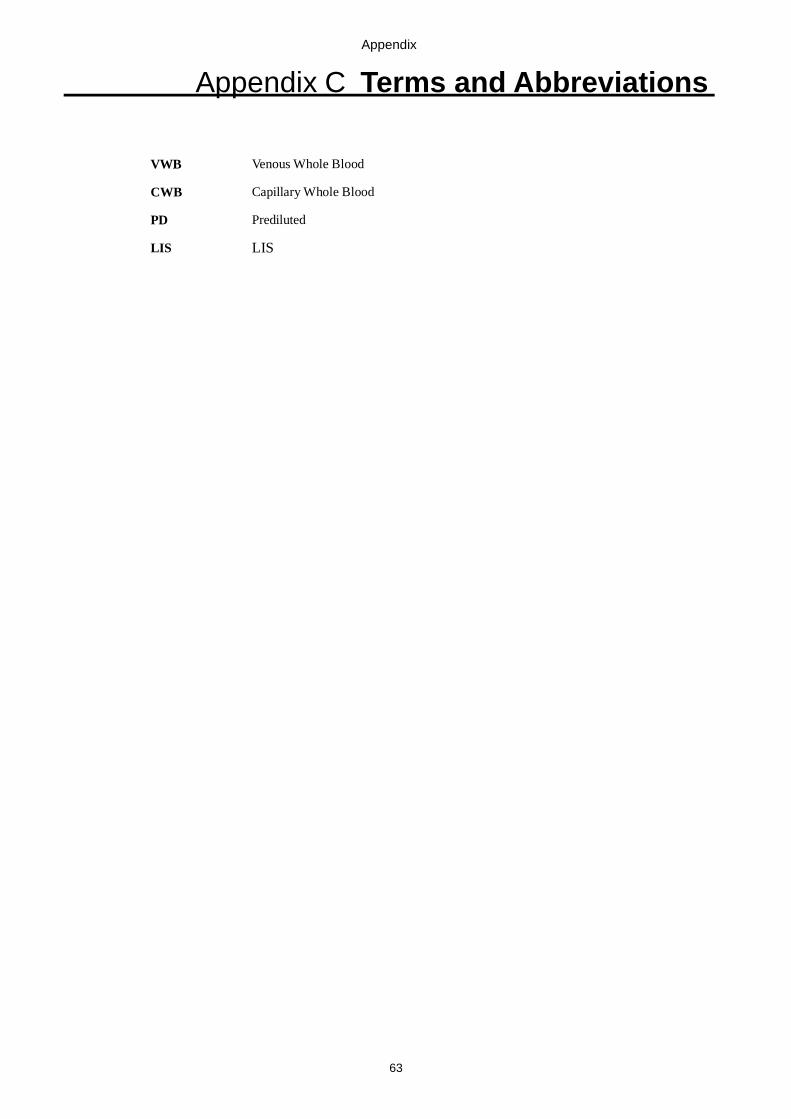
Appendix
63
Appendix C Terms and Abbreviations
VWB Venous Whole Blood
CWB Capillary Whole Blood
PD Prediluted
LIS LIS

5.01.80210