
OPERATOR/SERVICE MANUAL - - Walker Miller Equipment
61
CE WALK BEHIND ROLLER Stone Construction Equipment, Inc. P.O. Box 150, Honeoye, New York 14471 Phone: (800) 888-9926 Fax: 716-229-2363 A 100% employee-owned American manufacturer © 1996 Stone Construction Equipment, Inc. Printed in U.S.A. OPERATOR/SERVICE MANUAL MODELS: 65D Revision: A 4/96 P/N 56231 This equipment has been designed and tested to meet the requirements of the Ma- chinery Safety Directive 89/392/EEC and Amendments and therefore carries the CE mark.
-
Upload
khangminh22 -
Category
Documents
-
view
4 -
download
0
Transcript of OPERATOR/SERVICE MANUAL - - Walker Miller Equipment

��WALK BEHIND ROLLER
Stone Construction Equipment, Inc.P.O. Box 150, Honeoye, New York 14471
Phone: (800) 888-9926Fax: 716-229-2363
A 100% employee-owned American manufacturer© 1996 Stone Construction Equipment, Inc.
Printed in U.S.A.
OPERATOR/SERVICE MANUALMODELS: 65D
Revision: A 4/96 P/N 56231
This equipment has been designed and tested to meet the requirements of the Ma-chinery Safety Directive 89/392/EEC and Amendments and therefore carries theCE mark.

�������� ���������������������������������������������������������������������������������������������������������������������������
��� �������� ���������������������������������������������������������������������������������������������������������������� �
������������������ ������������������������������������������������������������������������������������������������������������� ���
����� !����� ������������������������������������������������������������������������������������������������������������������������ "�#
$�%&���%� ��%'��( ���������������������������������������������������������������������������������������������������� )�*+�����
�,��%���-�������&� ���������������������������������������������������������������������������������������������������������������� .
�,��%�����%� �/�� ��������������������������������������������������������������������������������������������������������� ����.
��%��,����%� ���0��- ����������������������������������������������������������������������������������������������������� �1��2
3%�����%��� ��������������������������������������������������������������������������������������������������������������������������
�!4���%���� ��������������������������������������������������������������������������������������������������������������������� �����
5,&� � �6�%-�%7��%� �%��������
6��%&� ���������������������������������������������������������������������������������������������������������������������������� #"�##
��������65D ROLLER
Left Hand Side Assembly ..................................................... 34-35
Drum ..................................................................................... 36-37
Frame, Drive and Vibration Linkage ...................................... 38-39
Transmission ......................................................................... 40-41
Vibrator Drive ........................................................................ 42-43
Hydraulic Tank, Motor and Pump .......................................... 44-45
Water System ....................................................................... 46-47
Steering Arm and Linkage .................................................... 48-49
Engine .................................................................................. 50-51
Handbrake ............................................................................ 52-53

L I M I T E D W A R R A N T Y
The Manufacturer warrants that products manufactured shall be free from defects in material and workman-ship that develop under normal use for a period of 90 days for concrete vibrators and electric pumps, one yearfor Rhino�, Bulldog�, Wolfpac Rollers�, trowels, Stompers�, saws, plates, engine powered pumps, and6 months for all other products from the date of shipment. The foregoing shall be the exclusive remedy of thebuyer and the exclusive liability of the Manufacturer. Our warranty excludes normal replaceable wear items,i.e. gaskets, wear plates, seals, O-rings, V-belts, drive chains, clutches, etc. Any equipment, part or productwhich is furnished by the Manufacturer but manufactured by another, bears only the warranty given by suchother manufacturer. (The Manufacturer extends the warranty period to "Lifetime" for the drum bearings andseals for the mortar mixers, and agrees to furnish, free of charge, the bearings and seals only upon receipt ofthe defective parts and a Warranty Evaluation Form. The eccentric bearings are warrantied for two years onthe plate compactors and five years on the Bulldog line, the trowel gearboxes are warrantied for two years,plus a Warranty Evaluation Form must accompany the defective parts.) Warranty is voided by product abuse,alterations, and use of equipment in applications for which it was not intended, use of non-manufacturer parts,or failure to follow documented service instructions. The foregoing warranty is exclusive of all other warran-ties whether written or oral, expressed or implied. No warranty of merchantability or fitness for a particularpurpose shall apply. The agents, dealer and employees of Manufacturer are not authorized to make modifica-tion to this warranty, or additional warranties binding on Manufacturer. Therefore, additional statements,whether oral or written, do not constitute warranty and should not be relied upon.
The Manufacturer's sole responsibility for any breach of the foregoing provision of this contract, with respectto any product or part not conforming to the Warranty or the description herein contained, is at its option (a) torepair, replace or refund such product or parts upon the prepaid return thereof to location designated specifi-cally by the Manufacturer. Product returns not shipped prepaid or on an economical transportation basis willbe refused (b) as an alternative to the foregoing modes of settlement - the Manufacturer's dealer to repairdefective units with reimbursement for expenses, except labor, and be reviewed with the Manufacturer prior torepair. A Warranty Evaluation Form must accompany all warranty claims.
Except as set forth hereinabove and without limitation of the above, there are no warranties or other affirmationswhich extends beyond the description of the products and the fact hereof, or as to operational efficiency,product reliability or maintainability or compatibility with products furnished by others. In no event whether asa result of breach of contract or warranty or alleged negligence, shall the Manufacturer be liable for special orconsequential damages including but not limited to: Loss of profits or revenues, loss of use of the product orany associated product, cost of capital, cost of substitute products, facilities or services or claims of custom-ers.
No claim will be allowed for products lost or damaged in transit. Such claims should be filed with the carrierwithin fifteen days.
Effective December 1, 1995.
MODEL NUMBER ___________________ Serial No.__________________________
Stone Construction Equipment, Inc. Phone: 1-800-888-9926Corporate Offices/Northern Mfg. Plant Phone: (716) 229-514132 East Main Street, P.O. Box 150 FAX: (716) 229-2363Honeoye, NY 14471-0150

REVISION: PAGE 1
65H
Dual
640 kg
680 kg
2360 x 785 x 1015 mm1420 x 785 x 1800 handle upright
2360 mm
650 mm
400 mm
200 mm
28 / 107 mm
Hydrostatic
5.4 kw
2750 rpm
8.25 L
18 L
Plastic tank, brass taps noncor-rosive dual spray bars
20 L (Front)15.5 L (Rear)
0-3.2 km/h
19 kn
72 hz
.5 mm
33%50%
Deadman's HandleReverse position system
Freewheel SystemParking BrakeLifting Points
Front & Rear Adjustable ScrapersAdjustable Handle
Specification Comparisons
MODEL
Drum Type
DimensionsOperating Wt.
Shipping Wt.
L X W X H
Operating Length
Drum Width
Drum Dia.
Curb Clearance
Wall Clearance
Operating SystemDrive System
Engine Options
Engine RPM's
Fuel Capacity
Hydraulic Capacity
Water System
Water Tank Capacity
PerformanceMax. Travel Speed
Eccentric Force
Frequency
Maximum Lift
Gradeability w/vibrationw/o vibration
Safety Features
Standards
65H
Dual
1412 lbs.
1500 lbs.
93"x31"x40"56"x31"x71" handle upright
93"
26"
16"
8"
1.1 / 4.2"
Hydrostatic
7.3 hp Hatz Diesel
2750 rpm
2.2 gallons
4.8 gallons
Plastic tank, brass taps noncor-rosive dual spray bars
5.3 gallons4.1 gallons
0-2 mph
4270 lbs.
4320 vpm
.02"
33%50%
Deadman's HandleReverse position system
Freewheel SystemParking BrakeLifting Points
Front & Rear Adjustable ScrapersAdjustable Handle
PAGE 2 REVISION:
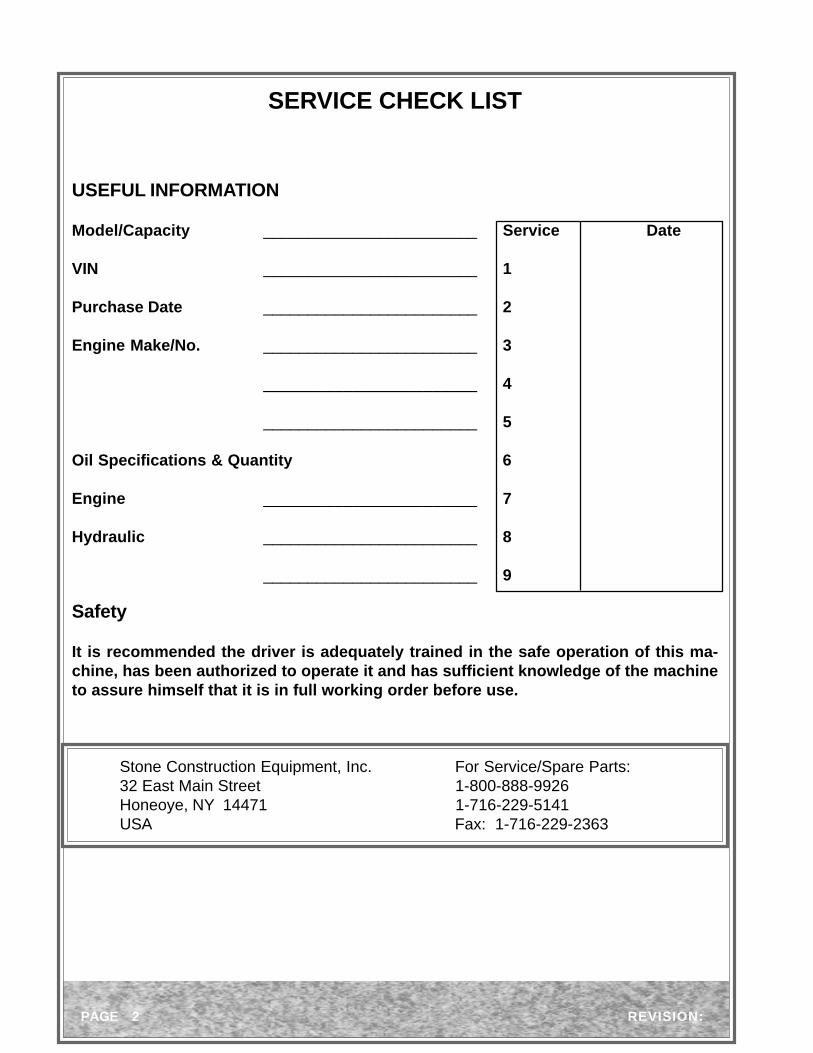
SERVICE CHECK LIST
USEFUL INFORMATION
Model/Capacity ________________________ Service Date
VIN ________________________ 1
Purchase Date ________________________ 2
Engine Make/No. ________________________ 3
________________________ 4
________________________ 5
Oil Specifications & Quantity 6
Engine ________________________ 7
Hydraulic ________________________ 8
________________________ 9
Safety
It is recommended the driver is adequately trained in the safe operation of this ma-chine, has been authorized to operate it and has sufficient knowledge of the machineto assure himself that it is in full working order before use.
Stone Construction Equipment, Inc. For Service/Spare Parts:32 East Main Street 1-800-888-9926Honeoye, NY 14471 1-716-229-5141USA Fax: 1-716-229-2363

REVISION: PAGE 3

PAGE 4 REVISION:
Introduction
The 65D roller is powered by a Hatz 1D41 single cylinder, hand start, diesel engine running at aconstant 2750rpm.
Forward reverse drive to the roller drums is by means of a hydrostatic transmission.
A hydraulic pump, belt driven at constant speed from the engine, supplies oil to a hydraulic motordriving each drum through spur reduction gears.
Rubber mountings at each end of the drums isolate the transmission and operator from the effectsof vibration.
An eccentric shaft mounted on grease packed ball bearings, is contained within each drum togenerate vibration. Drive to each shaft is at constant speed from the engine via a drive shaft,flexible couplings, dry plate clutch and pre-tensioned ‘Vee” belt running on machined pulleys.
Each roller drum is of heavy duty steel construction with seam welded plates to prevent ingress ofwater.
A removable cast aluminium side cover protects and provides access to the drive gears, clutchassembly and vibrator drive belt.
A plastic water tank is supplied with a brass water tap, noncorrosive spray bars and large diameterfilling cap for easy cleaning.
Front and rear adjustable scraper bars are provided and a parking brake is fitted in the transmissionas an added safety precaution.
The speed can be regulated to give the necessary control for safe operation under a wide rangeof working conditions.
Speed and direction of travel control is by a single control lever which when released will automati-cally return to the neutral position and stop the roller.
An automatic safety Reverse Override Button operates if the roller is reversed up to a wall or similarto prevent the operator from being trapped between the roller and wall.

REVISION: PAGE 5

SAFETY
These machines are designed to carry out the func-tion of compacting material of the non-cohesive, bi-tuminous and granular varieties.
If used correctly they will provide an effective and safemeans of compaction and meet the appropriateperformance standards.
It is essential that the drive/operator of the machineis adequately trained in its safe operation, be autho-rized to drive it, and have sufficient knowledge of themachine to ensure that it is in full working order, be-fore being put to use.

PAGE 6 REVISION:
Safety
These machines are designed to carry out the function of compacting materials of the non-cohe-sive, bituminous and granular varieties. If used correctly they will provide an effective and safemeans of compaction and meet the appropriate performance standards.
Operational Safety Points
When using this machine the following list of basic Do’s and Don’t’s should be applied. This list is notnecessarily a complete list, but applying these rules will greatly reduce the possibility of an accidentoccurring.
Always
•Carry out a daily pre-start check of the machine
•Look around the machine before starting the engine - children could be out of sight
•Before starting the engine, ensure the transmission control lever is in the NEUTRAL position
•Examine working area looking for possible dangers e.g. trenches, confined area, people working
•Park the machine on safe, firm, level ground
•Clear away obvious hazards and always operate with caution
•Ensure you have a clear view when driving
•Exercise great care when working on gradients - especially when crossing
•When refuelling make sure the engine is cold and the machine is in a well ventilated area, with the
engine stopped. Use clean fuel and container. Beware of naked flames, grinding sparks etc.
•Winch or lift the roller from any situation where it cannot extricate itself
•Wear appropriate protective clothing,
Hard Hat............................ at all timesSafety Boots...................... at all timesSafety Glasses................... at all timesReflective Clothing........... at all timesGloves............................... as conditions dictateEar Protectors.................... as conditions dictateRespirator.......................... in dusty conditions
•Wash/Clean the machine at the end of each working day - Keep water away from electrical
components.
It is essential the machine Operator is an able bodied adult, adequately trainedin its safe operation. The Operator must also be authorized to operate the ma-chine and have sufficient working knowledge of the machine to ensure it is in fulland safe working condition before it is put to use.

REVISION: PAGE 7
Never
Attempt to “jump” obstacles such as curbs and manholes
Drive at high speed over rough ground - drive slowly
Leave the roller unattended with the engine running, this practice is not only dangerous but cancause premature engine wear
Carry out maintenance unless the engine is stopped and the start key (if fitted) has been removed
Carry out maintenance unless the drums are chocked
Tamper with any of the safety devices on the machine
Tighten or disconnect any hose while the engine is running
Safe Operation Decals
The machine has a number of special decals fitted which draw the users attention to variouspoints of operation or safety.
Before Using the Machine
Read all the decals attached to the machine and fully understand their meaning. If you don’tunderstand their meaning contact your supervisor for clarification.
Condition of Decals
Ensure the decals are always clean and readable, replace when necessary.
Spare decals are obtainable from the Manufacturers Spares Department
Gradient Working
In the Technical Specification section of this handbook details are given of the recommendedgradient capability of the machine.
The gradients quoted give a general guide as to performance, but conditions existing on site interms of ground conditions and vehicle speed will have an effect on machine stability, an allow-ance for which must be made by the driver.
For more detailed information regarding working on gradients see the Gradient section in Op-eration and Use section of this manual.

PAGE 8 REVISION:
Direction/Speed Control
When operated the direction lever selects forward or reverse.Speed, in either direction, is proportionally increased as the levermoves away from neutral and is proportionally decreased as itmoves back.
For a smooth progressive acceleration or deceleration always movethe lever gently and slowly.
The lever is spring loaded to the neutral position so that when it isreleased the roller will come to an immediate stop.
Operating Controls
Reverse Override Button
This safety device prevents the machine from injuring the Operator if reversed into an obstructionand the Operator is prevented from releasing the direction/speed lever.
Never Operate the Vibrator when Roller is Standing on a Hard Surface
Parking Brake
A parking brake is provided in the drum transmission for additionalsafety when the roller is left unattended. The handbrake is appliedby pulling the lever backwards until it is parallel with the steering arm.
Vibrator Lever
The vibratory lever is of the spring loaded “over center” type andcontrols the clutch which starts and stops the vibrator. Movelever forward to start the vibrator and backward to stop it.

REVISION: PAGE 9
Water Sprinkler Tap
Spraying the drums with water during rolling is essentialto prevent asphalt loading up on the drum surfaces.
A water tank mounted at the rear of the machinedischarges water through brass spraybars onto eachdrum.
A tap in the feed pipe allows the water flow rate to becontrolled or cuts the supply off.
Do Not Attempt to Start the Engine with Control Arm in Storage Position.
Do Not Start or Operate Roller if Control Arm is Not Secured in Operat-ing Position.
Adjustment of the Control ArmPosition
The control arm may be secured in either aworking or a storage position. To reposition thearm use the following procedure.
Stop the engine and apply the handbrake
Remove the linch pin from the control arm pin
Support the weight of the control arm with onehand and remove the control arm pin
Reposition the control arm to its working orstorage position
Refit the control arm pin and retain with thelinch pin

PAGE 10 REVISION:
Machine Symbol Descriptions

REVISION: PAGE 11
Ear protection required when operating this equipment.
This notation appears before warnings in the text. It means that thestep which follows must be carried out to avoid the possibility ofpersonal injury or death. These warnings are intended to help thetechnician avoid any potential hazards encountered in the normalservice procedures. We strongly recommend that the reader takesadvantage of the information provided to prevent personal injury orinjury to others.
USE COMMON SENSE WHEN HANDLING FUELS
Transport and handle fuel only when contained in approved safetycontainer.
Do not smoke when refueling or during any other fuel handling opera-tion.
Do not refuel while the engine is running or while it is still hot.
If fuel is spilled during refueling, wipe it off from the engine immediatelyand discard the rag in a safe place.
Do not operate the equipment if fuel or oil leaks exist - repair immedi-ately.
Never operate this equipment in an explosive atmosphere.
Before using this equipment, study this entire manualto become familiar with its operation. Do not allow un-trained or unauthorized personnel, especially children,to operate this equipment. Use only factory authorizedparts for service.
When warning decals are destroyed or missing, con-tact the Manufacturer immediately at 1-800-888-9926for replacement. For the safety of yourself and others,it is imperative that the following rules are observed.Failure to do so may result in serious injury or death.
SAFETY PRECAUTIONS

PAGE 12 REVISION:
Never operate unit in a poorly ventilated or enclosed area.
Avoid prolonged breathing of exhaust gases.
Keep feet clear of all drums.
Keep work area free of bystanders
For foot protection, wear steel toe shoes or toe pads.
Caution: Escaping hydraulic fluid under pressure can have sufficient forceto penetrate the skin, causing serious personal injury.
Hydraulic fluid escaping under pressure from a very small hole can bealmost invisible. Use a piece of cardboard or wood to search for possibleleaks.
Never use your hands to detect pressure leaks.
Hydraulic tank temperature can reach 180 degrees F maximum.
Avoid contact with hot exhaust systems and engines.
Allow engine to cool before performing any repairs.

REVISION: PAGE 13
Operation
General
Operator Notes
The Operator must read this book thoroughly and understand the contents, especially safetydetails, before using the roller.
The Operator must wear a hard hat, overalls, safety boots etc. when using the roller.
The engine should not be allowed to idle for long periods or premature wear will occur. If themachine is not to be used for five minutes or more, it should be parked correctly and the enginemust be stopped.
Remember Engines Need Fuel, Lubricating Oil, Clean Air, Cooling
Delivery Checks
Immediately on taking delivery of the roller and before putting it into service:
Read this handbook thoroughly and understand.
Read the engine manufacturers handbook supplied with the machine.
Pre-Start Checks
Ensure the machine has been cleaned to enable leaks etc. to be noticed easily during the pre-start check and during normal operation.
Check general condition of machine - missing parts, loose fixings, fuel lines for damage, hydraulichose end fittings for leakage, hydraulic hose outer cover for ballooning, has it been damaged?
Check engine and hydraulic oil levels - make sure the engine and hydraulic tank are filled usingclean oil and a clean container.
Check fuel tank is full - make sure the tank is filled when the engine is cold and the machine is in awell ventilated area, with the engine stopped using clean fuel and container.
When Refueling Beware of Naked Flames, Grinding Sparks etc.
Before using the roller the Operator MUST have received satisfac-tory training in its operation and be fully aware of what each con-trol is for and its operation. The Operator must also be familiar withALL site and machine safety aspects

PAGE 14 REVISION:
Check for adequate ventilation if the machine is to be started or run in a building etc.
Do Not Use Starting Sprays to Assist Engine Starting
Engine Starting
Before the initial daily start of the engine carry out the daily checks as detailed on the previouspage and then ensure:
•The direction lever is in neutral.
•The vibrator lever is in the disengaged position.
•The parking brake is on.
•The air cleaner is clear - especially in dusty conditions.
•The starting handle is not damaged, is clean and is lightly oiled
Follow Instructions Given in Engine Manufacturers Handbook Suppliedwith Roller
Make certain the sump oil is to the top dipstick mark and the air cleaner is in good condition andcorrectly fitted and proceed as follows:
Hatz 1D41 - Hand Start
•Set the Throttle/Stop control lever to the full speed position - leverpulled fully upwards.
•Lift the decompressor lever and pull fully out.
•Remove the starting handle from its position ontop of the roller and insert the handle into thecorrect position on engine.

REVISION: PAGE 15
The Hatz starting handle is a Safety Starting Handle designed to limitany engine kick back. To allow the handle to function correctly thestarting handle grip must be held firmly and not allowed to turn in thehand.
•Turn the engine over vigorously with the starting handle, as the engine turns the decompressor willautomatically return to the run position and the engine will start.
•When engine has started, remove starting handle and return it to its clips on top of the roller.
•Never Use the Decompressor to Stop the Engine
•Do Not Allow Engine to Idle for Long Periods
Driving the Roller
•With the engine running, release the parking brake.
•Move the direction/travel control lever slowly UPWARDS tomove FORWARDS and slowly DOWNWARDS for REVERSE.To increase speed, move the lever gradually towards thefull extent of travel until the required speed has beenattained.
•When constantly rolling forwards and backwards, movethe direction lever forward into neutral, pause for amoment, then move into reverse, gradually increasingspeed as drive is gently taken up.
•Apply the same procedure when changing from forwardto reverse drive.
Gentle movement of control lever between forward and reverseminimizes strain on transmission and prevents drum skidding whendirection of travel is changed.

PAGE 16 REVISION:
Vibration
When vibration is engaged, the machine should not be on concrete or an extremely hard surfaceotherwise mechanical damage to the roller may occur.
The machine must be moving with the engine at full speed when vibration is engaged otherwisethe drum may create an indent in the surface being rolled.
Vibration Lever Operation
•Move the vibration lever forwards (away from theOperator) to engage vibration.
•Move the vibration lever backwards (towards theOperator) to disengage vibration.
To Prevent Mechanical Damage Do Not Vibrate On Concrete or Extremely Hard Surfaces.
Gradients
The machine must never be driven on gradients exceeding those given in the Technical Datasection of this manual.
The gradients quoted give a general guide as to performance, but conditions existing on site interms of ground conditions and vehicle speed will have an effect on machine stability, an allow-ance for which must be made by the driver.
Machine Adhesion Depends on the Surface being Rolled

REVISION: PAGE 17
When used on gradients the machine should only be driven UP or DOWN the gradient NEVERACROSS.
Although the machine may be completely stable crossing a gradient depending on the surface,the roller may begin to slide down the gradient out of control especially if vibration is being used.
Do Not Cross Gradients
Change in Handle Position On Inclines
Be extremely careful when approaching an ascending or descending gradient, the control handlewill either snatch UP or DOWN depending on the angle of the gradient.
The Operator must be awareof this movement and exer-cise extreme caution whenworking on uneven surfaces.Make sure loose clothing isclear of the control arm andthe Operators hands are notin a position in which thesudden change in height ofthe control arm may trap theOperators hands or arms.
It is recommended that, whenever possible, the roller controlarm points towards the highest point on the incline.
Using this method, if the machine does begin to slide on aslippery incline it will slide away from the Operator and nottowards him.

PAGE 18 REVISION:
To Stop and Park the Roller
The Machine Should Never be Used or Parked On Unstable/UnsafeGround
To Stop the Roller
•When stopping the machine the vibrator should not be in operation.
•Release the direction/speed control lever, this will stop the machineimmediately.
•Move throttle lever to the idle speed position.
•Never leave the machine with the engine running. If the Operator is toleave the machine the procedures in the following section, WhenParking the Machine, should also be carried out.
When Parking the Roller
Turn vibrator off.
Select a safe area where it will cause least obstruc-tion and inconvenience to others.
Release the direction/speed control lever allowingit to return to the neutral position.
Ensure machine is stationary on firm ground andapply handbrake.
Move throttle lever to the idle speed position.
If parking for more than a few minutes stop the engine.
Chock the drums if machine is parked on a slope.
Remove the start key on electric startmachines.
If temperatures are likely to fall belowfreezing point, the water tank should bedrained when parking for any considerablelength of time.

REVISION: PAGE 19
Transportation
Use a Trailer or Truck when Transporting
Loading
When loading the roller onto a trailer or truck, strong loading ramps, a crane or similar lifting deviceshould be used. See Technical Data section for roller weights.
Crane or Similar Lifting Device
If using a crane or lifting device the rope, chain, strap etc. should be of sufficient strength to supportthe roller safely and be free from damage. See Technical Data section for roller weights.
A single lifting point is provided for lifting the complete roller. The position of this point will ensure asafe stable lift of the roller in working condition using standard lifting gear. Other methods of liftingare not recommended.
Ramps
Ensure the trailer or truck will not move during loading by applying their brakes and also chockingtheir wheels if necessary.
The angle of ramps must not exceed the gradeability of the roller and in wet or muddy conditionsmay need to be less.
Gradeability Will Be Reduced In Wet, Muddy, Oily Conditions
•It is recommended that a winch is used in conjunction with driving the machine whenever theroller is loaded using ramps. Use the front lashing point to secure the winch hook using a ‘D’ link.
•Dragging the roller when towing, i.e. without the drums turning, may result in the drums developingflat spots which will seriously affect the finish obtained when rolling soft surfaces.

PAGE 20 REVISION:
Lashing
When loaded, the roller must be secured using chains, ropes, straps etc. of sufficient strength tohold the roller safely in all circumstances. Apply the Handbrake.
The lashing points provided on the front and rear of the roller must be used in conjunction withthose on the trailer or truck.
Towing
Towing is Not Recommended - Only Tow the Roller in an Emergency.
In an emergency, use the front or rear lashing point to secure the tow rope to the roller.
Dragging the roller when towing, i.e. without the drums turning, may result in the drums developingflat spots which will seriously affect the finish when rolling soft surfaces.
Towing a Trailer
When the roller is mounted on a trailer ensure the trailer is securely connected to the towing vehicleand the trailer electric are connected before towing.
When driving the towing vehicle pay extra attention when turning corners etc. because the trailerwill not always follow the exact tracks of the towing vehicle.
Avoid reversing with the trailer attached if at all possible, if it is necessary to reverse with the trailerattached, use a competent person to guide and give instructions. This person should ensurepeople and obstructions are clear of the trailer.
Do Not Travel at Excessive Speeds

REVISION: PAGE 21
Maintenance Section
For Your Safety
If the Machine Develops a Fault
•Park the machine in a safe area, if possible.
•Remove the starting handle.
•Attach a warning tag to the machine.
•Contact a qualified person to rectify the fault.
•Do not place hands, arm etc. in any area where there is a hydraulic leak while the hy-
draulic system is pressurized.
The Repair Area
•The repair area should be level, clean, dry and have adequate light and ventilation.
•Keep the floor clean, wipe up spilt oil and grease.
•Always use the correct tool for the job and ensure tools are kept in good condition.
•Jacks, hoists, lifting chains and ropes should be checked before using. Do they have
sufficient lifting capacity?
•Do not attempt to lift heavy objects on your own.
When Repairing
•Always wear eye protection.
•Always wear ear protectors when grinding or working in a noisy environment.
•Always wear goggles or a face mask when grinding or drilling.
•Always wear the correct goggles or protector when welding or burning.
•Release any pressure in the hydraulic circuit before carrying out hydraulic system repairs
etc.
•Always block the wheels before carrying out any repairs.
•If the machine is suspended or lifted always support the machine on adequate blocks.
•Always remove the starting handle to stop accidental starting.
•Never work with the engine running unless absolutely necessary.
•Never start the engine unless the area is well ventilated.
•Always exercise extreme caution when welding, grinding or burning, against fire risk.
Ensure adequate fire extinguishers are available.
•Never smoke or leave the engine running when refueling.
•Always use genuine Stone spare parts.
•Always test the machine thoroughly before putting it back to work.
Observing these points will not make the repair of the machine safe but combined with the skill andknowledge of a trained mechanic will certainly help.

PAGE 22 REVISION:
Daily Checks
•Clean roller, remove any build up of material.
•Check operation of all controls and rectify any faultsbefore using the machine.
•Check engine oil level and top up as required.
•Refuel
When refueling make sure the engine is cold and the machine is in a well ventilated area, with theengine stopped. Use clean fuel and container.
Beware of Naked Flames, Grinding Sparks etc. When Refueling.
•Check level of hydraulic fluid and top up as required using clean oil and container. The correctlevel is shown on the tanks sight gauge.
•Check for loose, worn or missing parts and rectify immediately.
•Drain water tank if subzero temperatures are expected.
Air Cleaner
Maximum engine protection against dust is possible only if the air cleaner is serviced at regularintervals. No hard and fast rules apply to the regularity of servicing because operating conditionsvary so much. The only way to determine if an air cleaner requires cleaning or replacing is tophysically check it.
If In Doubt - Check Air Cleaner Frequently
After First Week then Monthly
Vibrator Clutch
•Check the movement on clutch plate. The plate should liftby approximately 2mm (0.080 in) when disengaged andwhen in the engaged position the Operators lever should befree from the stop by approximately 10mm (0.390 in) if adjust-ment is needed this should be done on the cable at theOperators end.
General
•Check tightness of all fixings especially engine, pump andmotor nuts and bolts.

REVISION: PAGE 23
Monthly Checks
Water Tank
•Drain the water from the water tank through thesprinkler system.
•Access the tank through the filler hole and cleanout any residue, dirt, debris etc. from the bottomof the tank by wiping with a clean cloth.
•Unscrew the water filter and wash out/back flushto remove any dirt from the filter. Refit water filter.
•Refill water tank with fresh, clean water.
Spray Bars
•Remove the two plugs from the ends of the spray bars.
•Open the sprinkler tap and allow the water to flush throughthe spray bars.
•Close the sprinkler tap and refit the plugs.
•Open the sprinkler tap and check for any sprinkler holes thatare still blocked. Clean out blocked holes using a piece ofsoft wire. Remove the plugs from the spray bars and flushthough as above.
•Refit plugs and spray bars.
Pump Belt Tightness
•Remove top cover and check belt tightness. Tension iscorrect when there is a maximum of 5mm (0.200in) playat center of belt when deflected at its midpoint with aforce of 1.6kg (3.50lbs).
•If adjustment is necessary slacken the 3 bolts on thepump mounting bracket and slide bracket on its slottedholes until correctly adjusted. Tighten bolts and refit topcover.
•Check hydraulic system for leaks replacing any wornhoses.
Check all bolts, nuts etc. for tightness.

PAGE 24 REVISION:
Annually
Hydraulic System
•Drain the hydraulic system by removing drain plug from front of the hydraulic tank.
Beware of Scalding from Hot Oil - Check Oil Temperature Before Draining.
•Undo the four fixing bolts (A,B,C and D) and remove the topcover from the roller.
•Clean exterior of the transmission pump to prevent theingress of dirt into the hydraulic system.
•Unscrew the filter from the transmission pump and disposeof the filter safely.
•Clean and lightly grease the filter body sealing ring face.Fit a new filter cartridge and sealing ring to the transmissionpump and tighten hand tight.
•Remove the ten 6mm bolts securing tank lid and lift lid offcarefully. Discard sealing gasket.
•Unscrew the six screws holding the breather/filler capassembly to the tank lid and dispose of the completecap assembly and gasket.
•Unscrew and dispose of suction strainer.
•Thoroughly clean the interior of the tank and flushthrough with clean solvent.
•Fit a new suction strainer.
•Refit the tank lid using a new gasket. Use hydraulicsealant on the threads of the ten 6mm bolts.

REVISION: PAGE 25
•Fit a new breather/filler cap assembly to the tank lid using thenew gasket and screws supplied with the assembly.
•Carefully clean and replace the magnetic drain plug using anew sealing washer.
•Fill the hydraulic tank to the correct level on the sight gaugewith clean, fresh hydraulic oil.
•Before starting the engine, the hydraulic system requires bleedingto remove trapped air.
•Remove top allen screw plug from pump body.
•Operate engine decompressor and crank engine slowly until acontinuous stream of hydraulic oil pours from the hole with no airbubbles.
•Replace the allen screw plug securely.
•Top up the hydraulic tank to the correct level on the sight gaugeand replace the filler/breather cap securely.
•The engine may now be started and if there are no obviousleaks left running for ten minutes checking frequently.
•Check the hydraulic system for leaks.
•Rectify any leaks with engine stopped and top up the hydraulicoil level to the correct level on the sight gauge.
Never Attempt to Tighten or Loosen Hydraulic Fittings whenEngine is Running. Hydraulic Oil Leaks at High PressureCan Easily Penetrate the Skin - If the Skin is Penetrated withHydraulic Oil Seek Expert Medical Attention Immediately.

PAGE 26 REVISION:
Gear Drive
Remove the side covers and check there is sufficientlubricant on the drive gears. If necessary lightly re-greasethe gears (A,B,C and D) with special grease specified inthe Technical Data section.
Vibrator ‘Vee’ Belt Adjustment
Remove the side cover and inspect the Vee belt forsigns of a loose cover, cover swell, excessive wear ordamage and correct alignment in the pulley grooves.
Adjusting Belt Tension
•Check tension by measuring the deflection of the beltmidway between the two vibrator shaft pulleys.
•When correct, this deflection should measure 8mm(0.312in) when a deflection force of between 1.8kg(4.0lbs) and 2.5kg (5.50lbs) is applied.
•The belt may be adjusted by slackening the clampbolt on the jockey pulley and moving the jockeypulley to tighten or slacken its pressure on the belt.
•Tighten the clamp bolt and recheck the tension.Repeat as necessary until the belt tension is correct.
Scraper Bar Adjustment - Front & Rear
•Slacken the two fixing bolts holding scraper bar to theroller crossmember.
•Move the scraper bar IN or OUT until the scraper bar justclears when the drum is fully rotated.
•Retighten the two fixing bolts.
•Check drums and scraper bars for clearance.
•Repeat the above procedure until the correct clearanceis obtained.

REVISION: PAGE 27
Preservation and Storage
If the roller is to be stored for a long period of time the following procedures should be applied:
•Thoroughly wash down the exterior of the roller and remove any build up of material especially inthe scraper bar area.
•Drain the water tank and sprinkler system.
•Grease all greasing points.
•Start the engine and warm it up. Drain engine oil and refill with clean fresh oil to the correctspecification. See engine manufacturers handbook for further information on prolonged enginestorage with regards to anticorrosion oils and fluids.
•Check the hydraulic oil level and top up as required.
•Leave the vibrator lever in the off position.
•Store the roller on solid level ground which is not liable to flooding, standing water or airbornecontamination.
•Smear any exposed metal parts with grease.
•Leave the parking brake in the off position.
Chock the Drums Securely to Prevent the Roller Moving
Cleaning
•Using water or a pressure washer to wash down the exterior of the roller with or without detergentis generally all that is required.
Avoid Spraying Electrical Equipment with Pressure Washers
Asphalt or similar may be removed by soaking with diesel.
Do not use solvents or damage may be caused to paint work, rubber and plastic seals, hoses etc.
Contaminated Water/Fluids/Oils Must Be Disposed of Safely

PAGE 28 REVISION:
Direction/Travel Control Lever
Neutral Adjustment
The direction/speed control lever is connected to the transmission pump linkage by a push/pullstretchless cable and requires no maintenance. If the roller creeps in either direction when thecontrol lever is in the released, neutral position check the following before proceeding with theneutral adjustment procedure.
Possible Fault Possible Cause
Inner cable will not slide freely in outer casing Pinched cableTrapped cableTwisted cableBent cable
Control lever will not move freely Requires cleaningSeizedCatching on adja-cent metal work
Seized transmission linkage Requires cleaningSeized bearingsLinkage catching onadjacent parts
Neutral Adjustment Procedure
•Support the roller so both drums are clear of the ground and free torotate.
•Undo the four top cover fixing bolts (A,B,C and D) and remove toenable a clear view of the neutral position spring pack
•Start the engine and allow to idle.
Beware of the Uncovered Belt Drive
•Slacken rod end locknut ‘A’.
•Rotate the threaded shaft using a spanner on locknut ‘B’.The drums will begin to turn with increasing speed depend-ing on the direction of rotation of the shaft.
•Turn shaft back until drums begin to turn opposite direction,now find the midpoint between these two positions wherethe drums remain stationery and tighten the locknut ‘A’.
REVISION: PAGE 29
•Increase the engine speed to maximum rpm and operate the direction control fully in bothdirections approximately ten times.
•Check the drums stop rotating when the direction lever returns to the neutral position. If they donot then carry out the adjustment again with the engine at full speed.
•Stop engine and fully tighten the locknut. Fit the top cover and lower the roller to the ground.Test the roller and if necessary carry out the above procedure again.
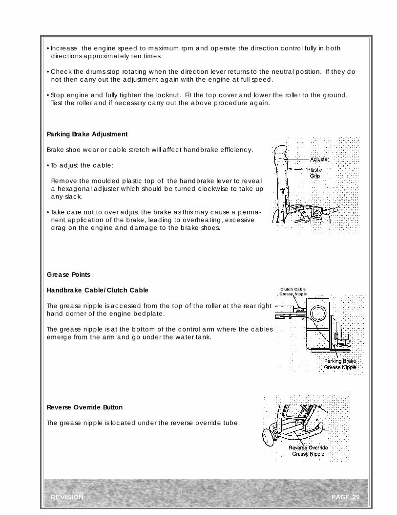
Parking Brake Adjustment
Brake shoe wear or cable stretch will affect handbrake efficiency.
•To adjust the cable:
Remove the moulded plastic top of the handbrake lever to reveala hexagonal adjuster which should be turned clockwise to take upany slack.
•Take care not to over adjust the brake as this may cause a perma-nent application of the brake, leading to overheating, excessivedrag on the engine and damage to the brake shoes.
Grease Points
Handbrake Cable/Clutch Cable
The grease nipple is accessed from the top of the roller at the rear righthand corner of the engine bedplate.
The grease nipple is at the bottom of the control arm where the cablesemerge from the arm and go under the water tank.
Reverse Override Button
The grease nipple is located under the reverse override tube.
Clutch CableGrease Nipple

PAGE 30 REVISION:

REVISION: PAGE 31
Consult the Maintenance section of this manual for instruc-tions on carrying out the above machine lubricationmaintenance procedures.
Beware of Scalding from Hot Oil - Check Oil Temperature Before Draining.
Never Attempt to Tighten or Loosen Hydraulic Fittings whenEngine is Running. Hydraulic Oil Leaks at High PressureCan Easily Penetrate the Skin. If the Skin is Penetrated withHydraulic Oil Seek Expert Medical Attention Immediately.
Clean machine before starting lubrication maintenance.Ensure machine is on solid, level ground before starting maintenance.Remove starting handle/start key when oils have been drained to preventaccidental starting.During lubrication maintenance ensure strict cleanliness is observed at alltimes.To avoid the risk of accidents, use the correct tool for the job and keeptools clean.The draining of engine or hydraulic oil is best carried out when the oil iswarm NOT hot.Any spilled oil must be cleaned up immediately.Use only CLEAN containers for oil and only CLEAN, FRESH oils and grease ofcorrect grades.
Contaminated Water / Fluids / Oils / Filters Must Be Dis-posed of Safely.

PAGE 32 REVISION:

REVISION: PAGE 33
Hydraulic Circuit

EXPLODED DIAGRAMS & PARTS LIST
Left Hand Side Assembly ................................................................................................................... 34-35
Drum .................................................................................................................................................. 36-37
Frame, Drive and Vibration Linkage.................................................................................................... 38-39
Transmission ...................................................................................................................................... 40-41
Vibrator Drive ..................................................................................................................................... 42-43
Hydraulic Tank, Motor and Pump........................................................................................................ 44-45
Water System ..................................................................................................................................... 46-47
Steering Arm and Linkage .................................................................................................................. 48-49
Engine ................................................................................................................................................ 50-51
Handbrake .......................................................................................................................................... 52-53
Decals ................................................................................................................................................ 54-55

- 34 -
Left Hand Side Plate

- 35 -
Item Part No. Description Qty. Item Part No. Description Qty.
REMARK:
Left Hand Side Plate
1 70219 Pin 122 70193 A.V. Mount 123 70405 Plate 24 70117 Nut 125 70408 Nilos Ring 26 70277 Bearing 47 70181 Spacer 28 70407 Nilos Ring 29 70718 Bolt 610 70128 Spring Washer 611 70404 Shaft 212 70403 Plate 1

- 36 -
Drum

- 37 -
Item Part No. Description Qty. Item Part No. Description Qty.
REMARK:
Drum
1 70428 Lock Washer 242 70159 Setscrew 243 70401 Housing 44 70531 Circlip 25 70422 Retainer 66 70398 O-Ring 67 70402 Seal 68 70390 Retainer 69 70424 Bearing 410 70575 Circlip 411 70391 Vibrator Shaft 212 70332 Drum 213 70423 Retainer 2

- 38 -
Frame, Drive and Vibration Linkage

- 39 -
Item Part No. Description Qty. Item Part No. Description Qty.
REMARK:
1 70403 Plate 12 70739 Setscrew 173 70128 Spring Washer 204 70309 Washer 65 70342 Crossmember 16 70335` Bedplate 17 70341 Crossmember 18 70740 Setscrew 19 70122 Washer 210 70538 Nut 111 70741 Setscrew 112 70301 Washer 213 70620 Nut 114 70336 Lever 115 70337 Plate 116 70385 Cable 117 70620 Nut 118 70301 Washer 219 70742 Bolt 120 70538 Nut 121 70122 Washer 422 70376 Ball Joint 223 70743 Bolt 224 70640 Nut 325 70375 Circlip 126 70369 Collar 227 70501 Spring 128 70371 Bolt 129 70744 Capscrew 130 70370 Housing 131 70400 Bush 132 70399 Pulley 133 70174 Drive belt 134 70201 Bush 135 70358 Pulley 136 70387 Setscrew 237 70745 Washer 238 70746 Washer 239 70272 Spacer 3
Frame, Drive and Vibration Linkage
40 70263 Washer 341 70130 Spring Washer 342 70681 Bolt 343 70747 Capscrew 344 70340 Scraper Blade 245 70748 Setscrew 446 70128 Spring Washer 447 70309 Washer 4

- 40 -
Transmission

- 41 -
Item Part No. Description Qty. Item Part No. Description Qty.
REMARK:
Transmission
1 70421 Buffer 22 70130 Spring Washer 43 70680 Bolt 44 70420 Cover 15 70683 Bolt 46 70130 Spring Washer 47 70578 Bearing 28 70414 Spacer 29 70415 Plate 210 70416 Gear 211 70749 Screw 812 70303 Plate 113 70116 Spring Washer 214 70125 Setscrew 215 70294 Gear 116 70578 Bearing 217 70251 Grommet 218 70305 Spacer 119 70528 Circlip 120 70580 Circlip 121 70228 Brake 122 70750 Capscrew 423 70538 Nut 424 70433 Cable 125 70292 Shaft 126 70125 Setscrew 127 70116 Spring Washer 128 70303 Plate 129 70419 Gear 130 70131 Key 131 70185 Hydraulic Motor 132 70130 Spring Washer 233 70113 Bolt 134 70706 Key 135 70413 Gear 236 70125 Setscrew 837 70128 Spring Washer 838 70309 Washer 839 70410 Hub 2
40 70407 Nilos Ring 241 70277 Bearing 442 70411 Spacer 243 70408 Nilos Ring 244 70412 Gear 245 70417 Plate 246 70396 Seal 247 70418 Plate 248 70117 Nut 1249 70193 A.V. Mount 1250 70113 Bolt 1251 70130 Spring Washer 1252 70749 Screw 1253 70683 Bolt 154 70751 Nut 155 70752 Washer 1

- 42 -
Vibrator Drive

- 43 -
Item Part No. Description Qty. Item Part No. Description Qty.
REMARK:
Vibrator Drive
36 70176 Clutch Plate 137 70570 Circliiip 138 70339 Pulley 139 70181 Spacer 140 70408 Nilos Ring 241 70277 Bearing 142 70137 Circlip 143 70538 Nut 144 70216 Hub 145 70172 Circlip 146 70625 Bolt 447 70278 Bearing 248 70220 Spacer 149 70204 Circlip 150 70366 Shaft 151 70602 Key 1
1 70409 Side Plate 12 70386 Plate 23 70131 Key 24 70356 Pulley 25 70392 Bush 26 70393 Vee Belt 17 70395 Bolt 18 70253 Circlip 29 70252 Bearing 210 70282 Pulley 111 70427 Spacer 112 70338 Plate 113 70729 Washer 114 70684 Nut 315 70753 Bolt 216 70263 Washer 417 70394 Spacer 218 70683 Bolt 219 70130 Spring Washer 220 70688 Pin 121 70308 Pivot Block 122 70689 Capscrew 123 70355 Cable 124 70429 Spring 125 70173 Bearing 226 70430 Spring 127 70691 Screw 128 70269 Spring Compressor 129 70274 Lever 130 70221 Screw 131 70754 Washer 232 70531 Circlip 133 70221 Housing 134 70198 Bearing 135 70205 Circlip 1

- 44 -
Hydraulic Tank, Motor and Pump

- 45 -
Item Part No. Description Qty. Item Part No. Description Qty.
REMARK:
Hydraulic Tank, Motor and Pump
1 70755 Setscrew 42 70130 Spring Washer 43 70281 Washer 44 70334 Hydraulic Tank 15 70577 Seal 16 70145 Plug 17 70140 Gasket 28 70139 Filler Cap 19 70756 Washer 610 70757 Screw 611 70758 Cap 112 70521 Cover 113 70466 Gasket 114 70759 Setscrew 1015 70746 Washer 1016 70251 Grommet 217 70233 Gauge 118 70474 Filter 119 70585 Seal 120 70760 Union 121 70761 Union 222 70762 O'Ring 223 70763 Sleeve 124 70764 Union 225 70577 Seal 226 70185 Hydraulic Motor 127 70679 Hydraulic Motor 128 70765 Hydraulic Hose 129 70766 Hydraulic Hose 130 70767 Hydraulic Hose 131 70161 Union 132 70151 O'Ring 133 70768 Union 134 70 769 Hydraulic Hose 135 70357 Pump 136 70770 Seal Kit 137 70771 Union 138 70581 Seal 139 70772 Filter 1

- 46 -
Water System

- 47 -
Item Part No. Description Qty. Item Part No. Description Qty.
REMARK:
Water System
1 70773 Socket 42 70354 Spray Bar 23 70351 Cover 14 70128 Spring Washer 65 70748 Setscrew 66 70367 Cover 17 70774 Cover 18 70281 Washer 49 70130 Spring Washer 410 70755 Setscrew 411 70538 Nut 612 70122 Washer 613 70425 Clip 314 70426 Clip 115 70333 Support 116 70382 Plastic 217 70352 Water Tank 118 70775 Cap 119 70538 Nut 220 70122 Washer 221 70740 Setscrew 222 70373 Strap 223 70374 Strap 224 70381 Strip 125 70434 Socket 226 70776 Clip 627 70279 Hose 2.5m28 70379 Filter 129 70777 Union 130 70698 Setscrew 431 70130 Spring Washer 432 70281 Washer 433 70514 Hose Clip 234 70520 Union 135 70383 Tap 136 70778 Elbow 137 70161 Cap 138 70122 Washer 439 70116 Spring Washer 440 70129 Setscrew 4
41 70519 Hose Clip 442 70779 Pipe Clip 143 70780 Bracket 144 70620 Nut 145 70301 Washer 146 70631 Spring Washer 147 70781 Bolt 148 70691 Screw 149 70116 Spring Washer 1

- 48 -
Steering Arm and Linkage

- 49 -
Item Part No. Description Qty. Item Part No. Description Qty.
REMARK:
Steering Arm and Linkage
1 70345 Push Button 12 70582 Spring 13 70622 Pin 14 70295 Bellows 15 70138 Bearing 26 70344 Control Arm 17 70572 Bearing 18 70166 Lever 19 70622 Pin 210 70330 Rod 111 70148 Knob 112 70739 Setscrew 113 70309 Washer 114 70641 Nut 115 70160 Lever 116 70156 Link 117 70158 Bolt 118 70355 Cable 119 70782 Bolt 120 70350 Pin 121 70717 Handle 122 70527 Washer 123 70783 Nut 124 70433 Cable 125 70129 Setscrew 126 70116 Spring Washer 127 70122 Washer 128 70519 Hose Clip 129 70127 Bolt 330 70128 Spring Washer 331 70530 Handbrake Lever 132 70309 Washer 633 70385 Cable 134 70349 Bracket 135 70301 Washer 236 70123 Setscrew 237 70784 Washer 238 70343 Nut 139 70347 Pin 140 70785 Pin 1
41 70346 Lever 142 70368 Bush 243 70348 Handle 144 70716 Bolt 145 70786 Cap 146 70637 Grease Nipple 1

- 50 -
Engine - Hatz 1D41

- 51 -
Item Part No. Description Qty. Item Part No. Description Qty.
REMARK:
Engine - Hatz 1D41
1 70365 Spacer 42 70683 Bolt 33 70130 Spring Washer 34 - - -5 70361 Engine 16 70116 Spring Washer 47 70797 Bolt 48 70364 Shaft 19 70597 Capscrew 410 70454 Coupling 111 70443 Coupling 212 70360 Coupling 113 70604 Washer 1214 70603 Bolt 615 70359 Coupling 116 70117 Nut 617 70605 Bolt 618 70602 Key 119 70378 Stud 120 70281 Washer 121 70684 Nut 122 70699 Setscrew 123 70380 Washer 224 70684 Nut 125 70353 Lifting Point 126 70141 Clamp 127 70377 Spacer 128 70362 Exhaust Pipe 129 70363 Cover 130 70798 Capscrew 331 70301 Washer 332 70799 Bracket 133 70372 Oil Drain 134 70577 Seal 135 70145 Plug 136 70800 Handle 1
37 70801 Setscrew 238 70301 Washer 239 70620 Nut 240 70698 Setscrew 441 70130 Spring Washer 4

- 52 -
Handbrake

- 53 -
Item Part No. Description Qty. Item Part No. Description Qty.
REMARK:
Handbrake
70228 Brake Assembly 11 70657 Backplate 12 70469 Brake Shoes 1 pr3 70658 Return Spring 14 70659 Return Spring 1
70685 Expander Assembly 15 70660 Housing 16 70661 Plunger 17 70662 Plunger Pin 18 70663 Drawlink 19 70664 Locknut 110 70665 Barrel Nut 111 70666 Roller 212 70667 Tappet 213 70668 Retaining Clip 114 70669 Dust Cover 115 70670 Spring Plate 116 70671 Locking Plate 117 70672 Adjuster Assembly 118 70733 Washer 219 70674 Locknut 220 70734 Tappet 221 70676 Wedge Cone 2

- 54 -
Decals
70546
70541
70561
70540
70544
70553
55201 70547
70829

- 55 -
Item Part No. Description Qty. Item Part No. Description Qty.
REMARK:
Decals
1 70540 Vibrator On/Off 12 70829 Emergency Stop 13 70541 Diesel Oil 14 70561 Refer to Handbook 15 70544 Ear Protection 16 70546 Lifting Point 17 70553 White Arrow 18 55201 Stone 29 70547 Water Tap 1

CALIFORNIA PROPOSITION 65 WARNING: En-gine exhaust from this product contains chemi-cals known to the State of California to cause can-cer, birth defects, or other reproductive harm.