
SGS 30A - Miller Welding
32
Processes OM-183 304A September 1998 SGS 30A Description MIG (GMAW) Welding Feeder Gun
-
Upload
khangminh22 -
Category
Documents
-
view
2 -
download
0
Transcript of SGS 30A - Miller Welding
Processes
OM-183 304ASeptember 1998
SGS 30A
Description
MIG (GMAW) Welding
Feeder Gun


TABLE OF CONTENTS
SECTION 1 − SAFETY PRECAUTIONS FOR ARC WELDING 1. . . . . . . . . . . . . . . . . . . . . . . . . . . . . . . 1-1. Symbol Usage 1. . . . . . . . . . . . . . . . . . . . . . . . . . . . . . . . . . . . . . . . . . . . . . . . . . . . . . . . . . . . . . . . 1-2. Arc Welding Hazards 1. . . . . . . . . . . . . . . . . . . . . . . . . . . . . . . . . . . . . . . . . . . . . . . . . . . . . . . . . . 1-3. Additional Installation, Operation, And Maintenance Hazards 2. . . . . . . . . . . . . . . . . . . . . . . . . 1-4. Principal Safety Standards 3. . . . . . . . . . . . . . . . . . . . . . . . . . . . . . . . . . . . . . . . . . . . . . . . . . . . . 1-5. EMF Information 3. . . . . . . . . . . . . . . . . . . . . . . . . . . . . . . . . . . . . . . . . . . . . . . . . . . . . . . . . . . . . .
SECTION 1 − CONSIGNES DE SÉCURITÉ POUR LESOUDAGE À L’ARC 4. . . . . . . . . . . . . . . . . . . . . . . . . . . . . . . . . . . . . . . . . . . . . . . . . . . . . . . . . . . . . . . . . . .
1-1. Signification des symboles 4. . . . . . . . . . . . . . . . . . . . . . . . . . . . . . . . . . . . . . . . . . . . . . . . . . . . . 1-2. Dangers du soudage à l’arc 4. . . . . . . . . . . . . . . . . . . . . . . . . . . . . . . . . . . . . . . . . . . . . . . . . . . . . 1-3. Autres dangers relatifs à l’installation, l’utilisation et l’entretien 5. . . . . . . . . . . . . . . . . . . . . . . . 1-4. Principales normes de sécurité 6. . . . . . . . . . . . . . . . . . . . . . . . . . . . . . . . . . . . . . . . . . . . . . . . . . 1-5. Informations sur les champs électromagnétiques 6. . . . . . . . . . . . . . . . . . . . . . . . . . . . . . . . . . .
SECTION 2 − DEFINITIONS 7. . . . . . . . . . . . . . . . . . . . . . . . . . . . . . . . . . . . . . . . . . . . . . . . . . . . . . . . . . . . 2-1. Manufacturer’s Rating Label For CE Products 7. . . . . . . . . . . . . . . . . . . . . . . . . . . . . . . . . . . . . 2-2. Symbols And Definitions 7. . . . . . . . . . . . . . . . . . . . . . . . . . . . . . . . . . . . . . . . . . . . . . . . . . . . . . .
SECTION 3 − INSTALLATION 8. . . . . . . . . . . . . . . . . . . . . . . . . . . . . . . . . . . . . . . . . . . . . . . . . . . . . . . . . . . 3-1. Specifications 8. . . . . . . . . . . . . . . . . . . . . . . . . . . . . . . . . . . . . . . . . . . . . . . . . . . . . . . . . . . . . . . . 3-2. Removing Top Cover 8. . . . . . . . . . . . . . . . . . . . . . . . . . . . . . . . . . . . . . . . . . . . . . . . . . . . . . . . . . 3-3. Adjusting Contact Tip Position 8. . . . . . . . . . . . . . . . . . . . . . . . . . . . . . . . . . . . . . . . . . . . . . . . . . . 3-4. Installing Wire Spool And Threading Welding Wire 9. . . . . . . . . . . . . . . . . . . . . . . . . . . . . . . . . . 3-5. Rotating Canister 9. . . . . . . . . . . . . . . . . . . . . . . . . . . . . . . . . . . . . . . . . . . . . . . . . . . . . . . . . . . . . 3-6. Connecting To 24 Volt Weld Control 10. . . . . . . . . . . . . . . . . . . . . . . . . . . . . . . . . . . . . . . . . . . . . . 3-7. Installing Gas Supply 11. . . . . . . . . . . . . . . . . . . . . . . . . . . . . . . . . . . . . . . . . . . . . . . . . . . . . . . . . . 3-8. Adjusting Drive Roll And Spool Brake Pressure 12. . . . . . . . . . . . . . . . . . . . . . . . . . . . . . . . . . . .
SECTION 4 − OPERATION 13. . . . . . . . . . . . . . . . . . . . . . . . . . . . . . . . . . . . . . . . . . . . . . . . . . . . . . . . . . . . . 4-1. Controls 13. . . . . . . . . . . . . . . . . . . . . . . . . . . . . . . . . . . . . . . . . . . . . . . . . . . . . . . . . . . . . . . . . . . . . 4-2. Shielding Gas 13. . . . . . . . . . . . . . . . . . . . . . . . . . . . . . . . . . . . . . . . . . . . . . . . . . . . . . . . . . . . . . . .
SECTION 5 − MAINTENANCE & TROUBLESHOOTING 14. . . . . . . . . . . . . . . . . . . . . . . . . . . . . . . . . . . . 5-1. Routine Maintenance 14. . . . . . . . . . . . . . . . . . . . . . . . . . . . . . . . . . . . . . . . . . . . . . . . . . . . . . . . . . 5-2. Changing Contact Tip And Liner 14. . . . . . . . . . . . . . . . . . . . . . . . . . . . . . . . . . . . . . . . . . . . . . . . . 5-3. Gun Drive Assembly Maintenance 15. . . . . . . . . . . . . . . . . . . . . . . . . . . . . . . . . . . . . . . . . . . . . . . 5-4. Replacing Canister Inlet Guide 16. . . . . . . . . . . . . . . . . . . . . . . . . . . . . . . . . . . . . . . . . . . . . . . . . . 5-5. Replacing Spool Canister 16. . . . . . . . . . . . . . . . . . . . . . . . . . . . . . . . . . . . . . . . . . . . . . . . . . . . . . 5-6. Replacing Contact Tip Adapter 17. . . . . . . . . . . . . . . . . . . . . . . . . . . . . . . . . . . . . . . . . . . . . . . . . . 5-7. Troubleshooting 17. . . . . . . . . . . . . . . . . . . . . . . . . . . . . . . . . . . . . . . . . . . . . . . . . . . . . . . . . . . . . .
SECTION 6 − ELECTRICAL DIAGRAMS 18. . . . . . . . . . . . . . . . . . . . . . . . . . . . . . . . . . . . . . . . . . . . . . . . . SECTION 7 − PARTS LIST 20. . . . . . . . . . . . . . . . . . . . . . . . . . . . . . . . . . . . . . . . . . . . . . . . . . . . . . . . . . . . . . WARRANTY
OM-183 304A

dec_con1 1/96
Declaration of Conformity forEuropean Community (CE) Products
This information is provided for units with CE certification (see rating label on unit).NOTE
Manufacturer’s Name: PowCon IncorporatedManufacturer’s Address: 8123 Miralani Drive
San Diego, CA 92126 USA
Declares that the product: SGS 30Aconforms to the following Directives and Standards:
Directives
Low Voltage Directive: 73/23/EEC
Electromagnetic Compatibility (EMC) Directive: 89/336/EEC
Machinery Directives: 89/392/EEC, 91/368/EEC, 93/C 133/04, 93/68/EEC
Standards
Arc Welding Equipment Part I: Welding Power Sources: IEC 974-1(April 1995 − Draft Revision)
Arc Welding Equipment: Wirefeed Systems: IEC 974-4(May 1995 − Draft Revision)
Degrees of Protection Provided By Enclosures (IP Code): IEC 529:1989
Insulation Coordination For Equipment With Low-Voltage Systems:Part I: Principles, Requirements and Tests: IEC 664-1: 1992
Electromagnetic Compatibility, (EMC): EN 50199
European Contact: Mr. Stewart Brown, European Sales ManagerPowCon (Europe)Springfield House, Water LaneWilmslow, Cheshire8K9 5AL United Kingdom
Telephone: 44 (0) 1625−525556Fax: 44 (0) 1625−537553

OM-183 304 Page 1
SECTION 1 − SAFETY PRECAUTIONS FOR ARC WELDINGsafety_som1 4/95OM-183 304 − 11/96
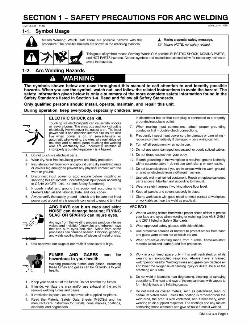
1-1. Symbol Usage
Means Warning! Watch Out! There are possible hazards with thisprocedure! The possible hazards are shown in the adjoining symbols.
This group of symbols means Warning! Watch Out! possible ELECTRIC SHOCK, MOVING PARTS,and HOT PARTS hazards. Consult symbols and related instructions below for necessary actions toavoid the hazards.
� Marks a special safety message.
� Means NOTE; not safety related.
1-2. Arc Welding Hazards
WARNINGThe symbols shown below are used throughout this manual to call attention to and identify possiblehazards. When you see the symbol, watch out, and follow the related instructions to avoid the hazard. Thesafety information given below is only a summary of the more complete safety information found in theSafety Standards listed in Section 1-4. Read and follow all Safety Standards.
Only qualified persons should install, operate, maintain, and repair this unit.
During operation, keep everybody, especially children, away.
ELECTRIC SHOCK can kill.Touching live electrical parts can cause fatal shocksor severe burns. The electrode and work circuit iselectrically live whenever the output is on. The inputpower circuit and machine internal circuits are alsolive when power is on. In semiautomatic orautomatic wire welding, the wire, wire reel, drive rollhousing, and all metal parts touching the weldingwire are electrically live. Incorrectly installed orimproperly grounded equipment is a hazard.
1. Do not touch live electrical parts.2. Wear dry, hole-free insulating gloves and body protection.3. Insulate yourself from work and ground using dry insulating mats
or covers big enough to prevent any physical contact with thework or ground.
4. Disconnect input power or stop engine before installing orservicing this equipment. Lockout/tagout input power accordingto OSHA 29 CFR 1910.147 (see Safety Standards).
5. Properly install and ground this equipment according to itsOwner’s Manual and national, state, and local codes.
6. Always verify the supply ground − check and be sure that inputpower cord ground wire is properly connected to ground terminal
in disconnect box or that cord plug is connected to a properlygrounded receptacle outlet.
7. When making input connections, attach proper groundingconductor first − double-check connections.
8. Frequently inspect input power cord for damage or bare wiring −replace cord immediately if damaged − bare wiring can kill.
9. Turn off all equipment when not in use.
10. Do not use worn, damaged, undersized, or poorly spliced cables.
11. Do not drape cables over your body.
12. If earth grounding of the workpiece is required, ground it directlywith a separate cable − do not use work clamp or work cable.
13. Do not touch electrode if you are in contact with the work, ground,or another electrode from a different machine.
14. Use only well-maintained equipment. Repair or replace damagedparts at once. Maintain unit according to manual.
15. Wear a safety harness if working above floor level.
16. Keep all panels and covers securely in place.
17. Clamp work cable with good metal-to-metal contact to workpieceor worktable as near the weld as practical.
ARC RAYS can burn eyes and skin;NOISE can damage hearing; FLYINGSLAG OR SPARKS can injure eyes.
Arc rays from the welding process produce intensevisible and invisible (ultraviolet and infrared) raysthat can burn eyes and skin. Noise from someprocesses can damage hearing. Chipping, grinding,and welds cooling throw off pieces of metal or slag.
NOISE
1. Use approved ear plugs or ear muffs if noise level is high.
ARC RAYS
2. Wear a welding helmet fitted with a proper shade of filter to protectyour face and eyes when welding or watching (see ANSI Z49.1and Z87.1 listed in Safety Standards).
3. Wear approved safety glasses with side shields.
4. Use protective screens or barriers to protect others from flashand glare; warn others not to watch the arc.
5. Wear protective clothing made from durable, flame-resistantmaterial (wool and leather) and foot protection.
FUMES AND GASES can behazardous to your health.Welding produces fumes and gases. Breathingthese fumes and gases can be hazardous to yourhealth.
1. Keep your head out of the fumes. Do not breathe the fumes.2. If inside, ventilate the area and/or use exhaust at the arc to
remove welding fumes and gases.3. If ventilation is poor, use an approved air-supplied respirator.4. Read the Material Safety Data Sheets (MSDSs) and the
manufacturer’s instruction for metals, consumables, coatings,cleaners, and degreasers.
5. Work in a confined space only if it is well ventilated, or whilewearing an air-supplied respirator. Always have a trainedwatchperson nearby. Welding fumes and gases can displace airand lower the oxygen level causing injury or death. Be sure thebreathing air is safe.
6. Do not weld in locations near degreasing, cleaning, or sprayingoperations. The heat and rays of the arc can react with vapors toform highly toxic and irritating gases.
7. Do not weld on coated metals, such as galvanized, lead, orcadmium plated steel, unless the coating is removed from theweld area, the area is well ventilated, and if necessary, whilewearing an air-supplied respirator. The coatings and any metalscontaining these elements can give off toxic fumes if welded.
OM-183 304 Page 2
CYLINDERS can explode if damaged.Shielding gas cylinders contain gas under highpressure. If damaged, a cylinder can explode. Sincegas cylinders are normally part of the weldingprocess, be sure to treat them carefully.
1. Protect compressed gas cylinders from excessive heat,mechanical shocks, slag, open flames, sparks, and arcs.
2. Install cylinders in an upright position by securing to a stationarysupport or cylinder rack to prevent falling or tipping.
3. Keep cylinders away from any welding or other electrical circuits.
4. Never drape a welding torch over a gas cylinder.5. Never allow a welding electrode to touch any cylinder.6. Never weld on a pressurized cylinder − explosion will result.7. Use only correct shielding gas cylinders, regulators, hoses, and
fittings designed for the specific application; maintain them andassociated parts in good condition.
8. Turn face away from valve outlet when opening cylinder valve.9. Keep protective cap in place over valve except when cylinder is in
use or connected for use.10. Read and follow instructions on compressed gas cylinders,
associated equipment, and CGA publication P-1 listed in SafetyStandards.
WELDING can cause fire orexplosion.Welding on closed containers, such as tanks,drums, or pipes, can cause them to blow up. Sparkscan fly off from the welding arc. The flying sparks,hot workpiece, and hot equipment can cause firesand burns. Accidental contact of electrode to metalobjects can cause sparks, explosion, overheating,or fire. Check and be sure the area is safe beforedoing any welding.
1. Protect yourself and others from flying sparks and hot metal.2. Do not weld where flying sparks can strike flammable material.3. Remove all flammables within 35 ft (10.7 m) of the welding arc. If
this is not possible, tightly cover them with approved covers.4. Be alert that welding sparks and hot materials from welding can
easily go through small cracks and openings to adjacent areas.
5. Watch for fire, and keep a fire extinguisher nearby.6. Be aware that welding on a ceiling, floor, bulkhead, or partition
can cause fire on the hidden side.7. Do not weld on closed containers such as tanks, drums, or pipes,
unless they are properly prepared according to AWS F4.1 (seeSafety Standards).
8. Connect work cable to the work as close to the welding area aspractical to prevent welding current from traveling long, possiblyunknown paths and causing electric shock and fire hazards.
9. Do not use welder to thaw frozen pipes.10. Remove stick electrode from holder or cut off welding wire at
contact tip when not in use.11. Wear oil-free protective garments such as leather gloves, heavy
shirt, cuffless trousers, high shoes, and a cap.12. Remove any combustibles, such as a butane lighter or matches,
from your person before doing any welding.
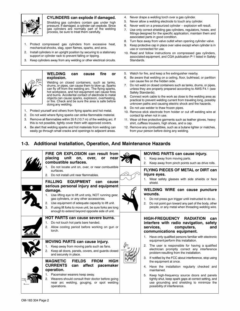
1-3. Additional Installation, Operation, And Maintenance Hazards
FIRE OR EXPLOSION can result fromplacing unit on, over, or nearcombustible surfaces.1. Do not locate unit on, over, or near combustible
surfaces.2. Do not install unit near flammables.
FALLING EQUIPMENT can causeserious personal injury and equipmentdamage.1. Use lifting eye to lift unit only, NOT running gear,
gas cylinders, or any other accessories.2. Use equipment of adequate capacity to lift unit.3. If using lift forks to move unit, be sure forks are long
enough to extend beyond opposite side of unit.
HOT PARTS can cause severe burns.1. Do not touch hot parts bare handed.2. Allow cooling period before working on gun or
torch.
MOVING PARTS can cause injury.1. Keep away from moving parts such as fans.2. Keep all doors, panels, covers, and guards closed
and securely in place.
MAGNETIC FIELDS FROM HIGHCURRENTS can affect pacemakeroperation.1. Pacemaker wearers keep away.2. Wearers should consult their doctor before going
near arc welding, gouging, or spot weldingoperations.
MOVING PARTS can cause injury.1. Keep away from moving parts.2. Keep away from pinch points such as drive rolls.
FLYING PIECES OF METAL or DIRT caninjure eyes.1. Wear safety glasses with side shields or face
shield.
WELDING WIRE can cause puncturewounds.1. Do not press gun trigger until instructed to do so.2. Do not point gun toward any part of the body, other
people, or any metal when threading welding wire.
HIGH-FREQUENCY RADIATION caninterfere with radio navigation, safetyservices, computers, andcommunications equipment.1. Have only qualified persons familiar with electronic
equipment perform this installation.
2. The user is responsible for having a qualifiedelectrician promptly correct any interferenceproblem resulting from the installation.
3. If notified by the FCC about interference, stop usingthe equipment at once.
4. Have the installation regularly checked andmaintained.
5. Keep high-frequency source doors and panelstightly shut, keep spark gaps at correct setting, anduse grounding and shielding to minimize thepossibility of interference.
OM-183 304 Page 3
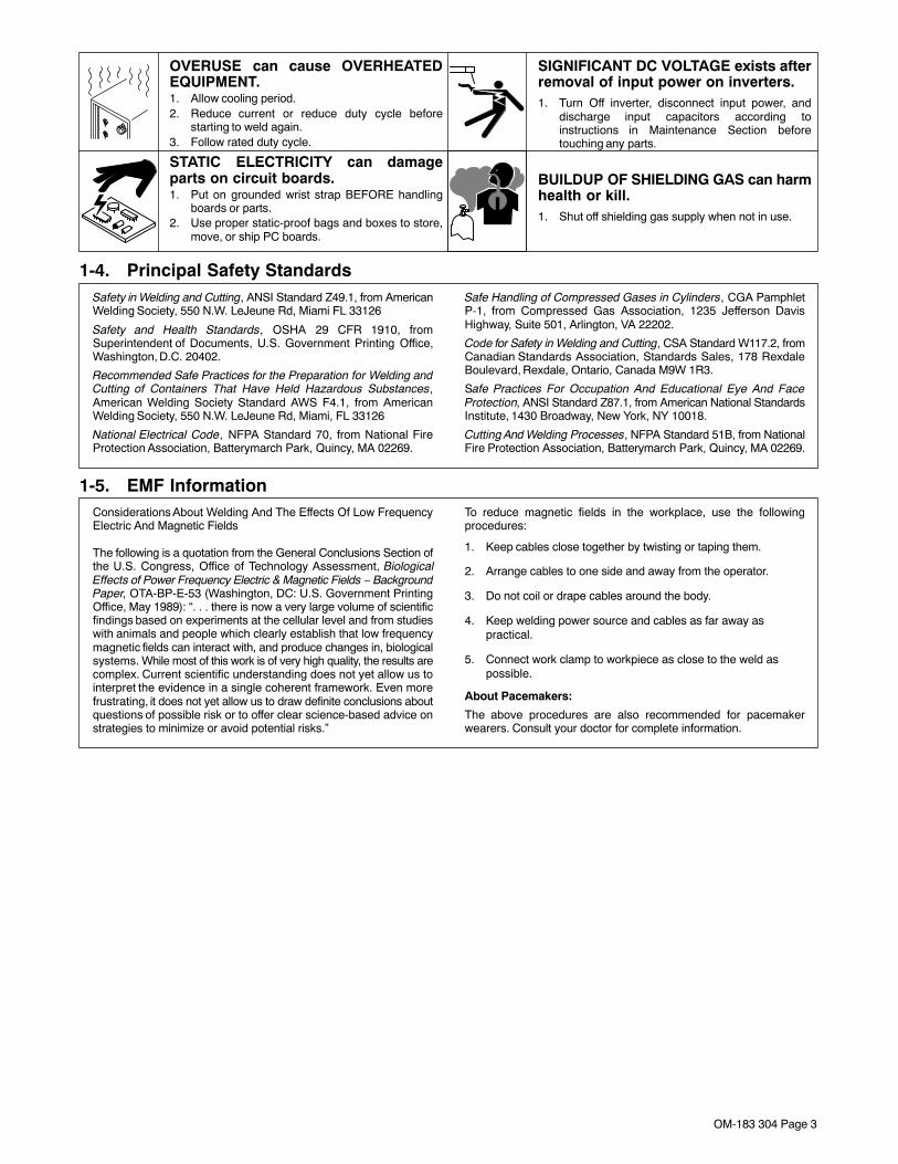
OVERUSE can cause OVERHEATEDEQUIPMENT.1. Allow cooling period.2. Reduce current or reduce duty cycle before
starting to weld again.3. Follow rated duty cycle.
STATIC ELECTRICITY can damageparts on circuit boards.1. Put on grounded wrist strap BEFORE handling
boards or parts.2. Use proper static-proof bags and boxes to store,
move, or ship PC boards.
SIGNIFICANT DC VOLTAGE exists afterremoval of input power on inverters.1. Turn Off inverter, disconnect input power, and
discharge input capacitors according toinstructions in Maintenance Section beforetouching any parts.
BUILDUP OF SHIELDING GAS can harmhealth or kill.1. Shut off shielding gas supply when not in use.
1-4. Principal Safety StandardsSafety in Welding and Cutting, ANSI Standard Z49.1, from AmericanWelding Society, 550 N.W. LeJeune Rd, Miami FL 33126
Safety and Health Standards, OSHA 29 CFR 1910, fromSuperintendent of Documents, U.S. Government Printing Office,Washington, D.C. 20402.
Recommended Safe Practices for the Preparation for Welding andCutting of Containers That Have Held Hazardous Substances,American Welding Society Standard AWS F4.1, from AmericanWelding Society, 550 N.W. LeJeune Rd, Miami, FL 33126
National Electrical Code, NFPA Standard 70, from National FireProtection Association, Batterymarch Park, Quincy, MA 02269.
Safe Handling of Compressed Gases in Cylinders, CGA PamphletP-1, from Compressed Gas Association, 1235 Jefferson DavisHighway, Suite 501, Arlington, VA 22202.
Code for Safety in Welding and Cutting, CSA Standard W117.2, fromCanadian Standards Association, Standards Sales, 178 RexdaleBoulevard, Rexdale, Ontario, Canada M9W 1R3.
Safe Practices For Occupation And Educational Eye And FaceProtection, ANSI Standard Z87.1, from American National StandardsInstitute, 1430 Broadway, New York, NY 10018.
Cutting And Welding Processes, NFPA Standard 51B, from NationalFire Protection Association, Batterymarch Park, Quincy, MA 02269.
1-5. EMF InformationConsiderations About Welding And The Effects Of Low FrequencyElectric And Magnetic Fields
The following is a quotation from the General Conclusions Section ofthe U.S. Congress, Office of Technology Assessment, BiologicalEffects of Power Frequency Electric & Magnetic Fields − BackgroundPaper, OTA-BP-E-53 (Washington, DC: U.S. Government PrintingOffice, May 1989): “. . . there is now a very large volume of scientificfindings based on experiments at the cellular level and from studieswith animals and people which clearly establish that low frequencymagnetic fields can interact with, and produce changes in, biologicalsystems. While most of this work is of very high quality, the results arecomplex. Current scientific understanding does not yet allow us tointerpret the evidence in a single coherent framework. Even morefrustrating, it does not yet allow us to draw definite conclusions aboutquestions of possible risk or to offer clear science-based advice onstrategies to minimize or avoid potential risks.”
To reduce magnetic fields in the workplace, use the followingprocedures:
1. Keep cables close together by twisting or taping them.
2. Arrange cables to one side and away from the operator.
3. Do not coil or drape cables around the body.
4. Keep welding power source and cables as far away aspractical.
5. Connect work clamp to workpiece as close to the weld aspossible.
About Pacemakers:
The above procedures are also recommended for pacemakerwearers. Consult your doctor for complete information.
OM-183 304 Page 4
SECTION 1 − CONSIGNES DE SÉCURITÉ POUR LESOUDAGE À L’ARC
safety_som_cfr 4/95
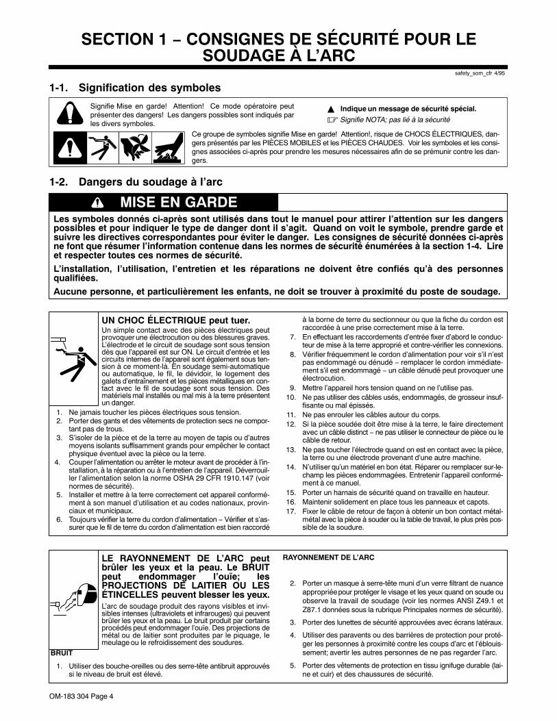
1-1. Signification des symboles
Signifie Mise en garde! Attention! Ce mode opératoire peutprésenter des dangers! Les dangers possibles sont indiqués parles divers symboles.
Ce groupe de symboles signifie Mise en garde! Attention!, risque de CHOCS ÉLECTRIQUES, dan-gers présentés par les PIÈCES MOBILES et les PIÈCES CHAUDES. Voir les symboles et les consi-gnes associées ci-après pour prendre les mesures nécessaires afin de se prémunir contre les dan-gers.
� Indique un message de sécurité spécial.
� Signifie NOTA; pas lié à la sécurité
1-2. Dangers du soudage à l’arc
Les symboles donnés ci-après sont utilisés dans tout le manuel pour attirer l’attention sur les dangerspossibles et pour indiquer le type de danger dont il s’agit. Quand on voit le symbole, prendre garde etsuivre les directives correspondantes pour éviter le danger. Les consignes de sécurité données ci-aprèsne font que résumer l’information contenue dans les normes de sécurité énumérées à la section 1-4. Lireet respecter toutes ces normes de sécurité.
L’installation, l’utilisation, l’entretien et les réparations ne doivent être confiés qu’à des personnesqualifiées.
Aucune personne, et particulièrement les enfants, ne doit se trouver à proximité du poste de soudage.
MISE EN GARDE
UN CHOC ÉLECTRIQUE peut tuer.Un simple contact avec des pièces électriques peutprovoquer une électrocution ou des blessures graves.L’électrode et le circuit de soudage sont sous tensiondès que l’appareil est sur ON. Le circuit d’entrée et lescircuits internes de l’appareil sont également sous ten-sion à ce moment-là. En soudage semi-automatiqueou automatique, le fil, le dévidoir, le logement desgalets d’entraînement et les pièces métalliques en con-tact avec le fil de soudage sont sous tension. Desmatériels mal installés ou mal mis à la terre présententun danger.
1. Ne jamais toucher les pièces électriques sous tension.2. Porter des gants et des vêtements de protection secs ne compor-
tant pas de trous.3. S’isoler de la pièce et de la terre au moyen de tapis ou d’autres
moyens isolants suffisamment grands pour empêcher le contactphysique éventuel avec la pièce ou la terre.
4. Couper l’alimentation ou arrêter le moteur avant de procéder à l’in-stallation, à la réparation ou à l’entretien de l’appareil. Déverrouil-ler l’alimentation selon la norme OSHA 29 CFR 1910.147 (voirnormes de sécurité).
5. Installer et mettre à la terre correctement cet appareil conformé-ment à son manuel d’utilisation et au codes nationaux, provin-ciaux et municipaux.
6. Toujours vérifier la terre du cordon d’alimentation − Vérifier et s’as-surer que le fil de terre du cordon d’alimentation est bien raccordé
à la borne de terre du sectionneur ou que la fiche du cordon estraccordée à une prise correctement mise à la terre.
7. En effectuant les raccordements d’entrée fixer d’abord le conduc-teur de mise à la terre approprié et contre-vérifier les connexions.
8. Vérifier fréquemment le cordon d’alimentation pour voir s’il n’estpas endommagé ou dénudé − remplacer le cordon immédiate-ment s’il est endommagé − un câble dénudé peut provoquer uneélectrocution.
9. Mettre l’appareil hors tension quand on ne l’utilise pas.10. Ne pas utiliser des câbles usés, endommagés, de grosseur insuf-
fisante ou mal épissés.11. Ne pas enrouler les câbles autour du corps.12. Si la pièce soudée doit être mise à la terre, le faire directement
avec un câble distinct − ne pas utiliser le connecteur de pièce ou lecâble de retour.
13. Ne pas toucher l’électrode quand on est en contact avec la pièce,la terre ou une électrode provenant d’une autre machine.
14. N’utiliser qu’un matériel en bon état. Réparer ou remplacer sur-le-champ les pièces endommagées. Entretenir l’appareil conformé-ment à ce manuel.
15. Porter un harnais de sécurité quand on travaille en hauteur.16. Maintenir solidement en place tous les panneaux et capots.17. Fixer le câble de retour de façon à obtenir un bon contact métal-
métal avec la pièce à souder ou la table de travail, le plus près pos-sible de la soudure.
LE RAYONNEMENT DE L’ARC peutbrûler les yeux et la peau. Le BRUITpeut endommager l’ouïe; lesPROJECTIONS DE LAITIER OU LESÉTINCELLES peuvent blesser les yeux.L’arc de soudage produit des rayons visibles et invi-sibles intenses (ultraviolets et infrarouges) qui peuventbrûler les yeux et la peau. Le bruit produit par certainsprocédés peut endommager l’ouïe. Des projections demétal ou de laitier sont produites par le piquage, lemeulage ou le refroidissement des soudures.
BRUIT
1. Utiliser des bouche-oreilles ou des serre-tête antibruit approuvéssi le niveau de bruit est élevé.
RAYONNEMENT DE L’ARC
2. Porter un masque à serre-tête muni d’un verre filtrant de nuanceappropriée pour protéger le visage et les yeux quand on soude ouobserve la travail de soudage (voir les normes ANSI Z49.1 etZ87.1 données sous la rubrique Principales normes de sécurité).
3. Porter des lunettes de sécurité approuvées avec écrans latéraux.
4. Utiliser des paravents ou des barrières de protection pour proté-ger les personnes à proximité contre les coups d’arc et l’éblouis-sement; avertir les autres personnes de ne pas regarder l’arc.
5. Porter des vêtements de protection en tissu ignifuge durable (lai-ne et cuir) et des chaussures de sécurité.
OM-183 304 Page 5
LES VAPEURS ET LES FUMÉESpeuvent être dangereuses pour lasanté.Le soudage produit des vapeurs et des fumées qu’il estdangereux de respirer.
1. Garder la tête à l’extérieur des vapeurs et des fumées et ne pasles respirer.
2. À l’intérieur, ventiler le poste de travail ou utiliser un dispositifplacé au niveau de l’arc pour évacuer les vapeurs et fumées desoudage.
3. Si la ventilation est mauvaise, utiliser un appareil respiratoire àadduction d’air pur approuvé.
4. Consulter les fiches signalétiques et les consignes du fabricantrelatives au métaux, produits d’apport, revêtements, nettoyantset dégraissants.
5. Ne travailler dans un espace confiné que s’il est bien ventilé, ou enportant un appareil respiratoire à adduction d’air pur. Demander àun observateur ayant reçu la bonne formation de toujours se tenirà proximité. Les vapeurs et fumées de soudage peuvent déplacerl’air et abaisser le niveau d’oxygène et causer des blessuresgraves voire mortelles. S’assurer que l’air est propre à larespiration.
6. Ne pas souder à proximité d’opérations de dégraissage, denettoyage ou de pulvérisation. La chaleur et les rayons de l’arcpeuvent réagir avec les vapeurs pour former des gaz hautementtoxiques et irritants.
7. Ne pas souder sur des métaux revêtus comme l’acier galvanisé,au plomb ou cadmié à moins que la pièce n’ait été entièrementdécapée, que le poste de travail soit bien ventilé. S’il y a lieu,porter un appareil respiratoire à adduction d’air pur. Lesrevêtements et les métaux qui contiennent de tels élémentspeuvent dégager des vapeurs toxiques lors du soudage.
LES BOUTEILLES peuvent exploser sielles sont endommagées.Les bouteilles contenant des gaz de protection sont àhaute pression. Une bouteille endommagée peutexploser. Étant donné que les bouteilles de gaz fontnormalement partie du matériel de soudage, les traiteravec le plus grand soin.
1. Protéger les bouteilles de gaz comprimé contre la chaleurintense, les chocs, le laitier, les flammes nues, les étincelles etl’arc.
2. Placer les bouteilles à la verticale en les fixant à un support fixe ouà un chariot pour éviter qu’elles ne tombent ou ne basculent.
3. Tenir les bouteilles à l’écart du poste de soudage ou d’autrescircuits électriques.
4. Ne jamais poser un chalumeau soudeur sur une bouteille de gaz.5. Ne jamais laisser une électrode de soudage toucher une bouteille.6. Ne jamais souder sur une bouteille sous pression : elle
exploserait.7. N’utiliser que des bouteilles de gaz de protection, des détendeurs,
des tuyaux souples et des raccords appropriés conçus pourl’application particulière; conserver ces matériels et leurs piècesen bon état.
8. Éloigner le visage de la sortie du robinet de la bouteille quand onl’ouvre.
9. Replacer le chapeau sur la bouteille après utilisation.10. Lire et suivre les consignes relatives aux bouteilles de gaz
comprimé, au matériel connexe ainsi que la publication P-1 de laCGA donnée sous la rubrique Principales normes de sécurité.
LE SOUDAGE peut causer un incendieou une explosion.Ne pas souder sur des récipients fermés comme desréservoirs, des fûts ou des tuyaux : ils peuventexploser. L’arc de soudage peut produire desétincelles. Des étincelles, une pièce chaude et unmatériel chaud peuvent provoquer des incendies etdes blessures. Le contact accidentel de l’électrode surdes objets métalliques peut produire des étincelles,l’explosion, la surchauffe ou un incendie. S’assurerque le lieu ne présente pas de danger avant d’effectuerle soudage.
1. Se protéger et protéger les personnes à proximité des étincelleset du métal chaud.
2. Ne pas souder dans un endroit où les étincelles peuvent atteindredes matériaux inflammables.
3. Enlever toutes les matières inflammables dans un rayon de moinsde 10 m de l’arc. Si cela n’est pas possible, bien les recouvrir enutilisant des bâches approuvées.
4. Prendre garde que les étincelles et les projections ne pénétrentdans des zones adjacentes en s’infiltrant dans des petitesfissures et ouvertures.
5. Prendre garde aux incendies et toujours avoir un extincteur àproximité.
6. Se rappeler que si l’on soude sur un plafond, un plancher, unecloison ou autre, le feu peut prendre de l’autre côté.
7. Ne pas souder sur des récipients fermés comme des réservoirs,des fûts ou des tuyaux à moins qu’ils ne soient préparés de façonappropriée conformément à la norme F4.1 de l’AWS (voir larubrique Principales normes de sécurité).
8. Raccorder le câble de retour à la pièce, le plus près possible de lazone de soudage, pour empêcher que le courant de soudage nesuive une trajectoire longue et éventuellement inconnue et qu’il neprovoque des risques d’électrocution et d’incendie.
9. Ne pas utiliser le chalumeau soudeur pour dégeler des tuyaux.10. Enlever l’électrode enrobée du porte-électrode ou couper le fil de
soudage au ras du bec contact quand on ne l’utilise pas.11. Porter des vêtements de protection non huileux comme des gants
en cuir, une chemise épaisse, des pantalons sans revers, deschaussures montantes et un casque.
12. Ne pas porter des matières combustibles sur soi comme unbriquet à gaz ou des allumettes quand on soude.
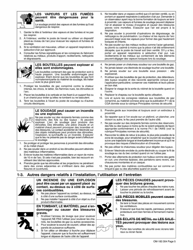
1-3. Autres dangers relatifs à l’installation, l’utilisation et l’entretienUN INCENDIE OU UNE EXPLOSIONpeut être causé par un appareil placé aucontact, au-dessus ou à côté de surfa-ces combustibles.1. Ne pas placer l’appareil au contact, au-dessus, ou
à côté d’une surface combustible.2. Ne pas installer l’appareil à côté d’un objet ou d’un
produit inflammable.
EN TOMBANT, LE MATÉRIEL peut s’en-dommager ou causer des blessuresgraves.1. N’utiliser l’anneau de levage que pour soulever
l’appareil; NE PAS l’utiliser pour soulever les cha-riots, les bouteilles de gaz ou autres accessoires.
2. Pour soulever la source de courant, utiliser des ap-pareils de puissance suffisante.
3. Si l’on utilise un élévateur à fourche pour déplacerl’appareil, s’assurer que la fourche est suffisammentlongue et dépasse de l’autre côté de l’appareil.
LES PIÈCES CHAUDES peuvent provo-quer des brûlures graves.1. Ne pas toucher les pièces chaudes les mains nues.2. Laisser une période de refroidissement avant de
toucher le pistolet ou la torche.
LES PIÈCES MOBILES peuvent causerdes blessures.1. Se tenir à l’écart des pièces en mouvement comme
les ventilateurs.2. S’assurer que tous les capots, panneaux, portes et
protecteurs sont bien fermés et fermement mainte-nus.
LES ÉCLATS DE MÉTAL ou LES SALE-TÉS peuvent provoquer des lésions auxyeux.1. Porter des lunettes de sécurité avec écrans laté-
raux ou écran facial.
OM-183 304 Page 6
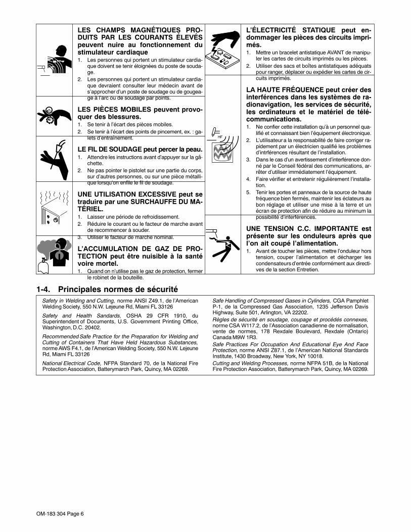
LES CHAMPS MAGNÉTIQUES PRO-DUITS PAR LES COURANTS ÉLEVÉSpeuvent nuire au fonctionnement dustimulateur cardiaque1. Les personnes qui portent un stimulateur cardia-
que doivent se tenir éloignées du poste de souda-ge.
2. Les personnes qui portent un stimulateur cardia-que devraient consulter leur médecin avant des’approcher d’un poste de soudage ou de gougea-ge à l’arc ou de soudage par points.
LES PIÈCES MOBILES peuvent provo-quer des blessures.1. Se tenir à l’écart des pièces mobiles.2. Se tenir à l’écart des points de pincement, ex. : ga-
lets d’entraînement.
LE FIL DE SOUDAGE peut percer la peau.1. Attendre les instructions avant d’appuyer sur la gâ-
chette.2. Ne pas pointer le pistolet sur une partie du corps,
sur d’autres personnes, ou sur une pièce métalli-que lorsqu’on enfile le fil de soudage.
UNE UTILISATION EXCESSIVE peut setraduire par une SURCHAUFFE DU MA-TÉRIEL.1. Laisser une période de refroidissement.2. Réduire le courant ou le facteur de marche avant
de recommencer à souder.3. Utiliser le facteur de marche nominal.
L’ACCUMULATION DE GAZ DE PRO-TECTION peut être nuisible à la santévoire mortel.1. Quand on n’utilise pas le gaz de protection, fermer
le robinet de la bouteille.
L’ÉLECTRICITÉ STATIQUE peut en-dommager les pièces des circuits impri-més.1. Mettre un bracelet antistatique AVANT de manipu-
ler les cartes de circuits imprimés ou les pièces.2. Utiliser des sacs et boîtes antistatiques adéquats
pour ranger, déplacer ou expédier les cartes de cir-cuits imprimés.
LA HAUTE FRÉQUENCE peut créer desinterférences dans les systèmes de ra-dionavigation, les services de sécurité,les ordinateurs et le matériel de télé-communications.1. Ne confier cette installation qu’à un personnel qua-
lifié et connaissant bien l’équipement électronique.2. L’utilisateur a la responsabilité de faire corriger ra-
pidement par un électricien qualifié les problèmesd’intrférences résultant de l’installation.
3. Dans le cas d’un avertissement d’interférence don-né par le Conseil fédéral des communications, ar-rêter d’utiliser immédiatement l’équipement.
4. Faire vérifier et entretenir régulièrement l’installa-tion.
5. Tenir les portes et panneaux de la source de hautefréquence bien fermés, maintenir les éclateurs aubon réglage et utiliser une mise à la terre et unécran de protection afin de réduire au minimum lapossibilité d’interférences.
UNE TENSION C.C. IMPORTANTE estprésente sur les onduleurs après quel’on ait coupé l’alimentation.1. Avant de toucher les pièces, mettre l’onduleur hors
tension, couper l’alimentation et décharger lescondensateurs d’entrée conformément aux directi-ves de la section Entretien.
1-4. Principales normes de sécuritéSafety in Welding and Cutting, norme ANSI Z49.1, de l’AmericanWelding Society, 550 N.W. Lejeune Rd, Miami FL 33126
Safety and Health Sandards, OSHA 29 CFR 1910, duSuperintendent of Documents, U.S. Government Printing Office,Washington, D.C. 20402.
Recommended Safe Practice for the Preparation for Welding andCutting of Containers That Have Held Hazardous Substances,norme AWS F4.1, de l’American Welding Society, 550 N.W. LejeuneRd, Miami FL 33126
National Electrical Code, NFPA Standard 70, de la National FireProtection Association, Batterymarch Park, Quincy, MA 02269.
Safe Handling of Compressed Gases in Cylinders, CGA PamphletP-1, de la Compressed Gas Association, 1235 Jefferson DavisHighway, Suite 501, Arlington, VA 22202.Règles de sécurité en soudage, coupage et procédés connexes,norme CSA W117.2, de l’Association canadienne de normalisation,vente de normes, 178 Rexdale Boulevard, Rexdale (Ontario)Canada M9W 1R3.Safe Practices For Occupation And Educational Eye And FaceProtection, norme ANSI Z87.1, de l’American National StandardsInstitute, 1430 Broadway, New York, NY 10018.Cutting and Welding Processes, norme NFPA 51B, de la NationalFire Protection Association, Batterymarch Park, Quincy, MA 02269.

OM-183 304 Page 7
1-5. Informations sur les champs électromagnétiquesNOTA Données sur le soudage et sur les effets des champs électri-ques et magnétiques basse fréquence.
Voici une citation tirée des conclusions générales du document Biolo-gical Effects of Power Frequency Electric & Magnetic Fields - Back-ground Paper (Effets biologiques des champs électriques et magné-tiques aux fréquences d’utilisation - Document de base), OTA-BP-E-53 (Washington, DC : U.S Government Printing Office, mai 1989)publié par l’Office of Technology Assessment (Congrès des États-Unis): «... des expériences au niveau cellulaire et des études surl’homme et l’animal nous ont apporté une foule de renseignements : ilest maintenant clair que les champs magnétiques basse fréquencepeuvent influer sur les systèmes biologiques et les modifier. Ces tra-vaux sont généralement d’excellente qualité, mais les résultats obte-nus sont complexes. Dans l’état actuel de nos connaissances dansle domaine scientifique, nous ne sommes pas en mesure d’inter-préter nos observations à la lumière d’une théorie générale. Et, ce quiest encore plus regrettable, nous ne pouvons rien affirmer de définitif
au sujet des risques éventuels, ni proposer des méthodes scientifi-ques précises pour réduire ces risques ou pour les éviter.»
Pour réduire l’intensité des champs magnétiques au poste de travail :
1. Grouper solidement les câbles en les entrelaçant ou en lesserrant avec un ruban adhésif.
2. Disposer les câbles sur un seul côté et à l’écart de l’opérateur.
3. Éviter d’enrouler les câbles ou de les poser sur l’épaule.
4. Éloigner le plus possible la source de courant et les câbles desoudage.
5. Raccorder le connecteur de pièce à la pièce à souder, le plusprès possible de la soudure.
Stimulateurs cardiaques :Les recommandations ci-avant s’adressent aussi, normalement, auxpersonnes qui utilisent un stimulateur cardiaque. Pour de plus am-ples renseignements, consultez votre médecin.
OM-1213 Page 8
SECTION 2 − DEFINITIONS
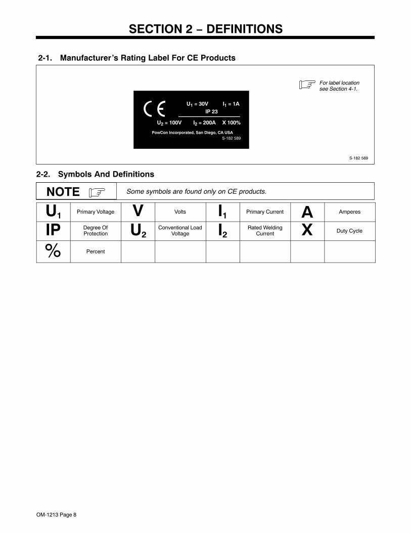
2-1. Manufacturer’s Rating Label For CE Products
S-182 589
For label locationsee Section 4-1.
PowCon Incorporated, San Diego, CA USA
U1 = 30V I1 = 1AIP 23
U2 = 100V I2 = 200A X 100%
S-182 589
2-2. Symbols And Definitions
Some symbols are found only on CE products.NOTE
U1 Primary Voltage V Volts I1 Primary Current A Amperes
IP Degree OfProtection U2
Conventional LoadVoltage I2
Rated WeldingCurrent X Duty Cycle
Percent
OM-183 304 Page 9
SECTION 3 − INSTALLATION
3-1. Specifications
Wire DiameterRange
ApproximateWire Feed
Range
CoolingMethod
MaximumSpool Size
WeldCircuitRating
IP Rating OverallDimensions Weight
.025 Thru 1/16 in(0.6 Thru 1.6 mm)
Aluminum Wire
.025 Thru 045 in(0.6 Thru 1.1 mm)
Hard Or Cored Wire
70 To 875 ipm(1.7 To 22.2
mpm)Air Cooled
4 in (102 mm)Diameter
100 Volts,200 Amperes,
100% DutyCycle Using
ArgonShielding Gas
IP 23
Length: 15-3/8 in(390 mm)
Width: 2-1/2 in(64 mm)
Height: 10-3/4 in(273 mm)
2.9 lb(1.3 kg) Gun
Only
14 lb(6.4 kg)
Gun With Cable
Use weld control or welding power source Owner’s Manual during gun installation.If contact tip, liner, and drive roll groove are not correct for wire size and type, seeSection 5 to change parts as needed. See Parts List for other available contacttips.
NOTE
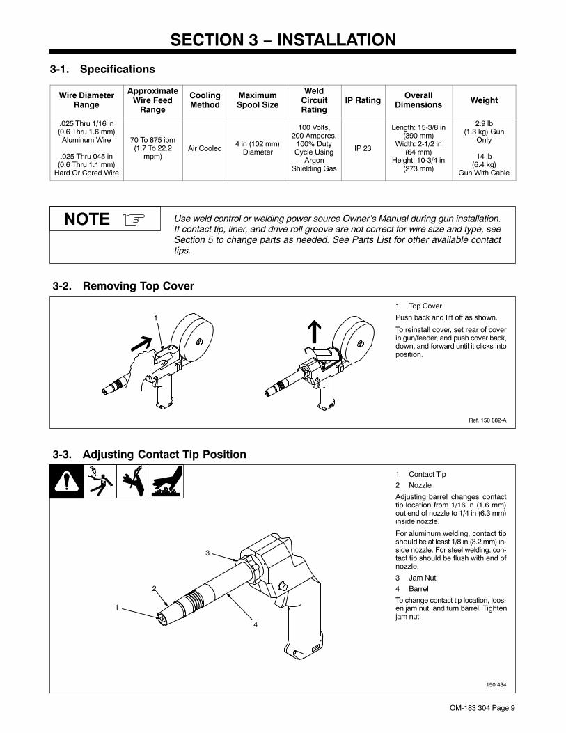
3-2. Removing Top Cover
Ref. 150 882-A
1 Top Cover
Push back and lift off as shown.
To reinstall cover, set rear of coverin gun/feeder, and push cover back,down, and forward until it clicks intoposition.
1
3-3. Adjusting Contact Tip Position
150 434
1 Contact Tip
2 Nozzle
Adjusting barrel changes contacttip location from 1/16 in (1.6 mm)out end of nozzle to 1/4 in (6.3 mm)inside nozzle.
For aluminum welding, contact tipshould be at least 1/8 in (3.2 mm) in-side nozzle. For steel welding, con-tact tip should be flush with end ofnozzle.
3 Jam Nut
4 Barrel
To change contact tip location, loos-en jam nut, and turn barrel. Tightenjam nut.
1
3
4
2
OM-183 304 Page 10
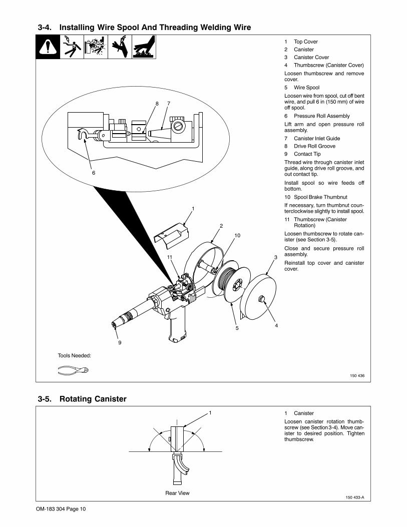
3-4. Installing Wire Spool And Threading Welding Wire
150 436
1 Top Cover
2 Canister
3 Canister Cover
4 Thumbscrew (Canister Cover)
Loosen thumbscrew and removecover.
5 Wire Spool
Loosen wire from spool, cut off bentwire, and pull 6 in (150 mm) of wireoff spool.
6 Pressure Roll Assembly
Lift arm and open pressure rollassembly.
7 Canister Inlet Guide8 Drive Roll Groove
9 Contact Tip
Thread wire through canister inletguide, along drive roll groove, andout contact tip.
Install spool so wire feeds offbottom.
10 Spool Brake Thumbnut
If necessary, turn thumbnut coun-terclockwise slightly to install spool.
11 Thumbscrew (CanisterRotation)
Loosen thumbscrew to rotate can-ister (see Section 3-5).
Close and secure pressure rollassembly.
Reinstall top cover and canistercover.
Tools Needed:
9
1
2
10
3
45
6
78
11
3-5. Rotating Canister
150 433-A
1 Canister
Loosen canister rotation thumb-screw (see Section 3-4). Move can-ister to desired position. Tightenthumbscrew.
1
Rear View
OM-183 304 Page 11
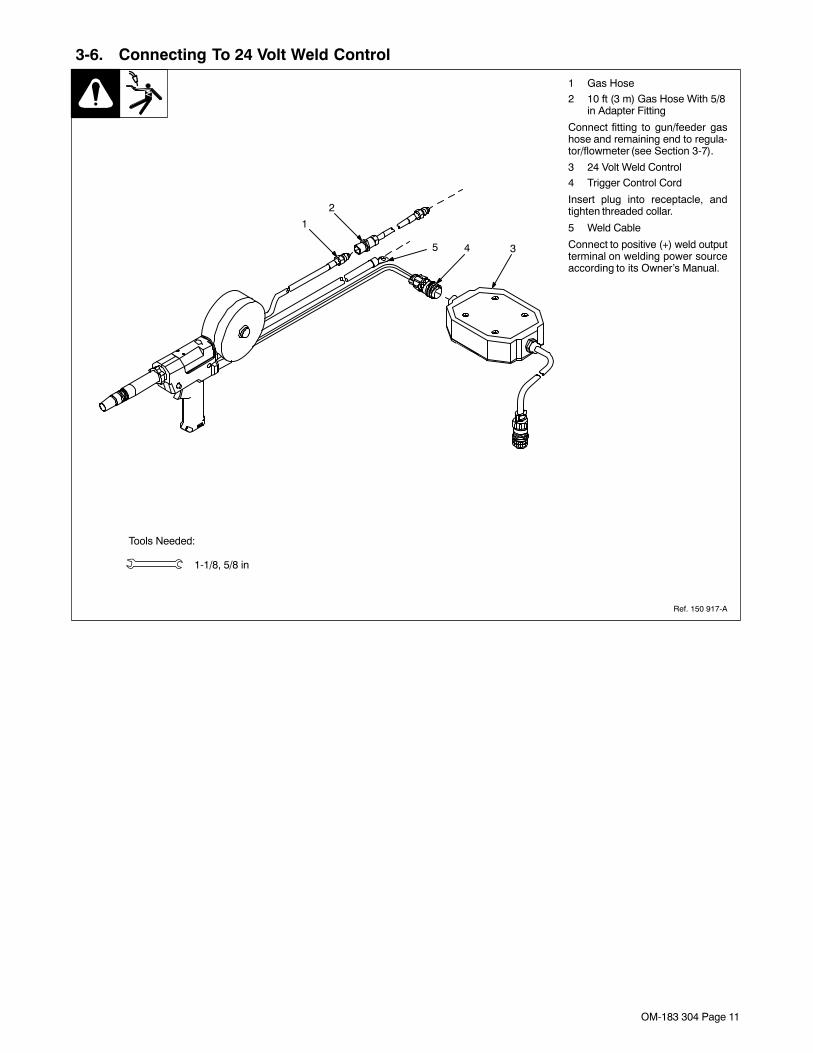
3-6. Connecting To 24 Volt Weld Control
Ref. 150 917-A
1 Gas Hose
2 10 ft (3 m) Gas Hose With 5/8in Adapter Fitting
Connect fitting to gun/feeder gashose and remaining end to regula-tor/flowmeter (see Section 3-7).
3 24 Volt Weld Control
4 Trigger Control Cord
Insert plug into receptacle, andtighten threaded collar.
5 Weld Cable
Connect to positive (+) weld outputterminal on welding power sourceaccording to its Owner’s Manual.
Tools Needed:
1-1/8, 5/8 in
1
2
345
OM-183 304 Page 12
3-7. Installing Gas Supply
ssb3.1* 5/94 − 158 697-A
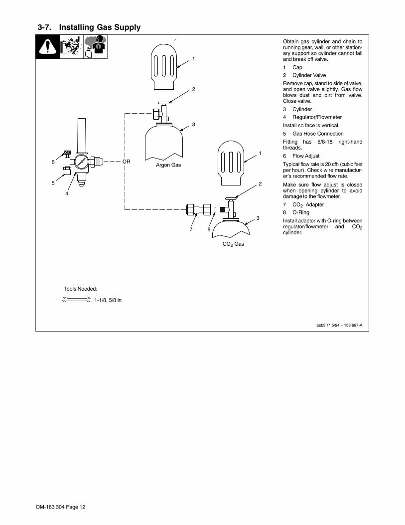
Obtain gas cylinder and chain torunning gear, wall, or other station-ary support so cylinder cannot falland break off valve.
1 Cap
2 Cylinder Valve
Remove cap, stand to side of valve,and open valve slightly. Gas flowblows dust and dirt from valve.Close valve.
3 Cylinder
4 Regulator/Flowmeter
Install so face is vertical.
5 Gas Hose Connection
Fitting has 5/8-18 right-handthreads.
6 Flow Adjust
Typical flow rate is 20 cfh (cubic feetper hour). Check wire manufactur-er’s recommended flow rate.
Make sure flow adjust is closedwhen opening cylinder to avoiddamage to the flowmeter.
7 CO2 Adapter
8 O-Ring
Install adapter with O-ring betweenregulator/flowmeter and CO2cylinder.
Tools Needed:
1-1/8, 5/8 in
CO2 Gas
7 8
3
1
2
4
5
6
1
2
3
Argon GasOR
OM-183 304 Page 13
3-8. Adjusting Drive Roll And Spool Brake Pressure
Ref. 151 112 / S-0651
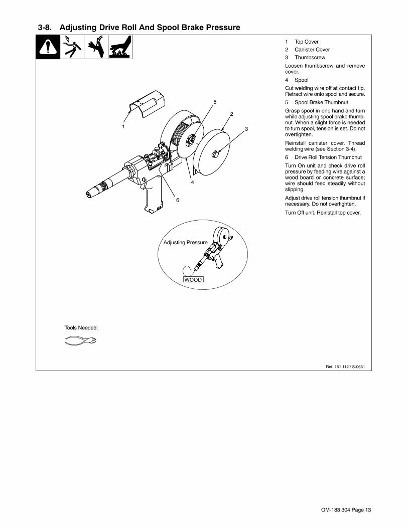
1 Top Cover
2 Canister Cover
3 Thumbscrew
Loosen thumbscrew and removecover.
4 Spool
Cut welding wire off at contact tip.Retract wire onto spool and secure.
5 Spool Brake Thumbnut
Grasp spool in one hand and turnwhile adjusting spool brake thumb-nut. When a slight force is neededto turn spool, tension is set. Do notovertighten.
Reinstall canister cover. Threadwelding wire (see Section 3-4).
6 Drive Roll Tension Thumbnut
Turn On unit and check drive rollpressure by feeding wire against awood board or concrete surface;wire should feed steadily withoutslipping.
Adjust drive roll tension thumbnut ifnecessary. Do not overtighten.
Turn Off unit. Reinstall top cover.
Tools Needed:
WOOD
1
2
5
3
4
6
Adjusting Pressure
OM-183 304 Page 14
SECTION 4 − OPERATION4-1. Controls
Ref. 147 741-A
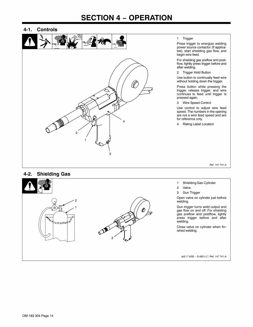
1 Trigger
Press trigger to energize weldingpower source contactor (if applica-ble), start shielding gas flow, andbegin wire feed.
For shielding gas preflow and post-flow, lightly press trigger before andafter welding.
2 Trigger Hold Button
Use button to continually feed wirewithout holding down the trigger.
Press button while pressing thetrigger, release trigger, and wirecontinues to feed until trigger ispressed again.
3 Wire Speed Control
Use control to adjust wire feedspeed. The numbers in the openingare not a wire feed speed and arefor reference only.
4 Rating Label Location
1
2
3
4
4-2. Shielding Gas
sb5.1* 6/92 − S-0621-C / Ref. 147 741-A
1 Shielding Gas Cylinder
2 Valve
3 Gun Trigger
Open valve on cylinder just beforewelding.
Gun trigger turns weld output andgas flow on and off. For shieldinggas preflow and postflow, lightlypress trigger before and afterwelding.
Close valve on cylinder when fin-ished welding.
1
2
3
OM-183 304 Page 15
SECTION 5 − MAINTENANCE & TROUBLESHOOTING
5-1. Routine Maintenance
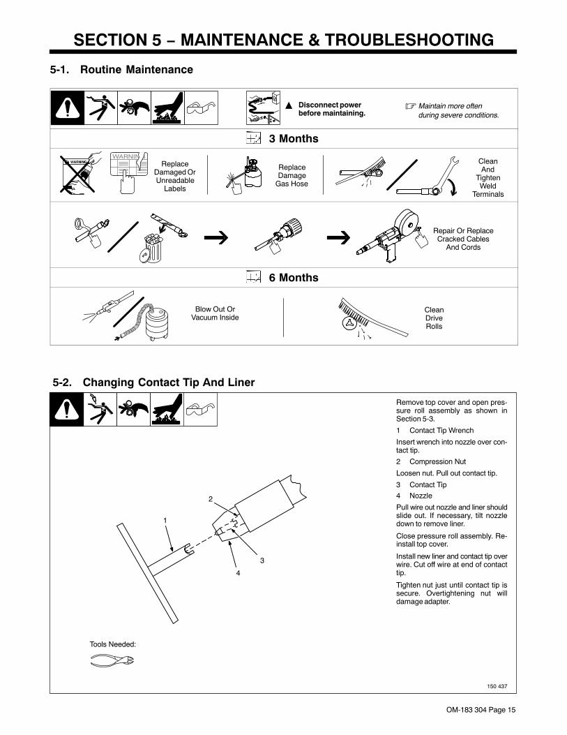
� Disconnect power before maintaining.
� Maintain more oftenduring severe conditions.
3 Months
ReplaceDamaged OrUnreadable
Labels
ReplaceDamage
Gas Hose
CleanAnd
TightenWeld
Terminals
Repair Or ReplaceCracked Cables
And Cords
6 Months
Blow Out OrVacuum Inside
CleanDriveRolls
5-2. Changing Contact Tip And Liner
150 437
Remove top cover and open pres-sure roll assembly as shown inSection 5-3.
1 Contact Tip Wrench
Insert wrench into nozzle over con-tact tip.
2 Compression Nut
Loosen nut. Pull out contact tip.
3 Contact Tip
4 Nozzle
Pull wire out nozzle and liner shouldslide out. If necessary, tilt nozzledown to remove liner.
Close pressure roll assembly. Re-install top cover.
Install new liner and contact tip overwire. Cut off wire at end of contacttip.
Tighten nut just until contact tip issecure. Overtightening nut willdamage adapter.
Tools Needed:
1
2
3
4
OM-183 304 Page 16
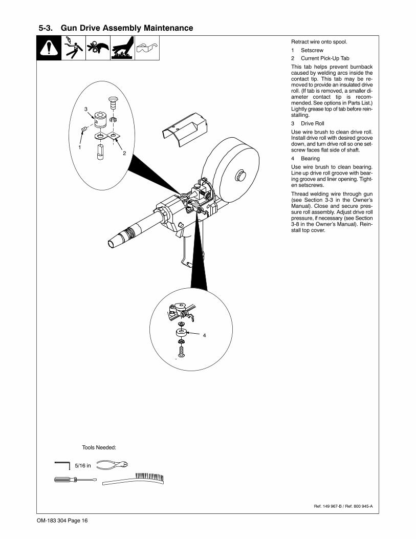
5-3. Gun Drive Assembly Maintenance
Ref. 149 967-B / Ref. 800 945-A
Retract wire onto spool.
1 Setscrew
2 Current Pick-Up Tab
This tab helps prevent burnbackcaused by welding arcs inside thecontact tip. This tab may be re-moved to provide an insulated driveroll. (If tab is removed, a smaller di-ameter contact tip is recom-mended. See options in Parts List.)Lightly grease top of tab before rein-stalling.
3 Drive Roll
Use wire brush to clean drive roll.Install drive roll with desired groovedown, and turn drive roll so one set-screw faces flat side of shaft.
4 Bearing
Use wire brush to clean bearing.Line up drive roll groove with bear-ing groove and liner opening. Tight-en setscrews.
Thread welding wire through gun(see Section 3-3 in the Owner’sManual). Close and secure pres-sure roll assembly. Adjust drive rollpressure, if necessary (see Section3-8 in the Owner’s Manual). Rein-stall top cover.
Tools Needed:
5/16 in
4
3
12
OM-183 304 Page 17
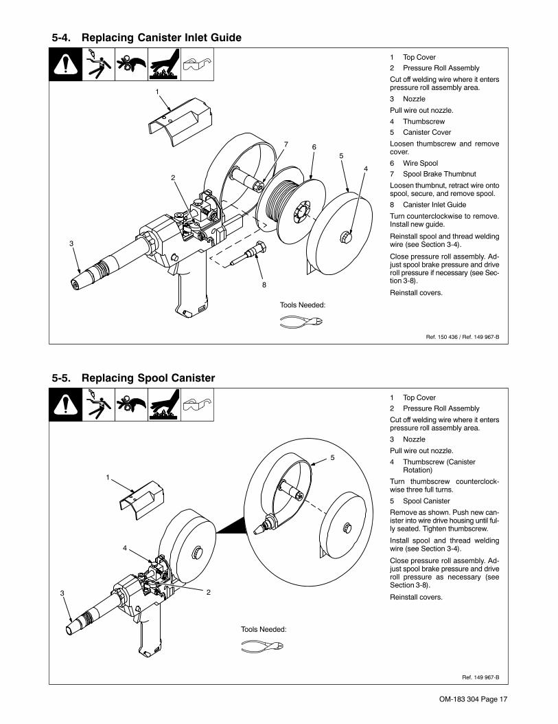
5-4. Replacing Canister Inlet Guide
Ref. 150 436 / Ref. 149 967-B
1 Top Cover
2 Pressure Roll Assembly
Cut off welding wire where it enterspressure roll assembly area.
3 Nozzle
Pull wire out nozzle.
4 Thumbscrew
5 Canister Cover
Loosen thumbscrew and removecover.
6 Wire Spool
7 Spool Brake Thumbnut
Loosen thumbnut, retract wire ontospool, secure, and remove spool.
8 Canister Inlet Guide
Turn counterclockwise to remove.Install new guide.
Reinstall spool and thread weldingwire (see Section 3-4).
Close pressure roll assembly. Ad-just spool brake pressure and driveroll pressure if necessary (see Sec-tion 3-8).
Reinstall covers.
Tools Needed:
1
2
3
4
567
8
5-5. Replacing Spool Canister
Ref. 149 967-B
1 Top Cover
2 Pressure Roll Assembly
Cut off welding wire where it enterspressure roll assembly area.
3 Nozzle
Pull wire out nozzle.
4 Thumbscrew (CanisterRotation)
Turn thumbscrew counterclock-wise three full turns.
5 Spool Canister
Remove as shown. Push new can-ister into wire drive housing until ful-ly seated. Tighten thumbscrew.
Install spool and thread weldingwire (see Section 3-4).
Close pressure roll assembly. Ad-just spool brake pressure and driveroll pressure as necessary (seeSection 3-8).
Reinstall covers.
Tools Needed:
1
23
4
5
OM-183 304 Page 18
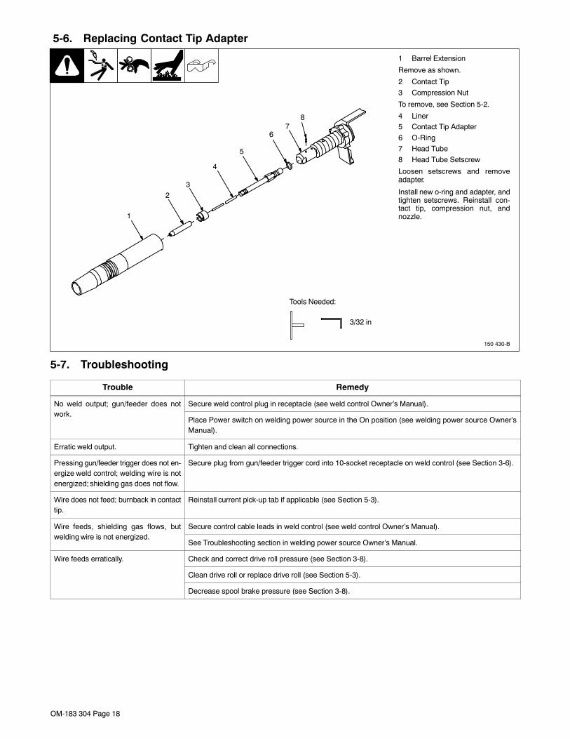
5-6. Replacing Contact Tip Adapter
150 430-B
1 Barrel Extension
Remove as shown.
2 Contact Tip
3 Compression Nut
To remove, see Section 5-2.
4 Liner5 Contact Tip Adapter
6 O-Ring
7 Head Tube
8 Head Tube Setscrew
Loosen setscrews and removeadapter.
Install new o-ring and adapter, andtighten setscrews. Reinstall con-tact tip, compression nut, andnozzle.
Tools Needed:
3/32 in
1
23
4
5
67
8
5-7. Troubleshooting
Trouble Remedy
No weld output; gun/feeder does notk
Secure weld control plug in receptacle (see weld control Owner’s Manual).work.
Place Power switch on welding power source in the On position (see welding power source Owner’sManual).
Erratic weld output. Tighten and clean all connections.
Pressing gun/feeder trigger does not en-ergize weld control; welding wire is notenergized; shielding gas does not flow.
Secure plug from gun/feeder trigger cord into 10-socket receptacle on weld control (see Section 3-6).
Wire does not feed; burnback in contacttip.
Reinstall current pick-up tab if applicable (see Section 5-3).
Wire feeds, shielding gas flows, butldi i i t i d
Secure control cable leads in weld control (see weld control Owner’s Manual).welding wire is not energized.
See Troubleshooting section in welding power source Owner’s Manual.
Wire feeds erratically. Check and correct drive roll pressure (see Section 3-8).
Clean drive roll or replace drive roll (see Section 5-3).
Decrease spool brake pressure (see Section 3-8).
OM-222 Page 19
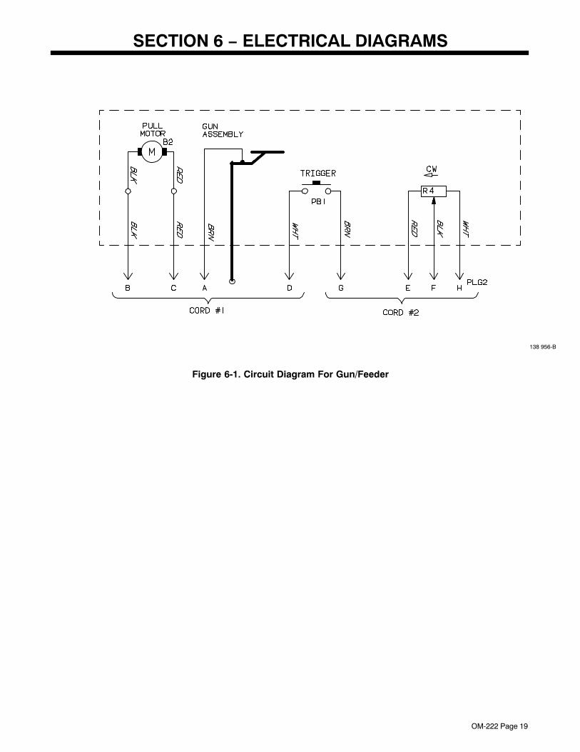
SECTION 6 − ELECTRICAL DIAGRAMS
138 956-B
Figure 6-1. Circuit Diagram For Gun/Feeder

OM-183 304 Page 20
Notes
OM-183 304 Page 21
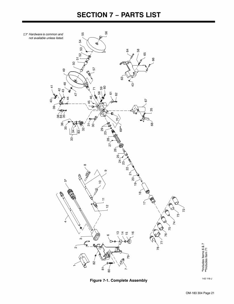
SECTION 7 − PARTS LIST
Figure 7-1. Complete Assembly143 116-J
*Inc
lude
s Ite
ms
6 &
7**
Incl
udes
Item
71
� Hardware is common andnot available unless listed.
12
3
45*
6
7
8
10
911
12
13 14 15 16
1718
1920
2122
2324
2526
2728
2329
3031
32
833433
3536
35843839
4041
42 43
44
4546
47
4849
5051
5253
5455 56
57
58
5859 60
61 62
71
63
64
65
66
43
67
6835
7069
**
72
7374
7576
7778
79
80
81
82
OM-183 304 Page 22
PartNo.
Dia.Mkgs.
ItemNo. Description Quantity
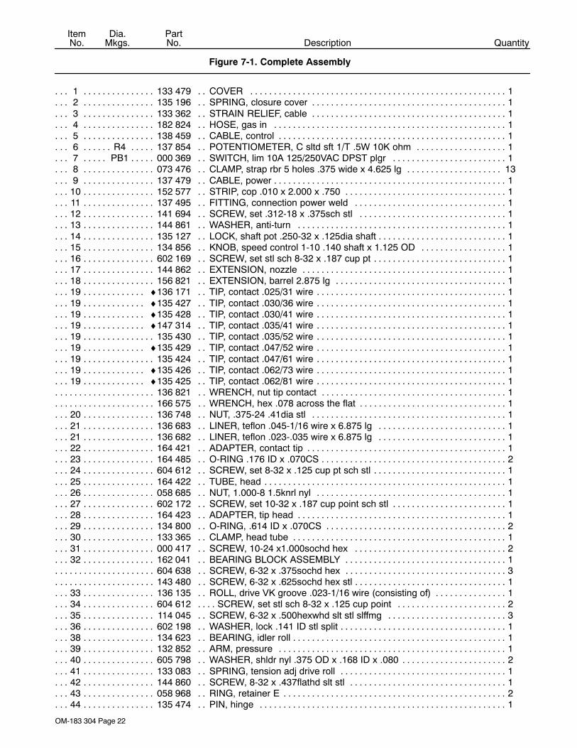
Figure 7-1. Complete Assembly
1 133 479 COVER 1. . . . . . . . . . . . . . . . . . . . . . . . . . . . . . . . . . . . . . . . . . . . . . . . . . . . . . . . . . . . . . . . . . . . . . . . . . 2 135 196 SPRING, closure cover 1. . . . . . . . . . . . . . . . . . . . . . . . . . . . . . . . . . . . . . . . . . . . . . . . . . . . . . . . . . . . . 3 133 362 STRAIN RELIEF, cable 1. . . . . . . . . . . . . . . . . . . . . . . . . . . . . . . . . . . . . . . . . . . . . . . . . . . . . . . . . . . . . 4 182 824 HOSE, gas in 1. . . . . . . . . . . . . . . . . . . . . . . . . . . . . . . . . . . . . . . . . . . . . . . . . . . . . . . . . . . . . . . . . . . . . 5 138 459 CABLE, control 1. . . . . . . . . . . . . . . . . . . . . . . . . . . . . . . . . . . . . . . . . . . . . . . . . . . . . . . . . . . . . . . . . . . . 6 R4 137 854 POTENTIOMETER, C sltd sft 1/T .5W 10K ohm 1. . . . . . . . . . . . . . . . . . . . . . . . . . . . . . . . . . . 7 PB1 000 369 SWITCH, lim 10A 125/250VAC DPST plgr 1. . . . . . . . . . . . . . . . . . . . . . . . . . . . . . . . . . . . . . . 8 073 476 CLAMP, strap rbr 5 holes .375 wide x 4.625 lg 13. . . . . . . . . . . . . . . . . . . . . . . . . . . . . . . . . . . . . . . . 9 137 479 CABLE, power 1. . . . . . . . . . . . . . . . . . . . . . . . . . . . . . . . . . . . . . . . . . . . . . . . . . . . . . . . . . . . . . . . . . . . .
10 152 577 STRIP, cop .010 x 2.000 x .750 1. . . . . . . . . . . . . . . . . . . . . . . . . . . . . . . . . . . . . . . . . . . . . . . . . . . . . . 11 137 495 FITTING, connection power weld 1. . . . . . . . . . . . . . . . . . . . . . . . . . . . . . . . . . . . . . . . . . . . . . . . . . . . 12 141 694 SCREW, set .312-18 x .375sch stl 1. . . . . . . . . . . . . . . . . . . . . . . . . . . . . . . . . . . . . . . . . . . . . . . . . . . 13 144 861 WASHER, anti-turn 1. . . . . . . . . . . . . . . . . . . . . . . . . . . . . . . . . . . . . . . . . . . . . . . . . . . . . . . . . . . . . . . . 14 135 127 LOCK, shaft pot .250-32 x .125dia shaft 1. . . . . . . . . . . . . . . . . . . . . . . . . . . . . . . . . . . . . . . . . . . . . . . 15 134 856 KNOB, speed control 1-10 .140 shaft x 1.125 OD 1. . . . . . . . . . . . . . . . . . . . . . . . . . . . . . . . . . . . . . 16 602 169 SCREW, set stl sch 8-32 x .187 cup pt 1. . . . . . . . . . . . . . . . . . . . . . . . . . . . . . . . . . . . . . . . . . . . . . . . 17 144 862 EXTENSION, nozzle 1. . . . . . . . . . . . . . . . . . . . . . . . . . . . . . . . . . . . . . . . . . . . . . . . . . . . . . . . . . . . . . . 18 156 821 EXTENSION, barrel 2.875 lg 1. . . . . . . . . . . . . . . . . . . . . . . . . . . . . . . . . . . . . . . . . . . . . . . . . . . . . . . . 19 ♦136 171 TIP, contact .025/31 wire 1. . . . . . . . . . . . . . . . . . . . . . . . . . . . . . . . . . . . . . . . . . . . . . . . . . . . . . . . . . 19 ♦135 427 TIP, contact .030/36 wire 1. . . . . . . . . . . . . . . . . . . . . . . . . . . . . . . . . . . . . . . . . . . . . . . . . . . . . . . . . . 19 ♦135 428 TIP, contact .030/41 wire 1. . . . . . . . . . . . . . . . . . . . . . . . . . . . . . . . . . . . . . . . . . . . . . . . . . . . . . . . . . 19 ♦147 314 TIP, contact .035/41 wire 1. . . . . . . . . . . . . . . . . . . . . . . . . . . . . . . . . . . . . . . . . . . . . . . . . . . . . . . . . . 19 135 430 TIP, contact .035/52 wire 1. . . . . . . . . . . . . . . . . . . . . . . . . . . . . . . . . . . . . . . . . . . . . . . . . . . . . . . . . . . . 19 ♦135 429 TIP, contact .047/52 wire 1. . . . . . . . . . . . . . . . . . . . . . . . . . . . . . . . . . . . . . . . . . . . . . . . . . . . . . . . . . 19 135 424 TIP, contact .047/61 wire 1. . . . . . . . . . . . . . . . . . . . . . . . . . . . . . . . . . . . . . . . . . . . . . . . . . . . . . . . . . . . 19 ♦135 426 TIP, contact .062/73 wire 1. . . . . . . . . . . . . . . . . . . . . . . . . . . . . . . . . . . . . . . . . . . . . . . . . . . . . . . . . . 19 ♦135 425 TIP, contact .062/81 wire 1. . . . . . . . . . . . . . . . . . . . . . . . . . . . . . . . . . . . . . . . . . . . . . . . . . . . . . . . . .
136 821 WRENCH, nut tip contact 1. . . . . . . . . . . . . . . . . . . . . . . . . . . . . . . . . . . . . . . . . . . . . . . . . . . . . . . . . . . . . . 166 575 WRENCH, hex .078 across the flat 1. . . . . . . . . . . . . . . . . . . . . . . . . . . . . . . . . . . . . . . . . . . . . . . . . . . . . .
20 136 748 NUT, .375-24 .41dia stl 1. . . . . . . . . . . . . . . . . . . . . . . . . . . . . . . . . . . . . . . . . . . . . . . . . . . . . . . . . . . . . 21 136 683 LINER, teflon .045-1/16 wire x 6.875 lg 1. . . . . . . . . . . . . . . . . . . . . . . . . . . . . . . . . . . . . . . . . . . . . . . 21 136 682 LINER, teflon .023-.035 wire x 6.875 lg 1. . . . . . . . . . . . . . . . . . . . . . . . . . . . . . . . . . . . . . . . . . . . . . . 22 164 421 ADAPTER, contact tip 1. . . . . . . . . . . . . . . . . . . . . . . . . . . . . . . . . . . . . . . . . . . . . . . . . . . . . . . . . . . . . . 23 164 485 O-RING .176 ID x .070CS 2. . . . . . . . . . . . . . . . . . . . . . . . . . . . . . . . . . . . . . . . . . . . . . . . . . . . . . . . . . . 24 604 612 SCREW, set 8-32 x .125 cup pt sch stl 1. . . . . . . . . . . . . . . . . . . . . . . . . . . . . . . . . . . . . . . . . . . . . . . . 25 164 422 TUBE, head 1. . . . . . . . . . . . . . . . . . . . . . . . . . . . . . . . . . . . . . . . . . . . . . . . . . . . . . . . . . . . . . . . . . . . . . . 26 058 685 NUT, 1.000-8 1.5knrl nyl 1. . . . . . . . . . . . . . . . . . . . . . . . . . . . . . . . . . . . . . . . . . . . . . . . . . . . . . . . . . . . 27 602 172 SCREW, set 10-32 x .187 cup point sch stl 1. . . . . . . . . . . . . . . . . . . . . . . . . . . . . . . . . . . . . . . . . . . . 28 164 423 ADAPTER, tip head 1. . . . . . . . . . . . . . . . . . . . . . . . . . . . . . . . . . . . . . . . . . . . . . . . . . . . . . . . . . . . . . . . 29 134 800 O-RING, .614 ID x .070CS 2. . . . . . . . . . . . . . . . . . . . . . . . . . . . . . . . . . . . . . . . . . . . . . . . . . . . . . . . . . 30 133 365 CLAMP, head tube 1. . . . . . . . . . . . . . . . . . . . . . . . . . . . . . . . . . . . . . . . . . . . . . . . . . . . . . . . . . . . . . . . . 31 000 417 SCREW, 10-24 x1.000sochd hex 2. . . . . . . . . . . . . . . . . . . . . . . . . . . . . . . . . . . . . . . . . . . . . . . . . . . . 32 162 041 BEARING BLOCK ASSEMBLY 1. . . . . . . . . . . . . . . . . . . . . . . . . . . . . . . . . . . . . . . . . . . . . . . . . . . . . .
604 638 SCREW, 6-32 x .375sochd hex 3. . . . . . . . . . . . . . . . . . . . . . . . . . . . . . . . . . . . . . . . . . . . . . . . . . . . . . . . . 143 480 SCREW, 6-32 x .625sochd hex stl 1. . . . . . . . . . . . . . . . . . . . . . . . . . . . . . . . . . . . . . . . . . . . . . . . . . . . . . .
33 136 135 ROLL, drive VK groove .023-1/16 wire (consisting of) 1. . . . . . . . . . . . . . . . . . . . . . . . . . . . . . . . . . . 34 604 612 SCREW, set stl sch 8-32 x .125 cup point 2. . . . . . . . . . . . . . . . . . . . . . . . . . . . . . . . . . . . . . . . . . . . . 35 114 045 SCREW, 6-32 x .500hexwhd slt stl slffmg 3. . . . . . . . . . . . . . . . . . . . . . . . . . . . . . . . . . . . . . . . . . . . . 36 602 198 WASHER, lock .141 ID stl split 1. . . . . . . . . . . . . . . . . . . . . . . . . . . . . . . . . . . . . . . . . . . . . . . . . . . . . . . 38 134 623 BEARING, idler roll 1. . . . . . . . . . . . . . . . . . . . . . . . . . . . . . . . . . . . . . . . . . . . . . . . . . . . . . . . . . . . . . . . . 39 132 852 ARM, pressure 1. . . . . . . . . . . . . . . . . . . . . . . . . . . . . . . . . . . . . . . . . . . . . . . . . . . . . . . . . . . . . . . . . . . . 40 605 798 WASHER, shldr nyl .375 OD x .168 ID x .080 2. . . . . . . . . . . . . . . . . . . . . . . . . . . . . . . . . . . . . . . . . . 41 133 083 SPRING, tension adj drive roll 1. . . . . . . . . . . . . . . . . . . . . . . . . . . . . . . . . . . . . . . . . . . . . . . . . . . . . . . 42 144 860 SCREW, 8-32 x .437flathd slt stl 1. . . . . . . . . . . . . . . . . . . . . . . . . . . . . . . . . . . . . . . . . . . . . . . . . . . . . 43 058 968 RING, retainer E 2. . . . . . . . . . . . . . . . . . . . . . . . . . . . . . . . . . . . . . . . . . . . . . . . . . . . . . . . . . . . . . . . . . . 44 135 474 PIN, hinge 1. . . . . . . . . . . . . . . . . . . . . . . . . . . . . . . . . . . . . . . . . . . . . . . . . . . . . . . . . . . . . . . . . . . . . . . .

OM-183 304 Page 23
PartNo.
Dia.Mkgs.
ItemNo. Description Quantity
Figure 7-1. Complete Assembly (Continued)
45 155 565 SCREW, thumb 1. . . . . . . . . . . . . . . . . . . . . . . . . . . . . . . . . . . . . . . . . . . . . . . . . . . . . . . . . . . . . . . . . . . . 134 799 O-RING, .176 ID x .070CS (used w/thumbscrew) 1. . . . . . . . . . . . . . . . . . . . . . . . . . . . . . . . . . . . . . . . . .
46 135 126 SCREW, set 6-32 x .125 cup point sch stl 1. . . . . . . . . . . . . . . . . . . . . . . . . . . . . . . . . . . . . . . . . . . . . 47 602 209 WASHER, tooth .256 ID stl intl 1. . . . . . . . . . . . . . . . . . . . . . . . . . . . . . . . . . . . . . . . . . . . . . . . . . . . . . . 48 602 154 SCREW, .250-20 x .500hexhd stl slffmg 1. . . . . . . . . . . . . . . . . . . . . . . . . . . . . . . . . . . . . . . . . . . . . . . 49 132 527 CANISTER, spool 1. . . . . . . . . . . . . . . . . . . . . . . . . . . . . . . . . . . . . . . . . . . . . . . . . . . . . . . . . . . . . . . . . . 50 148 488 POST, support spool 1. . . . . . . . . . . . . . . . . . . . . . . . . . . . . . . . . . . . . . . . . . . . . . . . . . . . . . . . . . . . . . . 51 132 529 PAD, brake 1. . . . . . . . . . . . . . . . . . . . . . . . . . . . . . . . . . . . . . . . . . . . . . . . . . . . . . . . . . . . . . . . . . . . . . . . 52 148 489 WASHER, anti-turn .380 ID 1. . . . . . . . . . . . . . . . . . . . . . . . . . . . . . . . . . . . . . . . . . . . . . . . . . . . . . . . . 53 132 524 NUT, .375-24 .56knrl alum 1. . . . . . . . . . . . . . . . . . . . . . . . . . . . . . . . . . . . . . . . . . . . . . . . . . . . . . . . . . 54 000 364 RING, retainer ext .145 shaft grv x .025thk 1. . . . . . . . . . . . . . . . . . . . . . . . . . . . . . . . . . . . . . . . . . . . 55 132 526 COVER, spool 1. . . . . . . . . . . . . . . . . . . . . . . . . . . . . . . . . . . . . . . . . . . . . . . . . . . . . . . . . . . . . . . . . . . . . 56 132 528 SCREW, thumb canister 1. . . . . . . . . . . . . . . . . . . . . . . . . . . . . . . . . . . . . . . . . . . . . . . . . . . . . . . . . . . . 57 132 521 GUIDE, inlet canister 1. . . . . . . . . . . . . . . . . . . . . . . . . . . . . . . . . . . . . . . . . . . . . . . . . . . . . . . . . . . . . . . 58 112 896 SPRING, cprsn .240 OD x .020 wire x .437 2. . . . . . . . . . . . . . . . . . . . . . . . . . . . . . . . . . . . . . . . . . . . 59 135 773 NUT, 8-32 .56knrl stl 1. . . . . . . . . . . . . . . . . . . . . . . . . . . . . . . . . . . . . . . . . . . . . . . . . . . . . . . . . . . . . . . . 60 143 360 SCREW, 8-32 x .500panhd phl stl 1. . . . . . . . . . . . . . . . . . . . . . . . . . . . . . . . . . . . . . . . . . . . . . . . . . . . 61 136 679 CLAMP, strain relief 1. . . . . . . . . . . . . . . . . . . . . . . . . . . . . . . . . . . . . . . . . . . . . . . . . . . . . . . . . . . . . . . . 62 129 351 SCREW, 8-32 x .500hexwhd slt stl slffmg 1. . . . . . . . . . . . . . . . . . . . . . . . . . . . . . . . . . . . . . . . . . . . . 63 164 591 CASE, gun LH 1. . . . . . . . . . . . . . . . . . . . . . . . . . . . . . . . . . . . . . . . . . . . . . . . . . . . . . . . . . . . . . . . . . . . . 64 173 527 SCREW, 8-32 x 1.500 2. . . . . . . . . . . . . . . . . . . . . . . . . . . . . . . . . . . . . . . . . . . . . . . . . . . . . . . . . . . . . . 65 135 896 PLUNGER, trigger hold 1. . . . . . . . . . . . . . . . . . . . . . . . . . . . . . . . . . . . . . . . . . . . . . . . . . . . . . . . . . . . . 66 173 528 SCREW, 8-32 x .875 1. . . . . . . . . . . . . . . . . . . . . . . . . . . . . . . . . . . . . . . . . . . . . . . . . . . . . . . . . . . . . . . 67 B2 161 813 MOTOR, gear PM 24VDC 420RPM 10.2:1 ratio 1. . . . . . . . . . . . . . . . . . . . . . . . . . . . . . . . . . . . 68 164 592 TRIGGER 1. . . . . . . . . . . . . . . . . . . . . . . . . . . . . . . . . . . . . . . . . . . . . . . . . . . . . . . . . . . . . . . . . . . . . . . . 69 164 582 HOUSING, wire drive (consisting of) 1. . . . . . . . . . . . . . . . . . . . . . . . . . . . . . . . . . . . . . . . . . . . . . . . . . 70 058 262 CAP, valve 1. . . . . . . . . . . . . . . . . . . . . . . . . . . . . . . . . . . . . . . . . . . . . . . . . . . . . . . . . . . . . . . . . . . . . . . . 71 135 580 FITTING, gas 1. . . . . . . . . . . . . . . . . . . . . . . . . . . . . . . . . . . . . . . . . . . . . . . . . . . . . . . . . . . . . . . . . . . . . .
146 555 SCREW, set 8-32 x .125 cup sch 2. . . . . . . . . . . . . . . . . . . . . . . . . . . . . . . . . . . . . . . . . . . . . . . . . . . . . . . . 72 ♦009 925 NOZZLE, spot outside corner .937 ID x 2.375 1. . . . . . . . . . . . . . . . . . . . . . . . . . . . . . . . . . . . . . . . 73 ♦050 116 NOZZLE,13/16 orf x 1-5/8 lg 1. . . . . . . . . . . . . . . . . . . . . . . . . . . . . . . . . . . . . . . . . . . . . . . . . . . . . . 74 ♦050 115 NOZZLE, 1/2 orf x 1-5/8 lg 1. . . . . . . . . . . . . . . . . . . . . . . . . . . . . . . . . . . . . . . . . . . . . . . . . . . . . . . . 75 050 622 NOZZLE, 5/8 orf x 1-5/8 lg 1. . . . . . . . . . . . . . . . . . . . . . . . . . . . . . . . . . . . . . . . . . . . . . . . . . . . . . . . . . 76 ♦000 442 NOZZLE, spot 1. . . . . . . . . . . . . . . . . . . . . . . . . . . . . . . . . . . . . . . . . . . . . . . . . . . . . . . . . . . . . . . . . . . 77 ♦004 466 NOZZLE, spot 1. . . . . . . . . . . . . . . . . . . . . . . . . . . . . . . . . . . . . . . . . . . . . . . . . . . . . . . . . . . . . . . . . . . 78 ♦000 443 NOZZLE, spot inside corner 1. . . . . . . . . . . . . . . . . . . . . . . . . . . . . . . . . . . . . . . . . . . . . . . . . . . . . . . 79 164 590 CASE, gun RH 1. . . . . . . . . . . . . . . . . . . . . . . . . . . . . . . . . . . . . . . . . . . . . . . . . . . . . . . . . . . . . . . . . . . . 80 183 884 SPRING, cprsn .240 OD x .026 wire x 1.000 1. . . . . . . . . . . . . . . . . . . . . . . . . . . . . . . . . . . . . . . . . . . 81 184 101 WASHER, shldr .140 ID x .250 OD 1. . . . . . . . . . . . . . . . . . . . . . . . . . . . . . . . . . . . . . . . . . . . . . . . . . . 82 135 647 NUT, 8-32 .33knrl brs 3. . . . . . . . . . . . . . . . . . . . . . . . . . . . . . . . . . . . . . . . . . . . . . . . . . . . . . . . . . . . . . . 83 162 042 CONTACT, current pick-up 1. . . . . . . . . . . . . . . . . . . . . . . . . . . . . . . . . . . . . . . . . . . . . . . . . . . . . . . . . . 84 134 624 BEARING, flg nyl .140 ID x .187 OD x .375flg x .031thk 2. . . . . . . . . . . . . . . . . . . . . . . . . . . . . . . . .
♦OPTIONALTo maintain the factory original performance of your equipment, use only Manufacturer’s SuggestedReplacement Parts. Model and serial number required when ordering parts from your local distributor.

2/96
OPTIONS AND ACCESSORIES
SX FLEX HEAD KIT
(#131 104)For .030 in.−1/16 in. (0.8 mm−1.6mm) wire.Used in place of the standardstraight barrel. Flexible head tubebends 60 degrees in any directionfor easier joint access andimproved operator comfort.Supplied with two Teflon liners andone contact tip for each wire sizelisted.
REPLACEMENT LINERS FORFLEX HEAD
(#138 255) .030 and .035 in. (0.8 and 0.9 mm) wire(#132 682) 3/64 and 1/16 in. (1.2 and 1.6 mm) wire
SX−A 50 DEGREE CURVEDBARRELS*
(#147 175) 6 in. (152 mm)(#147 176) 10 in. (254 mm)
Used with .030−1/16 in. (0.8−1.6mm) wire. Kits supplied with twoliners that accommodate all wiresizes.
REPLACEMENT TEFLONLINERS FOR CURVEDBARRELS
For 6 in. Barrel(#144 858) .030 and .035 in.(0.8 and 0.9 mm) wire(#144 859) .047 and 1/16 in.(1.2 and 1.6 mm) wire
For 10 in. Barrel(#144 854) .030 and .035 in.
(0.8 and 0.9 mm) wire(#144 855) .047 and 1/16 in.(1.2 and 1.6 mm) wire
SX−A 50 DEGREE CURVEDNOZZLE KIT
(#147 174)Attaches to standard gun barrelassembly and is ideal for access toconfined weld joint areas. Usedwith .030−1/16 in. (0.8−1/6 mm)wire.
Kit includes two of each sizecontact tips to accommodate allwire sizes. Uses standard straightbarrel head tube liner.
REPLACEMENT CONTACT TIPSFOR CURVED NOZZLE
(#148 155) .030 and .035 in.(0.8 and 0.9 mm) wire(#148 154) .047 in. (1.2 mm)wire(#148 156)1/16 in. (1.6 mm)wire
3 IN. HEAD TUBE EXTENSION*(#137 787)
Extends the standard gun barrel 3in. (72 mm) when a longer reach isrequired. The head tube extensionis supplied with two liners toaccommodate all wire sizes.
REPLACEMENT LINERS FORHEAD TUBE EXTENSION
(#138 223) .030 and .035 in. (0.8 and 0.9 mm) wire(#138 224) 3/64 and 1/16 in. (1.2 and 1.6 mm) wire
*Note: Uses standard SGS 30A contacttips. (Refer to SGS 30A GunConsumables chart for contact tips.)
GUN OPTIONS ANDACCESSORIES
CABLE COVER(#118 678)
Protects gun hose and cableassembly from wear and abrasion.Features a full−length zipper.
SX HEAT SHIELD(#131 103)
Helps protect operator’s hand fromspatter and reflected heat.
SPARE SPOOL CANISTER(#132 230)
Canister accommodates 4 in. (102mm) spools of wire. Can be loadedwith other popular wires to savetime in changeover.
HOSE AND CABLE EXTENSIONKITS
(#132 228) 25 ft. (7.6 m) (#132 229) 50 ft. (15 m)
Extends the standard 30 ft. (9 m)hose and cable assembly.Convenient plug−in connections.Includes gas hose, control cord,and weld power cable withInternational style insulatedconnector.
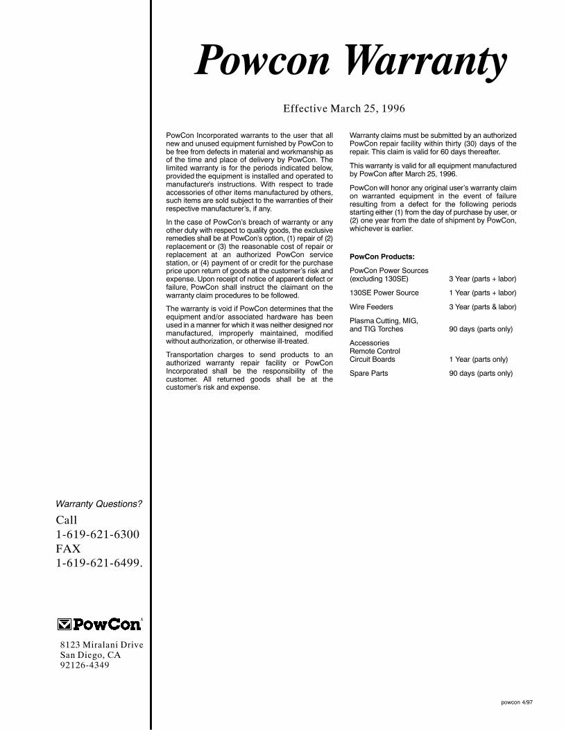
Effective March 25, 1996
PowCon Incorporated warrants to the user that allnew and unused equipment furnished by PowCon tobe free from defects in material and workmanship asof the time and place of delivery by PowCon. Thelimited warranty is for the periods indicated below,provided the equipment is installed and operated tomanufacturer’s instructions. With respect to tradeaccessories of other items manufactured by others,such items are sold subject to the warranties of theirrespective manufacturer’s, if any.
In the case of PowCon’s breach of warranty or anyother duty with respect to quality goods, the exclusiveremedies shall be at PowCon’s option, (1) repair of (2)replacement or (3) the reasonable cost of repair orreplacement at an authorized PowCon servicestation, or (4) payment of or credit for the purchaseprice upon return of goods at the customer’s risk andexpense. Upon receipt of notice of apparent defect orfailure, PowCon shall instruct the claimant on thewarranty claim procedures to be followed.
The warranty is void if PowCon determines that theequipment and/or associated hardware has beenused in a manner for which it was neither designed normanufactured, improperly maintained, modifiedwithout authorization, or otherwise ill-treated.
Transportation charges to send products to anauthorized warranty repair facility or PowConIncorporated shall be the responsibility of thecustomer. All returned goods shall be at thecustomer’s risk and expense.
Warranty claims must be submitted by an authorizedPowCon repair facility within thirty (30) days of therepair. This claim is valid for 60 days thereafter.
This warranty is valid for all equipment manufacturedby PowCon after March 25, 1996.
PowCon will honor any original user’s warranty claimon warranted equipment in the event of failureresulting from a defect for the following periodsstarting either (1) from the day of purchase by user, or(2) one year from the date of shipment by PowCon,whichever is earlier.
PowCon Products:
PowCon Power Sources(excluding 130SE) 3 Year (parts + labor)
130SE Power Source 1 Year (parts + labor)
Wire Feeders 3 Year (parts & labor)
Plasma Cutting, MIG,and TIG Torches 90 days (parts only)
AccessoriesRemote ControlCircuit Boards 1 Year (parts only)
Spare Parts 90 days (parts only)
powcon 4/97
Powcon Warranty
Warranty Questions?
Call1-619-621-6300FAX1-619-621-6499.
8123 Miralani DriveSan Diego, CA92126-4349

PRINTED IN USA
Model Name Serial/Style Number
Purchase Date (Date which equipment was delivered to original customer.)
Distributor
Address
City
State Zip
Please complete and retain with your personal records.
Always provide Model Name and Serial/Style Number.
Contact your Distributor for: Welding Supplies and Consumables
Options and Accessories
Personal Safety Equipment
Service and Repair
Replacement Parts
Owner’s Manuals
Circuit Diagrams
Contact the Delivering Carrierfor:
For assistance in filing or settling claims,contact your distributor and/or equipmentmanufacturer’s Transportation Department.
Resources Available
Owner’s Record
File a claim for loss or damage during ship-ment.