Operator Manual
102
English – Original Instructions 4-2010 0908-0219 (Issue 3) Operator Manual PowerCommand ® 2.2
-
Upload
khangminh22 -
Category
Documents
-
view
0 -
download
0
Transcript of Operator Manual

English – Original Instructions 4-2010 0908-0219 (Issue 3)
Operator Manual
PowerCommand® 2.2


Operator’s Manual Publication 0908-0219 PowerCommand® 2.2 Issue 3 – 4-2010
FOREWORD The purpose of this manual is to provide the Operator with sound, general information for the use and daily maintenance of the generator set. Refer to the Operator’s engine specific manual for additional engine information which must also be read before operating the set.
It is for guidance and assistance with recommendations for correct and safe procedures. Cummins Power Generation Limited cannot accept any liability whatsoever for problems arising as a result of following recommendations in this manual.
The information contained within the manual is based on information available at the time of going to print. In line with Cummins Power Generation Limited policy of continuous development and improvement, information may change at any time without notice. The Operators must therefore ensure that before commencing any work, they have the latest information available.
Operators are respectfully advised that it is their responsibility to employ competent persons to carry out any installation work in the interests of good practice and safety. Consult your Authorised Distributor for further installation information. It is essential that the utmost care is taken with the application, installation and operation of any diesel engine due to their potentially dangerous nature. Careful reference must also be made to other Cummins Power Generation Limited literature, in particular the Health and Safety Manual 0908-0110.
Should you require further assistance contact: -
Cummins Power Generation 1400 73rd Avenue NE Minneapolis MN 55432 USA
Tel:+1 (763) 574-5000 Fax:+1 (763) 574-5298 e-mail: [email protected]
Cummins Power Generation Columbus Avenue Manston Park Manston Ramsgate Kent CT12 5BF United Kingdom
Tel:+44 (0) 1843 255000 Fax:+44 (0) 1843 255902 e-mail:[email protected]
Cummins Power Generation 10 Toh Guan Road #07-01 TT International Tradepark Singapore 608838
Tel: (65) 6417 2388 Fax:(65) 6417 2399 e-mail: [email protected]
Web: www.cumminspower.com Web: www.cumminspower.com Web: www.cumminspower.com
Cummins Power Generation 35A/1/2, Erandawana Pune 411 038 India Tel.: (91 020) 3024 8600 Fax: (91 020) 6602 8090 e-mail: [email protected]
Cummins Power Generation Rua Jati, 310 - Cumbica Guarulhos –SP Brazil CEP: 07180-900 Tel.: (55 11) 2186 4195 Fax: (55 11) 2186 4729 e-mail: [email protected]
Web: www.cumminspower.com Web: www.cumminspower.com

Publication 0908-0219 Operator’s Manual Issue 3 – 4-2010 PowerCommand® 2.2
Engine Specific Publications CAUTION: Important, additional engine specific information is contained within the Engine
Operator’s Manual. This information must be read in conjunction with the Control Manual before attempting to run the generator set.
The relevant engine specific manual must be read in conjunction with this manual for the safe operation and maintenance of this generator set. The Engine Operator’s Manual – Operator Level - will be supplied with the documentation package for your generator set.
Supplementary Publications The Supplementary Publications appropriate to your system will also be supplied. Where appropriate the corresponding Instruction Manual(s) will also be supplied with any accessory that you order.
Title Publication No
Lead Acid Battery 0908-0101
Radiator Information 0908-0107
Health and Safety (Diesel Generator Sets) 0908-0110
If further, more detailed information is required, Engine Operation and Maintenance Manuals, and Service Manuals are available. Contact your authorised distributor.

Operator’s Manual Publication 0908-0219 PowerCommand® 2.2 Issue 3 – 4-2010
DISCLAIMER
ALTHOUGH THIS GENERATOR SET MAY BE SUPPLIED WITH AN EARTHING ROD IT WILL NOT BE
SUITABLE FOR ALL LOCAL CONDITIONS.
THE END USER IS RESPONSIBLE
FOR ENSURING THAT AN EARTHING ARRANGEMENT THAT
IS COMPLIANT WITH LOCAL CONDITIONS IS ESTABLISHED
AND TESTED BEFORE THE EQUIPMENT IS USED.
TRANSPORTATION WARNING: BEFORE ANY TRANSPORTATION, THE FLUID CONTAINMENT AREA (IF
APPLICABLE) MUST BE INSPECTED AND EMPTIED OF ANY SPILLAGE OR ENGINE WASTE. THE GENERATOR SET DOOR(S) (IF THE GENERATOR SET IS ENCLOSED) MUST BE LOCKED BEFORE TRANSPORTATION AND MUST REMAIN LOCKED DURING TRANSPORTATION AND SITING.

Publication 0908-0219 Operator’s Manual Issue 3 – 4-2010 PowerCommand® 2.2
This Page Has Been Left Intentionally Blank
Operator’s Manual Publication 0908-0219 PowerCommand® 2.2 Issue 3 – 4-2010
Contents Page i
CONTENTS Section Title Page
Schedule of Abbreviations ................................................................................................ i
1. Preliminary and Safety ........................................................................................... 1 1.1 Warning, Caution and Note Styles Used In This Manual................................................................1 1.2 General Information ........................................................................................................................1 1.3 Generator Plant Safety Code..........................................................................................................1 1.3.1 Positioning of Generator Set ....................................................................................................1 1.3.2 AC Supply and Isolation ...........................................................................................................2 1.3.3 Spillage .....................................................................................................................................2 1.3.4 Fluid Containment.....................................................................................................................2 1.3.5 Exhaust Precautions.................................................................................................................2
2. Introduction............................................................................................................. 3 2.1 General............................................................................................................................................3 2.2 Generator Set Identification ............................................................................................................3 2.3 After Sales Services........................................................................................................................4 2.3.1 Maintenance .............................................................................................................................4 2.3.2 Warranty ...................................................................................................................................4 2.3.3 Spares ......................................................................................................................................4 2.3.4 Overseas ..................................................................................................................................4 2.3.5 Additional Literature..................................................................................................................4
3. System Overview.................................................................................................... 5 3.1 SilentPower™ Canopy – Standard Set Main Features...................................................................5 3.2 SilentPower™ Canopy – Rental Set Main Features.......................................................................6 3.3 Generator Components – Typical Generator Set ...........................................................................7 3.3.1 Generator Rating ......................................................................................................................8 3.3.2 Engine.......................................................................................................................................8 3.3.3 Fuel Changeover System – Rental Only ..................................................................................9 3.3.4 Mains Powered Battery Charger – Set Mounted (Option)........................................................9 3.3.5 Battery Isolator – Rental Only.................................................................................................10 3.3.6 Alarm Module (Option)............................................................................................................10 3.3.7 Sensors...................................................................................................................................10 3.4 AC Supply and Isolation................................................................................................................11 3.5 Heaters..........................................................................................................................................11 3.5.1 Heater Supply and Isolation ...................................................................................................11 3.6 Mains Powered Battery Charger (Option).....................................................................................11 3.6.1 Operation ................................................................................................................................11
4. Control System ..................................................................................................... 13 4.1 Control System Description...........................................................................................................13 4.1.1 Power On/Off Modes ..............................................................................................................14 4.1.2 Operating Modes ....................................................................................................................14 4.2 Display Module - Front Panel........................................................................................................17 4.2.1 Lamp Indicators ......................................................................................................................18 4.2.2 Lamp (LED) Test Button.........................................................................................................18 4.2.3 Reset Button ...........................................................................................................................18 4.2.4 Graphical Display and Buttons ...............................................................................................19 4.2.5 Selection Buttons....................................................................................................................21 4.2.6 Default Settings ......................................................................................................................21 4.3 Fault Messages.............................................................................................................................22 4.3.1 Fault Acknowledgement .........................................................................................................22 4.4 Display Module – Initial Operator Menu........................................................................................23

Publication 0908-0219 Operator’s Manual Issue 3 – 4-2010 PowerCommand® 2.2
Page ii Contents
4.5 Display Module – Genset Data Operator Menu ........................................................................... 24 4.5.1 Generator Data ...................................................................................................................... 24 4.6 Display Module – Engine Data Operator Menu............................................................................ 26 4.6.1 Engine Data ........................................................................................................................... 26 4.7 Display Module – Alternator Data Operator Menu ....................................................................... 28 4.7.1 Alternator Data....................................................................................................................... 28 4.8 Display Module –Faults and Warnings Menus............................................................................. 30 4.8.1 Shutdown Fault Menu............................................................................................................ 30 4.8.2 Warning Fault Menu............................................................................................................... 32 4.8.3 Faults History Data Operator Menu ....................................................................................... 34 4.9 Display Module – Genset Setup Data Operator Menu................................................................. 36 4.10 Selecting Operating Modes .......................................................................................................... 40 4.10.1 Entering the Mode Change Access Code.............................................................................. 40 4.10.2 Selecting Manual Run Mode.................................................................................................. 41 4.10.3 Selecting Auto Mode.............................................................................................................. 42 4.10.4 Selecting Off Mode ................................................................................................................ 43
5. Operation...............................................................................................................45 5.1 Safety ........................................................................................................................................... 45 5.2 Introduction................................................................................................................................... 45 5.3 Maintenance................................................................................................................................. 45 5.4 Operating Recommendations....................................................................................................... 46 5.4.1 Running –in............................................................................................................................ 46 5.4.2 No Load Operation................................................................................................................. 46 5.4.3 Exercise Period...................................................................................................................... 46 5.4.4 Low Operating Temperatures ................................................................................................ 46 5.4.5 High Operating Temperatures ............................................................................................... 46 5.4.6 Operating Conditions for Prime, Standby and Continuous Power Ratings ........................... 47 5.4.7 De-Rating Factors.................................................................................................................. 48 5.5 Generator Set Operation .............................................................................................................. 49 5.5.1 Sequence of Operation.......................................................................................................... 50 5.6 Starting ......................................................................................................................................... 51 5.6.1 Initial Pre-Start Checks .......................................................................................................... 52 5.6.2 Operator’s Pre-Start Checks.................................................................................................. 53 5.6.3 Starting at Display Panel (Manual Run Mode) ...................................................................... 54 5.6.4 Starting from Remote Location (Auto Mode) ......................................................................... 55 5.6.5 Cold Starting with Loads........................................................................................................ 55 5.7 Stopping ....................................................................................................................................... 56 5.7.1 Stopping at Display Panel (Manual Mode) ............................................................................ 56 5.7.2 Stopping from Display Panel (Auto Mode) ............................................................................ 56 5.7.3 Stopping from Remote Location (Auto Mode) ....................................................................... 56 5.7.4 Emergency Stop (Code 1433) ............................................................................................... 57 5.8 Frequency Changing – Rental Only ............................................................................................. 58
6. Maintenance ..........................................................................................................59 6.1 Locking the Generator Set Out of Service ................................................................................... 60 6.1.1 Introduction ............................................................................................................................ 60 6.1.2 Immobilising the Generator Set for Safe Working ................................................................. 60 6.2 General......................................................................................................................................... 61 6.3 Daily or Refuelling Maintenance Procedures ............................................................................... 63 6.3.1 General Information ............................................................................................................... 63 6.3.2 Engine Operation Report ....................................................................................................... 63 6.4 Cooling System ............................................................................................................................ 63 6.4.1 Coolant Level - Check............................................................................................................ 64 6.4.2 Cooling Fan - Inspect............................................................................................................. 65 6.4.3 Drive Belt - Inspect................................................................................................................. 65 6.4.4 Radiator - Check .................................................................................................................... 65 6.5 Engine Oil ..................................................................................................................................... 66 6.5.1 Engine Oil Level – Check ...................................................................................................... 66

Operator’s Manual Publication 0908-0219 PowerCommand® 2.2 Issue 3 – 4-2010
Contents Page iii
6.6 Fuel System ..................................................................................................................................67 6.6.1 Fuel Level ...............................................................................................................................67 6.6.2 Fuel/Water Separator - Drain .................................................................................................67 6.7 Fluid Containment .........................................................................................................................68 6.8 Hoses and Fuel Lines - Check......................................................................................................68 6.9 Exhaust System ............................................................................................................................69 6.10 Generator Set Output - AC Electric System..................................................................................69 6.11 DC Electrical System ....................................................................................................................69
7. Troubleshooting ................................................................................................... 71 7.1 Introduction....................................................................................................................................71 7.2 Control Unit ...................................................................................................................................71 7.3 Safety Considerations ...................................................................................................................72 7.4 Fault Finding..................................................................................................................................73 7.5 Status Indicators ...........................................................................................................................74 7.6 Fault/Status Codes........................................................................................................................75 7.6.1 Fault Messages ......................................................................................................................75 7.6.2 Fault Acknowledgement .........................................................................................................75 7.6.3 Fault Categories .....................................................................................................................76 7.6.4 Customer Input Faults ............................................................................................................84

Publication 0908-0219 Operator’s Manual Issue 3 – 4-2010 PowerCommand® 2.2
Page iv Contents
Illustrations Figure Title Page Figure 1 Typical Open Generator Set Rating Plate.........................................................................3 Figure 2 Typical Enclosed Generator Set Rating Plate...................................................................3 Figure 3 Typical SilentPower™ Canopy for Standard Set ..............................................................5 Figure 4 Typical SilentPower™ Canopy for Rental Set...................................................................6 Figure 5 Typical C500 Generator Set..............................................................................................7 Figure 6 Typical Engine Components (QSX15) ..............................................................................8 Figure 7 Typical Alarm Modules Front Panel ................................................................................10 Figure 8 Typical Control System Panel .........................................................................................13 Figure 9 Display Module – Front Panel .........................................................................................17 Figure 10 Graphical Display with Typical Screenshot .....................................................................19 Figure 11 Initial Operator Menu.......................................................................................................23 Figure 12 Genset Data Menu – Typical Data ..................................................................................25 Figure 13 Engine Data Menu – Typical Data ..................................................................................27 Figure 14 Alternator Data Menu – Typical Data ..............................................................................29 Figure 15 Shutdown Faults menu – Typical Data ...........................................................................31 Figure 16 Warning Fault Menu – Typical Data................................................................................33 Figure 17 History Fault Menu – Typical Data ..................................................................................35 Figure 18 Setup Data Menu Sheet 1 of 3 – Typical Data................................................................37 Figure 19 Setup Data Menu Sheet 2 of 3 – Typical Data................................................................38 Figure 20 Data Menu Sheet 3 of 3 – Typical Data ..........................................................................39 Figure 21 Starting in Auto Mode......................................................................................................42 Figure 22 Display Module – Front Panel .........................................................................................74
Tables Table Title Page Table 1 Critical Shutdown Faults..................................................................................................16 Table 2 Periodic Maintenance Schedule....................................... Error! Bookmark not defined. Table 3 Fault Codes .....................................................................................................................77 Table 4 Troubleshooting Procedures for Fault Codes .................................................................85

Operator’s Manual Publication 0908-0219 PowerCommand® 2.2 Issue 3 – 4-2010
Schedule of Abbreviations Page i
Schedule of Abbreviations AC Alternating Current MCB Miniature Circuit Breaker ACB Air Circuit Breaker MCCB Moulded Case Circuit Breaker ACH Anti-Condensation Heaters MF Mains Failed ATS Automatic Transfer Switch MFSS Master First Start Sensor AVR Automatic Voltage Regulator MR Mains Returned MST Mains Sensing Transformer BHP Brake Horsepower MSU Mains Sensing Unit BMS Building Management System MV Medium Voltage BST Busbar Sensing Transformer NEC Neutral Earthing Contact CB Circuit Breaker CCA Cold Cranking Amps PC PowerCommand® CHP Combined Heat and Power PF Power Factor COP Continuous Power Rating PFC Power Factor Controller CT Current Transformer PLC Programmable Logic Controller PMG Permanent Magnet Generator dB(A) Unit of noise level PRP Prime Power Rating DC Direct Current PSU Power Supply Unit DIP Dual In-line Package PT/CT Potential Transformer / Current Transformer DMC Digital Master Control DMSU Demand Load Standby Unit QCC Quadrature Current Control EMCU Engine Monitoring and Control Unit RFI Radio Frequency Interference EMF Electromotive Force RMS Root Mean Square EPU Engine Protection Unit RPM Revolutions Per Minute RTD Resistance Temperature Detector FSS First Start Sensor GCP Generator Control Panel V Volts Genset Generator set VAC Volts, Alternating Current GKWT Global Kilowatt Transducer VCB Vacuum Circuit Breaker VDC Volts, Direct Current HMI Human/Machine Interface VF Volt-free HV High Voltage VT Voltage Transformer IC Integrated Circuit I/O Input / Output kVA Apparent Power kVAR Reactive Power kW Active / Real Power kWh Unit of electrical energy or work LED Light-Emitting Diode LTP Limited Time Power Rating LTA Low Temperature Aftercooling LV Low Voltage

Publication 0908-0219 Operator’s Manual Issue 3 – 4-2010 PowerCommand® 2.2
Page ii Schedule of Abbreviations
This Page Has Been Left Intentionally Blank

Operator’s Manual Publication 0908-0219 PowerCommand® 2.2 Issue 3 – 4-2010
Section 1 – Preliminary and Safety Page 1
SECTION 1 – PRELIMINARY AND SAFETY
1. Preliminary and Safety 1.1 Warning, Caution and Note Styles Used In This Manual
The following safety styles found throughout this manual indicate potentially hazardous conditions to the operator, service personnel or the equipment.
WARNING: WARNS OF A HAZARD THAT MAY RESULT IN SEVERE PERSONAL INJURY OR DEATH.
Caution Warns of a hazard or an unsafe practice that can result in product or property damage.
Note: A short piece of text giving information that augments the current text.
1.2 General Information This manual should form part of the documentation package supplied by Cummins Power Generation Limited with specific generator sets. In the event that this manual has been supplied in isolation please refer to other Cummins Power Generation Limited literature, in particular the Health and Safety Manual (0908-0110).
Note: It is in the Operator’s interest to read and understand all Health and Safety information together with all Warnings and Cautions contained within the documentation relevant to the generator set, its operation and daily maintenance.
1.3 Generator Plant Safety Code Before operating the generator set, read the manuals and become familiar with them and the equipment. Safe and efficient operation can be achieved only if the equipment is properly operated and maintained. Many accidents are caused by failure to follow fundamental rules and precautions.
WARNING: IMPROPER OPERATION AND MAINTENANCE CAN LEAD TO SEVERE PERSONAL INJURY OR LOSS OF LIFE AND PROPERTY BY FIRE, ELECTROCUTION, MECHANICAL BREAKDOWN OR EXHAUST GAS ASPHYXIATION. READ AND FOLLOW ALL SAFETY PRECAUTIONS, WARNINGS AND CAUTIONS THROUGHOUT THIS MANUAL AND THE HEALTH AND SAFETY MANUAL 0908-0110.
WARNING: LIFTING AND REPOSITIONING ON THE GENERATOR SET MUST ONLY BE CARRIED OUT USING SUITABLE LIFTING EQUIPMENT, SHACKLES AND SPREADER BARS IN ACCORDANCE WITH LOCAL GUIDELINES AND LEGISLATION BY SUITABLY TRAINED AND EXPERIENCED PERSONNEL. INCORRECT LIFTING CAN RESULT IN SEVERE PERSONAL INJURY, DEATH AND/OR EQUIPMENT DAMAGE. FOR MORE INFORMATION CONTACT YOUR AUTHORISED DISTRIBUTOR.
1.3.1 Positioning of Generator Set The area for positioning the set must be adequate and level and the area immediately around the set must be free of any flammable material.
WARNING: ON AN ENCLOSED GENERATOR SET, THE CANOPY DOORS MUST BE LOCKED BEFORE RE-POSITIONING AND MUST REMAIN LOCKED DURING TRANSPORTATION AND SITING.

Publication 0908-0219 Operator’s Manual Issue 3 – 4-2010 PowerCommand® 2.2
Page 2 Section 1 – Preliminary and Safety
1.3.2 AC Supply and Isolation It is the sole responsibility of the customer to provide the AC power supply and the means to isolate the AC input to the terminal box. Refer to the wiring diagram supplied with the generator set.
Note: A separate disconnecting device is required by BS EN 12601:2001.
Note: The AC supply must have the correct over current and earth fault protection according to local electrical codes and regulations.
The disconnecting device is not provided as part of the generator set, and Cummins Power Generation Limited accepts no responsibility for providing the means of isolation.
1.3.3 Spillage Any spillage that occurs during fuelling or during oil top-up or oil change must be cleaned up before starting the generator set.
1.3.4 Fluid Containment If fluid containment is incorporated into the bedframe it must be inspected at regular intervals. Any liquid present should be drained out and disposed of in line with local health and safety regulations. (See Health and Safety manual 0908-0110). Failure to perform this action may result in spillage of liquids which could contaminate the surrounding area.
Any other fluid containment area must also be checked and emptied, as above.
1.3.5 Exhaust Precautions WARNING: EXHAUST PIPES AND CHARGE AIR PIPES ARE VERY HOT AND THEY CAN
CAUSE SEVERE PERSONAL INJURY OR DEATH FROM DIRECT CONTACT OR FROM FIRE HAZARD.
The exhaust outlet may be sited at the top of the set, or at the bottom, make sure that the exhaust outlet is not obstructed. Personnel using this equipment must be made aware of the exhaust position.
WARNING: CONTAMINATED INSULATION IS A FIRE RISK WHICH CAN RESULT IN SEVERE PERSONAL INJURY.
The exhaust pipes may have some insulating covers fitted. If these covers become contaminated by fuel or oil they must be replaced before the generator set is run.
To minimise the risk of fire ensure the following steps are observed: • Ensure that the engine is allowed to cool thoroughly before topping up the oil or draining the
fuel filters. • Clean the exhaust pipe thoroughly.

Operator’s Manual Publication 0908-0219 PowerCommand® 2.2 Issue 3 – 4-2010
Section 2 – Introduction Page 3
SECTION 2 - INTRODUCTION
2. Introduction 2.1 General
Before any attempt is made to operate the generator set, the Operator must take time to read all of the manuals supplied with the generator set, and to familiarise themselves with the Warnings and Operating Procedures.
A generator set must be operated and maintained properly if you are to expect safe and reliable operation. This manual includes a maintenance schedule and a troubleshooting guide.
2.2 Generator Set Identification Each generator set is provided with a Generator Set Rating Plate similar to that shown below. This provides information unique to the generator set.
Figure 1 Typical Open Generator Set Rating Plate
Figure 2 Typical Enclosed Generator Set Rating Plate
Publication 0908-0219 Operator’s Manual Issue 3 – 4-2010 PowerCommand® 2.2
Page 4 Section 2 – Introduction
2.3 After Sales Services We offer a full range of after sales services as detailed below:
2.3.1 Maintenance WARNING: INCORRECT SERVICE OR PARTS REPLACEMENT CAN RESULT IN SEVERE
PERSONAL INJURY, DEATH, AND/OR EQUIPMENT DAMAGE. SERVICE PERSONNEL MUST BE TRAINED AND EXPERIENCED TO PERFORM ELECTRICAL AND/OR MECHANICAL SERVICE.
For customers who wish to have their generator sets expertly serviced at regular intervals your local distributor offers a complete maintenance contract package. This covers all items subject to routine maintenance and includes a detailed report on the condition of the generator set. In addition, this can be linked to a 24-hour call-out arrangement, providing assistance 365 days a year if necessary. Specialist engineers are available to maintain optimum performance levels from customer’s generator sets, and it is recommended that maintenance tasks are only undertaken by trained and experienced engineers provided by your authorised distributor.
2.3.2 Warranty All generator sets have a twelve months warranty from the commissioning date as standard. Extended warranty coverage is also available. In the event of a breakdown prompt assistance can normally be given by factory trained service engineers with facilities to undertake all minor and many major repairs to equipment on site.
For further warranty details contact your authorised distributor.
Note: Any damage caused to the generator set as a direct result of running in the Battle Short mode will not be covered by the Warranty.
Note: Damaged to any component will be rejected if the incorrect mix of anti-freeze has been used. Please contact your authorised Cummins distributor.
2.3.2.1 Warranty Limitations Cummins Power Generation Limited is not responsible for the repair or replacement of Product required because of normal wear; accident; misuse; abuse; improper installation; lack of maintenance; unauthorised modifications; improper storage; negligence; improper or contaminated fuel; or the use of parts that do not meet Cummins Power Generation Limited’s specifications.
2.3.3 Spares An extensive Spare Parts Department is available for any emergency breakdown and for the engineer who carries out his own routine maintenance. Please contact your authorised Cummins distributor. Please quote Plant Nos., Serial Nos., and Part Nos. when ordering spares.
2.3.4 Overseas Agents and representatives in almost 100 countries throughout the world offer installation and after sales service for the equipment provided. We can provide the name and address of the agent for your specific location.
For details on any of the above services contact your authorised distributor.
2.3.5 Additional Literature Should you require further, more detailed information regarding the engine or alternator please contact your authorised distributor. Please quote Plant Nos., and Serial Nos.

Operator’s Manual Publication 0908-0219 PowerCommand® 2.2 Issue 3 – 4-2010
Section 3 – System Overview Page 5
SECTION 3 – SYSTEM OVERVIEW
3. System Overview The PowerCommand®2.2 control consists of a control board with integral AVR, and a separate display panel (HMI). These units are contained within the control housing which is mounted on the bedframe at the rear of the generator set. This complete assembly may be housed within a SilentPower® canopy.
The PowerCommand®2.2 also provides the opportunity for remote display panels; bargraphs; and annunciators. Please contact your authorised distributor for further information.
3.1 SilentPower™ Canopy – Standard Set Main Features
Figure 3 Typical SilentPower™ Canopy for Standard Set
KEY 1. Display Panel 3. External Emergency Stop Button 2. Lifting Points 4. Lockable Doors for Security

Publication 0908-0219 Operator’s Manual Issue 3 – 4-2010 PowerCommand® 2.2
Page 6 Section 3 – System Overview
3.2 SilentPower™ Canopy – Rental Set Main Features
Figure 4 Typical SilentPower™ Canopy for Rental Set
KEY 1. Lifting Points 3. Display Panel 2. External Emergency Stop Button 4. Lockable Doors for Security

Operator’s Manual Publication 0908-0219 PowerCommand® 2.2 Issue 3 – 4-2010
Section 3 – System Overview Page 7
3.3 Generator Components – Typical Generator Set The main components of a typical C500 (QSX15) Generator Set are shown below, and referred to within this section. Refer to the Operator’s engine specific manual for additional, generator set specific information.
Various options are listed although they may not be available for all models.
Figure 5 Typical C500 Generator Set
KEY OPTIONS 1. Radiator Battery and Tray 2. Engine Alarm Module 3. Air Cleaner Battery Charger 4. Alternator Engine Coolant Heater 5. PC® 2.2 Display Screen Alternator Heater 6. Control Housing 7. Bedframe
Publication 0908-0219 Operator’s Manual Issue 3 – 4-2010 PowerCommand® 2.2
Page 8 Section 3 – System Overview
3.3.1 Generator Rating For details of your generator set rating refer to the Generator Set Rating Plate. Refer to Section 5.4 for operation at temperatures or altitudes above those stated on the Rating Plate.
3.3.2 Engine For engine specific information please refer to the relevant Operator’s specific engine manual supplied with the generator set document package.
Figure 6 Typical Engine Components (QSX15)
KEY 1. Fan belt 2. Oil filler 3. Dipstick

Operator’s Manual Publication 0908-0219 PowerCommand® 2.2 Issue 3 – 4-2010
Section 3 – System Overview Page 9
3.3.3 Fuel Changeover System – Rental Only A 3-way fuel valve system is provided to enable the generator set to be fuelled directly from an external tank.
Where the system comprises two valves it is essential that both valves are in the same position to prevent the following: • Fuel spillage from the generator set tank vent when fuel is drawn from the external tank and
spill returned to the generator set tank. • Fuel shortage when fuel is drawn from the generator set tank and spill returned to the external
tank.
WARNING: DO NOT ATTEMPT TO OPERATE THE GENERATOR SET WITH THE VALVES SET TO EXTERNAL TANK SUPPLY AND WITH THE BLANKING PLUGS FITTED AS THIS WILL CAUSE DAMAGE TO THE ENGINE’S FUEL SYSTEM.
Note: Consult your authorised distributor to establish the maximum head of fuel allowable at the generator set fuel pump.
3.3.4 Mains Powered Battery Charger – Set Mounted (Option) Optional single phase, mains powered battery charger, which is panel mounted, is available to maintain the battery in a charged condition when the generator set is not running.
Note: It is the sole responsibility of the Customer to provide the power supply and the means to isolate the supply to the charger. Cummins Power Generation Limited accepts no responsibility for providing the means of isolation.
Note: The AC supply must have the correct over current and earth fault protection according to local electrical codes and regulations.
Publication 0908-0219 Operator’s Manual Issue 3 – 4-2010 PowerCommand® 2.2
Page 10 Section 3 – System Overview
3.3.5 Battery Isolator – Rental Only A battery isolator is provided which isolates the negative feed from the battery to the engine. This can be used to isolate the battery to prevent battery drain through prolonged periods of generator set inactivity or where static battery charging is not available.
WARNING: THE BATTERY ISOLATOR SWITCH MUST NOT BE OPERATED WHILST THE GENERATOR SET IS RUNNING, AND MUST NOT BE USED TO STOP THE GENERATOR SET.
3.3.6 Alarm Module (Option) The Alarm Module provides audible warnings. Two versions are available, dependent on generator set configuration. The Type B Alarm provides a manual rocker switch to switch the alarm on or off.
Type A Type B
Figure 7 Typical Alarm Modules Front Panel
Note: If the Type B module has been switched off after giving an audible warning it will not be automatically re-set from the Control Panel after correcting the fault. Ensure that the manual rocker switch reflects the On or Off mode that is required.
3.3.7 Sensors Various generator set parameters are measured by sensors, and the resulting signals are processed by the control board.
Engine-mounted sensors are able to monitor the following systems: • Lube Oil Pressure • Cooling System Temp • Miscellaneous Areas.

Operator’s Manual Publication 0908-0219 PowerCommand® 2.2 Issue 3 – 4-2010
Section 3 – System Overview Page 11
3.4 AC Supply and Isolation It is the sole responsibility of the customer to provide the power supply and the means to isolate the AC input to the terminal box. Refer to the wiring diagram supplied with the generator set.
Note: A separate disconnecting device is required by BS EN 12601:2001.
Note: The AC supply must have the correct over current and earth fault protection according to local electrical codes and regulations.
WARNING: THE DISCONNECTING DEVICE IS NOT PROVIDED AS PART OF THE GENERATOR SET, AND CUMMINS POWER GENERATION LIMITED ACCEPTS NO RESPONSIBILITY FOR PROVIDING THE MEANS OF ISOLATION.
3.5 Heaters Caution: Heater(s) must not be energised if the coolant system has been drained.
3.5.1 Heater Supply and Isolation A heater supply is required for the operation of the engine and alternator heaters (if fitted). See Section 3.4.
Note: This disconnecting device is not provided as part of the generator set.
Note: It is the sole responsibility of the customer to provide the power supply and the means to isolate the AC input to the terminal box. Cummins Power Generation Limited accepts no responsibility for providing the means of isolation.
3.6 Mains Powered Battery Charger (Option) Caution: Isolate the charger before disconnecting the battery.
3.6.1 Operation This unit maintains the battery in a fully charged condition without over-charging. The unit also provides rapid charging, when necessary, at a current up to the rated output.
The charger’s electronic control circuit allows the charger to be left in circuit during engine cranking and to operate in parallel with the charge alternator.
The charger will supply current to the battery system when the battery terminal voltage is equal to the set float voltage, at which point only a trickle charge current is present. When the battery becomes discharged due to a load being present and the terminal voltage falls, the charger will again supply current to restore the voltage of the battery to the float voltage.
Publication 0908-0219 Operator’s Manual Issue 3 – 4-2010 PowerCommand® 2.2
Page 12 Section 3 – System Overview
This Page Has Been Left Intentionally Blank

Operator’s Manual Publication 0908-0219 PowerCommand® 2.2 Issue 3 – 4-2010
Section 4 – Control System Page 13
SECTION 4 – CONTROL SYSTEM
4. Control System 4.1 Control System Description
The control system is used to start and stop the generator set, and provides full generator set monitoring capability and protection in a stand-alone situation (non-paralleling) from the display screen. It monitors the engine for temperature, oil pressure and speed, and provides voltage and current metering. In the event of a fault the unit will indicate the fault type and automatically shut down the generator set on critical faults.
All indicators, control buttons and the display screen are on the face of the display module as illustrated in Figure 8.
There are two fault level signals generated by the control system as follows: • Warning: - signals an imminent or non-critical fault for the engine. The control provides an
indication only for this condition. • Shutdown: - signals a potentially critical fault for the engine. The control will immediately take
the engine off-load and automatically shut it down.
The standard control system operates on 12 or 24VDC battery power. The auxiliary equipment operates on LV AC power. The history data is stored in non-volatile memory and will not be deleted due to loss of battery power.
Figure 8 Typical Control System Panel
KEY 1. Alarm Module (option) 2. Display Module 3. Emergency Stop Button

Publication 0908-0219 Operator’s Manual Issue 3 – 4-2010 PowerCommand® 2.2
Page 14 Section 4 – Control System
4.1.1 Power On/Off Modes The Power On/Off modes of the control panel and operating software are Power On and Sleep.
Power On Mode In this mode, power is continuously supplied to the control panel. The control’s operating software and control panel lamps/graphical display will remain active until the Sleep mode is activated.
Sleep Mode Sleep mode is used to reduce battery power consumption when the control is not being used and it is in the Off or Auto mode. In this mode, the control’s operating software is inactive and the lamps and graphical display on the control panel are all off.
When all conditions are met (i.e. no unacknowledged faults and the control is in the Off/Auto mode) the sleep mode is activated after five minutes of keypad inactivity. This length of time is configurable.
To activate the control and view the menu display without starting the generator set, press any control button.
Note: Sleep mode can be enabled/disabled, contact your authorised distributor for options.
4.1.2 Operating Modes The PowerCommand®2.2 is operated by the Start/Stop/Manual/Auto buttons on the display module face. Refer to Figure 9.
Note: If Mode Change access code feature is enabled, a password is required to use these buttons to change the mode of operation. Contact you authorised distributor for options.
4.1.2.1 Stop Button Press this button to put the generator set into the Off mode. This will disable Auto and Manual modes. The green lamp above this button is lit when the generator set is in the Off mode.
If the generator set is running, in either Manual or Auto mode, and the Stop button is pressed, the engine will shut down.
Refer to Sections 4.10.4 and 5.7 for more information on stopping in Auto or Manual mode.
Note: If possible, hot shutdown under load should be avoided to help prolong the reliability of the generator set.
4.1.2.2 Manual Button Press this button to put the generator set into the Manual mode. The Start button must then be pressed within ten seconds. Failure to do this will result in the PowerCommand®2.2 control putting the generator set into the Off mode.
The green lamp above this button is lit when the generator set is in Manual mode.
Note: If Mode Change access code feature is enabled, the password must be entered before pressing the Start button.

Operator’s Manual Publication 0908-0219 PowerCommand® 2.2 Issue 3 – 4-2010
Section 4 – Control System Page 15
4.1.2.3 Start Button When the Manual button has been pressed, this Start button must be pressed within ten seconds to start the generator set. The generator set will start up normally but without the Time Delay to Start.
In other modes, this button has no effect.
Note: If the Start button is not pressed within the ten seconds of pressing the Manual button, the generator set will change to the Off mode automatically.
4.1.2.4 Auto Button Press this button to put the generator set into the Auto mode. In this mode the generator is controlled by a remote switch or device (e.g. transfer switch).
The green lamp above this button is lit when the generator set is in Auto mode.
4.1.2.5 Battle Short Mode Battle Short Mode is not a distinct mode of operation. The PowerCommand®2.2 is still in the Off, Manual or Auto mode while Battle Short mode is active. The PowerCommand®2.2 still follows the appropriate sequence of operation to start and stop the generator set. Battle Short mode is a generator set mode of operation that prevents the generator set from being shutdown by all but a few, select, critical shutdown faults.
The purpose of Battle Short Mode is to satisfy local code requirements, where necessary. To use this feature, the necessary software must be installed at the factory when the PowerCommand®2.2 is purchased. A qualified service personnel is required to enable this feature. When shipped from the factory, this feature is disabled.
Note: The Battle Short feature must be enabled or disabled using the PC Service tool.
WARNING: USE OF THE BATTLE SHORT MODE FEATURE CAN CAUSE A FIRE OR ELECTRICAL HAZARD, RESULTING IN SEVERE PERSONAL INJURY OR DEATH AND/OR PROPERTY AND EQUIPMENT DAMAGE. OPERATION OF THE SET MUST BE SUPERVISED DURING BATTLE SHORT OPERATION.
This feature must only be used during supervised, temporary operation of the generator set. The faults that are overridden when in Battle Short mode can affect generator set performance, or cause permanent engine, alternator or connected equipment damage.
Caution: If this mode of operation is selected, the protection of load devices will be disabled. Cummins Power Generation Limited will not be responsible for any claim resulting from the use of this mode.
Caution: All shutdown faults, including those overridden by Battle Short, must be acted upon immediately to ensure the safety and well being of the operator and the generator set.
Battle Short is turned on or off with an external switch connected to one of the two customer configured inputs or a soft switch on the display module.
When enabled, Battle Short switch input can be set using a Setup menu. To turn Battle Short mode on using the soft switch in the display module, Battle Short must be set to Operator Panel and enabled using the PC Service Tool. (Default is Inactive).
When Battle Short mode is enabled, the Warning status indicator lights, and code 1131 – Battle Short Active – is displayed.
The PC2.2 generates warning fault 2942 – Shutdown Override Fail – if the Battle Short Switch is active but any of the other conditions are not met.

Publication 0908-0219 Operator’s Manual Issue 3 – 4-2010 PowerCommand® 2.2
Page 16 Section 4 – Control System
When Battle Short mode is enabled and an overridden shutdown fault occurs, the shutdown lamp remains lit even though the set continues to run. Fault code 1416 – Fail to Shutdown – is displayed. If the fault is acknowledge, the fault message is cleared from the display but remains in the Fault History file as long as Battle Short mode is enabled.
Battle Short is suspended and a shutdown occurs immediately if any of the following critical shutdown faults occur:
Table 1 Critical Shutdown Faults
EVENT/FAULT CODE DESCRIPTION 115 Eng Crank Sensor Error 234 Crankshaft Speed High 236 Both Engine Speed Signals Lost 359 Fail To Start 781 CAN data link failure
1245 Engine Shutdown Fault 1336 Cooldown Complete 1433 Local Emergency Stop 1434 Remote Emergency Stop 1438 Fail to Crank 1992 Crankshaft Sensor High 2335 AC Voltage Sensing Lost (Excitation Fault) 2914 Genset AC Meter Failed
Operator’s Manual Publication 0908-0219 PowerCommand® 2.2 Issue 3 – 4-2010
Section 4 – Control System Page 17
4.2 Display Module - Front Panel Figure 9 shows the features of the front panel. It includes eight lamp indicators; the graphical display with nine buttons used to navigate through the menus; and six control mode buttons. This display panel enables the Operator to look at the status, adjust the settings, and start and stop the generator set.
Figure 9 Display Module – Front Panel
KEY
1. Indicator Lamp – Warning 10. Stop Button
2. Indicator Lamp – Shutdown 11. Manual Button
3. Indicator Lamp – Genset Running 12. Previous Menu Button
4. Indicator Lamp – Remote Start 13. Four Change Selection Buttons (Up, Down, Left, Right)
5. Indicator Lamp –Not in Auto 14. Item Select Button
6. Lamp Test Button 15. Home Button
7. Reset Button 16. Two Selection Buttons (page up or down)(for use with Item 17)
8. Auto Mode Button 17. Graphical Display
9. Start Button

Publication 0908-0219 Operator’s Manual Issue 3 – 4-2010 PowerCommand® 2.2
Page 18 Section 4 – Control System
4.2.1 Lamp Indicators Figure 9 shows the front panel of the Display Module with the five lamp indicators:
Warning This yellow lamp is lit whenever the control detects a Warning condition. This lamp is automatically shut off when the Warning condition no longer exists.
Shutdown Status This red lamp is lit when the control detects a Shutdown condition. The generator set cannot be started when this lamp is on. After the condition has been corrected, the lamp can be reset by first pressing the Stop button and then the Reset button.
Not in Auto This red lamp will flash when the control is NOT in Auto.
Remote Start This green lamp indicates the control is receiving a remote run signal. The remote run signal has no effect unless the generator set is in Auto.
Genset Running This green lamp is lit when the generator set is running at, or near, rated speed and voltage. This is not lit while the generator set is warming up or cooling down.
4.2.2 Lamp (LED) Test Button Press this button to test the lamps (LEDs). All of the lamps should turn on for five seconds.
Press and hold this for three seconds to turn on or off (to toggle) an external panel lamp.
4.2.3 Reset Button Press this to reset any active faults.
If the condition(s) that caused an existing shutdown fault still exists, the generator set generates the fault again.
If the condition(s) that caused an existing warning fault still exists, the generator set generates the fault again, but the Operator Panel stops displaying it in the graphical display.

Operator’s Manual Publication 0908-0219 PowerCommand® 2.2 Issue 3 – 4-2010
Section 4 – Control System Page 19
4.2.4 Graphical Display and Buttons Figure 10 shows the graphical display and the relevant menu selection buttons.
The graphical display is used to view menus of the menu-driven operating system. System messages (communication, event, and fault) are also shown on the display.
Two momentary soft-key buttons (item 5) are used to change pages within each screen. These selection buttons are “active” when the up and down triangles (▲ and ▼ in Section 4) are displayed in the graphical display. Some sub-menus do not include any active buttons.
Use the graphical display to view event/fault information, status, screens, and parameters.
Figure 10 Graphical Display with Typical Screenshot
Section 1 Control Status Section one displays the status of the controller.
STATUS DESCRIPTION Ready This is the default state. The controller is ready to start the generator set, or it has
started one of the start sequences but has not started the engine yet. Starting The controller is starting the engine in one of the start sequences. The generator
set has not reached idle speed (if applicable) or rated speed and voltage, and the controller is not raising the engine speed to idle or rated speed.
Idle Warmup The controller is raising the engine speed to idle speed, or the engine is running at idle speed in one of the start sequences.
Rated Freq and Voltage
The controller is raising the engine speed to rated speed; the generator set is running at rated speed and voltage; or the controller has started one of the stop sequences but has not started reducing the engine speed yet.
Idle Cooldown The controller is reducing the engine speed to idle speed, or the engine is running at idle speed in one of the stop sequences.
Stopping The controller is stopping the engine. Emergency Stop There is an active shutdown fault. Setup Mode The controller is in Setup mode. Wait to Powerdown The controller is ready to enter Powerdown mode, but another device is sending a
System Wakeup signal. Demo Mode The controller is running a demonstration. Every screen is available in the
demonstration, and any changes you make in the demonstration have no effect on the controller. To end the demonstration, the Operator Panel must be turned off.
KEY DESCRIPTION Section 1. Control status Section 2. Active fault or screen name Section 3. Relevant data to section 2 Section 4. Page up or down availability Buttons 5. Page up or down selection buttons Buttons 6. Selection change or accept buttons

Publication 0908-0219 Operator’s Manual Issue 3 – 4-2010 PowerCommand® 2.2
Page 20 Section 4 – Control System
Section 2 Active Fault or Screen Name Section two displays information about the last active shutdown fault. If there are no active shutdown faults, it displays the last active warning fault. If there are no active faults, the Operator Panel displays the screen name.
If there is an active fault, the Operator Panel displays the following information about it: • Fault type. • Fault code number. • Name of the controller that detected the fault e.g. the engine ECM unit. This is blank if the
controller detected the fault. • Fault name.
If you press the Reset button the Operator Panel stops displaying active warning faults, even if the condition(s) that caused the fault(s) has not been corrected. The Warning LED remains on, however.
The Operator Panel always displays any active shutdown faults, even if the Reset button is pressed.
FAULT TYPE DESCRIPTION Warning This is a warning fault. (See Section 7 – Troubleshooting) Derate This is a derate fault. (See Section 7 – Troubleshooting) Shutdown This is a shutdown fault that initiates a Shutdown Without Cooldown
sequence. (See Section 7 – Troubleshooting)
Section 3 Interactive Screen or Menu Section three shows information relevant to Section two. You can view the operating values for the generator set, navigate through screen and adjust parameters (if permitted).
The default screen is the Genset Data screen.
The following table explains how the Operator Panel displays when the value of a specific parameter is missing, unexpected, or outside the range allowed for the parameter.
OPERATOR PANEL DESCRIPTION
NWF There is a PCCNet network failure or a CAN (ECM) failure. OORL The value is less that the lowest allowed value for this parameter. OORH This value is greater that the highest allowed value for this parameter. -- -- -- This value is not applicable.
Section 4 Additional Functions Indicators Section four indicates if additional information or further sub-menus are available by up or down arrows (▲ and ▼). If that particular page or menu has no additional information, then no arrow will be visible at this time.
For example if the graphical display is not big enough to display the screen at one time an up and/or down arrow (▲ and ▼) will be visible. Press the appropriate selection button beneath the graphical display to look at the previous or next page of information in that screen.

Operator’s Manual Publication 0908-0219 PowerCommand® 2.2 Issue 3 – 4-2010
Section 4 – Control System Page 21
4.2.4.1 Menu Navigation Buttons
Home Button
Press this to return to the main menu at any time.
Previous Menu Button
Press this button to return to the previous menu.
Note: If you have not pressed the OK button before pressing the button, any changes made will not be saved.
4.2.5 Selection Buttons Four momentary (soft-key) buttons are used to change the selection in the graphical display.
Press the OK button to select the item that is currently highlighted in the graphical display: • If the selected item is a menu item, this opens the sub-menu
or screen. • If the selected item is a parameter, this lets you adjust the parameter (if possible) or prompts
you for a password. • If the selected item is a value you have just adjusted, this saves the change. • If the selected item is an action, the graphical display runs the action or prompts you for a
password.
4.2.6 Default Settings The control panel can display SAE or Metric units of measurement and should be set during the initial setup of the generator set. Qualified service personnel are required to change the default settings. Contact your authorised distributor.
Publication 0908-0219 Operator’s Manual Issue 3 – 4-2010 PowerCommand® 2.2
Page 22 Section 4 – Control System
4.3 Fault Messages A Fault message is an indicator of a Warning or Shutdown condition. It includes the fault type (Warning or Shutdown), fault number, and a short description. It also includes where the fault occurred if the generator set control did not detect the fault and is simply reporting the fault. Table 3 (Section 7.6) provides a list of the fault codes, types, messages displayed, and descriptions of the faults.
Active and acknowledged faults may be viewed in the Faults menu.
4.3.1 Fault Acknowledgement Shutdown faults must be acknowledged after the fault has been corrected. If in Auto or Manual mode, the control must be set to Stop mode (Off). Faults are cleared from the control panel display by pressing the Reset button.
Faults are also acknowledged when in Auto mode and the remote start command is removed.
Faults are re-announced if they are detected again after being acknowledged.
Operator’s Manual Publication 0908-0219 PowerCommand® 2.2 Issue 3 – 4-2010
Section 4 – Control System Page 23
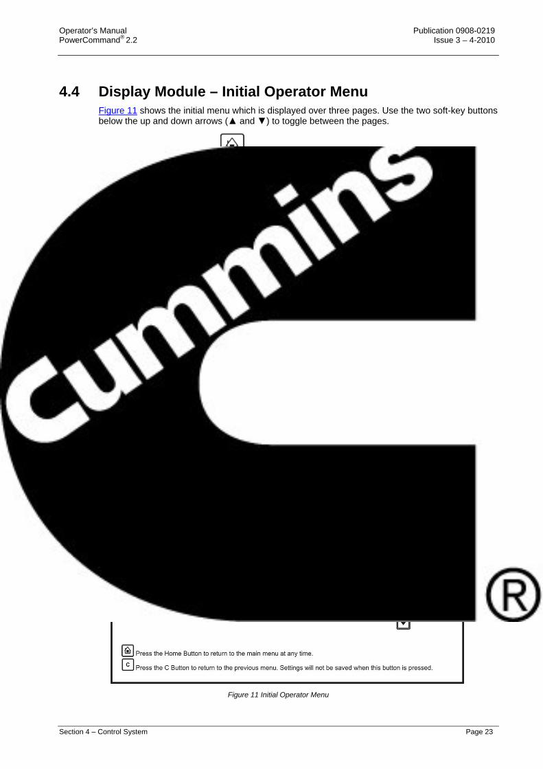
4.4 Display Module – Initial Operator Menu Figure 11 shows the initial menu which is displayed over three pages. Use the two soft-key buttons below the up and down arrows (▲ and ▼) to toggle between the pages.
Pressing the Home button from any screen will return the display to the main menu screens.
Figure 11 Initial Operator Menu
Publication 0908-0219 Operator’s Manual Issue 3 – 4-2010 PowerCommand® 2.2
Page 24 Section 4 – Control System
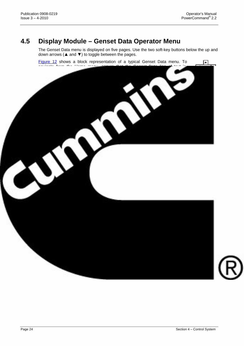
4.5 Display Module – Genset Data Operator Menu The Genset Data menu is displayed on five pages. Use the two soft-key buttons below the up and down arrows (▲ and ▼) to toggle between the pages.
Figure 12 shows a block representation of a typical Genset Data menu. To navigate from the Home menu, ensure that the Genset Data line of text is highlighted, and press the OK button.
4.5.1 Generator Data Use this menu to look at the status of the generator set.
NAME DESCRIPTION
Avg Voltage Genset Line-to-Line average voltage. Avg Current Genset average current. Total kW Genset total kW. Total PF Genset power factor. Frequency Genset frequency. Coolant Temp Monitor point for the Coolant Temperature. Engine Hrs Total engine run time. Oil Pressure Monitor point for the Oil Pressure.
Allowed values: 0~145 psi. Batt Voltage Battery voltage value. % Torq/Duty Monitor point for the percent engine torque output and the governor
percent duty cycle output when used with the HM ECM. Allowed values: -125~125%.
Fuel Rate Monitor point for Fuel Rate. Allowed values: 0~845 gal/hr.
Fuel Cons. Fuel consumption since last reset. Total Fuel C. Total fuel consumption since start of engine. Genset Application Rating kW rating The genset kW rating. kVA Rating The genset kVA Rating. Rated Current The value of the genset application nominal current. Genset Standby Rating kW rating kW rating for the genset in Standby configuration. kVA Rating kVA rating for the genset in Standby configuration. Rated Current The value of the genset Standby nominal current.

Operator’s Manual Publication 0908-0219 PowerCommand® 2.2 Issue 3 – 4-2010
Section 4 – Control System Page 25
Figure 12 Genset Data Menu – Typical Data

Publication 0908-0219 Operator’s Manual Issue 3 – 4-2010 PowerCommand® 2.2
Page 26 Section 4 – Control System
4.6 Display Module – Engine Data Operator Menu The Engine Data menu is displayed on three pages. Use the two soft-key buttons below the up and down arrows (▲ and ▼) to toggle between the pages.
Figure 13 shows a block representation of a typical Engine Data menu. To navigate from the Home menu, toggle down until the Engine Data line of text is highlighted, and press the OK button.
4.6.1 Engine Data Use this menu to look at the status of the engine.
NAME DESCRIPTION
Engine Hours Total engine run time. Coolant Temp Monitor point for the Coolant Temperature. Engine Speed Monitor point for the Average Engine Speed. Batt Voltage Battery voltage value. Oil pressure Monitor point for the Oil Pressure.
Allowed values: 0~145 psi Oil Temp Monitor point for the Oil Temperature.
Allowed values: -40~410oF Manf Temp Monitor point for the Intake Manifold Temperature
Allowed values: -40~410oF Boost Pres Monitor point for the Boost Absolute Pressure.
Allowed values: 0~148 psi. Rail Press Abs Monitor point for the Fuel Outlet Pressure.
Allowed values: 0~36404 psi. Fuel Inlet Temp Monitor point for the Fuel Temperature.
Allowed values: -40~410oF Coolant Press Monitor point for the Coolant Pressure.
Allowed values: 0~145 psi. Pump Press Abs Monitor point for the Fuel Supply Pressure.
Allowed values: 0~145 psi. Crank Press Monitor point for the Crankcase Pressure.
Allowed values: -35.67~38 psi. Aftercooler Temp Monitor point for the Aftercooler Temperature.
Allowed values: -40~410oF Ambient Press Monitor point for the Barometric Absolute Pressure.
Allowed values: 0~37 psi.

Operator’s Manual Publication 0908-0219 PowerCommand® 2.2 Issue 3 – 4-2010
Section 4 – Control System Page 27
Figure 13 Engine Data Menu – Typical Data

Publication 0908-0219 Operator’s Manual Issue 3 – 4-2010 PowerCommand® 2.2
Page 28 Section 4 – Control System
4.7 Display Module – Alternator Data Operator Menu The Alternator Data menu is displayed on three pages. Use the two soft-key buttons below the up and down arrows (▲ and ▼) to toggle between the pages.
Figure 14 shows a block representation of a typical Alternator Data menu. To navigate from the Home menu, toggle down until the Alternator Data line of text is highlighted, and press the OK button.
4.7.1 Alternator Data Use this menu to look at the status of the alternator. This menu displays line-to-line voltage, line-to-neutral voltage, current, and generator set power (in kVA). Some values are not available, dependent on the number of phases (one or three) and whether or not the application has current transformers.
NAME DESCRIPTION
L1 L2 L3
Alternator terminals.
LL(Vac) Genset L1L2 voltage. Genset L2L3 voltage. Genset L3L1 voltage.
LN(Vac) Genset L1N voltage. Genset L2N voltage. Genset L3N voltage.
Amps Monitors the genset L1 current value. Genset L2 current value. Genset L3 current value.
kW Genset L1 kW. Genset L2 kW. Genset L3 kW.
kVA Genset L1 kVA. Genset L2 kVA. Genset L3 kVA.
PF Genset L1 power factor. Genset L2 power factor. Genset L3 power factor.
Total kW Genset total kW. Total kVA Genset total kVA. Total PF Genset power factor. Frequency Genset frequency. AVR Duty Cycle The AVR PWM software command. Linear relationship between counts
and % duty cycle with 10000 counts = 100% duty cycle.

Operator’s Manual Publication 0908-0219 PowerCommand® 2.2 Issue 3 – 4-2010
Section 4 – Control System Page 29
Figure 14 Alternator Data Menu – Typical Data

Publication 0908-0219 Operator’s Manual Issue 3 – 4-2010 PowerCommand® 2.2
Page 30 Section 4 – Control System
4.8 Display Module –Faults and Warnings Menus The Faults and Warning menu is divided into three main sub-sections; Shutdown Faults (Active Shutdowns); Warning Faults (Active Warnings); and Faults History (showing up to thirty-two faults that have been cleared).
4.8.1 Shutdown Fault Menu This screen displays up to five faults. The same event/fault code may appear multiple times if detected by different sources.
NAME DESCRIPTION
Fit # This is the Fault code. SA This is the controller that identified the fault. It is blank if the PC2.2
identified the fault. Gen Response This is the type of fault (Shutdown or Warning) that was generated. Engine Hours This is how many hours the engine had run (not necessarily continuously)
when the fault was generated. mm/dd/yy This is the date the fault was generated. Hh/mm/ss This is the time the fault was generated.
Figure 15 shows a block representation of a typical Shutdown Fault menu.
To navigate from the Home menu, toggle down until the Faults line of text is highlighted, and press the OK button.
With the Shutdown Fault line of text highlighted press the OK button. This will display information regarding the Shutdown fault(s). Use the two soft-key buttons below the up and down arrows (▲ and ▼) to toggle between the pages.

Operator’s Manual Publication 0908-0219 PowerCommand® 2.2 Issue 3 – 4-2010
Section 4 – Control System Page 31
Figure 15 Shutdown Faults menu – Typical Data

Publication 0908-0219 Operator’s Manual Issue 3 – 4-2010 PowerCommand® 2.2
Page 32 Section 4 – Control System
4.8.2 Warning Fault Menu This menu displays up to thirty-two faults. The same event/fault code may appear multiple times if detected by different sources.
NAME DESCRIPTION
Fit # This is the Fault code. SA This is the controller that identified the fault. It is blank if the PC2.2
identified the fault. Gen Response This is the type of fault (Shutdown or Warning) that was generated. Engine Hours This is how many hours the engine had run (not necessarily continuously)
when the fault was generated. mm/dd/yy This is the date the fault was generated. Hh/mm/ss This is the time the fault was generated.
Figure 16 shows a block representation of a typical Warning Fault menu.
To navigate from the Home menu, toggle down until the Faults line of text is highlighted, and press the OK button.
Toggle down again until the Warning Faults text is highlighted.
With the Warning Fault line of text highlighted press the OK button. This will then display information regarding the current fault. Use the two soft-key buttons below the up and down arrows (▲ and ▼) to toggle between the pages.

Operator’s Manual Publication 0908-0219 PowerCommand® 2.2 Issue 3 – 4-2010
Section 4 – Control System Page 33
Figure 16 Warning Fault Menu – Typical Data

Publication 0908-0219 Operator’s Manual Issue 3 – 4-2010 PowerCommand® 2.2
Page 34 Section 4 – Control System
4.8.3 Faults History Data Operator Menu This menu displays up to thirty-two faults. The same event/fault code may appear multiple times if detected by different sources.
NAME DESCRIPTION
Fit # This is the Fault code. SA This is the controller that identified the fault. It is blank if the PC2.2
identified the fault. Engine Hours This is how many hours the engine had run (not necessarily continuously)
when the fault was generated. mm/dd/yy This is the date the fault was generated. Hh/mm/ss This is the time the fault was generated.
Figure 17 shows a block representation of a typical Fault History menu.
To navigate from the Home menu, toggle down until the Faults line of text is highlighted, and press the OK button.
Toggle down again until the Fault History text is highlighted.
With the Fault History line of text highlighted press the OK button. This will then display information regarding the fault(s) history. Use the two soft-key buttons below the up and down arrows (▲ and ▼) to toggle between the pages.

Operator’s Manual Publication 0908-0219 PowerCommand® 2.2 Issue 3 – 4-2010
Section 4 – Control System Page 35
Figure 17 History Fault Menu – Typical Data

Publication 0908-0219 Operator’s Manual Issue 3 – 4-2010 PowerCommand® 2.2
Page 36 Section 4 – Control System
4.9 Display Module – Genset Setup Data Operator Menu Figures 18, 19 and 20 show block representations of the Genset Setup Data menu.
Page down to the second page of the Home menu (using the two soft-key buttons below the up and down arrows [▲ and ▼]). See Section 4.4.
With the Setup line of text highlighted, press the OK button. This will display the Setup Menu (1/2).
Page down to the second page of the Setup menu (using the two soft-key buttons below the up and down arrows [▲ and ▼]).
Toggle down again until the Genset Setup text is highlighted.
With the Genset Setup line of text highlighted, press the OK button. This will display the Setup/Genset Data Menu (1/19).
Use the two soft-key buttons below the up and down arrows [▲ and ▼]) to page through the nineteen pages of the generator setup data.

Operator’s Manual Publication 0908-0219 PowerCommand® 2.2 Issue 3 – 4-2010
Section 4 – Control System Page 37
Figure 18 Setup Data Menu Sheet 1 of 3 – Typical Data

Publication 0908-0219 Operator’s Manual Issue 3 – 4-2010 PowerCommand® 2.2
Page 38 Section 4 – Control System
Figure 19 Setup Data Menu Sheet 2 of 3 – Typical Data

Operator’s Manual Publication 0908-0219 PowerCommand® 2.2 Issue 3 – 4-2010
Section 4 – Control System Page 39
Figure 20 Data Menu Sheet 3 of 3 – Typical Data

Publication 0908-0219 Operator’s Manual Issue 3 – 4-2010 PowerCommand® 2.2
Page 40 Section 4 – Control System
4.10 Selecting Operating Modes
4.10.1 Entering the Mode Change Access Code The Mode Change submenus are intended for qualified service personnel and site personnel only, and by default will require an Access password. If a password is required the Mode Change – Access Code menu will appear when you try to switch between Auto, Manual Run, or Stop modes.
To enter the mode access code:
1. With the first character highlighted, press the up and down arrow buttons until the required value is displayed.
2. Press the left arrow button to move to the next numeric character.
3. Repeat steps 1 and 2 until all characters of the Access Code are correct.
4. After you have completed entering the password, press the OK button.
Note: If an incorrect password is entered, the Operator menu that was displayed before Auto, Manual Run, or Stop mode was selected is re-displayed.
4.10.1.1 Passwords It is possible for the Operator to view every parameter in the graphical display, however a password may be required before adjustment of a parameter is permitted. The generator set will prompt you if a password is required, and inform you of the level of password required.
LEVEL DESCRIPTION COMMENT
0 No password None required
1 Operator password Restricted
2 Service password Restricted
3 Engineering password Restricted

Operator’s Manual Publication 0908-0219 PowerCommand® 2.2 Issue 3 – 4-2010
Section 4 – Control System Page 41
4.10.2 Selecting Manual Run Mode WARNING: WHEN CHANGING MODES, THE GENERATOR SET MAY START OR STOP
WITHOUT WARNING. ENSURE THERE IS NO DANGER TO PERSONNEL OR EQUIPMENT SHOULD THE GENERATOR SET START OR STOP WHEN CHANGING MODES.
Caution: Ensure that it is safe to do so before proceeding to change the mode.
Press the Manual button and then the Start button (within ten seconds).This will bypass the Time Delay to Start; activate the engine control system and the starting system.
If the engine does not start, the starter will disengage after a specified period of time, and the control will indicate a Fail to Start shutdown.
The generator set can be configured for one to seven starting cycles with set times for crank and rest periods for all starting modes (manual/remote). The default setting is for three start cycles, composed of fifteen seconds of cranking and thirty seconds of rest.
Note: The InPower service tool or access to the Setup menu is required to change the cycle number, and the crank and rest times. Contact an authorised service centre for assistance.
To clear a Fail to Start shutdown, press the Stop button and then press the
Reset button.
Before attempting to restart, wait two minutes for the starter motor to cool and then repeat the starting procedure. If the engine does not run after a second attempt, refer to the Troubleshooting section.

Publication 0908-0219 Operator’s Manual Issue 3 – 4-2010 PowerCommand® 2.2
Page 42 Section 4 – Control System
4.10.3 Selecting Auto Mode WARNING: WHEN CHANGING MODES, THE GENERATOR SET MAY START OR STOP
WITHOUT WARNING. ENSURE THERE IS NO DANGER TO PERSONNEL OR EQUIPMENT SHOULD THE GENERATOR SET START OR STOP WHEN CHANGING MODES.
Caution: Ensure that it is safe to do so before proceeding to change the mode.
Press the Auto button. This allows the generator set to be started from a remote switch or device (e.g. transfer switch).
In response to the Remote Start, the control lights the Remote Start indicator and initiates the starting sequence as shown in Figure 21. This start will incorporate the Time Delay to Start function.
Note: The InPower service tool or access to the Setup menu is required to change the cycle number, and the crank and rest times. Contact an authorised service centre for assistance.
WARNING: SHOULD A REMOTE START SIGNAL BE RECEIVED, THE GENERATOR SET WILL START AUTOMATICALLY. ENSURE THERE IS NO DANGER TO PERSONNEL OR EQUIPMENT SHOULD THE GENERATOR SET START WITHOUT WARNING.
Figure 21 Starting in Auto Mode
Operator’s Manual Publication 0908-0219 PowerCommand® 2.2 Issue 3 – 4-2010
Section 4 – Control System Page 43
4.10.4 Selecting Off Mode WARNING: WHEN CHANGING MODES, THE GENERATOR SET MAY STOP WITHOUT
WARNING. ENSURE THERE IS NO DANGER TO PERSONNEL OR EQUIPMENT SHOULD THE GENERATOR SET STOP WHEN CHANGING MODES.
Caution: Ensure that there is no danger to personnel or equipment if the generator set is stopped.
Press the Stop button to put the generator set into the Off mode. This will disable Auto and Manual modes.
If the generator set is running, in either Manual or Auto mode, and the Stop button is pressed, the engine will shut down. This action may include a Cooldown run. Refer to Section 5.7.
Note: If possible, hot shutdown under load should be avoided to help prolong the reliability of the generator set.

Publication 0908-0219 Operator’s Manual Issue 3 – 4-2010 PowerCommand® 2.2
Page 44 Section 4 – Control System
This Page Has Been Left Intentionally Blank

Operator’s Manual Publication 0908-0219 PowerCommand® 2.2 Issue 3 – 4-2010
Section 5 – System Operation Page 45
SECTION 5 – SYSTEM OPERATION
5. Operation 5.1 Safety
Personnel must be suitably qualified and experienced before operating a generator set. Before operating the system, the operator must become familiar with Section 1 of this manual – Preliminary and Safety Instructions, together with the Health and Safety Manual (0908-0110). Observe all of the WARNINGS and CAUTIONS at all times.
WARNING: BEFORE OPERATING THE PLANT BECOME FAMILIAR WITH THE EQUIPMENT AND HOW IT IS OPERATED (INCLUDING ALL CONTROLS, MANUALLY OPERATED VALVES AND ALARM DEVICES). SAFE AND EFFICIENT OPERATION CAN ONLY BE ACHIEVED IF THE PLANT IS OPERATED CORRECTLY.
WARNING: CONTACTING HIGH VOLTAGE COMPONENTS CAN CAUSE SEVERE PERSONAL INJURY OR DEATH BY ELECTROCUTION. DO NOT OPEN THE GENERATOR OUTPUT BOX WHILE THE GENERATOR SET IS RUNNING. READ AND OBSERVE ALL WARNINGS AND CAUTIONS IN YOUR GENERATOR SET MANUALS.
Caution: Personnel must be technically qualified before opening the control housing. Voltages are present which can cause electrical shock, resulting in personal injury. Even with the power removed, improper handling of components can cause electrostatic discharge and damage circuit board components.
5.2 Introduction This section describes the operation of the generator set. The text must be read in conjunction with Section 3 – the System Overview, and Section 4 – the Control System sections of this manual, together with the Operator’s specific engine manual supplied as part of the documentation pack. This latter manual will contain further information regarding the running and care of the generator set and also specific equipment instructions that may differ from the standard generator set.
All indicators, control switches/buttons, and graphical display are located on the face of the Control Panel as illustrated in Figure 9.
5.3 Maintenance To ensure maximum performance and reliability from your generator set it is essential that certain components are inspected periodically and, where necessary, maintenance procedures carried out as detailed in Section 6 – Maintenance.

Publication 0908-0219 Operator’s Manual Issue 3 – 4-2010 PowerCommand® 2.2
Page 46 Section 5 –System Operation
5.4 Operating Recommendations
5.4.1 Running –in Special ‘running-in’ oils are not recommended for new or rebuilt Cummins’ engines. Use the same type of oil during ‘running-in’ as is used in normal operation.
5.4.2 No Load Operation Periods of off-load operation must be held to a minimum. If it is necessary to keep the engine running for long periods of time when no electric output is required, best engine performance will be obtained by connecting a load of at least 30% rated load, but not to exceed rated load. Such a load could consist of heater element or load bank.
5.4.3 Exercise Period Generator sets on continuous standby must be able to go from a cold start to being fully operational in a matter of seconds. This can impose a severe burden on engine parts.
Regular exercising keeps engine parts lubricated, prevents oxidation of electrical contacts, and in general helps provide reliable engine starting.
Exercise the set for a minimum of ten minutes off-load at least once a week and for a minimum of 30 minutes with load at least once each month so the engine reaches normal operating temperatures.
5.4.4 Low Operating Temperatures Use a coolant heater if a separate source of power is available. The optional heater available from Cummins Power Generation Limited will help provide reliable starting under adverse weather conditions. Be sure the voltage of the separate power source is correct for the heater element rating.
5.4.5 High Operating Temperatures Refer to the generator set nameplate for the maximum operating temperature, if applicable.

Operator’s Manual Publication 0908-0219 PowerCommand® 2.2 Issue 3 – 4-2010
Section 5 – System Operation Page 47
5.4.6 Operating Conditions for Prime, Standby and Continuous Power Ratings Note: All generator sets supplied by Cummins Power Generation Limited must be run
under the following operating conditions, and in accordance with the operating information contained within the manuals’ documentation package supplied with each generator set.
5.4.6.1 Continuous Power rating (COP) for constant load applications The Continuous Power Rating is applicable to utility parallel and other non-variable load applications for supplying power continuously to a load of up to 100% of the continuous rating for an unlimited number of hours per year between the stated maintenance intervals and under stated ambient conditions. All maintenance must be carried out as prescribed in the generator set operating manuals. No sustained overload capability is available at this rating. This rating is applicable for utility base load operation. In these applications, generator sets are operated in parallel with a utility source and run under constant loads for extended periods of time.
5.4.6.2 Prime power rating The prime power rating is the maximum power available during a variable load sequence which may be run for an unlimited number of hours per year, between the stated maintenance intervals and under the stated ambient conditions. All maintenance must be carried out as prescribed in the generator set operating manuals. Prime power applications fall into one of the following two categories: • Unlimited time prime power (for variable load applications)
Prime power is available for an unlimited number of annual operating hours in variable load applications. The permissible average power output under variable load shall not exceed a 70% average of the prime power rating during any operation of 250 hours. The total operating time at 100% prime power shall not exceed 500 hours per year. A 10% overload capability is available for a period of 1 hour within a 12-hour period of operation, in accordance with ISO 3046-3:2006. Total operating time at the 10% overload power shall not exceed 25 hours per year.
• Limited running time prime power (for constant load applications)
Prime power is available for a limited number of hours in a non-variable load application. It is intended for use in situations where power outages are contracted, such as utility power curtailment. Generators may be operated in parallel with the public utility up to 750 hours per year at power levels never to exceed the prime power rating. No sustained overload capability is available at this rating. The customer should be aware, however, that the life of any generator will be reduced by constant high load operation. Any operation exceeding 750 hours per year at the prime power rating should use the Continuous Power Rating.
Publication 0908-0219 Operator’s Manual Issue 3 – 4-2010 PowerCommand® 2.2
Page 48 Section 5 –System Operation
5.4.6.3 Standby power rating (for variable load applications) The standby power rating is applicable for supplying emergency power for the duration of a utility power interruption, between the stated maintenance intervals and under the stated ambient conditions. All maintenance must be carried out as prescribed in the generator set operating manuals. No overload capability is available for this rating and utility parallel operation is not permitted at the standby power rating. For applications requiring sustained utility parallel operation the limited time prime power rating or continuous power rating must be utilised as applicable.
This rating is applicable to installations served by a reliable normal utility source. Generators should be sized for a maximum average load factor of 80% of the standby power rating with a maximum of 200 hours of operation per year, which includes less than 25 hours per year at the standby power rating. In installations served by unreliable utility sources (where outages last longer or occur more frequently), where operation is likely to exceed 200 hours per year, the prime power rating should be applied. The standby rating is only applicable for emergency and standby applications where the generator set serves as the back up to the normal utility source. Negotiated power outages are not considered as emergencies.
5.4.6.4 Notes applicable to all ratings The following notes are applicable to all ratings, unless otherwise agreed by the Regional Sales Manager of Cummins Power Generation Limited in writing: • When determining the actual average power output of a variable power sequence in any of
the ratings above, powers of less than 30% of the emergency standby power shall be taken as 30% and time at standstill shall not be counted.
• Variable load is calculated in accordance with methods and formulae given in ISO 8528-1-2005.
• All three-phase generators are rated for 0.8 power factor lag. Single-phase generators are rated for 1.0 power factor.
• All ratings are based on the following reference conditions:
a) Ambient temperature — 27°C (80oF)
b) Altitude above sea level — 150 metres
c) Relative humidity — 60%
d) Output power may be subject to de-rate if the above conditions are exceeded • If any of the above conditions are not satisfied, the operational life of the generating set may
be reduced. • Short term parallel operation with the utility for load transfer purposes only is permitted with all
ratings.
5.4.7 De-Rating Factors For de-rating factors applicable at specific sites please contact your authorised distributor.
Operator’s Manual Publication 0908-0219 PowerCommand® 2.2 Issue 3 – 4-2010
Section 5 – System Operation Page 49
5.5 Generator Set Operation Correct care of your engine will result in longer life, better performance, and more economical operation.
WARNING: DO NOT OPERATE A DIESEL ENGINE WHERE THERE ARE, OR CAN BE, COMBUSTIBLE VAPOURS. THESE VAPOURS CAN BE SUCKED THROUGH THE AIR INTAKE SYSTEM AND CAUSE ENGINE ACCELERATION AND OVERSPEEDING, WHICH CAN RESULT IN A FIRE, AN EXPLOSION, AND EXTENSIVE PROPERTY DAMAGE. NUMEROUS SAFETY DEVICES ARE AVAILABLE, SUCH AS AIR INTAKE SHUTOFF DEVICES, TO MINIMIZE THE RISK OF OVERSPEEDING IN WHICH AN ENGINE, BECAUSE OF APPLICATION, MIGHT OPERATE IN A COMBUSTIBLE ENVIRONMENT (FROM A FUEL SPILL OR GAS LEAK, FOR EXAMPLE). CUMMINS ENGINE COMPANY, INC. DOES NOT KNOW HOW YOU WILL USE YOUR ENGINE. THE EQUIPMENT OWNER AND OPERATOR, THEREFORE, IS RESPONSIBLE FOR SAFE OPERATION IN A HOSTILE ENVIRONMENT. CONSULT YOUR CUMMINS AUTHORISED DISTRIBUTOR FOR FURTHER INFORMATION.
Note: Cummins Power Generation Limited recommends the installation of an air intake shutoff device or a similar safety device to minimise the risk of overspeeding where an engine will be operated in a combustible environment.
Publication 0908-0219 Operator’s Manual Issue 3 – 4-2010 PowerCommand® 2.2
Page 50 Section 5 –System Operation
Caution: Do not idle the engine for excessively long periods. Long periods of idling (more than ten minutes) can damage an engine because combustion chamber temperatures drop so low the fuel will not burn completely. This will cause carbon to clog the injector spray holes and piston rings, and can cause the valves to stick. If the engine coolant temperature becomes too low (60°C [140°F]), raw fuel will wash the lubricating oil off the cylinder walls and dilute the crankcase oil. This will result in the moving parts of the engine not receiving the correct quality of lubrication.
5.5.1 Sequence of Operation The generator set is run Automatically using a Remote Start signal, or Manually using the generator set control panel buttons. LEDs are provided on the display module front panel to indicate the operating run mode of the generator set. The PowerCommand®2.2 initiates a starter cranking signal and will perform an automatically sequenced manual start, under a complete engine protection system combined with full monitoring capability. If a fault is sensed at Start-up, the engine is locked out and will not start.
The choice of Auto or Manual run mode is decided by authorised personnel during the generator set initial setup. An access code is required to switch between the Auto, Manual, or Stop modes, and this facility may be permitted or denied by the authorised personnel during the initial setup of the generator set.

Operator’s Manual Publication 0908-0219 PowerCommand® 2.2 Issue 3 – 4-2010
Section 5 – System Operation Page 51
5.6 Starting Caution: One operator must be in complete charge, or working under the direction of
someone who is. Remember that, upon starting the engine, cables and switchgear will become energised, possibly for the first time. Furthermore, equipment that does not form part of the generator set installation may become electrically charged. Ensure that only authorised and competent personnel carry out this work.
Caution: Do not use the Emergency Stop switch to shut down an engine unless a serious fault develops. The Emergency Stop push-switch must not be used for a normal shut-down as this will prevent a cooling down run in which the lubricating oil and engine coolant carry the heat away from the engine combustion chamber and bearings in a safe manner.
Caution: Avoid off-load running for other than short periods. A minimum loading of 30% is recommended. This loading will help to prevent the build up of carbon deposits in the injectors, due to unburnt fuel, and reduce the risk of fuel dilution of the engine lubricating oil. The engine must be shut down as soon as possible after the appropriate functions have been checked.
Before attempting to start the generator set, the operator must read through this entire manual, together with the Health and Safety manual and the specific engine manual provided as part of the documentation pack supplied with the generator set. It is essential that the operator be completely familiar with the generator set and the PowerCommand®2.2 control.
The following sub-sections cover the systems used to start and stop the generator set.
Before starting the generator set, make sure that exhaust and fuel fittings are tight and properly positioned, and that proper maintenance and pre-start checks have been performed.
During starting, automatic checks are carried out for the integrity of various protection systems. The PowerCommand®2.2 will not allow the generator set to continue the starting sequence if the integrity of a sensor is considered to be in doubt.
The generator set can be configured for a number of starting cycles (one to seven) with set times for crank and rest periods for all starting modes (manual/remote). The default setting is for three start cycles, composed of fifteen seconds of cranking and thirty seconds of rest.
Note: The number of starting cycles, and the crank and rest times are set from within the Setup menu. Qualified service personnel are required to change the default setting. Contact your authorised distributor.

Publication 0908-0219 Operator’s Manual Issue 3 – 4-2010 PowerCommand® 2.2
Page 52 Section 5 –System Operation
5.6.1 Initial Pre-Start Checks WARNING: VOLTAGE PRESENTS SPECIAL HAZARDS OF SEVERE PERSONAL INJURY
OR DEATH. EVEN AFTER GENERATOR SET SHUTDOWN AN ELECTRICAL SHOCK HAZARD MAY STILL EXIST, CAUSED BY INDUCED OR RESIDUAL VOLTAGE WITHIN THE ALTERNATOR OR CABLES. SERVICE PERSONNEL MUST BE WELL TRAINED/QUALIFIED TO WORK WITH DISTRIBUTION VOLTAGES.
Before starting, be sure competent personnel have made the following checks to ensure that the unit is ready for operation: • Generator Set Grounding Procedure – This must be followed prior to performing service or
inspection procedures that may expose personnel to conductors normally energized with voltages greater than 600 volts. Contact your authorised distributor.
• Megger and Insulation Testing – This must be performed on all generator sets before initial start-up and after the generator set Grounding Procedure has been completed. Insulation testing for low voltage (less than 600 volts) generator sets is recommended by Cummins Power Generation Limited. These tests are used to verify that the windings are dry before the generator set is operated, and to develop a base line for future test comparisons. Contact your authorised distributor.
Caution: When Megger testing an alternator, failure to protect the voltage regulator, control, and diodes could result in permanent damage to one or more of the electronic components.
• Lubrication - Check the engine lubrication oil level and ensure that the correct level is always maintained.
Note: Generator sets may be shipped dry. They must be filled with the correct type and quantity of oil before use. Be sure to check oil level before initial start.
• Coolant - Check the engine coolant level and ensure that the level is always maintained at the coolant expansion tank. Fill the cooling system to the bottom of the fill neck in the radiator fill or expansion tank. Do not check while the engine is hot.
Note: Generator sets may be shipped dry. They must be filled with the correct type and quantity of coolant before use. Be sure to check coolant level(s) before initial start.
Caution: It is essential that Cummins Power Generation Limited’s recommendations for the correct type and concentration of anti-freeze and DCA inhibitor are complied with. Warranty claims for damage will be rejected if the incorrect mix has been used. Consult your authorised distributor for the correct anti-freeze specifications and concentration for your operating conditions.
Note: Some radiators have two fill necks, both of which must be filled when the cooling system has been drained.
Caution: Do not attempt to remove a radiator pressure cap while the generator is running, or is stationary but hot. Always allow it to cool before removing the cap.

Operator’s Manual Publication 0908-0219 PowerCommand® 2.2 Issue 3 – 4-2010
Section 5 – System Operation Page 53
5.6.2 Operator’s Pre-Start Checks WARNINGS: WINDINGS OF HIGH VOLTAGE, 601 TO 15,000 VOLTS, GENERATOR SETS
MUST BE DRY BEFORE THE GENERATOR SET IS OPERATED. FAILURE TO ENSURE DRY WINDINGS BEFORE START-UP MAY RESULT IN CATASTROPHIC FAILURE, SEVERE PERSONAL INJURY OR DEATH.
Before starting, be sure competent personnel have made the following checks to ensure that the unit is ready for operation: • Fuel Supply - Ensure that the fuel tank is filled to the normal level and that the fuel system is
primed and all the valves required for operation are open. Ensure that there are no leaks and that all fittings are tight.
• Lubrication - Check the engine lubrication oil level and ensure that the correct level is always maintained.
• Coolant - Check the engine coolant level and ensure that the level is always maintained at the coolant expansion tank. Fill the cooling system to the bottom of the fill neck in the radiator fill or expansion tank. Do not check while the engine is hot.
Note: Some radiators have two fill necks, both of which must be filled when the cooling system has been drained.
Caution: Do not attempt to remove a radiator pressure cap while the generator is running, or is stationary but hot. Always allow it to cool before removing the cap.
• Cooling Air Inlet/Outlets - Ensure that the cooling air inlets/outlets are unobstructed. • Exhaust Outlet - Ensure that exhaust components are secured and not warped; that the
exhaust outlet is unobstructed; that no combustible materials are near the system, and gases are discharged away from building openings. Ensure that there are no leaks and that all fittings are tight.
• Batteries – Ensure that the batteries are charged, that the electrolyte is at the correct level and that all connections are correct.
• Auxiliary AC Supplies - Ensure that all auxiliary equipment is receiving power from the customer’s supply.
• Emergency Stop/Fire Detection Equipment - Ensure that all related equipment is fully operational.

Publication 0908-0219 Operator’s Manual Issue 3 – 4-2010 PowerCommand® 2.2
Page 54 Section 5 –System Operation
5.6.3 Starting at Display Panel (Manual Run Mode) WARNING: ENSURE THAT ALL PRE-START CHECKS ARE CARRIED OUT BEFORE
STARTING THE GENERATOR SET. DO NOT ATTEMPT TO START THE GENERATOR UNTIL IT IS SAFE TO DO SO. WARN ALL OTHERS IN THE VICINITY THAT THE SET IS ABOUT TO START.
To start the generator set in the Manual Run mode, press the Manual button on the display
module front panel, and then press the Start button within ten seconds. Failure to press the Start button within this time will result in the generator set changing to the Off mode. (Refer also to Section 4.10.2)
Note: If the mode change access code feature has been enabled, enter the access code when prompted. (See Section 4.10.1).
The PowerCommand®2.2 will initiate a starter cranking signal and will perform an automatically sequenced manual start, under a complete engine protection system combined with full monitoring capability. This will activate the engine control system and the starting procedure. The starter will begin cranking, and after a few seconds the engine will start and the starter will disconnect.
Should the engine fail to start, the starter will disengage after a specified period of time and the control will indicate a Fail to Start shutdown.
To clear a Fail to Start shutdown, press the Stop button and then press the
Reset button. Before attempting to re-start wait a minimum of two minutes for the starter motor to cool and then repeat the starting procedure. If the engine does not run after a second attempt, refer to Section 7 – Troubleshooting.
To disable Manual mode, change to Auto or Stop mode. If the generator set is running when it leaves Manual mode, it will continue to run if Auto mode has been selected and the remote start signal is active. If there is no active remote start signal, the generator set will stop.

Operator’s Manual Publication 0908-0219 PowerCommand® 2.2 Issue 3 – 4-2010
Section 5 – System Operation Page 55
5.6.4 Starting from Remote Location (Auto Mode) WARNING: ENSURE THAT ALL PRE-START CHECKS ARE CARRIED OUT BEFORE
STARTING THE GENERATOR SET. DO NOT ATTEMPT TO START THE GENERATOR UNTIL IT IS SAFE TO DO SO. WARN ALL OTHERS IN THE VICINITY THAT THE SET IS ABOUT TO START.
To start the generator set in the Auto Run mode, select the Auto button from the display module front panel. (Refer also to Section 4.10.3).
Only on receipt of a remote start signal, and after a Time Delay to Start, will the PowerCommand®2.2 initiate the starting sequence as above.
The Remote Start LED will be lit.
Note: If the mode change access code feature has been enabled, enter the access code when prompted. (See Section 4.10.1).
To disable Auto mode, change to Manual or Stop mode.
5.6.5 Cold Starting with Loads WARNING: ENSURE THAT ALL PRE-START CHECKS ARE CARRIED OUT BEFORE
STARTING THE GENERATOR SET. DO NOT ATTEMPT TO START THE GENERATOR UNTIL IT IS SAFE TO DO SO. WARN ALL OTHERS IN THE VICINITY THAT THE SET IS ABOUT TO START.
Use a coolant heater if a separate source of power is available. The optional heater available from Cummins Power Generation Limited will help provide reliable starting under adverse weather conditions. Be sure the voltage of the separate power source is correct for the heater element rating.
Cummins Power Generation Limited recommends equipping diesel standby generator sets (life safety systems) with engine water jacket coolant heaters to maintain the coolant at a minimum of 32°C (90°F) and, for most applications, accept the emergency load in ten seconds or less. Although most Cummins Power Generation Limited generator sets will start in temperatures down to -32°C (-25°F) when equipped with engine water jacket coolant heaters, it might take more than ten seconds to warm the engine up before a load can be applied when ambient temperatures are below 4°C (40°F).
To advise the Operator of a possible delay in accepting the load, the Low Coolant Temp (code 1435) message, in conjunction with illumination of the Warning LED, is provided. The engine cold sensing logic initiates a warning when the engine water jacket coolant temperature falls below 21°C (70°F). In applications where the ambient temperature falls below 4°C (40°F), a cold engine may be indicated even though the coolant heaters are connected and functioning correctly. Under these conditions, although the generator set may start, it may not be able to accept load within ten seconds. When this condition occurs, check the coolant heaters for correct operation. If the coolant heaters are operating correctly, other precautions may be necessary to warm the engine before applying a load.
Publication 0908-0219 Operator’s Manual Issue 3 – 4-2010 PowerCommand® 2.2
Page 56 Section 5 –System Operation
5.7 Stopping Note: The access code may be required before initiating the Stop button sequence to put
the generator set into the Off mode. Refer to Section 4.10.1.
Caution: Run the generator set at no load for three to five minutes before stopping. This allows the lubricating oil and engine coolant to carry heat away from the combustion chamber and bearings.
5.7.1 Stopping at Display Panel (Manual Mode) If the generator set was started at the control panel in Manual mode, press the
Stop button once to put the generator set into a Cooldown run after which the set will enter the Off mode.
Pressing the Stop button twice will stop the generator set immediately, without a Cooldown run, after which the set will enter the Off mode.
Note: If possible, hot shutdown under load should be avoided to help prolong the reliability of the set. A hot shutdown may result in a Hot Shutdown Warning.
5.7.2 Stopping from Display Panel (Auto Mode)
If the generator set was started in Auto mode, press the Stop button once to stop the generator set immediately after which the set will enter the Off mode.
Note: If possible, hot shutdown under load should be avoided to help prolong the reliability of the set. A hot shutdown may result in a Hot Shutdown Warning.
5.7.3 Stopping from Remote Location (Auto Mode) If the control receives a remote stop signal, the generator set completes its normal shutdown sequence incorporating a Cooldown run (Refer to Figure 21). (The remote stop signal is actually the removal of the remote start signal to the control).
The generator set stops after completing the Time Delay to Stop function (zero to 600 seconds).
The set will remain in the Auto mode, and subject to a remote start signal, unless the Stop button is pressed. If this button is pressed the set will enter the Off mode.
Note: The InPower service tool or access to the Setup menus is required to enable and change the time delay start/stop settings. Contact an authorised service centre for assistance.

Operator’s Manual Publication 0908-0219 PowerCommand® 2.2 Issue 3 – 4-2010
Section 5 – System Operation Page 57
5.7.4 Emergency Stop (Code 1433) The Local Emergency Stop Button is situated on the front of the Control Panel. This is a mechanically latched switch that will unconditionally stop the engine when pressed, bypassing any time delay to stop. Push this button in for Emergency Shutdown of the engine.
Note: If the engine is not running, pushing the button in will prevent the starting of the engine, regardless of the start signal source (Manual or Auto - remote).
When the Emergency Stop Button is pressed the display panel will indicate the Shutdown condition by illuminating the red Shutdown status LED and displaying the following message on the graphical LCD display:
Fault Number: 1433 EMERGENCY STOP
A Remote Emergency Stop Button may be incorporated within the installation. If this Stop Button is activated the following message will be displayed;
Fault Number: 1434 REMOTE EMERGENCY STOP
To reset:
1. Pull, or twist and pull, the button out.
2. Press the Stop button on the Display Module to acknowledge this action.
3. Press the Reset button.
4. Press the Auto or Manual Run Button, as previously determined. (See Section 4.10).
Caution: Do not use an Emergency Stop button to shut down an engine unless a serious fault develops.
Note: Ensure the remote start control is not active or when the Emergency Stop is reset the generator set could start running.
Caution: Ensure that the cause of the emergency stop is fully investigated and remedied before a fault Reset and generator Start are attempted.
Note: An external Emergency Stop button is situated in close proximity to the control panel viewing window. (Rental Units only).

Publication 0908-0219 Operator’s Manual Issue 3 – 4-2010 PowerCommand® 2.2
Page 58 Section 5 –System Operation
5.8 Frequency Changing – Rental Only Within the PowerCommand®2.2 Set-up menu is the option to select 50 Hz or 60Hz running. This option is Password protected and is determined at the initial setting up of the set.
The Set-up menu is used to control the displaying of a further menu that allows for adjusting the generator set frequency settings.
The Frequency menu is designed only for use with rental sets. Changing the parameters on this menu MUST ONLY be done by trained service personnel.
WARNING: ANY CHANGE TO THE FREQUENCY SETTINGS MUST ONLY BE CARRIED OUT BY THE RENTAL FLEET OWNER.
WARNING: ADJUSTING THE FREQUENCY SETTINGS MUST ONLY BE DONE BY TECHNICALLY TRAINED AND EXPERIENCED SERVICE PERSONNEL. THE FREQUENCY SETTINGS MUST ONLY BE ADJUSTED TO CORRESPOND TO THE PARAMETERS OF THE INSTALLED INPUT POWER SUPPLY. SAVING SETTINGS THAT DO NOT CORRESPOND TO THE POWER SUPPLY CAN CAUSE SEVERE PERSONAL INJURY AND EQUIPMENT OR PROPERTY DAMAGE.
Refer to the Frequency Changing Manual specific to your Generator Set for further information.

Operator’s Manual Publication 0908-0219 PowerCommand® 2.2 Issue 3 – 4-2010
Section 6 – Maintenance Page 59
SECTION 6 – MAINTENANCE
6. Maintenance All maintenance tasks must be assessed for health and safety risks, the preventative measures identified must be actioned. Accompaniment is required for tasks where the presence of someone else will add significantly to the safety of the task.
Read, understand and comply with all Caution and Warning notes in this section, those contained within Section 1 - Preliminary and Safety, and those contained within the Health and Safety Manual (0908-0110). Refer also to the Operator’s engine specific manual supplied as part of the generator set documentation pack. This latter manual will contain further information regarding the running and care of the generator set and also specific equipment instructions that may differ from the standard generator set.
Ensure adequate lighting and staging (where required) are installed.
Caution: Maintenance. must only be carry out by authorised and qualified maintenance engineers, who are familiar with the equipment and its operation.
WARNING: DEPENDENT UPON THE CONTROL SYSTEM FITTED, THIS UNIT MAY OPERATE AUTOMATICALLY AND COULD START WITHOUT WARNING.
Caution: Before carrying out any maintenance work, become familiar with the Generator Plant Safety Code given in Section 1 of this manual, together with the Health and Safety Manual (0908-0110).
Caution: Always disconnect a battery charger from its AC source before disconnecting the battery leads. Failure to do so can result in voltage spikes high enough to damage the DC control circuits of the generator set.
WARNING: ACCIDENTAL STARTING OF THE GENERATOR SET WHILE WORKING ON IT CAN CAUSE SEVERE PERSONAL INJURY OR DEATH. PREVENT ACCIDENTAL STARTING BY DISCONNECTING THE STARTING BATTERY LEADS (NEGATIVE [-] FIRST). ENSURE BATTERY AREA HAS BEEN WELL-VENTILATED BEFORE SERVICING THE BATTERY. SPARKS OR ARCING CAN IGNITE EXPLOSIVE HYDROGEN GAS GIVEN OFF BY BATTERIES, CAUSING SEVERE PERSONAL INJURY. ARCING CAN OCCUR WHEN LEADS ARE REMOVED OR REPLACED, OR WHEN THE NEGATIVE (-) BATTERY LEAD IS CONNECTED AND A TOOL USED TO CONNECT OR DISCONNECT THE POSITIVE (+) BATTERY LEAD TOUCHES THE FRAME OR OTHER GROUNDED METAL PART OF THE GENERATOR SET. INSULATED TOOLS MUST BE USED WHEN WORKING IN THE VICINITY OF THE BATTERIES. ALWAYS REMOVE THE NEGATIVE (-) LEAD FIRST AND RECONNECT LAST.
ENSURE HYDROGEN FROM THE BATTERY, ENGINE FUEL AND OTHER EXPLOSIVE FUMES ARE FULLY DISSIPATED. THIS IS ESPECIALLY IMPORTANT IF THE BATTERY HAS BEEN CONNECTED TO A BATTERY CHARGER.
WARNING: TO COMPLETE MAINTENANCE TASKS AT HEIGHT REFER TO LOCAL LEGISLATIVE REQUIREMENTS. SUITABLE EQUIPMENT FOR PERFORMING THESE TASKS MUST BE USED IN ACCORDANCE WITH THE LOCAL GUIDELINES AND LEGISLATION. FAILURE TO FOLLOW THESE INSTRUCTIONS CAN RESULT IN SEVERE PERSONAL INJURY OR DEATH.

Publication 0908-0219 Operator’s Manual Issue 3 – 4-2010 PowerCommand® 2.2
Page 60 Section 6 – Maintenance
WARNING: DO NOT USE THE SKID (BEDFRAME) OR ANY PART OF THE GENERATOR SET AS A MEANS OF ACCESS. USE OF THE GENERATOR SET AS ACCESS MAY RESULT IN SEVERE PERSONAL INJURY OR DEATH AND/OR PROPERTY AND EQUIPMENT DAMAGE.
WARNING: BEFORE CARRYING OUT ANY MAINTENANCE WORK, LOCK OFF FOR SAFE WORKING: 1. PRESS THE OFF MODE SWITCH ON THE GENERATOR SET CONTROL PANEL. 2. AS AN ADDITIONAL PRECAUTION, PRESS THE EMERGENCY STOP BUTTON, AND HOLD IN FOR 30 SECONDS. 3. ISOLATE ALL SUPPLIES TO THE GENERATOR SET. 4. ISOLATE THE BATTERY CHARGER. 5. DISCONNECT THE BATTERY. 6. REMOVE THE STARTER CONTROL WIRES. 7. A SUITABLE WARNING PLATE STATING ‘MAINTENANCE IN PROGRESS’ SHOULD BE DISPLAYED PROMINENTLY.
WARNING: SOME PANEL INTERNAL COMPONENTS MAY HAVE LIVE EXPOSED TERMINATIONS EVEN IF THE GENERATOR SET IS NOT RUNNING. ISOLATE (LOCK AND TAG) ALL EXTERNAL ELECTRICAL SUPPLIES PRIOR TO ACCESS OF THE CONTROL PANEL.
6.1 Locking the Generator Set Out of Service
6.1.1 Introduction Before any work is carried out for maintenance, etc., the plant must be immobilised. Even if the plant is put out of service by pressing the Off switch on the control panel, the plant cannot be considered safe to work on until the engine is properly immobilised as detailed in the following procedures.
Caution: Refer also to the Operator’s engine specific manual included in the documentation package supplied with the generator set. This manual will contain specific equipment instructions that may differ from the standard generator set.
WARNING: BEFORE CARRYING OUT ANY MAINTENANCE, ISOLATE ALL SUPPLIES TO THE GENERATOR SET AND ANY CONTROL PANELS. RENDER THE SET INOPERATIVE BY DISCONNECTING THE PLANT BATTERY.
Caution: If the engine has been running recently explosive gases (given off during battery charging) may be present in the vicinity of the batteries. Ensure the area is well ventilated before disconnecting batteries.
6.1.2 Immobilising the Generator Set for Safe Working Note: Shutdown the engine first, as described in Section 5.7 - Stopping.
To immobilise the engine:
1. Press the Off Mode switch on the display panel.
2. Press the Emergency Stop Button, (and hold in for 30 seconds). This will prevent the starting of the generator set regardless of the Start signal source and will therefore provide an additional safety step for immobilising the generator set. (See also Section 5.7).
Note: When this Stop Button is pressed the display panel will indicate the Shutdown condition by illuminating the red Shutdown status LED and displaying the following message on the graphical LCD display:
Fault Number: 1433 EMERGENCY STOP

Operator’s Manual Publication 0908-0219 PowerCommand® 2.2 Issue 3 – 4-2010
Section 6 – Maintenance Page 61
or Fault Number: 1434
REMOTE EMERGENCY STOP
Note: This Fault will affect the Fault History memory bank.
3. As an additional precaution, thoroughly ventilate the plant room before disconnecting any leads.
4. Isolate and lock off the supply to the heater, where fitted.
5. Isolate and lock off the supply to the battery charger, where fitted.
6. Isolate the fuel supply to the engine.
7. Disconnect the starting batteries and control system batteries, (if separate). Disconnect the negative (-) lead first. Attach a padlock through one of the battery leads and tag for safe working.
8. Fit warning notices at each of the above points to indicate Maintenance in Progress - Plant Immobilised for Safe Working.
6.2 General The maintenance procedures covered in this manual are intended for Operator-level service only and must be performed at whichever interval occurs first. At each scheduled maintenance interval, perform all previous maintenance checks that are due for scheduled maintenance.
Table 1 covers the recommended service intervals for a generator set on Standby service. If the generator set will be subjected to Prime usage or extreme operating conditions, the service intervals should be reduced accordingly. Consult your authorised distributor.
Some of the factors that can affect the maintenance schedule are: • Use for continuous duty (prime power) • Extremes in ambient temperature • Exposure to elements • Exposure to salt water • Exposure to windblown dust or sand.
Consult with an authorised distributor if the generator set will be subjected to any extreme operating conditions and determine a suitable schedule of maintenance. Use the running time meter to keep an accurate log of all service performed for warranty support. Perform all service at the time period indicated, or after the number of operating hours indicated, whichever comes first. Use Table 1 to determine the maintenance required and then refer to the sections that follow for the correct service procedures.
Refer also to the Operator’s engine manual supplied with the generator set.
Publication 0908-0219 Operator’s Manual Issue 3 – 4-2010 PowerCommand® 2.2
Page 62 Section 6 – Maintenance
Table 2 Periodic Maintenance Schedule
MAINTENANCE ITEMS Daily
or after 8 Hours
Weekly or after 50
Hours 7
Monthly or after 100
Hours7
3 Months or after
250 Hours ■5, 7
Perform maintenance tasks as specified using Daily or Hourly periods – whichever is the sooner
Fuel tank level ■ Fuel lines and hoses ■1 Bedframe fluid containment (where fitted), drain if necessary ■8
Engine oil level ■1 ■6 Coolant level of radiator(s) (water jacket & LTA) ■4 Coolant lines and radiator hoses for wear and cracks ■1
Cooling fan blades ■ All exhaust components, and hardware (fittings, clamps, fasteners, etc.) ■1
Drive belt, condition and tension ■2 Air cleaner restriction indicator (where fitted) ■ Air intake system for leaks ■ Electrical connections (battery, starter motor and alternator connections)
■
Safety controls and alarms ■
Check:
Operation of Emergency Stop Button ■
Drain: Water from fuel pre-filter (where fitted) ■3
Clean: Radiator matrix ■4,5 ■1 – Check for oil, fuel, coolant and exhaust system leaks. Check exhaust system audibly and visually with generator set running. (Refer to Sections 6.8
and 6.9). ■2 – Visually check belt for evidence of wear or slippage. Replace if hard or brittle (to be undertaken by a Service Engineer). ■3 – Drain one cup, or more, of fuel to remove water and sediment. ■4 – Refer to Section 6.4 of this manual and to the Radiator Information Manual 0908-0107-00 supplied with this generator set. ■5 – To be undertaken by a Service Engineer. Please refer to your Authorised Distributor. ■6 – Engine oil and filter must be replaced after the initial running-in period of 50 hours. Please refer to your authorised distributor. ■7 – All maintenance checks and inspections listed at lesser maintenance intervals must also be carried out at this time. ■8 – For generator sets with QSB7 engines refer to Engine Operators manual for that model.
Operator’s Manual Publication 0908-0219 PowerCommand® 2.2 Issue 3 – 4-2010
Section 6 – Maintenance Page 63
6.3 Daily or Refuelling Maintenance Procedures Monitor fluid levels, oil pressure, and coolant temperature frequently. During operation, be alert for mechanical problems that could create unsafe or hazardous conditions. The following sections cover areas that must be frequently inspected for continued safe operation.
6.3.1 General Information Preventative maintenance begins with day-to-day awareness of the condition of the generator set.
Before starting the generator set check the oil and coolant levels and look for: • Leaks • Loose or damaged parts • Worn or damaged belts • Any change in engine or generator set appearance.
6.3.2 Engine Operation Report The engine must be maintained in good mechanical condition if the operator is to obtain optimum satisfaction from its use. Running reports are necessary to enable programmed or emergency servicing to be carried out.
Comparison and intelligent interpretation of the running report, together with a practical follow-up action will eliminate most failures and emergency repairs.
Most engine problems give an early warning. Look and listen for changes in engine performance, sound, or appearance that can indicate service or repair is needed. Some engine changes to look for and report on are: • Low lubricating oil pressure • Low power • Abnormal water or oil temperature • Unusual engine noise • Excessive exhaust smoke • Excessive use of coolant, fuel or lubricating oil • Any coolant, fuel or lubricating oil leaks. • Misfire • Vibration
6.4 Cooling System WARNING: CONTACT WITH HOT COOLANT CAN RESULT IN SERIOUS SCOLDING.
ALLOW COOLING SYSTEM TO COOL BEFORE RELEASING PRESSURE AND REMOVING WATER JACKET RADIATOR CAP OR LTA EXPANSION TANK CAP.
Caution: Loss of coolant can allow engine to overheat without protection of shutdown device, and cause severe damage to the engine. Maintain coolant level for proper operation of high engine temperature shutdown system.
Publication 0908-0219 Operator’s Manual Issue 3 – 4-2010 PowerCommand® 2.2
Page 64 Section 6 – Maintenance
6.4.1 Coolant Level - Check WARNING: DO NOT REMOVE THE RADIATOR CAP FROM A HOT ENGINE; WAIT UNTIL
THE TEMPERATURE IS BELOW 50oC (122oF) BEFORE REMOVING PRESSURE CAP. FAILURE TO DO SO CAN RESULT IN PERSONAL INJURY FROM HEATED COOLANT SPRAY OR STEAM. REMOVE FILLER CAP SLOWLY TO RELEASE COOLANT SYSTEM PRESSURE.
Caution: Avoid prolonged or repeated skin contact with antifreeze. Refer to the Health and Safety Manual 0908-0110 for handling and disposal of antifreeze.
Note: Never use a sealing additive to stop leaks in the coolant system. This can result in a blocked coolant system and inadequate coolant flow causing the engine to overheat.
Coolant level must be checked daily. The standard coolant concentration is 50% Ethylene Glycol and water, this concentration must be maintained. Warranty claims for damage will be rejected if the incorrect mix of anti-freeze has been used. Consult your authorised distributor for the correct anti-freeze specifications and concentration for your operating conditions. The recommended antifreeze is Fleetguard® Compleat ES which is a low-silicate antifreeze, or its equivalent.
Caution: Do not add cold coolant to a hot engine. Engine castings can be damaged. Allow the engine to cool to below 50°C (122°F) before adding coolant.
Note: On applications that use a coolant recovery system, check to ensure the coolant is at the appropriate level on the coolant recovery tank dependent on engine temperature.
Fill the cooling system with coolant to the bottom of the fill neck in the radiator or expansion tank, with the coolant temperature at 50°C (122°F) or lower.
Note: Some radiators have two fill necks, both of which must be filled. Refer to the generator set specific drawings supplied with the set.
Operator’s Manual Publication 0908-0219 PowerCommand® 2.2 Issue 3 – 4-2010
Section 6 – Maintenance Page 65
6.4.2 Cooling Fan - Inspect
WARNING: PERSONAL INJURY CAN RESULT FROM A FAN BLADE FAILURE. NEVER PULL OR PRY ON THE FAN, THIS CAN DAMAGE THE FAN BLADE(S) AND CAUSE FAN FAILURE.
A visual inspection of the cooling fan is required daily. Check for cracks, loose rivets, and bent or loose blades. Check the fan to make sure it is securely mounted.
Contact your authorised distributor if the fan is damaged.
6.4.3 Drive Belt - Inspect Visually inspect the belt through the guarding, checking for intersecting cracks. Small transverse (across the belt width) cracks are acceptable. Longitudinal (direction of belt length) cracks that intersect with transverse cracks are NOT acceptable. Contact your authorised distributor if the belt is frayed or has pieces of material missing.
6.4.4 Radiator - Check Check for damaged hoses, and loose and damaged hose clamps.
Inspect the exterior of the radiator (through the guarding) for obstructions. During the service life of a radiator a build up of foreign matter can obstruct the flow of air through the radiator cores, reducing the cooling capability. To ensure the continued efficiency of the radiator, the core will require cleaning.
Refer to the Radiator Information Manual 0908-0107 for further details on cleaning the radiator.

Publication 0908-0219 Operator’s Manual Issue 3 – 4-2010 PowerCommand® 2.2
Page 66 Section 6 – Maintenance
6.5 Engine Oil
6.5.1 Engine Oil Level – Check WARNING: CRANKCASE PRESSURE CAN BLOW OUT HOT OIL AND CAUSE SEVERE
BURNS. DO NOT CHECK OIL WHILE THE GENERATOR SET IS OPERATING.
Caution: Do not operate the engine with the oil level below the low mark or above the high mark. Overfilling can cause foaming or aeration of the oil while operation below the low mark may cause loss of oil pressure.
Caution: Prolonged and repeated skin contact with used engine oils can cause skin disorders or other bodily injury. Refer to the Health and Safety Manual (0908-0110-00) supplied with your generator set for precautions when handling or disposing of used engine oil.
Check the engine oil level during engine shutdown periods at the intervals specified in the Maintenance Table 1.
Never operate the engine with the oil level below the L (Low) mark, or above the H (High) mark. Wait at least fifteen minutes, after shutting off the engine, before checking the oil level. This allows time for the oil to drain back to the oil pan.
Note: Use high-quality 15W-40 multi-viscosity lubricating oil such as Cummins Premium Blue® or its equivalent. Consult your authorised distributor for the correct lubricating oil for your operating conditions.

Operator’s Manual Publication 0908-0219 PowerCommand® 2.2 Issue 3 – 4-2010
Section 6 – Maintenance Page 67
6.6 Fuel System WARNING: IGNITION OF FUEL CAN CAUSE SERIOUS PERSONAL INJURY OR DEATH BY
FIRE OR EXPLOSION. DO NOT PERMIT ANY FLAME, CIGARETTE, OR OTHER IGNITER NEAR THE FUEL SYSTEM, OR IN AREAS SHARING VENTILATION.
WARNING: ENGINE FUEL ACTUATORS CAN OPERATE AT VOLTAGES UP TO 140 VOLTS DC.
WARNING: DO NOT MIX GASOLINE OR ALCOHOL WITH DIESEL FUEL. THIS MIXTURE CAN CAUSE AN EXPLOSION AND DAMAGE TO THE ENGINE – GASOLINE AND ALCOHOL HAVE INFERIOR LUBRICITY.
Caution: Due to the precise tolerances of diesel injection systems, it is extremely important that the fuel be kept clean and free of dirt or water. Dirt or water in the system can cause severe damage to both the injection pump and the injection nozzles.
Use ASTM No. 2D fuel with a minimum Cetane number of 40. No. 2 diesel fuel gives the best economy and performance under most operating conditions. Fuels with Cetane numbers higher than 40 are often needed in high altitudes, or extremely low ambient temperatures, to prevent misfires and excessive smoke. Contact your authorised distributor for your operating conditions.
Note: A diesel fuel to BS 2869:2006; (Fuel oils for agricultural, domestic and industrial engine and boilers), conforming to the requirements and test methods of that specification would be an acceptable alternative to ASTM No. 2D.
6.6.1 Fuel Level To avoid condensation problems, keep fuel supply tanks as full as possible by filling up each time the engine is used. Condensation (water) can cause clogging of the fuel filters as well as possible freezing problems. In addition, water mixing with the sulphur in the fuel forms acid which can corrode and damage engine parts.
A base fuel tank may be incorporated into the bedframe. This tank is fitted with a large filler cap with in-built coarse filter, and provides a minimum of eleven hours operation at a nominal 100% load.
6.6.2 Fuel/Water Separator - Drain Drain the water and sediment from the separator daily.
Set-mounted fuel/water separators are fitted to provide protection for the engine fuel injection system as water-free fuel supplies cannot be guaranteed.
Turn the valve counterclockwise, four complete turns, until the valve drops down one inch. Drain the filter sump of water until clear fuel is visible.
Push the valve up and turn the valve clockwise to close drain valve.
Caution: Do not over tighten the valve. Over tightening can damage the threads.
Note: If more than 2 oz is drained, refilling of the filter is required to prevent hard starting.

Publication 0908-0219 Operator’s Manual Issue 3 – 4-2010 PowerCommand® 2.2
Page 68 Section 6 – Maintenance
6.7 Fluid Containment The bedframe fluid containment area (if applicable) must be inspected at regular intervals and any liquid must be drained off and disposed off in line with local health and safety regulations. (Refer also to Health and Safety manual 0908-0110-00). Failure to perform this action may result in spillage of liquids likely to contaminate the surrounding area.
KEY 1. Containment Area
Any other fluid containment area must also be checked and emptied, as above.
6.8 Hoses and Fuel Lines - Check WARNING: MOVING PARTS CAN CAUSE SEVERE PERSONAL INJURY OR DEATH. USE
EXTREME CAUTION AROUND HOT MANIFOLDS, MOVING PARTS, ETC..
TO PREVENT SERIOUS BURNS, AVOID CONTACT WITH HOT METAL PARTS SUCH AS RADIATOR, TURBOCHARGER AND EXHAUST SYSTEM.
With the generator set operating, inspect the supply lines, return lines, filters, and fittings for leaks. Check any flexible sections for cuts, cracks and abrasions and ensure they are not rubbing against anything that could cause breakage. If any leaks are detected, shut down the generator set (if possible), contact your authorised distributor and have the leaks corrected immediately.

Operator’s Manual Publication 0908-0219 PowerCommand® 2.2 Issue 3 – 4-2010
Section 6 – Maintenance Page 69
6.9 Exhaust System WARNING: EXHAUST COMPONENTS BECOME VERY HOT WHEN THE GENERATOR SET
IS IN USE AND REMAIN HOT FOR A PERIOD OF TIME AFTER THE GENERATOR SET HAS BEEN SHUT DOWN. THESE COMPONENTS CAN CAUSE SEVERE PERSONAL INJURY OR DEATH FROM CONTACT. ALLOW THESE COMPONENTS TO COOL COMPLETELY BEFORE PERFORMING ANY MAINTENANCE TASKS.
WARNING: INHALATION OF EXHAUST GASES CAN RESULT IN SERIOUS PERSONAL INJURY OR DEATH. BE SURE DEADLY EXHAUST GAS IS PIPED OUTSIDE AND AWAY FROM WINDOWS, DOORS OR OTHER INLETS TO BUILDINGS. DO NOT ALLOW TO ACCUMULATE IN HABITABLE AREAS.
WARNING: MOVING PARTS CAN CAUSE SEVERE PERSONAL INJURY OR DEATH. USE EXTREME CAUTION AROUND HOT MANIFOLDS, MOVING PARTS, ETC..
With the generator set operating, inspect the exhaust system visually and audibly where possible checking for leaks within the system, with out removing guarding and panels. If any leaks are detected, shut down the generator set, contact your authorized distributor and have the leaks corrected immediately.
6.10 Generator Set Output - AC Electric System Check the following while the generator set is operating: • Frequency: The generator set frequency should be stable and the reading should be the
same as the generator set nameplate rating (50Hz/1500RPM or 60Hz/1800RPM). • AC Voltage: At no load, the line–to–line voltage(s) should be the same as the generator set
nameplate rating. • AC Ammeter: At no load, the current readings should be zero. With a load applied, each line
current should be similar. • Panel Lamps: When the Operating Panel is first connected to the DC supply, the system runs
a check by illuminating each of the indicator lamps in turn.
6.11 DC Electrical System Check the terminals on the batteries for clean and tight connections. Loose or corroded connections create resistance, which can hinder starting. Use insulated tools when disconnecting battery cables. Clean and reconnect the battery cables if loose. Always disconnect both ends of the negative battery cable. Reconnect one end of the cable to the negative battery terminal and the other end to ground. This will ensure that any arcing will be away from the battery and least likely to
ignite explosive battery gases.
WARNING: IGNITION OF EXPLOSIVE BATTERY GASES CAN CAUSE SEVERE PERSONAL INJURY. DO NOT SMOKE, DO NOT USE NAKED FLAMES OR CAUSE SPARKS WHILE SERVICING BATTERIES.
Refer to Supplementary Publication 0908-0101 for cleaning and safety precautions of the battery

Publication 0908-0219 Operator’s Manual Issue 3 – 4-2010 PowerCommand® 2.2
Page 70 Section 6 – Maintenance
This Page Has Been Left Intentionally Blank
Operator’s Manual Publication 0908-0219 PowerCommand® 2.2 Issue 3 – 4-2010
Section 7 – Troubleshooting Page 71
SECTION 7 – TROUBLESHOOTING
7. Troubleshooting 7.1 Introduction
Fault code information, together with Warning and Shutdown information, is provided in this section to assist in locating and identifying the possible causes of faults in the generator set system. Refer also to the Operator’s engine specific manual supplied as part of the generator set documentation pack. This latter manual will contain further information regarding the running and care of the generator set and also specific equipment instructions that may differ from the standard generator set.
7.2 Control Unit The generator set control system continuously monitors engine sensors for abnormal conditions, such as low oil pressure and high coolant temperature. If any of these conditions occur, the control will light a yellow Warning lamp or a red Shutdown lamp and will display a message on the graphical display panel. In the event of an engine shutdown fault (red Shutdown LED), the control will stop the engine immediately.
This section lists the Warning and Shutdown Fault Codes/Messages (Table 3), and suggests possible causes of the fault.
Note: Displayed error codes that are not listed in Table 3 will require an authorised service representative to correct the fault. Contact an authorised service centre for assistance.

Publication 0908-0219 Operator’s Manual Issue 3 – 4-2010 PowerCommand® 2.2
Page 72 Section 7 – Troubleshooting
7.3 Safety Considerations Fault finding work, particularly in confined areas, must be carried out by two engineers working together. Read, understand and comply with all safety precautions listed within Section 1 – Preliminary and Safety – and observe all instructions and precautions throughout this manual, the Operator’s engine specific manual, and the Health and Safety Manual (0908-0110).
The installation of a generator set can be designed for remote starting. When troubleshooting a generator set that is shutdown ensure that the set cannot be accidentally re-started. Refer to Section 6.2 – Locking the Generator Set out of Service.
WARNING: HIGH VOLTAGES ARE PRESENT WHEN THE GENERATOR SET IS RUNNING. DO NOT OPEN THE OUTPUT BOX WHILE THE GENERATOR SET IS RUNNING.
WARNING: SOME PANEL INTERNAL COMPONENTS MAY HAVE LIVE EXPOSED TERMINATIONS EVEN IF THE GENERATOR SET IS NOT RUNNING. ISOLATE ALL EXTERNAL ELECTRICAL SUPPLIES PRIOR TO ACCESS OF THE CONTROL PANEL.
WARNING: CONTACTING HIGH VOLTAGE COMPONENTS CAN CAUSE SEVERE PERSONAL INJURY OR DEATH BY ELECTROCUTION. KEEP THE OUTPUT BOX COVERS IN PLACE DURING TROUBLESHOOTING. TESTING AND/OR ADJUSTMENTS MUST ONLY BE CARRIED OUT BY PERSONNEL QUALIFIED TO PERFORM ELECTRICAL SERVICING.
Caution: Always disconnect a battery charger from its AC source before disconnecting the battery leads. Failure to do so can result in voltage spikes high enough to damage the DC control circuits of the generator set.
WARNING: VENTILATE BATTERY AREA BEFORE WORKING ON OR NEAR BATTERY – WEAR GOGGLES – STOP GENERATOR SET AND DISCONNECT CHARGER BEFORE DISCONNECTING BATTERY CABLES – DISCONNECT NEGATIVE(-) CABLE FIRST AND RECONNECT LAST.
WARNING: IGNITION OF EXPLOSIVE BATTERY GASES CAN CAUSE SEVERE PERSONAL INJURY OR DEATH. ARCING AT BATTERY TERMINALS, LIGHT SWITCH OR OTHER EQUIPMENT, FLAME, PILOT LIGHTS AND SPARKS, CAN IGNITE BATTERY GAS. DO NOT SMOKE, OR SWITCH INSPECTION LIGHT ON OR OFF NEAR BATTERY. DISCHARGE STATIC ELECTRICITY FROM BODY BEFORE TOUCHING BATTERIES BY FIRST TOUCHING A GROUNDED METAL SURFACE.
WARNING: ACCIDENTAL STARTING OF THE GENERATOR SET WHILE WORKING ON IT CAN CAUSE SEVERE PERSONAL INJURY OR DEATH. PREVENT ACCIDENTAL STARTING BY DISCONNECTING THE STARTING BATTERY LEADS (NEGATIVE [-] FIRST).

Operator’s Manual Publication 0908-0219 PowerCommand® 2.2 Issue 3 – 4-2010
Section 7 – Troubleshooting Page 73
7.4 Fault Finding Should a fault condition occur during operation follow the procedures in the following tables to locate and correct the problem. For any symptom not listed, contact an authorised service centre for assistance.
Before starting any fault finding, ensure that the following basic checks are carried out: • All switches and controls are in their correct positions • The fuel oil level is correct • The lubricating oil level is correct • The coolant level is correct • The radiator matrix is free from obstruction • The battery charge condition is satisfactory and the connections are secure • The generator set electrics and alternator connections are secure • The panel connections are secure • The protection circuits have been reset • Blown fuses have been replaced • Tripped contactors or circuit breakers have been reset.
WARNING: MANY TROUBLESHOOTING PROCEDURES PRESENT HAZARDS THAT CAN RESULT IN SEVERE PERSONAL INJURY OR DEATH. SERVICE PROCEDURES MUST ONLY BE CARRIED OUT BY QUALIFIED SERVICE PERSONNEL WITH KNOWLEDGE OF FUELS, ELECTRICITY AND MACHINERY HAZARDS. REVIEW SAFETY PRECAUTIONS LISTED WITHIN SECTION 1 - PRELIMINARY AND SAFETY SECTION - OF THIS MANUAL TOGETHER WITH THE HEALTH AND SAFETY MANUAL (0908-0110).

Publication 0908-0219 Operator’s Manual Issue 3 – 4-2010 PowerCommand® 2.2
Page 74 Section 7 – Troubleshooting
7.5 Status Indicators
Figure 22 Display Module – Front Panel
Warning This yellow lamp is lit whenever the control detects a Warning condition. This lamp is automatically shut off when the Warning condition no longer exists.
Shutdown Status This red lamp is lit when the control detects a Shutdown condition. The generator set cannot be started when this lamp is on. After the condition has been corrected, the lamp can be reset by first pressing the Stop button and then the Reset button.
Not in Auto This red lamp is will flash when the control is NOT in Auto.
Remote Start This green lamp indicates the control is receiving a remote run signal. The remote run signal has no effect unless the generator set is in Auto.
Genset Running This green lamp is lit when the generator set is running at, or near, rated speed and voltage. This is not lit while the generator set is warming up or cooling down.

Operator’s Manual Publication 0908-0219 PowerCommand® 2.2 Issue 3 – 4-2010
Section 7 – Troubleshooting Page 75
7.6 Fault/Status Codes WARNING: MANY TROUBLESHOOTING PROCEDURES PRESENT HAZARDS THAT CAN RESULT IN SEVERE PERSONAL INJURY OR
DEATH. SERVICE PROCEDURES MUST ONLY BE CARRIED OUT BY QUALIFIED SERVICE PERSONNEL WITH KNOWLEDGE OF FUELS, ELECTRICITY AND MACHINERY HAZARDS. ACCIDENTAL STARTING OF THE GENERATOR SET WHILE WORKING ON IT CAN CAUSE SEVERE PERSONAL INJURY OR DEATH. PREVENT ACCIDENTAL STARTING BY DISCONNECTING THE STARTING BATTERY LEADS (NEGATIVE [-] FIRST).
7.6.1 Fault Messages A Fault message is an indicator of a Warning or Shutdown condition. It includes the fault type (Warning or Shutdown), fault number, and a short description. It also includes where the fault occurred if the generator set control did not detect the fault and is simply reporting the fault. Table 3 provides a list of the fault codes, types, messages displayed, and descriptions of the faults.
Active and acknowledged faults may be viewed in the Faults menu.
7.6.2 Fault Acknowledgement Shutdown faults must be acknowledged after the fault has been corrected. If in Auto or Manual mode, the control must be set to Stop mode (Off). Faults are cleared from the control panel display by pressing the Reset button.
Faults are also acknowledged when in Auto mode and the remote start command is removed.
Faults are re-announced if they are detected again after being acknowledged.
Note: Gaps in the code numbers are for codes that do not apply to this generator set. Some of the codes listed are feature dependent and will not be displayed by this control.

Publication 0908-0219 Operator’s Manual Issue 3 – 4-2010 PowerCommand® 2.2
Page 76 Section 7 – Troubleshooting
7.6.3 Fault Categories The fault codes have been divided into five categories to help you determine what corrective action to take for safe operation of the generator set. Use Table 3 to find the category (CTG) and fault description for all codes.
Note: Gaps in the code numbers are for codes that do not apply to this generator set. Some of the codes listed are feature dependent and will not be displayed by this control.
Category A Fault Codes: Pertain to engine or alternator shutdown faults that require immediate repair by trained and experienced service personnel (generator set non-operational). The control prevents the set from being re-started if a shutdown fault has not been corrected.
Category B Fault Codes: Consists of faults that can affect generator set performance or can cause engine, alternator, or connected equipment damage. Operate the set only when it is powering critical loads and cannot be shut down. Requires repair by trained and experienced service personnel.
Category C Fault Codes: Consists of faults that do not affect generator set performance, but require repair by trained and experienced service personnel. These codes indicate a defective harness or wiring problem.
These codes can also indicate a defective engine sensor, leaving no engine protection. (Without this protection, engine damage can occur without detection).
Caution: Continued operation may void generator set warranty if damage occurs that relates to this fault condition.
Category D Fault Codes: Consist of faults that are repairable by site personnel. Service will be required by trained and experienced service personnel if site personnel cannot resolve the problem after taking the corrective actions suggested in Table 4.
Category E Fault Codes: Indicates non-critical operational status of the generator set, external faults, or customer fault inputs. These faults require repair by trained and experienced service personnel.

Operator’s Manual Publication 0908-0219 PowerCommand® 2.2 Issue 3 – 4-2010
Section 7 – Troubleshooting Page 77
Table 3 Fault Codes CTG CODE LAMP DISPLAYED MESSAGE DESCRIPTION
A 121 Shutdown SPEED SIGNAL LOST Indicates that no magnetic pickup pulses were sensed for a Loss of Speed delay. If a magnetic pickup is disabled, this fault is not activated.
B 135 Warning OIL PRESS SENSOR OOR HIGH
Indicates the oil pressure sensor output is out of range (OOR), high.
C 141 Warning OIL PRESS SENSOR OOR LOW
Indicates the oil pressure sensor output is out of range (OOR), low.
B 143** Warning PRE-LOW OIL PRESSURE
Indicates the engine oil pressure is approaching an unacceptable level.
C 144 Warning COOLANT SENSOR OOR LOW
Indicates the coolant temperature sensor output is out of range (OOR), low.
C 145 Warning COOLANT SENSOR OOR HIGH
Indicates the coolant temperature sensor output is out of range (OOR), high.
C 146** Warning PRE-HIGH COOLANT TEMP
Indicates that the engine is operating near cooling system capacity. Increase in load or higher ambient temperature may cause High Coolant Temp (code 151) shutdown.
D 151** Shutdown HIGH COOLANT TEMP Indicates that the engine coolant temperature is above normal and has reached the Shutdown trip point.
C 153 Warning INTAKE MANIFOLD TEMP OOR HIGH
Indicates that the intake manifold temperature sensor is out of range (OOR), high.
C 154 Warning INTAKE MANIFOLD TEMP OOR LOW
Indicates that the intake manifold temperature sensor is out of range (OOR), low.
D 155 Shutdown INTAKE MANIFOLD TEMP HIGH
Indicates that the intake manifold temperature sensor is above normal and has reached the shutdown trip point.
C 195 Warning COOLANT LEVEL OOR HIGH
Indicates that a sensor on the radiator has detected that the coolant level is out of range (OOR), high.
C 196 Warning COOLANT LEVEL OOR LOW
Indicates that a sensor on the radiator has detected that the coolant level is out of range (OOR), low.
D 197 Warning COOLANT LEVEL LOW Indicates that a sensor on the radiator has detected that the coolant level is below normal.
* For more information on these events, refer to the Battle Short Mode description in Section 4. ** Any values listed in the Description column for these faults are default values. ^ These faults are available only if your installation includes the optional I/O Module (Kit 541-1291)

Publication 0908-0219 Operator’s Manual Issue 3 – 4-2010 PowerCommand® 2.2
Page 78 Section 7 – Troubleshooting
CTG CODE LAMP DISPLAYED MESSAGE DESCRIPTION A 234** Shutdown OVERSPEED Indicates that the engine has exceeded normal operating speed. The default
thresholds are 1725 RPM (50Hz) or 2075 RPM (60Hz). A 285 Shutdown ECM PGN TIMEOUT Datalink failure. PowerCommand®2.2 control not responding to the engine control
module. A 286 Shutdown ECM CONFIGURABLE
ERROR Indicates an engine control module configuration error – out of calibration.
D 359 Shutdown FAIL TO START The system has failed to start after a set number of crank attempts. This indicates a possible fuel system or air induction problem (engine cranks but fails to start).
A 415** Shutdown LOW OIL PRESSURE Indicates the engine oil pressure has dropped below normal and has reached the shutdown trip point.
C 421^ Shutdown OIL TEMP HIGH Indicates the engine oil temperature is above normal and has reached the shutdown trip point. (I/O Module option).
B 425^ Shutdown OIL TEMP OOR Indicates the engine oil temperature output is out of range (OOR). High or low. (I/O Module option).
A 426 Shutdown DATA LINK ERROR Datalink failure. No communications between the PowerCommand®2.2 control and the engine control module.
A 427** Warning CAN LINK LOST Datalink fault. Indicates that important data was lost between the PowerCommand®2.2 control and the engine control module.
D 441** Warning LOW BATTERY Indicates battery voltage supply to the control is approaching a low level at which unpredictable operation can occur.
D 442** Warning HIGH BATTERY Indicates battery voltage supply to the control is approaching a high level at which damage to the control can occur.
D 488^ Shutdown INTAKE MANIFOLD TEMP HIGH
Indicates that the intake manifold temperature is above normal and has reached the shutdown trip point. (I/O Module option).
A 689 Shutdown ENGINE SPEED ERRATIC
Indicates a fault condition in the engine crankshaft sensor circuit.
A 781 Shutdown CAN LINK LOST Datalink failure. No communications between the PowerCommand®2.2 control and the engine control module.
D 1117 Warning ECM POWER LOST Indicates battery voltage supply to the engine control module was lost.
B 1123* Shutdown SHUTDOWN AFTER BS A shutdown fault occurred while the Battle Short mode was enabled.
D 1131* Warning BATTLE SHORT ACTIVE Indicates that the control is in Battle Short mode – used to bypass several fault shutdowns for generator set operation during emergencies.
* For more information on these events, refer to the Battle Short Mode description in Section 4. ** Any values listed in the Description column for these faults are default values. ^ These faults are available only if your installation includes the optional I/O Module (Kit 541-1291)

Operator’s Manual Publication 0908-0219 PowerCommand® 2.2 Issue 3 – 4-2010
Section 7 – Troubleshooting Page 79
CTG CODE LAMP DISPLAYED MESSAGE DESCRIPTION C 1246 Warning GENERIC ENGINE
FAULT Engine control fault code not recognised by the PowerCommand®2.2 control.
E 1311 Configurable Customer Fault Input 1 The nature of the fault is an optional customer selection.
E 1312 Configurable Customer Fault Input 2 The nature of the fault is an optional customer selection.
E 1317 Configurable Customer Fault Input 3 The nature of the fault is an optional customer selection.
E 1318 Configurable Customer Fault Input 4 The nature of the fault is an optional generator set input.
B 1416* Warning FAIL TO SHUTDOWN Indicates that a shutdown fault is active, but is being bypassed by Battle Short.
A 1417 Shutdown FAILURE TO POWER DOWN
Indicates the control is powered up after attempting to go to sleep.
D 1433 Shutdown LOCAL EMERGENCY STOP
Indicates a Local Emergency Stop has been activated.
D 1434 Shutdown REMOTE EMERGENCY STOP
Indicates a Remote Emergency Stop has been activated.
D 1435** Warning LOW COOLANT TEMP Indicates that the engine coolant temperature is below the adjusted setpoint. This may indicate that the coolant heater is not operating or is not circulating coolant.
D 1438 Shutdown FAIL TO CRANK The generator set has failed to sense rotation for two start attempts. This indicates a possible fault with the control, speed sensing, or the starting system.
D 1442** Warning WEAK BATTERY Indicates that the generator set battery voltage is below battery thresholds during cranking.
A 1446** Shutdown HIGH AC VOLTAGE Indicates that one or more measured AC output voltages have exceeded the threshold for longer than a specified time limit. The threshold and time limits are 130% of nominal for zero seconds or 110% of nominal for ten seconds.
A 1447** Shutdown LOW AC VOLTAGE Indicates that the measured AC output voltage is below the threshold for longer than a specified time limit. The threshold and time limits are 85% of nominal for ten seconds.
A 1448** Shutdown UNDER FREQUENCY Indicates that the alternator frequency is 6 Hz under the nominal frequency.
A 1449** Shutdown OVER FREQUENCY Indicates that the alternator frequency is 6 Hz above the nominal frequency.
A 1469** Shutdown SPEED HZ MATCH Indicates that measured engine speed and measured alternator AC output frequency do not agree.
* For more information on these events, refer to the Battle Short Mode description in Section 4. ** Any values listed in the Description column for these faults are default values. ^ These faults are available only if your installation includes the optional I/O Module (Kit 541-1291)

Publication 0908-0219 Operator’s Manual Issue 3 – 4-2010 PowerCommand® 2.2
Page 80 Section 7 – Troubleshooting
CTG CODE LAMP DISPLAYED MESSAGE DESCRIPTION B 1471** Warning HIGH AC CURRENT Indicates that the alternator output current (one or more phases) has exceeded safe
operating limits. A 1472** Shutdown HIGH AC CURRENT Indicates that the alternator output current (one or more phases) has exceeded the
alternator’s current rating. C 1845 Warning WATER IN FUEL OOR
HIGH Indicates the water in fuel sensor is out of range (OOR), high.
C 1846 Warning WATER IN FUEL OOR LOW
Indicates the water in fuel sensor is out of range (OOR), low.
D 1852 Warning WATER IN FUEL Indicates that the water in fuel is above normal and has reached the warning trip point.
E 1853 Configurable Annunciator Fault 2 The nature of the annunciator fault is an optional customer selection.
E 1854 Configurable Annunciator Fault 3 The nature of the annunciator fault is an optional customer selection.
E 1855 Configurable Annunciator Fault 1 The nature of the annunciator fault is an optional customer selection.
E 1944 Warning ANNUNCIATOR OUTPUT CONFIGURATION ERROR
Indicates a mismatch in the configuration of one of the annunciator relay outputs.
D 1965^ Warning EXHAUST TEMPERATURE OOR
Indicates the exhaust temperature sensor is out of range (OOR), high or low. (Aux 101 I/O option).
B 1992 Warning ENGINE OVERSPEED Indicates that the engine has exceeded normal operating speed. The default thresholds are 1725 RPM (50Hz) or 2075 RPM (60Hz). (ECM fault code).
C 2224^ Warning FUEL LEVEL OOR Indicates the fuel level sensor is out of range (OOR), high or low. (Aux 101 I/O option).
A 2335 Shutdown EXCITATION FAULT Indicates that a loss of voltage or frequency sensing from the generator has occurred.
C 2398^ Warning AMBIENT TEMPERATURE OOR
Indicates the ambient temperature sensor is out of range (OOR), high or low. (Aux 101 I/O option).
* For more information on these events, refer to the Battle Short Mode description in Section 4. ** Any values listed in the Description column for these faults are default values. ^ These faults are available only if your installation includes the optional I/O Module (Kit 541-1291)

Operator’s Manual Publication 0908-0219 PowerCommand® 2.2 Issue 3 – 4-2010
Section 7 – Troubleshooting Page 81
CTG CODE LAMP DISPLAYED MESSAGE DESCRIPTION C 2542^ Warning VOLTAGE BIAS OOR Indicates the voltage bias circuit output is out of range (OOR), high or low. (Aux 101
I/O option). A 2545 Shutdown KEYSWITCH RESET
REQUIRED Indicates a datalink failure. Communications are lost between the PowerCommand®2.2 control and the engine control module.
E 2619^ Diagnostic AUX 101 ANALOG INPUT 1
The nature of the Base I/O Module event is an optional customer selection. (Aux 101 I/O Module option). Each event function can be programmed (using InPower service tool or access to the Setup menu), as follows: a) Change display name using up to 32 characters b) Select active low or high input.
E 2621^ Diagnostic AUX 101 ANALOG INPUT 2
See code 2619
E 2622^ Diagnostic AUX 101 ANALOG INPUT 3
See code 2619
E 2623^ Diagnostic AUX 101 ANALOG INPUT 4
See code 2619
E 2624^ Diagnostic AUX 101 ANALOG INPUT 5
See code 2619
E 2625^ Diagnostic AUX 101 ANALOG INPUT 6
See code 2619
E 2626^ Diagnostic AUX 101 ANALOG INPUT 7
See code 2619
E 2627^ Diagnostic AUX 101 ANALOG INPUT 8
See code 2619
E 2628^ Diagnostic AUX 102 DIGITAL INPUT 9
The nature of the Aux I/O Module event is an optional customer selection. (Aux 102 I/O Module option). Each event function can be programmed (using InPower service tool or access to the Setup menu), as follows: a) Change display name using up to 32 characters b) Select active low or high input.
E 2629^ Diagnostic AUX 102 DIGITAL INPUT 10
See code 2628
* For more information on these events, refer to the Battle Short Mode description in Section 4. ** Any values listed in the Description column for these faults are default values. ^ These faults are available only if your installation includes the optional I/O Module (Kit 541-1291)

Publication 0908-0219 Operator’s Manual Issue 3 – 4-2010 PowerCommand® 2.2
Page 82 Section 7 – Troubleshooting
CTG CODE LAMP DISPLAYED MESSAGE DESCRIPTION E 2631^ Diagnostic AUX 102 DIGITAL
INPUT 11 See code 2628
E 2632^ Diagnostic AUX 102 DIGITAL INPUT 12
See code 2628
A 2676 Shutdown ALTERNATOR FREQUENCY CONFLICT
Indicates the measured alternator line frequency and measured alternator excitation frequency do not agree.
A 2677 Shutdown FAIL TO STOP The generator set continues to run after receiving a stop command from the controller.
B 2678** Warning CHARGER FAILURE Indicates the battery charging alternator has not reached an acceptable voltage range within the selected time period (default is 120 seconds). This warning is also displayed if your alternator is a type that does not support the control’s charging alternator logic functionality. If this occurs, this warning can be disabled if the Charging Alt. Enable setting is set to “No”.
C 2693^ Warning SPEED BIAS OOR Indicates the speed bias circuit output is out of range (OOR), high or low. (Aux 101 I/O Module option).
C 2694^ Warning ALTERNATOR RTD OOR Indicates the alternator RTD sensor is out of range (OOR), high or low. (Aux 101 I/O Module option).
A 2696^ Shutdown ALTERNATOR RTD TEMP HIGH
Indicates the alternator temperature is above normal and has reached the shutdown trip point. (I/O Module option).
C 2729^ Warning I/O MODULE LOST Indicates an intermittent datalink between the I/O module and the control board. (Aux 101 I/O Module option).
C 2731 Shutdown I/O MODULE LOST Indicates the datalink between the I/O module and the control board is lost. (Aux 101 I/O Module option).
* For more information on these events, refer to the Battle Short Mode description in Section 4. ** Any values listed in the Description column for these faults are default values. ^ These faults are available only if your installation includes the optional I/O Module (Kit 541-1291)

Operator’s Manual Publication 0908-0219 PowerCommand® 2.2 Issue 3 – 4-2010
Section 7 – Troubleshooting Page 83
CTG CODE LAMP DISPLAYED MESSAGE DESCRIPTION A 2897 Shutdown FACTORY BLOCK
CORRUPT Indicates a fatal software error occurred in the PowerCommand®2.2 control.
A 2898 Warning PERIODIC/FAULT CORRUPT
Indicates that either the periodic data file or the fault history file has been corrupted. Remove and re-apply power to the control to clear the fault. (Periodic and/or fault history data will be lost after re-setting the control).
A 2899 Shutdown USER BLOCK CORRUPT
Indicates a fatal software error occurred in the PowerCommand®2.2 control.
A 2911 Shutdown TRIM BLOCK CORRUPT Indicates a fatal software error occurred in the PowerCommand®2.2 control.
D 2964 Warning INTAKE MANIFOLD TEMPERATURE HIGH
Indicates engine has begun to overheat (intake manifold temperature has risen to an unacceptable level). Increase in load or higher ambient temperature may cause Intake Manifold Temp High (code 155) shutdown.
A 2972** Shutdown FIELD OVERLOAD Indicates that the Field Voltage has been above 70V for eight seconds.
* For more information on these events, refer to the Battle Short Mode description in Section 4. ** Any values listed in the Description column for these faults are default values. ^ These faults are available only if your installation includes the optional I/O Module (Kit 541-1291)

Publication 0908-0219 Operator’s Manual Issue 3 – 4-2010 PowerCommand® 2.2
Page 84 Section 7 – Troubleshooting
7.6.4 Customer Input Faults Dependent on Customer Options specified, the Customer Input Faults may indicate the following:
ACTUAL TEXT SHOWN TRANSLATION
Earth Fault Earth Fault
Low Fuel Low Fuel
High Fuel High Fuel
High Alternator Temperature High Alternator Temperature
Dependent on the number of Customer Options required, an adjacent display panel may be fitted where these Faults will be displayed.

Operator’s Manual Publication 0908-0219 PowerCommand® 2.2 Issue 3 – 4-2010
Section 7 – Troubleshooting Page 85
Table 4 Troubleshooting Procedures for Fault Codes FAULT CODE CORRECTIVE ACTION – *(IF IN DOUBT, CALL YOUR AUTHORISED SERVICE ENGINEER)
CODE: 143
LAMP: Warning
MESSAGE: PRE-LOW OIL PRESSURE
Indicates engine oil pressure has dropped below the warning trip point. If generator is powering critical loads and cannot be shut down, wait until next shutdown period and then follow the fault code 415 procedure.
CODE: 146
LAMP: Warning
MESSAGE: PRE-HIGH COOL TEMP
Indicates engine is operating near cooling system capacity. Increase in load or higher ambient temperature may cause High Coolant Temp (151) shutdown. Review fault code 151 correction list for other possible causes.
CODE: 151
LAMP: Shutdown MESSAGE: HIGH COOLANT TEMP
Indicates engine has overheated (coolant temperature has risen above the shutdown trip point). Allow engine to cool down completely before proceeding with the following checks: a) Look for possible coolant leakage points and repair if necessary. Check coolant level and
replenish if low. b) Check for obstructions to cooling airflow and correct as necessary. c) Check fan belt and repair or tighten if necessary. d) Check blower fan and circulation pumps on remote radiator installations. e) Reset control and restart after locating and correcting problem.
CODE: 155
LAMP: Shutdown MESSAGE: INTAKE MANIFOLD TEMP HIGH
Indicates engine has overheated (intake manifold temperature has risen above the shutdown trip point). Large load or high ambient temperature may be the cause. Review fault code 151 correction list for other possible causes.
CODE: 197
LAMP: Warning MESSAGE: COOLANT LEVEL LOW
Indicates engine coolant level has fallen below the trip point. If generator is powering critical loads and cannot be shut down, wait until next shutdown period. If engine can be stopped allow engine to cool down completely before proceeding: a) Look for possible coolant leakage points and repair if necessary. Check coolant level and
replenish if low. b) Reset control and restart after locating and correcting problem.

Publication 0908-0219 Operator’s Manual Issue 3 – 4-2010 PowerCommand® 2.2
Page 86 Section 7 – Troubleshooting
FAULT CODE CORRECTIVE ACTION – *(IF IN DOUBT, CALL YOUR AUTHORISED SERVICE ENGINEER)
CODE: 359
LAMP: Shutdown MESSAGE: Fail to Start
Indicates possible fuel system or air induction problem. (Engine cranks but fails to start). Allow engine to cool down completely before proceeding with the following checks: a) Check for empty fuel tank, fuel leaks, or blocked fuel lines and correct as required. b) Check for dirty fuel filter and replace if necessary. c) Check for dirty or blocked air filter and replace if necessary. d) Reset control and restart after correcting the problem.
CODE: 415
LAMP: Shutdown
MESSAGE: LOW OIL PRESSURE
Indicates engine oil pressure has dropped below the shutdown trip point. Allow engine to cool down completely before proceeding with the following checks: a) Check the oil level, lines and filters. b) If the oil system is OK but the oil level is low, replenish. c) Reset control and restart after locating and correcting problem.
CODE: 441
LAMP: Warning MESSAGE: LOW BAT VOLTAGE
Indicates battery voltage supply to the control is approaching a low level at which unpredictable operation will occur. If engine can be stopped allow engine to cool down completely before proceeding: a) Poor battery cable connections. Clean the battery cable terminals and tighten all connections. b) Check battery charge voltage float level if applicable (raise float level). c) Discharged or defective battery; Check the battery charger fuse; Recharge or replace the
battery.
CODE: 442
LAMP: Warning
MESSAGE: HIGH BAT VOLTAGE
Indicates battery voltage supply to the control is approaching a high level at which damage to the control can occur. If engine can be stopped allow engine to cool down completely before proceeding: a) Poor battery cable connections. Clean the battery cable terminals and tighten all connections. b) Check battery charge float level if applicable (lower float level).
CODE: 488
LAMP: Shutdown
MESSAGE: INTAKE MANIFOLD TEMP HIGH
Indicates engine has overheated (intake manifold temperature has risen above the shutdown trip point). Large load or high ambient temperature may be the cause. Review fault code 151 correction list for other possible causes.

Operator’s Manual Publication 0908-0219 PowerCommand® 2.2 Issue 3 – 4-2010
Section 7 – Troubleshooting Page 87
FAULT CODE CORRECTIVE ACTION – *(IF IN DOUBT, CALL YOUR AUTHORISED SERVICE ENGINEER)
CODE: 1117
LAMP: Warning MESSAGE: ECM POWER LOST
Indicates that ‘Keyswitch’ to the ECM was NOT removed for 30 seconds before removing battery power to the ECM (removing battery cable). To reset: a) Press the Stop button and press Emergency Stop button and wait for 30 seconds. b) Re-set Emergency Stop and select operating mode (manual or remote).
CODE: 1131
LAMP: Warning MESSAGE: BATTLE SHORT ACTIVE
Indicates that the control is in Battle Short mode – used to bypass several fault shutdowns therefore allowing generator set operation during emergencies.
CODE: 1311, 1312, 1317, 1318 LAMP: Configurable MESSAGE: CONFIGURABLE INPUT 1, 2, 3, 4
The nature of the fault is an optional customer selection. Example inputs: Low Fuel Day Tank, Water In Fuel, Ground Fault, etc. Each of the fault functions can be programmed (using InPower service tool or access to Setup menu), as follows: a) Event, Warning or Shutdown level if Function Select = Fault Input. b) Change display name using up to 32 characters
CODE: 1416
LAMP: Warning MESSAGE: FAIL TO SHUTDOWN
The generator set continues to run after receiving a shutdown command from the controller. The Battle Short feature is enabled – this is used to bypass several critical fault shutdowns therefore allowing generator set operation during emergencies.
CODE: 1433/1434
LAMP: Shutdown MESSAGE: E-STOP - LOCAL
E-STOP - REMOTE
Indicates local or remote Emergency Stop. Emergency Stop shutdown status can be reset only at the local control panel. After locating and correcting problem, reset the local/remote Emergency Stop button as follows: a) De-activate (disable) emergency stop button. b) Press the Stop button. c) Select the desired operating mode (manual or remote).

Publication 0908-0219 Operator’s Manual Issue 3 – 4-2010 PowerCommand® 2.2
Page 88 Section 7 – Troubleshooting
FAULT CODE CORRECTIVE ACTION – *(IF IN DOUBT, CALL YOUR AUTHORISED SERVICE ENGINEER)
CODE: 1435
LAMP: Warning MESSAGE: LOW COOLANT TEMP
Indicates engine coolant heater is not operating or is not circulating coolant. If engine can be stopped allow engine to cool down completely before proceeding with the following checks: a) The coolant heater is not connected to power supply.
Check for blown fuse or disconnected heater cable and correct as required. b) Look for possible coolant leaks and repair as required.
Check for low coolant level and replenish if required.
Set is not operating. Warning occurs when engine coolant temperature is 21oC (70oF) or lower. NOTE: In applications where the ambient temperature falls below 4oC (40oF), Low Coolant Temp may be indicated even though the coolant heaters are operating.
CODE: 1438
LAMP: Shutdown
MESSAGE: FAIL TO CRANK
Indicates a possible fault with control, speed sensing, or starting system. See code 441 for corrective action.
CODE: 1442
LAMP: Warning
MESSAGE: WEAK BATTERY
Indicates that during cranking, the battery voltage is at, or below, the weak battery warning trip point for a time greater than, or equal to, the weak battery set time. See code 441 for corrective action.
CODE: 1448
LAMP: Shutdown MESSAGE: UNDER FREQUENCY
Indicates that the generator set frequency has dropped below 90% of nominal for approximately ten seconds. Allow engine to cool down completely before proceeding with the following checks: a) Check the fuel supply. b) Check the air intake supply. c) Check the load and correct any overload.
CODE: 1852
LAMP: Warning MESSAGE: WATER IN FUEL
Indicates that the water in the fuel is above normal and has reached the warning trip point. If engine can be stopped allow engine to cool down completely before proceeding with the following checks: a) Check fuel in tank (local or remote). b) Drain and re-fill if necessary. c) Be aware of all Health and Safety, and environmental issues if draining tank.
CODE: 2964
LAMP: Warning
MESSAGE: HIGH INTAKE MANIFOLD TEMP
Indicates engine is operating near system capacity. Increase in load or high ambient temperature may cause High Intake Manifold Temperature (155) shutdown. If engine can be stopped allow engine to cool down completely before proceeding with the following checks: a) Review fault code 151 correction list for other possible causes.


Cummins Power Generation 1400 73rd Avenue NE Minneapolis MN 55432 USA
Tel:+1 (763) 574-5000 Fax:+1 (763) 574-5298 e-mail: [email protected]
Cummins Power Generation Columbus Avenue Manston Park Manston Ramsgate Kent CT12 5BF United Kingdom
Tel:+44 (0) 1843 255000 Fax:+44 (0) 1843 255902 e-mail:[email protected]
Cummins Power Generation 10 Toh Guan Road #07-01 TT International Tradepark Singapore 608838
Tel: (65) 6417 2388 Fax:(65) 6417 2399 e-mail: [email protected]
Web: www.cumminspower.com Web: www.cumminspower.com Web: www.cumminspower.com
Cummins Power Generation 35A/1/2, Erandawana Pune 411 038 India Tel.: (91 020) 3024 8600 Fax: (91 020) 6602 8090 e-mail: [email protected]
Cummins Power Generation Rua Jati, 310 - Cumbica Guarulhos –SP Brazil CEP: 07180-900 Tel.: (55 11) 2186 4195 Fax: (55 11) 2186 4729 e-mail: [email protected]
Web: www.cumminspower.com Web: www.cumminspower.com
Cummins®, the “C” logo, and “Our energy working for you.”
are trademarks of Cummins Inc.
©2010 Cummins Power Generation, Inc. All rights reserved