Daniel Simplex Orifice Fittings Owner and Operator Manual
50
Owner and Operator Manual Part Number: 3-9008-004, rev. D May 2012 Daniel TM Simplex TM Orifice Fittings 2” - 8”150-2500
-
Upload
khangminh22 -
Category
Documents
-
view
0 -
download
0
Transcript of Daniel Simplex Orifice Fittings Owner and Operator Manual

Owner and Operator ManualP ar t N u m be r : 3 - 9 00 8- 0 0 4 , r e v . D
M ay 201 2
DanielTM SimplexTM Orifice Fittings2 ” - 8 ” 1 5 0 - 2 5 0 0


IMPORTANT SAFETY INSTRUCTIONS
Daniel Measurement and Control, Inc. (Daniel) designs, manufactures and tests products tofunction within specific conditions. Because these products are sophisticated technicalinstruments, it is important that the owner and operation personnel strictly adhere both to theinformation printed on the product nameplate and to all instructions provided in this manualprior to installation, operation, and maintenance.
Daniel also urges you to integrate this manual into your training and safety program.
BE SURE ALL PERSONNEL READ AND FOLLOW THE INSTRUCTIONS IN THIS MANUAL AND ALL NOTICES AND PRODUCT WARNINGS.
Product owners (Purchasers):
• Use the correct product for the environment and pressures present. See technical data or product specifications for limitations. If you are unsure, discuss your needs with your Daniel representative.
• Inform and train all personnel in the proper installation, operation, and maintenance of this product.
• To ensure safe and proper performance, only informed and trained personnel should install, operate, repair and maintain this product.
• Verify that this is the correct instruction manual for your Daniel product. If this is not the correct documentation, contact Daniel at 1-713-827-6314. You may also download the correct manual from:
http://www.daniel.com
• Save this instruction manual for future reference.
• If you resell or transfer this product, it is your responsibility to forward this instruction manual along with the product to the new owner or transferee.
• ALWAYS READ AND FOLLOW THE INSTALLATION, OPERATIONS, MAINTENANCE AND TROUBLESHOOTING MANUAL(S) AND ALL PRODUCT WARNINGS AND INSTRUCTIONS.
• Do not use this equipment for any purpose other than its intended service. This may result in property damage and/or serious personal injury or death.
Installing, operating or maintaining a Daniel Product improperly could lead to serious injury ordeath from explosion or exposure to dangerous substances. To reduce this risk:
• Comply with all information on the product, in this manual, and in any local and national codes that apply to the product.
• Do not allow untrained personnel to work with this product.
Use Daniel parts and work procedures specified in this manual.

Product Operation Personnel:
• To prevent personal injury, personnel must follow all instructions of this manual prior to and during operation of the product.
• Follow all warnings, cautions, and notices marked on, and supplied with, this product.
• Verify that this is the correct instruction manual for your Daniel product. If this is not the correct documentation, contact Daniel at 1-713-827-6314. You may also download the correct manual from:
http://www.daniel.com
• Read and understand all instructions and operating procedures for this product.
• If you do not understand an instruction, or do not feel comfortable following the instructions, contact your Daniel representative for clarification or assistance.
• Install this product as specified in the INSTALLATION section of this manual per applicable local and national codes.
• Follow all instructions during the installation, operation, and maintenance of this product.
• Connect the product to the proper pressure sources when and where applicable.
• Use only replacement parts specified by Daniel. Unauthorized parts and procedures can affect this product's performance, safety, and invalidate the warranty. "Look-a-like" substitutions may result in deadly fire, explosion, release of toxic substances or improper operation.
• Save this instruction manual for future reference.

Signal words and symbols used in this manual
Pay special attention to the following signal words, safety alert symbols and statements:
Indicates a hazardous situation which, if not avoided, will result in death or serious injury.
Indicates a hazardous situation which, if not avoided, could result in death or serious injury.
Indicates a hazardous situation which, if not avoided, could result in minor or moderate injury.
Used to address practices associated with possible equipment damage and miscellaneous practices not related to personal injury.
Safety alert symbol
This is a safety alert symbol. It is used to alert you to potential physical injury hazards. Obey all safety messages that follow this symbol to avoid possible injury or death

D a n i e l M e a s u r e m e n t a n d C o n t r o l , I n c .
Daniel Simplex Orifice Fittings
NOTICE
THE CONTENTS OF THIS PUBLICATION ARE PRESENTED FOR INFORMATIONAL PURPOSES ONLY, AND WHILE EVERYEFFORT HAS BEEN MADE TO ENSURE THEIR ACCURACY, THEY ARE NOT TO BE CONSTRUED AS WARRANTIES ORGUARANTEES, EXPRESSED OR IMPLIED, REGARDING THE PRODUCTS OR SERVICES DESCRIBED HEREIN OR THEIRUSE OR APPLICABILITY. ALL SALES ARE GOVERNED BY DANIEL'S TERMS AND CONDITIONS, WHICH ARE AVAILABLEUPON REQUEST. WE RESERVE THE RIGHT TO MODIFY OR IMPROVE THE DESIGNS OR SPECIFICATIONS OF SUCHPRODUCTS AT ANY TIME.
DANIEL DOES NOT ASSUME RESPONSIBILITY FOR THE SELECTION, USE OR MAINTENANCE OF ANY PRODUCT.RESPONSIBILITY FOR PROPER SELECTION, USE AND MAINTENANCE OF ANY DANIEL PRODUCT REMAINS SOLELYWITH THE PURCHASER AND END-USER.
TO THE BEST OF DANIEL'S KNOWLEDGE THE INFORMATION HEREIN IS COMPLETE AND ACCURATE. DANIEL MAKESNO WARRANTIES, EXPRESSED OR IMPLIED, INCLUDING THE IMPLIED WARRANTIES OF MERCHANTABILITY ANDFITNESS FOR A PARTICULAR PURPOSE WITH RESPECT TO THIS MANUAL AND, IN NO EVENT, SHALL DANIEL BELIABLE FOR ANY INCIDENTAL, PUNITIVE, SPECIAL OR CONSEQUENTIAL DAMAGES INCLUDING, BUT NOT LIMITEDTO, LOSS OF PRODUCTION, LOSS OF PROFITS, LOSS OF REVENUE OR USE AND COSTS INCURRED INCLUDINGWITHOUT LIMITATION FOR CAPITAL, FUEL AND POWER, AND CLAIMS OF THIRD PARTIES.
PRODUCT NAMES USED HEREIN ARE FOR MANUFACTURER OR SUPPLIER IDENTIFICATION ONLY AND MAY BETRADEMARKS/REGISTERED TRADEMARKS OF THESE COMPANIES.
DANIEL AND THE DANIEL LOGO ARE REGISTERED TRADEMARKS OF DANIEL INDUSTRIES, INC. THE EMERSON LOGOIS A TRADEMARK AND SERVICE MARK OF EMERSON ELECTRIC CO.
.
COPYRIGHT © 2012 BY DANIEL MEASUREMENT AND CONTROL, INC., HOUSTON, TEXAS, U.S.A.
All rights reserved. No part of this work may be reproduced or copied in any form or by any means - graphic, electronic, or mechanical – without first receiving the written permission of Daniel Measurement and Control,
Inc. Houston, Texas, U.S.A.

W A R R A N T Y
1. LIMITED WARRANTY: Subject to the limitations contained in Section 2 herein, Daniel Measurement &Control, Inc. ("Daniel") warrants that the licensed firmware embodied in the Goods will execute theprogramming instructions provided by Daniel, and that the Goods manufactured by Daniel will be freefrom defects in materials or workmanship under normal use and care and Services will be performed bytrained personnel using proper equipment and instrumentation for the particular Service provided. Theforegoing warranties will apply until the expiration of the applicable warranty period. Goods are warrantedfor twelve (12) months from the date of initial installation or eighteen (18) months from the date ofshipment by Daniel, whichever period expires first. Consumables and Services are warranted for a periodof 90 days from the date of shipment or completion of the Services. Products purchased by Daniel from athird party for resale to Buyer ("Resale Products") shall carry only the warranty extended by the originalmanufacturer. Buyer agrees that Daniel has no liability for Resale Products beyond making a reasonablecommercial effort to arrange for procurement and shipping of the Resale Products. If Buyer discovers anywarranty defects and notifies Daniel thereof in writing during the applicable warranty period, Daniel shall,at its option, correct any errors that are found by Daniel in the firmware or Services or repair or replaceF.O.B. point of manufacture that portion of the Goods or firmware found by Daniel to be defective, orrefund the purchase price of the defective portion of the Goods/Services. All replacements or repairsnecessitated by inadequate maintenance, normal wear and usage, unsuitable power sources orenvironmental conditions, accident, misuse, improper installation, modification, repair, use ofunauthorized replacement parts, storage or handling, or any other cause not the fault of Daniel are notcovered by this limited warranty, and shall be at Buyer's expense. Daniel shall not be obligated to pay anycosts or charges incurred by Buyer or any other party except as may be agreed upon in writing in advanceby Daniel. All costs of dismantling, reinstallation and freight and the time and expenses of Daniel'spersonnel and representatives for site travel and diagnosis under this warranty clause shall be borne byBuyer unless accepted in writing by Daniel. Goods repaired and parts replaced by Daniel during thewarranty period shall be in warranty for the remainder of the original warranty period or ninety (90) days,whichever is longer. This limited warranty is the only warranty made by Daniel and can be amended only ina writing signed by Daniel. THE WARRANTIES AND REMEDIES SET FORTH ABOVE ARE EXCLUSIVE. THEREARE NO REPRESENTATIONS OR WARRANTIES OF ANY KIND, EXPRESS OR IMPLIED, AS TO MERCHANTABIL-ITY, FITNESS FOR PARTICULAR PURPOSE OR ANY OTHER MATTER WITH RESPECT TO ANY OF THE GOODSOR SERVICES. Buyer acknowledges and agrees that corrosion or erosion of materials is not covered by thiswarranty.
2. LIMITATION OF REMEDY AND LIABILITY: DANIEL SHALL NOT BE LIABLE FOR DAMAGES CAUSED BY DELAYIN PERFORMANCE. THE REMEDIES OF BUYER SET FORTH IN THIS AGREEMENT ARE EXCLUSIVE. IN NOEVENT, REGARDLESS OF THE FORM OF THE CLAIM OR CAUSE OF ACTION (WHETHER BASED IN CONTRACT,INFRINGEMENT, NEGLIGENCE, STRICT LIABILITY, OTHER TORT OR OTHERWISE), SHALL DANIEL'S LIABILITYTO BUYER AND/OR ITS CUSTOMERS EXCEED THE PRICE TO BUYER OF THE SPECIFIC GOODSMANUFACTURED OR SERVICES PROVIDED BY DANIEL GIVING RISE TO THE CLAIM OR CAUSE OF ACTION.BUYER AGREES THAT IN NO EVENT SHALL DANIEL'S LIABILITY TO BUYER AND/OR ITS CUSTOMERS EXTENDTO INCLUDE INCIDENTAL, CONSEQUENTIAL OR PUNITIVE DAMAGES. THE TERM "CONSEQUENTIALDAMAGES" SHALL INCLUDE, BUT NOT BE LIMITED TO, LOSS OF ANTICIPATED PROFITS, REVENUE OR USEAND COSTS INCURRED INCLUDING WITHOUT LIMITATION FOR CAPITAL, FUEL AND POWER, AND CLAIMSOF BUYER'S CUSTOMERS.


Owner and Operator Manual Table of Contents3-9008-001 Rev D May 2012
Contents Important safety instructions .......................................................................... iii
Section 1: Introduction
1.1 Purpose of this manual ................................................................................ 1
1.2 Description ................................................................................................. 1
1.2.1 Technical data ............................................................................................... 2
1.3 Specifications ............................................................................................. 5
1.3.1 Daniel Simplex Orifice Fitting sizes 2”-8” 150-2500 ....................................... 5
Section 2: Installation
2.1 General information .................................................................................... 9
2.2 Storage .................................................................................................... 10
2.3 Preliminary steps ...................................................................................... 10
2.4 Severe service conditions ........................................................................... 11
2.5 Corrosive service ....................................................................................... 11
2.5.1 External corrosive environments.................................................................. 12
2.5.2 Internal corrosive environments .................................................................. 12
2.6 Low temperature service ............................................................................ 12
2.7 Design considerations ............................................................................... 12
2.8 Commissioning the Daniel Simplex Orifice Fitting Installation ...................... 13
2.9 Commissioning - Line Pressure Test ............................................................ 14
2.10 Commissioning - Orifice Plate Installation ................................................. 17
Section 3: Maintenance
3.1 Normal operating conditions ...................................................................... 21
3.1.1 Lubrication .................................................................................................. 21
Section 4: Orifice plate installation and removal instructions
4.1 Plate change procedure ............................................................................. 23
4.2 Selecting an appropriate plate change procedure ........................................ 23
4.3 Operating instructions .............................................................................. 25
4.4 Plate removal ............................................................................................ 26
4.5 Plate insertion .......................................................................................... 27
Section 5: Supplemental information
5.1 Recommended spare parts for one-year operation ....................................... 29
5.2 Torque information ................................................................................... 29
5.2.1 Joint assembly procedures ........................................................................... 30
Table of Contents ix

Table of Contents Owner and Operator ManualMay 2012 3-9008-004 Rev D
x Table of Contents

Owner and Operator Manual List of Tables3-9008-004 Rev D May 2012
List of TablesTable 1-1 Parts and materials list ....................................................................................................... 6
Table 2-1 Daniel alternate components........................................................................................... 12
Table 4-1 Sealing bar/Orifice plate carrier assembly (8NSC-14.3) .................................................... 25
Table 5-1 Recommended spare parts for one year operation........................................................... 29
Table 5-2 Clamping bar screw (11) quantity and torque requirements ............................................ 30
List of Tables xi

List of Tables Owner and Operator ManualMay 2012 3-9008-004 Rev D
xii List of Tables

Owner Operator Manual List of Figures3-9008-004 Rev D May 2012
List of Figures Figure 1-1 Daniel Simplex Orifice Fitting exploded and assembled view ........................................ 5
Figure 5-1 Torque pattern sequences .......................................................................................... 32
List of Figures xiii

List of Figures Owner Operator Manual May 2012 3-9008-004 Rev D
xiv List of Figures

Owner and Operator Manual Section 1: Introduction3-9008-004 Rev D May 2012
111213141516
Section 1: Introduction1.1 Purpose of this manual
Daniel Measurement & Control Inc. designed this manual to guide owners and personnel in the installation, operation and maintenance of the DanielTM SimplexTM Orifice Fitting.
To ensure safe and proper installation, operation and maintenance, it is imperative that product owners and operation personnel read and follow the information contained in this manual.
1.2 Description
The Daniel Simplex Orifice Fitting (Simplex) is an orifice plate holding device that houses, and accurately positions, an orifice plate within a pipe or tube to measure fluid flow. It is just one component of an orifice plate flow measurement system. The Simplex is designed to position an orifice plate, concentric to flow moving through a pipe or tube within API 14.3.2 or ISO 5167 location requirements.
The orifice plate held within a Simplex restricts flow moving through the pipe or tube. This restriction creates what is known as a differential pressure. Differential pressure is the difference in pressure between two points. Within an orifice plate flow measurement system differential pressure across an orifice plate held within a Simplex is the difference between the pressure at the upstream meter tap before the gas passes through the orifice (one point) and the pressure at the downstream meter tap after it has passed through the orifice (the second point).
The rate of flow moving through the Simplex is determined from the recorded values of differential pressure. These values, along with other information gathered from the flowing fluid and other elements, are used to calculate the amount of fluid passing through the flow measurement system.
The Simplex single chamber design allows for the inspection and the replacement of an orifice plate without removing the Simplex from the pipe or tube. Therefore, using a Simplex eliminates the effort required to remove and inspect an orifice plate housed in conventional orifice flange union installations.
Daniel designs and manufactures all Simplex units to applicable AGA recommendations and in accordance with selected ANSI, ASME, ASTM and ISO 5167 specifications.
Products bearing the “CE” mark are designed and manufactured in compliance with the European Union Pressure Equipment Directive (PED) 97/23/EC.
Purpose of this manual 1

Section 1: Introduction Owner and Operator ManualMay 2012 3-9008-004 Rev D
1.2.1 Technical data
• Fluid static pressure: Material of construction dependent. (Refer to ASME codes and ANSI specifications when applicable)*
• Fluid phases: gas, liquid, vapor
• Fluids measured: most hydrocarbons
• Fluid temperature parameters: Material of construction dependent. (Refer to ASME codes).*
• Orifice plate seal Refer to ASME codes and ANSI specifications formaterial limitations: Fitting operating limits. Never exceed temperature
operating limits.
w/ Nitrile Seal Maximum: 250 F (+121 C) Minimum: -30 F (-34 C)
w/ HNBR Seal Maximum: +300 F (+148 C) Minimum: -20 F (-28 C)
w/ FKM Seal Maximum: +392 F (+200 C) Minimum: -15 F (-26 C)
w/ FFKM Seal Maximum: +620 F (+327 C) Minimum: -4 F (-20 C)
• Differential pressure: See AGA Report #3
Space limits:
See “Simplex Orifice Plate Holder Product Datasheet: DAN-SIMPLEX-DS”
Time parameters:
See Orifice Plate changing instructions
Follow all the safety and equipment limits recommended in 1.2.1: Technical data of this manual. It is the owner’s and/or purchaser’s responsibility to comply with these parameters.
PERSONAL PROTECTION HAZARD
Follow all parameters for the Simplex Orifice Fitting indicated below.
Failure to do so may result in injury or equipment damage.
2 Technical data

Owner and Operator Manual Section 1: Introduction3-9008-004 Rev D May 2012
T
Components:
• Maintenance interval: Examine components during orifice plate changes or at least once a year. Replace components when worn or damaged.
• Seal replacement: Examine seals and gaskets during orifice plate inspections or at least once a year. Replace when worn or damaged.
• Fastener torque verification: Monthly (see Section 5.2 for size /ANSI Class values).
• Corrosion allowances: Fluid / service dependent (Reference: U.S. DOT, CFR Title 49: Part 192.477 Internal corrosion control: Monitoring).
Environmental parameters:
• Application: Surface conditions (no sub-sea applications).
• Confined/open: Designed for outdoor use. May be used in well ventilated spaces (buildings / enclosures - meter houses). Installation at product owner’s discretion.
• Site temperature: Material of construction dependent. (Example: WCB maximum: +200 F (+93 C), minimum: -20 F (-28 C)).
• Site humidity: No limit
• Site elevation: No limit
• Proximity to population: For new installations, placement of the Simplex shall be at a location that has fewer than 10 buildings intended for human occupancy within an area that extends 220 yards (200 meters) radially from the Orifice Fitting. (Reference: Class 1 Location: U.S. DOT, CFR Title 49: Part 192.5).
• Proximity to traffic: A Simplex must be protected from accidental damage by vehicular traffic or other similar causes, either by being placed at a safe distance from the traffic or by installing barricades.
• Proximity to equipment: Install the Simplex in a well ventilated place, not less than 3 feet (914 millimeters) from any source of ignition or any source of heat which might damage the unit.
echnical data 3

Section 1: Introduction Owner and Operator ManualMay 2012 3-9008-004 Rev D
Interface parameters:
• Replacement parts: Use only replacement parts specified by Daniel. Unauthorized parts and procedures can affect this product’s performance and place the safe operation of your process at risk.
• After market attachments: Use of pressure sensing equipment, drain valves and other accessories (e.g., needle valves, multi-port valves, transmitters, 3- pin recorders...etc.) are permissible. The use of after-market equipment must be installed and operated as directed by the after-market equipment manufacturer, and their warranties and replacements are not contained within the scope of this document.
• Pipe supports: Support the flow measurement system (or meter tube) at regular intervals to prevent bending due to the weight of the system, as well as the weight of the measured fluid. Since all meter tubes are unique, it is important that an engineer design a piping system, which can place support for each tube during regular intervals. Proper support placement can reduce the potential of creating stress at welded joints and flanges, which may lead to leaks and may ultimately lead to failure or rupture of the flow measurement system.
• Vandalism / Tampering: It is the responsibility of each product owner to protect the Simplex from vandalism, tampering or other unauthorized activity.
* Indicates standard “A/AASG” Trim product. For applications outside parameters above please consult the factory.
4 Technical data

Owner and Operator Manual Section 1: Introduction3-9008-004 Rev D May 2012
1.3 Specifications
1.3.1 Daniel Simplex Orifice Fitting sizes 2”-8” 150-2500
Figure 1-1 Daniel Simplex Orifice Fitting exploded and assembled view
Specifications 5

Section 1: Introduction Owner and Operator ManualMay 2012 3-9008-004 Rev D
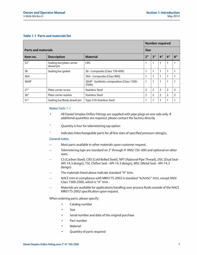
Table 1-1 Parts and materials list
Parts and materials
Number required
Size
Item no. Description Material 2” 3” 4” 6” 8”
4 Body Cast CS A216 WCB (Class 150-2500) 1 1 1 1 1
8N Plate carrier Type 316 Stainless Steel 1 1 1 1 1
8E-DSC Orifice plate sealing unit DSC - Elastomer (STD f/Class 150-600) 1 1 1 1 1
8TSC (8TSC, 8SNC and 8MSC are optional seals for all ANSI classes)
TSC - PT FE (STD f/Class 900-2500) 1 1 1 1 1
8SNC SNC - CS or SS w/O-ring seals (NBR, HNBR, FMK or FFKM options)
1 1 1 1 1
8MSC MSC - Type 316 Stainless Steel 1 1 1 1 1
8NSC-14.3 Sealing bar/orifice plate carrier assembly
(See Table 4-1 for assembly parts list)
11 Clamping bar screw 11 - Heat treated alloy steel (Class 150-900) Table 5-2
11HP 11HP - Heat treated alloy steel (Class 1500-2500)
Table 5-2
12 Clamping bar 12 - CRS (Chemically treated) (Class 150-900) 1 1 1 1 1
12HP 12HP - CRS (Chemically treated) (Class 1500-2500)
1 1 1 1 1
13 Orifice plate Type 304 or 316 Stainless Steel 1 1 1 1 1
17 Nameplate 1 1 1 1 1
18 Nameplate fastener 2 2 2 2 2
30 Drain plug 1” NPT - CRS 1 1 1
1/2” NPT - CRS 1 1
15 (Drain plug option - reducer w/NPT plug)
1” x 1/2” NPT - CRS 1 1 1
30R 1/2”NPT - CRS 1 1 1
31* Meter tap plug 1/2” NPT - CRS (Body w/T-Taps) 2
(4)12
(4)12
(4)12 2
31P* Thread protectors 1/2” polymer plugs (Body w/T-Taps) 2
(4)12
(4)12
(4)12 2
35 Sealing bar 35 - CRS (Chemically treated) (Class 150-600) 1 1 1 1 1
35A 35A CRS (Chemically treated) (Class 900) 1 1 1 1 1
35HP 35HP - CRS (Chemically treated) (Class 1500-2500)
1 1 1 1 1
6 Daniel Simplex Orifice Fitting sizes 2”-8” 150-2500
Owner and Operator Manual Section 1: Introduction3-9008-004 Rev D May 2012
Notes:Table 1-1
• All Daniel Simplex Orifice Fittings are supplied with pipe plugs on one side only. If additional quantities are required, please contact the factory directly.
1 Quantity is four for telemetering tap option
* Indicates Interchangeable parts for all line sizes of specified pressure rating(s).
General notes:
– Most parts available in other materials upon customer request.
– Telemetering taps are standard on 2" through 4" ANSI 150 -600 and optional on other sizes.
– CS (Carbon Steel), CRS (Cold Rolled Steel), NPT (National Pipe Thread), DSC (Dual Seal - API-14.3 design), TSC (Teflon Seal - API-14.3 design), MSC (Metal Seal - API-14.3 design)
– The materials listed above indicate standard “A” trim.
– NACE trim in compliance with MR0175-2002 is standard “A/AASG” trim, except ANSI Class 1500-2500, which is “A” trim .
– Materials are available for applications handling sour process fluids outside of the NACE MR0175-2002 specification upon request.
When ordering parts, please specify:
• Catalog number
• Size
• Serial number and date of the original purchase
• Part number
• Material
• Quantity of parts required
52* Sealing bar/plate carrier dowel pin
CRS 1 1 1 1 1
36 Sealing bar gasket 36 - Composite (Class 150-600) 1 1 1 1 1
36A 36A - Composite (Class 900) 1 1 1 1 1
36HP 36HP - Synthetic composition (Class 1500-2500)
1 1 1 1 1
37* Plate carrier screw Stainless Steel 2 2 2 2 2
38* Plate carrier washer Stainless Steel 2 2 2 2 2
51* Sealing bar/Body dowel pin Type 316 Stainless Steel 1 1 1 1 1
Table 1-1 Parts and materials list
Parts and materials
Number required
Size
Item no. Description Material 2” 3” 4” 6” 8”
Daniel Simplex Orifice Fitting sizes 2”-8” 150-2500 7

Section 1: Introduction Owner and Operator ManualMay 2012 3-9008-004 Rev D
Recommended clamping bar assembly:
1. Clean all fastening and sealing surfaces of all debris.
2. Chase threads by running screw through clamping bar by hand.
3. Assemble unit and apply torque to screws per pattern provided.
4. Tighten screw as follows:
• Install; less than 20% of required torque
• Second Pass: 20% -30% of required torque
• Third Pass: 50% - 70% of required torque
• Fourth Pass: 100% of required torque
• Verify that the Sealing Bar (35, 35A, 35HP), Sealing Bar Gasket (36, 36A, 36HP) and Body (4) were brought together evenly and gasket does not leak
• Fifth Pass: 100% of required torque four (4) hours after Fourth Pass
LOOSE CLAMPING BAR SCREW HAZARD
The factory assembled and shipped this product with loose clamping bar screws. Tighten all clamping bar screws before applying pressure to this product.
Failure to do so may result in injury or equipment damage.
8 Daniel Simplex Orifice Fitting sizes 2”-8” 150-2500

Owner Operator Manual Section 2: Installation3-9008-004 Rev D May 2012
21TOP (14)
Section 2: Installation
2.1 General information
The Daniel Simplex Orifice Fitting is an essential element in an orifice plate flow measurement system. Other elements in the system usually include, but are not limited to, a meter tube, a flow conditioner, and various data recording devices. Purchasers have the option of acquiring only a Simplex from Daniel for later installation in a flow measurement system, or purchasing a complete orifice plate flow measurement system containing a Simplex.
If a Simplex is purchased separately from a measurement system, then it is the responsibility of the product operators or product owners to assemble and test the flow measurement system containing the Simplex.
Daniel tests every Simplex unit to a hydrostatic pressure of 1.5 times its rated maximum allowable operating pressure at the factory under controlled conditions. Purchasers have the option to order these results from Daniel prior to testing.
When assembling a flow measurement system that will contain a Simplex, particular attention should be paid to the requirements for permanent joining of components and the non-destructive testing of the completed assembly. See the appropriate code (AGA-3, etc.) for meter tube requirements. The product operator or product owner is responsible for confirming the maximum allowable operating pressure of each item in the flow measurement system prior to performing any pressure test. The product operator should never exceed the maximum allowable operating pressure of the lowest rated component within a flow measurement system.
HIGH PRESSURE HAZARD
Follow all instructions provided in this section when installing the Sealing Bar Gasket (36, 36A, 36HP), Sealing Bar / Orifice Plate Carrier Assembly (8NSC-14.3), and Clamping Bar (12, 12HP).
Failure to do so may cause pressurized fluids to escape, resulting in serious injury or death.
General information 9

Section 2: Installation Owner Operator ManualMay 2012 3-9008-004 Rev D
Important
The installation technician must confirm the maximum allowable operating pressure (MAOP) of each item in the system, including the Simplex, prior to performing any leak test.
2.2 StorageA light spray of rust inhibitor applied to the inside bore of a Simplex will aid in protecting its surface finish. A light spray of rust inhibitor applied to the bore of the meter tube assembly will also protect its surface finish prior to commissioning.
2.3 Preliminary stepsIt is the responsibility of both the product owners and product operators to ensure that all requirements are met on installations built to comply with the European Union Pressure Equipment Directive (PED) 97/23/EC when required.
It is the responsibility of the product operators to clean the Simplex and all piping components of foreign matter such as welding debris, scale, oil, grease, and dirt before commissioning.
EXPLOSION HAZARD
Never exceed the maximum allowable operating pressure of the lowest rated item in the system.
Exceeding the maximum allowable operating pressure may result in serious injury or death.
On installations which require compliance with the European Union Pressure Equipment Directive (PED) 97/23/EC, it is the responsibility of the end user and/or product owner to ensure that all essential safety requirements of the directive are met.
Particular attention should be paid to the requirements for permanent joining and non-destructive testing. Refer to the “Daniel Orifice Fittings - Installation and Operating Instructions specific to the Pressure Equipment Directive”, Part Number 3-9008-002.
10 Storage

Owner Operator Manual Section 2: Installation3-9008-004 Rev D May 2012
If product owners or product operators expect that the Simplex will encounter severe conditions (conditions where there is likely to be an accumulation of sediment for any cause), then Daniel recommends the removal of the Drain Plug (30) at the bottom of the Simplex and the installation of a blow down valve in its place. (See Section 2.4 for instructions concerning severe service conditions).
Daniel recommends that both product owners and product operators record the Simplex Nameplate (17) data for future reference prior to installation. Nameplate (17) data contains information that is useful if you need to correspond with a Daniel representative. Always provide the serial number and model number of the fitting when ordering spare parts.
It is the responsibility of both the product owners and product operators to install the Simplex™ in a well designed measurement system in accordance with:
• maximum operating pressure of the measurement system
• measurement system test pressures
• minimum and maximum process temperatures and ambient site temperatures
• mass of fluid in both process and test conditions
• chemical composition and toxicity of fluid in operating and test conditions
• traffic, wind and earthquake loading at the measurement site
• reaction forces and moments, which result from supports, attachments, piping, etc.
• corrosion, erosion, fatigue, etc.
• decomposition of unstable fluids in operating and test conditions
• possible damage from external fire
2.4 Severe service conditions If product owners or personnel expect that the Simplex will encounter severe conditions (environment where there is likely to be an accumulation of sediment for any cause), then Daniel recommends the removal of the Drain Valve Plug (30) near the bottom of the Simplex and the installation of a blow down valve in its place.
2.5 Corrosive service Corrosive environments may affect both the external and internal surfaces of the Simplex. Daniel defines external corrosive environments as those conditions that affect the outer surfaces of the Simplex, while an internal corrosive environment is a condition that affects the surface inside the Simplex. Read, understand, and follow instructions in the sections below if an internal or external corrosive environment exists.
Severe service conditions 11

Section 2: Installation Owner Operator ManualMay 2012 3-9008-004 Rev D
12 External corrosive environments
2.5.1 External corrosive environments For Simplexes located in external corrosive environments (offshore platforms, marine terminals, etc), Daniel recommends replacing the standard carbon steel Drain Valve Plug (30) with the stainless steel versions listed in the “Corrosive Service” column (refer to Table 2-1).
2.5.2 Internal corrosive environments For Daniel Simplex Orifice Fittings located in internal corrosive environments, Daniel recommends that product owners purchase a Simplex appropriate for the intended service. Daniel offers the Daniel Simplex Orifice Fitting in a number of trims (Refer to Table 1-1 for parts and material list).
A Simplex is a flow measurement device built to exact inside diameter specifications. Daniel does not provide an allowance for corrosion on the inside diameter.
2.6 Low temperature service Daniel designed the Simplex to function within the temperature/pressure ranges, per material, designated in ASME/ANSI B16.5.
2.7 Design considerations Measurement personnel can select a Simplex for use in a variety of flow measurement systems around the world. Each application has its own unique set of service and environmental condition limitations (Refer to Section 1.2.1: Technical data).
Important
Product owners and operating personnel must evaluate both the service, and environmentalconditions prior to installing a Simplex Orifice Fitting. Therefore, it is the responsibility of theend user to install the Simplex in a well designed piping system.
Some conditions to consider:
• Service operating pressure
• Service testing pressures
• Service process temperature and ambient site temperatures
• Mass of fluid in process and test conditions
• Chemical composition and toxicity of fluid in operating conditions
• Traffic, wind and earthquake at loading site
Table 2-1 Daniel alternate components
Part No. DescriptionStandard Service
Stainless Steel Corrosive Service
Low Temp Service
30 Drain Plug 1-507-01-103 1-507-01-143 1-507-01-170

Owner Operator Manual Section 2: Installation3-9008-004 Rev D May 2012
• Reaction forces and moments which result from supports, attachments, piping, etc.
• Corrosion, erosion, fatigue, etc.
• Decomposition of unstable fluids in operating and test conditions
• Possible damage from external fire
Install the Simplex in any horizontal line with the plate access opening in a vertical up position or with the Simplex rotated left or right to give a horizontal opening position. Daniel Simplex Orifice Fittings to 8” size may be installed in a vertical down flow direction.
2.8 Commissioning the Daniel Simplex Orifice Fitting Installation
Commissioning is the process of verifying that a Simplex performs in accordance with the user’s intended operational, maintenance, and measurement requirements.
The information contained in this section addresses commissioning topics for a Simplex fully, or partially, assembled within an orifice plate flow measurement system.
Purchasers have the option of acquiring a Simplex from Daniel for later installation in a flow measurement system, or purchasing a complete orifice plate flow measurement system containing a Simplex.
Daniel packages orifice plates and seal rings separately from the Simplex.
Product owners and product operators choosing to install a Simplex into a flow measurement system NOT designed by Daniel must insure that the fabrication techniques and subsequent testing meet recognized industry standards.
Fitting installation personnel must confirm that the line flow direction corresponds to the flow directional indicator (an arrow or “INLET” / “OUTLET” tags) positioned on the Simplex Body (4).
The Simplex may be installed in any horizontal line with the plate access opening in a vertical (up) position or with the fitting rotated left or right to obtain a horizontal (side) opening position.
• Remove all foreign matter from the meter tube interior and the bore piping section of the Simplex prior to installation.
FLUID EXPLOSION HAZARD
The Simplex is a device that contains fluid at elevated pressure.
Failure to follow the instructions in this manual will result in serious injury or death.
Commissioning the Daniel Simplex Orifice Fitting Installation 13

Section 2: Installation Owner Operator ManualMay 2012 3-9008-004 Rev D
• Install the proper end flange gaskets, if required, and tighten all bolting to the appropriate torque, per product operator specifications.
• Install the Sealing Bar Gasket (36, 36A, 36HP), Sealing Bar / Orifice Plate Carrier Assembly (8NSC-14.3), and Clamping Bar (12, 12HP) onto the Body (4).
• Tighten and secure all Clamping Bar Screws (11) to the torque values provided in Section 5.2 .
Important
The correct positioning and installation of the Sealing Bar Gasket (35, 35A, 35HP), Sealing Bar / Orifice Plate Carrier Assembly (8NSC-14.3), and Clamping Bar (12, 12HP) are essential to providing a pressure barrier between the line pressure and atmospheric pressure.
2.9 Commissioning - Line Pressure Test Conditions:
• The pressure within the Simplex Body (4) and the adjacent metering system is equivalent to atmospheric pressure.
• The Orifice Plate (13) and Orifice Plate Sealing Unit (8E-DSC or 8TSC or 8MSC) is not installed on the Sealing Bar / Orifice Plate Carrier Assembly (8NSC-14.3)
• The Sealing Bar Gasket (36, 36A, 36HP) is installed on the Sealing Bar / Orifice Plate Carrier Assembly (8NSC-14.3)
• The Sealing Bar / Orifice Plate Carrier Assembly (8NSC-14.3) is installed.
• The Clamping Bar (12, 12HP) is installed.
• The Clamping Bar Screws (11 or 11XP) are tightened to torque requirements per Section 5.2.
After installing the Simplex into the service line, personnel may perform a line pressure test of the service line.
FLUID EXPLOSION HAZARD
The Simplex is a device that contains fluid at elevated pressure.
Failure to follow the instructions in this manual will result in serious injury or death.
14 Commissioning - Line Pressure Test

Owner Operator Manual Section 2: Installation3-9008-004 Rev D May 2012
Perform a leak test after installing the Simplex and securing the Clamping Bar (12, 12HP).
1. Install a pressure gauge (calibrated to a recognized standard) on the orifice metering system in a location where the gauge will detect the pressure inside the Simplex. Test personnel must choose a pressure gauge rated for the maximum operating pressure of the system (the Simplex, service line seals (flange gaskets) and the adjacent piping) determined by the product owner and product operator.
Important
The installation technician must confirm the maximum allowable operating pressure (MAOP) of each item in the system, including the Simplex, prior to performing any leak test.
2. Slowly pressurize the orifice metering system at a rate of 1 psig per second (0.15 bars per second) and then stop the pressurization when the pressure inside the plate holder reaches 20 psig (1.4 bar). Hold the system at this pressure for five minutes.
Important
The correct positioning and installation of the Sealing Bar Gasket (35, 35A, 35HP), Sealing Bar / Orifice Plate Carrier Assembly (8NSC-14.3), and Clamping Bar (12, 12HP) are essential to providing a pressure barrier between the line pressure and atmospheric pressure.
3. During this five-minute hold, test personnel should apply a leak detection solution over all connections and joint areas throughout the entire orifice metering system (including the Sealing Bar Gasket (36, 36A, 36HP) and all threaded connections on the Simplex). No leakage should be visibly, or audibly, detected during this five-minute hold period.
4. If a leak is detected, mark the leak area with a marker and reduce the pressure inside the Daniel Senior Orifice Fitting to 0 psig (0 bar). Tighten any fastener or connector adjacent to the leak area and repeat the leak test again.
EXPLOSION HAZARD
Never exceed the maximum allowable operating pressure of the lowest rated item in the system.
Failure to do so may result in serious injury or death.
Commissioning - Line Pressure Test 15

Section 2: Installation Owner Operator ManualMay 2012 3-9008-004 Rev D
5. If after several attempts to contain the leakage it persists, call your Daniel Customer Service for assistance. Contact information is found in the back of this manual.
6. Once the 20 psig (1.4 bar) leak test is complete, and no leaks are detected, then slowly raise the pressure inside the orifice metering system at a rate of 10 psig per second (0.70 bars per second) and then stop the pressurization when the pressure inside the Simplex reaches the maximum operating pressure of the system (the Simplex and the adjacent piping) determined by the product operator. Hold the system at that pressure for ten minutes.
Important
The installation technician must confirm the maximum allowable operating pressure (MAOP) of each item in the system, including the Simplex, prior to performing any leak test.
During this ten-minute hold, test personnel shall apply a leak detection solution over all connections and joint areas throughout the entire orifice metering system (including the Sealing Bar Gasket (36, 36A, 36HP) and all threaded connections on the Simplex). No leakage should be visibly, or audibly, detected during this ten-minute hold period.
LEAKAGE HAZARD
Correct all leaks of any size prior to operating the system.
Failure to do so may lead to serious injury or death.
EXPLOSION HAZARD
Never exceed the maximum allowable operating pressure of the lowest rated item in the system.
Failure to do so may result in serious injury or death.
16 Commissioning - Line Pressure Test

Owner Operator Manual Section 2: Installation3-9008-004 Rev D May 2012
European Union Pressure Equipment Directive (PED) 97/23
Important
The installation technician must confirm the maximum allowable operating pressure (MAOP) of each item in the system, including the Simplex, prior to performing any leak test.
7. If a leak is detected, mark the leak area and reduce the pressure inside the orifice metering system to 0 psig (0 bar). If a leak is detected at a fastener or connector, then tighten that fastener or connector and repeat the entire leak test again.
8. If several attempts to stop a leak fail, call Daniel Customer Service for assistance.
9. Slowly release the pressure from the orifice metering system until the pressure gauge reads zero (0) psig.
10. The Simplex, with the orifice metering system, is now ready for orifice plate installation, final pressurization, and operation.
2.10 Commissioning - Orifice Plate Installation Conditions:
• The pressure within the Simplex Body (4) and the adjacent metering system is equivalent to atmospheric pressure.
On installations which are required to comply with the European Union Pressure Equipment Directive (PED) 97/23/EC, the installation must be tested to at least 1.43 times the maximum allowable operating pressure (MAOP) of the lowest rated component in the system as determined by the product operator.
EXPLOSION HAZARD
Never exceed the maximum allowable operating pressure of the lowest rated item in the system.
Failure to do so may result in serious injury or death.
Commissioning - Orifice Plate Installation 17

Section 2: Installation Owner Operator ManualMay 2012 3-9008-004 Rev D
• The Orifice Plate (13) and the Orifice Plate Sealing Unit (8E-DSC or 8TSC or 8MSC) is installed into the Sealing Bar / Orifice Plate Carrier Assembly (8NSC-14.3)
• The Sealing Bar Gasket (36, 36A, 36HP) is installed on Sealing Bar / Orifice Plate Carrier Assembly (8NSC-14.3) The Sealing Bar / Orifice Plate Carrier Assembly (8NSC-14.3) is installed.
• The Clamping Bar (12 or 12HP) is installed.
• The Clamping Bar Screws (11 or 11XP) are tightened to torque requirements per Table 5-2.
1. The pressure inside the Simplex Body (4) and adjacent metering system components MUST be at atmospheric pressure (0 psia) to begin orifice plate installation. When evacuating the metering system, direct fluid and/or gas to a safe area away from the operator and in accordance with local environmental regulations.
2. CONFIRM that the pressure inside the Daniel Simplex Orifice Fitting Body (4) and adjacent metering system components is equivalent to atmospheric pressure.
3. Loosen each Clamping Bar Screw (11) two turns. Do not remove the Clamping Bar (12, 12HP).
4. Lightly tap the Sealing Bar / Orifice Plate Carrier Assembly (8NSC-14.3) to break the seal generated between the Sealing Bar Gasket (36, 36A, 36HP) and the Body (4).
5. Once the seal is broken, slide the Clamping Bar (12, 12HP) out from the Body (4).
6. Lift the entire Sealing Bar / Orifice Plate Carrier Assembly (8NSC-14.3) out from the Body (4). Note: Tapping the Sealing Bar (35, 35A, 35HP) will loosen the Sealing Bar / Orifice Plate Carrier Assembly (8NSC-14.3) from the Body (4).
7. Remove the Sealing Bar Gasket (36, 36A, 36HP) from the Simplex.
8. Install a new Sealing Bar Gasket (36, 36A, 36HP) onto the PC Sub-Assembly. Do not reinstall any gasket once it has been compressed.
9. Install a new Orifice Plate Sealing Unit (8E - DSC) or (8TSC) or (8MSC) onto the Orifice Plate (13).
10. Install the Orifice Plate (13) and new Orifice Plate Sealing Unit (8E - DSC) or (8TSC) or (8MSC) into the PC Sub-Assembly taking into account the flow direction of the metering system. This can be done using the Sealing Bar/Body Dowel Pin (51) located in the Body (4) as a reference.
FLUID EXPLOSION HAZARD
The Simplex is a device that contains fluid at elevated pressure.
Failure to follow the instructions in this manual will result in serious injury or death.
18 Commissioning - Orifice Plate Installation

Owner Operator Manual Section 2: Installation3-9008-004 Rev D May 2012
Important
Failure to install the Orifice Plate (13) and Orifice Plate Sealing Unit (8E - DSC) or (8TSC) or (8MSC) in a position properly oriented with the direction of flow will result in measurement error and a possible loss of revenue.
11. Lower the PC Sub-Assembly into the Body (4) aligning the Sealing Bar (35, 35A, 35HP) with the Sealing Bar/Body Dowel Pin (51) located in the Body (4).
12. Continue to lower the PC Sub-Assembly using the Sealing Bar/Body Dowel Pin (51) as a guide until it contacts the Body (4).
13. Install the Clamping Bar (12, 12HP).
Important
The correct positioning and installation of the Sealing Bar Gasket (35, 35A, 35HP), Sealing Bar / Orifice Plate Carrier Assembly (8NSC-14.3), and Clamping Bar (12, 12HP) are essential to providing a pressure barrier between the line pressure and atmospheric pressure.
14. Tighten each Clamping Bar Screw (11) to the torque recommended in Section 5.2.
15. Remove any commissioning equipment (test instruments, tubing, etc.,) from system.
16. The Daniel Simplex Orifice Fitting is now ready for final pressurization and operation.
Commissioning - Orifice Plate Installation 19

Section 2: Installation Owner Operator ManualMay 2012 3-9008-004 Rev D
20 Commissioning - Orifice Plate Installation

Owner and Operator Manual Section 3: Maintenance3-9008-004 Rev D May 2012
Section 3: Maintenance
3.1 Normal operating conditions
Under normal measurement conditions, a product operator should inspect the Simplex, as well as the meter tube, at intervals established by the product operator.
It is the responsibility of the product owner and product operator to perform inspections at appropriate intervals during the life of their system.
1. An external inspection of the Simplex and metering system shall include a visual assessment of the entire system for vandalism, or other inadvertent damage.
2. Tighten fastener and connector components, if necessary.
3. Natural corrosion and erosion of the orifice metering system internal features require that maintenance personnel perform an inspection of the orifice system’s bore diameter to ensure compliance with a metering code (for example, AGA-3).
3.1.1 Lubrication Apply a light coat of lubricant on the orifice seal ring to assist in installation and extraction of the plate carrier assembly.
FLUID EXPLOSION HAZARD
The Simplex is a device that contains fluid at elevated pressure.
Failure to follow the instructions in this manual will result in serious injury or death.
Normal operating conditions 21
Section 3: Maintenance Owner and Operator ManualMay 2012 3-9008-004 Rev D
22 Lubrication

Owner and Operator Manual Section 4: Orifice plate installation and removal instructions3-9008-004 Rev D May 2012
Section 4: Orifice plate installation and removal instructions
4.1 Plate change procedure
Follow these instructions during every plate change.
Never place any part of your body over the slot opening of the Body when the Sealing Bar Gasket (36, 36A or 36HP), the Sealing Bar (35, 35A or 35HP) and the Clamping Bar (12 or 12HP) are removed from the Daniel Simplex Orifice Fitting and the line is under pressure.
* Daniel Simplex Orifice Fitting is shown in vertical position. The KEEP OUT ZONE includes the plate carrier slot opening of the Body (4) even when the Simplex is positioned horizontally (laying on its side).
FLUID EXPLOSION HAZARD
Follow the instructions below to avoid inadvertent or accidental the propulsion of fluid or internal components from the Body (4).
Failure to do so will result in serious injury or death.
EXPLOSION HAZARD
The Daniel Simplex Orifice Fitting contains fluid at elevated pressure. Make sure to follow the instructions below for proper installation and removal of the plate.
Failure to do so can cause an explosive release and may result in serious injury or death.
Plate change procedure 23

Section 4: Orifice plate installation and removal instructions Owner and Operator ManualMay 2012 3-9008-004 Rev D
Important
In order to perform a safe and efficient plate change operation with a Simplex, the on-site personnel must evaluate both the service and environmental conditions prior to beginning this operation.
As stated in the product description section of this manual, the Simplex utilizes a “single chamber” design.
The following are the conditions required to start the removal procedure of the orifice plate:
• The SImplex is at atmospheric pressure (all product is removed from unit).
• The Sealing Bar Gasket (36, 36A or 36HP), the Sealing Bar (35, 35A or 35HP), and the Clamping Bar (12 or 12HP) are fastened to the Simplex.
Procedure:
To remove the Orifice Plate (13) from the Simplex, the operator must first release pressure from the Body (4).
1. Wait several seconds while the pressure leaves the Simplex Body (4).
Important
Although the fluid pressure contained in the Body (4) is reduced to ambient conditions in thefollowing operations, there still remain remnants of the fluid in that chamber. The operator mustemploy a system to address the remaining fluid based upon the fluids’ chemical compositionand toxicity.
2. Loosen each Clamping Bar Screw (11 or 11HP) located on the Clamping Bar (12 or 12HP) approximately two turns with the Operating Wrench (2).
3. Once the Clamping Bar Screws (11or 11HP) are loose, Slide the Clamping Bar (12 or 12HP) containing the Clamping Bar Screws (11 or 11HP), the Sealing Bar (35, 35A or 35HP) from the Body (4).
4. Remove the Sealing Bar Gasket (36, 36A or 36HP) from the Body (4).
5. Remove the Orifice Plate Carrier (8DM or 8DMC) from the Body (4) and perform the scheduled work on the Orifice Plate (13) and Orifice Plate Carrier (8DM or 8DMC).
24 Plate change procedure

Owner and Operator Manual Section 4: Orifice plate installation and removal instructions3-9008-004 Rev D May 2012
4.2 Operating instructions
The Simplex design allows an operator to install or remove the Orifice Plate (13) with a minimum amount of metering system shut-down time.
The Simplex Plate Carrier (8N) is just one piece in a larger assembly. That assembly, referred to as the Sealing Bar / Orifice Plate Carrier Assembly (8NSC-14.3) the following parts: Sealing Bar / Orifice Plate Carrier Assembly (8NSC-14.3)
A product operator can remove the entire Sealing Bar / Orifice Plate Carrier Assembly (8NSC14.3) from the Body (4).
To change or inspect, an orifice plate or orifice plate seal, simply push on the Orifice Plate (13) and Orifice Plate Sealing Unit (8E - DSC) or (8TSC) or (8MSC) until it pops out of the Sealing Bar / Orifice Plate Carrier Assembly (8NSC-14.3).
By removing the Orifice Plate Sealing Unit (8E - DSC) or (8TSC) or (8MSC) from the Orifice Plate (13), a product operator may then closely inspect both parts for signs of damage or wear.
Table 4-1 Sealing bar/Orifice plate carrier assembly (8NSC-14.3)
Quantity Description and item number
1 Plate carrier (8N)
1 Sealing bar (35, 35A, 35HP)
2 Plate carrier screws (37)
2 Plate carrier washers (38)
1 Sealing bar plate carrier dowel pin (52)
1 Orifice plate sealing unit (8E-DSC) or (8TSC) or (8MSC)
1 Orifice plate (13)
HIGH PRESSURE HAZARD
Follow all instructions provided in Section 2 when installing the Sealing Bar Gasket (36, 36A, 36HP), Sealing Bar / Orifice Plate Carrier Assembly (8NSC-14.3), and Clamping Bar (12, 12HP).
Failure to do so may cause pressurized fluids to escape, resulting in serious injury or death.
Operating instructions 25

Section 4: Orifice plate installation and removal instructions Owner and Operator ManualMay 2012 3-9008-004 Rev D
4.3 Plate removal
Conditions:
• The Simplex is operating at working pressure.
• The Orifice Plate (13) is located in flow stream.
Procedure:
Isolate the orifice metering system supporting the Simplex and release the working pressure until the entire system reaches atmospheric (ambient) pressure.
6. Loosen each Clamping Bar Screw (11) two turns when the system reaches atmospheric (ambient) pressure. Do not remove the Clamping Bar (12, 12HP).
7. Lightly tap the Sealing Bar (35, 35A, 35HP) to break the seal generated between the Sealing Bar Gasket (36, 36A, 36HP) and the Body (4).
8. Once the seal is broken, slide the Clamping Bar (12, 12HP) out from the Body (4).
9. Lift the entire Sealing Bar / Orifice Plate Carrier Assembly (8NSC-14.3) out from the Body (4). Note: Tapping the Sealing Bar (35, 35A, 35HP) will loosen the Sealing Bar / Orifice Plate Carrier Assembly (8NSC-14.3) from the Body (4).
10. Remove the Sealing Bar Gasket (36, 36A, 36HP) from the Simplex.
FLUID EXPLOSION HAZARD
Release pressurized fluid into a safe area. The discharge may cause contamination and/or the accumulation of volatile gas mixtures.
Volatile gas mixtures are explosive and/or toxic and may lead to serious injury or death.
FLUID EXPLOSION HAZARD
The Simplex is a device that contains fluid at elevated pressure.
Failure to follow the instructions in this manual will result in serious injury or death.
26 Plate removal

Owner and Operator Manual Section 4: Orifice plate installation and removal instructions3-9008-004 Rev D May 2012
11. Remove the Orifice Plate (13) and Orifice Plate Sealing Unit (8E - DSC) or (8TSC) or (8MSC) from the Sealing Bar / Orifice Plate Carrier Assembly (8NSC-14.3).
12. Remove the Orifice Plate Sealing Unit (8E -DSC) or (8TSC) or (8MSC) from the Orifice Plate (13).
4.4 Plate insertion
Conditions:
• The Simplex is at atmospheric (ambient) pressure.
• The Simplex is in the orifice metering system.
• The Sealing Bar / Orifice Plate Carrier Assembly (8NSC-14.3), Clamping Bar (12, 12HP), with Clamping Bar Screws (11), are removed from the Body (4).
Procedure:
1. Install a new Sealing Bar Gasket (36, 36A, 36HP) onto the Sealing Bar / Orifice Plate Carrier Assembly (8NSC-14.3). Do not reinstall any gasket once it has been compressed.
2. Install a new Orifice Plate Sealing Unit (8E - DSC) or (8TSC) or (8MSC) onto the Orifice Plate (13).
3. Install the Orifice Plate (13) and new Orifice Plate Sealing Unit (8E - DSC) or (8TSC) or (8MSC) into the Sealing Bar / Orifice Plate Carrier Assembly (8NSC-14.3) taking into account the flow direction of the metering system. This can be done using the Sealing Bar/Body Dowel Pin (51) located in the Body (4) as a reference.
Important
Failure to install the Orifice Plate (13) and Orifice Plate Sealing Unit (8E - DSC) or (8TSC) or (8MSC) in a position properly oriented with the direction of flow will result in measurement error and a possible loss of revenue.
4. Lower the Sealing Bar / Orifice Plate Carrier Assembly (8NSC-14.3) into the Body (4) aligning the Sealing Bar (35, 35A, 35HP) with the Sealing Bar/Body Dowel Pin (51) located in the Body (4).
FLUID EXPLOSION HAZARD
The Simplex is a device that contains fluid at elevated pressure.
Failure to follow the instructions in this manual will result in serious injury or death.
Plate insertion 27

Section 4: Orifice plate installation and removal instructions Owner and Operator ManualMay 2012 3-9008-004 Rev D
5. Continue to lower the Sealing Bar / Orifice Plate Carrier Assembly (8NSC-14.3) using the Sealing Bar/Body Dowel Pin (51) as a guide until it contacts the Body (4).
6. Install the Clamping Bar (12, 12HP).
7. Tighten each Clamping Bar Screw (11) to the torque recommended in Section 5.2 of this manual.
8. The Simplex is now ready for final pressurization and operation.
Important
The correct positioning and installation of the Sealing Bar Gasket (35, 35A, 35HP), Sealing Bar / Orifice Plate Carrier Assembly (8NSC-14.3), and Clamping Bar (12, 12HP) are essential to providing a pressure barrier between the line pressure and atmospheric pressure.
28 Plate insertion

Owner Operator Manual Section 5: Supplemental information3-9008-004 Rev D May 2012
Section 5: Supplemental information5.1 Recommended spare parts for one-year operation
5.2 Torque information Daniel utilizes a bolted sealing bar gasket joint assembly when constructing the Simplex. To successfully pass all factory tests, factory personnel torque each fastener in the joint assembly to contain pressure and seal the unit. On conclusion of factory pressure testing, the sealing bar gasket is replaced and the bolted joint is slightly tightened for shipment. Product owners and product operators must realize that service conditions and time will impact the tightness and strength of factory assembled joints. Some conditions of time and service may loosen the joint assemblies. Some, but not all, of service conditions that will affect joint assemblies are:
• temperature changes
• vibration
• mechanical loads
• pressure loads
• condition of joint assembly components (fasteners, gaskets, sealing surface conditions)
The information contained in this manual is to provide product owners and operators basic torque values to use as a starting point to provide adequate assembly and in-service clamping force in most applications. However, product owners and product operators are ultimately responsible for joint assembly.
Table 5-1 Recommended spare parts for one year operation
Item No. Description Material Quantity
8E-DSC Orifice Plate Sealing Unit Elastomer 5
8TSC Orifice Plate Sealing Unit Teflon 1
8MSC Orifice Plate Sealing Unit Metallic 1
36 36 Sealing Bar Gasket (ANSI 150-600)
Flat Fiber Sheet 5
36A Sealing Bar Gasket (ANSI 900)
Flat Fiber Sheet 5
36HP Sealing Bar Gasket (ANSI 1500-2500)
Elastomer 5
37 Plate Carrier Screw 316SS 2
38 Plate Carrier Washer 316SS 2
Recommended spare parts for one-year operation 29

Section 5: Supplemental information Owner Operator ManualMay 2012 3-9008-004 Rev D
5.2.1 Joint assembly procedures
1. Clean all fastening and sealing surfaces of all debris and chase threads by running each fastener through its intended tapped hole by hand
2. Assemble joint and apply torque (refer to per torque application patterns provided)
3. Tighten each fastener as follows:
• Install fastener - apply less than 20% of required torque
• Second Pass - apply 20% - 30% of required torque
• Third Pass - apply 30% - 70% of required torque
• Fourth Pass - apply 100% of required torque
• Verify that the Sealing Bar (35, 35A, 35HP), Sealing Bar Gasket (36, 36A, 36HP) and Body (4) were brought together evenly and gasket does not leak.
• Fifth Pass - apply 100% of required torque four hours after Fourth Pass
Table 5-2 Clamping bar screw (11) quantity and torque requirements
Nominal size (in.) ANSI ClassNumber of screws Screw size
Required torque (ft. - lbs)
Minimum Maximum
2
150 4 1/2”-13 75 95
300 4 1/2”-13 75 95
600 4 1/2”-13 75 95
900 4 1/2”-13 110 135
1500 8 5/8”-11 80 100
2500 10 5/8”-11 135 170
3
150 4 1/2”-13 95 120
300 4 1/2”-13 95 120
600 4 1/2”-13 95 120
900 4 1/2”-13 110 135
1500 10 5/8”-11 80 100
2500 10 5/8”-11 135 170
4
150 5 1/2”-13 85 105
300 5 1/2”-13 85 105
600 5 1/2”-13 85 105
900 5 1/2”-13 95 120
1500 12 5/8”-11 80 100
2500 12 5/8”-11 135 170
30 Joint assembly procedures

Owner Operator Manual Section 5: Supplemental information3-9008-004 Rev D May 2012
6
150 6 1/2”-13 95 120
300 6 1/2”-13 95 120
600 6 1/2”-13 95 120
900 6 1/2”-13 95 120
1500 14 5/8”-11 85 105
2500 14 5/8”-11 140 175
8
150 7 1/2”-13 95 120
300 7 1/2”-13 95 120
600 7 1/2”-13 95 120
900 7 1/2”-13 95 120
1500 16 5/8”-11 90 115
2500 26 5/8”-11 105 130
Table 5-2 Clamping bar screw (11) quantity and torque requirements
Nominal size (in.) ANSI ClassNumber of screws Screw size
Required torque (ft. - lbs)
Minimum Maximum
Joint assembly procedures 31

Section 5: Supplemental information Owner Operator ManualMay 2012 3-9008-004 Rev D
Figure 5-1 Torque pattern sequences
32 Joint assembly procedures

DANIELTM MEASUREMENT AND CONTROL, INC.
RETURNED MATERIAL AUTHORIZATIONREPAIR FORM FOR USED EQUIPMENT
INCLUDING DECONTAMINATION/CLEANING STATEMENT
A Return Material Authorization (RMA) number must be obtained prior to returning any equipment for any reason. Download the RMA form from the Support Services web page by selecting the link below.
http://www2.emersonprocess.com/EN-US/BRANDS/DANIEL/SUPPORT-SERVICES/Pages/Support-Services.aspx
1. Return Material Authorization (RMA) Number_________________________________
2. Equipment to be returned:Model Number ___________________Serial Number__________________________
3. Reason for return: _________________________________________________________________________________________________________________________________________________________________________________________________________________________________________________________________________________________________________________________________________________________
Decontamination/Cleaning Fluids Process
A. List each substance in which the equipment was exposed. Attach additional documents if necessary.
CommonName
CAS# ifAvailable
Used for HazardousWaste (20 CFR 261)
EPA Waste Codeif used for hazardous waste
[ ] Yes [ ] No
[ ] Yes [ ] No
[ ] Yes [ ] No
[ ] Yes [ ] No
[ ] Yes [ ] No
[ ] Yes [ ] No
B. Circle any hazards and/or process fluid types that apply:
Infectious Radioactive Explosive Pryophoric Poison Gas
Cyanides Sulfides Corrosive Oxidizer Flammable Poison
Carcinogen Peroxide Reactive-Air Reactive-Water Reactive-Other (list):
Other Hazard Category (list):
C. Describe decontamination/cleaning process. Include MSDS description for substances used in decontamination and cleaning processes. Attach additional documents if necessary.

Shipping Requirements
Failure to comply with this procedure will result in the shipment being refused.
1. Write the RMA number on the shipping package.
2. Inside the package include one copy of this document and all required Material Safety Data Sheets (MSDS)
3. Outside of the package attach one copy of this document and all required Material Safety Data Sheets (MSDS).
THIS EQUIPMENT, BEING RETURNED "FOR REPAIR," HAS BEEN COMPLETELY DECONTAMINATED AND CLEANED. ALL FOREIGN SUBSTANCES HAVE BEEN DOCUMENTED ABOVE AND MSDS SHEETS ARE ATTACHED.
By_________________________________ _____________________________________(Signature) (Print name)
Title:_______________________________ Date:________________________________
Company:___________________________
Phone: ____________________________ Fax:_________________________________


Daniel Gas and Liquid Ultrasonic Flow Meters power PlantWeb by communicating health and process variable information via the HART® protocol and are core components of the PlantWeb digital plant architecture.
Emerson Process Management Daniel Measurement and Control, Inc. 11100 Brittmoore Park DriveHouston, TX 77041T+1 713-467-6000F+1 713-827-4805www.emerson.com
Copyright© 2012Daniel Measurement and Control, Inc. and Daniel Measurement Services, Inc. Divisions of Emerson Process Management reserve the right to make changes to any of its products or services at any time without prior notification in order to improve that product or service and to supply the best product or service possible.
Daniel Measurement Services, Inc. offers both on-call and contract maintenance service designed to provide single-source responsibility for all Daniel products. The sales and service offices of Daniel Measurement and Control, Inc. are located throughout the United States and in major countries overseas. For the location of the sales or service office nearest you, telephone the number below or visit the Daniel Measurement and Control, Inc. website.
T+1713-827-6314F+1713-827-4805www.emerson.com