HDPE PIPES & FITTINGS. - EPICOS
57
HDPE PIPES & FITTINGS. NATIONAL INDUSTRIES COMPANY For Building Materials (KSCC)
-
Upload
khangminh22 -
Category
Documents
-
view
4 -
download
0
Transcript of HDPE PIPES & FITTINGS. - EPICOS

HDPE PIPES & FITTINGS.
NATIONAL INDUSTRIES COMPANY
For Building Materials (KSCC)

Page : 2
Index Description Page No. 1. Introduction 3 2. HDPE Pipe factory 4 3. Krah Pipe System 5 4. Pipe made from HDPE or PP 6 5. Why profiled pipes 10 6. Elasticity of HDPE pipes 12 7. Delivery program 14 8. NIC HDPE pipes as per ISO 9969 16 9. Technology at highest level 17 10. Technical Background 19 11. Hydraulics 22 12. Jointing technique 25 13. Other jointing techniques 28 14. HDPE pipe profiles 30 15. Fittings 32 16. Special constructions 36 17. Manholes 38 18. Transport, Handling, Storage 42 19. Installation 44 20. Leakage test 45 21. Total quality management 46 22. Advantages at glance 48 23. other applications 49 24. Questionnaire Forms 54

Page : 3
1. Introduction Ever since the history of civilization is faced with the unreliable infrastructure system within their collective resettlement areas. The historical process of evolution of the human kind up to the contemporary era has marked various infrastructure systems that have corresponded to a technological development specific to that era. However, tremendous difficulties were observed in selection of the material construction, which was sought to provide anticipated permanent solutions for the system utilized. This had eventually given an impetus for further research and investigations. The discovery of plastics, which was considered as the biggest invention in the 20th century, together with further development achieved in the plastic technology has resulted with a comprehensive solution of contemporary societies’ problems faced in this field, by providing excellent material specifications. The fact that the processing of the plastic is very easy and the plastic materials provide the superior properties against adverse effect of the ambient and the chemicals; the use of plastics has been eventually spread over many fields of applications, including durable goods. To this effect, the researchers have considered the ways to make use of the plastics as the materials for the infrastructure system that inherently require great deal of investments. There have been huge technical difficulties encountered in manufacturing of the pipes especially with bigger diameters in conformity with the requirements of infrastructure systems and no satisfactory solution had been established until recently. National Industries Company one of the major companies owned by “NI Group”. The NI Group is a holding company of a diversified group of industrial and financial companies in the Middle East, Europe and North America. NI Group invests heavily in automation and modern production technology. It develops and uses up to date technology and materials to maintain high quality, cost effective and environmentally sensitive products. In Kuwait, at “N.I.C.” over 1,500 employees operate two major factory complexes, encompassing eleven plants, called Building Material Group. These two major complexes of BMG are Mina Abdullah factory complex and Sulaibiyah Factory complex. Mina Abdullah factory complex includes “HDPE Pipes Factory”, which produces HDPE Pipes, manholes and fittings. The complex also contains a rapidly expanding quarrying plant and one of the largest sand lime bricks in the world. Another factory produces around 70% of Kuwait’s gas-aerated concrete blocks “Al Abyad.” The complex includes various other plants producing: NIC Plaster, NIC Glue Mortar, NIC Pvc Pipes and Fittings and NIC Ready Mix concrete.

Page : 4
2. HDPE Pipe Factory “HDPE Pipe” factory was established in 2002 in response to the ever increasing demand in Kuwait and neighboring countries. This factory is considered one of the largest in the Middle East, with an annual production capacity reaching 4,000 metric tones of HDPE pipes and fittings. HDPE pipes ranges from 300 to 4000 mm., and are produced in accordance with international standard including; German (DIN), British (BS), European (ISO), American (ASTM), Saudi Arabia and Kuwaiti standards. HDPE Pipe factory is capable of producing its products to other standards when required by our clients.

Page : 5
3. Krah pipe systems.
For years tremendous difficulties were observed in selection of the material of construction for infrastructural systems, which should be suitable to provide anticipated permanent solutions. Over twenty years ago, engineers sought to address the inherent weakness of concrete, clay, ductile and steel sewer pipe systems. These and other sewer pipe systems either tend to be brittle or are too sensitive to aggressive chemicals and soil conditions. Failures had become a common occurrence world-wide in sewer and other large-diameter-pipe applications. See the damages of rigid pipes in the pictures above (crack and root intrusion). So they derived benefit from the fact that the processing of plastic is very easy and
e plastic materials provide superior properties against adverse effect of the mbient and the chemicals.
In addition to the permanent solution that lasts through generations, Krah piping systems is able to provide everlasting and economic solutions in wide-ranging fields of applications as for example drain, storm-drain and sewer systems as well as sea outfall, manholes and reservoirs. In order to meet the requirements of the infrastructure systems, Krah has developed the most robust and advantageous large-bore-pipe systems. So far tests have shown that the pressure pipes made of HDPE have a lifetime of over 100 years. Moreover the inertness of this material to notches and stress cracking ensures a trouble-free service of the pipe and of course the complete piping system.
tha
Page : 6
or PP. Polyethylene and polypropylene are thermoplastics with excellent properties for the application of water and sewer as for the fabrication of containers for liquids and solid materials. Polyethylene and polypropylene are resistant to many chemicals and very suitable for conveying and storing various liquids.
Weldability olyethylene and polypropylene can be welded, i.e. it can be reused continuously.
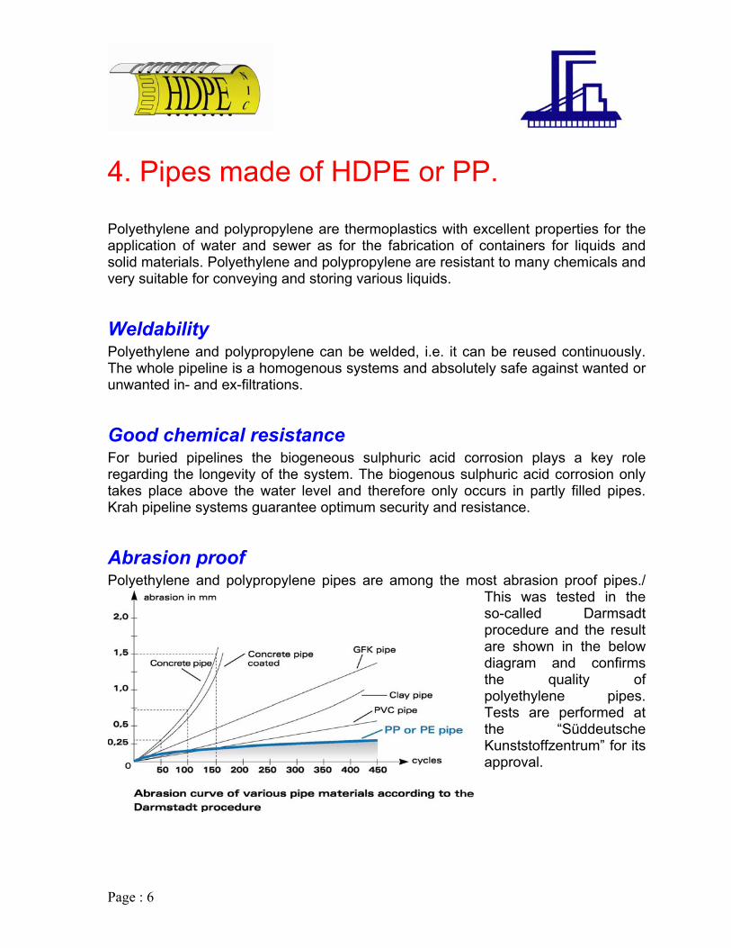
This was tested in the so-called Darmsadt
the quality of polyethylene pipes.
“Süddeutsche Kunststoffzentrum” for its
4. Pipes made of HDPE
PThe whole pipeline is a homogenous systems and absolutely safe against wanted or unwanted in- and ex-filtrations.
Good chemical resistance For buried pipelines the biogeneous sulphuric acid corrosion plays a key role regarding the longevity of the system. The biogenous sulphuric acid corrosion only takes place above the water level and therefore only occurs in partly filled pipes. Krah pipeline systems guarantee optimum security and resistance.
Abrasion proof Polyethylene and polypropylene pipes are among the most abrasion proof pipes./
procedure and the result are shown in the below diagram and confirms
Tests are performed at the
approval.

Page : 7
Impact Resistance High impact resistance, even at low temperatures, ensures a robust pipe.
Recycling polypropylene materials can be recycled to 100%. They belong to plastics. Thermoplastics have the property to be refusible without
Resistant to microorganisms, rodents and termites pipes does not give the teeth of rodents
ates.
Very good hydraulics of the pipes Inner diameter and
ive inner diameter according to DIN 16961.
Polyethylene andthe group thermothe structure of the material being modified dramatically. For this reason material of PE and PP can be put back into the production cycle.
The smooth round surface of plasticsufficient hold to cause damage. Moreover even in termite-affected countries no damage to PE pipelines by termites has ever been occurred. PE and PP are not a nutrient medium for bacteria, fungi and spores, so that the material is resistant to all forms of microbial attack as well as to both sulphurous acid and sulf
hydraulic properties of KRAH pipes will remain constant regardless of the wall thickness or the profiles due to the smooth anti adhesive inner pipe surface. The nominal diameter (e.g. DN 500) corresponds to the respect

Page : 8
V-resistance Black polyethylene pipes are permanently resistance to atmospheric corrosion and
V radiation. Thus the pipes can be used and stored outside without the pipe material being damaged.
Specific Weight
U
U
Properties The materials from which the Krah pipes are produced properties. Other materials can be used after prior acceptancthird party for quality control. The used material should have the following specification:
fe
eatures the following of the producer and a
Page : 9
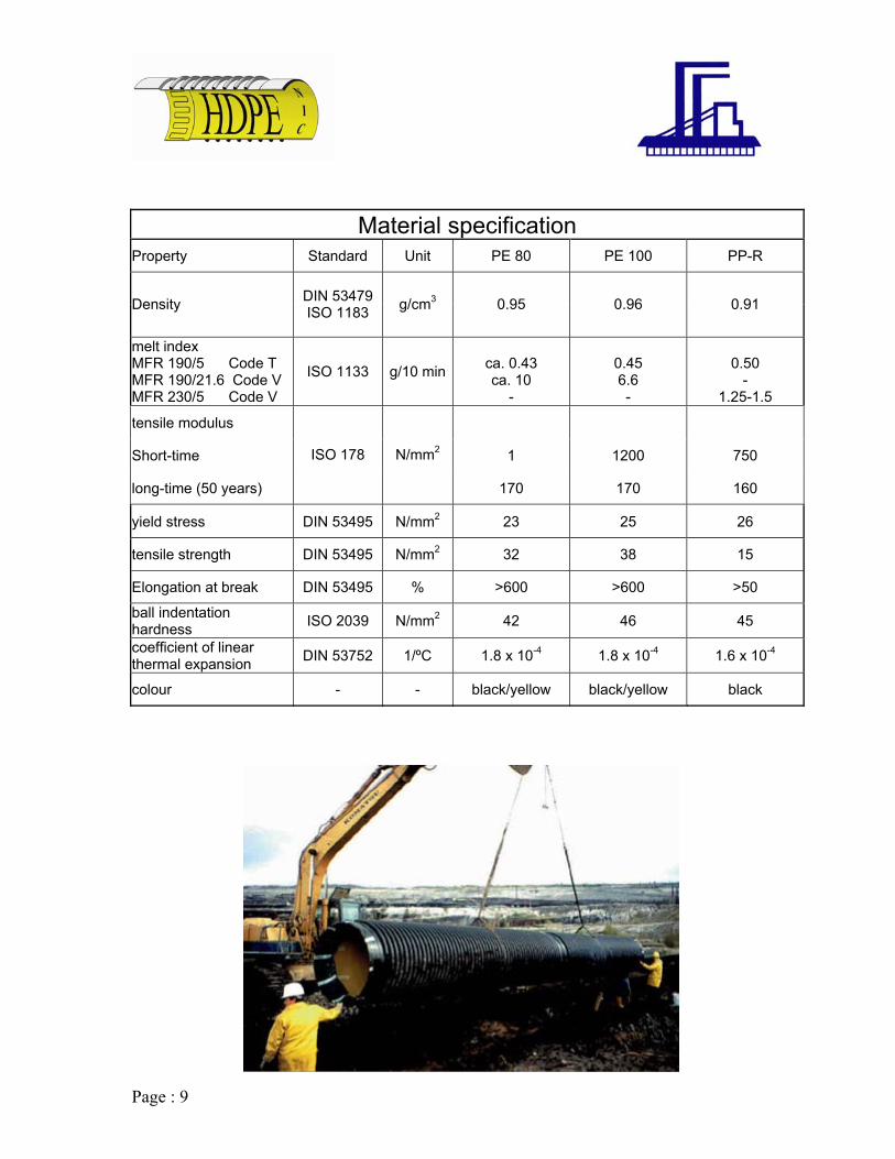
Material specification
Property Standard Unit PE 80 PE 100 PP-R
Density DIN 53479 ISO 1183 g/cm3 0.95 0.96 0.91
melt index MFR 190/5 Code T MFR 190/21.6 Code V MFR 230/5 Code V
ISO 1133 g/10 min
ca. 0.43 ca. 10
-
0.45 6.6 -
0.50
- 1.25-1.5
tensile modulus
Short-time 1 1200 750
long-time (50 years)
ISO 178 N/mm2
170 170 160
yield stress DIN 53495 N/mm2 23 25 26
tensile strength DIN 53495 N/mm2 32 38 15
Elongation at break DIN 53495 % >600 >600 >50
ball indentation hardness ISO 2039 N/mm2 42 46 45
coefficient of linear thermal expansion DIN 53752 1/ºC 1.8 x 10⁻⁴ 1.8 x 10⁻⁴ 1.6 x 10⁻⁴
colour - - black/yellow black/yellow black

Page : 10
5. Why profiled pipes?
people hav f wns a cities, transport facilities for water and sewage water have been needed, Pipes were constructed and gained more and
tance. W w mand and modified requirements again and loo ern e prod methods materials the
e proceeding industrialization also plastic came into question and thus, the peo d uce pi with all kin f plastic m ials
the advantages of this kind of material.
im of "NIC HDPE" as to be in the position to offer the customer an ideal solution of a total pipe system, so that they are able to serve the requirements of the projects with the pipes fittings from DN 300 to DN 4000. "NIC HDPE" found solution in profiled pipes and outstanding advantages of Polyethylene and polypropylene. (Refer Sec.4) The practical experience showed us, that it is necessary to be in the position to offer pipes, which are applicable for all kinds of conditions. Therefore different kinds of pipe wall profiles have been developed, which are combinable with nearly all kinds of diameters. So, "NIC HDPE" is offering profiles VW, PR, SQ and ST. (Refer Sec. 14) Besides the high flexibility of the KRAH piping systems, these profiled pipes have succeeded to meet the German standards DIN 16961 or DIN 8075 as well as the standards of other countries like the European norm prEN 13476, the Brazilian norms NBR 7373, the Japanese Norm JIS K 6780 and the US Norm ASTM F894.
Since the e begun to ound to nd
more in impor ith the gro ing deagain the people ked for alt ativ uction and for pipes. With thdecades ago, ple starte to prod pes ds o aterand made use of The a w
Page : 11
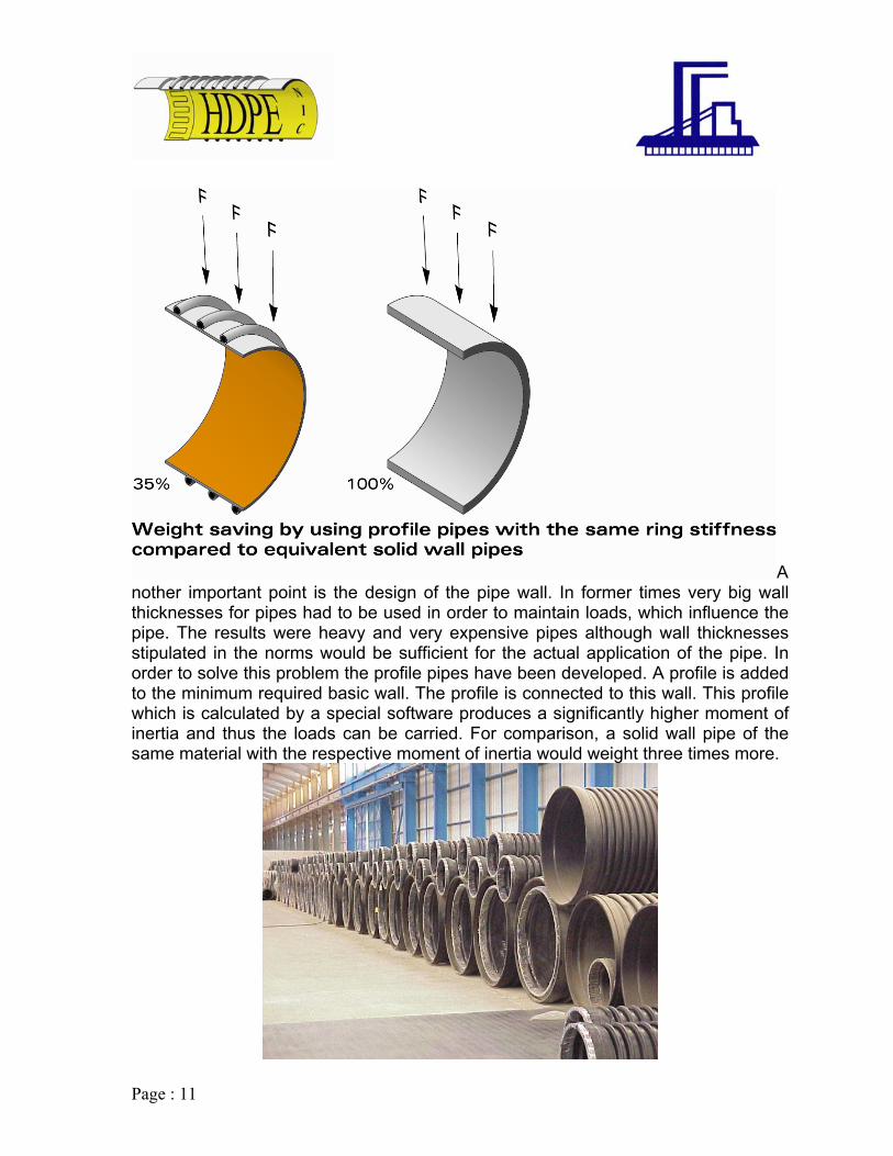
Another important point is the design of the pipe wall. In former times very big wall thicknesses for pipes had to be used in order to maintain loads, which influence the pipe. The results were heavy and very expensive pipes although wall thicknesses stipulated in the norms would be sufficient for the actual application of the pipe. In
with the respective moment of inertia would weight three times more.
order to solve this problem the profile pipes have been developed. A profile is added to the minimum required basic wall. The profile is connected to this wall. This profile which is calculated by a special software produces a significantly higher moment of inertia and thus the loads can be carried. For comparison, a solid wall pipe of the same material

Page : 12
6. Elasticity of HDPE Profiled Pipes.
Pipes made of Polyethylene and Polypropylene has considerable advantages to other pipe materials like concrete, steel, ductile etc. One of these advantages is the
pipe will be diminished. Within a short time there is a balance in the area around the pipeline and the deformation comes to a standstill. Plastic pipes react very flexible to static loads, while the loads do not concentrate themselves on the pipes, but are diverted to the surrounding soil. Flexible pipes still function, when other rigid pipe systems have already broken.
In axial direction Since the pipelines are profiled on the outside, these profiles can fix the pipes in the soil, There will be no or very few axial extension in the pipeline, Krah pipes are nearly unaffected by temperature variations.
high flexibility. Even in areas, which are highly affected by earthquakes, our pipes are hardly damaged in comparison to pipes made of other materials. Despite the flexibility of the Krah pipes they have a great capacity to carry loads, so that they are also suitable for road construction.
In radial direction Elastic pipes can react to changes in their environment. Due to the deformation performance, the load is distributed to its surrounding and the force acting on the

Page : 13
Benhe maximum bending radius depends on the proportion of the pies wall thickness
to the diameter of the pipes. If the proportion is small the maximum bending has to be considered with the relation to the buckling. If the proportion is bigger the maximum bending of the pipe wall has to be considered on a long-term basis. A maximum expansion of 2.5% (ξ) should not be exceeded. Formula for bending :
ding T
2
2*
*28.01
+
=sDi
sRB
BR = bending radius [mm] s = wall thickness (for profiles the water wall thickness) [mm] formula for expansion:
ε
100*2
+
=sDi
RB
Di = internal diameter [mm] ε = peripheral strain [%]

Page : 14
7. Delivery Program
ns: Din 16961
prEN 13476-1 Or on request ASTM F 894 JS K 6780 St ATV A 127 ISO 9969 Hydraulic calculations: ATV A 110
Laying of pipes EN 1610 ASTM D 2321
W DVS 2207 KWS
Materials High density polyethylene (PE80 and PE 100). Polyethylene-random (PP-R), polyethylene-homo (PP-H), polypropylene-flammable (PP-S). Other materials on request.
Pipe lengths The standard laying length (L) of the Krah pipes is six meters. In addition it is possible to produce continuously any lengths between one and six metes. The longer a pipe is the fewer joints are necessary and this is advantageous for the installation of the pipe. Moreover it is possible to deliver the pipes already jointed, whereby the installation time on site is reduced again. Lengths up to 18 m consisting of 3 pipes sections are common.
"NIC HDPE" Profiled Pipes
Used standards and recommendatio Pipe:
NBR 7373
atical calculations:
elding or pipes: Internal standard:

Page : 15
Pipe dimension Standard and special lengths are produced with internal diameters
from DN 300 to DN 4000 mm, so in case of
nt wall thicknesses al diameter is
e same with the capacity.
ternal diameter
ing length [mm]
up to 300 mm can be produced.
iffness
weight can be reduced up to 65% compared to a solid wall pipe with the same ring stiffness. Krah pipes offer the best security and durability.
s
(D1)
differethe internalways th
c hydrauli Di = in[mm] L = lay
Wall thickness and profile type Depending on the application, profiled and solid/smooth-wall pipes with wall hicknesst
Profile and StBy using a profiled pipe it is possible to use a light pipe for a high static load. The supportable static load is determined for every profile geometry by the factors elastic modulus [N/mm2] of the respective material and the moment of inertia of the profile geometry [mm4/mm] referring to the pipe diameter. The result is called ring stiffness. By using a profile design pipe, the

Page : 16
Page : 16
8. NIC HDPE Pipes as per ISO 9969 Type SN 8 Type SN 16 Nominal Dia.
DN mm Socket inner
Dia. Type SN 2 SN=2kN/m2
Type SN 4 SN=4kN/m2
300 380 PR 21-0.4 PR 21-0.4
400 480 PR 21-0.4 PR 21-0.4
500 580 PR 21-0.4 PR 34-0.99
600 680 PR 34-0.99 PR 34-1.2
700 780 PR 34-0.99 PR 42-1.9
800 880 PR 42-1.9 PR 54-4.5
900 980 PR 42-2.28 PR 54-4.5
1000 1080 PR 42-2.6 PR 54-5.5
1200 1280 PR 54-4.5 PR 54-9.6
1400 1480 PR 54-7.0 PR 54-16.3
1600 1680 PR 54-11.36 PR 54-24.25
SN=8kN/m2 SN=16kN/m2
PR 21-0.4 PR 34-0.99
PR 34-0.99 PR 42-1.9
PR 42-1.9 PR 54-4.5
PR 42-2.6 PR 54-4.7
PR 54-4.5 PR 54-8.0
PR 54-11.39 PR 54-6.6
PR 54-8.0 PR 54-16.3
PR 54-11.39 **
PR 54-19.8 **
** **
** **
1800 1880 PR 54-16.3 SQ1 54-31.5 ** **
2000 2080 PR 54-24.25 SQ1 54-31.5 ** **
2200 ** ** ** ** **
2400 ** ** ** ** **
2600 ** ** ** ** **
2800 ** ** ** ** **
3000 ** ** ** ** **
3200 ** ** ** ** **
3400 ** ** ** ** **
3600 ** ** ** ** **
3800 ** ** ** ** **
4000 ** ** ** ** **
** stands for special profile shapes on request

Page : 17
9. Technology at the highest level.
Production Technology The production of th NIC HDPE" ofiled pipes made on the machines manufactured by Krah AG is designed to meet the requirement of the present local governmental norms and standards. Quality and ciency are a s, which havbeen realized. A gr riety of pi types can b roduced. On e following es various properties and advantages are described. In case of huge projects in large pipe sizes a pipe production on the jobsite is possible. Its mobility is one of the biggest adv es of the K production es.
e " pr
effi im e
eat va pe e p th pag
antag rah lin

Page : 18
If requested all "NIC HDPE" profiled pipes can be delivered either with a bright, inspection friendly or an electro-conductive inner surface made by the co-extrusion process. This method ensures an inspection friendly, bright inner surface and the same time a long term UV-resistant outer surface. A pipe production out of grey material cannot fulfil these important properties.
KRAH-PIPES
The advantages at a glance :
• Safe and field proven pipe system. • Safe and easy connection technique (Electro-fusion welding
system). • Good chemical resistant (material polyethylene and
polypropylene). • High mechanical resistance (abrasion and impact resistant, secure
against fracture). • Good Hydraulics (smooth inner surface). • Flexibility (secure against fracture even in case of earth
movement). • Easy to handle (low weight, easy processing, quick assembly).
0C, to +800C).
stant.
• Lifetime over 100 years.
• Resistant to rodents.
Co-Extrusion
• High temperature resistance (application from -40
• Inspection friendly due to light inner surface.
• Earthquake proven.
• UV-resi
• Environmentally friendly.
• Material can be recycled to 100%.
Page : 19
ical background.
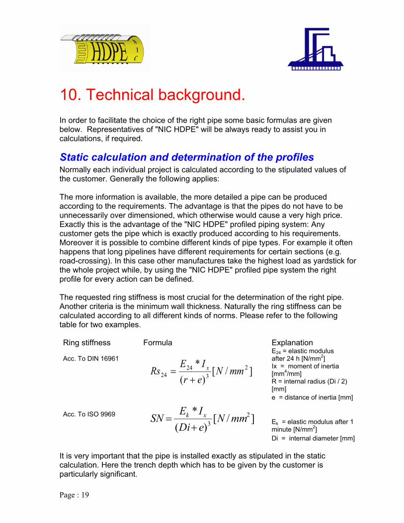
tatic calculation and determination of the profiles Normally each ind s calculated according to the stipulated values of t lies: The more information is available, the more detailed a pipe can be produced acco i ge is that the pipes do not have to be unn high price. Exactly this is the advantage of the "NIC HDPE" profiled piping system: Any cust to his requirements. Moreover it is possible to combine different kinds of pipe types. For example it often hap n (e.g. road-crossing). In this case other manufactures take the highest load as yardstick for the o profiled pipe system the right prof f The req tiffness is most crucial for the determination of the right pipe. Ano s can be calculated according to all different kinds of norms. Please refer to the following tablRin tiRing stiffness Formula Explanation
AccE24 = elastic modulus after 24 h [N/mm2]
Ix = moment of inertia [mm4/mm]
R = internal radius (Di / 2) [mm]
e = distance of inertia [mm] Acc. To ISO 9969
Ek = elastic modulus after 1 minute [N/mm2]
Di = internal diameter [mm] It is very important that the pipe is installed exactly as stipulated in the static calculation. Here the trench depth which has to be given by the customer is particularly significant.
10. Techn In order to facilitate the choice of the right pipe some basic formulas are given below. Representatives of "NIC HDPE" will be always ready to assist you in calculations, if required.
Sividual project i
he customer. Generally the following app
rd ng to the requirements. The advantaecessarily over dimensioned, which otherwise would cause a very
omer gets the pipe which is exactly produced according
pe s that long pipelines have different requirements for certain sections
wh le project while, by using the "NIC HDPE"ile or every action can be defined.
uested ring sther criteria is the minimum wall thickness. Naturally the ring stiffnes
e for two examples. g s ffness
. To DIN 16961
]/[)(
* 23
24 mmNerIE
Rs x
+=24
]/[)(
23 mmNeDixk
+=
* IESN

Page : 20
are all described in the norm e determined and the later
as to be carried out. ATV A 127. One of these installation possibilities has to be e the
is for n. The recommended or feasible compaction depends,
among other things, on the type of soil.
utionary .
static calculation are: - installation depth
the standard profiles. For the calculation the llowing conditions were assumed:
ses und water
terial G1 esive soil) - compaction: 97% proctor density
the pi- pipe made of standard material PE - 80 (E-modulus, short 800 N/mm
There exist several possibilities to install the pipes thatATV 127. One of these installation possibilities has to bhdetermined and later has to be carried out. It is absolutely necessarily to observvalues for the compaction stipulated in the static calculation as this is the basthe whole static calculatio
As loads, especially traffic loads, directly affect the manhole, special precameasures have to taken. For more about manholes please refer to the pages 27-29The most significant influencing factors for the
- traffic and area load - groundwater table - soil characteristics - installation conditions
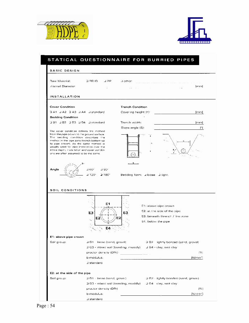
Please also refer to the questionnaire at end of catalogue.
Pipe selection The following table gives an overview offoThe selection of the profiles in the list is the result of a calculation according to ATVA 127 with a maximal deflection of 6% after 50 years of service.
- a covering of 1000 [mm] up to 5000 [mm] - normal safety clas- no gro- filling ma (non coh
- bedding of pe 180°
2)

Page : 21
Profile Selection Diameter in mm Without traffic load With traffic load
300 PR 21-0.4 PR 21-0.4 400 PR 21-0.4 PR 21-0.4 500 PR 21-0.4 PR 21-0.4 600 PR 21-0.4 PR 34-1.2 700 PR 21-0.4 PR 34-1.2 800 PR 34-1.2 PR 42-01.9 900 PR 34-1.2 PR 42-02.6 1000 PR 34-1.2 PR 54-04.7 1100 PR 42-02.6 PR 54-05.5 1200 PR 42-02.6 PR 54-06.6 1300 PR 54-04.7 PR 54-08.0 1400 PR 54-04.7 PR 54-08.5 1500 PR 54-05.5 PR 54-10.3 1600 PR 54-06.6 PR 54-11.8 1700 PR 54-07.0 PR 54-12.9 1800 PR 54-08.0 PR 54-14.2 1900 PR 54-10.3 PR 54-16.3 2000 PR 54-10.3 PR 54-19.8 2100 PR 54-11.8 PR 54-19.8 2200 PR 54-14.2 SQ1-34-12 2300 PR 54-16.3 SQ1-34-12 2400 PR 54-19.8 SQ1-34-15 2500 SQ1-34-22 SQ1-34-18 2600 SQ2-34-46 SQ2-34-22 2700 SQ2-34-46 SQ2-34-22 2800 SQ2-34-46 SQ2-34-46 2900 SQ2-34-46 SQ2-34-46 3000 SQ2-34-46 SQ2-34-46
Above 3000 Special shapes as per request.

Page : 22
11. Hydraulics Calculation of Flow Rate To determine t w rate “Q” for a ipe in a continu ge, the so called “normal discharge” – for publ es, the ATV A 1 d and also the European standard DIN EN 752 recommends to use the fo is related to Prandtl-Colebrook and is called the “general discharge form
he flo fully filled pic sewer pip
ous dischar10 standar
rmula whichula”:
2*klog*2
Q = flow rate [Di = internal diameter [m] V = kinemati sity for sewag(acc. To ATV A 110: v = 1.31 x 10-
j = energy gr at normal disck = hydraulic effective roughness [g = acceleration due to gravity The values of k is indicated in the t TV A 110 stanroughness of 0.25 to 1.50 mm (depending on the kind of pipe). All possible losses are included in the value.
Calculation of partly filled pipes at normal discharge For the calculation of partly filled pipes at normal discharge there are tables in the ATV Arbeitsbl 10 available fo ed, calculatio owing formula:
v = flow speed [m/s]
rh = hydraulic radius [m], for circular profiles = D/4 V = fully filled value T = partly filled value
m3/s]
c visco e [m2/s] 6 [m2/s])
adient, harge [-] m]
able of the A dard as real
att A 1 r the flow spe n with the foll
(r= ) 625.0
]/[*71.32
*51.24
* 32
smgDiJDigDiJDi
vDiQ
+−=
π
,, // vhThvT rvv
Page : 23
b ays, if there exist a great difference between the pipe. In order to design the pipes adequately n when carrying out the dimensioning.
Buckling Buckling forces (p ) occurs alwinside and the outside pressure of a this has to be taken into consideratioThe general formula for the buckling capacity of a pipe structure is:
][**23
MPaSEP e
b
= 1 Dv m −
E = modulus of elasticity [N/mm2] se = equivalent solid wall thickness [mm]
r (Di+s) [mm] [-]
n the stress level, the temperature and υ ) which should be used is 0.4 [-] for
lene.
he computation model for calculating the hoop stress σ on the pipe wall induced by an internal pressure pi, is called the ring formula. According to ISO standard 161
Dm = mean diametev = contraction coefficient The modulus of elasticity (E) is depending othe loading time. The contraction coefficient (polyethylene and o.38 [-] for polypropy
Internal pressure T
part 1, the formula is as follows:
]/[10**2
* 2mmNsDp ei=σ
y re-arrangement, the formula can express the wall thickness (s0: B
i
][*2*10
mmp
S+
=σ
DePi ∗
]/[ 2mmNCMRS
s =σ
Page : 24
ressure [bar]
The permissible design stress is defined by the pipe material lifetime, safety factor and temperature according to DIN 8074, or according to other official test
ocuments.
Pi = working pDe = external diameter (Di+2s) [mm] σ = hoop stress acc. To ISO 161 [N/mm2] σs = permissible design stress [N/mm2]
mm] s = wall thickness, here explicit only the water way wall thickness [RS = minimum required strength [N/mm2] M
dThe standard safety factor for water Cmin = 1.25 [-] c = 1.6 [-]
In reality the MRS of the raw material is higher, depending on the resign supplier.
8075 2] for PE100 8075
12 [N/mm2] for PP-R 8078 8078
quivalent standard dimension ratio To get an equivalent value (eSDR) for "NIC HDPE" pipes, in case that there is no internal pressure, the following formula can be used:
The minimum required strength (MRS) according DIN 8 [N/mm2] for PE80 11 [N/mm
12 [N/mm2] for PP-H The values are of 50 years and a temperature of 20ºC. Other lifetime and temperature values on request.
E
][−=SDeSDR or ][*2
−+
=S
SDiSDR
]/[1.12
4 mmmmI x = ][12*3 mmIS xe = 1*3S and
]12*
1**23
3
−+
=x
x
IIDi
eSDR [2

Page : 25
ue
ith different joint systems. The pipe ends
tegrated Electro-Fusion.
12. Jointing Techniq All "NIC HDPE" pipes can be delivered ware equipped accordingly and integrated directly in the pipe.
In
weld plastic pipes and fittings with help of Electro-Fusion has been
a common method in the market for is joint
technique is very favourable, simple and secure. "NIC HDPE" is using this technique
r big pipes. A welding wire is included in the socket is
g device whereby the two pipe ends (the socket and the spigot) are jointed together. By this fast jointing technique it is possible to install pipes in such a short period of time which has never been realizable before. Without any problems and with only one welding device it is possible to install a pipeline of 72 mm with a diameter of
200 mm in 8 hours. The recording which is necessary for the quality assurance is realizable very easy and secure with the help of the welding device from "NIC HDPE"
Tothe
1
years. Above all because th
also fowhichheated with the help of a special weldin
Page : 26
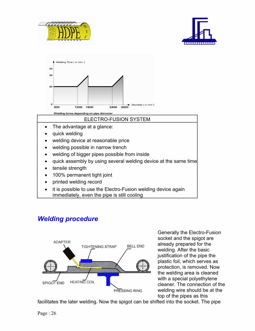
ELECTRO-FUSION SYSTEM
• The advantage at a glance: • quick welding • welding device at reasonable price • welding possible in narrow trench • welding of bigger pipes possible from inside • quick assembly by using several welding device at the same time • tensile strength • 100% permanent tight joint • printed welding record • it is possible to use the Electro-Fusion w
immediately, even the pipe is still coolin
Welding procedure
elding device again g
Generally the Electro-Fusion socket and the spigot are
s the later welding. Now the spigot can be shifted into the socket. The pipe
already prepared for the welding. After the basic justification of the pipe the plastic foil, which serves as protection, is removed. Now the welding area is cleaned with a special polyethylene cleaner. The connection of the welding wire should be at thetop of the pipes as this
facilitate

Page : 27
is justified, the inside support ring is put into the right position and the outer tensile band is tightened. The welding adapter is screwed on the ends of the welding wire, Now it can be connected to the welding device. On the pipe is a barcode, which includes all necessary information for the welding. With the help of a barcode reader this information is read and welding can be started. After having finished the welding a certain cooling time which depends on several factors, has to be respected. Only after this cooling time the inside support ring and the outer tensile band can be completely detached.
Software
The welding device Tiny Data has the capacity to recThese welding records are saved in the device and ccomputer. The software which is needed for this is casoftware two things can be done: on the one hand thcan be read and administered and on the otthe pipes can be made.
oal
eher hand the barcode for the welding of
rd any individual welding. n be read out by the led “Krahcode”. With this data of the welding device

Page : 28
ointed with the help of a extrusion welding extruder. The outsides of the ends are chamfered. Thus a welding seam is produced which looks like a V. Normally no socket-spigot connection is used. The welding has to be done according to DVS 2207 part 4.
13. Other jointing possibilities. In addition to our unique integrated Electro-Fusion jointing technique our pipes can also be produced with the following techniques:
V seam extrusion welding ipes and fittings are jP
Extrusion welding The pipe and/or fittings, which shall be connected, are jointed by a socket and spigot
joint. Thus the two pipe ends are jointed with a extrusion welding device. The jointing method can be carried out inside or/and
ing pressure
rding
outside of the pipe. This jointis most suitable for low-gravity and manholes. Accoto DVS 2270 part.

Page : 29
methods is only recommended for pies and fittings with a maximum wall thickness of 150 mm and
to VS
tfl
manufactured with the pipe, or the flanges are available as separate fitting. This kind of jointing method is mostly used for open sea discharge application and for tank connections. The greatest advantage of this connection is the facility of disjointing.
Gasket connection This connection also uses the socket a jointing including a special rubber sealing which is installed into the spigo
also disjointable. The pipe ends has to have the minimum stiffness
asa1
mplete pipe system is always just as good as its weakest component. The kest component of the pipe is the joint. Therefore it is important to choose the
most suitable and permanent joint. The most preferred joint system is the Electro-Fusion welding. As the whole pipe system becomes a homogenous unit.
Heat element butt welding The pipes and fittings are jointed with the help of a heating element butt welding machine. The ends of the pipes and fittings are butt-welded. This kind of jointing
Flange connection The ends of the pipes and fittings are jointed with rubber gasket. Depending on the type of pipe the
with diameters from 300 mm2500 mm. According to D2270 part 1.
he help of steel flange and a ange adapters are completely
nd spigot t end of the pipe or the fittings. This method is
Please note
in the spigot and the socket ccording to prEN 13476 and hould withstand the test ccording to prEN 1277 and EN 053.
A cowea
Page : 30
file
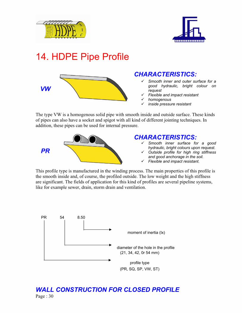
14. HDPE Pipe Pro
CHARACTERISTICS: Smooth inner and outer surface fo
good hydraulic, bright colour request
Flexible and impact resistant homogenous inside pressure res
VW r a on
istant
solid pipe with smooth inside and outside surface. These kinds and spigot with all kind of different jointing techniques. In
The type VW is a homogenousof pipes can also have a socketaddition, these pipes can be used for internal pressure.
CHARACTERISTICS: Smooth inner surface for a goo
hydraulic, bright colours upon request Outside profile for high ring st
and good anchorage in the Flexible and impact resistan
PR
This profile type is manufactured in the winding process. The m
d .
iffness soil. t.
ain properties of this profile is the smooth inside and, of course, the profiled outside. The low weight and the high stiffness
plication for this kind of profiles are several pipeline systems, drain and ventilation.
n
diameter of the hole in the profile (21, 34, 42, 0r 54 mm)
WALL CONSTRUCTION FOR CLOSED PROFILE
are significant. The fields of aplike for example sewer, drain, storm
t of inertia (Ix)
Explanation of the profile no. PR 54 8.50
mome
profile type (PR, SQ, SP, VW, ST)

Page : 31
(Single and Multilayer Wall)
ST
ARACTERISTICS: Smooth inner and outer surface for a
good hydraulic, bright colour on request
Flexible and impact resistant
SQ3
smooth both inside and outside and therefore very suitable for standing objects such as shafts. This profile is in particular suitable forland-fills, because the coefficient of friction is low at the outside surface. U
ada ept d to fit the side requirements and ains etc.) The guidelines for this
lculatio (FEM) calculation.
Pip
CH
homogenous inside pressure resistant
SQ1 SQ2
CHARACTERISTICS: This profile is developed to fabricate shafts and special constructions. The pipe wall is
pon request, the inside surface can be made in a bright colour or electro-conductive. In individual cases the static calculation must beconditions; such as ground water or special loads (trca n are described in ATV 127 or finite element We have available software to do these calculations.
es with the profile type ST are specially made for vertical tanks,
where different wall thickness in one pipe are required to save material. The calculation method is according to DVS 2205

Page : 32
15. Fittings. All fitting are fabricated from pipes of the type VW or SQ. Generally the fittings are designed corresponding to the required stiffness and in consideration of the welding factors. Every fitting can have any kind of pipe end and any jointing techniques including the integrated Electro-Fusion socket and spigot.
All pipe end dimensions fulfill the requirement ominimum lengths and stiffness. The standard spigot le
ard socket length (Lm) is 140 mm.
f the p rEN 14376 standard, like ngth (Ls) is 140 mm and the
stand

Page : 33
ranches can be manufactured and delivered in every type and form. The angle can
Branches Bbe adapted individually from 30º to 90º as well as the ends and the respective segment lengths.
Tee dimensions as per standard DIN 16961 Di1 [mm] Di2 [mm] Lt [mm] L1 [mm] L2 [mm]
300 100/150/200/250 1100 350 750 400 100/150/200/250/300 1300 400 900 500 100/150/200/250/300 1400 400 1000 600 100/150/200/250/300 1650 450 1200 700 100/150/200/250/300 1900 500 1400 800 100/150/200/250/300 1900 500 1400 900 100/150/200/250/300 2000 500 1600 1000 100/150/200/250/300 2000 500 1600 1100 100/150/200/250/300 2100 500 1600 1200 100/150/200/250/300 2100 500 1800 1300 100/150/200/250/300 1400 100/150/200/250/300 1500 100/150/200/250/300 1600 100/150/200/250/300 1800 100/150/200/250/300 2000 100/150/200/250/300
2000 - 4000 Special construction as per design dimensions

Page : 34
ends anufactured and segmented in different angles and the related
BBends can be mradius of the bend to pipe diameter can be selected independently.
Bend dimensions as per standard DIN 16961
Number of Segments, L, [mm] Di [mm] 2 2 3 3 4 4
α =15° α =30° α =45° α
400 210 270 330 410 500 70 236 310 390 49600 180 270 350 450 56700 200 300 400 510 550800 210 320 430 560 720900 220 340 470 620 790
1000 240 380 520 680 8701100 250 400 560 750 9501200 270 430 600 800 1021300 300 460 640 860 1101400 330 490 680 920 1181500 360 520 980 11600 390 650 11800 420 580 100-40 Special construction as r design dimensions pe
=60° α =75° α =90° 300 100 190 230 280 330 410
160 510 0 600 0 700
820 900 1000 1100 1200
0 1300 0 1400 0 1500
720 260 1600 760 1040 340 1700 800 1100 420 1800
20 00

Page : 35
tion will always meet the requirements.
Reductions Reduction can be mane both centric and eccentric so that the reduc
Reduction dimensions as per standard DIN 16961 Di2 Di2 Lt L1 L2
[mm] [mm] [mm] [mm] [mm] 300 400 1200 500 500
500 1300 500 500 1400 500
1400 500 0
700 1500 500 0 600 00 5
00 5700 00 5
00 5800 00 5
00 5100 cial c on as ign dim s
500 400 500
600 500 500 600 150 500 500
50 700 16 00 500
800 16 00 500 800 17 00 500
900 17 00 500 900 18 00 500
1000 18 00 500 900-4000 0-3600 Spe onstructi per des ension
Page : 36
ial Constructions.
ns
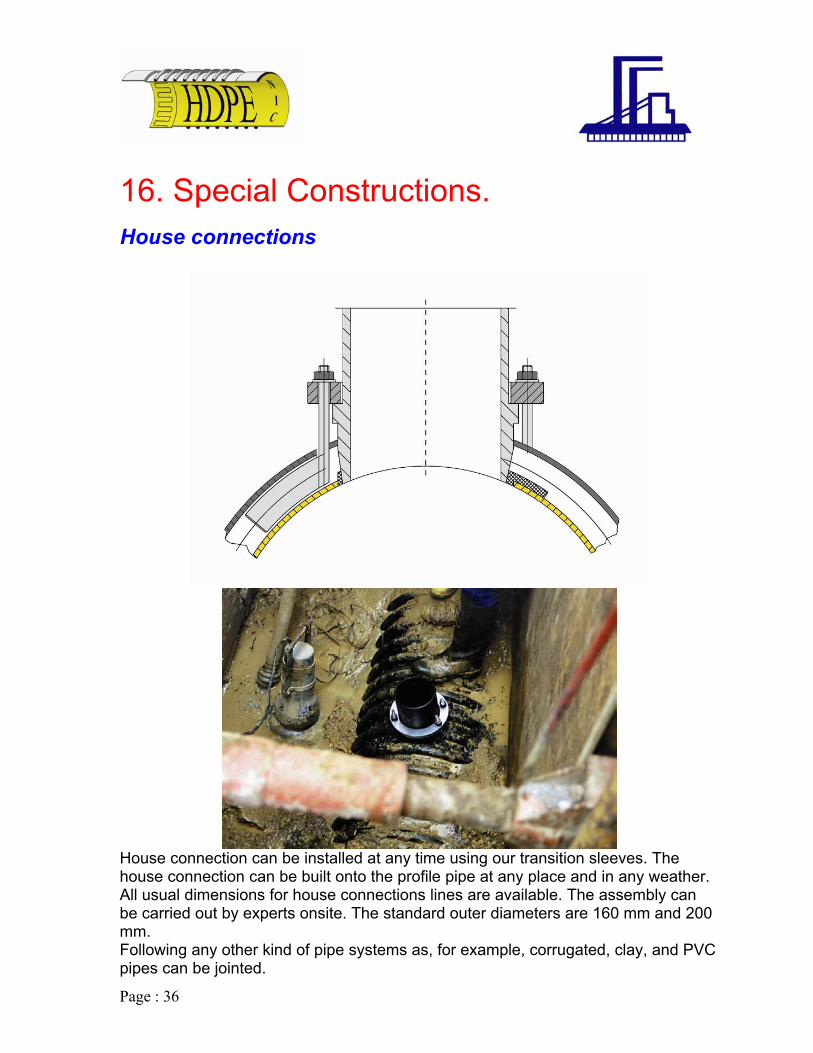
16. SpecHouse connectio
House connection can be installed at any time using our transition sleeves. The house connection can be built onto the profile pipe at any place and in any weather. All usual dimensions for house connections lines are available. The assembly can be carried out by experts onsite. The standard outer diameters are 160 mm and 200 mm. Following any other kind of pipe systems as, for example, corrugated, clay, and PVC pipes can be jointed.

Page : 37
Puddle flanges
In order to lead Krah pipes through wall, e.g. in sewage plants or concrete shafts, we recommend our puddle flanges which can be flush mounted in concrete. The tightness is secured by a ring made of EPDM.
Puddle flange dimension Type KPF 1 Type KPF 2 and KPF 2a
Di d1 b1 d2 d3 d4 b2 b3 b4 [mm] [mm] [mm] [mm] [mm] [mm] [mm] [mm] [mm] 300 - - 336 442 517 200 130 140 400 - - 436 542 617 200 130 140 500 - - 536 642 717 200 130 140 600 - - 636 742 817 200 130 140 700 770 160 736 842 917 200 130 140 800 870 160 836 942 1017 300 130 140 900 970 160 936 1056 1131 300 130 140
1000 1070 160 1036 1156 1231 300 130 140 1100 1170 160 1136 1256 1331 300 130 140 1200 1270 160 1236 1356 1431 300 130 140 1300 1370 160 - - - - - - 1400 1470 160 - - - - - 1500 1570 160 - - - - - - 1600 1670 160 - - - - - 1700 1770 160 - - - - - - 180
-
-
0 1870 160 - - - - - - 1900 1970 160 - - - - - - 2000 2070 160 - - - - - -

Page : 38
7. Manholes. 1
of the same material as the pipes nd also connected to the system with similar jointing techniques. The special
advantage is that a homogeneou aterial is produced. With eference, pr ke SQ and VW are used for the production of the
manholes, as the soil can densify tter at smoot tside e pip d settwithout problems.
To offer the possibility to control and maintain pipe systems regularly, manholes are integrated in the system. These are mainly installed at the positions of bends, reduction or branches. The manholes are madea
s system of the same mpr ofile types li
be the h ou of th e an le

Page : 39
Standard manhole
This kind of manhole is situated centrically above the pipe. Because of staticsafety reason this type is only recommended if the diameter of the pipe is smaller or equal to the diamet
and
er of the manhole. Normally the diameters DN 800 of ND 1000 are used for this kind of manhole. Usually the lower part of the manhole is completely fabricated out of polyethylene or polypropylene according to the statical requirements. The upper part is a concrete or reinforced concrete ring according to DIN 4034. Even very complex constructions according to the engineer’s requirements are possible. The main advantage is the sustainable, flexible lightweight, inspection friendly, self-cleaning and durable construction.
Manholes design pipe diameter (Di1) manhole diameter (Di2) height (h) length (L)
[mm] [mm] [mm] [mm] 300 800, 1000 min 1000, max 6000 2000 400 800, 1000 min 1000, max 6000 2000 500 800, 1000 min 1000, max 6000 2000 600 800, 1000 min 1000, max 6000 2000 700 800, 1000 min 1000, max 6000 2000 800 1000 min 1000, max 6000 2000 900 1000 min 1000, max 6000 2000
Page : 40
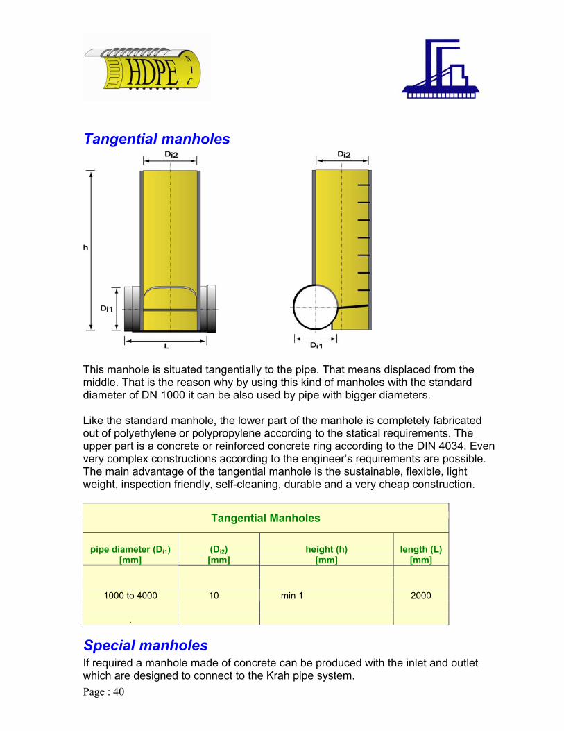
Tangential manholes
This manhole is situated tangentially to the pipe. That means displaced from the middle. That is the reason why by using this kind of manholes with the standard diameter of DN 1000 it can be also used by pipe with bigger diameters.
n ing to the engineer’s requirements are possible.
he main advantage of the tangential manhole is the sustainable, flexible, light
Like the standard manhole, the lower part of the manhole is completely fabricated out of polyethylene or polypropylene according to the statical requirements. The upper part is a concrete or reinforced concrete ring according to the DIN 4034. Evevery complex constructions accordTweight, inspection friendly, self-cleaning, durable and a very cheap construction.
Tangential Manholes
pipe diameter (manhole diameter
Di1) [mm]
(Di2) [mm]
00 000 to max 6000 2000 .
re de t to th e system.
height (h) [mm]
length (L) [mm]
1000 to 4000 10 min 1
Special manholes If required a manhole made of concrete can be produced with the inlet and outlet which a signed to connec e Krah pip

Page : 41
Cover of manholes
For the cover of the manholes there exist all different kinds of possibilities. Especially the application case and the loads are major criteria for the correct choice of the cover.
y d
le which lies
is lways even.
Moreover it is possible to choose between the following covers:
Regularly the manholes are installed in such a way that the top edge is justified tothe earth’s surface or the street. In this case the cover has to be designed in a wathat the direct load conditions, e.g. crossing vehicles, can be carried and forwarde
he most frequently used system is the concrete plate above the manhoTon a ring anchor. The advantage is that the rising loads are not forwarded to the manhole but through the ring anchor to the surrounding earth. Also the PE cone, which was especially developed for PE and PP manholes, has similar properties like the above-described cover. These covers are especially suitable for the installation in roads, as the cover is integrated into the asphalt and flexibly connected with the manhole (telescopic).
hus covers moves with the asphalt in case that the road settles and the manholeTa
Page : 42
Handling, Storage
Transport
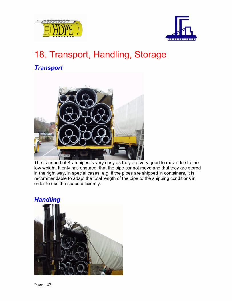
18. Transport,
The transport of Krah pipes is very easy as they are very good to move due to the low weight. It only has ensured, that the pipe cannot move and that they are stored in the right way, in special cases, e.g. if the pipes are shipped in containers, it is recommendable to adapt the total length of the pipe to the shipping conditions in order to use the space efficiently.
Handling
Page : 43
the pipes in the d. Normally the
pipes can be unloaded and transported to the trench by an excavator, which anyway e.
Storage
Forklifts with a rod of 5 meters are very suitable for the handling ofproduction facilities. On site no additional heavy devices are neede
is present on sit
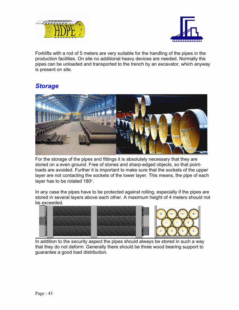
For the storage of the pipes and fittings it is absolutely necessary that they are
rotected against rolling, especially if the pipes are tored in several layers above each other. A maximum height of 4 meters should not
stored on a even ground. Free of stones and sharp-edged objects, so that point-loads are avoided. Further it is important to make sure that the sockets of the upper layer are not contacting the sockets of the lower layer. This means, the pipe of eachlayer has to be rotated 180°. n any case the pipes have to be pIsbe exceeded.
In addition to the security aspect the pipes should always be stored in such a way that they do not deform. Generally there should be three wood bearing support to guarantee a good load distribution.

Page : 44
19. Installation
The installation of NIC HDPE pipes is very easy. After the trench has been prepared in the same way as for all other pipes, the "NIC HDPE" pipe is laid down and aligned. The individual pipe parts are jointed with the different kinds of jointing
general, the installation is carried out according to EN 1610.
techniques. The backlifting has to be carried out according to the requirements of the statical calculations. In
Page : 45
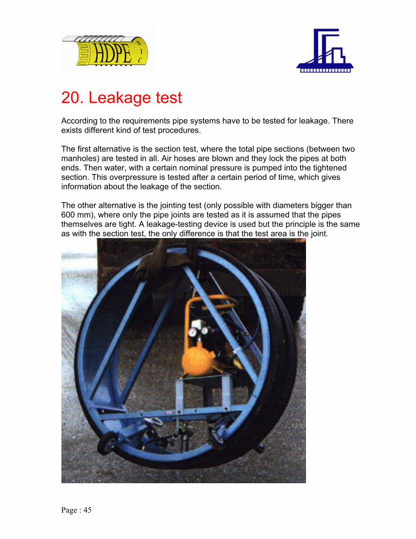
t According to the requirements pipe systems have to be tested for leakage. There exists different kind of test procedures. The first alternative is the section test, where the total pipe sections (between two manholes) are tested in all. Air hoses are blown and they lock the pipes at both ends. Then water, with a certain nominal pressure is pumped into the tightened section. This overpressure is tested after a certain period of time, which gives information about the leakage of the section. The other alternative is the jointing test (only possible with diameters bigger than 600 mm), where only the pipe joints are tested as it is assumed that the pipes themselves are tight. A leakage-testing device is used but the principle is the same as with the section test, the only difference is that the test area is the joint.
20. Leakage tes
Page : 46
anagement.
st procedures for the quality assurance. The hole production process is included in an extensive Total-Quality-Management-
efore production control e
During production control
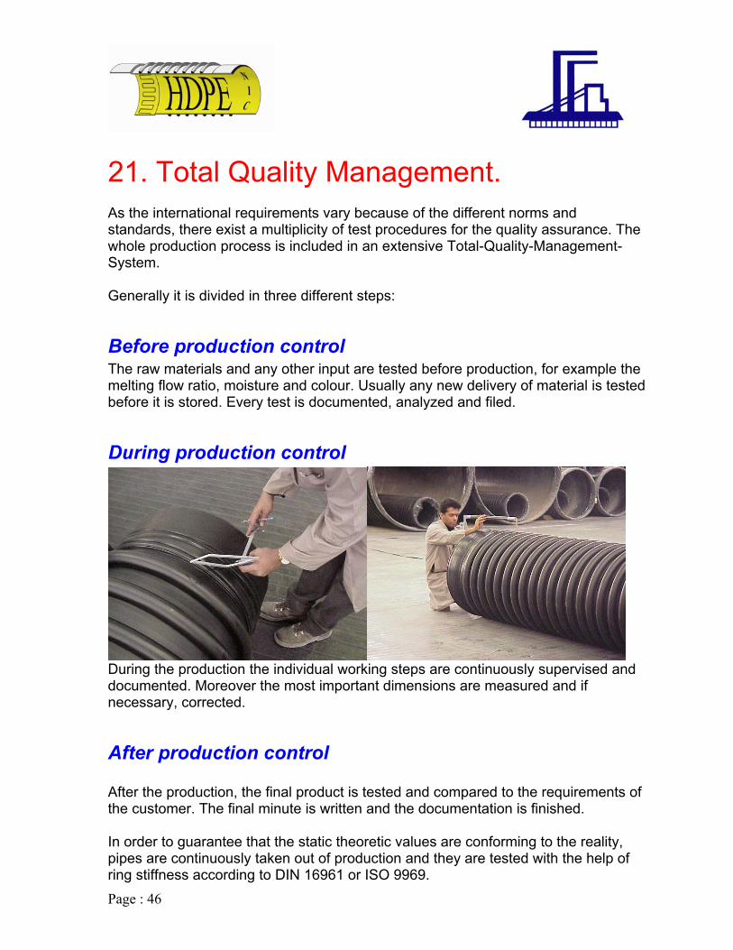
21. Total Quality M As the international requirements vary because of the different norms and standards, there exist a multiplicity of tewSystem. Generally it is divided in three different steps:
BThe raw materials and any other input are tested before production, for example thmelting flow ratio, moisture and colour. Usually any new delivery of material is testedbefore it is stored. Every test is documented, analyzed and filed.
During the production the individual working steps are continuously supervised and documented. Moreover the most important dimensions are measured and if necessary, corrected.
After production control After the production, the final product is tested and compared to the requirements of the customer. The final minute is written and the documentation is finished. In order to guarantee that the static theoretic values are conforming to the reality, pipes are continuously taken out of production and they are tested with the help of ring stiffness according to DIN 16961 or ISO 9969.

Page : 47
uality certificates and external quality control
s ment of ISO 9001 : 2000. The quality control exceeds by far the ISO 9001
f the final product is tested. As result es for every delivery of pipes from the
ost simple quality certificate 2.2 to the first class certificate 3.1b according to EN
Q In general the whole production is constantly supervised by a third party inspection, like Kuwait University, KISR, etc. All quality procedures and management confirmo requiretcertifications because in our case the quality o
e are in the position to issue quality certificatwm10204.

Page : 48
2. Advantages at glance.
Time saving Up to 30% saving when laying the light and flexible pipes with lengths of 6 m.
Maintenance The smooth inner surface reduces the maintenance and cleaning costs considerably.
Hydraulics Due to very good hydraulics properties, smaller pipe diameters can be used compared to current traditional pipe materials.
Tightness 100% tight joints. No infiltration or exfiltration, no root penetration due to welded system.
ength The standard lengths of 6 m reduced the amount of joints.
2 .
Durability Low investment costs and a service life over 100 years reduce the operating costs.
L

Page : 49
ater outlets / discharge
23. Other Applications.
W
Water outlets are used for the discharge of liquid and gaseous substances at thebase of rH
technology,requiremenproject
ivers and the sea. For the construction and operation of such pipelines "NIC DPE" pipes offer considerable advantages, such as the elasticity of the pipeline
and therefore optimum adaptation to the area, low weight, secure and strong jointing seawater resistance and pipe stiffness exactly adapted to the respective ts because the appropriate profiles are selected for every individual

Page : 50
Reservoirs, storm water tanks
Within a sewage system, especially mixed water systems, reservoirs can store rainwater for delaying release to the sewage plant. This will avoid overload. As reservoir systems are usually built in subsequently, they must be assembled in a very short time. Since the "NIC HDPE" reservoir are prefabricated, this conditionfulfilled p
is erfectly. "NIC HDPE" tanks offer considerable advantages:
smooth inner surface which prevent incrustations the pipe’s self cleaning ability
- -
Page : 51
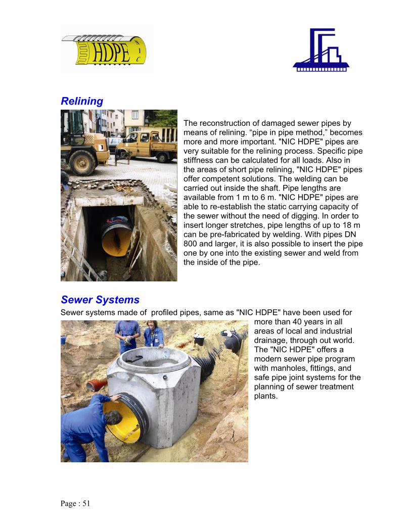
Relining The reconstruction of damaged sewer pipes by means of relining. “pipe in pipe method,” becomes more and more important. "NIC HDPE" pipes are very suitable for the relining process. Specific pipe stiffness can be calculated for all loads. Also in the areas of short pipe relining, "NIC HDPE" pipes offer competent solutions. The welding can be carried out inside the shaft. Pipe lengths are available from 1 m to 6 m. "NIC HDPE" pipes are able to re-establish the static carrying capacity of the sewer without the need of digging. In order to insert longer stretches, pipe lengths of up to 18 m can be pre-fabricated by welding. With pipes DN 800 and larger, it is also possible to insert the pipe one by one into the existing sewer and weld from the inside of the pipe.
Sewer Systems Sewer systems made of profiled pipes, same as "NIC HDPE" have been used for
more than 40 years in all areas of local and industrial drainage, through out world. The "NIC HDPE" offers a modern sewer pipe program with manholes, fittings, and
r the nt
safe pipe joint systems foplanning of sewer treatmeplants.

Page : 52
ilpzotaa
Tanks and Containers ProfpolyhoriFor planadvexp
ed or solid pipes made of polyethylene or ropylene are well suited for the manufacture of ontal and vertical tanks. ther special construction like chimneys, compost s and wash towers "NIC HDPE" pipes offer all ntages regarding variety, precision, quality, and ndability.

Page : 53
pecial tunnels & Ventilations. S
In addition to the common areas of application "NIC HDPE" pipes are also suitable for special projects like tunnels etc. "NIC HDPE" pipes are also used as ventilating pipes. The advantages over the traditional ventilating pipes which are made of sheet steel, is that there occur no corrosion which is especially important for the chemical and biological industry.
Page : 54

Page : 55

Page : 56

Page : 57