T4 User & Operator Manual - Crowcon
58
Personal Gas Detection Equipment T4 User & Operator Manual T4 Portable Multigas Detector M070044/Eng Issue 4 Nov 2016
-
Upload
khangminh22 -
Category
Documents
-
view
1 -
download
0
Transcript of T4 User & Operator Manual - Crowcon

Personal Gas Detection Equipment
T4 User & Operator Manual
T4 Portable Multigas Detector
M070044/EngIssue 4 Nov 2016
NAVIGATION INSTRUCTIONSThe symbols in the left-hand margin of each page of the manual will enable you to carry out the following functions:
Click on this button to display the Contents page.
Click on this button to display the previous page.
Click on this button to display the next page.
Click on this button to display the previous view (use it to return from a reference jump).
Click on this button to display next view (use it to return to a reference jump).
Click this button to print some or all of the document (specific pages can be chosen).
Exit Click this button to exit the User and Operator Manual.
! Press the Esc key to display normal Acrobat© Controls.
Contents

3
CONTENTSPROLOGUE . . . . . . . . . . . . . . . . . . . . . . . . . . . . . . . . . . . . . . . . . . . . . 6
T4 Overview . . . . . . . . . . . . . . . . . . . . . . . . . . . . . . . . . . . . . . . . . . . . . . . . . . . .6Safety Information . . . . . . . . . . . . . . . . . . . . . . . . . . . . . . . . . . . . . . . . 7Unpacking . . . . . . . . . . . . . . . . . . . . . . . . . . . . . . . . . . . . . . . . . . . . . 101. Set-up . . . . . . . . . . . . . . . . . . . . . . . . . . . . . . . . . . . . . . . . . . . . . . 12
1.1 Prior to use . . . . . . . . . . . . . . . . . . . . . . . . . . . . . . . . . . . . . . . . . . . . . . . . .121.2 T4 orientation . . . . . . . . . . . . . . . . . . . . . . . . . . . . . . . . . . . . . . . . . . . . . . .121.3 Charging & battery indications . . . . . . . . . . . . . . . . . . . . . . . . . . . . . . . .131.4 Fitting the calibration/bump test plate . . . . . . . . . . . . . . . . . . . . . . . . . .151.5 Fitting the external filter plate . . . . . . . . . . . . . . . . . . . . . . . . . . . . . . . . .161.6 +ve Safety™ . . . . . . . . . . . . . . . . . . . . . . . . . . . . . . . . . . . . . . . . . . . . . . . .171.7 Quick view . . . . . . . . . . . . . . . . . . . . . . . . . . . . . . . . . . . . . . . . . . . . . . . . .18
2. Operation . . . . . . . . . . . . . . . . . . . . . . . . . . . . . . . . . . . . . . . . . . . 212.1 Turning on . . . . . . . . . . . . . . . . . . . . . . . . . . . . . . . . . . . . . . . . . . . . . . . . .212.2 Home screen . . . . . . . . . . . . . . . . . . . . . . . . . . . . . . . . . . . . . . . . . . . . . . .242.3 Alarms. . . . . . . . . . . . . . . . . . . . . . . . . . . . . . . . . . . . . . . . . . . . . . . . . . . . .25
2.3.1 Low battery alarm . . . . . . . . . . . . . . . . . . . . . . . . . . . . . . . . . . . . . . .252.3.2 Instantaneous alarm . . . . . . . . . . . . . . . . . . . . . . . . . . . . . . . . . . . . .252.3.3 Short term exposure limit alarm (STEL) . . . . . . . . . . . . . . . . . . . . .262.3.4 Time weighted average alarm (TWA) . . . . . . . . . . . . . . . . . . . . . . . .262.3.5 TWA Resume function* . . . . . . . . . . . . . . . . . . . . . . . . . . . . . . . . . . .26
2.4 Alarm and status icons . . . . . . . . . . . . . . . . . . . . . . . . . . . . . . . . . . . . . . .272.5 Accepting and Clearing Alarms . . . . . . . . . . . . . . . . . . . . . . . . . . . . . . . .28

4
2.6 Sensors . . . . . . . . . . . . . . . . . . . . . . . . . . . . . . . . . . . . . . . . . . . . . . . . . . .292.6.1 Oxygen sensor . . . . . . . . . . . . . . . . . . . . . . . . . . . . . . . . . . . . . . . . .292.6.2 Electro-chemical sensors . . . . . . . . . . . . . . . . . . . . . . . . . . . . . . . .292.6.3 Pellistor sensors . . . . . . . . . . . . . . . . . . . . . . . . . . . . . . . . . . . . . . .302.6.4 Pellistor saver mode . . . . . . . . . . . . . . . . . . . . . . . . . . . . . . . . . . . .30
2.7 T4 menu icons . . . . . . . . . . . . . . . . . . . . . . . . . . . . . . . . . . . . . . . . . . . . . .312.8 Accessing T4 menu functions . . . . . . . . . . . . . . . . . . . . . . . . . . . . . . . . .32
2.8.1 Home screen . . . . . . . . . . . . . . . . . . . . . . . . . . . . . . . . . . . . . . . . . . .322.8.2 Information Screen . . . . . . . . . . . . . . . . . . . . . . . . . . . . . . . . . . . . . .322.8.3 Manual zero . . . . . . . . . . . . . . . . . . . . . . . . . . . . . . . . . . . . . . . . . . . .332.8.4 Peak Mode . . . . . . . . . . . . . . . . . . . . . . . . . . . . . . . . . . . . . . . . . . . . .342.8.5 Bump Test . . . . . . . . . . . . . . . . . . . . . . . . . . . . . . . . . . . . . . . . . . . . .352.8.6 Calibration . . . . . . . . . . . . . . . . . . . . . . . . . . . . . . . . . . . . . . . . . . . . .372.8.7 STEL (Short term exposure limit) . . . . . . . . . . . . . . . . . . . . . . . . . .392.8.8 TWA (Time weighted average) . . . . . . . . . . . . . . . . . . . . . . . . . . . . .392.8.9 Shutdown . . . . . . . . . . . . . . . . . . . . . . . . . . . . . . . . . . . . . . . . . . . . .39
2.9 Data Logging . . . . . . . . . . . . . . . . . . . . . . . . . . . . . . . . . . . . . . . . . . . . . . .402.10 Event logging . . . . . . . . . . . . . . . . . . . . . . . . . . . . . . . . . . . . . . . . . . . . . .402.11 Bump Test . . . . . . . . . . . . . . . . . . . . . . . . . . . . . . . . . . . . . . . . . . . . . . . .412.12 Calibration . . . . . . . . . . . . . . . . . . . . . . . . . . . . . . . . . . . . . . . . . . . . . . . .422.13 New sensor calibration/service . . . . . . . . . . . . . . . . . . . . . . . . . . . . . . .422.14 T4 Aspirator Plate . . . . . . . . . . . . . . . . . . . . . . . . . . . . . . . . . . . . . . . . . .43
3. Service and maintenance . . . . . . . . . . . . . . . . . . . . . . . . . . . . . . 454. Specification . . . . . . . . . . . . . . . . . . . . . . . . . . . . . . . . . . . . . . . . . 46
5
5. Accessories . . . . . . . . . . . . . . . . . . . . . . . . . . . . . . . . . . . . . . . . . 476. Troubleshooting . . . . . . . . . . . . . . . . . . . . . . . . . . . . . . . . . . . . . . 48
6.1 T4 Fault / Warning / Information Descriptions . . . . . . . . . . . . . . . . . . . .486.1.1 Service Faults . . . . . . . . . . . . . . . . . . . . . . . . . . . . . . . . . . . . . . . . . .486.1.2 Fault/Warning/Information Messages . . . . . . . . . . . . . . . . . . . . . . .48
7. Appendices . . . . . . . . . . . . . . . . . . . . . . . . . . . . . . . . . . . . . . . . . . 557.1 Sensor Limitations . . . . . . . . . . . . . . . . . . . . . . . . . . . . . . . . . . . . . . . . . .557.2 Crowcon contacts . . . . . . . . . . . . . . . . . . . . . . . . . . . . . . . . . . . . . . . . . . .56
Warranty . . . . . . . . . . . . . . . . . . . . . . . . . . . . . . . . . . . . . . . . . . . . . . . 57
6
PROLOGUET4 OverviewThank you for purchasing T4. At Crowcon we recognise the need for reliable and robust personal monitors which are sized to be worn and simple to use.
T4 is a portable monitor capable of detecting up to 4 gases in a compact and wearable design. Focused on users and fleet managers alike, T4 offers application focused solutions giving greater operating time and reduced set up time.
T4 is classified for use in hazardous areas and gives loud and bright audible and visual alarm indications as well as a vibrate alert. The front mount display is backlit for ease of use, and the simple single button solution makes using and training quick and easy.

7
Safety Information• T4 is a hazardous area certified gas detector and as such must be operated and maintained in
strict accordance with the instructions, warnings and label information included in this manual. T4 must be operated within the limitations stated.
• Read and understand all instructions in the operation section of this manual prior to use.• Before use ensure that the equipment is in good condition, the enclosure is intact has not been
damaged in any way.• If there is any damage to the equipment do not use, contact your local Crowcon office or agent
for repair/replacement.• Do not disassemble or substitute components as this may impair intrinsic safety and invalidate
safety certification.• Only genuine Crowcon replacement parts must be used; substitute components may invalidate
certification and warranty of the T4 and accessories, reference “Service and Maintenance” section for details.
• No live maintenance is permissible.• Observe all warnings and instructions marked on the unit and within this manual.• Observe site health and safety procedures for gases being monitored and evacuation
procedures.• Understand the screen display and alarm warnings prior to use.• If this product is not working properly, read the troubleshooting guide and/or contact your local
Crowcon office or agent, for details reference the ‘Crowcon Contacts’ section of the manual • Ensure maintenance, service and calibration is carried out in accordance with the procedures in
the manual and only by trained personnel.Charging & Communication (Um = 9.1V)
• The T4 re-chargeable battery must only be charged in non-hazardous (safe) areas.• Only connect to T4 in a safe area for charging or communications.• T4 must not be charged or have communication to the device, at ambient temperatures outside
the range 0°C to +40°C.• T4 has been certified and marked Um = 9.1V therefore, if charging T4 via the T4 Charger
Cradle use only Crowcon supplied AC Adaptor. Otherwise this may impair intrinsic safety and invalidate safety certification.
• T4 has been certified and marked Um = 9.1V therefore, if charging T4 via the T4 10 way charger use only Crowcon supplied AC Adaptor. Otherwise this may impair intrinsic safety and invalidate safety certification.
8
• Alternative charging and communication cable assemblies types “power cable”, “communication cable”, “power and communication cable”, “vehicle power cable”, ”cradle power and communications” and “cradle charger“ are suitable for use with T4.
• Refer to Power & Communication Cables Technical Data” manual (M07996) for further details. • These devices are intended for use in normal atmospheric conditions of temperature –20 °C
to +55 °C; pressure 80 kPa (0,8 bar) to 110 kPa (1,1 bar); and air with normal oxygen content, typically 21 % v/v (volume/volume).
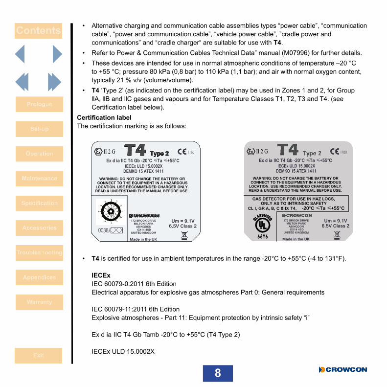
• T4 ‘Type 2’ (as indicated on the certification label) may be used in Zones 1 and 2, for Group llA, llB and llC gases and vapours and for Temperature Classes T1, T2, T3 and T4. (see Certification label below).
Certification label The certification marking is as follows:
• T4 is certified for use in ambient temperatures in the range -20°C to +55°C (-4 to 131°F). IECEx IEC 60079-0:2011 6th Edition Electrical apparatus for explosive gas atmospheres Part 0: General requirements IEC 60079-11:2011 6th Edition Explosive atmospheres - Part 11: Equipment protection by intrinsic safety “i” Ex d ia IIC T4 Gb Tamb -20°C to +55°C (T4 Type 2) IECEx ULD 15.0002X
1180II 2 G
0038/
Um = 9.1V6.5V Class 2
Ex d ia IIC T4 Gb -20°C ≤ Ta ≤ +55°C
172 BROOK DRIVEMILTON PARK
ABINGDONOX14 4SD
UNITED KINGDOM
Made in the UK
WARNING: DO NOT CHARGE THE BATTERY OR CONNECT TO THE EQUIPMENT IN A HAZARDOUS
LOCATION. USE RECOMMENDED CHARGER ONLY. READ & UNDERSTAND THE MANUAL BEFORE USE.
DEMKO 15 ATEX 1411 IECEx ULD 15.0002X
1180II 2 G
Um = 9.1V6.5V Class 2
Ex d ia IIC T4 Gb -20°C ≤ Ta ≤ +55°C
172 BROOK DRIVEMILTON PARK
ABINGDONOX14 4SD
UNITED KINGDOM
Made in the UK
WARNING: DO NOT CHARGE THE BATTERY OR CONNECT TO THE EQUIPMENT IN A HAZARDOUS
LOCATION. USE RECOMMENDED CHARGER ONLY. READ & UNDERSTAND THE MANUAL BEFORE USE.
66Y6
DEMKO 15 ATEX 1411 IECEx ULD 15.0002X
GAS DETECTOR FOR USE IN HAZ LOCS,ONLY AS TO INTRINSIC SAFETY
CL I, GR A, B, C & D: T4, -20°C ≤ Ta ≤ +55°C

9
ATEX EN 60079-0: 2012 + A11:2013 Explosive atmospheres – Part 0: Equipment - General requirements EN 60079-11:2012 Explosive atmospheres - Part 11: Equipment protection by intrinsic safety “i” II 2 G Ex d ia IIC T4 Gb Tamb -20°C to +55°C (T4 Type 2) DEMKO 15 ATEX 1411 UL Gas detector use in hazardous locations Class 1 Division 1, Groups A, B, C and D only as to intrinsic safety. UL 913 Applicable Edition of the UL standard UL 60079-0:2013 Applicable Edition of the UL standard UL 60079-11:2013 Applicable Edition of the UL standard

10
UnpackingYour T4 will have been inspected and quality checked before it left our manufacturing facility. It will be configured as a standard unit with standard settings as shown in the table below and any changes to suit your specific site requirements can be made utilising Portables Pro 2.0 PC Application and the Communications Cable, part number CH0103.
T4 Standard Configuration Settings:
Alarm levels/type* H2S (Hydrogen Sulphide) Low Alarm = 5 PPM Rising alarm Latched High Alarm = 10 PPM Rising alarm STEL = 10 PPM TWA = 5 PPMCO (Carbon Monoxide) Low Alarm = 30 PPM Rising alarm Latched High Alarm = 100 PPM Rising alarm STEL = 100 PPM TWA = 30 PPM Rising alarm LatchedO2 (Oxygen) Low Alarm = 19% Vol Falling Latched High Alarm = 23.5% Vol RisingLEL Low Alarm = 20% Rising alarm Latched LEL (CH4) Rising alarm High Alarm = 40% LEL (CH4) (all T4s are shipped having been calibrated with 2.2% Vol CH4)

11
Calibration Interval 180 daysBump Test DisabledBump Interval 180 days+ve Safety™ EnabledAutozero Autozero ConfirmLock on calibration due DisabledLock on bump due DisabledHome Screen Flipped Disabled
* Other regional defaults are available
Box contents• T4 checked and calibrated • Quick start guide• Calibration/Bump test plate for gas testing T4 – tubing can be bought separately in 1 m (3 feet
lengths)• Calibration report• Declaration of Conformity
The following items are optional:
Optional items• T4 cradle charger – part number T4-CRD• T4 ten way charger – part number T4-TWC• T4 sensor filter plate – part number T4-EXT-F• T4 Aspirator Plate – part number T4-ASP-CAP• Portables Pro 2.0 software• Communications cable – part number CH0103• T4 Vehicle charger – part number T4-VHL (ATEX/IECEx/UL Version)
T4-VHL-BR (INMETRO Version)• T4 I-Test – part number – IT-T4-11Z-ZB-1 (ATEX Version)
IT-T4-11Z-ZB-2 (UL Version) IT-T4-11Z-ZB-3 (INMETRO Version)
12
1. Set-up1.1 Prior to useBefore use, T4 should always be checked for any signs of physical damage.
T4 uses a Lithium Ion (Li-ion) battery pack and should arrive with sufficient charge to be used straight out the box. However, if this is the first time of use, the battery will require charging to attain the full operating time (see Charging & battery indications on page 13).
For battery run times, see the table on page 46.
1.2 T4 orientation
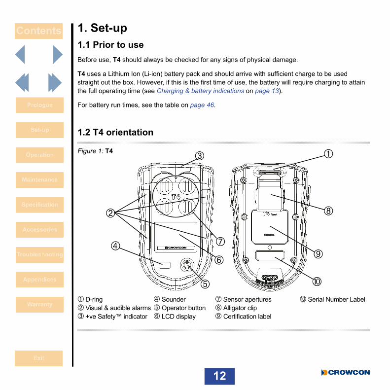
Figure 1: T4
À D-ring à Sounder Æ Sensor apertures É Serial Number Label Á Visual & audible alarms Ä Operator button Ç Alligator clip  +ve Safety™ indicator Å LCD display È Certification label
À
ÃÈ
Ç
Ä
Â
Å
Æ
Á
É

13
1.3 Charging & battery indicationsCharging should only take place in non-hazardous (safe) areas. To charge T4, simply plug it into either the desktop charging unit À or the ten-way charging unit Á (see Figure 2 below). Ensure T4 fits firmly on to the power connector of whichever charging unit is used.
Figure 2: Charging options
Referring to Figure 3 below, when T4 is powered off and placed in a charger, the +ve Safety™ LED will indicate charging status. Whilst T4 is charging the LED will flash red À, then when fully charged the LED will flash green Á.
Figure 3: Charging LED status
À Á
À Á
14
T4 battery icon contains a maximum of 3 segments and will indicate charging by sequentially filling the battery segments and repeating this process. When fully charged all three segments will be displayed.
When T4 is powered up and placed in a charger, the battery icon will indicate charging status but the +ve Safety™ LED will indicate +ve Safety™ status, NOT charging status.
If T4 is switched on whilst charging, after approximately 30 minutes of being on charge T4 will automatically power down and continue charging, showing the battery charging icon in the bottom right of the screen.
Whilst T4 is not charging the battery icon segments, indicate the battery’s state of charge. These are only shown when T4 is not placed in a charger.
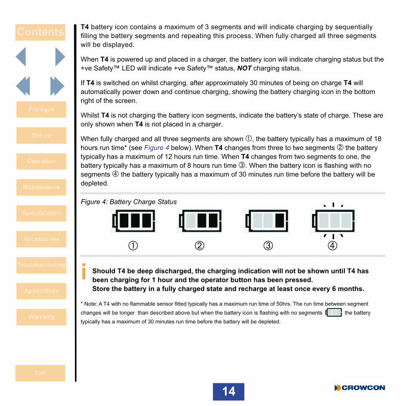
When fully charged and all three segments are shown À, the battery typically has a maximum of 18 hours run time* (see Figure 4 below). When T4 changes from three to two segments Á the battery typically has a maximum of 12 hours run time. When T4 changes from two segments to one, the battery typically has a maximum of 8 hours run time Â. When the battery icon is flashing with no segments à the battery typically has a maximum of 30 minutes run time before the battery will be depleted.
Figure 4: Battery Charge Status
i Should T4 be deep discharged, the charging indication will not be shown until T4 has been charging for 1 hour and the operator button has been pressed. Store the battery in a fully charged state and recharge at least once every 6 months.
* Note: A T4 with no flammable sensor fitted typically has a maximum run time of 50hrs. The run time between segment changes will be longer than described above but when the battery icon is flashing with no segments the battery typically has a maximum of 30 minutes run time before the battery will be depleted.
À Á ÃÂ
15
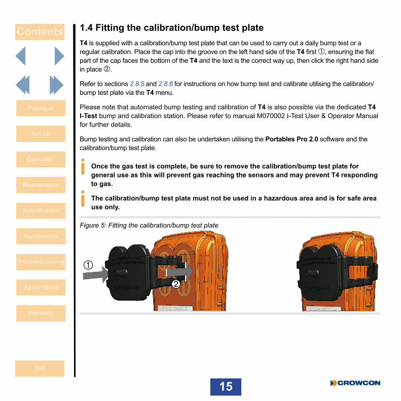
1.4 Fitting the calibration/bump test plateT4 is supplied with a calibration/bump test plate that can be used to carry out a daily bump test or a regular calibration. Place the cap into the groove on the left hand side of the T4 first À, ensuring the flat part of the cap faces the bottom of the T4 and the text is the correct way up, then click the right hand side in place Á.
Refer to sections 2.8.5 and 2.8.6 for instructions on how bump test and calibrate utilising the calibration/bump test plate via the T4 menu.
Please note that automated bump testing and calibration of T4 is also possible via the dedicated T4 I-Test bump and calibration station. Please refer to manual M070002 I-Test User & Operator Manual for further details.
Bump testing and calibration can also be undertaken utilising the Portables Pro 2.0 software and the calibration/bump test plate.
i Once the gas test is complete, be sure to remove the calibration/bump test plate for general use as this will prevent gas reaching the sensors and may prevent T4 responding to gas.
i The calibration/bump test plate must not be used in a hazardous area and is for safe area use only.
Figure 5: Fitting the calibration/bump test plate
À
Á

16
1.5 Fitting the external filter plateThe external filter plate is an optional accessory incorporating filters that allow gas to pass through but protect the sensors from dirt and debris. The filter plate will protect the sensors making it easier to maintain T4.
Place the filter plate into the groove on the left hand side of the T4 first À, ensuring the flat part of the plate faces the bottom of the T4, then click the right hand side in place Á.
Figure 6: Fitting the external filter plate
The filter plate is suitable for use in a hazardous area.
The filter plate has been designed to operate with the charging accessories and does not need to be removed when inserting T4 in to the desktop charger, the ten-way charger or the T4 vehicle charger.
i The filter plate should be replaced if the filters are damaged by substances that could affect the flow of gas to the sensors, like paints, grease or oils.
À
Á

17
1.6 +ve Safety™+ve Safety™ is a quick and easy indication of the operating status of T4, this status is indicated by a front mounted LED.
When the +ve Safety™ LED is illuminated green, this indicates that the unit is functioning as required and no further action is necessary, such as bump testing or calibration. This enables users and supervisors to easily see that the employee is safe and following work procedures.
When the +ve Safety™ LED is illuminated red this indicates that one of the following situations has occurred and will require user action:
• Battery is critically low: The battery has a maximum of 30 minutes runtime before it will be completely depleted. This will be accompanied by additional alerts signifying a low battery, see Section 1.3.
• Bump test is required: Bump test has failed or exceeded the due date required to meet site procedures. The bump test due date can be reviewed via the information menu, see Section 2.8.2.
• Calibration is due: Calibration has failed or exceeded the due date required to meet the site procedure. The calibration due date can be reviewed via the information menu, see Section 2.8.2.
• T4 is in gas alarm: This could be a high or low gas alarm, or a STEL or TWA alarm. T4 display will indicate which alarm type has been activated by the relevant icon being displayed on the screen, see Section 2.3.
• T4 fault: T4 must be reviewed by trained personnel for repair as T4 has detected an internal fault. An appropriate fault warning will also have been shown on the display.
Figure 7: +ve Safety™ indicators

18
1.7 Quick viewThe configuration details of T4 can be reviewed even if T4 is not powered by momentarily pressing the operator button.
The device will emit an audible blip and the LED’s to the right of the display will flash red once, the serial number of T4 will then be displayed for 10 seconds, T4 will then turn off.
To review all configuration items the operator button must be pressed to scroll through the available screens.
The configuration items that may be displayed are as follows:
• Serial number• Firmware Version • Configured User • Sensors configured lower alarm levels (alarm 1)• Sensors configured upper alarm levels (alarm 2)• STEL configured alarm levels (if a toxic sensor is fitted)• TWA configured alarm levels (if a toxic sensor fitted)• Calibration Due Date• Bump Due Date• Instrument Date and Time
i The is shown on all screens indicating that quick view is being accessed.
The battery status is also shown on each screen.
If +ve Safety™ is configured, the +ve Safety™ LED will also illuminate for the duration of the quick view review, showing the status of the instrument (see Section 1.6)

19
The screen displays the Quick View screen.
The screen then displays the T4 serial number.
The screen then displays the T4 firmware version.
This screen displays the T4’s configured user name.
This screen displays the sensors configured lower alarm levels.
This screen displays the sensors configured upper alarm levels.
20
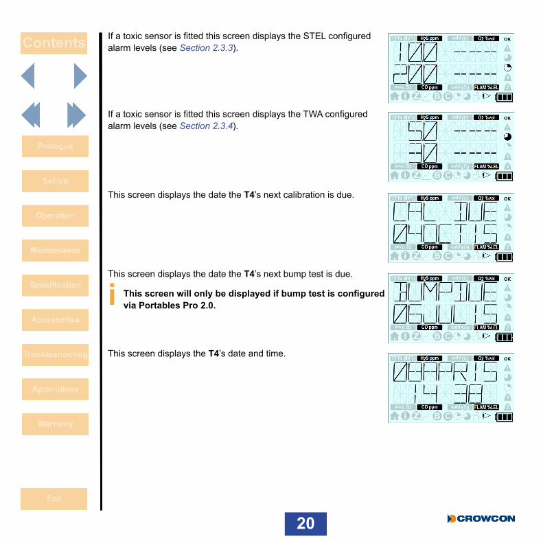
If a toxic sensor is fitted this screen displays the STEL configured alarm levels (see Section 2.3.3).
If a toxic sensor is fitted this screen displays the TWA configured alarm levels (see Section 2.3.4).
This screen displays the date the T4’s next calibration is due.
This screen displays the date the T4’s next bump test is due.
i This screen will only be displayed if bump test is configured via Portables Pro 2.0.
This screen displays the T4’s date and time.
21
2. Operation
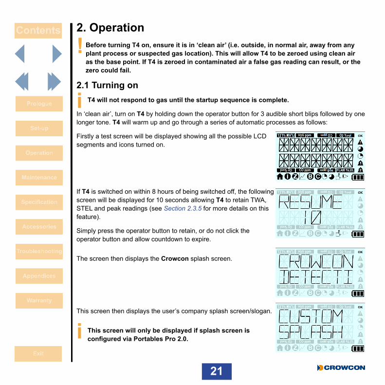
! Before turning T4 on, ensure it is in ‘clean air’ (i.e. outside, in normal air, away from any plant process or suspected gas location). This will allow T4 to be zeroed using clean air as the base point. If T4 is zeroed in contaminated air a false gas reading can result, or the zero could fail.
2.1 Turning on
i T4 will not respond to gas until the startup sequence is complete.
In ‘clean air’, turn on T4 by holding down the operator button for 3 audible short blips followed by one longer tone. T4 will warm up and go through a series of automatic processes as follows:
Firstly a test screen will be displayed showing all the possible LCD segments and icons turned on.
If T4 is switched on within 8 hours of being switched off, the following screen will be displayed for 10 seconds allowing T4 to retain TWA, STEL and peak readings (see Section 2.3.5 for more details on this feature).
Simply press the operator button to retain, or do not click the operator button and allow countdown to expire.
The screen then displays the Crowcon splash screen.
This screen then displays the user’s company splash screen/slogan.
i This screen will only be displayed if splash screen is configured via Portables Pro 2.0.

22
This screen then displays the T4 serial number.
This screen then displays the T4 firmware version.
This screen then displays the T4’s configured user name.
This screen then displays the sensors’ configured lower alarm levels.
This screen then displays the sensors’ configured upper alarm levels.
If a toxic sensor is fitted this screen then displays the STEL configured alarm levels (see Section 2.3.3).

23
If a toxic sensor is fitted this screen then displays the TWA configured alarm levels (see Section 2.3.4)
This screen then displays the date the T4’s next calibration is due.
This screen then displays the date the T4’s next bump test is due.
i This screen will only be displayed if bump test is configured via Portables Pro 2.0.
This screen then displays the T4’s date and time.
If configured to do so, the last screen is the autozero screen.
i This will operate as configured via Portables Pro 2.0.
The instrument will then revert to the normal operation ‘home screen’.

24
2.2 Home screenAfter a successful start up sequence the screen will display the home screen as shown below À and (if configured) the +ve Safety™ LED will be illuminated green indicating T4 is operating correctly.
i The image shown is the home screen of a T4 fitted with 4 sensors.
The same screen is also shown in ‘home screen flipped’ mode’ Á, if this has been configured via Portables Pro 2.0.
Figure 8: Display screen after successful start up
u Gas type & unit v Gas level w Home screen symbol x Battery Level indicator
u u
uuw
v
vv
x
v
À Á

25
2.3 AlarmsT4 has the following types of alarm:
• Low battery • Instantaneous • Time weighted average (TWA) • Short term exposure (STEL)
2.3.1 Low battery alarmT4 will indicate a low battery alarm when the battery has a maximum of 30 minutes remaining life.
i This warning should be acknowledged immediately by pressing the operator button.
The sounder will then emit an audible double blip every 5 seconds and the display will flash the battery empty icon .
In addition, if configured to do so (see Section 1.6), the +ve Safety™ LED will change state and illuminate red.
When the low battery alarm is displayed the operator should finish their current activity and move to a safe area before the 30 minutes battery life expiries.
2.3.2 Instantaneous alarmT4 will go into alarm immediately if the level of any gas configured to be detected, exceeds acceptable limits. A minimum and maximum level is set for oxygen, whilst the remaining gases will cause an alarm for rising gas levels.
T4 will indicate an alarm state ‘1’ or alarm state ‘2’ according to which configured gas level has been exceeded.
When T4 is in instantaneous alarm the appropriate ‘bell’ alarm symbol or will flash repeatedly on the screen to indicate which level of alarm has been triggered, the gas type and unit icon will flash to indicate which gas has triggered the alarm, the sounder will emit a tone, alarm LEDs will flash red and blue, and the T4 will vibrate.
i If +ve Safety™ is configured the +ve Safety™ LED will also be illuminated red. The LED will return to green when the instantaneous alarm is cleared.

26
2.3.3 Short term exposure limit alarm (STEL)For each toxic gas being monitored T4 stores information about the gas levels detected to determine the average exposure over a 15 minute running period. If the average levels detected over the defined period of time exceed predetermined levels, T4 will go into alarm (STEL is not monitored for the duration of a bump test or calibration). The STEL alarm level can be configured via Portables Pro 2.0.
In the alarm state, the STEL symbol on the screen will flash indicating the STEL levels have been exceeded, the sounder will emit a tone, alarm LEDs will flash red and blue, and the T4 will vibrate.
i If +ve Safety™ is configured the +ve Safety™ LED will also be illuminated red. The LED will return to green when the STEL alarm is cleared.
2.3.4 Time weighted average alarm (TWA)For each toxic gas being monitored T4 stores information about the gas levels detected to determine the average exposure over an 8 hr running period. If the average levels detected over the defined period of time exceed predetermined levels, T4 will go into alarm (TWA is not monitored for the duration of a bump test or calibration). The TWA alarm level can be configured via Portables Pro 2.0.
In the alarm state, the TWA symbol on the screen will flash indicating the TWA levels have been exceeded, the sounder will emit a tone, alarm LEDs will flash red and blue, and T4 will vibrate.
i If +ve Safety™ is configured the +ve Safety™ LED will also be illuminated red. The LED will return to green when the TWA alarm is cleared.
2.3.5 TWA Resume function*TWA Resume allows TWA, STEL and peak readings to be retained after T4 has been switched off for a period of time, for example while an operator travels to a new location. This prevents recent toxic exposure history from being lost and the associated risk of the operator exceeding safe exposure levels.
If T4 is switched off for less than 15 minutes and the TWA Resume function is selected (see below), T4 will retain the STEL, TWA and peak gas values when powered back on.
If T4 is switched off for more than 15 minutes but less than 8hrs, and the TWA Resume function is selected (see below), T4 will retain the TWA and peak gas values when powered back on but the STEL values will be cleared.
If T4 is switched off for more than 8hrs the TWA Resume function will not be available in the start up sequence and T4 will clear the TWA, STEL and peak gas values when powered back on.

27
The TWA Resume function can be activated during the start up sequence.
Upon start up, following the test screen, if T4 is switched on within 8 hours of being switched off, the screen shown right will be displayed for 10 seconds allowing the user to ‘resume’ if required.
Simply click the operator button.
If T4 is now being used by a new operator and the TWA Resume function is not required do not click the operator button and allow countdown to expire. This will reset the STEL, TWA and peak values back to zero.
* Patent pending - UK Patent Application Number 1501699.1
2.4 Alarm and status iconsThe alarm status is represented by the icons shown in the table below:
Icon Description Action
Status OK No action required
Fault status Refer to Section 6 for troubleshooting
Long term exposure alarm (TWA) Follow site procedure
Short term exposure alarm (STEL) Follow site procedure
Alarm 1 Follow site procedure
Alarm 2 Follow site procedure

28
2.5 Accepting and Clearing AlarmsThe operation of alarms in terms of how they are cleared is dependent upon the alarm type and also the configuration option, which can be changed via Portables Pro 2.0.
The options are ‘latched’ and ‘non-latching’ and the functionality is described in the table below.
i Alarm 2 cannot be configured and behaves as a latched alarm.
Configuration Setting
(Alarm 1 only)
Instantaneous Alarm 1 Instantaneous Alarm 2
Latched An instantaneous alarm 1 can be cancelled by pressing the operator button but only when the gas level has dropped below the alarm level
An instantaneous alarm 2 can be cancelled by pressing the operator button but only when the gas level has dropped below the alarm level
Non-latching An instantaneous alarm 1 will not be latched and will return to a non- alarm state without user acceptance once the gas level has dropped below the alarm level
An instantaneous alarm 2 can be cancelled by pressing the operator button but only when the gas level has dropped below the alarm level
i While in alarm, T4 will continue to record levels of all the gases being monitored.
29
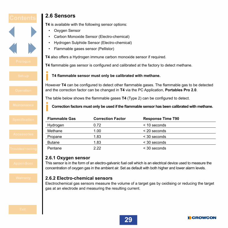
2.6 SensorsT4 is available with the following sensor options:
• Oxygen Sensor• Carbon Monoxide Sensor (Electro-chemical)• Hydrogen Sulphide Sensor (Electro-chemical)• Flammable gases sensor (Pellistor)
T4 also offers a Hydrogen immune carbon monoxide sensor if required.
T4 flammable gas sensor is configured and calibrated at the factory to detect methane.
i T4 flammable sensor must only be calibrated with methane.
However T4 can be configured to detect other flammable gases. The flammable gas to be detected and the correction factor can be changed in T4 via the PC Application, Portables Pro 2.0.
The table below shows the flammable gases T4 (Type 2) can be configured to detect.
i Correction factors must only be used if the flammable sensor has been calibrated with methane.
Flammable Gas Correction Factor Response Time T90Hydrogen 0.72 < 10 secondsMethane 1.00 < 20 secondsPropane 1.83 < 30 secondsButane 1.83 < 30 secondsPentane 2.22 < 30 seconds
2.6.1 Oxygen sensorThis sensor is in the form of an electro-galvanic fuel cell which is an electrical device used to measure the concentration of oxygen gas in the ambient air. Set as default with both higher and lower alarm levels.
2.6.2 Electro-chemical sensors Electrochemical gas sensors measure the volume of a target gas by oxidising or reducing the target gas at an electrode and measuring the resulting current.

30
2.6.3 Pellistor sensors Pellistor sensors (or catalytic beads) are specifically designed to sense explosive gases. The detecting element consists of small “beads” of catalyst loaded ceramic whose resistance changes in the presence of gas.
2.6.4 Pellistor saver mode Pellistor sensors can suffer degradation if powered while exposed to flammable gas concentrations greater than 100% LEL, and also if exposed to high levels of H2S or silicones.
To reduce degradation T4 employs a Pellistor saver mode.
When the flammable gas exceeds the pellistor saver threshold, the detector will turn off the sensor for a minimum period of 200 seconds À.
When pellistor saver mode is activated the user must immediately move to a clean air environment.
After the defined period the sensor can be re-activated by a single click of the operator button Á once the instrument is in a clean air environment.
After a stabilisation time (Â), if the gas level still exceeds the threshold then the sensor will be turned off and the cycle starts again.
While in saver mode and the subsequent stabilise time, the gas level displayed on the LCD screen will indicate over range. As the sensor has been exposed to a gas level sufficient to cause a sensor over-range T4 should be gas tested to ensure no lasting damage has occurred.
À
Á
Â

31
2.7 T4 menu iconsThe following menu functions on the T4 display can be selected:
Icon Title Action
Home Return to Home page
Information Displays unit status/configuration
Zero Performs a sensor zero
Peak Mode Displays peak gas readings
Bump Performs a bump test
Calibration Performs a Calibration
STEL (Short Term Exposure Limit) Displays the current STEL value
TWA (Long Term Exposure Limit) Displays the current TWA value

32
2.8 Accessing T4 menu functions X With the home screen displayed, double click the operator button À to access the menu functions Á.
X Single click the operator button repeatedly to scroll right until the required menu icon is displayed and then double click the operator button to select the function.
X As a safety feature if gas is detected whilst in a menu, T4 will revert back to the home screen to ensure the gas readings are displayed. This will not occur if T4 was in bump test mode, calibration mode or peak mode.
2.8.1 Home screenWhen this icon is selected, the Home screen will be displayed.
2.8.2 Information ScreenThe information screen displays the T4 status/configuration.
X With the home screen displayed, double click the operator button to access the menu functions screen.
X Single click the operator button repeatedly to scroll right until the menu icon is displayed and then double click the operator
button to select.The screen will display the same sequence of screens as when Quick View is selected, please refer to Section 1.7 for details.
In addition the Information screen will also display any identified fault; this fault will be indicated by a warning icon on the home screen.
Accessing the information screen will provide further details of the identified fault.
ÀÁ
33
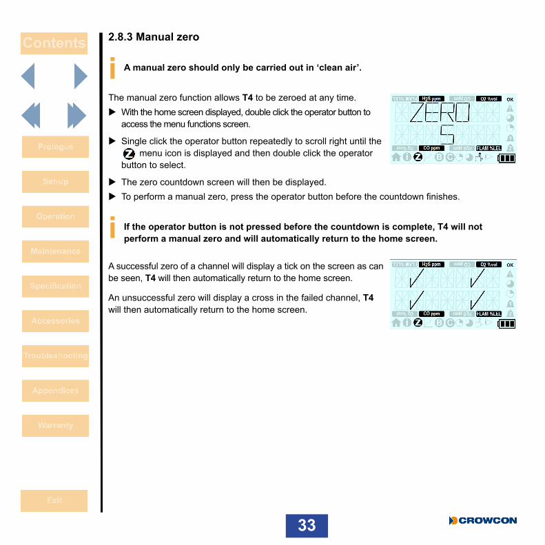
2.8.3 Manual zero
i A manual zero should only be carried out in ‘clean air’.
The manual zero function allows T4 to be zeroed at any time. X With the home screen displayed, double click the operator button to
access the menu functions screen.
X Single click the operator button repeatedly to scroll right until the menu icon is displayed and then double click the operator
button to select.
X The zero countdown screen will then be displayed. X To perform a manual zero, press the operator button before the countdown finishes.
i If the operator button is not pressed before the countdown is complete, T4 will not perform a manual zero and will automatically return to the home screen.
A successful zero of a channel will display a tick on the screen as can be seen, T4 will then automatically return to the home screen.
An unsuccessful zero will display a cross in the failed channel, T4 will then automatically return to the home screen.
34
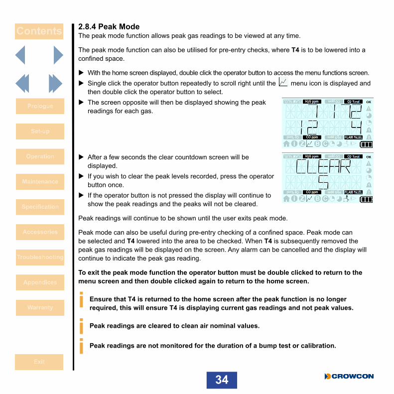
2.8.4 Peak ModeThe peak mode function allows peak gas readings to be viewed at any time.
The peak mode function can also be utilised for pre-entry checks, where T4 is to be lowered into a confined space.
X With the home screen displayed, double click the operator button to access the menu functions screen. X Single click the operator button repeatedly to scroll right until the menu icon is displayed and then double click the operator button to select.
X The screen opposite will then be displayed showing the peak readings for each gas.
X After a few seconds the clear countdown screen will be displayed.
X If you wish to clear the peak levels recorded, press the operator button once.
X If the operator button is not pressed the display will continue to show the peak readings and the peaks will not be cleared.
Peak readings will continue to be shown until the user exits peak mode.
Peak mode can also be useful during pre-entry checking of a confined space. Peak mode can be selected and T4 lowered into the area to be checked. When T4 is subsequently removed the peak gas readings will be displayed on the screen. Any alarm can be cancelled and the display will continue to indicate the peak gas reading.
To exit the peak mode function the operator button must be double clicked to return to the menu screen and then double clicked again to return to the home screen.
i Ensure that T4 is returned to the home screen after the peak function is no longer required, this will ensure T4 is displaying current gas readings and not peak values.
i Peak readings are cleared to clean air nominal values.
i Peak readings are not monitored for the duration of a bump test or calibration.

35
2.8.5 Bump Test
i T4 bump test via menu must be performed utilizing quad gas containing CO, H2S, O2 and CH4 for a fully populated T4.
i The applied test gas must contain gas concentrations capable of exceeding the configured alarm level 1 for each gas.
i Bump strategy must be enabled for the bump test to operate via the menu function, this can be configured utilizing Portables Pro 2.0.
i A bump test can also be performed via Portables Pro 2.0 or via I-Test.
i If utilizing gas extraction do not place the extraction outlet closer than 20cm to the calibration/bump plate as this may result in an incorrect bump test result.
The bump test function allows T4 to be bump tested at anytime.
X Ensure the calibration/bump test plate is fitted and the gas supply attached but not providing gas, before selecting the bump test function.
X With the home screen displayed, double click the operator button to access the menu functions screen.
X Single click the operator button repeatedly to scroll right until the menu icon is displayed and then double click the operator
button to select. X The bump test countdown screen will then be displayed. X To initiate a bump test, press the operator button before the countdown is complete
X The apply gas countdown screen will then be displayed and the test gas must now be applied.
i If the operator button is not pressed before the countdown is complete, T4 will not perform a bump test and will automatically return to the home screen.

36
When T4 detects the applied test gas the countdown screen will be replaced with the bump test gas reading screen, this will continue to show the gas readings until the bump test result is displayed.
i If the test gas is not supplied before the end of the countdown the bump test will fail, the bump test will be set to due and, if configured, the +ve Safety™ LED will be illuminated red.
X If the bump test is successful a tick will be displayed for each gas that passes, if the bump test is not successful a cross will displayed for each gas that fails.
X The remove gas countdown screen will then be displayed, the test gas must be turned off and the bump/calibration plate removed.
X The updated bump test date due screen will be displayed following a successful bump test.
X If the bump test was not successful the bump due now screen will be displayed and, if configured, the +ve safety LED will be illuminated red.
X During the bump test as gas is applied the instantaneous alarms will be activated as the gas level exceeds the configured alarm level.
X This will be indicated by the appropriate ‘bell’ alarm and gas type and unit icon flashing repeatedly but the sounder, LED’s and vibrator will be disabled during the bump test.
X A short period after the completion of the bump test the sounder, LED’s and vibrator will be enabled. X Press the operator button to cancel the alarm.
37
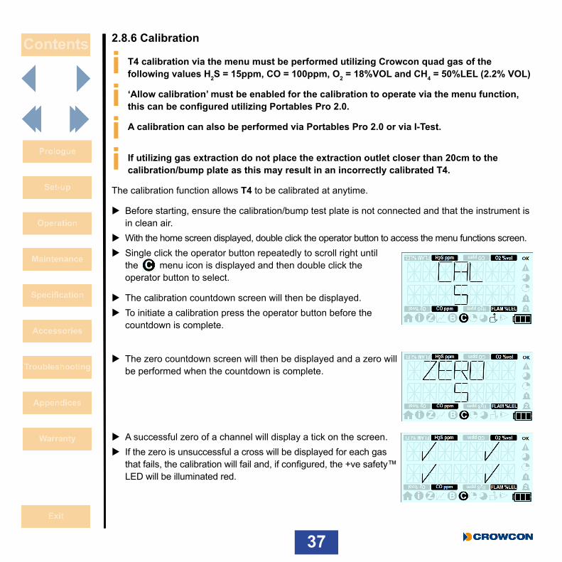
2.8.6 Calibration
i T4 calibration via the menu must be performed utilizing Crowcon quad gas of the following values H2S = 15ppm, CO = 100ppm, O2 = 18%VOL and CH4 = 50%LEL (2.2% VOL)
i ‘Allow calibration’ must be enabled for the calibration to operate via the menu function, this can be configured utilizing Portables Pro 2.0.
i A calibration can also be performed via Portables Pro 2.0 or via I-Test.
i If utilizing gas extraction do not place the extraction outlet closer than 20cm to the calibration/bump plate as this may result in an incorrectly calibrated T4.
The calibration function allows T4 to be calibrated at anytime.
X Before starting, ensure the calibration/bump test plate is not connected and that the instrument is in clean air.
X With the home screen displayed, double click the operator button to access the menu functions screen. X Single click the operator button repeatedly to scroll right until the menu icon is displayed and then double click the operator button to select.
X The calibration countdown screen will then be displayed. X To initiate a calibration press the operator button before the countdown is complete.
X The zero countdown screen will then be displayed and a zero will be performed when the countdown is complete.
X A successful zero of a channel will display a tick on the screen. X If the zero is unsuccessful a cross will be displayed for each gas that fails, the calibration will fail and, if configured, the +ve safety™ LED will be illuminated red.
38
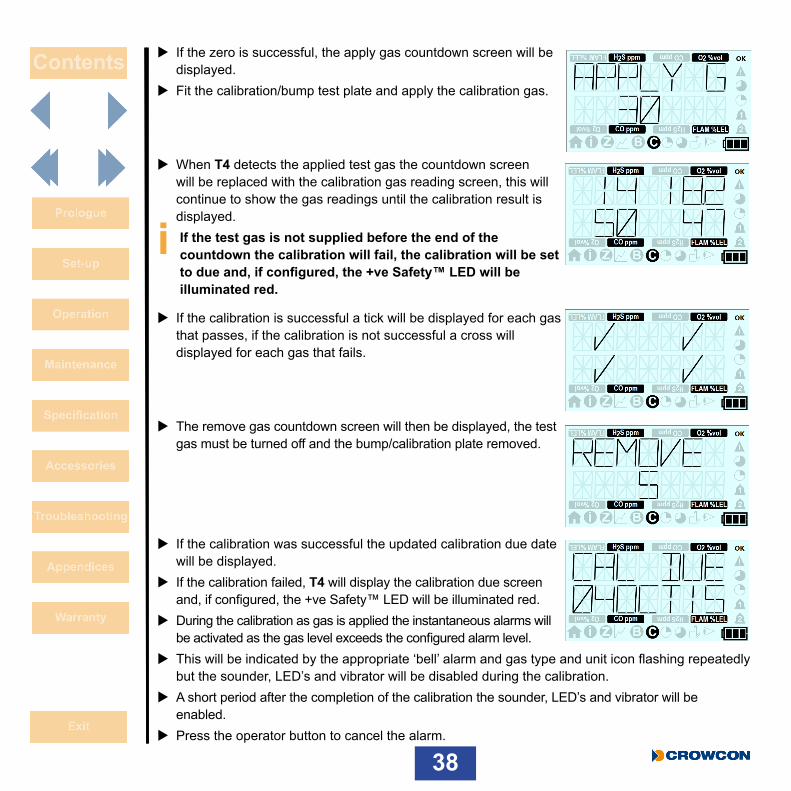
X If the zero is successful, the apply gas countdown screen will be displayed.
X Fit the calibration/bump test plate and apply the calibration gas.
X When T4 detects the applied test gas the countdown screen will be replaced with the calibration gas reading screen, this will continue to show the gas readings until the calibration result is displayed.
i If the test gas is not supplied before the end of the countdown the calibration will fail, the calibration will be set to due and, if configured, the +ve Safety™ LED will be illuminated red.
X If the calibration is successful a tick will be displayed for each gas that passes, if the calibration is not successful a cross will displayed for each gas that fails.
X The remove gas countdown screen will then be displayed, the test gas must be turned off and the bump/calibration plate removed.
X If the calibration was successful the updated calibration due date will be displayed.
X If the calibration failed, T4 will display the calibration due screen and, if configured, the +ve Safety™ LED will be illuminated red.
X During the calibration as gas is applied the instantaneous alarms will be activated as the gas level exceeds the configured alarm level.
X This will be indicated by the appropriate ‘bell’ alarm and gas type and unit icon flashing repeatedly but the sounder, LED’s and vibrator will be disabled during the calibration.
X A short period after the completion of the calibration the sounder, LED’s and vibrator will be enabled.
X Press the operator button to cancel the alarm.

39
2.8.7 STEL (Short term exposure limit) The STEL function allows the current STEL value to be displayed.
For further details on the function of the STEL alarm refer to Section 2.3.3.
X With the home screen displayed, double click the operator button to access the menu functions screen.
X Single click the operator button repeatedly to scroll right until the menu icon is displayed and then double click the operator button to select.
X The STEL current value screen will then be displayed. X T4 will revert back to the home screen automatically after 30 seconds or the operator button can be double clicked to return to the menu screen and then double clicked again to return to the home screen.
2.8.8 TWA (Time weighted average) The TWA (or long term exposure limit) function allows the current TWA value to be displayed.
For further details on the function of the TWA alarm refer to Section 2.3.4.
X With the home screen displayed, double click the operator button to access the menu functions screen.
X Single click the operator button repeatedly to scroll right until the menu icon is displayed and then double click the operator button to select.
X The TWA current value screen will then be displayed.
X T4 will revert back to the home screen automatically after 30 seconds or the operator button can be double clicked to return to the menu screen and then double clicked again to return to the home screen.
2.8.9 Shutdown To turn T4 off, press and hold the operator button. A 5 second countdown will start. Hold the button down until the countdown has finished and T4 will shut down. If you release the button before the countdown has finished, T4 will resume operation. Once off, place on charge if required (see Section 1.3).
T4 cannot be shutdown if a zero, bump test or calibration is in progress.

40
2.9 Data LoggingThe data log records gas levels for all sensors and has capacity of 45,000 logs (125hrs @10 sec intervals).
All data logs can be downloaded from T4 via Portables Pro 2.0.
2.10 Event loggingEvent logging records significant events occurring during T4 operation.
The event log has a capacity of at least 1000 events.
Events include:• Power on/off• Alarm 1 Activation• Alarm 2 Activation• STEL Alarm Activation • TWA Alarm Activation • Operator Acknowledgments• Calibration Events/Status• Bump Test Events/Status
• Zero Events/Status• Low Battery • User Change• Pellistor Saver Mode • Insert Into I-Test station• Time Change/Set • Event Log Upload• Faults
41
2.11 Bump Test Crowcon recommends regular bump tests to confirm sensor operation. This involves applying a known composition of the correct gas to each sensor to verify sensor response and alarm function. Organisational specific Health and Safety regulations should be adhered to, and a number of flexible and simple solutions are available.
T4 implements a speedy bump test in which gas is applied to trigger alarm level 1.
T4 bump strategy can be configured via Portables Pro 2.0.
A bump test can be performed on T4 in one of the following ways:
• Via T4 menu and utilizing the calibration/bump test plate (see Section 2.8.5)• Via Portables Pro 2.0 utilizing the calibration/bump test plate• Via the I-Test gas station where all testing is fully automated.
I-Test is an intelligent stand alone gas test and calibration solution, suitable for small and large fleet users alike, I-Test offers simple fully managed testing with data capture as well as the ability to update configurations. Please refer to I-Test User & Operator Manual M070002
If any channel fails speedy bump then T4 should be calibrated, please refer to Section 2.8.6.
i From the 1st November 2010, EN60079-29 part 1 has been harmonised under the ATEX directive 94/9/EC. Therefore to comply with the ATEX directive, portable apparatus sensing flammable gases should have a functional check with gas before each day of use. Other testing regimes may be employed depending on local circumstances.
42
2.12 Calibration Calibration should be carried out if any channel fails a bump test or if T4 has exceeded its calibration due date.
A calibration can be performed on T4 in one of the following ways:• Via T4 menu and utilizing the calibration/bump test plate (see Section 2.8.6)• Via Portables Pro 2.0 utilizing the calibration/bump test plate• Via the I-Test gas station where all testing is fully automated.
I-Test is an intelligent stand alone gas test and calibration solution, suitable for small and large fleet users alike, I-Test offers simple fully managed testing with data capture as well as the ability to update configurations.
i I-Test is suitable for regular periodic calibrations but Portables Pro 2.0 must be utilised for calibration when sensors or PCB’s have been replaced.
Please refer to I-Test User & Operator Manual M070002.
T4 calibration due dates are automatically updated upon a successful calibration; the factory default interval is set at 180 days.
Calibration should be undertaken with the appropriate Crowcon supplied gas cylinder or equivalent.
i The flammable sensor should always be calibrated with methane gas.
If the calibration fails this may be indicative of a more serious sensor issue, including the need to replace sensors. The T4 should then be serviced.
2.13 New sensor calibration/serviceServicing or the fitment of a new sensor can only be undertaken by a suitably trained technician using Portables Pro 2.0 software and the appropriate gas.
In addition calibration should be performed as required by local or organisational regulations. In the absence of suitable evidence, such as a field assessment by a competent person, Crowcon recommend regular service and calibration every 6 months.
43
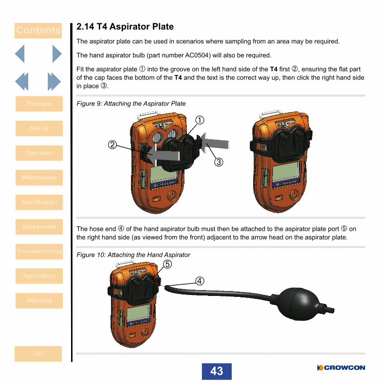
2.14 T4 Aspirator PlateThe aspirator plate can be used in scenarios where sampling from an area may be required.
The hand aspirator bulb (part number AC0504) will also be required.
Fit the aspirator plate À into the groove on the left hand side of the T4 first Á, ensuring the flat part of the cap faces the bottom of the T4 and the text is the correct way up, then click the right hand side in place Â.
Figure 9: Attaching the Aspirator Plate
The hose end à of the hand aspirator bulb must then be attached to the aspirator plate port Ä on the right hand side (as viewed from the front) adjacent to the arrow head on the aspirator plate.
Figure 10: Attaching the Hand Aspirator
À
Á
Â
Ã
Ä
44
The fitment of the plate should then be checked to ensure a gas tight seal has been achieved. The bulb should be depressed whilst blocking the adjacent port with a finger; the T4 may at this point indicate an alarm on the O2 sensor this is due to the pressure effect on the oxygen sensor. The hand aspirator bulb should not return to the rounded shape if a gas tight seal has been achieved. If the bulb does return to is normal shape, reposition the aspirator plate and repeat this test.
Allow the O2 sensor to stabilise before continuing.
The sample hose must then be attached to the aspirator plate on the left hand side (as viewed from the front) adjacent to the base of the arrow on the aspirator plate.
Place the sample tube into the area to be sampled and depress the aspirator bulb. Allow the bulb to return to its rounded shape and then depress the bulb again. Repeat this process to get a constant sample flow to the sensors.
Every depression of the aspirator bulb should pull the sample approximately 25cm up the tube. Therefore to sample from a 5 meter hose – at least 20 aspirations will be required, however a minimum of 1 minute is recommended to ensure a stable sample is read.
The maximum length of the sample hose allowable is 30m.
It should be noted that for sample hose lengths greater than 5m the oxygen sensor may initially go into a falling alarm state for approximately 1 minute, due to pressure effects, before settling back down to read accurately.

45
3. Service and maintenanceT4 is designed to require minimal service and maintenance. As with all electrochemical sensors however, these will require periodic replacement.
i Ensure maintenance, service and calibration are carried out in accordance with the procedures in the manual and only by trained personnel.
For further service or maintenance, contact your local Crowcon agent or regional office (see Section 7.2).
46
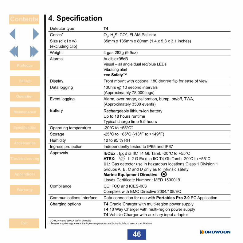
4. SpecificationDetector type T4Gases* O2, H2S, CO*, FLAM PellistorSize (d x l x w) (excluding clip)
35mm x 135mm x 80mm (1.4 x 5.3 x 3.1 inches)
Weight 4 gas 282g (9.9oz)Alarms Audible>95dB
Visual – all angle dual red/blue LEDs Vibrating alert +ve Safety™
Display Front mount with optional 180 degree flip for ease of viewData logging 130hrs @ 10 second intervals
(Approximately 78,000 logs)Event logging Alarm, over range, calibration, bump, on/off, TWA,
(Approximately 3500 events)Battery Rechargeable lithium-ion battery
Up to 18 hours runtime Typical charge time 5.5 hours
Operating temperature -20°C to +55°C
Storage -25°C to +65°C (-13°F to +149°F)Humidity 10 to 95 % RHIngress protection Independently tested to IP65 and IP67Approvals IECEx : Ex d ia IIC T4 Gb Tamb -20°C to +55°C
ATEX: II 2 G Ex d ia IIC T4 Gb Tamb -20°C to +55°C UL: Gas detector use in hazardous locations Class 1 Division 1 Groups A, B, C and D only as to intrinsic safety Marine Equipment Directive: Lloyds Certificate Number : MED 1500019
Compliance CE, FCC and ICES-003 Complies with EMC Directive 2004/108/EC
Communications Interface Data connection for use with Portables Pro 2.0 PC ApplicationCharging options T4 Cradle Charger with multi-region power supply
T4 10 Way Charger with multi-region power supply T4 Vehicle Charger with auxiliary input adaptor
* CO H2 Immune sensor option available Sensors may be degraded at the higher temperatures subject to individual sensor specifications

47
5. AccessoriesPart Number Description
T4-CRD T4 Cradle Charger with multi-region power supply
T4-TWC T4 10 Way Charger with multi-region power supply
E011166 T4 10 Way Charger multi-region power supply
T4-VHL T4 Vehicle Charger with auxiliary input adaptor
T4-VHL-BR INMETRO T4 vehicle charger, includes vehicle charging adaptor
CH0106 Vehicle Charger auxiliary input adaptor
CH0103 USB communications lead (not powered)
CH0104 USB communication and power lead
T4-EXT-F T4 Sensor Filter Plate
T4-CAL-CAP T4 calibration/bump test plate
T4-ASP-CAP T4 Aspirator Plate
AC0504 Hand aspirator bulb
48
6. Troubleshooting6.1 T4 Fault / Warning / Information Descriptions
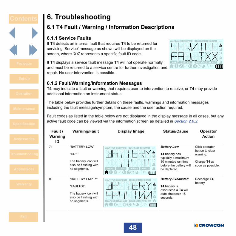
6.1.1 Service FaultsIf T4 detects an internal fault that requires T4 to be returned for servicing ‘Service’ message as shown will be displayed on the screen, where ‘XX’ represents a specific fault ID code.
If T4 displays a service fault message T4 will not operate normally and must be returned to a service centre for further investigation and repair. No user intervention is possible.
6.1.2 Fault/Warning/Information MessagesT4 may indicate a fault or warning that requires user to intervention to resolve, or T4 may provide additional information on instrument status.
The table below provides further details on these faults, warnings and information messages including the fault message/symptom, the cause and the user action required.
Fault codes as listed in the table below are not displayed in the display message in all cases, but any active fault code can be viewed via the information screen as detailed in Section 2.8.2.
Fault /Warning
ID
Warning/Fault Display Image Status/Cause Operator Action
71 “BATTERY LOW”
“ID71”
The battery icon will also be flashing with no segments.
Battery Low
T4 battery has typically a maximum 30 minutes run time before the battery will be depleted.
Click operator button to clear warning.
Charge T4 as soon as possible.
0 “BATTERY EMPTY”
“FAULT00”
The battery icon will also be flashing with no segments.
Battery Exhausted
T4 battery is exhausted & T4 will auto shutdown 15 seconds.
Recharge T4 battery.

49
Fault /Warning
ID
Warning/Fault Display Image Status/Cause Operator Action
73 “CHARGER SHUTDOWN”
“ID 73”
Charger Shutdown
T4 has been placed on charge whilst T4 is powered on for a prolonged period.
T4 will auto shutdown after 15 seconds to prevent circuit damage.
If T4 requires charging no action required, T4 will auto switch off and continue charging.
If T4 is removed from the charger it will not auto switch off and continue operating normally.
21 “TIME LOST”
(Displayed during start up)
Time & Date Lost
T4 has detected its internal time and date has been lost.
T4 time and date must be reset to ensure correct operation.
This can be reset utilising Portables Pro 2.0 or by placing T4 into I-Test.
74 “BUMPDUE”
“LOCKED”
Bump Locked
A bump test is due and T4 is configured to lock on bump due.
Perform a bump test (or a calibration) on T4 to ‘unlock’ for normal operation.
25 “CAL DUE”
“LOCKED”
Calibration Locked
Calibration is due and T4 is configured to lock on calibration due.
Perform a calibration on T4 to ‘unlock’ for normal operation.

50
Fault /Warning
ID
Warning/Fault Display Image Status/Cause Operator Action
26
27
28
29
‘X’
Whilst in ‘zero menu’.
(The warning ID code for each specific gases is shown in the adjacent column)
H2S
O2
CO
LEL
Zero Failure
Displayed if the result of a sensor zero was a fail.
The ‘X’ indicates which sensor has failed the zero (in the example all gases failed the zero).
Ensure T4 is in ‘clean air’ and repeat the zero operation.
T4 must be returned to a service centre for further investigation and repair if the zero is not successful when repeated.
42
43
44
45
‘X’
Whilst in ‘autozero function’.
(The recorded warning ID code for each specific gases is shown in the adjacent column)
H2S
O2
CO
LEL
Autozero Abort
Displayed if an autozero was aborted due to T4 detecting gas being present outside acceptable limits.
The ‘X’ indicates which sensor has failed the zero (in the example all gases failed the zero).
Ensure T4 is in ‘clean air’ and repeat the zero operation.
T4 must be returned to a service centre for further investigation and repair if the zero is not successful when repeated.
51
Fault /Warning
ID
Warning/Fault Display Image Status/Cause Operator Action
81
82
83
84
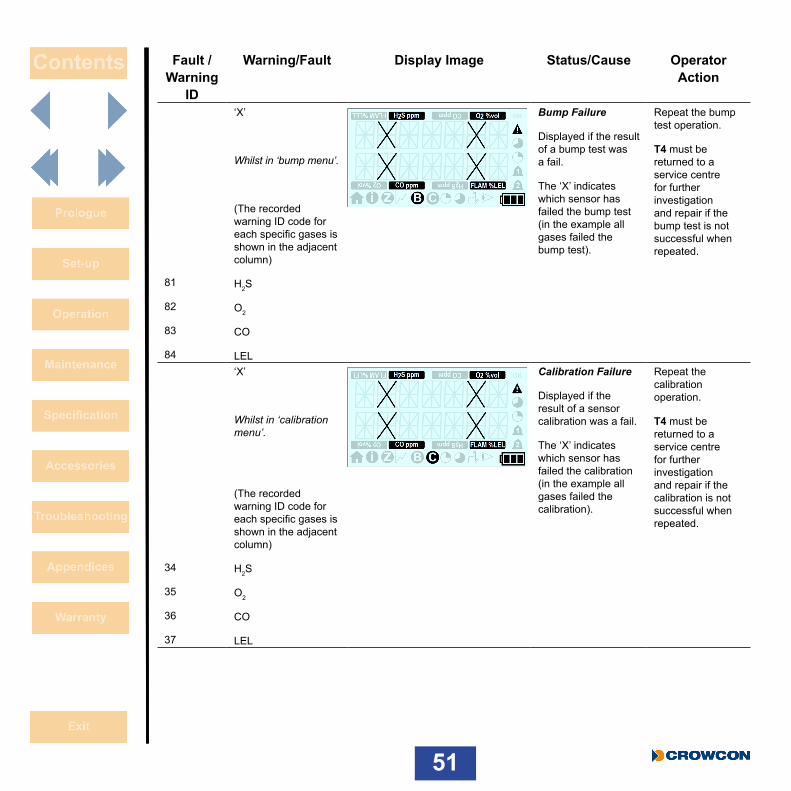
‘X’
Whilst in ‘bump menu’.
(The recorded warning ID code for each specific gases is shown in the adjacent column)
H2S
O2
CO
LEL
Bump Failure
Displayed if the result of a bump test was a fail.
The ‘X’ indicates which sensor has failed the bump test (in the example all gases failed the bump test).
Repeat the bump test operation.
T4 must be returned to a service centre for further investigation and repair if the bump test is not successful when repeated.
34
35
36
37
‘X’
Whilst in ‘calibration menu’.
(The recorded warning ID code for each specific gases is shown in the adjacent column)
H2S
O2
CO
LEL
Calibration Failure
Displayed if the result of a sensor calibration was a fail.
The ‘X’ indicates which sensor has failed the calibration (in the example all gases failed the calibration).
Repeat the calibration operation.
T4 must be returned to a service centre for further investigation and repair if the calibration is not successful when repeated.

52
Fault /Warning
ID
Warning/Fault Display Image Status/Cause Operator Action
66 ”BUMP DUE”
“NOW”
(Displayed during start up)
Bump Test due
T4 bump test is overdue.
Undertake a bump test on T4.
This will clear the bump due warning.
67 “CAL DUE”
“NOW”
(Displayed during start up)
Calibration Due
T4 calibration is overdue.
Undertake a calibration on T4.
This will clear the calibration due message.
50
51
52
53
“WARNING”
“ID 50”
This will then be followed by the ‘home screen’ displaying:
‘---‘ for the gas in fault.
(The fault ID code for the specific gases is shown in the adjacent column)
H2S
O2
CO
LEL
Hardware Warning
T4 has detected hardware fault with a specific gas channel.
Click operator button to clear warning.
T4 must be returned to a service centre for further investigation and repair.
53
Fault /Warning
ID
Warning/Fault Display Image Status/Cause Operator Action
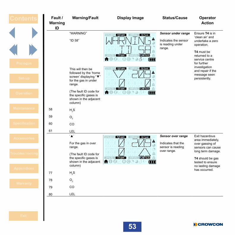
58
59
60
61
“WARNING”
“ID 58”
This will then be followed by the ‘home screen’ displaying “▼” for the gas in under range.
(The fault ID code for the specific gases is shown in the adjacent column)
H2S
O2
CO
LEL
Sensor under range
Indicates the sensor is reading under range.
Ensure T4 is in ‘clean air’ and undertake a zero operation.
T4 must be returned to a service centre for further investigation and repair if the message seen persistently.
77
78
79
80
‘▲’
For the gas in over range.
(The fault ID code for the specific gases is shown in the adjacent column)
H2S
O2
CO
LEL
Sensor over range
Indicates that the sensor is reading over range.
Exit hazardous area immediately, over gassing of sensors can cause long term damage.
T4 should be gas tested to ensure no lasting damage has occurred.

54
Fault /Warning
ID
Warning/Fault Display Image Status/Cause Operator Action
1 “WARNING”
“ID 01”
Firmware Fault
T4 has detected an unexpected internal firmware fault.
Click operator button to clear warning.
T4 has recovered to safe state.
T4 must be returned to a service centre for further investigation and repair if the message seen persistently.
14, 15, 16, 17, 18
“WARNING”
“ID 14”
(the warning ID shown could be one of the codes in the adjacent column)
Configuration Failure
T4 has detected a configuration read or write failure.
Click operator button to clear warning.
T4 has recovered to safe state.
T4 must be returned to a service centre for further investigation and repair if the message seen persistently.
22, 23 “WARNING”
“ID 22”
(the warning ID shown could be one of the codes in the adjacent column)
Logging Fault
T4 has detected it is unable to store data in the data or event log.
Click operator button to clear warning.
T4 has recovered to safe state.
T4 must be returned to a service centre for further investigation and repair if the message seen persistently.

55
7. Appendices7.1 Sensor LimitationsThe detector is not suitable for use in ambient temperatures above 55°C and electrochemical toxic gas sensors may be degraded, reducing life at these temperatures. Water should not be allowed to collect on the sensors as this may impede gas diffusion. Use with care in wet or humid environments where water may condense on the sensors, and check response after use.
Persistent exposure to high levels of toxic gas can shorten the life of toxic sensors. Toxic sensors may also be cross-sensitive to gases other than their specific target gas, and hence the presence of other gases may cause the sensor to respond. If unsure, contact Crowcon or your local agent.
Use of high power radio transmitters in close proximity to the detector may exceed RFI immunity levels and cause erroneous indications. If such problems are experienced, remove antennae to a reasonable distance from the detector (e.g. 30 cm).
Standard units detect flammable gases using a catalytic flammable sensor which operates in the presence of oxygen. It is advisable to check the oxygen concentration as well as the flammable gas concentration before entering a confined space. Oxygen levels below 10% will reduce a flammable gas reading.
The performance of catalytic sensors may be permanently degraded if exposed to silicones, sulphur containing gases (such as H2S), lead or chlorine compounds (including chlorinated hydrocarbons).

56
7.2 Crowcon contacts
UK: Crowcon Detection Instruments Ltd 172 Brook Drive, Milton Park, Abingdon, Oxfordshire, OX14 4SD +44 (0) 1235 557700 [email protected]
US: Crowcon Detection Instruments Ltd 1455 Jamike Avenue, Suite 100, Erlanger, KY 41018 +1 800 527 6926 [email protected]
NL: Crowcon Detection Instruments Ltd Vlambloem 129, 3068JG, Rotterdam +31 10 421 1232 [email protected]
SG: Crowcon Detection Instruments Ltd Block 194 Pandan Loop, #06-20 Pantech Industrial Complex, Singapore, 128383 +65 6745 2936 [email protected]
CN: Crowcon Detection Instruments Ltd Unit 316, Area 1, Tower B, Chuangxin Building, 12 Hongda North Road, Beijing Economic & Technological Development Area, Beijing, China 100176 +86 10 6787 0335 [email protected] www.crowcon.com
57
WarrantyThis equipment leaves Crowcon’s factory fully tested and calibrated. If within the warranty period of two years from despatch, the equipment which includes battery and common sensors (see sensor chart below) is proved to be defective by reason of faulty workmanship or material, we undertake at our option either to repair or replace it free of charge, subject to the conditions below.
Battery WarrantyAll batteries degrade in performance over time and usage. For the purpose of this warranty it is considered that two years use equates to 500 full charge / discharge cycles (fully empty to full) and users should expect to see no greater than a 20% decline in run time after either this time or number of cycles, whichever is sooner.
Sensor Warranty
Sensor Warranty Expected LifeOxygen 2 years 2 yearsFlammable (pellistor) 2 years Up to 5 years in airCarbon monoxide 2 years >2 yearsHydrogen sulphide 2 years >2 years
Warranty Procedure
To facilitate efficient processing of any claim, contact your local Crowcon agent/distributor, a Crowcon regional office or our global customer support team (English working language) on +44 (0)1235 557711 or [email protected] to obtain a returns form for identification and traceability purposes. This form may be downloaded from our website ‘crowconsupport.com’ and requires the following information:
• Your company name, contact name, phone number and email address.• Description and quantity of goods being returned, including any accessories. • Instrument serial number(s).• Reason for return.
T4 will not be accepted for warranty without a Crowcon Returns Number (CRN). It is essential that the address label is securely attached to the outer packaging of the returned goods.
The guarantee will be rendered invalid if the detector is found to have been altered, modified, dismantled, tampered with, or has not used Crowcon spares for replacement parts (including sensors) or has been serviced or repaired by any party not authorised and certified by Crowcon to do so. The warranty does not cover misuse or abuse of the unit including use outside of specified limits.

58
Warranty Disclaimer
Crowcon accept no liability for consequential or indirect loss or damage howsoever arising (including any loss or damage arising out of the use of the detector) and all liability in respect of any third party is expressly excluded.
This warranty does not cover the accuracy of the calibration of the unit or the cosmetic finish of the product. The unit must be maintained in accordance with the instructions in this manual.
The warranty on replacement consumable items supplied under warranty to replace faulty items, will be limited to the unexpired warranty of the original supplied item.
Crowcon reserves the right to determine a reduced warranty period, or decline a warranty period for any sensor supplied for use in an environment or for an application known to carry risk of degradation or damage to the sensor.
Our liability in respect of defective equipment shall be limited to the obligations set out in the guarantee and any extended warranty, condition or statement, express or implied statutory or otherwise as to the merchantable quality of our equipment or its fitness for any particular purpose is excluded except as prohibited by statute. This guarantee shall not affect a customer’s statutory rights.
Crowcon reserves the right to apply a handling and carriage charge whereby units returned as faulty, are found to require only normal calibration or servicing, which the customer then declines to proceed with.
For warranty and technical support enquiries please contact:
Customer Support
Tel: +44 (0) 1235 557711
Fax: +44 (0) 1235 557722
Email: [email protected]