Parts Manual - IPU Group
52
Parts Rev. Date: 9/2005 IS4000Z Series Zero-Turn Riding Mower Manual 5100509 5375 North Main Street Munnsville, NY 13409 USA 800-933-6175 Ferris Industries TP 400-7267-00-4Z-F Models: IS4000Z/K25 00 Revision
-
Upload
khangminh22 -
Category
Documents
-
view
2 -
download
0
Transcript of Parts Manual - IPU Group

Parts
Rev. Date: 9/2005
IS4000Z SeriesZero-Turn Riding Mower
Manual
5100509
5375 North Main StreetMunnsville, NY 13409 USA800-933-6175
Ferris Industries
TP 400-7267-00-4Z-F
Models:IS4000Z/K25
00Revision


Table Of Contents
Torque Specification Chart ............................................................................................. Inside Back Cover
MODEL COMPONENTS PAGEFront Suspension & Main Frame Group ............................................................................................................................. 4Rear Covers & Bumper Group ........................................................................................................................................... 6Seat, Floor, Control Cover, & Fender Group ...................................................................................................................... 8Instrument Panel Group ..................................................................................................................................................... 1025hp Kohler Engine Group ................................................................................................................................................. 12Hydraulic Pump & PTO Group ........................................................................................................................................... 14Motion Control Group ......................................................................................................................................................... 16Gas Tank, Hydraulic Reservoir, & Neutral Return Group ................................................................................................... 18Hydraulic Idler Group ......................................................................................................................................................... 20Hydraulic Group ................................................................................................................................................................. 22Upper Brake & Control Shaft Group ................................................................................................................................... 24Parking Brake Group - Lower ............................................................................................................................................. 26Deck Lift Group .................................................................................................................................................................. 28Gear Box Group ................................................................................................................................................................. 32Wheels & Tires Group ........................................................................................................................................................ 3461" Mower Housing, Cover, Spindle & Blade Group .......................................................................................................... 36Battery Tray & Oil Cooler Group ........................................................................................................................................ 38Suspension Group ............................................................................................................................................................. 4061" Mower Deck Roller Group ............................................................................................................................................ 4261" Mower Rear Mount Group ............................................................................................................................................ 4461" Mower Drive Group ...................................................................................................................................................... 46Electrical Group Kohler .................................................................................................................................................. 48

Front Suspension & Main Frame Group267FRM0NOTE: Unless noted otherwise,
use the standard hardware torque specification chart.
The above parts group applies to the following Mfg. Nos.:
2005 4 © Copyright Ferris Industries. All Rights Reserved.
IS4000Z/K25
TP 400-7267-00-4Z-F

PART NO. DESCRIPTIONREF NO. QTY.
Front Suspension & Main Frame Group
Footnotes
1 5020884 4 BEARING, Tapered Roller 2 5021072 2 SEAL, Grease 3 5025160 2 WASHER, 3/4 4 5025203X10 2 PIN, Cotter 5 5025104 2 NUT, Hex, Slotted, 3/4-16 6 5021073 2 CAP 7 5046266 1 SUSPENSION ARM, Right 8 5046267 1 SUSPENSION ARM, Left 9 5022111 8 ROD END SEAL
10 5046187 4 SPACER, SMALL 11 5046186 4 SPACER, LARGE 12 5025284 4 NUT, Hex, Nylon Lock, 3/4-16 13 5045733 1 FRONT FRAME 14 5045709 1 MAIN FRAME 15 5045904 2 SPRING COMPRESSION PLATE 16 5045898 2 SPRING RETAINER 17 5021747 2 SPRING, Suspension 18 5021687 2 SHOCK ABSORBER 19 5025298 2 SET SCREW, Square Hd, 1/2-13 x 3 20 5025301 2 NUT, Hex, Jam, 1/2-13 21 5025098 10 NUT, Hex, Nylon Lock, 1/2-20 22 5025018X14 2 BOLT, 1/2-20 x 1-3/4 23 5046060 1 SUSPENSION SUPPORT PLATE 24 5022039 4 BALL JOINT, 3/4-16 25 5025093 4 NUT, Hex, Jam, 3/4-16 26 5025018X10 8 BOLT, 1/2-20 x 1-1/4 27 5044959 2 MOUNT, SHOCK 28 5044992 2 SPACER, Lift Plate 29 5025100 4 NUT, Hex, Side Lock, 3/8-16 30 5025265X32 4 BOLT, 3/4-16 x 4 31 5025013X20 2 BOLT, 3/8-16 x 2-1/2 32 5025156 12 WASHER, 3/8 33 5025013X28 2 BOLT, 3/8-16 x 3-1/2 34 5045769 2 YOKE, Caster 35 5044933 4 SPACER, Lift Ball Joint
The above parts group applies to the following Mfg. Nos.:
2005 5 © Copyright Ferris Industries. All Rights Reserved.
IS4000Z/K25
TP 400-7267-00-4Z-F

Rear Covers & Bumper Group267BMP0NOTE: Unless noted otherwise,
use the standard hardware torque specification chart.
The above parts group applies to the following Mfg. Nos.:
2005 6 © Copyright Ferris Industries. All Rights Reserved.
IS4000Z/K25
TP 400-7267-00-4Z-F

PART NO. DESCRIPTIONREF NO. QTY.
Rear Covers & Bumper Group
Footnotes
1 5045793 1 SUPPORT COVER, REAR 2 5045784 1 SHIELD, REAR 3 5045778 1 BUMPER 4 5025018X12 2 BOLT, 1/2-20 x 1-1/2 5 5025098 2 NUT, Hex, Nylon Lock, 1/2-20 6 5025013X8 4 BOLT, 3/8-16 x 1 7 5025156 8 WASHER, Flat, 3/8 8 5025011X8 4 BOLT, 5/16-18 x 1 9 5025170 4 WASHER, Lock, 5/16
10 5025155 4 WASHER, Flat, 5/16 11 5025013X12 4 BOLT, 3/8-16 x 1-1/2 12 5025128 8 NUT, Serrated Flange, 3/8-16 13 5022308 4 BODY CLIP, 5/16-18
The above parts group applies to the following Mfg. Nos.:
2005 7 © Copyright Ferris Industries. All Rights Reserved.
IS4000Z/K25
TP 400-7267-00-4Z-F

Seat, Floor, Control Cover, & Fender Group267STM0NOTE: Unless noted otherwise,
use the standard hardware torque specification chart.
The above parts group applies to the following Mfg. Nos.:
2005 8 © Copyright Ferris Industries. All Rights Reserved.
IS4000Z/K25
TP 400-7267-00-4Z-F

PART NO. DESCRIPTIONREF NO. QTY.
Seat, Floor, Control Cover, & Fender Group
Footnotes
1 5022031 1 SEAT 1 5022031 1 CUSHION, Seat, Gray 1 5020930 1 CUSHION, Back, Gray 1 5022440 2 ARM REST, Gray 2 5025096 4 NUT, Hex, Nylon Lock, 3/8-16 3 5045728 1 SEAT MOUNT PLATE 4 5025057 6 NUT, Hex, Nylon Lock, 5/16-18 5 5021102 2 SPRING, Compression 6 5025156 8 WASHER, 3/8 7 5025128 6 NUT, Hex, Serrated Flange 3/8-16 8 5046080 1 FRONT COVER 9 5025013X32 2 BOLT, 3/8-16 x 4
10 5025013X8 4 BOLT, 3/8-16 x 1 11 5025013X10 4 BOLT, 3/8-16 x 1-1/4 12 5046077 1 FENDER, RIGHT 13 5046123 1 SIDE COVER, RIGHT 14 5045739 1 FLOOR PLATE 15 5025013X18 2 BOLT, 3/8-16 x 2-1/4 16 5021877 2 RUBBER STRAP 17 5025011X8 6 BOLT, 5/16-18 x 1 18 5044873 1 SAFETY WALK 19 5025155 4 WASHER, 5/16 20 5022308 6 BODY CLIP, 5/16-18 21 5046122 1 SIDE COVER, LEFT 22 5046076 1 FENDER, LEFT 23 5045757 1 SAFETY WALK
The above parts group applies to the following Mfg. Nos.:
2005 9 © Copyright Ferris Industries. All Rights Reserved.
IS4000Z/K25
TP 400-7267-00-4Z-F

Instrument Panel Group267INS0NOTE: Unless noted otherwise,
use the standard hardware torque specification chart.
The above parts group applies to the following Mfg. Nos.:
2005 10 © Copyright Ferris Industries. All Rights Reserved.
IS4000Z/K25
TP 400-7267-00-4Z-F

PART NO. DESCRIPTIONREF NO. QTY.
Instrument Panel Group
Footnotes
1 5022180 1 SWITCH, PTO 2 5020060 1 HOUR METER 3 5022387 1 VOLTMETER 4 5020927 1 SWITCH, Ignition 5 5025011X6 4 BOLT, 5/16-18 x 3/4 6 5021662 2 CABLE, Throttle & Choke 7 5025127 4 NUT, Hex, Serrated Flange, Small 5/16-18 8 5022308 4 BODY CLIP, 5/16-18 9 5025011X8 4 BOLT, 5/16-18 x 1
10 5025155 4 WASHER, 5/16 11 5025270 2 MACHINE SCREW, Truss Head #10-24 x 1 12 5045696 1 COVER, CONTROL PANEL 13 - 1 FUSE BLOCK 14 5025271 2 NUT, Hex, Nylon Lock, #10-24
The above parts group applies to the following Mfg. Nos.:
2005 11 © Copyright Ferris Industries. All Rights Reserved.
IS4000Z/K25
TP 400-7267-00-4Z-F

25hp Kohler Engine Group267ENGKNOTE: Unless noted otherwise,
use the standard hardware torque specification chart.
The above parts group applies to the following Mfg. Nos.:
2005 12 © Copyright Ferris Industries. All Rights Reserved.
IS4000Z/K25
TP 400-7267-00-4Z-F

PART NO. DESCRIPTIONREF NO. QTY.
25hp Kohler Engine Group
Footnotes
1 5022369 1 ENGINE, 25hp, Kohler 2 5025011X16 1 BOLT, 5/16-18 x 2 3 5025128 14 NUT, Hex, Serrated Flange, 3/8-16 4 5025096 3 NUT, Hex, Nylon Locking, 3/8-16 5 5025013X8 18 BOLT, 3/8-16 x 1 6 5045748 1 ENGINE MOUNT 7 5025013X16 3 BOLT, 3/8-16 x 2 8 5025032 1 NUT, Hex, 5/16-18 9 5025057 1 NUT, Hex, Nylon Locking, 5/16-18
10 5025156 21 WASHER, Flat, 3/8
The above parts group applies to the following Mfg. Nos.:
2005 13 © Copyright Ferris Industries. All Rights Reserved.
IS4000Z/K25
TP 400-7267-00-4Z-F

Hydraulic Pump & PTO Group267PTO0NOTE: Unless noted otherwise,
use the standard hardware torque specification chart.
The above parts group applies to the following Mfg. Nos.:
2005 14 © Copyright Ferris Industries. All Rights Reserved.
IS4000Z/K25
TP 400-7267-00-4Z-F

PART NO. DESCRIPTIONREF NO. QTY.
Hydraulic Pump & PTO Group
Footnotes
1 5045289 1 BOLT, 7/16-20 x 2-1/2 2 5045475 1 CLUTCH RETAINER 3 5022330 1 CLUTCH, Electric 4 5025010X8 4 BOLT, 1/4-20 x 1 5 5022382 2 PULLEY, Pump 6 5022315 2 BELT, PTO 7 5022380 1 PULLEY, Crank Shaft 8 5025013X8 4 BOLT, 3/8-16 x 1 9 5025156 8 WASHER, Flat, 3/8
10 5025018X14 4 BOLT, 1/2-20 x 1-3/4 11 5022314 2 BELT, Hydraulic 12 5022383 2 BUSHING, Tapered Hub 13 5045707 1 ANTI-ROTATION BRACKET 14 5043636 1 CLUTCH ANCHOR PAD 15 5025164 1 WASHER, Fender, 5/16 16 5025011X8 1 BOLT, 5/16-18 x 1 17 5025165 2 WASHER, Fender, 3/8 18 5045139 2 WASHER, Idler Arm Retaining 19 5045135 1 PIVOT SHAFT 20 5025013X32 2 BOLT, 3/8-16 x 4 21 5025013X12 2 BOLT, 3/8-16 x 1-1/2 22 5025013X10 2 BOLT, 3/8-16 x 1-1/4 23 5045771 1 SKID PLATE 24 5045774 2 SPRING MOUNT TAB 25 5025155 1 WASHER, Flat, 5/16 26 5025057 1 NUT, Hex, Nylon Lock, 5/16-18 27 5025096 6 NUT, Hex, Nylon Lock, 3/8-16 28 5021824 4 BOLT, Carriage, 1/2-13 x 1-1/2 29 5025056 8 NUT, Hex, Nylon Lock,1/2-13 30 5044913 4 WASHER, Frame Retaining 31 5025084 1 NUT, Hex, Jam, 3/8-16 32 5025128 4 NUT, Serrated Flange, 3/8-16 33 5022376 1 PUMP, Hydraulic, Right 34 5022375 1 PUMP, Hydraulic, Left 35 5022156 2 KEY, 5mm SQ.. x 25mm 36 5050407X1 1 KEY, 1/4 SQ.. x 1 37 5050404X3 1 KEY, 1/4 SQ.. x 2 38 5046036 1 PUMP PLATE
The above parts group applies to the following Mfg. Nos.:
2005 15 © Copyright Ferris Industries. All Rights Reserved.
IS4000Z/K25
TP 400-7267-00-4Z-F

Motion Control Group267MCG0NOTE: Unless noted otherwise,
use the standard hardware torque specification chart.
The above parts group applies to the following Mfg. Nos.:
2005 16 © Copyright Ferris Industries. All Rights Reserved.
IS4000Z/K25
TP 400-7267-00-4Z-F

PART NO. DESCRIPTIONREF NO. QTY.
Motion Control Group
Footnotes
1 5025011X6 4 BOLT, 5/16-18 x 3/4 2 5025170 4 WASHER, Lock, 5/16 3 5025155 4 WASHER, 5/16 4 5025013X16 4 BOLT, 3/8-16 x 2 5 5025096 6 NUT, Hex, Nylon Locking, 3/8-16 6 5025156 4 WASHER, 3/8 7 5045948 2 BEARING & INSERT ASSEMBLY 7 5020827 1 Bearing 7 5021879 1 Insert 8 5022068 2 FOAM GRIP 9 5025035 4 NUT, Hex, 3/8-24
10 5045747 2 CONTROL ROD 11 5025013X18 2 BOLT, 3/8-16 x 2-1/4 12 5022392 2 BALL JOINT, 3/8 L.H., Female 13 5045863 2 CONTROL ARM 14 5044933 2 SPACER 15 5025032 4 NUT, Hex, 5/16-18 16 5025011X8 2 BOLT, 5/16-18 x 1 17 5045854 2 CONTROL HANDLE BASE 18 5045725 2 ADJUSTABLE LINK 19 5021124 2 BALL JOINT, 3/8 20 5045763 2 MOTION CONTROL LEVER 21 5025126 2 NUT, Hex, Serrated Flange, 1/4-20 22 5025010X14 2 BOLT, 1/4-20 x 1-3/4
The above parts group applies to the following Mfg. Nos.:
2005 17 © Copyright Ferris Industries. All Rights Reserved.
IS4000Z/K25
TP 400-7267-00-4Z-F

Gas Tank, Hydraulic Reservoir, & Neutral Return Group267TNK0NOTE: Unless noted otherwise,
use the standard hardware torque specification chart.
The above parts group applies to the following Mfg. Nos.:
2005 18 © Copyright Ferris Industries. All Rights Reserved.
IS4000Z/K25
TP 400-7267-00-4Z-F

PART NO. DESCRIPTIONREF NO. QTY.
Gas Tank, Hydraulic Reservoir, & Neutral Return Group
Footnotes
1 5045873 1 FUEL TANK 2 5021877 9 RUBBER PAD 3 5045872 1 HYDRAULIC RESERVOIR 4 5025156 8 WASHER, 3/8 5 5025013X12 4 BOLT, 3/8-16 x 1-1/2 6 5025096 4 NUT, Hex, Nylon Locking, 3/8-16 7 5046061 2 HOLD DOWN PLATE 8 5046043 1 SPRING BRACKET, Left 9 5025127 6 NUT, Serrated Flange, 5/16-18
10 5025011X18 2 BOLT, 5/16-18 x 2-1/4 11 5022421 2 SPRING, Compression 12 5022290 2 BUSHING, Flange 13 5025155 6 WASHER, 5/16 14 5025011X56 2 BOLT, 5/16-18 x 7 15 5046044 1 SPRING BRACKET, Right 16 5022386 1 GAS CAP 17 5022437 1 CAP, Hydraulic Reservoir 18 5025011X6 4 BOLT, 5/16-18 x 3/4 19 5025057 2 NUT, Hex, Nylon Locking, 5/16-18
The above parts group applies to the following Mfg. Nos.:
2005 19 © Copyright Ferris Industries. All Rights Reserved.
IS4000Z/K25
TP 400-7267-00-4Z-F

Hydraulic Idler Group267HYD0NOTE: Unless noted otherwise,
use the standard hardware torque specification chart.
The above parts group applies to the following Mfg. Nos.:
2005 20 © Copyright Ferris Industries. All Rights Reserved.
IS4000Z/K25
TP 400-7267-00-4Z-F

PART NO. DESCRIPTIONREF NO. QTY.
Hydraulic Idler Group
Footnotes
1 5025013X32 1 BOLT 3/8-16 x 4 2 5022373 1 PULLEY, Flat Idler 3 5044933 1 SPACER 4 5044959 1 SHOCK MOUNT 5 5025156 2 WASHER, 3/8 6 5025096 1 NUT, Hex, Nylon Lock, 3/8-16 7 5021826 1 SPRING 8 5022157 2 BUSHING, Flange 9 5045704 1 IDLER ARM
The above parts group applies to the following Mfg. Nos.:
2005 21 © Copyright Ferris Industries. All Rights Reserved.
IS4000Z/K25
TP 400-7267-00-4Z-F

Hydraulic Group267HYD1NOTE: Unless noted otherwise,
use the standard hardware torque specification chart.
The above parts group applies to the following Mfg. Nos.:
2005 22 © Copyright Ferris Industries. All Rights Reserved.
IS4000Z/K25
TP 400-7267-00-4Z-F

PART NO. DESCRIPTIONREF NO. QTY.
Hydraulic Group
Footnotes
1 5022046 4 HYDRAULIC HOSE ASSEMBLY 2 5021363 4 FITTING, 1/2 NPT, 90 Deg. O-Ring Swivel 3 5022388 11 FITTING, 1/2 NPT, Straight, Push On 4 - 1 HYDRAULIC PUMP, Left 5 - 1 HYDRAULIC PUMP, Right 6 5021166 4 FITTING, 7/8 Straight, Swivel 7 5022368 2 HYDRAULIC WHEEL MOTOR 8 5021132 3 FITTING 1/2 npt, 90 Deg. Swivel 9 5022374 1 FITTING 1/2 NPT, Manifold
10 5021163 1 NIPPLE, 1/2 NPT 11 5020985 1 COUPLER, 1/2 NPT 12 - 1 HYDRAULIC OIL RESERVOIR 13 5021356 1 FILTER HEAD 14 5021357 1 FILTER 15 5022390 1 FITTING, Union-T, 3/4-16, 45 Deg. 16 - 1 HYDRAULIC OIL COOLER 17 5020986 1 PIPE PLUG, 1/2 NPT 18 5050857X23 1 HYDRAULIC HOSE, Filter To Pump (Right) 19 5050857X8 1 HYDRAULIC HOSE, Filter To Pump (Left) 20 5050857X3 1 HYDRAULIC HOSE, Filter To Union-T 21 5050857X15 1 HYDRAULIC HOSE, Reservoir To Filter 22 5050857X12 1 HYDRAULIC HOSE, Cooler To Reservoir 23 5050857X35 1 HYDRAULIC HOSE, Pump To Cooler (Left) 24 5050857X13 1 HYDRAULIC HOSE, Pump To Cooler (Right)
The above parts group applies to the following Mfg. Nos.:
2005 23 © Copyright Ferris Industries. All Rights Reserved.
IS4000Z/K25
TP 400-7267-00-4Z-F

Upper Brake & Control Shaft Group267PBR0NOTE: Unless noted otherwise,
use the standard hardware torque specification chart.
The above parts group applies to the following Mfg. Nos.:
2005 24 © Copyright Ferris Industries. All Rights Reserved.
IS4000Z/K25
TP 400-7267-00-4Z-F

PART NO. DESCRIPTIONREF NO. QTY.
Upper Brake & Control Shaft Group
Footnotes
1 5022308 2 BODY CLIP, 5/16-18 2 5045688 1 CONTROL ARM MOUNT, Left 3 5022360 2 DAMPENER 4 5025510 1 FOAM GRIP 5 5045619 1 BRAKE LEVER 6 5045788 1 BRAKE SHAFT 7 5046067 1 BRAKE SWITCH BRACKET 8 5025128 4 NUT, Hex, Serrated Flange 3/8-16 9 5022379 2 BEARING, Triangle
10 5025155 10 WASHER, 5/16 11 5025267X6 2 CAPSCREW, Button Socket Hd, 5/16-18 x 3/4 12 5025084 2 NUT, Hex Hd, Jam, 3/8-16 13 5041930 4 SPACER 14 5025032 4 NUT, Hex, 5/16-18 15 5025127 14 Nut, Hex, Serrated Flange, 5/16-18 16 5025013X6 4 BOLT, 3/8-16 x 3/4 17 5025011X12 6 BOLT, 5/16-18 x 1-1/2 18 5025057 4 NUT, HeX, Nylon Locking, 5/16-18 19 5025013X16 1 BOLT, 3/8-16 x 2 20 5025011X6 2 BOLT, 5/16-18 x 3/4 21 5045781 2 BRAKE LINKAGE 22 5025010X14 2 BOLT, 1/4-20 x 1-3/4 23 5025287 2 NUT, Hex, Side Locking, 1/4-20 24 5025011X8 8 BOLT, 5/16-18 x 1 25 5046081 1 CONTROL ARM MOUNT, Right 26 5046074 1 NEUTRAL PLATE, Right 27 5046075 1 NEUTRAL PLATE, Left (not shown)
The above parts group applies to the following Mfg. Nos.:
2005 25 © Copyright Ferris Industries. All Rights Reserved.
IS4000Z/K25
TP 400-7267-00-4Z-F

Parking Brake Group - Lower267PBR1NOTE: Unless noted otherwise,
use the standard hardware torque specification chart.
The above parts group applies to the following Mfg. Nos.:
2005 26 © Copyright Ferris Industries. All Rights Reserved.
IS4000Z/K25
TP 400-7267-00-4Z-F

PART NO. DESCRIPTIONREF NO. QTY.
Parking Brake Group - Lower
Footnotes
1 - 2 BRAKE LINKAGE PIVOT 2 - 2 BOLT, 1/4-20 x 1-3/4 3 - 2 NUT, Hex, Nylon Lock, 1/4-20 4 5025156 6 WASHER, 3/8 5 5025013X10 2 BOLT, 3/8-16 x 1-1/4 6 5025096 2 NUT, Hex, Nylon Lock, 3/8-16 7 5041930 2 SPACER, Pivot 8 5045777 2 LINK, Brake Lock 9 5022361 2 SPRING, Compression
10 5025155 2 WASHER, 5/16 11 5025045 2 NUT, Hex, Nylon Lock, 5/16-24 12 5022209 2 CABLE, Brake 13 5045604 1 BRACKET, Cable Mount-LH 14 5021494 2 SPRING, Compression 15 5025164 2 WASHER, Fender, 5/16 16 5025033 6 NUT, Hex, 5/16-24 17 5045947 2 ADJUSTER, Brake Linkage 18 5022342 1 BRAKE CALIPER, LH 19 5022341 1 BRAKE CALIPER, RH (not shown) 20 5025211 2 HAIRPIN CLIP 21 5022340 2 MOUNT, Brake Caliper 22 5022339 2 HUB, 8" Brake Disc 23 5045605 1 BRACKET, Cable Mount-RH
The above parts group applies to the following Mfg. Nos.:
2005 27 © Copyright Ferris Industries. All Rights Reserved.
IS4000Z/K25
TP 400-7267-00-4Z-F

Deck Lift Group267DLT0NOTE: Unless noted otherwise,
use the standard hardware torque specification chart.
The above parts group applies to the following Mfg. Nos.:
2005 28 © Copyright Ferris Industries. All Rights Reserved.
IS4000Z/K25
TP 400-7267-00-4Z-F

PART NO. DESCRIPTIONREF NO. QTY.
Deck Lift Group
Footnotes
1 5044999 1 DECK LIFT LOCK 2 5025210 1 HAIRPIN CLIP 3 5025158 2 WASHER, 1/2 4 5010580 1 COLLAR, 1/2 Set 5 5045058 1 DECK LIFT PEDAL 6 5044875 1 SAFETY WALK, Deck Lift Pedal (not shown) 7 5022044 1 PIN, Clevis, 1/2 x 2-1/2 8 5044987 1 ARM, Deck Lift Pivot 9 5022097 1 CAP
10 5044994 2 LINK, Deck Lift 11 5025018X24 2 BOLT, 1/2-20 x 3 12 5025098 2 NUT, Hex, Nylon Lock, 1/2-20 13 5045379 1 DECK HEIGHT PLATE 14 5022063 1 DECAL, Deck Height (not shown) 15 5022045 1 PIN, 1/2 x 3 16 5025013X22 4 BOLT, 3/8-16 x 2-3/4 17 50449925 4 SPACER, Lift Plate 18 5025096 8 NUT, Hex, Nylon Lock, 3/8-16 19 5044993 1 LIFT PIVOT BOLT 20 5025282 1 NUT, Hex Jam, Nylon Lock, 5/8-11 21 5025013X10 4 BOLT, 3/8-16 x 1-1/4 22 5045743 1 DECK LIFT SHAFT & MOUNT ASSEMBLY 23 5020095 4 CREASE FITTING 24 5022393 2 SPRING ROD 25 5045856 4 SPRING ROD PIVOT 26 5022366 4 PIN, Spring, 3/16 x 1-1/4 27 5025281 4 WASHER, 5/8 28 5025040 12 NUT, Hex, 5/8-11 29 5041477 2 SPACER 30 5022333 2 SPRING, Deck Lift 31 5025159 2 WASHER, USS, 5/8 32 5045767 1 DECK LIFT PIVOT-LH 33 5045766 1 DECK LIFT PIVOT-RH (not shown) 34 5045684 1 REAR DECK LIFT FRAME-LH 35 5045685 1 REAR DECK LIFT FRAME-RH (not shown) 36 5025056 4 NUT, Hex, Nylon Lock, 1/2-13 37 5045857 4 BUSHING, DECK PIVOT 38 5045855 2 LIFT, BOLT PIVOT 39 5025164 4 WASHER, Fender, 5/16 40 5025170 4 WASHER, Lock 5/16 41 5021253 2 SHIM
The above parts group applies to the following Mfg. Nos.:
2005 29 © Copyright Ferris Industries. All Rights Reserved.
IS4000Z/K25
TP 400-7267-00-4Z-F

Deck Lift Group267DLT0NOTE: Unless noted otherwise,
use the standard hardware torque specification chart.
The above parts group applies to the following Mfg. Nos.:
2005 30 © Copyright Ferris Industries. All Rights Reserved.
IS4000Z/K25
TP 400-7267-00-4Z-F

PART NO. DESCRIPTIONREF NO. QTY.
Deck Lift Group
Footnotes
42 5025516 2 PIN, Roll, 3/16 x 1-1/2 43 5025017X68 2 BOLT, 1/2-20 x 8-1/2 44 5025017X52 2 BOLT, 1/2-20 x 6-1/2 45 5025012X6 4 BOLT, 5/16-24 x 3/4
The above parts group applies to the following Mfg. Nos.:
2005 31 © Copyright Ferris Industries. All Rights Reserved.
IS4000Z/K25
TP 400-7267-00-4Z-F

Gear Box Group267GBX0NOTE: Unless noted otherwise,
use the standard hardware torque specification chart.
The above parts group applies to the following Mfg. Nos.:
2005 32 © Copyright Ferris Industries. All Rights Reserved.
IS4000Z/K25
TP 400-7267-00-4Z-F

PART NO. DESCRIPTIONREF NO. QTY.
Gear Box Group
Footnotes
1 5025011X8 8 BOLT, 5/16-18 x 1 2 5025170 8 WASHER, Lock, 5/16 3 5025155 8 WASHER, 5/16 4 5045775 2 GEAR BOX BRACKET 5 5022378 1 GEAR BOX 6 5025010X8 4 BOLT, 1/4-20 x 1 7 5050407X1 2 KEY, 1/4 x 2 8 5020819 2 TAPERED LOCK HUB 9 5020815 1 PULLEY, Spindle
10 5022384 1 PULLEY, Gear Box
The above parts group applies to the following Mfg. Nos.:
2005 33 © Copyright Ferris Industries. All Rights Reserved.
IS4000Z/K25
TP 400-7267-00-4Z-F

Wheels & Tires Group267WHL0NOTE: Unless noted otherwise,
use the standard hardware torque specification chart.
The above parts group applies to the following Mfg. Nos.:
2005 34 © Copyright Ferris Industries. All Rights Reserved.
IS4000Z/K25
TP 400-7267-00-4Z-F

PART NO. DESCRIPTIONREF NO. QTY.
Wheels & Tires Group
Footnotes
1 5022371 2 WHEEL & TIRE ASSEMBLY, Front, 13 x 6.5 x 6, Complete (Includes Ref 2 thru 5) 2 5022577 2 TIRE, Front, 13 x 6.5 x 6 3 5022578 2 WHEEL ASSEMBLY, Front, for 13 x 6.5 x 6 Tires, Complete (Includes Ref 4 & 5) 4 5022579 4 BEARING, Roller (2 per tire) 5 5022580 4 RETAINER, Bearing (2 per tire) 6 5022581 2 AXLE, Front Caster 7 5025017X68 2 BOLT, 1-2/13 x 8-1/2 8 5025056 2 NUT, Hex, Nylon Lock, 1-2/13 9 5022372 2 WHEEL & TIRE ASSEMBLY, Rear, 24 x 12 x 12, Complete (Includes Ref 10 &
11) 10 5022582 2 TIRE, Rear, 24 x 12 x 12 11 5022583 2 WHEEL ASSEMBLY, Rear, for 24 x 12 x 12 Tires 12 5022215 10 WHEEL LUG, 1/2 x 1-5/8
The above parts group applies to the following Mfg. Nos.:
2005 35 © Copyright Ferris Industries. All Rights Reserved.
IS4000Z/K25
TP 400-7267-00-4Z-F

61" Mower Housing, Cover, Spindle & Blade Group2676HC0NOTE: Unless noted otherwise,
use the standard hardware torque specification chart.
The above parts group applies to the following Mfg. Nos.:
2005 36 © Copyright Ferris Industries. All Rights Reserved.
IS4000Z/K25
TP 400-7267-00-4Z-F

PART NO. DESCRIPTIONREF NO. QTY.
61" Mower Housing, Cover, Spindle & Blade Group
Footnotes
1 5045801 1 61" MOWER HOUSING 2 5045253 1 SPINDLE COVER-RH 3 5045252 1 SPINDLE COVER-LH 4 5020841X1 4 RUBBER LATCH 5 5020841X4 4 CLEVIS PIN 6 5020841X5 4 COTTER PIN 7 5041668 1 DISCHARGE CHUTE 8 5025011X8 2 BOLT, 5/16-18 x 1 9 5025057 2 NUT, Hex, Nylon Lock, 5/16-18
10 5025040 3 NUT, Hex, 5/8-11 11 5041477 18 SPACER, Blade 12 5050407X9 3 KEY, 1/4 x 2-1/2 13 5030301 3 SPINDLE ASSEMBLY, Complete (includes Ref 14-21) 14 5041480 3 SPINDLE SHAFT 15 5020864 6 SNAP RING, External 16 5020866 6 SNAP RING, Internal 17 5041653 3 SPINDLE WASHER, Top 18 5020828 6 BEARING 19 5030293 3 SPINDLE HOUSING 20 5020095 3 GREASE FITTING 21 5041672 3 SPINDLE WASHER, Bottom 22 5025011X10 12 BOLT, 5/16-18 x 1-1/4 23 5025139 12 NUT, Hex, Serrated Flange, 5/16-18 24 5020842 3 MOWER BLADE 25 5025159 3 WASHER, USS, 5/8 26 5025019X76 3 BOLT, 5/8-11 x 9-1/2
The above parts group applies to the following Mfg. Nos.:
2005 37 © Copyright Ferris Industries. All Rights Reserved.
IS4000Z/K25
TP 400-7267-00-4Z-F

Battery Tray & Oil Cooler Group267CLR0NOTE: Unless noted otherwise,
use the standard hardware torque specification chart.
The above parts group applies to the following Mfg. Nos.:
2005 38 © Copyright Ferris Industries. All Rights Reserved.
IS4000Z/K25
TP 400-7267-00-4Z-F
PART NO. DESCRIPTIONREF NO. QTY.
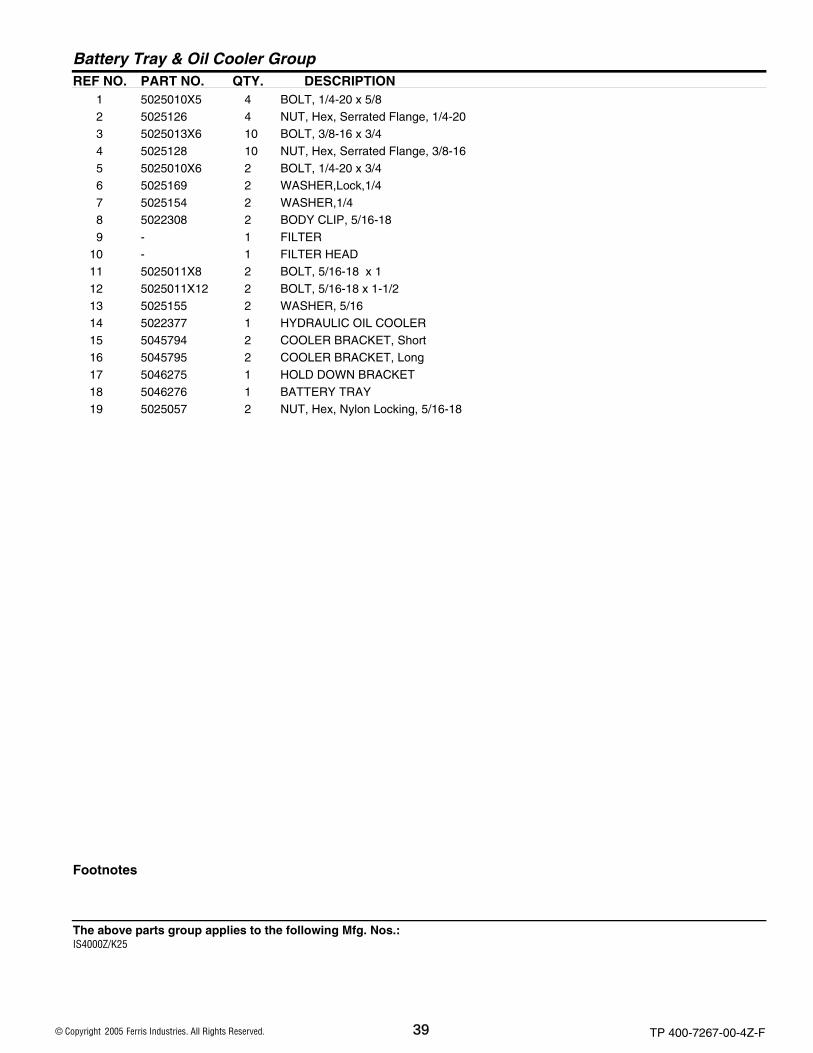
Battery Tray & Oil Cooler Group
Footnotes
1 5025010X5 4 BOLT, 1/4-20 x 5/8 2 5025126 4 NUT, Hex, Serrated Flange, 1/4-20 3 5025013X6 10 BOLT, 3/8-16 x 3/4 4 5025128 10 NUT, Hex, Serrated Flange, 3/8-16 5 5025010X6 2 BOLT, 1/4-20 x 3/4 6 5025169 2 WASHER,Lock,1/4 7 5025154 2 WASHER,1/4 8 5022308 2 BODY CLIP, 5/16-18 9 - 1 FILTER
10 - 1 FILTER HEAD 11 5025011X8 2 BOLT, 5/16-18 x 1 12 5025011X12 2 BOLT, 5/16-18 x 1-1/2 13 5025155 2 WASHER, 5/16 14 5022377 1 HYDRAULIC OIL COOLER 15 5045794 2 COOLER BRACKET, Short 16 5045795 2 COOLER BRACKET, Long 17 5046275 1 HOLD DOWN BRACKET 18 5046276 1 BATTERY TRAY 19 5025057 2 NUT, Hex, Nylon Locking, 5/16-18
The above parts group applies to the following Mfg. Nos.:
2005 39 © Copyright Ferris Industries. All Rights Reserved.
IS4000Z/K25
TP 400-7267-00-4Z-F

Suspension Group267SUS0NOTE: Unless noted otherwise,
use the standard hardware torque specification chart.
The above parts group applies to the following Mfg. Nos.:
2005 40 © Copyright Ferris Industries. All Rights Reserved.
IS4000Z/K25
TP 400-7267-00-4Z-F

PART NO. DESCRIPTIONREF NO. QTY.
Suspension Group
Footnotes
1 5025294 2 SET SCREW, Square Hd, 1/2-13 x 3 2 5025301 2 NUT, Hex, Jam, 1/2-13 3 5045904 2 SPRING COMPRESSION PLATE 4 5045898 2 SPRING RETAINER 5 5021747 2 SPRING, Suspension 6 5045601 1 SPRING SADDLE-LH 7 5045602 1 SPRING SADDLE-RH (not shown) 8 5045588 2 WHEEL MOTOR MOUNT 9 5045304 2 SUSPENSION A-ARM, Upper
10 5022250 16 BUSHING, Flange 11 5020095 12 GREASE FITTING 12 5045305 4 PIVOT SLEEVE, Long 13 5045306 8 PIVOT SLEEVE, Short 14 5022269 8 O-RING 15 5045307 8 WASHER, A-Arm 16 5025294 8 CAPSCREW, Allen Head, 1/2-13 x 3 17 5025056 10 NUT, Hex, Nylon Lock, 1/2-13 18 5045308 2 SUSPENSION A-ARM, Lower 19 5025018X24 4 BOLT, 1/2-20 x 3 20 5025098 8 NUT, Hex, Nylon Lock, 1/2-20 21 5025018X20 4 BOLT, 1/2-20 x 2-1/2 22 5025017X52 4 BOLT, 1/2-13 x 6-1/2 23 5046059 2 SPACER PLATE 24 5025314 2 NUT, Hex, Side Locking, 1/2-13
The above parts group applies to the following Mfg. Nos.:
2005 41 © Copyright Ferris Industries. All Rights Reserved.
IS4000Z/K25
TP 400-7267-00-4Z-F

61" Mower Deck Roller Group2675RL0NOTE: Unless noted otherwise,
use the standard hardware torque specification chart.
The above parts group applies to the following Mfg. Nos.:
2005 42 © Copyright Ferris Industries. All Rights Reserved.
IS4000Z/K25
TP 400-7267-00-4Z-F

PART NO. DESCRIPTIONREF NO. QTY.
61" Mower Deck Roller Group
Footnotes
1 5020785 1 ROLLER, Nose 2 5041655 1 ROLLER PIN 3 5025128 7 NUT, Hex, Serrated Flange, 3/8-16 4 5025013X8 1 BOLT, 3/8-16 x 1 5 5020655 2 LYNCH PIN 6 5041476 6 SPACER, Caster 7 5021541 4 BUSHING, Flange 8 5045185 2 CASTER MOUNT ARM 9 5020095 2 GREASE FITTING
10 5025013X6 6 BOLT, 3/8-16 x 3/4 11 5022098 2 CAP, Plastic 12 5045034 2 CASTER ROLLER PIN 13 5045188 2 CASTER YOKE 14 5022060 2 ROLLER, Caster 15 5025011X6 2 BOLT, 5/16-18 x 3/4 16 5025127 2 NUT, Hex, Serrated Flange, 5/16-18
The above parts group applies to the following Mfg. Nos.:
2005 43 © Copyright Ferris Industries. All Rights Reserved.
IS4000Z/K25
TP 400-7267-00-4Z-F

61" Mower Rear Mount Group2676RM0NOTE: Unless noted otherwise,
use the standard hardware torque specification chart.
The above parts group applies to the following Mfg. Nos.:
2005 44 © Copyright Ferris Industries. All Rights Reserved.
IS4000Z/K25
TP 400-7267-00-4Z-F

PART NO. DESCRIPTIONREF NO. QTY.
61" Mower Rear Mount Group
Footnotes
1 5045103 2 DECK PUSHER BAR 2 5020095 2 GREASE FITTING 3 5025093 2 NUT, Hex, Jam, 3/4-16 4 5025265X24 2 BOLT, 3/4-16 x 3 5 5022111 4 ROD END SEAL 6 5022039 2 BALL JOINT, 3/4-16 7 5025160 2 WASHER, 3/4 8 5025284 2 NUT, Hex, Nylon Lock, 3/4-16 9 5025139 2 NUT, Hex, Serrated Flange, 5/16-18
10 5045037 2 PUSHER BAR MOUNT PIN 11 5025011X8 2 BOLT, 5/16-18 x 1
The above parts group applies to the following Mfg. Nos.:
2005 45 © Copyright Ferris Industries. All Rights Reserved.
IS4000Z/K25
TP 400-7267-00-4Z-F

61" Mower Drive Group2676PB0NOTE: Unless noted otherwise,
use the standard hardware torque specification chart.
The above parts group applies to the following Mfg. Nos.:
2005 46 © Copyright Ferris Industries. All Rights Reserved.
IS4000Z/K25
TP 400-7267-00-4Z-F

PART NO. DESCRIPTIONREF NO. QTY.
61" Mower Drive Group
Footnotes
1 5022399 1 BELT, 61" Deck 2 5025010X8 6 BOLT, 1/4-20 x 1 3 5020819 3 HUB, Taper Lock 4 5020815 3 PULLEY, Spindle 5 5025056 5 NUT, Hex, Nylon Lock, 1/2-13 6 5025158 4 WASHER, 1/2 7 5021976 4 PULLEY, Idler 8 5045024 3 IDLER PULLEY MOUNT 9 5025017X28 3 BOLT, 1/2-13 x 3-1/2
10 5045023 2 IDLER SPACER 11 5025150 2 WASHER, USS, 1/2 12 5025017X24 1 BOLT, 1/2-13 x 3 13 5021811 1 EYEBOLT 14 5042142 1 SPRING ANCHOR 15 5021680 1 SPRING, Compression 16 5025156 1 WASHER, 3/8 17 5025096 1 NUT, Hex, Nylon Lock, 3/8-16 18 5025013X8 1 BOLT, 3/8-16 x 1 19 5025128 1 NUT, Hex, Serrated Flange, 3/8-16 20 5045019 1 IDLER ARM 21 5021541 2 BUSHING, Flange 22 5020095 1 GREASE FITTING 23 5045022 1 IDLER ARM PIVOT SHAFT 24 5025017X36 1 BOLT, 1/2-13 x 4-1/2
The above parts group applies to the following Mfg. Nos.:
2005 47 © Copyright Ferris Industries. All Rights Reserved.
IS4000Z/K25
TP 400-7267-00-4Z-F

Electrical Group Kohler267EGK0NOTE: Unless noted otherwise,
use the standard hardware torque specification chart.
The above parts group applies to the following Mfg. Nos.:
2005 48 © Copyright Ferris Industries. All Rights Reserved.
IS4000Z/K25
TP 400-7267-00-4Z-F

PART NO. DESCRIPTIONREF NO. QTY.
Electrical Group Kohler
Footnotes
1 5045807 1 IS4000Z/K25 Wire Harness 2 5022387 1 VOLTMETER 3 5020927 1 SWITCH, Ignition 4 5020060 1 HOUR METER 5 5022180 1 SWITCH, PTO 6 5022095 3 SWITCH, Plunger, NO/NC 7 5022182 1 SWITCH, Plunger, Snap-In, NO/NC 8 5021451 1 SWITCH, Plunger, NO 9 5045759 1 CABLE, Negative (-) Battery (not shown)
10 5045758 1 CABLE, Positive (+) Battery (not shown) 11 5021603 4 FUSE, 20A (not shown)
The above parts group applies to the following Mfg. Nos.:
2005 49 © Copyright Ferris Industries. All Rights Reserved.
IS4000Z/K25
TP 400-7267-00-4Z-F


Torque Specification ChartFOR STANDARD MACHINE HARDWARE (Tolerance ± 20%)
HardwareGrade
SAE Grade 2 SAE Grade 5 SAE Grade 8
Size Of in/lbs in/lbs in/lbsHardware ft/lbs Nm. ft/lbs Nm. ft/lbs Nm.
8-32 19 2.1 30 3.4 41 4.68-36 20 2.3 31 3.5 43 4.910-24 27 3.1 43 4.9 60 6.810-32 31 3.5 49 5.5 68 7.71/4-20 66 7.6 8 10.9 12 16.31/4-28 76 8.6 10 13.6 14 19.05/16-18 11 15.0 17 23.1 25 34.05/16-24 12 16.3 19 25.8 27 34.03/8-16 20 27.2 30 40.8 45 61.23/8-24 23 31.3 35 47.6 50 68.07/16-14 30 40.8 50 68.0 70 95.27/16-20 35 47.6 55 74.8 80 108.81/2-13 50 68.0 75 102.0 110 149.61/2-20 55 74.8 90 122.4 120 163.29/16-12 65 88.4 110 149.6 150 204.09/16-18 75 102.0 120 163.2 170 231.25/8-11 90 122.4 150 204.0 220 299.25/8-18 100 136 180 244.8 240 326.43/4-10 160 217.6 260 353.6 386 525.03/4-16 180 244.8 300 408.0 420 571.27/8-9 140 190.4 400 544.0 600 816.07/8-14 155 210.8 440 598.4 660 897.61-8 220 299.2 580 788.8 900 1,244.01-12 240 326.4 640 870.4 1,000 1,360.0
Hex Head Capscrew
Hex Nut
Lockwasher
Washer
Carriage Bolt
NOTES1. These torque values are to be used for all hardware
excluding: locknuts, self-tapping screws, thread formingscrews, sheet metal screws and socket head setscrews.
2. Recommended seating torque values for locknuts:a. for prevailing torque locknuts - use 65% of grade 5
torques.b. for flange whizlock nuts and screws - use 135% of
grade 5 torques.3. Unless otherwise noted on assembly drawings, all torque
values must meet this specification.
Hardware Identification & Torque SpecificationsCommon Hardware Types
Screw, 1/2 x 2
BodyDiameter
BodyLength
InsideDiameter
Nut, 1/2”
NoMarks
3/8” Bolt or NutWrench—9/16”
3/8
5/16” Bolt or NutWrench—1/2”
5/16
1/4” Bolt or NutWrench—7/16”
1/4
1/2” Bolt or NutWrench—3/4”
1/2DIA.
7/16DIA.
7/16” Bolt or NutWrench (Bolt)—5/8”
Wrench (Nut)—11/16”
Wrench & Fastener Size Guide
Standard Hardware Sizing
When a washer or nut is identified as 1/2”, this is theNominal size, meaning the inside diameter is 1/2 inch; if asecond number is present it represent the threads per inch
When bolt or capscrew is identified as 1/2 - 16 x 2”, thismeans the Nominal size, or body diameter is 1/2 inch; thesecond number represents the threads per inch (16 in thisexample, and the final number is the body length of thebolt or screw (in this example 2 inches long).
The guides and ruler furnished below are designed tohelp you select the appropriate hardware and tools.
01/4
3/41/2
11/4
3/41/2
21/4
3/41/2
31/4
3/41/2
4

www.ferrisindustries.com
© Copyright Ferris IndustriesAll Rights Reserved. Printed In USA.
2005
5375 North Main StreetMunnsville, NY 13409 USA800-933-6175
Ferris Industries
IS4000Z SeriesZero-Turn Riding Mower
IT IS THE POLICY OF FERRIS INDUSTRIES TO IMPOVE ITS PRODUCTS WHENEVER IT IS POSSIBLE AND PRACTICAL TO DO SO. WE RESERVE THE RIGHT TO MAKE CHANGES OR ADD IMPROVEMENTS AT ANY TIME WITHOUT INCURRING ANY OBLIGATION TO MAKE SUCH CHANGES ON PRODUCTS MANUFACTURED PREVIOUSLY.
PartsManual