Operator Manual - Great Plains Manufacturing
94
Manufacturing, Inc. www.greatplainsmfg.com © Copyright 2003 Printed 08/01/2018 500-641M EN Table of Contents Index Table of Contents Index ORIGINAL INSTRUCTIONS Operator Manual TSF1080, TSF1090, TSF1280 & TSF1290 80- and 90-Foot Front Fold Boom Sprayers Read the operator manual entirely. When you see this symbol, the subsequent instructions and warnings are serious - follow without exception. Your life and the lives of others depend on it! Illustrations may show optional equipment not supplied with standard unit. ! 27295
-
Upload
khangminh22 -
Category
Documents
-
view
1 -
download
0
Transcript of Operator Manual - Great Plains Manufacturing

Table of Contents Index
Operator ManualTSF1080, TSF1090, TSF1280 & TSF1290
80- and 90-Foot Front Fold Boom Sprayers
Manufacturing, Inc.www.greatplainsmfg.com
Read the operator manual entirely. When you see this symbol, the subsequent instructions and warnings are serious - follow without exception. Your life and the lives of others depend on it!
Illustrations may show optional equipment not supplied with standard unit.
!
27295
© Copyright 2003 Printed 08/01/2018 500-641M
EN
Table of Contents Index
ORIGINAL INSTRUCTIONS

Machine IdentificationRecord your machine details in the log below. If you replace this manual, be sure to transfer this information to the newmanual.
If you or the dealer have added options not originally ordered with the machine, or removed options that were originallyordered, the weights and measurements are no longer accurate for your machine. Update the record by adding themachine weight and measurements with the option(s) weight and measurements.
Dealer Contact Information
Model Number
Serial Number
Machine Height
Machine Length
Machine Width
Machine Weight
Year of Construction
Delivery Date
First Operation
Accessories
Name:
Street:
City/State:
Telephone:
Email:
Dealer’s Customer No.:
WARNING: Cancer and Reproductive Harm - www.P65Warnings.ca.gov

TSF1080, TSF1090, TSF1280 & TSF1290 Cover Index iii
Table of Contents
Important Safety Information.................................................1Safety Reflectors and Decals ............................................8
Introduction...........................................................................18Document Family.............................................................18Description of Unit ...........................................................18
Intended Usage ........................................................18Models Covered .......................................................18
Using This Manual...........................................................18Definitions.................................................................18
Owner Assistance............................................................19Preparation and Setup .........................................................20
Before You Start ..............................................................20Hitching Tractor to Sprayer..............................................20
Hitch Type ................................................................20Hitching with Hydraulic Pump...................................21Hitching with PTO Pump ..........................................22
Axle Spacing....................................................................22Electrical Connections .....................................................23Hydraulic Hookup ............................................................23
Sprayer Control Hydraulic Hookup...........................23Hydraulic Pump Hookup...........................................24
Tractor / PTO Shaft Hookup ............................................25Leveling Sprayer..............................................................26
Hitch Height..............................................................26Frame Level Adjustment ..........................................27Leveling Boom..........................................................27
Locking System Setup.....................................................28Hydraulic Pump Setup.....................................................28
Ace Pump Flow Limiter (Option) ..............................29Setting Pump Rate ...................................................29
Electrical Installation........................................................30Lights........................................................................30Raven SCS 450........................................................30Hydraulic Valve Control............................................32Foam Marker Control (Option) .................................32Raven AutoBoom (Option) .......................................32
Spraying Setup ................................................................33Hydraulic Pump Setup..............................................33PTO Pump Setup .....................................................33Manual Throttle Valve ..............................................33
Sprayer Calibration..........................................................34Speed Calibration.....................................................34Rate Calibration........................................................35
Operations.............................................................................37General Notes For Field Operation .................................37
Operating Checklist..................................................38Using Hand Wash Tank ..................................................38Transporting ....................................................................39Plumbing Overview .........................................................40Filling Tanks ....................................................................43
Filling Hand Wash Tank ...........................................43Filling the Flush Tank ...............................................44Filling the Main Tank ................................................44
Adding Chemicals ...........................................................47Inducting Chemicals (Option)...................................48
Agitation ..........................................................................49Foam Marker Tank Fill ....................................................49Boom Operations ............................................................49
2007+ Sprayer Hydraulics........................................492006- Sprayer Hydraulics.........................................49Elevator Raising/Lowering .......................................50Boom Height ............................................................50Boom Unfolding........................................................51Boom Fold................................................................51Boom Tilt ..................................................................51AutoBoom Operation (Option)..................................5160-Foot Spraying......................................................52
Operating Pump ..............................................................53Unloading Materials.........................................................53Tank and Boom Flush .....................................................54Parking ............................................................................55
Unhitching with Hydraulic Pump ..............................56Unhitching with PTO Pump......................................56
Storage............................................................................57Adjustments..........................................................................58
General Field Adjustments ..............................................58Boom Height ............................................................58Nozzle Pressure.......................................................58
Axle Wheel Spacing Adjustment .....................................59Break Away Spring..........................................................60
Troubleshooting ...................................................................61Maintenance and Lubrication..............................................63
Sprayer/Boom Maintenance............................................63Equipment Cleanup.........................................................63General Information.........................................................63Filter Maintenance...........................................................64
Clean Out Solution Whirlfilter® ................................64Clean Out Tank Fill Filter .........................................64
Shear Bolt........................................................................65Pump Maintenance and Repair.......................................66
08/01/2018 Cover Index 500-641M
© Copyright 2003 All rights Reserved
Great Plains Manufacturing, Inc. provides this publication “as is” without warranty of any kind, either expressed or implied. While every precaution has beentaken in the preparation of this manual, Great Plains Manufacturing, Inc. assumes no responsibility for errors or omissions. Neither is any liability assumed fordamages resulting from the use of the information contained herein. Great Plains Manufacturing, Inc. reserves the right to revise and improve its products asit sees fit. This publication describes the state of this product at the time of its publication, and may not reflect the product in the future.
Trademarks of Great Plains Manufacturing, Inc. include: AccuShot, Max-Chisel, Row-Pro, Singulator Plus, Short Disk, Swath Command, Terra-Tine, Ultra-Chisel, and X-Press.
Registered Trademarks of Great Plains Manufacturing, Inc. include: Air-Pro, Clear-Shot, Discovator, Great Plains, Land Pride, MeterCone, Nutri-Pro, Seed-Lok, Solid Stand, Terra-Guard, Turbo-Chisel, Turbo-Chopper, Turbo-Max, Turbo-Till, Ultra-Till, Whirlfilter, and Yield-Pro.
Brand and Product Names that appear and are owned by others are trademarks of their respective owners.Printed in the United States of America

TSF1080, TSF1090, TSF1280 & TSF1290 Cover Index iv
Ace Pumps ...............................................................67Elevator Slide ..................................................................70Quad-Jet Agitators...........................................................70Tank Entry .......................................................................71Lubrication .......................................................................72
Options ..................................................................................75AutoBoom........................................................................75Axles and Wheels............................................................75Calibration Accessories ...................................................76Chemical Inductor............................................................76High Volume Foam Marker..............................................76Gauge Protector ..............................................................77Hitches (Hydraulic Pump Only) .......................................77Open Center Hydraulic Kit...............................................77Pumps .............................................................................78
Ace Hydraulic Pump.................................................78Ace PTO Pumps ......................................................78
Speed Sensors................................................................79Radar Speed Sensor................................................79Raven Wheel Speed Sensor....................................79Y-Cable ....................................................................79
Appendix ...............................................................................80Specifications and Capacities .........................................80Tire Inflation Chart...........................................................80Torque Values .................................................................81Hydraulic and Plumbing Diagrams ..................................82
Boom Hydraulics ......................................................82Standard Closed Center Pin Assignments...............83Manifold-Boom Assignments ...................................84Raven G1 AutoBoom Hydraulics .............................85
08/01/2018 Cover Index 500-641M

TSF1080, TSF1090, TSF1280 & TSF1290 Table of Contents Index 1
Important Safety Information
Look for Safety SymbolThe SAFETY ALERT SYMBOL indicates there is apotential hazard to personal safety involved and extrasafety precaution must be taken. When you see thissymbol, be alert and carefully read the message thatfollows it. In addition to design and configuration ofequipment, hazard control and accident prevention aredependent upon the awareness, concern, prudence andproper training of personnel involved in the operation,transport, maintenance and storage of equipment.
Be Aware of Signal WordsSignal words designate a degree or level of hazardseriousness.
DANGER indicates an imminently hazardous situationwhich, if not avoided, will result in death or serious injury.This signal word is limited to the most extreme situations,typically for machine components that, for functionalpurposes, cannot be guarded.
WARNING indicates a potentially hazardous situationwhich, if not avoided, could result in death or seriousinjury, and includes hazards that are exposed whenguards are removed. It may also be used to alert againstunsafe practices.
CAUTION indicates a potentially hazardous situationwhich, if not avoided, may result in minor or moderateinjury. It may also be used to alert against unsafepractices.
Be Familiar with Safety Decals Read and understand “Safety Reflectors and Decals”
starting on page 8, thoroughly.
Read all instructions noted on the decals.
Avoid High Pressure Fluids Escaping fluid under pressure can penetrate the skin,
causing serious injury. If hydraulic fluid penetrates theskin under pressure, immediate medical attention isrequired. See a physician familiar with this type of injury
Avoid the hazard by relieving pressure beforedisconnecting hydraulic lines.
Use a piece of paper or cardboard, NOT BODY PARTS, tocheck for suspected leaks.
Wear protective gloves and safety glasses or goggles whenworking with hydraulic systems.
08/01/2018 Table of Contents Index 500-641M

TSF1080, TSF1090, TSF1280 & TSF1290 Table of Contents Index Important Safety Information 2
Wear Protective EquipmentGreat Plains advises all users of chemical pesticides orherbicides to use the following personal safetyequipment.
Waterproof, wide-brimmed hat
Waterproof apron.
Face shield, goggles or full face respirator.
Goggles with side shields or a full face respirator isrequired if handling or applying dusts, wettable powders,or granules or if being exposed to spray mist.
Cartridge-type respirator approved for pesticide vaporsunless label specifies another type of respirator.
Waterproof, unlined gloves. Neoprene gloves arerecommended.
Cloth coveralls/outer clothing changed daily; waterproofitems if there is a chance of becoming wet with spray
Waterproof boots or foot coverings
Do not wear contaminated clothing. Wash protectiveclothing and equipment with soap and water after eachuse. Personal clothing must be laundered separately fromhousehold articles.
Clothing contaminated with certain pesticides must bedestroyed according to state and local regulations. Readchemical label for specific instructions.
Wear clothing and equipment appropriate for the job.Avoid loose-fitting clothing.
Prolonged exposure to loud noise can cause hearingimpairment or loss. Wear suitable hearing protection suchas earmuffs or earplugs.
Avoid wearing entertainment headphones while operatingmachinery. Operating equipment safely requires the fullattention of the operator.
08/01/2018 Table of Contents Index 500-641M

TSF1080, TSF1090, TSF1280 & TSF1290 Table of Contents Index Important Safety Information 3
Handle Chemicals Properly Read and follow chemical manufacturer’s instructions.
Wear protective clothing.
Handle all chemicals with care.
Agricultural chemicals can be dangerous. Improper usecan seriously injure persons, animals, plants, soil andproperty.
Inhaling smoke from any type of chemical fire is a serioushealth hazard.
Store or dispose of unused chemicals as specified by thechemical manufacturer.
Before adding chemical to the tank, make sure tank is atleast half full. Do not pour concentrate into an emptytank.
Never leave fill hose attached to the sprayer after fillingtank. Chemicals in tank can siphon out of tank andcontaminate freshwater source.
Always keep hand-wash tank filled with clean water andhave soap available in case of an emergency. Immediatelyand thoroughly flush any area of the body that iscontaminated by chemicals.
Do not touch sprayer components with mouth or lips.
If chemical is swallowed, carefully follow the chemicalmanufacturer’s recommendations and consult with adoctor.
If persons are exposed to a chemical in a way that couldaffect their health, consult a doctor immediately with thechemical label or container in hand. Any delay couldcause serious illness or death.
Dispose of empty chemical containers properly. By lawrinsing of the used chemical container must be repeatedthree times. Puncture the container to prevent future use.An alternative is to jet-rinse or pressure rinse thecontainer.
Wash hands and face before eating after working withchemicals. Shower as soon as spraying is completed forthe day.
Spray only with acceptable wind conditions. Wind speedmust be below 5 mph. Make sure wind drift of chemicalswill not affect any surrounding land, people or animals.
Never wash out the sprayer tank within 100 feet (30m) ofany freshwater source or in a car wash.
Rinse out the tank. Spray rinse water on last field sprayed.
08/01/2018 Table of Contents Index 500-641M

TSF1080, TSF1090, TSF1280 & TSF1290 Table of Contents Index Important Safety Information 4
Confined SpaceOnce used for hazardous fertilizers, or seeds withhazardous treatments, your tank may become a“permit-required confined space” under applicablestatutes, regulations, insurance rules or business policy.
When hazardous fumes are present, you can be quicklyovercome even with the tank lid open.
Do not enter a tank for material loading, materialunloading, tank cleaning or valve maintenance.
Clean tank by power washing from outside the tank top.
Perform valve maintenance by removing meters frombottom of empty tank.
If obstruction removal or repair requires tank entry, havethe work performed by a team trained in confined spaceprocedures. See “Tank Entry” on page 71.
Use A Safety Chain Use a safety chain to help control drawn machinery
should it separate from tractor drawbar.
Use a chain with a strength rating equal to or greater thanthe gross weight of towed machinery.
Attach chain to tractor drawbar support or other specifiedanchor location. Allow only enough slack in chain topermit turning.
Replace chain if any links or end fittings are broken,stretched or damaged.
Do not use safety chain for towing.
Keep Riders Off Machinery Riders obstruct the operator’s view. Riders could be struck
by foreign objects or thrown from the machine.
Never allow children to operate equipment.
Keep all bystanders away from machine during operation.
Use Safety Lights and Devices Slow-moving tractors and towed implements can create a
hazard when driven on public roads. They are difficult tosee, especially at night.
Use flashing warning lights and turn signals wheneverdriving on public roads.
Use tractor lights and lights provided with implement.
08/01/2018 Table of Contents Index 500-641M

TSF1080, TSF1090, TSF1280 & TSF1290 Table of Contents Index Important Safety Information 5
Check for Overhead Lines
Sprayer booms contacting overhead electrical lines canintroduce lethal voltage levels on sprayer and tractor frames.A person touching almost any metal part can complete thecircuit to ground, resulting in serious injury or death. Athigher voltages, electrocution can occur without directcontact.
Avoid overhead lines during sprayer operations.
Transport Machinery Safely Maximum transport speed for implement is 20 mph (32
kph). Some rough terrains require a slower speed. Suddenbraking can cause a towed load to swerve and upset.
Do not exceed 20 mph (32 kph). Never travel at a speedwhich does not allow adequate control of steering andstopping. Reduce speed if towed load is not equipped withbrakes.
Comply with state and local laws.
Do not tow an implement that, when fully loaded, weighsmore than 1.5 times the weight of towing vehicle.
Carry reflectors or flags to mark Front Fold BoomSprayer in case of breakdown on the road.
Keep clear of overhead power lines and otherobstructions when transporting. Refer to transportdimensions under “Specifications and Capacities” onpage 80.
Do not fold or unfold the Front Fold Boom Sprayer whilethe tractor is moving.
Shutdown and Storage Fold Front Fold Boom Sprayer, put tractor in park, turn off
engine, and remove the key.
Secure Front Fold Boom Sprayer using blocks andsupports provided.
Detach and store Front Fold Boom Sprayer in an areawhere children normally do not play.
08/01/2018 Table of Contents Index 500-641M

TSF1080, TSF1090, TSF1280 & TSF1290 Table of Contents Index Important Safety Information 6
Practice Safe Maintenance Understand procedure before doing work. Use proper
tools and equipment. Refer to this manual for additionalinformation.
Work in a clean, dry area.
Fold the Front Fold Boom Sprayer, put tractor in park,turn off engine, and remove key before performingmaintenance.
Make sure all moving parts have stopped and all systempressure is relieved.
Allow Front Fold Boom Sprayer to cool completely.
Disconnect battery ground cable (-) before servicing oradjusting electrical systems or before welding on FrontFold Boom Sprayer.
Inspect all parts. Make sure parts are in good conditionand installed properly.
Remove buildup of grease, oil or debris.
Remove all tools and unused parts from Front Fold BoomSprayer before operation.
Prepare for Emergencies Be prepared if a fire starts.
Keep a first aid kit and fire extinguisher handy.
Keep emergency numbers for doctor, ambulance, hospitaland fire department near phone.
Tire Safety Tire changing can be dangerous and should be performed
by trained personnel using correct tools and equipment.
When inflating tires, use a clip-on chuck and extensionhose long enough for you to stand to one side–not in frontof or over tire assembly. Use a safety cage if available.
When removing and installing wheels, use wheel-handlingequipment adequate for weight involved.
08/01/2018 Table of Contents Index 500-641M

TSF1080, TSF1090, TSF1280 & TSF1290 Table of Contents Index Important Safety Information 7
Safety At All Times Thoroughly read and understand the instructions in this
manual before operation. Read all instructions noted onthe safety decals.
Be familiar with all Front Fold Boom Sprayer functions.
Operate machinery from the driver’s seat only.
Do not leave Front Fold Boom Sprayer unattended withtractor engine running.
Do not dismount a moving tractor. Dismounting a movingtractor could cause serious injury or death.
Do not stand between the tractor and Front Fold BoomSprayer during hitching.
Keep hands, feet and clothing away from power-drivenparts.
Wear snug-fitting clothing to avoid entanglement withmoving parts.
Watch out for wires, trees, etc., when folding and raisingFront Fold Boom Sprayer. Make sure all persons are clearof working area.
Do not turn tractor too tightly, causing Front Fold BoomSprayer to ride up on wheels. This could cause personalinjury or equipment damage.
Use only water without pesticides added to calibrate thesprayer. Do not exceed the calibrated sprayer speed andpressure when operating.
When using a PTO pump, be sure that PTO shield is inplace on the tractor, PTO coupler bolts are torqued to thecorrect specification, and torque bar is properly chainedto tractor drawbar.
Spray with the boom in the unfolded position only.
The boom has many pinch points during field operationand folding. Keep all bystanders away.
Never use tank for potable water.
08/01/2018 Table of Contents Index 500-641M

TSF1080, TSF1090, TSF1280 & TSF1290 Table of Contents Index Important Safety Information 8
Safety Reflectors and DecalsYour sprayer comes equipped with all safety reflectorsand decals in place. They were designed to help yousafely operate your sprayer.
Read and follow decal directions.
Keep all safety decals clean and legible.
Replace all damaged or missing decals. Order new decalsfrom your Great Plains dealer. Refer to this section forproper decal placement.
When ordering new parts or components, also requestcorresponding safety decals.
To install new decals:
1. Clean the area on which the decal is to be placed.
2. Peel backing from decal. Press firmly on surface,being careful not to cause air bubbles under decal.
Slow Moving Vehicle Reflector818-055C
Center section of boom, facing to rear;1 total
Red Reflectors(TSF1080/TSF1090 S/N 1183RR-)(TSF1280/TSF1290 S/N 1109VV-)838-266C
Center section of boom, outside ends,Rear face of lower tube;2 total
20441A
20441
08/01/2018 Table of Contents Index 500-641M

TSF1080, TSF1090, TSF1280 & TSF1290 Table of Contents Index Important Safety Information 9
Red Reflectors(TSF1080/TSF1090 S/N 1184RR+)(TSF1280/TSF1290 S/N 1110VV+)838-266C
At rear of center section of boom under light brackets ateach end,on each side of SMV reflector at rear of center section;4 total
Amber Reflectors (Trailer)838-265C
Main frame, outside faces, front and rear corners;4 total
Amber Reflectors (Boom)(TSF1080/TSF1090 S/N 1183RR-)(TSF1280/TSF1290 S/N 1109VV-)838-265C
Center section of boom, front face of forward tube,outside ends:2 total
68467
20377
2037720441
08/01/2018 Table of Contents Index 500-641M

TSF1080, TSF1090, TSF1280 & TSF1290 Table of Contents Index Important Safety Information 10
Amber Reflectors (Boom)(TSF1080/TSF1090 S/N 1184RR+)(TSF1280/TSF1290 S/N 1110VV+)838-265C
Center section of boom at outside ends of light brackets,front face of center boom at each end;4 total
Daytime Reflectors(TSF1080/TSF1090 S/N 1183RR-)(TSF1280/TSF1290 S/N 1109VV-)838-267C
Center section of boom, rear face of lower tube, justinboard of Red reflectors;2 total
Daytime Reflectors(TSF1080/TSF1090 S/N 1184RR+)(TSF1280/TSF1290 S/N 1110VV+)838-267C
At rear of center section of boom under light brackets ateach end;2 total
68466
20441
68467
08/01/2018 Table of Contents Index 500-641M

TSF1080, TSF1090, TSF1280 & TSF1290 Table of Contents Index Important Safety Information 11
Danger: Rotating Driveline (PTO only)818-142C
Top of PTO shaft guard;1 total
Danger: Rotating Driveline (PTO only)818-187C
Top of PTO bearing mount guard;1 total
Danger: Agricultural Chemicals818-323C
Front face of mainframe left side,At rear of center section of boom;2 total
20377
DANGER
20377
DANGER
20377
68467
08/01/2018 Table of Contents Index 500-641M
TSF1080, TSF1090, TSF1280 & TSF1290 Table of Contents Index Important Safety Information 12
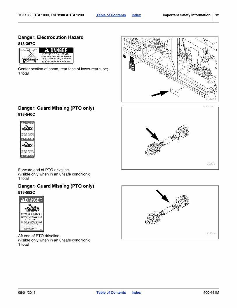
Danger: Electrocution Hazard818-367C
Center section of boom, rear face of lower rear tube;1 total
Danger: Guard Missing (PTO only)818-540C
Forward end of PTO driveline(visible only when in an unsafe condition);1 total
Danger: Guard Missing (PTO only)818-552C
Aft end of PTO driveline(visible only when in an unsafe condition);1 total
20441A
20377
20377
08/01/2018 Table of Contents Index 500-641M

TSF1080, TSF1090, TSF1280 & TSF1290 Table of Contents Index Important Safety Information 13
Danger: Crushing Hazard818-864C
Base of elevator(1),boom center section, rear face of fixed mount(1),boom center section, front face of center boom next toamber reflectors(2);4 total
68467
68467
68466
08/01/2018 Table of Contents Index 500-641M

TSF1080, TSF1090, TSF1280 & TSF1290 Table of Contents Index Important Safety Information 14
Warning: Negative Tongue Weight818-019C
Left side of tongue;1 total
Warning: Excessive Speed818-188C
Front left side of hitch;1 total
Warning: Chemical Overflow (Option)818-303C
Outside face of inductor tank;1 total
Warning: Axle Adjustment818-548C
Left center side of main frame;1 total
20377
NEGATIVE TONGUE WEIGHTHAZARD
Negative tongue weight can cause immediateelevation of tongue when unhitching implement
To prevent serious injury or death:
Always be certain implement is hitched securely to tractor drawbar before reaising.
Lower implement BEFORE unhitching.818-019C Rev. D
WARNING
20377
818-188C Rev. C
Do Not exceed 20 mph maximum transportspeed. Loss of vehicle control and/or machinecan result.
To Prevent Serious Injury or Death:EXCESSIVE SPEED HAZARD
WARNING
16142
20377
08/01/2018 Table of Contents Index 500-641M

TSF1080, TSF1090, TSF1280 & TSF1290 Table of Contents Index Important Safety Information 15
Warning: High Pressure Fluids818-339C
Front left side of hitch,at rear of center section of boom;2 total
Warning: Overhead Boom818-467C
Rear face of top inboard gusset, each boom innersection;2 total
Warning: Water Contamination818-696C
Left side of main frame, at walkboard;1 total
20238
20441A
20441
20377
08/01/2018 Table of Contents Index 500-641M

TSF1080, TSF1090, TSF1280 & TSF1290 Table of Contents Index Important Safety Information 16
Warning: Pinch Point818-798C
Rear facing on center section pivot tubes (2),rear face, lower inboard gusset, boom inner section (2),inside faces of end plates at boom section joint (4);8 total
Caution: General Sprayer
818-324C
Front of tank, lower left;1 total
Caution: Read Operator’s Manual818-587C
Front left side of hitch; 1 total
20441
20377
20238
WARNING:Cancer and Reproductive Harm - www.P65Warnings.ca.gov
Read Owner’s Manual before using machine.Stand clear when folding and unfolding markers.Stand clear when raising and lowering machine.Keep all safety shields and devices in place.Keep hands, feet, and clothing away from
Never ride on machine.
Always lower or properly support machine
Escaping hydraulic fluid can cause serious
Review safety instructions with all operators
moving chains and sprockets.
BEFORE servicing.
818-587C Rev. B
injury.
annually.
CAUTION
08/01/2018 Table of Contents Index 500-641M

TSF1080, TSF1090, TSF1280 & TSF1290 Table of Contents Index Important Safety Information 17
Caution: Tire Pressure & Torque(TSF1080/TSF1090)818-365C (SN 1129RR-)
13.6-38 wheel rims;Valve stem side of tire rim; 1 each wheel0 or 2 total
848-347C (SN 1130RR+)
320/85R38 Radial TiresValve stem side of tire rim; 1 each wheel0 or 2 total
Caution: Tire Pressure and Torque(TSF1280/TSF1290)818-381C
14.9 R46 wheel rims;0 or 2 total
General: Handwash Tank Location818-304C
front of hand wash tank, (main tank front top);1 total
13838
21519
20377
08/01/2018 Table of Contents Index 500-641M

TSF1080, TSF1090, TSF1280 & TSF1290 Table of Contents Index 18
Introduction
Great Plains welcomes you to its growing family of newproduct owners. Your Front Fold Boom Sprayer has beendesigned with care and built by skilled workers usingquality materials. Proper setup, maintenance, and safeoperating practices will help you get years of satisfactoryuse from the machine.
Document Family500-641M Operator Manual (this document)500-641P Parts Manual509-200M Application Guide832-038C Nozzle Calculator (U.S.customary units)832-058C Nozzle Calculator (metric)
Description of UnitThe TSF1080, TSF1090, TSF1280 & TSF1290 arepull-type implements. They have a working width of 80 or90 feet (24.4 or 27.4m) depending on model, and arecapable of spraying at either 60 feet (18.3m) or the full 80or 90 feet depending on your application needs. Thelevel float boom is fully suspended starting with verticalspring suspension in a 42-inch (107cm) hydraulicelevator which provides a wide range of boom heightadjustment along with gas shocks that provideside-to-side stability.
Intended UsageUse these booms as part of a pressurized sprayersystem to apply liquid pesticides, herbicides or fertilizersto production-agriculture crops only. Do not modifysprayer for use with attachments other than thoseapproved by Great Plains.
Models Covered
Using This ManualThis manual familiarizes you with safety, assembly,operation, adjustments, troubleshooting, andmaintenance. Read this manual and follow therecommendations to help ensure safe and efficientoperation.
The information in this manual is current at printing.Some parts may change to assure top performance.
DefinitionsThe following terms are used throughout this manual.
Right-hand and left-hand as used in this manual aredetermined by facing the direction the machine will travelwhile in use unless otherwise stated.
Paragraphs in this format present a crucial point of informationrelated to the current topic. Read and follow the directions to:- remain safe,- avoid serious damage to equipment and- ensure desired field results.
NOTE:Paragraphs in this format provide useful informationrelated to the current topic.
Figure 1: TSF1080, TSF1090, TSF1280 & TSF1290 Sprayer
27296
R
L
TSF-1080-3330 1000 Gallon 80 foot 30in spacing
TSF-1080-4820 1000 Gallon 80 foot 20in spacing
TSF-1090-3730 1000 Gallon 90 foot 30in spacing
TSF-1090-5420 1000 Gallon 90 foot 20in spacing
TSF-1280-3330 1250 Gallon 80 foot 30in spacing
TSF-1280-4820 1250 Gallon 80 foot 20in spacing
TSF-1290-3730 1250 Gallon 90 foot 30in spacing
TSF-1290-5420 1250 Gallon 90 foot 20in spacing
08/01/2018 Table of Contents Index 500-641M

TSF1080, TSF1090, TSF1280 & TSF1290 Table of Contents Index Introduction 19
Owner AssistanceIf you need customer service or repair parts, contact aGreat Plains dealer. They have trained personnel, repairparts and equipment specially designed for Great Plainsproducts.
Refer to Figure 2
Your machine’s parts were specially designed andshould only be replaced with Great Plains parts. Alwaysuse the serial and model number when ordering partsfrom your Great Plains dealer. The serial-number plate islocated on the front face of the left vertical tube of the3-point frame.
Record your sprayer model and serial number here forquick reference:
Model Number:__________________________
Serial Number: __________________________
The serial number plate is located on the front of the tankframe.
Further AssistanceGreat Plains Manufacturing, Inc. and your Great Plainsdealer want you to be satisfied with your new product. Iffor any reason you do not understand any part of thismanual or are otherwise dissatisfied, please take thefollowing actions first:
1. Discuss the matter with your dealership servicemanager. Make sure they are aware of any problemsso they can assist you.
2. If you are still unsatisfied, seek out the owner orgeneral manager of the dealership.
If your dealer is unable to resolve the problem or theissue is parts related, please contact:
Great Plains Service Department1525 E. North St.
P.O. Box 5060Salina, KS 67402-5060
Or go to www.greatplainsag.com and follow the contactinformation at the bottom of your screen for our servicedepartment.
Figure 2Serial Number Plate
20422
08/01/2018 Table of Contents Index 500-641M

TSF1080, TSF1090, TSF1280 & TSF1290 Table of Contents Index 20
Preparation and Setup
Before You StartRead and understand the owners manual for yoursprayer. A basic understanding of how the sprayer workswill aid in the assembly, setup and operation of yoursprayer.
Perform these checks before setting up your cross-foldboom.
1. Read and understand “Important Safety Informa-tion” on page 1.
2. Check that all working parts are moving freely, boltsare tight, and cotter pins are spread.
3. Check that all grease fittings are in place andlubricated. See “Lubrication” on page 72.
4. Check that all safety decals and reflectors arecorrectly located and legible. Replace if damaged.See “Safety Reflectors and Decals” on page 8.
Hitching Tractor to SprayerThe standard TSF1080, TSF1090, TSF1280 & TSF1290sprayers require a tractor with closed center hydraulics. Ifthe tractor has open center hydraulics, the sprayer mustbe adapted to it with an open center conversion kit,833-427C. See page 77.
Hitch TypeIf the sprayer has a hydraulic pump, the hitch is a choiceof single tang or clevis. Hitching instructions begin onpage 21.
If the sprayer has a PTO pump, a ball hitch with hitchplate is standard. Hitching instructions begin on page 22.
You may be severely injured or killed by being crushedbetween the tractor and sprayer. Do not stand or place anypart of your body between sprayer and moving tractor. Stoptractor engine and set park brake before installing the hitchpin.
Electrocution hazard. To prevent serious injury or death fromelectric shock, keep clear of overhead power lines whentransporting, folding or unfolding boom. Boom is notgrounded. Electrocution can occur without direct contact.Refer to transport dimensions under “Specifications andCapacities” on page 80. Do not fold or unfold boom whiletractor is moving.
Negative tongue weight - do not unfold boom before hitching.When the tank is low or empty, unfolded booms can move thecenter of gravity aft of the wheels. This will cause the tongueto rise, with risk of personal injury and equipment damage.
08/01/2018 Table of Contents Index 500-641M

TSF1080, TSF1090, TSF1280 & TSF1290 Table of Contents Index Preparation and Setup 21
Hitching with Hydraulic PumpRefer to Figure 3
A hydraulic pump sprayer has either a single tang orclevis hitch. To change the hitch type, see “Hitches(Hydraulic Pump Only)” on page 77 for orderinginformation. The clevis hitch may be inverted ifnecessary to obtain ideal hitch height.
Refer to Figure 4
1. Park the sprayer in an open, flat and level area with the jack in the park position.
2. Back the tractor up to the sprayer, and adjust thesprayer hitch height with the jack and/or adjust thetractor hitch height. Back the tractor until the hitchesalign.
3. Insert the hitch pin and secure.
4. Skip to “Leveling Sprayer” on page 26.
Refer to Figure 4 and Figure 5
5. Remove the jack and pin it to the storage stob on thebrace tube above the left wheel axle.
Figure 3Tang or Clevis Hitch
20234
Figure 4Jack in Parking Position
13811
Figure 5Jack in Storage Position
20402
08/01/2018 Table of Contents Index 500-641M

TSF1080, TSF1090, TSF1280 & TSF1290 Table of Contents Index Preparation and Setup 22
Hitching with PTO PumpRefer to Figure 6
A PTO pump sprayer has a ball hitch. The hitch partsinclude a hitch plate and ball hitch pin to adapt a plaintractor drawbar to ball hitch use.
If the tractor already has a ball hitch-compatible drawbar,skip to step 6.
1. Remove the hammer-strap on the tractor.
2. Assemble the ball hitch plate to the drawbar byplacing the 1-8 x 5-inch long bolt through thedrawbar hole using flat washers on both ends.
3. Place the backup plate on top of the drawbar andorient the slots so they point in the oppositedirections from the hitch plate slots.
4. Insert the 34-10 x 5-inch long bolt throughwashers, the backup plate slots and the hitchplate slots. Secure with washers and flange nutsprovided.
5. Insert the ball hitch pin stud in the hitch plate and secure with washer and 114-7 nylon insert nut.
6. Park the sprayer in an open, flat, level area with thejack in the park position.
Refer to Figure 7 and Figure 8
7. Back the tractor up to the sprayer. Hook up thesprayer ball hitch onto the stud pin mounted onthe ball hitch plate . Secure the ball hitch with thelarge flat washer and the lynch pin .
8. Remove the jack and pin it to the storage stob on thebrace tube above the left wheel axle.
Axle SpacingThe TSF sprayers have sliding axles allowing wheelcenter-lines to be in the range:N.America: 80 to 120 inches (203 to 305cm)Export: 203 to 290cm (80 to 114in).
You can set them to match or complement tractor tirespacing.
This adjustment is most easily done when the sprayer ismechanically hitched with empty tanks. See “AxleWheel Spacing Adjustment” on page 59 for detailedinstructions.
Figure 6Ball Hitch
20359
1
2
3
5
4
78
6
1
23
5
2
45
2
6 2
Figure 7Jack in Parking Position
13811
62
8 7
Figure 8Jack in Storage Position
20402
08/01/2018 Table of Contents Index 500-641M

TSF1080, TSF1090, TSF1280 & TSF1290 Table of Contents Index Preparation and Setup 23
Electrical ConnectionsFor a new sprayer (or moving to a different tractor), firstcomplete tractor electrical installation (See “ElectricalInstallation” on page 30), and installation of any sprayerOptions not factory- or dealer-installed.
Hydraulic Hookup.The standard TSF1080, TSF1090, TSF1280 & TSF1290sprayer has a single hydraulic connection at the hitch.Each cart hydraulic function is served by anelectro-hydraulic control valve at boom center.
If an optional hydraulic pump is installed, there is asecond hydraulic connection for the pump, which islocated near the hitch.
Refer to Figure 9
Both hose sets have labels for flow conventions. Theselabels use cylinder Base/Extend and Rod/Retract icons.
Be sure to connect these to the matching tractorremotes, so that when remote levers are activated asdescribed in this manual:a. booms move in the described directions, andb. pump flow is forward and not reversed.
Sprayer Control Hydraulic HookupIf the sprayer has a hydraulic pump, and the tractor hasonly one circuit capable of continuous flow or only onecapable of adjustable continuous flow, reserve that circuitfor the pump, and use another for the main sprayerfunctions.
1. Connect the main sprayer hydraulic hoses to suitable tractor remotes. They are easily identified, as they pass behind the pump.
Lights Standard
Raven Controller Standard
Electro-Hydraulics Standard (two connectors)
Foam Marker Optional
Raven G1 AutoBoom Optional
Wheel Sensor Optional
Radar SensorOptional - routine hook-up necessary only if sensor is mounted on sprayer
Figure 9Hose Label
27270
08/01/2018 Table of Contents Index 500-641M

TSF1080, TSF1090, TSF1280 & TSF1290 Table of Contents Index Preparation and Setup 24
Hydraulic Pump HookupThe hydraulic motor used on all liquid pumps is a 7 gpm(23 liter/min.) motor. If the tractor used on the sprayerdoes not have the capabilities to adjust the remotesdown to this flow, then a Hydraulic Flow Divider Kit mustbe installed so that flow can be controlled to preventoperating the pump at excessive speeds. See a GreatPlains dealer for more information.
Refer to Figure 10
2. The pressure hose coming out of the tractor remotesmust be connected to the motor inlet port (“I” oncurrent pumps; “A” on older pumps, Base end onhose label), and the return line connected to themotor outlet (“O” on current pumps, “B” on olderpumps, Rod end on hose label).
3. Before operating, place a stop in the neutral positionfor the tractor hydraulics so that the hydraulic levercan only be moved to the float and down positions.Refer to the tractor’s operator’s manual or tractordealer on information for the neutral stop.
DO NOT move the hydraulic lever into the neutral positionwhile the hydraulic pump is running. To do so may causedamage to the hydraulic pump.
4. See page 53 for setting flow rate.
Figure 10Ace Pump Connections
27141
Date Code
Motor Model (204N,206N,210N)
Inlet PortOutlet Port
08/01/2018 Table of Contents Index 500-641M

TSF1080, TSF1090, TSF1280 & TSF1290 Table of Contents Index Preparation and Setup 25
Tractor / PTO Shaft Hookup
Rotating driveline contact can cause death. KEEP AWAY!Shut down tractor when making connection.Do not operate without guards attached and driveline securelyattached at both ends.
1. Verify that the tractor drawbar height, and tractor PTO-to-drawbar spacing, are within ASAE stan-dards, or as shown on page 26.
2. Position the PTO pump on the tractor’s PTO shaftwith the coupler bolt removed on the splined end.
3. Push the coupler of the pump on to align with notchin the tractor PTO shaft and install bolt.
4. For a 540 rpm pump or a 1000 rpm 138-inch splinepump, torque the 12-inch Grade 8 coupler bolts to105 ft-lbs.
5. Rotate the PTO shaft by hand to make sure the boltsclear the PTO shielding.
6. Attach the torque bar chain to the drawbar securely.
7. Hook the tarp strap in such a way that the slack inthe chain is taken up slowly when the PTO isengaged so the torque bar does not bang.
8. Tie up any loose hoses with cable ties to preventhose damage.
Refer to Figure 11
9. If ASAE dimensions can be maintained, re-adjust thetractor drawbar so that the implement end of thedriveline centerline, at the bearing housing is levelwith or slightly higher than the output centerline atthe tractor. This reduces driveline vibration whenturning a corner.
Refer to Figure 12
10. If insufficient (or no) hitch adjustment is available,adjust the rear driveline height by loosening the fourbolts securing the pump mount.
NOTE:If, after adjusting the vertical position of the pumpdrive-shaft, the drive-shaft is still much higher than thePTO drive-shaft on the tractor, adjust the hitch up oneposition and readjust the pump drive-shaft. See“Leveling Sprayer” on page 26.
Figure 11Sprayer PTO Input
15837
Figure 12Sprayer Pump Mount
13035
44
DANGER
4
08/01/2018 Table of Contents Index 500-641M

TSF1080, TSF1090, TSF1280 & TSF1290 Table of Contents Index Preparation and Setup 26
Leveling SprayerRefer to Figure 13
Check and adjust this only when hitched on level ground.
For proper tank drainage and correct boom heightcontrol, the tank mainframe must be sloped forward inoperation at an angle of:
one to two degrees (1-2.
ASAE standards call for the top of the tractor drawbar to be 13 to 20 inches (33 to 51cm) above ground.
Using a level, and yardstick or meter stick, check alongthe tank frame. The forward end of the measuring stickwould be lower than the back end by:yardstick: 34inmeter stick: 2cm
Level may be adjusted either at the hitch, or at thetongue-to-frame joint (or both).
If a PTO pump is present, the hitch height adjustmentrange may be limited. If adjustments are made for PTOalignment, level needs to be re-checked, and may needadjustment at the tongue-mainframe joint .
Hitch HeightWith a hydraulic pump sprayer, make levelingadjustments at the tractor hitch (if possible). Keep thetractor drawbar height within the ASAE recommendedrange (13-20 inches, 33-51cm).
With a PTO pump, make leveling adjustments at thehitch, but only if:
• both drawbar height ,
• PTO output to drawbar spacing can be kept withinrecommendation - and
• the PTO input at the bearing mount (see Figure 11on page 25) can be kept at or slightly above theheight of the PTO output.
References:
Drawbar Height 13 to 20 inches 33 to 51cm
PTO-to-Drawbar 6 to 12 inches 15.2 to 30.5cm
540 PTO Setback 14 inches 35.6cm
1000 PTO Setback 16 inches 40.6cm
2
Figure 13Leveled Sprayer
27161
1
3
1
2
4
Figure 14540 rpm PTO Dimensions
15764
2
5
Tractor
3
3
2
4
4
Figure 151000 rpm PTO Dimensions
15765
2
6
Tractor
2
4
5
6
08/01/2018 Table of Contents Index 500-641M

TSF1080, TSF1090, TSF1280 & TSF1290 Table of Contents Index Preparation and Setup 27
Frame Level Adjustment
Block the wheels, and use a hoist or multiple jacks for thisadjustment. Do not remove the adjustment bolts until the frontend of the tank mainframe is fully supported. Do not removethe rear pivot bolts.
Refer to Figure 16 (shown with the tongue removed for clarity - do not remove the tongue for adjustment)
The tongue can pivot about a pair of rear bolts , whenthe forward adjustment bolts are removed. Two plates
with staggered hole patterns permit re-securing thetongue over a range of angles.
1. Securely support the front of the tank mainframe with a hoist or multiple jacks and stands.
2. Remove both adjustment bolts .
3. Adjust the hoist or jacks up or down until themainframe is as close as possible to the desired 1forward tilt angle.
4. Re-insert and securely fasten the adjustment bolts. Torque these 34-10 Grade 5 bolts to per the chart
“Torque Values” on page 81.
Leveling Boom
Pinch point hazard. Your fingers, hands or arms could beseriously injured or severed if caught in the folding boomsections. Shut off tractor and remove key before adjustingshims.
NOTE:The boom sections must be level across the span foreven spraying.
Refer to Figure 17 and Figure 18
To adjust the inner arm:
1. Unfold the boom. See page 51.
2. Place supports under boom.
3. Loosen bolts holding the plates at the top of thepivots, located between the center section and theinner boom arms.
4. Add or remove shims as necessary.Additional shims are available from Great Plains aspart number 506-826D.
5. Retighten bolts.
2
Figure 16Tongue-Mainframe Adjustment
27163
1
31
2
3
2
2
Figure 17Boom Level Shims Installed
21762
Figure 18Boom Level Shims
21805
08/01/2018 Table of Contents Index 500-641M

TSF1080, TSF1090, TSF1280 & TSF1290 Table of Contents Index Preparation and Setup 28
Locking System SetupRefer to Figure 19
The TSF1080, TSF1090, TSF1280 and TSF1290 have alocking system for automatic boom locking during foldingand transport. For proper folding, the boom-lock cablemust be tight enough that the lock arms just clear theirstops when unfolded and rest secure against the stopwhen folded.
Refer to Figure 20
To adjust the tension on the boom-lock cable, loosen jamnut and turn clevis.
Re-tighten jam nut.
Hydraulic Pump SetupThe hydraulic motor used on all liquid pumps is a 7 gpm(23 liter/min.) motor. If the tractor used on the sprayerdoes not have the capabilities to adjust the remotesdown to this flow, then a Hydraulic Flow Divider Kit mustbe installed so that flow can be controlled to preventoperating the pump at excessive speeds. See a GreatPlains dealer for more information.
1. Connect the hydraulic pump to the tractor remotes. See “Hydraulic Pump Hookup” on page 24 for details. If no limiter is required, skip to step 1.
DO NOT move the hydraulic lever into the neutral positionwhile the hydraulic pump is running. To do so may causedamage to the hydraulic pump.
Figure 19Boom Lock Arms
21760
Figure 20Boom Lock Cable
21761
Figure 21Ace Pump Flow Limiter
23395
08/01/2018 Table of Contents Index 500-641M

TSF1080, TSF1090, TSF1280 & TSF1290 Table of Contents Index Preparation and Setup 29
Ace Pump Flow Limiter (Option)The flow limiter (Great Plains part number 829-125C) isa hydraulic device designed to shut off the flow ofhydraulic oil when a specified flow is exceeded. Ontractors with LOAD SENSING (LS) Closed Centerhydraulic systems, this device limits the flow of oil to theAce motor and prevents failures due to misapplication.
Newer Case-IH, John Deere, New Holland, and CATtractors, present a great potential to turn the motorsbeyond their rated speeds. Flows out of the hydraulicvalves can exceed 20 gpm while the motors are rated at4-11 gpm. The flow limiter protects the Ace motor byshutting off when hydraulic flows exceed the motor’scapacity.
The flow limiter should not be used on OPEN Center orPRESSURE COMPENSATING Closed Center hydraulicsystems. The flow limiter should not be used with arestrictor orifice.
Flow Limiter Installation
1. Install the flow limiter in the inlet port of the Acemotor.
2. Shut off boom and agitation valves on the sprayer todeadhead the sprayer pump flow.
3. Adjust the flow control on the tractor to the minimumflow setting (typically a “turtle” icon).
4. Move the hydraulic lever to the “Lower/Retract”position.
5. Adjust the flow control on the tractor until the sprayersystem deadhead pressure is 80 psi.
If the flow limiter stops the flow of oil to the motor:
a. Move the hydraulic lever to the “Neutral” position. This removes the oil pressure from the flow limiter and allows it to reset.
b. Adjust the flow control to a lower flow position.c. Repeat step 4 and step 5.
Setting Pump Rate1. To determine the correct setting of the flow rate, start
out with the hydraulic flow control valve at minimumflow for the outlets that operate the pump.
2. With water in the sprayer tank and in the pump, placethe hydraulic lever in the float position.
3. Open up the sprayer flow control valve to itsmaximum setting.
4. Start the tractor and engage the pump by placing thehydraulic lever in the down (forward) position.
5. Once the system builds pressure, close the agitationvalve, shut off the boom section switches, and closethe throttling valves (if applicable).
6. The pump is now at deadhead pressure and thehydraulic control valve must be adjusted so that thespray pressure reaches 80 psi maximum on thenozzle pressure gauge. This process should be donewith the tractor throttle set at normal operatingspeed. Mark this setting on the hydraulic controlvalve for future reference.
7. Open up the agitation valve and reset the throttlevalve (if applicable). See “Manual Throttle Valve” onpage 33.
08/01/2018 Table of Contents Index 500-641M

TSF1080, TSF1090, TSF1280 & TSF1290 Table of Contents Index Preparation and Setup 30
Electrical InstallationPrior to first use, complete these items (or verify that theyhave been completed), then make the tractor-sprayerelectrical connections (see page 25).
LightsRefer to Figure 22
The lights and harness are standard, and pre-installedon the sprayer, but require the common SAE J560B7-pin receptacle on the tractor. If your tractor does nothave this connector, your dealer can assist you with theinstallation of one.
Raven SCS 450The Raven SCS 450 (Sprayer Control System) isstandard, and the sprayer-side components (other thanspeed sensor) are pre-installed.
The SCS 450 system consists of a computer-basedControl Console, a Speed Sensor, a turbine type FlowMeter and a motorized Control Valve. The Consolemounts directly in the cab of the tractor for easy operatoruse. The Radar Speed Sensor is mounted to the frameof the tractor or sprayer (wheel drive and speedometerDrive Speed Sensors are also available.) The motorizedControl Valve and Flow Meter mount to the frameworksupporting the boom valves. Appropriate cabling isfurnished for field installation.
The controller module must be installed in the tractor cabprior to first use, and must be connected to one or moretractor systems, including:
• battery power (red:+, black:-)
• existing or new speed sensor, if tractor-mounted(and if new tractor mount, the sensor must beinstalled)
Your Great Plains dealer can assist with the installation.A Raven installation and service manual are provided.
Once installed and connected for the first time, setup andcalibration steps are necessary prior to first fieldoperations. See “Sprayer Calibration” on page 34.
It is important to read and understand the Raven manualbefore operating the system.
The operator sets the target volume per area to besprayed and the SCS 450 automatically maintains theflow regardless of vehicle speed or gear selection. Amanual override switch allows the operator to manuallycontrol flow for system check-out and spot spraying.Actual volume per area being applied is displayed at alltimes. The SCS 450 additionally functions as an areamonitor, speed monitor and volume totalizer.
Figure 22Tractor Lighting Connector
26467
08/01/2018 Table of Contents Index 500-641M

TSF1080, TSF1090, TSF1280 & TSF1290 Table of Contents Index Preparation and Setup 31
Raven Setup
Current TSF1080, TSF1090, TSF1280 & TSF1290sprayers include a Raven SCS 450 controller asstandard equipment. The controller needs to be installedin the tractor cab, and cables run to the sprayer, speedsensor and battery prior to first use. Consult the includedRaven manual for installation instructions.
The SCS 450 requires some initial data about yoursprayer and tractor prior to first use.
This data is retained as long as the SCS 450 remainsconnected to battery power. If power is removed forelectrical work, long term tractor parking or welding, thedata is lost and must be re-entered.
Consult the Raven manual for display interpretation andkeyboard procedures.
The following data is needed for Raven setup:
Model Description BOOM CAL SPEED CAL METER CAL VALVE CAL
TSF-1080-3330 1000 Gallon 80 foot 30in spacing 990in (2515 cm) 598*
* Suggested initial value. Refine using calibration procedure in Raven SCS 450 manual.
Cable Tag†
† This value is printed on a durable tag attached to the meter cable.
Body Label‡
‡ This value, typically “2123”, is printed on the label on the valve body.
TSF-1080-4820 1000 Gallon 80 foot 20in spacing 960 in (2438 cm) 598* Cable Tag† Body Label‡
TSF-1090-3730 1000 Gallon 90 foot 30in spacing 1110 in (2819 cm) 598* Cable Tag† Body Label‡
TSF-1090-5420 1000 Gallon 90 foot 20in spacing 1080 in (2743 cm) 598* Cable Tag† Body Label‡
TSF-1280-3330 1250 Gallon 80 foot 30in spacing 990in (2515 cm) 598* Cable Tag† Body Label‡
TSF-1280-4820 1250 Gallon 80 foot 20in spacing 960 in (2438 cm) 598* Cable Tag† Body Label‡
TSF-1290-3730 1250 Gallon 90 foot 30in spacing 1110 in (2819 cm) 598* Cable Tag† Body Label‡
TSF-1290-5420 1250 Gallon 90 foot 20in spacing 1080 in (2743 cm) 598* Cable Tag† Body Label‡
Figure 23Raven SCS 450 and Cab Cables
27271
08/01/2018 Table of Contents Index 500-641M

TSF1080, TSF1090, TSF1280 & TSF1290 Table of Contents Index Preparation and Setup 32
Hydraulic Valve ControlRefer to Figure 24
Install the Fasse valve switch box in a convenientlocation in the tractor cab.
The Fasse controller requires a connection to the tractorbattery. Use the 6 ft, two-wire red and black cable toconnect the hydraulic controls. Connect red wire fromeach cable to positive terminal and black wire from eachcable to negative terminal.
If no foam marker is installed, one 4-pin connector isnot used.
Foam Marker Control (Option)This option includes a separate installation and operationmanual.
If ordered with the sprayer, the foam marker isfactory-installed and cabled to the Fasse harness.
Raven AutoBoom (Option)This option includes a separate installation and operationmanual.
Refer to Figure 25
Dealer installation of the AutoBoom normally includes onthe sprayer-side components. Install the controllermodule at a convenient location in the tractor cab.
Connect the unterminated ends of the power lead to aswitched source of 12Vdc power (black-, red+).
Route the control harness to the hitch.
Figure 24Fasse Valve Switch Box
27272
1
1
Figure 25Raven G1 AutoBoom Controller
25023
1
2
1
2
08/01/2018 Table of Contents Index 500-641M

TSF1080, TSF1090, TSF1280 & TSF1290 Table of Contents Index Preparation and Setup 33
Spraying Setup1. Securely hitch the sprayer to the tractor and fasten
the safety chain. Make sure the hitch is adjusted for1-2 forward tilt of the tank (front of sprayer tankframe is about 112in {3.8cm} lower than the rear) sothat liquid in the tank will drain to the sump.
2. Fill sprayer tank half full with clean water forcalibrating purposes.
3. Hook-up the pump to the tractor. Engage the pumpslowly and check for any leaks.
4. Set the deadhead pressure of the pump at 80 psidepending on how the pump is driven. SeeHydraulic Pump Setup or PTO Pump Setup below.
5. Calibrate sprayer. See Sprayer Calibration onpage 34
Hydraulic Pump Setup1. To determine the correct flow rate to the hydraulic
motor, start with the hydraulic control valve set at a minimum flow, and the hydraulic lever in the float position.
2. Open up the sprayer control valve to its maximumsetting. (On the Raven SCS 450 monitor, with thepower switch On, the Rate switch must be placed inthe manual position, and the increase/decreaseswitch must be pushed to Increase for 10-12seconds.)
3. Start the tractor and engage the pump by placing thehydraulic lever in the down position. Once thesystem builds pressure on the nozzle pressuregauge, speed up the tractor throttle to normaloperating speed. Shut off the boom section switchesand close the agitation valve.
4. The pump is now at deadhead pressure and thehydraulic control valve must be adjusted up until thespray pressure reaches 80 psi maximum on thenozzle pressure gauge. Mark this setting on thehydraulic control valve for future reference.
5. Open up the agitation valve.
PTO Pump Setup1. Open up the sprayer control valve to the maximum
setting. (On the Raven SCS 450 monitor, with the power switch on, the rate switch must be placed in the manual position, and the increase/decrease switch must be pushed to increase for 10-12 sec-onds.)
2. Start the tractor and engage the PTO pump slowlywith the tractor engine idling. Once the system buildspressure on the nozzle pressure gauge, shut off theboom section switches, and close the agitation valve.
3. The pump is now at deadhead pressure. Increasethe engine rpms until the spray pressure reaches80 psi maximum on the nozzle pressure gauge orthe PTO speed reaches the rated rpm (540/1000).Never exceed the rated tractor PTO rpm. This is therpm needed to spray at to prevent excess pressureon the sprayer’s plumbing.
4. Open up the agitation valve.
Manual Throttle ValveWhen the manual throttle valve is full open (valve inFigure 28 on page 41), the pressure adjustment can bevery sensitive. The butterfly valve has to move moreoften causing additional wear.
To decrease the sensitivity, set the manual throttleadjustment valve as follows:
1. Open the throttle valve so that it is wide open and there is full flow to the sprayer booms. Open the but-terfly valve until it is full open.
2. Close the throttle valve down until the pressure isabout 20 psi greater than the pressure you intend tospray at. Spraying pressure is determined whencalibrating sprayer. Refer to the Application Guide.
With this valve set, it decreases the flow through theelectric ball valve and reduces the sensitivity of thepressure adjustment switch.
23
16
08/01/2018 Table of Contents Index 500-641M

TSF1080, TSF1090, TSF1280 & TSF1290 Table of Contents Index Preparation and Setup 34
Sprayer CalibrationSprayer calibration prepares your sprayer for operationand diagnoses nozzle wear. This gives you optimumperformance from your nozzles and ensures accurateapplication.
Equipment that may be needed:
• Calibration Container
• Great Plains Nozzle Tip Calculator:832-038C - U.S. customary units (English), or832-058C - Metric (English/Russian legends)
• General calculator
• Stopwatch or wristwatch with second hand.Speed CalibrationCurrent TSF1080, TSF1090, TSF1280 & TSF1290sprayers include a Raven SCS 450 controller asstandard equipment, and the SCS 450 requires a speedsensing input, a new or existing wheel sensor or radar.
For a sprayer with the Raven SCS440 controller, performthe speed calibration procedure from the Raven SCS450 manual, then resume at “Rate Calibration” on page35 in this manual.
For a sprayer without a Raven controller, use thefollowing steps.
1. Measure off a 200 foot (or 100 meter) course in the area to be sprayed or in an area with similar surface conditions.
2. Select the engine throttle setting and gear that will beused when spraying. Allow ample approach distanceto starting point so that tractor is at desired speed atstart marker. Allow ample overrun area so thatbraking is not needed until exiting the course.
3. Hold the speed as you approach the “start” marker,and check the time required to travel through thecourse to the “end” marker.
4. Repeat the above procedure, and average the timesthat were recorded. Use these equations todetermine the trial ground speed.
27165
Example:27 seconds over a 200 ft course
Speed was: 5.05 mph
200 6027 88
------------------- 5.05=
TrialMPHCourseFeet 60
ElapsedSeconds 88----------------------------------------------------=
TrialKPHCourseMeters 3.6ElapsedSeconds
------------------------------------------------=
08/01/2018 Table of Contents Index 500-641M

TSF1080, TSF1090, TSF1280 & TSF1290 Table of Contents Index Preparation and Setup 35
Rate CalibrationCurrent TSF1080, TSF1090, TSF1280 & TSF1290sprayers include a Raven SCS 450 controller asstandard equipment, and the SCS 450 system includes aflow rate sensor in the boom plumbing. This supportsdirect real-time readout of the current application rate.
For a newer sprayer, perform the rate calibrationprocedures from the Raven SCS 450 manual.
For an older sprayer without an SCS 450, perform thefollowing steps.
1. Determine the nozzle rate (gpm or liters/min) at which your chemical should be sprayed. In determin-ing the rate, and which spray nozzles to use with your sprayer, you need to know:
2. Using this information, calculate the nozzle rate, pernozzle, per a formula below:
Using 0.34 gpm and pressure 30 psi, you wouldselect a nozzle from your nozzle chart that comesclosest to providing the desired output.
3. Turn on your sprayer and adjust the pressure.
4. While operating the sprayer at desired pressure,catch the discharge in the calibration container forone minute. For U.S. customary units, divide thenumber of ounces caught by 128 to determinegallons per minute (GpM) per nozzle. 128 fluidounces equals one gallon.
Parameter Units Your value Data Source
Nozzle SpacingIn or SpacingCm inch or cm from sprayer configuration (page 18)
Target GpA or LpHa g/ac or liters/Ha From material container or supplier
Intended Mph ok Kph mph or kph From course trial above
Nominal application psi or kg/cm2 psi or kg/cm2 from GP slide chart
Example:Nozzle Spacing: 20 inSpeed: 5.05 mphPressure: 30 psi
Nozzle Rate = 0.34 Gallons Per Minute
20 5.05 205940
-------------------------------- 0.34=
NozzleGpMGpA Mph SpacingIn
5940-----------------------------------------------------------=
NozzleLpMLpHa Kph SpacingCm
60000----------------------------------------------------------------=
Example:Sample: 44 U.S. Fluid Ounces in 1 minute
Nozzle Rate = 0.34 Gallons Per Minute
44128-------- 0.34=
NozzleGpMSampleOuncesPerMinute
128----------------------------------------------------------------=
08/01/2018 Table of Contents Index 500-641M

TSF1080, TSF1090, TSF1280 & TSF1290 Table of Contents Index Preparation and Setup 36
5. Check the area rate. You need:the nozzle spacing (inches or cm) from the sprayer,the intended field speed from step 4, andthe nozzle GpM or LpM from step 4.
The above procedure assures you of accurateapplication in the event there is an error in the gauge,nozzle spacing, nozzle height, tractor speed or nozzlewear.
Since all tabulations are based on spraying clean water,conversion factors must be used when spraying solutionswhich are heavier or lighter than water, or whichsignificantly change the viscosity of water. Consultmaterial supplier documents for assistance.
Do not calibrate with actual agricultural chemicals. There isextreme hazard in sample collection, and excess materialwould be applied where the sprayer is parked. Instead, rely onthe Rate Controller monitoring, and observed tankconsumption rate over the acres/hectares applied.
If sprayer is equipped with a Raven SCS 450 AutomaticRate Controller, this simple calibration procedure willalso work for verifying speed and proper nozzle output.
All Raven SCS 450 Control Systems require either wheeldrive speed sensor magnets or a radar speed sensor.Calibration procedures for the speed sensor magnetscan be found in the Raven SCS 450 manual. Calculationprocedures for radar speed sensors are included witheach radar unit dependent on make and model. Makesure to follow initial programming instructions (Step 3) ofthe Raven manual to select eitherSP1-(wheel drive sensor), orSP2-(radar sensor).
Example:Nozzle rate: 0.34 GpMSpeed 5.05 MphSpacing: 20ini
Area Rate = 20 Gallons Per Acre
0.34 59405.05 20
-------------------------- 20=
GpANozzleGpM 5940Mph SpacingIn
----------------------------------------------=
LpHaNozzleLpM 60000Kph SpacingCm
------------------------------------------------=
08/01/2018 Table of Contents Index 500-641M

TSF1080, TSF1090, TSF1280 & TSF1290 Table of Contents Index 37
Operations
General Notes For Field Operation1. Lubricate the sprayer as needed. See “Lubrication”
on page 72.
2. Check the tire pressure in each tire. See “TireInflation Chart” on page 80.
3. Securely hitch the sprayer to the tractor and fastenthe safety chain. Make sure the hitch is adjusted sothat the tank contents drain to the sump of the tank.See “Hitching Tractor to Sprayer” on page 20.
4. Hook-Up the pump to the tractor. See “HitchingTractor to Sprayer” on page 20.
5. Fill the hand wash tank with clean water. Have soapavailable to wash any exposed areas.
6. Check and clean, if necessary, pump, nozzles andWhirlfilters®.
7. Check the sprayer initially and periodically for loosebolts, pins and hose clamps. Check the hoses,pumps, valves and fittings for leaks.
8. When transporting the sprayer,DO NOT exceed 20 mph/32 kph andDO NOT transport with chemical in the tank.
9. NEVER allow anyone to ride on the sprayer.
At the Field
10. Make sure all tank shut off valves are turned on.
11. Calibrate sprayer with a half tank of water only, notchemical and water. Refer to the calibrationprocedures in the Application Guide.
12. Adjust the boom height required for the nozzles andspacing to be used. (Refer to nozzle tables in theApplication Guide.)
Make sure to read the label on the chemical compound that isto be applied. It is the law.
13. Consider how the chemical will be stored and howyou will dispose of the chemical, according to thechemical label.
14. When calibrating, filling the tank, or working aroundchemicals, wear protective clothing that covers thebody. See “Wear Protective Equipment” on page 2.Never open a container with your bare hands.
15. When filling the sprayer, it is better to mix thechemical in the field where it is to be applied.Position the sprayer 100 feet from any well or otherwater source before mixing the chemical.
16. Safely and carefully add the chemical to the sprayertank. By law rinsing of the used chemical containermust be repeated three times. The container shouldthen be punctured to prevent future use. Analternative is to jet-rinse or pressure rinse thecontainer. When adding chemical, remain at least100 feet from any water well or fresh water source.Follow chemical manufacturer’s recommendationsfor safe handling of chemicals.
17. Take note of adjoining crops, houses, gardens,people, etc.
18. Apply spray when the wind is 5 mph/8 kph or less.Minimize drift. Use nozzle tips with the largestpractical openings. Operate the sprayer boom at thelowest practical height and lowest practical pressure.
19. If possible, work crosswise to the wind, starting fromthe downwind side of the field. This will preventheading directly into the chemical fumes.
20. Drive at the same speed you used in your calibration.Refer to Application Guide. Keep your sprayercalibrated.
21. When turning at the end of a field, make sure you arecorrect on the rows so that the boom will not overlapon crop previously sprayed.
22. Check the sprayer initially and periodically for loosebolts, pins and hose clamps. Check the hoses,pumps, valves and fittings for leaks.
23. Check the condition of hoses and connectionsfrequently. Release system pressure before workingon the sprayer by shutting off the pump and flippingthe individual boom section switches on the controlbox. Always wear rubber gloves when makingrepairs or adjustments.
24. When you are finished spraying, empty the tank andflush the sprayer with water, including the pump, thenozzles and the bypass line from the throttlingvalves. Properly store the chemical emptied from thetank or dispose of it per label recommendations.
Read and follow chemical manufacturer’s instructions. Somechemicals and cause serious burns, lung damage and evendeath.
08/01/2018 Table of Contents Index 500-641M

TSF1080, TSF1090, TSF1280 & TSF1290 Table of Contents Index Operations 38
Operating ChecklistEach time the sprayer is used, check the following:
Check sprayer tire pressure, wear and overall condition.
Check the tractor’s brakes to make sure they operate properly.
Make sure all lights and turn signals are working properly.
Lubricate sprayer as needed.
Booms must be locked in place before transporting.
Inspect tank. Make sure the hitch is adjusted so that the solution drains to the sump.
Use safety equipment as listed on page 2.
Fill with water and calibrate sprayer BEFORE adding chemical to the tank.
Check the position of the ball valves in the plumbing to see if they are in the correct position.
Check hoses, pumps and valves for any leaks.
Check nozzle pattern for streaks and non-uniformity.
Check the sprayer initially and periodically for loose bolts and pins.
Follow “Important Safety Information” on page 1 of this Manual.
Make sure the hand wash tank is full of clean water.
Using Hand Wash TankIn the event of an accidental spill of chemicals on skin orin eyes, use the Hand Wash Tank to flush awaychemicals.
1. Make sure all persons working with or near the sprayer know where the tank is located and how to use it. In the event of a spraying accident, it may be necessary to find and operate the wash line with impaired vision.
2. Open the tank valve and use the hose to direct theclean water on all contaminated areas. Wash allcontaminated areas of skin with soap and water. Toflush chemicals from eyes, point the hose and waterstream upward while lowering eyes into the streamof flowing water.
3. Close the tank valve and refill the hand wash tank.See “Filling Hand Wash Tank” on page 43.
4. Periodically empty and refill the hand wash tank withclean water.
Figure 26Hand Wash Tank Valve
27268
08/01/2018 Table of Contents Index 500-641M

TSF1080, TSF1090, TSF1280 & TSF1290 Table of Contents Index Operations 39
Transporting1. Position your sprayer in an open area where you will
not hit power lines, buildings, etc. when the boom is folded.
2. If transporting empty, do at least fill the hand washtank. See “Filling Hand Wash Tank” on page 43.
3. Check that the tractor is capable of towing thesprayer. The sprayer must weigh no more than 150%of the tractor weight. The tractor must be rated forthe load. See table at right for sprayer configurations.
4. Make sure the safety chain is securely fastened tothe tractor draw bar and the retaining clip is fastenedto the hitch pin.
5. Never allow riders when transporting the sprayer.
6. When transporting your sprayer, be sure to watch theheight clearances of your folded boom to preventdamage to the boom and possible injury.
Contact with electrical power lines can cause death byelectrocution.
7. Do not exceed 20 mph (32 kph) while transportingyour sprayer.
8. Do not transport sprayer while filled with chemicalmixture.
NOTE:If a suitable water source exists at the field, transportthe sprayer with main tank empty. The weight of thesprayer more than doubles when the main tank is full.
818-188C Rev. C
Do Not exceed 20 mph maximum transportspeed. Loss of vehicle control and/or machinecan result.
To Prevent Serious Injury or Death:EXCESSIVE SPEED HAZARD
WARNING
Sprayer Configuration Weight
TSF 1080, Empty 9290 lbs (4214 kg)
TSF 1080, Full 23390 lbs (10610 kg)
TSF 1090, Empty 9340 lbs (4237 kg)
TSF 1090, Full 23440 lbs (10632 kg)
TSF 1280, Empty 9760 lbs (4427 kg)
TSF 1280, Full 27385 lbs (12422 kg)
TSF 1290, Empty 9890 lbs (4486 kg)
TSF 1290, Full 27435 lbs (12444 kg)
08/01/2018 Table of Contents Index 500-641M

TSF1080, TSF1090, TSF1280 & TSF1290 Table of Contents Index Operations 40
Plumbing OverviewRefer to Figure 28
A basic knowledge of how the sprayer is plumbed helpsyou understand how to operate your Great PlainsSprayer. Throughout this manual, the components onthis diagram are described with the terminology labelingthese components.
Five of the valves are labeled on the sprayer decals.
Other key components are:
Valves operate by moving their handles to point at thefunction on the decal, or toward the pipe desired on anotherwise unmarked selector valve. Shut-off valves areopen when the handle is parallel to the piping, andclosed when the handle is perpendicular.
Fluid is drawn from the main tank via the sump and passes through the pump. The illustration showsan Ace hydraulic pump, but your pump may be PTO or anon-standard installation.
From the pump, fluid passes through the solutionWhirlfilter® , which filters out or grinds up allundissolved chemical and solid particles. The fluid thenpasses through both the flow meter and the bypasscontrol butterfly valve .
The bypass control butterfly valve controls how muchfluid goes to the boom. This is regulated by the RavenSCS 450 controller. The fluid passes through the flowmeter and proceeds to the 5-Way Boom Manifold valves. If a boom valve is on, the fluid passes to itsrespective boom section and is sprayed out the individualnozzles. See page 84 for a layout of the boom plumbing.
The agitation is set by adjusting the agitation pressurevalve while the pump is at operating speed. Refer toApplication Guide to adjust the agitation.
The optional inductor provides convenientpump-driven loading of concentrates into the main tank.
There are tank shut off valves ( - ) at each inlet andoutlet. Use these to prevent spills and isolate any leaks.
To operate a correctly connected hydraulic pump, pushthe hydraulic lever in the “down” position. When you wantto stop the pump, put the hydraulic lever in the “float”position.
Do not move the hydraulic lever to the neutral position whilethe hydraulic pump is running. To do so may cause damage tothe hydraulic pump.
Agitator Selector Valve
Pump Inlet (Tank) Selector Valve
Fill/Spray Selector Valve
Product Valve (Tank Fill vs. Induct)
Inductor Valve (On/Off)Figure 27
Valve Setting Decal838-700C
1
2
3
4
5
Main Tank
Flush Tank
Main Tank Sump
Pump
Solution Whirlfilter®
Flow Meter
Bypass Control Butterfly Valve
5-Way Boom Manifold Valves
Agitation Gauge
Inductor
Main Inlet Quick Connect
Main Inlet Filter
Flush Tank Inlet Quick Connect
Manual Throttle Valve
Agitator Inlet Shutoff Valves (Normally Open)
Main Inlet Shutoff (Normally Closed)
Flush Tank Inlet Shutoff (Normally Closed)
Main Tank Sump Shutoff (Normally Open)
Whirlfilter Cleanout Shutoff Valve (Normally Closed)
Inductor Outlet/Tank Inlet Shutoff Valve (N.Open)
10
11
12
13
14
15
16
17
18
19
20
21
22
23
30
31
32
33
34
35
10 12
13
14
15
16
16
15 17
1
15
30 35
08/01/2018 Table of Contents Index 500-641M

TSF1080, TSF1090, TSF1280 & TSF1290 Table of Contents Index Operations 41
10
12
13
14
16
15
17
18
19
30
30
20
21
31
32
2233
34
23
11
35
Figure 28Sprayer Tank Plumbing
24457
08/01/2018 Table of Contents Index 500-641M

TSF1080, TSF1090, TSF1280 & TSF1290 Table of Contents Index Operations 42
Figure 1Boom Plumbing System
24459A
08/01/2018 Table of Contents Index 500-641M

TSF1080, TSF1090, TSF1280 & TSF1290 Table of Contents Index Operations 43
Filling TanksAlways fill the hand wash tank first.
Filling Hand Wash Tank
Use only potable or distilled water in the hand wash tank. Inthe event of a chemical accident, it may be necessary to spraythis water into your eyes.
Keep the hand wash tank clean, and free of mold and fungus.After a period of storage, scrub the inside using a milddetergent. Rinse thoroughly.
Plug or cap the hose when parked or stored, to prevent pestsfrom entering, nesting and plugging the hose. Test the valveand hose when filling.
To fill the hand wash tank:
Refer to Figure 29
1. Open the filler cap and inspect the condition of the tank interior. If any debris, sediments, deposits or growths are seen, scrub and rinse the tank before use.
2. Unplug/uncap the hose and open the valve .
3. Begin adding clean water at the filler.
If water flows freely out the hose, close the valve.
If water does not flow freely out the hose, stopadding water, and clear the obstruction.
4. Close the valve and complete filling the tank.
Figure 29Hand Wash Tank Fill
27268
1
2
1
2
08/01/2018 Table of Contents Index 500-641M

TSF1080, TSF1090, TSF1280 & TSF1290 Table of Contents Index Operations 44
Filling the Flush TankThe rinse/flush tank fills from the bottom of the tank anduses a standard 2 inch Cam-Lock coupler , located onthe valve control panel, to connect to the freshwaterhose.
The flush tank fill line is not connected to the sprayerpump. A supply pump or pressurized water source isrequired to fill the flush tank.
The tank lid is vented and does not need to be openedfor any tank operations other than inspection andcleaning.
To fill the flush tank:
Refer to Figure 30, page 40 and Figure 28 on page 41.
1. Check that the hand wash tank is full.
2. Check that all shutoff and cleanout valves are in their“normal” positions for field operations.
3. Close the ball valve at the flush tank inlet.
4. Set pump inlet selector valve to MAIN TANK.
5. Connect the supply hose to the quick-fill Cam-Lockcoupler.
NOTE:If using a positive-displacement pump, open the inletvalve before starting the pump.
6. Turn on the water supply.
7. Open the quick-fill ball valve .
8. Stop filling by first stopping the pump, then closingthe inlet valve .
Filling the Main TankInspect Main Tank Quad Jets
The main tank has two 4-port nozzles at the bottom. Aportion of the materials to be applied are recirculatedthrough these jets to evenly mix the chemicals and keepinsoluble components in suspension.
Before adding water to the main tank, inspect the quadports to see that their nozzles point toward the tankcorners.
If the nozzles are not correctly aligned, see “Quad-JetAgitators” on page 70 for adjustment instructions.Follow the instructions carefully, as tank entry may berequired, and can be extremely hazardous.
Figure 30Flush Tank Fill
22673
32
22
2
22
32
2
32
32
32
Figure 31Quad Jet Orientation
13784
08/01/2018 Table of Contents Index 500-641M

TSF1080, TSF1090, TSF1280 & TSF1290 Table of Contents Index Operations 45
Adding Water to Main Tank
When filling the sprayer tank, use a check valve or anti-siphondevice to prevent the solution in the tank from infiltrating intothe fresh water source and contaminating it.
Never add chemicals to an empty tank. Add chemicals at thefield. See page 47.
The tank straps that wrap around the sprayer tank may becomeloose after the first few hours of operation. This occurs whenthe tank settles in the saddle. Polyethylene tanks are especiallysusceptible to this. Retighten the tank straps to secure the tank.
Refer to Figure 32, Figure 33, page 40 and Figure 28 on page 41.
The main tank fills from the bottom of the tank and usesa standard 2 inch Cam-Lock coupler , located underthe walkboard, to connect to the freshwater hose. Thesprayer must be hitched to the tractor for this operation.
The tank lid is vented and does not need to be openedfor any tank operations.
To fill the tank:
1. Check that the hand wash tank is full.
2. Check that all shutoff and cleanout valves are in their“normal” positions for field operations. Set all boomswitches to OFF.
Main Fill Using Sprayer’s Pump
The sprayer’s own hydraulic or PTO pump is a centrifugaltype, and may be run with downstream valves closed. Itmay require priming if the water level at the source hasno pressure and is below the sprayer.
3. Close the ball valve at the main tank inlet.
4. Set panel valve to OFF.
5. Set panel valve to MAIN TANK.
6. Set inductor valve to TANK FILL.
7. Connect the supply hose to the quick-fill Cam-Lockcoupler .
8. Turn on the water.
9. Open the quick-fill ball valve .
10. Start the sprayer pump.
11. Stop filling by first stopping the pump, then closingthe inlet valve .
Figure 32Main Tank Fill Inlet
27273
31
20
NOTE:Use of the sprayer’s own pump to fill the tank is possibleonly when the optional inductor is installed. Tank Fillrelies on valves and plumbing supplied with the inductor.
Figure 33Main Tank Fill with Sprayer Pump
27274
3
2
120
31
1
2
4
20
31
31
08/01/2018 Table of Contents Index 500-641M

TSF1080, TSF1090, TSF1280 & TSF1290 Table of Contents Index Operations 46
Main Fill Using Supply Pump
If relying on gravity, make sure the supply tank is higher thanthe sprayer tank.
If relying on an external pump, make sure there is sufficientpressure at the tank inlet (nominally, at least 10 psi).
Failure to do so can cause back-flow from the sprayer tankcausing sickness, serious injury or death from watercontamination.
If the supply pump at the water source is a positivedisplacement type, do not start it until after opening the ballvalve at the inlet.
1. Close the ball valve at the main tank inlet.
2. Set panel valve to MAIN TANK.
3. Set panel valve to SPRAY.
4. Connect the supply hose to the quick-fill Cam-Lockcoupler .
5. If using gravity or a pump that is not positivedisplacement, turn on the water source.
6. Open the quick-fill ball valve .
7. If using a positive displacement pump, turn it on.
8. When the tank is filled to the required level:
• If using gravity or a pump that is not positivedisplacement, close the inlet ball valve , thenshut off the water source.
• If using a positive displacement pump, shut offthe pump, and then close the inlet ball valve .
Figure 34Main Tank Fill with Supply Pump
22673
3
2
1
31
31
2
3
20
31
31
31
08/01/2018 Table of Contents Index 500-641M

TSF1080, TSF1090, TSF1280 & TSF1290 Table of Contents Index Operations 47
Adding ChemicalsChemicals may be added at the tank top, or by using theoptional inductor.
1. Check that the hand wash tank is full of fresh potable or distilled water.
2. Before you add the chemical to the tank, make surethe tank is at least one half full of water. Never addchemicals to an empty tank. Do not add water afteradding chemicals. Make sure the freshwater hose isdisconnected and the inlet shutoff closed.
3. Check that all shutoff and cleanout valves are set totheir “Normal” field positions. Set all boom switchesto OFF.
4. Park the sprayer so that you will be facing downwindwhen adding chemicals at the lid or at the inductor.
5. Keep the spray solution away from all skin. Wearprotective clothing and goggles. If the solutionscomes in contact with the body, wash off thecontaminated area with soap and water.
6. Do not smoke while handling chemicals.
7. Store or dispose of unused chemicals as specifiedby the chemical manufacturer.
8. Dispose of empty chemical containers properly. Bylaw rinsing of the used chemical container must berepeated three times. Puncture the container toprevent future use. An alternative is to jet-rinse orpressure rinse the container.
If using liquid fertilizer, or any other chemical corrosive tobrass, install a Great Plains 507-034V gauge protector at theinlet of the agitation gauge . Failure to do so results incorrosion, eventually causes the gauge to fail, and chemicalthen leaks under pressure from the gauge.
Do not add chemicals until you are at the field, just prior tospraying. When you add a chemical, follow the manufacturer’sinstructions for mixing the spray solution in order to achievethe desired application rate.
Read the manufacturer’s label carefully before handlingchemicals.
Figure 35Gauge Protector
27297
1
18
507-034V
18
08/01/2018 Table of Contents Index 500-641M

TSF1080, TSF1090, TSF1280 & TSF1290 Table of Contents Index Operations 48
Inducting Chemicals (Option)
Always turn pump on before opening inductor shutoff valve (atstep 14). Always turn pump off after closing inductor shutoffvalve (at step 19). If the pump is not running, the tank candrain back through the inductor. The inductor lid is vented,and cannot prevent overflow.
Refer to Figure 28 on page 41
9. Check that the inductor-outlet/tank-inlet valve isopen.
Refer to Figure 36 and Figure 37
10. At the inductor, set valves:inductor valve (5) to OFF andproduct valve (4) from OFF to INDUCT.
11. At the valve panel, set valves:(1) to AGITATE,(2) to MAIN TANK, and(3) to SPRAY.
12. Be sure the valve to the tank is open. Start the pump.
NOTE:The pump recirculates tank contents through aventuri beneath the inductor tank.
13. Open the inductor lid.
NOTE:The inductor lid is vented, and the inductor may beoperated with the lid on or off.
14. Open the inductor shutoff valve (5) and inspect toensure that there is no back-flow of water from thetank into the inductor.
15. Add the chemical to the inductor tank.
16. When the required amount of chemical has beenadded, and the inductor tank is empty, close theinductor shutoff valve (5).
17. Secure the lid on the inductor tank.
18. Turn off the pump.
19. Set the product valve (4) to OFF.
35
Figure 36Panel for Induction
27275
3
2
1
Figure 37Inductor Valves On
14993
5
4
08/01/2018 Table of Contents Index 500-641M

TSF1080, TSF1090, TSF1280 & TSF1290 Table of Contents Index Operations 49
AgitationRefer to Figure 38
The agitator system bleeds off some of the material flowand recirculates it through quad jet orifices at the bottomof the tank. It helps maintain constant concentration withmaterials that might otherwise tend to precipitate,sediment or stratify.
The agitation valve (1) adjusts the pressure to theagitation nozzles in the tank when set to positions inbetween OFF and AGITATION.
Refer to the agitation gauge (18), and adjust thepressure to a desired rate. Different chemicals requiredifferent agitation pressures to keep the chemical insuspension. (see chemical label).
Foam Marker Tank FillConsult the separate manual provided with the markersystem for information on selecting, mixing, loading andapplying marker foam.
Boom Operations2007+ Sprayer HydraulicsOn newer sprayers, the hydraulics use a live system. Thetractor hydraulic pump may be left on during sprayeroperations. This requires 5-to-8 gpm flow.
The console toggle switches move up and down fromcenter off, and are auto-return. They must be held up ordown until an operation is complete.
2006- Sprayer HydraulicsThe tractor circuit is engaged only during the operation,and the tractor lever determines the direction of cylindermovement.
The console switches move only up, are detented, andremain in the selected position until moved. The switchmay be operated before or after lever movement.
Refer to Figure 39
The live hydraulic controls come standard to operate withclosed center tractor hydraulics. To be used with an opencenter system a conversion kit must be purchased (see“Open Center Hydraulic Kit” on page 77). To install theconversion kit, remove the plug from the end of the valveblock (14) located on the top of the center boom section.Install the conversion valve and coil into this location.Plug the electrical cable into the open plug on the valveharness and the conversion is complete.
Figure 38Agitation Valve
27275
118
Figure 39Fasse Valve Block
29639
14
08/01/2018 Table of Contents Index 500-641M

TSF1080, TSF1090, TSF1280 & TSF1290 Table of Contents Index Operations 50
Elevator Raising/LoweringThe elevator lifts and lowers the center section of theboom, which raises and lowers the entire boom.
Refer to Figure 40
Lifting is performed by a hydraulic cylinder controlled bya solenoid valve, which in turn is controlled by anup-down/center-stop switch on the boom control panelin the tractor cab.
The elevator is fully raised for folding.
Lowering is by gravity retraction of the cylinder. When theswitch is toggled down, the hydraulic circuit is put in float.Lifting and lowering speeds may differ.
Boom HeightAfter calibrating the sprayer for the specific nozzle to beused at a desired pressure and tractor speed, the mainfield adjustment is the boom height.
Depending on which type of nozzle is being used, set theboom height so that the correct overlap for that specificnozzle is achieved. If the crop canopy is taller in somefields than others, adjust the boom height accordingly.Refer to the Nozzle Charts in the Application Guide todetermine the height of the boom.
In center-off, the elevator stays at the current position. Innormal field operations, the elevator is set to the desiredheight, and left there for the field. Typically this is about20in (51cm) above the crop canopy.
As necessary, wings are raised and lowered at turns bythe operator, and adjusted to accommodate uneventerrain. The optional AutoBoom system is useful onirregular terrain.
Figure 40Elevation Switches
27276
1
1
08/01/2018 Table of Contents Index 500-641M

TSF1080, TSF1090, TSF1280 & TSF1290 Table of Contents Index Operations 51
Boom Unfolding
Negative tongue weight. Do Not unfold the booms if thesprayer is unhooked from tractor with the sprayer tank emptyor low.
The following procedure should be used to unfold theboom.
1. Raise left and right Tilt to uppermost position.
2. Unfold left and right inner booms 90°.
3. Lower left and right tilt to lowest position. Make surelock plunger lowers out of the way.
4. Unfold left and right outer booms 180°.
5. Lower elevator to desired spraying height.
Normal boom use may shift the outer boom supportlocks along the inner section. When properly adjusted,the outer arm plate will snap into the gap between thelock plates, and the holes line up. Loosen the U-bolts andreposition brackets as necessary. Adjust cable tension sothe plunger is out of the way when boom is unfolded.
Make sure outer boom cylinder pressure is released andlock plunger is free to move up and down beforeunfolding boom.
Boom FoldThe following procedure should be used to fold theboom.
1. Raise elevator to top position.
2. Fold left and right outer booms 180°. Make sureouter booms snap into locks.
3. Raise left and right tilt to uppermost position. Makesure lock plunger moves up, locking boom in place.
4. Fold left and right inner booms 90°.
5. Lower left and right tilt so the booms rest on thetransport supports.
NOTE:Outer booms will not lock if booms are tilted.
Boom TiltTilt cylinders are single-acting (hydraulic retract,gravity/float extend).
On the standard TSF sprayers, the booms are level at fullextension.
Tilt is used for storage and for lifting the booms atobstacles and turns.
AutoBoom Operation (Option)On TSF sprayers with AutoBoom, the Tilt cylinders canextend below boom level. Boom tilt at full extension isregulated by gauge wheels with pressure transducers.
Consult the Raven manual for detail on AutoBoominstallation, setup, adjustments and operations.
Figure 41Switches for Unfolding Steps
27276
2 2 4451 1
Figure 42Switches for Folding Steps
27276
4 4 2213 3
08/01/2018 Table of Contents Index 500-641M

TSF1080, TSF1090, TSF1280 & TSF1290 Table of Contents Index Operations 52
60-Foot SprayingThe TSF sprayer is capable of spraying at 60 feet as wellas 80/90 feet. The conversion may be done starting froma folded configuration, or with booms unfolded.
Refer to Figure 43 (depicting right boom fully unfolded)
The outer boom has an inner section (the 60-footboom) and an outer section (the 80-foot or 90-footboom). The 80/90 section can be folded back, whileleaving the 60-foot section extended.
Conversion to 60-Foot, from Folded
1. Raise left and right Tilt to uppermost position.
2. Unfold left and right inner booms 90°.
3. Lower elevation to a position where the end of theboom is easily accessible.
4. Remove the pin interconnecting the 60-foot and80/90-foot boom sections.
5. Manually swing the 60 foot boom section out 180°until it seats in the snaps .
6. Replace pin in the 80/90-foot section for storage.
7. Unhook cable from the ring on the lock plunger,and hook the cable to the stationary ring on theweldment. This keeps the 80/90-foot section locked to the inner boom .
8. Turn off sprayer boom sections 1 and 5.
Conversion to 60-Foot, from Unfolded
1. Remove the pin connecting the 60-foot and 80/90-foot boom sections.
2. Hydraulically fold the inner section of outer boom180°.
3. Replace pin in the 80/90-foot section for storage.
4. Unhook cable from lock plunger ring, and hook itto the stationary ring on the weldment. This keepsthe 80/90-foot section locked to the inner boom .
5. Turn off sprayer boom sections 1 and 5.
Re-conversion to Full Width
1. Remove pin from storage in the 80/90ft section.
2. Unhook the lock cable from welded ring and hookto plunger ring.
3. Fold 60-foot boom and replace pin to tie outerboom sections together.
While converted to 60-foot operation, do not attempt to unfoldthe outer boom sections with the hydraulics, or machinedamage will occur.
Figure 4360ft Boom Operations
27298
2
3
1
4
7
6
5
2
3
1
4
25
4
6
31
4 2
3
2
4
6
3 1
4
6
2 4
08/01/2018 Table of Contents Index 500-641M

TSF1080, TSF1090, TSF1280 & TSF1290 Table of Contents Index Operations 53
Operating Pump
Rotating drive line contact can cause death. KEEP AWAY! Donot operate without guards attached and drive line securelyattached at both ends.
To operate the PTO pumps, engage the PTO shaft slowlyat the tractor’s idle throttle position. Slowly accelerate tothe desired PTO rpm. On a 540 rpm pump, the rpm ofthe PTO would be the speed at which the dead headpressure reaches 80 psi or 540 rpm. On a 1000 rpmpump, the rpm of the PTO would be the speed at whichthe dead head pressure reaches 80 psi or 1000 rpm.
Never operate the PTO pump without the tractor PTO shield inplace, and the pump torque bar firmly chained in place.
1. To operate the hydraulic pump, first make sure that the hydraulic hoses are routed correctly so that the pump turns in the correct direction. See “Hitching with Hydraulic Pump” on page 21.
2. To run the pump, push the hydraulic lever in the“down” position.
3. When stopping the pump, push the hydraulic lever inthe “float” position.
Do not move the hydraulic lever to the neutral position whilethe hydraulic pump is running. To do so may cause damage tothe hydraulic pump.
Unloading MaterialsSprayed chemicals are normally diluted in water forapplication, and cannot be recaptured and stored forre-use.
Refer to Figure 44
If a small amount of material remains in the main tank atcompletion of spraying, one method of disposing of it isto apply it to the same fields. To avoid an overdose ofmaterial, reduce the rate or further dilute the tankcontents with water (but do not use the Flush tank waterfor this - reserve it for final tank flush and clean-out).
If material must be drained from the tank, rather thanapplied via boom, drain at the Whirlfilter sump .
Do not attempt to drain the main tank by removing the mainsump cap. Potentially hazardous materials will spray inrandom directions as the clamp is being removed.
Figure 44Whirlfilter Sump
20403
1
1
08/01/2018 Table of Contents Index 500-641M

TSF1080, TSF1090, TSF1280 & TSF1290 Table of Contents Index Operations 54
Tank and Boom FlushThe Tank Rinse and Flush features use the fresh water inthe 100 gallon flush tank to rinse out the main sprayertank and boom in the field.
Before operation, make sure the Flush tank is filled withfresh, clean water.
1. Completely empty the chemical in the main sprayer tank by turning the agitation off the last pass and spraying the main tank contents out in the field. To avoid overdosing, use a higher ground speed or lower application rate.
2. Make sure all boom valves and pump are turned off.
Refer to Figure 45
3. Set the panel valves to:
• agitation valve to “FLUSH”,
• tank valve “FLUSH TANK”, and
• operation valve “SPRAY”.4. Operate the pump with the sprayer stationary, and
rinse the tank until 13 of the flush tank volume (33gallons or 126 liters) is consumed and then stop thepump.
5. With the sprayer pump off, turn the agitation valve from “FLUSH” to “OFF”.
Refer to Figure 46
6. Rotate the tank valve from “FLUSH TANK” to“MAIN TANK”.
7. Operate the pump and spray out, in the field justfinished, the full 33 gallon (126 liter) volume of liquid(deposited into the main sprayer tank from the FlushTank).
8. Repeat step 2 through step 7 twice more until theflush tank is empty and the main sprayer tank andboom has been rinsed completely three times.
9. Reset the agitation pressure before filling the mainsprayer tank again.
Figure 45Panel for Tank Rinse
22672
2
3
1
1
2
3
1
Figure 46Panel for Boom Flush
22673
2
3
12
08/01/2018 Table of Contents Index 500-641M

TSF1080, TSF1090, TSF1280 & TSF1290 Table of Contents Index Operations 55
ParkingThe following list should be conducted when unhitchingthe sprayer. Important unhitching steps are different forhydraulic pump hitches and PTO hitches.
See “Storage” on page 57, for more information aboutlong term storage of the sprayer.
Negative tongue weight. Do Not unhitch an unfolded sprayer.If the tank is low or empty, the hitch will rise whendisconnected from the tractor.
Refer to Figure 47 and Figure 48
1. Fold the booms.
2. If field operations are complete, drain the sprayertank of any excess water left from flushing. Disposeof or store chemical properly by instructions on thechemical label.
Refer to Figure 49 or Figure 50 on page 56
3. Inspect the hitch.
• For a PTO hitch, if the large flat washer islifted up against the cross pin , there isnegative tongue weight.
• For a hydraulic pump hitch, if there is a gapbetween the [top] tang and the tractor tongue,there is negative tongue weight
DO NOT UNHITCH before resolving the negativetongue weight. Fold booms if not already done.
4. Park the sprayer on a flat, level area, preferablywhere it is sheltered from direct sunlight.
5. Remove the jack from the transport position andmove it to the parking position.
6. If the ground is soft, place a board or plate under thejack to widen the ground contact area.
7. Extend the jack until the weight of the tongue is offthe tractor drawbar and is supported by the jack.
8. Disconnect the electrical lines.
9. Set all tractor circuits to Float. Shut off tractor.Unplug the hydraulic lines.
Figure 47Jack in Transport Position
20402
8
7
Figure 48Jack in Parking Position
13811
08/01/2018 Table of Contents Index 500-641M

TSF1080, TSF1090, TSF1280 & TSF1290 Table of Contents Index Operations 56
Unhitching with Hydraulic Pump
Negative tongue weight. Do Not unhitch an unfolded sprayer.If the tank is low or empty, the hitch will rise whendisconnected from the tractor.
Refer to Figure 49
A hydraulic pump sprayer has either a single tang orclevis hitch.
1. Remove the hitch pin.
2. Disconnect the safety chain.
3. Check for any cables or hoses not yet disconnected.
4. Pull the tractor forward.
Unhitching with PTO PumpRefer to Figure 50
1. Disconnect the PTO drive line.
2. Remove the 34-10 x 5-inch long bolt and the1-8 x 5-inch long bolt .
3. Swing the ball hitch plate away from the tractortongue and loosely re-assemble the backup plate on it using the bolts, washers and nuts just removed.
4. Check for any cables or hoses not yet disconnected.
5. Pull the tractor forward.
Figure 49Hydraulic Pump Hitch
20234
Figure 50PTO Hitch
20359
1
2
3
5
4
78
6
43
25
08/01/2018 Table of Contents Index 500-641M

TSF1080, TSF1090, TSF1280 & TSF1290 Table of Contents Index Operations 57
Storage1. Empty solution from the tank, clean the chemical
inductor (option), and store or dispose of the chemi-cal as recommended by the manufacturer’s chemical label.
2. Flush the entire sprayer system with clean water.
3. Clean out Whirlfilter®. See “Clean Out SolutionWhirlfilter®” on page 64.
4. Circulate 3 - 5 gallons (11-19 liters) of antifreeze(Great Plains strongly recommends the use ofnon-toxic recreational vehicle antifreeze) through thesystem including the pump, hoses and nozzles.
5. A cast iron pump must be either full of RV antifreezeor completely empty of all liquid to avoid corrosion. Ifthe contents of the pump is unclear it is advisable todrain the pump, remove it, and place it in a warm dry,environment during the winter.
Regular antifreeze is harmful or fatal to animals and humans.Use carefully according to the label’s instructions. We stronglyrecommend the use of recreational vehicle (RV) antifreezewhich does not exhibit these harmful side effects.
6. Wash off the exterior of the sprayer thoroughly usinga safe solvent or soap and water.
7. Unhitch sprayer per steps under “Parking” on page55.
8. Remove nozzles, disconnect the control box, andplace them indoors with the pump.
9. Change filters in the tractor cab after finished.
10. Apply grease to exposed cylinder rods to preventrust. Be sure to remove grease prior to next use, toavoid damaging seals.
11. Inspect all parts of the sprayer for wear and rust.Repair and paint parts as necessary.
12. Store the sprayer in a dry area away from directsunlight.
08/01/2018 Table of Contents Index 500-641M

TSF1080, TSF1090, TSF1280 & TSF1290 Table of Contents Index 58
Adjustments
The following table summarizes the availableadjustments. Not all are in this section of the manual.
General Field AdjustmentsBoom HeightAfter calibrating the sprayer for the specific nozzle thatwill be used at a desired pressure and tractor speed, themain field adjustment is the boom height. See “BoomHeight” on page 50. Depending on which type of nozzleis being used, set the boom height so that the correctoverlap for that specific nozzle is achieved. If the cropcanopy is taller in some fields than others adjust theboom height accordingly. Refer to the Nozzle Charts inthe Application Guide located in this manual todetermine the height of the boom needed.
EXAMPLE: A 2.5 Metercone nozzle at 20 inch spacing isbeing used. From the Nozzle Chart (refer to theApplication Guide), a height of 19 to 21 inches abovethe top of the crop is required. If the crop is 6 inches offthe ground, the boom height should be set to 25 to 27inches off the ground.
Nozzle PressureAnother area that will need some field adjustments is thenozzle pressure. As the tank level decreases the boompressure may need to be adjusted to keep the pressureat the same magnitude for what the sprayer wascalibrated for if the sprayer is not equipped with amonitor. Watch the pressure gauge and be aware ofchanges in the pressure.
Adjustment Page Adjustment Affects
Leveling Sprayer 26
Frame Level Adjustment 27 Proper tank drainage and correct boom height control
Leveling Boom 27 Consistent boom height across all rows
Hydraulic Flow Limiter 29 Pump protection and coarse pumping rate
Spraying Setup 33 Correct material pressure and flow
Manual Throttle Valve 33 Maximum consistency of rate control
Agitation 49 Consistent materials solution
Boom Adjustments
Boom Height 50 Correct spray cone overlap for even application
Width Conversion 52 60-foot operation
Elevator Slide 70 Sooth movement and consistent boom level
Break Away Spring 60 Proper boom end response to obstacles
Auto-Boom adjustments * See separate Raven manual
Nozzle Selection * see separate Application Guide and nozzle slide chart
Initial GPM and pressure * see separate Application Guide and nozzle slide chart
Foam setup and rate * see separate manual
Axle Wheel Spacing Adjustment 59 Tire tracks relative to rows and tractor tires
08/01/2018 Table of Contents Index 500-641M

TSF1080, TSF1090, TSF1280 & TSF1290 Table of Contents Index Adjustments 59
Axle Wheel Spacing AdjustmentRefer to Figure 51
Axle extension can be adjusted for differing rowspacings.
Do not change the fore/aft position of the axle mount, Movingit forward may result in negative tongue weight even whenfolded. Moving it aft increases positive tongue weight and riskstire contact with boom.
1. Hitch the sprayer on level ground.
2. Measure the current wheel spacing (span) betweentread center-lines.
NOTE:Also measure the distance from the outer end of eachaxle to the mount. Keep these equal, or the sprayerwill pull skewed.
3. Compute the difference between the current anddesired spans. Divide it by two. This is the amount toextend or retract each axle.
4. Use a hoist or jacks at the left rear corner of themainframe to raise the sprayer until the tire on thatside (only) is slightly elevated off the ground.
Leave the other tire firmly on the ground to provide resistanceto lateral frame movement when adjusting an axle.
5. Loosen the bolts joining the upper and lower axlemounts, starting with the bolts nearest the wheelbeing adjusted. Loosen only enough bolts to allowmovement of the axle to be adjusted.
6. Slide the axle in or out to the new setting.
Do not adjust the wheel spacing wider than:120in (305cm) on North American models, or290cm (114in) on export modelsat tire tread center lines. To do so may cause a falling axlehazard while the sprayer is in service.
7. Secure the four bolts nearest the tire.
8. Lower the adjusted side.
9. Elevate the right corner, and repeat step 5 throughstep 8.
10. Tighten all the bolts to “Torque Values” on page 81.
Figure 51Wheel Axle Adjustment
13855
08/01/2018 Table of Contents Index 500-641M

TSF1080, TSF1090, TSF1280 & TSF1290 Table of Contents Index Adjustments 60
Break Away SpringRefer to Figure 52
If an outer boom arm strikes an obstruction, a pair ofspring-load rollers ride up and out of a detent, allowingthe arm to pivot back and upward.
The arm usually re-seats itself automatically. If it doesnot:
1. Stop the tractor and set the parking brake.
2. Set hydraulic pump circuit to Float or shut downPTO.
3. Wear gloves and swing the arm forward until therollers are back in detent.
Periodically check that break-away springs arecompressed to dimension in the figure:512 inches (14cm)
Adjust spring by turning mounting nut under spring.
More serious obstructions may fail a shear bolt at theinner arm pivot. See page 65 for replacing this shearbolt.
Figure 52Break-Away Spring
17001
1
1
08/01/2018 Table of Contents Index 500-641M

TSF1080, TSF1090, TSF1280 & TSF1290 Table of Contents Index 61
Troubleshooting
Problem Problem Area Specific Checks Solutions
Pressure decreasing
Between gauge and liquid supply
Pump wearing Rebuild or replace pump
Plugged suction or pump to pressure head hose Clean hose and reduce cause of clogging
Plugged Whirlfilter See “Clean Out Solution Whirlfilter®” on page 64.
Plugged gauge Remove the quick disconnect fitting and flush gauge protector
Pressure fluctuating
Between pump outlet and liquid
Check suction hose & fittings for air leaks. Air in system is indicated by buffs of air at nozzles
Remove obstruction from clogged area
Vortex in tank suction Align agitators properly
Cracked pump housing Replace pump housing
Pressure increasing
Between gauge and nozzle
Nozzle screens clogged Clean screens
Nozzle orifices plugged Remove material with soft brush or air
Boom hoses becoming clogged Remove obstruction from clogged area
Boom hoses pinched Use cable ties to position hose so it will not kink
Pressure cannot increase
Pump or electric ball valve
From nozzle charts check liquid demand against pump capacity (nozzle requirement + agitation requirement)
Reduce swath width by nozzle reduction; install smaller nozzles and drive at a lower rate of speed
Electric ball valve or gauge not functional Replace or repair
Pressure adjust switch faulty Test switch & replace if faulty
Fuse is out in control box Replace fuse
Manual pressure adjustment valve not all the way open
Open the manual pressure valve all the way and allow the electric ball valve to govern the pressure
No pressure Plumbing Tank shut-off valves off Make sure all tank shut-off valves are open
Loose fittings Tighten fittings so pump can prime
Collapsed suction hose to pump Replace hose
Obstruction in suction hose or tank Remove obstruction
No pressure Pump Hydraulic pump running in the wrong direction Switch hydraulic hoses in the tractor outlet
PTO pump coupler loose Tighten PTO coupler
Pressure cannot decrease
Pump or electric ball valve Tank agitation restricted Check that the agitator valve is open and that the
liquid is being agitated
Liquid will not induct
Chemical Inductor
Make sure the valve below the inductor tank is open
Make sure the pump is in operation and has prime
Make sure the venturi bypass valve is open
Inductor overflow
Chemical Inductor
Close valve below inductor tank until pump is running, has pressure and venturi valve is open
08/01/2018 Table of Contents Index 500-641M

TSF1080, TSF1090, TSF1280 & TSF1290 Table of Contents Index Troubleshooting 62
Switch No.
Boot Color Switch Position Hot Wires Pin Out Location
Pressure Ports
Tank Ports Function
Left Foam (stat) Red & Wht 4 Cond D-4WP, A-4WP Left Foam Marker1 Long White Center (off) --------- --------- --------- --------- Off
Right Foam (stat) Red & Grn 4 Cond D-4WP, C-4WP Right Foam Marker
Up (mom) Red/Blk & Grn 5-12P, 10-12P C5 Left Tilt UpCenter (off) --------- --------- --------- --------- Off
Down (mom) Red/Blk & Grn & Blk/Wht 5-12P, 10-12P, 9-12P C5 Left Tilt Down
Up (mom) Org/Blk & Grn 6-12P, 10-12P C4 Center UpCenter (off) --------- --------- --------- --------- Off
Down (mom) Org/Blk & Grn & Blk/Wht 6-12P, 10-12P, 9-12P C4 Center Down
Up (mom) Wht/Blk & Grn 7-12P, 10-12P C3 Right Tilt UpCenter (off) --------- --------- --------- --------- Off
Down (mom) Wht/Blk & Grn & Blk/Wht 7-12P, 10-12P, 9-12P C3 Right Tilt Down
Up (mom) Grn/Wht & Blu/Wht & Grn A-3P, B-3P, 10-12P C7 C14 Left Outer FoldCenter (off) --------- --------- --------- --------- Off
Down (mom) Grn/Wht & Blu/Wht & Grn & Blk/Wht A-3P, B-3P, 10-12P, 9-12P C14 C7 Left Outer Unfold
Up (mom) Grn/Blk & Red/Wht & Grn 12-12P, C-3P, 10-12P C6 C13 Left Inner FoldCenter (off) --------- --------- --------- --------- Off
Down (mom) Grn/Blk & Red/Wht & Grn & Blk/Wht 12-12P, C-3P, 10-12P, 9-12P C13 C6 Left Inner Unfold
Up (mom) Wht & Blu & Grn 3-12P, 8-12P, 10-12P C2 C9 Right Inner FoldCenter (off) --------- --------- --------- --------- Off
Down (mom) Wht & Blu & Grn & Blk/Wht 3-12P, 8-12P, 10-12P, 9-12P C9 C2 Right Inner Unfold
Up (mom) Red & Org & Grn 1-12P, 2-12P, 10-12P C1 C8 Right Outer FoldCenter (off) --------- --------- --------- --------- Off
Down (mom) Red & Org & Grn & Blk/Wht 1-12P, 2-12P, 10-12P, 9-12P C8 C1 Right Outer Unfold
--------- --------- --------- Blk (zip) --------- --------- --------- Ground--------- --------- --------- Blk 11-12P --------- --------- Ground--------- --------- --------- Blu/Blk 4-12P --------- --------- Ground--------- --------- --------- Blk B-4WP --------- --------- Ground
29641
7 Short Grey
8 Short Red
4 Long Blue
5 Short Green
6 Short Yellow
Firing Diagram for Fasse 700-0807-4208 Great Plains 833-423C
2 Long Red
3 Long White
08/01/2018 Table of Contents Index 500-641M

TSF1080, TSF1090, TSF1280 & TSF1290 Table of Contents Index 63
Maintenance and Lubrication
Proper servicing and adjustment is the key to long life forany implement. With careful and systematic inspection,costly maintenance, repairs and down time can beavoided.
Before working on, servicing or making adjustments onsprayer, always disengage power, shut off tractor engine, makesure all moving parts have stopped, and all pressure in thesystem is relieved.
Always wear rubber gloves when making repairs oradjustments.
Make sure all safety equipment mentioned in “ImportantSafety Information” starting on page 1, are stored in aneasily accessible place but protected from potentialcontamination from dust or chemicals.
Sprayer/Boom Maintenance1. After several hours of operation, check sprayer for
loose bolts, pins and hose clamps.
2. Check hoses, pumps, valves and fittings for leaks.Always wear rubber gloves when making repairs andadjustments.
3. Clean nozzles with an air hose with less than 30 psi.Periodically replace nozzles.
4. Keep elevator slide pads properly adjusted.Lubricating slide pads with grease may cause dirtaccumulation that jams elevator. If necessary, usesilicone spray on slide pads.
5. For lubrication points and intervals refer to“Lubrication” starting on page 72.
6. Check for proper air pressure in the sprayer tires.See “Tire Inflation Chart” on page 80
7. Wash sprayer and boom daily using a safe solvent,or soap and water.
8. If equipped with a foam marker, clean the air filter onthe air pump no less than once a week, even moreoften in extreme conditions.
Equipment Cleanup
Read and follow chemical manufacturer’s instructions. Somechemicals and cause serious burns, lung damage and evendeath.
Nozzles should be cleaned with a low pressure (lessthan 30 psi) air hose, and periodically replaced. Haul asupply tank of water so cleaning of the spray tank andapplicator can be done in the field. NEVER wash tankout in the yard or at a car wash.
Dispose of leftover chemical in the same mannerdescribed on the manufacturer’s label of the chemicallast used in the sprayer. Rinse out the tank and spray therinse water on the last field that was sprayed.
Flush the sprayer with fresh water and spray the water inthe field that was last sprayed. While the sprayer is beingflushed at the field, turn the boom section switches “on”to flush the nozzles, then turn them “off” to flush out thebypass lines. Repeat this procedure several times.
General InformationIf equipment is to be used in freezing or near freezingconditions, protect pump and plumbing system bythoroughly draining liquid and pumping antifreeze (GreatPlains strongly recommends the use of recreationalvehicle antifreeze) solution through the plumbing system.
The cast iron pump must be either full of RV antifreeze orcompletely empty of all liquid to avoid corrosion. If thecontents of the pump is unclear it is advisable to drainthe pump, remove it, and place it in a warm dry,environment during the winter.
Check the condition of the sprayer hoses and clamps. Fixall leaks by tightening hose clamps or fittings. If the pumpis leaking, refer to the pump maintenance section. If thehoses are dragging when the sprayer is operated usecable ties to fix their position. Make sure the hoses donot bind or kink when the boom is folded or raised. If so,route the hoses to prevent kinking and binding. If hosesare damaged, replace as necessary. Periodically checkfor loose bolts and tighten.
Inspect all parts of the sprayer for wear and rust. Repairand paint parts as necessary.
08/01/2018 Table of Contents Index 500-641M

TSF1080, TSF1090, TSF1280 & TSF1290 Table of Contents Index Maintenance and Lubrication 64
Filter MaintenanceThere are two filters on the sprayer. One is a canistertype that filters the water entering the tank and the otheris a Whirlfilter® that filters the chemical solution beingsprayed.
These need to be cleaned seasonally, or sooner if flowrestriction is observed.
Clean Out Solution Whirlfilter®Refer to Figure 53
1. Fill the sprayer tank with water and turn the pump on.
2. With the pump running, slowly open the clean-outvalve and allow the grit to flow out into a bucket.Clean out the solution Whirlfilter® only when thesprayer tank is filled with water and no chemical hasbeen added.
3. Close the clean-out valve and turn off the pump.
4. Dispose of the grit and water in the same mannerdescribed on the manufacturer’s label of the latestchemical used in the sprayer.
Clean Out Tank Fill Filter
Wear chemical gloves and protective clothing. Although usedfor adding clean water, the chemical mix in the main tank canback-wash into this assembly.
Refer to Figure 54
1. Start with an empty sprayer tank.
2. Position a bucket under the plug in the sump cap of the filter. Remove the plug and allow the grit to
fall out.
3. Screw the plug back in using pipe thread sealant toseal the plug.
4. Dispose of the grit and water in the same mannerdescribed on the manufacturer’s label of the latestchemical used in the sprayer.
If draining the filter does not improve flow:
5. Unscrew the entire sump cap . Remove it slowlyand save the gasket .
6. Remove the filter element . Clean or replace it.
7. Re-assemble the filter. No thread sealant is requiredon the main cap threads.
Figure 53Whirlfilter Clean-Out Valve
15787
Figure 54Tank Inlet Filter
21808
2
4
1
3
12
23
4
08/01/2018 Table of Contents Index 500-641M

TSF1080, TSF1090, TSF1280 & TSF1290 Table of Contents Index Maintenance and Lubrication 65
Shear BoltRefer to Figure 55
Your Great Plains sprayer is equipped with four shearbolts , two each side, to help prevent damage to thebooms. These are located at the inner boom pivot postsat the ends of the center section. When the boomencounters an obstruction, both bolts on that side fail,allowing the boom to swing back.
If a pair of shear bolts breaks, replace them with a pair of58-11 x 3-inch Grade 5 bolts (Great Plains part802-160C). If this size and grade bolt is not immediatelyavailable, you may temporarily substitute metric M14x2Class 8.8 bolts.
Using a lower grade/class bolt causes nuisance shears.Using a higher grade/class bolt may result in seriousequipment damage.
Inspect these bolts at the start of the spraying season toinsure the bolts have not been weakened through use orrusting.
Stock a spare nut for each spare shear bolt, as the nutend of the sheared bolt commonly falls away and isdifficult to locate.
Figure 55Shear Bolts
22940
1
1
1
08/01/2018 Table of Contents Index 500-641M

TSF1080, TSF1090, TSF1280 & TSF1290 Table of Contents Index Maintenance and Lubrication 66
Pump Maintenance and RepairThe Great Plains pump is designed for long life andservice. Through the years there may be a need toreplace the mechanical seal or service some componentof the pump. A mechanical seal may weep slightly, but ifit starts to drip the pump will have to be disassembled.Before disassembling the pump be sure to wash it outwith fresh water. Refer to the parts manual for thecomponents of the pump.
Refer to Figure 56
If the pump is leaking, before removing it from thesprayer, run the pump with adequate water in the tank todiagnose the actual pump problem. If fluid leaks outbetween the front suction housing and the rear volutehousing , the housing gasket may be dried out. Givethe gasket adequate time to absorb moisture andswell up. If necessary, retighten the volute housing byalternating on opposite sides until all nuts are torquedto 16 - 18 ft-lbs. It is a good practice to apply grease toboth sides of the gasket to prevent shrinkage.
If seal replacement is required:
1. Disassemble pump and clean all components.
2. Assemble the ceramic ring seat of the mechanicalseal into the volute housing of the pump. Makesure the ceramic seat is positioned square into thevolute housing.
3. Clean off any grease or dirt from pump shaft anddry the shaft so the rubber bellows on themechanical seal will adhere to the shaft properlywhen assembled.
4. Bolt up the pump input bearing housing (not shown)to the volute housing using bolts , and withspacers (not furnished) for alignment and assemblyof the shaft seal.
5. Assemble the seal without its spring, on the pumpshaft by pushing on the inside rubber portion of theseal using water as the lubrication. The graphite sealface should touch the white ceramic seat face. Therubber bellows adhering to the pump shaft shouldnot protrude more than 116 inch (1.6mm) beyond thestainless steel ring located on the impeller side of theseal.
6. Assemble the seal’s spring and the impeller, beingcareful not to move the mechanical seal that hasbeen positioned on the pump shaft. Torque theimpeller bolt 16-18 ft-lbs (22-24 N-m).
7. Remove the three bolts and spacers. Using gungrease, lubricate the gasket . Assemble the gasket
and suction housing using bolts, flat washersand locknuts. Torque nuts 16 - 18 ft-lbs.
Figure 56Centrifugal Pump Assembly
11591
5
8
6
8
9
6
7 8
10
8 2 3 4
7
1
6
6 5
08/01/2018 Table of Contents Index 500-641M

TSF1080, TSF1090, TSF1280 & TSF1290 Table of Contents Index Maintenance and Lubrication 67
Ace PumpsThe Ace pump is designed for long life and service.Through the years, it may be necessary to replace themechanical seal or service components of the pump. Amechanical seal may weep slightly, but if it starts to drip,the pump will have to be disassembled. Beforedisassembly, be sure to wash it out with fresh water.
If the pump leaks, before removal from sprayer, run thepump with adequate water in tank to diagnose the actualpump problem.
Ace Hydraulic Pump Seal Replacement
Refer to Figure 57
Ace Pump Disassembly
1. Remove four 516-inch hex head cap screws from rear of motor. Remove motor and coupler.
2. Remove rear internal bearing snap ring .
3. Remove four 38 x 34-inch hex head cap screws from mounting frame . Remove volute .
4. Remove 38-inch lock nut from shaft . Insert aflat file into impeller vane to hold stationary.
Excess torque may damage plastic impellers.
5. Press shaft out of impeller using one 516-inchhex head cap screw from step 1. Remove impeller
, key , and rotating seal member .
6. Press shaft/bearing assembly out of frame.
7. Remove stationary seal member by prying outwith screwdriver or pressing out from motor end ofpump housing.
8. Remove o-ring from shaft groove.
If replacing only the pump seal:
a. Press the shaft /bearing assembly into frame.b. Reinstall rear internal bearing snap ring.c. Skip to Assembly step 8.
9. Press bearings off of shaft.
10. Remove forward internal bearing snap ring .
Figure 57Ace Hydraulic Pump
23373
19
18
11
9
8 2
3 16
16 5
5 15 6
17
20
11
08/01/2018 Table of Contents Index 500-641M

TSF1080, TSF1090, TSF1280 & TSF1290 Table of Contents Index Maintenance and Lubrication 68
Ace Pump Assembly
Refer to Figure 58
1. Install forward internal bearing snap ring inmounting frame .
2. Press in forward bearing from rear side ofmounting frame to snap ring .
3. Install two external shaft retainer rings withspacer between on shaft .
4. Press shaft assembly through forward bearing until forward shaft snap ring rests against innerface of forward bearing .
5. Press rear bearing over shaft .
6. Insert rear internal bearing snap ring .
7. Slide rubber slinger over shaft and push backto front bearing .
8. Clean old sealant from mounting frame seal bore.
9. Install o-ring in shaft groove.
10. Apply non-hardening Type 2 Permatex or similarunder stationary seal flange.
11. Place stationary portion of seal over shaft andpress into seal bore cavity. Use a 138-inch ID pipe orPTO adapter to press seal flange evenly on all sides.
12. Install rotating portion of seal over shaft ando-ring by hand. The two polished seal facesshould face each other. Avoid contacting polishedseal faces.
13. Insert key in keyway and install impeller onshaft .
14. Place lock washer and 38-inch lock nut on shaft and tighten nut .
15. Replace volute o-ring or gasket , volute , andfour 38 x 34-inch cap screws .
16. Position coupler in pump shaft slot and fill cavitysurrounding coupler with grease.
17. Install motor by aligning motor tang and couplerslot. Rotate motor until nameplate faces up.
18. Install four 516-inch cap screws .
Figure 58Ace Hydraulic Pump
23373
118
128 11
13
14 16
12
13
12
12 16
11
10 16
12
20
17 16
6 16
20
15 5 5
16
4 3
16 3
7 2
9
18
18
19
08/01/2018 Table of Contents Index 500-641M

TSF1080, TSF1090, TSF1280 & TSF1290 Table of Contents Index Maintenance and Lubrication 69
Ace Belt Drive Pump Seal Replacement
Refer to Figure 15
1. Loosen four 38 x 34-inch long hex screws which attach the pump volute to the mounting frame. Remove volute from mounting frame.
2. Remove impeller from pump shaft. Use file orsimilar tool to unscrew in clockwise direction (lefthand thread).
3. Ceramic rotating portion of the seal may now beremoved.
4. Using two screwdrivers inserted in mounting frameweep holes, pry non-rotating portion of the seal toward the threaded part of the shaft and finishremoving by hand.
5. If seal case is difficult to extract from the mountingframe seal bore, two screwdrivers may be used tofurther dislodge the seal.
6. Apply a small portion of non-hardening sealant tonew seal case to assure good seal mounting framebore. Insert case into bore.
7. Make sure non-rotating seal portion is properlyseated by tapping lightly with suitable tool.
8. Place o-ring over pump shaft and slide downward.Oil face of new ceramic portion with light lubricatingoil and place over o-ring and press downward tocontact with the stationary portion.
9. Install impeller on shaft (left hand thread). Tighten byinserting a file or similar tool into impeller vane andturn counter-clockwise while holding shaft steady.
10. Replace gasket , volute, and four 38 x 34-inch longhex screws.
Figure 59Ace Belt Drive Pump Seal
16141
1
2
3
4
5
6
08/01/2018 Table of Contents Index 500-641M

TSF1080, TSF1090, TSF1280 & TSF1290 Table of Contents Index Maintenance and Lubrication 70
Elevator SlideRefer to Figure 60
The polyethylene slides on the elevator can be adjustedto take out any side-to-side play. Periodically check theslide pads for wear. As the pads wear, tighten 1/2-inchbolts on both sides of elevator frame until pads justtouch frame.
Tighten the slides so that there is a minimal amount ofplay in the elevator.
When tightening the slides be sure to keep the elevator slidecentered in the elevator mount. If the elevator is adjusted toone side there can be an interference.
Cycle the elevator a few times to ensure there is nobinding and that the slides are sufficiently tightened.
Quad-Jet AgitatorsRefer to Figure 61
The Quad-Jet agitators are two 4-port nozzle heads inthe sprayer tank. A portion of the tank outflow may berecirculated to the quad jets to maintain a constantconcentration of materials that might otherwise tend tostratify, clump, precipitate or sediment.
The agitator head is oriented at 45 degrees, withreference to the tank ends, so that the water jets areaimed at the corners of the tank. At completion of tankflushing, check that the ports are pointing to the corners.
If the ports have shifted, re-adjust them. If they requirefrequent adjustment, remove the assemblies and checkfor loose fittings.
Confined space, chemical fume and low oxygen hazards.Review and implement the recommendations of the nextsection (Tank Entry) before performing any work inside thetank.
Figure 60Elevator Slide
17000
A
B B
Figure 61Quad Jet Agitators
13784
08/01/2018 Table of Contents Index 500-641M
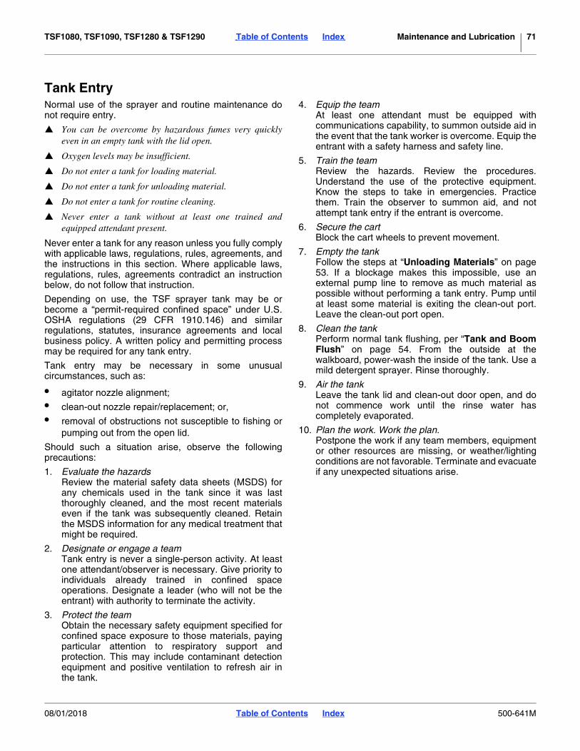
TSF1080, TSF1090, TSF1280 & TSF1290 Table of Contents Index Maintenance and Lubrication 71
Tank EntryNormal use of the sprayer and routine maintenance donot require entry.
You can be overcome by hazardous fumes very quicklyeven in an empty tank with the lid open.
Oxygen levels may be insufficient.
Do not enter a tank for loading material.
Do not enter a tank for unloading material.
Do not enter a tank for routine cleaning.
Never enter a tank without at least one trained andequipped attendant present.
Never enter a tank for any reason unless you fully complywith applicable laws, regulations, rules, agreements, andthe instructions in this section. Where applicable laws,regulations, rules, agreements contradict an instructionbelow, do not follow that instruction.
Depending on use, the TSF sprayer tank may be orbecome a “permit-required confined space” under U.S.OSHA regulations (29 CFR 1910.146) and similarregulations, statutes, insurance agreements and localbusiness policy. A written policy and permitting processmay be required for any tank entry.
Tank entry may be necessary in some unusualcircumstances, such as:
• agitator nozzle alignment;
• clean-out nozzle repair/replacement; or,
• removal of obstructions not susceptible to fishing orpumping out from the open lid.
Should such a situation arise, observe the followingprecautions:
1. Evaluate the hazardsReview the material safety data sheets (MSDS) forany chemicals used in the tank since it was lastthoroughly cleaned, and the most recent materialseven if the tank was subsequently cleaned. Retainthe MSDS information for any medical treatment thatmight be required.
2. Designate or engage a teamTank entry is never a single-person activity. At leastone attendant/observer is necessary. Give priority toindividuals already trained in confined spaceoperations. Designate a leader (who will not be theentrant) with authority to terminate the activity.
3. Protect the teamObtain the necessary safety equipment specified forconfined space exposure to those materials, payingparticular attention to respiratory support andprotection. This may include contaminant detectionequipment and positive ventilation to refresh air inthe tank.
4. Equip the teamAt least one attendant must be equipped withcommunications capability, to summon outside aid inthe event that the tank worker is overcome. Equip theentrant with a safety harness and safety line.
5. Train the teamReview the hazards. Review the procedures.Understand the use of the protective equipment.Know the steps to take in emergencies. Practicethem. Train the observer to summon aid, and notattempt tank entry if the entrant is overcome.
6. Secure the cartBlock the cart wheels to prevent movement.
7. Empty the tankFollow the steps at “Unloading Materials” on page53. If a blockage makes this impossible, use anexternal pump line to remove as much material aspossible without performing a tank entry. Pump untilat least some material is exiting the clean-out port.Leave the clean-out port open.
8. Clean the tankPerform normal tank flushing, per “Tank and BoomFlush” on page 54. From the outside at thewalkboard, power-wash the inside of the tank. Use amild detergent sprayer. Rinse thoroughly.
9. Air the tankLeave the tank lid and clean-out door open, and donot commence work until the rinse water hascompletely evaporated.
10. Plan the work. Work the plan.Postpone the work if any team members, equipmentor other resources are missing, or weather/lightingconditions are not favorable. Terminate and evacuateif any unexpected situations arise.
08/01/2018 Table of Contents Index 500-641M

TSF1080, TSF1090, TSF1280 & TSF1290 Table of Contents Index Maintenance and Lubrication 72
Lubrication
Elevator Slide
Pads and exposed vertical tube bearing surfaces
Type of Lubrication: Dry graphite or NLGI grade 2greaseQuantity: coat surface lightly
Swing Arm Weldment
2 grease fittings each side; 4 total
Type of Lubrication: GreaseQuantity: Until resistance is felt
Ace Pump: (if applicable)
1 grease fitting(located on belt idler arm casting)
Type of Lubrication: GreaseQuantity: 3 pumps
50Multi-purposespray lubricant
Multi-purposegrease lubricant
Multi-purposeoil lubricant
Intervals(operating hours)at which serviceis required
Inspection
34208
27384
10
20417
10
15979
10
08/01/2018 Table of Contents Index 500-641M

TSF1080, TSF1090, TSF1280 & TSF1290 Table of Contents Index Maintenance and Lubrication 73
PTO Pump: (if applicable)
1 grease fitting(located on rear gear case cover, and marked by decal)
Type of Lubrication: GreaseQuantity: 5 pumps
Inner Pivot Tube
2 grease fittings each side (top and bottom); 4 total
Type of Lubrication: GreaseQuantity: Until resistance is felt
Base Pivot, Inner Fold Section
1 grease fitting each side; 2 total
Type of Lubrication: GreaseQuantity: Until resistance is felt
12229
10
20418
30
20419
30
08/01/2018 Table of Contents Index 500-641M

TSF1080, TSF1090, TSF1280 & TSF1290 Table of Contents Index Maintenance and Lubrication 74
Base Pivot, Outer Fold Section
2 grease fittings each side; 4 total
Type of Lubrication: GreaseQuantity: Until resistance is felt
Base Pivot, Outer Fold Section
1 grease fitting each outer break-away boom; 4 total
Type of Lubrication: GreaseQuantity: Until resistance is felt
Transport: Wheel Bearings
2 bearings each axle; 4 total
Type of Lubrication: GreaseQuantity: repack
20420
30
27299
30
13854
Seasonally
08/01/2018 Table of Contents Index 500-641M

TSF1080, TSF1090, TSF1280 & TSF1290 Table of Contents Index 75
Options
AutoBoomThe Raven G1 AutoBoom system consists of:
• adjustable gauge wheel assemblies with pressuretransducers for lift sensing,
• on-sprayer hydraulic control valve assembly,plumbed into existing sprayer lines, and;
• a cab control module with harness connections tovalve block, sensors and power.
The standard kit is for tractors with closed centerhydraulics. The sprayer-side components of theAutoBoom are dealer-installed.
The AutoBoom includes separate installation andoperation manuals.
Axles and WheelsAll sprayers are available with North American or Exportaxles. Sprayers shipped by intermodal container musthave export axles. Export models have shorter axletubes. Available wheel-to-wheel span is:N.America: 80 to 120 inches (203 to 305cm)Export: 203 to 290cm (80 to 114in).
1000 gallon sprayers (TSF-1080/1090) have a furtherchoice of:
• 13.6x38 wheels and two-step ladder, or
• 14.9 R46 wheels and three-step ladder.
• 1200 gallon sprayers (TSF-1280/1290) use only14.9 R46 wheels.
For setup, see “Axle Wheel Spacing Adjustment” onpage 59.
Description Part Numbers
RAVEN G1 AUTOBOOM ASY 833-421C
G1 OPEN CENTER CONV. 833-422C
Description Option Part Numbers
13.6-38 Wheel, N.America SN1129RR- 70 504-037A
13.6-38 Wheel, Export 72 504-046A
14.9 R46 Wheel, N.America SN1129RR- 71 504-036A
14.9 R46 Wheel, Export 73 504-047A
320/85R38 WHEEL & AXLE ASSY SN1130RR+ 70 504-051A
320/85R38 WHEEL & AXLE ASY EXP SN1130RR+ 71 504-052A
Figure 62Raven G1 AutoBoom Controller
25023
Figure 63Wheels, Axles and Ladder
27300
08/01/2018 Table of Contents Index 500-641M

TSF1080, TSF1090, TSF1280 & TSF1290 Table of Contents Index Options 76
Calibration AccessoriesYour sprayer includes a nozzle calculator and samplecontainer. Export sprayers include a metric nozzlecalculator.
Chemical InductorThe inductor eliminates the need to climb the walkboardand add materials directly to the tank water. It provides aconvenient and safe dedicated ground-level 3-gallon(11.3 liter) tank.
If ordered with a new TSF1080, TSF1090, TSF1280 &TSF1290 (option #61), the inductor is pre-installed priorto delivery.
For operations, see “Chemical Inductor” on page 76.
The inductor adds 38 lbs (17 kg) to the empty weight ofthe sprayer. When fully loaded with material, the inductoradds 83 lbs (38 kg) to the sprayer.
High Volume Foam MarkerThis kit includes a 25 gallon tank with integral pump,mounting hardware, plumbing, nozzles and cab control.Dispensers are provided for both left and right booms.
If ordered with a new TSF1080, TSF1090, TSF1280 &TSF1290 (option #52 or 53), the foam marker tank ispre-installed prior to delivery. The foam marker includesa separate installation and operation manual.
The foam marker adds 114 lbs (52 kg) to the emptyweight of the sprayer. When fully loaded, it adds 314 lbs(91 kg) to the sprayer.
Description Part Numbers
CALIBRATION CONTAINER 817-199C
NOZZLE TIP CALCULATOR 832-038C
NOZZLE TIP CALCULATOR-METRIC 832-058C Figure 64Calibration Accessories
27165
Description Option Part Numbers
CHEMICAL INDUCTOR ASY 61 502-144K
Figure 65 22668
Description Option Part Numbers
FOAM MARKER KIT 80/90FT 52 502-147A
FOAM MARKER 60/80, 60/90FT 53 502-153A
Figure 66Foam Marker Components
22703
08/01/2018 Table of Contents Index 500-641M

TSF1080, TSF1090, TSF1280 & TSF1290 Table of Contents Index Options 77
Gauge ProtectorThis fitting protects the control panel pressure gaugefrom corrosive chemicals added to the main tank.
See page 47 for installation location.
Hitches (Hydraulic Pump Only)Sprayers with hydraulic (not PTO) pumps have a choiceof tang or clevis hitch.
For setup, see “Hitching with Hydraulic Pump” onpage 21.
Open Center Hydraulic Kit2007+ sprayers require a tractor with closed centerhydraulics. Use this kit to convert the sprayer for use withan open center tractor.
For installation location, see page 82.
Description Part Number
GAUGE PROTECTOR ASSY 507-034V
Figure 67Gauge Protector
27297
507-034V
Description Option Part Numbers
Clevis Hitch 62 500-007H
Tang Hitch 63 500-008H
Figure 68Tang or Clevis Hitch
20234
63
62
Description Part Number
FASSE LIVE HYD OPEN CTR KIT 833-427C
Figure 69Open Center Kit
27385
08/01/2018 Table of Contents Index 500-641M

TSF1080, TSF1090, TSF1280 & TSF1290 Table of Contents Index Options 78
PumpsThe standard TSF1080, TSF1090, TSF1280 & TSF1290does not include a pump. Optional hydraulic or PTOpumps are available.
Ace Hydraulic PumpIf ordered with a new TSF1080, TSF1090, TSF1280 &TSF1290 (Option 35), the pump is pre-installed prior todelivery.
For operation, see “Operating Pump” on page 53.
Pump kit weight: 40 lbs (18 kg)
Ace Flow Limiter
On tractors with LOAD SENSING (LS) Closed Centerhydraulic systems, this device limits the flow of oil to theAce motor and prevents failures due to misapplication.Your Great Plains dealer can assist with installation ofthe flow limiter.
For use, see “Ace Pump Flow Limiter (Option)” onpage 29.
Ace PTO PumpsPumps are available for 540 rpm PTO (#33) or 1000 rpm138-inch PTO (#34).
The pump kit includes required hitch components.
If ordered with a new TSF1080, TSF1090, TSF1280 &TSF1290 (see option #s above), the pump ispre-installed prior to delivery.
Pump kit weights:
Description Option Part Numbers
PUMP - TS HIGH VOL HYD 35 507-105A
Description Part Numbers
FLOW LIMITER VALVE - ACE PUMP 829-125C (2006-)
FLOW LIMITER VALVE - ACE PUMP 829-131C (2007+)
Description Option Part Numbers
PUMP TS ACE150 540 DRIVE SHAFT 33 507-083A
PUMP TS ACE 1000 1-3/8 DR SHFT 34 507-084A
507-083A 152 lbs (69 kg)
507-084A 167 lbs (76 kg)
Figure 70Hydraulic Pump Components
27301
Figure 71Ace Flow Limiter
23395
Figure 72Ace PTO Pump
20358
08/01/2018 Table of Contents Index 500-641M

TSF1080, TSF1090, TSF1280 & TSF1290 Table of Contents Index Options 79
Speed SensorsThe standard TSF1080, TSF1090, TSF1280 & TSF1290does not include a speed sensor, which is required bythe Auto-Control system to regulate material rate basedon current speed. Optional sensors kits detect speed viawheel rotation or radar ground speed.
If the tractor already has a speed sensor, a “Y” cable isavailable to share its signal with the Raven SCS 450controller. Otherwise, order one of the following:
Your Great Plains dealer can assist you with installation
Radar Speed SensorThis easy-to-install precision sensor may be mounted oneither the tractor or the sprayer. It is compatible with awide variety of agricultural cab controls, and may beused for implements other than the TSF1080, TSF1090,TSF1280 & TSF1290 when not spraying.
Raven Wheel Speed SensorThis economical speed sensor is sprayer-mounted.Consult your dealer for installation.
Y-CableIf your tractor already has a speed sensor, it may becompatible with the Raven SCS 450 controller. Consultyour dealer for advice.
If the sensor is compatible, these cables share the signalbetween your existing tractor systems and the RavenSCS 450.
Description Option Part Numbers
TSF RADAR KIT 43 509-289A
TSF WHEEL SENSOR MNT KIT 42 509-288A
Figure 73Radar Speed Sensor
27153
Figure 74Wheel Speed Sensor
27154
Part Numbers Comment
115-0159-432 TRW radar, Case IH
115-0159-519 DICKEY-john or Magnavox radar, John Deere 1990 or later
115-0159-518 DICKEY-john radar, Cat Challenger (Model 65 & 75)
115-0159-517 DICKEY-john radar, Case IH
115-0159-529 DICKEY-john radar, Ford/White
115-0159-627 DICKEY-john radar, Cat Challenger (Model 65C, 75C-Mod, D-Mod Row Crop 35,45,55)
115-0159-700 DICKEY-john or Magnavox radar, John Deere 7000/8000/9000 Series (2WD or MFWD)
117-0159-462 Magnavox radar, other than John Deere
117-0159-463 TRW radar, other than Case IH
Figure 75Y Cable
27155
08/01/2018 Table of Contents Index 500-641M

TSF1080, TSF1090, TSF1280 & TSF1290 Table of Contents Index 80
Appendix
Specifications and CapacitiesTSF-1080 TSF-1090 TSF-1280 TSF-1290
Boom Width 60 or 80 feet18.3 or 24.4m
60 or 90 feet18.3 or 27.4m
60 or 80 feet18.3 or 24.4m
60 or 90 feet18.3 or 27.4m
Nozzle Spacing 20 or 30in (51 or 76cm)
Nozzle Count 48 (20-inch) or 33 (30-inch) 54 (20-inch) or 37 (30-inch)
Main Tank Capacity 1000 gallons (3785 liters) 1250 gallons (4731.7 liters)
Flush Tank Capacity 100 gallons (379 liters)
Hand Wash Tank Capacity 5 gallons (18.9 liters)
Marker Foam Tank Capacity 25 gallons (95 liters)
Tractor Requirement 100 hp (75 kW)
Closed Center*
Hydraulic Circuits
* An optional kit (833-427C) is available for open center tractors. See page 77.
One hydraulic remote (with PTO pump)Two hydraulic remotes (with hydraulic pump)†
† If tractor cannot restrict flow to 6 gpm, purchase a flow-control kit from your Great Plains dealer.
Empty Weight 9290 lbs (4214 kg) 9340 lbs (4237 kg) 9760 lbs (4427 kg) 9890 lbs (4486 kg)
Full Weight 23390 lbs (10610 kg) 23440 lbs (10632 kg) 27385 lbs (12422
kg)27435 lbs (12444
kg)
Working Width 83 feet (25.3m) 93 feet (28.4m) 83 feet (25.3m) 93 feet (28.4m)
Transport Width 13 feet (4m)
Transport Height 13 feet 6 inch (4.1m)
Length 22 feet 5 inch (6.8m)
Clearance‡
‡ Lowest part of hitched sprayer is the tractor side of the hitch.
28 in (71cm)
Wheel Spacing North American models: 80 to 120 inches (203 to 305cm)Export models: 203 to 290cm (80 to 114 inch)
Tire Size 320/85R38 **
** May be upgraded by Option to 14.9 R46.
14.9 R46
Pumps††
†† Standard sprayer does not include a pump.
Ace Hydraulic,Ace Tractor mounted high volume PTO pump - 540 rpm,
Ace Tractor mounted high volume PTO pump - 1000 rpm 138-inch spline, orcustomer-provisioned 90 gpm at 30 psi (341 liters/min at 207 kPa)
Tire Inflation Chart Tire Warranty Information
Wheel Tire Size InflationAll tires are warranted by the original manufacturer of the tire. Tire warranty information is found in the brochures included with your Operator’s and Parts Manuals or online at the manufacturer’s websites listed below. For assistance or information, contact your nearest Authorized Farm Tire Retailer.Manufacturer WebsiteFirestone www.firestoneag.comGleason www.gleasonwheel.comTitan www.titan-intl.com
Transport 13.6-38 6 Ply Tubeless 22 psi152 kPa
Transport 14.9 R46 4* 10 Ply Radial 36 psi221 kPa
Transport 320/85R38 Radial 52 psi359 kPa
08/01/2018 Table of Contents Index 500-641M

TSF1080, TSF1090, TSF1280 & TSF1290 Table of Contents Index Appendix 81
Torque Values
94 6
25199m
BoltSize
Bolt Head IdentificationBoltSize
Bolt Head Identification
Grade 2 Grade 5 Grade 8 Class 5.8 Class 8.8 Class 10.9in-tpia N-mb N-m N-m mm x pitchc N-m N-m N-m1⁄4-20 7.4 11 16 M 5 X 0.81⁄4-28 8.5 13 18 M 6 X 1 7 11 155⁄16-18 15 24 33 M 8 X 1.25 17 26 365⁄16-24 17 26 37 M 8 X 1 18 28 393⁄8-16 27 42 59 M10 X 1.5 33 52 723⁄8-24 31 47 67 M10 X 0.75 39 61 857⁄16-14 43 67 95 M12 X 1.75 58 91 1257⁄16-20 49 75 105 M12 X 1.5 60 95 1301⁄2-13 66 105 145 M12 X 1 90 105 1451⁄2-20 75 115 165 M14 X 2 92 145 2009⁄16-12 95 150 210 M14 X 1.5 99 155 2159⁄16-18 105 165 235 M16 X 2 145 225 3155⁄8-11 130 205 285 M16 X 1.5 155 240 3355⁄8-18 150 230 325 M18 X 2.5 195 310 4053⁄4-10 235 360 510 M18 X 1.5 220 350 4853⁄4-16 260 405 570 M20 X 2.5 280 440 6107⁄8-9 225 585 820 M20 X 1.5 310 650 900
7⁄8-14 250 640 905 M24 X 3 480 760 1050
1-8 340 875 1230 M24 X 2 525 830 1150
1-12 370 955 1350 M30 X 3.5 960 1510 2100
11⁄8-7 480 1080 1750 M30 X 2 1060 1680 2320
11⁄8-12 540 1210 1960 M36 X 3.5 1730 2650 3660
11⁄4-7 680 1520 2460 M36 X 2 1880 2960 4100
11⁄4-12 750 1680 2730
13⁄8-6 890 1990 3230 a. in-tpi = nominal thread diameter in inches-threads per inch
13⁄8-12 1010 2270 3680 b. N· m = newton-meters
11⁄2-6 1180 2640 4290
11⁄2-12 1330 2970 4820
c. mm x pitch = nominal thread diameter in mm x thread pitch
Torque tolerance + 0%, -15% of torquing values. Unless otherwise specified use torque values listed above.
5.8 8.8 10.9
25199
ft-lbd ft-lb ft-lb ft-lb ft-lb ft-lb5.6 8 12
6 10 14 5 8 11
11 17 25 12 19 27
13 19 27 13 21 29
20 31 44 24 39 53
22 35 49 29 45 62
32 49 70 42 67 93
36 55 78 44 70 97
49 76 105 66 77 105
55 85 120 68 105 150
70 110 155 73 115 160
79 120 170 105 165 230
97 150 210 115 180 245
110 170 240 145 230 300
170 265 375 165 260 355
190 295 420 205 325 450
165 430 605 230 480 665
185 475 670 355 560 780
250 645 910 390 610 845
275 705 995 705 1120 1550
355 795 1290 785 1240 1710
395 890 1440 1270 1950 2700
500 1120 1820 1380 2190 3220
555 1240 2010
655 1470 2380
745 1670 2710
870 1950 3160d. ft-lb = foot pounds
980 2190 3560
3 5 7
08/01/2018 Table of Contents Index 500-641M

TSF1080, TSF1090, TSF1280 & TSF1290 Table of Contents Index Appendix 82
Hydraulic and Plumbing DiagramsBoom Hydraulics
C13
C2 C1C3C4C5C6C7
C8C9C14P
T
C1
C8
C3
C9
C2
C4C6
C13
C5
C14C7
Valve Port Function
, Tractor Remote Circuit
Right Outer Boom Fold
Right Inner Boom Fold
Right Boom Lift
Elevator Lift
Left Boom Lift
Left Inner Boom Unfold
Left Outer Boom Fold
Right Outer Boom Unfold
Right Inner Boom Unfold
Left Inner Boom Fold
Left Outer Boom Unfold
P T
C1
C2
C3
C4
C5
C6
C7
C8
C9
C13
C14
27269
833-427C
08/01/2018 Table of Contents Index 500-641M

TSF1080, TSF1090, TSF1280 & TSF1290 Table of Contents Index Appendix 83
Standard Closed Center Pin Assignments
Switch No. Boot Color Hot Wires Pin Out Location Function
D-4WP, A-4WP1 Long White Center (off) --------- --------- --------- --------- Off
D-4WP, C-4WP
2 Long Red
Up (mom) 5-12P, 10-12P C5 Left Tilt UpCenter (off) --------- --------- --------- --------- Off
C5 Left Tilt Down
3 Long White
Up (mom) 6-12P, 10-12P C4 Center UpCenter (off) --------- --------- --------- --------- Off
C4 Center Down
4 Long Blue
Up (mom) 7-12P, 10-12P C3 Right Tilt UpCenter (off) --------- --------- --------- --------- Off
C3
5 Short Green
Up (mom) C7 C14Center (off) --------- --------- --------- --------- Off
C14 C7
6 Short Yellow
Up (mom) C6 C13 Left Inner FoldCenter (off) --------- --------- --------- --------- Off
C13 C6
7 Short GreyUp (mom) C2 C9
Center (off) --------- --------- --------- --------- Off
C9 C2
8 Short RedUp (mom) C1 C8
Center (off) --------- --------- --------- --------- Off
C8 C1
--------- --------- --------- --------- --------- --------- Ground--------- --------- --------- 11-12P --------- --------- Ground--------- --------- --------- 4-12P --------- --------- Ground--------- --------- --------- B-4WP --------- --------- Ground
Switch Position
Pressure Ports
Tank Ports
Left Foam (stat)
Red & Wht 4 Cond
Left Foam Marker
Right Foam (stat)
Red & Grn 4 Cond
Right Foam Marker
Red/Blk & Grn
Down (mom)
Red/Blk & Grn & Blk/Wht
5-12P, 10-12P, 9-12P
Org/Blk & Grn
Down (mom)
Org/Blk & Grn & Blk/Wht
6-12P, 10-12P, 9-12P
Wht/Blk & Grn
Down (mom)
Wht/Blk & Grn & Blk/Wht
7-12P, 10-12P, 9-12P
Right Tilt Down
Grn/Wht & Blu/Wht & Grn
A-3P, B-3P, 10-12P
Left Outer Fold
Down (mom)
Grn/Wht & Blu/Wht & Grn &
Blk/WhtA-3P, B-3P,
10-12P, 9-12PLeft Outer
Unfold
Grn/Blk & Red/Wht & Grn
12-12P, C-3P, 10-12P
Down (mom)
Grn/Blk & Red/Wht & Grn &
Blk/Wht12-12P, C-3P, 10-12P, 9-12P
Left Inner Unfold
Wht & Blu & Grn
3-12P, 8-12P, 10-12P
Right Inner Fold
Down (mom)
Wht & Blu & Grn & Blk/Wht
3-12P, 8-12P, 10-12P, 9-12P
Right Inner Unfold
Red & Org & Grn
1-12P, 2-12P, 10-12P
Right Outer Fold
Down (mom)
Red & Org & Grn & Blk/Wht
1-12P, 2-12P, 10-12P, 9-12P
Right Outer Unfold
Blk (zip)Blk
Blu/BlkBlk
34218
08/01/2018 Table of Contents Index 500-641M

TSF1080, TSF1090, TSF1280 & TSF1290 Table of Contents Index Appendix 84
Manifold-Boom Assignments
27306
L
R
CENTER
INNER
INNER
OUTER
OUTER
60-Foot Sectio
ns
08/01/2018 Table of Contents Index 500-641M

TSF1080, TSF1090, TSF1280 & TSF1290 Table of Contents Index Appendix 85
Raven G1 AutoBoom Hydraulics
27305
08/01/2018 Table of Contents Index 500-641M

TSF1080, TSF1090, TSF1280 & TSF1290 Table of Contents Index Appendix 86
Warranty
38112
WarrantyGreat Plains (a division of Great Plains Manufacturing, Inc.) warrants to theoriginal purchaser that this Great Plains unit will be free from defects in materialand workmanship for a period of one year from the first use date when used asintended and under normal service and conditions for personal use; ninety daysfor custom/commercial or rental use. This Warranty is limited to the replacementof any defective part by Great Plains and the installation by the dealer of anysuch replacement part. Great Plains reserves the right to inspect any equipmentor part which are claimed to have been defective in material or workmanship.
The following items and/or conditions are not covered under warranty:failures resulting from abuse or misuse of the equipment, failures occurring as aresult of accidental damage or acts of God, failures resulting from alterations ormodifications, failures caused by lack of normal maintenance as outlined in theoperator’s manual, repairs made by non-authorized personnel, items replaced orrepaired due to normal wear (such as wear items and ground engagingcomponents), repeat repair due to improper diagnosis or repair by the dealer,temporary repairs, service calls and/or mileage to and from customer location,overtime premium, or unit hauling expenses. The warranty may be voided if theunit is towed at speeds in excess of 20 miles per hour (32 kilometers per hour),or is used in soils with rocks, stumps, or other obstructions.
Great Plains reserves the right to make changes in materials or design of theproduct at any time without notice. The warranty shall not be interpreted torender Great Plains liable for damages of any kind, direct or consequential orcontingent to property. Furthermore, Great Plains shall not be liable for damagesresulting from any cause beyond its control. This warranty does not extend tocrop loss, losses caused by planting or harvest delays or any expense or loss oflabor, supplies, rental machinery, or for any other reason.
No other warranty of any kind whatsoever express or implied, is made withrespect to this sale; and all implied warranties of merchantability and fitness fora particular purpose which exceed the obligations set forth in this writtenwarranty are hereby disclaimed and excluded from this sale.
This warranty is not valid unless the unit is registered with Great Plains within10 days from the date of the original purchase.
08/01/2018 Table of Contents Index 500-641M

TSF1080, TSF1090, TSF1280 & TSF1290 Cover Table of Contents 87
Index
AAce pump ............................. 67,72,78Ace pump connections .......................24adding chemicals ................................47adjustment bolts .................................27adjustment, flow limiter .......................29agitation gauge ...................................40agitation valve ............................. 29,33agitator ...............................................49agitator inlet ........................................40agitator nozzle alignment ...................71agitator nozzles ..................................70agitator selector valve ........................40antifreeze ..................................... 57,63Application Guide ...........33,37,50,58ASAE standards .................................26AutoBoom.......................23,32,75,85AutoBoom operation ...........................51axle adjustment ..................................15axle wheel spacing .............................59axles ...................................................75axles, sliding .......................................22
Bball valve, electric ...............................33boom height ................................. 50,58boom hydraulics .................................82boom level ..........................................27boom operations .................................49boom plumbing ...................................42boom unfolding ...................................51boom-lock cable .................................28break away spring ..............................60butterfly valve .....................................40bypass control ....................................40
Ccable, boom lock ................................28cage, safety ..........................................6calibration ...........................................34canister filter .......................................64canopy, crop .......................................50caution decals
general ........................................16hand wash tank ...........................17tire ...............................................17
chain, safety .........................................4checklists
operating .....................................38chemical .............................................37chemical container .............................37chemical containers ............................47chemical disposal .................................3chemical fire .........................................3chemical inductor ...............................76
chemical overflow decal ..................... 14chemicals .....3,36,38,45,47,53,63chemicals, inducting ........................... 48clean-out ......................................40,64cleanup .............................................. 63clevis hitch ......................................... 21clevis, boom lock ................................ 28closed center ................................20,75closed center, load sensing ............... 29components, plumbing ....................... 40confined space ...............................4,71console............................................... 30containers, chemical .......................... 47container, chemical ............................ 37contamination ..................................... 16control valve ....................................... 30corrosives ........................................... 47crop canopy ....................................... 50customer service ................................ 19
Ddanger decals
agricultural chemicals ................. 11crushing hazard .......................... 13electrocution ............................... 12guard missing ............................. 12PTO ............................................ 11
daytime reflectors ............................... 10deadhead pressure ......................29,33decals ................................................... 8
cautiontire pressure and torque ...... 17
divider kit ............................................ 24drawbar .............................................. 22driveline .............................................. 25
Eelectric ball valve ................................ 33electrical connections......................... 23electrical installation ........................... 30electrocution......................................... 5electrocution hazard ........................... 20electro-hydraulics ............................... 23element, filter ..................................... 64elevator .................................50,51,63elevator slide ................................70,72entry, tank ............................................ 4
Ffalling axle hazard .............................. 59Fasse valve ........................................ 32fill selector valve ................................. 40filters .................................................. 64filter, inlet ............................................ 40fire ........................................................ 6flow limiter ....................................29,78
flow meter .................................... 30,40flush ....................................................54flush tank ..................................... 40,44flush tank inlet.....................................40flushing ...............................................37foam marker ................................ 23,76foam marker control ............................32foam marker tank................................49frame level ..........................................27freezing ...............................................63fumes ....................................................4Ggauge..................................................40gauge protector ........................... 47,77gauge wheels .....................................51G1 AutoBoom .................23,32,75,85
Hhammer-strap .....................................22hand wash tank ........................... 38,43handles, valves ...................................40hand-wash tank ....................................3handwash tank decal ..........................17harness ...............................................30hazardous fumes ..................................4hazard, confined space ......................70hazard, falling axle..............................59hazard, overflow .................................48height, boom .......................................50high pressure fluids ....................... 1,15hitch ....................................................21hitch height .........................................26hitch plate ...........................................22hitches ................................................77hitch, PTO...........................................22hose labels .........................................23hydraulic connection ...........................23hydraulic flow divider ..........................24hydraulic pump . 20,21,23,33,53,78hydraulic valve control ........................32
Iinducting chemicals ............................48inductor ................................. 40,45,76inductor tank .......................................14inductor valve .....................................40inlet, main tank ...................................45
Jjack, parking ......................... 21,22,55
Llabels, hose ........................................23leaks ...................................................66left-hand defined .................................18level boom ..........................................27
08/01/2018 Cover Table of Contents 500-641M

TSF1080, TSF1090, TSF1280 & TSF1290 Cover Table of Contents 88
level frame ..........................................27level sprayer .......................................26level, PTO...........................................25lights ....................................... 4,23,30lines, electrical ......................................5load sensing closed center .......... 29,78lock plunger ring .................................52locking system ....................................28lubrication ...........................................72Mmain inlet ............................................40main inlet filter ....................................40main tank ............................................40main tank fill .......................................44main tank inlet ....................................45maintenance .........................................6manifold ..............................................84manual throttle valve ................... 33,40marker .................................. 23,32,76marker tank ........................................49material safety data sheets ................71MSDS .................................................71
Nnegative tongue weight ........ 20,51,55Note defined .......................................18Notice defined ....................................18nozzle .......................................... 37,50nozzle pressure ..................................58nozzle repair/replacement ..................71nozzles ................................. 34,57,63nozzles, agitation ................................44
Oobstructions ........................................60obstructions, tank ...............................71open center .......................... 20,29,75overflow hazard ..................................48overhead boom decal .........................15overhead lines ......................................5
Pparking ................................................55parking jack ........................................21permit-required confined space ..... 4,71pin assignments .................................83plumbing .............................................40plumbing, boom ..................................42power lines ...........................................5product valve ......................................40protective clothing ..............................37protective equipment ............................2protector, gauge .................................47PTO bearing mount guard ..................11PTO decals .................................. 11,12PTO driveline ......................................12PTO pump .......... 7,22,33,53,73,78PTO shaft guard .................................11PTO shaft hookup ..............................25
pump ............................................40,78pump inlet .......................................... 40pump maintenance ............................ 66pump operations ................................ 53pump, storage .................................... 63
Qquad jets ............................................ 44quad-jet .............................................. 70quick connect ..................................... 40Rradar sensor ....................................... 23Raven Auto-Boom.............................. 32Raven Controller ................................ 23Raven G1 AutoBoom ............23,75,85Raven SCS 450 ...........................30,34reflectors
amber......................................9,10daytime ....................................... 10SMV .............................................. 8
right-hand defined .............................. 18rinse ................................................... 54RV antifreeze ..................................... 57
SSAE J560B......................................... 30safety ................................................... 1safety cage........................................... 6safety chain .......................................... 4safety reflectors .................................... 8SCS 450.......................................30,31seal, Ace pump .................................. 69selector valve ..................................... 40sensors .............................................. 23setup, Raven SCS ............................. 31setup, spraying................................... 33shear bolt .....................................60,65shims.................................................. 27shutoff valves ..................................... 40signal words ......................................... 1sliding axles ....................................... 22slow moving vehicle reflector ............... 8solution Whirlfilter ............................... 40span, wheel ........................................ 75specifications ..................................... 80speed ................................................... 5speed limit ............................................ 5speed sensor ........................30,36,79speed, wind .......................................... 3spray selector valve ........................... 40sprayer calibration .............................. 34Sprayer Control System (SCS) .......... 30sprayer hydraulics .............................. 49sprayer pump mount .......................... 25spring, break away ............................. 60SP1-(wheel drive sensor) ................... 36SP2-(radar sensor) ............................ 36stob .................................................... 22
storage................................................57straps, tank .........................................45sump ...................................................40sump, Whirlfilter ..................................53Ttang hitch ............................................21tank entry ....................................... 4,71tank lid ................................................45tank straps ..........................................45tank, hand wash .................................38tarp strap ............................................25throttle valve ................................ 29,40throttle valve, manual .........................33tilt ........................................................51tire.......................................................59tire safety ..............................................6toggle switches ...................................49torque values ......................................81tractor weight ........................................5transport speed.....................................5transporting.........................................39turns............................................. 37,50
Uunfolding, boom ..................................51unhitching ...........................................56
Vvalves, list ...........................................40Wwarning decals
axle ..............................................15boom ...........................................15contamination ..............................16negative tongue weight ...............14overflow .......................................14pinch ............................................16speed...........................................14
warranty ..............................................86water, hand wash tank........................43weight, sprayer ...................................39weight, towing vehicle.........................39welding .................................................6wheel sensor ......................................23wheel spacing .....................................59wheels ................................................75Whirlfilter ..................37,40,53,57,64wind ....................................................37working width ......................................18
YY-cable ...............................................79
Numerics13.6-38 6 ply tubeless ........................80320/85R38 radial ................................8060-foot spraying ..................................527-pin receptacle ..................................30
08/01/2018 Cover Table of Contents 500-641M

Table of Contents Index
Table of Contents Index

Great Plains, Mfg.1525 E. North St.P.O. Box 5060Salina, KS 67402