OPERATOR ADAPTER APCGETDA - nVent HOFFMAN
20
© 2018 Hoffman Enclosures Inc. PH 763 422 2211 • nVent.com/HOFFMAN 87569290 Rev. E P/N 87415740 OPERATOR ADAPTER APCGETDA Installation Instructions for General Electric Types STDA (Variable Depth) and Flexible Cable Operating Mechanisms (For parts list, see page 2) For floor-mounted enclosures with disconnect on the right flange, see pages 3-6 (flexible cable mechanism, see pages 15-19) For one- through six-door free-standing enclosures with the disconnect on the right flange, see pages 7-10 (flexible cable mechanism, see pages 15-19) For floor-mounted enclosures with the disconnect on the centerpost, see pages 11-14 (flexible cable mechanism, see pages 15-19) Master Door Master Door Master Door Master Door
-
Upload
khangminh22 -
Category
Documents
-
view
2 -
download
0
Transcript of OPERATOR ADAPTER APCGETDA - nVent HOFFMAN

© 2018 Hoffman Enclosures Inc. PH 763 422 2211 • nVent.com/HOFFMAN 87569290Rev. E P/N 87415740
OPERATOR ADAPTER APCGETDAInstallation Instructions for General Electric Types STDA
(Variable Depth) and Flexible Cable Operating Mechanisms (For parts list, see page 2)
For floor−mounted enclosures with disconnect on the right flange,see pages 3−6 (flexible cable mechanism, see pages 15−19)
For one− through six−door free−standing enclosures with the disconnect on theright flange, see pages 7−10 (flexible cable mechanism, see pages 15−19)
For floor−mounted enclosures with the disconnect on the centerpost,see pages 11−14 (flexible cable mechanism, see pages 15−19)
MasterDoor
MasterDoor
MasterDoor
MasterDoor

© 2018 Hoffman Enclosures Inc. PH 763 422 2211 • nVent.com/HOFFMAN 87569290- 2 -
WARNINGThe functions, fits, and clearances of the installation described hereon are calculated from information supplied by the
manufactures of the equipment to be installed. Be certain to check the function, fits, and clearances of all equipment both before and after installation to assure that is operates properly and safely and meets all applicable codes, standards, and regulations.
In the event the completed installation does not function properly or fails to meet any such codes, standards, or regulations, do not attempt to make alterations or operate the equipment. Report such facts immediately to:
Hoffman Customer Service 2100 Hoffman Way Anoka, MN 55303
763 422 2211 http://hoffman.nvent.com/contact-us
PARTS LIST
Operator Adapter, Catalog Number A21GETDA, for General Electric Disconnects
Item No . . . . . . . Part Name. . . . . . . . . . . . . . . . . . . . . . . . . . . . . . . . Part No. . . . . . . . . . .Quantity1 . . . . . . . . . . . . . Plate, Mounting . . . . . . . . . . . . . . . . . . . . . . . . . . . 87400020 . . . . . . . . .12 . . . . . . . . . . . . . Slide Arm. . . . . . . . . . . . . . . . . . . . . . . . . . . . . . . . . 26250001 . . . . . . . . .13 . . . . . . . . . . . . . Shoulder Collar . . . . . . . . . . . . . . . . . . . . . . . . . . . . 26149001 . . . . . . . . .14 . . . . . . . . . . . . . Screw, 1/4−20x7/8 Hex Head. . . . . . . . . . . . . . . . 99401030 . . . . . . . . .15 . . . . . . . . . . . . . Lockwasher, 1/4 Spring. . . . . . . . . . . . . . . . . . . . . 99401318 . . . . . . . . .16 . . . . . . . . . . . . . Washer, Flat . . . . . . . . . . . . . . . . . . . . . . . . . . . . . . 22101003 . . . . . . . . .27 . . . . . . . . . . . . . Lockwasher, 1/4 Int.. . . . . . . . . . . . . . . . . . . . . . . . 99401300 . . . . . . . . .28 . . . . . . . . . . . . . Nut, 1/4−20 Hex . . . . . . . . . . . . . . . . . . . . . . . . . . . 99401406 . . . . . . . . .29 . . . . . . . . . . . . . Door Catch . . . . . . . . . . . . . . . . . . . . . . . . . . . . . . . 23101002 . . . . . . . . .110 . . . . . . . . . . . . Screw, 10−32x3/8 Pan Head. . . . . . . . . . . . . . . . . 99401007 . . . . . . . . .211 . . . . . . . . . . . . Lockwasher, #10 Int. . . . . . . . . . . . . . . . . . . . . . . . 99401307 . . . . . . . . .212 . . . . . . . . . . . . Label, (extra) . . . . . . . . . . . . . . . . . . . . . . . . . . . . . . 26147001 . . . . . . . . .113 . . . . . . . . . . . . Installation Instruction. . . . . . . . . . . . . . . . . . . . . . 87415740 . . . . . . . . .1

© 2018 Hoffman Enclosures Inc. PH 763 422 2211 • nVent.com/HOFFMAN87569290 - 3 -
INTRODUCTIONThis installation instruction is for General Electric (variable depth) mechanisms. These mechanisms are for disconnect switches and circuit breakers mounted in Hoffman two−door, floor−mounted, enclosures with the disconnect on the right flange.
MasterDoor
INSTALLATION STEPSStep 1 − Position mounting plate (item 1) on the inside of the enclosure, behind the opening provided in enclosure flange.
Step 2 − Assemble the G.E. STDA operating handle through the opening in the enclosure and through the mounting plate. Omit cap screw and lockwasher which fits into bottom hole of G.E. operating handle. Also omit G.E. stiffening bracket which is not required.
Step 3 − Install the slide arm (item 2) over the interlock part of the G.E. operating handle as shown. Place the smaller diameter end of the shoulder collar (item 3) through the oval slot in the slide arm. Install long cap screw (item 4) with lockwasher (item 5) through shoulder collar into the bottom mounting hole of the G.E. operating handle and tighten. The slide arm should move up and down smoothly. Install G.E. interlock blade per G.E. instructions.
Step 4 − Attach the bottom of the slide arm (item 2) to the offset arm of the lock release mechanism. Use two flat washers (item 6), two lockwashers (item 7), and two hex nuts (item 8). Do not tighten until parts are adjusted (see Step 5 − (B) )
Step 5 − The handle safety lock release mechanism is adjustable in two places.
(A) Check the adjustment of the factory installed roller bracket. The door latch should hit against the latch stop portion of the roller bracket when the door is closed and latched. Adjust up or down if necessary. The attached mechanism will then provide the necessary up−down motion required to operate the release mechanism in the G.E. operating handle.
(B) Adjust the length of the slide arm assembly. With proper adjustment of the slide arm, the safety lock (in G.E. operating handle) should release just before the master door is fully latched. Lengthen slide arm if safety lock releases too soon. Shorten slide arm if safety lock releases too late.
Step 6 − Attach the door catch (item 9) provided by Hoffman to the tapped spacer on the door using the bottom set of mounting holes. Use two screws (item 10) and lockwashers (item 11). The door catch prevents the door from being opened when the G.E. operating handle is in the “ON” position. The door catch may be adjusted up or down to hook properly on the interlock blade. The door catch (item 9) must be positioned so it just clears the top of the interlock blade when the G.E. operating handle is in extreme “OFF” position.
Step 7 − Drill and tap holes in panel as shown in the diagram and table 1. See General Electric instructions for locating holes for fuse blocks for 200 AMP. switches.
Step 8 − Install panel in enclosure.
Step 9 − Mount disconnect switch or circuit breaker and operating mechanism on panel using General Electric instructions and parts. See table 2 for enclosure “D” dimension. Attach G.E. handle return spring between drive link on G.E. operating handle and hole provided in Hoffman adapter plate as shown.

© 2018 Hoffman Enclosures Inc. PH 763 422 2211 • nVent.com/HOFFMAN 87569290- 4 -
For Floor−Mounted, Two−Door, Enclosures With Disconnect on Right Flange
* Parts of lock release mechanism
Drive link
Handle return spring
interlock
* Offset arm
Lock releasemechanism
Roller *bracket
Roller bracket *latch stop
Interlock blade

© 2018 Hoffman Enclosures Inc. PH 763 422 2211 • nVent.com/HOFFMAN87569290 - 5 -
For Floor−Mounted, Two−Door, Enclosures With Disconnect on Right Flange

© 2018 Hoffman Enclosures Inc. PH 763 422 2211 • nVent.com/HOFFMAN 87569290- 6 -
For Two−Door, Floor−Mounted Enclosure With Disconnect on Right Flange
TABLE 1Sub−panel Drilling
G.E.OPERATING
MECHANISM
G.E.DISCONNECT
T TYPENo. ofHoles Hole Size
Enclosure Height 60.12 72.12 B X Y
A A
TDOM1A QMR−QMW 4 1/4−20 4.19 10.19 .88 3.00 6.75TDOM1JA QMR−QMW 4 1/4−20 4.19 10.19 .88 3.00 6.75TDOM1B QMR−QMW 4 1/4−20 4.19 10.19 .88 3.00 6.75
TDOM1JB QMR−QMW 4 1/4−20 4.19 10.19 .88 3.00 6.75TDOM2 QMR−QMW 4 1/4−20 4.19 10.19 .81 7.00 7.25
SDOM1A SE150 4 1/4−20 4.19 10.19 .88 3.00 6.75SDOM3 SF250 4 1/4−20 4.59 10.59 1.81 2.75 10.88
SDOM4 SG600 6 1/4−20 ------ 8.59 1.47 3.35 5.51 and 12.20
SDOM1A TEB, TED 4 1/4−20 4.19 10.19 .88 3.00 6.75SDOM1A
SDOM1APTB1
TEC, TECL 4 1/4−20 4.19 10.19 .88 3.00 6.75
TDOM3 TFJ, TFK 4 1/4−20 4.19 10.19 .81 2.75 10.88TDOM4 J FRAME 4 1/4−20 ------ 9.56 1.75 5.50 8.63TDOM5 TB4, TJH 4 1/4−20 ------ 9.56 1.75 5.50 14.63TDOM6 K FRAME 4 1/4−20 ------ 5.81 1.75 5.50 16.75
TABLE 2
Hoffman Disconnect Enclosure DescriptionEnclosure Depth G.E. (1)
C “D”
Two-Door, Floor-Mounted Disconnect on Right Flange
12.13 10.91
18.13 16.91
24.13 22.91 (2)
1) This dimension is used to determine the length to cut off General Electric drive rod and stiffener rod (if used). See G.E. instructions.2) This dimension is greater than the depth range of standard G.E. drive rod and stiffener rod. A six inch high platform is provided with this enclosure to reduce depth for disconnect mounting. The platform can be eliminated if G.E. type TDSR extended length drive rod and stiffener rod is used. Some devices require two rods.

© 2018 Hoffman Enclosures Inc. PH 763 422 2211 • nVent.com/HOFFMAN87569290 - 7 -
INTRODUCTIONThis installation instruction is for General Electric (variable depth) mechanisms. These mechanisms are for disconnect switches and circuit breakers mounted in Hoffman one− through three−door, free−standing enclosures with the disconnect on the right flange.
INSTALLATION STEPSStep 1 − Position mounting plate (item 1) on the inside of the enclosure, behind the opening provided in the enclosure flange.
Step 2 − Assemble the G.E. STDA operating handle through the opening in the enclosure and through the mounting plate. Omit cap screw and lockwasher which fits into bottom hole of G.E. operating handle. Also omit G.E. stiffening bracket which is not required.
Step 3 − Install the slide arm (item 2) over the interlock part of the G.E. operating handle as shown. Place the smaller diameter end of the shoulder collar (item 3) through the oval slot in the slide arm. Install long cap screw (item 4) with lockwasher (item 5) through shoulder collar into the bottom mounting hole of the G.E. operating handle and tighten. The slide arm should move up and down smoothly. Install G.E. interlock blade per G.E. instructions.
Step 4 − Attach the bottom of the slide arm (item 2) to the offset arm of the lock release mechanism. Use two flat washers (item 6), two lockwashers (item 7), and two hex nuts (item 8). Do not tighten until parts are adjusted (see Step 5 − (B) )
Step 5 − The handle safety lock release mechanism is adjustable in two places.
(A) Check the adjustment of the factory installed roller bracket. The door latch should hit against the latch stop portion of the roller bracket when the door is closed and latched. Adjust up or down if necessary. The attached mechanism will then provide the necessary up−down motion required to operate the release mechanism in the G.E. operating handle.
(B) Adjust the length of the slide arm assembly. With proper adjustment of the slide arm, the safety lock (in G.E. operating handle) should release just before the master door is fully latched. Lengthen slide arm if safety lock releases too soon. Shorten slide arm if safety lock releases too late.
Step 6 − Attach the door catch (item 6) provided by Hoffman to the tapped spacer on the door using the bottom set of mounting holes. Use two screws (item 10) and lockwashers (item 11). The door catch prevents the door from being opened when the G.E. operating handle is in the “ON” position. The door catch may be adjusted up or down to hook properly on the interlock blade. The door catch (item 9) must be positioned so it just clears the top of the interlock blade when the G.E. operating handle is in extreme “OFF” position.
Step 7 − Drill and tap holes in panel as shown in the diagram and table 1. See General Electric instructions for locating holes for fuse blocks for 200 AMP. switches.
Step 8 − Install panel in enclosure.
Step 9 − Mount disconnect switch or circuit breaker and operating mechanism on panel using General Electric instructions and parts. See table 2 for enclosure “D” dimension. Install and adjust G.E. drive rod per G.E. instructions. Attach G.E. handle return spring between drive link on G.E. operating handle and hole provided in Hoffman adapter plate as shown.
MasterDoor

© 2018 Hoffman Enclosures Inc. PH 763 422 2211 • nVent.com/HOFFMAN 87569290- 8 -
For One−, Two−, and Three−Door, Free−Standing Enclosure with Disconnect on Right Flange
* Parts of lock release mechanism
Drive link
Handle return spring
interlock
* Offset arm
Lock releasemechanism
Roller *bracket
Roller bracket *latch stop
Interlock blade

© 2018 Hoffman Enclosures Inc. PH 763 422 2211 • nVent.com/HOFFMAN87569290 - 9 -
For One−, Two−, and Three−Door, Free−Standing Enclosures With Disconnect on Right Flange

© 2018 Hoffman Enclosures Inc. PH 763 422 2211 • nVent.com/HOFFMAN 87569290- 10 -
For One−, Two−, and Three−Door, Free−Standing Enclosure With Disconnect on Right Flange
TABLE 1Sub−panel Drilling
G.E.OPERATING
MECHANISM
G.E.DISCONNECT
TYPENo. ofHoles
Hole Size
Enclosure HeightB X Y
62.81 72.12 74.81 84.12 90.12G.E.
OPERATINGMECHANISM
G.E.DISCONNECT
TYPENo. ofHoles
HoleSize A A A A A B X Y
TDOM1A QMR−QMW 4 1/4−20 4.64 6.19 10.64 12.19 15.19 .88 3.00 6.75TDOM1JA QMR−QMW 4 1/4−20 −−−− 6.19 10.64 12.19 15.19 .88 3.00 6.75TDOM1B QMR−QMW 4 1/4−20 4.64 6.19 10.64 12.19 15.19 .88 3.00 6.75
TDOM1JB QMR−QMW 4 1/4−20 4.64 6.19 10.64 12.19 15.19 .88 3.00 6.75TDOM2 QMR−QMW 4 1/4−20 4.64 6.19 10.64 12.19 15.19 .81 7.00 7.25
SDOM1A SE150 4 1/4−20 4.64 6.19 10.64 12.19 15.19 .88 3.00 6.75SDOM3 SF250 4 1/4−20 5.04 6.59 11.04 12.59 15.59 1.81 2.75 10.88
SDOM4 SG600 6 1/4−20 3.04 4.59 9.04 10.59 13.59 1.47 3.35 5.51 and12.20
SDOM1A TEB, TED 4 1/4−20 4.64 6.19 10.64 12.19 15.19 .88 3.00 6.75SDOM1A & SDOM1AP
TB1 TEC, TECL 4 1/4−20 4.64 6.19 10.64 12.19 15.19 .88 3.00 6.75
TDOM3 TFJ, TFK 4 1/4−20 4.64 6.19 10.64 12.19 15.19 .81 2.75 10.88TDOM4 J FRAME 4 1/4−20 4.01 5.56 10.01 11.56 14.56 1.75 5.50 8.63TDOM5 TB4, TJH 4 1/4−20 4.01 5.56 10.01 11.56 14.56 1.75 5.50 14.63TDOM6 K FRAME 4 1/4−20 N/A −−−− N/A 7.81 10.81 1.75 5.50 16.75
TDOM7 TB6, TB8 6 1/4−20 N/A −−−− N/A 7.81 10.81 1.75 5.50 16.75 and 23.12
TABLE 2
Hoffman Disconnect Enclosure DescriptionEnclosure Depth G.E. (1)
C “D”
One− and Two−Door, Floor−Mounted Disconnect on Right Flange
18.13 16.91
20.13 18.91
24.13 22.91 (2)
One− Through Six−Door, Free−Standing Disconnect on Right Flange
18.13 15.91
24.13 21.91 (2)
Two−Door, Free−Standing Disconnect on Right Flange
12.12 10.90
18.12 16.90
24.12 22.90 (2)
1) This dimension is used to determine the length to cut off General Electric drive rod and stiffener rod (if used). See G.E. instructions.2) This dimension is greater than the depth range of standard G.E. drive rod and stiffener rod. A six inch high platform is provided with this enclosure to reduce depth for disconnect mounting. The platform can be eliminated if G.E. type TDSR extended length drive rod and stiffener rod is used. Some devices require two rods.

© 2018 Hoffman Enclosures Inc. PH 763 422 2211 • nVent.com/HOFFMAN87569290 - 11 -
INTRODUCTIONThis installation instruction is for General Electric (variable depth) mechanisms. These mechanisms are for disconnect switches and circuit breakers mounted in Hoffman two−door, floor−mounted enclosures with the disconnect on the centerpost.
INSTALLATION STEPSStep 1 − Position mounting plate (item 1) on the inside of the enclosure, behind the opening provided in the centerpost.
Step 2 − Assemble the G.E. type STDA operating handle through the opening in the centerpost and through the mounting plate. Omit cap screw and lockwasher which fits into bottom hole of G.E. operating handle. Also omit G.E. stiffening bracket which is not required.
Step 3 − Cut 2 1/2 inches off bottom end of slide arm (item 4). (bottom end of slide arm has rectangular holes only)
Step 4 − Install the slide arm (item 2) over the interlock part of the G.E. operating handle as shown. Place the smaller diameter end of the shoulder collar (item 3) through the oval slot in the slide arm. Install long cap screw (item 4) with lockwasher (item 5) through shoulder collar into the bottom mounting hole of the G.E. operating handle and tighten. The slide arm should move up and down smoothly. Install G.E. interlock blade per G.E. instructions.
Step 5 − Attach the bottom of the slide arm (item 2) to the offset arm as shown. Use two flat washers (item 6), two lockwashers (item 7), and two hex nuts (item 8). Do not tighten until parts are adjusted.
Step 6 − Adjust the length of the slide arm assembly. With proper adjustment of the slide arm, the safety lock (in G.E. operating handle) should release just before the master door is fully latched. Lengthen slide arm if safety lock releases too soon. Shorten slide arm if safety lock releases too late.
Step 7 − Attach the door catch (item 9) provided by Hoffman to the tapped space on the door using the bottom set of mounting holes. Use two screws (item 10) and two lockwashers (item 11). The door catch prevents the door from being opened when the G.E. operating handle is in the “ON” position. The door catch may be adjusted up or down to hook properly on the interlock blade. The door catch (item 9) must be positioned so it just clears the top of the interlock blade when the G.E. operating handle is in extreme “OFF” position.
Step 8 − Drill and tap holes in panel as shown in the diagram and table 1. See General Electric instructions for locating holes for fuse blocks for 200 AMP. switches.
Step 9 − Install panel on collar studs in enclosure.
Step 10 − Mount disconnect switch or circuit breaker and operating mechanism on panel using General Electric instructions and parts. See table 2 for enclosure “D” dimension. Install and adjust G.E. drive rod per G.E. instructions. Attach G.E. handle return spring between drive link on G.E. operating handle and hole provided in Hoffman adapter plate as shown.
* NOTE: An optional General Electric flange stiffener kit (catalog number TDSR) is recommended when General Electric type STDA devices are installed in 72.12 inch high enclosures with operating handle mounted on centerpost. Use with TDOM1,2,3 operating mechanisms.
MasterDoor

© 2018 Hoffman Enclosures Inc. PH 763 422 2211 • nVent.com/HOFFMAN 87569290- 12 -
For Floor−Mounted, Two−Door, Enclosure With Disconnect on Centerpost.
Drive link
Interlock
Interlock blade
Handle return spring
Offset arm

© 2018 Hoffman Enclosures Inc. PH 763 422 2211 • nVent.com/HOFFMAN87569290 - 13 -
For Floor−Mounted, Two−Door, Enclosure With Disconnect on Centerpost.

© 2018 Hoffman Enclosures Inc. PH 763 422 2211 • nVent.com/HOFFMAN 87569290- 14 -
For Two−Door, Floor−Mounted Enclosure With Disconnect on Centerpost
TABLE 1Sub−panel Drilling
G.E.OPERATING
MECHANISM
G.E.DISCONNECT
TYPENo. ofHoles
Hole Size
Enclosure Height 60.12 72.12 B X Y
A ATDOM1A QMR−QMW 4 1/4−20 4.19 10.19 2.06 3.00 6.75
TDOM1JA QMR−QMW 4 1/4−20 4.19 10.19 2.06 3.00 6.75TDOM1B QMR−QMW 4 1/4−20 4.19 10.19 2.06 3.00 6.75
TDOM1JB QMR−QMW 4 1/4−20 4.19 10.19 2.06 3.00 6.75TDOM2 QMR−QMW 4 1/4−20 4.19 10.19 2.00 7.00 7.25
SDOM1A SE150 4 1/4−20 4.19 10.19 2.06 3.00 6.75SDOM3 SF250 4 1/4−20 4.59 10.59 3.00 2.75 10.88
SDOM4 SG600 6 1/4−20 −−−− 8.59 2.66 3.35 5.51 and12.20
SDOM1A TEB, TED 4 1/4−20 4.19 10.19 2.06 3.00 6.75SDOM1A & SDOM1AP
TB1 TEC, TECL 4 1/4−20 4.19 10.19 2.06 3.00 6.75
TDOM3 TFJ, TFK 4 1/4−20 4.19 10.19 2.00 2.75 10.88TDOM4 J FRAME 4 1/4−20 −−−− 9.56 2.94 5.50 8.63TDOM5 TB4, TJH 4 1/4−20 −−−− 9.56 2.94 5.50 14.63TDOM6 K FRAME 4 1/4−20 −−−− 5.81 2.94 5.50 16.75
TABLE 2
Hoffman Disconnect Enclosure DescriptionEnclosure Depth G.E. (1)
C “D”
Two−Door, Floor−Mounted Disconnect on Centerpost
12.13 10.91
18.13 16.91
1) This dimension is used to determine the length to cut off General Electric drive rod and stiffener rod (if used). See G.E. instructions.2) This dimension is greater than the depth range of standard G.E. drive rod and stiffener rod. A six inch high platform is provided with this enclosure to reduce depth for disconnect mounting. The platform can be eliminated if G.E. type TDSR extended length drive rod and stiffener rod is used. Some devices require two rods.
© 2018 Hoffman Enclosures Inc. PH 763 422 2211 • nVent.com/HOFFMAN87569290 - 15 -
INTRODUCTIONThis installation instruction is for General Electric SCH cable operating mechanisms. These mechanisms are for circuit breakers mounted in Hoffman disconnect enclosures.
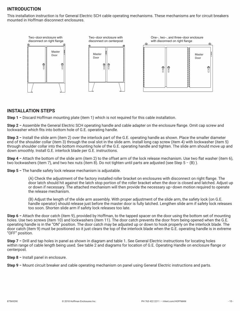
INSTALLATION STEPSStep 1 − Discard Hoffman mounting plate (item 1) which is not required for this cable installation.
Step 2 − Assemble the General Electric SCH operating handle and cable adapter on the enclosure flange. Omit cap screw and lockwasher which fits into bottom hole of G.E. operating handle.
Step 3 − Install the slide arm (item 2) over the interlock part of the G.E. operating handle as shown. Place the smaller diameter end of the shoulder collar (item 3) through the oval slot in the slide arm. Install long cap screw (item 4) with lockwasher (item 5) through shoulder collar into the bottom mounting hole of the G.E. operating handle and tighten. The slide arm should move up and down smoothly. Install G.E. interlock blade per G.E. instructions.
Step 4 − Attach the bottom of the slide arm (item 2) to the offset arm of the lock release mechanism. Use two flat washer (item 6), two lockwashers (item 7), and two hex nuts (item 8). Do not tighten until parts are adjusted (see Step 5 − (B) ).
Step 5 − The handle safety lock release mechanism is adjustable.
(A) Check the adjustment of the factory installed roller bracket on enclosures with disconnect on right flange. The door latch should hit against the latch stop portion of the roller bracket when the door is closed and latched. Adjust up or down if necessary. The attached mechanism will then provide the necessary up−down motion required to operate the release mechanism.
(B) Adjust the length of the slide arm assembly. With proper adjustment of the slide arm, the safety lock (on G.E. handle operator) should release just before the master door is fully latched. Lengthen slide arm if safety lock releases too soon. Shorten slide arm if safety lock releases too late.
Step 6 − Attach the door catch (item 9), provided by Hoffman, to the tapped spacer on the door using the bottom set of mounting holes. Use two screws (item 10) and lockwashers (item 11). The door catch prevents the door from being opened when the G.E. operating handle is in the “ON” position. The door catch may be adjusted up or down to hook properly on the interlock blade. The door catch (item 9) must be positioned so it just clears the top of the interlock blade when the G.E. operating handle is in extreme “OFF” position.
Step 7 − Drill and tap holes in panel as shown in diagram and table 1. See General Electric instructions for locating holes within range of cable length being used. See table 2 and diagrams for location of G.E. Operating Handle on enclosure flange or centerpost.
Step 8 − Install panel in enclosure.
Step 9 − Mount circuit breaker and cable operating mechanism on panel using General Electric instructions and parts.
MasterDoor
Two−door enclosure withdisconnect on right flange
MasterDoor
MasterDoor
Two−door enclosure withdisconnect on centerpost
One−, two−, and three−door enclosurewith disconnect on right flange

© 2018 Hoffman Enclosures Inc. PH 763 422 2211 • nVent.com/HOFFMAN 87569290- 16 -
For Floor−mounted, Two−Door, Enclosures With Disconnect on Right FlangeFor Floor−mounted, Two−Door, Enclosures With Disconnect on Centerpost
For One−, Two−, and Three−Door, Free−Standing Enclosures With Disconnect on Right Flange
Interlock
Handle return spring
* Offset arm
Lock release mechanism
Roller bracket latch stop *
Roller bracket *
General Electric cableadapter assembly
* Parts of lock release mechanism on enclosure with disconnect on right flange
Drive link
Interlock blade

© 2018 Hoffman Enclosures Inc. PH 763 422 2211 • nVent.com/HOFFMAN87569290 - 17 -
For Floor−mounted, Two−Door, Enclosures With Disconnect on Right FlangeFor One−, Two−, and three−Door, Free−Standing Enclosures With Disconnect on Right Flange

© 2018 Hoffman Enclosures Inc. PH 763 422 2211 • nVent.com/HOFFMAN 87569290- 18 -
For Floor−mounted, Two−Door, Enclosures With Disconnect on Centerpost

© 2018 Hoffman Enclosures Inc. PH 763 422 2211 • nVent.com/HOFFMAN87569290 - 19 -
For Floor−Mounted, Two−Door, Enclosures With Disconnect on Right FlangeFor Floor−Mounted, Two−Door, Enclosures With Disconnect on Centerpost
For One−, Two−, and Three−Door, Enclosures With Disconnect on Right Flange
TABLE 1Sub−panel Drilling
CABLEMECHANISM
CIRCUITBREAKER No. of Holes Hole Size X Y Cmin (1)
SCOMIA E150 4 8−32 1.38 4.88 1.38
SCOMIEF SE150 SF250
4 10−32 1.38 4.88 1.384 12−24 1.38 7.75 1.38
SCOMIG SG600 4 12−24 1.81 7.75 1.84SCOMIK SK1200 4 5/16−18 2.75 14.25 2.75
1) See General Electric instructions for range of dimensions which vary with enclosure depth and various lengths of operating cables that are available from General Electric.
TABLE 2 Location of Disconnect Operating Handle
Hoffman Disconnect Enclosure Description Enclosure Height A H
Two−Door, Floor−Mounted Disconnect on Right Flange
60.13 5.81
72.13 11.81
Two−Door, Floor−Mounted Disconnect on Centerpost
60.13 5.81
72.13 11.81
One Through Three−Door, Free−Standing Disconnect on Right Flange
72.13 7.81
84.13 13.81
90.13 16.81
Two−Door, Free−Standing Disconnect on Right Flange
62.81 6.26
74.81 12.26

© 2018 Hoffman Enclosures Inc. PH 763 422 2211 • nVent.com/HOFFMAN 87569290Rev. E P/N 87415740