Steering Wheel Audio Control Interface Adapter - 12volt-shop
Upload
khangminh22Category
view
0download
0
CAN adapter CAN-CONTROL manual v0.1

2
Table of Contents 1. Purpose of Can Adapter CAN-CONTROL ............................................................................. 3
2. Connecting FM Device with CAN-CONTROL........................................................................ 4
2.1. Connecting FMB1YX with CAN-CONTROL ............................................................................... 4
2.2. Connecting FMA1YX/FM11YX with CAN-CONTROL ................................................................ 4
3. CAN-CONTROL Configuration .............................................................................................. 5
3.1. CAN-CONTROL program number selection ........................................................................... 5
3.1.1 CAN-CONTROL program number configuration via SMS command ............................. 5
3.1.2. CAN-CONTROL program number configuration via Configurator ................................ 5
3.1.3 Selecting CAN-CONTROL program number manually .................................................... 6
3.2. FMB1YX CAN-CONTROL Configuration ................................................................................... 7
3.3. FM11YX/FMA1YX CAN-CONTROL Configuration .................................................................... 7
3.4. SMS Configuration .................................................................................................................... 8
3.4.1. SMS/GPRS Commands ....................................................................................................... 8
3.4.2. SMS/GPRS Command List ................................................................................................. 9
3.4.3 FMA1YX/FM11YX IO Elements .......................................................................................... 10
3.4.4 FMB1YX IO Elements ......................................................................................................... 11
4. AVL Parameters ID .............................................................................................................. 16

3
1. Purpose of Can Adapter CAN-CONTROL CAN-CONTROL is used to control various functions in light vehicles such us doors lock/unlock, windows open/close, turning lights and etc. With this adapter FMB1YX, FMA1XY, FM11XY devices is able to control certain functions as well as collect and send vehicle data.
Depending on what device CAN-CONTROL is used with the connection between CAN Adapter and FM devices can be either via dedicated contacts or USB plug.
Table 1 CAN-CONTROL Technical characteristics
Characteristic description Value
Min. Typ. Max. Unit Supply Voltage:
Supply Voltage(Recommended Operating Conditions)
+9 12 +16 V
Current Consumption
Working mode(with 12V) 23,6 mA
Sleep mode(with 12V) 0,95 mA
After turning the ignition on 23,7 mA
Working Temperature
Working Temperature -40 80 ºC

4
2. Connecting FM Device with CAN-CONTROL
FM11YX and FMA1YX share the same USB port for connecting adapter and configuring device with PC, while FMB1YX has dedicated pins for connection to CAN devices labeled Input 5 and Input 6.
2.1. Connecting FMB1YX with CAN-CONTROL • Connect Pin 5 to FMB1YX INPUT 5 pin and Pin 6 to INPUT 6 pin and connect CAN-CONTROL
adapter to other end of the cable. • Connect Pins 1-8 as specified in wiring scheme. • Connect car power supply lines to Pin 11 positive, Pin 10 negative. • For numbered pinout see sticker on CAN adapter.
2.2. Connecting FMA1YX/FM11YX with CAN-CONTROL • Connect USB Plug to FMA1YX, FM11YX device, connect CAN-CONTROL to other end of the
cable. • Connect Pins 1-8 as specified in wiring scheme. • Connect car power supply lines to Pin 11 positive, Pin 10 Negative. • For numbered pinout see sticker on CAN adapter.
Attention! Ordered CAN-CONTROL packaging may vary: standard package for FMB1YX series devices and other package for FMA1YX, FM11YX series with Mini-USB cable.
Attention! For detailed connection diagram of adapter to light vehicle please contact Teltonika, LTD sales representative and provide CAR manufacturer, model and year information.
Attention! Do not swap CAN L and CAN H lines. Do not swap power supply lines. Make sure that voltage do not exceeds 30V. Power supply lines should be connected at the end of installation work.
Figure 1 CAN CONTROL base conection scheme

5
3. CAN-CONTROL Configuration
3.1. CAN-CONTROL program number selection CAN-CONTROL must be set to program number which depends on vehicle model. Needed program number is always written on CAN-CONTROL mounting scheme. Please contact Your Teltonika sales manager to get latest supported vehicle list and mounting scheme for your vehicle, please provide CAR manufacturer, model and year information.
3.1.1 CAN-CONTROL program number configuration via SMS command CAN-CONTROL program number can be set remotely, using SMS command. SMS command: lvcansetprog X or login pass lvcansetprog X X is new program number value. Example: lvcansetprog 11434 SMS response: LVCAN ProgNum: 11434
3.1.2. CAN-CONTROL program number configuration via Configurator CAN-CONTROL program number can be set via Configurator, see Figure 2. Go to CAN Adapter (1) → Program Number (2). Enter program number and press Save to device (3) button that saves the current configuration into FMB1YX.
Figure 2 CAN Adapter Settings in Configurator, 1 – CAN Adapter settings, 3 – Save to
device, 3 – Program number field

6
3.1.3 Selecting CAN-CONTROL program number manually Steps to set program number:
• Hold SWITCH down until LED starts blinking. • Release the SWITCH. • Then LED starts blinking and counting first digit of program number (one blink means digit 1,
two blinks mean digit 2 etc). • To stop counter push SWITCH. • Release the SWITCH, then LED starts blinking and counting second digit of program number. • To stop counter push SWITCH. • Release the SWITCH, then LED starts blinking and counting third digit on program number. • To stop counter push SWITCH. • Release the SWITCH, then LED starts blinking and counting fourth digit on program number. • To stop counter push SWITCH. • Release the SWITCH, then LED starts blinking and counting fifth digit on program number. • To stop counter push SWITCH. • Release SWITCH, if programming is successful LED will blink 10 times.
Figure 3 Can Adapter

7
3.2. FMB1YX CAN-CONTROL Configuration Because FMB1YX have CAN-CONTROL RX and TX in its own pinout, device configuration can be performed via Micro-USB or Blue-tooth connection via Configurator when CAN adapter is connected to the vehicle. When FMB1YX is connected to CAN-CONTROL, user can see all information that is received from the vehicle in Configurator → CAN Adapter (Figure 2), all data are highlighted by green background color. Information in this section is automatically refreshed. CAN bus data which can be read from your car is provided in "CAN-CONTROL supported vehicle list" document. The CAN-CONTROL I/O element can be configured like any other I/O element in FMB1YX Configurator.
When using offline configuration method user can select which CAN data will be read from CAN-CONTROL and sent directly to the server without connection to adapter. Please note that parameters depend on vehicle manufacturer and vehicle model. For further information check "CAN-CONTROL supported vehicle list” document.
3.3. FM11YX/FMA1YX CAN-CONTROL Configuration FM11YX/FMA1YX devices shares the same USB port for connecting CAN-CONTROL adapter and configuring device with PC. FM11YX/FMA1YX can be configured using “SCAN” function or “Offline Configuration”. SCAN function – is in use when FM11YX/FMA1YX is connected to CAN adapter, see (Figure 4).
Figure 4 LVCAN settings in FM11YX/FMA1YX Configurator

8
To configure CAN data connect CAN-CONTROL to CAN bus and to the FM11YX/FMA1YX device (Figure 5) wait 10 seconds. Car engine must be started.
Disconnect CAN-CONTROL from FM11YX/FMA1YX, and connect PC USB cable to FM11YX/FMA1YX device (Figure 6). It is very important not to disconnect from power source, because then all CAN data will be lost.
Readable CAN data are highlighted by green background color. CAN bus data which can be read from your car is shown in “CAN-CONTROL supported vehicle list” document.
Available CAN Bus IO parameters and configuration can be found in Configurators CAN tab (Figure 4).
3.4. SMS Configuration All CAN-CONTROL IO elements can be configured remotely via SMS command
3.4.1. SMS/GPRS Commands1
CAN-CONTROL has several dedicated SMS/GPRS commands. All commands are case sensitive. Essential fields in ‘SMS’ part is ‘Login’ and ‘Password’. The login and password are used with every SMS sent to FM device. If login and password are not set, in every SMS sent to FM device two spaces before command have to be used (<space><space><command>).
Command structure with set login and password:
<login><space><password><space><command>, example: asd 123 lvcangetinfo
1GPRS commands require Codec 12 Protocol
Figure 5 CAN-CONTROL basic connection scheme
Figure 6 FM connection to PC

9
3.4.2. SMS/GPRS Command List Table 2 Command List
Command Description Response lvcansetprog # Set program number to LV-CAN200/ ALL-CAN300/CAN-CONTROL
that is connected to FMB1YX. # three digit number that identity vehicle.
Yes
lvcangetprog Get program number from LV-CAN200/ ALL-CAN300 that is connected to FMB1YX.
Yes
lvcangetinfo Get information about connected LV-CAN200/ALL-CAN300. Yes
Lvcanclear # Clear Total Mileage (counted), Engine Work Time (counted), Fuel Consumed (counted) parameters values.
# - parameter (0 – Engine work time (counted), 1 – Fuel Consumed (counted), 2 – Vehicle Mileage (counted)).
lvcanopenalldoors Open [unlock] all doors Yes
lvcanclosealldoors Close [lock] all doors Yes
lvcanopentrunk Open [unlock] trunk Yes
lvcanturninglights One flash of all turn lights ordered trough accidental / blinking turn light switch
Yes
lvcanwindowsopen:# open windows xx sec. (one sending of command will cause the windows to continue opening for xx seconds). xx: [1,3,5...25,27,29]
Yes
lvcanwindowsclose:# close windows xx sec. (one sending of command will cause the windows to continue closing for xx seconds). xx: [1,3,5...25,27,29]
Yes
10
3.4.3 FMA1YX/FM11YX IO Elements For FMA1YX/FM11YX devices first ID number is always “2”, second and third ID numbers refers to specific CAN-CONTROL IO element (Table 3). And the last ID number refers to sections – Property; Generation Type; Low level, High level and Averaging Constant (Table 4). Here’s example: ID 2013 – configures Accelerator Pedal position parameter “High Level”
Table 3 CAN-CONTROL IO elements SMS configuration Ids range
CAN-CONTROL IO Element Parameter Ids range Speed 2000-2004
Accelerator pedal position 2010-2014
Total fuel used 2020-2023
Fuel level (liters) 2030-2034
Engine RPM 2040-2044
Total mileage 2050-2053
Fuel level (percent) 2060-2064
Program number 2070-2073
Module ID 2080-2083
Total Mileage (counted) 2110-2113
Fuel Consumed (counted) 2120-2123
Engine Temperature 2170-2174
Control State Flags 2230-2233
Security State Flags 2320-2323
Table 4 CAN-CONTROL IO parameters configuration
Parameter ID Parameter name Available values 2xx0 Priority 0 – IO element disabled
1 – Low priority 2 – High priority 3 – Panic priority
2xx1 Generation type 0 – Event on exit 1 – Event on entrance 2 – Event on both 3– Monitoring 4 – Hysteresis 5 – On change
2xx2 Low level
2xx3 High Level
2xx4 Averaging Constant
From 0 to 232

11
3.4.4 FMB1YX IO Elements
3.4.4.1 CAN Adapter Mode
Sets LVCAN mode: 0 – Auto Detect, 1 – LV-CAN200, 2 – ALL-CAN300, 3 - CAN-CONTROL.
3.4.4.2 Send data with 0, if ignition is off (ID = 45001)
This parameter enables/disables data sending with 0 value, if ignition is off. 0 – Disable, 1 – Enable.
3.4.4.3 Program Number (ID = 45002)
Sets LVCAN Program number.
3.4.4.4 1st LVCAN property parameter priority (ID=45100)
Parameter defines LVCAN property type of priority: 0 is disabled, 1 – low, 2 – high, 3 - panic.
3.4.4.5 1st LVCAN property parameter operand (ID=45101)
Minimum Value
Maximum Value
Default Value
Goes with (depends on parameters)
Value Type
0 2 0 Send data with 0, if ignition is off (ID = 45001)
Program Number (ID = 45002)
Uint8
Minimum Value
Maximum Value
Default Value
Goes with (depends on parameters)
Value Type
0 1 0 LVCAN Mode (ID = 45000)
Program Number (ID = 45002)
Uint8
Minimum Value
Maximum Value
Default Value
Goes with (depends on parameters)
Value Type
0 999 0 LVCAN Mode (ID = 45000)
Send data with 0, if ignition is off (ID = 45001)
Uint16
Minimum Value
Maximum Value
Default Value
Goes with (depends on parameters)
Value Type
0 1 0 LVCAN Mode (ID = 45000)
Program Number (ID = 45002)
Uint8

12
Parameter defines when event is sent: 0 – on range exit, 1 – on range entrance, 2 – both, 3 – monitoring, 4 – hysteresis, 5 – on changes, 6 – on delta change.
3.4.4.6 1st LVCAN property parameter High level (ID=45102)
Parameter defines high value of triggered LVCAN property. This parameter is used to set thresholds for LVCAN properties to generate events.
3.4.4.7 1st LVCAN property parameter Low level (ID=45103)
Minimum Value
Maximum Value
Default Value
Goes with (depends on parameters)
Value Type
0 3 0 1st LVCAN property parameter operand (ID=45101)
1st LVCAN property parameter High level (ID=45102)
1st LVCAN property parameter Low level (ID=45103)
1st LVCAN property parameter Event only (ID=45104)
1st LVCAN property parameter averaging constant (ID=45105)
1st LVCAN property parameters Send SMS to (ID=7141)
1st LVCAN property parameters SMS Text (ID=8141)
Uint8
Minimum Value
Maximum Value
Default Value
Goes with (depends on parameters)
Value Type
0 255 0 1st LVCAN property parameter priority (ID=45100)
1st LVCAN property parameter operand (ID=45101)
1st LVCAN property parameter Low level (ID=45103)
1st LVCAN property parameter Event only (ID=45104)
1st LVCAN property parameter averaging constant (ID=45105)
1st LVCAN property parameters Send SMS to (ID=7141)
1st LVCAN property parameters SMS Text (ID=8141)
Uint8

13
Parameter defines low value of triggered LVCAN property. This parameter is used to set thresholds for LVCAN properties to generate events.
3.4.4.8 1st LVCAN property parameter Event only (ID=45104)
Parameter defines when LVCAN element value is sent: 0 – with every AVL packet, 1 – on event only. On event means that LVCAN element value is included to AVL packet only when this particular event happens. With regular, periodic records such LVCAN element value is not included.
Minimum Value
Maximum Value
Default Value
Goes with (depends on parameters)
Value Type
0 255 0 1st LVCAN property parameter priority (ID=45100)
1st LVCAN property parameter operand (ID=45101)
1st LVCAN property parameter High level (ID=45102)
1st LVCAN property parameter Event only (ID=45104)
1st LVCAN property parameter averaging constant (ID=45105)
1st LVCAN property parameters Send SMS to (ID=7141)
1st LVCAN property parameters SMS Text (ID=8141)
Uint8
Minimum Value
Maximum Value
Default Value
Goes with (depends on parameters)
Value Type
0 1 0 1st LVCAN property parameter priority (ID=45100)
1st LVCAN property parameter operand (ID=45101)
1st LVCAN property parameter High level (ID=45102)
1st LVCAN property parameter Low level (ID=45103)
1st LVCAN property parameter averaging constant (ID=45105)
1st LVCAN property parameters Send SMS to (ID=7141)
1st LVCAN property parameters SMS Text (ID=8141)
Uint8
14
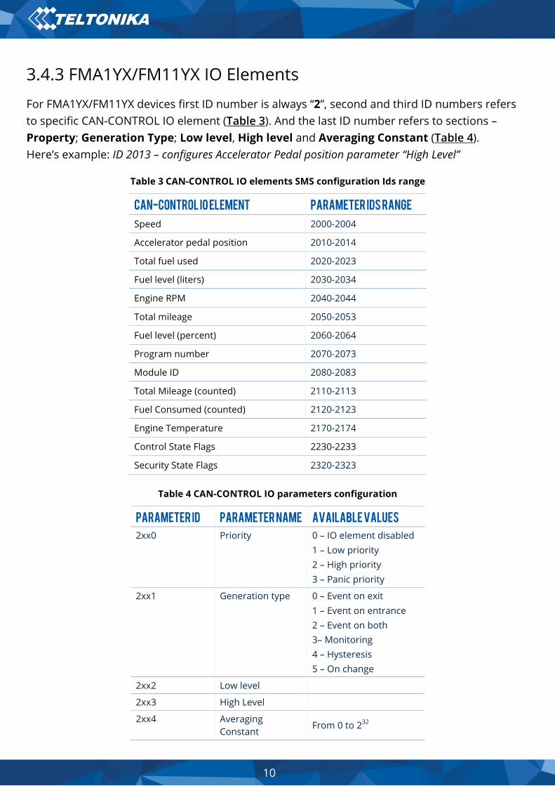
3.4.4.9 1st LVCAN property parameter averaging constant (ID=45105)
Parameter defines LVCAN property sample length to average.
3.4.4.10 1st LVCAN property parameters Send SMS to (ID=7141)
Enable/Disable SMS event sending. 0 – Disable, 1-10 SMS will be sent to configured GSM number.
3.4.4.11 1st LVCAN property parameters SMS Text (ID=8141)
Configure LVCAN property parameter SMS event text here.
Minimum Value
Maximum Value
Default Value
Goes with (depends on parameters)
Value Type
0 65535 10 1st LVCAN property parameter priority (ID=45100)
1st LVCAN property parameter operand (ID=45101)
1st LVCAN property parameter High level (ID=45102)
1st LVCAN property parameter Low level (ID=45103)
1st LVCAN property parameter Event only (ID=45104)
1st LVCAN property parameters Send SMS to (ID=7141)
1st LVCAN property parameters SMS Text (ID=8141)
Uint16
Minimum Value
Maximum Value
Default Value
Goes with (depends on parameters)
Value Type
0 10 0 1st LVCAN property parameter priority (ID=45100)
1st LVCAN property parameter operand (ID=45101)
1st LVCAN property parameter High level (ID=45102)
1st LVCAN property parameter Low level (ID=45103)
1st LVCAN property parameter Event only (ID=45104)
1st LVCAN property parameter averaging constant (ID=45105)
1st LVCAN property parameters SMS Text (ID=8141)
Uint8

15
3.4.4.12 All CAN I/O elements parameters property ID
Parameter name Priority
Operand High level
Low level
Event only
Avg const
Send SMS to
SMS text
Vehicle Speed 45100 45101 45102 45103 45104 45105 7141 8141
Acceleration Pedal Position (percent)
45110 45111 45112 45113 45114 45115 7142 8142
Fuel Consumed (liters)
45120 45121 45122 45123 45124 - 7143 8143
Fuel Level (liters) 45130 45131 45132 45133 45134 45135 7144 8144
Engine RPM 45140 45141 45142 45143 45144 45145 7145 8145
Total Mileage 45150 45151 45152 45153 45154 - 7146 8146
Fuel Level (percent) 45160 45161 45162 45163 45164 45165 7147 8147
Program Number 45180 45181 45182 45183 45184 - 7149 8149
Module ID 45190 45191 45192 45193 45194 - 7150 8150
Total Mileage (counted)
45220 45221 45222 45223 45224 - 7153 8153
Fuel Consumed (counted)
45230 45231 45232 45233 45234 - 7154 8154
Engine Temperature 45280 45281 45282 45283 45284 45285 7159 8159
Control State Flags 45340 45341 45342 45343 45344 - 7165 8165
Security State Flags 45430 45431 45432 45433 45434 - 7174 8174
Battery Voltage 45720 45721 45722 45723 45724 - 7203 8203
CNG Used 45900 45901 45902 45903 45904 - 7237 8237
CNG Level 45910 45911 45912 45913 45914 - 7238 8238
Minimum Value
Maximum Value
Default Value
Goes with (depends on parameters)
Value Type
0 160 LVC Vehicle speed
1st LVCAN property parameter priority (ID=45100)
1st LVCAN property parameter operand (ID=45101)
1st LVCAN property parameter High level (ID=45102)
1st LVCAN property parameter Low level (ID=45103)
1st LVCAN property parameter Event only (ID=45104)
1st LVCAN property parameter averaging constant (ID=45105)
1st LVCAN property parameters Send SMS to (ID=7141)
String

16
4. AVL Parameters ID When no I/O element is enabled, AVL packet comes with GNSS information only. After enabling I/O element(s) AVL packet along with GPS information contains current value(s) of enabled I/O element. List of available CAN data, parameter size, ID and value range you can find in Table 5.
Table 5 ACQUIRED PARAMETRS IO Ids
Property Input Param index
Size (Bytes)
Param IO ID
Measurement units
a1 Remarks
CAN-CONTROL
Program number
29 4 100 - -
Module ID 30 8 101 - -
Total Mileage 33 4 87 meters 1
Total Mileage (counted) * 34 4 105 meters 1
Fuel Consumed 35 4 83 Ltr * 10 0.1
Fuel Consumed (counted) * 36 4 107 Ltr * 10 0.1
Fuel Level [%] 37 1 89 % 1
Fuel Level [liters] 38 2 84 Ltrs * 10 0.1
Engine RPM 42 2 85 - 1
Engine Temperature 44 1 115 °C x 10 0.1 signed
Accelerator Pedal Position 45 1 82 % 1
Vehicle Speed 46 1 81 km/h 1
Control State Flags 52 4 123 - -
Security State Flags 61 8 132 -
Battery Level (percent) 81 1 152 % 1
NOTE: „Total Fuel Used“ is sent to server multiplied by 10. Example: if value was 150.5 liters, „1505“ will be sent to server. * - Fuel consumed (counted), Total mileage (counted), Engine Work Time (counted) are parameters, which are counted after CAN-CONTROL is connected to CAN bus.
Copyright © 2022 FDOKUMEN