thyssenKrupp Elevator Corporation - National Cooperative ...
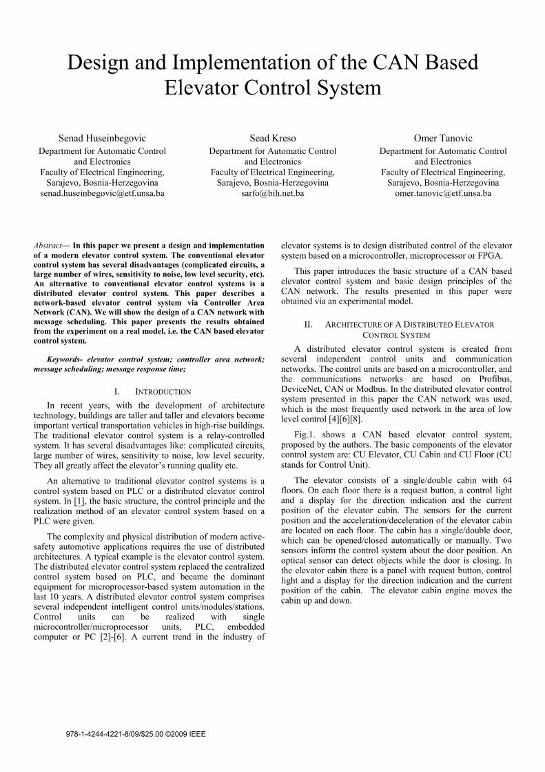
Design and Implementation of the CAN Based Elevator Control System
Senad Huseinbegovic Department for Automatic Control
and Electronics Faculty of Electrical Engineering,
Sarajevo, Bosnia-Herzegovina [email protected]
Sead Kreso Department for Automatic Control
and Electronics Faculty of Electrical Engineering,
Sarajevo, Bosnia-Herzegovina [email protected]
Omer Tanovic Department for Automatic Control
and Electronics Faculty of Electrical Engineering,
Sarajevo, Bosnia-Herzegovina [email protected]
Abstract— In this paper we present a design and implementation of a modern elevator control system. The conventional elevator control system has several disadvantages (complicated circuits, a large number of wires, sensitivity to noise, low level security, etc). An alternative to conventional elevator control systems is a distributed elevator control system. This paper describes a network-based elevator control system via Controller Area Network (CAN). We will show the design of a CAN network with message scheduling. This paper presents the results obtained from the experiment on a real model, i.e. the CAN based elevator control system.
Keywords- elevator control system; controller area network; message scheduling; message response time;
I. INTRODUCTION In recent years, with the development of architecture
technology, buildings are taller and taller and elevators become important vertical transportation vehicles in high-rise buildings. The traditional elevator control system is a relay-controlled system. It has several disadvantages like: complicated circuits, large number of wires, sensitivity to noise, low level security. They all greatly affect the elevator’s running quality etc.
An alternative to traditional elevator control systems is a control system based on PLC or a distributed elevator control system. In [1], the basic structure, the control principle and the realization method of an elevator control system based on a PLC were given.
The complexity and physical distribution of modern active-safety automotive applications requires the use of distributed architectures. A typical example is the elevator control system. The distributed elevator control system replaced the centralized control system based on PLC, and became the dominant equipment for microprocessor-based system automation in the last 10 years. A distributed elevator control system comprises several independent intelligent control units/modules/stations. Control units can be realized with single microcontroller/microprocessor units, PLC, embedded computer or PC [2]-[6]. A current trend in the industry of
elevator systems is to design distributed control of the elevator system based on a microcontroller, microprocessor or FPGA.
This paper introduces the basic structure of a CAN based elevator control system and basic design principles of the CAN network. The results presented in this paper were obtained via an experimental model.
II. ARCHITECTURE OF A DISTRIBUTED ELEVATOR CONTROL SYSTEM
A distributed elevator control system is created from several independent control units and communication networks. The control units are based on a microcontroller, and the communications networks are based on Profibus, DeviceNet, CAN or Modbus. In the distributed elevator control system presented in this paper the CAN network was used, which is the most frequently used network in the area of low level control [4][6][8].
Fig.1. shows a CAN based elevator control system, proposed by the authors. The basic components of the elevator control system are: CU Elevator, CU Cabin and CU Floor (CU stands for Control Unit).
The elevator consists of a single/double cabin with 64 floors. On each floor there is a request button, a control light and a display for the direction indication and the current position of the elevator cabin. The sensors for the current position and the acceleration/deceleration of the elevator cabin are located on each floor. The cabin has a single/double door, which can be opened/closed automatically or manually. Two sensors inform the control system about the door position. An optical sensor can detect objects while the door is closing. In the elevator cabin there is a panel with request button, control light and a display for the direction indication and the current position of the cabin. The elevator cabin engine moves the cabin up and down.
978-1-4244-4221-8/09/$25.00 ©2009 IEEE
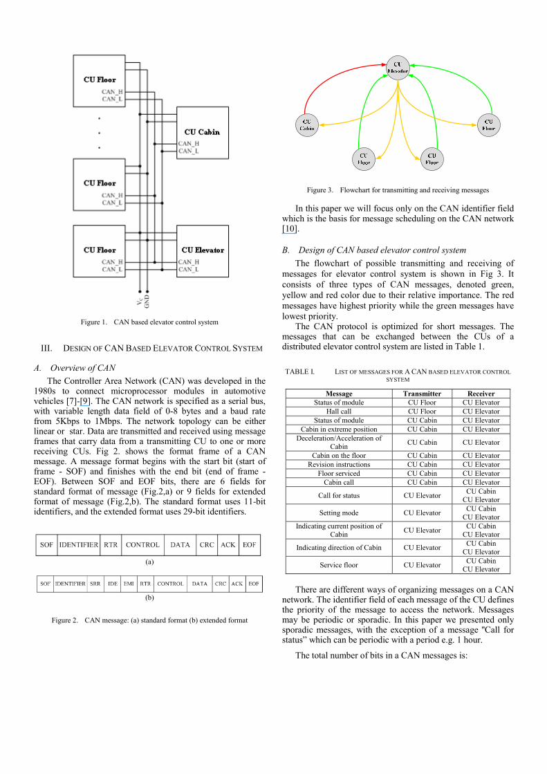
Figure 1. CAN based elevator control system
III. DESIGN OF CAN BASED ELEVATOR CONTROL SYSTEM
A. Overview of CAN The Controller Area Network (CAN) was developed in the
1980s to connect microprocessor modules in automotive vehicles [7]-[9]. The CAN network is specified as a serial bus, with variable length data field of 0-8 bytes and a baud rate from 5Kbps to 1Mbps. The network topology can be either linear or star. Data are transmitted and received using message frames that carry data from a transmitting CU to one or more receiving CUs. Fig 2. shows the format frame of a CAN message. A message format begins with the start bit (start of frame - SOF) and finishes with the end bit (end of frame - EOF). Between SOF and EOF bits, there are 6 fields for standard format of message (Fig.2,a) or 9 fields for extended format of message (Fig.2,b). The standard format uses 11-bit identifiers, and the extended format uses 29-bit identifiers.
(a)
(b)
Figure 2. CAN message: (a) standard format (b) extended format
Figure 3. Flowchart for transmitting and receiving messages
In this paper we will focus only on the CAN identifier field which is the basis for message scheduling on the CAN network [10].
B. Design of CAN based elevator control system The flowchart of possible transmitting and receiving of
messages for elevator control system is shown in Fig 3. It consists of three types of CAN messages, denoted green, yellow and red color due to their relative importance. The red messages have highest priority while the green messages have lowest priority.
The CAN protocol is optimized for short messages. The messages that can be exchanged between the CUs of a distributed elevator control system are listed in Table 1.
TABLE I. LIST OF MESSAGES FOR A CAN BASED ELEVATOR CONTROL SYSTEM
Message Transmitter Receiver Status of module CU Floor CU Elevator
Hall call CU Floor CU Elevator Status of module CU Cabin CU Elevator
Cabin in extreme position CU Cabin CU Elevator Deceleration/Acceleration of
Cabin CU Cabin CU Elevator
Cabin on the floor CU Cabin CU Elevator Revision instructions CU Cabin CU Elevator
Floor serviced CU Cabin CU Elevator Cabin call CU Cabin CU Elevator
Call for status CU Elevator CU Cabin CU Elevator
Setting mode CU Elevator CU Cabin CU Elevator
Indicating current position of Cabin CU Elevator CU Cabin
CU Elevator
Indicating direction of Cabin CU Elevator CU Cabin CU Elevator
Service floor CU Elevator CU Cabin CU Elevator
There are different ways of organizing messages on a CAN
network. The identifier field of each message of the CU defines the priority of the message to access the network. Messages may be periodic or sporadic. In this paper we presented only sporadic messages, with the exception of a message ''Call for status” which can be periodic with a period e.g. 1 hour.
The total number of bits in a CAN messages is:
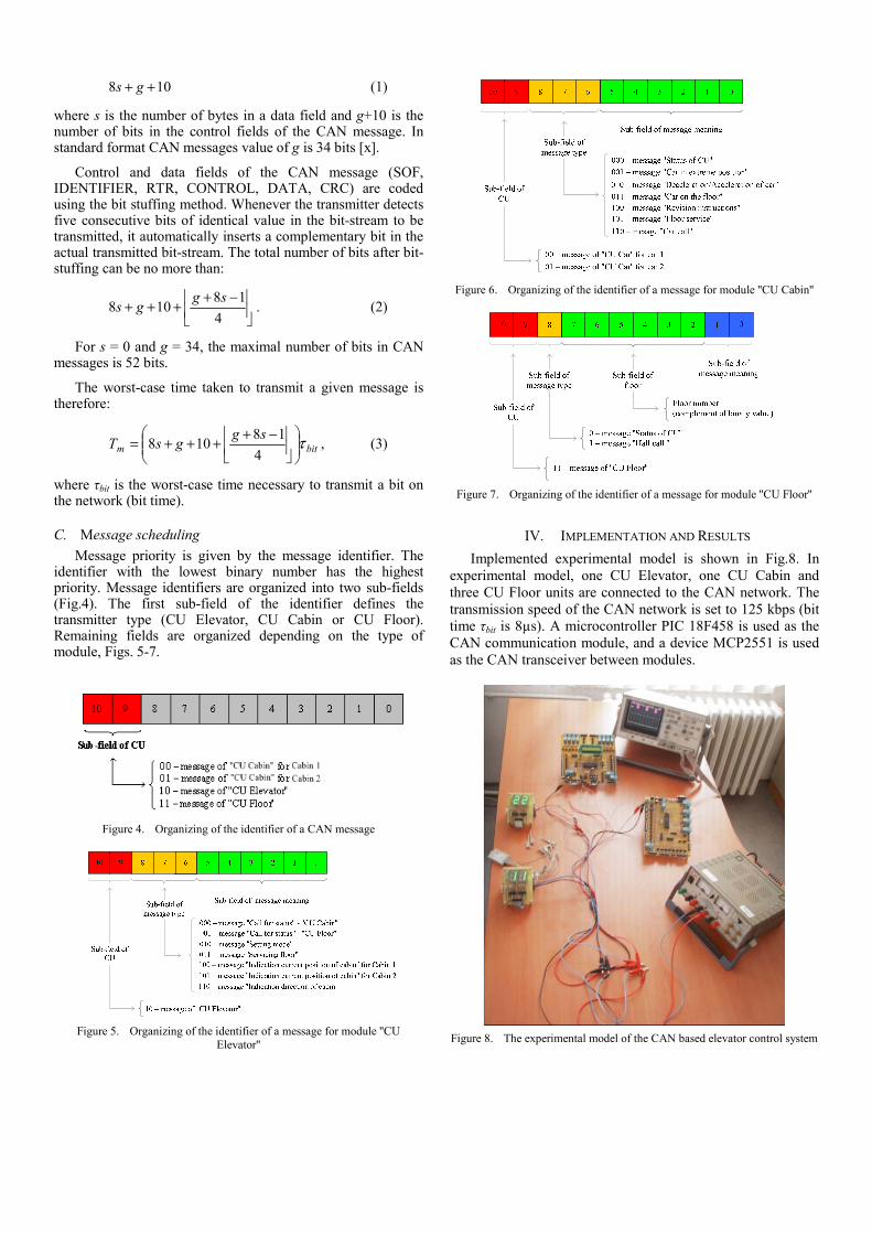
108 ++ gs (1)
where s is the number of bytes in a data field and g+10 is the number of bits in the control fields of the CAN message. In standard format CAN messages value of g is 34 bits [x].
Control and data fields of the CAN message (SOF, IDENTIFIER, RTR, CONTROL, DATA, CRC) are coded using the bit stuffing method. Whenever the transmitter detects five consecutive bits of identical value in the bit-stream to be transmitted, it automatically inserts a complementary bit in the actual transmitted bit-stream. The total number of bits after bit-stuffing can be no more than:
⎥⎦
⎥⎢⎣
⎢ −++++
418
108sg
gs . (2)
For s = 0 and g = 34, the maximal number of bits in CAN messages is 52 bits.
The worst-case time taken to transmit a given message is therefore:
bitmsggsT τ⎟⎟
⎠
⎞⎜⎜⎝
⎛⎥⎦
⎥⎢⎣
⎢ −++++=4
18108 , (3)
where τbit is the worst-case time necessary to transmit a bit on the network (bit time).
C. Message scheduling Message priority is given by the message identifier. The
identifier with the lowest binary number has the highest priority. Message identifiers are organized into two sub-fields (Fig.4). The first sub-field of the identifier defines the transmitter type (CU Elevator, CU Cabin or CU Floor). Remaining fields are organized depending on the type of module, Figs. 5-7.
Figure 4. Organizing of the identifier of a CAN message
Figure 5. Organizing of the identifier of a message for module ''CU
Elevator''
Figure 6. Organizing of the identifier of a message for module ''CU Cabin''
Figure 7. Organizing of the identifier of a message for module ''CU Floor''
IV. IMPLEMENTATION AND RESULTS Implemented experimental model is shown in Fig.8. In
experimental model, one CU Elevator, one CU Cabin and three CU Floor units are connected to the CAN network. The transmission speed of the CAN network is set to 125 kbps (bit time τbit is 8µs). A microcontroller PIC 18F458 is used as the CAN communication module, and a device MCP2551 is used as the CAN transceiver between modules.
Figure 8. The experimental model of the CAN based elevator control system
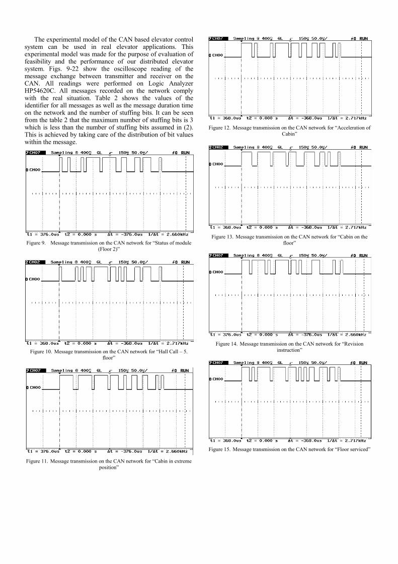
The experimental model of the CAN based elevator control system can be used in real elevator applications. This experimental model was made for the purpose of evaluation of feasibility and the performance of our distributed elevator system. Figs. 9-22 show the oscilloscope reading of the message exchange between transmitter and receiver on the CAN. All readings were performed on Logic Analyzer HP54620C. All messages recorded on the network comply with the real situation. Table 2 shows the values of the identifier for all messages as well as the message duration time on the network and the number of stuffing bits. It can be seen from the table 2 that the maximum number of stuffing bits is 3 which is less than the number of stuffing bits assumed in (2). This is achieved by taking care of the distribution of bit values within the message.
Figure 9. Message transmission on the CAN network for “Status of module
(Floor 2)”
Figure 10. Message transmission on the CAN network for “Hall Call – 5.
floor”
Figure 11. Message transmission on the CAN network for “Cabin in extreme
position”
Figure 12. Message transmission on the CAN network for “Acceleration of
Cabin”
Figure 13. Message transmission on the CAN network for “Cabin on the
floor”
Figure 14. Message transmission on the CAN network for “Revision
instruction”
Figure 15. Message transmission on the CAN network for “Floor serviced”
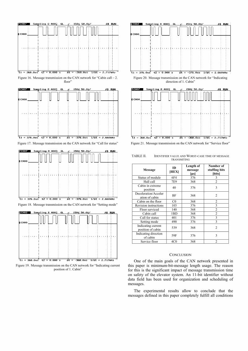
Figure 16. Message transmission on the CAN network for “Cabin call – 2.
floor”
Figure 17. Message transmission on the CAN network for “Call for status”
Figure 18. Message transmission on the CAN network for “Setting mode”
Figure 19. Message transmission on the CAN network for “Indicating current
position of 1. Cabin”
Figure 20. Message transmission on the CAN network for “Indicating
direction of 1. Cabin”
Figure 21. Message transmission on the CAN network for “Service floor”
TABLE II. IDENTIFIER VALUE AND WORST-CASE TIME OF MESSAGE TRANSMITING
Message ID [HEX]
Length of message
[µs]
Number of stuffing bits
[bits] Status of module 6F4 376 3
Hall call 7E9 368 2 Cabin in extreme
position 40 376 3
Deceleration/Acceleration of cabin BF 368 2
Cabin on the floor C0 368 2 Revision instructions 103 376 3
Floor serviced 140 368 2 Cabin call 1BD 368 2
Call for status 401 376 3 Setting mode 490 376 3
Indicating current position of cabin 539 368 2
Indicating direction of cabin 59F 376 3
Service floor 4C0 368 2
CONCLUSION One of the main goals of the CAN network presented in
this paper is minimum-bit-message length usage. The reason for this is the significant impact of message transmission time on safety of the elevator system. An 11-bit identifier without data field has been used for organization and scheduling of messages.
The experimental results allow to conclude that the messages defined in this paper completely fulfill all conditions
for work in a real system. At a transmission speed of 125 Kbps the longest message lasts 376 μs. For elevators which travel at 4m/s the height that the elevator passes during a message transmission is about 1,55mm which is within the allowed range of ±6mm [12]. This relates to the case where no collision on the network occurred. In case of a collision this height has a higher value. This case will be considered during further research. The disadvantage of this concept is the limited number of floors (maximum number of 64 floors) and cabins (maximum number of 2 cabins). This will also be considered during further research.
REFERENCES
[1] X.Yang, Q.Zhu, H.Xu: ''Design and practice of an elevator control system based on PLC'', Workshop on Power Electronics and Intelligent Transportation System, 2008.
[2] M.-L.Siikonen: ''Planning and control models for elevaor in high-rise buildings'', Research reports, KONE Corporation, october 1997
[3] J.Kotzin, V.Srovnal: ''CAN based distributed control system modeling using UML'', ICIT 2003, Maribor
[4] ''Microprocessor system for elevator control – RVM alfa'', User manual, TTC TELSYS, A.S.
[5] ''MicroZed elevator control module 8/16/24/32 Collective - Version3.3'', User manual, S.&A.S. LTD.
[6] ''WP-CAN 3200 microprocessor-based serial communication lift controller'', User manual, Wuxi WIPO Electronic Co.,Ltd
[7] R. Bosch: ''CAN specification, version 2.0'', Stuttgart, 1991. [8] N.Xiaodong, Z.Yanjun: ''Determining message delivery delay of CAN'',
Prceedings of IEEE TENCON'02, 2002. [9] M.Farsi, K.Ratcliff, M.Barbosa: ''An overview of controller area
network'', Networking Systems, Computing&Control Engineering Journal, June 1999.
[10] K.C.Lee,H.-H.Lee: ''Network-based fire-detection system via CAN for smart home automation'', IEEE Transactions on Consumer Electronics, Vol. 50, No. 4, November 2004.
[11] T.Nolte, H.Hansson, C.Norstroem: ''Minimizing CAN response-time jitter by message manipulation'', Proceedings of 8th IEEE RTAS'02, 2002.
[12] C.A.Skalski: ''High-performance elevator control system'', presented at Industry Application Society (IAS-IEEE) Annual Meeting in Mexico, 1983.
Copyright © 2022 FDOKUMEN


![Elevator Catalog [1.3 MB] - Wirerope Works](https://static.fdokumen.com/doc/165x107/6327034c6d480576770d1104/elevator-catalog-13-mb-wirerope-works.jpg)