analisa desain elevator top traction 1000kgs 60 m/m car 1600 ...
Upload
khangminh22Category
view
3download
0
sustainability
Article
Construction Management Solutions to MitigateElevator Noise and Vibration of High-RiseResidential Buildings
Yangki Oh 1, Minwoo Kang 1 , Kwangchae Lee 2 and Sunkuk Kim 2,*1 Department of Architecture, Mokpo National University, Muan-gun, Jeollanam-do 58554, Korea;
[email protected] (Y.O.); [email protected] (M.K.)2 Department of Architectural Engineering, Kyung Hee University, Yongin-si, Gyeonggi-do 17104, Korea;
[email protected]* Correspondence: [email protected]; Tel.: +82-31-201-2922
Received: 11 September 2020; Accepted: 19 October 2020; Published: 27 October 2020
Abstract: In high-rise residential buildings (HRBs), elevators run at a high speed, which causesproblems such as change of atmospheric pressure, noise, and vibration. Elevator noise andvibration (ENV) of HRBs causes both mental anxiety and a consistently negative effect for promotinga comfortable residential area. Therefore, a solution for alleviating the ENV of HRBs is essential.To date, studies related to ENV have been mostly conducted in the approach of mechanical and electricaspects. There have been few cases conducted from the perspective of construction management(CM), which integrates design and construction. Therefore, the aim of this study is to proposeCM solutions to mitigate the ENV of HRB. For this study, the CM solution is presented afteridentifying the ENV problems of HRBs through documented research and case measurement.By measuring the noise of HRB that the solution was applied to, the noise level, especially in a rangeof >125 Hz, was extensively reduced. The result of this study will be used as sustainable guidelinesthat alleviate ENV problems in the process of design and construction of HRB elevators. It is expectedthat studies for improving ENV problems that occur in high-rise elevators will increase on the basisof the results of this study.
Keywords: elevator; noise; vibration; construction management; high-rise residential building
1. Introduction
A high-rise residential building (HRB) is a type of housing that has multi-dwelling units builton the same land. This housing has become popular in urban areas because of the increase in landcost [1]. Efficient vertical mobility is a critical component of developing and constructing tallbuildings [2]. Advances in elevators over the past 20 years are probably the greatest advances we haveseen in tall buildings [3].
However, the elevators of HRB operated at a high-speed cause problems such as changesin atmospheric pressure inside and outside a lift car, noise, and vibration [4–13]. In particular, elevatornoise and vibration (ENV) cause both mental anxiety for passengers and a consistent negative effecton promoting a comfortable residential area close to the elevator shaft [11,14–21]. To secure a sustainableliving environment, the impacts can be significant issues related to sound quality, sleeping conditions,and enjoyment within residences [14,16–20,22–25].
To solve these problems, multiple studies have been conducted, which mostly focusedon mechanical and electric aspects [6,7,10,26–36]. However, it is not easy to solve ENV problems onlywith machinery solutions for HRB elevators that run at a speed of >90 m/min [21,37–39]. The reason is
Sustainability 2020, 12, 8924; doi:10.3390/su12218924 www.mdpi.com/journal/sustainability

Sustainability 2020, 12, 8924 2 of 21
that not only do noise and vibrations occur in the elevating machinery itself, but there are architecturalproblems of elevator shafts or air turbulence because HRB elevators run at a high speed [4,14,37–39].Thus, identifying solutions after analyzing such causes is necessary. Solutions for ENV problemsshould be provided in detail in the design phase primarily, and construction should be followedaccording to the design details. However, we have confirmed that ENV problems continue to occurdue to errors or mistakes in the design and construction phase through research and site surveys overthe past several years.
This is because there is no CM solution that integrates design and construction for ENV problems.As shown in routines (1) and (2) in Figure 1, even if ENV solutions are provided with the documentsincluding drawings and specifications in the design phase, the details including the precision, quality,and tolerance of construction suitable for the site condition must be determined in the constructionphase after design review. As shown in routines (3), (4), and (5) in Figure 1, if design errors oromissions are confirmed after design review, construction details are determined after performingsupplementary design. In other words, additional designs can be carried out according to the sitesituation at the construction phase. Solutions applied to the design and construction phases andintegrated management of them are defined as CM solutions in this paper. The aim of this study is topropose CM solutions to mitigate the ENV of HRB.
Sustainability 2020, 12, x FOR PEER REVIEW 2 of 22
Sustainability 2020, 12, x; doi: FOR PEER REVIEW www.mdpi.com/journal/sustainability
is that not only do noise and vibrations occur in the elevating machinery itself, but there are
architectural problems of elevator shafts or air turbulence because HRB elevators run at a high speed
[4,14,37–39]. Thus, identifying solutions after analyzing such causes is necessary. Solutions for ENV
problems should be provided in detail in the design phase primarily, and construction should be
followed according to the design details. However, we have confirmed that ENV problems continue
to occur due to errors or mistakes in the design and construction phase through research and site
surveys over the past several years.
This is because there is no CM solution that integrates design and construction for ENV
problems. As shown in routines (1) and (2) in Figure 1, even if ENV solutions are provided with the
documents including drawings and specifications in the design phase, the details including the
precision, quality, and tolerance of construction suitable for the site condition must be determined in
the construction phase after design review. As shown in routines (3), (4), and (5) in Figure 1, if design
errors or omissions are confirmed after design review, construction details are determined after
performing supplementary design. In other words, additional designs can be carried out according to
the site situation at the construction phase. Solutions applied to the design and construction phases
and integrated management of them are defined as CM solutions in this paper. The aim of this study
is to propose CM solutions to mitigate the ENV of HRB.
Figure 1. Design and construction integrated construction management (CM) solutions for elevator
noise and vibration (ENV) problems.
Figure 2 shows the methods and procedures of this study. First, review the definition of HRB
and elevator and ENV sources and transmissions by surveying the design guidelines. Second,
analyze the ENV sources and the transmissions of HRBs through documents and examine the site,
and then measure ENV as a designated HRB that CM solutions have not been applied to as a case
study. Third, propose design and construction solutions that have been confirmed using multiple
documents that have been presented and studies that have been previously conducted. Moreover,
confirm the effectiveness of CM solutions proposed in this study after measuring ENV of a case HRB
that these solutions are applied with. Fourth, discuss the consistent improvement of problems that
occur in high-rise elevators as per the results of this study and then describe results in the conclusion.
Figure 2. Research process and methodology. HRB = high-rise residential buildings.
Figure 1. Design and construction integrated construction management (CM) solutions for elevatornoise and vibration (ENV) problems.
Figure 2 shows the methods and procedures of this study. First, review the definition of HRB andelevator and ENV sources and transmissions by surveying the design guidelines. Second, analyzethe ENV sources and the transmissions of HRBs through documents and examine the site, and thenmeasure ENV as a designated HRB that CM solutions have not been applied to as a case study. Third,propose design and construction solutions that have been confirmed using multiple documents that havebeen presented and studies that have been previously conducted. Moreover, confirm the effectivenessof CM solutions proposed in this study after measuring ENV of a case HRB that these solutions areapplied with. Fourth, discuss the consistent improvement of problems that occur in high-rise elevatorsas per the results of this study and then describe results in the conclusion.
Sustainability 2020, 12, x FOR PEER REVIEW 2 of 22
Sustainability 2020, 12, x; doi: FOR PEER REVIEW www.mdpi.com/journal/sustainability
is that not only do noise and vibrations occur in the elevating machinery itself, but there are
architectural problems of elevator shafts or air turbulence because HRB elevators run at a high speed
[4,14,37–39]. Thus, identifying solutions after analyzing such causes is necessary. Solutions for ENV
problems should be provided in detail in the design phase primarily, and construction should be
followed according to the design details. However, we have confirmed that ENV problems continue
to occur due to errors or mistakes in the design and construction phase through research and site
surveys over the past several years.
This is because there is no CM solution that integrates design and construction for ENV
problems. As shown in routines (1) and (2) in Figure 1, even if ENV solutions are provided with the
documents including drawings and specifications in the design phase, the details including the
precision, quality, and tolerance of construction suitable for the site condition must be determined in
the construction phase after design review. As shown in routines (3), (4), and (5) in Figure 1, if design
errors or omissions are confirmed after design review, construction details are determined after
performing supplementary design. In other words, additional designs can be carried out according to
the site situation at the construction phase. Solutions applied to the design and construction phases
and integrated management of them are defined as CM solutions in this paper. The aim of this study
is to propose CM solutions to mitigate the ENV of HRB.
Figure 1. Design and construction integrated construction management (CM) solutions for elevator
noise and vibration (ENV) problems.
Figure 2 shows the methods and procedures of this study. First, review the definition of HRB
and elevator and ENV sources and transmissions by surveying the design guidelines. Second,
analyze the ENV sources and the transmissions of HRBs through documents and examine the site,
and then measure ENV as a designated HRB that CM solutions have not been applied to as a case
study. Third, propose design and construction solutions that have been confirmed using multiple
documents that have been presented and studies that have been previously conducted. Moreover,
confirm the effectiveness of CM solutions proposed in this study after measuring ENV of a case HRB
that these solutions are applied with. Fourth, discuss the consistent improvement of problems that
occur in high-rise elevators as per the results of this study and then describe results in the conclusion.
Figure 2. Research process and methodology. HRB = high-rise residential buildings.
Figure 2. Research process and methodology. HRB = high-rise residential buildings.

Sustainability 2020, 12, 8924 3 of 21
2. ENV of HRBs
2.1. Review of HRBs and Elevators
Emporis Standards defines a high-rise building as a multi-story structure between 35 and 100 mor a building of unknown height from 12 to 39 floors [40]. Korea Land and Housing Corporation(KLHC), Korea, which develops public apartments, classifies low-rise buildings as those with 5–6 floors,mid-rise as those with 7–15 floors, high-rise as those with 16–20 floors, and super high-rise as thosewith 21–49 floors as per residential building guidelines [41]. For construction at a relatively large scale,residential building projects comprise many buildings with different numbers of floors. Dependingon the number of floors and households per floor, the capacity and speed of elevators in each buildingvaries [41]. As shown in Table 1, the capacity comprises many passengers, loading capacity, box size,size of exits that are available, and elevator speed regulated by KLHC guidelines comprising six levelswith the range from 60 m/min as a minimum to 180 m/min as a maximum as per the number of floorsin a building. For the reference, HRBs in Korea have mostly 12–40 floors, and there is recently a caseof a building with >40 floors. This study is precisely processed on HRBs with >12 floors and elevatorsat a speed of >90 m/min.
Table 1. Elevator speed by operating floor [42].
No. of Floors Elevator Speed Remarks
Under 10th floor 60 m/min
Applied to elevators installed after June 201110 to 14th floor 90 m/min15 to 25th floor 105 m/min26 to 30th floor 120 m/min31 to 40th floor 150 m/minOver 40th floor 180 m/min
The change of air pressure, noise, and vibration generated while HRB elevators are being operatedcause passengers to be discomforted and has a negative effect on the residential environment of nearbyresidents [4,8,11–13]. As per the building code of many countries, the characteristic noise level, becauseof a life within an apartment building, should not exceed 30 dB(A) in any bedroom or living roomof apartments [15,43–45]. However, for many HRBs, there are multiple cases that noise level exceeds30 dB(A) in the apartments around elevators [15,19,21]. Many researchers state that any noise problemmay be described in terms of a source, a transmission path, and a receiver; furthermore, noise controlmay take the form of altering any one or all elements. The noise source is the one in which the vibratorymechanical energy originates because of a physical phenomenon such as mechanical shock, impacts,friction, or turbulent airflow [14,46,47].
Both noise and vibration that occur in HRB elevators are said to be noise sources; moreover,the parts of elevating system and structure of building are transmission paths and residents areconsidered as receivers. Therefore, it is primary solutions in response with the location of the sourcethat reduce mechanical shock, impacts, and friction sources occurring while elevator machinery isbeing operated, or alleviate the occurrence of turbulent air noise generated while an elevator car ison the move. The secondary solution is controlling transmission paths in which elevators are arrangedin isolation in the housing units of HRB, or they are designed to have a buffer space between them.Although many studies have been focusing on primary solutions, the ENV problems of HRBs havenot been sufficiently solved [14,15,24,25,27,36]. Therefore, in-depth studies on primary and secondarysolutions are required and then applied. The reason is that it is difficult to reduce elevator noise under30 dB(A) caused at a high speed of it, even if noise and vibration can be partly alleviated by primarysolution in the case of HRB elevators. This is because the damage largely escalates if ENV problemsoccur because the number of HRB residents is less.

Sustainability 2020, 12, 8924 4 of 21
2.2. Review of ENV Sources
Fullerton [14] and Ingold [23] specifically described sources, transmission paths, and controlof ENV. Torres and Haugen [27] reported a case study regarding noise and vibration because of machineroom-less (MRL) elevators of apartment buildings and proposed an approach for alleviation [27].Based on multiple studies, MRL elevators as gearless synchronous machines reduce electric energyby 50% compared to the geared traction elevators [27,48,49].
Moreover, many researchers published studies on ENV sources and transmissions [14,16,18–21,35].The noise source is the one in which the vibratory mechanical energy originates because of a physicalphenomenon such as mechanical shock, impacts, friction, tonal sound, or turbulent airflow [14,27,34,50–52].Especially, interactions between the pulley and the cables that suspend the elevator cab showthe potential for a tonal sound. These sounds vary in loudness and frequency with the system’s speed,with the loudest airborne sounds being attributed to the fastest speed of operation [14,19]. The elevatorsof HRBs runs at a high speed from 90 to 180 m/min, which caused tonal sound at a considerable level.
In many studies, although ENV sources were introduced, most of them were from the perspectiveof a mechanical system and little was covered in terms of CM solutions for HRB [14,15,26–36,48].Thus, in this study, ENV sources and transmission paths of HRB are analyzed. Confirming clearlyairborne and structure-borne transmission paths through a study is to obtain clues to CM solutionsto alleviate the ENV of HRBs. Several researchers, including Fullerton [14], Ingold [23], and Torresand Haugen [27], have partially presented ENV solutions from a design and construction perspective.However, they did not proceed from the perspective of a CM solution that integrates the design andconstruction phases as introduced in Figure 1.
3. Noise and Vibration Analysis of HRBs
3.1. ENV Source and Transmission Analysis of HRBs
Figure 3 shows the paths on which noise and vibration generated in the traction elevatorsof HRBs are transmitted to a residence. ENV occurs only when the machinery primarily runsin a machine room and a hoist way. Noise caused from various sources comprises airborne noisetransmitted in the form of soundwaves through air particles, as shown in Figure 3, as well asstructure-borne noise transmitted through the slabs, walls, and ceilings of buildings [7,14,17,18,21,27].These two types of noises are delivered to a space that requires quietness, such as bedrooms and livingrooms of residences, and consistently hinders living comfort.
Sustainability 2020, 12, x FOR PEER REVIEW 4 of 22
Sustainability 2020, 12, x; doi: FOR PEER REVIEW www.mdpi.com/journal/sustainability
2.2. Review of ENV Sources
Fullerton [14] and Ingold [23] specifically described sources, transmission paths, and control of
ENV. Torres and Haugen [27] reported a case study regarding noise and vibration because of
machine room-less (MRL) elevators of apartment buildings and proposed an approach for alleviation
[27]. Based on multiple studies, MRL elevators as gearless synchronous machines reduce electric
energy by 50% compared to the geared traction elevators [27,48,49].
Moreover, many researchers published studies on ENV sources and transmissions [14,16,18–
21,35]. The noise source is the one in which the vibratory mechanical energy originates because of a
physical phenomenon such as mechanical shock, impacts, friction, tonal sound, or turbulent airflow
[14,27,34,50–52]. Especially, interactions between the pulley and the cables that suspend the elevator
cab show the potential for a tonal sound. These sounds vary in loudness and frequency with the
system’s speed, with the loudest airborne sounds being attributed to the fastest speed of operation
[14,19]. The elevators of HRBs runs at a high speed from 90 to 180 m/min, which caused tonal sound
at a considerable level.
In many studies, although ENV sources were introduced, most of them were from the
perspective of a mechanical system and little was covered in terms of CM solutions for HRB [14,15,26–
36,48]. Thus, in this study, ENV sources and transmission paths of HRB are analyzed. Confirming
clearly airborne and structure-borne transmission paths through a study is to obtain clues to CM
solutions to alleviate the ENV of HRBs. Several researchers, including Fullerton [14], Ingold [23], and
Torres and Haugen [27], have partially presented ENV solutions from a design and construction
perspective. However, they did not proceed from the perspective of a CM solution that integrates the
design and construction phases as introduced in Figure 1.
3. Noise and Vibration Analysis of HRBs
3.1. ENV Source and Transmission Analysis of HRBs
Figure 3 shows the paths on which noise and vibration generated in the traction elevators of
HRBs are transmitted to a residence. ENV occurs only when the machinery primarily runs in a
machine room and a hoist way. Noise caused from various sources comprises airborne noise
transmitted in the form of soundwaves through air particles, as shown in Figure 3, as well as
structure-borne noise transmitted through the slabs, walls, and ceilings of buildings [7,14,17,18,21,27].
These two types of noises are delivered to a space that requires quietness, such as bedrooms and
living rooms of residences, and consistently hinders living comfort.
Figure 3. The transmission paths of traction ENV [17,18,21]. Figure 3. The transmission paths of traction ENV [17,18,21].

Sustainability 2020, 12, 8924 5 of 21
By considering various studies [14,16,18–21,27,34,35,50–53] and the research of previous years,the sources, causes, and types of traction elevators have been identified, which are organizedin Table 2. For machine rooms, noise is generated by operating multiple machine parts along withthe high-frequency rotation of motors, meshing frequency of the gear system, on-and-off brakes,and electrical contact switches to control the elevator. For the hoist way, the sources are noise causedin the process of operation of door parts and by the misalignment of the door and the noise causedwhen an elevator car goes up and down as per the rails and elevator car guide, and from activities suchas the rotation of bearings and rollers, passing through rail joints, and interactions between pulleysand cables.
As shown in Table 1, elevators at a high speed of >90 m/min are used in HRBs. At this time,inrush, air friction, and puff noises generated by elevator cars work as sources [8,9,38,39]. Moreover,the operation of devices such as machine cooling fans, car ventilation fans, car arrival signals,and friction and impact of machine parts work as sources. As shown in Table 2, various forms of noisescomprise mechanical shock, impacts, friction, tonal sound, or turbulent airflow in a physical sense.
Table 2. Noise sources, causes, and types of traction elevators.
Sources Causes Types of Noises
MachineRoom
Motor - High frequency rotation - Tonal sound
Gear and brake- Meshing frequency of the
gear system- On-and-off the brakes
- Mechanical shock,Impact, Friction
- Impact
Control panel - Electrical contact switchesto control the elevator
- Impact
Hoist Way
Door- Operation of door parts- Misalignment
- Friction
Rails and elevatorcar guide
- Rotation of bearings- Rotation of rollers- Pass through rail joints- Interactions between
pulley and cables
- Tonal sound- Tonal sound, Friction- Mechanical shock, Impact- Tonal sound, Friction
Car - Inrush, air friction, andnarrow–section pass of car
- Turbulent airflow
Table 3 shows the specific analysis of paths in which noises generated from various sources,as introduced in Figure 3, are transformed into structure-borne and airborne noises and transmittedto the residence. For structure-borne noise, vibratory noise generated by elevating machineryin the machine room is transmitted to residences via an anti-vibration pad, a machine support frame,a machine room slab, and a hoist way wall. Recently, it is common that an anti-vibration pad is designeddouble-layered between traction machine and support frame and is designed as a vibration transferarea and the size of the machine support frame are reduced, which leads to the considerable reductionof structure-borne noise transmitted from the machine room compared to the past. For structure-bornenoise, vibratory noise generated by an elevator car as well as the ascent and descent of counter weightis transmitted to residences via an elevator car guide, rails, rail brackets, and hoist way.

Sustainability 2020, 12, 8924 6 of 21
Table 3. Transmission paths of ENV [14,21,39].
Description Sources Transmission Paths
Structure–borne noisesMachine room
Machinery→ Anti-vibration pad→Machinesupport frame→Machine room slab→ Hoistway wall→ Residences
Hoist way Elevator car guide→ Rails→ Rail brackets→Hoist way wall→ Residences
Airborne noisesMachine room
Rope hole→ Hoist way wall→ ResidencesOutside ventilation openings→ Neighboringresidence windows→ Residences
Hoist way Hoist way→ Hoist way wall→ Residence
Airborne noise produced in a machine room is transferred via a rope hole because Figure 3shows passing by a hoist wall to residences; moreover, airborne noise is transferred to residences pastventilation openings and neighboring residence windows of the machine. Airborne noise producedin the hoist way is transferred to residences through a hoist way wall. Moreover, there could beairborne noise produced in the hoist way, which can be easily controlled by a >200-mm-thick reinforcedconcrete (RC) wall and tightly closed concrete placement without any cracks.
3.2. ENV Case Analysis of an HRB
To present CM solutions, it is necessary to analyze ENV problems and the actual conditionof the ENV of HRB. We performed measurements of 2 buildings, as Figure 4 shows, as designatingone area of apartment complex ‘W’ located in Seoul known for ENV problems. As shown in Figure 4,the elevator is adjacent to the bedroom or living room and is a traction-type, having a machine room.Figure 4a shows a case that the elevator of Building ‘A’ is adjacent to a living room of a nearby residence,whereas Figure 4b is a case that the elevator of Building ‘B’ is adjacent to a bedroom of a nearbyresidence. As shown in Figure 4c, the vibration was measured with four sensors attached to the wall,and another four sensors were then installed on the upper part of a room floor to measure noise.The measurement time was 50 seconds, and the elevator speed was 60 m/min as the lowest speedof HRB classified in Table 1. Table 4 shows the measurement system used to measure noise andvibrations produced by the elevator with a capacity of 550 kg, i.e., 8 persons.

Sustainability 2020, 12, 8924 7 of 21
Sustainability 2020, 12, x FOR PEER REVIEW 7 of 22
Sustainability 2020, 12, x; doi: FOR PEER REVIEW www.mdpi.com/journal/sustainability
Table 4. Measurement system.
Description Model Manufacturer Details
Noise
Analyzer Apollo SINUS Bandwidth: DC~80kHz/Dynamic
range: 120dB
Microphone CLASS 0 (LEMO) G.R.A.S Bandwidth: 3.15~20kHz/Dynamic
range: 135dB
Vibration
Analyzer SA-01 RION Bandwidth: 0.5~20kHz/Dynamic
range: 140dB
Accelerometer
Single Axis
Accelerometer
(SW)
B.S.W.A Bandwidth: 0.5~14kHz/Maximum
Acceleration: 0.0002g rms
Figure 4. ENV measurement of HRB ‘W’: (a) The living room in Building ‘A’; (b) the bedroom in
Building ‘B’; (c) the vibration measurement sensors on the living room or bedroom wall; (d) the noise
measurement sensors in the living room or bedroom space.
Figure 5 shows a graph in which noise and the result of vibratory measurements are
simultaneously written; it is a case in which a living room is adjacent to the elevator-like Figure 4a.
Figure 5b shows a case in which the bedroom is adjacent to the elevator-like Figure 4b. To date,
elevator noise has shown a sound pressure level of 35dBA on an average when reviewing the result
of the noise measurement of the elevator in an apartment building in Korea. Although this noise level
is quieter than the sound level criteria in a library, many residents face discomfort because the noise
in low-frequency bands has a considerable influence on them. Note that the energy distribution of
the general environment noise ranges from 125 Hz to 4 kHz; however, as shown in Figure 5, elevator
noise is distributed up to 63 Hz or even up to 32 Hz. In other words, the noise accompanying
vibrations is sensed with considerable discomfort even if it is low. The common tendency identified
in both graphs is the increase in value of contrast measurement data of the background noise (BGN),
and the background vibration (BGV) appears to be high within the range of low-frequency bands of
Figure 4. ENV measurement of HRB ‘W’: (a) The living room in Building ‘A’; (b) the bedroomin Building ‘B’; (c) the vibration measurement sensors on the living room or bedroom wall; (d) the noisemeasurement sensors in the living room or bedroom space.
Table 4. Measurement system.
Description Model Manufacturer Details
NoiseAnalyzer Apollo SINUS Bandwidth: DC~80 kHz/Dynamic
range: 120 dB
Microphone CLASS 0 (LEMO) G.R.A.S Bandwidth: 3.15~20kHz/Dynamic range: 135 dB
Vibration
Analyzer SA-01 RION Bandwidth: 0.5~20 kHz/Dynamicrange: 140 dB
AccelerometerSingle Axis
Accelerometer(SW)
B.S.W.ABandwidth: 0.5~14
kHz/Maximum Acceleration:0.0002 g rms
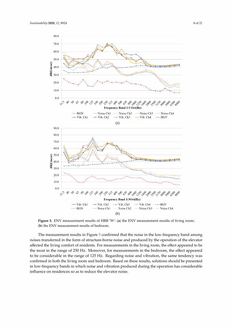
Figure 5 shows a graph in which noise and the result of vibratory measurements are simultaneouslywritten; it is a case in which a living room is adjacent to the elevator-like Figure 4a. Figure 5b showsa case in which the bedroom is adjacent to the elevator-like Figure 4b. To date, elevator noise has showna sound pressure level of 35 dBA on an average when reviewing the result of the noise measurementof the elevator in an apartment building in Korea. Although this noise level is quieter than the soundlevel criteria in a library, many residents face discomfort because the noise in low-frequency bands hasa considerable influence on them. Note that the energy distribution of the general environment noiseranges from 125 Hz to 4 kHz; however, as shown in Figure 5, elevator noise is distributed up to 63 Hzor even up to 32 Hz. In other words, the noise accompanying vibrations is sensed with considerablediscomfort even if it is low. The common tendency identified in both graphs is the increase in valueof contrast measurement data of the background noise (BGN), and the background vibration (BGV)appears to be high within the range of low-frequency bands of <500 Hz. This corresponds to a figurereported in the guidelines of many previous published studies [16,54,55].
Sustainability 2020, 12, 8924 8 of 21
Sustainability 2020, 12, x FOR PEER REVIEW 8 of 22
Sustainability 2020, 12, x; doi: FOR PEER REVIEW www.mdpi.com/journal/sustainability
< 500 Hz. This corresponds to a figure reported in the guidelines of many previous published studies
[16,54,55].
Figure 5. ENV measurement results of HRB ‘W’: (a) the ENV measurement results of living room; (b)
the ENV measurement results of bedroom.
The measurement results in Figure 5 confirmed that the noise in the low-frequency band among
noises transferred in the form of structure-borne noise and produced by the operation of the elevator
affected the living comfort of residents. For measurements in the living room, the effect appeared to
be the most in the range of 250 Hz. Moreover, for measurements in the bedroom, the effect appeared
to be considerable in the range of 125 Hz. Regarding noise and vibration, the same tendency was
confirmed in both the living room and bedroom. Based on these results, solutions should be
presented in low-frequency bands in which noise and vibration produced during the operation has
considerable influence on residences so as to reduce the elevator noise.
Figure 5. ENV measurement results of HRB ‘W’: (a) the ENV measurement results of living room;(b) the ENV measurement results of bedroom.
The measurement results in Figure 5 confirmed that the noise in the low-frequency band amongnoises transferred in the form of structure-borne noise and produced by the operation of the elevatoraffected the living comfort of residents. For measurements in the living room, the effect appeared to bethe most in the range of 250 Hz. Moreover, for measurements in the bedroom, the effect appearedto be considerable in the range of 125 Hz. Regarding noise and vibration, the same tendency wasconfirmed in both the living room and bedroom. Based on these results, solutions should be presentedin low-frequency bands in which noise and vibration produced during the operation has considerableinfluence on residences so as to reduce the elevator noise.

Sustainability 2020, 12, 8924 9 of 21
4. CM Solutions
4.1. Design Solutions
4.1.1. Separation of Residences and Elevators
In the ground of residents, to relieve ENV damages of HRBs, solutions applied in the designphase comprise two approaches. First, to separate space that is sensitive to noise such as bedrooms andliving rooms from hoist ways or elevator shafts. Second, to arrange a buffer space between the roomsthat are adjacent to hoist ways to increase the thickness of machine room slabs and hoist way walls,and to supplement partly building components similar to the detailed changes of hoist ways.
The most efficient approach to relieve the effects of noise and vibration of HRB elevators that runat a high speed is to separate elevators from residences and arrange them. By comparing the resultsof‘noise measurement from the case when an elevator is attached to a living room or bedroom,like Figure 4, with the results of noise measurement from the case when an elevator is separatedfrom residence, the effect can be confirmed. In particular, it is confirmed that noise became as low as10–20 dB in the band of >125 Hz where the elevator is separated from residences. However, in a limitedbuilding area, residence design with high density should be high and if considering design-constraintconditions, such as daylight, view, and space function, there is a case that space that is sensitive tonoise like living rooms and bedrooms cannot be separated and arranged. In this case, the seconddesign solutions should be identified.
4.1.2. Buffer Space Design
As shown in Figure 6a, because the elevator hoist way is adjacent to bedrooms, noise and vibrationare directly transferred if the elevator is operated. The case of toilet has a reduced impact of ENV;the case of a bedroom has a bad influence on rest and sleeping time. For HRBs in Korea, becausea hoist way is designed with a 200-mm-thick bearing walls, airborne noise is blocked. However,the shield effect of structure-borne noise is not high. Thus, to relieve the transmission of structure-bornenoise, residents feel it can be reduced if a wardrobe is placed similar to Figure 6b. To check the effectof it, one case of noise measurement in an apartment bedroom where there was a wardrobe sharingthe wall with the elevator shaft was measured in comparison with another case without the wardrobein the same condition. In Figure 6b, similar to the case of the installed wardrobe, the installationof wardrobe reduced noise level by ~7.6 dB, although Figure 6b is in the same plane compared tothe general rectangular shape bedroom of Figure 6a. Such noise reduction was basically made possibleby the effect of sound absorption or sound insulation using sound-absorbing materials such as blanketand clothing, both of which are filled at both sides of the wardrobe and inside of it. Moreover,the installation of the wardrobe made it possible to control the phenomenon of noise in a low-frequencyband, known as room mode, which breaks the rectangular shape of a bedroom.

Sustainability 2020, 12, 8924 10 of 21
Sustainability 2020, 12, x FOR PEER REVIEW 10 of 22
Sustainability 2020, 12, x; doi: FOR PEER REVIEW www.mdpi.com/journal/sustainability
Figure 6. Noise reduction design using a wardrobe: (a) A floor plan without a wardrobe; (b) a floor
plan with a wardrobe [17,21].
4.1.3. Change of Hoist Way Details
The elevator that runs at 120 m/min should be installed in HRBs with > 26 floors (Table 1), and
for HRBs with > 40 floors, the elevator should run at a high speed of 180m/min. For elevators that run
at a high speed, turbulent airflow is produced, which leads to air friction noise, puff noise, inrush
noise, and draft noise [38,39,56]. Design solutions regarding airborne noises are attributed to such a
turbulent airflow.
(1) Air Friction Noise
As an elevator runs at a high speed in a hoist way (Figure 7a), air is compressed in a car-heading
direction and elevator piston effect that increases air pressure [4,8,9,37,38,39,57,58]. Compressed air
travels through the cramped gap between car and hoist way to the upper part of the car, which creates
noise known as an air friction noise. The air friction noise gets louder as the area of the gap gets
smaller compared to the area of the car with a faster speed of the elevator. This occurs as either a
single elevator or double elevators run at a high speed in a hoist way. When two elevators run at the
same time and in the same direction, the noise gets even louder. There is not an issue in the case that
the elevator runs at 120 m/min in the hoist way for a single elevator, and the elevator runs at 180
m/min in the hoist way for double elevators. Note that the area of the hoist way should be designed
to be bigger than normal by 40% at a higher speed such as Figure 7b [38,39].
Figure 7. Air friction noise and design solution: (a) Air friction noise; (b) a design solution for air
friction noise.
Figure 6. Noise reduction design using a wardrobe: (a) A floor plan without a wardrobe; (b) a floorplan with a wardrobe [17,21].
4.1.3. Change of Hoist Way Details
The elevator that runs at 120 m/min should be installed in HRBs with >26 floors (Table 1),and for HRBs with >40 floors, the elevator should run at a high speed of 180 m/min. For elevatorsthat run at a high speed, turbulent airflow is produced, which leads to air friction noise, puff noise,inrush noise, and draft noise [38,39,56]. Design solutions regarding airborne noises are attributed tosuch a turbulent airflow.
(1) Air Friction NoiseAs an elevator runs at a high speed in a hoist way (Figure 7a), air is compressed in a car-heading
direction and elevator piston effect that increases air pressure [4,8,9,37–39,57,58]. Compressed air travelsthrough the cramped gap between car and hoist way to the upper part of the car, which creates noiseknown as an air friction noise. The air friction noise gets louder as the area of the gap gets smallercompared to the area of the car with a faster speed of the elevator. This occurs as either a single elevatoror double elevators run at a high speed in a hoist way. When two elevators run at the same time andin the same direction, the noise gets even louder. There is not an issue in the case that the elevator runsat 120 m/min in the hoist way for a single elevator, and the elevator runs at 180 m/min in the hoist wayfor double elevators. Note that the area of the hoist way should be designed to be bigger than normalby 40% at a higher speed such as Figure 7b [38,39].
Sustainability 2020, 12, x FOR PEER REVIEW 10 of 22
Sustainability 2020, 12, x; doi: FOR PEER REVIEW www.mdpi.com/journal/sustainability
Figure 6. Noise reduction design using a wardrobe: (a) A floor plan without a wardrobe; (b) a floor
plan with a wardrobe [17,21].
4.1.3. Change of Hoist Way Details
The elevator that runs at 120 m/min should be installed in HRBs with > 26 floors (Table 1), and
for HRBs with > 40 floors, the elevator should run at a high speed of 180m/min. For elevators that run
at a high speed, turbulent airflow is produced, which leads to air friction noise, puff noise, inrush
noise, and draft noise [38,39,56]. Design solutions regarding airborne noises are attributed to such a
turbulent airflow.
(1) Air Friction Noise
As an elevator runs at a high speed in a hoist way (Figure 7a), air is compressed in a car-heading
direction and elevator piston effect that increases air pressure [4,8,9,37,38,39,57,58]. Compressed air
travels through the cramped gap between car and hoist way to the upper part of the car, which creates
noise known as an air friction noise. The air friction noise gets louder as the area of the gap gets
smaller compared to the area of the car with a faster speed of the elevator. This occurs as either a
single elevator or double elevators run at a high speed in a hoist way. When two elevators run at the
same time and in the same direction, the noise gets even louder. There is not an issue in the case that
the elevator runs at 120 m/min in the hoist way for a single elevator, and the elevator runs at 180
m/min in the hoist way for double elevators. Note that the area of the hoist way should be designed
to be bigger than normal by 40% at a higher speed such as Figure 7b [38,39].
Figure 7. Air friction noise and design solution: (a) Air friction noise; (b) a design solution for air
friction noise.
Figure 7. Air friction noise and design solution: (a) Air friction noise; (b) a design solution for airfriction noise.

Sustainability 2020, 12, 8924 11 of 21
(2) Narrow-Section Passing NoiseNarrow-section passing noise, called puff noise [38], is a noise that is produced when an elevator
goes through protruding steel installed as Figure 8a because of the structural mechanism orthe installation of a guide rail. The elevator goes through an RC beam, which creates wind pressure thatcontributes to the noise. For HRBs, such protruding parts are reported per floor; therefore, the noiserepeatedly occurs. To prevent this, architectural designing should be processed without the protrudingparts inside the hoist way. However, in cases where it is unavoidable to have protruding parts, it isappropriate to install an air sliding panel upon and underneath the protruding parts to relieve the windpressure that occurs in that area (Figure 8b). The appropriate angle of the air sliding panel is 4–8 [38,39].This solution is required in the hoist way for a single elevator that runs at a speed of >150 m/min;in other words, with >31 floors in HRBs. The same solution is to be considered in the case that the carspeed is >180 m/min in a hoist way for double elevators.
Sustainability 2020, 12, x FOR PEER REVIEW 11 of 22
Sustainability 2020, 12, x; doi: FOR PEER REVIEW www.mdpi.com/journal/sustainability
(2) Narrow-Section Passing Noise
Narrow-section passing noise, called puff noise [38], is a noise that is produced when an elevator
goes through protruding steel installed as Figure 8a because of the structural mechanism or the
installation of a guide rail. The elevator goes through an RC beam, which creates wind pressure that
contributes to the noise. For HRBs, such protruding parts are reported per floor; therefore, the noise
repeatedly occurs. To prevent this, architectural designing should be processed without the
protruding parts inside the hoist way. However, in cases where it is unavoidable to have protruding
parts, it is appropriate to install an air sliding panel upon and underneath the protruding parts to
relieve the wind pressure that occurs in that area (Figure 8b). The appropriate angle of the air sliding
panel is 4°−8° [38,39]. This solution is required in the hoist way for a single elevator that runs at a
speed of > 150 m/min; in other words, with > 31 floors in HRBs. The same solution is to be considered
in the case that the car speed is > 180 m/min in a hoist way for double elevators.
Figure 8. Narrow-section passing noise and design solution: (a) Noise generation; (b) the design
solution.
(3) Inrush Noise
It is common to arrange more than two elevators in HRB where there are > 20 floors and four
householders on each floor. When only one elevator of multiple elevators enters in the single hoist
way (Figure 9a), noise is produced by compressed air flow, which is called inrush noise [38]. It is
common that the car vibration occurs along with noise when the inrush noise by the high speed is
considerable. This is preventable because the cause of inrush noise is rapid air compression when an
elevator rushes in. The best approach is not to have the single hoist way; however, in the case where
it is unavoidable to have one because of structural constraints, two solutions can be considered. First,
similar to Figure 9b, ventilation openings can be placed either on one side or both sides of the single
hoist way wall. The size of the opening varies depending on the size and speed of the car; however,
there is no trouble if it is designed within 1.5 m2. If it is difficult to place the ventilation opening, the
wall is expanded such that the floor area of the hoist way is increased by > 40% (Figure 9c) [38,39].
Figure 8. Narrow-section passing noise and design solution: (a) Noise generation; (b) the design solution.
(3) Inrush NoiseIt is common to arrange more than two elevators in HRB where there are >20 floors and four
householders on each floor. When only one elevator of multiple elevators enters in the single hoistway (Figure 9a), noise is produced by compressed air flow, which is called inrush noise [38]. It iscommon that the car vibration occurs along with noise when the inrush noise by the high speed isconsiderable. This is preventable because the cause of inrush noise is rapid air compression whenan elevator rushes in. The best approach is not to have the single hoist way; however, in the case whereit is unavoidable to have one because of structural constraints, two solutions can be considered. First,similar to Figure 9b, ventilation openings can be placed either on one side or both sides of the singlehoist way wall. The size of the opening varies depending on the size and speed of the car; however,there is no trouble if it is designed within 1.5 m2. If it is difficult to place the ventilation opening,the wall is expanded such that the floor area of the hoist way is increased by >40% (Figure 9c) [38,39].

Sustainability 2020, 12, 8924 12 of 21
Sustainability 2020, 12, x FOR PEER REVIEW 11 of 22
Sustainability 2020, 12, x; doi: FOR PEER REVIEW www.mdpi.com/journal/sustainability
(2) Narrow-Section Passing Noise
Narrow-section passing noise, called puff noise [38], is a noise that is produced when an elevator
goes through protruding steel installed as Figure 8a because of the structural mechanism or the
installation of a guide rail. The elevator goes through an RC beam, which creates wind pressure that
contributes to the noise. For HRBs, such protruding parts are reported per floor; therefore, the noise
repeatedly occurs. To prevent this, architectural designing should be processed without the
protruding parts inside the hoist way. However, in cases where it is unavoidable to have protruding
parts, it is appropriate to install an air sliding panel upon and underneath the protruding parts to
relieve the wind pressure that occurs in that area (Figure 8b). The appropriate angle of the air sliding
panel is 4°−8° [38,39]. This solution is required in the hoist way for a single elevator that runs at a
speed of > 150 m/min; in other words, with > 31 floors in HRBs. The same solution is to be considered
in the case that the car speed is > 180 m/min in a hoist way for double elevators.
Figure 8. Narrow-section passing noise and design solution: (a) Noise generation; (b) the design
solution.
(3) Inrush Noise
It is common to arrange more than two elevators in HRB where there are > 20 floors and four
householders on each floor. When only one elevator of multiple elevators enters in the single hoist
way (Figure 9a), noise is produced by compressed air flow, which is called inrush noise [38]. It is
common that the car vibration occurs along with noise when the inrush noise by the high speed is
considerable. This is preventable because the cause of inrush noise is rapid air compression when an
elevator rushes in. The best approach is not to have the single hoist way; however, in the case where
it is unavoidable to have one because of structural constraints, two solutions can be considered. First,
similar to Figure 9b, ventilation openings can be placed either on one side or both sides of the single
hoist way wall. The size of the opening varies depending on the size and speed of the car; however,
there is no trouble if it is designed within 1.5 m2. If it is difficult to place the ventilation opening, the
wall is expanded such that the floor area of the hoist way is increased by > 40% (Figure 9c) [38,39].
Figure 9. Inrush noise and design solution: (a) Inrush noise; (b) a ventilation opening arrangement;(c) expansion of the hoist way floor area.
(4) Draft NoiseGenerally, in a high-lift elevator, a pressure difference is generated between the landing and
hoist way. Therefore, air flows into and out of the hoist way from the gap around the landing door;at that time, a blowing sound called draft noise is generated [39,56]. In particular, this noise getsworse when the air produced by a heater in winter flows in the hoist way and the elevator ascends.The solution to this is to design an entrance door that is double-layered or a revolving door such thatcold air outside does not enter within HRB. Moreover, it should be designed with air-shieldingdetails between and around elevator opening frame of the landing floor such as a landing door, jamb,and sill [56].
4.1.4. Other Design Solutions
Note that design solutions should be considered, in addition to design solutions that are suggested,so as to alleviate the ENV that residents of HRBs feel.
• As shown in Figure 3, a machine support frame should be suspended from a machine roomfloor slab.
• The thickness of the machine room floor is designed to be possibly >350 mm, includinga 200-mm-thick RC slab and 150-mm-sized light-weight concrete.
• The thickness of the wall in the machine room is designed to be >150 mm, whereas the soundabsorption layer is placed within the wall.
• The thickness of the hoist way wall is designed to be >200 mm.• If the hoist way space is sufficiently big, separated beams are supplemented. Moreover,
the installation of rail brackets reduces noise a lot while an elevator is running.• The counter-weight of the elevator is planned to be installed on the staircase or external wall
rather than adjacent residences.
4.2. Construction Solutions
Construction solutions are the ones to be applied to at the construction phase and are aboutthe selection of elevating machinery, the location, and the method of installation, in addition to designsolutions that present solutions to ENV problems at a planning phase. Similar to Table 5, the problemsare classified into structure-borne and airborne noises, and again classified into the machine room andhoist way (shaft), and then construction solutions are analyzed and presented. They are subdividedinto either controlling elevator vibration or noise sources and controlling transmission paths.

Sustainability 2020, 12, 8924 13 of 21
Table 5. Construction solutions to mitigate ENV.
Description Sources Solutions
Structure-BorneNoises
Machineroom
Measures for vibration sources- Use of high-quality motors- Precise balance of brakes, gears, and elevator car
Measures for anti-vibration- Isolation of the traction machine from the support frame- Isolation of the switchgear cabinet from the machine room slab
Hoist way
Measures for vibration sources- Improvement of guide rail machining accuracy: Machining error
within ±2 mm/5 m- Improvement of guide rail installation accuracy: Seam surface
difference between rails within ±0.05 mmMeasures for anti-vibration
- Fastening rail brackets at the edge of slab- Isolation of guide rails from hoist way wall
Airborne Noises
Machineroom
Measures for noise sources- Use of high-quality motors- Precise machining and fabrication of brakes, gears, and
coupling parts- Use of low-noise cooling fan or self-cooling system
Measures for anti-noise- Installation of sound insulation cover over the rope hole- Isolation of airborne noise inside machine room
Hoist way- Precise installation of elevator doors for silent operation- Volume adjustment of door enunciator
Table 5 shows the construction solutions to mitigate ENV that are obtained through the studiesfor years after contemplating various research documents [14,18–21,27,38,39,50–52]. Structure-bornenoise generated in the machine room primarily occurs via the vibration of the elevating machinery.To alleviate this, elevating motor with power filters with high quality basically are used and brakes,gears, and elevator car should be installed to maintain the precise balance of elevator machinery.Moreover, vibration isolation pads that have high damping performance such as neoprene or rubbershould be inserted at fixing points such that the vibration is generated in the traction machineand switchgear cabinet [14,18–21,50–52]. When anti-vibration pads are installed in the tractionmachine, the first natural vibration frequency of the whole elevator should be maintained at a lessthan audible frequency band. For the traction machine to work precisely aligned with the heightbetween elevator car and hall landing, elevator machinery and anti-vibration pads should be installed,thus maintaining balance to minimize isolation deflection. For this purpose, close cooperation withan elevator manufacturer and installer is required at the installation phase.
To alleviate structure-borne noise generated in the hoist way or elevator shaft, the machiningerrors of guide rails are to be maintained within ±2 mm/5 m, and seam surface difference betweenguide rails of the guide rails should be installed within ±0.05 mm, which alleviates vibration becauseof the movement of rollers. Vibration-borne noise produced in the hoist way occurs betweenthe guide rollers of the car and rails. To prevent this, brackets should be installed next to the floor slabto fixate the rail (Figure 10). The floor slab edges are inherently stiffer than the shaft walls and willlimit the transmission of rail and roller guide interactions from generating the structure-borne noisein adjacent spaces [14,17,21]. Furthermore, anti-vibration pads should be installed between bracketsand floor slab edges. For reference, depending on the location of the rail brackets, it is confirmed thatthe noise difference by ~4 dB on an average occurs because of the measurement of noise whilean elevator is running [21].

Sustainability 2020, 12, 8924 14 of 21
Sustainability 2020, 12, x FOR PEER REVIEW 13 of 22
Sustainability 2020, 12, x; doi: FOR PEER REVIEW www.mdpi.com/journal/sustainability
- Improvement of guide rail machining accuracy: Machining error within
± 2mm/5m
- Improvement of guide rail installation accuracy: Seam surface difference
between rails within ± 0.05mm
Measures for anti-vibration
- Fastening rail brackets at the edge of slab
- Isolation of guide rails from hoist way wall
Airborne
Noises
Machine
room
Measures for noise sources
- Use of high-quality motors
- Precise machining and fabrication of brakes, gears, and coupling parts
- Use of low-noise cooling fan or self-cooling system
Measures for anti-noise
- Installation of sound insulation cover over the rope hole
- Isolation of airborne noise inside machine room
Hoist way - Precise installation of elevator doors for silent operation
- Volume adjustment of door enunciator
Table 5 shows the construction solutions to mitigate ENV that are obtained through the studies
for years after contemplating various research documents [14,18–21,27,38,39,50–52]. Structure-borne
noise generated in the machine room primarily occurs via the vibration of the elevating machinery.
To alleviate this, elevating motor with power filters with high quality basically are used and brakes,
gears, and elevator car should be installed to maintain the precise balance of elevator machinery.
Moreover, vibration isolation pads that have high damping performance such as neoprene or rubber
should be inserted at fixing points such that the vibration is generated in the traction machine and
switchgear cabinet [14,18–21,50–52]. When anti-vibration pads are installed in the traction machine,
the first natural vibration frequency of the whole elevator should be maintained at a less than audible
frequency band. For the traction machine to work precisely aligned with the height between elevator
car and hall landing, elevator machinery and anti-vibration pads should be installed, thus
maintaining balance to minimize isolation deflection. For this purpose, close cooperation with an
elevator manufacturer and installer is required at the installation phase.
To alleviate structure-borne noise generated in the hoist way or elevator shaft, the machining
errors of guide rails are to be maintained within ± 2 mm/5 m, and seam surface difference between
guide rails of the guide rails should be installed within ± 0.05 mm, which alleviates vibration because
of the movement of rollers. Vibration-borne noise produced in the hoist way occurs between the
guide rollers of the car and rails. To prevent this, brackets should be installed next to the floor slab to
fixate the rail (Figure 10). The floor slab edges are inherently stiffer than the shaft walls and will limit
the transmission of rail and roller guide interactions from generating the structure-borne noise in
adjacent spaces [14,17,21]. Furthermore, anti-vibration pads should be installed between brackets and
floor slab edges. For reference, depending on the location of the rail brackets, it is confirmed that the
noise difference by ~4 dB on an average occurs because of the measurement of noise while an elevator
is running [21].
Figure 10. Fastening rail brackets at the edge of a slab. Figure 10. Fastening rail brackets at the edge of a slab.
Measures in correspondence with the construction phase should be considered because airbornenoises generated in the machine room primarily occur by the tonal sound of the elevating machinery.It is essential to select motors of good quality to encounter noise sources and precise machining;moreover, the fabrication of brakes, gears, and coupling parts should be performed.
A low-noise cooling fan or self-cooling system in the machine room should be used. As shownin Figure 3, sound insulation cover should be installed around the rope hole as transmission pathsof airborne noises in the machine room. Moreover, soundproofing materials should be used toencounter isolation of airborne noise on the interior wall and the ceiling in the machine room. Afterglass wool as thick as 50 mm is placed on the wall and ceiling in the machine room, it is confirmed thatthe level of noise generated in the elevating machinery is reduced by 6.2 dB on average. In particular,it is confirmed that the noise level in the range of 1 kHz frequency is reduced by 9.4 dB at the maximum.
Airborne noises generated in the hoist way are primarily related to the elevator door. The primarynoise sources of the door are its misalignments or improper installation and alarm sound for arrivalon each floor. To solve such problems, the precise installation of doors is required, and the volumeof the door enunciator is to be adjusted to <60 dB(A).
4.3. Verification of CM Solutions
In this study, the suggested CM solutions are applied and how much ENV is alleviated shouldbe confirmed. For this purpose, after selecting the HRB project with a 25-story building as a case,the most effective elevators of CM solutions and design solutions, such as separation of residences andelevators as well as the hoist way wall as thick as 200 mm, were applied. One noticeable aspect is thatit is designed using MRL elevators [49] that are generally used for buildings of <20 floors. Moreover,after selecting an OTIS elevating machine of good quality at the construction phase, the constructionsolutions suggested in Table 5 were mostly applied. The case project was completed in 2020, whereasthe elevator noise of two buildings was measured in the same method of Figure 4d. The vibrationmeasurement with the sensors attached on the wall was not done without the agreement of the residents(Figure 4c).
As shown in Figure 11a, the staircase was placed between the elevator and the bedroomof residence. Two elevators were placed as per design guidelines because there were four householderson each floor in Building ‘A’ [41,42]. Figure 11b shows that the elevator is separated from residenceusing the elevator hall. For this measurement, it was conditional that the elevator runs departingfrom the second floor as the lowest floor and stopped on the 25th floor. The measurement was madein bedrooms on the 25th floor as the highest floor. Moreover, the measurement time was 90 seconds,and the elevator speed was 105 m/mm, which is the speed of the 25-story HRB classified in Table 1.The same measuring system as in Table 5 was used for measuring noise generated by the elevator witha capacity of 15 persons and 1150 kg.

Sustainability 2020, 12, 8924 15 of 21
Sustainability 2020, 12, x FOR PEER REVIEW 14 of 22
Sustainability 2020, 12, x; doi: FOR PEER REVIEW www.mdpi.com/journal/sustainability
Measures in correspondence with the construction phase should be considered because airborne
noises generated in the machine room primarily occur by the tonal sound of the elevating machinery.
It is essential to select motors of good quality to encounter noise sources and precise machining;
moreover, the fabrication of brakes, gears, and coupling parts should be performed.
A low-noise cooling fan or self-cooling system in the machine room should be used. As shown
in Figure 3, sound insulation cover should be installed around the rope hole as transmission paths of
airborne noises in the machine room. Moreover, soundproofing materials should be used to
encounter isolation of airborne noise on the interior wall and the ceiling in the machine room. After
glass wool as thick as 50 mm is placed on the wall and ceiling in the machine room, it is confirmed
that the level of noise generated in the elevating machinery is reduced by 6.2 dB on average. In
particular, it is confirmed that the noise level in the range of 1 kHz frequency is reduced by 9.4 dB at
the maximum.
Airborne noises generated in the hoist way are primarily related to the elevator door. The
primary noise sources of the door are its misalignments or improper installation and alarm sound for
arrival on each floor. To solve such problems, the precise installation of doors is required, and the
volume of the door enunciator is to be adjusted to < 60 dB(A).
4.3. Verification of CM Solutions
In this study, the suggested CM solutions are applied and how much ENV is alleviated should
be confirmed. For this purpose, after selecting the HRB project with a 25-story building as a case, the
most effective elevators of CM solutions and design solutions, such as separation of residences and
elevators as well as the hoist way wall as thick as 200 mm, were applied. One noticeable aspect is that
it is designed using MRL elevators [49] that are generally used for buildings of < 20 floors. Moreover,
after selecting an OTIS elevating machine of good quality at the construction phase, the construction
solutions suggested in Table 4 were mostly applied. The case project was completed in 2020, whereas
the elevator noise of two buildings was measured in the same method of Figure 4d. The vibration
measurement with the sensors attached on the wall was not done without the agreement of the
residents (Figure 4c).
As shown in Figure 11a, the staircase was placed between the elevator and the bedroom of
residence. Two elevators were placed as per design guidelines because there were four householders
on each floor in Building ‘A’ [41,42]. Figure 11b shows that the elevator is separated from residence
using the elevator hall. For this measurement, it was conditional that the elevator runs departing
from the second floor as the lowest floor and stopped on the 25th floor. The measurement was made
in bedrooms on the 25th floor as the highest floor. Moreover, the measurement time was 90 seconds,
and the elevator speed was 105 m/mm, which is the speed of the 25-story HRB classified in Table 1.
The same measuring system as in Table 5 was used for measuring noise generated by the elevator
with a capacity of 15 persons and 1150 kg.
Figure 11. Elevator noise measurement of HRB ‘D’: (a) The 25th floor plan of Building ‘A’;(b) the 25th floor plan of Building ‘B’.
Figure 12 shows the result of noise measurement for the case that elevators and residences wereisolated, as seen in Figure 11a,b. Similar to Figure 5, the effect of noise measurements compared toBGN in the range of <500 Hz appears to be extensive. Note that regardless of different conditions,it shows that it was a low-frequency band that had an influence on elevator noise. In particular,the effect of the two cases seemed to be extensive at 63 Hz; moreover, the common aspect is thatthe effect of low-frequency bands at the central measuring point appeared to be less. The reason isthat the low-pitched superposition phenomenon by the room mode was most remarkably noticeableat the corners of rectangular bedrooms. Figure 13 shows the distribution of the sound pressurelevel by the overlapping and offsetting of sound energy per frequency band in the rectangular room.The low sound energy at 63 and 125 Hz certainly demonstrated the phenomenon of remarkable overlapat the corners of the room [59].
Sustainability 2020, 12, x FOR PEER REVIEW 15 of 22
Sustainability 2020, 12, x; doi: FOR PEER REVIEW www.mdpi.com/journal/sustainability
Figure 11. Elevator noise measurement of HRB ‘D’: (a) The 25th floor plan of Building ‘A’; (b) the 25th
floor plan of Building ‘B’.
Figure 12 shows the result of noise measurement for the case that elevators and residences were
isolated, as seen in Figure 11a and Figure 11b. Similar to Figure 5, the effect of noise measurements
compared to BGN in the range of < 500 Hz appears to be extensive. Note that regardless of different
conditions, it shows that it was a low-frequency band that had an influence on elevator noise. In
particular, the effect of the two cases seemed to be extensive at 63 Hz; moreover, the common aspect
is that the effect of low-frequency bands at the central measuring point appeared to be less. The
reason is that the low-pitched superposition phenomenon by the room mode was most remarkably
noticeable at the corners of rectangular bedrooms. Figure 13 shows the distribution of the sound
pressure level by the overlapping and offsetting of sound energy per frequency band in the
rectangular room. The low sound energy at 63 and 125 Hz certainly demonstrated the phenomenon
of remarkable overlap at the corners of the room [59].
Figure 12. Elevator noise measurement results of HRB ‘D’: (a) The measurement results of ‘Building
A’; (b) the measurement results of ‘Building B’.
Figure 13. Different patterns of spatial distribution of sound pressure level in a room according to the
frequency bands [59]: (a) The noise measurement results at the center; (b) the noise measurement
results at the corners.
Figure 12. Elevator noise measurement results of HRB ‘D’: (a) The measurement results of ‘Building A’;(b) the measurement results of ‘Building B’.

Sustainability 2020, 12, 8924 16 of 21
Sustainability 2020, 12, x FOR PEER REVIEW 15 of 21
Sustainability 2020, 12, x; doi: FOR PEER REVIEW www.mdpi.com/journal/sustainability
Figure 11. Elevator noise measurement of HRB ‘D’: (a) The 25th floor plan of Building ‘A’; (b) the 25th floor plan of Building ‘B’.
Figure 12 shows the result of noise measurement for the case that elevators and residences were isolated, as seen in Figure 11a,b. Similar to Figure 5, the effect of noise measurements compared to BGN in the range of <500 Hz appears to be extensive. Note that regardless of different conditions, it shows that it was a low-frequency band that had an influence on elevator noise. In particular, the effect of the two cases seemed to be extensive at 63 Hz; moreover, the common aspect is that the effect of low-frequency bands at the central measuring point appeared to be less. The reason is that the low-pitched superposition phenomenon by the room mode was most remarkably noticeable at the corners of rectangular bedrooms. Figure 13 shows the distribution of the sound pressure level by the overlapping and offsetting of sound energy per frequency band in the rectangular room. The low sound energy at 63 and 125 Hz certainly demonstrated the phenomenon of remarkable overlap at the corners of the room [59].
Figure 12. Elevator noise measurement results of HRB ‘D’: (a) The measurement results of ‘Building A’; (b) the measurement results of ‘Building B’.
(b)
Figure 13. Different patterns of spatial distribution of sound pressure level in a room according tothe frequency bands [59]: (a) The noise measurement results at the center; (b) the noise measurementresults at the corners.
Figure 14 shows the analysis of the level of noise reduction and noise characteristicsas per the frequency band after the average conversion of the measurement results of Figures 5 and 12.The measurement results of Figure 12 show that, in this study, CM solutions that were appliedas suggested demonstrate the remarkable reduction of noise in the frequency band of >100 Hz.Figure 12 shows that there was no considerable difference at frequencies of <125 Hz; however,it was confirmed that noise of HRB ’D’, in which elevators and residences are isolated in the frequencyof >125 Hz, was measured at a noise level lower than that of HRB ’W’. As shown in Figure 13,for HRB ’W’, while the average value of the noise level compared to BGN makes a difference within26 dB(A), the case of HRB ’D’ maintains the level of 5 dB(A). This is explained to be the alleviating noisethat residents feel with CM solutions suggested in this study. However, regardless of the isolationof elevators and residences in the low-frequency band of <125 Hz, the noise level compared toBGN seems to be high. The structure-borne noise generated by the operation of the elevator is analyzedto be high in the low-frequency band.
Sustainability 2020, 12, x FOR PEER REVIEW 16 of 22
Sustainability 2020, 12, x; doi: FOR PEER REVIEW www.mdpi.com/journal/sustainability
Figure 14 shows the analysis of the level of noise reduction and noise characteristics as per the
frequency band after the average conversion of the measurement results of Figures 5 and 12. The
measurement results of Figure 12 show that, in this study, CM solutions that were applied as
suggested demonstrate the remarkable reduction of noise in the frequency band of > 100 Hz. Figure
12 shows that there was no considerable difference at frequencies of < 125 Hz; however, it was
confirmed that noise of HRB ’D’, in which elevators and residences are isolated in the frequency of >
125 Hz, was measured at a noise level lower than that of HRB ’W’. As shown in Figure 13, for HRB
’W’, while the average value of the noise level compared to BGN makes a difference within 26 dB(A),
the case of HRB ’D’ maintains the level of 5 dB(A). This is explained to be the alleviating noise that
residents feel with CM solutions suggested in this study. However, regardless of the isolation of
elevators and residences in the low-frequency band of < 125 Hz, the noise level compared to BGN
seems to be high. The structure-borne noise generated by the operation of the elevator is analyzed to
be high in the low-frequency band.
Figure 14. Noise analysis by frequency band according to the location of elevators and residences.
Figure 14. Noise analysis by frequency band according to the location of elevators and residences.

Sustainability 2020, 12, 8924 17 of 21
5. Discussion
To solve ENV problems of a building, multiple studies regarding mechanical solutions have beenconducted; in certain studies, solutions were presented from the perspective of design and construction,which are only for residential buildings of less than ten floors. Thus, to alleviate the ENV of HRBs thatrun at >90 m/min, solutions that consider the characteristics of high-speed elevators and HRB floorplans on the basis of knowledge obtained from the results of their study are necessary. We analyzedthe characteristics of noises and vibrations produced in machine rooms and hoist ways throughENV-related studies of HRBs for the past few years and sources vs. transmission paths of airborne andstructure-borne noises, and then presented solutions that control the stage of design and construction.A case study was processed to confirm the given solutions. CM solutions applied to the case of HRB ‘D’,including isolation arrangement of elevators and residences, 200-mm-think RC wall design of hoistway and most other solutions are presented in Table 4; they were then applied to the constructionphase. We were then able to confirm considerable improvement compared to HRB ‘W’ case becauseof the measurement on noise of HRB ‘D’. Vibration measurement was impossible because the residentsopposed to sensors being installed on the wall; however, it is assumed that there may have beenimprovement of vibration corresponding to that of noise considering the HRB ‘W’ case.
Studies on identifying the effectiveness of alleviating noise should continue with thoroughexperimentation in each item to clarify the utility of the CM solutions given in this study. The extraapplication of researches of CM solutions should be processed by the subject area of HRBs presentedin Table 1.
6. Conclusions
There are have been many studies regarding ENV worldwide, which is proof that the more sensitivehumans have been to noise, the more comfortable life environment they have demanded. In particular,for HRBs built in many downtown areas where there are external noise sources, residents demandmore static environments, while noise is more likely to occur because of the use of high-speed elevators.To solve such as dilemma, we contemplated multiple documents and presented CM solutionsto alleviate ENV of HRBs in this thesis by means of the study of years. An HRB project withENV problems and an HRB project that uses solutions given in this study were processed as a case study,and its effectiveness was verified, with the results as following.
First, BGN and BGV appear to be relatively high in the range of low frequency of <500 Hzif an elevator hoist way is adjacent to the living room or bedroom. It was confirmed that the noiseproduced at low-frequency bands of 250 Hz for a living room and those of 125 Hz for a bedroom hada considerable impact on the living comfort of residents.
Second, in the case of HRBs to which CM solutions are applied, the effect of the measured noisecompared to BGN is within the range of <500 Hz. This shows that what affects elevator noise werelow-frequency bands of <500 Hz. CM solutions application effects appeared to be the most in the rangeof 63 Hz; moreover, a common aspect is the effects of low-frequency band turning out to be littleat the central measurement point Ch3. The reason is because it is analyzed that the distribution of soundpressure level by overlapping and offsetting of sound energy per frequency band in the rectangularroom was remarkably noticeable.
Third, compared to the measurement results of the two case projects, the elevator noise of HRBs thatCM solutions were applied to in the frequency band of >100 Hz are confirmed to remarkably reducenoise. Especially, it is confirmed that the CM solutions-applied noise of HRB ‘D’ was measured to berelatively low, in the frequency band of >125 Hz. While the average value of noise level compared toBGN in the case of HRB ‘W’ with ENV problems makes a difference of 26 dB(A), the case of HRB ‘D’ thatthe CM solutions were applied to maintain the level of 5 dB(A). Thus, it is comprehended that,in this study, the CM solutions suggested largely alleviated noise.

Sustainability 2020, 12, 8924 18 of 21
Author Contributions: Conceptualization, Y.O. and S.K.; methodology, S.K.; validation, Y.O., M.K., and S.K.;formal analysis, Y.O. and M.K.; measurement and data curation, Y.O. and M.K.; writing—original draft preparation,Y.O. and K.L.; writing—review and editing, S.K.; visualization, K.L.; supervision, S.K.; project administration, S.K.;funding acquisition, Y.O. All authors have read and agreed to the published version of the manuscript.
Funding: This research was supported by the grant (20RERP-B082204-07) from Residential Environment ResearchProgram funded by Ministry of Land, Infrastructure and Transport of Korean government.
Conflicts of Interest: The authors declare no conflict of interest. The funders had no role in the design of the study;in the collection, analyses, or interpretation of data; in the writing of the manuscript, or in the decision to publishthe results.
References
1. Rashidah, S.; Che-Ani, A.I.; Sairi, A.; Tawil, N.M.; Razak, M. Classification of High-Rise Residential BuildingFacilities: A Descriptive Survey on 170 Housing Scheme in Klang Valley, MATEC Web of Conferences 66;Guéhot, S., Ed.; EDP Sciences: Les Ulis, France, 2016; Volume 00103, pp. 1–4. [CrossRef]
2. Al-Kodmany, K. Tall buildings and elevators: A review of recent technological advances. Buildings 2015, 5,1070–1104. [CrossRef]
3. Wood, A.; Henry, S.; Safarik, D. 2014 Best Tall Buildings. In Proceedings of the CTBUH Award Ceremony,2 November 2014; Illinois Institute of Technology (IIT): Chicago, IL, USA, 2014.
4. Liu, J.; Zhang, R.; He, Q.; Zhang, Q. Study on horizontal vibration characteristics of high-speed elevator withairflow pressure disturbance and guiding system excitation. Mech. Ind. 2019, 20, 305. [CrossRef]
5. Qiu, L.; Wang, Z.; Zhang, S.; Zhang, L.; Chen, J. A Vibration-Related Design Parameter Optimization Methodfor High-Speed Elevator Horizontal Vibration Reduction. Shock Vib. 2020. [CrossRef]
6. Kawasaki, R.; Hironaka, Y.; Nishimura, M. Noise and Vibration Analysis of Elevator Traction Machine.In Proceedings of the Inter-noise 2010, Noise and Sustainability, Lisbon, Portugal, 13–16 June 2010; pp. 1–9.
7. Noda, S.; Mizuno, S.; Kamijo, Y.; Matsushita, M. Prediction of Room Noise Caused by Vibration of High PowerElevator Traction Machine. In Proceedings of the 2013 International Conference on Energy, Environment,Ecosystems and Development, Lemesos, Cyprus, 21–23 March 2013; pp. 130–134. Available online:http://www.inase.org/library/2013/rhodes/bypaper/EEED/EEED-16.pdf (accessed on 25 June 2020).
8. Klote, J.H. Elevator pressurization in tall buildings. Int. J. High-Rise Build. 2013, 2, 341–344. [CrossRef]9. Klote, J.H. An analysis of the influence of piston effect on elevator smoke control. In NIST Interagency/Internal
Report (NISTIR)—88-3751; NIST Pubs: Gaithersburg, MD, USA, 1988. [CrossRef]10. Mutoh, N.; Kagomiya, K.; Kurosawa, T.; Konya, M.; Andoh, T. Horizontal vibration suppression method
suitable for super-high-speed elevators. Electr. Eng. Japan 1999, 129, 59–73. [CrossRef]11. Szydlo, K.; Wolszczak, P.; Longwic, R.; Litak, G.; Dziubinski, M.; Drozd, A. assessment of lift passenger
comfort by the Hilbert–Huang transform. J. Vib. Eng. Technol. 2020, 8, 373–380. [CrossRef]12. Szydlo, K.; Maciag, P.; Longwic, R.; Lotko, M. Analysis of vibroacoustic signals recorded in the passenger lift
cabin. Adv. Sci. Technol. Res. J. 2016, 10, 193–201. [CrossRef]13. Zhang, Y.; Sun, X.; Zhao, Z.; Su, W. Elevator ride comfort monitoring and evaluation using smartphones.
Mech. Syst. Signal Process. 2018, 105, 377–390. [CrossRef]14. Fullerton, J.L. Review of elevator noise and vibration criteria, sources and control for multifamily residential
buildings. In Proceedings of the Inter-Noise and Noise-Con Congress and Conference Proceedings, Honolulu,HI, USA, 3–6 December 2006; Volume 6, pp. 1230–1237.
15. Kalkman Ir, C.; Buijsing, J.H.N. Noise levels in apartment block caused by lift; what can be done in orderto reduce complaints. In Proceedings of the 2001 International Congress and Exhibition on Noise ControlEngineering, Hague, The Netherlands, 27–30 August 2001. Available online: https://www.peutz.nl/sites/peutz.nl/files/publicaties/Peutz_Publicatie_KK_Internoise_08-2001.pdf (accessed on 25 June 2020).
16. Jeong, A.Y.; Kim, K.W.; Shin, H.K.; Yang, K.S. Criteria and Characteristics of Elevator Noise in Apartments.Appl. Mech. Mater. 2017, 873, 231–236. [CrossRef]
17. Lee, K.W. A Study on the Measures to Reduce Elevator Noises. Master’s Thesis, Catholic KwandongUniversity, Gangneung, Korea, 2013; pp. 9–35. (In Korean)

Sustainability 2020, 12, 8924 19 of 21
18. Kim, H.S.; Kim, H.G.; Kim, M.J.; Oh, Y.I. Reduction Methods of the Elevator-Operating Noise in ApartmentHousings. In Proceedings of the International Conference, Korean Society for Noise and Vibration Engineering(KSNVE), Seoul, Korea, 9–12 February 1994; pp. 619–626. Available online: http://www.dbpia.co.kr/journal/articleDetail?nodeId=NODE02420216 (accessed on 23 July 2020).
19. Evans, J.B. Elevator equipment noise mitigation for high-rise residential condominium. J. Acoust. Soc. Am.2012, 131, 3262. [CrossRef]
20. Kim, M.J.; Kim, H.G.; Kim, H.S. Research on the Elevator-operating Noise and Vibration in ApartmentBuildings. In Proceedings of the Korean Society for Noise and Vibration Engineering (KSNVE), Pyeongchang,Korea, 14–16 November 2001; pp. 488–493. Available online: http://www.dbpia.co.kr/journal/articleDetail?nodeId=NODE02451458 (accessed on 23 July 2020). (In Korean)
21. Kim, H.G.; Kim, M.J. Reduction Method of Elevator-operating Noise and Vibration in Apartment Housings; Landand Housing Institute, Korea Land and Housing Corporation: Seongnam, Korea, 2000; pp. 1–128. Availableonline: https://dl.nanet.go.kr/SearchDetailView.do?cn=MONO1200102249 (accessed on 22 October 2020).(In Korean)
22. Lee, S.; Kim, J.; Kim, D. A Study on the Cause of Noise and Vibration of Elevators. In Proceedingsof the Korean Society for Noise and Vibration Engineering (KSNVE), Seoul, Korea, 18–21 May 1994;pp. 94–99. Available online: http://www.auric.or.kr/User/Rdoc/DocRdoc.aspx?returnVal=RD_R&dn=114296#.X03YAcgzZnI (accessed on 27 July 2020). (In Korean)
23. Ingold, D. Mitigating Elevator Noise in Multifamily Residential Buildings. Available online:http://buildipedia.com/aec-pros/construction-materials-and-methods/mitigating-elevator-noise-in-multifamily-residential-buildings?print=1&tmpl=component (accessed on 2 September 2020).
24. Zhou, Y.Q. In-car noise reduction for a newly developed home elevator. J. Acoust. Soc. Am. 1997, 101, 3018.[CrossRef]
25. Jeon, E.S.; Cho, B.H. The countermeasure which reduces the noise and vibration of the building elevator.J. Korean Digit. Archit. Inter. Assoc. 2005, 5, 35–42. (In Korean)
26. Watanabe, S.; Yumura, T.; Kariya, Y.; Hoshinoo, T. The Brake Noise Reduction Method for the ElevatorTraction Machine. In Proceedings of the Transportation and Logistics Conference, Kawasaki, Japan,8 December 2003; pp. 133–134. [CrossRef]
27. Torres, J.; Haugen, K. Noise Produced by Lift In Multi-Story Apartment Building, Case Study. In Proceedingsof the Inter-noise 2019, Noise Control for a Better Environment, Madrid, Spain, 16–19 June 2019.
28. Kawasaki, R.; Hironaka, Y.; Tanaka, T.; Daikoku, A. Noise and vibration analysis of elevator traction machine.In Nippon Kikai Gakkai Ronbunshu, C Hen/Transactions of the Japan Society of Mechanical Engineers, Part C; JapanSociety of Mechanical Engineers: Tokyo, Japan, 2010; Volume 76, pp. 2032–2038. [CrossRef]
29. Arrasate, X.; McCloskey, A.; Hernández, X.; Telleria, A. Optimum Design of Traction Electrical Machinesin Lift Installations. In Proceedings of the Symposium on Lift & Escalator Technologies, Northampton, UK,23–24 September 2015; Volume 5. Available online: https://www.researchgate.net/publication/282607214(accessed on 28 July 2020).
30. Wang, X.W.; Yu, Y.J.; Zhang, R.J.; Wang, S.C.; Tian, Y. The summary research on the noise of high-speedtraction elevators. Appl. Mech. Mater. 2014, 541–542, 716–721. [CrossRef]
31. Landaluze, J.; Portilla, I.; Cabezón, N.; Martínez, A.; Reyero, R. Application of active noise control toan elevator cabin. Control Eng. Pract. 2003, 11, 1423–1431. [CrossRef]
32. Yu, S.; Pan, P.; Wang, H.; Chen, L.; Tang, R. Investigation on noise and vibration origin in permanentmagnet electrical machine for elevator. In Proceedings of the ICEMS 2005 Proceedings of the EighthInternational Conference on Electrical Machines and Systems, Nanjing, China, 27–29 September 2005;Volume 1, pp. 330–333. [CrossRef]
33. Shi, L.Q.; Liu, Y.Z.; Jin, S.Y.; Cao, Z.M. Numerical simulation of unsteady turbulent flow inducedby two-dimensional elevator car and counter weight system. J. Hydrodyn. 2007, 19, 720–725. [CrossRef]
34. Salmon, J.K.; Yoo, Y.S. Reduction of noise and vibration in an elevator car by selectively reducing air turbulence.J. Acoust. Soc. Am. 1991, 90, 3387–3388. [CrossRef]
35. Yang, I.H.; Jeong, J.E.; Jeong, U.C.; Kim, J.S.; Oh, J.E. Improvement of noise reduction performancefor a high-speed elevator using modified active noise control. Appl. Acoust. 2014, 79, 58–68. [CrossRef]

Sustainability 2020, 12, 8924 20 of 21
36. Tray Edmonds, P.E.; Fullerton, J.L. Noise and vibration control of an offset traction elevator system. In Proceedingsof the INTER-NOISE 2015—44th International Congress and Exposition on Noise Control Engineering,San Francisco, CA, USA, 9–12 August 2015. Available online: https://scholar.google.com/scholar?hl=ko&as_sdt=0%2C5&q=Noise+and+vibration+control+of+an+offset+traction+elevator+system&btnG= (accessedon 25 August 2020).
37. Park, C. Elevator Noises and Vibrations. Research on Construction Technology; Ssangyong Construction Co. Ltd.:Seoul, Korea, 2005; Volume 34, pp. 50–57. Available online: http://www.auric.or.kr/User/Rdoc/DocRdoc.aspx?returnVal=RD_R&dn=172387#.X02lu8gzZnI (accessed on 5 August 2020). (In Korean)
38. Song, K.H. Solutions to mitigate elevator noise and vibration. J. ACRS Korean Assoc. Air Cond. Refrig.Sanit. Eng. 1999, 16, 65–76. (In Korean)
39. Nam, K. Solutions to Mitigate High-Speed Elevator Noise and Vibration, Construction Management and Technology;Samsung Construction Co. Ltd.: Seoul, Korea, 1997; Volume 44, pp. 32–41. (In Korean)
40. Emporis. Emporis Standards: High-Rise Building (ESN 18727). Available online: https://www.emporis.com/
building/standard/3/high-rise-building (accessed on 5 August 2020).41. Korea Land and Housing Corporation, Design Guidelines (Architecture), No. 1988. 2018, p. 3. Available
online: https://blog.naver.com/pvc1120/221835099946 (accessed on 28 July 2020).42. Korea Land and Housing Corporation, Design Guidelines (Electrical and Telecommunication Facilities),
No. 1990. 2018, p. 138. Available online: https://blog.naver.com/PostView.nhn?blogId=pvc1120&logNo=
221824014189&redirect=Dlog&widgetTypeCall=true&directAccess=false (accessed on 28 July 2020).43. ASHRAE. 2019 ASHRAE Handbook—HVAC Applications: Chapter 49 Noise and Vibration Control (TC 2.6, Sound
and Vibration Control); American Society of Heating, Refrigerating and Air-Conditioning Engineers: Atlanta,GA, USA, 2019.
44. National Elevator Industry, Inc. Building Transportation Standards and Guidelines NEII-1, NEII.Available online: https://nationalelevatorindustry.org/wp-content/uploads/2019/09/neii-1.pdf (accessed on19 August 2020).
45. BSI. BS 8233:2014 Guidance on Sound Insulation and Noise Reduction for Buildings; The British StandardsInstitution: London, UK, 2014.
46. Hansen, C.H.; Goelzer, B. Engineering Noise Control. J. Acoust. Soc. Am. 1996, 100, 1279.47. Bies, D.A.; Hansen, C.H.; Howard, C.Q. Engineering Noise Control, 5th ed.; CRC Press; Taylor & Francis
Group: Boca Raton, FL, USA, 2018; pp. 3–7.48. National Elevator Industry, Inc. The Benefits of Machine Room Less Elevators, The Insider; NEII: New York, NY,
USA, November 2015. Available online: http://www.neii.org/insider/editions/20151112.pdf (accessed on3 August 2020).
49. Elevatorpedia. Machine Room Less Elevator. Available online: https://elevation.fandom.com/wiki/Machine_room_less_elevator (accessed on 20 August 2020).
50. Crocker, M.J. General Introduction to Noise and Vibration Transducers, Measuring Equipment, Measurements,Signal Acquisition, and Processing, Handbook of Noise and Vibration Control; Crocker, M.J., Ed.; John Wiley &Sons, Inc.: Hoboken, NJ, USA, 2007; Chapter 35, pp. 417–434, ISBN 978-0-471-39599-7.
51. Ojanen, T. Aero-vibro Acoustic Simulation of an Ultrahigh-Speed Elevator. Master’s Thesis, TampereUniversity of Technology, Tampere, Finland, 2016. Available online: https://trepo.tuni.fi/handle/123456789/
23851 (accessed on 20 August 2020).52. Foulkes, T.J. Dynamic absorbers to control elevator noise in buildings—A case study. J. Acoust. Soc. Am.
1992, 91, 2350. [CrossRef]53. Research Team, Noise Control in Architecture, Science Teaching Kit for Senior Secondary Curriculum,
Hong Kong Institute of Architects. 2012, p. 11. Available online: https://minisite.proj.hkedcity.net/hkiakit/getResources.html?id=4049 (accessed on 27 August 2020).
54. The Engineering ToolBox, NC-Noise Criterion. Available online: https://www.engineeringtoolbox.com/nc-noise-criterion-25.html#:~:text=%20Sound%20pressure%20levels%20are%20measured%20for%20different,8%208000%20Hz%20%3A%2045%20dB%20More%20 (accessed on 27 August 2020).
55. The Engineering ToolBox, NR—Noise Rating Curve, An introduction to the Noise Rating—NR—Curvedeveloped by the International Organization for Standardization (ISO). Available online: https://www.engineeringtoolbox.com/nr-noise-rating-d_60.html (accessed on 27 August 2020).

Sustainability 2020, 12, 8924 21 of 21
56. Patent. WO2012176297A1—Elevator Landing Door Device—Google Patents. Available online: https://patents.google.com/patent/WO2012176297A1/en (accessed on 21 August 2020).
57. Miller, R.S. Elevator shaft pressurization for smoke control in tall buildings. Build. Environ. 2011, 46,2247–2254. [CrossRef]
58. Tamura, T.; Itoh, Y. Unstable aerodynamic phenomena of a rectangular cylinder with critical section. J. WindEng. Ind. Aerodyn. 1999, 83, 121–133. [CrossRef]
59. Oh, Y.; Joo, M.K.J.; Park, J.Y.; Kim, H.G.; Yang, K.S. Deviation of Heavy-Weight Floor Impact SoundLevels According to Measurement Positions. J. Acoust. Soc. Korea 2006, 25, 49–55. Available online:https://www.koreascience.or.kr/article/JAKO200614222983617.page (accessed on 28 August 2020). (In Korean)
Publisher’s Note: MDPI stays neutral with regard to jurisdictional claims in published maps and institutionalaffiliations.
© 2020 by the authors. Licensee MDPI, Basel, Switzerland. This article is an open accessarticle distributed under the terms and conditions of the Creative Commons Attribution(CC BY) license (http://creativecommons.org/licenses/by/4.0/).
Copyright © 2022 FDOKUMEN