low plasticity burnishing (lpb) treatment to mitigate fod ... - DTIC
12
Proceedings of the Tri-Service Corrosion Conference Las Vegas, NV, November 17-21, 2003 LOW PLASTICITY BURNISHING (LPB) TREATMENT TO MITIGATE FOD AND CORROSION FATIGUE DAMAGE IN 17-4 PH STAINLESS STEEL Paul S. Prevéy ([email protected] ) N. Jayaraman ([email protected] ) Lambda Research, 5521 Fair Lane, Cincinnati, OH 45227 – 3401 Ravi Ravindranath ([email protected] ) NAVAIR, Patuxent River, MD 20670-1908 ABSTRACT The benefits of applying low plasticity burnishing (LPB) to 17-4PH Stainless Steel (H1100) on both the fatigue and corrosion fatigue performance were compared with the shot peened (SP) and low stress ground (LSG) conditions. LPB treatment dramatically improved both the high cycle fatigue (HCF) performance and fatigue strength. The baseline LSG and SP treatments showed similar fatigue strengths of about 150 ksi (~1035 MPa), while LPB treatment improved the fatigue strength by about 30%. Introduction of an EDM notch of a o = 0.010 in. (0.25 mm) and c o = 0.030 in. (0.75 mm) simulating a semi-elliptical surface foreign object damage (FOD), decreased the fatigue strength of both SP and LSG by nearly 80%, while LPB helped retain much of the fatigue strength at the levels comparable to baseline material without FOD. Corrosion fatigue strength (in the presence of active corrosion medium of 3.5% NaCl solution) of the LSG material showed a drop of nearly 33% from the baseline material without corrosion; LPB material showed corrosion fatigue strength nearly the same as the baseline material without corrosion. While the introduction of a simulated FOD on the LSG dramatically decreased the fatigue strength to less than 15 ksi (~100 MPa), LPB retained nearly 90% of the fatigue strength of the baseline material without corrosion. Mechanistically, the effect of corrosion and FOD resulted in early crack initiation and growth, thus resulting in a dramatic decrease in fatigue performance. Despite the existence of similar corrosion conditions, the deep compressive surface residual stresses from LPB treatment helped to mitigate the individual and synergistic effects of corrosion fatigue and FOD. Keywords: Residual Stresses, Surface Enhancement, Corrosion Fatigue, High Cycle Fatigue (HCF), Low Plasticity Burnishing (LPB), Shot Peening (SP), Foreign Object Damage (FOD) INTRODUCTION Introduction of residual compressive stresses in metallic components has long been recognized 1-4 to lead to enhanced fatigue strength. For example, many engineering components have been shot-peened or cold worked with the fatigue strength enhancement as the primary objective or as a by-product of a surface hardening treatment like carburizing/nitriding, physical vapor deposition, etc. Over the last decade, other examples of the former type of treatment like low plasticity burnishing (LPB) 5 , laser shock peening (LSP) 6 , and ultrasonic peening 7 have emerged. In all the surface treatment processes, key benefits are obtained when deep compression is achieved with no or minimal cold work of the surface. All of these surface treatment methods
-
Upload
khangminh22 -
Category
Documents
-
view
2 -
download
0
Transcript of low plasticity burnishing (lpb) treatment to mitigate fod ... - DTIC

Proceedings of the Tri-Service Corrosion Conference
Las Vegas, NV, November 17-21, 2003
LOW PLASTICITY BURNISHING (LPB) TREATMENT TO MITIGATE FOD AND CORROSION FATIGUE DAMAGE IN 17-4 PH STAINLESS STEEL
Paul S. Prevéy ([email protected]) N. Jayaraman ([email protected])
Lambda Research, 5521 Fair Lane, Cincinnati, OH 45227 – 3401
Ravi Ravindranath ([email protected]) NAVAIR, Patuxent River, MD 20670-1908
ABSTRACT
The benefits of applying low plasticity burnishing (LPB) to 17-4PH Stainless Steel (H1100) on both the fatigue and corrosion fatigue performance were compared with the shot peened (SP) and low stress ground (LSG) conditions. LPB treatment dramatically improved both the high cycle fatigue (HCF) performance and fatigue strength. The baseline LSG and SP treatments showed similar fatigue strengths of about 150 ksi (~1035 MPa), while LPB treatment improved the fatigue strength by about 30%. Introduction of an EDM notch of ao = 0.010 in. (0.25 mm) and co = 0.030 in. (0.75 mm) simulating a semi-elliptical surface foreign object damage (FOD), decreased the fatigue strength of both SP and LSG by nearly 80%, while LPB helped retain much of the fatigue strength at the levels comparable to baseline material without FOD. Corrosion fatigue strength (in the presence of active corrosion medium of 3.5% NaCl solution) of the LSG material showed a drop of nearly 33% from the baseline material without corrosion; LPB material showed corrosion fatigue strength nearly the same as the baseline material without corrosion. While the introduction of a simulated FOD on the LSG dramatically decreased the fatigue strength to less than 15 ksi (~100 MPa), LPB retained nearly 90% of the fatigue strength of the baseline material without corrosion. Mechanistically, the effect of corrosion and FOD resulted in early crack initiation and growth, thus resulting in a dramatic decrease in fatigue performance. Despite the existence of similar corrosion conditions, the deep compressive surface residual stresses from LPB treatment helped to mitigate the individual and synergistic effects of corrosion fatigue and FOD. Keywords: Residual Stresses, Surface Enhancement, Corrosion Fatigue, High Cycle Fatigue (HCF), Low Plasticity Burnishing (LPB), Shot Peening (SP), Foreign Object Damage (FOD)
INTRODUCTION Introduction of residual compressive stresses in metallic components has long been recognized1-4 to lead to enhanced fatigue strength. For example, many engineering components have been shot-peened or cold worked with the fatigue strength enhancement as the primary objective or as a by-product of a surface hardening
treatment like carburizing/nitriding, physical vapor deposition, etc. Over the last decade, other examples of the former type of treatment like low plasticity burnishing (LPB)5, laser shock peening (LSP)6, and ultrasonic peening7 have emerged. In all the surface treatment processes, key benefits are obtained when deep compression is achieved with no or minimal cold work of the surface. All of these surface treatment methods
Report Documentation Page Form ApprovedOMB No. 0704-0188
Public reporting burden for the collection of information is estimated to average 1 hour per response, including the time for reviewing instructions, searching existing data sources, gathering andmaintaining the data needed, and completing and reviewing the collection of information. Send comments regarding this burden estimate or any other aspect of this collection of information,including suggestions for reducing this burden, to Washington Headquarters Services, Directorate for Information Operations and Reports, 1215 Jefferson Davis Highway, Suite 1204, ArlingtonVA 22202-4302. Respondents should be aware that notwithstanding any other provision of law, no person shall be subject to a penalty for failing to comply with a collection of information if itdoes not display a currently valid OMB control number.
1. REPORT DATE NOV 2003 2. REPORT TYPE
3. DATES COVERED 00-00-2003 to 00-00-2003
4. TITLE AND SUBTITLE Low Plasticity Burnishing (LPB) Treatment to Mitigate FOD andCorrosion Fatigue Damage in 17-4 PH Stainless Steel
5a. CONTRACT NUMBER
5b. GRANT NUMBER
5c. PROGRAM ELEMENT NUMBER
6. AUTHOR(S) 5d. PROJECT NUMBER
5e. TASK NUMBER
5f. WORK UNIT NUMBER
7. PERFORMING ORGANIZATION NAME(S) AND ADDRESS(ES) Lambda Research,5521 Fair Lane,Cincinnati,OH,45227
8. PERFORMING ORGANIZATIONREPORT NUMBER
9. SPONSORING/MONITORING AGENCY NAME(S) AND ADDRESS(ES) 10. SPONSOR/MONITOR’S ACRONYM(S)
11. SPONSOR/MONITOR’S REPORT NUMBER(S)
12. DISTRIBUTION/AVAILABILITY STATEMENT Approved for public release; distribution unlimited
13. SUPPLEMENTARY NOTES The original document contains color images.
14. ABSTRACT see report
15. SUBJECT TERMS
16. SECURITY CLASSIFICATION OF: 17. LIMITATION OF ABSTRACT
18. NUMBEROF PAGES
11
19a. NAME OFRESPONSIBLE PERSON
a. REPORT unclassified
b. ABSTRACT unclassified
c. THIS PAGE unclassified
Standard Form 298 (Rev. 8-98) Prescribed by ANSI Std Z39-18

Low Plasticity Burnishing (LPB) Treatment to Mitigate FOD and Corrosion Fatigue Damage in 17-4 PH Stainless Steel 2
have been shown to benefit fatigue prone engineering components to different degrees. Corrosion fatigue damage, stress corrosion cracking, foreign object damage (FOD), and erosion damage are generally recognized as significant degradation processes that affect naval aircraft turbine engine compressor components. Precipitation hardened martensitic stainless steels are widely used in applications where a combination of high strength and resistance to corrosion is needed. 17-4PH stainless steel is probably the most used alloy steel of this kind. Components made of precipitation hardened martensitic stainless steels have been known to be prone to corrosion fatigue and stress corrosion cracking (SCC).8-11
Much of the earlier research on this topic focused on preventing or minimizing corrosion fatigue damage and stress corrosion cracking through alloy chemistry, microstructure control through heat treatment and surface treatment. Low plasticity burnishing (LPB) has been demonstrated to provide a deep surface layer of high magnitude compression in various aluminum, titanium, nickel based alloys and steels. The deep compressive residual stress state on the surface of these materials mitigates fatigue damage including FOD,12-14 fretting fatigue damage,15-16 and corrosion fatigue damage.17-20 The LPB process can be performed on conventional CNC machine tools at costs and speeds comparable to conventional machining operations such as surface milling. The main goal of this research is to investigate the effect of a compressive surface residual stress state imparted by LPB process upon the mechanisms of corrosion fatigue and FOD in 17-4 PH stainless steel, and compare these results with the results obtained after a conventional SP surface treatment.
EXPERIMENTAL PROCEDURE
Material and Heat Treatment 17-4 PH stainless steel was procured in the form of 0.5 in. (~12.7 mm) thick plates. Bars of
nominal dimensions of 0.375 in. X 1.25 in. X 8 in. (9.5 mm X 31.75 mm X 203.2 mm) were initially machined. All the bars were heat-treated to the H1100 condition – i.e., aged at 593 ºC (1100 ºF) for 4 hours, followed by air-cooling. The nominal composition and tensile properties of the heat-treated steel are as follows: Chemical Composition: (weight%) C-0.040%, Nb-0.32%, Cr-15.35%, Cu-3.39%, Mn-0.69%, Mo-0.24%, Ni-4.24%, P-0.024%, S-0.006%, Si-0.63%, Ti-<0.01%, Bal-Fe. 0.2% Y.S. = 156 ksi (~1,075 MPa), UTS = 160 ksi (~1,100 MPa), Elong. = 16%, RA = 66.4% HCF Specimen Processing Thick section fatigue specimens were finish machined out of the heat-treated bars by LSG. A typical fatigue specimen is shown in Figure 1a, which has a trapezoidal cross section in the gauge section. This special design enables the testing of specimens with a deep surface layer of compressive residual stress. The trapezoidal cross section HCF sample was designed to force fatigue failures to initiate in the compressive gage section surface under 4-point bend loading. To simulate FOD, a semi-elliptical surface notch of depth of ao = 0.01 in. (0.25 mm) and surface length of 2co = 0.06 in. (1.5 mm) was introduced in selected groups of specimens by electrical discharge machining (EDM). LPB Processing LPB process parameters were developed by Surface Enhancement Technologies, LLC, (SET) for thick sections of 17-4 PH Stainless Steel using proprietary methods to impart the greatest depth and magnitude of residual stress with minimal cold work. The CNC control code was modified to allow positioning of the LPB tool in a series of passes along the gage section while controlling the burnishing pressure to develop the desired magnitude of compressive stress with relatively low cold working. Figure 1b shows a thick section fatigue specimen in the process of being low plasticity burnished in the four-axis

Low Plasticity Burnishing (LPB) Treatment to Mitigate FOD and Corrosion Fatigue Damage in 17-4 PH Stainless Steel 3
manipulator on the CNC milling machine. Figure 1c shows a thick section fatigue specimen with a LPB processed top surface.
Figure 1a: Photograph of a typical thick section specimen.
Figure 1b: A set of 8 thick section specimens being LPB processed in a 4-axis CNC milling machine.
Figure 1c: The LPB treated surface patch in the gage section of a thick section specimen. SP Processing Shot peening was done using a conventional air blast peening system equipped with a rotating table on two sets of fatigue specimens with the following process parameters: 125% coverage, 14CW shots and 8A intensity.
Figure 1d: A specimen mounted in the 4-point bend fatigue test set-up.
Figure 1e: A thick section specimen with salt solution soaked tissue wrapped around the gage section. High Cycle Corrosion Fatigue Testing All high cycle fatigue tests were performed under constant amplitude loading on a Sonntag SF-1U fatigue machine. A photo of the fatigue test setup is shown in Figure 1d. Fatigue testing was conducted at ambient temperature (~72F) in four-point bending mode. The cyclic frequency and load ratio, R, were 30 Hz and 0.1 respectively. Tests were conducted to the event of specimen fracture or until a "run-out" life of 2.5 x 10⁶ was attained whichever occurred first. Run-out specimens were subsequently re-tested to fracture at a minimum stress of at least 20 ksi greater than the stress level at which run-out had occurred. For analysis purposes, such re-tests were regarded as virgin tests and results were included thus in S-N results. Cycling was terminated upon separation of the sample or when displacement resulting from severe cracking exceeded equipment limits. Specimens from tests terminated for the latter reason were subsequently broken by hand to
Low Plasticity Burnishing (LPB) Treatment to Mitigate FOD and Corrosion Fatigue Damage in 17-4 PH Stainless Steel 4
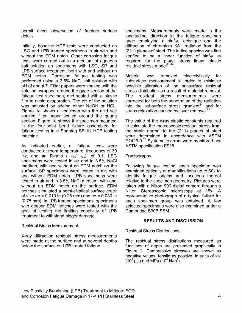
permit direct observation of fracture surface details. Initially, baseline HCF tests were conducted on LSG and LPB treated specimens in air with and without the EDM notch. Other corrosion fatigue tests were carried out in a medium of aqueous salt solution on specimens with LSG, SP and LPB surface treatment, both with and without an EDM notch. Corrosion fatigue testing was performed using a 3.5% NaCl salt solution with pH of about 7. Filter papers were soaked with the solution, wrapped around the gage section of the fatigue test specimen, and sealed with a plastic film to avoid evaporation. The pH of the solution was adjusted by adding either NaOH or HCL. Figure 1e shows a specimen with the acid salt soaked filter paper sealed around the gauge section. Figure 1e shows the specimen mounted in the four-point bend fixture assembled for fatigue testing in a Sonntag SF-1U HCF testing machine. As indicated earlier, all fatigue tests were conducted at room temperature, frequency of 30 Hz, and an R-ratio ( �min/�max), of 0.1. LSG specimens were tested in air and in 3.5% NaCl medium, with and without an EDM notch on the surface. SP specimens were tested in air, with and without EDM notch. LPB specimens were tested in air and in 3.5% NaCl medium, with and without an EDM notch on the surface. EDM notches simulated a semi-elliptical surface crack of size ao = 0.010 in (0.25 mm) and co = 0.030 in (0.75 mm). In LPB treated specimens, specimens with deeper EDM notches were tested with the goal of testing the limiting capability of LPB treatment to withstand bigger damage. Residual Stress Measurement X-ray diffraction residual stress measurements were made at the surface and at several depths below the surface on LPB treated fatigue
specimens. Measurements were made in the longitudinal direction in the fatigue specimen gage employing a sin2ø �technique and the diffraction of chromium Ká1 radiation from the (211) planes of steel. The lattice spacing was first verified to be a linear function of sin2ø �as required for the plane stress linear elastic residual stress model21-24. Material was removed electrolytically for subsurface measurement in order to minimize possible alteration of the subsurface residual stress distribution as a result of material removal. The residual stress measurements were corrected for both the penetration of the radiation into the subsurface stress gradient24 and for stress relaxation caused by layer removal.25
The value of the x-ray elastic constants required to calculate the macroscopic residual stress from the strain normal to the (211) planes of steel were determined in accordance with ASTM E1426-9.26 Systematic errors were monitored per ASTM specification E915. Fractography Following fatigue testing, each specimen was examined optically at magnifications up to 60x to identify fatigue origins and locations thereof relative to the specimen geometry. Pictures were taken with a Nikon 990 digital camera through a Nikon Stereoscopic microscope at 15x. A representative photograph of a typical failure for each specimen group was obtained. A few selected specimens were also examined under a Cambridge S90B SEM.
RESULTS AND DISCUSSION Residual Stress Distributions The residual stress distributions measured as functions of depth are presented graphically in Figure 2. Compressive stresses are shown as negative values, tensile as positive, in units of ksi (103 psi) and MPa (106 N/m2).

Low Plasticity Burnishing (LPB) Treatment to Mitigate FOD and Corrosion Fatigue Damage in 17-4 PH Stainless Steel 5
0 5 10 15 20 25 30 35 40 45 50-125
-100
-75
-50
-25
0
25
S/N 28 LSG S/N 20 SP S/N 88 LPB
Re
sid
ua
l S
tre
ss
(k
si)
Depth (x 10-3
in.)
0 250 500 750 1000 1250
-800
-600
-400
-200
0
Re
sid
ua
l Stre
ss
(MP
a)
Depth (x 10-3
m m )
0 5 10 15 20 25 30 35 40 45 500
20
40
60
80
(211) PERCENT COLD WORK DISTRIBUTION
2/14/03
Gage Region Locat ion17-4PH STAINLESS STEEL H1100 HCF BARS
Lambda Research10536 .d19 .d20 .d21
AXIAL RESIDUAL STRESS DISTRIBUTION
Depth (x10 -3 in.)
Co
ld W
ork
(%
)
Figure 2. Residual stress distribution for LSG, SP and LPB processed (and fatigue tested, all in air) specimens. S/N28 (LSG): Smax = 140 ksi (~965 MPa); Nf = 3,303,607 cycles, S/N20 (SP): Smax = 185 ksi (~1275 MPa); Nf = 148,980 cycles, S/N88 (LPB): Smax = 210 ksi (~1,450 MPa); Nf = 200,445 cycles Figure 2 shows the residual stress (RS) and %cold work (CW) profiles for specimens subjected to LSG, SP and LPB treatment after fatigue testing. The LSG specimen shows surface compression of about -85 ksi (~ -585 MPa), which decreases rapidly to nearly zero at a depth of 0.002 in. (~0.05 mm). This specimen is cold worked 15% at the surface. In comparison, SP treatment shows surface compression of about -105 ksi (~ -725 MPa), which becomes more compressive to about –125 ksi (~ -860 MPa) at a depth of about 0.002 in. (~0.05 mm), and rapidly relaxes to nearly zero residual stress at a depth of about 0.010 in. (~0.25 mm). More importantly, the SP treatment produces a very high degree of cold work, nearly 70% cold work on the surface, which decreases to nearly zero within a depth of 0.005 in. (~0.125 mm). In contrast to both these, LPB
treatment produces surface compression of -100 ksi (~ -690 MPa), which becomes more compressive to about -115 ksi (~ -790 MPa) at 0.005 in. (~0.125 mm) and gradually decreases to zero at a depth of about 0.040 in. (~1 mm). LPB produces surface cold work of < 5%, which decreases to nearly zero within 0.001 in. (~0.025 mm). The low cold work associated with the LPB process is credited with the high stability of the compressive residual stresses of LPB treated parts to thermal exposure and mechanical overload conditions. In contrast, the SP treated specimens tend to go through recovery and recrystallization processes that are dominant in highly cold worked parts, and thereby lose the beneficial compressive residual stresses. HCF and Corrosion Fatigue Performance Figures 3-6 show the HCF and corrosion fatigue performance of 17-4 PH Stainless Steel (H1100) in the form of S-N curves. In Figure 3, the baseline material (LSG) performance with and without the EDM notch is presented. The unnotched LSG condition shows a fatigue strength, (endurance limit at about 107 cycles) Smax of about 150 ksi (~1035 MPa). In comparison, corrosion fatigue for LSG results in a fatigue strength of about 100 ksi (~690 MPa). Introduction of a semi-elliptical EDM notch of nominal size ao = 0.010 in. (0.25 mm) and co = 0.030 in. (0.75 mm) drastically decreases the fatigue strength to about 20 ksi (~140 MPa) for both air and corrosion environments. With the EDM notch, the fatigue lives at higher stresses show a corresponding decrease of over an order of magnitude in comparison to the unnotched specimens. In Figure 3, power law lines were fitted to the data and these lines are included in the presentation of data. The lines in this figure represent the average behavior of the material in its baseline LSG condition, and are used in Figures 4 and 5 for purposes of comparison with other surface treatment processes.

Low Plasticity Burnishing (LPB) Treatment to Mitigate FOD and Corrosion Fatigue Damage in 17-4 PH Stainless Steel 6
104 105 10 6 1070
250
500
750
1000
1250
1500
(4-point Bending, R=0.1, 30 Hz, RT)
All FOD 0.010 in. DeepAll FOD 0.010 in. Deep LSG LSG LSG + FOD LSG + FOD LSG + Salt LSG + Salt LSG + FOD + Salt LSG + FOD + Salt
CYCLES TO FAILURE
MA
XIM
UM
ST
RE
SS
(M
Pa
)
HIGH CYCLE FATIGUE DATA 17-4 PH SS H1100 Thick Sect ion HCF Specimen
0
50
100
150
200
230-10540
MA
XIM
UM
ST
RE
SS
(ks
i)
Figure 3. Baseline HCF and corrosion fatigue results plotted in the form of S-N curves for LSG treatment. The fitted lines are used in Figures 4 and 5 for the purpose of comparison of fatigue performance of SP and LPB treated specimens.
104 105 10 6 1070
250
500
750
1000
1250
1500
(4-point Bending, R=0.1, 30 Hz, RT)
All FOD 0.010 in. DeepAll FOD 0.010 in. Deep SP SP SP + FOD SP + FOD LSG LSG LSG + FOD LSG + FOD LSG + Salt LSG + Salt LSG + FOD + Salt LSG + FOD + Salt
CYCLES TO FAILURE
MA
XIM
UM
ST
RE
SS
(M
Pa
)
HIGH CYCLE FATIGUE DATA 17-4 PH SS H1100 Thick Sect ion HCF Specimen
0
50
100
150
200
230-10540
MA
XIM
UM
ST
RE
SS
(ks
i)
Figure 4. HCF results for SP treatment. Baseline data for LSG treatment (fitted lines from Figure 3) are shown for comparison. Corrosion fatigue tests were not performed on SP treated specimens since no significant benefit in HCF behavior was observed due to shot peening, as seen in this figure. Figure 4 shows the HCF performance of both unnotched and notched SP treated specimens. This figure includes fitted lines from Figure 3, representing the baseline performance. Benefits of surface compression from the shot peening treatment are clearly seen by way of considerably improved HCF performance of the unnotched specimens. The unnotched HCF
performance of the SP treated specimens is comparable to that of the HCF performance of the unnotched LSG (baseline) material.
104 105 10 6 1070
250
500
750
1000
1250
1500
(4-point Bending, R=0.1, 30 Hz, RT)
All FOD 0.010 in. DeepAll FOD 0.010 in. Deep LPB LPB LPB + FOD LPB + FOD LPB + Salt LPB + Salt LPB + FOD + Salt LPB + FOD + Salt LSG LSG LSG + FOD LSG + FOD LSG + Salt LSG + Salt LSG + FOD + Salt LSG + FOD + Salt
CYCLES TO FAILURE
MA
XIM
UM
ST
RE
SS
(M
Pa
)
HIGH CYCLE FATIGUE DATA 17-4 PH SS H1100 Thick Sect ion HCF Specimen
0
50
100
150
200
230-10540
MA
XIM
UM
ST
RE
SS
(ks
i)
Figure 5. Corrosion fatigue and HCF results for LPB reatment. Baseline data for LSG treatment (fitted lines from Figure 3) are shown for comparison.
0.00 0.01 0.02 0.03 0.04 0.050
50
100
150
200
HIGH CYCLE FATIGUE DATADepth of EDM Notch vs. Endurance Limit
17-4 PH Steel, 4-point Bending, R=0.1, 30 Hz, RT
En
du
ran
ce
Lim
it (
ks
i)
Depth of EDM notch, in.
LPB Treated (in air) LPB Treated + Corrosion Fatigue(3.5% Salt Water) Shot Peened (in air) LSG (in air) LSG + Corrosion Fatigue(3.5% Salt Water)
Figure 6: HCF and Corrosion fatigue performance as a function of EDM notch depth in 17-4 PH SS - H1100. Note that while for LSG and shot peened specimens a notch of 0.010 in depth resulted in dramatic loss of fatigue strength. LPB even with a 0.040 in. of notch depth has good fatigue strength. Also, note that for LPB, the HCF and corrosion fatigue behavior of notched specimens are practically indistinguishable.
However, the introduction of a 0.010 in. (0.25 mm) deep notch knocks the performance down

Low Plasticity Burnishing (LPB) Treatment to Mitigate FOD and Corrosion Fatigue Damage in 17-4 PH Stainless Steel 7
to be similar to the notched LSG (baseline) condition. This is not surprising since the corresponding residual stress profile (shown in Figure 2) indicates a depth of compression much shallower than the depth the EDM notch. Figure 5 shows the HCF and corrosion fatigue behavior of LPB treated specimens. Again, the trend lines for the baseline LSG material from Figure 3 are included in this Figure. The unnotched LPB treatment shows superior HCF performance with a fatigue strength of 190 ksi (~1310 MPa). Figure 5 also shows that fatigue data from all of the other test conditions with LPB treatment, notched HCF, and both notched and unnotched corrosion fatigue may be grouped into one set of data. A couple of inferences may be reached from this data. Firstly, the fact that the notched HCF data, and the notched and unnotched corrosion fatigue data are practically indistinguishable in LPB treated system shows that for all practical purposes LPB process has negated the effects of corrosion in the corrosion fatigue process. Secondly, it is interesting to note that the HCF and corrosion fatigue performance of this group are statistically no worse than the unnotched baseline (LSG) material. Figure 6 shows a summary of HCF and corrosion fatigue tests for a number of specimens with deeper EDM notches up to a depth of 0.040 in. (~1 mm). Here, it is evident that for both shot peened and LSG materials, even a 0.010 in. (0.25 mm) deep EDM notch greatly decreases the HCF and corrosion fatigue strength to a value between 25 and 40 ksi (~170 and 275 MPa). In contrast, the LPB treated specimens withstand even a 0.040 in. (~1 mm) deep EDM notch with a fatigue strength of at least 55 ksi (~ 380 MPa). Again, this HCF and corrosion fatigue performance for the LPB treated specimens are easily explained based on the residual stress distributions seen in Figure 2. Fractography Figure 7 shows optical fractographs of unnotched specimens fatigue tested in air. Figure 7a shows the fracture surface of a LSG specimen with multiple crack initiation sites, while Figures 7b
Figure 7a: LSG, Smax = 170 ksi (1,170 MPa), Nf = 103,997 cycles – arrows indicate multiple crack initiation sites.
Figure 7b: SP, Smax = 181 ksi (1,250 MPa), Nf = 119,245 cycles – arrows indicate multiple crack initiation sites.
Figure 7c: LPB, Smax = 195 ksi (1,345 MPa), Nf = 316,663 cycles – arrow indicates one dominant crack initiation Figure 7: Optical fractographs of unnotched LSG, SP and LPB specimens tested in air. and 7c show the surface of a shot peened and LPB treated specimens, respectively, with crack initiation sites. The general features of the fracture surface are typical of crack initiation followed by fatigue crack growth to failure. Figure 8 show SEM fractographs of a corrosion fatigue

Low Plasticity Burnishing (LPB) Treatment to Mitigate FOD and Corrosion Fatigue Damage in 17-4 PH Stainless Steel 8
tested unnotched LSG specimen. Again, a single dominant initiation site leads to crack growth. The higher magnification SEM image in Figure 8b indicates the intergranular fracture mode typical of fatigue crack growth conditions under corrosion fatigue conditions. Figure 9 shows optical fractographs of corrosion fatigue tested specimens with EDM notches. Figures 9a through 9d show fractographs of a corrosion fatigue tested LPB specimen. Here, Figures 9a and b show a single crack initiation site, and Figures 9c and d show the gage side view near the crack origin and below the fracture surface. Evidence of crack initiation at a corrosion pit is evident in these SEM photographs. Figure 10 shows optical fractographs of EDM notched LPB treated specimens under corrosion fatigue conditions. Again the crack initiation and growth regions are quite evident in these fractographs.
Figure 8a: LSG + Salt unnotched, Smax = 120 ksi (825 MPa), Nf = 391,342 cycles – arrow indicates initiation site
Figure 8b: Same as 8a, but higher magnification
Figure 8: SEM fractographs of corrosion fatigue tested LSG specimens
Figure 9a: LPB + salt unnotched, Smax = 150 ksi (1,035 MPa), Nf = 316,613 cycles – arrow indicates initiation
Figure 9b: Same as 9a, but higher magnification
Figure 9c: Same region as 9a, gage surface near crack initiation site (arrow).
Figure 9d: Same as 9a, cracking on the gage surface just below the crack initiation site.

Low Plasticity Burnishing (LPB) Treatment to Mitigate FOD and Corrosion Fatigue Damage in 17-4 PH Stainless Steel 9
Figure 9e: Cracking on the gage surface just below crack initiation site at the initial stage of formation of a corrosion pit (arrow).
Figure 9f: Intergranular crack growth, in a region away from the initiation site. Figure 9: SEM fractographs of a corrosion fatigue tested LPB specimen.
DISCUSSION The HCF and corrosion fatigue results presented in Figure 3-6 and the fractographic observations in Figures 7-10 are fully consistent with the residual stress results shown in Figure 2. For both LSG and shot peened specimens, the depth of compression is less than 0.010 in. (~ 0.25 mm) and correspondingly, the HCF and corrosion fatigue performance for both these conditions deteriorated to very low values. The depth of compression achieved in LPB treated specimens is > 0.040 in. (~ 1 mm), that correspondingly nearly equals the limit of tolerance of EDM notch for corrosion fatigue. These results quite elegantly demonstrate the beneficial effect of surface compressive residual stresses on corrosion fatigue performance.
Figure 10a: Optical fractograph of corrosion fatigue tested notched (0.010 in.) specimen LPB + salt 0.010 in. EDM notch. Smax = 140 ksi (965 MPa);Nf =794,917 cycles – note the notch depth is smaller than the approximate LPB processed zone (dotted white line).
Figure 10b: Optical fractograph of HCF tested notched (0.040 in.) specimen. LPB 0.040 in. EDM notch Smax=83ksi (570 MPa);Nf = 424,044 cycles – note the notch depth is the same as the approximate LPB processed zone (dotted white line)
SUMMARY AND CONCLUSIONS
In summary, low plasticity burnishing (LPB) treatment was studied on 17-4 PH Stainless steel (H1100) specimens, which were tested for corrosion fatigue performance in neutral salt solution environment. Effect of EDM notches to simulate FOD related initial damage conditions were studied. The results overwhelmingly indicate that LPB imparted highly beneficial compressive residual stresses on the surface, and further that LPB treated specimens could easily withstand erosion and/or FOD related damage up to a depth of about 0.040 in. (~ 1 mm) from the surface.
Low Plasticity Burnishing (LPB) Treatment to Mitigate FOD and Corrosion Fatigue Damage in 17-4 PH Stainless Steel 10
ACKNOWLEDGEMENTS
Support of this work by NAVAIR SBIR contract N68335-02-C-0384 is gratefully acknowledged. Authors also wish to thank Doug Hornbach for his help with residual stress measurements and Perry Mason for his help in conducting fatigue tests.
REFERENCE 1. Frost, N.E. Marsh, K.J. Pook, L.P., Metal
Fatigue, Oxford University Press, 1974. 2. Fuchs, H.O. and Stephens, R.I., Metal
Fatigue In Engineering, John Wiley & Sons, 1980.
3. Berns, H. and Weber, L., "Influence of Residual Stresses on Crack Growth," Impact Surface Treatment, edited by S.A. Meguid, Elsevier, 33-44, 1984.
4. Ferreira, J.A.M., Boorrego, L.F.P., and Costa, J.D.M., "Effects of Surface Treatments on the Fatigue of Notched Bend Specimens," Fatigue, Fract. Engng. Mater., Struct., Vol. 19 No.1, pp 111-117,1996.
5. Prevéy, P.S. Telesman, J. Gabb, T. and Kantzos, P., “FOD Resistance and Fatigue Crack Arrest in Low Plasticity Burnished IN718”, Proc of the 5th National High Cycle Fatigue Conference, Chandler, AZ. March 7-9, 2000.
6. Clauer, A.H., "Laser Shock Peening for Fatigue Resistance," Surface Performance of Titanium, J.K. Gregory, et al, Editors, TMS Warrendale, PA (1996), pp 217-230.
7. T. Watanabe, K. Hattori, et al, “Effect of Ultrasonic Shot Peening on Fatigue Strength of High Strength Steel,” Proc. ICSP8, Garmisch-Partenkirchen, Germany, Ed. L. Wagner, pg 305-310.
8. F. J. Heyman, V. P. Swaminathan, J.W. Cunningham, “Steam Turbine Blades: Considerations in Design and a Survey of Blade Failure,” EPRI Repot CS-1967, Palo Alto, CA, EPRI, 1981.
9. C.S. Carter, D.G. Warwick, A.M. Ross, J.M. Uchida, Corrosion, 27, 1971, p190.
10. R.M. Thompson, G.B. Kohut, D.R. Candfield, W.R. Bass, Corrosion, 47, 1991, p216.
11. V.P. Swaminathan, J.W. Cunningham, Corrosion Fatigue of Steam Turbine Blade Materials, ed., R.I. Jaffee, Pergamon Press, New York, NY, 1983, p.3.1
12. P. Prevéy, N. Jayaraman, R. Ravindranath, “Effect of Surface Treatments on HCF Performance and FOD Tolerance of a Ti-6Al-4V Vane,” Proceedings 8th National Turbine Engine HCF Conference, Monterey, CA, April 14-16, 2003
13. Paul S. Prevéy, Doug Hornbach, Terry Jacobs, and Ravi Ravindranath, “Improved Damage Tolerance in Titanium Alloy Fan Blades with Low Plasticity Burnishing,” Proceedings of the ASM IFHTSE Conference, Columbus, OH, Oct. 7-10, 2002
14. Paul S. Prevéy, et. al., “The Effect of Low Plasticity Burnishing (LPB) on the HCF Performance and FOD Resistance of Ti-6Al-4V,” Proceedings: 6th National Turbine Engine High Cycle Fatigue (HCF) Conference, Jacksonville, FL, March 5-8, 2001.
15. M. Shepard, P. Prevéy, N. Jayaraman, “Effect of Surface Treatments on Fretting Fatigue Performance of Ti-6Al-4V,” Proceedings 8th National Turbine Engine HCF Conference, Monterey, CA, April 14-16, 2003
16. Paul S. Prevéy and John T. Cammett, “Restoring Fatigue Performance of Corrosion Damaged AA7075-T6 and Fretting in 4340 Steel with Low Plasticity Burnishing,” Proceedings 6th Joint FAA/DoD/NASA Aging Aircraft Conference, San Francisco, CA, Sept 16-19, 2002
17. N. Jayaraman, Paul S. Prevéy, Murray Mahoney, “Fatigue Life Improvement of an Aluminum Alloy FSW with Low Plasticity Burnishing,” Proceedings 132nd TMS Annual Meeting, San Diego, CA, Mar. 2-6, 2003.
18. Paul S. Prevéy and John T. Cammett, “The Influence of Surface Enhancement by Low Plasticity Burnishing on the Corrosion Fatigue Performance of AA7075-T6,” Proceedings 5th International Aircraft Corrosion Workshop, Solomons, Maryland, Aug. 20-23, 2002.

Low Plasticity Burnishing (LPB) Treatment to Mitigate FOD and Corrosion Fatigue Damage in 17-4 PH Stainless Steel 11
19. John T. Cammett and Paul S. Prevéy, “Fatigue Strength Restoration in Corrosion Pitted 4340 Alloy Steel Via Low Plasticity Burnishing.” Retrieved from www.lambda-research.com Sept. 5, 2003.
20. Paul S. Prevéy, "Low Cost Corrosion Damage Mitigation and Improved Fatigue Performance of Low Plasticity Burnished 7075-T6", Proceedings of the 4th International Aircraft Corrosion Workshop, Solomons, MD, Aug. 22-25, 2000.
21. Hilley, M.E. ed.,(2003), Residual Stress Measurement by X-Ray Diffraction, HSJ784, (Warrendale, PA: SAE).
22. Noyan, I.C. and Cohen, J.B., (1987) Residual Stress Measurement by Diffraction and Interpretation, (New York, NY: Springer-Verlag).
23. Cullity, B.D., (1978) Elements of X-ray Diffraction, 2nd ed., (Reading, MA: Addison-Wesley), pp. 447-476.
24. Prevéy, P.S., (1986), “X-Ray Diffraction Residual Stress Techniques,” Metals Handbook, 10, (Metals Park, OH: ASM), pp 380-392.
25. Koistinen, D.P. and Marburger, R.E., (1964), Transactions of the ASM, 67.
26. Moore, M.G. and Evans, W.P., (1958) “Mathematical Correction for Stress in Removed Layers in X-Ray Diffraction Residual Stress Analysis,” SAE Transactions, 66, pp. 340-345.