ISDN Terminal Adapter User Manual - IC Intracom
68
ISDN Terminal Adapter User Manual
-
Upload
khangminh22 -
Category
Documents
-
view
0 -
download
0
Transcript of ISDN Terminal Adapter User Manual - IC Intracom

ISDN Terminal AdapterUser Manual

ISDN Terminal AdapterUser Manual
No part of this publication may be reproduced in any form by any means without the prior writtenpermission. Other trademarks or brand names mentioned herein are trademarks or registeredtrademarks of their respective companies.
March 2001. Version 01

I
ContentsCHAPTER 1. INTRODUCTION ...............................................................................1
Features .........................................................................................................................1Package Checklist .........................................................................................................1System Requirements ....................................................................................................2
CHAPTER 2. BEFORE INSTALLATION................................................................3
Subscribe for an ISDN BRI (Basic Rate Interface) Line...............................................3Collect Information about Your ISDN Line ..................................................................3Internet Access Account................................................................................................3Terminal Emulation Program ........................................................................................4
CHAPTER 3. CONNECTING ISDN TERMINAL ADAPTER ..............................5
Connecting Procedures..................................................................................................5Connection Diagram .....................................................................................................6
CHAPTER 4. INSTALLATION AND SETUP UNDER WINDOWS 95/98/ME....9
Step 1 Installing Driver for ISDN TA...........................................................................9Under Windows 95....................................................................................................9Under Windows 98.................................................................................................. 11Under Windows Me ................................................................................................12
Step 2 Configuring ISDN TA by ‘ISDN Utility Program’ .........................................14Step 3 Adding Virtual Modem ...................................................................................14
Configuring the Virtual Modem Property ...............................................................18Step 4 Creating Dial-Up Connection..........................................................................20
Connecting to Internet or Remote Network.............................................................21
CHAPTER 5. INSTALLATION AND SETUP UNDER WINDOWS NT4.0 ........23
Step 1 Configuring ISDN TA by ‘ISDN Utility Program’ .........................................23Step 2 Install Your ISDN TA as a Modem .................................................................23Step 3 Configuring the Modem Property ...................................................................30Step 4 Creating Your Dial-Up Network Connection ..................................................31
Configure Dial Entry and Modem Properties..........................................................34
CHAPTER 6. INSTALLATION AND SETUP UNDER WINDOWS 2000...........35
Step 1 Installing Driver for ISDN TA.........................................................................35Step 2 Configuring ISDN TA by ‘ISDN Utility Program’ .........................................37Step 3 Creating Dial-up Connection ..........................................................................37
CHAPTER 7. USING ‘ISDN UTILITY PROGRAM’............................................45
Getting Started ............................................................................................................45Upgrade New Firmware ..............................................................................................45Set System Parameter ..................................................................................................47Set Protocol Parameter................................................................................................48

ISDN Terminal Adapter User Manual
II
CHAPTER 8. AT COMMANDS & RESULT CODES ...........................................49
Result Code List..........................................................................................................56
APPENDIX A SPECIFICATIONS.............................................................................59
APPENDIX B CAPI20 INTERFACE.........................................................................61
Installing CAPI20 driver under Windows 95 ..............................................................61Configuring CAPI20 ...................................................................................................61
ISDN Monitor .........................................................................................................62Upgrade Firmware...................................................................................................63Linetest....................................................................................................................63Log ..........................................................................................................................63
Uninstall the CAPI20 device driver in Windows 95 ...................................................64
APPENDIX C GLOSSARY.........................................................................................65
1
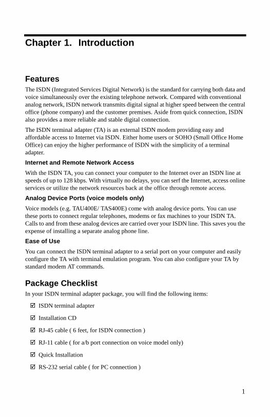
Chapter 1. Introduction
FeaturesThe ISDN (Integrated Services Digital Network) is the standard for carrying both data andvoice simultaneously over the existing telephone network. Compared with conventionalanalog network, ISDN network transmits digital signal at higher speed between the centraloffice (phone company) and the customer premises. Aside from quick connection, ISDNalso provides a more reliable and stable digital connection.
The ISDN terminal adapter (TA) is an external ISDN modem providing easy andaffordable access to Internet via ISDN. Either home users or SOHO (Small Office HomeOffice) can enjoy the higher performance of ISDN with the simplicity of a terminaladapter.
Internet and Remote Network AccessWith the ISDN TA, you can connect your computer to the Internet over an ISDN line atspeeds of up to 128 kbps. With virtually no delays, you can serf the Internet, access onlineservices or utilize the network resources back at the office through remote access.
Analog Device Ports (voice models only)Voice models (e.g. TAU400E/ TAS400E) come with analog device ports. You can usethese ports to connect regular telephones, modems or fax machines to your ISDN TA.Calls to and from these analog devices are carried over your ISDN line. This saves you theexpense of installing a separate analog phone line.
Ease of UseYou can connect the ISDN terminal adapter to a serial port on your computer and easilyconfigure the TA with terminal emulation program. You can also configure your TA bystandard modem AT commands.
Package ChecklistIn your ISDN terminal adapter package, you will find the following items:
! ISDN terminal adapter
! Installation CD
! RJ-45 cable ( 6 feet, for ISDN connection )
! RJ-11 cable ( for a/b port connection on voice model only)
! Quick Installation
! RS-232 serial cable ( for PC connection )

ISDN Terminal Adapter User Manual
2
! Power adapter
! DSU (Japan only for ISDN S/T interface, optional)
System Requirements" IBM PC or compatible" 486 CPU or better" 16 MB RAM or more" Windows 95(OSR2) / 98 / Me / NT4.0 / 2000" CD-ROM drive

3
Chapter 2. Before Installation
The installation requirements depend on the models of your ISDN TA. Refer to the tablebelow to have a general overview of your ISDN TA model.
Model ISDN Interface Voice Model(with TEL port)
NT1 Device
TAS 200E S/T × #
TAU 200E U × ×
TAS 400E S/T # #
TAU 400E U # ×
To ensure a successful installation, please prepare the following items before proceeding.
Subscribe for an ISDN BRI (Basic Rate Interface) LineBefore using the ISDN terminal adapter, you need to subscribe for an ISDN BRI from yourtelephone service provider. Your line is installed by your local telephone company.
NOTE: For North America and Japan only, if your adapter has an S/T-interface, you needa separate network terminating device (NT1) to connect your ISDN line.
Collect Information about Your ISDN LineUpon your subscription for an ISDN BRI Line, your ISDN service provider will supply thefollowing information:
" ISDN central switch typeISDN switch type usually depends on your geographic location.
" ISDN phone numbers" SPIDs (Service Profile Identifiers), North America only.
Internet Access AccountTo access Internet through ISDN TA, you must get an Internet access account from yourlocal ISP (Internet Service Provider) with ISDN access service. Your ISP should provideyou with the following information:
" user name and password" dial-up ISDN number of the ISP" TCP/IP properties: host name, domain name, domain name server address, IP address,
and gateway address (some properties might not necessary)

ISDN Terminal Adapter User Manual
4
Terminal Emulation ProgramTo configure the ISDN TA, you need a terminal emulation program, such asHyperTerminal, Terminal, ProComm, etc.

5
Chapter 3. Connecting ISDN Terminal Adapter
Connecting ProceduresThe connecting procedure depends on the type of adapter you have. Be sure to turn offyour computer before proceeding. Follow the steps below to connect the cables to youradapter.
1. Terminator Setup (for models with S/T interface only)
ISDN S/T interface can support up to 8 ISDN terminals and connect to the ISDNnetwork via NT1 device. Only one ISDN S/T device can be set to the terminatorenabled. Normally the ISDN terminal that is farthest from NT1 should have theterminator enabled.
To setup the terminator with provided DIP switch:
Single ISDN device connected to NT1
If the ISDN TA is the only device connected to NT1, keep the default setting toenable the terminator. (The 1 and 2 DIP switch are set to ‘ON’.)
Multiple ISDN devices connected to NT1
If there are other ISDN devices connected to NT1, set the DIP switch (1 and 2) to‘OFF’.
2. Connect to ISDN wall jack
" S/T InterfaceConnect the port labeled S/T on the rear of the TA and the NT1 interface withRJ45 cable. Then insert the ISDN BRI line into the NT1 socket and the ISDNwall jack.
" U InterfacePlug one end of the RJ-45 cable to U port of the TA, and plug the other end tothe ISDN wall jack.
NOTE: Please kindly be informed that even RJ-45 connector has 8 pins and RJ-11has 4 or 6 pins, but you can still plug the cable from wall jack with RJ-11 connectorinto the RJ-45 jack on the U port of the TA. The U interface works as well.
3. Connect to analog devices (for models with TEL interface only)
If your ISDN TA model comes with TEL interface, connect cables from analogdevices (such as telephone, G3 fax, modem, or answering machine) to LINE1 orLINE2.
NOTE: In the UK, an adapter is provided to convert from the UK type 103 plug tothe US RJ11 plug. The REN (Ringer Equivalence Number) drive capability or

ISDN Terminal Adapter User Manual
6
parallel ring number is 3, so you can connect up to 3 analog devices, assuming eachdevice has a REN of 1.
4. Connect to your computer.
Connect one end of the RS-232 serial cable to the port labeled SERIAL PORT onthe rear of the T/A, and the other end to the appropriate serial port on your computer.
5. Connect the A/C adapter connector to the AC IN jack on the rear of the TA, thenplug the adapter into an AC power outlet.
Connection DiagramThe diagrams below illustrate typical connection on various ISDN TA models. Refer toappropriate diagram corresponding to you model.
Option 1: For TAU400E
Option 2: TAS400E:

Chapter 3 Connecting ISDN Terminal Adapter
7
Option 3: For TAU200E
Option 4: For TAS200E

9
Chapter 4. Installation and Setup UnderWindows 95/98/Me
This section describes detailed procedures of installation and setup as outlined below forWindows 95/98/Me users.
Step 1 Installing Driver for ISDN TA
After starting Windows, system will automatically detect the terminal adapter, youshould follow the on-screen instructions to finish the driver installation.
Step 2 Configuring ISDN TA by ‘ISDN Utility Program’
Once the ISDN TA driver is installed, you will need to edit its settings according toyour requirements.
Step 3 Adding Virtual Modem
You can install the ISDN TA as virtual modem according to your requirement.
Step 4 Creating Dial-Up Connection
This section will guide you through the steps of creating a Dial-Up connection.You can access Internet or remote network once the connection is established.
Step 1 Installing Driver for ISDN TAAfter hardware connection, power on the ISDN TA and then your computer. Follow thestep-by-step instructions below to perform installation and setup procedures.
Under Windows 95
1. Windows 95 will automatically detect the ISDN TA. Click Next.

ISDN Terminal Adapter User Manual
10
2. Click Other Locations.
3. Click Browse to locate the path to the driver: E:\Driver\Win9x where E: is yourCD-ROM drive letter. Then click OK.
4. Click Finish.
Now, you are done with driver installation. Please proceed to ‘Step 2 Configuring ISDNTA by ‘ISDN Utility Program’ on page 14.

Chapter 4 Installation and Setup Under Windows 95/98/Me
11
Under Windows 98
1. Windows will detects the ISDN TA. Click Next.
2. Select Search for the best driver for your device and then click Next.
3. Select Specify a location and click Browse to locate the path to the driver:D:\Driver\Win9x where D is your CD-ROM drive letter. Then click Next.

ISDN Terminal Adapter User Manual
12
4. When Windows finds the driver, click Next.
5. Click Finish.
Now, you are done with driver installation. Please proceed to ‘Step 2 Configuring ISDNTA by ‘ISDN Utility Program’ on page 14.
Under Windows Me
1. When prompted with Add New Hardware Wizard, select Specify thelocation…and then click Next.

Chapter 4 Installation and Setup Under Windows 95/98/Me
13
2. With Search for the best driver… selected, check ONLY Specify a location. ClickBrowse to locate the path to the driver: D:\Driver\WinMe where D: is your CD-ROM drive letter, then click Next.
3. Windows will find the driver for this device; click Next to continue.
4. Click Finish to complete installing the driver.
ISDN Terminal Adapter User Manual
14
Step 2 Configuring ISDN TA by ‘ISDN Utility Program’The ISDN TA's default parameters are suitable for most configurations. However, if youneed to configure your ISDN TA for special-purpose requirements, refer to ‘Chapter 7Using ‘ISDN Utility Program’’ on page 45 for instructions.
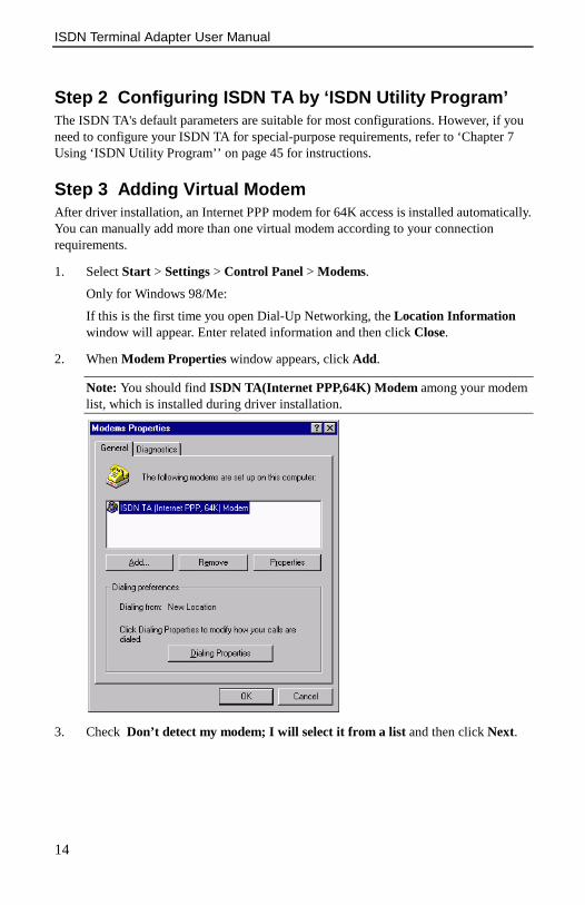
Step 3 Adding Virtual ModemAfter driver installation, an Internet PPP modem for 64K access is installed automatically.You can manually add more than one virtual modem according to your connectionrequirements.
1. Select Start > Settings > Control Panel > Modems.
Only for Windows 98/Me:
If this is the first time you open Dial-Up Networking, the Location Informationwindow will appear. Enter related information and then click Close.
2. When Modem Properties window appears, click Add.
Note: You should find ISDN TA(Internet PPP,64K) Modem among your modemlist, which is installed during driver installation.
3. Check Don’t detect my modem; I will select it from a list and then click Next.

Chapter 4 Installation and Setup Under Windows 95/98/Me
15
4. Click Have Disk. Insert the installation CD into your CD-ROM drive.

ISDN Terminal Adapter User Manual
16
5. Click Browse to specify the path to the driver: D:\Driver\Win9x (or WinMe forWindows Me) where D is your CD-ROM drive letter, then click OK.
6. Select the modem type you require from the list and then click on Next.
NOTE:
You can add more than one virtual modems one by one manually. Each modem willautomatically connect to the appropriate protocol as the modem name specifiedwhen you make a connection via the modem you selected.
The purpose of each modem type supported is described as follows:
" The ISDN TA (Internet PPP, 64K) Modem is used for 64K Internet Access.The used protocol in B channel is PPP.
" The ISDN TA (Internet MLPPP, 128K) Modem is used for 128K InternetAccess. The used protocol in B channels is MultiLink PPP.
" The ISDN TA (Internet MLPPP +BOD, 128K) Modem is used for 128KInternet Access. The used protocols in B channels are MultiLink PPP andBandwidth on Demand (BOD). This means you may have a voice call while 2B channels are used by MultiLink PPP Internet Access. The modem will dropone B channel automatically and make a voice call through this free B channel.After finishing the voice call, the modem will check the data flow in used Bchannel and connect another B channel automatically if usage rate is high.
" The ISDN TA (X.75 Transparent, 64K) Modem is used for BBS Access andfile transfer. The used protocol in B channel is X.75 Transparent.
" The ISDN TA (X.75 T.70NL, 64K) Modem is used for BBS Access and filetransfer. The used protocol in B channel is X.75 T.70NL.
" The ISDN TA (X.75 EFT, 64K) Modem is used for BBS Access and file
Chapter 4 Installation and Setup Under Windows 95/98/Me
17
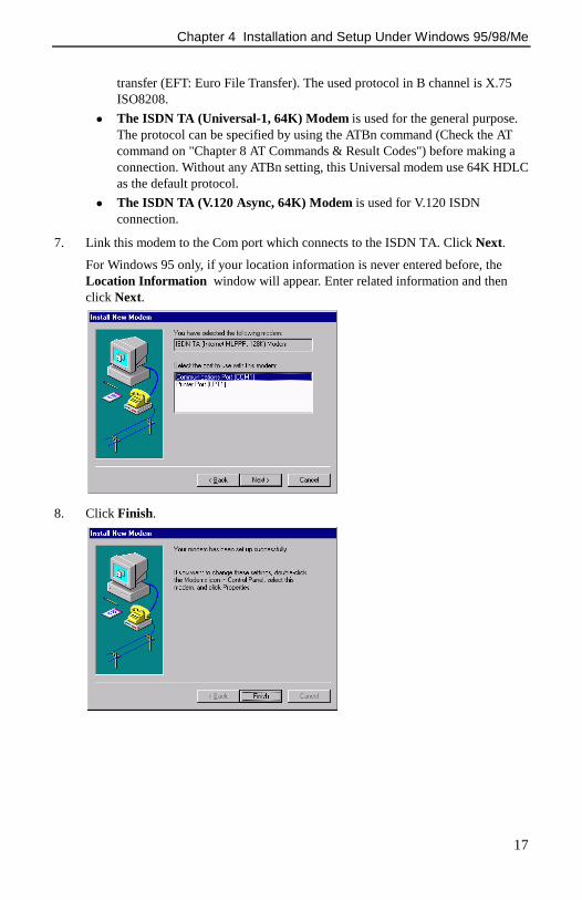
transfer (EFT: Euro File Transfer). The used protocol in B channel is X.75ISO8208.
" The ISDN TA (Universal-1, 64K) Modem is used for the general purpose.The protocol can be specified by using the ATBn command (Check the ATcommand on "Chapter 8 AT Commands & Result Codes") before making aconnection. Without any ATBn setting, this Universal modem use 64K HDLCas the default protocol.
" The ISDN TA (V.120 Async, 64K) Modem is used for V.120 ISDNconnection.
7. Link this modem to the Com port which connects to the ISDN TA. Click Next.
For Windows 95 only, if your location information is never entered before, theLocation Information window will appear. Enter related information and thenclick Next.
8. Click Finish.

ISDN Terminal Adapter User Manual
18
9. You will return to Modems Properties window. Highlight the ISDN TA modemyou just installed and click Properties to verify its configuration.
Configuring the Virtual Modem Property
10. Under General tab, set Maximun speed to 115200.

Chapter 4 Installation and Setup Under Windows 95/98/Me
19
11. Click Connection tab and configure the parameters as the following:
" Data bits: 8" Parity: None" Stop bits: 1
Then click Port Settings.
12. Enable Use FIFO buffers and then click OK.
For Windows 95/98
For Windows Me

ISDN Terminal Adapter User Manual
20
13. Returning to Connection tab, click Advanced tab. Select Use flow control andenable Hardware (RTS/CTS) option. Click OK.
14. When returning to Connection tab, click OK. Then click Close to exit ModemsProperties window.
Whenever you want to configure the properties of the ISDN modem, follow the steps:
1. Click Start > Settings > Control Panel > Modems.
2. Select the ISDN TA modem you want to configure, then click Properties.
Step 4 Creating Dial-Up Connection1. From the desktop, double-click My Computer and then Dial-Up Networking.
If Dial-Up Networking is not installed on your computer, click Start > Settings >Control Panel > Add/Remove Programs > Windows Setup > Communications,check Dial-Up Networking, then follow the on-screen instructions to proceed.
2. If this is your first connection, click Next. Otherwise, double-click Make NewConnection.
3. In the Make New Connection window, type a name for this connection and selectappropriate device from the list. Click Next.

Chapter 4 Installation and Setup Under Windows 95/98/Me
21
4. Enter the telephone number of your ISP and then click Next.
5. Click Finish and then an icon is created for this connection.
Connecting to Internet or Remote Network
1. From the desktop, double-click My Computer and then Dial-Up Networking.
2. Double-click the icon for the connection you created for ISDN TA.
3. In the Connect To dialog box, enter User name and Password specified by yourISP or network administrator. Click Connect.
4. The server will verify your user name, password and register you on the server.
5. When the connection is established, the Connected to dialog box appears.
You are now able to use the Internet tools to access the Internet or network tool to accessremote network.
With problems after connecting such as the line is dropped or you cannot access the

ISDN Terminal Adapter User Manual
22
Internet/ remote network, verify your network settings with your ISP or networkadministrator.

23
Chapter 5. Installation and Setup underWindows NT4.0
After hardware connection, turn on your computer and start Windows NT. If yourWindows NT has installed the PNPISA before, Windows NT should detect an ISDN TAand request for the driver. Please check Do not install a driver and follow the instructionsbelow.
Step 1 Configuring ISDN TA by ‘ISDN Utility Program’The ISDN TA's default parameters are suitable for most configurations. However, if youneed to configure your ISDN TA for special-purpose requirements, refer to ‘Chapter 7Using ‘ISDN Utility Program’’ on page 45 for instructions.
Step 2 Install Your ISDN TA as a ModemTake note of following items before proceeding:
" Remote Access Service (RAS)Before proceeding, it is recommended to install the RAS (also known as Dial-UpNetworking ). You can install it with at least one modem. Any modem will do; it isonly needed to install the ISDN TA and can later be removed. Check Windows NTdocumentation for information on installing RAS.
" Have the information on ISP and network handy. You may be prompted for theinformation during installation.
Follow the steps below to install the ISDN TA as a modem:
1. Click Start > Settings > Control Panel. Double-click the Modems icon.
2. If you have installed a modem previously, the Modem Properties window appears;click Add. Otherwise, go to Step 3 directly.

ISDN Terminal Adapter User Manual
24
3. In Install New Modem dialog box, check Don't detect my modem… and then clickNext.

Chapter 5 Installation and Setup under Windows NT
25
4. Click Have Disk. Insert the installation CD into your CD-ROM drive.
5. Click Browse to specify the path to the driver: D:\Driver\NT40 where D is yourCD-ROM drive letter, then click OK.
6. Highlight the model you want to install and click Next.
NOTE:
You can add more than one virtual modems one by one manually. Each modem willautomatically connect to the appropriate protocol as the modem name specifiedwhen you make a connection via the modem you selected.
The purpose of each modem type supported is described as follows:
" The ISDN TA (Internet PPP, 64K) Modem is used for 64K Internet Access.The used protocol in B channel is PPP.

ISDN Terminal Adapter User Manual
26
" The ISDN TA (Internet MLPPP, 128K) Modem is used for 128K InternetAccess. The used protocol in B channels is MultiLink PPP.
" The ISDN TA (Internet MLPPP +BOD, 128K) Modem is used for 128KInternet Access. The used protocols in B channels are MultiLink PPP andBandwidth on Demand (BOD). This means you may have a voice call while 2B channels are used by MultiLink PPP Internet Access. The modem will dropone B channel automatically and make a voice call through this free B channel.After finishing the voice call, the modem will check the data flow in used Bchannel and connect another B channel automatically if usage rate is high.
" The ISDN TA (X.75 Transparent, 64K) Modem is used for BBS Access andfile transfer. The used protocol in B channel is X.75 Transparent.
" The ISDN TA (X.75 T.70NL, 64K) Modem is used for BBS Access and filetransfer. The used protocol in B channel is X.75 T.70NL.
" The ISDN TA (X.75 EFT, 64K) Modem is used for BBS Access and filetransfer (EFT: Euro File Transfer). The used protocol in B channel is X.75ISO8208.
" The ISDN TA (Universal-1, 64K) Modem is used for the general purpose.The protocol can be specified by using the ATBn command (Check the ATcommand on "Chapter 8 AT Commands & Result Codes") before making aconnection. Without any ATBn setting, this Universal modem use 64K HDLCas the default protocol.
" The ISDN TA (V.120 Async, 64K) Modem is used for V.120 ISDNconnection.
7. Highlight the COM Port the ISDN TA is connected to. Click Next.

Chapter 5 Installation and Setup under Windows NT
27
8. Click Finish.
9. Click Close to exit the Modems Properties window.
10. When prompted to setup the modem, click Yes.

ISDN Terminal Adapter User Manual
28
11. In the Add RAS Device window, select the ISDN modem you just installed andclick OK.If you do not see this screen, proceed to next step directly.
12. With your ISDN modem selected, click Configure.
13. Select required port usage and then click OK.
14. When returning to Remote Access Setup window, click Network.
15. Different Network Configuration dialog box will appear according to the portusage you select in Step 13.
" Option 1: Dial out only is selectedCheck the protocol you required. If you are going to access Internet, checkTCP/IP usually. Then click OK.

Chapter 5 Installation and Setup under Windows NT
29
" Option 2: Receive calls only or Dial out and Receive calls is selectedCheck your ISP to set the network settings. Also check that you haveenabled Allow any authentication including clear text; then clickOK. Several dialog boxes will appear according to your networksettings. Follow the on-screen instructions to set the settings.
16. Click Continue and you are done with installation.
If you are prompted for Windows NT files, specify the location of Windows NT filesand click Continue.
17. When asked to restart your computer, click Yes.
ISDN Terminal Adapter User Manual
30
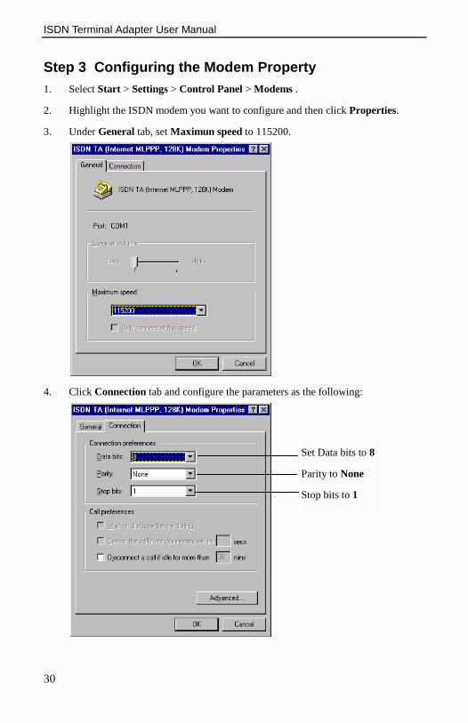
Step 3 Configuring the Modem Property1. Select Start > Settings > Control Panel > Modems .
2. Highlight the ISDN modem you want to configure and then click Properties.
3. Under General tab, set Maximun speed to 115200.
4. Click Connection tab and configure the parameters as the following:
Set Data bits to 8
Parity to None
Stop bits to 1

Chapter 5 Installation and Setup under Windows NT
31
5. Click Advanced and configure the parameters as the following:Check the Use flow controlcheckbox.
EnableHardware(RTS/CTS)
Step 4 Creating Your Dial-Up Network Connection1. From the desktop, double-click My Computer and then Dial-Up Networking.
2. If this is the first time you open Dial-Up Networking, a message box prompts you toadd an entry to the phonebook. Click OK.
If this is not the first time you open Dial-Up Networking, click New.
3. The New Phonebook Entry Wizard window appears. Enter a name for the newphonebook entry and then click Next.

ISDN Terminal Adapter User Manual
32
4. Check applicable statement, then click Next.
5. Enter the phone number of your ISP and click Next.
6. Click Finish.
Chapter 5 Installation and Setup under Windows NT
33
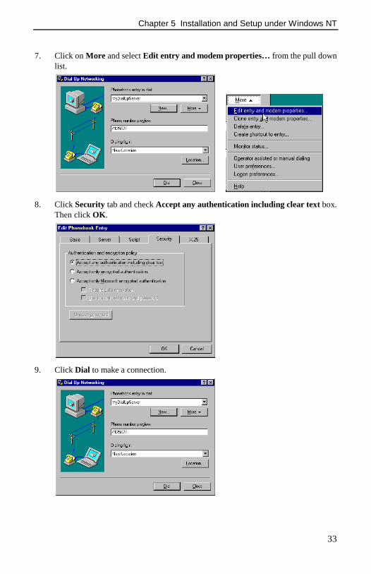
7. Click on More and select Edit entry and modem properties… from the pull downlist.
8. Click Security tab and check Accept any authentication including clear text box.Then click OK.
9. Click Dial to make a connection.

ISDN Terminal Adapter User Manual
34
10. Enter your User name and Password, then click OK.
The system will dial and connect to your ISP at either 128k or 64k depending on yoursetup. The server will verify your login name, password, and register you on the server. Ifconnection is successfully established, you are able to use the Internet tools to access theInternet or network tool to access remote network.
When double-clicking the small icon of Dial-Up Networking at Windows taskbar, theDial-Up Networking Monitor will show the connection status including connectionspeed, etc.
With problems after connecting such as the line is dropped or you cannot access theInternet/ remote network, verify your network settings with your ISP or networkadministrator.
Configure Dial Entry and Modem Properties
If you need to configure more parameters for your dial entry, follow the procedures below.
1. From the desktop, double-click My Computer and then Dial-Up Networking.
2. When Dial-Up Networking window appears, select your dial entry fromPhonebook entry to dial field and then click More.
3. Select Edit entry and modem properties… from the pull down list.
4. Click required tab and configure needed settings; click OK.
5. When returning to Dial-Up Networking window, click Close to finishconfiguration or click Dial to make a connection.

35
Chapter 6. Installation and Setup underWindows 2000
Step 1 Installing Driver for ISDN TA1. When prompted with Found New Hardware Wizard, click Next to continue.
2. Select Search for a suitable driver… and click Next.

ISDN Terminal Adapter User Manual
36
3. Check Specify a location and then click Next.
4. Insert the installation CD into your CD-ROM drive. Click Browse to specify thepath to the driver: D:\Driver\W2K where D is your CD-ROM drive letter, then clickOK.
5. Windows will find the driver; click Next.

Chapter 6 Installation and Setup under Windows 2000
37
6. When prompted with Digital Signature Not Found, click Yes.
7. Click Finish to complete the installation.
Step 2 Configuring ISDN TA by ‘ISDN Utility Program’The ISDN TA's default parameters are suitable for most configurations. However, if youneed to configure your ISDN TA for special-purpose requirements, refer to ‘Chapter 7Using ‘ISDN Utility Program’’ on page 45 for instructions.
Step 3 Creating Dial-up Connection1. From your desktop, double-click My Computer and then Network and Dial-up
Connections.

ISDN Terminal Adapter User Manual
38
2. Double click Make New Connection icon. If this is the first time you make newconnection, Location Information window will appear. Enter related informationand click OK. Returning to Phone And Modem Options window, click OK.
3. Click Next.
Chapter 6 Installation and Setup under Windows 2000
39
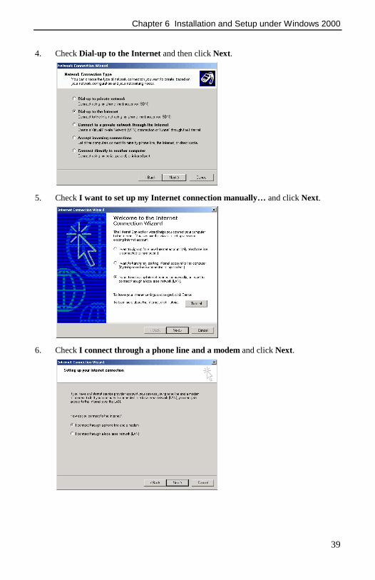
4. Check Dial-up to the Internet and then click Next.
5. Check I want to set up my Internet connection manually… and click Next.
6. Check I connect through a phone line and a modem and click Next.

ISDN Terminal Adapter User Manual
40
7. Uncheck Use area code and dialing rules. Enter the telephone number provided byyour ISP and then click Next.
8. Enter User name and Password provided by your ISP and then click Next.
9. Type a name for the dial-up connection and click Next.
Chapter 6 Installation and Setup under Windows 2000
41
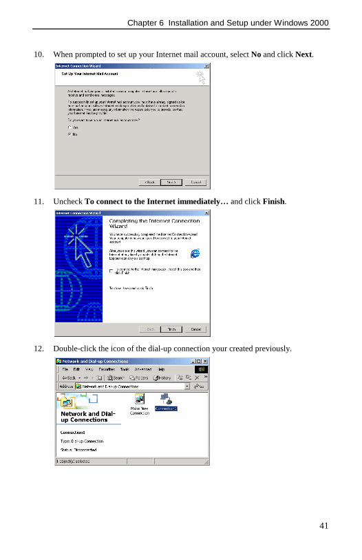
10. When prompted to set up your Internet mail account, select No and click Next.
11. Uncheck To connect to the Internet immediately… and click Finish.
12. Double-click the icon of the dial-up connection your created previously.

ISDN Terminal Adapter User Manual
42
13. Click Properties.
14. Under General tab, click Configure.

Chapter 6 Installation and Setup under Windows 2000
43
15. Click the drop-down menu of Modem protocol and select the protocol you need.Then click OK.
16. Click OK to return to Connect window. Click Dial to make a connection.
17. Wait for verifying username and password.

ISDN Terminal Adapter User Manual
44
18. When the connection is complete, click OK.
19. You can monitor the status of connection via the following screen.
Now you are able to use the Internet tools to access the Internet or network tool to accessremote network. Enjoy the Internet resource with ISDN super speed now.

45
Chapter 7. Using ‘ISDN Utility Program’
The ISDN TA's default parameters are suitable for most configurations. However, you mayneed to configure your ISDN TA for specific requirements.
This chapter describes how to configure the ISDN TA by provided ‘ISDN Utility Program’through terminal emulation program, such as Procom, Telex, HyperTerminal and so on.
NOTE: You should have your ISDN TA driver installed prior to configuring the ISDN TA.You may also refer to the AT commands to control the system parameters directly.
Getting Started1. Start the terminal emulation program and select the same COM port assigned to the
ISDN TA for the program.
2. Configure the parameters of your terminal emulation program as the followingvalues:
" Baud Rate: 115200" Data Bit: 8" Parity Check: None" Stop Bit: 1" Flow Control: RTS/CTS
3. Issue the following AT command at the prompt and then press enter:
AT@
The main menu of ISDN Utility Program appears.
4. Select required item from the main menu and use the function keys shown at thebottom of the screen to configure your ISDN TA.
Upgrade New FirmwareAfter you download new firmware, you can upgrade the firmware by terminal emulationprogram. The interactive procedure will lead you to complete the upgrade procedure.

ISDN Terminal Adapter User Manual
46
1. The strings below will be shown when you enter the Upgrade New Firmwarescreen:
Are you sure to upgrade the new firmware <Y/N>:_Press Y to enter upgrade procedure. If you press N, you will return to ISDN UtilityProgram.
2. The below strings will be shown on the screen:ISDN TA upgrade procedure starts:Erase current driver <Y/N>:_
Press ‘Y’ to continue.
If you select ‘N’, you will exit this upgrade procedure and then the version number,current selected protocol and speed in B channel will be prompted. If there is nodriver (firmware) in flash memory, the tool will inform you to finish the upgradeprocedure.
3. The tool starts to erase the driver in flash memory and you will see the strings below:Erasing ISDN driver………(wait about 5 seconds)Finish erase procedureWaiting for new firmware through ASCII mode transmissionIf you want to exit upgrade procedure, press ‘$’ to exit now.
Then select the transmission type with ASCII mode (text mode) and specify the newfirmware filename (with extension of ABS). For example, select Transfer > SendText File and specify the filename in HyperTerminal. During the transmission, thebelow strings will be shown.
Compare S0-record OKLoad Addr = ######
If you press ‘$’, you still need to return to step 2 to restart upgrade procedure.
4. Do not press any key during transferring the file; otherwise you will interrupt thenormal procedure. After the file is transferred completely, the below strings will beshown on the screen:
Compare S5-record OKFinish upgrade procedurePress ‘N’ to exit this program and go into AT command mode.ISDN TA upgrade procedure starts:Erase current driver <Y/N>:_
Select ‘N’ to finish upgrading and exit upgrade procedure. The version number,current selected protocol and speed in B channel will be prompted. If you select ‘Y’,return to step 3 to restart erasing the driver in flash memory.

Chapter 7 Using ‘ISDN Utility Program’
47
Set System ParameterThe system parameter screen is shown as below.
The following parameters can be configured:
Parameters Description
SWITCH TYPE Set the country or ISDN switch type which meets your local telephonecompany requirement.
CODEC Specify your country code upon different telecommunicationsstandards.
" A_Law: for countries follow European telecommunicationstandards.
" u_Law: for countries follow the US telecommunication standards,If you are using AT commands:ATCODEC=0 for a_Law and ATCODEC=1 for u_Law.
STANDBYTIME
Specify the time period between dialing the last digit and sending a callrequest. It is suggested to leave it as default.
MSN (Incoming) This parameter is used for ISDN switches supporting MSN (MultipleSubscriber Number) service. MSN service is supported by someEuropean telephone companies.
If you enter the number here, then the called telephone number (calledparty number) of the incoming call will be required to match the MSNvalue, otherwise no service will answer or accept this incoming call.
If you want to answer any incoming calls, please leave it blank.
MSN (Outgoing) This parameter is used to tell ISDN central switch that this call is madeby this telephone number and bill to this telephone number.
SPID For North America only. Please check with your ISDN serviceprovider if it is necessary.
Enter the corresponding SPIDs (Service Profile Identifiers) specifiedby your ISDN service provider. Enter either one or two SPID numbersdepending on your switch type for your ISDN line.

ISDN Terminal Adapter User Manual
48
Parameters Description
SAD Abbreviation of Sub-Address. It is almost the same as MSN. It may beavailable or not, depending on your ISDN phone company.
Notes:For the incoming data call, the TAS(U)400E/TAS(U)200E will get the used B channelprotocol, called party number and subaddress from the SETUP packet. If there is no usedB channel protocol in SETUP, TA will detect the protocol such as V.120, X.75, and HDLCin B channel automatically (Please refer to the AT&AP command for the detail.). If thereare parameters set in MSN, Subaddress, and Protocol (please refer to AT&ZIr=m*n*pcommand), these parameters will be checked during the incoming SETUP packet's values.If the MSN values are matched(Please refer to AT&ZI? Command), thenTAS(U)400E/TAS(U)200E will accept this call, otherwise this call will be rejected.
Set Protocol ParameterThe protocol parameter screen is shown below.
These protocols are used in the B channel. You can set the packet size and window size tomeet the requirement of remote site or for better performance. For convenience, you maystore the settings for different purposes into profile 0 or profile 1. Therefore, you can selectone of these profiles to speed up the configuration and usage. Please refer to the chapter ofAT command set for related information.

49
Chapter 8. AT Commands & Result Codes
The terminal adapters support Communication interface (RS-232C). It allows applicationsto access the terminal adapters as an analog modem. We provide the extra AT commands toenable ISDN features such as HDLC, X.75, V.120, or Async to Sync PPP (as the listbelow).
The following AT Commands are provided to control the ISDN connections, lineprotocols and call handling. You should use these parameters to change your applicationsetup-strings to access the terminal adapters with the correct protocol and settings.
Command Samples Description
ATA Answer an incoming call
ATBn Select protocol of transmission in B channel
ATB0 64K HDLC
ATB20 V.120 Async.
ATB3 X.75 Transparent, the same as ATB30
ATB30 X.75 Transparent
ATB31 X.75 T.70 NL
ATB32 X.75 EuroFT
ATB4 Async PPP to Sync PPP conversion
ATB41 Async to Sync PPP conversion in MLPPP mode,compatible with Microsoft ISDN Accelerator pack
ATB42 Async to Sync PPP conversion in MLPPP mode withBandwidth on Demand (BOD)
ATB5 Bit Transparent (This command is only used forRVS-COM’s soft-G3Fax)
ATCODEC Set or display the codec of POTS
ATCODEC=n n = 0 for A_Law
n = 1 for u_Law
ATCODEC? Display the current settings
ATDn Dial a telephone number
ATD7693007 Dial telephone number 7693007
ATDL Redial the last dial number
ATEn Echo characters when in command mode

ISDN Terminal Adapter User Manual
50
Command Samples Description
ATE0 Echo off
ATE1 Echo on
ATHn On-Off Hook
ATH On-Hook, Disconnect (same as ATH0)
ATH1 Off-Hook
ATIn Display Driver information
ATI0 Display version number, selected protocol,connected speed (same as ATI)
ATI1 Display switch type, codec, SPIDs, standby time,MSN..
ATI2 Display the last connection status including calldirection, used protocol, disconnection cause, andused time period for POTS interface.
ATI3 Display the last connection status including calldirection, used protocol, speed, disconnection cause,and used time period for DATA interface.
ATO On-Line command, switch to on-line mode fromcommand mode
ATP Set or display the country or switch type
ATP=n n= 0 -> Australia
1 -> Belgium
2 -> China
3 -> Colombia
4 -> Denmark
5 -> Dutch
6 -> Euro ISDN
7 -> Finland
8 -> France
9 -> Germany
10 -> Israel
11 -> Italy
12 -> Japan
13 -> Korea
14 -> Korea-CountrySide

Chapter 8 AT Commands & Result Codes
51
Command Samples Description
15 -> Singapore
16 -> Slovenia
17 -> South Africa
18 -> Spain
19 -> Sweden
20 -> Swiss
21 -> Taiwan
22 -> U.K.
23 -> USA (AT&T Multi-P)
24 -> USA (AT&T P-T-P)
25 -> USA (NI-1)
26 -> USA (NI-2)
27 -> USA (NTI/DMS)
ATP? Display the country or switch type
ATQn Return the result code
ATQ0 Return the result code
ATQ1 Does not return the result code
ATSr Set or display the register value
ATS0=1 Set register 0 to 1, (S0=0, disable the auto-answermode)
ATSr? Display register r content
ATS1? Register 1 is read only, display the ring count
ATS2 Escape code character (default S2=43, ASCII “+”)
ATS3 Carriage return character (default S3=13,representing a carriage return)
ATS4 Line feed character (default S4=10, representing “CTRL J” or the line feed character)
ATS5 Back space character (default S5=8, representing “CTRL H”)
ATS7 Wait for carries after dial (default S7=30 seconds)
ATS12 Escape code guard time (default S12=50)
ATS25 Delay to DTR (default S25=5)
ATS30 Disconnect the connection automatically if there is

ISDN Terminal Adapter User Manual
52
Command Samples Description
no data transmission in n*10 seconds (n=0 to 255,default S30=0, it will not disconnect the connection)
ATS37 Send the Low Layer Compatibility (LLC)information for data call
S37=0 for not sending LLC (default)
S37=128 for sending LLC
ATS38 Windows size of HDLC 56K or 64K
ATS39 Packet size of HDLC 56K or 64K from 1 to 2048
ATS40 Windows size of V.120
ATS41 Packet size of V.120
ATS44 Window size of X.75 (Transparent)
ATS45 Packet size of X.75 (Transparent) from 1 to 2048
ATS46 Window size of X.75 T.70 NL
ATS47 Packet size of X.75 T.70 NL from 1 to 2048
ATS50 Window size of X.75 EuroFT
ATS51 Packet size of X.75 EuroFT from 128 to 2048
ATS53 Average data flow from 1000 to 7000 bytes (default4, it means 4000 bytes)
Active the second channel if average data flow isover 4000 bytes in 10 seconds. This register is onlyavailable in MLPPP BOD mode, ATB42.
ATS54 Time period from 5 to 20 minutes
Disconnect the second channel if average data flowbelow N bytes (set by ATS53) in 5 minutes. Thisregister is only available in MLPPP BOD mode,ATB42.
ATS55=n Select the ring pattern for POTS 1, n=0 to 7
pattern # Ring ON Ring Off
0 0.5 second 0.5 second
1 0.5 1.0
2 0.5 1.5
3 1.0 1.0
4 1.0 2.0
5 1.0 3.0

Chapter 8 AT Commands & Result Codes
53
Command Samples Description
6 2.0 2.0
7 2.0 3.0
ATS56=n Select the ring pattern for POTS 2, n=0 to 7
Pattern description is the same as above.
ATSPID Set or display the SPID
ATSPID0=n Set first entry of SPIDs to n
ATSPID1=n Set second entry of SPIDs to n
ATSPIDm? Display the m-th entry of SPID, m=0,1
ATSTBY ATSTBY=n Set the standby time n=3 to 10
ATSTBY? Display setting value of the standby time
ATUPG Download the new driver into TA, please follow theinstruction shown in the screen to finish all ofprocedures.
ATVn Verbose command
ATV0 Return digit result code
ATV1 Returns word result code
ATXn Enable extended result code
ATX0 Disable the extended result code
ATX1 Enable extended result code
ATZ Reset and store back the profile 0
ATZn Reset and store back the profile n, n=0,1
AT&ABn Baudrate detection
AT&AB0 Detect baudrate automatically, same as AT&AB(default)
AT&AB1 Disable auto-baudrate detection and fix to currentbaudrate
AT&AB? Display the current baudrate
AT&APn Incoming protocol detection
AT&AP0 Disable incoming protocol auto-detection.
AT&AP1 Detect incoming protocol automatically
+++ Escape command
AT&Cn Control DCD

ISDN Terminal Adapter User Manual
54
Command Samples Description
AT&C0 Keep always the DCD line ON ( the same as AT&C )
AT&C1 DCD line is active if connected
AT&Dn Control DTR
AT&D0 Ignore the DTR, assume DTR is always ON.
AT&D2 DTR OFF will cause the ISDN TA to hang up
AT&E Select the line speed in the B channel
AT&E0 64K bps
AT&E1 56K bps
AT&F Reset registers to factory setting, default value
AT&Kn DTE/Modem Flow Control
AT&K0 Disable DTE/DCE flow control
AT&K3 Enable RTS/CTS DTE/DCE flow control
AT&K4 Enable XON/XOFF DTE/DCE flow control
AT&K6 Enable RTS/CTS and XON/XOFF DTE/DCE flowcontrol
AT&Nn Select the voice type
AT&N0 Select the SPEECH as the voice type
AT&N1 Select the 3.1K Audio voice type
AT&Tn n = 0 for clearing the conformance test setting
n = 1 for setting the loopback test for conformancetest.
This command is used for PTT approval only.
AT&TEST Self-diagnostic of device
AT&V View profile
AT&W AT&Wn Write active configuration to profile n, n=0,1
AT&Y AT&Yn Load profile n when power on, n=0,1
AT&ZIr=n*m*p Set the called party number for screening incomingcall (MSN). “n” is the local telephone number, “*” isthe sub address symbol (option), if needed, “m” isthe sub address (option). The second "*" is option. Ifneeded, the p is the protocol indicator.
P = 0 for accepting all protocols with auto-detection

Chapter 8 AT Commands & Result Codes
55
Command Samples Description
= 2 for receiving V.120 protocol only
= 3 for receiving X.75 Transparent only
= 4 for receiving X.75 T.70NL only
= 5 for receiving X.75 EFT (Euro FileTransfer)only
= 6 for receiving HDLC (such as PPP…) only
Where the r=0,1, to 3, the 0 for POTS 1, 1 for POTS2, and 2 to 3 for DATA port. The maximum length ofMSN is 18 digits and 8 digits for subaddress.
For example, if you want to set a MSN with aspecific protocol (X.75 Transparent) for incomingcall, you may enter this command asAT&ZI2=81722043**3 (no subaddress).
AT&ZI?
AT&ZIr?
Display the setting values, r=0,1,2 to 3
AT&ZOr=n*m Set the calling party number for outgoing call. “n”is the local telephone number, “*” is the sub addresssymbol, if needed (option), and “m” is the subaddress (option). Where the r=0,1,2, the 0 for POTS1, 1 for POTS 2, and 2 for DATA port.
AT&ZO?
AT&ZOr?
Display the setting values, r=0,1,2
AT%Sn Serial mode setting, n=0, 1
AT%S0 Automatic speed mode such as 300, 1200, 2400,4800, 9600, 19200, 38400, 57600, or 115200 bps
AT%S1 set DTE to 230400 bps mode
AT#C Caller ID setting
AT#C? Display the current Caller ID mode
AT#C0 Disable Caller ID
AT#C1 Enable Caller ID
AT#C2 Enable to display CallerID;CallerSub;CIP;CalledID;CalledSub
AT#Tn This command used for some ISDN central officeswitches, the incoming call doesn't indicate thecalled party number even though the MSN numberhad been assigned. This will cause inconvenience for

ISDN Terminal Adapter User Manual
56
Command Samples Description
the user. This command provided for the user toEnable/Disable Ring on POT1/2. The setting valuewill return to the default (Enable) when you turn offTA unless you store setting to the profile 0 andprofile 1.
AT#T0=0 Disable Ring on POTS1
AT#T0=1 Enable RING on POTS1
AT#T1=0 Disable Ring on POTS2
AT#T1=1 Enable RING on POTS2
AT#T0? View the setting on POTS1
AT#T1? View the setting on POTS2
A/ Repeat the last AT command
AT@ To configure the switch type, codec, SPID, MSN byan user-friendly interface
Result Code ListResult Code Result String ATX0 ATX1
0 OK o o
1 CONNECT o x
2 RING o o
3 NO CARRIER o o
4 ERROR o o
7 BUSY o o
8 NO ANSWER o o
82 CONNECT 56000/V120 ASYNC. x o
84 CONNECT 56000/X.75 TRANS. x o
85 CONNECT 56000/X.75 T.70NL x o
86 CONNECT 56000/X.75 EuroFT. x o
87 CONNECT 56000/HDLC x o
88 CONNECT 56000/Async. to Sync. PPP x o
89 CONNECT 56000/Async. to Sync. MLPPP x o
90 CONNECT 112000/Async. to Sync. MLPPP x o
92 CONNECT 64000/V120 ASYNC. x o

Chapter 8 AT Commands & Result Codes
57
Result Code Result String ATX0 ATX1
94 CONNECT 64000/X.75 TRANS. x o
95 CONNECT 64000/X.75 T.70NL x o
96 CONNECT 64000/X.75 EuroFT. x o
97 CONNECT 64000/HDLC x o
98 CONNECT 64000/Async. to Sync. PPP x o
99 CONNECT 64000/Async. to Sync. MLPPP x o
100 CONNECT 128000/Async. to Sync. MLPPP x o

59
Appendix A Specifications
! ISDN Interface:
1. U Interface (TAU400E/TAU200E)
Line two-wire, full duplex
Line Code 2B1Q
Connector RJ-45 * 1
2. S/T Interface (TAS400E/TAS200E)
Line four-wire, full duplex
Line code AMI
Connector RJ-45 * 1
Support Japan DSU (for Japan model type only)
! Data Port Interface:
Physical interface RS-232
Data Rate Async. Up to 230.4kbps
Connector DB9(TAS400E/TAS200E) or DB25 (TAU400E/TAU200E) female * 1
! Analog Interface: (for TAS(U)400E only)
Analog port two R-interface port
power feeding 25V, 25mA
Ring Signal 20Hz, 56Vrms
REN 3
Dialing method Tone, Pulse
Connector RJ-11 * 2
! LED Indicators:
1. Power status lamp PWR
2. Analog phone status lamp T1, T2 (for TAS(U)400E only)
3. ISDN line status lamp LK
4. Carrier detector lamp CD
5. Data port receiving data lamp RD
6. Data port transmitting data lamp SD

ISDN Terminal Adapter User Manual
60
7. Multi-channels status lamp MP
8. Auto answer status lamp AA
! Power Adapter:
Input voltage 120Vac or 230Vac
! D Channel Signaling Protocol Compatibility1. AT&T 5ESS, Nortel DMS-100
2. US NI-1 & NI-2
3. ETSI, French Deltas, German Deltas
4. Japan INS-64
! B Channel Protocol Compatibility1. Voice (for TAS(U)400E only)
2. Data (56K, 64K, 112K or 128K HDLC)
3. V.120
4. X.75
5. Async. PPP to Sync. PPP conversion
6. MultiLink PPP
7. MultiLink PPP with Bandwidth on demand (BOD)
8. B channel protocol auto-detection for V.120, X.75, HDLC for incoming call

61
Appendix B CAPI20 Interface
With CAPI interface, you can use any ISDN application such as RVS-COM, ZOC thatrequires a CAPI driver. For example, you can get Soft-G3Fax, Telephony, File Transferfunctions through RVS-COM.
For your convenience, CAPI drivers for Windows 95 and 98 are include in the installationCD. Before you install this CAPI20 device driver, the ISDN TA should be installed andconfigured as described in “Chapter 4 Installation and Setup Under Windows 95/98/Meon” page 9.
This section will describe the CAPI installation and configuration using Windows 95 as anexample. For Windows 98 users, the install process is basically the same as in theWindows 95. The interface of CAPI will somewhat different from Winsows95. But thefunction is the same.
Installing CAPI20 driver under Windows 95You may follow these steps to install CAPI20 device driver:
1. Insert the installation CD into your CD-ROM drive.
2. Click Start > Settings > Control Panel > Add New Hardware.
3. When wizard appears, click Next .
4. Select No to prevent Windows from searching for your new hardware and clickNext.
5. Highlight Other devices and click Next.
6. Click Have Disk.
7. Click Browse to locate the driver: x:\TA\CAPI\Win95 and then click OK.
8. The model of the hardware will list. Click Next.
9. Click Finish to compete the installation.
10. When prompted to restart your computer, click Yes.
Configuring CAPI201. Click Start > Settings > Control Panel > System > Device Manager > ISDNLink
> ISDN TA CAPI Driver > Properties.
2. In the properties of this CAPI driver, click Setting tab. You can set the systemparameters including Switch Type and SPID which is available according to theSwitch Type you select.

ISDN Terminal Adapter User Manual
62
3. Click POTS Setting to configure your POTS setting. You can set Dial Standby sec,Codec, Call Type (Voice), MSN and SAD (subaddress) for POTS ports. For moreinformation, please refer to “Set System Parameter” on page 47. If you check theEnable option for POT port, it means the analog devices connected to POTS portswill not receive any incoming call (no ring tone) if the called party number(telephone number) does not match MSN and/or SAD settings.
ISDN MonitorWhenever you start Windows 95, the ISDN Monitor is launched automatically with itsicon located on the right side of the taskbar.
If you see the symbol appearing inside the icon as a stop sign, thismeans the device driver can not reach the ISDN terminal adapter.You should check the power and cable of ISDN external adapterfor first step troubleshooting.
If you see tiny Z signs over the icon, this means there is no CAPI application runningwhich requires the CAPI20 device driver. At this time, you canaccess your ISDN TA through COM port such as COM2 directly.
Right-click the ISDN Monitor icon and the menu is displayed.You may execute following functions from the menu:

Appendix B CAPI20 Interface
63
Upgrade FirmwareBefore upgrading the firmware, please make sure there is no user accessing this device.Then specify the new firmware file name and its directory by selecting Choose File andstart the upgrade action by clicking Upgrade. It is easier and user-friendly to upgradefirmware than using AT command set.
LinetestWhen entering the ISDN line tester window, click Start. You will be prompted to inputyour ISDN Telephone Number for doing a loopback test from your site to ISDN switchand back to your site. This function is to check the ISDN line installation and TAconfiguration.
LogIf you start a CAPI20 application, the stop and Z signs will be off and will function asISDN monitor which can record the D, B1, B2, and CAPI messages in the ISDN line andCAPI driver.

ISDN Terminal Adapter User Manual
64
Note: If you use RVS-COM as CAPI20 application, please install the ISDN CAPI adapter(access the ISDN device through CAPI interface), not the ISDN terminal adapter (whichaccesses the ISDN device through physical COM port).
Uninstall the CAPI20 device driver in Windows 95If you wish to remove the CAPI device driver from your system, you may follow thesesteps to uninstall CAPI20 device driver:
Click Start > Settings > Control Panel > System >Device Manager > ISDNLink, >ISDN TA CAPI Driver > Remove. When warning message appears, click OK to removethe device.
65
Appendix C Glossary
AT commandsATtention Codes. AT commands are used to configure and operate the ISDN modem.These commands can be sent either automatically or manually through yourcommunications software.
B ChannelAn ISDN communication channel that bears or carries voice, circuit, or packetconversations at 64 kbps.
BRIBasic Rate Interface. A kind of ISDN line contains two B channels, each with 64 kbps fordata and voice transmission, and a single D channel (16 kbps) which is used for signalingand call progress messages.
CAPICommon ISDN Application Programming Interface. It is a standard interface installed onyour PC which takes control of various ISDN services, such as voicemail, Eurofiletransfer, fax, telephony, etc. Users can use the applications based on this standard interfaceto handle the communication over ISDN connections.
D-ChannelAn ISDN communication channel used for sending information between the ISDNequipment and the ISDN central office switch at 16 kbps.
G3 FAXGroup 3 FAX. It is a type of FAX transmission most common in use today. Group 3 can besupported over ISDN by an application making a voice-type call to a remote FAXmachine.
ISDNIntegrated Services Digital Network. ISDN provides a digital telephone service whichallows both data and voice communication over the same telephone line and at higherspeed than the traditional POTs service.
MSNMultiple Subscriber Number. The MSN service is provided by your ISDN serviceprovider. It allows you to have several phone numbers for your ISDN line. You can assigndifferent numbers to the various features (virtual devices) that your TA can provide.
Multi-link PPPAllows you to combine two or more B-channels into a single, faster PPP connection. WithMulti-link PPP, you can have a 128 Kbps PPP connection over a Basic Rate ISDN line.
ISDN Terminal Adapter User Manual
66
NT1 DeviceNetwork Termination 1 Device. A device that connects to your ISDN hardware and alsoworks as a converter between an ISDN U-interface and an ISDN S/T-Interface. An NT1converts a line from a 2-wire to a 4-wire connection. Some ISDN adapters have an NT1already built into them, therefore spare users the expense of external NT1 device.
With a S/T outlet interface, you need an NT1 device connecting to the ISDN switch. In theUK, and in many European countries, the NT1 device is supplied by the telephonecompany.
POTSPlain Old Telephone Service. Also known as analog telephone service, it is the basictelephone service used to access the public switched network.
PPPPoint-to-Point Protocol. PPP provides a standard method of transmitting data through theInternet. PPP is used for communication between a computer and an Internet serviceprovider.
S/T-interfaceA four-wire ISDN interface. The S/T interface is the part of an ISDN line that connects tothe terminal equipment.
SPIDService Profile Identifier. It is a set of numbers assigned to your ISDN line by your phonecompany and is applicable to North America only. The central office switch use SPIDS asunique identification numbers for each ISDN line, so it can determine where to send callsand signals. Typically, if your ISDN line has only one telephone number, a SPID is notrequired.
TATerminal Adapter. A device that connects a PC or other equipment to an ISDN line.
U-interfaceA two-wire ISDN interface. The U interface is the most common ISDN interface andextends from the central office.