9.3 Motors and Generators - GitHub Pages
31
Peter Tran 9.3 Motors and Generators Contextual Outline Modern industrialised society is geared to using electricity. Electricity has characteristics that have made it uniquely appropriate for powering a highly technological society. There are many energy sources that can be readily converted into electricity. In Australia, most power plants burn a fuel, such as coal, or use the energy of falling water to generate electricity on a large scale. Electricity is also relatively easy to distribute. Electricity authorities use high-voltage transmission lines and transformers to distribute electricity to homes and industries around each state. Voltages can be as high as 5 x 10 5 volts from power stations but by the time this reaches homes, the electricity has been transformed to 240 volts. While it is relatively economical to generate electric power at a steady rate, there are both financial and environmental issues that should be considered when assessing the long-term impact of supplying commercial and household power. The design of a motor for an electrical appliance requires consideration of whether it will run at a set speed, how much power it must supply, whether it will be powered by AC or DC and what reliability is required. The essentials of an electric motor are the supply of electrical energy to a coil in a magnetic field causing it to rotate. The generation of electrical power requires relative motion between a magnetic field and a conductor. In a generator, mechanical energy is converted into electrical energy while the opposite occurs in an electric motor. The electricity produced by most generators is in the form of alternating current. In general AC generators, motors and other electrical equipment are simpler, cheaper and more reliable than their DC counterparts. AC electricity can be easily transformed into higher or lower voltages making it more versatile than DC electricity. This module increases students’ understanding of the applications and uses of physics and the implications of physics for society and the environment.
-
Upload
khangminh22 -
Category
Documents
-
view
0 -
download
0
Transcript of 9.3 Motors and Generators - GitHub Pages

Peter Tran
9.3 Motors and Generators
Contextual Outline
Modern industrialised society is geared to using electricity. Electricity has characteristics that have made it uniquely appropriate for powering a highly technological society. There are many energy sources that can be readily converted into electricity. In Australia, most power plants burn a fuel, such as coal, or use the energy of falling water to generate electricity on a large scale. Electricity is also relatively easy to distribute. Electricity authorities use high-voltage transmission lines and transformers to distribute electricity to homes and industries around each state. Voltages can be as high as 5 x 10⁵ volts from power stations but by the time this reaches homes, the electricity has been transformed to 240 volts. While it is relatively economical to generate electric power at a steady rate, there are both financial and environmental issues that should be considered when assessing the long-term impact of supplying commercial and household power. The design of a motor for an electrical appliance requires consideration of whether it will run at a set speed, how much power it must supply, whether it will be powered by AC or DC and what reliability is required. The essentials of an electric motor are the supply of electrical energy to a coil in a magnetic field causing it to rotate. The generation of electrical power requires relative motion between a magnetic field and a conductor. In a generator, mechanical energy is converted into electrical energy while the opposite occurs in an electric motor. The electricity produced by most generators is in the form of alternating current. In general AC generators, motors and other electrical equipment are simpler, cheaper and more reliable than their DC counterparts. AC electricity can be easily transformed into higher or lower voltages making it more versatile than DC electricity. This module increases students’ understanding of the applications and uses of physics and the implications of physics for society and the environment.

Peter Tran
1. Motors use the effect of forces on current-carrying conductors in magnetic fields
Students learn to: Notes:
§ discuss the effect on the magnitude of the force on a current-carrying conductor of variations in: – the strength of the magnetic
field in which it is located – the magnitude of the current in
the conductor – the length of the conductor in
the external magnetic field – the angle between the direction
of the external magnetic field and the direction of the length of the conductor
§ Strength of the magnetic field Force is proportional to the electrical field strength (B). As strength increases, the force increases.
§ Magnitude of the current Force is proportional to the current. (I) As current increases, the force increases.
§ Length of the conductor Force is proportional to the magnetic field. (L) As magnetic field increases, the force increases
§ Angle between the direction of the external magnetic field and the direction of the length of the conductor The force is maximum when perpendicular (sin 90) and 0 when parallel to the direction (sin 0).
F = BIlsinθ F = Force(N)
B = Strengthofexternalmagneticfield(T) I = Current(A)
l = Lengthofconductorinsidemagneticfield(m) θ = theanglebetweenwireanddirectionofmagneticfield(°)
§ Right Hand Grip Rule
§ describe qualitatively and quantitatively the force between long parallel current-carrying conductors:
§ A current-carrying wire has a magnetic field and if two is placed parallel then it will exert a force (with a finite distance between them). It happens because of the interaction with the two magnetic fields [Ampere’s Law].
§ Currents on two both the wires flow in the same direction è Attractive § Currents on both wires flow in opposite direction è Repulsive § Force are the same, even though they carrying different currents. § Current is proportional to Force; as current increases, the force increases. § Distance of separation is inversely proportional to Force, as distance increases, the force decreases. § Force [vector] MUST have direction.
Fl= k
lDlEd
Fl= k I1I2
d

Peter Tran
F = Force(N) l = lengthoftheshorterconductor(m)
k = Constant(2.0 × 10KL) lDlE = Currentinconductors(A) d =Distanceofseperation(m)
§ define torque as the turning
moment of a force using:
§ Torque: The turning moment of a force on an object. § Distance is proportional to Torque, as distance increases, Torque increases.
The Force is inversely proportional to the distance, force increases, distance decreases. Distance increases, force decreases. τ = Fd
τ = Torque(Nm) F = Force(N)
d = Perpendicullardistancefromthetangentialforcetopivot(m) § If force is at angle
τ = Fdsinθ § Torque requires direction.
§ identify that the motor effect is due
to the force acting on a current-carrying conductor in a magnetic field
§ Motor Effect: The force experience when a current carrying conductor moves in an external magnetic field. § This force is produced due to the interactions of the magnet’s magnetic field and the conductor’s electromagnetic field. § The direction of the force can be determined via the Right-Hand Push Rule.
Thumb indicates the direction of current Palm indicates the direction of force Finger indicates the direction of magnetic field
t = Fd

Peter Tran
§ describe the forces experienced by a current-carrying loop in a magnetic field and describe the net result of the forces
§ Force experienced by a current carrying loop in a magnetic field, creates torque [turning force] which enables the loop to rotate. § Forces on side AB and CD:
– Using Right-Hand Palm Rule; it can determine the direction of force [As shown in diagram]. – Directions are of the long sides are always in opposite direction, thus creating a torque [Rotates]. – They experience maximum force as the direction of current is perpendicular to the magnetic field. – Force, hence will be constant throughout the rotation.
§ Forces on side AD and BC: – They experience no force as the direction of current is parallel to the magnetic field. – But the magnitude of force varies depending on the position [Due to the angle for the equation F = nBILsinθ].
Zero; if the current is parallel [sin0]. Maximum; when the current is perpendicular [sin90].
§ Net Effect: – Torque is greatest when loop is parallel to the magnetic field [But the force is
perpendicular to the magnetic field]. – Torque decreases as angle between the conductor to the magnetic field
increases. – Torque is zero when loop is perpendicular to the magnetic field [But the force is
parallel to the magnetic field]. § Maximum torque calculations:
τT = τD +τE = FdD +FdE Indiagram
τVW = Fdcosθ = BILsinθdcosθ Butsincemaximumtorquecanonlyoccur
whenforceisperpendiculartothemagneticfield F = BILsin90
= BIL ∴ τVW = Fdcosθ = BILdcosθ
SimilarlyforτZ[ τZ[ = Fdcosθ = BILdcosθ Hencetotaltorqueis τ = τVW +τZ[
τ = BILdcosθ + BILdcosθ τ = BIL2dcosθ

Peter Tran
SinceL = lengthofwire d = perpendiculardistnacefromwiretopivot
[asshownindiagram a^ xisofrotation] HenceL = WX
2d = XY ∴ τcde = BI(WX × XY)cosθ
ButWX × XYistheareaoftheconductor HencewecanreplaceWX × XYasA = Area
∴ τcde = BIAcosθ τcde = Maximumtorque(Nm) B = Magneticfieldstrength(T)
I = Current(A) A = Area(mE)
θ = Theangleformedbetweentheplaneofthecoilandthemagneticfield(°) NOT: Ifacoilconsistofnloopsofwire
τcde = nBIAcosθ
§ describe the main features of a DC electric motor and the role of each feature
§ DC electric motor: A device that converts electrical potential energy into rotational kinetic energy by allowing current through a coil in a magnetic field.
§ Main features: Parts Description Purpose Permanent Magnets
Two magnets are placed in the opposites, having opposite places facing each other. They are curved to fit around the armature.
The magnets supply a magnetic field which interacts with the current and produces the motor effect.
Electromagnets Armature A ferromagnetic cylinder
that rotates freely on it axis. Also, is the base for the coil wire.
The armature maximizes the torque on the given coil [runs more efficiently]. laminations reduce eddy currents which might otherwise overheat the armature.

Peter Tran
§ identify that the required magnetic fields in DC motors can be produced either by current-carrying coils or permanent magnets
§ The stator provides the external -field which interacts with the current in the coils to produce the motor effect. § Permanent magnets are curved to create a radial -field, which keeps the plane of the coil parallel to the magnetic field at a greater
range of positions, thus maintaining maximum torque. § Magnetic field can be provided by:
– Stationary permanent magnets: on opposite sides of motor with opposite poles facing each other. – Pairs of electromagnets: each consists of coils of wire wound around a soft iron core.
§ Electromagnets are more useful in motors than permanent magnets because: – They produce stronger -fields, resulting in greater torque. – The direction of the -field can be reversed by switching the current direction, which can run the motor backwards. – Their -fields can be adjusted in strength and switched on/off as desired.
Students: Notes:
§ solve problems using:
§ perform a first-hand investigation to demonstrate the motor effect
§ solve problems and analyse information about the force on current-carrying conductors in magnetic fields using:
Fl= k I1I2
d
F = BIl sinq

Peter Tran
§ solve problems and analyse information about simple motors using:
§ identify data sources, gather and process information to qualitatively describe the application of the motor effect in: – the galvanometer – the loudspeaker
§ Used of motor effect in: – The galvanometer
§ A device that used to measure the magnitude and direction of small DC currents. – Description
§ The Galvanometer works by consisting of a coil wounded around a soft iron core. They are connected in series so the current can be tested.
§ The soft iron core is fixated in magnetic field. The magnetic field is produced by permanent magnets. § A needle is also attached to the centre of the coil. § A spring is attach need the coil, and allows the coil to return to its original position.
– How is work § The current is supplied via an external source. § When the current flows, the coil with experiences a force [torque]. This is due to the motor effect which stretches the
spring [coil]. § The needle will rotate until as the spring is stretched, but is stopped when the spring is equalled by a counter balancing
tension spring. § The magnets are curved to create a radial B field, thus making the coil parallel to the field where ever it rotates and thus
it’s constant. § This creates a linear scale. And the amount of deflection is proportional to the current flow.
– The Loudspeaker § A device that transforms electrical energy into sound energy.
– Description § Consists of circular magnets with North and South radial poles, where in the middle a movable coil [voice call] is positioned. § The coil is connected to amplifiers, which produced an alternating current. § As the force of the coil vibrates more, the sound produced is louder.
– How it works § When a current flow through the coil, it experiences a force within the B field, [Motor Effect]. The alternating current
causes the direction to of the force to change, thus vibrates back and forth depending on the flow of current. § The voice coil is connected to speaker cone, and so as the voice coil vibrates, the attach cone vibrates. § The vibration of the cone causes the vibration of surrounding air molecules which in turn produces longitudinal sound
t = nBIAcosq

Peter Tran
waves.
2. The relative motion between a conductor and magnetic field is used to generate an electrical voltage
Students learn to: Notes:
§ outline Michael Faraday’s discovery of the generation of an electric current by a moving magnet
§ Michael Faraday’s concept of conservation of energy led him to believed that electric current can flow in symmetry; meaning that since, an electric current could cause a magnetic field, a moving magnetic field should be able to produce an electric current.
§ His discovery to electromagnetic induction led to electric generators today. § Electromagnetic Induction [EM Induction]: The generation of an EMR [Electromotive force] or electric current through the use of a
magnetic field. § In 1831, he successfully showed that by moving a magnet near a coil could generate electric current in the coil. § Experiment 1: A coil was connected to a galvanometer and a magnet was placed near it at a certain velocity.
– When the magnet was placed near coil, it caused the galvanometer needle to deflect. – So when one pole moved in, the needle deflected in one direction, and when that pole moved out, the needle deflected in the
other direction. – When the opposite pole moved in, it deflected in the opposite direction of that other pole, and vice versa. – When the magnet was stationary near the coil, there was no deflection meaning no current was produced. – This meant that an electric current was produced due to the change in magnetic field surrounding the coil. – It was also denoted that the magnitude of current depended on the velocity of the magnet when placed near the coil. i.e. the
faster the magnet moved in or out of the coil, the greater the current. § Experiment 2: Two wires [Primary wire and secondary wire] were coiled around a soft iron ring. The primary coil attached to the DC
power supply and a switch and the secondary coil was attached to the coil. – When the DC power supply was switched on, the galvanometer deflected then went to zero, and when it was switched off, the
galvanometer moved in the opposite direction to the first deflection before coming back to zero. – The change in B field produced by the primary coil causes the momentary flow of current in the secondary coil. This only occurs
when the switch is on or off. When the switch remains either on or off, there is no current flow, thus the galvanometer is zero. § Through these experiments he could detect that a current temporary flowed within the coil; measured by the galvanometer, as it
spiked in up and back to zero. § Also, the temporary current could only be induced whilst the magnets were moving. Meaning a stationary magnet couldn’t produce
this current.

Peter Tran
§ define magnetic field strength B as magnetic flux density
§ Magnetic field strength B is the same as Magnetic flux density. § Magnetic Flux: The amount of magnetic field passing through the given area. è Magnetic flux are basically the lines on a magnetic
field. § I.e. A stronger magnet would contain more magnetic flux, and a weaker magnet would contain less magnetic flux. § Measured in Weber [WB]. [𝛗] § The magnetic field strength B is depended on the spacing between the magnetic flux lines. Thus, the greater the magnetic density,
the closer the flux lines meaning the stronger the field. § Magnetic Flux Density: The amount of magnetic flux in the given area per unit area. § Measured in Tesla [T] or Weber per m/s^2]. § Equation for Magnetic Flux Density:
B = ϕkA
B = MagneticfieldstrengthorMagneticfluxdensity(TorWbmE) A = Area(mE)
ϕk = Magneticflux(Wb)
§ describe the concept of magnetic flux in terms of magnetic flux density and surface area
§ Magnetic flux in terms of magnetic flux density and surface area: The number of magnetic flux density [magnet field lines] passing through a given surface area.
ϕk = BA B = MagneticfieldstrengthorMagneticfluxdensity(TorWbmE)
A = Area(mE) ϕk = Magneticflux(Wb)
§ The greater the magnetic flux density, the more magnetic flux line passing through the given area.
§ describe generated potential
difference as the rate of change of magnetic flux through a circuit
§ For current to flow, there must be an EMF. § EMF [Electric Motive Force]: The force on a moving charge in an electric field, which create potential difference [Voltage]. § For an EMF to be induced, there must be an change in the amount of magnetic flux. § Faraday’s Law: The relative motion between a conductor and a magnetic field will create a change in magnetic flux, hence an EMF is
induced. § EMF is equal to the rate of change in magnetic flux within a given time.
ε = −ndϕdt
ε = EMForPotentialDifference

Peter Tran
n = Numberofloops dϕ = Changeinmagneticflux
dt = Changeintime § ϕ [EMF] changes, as B [Magnetic field strength], A [Area] changes and N [Number of loops]. § The rate at which the magnetic flux changes determines the magnitude of the EMF.
– The faster the movement, the more current is induced, which means more change in magnetic flux. § account for Lenz’s Law in terms of
conservation of energy and relate it to the production of ∂ in motors
§ Lenz’s Law is a result of the Law of conservation of energy. § If Lenz’s Law didn’t obey the Law of conservation of energy:
– Energy can’t be created spontaneously due to the conservation of energy [Energy can’t be created nor destroy, but transforms from one form to another].
– So, if the direction of the current didn’t oppose the direction if the magnetic, then it would mean there will be more induced EMF, meaning more current out of nowhere [both going in same direction], creating ‘Free Energy’ which is impossible. [The magnitude of would be infinite without any work]. This violates energy being created, which it can’t.
– Thus Lenz’s hold must obey the Law of conservation of energy. § In that case of the magnetic field, coil with the conservation of energy, the kinetic energy is transformed to produce an induced
current [electrical energy]. That electrical energy is known as the work. § This electrical energy should oppose the original change in flux, via conservation of energy. § E.g. If a North magnet approaches a coil, the coil will be induced with an EMF and a current will flow through countering the north part
of the magnet by creating a north pole on stop the magnet from attraction. § Lenz’s Law: An induced EMF, always give rise to an induced current with a B-field that would oppose the direction of the original flux
direction. § This is denoted in the EMF equation by the negative sign.
ε = −ndϕdt
§ explain that, in electric motors, back emf opposes the supply emf
§ Due to the motor effect, a current will experience a force [torque] due to it presents in an external magnetic field. § Considering Faraday’s Law states that this rotation will cause a change in magnetic flux within the area of the coil, thus an EMF is
induced. § Now considering Lenz’s Law, the induced EMF will flow in a direction such it opposes the supplied EMF. This induced EMF is known as
Back EMF, as it counters the supplied EMF. § Hence, in electrical motors, the back EMF opposes the supplied EMF.
εopT = εqrsstu − εvdwx

Peter Tran
§ If they didn’t oppose, then the current would infinitely increase violating the Law of conservation of Energy. § The supplied EMF is usually constant, as the magnitude of Back EMF is proportional the speed of motor. § Scenarios:
– Not attach with load: § Back would increase until it cancels out with the suppled EMF. § Hence there is no voltage, meaning no net force acting on the rotation. § This gives us a constant rotation.
– Attach with load: § Then the coil rotates at a slower rate, and back EMF is reduced. § This means for a larger current flow.
– Overload: § This will occur due to the armature rotating at a very slow rate, which isn’t sufficient to produce back EMF. Hence, a large
amount of current will flow causing the motor to burn and overheat. § To § protective mechanism [series resistance], which is turned off at high speeds. [NEED MORE EXPLANATION].
§ explain the production of eddy currents in terms of Lenz’s Law
§ Eddy current occurs when there is relative motion between a flat surfaced conductor and magnetic field. § When the solid conductors experience motion it will be moving hence, there will be a change in magnetic flux. § Faraday’s Law states when a conductor experience the change in magnetic field, it induces an EMF, which induces a current. § With Lenz’s Law the direction of these current will oppose the magnetic flux, hence move in circular motion. § An eddy current acts like a current in a coil or solenoid, hence creates its own magnetic field. § Eddy currents: Small circular currents induced in the surface of a flat conductor when it is moving relative to a magnetic field. § The direction of eddy current can be determined via Right Hand Push Rule. § Eddy current can be known as a form of heat.

Peter Tran
§ describe the main components of a generator
§ Generator: a device used to transform mechanical kinetic energy into electrical energy. [Opposite to what a motor does]. § Generators can be AC or DC. § Usually to create the rotation of the magnet, we don’t use electricity, as it might be counter-intuitive. § The stationary parts are called stators [magnets] and the rotating part is known as the rotor [coil].
Features Description Stators Fixed part of a generator which supplies a magnetic field in which the coil rotates. Rotors Consists of a single loop of wire made to rotate within a magnetic field, or several coils of wire wound on
an armature. Armature Cylinder of laminated iron mounted on an axle which is carried in bearings mounted in the external
structure. Brushes The brushes are carbon blocks that maintain contact with the ends of the coils via the slip rings (AC) or the
split-ring commutator (DC), and conduct electric current from the coils to the external circuit. Split Ring Commutator [AC]
AC generators consist of two full ring commutators and are connected to the coil and brush. They do not reversed directions in output currents. So, an AC current is produced. The induced EMF changes polarity every half rotation, meaning that the voltage varies like a sine wave, alternating direction.
Split Ring Commutator [DC]
Dc generators consist of two half split ring commutators connected to the brush, and provide reversed direction output every half rotation [like a motor]. The induced EMF changes polarity every half rotation, meaning voltage fluctuates from 0 – max, while current is in a constant direction.
Students: Notes:

Peter Tran
§ perform an investigation to model the generation of an electric current by moving a magnet in a coil or a coil near a magnet
Induced current due to relative motion of magnet § Aim: To demonstrates Faraday’s electromagnetic induction by generating induced electric current in a coil conductor by the relative
motion of a magnet. § Equipment: magnet, solenoid [copper wire], galvanometer, wire § Method:
– A wire coil is connected to a galvanometer in series. – By holding a magnet, push and pull the magnet in the solenoid, and its effect can be observed in a galvanometer.
§ Result: The galvanometer initially started at zero, but as the motion of the magnet push or pull near the magnet, it could be noted that a deflection occur for a temporary amount of time. This indicated that some sort of current is induced hence confirming Faraday’s electromagnetic induction, that a generation of an electric current will arise by moving a magnet in or near a coil.
§ plan, choose equipment or resources for, and perform a first-hand investigation to predict and verify the effect on a generated electric current when: – the distance between the coil
and magnet is varied – the strength of the magnet is
varied – the relative motion between the
coil and the magnet is varied
§ From the experiment above ^^^ – The distance between the coil and magnet is varied
§ It can be noted that the electric current was weaker when the magnet was placed further away. § Meaning a motion at a closer distance between coil and magnet will affect the value of electric current.
– The strength of the magnet is varied § If the magnets were to change in strength, the magnetic field of the magnet will change. § A stronger magnet will have induced a larger magnitude of electric current. § The strength of magnet can remain the same but by placing a soft iron core inside the coil, will lead a stronger magnetic field,
hence larger induced current. § A lower strength magnet will thus, generate a smaller current. § Further note that the coil also determines the value, as x loops, is x time larger than one loop.
– The relative motion between the coil and the magnet is varied § The motion at which the magnet enters and exits near the magnet will result in different magnitude. § Having a larger velocity [moving it fast] will provide a larger electric current. § Conversely, a slow-moving magnet will induce a small current.
§ gather, analyse and present information to explain how
§ A coil or electromagnet is placed under a large glass/ceramic cooktop [Induction heating]. § The coil is connected to an AC source, which establishes a strong change in magnetic field.

Peter Tran
induction is used in cooktops in electric ranges
§ When a pan or pot is placed on the cooktop, the changing magnetic field creates eddy currents on the base of the pan. Since eddy current is circular current induced in flat conductor plates when place in a change of magnetic field.
§ Since the base of the pan is a conductor, some of the electrical energy is converted into heat energy [Induction heating]. Electrical energy, as the current of the coil which is the magnetic field and the eddy current. In the eddy currents, atoms collide and vibrate due to the magnetic field, hence increasing its kinetic energy produces heat [thermal energy].
§ Advantages: – Induction cooktops are safe, as the glass/ceramic cooktops will remain cool. No open flames, hence reduces the threat of fire
hazard. – Cheap and easy to clean with a flat glass surface. – Energy efficient, as almost all the energy is distributed on the pan. Where as compared to gas cooktops, where energy is carried
away into the environment.
§ gather secondary information to identify how eddy currents have been utilised in electromagnetic braking
§ Electromagnetic braking applies the principle of EM induction. § The rotation of a conductive disk/wheel is passed through within an external magnetic field. § The relative motion of the wheel between the B field causes a change in flux. § Having a change in magnetic flux will induce current [Faraday’s Law], but the current will be an eddy current. § The eddy currents are induced in a way that opposes the original change in flux, counteracting the motion of the wheel, hence slowing
it down [Lenz’s Law]. § This is used in smooth braking devices for trains, trams, and rollercoasters. When an electromagnetic is switched on, an external
magnetic field is produced and will affect the wheel to experience electromagnetic braking. § Note that the electromagnet and the wheel do not come in contact in any way, giving this an advantage for minimizing friction. § Advantages:
– Less wear and tear as there is no contact between wheel and braking mechanism. More reliable and reduced maintenance cost. – Smoother braking. – Eddy current is proportional to the speed of the vehicle. [If the wheel rotates faster è change in flux is larger è large eddy
current è larger counter force] – Thus, a smooth deceleration is obtained.

Peter Tran
3. Generators are used to provide large scale power production
Students learn to: Notes:
§ describe the main components of a generator
§ Generator: a device used to transform mechanical kinetic energy into electrical energy. [Opposite to what a motor does]. § Generators can be AC or DC. § Usually to create the rotation of the magnet, we don’t use electricity, as it might be counter-intuitive. § The stationary parts are called stators [magnets] and the rotating part is known as the rotor [coil].
Features Description Stators Fixed part of a generator which supplies a magnetic field in which the coil rotates. [stationary part of
the motor that supplies a magnetic field]. Rotors Consists of a single loop of wire made to rotate within a magnetic field, or several coils of wire
wound on an armature. [Rotating component of the motor that is usually the coil]. Armature Cylinder of laminated iron mounted on an axle which is carried in bearings mounted in the external
structure. Brushes The brushes are carbon blocks that maintain contact with the ends of the coils via the slip rings (AC)
or the split-ring commutator (DC), and conduct electric current from the coils to the external circuit. Slip Ring Commutator [AC] AC generators consist of two full ring commutators and are connected to the coil and brush. They do
not reversed directions in output currents. So, an AC current is produced. The induced EMF changes polarity every half rotation, meaning that the voltage varies like a sine wave, alternating direction.
Split Ring Commutator [DC]
DC generators consist of two half split ring commutators connected to the brush, and provide reversed direction output every half rotation [like a motor]. The induced EMF changes polarity every half rotation, meaning voltage fluctuates from 0 – max, while current is in a constant direction.
Energy Source
§ compare the structure and function of a generator to an electric motor
§ Similarities [Motors/Generators]: – Motors and Generators both possess same features, like a stator, rotor, split ring commutators. Their structures are similar with a
coil in a magnetic field. – The magnetic field can be produced by permanent magnets or electromagnets. – Obey Lenz’s Law:
§ In motors, the back EMF oppose the supplied EMF. § In generators, the induced magnetic field due to Lenz’s Law reduces the kinetic energy of the rotor or moving magnet.
§ Differences [Motors/Generators]: – Motors are devices that converts electrical energy to mechanical kinetic energy, whereas generators are devices that convert

Peter Tran
mechanical kinetic energy to electrical energy. – In motors, the terminals are connected to a power supply and their axle are connected to a load whereas in generators, the
terminal are connected to a circuit with their axle connected to an energy source. – Motors use a current via a voltage supply to produce torque as an output whereas, generators use torque via a handle to produce
a current as an output.
§ Describe the structure and explain the function of split-ring commutators in DC generators. – A DC generator has the same components as a motor [stator, rotor, split-ring], but functions in a way where mechanical
kinetic energy is converted into electrical energy. It uses a split-ring commutator to generate the electrical energy. As the split-ring rotates the brushed and the commutators will be in contact for half a cycle. When the coil is vertical, the brushes are aligned leaving a gap in the split ring commutator. No current will through the coil. Momentum carries the coil and along with the split-ring commutator. They can be positioned in contact but opposite sides, ensuring that have consistent electrical polarity.
§ Describe the structure and explain the function of slip-ring commutators in AC generators
§ describe the differences between AC and DC generators
§ AC Generators: – Simple generators use slip ring – Maintain a constant connection between the rotating coil and external circuit – Produces alternating current [AC]
§ DC Generators: – Simple generators use split ring – Just like a motor, when the coil is perpendicular to the magnet field [EMF = 0] then the commutator reversed between the
terminals. This ensures the current always flow in one direction.
One advantage and disadvantage of AC generators when compared to DC [3 marks] – AC generators are advantageous over DC due to their ability to transmit electrical energy over long distance by using a
transformer. But they are at lose with DC generators due to DC having a smoother output of voltage, allowing for suitable use in electrical appliance. AC can do this too, but requires a rectifier.
– AC are also advantageous in due to having a slip-ring commutator that provides constant contact, hence reducing the spark and friction between the commutator and brush. This is where DC fails as it will require a lot of maintenance
Compare the main components of AC and DC generators [3 marks] – The structural design in both AC and DC generators are very similar consisting of a stator and rotor. In AC generator, they are
connected to the external circuit via slip-ring, whereas DC generator are connected by split-ring commutators.

Peter Tran
§ discuss the energy losses that occur as energy is fed through transmission lines from the generator to the consumer
§ Power loss in transmission lines: The rate at which electrical energy is lost as heat: § Power stations are mostly located far away from large cities [environmental an pollution purposes]. § This causes problems with transferring electricity, having electricity travel long distance will cause some power loss due to the
resistance, as energy is lose mainly of heat. § Power loss occurs in transmission lines,
V = IR P = VI
ThereforePowerlosss = IER § Ways to reduce power loss:
– Transformers can change the current flow through the coils. – As they decrease, so does the power loss. – Using a transformer allows for electricity to flow for long distances without wasting too much power [step-up transformers] – That is why AC is higher used over DC [Transformer work on AC] – This means we can build power station far away from society and near their source of energy è coal mines. – Other substations located near households uses a step-down transformers to reduce voltage, to suit the required level for
practical and safe use. Maximizing voltage will minimize current, reducing power loss Type of material use can affect power loss, as copper and aluminium has low resistivity and high conductivity, also the length and area of the wire can affect the resistivity hence powerless.

Peter Tran
§ assess the effects of the development of AC generators on society and the environment
§ Society: – AC generators are much more simpler and cheaper to build then DC generator. They also allow for wide transmission of energy. – With AC generators, we can able to perform task, that were once impossible. We are also able to do tasks with minimum labor, in
an efficient manner. E.g. Fridges, air conditioners, computer. [Electrical appliances]. They make life easier. – The use of AC generators has allowed for the advancement in technology, like electrical communication. – But with AC generators, we are more dependent on electricity. A discrepancy in power loss or failure can cause wide spread
inconvenience and loss of production. With this loss lead to economic crisis. – Also, with electrical appliance make life more effective, they can take over the workplace, leading to redundancy and increase
unemployment rates. § Environment:
– Having power station located away from large cities can – Reduces the use of burning wood, and coal in houses, enhancing the air quality in urban areas. – But, having AC generation requires the burning of fossil fuel in power station which lead to greenhouse effects. They release
harmful pollutions, acid rain and global warming. – Nuclear power station will give off radioactive waste, which is very harmful for the environment. – Also, land must be cleared in order to provide enough space for transmission lines, and mining areas to supply for fossil fuels. This
result in loss of habitats and deforestation. § Assessment:
Students: Notes:
§ plan, choose equipment or resources for, and perform a first-hand investigation to demonstrate the production of an alternating current
Production of AC § Aim: to demonstrate the production of alternating current § Equipment: magnet, copper coil, galvanometer, clips § Method:
– Attach the copper coil to the galvanometer in series. – With the magnet push in and pull out to the coil, and observed the motion of the galvanometer. – The speed can be varied to increase and decrease the value of current.
§ Result: From the experiment, when the movement of the magnet went into the coil, there could be a note of a deflection of the needle in one direction. Halting the magnet in at stationary position will result in the needle going back to zero. But as the movement

Peter Tran
reverse, [going out], the needle could be denote as deflecting in the other direction, hence the notion of the galvanometer moving forth and back indicated the production of alternating current by the alternation of polarity in the magnets.
§ gather secondary information to discuss advantages/disadvantages of AC and DC generators and relate these to their use
§ The difference between a AC and DC generator is their type of commutators used as AC has slip rings and DC has split ring. § Both AC and DC generator both has a common purpose and that is to generate voltage [EMF] using mechanical energy. § DC Generators:
– Advantages: § Since most device use DC. AC generators can convert DC [using rectifier]. This method will be more simpler and cheaper to
produce DC for DC device. § No EM radiation meaning less insulation § DC generators can provide less fluctuation in current. This can only be done by adding more coil and turns on the armature;
making for a smoother current flow § DC is on safer than AC.
– Disadvantages: § Since DC generator uses split ring commutators, their contact on each rotation with the brushes with cause them to wear
down. Having contact will cause friction and make the commutators and brush deteriorate. This will cause a lot of maintenance, unreliable due to the short life span.
§ With friction on the rings, spark will be an interference with the generator. [Danger]. § During transmission over long distributed distance, DC generators will lose more energy than AC, and that will be costly. This
make DC generators more difficult to supply over transmission lines. § The voltage cannot be stepped up or down due to having one direction of current flowing. § DC uses a split ring commutator that wears down and as the brushes make contact with the commutator.
§ AC Generators: – Advantage:
§ AC generators can convert to DC. § Voltage on AC generators can be transformed using a transformer. Either a step-up or a step-down. This allows for energy to
be transfer over long distances. § Since, electricity can be transmitted over long distances, AC generators also provide less energy loss in transmission due to
low current. § Simpler and cheaper than DC generators and uses a slip-ring commutator to which is more reliable and long lasting. [This is
because slip-ring commutator will always have contact with he brushes which creates a smooth current flow. – Disadvantages:
§ EM radiation interferes with other electrical appliances.

Peter Tran
§ To reduce this interference, AC generators must be equipped with larger insulators. § Very dangerous compared to DC generators
§ analyse secondary information on the competition between Westinghouse and Edison to supply electricity to cities
§ In the 19th Centuries, two scientists had to promote their generators to supply the cities. § Edison promoted the DC generator, while Westinghouse promoted the AC generator. § At the DC generators were more favorable due to its well established in its technology. DC technology worked in short distance,
distributing one voltage, and were very expensive, meaning any power loss would be disadvantageous. § Transmission in DC generator meant a lot of loss in valuable power. Also, long and unattractive wires had to be placed to carry these
currents. § AC generators avoid most of these issues and could provide either a step-up or a step-down transformer. This meant voltage could be
varied over long distances transmission. § Also, AC generator could transmit more voltage over greater distance then DC generator. Additionally, economically they are more
cheaper and simpler and will have less powerless. § AC generators gain popularity and was supported by Telsa’s invention of induction motors which ran only with AC. § Over a few competitions of proving AC was bad and DC was bad. Observers found that AC was a more superior type of transmission
sue to less attenuation and power loss. § Thus, AC generators dominant which was the global standard of electricity transmission.
§ gather and analyse information to identify how transmission lines are: – insulated from supporting
structures – protected from lightning
strikes
§ Transmission lines are tall towers that are designed to transfer large amount of electrical energy. – Insulation from supporting Structures
§ Sparks can jump 1 cm for every 10 000 V in dry air. § To prevent the spark from jumping on it metal support tower, insulator is used to separate them. It is insulated because when
the currents meet the pylon or metal support tower, the current can be earthed, hence dispatching the energy. § To separate the transmission lines to the metal tower, they are supported by ceramic disc [plates] è made of porcelain
[insulator]. § They are designed to reduce the possibility of charge leaking through the insulator themselves. § These ceramic plates are highly insulated, with high resistance and do not degrade from environmental exposure è due to
their umbrella shape design]. § Since they are become conductive due to the collection of dust and rain water, their umbrella shaped design prevent buildup
of dust. They are also stack on top of each other, forcing rainwater to drop as individual droplets. § They are usually long in length. The higher the voltage, the long the distance, hence more plates so current is harder to jump
and discharge. – Protection from Lighting Strikes

Peter Tran
§ When lighting strikes, they pass from the bottom of a thundercloud to the highest point on earth. § Generally, they will strike on high trees, and structures. § Transmission lines and towers are usually made to take on these hits. § On top of transmission line there are shield conductors (continuous earth line. When lighting strikes, they would hit the shield
conductor rather than the transmission lines. § These shield conductors are earthed, hence all the current from the lighting will flow into the ground § Pylon, as mentioned above are towers that are high insulated and well-earthed to prevent overexertion of current. § Most of these towers will be well designed into the ground and over long distances, so they don’t interfere and damage
adjacent transmission lines.
4. Transformers allow generated voltage to be either increased or decreased before it is used
Students learn to: Notes:
§ describe the purpose of transformers in electrical circuits
§ Transformers: A device that increase or decreases [Alters] AC voltage. § Mainly used in CRT and electrical appliances. § They consist of two coils of insulated wires, namely the primary coil and secondary coil. They are wounded onto a soft iron core or
linked by a soft iron core. § Design to allow as much magnetic flux threading through the primary coil to the secondary coil. § Two types of transformer:
– Step-down è Appliances which require lower voltage to function. E.g. clock, radios. – Step-up è Appliances which require high voltage to function. E.g. television, air conditions.
§ Unwanted Heat production in transformers and ways in which these can be overcome.
§ compare step-up and step-down § Step-up transformer:

Peter Tran
transformers – Number of loops for the secondary is great than the number of loops for the primary. ns < n|
– Reduces the current and increases voltages. Vs < V| Is > I|
– Used in Sub-stations, to heighten voltage to reduce power loss over long distance transmission.
§ Step-down transformer: – Number of loops for the primary is greater than the number of loops for the secondary.
ns > n| – Reduces the voltage and increases the current.
Vs > V| Is < I|
– Used in Power Stations and towns to reduce the current, and in homes use and household appliances.
§ identify the relationship between the ratio of the number of turns in the primary and secondary coils and the ratio of primary to secondary voltage
§ From Faraday’s Law: – For Primary Coil:
Vs = ns∆Φ∆t
– For Secondary Coil:
V| = n|∆Φ∆t
Hence ∆�∆T= ��
��
Sub,∆Φ∆t
=V|n|intoVs = ns
∆Φ∆t
Vs = nsV|n|
∴ VsV|= nsn|
Notethatthisis100%efficencyand
Peter Tran
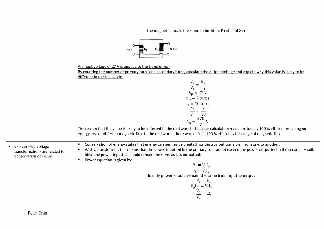
themagneticfluxisthesameinboththePcoilandScoil
An input voltage of 27 V is applied to the transformer By counting the number of primary turns and secondary turns, calculate the output voltage and explain why this value is likely to be different in the real world.
VsV|= nsn|
Vs = 27V ns = 7turns n| = 10turns 27V|=
710
V| = 2707V
The reason that the value is likely to be different in the real world is because calculation made are ideally 100 % efficient meaning no energy loss or different magnetic flux. In the real world, there wouldn’t be 100 % efficiency in linkage of magnetic flux.
§ explain why voltage transformations are related to conservation of energy
§ Conservation of energy states that energy can neither be created nor destroy but transform from one to another. § With a transformer, this means that the power inputted in the primary coil cannot exceed the power outputted in the secondary coil.
Ideal the power inputted should remain the same as it is outputted. § Power equation is given by:
Ps = VsIs P| = V|I|
Ideallypowershouldremainthesamefrominputtooutput ∴ Ps = P| VsIs = V|I|
∴ VsV|= I|Is

Peter Tran
§ The relationships are inversely proportional, thus an increase in voltage will result in a decrease in current [Step-up Transformer. Conversely a decrease in voltage will result in an increase of current [Step-down transformers].
VsV|=I|Is= nsn|
§ This is fitted if 100% power inputted is equal to the 100% outputted. § Energy is dispatched on the soft iron core due to the change in magnetic flux inducing eddy current. Which is represented as heat.
§ explain the role of transformers in electricity sub-stations
§ The roles of transformers in electricity sub stations is to reduce the cost and efficiency on the transmission of electrical energy. § When electricity produced by generators are flowing over long distance to households [without transformers], they will suffer a lot of
power loss and this is very disadvantageous. Evident in P=VI § Hence the roles of transformers are to minimize the power loss, with little cost using a step-up transformer. They maximize the voltage
as high as possible to minimize the current produce as there is little power loss. § Process of transformers in sub stations:
– Generators at power station will produce up to 23 kV output voltage – Which are stepped up [using a step-up transformer] to 330 kV, as they travel in high transmission lines, there high voltage cause
low current, which means easier flow over long distances will very little power loss. – At regional sub stations the voltage is lower 110 kV or 66 kV – Then are step-up down further to 11kV or 33kV, by local substation for pole transmission [distribution poles]. – Transmission line on poles, will be connected to a transformer box which reduces the voltage to 240 V [domestic mains] or 415 V
[industrial uses]. § Basically, the role of transformers maximizes the voltage for transmission, then progressive reduces voltage as it reaches consumers.
§ discuss why some electrical appliances in the home that are connected to the mains domestic power supply use a transformer
§ Electricity coming into a household will be at 240 V AC. § Electrical appliance can only be performance with their required voltage input. § Electrical appliance like the television require more than 240 V to function, thus it requires a step-up transformer, to push up the 240 V
to the required voltage to power on the television. Without a transformer, the TV simply won’t turn on since the 240 V input is far too less
§ Conversely a battery or a phone charge, requires less than a 240 V to function, thus it requires a step-down transformer to lower the voltage to suit the appliance. Without these transformers, the 240 V would simply be much for the appliance to handle with the overexertion of current, hence explode or short circuit.
§ Also, many appliances run on DC [computer, laptops] hence won’t function with the 240 V AC. A transformer rectifier is installed to convert the AC into DC for the DC appliances.

Peter Tran
§ discuss the impact of the development of transformers on society
§ domestic electricity would mean that it will deliver a 240 V and 415 V with the use of a transformer from power stations. § Without the use of transformers, there will be large energy loss and will be very inefficient [increased the rural living standard]. § Impact on society:
– Transformers have made it possible for electrical energy to be transmitted over long distance, with very little power loss. This is energy efficiency and economically beneficial. Hence reduces makes electrical energy affordable for consumers.
– This long transmission of energy means that power stations can be located away from residential area, reducing the air pollution and harmful effects society is subjected to.
– Remote areas are now able to access electrical energy due grid-supplied electricity by step-down transformers. This raise the living standard and increases the scope of living.
– Transformers have allowed a range of everyday appliances to be continentally connected to the main power supply by stepping up and down voltage.
– Transformers has allowed us to only need one electrical source [AC]. – Step-down transformers in household appliance, has made appliance safer. – Always for manipulation of voltage and energy with ease and at little cost.
§ Negative impact of transformer: – Change the way of living by us becoming more depend. – Transformers has allowed for the development of efficient machines that is increasing taking the workplace, which lower the
standard for living for unskilled workers. – Step-up transformers can increase the risk of electrocution.
§ Development of transformers was crucial in determining the success of the AC system over DC electricity, and in the widespread proliferation of electricity grids.
Analysis the impact of transformer on society [8marks] – Transformers has majorly affect our society about in a positive and negative way. – Positive: – With the development of transformers, they have allowed for altering the voltage with either a step-up or step-down transformer. – With those transformers, it has made possible for long range transmission of electrical energy. This means increasing the voltage
from power station, using a step-up transformer to allow for a successful transmission with very little power loss. Meaning it is more efficiency and will cost less.
– With the long-range transmission, power station can be located away from rural residential areas, to reduce to pollution is subject to. Sub-station can be distributed across towns with transformers increasing voltage for transmission and decrease as they reach houses.
– Also, with transformers allowing long range electrical transmission, it has made energy more affordable to all consumers. Remote

Peter Tran
areas are also, now able to access electricity with grid-supplied high voltage electricity, which are reduced by transformers to the household. This increases the living standards.
– Also, household appliances can be conveniently being supplied by the main supplies with the development of transformers as voltage can be manipulated to suit the appliance required voltage input.
– Negative: – With transformers producing efficient electrical energy, humans have become more depend on electricity, as it become a necessity
for the everyday life. – Also, transformers have led to the development of advance machines that are taking over the workplace. This increases the
unemployment rate and lowers the living standards for unskilled workers. – Hence transformers have majorly affect society’s growth and standard of living, having the positive outweigh the negative. – Transformers allow the widespread use of electronic devices powered by mains voltages. Such proliferation of electronic devices
has had significant effects on society, including rapid communication and data processing resulting in significant changes to the workforce, and the development of a large IT sector. Transformers allow the efficient distribution of electrical energy over distances, so that consumers may be located at a distance from the point of generation. This reduces the effect of pollution in large cities, improving living conditions and the focus of health programs. It also allows an equitable standard of living to be delivered across the population regardless of location.
Students: Notes:
§ perform an investigation to model the structure of a transformer to demonstrate how secondary voltage is produced
§ solve problems and analyse information about transformers using:
§ VsV|=I|Is= nsn|
Vp
Vs=npns

Peter Tran
§ gather, analyse and use available evidence to discuss how difficulties of heating caused by eddy currents in transformers may be overcome
§ As electrical energy flow in the primary coil to the secondary, it will produce a change in magnetic flux, inducing eddy currents on the soft iron core. [Faraday’s Law of magnetic induction].
§ The presence of eddy current is a form of heat energy, which can be represented as power loss in transformers, thus having excessive heat will damage the coils and the transformers.
§ To overcome heat from eddy current produced in the iron core: – The use of laminated iron core. This is having layer of soft iron cores compressed but separated by thin insulating layers.
§ Thus, when eddy currents are produce on to core, the insulated layer will prevent them from producing one big eddy current. These small induced eddy current has less of a value than one big eddy current.
§ Limits the circulation of forming one eddy current, hence reducing the heating. – Use of ferrite material as the iron core – Heat sink are usually used to cool down the core over a large surface area. – The use of dark casing, or black material is implemented as dark color absorb the internal heat quickly and dissipate into the
external environment. – Thicker wires mean less resistivity, hence reducing eddy current. – Casing with slit allow air to pass through and cool the core. – Internal fans or water cooling
§ gather and analyse secondary
information to discuss the need for transformers in the transfer of electrical energy from a power station to its point of use
§ Power loss or energy loss can be shown in: P = IER
With this equation, the lower the current, means the lower the power loss. Hence the use of a step-up transformer with AC will overcome powerless. As the amount of AC current flowing through
§ With step-up transformers, we are allowing to heighten the voltage for long range transmissions and power towns and rural area. § The transmission distance can be increased and lowers costs. § Transformers also allow voltages to be stepped down as electricity enters population centres § Transformers can also be used to step up/down voltages to meet different demands. § Therefore, one mains supply can be used to power many devices. § To get electrical energy from the power station to the point of use [household]:
– Electrical energy is provided by the power stations at a voltage of 240V – This is stepped-up to 220kV and 500kV by a step-up transformer for transmission lines. [The high voltage would mean a low
current, meaning that transformation of energy is much more deliverable with very less power loss]. – Regional sub stations will contain transformers that step-down the voltage to around 22kV or 33kV.

Peter Tran
– Before the distribute power lines with transformers step it down even further to the standard 240 V into consumer’s house
5. Motors are used in industries and the home usually to convert electrical energy into more useful forms of energy
Students: Notes:
§ describe the main features of an AC electric motor
§ AC electric motor: Like a DC motor except that do not require a commutator. § An electric motor consists of two main parts:
– Stator: Stationary part of motor, that connects the frame of the machine. It provides a magnetic field for the rotor to rotate. – Rotor: Has an armature and coil, and is the rotating part of a motor.
§ Two type of electric motors; AC Synchronous Motor, AC Induction Motors. § AC Synchronous Motor / Standard AC Motor / Universal DC Motor.
– These motors are the general motor consisting of stator, rotor with commutators and brushes for conductivity. – The speed of the coil is synchronized to the frequency of the applied voltage. – A DC motor will allow one direction of current and AC will allow for alternating current. – The reason synchronous motor isn’t used, because they are inefficient and will fail when the machine requires heavy load. Heavy
load will slow down the rotor and lose the synchronous, making them bad. – Only support single phase.
§ Induction Motor – These motors have stator and rotor, but doesn’t require a connection. Instead uses a rotating external magnetic field. – In a three phased AC induction motor, the changing magnetic field will set up an induced current in the rotor, allowing it to spin.
[Torque is produced by the interaction of magnetic field]. § Components
– The stator in a three-phased induction motor, will consist of three pairs of electromagnets. These electromagnets are made by having wires wound an soft iron core. Note that their polarity of these wires when current is supplied must be opposite and the end of the stators. The wires are linked electrically. When current is supplied, the induced wires will provided magnetic field throughout the stator as the current flows in the wire.
– The rotor part of an induction motor, is known as a squirrel cage motor. It is a cyclinder made of copper or aluminium bars connected by two ends rings and encased in a laminared iron armture. The lamination allows for an intensifition of the magnetic field passing as well as decrease the heat via eddy currents. An shaft is located in the middle
– These components makes the most common AC induction motor; 3 phased Squirrel cage motor. [Converts electrical energy into mechanical energy.

Peter Tran
§ Functionality – When AC is supplied the change in current creates a rotating magnetic field. From one pair electromagnetic to another to another
and repeats. 3 Phased. This rotating magnetic field will create a changing flux on the squirrel cage. This results in induced current on the squirrel cage’s bars, hence a external mangnetic field. This interaction of the changing magnetic field of electromagnetics and magnetic field of the squirrel cage, will experience a force, namingly torque. [Motor effect]. As a reasult to torque, the rotor will spin and rotate in the direction of the changing magnetic field.
– The notion of the a cat mouse chase is alluded in a induction motor beacause, the rotating magnetic field on the stator will rotate at a faster speed then the rotor, as the rotor/squireel cage is also chasing the changing magnetic field to oppose the change from occurring.
§ In terms of Lenz’s Law – Lenz’s Law states that an induced current will flow in a direction that oppose the change. Hence in induction motors, the rotor will
want to stop the change made by the rotating magnetic field by moving will the direction of the rotating magnetic field. It will forever try to prevent that change by rotating will it and not against, because going against the rotating will not be logical.
§ Slip speed – If the speed of the rotor rotated at the same rate as the rotating magnetic field, there would be no motion between the two,
hence no change, resulting force and induced current. – If the coil is to experience a force [torque], then it must have some relative movement, such as lag or be constantly slipping
behind the magnetic field. – This means that the rotation of the rotor must be less than the magnetic field’s. – Slip speed is the term given to the difference in rotational speed of the coil and the magnetic field.
§ Advantages of Induction motors over conventional universal motors – Low maintenance. This is because there is no contact between stators and rotor using a brush and commutators. – Without features of an conventional motor, they are simpler motors. – Less wear and more safe, as there is less friction meaning less heat and sparks. – Relatively low cost.
§ Disadvantages of Induction motors over conventional universal motors. – Speed is limit as it cannot exceed the frequency of the stator. [Australia è 50Hz] – Has a low starting torque. – Requires 3 phases instead of one, which makes them more complex.

Peter Tran
Students: Notes:
§ perform an investigation to demonstrate the principle of an AC induction motor
Examining the principle involved in an AC Induction Motor § Aim: To demonstrate the principle of induction motors. § Equipment: Aluminum foil, compass needle [drill chuck], thread, magnet bar, retort stand. § Method:
– With aluminum foil, a disc was formed and attached to the end of thread. – The thread is then attached onto a retort stand using a clamp, and this allows the disc to be hanged vertically and rotate freely. – A compass needle [drill chuck] is induced with a magnet bar, which allows for a free rotation. – The magnet using the drill is placed under the disc and rotated in one direction. – The hanging disc’s movement is observed.
§ Diagram: § Result: The movement of the disc was in the same direction as the movement of the magnet. The magnetic field from the magnetics
associated with a flat surfaced conductor in relative motion, induced eddy currents and hence produced a force of attraction between the rotor and stator which causes the rotor to follow the rotating magnet. Different result answer The change in flux caused by the magnetic induced eddy currents on the foil and makes is resist to the rotating magnetic field [Lenz’s Law]. These induced currents interact with the B field, and produces a force [motor effect]. This force causes an attraction, making the disc chase in a same direction circular motion of the magnet, as it dragged along.
§ Others: As the speed of the disc increased, it tried to reach the speed, but never surpassed. Reversing the direction, will cause the disc to slow down, and halt before, spinning in the opposite direction.
§ gather, process and analyse information to identify some of the energy transfers and transformations involving the conversion of electrical energy into more useful forms in the home and industry
§ Electrical Energy: Electrical energy is a form of energy that is used in our daily lives. It widespread and domestic uses has allowed for many useful achievements and make life easier and efficient. They also can be converted to other forms of the energy easily.
§ Energy transfer is the transfer of energy from one location to another, for a conversion the same electrical energy. For both homes and industries, electrical energy can be converted to kinetic energy (e.g. hair dryers, washing machines) or electromagnetic radiation (e.g. light bulbs, microwave ovens, computer screens) or thermal energy (electric cooktops, electric heaters, electric blankets).
§ In the home: – Electrical energy ->light energy in light bulbs. – Electrical energy -> heat energy for heaters and cooking devices such as toasters – Electrical energy -> kinetic energy in fans

Peter Tran
§ Industry: – Electrical energy -> kinetic energy which then drives the machinery used in the production of goods. – Electrical Energy -> EM radiation for X-rays in imaging the interior of motors, foundations. Etc – Electrical energy -> chemical energy in electrolysis