NXperience - NOVUS Automation
50
NOVUS AUTOMATION 1/50 NXperience INSTRUCTION MANUAL V1.0x E 1. NXPERIENCE INTRODUCTION ....................................................................................................................................................................4 2. INSTALLATION AND REQUIREMENTS ........................................................................................................................................................5 2.1 INSTALLATION...............................................................................................................................................................................................5 2.2 MINIMUM SYSTEM REQUIREMENTS ..........................................................................................................................................................6 3. STARTING UP NXPERIENCE........................................................................................................................................................................7 3.1 DOWNLOAD ...................................................................................................................................................................................................7 3.2 CONFIGURE ...................................................................................................................................................................................................7 3.3 DIAGNOSTICS ...............................................................................................................................................................................................7 3.4 MONITOR .......................................................................................................................................................................................................8 3.5 NOVUS CLOUD ..............................................................................................................................................................................................8 3.6 SOFTWARE PREFERENCES ........................................................................................................................................................................8 4. NOVUS CLOUD MANAGER...........................................................................................................................................................................9 4.1 PREREQUISITES TO SENDING LOGS TO NOVUS CLOUD .......................................................................................................................9 4.2 NOVUS CLOUD MANAGER...........................................................................................................................................................................9 4.3 SELECTING NOVUS CLOUD IN THE SELECT DEVICE GUIDE................................................................................................................11 5. SOFTWARE PREFERENCES ......................................................................................................................................................................12 5.1 PREFERENCES SCREEN ...........................................................................................................................................................................12 5.2 SOFTWARE UPDATE VIA NXPERIENCE ...................................................................................................................................................12 6. DOWNLOAD LOGS AND TREATMENT ......................................................................................................................................................14 6.1 DATA GRAPH, MAP AND TABLE ................................................................................................................................................................14 6.1.1 DATA GRAPH FEATURES...........................................................................................................................................................................14 6.2.1 MAP FEATURES ..........................................................................................................................................................................................15 6.3.1 INFORMATION FIELDS ...............................................................................................................................................................................15 6.2 OPEN FILE, DOWNLOAD, SAVE TO FILE ..................................................................................................................................................16 6.3 GRAPH PROPERTIES .................................................................................................................................................................................16 6.3.1 DEFAULT GRAPH PROPERTIES FUNCTION ............................................................................................................................................16 6.3.2 ASSUMPTIONS AND LIMITATIONS ............................................................................................................................................................17 6.4 FILTER LOG ................................................................................................................................................................................................. 17 6.4.1 DEFAULT FILTER LOG OPERATION..........................................................................................................................................................17 6.4.2 ASSUMPTIONS AND LIMITATIONS ............................................................................................................................................................17 6.5 CHART JUNCTION.......................................................................................................................................................................................18 6.5.1 DEFAULT FUNCTIONING OF A JUNCTION ...............................................................................................................................................18 6.5.2 ASSUMPTIONS AND LIMITATIONS FOR A JUNCTION ............................................................................................................................18 6.5.3 SAVING AND OPENING FILES WITH GRAPH JUNCTIONS......................................................................................................................18 6.6 REPORTS AND EXPORTING LOGS ...........................................................................................................................................................19 6.6.1 STEPS TO CREATE A REPORT ................................................................................................................................................................. 19 6.6.2 PARAMETERS OF A REPORT ....................................................................................................................................................................19 6.6.3 TYPES OF REPORTS ..................................................................................................................................................................................20 6.6.3.1 R1 - ALARMS ................................................................................................................................................................................................ 20 6.6.3.2 R2 - GRAPH .................................................................................................................................................................................................. 20 6.6.3.3 R3 - GRAPH + TABLE .................................................................................................................................................................................. 20 6.6.3.4 R4 - ONE CHANNEL .................................................................................................................................................................................... 20 6.6.3.1 R5 AND R6 - EVENTS AND ONE ALARM EVENTS ...................................................................................................................................21 6.6.3.2 R7 - TOTALIZATION..................................................................................................................................................................................... 21 6.6.4 REPORT VIEWING SCREEN.......................................................................................................................................................................21 6.6.5 EXPORT TO OTHER FORMATS ................................................................................................................................................................. 21 6.7 SENDING DATA TO THE CLOUD ...............................................................................................................................................................22 6.7.1 ASSUMPTIONS AND RESTRICTIONS FOR SENDING DATA TO NOVUS CLOUD .................................................................................22 6.1 DOWNLOAD LOGS BY NOVUS CLOUD.....................................................................................................................................................22 7. CUSTOMIZED CHANNEL CALIBRATION ...................................................................................................................................................24
-
Upload
khangminh22 -
Category
Documents
-
view
3 -
download
0
Transcript of NXperience - NOVUS Automation

NOVUS AUTOMATION 1/50
NXperience
INSTRUCTION MANUAL V1.0x E
1. NXPERIENCE INTRODUCTION ....................................................................................................................................................................4 2. INSTALLATION AND REQUIREMENTS ........................................................................................................................................................5 2.1 INSTALLATION ...............................................................................................................................................................................................5 2.2 MINIMUM SYSTEM REQUIREMENTS ..........................................................................................................................................................6 3. STARTING UP NXPERIENCE ........................................................................................................................................................................7 3.1 DOWNLOAD ...................................................................................................................................................................................................7 3.2 CONFIGURE ...................................................................................................................................................................................................7 3.3 DIAGNOSTICS ...............................................................................................................................................................................................7 3.4 MONITOR .......................................................................................................................................................................................................8 3.5 NOVUS CLOUD ..............................................................................................................................................................................................8 3.6 SOFTWARE PREFERENCES ........................................................................................................................................................................8 4. NOVUS CLOUD MANAGER ...........................................................................................................................................................................9 4.1 PREREQUISITES TO SENDING LOGS TO NOVUS CLOUD .......................................................................................................................9 4.2 NOVUS CLOUD MANAGER ...........................................................................................................................................................................9 4.3 SELECTING NOVUS CLOUD IN THE SELECT DEVICE GUIDE................................................................................................................11 5. SOFTWARE PREFERENCES ......................................................................................................................................................................12 5.1 PREFERENCES SCREEN ...........................................................................................................................................................................12 5.2 SOFTWARE UPDATE VIA NXPERIENCE ...................................................................................................................................................12 6. DOWNLOAD LOGS AND TREATMENT ......................................................................................................................................................14 6.1 DATA GRAPH, MAP AND TABLE ................................................................................................................................................................14 6.1.1 DATA GRAPH FEATURES ...........................................................................................................................................................................14 6.2.1 MAP FEATURES ..........................................................................................................................................................................................15 6.3.1 INFORMATION FIELDS ...............................................................................................................................................................................15 6.2 OPEN FILE, DOWNLOAD, SAVE TO FILE ..................................................................................................................................................16 6.3 GRAPH PROPERTIES .................................................................................................................................................................................16 6.3.1 DEFAULT GRAPH PROPERTIES FUNCTION ............................................................................................................................................16 6.3.2 ASSUMPTIONS AND LIMITATIONS ............................................................................................................................................................17 6.4 FILTER LOG .................................................................................................................................................................................................17 6.4.1 DEFAULT FILTER LOG OPERATION..........................................................................................................................................................17 6.4.2 ASSUMPTIONS AND LIMITATIONS ............................................................................................................................................................17 6.5 CHART JUNCTION .......................................................................................................................................................................................18 6.5.1 DEFAULT FUNCTIONING OF A JUNCTION ...............................................................................................................................................18 6.5.2 ASSUMPTIONS AND LIMITATIONS FOR A JUNCTION ............................................................................................................................18 6.5.3 SAVING AND OPENING FILES WITH GRAPH JUNCTIONS......................................................................................................................18 6.6 REPORTS AND EXPORTING LOGS ...........................................................................................................................................................19 6.6.1 STEPS TO CREATE A REPORT .................................................................................................................................................................19 6.6.2 PARAMETERS OF A REPORT ....................................................................................................................................................................19 6.6.3 TYPES OF REPORTS ..................................................................................................................................................................................20 6.6.3.1 R1 - ALARMS ................................................................................................................................................................................................ 20 6.6.3.2 R2 - GRAPH .................................................................................................................................................................................................. 20 6.6.3.3 R3 - GRAPH + TABLE .................................................................................................................................................................................. 20 6.6.3.4 R4 - ONE CHANNEL .................................................................................................................................................................................... 20 6.6.3.1 R5 AND R6 - EVENTS AND ONE ALARM EVENTS ................................................................................................................................... 21 6.6.3.2 R7 - TOTALIZATION ..................................................................................................................................................................................... 21 6.6.4 REPORT VIEWING SCREEN .......................................................................................................................................................................21 6.6.5 EXPORT TO OTHER FORMATS .................................................................................................................................................................21 6.7 SENDING DATA TO THE CLOUD ...............................................................................................................................................................22 6.7.1 ASSUMPTIONS AND RESTRICTIONS FOR SENDING DATA TO NOVUS CLOUD .................................................................................22 6.1 DOWNLOAD LOGS BY NOVUS CLOUD .....................................................................................................................................................22 7. CUSTOMIZED CHANNEL CALIBRATION ...................................................................................................................................................24

NOVUS AUTOMATION 2/50
7.1 DEFAULT CUSTOMIZED CALIBRATION FUNCTIONING ..........................................................................................................................24 7.2 CUSTOMIZED CALIBRATION INTERFACE FOR CHANNELS...................................................................................................................24 8. DEVICE MONITORING ................................................................................................................................................................................25 8.1 DEFAULT MONITORING FUNCTIONING ...................................................................................................................................................25 8.2 VISUAL FIELDS ON THE MONITORING SCREEN .....................................................................................................................................25 8.2.1 DOT CHART GRAPH ...................................................................................................................................................................................25 8.2.2 BAR GRAPH .................................................................................................................................................................................................26 8.2.3 ALARMS........................................................................................................................................................................................................27 8.2.4 LED PANEL...................................................................................................................................................................................................27 8.3 COMPONENT RESIZING .............................................................................................................................................................................28 8.4 CONTROL BUTTONS ..................................................................................................................................................................................28 9. CONFIGURATION DEVICE ..........................................................................................................................................................................29 10. DEVICES DIAGNOSTIC ...............................................................................................................................................................................30

NOVUS AUTOMATION 3/50
11. NXPERIENCE TRUST INTRODUCTION .....................................................................................................................................................32 12. OPERATION MODES ...................................................................................................................................................................................33 12.1 STANDARD OPERATION MODE: NXPERIENCE STANDARD ..................................................................................................................33 12.2 VALIDATION OPERATION MODE: NXPERIENCE TRUST ........................................................................................................................33 13. ACCESS TO NXPERIENCE TRUST ............................................................................................................................................................34 13.1 PRIMARY ADMINISTRATOR USER ............................................................................................................................................................35 13.2 BLOCKED OR NON-EXISTING USER.........................................................................................................................................................35 13.3 EXPIRED PASSWORD ................................................................................................................................................................................35 14. SECURITY SYSTEM ADMINISTRATION ....................................................................................................................................................36 14.1 USER LIST ....................................................................................................................................................................................................36 14.1.1 USER CONFIGURATION .............................................................................................................................................................................36 14.1.2 USER REGISTRATION ................................................................................................................................................................................37 14.1.3 REPORT AND EXPORT ...............................................................................................................................................................................39 14.2 LIST OF AUDIT LOGS LIST .........................................................................................................................................................................40 14.2.1 FILTER ..........................................................................................................................................................................................................40 14.2.2 REPORT AND EXPORT ...............................................................................................................................................................................41 14.3 GENERAL SETTINGS ..................................................................................................................................................................................42 14.3.1 DIRECTORY SELECTION ............................................................................................................................................................................42 14.3.2 GENERAL USER SETTINGS .......................................................................................................................................................................42 14.3.3 DEVICE CONFIGURATION ..........................................................................................................................................................................42 14.4 HOW TO GENERATE REPORTS FOR DOWNLOADED DATA AND EXPORT TO DIFFERENT FORMATS ...........................................42 14.5 DATA SECURITY .........................................................................................................................................................................................43 14.5.1 CRYPTOGRAPHY ........................................................................................................................................................................................43 14.5.2 DATA .............................................................................................................................................................................................................43 15. CONFIGURING DEVICES WITH NXPERIENCE TRUST ............................................................................................................................44 16. 21 CFR PART 11 ..........................................................................................................................................................................................45 16.1 PRESENTATION ..........................................................................................................................................................................................45 16.2 COMPLIANCE MATRIX ................................................................................................................................................................................45 16.2.1 CONTROLS FOR CLOSED SYSTEMS (11.10) ...........................................................................................................................................45 16.2.2 CONTROLS FOR OPEN SYSTEMS (11.30) ................................................................................................................................................47 16.2.3 SIGNATURE MANIFESTATIONS (11.50) ....................................................................................................................................................47 16.2.4 SIGNATURE/RECORDING LINKING (11.70) ..............................................................................................................................................47 16.2.5 GENERAL REQUIREMENTS – ELECTRONIC SIGNATURES (11.100) .....................................................................................................48 16.2.6 ELECTRONIC SIGNATURE COMPONENTS AND CONTROL (11.200) ....................................................................................................49 16.2.7 CONTROLS FOR IDENTIFICATION CODES/PASSWORDS (11.300) .......................................................................................................50

NOVUS AUTOMATION 4/50
1. NXPERIENCE INTRODUCTION The NXperience software is the main tool for configuration, data download and analysis for NOVUS line of wireless transmitters and data loggers. It allows exploring all the features of the devices by communicating through its USB and TCP-IP interfaces and NOVUS Cloud resource. It is also a complete tool for managing data downloaded by devices, allowing graphical analysis of multiple data, alarm processing, positioning map visualization, mathematical calculations and reporting and export of multiple formats. It also has diagnostic and commissioning tools specific to each device, making it easier to detect problems and perform various tests. The software also enables you to create and manage a NOVUS Cloud account, the data storage portal of your NOVUS devices. NXperience is a complete configuration tool for NOVUS's new line of devices. This manual describes generic software features. For instructions on configuring devices, please refer to the specific operating manual. The software can be downloaded free of charge from our website www.novusautomation.com, in the Downloads area. For specific information about NXperience Trust, go to the second part of this manual.
NOVUS AUTOMATION 5/50
2. INSTALLATION AND REQUIREMENTS
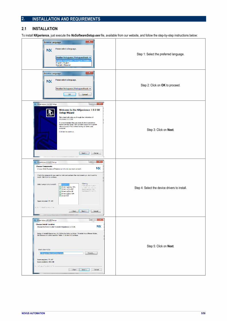
2.1 INSTALLATION To install NXperience, just execute the NxSoftwareSetup.exe file, available from our website, and follow the step-by-step instructions below:
Step 1: Select the preferred language.
Step 2: Click on OK to proceed.
Step 3: Click on Next.
Step 4: Select the device drivers to install.
Step 5: Click on Next.
NOVUS AUTOMATION 6/50
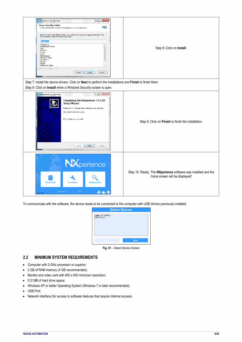
Step 6: Click on Install.
Step 7: Install the device drivers. Click on Next to perform the installations and Finish to finish them. Step 8: Click on Install when a Windows Security screen is open.
Step 9: Click on Finish to finish the installation.
Step 10: Ready. The NXperience software was installed and the home screen will be displayed!
To communicate with the software, the device needs to be connected to the computer with USB drivers previously installed.
Fig. 01 – Select Device Screen
2.2 MINIMUM SYSTEM REQUIREMENTS • Computer with 2-GHz processor or superior; • 2 GB of RAM memory (4 GB recommended); • Monitor and video card with 800 x 600 minimum resolution; • 512 MB of hard drive space; • Windows XP or better Operating System (Windows 7 or later recommended); • USB Port; • Network interface (for access to software features that require Internet access).

NOVUS AUTOMATION 7/50
3. STARTING UP NXPERIENCE Once started, NXperience shows five buttons for the features that the software offers: Data Download, Device Configuration, Device Diagnostics, located on the main buttons, and Monitoring Devices, NOVUS Cloud and Software Preferences, located on the bottom buttons.
Fig. 02 – Home Screen
3.1 DOWNLOAD This option makes it possible to download data from devices to which the software provides support or open downloaded files previously saved by the software. After a download is completed or while a downloaded file is open, the user is taken to the download screen, which offers several customization options, exports to other formats, report generation, formula application, sending data to the NOVUS Cloud. This feature will be explained in the Download Logs and Treatment chapter.
Fig. 03 – Download Screen
3.2 CONFIGURE This option provides the Read Device feature for devices the software supports and the Create Configuration feature for devices, which can be saved to the file for later use. It also allows for opening previously saved configuration files. Each device has an exclusive configuration screen, with its respective specificities. This feature is explained in detail in the manual for each device that the software supports.
Fig. 04 – Configuration Screen
3.3 DIAGNOSTICS This option provides diagnostics functionality, which allows you to observe the operation of digital and analog channels and various communication interfaces, such as Ethernet interface and RS485 interface, and perform value and status forcing tests. Each device has a unique diagnostic screen, which includes the respective characteristics of each. This functionality will be explained in detail in the manual of each device for which the software supports.

NOVUS AUTOMATION 8/50
3.4 MONITOR
Clicking on the button will display the device monitoring screen. With this option, it is possible to monitor indefinitely and locally a device connected to the USB port of the computer or a device registered in the NOVUS Cloud remotely. This feature allows you to monitor the channel values of the selected device, display notifications about alarm states, and perform calculations of minimum, maximum and average values of each channel for the monitored period. This functionality is described in detail in detail in the Device Monitoring chapter.
3.5 NOVUS CLOUD
Clicking on the button will display the NOVUS Cloud management screen. This feature allows you to add, remove and re-enable devices, as well as make remote settings on devices linked to the NOVUS Cloud and manage the data downloaded by each device. The NOVUS CLOUD Manager chapter provides information on how to register users and how to add devices to NOVUS Cloud, although the specific features of NOVUS Cloud are described in detail in its specific manual, available on our website.
3.6 SOFTWARE PREFERENCES
Clicking the button will display the software preferences screen, which allows you to set the default language, set the behavior of the software on startup and check for automatic updates. This feature will be described in detail in the Software Preferences chapter.

NOVUS AUTOMATION 9/50
4. NOVUS CLOUD MANAGER NOVUS Cloud is a portal in the cloud that allows you to manage the downloaded logs and make remote configurations on the registered devices. Check the specific NOVUS Cloud manual for more precise information on how it works.
4.1 PREREQUISITES TO SENDING LOGS TO NOVUS CLOUD • Active Internet connection. • Connection without security restrictions that could block the software’s access to the network.
4.2 NOVUS CLOUD MANAGER In the lower right corner of the NXperience home screen is located the button , which allows, once the user is logged in, to reactivate, remove or add a device to NOVUS Cloud.
Fig. 05 – NOVUS Cloud Manager
If you do not have an account, you can create it by clicking on the Click here to sign up now option. The link will guide you to NOVUS Cloud registration page, which will be accessed through the user's default browser:
Fig. 06 – NOVUS Cloud Sign Up
On the registration page you will need to fill in the email, the first and last name of the user for whom the registration will be created and agree to the terms of service before clicking the Create Account button.
Fig. 07 – Successful registration

NOVUS AUTOMATION 10/50
Once the account is created, the user will automatically receive a confirmation email, informing an activation link and a temporary password for the previously created account:
Fig. 08 – Account activation
For more information on how to access your NOVUS Cloud account directly through the browser, check the NOVUS Cloud manual. Once logged in, the NOVUS Cloud Manager home screen will display information about the name, model, serial number, status and CIK of the devices already registered, as well as allow them to be removed or reactivated, being they have expired or inactive status. You will also be able to add new devices to the manager. To do so, just click the Add button. The Add button will generate a pop-up, called Device Information, that requests data from the device to be registered, as can be seen in the image below:
Fig. 09 – Device information to add
To add a device to the NOVUS Cloud Manager, you must provide your serial number and your IMEI or MAC in addition to a name for the device to be registered. The Device Name field can support up to 30 characters. The device model, however, will be automatically recognized by the software. Once the device has been registered, it will appear on the screen of the NOVUS Cloud manager, as can be seen below:
Fig. 10 – Registering a device
The standard of NOVUS free accounts includes a single Portal, which serves to separate the devices into blocks according to the user's needs. To hire more than one portal, contact the NOVUS business sector for more accurate information about the service. Although an account is capable of multiple devices, each device can only be registered in a single account. Attempting to register a device previously registered in another account will generate the following popup:
Fig. 11 – Device already linked
A device added to NOVUS Cloud Manager will remain Inactive until it is activated. To activate a device, the user has 24 hours after the registration to make the device communicate with NOVUS Cloud. If communication with NOVUS Cloud does not occur, the status will change to Expired and the user will need to reactivate the device to perform the process.

NOVUS AUTOMATION 11/50
To re-enable it, simply click on the Reactivate button and confirm its reactivation:
Fig. 12 – Re-enable the device
As can be seen below, reactivating a device, however, can result in a delay of up to five minutes for reading and obtaining your new status.
Fig. 13 – Re-enable the device: 5 minutes delay
If there is no longer any interest in keeping the device registered to a particular account or if it is in the interest of registering the device in another account, it is possible to delete it from the NOVUS Cloud Manager. It is necessary to select the device to be removed with a simple click on it and click on the Remove button, confirming the exclusion:
Fig. 14 – Delete a device
4.3 SELECTING NOVUS CLOUD IN THE SELECT DEVICE GUIDE NXperience also allows remote access to devices previously registered and linked to NOVUS Cloud by selecting the option NOVUS Cloud:
Fig. 15 – Select a device: NOVUS Cloud
Selecting NOVUS Cloud will ask you to log in your NOVUS Cloud account, as you can see in the image below:
Fig. 16 – NOVUS Cloud login
Once you made NOVUS Cloud login, the devices registered in NOVUS Cloud will appear as follows, the first tag corresponding to your model, the second tag corresponding to the user's given name and the third tag corresponding to the serial number of the device registered:
Fig. 17 – NOVUS Cloud Tags
Logging in with the device through NOVUS Cloud will offer the same functionality as with the USB interface, but there may be a short period of time to assimilate the implemented updates.
NOVUS AUTOMATION 12/50
5. SOFTWARE PREFERENCES
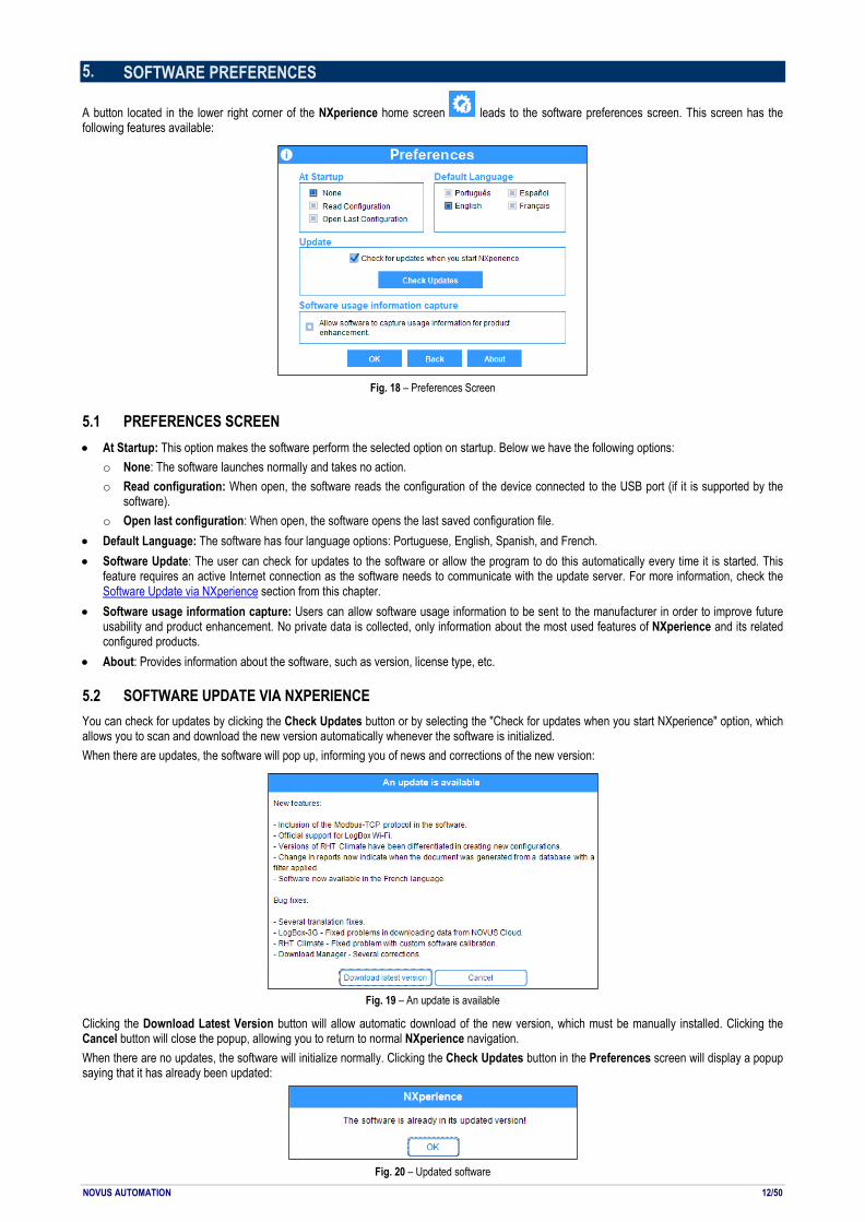
A button located in the lower right corner of the NXperience home screen leads to the software preferences screen. This screen has the following features available:
Fig. 18 – Preferences Screen
5.1 PREFERENCES SCREEN • At Startup: This option makes the software perform the selected option on startup. Below we have the following options:
o None: The software launches normally and takes no action. o Read configuration: When open, the software reads the configuration of the device connected to the USB port (if it is supported by the
software). o Open last configuration: When open, the software opens the last saved configuration file.
• Default Language: The software has four language options: Portuguese, English, Spanish, and French. • Software Update: The user can check for updates to the software or allow the program to do this automatically every time it is started. This
feature requires an active Internet connection as the software needs to communicate with the update server. For more information, check the Software Update via NXperience section from this chapter.
• Software usage information capture: Users can allow software usage information to be sent to the manufacturer in order to improve future usability and product enhancement. No private data is collected, only information about the most used features of NXperience and its related configured products.
• About: Provides information about the software, such as version, license type, etc.
5.2 SOFTWARE UPDATE VIA NXPERIENCE You can check for updates by clicking the Check Updates button or by selecting the "Check for updates when you start NXperience" option, which allows you to scan and download the new version automatically whenever the software is initialized. When there are updates, the software will pop up, informing you of news and corrections of the new version:
Fig. 19 – An update is available
Clicking the Download Latest Version button will allow automatic download of the new version, which must be manually installed. Clicking the Cancel button will close the popup, allowing you to return to normal NXperience navigation. When there are no updates, the software will initialize normally. Clicking the Check Updates button in the Preferences screen will display a popup saying that it has already been updated:
Fig. 20 – Updated software

NOVUS AUTOMATION 13/50
If there is no Internet connection, required to download any available updates, the software will display the following popup:
Fig. 21 – No Internet connection
NOVUS AUTOMATION 14/50
6. DOWNLOAD LOGS AND TREATMENT On this screen, the user will download data from the devices. Each download is separated into a graph with data that can be worked with to extract the information required and desired by the user. For example, the user can generate new graphs, selecting only the channels related to the measurements of each device, from there generating a complete report about the humidity status of a location. In the case of devices that have the GPS interface and once the functionality has been enabled in its configuration, it is possible to generate a map of the route made by them, relating it to the values downloaded by the enabled channels, and offering information about the latitude and the length of each log in memory, which will be portrayed by a small red circle. On this screen it is also possible to send the downloaded data to the NOVUS Cloud or export them to the user’s preferred format, save customizations made without a file, and apply predefined formulas to the downloaded data, among other functions that will be explained more specifically throughout this manual.
6.1 DATA GRAPH, MAP AND TABLE
6.1.1 DATA GRAPH FEATURES
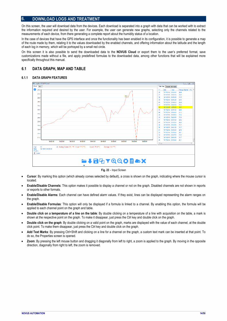
Fig. 22 – Input Screen
• Cursor: By marking this option (which already comes selected by default), a cross is shown on the graph, indicating where the mouse cursor is located.
• Enable/Disable Channels: This option makes it possible to display a channel or not on the graph. Disabled channels are not shown in reports or exports to other formats.
• Enable/Disable Alarms: Each channel can have defined alarm values. If they exist, lines can be displayed representing the alarm ranges on the graph.
• Enable/Disable Formulas: This option will only be displayed if a formula is linked to a channel. By enabling this option, the formula will be applied to each channel point on the graph and table.
• Double click on a temperature of a line on the table: By double clicking on a temperature of a line with acquisition on the table, a mark is shown at the respective point on the graph. To make it disappear, just press the Ctrl key and double click on the graph.
• Double click on the graph: By double clicking on a valid point on the graph, marks are displayed with the value of each channel, at the double click point. To make them disappear, just press the Ctrl key and double click on the graph.
• Add Text Marks: By pressing Ctrl+Shift and clicking on a line for a channel on the graph, a custom text mark can be inserted at that point. To do so, the Properties screen is opened.
• Zoom: By pressing the left mouse button and dragging it diagonally from left to right, a zoom is applied to the graph. By moving in the opposite direction, diagonally from right to left, the zoom is removed.

NOVUS AUTOMATION 15/50
6.2.1 MAP FEATURES
This feature is only available for devices that contain the GPS interface, and, in order to function, you must first be enabled it when performing device configuration through NXperience. Each log will have its position marked by latitude and length, which can be visualized in the parameter "Position", located below the map, and will be indicated by a point in red. Selecting a specific point in the course will cause the icon to change to a red diamond and highlight yellow in the Data View table. Moving the mouse over the map will inform the geographic position of the map, even if the cursor is outside the route performed by the device.
Fig. 23 – Maps
• Double click on the map: A double click on a point of the route performed by the device on the map will show the marks with the value of each channel.
• Double-click on the latitude and longitude on a line in the Data View Table: When you double-click on latitude and longitude on a line with acquisition in the table, a mark is shown on its graph point.
• Zoom: Click the and buttons to zoom the map.
• Moving: Click the , , and buttons to move along the map extension. • Overlays: Clicking the button on the right side of the map will expand a tab, which allows you to define the type of marker to be used to
delineate the route taken by the device on the map: Polygons, which will demarcate the route taken by the device, or Markers, which will show time and location of each log, as can be seen in Fig. 24.
Fig. 24 – Overlays
• Map: Clicking the button on the right side of the map will expand a more comprehensive map of the route, as can be seen in Fig. 25.
Fig. 25 – Map
6.3.1 INFORMATION FIELDS
• Logs: Shows the acquisition number where the graph cursor is located when over the graph. • Date: Shows the date of the point where the mouse cursor is located. • Position: Shows the geographic position, consisting of latitude and longitude, of the time of acquisition if a red marker has been selected or the
geographical location of the location where the mouse cursor is when it is on the map. • Lower, Upper and Average Values: Shows the respective values for each channel. • Data View Tab: Shows information about the logs downloaded by the device. • General Information Tab: Shows varied information about the device from which the data were downloaded. • Events Tab: For certain devices, this tab is displayed when a download occurs. This screen shows all digital events that were recorded in the
device’s memory.
NOVUS AUTOMATION 16/50
6.2 OPEN FILE, DOWNLOAD, SAVE TO FILE Features accessed by clicking on the buttons with the same names on the Download screen.
Fig. 26 – Buttons
• Open File : Files in .nxd (NX Data File) format can be opened with this button. Upon selecting a file in this format, all graphs saved in that file will be opened with all data and customizations. Files in .nxd format can be opened by dragging the files into the Download screen.
• Download Logs : Data can be downloaded from a device compatible with NXperience and connected to the PC. A status bar will be displayed while the software is downloading data.
• Save File : The selected graph can be saved to a file, along with all customizations and formulas (if any). If the graph is a junction, the graphs that generated this junction will be saved to the same file.
6.3 GRAPH PROPERTIES
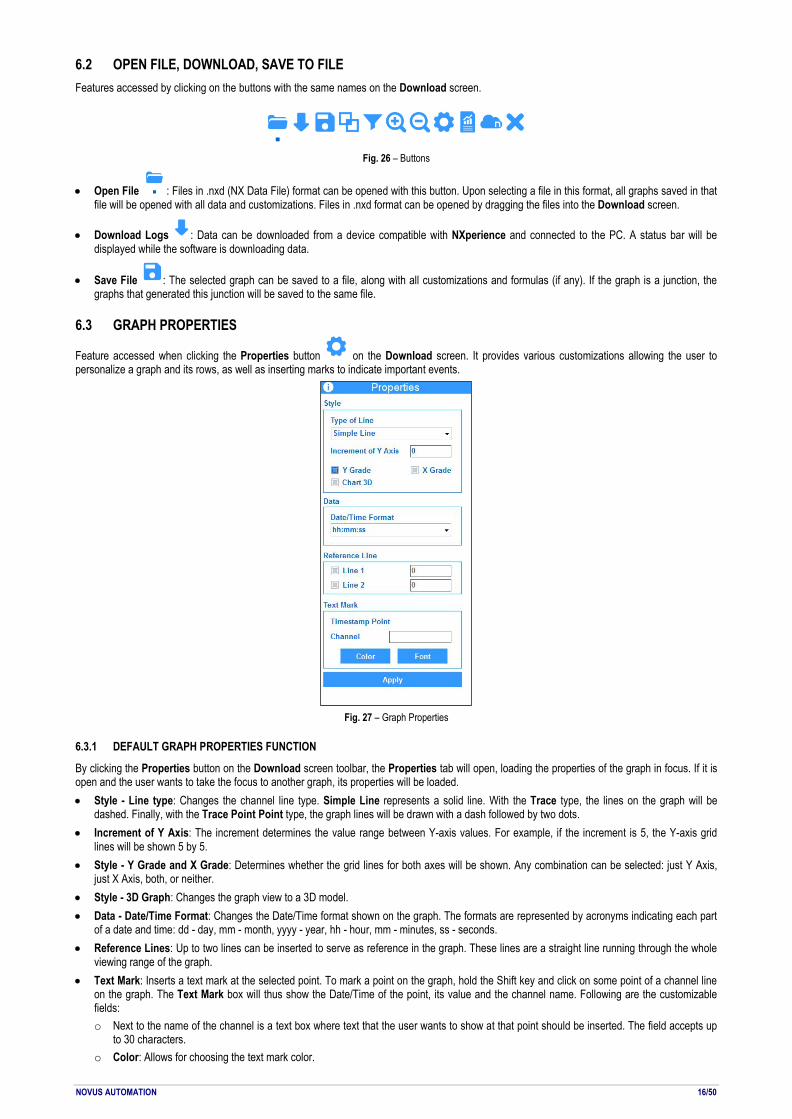
Feature accessed when clicking the Properties button on the Download screen. It provides various customizations allowing the user to personalize a graph and its rows, as well as inserting marks to indicate important events.
Fig. 27 – Graph Properties
6.3.1 DEFAULT GRAPH PROPERTIES FUNCTION
By clicking the Properties button on the Download screen toolbar, the Properties tab will open, loading the properties of the graph in focus. If it is open and the user wants to take the focus to another graph, its properties will be loaded. • Style - Line type: Changes the channel line type. Simple Line represents a solid line. With the Trace type, the lines on the graph will be
dashed. Finally, with the Trace Point Point type, the graph lines will be drawn with a dash followed by two dots. • Increment of Y Axis: The increment determines the value range between Y-axis values. For example, if the increment is 5, the Y-axis grid
lines will be shown 5 by 5. • Style - Y Grade and X Grade: Determines whether the grid lines for both axes will be shown. Any combination can be selected: just Y Axis,
just X Axis, both, or neither. • Style - 3D Graph: Changes the graph view to a 3D model. • Data - Date/Time Format: Changes the Date/Time format shown on the graph. The formats are represented by acronyms indicating each part
of a date and time: dd - day, mm - month, yyyy - year, hh - hour, mm - minutes, ss - seconds. • Reference Lines: Up to two lines can be inserted to serve as reference in the graph. These lines are a straight line running through the whole
viewing range of the graph. • Text Mark: Inserts a text mark at the selected point. To mark a point on the graph, hold the Shift key and click on some point of a channel line
on the graph. The Text Mark box will thus show the Date/Time of the point, its value and the channel name. Following are the customizable fields: o Next to the name of the channel is a text box where text that the user wants to show at that point should be inserted. The field accepts up
to 30 characters. o Color: Allows for choosing the text mark color.

NOVUS AUTOMATION 17/50
o Font: Allows for changing the font of the text inserted at the mark, as well as its formatting. o To change a text mark, it needs to be selected again (Shift + click) to make the necessary edits and click on the Apply button. o To remove a text mark, it needs to be selected again (Shift + click) to delete the edit field and click on the Apply button. o The user can add as many text marks as desired.
• After selecting the desired customizations, the user should press the Apply button to apply the changes.
6.3.2 ASSUMPTIONS AND LIMITATIONS
• All customizations will be saved when the user saves the graph to a file. • All customizations will be shown in the reports. • There are report templates that show a detailed explanation for each text mark. • When a formula is applied to a channel with text marks, all marks will disappear. • When a formula is applied to a graph, all text marks will disappear.
6.4 FILTER LOG
Feature accessed by clicking the Filter button on the Download screen. It allows the user to filter data from one or more channels. Data can be filtered by Value (Y-Axis) or by Date (X-Axis).
Fig. 28 – Data Filter
6.4.1 DEFAULT FILTER LOG OPERATION
• Interval between Dates: By selecting the start date (from) and then the end date (to), the data filter can be run between them. The data filter can be run between any two dates by selecting the start date (from) and then selecting the end date (to). o The end date may not be earlier than the start date. o If the period between selected dates is outside the data acquisition period, no data will be displayed from a channel on the graph or on the
table. • In the Last: With this filter, data will be displayed from X days before the time when the filter is applied, where X is the number of days.
o If there are no data in the period of X days before the time of download, no data will be shown on the graph or on the table. • Y Left and Y Right: These refer to the filters applied on the Y-axes of a graph, meaning the filter will be applied to the values of acquisitions. In
the case of a temperature channel, for example, if a filter is applied between 20 and 30 °C, only acquisitions between the selected range will be shown.
• One filter may be chosen for the X-Axis (Date) and one filter for the Y-Axis (Value). • Filter: Applies the filters configured on the graph. • Restore: Resets the graph with the original data from each channel.
6.4.2 ASSUMPTIONS AND LIMITATIONS
• Unlike the zoom, which just draws visually closer to point of the graph, the data filter narrows the scope of the acquisitions. Data that are outside this filter will be excluded from the graph and table.
• By applying a filter, minimum, mean and maximum values for a channel are recalculated. • Saving a graph with a filter to file doesn’t just save the filtered information, but also all original data from each channel. • Reports can be created for channels with filters applied. • It is possible to send only the filtered data to NOVUS Cloud. • By applying a formula to a channel with a filter applied, this formula is applied to all channel points, including those that are outside the filter.

NOVUS AUTOMATION 18/50
6.5 CHART JUNCTION
Feature accessed when clicking the Chart Junction button on the Download screen. Allows for merging variables from two or more graphs into just one, facilitating analyses and comparisons between variable values, report creation, etc.
Fig. 29 – Junction Graphs
6.5.1 DEFAULT FUNCTIONING OF A JUNCTION
• Two or more graphs need to be open on the Download screen to perform a graph junction. • Open the Chart Junction tab by clicking the button with the same name on the Download screen. • Enter a name for the junction in the Junction Name field. • The Channel Selection filed has two lists. On the left side is the list of open graphs. By clicking the name of one of the graphs on this list, the
channels list will be filled out with the channels existing on the chosen graph. • On the channels list, the user can select which channels should be included in the junction. When a channel is selected, the number of merged
channels is increased by one. There can be up to eight channels in one junction. • By selecting another graph from the list, the channels from that graph will be displayed. • A channel junction of up to eight different graphs is possible. • Click the Junction button to junction the selected channels. A new graph will be created with all selected channels.
6.5.2 ASSUMPTIONS AND LIMITATIONS FOR A JUNCTION
• A junction can have up to eight channels. • A junction can be created from up to eight different graphs. • Junctions cannot be created from other junctions. Thus, graphs that are junctions do not appear on the list of graphs for creating new junctions. • You cannot join two positions on the map. • When channels from different graphs have the same name, the second channel with the same name gains a suffix (1). When there are three
channels with the same name, the third channel gains the suffix (2), and so on. • Text marks and any types of formatting made to a graph are not imported to a merged graph. • A graph generated from a junction does not have the General Information tab, just the Data View Table tab.
6.5.3 SAVING AND OPENING FILES WITH GRAPH JUNCTIONS
• To save a merged graph, just select it on the Download screen and click the Save File button. • When a merged graph is saved to file, all graphs that generated the junction will be saved to the same file. • When a merged graph file is opened, all graphs from which the merged graph originated will be opened as well.
NOVUS AUTOMATION 19/50
6.6 REPORTS AND EXPORTING LOGS
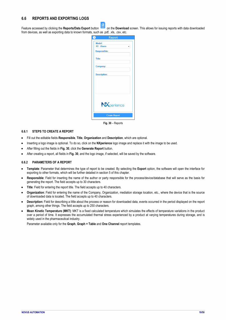
Feature accessed by clicking the Reports/Data Export button on the Download screen. This allows for issuing reports with data downloaded from devices, as well as exporting data to known formats, such as .pdf, .xls, .csv, etc.
Fig. 30 – Reports
6.6.1 STEPS TO CREATE A REPORT
• Fill out the editable fields Responsible, Title, Organization and Description, which are optional. • Inserting a logo image is optional. To do so, click on the NXperience logo image and replace it with the image to be used. • After filling out the fields in Fig. 30, click the Generate Report button. • After creating a report, all fields in Fig. 30, and the logo image, if selected, will be saved by the software.
6.6.2 PARAMETERS OF A REPORT
• Template: Parameter that determines the type of report to be created. By selecting the Export option, the software will open the interface for exporting to other formats, which will be further detailed in section 5 of this chapter.
• Responsible: Field for inserting the name of the author or party responsible for the process/device/database that will serve as the basis for generating the report. The field accepts up to 30 characters.
• Title: Field for entering the report title. The field accepts up to 40 characters. • Organization: Field for entering the name of the Company, Organization, mediation storage location, etc., where the device that is the source
of downloaded data is located. The field accepts up to 40 characters. • Description: Field for describing a little about the process or reason for downloaded data, events occurred in the period displayed on the report
graph, among other things. The field accepts up to 250 characters. • Mean Kinetic Temperature (MKT): MKT is a fixed calculated temperature which simulates the effects of temperature variations in the product
over a period of time. It expresses the accumulated thermal stress experienced by a product at varying temperatures during storage, and is widely used in the pharmaceutical industry. Parameter available only for the Graph, Graph + Table and One Channel report templates.
NOVUS AUTOMATION 20/50
6.6.3 TYPES OF REPORTS
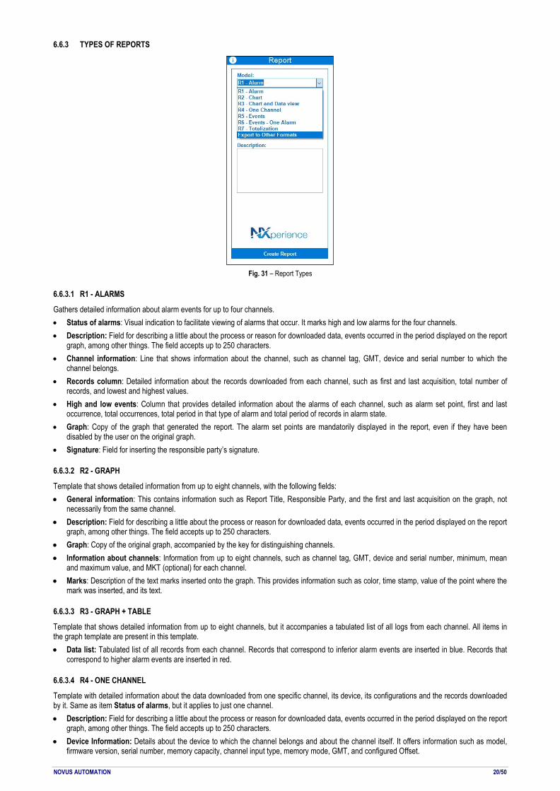
Fig. 31 – Report Types
6.6.3.1 R1 - ALARMS
Gathers detailed information about alarm events for up to four channels. • Status of alarms: Visual indication to facilitate viewing of alarms that occur. It marks high and low alarms for the four channels. • Description: Field for describing a little about the process or reason for downloaded data, events occurred in the period displayed on the report
graph, among other things. The field accepts up to 250 characters. • Channel information: Line that shows information about the channel, such as channel tag, GMT, device and serial number to which the
channel belongs. • Records column: Detailed information about the records downloaded from each channel, such as first and last acquisition, total number of
records, and lowest and highest values. • High and low events: Column that provides detailed information about the alarms of each channel, such as alarm set point, first and last
occurrence, total occurrences, total period in that type of alarm and total period of records in alarm state. • Graph: Copy of the graph that generated the report. The alarm set points are mandatorily displayed in the report, even if they have been
disabled by the user on the original graph. • Signature: Field for inserting the responsible party’s signature.
6.6.3.2 R2 - GRAPH
Template that shows detailed information from up to eight channels, with the following fields: • General information: This contains information such as Report Title, Responsible Party, and the first and last acquisition on the graph, not
necessarily from the same channel. • Description: Field for describing a little about the process or reason for downloaded data, events occurred in the period displayed on the report
graph, among other things. The field accepts up to 250 characters. • Graph: Copy of the original graph, accompanied by the key for distinguishing channels. • Information about channels: Information from up to eight channels, such as channel tag, GMT, device and serial number, minimum, mean
and maximum value, and MKT (optional) for each channel. • Marks: Description of the text marks inserted onto the graph. This provides information such as color, time stamp, value of the point where the
mark was inserted, and its text.
6.6.3.3 R3 - GRAPH + TABLE
Template that shows detailed information from up to eight channels, but it accompanies a tabulated list of all logs from each channel. All items in the graph template are present in this template. • Data list: Tabulated list of all records from each channel. Records that correspond to inferior alarm events are inserted in blue. Records that
correspond to higher alarm events are inserted in red.
6.6.3.4 R4 - ONE CHANNEL
Template with detailed information about the data downloaded from one specific channel, its device, its configurations and the records downloaded by it. Same as item Status of alarms, but it applies to just one channel. • Description: Field for describing a little about the process or reason for downloaded data, events occurred in the period displayed on the report
graph, among other things. The field accepts up to 250 characters. • Device Information: Details about the device to which the channel belongs and about the channel itself. It offers information such as model,
firmware version, serial number, memory capacity, channel input type, memory mode, GMT, and configured Offset.

NOVUS AUTOMATION 21/50
• Channel information: Line that shows information about the channel. It also includes the mean value and the MKT of data represented in the report.
• Graph: Copy of the original graph, accompanied by the key for distinguishing channels. • Marks: Description of the text marks inserted onto the graph. This provides information such as color, time stamp, value of the point where the
mark was inserted, and its text. • Data list: Tabulated list of all records from the channel. Records that correspond to inferior alarm events are inserted in blue. Records that
correspond to higher alarm events are inserted in red. This report shows records in three columns per page. • Signature: Field for inserting the responsible party’s signature.
6.6.3.1 R5 AND R6 - EVENTS AND ONE ALARM EVENTS
These are two report templates for alarm events. They support the independent alarms of LogBox 3G and LogBox Wi-Fi, gathering detailed information about the alarm events that occurred within the period of time covered by the downloaded data. Model R5 shows analytical data of up to 10 configured alarms from a LogBox. Besides showing analytical data of 1 specific alarm, model R6 also shows a list of all logs where events of the configured alarm have occurred. • Description: Field for describing important details about the process, about the downloaded data or about events occurred within the period of
time displayed on the report chart, among other things. This field can accept up to 250 characters. • Device Information: It shows information such as device model, firmware version, serial number, GMT, total downloaded logs and start and
end logging date. • Alarm Information: It shows information of the configured alarms, like the number of alarm occurrences, first and last alarm occurrence,
smallest and biggest value in alarm and the longest period of time in an alarm condition. • List of Logs: It shows detailed information about the logs in alarm state from a downloaded set of data. It has the time stamp and its
correspondent value.
6.6.3.2 R7 - TOTALIZATION
Report model that show a totalization of the values logged within a selected period of time. All logged values of a channel in a time window are added and the sum is showed on the report. It is possible to select periods of 1 hour, 8 hours, 1 day, 1 week or 1 month. The option "Closed Period" will define whether it will work in an absolute time period (e.g.: 01:00 am to 01:59 am in a weekly basis starting every Sunday at midnight and stopping every Saturday at 11:59:59 pm) or in a time period that is relative to the first log (e.g.: weekly basis starting in the first log time stamp which is Wednesday at 01:00 pm and stops next Wednesday at 12:59:59 pm). • Description: Allows you to describe important details about the process, about the downloaded data or about events occurred within the period
of time displayed on the report chart, among other things. This field can accept up to 250 characters. • General Information: It shows information such as device model, firmware version, serial number, GMT, total downloaded logs and start and
end logging date. • Totalized Histogram: It shows a bar graph to every channel with its totalized value within the configured period of time. • List of Totalization Periods: For each channel, a list of totalization periods is shown below the chart with start time stamp, the final time stamp
and the totalized value.
6.6.4 REPORT VIEWING SCREEN
When a report is generated, a preview is shown on a special screen, making some functions available:
Fig. 32 – Report view toolbar
• Print: Allows you to send the report to be printed. • Export to PDF: Allows you to export the report to a document in .pdf format. • Find: Allows you to scan the document to find a value, word or text. • Zoom: Allows you to increase or decrease the zoom in the document. When zooming out, several pages can be viewed on the same screen. • Full screen: It shows the document in full screen, without the toolbar. • Thumbnails: To the left, it shows the document pages for quick access. • Page properties: Allows you to configure the document’s page properties. • Page forward or backward: Allows you to move forward or backward to previous pages. The page number can be entered to jump directly to
the desired page. • Close: Allows you to close the document screen and return to NXperience.
6.6.5 EXPORT TO OTHER FORMATS
By selecting the Export item in the Model field, a new interface opens on the screen. There the user can choose the file format to which data are to be exported. • The data are exported in tabulated form. The first column corresponds to the time stamp of each record. The others show the value of each
channel at that respective time stamp. • Data from up to eight channels can be exported to the same file. • The formats available for exporting are:
o Extensible Style Language (.xls);

NOVUS AUTOMATION 22/50
o Portable Document Format (.pdf); o Comma-separated values (.csv); o Rich Text Format (.rtf); o Hyper Text Markup Language (.html).
6.7 SENDING DATA TO THE CLOUD
Feature accessed when clicking the NOVUS Cloud button on the Download screen. Allows you to send the downloaded logs to a NOVUS Cloud account.
Fig. 33 – NOVUS Cloud
To send the downloaded logs to NOVUS Cloud, it is necessary to fill in the User and Password fields in the NOVUS Cloud screen of the download manager. The User field allows up to 60 characters. The Password field allows up to 30 characters. Once you have completed the above parameters, simply click on the Send for NOVUS Cloud button. All records for each selected channel will be sent in order. If there is an error in sending a channel, the software will continue to send the other channels. It does not abort the operation.
6.7.1 ASSUMPTIONS AND RESTRICTIONS FOR SENDING DATA TO NOVUS CLOUD
• Any data volume that belongs to a default channel on a device compatible with NOVUS Cloud. • Data from channels with a formula applied. In this case, a channel should be pre-registered for the device in question on NOVUS Cloud, with
the alias equal to the name of the channel with the formula applied. For more information on how to register new variables on NOVUS Cloud, refer to the product documentation.
• Having a graph active on the Download screen, with data from devices compatible with NOVUS Cloud. • Having at least one channel selected on the active graph. • Data can be sent from graphs that are a junction of other graphs. • Data can be sent from a graph with some filter applied. In this case, only data within the configured filter should be sent. • Data are always sent to NOVUS Cloud in UTC (GMT-0).
6.1 DOWNLOAD LOGS BY NOVUS CLOUD You can download logs from devices linked to NOVUS Cloud by selecting the NOVUS Cloud option from the Download screen:
Fig. 34 – Select a device: NOVUS Cloud

NOVUS AUTOMATION 23/50
Selecting NOVUS Cloud will ask you to log in your NOVUS Cloud account, as you can see in the image below:
Fig. 35 – NOVUS Cloud login
Once you made NOVUS Cloud login, the devices registered in NOVUS Cloud will appear as follows, the first tag corresponding to your model, the second tag corresponding to the user's given name and the third tag corresponding to the serial number of the device registered:
Fig. 36 – NOVUS Cloud tags
Once you have selected the device for which you want to download, simply select the period of logs to be downloaded:
Fig. 37 – Download: NOVUS Cloud

NOVUS AUTOMATION 24/50
7. CUSTOMIZED CHANNEL CALIBRATION Feature that allows for customized channel calibration, inserting up to X customization points, where X depends on the device for which the channel is being configured.
Fig. 38 – Customized Calibration Screen
7.1 DEFAULT CUSTOMIZED CALIBRATION FUNCTIONING • Whenever the user wants to access the customized calibration screen for a channel, the current software configuration will need to be sent to
the device. After this, the software will reread all configurations, to find out the device configuration. • There are certain channel parameters that, when altered, lead to the loss of calibration points, if existing. The following message is displayed:
"Channel X has a customized calibration. What do you want to do?" In this case, the user has three options: o Recalibrate: Allows you to reset the calibration. o Delete channel calibration: Allows you to delete all configured calibration points. o Restore channel: Allows you to reset channel configurations to the status when the device was read.
• If the user chooses to calibrate or recalibrate, the calibration screen will be shown. • The calibration points already configured in the device, if any, should be shown on the table of points when the screen is shown. • Each device allows a different number of calibrations for each channel. For more details, refer to the device documentation. • The user can read the device channel, or type in read and desired values. • After the points are configured, just click on the Apply button to send the points' configuration to the device. • Calibration points will be sent when the Apply button is clicked. The Send Configuration button on the device configuration screen is only
used for sending other channel configurations.
7.2 CUSTOMIZED CALIBRATION INTERFACE FOR CHANNELS The customized calibration screen has the following features: • Read Channel: Take reading of the channel. The read value is entered in the Measured field. • Measured: Field where the value measured at the calibration point is entered. When the device takes a reading of the channel and the value is
equal to this value, it will be replaced by the desired value. The field accepts only numbers, commas and periods. The field accepts values with X decimal places, where X is the number of decimal places configured for the channel.
• Desired: Field where the desired value is inserted. Thus, when the device reads from the sensor and the read value is equal to the measured value, the device will show the desired value. The field accepts only numbers, commas and periods. The field accepts values with X decimal places, where X is the number of decimal places configured for the channel.
• Add: Add the measured value and the desired value to the table of calibration points. The Measured and Desired fields should be filled out for this button to be enabled.
• Table of calibration points: Table showing the already entered calibration points. Each set of measured and desired values is entered on this table when the Add button is pressed.
• Organize: Organizes values in ascending order on the table, using the Measured column as base. • Delete Line: Deletes a calibration point that should be selected on the table.
When the button is pressed and no item is selected on the table, a message will be displayed. It order to be deleted, a calibration needs to be selected on the table.
• Delete All: Clears the table of calibration points. To remove all calibration points for a channel, the Apply button needs to be pressed to clear points on the device.
• Apply: Applies all calibration points entered on the points table. If any error occurs when sending calibration points to the device, a message will be displayed to the user.
• Cancel: Discard all points entered on the table and returns to the default device configuration screen.

NOVUS AUTOMATION 25/50
8. DEVICE MONITORING Functionality that allows to monitor the channels of the devices. Monitoring provides visual tools for displaying values in graph, LED panel, bar graph form, among other features that we will see in this chapter. 8.1 DEFAULT MONITORING FUNCTIONING
On the NXperience home screen, click on the button in the lower right corner of the screen.
Fig. 39 – Home Screen (Monitor)
If there is more than one device plugged into the PC, the software will ask the user to select which device to monitor. The user will see the welcome screen, where some of the software features will be described briefly. On this screen, the user should define the interval for refreshing monitored variables.
Fig. 40 - Welcome Screen
Click the To Online Monitoring! button to begin. The monitoring screen will be shown.
8.2 VISUAL FIELDS ON THE MONITORING SCREEN The monitoring screen has four monitoring tools: a dot plot graph, a bar graph, bar meters for the alarms, and finally the values of each channel on a LED panel.
Fig. 41 – Visual Fields on the Monitoring Screen
8.2.1 DOT CHART GRAPH
With each reading, the values read from each channel will be entered on its respective line. This graph can cover up to eight channels. • Channel error values will be displayed on the graph.
NOVUS AUTOMATION 26/50
• The graph uses an automatic scale. Depending on the channel values (if there is a big difference between minimum and maximum values), these values may be at the edges and visually not appear.
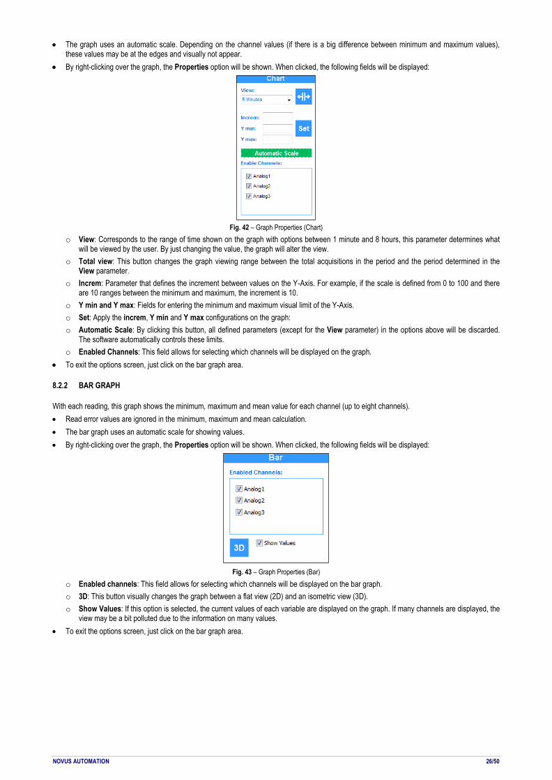
• By right-clicking over the graph, the Properties option will be shown. When clicked, the following fields will be displayed:
Fig. 42 – Graph Properties (Chart)
o View: Corresponds to the range of time shown on the graph with options between 1 minute and 8 hours, this parameter determines what will be viewed by the user. By just changing the value, the graph will alter the view.
o Total view: This button changes the graph viewing range between the total acquisitions in the period and the period determined in the View parameter.
o Increm: Parameter that defines the increment between values on the Y-Axis. For example, if the scale is defined from 0 to 100 and there are 10 ranges between the minimum and maximum, the increment is 10.
o Y min and Y max: Fields for entering the minimum and maximum visual limit of the Y-Axis. o Set: Apply the increm, Y min and Y max configurations on the graph: o Automatic Scale: By clicking this button, all defined parameters (except for the View parameter) in the options above will be discarded.
The software automatically controls these limits. o Enabled Channels: This field allows for selecting which channels will be displayed on the graph.
• To exit the options screen, just click on the bar graph area.
8.2.2 BAR GRAPH
With each reading, this graph shows the minimum, maximum and mean value for each channel (up to eight channels). • Read error values are ignored in the minimum, maximum and mean calculation. • The bar graph uses an automatic scale for showing values. • By right-clicking over the graph, the Properties option will be shown. When clicked, the following fields will be displayed:
Fig. 43 – Graph Properties (Bar)
o Enabled channels: This field allows for selecting which channels will be displayed on the bar graph. o 3D: This button visually changes the graph between a flat view (2D) and an isometric view (3D). o Show Values: If this option is selected, the current values of each variable are displayed on the graph. If many channels are displayed, the
view may be a bit polluted due to the information on many values. • To exit the options screen, just click on the bar graph area.

NOVUS AUTOMATION 27/50
8.2.3 ALARMS
With each reading, the channel values are shown on bar meters, informing whether they are in alarm state or not or whether some type of alarm has occurred. • Read error values are displayed on the bar meters. • The channel name should be displayed over each bar meter, and the unit for each channel should be shown below the channel name. • Bar meters use an automatic scale to display values. • The range shown in green on meters is the range in which there are no alarm occurrences. • The ranges shown in red on the meters are determined by the minimum and maximum alarm setpoint value. • Below each bar meter is a status indicator informing whether an alarm has been triggered on the channel since the monitoring began.
Fig. 44 – Status Indicator
o If the channel has experienced an alarm, this button will be red and will be available to click. A new screen will therefore be shown with a table of all acquisitions in which high or low alarms have occurred.
Fig. 45 – Alarm Events
o On the table, we have information such as type of event, value, and time stamp when the alarm event occurred. o All alarm events can be cleared from a given channel by clicking the Clear Events button on this screen. o Data from the table can be exported to an Excel file by clicking the Export button on this screen. o To close the Alarm Events screen, just click the Close button. o High-level events are shown in red on the table, and low-level events are shown in blue.
The alarms panel works only for those devices whose alarms are directly attached to each channel. For devices like LogBox-3G and LogBox WI-FI, whose alarms are independent from each channel, this panel will stay blank since it is not applicable.
8.2.4 LED PANEL
Panel located at the bottom of the monitoring screen, where a digital LED is shown for each read channel. • Read error values are displayed on the digital LED panel. • The channel name should be showed above each digital LED. • The line color representing the channel on the graph should be shown next to the channel name. • The unit for each channel should be shown below the digital LED. • By right-clicking over the LED panel, the Properties option will be shown. When clicked, the following fields will be displayed:
Fig. 46 – LED Panel
o Enabling channels: The user can select which channels should be shown on the LED panel. o To close the Properties screen, just left-click on the LED panel.

NOVUS AUTOMATION 28/50
• The upper right corner of the LED panel shows the time stamp of the last reading.
8.3 COMPONENT RESIZING • Three components on the monitoring screen can be resized: the graph, the bar meters and the bar graph. • These components can be resized by placing the mouse right at the borders of each component. The mouse icon will thus change into the
default Windows expand icon. Then just hold down the left mouse button and move the border of the components left or right or up or down, in the case of the Bar Meter or Bar Graph component.
• The LED panel cannot be resized vertically. When the monitoring screen is maximized, it expands horizontally and automatically. • We recommend using software monitoring with the screen maximized.
8.4 CONTROL BUTTONS
Buttons located in the lower right corner of the monitoring screen. Each has a respective function:
Fig. 47 – Control Buttons
• Monitoring/Pause : Allows you to pause a monitoring in progress. When clicked again, the monitoring will be restarted.
• Restart Online Monitoring : Allows you to restart a monitoring. All alarm events, minimum, maximum and mean values will be reset, and the graph curves will be erased.
• Print : Allows you to print the current screen status.
• Close : Allows you to conclude the monitoring, closes the software monitoring screen and returns to the home screen.

NOVUS AUTOMATION 29/50
9. CONFIGURATION DEVICE The Configure screen provides the Read Device features for which the software supports and Create Configuration for the devices, which can be saved for later use. In addition, it allows you to open previously saved configuration files. Each device has a unique configuration screen, which includes the respective characteristics of each. This functionality is explained in detail in the manual of each device for which the software supports.

NOVUS AUTOMATION 30/50
10. DEVICES DIAGNOSTIC The Diagnostics screen provides diagnostics functionality, which allows you to observe the operation of digital and analogue channels and various communication interfaces, such as Ethernet interface and RS485 interface, and perform value and state forcing tests. Each device has a unique diagnostic screen, which includes the respective characteristics of each. This functionality will be explained in detail in the manual of each device for which the software supports.

NOVUS AUTOMATION 31/50
NOVUS AUTOMATION 32/50
11. NXPERIENCE TRUST INTRODUCTION The NXperience Trust is an operating mode available from NXperience version 2.0 that enables the validation of information, devices and operations to meet the FDA 21 CFR Part 11 (US) standard. In addition, it can be used for operations that require assurances of information integrity and that offer greater security of access. The NXperience Trust also provides tools that allow you to monitor the software users and the devices validated by it. This new operating mode is activated by the use of a Hardkey, which enables the software to audit records, ensure the integrity of stored information and make NOVUS devices validated according to standards. Part 11 of the FDA 21 CFR standard usually applies to manufacturers of drugs and medical devices, biotechnology companies, developers and manipulators of biological and pharmaceutical products, other industries regulated by the FDA in the United States of America, and various organizations adopting similar mechanisms information security in other countries. The standard establishes the implementation of controls, system validations, audit records, electronic signatures and documentation for the software and all systems involved in the processing of electronic data that must be maintained for a fixed period of time so that periodic inspections of the operations. NXperience Trust is compatible with all device models for which the software supports. All information in the first part of this manual applies to the NXperience Trust.
Fig. 48 – Validation Hardkey

NOVUS AUTOMATION 33/50
12. OPERATION MODES When enabled by the Hardkey, the NXperience Trust features an access manager with user profiles that allows the creation of audit logs for the analysis of operations performed and provides information security using secure encryption algorithms and systems for detecting violations of the data. When the NXperience Trust mode is not activated (use without the Hardkey), the application will run in NXperience Standard mode, which allows all basic configuration, download, diagnostic and monitoring functions to be used with non-validated devices. In this case, access to validated device information will not be available until the activation requirements are met.
12.1 STANDARD OPERATION MODE: NXPERIENCE STANDARD The standard NXperience operating mode, named NXperience Standard, will be accessible whenever a Hardkey is not detected and its standard operation is listed in the first part of this manual. NXperience Standard mode has a function limitation on the operation of validated devices: It does not have event log records, it does not allow users to be created for the system, it does not configure or download data from already validated devices, it does not open data files that they have generated by the NXperience Trust and does not generate reports with unique IDs.
Fig. 49 – NXperience Standard Mode
12.2 VALIDATION OPERATION MODE: NXPERIENCE TRUST The NXperience validation mode, named the NXperience Trust, will be activated by inserting a Hardkey into a compatible USB port on the computer where NXperience is installed. The application performs the Hardkey detection and recognition whenever the software is started. If the Hardkey has not been inserted or has not been recognized, however, NXperience will normally operate in Standard mode, and may perform operations on non-validated devices. When the Hardkey is detected and recognized, the software automatically activates the NXperience Trust. NXperience Trust requires the secure identification of a registered user before granting access to the main operating interface. Periodically and in order to keep the validated mode activated, the software will check for the presence of Hardkey. If NXperience Trust does not identify the Hardkey connected within 10 minutes, it will display the following message: "Hardkey not detected. In order for the validated system to continue running, the Hardkey identification is required. If the Hardkey is not detected during the next scan, the NXperience will close."
Fig. 50 – NXperience Trust Mode
To access the NXperience Trust for the first time, initial login information must be used for the primary administrator user, factory default and general knowledge (see chapter Access to NXperience Trust). Master password exchange is the responsibility of the software or organization user. In order to comply with 21 CFR 11, each organization shall establish its own security procedures for access to information. Thus, it is important to note that the simple use of the NXperience Trust and NOVUS devices, even if validated, does not in itself guarantee compliance with the 21 CFR 11. NOVUS products consist of tools designed to assist in the service.

NOVUS AUTOMATION 34/50
13. ACCESS TO NXPERIENCE TRUST The first access to the NXperience Trust security system interface must be performed with the primary administrator user. Your login is "NXperience" and your initial access password is "NXperience".
Fig. 51 – NXperience Trust mode access interface
After entering the login and password information and clicking the Login button, an NXperience Trust session will begin. Incorrect or missing login information will result in an error message as shown in the Blocked or Non-Existing User section of this chapter. If an incorrect password has been entered in the attempt to log in as the primary administrator user, NXperience Trust will display the following message: "Incorrect administrator password." If an incorrect password has been entered in the attempt to log in with any other users' account, NXperience Trust will display a warning message and allow access attempts up to the limit defined in the General User Settings section (see Security System Administration chapter). By default, three attempts are allowed.
Fig. 54 – Invalid password warning
If the user login is successful, the NXperience main interface will be displayed, with the addition of NXperience Trust mode security system administration controls.
Fig. 53 – Active NXperience Trust mode for primary administrator
The counter located at the top left of the screen will show the time elapsed since the login of the connected user, identified below. Clicking the Exit button will allow you to log out and log in again or shut down the NXperience Trust. The information pertinent to the Hardkey, in turn, will inform you when it is connected to the USB port of the computer or notebook, if it is removed after starting the operation. It is important to remember, however, that, as informed in the previous chapter, NXperience will be initialized in NXperience Standard mode whenever the Hardkey is not identified at the time of running the software.
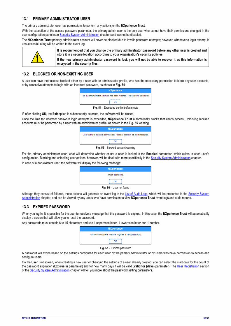
NOVUS AUTOMATION 35/50
13.1 PRIMARY ADMINISTRATOR USER The primary administrator user has permissions to perform any actions on the NXperience Trust. With the exception of the access password parameter, the primary admin user is the only user who cannot have their permissions changed in the user configuration panel (see Security System Administration chapter) and cannot be disabled. The NXperience Trust primary administrator account will never be blocked due to invalid password attempts; however, whenever a login attempt is unsuccessful, a log will be written to the event log.
It is recommended that you change the primary administrator password before any other user is created and store it in a secure location according to your organization's security policies. If the new primary administrator password is lost, you will not be able to recover it as this information is encrypted in the security files.
13.2 BLOCKED OR NON-EXISTING USER A user can have their access blocked either by a user with an administrator profile, who has the necessary permission to block any user accounts, or by excessive attempts to login with an incorrect password, as shown in Fig. 54:
Fig. 54 – Exceeded the limit of attempts
If, after clicking OK, the Exit option is subsequently selected, the software will be closed. Once the limit for incorrect password login attempts is exceeded, NXperience Trust automatically blocks that user's access. Unlocking blocked accounts must be performed by a user with an administrator profile, as shown in the Fig. 55 warning:
Fig. 55 – Blocked account warning
For the primary administrator user, what will determine whether or not a user is locked is the Enabled parameter, which exists in each user's configuration. Blocking and unlocking user actions, however, will be dealt with more specifically in the Security System Administration chapter. In case of a non-existent user, the software will display the following message:
Fig. 56 – User not found
Although they consist of failures, these actions will generate an event log in the List of Audit Logs, which will be presented in the Security System Administration chapter, and can be viewed by any users who have permission to view NXperience Trust event logs and audit reports.
13.3 EXPIRED PASSWORD When you log in, it is possible for the user to receive a message that the password is expired. In this case, the NXperience Trust will automatically display a screen that will allow you to reset the password. Any passwords must contain 6 to 15 characters and use 1 uppercase letter, 1 lowercase letter and 1 number.
Fig. 57 – Expired password
A password will expire based on the settings configured for each user by the primary administrator or by users who have permission to access and configure users. On the User List screen, when creating a new user or changing the settings of a user already created, you can select the start date for the count of the password expiration (Expires in parameter) and for how many days it will be valid (Valid for (days) parameter). The User Registration section of the Security System Administration chapter will tell you more about the password setting parameters.

NOVUS AUTOMATION 36/50
14. SECURITY SYSTEM ADMINISTRATION
Access to the NXperience Trust security system configuration, available by clicking on icon from the software home screen, allows you to view the user configuration screen, event log screen, and general settings in this mode. Your access is allowed to the primary administrator user, where all functions will be accessible from login, and for registered users who have the "Change software preferences", "Access and configure users" and "View event logs and audit reports" (the User Registration section in this chapter provides information on how to register a new user and how to set their permissions).
14.1 USER LIST This panel displays information about registered users as well as their user ID randomly assigned to it. Blocked or disabled users will be grayed out and can be enabled by the primary administrator user or by users who have the "Access and configure users" permission.
Fig. 58 – User list screen
14.1.1 USER CONFIGURATION
14.1.1.1 USER INCLUSION
To register a new user, simply access the user panel and click the button. This action will clear the include interface and unlock the fields for entering the data of a new user and will allow you to configure the parameters pertinent to password control and their specific permissions.
Once all parameters have been filled in, the button must be clicked to end the user inclusion. Filling the user creation parameters, but not clicking this button will cause user creation not to be completed. Adding users is only allowed for users who have the "Access and configure users" permission (see the User Registration section in this chapter). Adding a user to the NXperience Trust will generate an event log in the List of Audit Logs.
14.1.1.2 CHANGING USER PARAMETERS
To change the settings of a specific user, simply select it from the list of users and, after doing it, change the desired parameters.
Once all the desired parameters have been changed, you must click on the button to save the changes. Changing any parameters in this configuration area, but not clicking this button will cause the changes to not be applied. Not all parameters can be changed. The user name and login cannot be changed. The unique ID of each user, randomly generated, cannot be changed either. Changing a user's parameters will generate an event log in the List of Audit Logs.
14.1.1.3 USER EXCLUSION
The NXperience Trust does not allow users to be excluded. For auditing purposes and for verifications and reports to be made, all users already created must remain registered in the database. If a user is no longer required, simply uncheck the Enabled parameter of your user settings to block your access to the application (see the User Registration section in this chapter). This action will generate an event log in the List of Audit Logs.

NOVUS AUTOMATION 37/50
14.1.1.4 BLOCKING AND UNBLOCKING USERS
As shown in the chapter Access to NXperience Trust, the user will be blocked, by default, after three consecutive and unsuccessful login attempts (although it is possible to change the number of login attempts on the NXperience Trust General Settings screen). If necessary, a user can also have their access blocked by the primary administrator or by users who have permission to access and configure users. To authorize access for a blocked user, only the primary administrator or users with the appropriate permission access the users screen and, after selecting the user to be unblocked in the User List, mark the Enabled parameter. Blocked users will be grayed out in the user list. Blocking and unblocking user actions, including unsuccessful attempts to access the NXperience Trust that result in blocking a user, will generate event logs in the List of Audit Logs.
14.1.2 USER REGISTRATION
In order to register a new user, it is necessary to fill in basic user information, control parameters (enable/disable user and password validity), action permissions within the NXperience Trust security interface and during the use of validated devices and, optionally, NOVUS Cloud login data, a NOVUS cloud portal (see the NOVUS Cloud manual available on our website).
Fig. 59 – User parameters
14.1.2.1 INFORMATION
Allows you to enter the information you need to create a user.
• Name: It allows you to enter a name for the user. It is the information that will appear in the log events at the time an action is performed. This parameter allows up to 32 characters and cannot be edited after user creation.
• Login: It allows you to enter a login for the user. It will be used to access the NXperience Trust. This parameter allows 8 to 15 characters and cannot be edited after user creation.
• Password: It allows you to enter a password for the user. It will be used to access the NXperience Trust. This parameter allows 6 to 15 characters and must contain at least 1 uppercase letter, 1 lowercase letter and 1 number.
• Description: It allows you to enter a description for the user. This parameter is optional and allows up to 32 characters. • Profile: It allows you to select a profile for the user: Operator, Analyst, Supervisor and Administrator. Each profile has a separate list of
permissions, although they are only customizable suggestions. No new profiles can be created. Existing profiles cannot be deleted. Each profile will always be pre-configured in the same way, allowing manual customization for each user.
14.1.2.2 CONTROL Allows you set a validation period for the password and block a user's access to the NXperience Trust.
• Enabled: It allows you to enable or disable a user. A disabled user will not be able to log in to NXperience Trust. A user can have their login disabled manually by the primary administrator user or by a user with the "Access and configure users" permission. Their login also may be blocked by excessive login attempts with an incorrect password (see section Blocking and Unblocking Users in this chapter). Inactive users must be disabled for validation purposes and will be displayed in gray in the user list.
• Expires in: It allows you to select a date for the expiration of the password of the selected user. From that date, the registered password will expire in the days count defined in the Valid for (days) parameter. It is recommended that, when a user is created, this parameter is filled with an expired date, which will force the user to enter a password of their choice during their first login.
• Valid for (days): It allows you to define the number of days for which the password registered by the user will be valid. The value set in this parameter applies to calculate the expiration date of a password once it is changed by the user. It will not be applied when the expiration date is changed in the admin panel.
NOVUS AUTOMATION 38/50
14.1.2.3 PERMISSIONS Allows you to set the user's access permissions. All actions taken with these permissions will generate specific logs, which will bring information pertinent to the action, in the NXperience Trust List of Audit Logs.
• Configure devices: It allows the user to make changes to the device configuration. This permission is required for the following actions: Configure a device, perform a custom device calibration, update the firmware, change the password, and access the diagnostics screen. If the "Configure devices" option is unchecked, the "Send configuration and downloads to NOVUS Cloud", "Perform custom device calibration", "Perform value forcing (Diagnostics)" and "Remove devices from the validation mode" cannot be marked.
• Perform device data download: It allows the user to perform device data download, either through the USB or Ethernet interface or through the NOVUS Cloud. Verification will be done either on the Download button on the home screen or on the specific button for this function on the download screen or the shortcut for download from the configuration screen.
• Save configuration files: It allows the user to save device configuration files. • Save downloaded files: It allows the user to save data downloaded files from validated devices. • Generate reports and export downloaded data: It allows the user to create reports and export the data to formats such as .xls, .doc and .pdf. • Access NOVUS Cloud administration panel: It allows the user to use all the functionality of the NOVUS Cloud Manager panel, such as
inserting, removing and reactivating devices, available by clicking the button on the NXperience Trust home screen. • Send configuration and downloads to NOVUS Cloud: It allows the user to send a configuration or data download to the NOVUS Cloud. To
enable this permission, the "Configure Devices" permission must be enabled. • Perform custom device calibration: It allows the user to perform the custom calibration of a device. To enable this permission, the "Configure
Devices" permission must be enabled.
• Use the software monitoring module: It allows the user to use the monitoring module of a device, available by clicking on the button, located on the NXperience home screen.
• Perform value forcing (Diagnostics): It allows the user to force values, alarms and/or buzzers on the diagnostics screen, according to the features provided by the devices. To access this feature, simply click the Diagnostics button on the NXperience Trust home screen. To enable this permission, the "Configure Devices" permission must be enabled.
• Change software preferences: It allows the user to apply changes to software preferences. This permission will be checked by clicking the OK or Apply buttons, respectively, of the general software preferences screens (see the Software Preferences chapter) and preferences of the NXperience Trust administration panel (see the General Settings section of this chapter).
• Access and configure users: It allows the user to access and change the system user settings in the NXperience Trust security interface. It is recommended to give this permission only to the system administrator.
• View event logs and audit reports: It allows the user to view and create system log events reports. • Remove devices from the validation mode: It allows the user to remove devices from the validated mode. To enable this permission, the
"Configure Devices" permission must be enabled. A device in the validated mode cannot be configured by a standard version of NXperience. It is recommended that in a fully validated system, all devices are validated.
14.1.2.4 NOVUS CLOUD
Allows you to link the selected user profile to an account previously created in NOVUS Cloud (check the NOVUS Cloud Manager chapter). Once these fields are filled in, this will automatically fill in the NOVUS Cloud login information. You can access the NOVUS Cloud Manager by clicking the
button in the NXperience home screen. If the "Access NOVUS Cloud administration panel" or "Send configuration and download to NOVUS Cloud" permissions are disabled for a user, these parameters are not enabled. • User: It allows you to enter the user name or e-mail of the NOVUS Cloud account to be linked to the selected user. • Password: It allows you to enter the password to access the NOVUS Cloud account to be linked to the selected user.

NOVUS AUTOMATION 39/50
14.1.3 REPORT AND EXPORT
14.1.3.1 REPORT
Clicking the button allows you to generate a report with information about all the users registered in the system. You can save this report in PDF format. Divided per user and identified by the user ID number, the report provides various information about each user's data (such as login, name and ID, for example) and their movement within the software (date and time of last access and number of accesses since the time of the creation of each report, for example). This report does not contain any filters, so it will always display information about all registered users. Each report will be created with a unique ID, which will guarantee its integrity.
Fig. 60 – Report
14.1.3.2 EXPORT TO EXCEL FORMAT
Clicking the button allows you to create a document in Excel format with information about all the users registered in the system, which makes it easier, for example, to compare the information and permissions of each user.

NOVUS AUTOMATION 40/50
14.2 LIST OF AUDIT LOGS LIST In this screen, you can view and report on all events registered by the NXperience Trust, as well as run filters to perform accurate searches of specific events and export the downloaded data to different formats. Actions taken in the NXperience Trust will generate specific event logs, which will be identified in the Event Name field and described in the Description field of this list. The software will also identify whether the event resulted in success or failure and the data of the user responsible for performing it, as well as identify the Windows user logged in at the time of the event.
Fig. 61 – List of audit logs
• Date/Time: It shows the time and the exact day that the event occurred. • Event Name: It shows the name of the event that occurred. Indicates the action that generated that log. • User: It shows the name of the user who generated the event. • ID: It shows the user ID, which refers to the unique code of each user, randomly generated by the NXperience Trust. • Windows Name: It shows the Windows user logged in at the time the event occurred. • Result: It shows if the registered action was successful or if that log is a denial to the action initially intended by the user. • Description: It shows details of the action that generated the log.
14.2.1 FILTER
Fig. 62 – Filter
• Interval between dates: Allows you to view the data between two time periods. To run this filter, you must enter a start and end date and time. The "Interval between dates" and "In the last (X) days" filters are mutually exclusive.
• In the last (X) days: Allows you to define how many days ago the filter should be applied. The "Interval between dates" and "In the last (X) days" filters are mutually exclusive.
• By User: Allows you to run a filter by user. This filter can be used in conjunction with other filter types. • By Event: Allows you to run a filter by event type. This filter will display a list of all events that have already occurred in the software. • Apply: Allows you to apply the chosen filter settings. • Clear: Allows you to clear the filter settings made.

NOVUS AUTOMATION 41/50
• Back: Allows you to return to the log screen without applying any data filter.
14.2.2 REPORT AND EXPORT
14.2.2.1 REPORT
Clicking the button allows you to generate a report with all events registered in the system or only with events registered within a predetermined filter. This report will display, in addition to the event list, the number of events that occurred, the date and time of the first and last logged event, and show information about the user responsible for creating the report, as well as the date it was created. Each report will be created according to the currently established filter. If no filter is enabled, the report will be created with all events registered by the NXperience Trust. Each report will be created with a unique ID, which will make it possible to guarantee the integrity of the digital or printed document.
Fig. 63 – Audit log report
14.2.2.2 EXPORT TO EXCEL FORMAT
Clicking the button allows you to create a document in Excel format with information recorded in a table format, making it easier to view audit logs.

NOVUS AUTOMATION 42/50
14.3 GENERAL SETTINGS
Fig. 64 – General settings
14.3.1 DIRECTORY SELECTION
• Database Location: It shows you where the system database files, the user database, and the event log will reside. The default path used during software installation will be C:\Users\username\AppData\Local\NXperience\SecuritySystem.
• Reset Database: It allows you to reset the location of the database. When the database location is reset, the NXperience Trust will check if a database already exists in this path, and it will ask the user if he wants to replace the existing database in the folder or if he wants to use it as the new default database. Once the second option is chosen, NXperience Trust will use the existing database in the chosen folder and discard the previous one.
• More than one NXperience Trust station using the same database: If you want more than one NXperience Trust station to use the same database, simply place it in a shared location on the network. In this way, all users and event logs are valid for all workstations that have an NXperience installed and a Hardkey connected.
14.3.2 GENERAL USER SETTINGS
• Login Attempts: It allows you to set the number of unsuccessful login attempts that users can perform before their access is blocked. A blocked user will not be able to log in to NXperience Trust. Each unsuccessful attempt will generate a log in the event log, as well as the blocked action of that particular user.
• Single Password: It allows you to define whether or not users can repeat previously used passwords. If this parameter is checked, users will have to enter a different password every time the previous password expires.
• Automatic Logoff: It allows you to define whether or not users will be logged out of the NXperience Trust by inactivity, that is, if they have not interacted with the software for a certain amount of time in the Login Time (min) parameter. Unchecking this option will cause users to never unintentionally unplug the system.
• Login Time (min): It allows you to define the period that the user will remain logged in to the system without performing any interactions. You can choose between 1, 5, 15, 30 and 60 minutes. This parameter can only be set if the Automatic Logoff option is enabled.
• Apply button: It allows you to apply changes made to general user settings. Changing any parameters in this configuration area, but not clicking this button will cause the changes you have made to not be applied.
14.3.3 DEVICE CONFIGURATION
• Remove Device from Validation Mode: It allows you to select and remove a device from Validation Mode.
14.4 HOW TO GENERATE REPORTS FOR DOWNLOADED DATA AND EXPORT TO DIFFERENT FORMATS From the data downloaded from the devices, NXperience allows you to create reports of various formats and types of information (see the Reports and Exporting Logs section of the Download Logs and Treatment chapter). The NXperience Trust, in turn, adds information and security layers to the reports generated, as follows: • Unique ID: A unique key will be created, inserted in every page of the document, for each report. This makes the document unique, preventing
its tampering. • Electronic Signature: Each report is created with the user data logged into the system. You cannot change this information. • Reason for report: At the time of document creation, the user must choose the reason the report is being created: Responsibility, Authorship,
Review or Approval, as explained below. o Approval: Defines that the user approved the information contained in the downloaded data.

NOVUS AUTOMATION 43/50
o Review: Defines that the user created the document for the purpose of reviewing the downloaded data. o Liability: Defines that the user assumed the responsibility for the situation or the state of the process that the downloaded data represents. o Authorship: Define that the user assumed the authorship by the situation or the state of the process that the downloaded data represents.
Fig. 65 – NXperience Trust reports
Exporting data to readable formats works the same way as the default version of the software. For more details, see the Reports and Exporting Logs section of the Download Logs and Treatment chapter.
14.5 DATA SECURITY
14.5.1 CRYPTOGRAPHY
The user database, event logs, and device data and password downloaded files are protected by encryption, which makes the information completely unreadable to users attempting to view the data by any software other than NXperience Trust.
14.5.2 DATA
The user database, event logs, and password files are protected from changing information and data corruption. If any of them is maliciously altered, the software will display a message, informing the event, and, as needed, will create a new user base, a new event log and/or a new password file. None of these files will be deleted by the NXperience Trust, but renamed with the prefix "corrupt_datahora", where the date and time refer to the time it was renamed. Device data downloaded files are protected only against improper changes of information. That way, when a file is changed, the software will be able to detect the fact that the original information has been tampered with. Once the file has been tampered with, the NXperience Trust will be unable to recover it. Reports receive a unique ID in each document, inserted by the NXperience Trust, which ensures that there will be no identical reports. This ID is defined by an algorithm that uses the user ID that generated the report, the time the report was created, and other control information from NXperience itself.
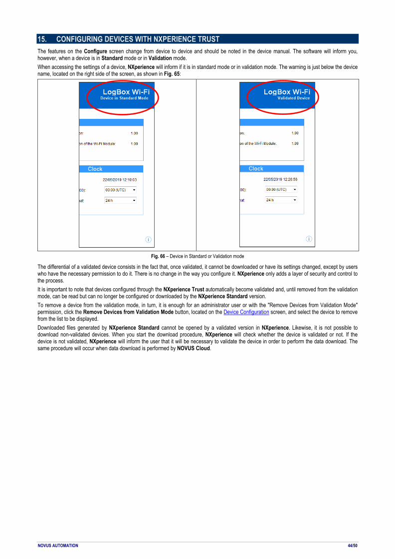
NOVUS AUTOMATION 44/50
15. CONFIGURING DEVICES WITH NXPERIENCE TRUST The features on the Configure screen change from device to device and should be noted in the device manual. The software will inform you, however, when a device is in Standard mode or in Validation mode. When accessing the settings of a device, NXperience will inform if it is in standard mode or in validation mode. The warning is just below the device name, located on the right side of the screen, as shown in Fig. 65:
Fig. 66 – Device in Standard or Validation mode
The differential of a validated device consists in the fact that, once validated, it cannot be downloaded or have its settings changed, except by users who have the necessary permission to do it. There is no change in the way you configure it. NXperience only adds a layer of security and control to the process. It is important to note that devices configured through the NXperience Trust automatically become validated and, until removed from the validation mode, can be read but can no longer be configured or downloaded by the NXperience Standard version. To remove a device from the validation mode, in turn, it is enough for an administrator user or with the "Remove Devices from Validation Mode" permission, click the Remove Devices from Validation Mode button, located on the Device Configuration screen, and select the device to remove from the list to be displayed. Downloaded files generated by NXperience Standard cannot be opened by a validated version in NXperience. Likewise, it is not possible to download non-validated devices. When you start the download procedure, NXperience will check whether the device is validated or not. If the device is not validated, NXperience will inform the user that it will be necessary to validate the device in order to perform the data download. The same procedure will occur when data download is performed by NOVUS Cloud.

NOVUS AUTOMATION 45/50
16. 21 CFR PART 11
16.1 PRESENTATION NXperience Trust software was developed to comply the technical requirements of FDA 21 CFR Part 11 and offers the following tools: 1. User login to edit, configure and download data from devices, as well as create data reports. 2. Complete control of access to the environment through the configuration of profiles for users and the delegation of authority by supervisors. 3. Data registration protected against changes, being allowed to be opened and read only within the software environment. 4. Data download file read from registers with Timestamp and values of each reading. 5. Efficient mechanisms to control and detect changes in the integrity of data log files. 6. Created reports that contain integrity control keys from the histories used to generate them. 7. Presentation of the data in readable and non-readable formats. The process where the NXperience Trust will run must have well-defined access policies to ensure non-repudiation by process users. NXperience Trust does not protect files from deletion or removal from their original directories, and the user is responsible for controlling those files with specific software. Maintenance and backup of files created by the NXperience Trust software are the responsibility of the user.
16.2 COMPLIANCE MATRIX This compliance matrix presents the approach adopted to collaborate in the validation procedure of computational systems present in the process. On the left side of the table are the requirements and, on the right hand side, how these requirements can be met in the NXperience Trust.
16.2.1 CONTROLS FOR CLOSED SYSTEMS (11.10)
"Persons who use closed systems to create, modify, maintain, or transmit electronic records shall employ procedures and controls designed to ensure the authenticity, integrity, and, when appropriate, the confidentiality of electronic records, and to ensure that the signer cannot readily repudiate the signed record as not genuine. Such procedures and controls shall include the following:"
21 CFR PART 11 NXPERIENCE
(a) Validation of systems to ensure accuracy, reliability, consistent intended performance, and the ability to discern invalid or altered records.
The data log made by the NXperience Trust software goes through a protection mechanism that allows the software to detect if it has changed or are invalid.
(b) The ability to generate accurate and complete copies of records in both human readable and electronic form suitable for inspection, review, and copying by the agency. Persons should contact the agency if there are any questions regarding the ability of the agency to perform such review and copying of the electronic records.
NXperience Trust software history files are encrypted and unreadable. To make them readable, the user can export them to a variety of known formats or create a report. In either case, the original document will remain intact.
(c) Protection of records to enable their accurate and ready retrieval throughout the records retention period.
Once created, the history files cannot be changed either inside or outside the NXperience Trust software. The user must be responsible for the protection of these files.
(d) Limiting system access to authorized individuals.
NXperience Trust software has a login mechanism. The process supervisor can create policies for each user who needs access. Any improper access attempt will generate a record in the application events

NOVUS AUTOMATION 46/50
(e) Use of secure, computer-generated, time- stamped audit trails to independently record the date and time of operator entries and actions that create, modify, or delete electronic records. Record changes shall not obscure previously recorded information. Such audit trail documentation shall be retained for a period at least as long as that required for the subject electronic records and shall be available for agency review and copying.
NXperience Trust software creates an encrypted user event log file. The information to be written to this file can be selected by the user. Retention of this log file is the responsibility of the user.
(f) Use of operational system checks to enforce permitted sequencing of steps and events, as appropriate.
NXperience Trust software follows a sequence of steps, so you cannot perform an action in two different paths.
(g) Use of authority checks to ensure that only authorized individuals can use the system, electronically sign a record, access the operation or computer system input or output device, alter a record, or perform the operation at hand.
To access the NXperience Trust software, the user must log in. Access to the configuration, diagnostic and download environment requires the access of a user who has permission to perform this action. Access is the responsibility of the user.
(h) Use of device (e.g., terminal) checks to determine, as appropriate, the validity of the source of data input or operational instruction.
Does not apply to NXperience Trust software. The procedure for verifying the existence of the devices is the responsibility of the users of the system.
(i) Determination that persons who develop, maintain, or use electronic record/electronic signature systems have the education, training, and experience to perform their assigned tasks.
Does not apply to NXperience Trust software. Those responsible for the process should determine the users of the systems.
(j) The establishment of, and adherence to, written policies that hold individuals accountable and responsible for actions initiated under their electronic signatures, in order to deter record and signature falsification.
Does not apply to NXperience Trust software. Those responsible for the process should determine the users of the systems.
(k) Use of appropriate controls over systems documentation including: (1) Adequate controls over the distribution of, access to, and use of documentation for system operation and maintenance. (2) Revision and change control procedures to maintain an audit trail that documents time-sequenced development and modification of systems documentation.
With regard to NXperience Trust software, the system has documentation that explains its features with each new version released.
Table 01 – Controls for closed systems

NOVUS AUTOMATION 47/50
16.2.2 CONTROLS FOR OPEN SYSTEMS (11.30)
21 CFR PART 11 NXPERIENCE
Persons who use open systems to create, modify, maintain, or transmit electronic records shall employ procedures and controls designed to ensure the authenticity, integrity, and, as appropriate, the confidentiality of electronic records from the point of their creation to the point of their receipt. Such procedures and controls shall include those identified in 11.10, as appropriate, and additional measures such as document encryption and use of appropriate digital signature standards to ensure, as necessary under the circumstances, record authenticity, integrity, and confidentiality.
Documents created by NXperience Trust software are encrypted and cannot be edited inside or outside the system. The files have mechanisms to control their integrity for less that has been the change in the data.
Table 02 – Controls for open systems
16.2.3 SIGNATURE MANIFESTATIONS (11.50)
"(a) Signed electronic records shall contain information associated with the signing that clearly indicates all of the following:"
21 CFR PART 11 NXPERIENCE
(1) The printed name of the signer. The author's name appears in the report.
(2) The date and time when the signature was executed. The date/time when the signature was generated appears in created reports.
(3) The meaning (such as review, approval, responsibility, or authorship) associated with the signature. Authorship information appears in created reports.
(b) The items identified in paragraphs (a)(1), (a)(2), and (a)(3) of this section shall be subject to the same controls as for electronic records and shall be included as part of any human readable form of the electronic record (such as electronic display or printout).
The created reports are presented in a readable format.
Table 03 – Signature manifestations
16.2.4 SIGNATURE/RECORDING LINKING (11.70)
21 CFR PART 11 NXPERIENCE
Electronic signatures and handwritten signatures executed to electronic records shall be linked to their respective electronic records to ensure that the signatures cannot be excised, copied, or otherwise transferred to falsify an electronic record by ordinary means.
Electronic signatures of documents cannot be removed. When a report is issued, that information will be printed along with the data.
Table 04 – Signature/recording linking
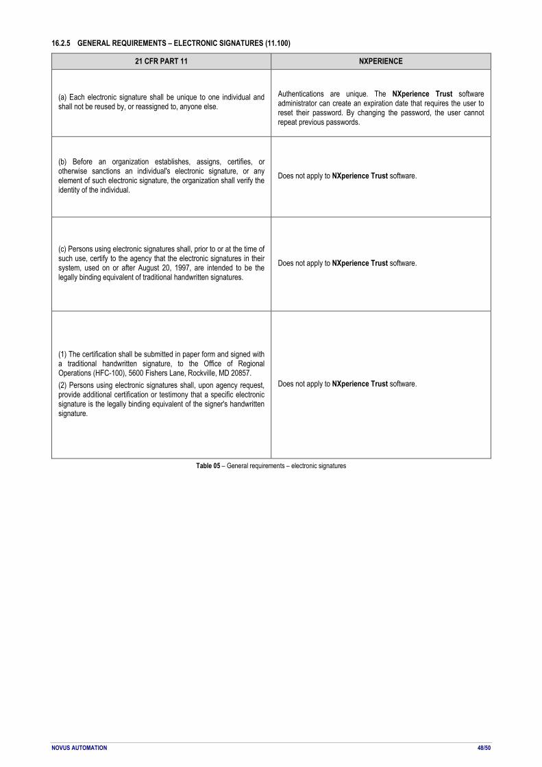
NOVUS AUTOMATION 48/50
16.2.5 GENERAL REQUIREMENTS – ELECTRONIC SIGNATURES (11.100)
21 CFR PART 11 NXPERIENCE
(a) Each electronic signature shall be unique to one individual and shall not be reused by, or reassigned to, anyone else.
Authentications are unique. The NXperience Trust software administrator can create an expiration date that requires the user to reset their password. By changing the password, the user cannot repeat previous passwords.
(b) Before an organization establishes, assigns, certifies, or otherwise sanctions an individual's electronic signature, or any element of such electronic signature, the organization shall verify the identity of the individual.
Does not apply to NXperience Trust software.
(c) Persons using electronic signatures shall, prior to or at the time of such use, certify to the agency that the electronic signatures in their system, used on or after August 20, 1997, are intended to be the legally binding equivalent of traditional handwritten signatures.
Does not apply to NXperience Trust software.
(1) The certification shall be submitted in paper form and signed with a traditional handwritten signature, to the Office of Regional Operations (HFC-100), 5600 Fishers Lane, Rockville, MD 20857. (2) Persons using electronic signatures shall, upon agency request, provide additional certification or testimony that a specific electronic signature is the legally binding equivalent of the signer's handwritten signature.
Does not apply to NXperience Trust software.
Table 05 – General requirements – electronic signatures
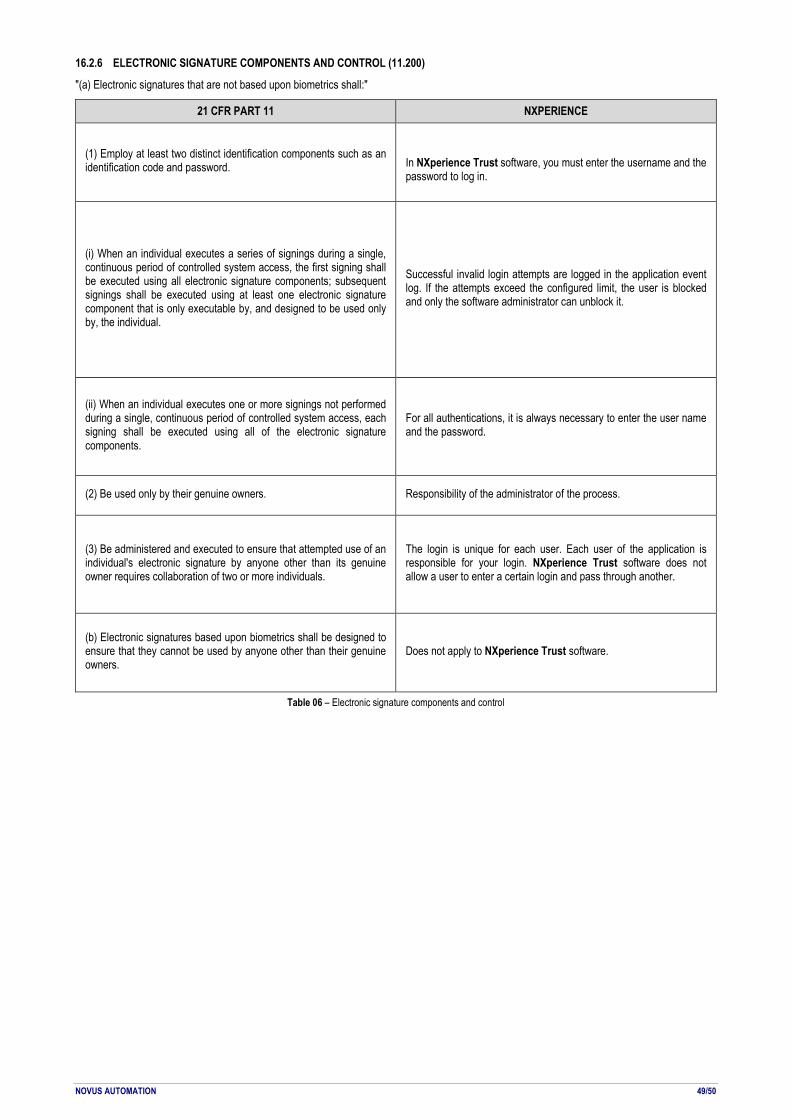
NOVUS AUTOMATION 49/50
16.2.6 ELECTRONIC SIGNATURE COMPONENTS AND CONTROL (11.200)
"(a) Electronic signatures that are not based upon biometrics shall:"
21 CFR PART 11 NXPERIENCE
(1) Employ at least two distinct identification components such as an identification code and password.
In NXperience Trust software, you must enter the username and the password to log in.
(i) When an individual executes a series of signings during a single, continuous period of controlled system access, the first signing shall be executed using all electronic signature components; subsequent signings shall be executed using at least one electronic signature component that is only executable by, and designed to be used only by, the individual.
Successful invalid login attempts are logged in the application event log. If the attempts exceed the configured limit, the user is blocked and only the software administrator can unblock it.
(ii) When an individual executes one or more signings not performed during a single, continuous period of controlled system access, each signing shall be executed using all of the electronic signature components.
For all authentications, it is always necessary to enter the user name and the password.
(2) Be used only by their genuine owners. Responsibility of the administrator of the process.
(3) Be administered and executed to ensure that attempted use of an individual's electronic signature by anyone other than its genuine owner requires collaboration of two or more individuals.
The login is unique for each user. Each user of the application is responsible for your login. NXperience Trust software does not allow a user to enter a certain login and pass through another.
(b) Electronic signatures based upon biometrics shall be designed to ensure that they cannot be used by anyone other than their genuine owners.
Does not apply to NXperience Trust software.
Table 06 – Electronic signature components and control

NOVUS AUTOMATION 50/50
16.2.7 CONTROLS FOR IDENTIFICATION CODES/PASSWORDS (11.300)
"Persons who use electronic signatures based upon use of identification codes in combination with passwords shall employ controls to ensure their security and integrity. Such controls shall include:"
21 CFR PART 11 NXPERIENCE
(a) Maintaining the uniqueness of each combined identification code and password, such that no two individuals have the same combination of identification code and password.
You cannot create two users with the same authentication in the NXperience Trust software.
(b) Ensuring that identification code and password issuances are periodically checked, recalled, or revised (e.g., to cover such events as password aging).
The software administrator can set a date for the expiration of each user's password, thus forcing the setting of a new password.
(c) Following loss management procedures to electronically deauthorize lost, stolen, missing, or otherwise potentially compromised tokens, cards, and other devices that bear or generate identification code or password information, and to issue temporary or permanent replacements using suitable, rigorous controls.
Does not apply to NXperience Trust software.
(d) Use of transaction safeguards to prevent unauthorized use of passwords and/or identification codes, and to detect and report in an immediate and urgent manner any attempts at their unauthorized use to the system security unit, and, as appropriate, to organizational management.
Does not apply to NXperience Trust software.
(e) Initial and periodic testing of devices, such as tokens or cards, that bear or generate identification code or password information to ensure that they function properly and have not been altered in an unauthorized manner.
Does not apply to NXperience Trust software.
Table 07 – Controls for identification codes/passwords