catalog - conveyor rollers rollerdrive controls - Interroll Group
142
CATALOG CONVEYOR ROLLERS ROLLERDRIVE CONTROLS INSPIRED BY EFFICIENCY
-
Upload
khangminh22 -
Category
Documents
-
view
0 -
download
0
Transcript of catalog - conveyor rollers rollerdrive controls - Interroll Group

CATALOGCONVEYOR ROLLERS ROLLERDRIVE CONTROLS
INSPIRED BY EFFICIENCY

© 2018 INTERROLL
PRODUCT LOCATER
Products Applications Drive concepts Load capacity/diameter
Application area Suitable for use in deep-freeze areas
Quiet Waterproof Gravity Flat belt Round belt Chain Toothed belt PolyVee belt Max. load capacity [N]
Ø Tube [mm] (based on weight range)
Page
Products for lightweight materials
Gravity conveyor roller Series 1100 Gravity conveyor application – l l l – – – – – 180 16/20/30/40 40
Slide bearing conveyor roller Series 1500 Non-driven conveyor in moist area l l l l l – – – – 50 30/50 58
Universal conveyor roller Series 1700 light For universal use l l – l l – – – – 150 20/30 64
Fixed drive conveyor roller Series 3500 light Fixed drive conveyors l – – – – – l – – 150 30 86
Tapered fixed drive conveyor roller Series 3500KXO light Fixed drive curves – l – l – l – – – 150 Based on 20 102
Friction/double-friction conveyor roller Series 3800 light Friction conveyor – – – – – – l – – 150 30 124
Products for medium-duty materials
Gravity conveyor roller Series 1100 Gravity conveyor application – l l l – – – – – 350 50 40
Steel conveyor roller Series 1200 Cold or hot environment/materials l – – l l – – – – 1200 30/40/50/60/80 46
Slide bearing conveyor roller Series 1500 Non-driven conveyor in moist area l l l l l – – – – 200 50 58
Universal conveyor roller Series 1700 For universal use l l l l l l – – – 2000 40/50/51/60/63/80 68
Tapered universal conveyor roller Series 1700KXO Curves l l – l l l – – – 500 Based on 50 76
Fixed drive conveyor roller Series 3500 Fixed drive conveyors l l l – l l l l l 2000 40/50/60/63 90
Tapered fixed drive conveyor roller Series 3500KXO Fixed drive curves l l – – – l l – l 500 Based on 50 106
Adjustable/friction conveyor roller Series 3800 Friction conveyor – l – – l – l l l 3000 40/50/60 128
Double friction conveyor roller Series 3870 Friction conveyor for critical materials – l – – – – l – – 500 50 138
Magnetic speed controller Series MSC 50 Gravity conveyors – l l l – – – – – 500 51/52 154
Products for heavy materials
Heavy-duty universal conveyor roller Series 1450 Gravity/freezer area l l l l l – – – – 5000 60/80/89 52
Universal conveyor roller Series 1700 heavy Universally applicable/belt idler l l l l l l – – – 3000 50/51/60 82
Fixed drive conveyor roller Series 3500 heavy Fixed drive conveyors – – l – – – l – – 3000 60 112
Heavy-duty conveyor roller Series 3600 Pallet roller drive and pallet transfer – l l – – – l l – 3500 80/89 118
Double friction conveyor roller Series 3880 Friction conveyor for critical materials – – – – – – l – – 2400 80 144
Heavy-duty conveyor roller Series 3950 Pallet roller drive and pallet transfer l – l – – – l – – 5000 80/89 148
l = suitable l = limited suitability – = not suitable
© 2018 INTERROLL

"Inspired by Efficiency"
Smart handling of resources is mandatory for Interroll. Because we are convinced that efficiency is a
fundamental value. It drives us to constantly improve products and processes. Efficiency inspires our daily activities.
"Inspired by Efficiency" means: We develop products for internal logistics that perfectly adapt to the needs of our customers.
As global market leader in technology and innovation in our industry, we believe that strengthening the business of our
customers in a significant and lasting way is our responsibility. For Interroll, the key to success is the
consistent pursuit of efficiency.
Ù Product locater
Symbols
Products for lightweight materials
Products for medium-duty materials
Products for heavy materials
Suitable for freezer area
Suitable for quiet applications
Suitable for moist areas
Partially suitable for moist areas
Partially suitable for quiet applications
Partially suitable for moist areas
Product overview Ú
Contents
www.interroll.com
The CAD drawings are available under www.interroll.com/support/cad-service.
Product overview 6
The Interroll Group 10
Interroll core products and solutions 12
General technical information 14
Rollers 40
Conveyor accessories 158
RollerDrive 200
Controls 214
Accessories 240
Planning basics 248
Index 277
5© 2018 INTERROLL

PRODUCT OVERVIEW
7© 2018 INTERROLL
PRODUCT OVERVIEW
Conveyor rollers
Gravity conveyor rollerSeries 1100 | page 40
Steel conveyor rollerSeries 1200 | page 46
Heavy-duty universal conveyor roller Series 1450 | page 52
Slide bearing conveyor rollerSeries 1500/1520 | page 58
Universal conveyor rollerSeries 1700 light | page 64
Universal conveyor rollerSeries 1700 | page 68
Tapered universal conveyor rollerSeries 1700KXO | page 76
Universal conveyor rollerSeries 1700 heavy | page 82
Fixed drive conveyor rollerSeries 3500 light | page 86
Fixed drive conveyor rollerSeries 3500 | page 90
Fixed drive curve rollerSeries 3500KXO light | page 102
Fixed drive curve rollerSeries 3500KXO | page 106
Fixed drive conveyor rollerSeries 3500 heavy | page 112
Heavy-duty conveyor rollerSeries 3600 | page 118
Friction conveyor roller, double friction conveyor rollerSeries 3800 light | page 124
Friction conveyor rollerSeries 3800 | page 128
© 2018 INTERROLL6
Double friction conveyor rollerSeries 3870 | page 138
Double friction conveyor rollerSeries 3880 | page 144
Heavy-duty conveyor rollerSeries 3950 | page 148
Magnetic speed controllerSeries MSC 50 | page 154
Conveyor accessories
Polymer conveyor wheelSeries 2130 | page 158
Polymer conveyor wheelSeries 2160 | page 160
Steel conveyor wheelSeries 2200 | page 162
Polymer conveyor wheelSeries 2370 | page 164
OmniwheelSeries 2500 | page 166
Pressure rollerSeries 2600 | page 168
Omnimat moduleSeries 2800 | page 172
Steel ball transfer unitSeries 5000 | page 174
Polymer ball transfer unitSeries 5500 | page 180
Wheel trackFloway Series | page 184
Wheel trackSeries BU40 | page 188
Roller trackSeries BU50 | page 194

PRODUCT OVERVIEW
9© 2018 INTERROLL
PRODUCT OVERVIEW
© 2018 INTERROLL8
24-V motor rollers
RollerDriveEC310 | page 200
RollerDriveEC310 DF | page 206
RollerDriveEC310 IP66 | page 210
Controls for 24-V motor rollers
DriveControl 20 | page 214 DriveControl 54 | page 218 ZoneControl | page 222 ConveyorControl | page 226
MultiControl | page 232 PowerControl | page 236
Accessories for rollers
PolyVee belt | page 240 PolyVee tensioning device | page 241
PolyVee finger guard | page 241
Accessories for 24-V motor rollers
RollerDrive EC310 fastening socket | page 242
RollerDrive EC310 extension cable | page 242
RollerDrive EC310 counter wrench | page 242
AdControl | page 246
Accessories for controls
Magnetic key | page 247 Flat cable for voltage supply | page 243
ConveyorControl communication cable | page 243
MultiControl communication cable | page 244
MultiControl Y-cable | page 244 ConveyorControl termination box | page 246

© 2018 INTERROLL 11
THE INTERROLL GROUP
10© 2018 INTERROLL
THE INTERROLL GROUP
The Interroll Group is a globally leading supplier of high-quality key products and services for internal logistics. The company, which is listed on the stock exchange and has its headquarters in Switzerland, employs some 2000 people in 32 companies around the globe.
Interroll‘skey markets
Warehousing &Distribution
Food Processing
Airport
CourierExpress Postal
IndustrialProduction
Supermarket
Holding Global Competence Centers
Sales, Production & Service Regional Competence Centers

© 2018 INTERROLL 13
INTERROLL CORE PRODUCTS AND SOLUTIONS
12© 2018 INTERROLL
Transporting and distributingMillions of different individual items travel through the world’s flow of goods every day and must be delivered on time to the correct destination. This is a trend that requires a performance-based logistics system with efficient material flow systems. Interroll’s innovative conveyor modules and subsystems are always ready for key locations in customers' systems:
· Crossbelt sorters· Belt curves and belt merges· Conveyor modules with zero-pressure accumulation· Roller conveyors· Belt conveyors
Precisely pre-assembled and rapidly delivered for fast, simple integration into the complete system on site (plug and play). The conveyor modules and subsystems provide users with key assurances: excellent availability whilst being easy to use; outstanding efficiency even at low throughput volumes; efficient investment with a short period of return on investment; adaptability in the event of change.
Storage and pickingEconomical and user-friendly: the dynamic storage solution that operates without power. It is designed for fast-moving goods (e.g. groceries) that have to be quickly picked and immediately conveyed to consumers. The principle is as simple as it is ingenious. It is known as FIFO, First In – First Out, and guarantees that what has been stored first is also picked first. Or LIFO, Last In – First Out, when the pallet stored last is picked first. It means making maximum use of minimum space. The needs of our customers are as diverse as our products, therefore our
· Pallet Flow· Carton Flow
peripheral subsystems offer unlimited design options. The picking times can scarcely be beaten. The return on investment for the operator is two to three years and is integrated into "Just in Time".
INTERROLL CORE PRODUCTS AND SOLUTIONS
The solutions for our customers' daily logistical challenges are based on Interroll key products that are built on a worldwide common platform.
ConveyingVersatile and reliable core products ensure a dynamic, efficient material flow across all continents and in all industries:
· Conveyor rollers· 24 V motor rollers (RollerDrive)· Controls for RollerDrive· Drum motors and idler pulleys· Pallet drive and control (PalletDrive and PalletControl)
They are used to convey, accumulate, feed or remove goods. Powered or with the force of gravity. With or without dynamic pressure. Easy-to-install drive solutions for new plants or for refurbishing existing plants. Excellent products that will pay for themselves and that you can rely on. In every respect.

GENERAL TECHNICAL INFORMATIONPLATFORMS
GENERAL TECHNICAL INFORMATIONPLATFORMS
15© 2018 INTERROLL14 © 2018 INTERROLL
PlatformsInterroll Conveyor Roller Series are arranged into five so-called platforms. Each platform is characterized by a certain type of bearing and certain materials – the two key factors for the operation and application possibilities of the products.
The following applies within a platform:
· The bearings and materials for the bearing housing and seal are identical
· The size of the bearings may differ· The versions are produced by the combination of shaft/tube
dimensions and drive heads as well as the materials
Platform 1100
Associated roller series Catalog page
Gravity conveyor roller 1100 page 40
Polymer conveyor wheel 2130 page 158
Polymer conveyor wheel 2370 page 164
Wheel track BU40 with polymer wheels
page 188
Application
· For gravity applications· Particularly smooth operation of conveyor rollers· Stainless steel version suitable for moist areas· For lightweight and medium-heavy materials to be conveyed· Not suitable for drive conveyors
Properties
Platform 1100 provides for cost-effective solutions and is particularly suitable for gravity applications under normal ambient temperatures.
For information about properties and application areas of the polymers used, please refer to the chapter Material Specification page 272.
Bearings and materials
The bearing is made of polymer with balls made of uncoated steel or stainless steel. The outer ring and inner cone of the bearing are made of polypropylene. The bearings are lubricated with a food-safe grease.
Platform 1200
Associated roller series Catalog page
Steel conveyor roller 1200 page 46
Steel conveyor wheel 2200 page 162
Wheel track BU40 with steel rollers
page 188
Application
· For temperature ranges outside of the limits for polymer· For lightweight and medium-heavy materials to be conveyed· For driven and non-driven conveyors
Properties
Platform 1200 is specifically designed for use in extreme ambient temperatures. All versions are antistatic.
Bearings and materials
The pressed steel bearing seats and internal rings of the ball bearing are hardened and galvanized zinc-plated. The shape of the ball bearing is designed specifically for conveyor rollers and tolerates greater deflection of the bearing than comparable precision ball bearings.
Platform 1450
Associated roller series Catalog page
Heavy-duty universal conveyor roller 1450 page 52
Heavy-duty conveyor roller 3600 page 118
Double friction conveyor roller 3880 page 144
Heavy-duty conveyor roller 3950 page 148
Application
· For particularly heavy-duty loads and heavy individual loads· Suitable for extreme temperatures with steel bearing housings· For driven and non-driven conveyors
Properties
Platform 1450 is specifically designed for high loads caused by heavy individual weights. One version is available for freezer applications. The drive elements made of technopolymers are designed to be twist-proof with a form-fit connection with the tube. The steel drive heads and flanges are all galvanized zinc-plated after being welded to the tube for optimum corrosion protection. All of the welds run right around the tube, not just in certain areas. For information about properties and application areas of the polymers used, please refer to the chapter Material Specification page 272.
Bearings and materials
The standard version bearings are precision ball bearings 6205 2RZ or 6204 2RZ. Depending on the series, the drive elements, such as sprockets or toothed belt drive heads, are made of fiberglass-reinforced polyamide and polyoxymethylene or steel. The bearing housing on the non-driven side and the seals are made of polyamide.
Platform 1500
Associated roller series Catalog page
Slide bearing conveyor roller 1500 page 58
Omniwheel 2500 page 166
Omnimat module 2800 page 172
Wheel track Floway page 184
Application
· For wet and hygienic areas· For lightweight and medium-heavy materials to be conveyed· For driven and non-driven conveyors
Properties
Platform 1500 is specifically designed for use in hygienic areas and in areas at risk of corrosion. All of the bearing housings are sealed internally so that liquids or other substances cannot penetrate the rollers. The conveyor rollers can be cleaned with conventional detergents. For information about properties and application areas of the polymers used, please refer to the chapter Material Specification page 272.
Bearings and materials
The bearings are designed as slide bearings and are made of polymer (polyoxymethylene with the addition of polytetrafluorethylene (PTFE)) with a stainless steel shaft pin. The materials and surfaces of the bearing pair are aligned to each other so that the bearings can run dry without lubrication. The tubes are made of polymer or stainless steel. All of the materials are completely corrosion-proof.
Pla
nnin
g b
asi
csR
olle
rs |
Conv
eyin
g e
lem
ents
| R
olle
rDri
ve |
Cont
rols
| A
cces
sori
esG
ener
al t
echn
ica
l inf
orm
ati
on

GENERAL TECHNICAL INFORMATIONPLATFORMS
GENERAL TECHNICAL INFORMATIONPLATFORMS
17© 2018 INTERROLL16 © 2018 INTERROLL
Platform 1700
Associated roller series Catalog page
Universal conveyor roller 1700 light page 64
Universal conveyor roller 1700 page 68
Tapered universal conveyor roller 1700KXO page 76
Universal conveyor roller 1700 heavy page 82
Pressure roller 2600 page 168
Fixed drive conveyor roller 3500 light page 86
Fixed drive conveyor roller 3500 page 90
Fixed drive curve roller 3500KXO light page 102
Fixed drive curve roller 3500KXO page 106
Fixed drive conveyor roller 3500 heavy page 112
Friction conveyor roller, double friction conveyor roller
3800 light page 124
Friction conveyor roller 3800 page 128
Double friction conveyor roller 3870 page 138
Roller track BU50 page 194
Magnetic speed controller MSC 50 page 154
RollerDrive EC310 page 200
Application
· For universal use· For particularly quiet conveyance at high speeds· For lightweight and medium-heavy materials to be conveyed· For driven and non-driven conveyors
Properties
Platform 1700 is designed for high loads at very low noise levels and provides the ultimate in flexibility with its different drive options. The bearing design comprising polyamide bearing housing, precision ball bearing and a polypropylene or polyamide seal produces an extremely quiet conveyor roller, which can simultaneously carry heavy loads. Bearing housings and belt drive heads are installed in the tubes in a form-fit way (flanging for steel tube and press-in edge for polymer tube). The unique feature about this platform 1700 is the tapered shaft-shuttle, which combines the benefits of a female threaded shaft and a spring-loaded shaft (cf. shaft-shuttle shaft design page 20).
For information about properties and application areas of the polymers used, please refer to the chapter Material Specification page 272.
Bearings and materials
Sealed DIN precision ball bearings 6002 2RZ, 689 2Z and 6003 2RZ are used. They are greased with a silicon-free lubricant and have a secure bearing housing in the base of the roller thanks to a snap-on edge. In addition, the ball bearing 6002 2RZ is oiled or available in a stainless steel design. The integral polypropylene seal is fixed in the internal ring of the ball bearing and has three functions: Protection of the ball bearing against coarse dirt and splashing water, diameter compensation of shaft and internal ring as well as diverting axial forces into the ball bearing.
Platform 5000
Associated roller series Catalog page
Steel ball transfer unit 5000 page 174
Polymer ball transfer unit 5500 page 180
Application
· For pushing, e.g. of steel or wooden plates· For aligning medium-heavy and heavy materials
Properties
The platform 5000 is designed for omni-directional pushing or aligning of medium-heavy and heavy materials. The series differ in the following features:
· Housing design· Fastener· Material of housing· Material of support balls· Material of main balls· Load capacities
Bearings and materials
The principle of the ball roller consists of several small support balls that support a larger main ball. The main ball can be made of polymer or steel, depending on the series. The housing can be of polyamide or steel.
Pla
nnin
g b
asi
csR
olle
rs |
Conv
eyin
g e
lem
ents
| R
olle
rDri
ve |
Cont
rols
| A
cces
sori
esG
ener
al t
echn
ica
l inf
orm
ati
on

GENERAL TECHNICAL INFORMATIONSHAFTS
GENERAL TECHNICAL INFORMATIONBEARINGS
19© 2018 INTERROLL18 © 2018 INTERROLL
Shafts
Shaft materialInterroll offers shafts made of three different materials or finishings:
· Uncoated steel· Zinc-plated steel· Stainless steel
All shafts are manufactured from cold-drawn steel. Interroll recommends to match the shaft material to the material of the side profile.
Zinc-plated shafts are cut from galvanized zinc-plated rod material, thus the front faces of the female threaded or spring-loaded shafts are always without zinc plating.
Male threaded shafts cannot be zinc-plated, otherwise they pose a risk of blocked threads due to the zinc layer. For this reason, Interroll recommends selecting either male threaded or flatted shafts in stainless steel to obtain adequate corrosion protection.
Manufacturing processAfter the sawing process, the shafts are milled. Milling reduces deformations of the shaft ends or damages on the side profile during installation to a minimum. Furthermore, milling removes sharp burrs, thereby ruling out a risk of injuries. Hence, this creates not only safe, but also perfectly manageable rollers.
For threaded holes, the centering holes are drilled in a first step to ensure precisely centered threaded holes in the shaft.
Versions
Spring-loaded shaft
Spring-loaded shafts can be manufactured from round material or hex material.
· Simple shaft design· Very fast and simple installation and removal· Suitable crosslinks have to be provided between the side
profiles to reinforce the conveyor.
· With driven rollers, play between the shaft and the mounting hole (inevitably due to oblique installation) will create noise, particularly when starting and stopping the turning motion (especially at hex shafts).
· Depending on the selection of material pairing (shaft/side profile) and dimensions (size of hole and spring-loaded shaft), it may lead to wear of the shaft (hexagon looses its edges) or the side profile.
· Shield for zinc-plated shaft material is not zinc-plated
Female threaded shaft
Female threaded shafts can be manufactured from round material or hex material.
· Lead to a very stable frame construction – generally, no use of crosslinks is required
· A firm connection causes a lot less noise than shafts that are not firmly screwed together.
· The roller shaft and side profile stabilize each other resulting in the conveyor rollers having a greater load capacity than loosely fitted rollers.
· Wear-free towards spring-loaded shafts due to firm connection in the side profile
· Medium-fast installation and removal· Shield for zinc-plated shaft material not zinc-plated· Safe discharge of static charges (anti-static design)
Interroll offers the following threads and thread depths:
Thread Thread depths[mm]
M5 12
M6 15
M8 15
M10 20
M12 20, 25
M16 25
BearingsInterroll utilizes different bearings, such as slide bearings or special ball bearings made of polypropylene with steel balls. However, the following section describes only the precision ball bearings used by Interroll.
Further information on the bearing assemblies (ball bearings with bearing housings and seals) is provided in the Platforms chapter (page 14) and under Material Specification (page 272).
All precision ball bearings used are designed as 2RZ, except for type 689. The steel sealing discs form a narrow sealing gap, but are non-contacting. They ensure an optimal startup of the roller. The steel-reinforced rubber sealing lips (NBR) lie against the inner ring under external pressure and thus provide an exceptional sealing quality comparable to the 2RS version. The oil-lubricated version is characterized by its easy start and exceptional easy-running properties.
Precision ball bearings in accordance with DIN 625 have the following properties:
· Series 689, 60 and 62 standard DIN grooved ball bearings· Excellent load capacity and operational life· Precision ball race· Extremely temperature-resistant· Low-noise operation· With stainless steel design: manufactured throughout from
corrosion-proof material
All precision ball bearings are specified by Interroll beyond the requirements of DIN 625 for optimum, durable and constant operation. Interroll specifies the bearing play, lubrication and sealing etc.
Pla
nnin
g b
asi
csR
olle
rs |
Conv
eyin
g e
lem
ents
| R
olle
rDri
ve |
Cont
rols
| A
cces
sori
esG
ener
al t
echn
ica
l inf
orm
ati
on

GENERAL TECHNICAL INFORMATIONSHAFTS
GENERAL TECHNICAL INFORMATIONSHAFTS
21© 2018 INTERROLL20 © 2018 INTERROLL
Shaft with shaft-shuttle
Shafts with shaft-shuttle are made of hex material. Both ends are fitted with the shaft-shuttle made of polyamide. The conical shaft-shuttle reduces the hex surface towards the shaft end.
· Very fast and simple installation and removal· Similar low noise level as female threaded shafts· Wear-free towards spring-loaded shafts due to zero-clearance
seating of the shaft free in the side profile (11 mm hex hole, +0.3/+0.8 mm)
· Anti-static version· Particularly suited for modernizing systems; side profiles that
have been in use for a long time generally show high tolerances in the holes
· Evenly aligned, anti-rotation shuttles (positioning one side is sufficient)
· Both shaft ends can be pushed in· Suitable crosslinks have to be provided between the side
profiles to reinforce the conveyor· No scratching of high-quality side profiles during installation
and removal
Male threaded shaft
Male threaded shafts are made of round material.
Male threaded shafts feature a thread cut onto the shaft ends. In each case, a nut is screwed onto the shaft in front of the seal. The two nuts are subtracted from the dimension of the "lane width" during the production of the roller. They shorten the usable length of the roller compared to rollers with female threaded shafts.
· A firm connection causes a lot less noise than shafts that are not screwed together
· Very stable frame construction – generally, no use of crosslinks is required
· The roller shaft and side profile stabilize each other resulting in the conveyor rollers having a greater load capacity than loosely fitted rollers.
· Wear-free towards spring-loaded shafts due to firm connection in the side profile
· The two nuts at the seal and two nuts with washers for fastening are part of the scope of delivery
· Available only in the versions uncoated steel or stainless steel
Flatted shaft
Flatted shafts are made of round material. They have two lateral, parallel milled sections at the shaft ends, which fit into corresponding side profile holes, e.g. into side profiles with open longitudinal holes.
· Very fast and simple installation and removal· Suitable crosslinks have to be provided between the side
profiles to reinforce the conveyor.· Lower noise level than spring-loaded shafts since only minor
play is required (no oblique installation)
A flat shaft can be created on both sides as well as on one side only (D shaft). The flat shaft can be defined in increments of 0.5 mm. Minimum and maximum dimensions depend on the selected shaft diameter.
Fixed shaft
Fixed shafts can be manufactured from hexagon or round material. It is possible to fit the round shafts with a flat shaft. The shafts are mostly inserted in fastening holes in the side profile that are open at the top. To rule out that the shaft turns inside the guide of the side profile, Interroll recommends the use of hexagon shafts or round flatted shafts in corresponding side profiles intended for this purpose.
· Shields, or flat shafts if needed, are not zinc-plated for zinc-plated shaft material.
· Simple shaft design· Very fast and simple installation and removal with fastening
holes open to the top· Suitable crosslinks have to be provided between the side
profiles to reinforce the conveyor· With driven rollers, play between the shaft and the mounting
hole will create noise, particularly when starting and stopping the turning motion. For this reason, Interroll recommends the lowest play possible.
Installation instructionsThe following should be considered in relation to the selection of a shaft and construction of the side profiles:
1. The hole dimension of the side profile should be as small as possible on conveyor rollers with female threaded shafts. Larger holes can lead to a higher tolerance of the roller pitch and to the height differences of several conveyor rollers. The function of the roller conveyor can be affected by the hole and screw selection.
2. For softer side profiles made out of aluminum or thick powder coatings, female threaded shafts should always be selected with the largest possible diameter and the smallest possible thread. This minimizes the risk of the shaft penetrating the aluminum profile.
3. The installation of conveyor rollers with spring-loaded shaft must be done in an oblique way. That is the spring-loaded shaft must be inserted in a hole of the side profile. Afterwards, the other roller end is moved from an oblique to a horizontal position. The spring-loaded shaft can be inserted into the hole on the opposite side only in the horizontal position. Too small a hole could make installation significantly more difficult.
a
The following formula and the drawings should provide support in sufficiently dimensioning the fastening hole. For this purpose, an oversize of 0.5 mm of d1 compared to the shaft diameter is sufficient in most cases.
d1 = S ∙ (H + D/2)
(EL – 1)+ d
EL
D
H
d1
S
d
Scope of deliveryMaterial required for fastening the rollers is not part of the scope of delivery, such as washers, nuts, screws.
Exceptions
Product Scope of delivery
Rollers with male threaded shafts Nuts and washers
Rollers of series 3500KXO light Taper disks and ball sockets
Pla
nnin
g b
asi
csR
olle
rs |
Conv
eyin
g e
lem
ents
| R
olle
rDri
ve |
Cont
rols
| A
cces
sori
esG
ener
al t
echn
ica
l inf
orm
ati
on

GENERAL TECHNICAL INFORMATIONSHAFTS
GENERAL TECHNICAL INFORMATIONSHAFTS
23© 2018 INTERROLL22 © 2018 INTERROLL
LabelingAll shafts starting with a length of 100 mm are labeled with the respective production order number. The number is located on the shaft inside the tube. It allows users to order an identical roller without having to provide information about the product, such as the length.
Axial play
Conveyor rollers must not be warped during installation or operation. This means that play must exist between the seal of the roller and the side profile. The roller must move in axial direction under load.
The axial play must not be too high. Rollers with tapered shaft-shuttle or RollerDrive with tapered spring-loaded shaft are designed so that they have the best possible fit for the hole in the side profile, even in cases of high hole tolerances. This reduces wear and possible noise. If the axial play is too high, it may pose the risk of insufficient positioning of the hexagon in the hole, which leads to wear and noise.
The maximum play is already taken into account during the manufacture of the rollers.
0.50.5
RL
EL=AGL
U
Example: At the time of ordering, a lane width (EL = installation length) of 500 mm is specified for a roller of series 1700 with female threaded shaft. The dimension from seal to seal measures approx. 499 mm. Hence, the roller has an axial play of approx. 1 mm (see figure above).
16.5
1 7.1
35 RL U
EL=AGL=RL+40
0.55
The axial play under consideration depends on roller series and roller version. For example, an axial play of approx. 1 mm on the drive side and 0.5 mm on the other side is taken into account for a roller of series 3500 with sprocket head (see figure above).
The axial play stated is only a guide value. There may be slight deviations from this figure in individual cases when production tolerances are added. The function of a correctly installed and used conveyor roller is not being impacted.
Variable shaft lengthA deviation of the standard shaft length is possible for all roller series. The shafts can be shortened or lengthened. The axial support of a roller via the seal must be ensured at all times. For some roller series, this requires taking appropriate measures in case of a shaft lengthening.
A length change is possible for the following shaft versions:
· Female threaded shaft· Male threaded shaft· Fixed shaft· Spring-loaded shaft· Flatted shaft
The length changes depend on the actual shaft version. Please direct any questions to your Interroll contact person. Axial support by the seal may no longer be guaranteed with a length change. With greater axial forces, e.g. where there is lateral displacement, suitable replacement structures, such as spacing tubes, may have to be fitted.
With female threaded shafts, the shaft can be lengthened only if the seal is given an axial support. Depending on the thread and shaft diameter, a retaining ring can be inserted. The retaining ring is secured via a groove incorporated in the shaft. The combination of a female threaded shaft with flatted shaft also requires a support of the seal.
In case of a shaft lengthening, the maximum load capacity of the roller is reduced compared to the values that are specified for each side.
Shaft adapterThe shaft adapter is a conductive polymer component that can be pressed onto roller shafts. It can be inserted in side profiles with open elongated holes. In this case, the roller is placed from the top. The shaft adapter significantly reduces the noise level compared to the pure steel shaft and increases the installation length of the roller. The shaft adapter is not an alternative to the tapered shaft-shuttle (page 20).
Technical data
Material Polyoxymethylene, RAL9005 (jet black)
Temperature range 0 to + 40 °C
Suitable shafts Fixed round shafts (Ø 8 and 10 mm)
Anti-static version < 106 Ω
Max. static load of a roller with the use of shaft adapters
See load capacity in the corresponding table (load capacity is not reduced by shaft adapter)
Design versions
Shaft diameter [mm]
Drawing Longer installation length [mm]
8 +5
10 +4
1 Adapter 11 HEX (hexagon)2 Adapter flat shaft 12
The shaft adapter can be used with the following roller series:
· Series 1100· Series 1700· Series 3500 (for drive heads for belts)
Pla
nnin
g b
asi
csR
olle
rs |
Conv
eyin
g e
lem
ents
| R
olle
rDri
ve |
Cont
rols
| A
cces
sori
esG
ener
al t
echn
ica
l inf
orm
ati
on

GENERAL TECHNICAL INFORMATIONTUBES
GENERAL TECHNICAL INFORMATIONTUBES
25© 2018 INTERROLL24 © 2018 INTERROLL
Tubes
Tube materials/tube diameters
Steel/stainless steel
The steel tubes used by Interroll are manufactured in accordance with DIN EN 10305-1, DIN EN 10305-3 and DIN EN 10305-7, but with stricter tolerance specifications.
The roller manufacturing and transport may result in minor scoring or scratches to appear on the tube surface. However, they do not have any effect on the functionality of the roller.
Benefits· Highest resistance and bending stiffness· Steel – corrosion protection through zinc-plating, chrome-
plating or carbonitriding· Stainless steel – very good and long-life corrosion protection· Stainless steel – Application also possible in aggressive
environments (not suitable for seawater)· Sprockets and flanges can be welded on (flanges not together
with stainless steel tube)· Steel tubes can be flanged over the bearing assembly so that
the bearing housing can no longer move out (not for carbonitrided or chrome-plated tube as well as tubes with a wall thickness greater than 1.5 mm)
Versions· With grooves (not for carbonitrided and chrome-plated tube)· Covered with PVC or PU sleeve· With lagging· With pushed-on tapered elements· With flanges welded on
When used in belt conveyors, there is noise caused by the pared tube welds coming into contact with the belt. Interroll recommends testing the relevant application.
Aluminum
Aluminum tubes have slightly lower strength and only about 33 % of the flexural strength of steel tubes. However, they weigh only 36 % of the weight of comparable steel tubes.
Benefits· Significantly lighter than steel tube· Corrosion-resistant· Aluminum tubes can be flanged over the bearing assembly so
that the bearing housing can no longer move out
Versions· Covered with PVC or PU sleeve· With pushed-on tapered elements
Ø Rollers[mm]
Anodized surface Anti-static version
16 Yes No
20 Yes No
50 No Yes
PVC
Benefits· Noise-dampening· Highly impact-resistant· Very lightweight· Corrosion-resistant, no surface treatment required· Easy to clean
Polymer tubes have a significantly lower load capacity compared with steel and aluminum tubes with the same diameter. With polymer tubes with a diameter of 30 mm and larger, the bearing assemblies are connected form-fit with the tube so that an absolutely safe seating is ensured. An ambient temperature range from −5 to +40 °C applies to polymer tubes. With a high ambient temperature (from 30 °C) and high continuous static load (over hours), a permanent deformation of the rollers cannot be ruled out. When dimensioning the rollers for an existing width between the side profiles (lane width), a thermal expansion must be taken into account. In case of large temperature differences, the length of the roller changes based on the following formula:
∆LT = 0,08 ∙ L ∙ ∆T 1000
ΔLT = change in length due to temperature change (mm)ΔT = temperature difference (°C)L = tube length (mm)
A proper functioning requires that a warping of the roller at high temperature is being avoided.
Versions· Covered with PVC or PU sleeve
Polymer tubes are available in the following colors:
Color RAL number Ø Tube[mm]
Stone gray 7030 16, 20, 30, 40, 50, 63
Graphite gray 7024 20
Sky blue 5015 30, 40, 50, 63
Tube diameterThe following overview lists all available shell diameters and their wall thicknesses. The respective shell series chapter describes which diameter is available in which material.
Ø Tube[mm]
Wall thicknesses[mm]
16 1.0
20 1.5
30 1.2; 1.8
40 1.5; 2.3
50 1.5; 2.8; 3.0
51 2.0
60 1.5; 2.0; 3.0
63 3.0
80 2.0; 3.0
89 3.0
Finishing of shell materials
Material Surface finishing
Steel Zinc-plating
Steel Chrome-plating
Steel Carbonitriding
Aluminum Anodizing
Zinc-plating
Galvanized zinc-plating of steel tubes is a cost-efficient corrosion protection.
Application· For dry application areas with normal temperatures· Conditional suitability for environments with salt and humidity,
e. g. installations in harbor areas or in sub-tropical countries· Conditional suitability in applications with moist or wet
materials
Besides zinc-plated tubes, Interroll also offers zinc-plated shafts and zinc-plated sprocket heads. Front sides of shafts cannot be zinc-plated.
ProcedureThe surface of the steel tube material is galvanically zinc-plated (using electrolysis). The electrolysis produces an extremely even, thin sleeve. The entire process involves pre-treatment, zinc-plating, passivating and drying.
PropertiesZinc-plated tubes are suitable for flanging and applying grooves. The galvanized zinc-plating is a temporary protection of the steel tube against corrosion.
The duration of the corrosion protection is reduced by the mechanical and thermal loads to which it is subjected. Particles of the zinc layer may be carried off when transporting materials over zinc-plated steel rollers.
Zinc-plated surfaces are sensitive to scratching and abrasion. Damage can result in point corrosion.
Extreme changes in temperature must be avoided as they can cause internal tension. Furthermore, corrosion resistance becomes reduced as the temperature rises.
In order to maintain the limited protective effects of zinc-plating, special packaging must be used for sea freight, for example.
Special measures must also be employed if the materials are to be stored for a longer period of time. Zinc-plating is not food-compatible. A zinc-plated and passivated surfaced reacts with the following substances:
· Humidity· Acidic environment (exhaust fumes, salts, wood acid etc.)· Alkaline substances (lime, chalk, cleaning agents, CO2)· Perspiration· Solutions of other metals (copper, iron etc.) Pl
ann
ing
ba
sics
Ro
llers
| Co
nvey
ing
ele
men
ts |
Ro
llerD
rive
| Co
ntro
ls |
Acc
esso
ries
Gen
era
l tec
hnic
al i
nfo
rma
tio
n

GENERAL TECHNICAL INFORMATIONTUBES
GENERAL TECHNICAL INFORMATIONTUBES
27© 2018 INTERROLL26 © 2018 INTERROLL
Layer thickness 6 to 15 µm
Passivation Additional blue passivation (chromium(IV)-free)
Standards complied with DIN EN ISO 2081DIN 50961Zinc-plating according to RoHS regulations
Temperature range −40 to +200 °C
Antistatic Yes
The long material is zinc-plated. When the tube is sawed off, the front sides are not zinc-plated.
Chrome-plating
Bright chrome-plating of steel tubes is a corrosion protection that do not leave behind any abrasion on materials or other locations in contrast to zinc-plated tubes.
Application· For color and abrasion-sensitive materials· For dry application areas with normal temperatures· The suitability for environments with salt, e.g. systems in harbor
regions or subtropical countries, must be checked.· Suitable for paper and wood industry
ProcedureThe plating thickness generally measures 15 to 30 µm. The electrolysis produces an extremely even, thin sleeve.
PropertiesChrome-plated tubes are suitable for flanging or applying grooves.
The chrome-plating is a good protection of the steel tube against corrosion. The duration of the corrosion protection is reduced by the mechanical and thermal loads to which it is subjected. Damages of the chrome layer can result in point corrosion.
Extreme changes in temperature must be avoided as they can cause internal tension. In order to maintain the protective effects of chrome-plating, special packaging must be used for the rollers, e.g. for sea freight (salt water). Special measures must also be employed if the materials are to be stored for a longer period of time.
A chrome-plated surface can react with the following substances:
· Acidic environment (exhaust fumes, salts, wood acid etc.)· Alkaline substances (lime, chalk, cleaning agents, CO2)· Solutions of other metals (copper, iron etc.)
Layer thickness 15 to 30 µm
Standards complied with DIN EN ISO 1456Chrome-plating according to RoHS regulations
Temperature range −40 to +200 °C
Antistatic Yes
Chrome-plating is performed on the tube section that has been cut to the correct length. This will also chrome-plate the front sides.
Carbonitriding
Carbonitriding is a wear-resistant corrosion protection for steel tubes.
Application· For highly stressed conveyor rollers, e.g. from the transport of
steel containers· For applications where materials must be transported axially on
rollers
ProcedureCarbonitriding is a thermochemical process. For this purpose, the surface of the tube is enriched with nitrogen which creates a wear-resistant ceramic coating.
PropertiesCarbonitrided tubes are partially suitable (up to 1.5 mm wall thickness) for flanging, but not for the application of grooves.
The ceramic coating is a temporary protection of the steel tube against corrosion. It is resistant to scratching and chafing. Mechanical damage can result in point corrosion.
In addition, carbonitriding distinguishes itself with the following properties:
· Abrasion-resistant surfaces· Good sliding properties· Excellent temperature resistance· Low warpage· Free of scales· Good corrosion resistance
The ceramic coating is not food-compatible. The carbonitrided surface does not create any abrasion, but can leave color traces behind.
A carbonitrided surface can react with the following substances:
· Acidic environment (exhaust fumes, salts, wood acid etc.)· Alkaline substances (lime, chalk, cleaning agents, CO2)· Perspiration· Solutions of other metals (copper, iron etc.)
Tube color Matt, light gray, and scale-free (no grinding necessary/possible)
Min. reference length 100 mm
Max. reference length 2000 mm
Temperature range −40 to +80 °C
Antistatic Yes
Carbonitriding is performed on the tube section that has already been cut to the correct length. This will also carbonitride the front sides.
Anodizing
Anodizing is a corrosion protection for aluminum tubes.
Application· For weight-sensitive applications, e.g. shuttle systems.· For aluminum tubes with diameters of 16 and 20 mm
ProcedureThe surface of the aluminum tube is given an oxidic protective coating. Compared to galvanizing procedures, the top material layer is transformed and an oxide is formed.
PropertiesThe duration of the corrosion protection is reduced by the mechanical and thermal loads to which it is subjected. Particles may be carried off when transporting materials over anodized rollers.
Anodized surfaces are low-sensitive to scratching and abrasion. Mechanical damage can result in point corrosion.
An anodized surface can react with solutions of other metals, such as copper, iron, etc.
Layer thickness ≥ 20 µm
Tube color Aluminum color (natural)
Standards complied with DIN 17611, DIN EN 754/755
Temperature range −40 to +80 °C
Antistatic No
The rod material is anodized. When the tube is sawed off, the front sides are not anodized.
Comparison
The different finishings of steel tube have different resisting forces compared to mechanical wear. The following table provides a factor that shows the reduction in wear of the tube surface compared to the steel zinc-plated version.
Material/finishing Factor
Zinc-plated steel 1
Stainless steel 5
Steel chrome-plated 50
Steel carbonitrided 120
A carbonitrided surface is 120 times as resistant as a zinc-plated surface.
Pla
nnin
g b
asi
csR
olle
rs |
Conv
eyin
g e
lem
ents
| R
olle
rDri
ve |
Cont
rols
| A
cces
sori
esG
ener
al t
echn
ica
l inf
orm
ati
on

GENERAL TECHNICAL INFORMATIONTUBES
GENERAL TECHNICAL INFORMATIONTUBES
29© 2018 INTERROLL28 © 2018 INTERROLL
Tubes with grooves
Grooves are running grooves that can be placed in steel or aluminum tubes. They are used to guide round belts. When using the corresponding round belt, they are below the roller surface and, as such, do not contact the material.
When the round belt is moved, the conveyor roller also moves. Two options are differentiated here:
· Wrapping from roller to roller· Wrapping of a driven shaft that is positioned below the
conveyor rollers. The guide rollers required for guiding the round belts on the drive shaft are located on page 168.
They are driven by round belts guided by grooves – in straight sections via cylindrical rollers or in curve sections via cylindrical rollers or rollers with tapered elements.
Grooves can be applied for the following roller and RollerDrive series:
Roller or RollerDrive series Catalog page
Universal conveyor roller 1700 page 68
Universal conveyor roller 1700 heavy page 82
Tapered universal conveyor roller 1700KXO page 76
RollerDrive EC310 page 200
Please contact your Interroll contact person if grooves need to be applied to other roller series.
Rollers with grooves always contain an antistatic element. The maximum conveyor force of the round belt measures 300 N. The maximum load capacity per conveyor roller with groove measures 300 N due to the low conveyor force of the round belt. The load capacity information in the individual roller series refers to rollers without grooves. The maximum load capacity of the conveyor roller is lower with tube lengths of greater than 1400 mm. Interroll recommends a shaft version that is secured against twisting for round belt drives, such as a female threaded shaft. Grooves can be applied to tubes with a wall thickness of up to 2 mm.
It is possible to apply one to four grooves for each tube. The dimensions A ands up to D, as needed, must be specified accordingly at the time of ordering. Version-dependent limitations of the groove positions are located in the respective chapters of the roller and RollerDrive series.
A
B
D
C
RL
Grooves reduce the concentric precision and load capacity of conveyor rollers. Interroll recommends conveyor rollers with round belt drive heads or PolyVee drive heads of the Series 3500 to ensure that concentric precision is adhered to (page 90).
A B
min. 8
Concentric precisionConveyor rollers and RollerDrive are manufactured from tubes according to DIN standard. This standard allows deviations in form and straightness, which give rise to the concentric precision.
The concentric deviation is the maximum radial deviation of the diameter of the tube from a perfect circle.
Example: A concentric deviation t = 0.3 mm means that the maximum radial deviation of the entire tube is 0.3 mm.
t
Fig.: Concentric deviation t
In principle, concentric deviation depends on the length and material of the tube. It is all the greater the longer a tube is, especially with polymer tubes.
The average concentric deviation of Interroll conveyor rollers can be found in the following diagrams.
Steel tubes
2.0
1.5
1.0
0.5
00 500 1000 1500 2000
Ø ≤ 89 mm
Ø ≤ 60 mm
Length of conveyor roller [mm]
Conc
entri
c de
viat
ion
[mm
]
Polymer tubes
With polymer tubes, the concentric deviation increases disproportionately to the length of the tube. The following lengths should not be exceeded:
Ø Tube [mm] Max. tube length [mm]
16 300
20 400
30 500
40/50 600
63 800
1.5
1.0
0.5
00 200 400 600 800
Ø 20 mmØ 30 mm
Ø 40 mmØ 50 mmØ 63 mm
Length of conveyor roller [mm]
Conc
entri
c de
viat
ion
[mm
]
For steel tubes ≤ 2 mm wall thickness, Interroll offers a 100 % check. In the process, the concentric precision of every roller ordered is checked and, if needed, the tube is straightened. Carbonitrided and chrome-plated tubes cannot be straightened.
Please note that DIN-compliant tubes are permitted significantly higher concentric tolerances. For this reason, the empirically determined guide values represented in the diagrams can be exceeded in individual cases.
Pla
nnin
g b
asi
csR
olle
rs |
Conv
eyin
g e
lem
ents
| R
olle
rDri
ve |
Cont
rols
| A
cces
sori
esG
ener
al t
echn
ica
l inf
orm
ati
on

GENERAL TECHNICAL INFORMATIONPVC SLEEVE
GENERAL TECHNICAL INFORMATIONSTRAIGHTENED ROLLERS / ROLLER LENGTHS
31© 2018 INTERROLL30 © 2018 INTERROLL
PVC sleeve
The PVC sleeve ensures a particularly high noise reduction and offers a high level of protection for sensitive materials. An improved conveyance of materials is achieved with the higher coefficient of friction compared with a steel tube. Materials can easily be separated since the larger diameter leads to a higher speed with the same rotational speed.
Technical data
General technical data
Min. sleeve length 50 mm
Min. installation length of the conveyor roller
100 mm
Max. installation length of the conveyor roller
2000 mm
Temperature range −28 to + 50 °CRisk of fracture when cold starting at −30 °C
Material
Tube PVC, zinc-plated steel, chrome-plated steel, stainless steel, aluminum
PVC sleeve • Soft PVC, RAL7030 (stone gray)• Silicone-free• RoHS-compliant• REACH-compliant• Not food-safe• Non-conductive• Not oil or gasoline-resistant
Sleeve hardness 62 + 5 Shore A (at 20 °C); the hardness increases at lower temperatures
Tapered rollers cannot be fitted with a PVC sleeve.
Design versions
Ø Tube[mm]
Sleeve material thickness[mm]
30 2 5
40 2 5
50 2 5
60 2 5
80 2 5
The PVC sleeve is not glued onto the conveyor roller. The conveyor roller is pushed into the sleeve widened with compressed air by using a pressing machine. Then the sleeve is cut to the length of the tube or to the specified dimension.
Conveyor rollers with welded drive element can also be fitted with a PVC sleeve. This requires a drive element whose diameter is not greater than 12 mm of the tube.
Friction rollers (Series 3800, 3800 light, 3870) can be fitted only with 2-mm PVC sleeve. Rollers with PVC sleeve are always designed with an antistatic element. The PVC sleeve is not antistatic.
Straightened rollers / roller lengthsIn principle, the rollers manufactured by Interroll have a high concentric precision. The concentric precision is sufficient for almost all applications. On top of that, Interroll offers a 100% inspection for rollers made out of steel.
During the inspection, the concentric precision of each roller is measured. If the concentric precision falls outside the specified tolerance (page 28), the tube is straightened. The concentric deviation is corrected only if it falls outside the tolerance.
When measuring the concentric precision and also for the straightening process, the tube is the reference point. The concentricity between shaft and tube is not checked.
Technical dataStraightening is possible for tubes with a thickness up to 3 mm made of uncoated steel, zinc-plated steel, chrome-plated steel, stainless steel, aluminum and anodized aluminum.
Straightening is possible for the following tubes or tube lengths:
Ø Tube[mm]
Tube wall thickness[mm]
Min. length[mm]
Max. length[mm]
16 1 300 1000
20 1.5 490 1200
30 1.2 400 1200
40 1.5 600 1700
50 1.5 800 2000
51 2 600 1500
60 1.5 1000 2000
80 2 1500 2000
Straightening is possible for rollers with the following features:
· Rollers with grooves· Rollers with flange· Rollers with sleeve or lagging· Rollers with tapered elements· Carbonitrided and chrome-plated rollers and PVC rollers
Roller lengthsThe Interroll conveyor rollers can be manufactured in different lengths utilizing millimeter increments. Most versions can be manufactured starting at a length of approx. 200 mm. The longest dimension for many series is approx. 2000 mm. The shortest and longest dimension depends on many factors, such as shaft design, tube material, production process or packaging options.
Definitions
RL = Reference length/ordering lengthEL = Installation length, inside diameter between side profilesAGL = Total length of shaftU = Usable tube length, length without bearing housing and for flanged
metal tube without length of flanging
For conveyor rollers with female threaded shaft, the total shaft length corresponds to the installation length.
The installation length can be measured via the total shaft length only for rollers with female threaded shaft. For all other shaft designs, the installation length cannot be measured precisely at the conveyor roller. The axial play of approx. 0.5 mm or at the driven sides of approx. 1 mm is part of the installation length and does not allow an exact measurement of the installation length.
The reference length/ordering length has measurable reference edges on the conveyor roller for the following series:
· 1100· 1700· 1700 light (exception: Ø 20 mm)· 3500 light· 3500· 3500 heavy· 3800
Pla
nnin
g b
asi
csR
olle
rs |
Conv
eyin
g e
lem
ents
| R
olle
rDri
ve |
Cont
rols
| A
cces
sori
esG
ener
al t
echn
ica
l inf
orm
ati
on

GENERAL TECHNICAL INFORMATIONPU SLEEVE
GENERAL TECHNICAL INFORMATIONPVC SLEEVE
33© 2018 INTERROLL32 © 2018 INTERROLL
PU sleeve
The PU sleeve ensures a high level of noise reduction, particularly for steel containers, and offers a high level of protection of sensitive materials. An improved conveyance of materials is achieved with the higher coefficient of friction compared with a steel tube. Materials can easily be separated since the larger diameter leads to a higher speed with the same rotational speed. With mechanical stress, e.g. with abrasion, it offers a higher robustness than a PVC sleeve.
Technical data
General technical data
Min. sleeve length 50 mm
Max. installation length of the conveyor roller
1500 mm
Min. installation length of the conveyor roller
100 mm
Temperature range −28 to +80 °C
Material
Tube PVC, zinc-plated steel, chrome-plated steel, stainless steel, aluminum
PU sleeve • Polyurethane, RAL9005 (jet black), gloss• Softener-free• Silicone and halogen-free• FDA-compliant• RoHS-compliant• Non-conductive• Oil or gasoline-resistant
Sleeve hardness 75 + 5 Shore A (at 20 °C); the hardness increases at lower temperatures
Tapered rollers cannot be fitted with a PU sleeve.
Design versions
Ø Tube[mm]
Sleeve material thickness[mm]
40 2
50 2
51 2
60 2
With the lower elasticity, the PU sleeve cannot be applied to any other tube diameters or tubes with welded-on elements.
The PU sleeve is not glued onto the conveyor roller. The conveyor roller is pushed into the sleeve widened with compressed air by using a pressing machine. Then the sleeve is cut to the length of the tube or to the specified dimension. Rollers with PU sleeve are always designed with an antistatic element. The PU sleeve is not antistatic.
DimensionsThe PU sleeve generally covers the entire tube length. It is possible not to fit sections of the roller with the PU sleeve, e.g. the free space for grooves. A minimum length of 50 mm is required for a firm seating of the sleeve. With existing axial forces, a greater minimum length must be selected.
When ordering a roller with sleeve, always specify the dimensions A to D.
Split PU sleeve and PolyVee drive head
A
B C
D
DimensionsThe PVC sleeve generally covers the entire tube length. It is possible not to fit sections of the roller with the PVC sleeve, e.g. the free space for grooves. A minimum length of 50 mm is required for a firm seating of the sleeve. With existing axial forces, a greater minimum length must be selected.
When ordering a roller with sleeve, always specify the dimensions A to D.
Split PVC sleeve and PolyVee drive head
A
B C
D
PVC sleeve with clean cuts
A D
PVC sleeve and 2 grooves
A D
Pla
nnin
g b
asi
csR
olle
rs |
Conv
eyin
g e
lem
ents
| R
olle
rDri
ve |
Cont
rols
| A
cces
sori
esG
ener
al t
echn
ica
l inf
orm
ati
on

GENERAL TECHNICAL INFORMATIONLAGGING
GENERAL TECHNICAL INFORMATIONLAGGING
35© 2018 INTERROLL34 © 2018 INTERROLL
Lagging
The lagging ensures a high level of noise reduction and offers a high protection of medium-heavy to heavy materials. An improved conveyance of materials is achieved with the higher coefficient of friction compared with a steel tube. Materials can easily be separated since the larger diameter leads to a higher speed with the same rotational speed. The lagging offers a high robustness under mechanical stress and is very abrasion-proof. Compared to sleeves, that are not connected to the tube, axial forces are also allowed.
Technical data
General technical data
Min. reference length of the roller 112 mm
Max. reference length of the roller 1350 mm
Temperature range −30 to +80 °C
Min. installation length of the conveyor roller
110 mm
Material
Tube • Uncoated steel• Stainless steel
Black lagging • Nitrile rubber• Silicone- and halogen-free• Good resistance to alkalis• RoHS-compliant• Not FDA-compliant• Not antistatic• Oil, grease or gasoline-resistant• Not resistant to aromatics• Hardness 65 ± 5 Shore A
White or blue lagging • Nitrile rubber• Silicone- and halogen-free• Good resistance to alkalis• RoHS-compliant• FDA-compliant• Not antistatic• Oil, grease or gasoline-resistant• Not resistant to aromatics• Hardness 70 ± 5 Shore A
Tapered rollers cannot be fitted with a lagging. By default, rollers with lagging do not contain any antistatic element.
Design versionsFor tube diameters 40, 50, 51, 60, 80 and 89, a lagging of 2 to 5 mm thickness in increments of 0.1 mm is possible.
Roller series Ø Tube[mm]
Bearing housing of drive side/non-drive side
Min. distance of lagging to left/right tube end[mm]
1450 80 Flanged/Flanged 10/10
1450 89 Flanged/Flanged 10/10
1700 40 Flanged/Flanged 10/10
1700 50 Flanged/Flanged 10/10
1700 50 Cylindrical/Cylindrical 0/0
1700 51 Flanged/Flanged 10/10
1700 51 Cylindrical/Cylindrical 0/0
1700 60 Flanged/Flanged 10/10
1700 80 Flanged/Flanged 10/10
1700 heavy 50 Flanged/Flanged 10/10
1700 heavy 51 Flanged/Flanged 10/10
1700 heavy 60 Flanged/Flanged 10/10
3500 40 Cylindrical/Flanged 0/10
3500 50 Flanged/Flanged 15/15
3500 50 Cylindrical/Flanged 0/10
3500 50 Cylindrical/Cylindrical 0/0
3600 80 Flanged/Flanged 25/25
3600 89 Flanged/Flanged 25/25
RollerDrive 50 Cylindrical/Flanged 0/15
RollerDrive 50 Cylindrical/Cylindrical 0/0
The lagging is applied through hot vulcanization and reground. This creates a high-strength joint of the lagging with the tube, resulting in a surface that is highly resistant to abrasion and very precise. For uncoated steel material, projecting tube sections are protected against corrosion with a black paint coating. For welded drive heads, the tube and drive head remain untreated.
Friction rollers (Series 3800, 3800 light, 3870, 3880) can be fitted only with 2-mm lagging.
Dimensions
Stainless steel tube with 2 grooves and split lagging
A B C
D
Uncoated steel tube with 1/2" polymer double sprocket head with 14 teeth and lagging
D A
Pla
nnin
g b
asi
csR
olle
rs |
Conv
eyin
g e
lem
ents
| R
olle
rDri
ve |
Cont
rols
| A
cces
sori
esG
ener
al t
echn
ica
l inf
orm
ati
on

GENERAL TECHNICAL INFORMATIONFLANGES
GENERAL TECHNICAL INFORMATIONFLANGES
37© 2018 INTERROLL36 © 2018 INTERROLL
Flanges
Flanges guide materials and prevent their lateral wandering. Circumferential welds ensure a high stability.
Technical dataThe number of flanges and the roller pitch has to be selected in such a way that at least two flanges always guide the material at any given time.
Max. reference length 1600 mm
Material Zinc-plated steel, uncoated steel
Max. number of flanges/rollers 4
Temperature range Depending on roller series
Design versions
Ø Tube[mm]
Ø Flange, outsided2[mm]
Flange material thicknesss[mm]
Flange widthb[mm]
50 75 3 8.5
60 100 3 8.5
80 150 4 18.0
89 150 4 18.0
The following roller series can be delivered with flanges:
· 1200· 1450· 1700· 1700 heavy· 3500· 3500 heavy· 3600· 3950
DimensionsWhen ordering a roller with flange, always specify the dimensions A to D.
Flange
A
s
b
d2
d1
Fig.: Left flange
d1
s
d2
b D
Fig.: Right flange
Series 1450, 1700 and 1700 heavy with 2 flanges
d1[mm]
d2[mm]
s[mm]
b[mm]
Amin
[mm]Dmin
[mm]
50 75 3 8.5 23 23
60 100 3 8.5 23 23
80/89 150 4 18 25 25
s
d1
b
d2
A D
Series 3600 with 2 flanges
d1[mm]
d2[mm]
s[mm]
b[mm]
Amin
[mm]Dmin
[mm]
80/89 150 4 18 25 25
bDA
s
d2 d1
Series 3950 with 2 flanges
d1[mm]
d2[mm]
s[mm]
b[mm]
Amin
[mm]Dmin
[mm]
80/89 150 4 18 23 25
s
d2
DAb
d1
Series 1200
d1[mm]
d2[mm]
s[mm]
b[mm]
Amin
[mm]Dmin
[mm]
50 75 3 8.5 23 23
60 100 3 8.5 23 23
Series 3500
d1[mm]
d2[mm]
s[mm]
b[mm]
Amin
[mm]Dmin
[mm]
50 75 3 8.5 20 23
60 100 3 8.5 20 23
Series 3500 heavy
d1[mm]
d2[mm]
s[mm]
b[mm]
Amin
[mm]Dmin
[mm]
60 100 3 8.5 20 23
Pla
nnin
g b
asi
csR
olle
rs |
Conv
eyin
g e
lem
ents
| R
olle
rDri
ve |
Cont
rols
| A
cces
sori
esG
ener
al t
echn
ica
l inf
orm
ati
on

GENERAL TECHNICAL INFORMATIONTUBES WITH NOISE REDUCTION
GENERAL TECHNICAL INFORMATIONANTISTATIC ELEMENT
39© 2018 INTERROLL38 © 2018 INTERROLL
Antistatic elementThe antistatic element creates a permanent electrical connection between the metal tube and the shaft of the roller. If the side profile is grounded accordingly and an electrical connection is established between the shaft of the roller and the side profile, no static charge is created on the metal tube surface.
The antistatic element can be applied for the following tube materials or tube finishings:
Material Surface finishing
Steel None
Steel Zinc-plating
Steel Chrome-plating
Steel Carbonitriding
Stainless steel None
Aluminum None (no anodic oxide layer)
By default, the antistatic element is applied for all conveyor rollers with integrated groove or tapered elements and can be selected as an option for the following roller series:
· Series 1100· Series 1450· Series 1700 light· Series 1700· Series 1700KXO· Series 1700 heavy· Series 3500· Series 3500KXO light· Series 3500KXO· Series 3600· Series 3950
The antistatic element is available for the following roller diameters:
· 20 mm· 30 mm· 40 mm· 50 mm· 60 mm· 80 mm· 89 mm
Interroll recommends to ensure the electrical connection of the roller shaft to the side profile and to check the grounding potential on the roller surface before and after the use of the roller. Threaded shafts are best suited to establish a reliable electrical connection.
Tubes with noise reduction
Benefits· High noise reduction, particularly with steel containers· Reduces the frequency level and resonance when the rollers hit
the end stop
Technical data
Min. reference length for attenuation
250 mm
Max. reference length for attenuation*
2000 mm
Ø Tube 50 mm
Temperature range −28 to +80 °C
Tube Materials Uncoated steel, zinc-plated steel, stainless steel, aluminum
* The insulating material is inserted in the tube with a maximum length of 1,000 mm. This length is sufficient for noise reduction.
Design versionsThe following series can be equipped with noise reduction:
· Series 1100· Series 1200· Series 1500· Series 1700· Series 1700 heavy· Series 3500
Rollers with noise reduction are fitted with a foam inner tube. The foam is pressed into the tube during the production process of the roller. The noise reduction is also possible for rollers with grooves.
Pla
nnin
g b
asi
csR
olle
rs |
Conv
eyin
g e
lem
ents
| R
olle
rDri
ve |
Cont
rols
| A
cces
sori
esG
ener
al t
echn
ica
l inf
orm
ati
on

ROLLERSSERIES 1100
Gravity conveyor roller
ROLLERSSERIES 1100Gravity conveyor roller
41© 2018 INTERROLL40 © 2018 INTERROLL
High corrosion resistanceThe rollers consist of stainless material. Upon request, it is also possible to use stainless steel balls.
Resistant to contaminationThe smooth surfaces protect against dirt accumulation.
Lateral loadingThe tube ends are rounded, thereby allowing materials to be easily moved on from the side.
Robust constructionFor axial fixation of the bearing housing, the bearing assemblies for PVC tubes starting at a diameter of 30 mm are secured with an internal press-in edge in addition to the press fit.
Application areaInternal conveyor systems, particularly suited for cost-efficient implementation of gravity or push conveyors. Can also be used in the food processing sector. The grease used in the bearings is FDA-compliant.
Technical data
General technical data
Platform 1100
Max. load capacity 350 N
Max. conveyor speed 0.3 m/s
Temperature range −5 to +40 °C PVC tube: With increased ambient temperature (from +30 °C) and high continuous static load over hours, a permanent deformation of the rollers cannot be ruled out.
Material
Tube Zinc-plated steel, stainless steel, aluminum PVC: RAL7030 (stone gray) RAL7024 (dark gray) for Ø 20 mm RAL5015 (sky blue) from Ø 30 mm
Shaft Uncoated steel, zinc-plated steel, stainless steel
Bearing housing Polypropylene: RAL9005 (jet black) RAL7024 (dark gray) for tube with Ø 20 mm
Seal Polypropylene: RAL1021 (rape yellow) for use of carbon steel balls RAL7030 (stone gray) for use of stainless steel balls RAL7024 (dark gray) for use of stainless steel balls at Ø 20 mm
Bearing version Special ball bearing made of polypropylene with steel balls (carbon steel or stainless steel)
Design versions
Tube sleeves PVC sleeve (page 31)PU sleeve (page 33)Lagging (page 34)
Anti-static version (<106 Ω) Standard design for rollers with tube sleeves, cannot be used for PVC tube and tube with Ø 16 mm
Special tube surface treatment CarbonitridingChrome-plating
Shafts The following are available in addition to the variants listed in the load capacity tables:
• With spring on both sides• With variable length• Different design of both shaft ends
Noise reduction For tube with Ø 50 mm
Pla
nnin
g b
asi
csR
olle
rs |
Conv
eyin
g e
lem
ents
| R
olle
rDri
ve |
Cont
rols
| A
cces
sori
esG
ener
al t
echn
ica
l inf
orm
ati
on

ROLLERSSERIES 1100
Gravity conveyor roller
ROLLERSSERIES 1100Gravity conveyor roller
43© 2018 INTERROLL© 2018 INTERROLL42
Load capacities of series 1100 with screw-connected installation
The load capacity table refers to a temperature range of +5 to +40 °C.Valid for the following shaft designs: female thread or male thread.
Bearing: guided balls, no precision ball bearing.
Tube material Ø Tube/thickness [mm]
Ø Shaft [mm] Maximum static load [N] for installation length [mm]
100 200 300 400 500 600 700 800 900 1000 1100 1200
Aluminum 20 x 1.5 6 90 90 90 90 85 60 45 35 – – – –
50 x 1.5 10, 12 350 350 350 350 350 350 350 350 350 350 310 260
PVC 20 x 1.5 6 90 20 10 5 – – – – – – – –
30 x 1.8 8 120 90 35 20 15 – – – – – – –
40 x 2.3 8, 10 180 180 130 70 40 25 20 15 10 – – –
50 x 2.8 8, 10, 11 HEX, 12 350 350 275 150 95 70 50 35 30 25 20 15
Steel 20 x 1.5 6 90 90 90 90 90 90 90 90 75 60 50 45
30 x 1.2 8 120 120 120 120 120 120 120 120 120 120 120 120
50 x 1.5 8, 10, 11 HEX, 12 350 350 350 350 350 350 350 350 350 350 350 350
HEX = hexagon
Load capacities of series 1100 with loose installation
The load capacity table refers to a temperature range of +5 to +40 °C.Valid for the following shaft designs: spring-loaded shaft, fixed shaft or flatted shaft.
Bearing: guided balls, no precision ball bearing.
Tube material Ø Tube/thickness [mm]
Ø Shaft [mm] Maximum static load [N] for installation length [mm]
100 200 300 400 500 600 700 800 900 1000 1100 1200
Aluminum 16 x 1 5 50 50 50 50 30 20 15 10 – – – –
20 x 1.5 6 90 90 90 90 85 60 45 35 – – – –
50 x 1.5 8 350 350 350 350 350 345 295 260 230 210 190 180
10 350 350 350 350 350 350 350 350 350 350 310 260
PVC 16 x 1 5 35 7 – – – – – – – – – –
20 x 1.5 6 90 20 10 – – – – – – – – –
30 x 1.8 6, 8 120 90 35 20 15 – – – – – – –
40 x 2.3 8, 10 180 180 115 65 40 25 20 15 10 – – –
50 x 2.8 8, 10, 11 HEX, 12 350 350 275 150 95 65 50 35 30 25 20 15
Steel 16 x 1 5 50 50 50 50 50 50 45 35 25 20 20 15
20 x 1.5 6 90 90 90 90 90 90 90 90 75 60 50 45
30 x 1.2 8 120 120 120 120 120 120 120 120 120 120 120 120
50 x 1.5 8 350 350 350 350 350 330 280 245 220 195 180 165
10, 11 HEX, 12 350 350 350 350 350 350 350 350 350 350 350 350
HEX = hexagon
Pla
nnin
g b
asi
csR
olle
rs |
Conv
eyin
g e
lem
ents
| R
olle
rDri
ve |
Cont
rols
| A
cces
sori
esG
ener
al t
echn
ica
l inf
orm
ati
on

ROLLERSSERIES 1100
Gravity conveyor roller
ROLLERSSERIES 1100Gravity conveyor roller
45© 2018 INTERROLL© 2018 INTERROLL44
Dimensions
The dimensions of the conveyor roller depend on the shaft version. A sufficient axial play is already taken into account, so that only the actual lane width between side profiles is required for ordering.Ordering dimensions for tube sleeves, e.g. PVC sleeves, see page 31.
RL = Reference length/ordering lengthEL = Installation length, inside diameter between side profilesAGL = Total length of shaftU = Usable tube length: Length without bearing housing and for flanged metal tube without length of flanging
Female threaded shaft
0.50.5
EL=AGL
U
RL
Ø Tube[mm]
Tube material Ø Shaft[mm]
EL[mm]
AGL[mm]
U[mm]
20 x 1.5 Aluminum/PVC/Steel 6 RL + 5 RL + 5 RL − 16
30 x 1.2 Steel 8 RL + 5 RL + 5 RL − 26
30 x 1.8 PVC 8 RL + 5 RL + 5 RL − 12
40 x 2.3 PVC 8, 10 RL + 10 RL + 10 RL − 12
50 x 1.5 Steel 8, 11 HEX RL + 10 RL + 10 RL − 26
Aluminum/Steel 10, 12
50 x 2.8 PVC 8, 10, 11 HEX, 12 RL + 10 RL + 10 RL − 12
HEX = hexagon
Spring-loaded shaft
0.5 0.5
EL
AGL
U
RL
Ø Tube[mm]
Tube material Ø Shaft[mm]
EL[mm]
AGL[mm]
U[mm]
16 x 1 Aluminum/PVC/Steel 5 RL + 5 RL + 17 RL − 16
20 x 1.5 Aluminum/PVC/Steel 6 RL + 5 RL + 17 RL − 16
30 x 1.2 Steel 8 RL + 5 RL + 21 RL − 26
30 x 1.8 PVC 6 RL + 5 RL + 17 RL − 12
8 RL + 21
40 x 2.3 PVC 8 RL + 10 RL + 26 RL − 12
10 RL + 30
50 x 1.5 Aluminum/Steel 8 RL + 10 RL + 26 RL − 26
10 RL + 30
Steel 11 HEX RL + 32
12 RL + 34
50 x 2.8 PVC 8 RL + 10 RL + 26 RL − 12
10 RL + 30
11 HEX RL + 32
12 RL + 34
HEX = hexagon
Detailed product specifications are available on request.
Pla
nnin
g b
asi
csR
olle
rs |
Conv
eyin
g e
lem
ents
| R
olle
rDri
ve |
Cont
rols
| A
cces
sori
esG
ener
al t
echn
ica
l inf
orm
ati
on

ROLLERSSERIES 1200
Steel conveyor roller
ROLLERSSERIES 1200Steel conveyor roller
47© 2018 INTERROLL46 © 2018 INTERROLL
High reliabilityThe solid steel roller distinguishes itself with distinct longevity and high resilience, thanks to pressed and zinc-plated bearing shells with hardened running grooves.
Lateral loadingThe tube ends are rounded, thereby allowing materials to be easily moved on from the side. Axial forces are removed through ball bearings and seals.
Particularly robustThe shape of the ball bearings used is optimized for use in conveyor rollers so that large bearing deflections are possible.
Application areaDriven unit handling conveying, such as transport of cardboards, containers, barrels or tires. Suitable for implementing gravity or push conveyors. The roller is designed for use in a very broad temperature range from −28 to +80 °C. The version with steel bearing housing is designed for use in freezer applications or applications with very high ambient temperature.
Technical data
General technical data
Platform 1200
Max. load capacity 1200 N
Max. conveyor speed 0.8 m/s
Anti-static version (< 106 Ω) Yes
Temperature range −28 to +80 °C
Material
Tube Zinc-plated steel, stainless steel, aluminum
Shaft Uncoated steel, zinc-plated steel, stainless steel
Bearing housing Zinc-plated steel
Bearing version Steel ball bearings with hardened running grooves Oiled to Ø 40 mm, greased from Ø 50 mm
Design versions
Tube sleeves PVC sleeve (page 31)PU sleeve (page 33)Lagging (page 34)
Shafts The following are available in addition to the variants listed in the load capacity tables:
• With spring on both sides• With variable length• Different design of both shaft ends
Tube The following are available in addition to the variants listed in the load capacity tables:
• With flanges welded on
Noise reduction For tube with Ø 50 mm
Pla
nnin
g b
asi
csR
olle
rs |
Conv
eyin
g e
lem
ents
| R
olle
rDri
ve |
Cont
rols
| A
cces
sori
esG
ener
al t
echn
ica
l inf
orm
ati
on

ROLLERSSERIES 1200
Steel conveyor roller
ROLLERSSERIES 1200Steel conveyor roller
49© 2018 INTERROLL© 2018 INTERROLL48
Load capacities of series 1200 with screw-connected installation
The following load capacity table refers to a temperature range from −5 to +40 °C. The values may deviate for applications in other temperature ranges.Valid for the following shaft designs: female thread or male thread.
Bearing: hardened metal ball bearing.
Tube material Ø Tube/thickness [mm]
Ø Shaft [mm] Maximum static load [N] for installation length [mm]
100 200 300 400 500 600 700 800 900 1000 1200 1400 1600
Steel 30 x 1.2 8, 10 300 300 300 300 300 300 300 292 230 186 129 94 72
40 x 1.5 10, 12 800 800 800 800 800 800 800 800 685 555 385 280 215
50 x 1.5 10, 12 1200 1200 1200 1200 1200 1200 1200 1200 1200 1110 765 560 430
60 x 1.5 10, 12, 14 1200 1200 1200 1200 1200 1200 1200 1200 1200 1200 1200 985 755
80 x 2 12, 14 1200 1200 1200 1200 1200 1200 1200 1200 1200 1200 1200 1200 1200
Load capacities of series 1200 with loose installation
The following load capacity table refers to a temperature range from −5 to +40 °C. The values may deviate for applications in other temperature ranges.Valid for the following shaft designs: spring-loaded shaft, fixed shaft or flatted shaft.
Bearing: hardened metal ball bearing.
Tube material Ø Tube/thickness [mm]
Ø Shaft [mm] Maximum static load [N] for installation length [mm]
100 200 300 400 500 600 700 800 900 1000 1200 1400 1600
Steel 30 x 1.2 8, 10 300 300 300 300 300 300 300 290 230 185 130 95 70
40 x 1.5 8 800 800 800 735 585 490 420 370 330 300 255 225 200
10, 12 800 800 800 800 800 800 800 800 685 555 385 280 215
50 x 1.5 8 1200 1200 975 720 575 475 410 355 320 285 240 210 185
10 1200 1200 1200 1200 1200 1200 1050 925 830 750 640 560 430
11 SK, 12 1200 1200 1200 1200 1200 1200 1200 1200 1200 1110 765 560 430
51 x 2 10 1200 1200 1200 1200 1200 1190 1025 900 805 730 615 535 475
12 1200 1200 1200 1200 1200 1200 1200 1200 1200 1200 1055 775 590
60 x 1.5 10 1200 1200 1200 1200 1200 1175 1010 885 790 715 600 520 460
12, 14 1200 1200 1200 1200 1200 1200 1200 1200 1200 1200 1200 985 755
80 x 2 14 1200 1200 1200 1200 1200 1200 1200 1200 1200 1200 1200 1200 1200
Dimensions
The dimensions of the conveyor roller depend on the shaft version. A sufficient axial play is already taken into account, so that only the actual lane width between side profiles is required for ordering.Ordering dimensions for tube sleeves, e.g. PVC sleeves, see page 31, and for flanges see page 36.
RL = Reference length/ordering lengthEL = Installation length, inside diameter between side profilesAGL = Total length of shaftU = Usable tube length: Length without bearing housing and for flanged metal tube without length of flanging
Female threaded shaft
0.5 0.5
RL
EL=AGL
U
Ø Tube[mm]
Ø Shaft[mm]
EL[mm]
AGL[mm]
U[mm]
30 x 1.2 8, 10 RL + 6 RL + 6 RL − 8
40 x 1.5 10, 12 RL + 6 RL + 6 RL − 10
50 x 1.5 10, 12 RL + 6 RL + 6 RL − 12
60 x 1.5 10, 12, 14 RL + 6 RL + 6 RL − 21
80 x 2 14 RL + 3 RL + 3 RL − 21
Pla
nnin
g b
asi
csR
olle
rs |
Conv
eyin
g e
lem
ents
| R
olle
rDri
ve |
Cont
rols
| A
cces
sori
esG
ener
al t
echn
ica
l inf
orm
ati
on

ROLLERSSERIES 1200Steel conveyor roller
51© 2018 INTERROLL© 2018 INTERROLL50
Spring-loaded shaft
RL
EL
0.5 0.5
AGL
U
Ø Tube[mm]
Tube material Ø Shaft[mm]
EL[mm]
AGL[mm]
U[mm]
30 x 1.2 Steel 8 RL + 6 RL + 22 RL − 8
10 RL + 26
40 x 1.5 Steel 8 RL + 6 RL + 22 RL − 10
10 RL + 26
12 RL + 30
50 x 1.5 Steel 8 RL + 6 RL + 22 RL − 12
10 RL + 26
11 HEX RL + 28
12 RL + 30
51 x 2 Steel 10 RL + 6 RL + 26 RL − 12
12 RL + 30
60 x 1.5 Steel 10 RL + 6 RL + 26 RL − 21
12 RL + 30
14 RL + 34
80 x 2 Steel 14 RL + 3 RL + 31 RL − 21
HEX = hexagon
Detailed product specifications are available on request.
Pla
nnin
g b
asi
csR
olle
rs |
Conv
eyin
g e
lem
ents
| R
olle
rDri
ve |
Cont
rols
| A
cces
sori
esG
ener
al t
echn
ica
l inf
orm
ati
on

ROLLERSSERIES 1450
Heavy-duty universal conveyor roller
ROLLERSSERIES 1450Heavy-duty universal conveyor roller
53© 2018 INTERROLL52 © 2018 INTERROLL
Low-noiseThe use of precision ball bearings, Technopolymer bearing housings and seals result in very quiet running.
Lateral loadingThe tube ends are rounded, thereby allowing materials to be easily moved on from the side.
Axial loading capacityForces acting in axial direction are removed through ball bearings and seals.
Robust constructionTo obtain an axial fixing of bearing housing, ball bearing and seal against escaping, the bearing housing is not only pressed into the tube, but also flanged.
Application areaDriven and particularly non-driven conveying systems, such as transport of cardboards, containers, barrels, wheels, pallets or steel containers. Thanks to a carrying capacity of up to 5,000 N, the product can be used as universal conveyor roller for very high loads. The roller series can also be used for the implementation of gravity roller conveyors. The version with steel bearing housing is designed for use in freezer applications or applications with very high ambient temperature.
Technical data
General technical data
Platform 1450 1450
Max. load capacity 5000 N 4000 N
Max. conveyor speed 0.8 m/s 0.8 m/s
Anti-static version Override (< 106 Ω)
Temperature range −5 to +40 °C −28 to +80 °C
Material
Tube Zinc-plated steel, stainless steel Zinc-plated steel, stainless steel
Shaft Uncoated steel, zinc-plated steel, stainless steel Uncoated steel, zinc-plated steel, stainless steel
Seal Polyamide, RAL1021 (rape yellow) Steel
Bearing housing Polyamide, RAL9005 (jet black) Zinc-plated steel
Bearing version Precision steel ball bearing 6205 2RZ, bearing play C3, greased
Precision steel ball bearing 6204 1Z, greased
Design versions
Tube sleeves For PVC tube with Ø 60 and 80 mm (page 31)Lagging (page 34)
Anti-static version (<106 Ω) Standard design for rollers with grooves or tube sleeves
Shafts The following are available in addition to the variants listed in the load capacity tables:
• With variable length• Different design of both shaft ends
Tube The following are available in addition to the variants listed in the load capacity tables:
• With flanges welded on• With grooves for guiding round belts (only for tube with Ø 80 x 2 mm)
Pla
nnin
g b
asi
csR
olle
rs |
Conv
eyin
g e
lem
ents
| R
olle
rDri
ve |
Cont
rols
| A
cces
sori
esG
ener
al t
echn
ica
l inf
orm
ati
on

ROLLERSSERIES 1450
Heavy-duty universal conveyor roller
ROLLERSSERIES 1450Heavy-duty universal conveyor roller
55© 2018 INTERROLL© 2018 INTERROLL54
Load capacities of series 1450 with screw-connected installation
The load capacity table refers to a temperature range of +5 to +40 °C.Valid for the following shaft designs: female thread or male thread.
Bearing: 6205 2RZ.
Tube material Ø Tube/thickness [mm] Ø Shaft [mm] Maximum static load [N] for installation length [mm]
200 1000 1200 1400 1600 1800 2000
Steel 60 x 3 20 5000 3635 2515 1840 1405 1105 895
80 x 2 20 5000 5000 4285 3135 2395 1890 1525
80 x 3 20 5000 5000 5000 4530 3460 2725 2205
89 x 3 20 5000 5000 5000 5000 4815 3800 3070
Load capacities of series 1450 with screw-connected installation and freezer design
The load capacity table refers to a temperature range of −28 to +80 °C.Valid for the following shaft designs: female thread or male thread.
Bearing: 6204 1Z.
Tube material Ø Tube/thickness [mm] Ø Shaft [mm] Maximum static load [N] for installation length [mm]
200 1000 1200 1400 1600 1800 2000
Steel 80 x 2 20 2500 2500 2140 1565 1200 945 760
80 x 3 20 2500 2500 2500 2265 1730 1360 1100
89 x 3 20 2500 2500 2500 2500 2400 1900 1535
Load capacities of series 1450 with loose installation
The load capacity table refers to a temperature range of +5 to +40 °C.Valid for the following shaft designs: fixed shaft or flatted shaft.
Tube material Bearings Ø Tube/thickness [mm]
Ø Shaft [mm]
Maximum static load [N] for installation length [mm]
200 1000 1200 1400 1600 1800 2000
Steel 6204 2RZ 60 x 3 standard/seamless 20 5000 3635 2515 1840 1405 1105 895
6205 2RZ 80 x 2 20 5000 5000 4285 3135 2395 1890 1525
80 x 3 20 5000 5000 5000 4530 3460 2725 2205
89 x 3 20 5000 5000 5000 4465 4005 3655 3070
Dimensions
The dimensions of the conveyor roller depend on the shaft version. A sufficient axial play is already taken into account, so that only the actual lane width between side profiles is required for ordering.Ordering dimensions for tube sleeves, e.g. PVC sleeves, see page 31, and for flanges see page 36.
RL = Reference length/ordering lengthEL = Installation length, inside diameter between side profilesAGL = Total length of shaftU = Usable tube length: Length without bearing housing and for flanged metal tube without length of flanging
Roller, Ø 80 and Ø 89 mm, with polyamide bearing housing
0.50.5
5 5RLEL=AGL
U
Ø Tube[mm]
Ø Shaft[mm]
EL[mm]
AGL[mm]
U[mm]
80 x 2; 80 x 3; 89 x 3 20 RL + 10 RL + 10 RL − 26
Pla
nnin
g b
asi
csR
olle
rs |
Conv
eyin
g e
lem
ents
| R
olle
rDri
ve |
Cont
rols
| A
cces
sori
esG
ener
al t
echn
ica
l inf
orm
ati
on

ROLLERSSERIES 1450Heavy-duty universal conveyor roller
57© 2018 INTERROLL© 2018 INTERROLL56
Roller, Ø 60 mm, with polyamide bearing housing
RL
1 1
EL=AGL
U
Ø Tube[mm]
Ø Shaft[mm]
EL[mm]
AGL[mm]
U[mm]
60 x 3 20 RL + 10 RL + 10 RL − 10
Roller, Ø 80 and Ø 89 mm, with steel bearing housing
URL
EL=AGL5 5
0.50.5
Ø Tube[mm]
Ø Shaft[mm]
EL[mm]
AGL[mm]
U[mm]
80 x 2; 80 x 3; 89 x 3 20 RL + 10 RL + 10 RL − 26
Detailed product specifications are available on request.
Pla
nnin
g b
asi
csR
olle
rs |
Conv
eyin
g e
lem
ents
| R
olle
rDri
ve |
Cont
rols
| A
cces
sori
esG
ener
al t
echn
ica
l inf
orm
ati
on

ROLLERSSERIES 1500/1520
Slide bearing conveyor roller
ROLLERSSERIES 1500/1520Slide bearing conveyor roller
59© 2018 INTERROLL58 © 2018 INTERROLL
Long service lifeSmooth-running, wear-resistant slide bearings, which do not allow any grease to be washed out, are installed in series 1500. In addition, the use of shaft pins made of stainless steel ensures a high corrosion resistance. Pressed-in bearing housings prevent foreign bodies from penetrating into the inside of the roller.
Easy cleaningContaminations can be removed with commercial cleaning agents. For particular thorough cleaning, the roller can easily be removed and reinstalled.
Simple installationSlide bearing bushings allow engaging in a side profile with a maximum wall thickness of 2.5 mm and hexagon holes (does not apply to series 1520).
Application areaNon-driven container conveyor systems where the roller is generally used for conveying packaged or unpackaged food products. Since high levels of cleanliness requirements are met, the roller can be used in moist areas and a wet cleaning can be performed.
Technical data
General technical data
Platform 1500 1520
Max. load capacity 120 N 1100 N
Max. conveyor speed 0.8 m/s 0.8 m/s
Anti-static version No No
Temperature range −5 to +40 °C −28 to +40 °C (for steel tubes) PVC tube: With increased ambient temperature (from +30 °C) and high continuous static load over hours, a permanent deformation of the rollers cannot be ruled out.
−5 to +40 °C −28 to +40 °C (for steel tubes)
Shaft release Shaft pin, Ø 6 mm, stainless steel Shaft pin, Ø 12 mm, stainless steel, M8 female thread
Fastening holes Hexagon, 11 mm, +0.3/−0.8 mm Round hole for M8 screw
Material
Tube Zinc-plated steel, stainless steel, aluminum PVC: RAL7030 (stone gray) RAL5015 (sky blue)
Zinc-plated steel, stainless steel, aluminum PVC: RAL7030 (stone gray) RAL5015 (sky blue)
Shaft, permanently connected to bearing housing
Yes, stainless steel
Bearing housing Polypropylene, RAL1023 (traffic yellow) Polyoxymethylene, RAL9005 (jet black)
Sliding bearing bush Polymethylene, RAL7030 (stone gray)
Bearing version Slide bearing Slide bearing
Design versions
Tube sleeves PVC sleeve (page 31)PU sleeve (page 33)Lagging (page 34)
Special tube surface treatment CarbonitridingChrome-plating
Series 1500 Roller with and without slide bearing bushing
Noise reduction For tube with Ø 50 mm
Pla
nnin
g b
asi
csR
olle
rs |
Conv
eyin
g e
lem
ents
| R
olle
rDri
ve |
Cont
rols
| A
cces
sori
esG
ener
al t
echn
ica
l inf
orm
ati
on

ROLLERSSERIES 1500/1520
Slide bearing conveyor roller
ROLLERSSERIES 1500/1520Slide bearing conveyor roller
61© 2018 INTERROLL© 2018 INTERROLL60
Load capacities of series 1500 with fixed shaft
The load capacity table refers to a temperature range from −5 to +40 °C for PVC tubes and to a temperature range from −28 to +20 °C for steel tubes.Valid for the following shaft designs: fixed shaft.
Bearing: slide bearing.
Tube material Ø Tube/thickness [mm]
Ø Shaft [mm]
Maximum static load [N] for installation length [mm]
100 200 300 400 500 600 700 800
PVC 30 x 1.8 6 50 50 35 20 12 – – –
50 x 2.8 6 120 120 120 120 95 65 48 35
Steel 30 x 1.2 6 50 50 50 50 50 50 50 50
50 x 1.5 6 120 120 120 120 120 120 120 120
Load capacities of series 1520 with shaft pin
The load capacity table refers to a temperature range from −5 to +40 °C for PVC tubes and to a temperature range from −28 to +20 °C for steel tubes.Valid for the following shaft designs: Shaft pin with female thread.
Bearing: slide bearing.
Tube material Ø Tube/thickness [mm]
Ø Shaft pin [mm]
Maximum static load [N] for installation length [mm]
200 300 400 600 800 1000 1300 1600
PVC 50 x 2.8 12 500 250 150 65 36 – – –
Steel 50 x 1.5 12 1100 1100 1100 1100 1100 1100 650 400
Removal of a roller of series 1500
A roller of series 1500 can easily be installed in hexagon holes using the supplied slide bearing bushings. If the roller must be removed again, e.g. for cleaning, it is just as easy. Interroll recommends a 12-mm open-end wrench for the removal. The open-end wrench must be placed between the inside of the side profile and the bearing housing of the roller. It must be placed on the hexagon so that the two bracket joints of the slide bearing bushing no longer project. The bracket joints prevent the slide bearing bushings from inadvertently dropping out of the side profile. If the bracket joints are placed by the open-end wrench, the slide bearing bushing can easily be pulled out to the outside.
Dimensions of series 1500
A sufficient axial play is already taken into account, so that the actual lane width between side profiles is required.Ordering dimensions for tube sleeves, e.g. PVC sleeves, see page 31.
RL = Reference length/ordering lengthEL = Installation length, inside diameter between side profilesU = Usable tube length, length without bearing housing and for flanged metal tube without length of flanging
Ø Tube[mm]
Tube material Ø Shaft[mm]
EL[mm]
U[mm]
30 x 1.2 Steel 6 Stub/11 HEX Clip RL + 10 RL − 20
30 x 1.8 PVC 6 Stub/11 HEX Clip RL + 10 RL − 10
50 x 1.5 Steel 6 Stub/11 HEX Clip RL + 10 RL − 22
50 x 2.8 PVC 6 Stub/11 HEX Clip RL + 10 RL − 10
Stub = Shaft pinHEX = hexagon
PVC tube with slide bearing bushing
<p>[mm]</p><p<p<p [[>[>[>[mmmmmm]]]<]<]<///p/p/p>>>
RL
U
EL
2.5*2.5*
* Maximum profile width
PVC tube without slide bearing bushing
RL
U
Pla
nnin
g b
asi
csR
olle
rs |
Conv
eyin
g e
lem
ents
| R
olle
rDri
ve |
Cont
rols
| A
cces
sori
esG
ener
al t
echn
ica
l inf
orm
ati
on

ROLLERSSERIES 1500/1520Slide bearing conveyor roller
63© 2018 INTERROLL© 2018 INTERROLL62
Dimensions of series 1520
A sufficient axial play is already taken into account, so that the actual lane width between side profiles is required.Ordering dimensions for tube sleeves, e.g. PVC sleeves, see page 31.
RL = Reference length/ordering lengthEL = Installation length, inside diameter between side profilesU = Usable tube length, length without bearing housing and for flanged metal tube without length of flanging
Steel tube and female threaded shaft pin
Ø Tube[mm]
Tube material Ø Shaft[mm]
EL[mm]
U[mm]
50 x 1.5 Steel Shaft pin, M8 female thread RL + 20 RL − 22
50 x 2.8 PVC Shaft pin, M8 female thread RL + 20 RL − 10
RL
EL
U
Pla
nnin
g b
asi
csR
olle
rs |
Conv
eyin
g e
lem
ents
| R
olle
rDri
ve |
Cont
rols
| A
cces
sori
esG
ener
al t
echn
ica
l inf
orm
ati
on

ROLLERSSERIES 1700 LIGHT
Universal conveyor roller
ROLLERSSERIES 1700 LIGHTUniversal conveyor roller
65© 2018 INTERROLL64 © 2018 INTERROLL
Low-noiseThe use of precision ball bearings, Technopolymer bearing housings and seals result in very quiet running.
Lateral loadingThe tube ends are rounded, thereby allowing materials to be easily moved on from the side. Axial forces are removed through ball bearings and seals.
Small roller pitchesSmall roller pitches can be implemented by using rollers with a diameter of 20 or 30 mm.
Robust constructionTo achieve a high axial load capacity, particularly of bearing housings, ball bearings and seal, the bearing housing is not only pressed into the tube for the versions with metal tube, but also flanged. The bearing assemblies of the PVC tubes with a diameter of 30 mm are secured not only with a press fit, but also with an internal press-in edge.
Application areaInternal transport of small materials as well as use for assembly machines or packaging machines. Suitable for implementing gravity roller conveyors.
Technical data
General technical data
Platform 1700
Max. load capacity 150 N
Max. conveyor speed 1.5 m/s
Temperature range −28 to +40 °C PVC tube: With increased ambient temperature (from +30 °C) and high continuous static load over hours, a permanent deformation of the rollers cannot be ruled out.
Material
Tube Zinc-plated steel, stainless steel, aluminum PVC: RAL7030 (stone gray) RAL7024 (dark gray) for tube with Ø 20 mm RAL5015 (sky blue) for tube with Ø 30 mm
Shaft Uncoated steel, zinc-plated steel, stainless steel
Bearing housing Polyamide, RAL9005 (jet black)
Seal Polypropylene, RAL1021 (rape yellow) for tube with Ø 20 mm Polyamide, RAL1021 (rape yellow) for tube with Ø 30 mm
Bearing version Sealed precision ball bearing, steel 689 2Z, bearing play C0
Design versions
Tube sleeves PVC sleeve for rollers with zinc-plated tubes or stainless steel tubes (page 31)
Anti-static version (<106 Ω) Standard design for rollers with grooves or tube sleeves, cannot be used for PVC tube
Special tube surface treatment Carbonitriding
Lubrication options for ball bearing Greased for an ambient temperature from −28 to +40 °C (standard)
Shafts The following are available in addition to the variants listed in the load capacity tables:
• With spring on both sides• With variable length• Different design of both shaft ends
Pla
nnin
g b
asi
csR
olle
rs |
Conv
eyin
g e
lem
ents
| R
olle
rDri
ve |
Cont
rols
| A
cces
sori
esG
ener
al t
echn
ica
l inf
orm
ati
on

ROLLERSSERIES 1700 LIGHT
Universal conveyor roller
ROLLERSSERIES 1700 LIGHTUniversal conveyor roller
67© 2018 INTERROLL© 2018 INTERROLL66
Load capacities of series 1700 light with screw-connected installation
The load capacity table refers to a temperature range of +5 to +40 °C.The maximum static load at −28 °C to −6 °C measures 40 N.
Valid for the following shaft designs: female thread or male thread.
Bearing: 689 2Z.
Tube material Ø Tube/thickness [mm]
Ø Shaft [mm]
Maximum static load [N] for installation length [mm]
100 200 300 400 500 600
PVC 20 x 1.5 8 80 19 – – – –
30 x 1.8 8 150 80 35 20 – –
Aluminum 20 x 1.5 8 150 150 150 129 82 57
Steel 20 x 1.5; 30 x 1.2 8 150 150 150 150 150 150
Load capacities of series 1700 light with loose installation
The load capacity table refers to a temperature range of +5 to +40 °C.The maximum static load at −28 °C to −6 °C measures 40 N.
Valid for the following shaft designs: spring-loaded shaft, fixed shaft or flatted shaft.
Bearing: 689 2Z.
Tube material Ø Tube/thickness [mm] Ø Shaft [mm] Maximum static load [N] for installation length [mm]
100 200 300 400 500 600
PVC 20 x 1.5 6, 8 80 19 – – – –
30 x 1.8 6, 8 150 80 35 20 12 –
Aluminum 20 x 1.5 6 150 150 150 129 82 57
Steel 20 x 1.5; 30 x 1.2 6, 8 150 150 150 150 150 150
Dimensions
The dimensions of the conveyor roller depend on the shaft version. A sufficient axial play is already taken into account, so that only the actual lane width between side profiles is required for ordering.Ordering dimensions for tube sleeves, e.g. PVC sleeves, see page 31.
RL = Reference length/ordering lengthEL = Installation length, inside diameter between side profilesAGL = Total length of shaftU = Usable tube length: Length without bearing housing and for flanged metal tube without length of flanging
Spring-loaded shaft
U
RL
EL
AGL
0.5 0.5
Ø Tube[mm]
Tube material Ø Shaft[mm]
EL[mm]
AGL[mm]
U[mm]
20 x 1.5 Aluminum/PVC/Steel 6 RL + 5 RL + 15 RL − 16
8 RL + 21
30 x 1.2 Steel 6 RL + 5 RL + 15 RL − 26
8 RL + 21
30 x 1.8 PVC 6 RL + 5 RL + 15 RL − 12
8 RL + 21
Female threaded shaft
U
RL
EL=AGL
0.5 0.5
Ø Tube[mm]
Tube material Ø Shaft[mm]
EL[mm]
AGL[mm]
U[mm]
20 x 1.5 Aluminum/PVC/Steel 8 RL + 5 RL + 5 RL − 16
30 x 1.2 Steel 8 RL + 5 RL + 5 RL − 26
30 x 1.8 PVC 8 RL + 5 RL + 5 RL − 12 Pla
nnin
g b
asi
csR
olle
rs |
Conv
eyin
g e
lem
ents
| R
olle
rDri
ve |
Cont
rols
| A
cces
sori
esG
ener
al t
echn
ica
l inf
orm
ati
on

ROLLERSSERIES 1700
Universal conveyor roller
ROLLERSSERIES 1700Universal conveyor roller
69© 2018 INTERROLL68 © 2018 INTERROLL
Highest reliabilityThis roller series has been proven millions of times. The roller offers a very high degree of functional dependability.
Low-noiseThe use of precision ball bearings, Technopolymer bearing housings and seals result in very quiet running.
Good protection against dirt and waterThe roller excels with a good protection against coarse dirt and dripping water. An integrated groove ensures that water can be rejected.
Lateral loadingThe tube ends are rounded, thereby allowing materials to be easily moved on from the side. Axial forces are removed through ball bearings and seals.
Extremely soft startingIf an oiled precision ball bearing is used, the roller will start particularly easily.
Robust constructionTo achieve a high axial load capacity, particularly of bearing housings, ball bearings and seal, the bearing housing is not only pressed into the tube for the versions with metal tube, but also flanged. The bearing assemblies of the PVC tubes are secured not only with a press fit, but also with an internal press-in edge.
Application areaDriven and non-driven conveying systems, such as transport of cardboards, containers, barrels, or wheels. Suitable for implementing gravity or push conveyors. Also usable as belt bearing roller (no deflection).
Technical data
General technical data
Platform 1700
Max. load capacity 2000 N
Max. conveyor speed 2.0 m/s
Temperature range –5 to +40 °C with greased ball bearing –28 to +20 °C with oiled ball bearing PVC tube: With increased ambient temperature (from +30 °C) and high continuous static load over hours, a permanent deformation of the rollers cannot be ruled out. - Minimum temperature: –5 °C
Material
Tube Zinc-plated steel, stainless steel, aluminum PVC: RAL7030 (stone gray) RAL5015 (sky blue)
Shaft Uncoated steel, zinc-plated steel, stainless steel; tapered shaft-shuttle: Polyamide (antistatic design)
Bearing housing Polyamide, RAL9005 (jet black)
Seal Polypropylene, RAL1021 (rape yellow)
Bearing version Precision steel ball bearing 6002 2RZ, precision stainless steel ball bearing 6002 2RZ, bearing play each C3
Design versions
Tube sleeves PVC sleeve (page 31)PU sleeve (page 33)Lagging (page 34)
Anti-static version (<106 Ω) Standard design for rollers with grooves or tube sleeves, cannot be used for PVC tube
Special tube surface treatment CarbonitridingChrome-plating (for tube with Ø 50 mm)
Lubrication options for ball bearing Greased for an ambient temperature from –5 to +40 °COiled for an ambient temperature from –28 to +20 °C
Shafts The following are available in addition to the variants listed in the load capacity tables:
• With spring on both sides• With variable length• Different design of both shaft ends
Tube The following are available in addition to the variants listed in the load capacity tables:
• With grooves, e.g. for guiding round belts (applies to metal tubes)• For tube with Ø 50 mm: Bearing housings that are not being flanged, can be used as an option• With flanges welded on
Noise reduction For tube with Ø 50 mm
Pla
nnin
g b
asi
csR
olle
rs |
Conv
eyin
g e
lem
ents
| R
olle
rDri
ve |
Cont
rols
| A
cces
sori
esG
ener
al t
echn
ica
l inf
orm
ati
on

ROLLERSSERIES 1700
Universal conveyor roller
ROLLERSSERIES 1700Universal conveyor roller
71© 2018 INTERROLL© 2018 INTERROLL70
Load capacities of series 1700 with screw-connected installation
The following load capacity table refers to a temperature range from −5 to +40 °C and to a tube without grooves.The maximum static load at −28 °C to −6 °C measures 350 N.
Valid for the following shaft designs: female thread or male thread.
Bearing: 6002 2RZ.
Tube material Ø Tube/thickness [mm]
Ø Shaft [mm]
Maximum static load [N] for installation length [mm]
200 300 400 600 800 1000 1300 1600
PVC 50 x 2.8 8, 10, 12, 14 660 275 150 65 35 – – –
63 x 3.0 12, 14 1445 605 330 145 80 50 30 20
Steel 40 x 1.5 8, 10, 11 HEX, 12, 14 800 800 800 800 800 560 330 215
50 x 1.5 8 915 885 870 860 855 850 660 430
10 1790 1730 1700 1680 1665 1120 660 430
11 HEX, 12, 14 2000 2000 2000 2000 1765 1120 660 430
50 x 3 10 1790 1790 1700 1680 1665 1650 1200 790
12, 14 2000 2000 2000 2000 2000 2000 1200 790
51 x 2 12, 14 2000 2000 2000 2000 1875 1190 700 460
Steel 60 x 1.5 10 1790 1730 1705 1680 1665 1660 1155 760
12, 14 2000 2000 2000 2000 2000 1965 1155 760
60 x 2.0 12, 14 2000 2000 2000 2000 2000 2000 1500 985
60 x 3.0 12, 14 2000 2000 2000 2000 2000 2000 2000 1405
80 x 2.0 11 HEX, 12, 14 2000 2000 2000 2000 2000 2000 2000 2000
Aluminum 50 x 1.5 12, 14 2000 2000 2000 1060 590 375 219 145
HEX = hexagon
Load capacities of series 1700 with loose installation
The following load capacity table refers to a temperature range from −5 to +40 °C and to a tube without grooves.The maximum static load at −28 °C to −6 °C measures 350 N.
Valid for the following shaft designs: spring-loaded shaft, fixed shaft or flatted shaft.
Bearing: 6002 2RZ.
Tube material Ø Tube/thickness [mm]
Ø Shaft [mm]
Maximum static load [N] for installation length [mm]
200 300 400 600 800 1000 1300 1600
PVC 50 x 2.8 8, 10, 11 HEX, 12 660 275 150 65 35 – – –
63 x 3.0 8 835 580 330 145 80 50 – –
10, 11 HEX, 12 1445 605 330 145 80 50 – –
Steel 40 x 1.5 8 780 495 365 240 180 145 115 95
10 800 800 800 620 475 395 320 215
11 HEX, 12, 14 800 800 800 800 800 560 330 215
50 x 1.5 8 735 465 340 220 165 130 100 70
10 1630 1145 840 555 415 335 260 220
11 HEX 2000 2000 1545 1030 785 645 515 430
12 2000 2000 1805 1210 925 765 615 430
14 2000 2000 2000 2000 1765 1130 660 430
51 x 2 12 2000 2000 1770 1175 890 725 575 485
14 2000 2000 2000 2000 1805 1510 905 595
50 x 3 10 1630 1135 930 540 400 320 250 205
11 HEX 2000 2000 1500 1155 870 700 550 460
12 2000 2000 1750 990 745 600 470 390
14 2000 2000 2000 2000 1700 1400 1150 790
Pla
nnin
g b
asi
csR
olle
rs |
Conv
eyin
g e
lem
ents
| R
olle
rDri
ve |
Cont
rols
| A
cces
sori
esG
ener
al t
echn
ica
l inf
orm
ati
on

ROLLERSSERIES 1700
Universal conveyor roller
ROLLERSSERIES 1700Universal conveyor roller
73© 2018 INTERROLL© 2018 INTERROLL72
Tube material Ø Tube/thickness [mm]
Ø Shaft [mm]
Maximum static load [N] for installation length [mm]
200 300 400 600 800 1000 1300 1600
Steel 60 x 1.5 10 1630 1135 830 540 405 325 250 205
12 2000 2000 1755 1160 870 705 555 465
11 HEX 2000 2000 1510 995 745 605 470 390
14 2000 2000 2000 2000 1730 1430 1155 760
60 x 2.0 11 HEX 2000 2000 1500 980 735 590 460 380
12 2000 2000 1740 1140 855 690 540 445
14 2000 2000 2000 2000 1670 1365 1090 924
60 x 3.0 10 1630 1130 825 535 400 315 245 200
11 HEX 1000 1000 1485 970 725 580 450 370
12 2000 2000 1725 1130 840 675 525 430
14 2000 2000 2000 2000 1615 1310 1030 860
80 x 2.0 11 HEX 2000 2000 1475 960 715 570 440 355
12 2000 2000 1710 1115 830 660 510 415
14 2000 2000 2000 2000 1565 1255 975 800
Aluminum 50 x 1.5 8 745 470 345 230 175 140 110 90
10 1630 1200 900 610 480 375 220 145
11 HEX 2000 2000 1750 1060 590 375 220 145
12, 14 2000 2000 2000 1060 590 375 220 145
HEX = hexagon
Load capacities of series 1700 with tapered shaft-shuttle
Bearing: 6002 2RZ.
Tube material Ø Tube/thickness [mm]
Ø Shaft [mm]
Maximum static load [N] for installation length [mm]
200 300 400 600 800 1000 1300 1600
PVC 50 x 2.8 11 – 12 HEX 350 275 150 65 35 – – –
Steel 50 x 1.5 11 – 12 HEX 350 350 350 350 350 – – –
HEX = hexagon
Dimensions
The dimensions of the conveyor roller depend on the shaft version. A sufficient axial play is already taken into account, so that only the actual lane width between side profiles is required for ordering.Ordering dimensions for tube sleeves, e.g. PVC sleeves, see page 31, and for flanges see page 36.
RL = Reference length/ordering lengthEL = Installation length, inside diameter between side profilesAGL = Total length of shaftU = Usable tube length: Length without bearing housing and for flanged metal tube without length of flanging
Spring-loaded shaft and flat shaft
Spring-loaded shaft
EL
AGL
0.5 0.5U
RL
Flat shaft
U
RL
EL
AGL
0.5 0.5
Pla
nnin
g b
asi
csR
olle
rs |
Conv
eyin
g e
lem
ents
| R
olle
rDri
ve |
Cont
rols
| A
cces
sori
esG
ener
al t
echn
ica
l inf
orm
ati
on

ROLLERSSERIES 1700
Universal conveyor roller
ROLLERSSERIES 1700Universal conveyor roller
75© 2018 INTERROLL© 2018 INTERROLL74
Ø Tube[mm]
Tube material Ø Shaft[mm]
EL[mm]
AGL[mm]
U[mm]
50 x 2.8 PVC 8 RL + 10 RL + 26 RL − 12
10 RL + 30
11 HEX RL + 32
12 RL + 34
63 x 3.0 PVC 8 RL + 10 RL + 26 RL − 12
10 RL + 30
11 HEX RL + 32
12 RL + 34
40 x 1.5; 50 x 1.5 Aluminum/Steel 8 RL + 10 RL + 26 RL − 26
10 RL + 30
11 HEX RL + 32
12 RL + 34
14 RL + 38
51 x 2 Steel 12 RL + 10 RL + 34 RL − 28
14 RL + 38
50 x 3; 60 x 1.5; 60 x 3.0 Steel 10 RL + 10 RL + 30 RL − 26
11 HEX RL + 32
12 RL + 34
14 RL + 38
60 x 2.0; 80 x 2,0 Steel 11 HEX RL + 10 RL + 32 RL − 26
12 RL + 34
14 RL + 38
HEX = hexagon
Tapered shaft-shuttle
RLEL
0.5 0.5U
Ø Tube[mm]
Tube material Ø Shaft[mm]
EL[mm]
U[mm]
50 x 2.8 PVC 11 TH RL + 10 RL − 12
50 x 1.5 Steel 11 TH RL + 10 RL − 26
TH = tapered hexagon
Female threaded shaft
0.50.5
RL
EL=AGL
U
Ø Tube[mm]
Tube material Ø Shaft[mm]
EL[mm]
AGL[mm]
U[mm]
50 x 2.8 PVC 8, 10, 12, 14 RL + 10 RL + 10 RL − 12
63 x 3.0 PVC 12, 14 RL + 10 RL + 10 RL − 12
40 x 1.5 Steel 8, 10, 11 HEX, 12, 14 RL + 10 RL + 10 RL − 26
50 x 1.5 Aluminum/Steel 8, 10, 11 HEX, 12, 14 RL + 10 RL + 10 RL − 26
50 x 3 Steel 10, 12, 14 RL + 10 RL + 10 RL − 12
51 x 2 Steel 12, 14 RL + 10 RL + 10 RL − 28
60 x 1.5 Steel 10, 12, 14 RL + 10 RL + 10 RL − 26
60 x 2.0; 60 x 3.0 Steel 12, 14 RL + 10 RL + 10 RL − 26
80 x 2.0 Steel 11 HEX, 12, 14 RL + 10 RL + 10 RL − 26
HEX = hexagon
Detailed product specifications are available on request.
Pla
nnin
g b
asi
csR
olle
rs |
Conv
eyin
g e
lem
ents
| R
olle
rDri
ve |
Cont
rols
| A
cces
sori
esG
ener
al t
echn
ica
l inf
orm
ati
on

ROLLERSSERIES 1700KXO
Tapered universal conveyor roller
ROLLERSSERIES 1700KXOTapered universal conveyor roller
77© 2018 INTERROLL76 © 2018 INTERROLL
Highest reliabilityThis roller series has been proven millions of times. The roller offers a very high degree of functional dependability.
Low-noiseThe use of precision ball bearings, Technopolymer bearing housings and seals result in very quiet running.
Good protection against dirt and waterThe roller excels with a good protection against coarse dirt and dripping water. An integrated groove ensures that water can be rejected.
Good running propertiesThe tapered elements made of polypropylene distinguish themselves with a low net weight so that good startup properties can be achieved.
Robust constructionThe tapered elements are abrasion-proof, noise-reducing, impact-resistant and excel through a high weather-resistance.
Application areaDriven unit handling conveying, such as transport of cardboards, containers or tires. Suitable for implementing gravity or driven roller curves. Tight curve radii are possible if tapered elements with a conicity of 2.2° are used.
Technical data
General technical data
Differentiation of tapered elements Conicity 1.8° Conicity 1.8° Conicity 2.2°
Color Gray Color Black Color Gray
Inner curve radius 800/850 mm 800/850 mm 690 mm
Platform 1700 1700 1700
Max. load capacity 500 N 500 N 500 N
Max. conveyor speed 2 m/s 2 m/s 2 m/s
Anti-static version (< 106 Ω) No Yes No
Impact-resistant version Yes No Yes
Temperature range –5 to +40 °C with greased ball bearing –28 to +20 °C with oiled ball bearing
−5 to +40 °C with greased ball bearing
–5 to +40 °C with greased ball bearing –28 to +20 °C with oiled ball bearing
Material
Tube Zinc-plated steel, stainless steel, aluminum
Zinc-plated steel, stainless steel, aluminum
Zinc-plated steel, stainless steel, aluminum
Shaft Uncoated steel, zinc-plated steel, stainless steel
Uncoated steel, zinc-plated steel, stainless steel
Uncoated steel, zinc-plated steel, stainless steel
Color of tapered elements RAL7030 (stone gray) RAL9005 (jet black) RAL7030 (stone gray)
Tapered cone material Polyamide and polypropylene Polypropylene Polyamide and polypropylene
Bearing housing Polyamide, RAL9005 (jet black) Polyamide, RAL9005 (jet black) Polyamide, RAL9005 (jet black)
Seal Polypropylene, RAL1021 (rape yellow)
Polypropylene, RAL1021 (rape yellow)
Polypropylene, RAL1021 (rape yellow)
End cover of the last tapered element Polypropylene, RAL1021 (rape yellow)
Polypropylene, RAL1021 (rape yellow)
Metal disk, not completely closing
Bearing version Precision steel ball bearing 6002 2RZ, precision stainless steel ball bearing 6002 2RZ, bearing play each C3
An antistatic element is always present in the tube of a roller with tapered elements.
To prevent any damages from static charging or discharging, Interroll recommends the use of black tapered elements.
Pla
nnin
g b
asi
csR
olle
rs |
Conv
eyin
g e
lem
ents
| R
olle
rDri
ve |
Cont
rols
| A
cces
sori
esG
ener
al t
echn
ica
l inf
orm
ati
on

ROLLERSSERIES 1700KXO
Tapered universal conveyor roller
ROLLERSSERIES 1700KXOTapered universal conveyor roller
79© 2018 INTERROLL© 2018 INTERROLL78
Design versions
Lubrication options for ball bearing Greased for an ambient temperature from −5 to +40 °C (standard)Oiled for an ambient temperature from –28 to +20 °C
Shafts The following are available in addition to the variants listed in the load capacity tables:
• With spring on both sides• With variable length• Different design of both shaft ends
Tube The following are available in addition to the variants listed in the load capacity tables:
• With grooves, e.g. for guiding round belts
Load capacities of series 1700KXO with screw-connected installation
The following load capacity table refers to a temperature range from −5 to +40 °C and to a tube without grooves.The maximum static load at −28 °C to −6 °C measures 350 N.
Valid for the following shaft designs: female thread or male thread.
Bearing: 6002 2RZ.
Tube material Ø Tube/thickness [mm]
Ø Shaft [mm]
Maximum static load [N] for installation length [mm]
200 300 400 600 800 900 1000
Steel 50 x 1.5 11 HEX, 12, 14 500 500 500 500 500 500 500
Aluminum 50 x 1.5 14 500 500 500 500 500 500 500
HEX = hexagon
Load capacities of series 1700KXO with loose installation
The following load capacity table refers to a temperature range from −5 to +40 °C and to a tube without grooves.The maximum static load at −28 °C to −6 °C measures 350 N.
Valid for the following shaft designs: spring-loaded shaft, fixed shaft or flatted shaft.
Bearing: 6002 2RZ.
Tube material Ø Tube/thickness [mm]
Ø Shaft [mm]
Maximum static load [N] for installation length [mm]
200 300 400 600 800 900 1000
Steel 50 8 500 465 340 220 165 145 130
10 500 500 500 500 415 370 335
11 HEX, 12 500 500 500 500 500 500 500
HEX = hexagon
Dimensions
The dimensions of the conveyor roller depend on the shaft version. A sufficient axial play is already taken into account, so that only the actual lane width between side profiles is required for ordering.
RL = Reference length/ordering lengthEL = Installation length, inside diameter between side profilesAGL = Total length of shaftU = Usable tube length: Length of tapered elements
Reference lengths with tapered elements
Conicity: 1.8°, color: gray (not antistatic) Conicity: 1.8°, color: black (antistatic)
Reference length[mm]
Min. Ø[mm]
Max. Ø[mm]
Reference length[mm]
Min. Ø[mm]
Max. Ø[mm]
150 55.6 64.8 150 55.6 64.8
200 52.5 64.8 200 52.5 64.8
250 55.6 71.2 250 55.6 71.2
300 52.5 71.2 300 52.5 71.2
350 55.6 77.6 350 55.6 77.6
400 52.5 77.6 400 52.5 77.6
450 55.6 84.0 450 55.6 84.0
500 52.5 84.0 500 52.5 84.0
550 55.6 90.4 550 55.6 90.4
600 52.5 90.4 600 52.5 90.4
650 55.6 96.8 650 55.6 96.8
700 52.5 96.8 700 52.5 96.8
750 55.6 103.2 750 55.6 103.2
800 52.5 103.2 800 52.5 103.2
850 55.6 109.9 – – –
900 52.5 109.9 – – –
950 55.6 116.0 – – –
1000 52.5 116.0 – – –
Pla
nnin
g b
asi
csR
olle
rs |
Conv
eyin
g e
lem
ents
| R
olle
rDri
ve |
Cont
rols
| A
cces
sori
esG
ener
al t
echn
ica
l inf
orm
ati
on

ROLLERSSERIES 1700KXO
Tapered universal conveyor roller
ROLLERSSERIES 1700KXOTapered universal conveyor roller
81© 2018 INTERROLL© 2018 INTERROLL80
Conicity: 2.2°, color: gray (not antistatic)
Reference length[mm]
Min. Ø[mm]
Max. Ø[mm]
190 56.0 70.6
240 56.0 74.4
290 56.0 78.3
340 56.0 82.1
440 56.0 89.8
540 56.0 97.5
640 56.0 105.2
740 56.0 112.8
For higher surface of the tube with respect to the tapered elements, it is also possible to obtain different reference lengths. The specified minimum diameters refer to the smallest diameter of the first tapered element. The reference lengths 150 mm and 200 mm as well as 950 mm and 1,000 mm do not receive an end cover.
Tapered elements with 1.8° female threaded shaft and 2 grooves
AB
0.5
0.55
min. 8
RLAGL=EL=RL+10
1.8°
U
Tapered elements with 1.8° and tube projection on the right
A BRL
AGL=EL=RL+10
1.8°
U
Tapered elements with 1.8° and spring-loaded shaft
RL
AGL=EL+22EL=RL+10
0.5 0.5U
1.8°
Tapered elements with 2.2°
0.5
RLAGL=EL=RL+10
0.5
2.2°
U
Pla
nnin
g b
asi
csR
olle
rs |
Conv
eyin
g e
lem
ents
| R
olle
rDri
ve |
Cont
rols
| A
cces
sori
esG
ener
al t
echn
ica
l inf
orm
ati
on

ROLLERSSERIES 1700 HEAVY
Universal conveyor roller
ROLLERSSERIES 1700 HEAVYUniversal conveyor roller
83© 2018 INTERROLL82 © 2018 INTERROLL
Highest reliabilityThis roller series has been proven millions of times. The roller offers a very high degree of functional dependability.
Low-noiseThe use of precision ball bearings, Technopolymer bearing housings and seals result in very quiet running.
Lateral loadingThe tube ends are rounded, thereby allowing materials to be easily moved on from the side. Axial forces are removed through ball bearings and seals.
Robust constructionTo obtain an axial fixing of bearing housing, ball bearing and seal against escaping, the bearing housing is not only pressed into the tube, but also flanged.
Application areaDriven unit handling conveying and particularly driven conveyor systems, transport of medium-heavy to heavy materials, e.g. cardboards, containers, barrels, pallets or rims. Suitable for implementing gravity or gravity roller conveyors. Also usable for mechanical engineering applications. The version with steel tube and dimension 60 x 3 mm can also be used as belt idler.
Technical data
General technical data
Platform 1700
Max. load capacity 3000 N
Max. conveyor speed 2 m/s
Temperature range −28 to +40 °C
Material
Tube Zinc-plated steel, stainless steel
Shaft Uncoated steel, zinc-plated steel, stainless steel
Bearing housing Polyamide, RAL9005 (jet black)
Seal Polyamide, RAL1021 (rape yellow)
Bearing version Precision steel and stainless steel ball bearing 6003 2RZ, bearing play C3, greased
Design versions
Tube sleeves PVC sleeve (page 31)PU sleeve (page 33)Lagging (page 34)
Anti-static version (<106 Ω) Standard design for rollers with grooves or tube sleeves
Special tube surface treatment Carbonitriding (only for tube with Ø 50 x 1.5 mm)
Shafts The following are available in addition to the variants listed in the load capacity tables:
• With variable length• Different design of both shaft ends
Tube The following are available in addition to the variants listed in the load capacity tables:
• With flanges welded on• Seamless version for tube with Ø 60 x 3 mm, noise-optimized for use as idler pulley• With grooves, e.g. for guiding round belts (does not apply to tube with Ø 60 x 3 mm)
Noise reduction For tube with Ø 50 mm
Pla
nnin
g b
asi
csR
olle
rs |
Conv
eyin
g e
lem
ents
| R
olle
rDri
ve |
Cont
rols
| A
cces
sori
esG
ener
al t
echn
ica
l inf
orm
ati
on

ROLLERSSERIES 1700 HEAVYUniversal conveyor roller
85© 2018 INTERROLL© 2018 INTERROLL84
Load capacities of series 1700 heavy
The following load capacity table refers to a temperature range from −5 to +40 °C and to a tube without grooves.The maximum static load at −28 °C to −6 °C measures 600 N.
Valid for the following shaft designs: female thread or male thread.
Bearing: 6003 2RZ.
Tube material Ø Tube/thickness [mm]
Ø Shaft [mm]
Maximum static load [N] for installation length [mm]
200 300 400 600 800 1000 1300 1600
Zinc-plated steel, stainless steel
50 x 1.5 17 3000 3000 3000 3000 1760 1120 655 430
51 x 2.0 17 3000 3000 3000 3000 2420 1540 905 595
60 x 3.0, standard/seamless 17 3000 3000 3000 3000 3000 3000 2135 1405
Dimensions
The dimensions of the conveyor roller depend on the shaft version. A sufficient axial play is already taken into account, so that only the actual lane width between side profiles is required for ordering.Ordering dimensions for tube sleeves, e.g. PVC sleeves, see page 31, and for flanges see page 36.
RL = Reference length/ordering lengthEL = Installation length, inside diameter between side profilesAGL = Total length of shaftU = Usable tube length: Length without bearing housing and for flanged metal tube without length of flanging
Female threaded shaft
0.50.5
RL
EL=AGL
U
Ø Tube[mm]
Ø Shaft[mm]
EL[mm]
AGL[mm]
U[mm]
50 x 1.5; 60 x 3 17 RL + 10 RL + 10 RL − 26
51 x 2 17 RL + 10 RL + 10 RL − 28
Pla
nnin
g b
asi
csR
olle
rs |
Conv
eyin
g e
lem
ents
| R
olle
rDri
ve |
Cont
rols
| A
cces
sori
esG
ener
al t
echn
ica
l inf
orm
ati
on

ROLLERSSERIES 3500 LIGHT
Fixed drive conveyor roller
ROLLERSSERIES 3500 LIGHTFixed drive conveyor roller
87© 2018 INTERROLL86 © 2018 INTERROLL
Flexible designThe product is available in numerous chain drive versions. This allows implementing wrapping and tangential chain drives.
High-quality bearingSealed precision ball bearings of type 689 2Z are used.
Lateral loadingThe tube ends are rounded, thereby allowing materials to be easily moved on from the side. Axial forces are removed through ball bearings and seals.
Small roller pitchesSmall roller pitches can be implemented by using rollers with a diameter of 30 mm.
Application areaDriven unit handling conveying, transport of cardboards or containers with small dimensions. Suitable in the packaging industry, in assembly machines or for implementing machine chains.
Technical data
General technical data
Platform 1700
Max. load capacity 150 N
Max. conveyor speed 0.5 m/s
Temperature range −5 to +40 °C
Material
Tube Zinc-plated steel, stainless steel
Shaft Uncoated steel, zinc-plated steel, stainless steel
Bearing housing Polyamide, RAL9005 (jet black)
Drive head Uncoated steel (the sprocket heads including tube are zinc-plated after welding them on)
Seal Polyamide on drive side each in RAL1021 (rape yellow)
Bearing version Precision steel ball bearing 689 2Z, greased
Design versions
Tube sleeves PVC sleeve (page 31)
Anti-static version (<106 Ω) Standard design for rollers with grooves or tube sleeves
Shafts The following are available in addition to the variants listed in the load capacity tables:
• With variable length• Different design of both shaft ends
Pla
nnin
g b
asi
csR
olle
rs |
Conv
eyin
g e
lem
ents
| R
olle
rDri
ve |
Cont
rols
| A
cces
sori
esG
ener
al t
echn
ica
l inf
orm
ati
on

ROLLERSSERIES 3500 LIGHT
Fixed drive conveyor roller
ROLLERSSERIES 3500 LIGHTFixed drive conveyor roller
89© 2018 INTERROLL© 2018 INTERROLL88
Load capacities of series 3500 light
The load capacity table refers to a temperature range of +5 to +40 °C.Valid for the following shaft designs: female thread or male thread.
Bearing: 689 2Z.
Tube material Ø Tube/thickness [mm]
Drive element Ø Shaft [mm]
Maximum static load [N] for installation length [mm]200 400 600
Steel 30 x 1.2 Welded steel sprocket head 3/8", T12 8 150 150 150
Welded steel double sprocket head 3/8", T12 8 150 150 150
T = Number of teeth
Dimensions
A sufficient axial play is already taken into account, so that the actual lane width between side profiles is required. The dimensions of the conveyor roller depend on the shaft version and the drive element.Ordering dimensions for tube sleeves, e.g. PVC sleeves, see page 31.
RL = Reference length/ordering lengthEL = Installation length, inside diameter between side profilesAGL = Total length of shaftU = Usable tube length: Length without bearing housing and for flanged metal tube without length of flanging
Ø Tube[mm]
Tube material Ø Shaft[mm]
Drive element EL[mm]
AGL[mm]
U[mm]
30 x 1.2 Steel 8 Welded steel sprocket head 3/8", T12 RL + 28 RL + 28 RL − 21
Welded steel double sprocket head 3/8", T12 RL + 48 RL + 48
T = Number of teeth
3/8" steel sprocket head with 12 teeth
10
Ø 2
3
Ø 3
6.8
Ø 3
9
0.5
EL=AGL=RL+28
U
RL25.5
5.2 0.5
2.5
3/8" steel double sprocket head with 12 teeth
10
EL=AGL=RL+48
0.50.5
20
2.5
U5.2
RL45.5
Ø 2
3
Ø 3
6.8
Ø 3
9
Pla
nnin
g b
asi
csR
olle
rs |
Conv
eyin
g e
lem
ents
| R
olle
rDri
ve |
Cont
rols
| A
cces
sori
esG
ener
al t
echn
ica
l inf
orm
ati
on

ROLLERSSERIES 3500
Fixed drive conveyor roller
ROLLERSSERIES 3500Fixed drive conveyor roller
91© 2018 INTERROLL90 © 2018 INTERROLL
Low-noiseThe use of polyamide drive heads results in very quiet running.
Lateral loadingThe tube ends are rounded, thereby allowing materials to be easily moved on from the side. Axial forces are removed through ball bearings and seals.
Robust constructionAn axial fixation of the bearing assembly (bearing housing, ball bearing, seal) on the non-drive side can be accomplished in several ways. For the design with steel tube, the bearing assembly is pressed into the tube and then flanged. For the design with PVC tube, it is fitted with a groove inside the tube in which the press-in edge of the bearing housing engages. For the designs with PolyVee and round belt, the drive bearing assembly is also pressed into the tube and then flanged.
Modular constructionWith a permanently installed bearing housing for a tube diameter of 50 and 60 mm, insertable polyamide drive heads, such as sprocket, toothed belt and flat belt heads, are interchangeable and can also be exchanged with friction heads. Numerous drive versions are available with flat, PolyVee, round or toothed belts as well as chains.
· Round belt drive head With the round belt drive head, the drive section is separated from the conveying section, so that materials cannot be shifted due to batching belts. Since the drive head has a higher friction because of grooves in the metal tube, the result is a higher conveyance of the round belts. If the round belts should slip because of the application, then the wear of the belts on a round belt drive head is higher.
· PolyVee drive head The nine grooves of the drive head allow the use of 2-rib, 3-rib or 4-rib PolyVee belts. Compared with a round belt, the use of a 2-rib belt allows transferring approximately twice the torque.
Application areaDriven unit handling conveying, such as transport of cardboards, containers, barrels or tires.
Technical data
General technical data
Platform 1700
Max. load capacity 2000 N
Max. conveyor speed 2.0 m/sec (0.5 m/sec with chain)
Temperature range −28 to +40 °C (rollers with toothed belt drive −5 to +40 °C) For rollers with PolyVee or round belt drive head in freezer area, oiled ball bearings are recommended. PVC tube: With increased ambient temperature (from +30 °C) and high continuous static load over hours, a permanent deformation of the rollers cannot be ruled out. - Minimum temperature: –5 °C
Material
Tube Zinc-plated steel, stainless steel, aluminum PVC: RAL7030 (stone gray) RAL5015 (sky blue)
Shaft Uncoated steel, zinc-plated steel, stainless steel; tapered shaft-shuttle: Polyamide (antistatic design)
Bearing housing Polyamide, RAL9005 (jet black)
Drive head Polyamide, RAL9005 (jet black), sprockets also in uncoated steel (the sprocket heads including tube are zinc-plated after welding them on)
Seal Polypropylene and polyamide on drive side each in RAL1021 (rape yellow)
Bearing version Precision steel ball bearing 6002 2RZ, precision stainless steel ball bearing 6002 2RZ, bearing play each C3
Pla
nnin
g b
asi
csR
olle
rs |
Conv
eyin
g e
lem
ents
| R
olle
rDri
ve |
Cont
rols
| A
cces
sori
esG
ener
al t
echn
ica
l inf
orm
ati
on

ROLLERSSERIES 3500
Fixed drive conveyor roller
ROLLERSSERIES 3500Fixed drive conveyor roller
93© 2018 INTERROLL© 2018 INTERROLL92
Design versions
Tube sleeves PVC sleeve (page 31)PU sleeve (page 33)Lagging (page 34)
Anti-static version (<106 Ω) Standard design for rollers with grooves or tube sleeves, not for PVC tube
Special tube surface treatment CarbonitridingChrome-plating
Lubrication options for ball bearing Greased for an ambient temperature from –5 to +40 °C (standard)Oiled for an ambient temperature from –28 to +20 °C
Shafts The following are available in addition to the variants listed in the load capacity tables:
• With spring on both sides• With variable length• Different design of both shaft ends
Tube The following are available in addition to the variants listed in the load capacity tables:
• With flanges welded on
Drives The following are available in addition to the variants listed in the load capacity tables:
• The drive heads for round, PolyVee and toothed belt can be designed with an additional fixation for temperature-sensitive applications (freezer applications). This fixation is located inside the roller and creates a form-fit torque transfer between tube and drive head. Hence, damages to materials or collecting adhesive tape at the outside of interfering corners is being avoided.
Noise reduction For tube with Ø 50 mm
Load capacities of series 3500 with screw-connected installation
The load capacity table refers to a temperature range of +5 to +40 °C.The maximum static load at −28 °C to −6 °C measures 350 N.
Valid for the following shaft designs: female thread or male thread.
Bearing: 6002 2RZ.
Tube material Ø Tube/thickness [mm]
Drive element Ø Shaft [mm]
Maximum static load [N] for installation length [mm]
200 400 600 800 1000 1200 1400
Aluminum 50 x 1.5 PolyVee drive head 12, 14 350 350 350 350 350 255 190
Round belt drive head 12, 14 350 350 350 350 350 255 190
PVC 50 x 2.8 Polymer sprocket head 1/2", T14 12 1060 185 75 40 – – –
Polymer double sprocket head 1/2", T14 935 215 80 45 – – –
Polymer sprocket head 1/2", T9 and T14 14 300 185 75 40 – – –
Polymer sprocket head 1/2", T14 1060 185 75 40 – – –
Polymer double sprocket head 1/2", T14 1475 215 80 45 – – –
Tube material Ø Tube/thickness [mm]
Drive element Ø Shaft [mm]
Maximum static load [N] for installation length [mm]
200 400 600 800 1000 1200 1400
PVC 63 x 3 Polymer sprocket head 1/2", T14 14 2100 410 165 90 – – –
Polymer double sprocket head 1/2", T14 1485 470 180 95 – – –
Steel 40 x 1.5 Polymer double sprocket head 1/2", T14 12 800 770 685 655 640 630 620
Polymer sprocket head 1/2", T9 14 300 300 300 300 300 300 300
Polymer toothed belt drive head 8, T18 800 800 800 800 800 800 600
Steel 50 x 1.5 Polymer sprocket head 1/2", T14 12 1320 975 915 885 870 830 600
Polymer double sprocket head 1/2", T14 935 770 685 655 640 630 620
PolyVee drive head 350 350 350 350 350 350 350
Round belt drive head 350 350 350 350 350 350 350
Polymer flat belt drive head 38 mm 14 2000 1510 1405 1360 1220 830 601
Polymer sprocket head 1/2", T9 and T14 300 300 300 300 300 300 300
Polymer sprocket head 1/2", T13 and T14 1500 1500 1450 1405 1215 825 600
Polymer double sprocket head 3/8", T20 1500 1500 1450 1405 1215 825 600
Polymer toothed belt drive head 8, T18 1500 1500 1450 1405 1215 825 600
Polymer double sprocket head 1/2", T14 1485 1222 1090 1040 1015 860 620
PolyVee drive head 350 350 350 350 350 350 350
Round belt drive head 350 350 350 350 350 350 350
Welded steel sprocket head 1/2", T14 2000 2000 2000 1760 1120 775 565
Welded steel double sprocket head 1/2", T14
2000 2000 2000 1760 1120 775 565
Steel 60 x 1.5 Polymer sprocket head 1/2", T14 12 1320 975 915 885 870 860 855
Polymer double sprocket head 1/2", T14 935 770 685 655 640 630 620
Polymer flat belt drive head 38 mm 14 2000 1510 1405 1360 1340 1325 1055
Polymer sprocket head 1/2", T9 and T14 300 300 300 300 300 300 300
Polymer sprocket head 1/2", T14 1500 1500 1450 1405 1385 1370 1050
Polymer double sprocket head 3/8", T20 1500 1500 1450 1405 1385 1370 1050
Polymer toothed belt drive head 8, T18 1500 1500 1450 1405 1385 1370 1050
Polymer double sprocket head 1/2", T14 1485 1220 1090 1040 1015 1000 990
Welded steel sprocket head 1/2", T14 2000 2000 2000 2000 1960 1355 990
Welded steel double sprocket head 1/2", T14
2000 2000 2000 2000 1960 1355 990
T = Number of teeth
Pla
nnin
g b
asi
csR
olle
rs |
Conv
eyin
g e
lem
ents
| R
olle
rDri
ve |
Cont
rols
| A
cces
sori
esG
ener
al t
echn
ica
l inf
orm
ati
on

ROLLERSSERIES 3500
Fixed drive conveyor roller
ROLLERSSERIES 3500Fixed drive conveyor roller
95© 2018 INTERROLL© 2018 INTERROLL94
Load capacities of series 3500 with loose installation
The load capacity table refers to a temperature range of +5 to +40 °C.The maximum static load at −28 °C to −6 °C measures 350 N.
Bearing: 6002 2RZ.
Tube material Ø Tube/thickness [mm]
Shaft design Drive element Ø Shaft [mm]
Maximum static load [N] for installation length [mm]200 400 600 800 1000 1200 1400
Steel 50 x 1.5 Spring-loaded shaft; fixed shaft; flatted shaft
PolyVee drive head 11 HEX 350 350 350 350 350 350 350
Round belt drive head 350 350 350 350 350 350 350
50 x 1.5 Tapered shaft-shuttle PolyVee drive head 11 TH 350 350 350 350 350 350 350
Round belt drive head 350 350 350 350 350 350 350
HEX = hexagonTH = tapered hexagon
Dimensions
A sufficient axial play is already taken into account, so that the actual lane width between side profiles is required. The dimensions of the conveyor roller depend on the shaft version and the drive element.Ordering dimensions for tube sleeves, e.g. PVC sleeves, see page 31, and for flanges see page 36.
RL = Reference length/ordering lengthEL = Installation length, inside diameter between side profilesAGL = Total length of shaftU = Usable tube length: Length without bearing housing and for flanged metal tube without length of flanging
Ø Tube[mm]
Tube material Ø Shaft[mm]
Drive element EL[mm]
AGL[mm]
U[mm]
50 x 1.5 Aluminum 12, 14 PolyVee, round belt drive head RL + 36 RL + 36 RL − 23
50 x 2.8 PVC 12 Polymer sprocket head 1/2", T14 RL + 40 RL + 40 RL − 12
Polymer double sprocket head 1/2", T14 RL + 62 RL + 62
14 Polymer sprocket head 1/2", T9, T11 and T14 RL + 40 RL + 40
Polymer double sprocket head 1/2", T14 RL + 62 RL + 62
63 x 3 PVC 14 Polymer sprocket head 1/2", T14 RL + 40 RL + 40 RL − 12
Polymer double sprocket head 1/2", T14 RL + 62 RL + 62
40 x 1.5 Steel 12 Polymer double sprocket head 1/2", T14 RL + 62 RL + 62 RL − 18
14 Polymer sprocket head 1/2", T9 and T14 RL + 40 RL + 40
Polymer toothed belt drive head T8, T18
Ø Tube[mm]
Tube material Ø Shaft[mm]
Drive element EL[mm]
AGL[mm]
U[mm]
50 x 1.5 Steel 12 Polymer sprocket head 1/2", T14 RL + 40 RL + 40 RL − 19
Polymer double sprocket head 1/2", T14 RL + 62 RL + 62
PolyVee, round belt drive head RL + 36 RL + 36 RL − 23
14 Polymer flat belt drive head 38 mm RL + 40 RL + 40 RL − 19
Polymer sprocket head 1/2", T9, T11. T13 and T14
Polymer double sprocket head 3/8", T20
Polymer toothed belt drive head 8, T18
Polymer double sprocket head 1/2", T14 RL + 62 RL + 62
PolyVee, round belt drive head RL + 36 RL + 36 RL − 23
Welded steel sprocket head 1/2", T14 RL + 40 RL + 40 RL − 23
Welded steel double sprocket head 1/2", T14 RL + 62 RL + 62
60 x 1.5 Steel 12 Polymer sprocket head 1/2", T14 RL + 40 RL + 40 RL − 19
Polymer double sprocket head 1/2", T14 RL + 62 RL + 62
14 Polymer flat belt drive head 38 mm RL + 40 RL + 40
Polymer sprocket head 1/2", T9, T11 and T14
Polymer double sprocket head 3/8", T20
Polymer toothed belt drive head 8, T18
Polymer double sprocket head 1/2", T14 RL + 62 RL + 62
Welded steel sprocket head 1/2", T14 RL + 40 RL + 40 RL − 23
Welded steel double sprocket head 1/2", T14 RL + 62 RL + 62
T = Number of teeth
Pla
nnin
g b
asi
csR
olle
rs |
Conv
eyin
g e
lem
ents
| R
olle
rDri
ve |
Cont
rols
| A
cces
sori
esG
ener
al t
echn
ica
l inf
orm
ati
on

ROLLERSSERIES 3500
Fixed drive conveyor roller
ROLLERSSERIES 3500Fixed drive conveyor roller
97© 2018 INTERROLL© 2018 INTERROLL96
PolyVee drive head and female threaded shaft
0.5
31
(8.5)0.5
RL
U
EL=AGL=RL+36
(18.7) 5
Ø 4
3
· PolyVee belt see page 240· PolyVee tensioning device see page 241· PolyVee finger guard see page 241
Round belt drive head and female threaded shaft
0.531
0.5
RL
U
EL=AGL=RL+36
5
Ø 3
7.8
Ø 4
3
R5
13 13.5
Round belt drive head and tapered shaft-shuttle
Ø 3
7.8
5
U
RL31
EL=RL+36
13 13.5
R5
Ø 4
3
0.5 0.5
Flat belt drive head and female threaded shaft
1
35
Ø 3
8
24
Ø 44.5U
RL 5
0.5
EL=AGL=RL+40
Toothed belt drive head (8 pitch and 18 teeth)
4 27.5
1
35 RL 5
0.5
EL=AGL=RL+40
Wirk
-Ø
45.
8U
Interroll recommends a max. belt width of 12 mm and a poly chain GT gearing.
Pla
nnin
g b
asi
csR
olle
rs |
Conv
eyin
g e
lem
ents
| R
olle
rDri
ve |
Cont
rols
| A
cces
sori
esG
ener
al t
echn
ica
l inf
orm
ati
on

ROLLERSSERIES 3500
Fixed drive conveyor roller
ROLLERSSERIES 3500Fixed drive conveyor roller
99© 2018 INTERROLL© 2018 INTERROLL98
1/2" polymer sprocket head with 9 teeth
16.5
7.11
35
Ø 2
0
Ø 3
7.13
Ø 4
2.5
Ø 45
U
RL 5
0.5
EL=AGL=RL+40
1/2" polymer sprocket head with 11 teeth
16.5
7.11
35
U
RL 5
0.5
EL=AGL=RL+40
Ø 2
0
Ø 4
5.08
Ø 5
0
Ø 45
1/2" polymer sprocket head with 13 teeth
16.5
1
35
Ø 5
3.07
Ø 3
8
Ø 5
8
7.1
Ø 45
URL 5
0.5
EL=AGL=RL+40
1/2" polymer sprocket head with 14 teeth
Ø 5
7.07
16.5
Ø 3
8
Ø 6
4
1 7.1
35 RL U
EL=AGL=RL+40
0.55
Ø 45
Pla
nnin
g b
asi
csR
olle
rs |
Conv
eyin
g e
lem
ents
| R
olle
rDri
ve |
Cont
rols
| A
cces
sori
esG
ener
al t
echn
ica
l inf
orm
ati
on

ROLLERSSERIES 3500
Fixed drive conveyor roller
ROLLERSSERIES 3500Fixed drive conveyor roller
101© 2018 INTERROLL© 2018 INTERROLL100
1/2" polymer double sprocket head with 14 teeth
Ø 5
7.07
EL=AGL=RL+62
RL
7.1
2216.5
Ø 6
2
U1
57
0.5
5
Ø 3
8
Ø 45
3/8" polymer double sprocket head with 20 teeth
35
9.1
5.2
16.8
Ø 4
9.6
Ø 6
0.9
Ø 6
4.6
U
RL 5
0.5
EL=AGL=RL+40
Welded 1/2" steel sprocket head
Ø 3
8
Ø 5
7.07
16.5
7.1
35
1
RL 5
0.5
EL=AGL=RL+40
Ø 6
2
U
Welded 1/2" steel double sprocket head
16.5
Ø 3
8
Ø 5
7.07
7.11
57 RL
0.5
5
EL=AGL=RL+62
22
Ø 6
2
U
Pla
nnin
g b
asi
csR
olle
rs |
Conv
eyin
g e
lem
ents
| R
olle
rDri
ve |
Cont
rols
| A
cces
sori
esG
ener
al t
echn
ica
l inf
orm
ati
on

ROLLERSSERIES 3500KXO LIGHT
Fixed drive curve roller
ROLLERSSERIES 3500KXO LIGHTFixed drive curve roller
103© 2018 INTERROLL102 © 2018 INTERROLL
Good starting propertiesSince the tapered elements are mode of polypropylene, the net weight is low.
Tight curve radiiUsing elements with a conicity of 1.8° allows implementing curve radii of only 357 mm.
Robust constructionThe tapered elements are abrasion-proof, noise-reducing, impact-resistant and excel through a high weather-resistance.
Additional components in the scope of deliveryThe rollers are delivered with four taper disks and two ball sockets so that an angle compensation can be created during fastening.
Application areaDriven unit handling conveying, such as transport of small cardboards or containers. Suitable for implementing driven roller curves in the packaging industry and for assembly machines as well as for implementing machine chains.
Technical data
General technical data
Platform 1700
Max. load capacity 150 N
Max. conveyor speed 0.8 m/s
Anti-static version No
Temperature range −5 to +40 °C with greased ball bearing
Material
Tube Zinc-plated steel, stainless steel, aluminum
Shaft Uncoated steel, zinc-plated steel, stainless steel
Tapered cones Polypropylene, RAL9005 (jet black)
Bearing housing Polyamide, RAL9005 (jet black)
Seal Polypropylene, RAL1021 (rape yellow)
End cover Cover from round belt guides; starting at a reference length of 300 mm, the round belt guides no longer cover the tapered element in its entirety
Drive head Polyamide RAL 9005 (jet black)
Bearing version Precision steel ball bearing 689 2Z, bearing play C0
An antistatic element is always present in the tube of a roller with tapered elements.
Design versions
Shaft: Ø 8 mm with M6 x 15 female thread
Reference length with tapered elements with round belt guides
Reference length [mm] 150 200 250 300 350 400 450 500 550 600
Min. Ø [mm] 23.4 23.4 23.4 23.4 23.4 23.4 23.4 23.4 23.4 23.4
Max. Ø [mm] 31.4 34.5 37.7 40.8 43.9 47.1 50.2 53.4 56.5 59.6
The specified minimum diameters refer to the smallest diameter of the first tapered element. Other lengths except the listed reference lengths are not available. A tube projection is not possible.
Pla
nnin
g b
asi
csR
olle
rs |
Conv
eyin
g e
lem
ents
| R
olle
rDri
ve |
Cont
rols
| A
cces
sori
esG
ener
al t
echn
ica
l inf
orm
ati
on

ROLLERSSERIES 3500KXO LIGHT
Fixed drive curve roller
ROLLERSSERIES 3500KXO LIGHTFixed drive curve roller
105© 2018 INTERROLL© 2018 INTERROLL104
Ø Tube[mm]
Tube material Ø Shaft[mm]
RL[mm]
U[mm]
Min. Ø[mm]
Max. Ø[mm]
20 x 1.5 Zinc-plated steel/stainless steel/aluminum
8 150 128 23.4 31.4
200 178 23.4 34.5
250 228 23.4 37.7
300 278 23.4 40.8
350 328 23.4 43.9
400 378 23.4 47.1
450 428 23.4 50.2
500 478 23.4 53.4
550 528 23.4 56.5
600 578 23.4 59.7
Load capacities of series 3500KXO light with screw-connected installation
The load capacity table refers to a temperature range of +5 to +40 °C.Valid for the following shaft designs: female thread.
Bearing: 689 2Z.
Tube material Ø Tube/thickness [mm]
Drive element Ø Shaft [mm]
Maximum static load [N] for installation length [mm]200 400 600
Zinc-plated steel, stainless steel, aluminum
20 x 1.5 Round belt guides on large diameter 8 150 150 150
Dimensions
A sufficient axial play is already taken into account, so that the actual lane width between side profiles is required. The dimensions of the conveyor roller depend on the shaft version and the drive element.
RL = Reference length/ordering lengthEL = Installation length, inside diameter between side profilesU = Usable tube length: Length of tapered elements
Fastening with angle compensation disks
U
RL
EL=RL+10
Ø 8
.1*
1.8°
* The recommended profile holes have a dimension of Ø 8.1 mm
Pla
nnin
g b
asi
csR
olle
rs |
Conv
eyin
g e
lem
ents
| R
olle
rDri
ve |
Cont
rols
| A
cces
sori
esG
ener
al t
echn
ica
l inf
orm
ati
on

ROLLERSSERIES 3500KXO
Fixed drive curve roller
ROLLERSSERIES 3500KXOFixed drive curve roller
107© 2018 INTERROLL106 © 2018 INTERROLL
Low-noiseThe use of polyamide drive heads results in very quiet running.
Tight curve radiiUsing elements with a conicity of 2.2° allows implementing tight curve radii.
Good running propertiesThe tapered elements made of polypropylene distinguish themselves with a low net weight so that good startup properties can be achieved.
Robust constructionThe tapered elements are abrasion-proof, noise-reducing, impact-resistant and excel through a high weather-resistance.
VariantsDepending on the requirement, the curve rollers can be supplied with drive heads for PolyVee belts, round belts or chains.
· Round belt drive head With the round belt head, the drive section is separated from the conveying section, so that materials cannot be shifted due to batching belts. Since the drive head has a higher friction because of grooves in the metal tube, the result is a higher conveyance of the round belts. If the round belts should slip because of the application, then the wear of the belts on a round belt drive head is higher.
· PolyVee drive head Compared with a round belt, the use of a 2-rib belt allows transferring approximately twice the torque. Conveying and drive technology are physically separated. A groove must remain clear between two belts so that the belts cannot touch.
Application areaDriven unit handling conveying in the curve section, such as transport of cardboards, containers or tires.
Technical data
General technical data
Differentiation of tapered elements Conicity 1.8°Color Gray
Conicity 1.8°Color Black
Conicity 2.2°Color Gray
Platform 1700 1700 1700
Max. load capacity 500 N 500 N 500 N
Max. conveyor speed 2 m/s (chain drive 0.5 m/s) 2 m/s (chain drive 0.5 m/s) 2 m/s (chain drive 0.5 m/s)
Anti-static version (< 106 Ω) No Yes No
Impact-resistant version Yes No Yes
Temperature range –5 to +40 °C with greased ball bearing –28 to +20 °C with oiled ball bearing
−5 to +40 °C with greased ball bearing
–5 to +40 °C with greased ball bearing –28 to +20 °C with oiled ball bearing
Material
Tube Zinc-plated steel, stainless steel, aluminum
Zinc-plated steel, stainless steel, aluminum
Zinc-plated steel, stainless steel, aluminum
Shaft Uncoated steel, zinc-plated steel, stainless steel
Uncoated steel, zinc-plated steel, stainless steel
Uncoated steel, zinc-plated steel, stainless steel
Color of tapered elements RAL7030 (stone gray) RAL9005 (jet black) RAL7030 (stone gray)
Material of tapered cones Polyamide and polypropylene Polypropylene Polyamide and polypropylene
Bearing housing Polyamide, RAL9005 (jet black) Polyamide, RAL9005 (jet black) Polyamide, RAL9005 (jet black)
Seal Polypropylene, RAL1021 (rape yellow)
Polypropylene, RAL1021 (rape yellow)
Polypropylene, RAL1021 (rape yellow)
End cover Polypropylene, RAL1021 (rape yellow)
Polypropylene, RAL1021 (rape yellow)
Metal disk, not completely closing
Drive head Polyamide, RAL 9005 (jet black), sprocket also in steel
Bearing version Precision steel ball bearing 6002 2RZ, precision stainless steel ball bearing 6002 2RZ, bearing play each C3
An antistatic element is always present in the tube of a roller with tapered elements.
To prevent any damages from static charging or discharging, Interroll recommends the use of black tapered elements.
Pla
nnin
g b
asi
csR
olle
rs |
Conv
eyin
g e
lem
ents
| R
olle
rDri
ve |
Cont
rols
| A
cces
sori
esG
ener
al t
echn
ica
l inf
orm
ati
on

ROLLERSSERIES 3500KXO
Fixed drive curve roller
ROLLERSSERIES 3500KXOFixed drive curve roller
109© 2018 INTERROLL© 2018 INTERROLL108
Design versions
Lubrication options for ball bearing Greased for an ambient temperature from –5 to +40 °C (standard)Oiled for an ambient temperature from –28 to +20 °C
Shafts The following are available in addition to the variants listed in the load capacity tables:
• With spring on both sides• With variable length• Different design of both shaft ends
Drives The following are available in addition to the variants listed in the load capacity tables:
• The drive heads for round and PolyVee belt can be designed with an additional fixation for temperature-sensitive applications (freezer applications). This fixation is located inside the roller and creates a form-fit torque transfer between tube and drive head. Hence, damages to materials or collecting adhesive tape at the outside of interfering corners is being avoided.
Load capacities of series 3500KXO with screw-connected installation
The load capacity table refers to a temperature range of +5 to +40 °C.The maximum static load at −28 °C to −6 °C measures 350 N.
Valid for the following shaft designs: female thread or male thread.
Bearing: 6002 2RZ.
Tube material Ø Tube/thickness [mm]
Drive element Ø Shaft [mm]
Maximum static load [N] for installation length [mm]200 400 600 800 1000
Steel 50 x 1.5 PolyVee drive head at the small diameter 12 350 350 350 350 350
Round belt drive head at the small diameter 350 350 350 350 350
Polymer double sprocket head 1/2", T14 500 500 500 500 500
Steel double sprocket head 1/2", T14 500 500 500 500 500
PolyVee drive head at the small diameter 14 350 350 350 350 350
Round belt drive head at the small diameter 350 350 350 350 350
Polymer sprocket head 1/2", T9 300 300 300 300 300
Polymer sprocket head 1/2", T14 500 500 500 500 500
Steel sprocket head 1/2", T14 500 500 500 500 500
Polymer double sprocket head 3/8", T20 at the large diameter
500 500 500 500 500
Polymer double sprocket head 1/2", T14 at the large diameter
500 500 500 500 500
Steel double sprocket head 1/2", T14 at the large diameter
500 500 500 500 500
T = Number of teeth
Load capacities of series 3500KXO with loose installation
The load capacity table refers to a temperature range of +5 to +40 °C.The maximum static load at −28 °C to −6 °C measures 350 N.
Valid for the following shaft designs: spring-loaded shaft, fixed shaft or flatted shaft.
Bearing: 6002 2RZ.
Tube material Ø Tube/thickness [mm]
Drive element Ø Shaft [mm]
Maximum static load [N] for installation length [mm]200 400 600 800 1000
Steel 50 x 1.5 PolyVee drive head at the small diameter 8, 11 HEX, 12
350 350 350 350 350
Round belt drive head at the small diameter 350 350 350 350 350
HEX = hexagon
Dimensions
A sufficient axial play is already taken into account, so that the actual lane width between side profiles is required. The dimensions of the conveyor roller depend on the shaft version and the drive element.
RL = Reference length/ordering lengthEL = Installation length, inside diameter between side profilesAGL = Total length of shaftU = Usable tube length: Length of tapered elements
Pla
nnin
g b
asi
csR
olle
rs |
Conv
eyin
g e
lem
ents
| R
olle
rDri
ve |
Cont
rols
| A
cces
sori
esG
ener
al t
echn
ica
l inf
orm
ati
on

ROLLERSSERIES 3500KXO
Fixed drive curve roller
ROLLERSSERIES 3500KXOFixed drive curve roller
111© 2018 INTERROLL© 2018 INTERROLL110
Reference length with tapered elements without drive head
Conicity: 1.8°, color: gray (not antistatic) Conicity: 1.8°, color: black (antistatic)
Reference length[mm]
Min. Ø[mm]
Max. Ø[mm]
Reference length[mm]
Min. Ø[mm]
Max. Ø[mm]
150 55.6 64.8 150 55.6 64.8
200 52.5 64.8 200 52.5 64.8
250 55.6 71.2 250 55.6 71.2
300 52.5 71.2 300 52.5 71.2
350 55.6 77.6 350 55.6 77.6
400 52.5 77.6 400 52.5 77.6
450 55.6 84.0 450 55.6 84.0
500 52.5 84.0 500 52.5 84.0
550 55.6 90.4 550 55.6 90.4
600 52.5 90.4 600 52.5 90.4
650 55.6 96.8 650 55.6 96.8
700 52.5 96.8 700 52.5 96.8
750 55.6 103.2 750 55.6 103.2
800 52.5 103.2 800 52.5 103.2
850 55.6 109.9 – – –
900 52.5 109.9 – – –
950 55.6 116.0 – – –
1000 52.5 116.0 – – –
The specified minimum diameters refer to the smallest diameter of the first tapered element. The reference lengths 150 mm and 200 mm as well as 950 mm and 1,000 mm do not receive an end cover.
Conicity: 2.2°, color: gray (not antistatic)
Reference length[mm]
Min. Ø[mm]
Max. Ø[mm]
190 56.0 70.6
240 56.0 74.4
290 56.0 78.3
340 56.0 82.1
440 56.0 89.8
540 56.0 97.5
640 56.0 105.2
740 56.0 112.8
The specified minimum diameters refer to the smallest diameter of the first tapered element.
Tapered elements with 1.8° and PolyVee drive head
Ø 4
3
0.5(8.5) (18.7)
31 RLEL=AGL=RL+36
5
0.5
1.8°
U
· PolyVee belt see page 240
Tapered elements with 2.2° and round belt drive head
Ø 3
7.8
13 13.5
31R5
RL 5 EL=AGL=RL+36
U 0.50.2
2.2°
Ø 4
3
Tapered elements with 1.8° and 1/2" polymer double sprocket head with 14 teeth
22
7.1
EL=AGL=RL+62
16.5
U RL
1
57
0.5
5
1.8°
Ø 45
Ø 6
2Ø
57.
07Ø
38
Pla
nnin
g b
asi
csR
olle
rs |
Conv
eyin
g e
lem
ents
| R
olle
rDri
ve |
Cont
rols
| A
cces
sori
esG
ener
al t
echn
ica
l inf
orm
ati
on

ROLLERSSERIES 3500 HEAVY
Fixed drive conveyor roller
ROLLERSSERIES 3500 HEAVYFixed drive conveyor roller
113© 2018 INTERROLL112 © 2018 INTERROLL
Very robust designWelded steel sprockets and steel tube with a dimension of 60 x 3 mm enable reaching a high mechanical stability of the conveyor roller. To achieve a high axial load capacity, the bearing housing opposite of the drive side is not only pressed into the tube, but also flanged.
High load capacityA stable, continuous female threaded shaft with Ø 17 mm ensures a high degree of reinforcement of the conveyor. Reinforced precision ball bearings of type 6003 are used. A corresponding small roller pitch is possible for the transport of very heavy goods.
High corrosion protectionAfter the welding process, the components consisting of tube, sprockets and flanges are individually zinc-plated, thereby achieving a high corrosion protection.
Lateral loadingThe tube ends opposite the drive side are rounded, thereby allowing materials to be easily moved on from the side. Axial forces are removed through ball bearings and seals.
Application areaParticularly suited for driven transport of heavy materials that require a small roller pitch, such as pallets and steel containers.
Technical data
General technical data
Platform 1700
Max. load capacity 3000 N
Max. conveyor speed 0.5 m/s
Anti-static version Yes (via sprocket head)
Temperature range −5 to +40 °C
Material
Tube Zinc-plated steel, stainless steel
Shaft Uncoated steel, zinc-plated steel, stainless steel
Bearing housing Polyamide, RAL9005 (jet black)
Drive head Uncoated steel, zinc-plated steel, stainless steel
Seal Polyamide on drive side in RAL1021 (rape yellow)
Bearing version Precision steel ball bearing 6003 2RZ, precision stainless steel ball bearing 6003 2RZ, bearing play each C3, greased
Design versions
Tube sleeves PVC sleeve (page 31)PU sleeve (page 33)Lagging (page 34)
Anti-static version (<106 Ω) Standard design for rollers with grooves or tube sleeves
Tube The following are available in addition to the variants listed in the load capacity tables:
• With flanges welded on
Pla
nnin
g b
asi
csR
olle
rs |
Conv
eyin
g e
lem
ents
| R
olle
rDri
ve |
Cont
rols
| A
cces
sori
esG
ener
al t
echn
ica
l inf
orm
ati
on

ROLLERSSERIES 3500 HEAVY
Fixed drive conveyor roller
ROLLERSSERIES 3500 HEAVYFixed drive conveyor roller
115© 2018 INTERROLL© 2018 INTERROLL114
Load capacities of series 3500 heavy with screw-connected installation
The load capacity table refers to a temperature range of +5 to +40 °C.Valid for the following shaft designs: female thread or male thread.
Bearing: 6003 2RZ.
Tube material Ø Tube/thickness [mm]
Drive element Ø Shaft [mm]
Maximum static load [N] for installation length [mm]
200 900 1000 1100 1300 1500
Steel 60 x 3 Welded steel sprocket head 1/2", T14 17 3000 3000 3000 3000 2135 1600
Welded steel sprocket head 5/8", T13 3000 3000 3000 3000 2135 1600
Welded steel double sprocket head 1/2", T14 3000 3000 3000 3000 2135 1600
Welded steel double sprocket head 5/8", T13 3000 3000 3000 3000 2135 1600
T = Number of teeth
Dimensions
A sufficient axial play is already taken into account, so that the actual lane width between side profiles is required. The dimensions of the conveyor roller depend on the shaft version and the drive element.Ordering dimensions for tube sleeves, e.g. PVC sleeves, see page 31, and for flanges see page 36.
RL = Reference length/ordering lengthEL = Installation length, inside diameter between side profilesAGL = Total length of shaftU = Usable tube length: Length without bearing housing and for flanged metal tube without length of flanging
Ø Tube[mm]
Tube material Ø Shaft[mm]
Drive element EL[mm]
AGL[mm]
U[mm]
60 x 3 Steel 17 Welded steel sprocket head 1/2", T14 RL + 40 RL + 40 RL − 23
Welded steel sprocket head 5/8", T13 RL + 36 RL + 36
Welded steel double sprocket head 1/2", T14 RL + 62 RL + 62
Welded steel double sprocket head 5/8", T13
T = Number of teeth
5/8" steel sprocket head with 13 teeth
U8.91
RL
EL=AGL
0.5
5
Ø 6
6.34
18
31
Ø 7
2.5
Ø 4
5
5/8" steel double sprocket head with 13 teeth
U
RL
EL=AGL
Ø 4
5
Ø 6
6.34
Ø 7
2.5
18 26
1
57
8.9 0.5
5
Pla
nnin
g b
asi
csR
olle
rs |
Conv
eyin
g e
lem
ents
| R
olle
rDri
ve |
Cont
rols
| A
cces
sori
esG
ener
al t
echn
ica
l inf
orm
ati
on

ROLLERSSERIES 3500 HEAVYFixed drive conveyor roller
117© 2018 INTERROLL© 2018 INTERROLL116
1/2" steel sprocket head with 14 teeth
RL
U
EL=AGL
35
7.11
5
0.5
16.5
Ø 6
2
Ø 5
7.07
Ø 4
1
1/2" steel double sprocket head with 14 teeth
U7.1 0.5
5 RL57
1
EL=AGL
16.5 22
Ø 4
1
Ø 6
2
Ø 5
7.07
Pla
nnin
g b
asi
csR
olle
rs |
Conv
eyin
g e
lem
ents
| R
olle
rDri
ve |
Cont
rols
| A
cces
sori
esG
ener
al t
echn
ica
l inf
orm
ati
on

ROLLERSSERIES 3600
Heavy-duty conveyor roller
ROLLERSSERIES 3600Heavy-duty conveyor roller
119© 2018 INTERROLL118 © 2018 INTERROLL
Numerous drive typesNumerous drive types are available. The rollers can optionally be driven via chain or toothed belt from roller to roller. It is also possible to use a tangential chain drive.
Low-noiseThe use of fiberglass-reinforced, viscoplastic polyamide drive heads results in very quiet running.
Lateral loadingThe tube ends are rounded, thereby allowing materials to be easily moved on from the side. Axial forces are removed through ball bearings and seals.
Robust constructionThe form-fit connection with notches at the tube ends ensures a radial and axial fixation of the drive heads. To achieve an axial fixation of bearing housing, ball bearing and seal against escaping, the bearing housing is not only pressed into the tube, but also flanged.
Application areaDriven unit handling conveying of heavy materials, such as transport of cardboards, containers, barrels, wheels, pallets or steel containers. Variants with toothed belt drive head are often used when zero maintenance is very important. Compared to a chain, the toothed belt does not have to be greased and, for this reason, is often used in the furniture industry.
Technical data
General technical data
Platform 1450
Max. load capacity 3500 N
Max. conveyor speed 0.5 m/s
Anti-static version Yes
Temperature range −5 to +40 °C
Material
Tube Zinc-plated steel, stainless steel
Shaft Uncoated steel, zinc-plated steel, stainless steel
Bearing housing Polyamide, RAL9005 (jet black)
Drive head Polyamide, RAL9005 (jet black)
Seal Polyamide, RAL1021 (rape yellow)
Bearing version Drive side: Precision steel ball bearing 6204 2RZ, greased Non-driven side: Precision steel ball bearing 6205 2RZ, greased
On the drive side, the seal in the internal ring of the ball bearing is not form-fit.
Design versions
Tube sleeves Lagging (page 34); for tube with Ø 80 mm and T15 sprocket head: PVC sleeve (page 31)
Shafts The following are available in addition to the variants listed in the load capacity tables:
• With variable length• Different design of both shaft ends
Tube The following are available in addition to the variants listed in the load capacity tables:
• With flanges welded on
T = Number of teeth
Pla
nnin
g b
asi
csR
olle
rs |
Conv
eyin
g e
lem
ents
| R
olle
rDri
ve |
Cont
rols
| A
cces
sori
esG
ener
al t
echn
ica
l inf
orm
ati
on

ROLLERSSERIES 3600Heavy-duty conveyor roller
ROLLERSSERIES 3600
Heavy-duty conveyor roller
121© 2018 INTERROLL© 2018 INTERROLL120
Load capacities of series 3600
The load capacity table refers to a temperature range of +5 to +40 °C.Valid for the following shaft designs: female thread or male thread.
Bearing: 6204 2RZ and 6205 2RZ.
Tube material Ø Tube/thickness [mm]
Drive element Ø Shaft [mm]
Maximum static load [N] for installation length [mm]400 600 800 1000 1200 1400 1600
Steel 80 x 2 Polymer sprocket head 5/8", T15 and T18 20 3500 3500 3500 3500 3500 3310 2510
Polymer double sprocket head 5/8", T15 and T18 3500 3150 3005 2925 2880 2845 2600
Polymer toothed belt drive head 8, T25 3500 3150 3005 2925 2880 2845 2600
Steel 80 x 3 Polymer sprocket head 5/8", T15 and T18 3500 3500 3500 3500 3500 3500 3500
Polymer double sprocket head 5/8", T15 and T18 3500 3150 3005 2925 2880 2845 2825
Polymer toothed belt drive head 8, T25 3500 3150 3005 2925 2880 2845 2600
Steel 89 x 3 Polymer sprocket head 5/8", T15 and T18 3500 3500 3500 3500 3500 3500 3500
Polymer double sprocket head 5/8", T15 and T18 3500 3150 3005 2925 2880 2845 2825
Polymer toothed belt drive head 8, T25 3500 3150 3005 2925 2880 2845 2825
T = Number of teeth
The width of the toothed belt drive head allows the use of two toothed belts.
Dimensions
The dimensions of the conveyor roller depend on the shaft version. A sufficient axial play is already taken into account, so that only the actual lane width between side profiles is required for ordering.Ordering dimensions for tube sleeves, e.g. PVC sleeves, see page 31, and for flanges see page 36.
RL = Reference length/ordering lengthEL = Installation length, inside diameter between side profilesAGL = Total length of shaftU = Usable tube length: Length without bearing housing and for flanged metal tube without length of flanging
Ø Tube[mm]
Ø Shaft[mm]
Drive element EL[mm]
AGL[mm]
U[mm]
80 x 2 20 Polymer sprocket head 5/8", T15 and T18 RL + 36 RL + 36 RL − 24
Polymer double sprocket head 5/8", T15 and T18 RL + 62 RL + 62
Polymer toothed belt drive head 8, T25
80 x 3 20 Polymer sprocket head 5/8", T15 and T18 RL + 36 RL + 36 RL − 24
Polymer double sprocket head 5/8", T15 and T18 RL + 62 RL + 62
Polymer toothed belt drive head 8, T25
89 x 3 20 Polymer sprocket head 5/8", T15 and T18 RL + 36 RL + 36 RL − 24
Polymer double sprocket head 5/8", T15 and T18 RL + 62 RL + 62
Polymer toothed belt drive head 8, T25
5/8" polymer sprocket head with 15 teeth
0.5
18
8.9 5RL31
EL=AGL
Ø 7
6.36
1
Ø 5
9
U
Ø 8
3
Pla
nnin
g b
asi
csR
olle
rs |
Conv
eyin
g e
lem
ents
| R
olle
rDri
ve |
Cont
rols
| A
cces
sori
esG
ener
al t
echn
ica
l inf
orm
ati
on

ROLLERSSERIES 3600Heavy-duty conveyor roller
ROLLERSSERIES 3600
Heavy-duty conveyor roller
123© 2018 INTERROLL© 2018 INTERROLL122
Toothed belt drive head (8 pitch) with 25 teeth and female threaded shaft
57 RL 5
0.5
EL=AGL
422 227
Ø 6
3.66
*Ø
67
1U
* Effective diameter
Interroll recommends a max. belt width of 20 mm and an HTD gearing.
5/8" polymer double sprocket head with 15 teeth
0.55RL
57
Ø 7
6.36
2618
8.9
EL=AGL
1
Ø 5
9
U
Ø 8
3
5/8" polymer sprocket head with 18 teeth
8.9
31RL 5
0.5
EL=AGL
18
Ø 9
1.42
1
Ø 6
6
U
Ø 9
8
5/8" polymer double sprocket head with 18 teeth
2618
Ø 9
1.42
8.9
57RL 5
0.5
EL=AGL
1
Ø 6
6
U
Ø 9
8
Pla
nnin
g b
asi
csR
olle
rs |
Conv
eyin
g e
lem
ents
| R
olle
rDri
ve |
Cont
rols
| A
cces
sori
esG
ener
al t
echn
ica
l inf
orm
ati
on

ROLLERSSERIES 3800 LIGHTFriction conveyor roller
Double friction conveyor roller
ROLLERSSERIES 3800 LIGHTFriction conveyor roller Double friction conveyor roller
125© 2018 INTERROLL124 © 2018 INTERROLL
Numerous drive typesVarious drive variants are available. The rollers can optionally be driven with flat or round belts as well as chains with a pitch of 3/8". Wrapping or tangential chain drive is possible.
Low-noiseThe flat belt drive head made of polyamide ensures very quiet running.
Low roller pitchesSmall roller pitches for transporting small materials can also be implemented.
Weight-dependentConveyance as well as accumulation pressure depend on the weight of the materials.
Two-sided friction couplingFor the double friction roller variant, the two-sided friction couplings are connected with each other by an internal tube. Positioning materials of different widths to the friction side are not required in this case.
Note: Please read the additional important information about the use of the friction roller in the planning section, page 259.
Application areaTransporting and accumulating unit handling conveyor systems, such as lightweight cardboards and containers. Also suitable for implementing buffer or cooling sections and for use in the packaging industry.
Technical data
General technical data
Platform 1700
Max. load capacity 150 N
Max. conveyor speed 0.5 m/s
Temperature range −5 to +40 °C
Material
Tube Zinc-plated steel, stainless steel
Shaft Uncoated steel, zinc-plated steel, stainless steel
Bearing housing Polyamide on drive side, polypropylene on non-drive side, each in RAL9005 (jet black)
Drive head Flat belt drive head – polyamide, RAL9005 (jet black) Sprocket head – zinc-plated steel
Seal Polypropylene on drive side, polyamide on non-drive side, each in RAL1021 (rape yellow)
Bearing version Precision steel ball bearing 689 2Z, greased
Design versions
Anti-static version <106 Ω
Special tube surface treatment Carbonitriding
Operating principle Sprocket head − single friction, flat belt drive head − double friction
Load capacities of series 3800 light
The load capacity table refers to a temperature range of +5 to +40 °C.Valid for the following shaft designs: female thread or male thread.
Bearing: 689 2Z.
Tube material Ø Tube/thickness [mm]
Function Drive element Ø Shaft [mm]
Maximum static load [N] for installation length [mm]200 400 600
Steel 30 x 1.2 Single friction design Steel sprocket head 3/8", T12 8 150 150 150
Steel double sprocket head 3/8", T12 150 150 150
Double friction design Flat belt drive head with Ø 30 mm 8 150 150 140
T = Number of teeth
Pla
nnin
g b
asi
csR
olle
rs |
Conv
eyin
g e
lem
ents
| R
olle
rDri
ve |
Cont
rols
| A
cces
sori
esG
ener
al t
echn
ica
l inf
orm
ati
on

ROLLERSSERIES 3800 LIGHTFriction conveyor roller
Double friction conveyor roller
ROLLERSSERIES 3800 LIGHTFriction conveyor roller Double friction conveyor roller
127© 2018 INTERROLL© 2018 INTERROLL126
Dimensions
A sufficient axial play is already taken into account, so that the actual lane width between side profiles is required. The dimensions of the conveyor roller depend on the shaft version and the drive element.
RL = Reference length/ordering lengthEL = Installation length, inside diameter between side profilesAGL = Total length of shaftU = Usable tube length: Length without bearing housing and for flanged metal tube without length of flanging
Single friction roller with 3/8" zinc-plated steel sprocket head and 12 teeth
U
RL
EL=AGL
Ø 2
3
Ø 3
6.8
0.5
2.5
5.20.5
25.5
10
Ø 3
9
Ø Tube[mm]
Tube material Ø Shaft[mm]
Drive element EL[mm]
AGL[mm]
U[mm]
30 x 1.2 Steel 8 Steel sprocket head 3/8", T12 RL + 28 RL + 28 RL − 16
Single friction roller with 3/8" zinc-plated steel double sprocket head and 12 teeth
5.20.5
45.5
U
RL
EL=AGL
0.5
2.5
Ø 2
3
Ø 3
9
10 20
Ø 3
6.8
Ø Tube[mm]
Tube material Ø Shaft[mm]
Drive element EL[mm]
AGL[mm]
U[mm]
30 x 1.2 Steel 8 Steel double sprocket head 3/8", T12 RL + 48 RL + 48 RL − 16
Double friction roller with flat belt drive head
13
0.5
2.5 RL 2.5
0.5
AGL
3
U
Ø 3
0
Ø Tube[mm]
Tube material Ø Shaft[mm]
Drive element[mm]
EL[mm]
AGL[mm]
U[mm]
30 x 1.2 Steel 8 Flat belt drive head Ø 30
RL + 5 RL + 5 RL − 28
Pla
nnin
g b
asi
csR
olle
rs |
Conv
eyin
g e
lem
ents
| R
olle
rDri
ve |
Cont
rols
| A
cces
sori
esG
ener
al t
echn
ica
l inf
orm
ati
on

ROLLERSSERIES 3800
Friction conveyor roller
ROLLERSSERIES 3800Friction conveyor roller
129© 2018 INTERROLL128 © 2018 INTERROLL
Modular constructionThe friction heads are interchangeable and can also be exchanged with fixed friction heads. A permanently pressed bearing housing allows inserting a variety of drive heads. The friction heads made of polyamide are secured against dropping out.
Low-noiseThe use of polyamide or polyoxymethylene drive heads results in very quiet running.
Numerous drive typesNumerous drive types are available. Depending on the requirement profile, the rollers can be driven with flat, PolyVee or toothed belts as well as chains with a pitch of 1/2" or 3/8".
Weight-dependentConveyance as well as accumulation pressure depend on the weight of the materials.
Note: Please read the additional important information about the use of the friction roller in the planning section, page 259.
Application areaTransporting and accumulating unit handling, such as cardboards or containers. Also suitable for implementing buffer or cooling sections.
Technical data
General technical data
Platform 1700
Max. load capacity 500 N
Max. conveyor speed 0.5 m/s
Temperature range −5 to +40 °C PVC tube: With increased ambient temperature (from +30 °C) and high continuous static load over hours, a permanent deformation of the rollers cannot be ruled out.
Material
Tube Zinc-plated steel, stainless steel, aluminum PVC: RAL7030 (stone gray) RAL5015 (sky blue)
Shaft Uncoated steel, zinc-plated steel, stainless steel
Bearing housing Polyamide, RAL9005 (jet black)
Drive head Polyamide, RAL9005 (jet black) Polyoxymethylene, RAL9005 (jet black) Steel (sprocket drive heads only)
Seal Polypropylene on non-drive side and polyamide on drive side each in RAL1021 (rape yellow)
Bearing version Precision steel ball bearing 6002 2RZ, precision stainless steel ball bearing 6002 2RZ, bearing play each C3
Design versions
Tube sleeves PVC sleeve (page 31)PU sleeve (page 33)Lagging (page 34)
Anti-static version (<106 Ω) Standard design for rollers with tube sleeves, cannot be used for PVC tube
Special tube surface treatment CarbonitridingChrome-plating
Shafts The following are available in addition to the variants listed in the load capacity tables:
• With variable length• Different design of both shaft ends
Pla
nnin
g b
asi
csR
olle
rs |
Conv
eyin
g e
lem
ents
| R
olle
rDri
ve |
Cont
rols
| A
cces
sori
esG
ener
al t
echn
ica
l inf
orm
ati
on

ROLLERSSERIES 3800
Friction conveyor roller
ROLLERSSERIES 3800Friction conveyor roller
131© 2018 INTERROLL© 2018 INTERROLL130
Load capacities of series 3800
The load capacity table refers to a temperature range of +5 to +40 °C.Valid for the following shaft designs: female thread or male thread.
Bearing: 6002 2RZ.
Tube material Ø Tube/thickness [mm]
Drive element Ø Shaft [mm]
Maximum static load [N] for installation length [mm]
200 400 600 800 1000 1200 1400
PVC 50 x 2.8 Polymer sprocket head 1/2", T14 12 500 185 75 40 – – –
Polymer double sprocket head 1/2", T14 500 215 85 45 – – –
Polymer flat belt drive head 38 mm 14 500 150 65 35 – – –
Polymer sprocket head 1/2", T9 and T14 300 300 135 70 – – –
Polymer sprocket head 1/2", T14 500 335 135 70 – – –
Polymer double sprocket head 3/8", T20 350 185 75 40 – – –
Polymer toothed belt drive head 8, T18 350 185 75 40 – – –
Polymer double sprocket head 1/2", T14 500 215 80 45 – – –
Steel 50 x 1.5 Polymer sprocket head 1/2", T14 12 500 500 500 500 500 500 500
Steel sprocket head 1/2", T14 500 500 500 500 500 500 500
Polymer double sprocket head 1/2", T14 500 500 500 500 500 500 500
Steel double sprocket head 1/2", T14 500 500 500 500 500 500 500
Polymer flat belt drive head 38 mm 14 500 500 500 500 500 500 500
Polymer sprocket head 1/2", T9 and T14 300 300 300 300 300 300 300
Polymer sprocket head 1/2", T14 500 500 500 500 500 500 500
Steel sprocket head 1/2", T14 500 500 500 500 500 500 500
Polymer double sprocket head 3/8", T20 350 350 350 350 350 350 350
Polymer toothed belt drive head 8, T18 350 350 350 350 350 350 350
Polymer double sprocket head 1/2", T14 500 500 500 500 500 500 500
Steel double sprocket head 1/2", T14 500 500 500 500 500 500 500
PolyVee drive head 350 350 350 350 350 350 350
Steel sprocket head 1/2", T14 15 500 500 500 500 500 500 500
Steel double sprocket head 1/2", T14 500 500 500 500 500 500 500
Tube material Ø Tube/thickness [mm]
Drive element Ø Shaft [mm]
Maximum static load [N] for installation length [mm]
200 400 600 800 1000 1200 1400
Steel 60 x 1.5 Polymer double sprocket head 1/2", T14 12 500 500 500 500 500 500 500
Polymer sprocket head 1/2", T9 and T14 14 300 300 300 300 300 300 300
Polymer sprocket head 1/2", T14 500 500 500 500 500 500 500
Steel sprocket head 1/2", T14 500 500 500 500 500 500 500
Polymer double sprocket head 3/8", T20 350 350 350 350 350 350 350
Polymer toothed belt drive head 8, T18 350 350 350 350 350 350 350
Polymer double sprocket head 1/2", T14 500 500 500 500 500 500 500
Steel double sprocket head 1/2", T14 500 500 500 500 500 500 500
Steel sprocket head 1/2", T14 15 500 500 500 500 500 500 500
Steel double sprocket head 1/2", T14 500 500 500 500 500 500 500
T = Number of teeth
Dimensions
A sufficient axial play is already taken into account, so that the actual lane width between side profiles is required. The dimensions of the conveyor roller depend on the shaft version and the drive element.Ordering dimensions for tube sleeves, e.g. PVC sleeves, see page 31.
RL = Reference length/ordering lengthEL = Installation length, inside diameter between side profilesAGL = Total length of shaftU = Usable tube length: Length without bearing housing and for flanged metal tube without length of flanging
Ø Tube[mm]
Tube material Ø Shaft[mm]
Drive element EL[mm]
AGL[mm]
U[mm]
50 x 2.8 PVC 12 Polymer sprocket head 1/2", T14 RL + 40 RL + 40 RL − 12
Polymer double sprocket head 1/2", T14 RL + 62 RL + 62
14 Polymer flat belt drive head 38 mm RL + 40 RL + 40
Polymer sprocket head 1/2", T9, T11 and T14
Polymer double sprocket head 3/8", T20
Polymer toothed belt drive head 8, T18
Polymer double sprocket head 1/2", T14 RL + 62 RL + 62
Pla
nnin
g b
asi
csR
olle
rs |
Conv
eyin
g e
lem
ents
| R
olle
rDri
ve |
Cont
rols
| A
cces
sori
esG
ener
al t
echn
ica
l inf
orm
ati
on

ROLLERSSERIES 3800
Friction conveyor roller
ROLLERSSERIES 3800Friction conveyor roller
133© 2018 INTERROLL© 2018 INTERROLL132
Ø Tube[mm]
Tube material Ø Shaft[mm]
Drive element EL[mm]
AGL[mm]
U[mm]
50 x 1.5 Steel 12 Polymer sprocket head 1/2", T14 RL + 40 RL + 40 RL − 19
Steel sprocket head 1/2", T14
Polymer double sprocket head 1/2", T14 RL + 62 RL + 62
Steel double sprocket head 1/2", T14
14 Polymer flat belt drive head 38 mm RL + 40 RL + 40
Polymer sprocket head 1/2", T9, T11 and T14
Steel sprocket head 1/2", T14
Polymer double sprocket head 3/8", T20
Polymer toothed belt drive head 8, T18
Polymer double sprocket head 1/2", T14 RL + 62 RL + 62
Steel double sprocket head 1/2", T14
PolyVee drive head RL + 40 RL + 40
60 x 1.5 Steel 12 Polymer double sprocket head 1/2", T14 RL + 62 RL + 62 RL − 19
14 Polymer sprocket head 1/2", T9, T11 and T14 RL + 40 RL + 40
Steel sprocket head 1/2", T14
Polymer double sprocket head 3/8", T20
Polymer toothed belt drive head 8, T18
Polymer double sprocket head 1/2", T14 RL + 62 RL + 62
Steel double sprocket head 1/2", T14
T = Number of teeth
PolyVee drive head
35
Ø 4
3
19 (18.7) U
RL 5
0.5
EL=AGL=RL+40
· PolyVee belt see page 240· PolyVee tensioning device see page 241· PolyVee finger guard see page 241
Flat belt drive head and female threaded shaft
1
35
Ø 3
8
24
Ø 44.5U
RL 5
0.5
EL=AGL=RL+40
Toothed belt drive head (8 pitch and 18 teeth) and female threaded shaft
27.54
1
35 RL 5
0.5
EL=AGL=RL+40
Ø 4
5.8*
U
Ø 49
Ø 4
9
* Effective diameter
Interroll recommends a max. belt width of 12 mm and a poly chain GT gearing.
Pla
nnin
g b
asi
csR
olle
rs |
Conv
eyin
g e
lem
ents
| R
olle
rDri
ve |
Cont
rols
| A
cces
sori
esG
ener
al t
echn
ica
l inf
orm
ati
on

ROLLERSSERIES 3800
Friction conveyor roller
ROLLERSSERIES 3800Friction conveyor roller
135© 2018 INTERROLL© 2018 INTERROLL134
1/2" polymer sprocket head with 9 teeth
16.5
7.11
35
Ø 2
0
Ø 3
7.13
Ø 4
2.5
Ø 45
U
RL 5
0.5
EL=AGL=RL+40
1/2" polymer sprocket head with 11 teeth
Ø 4
5.08
16.5
7.11
35
Ø 2
0
RL 5
EL=AGL=RL+40
U
Ø 5
0
Ø 45
0.5
1/2" polymer sprocket head with 14 teeth
7.1
Ø 5
7.07
Ø 3
8
Ø 6
4
16.5
1
35
0.5
EL=AGL=RL+40
Ø 45
5
U
RL
1/2" polymer double sprocket head with 14 teeth
Ø 5
7.07
16.5 22
Ø 3
8
7.11
57
EL=AGL=RL+62
0.5U
RL 5
Ø 45
Ø 6
2
Pla
nnin
g b
asi
csR
olle
rs |
Conv
eyin
g e
lem
ents
| R
olle
rDri
ve |
Cont
rols
| A
cces
sori
esG
ener
al t
echn
ica
l inf
orm
ati
on

ROLLERSSERIES 3800
Friction conveyor roller
ROLLERSSERIES 3800Friction conveyor roller
137© 2018 INTERROLL© 2018 INTERROLL136
3/8" polymer double sprocket head with 20 teeth
35
9.1
5.2
16.8
Ø 4
9.6
Ø 6
0.9
Ø 6
4.6
U
RL 5
0.5
EL=AGL=RL+40
1/2" zinc-plated steel sprocket head with 14 teeth
16.5
Ø 3
8
Ø 5
7.07
Ø 6
2
1 7.1 U
RL
0.5
5 AGL=EL=RL+40
Ø 45
35
1/2" zinc-plated steel double sprocket head with 14 teeth
7.11
16.5
Ø 3
8
Ø 5
7.07
57 5
0.5
EL=AGL=RL+62
22
U
RL
Ø 6
2
Ø 45
1/2" zinc-plated steel sprocket head with 14 teeth and adjustable friction
16.5
Ø 3
8
7.1
35 RL 18
EL=AGL=RL+53
Ø 5
7.07
U
Ø 6
2
Ø 50
Pla
nnin
g b
asi
csR
olle
rs |
Conv
eyin
g e
lem
ents
| R
olle
rDri
ve |
Cont
rols
| A
cces
sori
esG
ener
al t
echn
ica
l inf
orm
ati
on

ROLLERSSERIES 3870
Double friction conveyor roller
ROLLERSSERIES 3870Double friction conveyor roller
139© 2018 INTERROLL138 © 2018 INTERROLL
Two-sided friction couplingIt is a double friction roller whose two-side friction couplings are connected with each other by an internal tube. Positioning materials of different widths to the friction side are not required in this case.
Robust constructionThe drive heads are pressed together with the internal tube which secures them against dropping out.
Numerous drive variantsA toothed belt drive head and sprockets with different number of teeth are available so that wrapping and tangential chain drive can be implemented.
Note: Please read the additional important information about the use of the friction roller in the planning section, page 259.
Application areaTransporting and accumulating unit handling, such as cardboards or containers. Also suitable for implementing buffer or cooling sections.
Technical data
General technical data
Platform 1700
Max. load capacity 500 N
Max. conveyor speed 0.5 m/s
Anti-static version No
Temperature range −5 to +40 °C
Material
Tube Zinc-plated steel, stainless steel, aluminum
Shaft Uncoated steel, zinc-plated steel, stainless steel
Bearing housing Polyamide, RAL9005 (jet black)
Drive head Polyamide, RAL9005 (jet black)
Seal Polyamide, RAL1021 (rape yellow)
Bearing version Precision steel ball bearing 6002 2RZ, bearing play C3
Design versions
Tube sleeves PVC sleeve (page 31)PU sleeve (page 33)Lagging (page 34)
Special tube surface treatment CarbonitridingChrome-plating
Pla
nnin
g b
asi
csR
olle
rs |
Conv
eyin
g e
lem
ents
| R
olle
rDri
ve |
Cont
rols
| A
cces
sori
esG
ener
al t
echn
ica
l inf
orm
ati
on

ROLLERSSERIES 3870
Double friction conveyor roller
ROLLERSSERIES 3870Double friction conveyor roller
141© 2018 INTERROLL© 2018 INTERROLL140
Load capacities of series 3870
The load capacity table refers to a temperature range of +5 to +40 °C.Valid for the following shaft designs: female thread.
Bearing: 6002 2RZ.
Tube material Ø Tube/thickness [mm]
Drive element Ø Shaft [mm]
Maximum static load [N] for installation length [mm]
200 1100 1300 1500
Steel 50 x 1.5 Polymer sprocket head 1/2", T9, T11 and T14 14 500 500 440 280
Polymer toothed belt drive head 8, T18 500 500 440 280
Polymer double sprocket head 1/2", T14 500 500 440 280
60 x 3 Polymer sprocket head 1/2", T14 14 500 500 440 280
Polymer double sprocket head 1/2", T14 500 500 440 280
T = Number of teeth
Dimensions
A sufficient axial play is already taken into account, so that the actual lane width between side profiles is required. The dimensions of the conveyor roller depend on the shaft version and the drive element.Ordering dimensions for tube sleeves, e.g. PVC sleeves, see page 31.
RL = Reference length/ordering lengthEL = Installation length, inside diameter between side profilesAGL = Total length of shaftU = Usable tube length: Length without bearing housing and for flanged metal tube without length of flanging
Ø Tube[mm]
Ø Shaft[mm]
Drive element EL[mm]
AGL[mm]
U[mm]
50 x 1.5 14 Polymer sprocket head 1/2", T9, T11 and T14 RL + 35 RL + 35 RL − 21
Polymer toothed belt drive head 8, T18 RL + 40 RL + 40
Polymer double sprocket head 1/2", T14 RL + 57 RL + 57
60 x 3 14 Polymer sprocket head 1/2", T14 RL + 35 RL + 35 RL − 34
Polymer double sprocket head 1/2", T14 RL + 57 RL + 57
1/2" polymer sprocket head with 14 teeth
Ø 3
8
Ø 5
7.07
16.5
7.11
30 RL 5
0.5
EL=AGL=RL+35
U
Ø 6
4
1/2" polymer double sprocket head with 14 teeth
7.11
16.5 22
Ø 3
8
Ø 5
7.07
52 RL 5
0.5
EL=AGL=RL+57
U
Ø 6
2
Pla
nnin
g b
asi
csR
olle
rs |
Conv
eyin
g e
lem
ents
| R
olle
rDri
ve |
Cont
rols
| A
cces
sori
esG
ener
al t
echn
ica
l inf
orm
ati
on

ROLLERSSERIES 3870
Double friction conveyor roller
ROLLERSSERIES 3870Double friction conveyor roller
143© 2018 INTERROLL© 2018 INTERROLL142
Toothed belt drive head (8 pitch and 18 teeth) and female threaded shaft
5
U
RL
EL=AGL=RL+40
0.50.5
27.53.5
35
Ø 4
5.8
* Effective diameter
1/2" polymer sprocket head with 9 teeth
7.1
1
30 RL 5
0.5
EL=AGL=RL+35
U
16.5
Ø 2
0
Ø 3
7.13
Ø 4
2.5
1/2" polymer sprocket head with 11 teeth
Ø 4
5.08
7.11
30 RL 5
0.5
EL=AGL=RL+35
U
16.5
Ø 5
0
Ø 2
0
Pla
nnin
g b
asi
csR
olle
rs |
Conv
eyin
g e
lem
ents
| R
olle
rDri
ve |
Cont
rols
| A
cces
sori
esG
ener
al t
echn
ica
l inf
orm
ati
on

ROLLERSSERIES 3880
Double friction conveyor roller
ROLLERSSERIES 3880Double friction conveyor roller
145© 2018 INTERROLL144 © 2018 INTERROLL
Robust constructionVery robust design specifically for heavy materials. The sprocket disks are welded onto the internal tube.
Weight-dependentConveyance as well as accumulation pressure depend on the weight of the materials.
Two-sided friction couplingIt is a double friction roller whose two-side friction couplings are connected with each other by an internal tube. Positioning materials of different widths to the friction side are not required in this case.
Note: Please read the additional important information about the use of the friction roller in the planning section, page 259.
Application areaTransporting and accumulating unit handling conveyor systems, such as heavy containers, pallets or steel containers. Suitable for implementing buffer or cooling sections.
Technical data
General technical data
Platform 1450
Max. load capacity 2400 N
Max. conveyor speed 0.5 m/s
Anti-static version No
Temperature range −5 to +40 °C
Material
Tube Zinc-plated steel
Shaft Uncoated steel, zinc-plated steel, stainless steel
Bearing housing Polyamide, RAL9005 (jet black)
Sprocket disk Uncoated steel (the sprocket disk including tube is zinc-plated after welding it on)
Seal Polyamide, RAL1021 (rape yellow)
Bearing version Precision steel ball bearing 6204 2RZ, greased
Design versions
Tube sleeves PVC sleeve (page 31)Lagging (page 34)
Shafts The following are available in addition to the variants listed in the load capacity tables:
• With variable length• Different design of both shaft ends
Pla
nnin
g b
asi
csR
olle
rs |
Conv
eyin
g e
lem
ents
| R
olle
rDri
ve |
Cont
rols
| A
cces
sori
esG
ener
al t
echn
ica
l inf
orm
ati
on
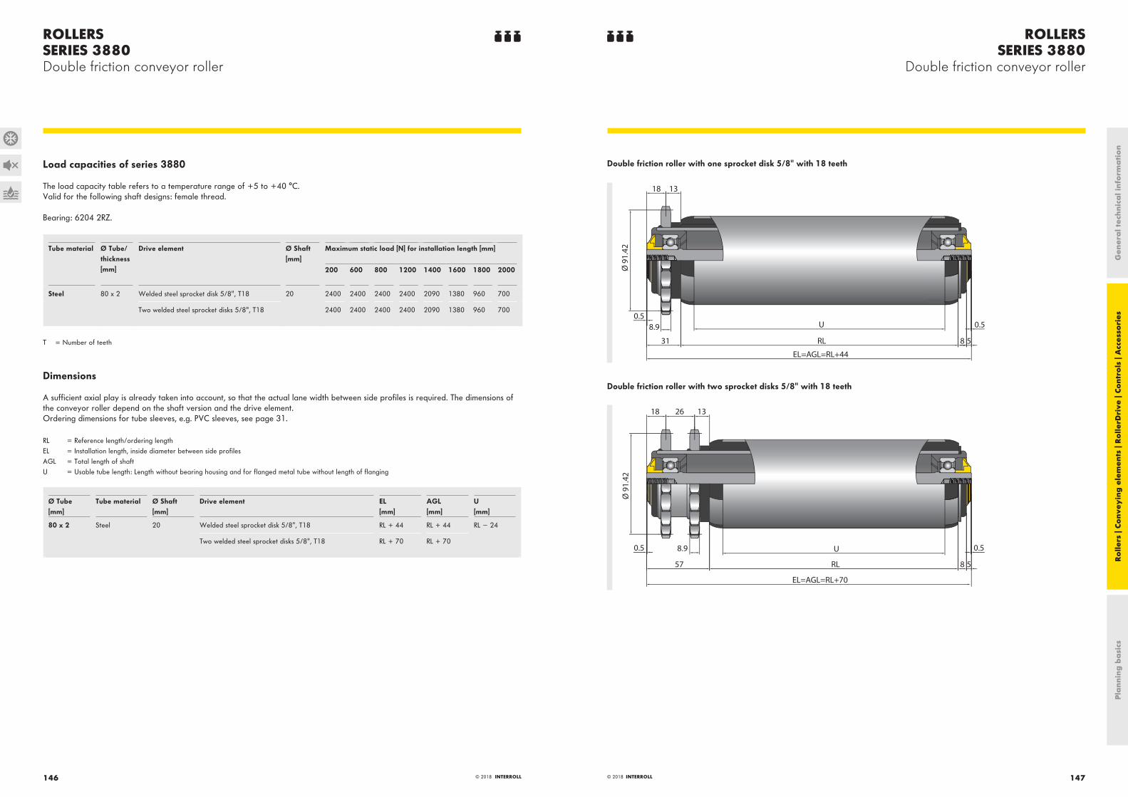
ROLLERSSERIES 3880
Double friction conveyor roller
ROLLERSSERIES 3880Double friction conveyor roller
147© 2018 INTERROLL© 2018 INTERROLL146
Load capacities of series 3880
The load capacity table refers to a temperature range of +5 to +40 °C.Valid for the following shaft designs: female thread.
Bearing: 6204 2RZ.
Tube material Ø Tube/thickness [mm]
Drive element Ø Shaft [mm]
Maximum static load [N] for installation length [mm]
200 600 800 1200 1400 1600 1800 2000
Steel 80 x 2 Welded steel sprocket disk 5/8", T18 20 2400 2400 2400 2400 2090 1380 960 700
Two welded steel sprocket disks 5/8", T18 2400 2400 2400 2400 2090 1380 960 700
T = Number of teeth
Dimensions
A sufficient axial play is already taken into account, so that the actual lane width between side profiles is required. The dimensions of the conveyor roller depend on the shaft version and the drive element.Ordering dimensions for tube sleeves, e.g. PVC sleeves, see page 31.
RL = Reference length/ordering lengthEL = Installation length, inside diameter between side profilesAGL = Total length of shaftU = Usable tube length: Length without bearing housing and for flanged metal tube without length of flanging
Ø Tube[mm]
Tube material Ø Shaft[mm]
Drive element EL[mm]
AGL[mm]
U[mm]
80 x 2 Steel 20 Welded steel sprocket disk 5/8", T18 RL + 44 RL + 44 RL − 24
Two welded steel sprocket disks 5/8", T18 RL + 70 RL + 70
Double friction roller with one sprocket disk 5/8" with 18 teeth
13 18
0.5
Ø 9
1.42
RL
U
8 5
0.58.9
31
EL=AGL=RL+44
Double friction roller with two sprocket disks 5/8" with 18 teeth
1326 18
0.5
Ø 9
1.42
U
RL
EL=AGL=RL+70
57 8 5
8.9 0.5
Pla
nnin
g b
asi
csR
olle
rs |
Conv
eyin
g e
lem
ents
| R
olle
rDri
ve |
Cont
rols
| A
cces
sori
esG
ener
al t
echn
ica
l inf
orm
ati
on

ROLLERSSERIES 3950
Heavy-duty conveyor roller
ROLLERSSERIES 3950Heavy-duty conveyor roller
149© 2018 INTERROLL148 © 2018 INTERROLL
Robust constructionFixed drive conveyor roller with a particularly stable, robust construction. The sprockets are made of steel and are permanently welded.
Numerous drive typesNumerous sprocket heads are available. Chains from roller to roller or tangential chain drives can optionally be used.
Lateral loadingThe tube ends are rounded, thereby allowing materials to be easily moved on from the side. Axial forces are removed through ball bearings and seals.
Application areaDriven unit handling conveying of heavy materials, such as transport of containers, barrels, wheels, pallets or steel containers.
Technical data
General technical data
Platform 1450 1450
Max. load capacity 5000 N 5000 N
Max. conveyor speed 0.5 m/s 0.5 m/s
Anti-static version Yes (via sprocket head) Yes (via sprocket head)
Temperature range −5 to +40 °C −28 to +20 °C
Material
Tube Zinc-plated steel, stainless steel Zinc-plated steel, stainless steel
Shaft Uncoated steel, zinc-plated steel, stainless steel Uncoated steel, zinc-plated steel, stainless steel
Bearing housing Polyamide, RAL9005 (jet black) Zinc-plated steel
Drive head Uncoated steel (the sprocket heads including tube are zinc-plated after welding them on), stainless steel
Uncoated steel (the sprocket heads including tube are zinc-plated after welding them on), stainless steel
Seal Drive side Polyamide, RAL1021 (rape yellow) Polyamide, RAL1021 (rape yellow)/steel
Seal on non-driven side Polyamide, RAL1021 (rape yellow) Zinc-plated steel
Bearing version Precision steel ball bearing 6205 2RZ, bearing play C3, greased
Precision steel ball bearing 6205 2RZ, bearing play C3 and 6204 1Z, greased
For zinc-plated design, the tube assembly is zinc-plated by component after welding on the sprocket head.
Design versions
Tube sleeves For tube with Ø 80 x 2 mm with sprocket head with 15 teeth: PVC sleeve (page 31)Lagging (page 34)
Anti-static version (<106 Ω) Standard design for rollers with tube sleeves
Tube The following are available in addition to the variants listed in the load capacity tables:
• With flanges welded on
Pla
nnin
g b
asi
csR
olle
rs |
Conv
eyin
g e
lem
ents
| R
olle
rDri
ve |
Cont
rols
| A
cces
sori
esG
ener
al t
echn
ica
l inf
orm
ati
on

ROLLERSSERIES 3950
Heavy-duty conveyor roller
ROLLERSSERIES 3950Heavy-duty conveyor roller
151© 2018 INTERROLL© 2018 INTERROLL150
Load capacities of series 3950
The load capacity table refers to a temperature range of +5 to +40 °C.Valid for the following shaft designs: female thread or male thread.
Bearing: 6205 2RZ.
Tube material Ø Tube/thickness [mm]
Drive element Ø Shaft [mm]
Maximum static load [N] for installation length [mm]
200 400 600 800 1000 1200 1400 1600
Steel 80 x 2 Welded steel sprocket head 5/8", T15 and T18 20 5000 5000 5000 5000 5000 4340 3170 2420
Welded steel double sprocket head 5/8", T15 and T18
5000 5000 5000 5000 5000 4340 3170 2420
Steel 80 x 3 Welded steel sprocket head 5/8", T15 and T18 20 5000 5000 5000 5000 5000 5000 4580 3490
Welded steel double sprocket head 5/8", T15 and T18
5000 5000 5000 5000 5000 5000 4580 3490
Steel 89 x 3 Welded steel sprocket head 5/8", T15 and T18 20 5000 5000 5000 5000 5000 5000 5000 4865
Welded steel double sprocket head 5/8", T15 and T18
5000 5000 5000 5000 5000 5000 5000 4865
T = Number of teeth
Load capacities of series 3950 freezer design
The load capacity table refers to a temperature range of −28 to +20 °C.
Tube material Ø Tube/thickness [mm]
Drive element Ø Shaft [mm]
Maximum static load [N] for installation length [mm]
200 400 600 800 1000 1200 1400 1600
Steel 80 x 2 Welded steel sprocket head 5/8", T15 and T18 20 2500 2500 2500 2500 2500 2170 1585 1210
Welded steel double sprocket head 5/8", T15 and T18
2500 2500 2500 2500 2500 2170 1585 1210
Steel 80 x 3 Welded steel sprocket head 5/8", T15 and T18 20 2500 2500 2500 2500 2500 2500 2290 1745
Welded steel double sprocket head 5/8", T15 and T18
2500 2500 2500 2500 2500 2500 2290 1745
Steel 89 x 3 Welded steel sprocket head 5/8", T15 and T18 20 2500 2500 2500 2500 2500 2500 2500 2432.5
Welded steel double sprocket head 5/8", T15 and T18
2500 2500 2500 2500 2500 2500 2500 2432.5
T = Number of teeth
Dimensions
The dimensions of the conveyor roller depend on the shaft version. A sufficient axial play is already taken into account, so that only the actual lane width between side profiles is required for ordering.Ordering dimensions for tube sleeves, e.g. PVC sleeves, see page 31, and for flanges see page 36.
RL = Reference length/ordering lengthEL = Installation length, inside diameter between side profilesAGL = Total length of shaftU = Usable tube length: Length without bearing housing and for flanged metal tube without length of flanging
Ø Tube[mm]
Tube material Ø Shaft[mm]
Drive element EL[mm]
AGL[mm]
U[mm]
80 x 2; 80 x 3; 89 x 3 Steel 20 Welded steel sprocket head 5/8", T15 and T18 RL + 36 RL + 36 RL − 23
Welded steel double sprocket head 5/8", T15 and T18 RL + 62 RL + 62
T = Number of teeth
5/8" steel sprocket head with 15 teeth
0.55RL8.9
31EL=AGL=RL+36
18
Ø 7
6.36
1 U
Ø 8
3
Ø 6
0
5/8" steel double sprocket head with 15 teeth
0.55RL8.9
57EL=AGL=RL+62
Ø 7
6.36
1 U
18 26
60Ø 8
3
Pla
nnin
g b
asi
csR
olle
rs |
Conv
eyin
g e
lem
ents
| R
olle
rDri
ve |
Cont
rols
| A
cces
sori
esG
ener
al t
echn
ica
l inf
orm
ati
on

ROLLERSSERIES 3950Heavy-duty conveyor roller
153© 2018 INTERROLL© 2018 INTERROLL152
5/8" steel sprocket head with 18 teeth
0.55RL
318.9
Ø 9
1.42
EL=AGL=RL+36
1
18
Ø 7
0
Ø 9
8.2
U
5/8" steel double sprocket head with 18 teeth
8.957
RL 50.5
EL=AGL=RL+62
Ø 9
1.42
1
18 26
Ø 7
0
Ø 9
8
U
Pla
nnin
g b
asi
csR
olle
rs |
Conv
eyin
g e
lem
ents
| R
olle
rDri
ve |
Cont
rols
| A
cces
sori
esG
ener
al t
echn
ica
l inf
orm
ati
on

ROLLERSSERIES MSC 50
Magnetic speed controller
ROLLERSSERIES MSC 50Magnetic speed controller
155© 2018 INTERROLL154 © 2018 INTERROLL
Purely mechanical solutionThe purely mechanical solution renders a cabling or control redundant.
Maintenance and wear-free brake functionThe contact-free eddy current brake operates maintenance and wear-free. It features the same high service life like a standard conveyor roller.
Soft startupThe gearless construction enables a softer startup which is already suitable for materials starting at 500 grams.
High braking powerMaterials up to 35 kg can be decelerated. The tube diameter of 51 mm provides the necessary higher surface to rollers with a 50-mm tube diameter given the same fastening height and allows optimal braking.
Easy installationThe fastening holes of the conveyor rollers can be used so that no fastening holders with additional profile holes have to be used. The direction-independent function rules out assembly errors.
No impact on sensitive materialsNo emissions to the outside are being generated, such as magnetism, which allows conveying even sensitive materials, such as electronic components.
Conveyance with ease of smooth containersThe design with PU sleeve also decelerates critical materials in a reliable way.
Application areaPerfectly suited for use in gravity conveyors, in end points at sorters and spiral conveyors.
Technical data
General technical data
Platform 1700
Max. load capacity 350 N
Max. conveyor speed 2 m/s
Min. length 210 mm
Max. length 1400 mm
Temperature range 0 to +40 °C
Material
Tube Zinc-plated steel, stainless steel
Shaft Stainless steel
Bearing housing Polyamide, RAL9005 (jet black)
Seal Polyamide, RAL1021 (rape yellow)
Bearing version Precision steel ball bearing 6002 2RZ, bearing play C3, oiled
Magnets Neodyme N45
Anti-static version Yes
Design versions
Tube sleeves PU sleeve (page 33)
Load capacities of series MSC 50
The load capacity table refers to a temperature range of 0 to +40 °C.Bearing: 6002 2RZ.
Tube material Shaft design PU sleeve Ø Tube/thickness [mm]
Ø Shaft [mm]
Max. static load [N]
Zinc-plated steel, stainless steel Spring-loaded shaft None 51 x 2 11 HEX 350
With 50 x 1.5 11 HEX 350
Fixed shaft None 51 x 2 11 HEX 350
With 50 x 1.5 11 HEX 350
Female thread None 51 x 2 11 HEX 350
With 50 x 1.5 11 HEX 350
HEX = hexagon
Pla
nnin
g b
asi
csR
olle
rs |
Conv
eyin
g e
lem
ents
| R
olle
rDri
ve |
Cont
rols
| A
cces
sori
esG
ener
al t
echn
ica
l inf
orm
ati
on

ROLLERSSERIES MSC 50Magnetic speed controller
157© 2018 INTERROLL© 2018 INTERROLL156
Dimensions
The dimensions of the conveyor roller depend on the shaft version. A sufficient axial play is already taken into account, so that only the actual lane width between side profiles is required for ordering.Ordering dimensions for PU sleeve, see page 33.
RL = Reference length/ordering lengthEL = Installation length, inside diameter between side profilesAGL = Total length of shaftU = Usable tube length: Length without bearing housing and for flanged metal tube without length of flanging
Ø 51 mm and spring-loaded shaft
U=RL-28
RL
EL=RL+10
AGL=EL+22
0.5 0.5
Ø 5
1
Ø 51 mm and fixed shaft
U=RL-28
RL
EL=RL+10
AGL=EL+22
0.5
Ø 5
1
0.5
Ø 54 mm (PU sleeve) and female threaded shaft
U=RL-26RL
EL=AGL=RL+10
0.5 0.5
Ø 5
4
Pla
nnin
g b
asi
csR
olle
rs |
Conv
eyin
g e
lem
ents
| R
olle
rDri
ve |
Cont
rols
| A
cces
sori
esG
ener
al t
echn
ica
l inf
orm
ati
on

CONVEYOR ACCESSORIESSERIES 2130
Polymer conveyor wheel
CONVEYOR ACCESSORIESSERIES 2130Polymer conveyor wheel
159© 2018 INTERROLL158 © 2018 INTERROLL
Quiet, light and robustThe material selected is a particularly impact-resistant polymer. The wheel features a double ball race made of steel, which ensures particularly quiet running. The wheel is especially light and offers a very soft startup.
Application areaThis series is universally applicable, e.g. it can be used as side guide roller.
Technical data
General technical data
Platform 1100
Max. load capacity 200 N
Max. conveyor speed 0.3 m/s
Temperature range 0 to +40 °C
Material
Wheels Polypropylene, RAL9005 (jet black)
Rubber seal Ethylene-propylene-diene monomer (EPDM)/RAL7030 (stone gray)
Rubber gasket hardness 50 Shore A
Bearing version Uncoated steel balls on zinc-plated steel collar
Anti-static version No
Load capacities of series 2130
The load capacity table refers to a temperature range of 0 to +40 °C.
Ø of hole [mm] Fitted rubber tire Max. dynamic load [N] Max. static load [N] Article number
6.5 No 200 200 S-64000376
8.2 200 200 S-64000377
6.5 Yes 50 50 RD-2132
8.2 50 50 RD-2133
Dimensions
Without rubber gasket
17
24
d Ø 4
8
With rubber gasket
d
ů
52
≈20
24
Pla
nnin
g b
asi
csR
olle
rs |
Conv
eyin
g e
lem
ents
| R
olle
rDri
ve |
Cont
rols
| A
cces
sori
esG
ener
al t
echn
ica
l inf
orm
ati
on

CONVEYOR ACCESSORIESSERIES 2160
Polymer conveyor wheel
CONVEYOR ACCESSORIESSERIES 2160Polymer conveyor wheel
161© 2018 INTERROLL160 © 2018 INTERROLL
Quiet, light and robustThe material selected is a particularly impact-resistant polymer. The wheel is very light and offers a very soft startup. The polymer ball race enables a very low noise level.
Application areaThis series is universally applicable. It can be used, e.g. as side guide wheel. With the variant with stainless steel balls, it can also be used in moist areas.
Technical data
General technical data
Platform 1100 1100
Material of bearing balls Uncoated steel Stainless steel
Max. load capacity 40 N 40 N
Max. conveyor speed 0.3 m/s 0.3 m/s
Temperature range 0 to +40 °C 0 to +40 °C
Wheels Polypropylene, RAL9005 (jet black) Polypropylene, RAL7030 (stone gray)
Wheel diameter 48 mm 48 mm
Collar version Polymer Polymer
Collar diameter 8 mm 8 mm
Anti-static version No No
Weight 18 g 18 g
Load capacities of series 2160
The load capacity table refers to a temperature range of 0 to +40 °C.
Material of bearing balls Max. static load [N] Article number
Uncoated steel 40 S-64000378
Stainless steel 40 S-64000379
Dimensions
Uncoated steel bearing balls
17
24
8.2 Ø 4
8
Stainless steel bearing balls
17
24
8.2 Ø 4
8
Pla
nnin
g b
asi
csR
olle
rs |
Conv
eyin
g e
lem
ents
| R
olle
rDri
ve |
Cont
rols
| A
cces
sori
esG
ener
al t
echn
ica
l inf
orm
ati
on

CONVEYOR ACCESSORIESSERIES 2200
Steel conveyor wheel
CONVEYOR ACCESSORIESSERIES 2200Steel conveyor wheel
163© 2018 INTERROLL162 © 2018 INTERROLL
Stable running and long service lifeThe steel conveyor wheel excels with its high load capacity, robustness at high and low temperatures as well as good running stability. Hardened ball running surfaces ensure a long service life.
Application areaThis series is universally applicable, can be used in freezer areas and as side guide wheel.
Technical data
General technical data
Platform 1200
Max. load capacity 200 N
Max. conveyor speed 0.3 m/s
Temperature range −30 °C to +40 °C, for rubber gasket 0 °C to +40 °C
Material
Wheels Zinc-plated steel
Rubber seal Ethylene-propylene-diene monomer (EPDM)/RAL7030 (stone gray)
Rubber gasket hardness 50 Shore A
Bearing version Uncoated steel balls on zinc-plated steel collar, single line ball race
Anti-static version Yes (< 106 Ω)
Load capacities of series 2200
The following load capacity table refers to a temperature range of −30 to +40 °C.
Ø Hole d [mm] Fitted rubber tire Max. dynamic load [N] Max. static load [N] Article number
6.5 No 200 200 S-1001352
8.2 200 200 S-1001353
6.5 Yes 50 50 RD-2202
8.2 50 50 RD-2203
Dimensions
Without rubber gasket
16
24
d Ø 4
8
With rubber gasket
≈20
24
d
ů
52
Pla
nnin
g b
asi
csR
olle
rs |
Conv
eyin
g e
lem
ents
| R
olle
rDri
ve |
Cont
rols
| A
cces
sori
esG
ener
al t
echn
ica
l inf
orm
ati
on

CONVEYOR ACCESSORIESSERIES 2370
Polymer conveyor wheel
CONVEYOR ACCESSORIESSERIES 2370Polymer conveyor wheel
165© 2018 INTERROLL164 © 2018 INTERROLL
Easy installationThe conveyor wheel is fixed via a floating fastening at the profile and can be installed with ease. A 2-mm large slot for placing the screwdriver is available.
Low operating noiseThe wheel ensures low-noise running.
Robust constructionThe wheel is made of impact-resistant polymer and features a double ball race.
Application areaThe product is universally applicable and particularly suited for conveyor sections in which no continuous roller can be used. Among other things, it is used with packaging machines and in mechanical engineering, e.g. for transporting workpiece carriers or containers that allow a lateral guide.
Technical data
General technical data
Platform 1100
Max. load capacity 50 N
Max. conveyor speed 0.3 m/s
Temperature range 0 to +40 °C
Material
Wheels Polypropylene, RAL9005 (jet black)
Shaft journal design Zinc-plated steel, M8 thread, 15 mm long
Bearing version Uncoated steel balls on zinc-plated collar or stainless steel balls on stainless steel collar
Anti-static version No
Load capacities of series 2370
The load capacity table refers to a temperature range of 0 to +40 °C.
Flange Storage Color Weight [g]
Load capacity [N]
Article number
None Uncoated steel balls, zinc-plated steel collar Black 45 50 S-64000446
Stainless steel balls, stainless steel collar Gray 45 50 S-64000448
With Uncoated steel balls, zinc-plated steel collar Black 49 50 S-64000445
Stainless steel balls, stainless steel collar Gray 49 50 S-64000447
Dimensions
Without flange
M8
15
17
28
Ø 3
8
With flange
M8
Ø 6
0
15
17
24
28
Ø 3
8
Pla
nnin
g b
asi
csR
olle
rs |
Conv
eyin
g e
lem
ents
| R
olle
rDri
ve |
Cont
rols
| A
cces
sori
esG
ener
al t
echn
ica
l inf
orm
ati
on

CONVEYOR ACCESSORIESSERIES 2500
Omniwheel
CONVEYOR ACCESSORIESSERIES 2500Omniwheel
167© 2018 INTERROLL166 © 2018 INTERROLL
Easy installation and useEasy installation on round and hexagon shaft. With low mass and easy running gray wheels, the omniwheel can easily be moved in all directions. Several omniwheels can be coupled with one another. Corrosion-proof due to the use of stainless steel pins. Drive in one direction when used with a hexagon shaft.
Application areaCrossings and switches can easily be implemented with the direction-independent turnability. Driven and non-driven conveyor segments, e.g. packing tables, assembly tables and feeds to processing machines. Particularly suited for softer materials such as cardboards.
Technical data
General technical data
Platform 1500
Max. load capacity 250 N
Max. conveyor speed 0.2 m/s
Temperature range 0 to +40 °C
Material
Housing Polyamide, RAL9005 (jet black)
Wheels Polyamide, RAL7030 (stone gray)
Journal Stainless steel
Bearing version Slide bearing
Anti-static version No
Load capacities of series 2500
The following load capacity table refers to a temperature range from 0 to +40 °C and to one omniwheel each.
Ø Roller[mm]
Hub opening[mm]
Load capacity[N]
Article number
48 8.1 +0.1/−0 50 S-64000380
8.1 +0.1/−0 HEX 50 S-64000381
80 12.2 +0.1/−0 250 S-64000382
11.2 +0.1/−0 HEX 250 S-64000383
HEX = hexagon
Dimensions
Round shaft
1/1 3/3
21,5/34
Ø 4
8/80
Round shaft, 2 wheels pushed together
40/65
Pla
nnin
g b
asi
csR
olle
rs |
Conv
eyin
g e
lem
ents
| R
olle
rDri
ve |
Cont
rols
| A
cces
sori
esG
ener
al t
echn
ica
l inf
orm
ati
on

CONVEYOR ACCESSORIESSERIES 2600Pressure roller
CONVEYOR ACCESSORIESSERIES 2600Pressure roller
169© 2018 INTERROLL168 © 2018 INTERROLL
Solid installationThe support of both ball bearings is accomplished with a space tube and allows a firm screw connection.
Good running propertiesPrecision ball bearings of type 6000 2Z and type 688 2Z are used.
Rust-free variantFor use under moist ambient conditions, a version made of stainless steel is available as an alternative. The slide bearings for the round belt guide wheels consist of polyamide.
Reliable belt guidesThe running surfaces for the belts feature a spherical shape. It allows the belt to self-center in the guides.
Application areaSuitable for use with conveyors that are driven via flat belts or drive shaft. As belt pressure wheel suitable for flat belts with 20 to 30 mm width. When used on a drive shaft, the round belt guide wheel takes on the function of a friction shaft. A floating fastening on the profile is used.
Technical data
General technical data
Platform 1700
Max. load capacity 250 N
Max. conveyor speed 2.5 m/s
Temperature range 0 to +40 °C
Material
Wheels See load capacity table
Bearing version See load capacity table
Anti-static version No
Load capacities of series 2600
The load capacity table refers to a temperature range of 0 to +40 °C.
Drive element Bearing version Flange Material Color Max. conveyor speed[m/s]
Max. static load[N]
Article number
Flat belt 6000 2Z Yes Polyamide Black 2.5 250 S-64000385
6000 2Z stainless steel Yes Polyamide White 2.5 250 S-64000386
6000 2Z No Polyamide Black 2.5 250 S-64000388
Round belt Slide bearing No Polyoxymethylene Gray 1.2 120 S-64000182
Pla
nnin
g b
asi
csR
olle
rs |
Conv
eyin
g e
lem
ents
| R
olle
rDri
ve |
Cont
rols
| A
cces
sori
esG
ener
al t
echn
ica
l inf
orm
ati
on

CONVEYOR ACCESSORIESSERIES 2600Pressure roller
171© 2018 INTERROLL© 2018 INTERROLL170
Dimensions
Flat belt drive and flange
31
36
+0.1
-0Ø
8.1
Ø 3
9.5
Ø 5
0
31.6
Flat belt drive
36+0
.1-0
Ø 8
.1
Ø 3
9.5
31.6
Round belt drive
Ø 2
5+0.5
+0.2 Ø
30.
4
Ø 5
0
31.5
R1R6
Pla
nnin
g b
asi
csR
olle
rs |
Conv
eyin
g e
lem
ents
| R
olle
rDri
ve |
Cont
rols
| A
cces
sori
esG
ener
al t
echn
ica
l inf
orm
ati
on

CONVEYOR ACCESSORIESSERIES 2800
Omnimat module
CONVEYOR ACCESSORIESSERIES 2800Omnimat module
173© 2018 INTERROLL172 © 2018 INTERROLL
Product benefits· Conveyance possible in every direction· Corrosion-proof due to the use of stainless steel pins.· Lateral dove tail profiles for fixed and form-fit connection; floor fastening with screw holes· Flexible adaptability and expandability· Different modules can be combined· Closed version can be applied as spacer
Application areaCrossings and switches can easily be implemented with the direction-independent turnability. Use as non-driven wheel conveyors for packing tables, assembly tables and feed to processing machines. Particularly suited for softer materials such as cardboards.
Technical data
General technical data
Platform 1500
Max. load capacity 50 N
Max. conveyor speed 0.2 m/s
Temperature range 0 to +40 °C
Material
Module Polypropylene, RAL1021 (rape yellow)
Wheel/housing See series 2500, use of wheels with Ø 48 mm with hub opening for 8 mm round shaft
Wheel mounting Round stainless steel shaft, Ø 8 mm
Anti-static version No
Load capacities of series 2800
The load capacity table refers to a temperature range of 0 to +40 °C.
Omnimat module Load capacity [N] Article number
With two polymer conveyor rollers 50 S-64000389
Closed, without wheels − S-64000243
Dimensions
With and without omniwheel
61.2
50 54
61.2
50
Pla
nnin
g b
asi
csR
olle
rs |
Conv
eyin
g e
lem
ents
| R
olle
rDri
ve |
Cont
rols
| A
cces
sori
esG
ener
al t
echn
ica
l inf
orm
ati
on

CONVEYOR ACCESSORIESSERIES 5000
Steel ball transfer unit
CONVEYOR ACCESSORIESSERIES 5000Steel ball transfer unit
175© 2018 INTERROLL174 © 2018 INTERROLL
Direction-independent operationThe use of balls allows transporting the material in every direction. Crossings and switches can also be implemented easily. In addition, particularly soft running balls are being used.
Good protection against dust and splashing waterFor variants with steel balls, a felt seal keeps out dust and splashing water. Variants with balls in stainless steel design also feature a long corrosion resistance.
Secure supportDuring operation, support balls circulate under the main ball. This accomplishes a constant and optimal support of the material.
Application areaAlignment of medium-heavy and heavy materials, such as plates or containers with a smooth bottom. For pushing, e.g. steel or wooden plates. Suitable for applications that require an upside-down installation.
Technical data
General technical data
Platform 5000
Max. load capacity 22,000 N
Max. conveyor speed 0.3 m/s
Temperature range –30 to +40 °C
Material
Ball See load capacity table
Housing material Zinc-plated steel (black)
Anti-static version Yes (< 106Ω)
To ensure optimum load capacity, it is advised that all ball transfer units are positioned at the exact same level.
Additional variants available on request.
Pla
nnin
g b
asi
csR
olle
rs |
Conv
eyin
g e
lem
ents
| R
olle
rDri
ve |
Cont
rols
| A
cces
sori
esG
ener
al t
echn
ica
l inf
orm
ati
on

CONVEYOR ACCESSORIESSERIES 5000
Steel ball transfer unit
CONVEYOR ACCESSORIESSERIES 5000Steel ball transfer unit
177© 2018 INTERROLL© 2018 INTERROLL176
Load capacities of series 5000
The following load capacity table refers to a temperature range of −30 to +40 °C.
Fastener Ø of ball[mm]
Ball material Material of support balls Max. static load[N]
Article number
Base flange 12.7 Chrome steel Chrome steel 460 S-1100048
25.4 Chrome steel Chrome steel 2250 S-1001365
25.4 Chrome steel Chrome steel 3750 S-1001366
38.1 Chrome steel Chrome steel 11000 S-1001367
50.8 Chrome steel Chrome steel 22000 S-1001368
Threaded pin 12.7 Chrome steel Chrome steel 460 S-1001359
25.4 Chrome steel Chrome steel 2250 S-1001360
25.4 Chrome steel Chrome steel 3750 S-1001361
38.1 Chrome steel Chrome steel 11000 S-1001362
50.8 Chrome steel Chrome steel 22000 S-1001363
Head flange 12.7 Chrome steel Chrome steel 460 S-1001369
25.4 Chrome steel Chrome steel 2250 S-1001370
25.4 Chrome steel Chrome steel 3750 S-1001371
38.1 Chrome steel Chrome steel 11000 S-1001372
50.8 Chrome steel Chrome steel 22000 S-1001373
Flush installation (press fit) 12.7 Chrome steel Chrome steel 460 S-1001356
38.1 Stainless steel Stainless steel 11000 S-1001378
External suspension 38.1 Chrome steel Chrome steel 9600at max. deflection
S-1100285
Spring pretension of "External suspension" variant = 454 kg
Dimensions
Bottom flange (for screw fastening)
T
CxC
FxF
E W Y
Ø D
Article number Ø Ball[mm]
Ø D[mm]
Y[mm]
W[mm]
T[mm]
F x F[mm]
C x C[mm]
E[mm]
S-1100048 12.7 23.8 22.2 18.4 3.2 Ø 44.5 Ø 34.9 2 x Ø 3.6
S-1001365 25.4 44 41.3 35.7 4.8 * 57.2 * 44.5 4 x Ø 6.1
S-1001366 25.4 50 44.5 38.1 6.4 * 76.2 * 57.9 4 x Ø 8.1
S-1001367 38.1 60 61.5 48.8 12.7 * 76.2 * 57.9 4 x Ø 8.1
S-1001368 50.8 100 98.4 84.1 9.5 * 127 * 101.6 4 x Ø 11.1*
* not countersunk
Pla
nnin
g b
asi
csR
olle
rs |
Conv
eyin
g e
lem
ents
| R
olle
rDri
ve |
Cont
rols
| A
cces
sori
esG
ener
al t
echn
ica
l inf
orm
ati
on

CONVEYOR ACCESSORIESSERIES 5000
Steel ball transfer unit
CONVEYOR ACCESSORIESSERIES 5000Steel ball transfer unit
179© 2018 INTERROLL© 2018 INTERROLL178
Head flange (for screw fastening) Y
T
Ø D
B
E
CxC
FxF
Article number Ø Ball[mm]
Ø D[mm]
Y[mm]
B[mm]
T[mm]
F x F[mm]
C x C[mm]
E[mm]
S-1001369 12.7 23.8 11.2 11 3.2 Ø 44.5 Ø 34.9 2 x Ø 3.6
S-1001370 25.4 44 10.3 31 4.8 * 57.2 * 44.5 4 x Ø 6.1
S-1001371 25.4 50 12.7 31.8 6.4 * 76.2 * 57.9 4 x Ø 8.1
S-1001372 38.1 60 25.4 34.6 12.7 * 76.2 * 57.9 4 x Ø 8.1
S-1001373 50.8 109.5 33.3 65.1 19.1 * 127 * 101.6 4 x Ø 10.2*
* not countersunk
Flush installation (press fit)
Ø D
Y W
Article number Ø Ball[mm]
Ø D[mm]
Y[mm]
W[mm]
S-1001356 12.7 20.6 19.1* 15.3
S-1001378 38.1 60.3 61.5 48.8
* total height including locking pin 22.3 mm
Threaded pin
Y W
Ø D
E L
d
Article number Ø Ball[mm]
Ø D[mm]
Y[mm]
W[mm]
L[mm]
d[mm]
S-1001359 12.7 20 19.1 15.3 16.1 M8 x 1.25
S-1001360 25.4 44 48.3 42.7 25 M12 x 1.75
S-1001361 25.4 50 51.3 44.9 25 M12 x 1.75
S-1001362 38.1 60 73.5 60.8 40 M20 x 2.5
S-1001363 50.8 100 105 90.7 54 M24 x 3
External suspension
Ø D
Y W
Ø A Ø B
G
E
Article number Ø Ball[mm]
Pretension[kg]
Max. deflection (recd.)
Load at max. deflection [kg]
Ø D[mm]
Y[mm]
W[mm]
Ø A[mm]
Ø B[mm]
Mounting holes E(Ø Pitch circle) [mm]
G[mm]
S-1100285 38.1 454 11.1 960 60.3 129.2 162.1 35 59.4 M6 x 3 (Ø 50.8) 12.7 Pla
nnin
g b
asi
csR
olle
rs |
Conv
eyin
g e
lem
ents
| R
olle
rDri
ve |
Cont
rols
| A
cces
sori
esG
ener
al t
echn
ica
l inf
orm
ati
on

CONVEYOR ACCESSORIESSERIES 5500
Polymer ball transfer unit
CONVEYOR ACCESSORIESSERIES 5500Polymer ball transfer unit
181© 2018 INTERROLL180 © 2018 INTERROLL
Direction-independent operationThe use of balls allows transporting the material in every direction. Crossings and switches can also be implemented easily. In addition, particularly soft running balls are being used.
Good protection against dust and humidityFor variants with steel balls, a felt seal keeps out dust. Design with main balls made of stainless steel or polymer also show a high corrosion resistance.
Suitable for sensitive materialsVariants with polymer balls are available for transporting goods with sensitive surfaces.
Secure supportThe main ball rotates on support balls which turn on a ball socket. This accomplishes a good support of the material. The ball socket consists of stainless steel in all variants.
Application areaThe roller is used for aligning medium-heavy materials, e.g. plates, containers or cardboards with smooth bottom. Furthermore, the roller can be used for pushing, e.g. when transporting steel or wooden plates.
Technical data
General technical data
Platform 5000 5000 5000
Max. load capacity 400 N 400 N 150 N
Max. conveyor speed 0.3 m/s 0.3 m/s 0.3 m/s
Temperature range 0 to +40 °C 0 to +40 °C 0 to +40 °C
Material
Ball Carbon steel Stainless steel Polyamide (white)
Housing Polyamide, RAL9005 (jet black) Polyamide, RAL7030 (stone gray) Polyamide, RAL9005 (jet black)
Support ball Uncoated steel Stainless steel Uncoated steel
Ball socket Stainless steel Stainless steel Stainless steel
Anti-static version No No No
To ensure optimum load capacity, it is advised that all ball transfer units are positioned at the exact same level.
Load capacities of series 5500
The load capacity table refers to a temperature range of 0 to +40 °C.
Fastener Ø Ball [mm]
Ball material Max. static load [N]
Article number
Bottom flange (for screw fastening) 25.4 Zinc-plated steel 400 S-64000391
Stainless steel 400 S-64000396
Polyamide 150 S-64000404
Head flange (press fit) 25.4 Zinc-plated steel 300 S-64000394
Stainless steel 300 S-64000398
Polyamide 150 S-64000406
Threaded pin 25.4 Zinc-plated steel 400 S-64000395
Stainless steel 400 S-64000399
Polyamide 150 S-64000402
Head flange (for screw fastening) 25.4 Zinc-plated steel 300 S-64000392
Stainless steel 300 S-64000397
Polyamide 150 S-64000405
Pla
nnin
g b
asi
csR
olle
rs |
Conv
eyin
g e
lem
ents
| R
olle
rDri
ve |
Cont
rols
| A
cces
sori
esG
ener
al t
echn
ica
l inf
orm
ati
on

CONVEYOR ACCESSORIESSERIES 5500
Polymer ball transfer unit
CONVEYOR ACCESSORIESSERIES 5500Polymer ball transfer unit
183© 2018 INTERROLL© 2018 INTERROLL182
Dimensions
Bottom flange (for screw fastening) G
T H
Ø D
C
F
E
Ø D[mm]
G[mm]
H[mm]
T[mm]
C[mm]
F[mm]
E[mm]
44 +0/−0.2 35 26 3 60 74/52 Ø 7
Head flange (for screw fastening)
G
C
F
E
T B H
Ø D
L
Ø D[mm]
G[mm]
H[mm]
T[mm]
B[mm]
L[mm]
C[mm]
F[mm]
E[mm]
44 +0/−0.2 15.6 26.3 3 19.3 34.9 60 74/52 Ø 7
Threaded pin
G L
A
Ø D
Ø F
T H
Ø D[mm]
G[mm]
A[mm]
L[mm]
Ø F[mm]
T[mm]
H[mm]
44 +0/−0.2 35 M8 20 52 3 26.3
Head flange (press fit)
Ø D
G
T
Ø F
H B
L
Ø D[mm]
G[mm]
Ø F[mm]
L[mm]
B[mm]
T[mm]
H[mm]
44 +0/−0.2 15.6 52 34.7 19.1 2.6 26.3
Pla
nnin
g b
asi
csR
olle
rs |
Conv
eyin
g e
lem
ents
| R
olle
rDri
ve |
Cont
rols
| A
cces
sori
esG
ener
al t
echn
ica
l inf
orm
ati
on

CONVEYOR ACCESSORIESFLOWAY SERIES
Wheel track
CONVEYOR ACCESSORIESFLOWAY SERIESWheel track
185© 2018 INTERROLL184 © 2018 INTERROLL
Secure guidesThe track is designed so that it prevents an opening and jumping out of the wheels under load.
Robust constructionThe continuous steel shaft guarantees high stability. The secure shaft support at the outer wings of the rail ensures that free-running of the wheels is also ensured under load.
Application areaThe track is universally applicable and suitable for light materials. It can be used in gravity conveyors, pushing and also as side guide. They are generally used in order picking racks.
Technical data
General technical data
Platform 1500
Max. load capacity 1360 N
Max. conveyor speed 1 m/s
Temperature range −28 to +40 °C
Lengths 1064 mm and 1596 mm
Wheel pitch 28 mm
Shaft diameter 3 mm
Wheel track wall thickness 0.8 mm
Material
Wheel track Zinc-plated steel
Shaft Zinc-plated steel
Wheels Polyethylene, RAL9005 (jet black)
Anti-static version No
Pla
nnin
g b
asi
csR
olle
rs |
Conv
eyin
g e
lem
ents
| R
olle
rDri
ve |
Cont
rols
| A
cces
sori
esG
ener
al t
echn
ica
l inf
orm
ati
on

CONVEYOR ACCESSORIESFLOWAY SERIESWheel track
187© 2018 INTERROLL© 2018 INTERROLL186
Load capacities of Floway series
The load capacity table refers to a temperature range from −28 to +40 °C. The load depends on the distance of the support cross ties under the wheel track.
23
45
67
89
1011
1213
1415
1617
0
160
320
480
640
800
960
1120
1280
1440
1600
48 76 104 132 160 188 216 244 272 300 328 356 384 412 440 468 496 524 552 580 608 636 664 692
Support distance [mm]
Load
cap
acity
[N]
FLOWAY profile with max. 2 mm bending
Number of rollers with 29-mm pitch
Pla
nnin
g b
asi
csR
olle
rs |
Conv
eyin
g e
lem
ents
| R
olle
rDri
ve |
Cont
rols
| A
cces
sori
esG
ener
al t
echn
ica
l inf
orm
ati
on

CONVEYOR ACCESSORIESSERIES BU40
Wheel track
CONVEYOR ACCESSORIESSERIES BU40Wheel track
189© 2018 INTERROLL188 © 2018 INTERROLL
Medium-heavy materials to be conveyedIf medium-heavy goods have to be handled, the wheel track can be equipped with steel wheels.
Sensitive materialsTo transport goods with critical surfaces, polymer wheels with covered rubber gasket can be used which minimize the risk of damages.
Good corrosion protectionThe wheel track is made of zinc-plated steel.
Easy installationThe wheels can easily be inserted in the track with a snap-in function.
Application areaThe track is universally applicable and suitable for light and medium-heavy materials. It can be used in gravity conveyors, pushing and also as side guide. Different wheel pitches can be selected.
Technical data
General technical data
Wheels used Polymer wheel (to series 2130 or 2160) Steel wheels (after series 2200)
Platform 1100 1200
Max. load capacity 1500 N 2600 N
Max. conveyor speed 1 m/s 1 m/s
Temperature range 0 to +40 °C –30 to +40 °C
Wheel pitch 52 mm, 104 mm 52 mm, 104 mm
Wheel track wall thickness 1.2 mm 1.2 mm
Min. length 156 mm 156 mm
Max. length 2496 mm 2496 mm
Hub inside diameter 8.2 mm 8.2 mm
Material
Wheel track Zinc-plated steel Zinc-plated steel
Anti-static version No Yes (< 106Ω)
Pla
nnin
g b
asi
csR
olle
rs |
Conv
eyin
g e
lem
ents
| R
olle
rDri
ve |
Cont
rols
| A
cces
sori
esG
ener
al t
echn
ica
l inf
orm
ati
on

CONVEYOR ACCESSORIESSERIES BU40
Wheel track
CONVEYOR ACCESSORIESSERIES BU40Wheel track
191© 2018 INTERROLL© 2018 INTERROLL190
Load capacities of series BU40
The load capacity table refers to a temperature range from –30 to +40 °C for steel wheels and to a temperature range from 0 to +20 °C for polymer wheels. The load depends on the selected wheel type (polymer or steel), the selected roller pitch (52 or 104 mm), and the distance from the support cross ties under the wheel track.
3
4
5
6
7
8
9
10
11
12
13
2
3
4
5
6
7
8
3 4
5 6
7 8
910
1112 13
14 15
2 3
4 5
6 7
8 9
0
200
400
600
800
1000
1200
1400
1600
1800
2000
2200
2400
2600
2800
104 156 208 260 312 364 416 468 520 572 624 676 728 780 832 884 936 988 1040
Support distance [mm]
Load
cap
acity
[N]
BU40 profile with max. 2 mm bending
Series 2200: number of rollers with 52-mm pitch
Series 2130: number of rollers with 52-mm pitch
Series 2130: number of rollers with 104-mm pitch
Series 2200: number of rollers with 104-mm pitch
Dimensions
Track without wheel
26 52
52 52
30
L max. = 2496
6.5
30
1.2
46
26.4
Track with wheel of series 2130
17
Ø 4
854
52
Track with wheel of series 2160
17
Ø 4
854
52
Pla
nnin
g b
asi
csR
olle
rs |
Conv
eyin
g e
lem
ents
| R
olle
rDri
ve |
Cont
rols
| A
cces
sori
esG
ener
al t
echn
ica
l inf
orm
ati
on

CONVEYOR ACCESSORIESSERIES BU40Wheel track
193© 2018 INTERROLL© 2018 INTERROLL192
Track with wheel of series 2200
16
Ø 4
854
52
Track with wheel of series 2130 with rubber gasket
56
Ø 5
1.75
20104
Track with wheel of series 2200 with rubber gasket
104
56Ø 5
2
20
Pla
nnin
g b
asi
csR
olle
rs |
Conv
eyin
g e
lem
ents
| R
olle
rDri
ve |
Cont
rols
| A
cces
sori
esG
ener
al t
echn
ica
l inf
orm
ati
on

CONVEYOR ACCESSORIESSERIES BU50
Roller track
CONVEYOR ACCESSORIESSERIES BU50Roller track
195© 2018 INTERROLL194 © 2018 INTERROLL
Heavy materialsThe track can be designed with steel rollers if heavy materials have to be moved.
Sensitive materialsTo transport goods with critical surfaces, polymer rollers can be used which minimize the risk of damages. Polymer rollers are also available in a flange design.
Robust constructionRobust rollers of series 1700 with a diameter of 50 mm are used in the track. The rollers are riveted in the profile.
Good corrosion protectionThe roller track is made of zinc-plated steel.
Application areaThe track is universally applicable and suitable for heavy materials. It can be used in gravity conveyors, pushing and also as side guide. Different roller pitches can be selected.
Technical data
General technical data
Platform 1700 1700
Roller versions Polymer roller without flange (article number 2901) polymer roller with flange (article number 2911)
Zinc-plated steel roller without flange (article number 2955)
Max. load capacity 5,400 N 15,500 N
Max. conveyor speed 2 m/s 2 m/s
Roller pitch (P) 52 mm, 78 mm, 104 mm, 156 mm 52 mm, 78 mm, 104 mm, 156 mm
Temperature range 0 to +40 °C −28 to +40 °C
Roller track wall thickness 2.5 mm 2.5 mm
Min. length 130 mm 130 mm
Max. length 3900 mm 3900 mm
Hub journal to fasten roller 8 mm 8 mm
Material
Roller track Zinc-plated steel Zinc-plated steel
Anti-static version No No
Pla
nnin
g b
asi
csR
olle
rs |
Conv
eyin
g e
lem
ents
| R
olle
rDri
ve |
Cont
rols
| A
cces
sori
esG
ener
al t
echn
ica
l inf
orm
ati
on

CONVEYOR ACCESSORIESSERIES BU50
Roller track
CONVEYOR ACCESSORIESSERIES BU50Roller track
197© 2018 INTERROLL© 2018 INTERROLL196
Load capacities of series BU50
The following load capacity tables refer to a temperature range from –5 °C to +40 °C for steel rollers and to a temperature range from 0 °C to +40 °C for polymer rollers. The maximum static load at −28 °C to −6 °C measures 350 N.
3 4
56
7 8
9 10
11 12
13 14
15 16
17 18
34
5 6
7 8
9 10
11 12
13
2 3
45
67
89
10 11
2 3
4 5
67
8
0
1000
2000
3000
4000
5000
6000
7000
117
143
169
195
221
247
273
299
325
351
377
403
429
455
481
507
533
559
585
611
637
663
689
715
741
767
793
819
845
871
897
923
949
975
1001
1027
1053
1079
1105
1131
1157
1183
1209
1235
1261
Support distance [mm]
Load
cap
acity
[N]
BU50 profile with max. 2 mm bending
Number of polymer rollers with 52-mm pitch
Number of polymer rollers with 104-mm pitch
Number of polymer rollers with 156-mm pitch
Number of polymer rollers with 78-mm pitch
Fig.: Roller track with polymer rollers
3
4
5
6
7
8
9
10
11
12
13
3
4
5
6
7
8
9
10
2
3
4
5
6
7
8
2
3
4
5
6
0
1000
2000
3000
4000
5000
6000
7000
8000
9000
10000
11000
12000
13000
14000
15000
16000
17000
117
143
169
195
221
247
273
299
325
351
377
403
429
455
481
507
533
559
611
637
663
689
715
741
767
793
819
845
871
897
923
949
975
1001585
Support distance [mm]
Load
cap
acity
[N]
BU50 profile with max. 2 mm bending
Number of steel rollers with 52-mm pitch
Number of steel rollers with 104-mm pitch
Number of steel rollers with 156-mm pitch
Number of steel rollers with 78-mm pitch
Fig.: Roller track with steel rollers
Pla
nnin
g b
asi
csR
olle
rs |
Conv
eyin
g e
lem
ents
| R
olle
rDri
ve |
Cont
rols
| A
cces
sori
esG
ener
al t
echn
ica
l inf
orm
ati
on

CONVEYOR ACCESSORIESSERIES BU50
Roller track
CONVEYOR ACCESSORIESSERIES BU50Roller track
199© 2018 INTERROLL© 2018 INTERROLL198
Dimensions
Track without roller
13 26 26
L max. = 390050
30
70
2.5
60
Ø 8.1
+0.2-0
+0.2-0Ø 8.1
SW11.5 +0.2-0
WAF = Width across flats
Track with polymer rollers
51
Ø 5
0
75
Ø 8
52
Track with polymer rollers with flange
Ø 5
0
Ø 8
Ø 7
0.5
56.578
Track with steel rollers
55
Ø 5
0
Ø 8
52
Pla
nnin
g b
asi
csR
olle
rs |
Conv
eyin
g e
lem
ents
| R
olle
rDri
ve |
Cont
rols
| A
cces
sori
esG
ener
al t
echn
ica
l inf
orm
ati
on

ROLLERDRIVESERIES EC310
RollerDrive
ROLLERDRIVESERIES EC310RollerDrive
201© 2018 INTERROLL200 © 2018 INTERROLL
Compact designThe motor integrated in the tube allows a very compact design of the conveyor system.
Very energy-efficientThe brushless motor features an energy recovery in braking.
Flexible possible applicationsThe drive can be used in straight sections and curves and ensures a constant conveying speed. Depending on the application area, PolyVee, round or toothed belts can be used for the transmission of force. Overall, nine gear stages are available. The electronic holding brake (Zero Motion Hold) holds materials in position, even on gravity conveyors, so that the RollerDrive can also be used as a drive in these applications.
Low-noiseThe use of decoupling elements achieves particularly low-noise running.
Maintenance-free and installation-friendlyThe brushless motor with internal commutation electronics does not require any maintenance. It features an overload protection that prevents damages due to overtemperature or blockage. It is connected securely without complex screw connection by using a motor cable with 5-pin snap-in plug.
Application areaDrive for unit handling conveyor systems, such as transporting cardboards, containers, barrels, workpiece carriers or tires. Suitable for sectional conveyors, roller curves, small belt conveyors and especially zero-pressure accumulation roller conveyors.
Technical data
General technical data
Mechanical power 32 W (at ambient temperature of 20 °C)
Max. noise emission (mounted) 55 dB(A), application-dependent
Possible static load capacity 350 N − for design with drive head (for PolyVee, round or toothed belt)1100 N − for design without drive head
Motor shaft 11 mm HEX, thread M12 x 1
Length of motor cable 0.48 m
Electrical data
Rated voltage 24 V DC
Rated current Approx. 2 A
Starting current Approx. 4 A
Protection rate IP54
Anti-static version Yes (< 10-6 Ω)
Dimensions
Tube diameter/wall thickness 50 x 1.5 mm; 51 x 2 mm
Max. reference length 1500 mm
Ambient conditions
Ambient temperature in operation 0 to +40 °C
Ambient temperature during transport and storage
−30 to +75 °C
Material
Tube Stainless steel, zinc-plated steel, chrome-plated steel, aluminum
Motor shaft Stainless steel
Tube sleeving PVC sleeve 2 mm, 5 mm PU sleeve 2 mm Lagging 2 to 5 mm Tapered elements
HEX = hexagon
The actual current flow depends on the application conditions, such as material weight, number of connected conveyor rollers, etc.
Depending on the design of the RollerDrive, an accessory, e.g. a ribbed nut for fastening on the cable side, is supplied. A delivery without accessory is possible on request.
Pla
nnin
g b
asi
csR
olle
rs |
Conv
eyin
g e
lem
ents
| R
olle
rDri
ve |
Cont
rols
| A
cces
sori
esG
ener
al t
echn
ica
l inf
orm
ati
on

ROLLERDRIVESERIES EC310
RollerDrive
ROLLERDRIVESERIES EC310RollerDrive
203© 2018 INTERROLL© 2018 INTERROLL202
Design versions
Gear ratio Max. conveyor speed[m/s]
Rated torque[Nm]
Startup torque[Nm]
Zero motion hold[Nm]
9 : 1 1.75 0.45 1.10 0.36
12 : 1 1.31 0.61 1.46 0.48
16 : 1 0.98 0.81 1.95 0.64
20 : 1 0.79 1.01 2.44 0.80
24 : 1 0.65 1.21 2.92 0.96
36 : 1 0.44 1.82 4.38 1.44
48 : 1 0.33 2.42 5.85 1.92
64 : 1 0.25 3.23 7.80 2.56
96 : 1 0.16 4.84 11.69 3.84
Before the run-in, the values may differ up to ±20 %. After a run-in phase, the values vary only in the range of ±10 % for 95 % of all RollerDrive used.
Dimensions
The minimum reference length depends on the gear box variant, the grooves in the tube and the drive or the bearing assembly. A sufficient axial play is already taken into account, so that the actual lane width between side profiles is required.When using the tapered hexagon spring shaft, it must be ensured that the design of the axial play is not too high. If the RollerDrive selected is too short, the shaft may have play in the hexagon hole. A hexagon hole with a size of at least 11.2 mm is recommended. If the RollerDrive is installed obliquely, the hole must be designed larger accordingly.
Ordering dimensions for tube sleeves starting at page 31Tool for installing the RollerDrive starting at page 242
RL = Reference length/ordering lengthEL = Installation length, inside diameter between side profiles
Design in protection rating IP54
13.1
EL
480
5
RL
PolyVee drive head with 11 mm hexagon spring shaft
11
31
EL=RL+36
RL
Ø 4
3
PolyVee drive head with M8 female thread fastening
Ø 4
3
31
EL=RL+36
RL
Round belt drive head with 11 mm hexagon spring shaft
31
11
EL=RL+36
RL
Ø 3
7.8
Round belt drive head with M8 female thread fastening
Ø 3
7.8
31
EL=RL+36
RL
2 grooves and tapered hexagon spring shaft
D
C
RL
EL=RL+10
15.5
Ø 3
8.4
5
Pla
nnin
g b
asi
csR
olle
rs |
Conv
eyin
g e
lem
ents
| R
olle
rDri
ve |
Cont
rols
| A
cces
sori
esG
ener
al t
echn
ica
l inf
orm
ati
on

ROLLERDRIVESERIES EC310RollerDrive
205© 2018 INTERROLL© 2018 INTERROLL204
2 grooves and M8 female thread fastening
D
C
EL=RL+10
Ø 3
8.4
RL
5
Toothed belt drive head with M8 female thread fastening
35
27.5
EL=RL+40
Ø 4
5.8
RL
Tapered hexagon spring shaft
15.5
EL=RL+10
RL
5
M8 female thread fastening
RL
EL=RL+10
5
Pla
nnin
g b
asi
csR
olle
rs |
Conv
eyin
g e
lem
ents
| R
olle
rDri
ve |
Cont
rols
| A
cces
sori
esG
ener
al t
echn
ica
l inf
orm
ati
on

ROLLERDRIVESERIES EC310 DF
RollerDrive for freezer applications
ROLLERDRIVESERIES EC310 DFRollerDrive for freezer applications
207© 2018 INTERROLL206 © 2018 INTERROLL
Compact designThe motor integrated in the tube allows a very compact design of the conveyor system.
Very energy-efficientThe brushless motor features an energy recovery in braking.
Flexible possible applicationsThe drive can be used in straight sections and curves and ensures a constant conveying speed. Depending on the application area, PolyVee or round belts can be used for the transmission of force. Overall, four gear stages are available. The electronic holding brake (Zero Motion Hold) holds materials in position, even on gravity conveyors, so that the RollerDrive can also be used as a drive in these applications.
Low-noiseThe use of decoupling elements achieves particularly low-noise running.
Maintenance-free and installation-friendlyThe brushless motor with internal commutation electronics does not require any maintenance. It features an overload protection that prevents damages due to overtemperature or blockage. It is connected securely without complex screw connection by using a motor cable with 5-pin snap-in plug.
Safe for use in freezer areaDifferent measures, such as a specifically greased gear box, render this RollerDrive perfect for use under freezer conditions.
Application areaDrive for unit handling conveyor systems, such as transporting cardboards, containers, barrels or workpiece carriers. Suitable for sectional conveyors, roller curves and especially zero-pressure accumulation roller conveyors in the freezer area.
Technical data
General technical data
Mechanical power 32 W
Max. noise emission (mounted) 55 dB(A), application-dependent
Possible static load capacity 350 N − for design with drive head (for PolyVee, round or toothed belt)1100 N − for design without drive head
Motor shaft 11 mm HEX, thread M12 x 1
Length of motor cable 0.48 m
Electrical data
Rated voltage 24 V DC
Rated current Approx. 2 A
Starting current Approx. 4 A
Protection rate IP54
Anti-static version Yes (< 10-6 Ω)
Dimensions
Tube diameter/wall thickness 50 x 1.5 mm; 51 x 2 mm
Max. reference length 1500 mm
Ambient conditions
Ambient temperature in operation −30 °C to 0 °C
Ambient temperature during transport and storage
−30 °C to +75 °C
Material
Tube Stainless steel, zinc-plated steel, chrome-plated steel, aluminum
Motor shaft Stainless steel
Tube sleeving PVC sleeve 2 mm, 5 mm PU sleeve 2 mm Lagging 2 to 5 mm Tapered elements (gray)
HEX = hexagon
The actual current flow depends on the application conditions, such as material weight, number of connected conveyor rollers, etc.
Depending on the design of the RollerDrive, an accessory, e.g. a ribbed nut for fastening on the cable side, is supplied. A delivery without accessory is possible on request.
For applications in the freezer area, Interroll recommends consulting your Interroll contact person. Pla
nnin
g b
asi
csR
olle
rs |
Conv
eyin
g e
lem
ents
| R
olle
rDri
ve |
Cont
rols
| A
cces
sori
esG
ener
al t
echn
ica
l inf
orm
ati
on

ROLLERDRIVESERIES EC310 DF
RollerDrive for freezer applications
ROLLERDRIVESERIES EC310 DFRollerDrive for freezer applications
209© 2018 INTERROLL© 2018 INTERROLL208
Design versions
Gear ratio Max. conveyor speed[m/s]
Rated torque[Nm]
Startup torque[Nm]
Zero motion hold[Nm]
20 : 1 0.79 1.01 2.44 0.80
24 : 1 0.65 1.21 2.92 0.96
36 : 1 0.44 1.82 4.38 1.44
48 : 1 0.33 2.42 5.85 1.92
Before the run-in, the values may differ up to ±20 %. After a run-in phase, the values vary only in the range of ±10 % for 95 % of all RollerDrive used.
Dimensions
The minimum reference length depends on the gear box variant, the grooves in the tube and the drive or the bearing assembly. A sufficient axial play is already taken into account, so that the actual lane width between side profiles is required. A hexagon hole with a size of at least 11.2 mm is recommended. If the RollerDrive is installed obliquely, the hole must be designed larger accordingly.
RL = Reference length/ordering lengthEL = Installation length, inside diameter between side profiles
Ordering dimensions for tube sleeves starting at page 31Tool for installing the RollerDrive starting at page 242
Design in protection rating IP54
13.1
EL
480
5
RL
2 grooves and M8 female thread fastening
D
C
EL=RL+10Ø
38.
4RL
5
Round belt drive head with M8 female thread fastening
Ø 3
7.8
31
EL=RL+36
RL
M8 female thread fastening
RL
EL=RL+10
5
PolyVee drive head with 11 mm hexagon spring shaft
11
31
EL=RL+36
RL
Ø 4
3
PolyVee drive head with M8 female thread fastening
Ø 4
3
31
EL=RL+36
RL
Pla
nnin
g b
asi
csR
olle
rs |
Conv
eyin
g e
lem
ents
| R
olle
rDri
ve |
Cont
rols
| A
cces
sori
esG
ener
al t
echn
ica
l inf
orm
ati
on

ROLLERDRIVESERIES EC310 IP66
RollerDrive for moist applications
ROLLERDRIVESERIES EC310 IP66RollerDrive for moist applications
211© 2018 INTERROLL210 © 2018 INTERROLL
Compact designThe motor integrated in the tube allows a very compact design of the conveyor system.
Very energy-efficientThe brushless motor features an energy recovery in braking.
Flexible possible applicationsThe drive can be used in straight sections and ensures a constant conveying speed. Depending on the application area, PolyVee or round belts can be used for the transmission of force. Overall, seven gear stages are available. The electronic holding brake (Zero Motion Hold) holds materials in position, even on gravity conveyors, so that the RollerDrive can also be used as a drive in these applications.
Low-noiseThe use of decoupling elements achieves particularly low-noise running.
Maintenance-free and installation-friendlyThe brushless motor with internal commutation electronics does not require any maintenance. It features an overload protection that prevents damages due to overtemperature or blockage. It is connected securely without complex screw connection by using a motor cable with 5-pin snap-in plug.
High protection ratingBy using seals on both sides of the RollerDrive, it achieves a protection rating of IP66 confirmed by an independent lab. As such, it can be used perfectly wherever water is used for cleaning or where wet products are conveyed.
Application areaDrive for unit handling conveyor systems, such as transporting containers or barrels. Suitable for sectional conveyors and especially zero-pressure accumulation roller conveyors that are cleaned with water.
Technical data
General technical data
Mechanical power 32 W (at ambient temperature of 20 °C)
Max. noise emission (mounted) 55 dB(A), application-dependent
Possible static load capacity 350 N
Motor shaft 11 mm HEX, thread M12 x 1
Length of motor cable 0.48 m
Electrical data
Rated voltage 24 V DC
Rated current Approx. 2 A
Starting current Approx. 4 A
Protection rate IP66
Anti-static version Yes (< 10-6 Ω)
Dimensions
Tube diameter/wall thickness 50 x 1.5 mm; 51 x 2 mm
Max. reference length 1500 mm
Ambient conditions
Ambient temperature in operation +5 °C to +40 °C
Ambient temperature during transport and storage
−30 °C to +75 °C
Material
Tube Stainless steel
Motor shaft Stainless steel
Tube sleeving PVC sleeve 2 mm, 5 mm PU sleeve 2 mm Lagging 2 to 5 mm
HEX = hexagon
The actual current flow depends on the application conditions, such as material weight, number of connected conveyor rollers, etc.
Depending on the design of the RollerDrive, an accessory, e.g. a ribbed nut for fastening on the cable side, is supplied. A delivery without accessory is possible on request.
Pla
nnin
g b
asi
csR
olle
rs |
Conv
eyin
g e
lem
ents
| R
olle
rDri
ve |
Cont
rols
| A
cces
sori
esG
ener
al t
echn
ica
l inf
orm
ati
on

ROLLERDRIVESERIES EC310 IP66
RollerDrive for moist applications
ROLLERDRIVESERIES EC310 IP66RollerDrive for moist applications
213© 2018 INTERROLL© 2018 INTERROLL212
Design versions
Gear ratio Max. conveyor speed[m/s]
Rated torque[Nm]
Startup torque[Nm]
Zero motion hold[Nm]
16 : 1 0.98 0.81 1.95 0.64
20 : 1 0.79 1.01 2.44 0.80
24 : 1 0.65 1.21 2.92 0.96
36 : 1 0.44 1.82 4.38 1.44
48 : 1 0.33 2.42 5.85 1.92
64 : 1 0.25 3.23 7.80 2.56
96 : 1 0.16 4.84 11.69 3.84
Before the run-in, the values may differ up to ±20 %. After a run-in phase, the values vary only in the range of ±10 % for 95 % of all RollerDrive used.
Dimensions
The minimum reference length depends on the gear box variant, the grooves in the tube and the drive or the bearing assembly. A sufficient axial play is already taken into account, so that the actual lane width between side profiles is required. A hexagon hole with a size of at least 11.2 mm is recommended. If the RollerDrive is installed obliquely, the hole must be designed larger accordingly.
RL = Reference length/ordering lengthEL = Installation length, inside diameter between side profiles
Ordering dimensions for tube sleeves starting at page 31Tool for installing the RollerDrive starting at page 242
Design in protection rating IP66
480
13.6
4
EL
RL
2 grooves and M8 female thread fasteningEL=RL+14
D
C
10
RL
Ø 3
8.4
M8 female thread fastening
10
RL
EL=RL+14PolyVee drive head with M8 female thread fastening
31
EL=RL+35
RL
Ø 4
3
Pla
nnin
g b
asi
csR
olle
rs |
Conv
eyin
g e
lem
ents
| R
olle
rDri
ve |
Cont
rols
| A
cces
sori
esG
ener
al t
echn
ica
l inf
orm
ati
on

CONTROLSDRIVECONTROL 20
Control for the RollerDrive EC310
CONTROLSDRIVECONTROL 20Control for the RollerDrive EC310
215© 2018 INTERROLL214 © 2018 INTERROLL
Product descriptionThe DriveControl 20 is a simple control for the RollerDrive EC310. It does not contain any logic (e.g. for zero-pressure accumulation conveying) and requires external signals.
DIP switches can be used to set the direction of rotation, a start and braking ramp and the speed in 15 increments. Digital inputs and outputs serve as interface to a higher-level control. This enables setting the direction of rotation and the speed in 7 increments, e.g. from a PLC. The braking energy of the RollerDrive EC310 is fed back into the 24-V supply system. The voltage fed back from the RollerDrive EC310 is limited at 30 V by means of the integral brake chopper (voltage-dependently switched load resistance).
Functions· Speed setting (DIP switches 15x, digital input 7x)· Selection of direction of rotation (via DIP switches or digital input)· Error signal output· Status display with LEDs· Voltage limitation via brake chopper
Application areaControl of RollerDrive EC310 in applications without start-stop operation, e.g. in roller curves. Mechanical engineering applications. Applications with PLC, but without fieldbus. Small applications with max. 10 RollerDrive.
Technical data
Electrical data
Rated voltage 24 V DC
Temporarily permissible voltage range 19 to 26 V DC
Current consumption* DriveControl: approx. 0.1 A Rated current per RollerDrive: approx. 2 A Startup current per RollerDrive: approx. 4 A
Fuse Present, non-replaceable
Protection rate IP20
Ambient conditions
Ambient temperature in operation 0 to +40 °C
Ambient temperature during transport and storage
−40 to +80 °C
Max. installation height above sea level** 1000 m
Cable cross-sections
Power supply Fine-wired, 1.5 mm² (AWG 16)
Inputs/outputs (I/O) Fine-wired, 0.08 to 0.5 mm² (AWG 28 to 20)
* The effective current in the application depends on the conveyor weight, conveyor speed and number of cycles.
** The installation in systems at an altitude above 1,000 m is possible. However, this can lead to a reduction of the performance values.
Pla
nnin
g b
asi
csR
olle
rs |
Conv
eyin
g e
lem
ents
| R
olle
rDri
ve |
Cont
rols
| A
cces
sori
esG
ener
al t
echn
ica
l inf
orm
ati
on

CONTROLSDRIVECONTROL 20Control for the RollerDrive EC310
217© 2018 INTERROLL© 2018 INTERROLL216
Dimensions
118 6
130
42(6
.5)
108(6)
(6.5
)
Ø 6
2.5
24
55
Accessories
· RollerDrive EC310 extension cable, page 242· PowerControl power supply, page 236
Ordering information
· Article number: S-1001415· Scope of supply: 2 plugs for voltage supply, 1 plug for inputs and outputs, polymer tool for cabling
Pla
nnin
g b
asi
csR
olle
rs |
Conv
eyin
g e
lem
ents
| R
olle
rDri
ve |
Cont
rols
| A
cces
sori
esG
ener
al t
echn
ica
l inf
orm
ati
on

CONTROLSDRIVECONTROL 54
Control for the RollerDrive EC310
CONTROLSDRIVECONTROL 54Control for the RollerDrive EC310
219© 2018 INTERROLL218 © 2018 INTERROLL
Product descriptionThe DriveControl 54 is a simple control for the RollerDrive EC310. It does not contain any logic (e.g. for zero-pressure accumulation conveying) and requires external signals. The DriveControl 54 has a protection rating of IP54 and, as a result, is suitable for use in wet environments or freezer conditions.
DIP switches can be used to set the direction of rotation, a start and braking ramp and the speed in 15 increments. Digital inputs and outputs serve as interface to a higher-level control. This enables setting the direction of rotation and the speed in 7 increments, e.g. from a PLC. The braking energy of the RollerDrive EC310 is fed back into the 24-V supply system. The voltage fed back from the RollerDrive EC310 is limited at 30 V by means of the integral brake chopper (voltage-dependently switched load resistance).
Functions· Speed setting (DIP switches 15x, digital input 7x)· Selection of direction of rotation (via DIP switches or digital input)· Error signal output· Status display with LEDs· Voltage limitation via brake chopper
Application areaControl of RollerDrive EC310 in applications without start-stop operation, e.g. in roller curves. Mechanical engineering applications. Applications with PLC, but without fieldbus. Small applications with max. 10 RollerDrive (cabling effort). Applications with anticipated splashing water or sprinkler system. Applications in freezer area.
Technical data
Electrical data
Rated voltage 24 V DC
Temporarily permissible voltage range 19 to 26 V DC
Current consumption* DriveControl: approx. 0.1 A Rated current per RollerDrive: approx. 2 A Startup current per RollerDrive: approx. 4 A
Fuse Present, non-replaceable
Protection rate IP54
Ambient conditions
Ambient temperature in operation −28 to +40 °C
Ambient temperature during transport and storage
−40 to +80 °C
Max. installation height above sea level** 1000 m
Cable cross-sections
Power supply Fine-wired, 1.5 mm² (AWG 16)
Inputs/outputs (I/O) Fine-wired, 0.08 to 0.5 mm² (AWG 28 to 20)
* The effective current in the application depends on the conveyor weight, conveyor speed and number of cycles.
** The installation in systems at an altitude above 1,000 m is possible. However, this can lead to a reduction of the performance values.
Dimensions
Ø 4.5
8
120
(8)
54
8
(8)104
70
27
Pla
nnin
g b
asi
csR
olle
rs |
Conv
eyin
g e
lem
ents
| R
olle
rDri
ve |
Cont
rols
| A
cces
sori
esG
ener
al t
echn
ica
l inf
orm
ati
on

CONTROLSDRIVECONTROL 54Control for the RollerDrive EC310
221© 2018 INTERROLL© 2018 INTERROLL220
Accessories
· RollerDrive EC310 extension cable, page 242· PowerControl power supply, page 236
Ordering information
Article number: S-1001416
Pla
nnin
g b
asi
csR
olle
rs |
Conv
eyin
g e
lem
ents
| R
olle
rDri
ve |
Cont
rols
| A
cces
sori
esG
ener
al t
echn
ica
l inf
orm
ati
on

CONTROLSZONECONTROL
ZPA control for the RollerDrive EC310
CONTROLSZONECONTROLZPA control for the RollerDrive EC310
223© 2018 INTERROLL222 © 2018 INTERROLL
The ZoneControl is a single-zone control for a RollerDrive EC310 and a zone sensor. The ZoneControl can be used to create stand-alone, zero-pressure accumulation conveyors which require no higher-level control (PLC). Additional functions and communication to upstream and downstream conveyors can be implemented via digital inputs and outputs (I/Os).
The advantage is that the ZPA logic is contained in the ZoneControl and does not have to be programmed within a PLC. DIP switches can be used to set the RollerDrive speed and direction of rotation as well as the logic (single or train release). For all ZoneControl connected with each other, the speed can also be changed with an analog signal.
The wiring of the voltage supply is done via switching wire and communication using commercial CAT5 cables (Ethernet cable). The ZoneControl is only partially suited when a tracking of materials or the control of the RollerDrive with start and brake ramps is being planned or a large number of additional functions is to be used.
The ZoneControl shows its strength in the fact that it does not have to be addressed, which makes an exchange in case of a failure extremely easy, and it can easily be configured with DIP switches.
Application areaZero-pressure accumulation conveying (ZPA) of a few to many zones in applications with or without PLC, but without fieldbus.
Functions
· Logic for zero-pressure accumulation conveying incl. initialization· Communication with upstream and downstream zones via peer-to-peer connection· Speed setting in 8 increments via DIP switches or analog signal· Direction of rotation setting of RollerDrive via DIP switches or external digital signal· Connection of a zone sensor· Connection of a start sensor for the start of the conveyor line· Determination of NPN or PNP switching logic· Switching a second RollerDrive into the zone· Additional functions: Running the conveyor empty, error signaling of all connected zones, external start or stop signal· Voltage limitation via brake chopper
Technical data
Electrical data
Rated voltage 24 V DC
Temporarily permissible voltage range 19 to 26 V DC
Current consumption* ZoneControl with sensor: approx. 0.2 A Rated current per RollerDrive: approx. 2 A Startup current per RollerDrive: approx. 4 A
Fuse Present, non-replaceable
Protection rate IP20
Ambient conditions
Ambient temperature in operation 0 to +40 °C
Ambient temperature during transport and storage
−40 to +80 °C
Max. installation height above sea level** 1000 m
Cable cross-sections
Power supply Fine-wired, 1.5 mm² (AWG 16)
Inputs/outputs (I/O) Fine-wired, 0.08 to 0.5 mm² (AWG 28 to 20)
* The effective current in the application depends on the conveyor weight, conveyor speed and number of cycles.
** The installation in systems at an altitude above 1,000 m is possible. However, this can lead to a reduction of the performance values.
Pla
nnin
g b
asi
csR
olle
rs |
Conv
eyin
g e
lem
ents
| R
olle
rDri
ve |
Cont
rols
| A
cces
sori
esG
ener
al t
echn
ica
l inf
orm
ati
on

CONTROLSZONECONTROLZPA control for the RollerDrive EC310
225© 2018 INTERROLL© 2018 INTERROLL224
Dimensions
(6.5
)
42
118 6
130
Ø 6
(6.5
)
108(6)
55
2.5
24
Accessories
· RollerDrive EC310 extension cable, page 242· Interroll PowerControl power supply, page 236
Ordering information
· Article number: S-1004023· Scope of supply: Plug for voltage supply, plug for inputs and outputs, one plug each for start and zone sensor, polymer tool for
cabling
Pla
nnin
g b
asi
csR
olle
rs |
Conv
eyin
g e
lem
ents
| R
olle
rDri
ve |
Cont
rols
| A
cces
sori
esG
ener
al t
echn
ica
l inf
orm
ati
on

CONTROLSCONVEYORCONTROL
ZPA contro system for the RollerDrive EC310
CONTROLSCONVEYORCONTROLZPA contro system for the RollerDrive EC310
227© 2018 INTERROLL226 © 2018 INTERROLL
The ConveyorControl system includes the GatewayControl, the CentralControl, the SegmentControl and the ComControl (page 227).
Cost-efficient, commercially available flat cables are used for wiring the communication and voltage. All settings are made with a Windows-based software – the Configurator. The software simplifies addressing and enables GUI-supported parameter setting of up to 200 RollerDrive and sensors simultaneously. The configuration of an existing application can be read out from the controls and changed as needed.
The advantage is that the ZPA logic is included and does not have to be programmed within a PLC. The ConveyorControl system allows tracking materials and offers a large number of setting options and additional functions.
Functions· Logic for zero-pressure accumulation conveying incl. initialization· Communication via bus system· Configurator allows the setting of (individually, in groups or all nodes):
– Speed, direction of rotation, start and stop ramp of RollerDrive– Sensor properties– Timer– Error handling– Logic for single/train release
· Status display with LEDs· Additional functions:
– Running the conveyor empty– External start or stop signal
· Interface to PROFIBUS, PROFINET or EtherNet/IP· Voltage limitation via brake chopper· Plug & Play in case of replacements – no addressing or configuration required
Application areaWith CentralControl: zero-pressure accumulation conveying (ZPA) of many zones without connected PLC. Or ZPA with input from a PLC connected via digital inputs and outputs. With GatewayControl: zero-pressure accumulation conveying (ZPA) of many zones with input from a PLC connected via fieldbus. Or universal control (not just ZPA) with PLC connected via fieldbus.
Possible applications
Use of a PLC Recommended products Description
No CentralControl, SegmentControl, ComControl ConveyorControl uses its own ZPA logicA start sensor can be connected to the ComControl
Yes, no fieldbus CentralControl, SegmentControl, ComControl ConveyorControl uses its own ZPA logicWherever a PLC has to be effective, a ComControl is placed for the communication to the PLC via digital inputs/outputs
Yes, communication via PROFIBUS, PROFINET or EtherNet/IP
GatewayControl and SegmentControl ConveyorControl uses its own ZPA logic
• PLC receives the status of all sensors, RollerDrive and error information, if applicable, via the bus
• PLC takes effect via corresponding control commands
Pure PLC control
• ZPA logic or any other logic must be programmed by the PLC• PLC receives the status of all sensors, RollerDrive and error information, if
applicable, via the bus
Technical data
The technical data apply to all controls of the ConveyorControl system.
Electrical data
Rated voltage 24 V DC
Temporarily permissible voltage range 19 to 26 V DC
Current consumption* CentralControl/GatewayControl: approx. 0.15 A SegmentControl/ComControl: approx. 0.05 A + connected sensors and actuators Rated current per RollerDrive: approx. 2 A Startup current per RollerDrive: approx. 4 A
Fuse Present, non-replaceable
Protection rate IP54
Ambient conditions
Ambient temperature in operation −28 to +40 °C
Ambient temperature during transport and storage −40 to +85 °C
Max. installation height above sea level** 1000 m
* The effective current in the application depends on the conveyor weight, conveyor speed and number of cycles.
** The installation in systems at an altitude above 1,000 m is possible. However, this can lead to a reduction of the performance values. Pla
nnin
g b
asi
csR
olle
rs |
Conv
eyin
g e
lem
ents
| R
olle
rDri
ve |
Cont
rols
| A
cces
sori
esG
ener
al t
echn
ica
l inf
orm
ati
on
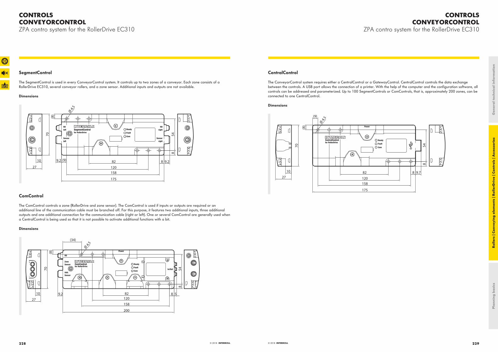
CONTROLSCONVEYORCONTROL
ZPA contro system for the RollerDrive EC310
CONTROLSCONVEYORCONTROLZPA contro system for the RollerDrive EC310
229© 2018 INTERROLL© 2018 INTERROLL228
SegmentControl
The SegmentControl is used in every ConveyorControl system. It controls up to two zones of a conveyor. Each zone consists of a RollerDrive EC310, several conveyor rollers, and a zone sensor. Additional inputs and outputs are not available.
Dimensions
9.2 (9) 9.2
Ø 4.5
(8)
548
882
120158
175
70
10
27
ComControl
The ComControl controls a zone (RollerDrive and zone sensor). The ComControl is used if inputs or outputs are required or an additional line of the communication cable must be branched off. For this purpose, it features two additional inputs, three additional outputs and one additional connection for the communication cable (right or left). One or several ComControl are generally used when a CentralControl is being used so that it is not possible to activate additional functions with a bit.
Dimensions
9.2
(8)
(34)
882120
158
200
854
Ø 4.5
510
27
70
CentralControl
The ConveyorControl system requires either a CentralControl or a GatewayControl. CentralControl controls the data exchange between the controls. A USB port allows the connection of a printer. With the help of the computer and the configuration software, all controls can be addressed and parameterized. Up to 100 SegmentControls or ComControls, that is, approximately 200 zones, can be connected to one CentralControl.
Dimensions
8 9.782
120158
175
(9)
(8)
Ø 4.5
548
10
27
70
Pla
nnin
g b
asi
csR
olle
rs |
Conv
eyin
g e
lem
ents
| R
olle
rDri
ve |
Cont
rols
| A
cces
sori
esG
ener
al t
echn
ica
l inf
orm
ati
on

CONTROLSCONVEYORCONTROLZPA contro system for the RollerDrive EC310
231© 2018 INTERROLL© 2018 INTERROLL230
GatewayControl
The ConveyorControl system requires either a GatewayControl or a CentralControl. GatewayControl controls the data exchange between the controls. A USB port allows the connection of a printer. With the help of the computer and the configuration software, all controls can be addressed and parameterized. Up to 100 controls, that is, approximately 200 zones, can be connected to one GatewayControl. But the crucial difference to the CentralConsole is the interface function to a fieldbus via an M12 connector. For the fieldbuses PROFIBUS, PROFINET and EtherNet/IP, the GatewayControl enables the connection to a PLC.
Dimensions
10
27
70
Ø 4.5
548
82
120158
175
8 9.77.4
(9)
(8)
Accessories
· RollerDrive EC310 extension cable, page 242· PowerControl power supply, page 236· Magnetic key, page 247· Flat cable for voltage supply, page 243· ConveyorControl communication cable, page 243· ConveyorControl termination box, page 245· Cable bridge for flat cable, page 245
Ordering information
Control Article number Scope of delivery
GatewayControl PROFIBUS S-1004026 USB stick with Configurator software; dummy plug for flat cable; magnetic key, termination box
GatewayControl PROFINET S-1100275 USB stick with Configurator software; dummy plug for flat cable; magnetic key, termination box
GatewayControl EtherNet/IP S-1101732 USB stick with Configurator software; dummy plug for flat cable; magnetic key, termination box
CentralControl S-1004027 USB stick with Configurator software; dummy plug for flat cable; magnetic key, termination box
SegmentControl S-1004024 Dummy plug for flat cable, one RollerDrive input and one sensor input
ComControl S-1004025 Dummy plug for flat cable and one sensor input; two flat cable pieces
Pla
nnin
g b
asi
csR
olle
rs |
Conv
eyin
g e
lem
ents
| R
olle
rDri
ve |
Cont
rols
| A
cces
sori
esG
ener
al t
echn
ica
l inf
orm
ati
on

CONTROLSMULTICONTROL
Universal control for the RollerDrive EC310
CONTROLSMULTICONTROLUniversal control for the RollerDrive EC310
233© 2018 INTERROLL232 © 2018 INTERROLL
Product descriptionThe MultiControl is a four-zone control. This means that up to four RollerDrive EC310 and four zone sensors can be connected. The use of Y-lines enables connecting four additional inputs or outputs. The connections can be configured individually.
If MultiControl is used as a network card, the fieldbuses PROFINET, EtherNet/IP or EtherCat can be used by simply toggling them.
With help of the MultiControl, sensors and RollerDrive are directly integrated in to the field bus level. No additional sensor/actuator level is necessary. A standard ribbon cable is used for power connection. The ribbon cable can be cut to the correct length and can be connected very quickly using the penetration technology of MultiControl.
Switching off connected RollerDrive without interrupting the communication is possible if the MultiControl features a second ribbon cable for voltage supply.
The addressing and naming is done over PLC software, a web user interface, or with the Interroll Teach-In method. With the Teach-In method, automatic addressing and configuration of all MultiControl is possible. In addition, the sequence of all MultiControls in the conveyor line can be determined. This saves time during the commissioning on site.
MultiControl can also be used as individual control for special applications. Interroll offers the programming of special software solutions if it cannot be done using a PLC.
Application areaZero-pressure accumulation conveying (ZPA) of many zones. Control of the Interroll Transfer and the Interroll High Performance Divert. Control of RollerDrive EC310 in applications without zero-pressure accumulation conveying.
Functions
· Easy handling – One controller card for PROFINET, EtherNet/IP and EtherCat (simple toggling of bus protocols)· Independent power supply possible for RollerDrive· Plug & Play in case of replacements – no addressing or configuration required· Status display with LEDs for all functions and I/Os· Logic for zero-pressure accumulation conveying incl. initialization· Communication via certified fieldbuses· Configuration via PLC, web browser menu and via Teach-In method of:
– Speed, direction of rotation, start and stop ramp of RollerDrive– Sensor properties– Timer– Error handling– Logic (single/train release)
· UL-certified· Voltage limitation via brake chopper
Possible applications
Use of a PLC Function of a PLC Function of MultiControl
No • None • Implementation of ZPA logic
Yes • Influencing the ZPA logic• Tracking of materials• Error diagnostics
• Implementation of own ZPA logic• Implementation of PLC specifications
Yes • The PLC must be programmed and controls all connected RollerDrive via this program
• Tracking of materials and error diagnostics
• Function as network card• Transmits the status of all sensors, RollerDrive and, if
necessary, error information to the PLC
Pla
nnin
g b
asi
csR
olle
rs |
Conv
eyin
g e
lem
ents
| R
olle
rDri
ve |
Cont
rols
| A
cces
sori
esG
ener
al t
echn
ica
l inf
orm
ati
on

CONTROLSMULTICONTROL
Universal control for the RollerDrive EC310
CONTROLSMULTICONTROLUniversal control for the RollerDrive EC310
235© 2018 INTERROLL© 2018 INTERROLL234
Technical data
Electrical data
Rated voltage 24 V DC
Temporarily permissible voltage range 22.8 to 25.2 V DC
Current consumption* Logic supply voltage: MultiControl: max. 0.2 A + connected sensors/actuators = max. 1.6 A Motor supply voltage: RollerDrive rated current: 4 x 2 A = 8 A RollerDrive startup current: 4 x 4 A = 16 A
Fuse Present, non-replaceable
Protection rate IP54
Ambient conditions
Ambient temperature in operation −30 °C to +40 °C
Ambient temperature during transport and storage −40 °C to +80 °C
Max. installation height above sea level** 1000 m
* The effective current in the application depends on the conveyor weight, conveyor speed and number of cycles.
** The installation in systems at an altitude above 1,000 m is possible. However, this can lead to a reduction of the performance values.
Dimensions
MultiControl
14 14
70
185
12
34
1
34
2
Base plate
163
151
90
60
26
6.5
4
15 15
32.5 32.5
ø 6.
5
ø 6.
5
ø 6.
5
70
6.5
6.5
To be able to position the magnetic key, the distance from the top edge of MultiControl to adjacent components must be at least 10 mm.
Accessories
· Flat cable for voltage supply, page 243· Magnetic key, page 247· MultiControl dummy plug, page 244· RollerDrive EC310 extension cable, page 242· MultiControl communication cable, page 244· MultiControl Y-cable, page 244· PowerControl power supply, page 236
Ordering information
· Article number: S-1101834· Scope of supply: Base plate· Questions about spare parts or additions: It is required to provide the existing firmware version.
Pla
nnin
g b
asi
csR
olle
rs |
Conv
eyin
g e
lem
ents
| R
olle
rDri
ve |
Cont
rols
| A
cces
sori
esG
ener
al t
echn
ica
l inf
orm
ati
on

CONTROLSPOWERCONTROL
Power supply for the controls of RollerDrive EC310
CONTROLSPOWERCONTROLPower supply for the controls of RollerDrive EC310
237© 2018 INTERROLL236 © 2018 INTERROLL
The PowerControl is a 3-phase power supply (400 V AC) in an IP54 housing for providing the 24-V DC system voltage. The power supply is perfectly adjusted to the current requirements of the RollerDrive EC310. For up to four seconds, the power supply furnishes a current of 30 A. Hence, the power supply facilitates the simultaneous starting of multiple RollerDrive.
The power supply is designed for decentral use. It does not have to be integrated in a costly switch cabinet and can be fastened directly on the side profile of the conveyor. Cable can be saved by placing it in the vicinity of the RollerDrive control. Thanks to the short cables, problems due to cable voltage losses are minimized. Two connections are available for the primary side so that the voltage for the next PowerControl can be looped through.
Properties· No installation in switch cabinet required· Self-protection against overload, feedback, short circuit and load drop· System compatible due to low cold start current (inrush) and active power factor correction· No power reduction (derating) over the entire operating temperature range of the Interroll
controls· Multiple terminal points on mains and load side; no special or expensive connector required· Cable entry via M20 fittings including seals· Maintenance-free
Application areaVoltage supply of MultiControl or ConveyorControl system via flat cable. Voltage supply of DriveControl or ZoneControl via round cable.
Technical data
Electrical data
Rated supply voltage 400 V AC, 3 phases
Supply system voltage range 380 to 480 V AC ± 15 %
Supply system frequency 50 to 60 Hz ± 6 %
Supply system power consumption Typically 0.8 A per phase at 3 x 400 V AC
Supply system cold start, inrush Typically 3 A at 400 V
Rated output voltage 24 V DC
Rated output power 480 W
Rated peak power Max. 720 W at 24 V DC for 4 s, repetition rate depends on duration and actual peak load
Maximum output current 30 A at 24 V for 4 s
Ripple/noise 100 mVpp, 20 Hz to 20 MHz, 50 Ohm
Feedback resistance Max. 32 V DC
Short-circuit current 20 A
Protection rate IP54
Ambient conditions
Ambient temperature in operation –30 to +40 °C
Ambient temperature during transport and storage −40 to +80 °C
Max. installation height above sea level* 1000 m
Miscellaneous data
Weight Approx. 2.5 kg
Color RAL7035 (gray)
* The installation in systems at an altitude above 1,000 m is possible. However, this can lead to a reduction of the performance values.
Pla
nnin
g b
asi
csR
olle
rs |
Conv
eyin
g e
lem
ents
| R
olle
rDri
ve |
Cont
rols
| A
cces
sori
esG
ener
al t
echn
ica
l inf
orm
ati
on

CONTROLSPOWERCONTROLPower supply for the controls of RollerDrive EC310
239© 2018 INTERROLL© 2018 INTERROLL238
Dimensions
230
200
288300
55110
4x Ø 4.2
(297
)
Ø 4
.2Ø
8
4.5
86.5
Ø 6 –13
25
SW24
345
Ordering information
· Article number: S-1004029· Scope of supply: Cable grommet for round and flat cable, dummy plug for a cable grommet each on the primary and secondary
side, supplied connecting cable for ground connection of 24-V ground.
Pla
nnin
g b
asi
csR
olle
rs |
Conv
eyin
g e
lem
ents
| R
olle
rDri
ve |
Cont
rols
| A
cces
sori
esG
ener
al t
echn
ica
l inf
orm
ati
on

241© 2018 INTERROLL
ACCESSORIES
240 © 2018 INTERROLL
PolyVee tensioning device
The PolyVee tensioning device enables easy tensioning of 2-rib and 3-rib PolyVee belts and is intended for roller pitches 75 mm and 100 mm. The tensioning device is designed for rollers and RollerDrive with a diameter of 50 mm. It cannot be used for tubes with tube sleeves or tapered elements.
The belt is perfectly tensioned and a roller/RollerDrive is correctly aligned horizontally as well as vertically. Hence, a female threaded shaft aligns with the fastening hole in the side profile.
Article number: S-1101272
Dimensions
25 +0.2+0.1
50 +0.2+0.1
R25
R25
R8
160
42
A A
B B
R8R8
R8 15
6042
A-A ( 1 : 1 )
B-B ( 1 : 1 )
radii without dimension R=2
PolyVee finger guard
The PolyVee finger guard safely protects against inadvertently reaching between PolyVee belt and roller drive head.
Product benefits
· Quick installation and removal, no screw connections required· Fits into any side profile, the finger guard sits on the seal of the
roller or on the fastening pin of the RollerDrive· Installation in mechanically finished conveyor systems, can also
be retrofitted in existing systems· Always the right match, the rear panel is designed directly for
two belts for quicker installation. The center of rear panel features a predetermined breaking point with which it can easily split in half in case of an uneven number of belts.
Technical data
· Temperature range: 0 to +40 °C · Color: Black· Distance between side frame and seal of roller: min. 0.5 mm;
max. 1.5 mm· Roller pitch: 75 mm and 100 mm
Article number
· Roller pitch 75 mm: S-8863· Roller pitch 100 mm: S-8864
Dimensions
150
40
R25.5
R9
R14P=75
Pla
nnin
g b
asi
csR
olle
rs |
Conv
eyin
g e
lem
ents
| R
olle
rDri
ve |
Cont
rols
| A
cces
sori
esG
ener
al t
echn
ica
l inf
orm
ati
on
PolyVee belt
A PolyVee belt is used for the drive from roller to roller or RollerDrive for straight sections and for curves and is suitable for use with the following series:
· Series 3500 Fixed drive conveyor roller· Series 3500KXO Tapered fixed drive conveyor roller· Series 3800 Friction conveyor roller· Series EC310 RollerDrive
Product description
· Elastic standard belt, 1 to 3 % pretension, for fixed shaft distances
· Significantly longer service life than round belts
· Up to 300 % higher torque transmission than with comparable round belts
· Much better efficiency compared to toothed belts since much less flexing work is required
· Curve application: Use of 2-rib or 3-rib belts· Suitable for normal and freezer temperatures· Belts are antistatic
Technical data
· Temperature range: −28 to +40 °C · Color: Black· Belt acc. to Type PJ; ISO 9981; DIN 7867
Design versions
Number of ribs Roller pitch ±1 mm
Max. weight of material to be conveyed [kg]
Article number Belt designation
2 60 50 S-1111211 256
2 75 S-1111217 286
2 90 S-1111220 314
2 100 S-1111222 336
2 120 S-1111224 376
3 60 300 S-1111216 256
3 75 S-1111219 286
3 90 S-1111221 314
3 100 S-1111223 336
3 120 S-1111225 376
ACCESSORIES

243© 2018 INTERROLL
ACCESSORIES
242 © 2018 INTERROLL
Voltage supply flat cable
The flat cable is used for the voltage supply of ConveyorControl and MultiControl. The outer contour of the line corresponds to the standard of AS interface. The shell of the line covers holes that were created by penetration contacts. This means that the cable maintains the protection rating even after disconnecting a control.
Article number: S-1004030
Technical data
· Temperature range: −28 to +40 °C · Strand insulation: Brown for +24 V, blue for ground· Length: 25 m· Cross section of braids: 2.5 mm²· Protection rating: IP54 in contacted state· UL CL2
Dimensions
2
4
10
3.6
6.5
9
ConveyorControl communication cable
The flat cable is used for the communication of the ConveyorControl control system. The different controls of the system simply contact the line via penetration contacts. The outer contour of the line corresponds to the standard of AS interface. The shell of the line covers holes that were created by penetration contacts. This means that the cable maintains the protection rating even after disconnecting a control.
Article number: S-1004031
Technical data
· Temperature range: −28 to +40 °C · Strand insulation: Brown for +24 V, blue for ground· Length: 50 m· Cross section of braids: 1.5 mm²· Protection rating: IP54 in contacted state· UL CL2
Dimensions
2
4
10
3.6
6.5
9
Pla
nnin
g b
asi
csR
olle
rs |
Conv
eyin
g e
lem
ents
| R
olle
rDri
ve |
Cont
rols
| A
cces
sori
esG
ener
al t
echn
ica
l inf
orm
ati
on
Fastening socket
The fastening socket is used for tightening according to the torque of the RollerDrive fastening nut using a torque wrench. The socket features a lateral opening through which the RollerDrive connecting cable can be fed to the outside.
Article number: S-1101248
Dimensions
17
12.7
(1/2
")
12
14 3
4
2Ø 23.5
85 3
Counter wrench
The RollerDrive EC310 has a glued-on ribbed nut that is located at the bearing housing. An additional nut is used to screw the RollerDrive in the side profile. Depending on the condition of the side profile, the glued-on nut must be secured with a counter wrench while tightening the outside nut.
The counter wrench size 17 WAF fits perfectly between the flange of the ribbed nut and the bearing housing of the EC310.
Article number: S-1101270
Dimensions
24.5
12
4
17.5
1.5
A-A ( 1 : 1 )
A
A
RollerDrive EC310 extension cable
The connecting cable of the EC310 can be extended easily with a plug connection by using the RollerDrive extension cable.
Article number: S-1004033
Technical data
· Temperature range: –30 to +40 °C · Color: Black· Length: 2 m· Outside diameter: 5 mm· Plug connection: M8 snap-in plug and socket· Protection rating: IP67 in connected state· Suitable for drag chains: no
ACCESSORIES

245© 2018 INTERROLL
ACCESSORIES
244 © 2018 INTERROLL
MultiControl dummy plug
The MultiControl features 4 RollerDrive, 2 communication and 4 sensor or I/O connections. If all connections are occupied, then the MultiControl has a protection rating of IP54. Based on the application, it is also possible that not all connections are occupied. If the protection rating of IP54 is to be maintained in such cases, then it is necessary to close the connections. The dummy plug package contains as many pugs as needed if the MultiControl has only the minimum connections.
Dummy plug package
MultiControl connection
Dummy plug size
Use Dummy plugs included
RollerDrive M8 Insert 3
Sensor or I/O M8 Screw 3
Communication M12 Screw 1
The dummy plugs are delivered prefabricated for the required connections.
Article number: S-1104466
Technical data
· Temperature range: –30 to +40 °C · Color: Black
Cable bridge for flat cable
The cable bridge allows electrically combining two flat cables and changing the position of one flat cable. The ends of both flat cables have to point in the same direction.
Article number: S-1004028
1 Conveyor system2 SegmentControl or ComControl3 Cable bridge4 Obstacle (wall, column or similar)
Technical data
· Temperature range: –30 to +40 °C · Protection rating: IP54· Suitable for the communication cable of the ConveyorControl
system· Suitable for the voltage line of the ConveyorControl system or
the MultiControl: can be loaded up to 6 A
Pla
nnin
g b
asi
csR
olle
rs |
Conv
eyin
g e
lem
ents
| R
olle
rDri
ve |
Cont
rols
| A
cces
sori
esG
ener
al t
echn
ica
l inf
orm
ati
on
MultiControl communication cable
The prefabricated PROFINET cable is used for communication with MultiControl. The cable allows connecting one MultiControl with another MultiControl, another bus node, a switch or a PLC.
Article number: S-1104438
Technical data
· Temperature range: –30 to +40 °C · Color: Green· Length: 3 m· Outside diameter: 6.5 mm · Plug connection: M12, straight on M12, straight· Protection rating: IP67 in contacted state· Line: Cat5, shielded· UL1581
MultiControl Y-cable
The Y-cable with M8 plugs enables the use of an additional input or output at the MultiControl.
Article number: S-1104460
Technical data
· Temperature range: –30 to +40 °C · Color: Black· Length: 300 mm (+ plug)· Outside diameter: 5 mm· Plug connection with single connector: M8, straight, screwed,
4-pin, for connecting to a MultiControl· Plug connection with dual connector: A) M8, straight, screwed,
4-pin, for connecting to a zone sensor B) M8, straight, screwed, 4-pin, for connecting to an input or output
· Protection rating: IP67 in contacted state
ACCESSORIES

247© 2018 INTERROLL
ACCESSORIES
246 © 2018 INTERROLL
Magnetic key
The magnetic key with a high-quality neodyme magnet offers many functions. For the MultiControl, it enables switching the bus protocol or the use of the Teach-In method. For the ConveyorControl, it enables addressing or, for example, performing a self-test.
Article number: S-64100210
Pla
nnin
g b
asi
csR
olle
rs |
Conv
eyin
g e
lem
ents
| R
olle
rDri
ve |
Cont
rols
| A
cces
sori
esG
ener
al t
echn
ica
l inf
orm
ati
on
ConveyorControl termination box
The small termination box serves as terminating resistor for the communication cable of the ConveyorControl system. The termination box can easily contact the cable using penetration technology.
Article number: S-1103892
Technical data
· Temperature range: –30 to +40 °C
Dimensions
2.7
4.341
.5 31.5
35.4
5
16
33
17.7
8
AdControl
The AdControl can be used if a RollerDrive EC300 (predecessor of EC310) is to be replaced with a RollerDrive EC310. The AdControl has a short connecting cable with plug. The plug corresponds to that of the EC300 and is connected with the existing DriveControl EC200/EC300 or extension cable. The EC310 is inserted on the left side. DIP switches are protected by a yellow end cover. The DIP switches can be used to set the gear stage of the previously used EC300 and the new EC310. The complex wiring of a new control is not needed. The use of the AdControl allows using a RollerDrive EC310 without changing the existing wiring. Depending on the gear ratio, the AdControl can also be used when replacing an EC200 with an EC310 (see instruction manual of AdControl).
Article number: S-1100372
Dimensions
55
2.5
24
6118
130
≈14
Ø 6
141
42(6
.5)
ACCESSORIES

PLANNING BASICSMATERIAL
249© 2018 INTERROLL
PLANNING BASICS
© 2018 INTERROLL248
MaterialThis chapter is intended to provide support in the planning of conveyor systems and the selection of matching products.
The properties of the material to be transported, the requirements with regards the conveyor system and the ambient conditions are the basis for the planning of the system.
Length and width of materialThe length and width of the material to be transported have an effect on several factors:
Straight running: The higher the ratio of length to width, the more stable will be the straight running of your items. With smaller length to width ratios, it may be necessary to put in place additional measures to stabilize the straight running of the materials.
Reference length: As a rule, the reference length corresponds to the conveyor width +50 mm or for large materials, such as pallets, +100 mm. In curves, Interroll recommends the use of tapered conveyor rollers whose length must be calculated separately (see page 262).
Roller pitch: To transport the material without problems, the roller pitch must be selected so that the material is carried by three conveyor rollers at any given time.
Surface pressure: The different Interroll conveyor rollers can be loaded with different forces. The static load capacity of a roller can be taken from the respective roller chapter. The values are based on the assumption that a material rests on the complete usable tube length and not just on a part of the tube. If a material has contact with less than approx. 50 % of the usable tube length, please have the application checked by Interroll beforehand.
Very long materials generally do not rest on all rollers that are located under them. If, for example, 20 rollers are under a piece of material, but the material contacts only 15 rollers, then the load capacity of a roller must be greater than one-fifteenth of the material. For very long materials, the tolerance of the roller fastening height should be kept as low as possible so that as many rollers as possible can carry the material.
Height of material to be conveyedThe greater the height of the material in relation to its bottom area, the higher is the risk of it tipping over when traveling on the conveyor. The following must be taken into consideration:
· Minimize the roller pitch as much as possible to ensure that the products are conveyed smoothly with as large a base surface as possible.
· Avoid rapid acceleration and harsh braking. When using RollerDrive, it is very convenient here to select ramps for starting and stopping.
· With inclined conveyor tracks, determine the center of gravity of the material to be transported and check whether there is a risk of it tipping.
Weight and weight distribution of the material to be conveyedThe weight of the material must be distributed on a number of conveyor rollers so that the maximum load capacity of the individual conveyor roller is not exceeded. This may mean that more than three conveyor rollers must support the material.
In principle the weight of the material should be distributed as evenly as possible. The more uneven the weight distribution is, the more difficult a reliable conveyance is.
If the weight in form of the goods is positioned, e.g. only at the start of the load carrier, then it is very likely that the rollers at the end of the load carrier support only very little weight. In the worst case scenario, the rollers at the start of the load carrier could be overloaded.
The greater the diameter of the tube is selected, the higher is the load capacity of the roller. The load capacity is increased if shafts are screwed together. In addition, the shafts reinforce the conveyor and act as a cross tie.
Drives, such as RollerDrive, must be selected so that the torque is sufficient to be able to move a system consisting of several conveyor rollers and drive elements. On top of that, the drive must be dimensioned for the material weight.
Drive elements, such as chains, round belts or flat belts, must also be selected while taking the material weight into consideration. For the container transport area, Interroll recommends the use of PolyVee belts whose service life and torque transmission are significantly higher than for round belts.
Material of conveying materialThe material, and especially the condition of the base, has an effect on the rolling and starting resistance.
Hard materials, such as polymer containers, feature lower rolling and starting resistances than soft materials, such as cardboards. This has a direct impact on the required drive output and must be included in its calculation. The softer the underside of the material to be conveyed, the higher is the drive output required for a product with the same weight but with a hard underside. For example, white goods are often packaged with styrofoam on the underside. Depending on the roller pitch, material weight, exposure time and softness of the styrofoam, the styrofoam shapes itself onto the rollers. A waveform matching the roller pitch can then be seen in the styrofoam. On friction conveyors,
Pla
nnin
g b
asi
csR
olle
rs |
Conv
eyin
g e
lem
ents
| R
olle
rDri
ve |
Cont
rols
| A
cces
sori
esG
ener
al t
echn
ica
l inf
orm
ati
on

PLANNING BASICSCONVEYOR REQUIREMENTS
PLANNING BASICSMATERIAL
251© 2018 INTERROLL250 © 2018 INTERROLL
the result can be that the materials will no longer start moving. In principle, the softer the material to be conveyed, the smaller the roller pitch needs to be.
Ribs, keyways, strips or grooves in the bottom of materials to be conveyed that run parallel to the direction of conveyance, do not pose a problem concerning transportability. The required drive output increases depending on their shape. Cross ribs can negatively impact the transporting. It may be necessary to determine the roller pitch empirically.
When checking whether a roller has sufficient load capacity for an application, it is important to take the condition of the material into consideration. Materials with an uneven bottom generally do not rest on all rollers that are located under them. With pallets, it must be ensured that only the rollers under the bulk of the pallet are actually bearing the load. The following diagram shows which runner load distribution occurs for an evenly loaded euro-pallet.
13% 24% 13%
13% 24% 13%
Fig.: Support of 2 runners
8% 12% 8%
8% 12% 8%
20%12% 12%
Fig.: Support of 3 runners
Conveyor requirementsThe following fundamental parameters determine the configuration of the conveyor:
· Maximum throughput per time unit· Geometry of material to be conveyed· Weight and weight distribution of the material to be conveyed· Control requirements· Environmental conditions
Static chargingIn principle, conveyance via rollers creates electrostatic charging which, among other things, depends on the properties of the material to be conveyed and the tube material.
To prevent electrostatic charging from occurring or dissipate it immediately and without creating sparks, Interroll offers antistatic versions for rollers with steel tube.
An option is available to conduct the charge via an antistatic element at low resistance from the tube to the shaft. If a conducting connection exists between roller shaft and side profile, it allows the charge to be discharged to the grounded side profile. Rollers with sleeve, with tapered elements or with polymer drive head always feature an antistatic element so that they can be connected with ground potential in the area of a tube projection. Static charge cannot be discharged from the PU and PVC sleeve or the gray tapered elements.
Compared to the gray versions, black tapered elements for a tube diameter of 50 mm are suitable for discharging static charges.
All RollerDrive variants, including in the IP66 design, as well as MSC 50, are always designed to be antistatic.
All solutions require the proper manufacturing and check of the conducting connection between shaft and side profile and the grounding of the side profile by the system manufacturer .
Rollers with welded steel sprocket head or double sprocket head can also be connected with ground potential via the chain.
Noise levelNoise is created by different components of a conveyor and the material itself.
Every drive creates noise. The Interroll RollerDrive is designed with decoupling elements which reduce the noise of the gear box. In most cases, the noise level of the RollerDrive is below 50 dBA. More and more zero-pressure accumulation conveyor systems are converted from pneumatic solutions with a centrally arranged drive to a RollerDrive solution. The significantly lower noise level is a deciding factor here.
The following applies to the noises of drive elements: A chain drive causes more noise than a belt drive.
Noise development at rollers depends on the bearing and how it is fastened in the tube. Precision ball bearings, such as those in series 1700, run significantly quieter than bearings such as those used in series 1100. The material of the bearing housing, in which the bearing is installed, also plays a role. A metal bearing housing is installed in series 1200 for extreme ambient temperatures, but it is significantly louder than one of the roller series 1700. Almost all of the roller series from Interroll are manufactured with technopolymer bearing housings in order to obtain the perfect noise reduction.
Very quiet rollers, drives and drive elements are of little use if the material on the conveyor creates noise. Various measures can counteract it. The following should be observed in this case:
· A small roller pitch generally causes less noise than a large roller pitch.
· Watch for small height tolerances at transitions and at the fastening of the rollers/RollerDrive.
· Fitting the rollers/RollerDrive with noise-reducing materials, e.g. with a PVC or PU sleeve
· Use of noise reduction inside of rollers for rollers with a diameter of 50 mm – see page 39
HumidityHumidity can occur in different forms as a result of the following:
· moist materials, e.g. bottle crates stored in the rain· moist environment, e.g. sculleries· applications that become moist, e.g. because of cleaning or
tripped sprinkler systems
If humidity can be expected in a system, then all components should be checked for corresponding resistance.
Interroll offers a series of products that are suitable for applications with humidity:
Tube material: Rollers and RollerDrive can be manufactured from rust-free material, such as stainless steel. In addition, materials can be protected with different finishing processes, such as zinc-plating, chrome-plating or carbonitriding.
Shaft material: Shafts can be manufactured from rust-free material, such as stainless steel.
Drive elements: Some drive elements are better suited for moist applications. PolyVee belts are much better suited than round belts which are guided via grooves in the tube. The round belts could slip in the smooth groove.
Pla
nnin
g b
asi
csR
olle
rs |
Conv
eyin
g e
lem
ents
| R
olle
rDri
ve |
Cont
rols
| A
cces
sori
esG
ener
al t
echn
ica
l inf
orm
ati
on

PLANNING BASICSDRIVE CONCEPTS
PLANNING BASICSCONVEYOR REQUIREMENTS
253© 2018 INTERROLL252 © 2018 INTERROLL
Drives: The RollerDrive already has a high degree of protection with protection rating of IP54. If high humidity or water jets can be expected in the application, Interroll recommends the design with protection rating IP66.
Bearing: All rollers with precision ball bearings are well protected against moisture and dust. For systems with constant humidity or moisture, Interroll offers designs with stainless steel ball bearings.
For series 1500, all components are suitable for moisture. Shaft pins are made of stainless steel and cannot rust. The tube can be manufactured from stainless steel, and grease cannot be flushed out of the slide bearings used, and the slide bearings cannot rust.
Applications in freezer areaApplications with an ambient temperature of approx. −28 °C are particularly prevalent in the food processing sector. Many items must be taken into account in the so-called freezer area:
· Does the startup of components change, such as for rollers?· Do drives require more output since the viscosity of grease
types may increase or components are frozen?· Are all the components functionally dependable, even if, e.g.,
different materials contract differently?
The Solutions from Interroll
Materials: For various products, Interroll offers variants that are particularly suited for freezer applications. The gray tapered elements are not brittle and, for this reason, well suited for freezer applications. The bearing housings of series 1700 are designed as high impact-resistant for freezer applications.
Drives: The RollerDrive EC310 is available in a freezer design. Even after a longer standstill, the RollerDrive starts up again. This is made possible by a special freezer grease and matched components or materials.
Drive elements: Before using a drive element, its suitability for freezer applications should be checked. It should also be ensured that the friction at temperatures below zero is sufficient and the drive elements cannot freeze since frozen drive elements could pose unplanned torque requirements for the drive.
Bearing: The precision ball bearings used also work in freezer conditions. However, the startup of the roller is higher in this case than at an ambient temperature of 20 °C. Drives are either designed for this higher startup, or oiled ball bearings are being used. The oiled bearings run significantly smoother at temperatures below zero.
Under freezer conditions, materials such as steel and polymer contract in different ways. For functional reliability, a PolyVee drive head for a RollerDrive is not only pressed into the steel tube, but it is also flanged. Additional security against twisting is
provided by a metal star. This star, which is being produced with laser cutting, is engaged in the drive head and channels itself into the inside wall of the tube. This innovative solution inside the tube allows avoiding interfering edges on the outside contour of the tube. This solution is available as an option for various designs series 3500 and 3500KXO.
Series 1200 is specifically designed for extreme temperature applications. Metal bearing housings in metal tubes offer the highest functional reliability.
Drive conceptsWith respect to drives, Interroll distinguishes between drives (such as round belts, PolyVee belts, chains, etc.) and the actual drive. Different drives are used in conveyor systems, such as drum motors, gear motors, motor rollers, etc. Furthermore, the potential energy of materials to be conveyed, e.g. on gravity conveyors, is also being utilized.
Gravity conveyorsA gravity conveyor differs significantly from the other concepts. It is not horizontally aligned, but always mounted at an incline. There are driven and non-driven gravity conveyors. The discussion below refers to a gravity conveyor without drive. Gravity conveyors use the potential energy of materials to be conveyed. This means that other technology must first move the material to a corresponding spatial height.
The material rolls without additional drive as a result of the potential energy up to the end of the conveyor or up to the preceding material. Due to the missing drive, a gravity conveyor is usually a cost-effective solution. The speed and the restart capability of materials is heavily influenced by:
· The incline of the conveyor· The already existing speed of a material when placed upon the
gravity conveyor· The ease of movement of the rollers· The conveyor length· The condition of the underside of a material to be conveyed· The weight of the material· Other properties
On the one hand, the material must reach the end of the conveyor. It must not stop because its weight is too low to start moving rollers at rest. If many materials are already on a gravity conveyor and, as a result, a piece of material stops in the last section of the conveyor, then it must be ensured that the last item will start again and reach the end of the gravity conveyor after the first materials have been conveyed.
On the other hand, the speed of the materials must not be or get too high. There is the risk that a material hits another jammed material or the end stop at the end of the conveyor. This creates an injury risk for employees who may want to remove the material by hand, as well as the risk of damaging the material.
Establishing the matching properties of a gravity conveyor becomes a challenge if different materials have to be moved. Generally, the materials on a gravity conveyor differ by at least one of the following properties: Weight, size, material and base condition. A mixture of different materials can also be transported by a gravity conveyor with respect to personnel and material safety as well as process reliability. Interroll offers different products for this purpose. The rollers of series 1100 are designed for use in gravity conveyors.
The following should be observed when selecting rollers for a gravity conveyor:
· Select rollers with particularly smooth startup.· Rollers with oiled ball bearings turn more easily than those
filled with grease.· The weight of the rollers: The wider the gravity conveyor, the
longer and, as a result, heavier the roller. Ideal are rollers with low mass inertia (lightweight tube material).
The magnetic speed controller MSC 50 enables the restart of materials starting at 0.5 kg and reliably decelerates materials up to 35 kg depending on the properties of the conveyor. If materials are lighter than 0.5 kg or heavier than 35 kg, it is also possible to use the RollerDrive series EC310.
The driven RollerDrive ensures that every lightweight material, regardless of its weight, can be moved or moved again. When decelerating heavy materials, the energy recovered by the RollerDrive must not be too high. If one or several RollerDrive are used within a gravity conveyor, it also provides the advantage of accumulation pressure reduction. If a RollerDrive, which may be connected with additional rollers via drive elements, is stopped, then the materials stop. This allows reducing the pressure on materials that are already on the conveyor or on the stop at the end of the conveyor. On long gravity conveyors, it may be advisable to use several RollerDrive in order to reduce the accumulation pressure even further. If the incline is so high that materials slide over the steel tube of stopped RollerDrive or rollers, then the friction may be increased due to PVC sleeve on the tube.
In principle, it is recommended to test every gravity conveyor design under original conditions.
Fixed drive conveyorIf a material moves in harmony with the drive, then it is generally a fixed or constantly driven conveyor. The drive head of the rollers used is permanently connected with the tube. If the fixed drive heads are replaced with friction drive heads, they create a friction conveyor. Depending on the drive element, it is also possible to use rollers without drive head, e.g. for a flat belt conveyor. Many different types of fixed drive conveyors are possible. They generally differ with respect to the selected drive element, such as chains, PolyVee belts, round belts used together with drive shafts or from roller to roller, flat belts, etc. and the drives used.
For all current fixed drive conveyors, Interroll offers matching conveyor rollers, with the RollerDrive EC310, the Pallet Drive and PolyVee belt even drives and drive elements. When using a RollerDrive as drive, it is recommended to place it in the middle of the driven conveyor rollers (for additional planning information about the RollerDrive, see page 268. Information about the Pallet Drive is located in separate product documents.) If many rollers have to be driven, then PolyVee belts offer advantages
Pla
nnin
g b
asi
csR
olle
rs |
Conv
eyin
g e
lem
ents
| R
olle
rDri
ve |
Cont
rols
| A
cces
sori
esG
ener
al t
echn
ica
l inf
orm
ati
on

PLANNING BASICSDRIVE ELEMENTS (BELT, CHAIN)
PLANNING BASICSDRIVE CONCEPTS
255© 2018 INTERROLL254 © 2018 INTERROLL
over round belts. The use of PolyVee belts reduces the number of roller revolutions with increasing distance to the RollerDrive. Additional information is also located in the chapter "Drive Elements" at page 255.
Friction conveyorFriction conveyors are generally used to transport and accumulate materials. The special thing about friction conveyors is that an accumulation of materials can be accomplished with only little accumulation pressure when the drive is switched on. The same situation on a fixed drive conveyor would cause the materials that were stopped first to receive so much pressure from the subsequent materials that fragile cardboards could be damaged. Friction conveyors are well suited for buffer sections with non-uniform loading and unloading.
Friction conveyor rollers are available with many different drive elements, see page 259. Even a conveyor with drive shaft can be used as friction conveyor. The guide wheel of series 2600 enables not only guiding a round belt, but it also enables the drive shaft to turn while the wheel remains at rest. It must be ensured that the round belt does not slip through as this could significantly shorten its service lie. For additional information, see page 257.
For some application's, it is a disadvantage if the materials touch, even if the accumulation pressure is reduced by the friction operation. In this case, a conveyor working at zero pressure accumulation may be better suited – see the next chapter (for additional information about friction conveyors, see page 259).
Zero pressure accumulation conveyorThe zero pressure accumulation conveying is often abbreviated as ZPA. A ZPA conveyor is generally divided into zones. The zone length is based on the length of the material or the longest material. Each zone features an option of identifying material to be conveyed, e.g. via a photo cell. In addition, every zone can be switched in and out. The zones are driven in different ways, see the examples below.
One option consists of a central drive, often a gear motor, that drives a flat belt. The flat belt is pressed onto the rollers using a switchable unit or guided past them. In the case of bypassing, the rollers are also often decelerated. It is feasible that the flat belt is pressed onto only a few rollers of a zone and the remaining rollers are connected with them by means of other drive elements. In many cases, this switching unit consists of pneumatic valves. They frequently cause an undesired noise level.
Another option always presses the flat belt against a section of a roller in every zone. The remaining portion of the roller is switched in or out via a coupling. The remaining rollers of every zone are connected with the driven roller via other drive elements.
Another concept is the use of decentral drives. Motor rollers are often used for this purpose. In this case, drives which are directly driving the respective rollers, are installed in one or several rollers of a zone. A drive element connecting the entire conveyor is redundant. The remaining rollers of a zone are generally connected with the motor roller(s) using PolyVee belts or round belts. The zones can be activated or deactivated by switching the motor rollers on or off in a targeted way.
Depending on the length of the conveyor, the design with central drive usually falls below the investment costs of a solution with motor rollers. However, the operating costs tend to be higher due to the constant turning of the drive, even when nothing may be conveyed at the time. For most solutions with motor rollers, higher investment costs are possibly amortized after a short time.
Not only the lower energy consumption speaks in favor of a solution with motor rollers, but also the compact design. The motor is installed in a roller and does not have to be placed next to or below the conveyor.
Compared to gear motors, motor rollers are maintenance-free, they do not have to be greased and generally offer a higher safety level with a protected extra-low voltage.
But solutions with motor rollers can also have disadvantages. For solutions with many motor rollers per zone, the availability decreases – the more motors are being used, the higher the probability that a motor roller fails.
For this reason, Interroll recommends the use of the RollerDrive EC310. In this case, one drive per zone is generally sufficient, and flexible control concepts are available. Furthermore, the controls offer many other options, such as change of direction of rotation or start and stop ramps which are not being offered by conventional ZPA conveyors. For technical data, please refer to page 200.
Drive elements (belt, chain)With respect to drives, Interroll distinguishes between the actual drive, such as RollerDrive, drum motor, Pallet Drive, gear motor, etc. and the drive elements. Drive elements refers to different types of the torque transmission.
Interroll offers conveyor rollers for all common drive elements:
· Chains· Toothed belt· PolyVee belt· Round belt· Flat belt
In principle, there are two possible types of power transmission for many drive elements:
· Tangential: Via a lateral medium running alongside the conveyor, such as a chain
· Roller-to-roller: From conveyor roller to conveyor roller or from drive shaft to conveyor roller.
Both types of power transmission can be used for friction conveyors and fixed drive conveyors.
ChainsThe chain is a tried and trusted method for driving conveyor rollers and conveyor elements in conveyor systems. Chains are characterized by their robustness and durability and are not sensitive to dirt and environmental influences. Very high levels of power can be transmitted with a chain. It is recommended to protect the chain drive against inadvertent contact.
Chains are not maintenance-free and are relatively loud in operation. They must be lubricated regularly in order to achieve an optimum service life. The noise created by a chain as drive element increases with increasing speed. For this reason, speeds higher than 0.5 m/s are not recommended.
Conveyor rollers with flanges welded on are often used for guiding pallets. Guiding pallets via flanges increases the power demand and must be taken into account during the dimensioning of the drive and drive elements.
The maximum drive length to be moved by a drive is limited by the permissible load of the chain. The following factors determine the maximum drive length "L":
· The permissible tensile load of the chain FMAX in N· The gravitational force of the individual material to be
transported FT in N· The roller resistance µ of the conveyor track, whereby a value
of 0.1 is generally selected· The projected conveying speed "S" in m/s· The placement cycle "t" of the materials (in S), i.e. the time
between two successive pieces of material to be conveyed
The maximum drive length "L" is being calculated:
L = Fmax · S · t
Ft · μ
If the drive station is positioned in the middle of the conveyor for the drive from roller to roller, then twice the drive length can theoretically be implemented. The sprockets that transfer the drive output must not be overloaded in such a case.
Based on the overall efficiency of this system, long drive lengths should be avoided. In many cases, drive lengths of more than 15 m have proven to be problematic.
FMAX can be determined with the permissible breaking load FB of the chain used. A safety factor of 7 (for which the wear of the chain is also within an acceptable range) is generally used for this purpose so that FMAX can be determined as follows:
Fmax = Fb7
According to DIN, the following breaking loads must be assumed:
Chain designation Breaking load FB FMAX
06B (3/8") 9100 N 1300 N
08B (1/2") 18,200 N 2600 N
10B (5/8") 22,700 N 3243 N
The drive output "P" required for maximum length can be calculated as follows:
P = L · μ · Ft
t
Pla
nnin
g b
asi
csR
olle
rs |
Conv
eyin
g e
lem
ents
| R
olle
rDri
ve |
Cont
rols
| A
cces
sori
esG
ener
al t
echn
ica
l inf
orm
ati
on

PLANNING BASICSDRIVE ELEMENTS (BELT, CHAIN)
PLANNING BASICSDRIVE ELEMENTS (BELT, CHAIN)
257© 2018 INTERROLL256 © 2018 INTERROLL
Tangential transmission of force
1 2 3 4 5 6
The tangential chain drive is characterized by its good level of efficiency and simple design. The drive head (2) consists only of one sprocket. For this reason, the installation length of the conveyor roller is shorter for a roller-to-roller drive. A single chain (1) drives all of the rollers in a conveyor. The chain is guided to the sprockets by a chain guide profile. The chain guide profile (5) is usually made of special plastic and must guide the chain extremely precisely.
When used in fixed drive conveyors, the sprockets are permanently connected with the tube of the conveyors. Friction conveyors use rollers whose sprockets are not permanently connected with the outside tube. 1 to 2 teeth of the sprockets mesh into the chain and only transfer the driving power required for the individual roller. The chain can be guided either along the top of bottom of the conveyor rollers. The precise positioning of the chain guide in relation to the conveyor rollers is extremely important. The maximum play in terms of height is 0.5 mm. The central motor station (4) must be installed in such a way that the driving side of the chain is as short as possible. It is advisable to provide the motor station with additional equipment for adjusting the chain tension. Idler pulleys (3, 6) guide the chain at the drive and/or end of conveyor in the corresponding direction. It is also possible to use the last conveyor rollers as chain deflection. In this case, it must be ensured that these rollers feature a DIN gearing.
Idler pulleys, which have to carry not only the load of the material to be conveyed, but also the chain traction forces, must be checked specifically with regard to their permissible bearing load. The driven conveyor length is restricted by the permissible breaking load of the chain and by the weight of the material to be conveyed.
The roller spacing (roller pitch) can be selected as required with tangential drives. Compared with roller-to-roller drives, the conveyor rollers are easy to fit and remove with tangential drives since they are not wrapped by the chain.
Starting at 1,000 operating hours, a lengthening of the chain of up to 2 % can be expected.
Wrapped force transmission
1 2 3
With wrapped force transmission, every conveyor roller is connected to the next one by a chain (1). For this reason the conveyor rollers require double sprocket heads (2). They need more space than with a tangential drive, so that the installation length of the roller is longer. Double sprocket heads always feature a DIN gearing (standard gearing).
An additional chain guide is not required. The roller pitch is subject to very tight tolerances and depends on the chain pitch.
t = Pc · nc – nt
2
t = Roller pitchnc =- Number of chain linksnt = Number of teeth of drive headPc = Chain pitch
The maximum conveyor length depends on the drive output of the motor station (3) and the permissible breaking load of the chain. The chain experiences its maximum load at the motor station. The tolerances for the roller pitch "Pr" and the breaking load are listed in the following table.
Chain pitch/designation
Pc[mm]
Tolerance of Pr[mm]
Breaking load[N]
Fmax
06B (3/8") 9.52 0 to −0.4 9100 1300 N
08B (1/2") 12.70 0 to −0.5 18200 2600 N
10B (5/8") 15.88 0 to −0.7 22700 3243 N
Pc = Chain pitchPr = Roller pitch
Toothed beltThe share of toothed belts as drive element in roller conveyor systems is declining. Toothed belts are generally used from roller to roller and are unable to negotiate curves. Compared to round or PolyVee belts, the power requirement of a toothed belt is significantly higher because of its design. This must be taken into account in the selection of the drive. Toothed belts pose a high demand on the tolerance of the roller pitch since the tooth engagement is form-fit with the profile of the drive head. Interroll recommends obtaining the tolerances to be followed from the manufacturer of the selected toothed belt.
One advantage of the toothed belt compared to round and PolyVee belts, is the fact that it passes movements without slipping when used properly. On top of that, toothed belts are low-noise and maintenance-free, lubricating or retensioning is not required.
The drive length of a conveyor with toothed belt drive should be dimensioned so that the overall load of 12,000 N material being conveyed at the same time is not being exceeded.
With the series 3500 and 3600, Interroll offers different conveyor rollers with toothed belt drive head. A maximum toothed belt width of 12 mm and a Poly Chain GT gearing is recommended for the series 3500, a maximum toothed belt width of 20 mm and an HTD gearing for the series 3600.
PolyVee beltPolyVee belts are ribbed V-belts that are generally used for the torque transmission from roller to roller in roller conveyor systems. The belts must feature a flexible tension member which renders them significantly less flexible than most round belts. Nevertheless, they can accept tolerances within the roller pitch because of their flexibility and used as drive elements in curves. For the installation of PolyVee belts, Interroll recommends the use of a PolyVee tensioning device, see page 241.
Compared to round belts, PolyVee belts can transfer a higher torque of up to 300 %, the service life is longer and, when used properly, a PolyVee belt does not slip over the drive head. In start-stop operation, the rollers can be stopped more precisely and, compared to round belts, a higher number of conveyor rollers can be driven because of the high torque transmission.
Due to the design of the PolyVee drive head and the small width of the belts, they can be placed very close to the side profile. This leads to an optimal tube utilization for materials. With the small diameter of the PolyVee drive head, any contact of PolyVee belt and material is generally ruled out.
In conveyor systems, 2-rib and 3-rib PolyVee belts are generally used. Interroll offers PolyVee belts for these designs for the most common roller pitches (see page 240). The 9-rib drive head also allows using 4-rib belts. The ability of high torque transmission
also carries with it a high demand on safety. Injuries, such as jammed fingers between PolyVee belt and drive head, must be avoided. Interroll offers a finger guard for the most common roller pitches. It does not have to be fastened to the side profile and, for this reason, can be used for almost all side profiles (see page 241).
Round beltRound belts, also referred to as O-rings, are available in different materials, colors and diameters. They are often used for the torque transmission from roller to roller. Long round belts, which may be guided under the rollers and drive several rollers, are rather rare. Round belts are cost-effective with respect to their purchase, are very flexible and can be installed with ease. The disadvantage is a relatively poor power transmission and relatively short service life. For this reason, the use of PolyVee belts predominates in conveyor systems.
Round belts are also being used in conveyors with drive shaft. In this case, a drive shaft runs under the entire conveyor. This shaft is generally driven by a gear motor. Special wheels are usually affixed on the drive shaft (e.g. series 2600, see page 168). One wheel guides and moves a round belt in each case. The round belt is twisted by 90 degrees when it is inserted in the groove of a conveyor roller. The wheels can either be fixed or sit loosely on the drive shaft. In case of a loose connection, it creates a conveyor with low accumulation pressure, see page 254.
Interroll offers several products for the use of round belts.
Series 1700: Rollers can be fitted with grooves as follows to be able to guide round belts:
· With one groove for the use described above in a conveyor with drive shaft
· With two grooves, e.g. for use in a conveyor with torque transmission from roller to roller
· With up to 4 grooves for additional application scenarios
Series 3500: As an alternative to guiding via grooves, Interroll offers a round belt drive head. The drive head made from polyamide offers the advantage that the round belts can be guided closer at the end of the roller or at the side profile of the conveyor. In this case, it is more likely to separate torque transmission and running surface of materials to be conveyed.
The round belt head offers a higher conveyance for most belts because of its material. This significant advantage must be taken into account if acceleration and deceleration for start-stop operation are so high that the belt briefly slips and wears out. The better the conveyance from the guide, the higher the wear in this case. Groove solutions in tubes and also the round belt drive head offer 10-mm wide grooves. This allows using round belts with a maximum diameter of 6 mm. In case of higher round belt diameters, there is the risk of two contact points of the round belt
Pla
nnin
g b
asi
csR
olle
rs |
Conv
eyin
g e
lem
ents
| R
olle
rDri
ve |
Cont
rols
| A
cces
sori
esG
ener
al t
echn
ica
l inf
orm
ati
on

PLANNING BASICSFRICTION ROLLERS
PLANNING BASICSDRIVE ELEMENTS (BELT, CHAIN)
259© 2018 INTERROLL258 © 2018 INTERROLL
– at the bottom and at the side of the groove. In this case, the belt is subjected to two different speeds and experiences above average wear.
Series 2600: The series offers a wheel which enable guiding round belts on drive shafts.
Flat beltFlat belts are used for tangential force transmission. In this case, the flat belt is guided under the rollers and, in each case, pressed against a part of the roller. This can be the tube or a drive head. Flat belts are used to construct fixed drive conveyors and friction conveyors. It is also possible to drive zero-pressure accumulation conveyors with flat belts. In such a case, the flat belt is permanently driven. Stopping subsections is done by decoupling the roller with the moving flat belt. Given the constantly turning central drive, this type of zero-pressure accumulation conveying leads to significantly higher energy consumption. Interroll recommends the use of RollerDrive as an alternative.
Flat belts hardly ever need any maintenance. A precise guiding of the belt is required. The flat belt is generally put in motion by a gear motor can must be brought to a pretension of approx. 1 % with a tensioning device. The drive power is generally transmitted more reliably if the loop angle of the flat belt on the roller can be increased with narrowing wheels.
Interroll offers different products for the use of flat belts. The conveyor rollers of series 1700 are frequently used for fixed drive conveyors. The series 3500 as fixed drive head is available with a flat belt drive head. The series 3800 offers friction solutions for flat belts. And the series 2600 offers several pressure rollers to guide and press on flat belts.
Friction rollers
IntroductionIf materials are accumulated on a roller conveyor and the rollers continue to be driven, it creates accumulation pressure. This accumulation pressure continues to grow the more materials are being driven by rollers. As a result, it can damage the underside of the material to be conveyed. In addition, it is possible that the first piece of material, which is generally stopped by a mechanical stopper, will be squashed. Friction rollers prevent these problems by reducing the accumulation pressure.
Friction rollers are based on the principle of the slip coupling. In this case, the friction force in the coupling must overcome the rolling friction between material and roller. Friction rollers offer the option of setting up accumulation conveyors with minimal accumulation pressure. When materials are stopped, the rollers will also stop. The drive of the friction rollers continues to turn in this case. When the stop is canceled, the complete roller units turn again and move the materials. In this case, the conveyance is load-dependent.
The bearing housing of the series 3800 is designed as a greased-for-life slip coupling and guarantees the roller's constant conveyor force. A tangential drive has proved itself to be especially economical when used on friction conveyors. For this purpose, a central drive moves a long chain or a flat belt. The flat belt or the chain are guided past the drive unit underneath the conveyor rollers so that all conveyor rollers are operating.
Application notes· Materials to be conveyed
– Even and stable bases of the materials to be conveyed are ideal so that each friction roller carries the material evenly. Soft, lightweight or uneven materials, e.g. cardboards, can be unsuitable for a friction conveyor.
– Only those materials can be used that prevent a mutual lifting out because of their shape. If necessary, the number of materials to be accumulated must be restricted.
– Round materials are generally not suitable since they distribute randomly on the conveyor during accumulation. To prevent round materials from falling off of the conveyor during accumulation, a suitable side guide is required.
· The conveyor force, which is produced by the friction roller by means of friction, regulates itself relative to the weight of the material to be conveyed. The conveyor force is seriously affected by the following factors:– Weight of conveyed material– Base condition of material to be conveyed– Position of material to be conveyed– Humidity– Temperature– Percentage of accumulation mode over the entire running
time These factors have, to an extent, a considerable effect on the
operation and operational lifespan of the conveyor roller. The task is to find out the sufficient conveyance for the respective material to be conveyed. A dimensioning test under original conditions is generally required for this purpose.
· To enable starting up the conveyor even with complex materials, the following measures may be helpful:– Selection of the correct friction roller. An adjustable or a
double friction roller may be better suited.– Reducing the roller pitch: With less load on each roller, its
conveyance ability is also reduced.– Creating an axial force of the drive head against the
bearing housing, similar to the adjustable friction roller.– Design of a minor incline in conveying direction
· Duration of accumulation mode– Accumulation mode should only be used for as long as is
necessary. When it can be seen that no conveyance will take place, then the central drive should be switched off. No energy will be used and the service life of the conveyor system will be increased. An overtemperature of the abradant polymer elements must be avoided.
– For long accumulation mode, steel sprocket drives offer an improved dissipation of the friction heat.
· Placement of material to be conveyed– If the material is significantly narrower than the friction
roller, it can affect the conveyance ability. With single friction rollers, the conveyance decreases the further away the material is from the friction drive.
– The same applies to the center of gravity of a material to be conveyed. The closer the center of gravity is to the friction drive, the better the conveyance.
· Friction roller– Flanges as well as other side guides cannot be used for
friction rollers. The friction that is being created could possibly not be overcome by the conveyor force of the friction coupling.
– The use of friction rollers represents a minimum requirement on the tolerance of the installation height of the rollers. If a friction roller that is installed at a low level is followed by a roller installed slightly higher, this may represent an interfering edge to the material to be conveyed that cannot be overcome.
– When using tube sleeves (e.g. PVC sleeves), a maximum sleeve material thickness of 2 mm is recommended.
· The maximum permissible conveying speed is 0.5 m/s.
Pla
nnin
g b
asi
csR
olle
rs |
Conv
eyin
g e
lem
ents
| R
olle
rDri
ve |
Cont
rols
| A
cces
sori
esG
ener
al t
echn
ica
l inf
orm
ati
on

PLANNING BASICSFRICTION ROLLERS
PLANNING BASICSFRICTION ROLLERS
261© 2018 INTERROLL260 © 2018 INTERROLL
· Use only under dry conditions· The bearing housings that are part of the friction element,
contain pockets. These pockets are filled with special grease. The grease must not be removed! It allows better startup values, due to the high adhesive force of the grease. In addition, friction heat that is being created, is dissipated better through the grease, and the wear of the polymer parts is reduced.
· The conveyance values listed below are non-binding. They refer to standard climate (65 % relative humidity and a temperature of +20 °C) and material positioned in the center.
Conveyor force Friction Ø Friction roller [mm]
4 – 6 % One-sided friction element 50
2 – 5 % One-sided friction element 60
8 – 13 % Two-sided friction element 50/60
4 – 6 % (12 %) One-sided, adjustable friction element
50/60
Functional differences
Series 3800
Series 3800 offers different drive heads. A drive head is set in motion using a drive element and turns inside the bearing housing. The bearing housing applies force onto the drive head with the weight of tube and material to be conveyed. This friction force causes the conveyance of bearing housing and tube. The material to be conveyed is moved through the rotation of the tube.
If the material is stopped, the tube stops and the drive head turns inside the bearing housing.
The product description of series 3800 is located on page 128.
Series 3800 – adjustable
With the adjustable series 3800, a 1/2“ steel sprocket drive head with 14 teeth is available, whereby the operating principle corresponds to the one described above. In addition, a male threaded shaft protrudes from the roller on the other side of the drive head. There is a nut and a spring on the shaft. Tightening
the nut tensions the spring, which exerts an axial force from the drive head onto the bearing housing. This axial force increases the conveyance to up to 12 % of the roller load. The more the nut is tightened, the earlier the tube is turning.
The product description of the series is located on page 128.
Series 3800 light
The series 3800 light offers a single friction solution as well as a double friction solution. The rollers have a diameter of 30 mm. The single friction rollers are equipped with steel sprocket heads and the double friction rollers with polymer drive heads for flat belts. The operating principle of the single friction corresponds to that of series 3800 and that of the double friction to that of series 3870.
The product description of series 3800 light is located on page 124.
Series 3870
Series 3870 offers different polymer sprocket heads. A drive head and a bearing assembly on the other side are pressed into an internal tube. This unit is integrated into the external tube. The operating principle corresponds to series 3800, whereby the internal tube rotates in the two bearing housings of the external tube. If a material to be conveyed is stopped, the drive head turns together with the internal tube, and the external tube is standing still. The advantage of this solution is that both sides of the roller feature a friction unit and conveyor force is generated with an off-center load.
The product description of series 3870 is located on page 138.
Series 3880
Series 3880 offers a single and a 5/8“ double sprocket head with 18 teeth. The operating principle corresponds to series 3870, whereby series 3880 does not use a drive head. The sprocket disk used here is welded onto the internal tube. With a roller-to-roller drive, two sprocket disks are welded onto the internal tube.
The product description of series 3880 is located on page 144.
Pla
nnin
g b
asi
csR
olle
rs |
Conv
eyin
g e
lem
ents
| R
olle
rDri
ve |
Cont
rols
| A
cces
sori
esG
ener
al t
echn
ica
l inf
orm
ati
on

PLANNING BASICSHOW TO BUILD A CURVE?
PLANNING BASICSHOW TO BUILD A CURVE?
263© 2018 INTERROLL262 © 2018 INTERROLL
How to build a curve?It is possible to build roller curves with cylindrical rollers. With such a design, materials to be conveyed are not conveyed in the center of the curve, but alongside a required side guide. This requires more energy and it poses the risk of damage to the side guide or material that is being conveyed. For this reason, the design with tapered conveyor rollers is recommended.
The diameter of the tapered rollers increases towards the direction of the outside curve diameter. With the increasing diameter, the circumferential speed increases. This allows materials to be transported through the curve without losing their orientation. With the usual speeds (max. 0.8 m/s) and ideal curve design, a side guide is not required.
Interroll offers different curve-capable rollers that feature the designation KXO. These are rollers with cylindrical steel tube onto which tapered elements are pushed. The following series are suitable for use in roller curves.
Series Based on Ø [mm]
Conicity Drive elements
3500KXO light 20 1.8° Round belt
1700KXO 50 1.8° and 2.2° Round belt
3500KXO 50 1.8° and 2.2° Round belts, PolyVee belts, chains
Curve dimensioningBased on this curve diagram, Interroll recommends the following steps:
EL Ri
90°
Ro
L
W
P o
P i
EL Installation length of the conveyor roller
Ri Internal radius of the curve
L Max. material length Po Roller pitch on the external diameter
W Max. material width Pi Roller pitch on the internal diameter
Ro External radius of the curve
1. Curve definition– Driven or non-driven curve (for the drive, see RollerDrive
EC310 page 200)– With driven curves, determination of the drive elements (see
sub-chapter Drive elements on page 263)2. Selection of the roller series (drive element, based on a
diameter of 20 or 50 mm)– Series 3500KXO light see page 102– Series 1700KXO see page 76– Series 3500KXO see page 106
3. Determining the dimensions of the largest possible material to be conveyed
4. Selecting the inside radius (note under "Radii")5. Calculating the minimal outside curve radius Ro
RO = 50 mm + (R� + W)2 + L 2 2 ( )
6. Calculating the minimal installation length of the conveyor rollers Installation length ELMIN = Ro – Ri
7. The reference lengths of the rollers are calculated based on the lengths of the tapered tube sleeves. The lengths must be greater than the calculated installation length.
8. Calculating the actual installation length of the selected curve roller (see the note in the respective chapter of the roller series)
9. Calculating the actual outside curve radius Ro Ro = EL + Ri with selected standard EL
10. Determining the roller pitch at the inside diameter or angle between the rollers
11. Calculating the roller pitch at the outside diameter Po
Po = Ro
Ri
Pi ∙
Installing the rollers
1,8˚
For the curve construction, it must be taken into account that the top side of the curve roller is level. Hence, the fastening shaft of the roller is not horizontal. As a result, vertically arranged side profiles do not have a 90° angle. For this reason, Interroll recommends an angle compensation so that the fastening shaft does not experience any warping. Due to the required angle compensation, curve rollers cannot be designed with tapered shaft-shuttle. RollerDrive can be used in curves only with protection rating IP54, and Interroll also recommends implementing an angle compensation in this case.
The installation length of curved sections must be longer than that of straight sections to ensure that the material to be conveyed does not touch the side guide in the curve. Please select the next larger installation length grid.
DriveUsing a RollerDrive as the drive for driven roller curves has established itself as the most cost-effective and attractive of all drive solutions. Curves with RollerDrive combined with the aforementioned tapered conveyor rollers are silent, compact and have a simple design.
Drive elementRound belts, chains and PolyVee belts are suitable as drive elements.
Round belts can be guided via grooves which are located in the area of a tube projection. As an alternative, round belts can also be guided via a drive head at the inside radius.
PolyVee belts are exclusively guided via a drive head, also at the inside radius.
A roller-to-roller drive is often implemented for chains. In such a case, the chains are guided via double sprocket heads at the outside radius.
The most frequent solution is the PolyVee belt. For use in curves, 2-rib and 3-rib flexible belts are suitable. The belts must occupy the first grooves from the direction of the inner curve radius. A distance of one groove is required between the two belts. Please read the notes in the chapter Drive Elements page 255.
Length of tapered elements1.8° elements: The first tapered element has a length of 45 mm or 95 mm. All additional elements have a length of 100 mm. This allows selecting the total length of the tapered elements in increments of 50 mm. The different lengths of the first tapered elements result in 2 different inside curve radii.
2.2° elements: The length of the first tapered is always 140 mm. Hence, the inner curve radius does not vary.
RadiiDifferent inside curve radii can be created with the different Interroll curve rollers. A material will be conveyed perfectly through a curve only if the radii are being maintained.
Curve rollers of series 1700KXO and 3500KXO can be manufactured with a tube projection. It is possible that the tube projection is located on the side of the tapered element with the smaller diameter. The first tapered element will then have the corresponding distance to the curve side profile. With this design, it must be taken into account that the inner curve radius must be reduced with a tube projection of more than 20 mm. A tube projection on the side of the tapered element with the larger diameter does not have any effect on the inner curve radius.
Inside curve radii for rollers with PolyVee or round belt drive head
Inner curve radius
Conicity Roller series Roller reference lengths[mm]
660 mm 2.2° 3500KXO 190, 240, 290, 340, 440, 540, 640, 740
820 mm 1.8° 3500KXO 150, 250, 350, 450, 550, 650, 750, 850, 950
770 mm 1.8° 3500KXO 200, 300, 400, 500, 600, 700, 800, 900, 1000 Pl
ann
ing
ba
sics
Ro
llers
| Co
nvey
ing
ele
men
ts |
Ro
llerD
rive
| Co
ntro
ls |
Acc
esso
ries
Gen
era
l tec
hnic
al i
nfo
rma
tio
n

PLANNING BASICSHOW TO BUILD A CURVE?
PLANNING BASICSHOW TO BUILD A CURVE?
265© 2018 INTERROLL264 © 2018 INTERROLL
Inner curve radii for non-driven rollers
Inner curve radius
Conicity Roller series Roller reference lengths[mm]
357 mm 1.8° 3500KXO light 150, 250, 350, 450, 550
357 mm 1.8° 3500KXO light 200, 300, 400, 500, 600
690 mm 2.2° 1700KXO 190, 240, 290, 340, 440, 540, 640, 740
850 mm 1.8° 1700KXO 150, 250, 350, 450, 550, 650, 750, 850, 950
800 mm 1.8° 1700KXO 200, 300, 400, 500, 600, 700, 800, 900, 1000
Inner curve radii for rollers driven via chain
Inner curve radius
Conicity Roller series Roller reference lengths[mm]
690 mm 2.2° 3500KXO 190, 240, 290, 340, 440, 540, 640, 740
850 mm 1.8° 3500KXO 150, 250, 350, 450, 550, 650, 750, 850, 950
800 mm 1.8° 3500KXO 200, 300, 400, 500, 600, 700, 800, 900, 1000
Inside curve radii for rollers with grooves
Grooves are applied within a tube projection at the inner curve radius. The table "Inside curve radii for non-driven curves" lists the curve radii for the rollers of series 1700KXO. The tube projection must then be subtracted from the corresponding curve radius.
Roller pitchThe roller pitch depends on the selected drive element.
PolyVee belt: For example, if a PolyVee belt is used in the curve for a roller pitch of 75 mm, then a hole pitch of 73.7 mm must be planned at the inside radius. The roller pitch at the outside radius can be calculated using the following formula:
Po = Ro
Pi
Pi ∙
Po = Roller pitch on the outside diameterPi = Roller pitch on the inside diameterRo = Outside radius of the curve
Interroll recommends an angle of 5° between two rollers. The angle must not be greater than 5.5°.
Round belts: Any length can be used here. To ensure a sufficient distance of the rollers,Interroll recommends not to plan more than 22 rollers in a 90° curve. This also applies to non-driven curves.
Chains: The chain as drive element allows only a limited number of roller pitches. The roller pitch is always a multiple of the ½“ chain pitch and can be calculated as follows:
PChain = (NT – Nc)2 ∙ 12.7
Pchain = Chain pitchNc = Number of teethNT =- Number of chain links
The calculation of the roller pitch is performed at the outside radius. With a roller-to-roller drive, the inside and outside sprockets are used alternatingly. The roller pitch should be dimensioned so that a chain on the outside sprockets is perfectly tensioned. With the same roller pitch in the curve, the chain on the inside sprockets will be tensioned a little bit less because of the reduced distance of the sprockets to each other.
The roller pitches at the inside and outside radius must be calculated on the basis of the chain pitch.
The following theoretical pitches (measured at the sprocket with a pitch of 1/2" and 14 teeth) have been proven and tested:
Number of chain links Pitch measured on the sprocket[mm]
28 88.9
30 101.6
32 114.3
34 127.0
36 139.7
38 152.4
The following information on the number of conveyor rollers required relates to a 90° curve on which a higher surface to the 90° angle of the side frame has been designed in for equalization.
Reference length[mm]
Pitch measured on the sprocket[mm]
88.9 101.6 114.3 127.0 139.7 152.4
250/300 19 16 14 13
350/400 20 18 16 14 13
450/500 19 17 15 14 13
550/600 21 18 17 15 14
650/700 20 18 16 15
750 21 19 17 16
800 19 17 16
850/900 20 18 17
Pla
nnin
g b
asi
csR
olle
rs |
Conv
eyin
g e
lem
ents
| R
olle
rDri
ve |
Cont
rols
| A
cces
sori
esG
ener
al t
echn
ica
l inf
orm
ati
on

PLANNING BASICSDIMENSIONING OF MAGNETIC SPEED CONTROLLER
PLANNING BASICSHOW TO BUILD A CURVE?
267© 2018 INTERROLL266 © 2018 INTERROLL
Number of rollersThe calculation or determination of the roller pitch and the angle of the roller curve result in the number of rollers to be used, which is not always an even number. In this case, the value must be rounded up or down. If a PolyVee belt is used in the curve for a roller pitch of 73 mm (based on a straight conveyor line), it results in an even roller count for the following curve angles:
Angle Number of rollers
30° 6
45° 9
90° 18
180° 36
SpeedFor a material to be conveyed perfectly through the curve, the curve speed and the speed of the straight conveyor line must be identical before and after the curve. The curve speed refers to the average speed, see the following sample calculation. If the speeds of straight and curve are different, the material to be conveyed can loose its orientation and, as a result, reach the side guide.
Sample calculation of average diameter
First, the average diameter of the tapered rollers is to be calculated. When tapered elements with an angle of 1.8° and a length of 450 mm are used, the starting diameter is 55.6 mm and the ending diameter 84.0 mm.
(Ømin + Ømax) 55,6 mm + 84,0 mm 2ØØ = = 2 = 69,8 mm
ØØ = Average diameter of tapered elementsØmin. = Starting diameterØmax. = Ending diameter
Sample calculation of same speed
Let us assume that the straight section before and after the curve is equipped with 50-mm diameter rollers and runs at a speed of 0.8 m/s. The speed in the curve is to be of the same value and must be converted to the average diameter of 69.8 mm.
SStrai. 0,8 m/s ØØ
SRD = = 69,8 mm = 0,57 m/s∙ ØStrai. ∙ 50 mm
SRD = Speed to be set of the RollerDriveSStrai. = Required speed on the straight lineØØ = Average diameter of tapered elementsØStrai. = Diameter of rollers on the straight line
Interroll recommends using different gear stages for the straight line sections and curves. A gear stage of 24:1 would be ideal for the calculated curve example. Based on a diameter of 50 mm, a maximum speed of 0.65 m/s can be calculated. Based on an average diameter of 69.8 mm, a RollerDrive with this gear box could also be set to 0.8 m/s. For sections with cylindrical rollers and RollerDrive before and after the curve, a gear stage of 20:1 would present itself. In general, the gear stage 20:1 could also be used in both parts of the system. The recommendation of the gear stage 24:1 for the curve is based on the fact that it has a higher torque and a higher torque is often required in curves.
Different forces occur in a curve. If the centrifugal force is greater than the static friction force, materials to be conveyed will almost always loose their orientation. This occurs at speeds over 0.8 m/s. At that point, materials will no longer be conveyed through the center of the curve and come into contact with the side guide at the outside radius. This depends on various factors, such as material and condition of the underside of the material to be conveyed, and these factors should also be taken into account during the planning of the curve.
Deep-freezingRoller curves ca also be operated in the freezer area. An ideal drive is the RollerDrive EC310 in deep-freezer design. Rollers should feature oiled ball bearings so that the required drive power is not increased unnecessarily. Interroll recommends PolyVee belts as drive element. They have to be watched for suitability for deep-freezing and that the belt tension is not too high.
Dimensioning of magnetic speed controllerThe magnetic speed controller MSC 50 is a mechanical speed controller that ensures a controlled speed on gravity conveyors with materials weighing up to 35 kg.
In contrast with conventional products, the speed controller operates without a gear box, thus enabling startup for very lightweight containers starting at 0.5 kg. The maximum mechanical output is 28 W, thus providing the required consistently high braking power for heavy containers. The operating principle is based on an eddy current brake. A double shielding of the magnets enables a uniform braking action.
Conventional products often contain brake shoes. The heavier a material, the more stronger the braking of these brake elements. This purely mechanical braking process causes wear. It means that such products have to be replaced after a certain time since the brake shoes are worn off. Such a wear does not take place in the MSC 50.
The hexagon shaft used serves the torque within the side profile. A loose, form-fit installation of the hexagon shaft is possible with hexagon holes in the side profiles. A hole size of 11.5 mm is required for an oblique installation. With a fixed installation using a female threaded shaft, a minimum torque of 20 Nm must be applied. Interroll recommends the additional use of a screw locking device.
The speed controller without PU sleeve is manufactured with a tube diameter of 51 mm. Together with conveyor rollers of 50 mm diameter, a minimum higher surface of 0.5 mm is created. This provides sufficient contact to the material to be conveyed, which leads to an optimal braking function.
The distribution, number and design of the speed controller in a conveyor track depends on many parameters:
· Incline of conveyor track· Roller pitch· Infeed speed, e.g. by a sorter· Material weight· Condition of the underside of the material to be conveyed
The data listed below has been determined by means of numerous tests. Materials to be conveyed with optimal undersides were used for this purpose. The data is intended to provide a reference point for the dimensioning of applications, whereby the combination of critical parameters is very large. Due to the multitude of influencing factors, Interroll cannot provide specific information about conveying speeds and, for this reason, recommends to empirically determine the final layout:
· Lightweight materials can run very slowly (approx. 0.01 m/s).· Under optimal conditions, heavy materials can run at 0.5 m/s.· The design with PU sleeve is intended to improve the static
friction for smooth plastic containers. The PU sleeve is particularly recommended in combination of conveyor tracks with large inline and high material weights.
· For cardboards and many other materials, the friction in combination with zinc-plated steel tube is sufficient.
· Inclines from 5 % to 10 % were examined in numerous tests. The following distances between the magnetic speed controllers were tested successfully:
Material weight[kg]
Distance of MSC 50[kg]
0.5 to 10 Maximum 2000
10 to 20 800 to 1500
20 to 35 Adjusted to the length of the material to be conveyed
· With infeed speeds into the gravity conveyor greater than 1 m/s, Interroll recommends the installation of three to four MSC 50 at the beginning of the gravity conveyor. The placement on the first 1,000 mm is used for immediate reduction of the speed. On the rest of the gravity conveyor, the distance values specified above can be applied as guide values.
Pla
nnin
g b
asi
csR
olle
rs |
Conv
eyin
g e
lem
ents
| R
olle
rDri
ve |
Cont
rols
| A
cces
sori
esG
ener
al t
echn
ica
l inf
orm
ati
on

PLANNING BASICSROLLERDRIVE DIMENSIONING
PLANNING BASICSROLLERDRIVE DIMENSIONING
269© 2018 INTERROLL268 © 2018 INTERROLL
RollerDrive dimensioning
Variant selectionRollerDrive EC310 is available in different variants. The following information should help in finding the correct design for a specific application.
Tube material
Various aspects must be taken into account when selecting the correct tube material.
If the material or the environment is moist, if water is used for cleaning, or if there is a risk that a sprinkler system could be activated, then a tube with a high corrosion protection should be selected. A tube made of stainless steel is recommended. If the RollerDrive is used in a weight-sensitive area, a RollerDrive with aluminum tube can reduce the weight. Many conventional motor rollers are generally heavier than the RollerDrive EC310.
The RollerDrive and also adjacent rollers must be capable of reliably moving the material. In many cases, this also includes stopping and starting the material without letting it slide on the tubes. This is particularly important for conveyors with an incline. For many materials, the friction to the metal tube of the RollerDrive is sufficient, e.g. tires. For other materials, a suitable sleeve or a lagging of the tube is required. It is recommended to fit the tube with a PU sleeve. It is more robust than a PVC sleeve and more cost-effective than a lagging. However, it is indispensable to adjust the friction of the RollerDrive to the application properties.
A metal tube, the different sleeve variants or the lagging are suitable for use in straight running conveyor line. Cylindrical RollerDrive can also be used for a curve. It must be taken into account that the material to be conveyed has to be force-guided in this case via a lateral confinement. The result can be damage to the material or the side guide. To avoid it, it is recommended to use RollerDrive and rollers with tapered elements.
Fastener
On the conducting side, the RollerDrive is fastened via a hexagon shaft in the side profile. The hexagon features an M12 male thread, an M12 fastening nut can be supplied on request. This nut features ribs on the contact surface to the side profile which prevents a loosening of the nut in almost all side profiles due to vibration. This very simple solution prevents the shaft from turning inside the fastening hole and damaging the connecting cable. The nut must be tightened with a torque of 70 Nm. A fastening socket for a torque wrench with opening for the RollerDrive connecting cable is suitable for this purpose, see page 242.
On the opposite side, the RollerDrive can be fastened in different ways. An M8 screw can be screwed into a shaft pin with female thread. For the IP66 variant, the shaft pin sits in a slide bearing.
For the conventional variant with protection rating IP54, it sits in a ball bearing. The fastening is also possible for a spring-loaded shaft solution. In combination with a drive head, e.g. a PolyVee drive head, the spring-loaded shaft is designed as hexagon. Without drive head, e.g. if round belts are guided via grooves, the spring-loaded shaft is designed as tapered hexagon. With this solution, the hexagon slides so far into the fastening hole until it is backlash-free. This solution reduces the noise level and possible wear.
RollerDrive with tapered elements require an angle compensation during fastening.
Protection rating
The RollerDrive has a protection rating of IP54. If this should not be sufficient due to moisture or dirt, a version with protection rating of IP66 is available.
Temperature range
The RollerDrive EC310 is designed for a temperature range from 0 to 40 °C. For freezer applications up to −30 °C, Interroll recommends the use of a corresponding freezer variant, see page 206.
Drive element
Several drive heads are available, and grooves can also be fitted in the tube, see chapter EC310, page 200 for further details. A comparison of the different drive elements is located on page 255. Interroll recommends the use of PolyVee belts since they are suitable for almost all applications (straight, curve, gravity, etc.).
Speed/torque
The RollerDrive EC310 covers all common speeds for ZPA conveyors. 9 gear stages are available to meet the requirements of different applications. The gear stage should be selected with respect to the required speed and the required torque. For this purpose, the RollerDrive can be varied with respect to speed. For example, the gear ratio 16 : 1 can turn with a maximum speed of 1 m/s, but also with every lower speed up to 0.1 m/s.
Compared with some drive solutions without gear box, the RollerDrive allows implementing a broad spectrum of applications with different torque requirements. It is sufficient to use the same drive with the same interface and control at all times, but employ different gear stages.
PlanningFor safe and reliable conveyance, at least one RollerDrive and two conveyor rollers have to be located under the material to be conveyed. It is recommended to place the RollerDrive in the center of the conveyor roller that it is driving.
If the material to be conveyed is to be moved on a conveyor perpendicular to the direction of the roller shaft, that is free of transverse force, then the static friction and rolling friction have to be overcome.
The following equation applies to materials to be conveyed, which are moved at a constant speed along a conveyor track:
F = m · g · μ
F = Required tangential force in Nm = Mass in kgg = Max. gravitational acceleration 9.81 m/sµ = Coefficient of friction
Sample calculation
If the weight of the material is 30 kg and the coefficient of friction is 0.04, the resulting required tangential force is 11.8 N.
With a roller radius of 25 mm, the required torque (force × distance) is 0.3 Nm. The required mechanical power at a speed of 0.5 m/s (force × speed) measures 5.9 W.
Coefficients of friction for different container materials when using rollers with steel tubes:
Material Coefficient of friction µ
Steel 0.03
Polymer, smooth 0.04
Polymer, profiled 0.05
Wood 0.05
Boxes 0.06
During zero-pressure accumulation conveying, the RollerDrive is started and stopped many times. The RollerDrive is designed for such a high number of cycles. The previously described calculations are used for checking to what extent a RollerDrive is capable of conveying certain materials. On top of that, the cycle count, i.e. how often the RollerDrive switches off and on per time unit, also plays a decisive role. The higher the cycle count, the higher the motor temperature. The motor temperature is also
affected by the turning time per time unit. The less the standstill time of the motor, the less cooling time for the motor. With cycle times that are too high and standstill times that are too low, the RollerDrive switches to a temperature protection function and can no longer be operated until is has cooled off. This must be taken into account for the planning.
The required drive force to convey an item at a constant speed along a roller conveyor depends on the condition of the underside of the material. A minimal force has to be exerted for a rigid, difficult to deform underside, such as a steel container.
However, a steel container tends to slide on the tube material during acceleration and deceleration. Approx. 3 % of the material weight must be applied as propelling force during constant travel. μ is approx. 8 % with a cardboard container. This can be explained by the soft and malleable underside. With a cardboard container, the differential figure is applied to the steel container for the deformation of the underside of the container and is therefore no longer available for the forward motion.
As a conveyor cycle consists of acceleration, constant travel and braking, acceleration is critical for assessing the output.
In the acceleration phase, the static friction is overcome and a transition to significantly lower roller friction takes place. For this reason, a power surge can be measured at the start of every conveyor cycle.
For zero-pressure accumulation conveying, the conveyor should be divided into zones. As a rule, every zone is driven by a RollerDrive. The zone length must orient itself at the material length or the longest material to be conveyed. The zone length must be longer than the longest material to be conveyed so that a gap prevents the materials from contacting each other. In most cases, light barriers are used to detect material in every zone. The run-on depends on various factors, such as speed or material weight, but also the selected drive element. The run-on describes the distance from the sensor to the front edge of the material to be conveyed. In an ideal case, the run-on is very small, although the material comes to a standstill later in most cases. To prevent the material from being partially conveyed onto the first roller of the next zone, the position of the sensor must be optimized accordingly. The programming of the logic of the zero-pressure accumulation conveying does not have to be complex, it is already contained in most Interroll controls. A power surge can be measured at the switch-on time of the RollerDrive. This application-dependent power surge must be taken into account when dimensioning the power supply, see the chapter Power supply dimensioning, page 270.
Pla
nnin
g b
asi
csR
olle
rs |
Conv
eyin
g e
lem
ents
| R
olle
rDri
ve |
Cont
rols
| A
cces
sori
esG
ener
al t
echn
ica
l inf
orm
ati
on

PLANNING BASICSPOWER SUPPLY DIMENSIONING
PLANNING BASICSPOWER SUPPLY DIMENSIONING
271© 2018 INTERROLL270 © 2018 INTERROLL
Power supply dimensioning
IntroductionThe Interroll RollerDrive and its different controls are operated with a voltage of 24 V DC. Interroll offers a 24-V power supply labeled PowerControl for this purpose. The PowerControl is exactly dimensioned for the requirements of the RollerDrive and its controls (see page 236). The following must be observed if conventional power supplies are used:
· The rated and startup current of the RollerDrive must be taken into account when dimensioning the power supply.
· The RollerDrive, and also its controls, feed back voltage, i.e. the power supply must be feedback-capable.
· The voltage must not be set to ≥ 25.2 V. Starting at 25.2 V, the brake chopper in the controls is activated. Long line lengths should be avoided since they could be accompanied by a high voltage drop.
Basic informationThe RollerDrive EC310 can be connected to the following controls:
· DriveControl 20· DriveControl 54· ZoneControl· SegmentControl· ComControl· MultiControl
Each control (without connected RollerDrive or connected sensor) allows a current flow of approx. 0.5 A (generally significantly lower). This current is not taken into account for the power supply dimensioning in the following example. The same applies to the sensors. As a rule, they can be assumed to have a current flow of 50 mA and are also not included in the sample calculation. If additional current-relevant inputs or outputs are switched, they should be included in the dimensioning.
The RollerDrive EC310 has a rated current of 2 A and a startup current of 4 A. The currents depend on different factors, e.g. start ramp of the RollerDrive, number of rollers connected to the RollerDrive, weight of the material to be conveyed, speed of the RollerDrive, etc. In many applications, the rated current is 1 A and the startup current 3.5 A.
In general, several RollerDrive are supplied by one power supply. The RollerDrive are mostly used for zero-pressure accumulation conveying. In this case, not all RollerDrive are started simultaneously in the so-called single release. For the power supply dimensioning, it would therefore be possible to include a simultaneity factor. If it is not clear how many RollerDrive could start simultaneously, Interroll recommends dimensioning the power supply with the assumption that all RollerDrive will start simultaneously.
Sample calculation/dimensioningThe calculation refers to the PowerControl, a 20-A power supply which can be loaded with 30 A up to 4 seconds.
Eight RollerDrive shall be supplied with voltage. Depending on the application, the RollerDrive requires a rated current of 1 A and a startup current of 3.5 A. In the system, it is possible that all RollerDrive start simultaneously.
Total rated current: 8 · 1 A = 8 A Total startup current: 8 · 3.5 A = 28 A
ExplanationsIf only the rated current is included, a 10-A power supply without power reserve could be sufficient. This can lead to incorrect behavior of controls or the installation: If all RollerDrive switch on simultaneously, a 10-A power supply with 28 A startup current would be overloaded. The power supply would switch off or the voltage would collapse. Hence, it is important that the startup current also be taken into account.
Which rated current and startup current are to be taken into account for the calculation, should be determined empirically. If this is not possible, Interroll recommends calculating with 2-A rated current and 4-A startup current for safety reasons.
Power supplies that allow for an output to the left and to the right should be used. Hence, the power supply can be positioned in the center of the controls to be supplied. This measure saves line and reduces voltage drop on the line.
Flat cables with cross sections of 2.5 mm2 can generally be loaded with a continuous current of 16 A.
If train release is used instead of single release, it must be assumed for conventional logic programs that all RollerDrive start simultaneously. The Interroll controls avoid a cumulative high startup current of all RollerDrive:
· ZoneControl: The control has a permanently set delay time of 125 ms in the train release program. After an enabling signal, the first RollerDrive starts. The next RollerDrive starts 125 ms later, etc.
· ConveyorControl: The delay time is adjustable, function identical to ZoneControl.
· MultiControl: The delay time is adjustable, function identical to ZoneControl.
Pla
nnin
g b
asi
csR
olle
rs |
Conv
eyin
g e
lem
ents
| R
olle
rDri
ve |
Cont
rols
| A
cces
sori
esG
ener
al t
echn
ica
l inf
orm
ati
on

PLANNING BASICSMATERIAL SPECIFICATION
PLANNING BASICSMATERIAL SPECIFICATION
273© 2018 INTERROLL© 2018 INTERROLL272
Tubes
Material Standards Specification
Uncoated steel, zinc-plated steel DIN EN 10305-1DIN EN 10305-2DIN EN 10305-3
Limited tolerances and material specifications by Interroll
Zinc-plating DIN EN ISO 2081DIN 50961
Galvanized zinc sleeve with additional blue passivation (chromium IV-free)Sleeve complies with RoHS regulationsPlating thickness 6 to 15 μm
Stainless steel DIN EN 10312 1.4301 (X5CrNi18-10) and 1.4509 (X2CrTiNb18)Limited tolerances by Interroll
Aluminum DIN 755 AW 6060 T66 (AlMgSi 0.5 F22)For 16 mm and 20 mm E6/EV1, stained, natural and anodizedSurface layer thickness 20 μm, isolating and non-conductiveFor 50 mm mill-finished, unfinished, thus conductive
PVC – PVC-U (rigid polyvinyl chloride, softener-free, silicon-free, highly impact-proof)Contains only materials, which have been tested and registered to comply with the REACH Directive (EC No. 1907/2006)RAL7030 (stone gray)RAL7024 (dark gray)RAL5015 (sky blue)
Bearings
Precision ball bearings, lubricated (689 2Z, 6002 2RZ, 6003 2RZ, 6204 2RZ, 6205 2RZ), used by Interroll:
Standard DIN 625
Material Rings and balls are made of stainless steel of material grade 100Cr6Hardness: 61 ± 2 HRC, with metal cages
Bearing play C3
2RZ Seal Non-grinding 2-lip seal with labyrinth effect manufactured from steel-reinforced acrylonitrile-butadiene rubber (NBR)
2Z Seal Non-grinding cover discs made of sheet steel
Lubrication Multi-grade grease, silicon-free
Precision ball bearing, lubricated (6002 2RZ)
Standard DIN 625
Material Rings and balls are made of stainless steel of material grade 100Cr6Hardness: 61 ± 2 HRC, with metal cages
Bearing play C3
2RZ Seal Non-grinding 2-lip seal with labyrinth effect manufactured from steel-reinforced acrylonitrile-butadiene rubber (NBR)
Lubrication Multi-grade oil, silicon-free
Precision ball bearings made of stainless steel, lubricated (6002 2RZ, 6003 2RZ)
Standard DIN 625
Material Rings and balls made of stainless steel, material 1.4125 (X105CrMo17), with a material grade to comply with AISI 440CHardness: 58 ± 2 HRC, with polyamide cages
Bearing play C3
2RZ Seal Non-grinding 2-lip seal with labyrinth effect manufactured from steel-reinforced acrylonitrile-butadiene rubber (NBR)
Lubrication Multi-grade grease, silicon-free
Steel conical mount
Material Wheel body material DX53D + Z, zinc-platedBearing parts, hardened
Lubrication Multi-grade grease, silicon-free
Polymer bearing
Material External ring and cone made of polypropyleneBalls made of carbon steel or stainless steel
Lubrication Multi-grade grease with low viscosity, silicon-free, FDA-tested
Pla
nnin
g b
asi
csR
olle
rs |
Conv
eyin
g e
lem
ents
| R
olle
rDri
ve |
Cont
rols
| A
cces
sori
esG
ener
al t
echn
ica
l inf
orm
ati
on

PLANNING BASICSMATERIAL SPECIFICATION
PLANNING BASICSMATERIAL SPECIFICATION
275© 2018 INTERROLL© 2018 INTERROLL274
Shafts
Material Standards Specification
Uncoated steel, zinc-plated steel DIN EN 10277-3 1.0715 (11SMn30)Limited tolerances and material specifications by Interroll
Zinc-plating DIN EN 12329DIN 50961
Galvanized zinc sleeve with additional blue passivation (chromium IV-free)Sleeve complies with RoHS regulationsPlating thickness 6 to 15 μm
Stainless steel DIN EN 10088-23 1.4305 (X5CrNi18-9)Limited tolerances by Interroll
PolyVee belt
Standards ISO 9982 (DIN 7867) PJ profile for 2-rib and 3-rib V-ribbed belts (PolyVee)
Material Complies with the Directive 2011/65/EC (RoHS)Contains only materials, which have been tested and registered to comply with the REACH Directive (EC No. 1907/2006)Halogen-free, silicon-free, PVC-free, flame-resistant
Certification UL-certified
Hardness Ribs 70 Shore A
Electrical conductivity < 7 MΩ (antistatic)
Temperature range −30 to +80 °C
Dimensions In accordance with ISO 9982 (DIN 7867), profile PJ
Please contact the relevant manufacturer for information on other drives.
Polymers
Interroll uses components made of polymer in almost all conveyor elements. Polymer has many advantages over steel:
· Sound reduction· Easy to clean· Excellent impact strength· Corrosion resistance· Lightweight· High quality design
Properties and applications
Polymer Properties Uses
Polyamide (PA) • Outstanding mechanical properties• Excellent wear resistance• Low coefficient of friction• Good chemical resistance
Sprocket drive heads, seals and bearing seats
Polypropylene (PP) • Low specific weight• Excellent heat resistance• Not hygroscopic• Good chemical resistance
Wheels, seals and bearing seats
Polyvinyl chloride (rigid PVC) • Scratch-resistant• Impact-resistant• Good chemical resistance
Tubes for polymer conveyor rollers
Polyoxymethylene (POM) • Outstanding mechanical properties• Excellent wear resistance• Low coefficient of friction• Very dimensionally stable• Minimal absorption of water• Used on parts which require a very high level of
precision
Toothed belt drive head and slide bearing
Resistance
Symbol Meaning Explanation
++ Very good resistance Continuous exposure to the medium causes no damage
+ Generally resistant Continuous exposure to the medium can cause damage, which is reversible when no longer exposed to the medium
− Mostly non-resistant Only resistant if there are optimum ambient and application conditions but generally some damage is to be expected
−− Completely non-resistant The medium may not come into contact with the polymer
The resistance of the polymers is affected by temperature, exposure to force, UV exposure, and the duration of exposure and concentration of the medium.
A thorough suitability test of the polymer to be used by the user is indispensable. The following overview serves as orientation aid.
Pla
nnin
g b
asi
csR
olle
rs |
Conv
eyin
g e
lem
ents
| R
olle
rDri
ve |
Cont
rols
| A
cces
sori
esG
ener
al t
echn
ica
l inf
orm
ati
on

PLANNING BASICSMATERIAL SPECIFICATION
INDEX Interroll from A to Z
277© 2018 INTERROLL© 2018 INTERROLL276
Product Polyamide (PA) Polyoxymethylene (POM)
Soft PVC Rigid PVC Polypropylene (PP)
Ethers ++ ++ − ++ −
Lower alcohols ++ ++ ++ − ++
Petrol ++ + −− ++ −
Esters ++ −− −− −− −
Fats ++ ++ − ++ +
Hydrofluoric acid −− −− − − −
Ketones ++ − −− −− ++
Aliphatic hydrocarbons ++ ++ −− ++ ++
Aromatized hydrocarbons ++ + −− −− −
Chlorinated hydrocarbons − ++ −− −− −−
Unsaturated, chlorinated hydrocarbons
+ ++ −− −− −−
Weak bases + ++ ++ ++ ++
Strong bases − ++ − ++ ++
Mineral oil ++ ++ − ++ −
Oils ++ ++ − ++ +
Oxidizing acids −− −− − −− −−
Weak acids −− − ++ ++ ++
Strong acids −− −− ++ − −−
Strong, organic acids − ++ − + ++
Inorganic salt solutions ++ ++ ++ ++ ++
Turpentine − − −− −− −−
Fuel mixture + ++ −− −− −
Water ++ ++ ++ ++ ++
A
AdControl 246
Adjustable friction roller 128
Antistatic element 251
Axial play 22
B
Ball bearing 18, 272
Bearings 18, 272
C
Cable bridge 245
CentralControl 226
Chain 255
ComControl 226
Communication cable 243, 244
Concentric precision 29
Contact guard 241
Controls 214, 218, 222, 226, 232
ConveyorControl 226
Counter wrench 242
Curve 262
Curve rollers 76, 102, 106
Double friction roller 124, 138, 144, 259
Drive concepts 253
DriveControl 20 214
DriveControl 54 218
Dummy plug 245
EC 310 200, 206, 210, 268
EtherCat 232
EtherNet/IP 226, 232
Extension cable 242
Fastening socket 242
Finger guard 241
Finishing of shell materials 25
Flanges 36
Flat belt 90, 255
Flat belt drive head 90, 106
Flat cable 243, 243
Freezer design 206
Friction rollers 124, 128
GatewayControl 226
Gravity roller 40
Grooves 68, 76, 255
Interroll 10
IP66 210
Lagging 34
Pla
nnin
g b
asi
csR
olle
rs |
Conv
eyin
g e
lem
ents
| R
olle
rDri
ve |
Cont
rols
| A
cces
sori
esG
ener
al t
echn
ica
l inf
orm
ati
on

INDEXInterroll from A to Z
INDEX Interroll from A to Z
279© 2018 INTERROLL278 © 2018 INTERROLL
M
Magnetic key 247
Magnetic speed controller 154, 267
Material 249
Moist area 58
Motor roller 200, 206, 210, 268
MultiControl 232
MultiControl dummy plug 245
MultiControl Y-cable 244
N
Noise reduction 39
O
O-Ring 168, 255
P
Pallet rollers 52, 118, 148
Platforms 14
PolyVee belt 240, 255, 274
PolyVee finger guard 241
PolyVee rollers 90, 106
PolyVee tensioning device 241
Power supply 236, 270
PowerControl 236, 270
Precision ball bearing 272
Profibus 226
Profinet 226, 232
PU sleeve 33
PVC sleeve 31
R
Roller pitch 251, 255, 262
Roller track 184, 188, 194
RollerDrive 200, 206, 210, 268
RollerDrive controls 214, 218, 222, 226, 232
RollerDrive counter wrench 242
RollerDrive extension cable 242
RollerDrive fastening socket 242
Round belt 168, 255
Round belt drive head 90
S
SegmentControl 226
Shaft adapter 23
Shaft designs 19
Shafts 19, 274
Slide bearing 58, 210
Smooth-running conveyor roller 40
Speed controller 154, 267
Sprocket 86, 90, 106, 112, 118, 124, 128, 138, 144, 148, 255
Straightened rollers 30
T
Tapered rollers 76, 102, 106
Tensioning device 241
Termination box 246
Toothed belt 90, 255
Toothed belt drive head 90
Tube material 24, 272
U
Universal conveyor roller 68
V
Variable shaft length 22
Y
Y-cable 244
Z
Zero-pressure accumulation conveying 253, 268
Zinc-plating 25, 272
ZoneControl 222
Pla
nnin
g b
asi
csR
olle
rs |
Conv
eyin
g e
lem
ents
| R
olle
rDri
ve |
Cont
rols
| A
cces
sori
esG
ener
al t
echn
ica
l inf
orm
ati
on

COMPETENCE CENTERfor conveyor rollers
LEGAL NOTICES
Contents We strive for the information presented to be correct, up to date and complete. We have carefully worked out the contents of this document. Nevertheless, errors and changes are expressly subject to change.
Copyright / intellectual property rightTexts, images, graphics and the like as well as their arrangement are protected by copyright and other protection laws. Reproduction, modification, transfer or publication of any part or the entire content of the document in any form is prohibited. This document is intended exclusively for information purposes and for intended use and does not authorize replicating the respective products. All identification symbols used in this document (protected trademarks, such as logos and commercial designations) are the property of Interroll AG or their respective owners and may not be used, copied or disseminated without prior written permission.
The Interroll Center of Excellence in Wermelskirchen (near Cologne, Germany) concentrates on conveyor rollers, RollerDrive and controls, used as key products in roller conveyors for container transport and other internal logistics systems.In this product sector, the company certified in compliance with ISO 9001 is responsible within the global Interroll Group for all technical concerns ranging from development and application engineering to production and support for local Interroll companies. With an annual production volume of several million units, Interroll is currently seen in the logistics sector as the world‘s largest specialist manufacturer of conveyor rollers.
Interroll Engineering GmbHHöferhof 16 | 42929 Wermelskirchen |Germany Tel.: +49 2193 23-0
280 © 2018 INTERROLL

INSPIRED BYEFFICIENCY
EN |
01 |
2018
About InterrollThe Interroll Group is a globally leading supplier of high-quality key products and services for internal logistics. The company supplies roughly 23,000 customers (system integrators and plant manufacturers) throughout the world with a broad product range in the four product groups "Rollers" (conveyor rollers), "Drives" (motors and drives for conveyor systems), "Conveyors & Sorters“ as well as "Pallet & Carton Flow” (flow storage systems). Core industries are courier, express and postal services, airports, food processing as well as distribution and other industries. With its headquarters in Sant’Antonino, Switzerland, Interroll features a worldwide network of thirty-two companies with roughly two thousand employees. The company was founded in 1959 and is listed on the SIX Swiss Exchange since 1997 and represented in the SPI Index.
interroll.com