LME7… Burner Controls
152
LME7… Burner Controls Combustion Controls SCC Inc. www.scccombustion.com
-
Upload
khangminh22 -
Category
Documents
-
view
3 -
download
0
Transcript of LME7… Burner Controls
LME7…Burner Controls
Combustion Controls
SCC Inc.
www.scccombustion.com
Daniel Perkins
Typewritten Text
Daniel Perkins
Text Box
Technical Instructions LME-1000
Daniel Perkins
Text Box
September 18, 2020

Intentionally Left Blank

LME Series Technical Instructions
Document No. LME-1000
SCC Inc. Page 1 Table of Contents
Table of Contents
Section 1: Overview
Introduction ........................................................................................................................... 1
LME7 System Builder ............................................................................................................. 2
Mounting ............................................................................................................................. 10
Important Safety Notes ........................................................................................................ 12
Approvals ............................................................................................................................. 13
Section 2: LME71 Wiring, Parameters, and Phase Diagrams
LME71 Wiring Diagrams ......................................................................................................... 1
LME71 Parameter List ............................................................................................................ 5
LME71 Phase Diagrams ........................................................................................................ 13
Section 3: LME73 Wiring, Parameters, and Phase Diagrams
LME73 Wiring Diagrams ......................................................................................................... 1
LME73 Parameter List ............................................................................................................ 5
LME73 Phase Diagrams ........................................................................................................ 11
Section 4: LME75 Wiring, Parameters, and Phase Diagrams
LME75 Wiring Diagrams ......................................................................................................... 1
LME75 Parameter List ............................................................................................................ 4
LME75 Phase Diagrams ........................................................................................................ 11
Section 5: Commissioning
Commissioning a New LME7 Burner Control .......................................................................... 1
Parameter Backups / Restores ............................................................................................... 2
Displaying the Flame Signal from the LME7 Burner Control.................................................... 3
Displaying the Actuator Position / PWM Blower Speed from the LME7 Burner Control .......... 4
Manually Adjusting the Actuator Position / PWM Blower Speed from the LME7 Burner
Control ............................................................................................................................. 4
AZL23 Display Unit Icons ........................................................................................................ 4

Technical Instructions LME Series
Document No. LME-1000
Table of Contents Page 2 SCC Inc.
Section 6: PWM Blowers
Introduction ........................................................................................................................... 1
PWM Blower Fundamentals ................................................................................................... 1
Centrifugal Blower Fundamentals .......................................................................................... 2
Blower Speed Monitoring ...................................................................................................... 3
Commissioning the LME7 when Using a PWM Blower............................................................ 5
Adjusting P0, P1, and P2 via the LME7 Built-in Display ........................................................... 7
Adjusting P0, P1, and P2 via the AZL23 Display Unit ............................................................... 8
Additional Tips for Burners with PWM Blowers ...................................................................... 9
Section 7: Troubleshooting
Troubleshooting Introduction ................................................................................................ 1
Complete Fault Code List ....................................................................................................... 3
Other Common Faults ............................................................................................................ 7
Section 8: Modbus
Introduction ........................................................................................................................... 1
Physical Connections.............................................................................................................. 1
Status LED .............................................................................................................................. 2
Tx/Rx LED ............................................................................................................................... 2
Modbus RTU Connection Details ............................................................................................ 3
BACnet MS/TP Connection Details ......................................................................................... 4
Using the OCI417 Configuration Utility ................................................................................... 5
Updating the OCI417.10 Firmware ......................................................................................... 7
Modbus Mapping ................................................................................................................... 8
BACnet Mapping .................................................................................................................. 11
Unused Inputs ...................................................................................................................... 13

LME Series Technical Instructions
Document No. LME-1000
SCC Inc. Page 3 Table of Contents
Section 9: ACS410
ACS410 Software Introduction ............................................................................................... 1
Software Installation .............................................................................................................. 2
Connecting to a PC ................................................................................................................. 3
Saving a Parameter Set to a PC .............................................................................................. 4
Uploading a Parameter Set to an LME7 .................................................................................. 5
Creating an LME7 Startup Report ........................................................................................... 6
Synchronizing the LME7 and PME Parameters ....................................................................... 7
Saving and Viewing Trends ..................................................................................................... 8
Viewing the Status Screen .................................................................................................... 10
Appendix A: Application Guide
Honeywell Modutrol IV Motor with the LME75 ...................................................................... 3
Multi-burner Application ..................................................................................................... 13
Two Flame Detectors ........................................................................................................... 16

Technical Instructions LME Series
Document No. LME-1000
Table of Contents Page 4 SCC Inc.
Intentionally Left Blank

Section 1 Overview
Section 2 LME71 Wiring, Parameters,
and Phase Diagrams
Section 3 LME73 Wiring, Parameters,
and Phase Diagrams
Section 4 LME75 Wiring, Parameters,
and Phase Diagrams
Section 5 Commissioning
Section 6 PWM Blowers
Section 7 Troubleshooting
Section 8 Modbus
Section 9 ACS410
Appendix A Application Guide

LME Series Technical Instructions
Document No. LME-1000
SCC Inc. Page 1 Section 1
Introduction
The LME7 burner control is ideally suited for use in industrial thermal process applications. The
LME7 is extremely flexible, and encompasses the following features:
Accepts standard UV, self-check UV, or self-check IR scanners and/or flame rods
Integral LED display
Programmable purge times and safety times
Programmable actuator positions for purge, ignition, and low fire
Adjustable time overlap of spark ignition and pilot valve
Adjustable time overlap of pilot and main gas valves
Proof-of-closure (POC) switch monitoring
Modbus RTU or BACnet MS/TP communication
Optional gas valve proving function
Password-protected access to OEM parameters
Integrated actuator control
Integrated PWM blower control
Figure 1-1: The Main Components of an LME7 System

Technical Instructions LME Series
Document No. LME-1000
Section 1 Page 2 SCC Inc.
LME7 System Builder
The LME7 burner control system is comprised of many components. Use the following pages to
choose the components needed for your specific application.
Control Panel Components
Base Unit – Qty (1) Required
Choose one of the following LME7 base unit options. See page 10 for mounting information.
LME71.000A1 Flame safeguard, without actuator control, without
self-check scanner capability, 110V
LME73.000A1 Flame safeguard, with actuator control, without
self-check scanner capability, 110V
LME75.000A1 Flame safeguard, with actuator control, with self-
check scanner capability, 110V
Program Module – Qty (1) Required
Choose one of the following PME7 program modules. The program module contains the
program sequence used to operate the burner.
Ba
se U
nit
Co
ntr
ols
Act
ua
tor
Act
ua
tor
Co
ntr
ol
Ca
n B
e D
isa
ble
d
Co
ntr
ols
PW
M B
low
er
Fla
me
Ro
d
No
n-S
elf
-Ch
eck
ing
UV
Sca
nn
er
Se
lf-C
he
ckin
g
UV
or
IR S
can
ne
r
Va
lve
Pro
vin
g
Pu
rge
In
de
pe
nd
en
t
Ig
nit
ion
Po
siti
on
An
alo
g I
np
ut
fo
r F
ire
Ra
te
PME71.111A1
LME71.000A1
• • •
PME71.112A1 • •
PME71.901A1 • • • • • •
PME73.811A1
LME73.000A1
• • • • • •
PME73.812A1 • • • • • •
PME73.840A1 • • • • • •
PME75.811A1 LME75.000A1
• • • • • • •
PME75.812A1 • • • • • • •

LME Series Technical Instructions
Document No. LME-1000
SCC Inc. Page 3 Section 1
Plug Set – Qty (1) Required
The terminal plug set for the LME7 is sold separately. Each LME7 needs one plug set.
AGG3.710 Plug set containing all terminals for an LME7 system
LME7 Package - Optional
For convenience, the LME7 base unit, PME7 program module, and AGG3.710 plug set can be
ordered as a package that is shipped pre-assembled.
LME71.111A1PKG LME71.000A1 with PME71.111A1 program module
and AGG3.710 plug set installed
LME71.112A1PKG LME71.000A1 with PME71.112A1 program module
and AGG3.710 plug set installed
LME71.901A1PKG LME71.000A1 with PME71.901A1 program module
and AGG3.710 plug set installed
LME73.811A1PKG
LME73.000A1 with PME73.811A1 program module
and AGG3.710 plug set installed
LME73.812A1PKG
LME73.000A1 with PME73.812A1 program module
and AGG3.710 plug set installed
LME73.840A1PKG
LME73.000A1 with PME73.840A1 program module
and AGG3.710 plug set installed
LME75.811A1PKG
LME75.000A1 with PME75.811A1 program module
and AGG3.710 plug set installed
LME75.812A1PKG
LME75.000A1 with PME75.812A1 program module
and AGG3.710 plug set installed

Technical Instructions LME Series
Document No. LME-1000
Section 1 Page 4 SCC Inc.
Remote Display – Optional
Each LME7 can be equipped with a remote display that provides additional status information
not shown by the integral LED display on the LME7. Either the remote display or the ACS410
software are required to change parameter settings on the LME7. See page 11 for mounting
information and panel cutout dimensions.
AZL23.00A9 Backlit remote display
Remote Display Cable – Qty (1) Required if Using the AZL23.00A9 Remote Display
This cable is required when using an AZL23 display to connect the AZL23 to the LME7 base unit.
TDCCOMBO
Pre-made 7-foot cable and adapter for connecting
the AZL23 display to the LME7 base unit
Interface Modules and Accessories – Optional
A separate interface module is required for Modbus or BACnet MS/TP communication with the
LME7.
OCI417.10 Modbus and BACnet MS/TP interface module
TDC207 7-foot cable to connect OCI417.10 to LME7 base unit
AGA5-05M OCI417.10 programming cable, USB type A to mini B
AGA15-24 24VDC, 15.2W power supply to power OCI417.10
Fuses - Optional
The LME7… base units do not have a built-in replaceable fuse. It is recommended to install an
external fuse on the incoming power to the LME7.
FUSE6.3A-SLOW 5-pack of 6.3A, 250V, 5x20mm, slow blow fuses

LME Series Technical Instructions
Document No. LME-1000
SCC Inc. Page 5 Section 1
Actuators and Accessories
Actuator – Qty (1) Optional with LME73 and LME75 Burner Controls
SQM4… and SQM5… series actuators are available for use with the LME73 and LME75 burner
controls. For more information on SQM4… actuators, refer to Document No. N7817. For more
information on SQM5… actuators, refer to Document No. 155-517P25.
SQM4… 45-160 in-lb torque, NEMA 4 standard, up to three
adjustable switches, zero and span adjustment
SQM5…
90-400 in-lb torque, NEMA 4 optional,
auto/manual toggle switch, six adjustable position
switches, zero and span adjustment
Couplings – Optional
Zero-lash, flexible couplings are available for SQM… actuators. For more information, refer to
Document No. CPBK-1000.
Cxx… Flexible couplings for SQM… actuators
Actuator Mounting Bracket Kits - Optional
Modular bracket kits are available to assist in mounting an SQM… actuator to a variety of valves
or dampers. A coupling is necessary when using a modular bracket kit. For more information,
refer to Document No. CPBK-2000.
BR-AS… Modular bracket kits for mounting SQM… actuators
to a variety of valves or dampers

Technical Instructions LME Series
Document No. LME-1000
Section 1 Page 6 SCC Inc.
Flame Scanners
Flame Scanners – Qty (1) Required Unless Using a Flame Rod
Four flame scanners are available for use with the LME7. For technical information about these
flame scanners, refer to Document No. N7711 for the QRA4.U, Document No. N7719 for the
QRI… flame scanners, and Document No. N7712 for the QRA75.A17.
QRA4.U
Ultraviolet (UV) flame scanner, non-self-checking,
forward viewing, with ¾” NPSM connection, for use
with LME71 or LME73 base units
QRA75.A17
Ultraviolet (UV) flame scanner, self-checking, side
viewing, for use with LME75 base units
QRI2A2.B180B
Infrared (IR) flame scanner, self-checking, forward
viewing, for use with LME75 base units
QRI2B2.B180B
Infrared (IR) flame scanner, self-checking, side
viewing, for use with LME75 base units
Flame Scanner Accessories
QRA75 Wiring Cable – Qty (1) Required per QRA75.A17 Flame Scanner
A pre-made 12 foot cable is required when using the QRA75.A17 flame scanner. For more
information, refer to Document No. N7712.
AGM23U
Pre-made 12 foot cable for use with the QRA75.A17
flame scanner. Supplied with 1/2” NPSM conduit
adapter
LME Series Technical Instructions
Document No. LME-1000
SCC Inc. Page 7 Section 1
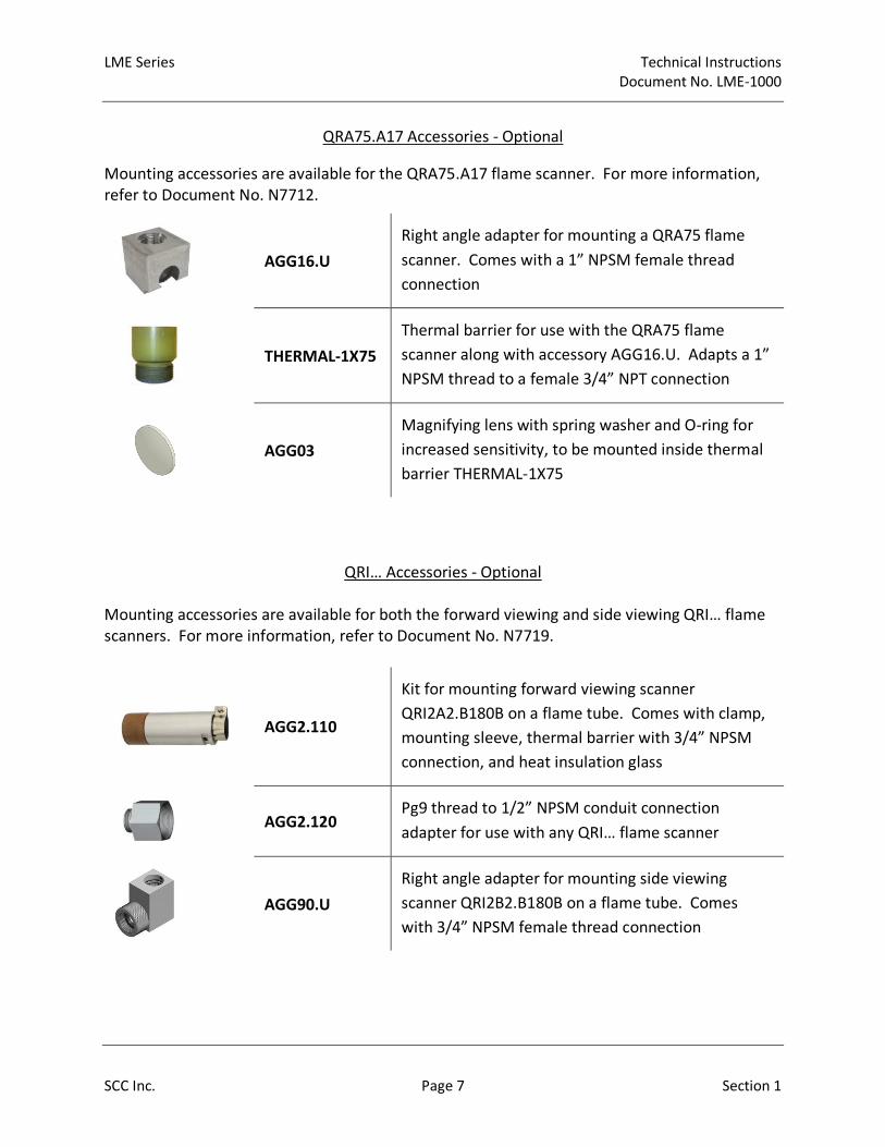
QRA75.A17 Accessories - Optional
Mounting accessories are available for the QRA75.A17 flame scanner. For more information,
refer to Document No. N7712.
AGG16.U
Right angle adapter for mounting a QRA75 flame
scanner. Comes with a 1” NPSM female thread
connection
THERMAL-1X75
Thermal barrier for use with the QRA75 flame
scanner along with accessory AGG16.U. Adapts a 1”
NPSM thread to a female 3/4” NPT connection
AGG03
Magnifying lens with spring washer and O-ring for
increased sensitivity, to be mounted inside thermal
barrier THERMAL-1X75
QRI… Accessories - Optional
Mounting accessories are available for both the forward viewing and side viewing QRI… flame
scanners. For more information, refer to Document No. N7719.
AGG2.110
Kit for mounting forward viewing scanner
QRI2A2.B180B on a flame tube. Comes with clamp,
mounting sleeve, thermal barrier with 3/4” NPSM
connection, and heat insulation glass
AGG2.120
Pg9 thread to 1/2” NPSM conduit connection
adapter for use with any QRI… flame scanner
AGG90.U
Right angle adapter for mounting side viewing
scanner QRI2B2.B180B on a flame tube. Comes
with 3/4” NPSM female thread connection

Technical Instructions LME Series
Document No. LME-1000
Section 1 Page 8 SCC Inc.
Additional Flame Scanner Accessories – Optional
Additional accessories are available for flame scanners to prevent heat from getting to the
scanner. For more information, refer to Document No. N7711 and Document No. N7712.
THERMAL-
75X75
Thermal barrier for use with the QRA4.U flame
scanner, and QRI2B2.B180B flame scanner when
used with right angle adapter AGG90.U. Adapts a
3/4” NPSM thread to a female 3/4” NPT connection.
Rated for scanner tube temperatures up to 250 °F
AGG02
Heat insulating lens with spring washer and O-ring,
for applications where the temperature at the
scanner will exceed 176 °F. Can be mounted inside
thermal barriers THERMAL-75X75 or THERMAL-1X75
ACS410 Software for Laptop
The ACS410 software for the LME7 offers many features including parameter backups, startup
reports, and trending. The software may be downloaded at www.scccombustion.com.
ACS410 Cables – Qty (1) Required if Using the ACS410 Software
To use the ACS410 software, cables are necessary to connect the LME7 to a PC.
OCI410.20
User-level PC interface module and cable. Permits
access to user level parameters only without the
ability to perform parameter backups
OCI410.30
Service-level PC interface module and cable. Permits
access to user and service level parameters only
without the ability to perform parameter backups
OCI410.40
OEM-level PC interface module and cable. Permits
access to all parameters and the ability to perform
parameter backups

LME Series Technical Instructions
Document No. LME-1000
SCC Inc. Page 9 Section 1
Enclosures
Enclosures - Optional
A small NEMA 1 enclosure is available for use with any LME7… base unit. Three ½” conduit
knockouts are available on both the top and the bottom of the enclosure.
LME7-ENC-KT NEMA 1 enclosure for any LME7… base unit
Trainers
Trainers - Optional
Training units are available to train OEMs and field technicians how to program and use the
various features of the LME75 burner control.
TR-L75-1A LME75 training unit, 110 VAC

Technical Instructions LME Series
Document No. LME-1000
Section 1 Page 10 SCC Inc.
Mounting
LME7 Controller
The LME7 must be mounted inside an enclosure that will protect it from dirt and moisture. The
unit should be mounted with three #8 screws (not provided). The panel, which the unit sits on,
should be drilled and tapped to accommodate these screws.
During the mounting process, consideration should be given to the various plugs and wires that
must be attached to the LME7. Electrical connections are made via plugs that are located in the
face of the unit with wires coming out to the top, left side, and right side of the unit. A space of
at least one inch is recommended above, to the left, and to the right of the LME7. The
recommended total space to leave for the LME7 is 8” x 6.75” x 3” because the overall
dimensions of the LME7 are 7.09” x 4.72” x 2.07”.
Figure 1-2: LME7 Dimensions (inches)

LME Series Technical Instructions
Document No. LME-1000
SCC Inc. Page 11 Section 1
AZL23 Display
The AZL23 is designed to be mounted in a rectangular cutout through the face / door of an
electrical enclosure. It has one screw on the top and another on the bottom that engage small
plastic tabs which will swing out when the screw is tightened clockwise; the screw can be
loosened to retract the tab and increase clearance before tightening. The tab will pinch the
sheet metal of the enclosure door between itself and the AZL23 gasket. This facilitates easy
removal and replacement of the AZL23 since it is designed to be taken out of the enclosure face
and held in the hands for setup and commissioning.
The AZL23 connects to the LME7 at terminal X56 with cable TDCCOMBO. The AZL23 has an
IP54 rating when mounted in an electrical enclosure.
Figure 1-3: AZL23 Dimensions (inches)

Technical Instructions LME Series
Document No. LME-1000
Section 1 Page 12 SCC Inc.
Important Safety Notes
The LME7 is a safety device. Under no circumstances should the unit be modified or
opened. SCC Inc. will not assume responsibility for damage resulting from unauthorized
modification of the unit.
All activities (mounting, installation, service work, etc.) must be performed by qualified
staff.
Before performing any work in the connection area of the LME7, disconnect the unit
from the main supply (all-polar disconnection).
Protection against electrical shock hazard on the LME7 and all other connected
electrical components must be ensured through good wiring and grounding practices.
Fall or shock can adversely affect the safety functions of an LME7. Such units must not
be put into operation, even if they do not exhibit any apparent damage.
Condensation and the entry of water into the unit must be avoided.

LME Series Technical Instructions
Document No. LME-1000
SCC Inc. Page 13 Section 1
Approvals
The LME7 has the following standards and approvals:

Technical Instructions LME Series
Document No. LME-1000
Section 1 Page 14 SCC Inc.
Intentionally Left Blank

Section 1 Overview
Section 2 LME71 Wiring,
Parameters, and
Phase Diagrams
Section 3 LME73 Wiring, Parameters,
and Phase Diagrams
Section 4 LME75 Wiring, Parameters,
and Phase Diagrams
Section 5 Commissioning
Section 6 PWM Blowers
Section 7 Troubleshooting
Section 8 Modbus
Section 9 ACS410
Appendix A Application Guide

LME Series Technical Instructions
LME-1000
SCC Inc. Page 1 Section 2
LME71 Wiring Diagrams
The following three pages show the wiring diagrams for the different PME71… program
modules used with the LME71… burner control. All common line, neutral, and ground
terminals are not shown on the wiring diagrams and are instead listed below.
Line terminals for all PME71… program modules:
X2-02.3 (sourced from safety loop input X3-04.1)
X3-02.2
X5-01.3
X5-03.4
X6-03.3 (sourced from safety loop input X3-04.1)
X9-04.3
X10-05.5
Neutral terminals for all PME71… program modules:
X2-01.2
X2-02.2
X2-03.2
X4-02.2
X6-03.2
X7-01.2
X7-04.2
Ground (PE) terminals for all PME71… program modules:
X2-01.1
X2-02.1
X4-02.1
X5-01.1
X6-03.1
X7-01.1
X7-04.1
X9-04.1
X10-05.4

Technical Instructions LME Series
Document No. LME-1000
Section 2 Page 2 SCC Inc.
PME71.111A1 – Pilot or direct spark; with purge; no actuator control; no valve proving

LME Series Technical Instructions
LME-1000
SCC Inc. Page 3 Section 2
PME71.112A1 – Pilot or direct spark; no purge; no actuator control; no valve proving

Technical Instructions LME Series
Document No. LME-1000
Section 2 Page 4 SCC Inc.
PME71.901A1 – PWM blower control; direct spark only; valve proving; no actuator control

LME Series LME71 Parameter List Technical Instructions
LME-1000
PW Level Default Range Description
041 Service Level PW 7173 Any 4 charactersThe service level password can be changed here. It must be exactly 4 characters in length. Enter the
current password, then enter the new password twice to change it (c = current, n = new, r = repeat).• • •
042 OEM Level PW L7unI Any 5 charactersThe OEM level password can be changed here. It must be exactly 5 characters in length. Enter the current
password, then enter the new password twice to change it (c = current, n = new, r = repeat).• • •
060 Backup / Restore SBackup - 0
Restore - 00-1
Used to perform parameter backups and restores.
Backup: Transfer LME7 parameters to PME7. Restore: Transfer PME7 parameters to LME7.
Set parameter to 1 and press the info button to begin the backup or restore. Once a parameter backup is
successful, the screen will display "bAC End". Once a parameter restore is successful, the screen will
display "rSt End".
• • •
101 LME7 Part Number ACS410 Displays the part number of the LME7 burner control being used. • • •
102 Production Date Date that the LME7 was produced in the DD.MM.YY format. • • •
103 Serial Number Serial number of the LME7. • • •
113 Burner ID Not set 0-99999999
The burner ID can be viewed through the AZL23 but can only be set using the ACS410 software with the
OCI410.40 OEM cable. The burner ID must be all digits (no letters), from 1-8 digits in length. Typically the
burner serial number is used. This serves as an identifier for the parameter set. The burner ID must be set
in order to perform a parameter backup to a PC using the ACS410 software. Parameter backups to the
PME7 program module can be made without setting the burner ID.
• • •
119LME7 Part Number
OEM
Displays the OEM part number of the LME7 burner control being used. Will be the same as parameter
101.• • •
120 PME7 Part Number Displays the part number of the PME7 program module being used. • • •
140 Display Mode S
111 - 1
112 - 1
901 - 4
1-4
Sets what will be displayed by the LME7 integral display.
1 = phase
2 = flame signal (QRA… flame scanner or flame rod)
3 = not used
4 = load
• • •
164 Startups
Displays the total number of startups. To reset this value, press and hold the info button until the value
begins to flash, then let go. The value will automatically change to 0. Press the info button again to
confirm the reset.
• • •
166 Total Startups Displays the total number of startups. Not resettable. • • •
170 Number of Relay Cycles
Displays the number of cycles on different internal relays in the LME7.
Index 00 = K12 relay cycles
Index 01 = K11 relay cycles
Index 02 = K2 relay cycles
Index 03 = K1 relay cycles
• • •
171 Max Relay Cycles Displays the maximum number of relay cycles allowed on the internal relays of the LME7. • • •
Read only
ACS410 Read only
Parameter
Number
PME71.
111A1
PME71.
112A1
PME71.
901A1
000 Level: Parameter Backup / Restore / Change Passwords
100 Level: General Information / Display Mode
LEGEND - Password Level: S = Service O = OEM S/O = View - Service, Write - OEM Info = Info Menu Ser = Service Menu ACS410 = ACS410 only
Shaded Parameters = Frequently Used
O
Parameter Name
Reset only
Info
Read only
Info
SCC Inc. Page 5 Section 2

LME Series Technical Instructions
LME-1000
PW Level Default Range Description
Parameter
Number
PME71.
111A1
PME71.
112A1
PME71.
901A1
LEGEND - Password Level: S = Service O = OEM S/O = View - Service, Write - OEM Info = Info Menu Ser = Service Menu ACS410 = ACS410 only
Shaded Parameters = Frequently UsedParameter Name
224Time Air Pressure
Switch13.818 sec 0-13.818 sec
Once the LME7 reaches phase 22 for the second time (between phases 24 and 30), this sets the length of
time the LME7 will wait for air pressure switch input X3-02.1 to become energized before a lockout occurs
due to lack of air pressure. As soon as the switch is made, the sequence progresses.
•
225 Prepurge Time111 - 29.106 sec
901 - 19.404 sec0-1237 sec
Sets the prepurge time (length of phase 30). The LME7 has a base prepurge time of 2.1 seconds. This
setting adds seconds to the base time.• •
226 Pre-Ignition Time 3.087 sec 1.029-37.485 secThe period of time that the ignition transformer (output X4-02.3) is energized before the main valves are
opened. Sets the length of phase 38.•
230Pilot / Main
Stabilization Time
111 - 3.234 sec
112 - 3.234 sec
901 - 15.582 sec
3.234-74.97 sec
On PME71.111A1 and PME71.112A1, this setting defines the pilot stabilizing period if a pilot is used.
During this period, only the pilot valve is open. The spark is de-energized.
On PME71.901A1, this setting defines the main stabilizing period. During this time, only the main valves
are open. The spark is de-energized. Sets the length of phase 44.
• • •
231Pilot and Main Overlap
Time9.996 sec 0-74.97 sec
When a fuel train with a pilot is used, this setting defines the overlap of the pilot (output X7-01.3) and the
main fuel valves (output X7-04.4). After this time expires, the pilot is de-energized. Sets the length of
phase 50.
• •
234 Postpurge Time111 - 19.404 sec
901 - 4.851 sec0-1237 sec Sets the postpurge time (length of phase 74). • •
235 Air Pressure Switch 0 0-1
This setting activates or deactivates the air pressure switch input X3-02.1.
0 = deactivated
1 = activated
•
237 POC Switch S 1 0-2
This setting defines the function of POC switch input X2-02.4.
0 = deactivated
1 = activated (verify POC switch is closed on startup and shutdown)
2 = activated (verify POC switch is closed on startup and shutdown, and open during operation)
• •
239 Forced Intermittent 0 0-1
When activated, this forces the LME7 to shut the burner down every 24 hours of uninterrupted operation.
The burner will automatically restart afterwards. The purpose of the shutdown is to check and cycle safety
devices. The PME71.901A1 will recycle every 24 hours.
0 = deactivated
1 = activated
• •
240
or
240.00
Repetition Flame
During Operation0 0-2
This sets the numbers of times a flame failure must occur during operation before causing a lockout. Most
North American codes require 1.
0 = no repetitions
1 = no repetitions
2 = 1 repetition
• • •
240.01
Repetition Flame
During Main Trial for
Ignition
0 0-4
This sets the numbers of times a flame failure must occur during main trial for ignition before causing a
lockout. Most North American codes require 1.
0 = no repetitions
1 = no repetitions
2 = 1 repetition
3 = 2 repetitions
4 = 3 repetitions
•
S/O
200 Level: Burner Control
S/O
SCC Inc. Page 6 Section 2

LME Series Technical Instructions
LME-1000
PW Level Default Range Description
Parameter
Number
PME71.
111A1
PME71.
112A1
PME71.
901A1
LEGEND - Password Level: S = Service O = OEM S/O = View - Service, Write - OEM Info = Info Menu Ser = Service Menu ACS410 = ACS410 only
Shaded Parameters = Frequently UsedParameter Name
241.00Valve Proving
Activation0 0-1
This setting determines if gas valve proving (leak testing) will be performed. Gas valve proving can be
performed on startup, shutdown, or both depending on the settings of parameters 241.01 and 241.02.
0 = deactivated
1 = activated
•
241.01 Valve Proving Setup 1 1 0-1
Determines at which point during the burner's sequence that valve proving will be performed. Used in
conjunction with parameter 241.02.
0 = valve proving on startup
1 = valve proving on shutdown
•
241.02 Valve Proving Setup 2 0 0-1
Determines at which point during the burner's sequence that valve proving will be performed. Used in
conjunction with parameter 241.01.
0 = valve proving according to parameter 241.01
1 = valve proving on startup and shutdown
•
242 VP Evacuation Time 2.646 sec 0-2.646 sec
If valve proving is performed, this specifies the length of time that the downstream valve (V2) is energized
(output X7-01.3). This will evacuate any gas that might exist between the gas valves. Sets the length of
phase 80.
•
243 VP Upstream Test 10.290 sec 1.029-37.485 sec
If valve proving is performed, this specifies the length of time that both the upstream and downstream
valves are closed. If the pressure between the valves rises during this period (enough to open the NC valve
proving pressure switch), then the upstream valve is leaking and the LME7 will lockout. A longer time
period will produce a more sensitive test. Sets the length of phase 81.
•
244 VP Fill Time 2.646 sec 0-2.646 sec
If valve proving is performed, this specifies the length of time that the upstream valve (V1) is energized
(output X7-04.4). This will fill the volume between the main gas valves to line pressure. Sets the length of
phase 82.
•
245 VP Downstream Test 10.290 sec 1.029-37.485 sec
If valve proving is performed, this specifies the length of time that both the upstream and downstream
valves are closed. If the pressure between the valves falls during this period (enough to close the NC valve
proving pressure switch), then the downstream valve is leaking and the LME7 will lockout. A longer time
period will produce a more sensitive test. Sets the length of phase 83.
•
247 Intermittent Pilot 0 0-1
Sets the type of pilot being used. If set to 1, the pilot valve will remain open from phase 40 to the end of
main operation (oP1).
0 = interrupted pilot
1 = intermittent pilot
• •
254
Flame Failure Response
Time
(FFRT)
1 0-1
Sets the flame failure response time (FFRT). The FFRT is the maximum length of time that the flame signal
can go away before a lockout occurs. This setting also doubles as the length of time the signal from the air
pressure switch can go away before a lockout occurs. On PME71.901A1, the FFRT is fixed at 1 second.
0 = 1 second
1 = 3 seconds
• •
257 Trial for Ignition
111 - 4.116 sec
112 - 4.116 sec
901 - 2.205 sec
0-13.23 sec
On PME71.111A1 and PME71.112A1, this setting defines the overlap of the spark (output X4-02.3) and the
pilot valve (output X7-01.3) if a pilot is used.
On PME71.901A1, this setting defines the overlap of the spark (output X4-02.3) and the main valves.
After this time expires, the spark is de-energized. The LME7 has a base time of 0.3 seconds. This setting
adds seconds to the base time. Sets the length of phase 40.
• • •
S/O
SCC Inc. Page 7 Section 2

LME Series Technical Instructions
LME-1000
PW Level Default Range Description
Parameter
Number
PME71.
111A1
PME71.
112A1
PME71.
901A1
LEGEND - Password Level: S = Service O = OEM S/O = View - Service, Write - OEM Info = Info Menu Ser = Service Menu ACS410 = ACS410 only
Shaded Parameters = Frequently UsedParameter Name
P0
403.00Ignition Speed 3000 RPM 800-9000 RPM
Sets the PWM blower speed during ignition. See Section 6 (PWM Blowers) for more information on
setting this value.•
P1
403.01Low Fire Speed 1200 RPM 400-9000 RPM
Sets the PWM blower speed at low fire. See Section 6 (PWM Blowers) for more information on setting this
value.•
P2
403.02High Fire Speed 5700 RPM 800-9000 RPM
Sets the PWM blower speed at high fire. See Section 6 (PWM Blowers) for more information on setting
this value.•
503.00 Standby Blower Speed 0 RPM 0-9000 RPM Sets the PWM blower speed when the burner is in standby (off). •
503.01Prepurge / Postpurge
Blower Speed5700 RPM 800-9000 RPM Sets the PWM blower speed during prepurge and postpurge. •
516.00Minimum Ignition
Speed800 RPM 800-9000 RPM
Sets the minimum allowable PWM blower speed during ignition (P0). This should be set to the minimum
blower speed at which the burner can still be safely ignited.•
516.01Maximum Ignition
Speed9000 RPM 800-9000 RPM
Sets the maximum allowable PWM blower speed during ignition (P0). This should be set to the maximum
blower speed at which the burner can still be safely ignited.•
517.00Minimum Low Fire
Speed400 RPM 400-9000 RPM
Sets the minimum allowable PWM blower speed when the burner is at low fire (P1). This should be set to
the minimum blower speed at which the burner can still be safely operated at low fire.•
517.01Maximum Low Fire
Speed9000 RPM 800-9000 RPM
Sets the maximum allowable PWM blower speed when the burner is at low fire (P1). This should be set to
the maximum blower speed at which the burner can still be safely operated at low fire.•
518.00Minimum High Fire
Speed800 RPM 800-9000 RPM
Sets the minimum allowable PWM blower speed when the burner is at high fire (P2). This should be set to
the minimum blower speed at which the burner can still be safely operated at high fire.•
518.01Maximum High Fire
Speed9000 RPM 800-9000 RPM
Sets the maximum allowable PWM blower speed when the burner is at high fire (P2). This should be set to
the maximum blower speed at which the burner can still be safely operated at high fire.•
519Maximum Blower
Speed5830 RPM 3000-9000 RPM
Sets the maximum blower speed according to the PWM blower manufacturer. This value is used to
calculate blower speed percentages.•
522 Ramp Up PWM Blower 14.994 sec 2.058-74.97 sec
This sets the speed that the PWM blower ramps up. This setting is active during operation as well as
driving to special positions (standby, prepurge, ignition, postpurge). Large blowers typically require a
longer ramp up.
•
523Ramp Down PWM
Blower14.994 sec 2.058-74.97 sec
This sets the speed that the PWM blower ramps down. This setting is active during operation as well as
driving to special positions (standby, prepurge, ignition, postpurge). Large blowers typically require a
longer ramp down.
•
S/O
S
500 Level: Special Positions / Modulation Ramps / Blower Speed Limits
400 Level: Blower Speeds
S
SCC Inc. Page 8 Section 2

LME Series Technical Instructions
LME-1000
PW Level Default Range Description
Parameter
Number
PME71.
111A1
PME71.
112A1
PME71.
901A1
LEGEND - Password Level: S = Service O = OEM S/O = View - Service, Write - OEM Info = Info Menu Ser = Service Menu ACS410 = ACS410 only
Shaded Parameters = Frequently UsedParameter Name
558 UDS Mode
This parameter is for Siemens use only.
0 = PC tool mode
1 = PWM mode
2 = actuator mode
3 = internally
4 = internally
5 = internally
•
559 Speed Control Mode 1 0-2
This setting activates or deactivates the internal PID control in the LME7. If using a PWM blower that has
its own internal speed control, this should be deactivated.
0 = deactivated
1 = activated
2 = test mode
•
560 Ratio Control Mode
Defines the device being controlled by the LME7 that is used to influence the amount of air to the burner.
This value is set by Siemens and cannot be modified. On PME71.901A1, this value should always be set to
1.
0 = none
1 = PWM blower
2 = actuator
•
644 Feedback Pulse / Rev 3 2-5This sets the expected number of pulses per revolution being output from the PWM blower. This
information should be provided by the blower manufacturer.•
646 Settling Time 2.058 sec 1.029-2.058 secThe blower speed must lie within tolerance band 1 for this length of time before the target speed is
considered reached.•
650.00 Tolerance Band 1 +/- 1% +/- 1-5%
Sets an inner tolerance band for blower speed control. Percentages are based on the maximum blower
speed (parameter 519). If the actual blower speed falls outside tolerance band 1 for longer than the time
set by parameter 660, a lockout occurs.
•
650.01 Tolerance Band 2 +/- 3% +/- 1-10%
Sets an outer tolerance band for blower speed control. Percentages are based on the maximum blower
speed (parameter 519). If the actual blower speed falls outside tolerance band 2, a lockout occurs
immediately.
•
654 Analog Input S 1 0-5
Sets the type of input signal being connected to terminal X65 or X5-03. This input signal is used to
determine the blower speed during operation.
0 = 3-position
1 = 0-10 VDC
2 = 0-135 Ohm
3 = 0-20 mA
4 = 4-20 mA with lockout when input is less than 4 mA
5 = 4-20 mA without lockout when input is less than 4 mA
•
658.00 PWM Startup S/O 25% 1-100%Sets the minimum PWM signal that the blower needs to receive in order to start the blower from
standstill. This information should be provided by the blower manufacturer.•
S/O
S/O
600 Level: PWM Blower Configuration
Read only
Read only
SCC Inc. Page 9 Section 2
LME Series Technical Instructions
LME-1000
PW Level Default Range Description
Parameter
Number
PME71.
111A1
PME71.
112A1
PME71.
901A1
LEGEND - Password Level: S = Service O = OEM S/O = View - Service, Write - OEM Info = Info Menu Ser = Service Menu ACS410 = ACS410 only
Shaded Parameters = Frequently UsedParameter Name
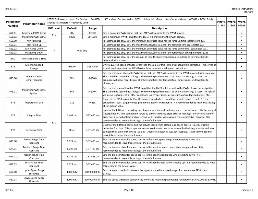
658.01 Minimum PWM Signal 0% 0-20% Sets a minimum PWM signal that the LME7 will transmit to the PWM blower. •
658.02 Maximum PWM Signal 100% 80-100% Sets a maximum PWM signal that the LME7 will transmit to the PWM blower. •
659.00 Min Ramp Up For Siemens use only. Sets the minimum allowable value for the ramp up time (parameter 522). •
659.01 Max Ramp Up For Siemens use only. Sets the maximum allowable value for the ramp up time (parameter 522). •
659.02 Min Ramp Down For Siemens use only. Sets the minimum allowable value for the ramp down time (parameter 523). •
659.03 Max Ramp Down For Siemens use only. Sets the maximum allowable value for the ramp down time (parameter 523). •
660 Tolerance Band 1 TimeFor Siemens use only. Sets the amount of time the blower speed can lie outside of tolerance band 1
before a lockout occurs.•
674Minimum Speed
Change40 RPM 0-255 RPM
Only requested speed changes larger than the value of this setting will actually be corrected. This serves as
a dead band to protect the PWM blower from constant small speed oscillations.•
675.00Minimum PWM
Signal Prepurge86% 0-100%
Sets the minimum allowable PWM signal that the LME7 will transmit to the PWM blower during prepurge.
This should be set so that as long as the blower speed remains at or above this setting, a successful
prepurge will occur regardless of all other conditions (air temperature, air pressure, undervoltage to
blower, etc.)
•
675.01Maximum PWM Signal
Ignition34% 0-100%
Sets the maximum allowable PWM signal that the LME7 will transmit to the PWM blower during ignition.
This should be set so that as long as the blower speed remains at or below this setting, a successful lightoff
will occur regardless of all other conditions (air temperature, air pressure, overvoltage to blower, etc.)
•
676 Proportional Gain 112 0-255
P-part of the PID loop controlling the blower speed when closed-loop speed control is used. P is the
proportional gain. Larger values give a more aggressive response. It is recommended to leave this setting
at the default value.
•
677 Integral Time 0.441 sec 0-37.485 sec
I-part of the PID loop controlling the blower speed when closed-loop speed control is used. I is the integral
(reset) function. This component serves to eliminate steady-state error by looking at the accumuation of
error over a period of time and correcting for it. Smaller values give a more aggressive response. It is
recommended to leave this setting at the default value.
•
678 Derivative Time 0 sec 0-37.485 sec
D-part of the PID loop controlling the blower speed when closed-loop speed control is used. D is the
derivative function. This component serves to eliminate overshoot caused by the integral value, and also
dampen the action of the P and I values. Smaller values give a weaker response. It is recommended to
leave this setting at the default value.
•
679.00Lower Range Time
Constant6.027 sec 0-37.485 sec
Sets the time constant for speed control in the lower speed range when ramping down. It is
recommended to leave this setting at the default value.•
679.01Medium Range Time
Constant6.027 sec 0-37.485 sec
Sets the time constant for speed control in the medium speed range when ramping down. It is
recommended to leave this setting at the default value.•
679.02Upper Range Time
Constant6.027 sec 0-37.485 sec
Sets the time constant for speed control in the upper speed range when ramping down. It is
recommended to leave this setting at the default value.•
679.03Total Range Time
Constant6.027 sec 0-37.485 sec
Sets the time constant for speed control in all speed ranges when ramping up. It is recommended to leave
this setting at the default value.•
680.00Upper Speed Range
Threshold4000 RPM 800-9000 RPM
Sets the speed threshold between the upper and medium speed ranges for parameters 679.01 and
679.02.•
680.01Lower Speed Range
Threshold2000 RPM 800-9000 RPM Sets the speed threshold between the lower and medium speed ranges for parameters 679.00 and 679.01. •
S/O
Read onlyS
S/O
SCC Inc. Page 10 Section 2

LME Series Technical Instructions
LME-1000
PW Level Default Range Description
Parameter
Number
PME71.
111A1
PME71.
112A1
PME71.
901A1
LEGEND - Password Level: S = Service O = OEM S/O = View - Service, Write - OEM Info = Info Menu Ser = Service Menu ACS410 = ACS410 only
Shaded Parameters = Frequently UsedParameter Name
701-711 Fault History Ser
Shows the current status (fault) along with the 10 most recent faults. 701 = current status, 702 = most
recent fault, 703 = next most recent fault, etc. Each fault has indices that provide additional information
about the fault:
Index 00 = fault code
Index 01 = start number
Index 02 = phase
Index 03 = load
• • •
903 Current Output / StageDisplays the current firing rate on a PME71.901A1. This will display "first stage" during main operation and
"----" during all other phases on PME71.111A1 and PME71.112A1.• • •
908 Target Speed %Displays the real time target speed of the PWM blower as a percentage of the maximum blower speed
(parameter 519). Will always display as a "-" on PME71.111A1 and PME71.112A1.• • •
920 Actual PWM Output Ser
Displays the real time PWM output to the blower as a percentage of the maximum blower speed
(parameter 519). Will always display as a "-" on PME71.111A1 and PME71.112A1. For example, if the
actual speed (936) is below the target speed (908), the actual PWM output will increase above the target
speed in an attempt to speed up the blower to achieve the target speed.
• • •
922Actual Actuator
PositionDisplays as "----" for all PME71… program modules. • • •
923Target Actuator
PositionDisplays as "----" for all PME71… program modules. • • •
935 Actual Speed RPMDisplays the real time actual speed of the PWM blower in RPM. Will always display as a "----" on
PME71.111A1 and PME71.112A1.• • •
936 Actual Speed % SerDisplays the real time actual speed of the PWM blower as a percentage of the maximum blower speed
(parameter 519). Will always display as a "-" on PME71.111A1 and PME71.112A1.• • •
944 Analog Input % ACS410Displays the real time analog input signal on terminal X65 as a percentage from 0-100%. Will always
display as a "----" on PME71.111A1 and PME71.112A1.• • •
951 Mains Voltage AZL Displays the real time mains voltage. Measured at terminal X3-04 pin 4 (neutral) and pin 5 (line). • • •
954 Flame Signal AZL
Displays the raw flame signal from 0-100% for any flame sensor type. A flame failure occurs when the
flame signal drops below 20% for the time period specified by parameter 254. This signal refers to input
terminal X10-06 (UV scanners) or input terminal X10-05.2 (flame rods).
• • •
961 Actual Phase Displays the real time phase of the LME7. • • •
3007 Flame Signal 1 StatusDisplays the status of the flame rod input X10-05.2. A value of 1 indicates a valid flame signal is present,
and a value of 0 indicates that no valid flame signal is present.• • •
3008 Flame Signal 2 StatusDisplays the status of UV flame scanner input X10-06. A value of 1 indicates a valid flame signal is present,
and a value of 0 indicates that no valid flame signal is present.• •
3033 BlowerDisplays the status of blower output X2-01.3. A value of 1 indicates the output is energized, and a value of
0 indicates the output is de-energized.• •
3034 IgnitionDisplays the status of ignition transformer output X4-02.3. A value of 1 indicates the output is energized,
and a value of 0 indicates the output is de-energized.• • •
ACS410
ACS410
Ser
ACS410
Read only
Read only
700 Level: Fault History
900 Level: Operational Data
SCC Inc. Page 11 Section 2

LME Series Technical Instructions
LME-1000
PW Level Default Range Description
Parameter
Number
PME71.
111A1
PME71.
112A1
PME71.
901A1
LEGEND - Password Level: S = Service O = OEM S/O = View - Service, Write - OEM Info = Info Menu Ser = Service Menu ACS410 = ACS410 only
Shaded Parameters = Frequently UsedParameter Name
3035 Safety ValveDisplays the status of safety valve output X6-03.3. A value of 1 indicates the output is energized, and a
value of 0 indicates the output is de-energized.• • •
3036 Main Valve V1Displays the status of main valve V1 output X7-04.3. A value of 1 indicates the output is energized, and a
value of 0 indicates the output is de-energized.• • •
3037 Main Valve V2Displays the status of main valve V2 output X7-01.3. A value of 1 indicates the output is energized, and a
value of 0 indicates the output is de-energized.•
3039 Pilot ValveDisplays the status of pilot valve output X7-01.3. A value of 1 indicates the output is energized, and a value
of 0 indicates the output is de-energized.• •
3088 ResetDisplays the status of the info button on the LME7. When the info button is pressed, this value is a 1, and
when the info button is not pressed, this value is a 0.• • •
3089 Remote ResetDisplays the status of remote reset input X2-03.1. A value of 1 indicates the input is energized, and a value
of 0 indicates the input is de-energized.• • •
3090Air Pressure Switch
Status
Displays the status of air pressure switch input X3-02.1. A value of 1 indicates the input is energized, and a
value of 0 indicates the input is de-energized.• •
3091 Gas Pressure SwitchesDisplays the status of gas pressure switch input X5-01.2. A value of 1 indicates the input is energized, and
a value of 0 indicates the input is de-energized.• • •
3092 Burner EnableDisplays the status of burner enable input X5-03.1. A value of 1 indicates the input is energized, and a
value of 0 indicates the input is de-energized.• • •
3133 AlarmDisplays the status of alarm output X2-03.3. A value of 1 indicates the output is energized, and a value of 0
indicates the output is de-energized.• • •
3303 Mains Voltage ACS410 Displays the real time mains voltage. Measured at terminal X3-04 pin 4 (neutral) and pin 5 (line). • • •
3307 Flame Signal 1 ACS410 Displays the flame signal strength (%) from a flame rod on terminal X10-05.2. • • •
3308 Flame Signal 2 ACS410 Displays the flame signal strength (%) from a UV flame scanner on terminal X10-06. • •
ACS410 Read only
SCC Inc. Page 12 Section 2

LME Series Technical Instructions
LME-1000
SCC Inc. Page 13 Section 2
LME71 Phase Diagrams
The Siemens LME7 burner controls can perform a number of different burner sequences based
upon which PME7 program module is used, how certain parameters are set, and how the LME7
is wired.
Each program module has an associated phase diagram. The phase diagrams illustrate when
input and output terminals are expected to be energized or de-energized. A legend on the
bottom of each page describes the various symbols used in the diagrams.
Notes:
1) A jumper can be added between terminals X7-04.4 and X7-01.3 for direct spark ignition.
If this jumper is added, main valve output X7-04.4 and pilot valve output X7-01.3 will be
energized from phase 40 through the end of operation (oP1).
2) If the LME7 is set to perform valve proving on startup, valve proving takes place at the
same time as prepurge. Phases 80-83 will be displayed on the LME7 and the AZL23 even
though prepurge (phase 30) is also occurring at the same time. The actual prepurge time
will be at least the sum of all four valve proving time parameters (242, 243, 244, 245).
3) If the LME7 is set to perform valve proving on shutdown, valve proving takes place at the
same time as postpurge. Phases 80-83 will be displayed on the LME7 and the AZL23 even
though postpurge (phase 74) is also occurring at the same time. The actual postpurge
time will be at least the sum of all four valve proving time parameters (242, 243, 244,
245).

LME Series Technical Instructions
LME-1000
Lock
ou
t
Sta
nd
by
, Wa
iting
for C
all
for H
ea
t
Te
st - Air P
ressu
re S
witch
Op
en
Blo
we
r On
Pre
pu
rge
Tria
l for Ig
nitio
n
Fla
me
De
tectio
n
Inte
rva
l 1: P
ilot
Sta
biliza
tion
Sa
fety
Tim
e 2
: Ma
in a
nd
Pilo
t Ov
erla
p
Inte
rva
l 2: M
ain
Sta
biliza
tion
Op
era
tion
Po
stpu
rge
Ho
me
Ru
n
Phase LOC OFF 21 22 30 40 42 44 50 50 oP1 74 10
Param. 225 257 230 231 254 240 234
OPER-
ATION
Terminal Description Notes
X3-04.5 Main Voltage
X3-04.1 Safety Loop X X X
X5-03.1 Burner On M
X3-02.1 Air Pressure Switch X M
X5-01.2 Gas Pressure Switch(es)
POC (P237 = 1)
POC (P237 = 2) X
X2-02.3 POC Source X X X
X6-03.3 Safety Valve X X X
X2-01.3 Blower X X X X
X4-02.3 Ignition Transformer X X X X X X X X X X X X
X7-04.4 Main Valve V1 Note 1 X X X X X X X X X X
X2-03.3 Alarm X X X X X X X X X X X X
Pilot Valve (P247 = 0) Note 1 X X X X X X X X X
Pilot Valve (P247 = 1) X X X X X X X
Legend : Energized M
Energized or de-energized
X De-energized
INP
UT
SO
UT
PU
TS
X XX10-05.2
X10-06.1/2
Must be energized by end of phase
X2-02.4
X7-01.3
PME71.111A1 Phase Diagram
SHUTDOWN
SAFETY
TIME 1
STARTUP
Flame Signal
SCC Inc. Page 14 Section 2

LME Series Technical Instructions
LME-1000
Lock
ou
t
Sta
nd
by
, Wa
iting
for C
all
for H
ea
t
Te
st - PO
C C
lose
d
Blo
we
r On
Tria
l for Ig
nitio
n
Fla
me
De
tectio
n
Inte
rva
l 1: P
ilot
Sta
biliza
tion
Sa
fety
Tim
e 2
: Ma
in a
nd
Pilo
t Ov
erla
p
Inte
rva
l 2: M
ain
Sta
biliza
tion
Op
era
tion
Ho
me
Ru
n
Phase LOC OFF 21 22 40 42 44 50 50 oP1 10
Param. 257 230 231 254 240
OPER-
ATION SHUTDOWN
Terminal Description Notes
X3-04.5 Main Voltage
X3-04.1 Safety Loop X X X
X5-03.1 Burner On M
X5-01.2 Gas Pressure Switch(es)
POC (P237 = 1)
POC (P237 = 2) X
X2-02.3 POC Source X X X
X6-03.3 Safety Valve X X X
X2-01.3 Blower X X X X
X4-02.3 Ignition Transformer X X X X X X X X X X
X7-04.4 Main Valve V1 Note 1 X X X X X X X X
X2-03.3 Alarm X X X X X X X X X X
Pilot Valve (P247 = 0) Note 1 X X X X X X X
Pilot Valve (P247 = 1) X X X X X
Legend : Energized M
Energized or de-energized
X De-energized
Must be energized by end of phase
X2-02.4
X7-01.3
INP
UT
SO
UT
PU
TS
X X
PME71.112A1 Phase Diagram
SAFETY
TIME 1
STARTUP
Flame Signal XX10-05.2
X10-06.1/2
SCC Inc. Page 15 Section 2

LME Series Technical Instructions
LME-1000
Lock
ou
t
Sta
nd
by
, Wa
iting
for C
all
for H
ea
t
Te
st - Air P
ressu
re S
witch
Op
en
Blo
we
r On
Driv
e to
Pre
pu
rge
Sp
ee
d
Te
st - Air P
ressu
re S
witch
Clo
sed
Pre
pu
rge
(No
te 2
)
Driv
e to
Ign
ition
Sp
ee
d
Pre
ign
ition
Tria
l for Ig
nitio
n
Fla
me
De
tectio
n
Inte
rva
l: Ma
in
Sta
biliza
tion
Op
era
tion
Driv
e to
Po
stpu
rge
Sp
ee
d
Po
stpu
rge
(No
te 3
)
Ho
me
Ru
n
Ev
acu
ate
Atm
osp
he
ric Te
st
Fill
Pre
ssure
Te
st
Phase LOC OFF 21 22 24 22 30 36 38 40 42 44 oP 72 74 10 80 81 82 83
Param. 224 225 226 257 240 234 242 243 244 245
OPER-
ATION
Terminal Description Notes
X3-04.5 Main Voltage
X3-04.1 Safety Loop
X5-03.1 Burner On M
X3-02.1 Air Pressure Switch X M
X5-01.2 Gas Pressure Switch(es)
X9-04.2 Valve Proving Pressure Switch X
X2-02.4 POC
X2-02.3 POC Source X
X6-03.3 Safety Valve X
X2-01.3 Blower X X X X
X4-02.3 Ignition Transformer X X X X X X X X X X X X X X X X X X
X7-04.4 Main Valve V1 X X X X X X X X X X X X X X X
X7-01.3 Main Valve V2 X X X X X X X X X X X X X X X
X2-03.3 Alarm X X X X X X X X X X X X X X X X X X X
S S S S T P P T I I I I O T P T P P P P
Legend : Energized M Must be energized by end of phase I Ignition speed
Energized or de-energized S Standby speed O
X De-energized P Prepurge/postpurge speed T Speed transitioning/modulating
Operation - speed
determined by input signal
INP
UT
SO
UT
PU
TS
XX10-05.2
X10-06.1/2X
SAFETY
TIME 1
STARTUP
Flame Signal
PWM Blower Speed
SHUTDOWN VALVE PROVING
PME71.901A1 Phase Diagram
X
SCC Inc. Page 16 Section 2

Section 1 Overview
Section 2 LME71 Wiring, Parameters,
and Phase Diagrams
Section 3 LME73 Wiring,
Parameters, and
Phase Diagrams
Section 4 LME75 Wiring, Parameters,
and Phase Diagrams
Section 5 Commissioning
Section 6 PWM Blowers
Section 7 Troubleshooting
Section 8 Modbus
Section 9 ACS410
Appendix A Application Guide

LME Series Technical Instructions
LME-1000
SCC Inc. Page 1 Section 3
LME73 Wiring Diagrams
The following three pages show the wiring diagrams for the different PME73… program
modules used with the LME73… burner control. All common line, neutral, and ground
terminals are not shown on the wiring diagrams and are instead listed below.
Line terminals for all PME73… program modules:
X2-02.3 (sourced from safety loop input X3-04.1)
X3-02.2
X5-01.3
X5-03.4
X6-03.3 (sourced from safety loop input X3-04.1)
X9-04.3
X10-05.5
Neutral terminals for all PME73… program modules:
X2-01.2
X2-02.2
X2-03.2
X4-02.2
X6-03.2
X7-01.2
X7-02.2
X7-04.2
Ground (PE) terminals for all PME73… program modules:
X2-01.1
X2-02.1
X4-02.1
X5-01.1
X6-03.1
X7-01.1
X7-02.1
X7-04.1
X9-04.1
X10-05.4

Technical Instructions LME Series
Document No. LME-1000
Section 3 Page 2 SCC Inc.
PME73.811A1 – Modulating actuator control with valve proving; ignition position = low fire

LME Series Technical Instructions
LME-1000
SCC Inc. Page 3 Section 3
PME73.812A1 – Modulating actuator control with independent ignition position; no valve
proving

Technical Instructions LME Series
Document No. LME-1000
Section 3 Page 4 SCC Inc.
PME73.840A1 – Floating/bumping (position proportional) actuator control with valve
proving; actuator can be disabled; ignition position = low fire

LME Series LME73 Parameter List Technical Instructions
LME-1000
PW Level Default Range Description
041 Service Level PW 7173 Any 4 charactersThe service level password can be changed here. It must be exactly 4 characters in length. Enter the
current password, then enter the new password twice to change it (c = current, n = new, r = repeat).• • •
042 OEM Level PW L7unI Any 5 charactersThe OEM level password can be changed here. It must be exactly 5 characters in length. Enter the current
password, then enter the new password twice to change it (c = current, n = new, r = repeat).• • •
060 Backup / Restore SBackup - 0
Restore - 00-1
Used to perform parameter backups and restores.
Backup: Transfer LME7 parameters to PME7. Restore: Transfer PME7 parameters to LME7.
Set parameter to 1 and press the info button to begin the backup or restore. Once a parameter backup is
successful, the screen will display "bAC End". Once a parameter restore is successful, the screen will
display "rSt End".
• • •
101 LME7 Part Number ACS410 Displays the part number of the LME7 burner control being used. • • •
102 Production Date Date that the LME7 was produced in the DD.MM.YY format. • • •
103 Serial Number Serial number of the LME7. • • •
113 Burner ID Not set 0-99999999
The burner ID can be viewed through the AZL23 but can only be set using the ACS410 software with the
OCI410.40 OEM cable. The burner ID must be all digits (no letters), from 1-8 digits in length. Typically the
burner serial number is used. This serves as an identifier for the parameter set. The burner ID must be set
in order to perform a parameter backup to a PC using the ACS410 software. Parameter backups to the
PME7 program module can be made without setting the burner ID.
• • •
119LME7 Part Number
OEM
Displays the OEM part number of the LME7 burner control being used. Will be the same as parameter
101.• • •
120 PME7 Part Number Displays the part number of the PME7 program module being used. • • •
123 Min Load Change 2% 1-10%This serves as a dead band for load changes to reduce small oscillations (hunting) by the actuator. If the
requested change in fire rate is less than the setting of this parameter, the actuator will not move.• •
140 Display Mode 1 1-4
Sets what will be displayed by the LME7 integral display.
1 = phase
2 = flame signal (QRA… flame scanner or flame rod)
3 = not used
4 = load
• • •
164 Startups
Displays the total number of startups. To reset this value, press and hold the info button until the value
begins to flash, then let go. The value will automatically change to 0. Press the info button again to
confirm the reset.
• • •
166 Total Startups Displays the total number of startups. Not resettable. • • •
170Number of
Relay Cycles
Displays the number of cycles on different internal relays in the LME7.
Index 00 = K12 relay cycles
Index 01 = K11 relay cycles
Index 02 = K2 relay cycles
Index 03 = K1 relay cycles
• • •
171 Max Relay Cycles Displays the maximum number of relay cycles allowed on the internal relays of the LME7. • • •
Parameter
Number
PME73.
811A1
PME73.
812A1
PME73.
840A1
000 Level: Parameter Backup / Restore / Change Passwords
100 Level: General Information / Display Mode
S
LEGEND - Password Level: S = Service O = OEM S/O = View - Service, Write - OEM Info = Info Menu Ser = Service Menu ACS410 = ACS410 only
Shaded Parameters = Frequently Used
O
Parameter Name
Reset only
Info
Read only
Info
Read only
ACS410 Read only
SCC Inc. Page 5 Section 3

LME Series Technical Instructions
LME-1000
PW Level Default Range Description
Parameter
Number
PME73.
811A1
PME73.
812A1
PME73.
840A1
LEGEND - Password Level: S = Service O = OEM S/O = View - Service, Write - OEM Info = Info Menu Ser = Service Menu ACS410 = ACS410 only
Shaded Parameters = Frequently UsedParameter Name
212 Max Time Low Fire S 58.212 sec 0-1237 sec
Sets the maximum time to let the LME7 drive the actuator to low fire before shutting the fuel valves after a
call for heat has been removed from X5-03.1. This setting does not affect fuel valve closing time in the
event of a safety shutdown.
• •
224Time Air Pressure
Switch13.818 sec 0-13.818 sec
Once the LME7 reaches phase 22 for the second time (between phases 24 and 30), this sets the length of
time the LME7 will wait for air pressure switch input X3-02.1 to become energized before a lockout occurs
due to lack of air pressure. As soon as the switch is made, the sequence progresses.
•
225 Prepurge Time 29.106 sec 0-1237 secSets the prepurge time (length of phase 30). The LME7 has a base prepurge time of 2.1 seconds. This
setting adds seconds to the base time.• • •
226 Pre-Ignition Time 6.174 sec 1.029-37.485 secThe period of time that the ignition transformer (output X4-02.3) is energized before the pilot valves are
opened. Sets the length of phase 38.•
230 Pilot Stabilization Time
811 - 3.234 sec
812 - 3.234 sec
840 - 9.408 sec
3.234-74.97 secThis setting defines the pilot stabilizing period if a pilot is used. During this period, only the pilot valve is
open. The spark is de-energized. Sets the length of phase 44.• • •
231Pilot and Main Overlap
Time
811 - 9.996 sec
812 - 9.996 sec
840 - 2.646 sec
0-74.97 secWhen a fuel train with a pilot is used, this setting defines the overlap of the pilot (output X7-01.3) and the
main fuel valves. After this time expires, the pilot is de-energized. Sets the length of phase 50.• • •
232 Main Stabilization Time
811 - 2.058 sec
812 - 2.058 sec
840 - 8.820 sec
2.058-74.97 secThis setting defines the main stabilizing period if a pilot is used. During this period, only the main valve is
open. The pilot valve is de-energized. "oP1" will be displayed during this time.• • •
234 Postpurge Time 19.404 sec 0-1237 sec Sets the postpurge time (length of phase 74). • • •
237 POC Switch S 1 0-2
This setting defines the function of POC switch input X2-02.4.
0 = deactivated
1 = activated (verify POC switch is closed on startup and shutdown)
2 = activated (verify POC switch is closed on startup and shutdown, and verify POC switch is open during
main operation)
• •
239 Forced Intermittent 0 0-1
When activated, this forces the LME7 to shut the burner down every 24 hours of uninterrupted operation.
The burner will automatically restart afterwards. The purpose of the shutdown is to check and cycle safety
devices. The PME73.840A1 will recycle every 24 hours.
0 = deactivated
1 = activated
• •
240 Repetition Flame 0 0-2
This sets the numbers of times a flame failure must occur during main operation before causing a lockout.
Most North American codes require 1 (no repetitions).
0 = no repetitions
1 = no repetitions
2 = 1 repetition
• • •
200 Level: Burner Control
S/O
S/O
SCC Inc. Page 6 Section 3

LME Series Technical Instructions
LME-1000
PW Level Default Range Description
Parameter
Number
PME73.
811A1
PME73.
812A1
PME73.
840A1
LEGEND - Password Level: S = Service O = OEM S/O = View - Service, Write - OEM Info = Info Menu Ser = Service Menu ACS410 = ACS410 only
Shaded Parameters = Frequently UsedParameter Name
241
or
241.00
Valve Proving
Activation1 0-1
This setting determines if gas valve proving (leak testing) will be performed. On PME73.811A1, gas valve
proving is performed during shutdown unless the postpurge time (parameter 234) is set to 0. In that case,
valve proving occurs during startup. On PME73.840A1, gas valve proving can be performed on startup,
shutdown, or both depending on the settings of parameters 241.01 and 241.02.
0 = deactivated
1 = activated
• •
241.01 Valve Proving Setup 1 1 0-1
Determines at which point during the burner's sequence that valve proving will be performed. Used in
conjunction with parameter 241.02.
0 = valve proving on startup
1 = valve proving on shutdown
•
241.02 Valve Proving Setup 2 0 0-1
Determines at which point during the burner's sequence that valve proving will be performed. Used in
conjunction with parameter 241.01.
0 = valve proving according to parameter 241.01
1 = valve proving on startup and shutdown
•
242 VP Evacuation Time 2.646 sec 0-2.646 sec
PME73.811A1: If valve proving is performed, this specifies the length of time that the downstream valve
(V2) is energized (output X7-02.3). This will evacuate any gas that might exist between the gas valves.
Sets the length of phase 80.
PME73.840A1: If valve proving is performed, this specifies the length of time that the upstream valve (V1)
is energized (output X7-04.4). This will fill the volume between the main gas valves to line pressure. Sets
the length of phase 80.
• •
243 VP Upstream Test 10.290 sec 1.029-37.485 sec
PME73.811A1: If valve proving is performed, this specifies the length of time that both the upstream and
downstream valves are closed. If the pressure between the valves rises during this period (enough to open
the NC valve proving pressure switch), then the upstream valve is leaking and the LME7 will lockout. A
longer time period will produce a more sensitive test. Sets the length of phase 81.
PME73.840A1: If valve proving is performed, this specifies the length of time that both the upstream and
downstream valves are closed. If the pressure between the valves falls during this period (enough to close
the NC valve proving pressure switch), then the downstream valve is leaking and the LME7 will lockout. A
longer time period will produce a more sensitive test. Sets the length of phase 81.
• •
244 VP Fill Time 2.646 sec 0-2.646 sec
PME73.811A1: If valve proving is performed, this specifies the length of time that the upstream valve (V1)
is energized (output X7-04.4). This will fill the volume between the main gas valves to line pressure. Sets
the length of phase 82.
PME73.840A1: If valve proving is performed, this specifies the length of time that the downstream valve
(V2) is energized (output X7-04.4). This will evacuate any gas that might exist between the gas valves.
Sets the length of phase 82.
• •
245 VP Downstream Test 10.290 sec 1.029-37.485 sec
PME73.811A1: If valve proving is performed, this specifies the length of time that both the upstream and
downstream valves are closed. If the pressure between the valves falls during this period (enough to close
the NC valve proving pressure switch), then the downstream valve is leaking and the LME7 will lockout. A
longer time period will produce a more sensitive test. Sets the length of phase 83.
PME73.840A1: If valve proving is performed, this specifies the length of time that both the upstream and
downstream valves are closed. If the pressure between the valves rises during this period (enough to open
the NC valve proving pressure switch), then the upstream valve is leaking and the LME7 will lockout. A
longer time period will produce a more sensitive test. Sets the length of phase 83.
• •
S/O
SCC Inc. Page 7 Section 3

LME Series Technical Instructions
LME-1000
PW Level Default Range Description
Parameter
Number
PME73.
811A1
PME73.
812A1
PME73.
840A1
LEGEND - Password Level: S = Service O = OEM S/O = View - Service, Write - OEM Info = Info Menu Ser = Service Menu ACS410 = ACS410 only
Shaded Parameters = Frequently UsedParameter Name
247 Intermittent Pilot 0 0-1
Sets the type of pilot being used. If set to 1, the pilot valve will remain open from phase 40 to the end of
main operation (oP…).
0 = interrupted pilot
1 = intermittent pilot
• • •
254
Flame Failure Response
Time
(FFRT)
1 0-1
Sets the flame failure response time (FFRT). The FFRT is the maximum length of time that the flame signal
can go away before a lockout occurs. This setting also doubles as the length of time the signal from the air
pressure switch can go away before a lockout occurs. On PME73.840A1, the FFRT is fixed at 1 second.
0 = 1 second
1 = 3 seconds
• •
257 Trial for Ignition
811 - 4.116 sec
812 - 4.116 sec
840 - 2.205 sec
0-13.23 sec
This setting defines the overlap of the spark (output X4-02.3) and the pilot valve (output X7-01.3) if a pilot
is used. The LME7 has a base time of 0.3 seconds. This setting adds seconds to the base time. Sets the
length of phase 40.
• • •
259 Actuator Opening Time
811 - 58.212 sec
812 - 58.212 sec
840 - 300.762 sec
0-1237 sec Set slightly longer than the time it takes for the actuator to drive from fully closed to fully open. • • •
260Actuator Closing
Time
811 - 58.212 sec
812 - 58.212 sec
840 - 300.762 sec
0-1237 sec Set slightly longer than the time it takes for the actuator to drive from fully open to fully closed. • • •
515.00Actuator Purge
Position1 0-1
Determines the position of the actuator during prepurge and postpurge. Note: This parameter is found at
the end of the 200 level parameters.
0 = Purge at low fire
1 = Purge at high fire
•
515.01 Actuator Activation 1 0-1
Used to activate or deactivate the use of an actuator. Note: This parameter is found at the end of the 200
level parameters.
0 = deactivated (no actuator)
1 = activated (with actuator)
•
654 Analog Input S 1 0-5
Sets the type of input signal being connected to terminal X65 or X5-03. This input signal is used to
determine the actuator position during operation.
0 = 3-position
1 = 0-10 VDC
2 = 0-135 Ohm
3 = 0-20 mA
4 = 4-20 mA with lockout when input is less than 4 mA
5 = 4-20 mA without lockout when input is less than 4 mA
• •
600 Level: Analog Input Configuration
500 Level: Actuator Configuration (These parameters are found at the end of the 200 level parameters)
S/O
S/O
SCC Inc. Page 8 Section 3

LME Series Technical Instructions
LME-1000
PW Level Default Range Description
Parameter
Number
PME73.
811A1
PME73.
812A1
PME73.
840A1
LEGEND - Password Level: S = Service O = OEM S/O = View - Service, Write - OEM Info = Info Menu Ser = Service Menu ACS410 = ACS410 only
Shaded Parameters = Frequently UsedParameter Name
701-711 Fault History Ser
Shows the current status (fault) along with the 10 most recent faults. 701 = current status, 702 = most
recent fault, 703 = next most recent fault, etc. Each fault has indices that provide additional information
about the fault:
Index 00 = fault code
Index 01 = start number
Index 02 = phase
Index 03 = load
• • •
903 Current Output / Stage Not applicable to the LME73. Displays as "----" for all PME73… program modules. • • •
908 Target Speed % Not applicable to the LME73. Displays as "----" for all PME73… program modules. • • •
920 Actual PWM Output Ser Not applicable to the LME73. Displays as "----" for all PME73… program modules. • • •
922Actual Actuator
Position
When an actuator is used and a potentiometer is connected, this displays the real-time position of the
actuator.• • •
923Target Actuator
Position
When an actuator is used and a potentiometer is connected, this displays the target position of the
actuator during main operation. Displays as "----" during all other phases.• • •
935 Actual Speed RPM Not applicable to the LME73. Displays as "----" for all PME73… program modules. • • •
936 Actual Speed % Ser Not applicable to the LME73. Displays as "----" for all PME73… program modules. • • •
944 Analog Input % ACS410 Displays the real time analog input signal on terminal X65 as a percentage from 0-100%. • • •
951 Mains Voltage AZL Displays the real time mains voltage. Measured at terminal X3-04 pin 4 (neutral) and pin 5 (line). • • •
954 Flame Signal AZL
Displays the raw flame signal from 0-100% for any flame sensor type. A flame failure occurs when the
flame signal drops below 20% for the time period specified by parameter 254. This signal refers to input
terminal X10-06 (UV scanners) or input terminal X10-05.2 (flame rods).
• • •
961 Actual Phase Displays the real time phase of the LME7. • • •
3007 Flame Signal 1 StatusDisplays the status of the flame rod input X10-05.2. A value of 1 indicates a valid flame signal is present,
and a value of 0 indicates that no valid flame signal is present.• • •
3008 Flame Signal 2 StatusDisplays the status of UV flame scanner input X10-06. A value of 1 indicates a valid flame signal is present,
and a value of 0 indicates that no valid flame signal is present.• •
3033 BlowerDisplays the status of blower output X2-01.3. A value of 1 indicates the output is energized, and a value of
0 indicates the output is de-energized.• • •
3034 IgnitionDisplays the status of ignition transformer output X4-02.3. A value of 1 indicates the output is energized,
and a value of 0 indicates the output is de-energized.• • •
3035 Safety ValveDisplays the status of safety valve output X6-03.3. A value of 1 indicates the output is energized, and a
value of 0 indicates the output is de-energized.• • •
3036 Main Valve A
Displays the status of main valve output X7-04.3. This is the upstream valve V1 output on PME73.811A1
and PME73.812A1, and the downstream valve V2 output on PME73.840A1. A value of 1 indicates the
output is energized, and a value of 0 indicates the output is de-energized.
• • •
3037 Main Valve B
Displays the status of main valve output X7-02.3. This is the downstream valve V2 output on
PME73.811A1 and the upstream valve V1 output on PME73.840A1. A value of 1 indicates the output is
energized, and a value of 0 indicates the output is de-energized.
• •
ACS410
Read only
ACS410
Ser
ACS410
Read only
700 Level: Fault History
900 Level: Operational Data
SCC Inc. Page 9 Section 3

LME Series Technical Instructions
LME-1000
PW Level Default Range Description
Parameter
Number
PME73.
811A1
PME73.
812A1
PME73.
840A1
LEGEND - Password Level: S = Service O = OEM S/O = View - Service, Write - OEM Info = Info Menu Ser = Service Menu ACS410 = ACS410 only
Shaded Parameters = Frequently UsedParameter Name
3039 Pilot ValveDisplays the status of pilot valve output X7-01.3. A value of 1 indicates the output is energized, and a value
of 0 indicates the output is de-energized.• • •
3088 ResetDisplays the status of the info button on the LME7. When the info button is pressed, this value is a 1, and
when the info button is not pressed, this value is a 0.• • •
3089 Remote ResetDisplays the status of remote reset input X2-03.1. A value of 1 indicates the input is energized, and a value
of 0 indicates the input is de-energized.• • •
3090Air Pressure Switch
Status
Displays the status of air pressure switch input X3-02.1. A value of 1 indicates the input is energized, and a
value of 0 indicates the input is de-energized.• • •
3091 Gas Pressure SwitchesDisplays the status of gas pressure switch input X5-01.2. A value of 1 indicates the input is energized, and
a value of 0 indicates the input is de-energized.• • •
3092 Burner EnableDisplays the status of burner enable input X5-03.1. A value of 1 indicates the input is energized, and a
value of 0 indicates the input is de-energized.• • •
3133 AlarmDisplays the status of alarm output X2-03.3. A value of 1 indicates the output is energized, and a value of 0
indicates the output is de-energized.• • •
3303 Mains Voltage ACS410 Displays the real time mains voltage. Measured at terminal X3-04 pin 4 (neutral) and pin 5 (line). • • •
3307 Flame Signal 1 ACS410 Displays the flame signal strength (%) from a flame rod on terminal X10-05.2. • • •
3308 Flame Signal 2 ACS410 Displays the flame signal strength (%) from a UV flame scanner on terminal X10-06. • •
ACS410 Read only
SCC Inc. Page 10 Section 3

LME Series Technical Instructions
LME-1000
SCC Inc. Page 11 Section 3
LME73 Phase Diagrams
The Siemens LME7 burner controls can perform a number of different burner sequences based
upon which PME7 program module is used, how certain parameters are set, and how the LME7
is wired.
Each program module has an associated phase diagram. The phase diagrams illustrate when
input and output terminals are expected to be energized or de-energized. A legend on the
bottom of each page describes the various symbols used in the diagrams.
Notes:
1) A jumper can be added between terminals X7-04.4 and X7-01.3 for direct spark ignition.
If this jumper is added, pilot valve output X7-01.3 and main valve output X7-04.4 will be
energized from phase 40 through the end of operation.
2) On PME73.811A1, if the LME7 is set to perform valve proving, valve proving will always
take place during shutdown unless it is the next startup following a lockout or power loss,
or if the postpurge time (parameter 234) is set to 0. In that case, valve proving occurs
during startup and shutdown. When valve proving occurs during shutdown, it will happen
at the same time as postpurge. Phases 80-83 will be displayed on the LME7 and the AZL23
even though postpurge (phase 74) is also occurring at the same time. The actual
postpurge time will be at least the sum of all four valve proving time parameters (242,
243, 244, and 245). When valve proving occurs during startup, it will happen at the same
time as prepurge. Phases 80-83 will be displayed on the LME7 and the AZL23 even
though prepurge (phase 30) is also occurring at the same time. The actual prepurge time
will be at least the sum of all four valve proving time parameters (242, 243, 244, and 245).
3) On PME73.840A1, if the LME7 is set to perform valve proving on startup, valve proving
takes place at the same time as prepurge. Phases 80-83 will be displayed on the LME7
and the AZL23 even though prepurge (phase 30) is also occurring at the same time. The
actual prepurge time will be at least the sum of all four valve proving time parameters
(242, 243, 244, and 245).
4) On PME73.840A1, if the LME7 is set to perform valve proving on shutdown, valve proving
takes place at the same time as postpurge. Phases 80-83 will be displayed on the LME7
and the AZL23 even though postpurge (phase 74) is also occurring at the same time. The
actual postpurge time will be at least the sum of all four valve proving time parameters
(242, 243, 244, and 245).

LME Series Technical Instructions
Document No. LME-1000
Lock
ou
t
Sta
nd
by
, Wa
iting
for C
all
for H
ea
t
Te
st - Air P
ressu
re S
witch
Op
en
Blo
we
r On
Driv
e to
Pre
pu
rge
Po
sition
Te
st - Air P
ressu
re S
witch
Clo
sed
Pre
pu
rge
(No
te 2
)
Driv
e to
Ign
ition
Po
sition
Tria
l for Ig
nitio
n
Fla
me
De
tectio
n
Inte
rva
l 1: P
ilot
Sta
biliza
tion
Sa
fety
Tim
e 2
: Pilo
t an
d
Ma
in O
ve
rlap
Inte
rva
l 2: M
ain
Sta
biliza
tion
Op
era
tion
Driv
e to
Low
Fire
Driv
e to
Po
stpu
rge
Po
sition
Po
stpu
rge
(No
te 2
)
Ho
me
Ru
n
Ev
acu
ate
Atm
osp
he
ric Te
st
Fill
Pre
ssure
Te
st
Phase LOC OFF 21 22 24 22 30 36 40 42 44 50 oP1 oP oP1 72 74 10 80 81 82 83
Param. 259 225 260 257 230 231 232 240 212 234 242 243 244 245
Terminal Description Notes
X3-04.5 Main Voltage
X3-04.1 Safety Loop X X
X5-03.1 Burner On M
X3-02.1 Air Pressure Switch X M
X5-01.2 Gas Pressure Switch(es)
X9-04.2 Valve Proving Pressure Switch X
POC (P237 = 1)
POC (P237 = 2) X
X2-02.3 POC Source X X
X6-03.3 Safety Valve X X
X2-01.3 Blower X X X
X4-02.3 Ignition Transformer X X X X X X X X X X X X X X X X X X X X X
X7-01.3 Pilot Valve Note 1 X X X X X X X X X X X X X X X X X X
X7-04.4 Main Valve V1 Note 1 X X X X X X X X X X X X X X X X X
X7-02.3 Main Valve V2 X X X X X X X X X X X X X X X X X
X2-03.3 Alarm X X X X X X X X X X X X X X X X X X X X X
X2-09.3 Drive to High Fire X X X X X X X X X X X X X X X X X X
X2-09.2 Drive to Ignition / Low Fire X X X X X X X X X X X X X X X
X2-09.1 Drive Closed X X X X X X X X X X X X X X X X X X X X
X2-09.4 Position Feedback M M M M M
Legend : Energized X De-energized
Energized or de-energized M Must be energized by end of phase
PME73.811A1 Phase Diagram
X
SAFETY
TIME 1
XX10-05.2
X10-06.1/2X
SHUTDOWNOPERATION STARTUP VALVE PROVING
INP
UT
S
X2-02.4
AC
TU
AT
OR
Flame Signal
OU
TP
UT
S
SCC Inc. Page 12 Section 3

LME Series Technical Instructions
Document No. LME-1000
Lock
ou
t
Sta
nd
by
, Wa
iting
for C
all
for H
ea
t
Te
st - Air P
ressu
re S
witch
Op
en
Blo
we
r On
Driv
e to
Pre
pu
rge
Po
sition
Te
st - Air P
ressu
re S
witch
Clo
sed
Pre
pu
rge
Driv
e to
Ign
ition
Po
sition
Tria
l for Ig
nitio
n
Fla
me
De
tectio
n
Inte
rva
l 1: P
ilot
Sta
biliza
tion
Sa
fety
Tim
e 2
: Pilo
t an
d
Ma
in O
ve
rlap
Inte
rva
l 2: M
ain
Sta
biliza
tion
Op
era
tion
Driv
e to
Low
Fire
Driv
e to
Po
stpu
rge
Po
sition
Po
stpu
rge
Ho
me
Ru
n
Phase LOC OFF 21 22 24 22 30 36 40 42 44 50 oP1 oP oP1 72 74 10
Param. 259 225 260 257 230 231 232 240 212 234
Terminal Description Notes
X3-04.5 Main Voltage
X3-04.1 Safety Loop X X
X5-03.1 Burner On M
X3-02.1 Air Pressure Switch X M
X5-01.2 Gas Pressure Switch(es)
POC (P237 = 1)
POC (P237 = 2) X
X2-02.3 POC Source X X
X6-03.3 Safety Valve X X
X2-01.3 Blower X X X
X4-02.3 Ignition Transformer X X X X X X X X X X X X X X X X X
X7-01.3 Pilot Valve Note 1 X X X X X X X X X X X X X X
X7-04.4 Main Valves Note 1 X X X X X X X X X X X X X X
X2-03.3 Alarm X X X X X X X X X X X X X X X X X
X2-09.3 Drive to High Fire X X X X X X X X X X X X X X
X2-09.2 Drive to Low Fire X X X X X X X X X X X X X X X X
X7-02.3 Drive to Ignition X X X X X X X X X X X X X
X2-09.1 Drive Closed X X X X X X X X X X X X X X X X
X2-09.4 Position Feedback M M M M M
Legend : Energized X De-energized
Energized or de-energized M Must be energized by end of phase
PME73.812A1 Phase Diagram
X
SAFETY
TIME 1
Flame Signal
SHUTDOWNOPERATION
OU
TP
UT
S
XX10-05.2
X10-06.1/2
STARTUP
INP
UT
S
X2-02.4
AC
TU
AT
OR
X
SCC Inc. Page 13 Section 3

LME Series Technical Instructions
Document No. LME-1000
Lock
ou
t
Sta
nd
by
, Wa
iting
for C
all
for H
ea
t
Te
st - Air P
ressu
re S
witch
Op
en
Blo
we
r On
Driv
e to
Pre
pu
rge
Po
sition
Te
st - Air P
ressu
re S
witch
Clo
sed
Pre
pu
rge
(No
te 3
)
Driv
e to
Ign
ition
Po
sition
Pre
ign
ition
Tria
l for Ig
nitio
n
Fla
me
De
tectio
n
Inte
rva
l 1: P
ilot
Sta
biliza
tion
Sa
fety
Tim
e 2
: Pilo
t an
d
Ma
in O
ve
rlap
Inte
rva
l 2: M
ain
Sta
biliza
tion
Op
era
tion
Driv
e to
Po
stpu
rge
Po
sition
Po
stpu
rge
(No
te 4
)
Ho
me
Ru
n
Ev
acu
ate
Atm
osp
he
ric Te
st
Fill
Pre
ssure
Te
st
Phase LOC OFF 21 22 24 22 30 36 38 40 42 44 50 oP1 oP 72 74 10 80 81 82 83
Param. 259 224 225 260 226 257 230 231 232 240 234 242 243 244 245
OPER-
ATION
Terminal Description Notes
X3-04.5 Main Voltage
X3-04.1 Safety Loop
X5-03.1 Burner On M
X3-02.1 Air Pressure Switch X M
X5-01.2 Gas Pressure Switch(es)
X9-04.2 Valve Proving Pressure Switch X
X2-02.4 POC
X2-02.3 POC Source X X
X6-03.3 Safety Valve X X
X2-01.3 Blower X X X X
X4-02.3 Ignition Transformer X X X X X X X X X X X X X X X X X X X X
X7-01.3 Pilot Valve Note 1 X X X X X X X X X X X X X X X X X X
X7-02.3 Main Valve V1 X X X X X X X X X X X X X X X
X7-04.4 Main Valve V2 Note 1 X X X X X X X X X X X X X X X X X X
X2-03.3 Alarm X X X X X X X X X X X X X X X X X X X X X
X2-09.3 Drive to High Fire X X X X X X X X X X X X X X X X X X X
X2-09.2 Drive to Ignition / Low Fire X X X X X X X X X X X X X X X
X2-09.1 Drive Closed X X X X X X X X X X X X X X X X X X X X
X2-09.4 Position Feedback M M M M M
Legend : Energized X De-energized
Energized or de-energized M Must be energized by end of phase
X
PME73.840A1 Phase Diagram
SHUTDOWN
INP
UT
S
STARTUP VALVE PROVING
X
SAFETY
TIME 1
AC
TU
AT
OR
Flame Signal
OU
TP
UT
S
XX10-05.2
X10-06.1/2
SCC Inc. Page 14 Section 3

Section 1 Overview
Section 2 LME71 Wiring, Parameters,
and Phase Diagrams
Section 3 LME73 Wiring, Parameters,
and Phase Diagrams
Section 4 LME75 Wiring,
Parameters, and
Phase Diagrams
Section 5 Commissioning
Section 6 PWM Blowers
Section 7 Troubleshooting
Section 8 Modbus
Section 9 ACS410
Appendix A Application Guide

LME Series Technical Instructions
LME-1000
SCC Inc. Page 1 Section 4
LME75 Wiring Diagrams
The following three pages show the wiring diagrams for the different PME75… program
modules used with the LME75… burner control. All common line, neutral, and ground
terminals are not shown on the wiring diagrams and are instead listed below.
Line terminals for all PME75… program modules:
X3-02.2
X5-01.3
X5-03.4
X6-03.3 (sourced from safety loop input X3-04.1)
X9-04.3
Neutral terminals for all PME75… program modules:
X2-01.2
X2-02.2
X2-03.2
X4-02.2
X6-03.2
X7-01.2
X7-02.2
X7-04.2
Ground (PE) terminals for all PME75… program modules:
X2-01.1
X2-02.1
X4-02.1
X5-01.1
X6-03.1
X7-01.1
X7-02.1
X7-04.1
X9-04.1

Technical Instructions LME Series
Document No. LME-1000
Section 4 Page 2 SCC Inc.
PME75.811A1 – Modulating actuator control with valve proving; self-check scanner or flame
rod; ignition position = low fire
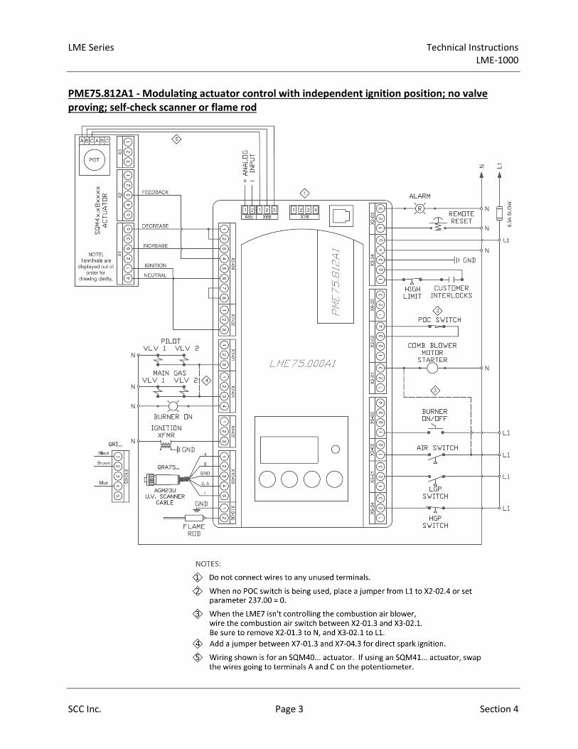
LME Series Technical Instructions
LME-1000
SCC Inc. Page 3 Section 4
PME75.812A1 - Modulating actuator control with independent ignition position; no valve
proving; self-check scanner or flame rod

LME Series LME75 Parameter List Technical Instructions
LME-1000
PW Level Default Range Description
041 Service Level PW 7576 Any 4 charactersThe service level password can be changed here. It must be exactly 4 characters in length. Enter the
current password, then enter the new password twice to change it (c = current, n = new, r = repeat).• •
042 OEM Level PW L7unI Any 5 charactersThe OEM level password can be changed here. It must be exactly 5 characters in length. Enter the current
password, then enter the new password twice to change it (c = current, n = new, r = repeat).• •
060 Backup / Restore SBackup - 0
Restore - 00-1
Used to perform parameter backups and restores.
Backup: Transfer LME7 parameters to PME7. Restore: Transfer PME7 parameters to LME7.
Set parameter to 1 and press the info button to begin the backup or restore. Once a parameter backup is
successful, the screen will display "bAC End". Once a parameter restore is successful, the screen will
display "rSt End".
• •
101 LME7 Part Number ACS410 Displays the part number of the LME7 burner control being used. • •
102 Production Date Date that the LME7 was produced in the DD.MM.YY format. • •
103 Serial Number Serial number of the LME7. • •
113 Burner ID Not set 0-99999999
The burner ID can be viewed through the AZL23 but can only be set using the ACS410 software with the
OCI410.40 OEM cable. The burner ID must be all digits (no letters), from 1-8 digits in length. Typically the
burner serial number is used. This serves as an identifier for the parameter set. The burner ID must be set
in order to perform a parameter backup to a PC using the ACS410 software. Parameter backups to the
PME7 program module can be made without setting the burner ID.
• •
119LME7 Part Number
OEM
Displays the OEM part number of the LME7 burner control being used. Will be the same as parameter
101.• •
120 PME7 Part Number Displays the part number of the PME7 program module being used. • •
123 Min Load Change 2% 1-10%This serves as a dead band for load changes to reduce small oscillations (hunting) by the actuator. If the
requested change in fire rate is less than the setting of this parameter, the actuator will not move.• •
140 Display Mode811 - 3
812 - 11-4
Sets what will be displayed by the LME7 integral display.
1 = phase
2 = flame signal (flame rod)
3 = flame signal (QRA75… or QRI... flame scanner)
4 = load
• •
164 Startups
Displays the total number of startups. To reset this value, press and hold the info button until the value
begins to flash, then let go. The value will automatically change to 0. Press the info button again to
confirm the reset.
• •
166 Total Startups Displays the total number of startups. Not resettable. • •
170Number of
Relay Cycles
Displays the number of cycles on different internal relays in the LME7.
Index 00 = K8 relay cycles
Index 01 = K7 relay cycles
Index 02 = K2 relay cycles
Index 03 = K1 relay cycles
• •
171 Max Relay Cycles Displays the maximum number of relay cycles allowed on the internal relays of the LME7. • •
Read only
ACS410 Read only
Parameter
Number
PME75.
811A1
PME75.
812A1
000 Level: Parameter Backup / Restore / Change Passwords
100 Level: General Information / Display Mode
S
LEGEND - Password Level: S = Service O = OEM S/O = View - Service, Write - OEM Info = Info Menu Ser = Service Menu ACS410 = ACS410 only
Shaded Parameters = Frequently Used
O
Parameter Name
Reset only
Info
Read only
Info
SCC Inc. Page 4 Section 4

LME Series Technical Instructions
LME-1000
PW Level Default Range Description
Parameter
Number
PME75.
811A1
PME75.
812A1
LEGEND - Password Level: S = Service O = OEM S/O = View - Service, Write - OEM Info = Info Menu Ser = Service Menu ACS410 = ACS410 only
Shaded Parameters = Frequently UsedParameter Name
179 Two Flame Sensor Logic 0 0-1
The LME75 allows the use of two flame sensors at the same time (one flame rod and one flame scanner).
This sets the logic for the flame sensor inputs.
0 = OR logic - a valid flame signal must be present on one of the two flame signal inputs. This applies from
the end of phase 42 through the end of burner operation.
1 = AND logic - a valid flame signal must be present on both flame signal inputs. This only applies from the
start of phase 52 through the end of operation. During phases 42-50, only one flame signal must be
present.
• •
180 Self-Check Time 0 0-1
Sets the time interval for the test of the self-check scanner. On the QRA75… scanner, this sets the length
of time between shutter operations.
0 = every 5 minutes
1 = every 5 seconds
• •
212 Max Time Low Fire 58.212 sec 0-1237 sec
Sets the maximum time to let the LME7 drive the actuator to low fire before shutting the fuel valves after a
call for heat has been removed from X5-03.1. This setting does not affect fuel valve closing time in the
event of a safety shutdown.
• •
216Extraneous Light
Tolerance Time29.106 sec 0-1237 sec
This sets the amount of time that a flame signal must be present in standby before the LME7 goes into
lockout (Loc 4). When a flame signal is present during standby, the LME7 immediately goes to Phase 04.
If the flame signal goes away before this time elapses, the LME7 will switch from Phase 04 back to standby
(OFF) without requiring a manual reset.
• •
217.00Flame On Response
Time
Sets the amount of time that a flame signal must be present before the LME7 considers that flame signal
to be valid. This parameter has no effect as the value is set to 0 seconds.• •
217.01
Flame Failure Response
Time
(FFRT)
811 - 2.940 sec
812 - 1.911 sec0-13.818 sec
Sets the flame failure response time (FFRT). The FFRT is the maximum length of time that the flame signal
can go away before a lockout occurs. The LME75 has a base flame failure response time of 1 second. This
setting adds time to the base time. For example, the default setting of 1.911 seconds means the FFRT is
2.911 seconds.
• •
218Forced Intermittent
Time80050.31 sec 0-80050.31 sec
Sets the length of time before a forced burner shutdown occurs. If the burner has been running
uninterrupted for this length of time, and parameter 239 is set to 1, the burner will shut down and
automatically restart afterwards. The purpose of the shutdown is to check and cycle safety devices.
• •
222 Prepurge Activation 1 0-1
Activates or deactivates prepurge after a normal shutdown. If this is set to 0, a prepurge will still occur on
the next startup following a lockout or a loss of power, or if valve proving is activated and occurs during
startup.
0 = deactivated
1 = activated
• •
223Low Gas Pressure
Shutdown Behavior1 0-1
Sets the behavior of the LME7 in the event that the low gas pressure switch connected to input X5-01.2 is
de-energized.
0 = safety shutdown and start prevention - the burner is shutdown and the LME7 goes into Phase 90 until
gas pressure is restored. Once gas pressure is restored, the burner will start back up automatically.
1 = lockout (Loc 20)
• •
Read only
S
S
S/O
200 Level: Burner Control
S/O
SCC Inc. Page 5 Section 4

LME Series Technical Instructions
LME-1000
PW Level Default Range Description
Parameter
Number
PME75.
811A1
PME75.
812A1
LEGEND - Password Level: S = Service O = OEM S/O = View - Service, Write - OEM Info = Info Menu Ser = Service Menu ACS410 = ACS410 only
Shaded Parameters = Frequently UsedParameter Name
224 Time Air Pressure Switch 13.818 sec 0-13.818 sec
Once the LME7 reaches phase 22 for the second time (between phases 24 and 30), this sets the length of
time the LME7 will wait for air pressure switch input X3-02.1 to become energized before a lockout occurs
due to lack of air pressure. As soon as the switch is made, the sequence progresses.
• •
225.00 Prepurge Time 29.106 sec 0-1237 sec Sets the prepurge time (length of phase 30) along with parameter 225.01. • •
225.01 Prepurge Multiplier 1 1-255Sets a multiplier for the prepurge time. The actual prepurge time (length of phase 30) is determined by
multiplying parameter 225.00 and this parameter.• •
230 Pilot Stabilization Time 3.234 sec 0-74.97 secThis setting defines the pilot stabilizing period if a pilot is used. During this period, only the pilot valve is
open. The spark is de-energized. Sets the length of phase 44.• •
231Pilot and Main Overlap
Time9.996 sec 0-74.97 sec
When a fuel train with a pilot is used, this setting defines the overlap of the pilot (output X7-01.3) and the
main fuel valves. After this time expires, the pilot is de-energized. Sets the length of phase 50.• •
232 Main Stabilization Time 2.058 sec 2.058-74.97 secThis setting defines the main stabilizing period if a pilot is used. During this period, only the main valve is
open. The pilot valve is de-energized. Sets the length of phase 52.• •
234.00 Postpurge Time811 - 0 sec
812 - 19.404 sec0-1237 sec Sets the postpurge time (length of phase 74) along wth parameter 234.01. • •
234.01 Postpurge Multiplier 1 1-255Sets a multiplier for the postpurge time. The actual postpurge time (length of phase 74) is determined by
multiplying parameter 234.00 and this parameter.• •
235.00Air Pressure Switch
Evaluation1 0-1
Sets the behavior of the air pressure switch input X3-02.1.
0 = Air pressure switch is not evaluated during operation (lack of air pressure has no effect)
1 = Air pressure switch is evaluated during operation (lack of air pressure causes a lockout)
• •
235.01Response Time Air
Pressure Switch0.294 sec 0-2.058 sec
Sets the amount of time that the air pressure switch input X3-02.1 can be de-energized before a lockout
occurs. The LME7 has a base time of 0.7 seconds. This setting adds time to the base time.• •
236Low Gas Pressure
Evaluation0 0-1
Sets the behavior of the low gas pressure switch input X5-01.2.
0 = Low gas pressure switch is evaluated during startup and operation (phases 30-70).
1 = Low gas pressure switch is only evaluated when main fuel valves are open (phases 52-70). This is
useful when the low gas pressure switch is mounted downstream of the main fuel valves for CSA B149.3
compliance.
• •
237.00 POC Switch 1 0-2
This setting defines the function of POC switch input X2-02.4. If set to deactivated, nothing can be wired to
this input.
0 = deactivated
1 = activated (verify POC switch is closed on startup and shutdown)
2 = activated (verify POC switch is closed on startup and shutdown, and verify POC switch is open during
main operation)
• •
237.01High Gas Pressure
SwitchS/O 0 0-1
PME75.811A1: Sets the function of input X2-02.4.
0 = POC
1 = high gas pressure switch
PME75.812A1: Activates or deactivates input X9-04.2 for use with a high gas pressure switch. If set to
deactivated, nothing can be wired to this input.
0 = deactivated
1 = activated
• •
S/O
S
SCC Inc. Page 6 Section 4

LME Series Technical Instructions
LME-1000
PW Level Default Range Description
Parameter
Number
PME75.
811A1
PME75.
812A1
LEGEND - Password Level: S = Service O = OEM S/O = View - Service, Write - OEM Info = Info Menu Ser = Service Menu ACS410 = ACS410 only
Shaded Parameters = Frequently UsedParameter Name
239 Forced Intermittent S/O 0 0-1
When activated, this forces the LME7 to shut the burner down after a predetermined length of
uninterrupted operation. This length of time is set by parameter 218. The burner will automatically
restart afterwards. The purpose of the shutdown is to check and cycle safety devices.
0 = deactivated
1 = activated
• •
240 Repetition Flame 0 0-4
This sets the numbers of times a flame failure during main operation or during main trial for ignition must
occur before causing a lockout. Most North American codes require 1 (no repetitions).
0 = no repetitions
1 = no repetitions
2 = 1 repetition
3 = 2 repetitions
4 = 3 repetitions
• •
241 Valve Proving Activation 0 0-1
This setting determines if gas valve proving (leak testing) will be performed. Gas valve proving is
performed during shutdown unless the postpurge time (parameter 234.00) is set to 0. In that case, valve
proving occurs during startup.
0 = deactivated
1 = activated
•
242 VP Evacuation Time 2.646 sec 0-2.646 sec
If valve proving is performed, this specifies the length of time that the downstream valve (V2) is energized
(output X7-01.3). This will evacuate any gas that might exist between the gas valves. Sets the length of
phase 80.
•
243 VP Upstream Test 10.290 sec 1.029-37.485 sec
If valve proving is performed, this specifies the length of time that both the upstream and downstream
valves are closed. If the pressure between the valves rises during this period (enough to open the NC valve
proving pressure switch), then the upstream valve is leaking and the LME7 will lockout. A longer time
period will produce a more sensitive test. Sets the length of phase 81.
•
244 VP Fill Time 2.646 sec 0-2.646 sec
If valve proving is performed, this specifies the length of time that the upstream valve (V1) is energized
(output X7-04.4). This will fill the volume between the main gas valves to line pressure. Sets the length of
phase 82.
•
245 VP Downstream Test 10.290 sec 1.029-37.485 sec
If valve proving is performed, this specifies the length of time that both the upstream and downstream
valves are closed. If the pressure between the valves falls during this period (enough to close the NC valve
proving pressure switch), then the downstream valve is leaking and the LME7 will lockout. A longer time
period will produce a more sensitive test. Sets the length of phase 83.
•
247 Intermittent Pilot 0 0-1
Sets the type of pilot being used. If set to 1, the pilot valve will remain open from phase 40 to the end of
main operation (oP…).
0 = interrupted pilot
1 = intermittent pilot
• •
257 Trial for Ignition811 - 9.114 sec
812 - 4.116 sec0-13.23 sec
This setting defines the overlap of the spark (output X4-02.3) and the pilot valve (output X7-01.3) if a pilot
is used. The LME7 has a base time of 0.3 seconds. This setting adds seconds to the base time. Sets the
length of phase 40.
• •
259 Actuator Opening Time 58.212 sec 0-1237 sec Set slightly longer than the time it takes for the actuator to drive from fully closed to fully open. • •
260 Actuator Closing Time 58.212 sec 0-1237 sec Set slightly longer than the time it takes for the actuator to drive from fully open to fully closed. • •
S/O
S
SCC Inc. Page 7 Section 4

LME Series Technical Instructions
LME-1000
PW Level Default Range Description
Parameter
Number
PME75.
811A1
PME75.
812A1
LEGEND - Password Level: S = Service O = OEM S/O = View - Service, Write - OEM Info = Info Menu Ser = Service Menu ACS410 = ACS410 only
Shaded Parameters = Frequently UsedParameter Name
515.00 Actuator Purge Position SDetermines the position of the actuator during prepurge and postpurge. Cannot be changed on the
LME75. The actuator will always purge at high fire.• •
515.01 Actuator Activation S/O811 - 0
812 - 10-1
Used to activate or deactivate the use of an actuator. If set to 0, parameter 560 must also be set to 0.
0 = deactivated (no actuator)
1 = activated (with actuator)
• •
560 Analog Input Type S811 - 0
812 - 20-2
Sets the type of input being used to control the actuator.
0 = no actuator / 3-position input
1 = do not use this setting (for future use only)
2 = analog input
• •
654 Analog Input Signal S811 - 5
812 - 10-5
Sets the type of input signal being connected to terminal X65 or X5-03 when parameter 560 is set to 2.
This input signal is used to determine the actuator position during operation.
0 = 3-position
1 = 0-10 VDC
2 = 0-135 Ohm
3 = 0-20 mA
4 = 4-20 mA with lockout when input is less than 4 mA
5 = 4-20 mA without lockout when input is less than 4 mA
• •
701-711 Fault History Ser
Shows the current status (fault) along with the 10 most recent faults. 701 = current status, 702 = most
recent fault, 703 = next most recent fault, etc. Each fault has indices that provide additional information
about the fault:
Index 00 = fault code
Index 01 = start number
Index 02 = phase
Index 03 = load
• •
903 Current Output / Stage Not applicable to the LME75. Displays as "----" for all PME75… program modules. • •
908 Target Speed % Not applicable to the LME75. Displays as "----" for all PME75… program modules. • •
920 Actual PWM Output Ser Not applicable to the LME75. Displays as "----" for all PME75… program modules. • •
922 Actual Actuator PositionWhen an actuator is used and a potentiometer is connected, this displays the real-time position of the
actuator.• •
923 Target Actuator PositionWhen an actuator is used and a potentiometer is connected, this displays the target position of the
actuator during main operation. Displays as "----" during all other phases.• •
935 Actual Speed RPM Not applicable to the LME75. Displays as "----" for all PME75… program modules. • •
936 Actual Speed % Not applicable to the LME75. Displays as "----" for all PME75… program modules. • •
944 Analog Input % ACS410 Displays the real time analog input signal on terminal X65 as a percentage from 0-100%. • •
Ser
ACS410 Read only
ACS410
Read only
700 Level: Fault History
900 Level: Operational Data
600 Level: Analog Input Configuration
500 Level: Actuator Configuration
Read only
SCC Inc. Page 8 Section 4

LME Series Technical Instructions
LME-1000
PW Level Default Range Description
Parameter
Number
PME75.
811A1
PME75.
812A1
LEGEND - Password Level: S = Service O = OEM S/O = View - Service, Write - OEM Info = Info Menu Ser = Service Menu ACS410 = ACS410 only
Shaded Parameters = Frequently UsedParameter Name
951 Mains Voltage AZL Displays the real time mains voltage. Measured at terminal X3-04 pin 4 (neutral) and pin 5 (line). • •
954 Flame Signal AZL
Displays the raw flame signal from 0-100% for any flame sensor type. A flame failure occurs when the
flame signal drops below 20% for the time period specified by parameter 217.01.
Index 00 = flame rod (input X10-06.2)
Index 01 = flame scanner QRA75/QRI (input X10-05.1)
• •
961 Actual Phase Displays the real time phase of the LME7. • •
3007 Flame Signal 1 StatusDisplays the status of the flame rod input X10-06.2. A value of 1 indicates a valid flame signal is present,
and a value of 0 indicates that no valid flame signal is present.• •
3008 Flame Signal 2 StatusDisplays the status of QRA75/QRI flame scanner input X10-05.1. A value of 1 indicates a valid flame signal
is present, and a value of 0 indicates that no valid flame signal is present.• •
3033 BlowerDisplays the status of blower output X2-01.3. A value of 1 indicates the output is energized, and a value of
0 indicates the output is de-energized.• •
3034 IgnitionDisplays the status of ignition transformer output X4-02.3. A value of 1 indicates the output is energized,
and a value of 0 indicates the output is de-energized.• •
3035 Safety ValveDisplays the status of safety valve output X6-03.3. A value of 1 indicates the output is energized, and a
value of 0 indicates the output is de-energized.• •
3036 Main Valve V1Displays the status of main valve V1 output X7-04.3. A value of 1 indicates the output is energized, and a
value of 0 indicates the output is de-energized.• •
3037 Main Valve V2Displays the status of main valve V2 output X7-02.3. A value of 1 indicates the output is energized, and a
value of 0 indicates the output is de-energized.•
3039 Pilot Valve 1Displays the status of pilot valve output X7-01.3. A value of 1 indicates the output is energized, and a value
of 0 indicates the output is de-energized.• •
3088 ResetDisplays the status of the info button on the LME7. When the info button is pressed, this value is a 1, and
when the info button is not pressed, this value is a 0.• •
3089 Remote ResetDisplays the status of remote reset input X2-03.1. A value of 1 indicates the input is energized, and a value
of 0 indicates the input is de-energized.• •
3090Air Pressure Switch
Status
Displays the status of air pressure switch input X3-02.1. A value of 1 indicates the input is energized, and a
value of 0 indicates the input is de-energized.• •
3091 Gas Pressure SwitchesDisplays the status of gas pressure switch input X5-01.2. A value of 1 indicates the input is energized, and
a value of 0 indicates the input is de-energized.• •
3092 Burner EnableDisplays the status of burner enable input X5-03.1. A value of 1 indicates the input is energized, and a
value of 0 indicates the input is de-energized.• •
3103 Load Controller OpenDisplays the status of load controller open input X5-03.3. A value of 1 indicates the input is energized, and
a value of 0 indicates the input is de-energized.• •
3104 Load Controller ClosedDisplays the status of load controller closed input X5-03.2. A value of 1 indicates the input is energized,
and a value of 0 indicates the input is de-energized.• •
3106 Not Used Not used • •
3107Valve Proving
Pressure Switch
Displays the status of valve proving pressure switch input X9-04.2. A value of 1 indicates the input is
energized, and a value of 0 indicates the input is de-energized. •
ACS410
Read only
Ser
SCC Inc. Page 9 Section 4

LME Series Technical Instructions
LME-1000
PW Level Default Range Description
Parameter
Number
PME75.
811A1
PME75.
812A1
LEGEND - Password Level: S = Service O = OEM S/O = View - Service, Write - OEM Info = Info Menu Ser = Service Menu ACS410 = ACS410 only
Shaded Parameters = Frequently UsedParameter Name
3108 POC StatusDisplays the status of POC input X2-02.4. A value of 1 indicates the input is energized, and a value of 0
indicates the input is de-energized.• •
3133 AlarmDisplays the status of alarm output X2-03.3. A value of 1 indicates the output is energized, and a value of 0
indicates the output is de-energized.• •
3136 Actuator OpenDisplays the status of the command signal to increase the actuator position via output X2-09.3. A value of
1 indicates the output is energized, and a value of 0 indicates the output is de-energized.• •
3146 Actuator CloseDisplays the status of the command signal to decrease the actuator position via output X2-09.2. A value of
1 indicates the output is energized, and a value of 0 indicates the output is de-energized.• •
3303 Mains Voltage ACS410 Displays the real time mains voltage. Measured at terminal X3-04 pin 4 (neutral) and pin 5 (line). • •
3307 Flame Signal 1 ACS410 Displays the flame signal strength (%) from a flame rod on terminal X10-06.2. • •
3308 Flame Signal 2 ACS410 Displays the flame signal strength (%) from a QRA75 or QRI flame scanner on terminal X10-05.1. • •
ACS410 Read only
SCC Inc. Page 10 Section 4

Technical Instructions LME Series
LME-1000
Section 4 Page 11 SCC Inc.
LME75 Phase Diagrams
The Siemens LME7 burner controls can perform a number of different burner sequences based
upon which PME7 program module is used, how certain parameters are set, and how the LME7
is wired.
Each program module has an associated phase diagram. The phase diagrams illustrate when
input and output terminals are expected to be energized or de-energized. A legend on the
bottom of each page describes the various symbols used in the diagrams.
Notes:
1) A jumper can be added between terminals X7-04.4 and X7-01.3 for direct spark ignition.
If this jumper is added, pilot valve output X7-01.3 and main valve output X7-04.4 will be
energized from phase 40 through the end of phase 70.
2) On PME75.811A1, if the LME7 is set to perform valve proving, valve proving will always
take place during shutdown unless it is the next startup following a lockout or power loss,
or if the postpurge time (parameter 234.00) is set to 0. In that case, valve proving occurs
during startup and shutdown. When valve proving occurs during shutdown, it will happen
at the same time as postpurge. Phases 80-83 will be displayed on the LME7 and the AZL23
even though postpurge (phase 74) is also occurring at the same time. The actual
postpurge time will be at least the sum of all four valve proving time parameters (242,
243, 244, and 245). When valve proving occurs during startup, it will happen at the same
time as prepurge. Phases 80-83 will be displayed on the LME7 and the AZL23 even
though prepurge (phase 30) is also occurring at the same time. The actual prepurge time
will be at least the sum of all four valve proving time parameters (242, 243, 244, and 245).
3) If parameter 235.00 is set to 0, air pressure switch input X3-02.1 only needs to be
energized during phases 22 through 52 and during phase 74. The switch is not checked
during main burner operation.
4) If parameter 236 is set to 1, low gas pressure switch input X5-01.2 only needs to be
energized during phases 52 through 70. The input is not checked before the main valves
are open. This is useful for applications where the low gas pressure switch is mounted
downstream of the safety shutoff valves (for CSA B149.3 compliance).

LME Series Technical Instructions
Document No. LME-1000
Lock
ou
t
Sta
nd
by
, Wa
iting
for C
all
for H
ea
t
Te
st - Air P
ressu
re S
witch
Op
en
Blo
we
r On
Driv
e to
Pre
pu
rge
Po
sition
Te
st - Air P
ressu
re S
witch
Clo
sed
Pre
pu
rge
(No
te 2
)
Driv
e to
Ign
ition
Po
sition
Tria
l for Ig
nitio
n
Fla
me
De
tectio
n
Inte
rva
l 1: P
ilot
Sta
biliza
tion
Sa
fety
Tim
e 2
: Pilo
t an
d
Ma
in O
ve
rlap
Inte
rva
l 2: M
ain
Sta
biliza
tion
Op
era
tion
Driv
e to
Low
Fire
Sh
utd
ow
n
Driv
e to
Po
stpu
rge
Po
sition
Po
stpu
rge
(No
te 2
)
Ho
me
Ru
n
Ev
acu
ate
Atm
osp
he
ric Te
st
Fill
Pre
ssure
Te
st
Phase LOC OFF 21 22 24 22 30 36 40 42 44 50 52 oP oP1 70 72 74 10 80 81 82 83
Param. 259 225 260 257 230 231 232 240 212 234 242 243 244 245
Terminal Description Notes
X3-04.5 Main Voltage
X3-04.1 Safety Loop X X
X5-03.1 Burner On M
X3-02.1 Air Pressure Switch Note 3 X M
X5-01.2 Gas Pressure Switch(es) Note 4
X9-04.2 Valve Proving Pressure Switch X
POC (P237.00 = 1, P237.01 = 0)
POC (P237.00 = 2, P237.01 = 0) X
High Gas Press. Sw. (P237.01 = 1)
X2-02.3 POC Source X X
X6-03.3 Safety Valve X X
X2-01.3 Blower X X X
X4-02.3 Ignition Transformer X X X X X X X X X X X X X X X X X X X X X X
X7-01.3 Pilot Valve Note 1 X X X X X X X X X X X X X X X X X X X
X7-04.4 Main Valve V1 Note 1 X X X X X X X X X X X X X X X X X
X7-02.3 Main Valve V2 X X X X X X X X X X X X X X X X X
X2-03.3 Alarm X X X X X X X X X X X X X X X X X X X X X X
X2-09.3 Drive to High Fire X X X X X X X X X X X X X X X X X X X
X2-09.2 Drive to Ignition / Low Fire X X X X X X X X X X X X X X X X
X2-09.1 Drive Closed X X X X X X X X X X X X X X X X X X X X X
X2-09.4 Position Feedback M M M M M
Legend : Energized X De-energized
Energized or de-energized M Must be energized by end of phase
X2-02.4
INP
UT
SA
CT
UA
TO
R
Flame Signal
OU
TP
UT
S
SHUTDOWNSTARTUP VALVE PROVINGOPERATION
XX10-05.1
X10-06.2X
PME75.811A1 Phase Diagram
X
SAFETY
TIME 1
SCC Inc. Page 12 Section 4

LME Series Technical Instructions
Document No. LME-1000
Lock
ou
t
Sta
nd
by
, Wa
iting
for C
all
for H
ea
t
Te
st - Air P
ressu
re S
witch
Op
en
Blo
we
r On
Driv
e to
Pre
pu
rge
Po
sition
Te
st - Air P
ressu
re S
witch
Clo
sed
Pre
pu
rge
Driv
e to
Ign
ition
Po
sition
Tria
l for Ig
nitio
n
Fla
me
De
tectio
n
Inte
rva
l 1: P
ilot
Sta
biliza
tion
Sa
fety
Tim
e 2
: Pilo
t an
d
Ma
in O
ve
rlap
Inte
rva
l 2: M
ain
Sta
biliza
tion
Op
era
tion
Driv
e to
Low
Fire
Sh
utd
ow
n
Driv
e to
Po
stpu
rge
Po
sition
Po
stpu
rge
Ho
me
Ru
n
Phase LOC OFF 21 22 24 22 30 36 40 42 44 50 52 oP oP1 70 72 74 10
Param. 259 225 260 257 230 231 232 240 212 234
Terminal Description Notes
X3-04.5 Main Voltage
X3-04.1 Safety Loop X X
X5-03.1 Burner On M
X3-02.1 Air Pressure Switch Note 3 X M
X5-01.2 Gas Pressure Switch(es) Note 4
X9-04.2 High Gas Pressure Switch
POC (P237.00 = 1)
POC (P237.00 = 2) X
X2-02.3 POC Source X X
X6-03.3 Safety Valve X X
X2-01.3 Blower X X X
X4-02.3 Ignition Transformer X X X X X X X X X X X X X X X X X X
X7-01.3 Pilot Valve Note 1 X X X X X X X X X X X X X X X
X7-04.4 Main Valves Note 1 X X X X X X X X X X X X X X
X2-03.3 Alarm X X X X X X X X X X X X X X X X X X
X2-09.3 Drive to High Fire X X X X X X X X X X X X X X X
X2-09.2 Drive to Low Fire X X X X X X X X X X X X X X X X X
X7-02.3 Drive to Ignition X X X X X X X X X X X X X X
X2-09.1 Drive Closed X X X X X X X X X X X X X X X X X
X2-09.4 Position Feedback M M M M M
Legend : Energized X De-energized
Energized or de-energized M Must be energized by end of phase
PME75.812A1 Phase Diagram
X
SAFETY
TIME 1
Flame Signal
SHUTDOWN
OU
TP
UT
S
XX10-05.1
X10-06.2X
STARTUP OPERATION
INP
UT
S
X2-02.4
AC
TU
AT
OR
SCC Inc. Page 13 Section 4

Technical Instructions LME Series
Document No. LME-1000
Section 4 Page 14 SCC Inc.
Intentionally Left Blank
Section 1 Overview
Section 2 LME71 Wiring, Parameters,
and Phase Diagrams
Section 3 LME73 Wiring, Parameters,
and Phase Diagrams
Section 4 LME75 Wiring, Parameters,
and Phase Diagrams
Section 5 Commissioning
Section 6 PWM Blowers
Section 7 Troubleshooting
Section 8 Modbus
Section 9 ACS410
Appendix A Application Guide

LME Series Technical Instructions
Document No. LME-1000
SCC Inc. Page 1 Section 5
Commissioning a New LME7 Burner Control
1. Ensure all devices are properly connected to the LME7. See Section 2 (LME71…), Section 3
(LME73…), or Section 4 (LME75…) of this manual for more information on wiring devices to the
LME7 burner control.
2. Install the PME7 program module into the LME7 burner control. Apply power to the LME7.
3. The LME7 will alternately display “rSt” and “PrC”, indicating that the parameter set from the
PME7 program module needs to be restored into the LME7 burner control. To do so, press and
hold the info button on the LME7 burner control until the LED on the LME7 turns yellow, then
release. This should take approximately three seconds.
4. The word “run” will briefly be displayed. Then, the display will alternate between “rSt” and
“End”. This indicates that the restore process was successful.
5. Press and hold the info button for approximately two seconds to reset the LME7. If everything
was done properly, the LME7 should now display “OFF”.
6. If any LME7 parameters need to be changed from their default values, an AZL23 display unit is
required. Plug in the AZL23 display unit.
7. To log in to the LME7 and access the parameters, press and hold the F and A buttons
simultaneously on the AZL23 until the word “CodE” appears.
8. Enter the password for the desired access level. The default passwords are:
LME71… / LME73… Service Level Password – 7173
LME75… Service Level Password – 7576
LME7… OEM Level Password – L7unI
9. Set all parameters as necessary for the application. See Section 2 (LME71…), Section 3
(LME73…), or Section 4 (LME75…) of this manual for more information on setting the
parameters in the LME7 burner control.
10. If using an LME73… or LME75… burner control with an actuator, the limit switches on the
actuator must be set. The most common actuator used with the LME7 is the SQM4x.x8xxxx. On
the SQM4x.x8xxxx actuator, set the red cam (I) for the desired high fire position. Set the blue
cam (II) for the desired low fire position. If using PME73.812A1 or PME75.812A1, which allow
for an independent ignition position, set the orange cam (III) for the desired ignition position. If
using an actuator other than the SQM4x.x8xxxx, see the actuator literature for more
information on setting the limit switches.
11. At this point, the LME7 burner control is fully commissioned. It is recommended to perform a
parameter backup to synchronize the parameter settings of the LME7 burner control and PME7
program module. See the next section for instructions on performing a parameter backup.

Technical Instructions LME Series
Document No. LME-1000
Section 5 Page 2 SCC Inc.
Parameter Backups / Restores
Both the LME7 burner control and PME7 program module contain one parameter set. The parameter
set in the LME7 burner control is always the one that is used for burner operation. The parameter set in
the PME7 program module is simply a backup parameter set. At any time, these two parameter sets can
be synchronized with a parameter backup or a parameter restore.
Parameter backup – Overwriting the PME7 parameter set with the LME7 parameter set
Parameter restore – Overwriting the LME7 parameter set with the PME7 parameter set
The following procedures can be used to perform parameter backups or parameter restores.
Parameter Backup (LME7 -> PME7) Using the LME7 Built-in Display
1. Press and hold the + and - buttons on the LME7 together for approximately one second. “PrC”
will be displayed briefly, then the display will show “rSt”.
2. Press the + or - button to toggle to “bAC”.
3. Press and hold the info button until the word “run” is displayed, then release.
4. The LME7 will alternately display “bAC” and “End” once the parameter backup is complete.
5. Press the info button to return to the normal display.
Parameter Restore (PME7 -> LME7) Using the LME7 Built-in Display
Use to overwrite the parameters in the LME7 with those previously saved in the PME7.
1. Press and hold the + and - buttons on the LME7 together for approximately one second. “PrC”
will be displayed briefly, then the display will show “rSt”.
2. Press and hold the info button until the word “run” is displayed, then release.
3. The LME7 will alternately display “rSt” and “End” once the parameter restore is complete.
4. Press the info button to return to the normal display.
Parameter Backup (LME7 -> PME7) Using the AZL23 Display Unit
1. Press and hold the F and A buttons on the AZL23 until “CodE” is displayed, then release.
2. Log in at the service or OEM level.
3. The display will show “000: Int”. Press the info button on the AZL23.
4. Toggle to parameter 060 using the + and - buttons, then press the info button.
5. Press the + or - button to toggle to “bAC_UP”, then press the info button.
6. Tap the + button twice to change the value to 1, then press the info button.
7. The word “run” will be displayed during the backup process.
8. The AZL23 will display “bAC End” once the parameter backup is complete.
9. Press the info button to return to the normal display.

LME Series Technical Instructions
Document No. LME-1000
SCC Inc. Page 3 Section 5
Parameter Restore (PME7 -> LME7) Using the AZL23 Display Unit
Use to overwrite the parameters in the LME7 with those previously saved in the PME7.
1. Press and hold the F and A buttons on the AZL23 until “CodE” is displayed, then release.
2. Log in at the service or OEM level.
3. The display will show “000: Int”. Press the info button on the AZL23.
4. Toggle to parameter 060 using the + and - buttons, then press the info button.
5. “rEStorE” will be displayed. Press the info button.
6. Tap the + button twice to change the value to 1, then press the info button.
7. The word “run” will be displayed during the restore process.
8. The AZL23 will display “rSt End” once the parameter restore is complete.
9. Press the info button to return to the normal display.
Displaying the Flame Signal from the LME7 Burner Control
The flame signal can be viewed on the LME7 burner control using the following procedures.
LME71…/LME73… Burner Control
1. Press and hold the + button on the LME7 burner control. “FL1” will be displayed briefly,
followed by the flame signal from 0-100%.
2. Holding the + button for less than three seconds will briefly display the flame signal. Upon
releasing the + button, the display will return to normal.
3. Holding the + button for more than three seconds will leave the flame signal displayed for two
minutes. This is indicated by the point after the flame signal value flashing. After two minutes,
or after pressing the + and - buttons together (escape), the display will return to normal.
LME75… Burner Control with a QRA75… or QRI… Flame Scanner
1. Press and hold the - button on the LME7 burner control. “FL2” will be displayed briefly,
followed by the flame signal from 0-100%.
2. Holding the - button for less than three seconds will briefly display the flame signal. Upon
releasing the - button, the display will return to normal.
3. Holding the - button for more than three seconds will leave the flame signal displayed for two
minutes. This is indicated by the point after the flame signal value flashing. After two minutes,
or after pressing the + and - buttons together (escape), the display will return to normal.
LME75… Burner Control with a Flame Rod
1. Press and hold the + button on the LME7 burner control. “FL1” will be displayed briefly,
followed by the flame signal from 0-100%.
2. Holding the + button for less than three seconds will briefly display the flame signal. Upon
releasing the + button, the display will return to normal.
3. Holding the + button for more than three seconds will leave the flame signal displayed for two
minutes. This is indicated by the point after the flame signal value flashing. After two minutes,
or after pressing the + and - buttons together (escape), the display will return to normal.

Technical Instructions LME Series
Document No. LME-1000
Section 5 Page 4 SCC Inc.
Displaying the Actuator Position / PWM Blower Speed from the LME7 Burner Control
The current position of the actuator (LME73…/LME75…) or speed of the PWM blower (LME71… with
PME71.901A1) can be viewed from the LME7 burner control using the following procedure.
1. Press and hold the A button on the LME7 burner control. “oP” will be displayed briefly, followed
by the actuator position / PWM blower speed from 0-100%.
2. Holding the A button for less than three seconds will briefly display the actuator position / PWM
blower speed. Upon releasing the A button, the display will return to normal.
3. Holding the A button for more than three seconds will leave the actuator position / PWM
blower speed displayed for two minutes. This is indicated by the decimal point in front of the
value flashing. After two minutes, or after pressing the + and - buttons together (escape), the
display will return to normal.
Manually Adjusting the Actuator Position / PWM Blower Speed from the LME7 Burner Control
During main operation, the current position of the actuator (LME73…/LME75…) or speed of the PWM
blower (LME71… with PME71.901A1) can be adjusted manually from the LME7 burner control using the
following procedure. Setting the actuator position / PWM blower speed manually overrides the analog
input signal on terminal X65 or the 3-position input signal on terminal X5-03.
1. Press and hold the A button on the LME7 burner control until the decimal point in front of the
value being displayed begins flashing. This takes approximately five seconds. “oP” will be
displayed briefly, followed by the actuator position / PWM blower speed from 0-100%.
2. Press and hold the A button again until “LoA” is displayed. Continue holding the A button and
simultaneously press the + or - button to increase or decrease the actuator position / PWM
blower speed respectively.
3. Once the desired actuator position / PWM blower speed is reached, release the A button. The
LME7 will alternately display “LoA” and the current actuator position / PWM blower speed.
4. To leave manual mode, press the + and - buttons together (escape). “oP” will be displayed and
the actuator position / PWM blower speed will be controlled by the analog input signal on
terminal X65 or the 3-position input signal on terminal X5-03.
AZL23 Display Unit Icons
Figure 5-1: AZL23 Display Unit Icons

Section 1 Overview
Section 2 LME71 Wiring, Parameters,
and Phase Diagrams
Section 3 LME73 Wiring, Parameters,
and Phase Diagrams
Section 4 LME75 Wiring, Parameters,
and Phase Diagrams
Section 5 Commissioning
Section 6 PWM Blowers
Section 7 Troubleshooting
Section 8 Modbus
Section 9 ACS410
Appendix A Application Guide

LME Series Technical Instructions
Document No. LME-1000
SCC Inc. Page 1 Section 6
Introduction
The LME71 flame safeguard, when used with the PME71.901A1 program module, features an
integrated, closed-loop PWM (pulse width modulation) blower control. This integrated control is used
to modulate the speed of a PWM blower with firing rate. The LME71 transmits a PWM control signal to
the blower, and then reads back the speed of the blower. On most PWM blowers, the speed feedback
signal is taken from Hall Effect sensors that commutate the PWM blower motor.
Blower speed has a large impact on the air flow delivered to the burner, and thus has a large impact on
the fuel-air ratio. A combustion air pressure switch offers only a small amount of protection, since the
switch must be set to allow low fire operation when the PWM blower is spinning slowly and the blower
output pressure is low. Blower speed feedback ensures that a blower failure will be quickly detected
and the burner will shut down safely.
PWM Blower Fundamentals
A common type of variable speed blower is the brushless DC blower, commonly referred to as a PWM
blower. These blowers typically have a variable speed drive and a DC brushless motor integrated into
one housing. These blowers are typically fed single-phase or three-phase AC voltage directly, and use
some type of AC to DC rectification to produce the DC voltage pulses necessary to drive the blower
motor.
Unlike a brushed DC motor, field windings in a brushless motor are triggered (commutated) via non-
contact Hall Effect sensors. In addition to commutating the motor, these Hall Effect sensors also provide
a pulsed output that the LME7 can use for blower speed feedback. Wiring of the speed feedback signal
is covered in Section 2.
Brushless DC motors usually do not have the same speed limitations as most three-phase blower motors
do. While most three-phase blower motors are limited to about 3,800 RPM, some brushless DC motors
used in blower applications will spin in excess of 8,000 RPM. This high-speed capability is attractive in a
blower application since more air flow at higher pressures can be generated with a smaller blower. The
LME7 can read blower speeds up to 9,000 RPM via the Hall Effect sensors in the blower.
Accurate speed control of a brushless DC motor can be more challenging as compared to a VFD and a
three-phase AC motor. The primary reasons behind this are the electromechanical characteristics of the
motors themselves. In brushless DC motors, the motor windings are being fed DC pulses of variable
duration (hence these blowers being called pulse width modulation). The width of these pulses
determines the blower’s speed for a given torque output and for a given blower input voltage. All three
of these variables – pulse width, torque output, and input voltage have a substantial impact on the
blower’s speed and can be regarded as primary variables.
Some PWM blowers have internal speed controls that compensate for torque output and input voltage
variances. This is done by taking a commanded speed set point (dictated by the LME7) and adjusting the
width of the pulse to achieve the commanded speed. PWM blowers having fast updating, properly
tuned internal speed controls typically work well with the LME7.

Technical Instructions LME Series
Document No. LME-1000
Section 6 Page 2 SCC Inc.
Centrifugal Blower Fundamentals
Since a centrifugal blower is the piece of machinery being controlled by the LME7, a brief mention of its
basic characteristics is warranted. Specifically, there are three fundamental "fan laws" that a person
working with such equipment should be aware of. These are:
1. Air flow varies linearly with the speed of the blower. In other words, the CFM of the blower is
directly proportional to the RPM of the blower.
2. The static output pressure of the blower (SP) varies by the square of the change in RPM:
3. The required brake horsepower of the blower (BHP) varies by the cube of the change in RPM:
Example: A blower spinning at 1750 RPM produces 10 in WC of static pressure, 4500 CFM of air flow,
and requires 20 BHP. What happens if the RPM is increased to 2750 RPM?
Assumptions: There is no air damper on the inlet to the blower, and system effects (such as the
restriction due to heat exchangers, the burner’s diffuser, etc...) are not taken into account.
Flow: CFM (new) = (2750 / 1750) * 4500 = 7071 CFM
Pressure: SP (new) = (2750 / 1750)2 * 10 = 24.7 in WC
Power: BHP (new) = (2750 / 1750)3 * 20 = 78 BHP

LME Series Technical Instructions
Document No. LME-1000
SCC Inc. Page 3 Section 6
Blower Speed Monitoring
To help ensure that the burner is either operated at a safe fuel-to-air ratio or is shut down, the blower
speed is constantly monitored while a flame is present. The speed is monitored in a way that nuisance
shutdowns are eliminated, but fast shutdowns will occur if the speed deviation is large. Two tolerance
bands centered about the target speed are used. These bands are:
1. Tolerance Band 1 - If the speed is within this band, it is considered acceptable and no action is
taken. If the blower speed falls outside of this band, the speed control in the LME7 or the PWM
blower will begin working to get it back inside this band. If the speed does not fall back inside
Tolerance Band 1 within five seconds, a lockout occurs. The width of this band is adjustable via
parameter 650.00 and the range is +/- 1.0 to 5.0% of the maximum blower speed (parameter 519).
2. Tolerance Band 2 - If the blower speed ever falls outside of this band, a lockout occurs immediately.
The width of this band is adjustable via parameter 650.01 and the range is +/- 1.0 to 10.0% of the
maximum blower speed (parameter 519). Tolerance band 2 should be set to a larger value than
tolerance band 1.
These bands are shown graphically in Figure 6-1.

Technical Instructions LME Series
Document No. LME-1000
Section 6 Page 4 SCC Inc.
Figure 6-1: Blower Speed Monitoring Bands
Time Max Min Max Min
sec % RPM RPM RPM RPM RPM
0 55 2750 2850 2650 3250 2250
3 60 3000 3100 2900 3500 2500
6 65 3250 3350 3150 3750 2750
9 70 3500 3600 3400 4000 3000
12 75 3750 3850 3650 4250 3250
15 80 4000 4100 3900 4500 3500
18 85 4250 4350 4150 4750 3750
21 90 4500 4600 4400 5000 4000
24 95 4750 4850 4650 5250 4250
27 100 5000 5100 4900 5500 4500
30 100 5000 5100 4900 5500 4500
33 100 5000 5100 4900 5500 4500
36 100 5000 5100 4900 5500 4500
39 100 5000 5100 4900 5500 4500
42 100 5000 5100 4900 5500 4500
HIG
H F
IRE
+1.0% to 5.0% +1.0% to 10.0%
-1.0% to 5.0% -1.0% to 10.0%
RA
MP
UP
+/- 500 RPM
Tolerance Band Limits for Figure 6-1
Tolerance band 1 = 2%
Tolerance band 2 = 10%
650.00 650.01
5000 RPM
+/- 100 RPM
Tolerance Band 1 Tolerance Band 2
Target Speed
Name of Tolerance Band
High Limit of Tolerance Band
Low Limit of Speed Band
Parameter to Adjust Width of Band
Maximum Blower Speed (P519)

LME Series Technical Instructions
Document No. LME-1000
SCC Inc. Page 5 Section 6
Commissioning the LME7 when Using a PWM Blower
After verifying that all PWM blower-related components are installed and wired correctly, the LME7
burner control can be programmed for the PWM blower application.
Prerequisites
• Ensure that the PWM blower is a closed loop type, meaning that it is utilizing an onboard speed
control properly tuned for that specific blower.
• Ensure that the maximum closed loop speed that the PWM blower is programmed for is adequate
for the application.
• Ensure the wiring is correct, paying particular attention to the low voltage wiring. Some PWM
blowers have their electronics internally powered from the high voltage, while others require
separate, external low voltage power.
After these points are double-checked, the LME7 parameters can be set for the application.
1. Set the blower ramp times.
a. Ramp up = Parameter 522
b. Ramp down = Parameter 523
These ramp times should be set at least 10% longer than the capabilities of the connected PWM
blower. For example, if the PWM blower can ramp up in 20 seconds, then parameter 522 should be
set to at least 22 seconds. The same logic applies for the ramp down, parameter 523.
2. Set the maximum speed of the PWM blower via parameter 519. This should be copied directly from
the blower nameplate or otherwise provided by the blower manufacturer.
3. Set the number of pulses per revolution for the PWM blower tachometer speed feedback signal via
parameter 644. This should be provided by the blower manufacturer and is typically only found in
the blower technical literature.
4. Set parameter 559 to activate or deactivate the LME7 internal speed control. For PWM blowers,
especially those utilizing a properly tuned onboard speed control, parameter 559 is typically set to 0.
Setting the value to 0 turns off the speed control inside the LME7 and allows the speed control to be
performed solely by the PWM blower.
5. Set the PWM blower speed monitoring bands to values that are safe for the application. These are
set via parameters 650.00 and 650.01. See complete explanation of these bands detailed earlier on
pages 3 and 4.
6. Set the standby speed of the PWM blower via parameter 503.00. This is typically set to 0 RPM.
7. Set the prepurge and postpurge speed of the PWM blower via parameter 503.01. This is often set at
the same value as the high fire speed (P2).

Technical Instructions LME Series
Document No. LME-1000
Section 6 Page 6 SCC Inc.
8. Set the ignition (P0), low fire (P1), and high fire (P2) blower speeds with the burner off. These values
are found in the 400 set of parameters. To set these parameters, use the following procedure:
a. Log in at the Service or OEM access level. The display will say “400: Set”. Press the info
button.
b. The display will say “run”. Press the + and - buttons together (escape). The display will then
show the ignition speed P0.
c. To adjust the ignition speed P0, press and hold the A button while simultaneously pressing
the + or - buttons to increase or decrease the ignition speed respectively. Once the desired
ignition speed P0 has been set, press the + button.
d. The low fire speed P1 will be displayed. Press and hold the A button while simultaneously
pressing the + or - buttons to increase or decrease the low fire speed respectively. Once the
desired low fire speed P1 has been set, press the + button.
e. The high fire speed P2 will be displayed. Press and hold the A button while simultaneously
pressing the + or - buttons to increase or decrease the high fire speed respectively. Once
the desired high fire speed P2 has been set, press the + and - buttons together (escape) two
times to get back to the normal screen (OFF).
9. At this point, all critical PWM blower related parameters have been set.

LME Series Technical Instructions
Document No. LME-1000
SCC Inc. Page 7 Section 6
Adjusting P0, P1, and P2 via the LME7 Built-in Display
1. While in standby (OFF), press and hold the A button and either the + or - button for more than five
seconds until “OFF” starts blinking.
2. Give the LME7 a call for heat. The LME7 will proceed to start the burner. After prepurge is
complete, the LME7 will slow the blower down to the preset ignition speed (P0).
3. At this point, the LME7 will alternately display P0 and a three-digit number. The three-digit number
is the setting of the ignition speed P0 divided by 10. For example, if the display alternately displays
P0 and 200, this means that the ignition speed is currently set for 2000 RPM.
4. To adjust the ignition speed, press and hold the A button while simultaneously pressing the + or -
button to increase or decrease the speed respectively. The speed of the blower will change in real
time. Once the desired ignition speed P0 has been set, press the info button.
5. The startup of the burner will continue. The burner will light off and establish flame. Once the
burner has lit off, it will drive to the preset low fire speed (P1).
6. The LME7 will then alternately display P1 and a three-digit number that is representative of the low
fire speed divided by 10. To adjust the low fire speed, press and hold the A button while
simultaneously pressing the + or - button to increase or decrease the speed respectively. The speed
of the blower will change in real time. Once the desired low fire speed P1 has been set, press the
info button.
7. The LME7 will immediately drive to the preset high fire speed P2.
8. The LME7 will then alternately display P2 and a three-digit number that is representative of the high
fire speed divided by 10. To adjust the high fire speed, press and hold the A button while
simultaneously pressing the + or - button to increase or decrease the speed respectively. The speed
of the blower will change in real time. Once the desired high fire speed P2 has been set, press the
info button.
9. Press the + and - buttons together (escape) to return to normal operation. The PWM blower will
now respond to the external load control signal being supplied to the LME7.

Technical Instructions LME Series
Document No. LME-1000
Section 6 Page 8 SCC Inc.
Adjusting P0, P1, and P2 via the AZL23 Display Unit
1. Log in at the Service or OEM access level. The display will say “400: Set”. Press the info button.
2. The display will say “run”. Give the LME7 a call for heat. The LME7 will proceed to start the burner.
After prepurge is complete, the LME7 will slow the blower down to the preset ignition speed (P0).
3. At this point, the LME7 will alternately display P0 and the ignition speed.
4. To adjust the ignition speed, press and hold the A button while simultaneously pressing the + or -
button to increase or decrease the speed respectively. The speed of the blower will change in real
time. Once the desired ignition speed P0 has been set, press the info button.
5. The startup of the burner will continue. The burner will light off and establish flame. Once the
burner has lit off, it will drive to the preset low fire speed (P1).
6. The LME7 will then alternately display P1 and the low fire speed. To adjust the low fire speed, press
and hold the A button while simultaneously pressing the + or - button to increase or decrease the
speed respectively. The speed of the blower will change in real time. Once the desired low fire
speed P1 has been set, press the info button.
7. The LME7 will immediately drive to the preset high fire speed P2.
8. The LME7 will then alternately display P2 and the high fire speed. To adjust the high fire speed,
press and hold the A button while simultaneously pressing the + or - button to increase or decrease
the speed respectively. The speed of the blower will change in real time. Once the desired high fire
speed P2 has been set, press the info button.
9. Press the + and - buttons together (escape) to return to normal operation. The PWM blower will
now respond to the external load control signal being supplied to the LME7.

LME Series Technical Instructions
Document No. LME-1000
SCC Inc. Page 9 Section 6
Additional Tips for Burners with PWM Blowers
• Most of the time, speed faults that are seen on the LME7 are caused by the PWM blower not being
able to decelerate quickly enough when the blower is being ramped down. If fast ramp times are
not critical for the application, ramp times (parameters 522 and 523) can be increased and this
should correct the issue.
• The LME7 in combination with the PWM blower can be tested for proper operation while the LME7
is in standby (OFF). After the PWM blower parameters are set, the standby speed of the PWM
blower can be adjusted with parameter 503.00. The actual speed as a % of the maximum blower
speed (parameter 519) can be read back on parameter 936. If different blower speeds are set and
plotted vs. the actual speed (936), the linearity of the PWM blower’s speed response can be
assessed.
• The ACS410 PC software has a trending package that is very useful when diagnosing PWM blower
speed issues. In particular, the target speed (parameter 920) and the actual speed (parameter 936)
can be plotted against one another in real time, and can be closely reviewed to see where the
largest deviations occur.
• The combustion air pressure switch should be set by taking the PWM blower to 10% below the
lowest anticipated low fire speed (if low fire is 50%, take the PWM blower to 40%) and setting the
switch to open at that point. This should maximize the safety potential of the combustion air
pressure switch and minimize nuisance air pressure trips. This can be done in standby by setting the
standby speed of the blower to 10% lower than low fire and adjusting the switch to trip at this point.
• Most PWM blowers have their own internal speed control. However, when using a PWM blower
that does not have its own internal speed control, parameter 559 must be set to 1 so that the LME7
can control the speed of the blower. When parameter 559 is set to 1, the LME7 controls the blower
speed using the PID values set by parameters 676, 677, and 678. The default settings of these
parameters are typically adequate.

Technical Instructions LME Series
Document No. LME-1000
Section 6 Page 10 SCC Inc.
Intentionally Left Blank
Section 1 Overview
Section 2 LME71 Wiring, Parameters,
and Phase Diagrams
Section 3 LME73 Wiring, Parameters,
and Phase Diagrams
Section 4 LME75 Wiring, Parameters,
and Phase Diagrams
Section 5 Commissioning
Section 6 PWM Blowers
Section 7 Troubleshooting
Section 8 Modbus
Section 9 ACS410
Appendix A Application Guide

Section 1 Overview
Section 2 LME71 Wiring, Parameters,
and Phase Diagrams
Section 3 LME73 Wiring, Parameters,
and Phase Diagrams
Section 4 LME75 Wiring, Parameters,
and Phase Diagrams
Section 5 Commissioning
Section 6 PWM Blowers
Section 7 Troubleshooting
Section 8 Modbus
Section 9 ACS410
Appendix A Application Guide

LME Series Technical Instructions
Document No. LME-1000
SCC Inc. Page 1 Section 7
Troubleshooting Introduction
The LME7 has an extensive list of fault codes to help clarify the nature of any fault. Section 7-2
describes every fault code in detail and gives guidance on how to correct it.
When a fault occurs, the LME7 will alternate between displaying “Loc” and the fault number.
The fault history is stored in the 700 set of parameters. These are only accessible with an AZL23
remote display or through the ACS410 software. To access the 700 set of parameters on the
AZL23, press and hold the info button until “SEr” is displayed, then let go. The LME7 stores the
last 11 fault codes:
Parameter 701 displays information about the current status of the LME7.
Parameter 702 displays information about the most recent fault.
Parameter 703 displays information about the second most recent fault.
…
Parameter 711 displays information about the 10th most recent fault.
Each fault code listed has indexes that provide additional information about the fault:
Index 00 = Fault code
Index 01 = Start number
Index 02 = Phase
Index 03 = Load
Index 01 will display a value of “._._”. This means that the AZL23 display ran out of room to
display the start number. When this happens, hold down the info button to display the value.
An example of how the AZL23 displays a fault code in the fault history is shown below:
Figure 7-1: LME7 Fault History Example with Indexes
Parameter Value
Index

Technical Instructions LME Series
Document No. LME-1000
Section 7 Page 2 SCC Inc.
Navigating the Fault History
To navigate the fault history, use the following key strokes on the AZL23.
• When the parameter number is flashing, press the “+” or “-” button to cycle through the
list of faults (parameters 701-711).
• When the parameter number is flashing, press and hold the info button to move the
cursor from the parameter number to the index number. This will cause the index
number to begin flashing.
• When the index number is flashing, press the “+” or “-” button to cycle through the list
of indexes (00-03).
• When the index number is flashing, press the “+” and “-” buttons together to escape
and move the cursor from the index number to the parameter number. This will cause
the parameter number to begin flashing.
Resetting Faults on the LME7 Burner Control
Faults can be reset in one of three ways on the LME7… burner control:
1. Pressing the info button on the LME7 burner control for 1-3 seconds.
Note: Pressing the info button for less than one second has no effect. Pressing the info
button for more than three seconds places the LME7 into diagnostic mode.
2. Pressing the info button on the AZL23 remote display until the word “rESET” appears,
then releasing.
Note: Releasing the info button before the word “rESET” appears has no effect.
Pressing the info button too long accesses the “InFo” menu.
3. Connecting neutral to reset terminal X2-03.1 for more than one second. This is typically
done with the use of a push button connected between neutral and X2-03.1.
Note: Connecting neutral to X2-03.1 for less than one second has no effect.
Accessing the Service (SEr) Menu
The service (SEr) menu contains the fault history as well as the 900 series of parameters that
are used for diagnostic purposes, such as flame signal (954) and incoming voltage (951).
1. From the home screen (OFF), press and hold the info button until the word “SEr” is
displayed, then release. The word “InFo” will briefly be displayed before “SEr”.
2. Press the + or - button to navigate through the parameters in the “SEr” menu.
3. When finished, press the “+” and “-” buttons together to escape.

Complete Fault Code List
Fault
CodeDescription of the Fault Corrective Action
2 No flame at start-up
A flame failure occurred during lightoff.
1. Check the wiring of the ignition transformer, pilot valve, and main valve(s).
2. Ensure manual shutoff valves on the pilot gas line and main gas line are open.
3. Check the fuel / air ratio at lightoff.
4. Check the flame detector signal in the presence of a known flame source. Replace the flame detector if it
does not produce the anticipated signal.
3 Air pressure switch open
The air pressure switch connected to terminal X3-02.1 is open, causing a fault. Ensure the setpoint of the
switch is set to an appropriate value. Check the wiring of the air pressure switch. If no air pressure switch is
being used, place a jumper from terminal X2-01.3 to X3-02.1.
4 Extraneous light
An extraneous light (flame signal present when there should be none) fault occurred.
1. Ensure that the source of light is not a flame. If it is, take corrective action immediately.
2. Ambient light can cause an extraneous light fault. Ensure the flame scanner is viewing a dark area.
3. UV scanners typically fail on, giving a false flame signal. Remove UV scanner and cover the bulb to
ensure it is not seeing any light. Look inside the bulb and see if any purple arcs of electricity are occurring
between the electrodes in the bulb. If there are, replace the UV scanner.
5 Air pressure switch closed
The air pressure switch connected to terminal X3-02.1 is closed before the blower output is energized in
phase 22, causing a fault. Ensure the setpoint of the switch is set to an appropriate value. Check the wiring
of the air pressure switch. If no air pressure switch is being used, place a jumper from terminal X2-01.3 to
X3-02.1.
6 Actuator position fault
The required position feedback from the connected SQM… actuator was not received.
1. Ensure the potentiometer on the SQM… actuator is wired correctly.
-For counter-clockwise actuators (SQM40…, SQM50…), terminal "c" on the potentiometer should be wired
to terminal X66.1 on the LME7, and terminal "a" on the potentiometer should be wired to terminal X66.3 on
the LME7.
-For clockwise actuators (SQM41..., SQM50...R), terminal "a" on the potentiometer should be wired to
terminal X66.1 on the LME7, and terminal "c" on the potentiometer should be wired to terminal X66.3 on
the LME7.
2. Ensure the SQM... actuator is wired properly to the LME7, especially the position feedback on terminal
X2-09.4 of the LME7.
3. Ensure no mechanical stops are preventing the actuator from reaching its expected position.
4. While not common, heavy vibration on the actuator can wear a track in the position feedback
potentiometer. If the fault always occurs at the same actuator position, the actuator may need to be
replaced, and the vibration needs to be reduced to avoid having a similar issue with the new actuator.
Section 7 Page 3 SCC Inc.

Fault
CodeDescription of the Fault Corrective Action
7 Loss of flame
A flame failure occurred during normal operation.
1. Check the fuel / air ratio.
2. Check the flame detector signal in the presence of a known flame source. Replace the flame detector if it
does not produce the anticipated signal.
10 Wiring or other error
This fault is a catchall and can be caused by a variety of issues. See Section 7-3 for a list of all known causes
of this fault. If none of the causes listed in Section 7-3 appears to be the cause, review all wiring on the
LME7 and check to see if a wire is landed on an incorrect terminal.
12Fuel valve V2 leaking (PME73.840A1)
Fuel valve V1 leaking (all other PME7s)
On PME73.840A1, the downstream gas valve V2 failed valve proving. On all other PME7 program modules,
the upstream gas valve V1 failed valve proving.
1. Bubble test the gas valve to ensure the valve is not leaking. If the valve is leaking, replace the valve.
2. Ensure that the setpoint of the valve proving pressure switch is set to 50% of the inlet pressure to the
upstream gas valve.
13Fuel valve V1 leaking (PME73.840A1)
Fuel valve V2 leaking (all other PME7s)
On PME73.840A1, the upstream gas valve V1 failed valve proving. On all other PME7 program modules, the
downstream gas valve V2 failed valve proving.
1. Bubble test the gas valve to ensure the valve is not leaking. If the valve is leaking, replace the valve.
2. Ensure that the setpoint of the valve proving pressure switch is set to 50% of the inlet pressure to the
upstream gas valve.
14 Proof-of-closure (POC) switch failure
The POC switch is not in the expected state. If a POC switch exists, ensure it is wired to terminal X2-02.4 on
the LME7. On an LME75 burner control, the source of power to the common side of the POC switch must
come from terminal X2-02.3. If no POC switch exists, either set parameter 237 to 0 or install a jumper
between terminals X2-02.3 and X2-02.4. If the POC input is deactivated, there must be nothing connected
to terminal X2-02.4.
20 Gas pressure fault
One of the gas pressure switches wired to terminal X5-01.2 opened, causing a fault. It is common for both
the high and low gas pressure switches to be wired to terminal X5-01.2, so the fault could be either a high
gas or low gas event. Check the gas supply and open any manual shutoff valves. Check the wiring of all gas
pressure switches. Check the setpoint of any gas pressure switches to ensure the setpoint is set to an
appropriate value.
21 High gas pressure fault
The high gas pressure switch wired to terminal X2-02.4 (PME75.811A1) or X9-04.2 (PME75.812A1) opened,
causing a fault. Check the wiring of the high gas pressure switch. Check the setpoint of the high gas
pressure switch and ensure it is set to an appropriate value. Check pressure regulators for ruptured
diaphragms or incorrect setpoints. If the high gas pressure switch input is deactivated, there must be
nothing connected to terminal X2-02.4 (PME75.811A1) or X9-04.2 (PME75.812A1).
Section 7 Page 4 SCC Inc.

Fault
CodeDescription of the Fault Corrective Action
22 Safety loop openCheck all of the switches wired into the safety loop on terminal X3-04.1. One of the switches opened,
causing the fault. Fix the condition that caused the switch to open and reset the fault.
60 Analog input out of range
The 4-20 mA input connected to terminal X65 is out of range. This input determines the position of the
actuator or speed of the PWM blower. Check the wiring of the analog input. If a fault is not desired when
the input drops below 4 mA, set parameter 654 to a 5.
83 PWM blower speed fault
The speed of the PWM blower does not match the expected speed. More specifically, the blower speed fell
outside of tolerance band 1 (parameter 650.00) for a time longer than the maximum speed deviation
allowed (parameter 660), or the blower speed fell outside of tolerance band 2 (parameter 650.01). There
are many possible corrective actions:
1. Increase ramp time up (parameter 522) and/or ramp time down (parameter 523) to allow the blower
more time to achieve the expected speed.
2. Increase the setting of tolerance band 1 (parameter 650.00) and/or tolerance band 2 (parameter 650.01).
3. Ensure that the maximum fan speed (parameter 519) and the number of pulses per revolution
(parameter 644) are set correctly for the blower being used.
4. Inspect wiring from PWM blower to LME7 to ensure the tachometer speed feedback signal is wired
correctly.
138 Restore process successfulThere is no fault. This fault occurs when a parameter set was successfully restored from the PME7 program
module to the LME7 base unit. Reset the fault.
139 No program module detectedThis fault occurs when no PME7 program module is plugged into the LME7 base unit. Insert a PME7
program module into the LME7 base unit and reset the fault.
167 Manual lockoutA manual lockout is caused by pressing the info button and any other button, either on the LME7 base unit
or on the AZL23 remote display. Reset the fault.
206 Inadmissible combination of units (LME7 / AZL23) Reset the LME7. If the fault occurs continuously, replace the LME7 and / or AZL23.
225 PWM blower speed fault
The speed of the PWM blower dropped below the minimum prepurge speed (parameter 675.00) during
prepurge, or the speed of the PWM blower exceeded the maximum ignition speed (parameter 675.01)
during ignition. Adjust parameter 675.00 or 675.01, or adjust purge speed (503.01) or ignition speed
(403.00).
226 PWM blower parameterization error
The following parameter settings are not allowed. Correct the parameter setting that is incorrect and reset
the fault.
1. Speed low-fire (P1) > speed high-fire (P2)
2. Speed low-fire (P0) = 0
3. Maximum blower speed (parameter 519) = 0
Section 7 Page 5 SCC Inc.

Fault
CodeDescription of the Fault Corrective Action
227 PWM blower parameterization error
One or more PWM blower settings are not compatible. Make sure the following three conditions on the
minimum and maximum speed settings are met.
1. 516.00 ≤ P0 ≤ 516.01
2. 517.00 ≤ P1 ≤ 517.01
3. 518.00 ≤ P2 ≤ 518.01
rSt Er1
rSt Er2
rSt Er3 Fault during restore processThe PME7 program module was removed during the restore process. Re-install the PME7 program module
and reset the fault to complete the restore process.
bAC Er3 Fault during backup processThe PME7 program module was removed during the backup process. Re-install the PME7 program module
and reset the fault. Perform the backup process again.
Err PrC No program module detectedThis fault occurs when no PME7 program module is plugged into the LME7 base unit. Insert a PME7
program module into the LME7 base unit and reset the fault.
Incompatible PME7 and LME7
The PME7 program module and LME7 base unit being used are incompatible. PME71 program modules are
only compatible with LME71 base units, PME73 program modules are only compatible with LME73 base
units, and PME75 program modules are only compatible with LME75 base units.
Section 7 Page 6 SCC Inc.

LME Series Technical Instructions
Document No. LME-1000
SCC Inc. Page 7 Section 7
Other Common Faults
Known Causes of Loc 10
Loc 10 is a catchall fault that can be caused by a variety of issues. All known causes of Loc 10
are listed below in Table 7-1.
Table 7-1: All Known Causes of Loc 10
Cause # LME71/73/75 Description Phase Corrective Action
1 All Line power is directly connected
to safety loop input X3-04.1 OFF
Power to the safety loop
must be sourced from
terminal X3-04.2
2 LME73/75
only PV jumper missing 40
Add a jumper between
terminals X2-09B.7 and
X2-09B.8
3 All Line power directly connected to
blower output terminal X2-01.3 OFF
Correct feedback/wiring
error
4 All K4 relay contacts welded 21
With no power on the LME7,
check continuity across pins
X2-01.3 and X2-02.3. If there
is continuity, replace the
LME7. See Note 1 below.
5 All Line power directly connected to
POC source terminal X2-02.3 OFF
Correct feedback/wiring
error
6 All Line power directly connected to
SV output terminal X6-03.3 OFF
Correct feedback/wiring
error
7 All Ambient temperature exceeds
140°F OFF
Adjust the temperature back
within the controller’s
acceptable range. Add
enclosure cooling if
necessary.
8 All Flame failure incorrectly being
logged as Loc 10 44, 50
Adjust combustion to avoid
flame failures during light-off
9 LME75 only Parameter 560 set incorrectly oP Set parameter 560 to any
value besides 1.
10 LME75 only Failed self-check sequence oP Check wiring of scanner.
Replace scanner.
Notes:
1. It is likely that the rating on the blower motor output X2-01.3 was exceeded.
Output X2-01.3 has a 2 Amp rating at 120 V, 50/60 Hz.

Technical Instructions LME Series
Document No. LME-1000
Section 7 Page 8 SCC Inc.
LME7 LED is Flashing Red
When the LED on the front of the LME7 is flashing red very quickly, this indicates that the LME7
has been placed into Diagnostic Mode. While being in Diagnostic Mode does not prevent
successful operation of the burner, it does remove the status that is typically displayed by the
LED, as well as causes operators to incorrectly conclude that the LME7 is damaged.
There is no practical use for Diagnostic Mode. To exit Diagnostic Mode, simply press and hold
the info button until the LED flashes yellow, then release the info button.
LME7 Stuck in Standby (OFF) / LME7 Faults Won’t Reset
Ensure that neutral is not directly connected to terminal X2-03.1, the remote reset input. To
remotely reset the LME7, neutral is momentarily applied to input X2-03.1. If neutral is applied
to X2-03.1 permanently, an LME7 fault cannot be reset and the LME7 will not start the burner
even when a call for heat signal is applied to input X5-03.1.
LME7 Stuck in Phase 90 (P90)
This indicates there is no power on input terminal X5-01.2. Typically, the low gas pressure
switch and/or high gas pressure switch are connected to terminal X5-01.2. Check for
appropriate gas pressure, and reset pressure switches if they are manual reset. Once power is
restored to terminal X5-01.2, the LME7 will exit Phase 90 automatically.
LME75 Does a Power Cycle During the Operating (oP) Phase
This could be caused by one of two scenarios:
1. Parameter 560 is set to a value of 1. If this is the case, change parameter 560 to a value
of 0 or 2 instead.
2. The self-check flame scanner failed the self-check sequence. Check the wiring of the
flame scanner. If the wiring looks correct and the issue persists, replace the flame
scanner.
LME7 Displays P04 (Phase 04)
This indicates the LME7 is detecting a flame signal when one should not be present (extraneous
light). Eventually if the flame signal does not go away, the LME7 will go into Loc 4.

Section 1 Overview
Section 2 LME71 Wiring, Parameters,
and Phase Diagrams
Section 3 LME73 Wiring, Parameters,
and Phase Diagrams
Section 4 LME75 Wiring, Parameters,
and Phase Diagrams
Section 5 Commissioning
Section 6 PWM Blowers
Section 7 Troubleshooting
Section 8 Modbus
Section 9 ACS410
Appendix A Application Guide

LME Series Technical Instructions
Document No. LME-1000
SCC Inc. Page 1 Section 8
Modbus RTU and BACnet MS/TP Communication
Introduction
The physical connection from the LME7 burner control to the Modbus RTU or BACnet MS/TP
system is made via an external OCI417.10 interface module. The OCI417.10 is compatible with
all LME7… burner controls and PME7… program modules.
Physical Connections
Power
Power to the OCI417.10 must be either 9-24VDC or 9-24VAC (nominal). Power consumption is
2.5W or less. SCC part number AGA15-24 is available as a suitable power supply.
Terminal designations:
Label Function
L+ DC + / AC ~
N- DC - / AC ~
Connection to the LME7...
The connection from the OCI417.10 to the LME7… should be made with a 4-wire RJ-11 cable
with reversed connections (voice cable), such as SCC part number TDC207. Maximum allowed
cable length is 3 meters.
Note that while the OCI417.10 is connected, the AZL23... or PC tool ACS410 via OCI410... may
not be simultaneously connected. Connecting multiple interfaces to the LME7... using a multi-
way cable or splitter may result in damage to the connected LME7..., OCI417.10, AZL23..., or
OCI410…

Technical Instructions LME Series
Document No. LME-1000
Section 8 Page 2 SCC Inc.
Connection to the BMS
The connection from the BMS to the OCI417.10 is via terminal block. The physical medium is
RS-485. Multiple RS-485 nodes may be connected in a daisy-chain. For long runs (typically
greater than 1,000 feet) or noisy environments, termination may be required on the end node.
Terminal designations:
Label Function
A RS-485 Data (+)
B RS-485 Data (-)
G RS-485 Common Ground
Status LED
The status LED annunciates the status of the OCI417.10 and the connection to the LME7…
Color Status
Green Flashing No Connection to LME7…
Green / Red Alternating Communicating with LME7…
Red Flashing Internal Error OCI417.10
Tx/Rx LED
The LED will flash red to indicate incoming communication on the RS-485 connection. The LED
will flash green to indicate outgoing communication. With normal communication, the LED will
rapidly alternate between green and red. NOTE: If the poll rate is fast the flashes may be very
brief and hard to notice.

LME Series Technical Instructions
Document No. LME-1000
SCC Inc. Page 3 Section 8
Modbus RTU Connection Details
Modbus RTU protocol selection and addressing is done using the PC tool OCI417 Configuration
Utility (see next section).
Supported addresses: 1-247
Supported baud rates: 2400, 4800, 9600, 19200, 38400, 57600 and 115200
Supported data bits: 8
Supported parity and stop bits: none (1 or 2 stop bits), odd (1 stop bit), and even (1 stop bit)
Supported function codes: 3 (read holding registers), 4 (read input registers)
Maximum read length: 125 (if beginning and ending registers are valid addresses)

Technical Instructions LME Series
Document No. LME-1000
Section 8 Page 4 SCC Inc.
BACnet MS/TP Connection Details
BACnet MS/TP protocol selection and addressing is done using the PC tool OCI417
Configuration Utility (see next section).
Supported addresses: 0-127
Supported baud rates: 9600, 19200, 38400, 57600, 76800 and 115200
Supported data bits: 8
Supported parity and stop bits: none (1 stop bit)
Supported device instances: 0-4194302

LME Series Technical Instructions
Document No. LME-1000
SCC Inc. Page 5 Section 8
Using the OCI417 Configuration Utility
1. To download the OCI417 configuration utility, go to the following website and click the
“OCI417.10 Configuration Utility” link to download and install the software.
http://www.scccombustion.com/flame.htm.
2. Once installed, double-click the icon to open the configuration utility.
3. The utility will open and show the connection status of the OCI417.10.

Technical Instructions LME Series
Document No. LME-1000
Section 8 Page 6 SCC Inc.
4. Use a mini-USB cable to connect the OCI417.10 to the computer, such as SCC part
number AGA5-05M. A driver may self-install the first time a connection is made. The
connected device will then be indicated on the screen.
5. The protocol can be changed between Modbus RTU and BACnet MS/TP from this
screen. See the previous sections for further details on the protocol-specific settings
that can be changed. Once the desired settings have been entered, click Submit to
apply. Click Reload to refresh the displayed settings.

LME Series Technical Instructions
Document No. LME-1000
SCC Inc. Page 7 Section 8
Updating the OCI417.10 Firmware
1. From the OCI417.10 Configuration Utility, click File -> Update Device…
2. Locate the supplied update file with a .duf extension and click Open.
3. The device will automatically reboot and reconnect with the OCI417.10 Configuration
Utility once the firmware update is complete. When a device is connected, the
firmware version is shown as one of the read-only parameters.

Technical Instructions LME Series
Document No. LME-1000
Section 8 Page 8 SCC Inc.
Modbus Mapping
ADDRESS ACCESS DESCRIPTION FORMAT NOTES
0 R PHASE Unsigned Int 16 1 R FLAME INTENSITY Unsigned Int 16 x10
2 R MAINS VOLTAGE Unsigned Int 16 x10
3 R STARTUPS RESETTABLE Unsigned Int 32 5 R STARTUPS TOTAL Unsigned Int 32 7 R RELAY K12 CYCLES Unsigned Int 32 9 R RELAY K11 CYCLES Unsigned Int 32
11 R RELAY K2 CYCLES Unsigned Int 32 13 R RELAY K1 CYCLES Unsigned Int 32 15 R MAX RELAY CYCLES Unsigned Int 32 17 R CURRENT OUTPUT PERCENT Unsigned Int 16 > 100 IS STAGES (101=S1, 102=S2)
18 R ACTUATOR ACTUAL PERCENT Unsigned Int 16 65535 (-1) IS NOT OPTIONED
19 R ACTUATOR TARGET PERCENT Unsigned Int 16 65535 (-1) IS NOT OPTIONED
20 R EXT LOAD CONTROLLER PERCENT Unsigned Int 16 65535 (-1) IS NOT OPTIONED
21 R FAN SPEED RPM Unsigned Int 16 65535 (-1) IS NOT OPTIONED
22 R FAN SPEED PERCENT Unsigned Int 16 65535 (-1) IS NOT OPTIONED
23 R TARGET FAN SPEED PERCENT Unsigned Int 16 65535 (-1) IS NOT OPTIONED
24 R PWM SIGNAL PERCENT Unsigned Int 16 65535 (-1) IS NOT OPTIONED
25 R STATUS INPUT WORD LME71/LME73 Unsigned Int 16 SEE BIT BREAKDOWN
25 bit 0 R SAFETY LIMIT (SK) Boolean TERMINAL X3.04.1
25 bit 1 R PROOF OF CLOSURE (POC) Boolean TERMINAL X2.02.4
25 bit 4 R PRESS SW VALVE PROVING (P LT) Boolean TERMINAL X9.04.2
25 bit 5 R LOW GAS PRESSURE SWITCH (Pmin) Boolean TERMINAL X5.01.2
25 bit 6 R CONTROL SWITCH (ON/OFF) Boolean TERMINAL X5.03.1
25 bit 7 R COMBUSTION AIR SWITCH (LP) Boolean TERMINAL X3.02.1
25 bit 8 R RESET TERMINAL (EK2) Boolean TERMINAL X2.03.1
25 bit 10 R INCREASE MODULATION (LR-OPEN) Boolean TERMINAL X5.03.3
25 bit 11 R DECREASE MODULATION (LR-CLOSED) Boolean TERMINAL X5.03.2
25 bit 12 R ACTUATOR FEEDBACK (SA-R) Boolean TERMINAL X2.09.4
25 bit 14 R RESET BUTTON LME Boolean
26 R STATUS OUTPUT WORD Unsigned Int 16 SEE BIT BREAKDOWN
26 bit 0 R FLAME PRESENT Boolean
26 bit 1 R ALARM (AL) Boolean TERMINAL X2.03.3
26 bit 2 R NO COMM TO LME Boolean STATUS FROM OCI417
26 bit 7 R SAFETY VALVE (SV) Boolean TERMINAL X6.03.3
26 bit 8 R ACTUATOR LOW-FIRE (SA-KL) Boolean TERMINAL X2.09.2
26 bit 9 R ACTUATOR HIGH-FIRE (SA-NL) Boolean TERMINAL X2.09.3
26 bit 10 R PILOT VALVE (PV) Boolean TERMINAL X7.01.3
26 bit 12 R IGNITION (Z) Boolean TERMINAL X4.02.3
26 bit 13 R FAN (M) Boolean TERMINAL X2.01.3
26 bit 14 R VALVE 1 (V1) Boolean TERMINAL X7.04.4
26 bit 15 R VALVE 2 (V2) Boolean TERMINAL X7.02.3
27 R STATUS INPUT WORD LME75 Unsigned Int 16 SEE BIT BREAKDOWN
27 bit 0 R PRESS SW VALVE PROVING (P LT) Boolean TERMINAL X9.04.2
27 bit 1
R
VALVE PROVING ENABLE (LT)
HIGH GAS PRESSURE SWITCH (Pmax)
PROOF OF CLOSURE (POC)
Boolean
TERMINAL X2.02.4

LME Series Technical Instructions
Document No. LME-1000
SCC Inc. Page 9 Section 8
Modbus Mapping
ADDRESS ACCESS DESCRIPTION FORMAT NOTES
27 bit 2 R INCREASE MODULATION (LR-OPEN) Boolean TERMINAL X5.03.3
27 bit 3 R DECREASE MODULATION (LR-CLOSED) Boolean TERMINAL X5.03.2
27 bit 4 R COMBUSTION AIR SWITCH (LP) Boolean TERMINAL X3.02.1
27 bit 5 R LOW GAS PRESSURE SWITCH (Pmin) Boolean TERMINAL X5.01.2
27 bit 6 R RESET BUTTON LME Boolean 27 bit 7 R RESET TERMINAL (EK2) Boolean TERMINAL X2.03.1
27 bit 8 R ACTUATOR FEEDBACK (SA-R) Boolean TERMINAL X2.09.4
27 bit 9 R SAFETY LIMIT (SK) Boolean TERMINAL X3.04.1
27 bit 10 R CONTROL SWITCH (ON/OFF) Boolean TERMINAL X5.03.1
27 bit 11 R INPUT CAMS (SA-ZL) Boolean TERMINAL X2.09.8
50 R PRODUCT ID String 60 R BURNER ID String 70 R OEM PRODUCT ID String 80 R PME PRODUCT ID String 90 RW OCI PRODUCT ID String WRITABLE DATA AREA
100 R CURRENT ERROR CODE Unsigned Int 16 101 R CURRENT ERROR STARTUPS Unsigned Int 32 103 R CURRENT ERROR PHASE Unsigned Int 32 PHASE IS 0 WHEN NO ERROR
104 R CURRENT ERROR LOAD Unsigned Int 16 255 IS NO LOAD RECORDED
110 R HISTORY 1 ERROR CODE Unsigned Int 16 111 R HISTORY 1 ERROR STARTUPS Unsigned Int 32 113 R HISTORY 1 ERROR PHASE Unsigned Int 32 PHASE IS 0 WHEN NO ERROR
114 R HISTORY 1 ERROR LOAD Unsigned Int 16 255 IS NO LOAD RECORDED
120 R HISTORY 2 ERROR CODE Unsigned Int 16 121 R HISTORY 2 ERROR STARTUPS Unsigned Int 32
123 R HISTORY 2 ERROR PHASE Unsigned Int 32 PHASE IS 0 WHEN NO ERROR
124 R HISTORY 2 ERROR LOAD Unsigned Int 16 255 IS NO LOAD RECORDED
130 R HISTORY 3 ERROR CODE Unsigned Int 16
131 R HISTORY 3 ERROR STARTUPS Unsigned Int 32
133 R HISTORY 3 ERROR PHASE Unsigned Int 32 PHASE IS 0 WHEN NO ERROR
134 R HISTORY 3 ERROR LOAD Unsigned Int 16 255 IS NO LOAD RECORDED
140 R HISTORY 4 ERROR CODE Unsigned Int 16 141 R HISTORY 4 ERROR STARTUPS Unsigned Int 32 143 R HISTORY 4 ERROR PHASE Unsigned Int 32 PHASE IS 0 WHEN NO ERROR
144 R HISTORY 4 ERROR LOAD Unsigned Int 16 255 IS NO LOAD RECORDED
150 R HISTORY 5 ERROR CODE Unsigned Int 16 151 R HISTORY 5 ERROR STARTUPS Unsigned Int 32 153 R HISTORY 5 ERROR PHASE Unsigned Int 32 PHASE IS 0 WHEN NO ERROR
154 R HISTORY 5 ERROR LOAD Unsigned Int 16 255 IS NO LOAD RECORDED
160 R HISTORY 6 ERROR CODE Unsigned Int 16 161 R HISTORY 6 ERROR STARTUPS Unsigned Int 32 163 R HISTORY 6 ERROR PHASE Unsigned Int 32 PHASE IS 0 WHEN NO ERROR
164 R HISTORY 6 ERROR LOAD Unsigned Int 16 255 IS NO LOAD RECORDED
170 R HISTORY 7 ERROR CODE Unsigned Int 16 171 R HISTORY 7 ERROR STARTUPS Unsigned Int 32 173 R HISTORY 7 ERROR PHASE Unsigned Int 32 PHASE IS 0 WHEN NO ERROR

Technical Instructions LME Series
Document No. LME-1000
Section 8 Page 10 SCC Inc.
Modbus Mapping
ADDRESS ACCESS DESCRIPTION FORMAT NOTES
174 R HISTORY 7 ERROR LOAD Unsigned Int 16 255 IS NO LOAD RECORDED
180 R HISTORY 8 ERROR CODE Unsigned Int 16 181 R HISTORY 8 ERROR STARTUPS Unsigned Int 32 183 R HISTORY 8 ERROR PHASE Unsigned Int 32 PHASE IS 0 WHEN NO ERROR
184 R HISTORY 8 ERROR LOAD Unsigned Int 16 255 IS NO LOAD RECORDED
190 R HISTORY 9 ERROR CODE Unsigned Int 16 191 R HISTORY 9 ERROR STARTUPS Unsigned Int 32 193 R HISTORY 9 ERROR PHASE Unsigned Int 32 PHASE IS 0 WHEN NO ERROR
194 R HISTORY 9 ERROR LOAD Unsigned Int 16 255 IS NO LOAD RECORDED
200 R HISTORY 10 ERROR CODE Unsigned Int 16 201 R HISTORY 10 ERROR STARTUPS Unsigned Int 32 203 R HISTORY 10 ERROR PHASE Unsigned Int 32 PHASE IS 0 WHEN NO ERROR
204 R HISTORY 10 ERROR LOAD Unsigned Int 16 255 IS NO LOAD RECORDED

LME Series Technical Instructions
Document No. LME-1000
SCC Inc. Page 11 Section 8
BACnet Mapping
ADDRESS DESCRIPTION UNITS ACTIVE TEXT INACTIVE TEXT
AV1 PHASE NO UNITS -- --
AV2 FLAME INTENSITY PERCENT -- --
AV3 MAINS VOLTAGE VOLTS -- --
AV4 STARTUPS RESETTABLE NO UNITS -- --
AV5 STARTUPS TOTAL NO UNITS -- --
AV6 RELAY K12 CYCLES NO UNITS -- --
AV7 RELAY K11 CYCLES NO UNITS -- --
AV8 RELAY K2 CYCLES NO UNITS -- --
AV9 RELAY K1 CYCLES NO UNITS -- --
AV10 MAX RELAY CYCLES NO UNITS -- --
AV11 CURRENT OUTPUT PERCENT PERCENT -- --
AV12 ACTUATOR ACTUAL PERCENT PERCENT -- --
AV13 ACTUATOR TARGET PERCENT PERCENT -- --
AV14 EXT LOAD CONTROLLER PERCENT PERCENT -- --
AV15 FAN SPEED RPM RPM -- --
AV16 FAN SPEED PERCENT PERCENT -- --
AV17 TARGET FAN SPEED PERCENT PERCENT -- --
AV18 PWM SIGNAL PERCENT PERCENT -- --
AV19 CURRENT ERROR CODE NO UNITS -- --
AV20 CURRENT ERROR STARTUPS NO UNITS -- --
AV21 CURRENT ERROR PHASE NO UNITS -- --
AV22 CURRENT ERROR LOAD PERCENT -- --
AV23 HISTORY 1 ERROR CODE NO UNITS -- --
AV24 HISTORY 1 ERROR STARTUPS NO UNITS -- --
AV25 HISTORY 1 ERROR PHASE NO UNITS -- --
AV26 HISTORY 1 ERROR LOAD PERCENT -- --
AV27 HISTORY 2 ERROR CODE NO UNITS -- --
AV28 HISTORY 2 ERROR STARTUPS NO UNITS -- --
AV29 HISTORY 2 ERROR PHASE NO UNITS -- --
AV30 HISTORY 2 ERROR LOAD PERCENT -- --
AV31 HISTORY 3 ERROR CODE NO UNITS -- --
AV32 HISTORY 3 ERROR STARTUPS NO UNITS -- --
AV33 HISTORY 3 ERROR PHASE NO UNITS -- --
AV34 HISTORY 3 ERROR LOAD PERCENT -- --
AV35 HISTORY 4 ERROR CODE NO UNITS -- --
AV36 HISTORY 4 ERROR STARTUPS NO UNITS -- --
AV37 HISTORY 4 ERROR PHASE NO UNITS -- --
AV38 HISTORY 4 ERROR LOAD PERCENT -- --
AV39 HISTORY 5 ERROR CODE NO UNITS -- --
AV40 HISTORY 5 ERROR STARTUPS NO UNITS -- --
AV41 HISTORY 5 ERROR PHASE NO UNITS -- --
AV42 HISTORY 5 ERROR LOAD PERCENT -- --
AV43 HISTORY 6 ERROR CODE NO UNITS -- --
AV44 HISTORY 6 ERROR STARTUPS NO UNITS -- --
AV45 HISTORY 6 ERROR PHASE NO UNITS -- --

Technical Instructions LME Series
Document No. LME-1000
Section 8 Page 12 SCC Inc.
BACnet Mapping
ADDRESS DESCRIPTION UNITS ACTIVE TEXT INACTIVE TEXT
AV46 HISTORY 6 ERROR LOAD PERCENT -- --
AV47 HISTORY 7 ERROR CODE NO UNITS -- --
AV48 HISTORY 7 ERROR STARTUPS NO UNITS -- --
AV49 HISTORY 7 ERROR PHASE NO UNITS -- --
AV50 HISTORY 7 ERROR LOAD PERCENT -- --
AV51 HISTORY 8 ERROR CODE NO UNITS -- --
AV52 HISTORY 8 ERROR STARTUPS NO UNITS -- --
AV53 HISTORY 8 ERROR PHASE NO UNITS -- --
AV54 HISTORY 8 ERROR LOAD PERCENT -- --
AV55 HISTORY 9 ERROR CODE NO UNITS -- --
AV56 HISTORY 9 ERROR STARTUPS NO UNITS -- --
AV57 HISTORY 9 ERROR PHASE NO UNITS -- --
AV58 HISTORY 9 ERROR LOAD PERCENT -- --
AV59 HISTORY 10 ERROR CODE NO UNITS -- --
AV60 HISTORY 10 ERROR STARTUPS NO UNITS -- --
AV61 HISTORY 10 ERROR PHASE NO UNITS -- --
AV62 HISTORY 10 ERROR LOAD PERCENT -- --
BV1 SAFETY LIMIT (SK) LME71/73 -- CLOSED OPEN
BV2 SAFETY LIMIT (SK) LME75 -- CLOSED OPEN
BV3 PROOF OF CLOSURE (POC) LME71/73 -- CLOSED OPEN
BV4 VALVE PROVING ENABLE (LT) LME75
HIGH GAS PRESS SW (Pmax) LME75
PROOF OF CLOSURE (POC) LME75
-- CLOSED OPEN
BV5 PRESS SW VALVE PROVING (P LT) LME71/73 -- CLOSED OPEN
BV6 PRESS SW VALVE PROVING (P LT) LME75 -- CLOSED OPEN
BV7 LOW GAS PRESSURE SWITCH (Pmin) -- CLOSED OPEN
BV8 CONTROL SWITCH (ON/OFF) LME71/73 -- CLOSED OPEN
BV9 CONTROL SWITCH (ON/OFF) LME75 -- CLOSED OPEN
BV10 COMBUSTION AIR SWITCH (LP) LME71/73 -- CLOSED OPEN
BV11 COMBUSTION AIR SWITCH (LP) LME75 -- CLOSED OPEN
BV12 RESET TERMINAL (EK2) LME71/73 -- CLOSED OPEN
BV13 RESET TERMINAL (EK2) LME75 -- CLOSED OPEN
BV14 INCREASE MODULATION (LR-OPEN) -- CLOSED OPEN
BV15 DECREASE MODULATION (LR-CLOSED) -- CLOSED OPEN
BV16 RESET BUTTON LME -- CLOSED OPEN
BV17 INPUT CAMS (SA-ZL) LME75 -- CLOSED OPEN
BV18 FLAME PRESENT -- FLAME NO FLAME
BV19 ALARM (AL) -- ALARM NO ALARM
BV20 NO COMM TO LME -- OK NO COMM
BV21 ACTUATOR FEEDBACK (SA-R) -- CLOSED OPEN
BV22 SAFETY VALVE (SV) -- CMD ON CMD OFF
BV23 ACTUATOR LOW-FIRE (SA-KL) -- CMD ON CMD OFF
BV24 ACTUATOR HIGH-FIRE (SA-NL) -- CMD ON CMD OFF
BV25 PILOT VALVE (PV) -- CMD ON CMD OFF
BV26 IGNITION (Z) -- CMD ON CMD OFF

LME Series Technical Instructions
Document No. LME-1000
SCC Inc. Page 13 Section 8
BACnet Mapping
ADDRESS DESCRIPTION UNITS ACTIVE TEXT INACTIVE TEXT
BV27 FAN (M) -- CMD ON CMD OFF
BV28 VALVE 1 (V1) -- CMD ON CMD OFF
BV29 VALVE 2 (V2) -- CMD ON CMD OFF
Unused Inputs
Any inputs unused by the selected PME… will still annunciate. For example, although
PME71.111A1 does not support valve proving, applying 120VAC to terminal X9-04.2 will still
cause Modbus address 25, bit 4 to show this terminal as active.

Technical Instructions LME Series
Document No. LME-1000
Section 8 Page 14 SCC Inc.
Intentionally Left Blank

Section 1 Overview
Section 2 LME71 Wiring, Parameters,
and Phase Diagrams
Section 3 LME73 Wiring, Parameters,
and Phase Diagrams
Section 4 LME75 Wiring, Parameters,
and Phase Diagrams
Section 5 Commissioning
Section 6 PWM Blowers
Section 7 Troubleshooting
Section 8 Modbus
Section 9 ACS410
Appendix A Application Guide

LME Series Technical Instructions
Document No. LME-1000
SCC Inc. Page 1 Section 9
ACS410 Software Introduction
The LME7 burner control can be completely programmed using either the AZL23 or a PC with
the ACS410 software. Most people find that using the AZL23 is more convenient than the
ACS410 for a “manual” setup of the LME7 parameters. However, the ACS410 has additional
capabilities that are not available with the AZL23 / LME7 alone. These additional, valuable
capabilities are:
1. Saving and printing all LME7 settings and information in a report format. This provides a
convenient, comprehensive startup report.
2. Saving and uploading entire LME7 parameter sets to or from a PC.
3. Viewing and saving trends.
4. Viewing a status screen of the LME7 inputs and outputs as well as the LME7 operating state.
The following pages will cover the software installation and how to connect the LME7 to a PC,
as well as explain how to utilize the basic capabilities of the ACS410 software, including
parameter sets, startup reports, trending, and the status screen.
Since most people prefer to use the AZL23 to set parameters in the LME7, the procedure to do
this with ACS410 will not be covered in this guide. For technical information about how to
program the LME7 through the ACS410 software, email [email protected] or go
to www.scccombustion.com/lmv3.htm and click on “ACS410 Software Operating Instructions”.
The ACS410 software can be used with the following PC operating systems:
Windows XP (service pack 2 minimum)
Windows 7
Windows 8.1
Windows 10
ACS410 cannot be used with the following PC operating systems:
Windows Vista
Windows ME
Technical Instructions LME Series
Document No. LME-1000
Section 9 Page 2 SCC Inc.
Software Installation
The following steps outline the procedure for installing the ACS410 software on a PC.
1. The ACS410 software can be downloaded from the SCC website:
a. Go to www.scccombustion.com/lmv3.htm.
b. Click on “ACS410 Software…” towards the bottom to begin the download.
2. Once the ACS410 software has been downloaded, double-click on the setup.exe file. This
should start the installation. Pick the desired options as the installation prompts:
a. Select the installation language and click “OK”.
b. When prompted, click “Next”.
c. Accept the license agreement and click “Next”.
d. Select the folder where the ACS410 software will be installed. The default folder is
C:\Program Files (x86)\Siemens\ACS410. Click “Next”.
e. Select the folder where the ACS410 software shortcuts will be installed in the Start
Menu. The default folder is ACS410. Click “Next”.
f. Select the checkbox if an ACS410 desktop icon is desired. Click “Next”.
g. Review the installation choices. If everything looks correct, click “Install”.
h. The ACS410 software will now be installed on the PC.
3. Once the ACS410 software installation is complete, a prompt to install the OCI410 device
drivers will appear. Perform the following steps to install these drivers:
a. Click “Next”.
b. The OCI410 drivers will now be installed.
c. Once the OCI410 drivers have been installed successfully, click “Finish”.
d. Select the checkbox if it is desired for ACS410 to launch immediately, then click “Finish”.
4. At this point, the ACS410 software is ready to run.

LME Series Technical Instructions
Document No. LME-1000
SCC Inc. Page 3 Section 9
Connecting to a PC
The following steps summarize the procedure for establishing communication between the
LME7 and a PC.
1. An OCI410 interface module is required to connect the LME7 to a PC. Three different
interface modules are available:
Table 9-1: Available Interface Modules to Connect the LME7 to a PC
Interface Module Capabilities
OCI410.20 User level PC interface module. Permits access to user level parameters
only without the ability to perform parameter backups
OCI410.30 Service level PC interface module. Permits access to user and service
level parameters only without the ability to perform parameter backups
OCI410.40 OEM level PC interface module. Permits access to all parameters and
the ability to perform parameter backups
It is highly recommended to acquire the OCI410.40 interface module.
2. Once the interface module is acquired, the LME7 can be connected to the PC. If an AZL23 is
being used, unplug the AZL23 from the LME7. Connect the RJ11 plug of the OCI410 interface
module into the X56 port on the LME7. Connect the USB plug of the OCI410 interface module
into a USB port on the PC. The ACS410 software should automatically identify which COM port
the OCI410 interface module is plugged into.
3. Open the ACS410 software. Click “OK” on the safety note and the “Login” dialog box will
appear. Click the “Online” button, and then select which password level is desired (IS – user,
SO – service, OEM – OEM). If attempting to connect at the service or OEM level, enter the
password. Remember that the OCI410.30 module is required to access the service level, and
the OCI410.40 module is required to access the OEM level. Then click “Connect”.
Note: The password is case-sensitive, and only certain characters are allowed to be typed into
the password field. For this reason, it is much easier to click the “#” button next to the
password and click on each character instead of typing the password manually.

Technical Instructions LME Series
Document No. LME-1000
Section 9 Page 4 SCC Inc.
Saving a Parameter Set to a PC
The following steps outline the procedure for saving parameter sets to a PC.
1. Ensure that the ACS410 software is open, and the PC is connected to the LME7 at the OEM
level. See previous sections if necessary.
2. The LME7 must have a burner ID in order to perform a parameter backup. The burner ID is
set via parameter 113 through the ACS410 software. To set the burner ID, click on the
“Parameters” tab. Click the “+” button next to the “100:General” set of parameters to expand
it. Click on parameter 113 and then press the “>” button to move parameter 113 to the right
side of the window. Once that is done, click on the “+” button in the upper-right corner of the
window and a box will appear called “Change parameter value”. Delete the existing value and
type in any number from one to eight digits in length for the burner ID. Press “OK”. Click the
“Save” button in the lower-right corner and a box will appear called “Changed parameters”.
Click “OK” for the parameter change to take effect.
3. Click on the “Backup / Restore” tab. Click on “Backup” in the lower-right corner.
4. A box will appear called “Backup description”. The default file name is the current date and
time. It is highly recommended to change the file name to something more job-specific.
Additionally, information can be added for description, device number, burner type, and burner
serial number. Once all of the relevant information has been entered, click “OK”.
5. After about a minute, a box should appear stating that the backup was successful and the
backup file should now be listed on the screen. The default location for storing parameter sets
is C:\Program Files (x86)\Siemens\ACS410\bkp. Notice that two files are created in this folder:
one with a .bkp file extension and one with a .unl file extension. Both files are necessary in
order to view the parameter set or restore it to an LME7.
Note: The parameter set is stored in machine language, so it is not useful as a startup report.
See the following section called “Creating an LME7 Startup Report” for the procedure for
creating and printing a comprehensive startup report.
LME Series Technical Instructions
Document No. LME-1000
SCC Inc. Page 5 Section 9
Uploading a Parameter Set to an LME7
The following steps outline the procedure for uploading parameter sets from a PC to an LME7.
1. Ensure that the ACS410 software is open, and the PC is connected to the LME7 at the
service or OEM level. See previous sections if necessary.
2. Click on the “Backup / Restore” tab. A list of stored parameter sets will display on the
screen. Select the parameter set to be uploaded into the LME7 and click on “Restore” in the
lower-right corner. This file will overwrite the parameter set on the LME7 and will determine
the behavior of the LME7. Be sure that the correct file is selected.
3. A prompt will appear asking to confirm that the proper file was selected. Click “Yes”. After
about a minute, a box should appear stating that the upload was successful. If an error
message is returned, see below for the cause of the error:
Burner ID: The burner ID of the data set stored on the PC does not match the burner ID of the
LME7. View the burner ID (parameter 113) of the stored parameter set and ensure that it
matches the burner ID displayed by parameter 113 on the LME7.
Note: This only applies if the burner ID of the LME7 has been modified from its default
value, which is undefined (all dashes). You can always overwrite the parameters on an
LME7 with an undefined burner ID.
Incompatible parameter sets: The current software version of the LME7 is not compatible with
the software version of the parameter set stored on the PC.
Different types of units: It is not possible to copy the parameter set from one version of LME7
to another version of LME7. For example, a parameter set saved from an LME71.111A1 burner
control cannot be restored into an LME73.811A1 burner control - it can only be restored into
another LME71.111A1 burner control.

Technical Instructions LME Series
Document No. LME-1000
Section 9 Page 6 SCC Inc.
Creating an LME7 Startup Report
The following steps outline the procedure for saving, viewing, and printing a startup report to a
PC.
1. Open the ACS410 software. Instead of logging in, click the “Offline” button. Then click the
“Backup” button and press “OK”. The ACS410 is now in offline mode and not communicating
with the LME7.
2. The screen should list all of the parameter backups that have previously been made. If a
new parameter backup needs to be made before creating the startup report, see the previous
section called “Saving a Parameter Set to a PC”.
3. Select the parameter set to be used for creating the startup report. Then click on “Load” in
the lower-right corner.
4. The “Info / Service” tab will now display all of the user level parameters and the fault
history of the selected parameter set. The “Parameters” tab will display all of the service and
OEM level parameters of the selected parameter set.
5. Select the “File” dropdown menu, and click on “Report”. Enter a description of the
parameter set if desired, then click on “OK” to generate the startup report.
6. A print preview of the startup report will be displayed. The startup report displays every
parameter setting and the fault history.
7. To print the startup report, click “Print”. The startup report can also be saved in PDF format
by printing it to a PDF writer. Most people prefer to have a PDF file of the parameter list and
fault history. These pieces provide a very inclusive LME7 startup report.

LME Series Technical Instructions
Document No. LME-1000
SCC Inc. Page 7 Section 9
Synchronizing the LME7 and PME Parameters
The ACS410 software can be used to synchronize the parameter set used by the LME7 and the
backup copy stored on the PME chip.
1. Ensure that the ACS410 software is open, and the PC is connected to the LME7 at the
service or OEM level. See previous sections if necessary.
2. Click on the “PME Backup / Restore” tab.
3. To overwrite the parameter backup that is stored on the PME chip with the current LME7
parameters, click on “Backup”. A window will appear asking if you are sure you would like to
procced with the backup. Click “Yes”. The backup takes approximately one minute. After the
backup is complete, the LME7 will display “bAC End” which means that the backup is complete.
A reset of the LME7 burner control is required to get rid of the “bAC End” message.
4. To overwrite the current LME7 parameters with the parameter backup that is stored on the
PME chip, click on “Restore”. A window will appear asking if you are sure you would like to
procced with the restore. Click “Yes”. The restore takes approximately one minute. After the
restore is complete, the LME7 will display “rSt End” which means that the restore is complete.
A reset of the LME7 burner control is required to get rid of the “rSt End” message.

Technical Instructions LME Series
Document No. LME-1000
Section 9 Page 8 SCC Inc.
Saving and Viewing Trends
The ACS410 software can be used to view and save trends. Trending enables a technician to
easily view and quantify system behavior over time. The following steps outline the procedure
for viewing and saving trends with the ACS410 software.
1. Open the ACS410 software and connect at the desired access level. For example, when
logged in at the user level, only user level parameters can be trended. See previous sections if
necessary. Most parameters that are desirable to trend are user level parameters (900 series
parameters). After the connection is established, click on the “Trending” tab. An example of
the trending screen is shown below in Figure 9-1.
Figure 9-1: The ACS410 Trending Screen
2. All of the parameters available to be trended are listed in the lower-left corner. Double-
click on any parameter or use the “>” button to select it as a parameter to be trended. A
maximum of nine parameters can be trended at one time.
3. Use the “X” column to select a multiplier other than 1. Click on the color square next to the
“X” column to change the color of the trend.

LME Series Technical Instructions
Document No. LME-1000
SCC Inc. Page 9 Section 9
4. Once all of the trend settings (trending profile) have been set, these settings can be saved if
desired. To save the trending profile, enter a file name in the “Trending profile” text box. The
default name is the current date and time. Add a description if desired, and then click “Save”.
Trending profiles are stored at: C:\Program Files\(x86)\Siemens\ACS410\tn. All trending
profiles are saved as .ptd files. Once the trending profile has been saved, a dialog box will
appear stating the save was successful. Click “OK”.
5. Before starting the trend, click on the “Save to file” check box if the trending data is to be
stored to a file. Enter a file name in the provided text box. The default name is the current
date and time.
6. Click the “Start” button to start the trending. Use the “+” and “-” buttons to adjust the scale
of the trend, or click the “0” button to return to the initial scale. Check the “Cursor” check box
to add a double line showing the cursor and to open a pop-up window showing the exact values
of the selected parameters. When the “Cursor” button is checked, the “<-” and “->” buttons
can be used to change the cursor’s position and update the values in the pop-up window
accordingly.
7. The trend will be buffered until the “Stop” button is clicked. The trending data will now be
saved under the file name created in step 5. Trending data is stored in the following location:
C:\Program Files (x86)\Siemens\ACS410\tn. Each set of trending data creates two files: one
with a .unl format and one with a .dtd format. Both files are necessary if the trend is to be
viewed at a later time through the ACS410 software.
8. To view a previously saved trend through the ACS410 software, click “Login” at the top of
the screen. Click the “Offline” button, then the “Trending” button, and then click “OK”. A list of
the saved trending data sets will appear. Choose the trending data that is to be viewed and
click “Load”.
9. To open previously saved trending data in Microsoft Excel, first open Microsoft Excel. Click
on “File” and then click “Open”. Navigate to the C:\Program Files (x86)\Siemens\ACS410\tn
folder, and open the .dtd file corresponding to the trending data to be opened. If the .dtd file
does not appear, select “All Files” in the dropdown menu in the lower right corner to ensure all
file types are displayed. Once the .dtd file is opened, the trending data will be displayed in a
clear, readable format.

Technical Instructions LME Series
Document No. LME-1000
Section 9 Page 10 SCC Inc.
Viewing the Status Screen
When connected to the LME7, the ACS410 can provide a status screen. This provides a useful
summary of the LME7 inputs and outputs, as well as the operating state of the LME7. The
following steps outline the procedure for viewing the ACS410 status screen.
1. Open the ACS410 software, and connect to the LME7 at any password level.
2. Once connected, click on the “Status” tab at the top of the screen. The status screen will
appear detailing the operating state of the LME7. The status screen looks like Figure 9-2 below.
Figure 9-2: The ACS410 Status Screen

Section 1 Overview
Section 2 LME71 Wiring, Parameters,
and Phase Diagrams
Section 3 LME73 Wiring, Parameters,
and Phase Diagrams
Section 4 LME75 Wiring, Parameters,
and Phase Diagrams
Section 5 Commissioning
Section 6 PWM Blowers
Section 7 Troubleshooting
Section 8 Modbus
Section 9 ACS410
Appendix A Application Guide

LME Series Technical Instructions
Document No. LME-1000
SCC Inc. Page 1 Appendix A
Appendix A: LME7 Application Guide
Description
The LME7 Application Guide includes programming, wiring, and operation examples of the
control system for the most common applications.

Technical Instructions LME Series
Document No. LME-1000
Appendix A Page 2 SCC Inc.
Table of Contents
Honeywell Modutrol IV Motor with the LME75
Introduction ........................................................................................................................... 3
Setup Procedure without Valve Proving ................................................................................. 3
Sequence of Operation without Valve Proving ....................................................................... 5
Setup Procedure with Valve Proving ...................................................................................... 7
Sequence of Operation with Valve Proving ............................................................................ 9
PME75.811A1 Program Sequence with Relays ..................................................................... 12
Multi-burner Application
Introduction ......................................................................................................................... 13
Example Wiring Diagram ...................................................................................................... 14
Sequence of Operations ....................................................................................................... 15
Two Flame Detectors
Introduction ......................................................................................................................... 16
Procedure and Notes ........................................................................................................... 16
Wiring Diagrams .................................................................................................................. 17

LME Series Technical Instructions
Document No. LME-1000
SCC Inc. Page 3 Appendix A
Honeywell Modutrol IV with the LME75
Introduction
The Siemens LME75 burner control is designed specifically for use with a Siemens SQM4… or
SQM5… series actuator. However, with some simple programming changes and the addition of
only a few relays, the LME75 can be set up to safely and effectively control a Honeywell
Modutrol IV motor.
An LME75.000A1 burner control with the PME75.811A1 program module must be used. No
other LME7… burner control or PME7… program module will successfully work in this
application. The Honeywell Modutrol IV motor must have high fire and low fire limit switches
and can be either a 0-135 Ohm or 4-20 mA motor.
There are two separate procedures outlined below. The first procedure summarizes how to
properly connect the LME75 to the Honeywell Modutrol IV motor when valve proving is not
being used. This procedure only requires two relays (one DPST relay and one SPDT relay).
The second procedure explains how to connect the LME75 to the Honeywell Modutrol IV motor
when valve proving is being used. This procedure requires four relays (one 3PST relay, one
SPDT relay, and two SPST relays).
Setup Procedure without Valve Proving
1. The following procedure should be used when valve proving is not being utilized.
2. Set the following parameters in the LME75 as described below:
Parameter 241 = 0
Parameter 259 = Greater than or equal to the running time of the Honeywell
Modutrol IV motor being used
Parameter 260 = Greater than or equal to the running time of the Honeywell
Modutrol IV motor being used
Parameter 515.01 = 1
Parameter 560 = 0
3. Wire the LME75.000A1 burner control, Honeywell Modutrol IV motor, and two relays as
shown in Figure A-1. See Section 4 for more details on how to wire in other devices to
the LME75.

Technical Instructions LME Series
Document No. LME-1000
Appendix A Page 4 SCC Inc.
Honeywell Modutrol IV with the LME75 (continued)
Figure A-1: Wiring a Honeywell Mod IV Motor to the LME75 (no Valve Proving)

LME Series Technical Instructions
Document No. LME-1000
SCC Inc. Page 5 Appendix A
Honeywell Modutrol IV with the LME75 (continued)
Sequence of Operation without Valve Proving
1. The LME75 is in standby. All valves are closed and all relays are de-energized. All relay
contacts are as shown in the electrical schematic. The Honeywell Modutrol IV motor
(hereafter referred to as mod motor) is at the low fire position.
2. The LME75 receives a call for heat. Output X2-09.1 is energized in phase 21 to drive the
mod motor to low fire. Since the mod motor is already at the low fire position, the low
fire proving switch is closed, and actuator feedback input X2-09.4 is energized.
3. Output X2-09.3 is energized in phase 24 to drive the mod motor to high fire. Relay CR-1
is energized. Normally open contact CR-1A closes, connecting terminals R and B on
0-135 Ohm mod motors or terminals F and - on 4-20 mA mod motors. This drives the
mod motor to the high fire position. Once the mod motor reaches the high fire position,
the high fire proving switch closes, and actuator feedback input X2-09.4 is energized.
Normally open contact CR-1B also closes, but this has no effect since main valve output
terminal X7-04.4 is de-energized during this phase.
4. The LME75 progresses to phase 22 and phase 30 (prepurge). During this time, output
X2-09.3 remains energized, keeping the mod motor at the high fire position. Actuator
feedback input X2-09.4 is required to remain energized during these phases, proving
that the mod motor is at the high fire position for the full length of the prepurge.
5. Output X2-09.3 de-energizes in phase 36, de-energizing relay CR-1. Contact CR-1A
opens, removing the connection that was keeping the mod motor to high fire. Since
normally open contact CR-2 remains open, the mod motor drives to the low fire
position. Output X2-09.2 is energized in phase 36. Once the mod motor reaches the
low fire position, the low fire proving switch closes, and actuator feedback input X2-09.4
is energized.
6. If the jumper for direct ignition is not installed, the LME75 progresses through phases
40, 42, and 44 without any change to the mod motor. During these phases, the LME75
lights off the pilot and establishes a flame signal. The mod motor remains at the low fire
position, and actuator feedback input X2-09.4 is required to remain energized during
these phases, proving that the mod motor is at the low fire position through the light-off
sequence.

Technical Instructions LME Series
Document No. LME-1000
Appendix A Page 6 SCC Inc.
Honeywell Modutrol IV with the LME75 (continued)
7. Main valve output X7-04.4 is energized in phase 50 (for piloted burners) or phase 40 (for
non-piloted burners). Input X5-03.3 is energized, which has no effect. Output X2-09.3 is
de-energized, so normally open contact CR-1B remains open, and relay CR-2 remains de-
energized. The mod motor remains at the low fire position. The LME75 lights off the
main burner and progresses through the end of phase 52 like this.
8. The LME75 transitions to operation phase oP. During phase oP, power on input
X5-03.3 is directly transmitted to output X2-09.3, causing relay CR-1 to energize.
Normally open contact CR-1B closes, energizing relay CR-2. Normally open contact CR-2
closes, allowing the modulation signal (0-135 Ohm or 4-20 mA) to control the mod
motor. Normally closed contact CR-2 opens, preventing the connection of terminals R
and B on 0-135 Ohm mod motors or terminals F and - on 4-20 mA mod motors. During
phase oP, the mod motor is controlled by an external control signal, and the LME75
does not require any type of position feedback.
9. The LME75 loses the call for heat and transitions to phase oP1. Output X2-09.2 is
energized to drive the mod motor to low fire before shutting the fuel valves. Once the
mod motor reaches the low fire position, the low fire proving switch closes, and
actuator feedback input X2-09.4 is energized.
10. Postpurge (phase 74) occurs at low fire. No actuator position feedback is required
during postpurge.
11. Output X2-09.1 is energized in phase 10 to drive the mod motor to low fire. Since the
mod motor is already at the low fire position, the low fire proving switch is closed, and
actuator feedback input X2-09.4 is energized.
12. The LME75 transitions to standby, displayed as “OFF” on the LME75 and AZL23.

LME Series Technical Instructions
Document No. LME-1000
SCC Inc. Page 7 Appendix A
Honeywell Modutrol IV with the LME75 (continued)
Setup Procedure with Valve Proving
1. The following procedure should be used when valve proving is being utilized.
2. Set the following parameters in the LME75 as described below:
Parameter 241 = 1
Parameter 259 = Greater than or equal to the running time of the Honeywell
Modutrol IV motor being used
Parameter 260 = Greater than or equal to the running time of the Honeywell
Modutrol IV motor being used
Parameter 515.01 = 1
Parameter 560 = 0
3. Wire the LME75.000A1 burner control, Honeywell Modutrol IV motor, and four relays as
shown in Figure A-2. See Section 4 for more details on how to wire in other devices to
the LME75.

Technical Instructions LME Series
Document No. LME-1000
Appendix A Page 8 SCC Inc.
Honeywell Modutrol IV with the LME75 (continued)
Figure A-2: Wiring a Honeywell Mod IV Motor to the LME75 (with Valve Proving)

LME Series Technical Instructions
Document No. LME-1000
SCC Inc. Page 9 Appendix A
Honeywell Modutrol IV with the LME75 (continued)
Sequence of Operation with Valve Proving
1. The LME75 is in standby. All valves are closed and all relays are de-energized. All relay
contacts are as shown in the electrical schematic. The Honeywell Modutrol IV motor
(hereafter referred to as mod motor) is at the low fire position.
2. The LME75 receives a call for heat. Output X2-09.1 is energized in phase 21 to drive the
mod motor to low fire. Relay CR-3 is energized. Output X6-03.3 energizes as well, but
this has no effect since normally closed contact CR-3 is open. Since the mod motor is
already at the low fire position, the low fire proving switch is closed, and actuator
feedback input X2-09.4 is energized.
3. Output X2-09.3 is energized in phase 24 to drive the mod motor to high fire. Relay CR-1
is energized. Normally open contact CR-1A closes, connecting terminals R and B on
0-135 Ohm mod motors or terminals F and - on 4-20 mA mod motors. This drives the
mod motor to the high fire position. Once the mod motor reaches the high fire position,
the high fire proving switch closes, and actuator feedback input X2-09.4 is energized.
Normally open contact CR-1B also closes, but this has no effect since main valve output
terminal X7-04.4 is de-energized during this phase.
4. The LME75 progresses to phase 22 and phase 30 (prepurge). During this time, output
X2-09.3 remains energized*, keeping the mod motor at the high fire position. Actuator
feedback input X2-09.4 is required to remain energized during these phases, proving
that the mod motor is at the high fire position for the full length of the prepurge.
* When valve proving is activated, the valve proving sequence typically takes place
during shutdown. However, after a lockout or a power cycle of the LME75, valve
proving takes place during prepurge as well as postpurge on the next startup. During
the valve proving sequence, output X2-09.3 de-energizes. To ensure the mod motor
remains at the high fire position during prepurge, power to relay CR-1 is latched in
through relay contact CR-1C. The latching circuit is broken when relay CR-3 is energized
in phase 36, thus opening normally closed contact CR-3. Also during valve proving, main
valve outputs X7-04.4 and X7-02.3 are briefly energized, but not at the same time. This
ensures relay CR-2 is never energized during valve proving, which would drive the
actuator off of the high fire position.

Technical Instructions LME Series
Document No. LME-1000
Appendix A Page 10 SCC Inc.
Honeywell Modutrol IV with the LME75 (continued)
5. Output X2-09.3 de-energizes and output X2-09.2 energizes in phase 36. These actions
de-energize relay CR-1 and energize relay CR-3. Normally open contact CR-1A opens,
removing the connection that was keeping the mod motor to high fire. Since normally
open contact CR-2 remains open, the mod motor drives to the low fire position. Once
the mod motor reaches the low fire position, the low fire proving switch closes, and
actuator feedback input X2-09.4 is energized.
6. If the jumper for direct ignition is not installed, the LME75 progresses through phases
40, 42, and 44 without any change to the mod motor. During these phases, the LME75
lights off the pilot and establishes a flame signal. The mod motor remains at the low fire
position, and actuator feedback input X2-09.4 is required to remain energized during
these phases, proving that the mod motor is at the low fire position through the light-off
sequence.
7. Main valve outputs X7-04.4 and X7-02.3 are energized in phase 50 (for piloted burners)
or phase 40 (for non-piloted burners). Input X5-03.3 is energized, which has no effect.
Output X2-09.3 is de-energized, so normally open contact CR-1B remains open, and
relay CR-2 remains de-energized. The mod motor remains at the low fire position. The
LME75 lights off the main burner and progresses through the end of phase 52 like this.
8. The LME75 transitions to operation phase oP. During phase oP, power on input
X5-03.3 is directly transmitted to output X2-09.3, causing relay CR-1 to energize.
Normally open contact CR-1B closes, energizing relay CR-2. Normally open contact CR-2
closes, allowing the modulation signal (0-135 Ohm or 4-20 mA) to control the mod
motor. Normally closed contact CR-2 opens, preventing the connection of terminals R
and B on 0-135 Ohm mod motors or terminals F and - on 4-20 mA mod motors. During
phase oP, the mod motor is controlled by an external control signal, and the LME75
does not require any type of position feedback.
9. The LME75 loses the call for heat and transitions to phase oP1. Output X2-09.2 is
energized to drive the mod motor to low fire before shutting the fuel valves. Once the
mod motor reaches the low fire position, the low fire proving switch closes, and
actuator feedback input X2-09.4 is energized.
10. Postpurge (phase 74) occurs at low fire. No outputs are energized that would allow the
mod motor to move off of low fire. No actuator position feedback is required during
postpurge.

LME Series Technical Instructions
Document No. LME-1000
SCC Inc. Page 11 Appendix A
Honeywell Modutrol IV with the LME75 (continued)
11. Output X2-09.1 is energized in phase 10 to drive the mod motor to low fire. Since the
mod motor is already at the low fire position, the low fire proving switch is closed, and
actuator feedback input X2-09.4 is energized.
12. The LME75 transitions to standby, displayed as “OFF” on the LME75 and AZL23.

Technical Instructions
LME-1000
LME Series
Lock
ou
t
Sta
nd
by
, Wa
iting
for C
all fo
r He
at
Te
st - Air
Pre
ssure
Sw
itch
Blo
we
r On
Driv
e to
Pre
pu
rge
Po
sition
Te
st - Air P
ressu
re
Sw
itch C
lose
d
Pre
pu
rge
(No
te 2
)
Driv
e to
Ign
ition
Po
sition
Tria
l for Ig
nitio
n
Fla
me
De
tectio
n
Inte
rva
l 1: P
ilot
Sta
biliza
tion
Sa
fety
Tim
e 2
Inte
rva
l 2: M
ain
Sta
biliza
tion
Op
era
tion
Driv
e to
Low
Fire
Sh
utd
ow
n
Driv
e to
Po
stpu
rge
Po
stpu
rge
(No
te
2)
Ho
me
Ru
n
Ev
acu
ate
Atm
osp
he
ric Te
st
Fill
Pre
ssure
Te
st
Phase LOC OFF 21 22 24 22 30 36 40 42 44 50 52 oP oP1 70 72 74 10 80 81 82 83
Param. 259 225 260 257 230 231 232 240 212 234 242 243 244 245
Terminal Description Notes
X3-04.5 Main Voltage
X3-04.1 Safety Loop X X
X5-03.1 Burner On M
X3-02.1 Air Pressure Switch Note 3 X M
X5-01.2 Gas Pressure Switch(es) Note 4
X9-04.2 Valve Proving Pressure Switch X
POC (P237.00 = 1, P237.01 = 0)
POC (P237.00 = 2, P237.01 = 0) X
High Gas Press. Sw. (P237.01 = 1)
X2-02.3 POC Source X X
X6-03.3 Safety Valve X X
X2-01.3 Blower X X X
X4-02.3 Ignition Transformer X X X X X X X X X X X X X X X X X X X X X X
X7-01.3 Pilot Valve Note 1 X X X X X X X X X X X X X X X X X X X
X7-04.4 Main Valve V1 Note 1 X X X X X X X X X X X X X X X X X
X7-02.3 Main Valve V2 X X X X X X X X X X X X X X X X X
X2-03.3 Alarm X X X X X X X X X X X X X X X X X X X X X X
X2-09.3 Drive to High Fire X X X X X X X X X X X X X X X X X X X
X2-09.2 Drive to Ignition / Low Fire X X X X X X X X X X X X X X X X
X2-09.1 Drive Closed X X X X X X X X X X X X X X X X X X X X X
X2-09.4 Position Feedback M M M M M
CR-1 Drive to High Fire X X X X X X X X X X X X X X X X X X X
CR-2 Release to Modulate X X X X X X X X X X X X X X X X X X X X X X
CR-3 Drive to Low Fire X X X X X X X X X X X X X X X
CR-4 Main Valve V2 Note 1 X X X X X X X X X X X X X X X X X
Legend : Energized X De-energized
Energized or de-energized M Must be energized by end of phase
RE
LAY
SIN
PU
TS
X2-02.4
AC
TU
AT
OR
Flame Signal
OU
TP
UT
S
SHUTDOWNSTARTUP VALVE PROVINGOPERATION
XX10-05.1
X10-06.2X
PME75.811A1 Phase Diagram with Relays
X
SAFETY
TIME 1
Appendix A Page 12 SCC Inc.

LME Series Technical Instructions
Document No. LME-1000
SCC Inc. Page 13 Appendix A
Multi-burner Application
Introduction
Many applications utilize multiple burners firing into a common chamber, where each
individual burner needs to have its own dedicated flame safeguard. In these applications, it is
often desired to use a “one down, one out” control scheme. A “one down, one out” control
scheme can be summarized as follows:
Each individual burner has its own dedicated flame safeguard
If an individual burner is down for any reason (no call for heat, in lockout, etc.), the rest
of the burners can continue to operate normally.
If all burners are down at the same time, the entire system must shut down, including
the main upstream shutoff valve that feeds every single burner.
The following equipment is required to install a “one down, one out” control scheme using the
LME7 burner controls:
(1) safety shutoff valve at each burner with proof-of-closure (POC)
(1) safety shutoff valve on the main gas train with POC
(2) control relays per burner
(1) external purge timer
(1) alarm time delay relay (Set this timer for the burner shutoff valve to close - suggest 2
seconds)
(1) main valve time delay relay (Set this timer long enough for the burner to be lit)
The following pages show an example of a “one down, one out” control scheme in an
application with 10 burners firing into a common chamber.

Technical Instructions LME Series
Document No. LME-1000
Appendix A Page 14 SCC Inc.
Multi-burner Application
Example Wiring Diagram

LME Series Technical Instructions
Document No. LME-1000
SCC Inc. Page 15 Appendix A
Multi-burner Application
Sequence of Operations
Sequence of operation to start system:
1. Power the system through the Power On/Off switch.
2. Power passes through the safety system interlocks.
a. Low gas pressure switch
b. High gas pressure switch
c. Main fuel valve proof of closure (POC)
d. Alarm timer TON-2
e. Any other customer interlocks
3. Power continues through main valve timer TON-3 to coil for purge timer relay TON-1.
4. Once purge is completed, purge timer contacts TON-1 close. The following happens
simultaneously:
a. Main fuel valve opens
b. Each burner call for heat is energized, beginning the ignition sequence
c. Main fuel valve timer TON-3 is energized
d. Latch around main fuel valve POC (TON-1 NO contacts)
5. All burners energize the shutoff valve at each burner and flame is detected. Burner
shutoff valve relays (CR11-CR20) are energized. The relay contacts keep the purge timer
energized and the system running.
6. Main fuel valve timer contacts TON-3 open.
Sequence of operation for a burner(s) going into alarm, and POC closing as expected:
1. LME7 alarm output from any burner is energized (X2-03.3) and shutoff valve specific to
that burner is de-energized (X7-04.3 & X7-04.4)
2. Burner shutoff valve closes
3. POC at burner shutoff valve closes
4. POC relay is energized (CR1-CR10)
5. Contacts at POC relay (CR1-CR10) open. This stops the alarm output from energizing the
alarm timer TON-2. If alarm timer TON-2 is energized, all burners will shut down.
6. The other LME7s not in alarm continue to run
Sequence of operation for a burner(s) going into alarm and the POC at the burner not closing:
1. LME7 alarm output from any burner is energized (X2-03.3) and shutoff valve specific to
that burner is de-energized (X7-04.3 & X7-04.4).
2. Burner shutoff valve closes
3. POC at burner shutoff valve does not close
4. Alarm output (X2-03.3) energizes alarm timer TON-2 through normally closed POC relay
(CR1-CR10)
5. Alarm timer TON-2 opens in safety limit string and all burners shut down.

Technical Instructions LME Series
Document No. LME-1000
Appendix A Page 16 SCC Inc.
Two Flame Detectors
Introduction
When using a piloted line burner with a flame propagating in excess of three feet, two flame
detectors are required by both NFPA 86 and CSA B149.3. These flame detectors are:
1. Ignition flame detector – used to sense the pilot burner flame at the source of ignition
2. Propagation flame detector – used to sense the main burner flame at the farthest point
from the source of ignition
The following procedure and wiring diagrams describe how to connect two flame detectors to a
single LME7 burner control and how to use a timer relay to switch between the two flame
detectors.
Procedure and Notes
1. An on-delay timer relay is required for this application. Set the timer relay for a time
that is shorter than parameter 231 (pilot and main overlap time), but longer than the
time it takes to light the main burner.
2. Wire the timer relay and flame detectors according to the appropriate wiring diagram
on the following pages.
3. When main valve terminal X7-04.4 is energized in phase 50, the timer relay will
energize. Once the preset time has elapsed, the normally open relay contact(s) will
close and the normally closed relay contact(s) will open. This will cause the switchover
from the ignition flame detector to the propagation flame detector.
4. On the following wiring diagrams, the ignition flame detector and propagation flame
detector can be switched if desired. For example, if the diagram shows a flame rod as
the ignition flame detector and a flame scanner as the propagation flame detector, it is
also okay to use the flame rod as the propagation flame detector and a flame scanner as
the ignition flame detector. To do so, simply wire the normally closed and normally
open timer relay contacts reverse of what the wiring diagram shows.

LME Series Technical Instructions
Document No. LME-1000
SCC Inc. Page 17 Appendix A
Two Flame Detectors (continued)
Wiring Diagrams
Two Flame Rods (Any LME7)
Two Flame Scanners (LME71/73)

Technical Instructions LME Series
Document No. LME-1000
Appendix A Page 18 SCC Inc.
Two Flame Detectors (continued)
Two QRA75 Flame Scanners (LME75)
Two Flame Scanners (LME75)

LME Series Technical Instructions
Document No. LME-1000
SCC Inc. Page 19 Appendix A
Two Flame Detectors (continued)
One Flame Rod and One Flame Scanner (LME71/73)
One Flame Rod and One Flame Scanner (LME75)

Technical Instructions LME Series
Document No. LME-1000
Appendix A Page 20 SCC Inc.
Intentionally Left Blank

Intentionally Left Blank

Daniel Perkins
Text Box
Technical Instructions LME-1000 September 18, 2020