
SCAMP™* - Liquid Controls
20
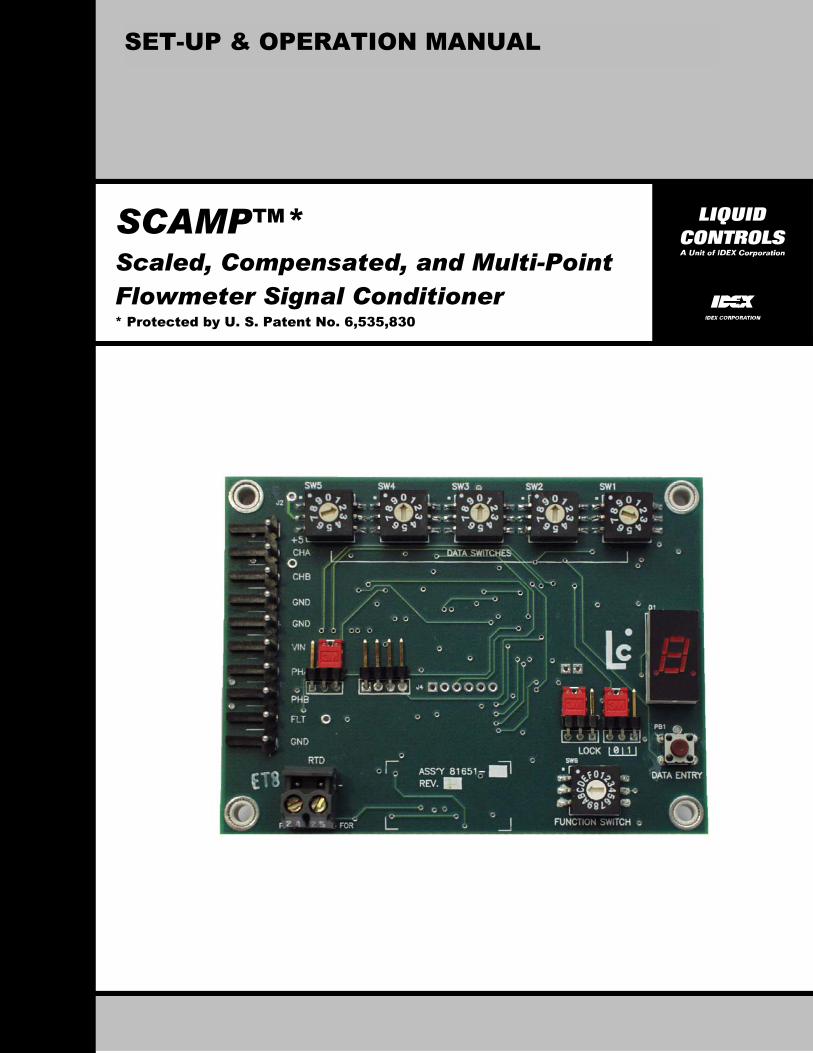
1 SET-UP & OPERATION MANUAL SCAMP™* Scaled, Compensated, and Multi-Point Flowmeter Signal Conditioner * Protected by U. S. Patent No. 6,535,830
-
Upload
khangminh22 -
Category
Documents
-
view
1 -
download
0
Transcript of SCAMP™* - Liquid Controls
1
SET-UP & OPERATION MANUAL
SCAMP™* Scaled, Compensated, and Multi-Point Flowmeter Signal Conditioner * Protected by U. S. Patent No. 6,535,830

2
TABLE OF CONTENTS SUBJECT PAGE Table of Contents.............................................................................................................. 2 Overview ........................................................................................................................... 3 Installing SCAMP and Making Basic Electrical Connections ............................................ 4 Powering Up SCAMP........................................................................................................ 4 Programming Meter k-Factor ............................................................................................ 5 Computing and Programming Multi-Point Calibration Data (Optional)........................ 6 – 9 Temperature Volume Compensation (Optional) ..................................................... 10 – 11 Fault Indicator/Electromechanical Totalizer (Optional) ................................................... 12 Final Checkout Flow Test................................................................................................ 12 Error Messages....................................................................................................... 13 – 14 Trouble Shooting............................................................................................................. 15 Appendix A, Specifications.............................................................................................. 16 Appendix B, SCAMP Function Tables ............................................................................ 17 Appendix C, Calculating the k-Factor for your Meter ...............................................18 - 19 Appendix D, Nominal Raw Pulser Resolution of LC Meters …..………………………….19 Electrical Safety NOTE: This equipment is suitable for Class I, Division 2, Groups C and D, or non-hazardous locations, only. Electromagnetic Compatibility Limitation NOTE: This (equipment and/or system) is suitable for use in all establishments other than domestic and those directly connected to the low voltage power supply network which supplies buildings used for domestic purposes. WARNING The SCAMPTM circuit board and attendant equipment including but not limited to 9-18 VDC power supply, 2-channel quadrature pulser, and electronic counter (whether supplied by Liquid Controls or others) must be installed and operated in accordance with all applicable national and local electrical, environmental, and safety codes. Failure to do so could result in serious injury or death. Explosion Hazard – Substitution of components may impair suitability for Class I, Division 2. Explosion Hazard - Do not disconnect equipment unless power has been switched off or the area is known to be non-hazardous. NOTE: The rotary data switches on SCAMP can be damaged by extensive or rough rotation of the mechanism. Please exercise appropriate care when setting all data values on the rotary switches. TOOLS REQUIRED: Small flat-blade screwdriver for attaching wires to terminal strips and making adjustments to rotary switches.

3
OVERVIEW SCAMPTM is an advanced electronic flowmeter signal conditioner that converts the output signal from the flowmeter to a volumetric unit of measure. SCAMP also temperature corrects the volume delivered to an API standard or to a programmable coefficient of expansion, and has the ability to linearize the flowmeter accuracy at up to sixteen points over its entire flow range. SCAMP is factory programmed and calibrated to provide a volumetrically correct, Weights & Measures approved and sealed, quadrature pulse output. The SCAMP output pulse can be used to operate most pulse actuated electronic counters, flow computers, PLC’s or other electronic control devices. SCAMP is micro-processor driven, and features a regulated power supply to protect against voltage transients, easy-to-use binary coded decimal (BCD) switches for data entry, watchdog timer to ensure reliable execution of software code, and a 7-segment LED display for data verification and error messaging. SCAMP is ready for operation with a minimum of mounting requirements and external wiring connections as described in Steps 1 and 2 on the following page. After installation but before final commissioning, the customer should verify that all factory-programmed parameters are resident in SCAMP memory, and that all data agrees with the values listed on the Meter Calibration Sheet included with the meter. NOTE: It is important that the SCAMP circuit board be paired with the meter for which it has been factory calibrated. Proper pairing of SCAMP and meter can be confirmed by matching Serial Number data for the meter and SCAMP, as recorded on the Meter Calibration Sheet. If the SCAMP circuit board is applied to a different meter, all calibration data for the meter must be re-computed and entered into SCAMP as described later in this manual. HELPFUL HINT: Customer-entered data values are setup by first selecting one of the basic SCAMP functions on the Function Switch (see Appendix B), and then setting the numeric data for that function on the five Data Switches on the SCAMP circuit board. Data is entered in memory by depressing the Data Entry pushbutton located on the SCAMP circuit board to the right of the Function Switch (see diagram on following page). Recovery from mis-entered or incorrect data is easy with SCAMP: simply re-position the Data Switches to the proper settings, and depress the Data Entry pushbutton. NOTE: On occasion, it may be desireable to clear all customer data from the SCAMP non-volatile memory and re-enter new data. This can be accomplished by performing a “Clear All” operation. To perform the “Clear All”, set the Function Switch to “0”, set all Data Switches to “0”, move the “0/1” jumper to the “0” position, and the “LOCK” jumper to the left-most position to unlock the unit, and then depress the Data Entry Pushbutton. This procedure should only be utilized in special cases involving complete reconfiguration of your unit. WARNING: After a successful “Clear All” operation, it will be necessary to re-enter all calibration data. To minimize the re-calibration effort, you may want to record all accessible data and Error Messages (Function Switch position “E”) before performing the “Clear All”.

4
INSTALLING SCAMP AND MAKING BASIC ELECTRICAL CONNECTIONS STEP 1. The SCAMP circuit board measures 4” X 3”. Corner mounting holes (0.144” ID) are provided on 3.640” centers and 2.640” centers, respectively. The circuit board should be mounted in a suitable environmentally sealed compartment, with the top surface of the board (surface with terminal strips and switches) positioned to provide easy access and viewing. Mounting the board to a vertical panel is recommended to guard against condensation moisture accumulating on the PC board surface. STEP 2. Connect the SCAMP circuit board to peripheral equipment including 9-18 VDC power supply, 2-channel quadrature pulser, electronic counter, RTD temperature probe (optional), and fault indicator/electromechanical counter (optional), as shown in the diagram below. NOTE: Phase A and Phase B pulser outputs (Terminals 7 and 8) are unpowered “current-sinking” open-collector outputs. Customer-supplied pull-up resistors (300-ohm minimum) may be required between terminals 6 – 7, and 6 – 8, if not already included in the customer-supplied electronic counter. Term Connection 1 +5V out to power pulser 2 Channel A in from Pulser 3 Channel B in from Pulser 4 Ground to Pulser 5 Ground to Power Supply 6 9 to 18 VDC Power Supply 7 Phase A to Counter 8 Phase B to Counter 9 Fault Output (optional) or low
frequency counter 10 Gnd return for output pulses 24 RTD (optional) 25 RTD (optional) WARNING! Do not disconnect while circuit is live unless area is known to be non-hazardous. POWERING UP SCAMP STEP 3: Carefully check that all wiring has been made in conformance with the directions in Step 2, and in conformance with all applicable national and local electrical, environmental, and safety codes and ordinances appropriate for this type of equipment. Then, turn power on to the unit. The 7-segment LED display on SCAMP should light up and execute a segment test within approximately 1-second of power being supplied to the unit.

5
PROGRAMMING METER K-FACTOR Your SCAMP circuit board has been factory calibrated to include a four-digit k-Factor for your specific meter (only if SCAMP is sold separately, i.e., without a meter, is calibration data not entered at the factory). The k-Factor is a number represented by the ratio of pulse edges into SCAMP (from the pulser) and whole pulses per channel out of SCAMP (to the electronic counter). The value of the k-Factor is a number in the range of 4.000 to 9999. IMPORTANT: PERFORM THESE OPERATIONS BEFORE PROCEEDING! Before beginning any programming, move the “LOCK” jumper located on the right-hand side of the circuit board to the left-most position to unlock the unit. Also, move the jumper marked “0/1” to the “0” position. NOTE: Care should be taken when the unit is unlocked because factory loaded data can be lost or altered if the Data Entry pushbutton switch is inadvertently depressed. STEP 4A. Checking the Factory Programmed k-Factor ♦ Set the Function Switch located on the lower right-hand side of the SCAMP circuit
board to the “0” position. Observe the k-Factor value scrolling on the LED display. The scrolling value will be a number such as “F19.58”. Confirm that the number appearing on SCAMP is identical to the k-Factor listed on your Meter Calibration Sheet. If the k-Factor is correctly entered in SCAMP, you may proceed to the next page “Computing and Programming Multi-Point Calibration Data”. If no data is present, an “F0” will scroll across the LED display and you should proceed to Step 4B.
STEP 4B. Programming a New k-Factor in the Field If required, a new k-Factor is easily programmed into SCAMP. Refer to your Meter Calibration Sheet for a factory-determined value, or to Appendix C for a detailed discussion on the calculation of a new k-Factor for your meter. Then, return to this step for loading the value into memory. ♦ Set the Function Switch located on the SCAMP circuit board to the “0” position. ♦ Set the Data Switches located along the top edge of the SCAMP circuit board to the
appropriate values to represent the four digit k-Factor for your meter, starting with the left-most switch (sw5). The right-most switch (sw1) is reserved for an extra digit to establish positioning (left-shifting) of the decimal point. For example, a k-Factor of 19.58 would be entered as 19582, where the last digit (“2”) specifies the positioning of the decimal point, i.e., two places to the left. The range of valid entries is 4.000 to 9999.
♦ Depress the Data Entry Pushbutton located on SCAMP to enter the new k-Factor value into memory. The LED display will now scroll the new value to verify that it has been successfully loaded into memory.

6
COMPUTING & PROGRAMMING MULTI-POINT CALIBRATION DATA (optional) Multi-point calibration permits compensating for inherent meter error across the full range of flow rates for the meter, thereby providing near-perfect meter accuracy for deliveries from maximum flow to minimum flow. SCAMP allows multi-point calibration for up to 16 different flow rates. Typically, the majority of the selected flow rates will be in the low to mid flow range where most meter inaccuracy occurs. Two data entries are required for each linearization point to complete a multi-point calibration: i.e., specification of a target flow rate, expressed in pulse edges per second, and specification of a percentage error at that flow rate as determined by prover runs or reference to the Meter Calibration Sheet. IMPORTANT: PERFORM THIS OPERATION BEFORE PROCEEDING! When accessing the multi-point calibration data in steps 5A through 5C below, ensure that the “0/1” jumper is in the “1” position. NOTE: It is NOT required that multi-point data be programmed for each or any of the 16 available points. If the data entered into SCAMP matches the data on your Meter Calibration Sheet, you may move ahead to Step 6. STEP 5A: Checking the Factory Programmed Multi-Point Calibration Data ♦ Set the Function Switch in the “0” position, and observe the scrolling LED display
to confirm that the same value is indicated by the LED display as listed on the Meter Calibration Sheet. Your scrolling display will consist of the alpha character “F” followed by up to four digits identifying the flow rate in pulse edges per second for which the calibration was made. Immediately following is the alpha character “P” followed by the value representing the percentage error at that flow rate. For example, “F2447 P0.113” represents a 0.113% delivery error at the flow rate represented by 2447 pulses per second. A display of “E20” indicates that no correction has been programmed for that point.
♦ Repeat this verification procedure by placing the Function Switch in positions 1 through F to confirm that the correct data is loaded into the SCAMP memory. Use the Meter Calibration Sheet as your reference.
STEP 5B: Entering Multi-Point Calibration Data (From Meter Calibration Sheet) If the factory-programmed multi-point calibration data has been inadvertently lost from memory or needs to be changed it can be entered into SCAMP by referencing your Meter Calibration Sheet and performing the following operations. ♦ Move the Function Switch to the “0” position. If there is no data (display shows
“E20”), or if you wish to change the value currently in memory, proceed as follows: ♦ Set the Data Switches located along the top edge of the SCAMP circuit board to the
appropriate values to represent the flow rate in pulse edges per second for your meter. Refer to your Meter Calibration Sheet. Start with the left-most switch (sw5). The right-most switch (sw1) is reserved for an extra digit to establish positioning (left-shifting) of the decimal point. For example, a pulse rate of 3704 would be entered as 37040, where the last digit (“0”) specifies the positioning of the decimal

7
COMPUTING & PROGRAMMING MULTI-POINT CALIBRATION DATA (Cont.) point, in this case, no left-shifting. The flow rate value must be an integer greater than 3.000. NOTE: If desired, individual calibration points may be disabled by entering any number less than -3.000. ♦ Depress the Data Entry Pushbutton located on SCAMP to enter the new flow rate
value into memory. The LED display will now scroll the new value to verify that it has been successfully loaded into memory. If the data was not accepted, an error code will be displayed. Refer to “Error Message” table on pages 13 and 14. NOTE: When the flow rate field is set, the percent error field is flagged as “not set” and will not be displayed on the LED display.
♦ Next, Set the Data Switches located along the top edge of the SCAMP circuit board to the appropriate values to represent the percent error for your meter (listed for Point 0 on your Meter Calibration Sheet), starting with the left-most switch (sw5). The right-most switch (sw1) is reserved for an extra digit to establish positioning (left-shifting) of the decimal point. For example, an error of 0.100% would be entered as 10004, where the last digit (“4”) specifies the positioning of the decimal point, i.e., left-shifting four digits. Negative values are entered using a zero “0” in the first-digit position (sw5). For example, an error of –0.100% would be entered on the Data Switches as 01003. The error percentage value must be greater than or equal to -3.000 and less than or equal to 3.000.
♦ Depress the Data Entry Pushbutton located on SCAMP to enter the new error percentage value into memory. The LED display will now scroll the flow rate and percentage error to verify that the value has been successfully loaded into memory, e.g. “F3704 P0.1”.
♦ Perform the identical operations for additional flow rates by moving the Function Switch to the “1” position (and then entering data), then to the “2” position, and so forth, for a maximum of up to sixteen flow rates.
Summary of how values are interpreted by Multi-Point Calibration Setup Entered Value Interpreted As Result Integer values greater than 3.000.
Flow Rate Resets the flow rate value to the new value and clears the percent error field.
Any value greater than or equal to -3.000 and less than or equal to 3.000.
Percent Error If the flow rate has been set, the percent error is reset to the new value. If the flow rate has not been set, an "E22" is generated.
Any Value less than -3.000. Disable Point The point is disabled and "E20" is displayed.
All other values. Range Error The current data remains intact and "E1" is displayed.

8
COMPUTING & PROGRAMMING MULTI-POINT CALIBRATION DATA (Cont.) IMPORTANT: The multi-point calibrations computed and entered above are not activated until the “0/1” jumper is moved back to the “0” position and the Function Switch is returned to either the Function 0 (gross measurement mode) or Function 1 through A (net measurement mode). STEP 5C: Entering New Multi-Point Calibration Data (using Prover Method) ♦ Move the Function Switch to the “0” position. If no multi-point calibration data has
been previously entered into SCAMP, the LED display will scroll “E20”. If there is no data or if you wish to change the value currently in memory, proceed as follows.
♦ Initiate a prover run at the highest flow rate for the meter, with the Function Switch set in the “0” position. When the flow rate is stable, press the Data Entry pushbutton located to the right of the Function Switch. The display will scroll the pulse rate that has been captured by SCAMP at that flow rate. For example, an M7 meter operating at a flow rate of 100 gallons per minute provides a nominal pulse rate of 3704 pulse edges per second for which the display would scroll “F3704”. Complete filling the prover to conclude the first portion of the multi-point calibration procedure. At the completion of the prover run, stop flow through the meter.

9
COMPUTING & PROGRAMMING MULTI-POINT CALIBRATION DATA (Cont.) ♦ Next, calculate meter error, as follows. % Error = (Prover volume-Meter volume) x 100 Prover volume Example: % Error = 100.15 -100.17 x 100 = -0.01997% 100.15 ♦ WITH NO FLOW THROUGH THE METER AND STILL IN THE FUNCTION WHERE
THE PULSE RATE WAS CAPTURED, set the Data Switches to specify the above- calculated error at the given flow rate. The value entered must be in the range of -3.000 to +3.000. Negative numbers are denoted by setting a “0” on the left-most Data Switch (sw5). Using the above example, the error of -0.01997% would first be rounded to 3 significant digits in accordance with Weights & Measures rules to -0.020, and then entered on the Data Switches as “00203”, where the last digit is used to establish left-shifting of the decimal point. Once the error value has been set on the Data Switches, depress the Data Entry pushbutton to enter the value in memory. The LED display will now scroll the new value, e.g. “F3704 P-0.02”.
♦ Perform the identical operations for additional flow rates by moving the Function Switch to the “1” position (and then entering data), then to the “2” position, and so forth, for a maximum of up to sixteen flow rates.
IMPORTANT: The multi-point calibrations computed and entered above are not activated until the “0/1” jumper is moved back to the “0” position and the Function Switch is returned to either the Function 0 (gross measurement mode) or Function 1 through A (net measurement mode). Circuit board illustration for identifying user switches and
jumpers referenced in instructions.

10
TEMPERATURE-VOLUME COMPENSATION (Optional) If temperature-volume compensation is desired, your unit must be outfitted with a standard 100-ohm platinum RTD temperature probe connected as shown in Step 2. Temperature volume compensation permits accurate “net” volumetric deliveries of product taking into account the thermal expansion or contraction of the liquid with changes in temperature. The feature corrects the delivery to a standard reference volume at a liquid temperature of 60oF (15oC). IMPORTANT: PERFORM THIS OPERATION BEFORE PROCEEDING! When accessing the temperature compensation and adjustment data, ensure that the “0/1” jumper is in the “0” position. STEP 6: Selecting a Temperature-Volume Compensation Table ♦ Refer to the table below and determine which table is appropriate for your
application. Set the Function Switch to the position dictated by your table selection. If the volume compensation parameter has not been set for the table selected, an “E40” error message will scroll on the LED display to indicate the missing parameter.
Function Switch
VCF Table Type
Temp. Scale
VCF Parameter Range
Base Temp.
Minimum Temp.
Maximum Temp.
Hold Temp.
0 None C N/A N/A N/A N/A N/A 1 Linear F F 0-0.0025 60 -130 +212 -130 2 Linear C C 0-0.005 15 -90 +100 -90 3 Table 24 F 0.500-0.550 SGU 60 -50 +140 -50 4 Table 54 C 0.500-0.600 SGU 15 -46 +60 -46 5 Table 54A C 610.5-1075.0 Kg/m3 15 -50 +95 -40 6 Table 54B C 653.0-1075.0 Kg/m3 15 -50 +95 -40 7 Table 54C C 0.000486– 0.001674 15 -50 +95 -40 8 Table 54D C 800-1164 Kg/m3 15 -50 +95 -40 9 Table 6B F 0-85°API 60 -50 +200 -40 A NH3 C N/A 15 -30 +40 -30
STEP 7: Setting the Volume Compensation Parameter ♦ Set the Data Switches on SCAMP to the desired VCF parameter. For example, the
maximum VCF parameter for Linear F compensation (Function Switch 1) is 0.0025, which is entered on the Data Switches as 25006, where the last digit (sw1) specifies positioning (left-shifting) of the decimal point. NOTE: A leading “0” indicates a negative number, which is why 0.0025 must be entered as 25006 instead of 00254.
♦ Depress the Data Entry pushbutton to enter the value placed on the Data Switches. The LED display will now scroll “Fxx.xx Px.xxx” where the first character set represents the temperature sensed by the RTD probe in degrees Fahrenheit, and the second character set represents the VCF parameter. Note that the first letter will be an “F” or “C” depending on the temperature scale for the selected compensation type.

11
TEMPERATURE-VOLUME COMPENSATION (Cont.) STEP 8: Temperature Adjustment Your SCAMP unit has been factory calibrated for accurate temperature measurement using a standard 100-ohm platinum RTD with 5 feet of lead wire meeting IEC Class 751-B requirements. If field adjustment is required to match a Weights & Measures thermometer reading, a temperature offset can be entered as follows: ♦ Set the Function Switch to the “C” position. The LED will scroll “A0 Cxx.xx” or “A0
Fxx.xx”, where “A0” indicates that no adjustment offset value has been set, “Cxx.xx” indicates the current temperature in degrees Celsius, and “Fxx.xx” indicates the current temperature in degrees Fahrenheit. (NOTE: If the current temperature is ±999.9, there is a problem with the probe, or it is not connected properly).
♦ Enter the Temperature Scale (Celsius or Fahrenheit) on the Data Switches. To select Celsius as the temperature scale, set the switches to 10003 and depress the Data Entry pushbutton. To select Fahrenheit as the temperature scale, set the switches to 20003 and depress the Data Entry pushbutton.
♦ Enter the Temperature Adjustment on the Data Switches required to match the Weights & Measures thermometer reading and depress the Data Entry pushbutton. The LED display will now scroll “Ay.yy Cxx.xx” or “Ay.yy Fxx.xx” depending on the temperature scale selected.
NOTE: If the temperature scale is Celsius, the temperature adjustment value must be greater than or equal to -0.300 and less than or equal to 0.300. If the temperature scale is Fahrenheit, the temperature adjustment value must be greater than or equal to -0.540 and less than or equal to 0.540. For example, an adjustment of -0.25 degrees Fahrenheit would be entered on the switches as 00252, where the leading zero indicates a negative number and the trailing “2” indicates positioning of the decimal point. The display would then read “A-0.25 Fxx.xx” where xx.xx is the current temperature in degrees Fahrenheit adjusted by -0.250.

12
FAULT INDICATOR / ELECTROMECHANICAL TOTALIZER (Optional) Function F (Terminals 9 & 10 or 9 & 6) can be utilized for either of two purposes: 1. To operate a fault indicator such as a LED or relay. 2. To operate an electromechanical or electronic counter as a long-term meter totalizer. IMPORTANT: PERFORM THIS OPERATION BEFORE PROCEEDING! When accessing the electromechanical totalizer k-Factor, ensure that the “0/1” jumper is in the “0” position. STEP 9: To operate as a fault indicator, set the Function Switch in the “F” position, and confirm the default setting of “F0” on the scrolling LED display. If some other value is indicated, set all of the Data Switches to “0”, and press the Data Entry pushbutton to load “0” into memory. The LED should now show “F0”, and the Terminal 9 output will be programmed for fault indication (i.e., pulled low into current-sinking state during non- fault conditions to provide “fail-safe” fault indication). Applications of this feature include indication of a fault condition or shut down of a pump during a fault. Function F can also operate as a scaled pulse output (with multi-point errors and temperature compensation applied) to drive an electromechanical or electronic counter as a long-term meter totalizer. The pulse from this output is a single-shot 20 millisecond ON pulse. The k-Factor for the counter is entered into SCAMP by setting the Function Switch to the “F” position, setting the k-Factor value on the Data Switches, and then depressing the Data Entry pushbutton to enter the value into memory. The value of the k-Factor is a number in the range from 40.00 to 9999. Output terminals 9 & 10 can now be used to drive an external totalizer. Note that due to the fixed pulse width timing of 20 milliseconds ON, the maximum frequency out of terminal 9 should be scaled such that it does not exceed 25 pulses per second. FINAL CHECKOUT FLOW TEST STEP 10: Begin by moving the “0/1” jumper to the “0” position. Set the Function Switch in the “0” position for Gross Delivery Mode (non-compensated deliveries), or in position “1” through “A” for Net Delivery Mode (temperature-compensated deliveries). The actual switch position reflects the Compensation Table (0-A) that has been selected. Then, run forward flow through your meter. If the dispenser counter counts backwards during forward flow, reverse the “A” and “B” wires on either the pulser or the counter. Your unit is now fully commissioned and ready for operation. Be sure the RTD probe is connected for temperature compensated systems. IMPORTANT: Before sealing the SCAMP in its enclosure, move the “LOCK” jumper to the “LOCK” position to protect the calibration data fields, and ensure that the “0/1” jumper is in the “0” position.

13
ERROR MESSAGES SCAMP provides error codes that appear on the LED display located on the SCAMP circuit board. Following is a list of all possible error codes along with a description of the error and suggested corrective actions. The errors are classified according to two levels of severity: non-critical errors; and disabling errors. Non-critical errors are not listed in Function Switch position “E”, and will not interrupt operation of SCAMP. Disabling errors are listed in Function Switch position “E”, and will prevent further operation of SCAMP. Non-Critical Errors
Error Code Description E0 No error has occurred. E1 Range error. The value read when the Data Entry pushbutton was pressed is
outside the valid range limit for the field selected. Ensure that the Data Switches represent the value desired, focusing on the decimal point adjuster switch (sw1), and attempt setting the value again.
E2 An individual data switch returned a value greater than 9. Ensure that each Data Switch is firmly “clicked” into its position and try entering the value again. If the problem persists, the SCAMP unit will need to be replaced.
E10 An attempt was made to calibrate the A to D converter at the 128.6 ohm resistor value before calibration was done at the 100.0 ohm resistor value.
E20 The linearization point has not been setup and is disabled. NOTE: Linearization data is optional and need not be set for each (or any) of the 16 available points. In the case of unused points, the E20 error message should be disregarded.
E21 The flow rate being set for a linearization point is already being used by another linearization point. Each linearization point being used must contain a unique flow rate.
E22 An attempt was made to set the percent error field of a linearization point but the flow rate has not been set for the point. Set the flow rate for the point first, and then re-enter the percent error field.
E30 A write to flash was attempted with the “LOCK” jumper in the “LOCK” position. Move the “LOCK” jumper out of the “LOCK” position and try setting the field again.
E40 The temperature volume compensation parameter has not been set. Set the Data Switches to the desired temperature volume compensation parameter for the compensation type selected and press the Data Entry pushbutton. NOTE: Temperature Volume Compensation parameters need not be set for unused Compensation Tables. In such cases, the E40 error message should be disregarded.

14
ERROR MESSAGES Disabling Errors
Error Code Description E100 The program code space of the SCAMP has been corrupted and needs to be
reloaded. Contact Liquid Controls on how to proceed. E110 An excessive number of pulser reversals have occurred. Once flow has
stopped, ensure that the pulser is connected properly to the SCAMP and try running flow again. If the problem persists, the pulser may need to be replaced.
E111 Scalar adjustment range error. The quadrature scalar was adjusted by linearization or temperature compensation so that it represents a k-Factor less than 4.000. Ensure that the linearization tables were set up correctly and that the temperature compensation parameter was entered correctly.
E120 Adjacent flow rate points in the linearization table have percent errors with a difference greater than 0.250%. Find the two points whose difference is out of range and use a spare point to fill the gap. If all points have been used, a re-analysis of the data will need to be performed so as to ensure no two adjacent flow rate points have a difference greater than 0.250%.
E121 Incomplete linearization table setup. A flow rate was set for a point, but the percent error field was not set. Find the point that is causing the error and either disable the point by entering an invalid flow rate, e.g. 04002, or set the percent error field for the point.
E130 An error occurred while reading from the non-volatile data storage device. Attempt to clear the error by performing a “Clear All” operation. This is done by moving the “0/1” jumper to the “0” position, setting the Function Switch and all Data Switches to “0”, and pressing the Data Entry pushbutton. WARNING: After a successful “Clear All” operation, it will be necessary to re-enter all calibration data. You may want to record all accessible data before performing the “Clear All” to minimize the re-calibration effort.
E131 An error occurred while writing to the non-volatile data storage device. Try setting the field again. If the field cannot be set successfully, attempt to clear the error by performing a “Clear All” operation. This is done by moving the “0/1” jumper to the “0” position, setting the Function Switch and all Data Switches to “0”, and pressing the Data Entry pushbutton. If the problem persists, the SCAMP unit will need to be replaced. WARNING: After a successful “Clear All” operation, it will be necessary to re-enter all calibration data. You may want to record all accessible data before performing the “Clear All” to minimize the re-calibration effort.
E140 The current temperature is out of range for the volume compensation type selected. Verify that the temperature probe is returning the correct temperature by moving the "0/1" jumper to the “0” position, setting the Function Switch to “C”, and reading the displayed temperature. If the temperature value is incorrect, replace the temperature probe. If the problem persists, the SCAMP unit will need to be replaced.
NOTE: The last Disabling Error Code (error codes greater than or equal to 100) may be viewed by setting the “0/1” jumper to the “0” position, the Function Switch to the “E” position, and observing the LED display. The last error code can be deleted (recommended only after resolution of the error) by setting all the Data Switches to “0”, and pressing the Data Entry pushbutton with the Function Switch in the “E” position.

15
TROUBLE SHOOTING PROBLEM: SCAMP will not power up. SOLUTION: Using a digital multi-meter, check to ensure that 9-18 VDC is present at
the Terminal Strip, Positions 5 and 6. Check further to ensure that the ground lead for the power supply is connected to Terminal 5, and that the positive power supply lead is connected to Terminal 6. Tighten all terminal connection screws.
PROBLEM: Field data is not being stored in SCAMP memory. SOLUTION: Make sure that the “LOCK” jumper is in the left-most position indicating
the unit is unlocked, and that the Data Entry pushbutton is depressed after setting the appropriate numerical values on the Data Switches. Data is only entered into SCAMP memory after the Data Entry pushbutton is depressed. NOTE: Multi-point calibration data must be entered with the “0/1” jumper in the “1” position.
PROBLEM: SCAMP does not operate the counter during flow. SOLUTION 1: Make sure that there are appropriate pull-up resistors for the attached
counter (SCAMP has open-drain outputs that switch to ground). NOTE: Most counters include internal pull-up resistors on the pulse input terminals. If your counter does not include such resistors, add the resistors (300-ohm, minimum) between SCAMP terminals 6 – 7, and 6 – 8.
SOLUTION 2: Check for the presence of a disabling error, such as a failed temperature probe for compensated systems. To check for such an error, place the Function Switch in the “E” position and note the message scrolled on the LED display. Take the corrective action indicated in the Error Message Table.
PROBLEM: The electronic counter counts backwards during forward flow. SOLUTION: Reverse the “A” and “B” wires on either the pulser or the counter.

16
APPENDIX A: SPECIFICATIONS SCAMP SPECIFICATIONS Circuit Board Dimensions………………………………………………………4” X 3” Ambient Temperature Range…………………………………………...-30 to +75º C Relative Humidity………………………………………….. 0-100% non-condensing Weatherproof………………………………………………………………………None (Circuit board is designed for installation in customer enclosure) Non-incendiary UL and C-UL……………………Class I, Division 2, Groups C & D Weights & Measures USA………………………………………………………….NIST Handbook 44 Canada (pending)..…………………………………………SVM-1 and SVM-2 Electro-Magnetic Compatibility (EMC)………………….per CE mark requirements SCAMP Power Supply……………………………….9 to 18 VDC @ 0.2A maximum SCAMP Outputs……...Two Open Drain FETs for quadrature output (100mA, Sinking) …………..(a jumper option is provided to make the B pulse an inverted A pulse1) …………One Open Drain FET for electromechanical pulse/fault output (1A, Sinking) ……………………………………………………………………………....One RS-232 Wiring Termination………………………..……Unpluggable Screw Terminal Block 1Needed for compatibility with certain dispenser heads. To convert the B pulse to an inverted A pulse, reposition the jumper on the left side of SCAMP to the left-most position (refer to diagram on page 4).

17
APPENDIX B: SCAMP FUNCTION TABLE “0/1” Jumper Set in Position “0” Function Switch Setting
Displayed Value
0 Gross k-Factor (gross metering mode). 1 Linear F compensation parameter and current temperature in degrees Fahrenheit. 2 Linear C compensation parameter and current temperature in degrees Celsius. 3 Table 24 compensation parameter and current temperature in degrees Fahrenheit. 4 Table 54 compensation parameter and current temperature in degrees Celsius. 5 Table 54A compensation parameter and current temperature in degrees Celsius. 6 Table 54B compensation parameter and current temperature in degrees Celsius. 7 Table 54C compensation parameter and current temperature in degrees Celsius. 8 Table 54D compensation parameter and current temperature in degrees Celsius. 9 Table 6B compensation parameter and current temperature in degrees Fahrenheit.
A Current temperature in degrees Celsius. (NH3 compensation is active)
B Seven segment display test. C Temperature Offset Adjustment and Current Adjusted Temperature. The
temperature is displayed in Celsius or Fahrenheit depending on the temperature scale selected.
D Serial Programming Mode (consult factory) E Last recorded disabling error number. F Electromechanical pulse output scale factor.
“0/1” Jumper Set in Position “1” Function Switch Setting
Displayed Value
0 Flow rate and percent error for linearization point # 0. 1 Flow rate and percent error for linearization point # 1. 2 Flow rate and percent error for linearization point # 2. 3 Flow rate and percent error for linearization point # 3. 4 Flow rate and percent error for linearization point # 4. 5 Flow rate and percent error for linearization point # 5. 6 Flow rate and percent error for linearization point # 6. 7 Flow rate and percent error for linearization point # 7 . 8 Flow rate and percent error for linearization point # 8. 9 Flow rate and percent error for linearization point # 9. A Flow rate and percent error for linearization point # A. B Flow rate and percent error for linearization point # B. C Flow rate and percent error for linearization point # C. D Flow rate and percent error for linearization point # D. E Flow rate and percent error for linearization point # E. F Flow rate and percent error for linearization point # F.

18
APPENDIX C: CALCULATING THE K-FACTOR FOR YOUR METER STEP 1: Determine how many whole pulses per unit of measure per output channel are desired for the application. Discussion: If the output counter only counts one channel on one edge (whether rising or falling), then the number desired is usually 1, 10, 100, or 1000 pulses per unit of volume. If, however, the counter uses both channels (e.g. dispensers usually count on both channels and on both edges) the number of whole pulses per unit of measure is the number of edges divided by 4. Dispensers generally require 250 whole pulses per gallon, which is 1000 edges divided by 4. STEP 2: Determine the nominal number of pulse edges per unit of volume that the raw pulser will output for your meter (refer to Meter Calibration Sheet). Discussion: The LC 100-ppr POD pulser outputs 100 whole pulses per channel times two channels, times two edges per channel or 400 pulse edges per revolution. Multiply this by the revolutions per flow unit for your meter. For example, an M7 meter has a nominal displacement of 5.555 revolutions per gallon. Therefore, the nominal number of pulse edges per unit is 2222 edges/gallon. Set the initial SCAMP k-Factor in Function 0 using the following number. Initial k-Factor = Input nominal pulse edges per unit volume Output whole pulses per unit volume The range of allowable k-Factors is 4.000 to 9999. Examples: 1. An M7 meter is to be set to output 100 pulses per gallon into a single channel
counter. Initial k-Factor = 2222 edges / gallon (nominal) = 22.22 100 pulses / gallon
Switch setting is dialed to 22222 (2222 with two decimal places). Put function switch in function 0 and enter the value by pressing the Data Entry pushbutton. The display will scroll “F22.22”.

19
APPENDIX C: CALCULATING THE K-FACTOR FOR YOUR METER (Cont.) 2. An M5 dispenser meter is to be set to output 250 whole pulses per channel per
gallon in order to count into a dispenser head that requires 1000 edges per gallon. Initial k-Factor = 4894.8 edges / gallon (nominal) = 19.5792 250 pulses per gallon Switch setting is dialed to 19582 (1958 with 2 decimal places).
Put function switch in function 0 and enter the value by pressing the Data Entry pushbutton. The display will scroll “F19.58“.
Once the initial k-Factor is set, a proving run can be made to fine tune the calibration. Fill the prover to a known level at the desired flow rate (usually the highest flow rate of the meter/system). Read the pulse count and compare it to the prover volume. If the two are not equal make the following calculation to adjust the function 0 k-Factor: New k-Factor = Current k-Factor x Meter volume Prover volume
Example: A 100 gallon proving is done on the M7 meter in example 1 above. The prover level is read out at 100.15 gallons. The pulse counter on the SCAMP reads 9987 pulses or 99.87 gallons when the decimal point is properly positioned. New k-Factor = 22.22 x 99.87 gallons = 22.1579
100.15 gallons Switch setting is dialed to 22162 (2216 with 2 decimal places)
Put function switch in function 0 and enter the value by pressing the Data Entry pushbutton. The display will scroll “F22.16”.
A verification run can be made to check the results of the fine tuning procedure. In the example above, there may be some small residue error due to rounding the calculated new k-Factor to a four digit number. This should be less than 0.1% in all cases and can be reduced by using one or more settings of the multi-point capabilities of the SCAMP. Using the verification run data, the first of the multi-points can be obtained. APPENDIX D: NOMINAL RAW PULSER RESOLUTION (100 ppr encoder) LC Meter Size
Max Flow Rate
Revs/Gallon Pulse Edges/ Gallon
Pulse Edges/ Litre
P 60 12.237 4894.8 1293.11 M/MA5 60 4.079 1631.6 431.04 M/MA7/10 150 5.555 2222.0 587.01 M/MA15/25 300 2.058 823.2 217.47 M30/40 450 0.742 296.8 78.41 M60/80 800 0.398 159.2 42.06 MS-75 700 0.255 102.0 26.95 MS-120 1200 0.158 63.2 16.70

20
SOLD AND SERVICED BY A NETWORK OF HIGHLY TRAINED FULL SERVICE DISTRIBUTORS
Backed By Our Worldwide Reputation For Quality, Accuracy and Advanced Design.
Warranty: Liquid Controls (“Seller”) products are warranted against defects in materials or workmanship for a period of one (1) year from date of installation, provided that the warranty shall not extend beyond twenty-four (24) months from the date of original shipment from seller. Seller’s obligations, set forth below, shall apply only to failure(s) to meet the foregoing obligations provided that seller is given written notice within (30) days of any occurrence from which a claim of defect arises. If a warranty dispute occurs, the purchaser shall be required to provide Seller with proof of date of sale. The minimum requirement to establish date of sale shall be a copy of the Seller’s invoice. In the event that a factory inspection by Seller or its designee(s) supports the validity of a claim, at the discretion of Seller, repair, replacement or refund shall be sole remedy for defect
and shall be made, free of charge, ex-works factory. In no event shall Seller be liable for any special, consequential, incidental, indirect or exemplary damages arising out of warranty, contract, tort, (including negligence) or otherwise, including but not limited to, loss of profit or revenue, loss of use of the product or any associated products and/or equipment, cost of substitute goods or services, downtime costs or claims of or by Purchaser’s clients or customers. In any event, the total liability of Seller for any and all claims arising out of or resulting from the performance, non-performance or use of the product shall not exceed the purchase price of the individual product giving rise to the claim. All other guaranties, warranties, conditions and representations, either express or implied, whether arising under any statute, common law, commercial usage or otherwise are excluded. Electronic Products require
Installation, start-up and servicing by local factory-trained service representatives. In the absence of installation, start-up and servicing of Electronic Products by Seller trained service representatives, this warranty is null and void. Seller’s obligations as set forth above shall not apply to any product, or, or any component part thereof, which is not properly installed, used, maintained or repaired, or which is modified other than pursuant to Seller’s instructions or approval. NOTE: The above warranty applies only to products manufactured by Liquid Controls, Lake Bluff, Illinois. Private label, OEM, and/or products manufactured by Liquid Controls licensee(s) are specifically excluded from the above warranty. Consult the factory for all non-Liquid Controls manufacturers’ warranties. NO IMPLIED OR STATUATORY WARRANTIES OF MERCHANTABILITY OR FITNESS FOR A PARTICULAR PURPOSE SHALL APPLY
2003 Liquid Controls, Inc Printed in U.S.A. (03/03) Bulletin #500184
LIQUID CONTROLS A Unit of IDEX Corporation 105 Albrecht Drive Lake Bluff, IL 60044-2242 (847) 295-1050 FAX: (847) 295-1057 www.lcmeter.com
Distributed By: