Technical Publication - Vivid™ E80 / Vivid™ E90 / Vivid™ E95
382
Technical Publication Vivid™ E80 / Vivid™ E90 / Vivid™ E95 Version 201 Service Manual Direction Number: GC091052 Rev. 3 BASIC SERVICE DOCUMENTATION. COPYRIGHT GENERAL ELECTRIC COMPANY. © 2014-2015 General Electric Company. All Rights Reserved.
-
Upload
khangminh22 -
Category
Documents
-
view
1 -
download
0
Transcript of Technical Publication - Vivid™ E80 / Vivid™ E90 / Vivid™ E95
Technical PublicationVivid™ E80 / Vivid™ E90 / Vivid™ E95Version 201Service Manual Direction Number: GC091052
Rev. 3
BASIC SERVICE DOCUMENTATION. COPYRIGHT GENERAL ELECTRIC COMPANY.
© 2014-2015 General Electric Company. All Rights Reserved.

This manual is a reference for the Vivid E80, Vivid E90 and Vivid E95 ultrasound systems (Hereafter listed as Vivid E80/E90/E95). All information provided in this manual is relevant for all three systems unless otherwise specified.
© 2014-2015 General Electric Company. Manufacturer: GE VINGMED ULTRASOUND ASStrandpromenaden 45NO-3191 Horten, NorwayTel:(+47) 3302 1100 Fax: (+47) 3302 1350www.gehealthcare.com
Vivid E80/E90/E95 – Service Manual i-1GC091052 Rev. 3
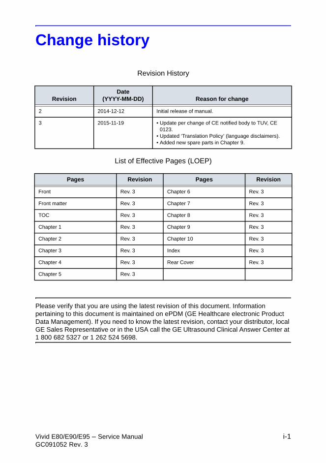
Change history
Revision History
List of Effective Pages (LOEP)
Please verify that you are using the latest revision of this document. Information pertaining to this document is maintained on ePDM (GE Healthcare electronic Product Data Management). If you need to know the latest revision, contact your distributor, local GE Sales Representative or in the USA call the GE Ultrasound Clinical Answer Center at 1 800 682 5327 or 1 262 524 5698.
RevisionDate
(YYYY-MM-DD) Reason for change
2 2014-12-12 Initial release of manual.
3 2015-11-19 • Update per change of CE notified body to TUV, CE 0123.
• Updated ‘Translation Policy’ (language disclaimers).• Added new spare parts in Chapter 9.
Pages Revision Pages Revision
Front Rev. 3 Chapter 6 Rev. 3
Front matter Rev. 3 Chapter 7 Rev. 3
TOC Rev. 3 Chapter 8 Rev. 3
Chapter 1 Rev. 3 Chapter 9 Rev. 3
Chapter 2 Rev. 3 Chapter 10 Rev. 3
Chapter 3 Rev. 3 Index Rev. 3
Chapter 4 Rev. 3 Rear Cover Rev. 3
Chapter 5 Rev. 3
i-2 Vivid E80/E90/E95 – Service ManualGC091052 Rev. 3
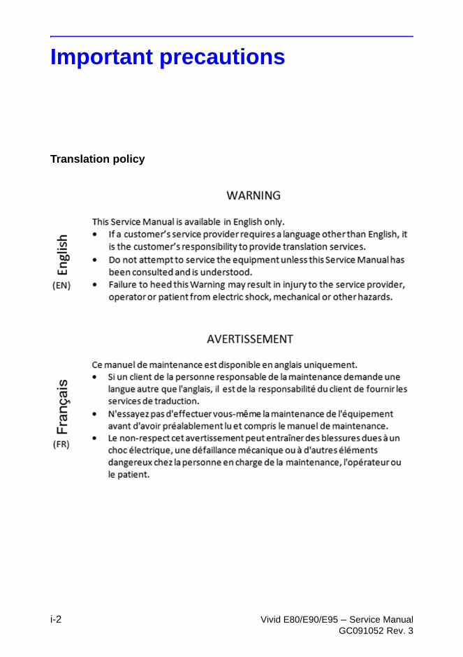
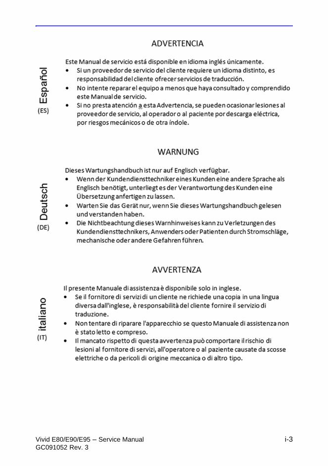
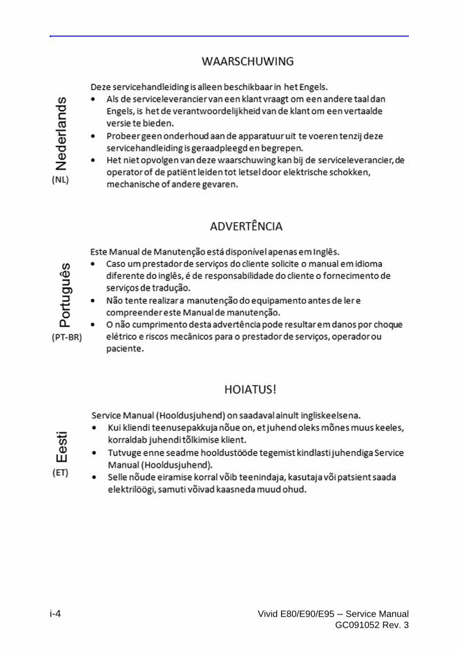
Important precautions
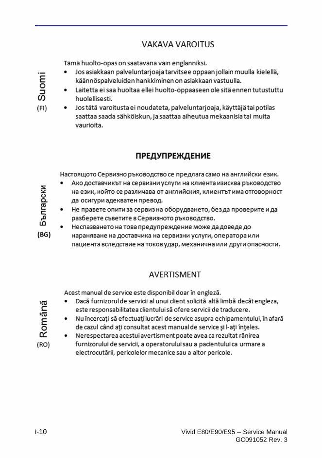
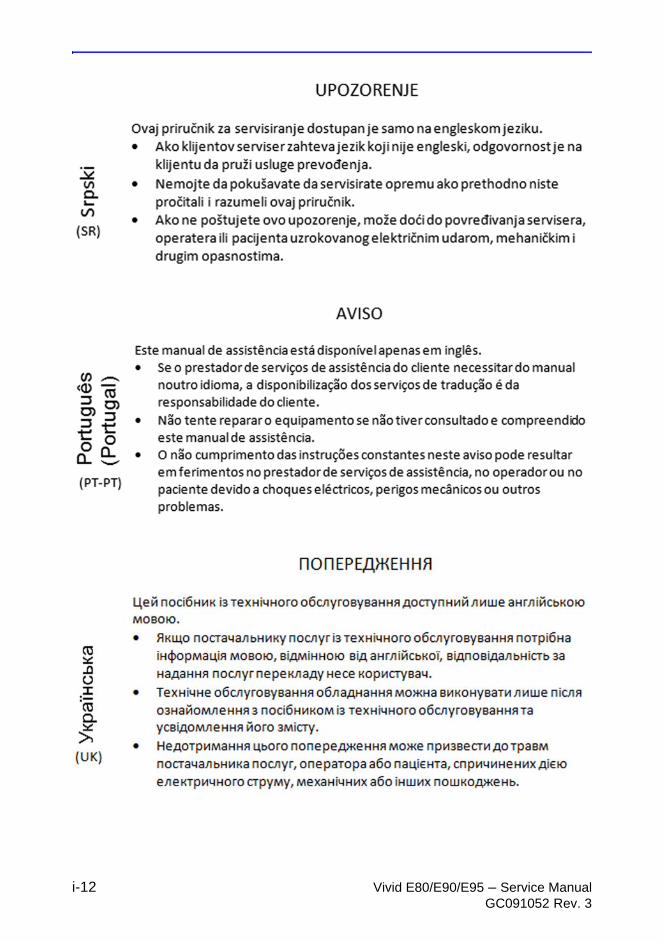
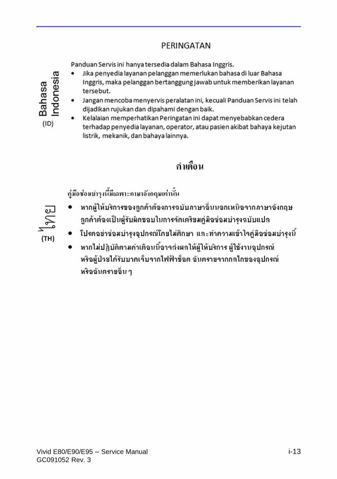
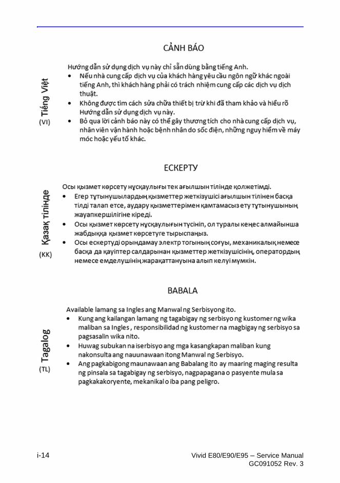
Translation policy
Vivid E80/E90/E95 – Service Manual i-3GC091052 Rev. 3
i-4 Vivid E80/E90/E95 – Service ManualGC091052 Rev. 3
Vivid E80/E90/E95 – Service Manual i-5GC091052 Rev. 3
i-6 Vivid E80/E90/E95 – Service ManualGC091052 Rev. 3
Vivid E80/E90/E95 – Service Manual i-7GC091052 Rev. 3

i-8 Vivid E80/E90/E95 – Service ManualGC091052 Rev. 3
Vivid E80/E90/E95 – Service Manual i-9GC091052 Rev. 3
i-10 Vivid E80/E90/E95 – Service ManualGC091052 Rev. 3

Vivid E80/E90/E95 – Service Manual i-11GC091052 Rev. 3
i-12 Vivid E80/E90/E95 – Service ManualGC091052 Rev. 3
Vivid E80/E90/E95 – Service Manual i-13GC091052 Rev. 3
i-14 Vivid E80/E90/E95 – Service ManualGC091052 Rev. 3
Vivid E80/E90/E95 – Service Manual i-15GC091052 Rev. 3
Damage in transportation
All packages should be closely examined at time of delivery. If damage is apparent, write “Damage In Shipment” on ALL copies of the freight or express bill BEFORE delivery is accepted or “signed for” by a GE representative or hospital receiving agent. Whether noted or concealed, damage MUST be reported to the carrier immediately upon discovery, or in any event, within 14 days after receipt, and the contents and containers held for inspection by the carrier. A transportation company will not pay a claim for damage if an inspection is not requested within this 14 day period.
Certified electrical contractor statement - For USA Only
All electrical installations that are preliminary to positioning of the equipment at the site prepared for the equipment shall be performed by licensed electrical contractors. Other connections between pieces of electrical equipment, calibrations, and testing shall be performed by qualified GE personnel. In performing all electrical work on these products, GE will use its own specially trained field engineers. All of GE’s electrical work on these products will comply with the requirements of the applicable electrical codes.
The purchaser of GE equipment shall only utilize qualified personnel (i.e. GE field engineers, personnel of third-party service companies with equivalent training, or licensed electricians) to perform electrical servicing on the equipment.
i-16 Vivid E80/E90/E95 – Service ManualGC091052 Rev. 3
Omission and errors
If there are any omissions, errors or suggestions for improving this documentation, contact the GE Global Documentation Group with specific information listing the system type, manual title, part number or direction number, revision number, page number and suggestion details.
Mail theinformation to:
GE Vingmed Ultrasound ASService DocumentationP.O.Box 141NO-3191 HORTENNORWAY
GE employees should use TrackWise to report service documentation issues.
These issues will then be in the internal problem reporting tool and communicated to the writer.
Vivid E80/E90/E95 – Service Manual i-17GC091052 Rev. 3
Service Safety Considerations
For a complete review of all safety requirements, see: ‘Safety considerations’ on page 1-8.
DANGER DANGEROUS VOLTAGES, CAPABLE OF CAUSING DEATH, ARE PRESENT IN THIS EQUIPMENT. USE EXTREME CAUTION WHEN HANDLING, TESTING AND ADJUSTING.
WARNING Use all Personal Protection Equipment (PPE) such as gloves, safety shoes, safety glasses, and kneeling pads, to reduce the risk of injury.
i-18 Vivid E80/E90/E95 – Service ManualGC091052 Rev. 3
Legal notes
The contents of this publication may not be copied or duplicated in any form, in whole or in part, without prior written permission of GE.
GE makes no representations or warranties with respect to the information herein. In addition, the information is subject to change without notice. Every precaution has been taken in the preparation of this document. Nevertheless, GE assumes no responsibility for errors, omissions, or any damages, including special or consequential, resulting from the use of this information. GE will issue updates to this information periodically, as needed. If there are any questions regarding the information contained in this manual, please contact your GE Representative.
Vivid E80/E90/E95 – Service Manual i-19GC091052 Rev. 3
Trademarks
All products and their name brands are trademarks of their respective holders.
Copyrights
© 2014-2015 by General Electric Company. All Rights Reserved.

i-20 Vivid E80/E90/E95 – Service ManualGC091052 Rev. 3
THIS PAGE WAS INTENTIONALLY LEFT BLANK
Vivid E80/E90/E95 – Service Manual i-21GC091052 Rev. 3
Table of Contents
Translation policy - - - - - - - - - - - - - - - - - - - - - - - - - - - - - - - - - - - - - - - - i-2Damage in transportation - - - - - - - - - - - - - - - - - - - - - - - - - - - - - - - - - i-15Certified electrical contractor statement - For USA Only - - - - - - - - - - - - i-15Omission and errors - - - - - - - - - - - - - - - - - - - - - - - - - - - - - - - - - - - - - i-16Service Safety Considerations - - - - - - - - - - - - - - - - - - - - - - - - - - - - - - i-17Legal notes - - - - - - - - - - - - - - - - - - - - - - - - - - - - - - - - - - - - - - - - - - - i-18Trademarks - - - - - - - - - - - - - - - - - - - - - - - - - - - - - - - - - - - - - - - - - - i-19Copyrights - - - - - - - - - - - - - - - - - - - - - - - - - - - - - - - - - - - - - - - - - - - - i-19
Table of ContentsChapter 1 — Introduction
Manual OverviewIntroduction - - - - - - - - - - - - - - - - - - - - - - - - - - - - - - - - - - - - - - - - - - - 1-2Vivid E80/E90/E95 models covered by this manual - - - - - - - - - - - - - - - 1-2Product description - - - - - - - - - - - - - - - - - - - - - - - - - - - - - - - - - - - - - - 1-3
Important conventionsConventions used in book - - - - - - - - - - - - - - - - - - - - - - - - - - - - - - - - - 1-4Standard hazard icons - - - - - - - - - - - - - - - - - - - - - - - - - - - - - - - - - - - 1-6Product icons - - - - - - - - - - - - - - - - - - - - - - - - - - - - - - - - - - - - - - - - - - 1-7
Safety considerationsIntroduction - - - - - - - - - - - - - - - - - - - - - - - - - - - - - - - - - - - - - - - - - - - 1-8Human Safety - - - - - - - - - - - - - - - - - - - - - - - - - - - - - - - - - - - - - - - - - 1-8Mechanical safety - - - - - - - - - - - - - - - - - - - - - - - - - - - - - - - - - - - - - - 1-11Electrical safety - - - - - - - - - - - - - - - - - - - - - - - - - - - - - - - - - - - - - - - 1-14
Dangerous procedure warnings Lockout/Tagout (LOTO) requirementsReturning probes and repair partsElectromagnetic compatibility (EMC)
What is EMC? - - - - - - - - - - - - - - - - - - - - - - - - - - - - - - - - - - - - - - - - 1-19Compliance - - - - - - - - - - - - - - - - - - - - - - - - - - - - - - - - - - - - - - - - - - 1-19Electrostatic discharge (ESD) prevention - - - - - - - - - - - - - - - - - - - - - 1-20
Customer assistanceContact information- - - - - - - - - - - - - - - - - - - - - - - - - - - - - - - - - - - - - 1-21Phone numbers for Customer Assistance - - - - - - - - - - - - - - - - - - - - - 1-22System manufacturer - - - - - - - - - - - - - - - - - - - - - - - - - - - - - - - - - - - 1-23
Chapter 2 — Site PreparationsGeneral Ultrasound system requirements
Ultrasound system environmental requirements- - - - - - - - - - - - - - - - - - 2-2Electrical requirements - - - - - - - - - - - - - - - - - - - - - - - - - - - - - - - - - - - 2-4EMI limitations - - - - - - - - - - - - - - - - - - - - - - - - - - - - - - - - - - - - - - - - - 2-7
i-22 Vivid E80/E90/E95 – Service ManualGC091052 Rev. 3
EMI prevention/abatement- - - - - - - - - - - - - - - - - - - - - - - - - - - - - - - - - 2-8Probes environmental requirements - - - - - - - - - - - - - - - - - - - - - - - - - - 2-9
Facility needsPurchaser responsibilities - - - - - - - - - - - - - - - - - - - - - - - - - - - - - - - - 2-10Required facility needs - - - - - - - - - - - - - - - - - - - - - - - - - - - - - - - - - - 2-12Desirable features- - - - - - - - - - - - - - - - - - - - - - - - - - - - - - - - - - - - - - 2-13Minimal floor plan suggestion- - - - - - - - - - - - - - - - - - - - - - - - - - - - - - 2-13Recommended floor plan suggestion - - - - - - - - - - - - - - - - - - - - - - - - 2-14Suggested floor plan, Ultrasound system, and EchoPAC PC in same room -
2-15Networking setup requirements - - - - - - - - - - - - - - - - - - - - - - - - - - - - 2-15
Environmental DangersPatient Vicinity UL60601-1 (USA)- - - - - - - - - - - - - - - - - - - - - - - - - - - 2-18Patient Environment IEC60601-1 (IEC60601-1-1) and ANSI AAMI
ES60601-1- - - - - - - - - - - - - - - - - - - - - - - - - - - - - - - - - - - - - - - - 2-19Chapter 3 — System Setup
Setup remindersSetup warnings- - - - - - - - - - - - - - - - - - - - - - - - - - - - - - - - - - - - - - - - - 3-2
Receiving and unpacking the equipmentWarnings for receiving and unpacking - - - - - - - - - - - - - - - - - - - - - - - - 3-4The Tilt and Shock indicators - - - - - - - - - - - - - - - - - - - - - - - - - - - - - - - 3-5Receiving the Vivid E80/E90/E95 - - - - - - - - - - - - - - - - - - - - - - - - - - - 3-8Unpacking the Vivid E80/E90/E95 - - - - - - - - - - - - - - - - - - - - - - - - - - 3-11
Packing materials - recycling informationPreparing for setup
Verify customer order - - - - - - - - - - - - - - - - - - - - - - - - - - - - - - - - - - - 3-17Physical inspection - - - - - - - - - - - - - - - - - - - - - - - - - - - - - - - - - - - - - 3-17EMI protection - - - - - - - - - - - - - - - - - - - - - - - - - - - - - - - - - - - - - - - - 3-17
Completing the setupSystem specifications - - - - - - - - - - - - - - - - - - - - - - - - - - - - - - - - - - - 3-18Electrical specifications - - - - - - - - - - - - - - - - - - - - - - - - - - - - - - - - - - 3-19Connections on the I/O Rear Panel - - - - - - - - - - - - - - - - - - - - - - - - - 3-20Connections on the Patient I/O panel - - - - - - - - - - - - - - - - - - - - - - - - 3-21Connecting probes - - - - - - - - - - - - - - - - - - - - - - - - - - - - - - - - - - - - - 3-22
ConfigurationVivid E80/E90/E95 configuration - - - - - - - - - - - - - - - - - - - - - - - - - - - 3-25Service Screen setup - - - - - - - - - - - - - - - - - - - - - - - - - - - - - - - - - - - 3-32Optional peripherals/peripheral connection - - - - - - - - - - - - - - - - - - - - 3-36Software Options configuration - - - - - - - - - - - - - - - - - - - - - - - - - - - - 3-37
Connectivity overviewPhysical connection - - - - - - - - - - - - - - - - - - - - - - - - - - - - - - - - - - - - 3-39
Connectivity setupCompatibility - - - - - - - - - - - - - - - - - - - - - - - - - - - - - - - - - - - - - - - - - 3-41Select TCP/IP Screen - - - - - - - - - - - - - - - - - - - - - - - - - - - - - - - - - - - 3-42Changing the AE Title and/or Port Number (Port No.) - - - - - - - - - - - - 3-43DHCP setup - - - - - - - - - - - - - - - - - - - - - - - - - - - - - - - - - - - - - - - - - - 3-44Set the Remote Archive’s Network Information - - - - - - - - - - - - - - - - - 3-47
Vivid E80/E90/E95 – Service Manual i-23GC091052 Rev. 3
Save the New Settings - - - - - - - - - - - - - - - - - - - - - - - - - - - - - - - - - - 3-49Product Locator Installation Card
Chapter 4 — General Procedures and Functional Checks General procedures
Power ON/Boot Up - - - - - - - - - - - - - - - - - - - - - - - - - - - - - - - - - - - - - - 4-2Power shut down - - - - - - - - - - - - - - - - - - - - - - - - - - - - - - - - - - - - - - - 4-5Complete power down - - - - - - - - - - - - - - - - - - - - - - - - - - - - - - - - - - - 4-7Creating presets - - - - - - - - - - - - - - - - - - - - - - - - - - - - - - - - - - - - - - - - 4-8
Functional checks2D Mode (B mode) checks - - - - - - - - - - - - - - - - - - - - - - - - - - - - - - - - 4-9M Mode Checks - - - - - - - - - - - - - - - - - - - - - - - - - - - - - - - - - - - - - - - 4-13Color Mode Checks - - - - - - - - - - - - - - - - - - - - - - - - - - - - - - - - - - - - 4-17PW/CW Doppler Mode Checks - - - - - - - - - - - - - - - - - - - - - - - - - - - - 4-21Tissue Velocity Imaging (TVI) Checks- - - - - - - - - - - - - - - - - - - - - - - - 4-25Probe/Connectors Checks - - - - - - - - - - - - - - - - - - - - - - - - - - - - - - - - 4-29ECG Check - - - - - - - - - - - - - - - - - - - - - - - - - - - - - - - - - - - - - - - - - - 4-30Cineloop Check - - - - - - - - - - - - - - - - - - - - - - - - - - - - - - - - - - - - - - - 4-31Back End Processor checks - - - - - - - - - - - - - - - - - - - - - - - - - - - - - - 4-32Operating Panel Test - - - - - - - - - - - - - - - - - - - - - - - - - - - - - - - - - - - 4-33Peripheral checks - - - - - - - - - - - - - - - - - - - - - - - - - - - - - - - - - - - - - - 4-33Mechanical Functions Checks - - - - - - - - - - - - - - - - - - - - - - - - - - - - - 4-35
Chapter 5 — Components and Functions (Theory)Software overview
System software - - - - - - - - - - - - - - - - - - - - - - - - - - - - - - - - - - - - - - - - 5-2Application software - - - - - - - - - - - - - - - - - - - - - - - - - - - - - - - - - - - - - 5-2
InSite ExCIntroduction - - - - - - - - - - - - - - - - - - - - - - - - - - - - - - - - - - - - - - - - - - - 5-3InSite ExC Icon- - - - - - - - - - - - - - - - - - - - - - - - - - - - - - - - - - - - - - - - - 5-3InSite ExC Status - - - - - - - - - - - - - - - - - - - - - - - - - - - - - - - - - - - - - - - 5-4InSite ExC Definitions - - - - - - - - - - - - - - - - - - - - - - - - - - - - - - - - - - - - 5-5Initiating a Request for Service (RFS) - - - - - - - - - - - - - - - - - - - - - - - - - 5-6Exiting InSite ExC - - - - - - - - - - - - - - - - - - - - - - - - - - - - - - - - - - - - - - - 5-9
Vivid E80/E90/E95 overviewIntroduction - - - - - - - - - - - - - - - - - - - - - - - - - - - - - - - - - - - - - - - - - - 5-10Note regarding USB ports - - - - - - - - - - - - - - - - - - - - - - - - - - - - - - - - 5-10Related information- - - - - - - - - - - - - - - - - - - - - - - - - - - - - - - - - - - - - 5-10Vivid E80/E90/E95 block diagram- - - - - - - - - - - - - - - - - - - - - - - - - - - 5-11Signal flow overview - - - - - - - - - - - - - - - - - - - - - - - - - - - - - - - - - - - - 5-12System configuration and software - - - - - - - - - - - - - - - - - - - - - - - - - - 5-12Operating Panel - - - - - - - - - - - - - - - - - - - - - - - - - - - - - - - - - - - - - - - 5-12The electronics - - - - - - - - - - - - - - - - - - - - - - - - - - - - - - - - - - - - - - - - 5-12Operating modes - - - - - - - - - - - - - - - - - - - - - - - - - - - - - - - - - - - - - - 5-13
Top Console with LCD monitor and Operating PanelTop Console description - - - - - - - - - - - - - - - - - - - - - - - - - - - - - - - - - 5-14Operating Panel (Control Panel)- - - - - - - - - - - - - - - - - - - - - - - - - - - - 5-19
Main ConsoleMain Console description - - - - - - - - - - - - - - - - - - - - - - - - - - - - - - - - 5-21
i-24 Vivid E80/E90/E95 – Service ManualGC091052 Rev. 3
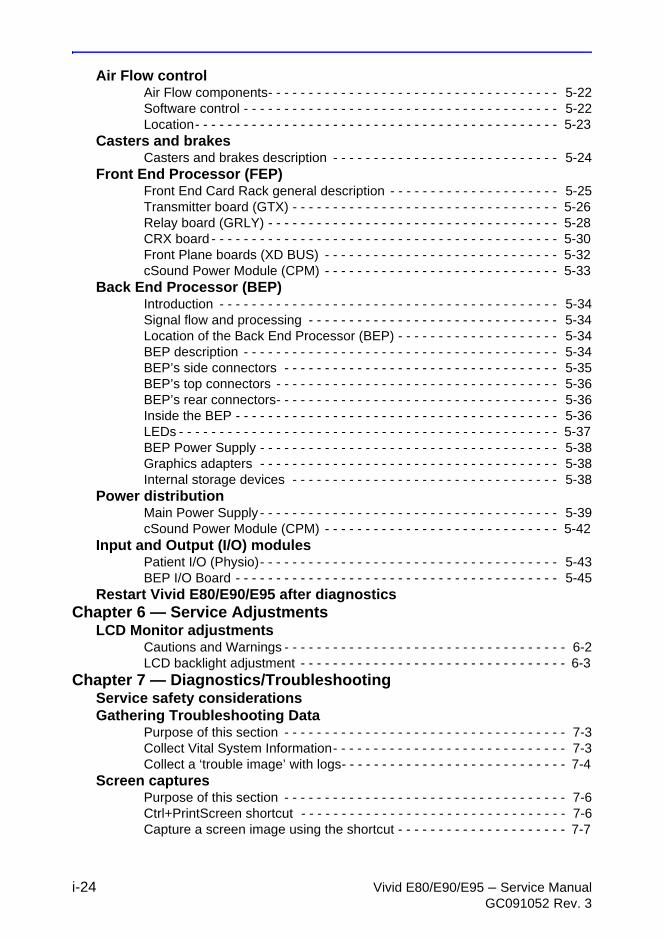
Air Flow controlAir Flow components- - - - - - - - - - - - - - - - - - - - - - - - - - - - - - - - - - - - 5-22Software control - - - - - - - - - - - - - - - - - - - - - - - - - - - - - - - - - - - - - - - 5-22Location- - - - - - - - - - - - - - - - - - - - - - - - - - - - - - - - - - - - - - - - - - - - - 5-23
Casters and brakesCasters and brakes description - - - - - - - - - - - - - - - - - - - - - - - - - - - - 5-24
Front End Processor (FEP)Front End Card Rack general description - - - - - - - - - - - - - - - - - - - - - 5-25Transmitter board (GTX) - - - - - - - - - - - - - - - - - - - - - - - - - - - - - - - - - 5-26Relay board (GRLY) - - - - - - - - - - - - - - - - - - - - - - - - - - - - - - - - - - - - 5-28CRX board - - - - - - - - - - - - - - - - - - - - - - - - - - - - - - - - - - - - - - - - - - - 5-30Front Plane boards (XD BUS) - - - - - - - - - - - - - - - - - - - - - - - - - - - - - 5-32cSound Power Module (CPM) - - - - - - - - - - - - - - - - - - - - - - - - - - - - - 5-33
Back End Processor (BEP)Introduction - - - - - - - - - - - - - - - - - - - - - - - - - - - - - - - - - - - - - - - - - - 5-34Signal flow and processing - - - - - - - - - - - - - - - - - - - - - - - - - - - - - - - 5-34Location of the Back End Processor (BEP) - - - - - - - - - - - - - - - - - - - - 5-34BEP description - - - - - - - - - - - - - - - - - - - - - - - - - - - - - - - - - - - - - - - 5-34BEP’s side connectors - - - - - - - - - - - - - - - - - - - - - - - - - - - - - - - - - - 5-35BEP’s top connectors - - - - - - - - - - - - - - - - - - - - - - - - - - - - - - - - - - - 5-36BEP’s rear connectors- - - - - - - - - - - - - - - - - - - - - - - - - - - - - - - - - - - 5-36Inside the BEP - - - - - - - - - - - - - - - - - - - - - - - - - - - - - - - - - - - - - - - - 5-36LEDs - - - - - - - - - - - - - - - - - - - - - - - - - - - - - - - - - - - - - - - - - - - - - - - 5-37BEP Power Supply - - - - - - - - - - - - - - - - - - - - - - - - - - - - - - - - - - - - - 5-38Graphics adapters - - - - - - - - - - - - - - - - - - - - - - - - - - - - - - - - - - - - - 5-38Internal storage devices - - - - - - - - - - - - - - - - - - - - - - - - - - - - - - - - - 5-38
Power distributionMain Power Supply - - - - - - - - - - - - - - - - - - - - - - - - - - - - - - - - - - - - - 5-39cSound Power Module (CPM) - - - - - - - - - - - - - - - - - - - - - - - - - - - - - 5-42
Input and Output (I/O) modulesPatient I/O (Physio)- - - - - - - - - - - - - - - - - - - - - - - - - - - - - - - - - - - - - 5-43BEP I/O Board - - - - - - - - - - - - - - - - - - - - - - - - - - - - - - - - - - - - - - - - 5-45
Restart Vivid E80/E90/E95 after diagnosticsChapter 6 — Service Adjustments
LCD Monitor adjustmentsCautions and Warnings - - - - - - - - - - - - - - - - - - - - - - - - - - - - - - - - - - - 6-2LCD backlight adjustment - - - - - - - - - - - - - - - - - - - - - - - - - - - - - - - - - 6-3
Chapter 7 — Diagnostics/TroubleshootingService safety considerationsGathering Troubleshooting Data
Purpose of this section - - - - - - - - - - - - - - - - - - - - - - - - - - - - - - - - - - - 7-3Collect Vital System Information- - - - - - - - - - - - - - - - - - - - - - - - - - - - - 7-3Collect a ‘trouble image’ with logs- - - - - - - - - - - - - - - - - - - - - - - - - - - - 7-4
Screen capturesPurpose of this section - - - - - - - - - - - - - - - - - - - - - - - - - - - - - - - - - - - 7-6Ctrl+PrintScreen shortcut - - - - - - - - - - - - - - - - - - - - - - - - - - - - - - - - - 7-6Capture a screen image using the shortcut - - - - - - - - - - - - - - - - - - - - - 7-7
Vivid E80/E90/E95 – Service Manual i-25GC091052 Rev. 3
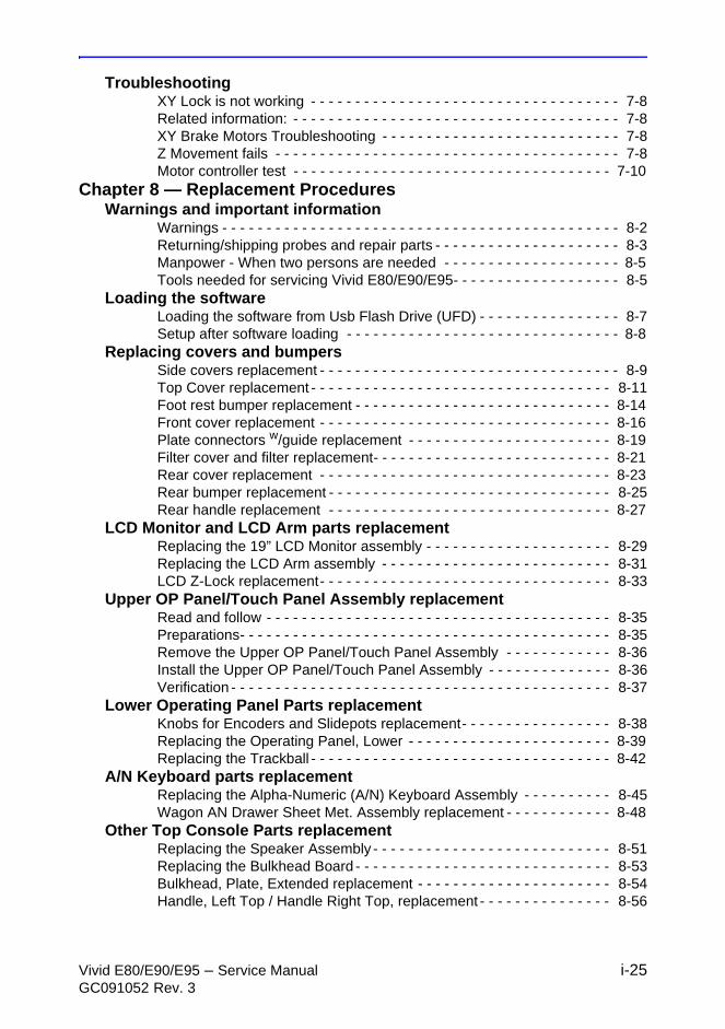
TroubleshootingXY Lock is not working - - - - - - - - - - - - - - - - - - - - - - - - - - - - - - - - - - - 7-8Related information: - - - - - - - - - - - - - - - - - - - - - - - - - - - - - - - - - - - - - 7-8XY Brake Motors Troubleshooting - - - - - - - - - - - - - - - - - - - - - - - - - - - 7-8Z Movement fails - - - - - - - - - - - - - - - - - - - - - - - - - - - - - - - - - - - - - - - 7-8Motor controller test - - - - - - - - - - - - - - - - - - - - - - - - - - - - - - - - - - - - 7-10
Chapter 8 — Replacement ProceduresWarnings and important information
Warnings - - - - - - - - - - - - - - - - - - - - - - - - - - - - - - - - - - - - - - - - - - - - - 8-2Returning/shipping probes and repair parts - - - - - - - - - - - - - - - - - - - - - 8-3Manpower - When two persons are needed - - - - - - - - - - - - - - - - - - - - 8-5Tools needed for servicing Vivid E80/E90/E95- - - - - - - - - - - - - - - - - - - 8-5
Loading the softwareLoading the software from Usb Flash Drive (UFD) - - - - - - - - - - - - - - - - 8-7Setup after software loading - - - - - - - - - - - - - - - - - - - - - - - - - - - - - - - 8-8
Replacing covers and bumpersSide covers replacement - - - - - - - - - - - - - - - - - - - - - - - - - - - - - - - - - - 8-9Top Cover replacement - - - - - - - - - - - - - - - - - - - - - - - - - - - - - - - - - - 8-11Foot rest bumper replacement - - - - - - - - - - - - - - - - - - - - - - - - - - - - - 8-14Front cover replacement - - - - - - - - - - - - - - - - - - - - - - - - - - - - - - - - - 8-16Plate connectors w/guide replacement - - - - - - - - - - - - - - - - - - - - - - - 8-19Filter cover and filter replacement- - - - - - - - - - - - - - - - - - - - - - - - - - - 8-21Rear cover replacement - - - - - - - - - - - - - - - - - - - - - - - - - - - - - - - - - 8-23Rear bumper replacement - - - - - - - - - - - - - - - - - - - - - - - - - - - - - - - - 8-25Rear handle replacement - - - - - - - - - - - - - - - - - - - - - - - - - - - - - - - - 8-27
LCD Monitor and LCD Arm parts replacementReplacing the 19” LCD Monitor assembly - - - - - - - - - - - - - - - - - - - - - 8-29Replacing the LCD Arm assembly - - - - - - - - - - - - - - - - - - - - - - - - - - 8-31LCD Z-Lock replacement- - - - - - - - - - - - - - - - - - - - - - - - - - - - - - - - - 8-33
Upper OP Panel/Touch Panel Assembly replacementRead and follow - - - - - - - - - - - - - - - - - - - - - - - - - - - - - - - - - - - - - - - 8-35Preparations- - - - - - - - - - - - - - - - - - - - - - - - - - - - - - - - - - - - - - - - - - 8-35Remove the Upper OP Panel/Touch Panel Assembly - - - - - - - - - - - - 8-36Install the Upper OP Panel/Touch Panel Assembly - - - - - - - - - - - - - - 8-36Verification - - - - - - - - - - - - - - - - - - - - - - - - - - - - - - - - - - - - - - - - - - - 8-37
Lower Operating Panel Parts replacementKnobs for Encoders and Slidepots replacement- - - - - - - - - - - - - - - - - 8-38Replacing the Operating Panel, Lower - - - - - - - - - - - - - - - - - - - - - - - 8-39Replacing the Trackball - - - - - - - - - - - - - - - - - - - - - - - - - - - - - - - - - - 8-42
A/N Keyboard parts replacementReplacing the Alpha-Numeric (A/N) Keyboard Assembly - - - - - - - - - - 8-45Wagon AN Drawer Sheet Met. Assembly replacement - - - - - - - - - - - - 8-48
Other Top Console Parts replacementReplacing the Speaker Assembly - - - - - - - - - - - - - - - - - - - - - - - - - - - 8-51Replacing the Bulkhead Board - - - - - - - - - - - - - - - - - - - - - - - - - - - - - 8-53Bulkhead, Plate, Extended replacement - - - - - - - - - - - - - - - - - - - - - - 8-54Handle, Left Top / Handle Right Top, replacement - - - - - - - - - - - - - - - 8-56
i-26 Vivid E80/E90/E95 – Service ManualGC091052 Rev. 3
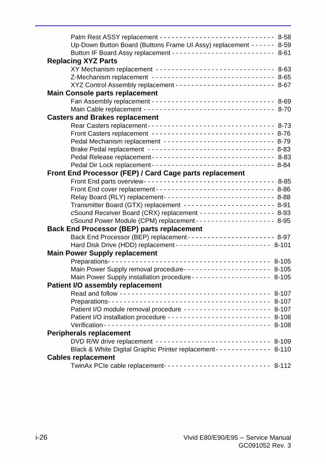
Palm Rest ASSY replacement - - - - - - - - - - - - - - - - - - - - - - - - - - - - - 8-58Up-Down Button Board (Buttons Frame UI Assy) replacement - - - - - - 8-59Button IF Board Assy replacement - - - - - - - - - - - - - - - - - - - - - - - - - - 8-61
Replacing XYZ PartsXY Mechanism replacement - - - - - - - - - - - - - - - - - - - - - - - - - - - - - - 8-63Z-Mechanism replacement - - - - - - - - - - - - - - - - - - - - - - - - - - - - - - - 8-65XYZ Control Assembly replacement - - - - - - - - - - - - - - - - - - - - - - - - - 8-67
Main Console parts replacementFan Assembly replacement - - - - - - - - - - - - - - - - - - - - - - - - - - - - - - - 8-69Main Cable replacement - - - - - - - - - - - - - - - - - - - - - - - - - - - - - - - - - 8-70
Casters and Brakes replacementRear Casters replacement - - - - - - - - - - - - - - - - - - - - - - - - - - - - - - - - 8-73Front Casters replacement - - - - - - - - - - - - - - - - - - - - - - - - - - - - - - - 8-76Pedal Mechanism replacement - - - - - - - - - - - - - - - - - - - - - - - - - - - - 8-79Brake Pedal replacement - - - - - - - - - - - - - - - - - - - - - - - - - - - - - - - - 8-83Pedal Release replacement - - - - - - - - - - - - - - - - - - - - - - - - - - - - - - - 8-83Pedal Dir Lock replacement - - - - - - - - - - - - - - - - - - - - - - - - - - - - - - - 8-84
Front End Processor (FEP) / Card Cage parts replacementFront End parts overview- - - - - - - - - - - - - - - - - - - - - - - - - - - - - - - - - 8-85Front End cover replacement - - - - - - - - - - - - - - - - - - - - - - - - - - - - - - 8-86Relay Board (RLY) replacement- - - - - - - - - - - - - - - - - - - - - - - - - - - - 8-88Transmitter Board (GTX) replacement - - - - - - - - - - - - - - - - - - - - - - - 8-91cSound Receiver Board (CRX) replacement - - - - - - - - - - - - - - - - - - - 8-93cSound Power Module (CPM) replacement - - - - - - - - - - - - - - - - - - - - 8-95
Back End Processor (BEP) parts replacementBack End Processor (BEP) replacement - - - - - - - - - - - - - - - - - - - - - - 8-97Hard Disk Drive (HDD) replacement - - - - - - - - - - - - - - - - - - - - - - - - 8-101
Main Power Supply replacementPreparations- - - - - - - - - - - - - - - - - - - - - - - - - - - - - - - - - - - - - - - - - 8-105Main Power Supply removal procedure- - - - - - - - - - - - - - - - - - - - - - 8-105Main Power Supply installation procedure - - - - - - - - - - - - - - - - - - - - 8-105
Patient I/O assembly replacementRead and follow - - - - - - - - - - - - - - - - - - - - - - - - - - - - - - - - - - - - - - 8-107Preparations- - - - - - - - - - - - - - - - - - - - - - - - - - - - - - - - - - - - - - - - - 8-107Patient I/O module removal procedure - - - - - - - - - - - - - - - - - - - - - - 8-107Patient I/O installation procedure - - - - - - - - - - - - - - - - - - - - - - - - - - 8-108Verification - - - - - - - - - - - - - - - - - - - - - - - - - - - - - - - - - - - - - - - - - - 8-108
Peripherals replacementDVD R/W drive replacement - - - - - - - - - - - - - - - - - - - - - - - - - - - - - 8-109Black & White Digital Graphic Printer replacement - - - - - - - - - - - - - - 8-110
Cables replacementTwinAx PCIe cable replacement- - - - - - - - - - - - - - - - - - - - - - - - - - - 8-112
Vivid E80/E90/E95 – Service Manual i-27GC091052 Rev. 3
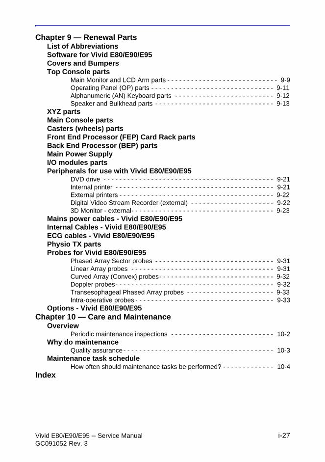
Chapter 9 — Renewal PartsList of AbbreviationsSoftware for Vivid E80/E90/E95Covers and BumpersTop Console parts
Main Monitor and LCD Arm parts - - - - - - - - - - - - - - - - - - - - - - - - - - - - 9-9Operating Panel (OP) parts - - - - - - - - - - - - - - - - - - - - - - - - - - - - - - - 9-11Alphanumeric (AN) Keyboard parts - - - - - - - - - - - - - - - - - - - - - - - - - 9-12Speaker and Bulkhead parts - - - - - - - - - - - - - - - - - - - - - - - - - - - - - - 9-13
XYZ partsMain Console partsCasters (wheels) partsFront End Processor (FEP) Card Rack partsBack End Processor (BEP) partsMain Power SupplyI/O modules partsPeripherals for use with Vivid E80/E90/E95
DVD drive - - - - - - - - - - - - - - - - - - - - - - - - - - - - - - - - - - - - - - - - - - - 9-21Internal printer - - - - - - - - - - - - - - - - - - - - - - - - - - - - - - - - - - - - - - - - 9-21External printers - - - - - - - - - - - - - - - - - - - - - - - - - - - - - - - - - - - - - - - 9-22Digital Video Stream Recorder (external) - - - - - - - - - - - - - - - - - - - - - 9-223D Monitor - external- - - - - - - - - - - - - - - - - - - - - - - - - - - - - - - - - - - - 9-23
Mains power cables - Vivid E80/E90/E95 Internal Cables - Vivid E80/E90/E95ECG cables - Vivid E80/E90/E95Physio TX partsProbes for Vivid E80/E90/E95
Phased Array Sector probes - - - - - - - - - - - - - - - - - - - - - - - - - - - - - - 9-31Linear Array probes - - - - - - - - - - - - - - - - - - - - - - - - - - - - - - - - - - - - 9-31Curved Array (Convex) probes- - - - - - - - - - - - - - - - - - - - - - - - - - - - - 9-32Doppler probes- - - - - - - - - - - - - - - - - - - - - - - - - - - - - - - - - - - - - - - - 9-32Transesophageal Phased Array probes - - - - - - - - - - - - - - - - - - - - - - 9-33Intra-operative probes - - - - - - - - - - - - - - - - - - - - - - - - - - - - - - - - - - - 9-33
Options - Vivid E80/E90/E95Chapter 10 — Care and Maintenance
OverviewPeriodic maintenance inspections - - - - - - - - - - - - - - - - - - - - - - - - - - 10-2
Why do maintenanceQuality assurance - - - - - - - - - - - - - - - - - - - - - - - - - - - - - - - - - - - - - - 10-3
Maintenance task scheduleHow often should maintenance tasks be performed? - - - - - - - - - - - - - 10-4
Index

i-28 Vivid E80/E90/E95 – Service ManualGC091052 Rev. 3
Vivid E80/E90/E95 – Service Manual 1-1GC091052 Rev. 3
Chapter 1
Introduction
This chapter describes important issues related to safely servicing the Vivid E80/E90/E95. The service provider must read and understand all the information presented here before installing or servicing the Vivid E80/E90/E95.
Introduction
1-2 Vivid E80/E90/E95 – Service ManualGC091052 Rev. 3
Manual Overview
Introduction
This manual provides installation and service information for the Vivid E80/E90/E95.
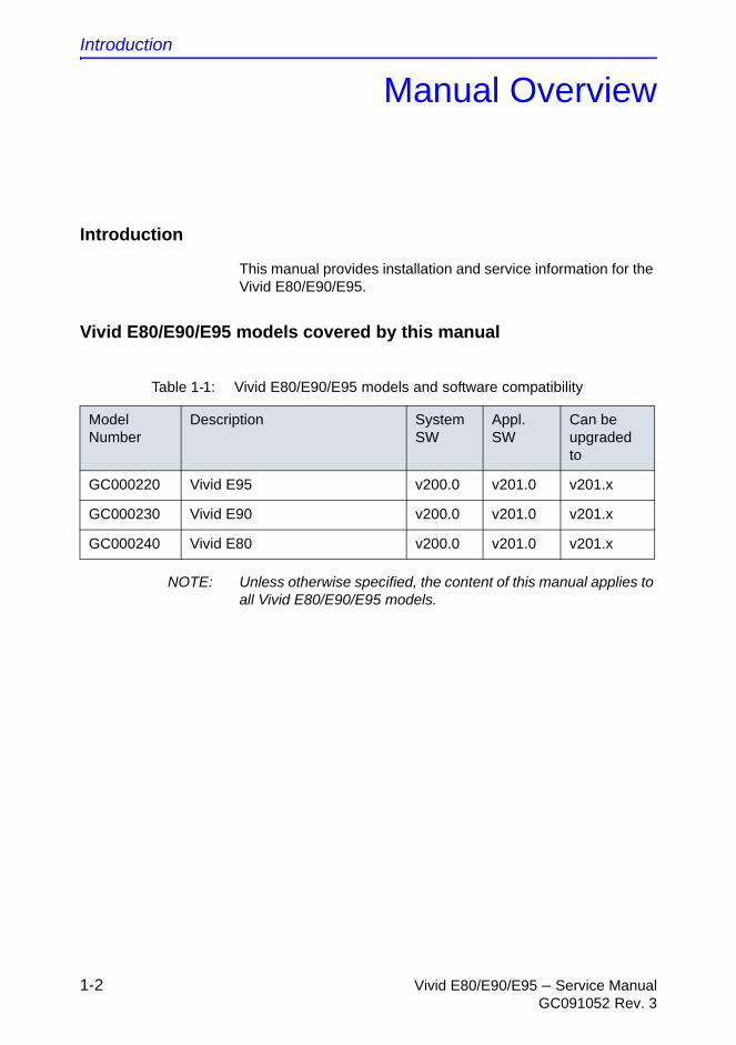
Vivid E80/E90/E95 models covered by this manual
NOTE: Unless otherwise specified, the content of this manual applies to all Vivid E80/E90/E95 models.
Table 1-1: Vivid E80/E90/E95 models and software compatibility
Model Number
Description System SW
Appl. SW
Can be upgraded to
GC000220 Vivid E95 v200.0 v201.0 v201.x
GC000230 Vivid E90 v200.0 v201.0 v201.x
GC000240 Vivid E80 v200.0 v201.0 v201.x
Manual Overview
Vivid E80/E90/E95 – Service Manual 1-3GC091052 Rev. 3
Product description
Overview of the Vivid E80/E90/E95 Ultrasound system
This Vivid E80/E90/E95 is a high performance digital ultrasound imaging system with total data management.
The Ultrasound system provides image generation in 2D, Color Doppler, Power Doppler, M-Mode, Color M-Mode, PW and 4D, Tissue Velocity imaging, and Contrast applications.
The fully digital architecture of the Vivid E80/E90/E95 allows optimal usage of all scanning modes and probe types throughout the full spectrum of operating frequencies.
Signal flows from the Probe Connector Panel to the Front End, and then over to the Back End Processor and finally to the monitor and peripherals.
System configuration is stored on the Vivid E80/E90/E95.
All necessary software is loaded from the hard drive on power up.
Purpose of the operator manual(s)
The operator manuals should be fully read and understood before operating the Vivid E80/E90/E95.
The online versions of the operator manuals are available via the Help function on Vivid E80/E90/E95’s Operating Panel.
The translated user manuals are available as PDF files on the Usb Flash Drive (UFD) delivered with the Vivid E80/E90/E95.
Introduction
1-4 Vivid E80/E90/E95 – Service ManualGC091052 Rev. 3
Important conventions
Conventions used in book
Important conventions, used in this document, are described below.
Model designations
This manual covers the Ultrasound systems listed in:
‘Vivid E80/E90/E95 models covered by this manual’ on page 1-2.
Icons
Pictures, or icons, are used wherever they will reinforce the printed message. The icons, labels, and conventions used on the product and in the service information are described in this chapter.
Safety precaution messages
Various levels of safety precaution messages may be found on the equipment and in the service information. The different levels of concern are identified by a flag word that precedes the precautionary message. Known or potential hazards to personnel are labeled in one of three ways:
• DANGER
• WARNING
• CAUTION
DANGER
Danger is used to indicate the presence of a hazard that will cause severe personal injury or death, or substantial property damage if the instructions are ignored.
Important conventions
Vivid E80/E90/E95 – Service Manual 1-5GC091052 Rev. 3
NOTE: Notes are used to provide important information about an item or a procedure.
NOTE: Be sure to read the notes; the information contained in a note can often save you time or effort.
WARNING Warning is used to indicate the presence of a hazard that may cause severe personal injury or substantial property damage if instructions are ignored.
CAUTION Caution is used to indicate the presence of a hazard that will or can cause minor personal injury or property damage if instructions are ignored.

Introduction
1-6 Vivid E80/E90/E95 – Service ManualGC091052 Rev. 3
Standard hazard icons
Important information will always be preceded by either the exclamation point (!) contained within a triangle, or the symbols for “Danger”, “Warning” or “Caution”, as seen throughout this chapter. In addition to text, several different graphical icons (symbols) may be used to make you aware of specific types of hazards that could possibly cause harm. Even if a symbol isn’t used in this manual, it may be included for your reference.
NOTE: Even if a symbol isn’t used on the product or in this manual, it may be included for your reference.
Table 1-2: Standard hazard icons
ELECTRICAL
MECHANICAL
RADIATION
LASER
HEAT
PINCH

Important conventions
Vivid E80/E90/E95 – Service Manual 1-7GC091052 Rev. 3
Standard Icons that indicate that a special procedure is to be used
Some others icons make you aware of specific procedures that should be followed.
Product icons
Refer to the Device labels in the Safety chapter in the User Manual.
Table 1-3: Standard Icons that indicates that a special procedure is to be used
Avoid Static Electricity Tag and Lock Out Wear Eye Protection
Hand Protection Foot Protection Wear Eye Protection
Introduction
1-8 Vivid E80/E90/E95 – Service ManualGC091052 Rev. 3
Safety considerations
Introduction
The following safety precautions must be observed during all phases of operation, service and repair of this equipment. Failure to comply with these precautions or with specific warnings elsewhere in this manual violates safety standards of design, manufacture, and intended use of the equipment.
Human Safety
• Operating personnel must not remove the Ultrasound system covers.
• Servicing should be performed by authorized personnel only.
Only personnel who have participated in a Vivid E80/E90/E95 Training Seminar are authorized to service the equipment.
NOTE: Local laws may restrict this device for sale or use by or on the order of a physician.
NOTE: For Vivid E80/E90/E95 Vet, local laws may restrict this device for sale or use by or on the order of a veterinarian.
DANGER DANGEROUS VOLTAGES, CAPABLE OF CAUSING DEATH, ARE PRESENT IN THIS EQUIPMENT. USE EXTREME CAUTION WHEN HANDLING, TESTING AND ADJUSTING.
WARNING If the covers are removed from an operating Vivid E80/E90/E95, some metal surfaces may be warm enough to pose a potential heat hazard if touched, even while in shutdown mode.
WARNING Because of the limited access to cabinets and equipment in the field, placing people in awkward positions, GE has limited the lifting weight for one person in the field to 16 KG (35 LBS). Anything over 16 KG (35 LBS) requires 2 people.
Safety considerations
Vivid E80/E90/E95 – Service Manual 1-9GC091052 Rev. 3
WARNING Have two people available to deliver and unpack the Vivid E80/E90/E95.
Attempts to move the Vivid E80/E90/E95 considerable distances or on an incline by one person could result in injury or damage or both.
WARNING Explosion Warning
DO NOT operate the equipment in an explosive atmosphere. Operation of any electrical equipment in such an environment constitutes a definite safety hazard.
WARNING DO NOT substitute parts or modify equipment
Because of the danger of introducing additional hazards, ONLY install GE approved parts. DO NOT perform any unauthorized modification of the equipment.
WARNING Tilting the console requires two people in order to avoid injury to service personnel and damage to the equipment.
WARNING Ensure that the Ultrasound system is turned off and unplugged
Wait for at least 20 seconds for capacitors to discharge as there are no test points to verify isolation. The amber light on the OP panel ON/OFF button will turn off.
Ultrasound system components may be energized. Always refer to the Ultrasound system's Proprietary Service Manual for LOTO warnings and cautions
Introduction
1-10 Vivid E80/E90/E95 – Service ManualGC091052 Rev. 3
WARNING When the top console is in its locked position, the gas shock is compressed and stores mechanical energy. During normal operation the top console, the weight of the monitor and the mechanical force of the gas shock are in balance. Take care if/when you activate this gas shock. Personal injury can occur after the panel is removed and the shock pressure is released. Take care when you repair the elevation assembly.
WARNING Risk of electrical shock, Ultrasound system must be turned off and disconnected from power source. Cord must be controlled at all times.
Wait for at least 20 seconds for capacitors to discharge as there are no test points to verify isolation. The amber light on the OP panel on/off button will turn off.
Ultrasound System components may be energized. Always refer to the Ultrasound system's Proprietary Service Manual for LOTO warnings and cautions.
WARNING Explosion Warning
DO NOT operate the equipment in an explosive atmosphere. Operation of any electrical equipment in such an environment constitutes a definite safety hazard.
WARNING Use all Personal Protection Equipment (PPE) such as gloves, safety shoes, safety glasses, and kneeling pads, to reduce the risk of injury.
WARNING Beware of possible sharp edges on all mechanical parts. If sharp edges are encountered, the appropriate PPE should be used to reduce the risk of injury.
WARNING Wear all PPE including gloves as indicated in the chemical MSDS.
Safety considerations
Vivid E80/E90/E95 – Service Manual 1-11GC091052 Rev. 3
Mechanical safety
WARNING While the software install procedure is designed to preserve data, you should save any patient data, images, system setups to removable media or hardcopy before doing a software upgrade.
WARNING Ultrasound probes are highly sensitive medical instruments that can easily be damaged by improper handling. Use care when handling and protect from damage when not in use. Do not use a damaged or defective probe. Failure to follow these precautions can result in serious injury and equipment damage.
WARNING Never use a probe that has fallen to the floor. Even if it looks OK, it may be damaged.
WARNING The Ultrasound system should not be moved with the Operator I/O Panel extended. Move the operator i/o panel to its centered and locked position. Lower the Operator I/O Panel as much as possible before moving the Ultrasound system.
WARNING Prior to elevating Ultrasound system:
• verify that the floating Operating Panel is locked in its lowest, parking position.
• verify that the front brake is locked and the Ultrasound system is unable to swivel.
• verify that the rear brakes are in the locked position.
WARNING When the Ultrasound system is raised for a repair or moved along any incline, use extreme caution since it may become unstable and tip over.
WARNING Remember: If the front caster swivel lock is engaged for transportation, pressing the release pedal once disengages the swivel lock. You must depress the release pedal a second time to engage the brake.

Introduction
1-12 Vivid E80/E90/E95 – Service ManualGC091052 Rev. 3
CAUTION Before you move or transport the Ultrasound system, make sure to lock the LCD monitor arm firmly and flip down the monitor to prevent damage to the Ultrasound system.
CAUTION Always lock the Top Console (Operating Panel) in its parking (locked) position before moving the Ultrasound system around.
CAUTION Do not move the Ultrasound system if the Operating Panel is in unlocked position.
CAUTION To avoid injury when you move the LCD monitor and the monitor arm, do not put your finger, hand, or object on the joint of the monitor or the monitor arm.
CAUTION Ensure that nobody touches the console arm/frogleg when moving the Operating Panel.
CAUTION Keep the heat venting holes on the monitor unobstructed to avoid overheating of the monitor.
CAUTION Vivid E80/E90/E95 weighs 128 kg (283 lb.) or more, depending on installed peripherals, when ready for use. Care must be used when moving it or replacing its parts.
Failure to follow the precautions listed below could result in injury, uncontrolled motion and costly damage.
ALWAYS:
• be sure the pathway is clear
• use slow, careful motions
• use two people when moving on inclines or lifting more than 16 kg (35 lbs)
Safety considerations
Vivid E80/E90/E95 – Service Manual 1-13GC091052 Rev. 3
NOTE: Special care should be taken when transporting the Ultrasound system in a vehicle:
• Before transporting, place the Ultrasound system in its special storage case.
• Ensure that the Ultrasound system is firmly secured while inside the vehicle.
• Secure Ultrasound system with straps or as directed otherwise to prevent motion during transport.
• Prevent vibration damage by driving cautiously. Avoid unpaved roads, excessive speeds, and erratic stops or starts.
CAUTION Do not transport Vivid E80/E90/E95 in a vehicle without locking the casters (wheels) and securing it as described in chapter 4.
CAUTION Use protective glasses during drilling, filing smooth surfaces, and during all other work where eyes need protection.
CAUTION Use protective gloves when working with sharp edges or when directed to wear PPE during a removal/replacement procedure.
CAUTION Use safety shoes when doing work where there is any chance of foot injury.
CAUTION Be careful not to pinch any of the cables.
Introduction
1-14 Vivid E80/E90/E95 – Service ManualGC091052 Rev. 3
Electrical safety
Safe practices
Follow these guidelines to minimize shock hazards whenever you are using the Vivid E80/E90/E95:
• To minimize shock hazard, the equipment chassis must be connected to an electrical ground.
• The Vivid E80/E90/E95 is equipped with a three-conductor AC power cable. This must be plugged into an approved electrical outlet with safety ground.
• The power outlet used for this equipment should not be shared with other types of equipment.
• Both the Vivid E80/E90/E95 power cable and the power connector must meet international electrical standards
WARNING Connecting a Vivid E80/E90/E95 to the wrong voltage level will most likely destroy it.
Safety considerations
Vivid E80/E90/E95 – Service Manual 1-15GC091052 Rev. 3
Probes
Follow these guidelines before connecting a probe to the Ultrasound system:
• Inspect the probe prior to each use for damage or degradation to the:
• housing
• cable strain relief
• lens
• seal
• connector pins
• locking mechanism
• Do not use a damaged or defective probe.
• Never immerse the probe connector or adapter into any liquid.
• The Vivid E80/E90/E95 has more than one type of probe port. Use the appropriate probe port designed for the probe you are connecting.
Peripherals
Refer to the Patient Safety Environment section of the User’s Manual for peripheral isolation information.

Introduction
1-16 Vivid E80/E90/E95 – Service ManualGC091052 Rev. 3
Dangerous procedure warnings
Warnings, such as the example below, precede potentially dangerous procedures throughout this manual. Instructions contained in the warnings must be followed.
DANGER
DANGEROUS VOLTAGES, CAPABLE OF CAUSING DEATH, ARE PRESENT IN THIS EQUIPMENT. USE EXTREME CAUTION WHEN HANDLING, TESTING AND ADJUSTING.
WARNING If the covers are removed from an operating Vivid E80/E90/E95, some metal surfaces may be warm enough to pose a potential heat hazard if touched, even while in shutdown mode.
WARNING Explosion Warning
DO NOT operate the equipment in an explosive atmosphere. Operation of any electrical equipment in such an environment constitutes a definite safety hazard.
WARNING DO NOT substitute parts or modify equipment
Because of the danger of introducing additional hazards, ONLY install GE approved parts. DO NOT perform any unauthorized modification of the equipment.
Lockout/Tagout (LOTO) requirements
Vivid E80/E90/E95 – Service Manual 1-17GC091052 Rev. 3
Lockout/Tagout (LOTO)
requirements
Follow Lockout/Tagout requirements by ensuring you are in total control of the AC power plug at all times during the service process.
To apply Lockout/Tagout (LOTO):
1. Plan and prepare for shutdown.
2. Shutdown the equipment.
3. Isolate the equipment.
4. Apply Lockout/Tagout Devices.
5. Control all stored and residual energy.
6. Verify isolation.
All potentially hazardous stored or residual energy is relieved.
WARNING Energy Control and Power Lockout for Vivid E80/E90/E95.
When servicing parts of the Ultrasound system where there is exposure to voltage greater than 30 volts:
1. Follow LOCK OUT/TAG OUT procedures.
2. Turn off the breaker.
3. Unplug the Ultrasound system.
4. Maintain control of the Ultrasound system power plug.
5. Wait at least 30 seconds for capacitors to discharge as there are no test points to verify isolation.
Ultrasound System components may be energized.
Introduction
1-18 Vivid E80/E90/E95 – Service ManualGC091052 Rev. 3
Returning probes and repair parts
NOTE: The US Department of Transportation (DOT) has ruled that “items that were saturated and/or dripping with human blood that are now caked with dried blood; or which were used or intended for use in patient care” are “regulated medical waste” for transportation purposes and must be transported as a hazardous material.
NOTE: The USER/SERVICE staff should dispose of all the waste properly, per federal, state, and local waste disposal regulations.
Equipment being returned must be clean and free of blood and other infectious substances. GE policy states that body fluids must be properly removed from any part or equipment prior to shipment. GE employees, as well as customers, are responsible for ensuring that parts/equipment have been properly decontaminated prior to shipment. Under no circumstance should a part or equipment with visible body fluids be taken or shipped from a clinic or site (for example, body coils or an ultrasound probe).
The purpose of the regulation is to protect employees in the transportation industry, as well as the people who will receive or open this package.
The Vivid E80/E90/E95 is not meant to be used for long-term storage of patient data or images. The user is responsible for the data on the Vivid E80/E90/E95 and a regular backup is highly recommended.
If the Vivid E80/E90/E95 is sent for repair, please ensure that any patient information is backed up and erased from the Vivid E80/E90/E95 before shipping. It is always possible during system failure and repair to lose patient data. GE is not responsible for the loss of this data.
If PHI (Patient Healthcare Information) data needs to be sent to GE employees for service purposes, GE will ascertain agreement from the customer. Patient information shall only be transferred by approved service processes, tools and devices restricting access, protecting or encrypting data where required, and providing traceability in the form of paper or electronic documents at each stage of the procedure while maintaining compliance with cross-border restrictions of patient information transfers.

Electromagnetic compatibility (EMC)
Vivid E80/E90/E95 – Service Manual 1-19GC091052 Rev. 3
Electromagnetic compatibility (EMC)
What is EMC?
Electromagnetic compatibility describes a level of performance of a device within its electromagnetic environment. This environment consists of the device itself and its surroundings including other equipment, power sources and persons with which the device must interface. Inadequate compatibility results when a susceptible device fails to perform as intended due to interference from its environment or when the device produces unacceptable levels of emission to its environment. This interference is often referred to as radio–frequency or electromagnetic interference (RFI/EMI) and can be radiated through space or conducted over interconnecting power of signal cables. In addition to electromagnetic energy, EMC also includes possible effects from electrical fields, magnetic fields, electrostatic discharge and disturbances in the electrical power supply.
Compliance
Vivid E80/E90/E95 conforms to all applicable conducted and radiated emission limits and to immunity from electrostatic discharge, radiated and conducted RF fields, magnetic fields and power line transient requirements.
For applicable standards, refer to the Safety Chapter of the Ultrasound system’s User’s Manual.
NOTE: For CE Compliance, it is critical that all covers, screws, shielding, gaskets, mesh, clamps, are in good condition, installed tightly without skew or stress. Proper installation following all comments noted in this service manual is required in order to achieve full EMC performance.
Introduction
1-20 Vivid E80/E90/E95 – Service ManualGC091052 Rev. 3
Electrostatic discharge (ESD) prevention
WARNING DO NOT touch any boards with integrated circuits prior to taking the necessary ESD precautions.
Always connect yourself, via an arm-wrist strap, to the advised ESD connection point located on the rear of the Ultrasound system (near the power connector).
Follow general guidelines for handling of electrostatic sensitive equipment.
WARNING Risk of electrical shock, Ultrasound system must be turned off. Avoid all contact with electrical contacts, conductors and components. Always use non-conductive handles designed for the removal and replacement of ESD sensitive parts. All parts that have the potential for storing energy must be discharged or isolated before making contact.
WARNING If the covers are removed from an operating Vivid E80/E90/E95, some metal surfaces may be warm enough to pose a potential heat hazard if touched, even while in shutdown mode.
Customer assistance
Vivid E80/E90/E95 – Service Manual 1-21GC091052 Rev. 3
Customer assistance
Contact information
If this equipment does not work as indicated in this service manual or in the user manual, or if you require additional assistance, please contact the local distributor or appropriate support resource, as listed below.
Before you call, identify the following information, and acquire image (Alt+D) to send to the Customer Care team:
1. Ultrasound system ID serial number.
2. Software version.
3. Date and time of occurrence.
4. Sequence of events leading to issue.
5. Is the issue repeatable?
6. Imaging mode, probe, preset/application.
7. Media brand, speed, capacity, type.
8. Save secondary image capture, cine loop, 4D multi-volume loop.
9. Detailed description of any problem encountered.
10. Where applicable, save the appropriate log files.
Remember to save the log files for each day on a separate media, labelled accordingly.
NOTE: Restart the application before resuming clinical scanning.
Introduction
1-22 Vivid E80/E90/E95 – Service ManualGC091052 Rev. 3
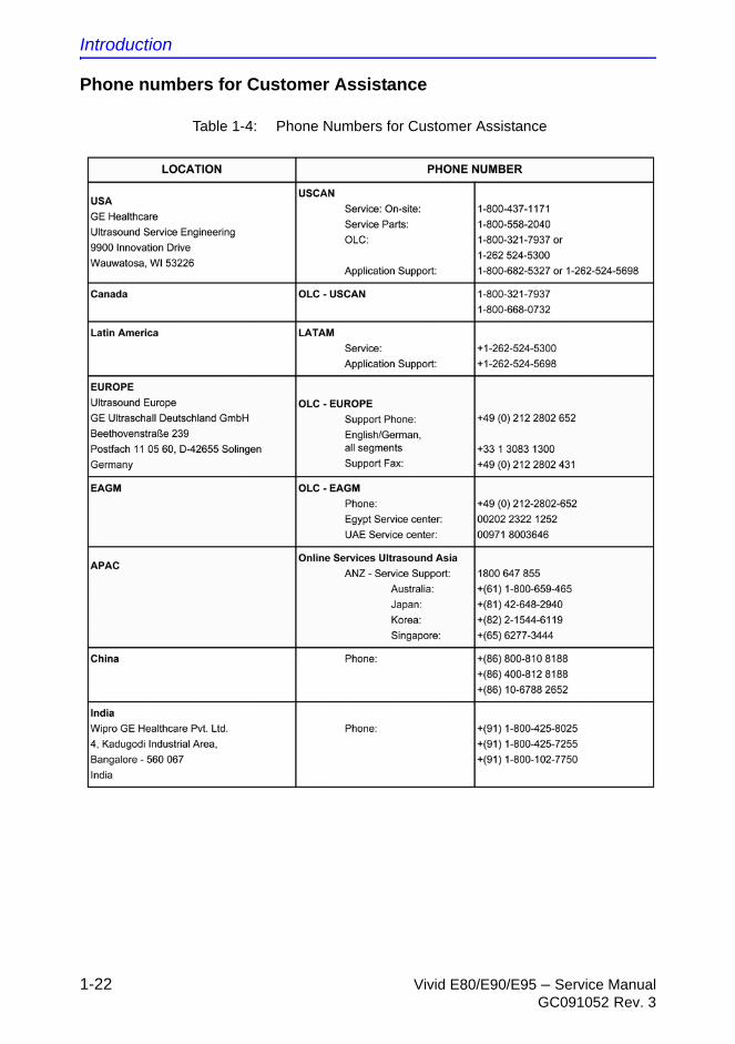
Phone numbers for Customer Assistance
Table 1-4: Phone Numbers for Customer Assistance
Customer assistance
Vivid E80/E90/E95 – Service Manual 1-23GC091052 Rev. 3
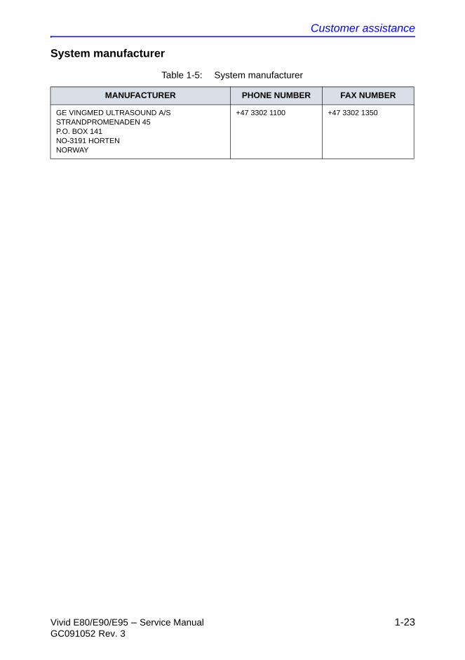
System manufacturer
Table 1-5: System manufacturer
MANUFACTURER PHONE NUMBER FAX NUMBER
GE VINGMED ULTRASOUND A/SSTRANDPROMENADEN 45P.O. BOX 141NO-3191 HORTENNORWAY
+47 3302 1100 +47 3302 1350

Introduction
1-24 Vivid E80/E90/E95 – Service ManualGC091052 Rev. 3
THIS PAGE WAS INTENTIONALLY LEFT BLANK

Vivid E80/E90/E95 – Service Manual 2-1GC091052 Rev. 3
Chapter 2
Site Preparations
This chapter provides the information required to plan and prepare for the setup of an Ultrasound system. Included are descriptions of the facility and electrical needs to be met by the purchaser of the Ultrasound system.
Site Preparations
2-2 Vivid E80/E90/E95 – Service ManualGC091052 Rev. 3
General Ultrasound system
requirements
Ultrasound system environmental requirements
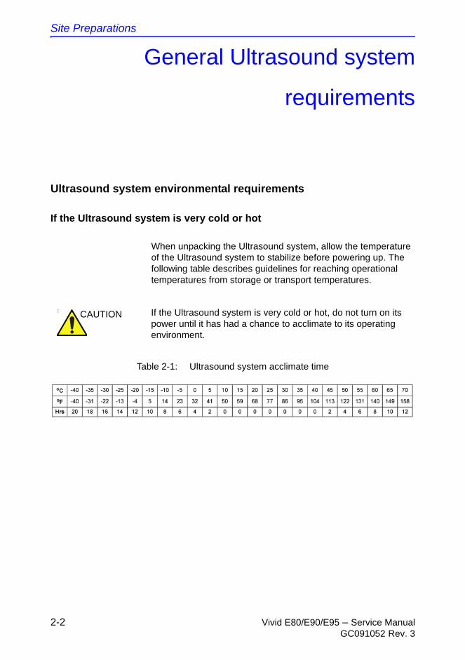
If the Ultrasound system is very cold or hot
When unpacking the Ultrasound system, allow the temperature of the Ultrasound system to stabilize before powering up. The following table describes guidelines for reaching operational temperatures from storage or transport temperatures.
CAUTION If the Ultrasound system is very cold or hot, do not turn on its power until it has had a chance to acclimate to its operating environment.
Table 2-1: Ultrasound system acclimate time

General Ultrasound system requirements
Vivid E80/E90/E95 – Service Manual 2-3GC091052 Rev. 3
Vivid E80/E90/E95 environmental specifications
Cooling
The cooling requirement for the Vivid E80/E90/E95 with monitor and on board peripherals, is up to 2390 BTU/h. This figure does not include cooling needed for lights, people, or other equipment in the room.
NOTE: Each person in the room places an additional 300 BTU/h demand on the cooling system.
Lighting
Bright light is needed for Ultrasound system installation, updates and repairs. However, operator and patient comfort may be optimized if the room light is subdued and indirect. Therefore a combination lighting system (dim/bright) is recommended. Keep in mind that lighting controls and dimmers can be a source of EMI which could degrade image quality. These controls should be selected to minimize possible interference.
Table 2-2: Environmental specifications for Vivid E80/E90/E95 systems
ConditionsTemperature
limits Humidity limitsAir pressure
limits Heat dissipation
Operation: 10 to 35 °C (50-95 °F)
30 - 85% non-condensing
700-1060 hPa 2390 BTU/h
Storage and transport:
-20 to +60 °C (-4 to +140 °F)
30 - 95% non-condensing
700-1060 hPa N/A
Site Preparations
2-4 Vivid E80/E90/E95 – Service ManualGC091052 Rev. 3
Electrical requirements
General requirements
NOTE: GE requires a dedicated power and ground for the proper operation of its Ultrasound equipment. This dedicated power shall originate at the last distribution panel before the Ultrasound system.
The Vivid E80/E90/E95 will function on voltages from 100-240 Volts and 50 or 60 Hz. However, if using 220 volt power in North America, then a center tapped power source is required.
Sites with a mains power system with defined Neutral and Live:
The dedicated line shall consist of one phase, a neutral (not shared with any other circuit), and a full size ground wire from the distribution panel to the Ultrasound outlet.
Sites with a mains power system without a defined Neutral:
The dedicated line shall consist of one phase (two lines), not shared with any other circuit, and a full size ground wire from the distribution panel to the Ultrasound outlet.
NOTE: Please note that image artifacts can occur, if at any time within the facility, the ground from the main facility's incoming power source to the Ultrasound system is only a conduit.
General Ultrasound system requirements
Vivid E80/E90/E95 – Service Manual 2-5GC091052 Rev. 3
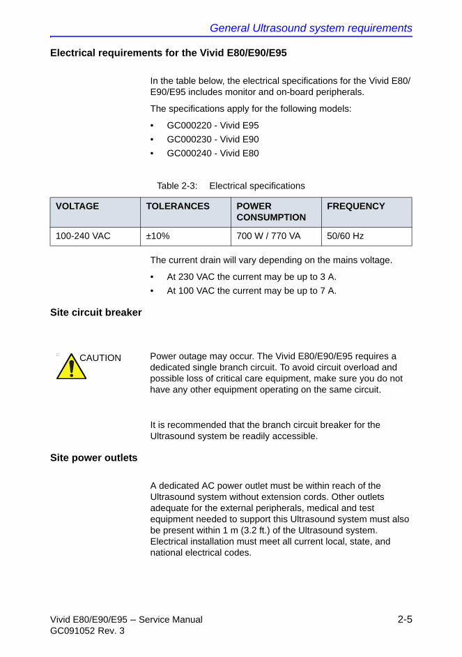
Electrical requirements for the Vivid E80/E90/E95
In the table below, the electrical specifications for the Vivid E80/E90/E95 includes monitor and on-board peripherals.
The specifications apply for the following models:
• GC000220 - Vivid E95
• GC000230 - Vivid E90
• GC000240 - Vivid E80
The current drain will vary depending on the mains voltage.
• At 230 VAC the current may be up to 3 A.
• At 100 VAC the current may be up to 7 A.
Site circuit breaker
It is recommended that the branch circuit breaker for the Ultrasound system be readily accessible.
Site power outlets
A dedicated AC power outlet must be within reach of the Ultrasound system without extension cords. Other outlets adequate for the external peripherals, medical and test equipment needed to support this Ultrasound system must also be present within 1 m (3.2 ft.) of the Ultrasound system. Electrical installation must meet all current local, state, and national electrical codes.
Table 2-3: Electrical specifications
VOLTAGE TOLERANCES POWER CONSUMPTION
FREQUENCY
100-240 VAC ±10% 700 W / 770 VA 50/60 Hz
CAUTION Power outage may occur. The Vivid E80/E90/E95 requires a dedicated single branch circuit. To avoid circuit overload and possible loss of critical care equipment, make sure you do not have any other equipment operating on the same circuit.
Site Preparations
2-6 Vivid E80/E90/E95 – Service ManualGC091052 Rev. 3
Power plug
If the Ultrasound system arrives without a power plug, or with the wrong plug, you must contact your GE dealer or the installation engineer must supply what is locally required.
Power stability requirements
Voltage drop-out:
Max 10 ms.
Power transients (all applications):
Less than 25% of nominal peak voltage for less than 1 millisecond for any type of transient, including line frequency, synchronous, asynchronous, or aperiodic transients.
General Ultrasound system requirements
Vivid E80/E90/E95 – Service Manual 2-7GC091052 Rev. 3
EMI limitations
Ultrasound systems are susceptible to Electromagnetic Interference (EMI) from radio frequencies, magnetic fields, and transients in the air or wiring. They also generate EMI. The Ultrasound system complies with limits as stated on the EMC label. However there is no guarantee that interference will not occur in a particular installation.
Possible EMI sources should be identified before the Ultrasound system is installed.
Electrical and electronic equipment may produce EMI unintentionally as the result of a defect. Some of these sources include:
• medical lasers
• scanners
• cauterizing guns
• computers
• monitors
• fans
• gel warmers
• microwave ovens
• light dimmers
• mobile phones
• in-house wireless phones (DECT phones)
• wireless computer keyboard and mouse
• air conditioning system
• High Frequency (HF) surgery equipment
• general AC/DC adapters
The presence of a broadcast station or broadcast van may also cause interference.
See: ‘EMI prevention/abatement’ on page 2-8 for EMI prevention tips.
Site Preparations
2-8 Vivid E80/E90/E95 – Service ManualGC091052 Rev. 3
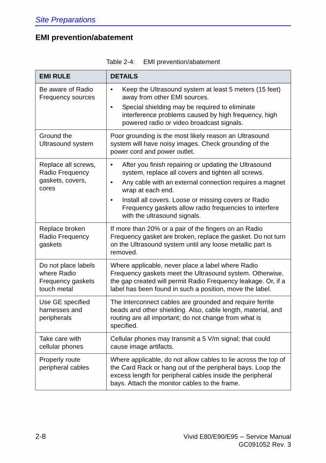
EMI prevention/abatement
Table 2-4: EMI prevention/abatement
EMI RULE DETAILS
Be aware of Radio Frequency sources
• Keep the Ultrasound system at least 5 meters (15 feet) away from other EMI sources.
• Special shielding may be required to eliminate interference problems caused by high frequency, high powered radio or video broadcast signals.
Ground the Ultrasound system
Poor grounding is the most likely reason an Ultrasound system will have noisy images. Check grounding of the power cord and power outlet.
Replace all screws, Radio Frequency gaskets, covers, cores
• After you finish repairing or updating the Ultrasound system, replace all covers and tighten all screws.
• Any cable with an external connection requires a magnet wrap at each end.
• Install all covers. Loose or missing covers or Radio Frequency gaskets allow radio frequencies to interfere with the ultrasound signals.
Replace broken Radio Frequency gaskets
If more than 20% or a pair of the fingers on an Radio Frequency gasket are broken, replace the gasket. Do not turn on the Ultrasound system until any loose metallic part is removed.
Do not place labels where Radio Frequency gaskets touch metal
Where applicable, never place a label where Radio Frequency gaskets meet the Ultrasound system. Otherwise, the gap created will permit Radio Frequency leakage. Or, if a label has been found in such a position, move the label.
Use GE specified harnesses and peripherals
The interconnect cables are grounded and require ferrite beads and other shielding. Also, cable length, material, and routing are all important; do not change from what is specified.
Take care with cellular phones
Cellular phones may transmit a 5 V/m signal; that could cause image artifacts.
Properly route peripheral cables
Where applicable, do not allow cables to lie across the top of the Card Rack or hang out of the peripheral bays. Loop the excess length for peripheral cables inside the peripheral bays. Attach the monitor cables to the frame.

General Ultrasound system requirements
Vivid E80/E90/E95 – Service Manual 2-9GC091052 Rev. 3
Probes environmental requirements
Operation and storage temperatures for probes
Table 2-5: Operation and storage temperatures for probes
Conditions Electronic PAMPTE
Operation: 10 to 40 ºC (50 to 104 ºF) 5 to 42.7 ºC (41 to 108,9 ºF)
Storage: -20 to 50 ºC (-4 to 122 ºF) -20 to 60 ºC (-4 to 140 ºF)
Temperature in degrees Celsius (ºC) conversion to degrees F (ºF):
(ºF) = (ºC * 9/5) + 32
CAUTION PAMPTE probes are designed for storage temperatures of -20 to +60 degrees C (-4 to +140 degrees F).
Electronic probes are designed for storage temperatures of -20 to +50 degrees C (-4 to +122 degrees F).
When exposed to large temperature variations, the product should be kept at room temperature the needed time to stabilize its temperature before use.

Site Preparations
2-10 Vivid E80/E90/E95 – Service ManualGC091052 Rev. 3
Facility needs
Purchaser responsibilities
The work and materials needed to prepare the site is the responsibility of the purchaser. Delay, confusion, and waste of manpower can be avoided by completing pre-installation work before delivery. Purchaser responsibility includes:
• Procuring the materials required
• Completing the preparations before delivery of the Ultrasound system
• Paying the costs for any alterations and modifications not specifically provided in the sales contract
Facility needs
Vivid E80/E90/E95 – Service Manual 2-11GC091052 Rev. 3
Purchaser responsibilities (continued)
NOTE: All electrical installations that are preliminary to the positioning of the equipment at the site prepared for the equipment must be performed by licensed electrical contractors. Other connections between pieces of electrical equipment, calibrations, and testing must also be performed by qualified personnel. The products involved (and the accompanying electrical installations) are highly sophisticated and special engineering competence is required. All electrical work on these products must comply with the requirements of applicable electrical codes. The purchaser of GE equipment must only utilize qualified personnel to perform electrical servicing on the equipment.
The desire to use a non–listed or customer provided product or to place an approved product further from the Ultrasound system than the interface kit allows, presents challenges to the installation team. To avoid delays during installation, such variances should be made known to the individuals or group performing the installation at the earliest possible date (preferably prior to the purchase).
The ultrasound suite must be clean prior to delivery of the Ultrasound system. Carpet is not recommended because it collects dust and creates static. Potential sources of EMI (electromagnetic interference) should also be investigated before delivery. Dirt, static, and EMI can negatively impact Ultrasound system reliability.
Site Preparations
2-12 Vivid E80/E90/E95 – Service ManualGC091052 Rev. 3
Required facility needs
NOTE: GE requires a dedicated power and ground for the proper operation of its Ultrasound equipment. This dedicated power shall originate at the last distribution panel before the Ultrasound system.
The Ultrasound system will function on voltages from 100-240 Volts and 50 or 60 Hz. However, if using 220 volt power in North America, then a center tapped power source is required.
Sites with a mains power system with defined Neutral and Live:
The dedicated line shall consist of one phase, a neutral (not shared with any other circuit), and a full size ground wire from the distribution panel to the Ultrasound outlet.
Sites with a mains power system without a defined Neutral:
The dedicated line shall consist of one phase (two lines), not shared with any other circuit, and a full size ground wire from the distribution panel to the Ultrasound outlet.
• Dedicated single branch power outlet of adequate amperage, meeting all local and national codes, which is located less than 2.5 m (8 ft.) from the Ultrasound system’s proposed location
• Door opening is at least 76 cm (30 in) wide
• Proposed location for Ultrasound system is at least 0.5 m (1.5 ft.) from the wall for cooling
• Power outlet and place for any external peripheral are within 2 m (6.5 ft.) of each other with peripheral within 1 m of the Ultrasound system to connect cables.
• Power outlets for other medical equipment
• Power outlets for test equipment within 1 m (3.2 ft.) of Ultrasound system
• Clean and protected space to store probes (in their cases or on a rack)
• Material to safely clean probes (done with a plastic container, never metal)
For the amperage requirements, see: ‘Electrical requirements’ on page 2-4.
Facility needs
Vivid E80/E90/E95 – Service Manual 2-13GC091052 Rev. 3
Desirable features
• Door is at least 92 cm (3 ft.) wide
• Circuit breaker for dedicated power outlet is easily accessible
• Sink with hot and cold water
• Receptacle for bio–hazardous waste, like used probe sheaths
• Emergency oxygen supply
• Storage for linens and equipment
• Nearby waiting room, lavatory, and dressing room
• Dual level lighting (bright and dim)
• Lockable cabinet ordered by GE for its software and proprietary manuals
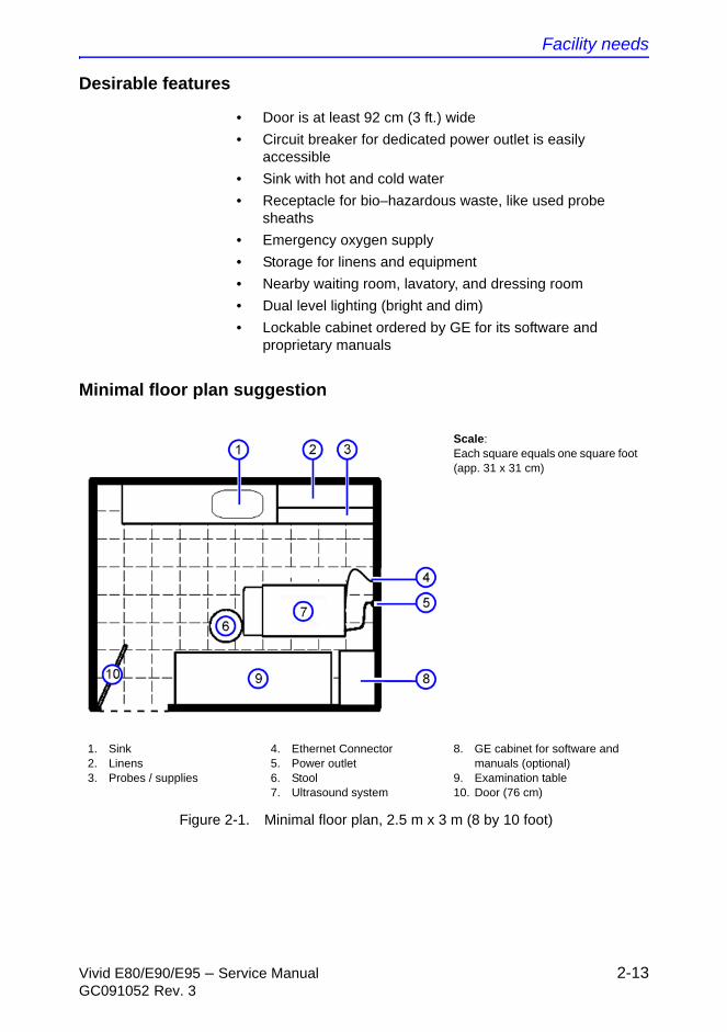
Minimal floor plan suggestion
Figure 2-1. Minimal floor plan, 2.5 m x 3 m (8 by 10 foot)
Scale: Each square equals one square foot (app. 31 x 31 cm)
1. Sink2. Linens3. Probes / supplies
4. Ethernet Connector5. Power outlet6. Stool7. Ultrasound system
8. GE cabinet for software and manuals (optional)
9. Examination table10. Door (76 cm)
Site Preparations
2-14 Vivid E80/E90/E95 – Service ManualGC091052 Rev. 3
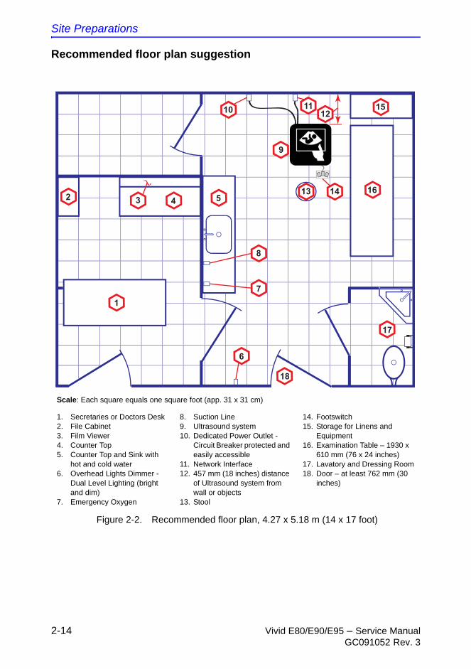
Recommended floor plan suggestion
Figure 2-2. Recommended floor plan, 4.27 x 5.18 m (14 x 17 foot)
Scale: Each square equals one square foot (app. 31 x 31 cm)
1. Secretaries or Doctors Desk2. File Cabinet3. Film Viewer 4. Counter Top5. Counter Top and Sink with
hot and cold water6. Overhead Lights Dimmer -
Dual Level Lighting (bright and dim)
7. Emergency Oxygen
8. Suction Line9. Ultrasound system10. Dedicated Power Outlet -
Circuit Breaker protected and easily accessible
11. Network Interface12. 457 mm (18 inches) distance
of Ultrasound system from wall or objects
13. Stool
14. Footswitch15. Storage for Linens and
Equipment16. Examination Table – 1930 x
610 mm (76 x 24 inches)17. Lavatory and Dressing Room18. Door – at least 762 mm (30
inches)
4
1
2
18
5
6
9
16
17
15
8
7
10 1112
313 14
Facility needs
Vivid E80/E90/E95 – Service Manual 2-15GC091052 Rev. 3
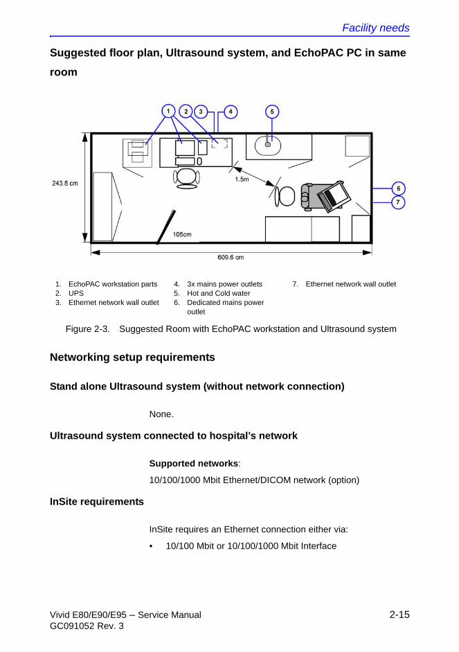
Suggested floor plan, Ultrasound system, and EchoPAC PC in same
room
Figure 2-3. Suggested Room with EchoPAC workstation and Ultrasound system
Networking setup requirements
Stand alone Ultrasound system (without network connection)
None.
Ultrasound system connected to hospital’s network
Supported networks:
10/100/1000 Mbit Ethernet/DICOM network (option)
InSite requirements
InSite requires an Ethernet connection either via:
• 10/100 Mbit or 10/100/1000 Mbit Interface
1. EchoPAC workstation parts2. UPS3. Ethernet network wall outlet
4. 3x mains power outlets5. Hot and Cold water6. Dedicated mains power
outlet
7. Ethernet network wall outlet
Site Preparations
2-16 Vivid E80/E90/E95 – Service ManualGC091052 Rev. 3
Purpose of the DICOM network function
DICOM services provide the operator with clinically useful features for moving images and patient information over a hospital network.
Examples of DICOM services include the transfer of images to workstations for viewing or transferring images to remote printers.
As an added benefit, transferring images in this manner frees up the on-board monitor and peripherals, enabling viewing to be done while scanning continues.
With DICOM, images can be archived, stored, and retrieved faster, easier, and at a lower cost.
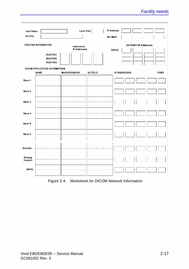
DICOM option setup requirements
To configure the Ultrasound system to work with other network connections, the site’s network administrator must provide information to complete the form “Worksheet for DICOM Network Information”. Ensure that there are no spaces in any field of the form.
Entries must include:
• A host name, local port number, AE Title, IP address and Net Mask for the Ultrasound system.
• The IP addresses for the default gateway and other routers at the site for ROUTING INFORMATION.
• The host name, IP address, port and AE Title for each device the site wants connected to the Ultrasound system for DICOM APPLICATION INFORMATION. A field for the make (manufacturer) and the revision of the device, is also included. This information may be useful for error solving.
Facility needs
Vivid E80/E90/E95 – Service Manual 2-17GC091052 Rev. 3
Figure 2-4. Worksheet for DICOM Network Information
Site Preparations
2-18 Vivid E80/E90/E95 – Service ManualGC091052 Rev. 3
Environmental Dangers
Patient Vicinity UL60601-1 (USA)
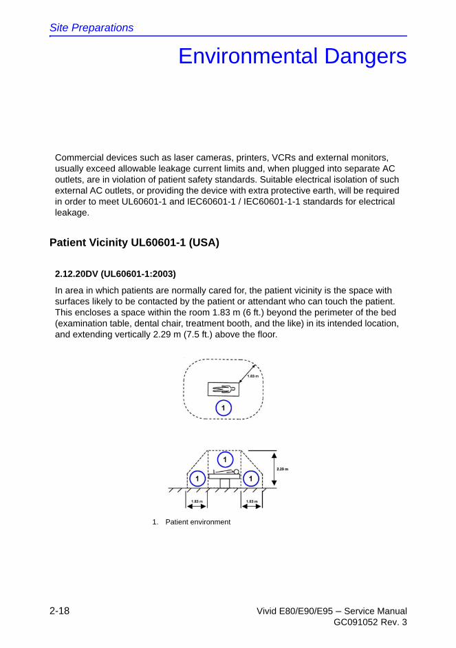
Commercial devices such as laser cameras, printers, VCRs and external monitors, usually exceed allowable leakage current limits and, when plugged into separate AC outlets, are in violation of patient safety standards. Suitable electrical isolation of such external AC outlets, or providing the device with extra protective earth, will be required in order to meet UL60601-1 and IEC60601-1 / IEC60601-1-1 standards for electrical leakage.
2.12.20DV (UL60601-1:2003)
In area in which patients are normally cared for, the patient vicinity is the space with surfaces likely to be contacted by the patient or attendant who can touch the patient. This encloses a space within the room 1.83 m (6 ft.) beyond the perimeter of the bed (examination table, dental chair, treatment booth, and the like) in its intended location, and extending vertically 2.29 m (7.5 ft.) above the floor.
1. Patient environment
Environmental Dangers
Vivid E80/E90/E95 – Service Manual 2-19GC091052 Rev. 3
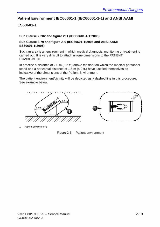
Patient Environment IEC60601-1 (IEC60601-1-1) and ANSI AAMI
ES60601-1
Figure 2-5. Patient environment
Sub Clause 2.202 and figure 201 (IEC60601-1-1:2000)
Sub Clause 3.79 and figure A.9 (IEC60601-1:2005 and ANSI AAMI ES60601-1:2005)
Such an area is an environment in which medical diagnosis, monitoring or treatment is carried out. It is very difficult to attach unique dimensions to the PATIENT ENVIROMENT.
In practice a distance of 2,5 m (8.2 ft.) above the floor on which the medical personnel stand and a horizontal distance of 1,5 m (4.9 ft.) have justified themselves as indicative of the dimensions of the Patient Environment.
The patient environment/vicinity will be depicted as a dashed line in this procedure. See example below.
1. Patient environment

Site Preparations
2-20 Vivid E80/E90/E95 – Service ManualGC091052 Rev. 3
THIS PAGE WAS INTENTIONALLY LEFT BLANK
Vivid E80/E90/E95 – Service Manual 3-1GC091052 Rev. 3
Chapter 3
System Setup
This chapter contains information needed to install Vivid E80/E90/E95.
Included is a procedure that describes how to receive and unpack the equipment and how to file a damage or loss claim.
How to prepare the facility and Ultrasound system of the actual installation, and how to check and test the Ultrasound system, probes, and external peripherals for electrical safety are also included in this procedure.
System Setup
3-2 Vivid E80/E90/E95 – Service ManualGC091052 Rev. 3
Setup reminders
Setup warnings
DANGER
WHEN USING ANY TEST INSTRUMENT THAT IS CAPABLE OF OPENING THE AC GROUND LINE (I.E., METER’S GROUND SWITCH IS OPEN), DON’T TOUCH THE ULTRASOUND SYSTEM!
CAUTION To prevent electrical shock, connect the Ultrasound system to a properly grounded power outlet. Do not use a three to two prong adapter. This defeats safety grounding.
CAUTION Do not wear the ESD wrist strap when you work on live circuits and more than 30 V peak is present.
CAUTION Do not operate this Ultrasound system unless all board covers and frame panels are securely in place. System performance and cooling require this.
Setup reminders
Vivid E80/E90/E95 – Service Manual 3-3GC091052 Rev. 3
Setup warnings (continued)
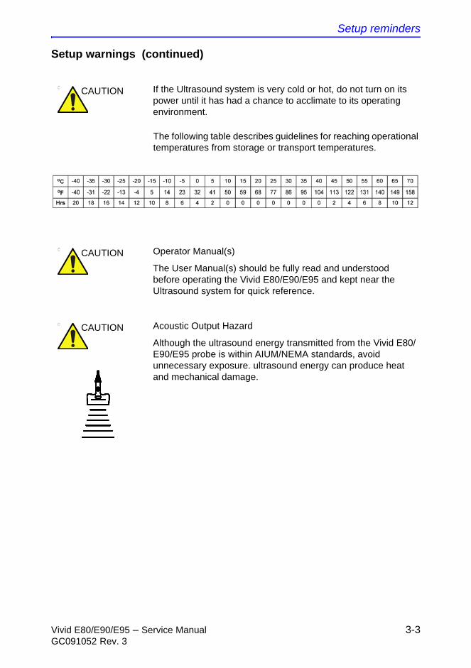
The following table describes guidelines for reaching operational temperatures from storage or transport temperatures.
CAUTION If the Ultrasound system is very cold or hot, do not turn on its power until it has had a chance to acclimate to its operating environment.
CAUTION Operator Manual(s)
The User Manual(s) should be fully read and understood before operating the Vivid E80/E90/E95 and kept near the Ultrasound system for quick reference.
CAUTION Acoustic Output Hazard
Although the ultrasound energy transmitted from the Vivid E80/E90/E95 probe is within AIUM/NEMA standards, avoid unnecessary exposure. ultrasound energy can produce heat and mechanical damage.
System Setup
3-4 Vivid E80/E90/E95 – Service ManualGC091052 Rev. 3
Receiving and unpacking the
equipment
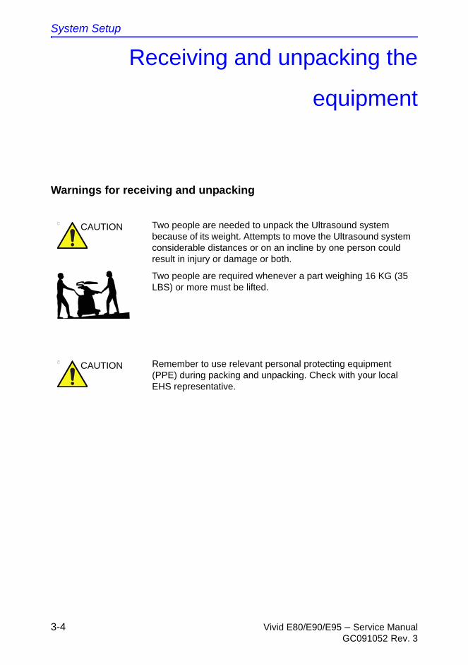
Warnings for receiving and unpacking
CAUTION Two people are needed to unpack the Ultrasound system because of its weight. Attempts to move the Ultrasound system considerable distances or on an incline by one person could result in injury or damage or both.
Two people are required whenever a part weighing 16 KG (35 LBS) or more must be lifted.
CAUTION Remember to use relevant personal protecting equipment (PPE) during packing and unpacking. Check with your local EHS representative.

Receiving and unpacking the equipment
Vivid E80/E90/E95 – Service Manual 3-5GC091052 Rev. 3
The Tilt and Shock indicators
Overview
Improper handling during transportation may harm the equipment inside the package even if the package itself is undamaged.
To make it easier to detect if the handling during transportation has been improper, a set of Tilt & Shock indicators have been attached to the transportation box.
Table 3-1: Shock and Tilt Watch
Description Illustration
ShockWatch
Tilt Watch
System Setup
3-6 Vivid E80/E90/E95 – Service ManualGC091052 Rev. 3
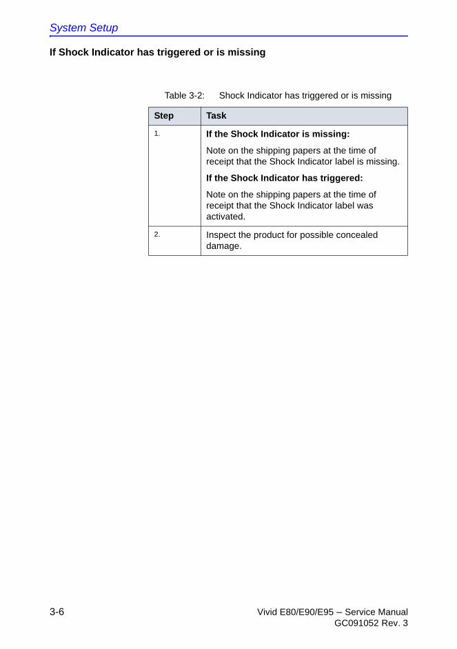
If Shock Indicator has triggered or is missing
Table 3-2: Shock Indicator has triggered or is missing
Step Task
1. If the Shock Indicator is missing:
Note on the shipping papers at the time of receipt that the Shock Indicator label is missing.
If the Shock Indicator has triggered:
Note on the shipping papers at the time of receipt that the Shock Indicator label was activated.
2. Inspect the product for possible concealed damage.
Receiving and unpacking the equipment
Vivid E80/E90/E95 – Service Manual 3-7GC091052 Rev. 3
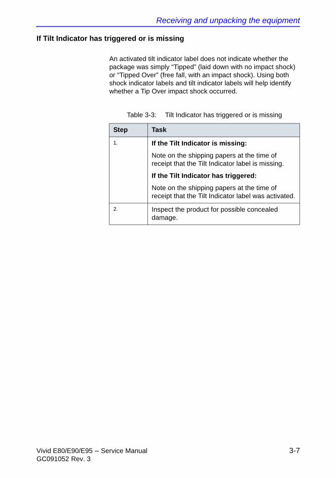
If Tilt Indicator has triggered or is missing
An activated tilt indicator label does not indicate whether the package was simply “Tipped” (laid down with no impact shock) or “Tipped Over” (free fall, with an impact shock). Using both shock indicator labels and tilt indicator labels will help identify whether a Tip Over impact shock occurred.
Table 3-3: Tilt Indicator has triggered or is missing
Step Task
1. If the Tilt Indicator is missing:
Note on the shipping papers at the time of receipt that the Tilt Indicator label is missing.
If the Tilt Indicator has triggered:
Note on the shipping papers at the time of receipt that the Tilt Indicator label was activated.
2. Inspect the product for possible concealed damage.
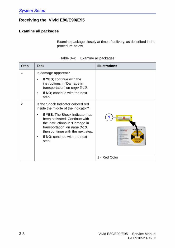
System Setup
3-8 Vivid E80/E90/E95 – Service ManualGC091052 Rev. 3
Receiving the Vivid E80/E90/E95
Examine all packages
Examine package closely at time of delivery, as described in the procedure below.
Table 3-4: Examine all packages
Step Task Illustrations
1. Is damage apparent?
• If YES; continue with the instructions in ‘Damage in transportation’ on page 3-10.
• If NO; continue with the next step.
2. Is the Shock Indicator colored red inside the middle of the indicator?
• If YES: The Shock Indicator has been activated. Continue with the instructions in ‘Damage in transportation’ on page 3-10, then continue with the next step.
• If NO: continue with the next step.
1 - Red Color
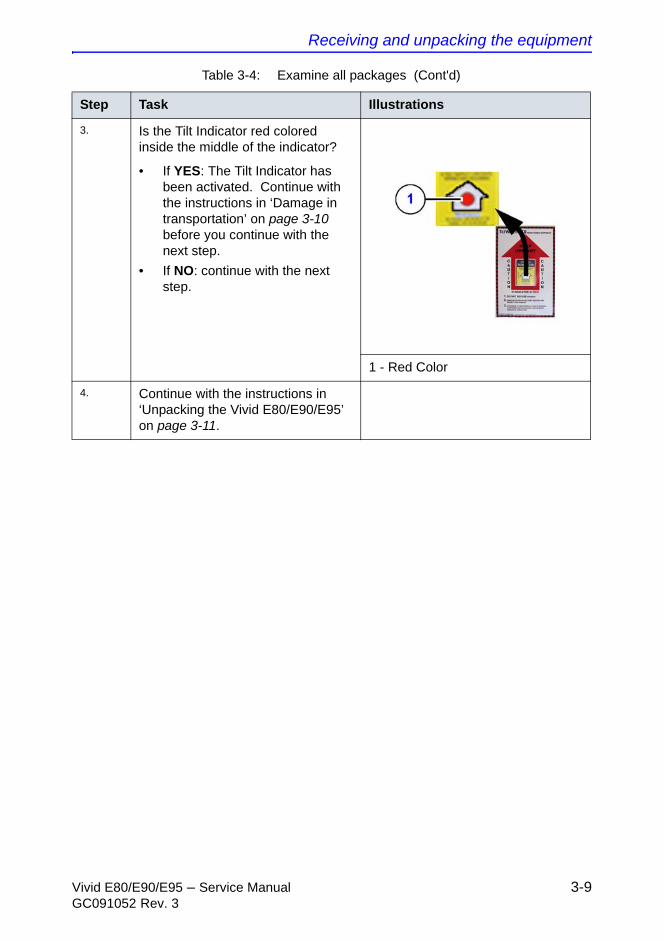
Receiving and unpacking the equipment
Vivid E80/E90/E95 – Service Manual 3-9GC091052 Rev. 3
3. Is the Tilt Indicator red colored inside the middle of the indicator?
• If YES: The Tilt Indicator has been activated. Continue with the instructions in ‘Damage in transportation’ on page 3-10 before you continue with the next step.
• If NO: continue with the next step.
1 - Red Color
4. Continue with the instructions in ‘Unpacking the Vivid E80/E90/E95’ on page 3-11.
Table 3-4: Examine all packages (Cont'd)
Step Task Illustrations
System Setup
3-10 Vivid E80/E90/E95 – Service ManualGC091052 Rev. 3
Damage in transportation
Follow this procedure if damage is apparent:
1. Write “Damage In Shipment” on ALL copies of the freight or express bill BEFORE delivery is accepted or “signed for“ by a GE representative or hospital receiving agent.
2. Report the damage to the carrier.
• Whether noted or concealed, damage MUST be reported to the carrier immediately upon discovery, or in any event, within 14 days after receipt, and the contents and containers held for inspection by the carrier.
• A transportation company will not pay a claim for damage if an inspection is not requested within this 14 day period.
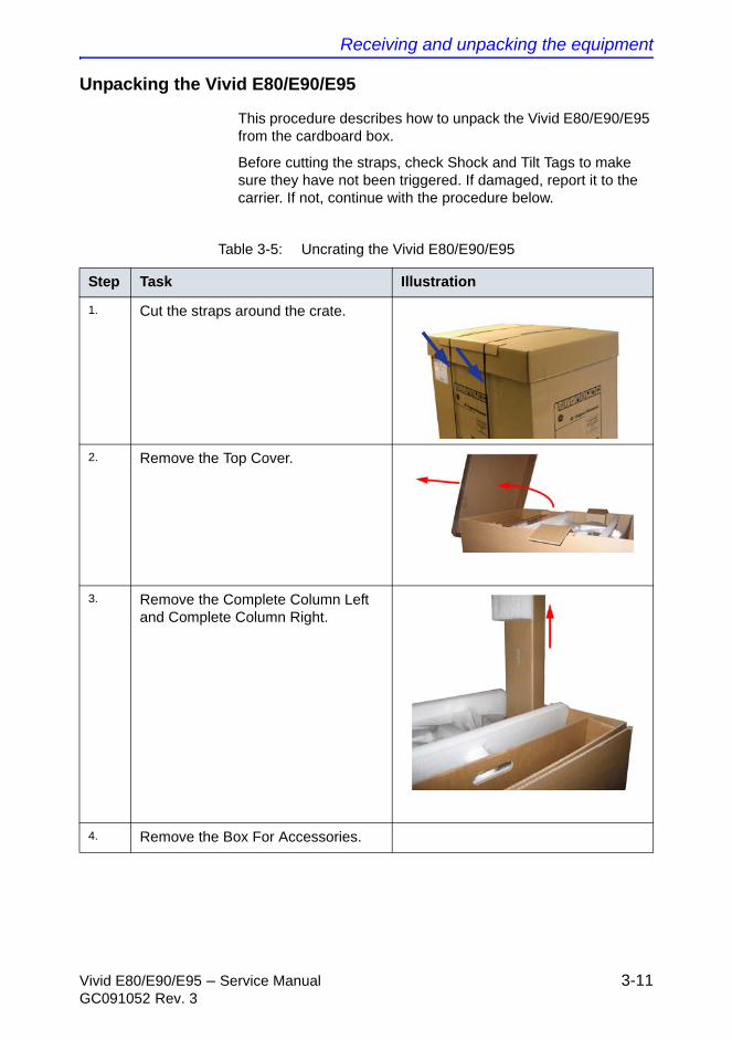
Receiving and unpacking the equipment
Vivid E80/E90/E95 – Service Manual 3-11GC091052 Rev. 3
Unpacking the Vivid E80/E90/E95
This procedure describes how to unpack the Vivid E80/E90/E95 from the cardboard box.
Before cutting the straps, check Shock and Tilt Tags to make sure they have not been triggered. If damaged, report it to the carrier. If not, continue with the procedure below.
Table 3-5: Uncrating the Vivid E80/E90/E95
Step Task Illustration
1. Cut the straps around the crate.
2. Remove the Top Cover.
3. Remove the Complete Column Left and Complete Column Right.
4. Remove the Box For Accessories.
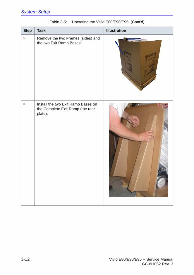
System Setup
3-12 Vivid E80/E90/E95 – Service ManualGC091052 Rev. 3
5. Remove the two Frames (sides) and the two Exit Ramp Bases.
6. Install the two Exit Ramp Bases on the Complete Exit Ramp (the rear plate).
Table 3-5: Uncrating the Vivid E80/E90/E95 (Cont'd)
Step Task Illustration
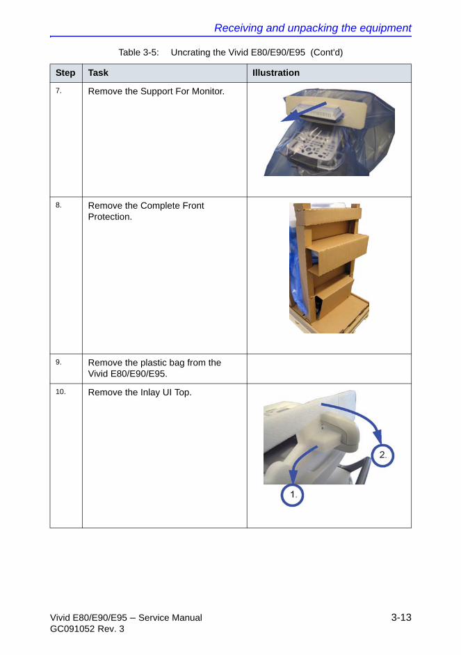
Receiving and unpacking the equipment
Vivid E80/E90/E95 – Service Manual 3-13GC091052 Rev. 3
7. Remove the Support For Monitor.
8. Remove the Complete Front Protection.
9. Remove the plastic bag from the Vivid E80/E90/E95.
10. Remove the Inlay UI Top.
Table 3-5: Uncrating the Vivid E80/E90/E95 (Cont'd)
Step Task Illustration
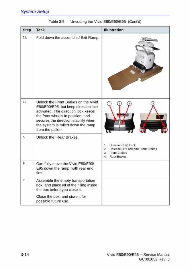
System Setup
3-14 Vivid E80/E90/E95 – Service ManualGC091052 Rev. 3
11. Fold down the assembled Exit Ramp.
12. Unlock the Front Brakes on the Vivid E80/E90/E95, but keep direction lock activated. The direction lock keeps the front wheels in position, and secures the direction stability when the system is rolled down the ramp from the pallet.
1. Direction (Dir) Lock2. Release Dir Lock and Front Brakes3. Front Brakes4. Rear Brakes
5. Unlock the Rear Brakes.
6. Carefully move the Vivid E80/E90/E95 down the ramp, with rear end first.
7. Assemble the empty transportation box and place all of the filling inside the box before you close it.
Close the box, and store it for possible future use.
Table 3-5: Uncrating the Vivid E80/E90/E95 (Cont'd)
Step Task Illustration

Packing materials - recycling information
Vivid E80/E90/E95 – Service Manual 3-15GC091052 Rev. 3
Packing materials - recycling
information
The packing materials for Vivid E80/E90/E95 are recyclable:
Table 3-6: Packaging parts for Vivid E80/E90/E95
Item Description Qty. Material *) Illustration
1. Export pallet 1200 x 800 1 D
2. Complete base 1 A
3. Complete column left and right
2 A
4. Support for monitor 1 C
5. Inlay UI Top 1 C
6. Complete front protection 1 B
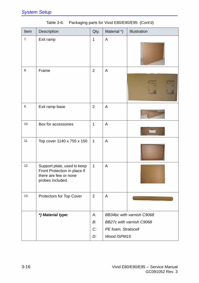
System Setup
3-16 Vivid E80/E90/E95 – Service ManualGC091052 Rev. 3
7. Exit ramp 1 A
8. Frame 2 A
9. Exit ramp base 2 A
10. Box for accessories 1 A
11. Top cover 1140 x 755 x 150 1 A
12. Support plate, used to keep Front Protection in place if there are few or none probes included.
1 A
13. Protectors for Top Cover 2 A
*) Material type: A:
B:
C:
D:
BB34bc with varnish C9068
BB27c with varnish C9068
PE foam, Stratocell
Wood ISPM15
Table 3-6: Packaging parts for Vivid E80/E90/E95 (Cont'd)
Item Description Qty. Material *) Illustration
Preparing for setup
Vivid E80/E90/E95 – Service Manual 3-17GC091052 Rev. 3
Preparing for setup
Verify customer order
Compare items received by the customer to those that are listed on the delivery order. Report any items that are missing, back ordered, or damaged.
Physical inspection
Verify that the Vivid E80/E90/E95 arrived intact (visual inspection).
If the Vivid E80/E90/E95 has been damaged, please refer to ‘Damage in transportation’ on page i-15 in the beginning of this manual.
EMI protection
The Vivid E80/E90/E95 has been designed to minimize the effects of Electro-Magnetic Interference (EMI). Many of the covers, shields, and screws are provided primarily to protect the Vivid E80/E90/E95 from image artifacts caused by this interference. For this reason, it is imperative that all covers and hardware are installed and secured before the Vivid E80/E90/E95 is put into operation.
See ‘EMI limitations’ on page 2-7 for more information about EMI protection.

System Setup
3-18 Vivid E80/E90/E95 – Service ManualGC091052 Rev. 3
Completing the setup
System specifications
System requirements verification
• Verify that the site meets the requirements listed in Chapter 2.
(See: ‘Facility needs’ on page 2-10.)
• Verify that the specifications below do not conflict with any on-site conditions.
Physical dimensions
Mass with monitor and peripherals
Table 3-7: Physical dimensions of Vivid E80/E90/E95 with monitor and peripherals - in transportation position
Height Width Depth Unit
141.0 58.5 83.0 cm
55.5 23 32.7 Inches
Table 3-8: Mass of Vivid E80/E90/E95 with monitor, without probes and peripherals
Model Mass [KG] Mass [LBS]
Vivid E80/E90/E95
128 283

Completing the setup
Vivid E80/E90/E95 – Service Manual 3-19GC091052 Rev. 3
Electrical specifications
Verification of the Vivid E80/E90/E95’s voltage setting
Verify that the mains voltage specified for the Vivid E80/E90/E95 is available on-site.
The voltage setting for the Vivid E80/E90/E95 is found on a label near the Mains Power Circuit Breaker on the rear of the Vivid E80/E90/E95.
Electrical specifications for Vivid E80/E90/E95
In the table below, the electrical specifications for Vivid E80/E90/E95 includes monitor and on board peripherals.
WARNING Connecting a Vivid E80/E90/E95 to the wrong voltage level will most likely destroy it.
Table 3-9: Electrical specifications for all Vivid E80/E90/E95 models
Voltage 100-240 VAC ±10%
Power Consumption 700W / 770 VA
Frequency 50/60 Hz
System Setup
3-20 Vivid E80/E90/E95 – Service ManualGC091052 Rev. 3
Connections on the I/O Rear Panel
NOTE: Accessory equipment connected to the analog and digital interfaces must be certified according to the respective IEC standards (e.g. IEC60950 for data processing equipment and IEC60601-1 for medical equipment). Furthermore, all complete configurations shall comply with the valid version of the system standard IEC60601-1-1. Everybody who connects additional equipment to the signal input part or signal output part of Vivid E80/E90/E95, configures a medical system, and is therefore responsible that the Ultrasound system complies with the requirements of the valid version of IEC60601-1-1. If in doubt, consult the technical service department or your local representative for GE.
Connect Ethernet
Connect the network cable to the Ethernet connector on the I/O Rear Panel.
The connector is located on the rear side of Vivid E80/E90/E95.
Connect USB Flash Card
NOTE: Only approved USB Flash Cards must be used. USB Flash Cards approved for Vivid E80/E90/E95 are verified for EMC performance according to EN55011 class B. The use of any other USB Flash Cards will compromise this verification, and may cause interference on Vivid E80/E90/E95 itself, or on other electronic devices.
For approved models, please refer to Chapter 9.
Install the USB Flash Card in one of the USB ports on the Vivid E80/E90/E95.
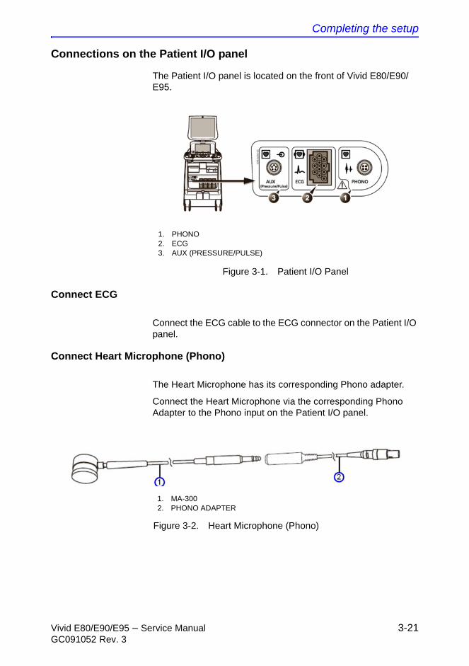
Completing the setup
Vivid E80/E90/E95 – Service Manual 3-21GC091052 Rev. 3
Connections on the Patient I/O panel
The Patient I/O panel is located on the front of Vivid E80/E90/E95.
Figure 3-1. Patient I/O Panel
Connect ECG
Connect the ECG cable to the ECG connector on the Patient I/O panel.
Connect Heart Microphone (Phono)
The Heart Microphone has its corresponding Phono adapter.
Connect the Heart Microphone via the corresponding Phono Adapter to the Phono input on the Patient I/O panel.
Figure 3-2. Heart Microphone (Phono)
1. PHONO2. ECG3. AUX (PRESSURE/PULSE)
1. MA-3002. PHONO ADAPTER
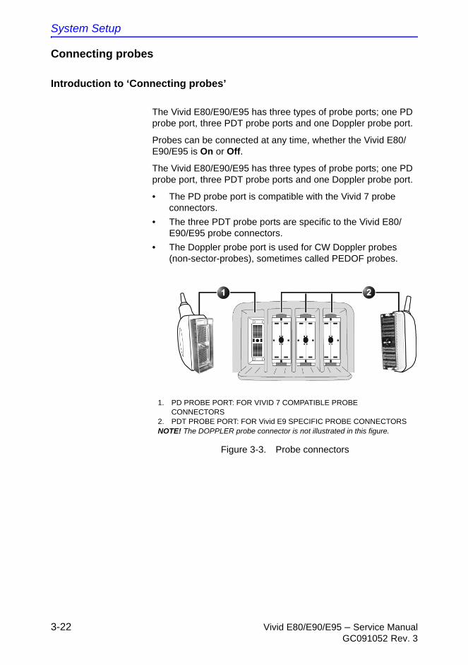
System Setup
3-22 Vivid E80/E90/E95 – Service ManualGC091052 Rev. 3
Connecting probes
Introduction to ‘Connecting probes’
The Vivid E80/E90/E95 has three types of probe ports; one PD probe port, three PDT probe ports and one Doppler probe port.
Probes can be connected at any time, whether the Vivid E80/E90/E95 is On or Off.
The Vivid E80/E90/E95 has three types of probe ports; one PD probe port, three PDT probe ports and one Doppler probe port.
• The PD probe port is compatible with the Vivid 7 probe connectors.
• The three PDT probe ports are specific to the Vivid E80/E90/E95 probe connectors.
• The Doppler probe port is used for CW Doppler probes (non-sector-probes), sometimes called PEDOF probes.
Figure 3-3. Probe connectors
1. PD PROBE PORT: FOR VIVID 7 COMPATIBLE PROBE CONNECTORS
2. PDT PROBE PORT: FOR Vivid E9 SPECIFIC PROBE CONNECTORSNOTE! The DOPPLER probe connector is not illustrated in this figure.

Completing the setup
Vivid E80/E90/E95 – Service Manual 3-23GC091052 Rev. 3
Connect a probe
NOTE: It is not necessary to turn OFF power to connect or disconnect a probe.
Follow these steps to connect a probe:
1. Before connecting the probe:
a. Do a visual check of the probe pins and Ultrasound system sockets.
b. Remove any dust or foam remains from the probe pins.
c. Inspect the probe and the probe cable for any visual damage.
2. Hold the probe connector vertically with the cable pointing upward.
3. Turn the connector locking handle counter-clockwise to the horizontal position.
4. Align the connector with the probe port and carefully push into place.
5. Turn the locking handle clockwise to the full vertical position to lock in place.
6. Position the probe cable so that it is not resting on the floor.
CAUTION Do not allow the probe head to hang freely. Excessive impact to the probe will result in irreparable damage.
CAUTION To prevent probe connector pins damage, or PCB board damage, do not use excessive force when connecting the probes.
CAUTION Keep the probe cables away from the wheels.
Do not bend the probe cables.
Do not cross cables between probes.
System Setup
3-24 Vivid E80/E90/E95 – Service ManualGC091052 Rev. 3
Disconnect a probe
Follow these steps to disconnect a probe:
1. Rotate the lock handle counter-clockwise to the horizontal position to unlock the connector.
2. Remove the connector from the port.
3. Ensure that the probe head is clean before placing the probe in its storage case.
For cleaning instructions, see the User Manual.
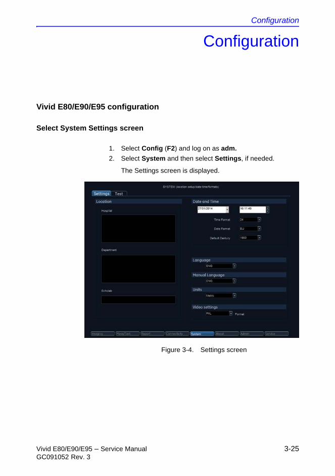
Configuration
Vivid E80/E90/E95 – Service Manual 3-25GC091052 Rev. 3
Configuration
Vivid E80/E90/E95 configuration
Select System Settings screen
1. Select Config (F2) and log on as adm.
2. Select System and then select Settings, if needed.
The Settings screen is displayed.
Figure 3-4. Settings screen
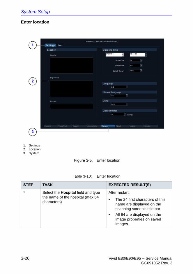
System Setup
3-26 Vivid E80/E90/E95 – Service ManualGC091052 Rev. 3
Enter location
Figure 3-5. Enter location
1. Settings2. Location3. System
Table 3-10: Enter location
STEP TASK EXPECTED RESULT(S)
1. Select the Hospital field and type the name of the hospital (max 64 characters).
After restart:
• The 24 first characters of this name are displayed on the scanning screen’s title bar.
• All 64 are displayed on the image properties on saved images.
Configuration
Vivid E80/E90/E95 – Service Manual 3-27GC091052 Rev. 3
2. Select the Department field and type the name of the department (max 64 characters).
After restart:
• This name will be displayed on the image properties on saved images
3. Select the Echolab field and type the name.
After restart:
• This name will be displayed on the image properties on saved images
Table 3-10: Enter location
STEP TASK EXPECTED RESULT(S)
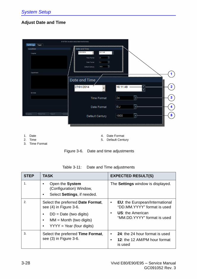
System Setup
3-28 Vivid E80/E90/E95 – Service ManualGC091052 Rev. 3
Adjust Date and Time
Figure 3-6. Date and time adjustments
1. Date2. Time3. Time Format
4. Date Format5. Default Century
Table 3-11: Date and Time adjustments
STEP TASK EXPECTED RESULT(S)
1. • Open the System (Configuration) Window,
• Select Settings, if needed.
The Settings window is displayed.
2. Select the preferred Date Format, see (4) in Figure 3-6.
• DD = Date (two digits)
• MM = Month (two digits)
• YYYY = Year (four digits)
• EU: the European/International “DD.MM.YYYY” format is used
• US: the American “MM.DD.YYYY” format is used
3. Select the preferred Time Format, see (3) in Figure 3-6.
• 24: the 24 hour format is used
• 12: the 12 AM/PM hour format is used
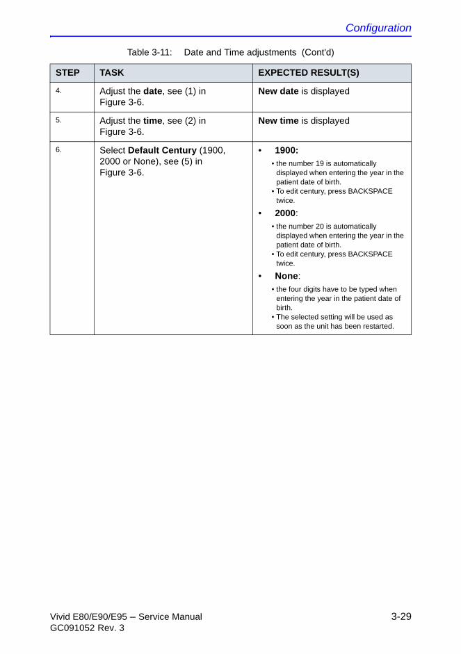
Configuration
Vivid E80/E90/E95 – Service Manual 3-29GC091052 Rev. 3
4. Adjust the date, see (1) in Figure 3-6.
New date is displayed
5. Adjust the time, see (2) in Figure 3-6.
New time is displayed
6. Select Default Century (1900, 2000 or None), see (5) in Figure 3-6.
• 1900: • the number 19 is automatically
displayed when entering the year in the patient date of birth.
• To edit century, press BACKSPACE twice.
• 2000: • the number 20 is automatically
displayed when entering the year in the patient date of birth.
• To edit century, press BACKSPACE twice.
• None: • the four digits have to be typed when
entering the year in the patient date of birth.
• The selected setting will be used as soon as the unit has been restarted.
Table 3-11: Date and Time adjustments (Cont'd)
STEP TASK EXPECTED RESULT(S)
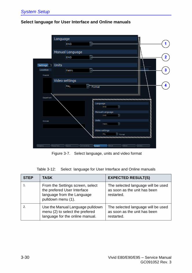
System Setup
3-30 Vivid E80/E90/E95 – Service ManualGC091052 Rev. 3
Select language for User Interface and Online manuals
Figure 3-7. Select language, units and video format
Table 3-12: Select language for User Interface and Online manuals
STEP TASK EXPECTED RESULT(S)
1. From the Settings screen, select the prefered User Interface language from the Language pulldown menu (1).
The selected language will be used as soon as the unit has been restarted.
2. Use the Manual Language pulldown menu (2) to select the prefered language for the online manual.
The selected language will be used as soon as the unit has been restarted.
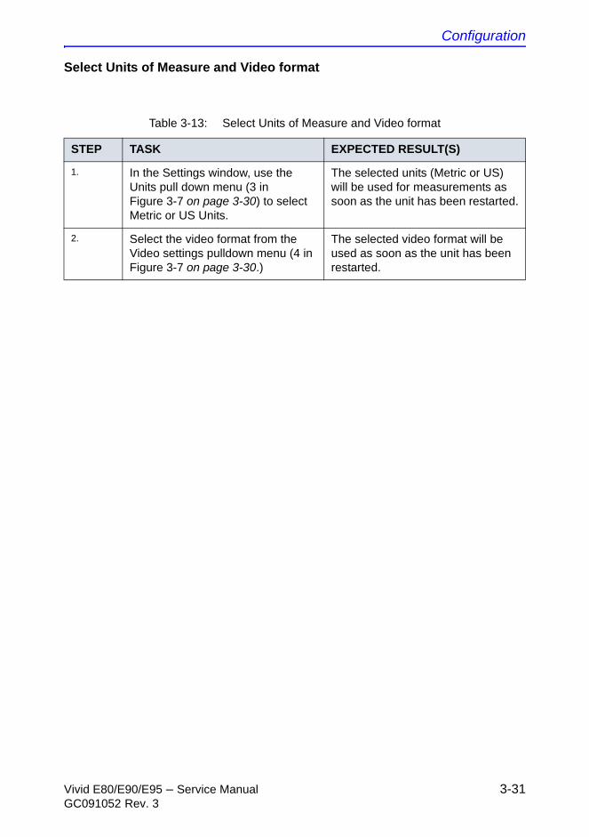
Configuration
Vivid E80/E90/E95 – Service Manual 3-31GC091052 Rev. 3
Select Units of Measure and Video format
Table 3-13: Select Units of Measure and Video format
STEP TASK EXPECTED RESULT(S)
1. In the Settings window, use the Units pull down menu (3 in Figure 3-7 on page 3-30) to select Metric or US Units.
The selected units (Metric or US) will be used for measurements as soon as the unit has been restarted.
2. Select the video format from the Video settings pulldown menu (4 in Figure 3-7 on page 3-30.)
The selected video format will be used as soon as the unit has been restarted.
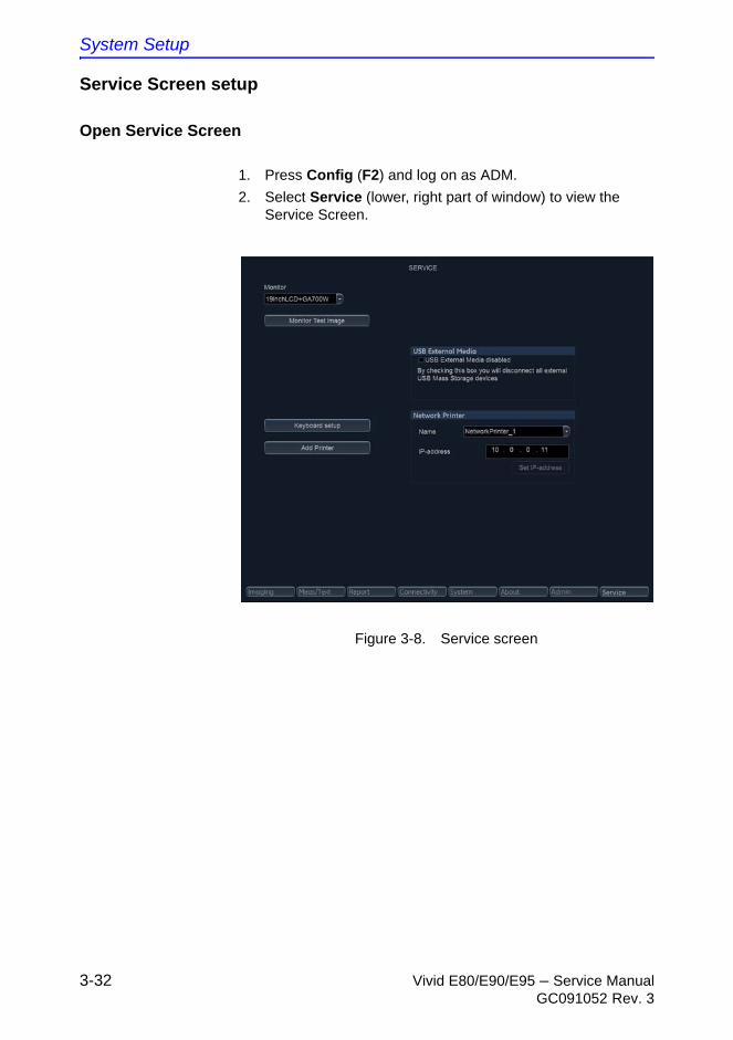
System Setup
3-32 Vivid E80/E90/E95 – Service ManualGC091052 Rev. 3
Service Screen setup
Open Service Screen
1. Press Config (F2) and log on as ADM.
2. Select Service (lower, right part of window) to view the Service Screen.
Figure 3-8. Service screen
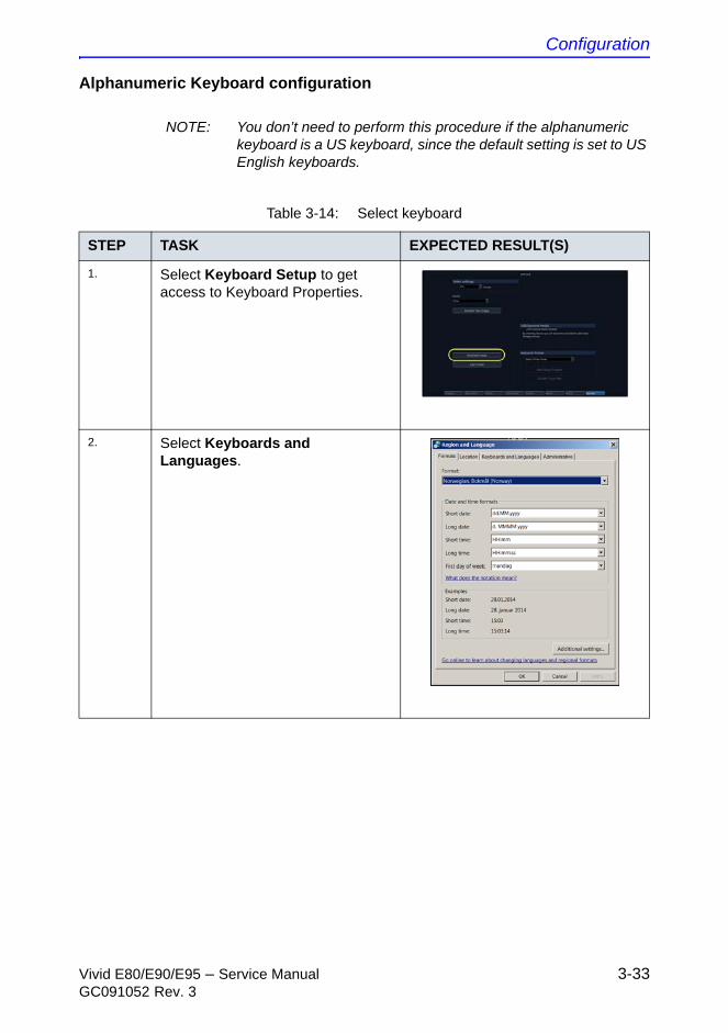
Configuration
Vivid E80/E90/E95 – Service Manual 3-33GC091052 Rev. 3
Alphanumeric Keyboard configuration
NOTE: You don’t need to perform this procedure if the alphanumeric keyboard is a US keyboard, since the default setting is set to US English keyboards.
Table 3-14: Select keyboard
STEP TASK EXPECTED RESULT(S)
1. Select Keyboard Setup to get access to Keyboard Properties.
2. Select Keyboards and Languages.
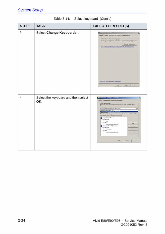
System Setup
3-34 Vivid E80/E90/E95 – Service ManualGC091052 Rev. 3
3. Select Change Keyboards...
4. Select the keyboard and then select OK.
Table 3-14: Select keyboard (Cont'd)
STEP TASK EXPECTED RESULT(S)
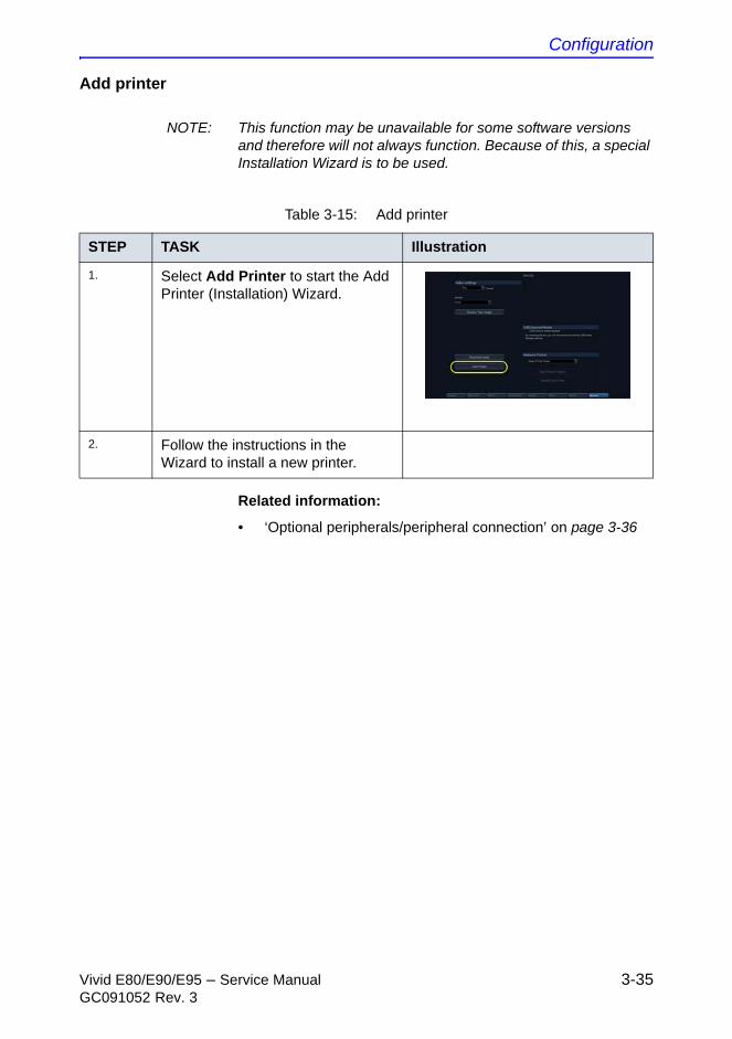
Configuration
Vivid E80/E90/E95 – Service Manual 3-35GC091052 Rev. 3
Add printer
NOTE: This function may be unavailable for some software versions and therefore will not always function. Because of this, a special Installation Wizard is to be used.
Related information:
• ‘Optional peripherals/peripheral connection’ on page 3-36
Table 3-15: Add printer
STEP TASK Illustration
1. Select Add Printer to start the Add Printer (Installation) Wizard.
2. Follow the instructions in the Wizard to install a new printer.
System Setup
3-36 Vivid E80/E90/E95 – Service ManualGC091052 Rev. 3
Optional peripherals/peripheral connection
Approved internal peripherals
This list covers the internal peripherals available for Vivid E80/E90/E95:
• Printer, Monochrome (Black & White), Digital SONY UP-D898
• MITSUBISHI Digital Monochrome Printer P95DE
Approved external peripherals
One of the external units listed below may be connected to the USB port on the rear of the Vivid E80/E90/E95:
External peripherals for connection to USB
• Footswitch
• Configuration of the footswitch is done on the Config > Imaging > Application screen.
• For more information, refer to the Vivid E80/E90/E95 user manual.
• External Data Storage:
• USB Flash Card
• Desktop hard drive (2TB with RAID1)
• COLOR Printers:
• SONY UPD-25MD
• SONY UPD-23MD
• MITSUBISHI Digital Color Printer CP30DW
External peripherals for connecting to Ethernet (TCP/IP)
When installing a new external printer connected via Ethernet (TCP/IP Network), please refer to the respective Installation manuals in the table below.
Table 3-16: Installation manuals / instructions
POS PRINTER MODELMANUAL DIRECTION
NUMBER COMMENTS
1. HP OfficeJet Pro 8000 GA294652
2. HP Laser Jet Pro 400 color M451
GA294652
Configuration
Vivid E80/E90/E95 – Service Manual 3-37GC091052 Rev. 3
Software Options configuration
Software Option introduction
A Software Option Key, an alphanumeric text string, enables a software option or a combination of software options.
The Software Option Key is specific to each Ultrasound system.
NOTE: More than one Software Option Key may be in use, depending on the installed options.
To install a Software Option
Follow these steps to install the Software Option Key:
1. Press Config (F2) and log on as adm.
2. Select Admin (lower part of window).
3. Select the System Admin tab.
System Setup
3-38 Vivid E80/E90/E95 – Service ManualGC091052 Rev. 3
To install a Software Option (continued)
4. Select New to open the New Key dialog where you type the SW Option Key.
5. Type the Software Option Key. It is case sensitive, and you must include the dashes (-) as they are part of the Software Option Key.
6. Press Save to save the new setting.
7. Restart to save and activate the settings and adjustments you have done so far.
CAUTION Incorrect Software Option Key entry will result in loss of functionality. If Software Option Key is not accepted by the Ultrasound system, please contact your local GE Service Representative or the Online Center.
Connectivity overview
Vivid E80/E90/E95 – Service Manual 3-39GC091052 Rev. 3
Connectivity overview
Physical connection
There are several possible connection methods, as outlined below.
Stand-alone Vivid E80/E90/E95
No network connection needed.
“Sneaker Net” environment
No network connection needed.
Use removable media to move the data.
System Setup
3-40 Vivid E80/E90/E95 – Service ManualGC091052 Rev. 3
Wired Ethernet from Vivid E80/E90/E95 to a workstation
Either of these situations may apply:
• Direct Cable Connection from Vivid E80/E90/E95 to a workstation via a Crossover Cable.
You will only need a Crossover Cable for the connection.
a. Connect one end of the Crossover Cable to the network connector on the Vivid E80/E90/E95.
b. Connect the other end to the network connector on the Workstation.
• Connection via a Peer-to-Peer network.
You will need a network hub and one network cable for each Ultrasound system / workstation
• Connection via Hospital Network.
You will need one network cable to connect the Vivid E80/E90/E95 to a wall outlet on the hospital’s network.
Connection from Vivid E80/E90/E95 to a DICOM Server on a network
You will need one network cable.
1. Connect one end of the cable to the Ethernet connector on Vivid E80/E90/E95.
2. Connect the other end of the cable to the wall outlet.
NOTE: If a Peer-to-Peer network is connected to the hospital’s network, you may connect the Vivid E80/E90/E95 to the Peer-to-Peer network.
Connectivity setup
Vivid E80/E90/E95 – Service Manual 3-41GC091052 Rev. 3
Connectivity setup
Compatibility
Vivid E80/E90/E95 can communicate with:
• EchoPAC
• Image Vault
For networks with Image Vault 5 server:
If not already done, install the latest version of the Vivid Raw Data Module (RDCM) on the Image Vault server.
For instructions, see: “Vivid Raw Data Module (RDCM) Installation Manual”, Direction Number IV294003.
• Other servers via DICOM
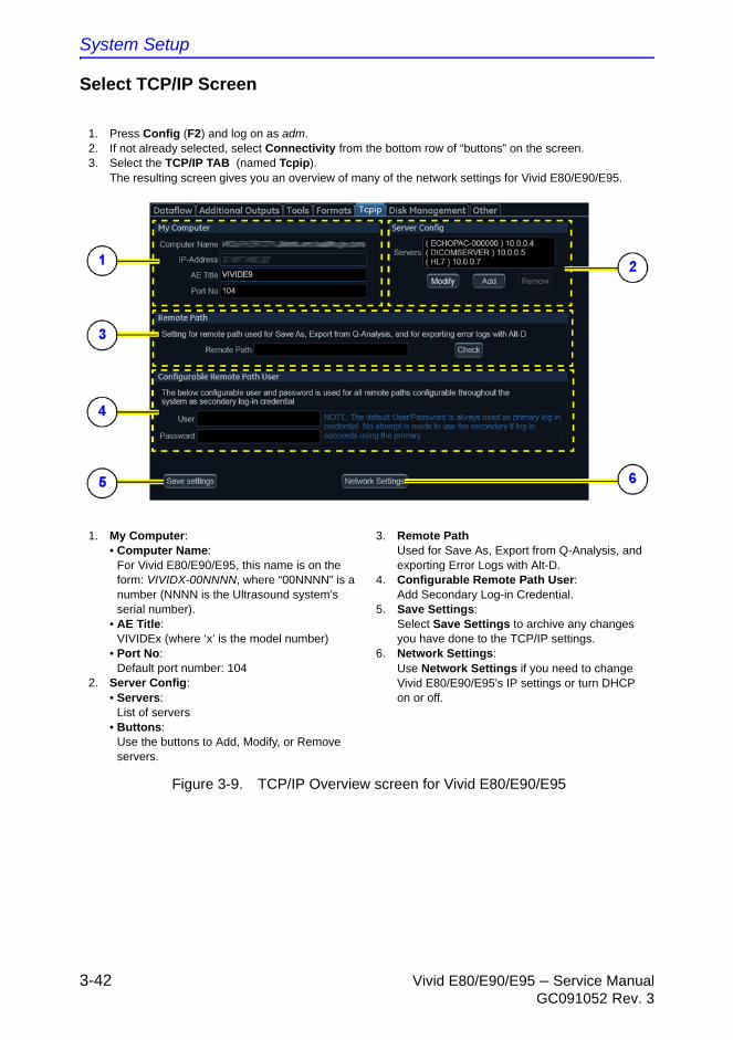
System Setup
3-42 Vivid E80/E90/E95 – Service ManualGC091052 Rev. 3
Select TCP/IP Screen
Figure 3-9. TCP/IP Overview screen for Vivid E80/E90/E95
1. Press Config (F2) and log on as adm.2. If not already selected, select Connectivity from the bottom row of “buttons” on the screen.3. Select the TCP/IP TAB (named Tcpip).
The resulting screen gives you an overview of many of the network settings for Vivid E80/E90/E95.
1. My Computer:• Computer Name:
For Vivid E80/E90/E95, this name is on the form: VIVIDX-00NNNN, where “00NNNN” is a number (NNNN is the Ultrasound system’s serial number).
• AE Title:VIVIDEx (where ‘x’ is the model number)
• Port No:Default port number: 104
2. Server Config:• Servers:
List of servers• Buttons:
Use the buttons to Add, Modify, or Remove servers.
3. Remote PathUsed for Save As, Export from Q-Analysis, and exporting Error Logs with Alt-D.
4. Configurable Remote Path User:Add Secondary Log-in Credential.
5. Save Settings:Select Save Settings to archive any changes you have done to the TCP/IP settings.
6. Network Settings:Use Network Settings if you need to change Vivid E80/E90/E95’s IP settings or turn DHCP on or off.
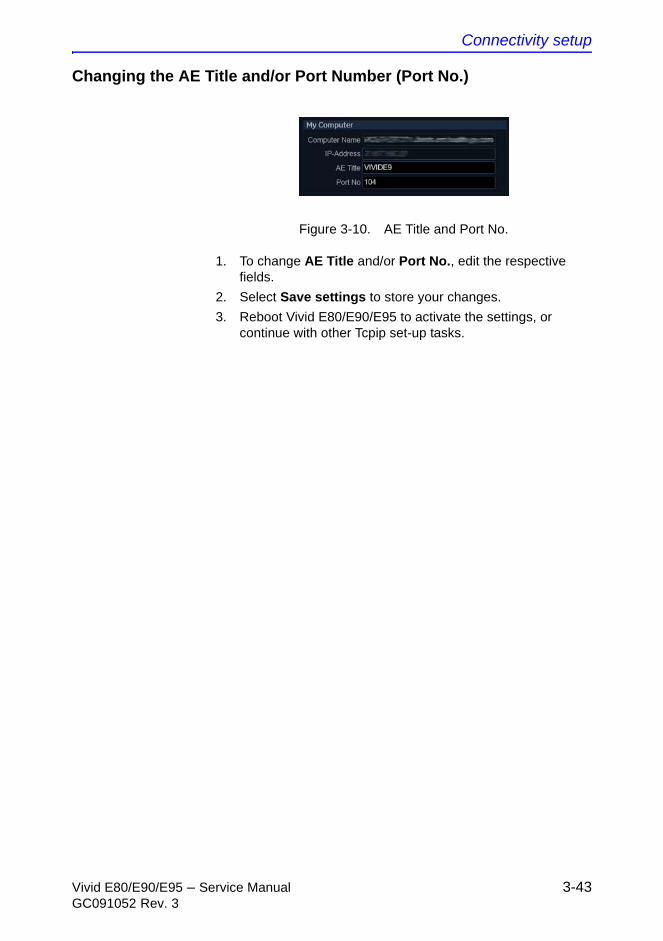
Connectivity setup
Vivid E80/E90/E95 – Service Manual 3-43GC091052 Rev. 3
Changing the AE Title and/or Port Number (Port No.)
Figure 3-10. AE Title and Port No.
1. To change AE Title and/or Port No., edit the respective fields.
2. Select Save settings to store your changes.
3. Reboot Vivid E80/E90/E95 to activate the settings, or continue with other Tcpip set-up tasks.
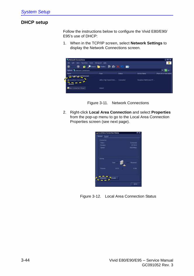
System Setup
3-44 Vivid E80/E90/E95 – Service ManualGC091052 Rev. 3
DHCP setup
Follow the instructions below to configure the Vivid E80/E90/E95’s use of DHCP:
1. When in the TCP/IP screen, select Network Settings to display the Network Connections screen.
Figure 3-11. Network Connections
2. Right-click Local Area Connection and select Properties from the pop-up menu to go to the Local Area Connection Properties screen (see next page).
Figure 3-12. Local Area Connection Status
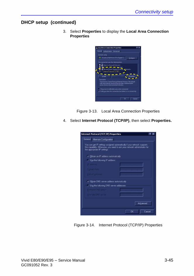
Connectivity setup
Vivid E80/E90/E95 – Service Manual 3-45GC091052 Rev. 3
DHCP setup (continued)
3. Select Properties to display the Local Area Connection Properties
Figure 3-13. Local Area Connection Properties
4. Select Internet Protocol (TCP/IP), then select Properties.
Figure 3-14. Internet Protocol (TCP/IP) Properties
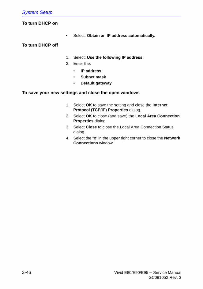
System Setup
3-46 Vivid E80/E90/E95 – Service ManualGC091052 Rev. 3
To turn DHCP on
• Select: Obtain an IP address automatically.
To turn DHCP off
1. Select: Use the following IP address:
2. Enter the:
• IP address
• Subnet mask
• Default gateway
To save your new settings and close the open windows
1. Select OK to save the setting and close the Internet Protocol (TCP/IP) Properties dialog.
2. Select OK to close (and save) the Local Area Connection Properties dialog.
3. Select Close to close the Local Area Connection Status dialog.
4. Select the “x” in the upper right corner to close the Network Connections window.
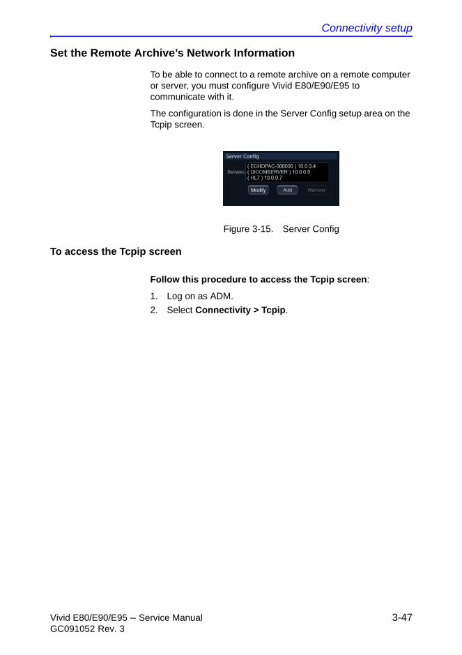
Connectivity setup
Vivid E80/E90/E95 – Service Manual 3-47GC091052 Rev. 3
Set the Remote Archive’s Network Information
To be able to connect to a remote archive on a remote computer or server, you must configure Vivid E80/E90/E95 to communicate with it.
The configuration is done in the Server Config setup area on the Tcpip screen.
Figure 3-15. Server Config
To access the Tcpip screen
Follow this procedure to access the Tcpip screen:
1. Log on as ADM.
2. Select Connectivity > Tcpip.

System Setup
3-48 Vivid E80/E90/E95 – Service ManualGC091052 Rev. 3
To add a server in the Server Config list
Follow this procedure to add a server to the list:
1. Select Add.
Figure 3-16. Server Configuration
2. Add the server's name in the Server Name field.
3. Add the server’s IP address in the IP-Address field.
4. Select Check to verify that the server is found.
This check is a network Ping. A symbol to the right of the Check button indicates the result:
• A green check mark next to the Check button indicates that the IP-Address was found on the network.
• A red mark indicates that the IP address was not found.
Troubleshooting tips:
• No network connection between the Ultrasound system and the server.
• The wrong IP Address.
To modify the setup for a server in the list
NOTE: Both the pre-defined servers and new servers can be modified.
Follow this procedure to modify the setup for a server in the list:
1. Highlight the server you want to modify.
2. Select Modify.
3. Update the information as needed.
4. Select Check to verify that the server is found.
This check is a network Ping. A symbol to the right for the Check button indicates the result:
• A green check mark next to the Check button indicates that the IP-Address was found on the network.
• A red mark indicates that the IP address was not found.
Troubleshooting tips:
Connectivity setup
Vivid E80/E90/E95 – Service Manual 3-49GC091052 Rev. 3
• no network connection between the Ultrasound system and the server
• wrong IP Address.
5. Select OK to confirm your new settings, or Cancel to leave without doing any changes.
To Delete a server from the list
To Delete a server from the list:
1. Highlight the server you want to delete from the list.
NOTE: You can only delete extra servers. The predefined servers can be modified, but not deleted.
2. Select Remove.
Save the New Settings
1. Press Save Settings to save the new settings.
The new settings are saved to a common settings file. After a restart, the settings are also included in other screens.
2. Restart Vivid E80/E90/E95 to activate the changes.
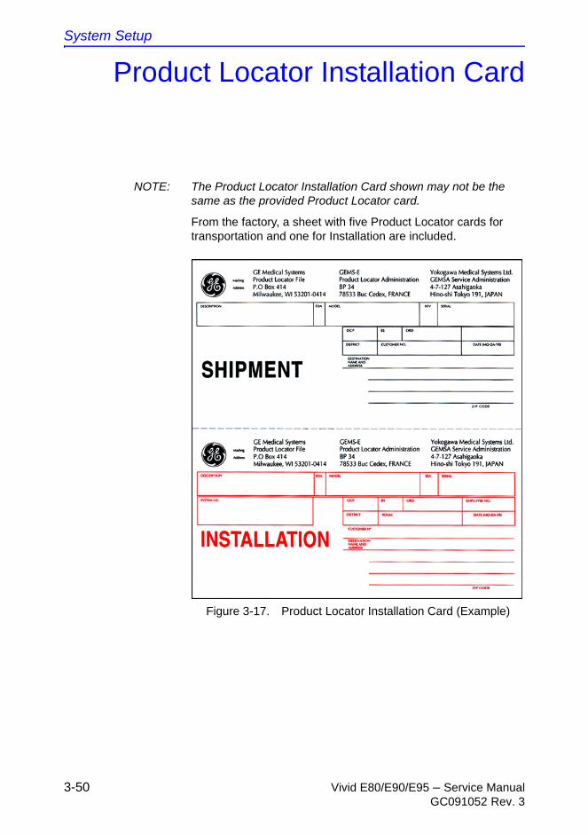
System Setup
3-50 Vivid E80/E90/E95 – Service ManualGC091052 Rev. 3
Product Locator Installation Card
NOTE: The Product Locator Installation Card shown may not be the same as the provided Product Locator card.
From the factory, a sheet with five Product Locator cards for transportation and one for Installation are included.
Figure 3-17. Product Locator Installation Card (Example)
Vivid E80/E90/E95 – Service Manual 4-1GC091052 Rev. 3
Chapter 4
General Procedures andFunctional Checks
This chapter includes General Procedures and Functional Checks.
General Procedures is a collection of commonly used procedures. The procedures are available by cross references from other parts of this manual.
Functional Checks is a collection of procedures for quickly checking major functions of the Vivid E80/E90/E95 and diagnostics instructions using the built-in service software. These checks can be a great asset in determining whether the Vivid E80/E90/E95 is working as it should.
General Procedures and Functional Checks
4-2 Vivid E80/E90/E95 – Service ManualGC091052 Rev. 3
General procedures
Power ON/Boot Up
Warnings
NOTE: Do not cycle the Circuit Breaker ON-OFF-ON in less than five (5) seconds. When turning OFF the Circuit Breaker, the Ultrasound system should de-energize completely before turning the circuit breaker ON.
DANGER
ALWAYS CONNECT THE ULTRASOUND SYSTEM TO A FIXED POWER SOCKET WHICH HAS THE PROTECTIVE GROUNDING CONNECTOR.
DANGER
NEVER USE A THREE-TO-TWO PRONG ADAPTER; THIS DEFEATS THE SAFETY GROUND.
DANGER
ENSURE THAT THE POWER CORD AND PLUG ARE INTACT AND THAT THE POWER PLUG IS THE PROPER HOSPITAL-GRADE TYPE (WHERE REQUIRED).
CAUTION Ultrasound system requires all covers.
Operate this Ultrasound system only when all board covers and frame panels are securely in place. The covers are required for safe operation, good Ultrasound system performance, and cooling purposes.
CAUTION Use only power supply cords, cables, and plugs provided or designated by GE.

General procedures
Vivid E80/E90/E95 – Service Manual 4-3GC091052 Rev. 3
Connect AC (mains) Power to the Vivid E80/E90/E95
Connecting AC Power to the Vivid E80/E90/E95 ultrasound unit, involves preliminary checks of the power cord, voltage level and compliance with electrical safety requirements.
1. Ensure that the wall outlet is of appropriate type, and that the Circuit Breaker is turned off.
2. Uncoil the power cable, allowing sufficient slack so that the unit can be moved slightly.
3. Verify that the power cable is without any visible scratches or any sign of damage.
4. Verify that the on-site mains voltage is within the limits indicated on the rating label near the Circuit Breaker on the rear of the unit.
5. Connect the Power Cable’s female plug to the Power Inlet at the rear of the unit.
6. Lock the plug in position with the Retaining Clamp (ACC Clamp).
7. Verify that the Mains Power Circuit Breaker is in OFF position, if not, switch it OFF.
8. Connect the Power Cable’s other end (male plug) to a hospital grade mains power outlet with the proper rated voltage, and the unit is ready for Power ON/Boot Up.
General Procedures and Functional Checks
4-4 Vivid E80/E90/E95 – Service ManualGC091052 Rev. 3
Switch ON the AC Power to Vivid E80/E90/E95
1. Switch ON the Mains Power Circuit Breaker at the rear of the unit.
You should hear a “click” from the relays in the AC Power and the unit is ready to boot.
2. Press once on the On/Off key on the Operating Panel to boot the Ultrasound system.
During a normal boot, you may observe that:
a. The Ultrasound system’s ventilation fan starts on full speed, but slows down after a few seconds (listen to the fan sound).
b. Power is distributed to the peripherals, Operating Panel (Console), Monitor, Front End Processor, and Back End Processor.
c. Back End Processor and rest of Ultrasound system starts with the sequence listed in the next steps:
d. Back End Processor is turned ON and starts to load the software.
e. The Start Screen is displayed on the monitor.
f. A start-up bar indicating the time used for software loading is displayed on the monitor.
g. The software initiates and sets up the Front End electronics and the rest of the instrument.
h. The backlight in the keyboard is lit.
i. As soon as the software has been loaded, either a 2D screen is displayed on the screen, indicating that a probe has been connected, or a No Mode screen is displayed, indicating that no probe has been connected.
NOTE: Total time used for start-up is typically 90 seconds or less. If starting after a power loss or a lock-up, the start-up time may be up to four minutes.
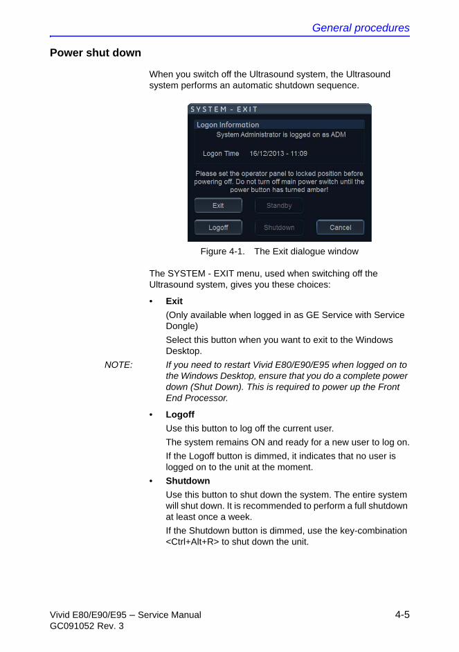
General procedures
Vivid E80/E90/E95 – Service Manual 4-5GC091052 Rev. 3
Power shut down
When you switch off the Ultrasound system, the Ultrasound system performs an automatic shutdown sequence.
Figure 4-1. The Exit dialogue window
The SYSTEM - EXIT menu, used when switching off the Ultrasound system, gives you these choices:
• Exit
(Only available when logged in as GE Service with Service Dongle)
Select this button when you want to exit to the Windows Desktop.
NOTE: If you need to restart Vivid E80/E90/E95 when logged on to the Windows Desktop, ensure that you do a complete power down (Shut Down). This is required to power up the Front End Processor.
• Logoff
Use this button to log off the current user.
The system remains ON and ready for a new user to log on.
If the Logoff button is dimmed, it indicates that no user is logged on to the unit at the moment.
• Shutdown
Use this button to shut down the system. The entire system will shut down. It is recommended to perform a full shutdown at least once a week.
If the Shutdown button is dimmed, use the key-combination <Ctrl+Alt+R> to shut down the unit.
General Procedures and Functional Checks
4-6 Vivid E80/E90/E95 – Service ManualGC091052 Rev. 3
Power shut down (continued)
• Cancel
Use this button to exit from the System-Exit menu and return to the previous operation.
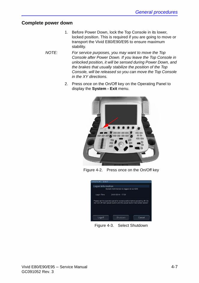
General procedures
Vivid E80/E90/E95 – Service Manual 4-7GC091052 Rev. 3
Complete power down
1. Before Power Down, lock the Top Console in its lower, locked position. This is required if you are going to move or transport the Vivid E80/E90/E95 to ensure maximum stability.
NOTE: For service purposes, you may want to move the Top Console after Power Down. If you leave the Top Console in unlocked position, it will be sensed during Power Down, and the brakes that usually stabilize the position of the Top Console, will be released so you can move the Top Console in the XY directions.
2. Press once on the On/Off key on the Operating Panel to display the System - Exit menu.
Figure 4-2. Press once on the On/Off key
Figure 4-3. Select Shutdown
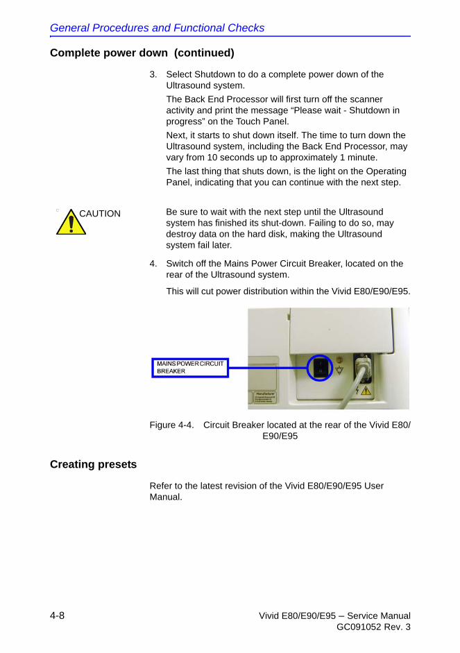
General Procedures and Functional Checks
4-8 Vivid E80/E90/E95 – Service ManualGC091052 Rev. 3
Complete power down (continued)
3. Select Shutdown to do a complete power down of the Ultrasound system.
The Back End Processor will first turn off the scanner activity and print the message “Please wait - Shutdown in progress” on the Touch Panel.
Next, it starts to shut down itself. The time to turn down the Ultrasound system, including the Back End Processor, may vary from 10 seconds up to approximately 1 minute.
The last thing that shuts down, is the light on the Operating Panel, indicating that you can continue with the next step.
4. Switch off the Mains Power Circuit Breaker, located on the rear of the Ultrasound system.
This will cut power distribution within the Vivid E80/E90/E95.
Figure 4-4. Circuit Breaker located at the rear of the Vivid E80/E90/E95
Creating presets
Refer to the latest revision of the Vivid E80/E90/E95 User Manual.
CAUTION Be sure to wait with the next step until the Ultrasound system has finished its shut-down. Failing to do so, may destroy data on the hard disk, making the Ultrasound system fail later.
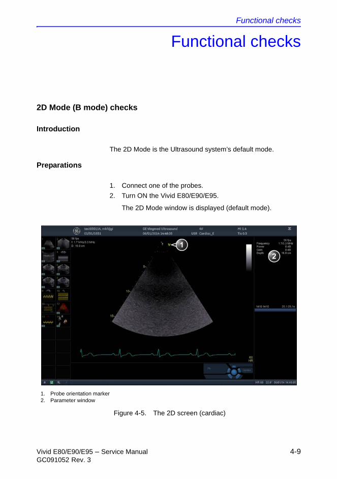
Functional checks
Vivid E80/E90/E95 – Service Manual 4-9GC091052 Rev. 3
Functional checks
2D Mode (B mode) checks
Introduction
The 2D Mode is the Ultrasound system’s default mode.
Preparations
1. Connect one of the probes.
2. Turn ON the Vivid E80/E90/E95.
The 2D Mode window is displayed (default mode).
Figure 4-5. The 2D screen (cardiac)
1. Probe orientation marker2. Parameter window
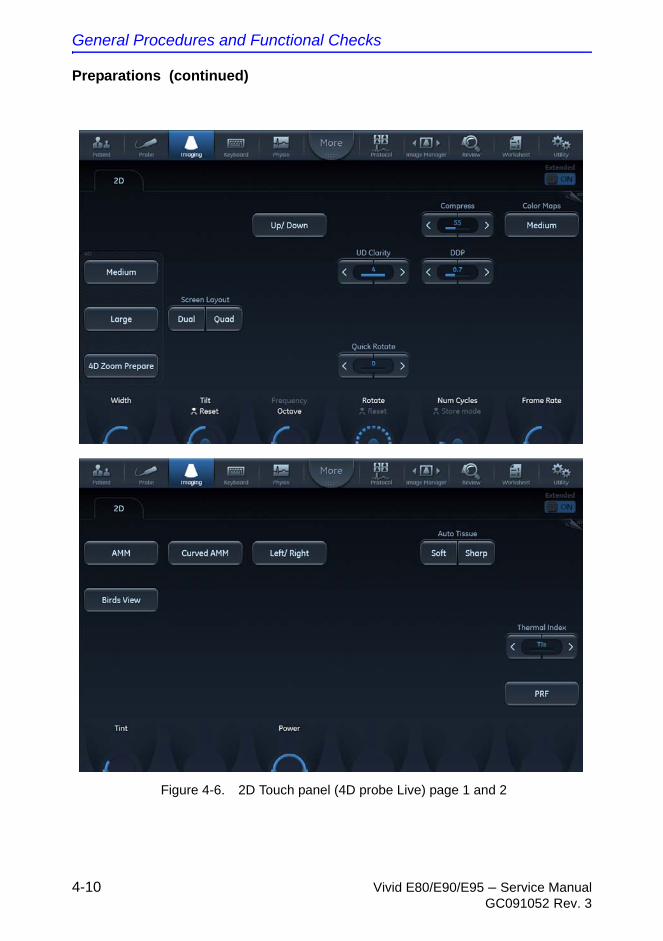
General Procedures and Functional Checks
4-10 Vivid E80/E90/E95 – Service ManualGC091052 Rev. 3
Preparations (continued)
Figure 4-6. 2D Touch panel (4D probe Live) page 1 and 2
Functional checks
Vivid E80/E90/E95 – Service Manual 4-11GC091052 Rev. 3
Adjust the 2D mode controls
The following controls can be adjusted to optimize the 2D Mode display:
• Swipe to page 2 on the Touch panel and press either Soft or Sharp Auto Tissue setting.
• Soft: optimizes the radial and lateral uniformity and brightness of the tissue continuously in real-time.
The mention “Soft” is displayed on the upper right corner of the image area
• Sharp: further enhances the image display by optimizing the grayscale curve.
The mention “Sharp” is displayed on the upper right corner of the image area
The Auto Tissue setting (Soft or Sharp) can be turned on/off by pressing Auto on the Control panel. The last used setting is then applied.
The Auto Tissue settings are only available in live scanning and cannot be turned off when the image is stored.
• If available, press Virtual Apex (probe dependent) to improve near field imaging, allowing increased visibility up to the width of the full probe aperture close to the surface.
• Use the Gain and TGC controls to optimize the overall image.
Gain increases or decreases the amount of echo information displayed. TGC compensates for depth-related attenuation in the image.
WARNING Always use the minimum power required to obtain acceptable images in accordance with applicable guidelines and policies.
General Procedures and Functional Checks
4-12 Vivid E80/E90/E95 – Service ManualGC091052 Rev. 3
• Use the Depth control to adjust the range to be imaged.
• Use the Frequency control (move to higher frequencies) or the Frame rate control (move to lower frame rate) to increase resolution in image.
• Use the Frequency control (move to lower frequency) to increase penetration.
• Use the Reject control to reduce noise in the image.
• Use the DDP control to optimize imaging in the blood flow regions and make a cleaner, less noisy image.
• Use UD Clarity (Cardiac) or UD Speckle reduce (non-cardiac) to reduce image speckle. Extra care must be taken to select the optimal Speckle reduction level, as too much filtering of speckle can mask or obscure desired image detail.
• Adjust Octave to toggle between Fundamental and Harmonic mode.
• Press Color maps and select a gray map from the menu on screen.
• If using a 4D probe:
• Adjust the Quick Rotate control on the Touch panel or press Angle on the Control panel to rotate the scan plane to predefined angles.
• Adjust the Rotate rotary of the Touch panel to fine tune the angle adjustment.
A scan plane indicator is displayed showing the angle position of the scan plane.

Functional checks
Vivid E80/E90/E95 – Service Manual 4-13GC091052 Rev. 3
M Mode Checks
M-Mode overview
Figure 4-7. The M-Mode screen (composite)
1. Time motion cursor conventional M-Mode2. Time motion cursor curved anatomical M-Mode3. Time motion cursor anatomical M-Mode4. Depth scale5. Time scale6. Parameter windowNote: The sweep speed information displayed in the bottom right corner of the image represents the user selected sweep speed and should be used only as a reference to confirm that the image was acquired at the selected sweep speed. It is not to be used for measurements or analysis. This is not an absolute value, but simply a reference number. Users performing studies using standardized protocols may find this sweep speed information useful for reading studies from other institutions.
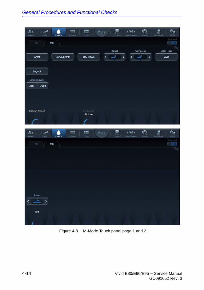
General Procedures and Functional Checks
4-14 Vivid E80/E90/E95 – Service ManualGC091052 Rev. 3
Figure 4-8. M-Mode Touch panel page 1 and 2
Functional checks
Vivid E80/E90/E95 – Service Manual 4-15GC091052 Rev. 3
This unit has three types of M-Mode:
• Conventional M-Mode (MM): displays a distance/time plot of a cursor line in the axial plane of the 2D-image.
• Anatomical M-Mode (AMM): displays a distance/time plot from a cursor line, which is independent from the axial plane. AMM is available in grayscale, color, TVI, Tissue Tracking, Strain rate and Strain modes.
• Curved Anatomical M-Mode (CAMM): displays a distance/time plot from a free-drawn cursor line. CAMM is available in grayscale, color, TVI, Tissue Tracking, Strain rate and Strain modes.
Conventional M-Mode can be combined with Color Mode.
Preparations
1. Connect one of the probes, to the Ultrasound system’s left-most probe connector.
2. Turn ON the Ultrasound system.
The 2D Mode window is displayed (default mode).
3. Press MM on the Operating Panel to bring up an M-Mode picture on the screen.
4. Use the trackball to position the cursor over the required area of the image.
Using M-Mode
Conventional M-Mode
1. To access M-Mode from any other scan mode, press MM on the control panel.
2. Use the trackball to position the cursor over the required area of the image.
3. Press Freeze.
4. Use the trackball to scroll through the data acquired.
Anatomical M-Mode
1. In M-Mode or 2D-Mode Freeze, press AMM on the Touch panel.
NOTE: Anatomical M-Mode can also be used with previously acquired digitally stored 2D images. More than one heart cycle should be stored if performing M-Mode in post processing.
2. Use the trackball (assigned function: Pos) to position the cursor over the required area of the image.
General Procedures and Functional Checks
4-16 Vivid E80/E90/E95 – Service ManualGC091052 Rev. 3
3. Press Trackball to allow free rotation of the solid full-length cursor line throughout the 2D image (trackball assigned function: Angle).
4. Rotate the solid cursor line to the desired direction.
Curved Anatomical M-Mode
1. In M-Mode, press Curved AMM.
2. Use the trackball (assigned function: Pos) to position the starting point of the time motion curve.
3. Press Select to anchor the starting point of the time motion curve.
4. Use the trackball to position the next point of the time motion curve.
5. Press Select to anchor the point of the time motion curve.
6. Repeat step 4 and 5 up to draw a complete time motion curve.
NOTE: The time motion curve can be edited by following the curve back to the desired point and redraw.
7. On the last point, press Select twice to terminate the curve.
NOTE: To edit the time motion curve, select a point, move it to a new position and press Select.
Optimizing M-Mode
The use of preset gives optimum performance with minimum adjustment. If necessary, the following controls can be adjusted to further optimize the M-Mode display:
NOTE: Refer to ‘Creating presets’ on page 4-8 about creating presets.
• Adjust Horizontal sweep to optimize the display resolution.
• Adjust Gain and TGC controls to adjust the range to be imaged.
• Use the Frequency (move to higher frequencies) or the Frame rate control (move to lower frame rate) to increase resolution in image.
• Adjust Dynamic range to optimize the useful range of incoming echoes to the available grayscale.
• Adjust Compress to further optimize the display.
• Adjust Reject to reduce noise while taking care not to eliminate significant low-level diagnostic information.
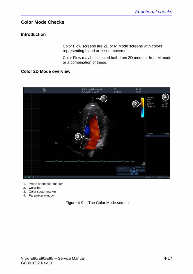
Functional checks
Vivid E80/E90/E95 – Service Manual 4-17GC091052 Rev. 3
Color Mode Checks
Introduction
Color Flow screens are 2D or M Mode screens with colors representing blood or tissue movement.
Color Flow may be selected both from 2D mode or from M mode or a combination of these.
Color 2D Mode overview
Figure 4-9. The Color Mode screen
1. Probe orientation marker2. Color bar3. Color sector marker4. Parameter window
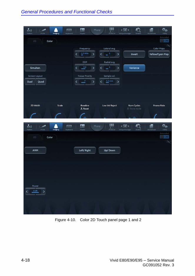
General Procedures and Functional Checks
4-18 Vivid E80/E90/E95 – Service ManualGC091052 Rev. 3
Figure 4-10. Color 2D Touch panel page 1 and 2
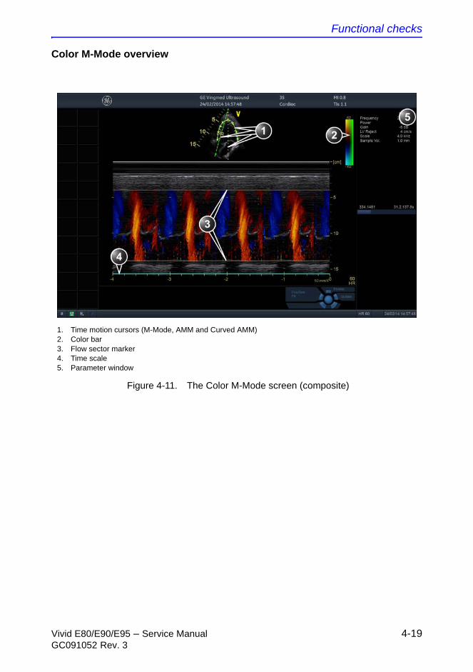
Functional checks
Vivid E80/E90/E95 – Service Manual 4-19GC091052 Rev. 3
Color M-Mode overview
Figure 4-11. The Color M-Mode screen (composite)
1. Time motion cursors (M-Mode, AMM and Curved AMM)2. Color bar3. Flow sector marker4. Time scale5. Parameter window
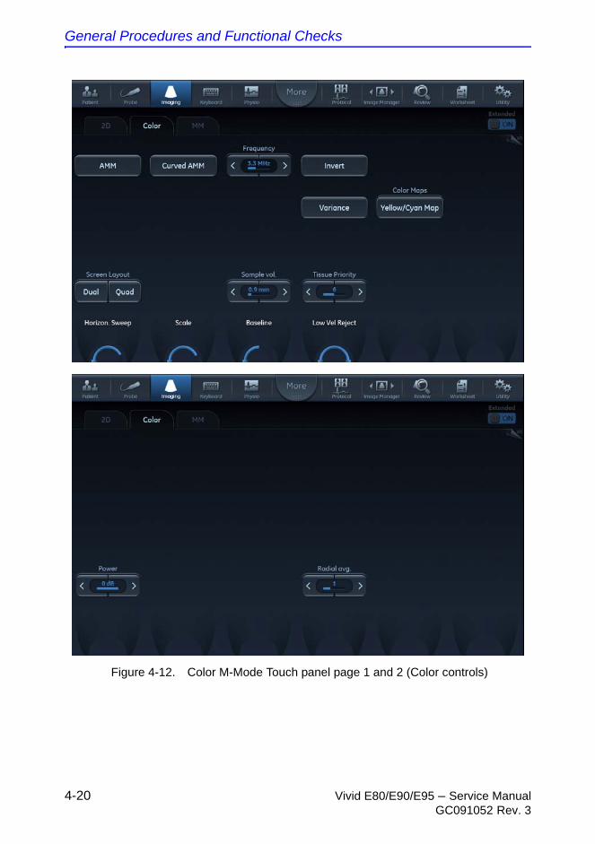
General Procedures and Functional Checks
4-20 Vivid E80/E90/E95 – Service ManualGC091052 Rev. 3
Figure 4-12. Color M-Mode Touch panel page 1 and 2 (Color controls)
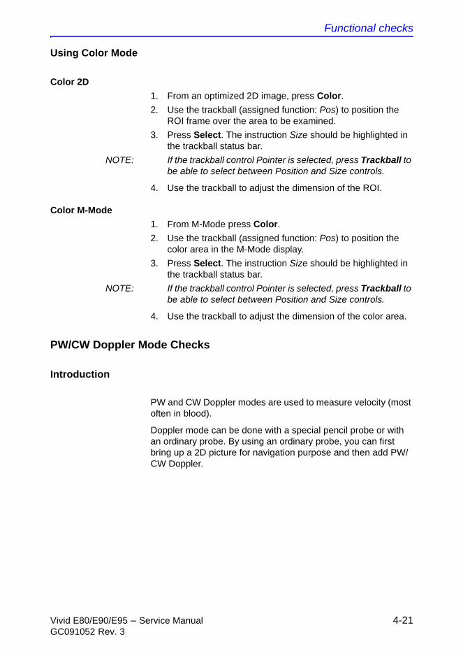
Functional checks
Vivid E80/E90/E95 – Service Manual 4-21GC091052 Rev. 3
Using Color Mode
Color 2D
1. From an optimized 2D image, press Color.
2. Use the trackball (assigned function: Pos) to position the ROI frame over the area to be examined.
3. Press Select. The instruction Size should be highlighted in the trackball status bar.
NOTE: If the trackball control Pointer is selected, press Trackball to be able to select between Position and Size controls.
4. Use the trackball to adjust the dimension of the ROI.
Color M-Mode
1. From M-Mode press Color.
2. Use the trackball (assigned function: Pos) to position the color area in the M-Mode display.
3. Press Select. The instruction Size should be highlighted in the trackball status bar.
NOTE: If the trackball control Pointer is selected, press Trackball to be able to select between Position and Size controls.
4. Use the trackball to adjust the dimension of the color area.
PW/CW Doppler Mode Checks
Introduction
PW and CW Doppler modes are used to measure velocity (most often in blood).
Doppler mode can be done with a special pencil probe or with an ordinary probe. By using an ordinary probe, you can first bring up a 2D picture for navigation purpose and then add PW/CW Doppler.

General Procedures and Functional Checks
4-22 Vivid E80/E90/E95 – Service ManualGC091052 Rev. 3
PW and CW Doppler overview
Figure 4-13. The PW/CW Doppler Mode screen
1. Sample volume (PW only)2. Angle correction marker3. Velocity scale4. Low velocity reject5. Nyquist velocity6. Doppler baseline7. Frequency scale (configurable, see page 4-23)8. Parameter windowNote: the sweep speed information displayed in the bottom right corner of the image represents the user selected sweep speed and should be used only as a reference to confirm that the image was acquired at the selected sweep speed. It is not to be used for measurements or analysis. This is not an absolute value, but simply a reference number. Users performing studies using standardized protocols may find this sweep speed information useful for reading studies from other institutions.
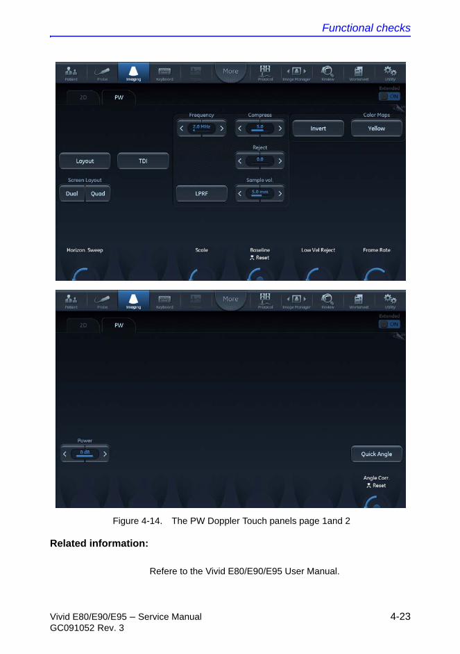
Functional checks
Vivid E80/E90/E95 – Service Manual 4-23GC091052 Rev. 3
Figure 4-14. The PW Doppler Touch panels page 1and 2
Related information:
Refere to the Vivid E80/E90/E95 User Manual.
General Procedures and Functional Checks
4-24 Vivid E80/E90/E95 – Service ManualGC091052 Rev. 3
Using PW/CW Doppler modes
Alternative 1
1. Press PW or CW. A scanning screen is displayed with a Doppler cursor on the 2D mode image and a Doppler spectrum in the lower part of the screen.
2. Use the trackball to position the Doppler cursor line and in PW the sample volume location over the area of interest.
3. In PW, adjust the Sample Volume.
NOTE: Sample Volume adjustment may affect the Scale, Frame rate and LV rej. settings.
Alternative 2
1. Press Cursor on the control panel. A cursor line is displayed on the 2D image.
2. Select the cursor type on the Touch panel.
3. With the trackball adjust the position of the cursor line.
4. Press PW or CW.
Optimizing PW/CW Doppler modes
The use of preset gives optimum performance with minimum adjustment. If necessary, the following controls can be adjusted to further optimize the PW/CW modes display:
NOTE: Refer to ‘Creating presets’ on page 4-8 about creating presets
• Adjust the Active mode gain to set the gain in the spectral Doppler area.
• Adjust Low velocity reject to reduce unwanted low velocity blood flow and tissue movement.
• In PW mode, adjust Sample volume to low setting for better resolution, or higher setting to more easily locate the disturbed flows. Adjustment of the Sample volume may affect the PRF (Nyquist limit) settings.
• Adjust the Compress setting to balance the effect of stronger and weaker echoes and obtain the desired intensity display.
• Adjust Frequency to optimize flow display. Higher setting will improve resolution and the lower setting will increase the depth penetration.
• Adjust Frame rate to a higher setting to improve motion detection, or to a lower setting to improve resolution.
Functional checks
Vivid E80/E90/E95 – Service Manual 4-25GC091052 Rev. 3
NOTE: Frequency and Frame rate settings may affect the Low Velocity Reject.
• Adjust Power to obtain an acceptable image using the lowest setting possible. This is particularly important in CW mode, as the energy duty cycle is 100% (constant).
NOTE: The Doppler Power setting affects only Doppler operating modes.
Adjust the following settings to further optimize the display of the image.
• Use the Horizontal sweep to optimize the sweep speed.
• To view signal detail, adjust Scale to enlarge the vertical spectral Doppler trace. Velocity range directly controls the pulse repetition frequency, which is responsible for the setting of the Nyquist limit (the ability to detect maximum velocity without aliasing).
• Use Invert to reverse the vertical component of the spectral Doppler area of the display.
• Use Quick angle and Angle correction to steer the ultrasound beam to the blood flow to be measured (Not typically required during cardiac studies).
• Adjust LPRF (PW Doppler mode only) to toggle between high and low Pulse Repetition Frequency (PRF). When the Doppler PRF is raised beyond a certain limit, more than one Doppler gate is displayed on the screen.
• Press Auto on the Control panel to activate Automatic Spectrum Optimization (ASO). ASO is used to automatically adjust baseline and scale of the PW/CW spectrum to optimize the spectral display. It will avoid the display of a folded spectrum and stretch the spectrum vertically as large as possible. ASO optimization is not continuous but performed instantaneously each time Auto is pressed.
Tissue Velocity Imaging (TVI) Checks
Introduction
TVI calculates and color codes the velocities in tissue. The tissue velocity information is acquired by sampling of tissue
CAUTION Use all noise reduction controls with care. Excessive application may obscure low level diagnostic information.
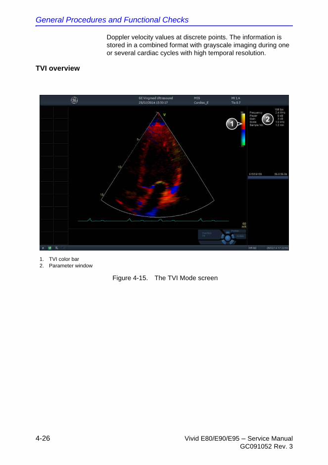
General Procedures and Functional Checks
4-26 Vivid E80/E90/E95 – Service ManualGC091052 Rev. 3
Doppler velocity values at discrete points. The information is stored in a combined format with grayscale imaging during one or several cardiac cycles with high temporal resolution.
TVI overview
Figure 4-15. The TVI Mode screen
1. TVI color bar2. Parameter window
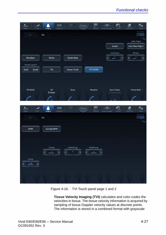
Functional checks
Vivid E80/E90/E95 – Service Manual 4-27GC091052 Rev. 3
Figure 4-16. TVI Touch panel page 1 and 2
Tissue Velocity Imaging (TVI) calculates and color-codes the velocities in tissue. The tissue velocity information is acquired by sampling of tissue Doppler velocity values at discrete points. The information is stored in a combined format with grayscale
General Procedures and Functional Checks
4-28 Vivid E80/E90/E95 – Service ManualGC091052 Rev. 3
imaging during one or several cardiac cycles with high temporal resolution.
Using TVI
1. While in 2D mode press TVI on the control panel.
2. Use the trackball (assigned function: Pos) to position the ROI frame over the area to be examined.
3. Press Select. The instruction Size should be highlighted in the trackball status bar.
NOTE: If the trackball control Pointer is selected, press Trackball to be able to select between Position and Size controls.
4. Use the trackball to adjust the dimension of the ROI.
Optimizing TVI
The use of presets gives optimum performance with minimum adjustment. If necessary, the following controls can be adjusted to further optimize the TVI display:
NOTE: Refer to ‘Creating presets’ on page 4-8 about creating presets.
• To reduce quantification noise (variance), the Nyquist limit should be as low as possible, without creating aliasing. To reduce the Nyquist limit: reduce the Scale value.
NOTE: The Scale value also affects the frame rate. There is a trade off between the frame rate and quantification noise.
• TVI provides velocity information only in the beam direction. The apical view typically provides the best window since the beams are then approximately aligned to the longitudinal direction of the myocardium (except near the apex). To obtain radial or circumferential tissue velocities, a parasternal view must be used. However, from this window the beam cannot be aligned with the muscle for all the parts of the ventricle.
NOTE: PW will be optimized for Tissue Velocities when activated from inside TVI.

Functional checks
Vivid E80/E90/E95 – Service Manual 4-29GC091052 Rev. 3
Probe/Connectors Checks
NOTE: Probes can be connected at any time, whether the Ultrasound system is ON or OFF
CAUTION Take the following precautions with the probe cables:
• Keep away from the wheels.
• Do not bend.
• Do not cross cables between probes.
Table 4-1: Probe and Connectors Checks
Step Task Expected Result(s)
1. Press Probe on the Operating Panel.
A list of the connected probes will pop up on the screen.
2. If not already selected, use the trackball to select the desired probe.
An application menu for the desired probe is listed on the screen.
3. • Trackball to the desired application.
• Press Select to launch the application.
• To change application without changing the current probe, press Appl. on the Operating Panel.
The selected application starts.
4. Verify no missing channels. All channels are functioning.
5. Verify there's no EMI/RFI or artifacts specific to the probe.
No EMI/RFI or artifacts.
6. Test the probe in each active connector slot.
It will display pictorial data each time.
7. Do a leakage test on the probe. It passes the test.
8. Repeat this procedure for all available probes.
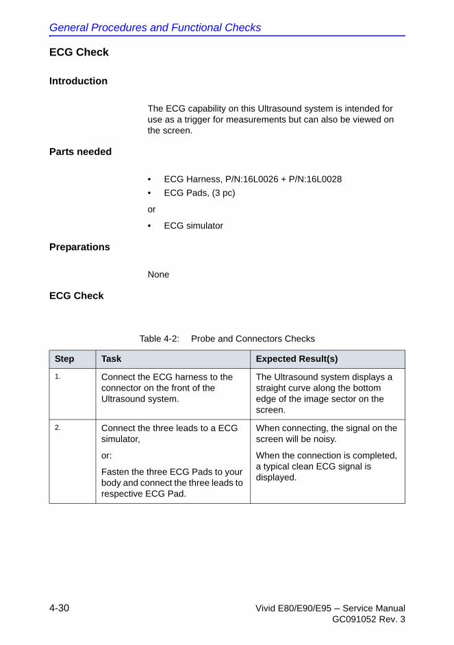
General Procedures and Functional Checks
4-30 Vivid E80/E90/E95 – Service ManualGC091052 Rev. 3
ECG Check
Introduction
The ECG capability on this Ultrasound system is intended for use as a trigger for measurements but can also be viewed on the screen.
Parts needed
• ECG Harness, P/N:16L0026 + P/N:16L0028
• ECG Pads, (3 pc)
or
• ECG simulator
Preparations
None
ECG Check
Table 4-2: Probe and Connectors Checks
Step Task Expected Result(s)
1. Connect the ECG harness to the connector on the front of the Ultrasound system.
The Ultrasound system displays a straight curve along the bottom edge of the image sector on the screen.
2. Connect the three leads to a ECG simulator,
or:
Fasten the three ECG Pads to your body and connect the three leads to respective ECG Pad.
When connecting, the signal on the screen will be noisy.
When the connection is completed, a typical clean ECG signal is displayed.
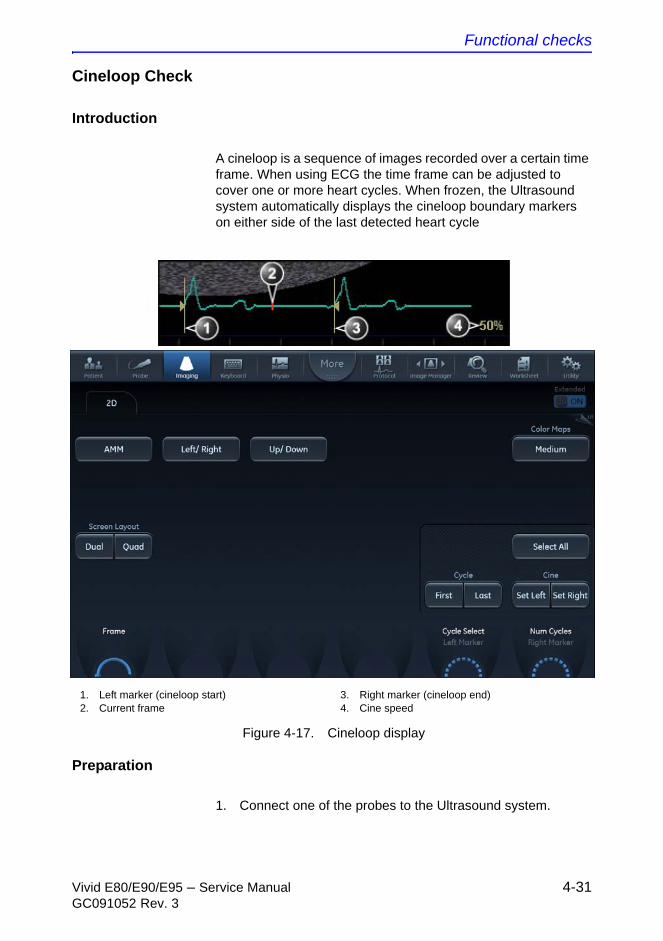
Functional checks
Vivid E80/E90/E95 – Service Manual 4-31GC091052 Rev. 3
Cineloop Check
Introduction
A cineloop is a sequence of images recorded over a certain time frame. When using ECG the time frame can be adjusted to cover one or more heart cycles. When frozen, the Ultrasound system automatically displays the cineloop boundary markers on either side of the last detected heart cycle
Figure 4-17. Cineloop display
Preparation
1. Connect one of the probes to the Ultrasound system.
1. Left marker (cineloop start)2. Current frame
3. Right marker (cineloop end)4. Cine speed
General Procedures and Functional Checks
4-32 Vivid E80/E90/E95 – Service ManualGC091052 Rev. 3
2. Turn ON the Ultrasound system. The 2D Mode window is displayed (default mode).
Using cineloop
Selection of a cineloop
1. Press Freeze.
The left and right markers are displayed on either side of the last detected heart cycle on the ECG trace.
2. Press 2D Freeze.
The selected heart beat is played back.
3. Press 2D Freeze to freeze the cineloop.
4. Use the trackball to scroll through the acquisition and find the sequence of interest.
5. Adjust Cycle select to move from heart beat to heart beat and select the heart cycle of interest.
6. Adjust Num cycles to increase or decrease the number of heart beats to be played back.
7. In Freeze, press Set left or Set right to set the corresponding cineloop boundary to the current frame.
8. Adjust Left marker and Right marker to trim or expand the cineloop boundaries.
9. Press 2D Freeze to run the cineloop and Img. Store to store the cineloop or Freeze to return to live scanning.
NOTE: Cineloop storage can be configured to store heart cycles with additional time before and after the R-wave and to display a preview before storage.
Adjustment of cineloop playback
1. Use the trackball or adjust Speed to set the speed of the cineloop playback.
The speed factor (%) is displayed on the right side of the ECG.
Back End Processor checks
• If all the previous tests have been passed successfully, the Back End Processor is most likely OK.
• If the Ultrasound system seems to be operating erratically, please refer to Chapter 7 in this manual.
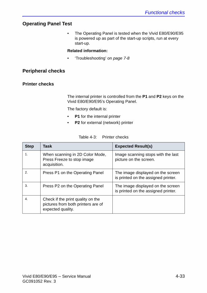
Functional checks
Vivid E80/E90/E95 – Service Manual 4-33GC091052 Rev. 3
Operating Panel Test
• The Operating Panel is tested when the Vivid E80/E90/E95 is powered up as part of the start-up scripts, run at every start-up.
Related information:
• ‘Troubleshooting’ on page 7-8
Peripheral checks
Printer checks
The internal printer is controlled from the P1 and P2 keys on the Vivid E80/E90/E95’s Operating Panel.
The factory default is:
• P1 for the internal printer
• P2 for external (network) printer
Table 4-3: Printer checks
Step Task Expected Result(s)
1. When scanning in 2D Color Mode, Press Freeze to stop image acquisition.
Image scanning stops with the last picture on the screen.
2. Press P1 on the Operating Panel The image displayed on the screen is printed on the assigned printer.
3. Press P2 on the Operating Panel The image displayed on the screen is printed on the assigned printer.
4. Check if the print quality on the pictures from both printers are of expected quality.
General Procedures and Functional Checks
4-34 Vivid E80/E90/E95 – Service ManualGC091052 Rev. 3
Windows Print Test Page
This tests that the printer is correctly installed and hooked up at the Windows level.
1. Open the Printers folder, either from Start > Settings > Printers or from Utilities > System > Printers.
2. Right click on a printer and select Preferences.
3. Select Print Test Page (this will send a print to the printer bypassing the Application software).
4. Observe the page. If the page prints out, the problem you are looking for is probably a configuration issue in windows, or configuration issue in Utilities > Connectivity.
If the page does not print out, there probably is a cabling issue, or a printer configuration issue in Windows.
NOTE: For the Sony small format printers, you will see the test page clipped. This is normal.
Setup and test a Printer Service
1. Select Utility > Connectivity
If you get a pop-up asking you to log on, select ADM.
If the customer has not changed the user, the password is ulsadm.
2. Select the Service tab.
3. In the comb box “Select Service to Add” select “Standard Print” and click on Add.
4. In the right pane Properties “Combo Box” Select the printer you wish to test. Set any other parameters you desire.
5. In the left pane “Properties” Enter a name that describes the printer and configuration you just selected in the right pane.
6. Select the Button tab.
7. Select one of the “Physical Print Buttons” that you want to configure.
8. In the right pane click on the service name you just created in the Services Tab.
9. Click on the “>>” button. This will place this service in the PrintFlow View for the printer button you selected.
10. Click on Save.
You have now configured a printer service and attached it to a print button.
Functional checks
Vivid E80/E90/E95 – Service Manual 4-35GC091052 Rev. 3
Setup and test a Printer Service (continued)
Now you can test the printer by pressing the print button you just configured. If you configured it for 1 row and 1 column each time you press the print button, you will get a print sent to the printer.
If you configured some other combination of rows or columns, you will have to push the printer button multiple times before a print is sent to the printer.
If the image does not print, check the configuration to verify that you have it set up correctly.
View the Windows Printer Queues
1. Go to Utility > System > Peripherals.
2. Click on Properties.
Mechanical Functions Checks
Operating Panel movement
Please refer to
• “Control panel adjustment” in the user manual
and to:
• “To unlock/lock the LCD monitor” in the User Manual.
Casters (Wheels), Brakes and Direction Lock checks
Please refer to: “The Casters (Wheels) control” in the user manual.
General Procedures and Functional Checks
4-36 Vivid E80/E90/E95 – Service ManualGC091052 Rev. 3
THIS PAGE WAS INTENTIONALLY LEFT BLANK

Vivid E80/E90/E95 – Service Manual 5-1GC091052 Rev. 3
Chapter 5
Components and Functions(Theory)
This chapter explains Vivid E80/E90/E95’s system concepts, component arrangement, and subsystem functions.
It also describes the power distribution and the Common Service Desktop interface.
Components and Functions (Theory)
5-2 Vivid E80/E90/E95 – Service ManualGC091052 Rev. 3
Software overview
System software
The System Software contains the operating system and 3rd party software.
It is based on Windows 7 Embedded and is delivered on the software and documentation Usb Flash Drive (UFD).
For software versions, see: ‘Software for Vivid E80/E90/E95’ on page 9-4.
Application software
The Application Software includes all the functionality for Vivid E80/E90/E95. It is included on the Software and Documentation Usb Flash Drive (UFD).
For software versions, see: ‘Software for Vivid E80/E90/E95’ on page 9-4.
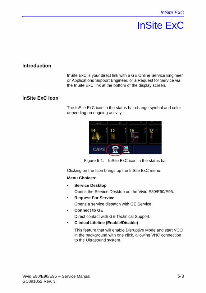
InSite ExC
Vivid E80/E90/E95 – Service Manual 5-3GC091052 Rev. 3
InSite ExC
Introduction
InSite ExC is your direct link with a GE Online Service Engineer or Applications Support Engineer, or a Request for Service via the InSite ExC link at the bottom of the display screen.
InSite ExC Icon
The InSite ExC icon in the status bar change symbol and color depending on ongoing activity.
Figure 5-1. InSite ExC icon in the status bar
Clicking on the Icon brings up the InSite ExC menu.
Menu Choices:
• Service Desktop
Opens the Service Desktop on the Vivid E80/E90/E95.
• Request For Service
Opens a service dispatch with GE Service.
• Connect to GE
Direct contact with GE Technical Support.
• Clinical Lifeline (Enable/Disable)
This feature that will enable Disruptive Mode and start VCO in the background with one click, allowing VNC connection to the Ultrasound system.
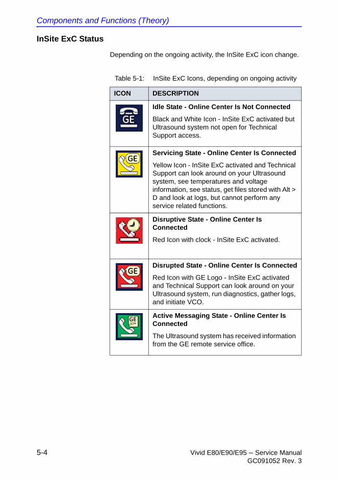
Components and Functions (Theory)
5-4 Vivid E80/E90/E95 – Service ManualGC091052 Rev. 3
InSite ExC Status
Depending on the ongoing activity, the InSite ExC icon change.
Table 5-1: InSite ExC Icons, depending on ongoing activity
ICON DESCRIPTION
Idle State - Online Center Is Not Connected
Black and White Icon - InSite ExC activated but Ultrasound system not open for Technical Support access.
Servicing State - Online Center Is Connected
Yellow Icon - InSite ExC activated and Technical Support can look around on your Ultrasound system, see temperatures and voltage information, see status, get files stored with Alt > D and look at logs, but cannot perform any service related functions.
Disruptive State - Online Center Is Connected
Red Icon with clock - InSite ExC activated.
Disrupted State - Online Center Is Connected
Red Icon with GE Logo - InSite ExC activated and Technical Support can look around on your Ultrasound system, run diagnostics, gather logs, and initiate VCO.
Active Messaging State - Online Center Is Connected
The Ultrasound system has received information from the GE remote service office.
InSite ExC
Vivid E80/E90/E95 – Service Manual 5-5GC091052 Rev. 3
InSite ExC Definitions
Here are definitions for the different InSite ExC states:
Virtual Console Observation (VCO). Allows Technical Support to control Vivid E80/E90/E95 functionality remotely.
Disruptive. Allows GE’s Technical Support person to connect to your Ultrasound system via VCO, to run diagnostics directly on your Ultrasound system, and to collect system logs. When the Ultrasound system is in Disruptive Mode, the icons are red. There are two disruptive states. If you see a telephone with a clock, then the Ultrasound system is in Disruptive, Not Connected Mode. If you see a telephone with GE, then the Ultrasound system is in Disruptive, Connected Mode.
Non-Disruptive. Allows GE's Technical support person to look around on your Ultrasound system, but not to perform any service-related functions, depending on whether InSite is connected. There are two Non-Disruptive states. If you see a black and white icon, InSite ExC is activated, but not open for Technical Support access. If you see a yellow icon, InSite ExC is activated and the Technical Support person can look around on your Ultrasound system, but cannot perform any service-related functions.
Connected. InSite ExC is connected.
Not Connected. InSite ExC is not connected.
NOTE: When Disruptive mode has been activated or a diagnostic has been run, the message, “Due to Service testing reboot required,” appears in red at the bottom of the display. It is recommended that you reboot the Ultrasound system before use. Make sure you disable disruptive mode before rebooting or the message will not be cleared.
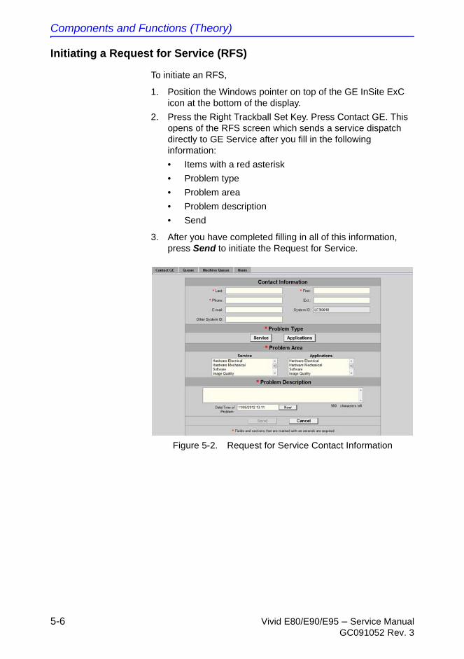
Components and Functions (Theory)
5-6 Vivid E80/E90/E95 – Service ManualGC091052 Rev. 3
Initiating a Request for Service (RFS)
To initiate an RFS,
1. Position the Windows pointer on top of the GE InSite ExC icon at the bottom of the display.
2. Press the Right Trackball Set Key. Press Contact GE. This opens of the RFS screen which sends a service dispatch directly to GE Service after you fill in the following information:
• Items with a red asterisk
• Problem type
• Problem area
• Problem description
• Send
3. After you have completed filling in all of this information, press Send to initiate the Request for Service.
Figure 5-2. Request for Service Contact Information
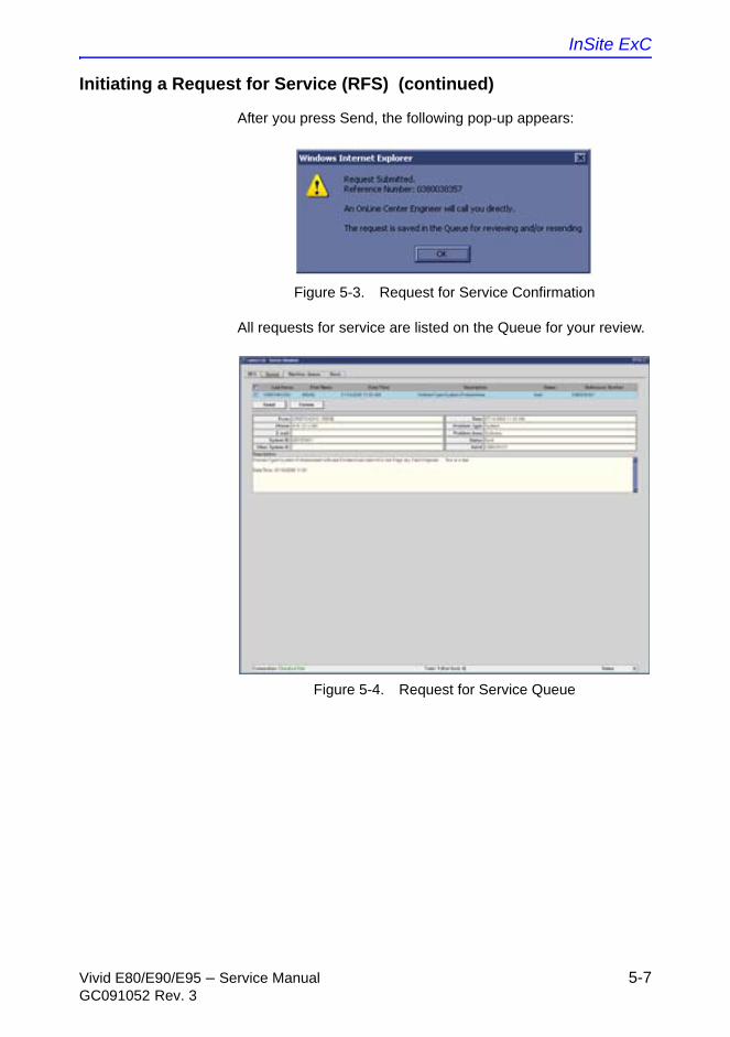
InSite ExC
Vivid E80/E90/E95 – Service Manual 5-7GC091052 Rev. 3
Initiating a Request for Service (RFS) (continued)
After you press Send, the following pop-up appears:
Figure 5-3. Request for Service Confirmation
All requests for service are listed on the Queue for your review.
Figure 5-4. Request for Service Queue
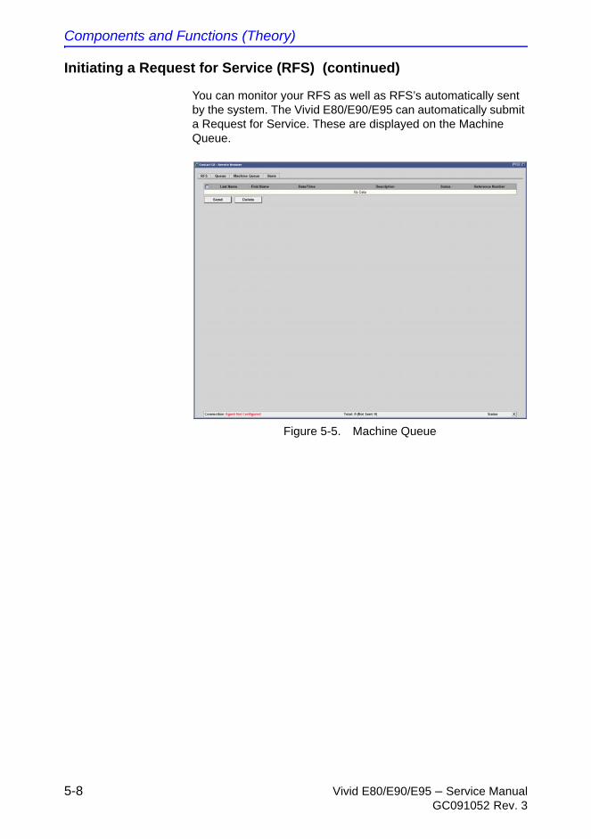
Components and Functions (Theory)
5-8 Vivid E80/E90/E95 – Service ManualGC091052 Rev. 3
Initiating a Request for Service (RFS) (continued)
You can monitor your RFS as well as RFS’s automatically sent by the system. The Vivid E80/E90/E95 can automatically submit a Request for Service. These are displayed on the Machine Queue.
Figure 5-5. Machine Queue
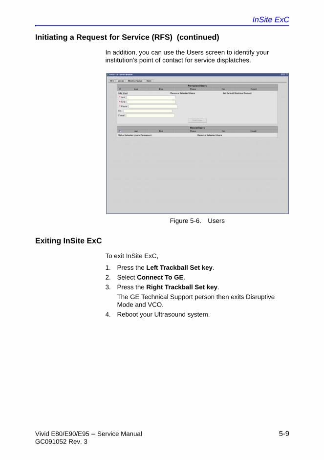
InSite ExC
Vivid E80/E90/E95 – Service Manual 5-9GC091052 Rev. 3
Initiating a Request for Service (RFS) (continued)
In addition, you can use the Users screen to identify your institution’s point of contact for service displatches.
Figure 5-6. Users
Exiting InSite ExC
To exit InSite ExC,
1. Press the Left Trackball Set key.
2. Select Connect To GE.
3. Press the Right Trackball Set key.
The GE Technical Support person then exits Disruptive Mode and VCO.
4. Reboot your Ultrasound system.
Components and Functions (Theory)
5-10 Vivid E80/E90/E95 – Service ManualGC091052 Rev. 3
Vivid E80/E90/E95 overview
Introduction
The Vivid E80/E90/E95 is a high performance digital ultrasound imaging system with total data management.
The Ultrasound system provides image generation in 4D, 2D (B) Mode, Color Doppler, Power Doppler (Angio), M-Mode, Color M-Mode, PW and CW Doppler spectra, Tissue Velocity imaging, advanced Strain and Contrast applications. The fully digital architecture of the Vivid E80/E90/E95 Ultrasound system allows optimal usage of all scanning modes and probe types, throughout the full spectrum of operating frequencies.
Note regarding USB ports
Depending on the system configuration, USB mass storage may be disabled on the system. Enabling/disabling of USB mass storage can only be done by users with administrator rights: Sys Admin or GE Admin users (see ‘Related information’ on page 5-10).
When USB mass storage is disabled the following icon is shown on the status bar: .
Related information
For more information, refer to ‘System users’ in the chapter ‘Basic operations’ in the User Manual.
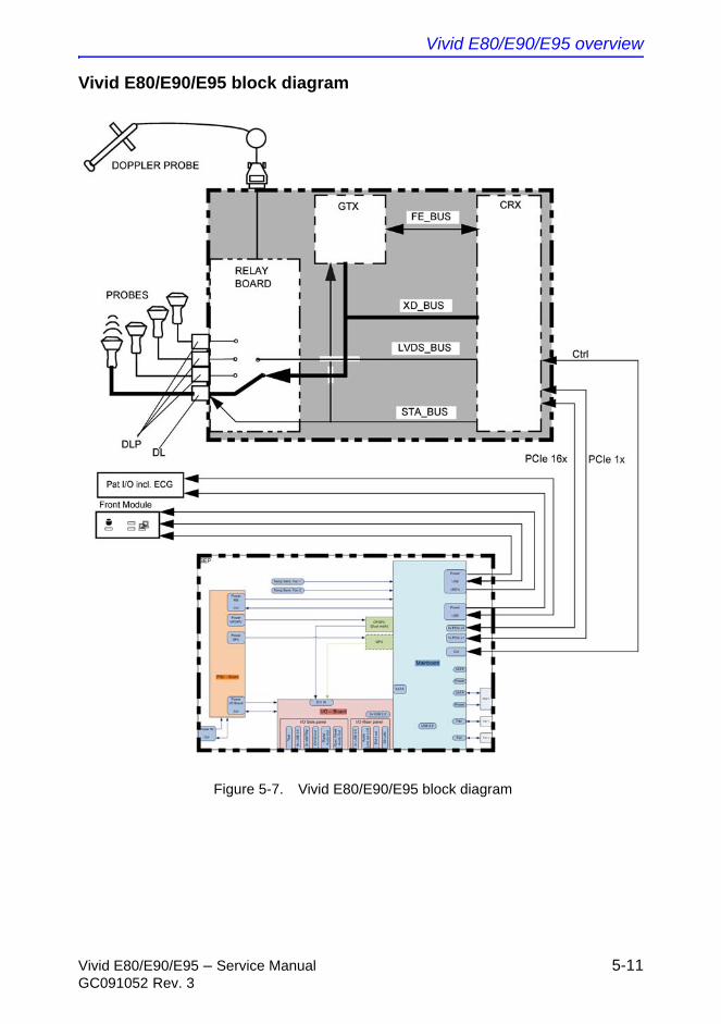
Vivid E80/E90/E95 overview
Vivid E80/E90/E95 – Service Manual 5-11GC091052 Rev. 3
Vivid E80/E90/E95 block diagram
Figure 5-7. Vivid E80/E90/E95 block diagram
Components and Functions (Theory)
5-12 Vivid E80/E90/E95 – Service ManualGC091052 Rev. 3
Signal flow overview
The GTX board(s) in the Front End Processor, generates the strong bursts transmitted by the probes as ultrasound, into the body. The Transmit bursts are routed from the GTX board via the XD bus to the Relay board where the ultrasound probes are connected.
Weak ultrasound echoes from blood cells and body structure are received by the probes and routed via the Relay board and the XD bus to the CRX board. The CRX board amplifies these signals. Then the signals are A/D converted. .
The digitized signal is transferred via the PCIe 16x bus to the Back End Processor for software beamforming and further signal prosessing.
The Back End Processor receives input commands from the User Interface (Operating Panel), handles the communication with the rest of the Ultrasound system, delivers signals (digital video) to the LCD screen and the Touch Screen. controls and delivers digital video signals to an optional, internal, Digital Video Recorder, provides output to an optional, internal printer. The communication to the network (Ethernet) is also handled by the Back End Processor.
System configuration and software
System configuration is stored on a hard disk drive inside the Back End Processor.
At power up, all necessary software is loaded from the hard disk drive.
Operating Panel
The user initiates system operation via the Operating Panel which contains a control panel with different controls for TGC and an LCD touch display. An alphanumeric keyboard is located as a drawer below the Operating Panel.
The electronics
The signal processing electronics in Vivid E80/E90/E95 is divided into two card cages:
• Front End Processor (FEP)
The FEP is sometimes called “Front End Card Cage”, “Front End”, or only “Card Cage”.
Vivid E80/E90/E95 overview
Vivid E80/E90/E95 – Service Manual 5-13GC091052 Rev. 3
For details about the FEP, see:‘Front End Processor (FEP)’ on page 5-25.
• Back End Processor (BEP)
For details about the BEP, see: ‘Back End Processor (BEP)’ on page 5-34
Operating modes
Vivid E80/E90/E95 supports these scanning modes:
• 2D-Mode
• M-Mode
• Color Mode
• PW and CW Doppler
• Tissue Velocity Imaging (TVI)
• Tissue Tracking
• Strain rate
• Strain
• Tissue Synchronization Imaging (TSI)
• 4D and Multi-plane Modes
For information about the different scanning modes, refer to the following chapters in the Vivid E80/E90/E95 User Manual:
• Scanning Modes
• 4D and Multi-plane Modes

Components and Functions (Theory)
5-14 Vivid E80/E90/E95 – Service ManualGC091052 Rev. 3
Top Console with LCD monitor and
Operating Panel
Top Console description
Introduction
The Top Console includes:
• LCD monitor on an adjustable arm
• Operating Panel with;
• an ON/OFF switch
• a touch screen and a switch board with controls for manipulating the picture quality and foruse in Measure & Analyze (M&A)
• an alphanumeric keyboard (QWERTY keyboard) on a drawer below the switch board.
• speakers for stereo sound output used during Doppler scanning/replay
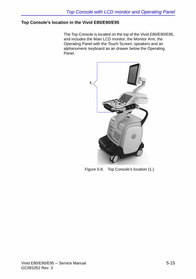
Top Console with LCD monitor and Operating Panel
Vivid E80/E90/E95 – Service Manual 5-15GC091052 Rev. 3
Top Console’s location in the Vivid E80/E90/E95
The Top Console is located on the top of the Vivid E80/E90/E95, and includes the Main LCD monitor, the Monitor Arm, the Operating Panel with the Touch Screen, speakers and an alphanumeric keyboard as an drawer below the Operating Panel.
Figure 5-8. Top Console’s location (1.)

Components and Functions (Theory)
5-16 Vivid E80/E90/E95 – Service ManualGC091052 Rev. 3
Connection from the Top Console to the rest of the Vivid E80/E90/E95
A flexible harness of electrical wires secures the connection between the Top Console and the rest of the Vivid E80/E90/E95.
The XYZ mechanism
The Top Console can be adjusted without moving the complete Ultrasound system.
It can be moved;
• up/down (Z-axis)
• sideways to the left and to the right (X-axis)
• back and forth (Y-axis)
The vertical movement of the Top Console is motor driven. The control buttons for the electrical motor are located around the handles. A gas spring inside the Ultrasound system assists in the Z-axis (vertical) movement.
The brakes used for locking the Top Console’s X and Y movement are operated by electrical motors.
The XY Locking mechanism
In addition to the brakes described above, a Park Lock mechanism is used to lock the Top Console in the “park position” used during transportation.
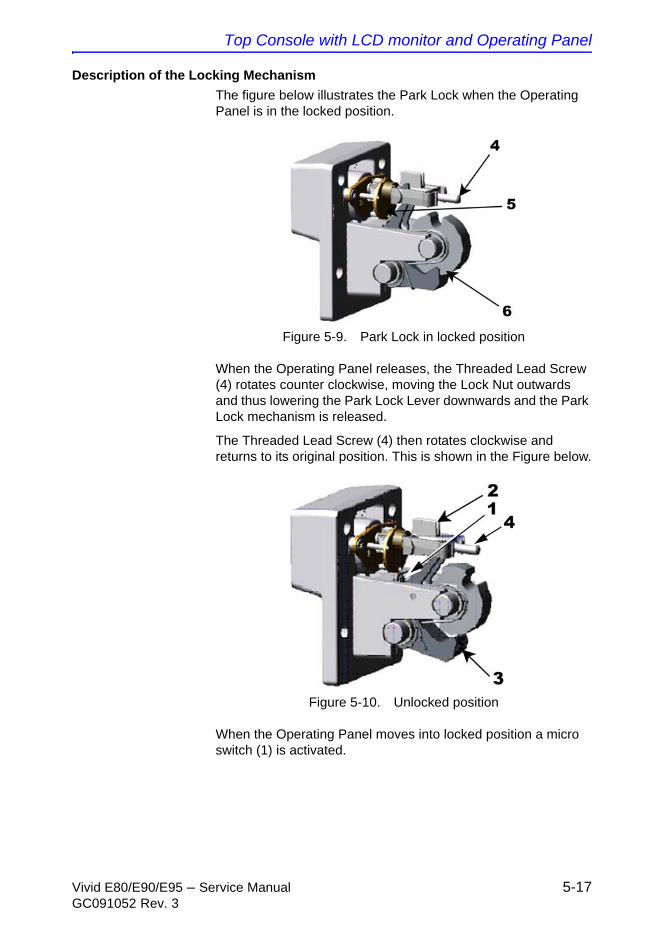
Top Console with LCD monitor and Operating Panel
Vivid E80/E90/E95 – Service Manual 5-17GC091052 Rev. 3
Description of the Locking Mechanism
The figure below illustrates the Park Lock when the Operating Panel is in the locked position.
Figure 5-9. Park Lock in locked position
When the Operating Panel releases, the Threaded Lead Screw (4) rotates counter clockwise, moving the Lock Nut outwards and thus lowering the Park Lock Lever downwards and the Park Lock mechanism is released.
The Threaded Lead Screw (4) then rotates clockwise and returns to its original position. This is shown in the Figure below.
Figure 5-10. Unlocked position
When the Operating Panel moves into locked position a micro switch (1) is activated.
Components and Functions (Theory)
5-18 Vivid E80/E90/E95 – Service ManualGC091052 Rev. 3
Description of the Locking Mechanism (continued)
The micro switch activation is used by the Motor Controller to detect when the Operating Panel is in locked position.
The XY (frogleg) brakes will stay ON if the Vivid E80/E90/E95 is powered down when the Operating Panel is locked. This enables release of the Park Lock, initiated by the micro switches on the Front Handle of the Operating Panel.
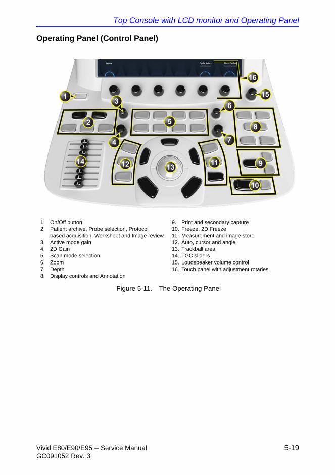
Top Console with LCD monitor and Operating Panel
Vivid E80/E90/E95 – Service Manual 5-19GC091052 Rev. 3
Operating Panel (Control Panel)
Figure 5-11. The Operating Panel
1. On/Off button2. Patient archive, Probe selection, Protocol
based acquisition, Worksheet and Image review3. Active mode gain4. 2D Gain5. Scan mode selection6. Zoom7. Depth8. Display controls and Annotation
9. Print and secondary capture10. Freeze, 2D Freeze11. Measurement and image store12. Auto, cursor and angle13. Trackball area14. TGC sliders15. Loudspeaker volume control16. Touch panel with adjustment rotaries
Components and Functions (Theory)
5-20 Vivid E80/E90/E95 – Service ManualGC091052 Rev. 3
Key illumination
The keys on the control panel are illuminated according to their availability:
• Illumination in green: The key function is currently active.
• Illumination in yellow: The key function is available (but not active) in the current state of the scanner.
• No illumination: The key is not available in the current state of the scanner.
The alphanumeric keyboard
The alphanumeric keyboard is situated on a drawer under the control panel.
Key Description
F1 Displays the online version of the user manual. Also available from Utility/Help on the Touch panel.
F2 Displays the configuration dialog box, allowing user configuration of various settings on the scanner. Some settings are configured for each application. Press Appl. to access application-specific settings. Also available from Utility/Config on the Touch panel.
F4 Displays the DICOM spooler window. The DICOM spooler is used for checking the current job’s status when a job is saved or when the total spooler status on the right of the Archive windows displays an error. Also available from Utility/Spooler on the Touch panel.
Main Console
Vivid E80/E90/E95 – Service Manual 5-21GC091052 Rev. 3
Main Console
Main Console description
The Main Console consists of a frame that acts as the skeleton of the Ultrasound system. The other parts, listed below, are mounted to the frame. The outside of the Main Console is covered with plastic covers.
The Main Console hosts the:
• Patient I/O
• Front End Processor (FEP)
• Back End Processor (BEP)
• I/O Rear Panel (BEP I/O Board)
• Optional B/W printer
• Power Supply
• Lifting mechanism for the Frog Leg and Top Console
• Rear handle
• Front and Rear Casters with lock and brake mechanism

Components and Functions (Theory)
5-22 Vivid E80/E90/E95 – Service ManualGC091052 Rev. 3
Air Flow control
Air Flow components
The Air Flow control includes the following components:
• air filter in the air intake on the back of the Vivid E80/E90/E95
• fans inside the Vivid E80/E90/E95
• temperature sensors several places inside the Vivid E80/E90/E95
• temperature control software, running on the BEP
Software control
Software, running on the BEP, samples the temperature on each sensor.
• If the temperature rises, fan speed (and air flow) is increased.
• If the temperature decrease, the fan speed decrease.
If the temperature increase over a pre-defined level for each sensor, the Vivid E80/E90/E95 will shut down. It will then need to rest for a period of time, until the temperature inside the Vivid E80/E90/E95 has decreased to an acceptable value, before it is possible to turn it on again.
If the Ultrasound system power down due to high temperature inside the Ultrasound system, it may indicate that the air filter need to be dusted or it may indicate a failure situation.

Air Flow control
Vivid E80/E90/E95 – Service Manual 5-23GC091052 Rev. 3
Location
Table 5-2: Location
ITEM DESCRIPTION LOCATION
1. Air Filter on the rear of the Vivid E80/E90/E95
2. Fan unit below Vivid E80/E90/E95’s Card Rack (Front End Rack).
3. Temperature sensors distributed on the cards in the Card Rack (Front End Rack).

Components and Functions (Theory)
5-24 Vivid E80/E90/E95 – Service ManualGC091052 Rev. 3
Casters and brakes
Casters and brakes description
The Vivid E80/E90/E95 has four casters (wheels), two Front Casters and two Rear Casters.
• All Casters are mounted on swivels so they can change direction as needed.
• The Front Casters can be locked in fixed directions.
• Three plastic pedals, used for controlling the brakes and direction locks, are located at the front of the Ultrasound system.
• The pedals are mounted on the Pedal Mechanism.
The Pedal Mechanism has these functions:
• direction lock
• parking brake
• release the two other functions, if activated
The direction lock and brakes are operating on the front wheels. A lever placed on each of the front wheels give the interface to the pedal mechanism. These levers are engaged by rods being moved by a rotating bracket (Bracket Rotation). When the mechanism is engaged in either position, the pedal will not move back into a neutral position. This is to indicate which function that is activated. It will then be needed to release this by the release pedal.
• The Rear Casters have brakes that are operated individually for each caster.
Front End Processor (FEP)
Vivid E80/E90/E95 – Service Manual 5-25GC091052 Rev. 3
Front End Processor (FEP)
Front End Card Rack general description
Introduction
The Front End Card Cage / Card Rack with the electronics is also called the Front End Processor (FEP).
FEP’s location
The FEP is located on the right side of the Vivid E80/E90/E95, behind the Right Side Cover.
FEP cards overview
These cards are included in the FEP:
• Relay board
• Transmitter board
• CRX board
• cSound Power Module
• Front Plane boards (Transducer bus boards)
• Backplane
CAUTION The cards have color-keys on the connectors to prevent installation in the wrong rack position. Do not change the color-keys position. Don’t insert a card in the wrong position in the card rack. If the power is turned on with a card placed in the wrong position, the Vivid E80/E90/E95 will be destroyed.
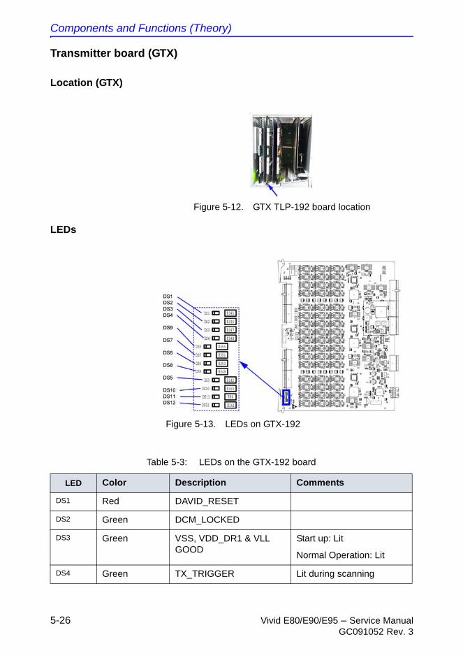
Components and Functions (Theory)
5-26 Vivid E80/E90/E95 – Service ManualGC091052 Rev. 3
Transmitter board (GTX)
Location (GTX)
Figure 5-12. GTX TLP-192 board location
LEDs
Figure 5-13. LEDs on GTX-192
Table 5-3: LEDs on the GTX-192 board
LED Color Description Comments
DS1 Red DAVID_RESET
DS2 Green DCM_LOCKED
DS3 Green VSS, VDD_DR1 & VLL GOOD
Start up: Lit
Normal Operation: Lit
DS4 Green TX_TRIGGER Lit during scanning
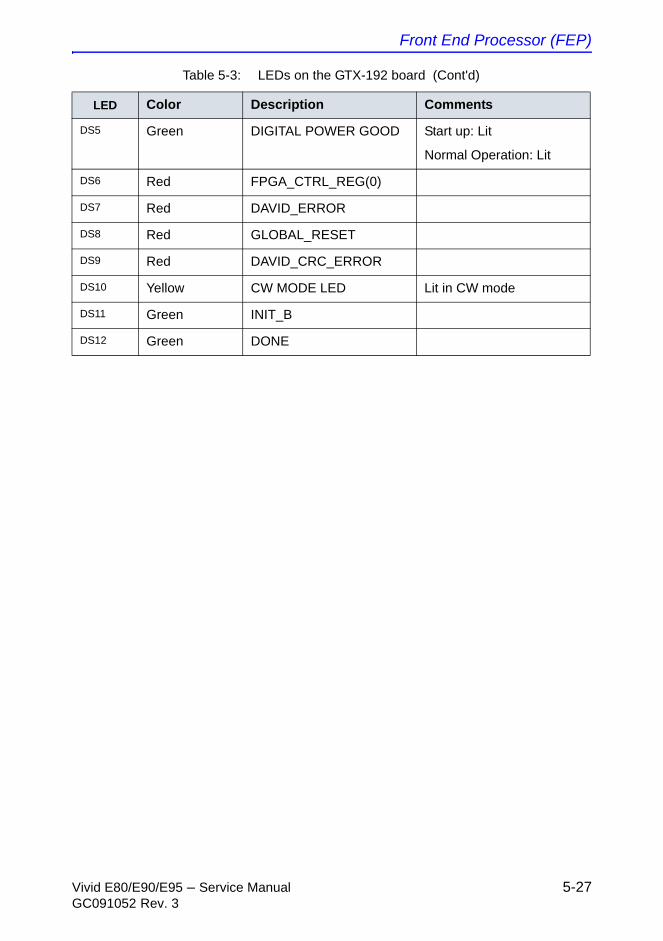
Front End Processor (FEP)
Vivid E80/E90/E95 – Service Manual 5-27GC091052 Rev. 3
DS5 Green DIGITAL POWER GOOD Start up: Lit
Normal Operation: Lit
DS6 Red FPGA_CTRL_REG(0)
DS7 Red DAVID_ERROR
DS8 Red GLOBAL_RESET
DS9 Red DAVID_CRC_ERROR
DS10 Yellow CW MODE LED Lit in CW mode
DS11 Green INIT_B
DS12 Green DONE
Table 5-3: LEDs on the GTX-192 board (Cont'd)
LED Color Description Comments
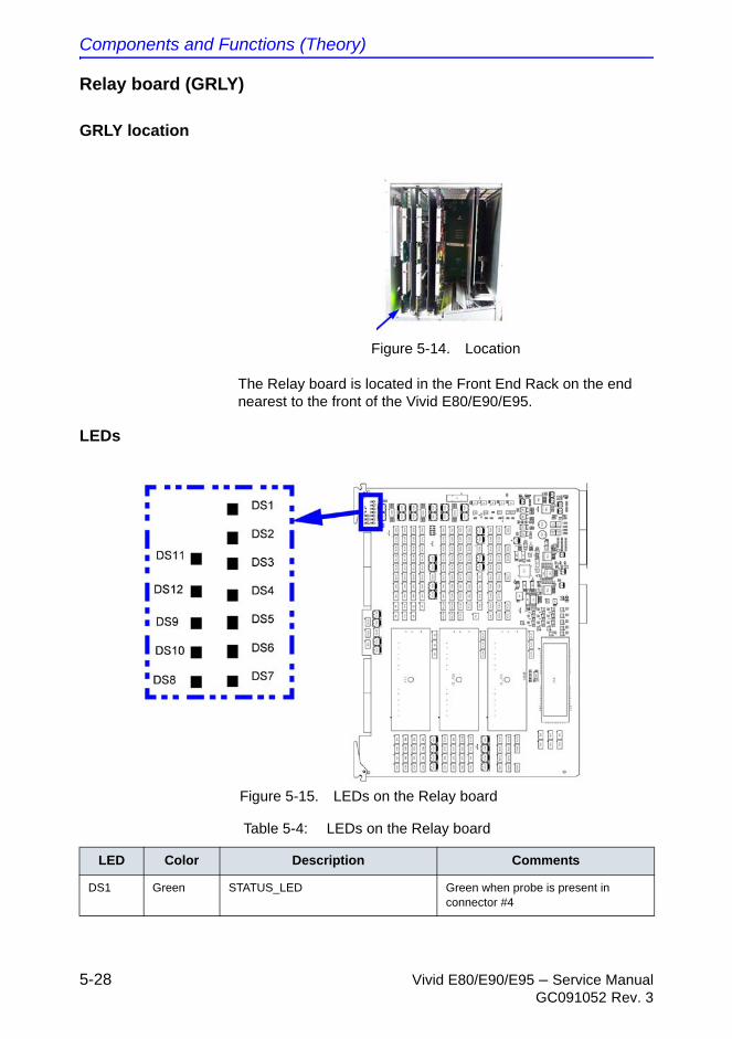
Components and Functions (Theory)
5-28 Vivid E80/E90/E95 – Service ManualGC091052 Rev. 3
Relay board (GRLY)
GRLY location
Figure 5-14. Location
The Relay board is located in the Front End Rack on the end nearest to the front of the Vivid E80/E90/E95.
LEDs
Figure 5-15. LEDs on the Relay board
Table 5-4: LEDs on the Relay board
LED Color Description Comments
DS1 Green STATUS_LED Green when probe is present in connector #4
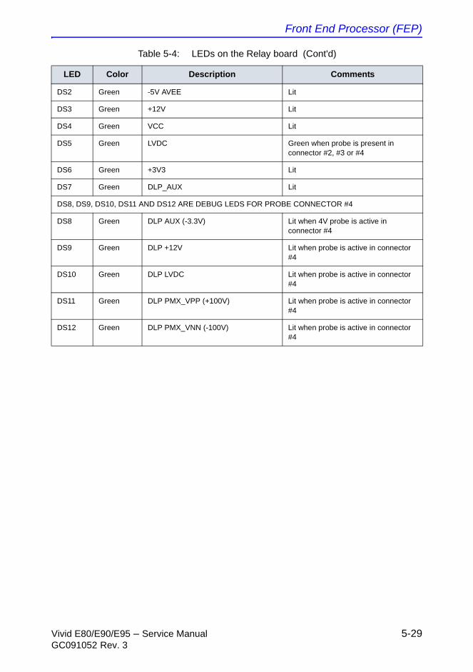
Front End Processor (FEP)
Vivid E80/E90/E95 – Service Manual 5-29GC091052 Rev. 3
DS2 Green -5V AVEE Lit
DS3 Green +12V Lit
DS4 Green VCC Lit
DS5 Green LVDC Green when probe is present in connector #2, #3 or #4
DS6 Green +3V3 Lit
DS7 Green DLP_AUX Lit
DS8, DS9, DS10, DS11 AND DS12 ARE DEBUG LEDS FOR PROBE CONNECTOR #4
DS8 Green DLP AUX (-3.3V) Lit when 4V probe is active in connector #4
DS9 Green DLP +12V Lit when probe is active in connector #4
DS10 Green DLP LVDC Lit when probe is active in connector #4
DS11 Green DLP PMX_VPP (+100V) Lit when probe is active in connector #4
DS12 Green DLP PMX_VNN (-100V) Lit when probe is active in connector #4
Table 5-4: LEDs on the Relay board (Cont'd)
LED Color Description Comments
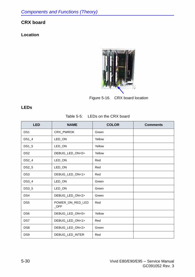
Components and Functions (Theory)
5-30 Vivid E80/E90/E95 – Service ManualGC091052 Rev. 3
CRX board
Location
Figure 5-16. CRX board location
LEDs
Table 5-5: LEDs on the CRX board
LED NAME COLOR Comments
DS1 CRX_PWROK Green
DS1_4 LED_ON Yellow
DS1_5 LED_ON Yellow
DS2 DEBUG_LED_ON<0> Yellow
DS2_4 LED_ON Red
DS2_5 LED_ON Red
DS3 DEBUG_LED_ON<1> Red
DS3_4 LED_ON Green
DS3_5 LED_ON Green
DS4 DEBUG_LED_ON<2> Green
DS5 POWER_ON_RED_LED_OFF
Red
DS6 DEBUG_LED_ON<0> Yellow
DS7 DEBUG_LED_ON<1> Red
DS8 DEBUG_LED_ON<2> Green
DS9 DEBUG_LED_INTER Red
Front End Processor (FEP)
Vivid E80/E90/E95 – Service Manual 5-31GC091052 Rev. 3
DS10 DEBUG_LED_ALLWAS_BLINK
Red - Blinking
Table 5-5: LEDs on the CRX board
LED NAME COLOR Comments
Components and Functions (Theory)
5-32 Vivid E80/E90/E95 – Service ManualGC091052 Rev. 3
Front Plane boards (XD BUS)
General description
The two Front Plane boards plug into the rear edge connectors on the Relay Board, the GTX Board and the CRX Board.
The XD signals, TX and RX signals to and from the probes (via the Relay Board) are routed via these boards.
Location
The Front Plane boards plugs into the connectors on the rear of the Relay board, the GTX board and the CRX board.
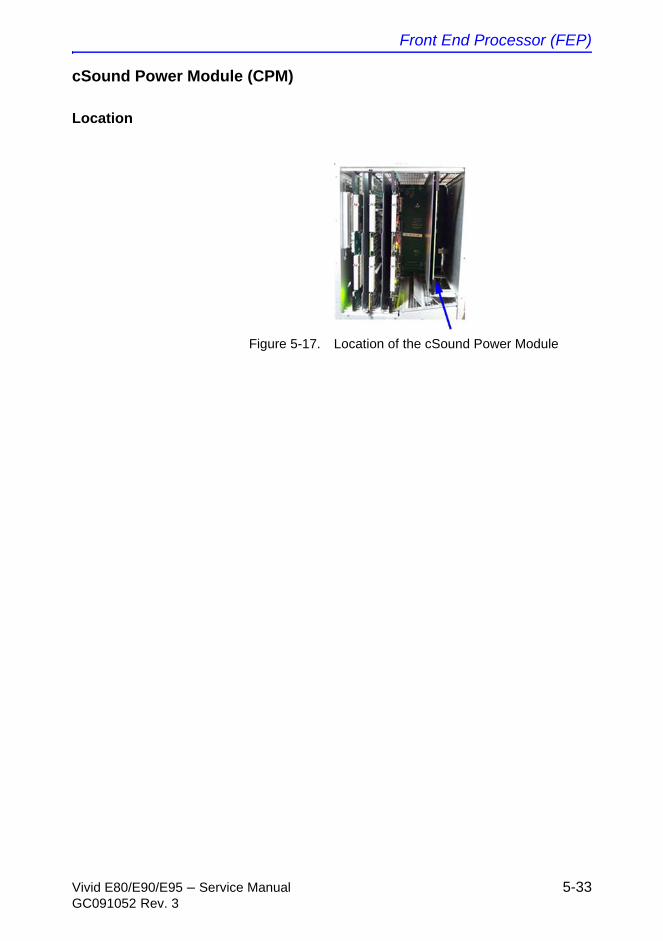
Front End Processor (FEP)
Vivid E80/E90/E95 – Service Manual 5-33GC091052 Rev. 3
cSound Power Module (CPM)
Location
Figure 5-17. Location of the cSound Power Module
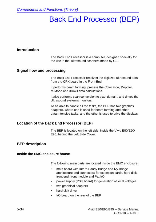
Components and Functions (Theory)
5-34 Vivid E80/E90/E95 – Service ManualGC091052 Rev. 3
Back End Processor (BEP)
Introduction
The Back End Processor is a computer, designed specially for the use in the ultrasound scanners made by GE.
Signal flow and processing
The Back End Processor receives the digitized ultrasound data from the CRX board in the Front End.
It performs beam forming, process the Color Flow, Doppler, M-Mode and 3D/4D data calculations.
It also performs scan conversion to pixel domain, and drives the Ultrasound system’s monitors.
To be able to handle all the tasks, the BEP has two graphics adapters, where one is used for beam forming and other data-intensive tasks, and the other is used to drive the displays.
Location of the Back End Processor (BEP)
The BEP is located on the left side, inside the Vivid E80/E90/E95, behind the Left Side Cover.
BEP description
Inside the EMC enclosure house
The following main parts are located inside the EMC enclosure:
• main board with Intel’s Sandy Bridge and Ivy Bridge architecture and connectors for extension cards, hard disk, front end, front module and Pat I/O
• power supply (PSU board) for generation of local voltages
• two graphical adapters
• hard disk drive
• I/O board on the rear of the BEP
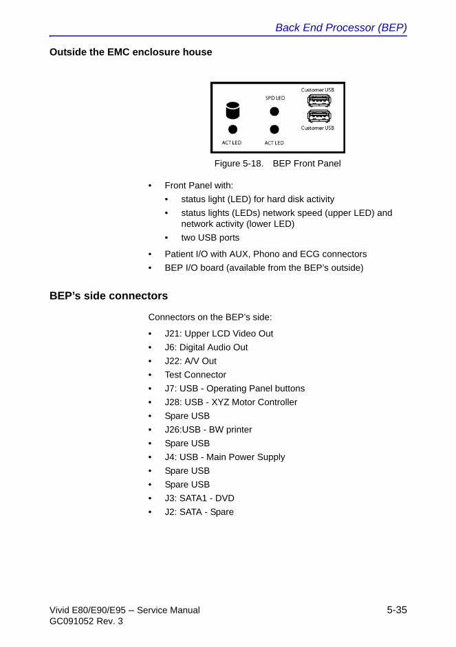
Back End Processor (BEP)
Vivid E80/E90/E95 – Service Manual 5-35GC091052 Rev. 3
Outside the EMC enclosure house
Figure 5-18. BEP Front Panel
• Front Panel with:
• status light (LED) for hard disk activity
• status lights (LEDs) network speed (upper LED) and network activity (lower LED)
• two USB ports
• Patient I/O with AUX, Phono and ECG connectors
• BEP I/O board (available from the BEP’s outside)
BEP’s side connectors
Connectors on the BEP’s side:
• J21: Upper LCD Video Out
• J6: Digital Audio Out
• J22: A/V Out
• Test Connector
• J7: USB - Operating Panel buttons
• J28: USB - XYZ Motor Controller
• Spare USB
• J26:USB - BW printer
• Spare USB
• J4: USB - Main Power Supply
• Spare USB
• Spare USB
• J3: SATA1 - DVD
• J2: SATA - Spare
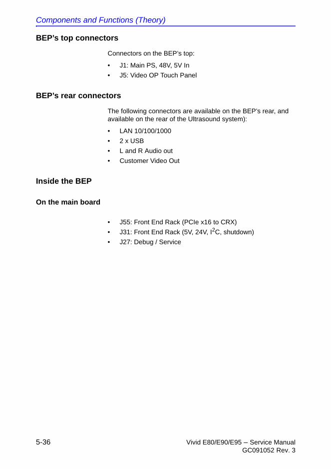
Components and Functions (Theory)
5-36 Vivid E80/E90/E95 – Service ManualGC091052 Rev. 3
BEP’s top connectors
Connectors on the BEP’s top:
• J1: Main PS, 48V, 5V In
• J5: Video OP Touch Panel
BEP’s rear connectors
The following connectors are available on the BEP’s rear, and available on the rear of the Ultrasound system):
• LAN 10/100/1000
• 2 x USB
• L and R Audio out
• Customer Video Out
Inside the BEP
On the main board
• J55: Front End Rack (PCIe x16 to CRX)
• J31: Front End Rack (5V, 24V, I2C, shutdown)
• J27: Debug / Service
Back End Processor (BEP)
Vivid E80/E90/E95 – Service Manual 5-37GC091052 Rev. 3
LEDs
LEDs on the BEP’s front cover
Figure 5-19. LEDs on BEP’s front panel
LED on the BEP’s Rear Panel
The LED on the Rear Panel indicates Post Codes:
Table 5-6: LEDs on BEP’s front panel
Item LED name Description
1. ACT LED HDD Activity
Blinks when the hard disk drive is active.
2. SPD LED Network Speed
• 1000 Mbit: Green Light
• 100 MBit: Amber Light
3. ACT LED Network Activity
Lit (green)
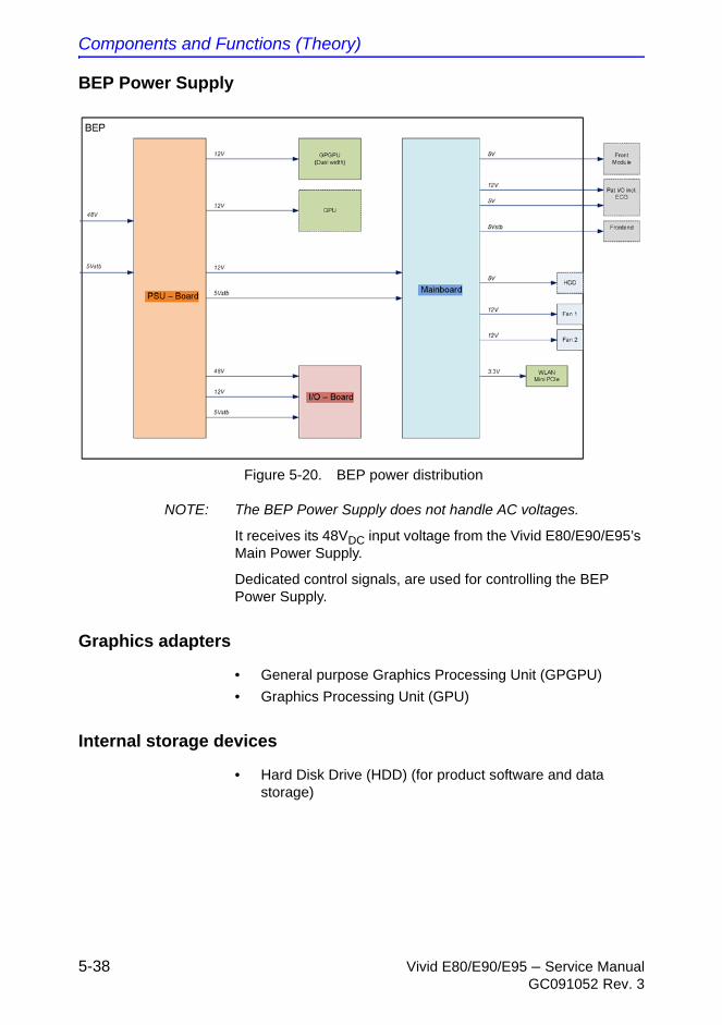
Components and Functions (Theory)
5-38 Vivid E80/E90/E95 – Service ManualGC091052 Rev. 3
BEP Power Supply
Figure 5-20. BEP power distribution
NOTE: The BEP Power Supply does not handle AC voltages.
It receives its 48VDC input voltage from the Vivid E80/E90/E95’s Main Power Supply.
Dedicated control signals, are used for controlling the BEP Power Supply.
Graphics adapters
• General purpose Graphics Processing Unit (GPGPU)
• Graphics Processing Unit (GPU)
Internal storage devices
• Hard Disk Drive (HDD) (for product software and data storage)

Power distribution
Vivid E80/E90/E95 – Service Manual 5-39GC091052 Rev. 3
Power distribution
Main Power Supply
General description
The Main Power Supply’s main task is to galvanically isolate the Vivid E80/E90/E95 from the on-site mains power system and to supply the various internal subsystems with DC voltages above +/- 6VDC.
Two 115 VAC outputs for use by internal peripherals, are also included.
Power from the wall outlet (100 VAC to 230 VAC, 50/60 Hz) is connected to the Main Power Supply.
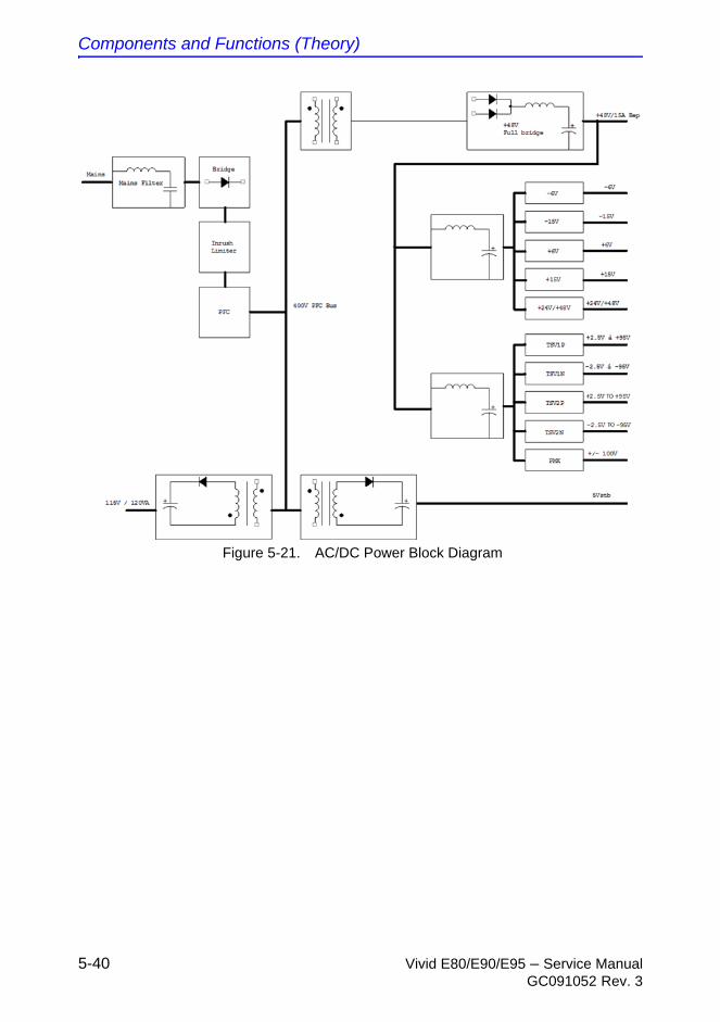
Components and Functions (Theory)
5-40 Vivid E80/E90/E95 – Service ManualGC091052 Rev. 3
Figure 5-21. AC/DC Power Block Diagram

Power distribution
Vivid E80/E90/E95 – Service Manual 5-41GC091052 Rev. 3
General description (continued)
The Main Power Supply delivers the needed voltages to the rest of the Ultrasound system:
• Internal peripherals (115 VAC)
• Front End Rack (DC power with several voltages)
• +24 VDC
• +/- 15 VDC
• +/- 6VDC
• Front End Rack (TSV1 and TSV2 for the transmitters)
• TSV1: +/-2.5 VDC to +/-95VDC
• TSV2: +/-2.5 VDC to +/-95VDC
• Front End Rack (PMX for the probe channel multiplexers inside some probes) +/-100VDC
• Back End Processor (48 VDC)
• Operating Panel, LCD, XYZ motors (48 VDC)
The mains cord has plugs in both ends. A female plug connects to the Ultrasound system and a male plug to the wall outlet.
Temperature Control
The Main Power Supply is equipped with internal fans with variable speed for temperature control.
Both the temperature of the air entering the power supply and leaving the power supply are measured.
The fans are controlled by software.
LEDs
There are no LEDs on the Main Power Supply.
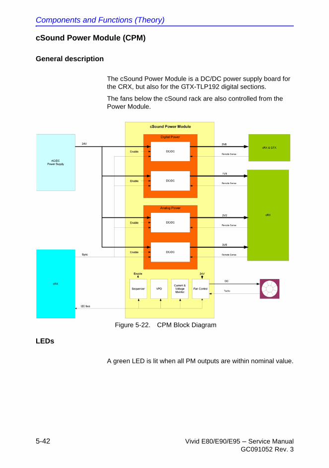
Components and Functions (Theory)
5-42 Vivid E80/E90/E95 – Service ManualGC091052 Rev. 3
cSound Power Module (CPM)
General description
The cSound Power Module is a DC/DC power supply board for the CRX, but also for the GTX-TLP192 digital sections.
The fans below the cSound rack are also controlled from the Power Module.
Figure 5-22. CPM Block Diagram
LEDs
A green LED is lit when all PM outputs are within nominal value.
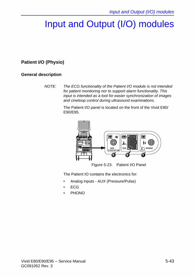
Input and Output (I/O) modules
Vivid E80/E90/E95 – Service Manual 5-43GC091052 Rev. 3
Input and Output (I/O) modules
Patient I/O (Physio)
General description
NOTE: The ECG functionality of the Patient I/O module is not intended for patient monitoring nor to support alarm functionality. This input is intended as a tool for easier synchronization of images and cineloop control during ultrasound examinations.
The Patient I/O panel is located on the front of the Vivid E80/E90/E95.
Figure 5-23. Patient I/O Panel
The Patient IO contains the electronics for:
• Analog inputs - AUX (Pressure/Pulse)
• ECG
• PHONO
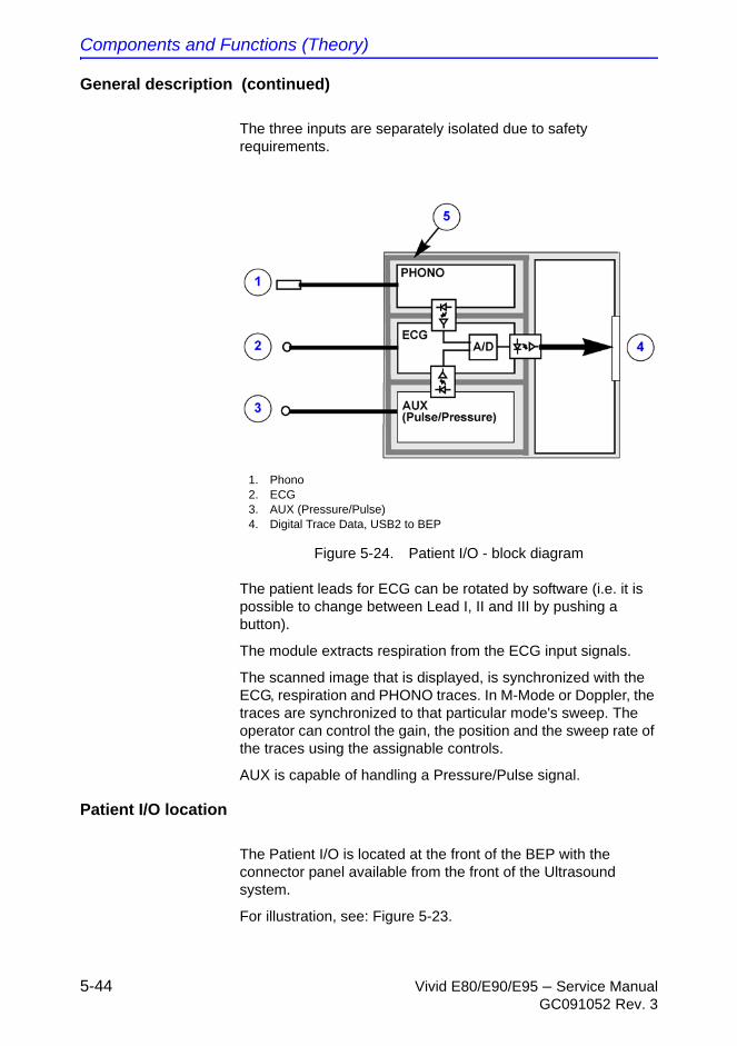
Components and Functions (Theory)
5-44 Vivid E80/E90/E95 – Service ManualGC091052 Rev. 3
General description (continued)
The three inputs are separately isolated due to safety requirements.
Figure 5-24. Patient I/O - block diagram
The patient leads for ECG can be rotated by software (i.e. it is possible to change between Lead I, II and III by pushing a button).
The module extracts respiration from the ECG input signals.
The scanned image that is displayed, is synchronized with the ECG, respiration and PHONO traces. In M-Mode or Doppler, the traces are synchronized to that particular mode's sweep. The operator can control the gain, the position and the sweep rate of the traces using the assignable controls.
AUX is capable of handling a Pressure/Pulse signal.
Patient I/O location
The Patient I/O is located at the front of the BEP with the connector panel available from the front of the Ultrasound system.
For illustration, see: Figure 5-23.
1. Phono2. ECG 3. AUX (Pressure/Pulse)4. Digital Trace Data, USB2 to BEP
Input and Output (I/O) modules
Vivid E80/E90/E95 – Service Manual 5-45GC091052 Rev. 3
BEP I/O Board
General description
• The BEP I/O board is the interface between the BEP and the rest of the Ultrasound system.
• The BEP I/O board is plugged into a connector on the BEP’s main board.
• The DVI signals are received via cable from the Display GPU.
Location
The I/O board is located inside the BEP with some connectors available on the rear of the Ultrasound system and some available inside the Ultrasound system.
Connectors on the I/O Rear Panel
• 2 x USB 2.0 (via HUB)
• Audio Line Out L+R
• DVI-out (external monitor)
• Giga bit LAN
Connectors on the I/O Side Panel (inside the Ultrasound system)
• Test connector (used by manufacturing)
• 8 x USB 2.0
• 2 x eSATAp
• DVI-D out (System Monitor)
• Digital Audio out
• Operating Panel Audio out
Components and Functions (Theory)
5-46 Vivid E80/E90/E95 – Service ManualGC091052 Rev. 3
Restart Vivid E80/E90/E95 after
diagnostics
Always shutdown the Ultrasound system and reboot after a diagnostics session.

Vivid E80/E90/E95 – Service Manual 6-1GC091052 Rev. 3
Chapter 6
Service Adjustments
This chapter describes how to adjust the Vivid E80/E90/E95.
Service Adjustments
6-2 Vivid E80/E90/E95 – Service ManualGC091052 Rev. 3
LCD Monitor adjustments
Cautions and Warnings
Be aware of pinch points at hinges when adjusting LCD Arm and LCD Monitor.
CAUTION To avoid injury when you move the LCD monitor and the monitor arm, do not put your finger, hand, or object on the joint of the monitor or the monitor arm.

LCD Monitor adjustments
Vivid E80/E90/E95 – Service Manual 6-3GC091052 Rev. 3
LCD backlight adjustment
Accessing the main LCD and touch screen backlight adjustments
1. Select Utility on the Touch Screen.
2. Ensure that Page 1 of 2 is selected.
Backlight and blue tint adjustment
On the Utility screen - Page 1 of 2, you can adjust the Backlight and the Blue tint on the Main LCD screen and the Backlight on the Touch Panel (TP).
• Adjust the left most rotary to adjust the LCD Backlight.
• Push and adjust the left most rotary to adjust the LCD Blue Tint.
• Adjust the second rotary from the left side, to adjust the Touch Panel (TP) Backlight.
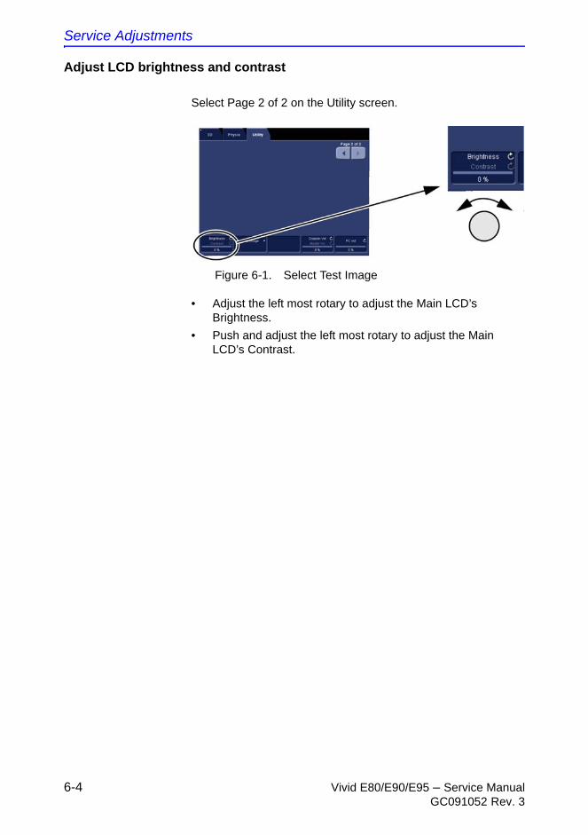
Service Adjustments
6-4 Vivid E80/E90/E95 – Service ManualGC091052 Rev. 3
Adjust LCD brightness and contrast
Select Page 2 of 2 on the Utility screen.
Figure 6-1. Select Test Image
• Adjust the left most rotary to adjust the Main LCD’s Brightness.
• Push and adjust the left most rotary to adjust the Main LCD’s Contrast.
Vivid E80/E90/E95 – Service Manual 7-1GC091052 Rev. 3
Chapter 7
Diagnostics/Troubleshooting
This chapter describes how to setup and run the tools and software that help maintain image quality and system operation. Very basic host, system and board level diagnostics are run whenever power is applied. Some Service Tools may be run at the application level.
Diagnostics/Troubleshooting
7-2 Vivid E80/E90/E95 – Service ManualGC091052 Rev. 3
Service safety considerations
DANGER
DANGEROUS VOLTAGES, CAPABLE OF CAUSING DEATH, ARE PRESENT IN THIS EQUIPMENT. USE EXTREME CAUTION WHEN HANDLING, TESTING AND ADJUSTING.
WARNING If the covers are removed from an operating Vivid E80/E90/E95, some metal surfaces may be warm enough to pose a potential heat hazard if touched, even while in shutdown mode.
WARNING Use all Personal Protection Equipment (PPE) such as gloves, safety shoes, safety glasses, and kneeling pads, to reduce the risk of injury.

Gathering Troubleshooting Data
Vivid E80/E90/E95 – Service Manual 7-3GC091052 Rev. 3
Gathering Troubleshooting Data
Purpose of this section
Trouble images and system data (logs) can be acquired at the Ultrasound system or through remote diagnostics (InSite). These data can be used to perform service at the Ultrasound system, or can be sent back to the manufacturer for analysis.
Collect Vital System Information
The following information is necessary in order to properly analyze data or images being reported as a malfunction or being returned to the manufacturer:
Product Name = Vivid E80/E90/E95
Select Config (F2) > About screen.
• Applications Software
• Application Software revision
• Software medium’s part number
• System Software
• System Software revision
• Software medium’s part number
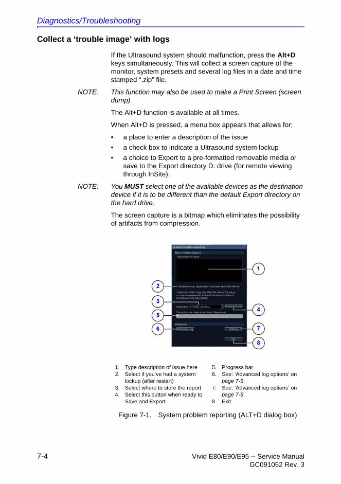
Diagnostics/Troubleshooting
7-4 Vivid E80/E90/E95 – Service ManualGC091052 Rev. 3
Collect a ‘trouble image’ with logs
If the Ultrasound system should malfunction, press the Alt+D keys simultaneously. This will collect a screen capture of the monitor, system presets and several log files in a date and time stamped “.zip” file.
NOTE: This function may also be used to make a Print Screen (screen dump).
The Alt+D function is available at all times.
When Alt+D is pressed, a menu box appears that allows for;
• a place to enter a description of the issue
• a check box to indicate a Ultrasound system lockup
• a choice to Export to a pre-formatted removable media or save to the Export directory D: drive (for remote viewing through InSite).
NOTE: You MUST select one of the available devices as the destination device if it is to be different than the default Export directory on the hard drive.
The screen capture is a bitmap which eliminates the possibility of artifacts from compression.
Figure 7-1. System problem reporting (ALT+D dialog box)
1. Type description of issue here2. Select if you’ve had a system
lockup (after restart)3. Select where to store the report4. Select this button when ready to
Save and Export
5. Progress bar6. See: ‘Advanced log options’ on
page 7-5.7. See: ‘Advanced log options’ on
page 7-5.8. Exit
Gathering Troubleshooting Data
Vivid E80/E90/E95 – Service Manual 7-5GC091052 Rev. 3
Advanced log options
• Extensive Log enables the creation of a log file containing additional information for the selected functionality.
• Options enables creation of a log file based on a selected bookmark or for a user configurable time frame. Different type of information can be selected to be part of the log file.
Diagnostics/Troubleshooting
7-6 Vivid E80/E90/E95 – Service ManualGC091052 Rev. 3
Screen captures
Purpose of this section
To capture screen images that can be used for diagnostic and troubleshooting purposes.
Ctrl+PrintScreen shortcut
A Ctrl+PrintScreen shortcut is available for quickly capturing the image displayed on the Ultrasound system. Images captured using this shortcut are saved in the D:\export directory using both the JPEG (.jpg) and raw DICOM (.dcm) formats.
The InSite connection will have access to the export folder on the “D:” drive to retrieve these images. This feature will allow the customer to quickly and easily acquire images that can then be viewed by the Online Centre (OLC).
Screen captures
Vivid E80/E90/E95 – Service Manual 7-7GC091052 Rev. 3
Capture a screen image using the shortcut
Follow the steps in this procedure to capture a screen image:
1. With the desired image displayed on the screen, press Ctrl and PrtSc (print screen) keys simultaneously.
2. From the touch panel, select: Utility > Service > Utilities > Common Utilities > Image Compress & Delete Utilities.
3. Select the check box for the image(s) you want to save in the D:\export directory.
4. Select Compress Files.
A compressed file of the images is stored in D:\export. You may rely on the date and time of the Ctrl+PrtSc procedure to identify the most recent image recorded.
The uncompressed files are stored in: d:\export\service\image.
Diagnostics/Troubleshooting
7-8 Vivid E80/E90/E95 – Service ManualGC091052 Rev. 3
Troubleshooting
XY Lock is not working
Follow the steps below to resolve this issue:
1. Run the XYZ Test Program and select Fix Lock.
2. If the Lock still does not respond when pushing the buttons in front of the UI, release the Lock manually.
3. Remove the Park Lock and adjust it manually.
Related information:
• ‘Test the motor controller’ on page 7-10
XY Brake Motors Troubleshooting
NOTE: Cables are not labeled at the XY controller, so right side and left side motors are not defined.
When troubleshooting the XY brake motors, keep this in mind:
• The rear motors are #1 and #3.
• The front motors are #2 and #4.
• Motor #1 and #2 are on the same side.
• Motor #3 and #4 are on the same side (opposite to motor #1 and #2).
If you are in a silent environment, it may be possible to hear which motor is activated during the test.
Z Movement fails
• If it is impossible to lower the Top Console but moving it upwards works OK, one of the control switches is stuck in the “Up” position.
• If you have to help the Top Console up when moving upwards, but the motor assistance work OK when lowering the Top Console, the gas spring inside the Z Mechanism is failing:
Troubleshooting
Vivid E80/E90/E95 – Service Manual 7-9GC091052 Rev. 3
NOTE: The Gas Spring is not replaceable. Replace the complete Z-Mechanism if the Gas Spring seems to fail.
• Replace the Z Mechanism.
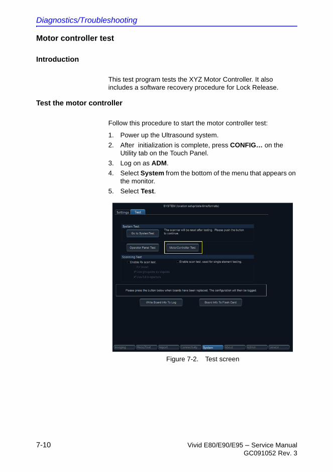
Diagnostics/Troubleshooting
7-10 Vivid E80/E90/E95 – Service ManualGC091052 Rev. 3
Motor controller test
Introduction
This test program tests the XYZ Motor Controller. It also includes a software recovery procedure for Lock Release.
Test the motor controller
Follow this procedure to start the motor controller test:
1. Power up the Ultrasound system.
2. After initialization is complete, press CONFIG… on the Utility tab on the Touch Panel.
3. Log on as ADM.
4. Select System from the bottom of the menu that appears on the monitor.
5. Select Test.
Figure 7-2. Test screen
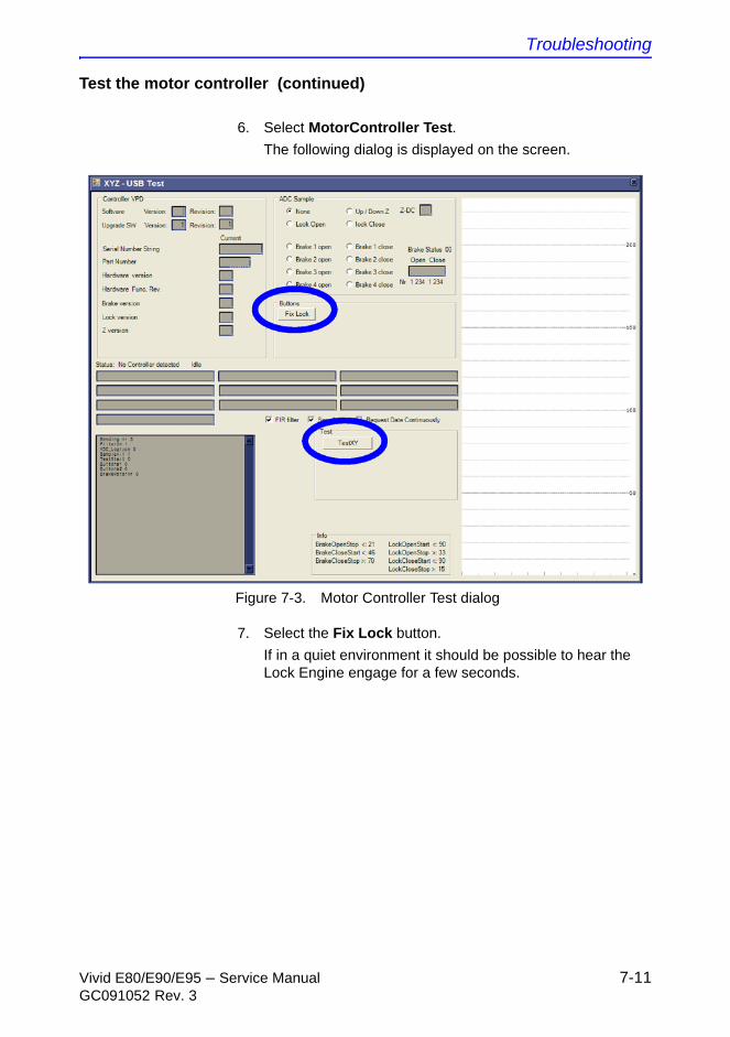
Troubleshooting
Vivid E80/E90/E95 – Service Manual 7-11GC091052 Rev. 3
Test the motor controller (continued)
6. Select MotorController Test.
The following dialog is displayed on the screen.
Figure 7-3. Motor Controller Test dialog
7. Select the Fix Lock button.
If in a quiet environment it should be possible to hear the Lock Engine engage for a few seconds.
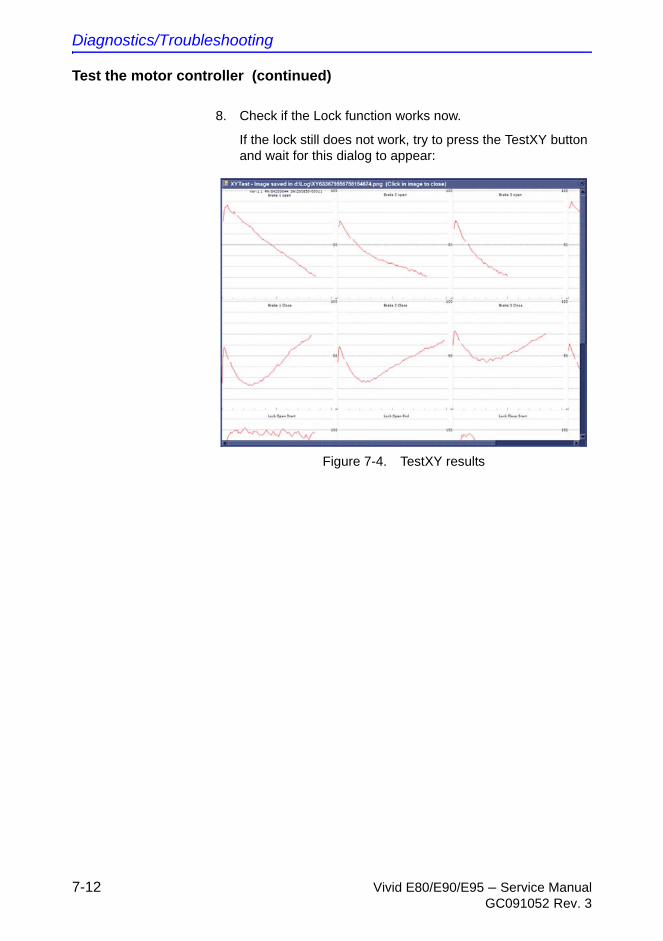
Diagnostics/Troubleshooting
7-12 Vivid E80/E90/E95 – Service ManualGC091052 Rev. 3
Test the motor controller (continued)
8. Check if the Lock function works now.
If the lock still does not work, try to press the TestXY button and wait for this dialog to appear:
Figure 7-4. TestXY results
Vivid E80/E90/E95 – Service Manual 8-1GC091052 Rev. 3
Chapter 8
Replacement Procedures
This chapter describes how to remove and install, or replace, modules and subsystems in the Vivid E80/E90/E95. It also describes how to reinstall the software.
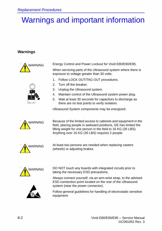
Replacement Procedures
8-2 Vivid E80/E90/E95 – Service ManualGC091052 Rev. 3
Warnings and important information
Warnings
WARNING Energy Control and Power Lockout for Vivid E80/E90/E95.
When servicing parts of the Ultrasound system where there is exposure to voltage greater than 30 volts:
1. Follow LOCK OUT/TAG OUT procedures.
2. Turn off the breaker.
3. Unplug the Ultrasound system.
4. Maintain control of the Ultrasound system power plug.
5. Wait at least 30 seconds for capacitors to discharge as there are no test points to verify isolation.
Ultrasound System components may be energized.
WARNING Because of the limited access to cabinets and equipment in the field, placing people in awkward positions, GE has limited the lifting weight for one person in the field to 16 KG (35 LBS). Anything over 16 KG (35 LBS) requires 2 people.
WARNING At least two persons are needed when replacing casters (wheels) or adjusting brakes.
WARNING DO NOT touch any boards with integrated circuits prior to taking the necessary ESD precautions.
Always connect yourself, via an arm-wrist strap, to the advised ESD connection point located on the rear of the Ultrasound system (near the power connector).
Follow general guidelines for handling of electrostatic sensitive equipment.
Warnings and important information
Vivid E80/E90/E95 – Service Manual 8-3GC091052 Rev. 3
NOTE: Use an ESD compatible work space or the ESD-kit during parts replacement.
Returning/shipping probes and repair parts
Equipment being returned must be clean and free of blood and other infectious substances.
GE policy states that body fluids must be properly removed from any part or equipment prior to shipment. GE employees, as well as customers, are responsible for ensuring that parts/equipment have been properly decontaminated prior to shipment. Under no circumstance should a part or equipment with visible body fluids be taken or shipped from a clinic or site (for example, body coils or an ultrasound probe). The purpose of the regulation is to protect employees in the transportation industry, as well as the people who will receive or open this package.
WARNING The waste of electrical and electronic equipment must not be disposed as unsorted municipal waste and must be collected separately.
Please contact the manufacturer or other authorized disposal company to decommission your equipment.
WARNING Spare Part order for Vivid E80/E90/E95 VET:
The same spare parts used in the current Vivid E80/E90/E95 consoles can be used in the veterinary consoles.
When ordering any of the following, the Vet label(s) MUST be ordered as they need to be applied to the new part:
• Side Covers - require label P/N: 5447716
• Back Cover - require label P/N: GB200182
• Probes - require label P/N: 5454608
CAUTION When performing replacement procedures within a veterinary environment, return any used/unused spare parts with the purple scrap marking label (regardless of the actual condition of the part) and add a description on the label stating that the items were removed from a veterinary environment.
Replacement Procedures
8-4 Vivid E80/E90/E95 – Service ManualGC091052 Rev. 3
NOTE: The US Department of Transportation (DOT) has ruled that “items that were saturated and/or dripping with human blood that are now caked with dried blood; or which were used or intended for use in patient care” are “regulated medical waste” for transportation purposes and must be transported as a hazardous material.
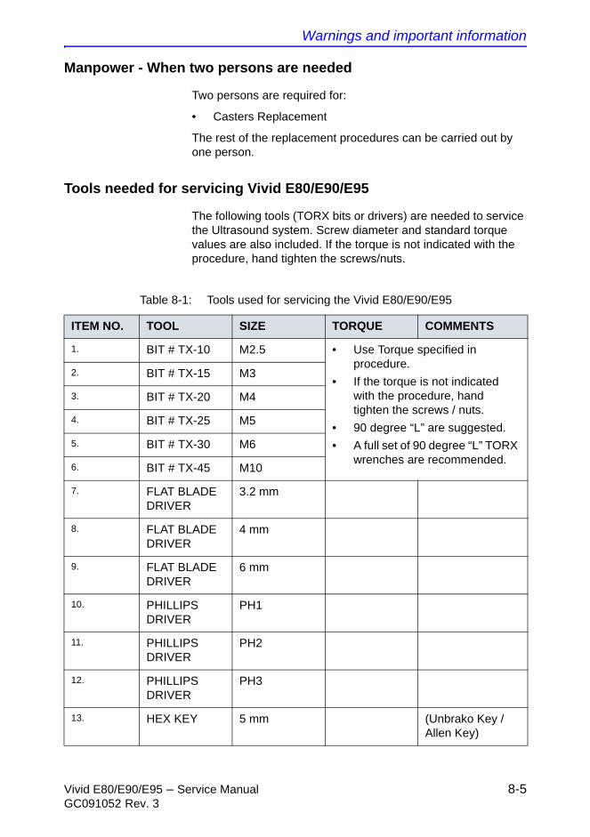
Warnings and important information
Vivid E80/E90/E95 – Service Manual 8-5GC091052 Rev. 3
Manpower - When two persons are needed
Two persons are required for:
• Casters Replacement
The rest of the replacement procedures can be carried out by one person.
Tools needed for servicing Vivid E80/E90/E95
The following tools (TORX bits or drivers) are needed to service the Ultrasound system. Screw diameter and standard torque values are also included. If the torque is not indicated with the procedure, hand tighten the screws/nuts.
Table 8-1: Tools used for servicing the Vivid E80/E90/E95
ITEM NO. TOOL SIZE TORQUE COMMENTS
1. BIT # TX-10 M2.5 • Use Torque specified in procedure.
• If the torque is not indicated with the procedure, hand tighten the screws / nuts.
• 90 degree “L” are suggested.
• A full set of 90 degree “L” TORX wrenches are recommended.
2. BIT # TX-15 M3
3. BIT # TX-20 M4
4. BIT # TX-25 M5
5. BIT # TX-30 M6
6. BIT # TX-45 M10
7. FLAT BLADE DRIVER
3.2 mm
8. FLAT BLADE DRIVER
4 mm
9. FLAT BLADE DRIVER
6 mm
10. PHILLIPS DRIVER
PH1
11. PHILLIPS DRIVER
PH2
12. PHILLIPS DRIVER
PH3
13. HEX KEY 5 mm (Unbrako Key / Allen Key)
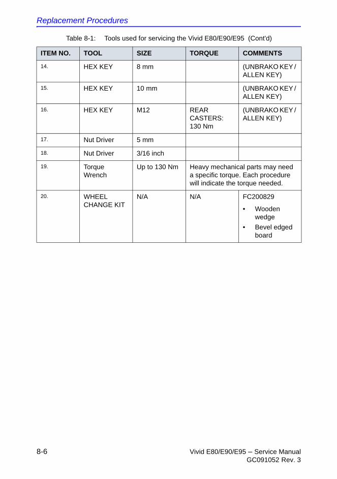
Replacement Procedures
8-6 Vivid E80/E90/E95 – Service ManualGC091052 Rev. 3
14. HEX KEY 8 mm (UNBRAKO KEY / ALLEN KEY)
15. HEX KEY 10 mm (UNBRAKO KEY / ALLEN KEY)
16. HEX KEY M12 REAR CASTERS: 130 Nm
(UNBRAKO KEY / ALLEN KEY)
17. Nut Driver 5 mm
18. Nut Driver 3/16 inch
19. Torque Wrench
Up to 130 Nm Heavy mechanical parts may need a specific torque. Each procedure will indicate the torque needed.
20. WHEEL CHANGE KIT
N/A N/A FC200829
• Wooden wedge
• Bevel edged board
Table 8-1: Tools used for servicing the Vivid E80/E90/E95 (Cont'd)
ITEM NO. TOOL SIZE TORQUE COMMENTS
Loading the software
Vivid E80/E90/E95 – Service Manual 8-7GC091052 Rev. 3
Loading the software
Loading the software from Usb Flash Drive (UFD)
1. Power down the Ultrasound system.
2. Remove all external USB devices.
3. Install the UFD in one of the USB ports on the Ultrasound system.
4. Power on the Ultrasound system and at the same time press and hold the F11 key on the alphanumeric keyboard until you get the first menu on the screen.
5. Follow the instructions on the screen.
Replacement Procedures
8-8 Vivid E80/E90/E95 – Service ManualGC091052 Rev. 3
Setup after software loading
When to use this procedure
Use this procedure if all partitions on the HDD have been erased during the software load.
Procedure for setup after software loading
1. Restore the Patient Archive and System Configurations from the backup you made before the software loading.
For instructions, see: “Data Backup and Restore” in the User Manual.
2. Install the network printer (if any).
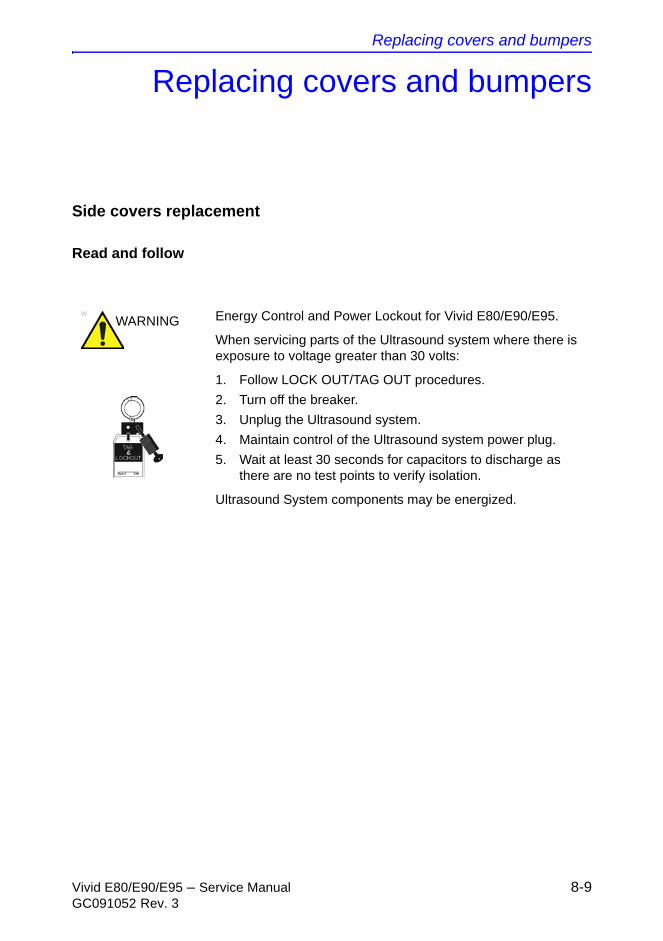
Replacing covers and bumpers
Vivid E80/E90/E95 – Service Manual 8-9GC091052 Rev. 3
Replacing covers and bumpers
Side covers replacement
Read and follow
WARNING Energy Control and Power Lockout for Vivid E80/E90/E95.
When servicing parts of the Ultrasound system where there is exposure to voltage greater than 30 volts:
1. Follow LOCK OUT/TAG OUT procedures.
2. Turn off the breaker.
3. Unplug the Ultrasound system.
4. Maintain control of the Ultrasound system power plug.
5. Wait at least 30 seconds for capacitors to discharge as there are no test points to verify isolation.
Ultrasound System components may be energized.
Replacement Procedures
8-10 Vivid E80/E90/E95 – Service ManualGC091052 Rev. 3
Remove the side covers
NOTE: The removal procedure is easier if the rear lock is released first, and then the front lock.
The Side Covers are “clicked” on to the Ultrasound system with two locks, located at the lower end of the cover. Two rectangular holes give access to the locks. By inserting a #1 Phillips screwdriver (10 - 16 cm / 4 - 6 inch length) (or similar size and length tool) into the holes and bending the handle on the screwdriver down to the floor, one lock at a time, you can release the locks. You may need to pull the cover outwards at the same time, to release the lock mechanism.
Follow these steps to remove one of the side covers:
1. Push a #1 Phillips screwdriver into one of the rectangular holes in the Side Bumper until it reaches the lock mechanism.
2. Push the handle on the screwdriver downwards to release the lock.
3. Repeat the steps above for the other lock.
4. Lift the cover forward and up to remove it.
5. Set it away on a safe place until you need it again.
6. Repeat the steps above to remove the other side cover.
Install the side covers
Follow these steps to install the side covers:
1. Align tabs at the top inside of side cover with the slots on top cover.
2. Place the top edge of the side cover so it hooks onto the top cover.
3. Align and squeeze the front edge of the side cover to latch it into place.
4. Position the side cover’s side lock first.
5. Position the side cover’s front lock.
6. Align and squeeze the bottom front of the side cover to latch it into place.
7. Position the side cover’s rear lock, lifting up the rear tab and guiding it into place.
8. Align and squeeze the bottom rear of the side cover to latch it into place.
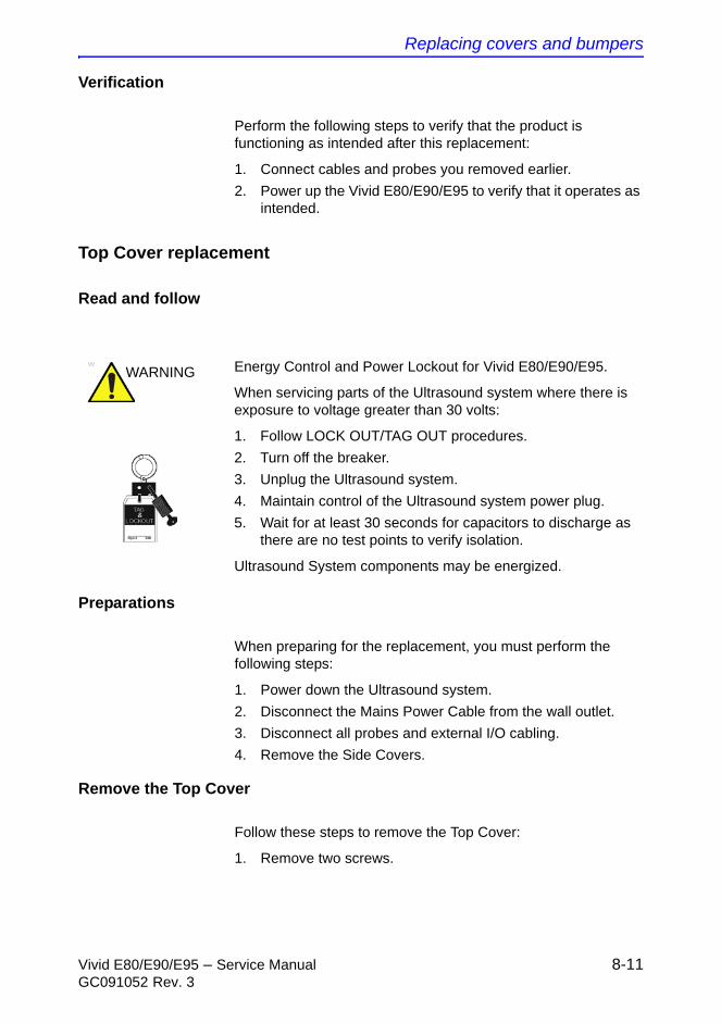
Replacing covers and bumpers
Vivid E80/E90/E95 – Service Manual 8-11GC091052 Rev. 3
Verification
Perform the following steps to verify that the product is functioning as intended after this replacement:
1. Connect cables and probes you removed earlier.
2. Power up the Vivid E80/E90/E95 to verify that it operates as intended.
Top Cover replacement
Read and follow
Preparations
When preparing for the replacement, you must perform the following steps:
1. Power down the Ultrasound system.
2. Disconnect the Mains Power Cable from the wall outlet.
3. Disconnect all probes and external I/O cabling.
4. Remove the Side Covers.
Remove the Top Cover
Follow these steps to remove the Top Cover:
1. Remove two screws.
WARNING Energy Control and Power Lockout for Vivid E80/E90/E95.
When servicing parts of the Ultrasound system where there is exposure to voltage greater than 30 volts:
1. Follow LOCK OUT/TAG OUT procedures.
2. Turn off the breaker.
3. Unplug the Ultrasound system.
4. Maintain control of the Ultrasound system power plug.
5. Wait for at least 30 seconds for capacitors to discharge as there are no test points to verify isolation.
Ultrasound System components may be energized.
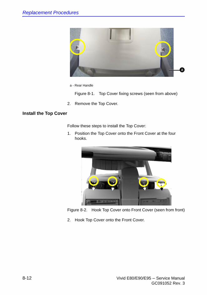
Replacement Procedures
8-12 Vivid E80/E90/E95 – Service ManualGC091052 Rev. 3
Figure 8-1. Top Cover fixing screws (seen from above)
2. Remove the Top Cover.
Install the Top Cover
Follow these steps to install the Top Cover:
1. Position the Top Cover onto the Front Cover at the four hooks.
Figure 8-2. Hook Top Cover onto Front Cover (seen from front)
2. Hook Top Cover onto the Front Cover.
a - Rear Handle
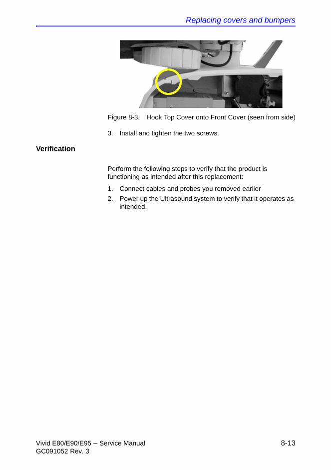
Replacing covers and bumpers
Vivid E80/E90/E95 – Service Manual 8-13GC091052 Rev. 3
Figure 8-3. Hook Top Cover onto Front Cover (seen from side)
3. Install and tighten the two screws.
Verification
Perform the following steps to verify that the product is functioning as intended after this replacement:
1. Connect cables and probes you removed earlier
2. Power up the Ultrasound system to verify that it operates as intended.
Replacement Procedures
8-14 Vivid E80/E90/E95 – Service ManualGC091052 Rev. 3
Foot rest bumper replacement
Read and follow
Preparations
When preparing for the replacement, you must perform the following steps:
1. Power down the Ultrasound system.
2. Disconnect the mains power cable from the wall outlet.
3. Disconnect all probes and external I/O cabling.
WARNING Energy Control and Power Lockout for Vivid E80/E90/E95.
When servicing parts of the Ultrasound system where there is exposure to voltage greater than 30 volts:
1. Follow LOCK OUT/TAG OUT procedures.
2. Turn off the breaker.
3. Unplug the Ultrasound system.
4. Maintain control of the Ultrasound system power plug.
5. Wait for at least 30 seconds for capacitors to discharge as there are no test points to verify isolation.
Ultrasound System components may be energized.
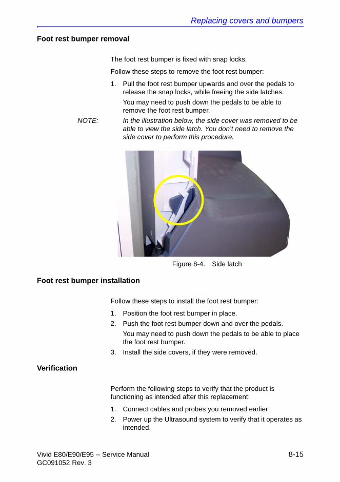
Replacing covers and bumpers
Vivid E80/E90/E95 – Service Manual 8-15GC091052 Rev. 3
Foot rest bumper removal
The foot rest bumper is fixed with snap locks.
Follow these steps to remove the foot rest bumper:
1. Pull the foot rest bumper upwards and over the pedals to release the snap locks, while freeing the side latches.
You may need to push down the pedals to be able to remove the foot rest bumper.
NOTE: In the illustration below, the side cover was removed to be able to view the side latch. You don’t need to remove the side cover to perform this procedure.
Figure 8-4. Side latch
Foot rest bumper installation
Follow these steps to install the foot rest bumper:
1. Position the foot rest bumper in place.
2. Push the foot rest bumper down and over the pedals.
You may need to push down the pedals to be able to place the foot rest bumper.
3. Install the side covers, if they were removed.
Verification
Perform the following steps to verify that the product is functioning as intended after this replacement:
1. Connect cables and probes you removed earlier
2. Power up the Ultrasound system to verify that it operates as intended.
Replacement Procedures
8-16 Vivid E80/E90/E95 – Service ManualGC091052 Rev. 3
Front cover replacement
Read and follow
Preparations
When preparing for the replacement, you must perform the following steps:
1. Power down the Ultrasound system.
2. Disconnect the mains power cable from the wall outlet.
3. Disconnect all probes and external I/O cabling.
4. Remove the side covers.
5. Remove the top cover.
6. Remove the foot rest bumper.
WARNING Energy Control and Power Lockout for Vivid E80/E90/E95.
When servicing parts of the Ultrasound system where there is exposure to voltage greater than 30 volts:
1. Follow LOCK OUT/TAG OUT procedures.
2. Turn off the breaker.
3. Unplug the Ultrasound system.
4. Maintain control of the Ultrasound system power plug.
5. Wait for at least 30 seconds for capacitors to discharge as there are no test points to verify isolation.
Ultrasound System components may be energized.

Replacing covers and bumpers
Vivid E80/E90/E95 – Service Manual 8-17GC091052 Rev. 3
Front cover removal
Follow these steps to remove the front cover:
1. Unscrew the two (2 pc) screws that fix the front cover assembly to the chassis.
2. Pull the upper end of the front cover out and upwards to free it from the pedals and the frame.
Front cover installation
Follow these steps to install the front cover:
1. Thread the front cover so it fits in between chassis and pedals.
2. Align the front cover guide pins with holes in the frame.
3. Fasten the front cover with two (2 pc) screws and washers.
NOTE: Orientate the washers as illustrated in the detail in the figure below.
Figure 8-5. Fixing screws with washers
4. Install the foot rest bumper.
5. Install the top cover.
6. Install the side covers.
Replacement Procedures
8-18 Vivid E80/E90/E95 – Service ManualGC091052 Rev. 3
Verification
Perform the following steps to verify that the product is functioning as intended after this replacement:
1. Connect cables and probes you removed earlier
2. Power up the Ultrasound system to verify that it operates as intended.
Replacing covers and bumpers
Vivid E80/E90/E95 – Service Manual 8-19GC091052 Rev. 3
Plate connectors w/guide replacement
Read and follow
Preparations
When preparing for the replacement, you must perform the following steps:
1. Power down the Ultrasound system.
2. Disconnect the mains power cable from the wall outlet.
3. Disconnect all probes and external I/O cabling.
4. Remove the side covers.
5. Remove the top cover.
6. Remove the front cover.
7. Remove the foot rest bumper.
WARNING Energy Control and Power Lockout for Vivid E80/E90/E95.
When servicing parts of the Ultrasound system where there is exposure to voltage greater than 30 volts:
1. Follow LOCK OUT/TAG OUT procedures.
2. Turn off the breaker.
3. Unplug the Ultrasound system.
4. Maintain control of the Ultrasound system power plug.
5. Wait for at least 30 seconds for capacitors to discharge as there are no test points to verify isolation.
Ultrasound System components may be energized.
Replacement Procedures
8-20 Vivid E80/E90/E95 – Service ManualGC091052 Rev. 3
Plate connectors w/guide removal
The plate connectors w/guide is attached with hatches.
Perform these steps to remove the plate connectors w/guide:
1. Use a flat bladed screwdriver to loosen the hatches.
2. Remove the Plate Connectors w/Guide
Plate connectors w/guide installation
Perform these steps to install the plate connectors w/guide:
1. Position the plate and snap it into position.
2. Install front cover.
3. Install Foot rest bumper.
4. Install top cover.
5. Install side covers.
Verification
Perform the following steps to verify that the product is functioning as intended after this replacement:
1. Connect cables and probes you removed earlier
2. Power up the Ultrasound system to verify that it operates as intended.
Replacing covers and bumpers
Vivid E80/E90/E95 – Service Manual 8-21GC091052 Rev. 3
Filter cover and filter replacement
Read and follow
Preparations
When preparing for the replacement, you must perform the following steps:
1. Power down the Ultrasound system
2. Disconnect the mains power cable from the wall outlet.
3. Disconnect all probes and external I/O cabling.
Filter cover and filter removal
Follow these steps to remove the filter cover:
1. Gently pull the filter cover out and away from the Ultrasound system.
2. Inspect the filter, and clean if necessary.
Filter and filter cover installation
Follow these steps to install the filter and the filter cover:
1. Install the clean (and dry) filter.
2. Place the filter cover into position and press the filter cover top corners until the filter cover locks engage.
WARNING Energy Control and Power Lockout for Vivid E80/E90/E95.
When servicing parts of the Ultrasound system where there is exposure to voltage greater than 30 volts:
1. Follow LOCK OUT/TAG OUT procedures.
2. Turn off the breaker.
3. Unplug the Ultrasound system.
4. Maintain control of the Ultrasound system power plug.
5. Wait for at least 30 seconds for capacitors to discharge as there are no test points to verify isolation.
Ultrasound System components may be energized.

Replacement Procedures
8-22 Vivid E80/E90/E95 – Service ManualGC091052 Rev. 3
Verification
Perform the following steps to verify that the product is functioning as intended after this replacement:
1. Connect cables and probes you removed earlier
2. Power up the Ultrasound system to verify that it operates as intended.
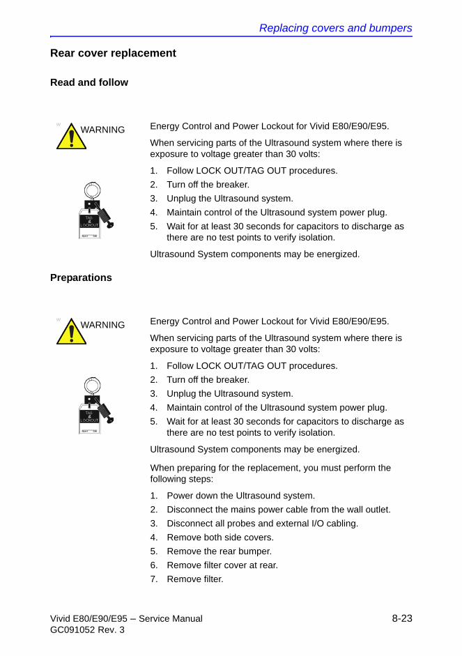
Replacing covers and bumpers
Vivid E80/E90/E95 – Service Manual 8-23GC091052 Rev. 3
Rear cover replacement
Read and follow
Preparations
When preparing for the replacement, you must perform the following steps:
1. Power down the Ultrasound system.
2. Disconnect the mains power cable from the wall outlet.
3. Disconnect all probes and external I/O cabling.
4. Remove both side covers.
5. Remove the rear bumper.
6. Remove filter cover at rear.
7. Remove filter.
WARNING Energy Control and Power Lockout for Vivid E80/E90/E95.
When servicing parts of the Ultrasound system where there is exposure to voltage greater than 30 volts:
1. Follow LOCK OUT/TAG OUT procedures.
2. Turn off the breaker.
3. Unplug the Ultrasound system.
4. Maintain control of the Ultrasound system power plug.
5. Wait for at least 30 seconds for capacitors to discharge as there are no test points to verify isolation.
Ultrasound System components may be energized.
Replacement Procedures
8-24 Vivid E80/E90/E95 – Service ManualGC091052 Rev. 3
Rear cover removal
Follow these steps to remove the rear cover:
1. Remove two screws on each side of the Rear Cover.
2. Lift the Rear Cover away.
Rear cover installation
Follow these steps to install the rear cover:
1. Position the lower edge of the rear cover into place on the rear of the Ultrasound system frame.
2. Tilt the top edge of the rear cover toward the Ultrasound system frame.
Be sure the Z mechanism’s manual release handle extends through the air vent on the rear cover.
3. Position the rear cover into place.
4. Gently pull up on the Z mechanism’s manual release handle to confirm proper position through the rear cover air vents.
5. Install the four screws, two on each side. Install the two lower screws first, then the upper screws.
6. Inspect the filter, and clean if necessary.
7. Install the filter.
8. Install the filter cover.
9. Install the rear bumper.
10. Install the side covers.
Verification
Perform the following steps to verify that the product is functioning as intended after this replacement:
1. Connect cables and probes you removed earlier
2. Power up the Ultrasound system to verify that it operates as intended.
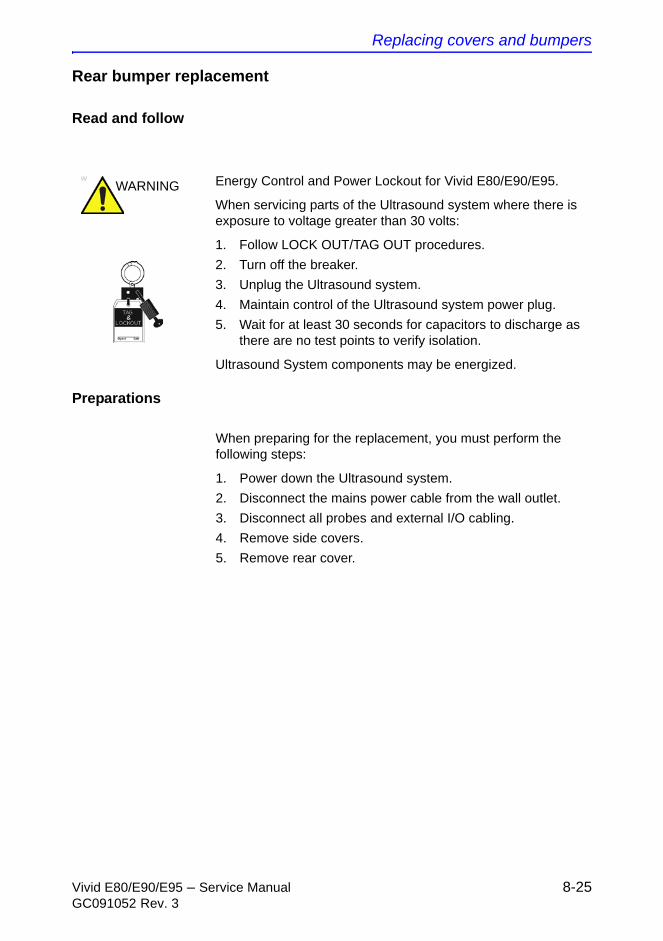
Replacing covers and bumpers
Vivid E80/E90/E95 – Service Manual 8-25GC091052 Rev. 3
Rear bumper replacement
Read and follow
Preparations
When preparing for the replacement, you must perform the following steps:
1. Power down the Ultrasound system.
2. Disconnect the mains power cable from the wall outlet.
3. Disconnect all probes and external I/O cabling.
4. Remove side covers.
5. Remove rear cover.
WARNING Energy Control and Power Lockout for Vivid E80/E90/E95.
When servicing parts of the Ultrasound system where there is exposure to voltage greater than 30 volts:
1. Follow LOCK OUT/TAG OUT procedures.
2. Turn off the breaker.
3. Unplug the Ultrasound system.
4. Maintain control of the Ultrasound system power plug.
5. Wait for at least 30 seconds for capacitors to discharge as there are no test points to verify isolation.
Ultrasound System components may be energized.
Replacement Procedures
8-26 Vivid E80/E90/E95 – Service ManualGC091052 Rev. 3
Rear bumper removal
Follow these steps to remove the rear bumper:
1. Remove one screw on each side of the Ultrasound system.
2. Remove the rear bumper.
Rear bumper installation
Follow these steps to install the rear bumper:
1. Place the rear bumper into position.
2. Install the 2 screws to secure the rear bumper.
Verification
Perform the following steps to verify that the product is functioning as intended after this replacement:
1. Connect cables and probes you removed earlier
2. Power up the Ultrasound system to verify that it operates as intended.
Replacing covers and bumpers
Vivid E80/E90/E95 – Service Manual 8-27GC091052 Rev. 3
Rear handle replacement
Read and follow
Preparations
When preparing for the replacement, you must perform the following steps:
1. Power down the Ultrasound system.
2. Disconnect the mains power cable from the wall outlet.
3. Disconnect all probes and external I/O cabling.
4. Remove the side covers.
5. Remove the rear cover.
6. Remove the top cover.
WARNING Energy Control and Power Lockout for Vivid E80/E90/E95.
When servicing parts of the Ultrasound system where there is exposure to voltage greater than 30 volts:
1. Follow LOCK OUT/TAG OUT procedures.
2. Turn off the breaker.
3. Unplug the Ultrasound system.
4. Maintain control of the Ultrasound system power plug.
5. Wait for at least 30 seconds for capacitors to discharge as there are no test points to verify isolation.
Ultrasound System components may be energized.
Replacement Procedures
8-28 Vivid E80/E90/E95 – Service ManualGC091052 Rev. 3
Rear handle removal
Follow these steps to remove the rear handle:
1. Remove the 2 upper screws, one on each side.
2. Remove the 4 lower screws, two on each side.
Rear handle installation
Follow these steps to install the rear handle:
1. Install the Rear handle in position so its fastening holes are flush with the holes in the frame.
2. Install the two screws for the rear handle (torque=3Nm).
3. Install the four hex cap screws for the rear handle.
4. Install the top cover.
5. Install the rear cover.
6. Install the side covers.
Verification
Perform the following steps to verify that the product is functioning as intended after this replacement:
1. Connect cables and probes you removed earlier
2. Power up the Ultrasound system to verify that it operates as intended.
LCD Monitor and LCD Arm parts replacement
Vivid E80/E90/E95 – Service Manual 8-29GC091052 Rev. 3
LCD Monitor and LCD Arm parts
replacement
Replacing the 19” LCD Monitor assembly
Read and follow
Preparations
When preparing for the replacement, you must perform the following steps:
1. Power down the Ultrasound system.
2. Move the Top Console to its lower position.
3. Disconnect the Mains Power Cable from the wall outlet.
4. Disconnect all probes and I/O cabling.
Related information
• ‘Power shut down’ on page 4-5
WARNING Energy Control and Power Lockout for Vivid E80/E90/E95.
When servicing parts of the Ultrasound system where there is exposure to voltage greater than 30 volts:
1. Follow LOCK OUT/TAG OUT procedures.
2. Turn off the breaker.
3. Unplug the Ultrasound system.
4. Maintain control of the Ultrasound system power plug.
5. Wait at least 30 seconds for capacitors to discharge as there are no test points to verify isolation.
Ultrasound System components may be energized.
Replacement Procedures
8-30 Vivid E80/E90/E95 – Service ManualGC091052 Rev. 3
Remove the 19” LCD Monitor’s Cables Cover
A cover at the rear side of the LCD Monitor assembly covers the two cables to the monitor. To get access to the cable connectors, remove the Cable Cover.
Follow these steps to remove the Cable Cover:
1. For easy access, tilt the LCD Monitor forward to horizontal position.
2. Unscrew the service screw on the top of the LCD Monitor assembly.
3. Remove the Monitor Cables Cover.
4. Lift the cover away and place it on a safe place.
Disconnect the 19” LCD Monitor Cables
Follow these steps to remove the cables:
1. Disconnect the three signal cables.
2. Remove the cable clips, if present.
Remove the 19” LCD Monitor assembly
Follow these steps to remove the LCD Monitor assembly
1. Loosen the four screws by turning each screw between one half and one turn counter-clockwise.
You don’t need to remove the screws.
2. Lift the LCD Monitor assembly upwards until you can lift it away from the Monitor Bracket.
3. Place the LCD Monitor on a clean and safe surface.
Install the 19” LCD Monitor assembly
Follow these steps to install the LCD monitor:
1. Install the LCD Monitor assembly on the Monitor Bracket. Verify that all four fixing screws have engaged in their slots.
2. Tighten the four screws.
3. Connect the cables.
4. Install the cable clips, if you removed any earlier.
5. Install the Monitor Service Cover and fasten it with the two fixing screws.
6. Tilt the monitor to horizontal position.
LCD Monitor and LCD Arm parts replacement
Vivid E80/E90/E95 – Service Manual 8-31GC091052 Rev. 3
Verification
Perform the following steps to verify that the product is functioning as intended after this LCD Monitor replacement:
1. Verify that all screws that you removed earlier have been installed.
2. If finished, connect the cables and probes you removed earlier.
3. Power up the Ultrasound system to verify that it operates as intended.
Replacing the LCD Arm assembly
Read and follow
Preparations
When preparing for the replacement, you must perform the following steps:
1. Power down the Ultrasound system.
2. Disconnect the Mains Power Cable from the wall outlet.
3. Disconnect all probes and external I/O cabling.
4. Remove the LCD Monitor assembly.
5. Remove the Bulkhead cover.
WARNING Energy Control and Power Lockout for Vivid E80/E90/E95.
When servicing parts of the Ultrasound system where there is exposure to voltage greater than 30 volts:
1. Follow LOCK OUT/TAG OUT procedures.
2. Turn off the breaker.
3. Unplug the Ultrasound system.
4. Maintain control of the Ultrasound system power plug.
5. Wait at least 30 seconds for capacitors to discharge as there are no test points to verify isolation.
Ultrasound System components may be energized.

Replacement Procedures
8-32 Vivid E80/E90/E95 – Service ManualGC091052 Rev. 3
Disconnect the cables from the Bulkhead board
Follow these steps to disconnect the cables from the Bulkhead board:
1. Disconnect the Power/USB PLUG from the Bulkhead board.
2. Bend the HDMI Connector Lock upwards, then disconnect the HDMI plug.
Remove the LCD Arm assembly
Follow these steps to remove the LCD Arm assembly:
1. Slide the LCD Mount Lock Handle into unlocked position.
2. Move the LCD Arm from side to side when at the same time pulling upwards, until you can lift LCD Arm assembly away.
Install the LCD Arm assembly
Follow these steps to install the LCD Arm assembly:
1. Carefully install the LCD Arm assembly into position, first feeding the LCD Arm cables down through the Top Console opening.
2. Push the LCD Mount Lock Handle into locked position.
3. Connect the LCD cables to the connectors on the Bulkhead.
4. Install the Bulkhead Cover.
5. Install the LCD monitor.
Verification
Perform the following steps to verify that the product is functioning as intended after this replacement:
1. Verify that all screws that you removed earlier have been installed.
2. If finished, connect the cables and probes you removed earlier.
3. Power up the Ultrasound system to verify that it operates as intended.
4. Move the LCD Monitor Arm from side to side and ensure that it moves as intended.
LCD Monitor and LCD Arm parts replacement
Vivid E80/E90/E95 – Service Manual 8-33GC091052 Rev. 3
LCD Z-Lock replacement
Read and follow
Preparations
When preparing for the replacement, you must perform the following steps:
1. Power down the Ultrasound system.
2. Disconnect the Mains Power Cable from the wall outlet.
3. Disconnect all probes and external I/O cabling.
4. Remove the Bulkhead Cover.
ADD RELATED INFO
LCD Z-Mount Lock removal procedure
NOTE: It is not necessary to remove the LCD Monitor or the LCD Arm.
Follow these steps to remove the LCD Mount Lock:
1. Remove the two screws securing the LCD Z-Mount Lock.
2. Remove the LCD Z-Mount Lock.
LCD Z-Mount Lock installation procedure
Follow these steps to install the LCD Z-Mount Lock:
1. Position the LCD Mount Lock.
2. Install the two screws securing the LCD Mount Lock.
3. Install the Bulkhead Cover.
WARNING Energy Control and Power Lockout for Vivid E80/E90/E95.
When servicing parts of the Ultrasound system where there is exposure to voltage greater than 30 volts:
1. Follow LOCK OUT/TAG OUT procedures.
2. Turn off the breaker.
3. Unplug the Ultrasound system.
4. Maintain control of the Ultrasound system power plug.
5. Wait at least 30 seconds for capacitors to discharge as there are no test points to verify isolation.
Ultrasound System components may be energized.
Replacement Procedures
8-34 Vivid E80/E90/E95 – Service ManualGC091052 Rev. 3
Verification
Perform the following steps to verify that the product is functioning as intended after this LCD Monitor replacement:
1. Verify that all screws that you removed earlier have been installed.
2. If finished, connect the cables and probes you removed earlier.
3. Power up the Ultrasound system to verify that it operates as intended.
4. Move the LCD Monitor Arm from side to side and ensure that it moves as intended.
Upper OP Panel/Touch Panel Assembly replacement
Vivid E80/E90/E95 – Service Manual 8-35GC091052 Rev. 3
Upper OP Panel/Touch Panel
Assembly replacement
Read and follow
Preparations
When preparing for the replacement, you must perform the following steps:
1. Power down the Ultrasound system.
2. Disconnect the Mains Power Cable from the wall outlet.
WARNING Energy Control and Power Lockout for Vivid E80/E90/E95.
When servicing parts of the Ultrasound system where there is exposure to voltage greater than 30 volts:
1. Follow LOCK OUT/TAG OUT procedures.
2. Turn off the breaker.
3. Unplug the Ultrasound system.
4. Maintain control of the Ultrasound system power plug.
5. Wait at least 30 seconds for capacitors to discharge as there are no test points to verify isolation.
Ultrasound System components may be energized.
WARNING DO NOT touch any boards with integrated circuits prior to taking the necessary ESD precautions.
Always connect yourself, via an arm-wrist strap, to the advised ESD connection point located on the rear of the Ultrasound system (near the power connector).
Follow general guidelines for handling of electrostatic sensitive equipment.

Replacement Procedures
8-36 Vivid E80/E90/E95 – Service ManualGC091052 Rev. 3
3. Disconnect all probes and external I/O cabling.
4. Remove the OP Panel Knobs, including the Volume control knob.
Remove the Upper OP Panel/Touch Panel Assembly
NOTE: For better access, swing the LCD Monitor to the side.
Follow these steps to remove the Upper OP Panel/Touch Panel assembly. Ensure that the OP Panel is in its uppermost position with the LCD out of the way:
1. At the rear of the Ultrasound system, release the XY mechanism by inserting a screwdriver into the release point and pressing until release.
2. Pull the Top Console out to its extended position to gain access to the screws in the next step.
3. Remove four screws with washers from the Operating Panel’s back cover.
4. Lift the Upper OP Panel/Touch Panel assembly slightly from the bottom, and then tilt the top toward the front of the Ultrasound system. There are tabs at the bottom of the Touch Panel Assembly. Pull straight up on these tabs.
5. Disconnect the cables at the back of the Upper OP Panel/Touch Panel Assembly.
6. Lift out the Touch Screen Assembly and place it on a clean and ESD safe surface.
Install the Upper OP Panel/Touch Panel Assembly
Follow these steps to install the Upper OP Panel/Touch Panel Assembly:
1. Place the Upper OP Panel/Touch Panel Assembly in the frame.
2. Ensure that all Ground cables are connected
3. Connect the cables you disconnected earlier to the Operating Panel, Upper.
4. Install the Upper OP Panel/Touch Panel Assembly.
5. Install the four screws to the Back Cover from behind.
CAUTION Failure to remove the OP Panel Knobs first could cause damage to the knob shafts.
Upper OP Panel/Touch Panel Assembly replacement
Vivid E80/E90/E95 – Service Manual 8-37GC091052 Rev. 3
6. Install the OP Panel knobs and the Volume knob.
Verification
Perform the following steps to verify that the product is functioning as intended after this replacement:
• Verify that all screws removed earlier have been installed.
• If finished, connect cables and probes removed earlier.
• Power up the Ultrasound system to verify that it operates as intended.
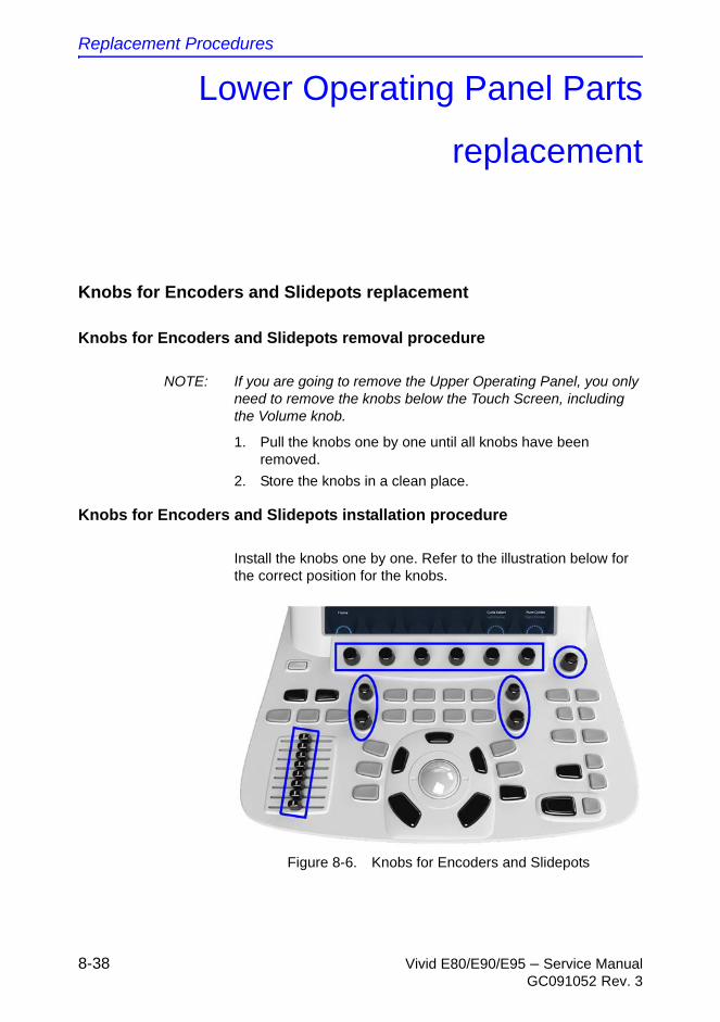
Replacement Procedures
8-38 Vivid E80/E90/E95 – Service ManualGC091052 Rev. 3
Lower Operating Panel Parts
replacement
Knobs for Encoders and Slidepots replacement
Knobs for Encoders and Slidepots removal procedure
NOTE: If you are going to remove the Upper Operating Panel, you only need to remove the knobs below the Touch Screen, including the Volume knob.
1. Pull the knobs one by one until all knobs have been removed.
2. Store the knobs in a clean place.
Knobs for Encoders and Slidepots installation procedure
Install the knobs one by one. Refer to the illustration below for the correct position for the knobs.
Figure 8-6. Knobs for Encoders and Slidepots
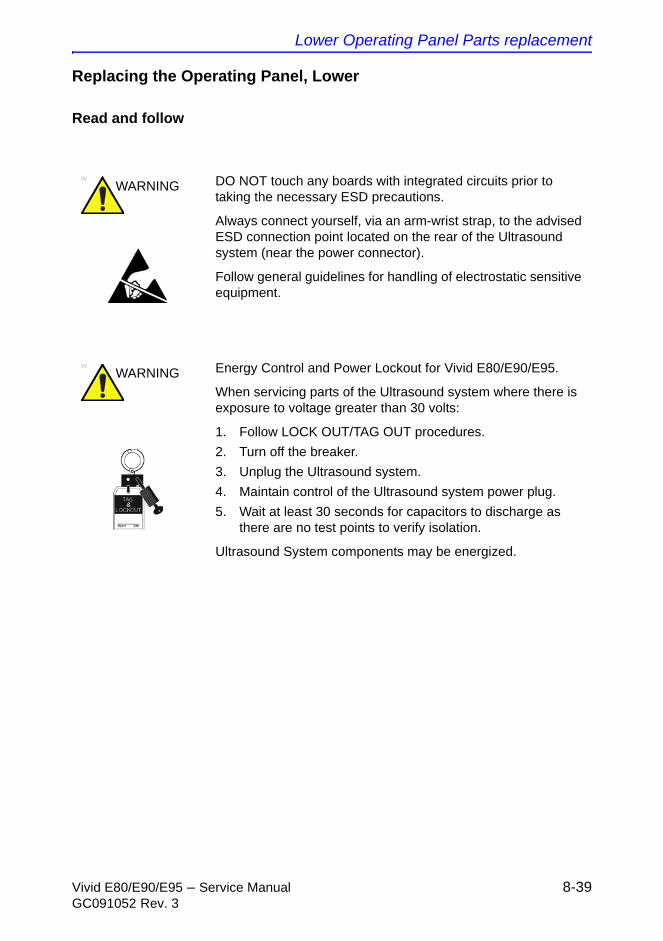
Lower Operating Panel Parts replacement
Vivid E80/E90/E95 – Service Manual 8-39GC091052 Rev. 3
Replacing the Operating Panel, Lower
Read and follow
WARNING DO NOT touch any boards with integrated circuits prior to taking the necessary ESD precautions.
Always connect yourself, via an arm-wrist strap, to the advised ESD connection point located on the rear of the Ultrasound system (near the power connector).
Follow general guidelines for handling of electrostatic sensitive equipment.
WARNING Energy Control and Power Lockout for Vivid E80/E90/E95.
When servicing parts of the Ultrasound system where there is exposure to voltage greater than 30 volts:
1. Follow LOCK OUT/TAG OUT procedures.
2. Turn off the breaker.
3. Unplug the Ultrasound system.
4. Maintain control of the Ultrasound system power plug.
5. Wait at least 30 seconds for capacitors to discharge as there are no test points to verify isolation.
Ultrasound System components may be energized.
Replacement Procedures
8-40 Vivid E80/E90/E95 – Service ManualGC091052 Rev. 3
Preparations
1. Power down the Ultrasound system.
2. Disconnect the Mains Power Cable from the wall outlet.
3. Disconnect all probes and external I/O cabling.
4. Remove the Rotary knobs below the Touch Panel and the Volume button.
5. Remove Operating Panel, Upper.
Remove the Operating Panel, Lower
Follow these steps to remove the Operating Panel:
1. Pull the Alphanumeric keyboard to its extended position to get access to the screws in the next step.
2. The screws are available from the underside of the Operating Panel tray. Unscrew and remove the four screws used for fixing the Operating Panel assembly to the Operating Panel tray.
3. Loosen the screws for the cables grounding on the Bulkhead Bracket and move the OP Cables away from the bracket.
4. On the Bulkhead Bracket, loosen the ESD wire from the Lower Panel.
5. Pull and lift the Operating Panel assembly up and away. Be careful to not destroy the fingers on each side of the Operating Panel, Lower.
6. Store it on an ESD safe place.
Install the Operating Panel, Lower
Follow these steps to install the Operating Panel, Lower:
1. Carefully, slide in the Operating Panel. Lower.
Be careful with the fingers which have to be placed under the side walls of the UI Frame, Upper.
2. On the Bulkhead Bracket, fasten the ESD wire from the Lower Panel.
3. Attach the cables to the cable grounding brackets/points, as illustrated below. Since this feature is for the EMI compatibility the braid have to be exposed under the bracket and the cables have to be well locked by the bracket.
4. Install the four fixing screws that fix the Operating Panel assembly to the Operating Panel tray (2 pc. M4x25 nearest
Lower Operating Panel Parts replacement
Vivid E80/E90/E95 – Service Manual 8-41GC091052 Rev. 3
to the front and 2 pc. M4 x 12 at the rear). The screws are entered from below the Operating Panel tray.
5. Install the Operating Panel, Upper.
Verification
Perform the following steps to verify that the product is functioning as intended after this Operating Panel replacement:
1. Verify that all screws that you removed earlier has been installed.
2. If finished, connect cables and probes you removed earlier.
3. Verify that the Alphanumeric Keyboard assembly can be moved as intended and that it locks in its inner position.
Replacement Procedures
8-42 Vivid E80/E90/E95 – Service ManualGC091052 Rev. 3
Replacing the Trackball
Read and follow
WARNING Energy Control and Power Lockout for Vivid E80/E90/E95.
When servicing parts of the Ultrasound system where there is exposure to voltage greater than 30 volts:
1. Follow LOCK OUT/TAG OUT procedures.
2. Turn off the breaker.
3. Unplug the Ultrasound system.
4. Maintain control of the Ultrasound system power plug.
5. Wait at least 30 seconds for capacitors to discharge as there are no test points to verify isolation.
Ultrasound System components may be energized.
WARNING DO NOT touch any boards with integrated circuits prior to taking the necessary ESD precautions.
Always connect yourself, via an arm-wrist strap, to the advised ESD connection point located on the rear of the Ultrasound system (near the power connector).
Follow general guidelines for handling of electrostatic sensitive equipment.
Lower Operating Panel Parts replacement
Vivid E80/E90/E95 – Service Manual 8-43GC091052 Rev. 3
Preparations
When preparing for the replacement, you must perform the following steps:
1. Power down the Ultrasound system.
2. Disconnect the Mains Power Cable from the wall outlet.
3. Disconnect all probes and external I/O cabling.
4. Remove the Rotary buttons below the Touch screen and the Volum button.
5. Remove the Operating Panel, Upper.
6. Remove the Operating Panel, Lower. Place it on a clean surface with the front down.
Remove the Trackball
Follow these steps to remove the Trackball:
1. Unplug the cable connectors from the Trackball.
2. Use the Hex key to remove the two fixing screws with washers.
3. Remove the Trackball and the Fixing Ring.
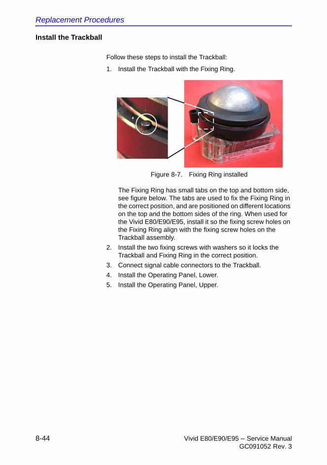
Replacement Procedures
8-44 Vivid E80/E90/E95 – Service ManualGC091052 Rev. 3
Install the Trackball
Follow these steps to install the Trackball:
1. Install the Trackball with the Fixing Ring.
Figure 8-7. Fixing Ring installed
The Fixing Ring has small tabs on the top and bottom side, see figure below. The tabs are used to fix the Fixing Ring in the correct position, and are positioned on different locations on the top and the bottom sides of the ring. When used for the Vivid E80/E90/E95, install it so the fixing screw holes on the Fixing Ring align with the fixing screw holes on the Trackball assembly.
2. Install the two fixing screws with washers so it locks the Trackball and Fixing Ring in the correct position.
3. Connect signal cable connectors to the Trackball.
4. Install the Operating Panel, Lower.
5. Install the Operating Panel, Upper.

A/N Keyboard parts replacement
Vivid E80/E90/E95 – Service Manual 8-45GC091052 Rev. 3
A/N Keyboard parts replacement
Replacing the Alpha-Numeric (A/N) Keyboard Assembly
Read and follow
Preparations
When preparing for the replacement, you must perform the following steps:
1. Power down the Ultrasound system.
2. Disconnect the Mains Power Cable from the wall outlet.
WARNING Energy Control and Power Lockout for Vivid E80/E90/E95.
When servicing parts of the Ultrasound system where there is exposure to voltage greater than 30 volts:
1. Follow LOCK OUT/TAG OUT procedures.
2. Turn off the breaker.
3. Unplug the Ultrasound system.
4. Maintain control of the Ultrasound system power plug.
5. Wait at least 30 seconds for capacitors to discharge as there are no test points to verify isolation.
Ultrasound System components may be energized.
WARNING DO NOT touch any boards with integrated circuits prior to taking the necessary ESD precautions.
Always connect yourself, via an arm-wrist strap, to the advised ESD connection point located on the rear of the Ultrasound system (near the power connector).
Follow general guidelines for handling of electrostatic sensitive equipment.
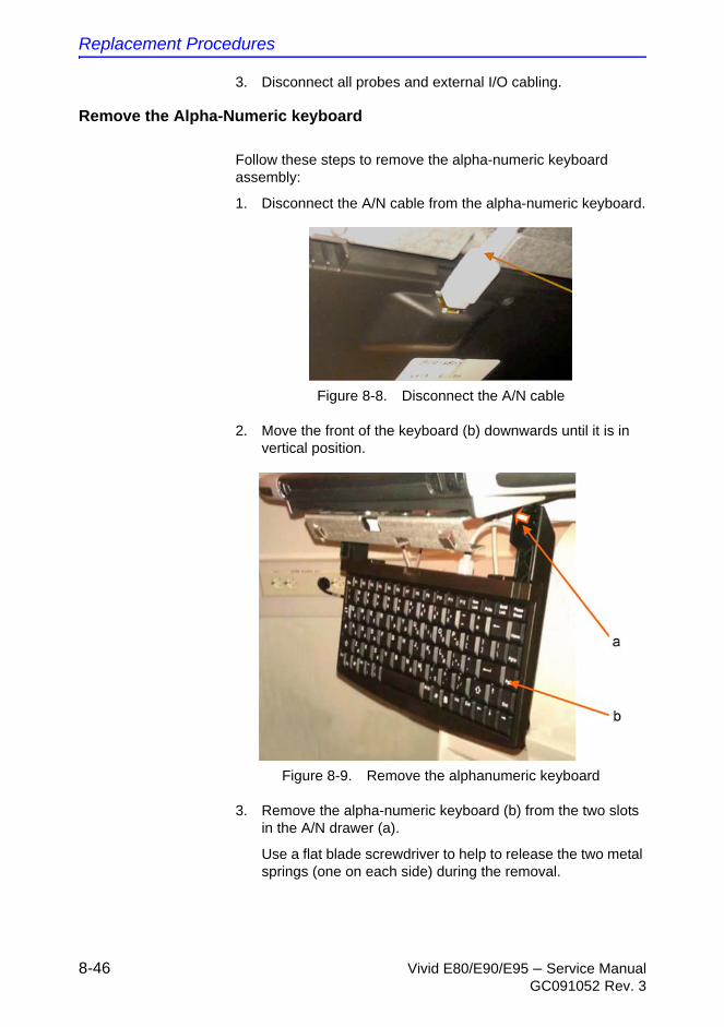
Replacement Procedures
8-46 Vivid E80/E90/E95 – Service ManualGC091052 Rev. 3
3. Disconnect all probes and external I/O cabling.
Remove the Alpha-Numeric keyboard
Follow these steps to remove the alpha-numeric keyboard assembly:
1. Disconnect the A/N cable from the alpha-numeric keyboard.
Figure 8-8. Disconnect the A/N cable
2. Move the front of the keyboard (b) downwards until it is in vertical position.
Figure 8-9. Remove the alphanumeric keyboard
3. Remove the alpha-numeric keyboard (b) from the two slots in the A/N drawer (a).
Use a flat blade screwdriver to help to release the two metal springs (one on each side) during the removal.

A/N Keyboard parts replacement
Vivid E80/E90/E95 – Service Manual 8-47GC091052 Rev. 3
Install the Alpha-Numeric keyboard
Follow these steps to install the alpha-numeric keyboard assembly:
1. Install the alpha-numeric keyboard (Figure 8-9 - b) into the two slots in the A/N drawer (Figure 8-9 - a) and slide the keyboard forwards.
2. Move the front of the keyboard upwards until it is locked in horizontal position.
3. Connect the A/N cable to the alpha-numeric keyboard (Figure 8-8).
4. Connect external cables and probes.

Replacement Procedures
8-48 Vivid E80/E90/E95 – Service ManualGC091052 Rev. 3
Wagon AN Drawer Sheet Met. Assembly replacement
Preparations
When preparing for the replacement, you must perform the following steps:
1. Power down the Ultrasound system.
2. Disconnect the Mains Power Cable from the wall outlet.
3. Disconnect all probes and external I/O cabling.
4. Remove the Rotary buttons below the Touch screen and the Volume button.
5. Remove the Operating Panel, Upper.
6. Remove the Operating Panel, Lower. Place it on a clean surface with the front down.
7. Remove the A/N Keyboard ASSY.
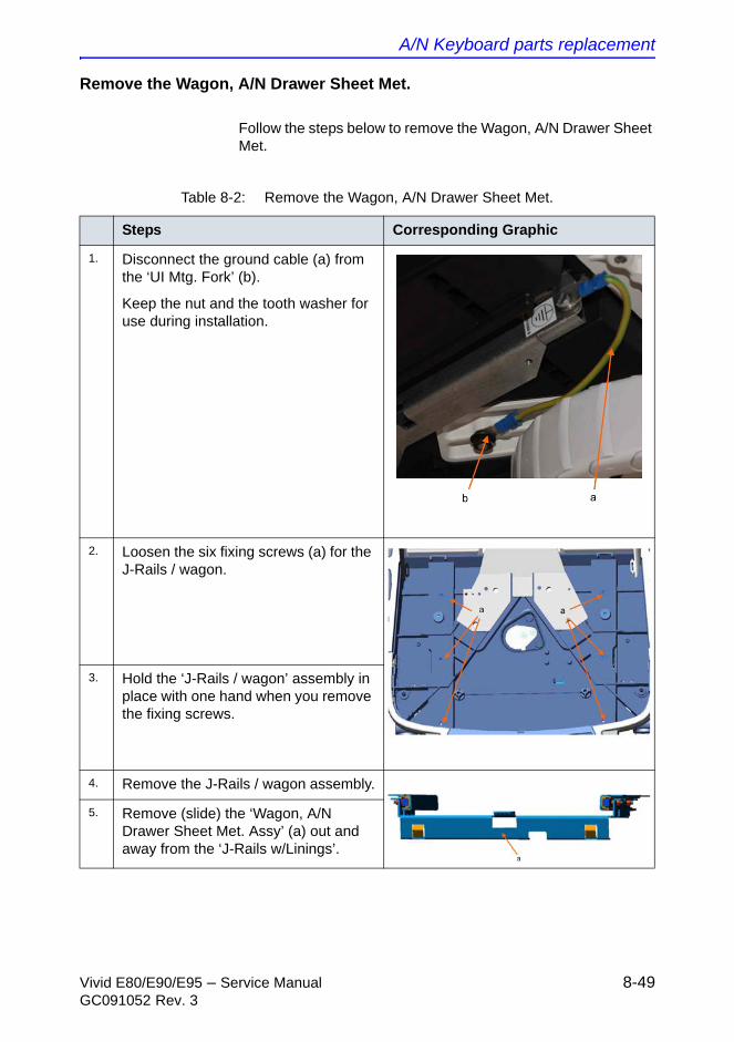
A/N Keyboard parts replacement
Vivid E80/E90/E95 – Service Manual 8-49GC091052 Rev. 3
Remove the Wagon, A/N Drawer Sheet Met.
Follow the steps below to remove the Wagon, A/N Drawer Sheet Met.
Table 8-2: Remove the Wagon, A/N Drawer Sheet Met.
Steps Corresponding Graphic
1. Disconnect the ground cable (a) from the ‘UI Mtg. Fork’ (b).
Keep the nut and the tooth washer for use during installation.
2. Loosen the six fixing screws (a) for the J-Rails / wagon.
3. Hold the ‘J-Rails / wagon’ assembly in place with one hand when you remove the fixing screws.
4. Remove the J-Rails / wagon assembly.
5. Remove (slide) the ‘Wagon, A/N Drawer Sheet Met. Assy’ (a) out and away from the ‘J-Rails w/Linings’.

Replacement Procedures
8-50 Vivid E80/E90/E95 – Service ManualGC091052 Rev. 3
Install the Wagon, A/N Drawer Sheet Met.
Follow these steps to install the Wagon, A/N Drawer Sheet Met.
1. Fasten the ground cable (Cable, GND, A/N Drawer) to the Wagon, A/N Drawer Sheet Met. Assy by use of screw M4x6 / washer tooth 4.3 (both sides of cable shoe), torque: 5,7 Nm.
2. Slide the Wagon, A/N Drawer Sheet Met. Assy into the J-Rails w/Linings.
3. Place the J-Rails / Wagon into the tracks in UI Frame, Lower.
4. Fix the J-Rails / Wagon to the UI Frame, Lower by using 6x screw M4x8 and washer, flat 4.3mm (7), torque: 2,3 Nm.
5. Connect the grounding cable, Cable, GND, A/N Drawer to the UI Mtg. Fork by use of nut M6 w/lock and washer tooth 6.4 between cable shoe and UI Mtg. Fork, torque: 5.7 Nm.
6. Install the A/N Keyboard.
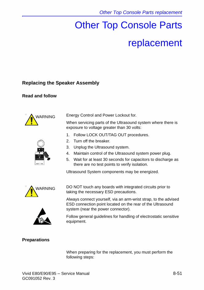
Other Top Console Parts replacement
Vivid E80/E90/E95 – Service Manual 8-51GC091052 Rev. 3
Other Top Console Parts
replacement
Replacing the Speaker Assembly
Read and follow
Preparations
When preparing for the replacement, you must perform the following steps:
WARNING Energy Control and Power Lockout for.
When servicing parts of the Ultrasound system where there is exposure to voltage greater than 30 volts:
1. Follow LOCK OUT/TAG OUT procedures.
2. Turn off the breaker.
3. Unplug the Ultrasound system.
4. Maintain control of the Ultrasound system power plug.
5. Wait for at least 30 seconds for capacitors to discharge as there are no test points to verify isolation.
Ultrasound System components may be energized.
WARNING DO NOT touch any boards with integrated circuits prior to taking the necessary ESD precautions.
Always connect yourself, via an arm-wrist strap, to the advised ESD connection point located on the rear of the Ultrasound system (near the power connector).
Follow general guidelines for handling of electrostatic sensitive equipment.

Replacement Procedures
8-52 Vivid E80/E90/E95 – Service ManualGC091052 Rev. 3
1. Power down the Ultrasound system.
2. Disconnect the Mains Power Cable from the wall outlet.
3. Disconnect all probes and external I/O cabling.
4. Remove two screws, fixing the Rear Lid (clear plastic).
5. Remove the Rear Lid.
6. Remove the Bulkhead Cover.
Remove the Speaker Assembly
Follow this procedure to remove the Speaker Assembly
1. Disconnect the Speaker Cable from the Bulkhead board.
2. Unscrew and remove the three fixing screws for the Speaker Assembly.
3. Remove the Speaker Assembly.
4. Repeat steps 1 - 3 for the other Speaker assembly, if necessary.
Install the Speaker Assembly
Follow this procedure to install the Speaker Assembly
1. Position the Speaker Assembly and install the three fixing screws.
2. Connect the Speaker Cable to the Bulkhead board.
3. Repeat steps 1 - 2 for the other Speaker Assembly, if necessary.
4. Install the Bulkhead Cover.
5. Install the Rear Lid and fasten its fixing screws.
6. Connect the external IO cabling and probes you disconnected earlier.
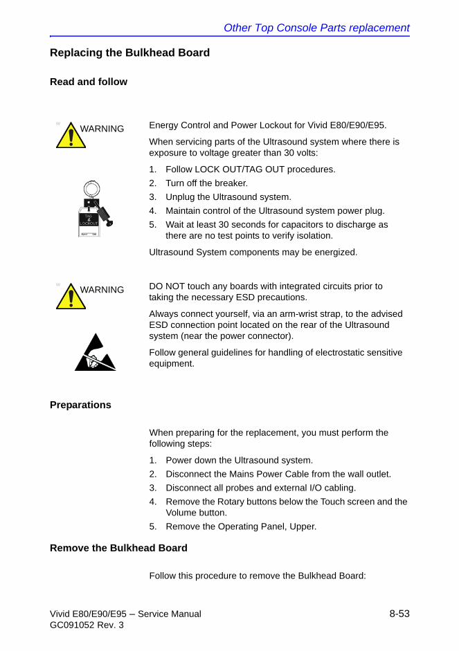
Other Top Console Parts replacement
Vivid E80/E90/E95 – Service Manual 8-53GC091052 Rev. 3
Replacing the Bulkhead Board
Read and follow
Preparations
When preparing for the replacement, you must perform the following steps:
1. Power down the Ultrasound system.
2. Disconnect the Mains Power Cable from the wall outlet.
3. Disconnect all probes and external I/O cabling.
4. Remove the Rotary buttons below the Touch screen and the Volume button.
5. Remove the Operating Panel, Upper.
Remove the Bulkhead Board
Follow this procedure to remove the Bulkhead Board:
WARNING Energy Control and Power Lockout for Vivid E80/E90/E95.
When servicing parts of the Ultrasound system where there is exposure to voltage greater than 30 volts:
1. Follow LOCK OUT/TAG OUT procedures.
2. Turn off the breaker.
3. Unplug the Ultrasound system.
4. Maintain control of the Ultrasound system power plug.
5. Wait at least 30 seconds for capacitors to discharge as there are no test points to verify isolation.
Ultrasound System components may be energized.
WARNING DO NOT touch any boards with integrated circuits prior to taking the necessary ESD precautions.
Always connect yourself, via an arm-wrist strap, to the advised ESD connection point located on the rear of the Ultrasound system (near the power connector).
Follow general guidelines for handling of electrostatic sensitive equipment.
Replacement Procedures
8-54 Vivid E80/E90/E95 – Service ManualGC091052 Rev. 3
1. Disconnect the cables from the Bulkhead Board:
• cable from Main Cable
• cables to left and right speaker
• two short USB cables (Bulkhead Board to OP)
2. Unscrew and remove two screws.
3. Remove the Bulkhead Board.
Install the Bulkhead Board
Follow this procedure to install the Bulkhead Board:
1. Slide the Bulkhead Board into the correct position.
2. Install the two screws (M3 x 6, Torque: 1.2 Nm).
3. Install the cables from the Bulkhead Board:
• two short USB cables (Bulkhead Board to OP)
• cables to left and right speaker
• cable from Main Cable
4. Install the Upper OP panel and the rotary knobs.
5. Connect probe(s) and external cables (network and mains power).
Bulkhead, Plate, Extended replacement
Read and follow
WARNING Energy Control and Power Lockout for .
When servicing parts of the Ultrasound system where there is exposure to voltage greater than 30 volts:
1. Follow LOCK OUT/TAG OUT procedures.
2. Turn off the breaker.
3. Unplug the Ultrasound system.
4. Maintain control of the Ultrasound system power plug.
5. Wait for at least 30 seconds for capacitors to discharge as there are no test points to verify isolation.
Ultrasound System components may be energized.
Other Top Console Parts replacement
Vivid E80/E90/E95 – Service Manual 8-55GC091052 Rev. 3
Preparations
When preparing for the replacement, you must perform the following steps:
1. Power down the Ultrasound system.
2. Disconnect the Mains Power Cable from the wall outlet.
3. Disconnect all probes and external I/O cabling.
4. Remove the Rotary buttons below the Touch screen and the Volume button.
5. Remove the Operating Panel, Upper.
6. Remove the Bulkhead board.
7. Remove the Operating Panel, Lower. Place it on a clean surface with the front down.
Remove the Bulkhead, Plate, Extended
The Bulkhead Plate is used to secure the Upper UI Frame to the Lower UI Frame.
Follow this procedure to remove the
1. Remove the seven fixing screws.
2. Remove the Bulkhead Plate including the Cable Clamp.
Install the Bulkhead, Plate, Extended
Follow this procedure to install the
1. Position the Bulkhead Plate so it aligns with the holes for the fixing screws.
2. Install the seven fixing screws as described below:
• The two upper screws are M6 x 20, Torque: 8.5 Nm.
• The next screw is M6 x 45, Torque: 8.5 Nm.
WARNING DO NOT touch any boards with integrated circuits prior to taking the necessary ESD precautions.
Always connect yourself, via an arm-wrist strap, to the advised ESD connection point located on the rear of the Ultrasound system (near the power connector).
Follow general guidelines for handling of electrostatic sensitive equipment.
Replacement Procedures
8-56 Vivid E80/E90/E95 – Service ManualGC091052 Rev. 3
• The lower left-most screw is M6 x 30, Torque: 8.5 Nm.
• The three other lower screws are M6 x 25, Torque: 8.5 Nm. Two of the screws are also fixing the Cable Clamp
3. Install the Operating Panel, Lower.
4. Install the Bulkhead Board.
5. Install the Operating Panel, Upper.
6. Install the Operating Panel Knobs.
Handle, Left Top / Handle Right Top, replacement
Read and follow
Preparations
When preparing for the replacement, you must perform the following steps:
1. Power down the Ultrasound system.
WARNING Energy Control and Power Lockout for Vivid E80/E90/E95.
When servicing parts of the Ultrasound system where there is exposure to voltage greater than 30 volts:
1. Follow LOCK OUT/TAG OUT procedures.
2. Turn off the breaker.
3. Unplug the Ultrasound system.
4. Maintain control of the Ultrasound system power plug.
5. Wait at least 30 seconds for capacitors to discharge as there are no test points to verify isolation.
Ultrasound System components may be energized.
WARNING DO NOT touch any boards with integrated circuits prior to taking the necessary ESD precautions.
Always connect yourself, via an arm-wrist strap, to the advised ESD connection point located on the rear of the Ultrasound system (near the power connector).
Follow general guidelines for handling of electrostatic sensitive equipment.
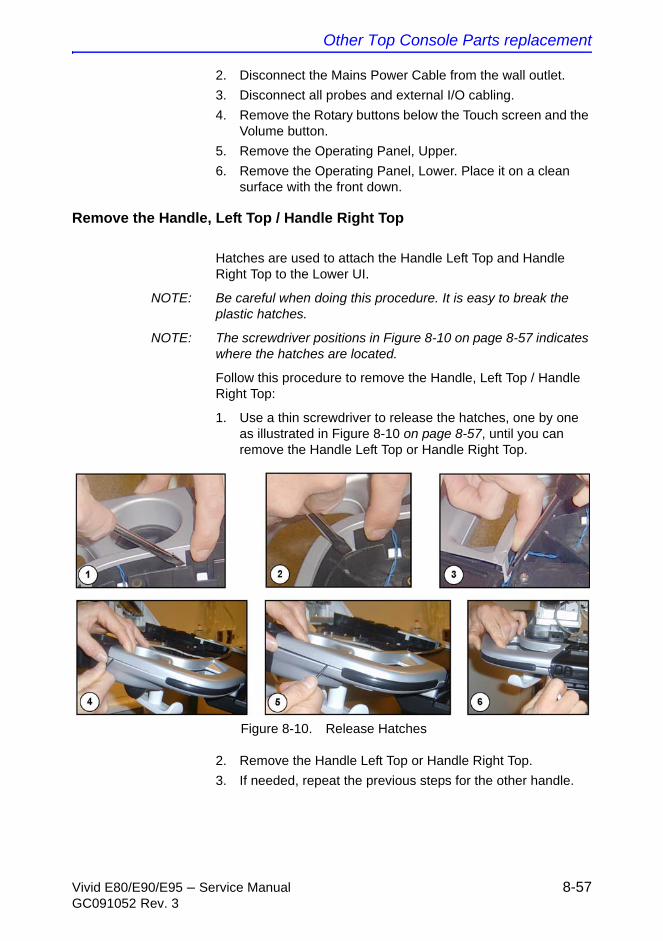
Other Top Console Parts replacement
Vivid E80/E90/E95 – Service Manual 8-57GC091052 Rev. 3
2. Disconnect the Mains Power Cable from the wall outlet.
3. Disconnect all probes and external I/O cabling.
4. Remove the Rotary buttons below the Touch screen and the Volume button.
5. Remove the Operating Panel, Upper.
6. Remove the Operating Panel, Lower. Place it on a clean surface with the front down.
Remove the Handle, Left Top / Handle Right Top
Hatches are used to attach the Handle Left Top and Handle Right Top to the Lower UI.
NOTE: Be careful when doing this procedure. It is easy to break the plastic hatches.
NOTE: The screwdriver positions in Figure 8-10 on page 8-57 indicates where the hatches are located.
Follow this procedure to remove the Handle, Left Top / Handle Right Top:
1. Use a thin screwdriver to release the hatches, one by one as illustrated in Figure 8-10 on page 8-57, until you can remove the Handle Left Top or Handle Right Top.
Figure 8-10. Release Hatches
2. Remove the Handle Left Top or Handle Right Top.
3. If needed, repeat the previous steps for the other handle.
Replacement Procedures
8-58 Vivid E80/E90/E95 – Service ManualGC091052 Rev. 3
Install the Handle, Left Top / Handle Right Top
Follow this procedure to install the Handle, Left Top / Handle Right Top:
1. Remove the Gel Cups (if present).
2. Install the Handle, Left Top / Handle, Right Top by pressing them into the UI Frame, Lower.
3. Install the Gel Cups you removed in step 1.
4. Install the Operating Panel, Lower.
5. Install the Operating Panel Upper.
Palm Rest ASSY replacement
Read and follow
Preparations
When preparing for the replacement, you must perform the following steps:
1. Power down the Ultrasound system.
2. Disconnect the Mains Power Cable from the wall outlet.
3. Disconnect all probes and external I/O cabling.
4. Remove the Rotary buttons below the Touch screen and the Volume button.
5. Remove the Operating Panel, Upper.
6. Remove the Operating Panel, Lower. Place it on a clean surface with the front down.
WARNING Energy Control and Power Lockout for Vivid E80/E90/E95.
When servicing parts of the Ultrasound system where there is exposure to voltage greater than 30 volts:
1. Follow LOCK OUT/TAG OUT procedures.
2. Turn off the breaker.
3. Unplug the Ultrasound system.
4. Maintain control of the Ultrasound system power plug.
5. Wait for at least 30 seconds for capacitors to discharge as there are no test points to verify isolation.
Ultrasound System components may be energized.
Other Top Console Parts replacement
Vivid E80/E90/E95 – Service Manual 8-59GC091052 Rev. 3
7. Remove Handle Left Top and Handle Right Top.
Remove the Palm Rest ASSY
Follow this procedure to remove the Palm Rest ASSY:
1. Release the lock mechanisms securing the Palm Rest ASSY.
2. Remove the Palm Rest ASSY.
Install the Palm Rest ASSY
Follow this procedure to install the Palm Rest ASSY:
1. Ensure the XYZ Buttons cable runs along the lower tray cable channel so that the cable is not pinched when the Palm Rest is replaced.
2. Replace the Palm Rest ASSY.
3. Install Handle Left Top and Handle Right Top.
4. Install the lock mechanisms securing the Palm Rest Cover.
5. Replace the Lower Operating Panel.
6. Replace the Upper Operating Panel.
Up-Down Button Board (Buttons Frame UI Assy) replacement
Read and follow
WARNING Energy Control and Power Lockout for Vivid E80/E90/E95.
When servicing parts of the Ultrasound system where there is exposure to voltage greater than 30 volts:
1. Follow LOCK OUT/TAG OUT procedures.
2. Turn off the breaker.
3. Unplug the Ultrasound system.
4. Maintain control of the Ultrasound system power plug.
5. Wait for at least 30 seconds for capacitors to discharge as there are no test points to verify isolation.
Ultrasound System components may be energized.
Replacement Procedures
8-60 Vivid E80/E90/E95 – Service ManualGC091052 Rev. 3
Preparations
When preparing for the replacement, you must perform the following steps:
1. Power down the Ultrasound system.
2. Disconnect the Mains Power Cable from the wall outlet.
3. Disconnect all probes and external I/O cabling.
4. Remove the Rotary buttons below the Touch screen and the Volume button.
5. Remove the Operating Panel, Upper.
6. Remove the Operating Panel, Lower. Place it on a clean surface with the front down.
7. Remove the Handle Top Left and Handle Top Right.
8. Remove the Palm Rest Cover.
Remove the Buttons Frame UI Assy
Follow this procedure to remove the Buttons Frame UI Assy:
1. Disconnect the cable to the Buttons Frame UI Assy.
2. Gently pop the XYZ Buttons Frame out of the Palm Rest section of the Lower OP Panel frame handle.
Install the Buttons Frame UI Assy
Follow this procedure to install the Buttons Frame UI Assy:
1. Insert the XYZ Buttons Frame into the Palm Rest section of the Lower Op Panel frame handle.
2. Connect the cable to the XYZ Buttons Frame.
3. Ensure the XYZ Buttons Frame cable runs along the Lower Op Panel cable channel so that the cable is not pinched when the Palm Rest is replaced
WARNING DO NOT touch any boards with integrated circuits prior to taking the necessary ESD precautions.
Always connect yourself, via an arm-wrist strap, to the advised ESD connection point located on the rear of the Ultrasound system (near the power connector).
Follow general guidelines for handling of electrostatic sensitive equipment.
Other Top Console Parts replacement
Vivid E80/E90/E95 – Service Manual 8-61GC091052 Rev. 3
4. Replace the Palm Rest.
5. Replace the Handle Top Left and Handle Top Right.
6. Replace the Lower Operating Panel.
7. Replace the Upper OP Panel/Touch Panel assembly.
Button IF Board Assy replacement
Read and follow
Preparations
When preparing for the replacement, you must perform the following steps:
1. Power down the Ultrasound system.
2. Disconnect the Mains Power Cable from the wall outlet.
3. Disconnect all probes and external I/O cabling.
WARNING Energy Control and Power Lockout for Vivid E80/E90/E95.
When servicing parts of the Ultrasound system where there is exposure to voltage greater than 30 volts:
1. Follow LOCK OUT/TAG OUT procedures.
2. Turn off the breaker.
3. Unplug the Ultrasound system.
4. Maintain control of the Ultrasound system power plug.
5. Wait for at least 30 seconds for capacitors to discharge as there are no test points to verify isolation.
Ultrasound System components may be energized.
WARNING DO NOT touch any boards with integrated circuits prior to taking the necessary ESD precautions.
Always connect yourself, via an arm-wrist strap, to the advised ESD connection point located on the rear of the Ultrasound system (near the power connector).
Follow general guidelines for handling of electrostatic sensitive equipment.
Replacement Procedures
8-62 Vivid E80/E90/E95 – Service ManualGC091052 Rev. 3
4. Remove the Rotary buttons below the Touch screen and the Volume button.
5. Remove the Operating Panel, Upper.
6. Remove the Operating Panel, Lower. Place it on a clean surface with the front down.
7. Remove Handle Left Top and Handle Right Top.
8. Remove the Palm Rest Cover.
Remove the Button IF Board Assy
Follow this procedure to remove the Button IF Board Assy
1. Disconnect all the five (5x) connectors from the board.
2. Push the TABs away to release the board.
3. Remove the board.
Install the Button IF Board Assy
Follow this procedure to install the Button IF Board Assy
1. Install the Button IF Board into the UI Frame, Lower by pressing it under the small hooks.
2. Ensure the XYZ Buttons Frame cable runs along the Lower Op Panel cable channel so that the cable is not pinched when the Palm Rest is replaced.
3. Install the Handle Left Top and Handle Right Top.
4. Replace the Palm Rest.
5. Replace the Lower Operating Panel.
6. Replace the Upper OP Panel/Touch Panel assembly.

Replacing XYZ Parts
Vivid E80/E90/E95 – Service Manual 8-63GC091052 Rev. 3
Replacing XYZ Parts
XY Mechanism replacement
Read and follow
Preparations
When preparing for the replacement, you must perform the following steps:
1. Power down the Ultrasound system.
2. Disconnect the Mains Power Cable from the wall outlet.
WARNING Energy Control and Power Lockout for Vivid E80/E90/E95.
When servicing parts of the Ultrasound system where there is exposure to voltage greater than 30 volts:
1. Follow LOCK OUT/TAG OUT procedures.
2. Turn off the breaker.
3. Unplug the Ultrasound system.
4. Maintain control of the Ultrasound system power plug.
5. Wait at least 30 seconds for capacitors to discharge as there are no test points to verify isolation.
Ultrasound System components may be energized.
WARNING DO NOT touch any boards with integrated circuits prior to taking the necessary ESD precautions.
Always connect yourself, via an arm-wrist strap, to the advised ESD connection point located on the rear of the Ultrasound system (near the power connector).
Follow general guidelines for handling of electrostatic sensitive equipment.

Replacement Procedures
8-64 Vivid E80/E90/E95 – Service ManualGC091052 Rev. 3
3. Disconnect all probes and external I/O cabling.
4. Remove the LCD Rear Cover.
5. Remove the LCD Monitor assembly.
6. Remove the LCD Arm assembly.
7. Remove the Rotary buttons below the Touch screen and the Volume button.
8. Remove the Operating Panel, Upper.
9. Remove the Operating Panel, Lower. Place it on a clean surface with the front down.
10. Remove the Bulkhead Board.
11. Remove the Bulkhead Plate.
12. Remove the Upper Frame Assembly.
13. Remove the Lower Frame Assembly.
Remove the XY Mechanism
Follow this procedure to remove the XY Mechanism:
1. From the rear side of the Ultrasound system, remove the four (4x) fixing screws.
2. Remove the XY mechanism.
Install the XY Mechanism
Follow this procedure to install the XY Mechanism:
1. Position the XY mechanism so it aligns with the holes for the four fixing screws.
2. Install the four fixing screws.
3. Install the Lower Frame Assembly.
NOTE: Ensure that Bumper Z enters the slide at the back, before tighten the screws.
4. Install the Upper Frame Assembly.
5. Install the Bulkhead Plate.
6. Install the Bulkhead Board.
7. Install the Operating Panel, Lower.
8. Install the Operating Panel, Upper.
9. Install the LCD Arm assembly.
10. Install the LCD Monitor assembly.
11. Install the LCD Rear Cover.
Replacing XYZ Parts
Vivid E80/E90/E95 – Service Manual 8-65GC091052 Rev. 3
Z-Mechanism replacement
Read and follow
NOTE: The Gas Spring is not replaceable. Replace the complete Z-Mechanism if the Gas Spring seems to fail.
Preparations
When preparing for the replacement, you must perform the following steps:
1. Power down the Ultrasound system.
2. Disconnect the Mains Power Cable from the wall outlet.
3. Disconnect all probes and external I/O cabling.
4. Remove the LCD Rear Cover.
5. Remove the LCD Monitor assembly.
6. Remove the LCD Arm assembly.
WARNING Energy Control and Power Lockout for Vivid E80/E90/E95.
When servicing parts of the Ultrasound system where there is exposure to voltage greater than 30 volts:
1. Follow LOCK OUT/TAG OUT procedures.
2. Turn off the breaker.
3. Unplug the Ultrasound system.
4. Maintain control of the Ultrasound system power plug.
5. Wait for at least 30 seconds for capacitors to discharge as there are no test points to verify isolation.
Ultrasound System components may be energized.
WARNING DO NOT touch any boards with integrated circuits prior to taking the necessary ESD precautions.
Always connect yourself, via an arm-wrist strap, to the advised ESD connection point located on the rear of the Ultrasound system (near the power connector).
Follow general guidelines for handling of electrostatic sensitive equipment.

Replacement Procedures
8-66 Vivid E80/E90/E95 – Service ManualGC091052 Rev. 3
7. Remove the Rotary buttons below the Touch screen and the Volume button.
8. Remove the Operating Panel, Upper.
9. Remove the Operating Panel, Lower. Place it on a clean surface with the front down.
10. Remove the Operating Panel, Upper.
11. Remove the Operating Panel, Lower.
12. Remove the Bulkhead Board.
13. Remove the Bulkhead Plate.
14. Remove the Upper Frame Assembly.
15. Remove the Lower Frame Assembly.
16. Remove the XY (Frogleg) Assembly.
17. Remove the XYZ Control Box.
Remove the Z-Mechanism
The Z-Mechanism is fastened with several screws.
Follow this procedure to remove the Z-Mechanism:
1. Remove four (4x) screws from the lower part of the Z-Mechanism.
2. Remove four (4x) screws.
3. Lift the Z-Mechanism away.
Install the Z-Mechanism:
Follow this procedure to install the Z-Mechanism:
1. Position the Z-Mechanism so the holes for the fixing screws align.
2. Install two (2x) M6x16 Countersunk and two (2x) M6x16 screws.
3. Install four (4x) M6x16 (lower part of unit).
4. Install the XY (Frogleg) Mechanism.
5. Install the Lower Frame Assembly.
6. Install the Upper Frame Assembly.
7. Install the Bulkhead Plate.
8. Install the Bulkhead Board.
9. Install the Operating Panel, Lower.
10. Install the Operating Panel, Upper.
11. Install the LCD Arm assembly.
12. Install the LCD Monitor assembly.

Replacing XYZ Parts
Vivid E80/E90/E95 – Service Manual 8-67GC091052 Rev. 3
13. Install the LCD Rear Cover.
XYZ Control Assembly replacement
Read and follow
Preparations
When preparing for the replacement, you must perform the following steps:
1. Power down the Ultrasound system.
2. Disconnect the Mains Power Cable from the wall outlet.
3. Disconnect all probes and external I/O cabling.
4. Remove the Left Side Cover.
5. Remove the Rear Cover.
6. Remove the Top Cover.
WARNING Energy Control and Power Lockout for Vivid E80/E90/E95.
When servicing parts of the Ultrasound system where there is exposure to voltage greater than 30 volts:
1. Follow LOCK OUT/TAG OUT procedures.
2. Turn off the breaker.
3. Unplug the Ultrasound system.
4. Maintain control of the Ultrasound system power plug.
5. Wait at least 30 seconds for capacitors to discharge as there are no test points to verify isolation.
Ultrasound System components may be energized.
WARNING DO NOT touch any boards with integrated circuits prior to taking the necessary ESD precautions.
Always connect yourself, via an arm-wrist strap, to the advised ESD connection point located on the rear of the Ultrasound system (near the power connector).
Follow general guidelines for handling of electrostatic sensitive equipment.

Replacement Procedures
8-68 Vivid E80/E90/E95 – Service ManualGC091052 Rev. 3
Remove the XYZ Control Assembly
Follow this procedure to remove the XYZ Control Assembly:
1. Disconnect the cables to the XYZ Control Assembly.
2. Unscrew and remove two (2x) screws.
3. Pull the top of the XYZ Control Assembly forwards, up and away from the bracket.
Install the XYZ Control Assembly
Follow this procedure to install the XYZ Control Assembly
1. Thread the XYZ Control Assembly into position.
2. Install the three screws at the top, rear. (M6x16 sunken. Torque: 9.8 Nm.)
3. Install the two remaining screws on the top. (M4x8, sunken. Torque: 4.9 Nm.)
4. Connect the cables to the XYZ Control Assembly.
5. Install the Top Cover.
6. Install the Rear Cover.
7. Install the Left Side Cover.

Main Console parts replacement
Vivid E80/E90/E95 – Service Manual 8-69GC091052 Rev. 3
Main Console parts replacement
Fan Assembly replacement
Read and follow
Preparations
When preparing for the replacement, you must perform the following steps:
1. Power down the Ultrasound system.
2. Disconnect the Mains Power Cable from the wall outlet.
3. Disconnect all probes and external I/O cabling.
4. Remove the Right Side Cover.
Remove the Fan Assembly
Follow this procedure to remove the Fan Assembly:
1. Unscrew the screws of the Card Rack Cover.
2. Remove the Card Rack Cover.
3. Pull the Fan Assembly out of the frame.
WARNING Energy Control and Power Lockout for .
When servicing parts of the Ultrasound system where there is exposure to voltage greater than 30 volts:
1. Follow LOCK OUT/TAG OUT procedures.
2. Turn off the breaker.
3. Unplug the Ultrasound system.
4. Maintain control of the Ultrasound system power plug.
5. Wait for at least 30 seconds for capacitors to discharge as there are no test points to verify isolation.
Ultrasound System components may be energized.

Replacement Procedures
8-70 Vivid E80/E90/E95 – Service ManualGC091052 Rev. 3
Install the Fan Assembly
Follow this procedure to install the Fan Assembly:
1. Align the Fan Assembly with the rails in the frame and push it into position.
2. Install the Card Rack Cover.
3. Install the screws of the Card Rack Cover.
4. Install the Right Side Cover.
Main Cable replacement
Read and follow
Preparations
When preparing for the replacement, you must perform the following steps:
WARNING Energy Control and Power Lockout for Vivid E80/E90/E95.
When servicing parts of the Ultrasound system where there is exposure to voltage greater than 30 volts:
1. Follow LOCK OUT/TAG OUT procedures.
2. Turn off the breaker.
3. Unplug the Ultrasound system.
4. Maintain control of the Ultrasound system power plug.
5. Wait at least 30 seconds for capacitors to discharge as there are no test points to verify isolation.
Ultrasound System components may be energized.
WARNING DO NOT touch any boards with integrated circuits prior to taking the necessary ESD precautions.
Always connect yourself, via an arm-wrist strap, to the advised ESD connection point located on the rear of the Ultrasound system (near the power connector).
Follow general guidelines for handling of electrostatic sensitive equipment.
Main Console parts replacement
Vivid E80/E90/E95 – Service Manual 8-71GC091052 Rev. 3
1. Power down the Ultrasound system.
2. Disconnect the Mains Power Cable from the wall outlet.
3. Disconnect all probes and external I/O cabling.
4. Remove the Rotary buttons below the Touch screen and the Volume button.
5. Remove the Operating Panel, Upper.
6. Remove the Operating Panel, Lower. Place it on a clean surface with the front down.
7. Remove the Left Side Cover.
8. Remove the Top Cover.
9. Remove the Main Cable Cover.
Remove the Main Cable
Three cable connectors must be disconnected in the Operating Panel area:
1. The cable with the D-SUB connector was disconnected from the Controller Board when you removed the Operating Panel, Upper.
2. Disconnect the HDMI cable from the Bulkhead.
3. Disconnect the cable from the Z switch (Up/Down control).
4. If not already done, unscrew the fixing screws on the Ground (GND) Clamp on the Bulkhead Bracket, so you can release the cables from the clamp.
Two cables are connected to the XY (Frog) brakes. They are routed to connectors inside the rear XY (Frog) legs. To disconnect these cables, follow this procedure:
1. Remove the covers on the rear XY (Frog) legs.
2. Disconnect the cables.
Two (2x) cables (from the Main Cable) are connected to the XYZ Control box.
• Disconnect the two cables.
The remaining two cables originate on the I/O at the BEP.
• Disconnect the two cables.
The Cable Chain is attached with two screws in the UI end and one screw in the other end.
1. Remove two screws from the Cable Chain’s anchor point at the lower UI.
2. Remove one screw on the other end of the Cable Chain.

Replacement Procedures
8-72 Vivid E80/E90/E95 – Service ManualGC091052 Rev. 3
3. Remove the Main Cable, including the Cable Chain away from the Ultrasound system.
Install the Main Cable
Follow this procedure to install the Main Cable:
1. Route the Main Cable, including the Cable Chain into its position.
2. Install the two (2x) screws used to attach the Cable Chain to the UI.
3. Install the screw at the other end of the Cable Chain.
4. Connect the D-SUB to J21 on the BEP I/O.
5. Connect the DVI to J22 on the BEP I/O.
6. Connect two (2x) cables to the XYZ Control box.
7. Route and connect the two XY cables.
8. Connect the HDMI connector to the Bulkhead.
9. Install the Cable Clamps.
10. Connect the cable to the Z-switch.
11. Power up the Ultrasound system.
12. Verify that the XYZ functions operate as they should.
13. Power down the Ultrasound system.
14. Install all covers.

Casters and Brakes replacement
Vivid E80/E90/E95 – Service Manual 8-73GC091052 Rev. 3
Casters and Brakes replacement
Rear Casters replacement
Preparations
When preparing for the replacement, you must perform the following steps:
1. Power down the Ultrasound system.
2. Disconnect the mains power cable from the wall outlet.
3. Disconnect all probes and external I/O cabling.
4. Remove both side covers.
5. Remove the rear bumper.
6. Remove the rear cover.
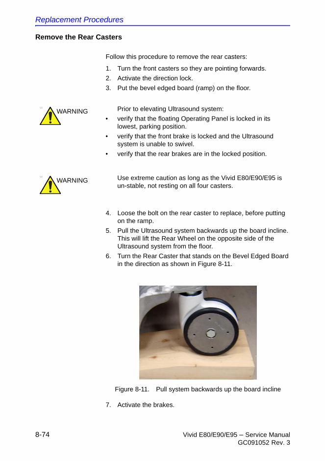
Replacement Procedures
8-74 Vivid E80/E90/E95 – Service ManualGC091052 Rev. 3
Remove the Rear Casters
Follow this procedure to remove the rear casters:
1. Turn the front casters so they are pointing forwards.
2. Activate the direction lock.
3. Put the bevel edged board (ramp) on the floor.
4. Loose the bolt on the rear caster to replace, before putting on the ramp.
5. Pull the Ultrasound system backwards up the board incline. This will lift the Rear Wheel on the opposite side of the Ultrasound system from the floor.
6. Turn the Rear Caster that stands on the Bevel Edged Board in the direction as shown in Figure 8-11.
Figure 8-11. Pull system backwards up the board incline
7. Activate the brakes.
WARNING Prior to elevating Ultrasound system:
• verify that the floating Operating Panel is locked in its lowest, parking position.
• verify that the front brake is locked and the Ultrasound system is unable to swivel.
• verify that the rear brakes are in the locked position.
WARNING Use extreme caution as long as the Vivid E80/E90/E95 is un-stable, not resting on all four casters.

Casters and Brakes replacement
Vivid E80/E90/E95 – Service Manual 8-75GC091052 Rev. 3
8. The Ultrasound system is now nearly balanced between one front caster and one rear caster.
9. Make the Ultrasound system rest on both Front Casters and lift the Rear Caster.
Put the wooden wedge under the chassis. This will stabilize the Ultrasound system with one rear caster free from the floor. This rear caster can now be removed.
10. Unscrew and remove the fixing bolt. Save the bolt for later use.
11. Remove the rear caster.
Install the Rear Casters
Follow this procedure to install the rear casters:
1. Align the caster, mounting it flat and toward the back.
2. Position the caster so it align with the hole for the fixing bolt.
3. Install the fixing bolt (M12x40 mm). Use a 10 mm HEX key, Torque: 130 Nm.
4. Remove the wooden wedge.
5. Roll the Ultrasound system off the bevel edged board (ramp).
6. To replace the other rear caster, repeat all the steps, starting from ‘Remove the Rear Casters’ on page 8-74, but now using the Bevel edged board and the wooden wedge on the other side of the Ultrasound system.
7. Install the rear cover.
8. Install the rear bumper.
9. Install the side covers.
Replacement Procedures
8-76 Vivid E80/E90/E95 – Service ManualGC091052 Rev. 3
Front Casters replacement
Preparations
When preparing for the replacement, you must perform the following steps:
1. Power down the Ultrasound system.
2. Disconnect the mains power cable from the wall outlet.
3. Disconnect all probes and external I/O cabling.
4. Remove both side covers.
5. Remove the foot rest bumper

Casters and Brakes replacement
Vivid E80/E90/E95 – Service Manual 8-77GC091052 Rev. 3
Remove the Front Casters
Follow this procedure to remove the Front Casters:
1. Turn front casters so they are pointing forwards.
2. Activate the direction lock.
3. Put the bevel edged board on the floor.
4. Pull the Ultrasound system backwards up the board incline. This will lift the rear caster on the opposite side of the Ultrasound system from the floor.
5. Turn the rear caster that stands on the bevel edged board in the direction as shown in Figure 8-11 on page 8-74.
6. The Ultrasound system is now nearly balanced between one front caster and one rear caster.
7. Make the Ultrasound system rest on both rear casters and lift the front caster.
8. Put the wooden wedge under the chassis. This will stabilize the Ultrasound system with one front caster free from the floor.
9. Unscrew and remove the three fixing screws for the front caster that is free from the floor. Save the screw for later use.
10. Remove the front caster.
WARNING Prior to elevating Ultrasound system:
• verify that the floating Operating Panel is locked in its lowest, parking position.
• verify that the front brake is locked and the Ultrasound system is unable to swivel.
• verify that the rear brakes are in the locked position.
WARNING Use extreme caution as long as the Vivid E80/E90/E95 is un-stable, not resting on all four casters.

Replacement Procedures
8-78 Vivid E80/E90/E95 – Service ManualGC091052 Rev. 3
Install the Front Casters
Follow this procedure to install the front casters:
1. Position the front caster so it align with the fastening screws.
2. Install the three fixing screws (M8x20 mm), Torque: 20.5 Nm (15.1 lb.-ft.).
3. Remove the wooden wedge.
4. Roll the Ultrasound system off the bevel edged board.
5. To replace the other Front Caster, repeat all the steps from ‘Remove the Front Casters’ on page 8-77, but now using the bevel edged board and the wooden wedge on the other side of the Ultrasound system.
6. Install the foot rest bumper.
7. Install the two side covers.
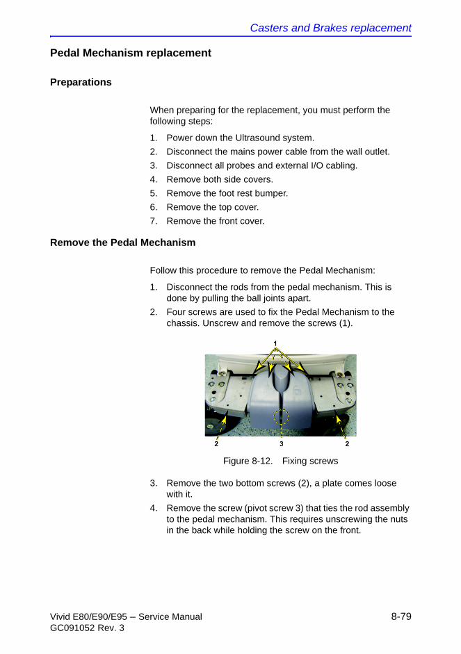
Casters and Brakes replacement
Vivid E80/E90/E95 – Service Manual 8-79GC091052 Rev. 3
Pedal Mechanism replacement
Preparations
When preparing for the replacement, you must perform the following steps:
1. Power down the Ultrasound system.
2. Disconnect the mains power cable from the wall outlet.
3. Disconnect all probes and external I/O cabling.
4. Remove both side covers.
5. Remove the foot rest bumper.
6. Remove the top cover.
7. Remove the front cover.
Remove the Pedal Mechanism
Follow this procedure to remove the Pedal Mechanism:
1. Disconnect the rods from the pedal mechanism. This is done by pulling the ball joints apart.
2. Four screws are used to fix the Pedal Mechanism to the chassis. Unscrew and remove the screws (1).
Figure 8-12. Fixing screws
3. Remove the two bottom screws (2), a plate comes loose with it.
4. Remove the screw (pivot screw 3) that ties the rod assembly to the pedal mechanism. This requires unscrewing the nuts in the back while holding the screw on the front.
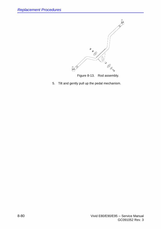
Replacement Procedures
8-80 Vivid E80/E90/E95 – Service ManualGC091052 Rev. 3
Figure 8-13. Rod assembly.
5. Tilt and gently pull up the pedal mechanism.

Casters and Brakes replacement
Vivid E80/E90/E95 – Service Manual 8-81GC091052 Rev. 3
Install the Pedal Mechanism
Follow this procedure to install the Pedal Mechanism:
1. Position the Pedal Mechanism and install the four fixing screws (Torque: 20.5 Nm).
2. Install the two bottom screws, including the plate.
3. Install the screw that ties the rod assembly to the pedal mechanism.
4. Connect the rods by snapping on the ball joints.
5. Verify that the pedals work as intended:
a. Push down brake pedal (from “free” position), release it and verify the pedal to return quickly up to half position.
b. Try to move the Ultrasound system back and forward; and verify that the brake pedal stay in brake mode.
c. Push down direction lock pedal and verify the pedal to return quickly.
d. Move Ultrasound system and verify Casters stay in direction lock mode.
e. At push down, observe the “Latches” to come over pivot T-Shape, and interfere by engaging.
6. Install the front cover.
7. Install both side covers.
8. Install the foot rest bumper.
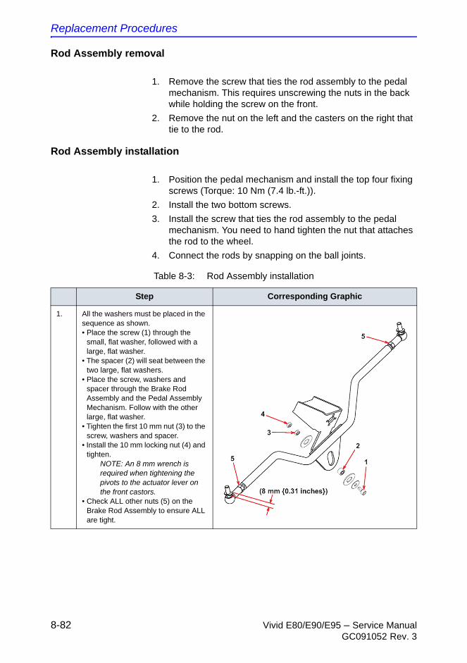
Replacement Procedures
8-82 Vivid E80/E90/E95 – Service ManualGC091052 Rev. 3
Rod Assembly removal
1. Remove the screw that ties the rod assembly to the pedal mechanism. This requires unscrewing the nuts in the back while holding the screw on the front.
2. Remove the nut on the left and the casters on the right that tie to the rod.
Rod Assembly installation
1. Position the pedal mechanism and install the top four fixing screws (Torque: 10 Nm (7.4 lb.-ft.)).
2. Install the two bottom screws.
3. Install the screw that ties the rod assembly to the pedal mechanism. You need to hand tighten the nut that attaches the rod to the wheel.
4. Connect the rods by snapping on the ball joints.
Table 8-3: Rod Assembly installation
Step Corresponding Graphic
1. All the washers must be placed in the sequence as shown. • Place the screw (1) through the
small, flat washer, followed with a large, flat washer.
• The spacer (2) will seat between the two large, flat washers.
• Place the screw, washers and spacer through the Brake Rod Assembly and the Pedal Assembly Mechanism. Follow with the other large, flat washer.
• Tighten the first 10 mm nut (3) to the screw, washers and spacer.
• Install the 10 mm locking nut (4) and tighten.
NOTE: An 8 mm wrench is required when tightening the pivots to the actuator lever on the front castors.
• Check ALL other nuts (5) on the Brake Rod Assembly to ensure ALL are tight.
Casters and Brakes replacement
Vivid E80/E90/E95 – Service Manual 8-83GC091052 Rev. 3
Brake Pedal replacement
Preparations
When preparing for the replacement, you must perform the following steps:
1. Power down the Ultrasound system.
2. Disconnect the mains power cable from the wall outlet.
3. Disconnect all probes and external I/O cabling.
4. Remove both side covers.
5. Remove the foot rest bumper.
6. Remove the top cover.
7. Remove the front cover.
8. Remove the pedal mechanism.
Remove the Brake Pedal
The pedal is fixed to the pedal mechanism with four (4x) hex key screws from below. Follow this procedure to remove the brake pedal:
1. Unscrew and remove the four screws.
2. Remove the brake pedal.
Install the Brake Pedal
Follow this procedure to install the Brake Pedal:
1. Position the Brake Pedal so you can install the fixing screws.
2. Install the four fixing screws.
Pedal Release replacement
This pedal, placed in the middle, is fixed with three screws.
With this in mind, please refer to ‘Brake Pedal replacement’ on page 8-83 for replacement instructions.
Replacement Procedures
8-84 Vivid E80/E90/E95 – Service ManualGC091052 Rev. 3
Pedal Dir Lock replacement
This pedal is fixed to the pedal mechanism in the same manner as the brake pedal.
With this in mind, please refer to ‘Brake Pedal replacement’ on page 8-83 for replacement instructions.
Front End Processor (FEP) / Card Cage parts replacement
Vivid E80/E90/E95 – Service Manual 8-85GC091052 Rev. 3
Front End Processor (FEP) / Card
Cage parts replacement
Front End parts overview
The list below list the positions of the cards. Position #1 is nearest the probe connectors (front of unit).
1. Relay board (GRLY)
2. Transmitter board (GTX-TLP192)
3. Receiver board (CRX)
4. cSound Power Module (CPM)
Front Plane (2x) with XDbus between the transmitter board the relay board and the receiver board.
Replacement Procedures
8-86 Vivid E80/E90/E95 – Service ManualGC091052 Rev. 3
Front End cover replacement
Read and follow
Preparations
When preparing for the replacement, you must perform the following steps:
WARNING Energy Control and Power Lockout for Vivid E80/E90/E95.
When servicing parts of the Ultrasound system where there is exposure to voltage greater than 30 volts:
1. Follow LOCK OUT/TAG OUT procedures.
2. Turn off the breaker.
3. Unplug the Ultrasound system.
4. Maintain control of the Ultrasound system power plug.
5. Wait for at least 30 seconds for capacitors to discharge as there are no test points to verify isolation.
Ultrasound System components may be energized.
WARNING DO NOT touch any boards with integrated circuits prior to taking the necessary ESD precautions.
Always connect yourself, via an arm-wrist strap, to the advised ESD connection point located on the rear of the Ultrasound system (near the power connector).
Follow general guidelines for handling of electrostatic sensitive equipment.
WARNING Risk of electrical shock, Ultrasound system must be turned off and disconnected from power source. Cord must be controlled at all times.
Wait for at least 20 seconds for capacitors to discharge as there are no test points to verify isolation. The amber light on the OP panel on/off button will turn off.
Ultrasound System components may be energized. Always refer to the Ultrasound system's service manual for LOTO warnings and cautions.

Front End Processor (FEP) / Card Cage parts replacement
Vivid E80/E90/E95 – Service Manual 8-87GC091052 Rev. 3
1. Power down the Ultrasound system.
2. Disconnect the Mains Power Cable from the wall outlet.
3. Disconnect all probes and external I/O cabling.
4. Remove the Right Side Cover.
Remove the FEP Cover
Follow these steps to remove the FEP Cover:
1. Unscrew the FEP Cover’s ten fixing screws.
2. Remove the FEP Cover.
Install the FEP Cover
NOTE: Do not use any tools when you tighten the finger screws.
1. Install the FEP Cover and fasten it with the ten fixing screws.
Use your fingers to tighten the screws.
2. Install the side cover.
Replacement Procedures
8-88 Vivid E80/E90/E95 – Service ManualGC091052 Rev. 3
Relay Board (RLY) replacement
Read and follow
WARNING Energy Control and Power Lockout for Vivid E80/E90/E95.
When servicing parts of the Ultrasound system where there is exposure to voltage greater than 30 volts:
1. Follow LOCK OUT/TAG OUT procedures.
2. Turn off the breaker.
3. Unplug the Ultrasound system.
4. Maintain control of the Ultrasound system power plug.
5. Wait for at least 30 seconds for capacitors to discharge as there are no test points to verify isolation.
Ultrasound System components may be energized.
WARNING DO NOT touch any boards with integrated circuits prior to taking the necessary ESD precautions.
Always connect yourself, via an arm-wrist strap, to the advised ESD connection point located on the rear of the Ultrasound system (near the power connector).
Follow general guidelines for handling of electrostatic sensitive equipment.
WARNING Risk of electrical shock, Ultrasound system must be turned off and disconnected from power source. Cord must be controlled at all times.
Wait for at least 20 seconds for capacitors to discharge as there are no test points to verify isolation. The amber light on the OP panel on/off button will turn off.
Ultrasound System components may be energized. Always refer to the Ultrasound system's service manual for LOTO warnings and cautions.
Front End Processor (FEP) / Card Cage parts replacement
Vivid E80/E90/E95 – Service Manual 8-89GC091052 Rev. 3
Preparations
When preparing for the replacement, you must perform the following steps:
1. Power down the Ultrasound system.
2. Disconnect the Mains Power Cable from the wall outlet.
3. Disconnect all probes and external I/O cabling.
4. Remove the Right Side Cover.
5. Remove the FEP Cover.
6. Remove the Front Plane boards.
Remove the Relay Board
Follow these steps to remove the Relay Board:
1. Pull out the Relay Board.
2. Place it on an ESD safe place.
Install the Relay Board
Follow these steps to install the Relay Board:
1. Carefully align the Relay Board with the rails and push it. Push the card to the left, so it enters correct in the mechanical slide, before you push it in position so it is seated in the Back Plane connectors.
2. Carefully install the two Front Plane Boards.
3. Install the FEP Cover and fasten it with its fixing screws.
4. Install the Right Side Cover.
Verification
Perform the following steps to verify that the product is functioning as intended after this Front End part replacement:
1. Verify that all screws that you removed earlier have been installed.
2. If finished, connect cables and probes you removed earlier
WARNING Prior to removing the Card Rack boards, the LEDs on the end of each board should be unlit, to indicate boards are unpowered.
Replacement Procedures
8-90 Vivid E80/E90/E95 – Service ManualGC091052 Rev. 3
3. Power up the Ultrasound system to verify that it starts as it should.
Front End Processor (FEP) / Card Cage parts replacement
Vivid E80/E90/E95 – Service Manual 8-91GC091052 Rev. 3
Transmitter Board (GTX) replacement
Read and follow
WARNING Energy Control and Power Lockout for Vivid E80/E90/E95.
When servicing parts of the Ultrasound system where there is exposure to voltage greater than 30 volts:
1. Follow LOCK OUT/TAG OUT procedures.
2. Turn off the breaker.
3. Unplug the Ultrasound system.
4. Maintain control of the Ultrasound system power plug.
5. Wait for at least 30 seconds for capacitors to discharge as there are no test points to verify isolation.
Ultrasound System components may be energized.
WARNING DO NOT touch any boards with integrated circuits prior to taking the necessary ESD precautions.
Always connect yourself, via an arm-wrist strap, to the advised ESD connection point located on the rear of the Ultrasound system (near the power connector).
Follow general guidelines for handling of electrostatic sensitive equipment.
WARNING Risk of electrical shock, Ultrasound system must be turned off and disconnected from power source. Cord must be controlled at all times.
Wait for at least 20 seconds for capacitors to discharge as there are no test points to verify isolation. The amber light on the OP panel on/off button will turn off.
Ultrasound System components may be energized. Always refer to the Ultrasound system's service manual for LOTO warnings and cautions.
Replacement Procedures
8-92 Vivid E80/E90/E95 – Service ManualGC091052 Rev. 3
Preparations
When preparing for the replacement, you must perform the following steps:
1. Power down the Ultrasound system.
2. Disconnect the Mains Power Cable from the wall outlet.
3. Disconnect all probes and external I/O cabling.
4. Remove the Right Side Cover.
5. Remove the FEP Cover.
6. Remove the Front Plane boards.
Remove the GTX board
Follow these steps to remove the GTX board:
1. Pull out the GTX Board.
2. Place it on an ESD safe place.
Install the GTX board
Follow these steps to install the GTX Board:
1. Carefully align the GTX Board with the rails and push it in till it is seated in the Back Plane connectors.
2. Carefully install the two Front Plane Boards.
3. Install the FEP Cover.
4. Install the Right Side Cover.
WARNING Prior to removing the Card Rack boards, the LEDs on the end of each board should be unlit, to indicate boards are unpowered.
Front End Processor (FEP) / Card Cage parts replacement
Vivid E80/E90/E95 – Service Manual 8-93GC091052 Rev. 3
cSound Receiver Board (CRX) replacement
Read and follow
WARNING Energy Control and Power Lockout for Vivid E80/E90/E95.
When servicing parts of the Ultrasound system where there is exposure to voltage greater than 30 volts:
1. Follow LOCK OUT/TAG OUT procedures.
2. Turn off the breaker.
3. Unplug the Ultrasound system.
4. Maintain control of the Ultrasound system power plug.
5. Wait for at least 30 seconds for capacitors to discharge as there are no test points to verify isolation.
Ultrasound System components may be energized.
WARNING DO NOT touch any boards with integrated circuits prior to taking the necessary ESD precautions.
Always connect yourself, via an arm-wrist strap, to the advised ESD connection point located on the rear of the Ultrasound system (near the power connector).
Follow general guidelines for handling of electrostatic sensitive equipment.
WARNING Risk of electrical shock, Ultrasound system must be turned off and disconnected from power source. Cord must be controlled at all times.
Wait for at least 20 seconds for capacitors to discharge as there are no test points to verify isolation. The amber light on the OP panel on/off button will turn off.
Ultrasound System components may be energized. Always refer to the Ultrasound system's service manual for LOTO warnings and cautions.

Replacement Procedures
8-94 Vivid E80/E90/E95 – Service ManualGC091052 Rev. 3
Preparations
When preparing for the replacement, you must perform the following steps:
1. Power down the Ultrasound system.
2. Disconnect the Mains Power Cable from the wall outlet.
3. Disconnect all probes and external I/O cabling.
4. Remove the Right Side Cover.
5. Remove the FEP Cover.
6. Remove the Front Plane boards.
Remove the CRX board
Follow these steps to remove the CRX board:
1. Pull out the CRX board.
2. Place it on an ESD safe place.
Install the CRX board
Follow these steps to install the CRX board:
1. Carefully align the CRX board with the rails and push it in till it is seated in the Back Plane connectors.
2. Install the FEP Cover.
3. Install the Right Side Cover.
WARNING Prior to removing the Card Rack boards, the LEDs on the end of each board should be unlit, to indicate boards are unpowered.

Front End Processor (FEP) / Card Cage parts replacement
Vivid E80/E90/E95 – Service Manual 8-95GC091052 Rev. 3
cSound Power Module (CPM) replacement
Preparations
When preparing for the replacement, you must perform the following steps:
1. Power down the Ultrasound system.
2. Disconnect the Mains Power Cable from the wall outlet.
3. Disconnect all probes and external I/O cabling.
4. Remove the Right Side Cover.
5. Remove the FEP Cover.
Remove the cSound Power Module
Carefully unplug the cSound Power Module.
Install the cSound Power Module
Plug in the cSound Power Module.

Replacement Procedures
8-96 Vivid E80/E90/E95 – Service ManualGC091052 Rev. 3
Back End Processor (BEP) parts
replacement
Back End Processor (BEP) parts replacement
Vivid E80/E90/E95 – Service Manual 8-97GC091052 Rev. 3
Back End Processor (BEP) replacement
Warnings
WARNING Energy Control and Power Lockout for Vivid E80/E90/E95.
When servicing parts of the Ultrasound system where there is exposure to voltage greater than 30 volts:
1. Follow LOCK OUT/TAG OUT procedures.
2. Turn off the breaker.
3. Unplug the Ultrasound system.
4. Maintain control of the Ultrasound system power plug.
5. Wait at least 30 seconds for capacitors to discharge as there are no test points to verify isolation.
Ultrasound System components may be energized.
WARNING When you return the used BEP to your local parts organization, make sure you remove ALL PATIENT DATA from the hard drive, given that the hard drive is still functional.In some countries, you may be required to delete all software from the disk before returning the BEP to the parts warehouse. Follow your local policies.
Replacement Procedures
8-98 Vivid E80/E90/E95 – Service ManualGC091052 Rev. 3
Warnings (continued)
Preparations
When preparing for the replacement, you must perform the following steps:
1. Record the Ultrasound system’s TCPIP settings and installed Option strings.
2. Export the Patient Archive images to a server or to external media.
3. Back up the Report Archive, User-Defined Configuration (Customer Presets), and Service settings.
You will perform a Restore after you have installed the new BEP and loaded the correct software.
4. Collect the error logs and record information on why the BEP must be changed.
5. Reload the system software from removable media. Select No when asked: Keep User Data and Patient Archive?
6. Power down the Ultrasound system.
7. Disconnect the Mains Power Cable from the wall outlet.
8. Disconnect all probes.
9. Remove the Side Covers.
10. Remove the Top Cover.
11. Remove the B/W Printer.
12. For easier access in the next steps, remove the Front Cover.
WARNING Before you dispose of the hard drive, or return the BEP to the local parts organization, make sure you remove ALL PATIENT DATA from the hard drive, given that the hard drive is still functional. In some countries, you may be required to delete all software from the disk before returning the hard drive to the parts warehouse. Follow your local policies.

Back End Processor (BEP) parts replacement
Vivid E80/E90/E95 – Service Manual 8-99GC091052 Rev. 3
Back End Processor (BEP) removal procedure
Follow these steps to remove the BEP:
1. Disconnect all I/O cables.
2. Disconnect the cables at the top of the BEP.
3. Unlatch the two latches that clamp the printer bracket to the top of the BEP.
4. Tilt the Front Cover forward just until the Column Cover Stop Tabs clear.
5. Lift the Lower Column Cover.
6. Push the printer bracket toward the FEP approximately 1.3 cm (1/2 inch) to free the 3 tabs from the BEP.
7. Remove the BEP Cover.
8. Remove the Printer Bracket from the BEP.
9. Reach inside the BEP and disconnect PCIe cable.
10. Remove the two hex key screws at the inside base of the BEP.
11. Slide the entire BEP out of the chassis.
Prepare the new BEP for installation
• If the BEP has an optional, extra graphics adapter, move this graphics adapter from the old BEP to the new BEP.
WARNING DO NOT touch any boards with integrated circuits prior to taking the necessary ESD precautions.
Always connect yourself, via an arm-wrist strap, to the advised ESD connection point located on the rear of the Ultrasound system (near the power connector).
Follow general guidelines for handling of electrostatic sensitive equipment.
WARNING Before you dispose of the hard drive, or return the BEP to the local parts organization, make sure you remove ALL PATIENT DATA from the hard drive, given that the hard drive is still functional. In some countries, you may be required to delete all software from the disk before returning the hard drive to the parts warehouse. Follow your local policies.

Replacement Procedures
8-100 Vivid E80/E90/E95 – Service ManualGC091052 Rev. 3
Back End Processor (BEP) installation procedure
Follow these steps to install the BEP:
1. Slide the BEP into the left side of the chassis frame.
2. Install the two (2x) hex key screws at the inside base of the BEP.
3. Reach inside the BEP and connect the PCIe cable.
NOTE: If you don’t reconnect the PCIe cable to the backplane, the Ultrasound system will power up, but will not scan. The BEP will launch into simulator mode.
4. Install the BEP Cover.
5. Replace the Printer Bracket at the top of the BEP.
Be sure the lip, on the underside of the bracket, hooks on the edge of the Card Rack, and the 3 tabs insert into the slots on the top of the BEP frame. The lip “clamps” the Card Rack and BEP together. This is a tight fit.
6. Lower the Lower Column Cover.
7. Position the Front Cover to engage the Column Cover Stop Tabs.
8. Latch the two latches that clamp the Printer Bracket to the top of the BEP.
9. Slide the B&W printer into the Printer Bracket and connect the cables to the back of the printer.
10. Tighten the Printer Bracket Wing Nut to secure the printer.
11. Connect all I/O cables at top and/or face of the BEP, including the printer cables.
12. Install the Top Cover (if removed), the Front cover (if removed) and the side covers.
13. If applicable, install the correct software on the new BEP.
14. Enter the Ultrasound system’s TCPIP settings and Option strings.
CAUTION Be careful not to pinch any of the cables.
CAUTION Be careful not to pinch any of the cables.
Back End Processor (BEP) parts replacement
Vivid E80/E90/E95 – Service Manual 8-101GC091052 Rev. 3
15. Restore the Patient Archive images, Report Archive, User-Defined Configuration (Customer Presets), and Service settings.
Verification after BEP or HDD replacement
Perform the following steps to verify that the product is functioning as intended after this replacement:
1. Verify that all screws that you removed earlier have been installed.
2. If finished, connect cables and probes removed earlier.
3. Power up the Ultrasound system to verify that it operates as intended.
4. Check/set Date, Time, and Time Zone, and set the Preset Region accordingly.
5. Reconnect to the network.
6. If the Ultrasound system was connected to InSite ExC, restore the service settings backed up prior to the software loading. Reboot and verify remote connectivity.
7. Confirm Patient Archive images, Report Archive, User Defined Configuration (Customer Presets), and Service settings are restored.
8. If DVD is installed: Format a DVD, and backup Customer Presets to confirm proper DVD write functionality.
Hard Disk Drive (HDD) replacement
Preparations
WARNING Before you dispose of the hard drive, make sure you remove ALL PATIENT DATA from the hard drive, given that the hard drive is still functional. In some countries, you may be required to delete all software from the disk before returning the hard drive to the parts warehouse. Follow your local policies.
Replacement Procedures
8-102 Vivid E80/E90/E95 – Service ManualGC091052 Rev. 3
WARNING Energy Control and Power Lockout for Vivid E80/E90/E95.
When servicing parts of the Ultrasound system where there is exposure to voltage greater than 30 volts:
1. Follow LOCK OUT/TAG OUT procedures.
2. Turn off the breaker.
3. Unplug the Ultrasound system.
4. Maintain control of the Ultrasound system power plug.
5. Wait at least 30 seconds for capacitors to discharge as there are no test points to verify isolation.
Ultrasound System components may be energized.
Back End Processor (BEP) parts replacement
Vivid E80/E90/E95 – Service Manual 8-103GC091052 Rev. 3
Preparations (continued)
When preparing for the replacement, you must perform the following steps:
1. Record the Ultrasound system’s TCPIP settings and installed Option strings.
2. Back up the Patient Archive images, Report Archive, User-Defined Configuration (Customer Presets), and Service settings. You will perform a Restore after the install.
3. Reload the system software from removable media. Select No when asked: Keep User Data and Patient Archive?
4. Power down the Ultrasound system.
5. Disconnect the Mains Power Cable from the wall outlet.
6. Disconnect all external cables (probes, ECG, physio, Ethernet, audio, video, USB).
7. Remove the Left Side Cover.
8. Remove the BEP Cover.
Hard Disk Drive (HDD) removal procedure
Follow these steps to remove the HDD:
1. Disconnect the cables connecting the HDD.
2. Remove the two screws that secures the HDD Bracket to the BEP’s frame.
3. Get hold of the HDD assembly and pull it out.
Replacement Procedures
8-104 Vivid E80/E90/E95 – Service ManualGC091052 Rev. 3
Hard Disk Drive (HDD) installation procedure
Follow these steps to install the HDD:
1. Position the HDD Assembly so it enters the two guides and slide the HDD in. You may need to apply a pressure to make it slide into position.
2. Install the two screws that secures the HDD bracket to the BEP’s frame.
3. Connect the two HDD cables to the HDD.
4. Install the BEP Cover as described in these steps:
a. Insert the base of the BEP Cover inside the base of the BEP.
Be sure the bottom lip of the BEP Cover rests inside the BEP.
b. Tilt the top of the BEP Cover toward the BEP.
c. Install the fixing screw(s) for the BEP Cover:
5. Replace the Left Side Cover.
6. Connect the Mains Power Cable to the wall outlet.
7. Power up the Ultrasound system.
8. Install the System software and the Application software.
9. Enter the Ultrasound system’s TCPIP settings and Option strings.
10. Restore the Patient Archive images, Report Archive, User-Defined Configuration (Customer Presets), and Service settings.
Verification
See: ‘Verification after BEP or HDD replacement’ on page 8-101.
CAUTION Be careful not to pinch any of the cables.

Main Power Supply replacement
Vivid E80/E90/E95 – Service Manual 8-105GC091052 Rev. 3
Main Power Supply replacement
Preparations
When preparing for the replacement, you must perform the following steps:
1. Power down the Ultrasound system.
2. Disconnect the Mains Power Cable from the wall outlet.
3. Disconnect all probes and external I/O cabling.
4. Remove both Side Cover.
5. Remove the Top Cover.
6. Remove the Filter Cover.
7. Remove the Rear Cover.
Main Power Supply removal procedure
Follow these steps to remove the Main Power Supply:
1. Disconnect the cables on top of the power supply.
2. Remove the three screws that secure the Main Power Supply.
3. Ease the Main Power Supply away from the fang bracket.
4. Pull/slide the entire Main Power Supply backwards until the connectors to the Front End Processor are unseated.
5. Lift the Main Power Supply away.
Main Power Supply installation procedure
Follow these steps to install the Main Power Supply:
1. Place the Main Power Supply base on the Ultrasound systems frame, and then tilt the top of the Main Power Supply toward the rear of the Card Cage until the Main Power Supply is vertical.
2. Slide the Main Power Supply forward to seat the connectors on the Card Cage.
3. Engage the tab onto the Fang.
4. Install the three screws.
Replacement Procedures
8-106 Vivid E80/E90/E95 – Service ManualGC091052 Rev. 3
5. Fill out and attach the rating plate.
6. Connect the cables at the top of the Main Power Supply.
7. Install the Rear Cover.
8. Install the Filter Cover.
9. Install the Top Cover.
10. Install both Side Covers.
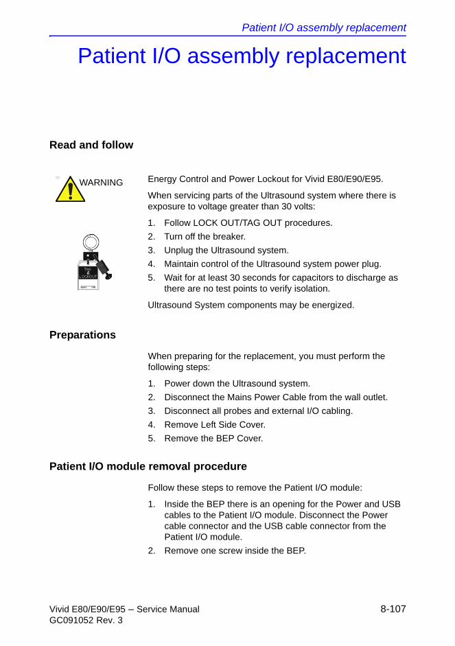
Patient I/O assembly replacement
Vivid E80/E90/E95 – Service Manual 8-107GC091052 Rev. 3
Patient I/O assembly replacement
Read and follow
Preparations
When preparing for the replacement, you must perform the following steps:
1. Power down the Ultrasound system.
2. Disconnect the Mains Power Cable from the wall outlet.
3. Disconnect all probes and external I/O cabling.
4. Remove Left Side Cover.
5. Remove the BEP Cover.
Patient I/O module removal procedure
Follow these steps to remove the Patient I/O module:
1. Inside the BEP there is an opening for the Power and USB cables to the Patient I/O module. Disconnect the Power cable connector and the USB cable connector from the Patient I/O module.
2. Remove one screw inside the BEP.
WARNING Energy Control and Power Lockout for Vivid E80/E90/E95.
When servicing parts of the Ultrasound system where there is exposure to voltage greater than 30 volts:
1. Follow LOCK OUT/TAG OUT procedures.
2. Turn off the breaker.
3. Unplug the Ultrasound system.
4. Maintain control of the Ultrasound system power plug.
5. Wait for at least 30 seconds for capacitors to discharge as there are no test points to verify isolation.
Ultrasound System components may be energized.
Replacement Procedures
8-108 Vivid E80/E90/E95 – Service ManualGC091052 Rev. 3
3. Remove the two fastening screws on the Patient I/O module’s mounting bracket.
4. Pull the Patient I/O module sideways, out of the frame.
Patient I/O installation procedure
Follow these steps to install the Patient I/O:
1. Align the Patient I/O with the opening and push it into its final position.
2. Connect the Power and USB cables (inside the BEP).
3. Install two fastening screws on the mounting bracket.
4. Install the BEP Cover.
5. Install the left side cover.
Verification
Perform the following steps to verify that the product is functioning as intended after this Patient I/O replacement:
1. Verify that all screws that you removed earlier have been installed.
2. If finished, connect cables and probes you removed earlier.
3. Power up the Ultrasound system to verify that it operates as intended.
CAUTION Be careful not to pinch any of the cables.
Peripherals replacement
Vivid E80/E90/E95 – Service Manual 8-109GC091052 Rev. 3
Peripherals replacement
DVD R/W drive replacement
Preparations
When preparing for the replacement, you must perform the following steps:
1. Power down the Ultrasound system.
2. Disconnect the Mains Power Cable from the wall outlet.
3. Disconnect all probes and external I/O cabling.
4. Remove the Side Covers.
5. Remove the Top Cover.
Remove the DVD drive
Follow this procedure to remove the DVD drive:
1. Raise the Top Console to the highest level.
2. Remove the 4 screws securing the right side of the DVD drive.
3. Tilt the Front Cover forward just until the Column Cover stop tabs clear.
4. Raise the Column Cover to access and remove the 4 screws securing the left side of the DVD drive.
5. Disconnect the cables to the DVD drive.
6. Slide the DVD drive out the front of the Ultrasound system.
NOTE: If Power Connection is different on new and old DVD drive: Move the DVD Interface Board, Part Number 5301204, from the old DVD drive that you removed, to the new DVD drive.
Install the DVD drive
Follow this procedure to install the DVD drive:
1. Slide the DVD drive into position.
2. Install the 8 screws to secure the DVD drive.
Replacement Procedures
8-110 Vivid E80/E90/E95 – Service ManualGC091052 Rev. 3
3. Connect the cables to the DVD drive.
4. Install the Covers.
Black & White Digital Graphic Printer replacement
Read and follow
Preparations
When preparing for the replacement, you must perform the following steps:
1. Power down the Ultrasound system.
2. Disconnect the Mains Power Cable from the wall outlet.
3. Disconnect all probes and external I/O cabling.
4. Remove the Left Side Cover.
Remove the Black & White Digital Graphic Printer
Follow this procedure to remove the Black & White Digital Graphic Printer:
1. Disconnect the cables from the back of the printer.
2. Loosen the printer bracket wing nut that secures the printer.
3. Slide the printer out.
Install the Black & White Digital Graphic Printer
Follow this procedure to install the Black & White Digital Graphic Printer:
WARNING Energy Control and Power Lockout for Vivid E80/E90/E95.
When servicing parts of the Ultrasound system where there is exposure to voltage greater than 30 volts:
1. Follow LOCK OUT/TAG OUT procedures.
2. Turn off the breaker.
3. Unplug the Ultrasound system.
4. Maintain control of the Ultrasound system power plug.
5. Wait for at least 30 seconds for capacitors to discharge as there are no test points to verify isolation.
Ultrasound System components may be energized.

Peripherals replacement
Vivid E80/E90/E95 – Service Manual 8-111GC091052 Rev. 3
1. Slide the printer into the printer bracket until the face is flush with the Ultrasound system.
2. Tighten the printer bracket wing nut to secure the printer in the printer bracket.
3. Connect the cables to the back of the printer.
4. Replace the Left Side Cover.
Replacement Procedures
8-112 Vivid E80/E90/E95 – Service ManualGC091052 Rev. 3
Cables replacement
TwinAx PCIe cable replacement
The TwinAx PCIe cable connects the CRX board (via the main board) to the back end processor (BEP).
Preparations
When preparing for the replacement, you must perform the following steps:
1. Power down the Ultrasound system.
2. Disconnect the Mains Power Cable from the wall outlet.
3. Disconnect all probes.
4. Remove both the Left Side Cover and the Right Side Cover.
Remove the TwinAx PCIe cable
Follow these steps to remove the TwinAx PCIe cable:
1. Disconnect the TwinAx PCIe cable from the BEP’s motherboard as described here:
a. Remove the BEP cover.
b. Disconnect the TwinAx PCIe (flat) cable from the connector on the motherboard.
2. Disconnect the TwinAx PCIe cable from the FEP card rack’s main board as described here:
a. Remove the FEP cover.
b. Carefully, unlock the two locks used to fix the cable plug to the connector.
c. Carefully, disconnect the TwinAx PCIe (flat) cable from the connector on the main board
CAUTION Be careful when performing the next step. The two locks on the connector for the PCIe cable are easy to break. If broken, you must replace the Main Board.
Cables replacement
Vivid E80/E90/E95 – Service Manual 8-113GC091052 Rev. 3
3. Remove the TwinAx PCIe cable.
Install the TwinAx PCIe cable
Follow these steps to install the TwinAx PCIe cable:
1. Route the new TwinAx PCIe cable between the inside of the BEP and the inside of the FEP.
2. Connect the TwinAx PCIe cable to the connector on the BEP’s motherboard.
3. Connect the TwinAx PCIe cable to the connector on the main board.
4. Install the covers on the BEP and on the FEP.
5. Install the side covers on the Ultrasound system.
6. Install the mains power cable.
CAUTION Be careful when performing the next step. The two locks on the connector for the PCIe cable are easy to break. If broken, you must replace the Main Board.

Replacement Procedures
8-114 Vivid E80/E90/E95 – Service ManualGC091052 Rev. 3
THIS PAGE WAS INTENTIONALLY LEFT BLANK
Vivid E80/E90/E95 – Service Manual 9-1GC091052 Rev. 3
Chapter 9
Renewal Parts
This chapter lists the renewal parts available for the Vivid E80/E90/E95.
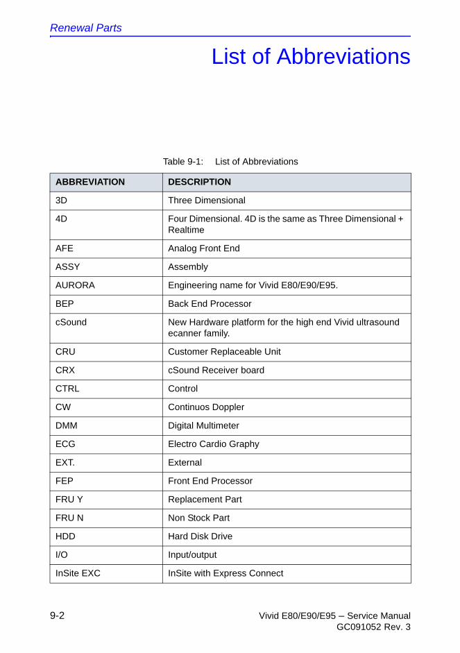
Renewal Parts
9-2 Vivid E80/E90/E95 – Service ManualGC091052 Rev. 3
List of Abbreviations
Table 9-1: List of Abbreviations
ABBREVIATION DESCRIPTION
3D Three Dimensional
4D Four Dimensional. 4D is the same as Three Dimensional + Realtime
AFE Analog Front End
ASSY Assembly
AURORA Engineering name for Vivid E80/E90/E95.
BEP Back End Processor
cSound New Hardware platform for the high end Vivid ultrasound ecanner family.
CRU Customer Replaceable Unit
CRX cSound Receiver board
CTRL Control
CW Continuos Doppler
DMM Digital Multimeter
ECG Electro Cardio Graphy
EXT. External
FEP Front End Processor
FRU Y Replacement Part
FRU N Non Stock Part
HDD Hard Disk Drive
I/O Input/output
InSite EXC InSite with Express Connect
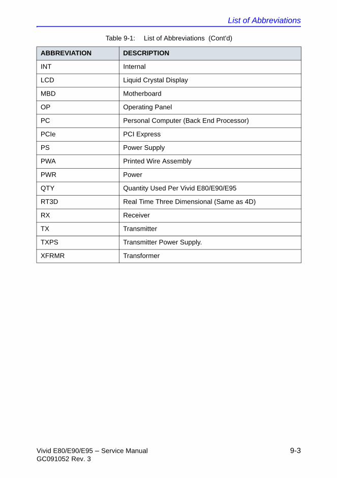
List of Abbreviations
Vivid E80/E90/E95 – Service Manual 9-3GC091052 Rev. 3
INT Internal
LCD Liquid Crystal Display
MBD Motherboard
OP Operating Panel
PC Personal Computer (Back End Processor)
PCIe PCI Express
PS Power Supply
PWA Printed Wire Assembly
PWR Power
QTY Quantity Used Per Vivid E80/E90/E95
RT3D Real Time Three Dimensional (Same as 4D)
RX Receiver
TX Transmitter
TXPS Transmitter Power Supply.
XFRMR Transformer
Table 9-1: List of Abbreviations (Cont'd)
ABBREVIATION DESCRIPTION
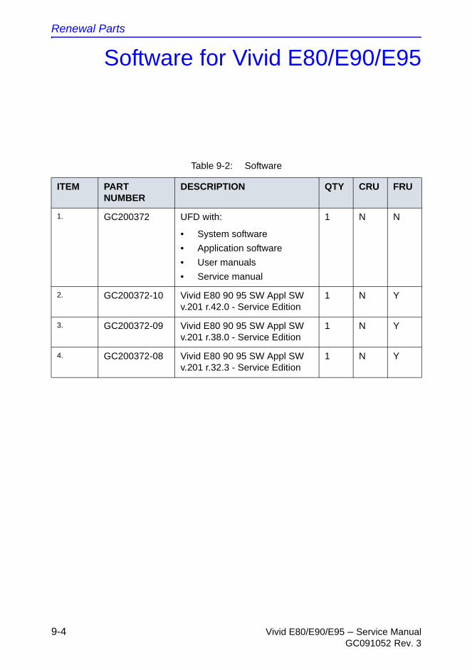
Renewal Parts
9-4 Vivid E80/E90/E95 – Service ManualGC091052 Rev. 3
Software for Vivid E80/E90/E95
Table 9-2: Software
ITEM PART NUMBER
DESCRIPTION QTY CRU FRU
1. GC200372 UFD with:
• System software
• Application software
• User manuals
• Service manual
1 N N
2. GC200372-10 Vivid E80 90 95 SW Appl SW v.201 r.42.0 - Service Edition
1 N Y
3. GC200372-09 Vivid E80 90 95 SW Appl SW v.201 r.38.0 - Service Edition
1 N Y
4. GC200372-08 Vivid E80 90 95 SW Appl SW v.201 r.32.3 - Service Edition
1 N Y
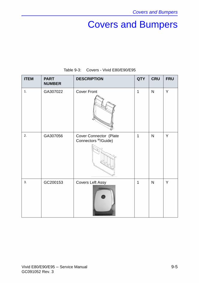
Covers and Bumpers
Vivid E80/E90/E95 – Service Manual 9-5GC091052 Rev. 3
Covers and Bumpers
Table 9-3: Covers - Vivid E80/E90/E95
ITEM PART NUMBER
DESCRIPTION QTY CRU FRU
1. GA307022 Cover Front 1 N Y
2. GA307056 Cover Connector (Plate Connectors w/Guide)
1 N Y
3. GC200153 Covers Left Assy 1 N Y
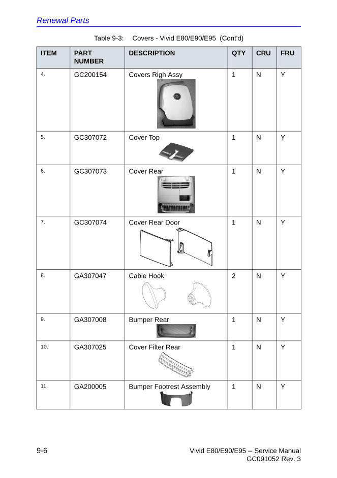
Renewal Parts
9-6 Vivid E80/E90/E95 – Service ManualGC091052 Rev. 3
4. GC200154 Covers Righ Assy 1 N Y
5. GC307072 Cover Top 1 N Y
6. GC307073 Cover Rear 1 N Y
7. GC307074 Cover Rear Door 1 N Y
8. GA307047 Cable Hook 2 N Y
9. GA307008 Bumper Rear 1 N Y
10. GA307025 Cover Filter Rear 1 N Y
11. GA200005 Bumper Footrest Assembly 1 N Y
Table 9-3: Covers - Vivid E80/E90/E95 (Cont'd)
ITEM PART NUMBER
DESCRIPTION QTY CRU FRU
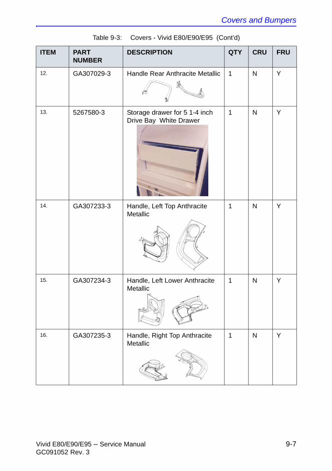
Covers and Bumpers
Vivid E80/E90/E95 – Service Manual 9-7GC091052 Rev. 3
12. GA307029-3 Handle Rear Anthracite Metallic 1 N Y
13. 5267580-3 Storage drawer for 5 1-4 inch Drive Bay White Drawer
1 N Y
14. GA307233-3 Handle, Left Top Anthracite Metallic
1 N Y
15. GA307234-3 Handle, Left Lower Anthracite Metallic
1 N Y
16. GA307235-3 Handle, Right Top Anthracite Metallic
1 N Y
Table 9-3: Covers - Vivid E80/E90/E95 (Cont'd)
ITEM PART NUMBER
DESCRIPTION QTY CRU FRU
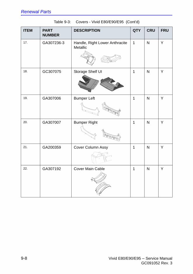
Renewal Parts
9-8 Vivid E80/E90/E95 – Service ManualGC091052 Rev. 3
17. GA307236-3 Handle, Right Lower Anthracite Metallic
1 N Y
18. GC307075 Storage Shelf UI 1 N Y
19. GA307006 Bumper Left 1 N Y
20. GA307007 Bumper Right 1 N Y
21. GA200359 Cover Column Assy 1 N Y
22. GA307192 Cover Main Cable 1 N Y
Table 9-3: Covers - Vivid E80/E90/E95 (Cont'd)
ITEM PART NUMBER
DESCRIPTION QTY CRU FRU
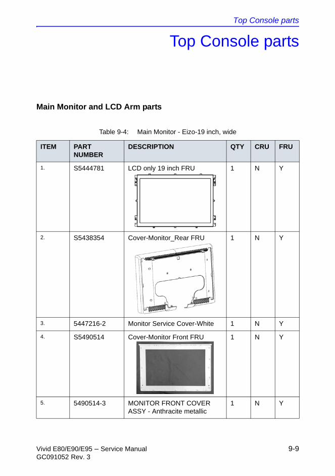
Top Console parts
Vivid E80/E90/E95 – Service Manual 9-9GC091052 Rev. 3
Top Console parts
Main Monitor and LCD Arm parts
Table 9-4: Main Monitor - Eizo-19 inch, wide
ITEM PART NUMBER
DESCRIPTION QTY CRU FRU
1. S5444781 LCD only 19 inch FRU 1 N Y
2. S5438354 Cover-Monitor_Rear FRU 1 N Y
3. 5447216-2 Monitor Service Cover-White 1 N Y
4. S5490514 Cover-Monitor Front FRU 1 N Y
5. 5490514-3 MONITOR FRONT COVER ASSY - Anthracite metallic
1 N Y
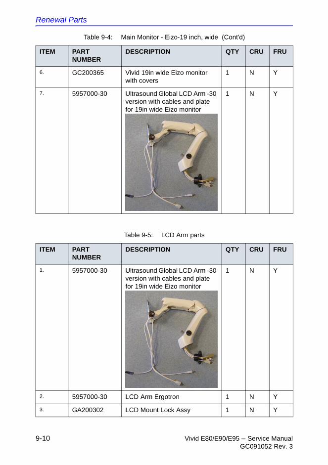
Renewal Parts
9-10 Vivid E80/E90/E95 – Service ManualGC091052 Rev. 3
6. GC200365 Vivid 19in wide Eizo monitor with covers
1 N Y
7. 5957000-30 Ultrasound Global LCD Arm -30 version with cables and plate for 19in wide Eizo monitor
1 N Y
Table 9-4: Main Monitor - Eizo-19 inch, wide (Cont'd)
ITEM PART NUMBER
DESCRIPTION QTY CRU FRU
Table 9-5: LCD Arm parts
ITEM PART NUMBER
DESCRIPTION QTY CRU FRU
1. 5957000-30 Ultrasound Global LCD Arm -30 version with cables and plate for 19in wide Eizo monitor
1 N Y
2. 5957000-30 LCD Arm Ergotron 1 N Y
3. GA200302 LCD Mount Lock Assy 1 N Y
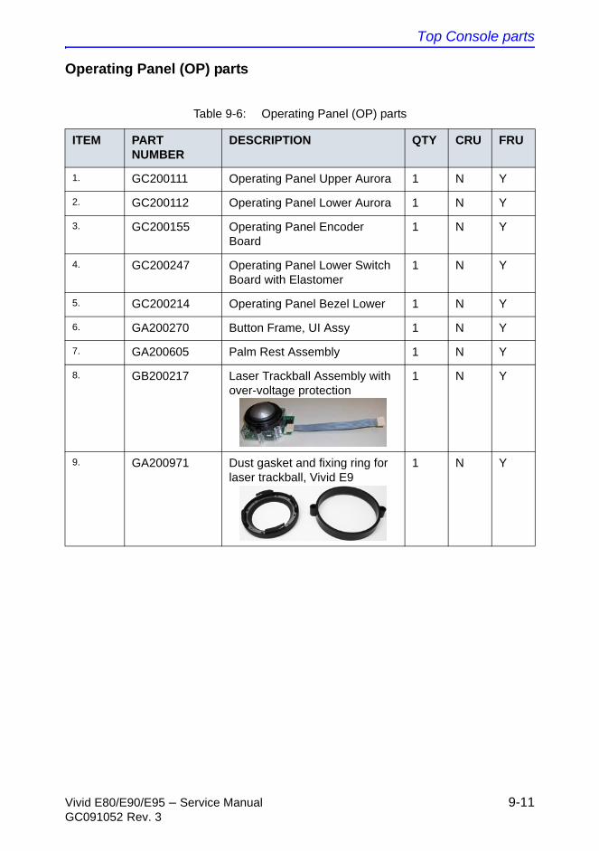
Top Console parts
Vivid E80/E90/E95 – Service Manual 9-11GC091052 Rev. 3
Operating Panel (OP) parts
Table 9-6: Operating Panel (OP) parts
ITEM PART NUMBER
DESCRIPTION QTY CRU FRU
1. GC200111 Operating Panel Upper Aurora 1 N Y
2. GC200112 Operating Panel Lower Aurora 1 N Y
3. GC200155 Operating Panel Encoder Board
1 N Y
4. GC200247 Operating Panel Lower Switch Board with Elastomer
1 N Y
5. GC200214 Operating Panel Bezel Lower 1 N Y
6. GA200270 Button Frame, UI Assy 1 N Y
7. GA200605 Palm Rest Assembly 1 N Y
8. GB200217 Laser Trackball Assembly with over-voltage protection
1 N Y
9. GA200971 Dust gasket and fixing ring for laser trackball, Vivid E9
1 N Y
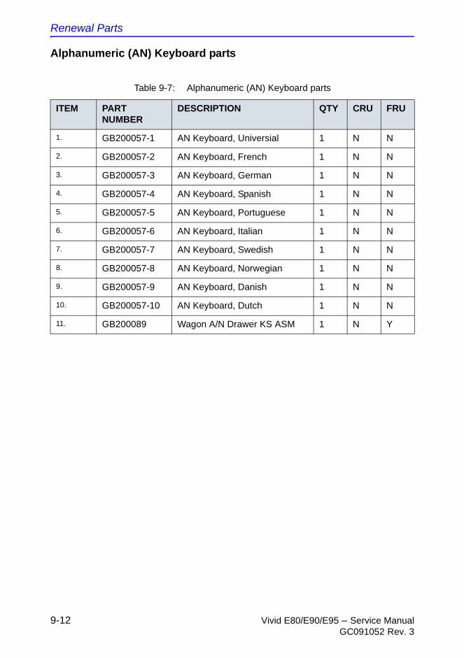
Renewal Parts
9-12 Vivid E80/E90/E95 – Service ManualGC091052 Rev. 3
Alphanumeric (AN) Keyboard parts
Table 9-7: Alphanumeric (AN) Keyboard parts
ITEM PART NUMBER
DESCRIPTION QTY CRU FRU
1. GB200057-1 AN Keyboard, Universial 1 N N
2. GB200057-2 AN Keyboard, French 1 N N
3. GB200057-3 AN Keyboard, German 1 N N
4. GB200057-4 AN Keyboard, Spanish 1 N N
5. GB200057-5 AN Keyboard, Portuguese 1 N N
6. GB200057-6 AN Keyboard, Italian 1 N N
7. GB200057-7 AN Keyboard, Swedish 1 N N
8. GB200057-8 AN Keyboard, Norwegian 1 N N
9. GB200057-9 AN Keyboard, Danish 1 N N
10. GB200057-10 AN Keyboard, Dutch 1 N N
11. GB200089 Wagon A/N Drawer KS ASM 1 N Y
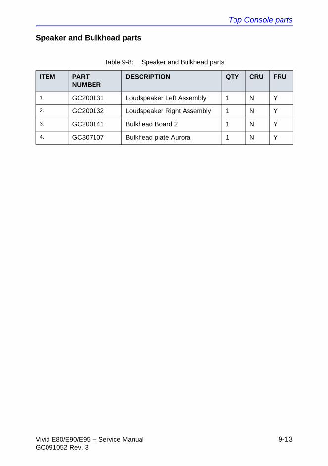
Top Console parts
Vivid E80/E90/E95 – Service Manual 9-13GC091052 Rev. 3
Speaker and Bulkhead parts
Table 9-8: Speaker and Bulkhead parts
ITEM PART NUMBER
DESCRIPTION QTY CRU FRU
1. GC200131 Loudspeaker Left Assembly 1 N Y
2. GC200132 Loudspeaker Right Assembly 1 N Y
3. GC200141 Bulkhead Board 2 1 N Y
4. GC307107 Bulkhead plate Aurora 1 N Y
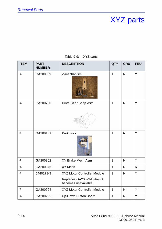
Renewal Parts
9-14 Vivid E80/E90/E95 – Service ManualGC091052 Rev. 3
XYZ parts
Table 9-9: XYZ parts
ITEM PART NUMBER
DESCRIPTION QTY CRU FRU
1. GA200039 Z-mechanism 1 N Y
2. GA200750 Drive Gear Snap Asm 1 N Y
3. GA200161 Park Lock 1 N Y
4. GA200952 XY Brake Mech Asm 1 N Y
5. GA200946 XY Mech 1 N N
6. 5440179-3 XYZ Motor Controller Module
Replaces GA200994 when it becomes unavailable
1 N Y
7. GA200994 XYZ Motor Controller Module 1 N Y
8. GA200285 Up-Down Button Board 1 N Y
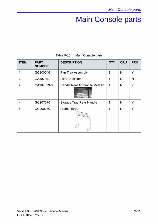
Main Console parts
Vivid E80/E90/E95 – Service Manual 9-15GC091052 Rev. 3
Main Console parts
Table 9-10: Main Console parts
ITEM PART NUMBER
DESCRIPTION QTY CRU FRU
1. GC200046 Fan Tray Assembly 1 N Y
2. GA307351 Filter Dust Rear 1 N N
3. GA307029-3 Handle Rear Anthracite Metallic 1 N Y
4. GC307076 Storage Tray Rear Handle 1 N Y
5. GC200060 Frame Targa 1 N Y
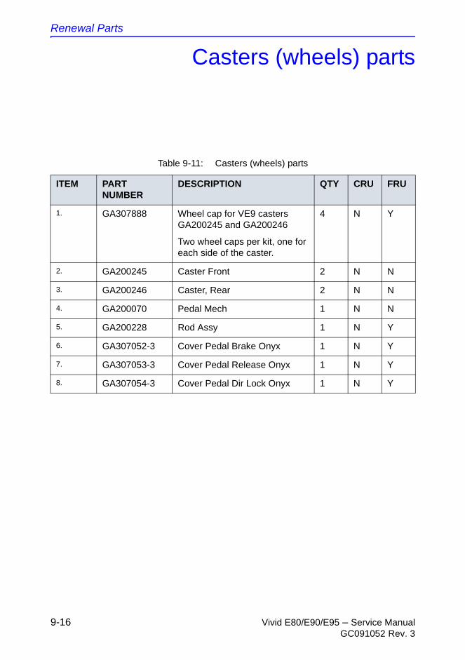
Renewal Parts
9-16 Vivid E80/E90/E95 – Service ManualGC091052 Rev. 3
Casters (wheels) parts
Table 9-11: Casters (wheels) parts
ITEM PART NUMBER
DESCRIPTION QTY CRU FRU
1. GA307888 Wheel cap for VE9 casters GA200245 and GA200246
Two wheel caps per kit, one for each side of the caster.
4 N Y
2. GA200245 Caster Front 2 N N
3. GA200246 Caster, Rear 2 N N
4. GA200070 Pedal Mech 1 N N
5. GA200228 Rod Assy 1 N Y
6. GA307052-3 Cover Pedal Brake Onyx 1 N Y
7. GA307053-3 Cover Pedal Release Onyx 1 N Y
8. GA307054-3 Cover Pedal Dir Lock Onyx 1 N Y
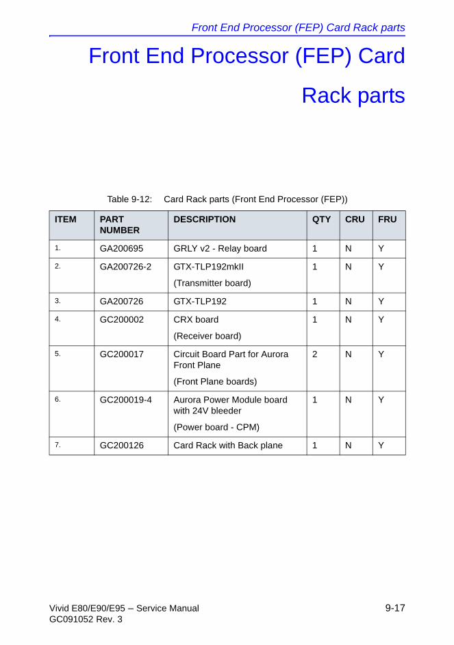
Front End Processor (FEP) Card Rack parts
Vivid E80/E90/E95 – Service Manual 9-17GC091052 Rev. 3
Front End Processor (FEP) Card
Rack parts
Table 9-12: Card Rack parts (Front End Processor (FEP))
ITEM PART NUMBER
DESCRIPTION QTY CRU FRU
1. GA200695 GRLY v2 - Relay board 1 N Y
2. GA200726-2 GTX-TLP192mkII
(Transmitter board)
1 N Y
3. GA200726 GTX-TLP192 1 N Y
4. GC200002 CRX board
(Receiver board)
1 N Y
5. GC200017 Circuit Board Part for Aurora Front Plane
(Front Plane boards)
2 N Y
6. GC200019-4 Aurora Power Module board with 24V bleeder
(Power board - CPM)
1 N Y
7. GC200126 Card Rack with Back plane 1 N Y
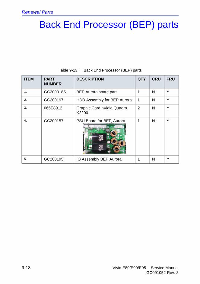
Renewal Parts
9-18 Vivid E80/E90/E95 – Service ManualGC091052 Rev. 3
Back End Processor (BEP) parts
Table 9-13: Back End Processor (BEP) parts
ITEM PART NUMBER
DESCRIPTION QTY CRU FRU
1. GC200018S BEP Aurora spare part 1 N Y
2. GC200197 HDD Assembly for BEP Aurora 1 N Y
3. 066E8912 Graphic Card nVidia Quadro K2200
2 N Y
4. GC200157 PSU Board for BEP, Aurora 1 N Y
5. GC200195 IO Assembly BEP Aurora 1 N Y
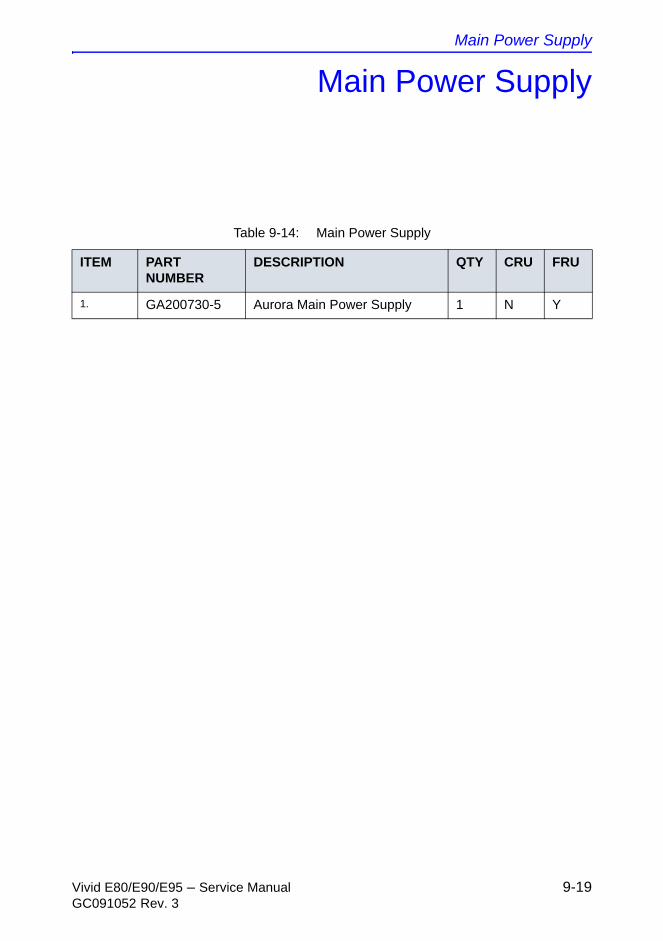
Main Power Supply
Vivid E80/E90/E95 – Service Manual 9-19GC091052 Rev. 3
Main Power Supply
Table 9-14: Main Power Supply
ITEM PART NUMBER
DESCRIPTION QTY CRU FRU
1. GA200730-5 Aurora Main Power Supply 1 N Y
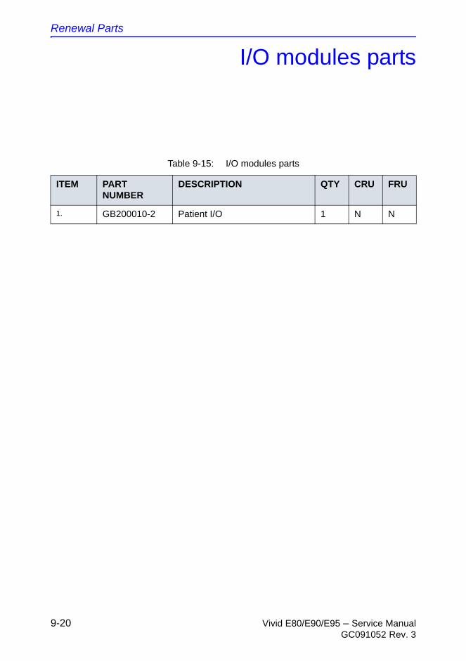
Renewal Parts
9-20 Vivid E80/E90/E95 – Service ManualGC091052 Rev. 3
I/O modules parts
Table 9-15: I/O modules parts
ITEM PART NUMBER
DESCRIPTION QTY CRU FRU
1. GB200010-2 Patient I/O 1 N N
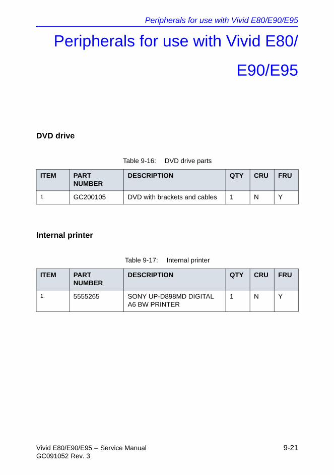
Peripherals for use with Vivid E80/E90/E95
Vivid E80/E90/E95 – Service Manual 9-21GC091052 Rev. 3
Peripherals for use with Vivid E80/
E90/E95
DVD drive
Internal printer
Table 9-16: DVD drive parts
ITEM PART NUMBER
DESCRIPTION QTY CRU FRU
1. GC200105 DVD with brackets and cables 1 N Y
Table 9-17: Internal printer
ITEM PART NUMBER
DESCRIPTION QTY CRU FRU
1. 5555265 SONY UP-D898MD DIGITAL A6 BW PRINTER
1 N Y
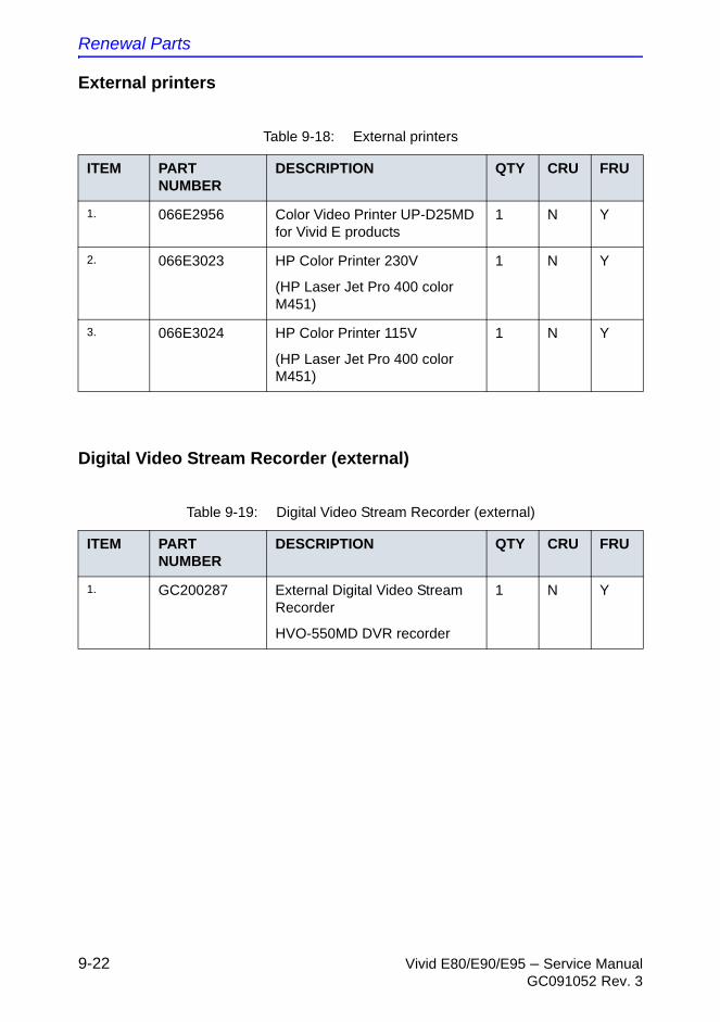
Renewal Parts
9-22 Vivid E80/E90/E95 – Service ManualGC091052 Rev. 3
External printers
Digital Video Stream Recorder (external)
Table 9-18: External printers
ITEM PART NUMBER
DESCRIPTION QTY CRU FRU
1. 066E2956 Color Video Printer UP-D25MD for Vivid E products
1 N Y
2. 066E3023 HP Color Printer 230V
(HP Laser Jet Pro 400 color M451)
1 N Y
3. 066E3024 HP Color Printer 115V
(HP Laser Jet Pro 400 color M451)
1 N Y
Table 9-19: Digital Video Stream Recorder (external)
ITEM PART NUMBER
DESCRIPTION QTY CRU FRU
1. GC200287 External Digital Video Stream Recorder
HVO-550MD DVR recorder
1 N Y
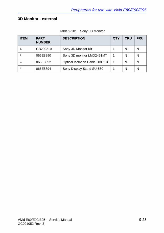
Peripherals for use with Vivid E80/E90/E95
Vivid E80/E90/E95 – Service Manual 9-23GC091052 Rev. 3
3D Monitor - external
Table 9-20: Sony 3D Monitor
ITEM PART NUMBER
DESCRIPTION QTY CRU FRU
1. GB200210 Sony 3D Monitor Kit 1 N N
2. 066E8890 Sony 3D monitor LMD2451MT 1 N N
3. 066E8892 Optical Isolation Cable DVI 104 1 N N
4. 066E8894 Sony Display Stand SU-560 1 N N
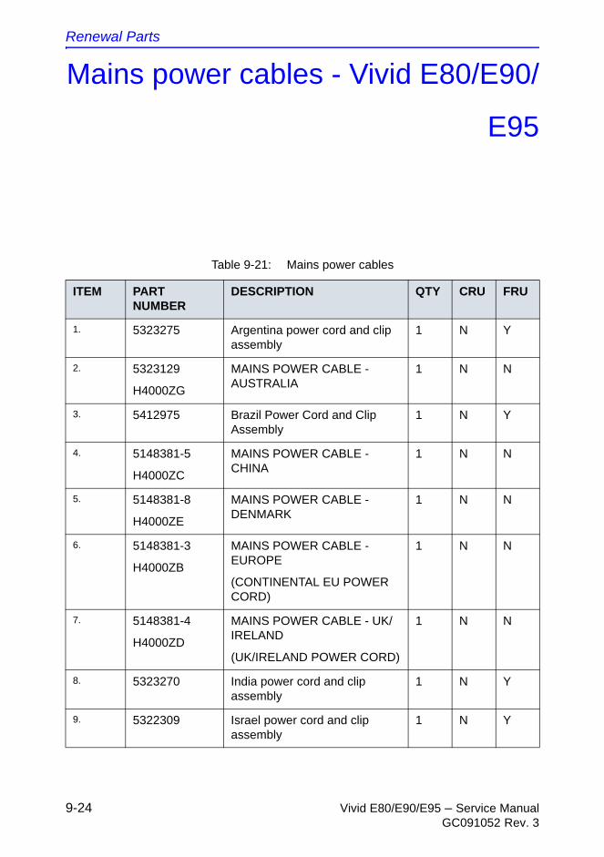
Renewal Parts
9-24 Vivid E80/E90/E95 – Service ManualGC091052 Rev. 3
Mains power cables - Vivid E80/E90/
E95
Table 9-21: Mains power cables
ITEM PART NUMBER
DESCRIPTION QTY CRU FRU
1. 5323275 Argentina power cord and clip assembly
1 N Y
2. 5323129
H4000ZG
MAINS POWER CABLE - AUSTRALIA
1 N N
3. 5412975 Brazil Power Cord and Clip Assembly
1 N Y
4. 5148381-5
H4000ZC
MAINS POWER CABLE - CHINA
1 N N
5. 5148381-8
H4000ZE
MAINS POWER CABLE - DENMARK
1 N N
6. 5148381-3
H4000ZB
MAINS POWER CABLE - EUROPE
(CONTINENTAL EU POWER CORD)
1 N N
7. 5148381-4
H4000ZD
MAINS POWER CABLE - UK/ IRELAND
(UK/IRELAND POWER CORD)
1 N N
8. 5323270 India power cord and clip assembly
1 N Y
9. 5322309 Israel power cord and clip assembly
1 N Y
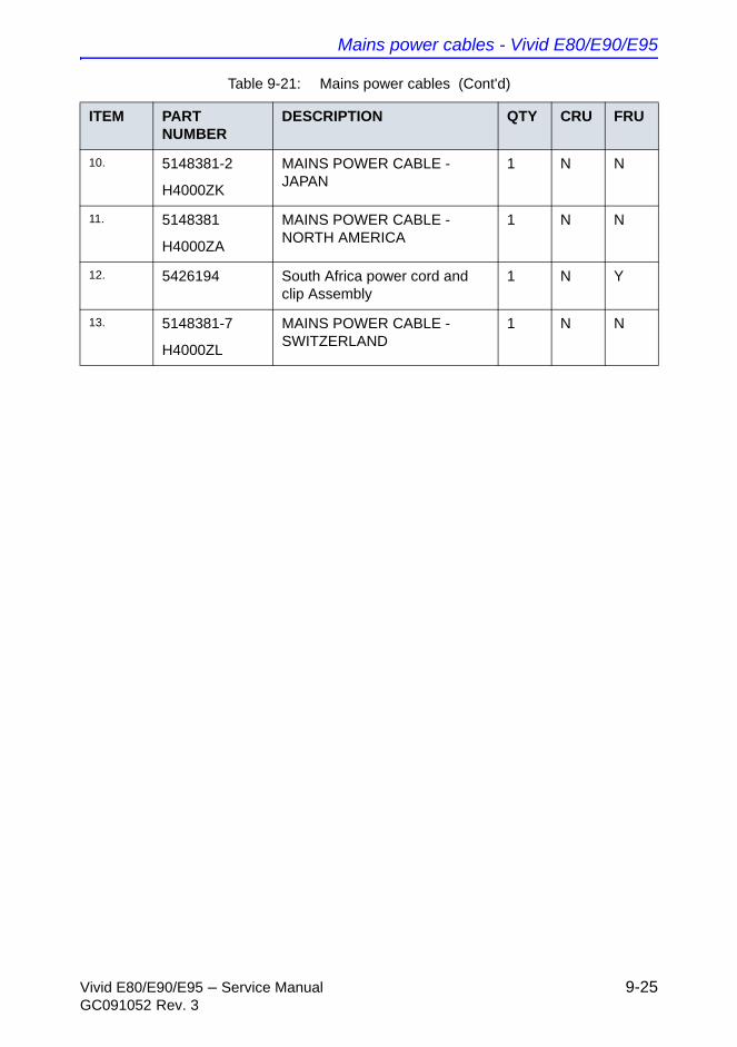
Mains power cables - Vivid E80/E90/E95
Vivid E80/E90/E95 – Service Manual 9-25GC091052 Rev. 3
10. 5148381-2
H4000ZK
MAINS POWER CABLE - JAPAN
1 N N
11. 5148381
H4000ZA
MAINS POWER CABLE - NORTH AMERICA
1 N N
12. 5426194 South Africa power cord and clip Assembly
1 N Y
13. 5148381-7
H4000ZL
MAINS POWER CABLE - SWITZERLAND
1 N N
Table 9-21: Mains power cables (Cont'd)
ITEM PART NUMBER
DESCRIPTION QTY CRU FRU
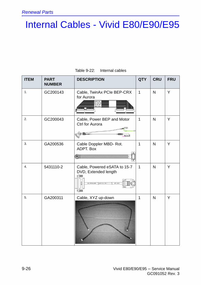
Renewal Parts
9-26 Vivid E80/E90/E95 – Service ManualGC091052 Rev. 3
Internal Cables - Vivid E80/E90/E95
Table 9-22: Internal cables
ITEM PART NUMBER
DESCRIPTION QTY CRU FRU
1. GC200143 Cable, TwinAx PCIe BEP-CRX for Aurora
1 N Y
2. GC200043 Cable, Power BEP and Motor Ctrl for Aurora
1 N Y
3. GA200536 Cable Doppler MBD- Rot. ADPT. Box
1 N Y
4. 5431110-2 Cable, Powered eSATA to 15-7 DVD, Extended length
1 N Y
5. GA200311 Cable, XYZ up-down 1 N Y
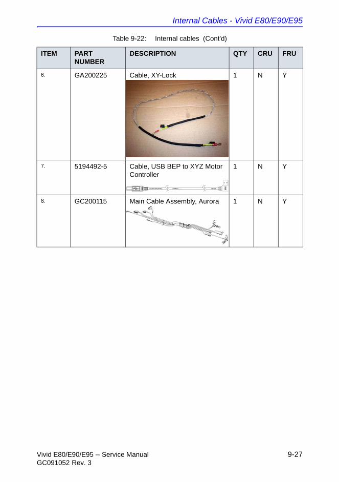
Internal Cables - Vivid E80/E90/E95
Vivid E80/E90/E95 – Service Manual 9-27GC091052 Rev. 3
6. GA200225 Cable, XY-Lock 1 N Y
7. 5194492-5 Cable, USB BEP to XYZ Motor Controller
1 N Y
8. GC200115 Main Cable Assembly, Aurora 1 N Y
Table 9-22: Internal cables (Cont'd)
ITEM PART NUMBER
DESCRIPTION QTY CRU FRU
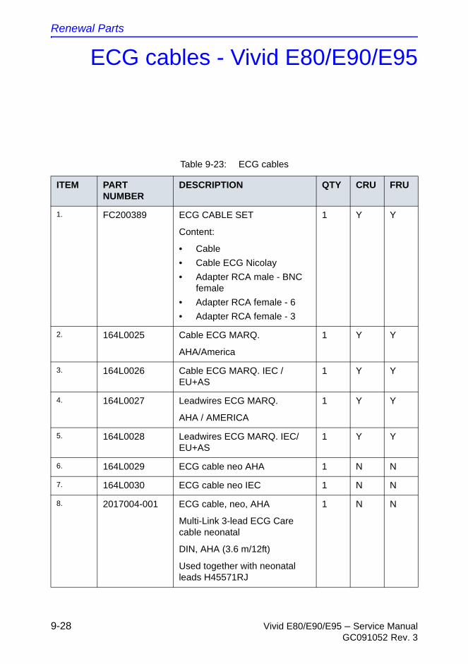
Renewal Parts
9-28 Vivid E80/E90/E95 – Service ManualGC091052 Rev. 3
ECG cables - Vivid E80/E90/E95
Table 9-23: ECG cables
ITEM PART NUMBER
DESCRIPTION QTY CRU FRU
1. FC200389 ECG CABLE SET
Content:
• Cable
• Cable ECG Nicolay
• Adapter RCA male - BNC female
• Adapter RCA female - 6
• Adapter RCA female - 3
1 Y Y
2. 164L0025 Cable ECG MARQ.
AHA/America
1 Y Y
3. 164L0026 Cable ECG MARQ. IEC / EU+AS
1 Y Y
4. 164L0027 Leadwires ECG MARQ.
AHA / AMERICA
1 Y Y
5. 164L0028 Leadwires ECG MARQ. IEC/EU+AS
1 Y Y
6. 164L0029 ECG cable neo AHA 1 N N
7. 164L0030 ECG cable neo IEC 1 N N
8. 2017004-001 ECG cable, neo, AHA
Multi-Link 3-lead ECG Care cable neonatal
DIN, AHA (3.6 m/12ft)
Used together with neonatal leads H45571RJ
1 N N
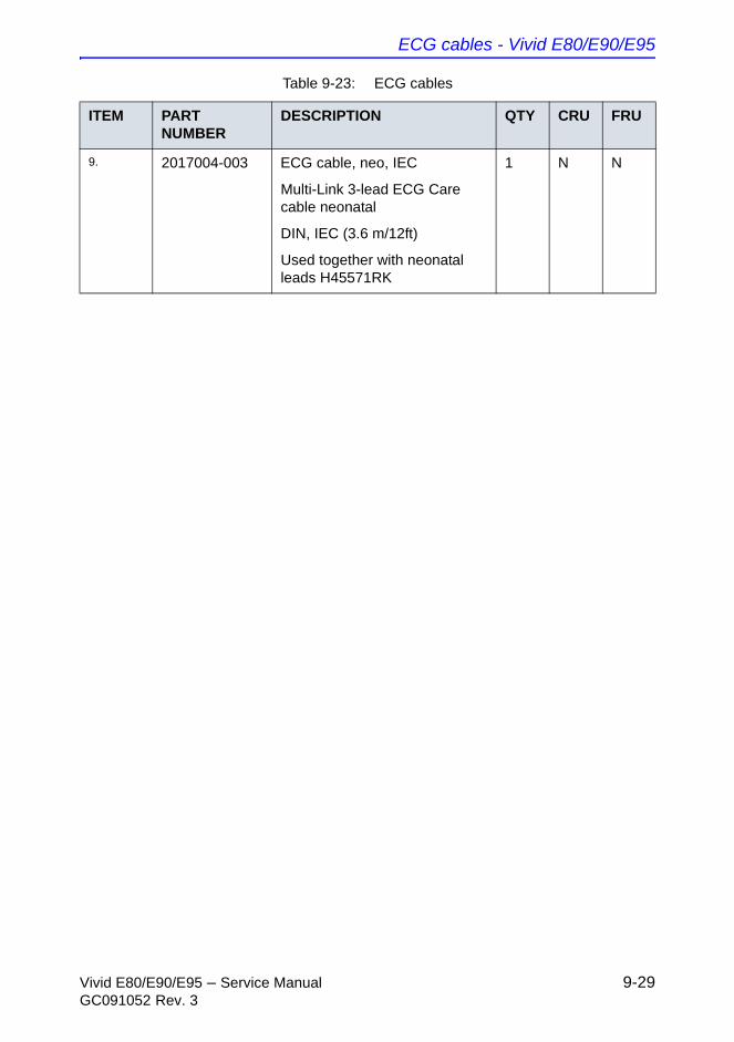
ECG cables - Vivid E80/E90/E95
Vivid E80/E90/E95 – Service Manual 9-29GC091052 Rev. 3
9. 2017004-003 ECG cable, neo, IEC
Multi-Link 3-lead ECG Care cable neonatal
DIN, IEC (3.6 m/12ft)
Used together with neonatal leads H45571RK
1 N N
Table 9-23: ECG cables
ITEM PART NUMBER
DESCRIPTION QTY CRU FRU
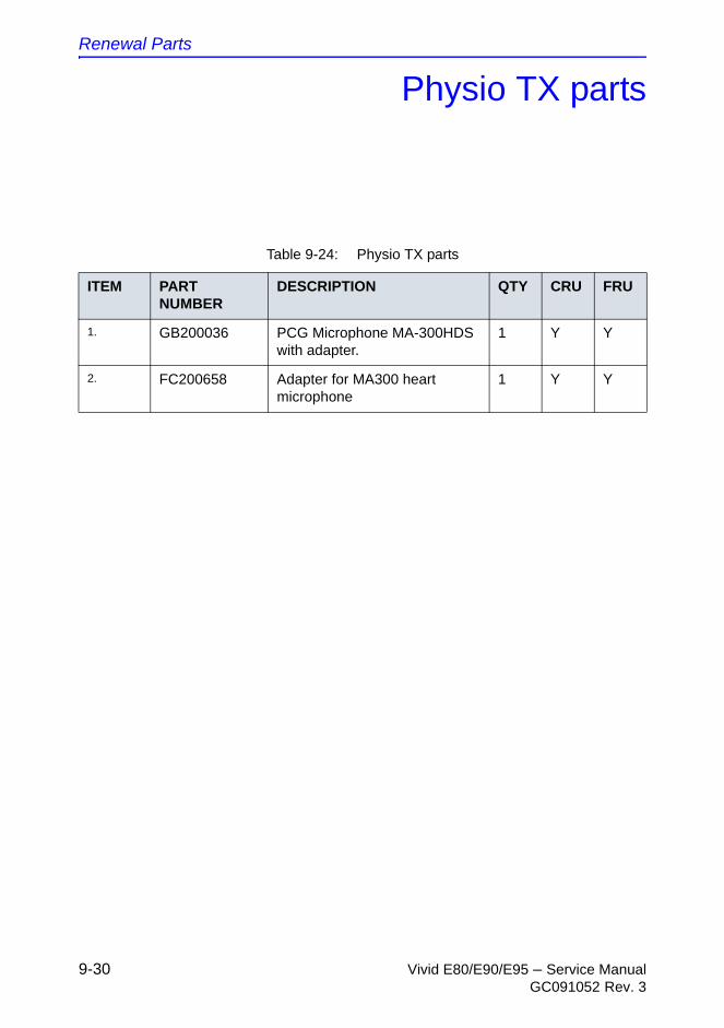
Renewal Parts
9-30 Vivid E80/E90/E95 – Service ManualGC091052 Rev. 3
Physio TX parts
Table 9-24: Physio TX parts
ITEM PART NUMBER
DESCRIPTION QTY CRU FRU
1. GB200036 PCG Microphone MA-300HDS with adapter.
1 Y Y
2. FC200658 Adapter for MA300 heart microphone
1 Y Y
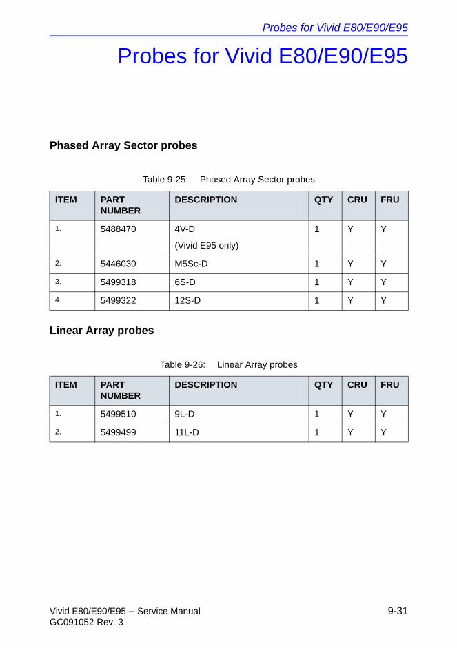
Probes for Vivid E80/E90/E95
Vivid E80/E90/E95 – Service Manual 9-31GC091052 Rev. 3
Probes for Vivid E80/E90/E95
Phased Array Sector probes
Linear Array probes
Table 9-25: Phased Array Sector probes
ITEM PART NUMBER
DESCRIPTION QTY CRU FRU
1. 5488470 4V-D
(Vivid E95 only)
1 Y Y
2. 5446030 M5Sc-D 1 Y Y
3. 5499318 6S-D 1 Y Y
4. 5499322 12S-D 1 Y Y
Table 9-26: Linear Array probes
ITEM PART NUMBER
DESCRIPTION QTY CRU FRU
1. 5499510 9L-D 1 Y Y
2. 5499499 11L-D 1 Y Y
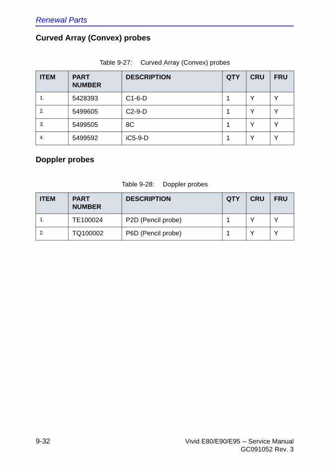
Renewal Parts
9-32 Vivid E80/E90/E95 – Service ManualGC091052 Rev. 3
Curved Array (Convex) probes
Doppler probes
Table 9-27: Curved Array (Convex) probes
ITEM PART NUMBER
DESCRIPTION QTY CRU FRU
1. 5428393 C1-6-D 1 Y Y
2. 5499605 C2-9-D 1 Y Y
3. 5499505 8C 1 Y Y
4. 5499592 iC5-9-D 1 Y Y
Table 9-28: Doppler probes
ITEM PART NUMBER
DESCRIPTION QTY CRU FRU
1. TE100024 P2D (Pencil probe) 1 Y Y
2. TQ100002 P6D (Pencil probe) 1 Y Y
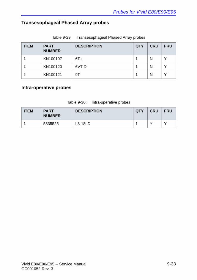
Probes for Vivid E80/E90/E95
Vivid E80/E90/E95 – Service Manual 9-33GC091052 Rev. 3
Transesophageal Phased Array probes
Intra-operative probes
Table 9-29: Transesophageal Phased Array probes
ITEM PART NUMBER
DESCRIPTION QTY CRU FRU
1. KN100107 6Tc 1 N Y
2. KN100120 6VT-D 1 N Y
3. KN100121 9T 1 N Y
Table 9-30: Intra-operative probes
ITEM PART NUMBER
DESCRIPTION QTY CRU FRU
1. 5335525 L8-18i-D 1 Y Y
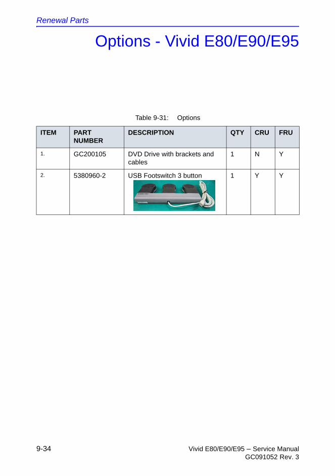
Renewal Parts
9-34 Vivid E80/E90/E95 – Service ManualGC091052 Rev. 3
Options - Vivid E80/E90/E95
Table 9-31: Options
ITEM PART NUMBER
DESCRIPTION QTY CRU FRU
1. GC200105 DVD Drive with brackets and cables
1 N Y
2. 5380960-2 USB Footswitch 3 button 1 Y Y

Vivid E80/E90/E95 – Service Manual 10-1GC091052 Rev. 3
Chapter 10
Care and Maintenance
Care and Maintenance
10-2 Vivid E80/E90/E95 – Service ManualGC091052 Rev. 3
Overview
Periodic maintenance inspections
It has been determined by engineering that your Vivid E80/E90/E95 does not have any high wear components that fail with use, therefore Periodic Maintenance inspections are not mandatory.
However, some customers’ Quality Assurance Programs may require additional tasks and or inspections at a different frequency than listed in this manual.
Why do maintenance
Vivid E80/E90/E95 – Service Manual 10-3GC091052 Rev. 3
Why do maintenance
Quality assurance
In order to gain accreditation from organizations such as the American College of Radiology (USA), it is the customer’s responsibility to have a quality assurance program in place for each Ultrasound system. The program must be directed by a medical physicists, the supervising radiologist/physician or appropriate designee.
Routine quality control testing must occur regularly. The same tests are performed during each period so that changes can be monitored over time and effective corrective action can be taken.
Testing results, corrective action and the effects of corrective action must be documented and maintained on the site.
Your GE service representative can help you with establishing, performing and maintaining records for a quality assurance program. Contact GE for coverage and/or price for service.
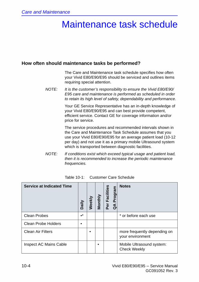
Care and Maintenance
10-4 Vivid E80/E90/E95 – Service ManualGC091052 Rev. 3
Maintenance task schedule
How often should maintenance tasks be performed?
The Care and Maintenance task schedule specifies how often your Vivid E80/E90/E95 should be serviced and outlines items requiring special attention.
NOTE: It is the customer’s responsibility to ensure the Vivid E80/E90/E95 care and maintenance is performed as scheduled in order to retain its high level of safety, dependability and performance.
Your GE Service Representative has an in-depth knowledge of your Vivid E80/E90/E95 and can best provide competent, efficient service. Contact GE for coverage information and/or price for service.
The service procedures and recommended intervals shown in the Care and Maintenance Task Schedule assumes that you use your Vivid E80/E90/E95 for an average patient load (10-12 per day) and not use it as a primary mobile Ultrasound system which is transported between diagnostic facilities.
NOTE: If conditions exist which exceed typical usage and patient load, then it is recommended to increase the periodic maintenance frequencies.
Table 10-1: Customer Care Schedule
Service at Indicated Time
Dai
ly
We
ekly
Mo
nth
ly
Per
Fac
iliti
es
QA
Pro
gra
m Notes
Clean Probes •* * or before each use
Clean Probe Holders •
Clean Air Filters • more frequently depending on your environment
Inspect AC Mains Cable • Mobile Ultrasound system: Check Weekly
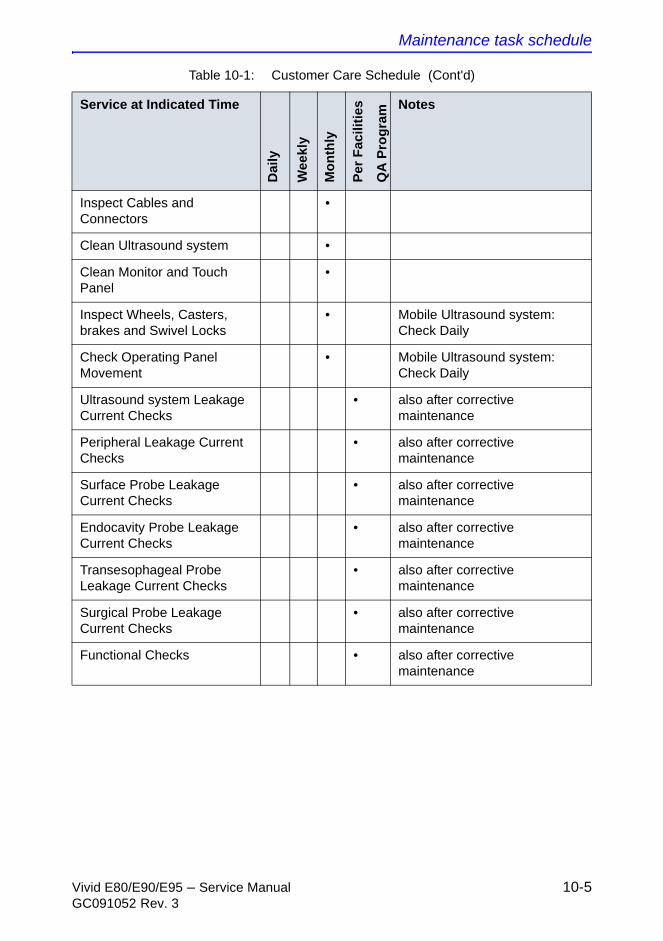
Maintenance task schedule
Vivid E80/E90/E95 – Service Manual 10-5GC091052 Rev. 3
Inspect Cables and Connectors
•
Clean Ultrasound system •
Clean Monitor and Touch Panel
•
Inspect Wheels, Casters, brakes and Swivel Locks
• Mobile Ultrasound system: Check Daily
Check Operating Panel Movement
• Mobile Ultrasound system: Check Daily
Ultrasound system Leakage Current Checks
• also after corrective maintenance
Peripheral Leakage Current Checks
• also after corrective maintenance
Surface Probe Leakage Current Checks
• also after corrective maintenance
Endocavity Probe Leakage Current Checks
• also after corrective maintenance
Transesophageal Probe Leakage Current Checks
• also after corrective maintenance
Surgical Probe Leakage Current Checks
• also after corrective maintenance
Functional Checks • also after corrective maintenance
Table 10-1: Customer Care Schedule (Cont'd)
Service at Indicated Time
Da
ily
We
ekl
y
Mo
nth
ly
Per
Fac
ilit
ies
QA
Pro
gra
m Notes

Care and Maintenance
10-6 Vivid E80/E90/E95 – Service ManualGC091052 Rev. 3
THIS PAGE WAS INTENTIONALLY LEFT BLANK
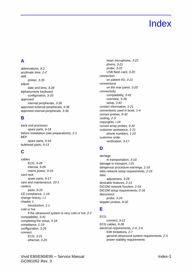
Vivid E80/E90/E95 – Service Manual Index-1GC091052 Rev. 3
Index
A
abbrevations, 9-2acclimate time, 2-2add
printer, 3-35adjust
date and time, 3-28alphanumeric keyboard
configuration, 3-33approved
internal peripherals, 3-36approved external peripherals, 3-36approved internal peripherals, 3-36
B
back end processorspare parts, 9-18
before installation (site preparations), 2-1BEP
spare parts, 9-18bulkhead parts, 9-13
C
cablesECG, 9-28internal, 9-26mains power, 9-24
card rackspare parts, 9-17
care and maintenance, 10-1casters
parts, 9-16CE compliance, 1-19change history, i-1chapter 1
introduction, 1-1cold or hot
if the ultrasound system is very cold or hot, 2-2compatibility, 3-41completing the setup, 3-18compliance, 1-19configuration, 3-25connect
ECG, 3-21ethernet, 3-20
heart microphone, 3-21phono, 3-21probe, 3-22USB flash card, 3-20
connectionon patient I/O, 3-21
connectionson the rear panel, 3-20
connectivitycompatibility, 3-41overview, 3-39setup, 3-41
contact information, 1-21conventions used in book, 1-4convex probes, 9-32cooling, 2-3copyrights, i-19curved array probes, 9-32customer assistance, 1-21
phone numbers, 1-22customer order
verification, 3-17
D
damagein transportation, 3-10
damage in transport, i-15dangerous procedure warnings, 1-16data network setup requirements, 2-15date
adjustment, 3-28desirable features, 2-13DICOM network function, 2-16DICOM setup requirements, 2-16disconnect
probe, 3-24doppler probes, 9-32
E
ECGconnect, 3-21
ECG cables, 9-28electrical requirements, 2-4, 2-6
EMI limitations, 2-7general ultrasound system requirements, 2-4power stability requirements
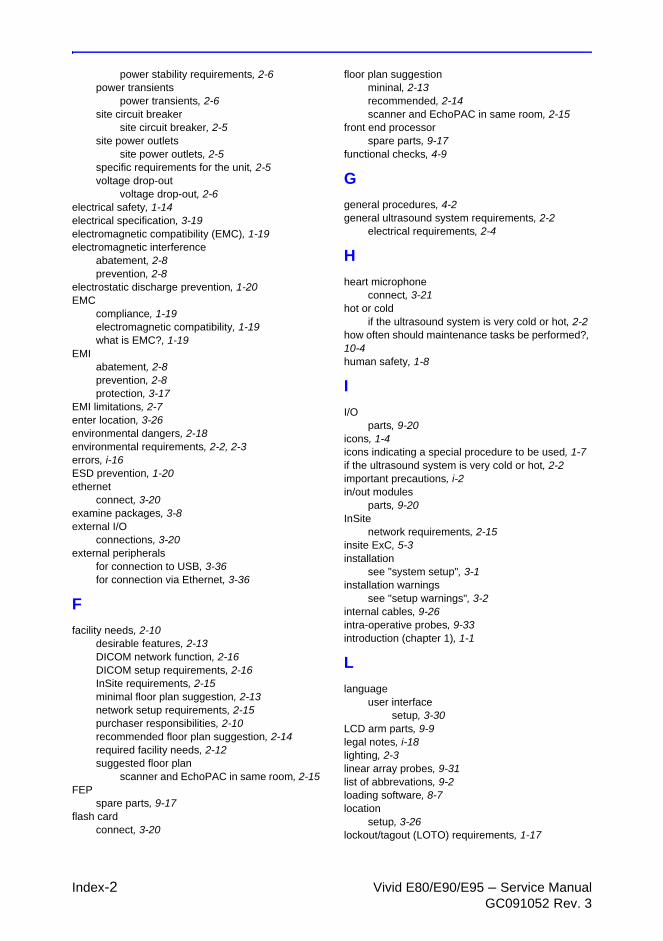
Index-2 Vivid E80/E90/E95 – Service ManualGC091052 Rev. 3
power stability requirements, 2-6power transients
power transients, 2-6site circuit breaker
site circuit breaker, 2-5site power outlets
site power outlets, 2-5specific requirements for the unit, 2-5voltage drop-out
voltage drop-out, 2-6electrical safety, 1-14electrical specification, 3-19electromagnetic compatibility (EMC), 1-19electromagnetic interference
abatement, 2-8prevention, 2-8
electrostatic discharge prevention, 1-20EMC
compliance, 1-19electromagnetic compatibility, 1-19what is EMC?, 1-19
EMIabatement, 2-8prevention, 2-8protection, 3-17
EMI limitations, 2-7enter location, 3-26environmental dangers, 2-18environmental requirements, 2-2, 2-3errors, i-16ESD prevention, 1-20ethernet
connect, 3-20examine packages, 3-8external I/O
connections, 3-20external peripherals
for connection to USB, 3-36for connection via Ethernet, 3-36
F
facility needs, 2-10desirable features, 2-13DICOM network function, 2-16DICOM setup requirements, 2-16InSite requirements, 2-15minimal floor plan suggestion, 2-13network setup requirements, 2-15purchaser responsibilities, 2-10recommended floor plan suggestion, 2-14required facility needs, 2-12suggested floor plan
scanner and EchoPAC in same room, 2-15FEP
spare parts, 9-17flash card
connect, 3-20
floor plan suggestionmininal, 2-13recommended, 2-14scanner and EchoPAC in same room, 2-15
front end processorspare parts, 9-17
functional checks, 4-9
G
general procedures, 4-2general ultrasound system requirements, 2-2
electrical requirements, 2-4
H
heart microphoneconnect, 3-21
hot or coldif the ultrasound system is very cold or hot, 2-2
how often should maintenance tasks be performed?, 10-4human safety, 1-8
I
I/Oparts, 9-20
icons, 1-4icons indicating a special procedure to be used, 1-7if the ultrasound system is very cold or hot, 2-2important precautions, i-2in/out modules
parts, 9-20InSite
network requirements, 2-15insite ExC, 5-3installation
see "system setup", 3-1installation warnings
see "setup warnings", 3-2internal cables, 9-26intra-operative probes, 9-33introduction (chapter 1), 1-1
L
languageuser interface
setup, 3-30LCD arm parts, 9-9legal notes, i-18lighting, 2-3linear array probes, 9-31list of abbrevations, 9-2loading software, 8-7location
setup, 3-26lockout/tagout (LOTO) requirements, 1-17

Vivid E80/E90/E95 – Service Manual Index-3GC091052 Rev. 3
LOTOlockout/tagout requirements, 1-17
M
main console parts, 9-15main monitor parts, 9-9main power supply, 9-19mains power cables, 9-24maintenance task schedule, 10-4manufacturer, 1-23mass
with monitor and peripherals, 3-18mechanical safety, 1-11model designations, 1-4models covered by this manual, 1-2
N
network setup requirements, 2-15
O
omission and errors, i-16OP parts, 9-11operating panel parts, 9-11operational and storage temperature for probes, 2-9options, 9-34overview of the ultrasound system, 1-3
P
packing materialsrecycling information, 3-15
patient I/Oconnections, 3-21
periodic maintenance inspection (PM), PM (periodic maintenance inspection), 10-2peripherals, 9-21phased array sector probes, 9-31phone numbers
customer assistance, 1-22phono
connect, 3-21physical dimensions, 3-18physical inspection
at arrivel, 3-17physio tx parts, 9-30power cables
mains, 9-24power supply
main, 9-19precautions
certified electrical contractor statement, i-15damage in transport, i-15important precautions, i-2service safety considerations, i-17translation policy, i-2
prepeare for setup, 3-17
printeradd, 3-35
probeconnect, 3-22disconnect, 3-24
probes, 9-31convex, 9-32curved array, 9-32doppler, 9-32intra-operative, 9-33linear array, 9-31phased array sector, 9-31TEE (transesophageal phased array), 9-33transesophageal phased array, 9-33
probes environmental requirements, 2-9operational and storage temperature for probes,
2-9product description, 1-3product icons, 1-7product locator installation card, 3-50products covered by this manual, 1-2purchaser responsibilities, 2-10purpose of operator manual, 1-3
R
rear panelconnections, 3-20
receiving and unpacking, 3-4receiving the product, 3-8recycling information
packing materials, 3-15required facility needs, 2-12requirements
ultrasound system, 2-2requirements verification, 3-18returning/shipping probes and repair parts, 1-18revision history, i-1
S
safetyhuman, 1-8
safety precaution messages, 1-4select
unit of measure, 3-31video format, 3-31
service safety considerations, i-17service screen
setup, 3-32setup
completion, 3-18preparations, 3-17reminders, 3-2service screen, 3-32
setup warnings, 3-2shipping/returning probes and repair parts, 1-18shock indicator, 3-5
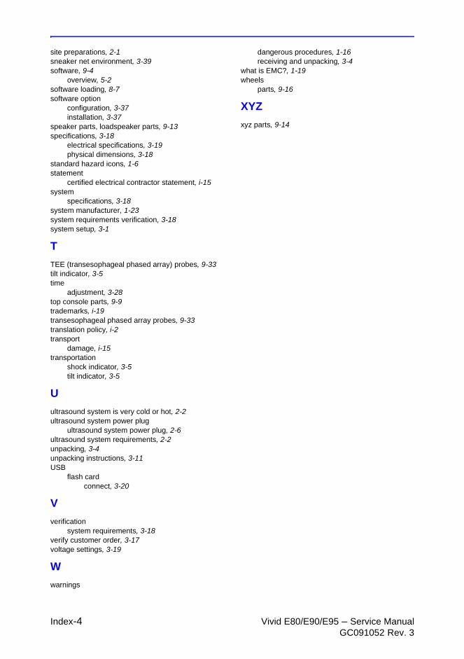
Index-4 Vivid E80/E90/E95 – Service ManualGC091052 Rev. 3
site preparations, 2-1sneaker net environment, 3-39software, 9-4
overview, 5-2software loading, 8-7software option
configuration, 3-37installation, 3-37
speaker parts, loadspeaker parts, 9-13specifications, 3-18
electrical specifications, 3-19physical dimensions, 3-18
standard hazard icons, 1-6statement
certified electrical contractor statement, i-15system
specifications, 3-18system manufacturer, 1-23system requirements verification, 3-18system setup, 3-1
T
TEE (transesophageal phased array) probes, 9-33tilt indicator, 3-5time
adjustment, 3-28top console parts, 9-9trademarks, i-19transesophageal phased array probes, 9-33translation policy, i-2transport
damage, i-15transportation
shock indicator, 3-5tilt indicator, 3-5
U
ultrasound system is very cold or hot, 2-2ultrasound system power plug
ultrasound system power plug, 2-6ultrasound system requirements, 2-2unpacking, 3-4unpacking instructions, 3-11USB
flash cardconnect, 3-20
V
verificationsystem requirements, 3-18
verify customer order, 3-17voltage settings, 3-19
W
warnings
dangerous procedures, 1-16receiving and unpacking, 3-4
what is EMC?, 1-19wheels
parts, 9-16
XYZ
xyz parts, 9-14


© 2014-2015 General Electric Company. Manufacturer: GE VINGMED ULTRASOUND ASStrandpromenaden 45NO-3191 Horten, NorwayTel:(+47) 3302 1100 Fax: (+47) 3302 1350www.gehealthcare.com