Reasons for withdrawing belief in vivid autobiographical memories
Upload
khangminh22Category
view
2download
0
User Manual

Table of Contents
Vivid Drive 23N User Manual Rev. 1i
TABLE OF CONTENTS
1. Before You Begin ....................................................................... 1What Is Included ........................................................................................... 1Unpacking Instructions.................................................................................. 1
Claims ................................................................................................................ 1Text Conventions .......................................................................................... 1Symbols ........................................................................................................ 1Disclaimer ..................................................................................................... 1Safety Notes.................................................................................................. 2
2. Introduction ................................................................................ 3Product Overview.......................................................................................... 3
Front Overview................................................................................................... 3Control Panel Description ........................................................................................ 3
Rear Overview ................................................................................................... 4Rear Panel Description............................................................................................ 4
Product Dimensions ...................................................................................... 5
3. Setup ........................................................................................... 6AC Power ...................................................................................................... 6Mounting ....................................................................................................... 6
Orientation.......................................................................................................... 6Rigging ............................................................................................................... 6
Signal Connections ....................................................................................... 6Video Source Connection .................................................................................. 6NovaLCTMars Connection................................................................................. 6Preview Monitor Connection .............................................................................. 6Connection Diagram .......................................................................................... 7
4. Operation .................................................................................... 8Control Panel Operation................................................................................ 8Menu Map ..................................................................................................... 8Operating Settings Configuration.................................................................. 13
INPUT Settings .................................................................................................. 13INPUT DETAIL ........................................................................................................ 13ZOOM ADJUST....................................................................................................... 13VGA ADJUST .......................................................................................................... 13ADC ADJUST .......................................................................................................... 13
OUTPUT Settings .............................................................................................. 14OUTPUT DETAIL .................................................................................................... 14OUTPUT FORMAT.................................................................................................. 14OUTPUT ADJUST................................................................................................... 14SCALE Settings....................................................................................................... 15SCREEN Settings.................................................................................................... 16RATIO...................................................................................................................... 16PICTURE Settings................................................................................................... 16Picture In Picture ..................................................................................................... 16TEXT OVERLAY ..................................................................................................... 17DISPLAY MODE...................................................................................................... 18GAMMA ................................................................................................................... 19

Vivid Drive 23N User Manual Rev. 1
Table of Contents
ii
TRANSITION Settings ....................................................................................... 20Transition MODE ..................................................................................................... 20FADE TIME ............................................................................................................. 20Transition ALPHA .................................................................................................... 20DEINTERLACE ....................................................................................................... 21
SPLIT Settings ................................................................................................... 21SPLIT Total.............................................................................................................. 21SPLIT Position and Size.......................................................................................... 21
SAVE SETUP Settings....................................................................................... 21SAVE TO ................................................................................................................. 21LOAD FROM ........................................................................................................... 22DELAY CALL........................................................................................................... 22
SYSTEM Settings .............................................................................................. 22SYSTEM INFO ........................................................................................................ 22TECH SUPPORT .................................................................................................... 22DATE&TIME ............................................................................................................ 22LOCK FRONT PANEL............................................................................................. 23HOT BACKUP ......................................................................................................... 23EDID FOLLOW........................................................................................................ 23
LANGUAGE語言 .................................................... 24FACTORY RESET ............................................................................................. 24
Total Reset .............................................................................................................. 24SAVE IP RESET...................................................................................................... 24
NovaLCTMars Software................................................................................ 25Software Setup................................................................................................... 25Screen Configuration ......................................................................................... 25
Sending Card Tab ................................................................................................... 25Receiving Card Tab................................................................................................. 25Screen Connection Tab........................................................................................... 25
Firmware Update................................................................................................ 26Video Panel Firmware Update ........................................................................... 26
Getting Started.............................................................................................. 27
5. Maintenance................................................................................ 28Product Maintenance .................................................................................... 28
6. Technical Specifications ........................................................... 29
Returns............................................................................................ 30
Contact Us ...................................................................................... 31

Page 1 of 31
Before You Begin
Vivid Drive 23N User Manual Rev. 1
1. Before You BeginWhat Is Included
Unpacking InstructionsCarefully unpack the product immediately and check the container to make sure all the parts are in the package and are in good condition.
ClaimsIf the box or the contents (the product and included accessories) appear damaged from shipping, or show signs of mishandling, notify the carrier immediately, not Chauvet. Failure to report damage to the carrier immediately may invalidate your claim. In addition, keep the box and contents for inspection.For other issues, such as missing components or parts, damage not related to shipping, or concealed damage, file a claim with Chauvet within 7 days of delivery.
Text Conventions
Symbols
DisclaimerChauvet believes that the information contained in this manual is accurate in all respects. However, Chauvet assumes no responsibility and specifically disclaims any and all liability to any party for any loss, damage or disruption caused by any errors or omissions in this document, whether such errors or omissions result from negligence, accident or any other cause. Chauvet reserves the right to revise the content of this document without any obligation to notify any person or company of such revision, however, Chauvet has no obligation to make, and does not commit to make, any such revisions. Download the latest version from www.chauvetdj.com.The works of authorship contained in this manual, including, but not limited to, all design, text and images are owned by Chauvet.© Copyright 2018 Chauvet & Sons, LLC. All rights reserved.Electronically published by Chauvet in the United States of America.CHAUVET, the Chauvet logo, and Vivid Drive 23N are registered trademarks or trademarks of Chauvet & Sons LLC (d/b/a Chauvet and Chauvet Lighting) in the United States and other countries. Other company and product names and logos referred to herein may be trademarks of their respective companies.
• Vivid Drive 23N• Power Cord• Rack Mount Adapter• DVI-to-DVI Jumper
• USB Cable• Warranty Card• Quick Reference Guide
Convention Meaning
1–512 A range of values
50/60 A set of values of which only one can be chosen
Settings A menu option not to be modified
<ENTER> A key to be pressed on the product’s control panel
ON A value to be entered or selected
Symbol Meaning
Electrical warning. Not following these instructions may cause electrical damage to the product, accessories, or the user.
Critical installation, configuration, or operation information. Not following these instructions may make the product not work, cause damage to the product, or cause harm to the operator.
Important installation or configuration information. The product may not function correctly if this information is not used.
Useful information.

Page 2 of 31Vivid Drive 23N User Manual Rev. 1
Before You Begin
Safety Notes• Always connect the product to a grounded circuit to avoid the risk of electrocution.• Always disconnect the product from the power source before cleaning or replacing the
fuse.• Avoid direct eye exposure to the light source while the product is on.• Make sure the power cord is not crimped or damaged.• Never disconnect the product from power cord by pulling or tugging on the cord.• If mounting the product overhead, always secure to a fastening device using a safety cable.• Make sure there are no flammable materials close to the product when operating.• Do not touch the product’s housing when operating because it may be very hot.
• Always make sure that the voltage of the outlet to which you are connecting the product is within the range stated on the decal or rear panel of the product.
• The product is for indoor use only! (IP20) To prevent risk of fire or shock, do not expose the product to rain or moisture.
• Always install the product in a location with adequate ventilation, at least 20 in (50 cm) from adjacent surfaces.
• Be sure that no ventilation slots on the product’s housing are blocked.• Never connect the product to a dimmer.• Make sure to replace the fuse with another of the same type and rating.• Never carry the product from the power cord or any moving part.• The maximum ambient temperature (Ta) is 104 °F (40 °C). Do not operate the product at
higher temperatures.• In the event of a serious operating problem, stop using the product immediately.• Never try to repair the product. Repairs carried out by unskilled people can lead to damage
or malfunction. Please contact the nearest authorized technical assistance center.• To eliminate unnecessary wear and improve its lifespan, during periods of non-use
completely disconnect the product from power via breaker or by unplugging it.
Keep this User Manual for future use. If you sell the product to someone else, be sure that they also receive this document.

Page 3 of 31
Introduction
Vivid Drive 23N User Manual Rev. 1
2. IntroductionProduct OverviewFront Overview
Control Panel Description
Button/Knob Function
SELECT Knob
Rotate to navigate upwards or downwards through the menu list, and increase or decrease a selected numeric value. Push to enable the currently displayed menu option or set the currently selected value into the selected function.
<CV/1> Selects CVBS input source, or enters the number 1 when editing a number value
<HDMI/2> Selects HDMI input source, or enters the number 2 when editing a number value
<SDI/3> Enters the number 3 when editing a number value
<VGA/4> Selects VGA input source, or enters the number 4 when editing a number value
<YPbPr/5> Selects YPbPr input source, or enters the number 5 when editing a number value
<BLACK/6> Blacks out the video output, or enters the number 6 when editing a number value
<MENU> Exits the current menu or function. Press and hold for 3 seconds to lock or unlock the control panel.
<SCALE/7> Navigates directly to the Scale menu, or enters the number 7 when editing a number value
<SPLIT/8> Navigates directly to the Split menu, or enters the number 8 when editing a number value
<COM/9> Enters the number 9 when editing a number value
<SAVE/0> Navigates directly to the Save menu, or enters the number 0 when editing a number value
<LOAD/10+> Navigates directly to the Load menu
LCD Display SELECT Knob 1
MENU 10+
2 3 4 5 6
7 8 9 0

Page 4 of 31Vivid Drive 23N User Manual Rev. 1
Introduction
Rear Overview
Rear Panel Description
# Port Function
1 RS232 RJ12 port for remote control system connection.
2 USB B 1 USB B port for firmware updates
3 DVI In DVI input connector for video signal from DVI1 OUT (11) or a pre-scaled video source
4 USB B 2 USB B port for connecting to NovaLCT Mars
5 Ethernet Out 2Ethernet ports for sending video signal to video panels (6 is port 1, 5 is port 2)
6 Ethernet Out 1
7 CVBS IN BNC connector for CVBS input
8 VGA/YPbPr IN DE-15 connector for video input from a VGA or YPbPr source
9 HDMI IN HDMI input port to scaler. This port must be used to use the scaler.
10 HDMI LOOP HDMI output port for sending non-scaled HDMI video signal to other devices
11 DVI1 OUT DVI output connector for sending scaled video signal to the DVI In port (3). This port must be connected to DVI In (3) for the scaler to be used.
12 DVI2+VGA OUT DVI output connector for sending scaled video signal to other devices
13 Power In Power input socket for a voltage range of 100 to 240 VAC, 50/60 Hz
1 2 3 4 5 6
117 8 9 10 1312
Page 5 of 31
Introduction
Vivid Drive 23N User Manual Rev. 1
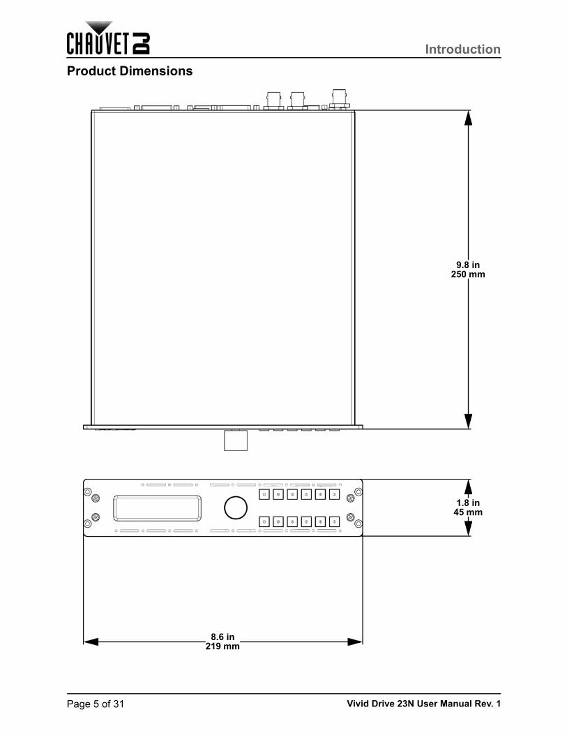
Product Dimensions
9.8 in250 mm
8.6 in219 mm
1.8 in45 mm
Page 6 of 31Vivid Drive 23N User Manual Rev. 1
Setup
3. SetupAC PowerThe Vivid Drive 23N has an auto-ranging power supply and it can work with an input voltage range of 100 to 240 VAC, 50/60 Hz. To determine the product’s power requirements (circuit breaker, power outlet, and wiring), use the current value listed on the label affixed to the product’s back panel, or refer to the product’s specifications chart. The listed current rating indicates the product’s average current draw under normal conditions.
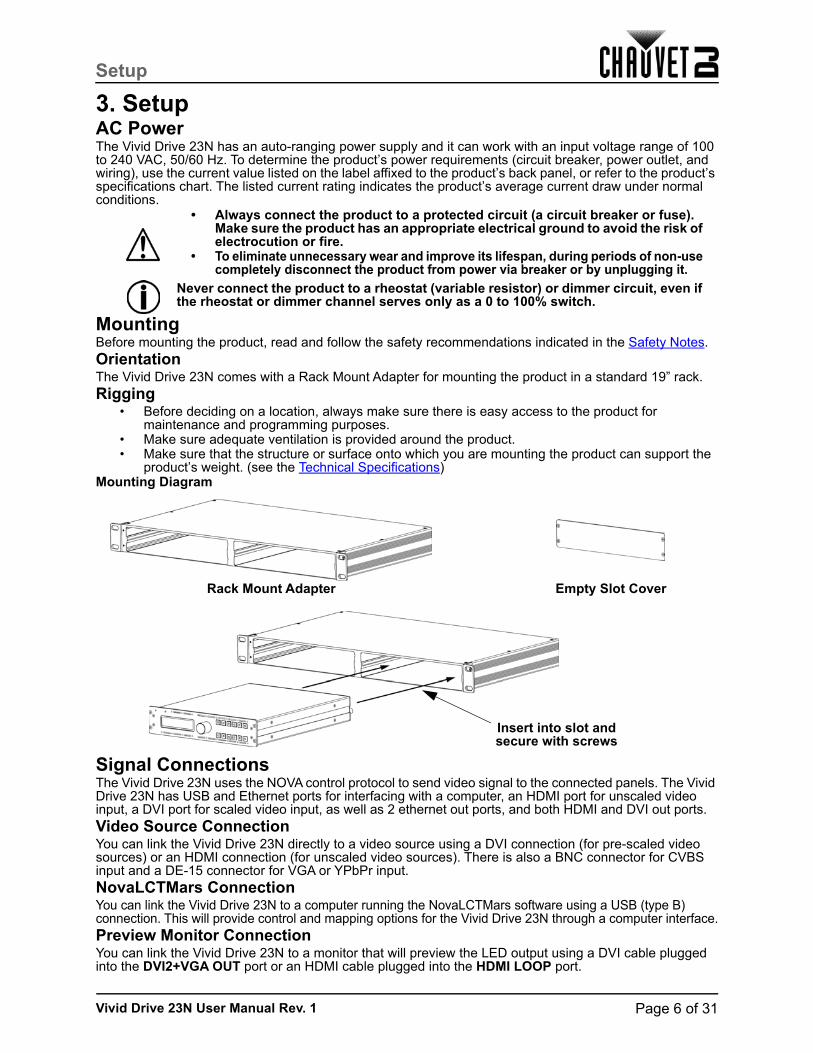
MountingBefore mounting the product, read and follow the safety recommendations indicated in the Safety Notes.OrientationThe Vivid Drive 23N comes with a Rack Mount Adapter for mounting the product in a standard 19” rack.Rigging
• Before deciding on a location, always make sure there is easy access to the product for maintenance and programming purposes.
• Make sure adequate ventilation is provided around the product.• Make sure that the structure or surface onto which you are mounting the product can support the
product’s weight. (see the Technical Specifications)Mounting Diagram
Signal ConnectionsThe Vivid Drive 23N uses the NOVA control protocol to send video signal to the connected panels. The Vivid Drive 23N has USB and Ethernet ports for interfacing with a computer, an HDMI port for unscaled video input, a DVI port for scaled video input, as well as 2 ethernet out ports, and both HDMI and DVI out ports.Video Source ConnectionYou can link the Vivid Drive 23N directly to a video source using a DVI connection (for pre-scaled video sources) or an HDMI connection (for unscaled video sources). There is also a BNC connector for CVBS input and a DE-15 connector for VGA or YPbPr input.NovaLCTMars ConnectionYou can link the Vivid Drive 23N to a computer running the NovaLCTMars software using a USB (type B) connection. This will provide control and mapping options for the Vivid Drive 23N through a computer interface.Preview Monitor ConnectionYou can link the Vivid Drive 23N to a monitor that will preview the LED output using a DVI cable plugged into the DVI2+VGA OUT port or an HDMI cable plugged into the HDMI LOOP port.
• Always connect the product to a protected circuit (a circuit breaker or fuse). Make sure the product has an appropriate electrical ground to avoid the risk of electrocution or fire.
• To eliminate unnecessary wear and improve its lifespan, during periods of non-use completely disconnect the product from power via breaker or by unplugging it.
Never connect the product to a rheostat (variable resistor) or dimmer circuit, even if the rheostat or dimmer channel serves only as a 0 to 100% switch.
Insert into slot and secure with screws
Rack Mount Adapter Empty Slot Cover

Page 7 of 31
Setup
Vivid Drive 23N User Manual Rev. 1
Connection Diagram
Unscaled Output
Data Connection for NovaLCTMars
Unscaled Video Input
Pre-scaled Video Input
Internal Scaler Output
(DVI to DVI Jumper)
Output to Panel Assembly
PC running NovaLCTMars and/or Video
Software
Vivid Drive 23N
Preview Monitor
Vivid 4 Panel Assembly
Unscaled Output to the next
Vivid Drive 23N
Scaled Output
Page 8 of 31Vivid Drive 23N User Manual Rev. 1
Operation
4. OperationControl Panel OperationPlease refer to the Front Overview for a detailed description of the control panel.
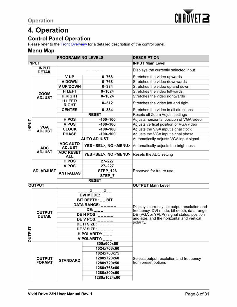
Menu MapPROGRAMMING LEVELS DESCRIPTION
INPUT INPUT Main Level
INP
UT
INPUT DETAIL _ _ _ _ _ Displays the currently selected input
ZOOM ADJUST
V UP 0–768 Stretches the video upwardsV DOWN 0–768 Stretches the video downwards
V UP/DOWN 0–384 Stretches the video up and downH LEFT 0–1024 Stretches the video leftwards
H RIGHT 0–1024 Stretches the video rightwardsH LEFT/RIGHT 0–512 Stretches the video left and right
CENTER 0–384 Stretches the video in all directionsRESET Resets all Zoom Adjust settings
VGA ADJUST
H POS -100–100 Adjusts horizontal position of VGA videoV POS -100–100 Adjusts vertical position of VGA videoCLOCK -100–100 Adjusts the VGA input signal clockPHASE -100–100 Adjusts the VGA input signal phase
AUTO ADJUST Automatically adjusts VGA input signal
ADC ADJUST
ADC AUTO ADJUST YES <SEL>, NO <MENU> Automatically adjusts the brightness
ADC RESET ALL YES <SEL>, NO <MENU> Resets the ADC setting
SDI ADJUST
H POS 27–227
Reserved for future useV POS 27–227
ANTI-ALIASSTEP_126
STEP_7RESET
OUTPUT OUTPUT Main Level
OU
TP
UT
OUTPUT DETAIL
_ _ _ _x_ _ _ _x_ _
Displays currently set output resolution and frequency, DVI mode, bit depth, data range, DE (VGA or YPbPr) signal status, position and size, and the horizontal and vertical polarity.
DVI MODE: _ _ _BIT DEPTH: _ _ BIT
DATA RANGE: _ _ _ _ _DE: _ _ _
DE H POS: _ _ _ _ _DE V POS: _ _ _ _ _DE H SIZE: _ _ _ _ _DE V SIZE: _ _ _ _ _H POLARITY: _ _ _V POLARITY: _ _ _
OUTPUT FORMAT STANDARD
800x600x60
Selects output resolution and frequency from preset options
1024x768x601024x768x751280x720x601280x720x501280x768x601280x800x60
1280x1024x60

Page 9 of 31
Operation
Vivid Drive 23N User Manual Rev. 1
OUTPUT (cont.) OUTPUT Main Level (cont.)
OU
TP
UT
(co
nt.)
OUTPUT FORMAT
(cont.)
STANDARD (cont.)
1360x768x60
Selects output resolution and frequency from preset options
1366x768x601400x1050x601440x800x601440x900x60
1600x1200x601680x1050x601920x1080x601920x1080x501920x1120x601920x1200x602048x1152x602560x812x601560x816x60
CUSTOM _ _ _ _x_ _ _ _x_ _ Sets custom resolution and frequency
OUTPUT ADJUST
DVI MODEDVI Sets the protocol to DVI (default)
HDMI Sets the protocol to HDMIBIT DEPTH 8 BIT (DVI) / 8–12 BIT (HDMI) Sets bit depth in HDMI mode
DATA RANGE
IMAGE RGB color spaceVIDEO YUV color space
DE ADJUST
DEOFF
Enables or disables digital encodingON
H POS 0–_ _ _ _ _ Adjusts the horizontal positionV POS 0–_ _ _ _ _ Adjusts the vertical positionH SIZE 61–_ _ _ _ Adjusts the horizontal size (width)V SIZE 61–_ _ _ _ Adjusts the vertical size (height)
H POLARITYPOS
Sets the phase of the horizontal scanNEG
V POLARITYPOS
Sets the phase of the vertical scanNEG
RESET Resets all output adjust settings
SCALE
H SIZE 61–_ _ _ _ Sets the width of DVI1 OUTV SIZE 61–_ _ _ _ Sets the height of DVI1 OUTH POS -100–_ _ _ _ Sets the horizontal position of DVI1 OUTV POS -16–_ _ _ _ Sets the vertical position of DVI1 OUT
RESET Resets scale settings
SCREEN
H SIZE 61–_ _ _ _ Sets the width of DVI2+VGA OUTV SIZE 61–_ _ _ _ Sets the Height of DVI2+VGA OUTH POS 0–_ _ _ _ Sets the horizontal position of DVI2+VGA OUTV POS 0–_ _ _ _ Sets the vertical position of DVI2+VGA OUT
MODEFULL SIZE DVI2+VGA OUT outputs unscaled video
SCREEN SIZE DVI2+VGA OUT outputs scaled videoRESET Resets screen settings
RATIO4:3 Sets the aspect ratio to 4:3
16:9 Sets the aspect ration to 16:9NORMAL Does not alter the aspect ratio
PICTURE
BRIGHTNESS 0–100 Adjusts the brightness of the outputCONTRAST 0–100 Adjusts the contrast of the output
SATURATION 0–100 Adjusts the saturation of the outputSHARPNESS 0–100 Adjusts the sharpness of the output
PROGRAMMING LEVELS DESCRIPTION
Page 10 of 31Vivid Drive 23N User Manual Rev. 1
Operation
OUTPUT (cont.) OUTPUT Main Level (cont.)
OU
TP
UT
(co
nt.)
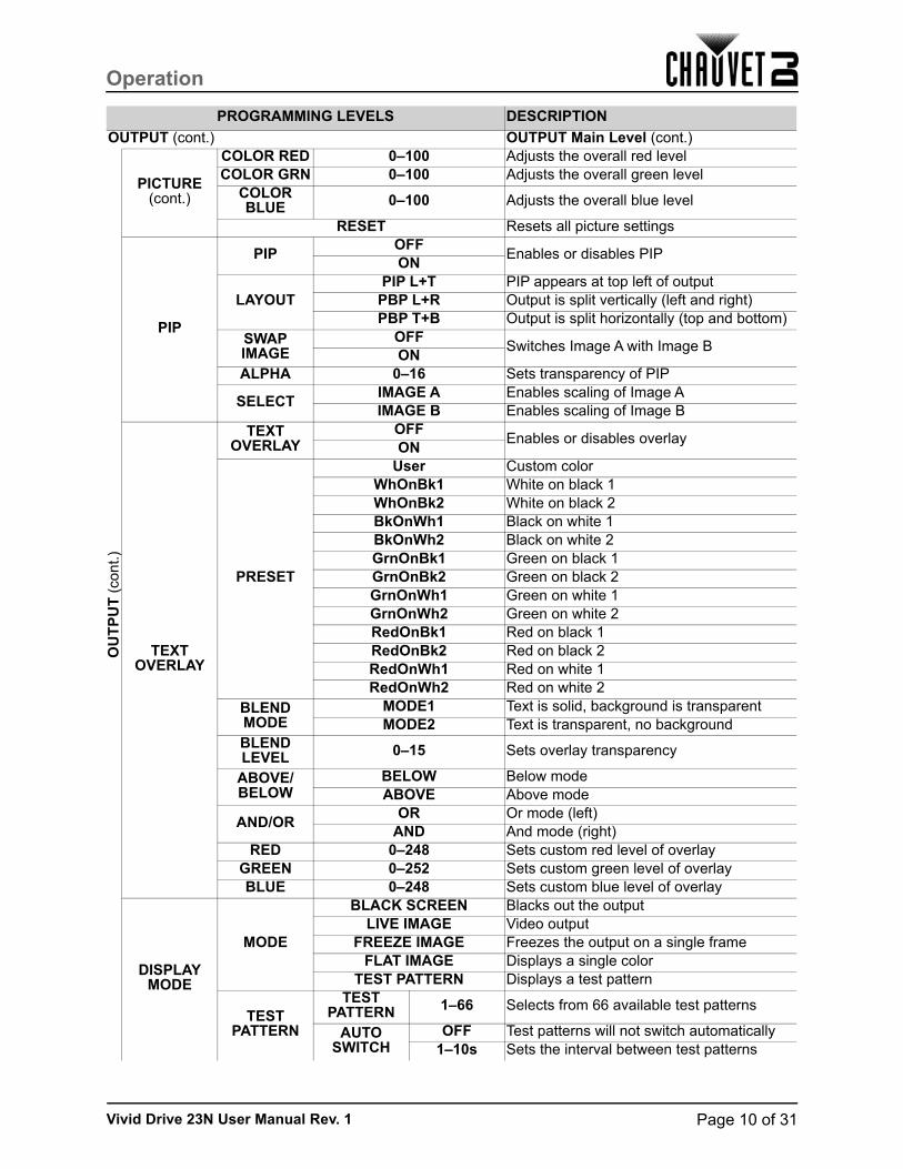
PICTURE (cont.)
COLOR RED 0–100 Adjusts the overall red levelCOLOR GRN 0–100 Adjusts the overall green level
COLOR BLUE 0–100 Adjusts the overall blue level
RESET Resets all picture settings
PIP
PIPOFF
Enables or disables PIPON
LAYOUTPIP L+T PIP appears at top left of output
PBP L+R Output is split vertically (left and right)PBP T+B Output is split horizontally (top and bottom)
SWAP IMAGE
OFFSwitches Image A with Image B
ONALPHA 0–16 Sets transparency of PIP
SELECTIMAGE A Enables scaling of Image AIMAGE B Enables scaling of Image B
TEXT OVERLAY
TEXT OVERLAY
OFFEnables or disables overlay
ON
PRESET
User Custom colorWhOnBk1 White on black 1WhOnBk2 White on black 2BkOnWh1 Black on white 1BkOnWh2 Black on white 2GrnOnBk1 Green on black 1GrnOnBk2 Green on black 2GrnOnWh1 Green on white 1GrnOnWh2 Green on white 2RedOnBk1 Red on black 1RedOnBk2 Red on black 2RedOnWh1 Red on white 1RedOnWh2 Red on white 2
BLEND MODE
MODE1 Text is solid, background is transparentMODE2 Text is transparent, no background
BLEND LEVEL 0–15 Sets overlay transparency
ABOVE/BELOW
BELOW Below modeABOVE Above mode
AND/OROR Or mode (left)
AND And mode (right)RED 0–248 Sets custom red level of overlay
GREEN 0–252 Sets custom green level of overlayBLUE 0–248 Sets custom blue level of overlay
DISPLAY MODE
MODE
BLACK SCREEN Blacks out the outputLIVE IMAGE Video output
FREEZE IMAGE Freezes the output on a single frameFLAT IMAGE Displays a single color
TEST PATTERN Displays a test pattern
TEST PATTERN
TEST PATTERN 1–66 Selects from 66 available test patterns
AUTO SWITCH
OFF Test patterns will not switch automatically1–10s Sets the interval between test patterns
PROGRAMMING LEVELS DESCRIPTION

Page 11 of 31
Operation
Vivid Drive 23N User Manual Rev. 1
OUTPUT (cont.) OUTPUT Main Level (cont.)
OU
TP
UT
(co
nt.)
DISPLAY MODE(cont.)
TEST PATTERN
(cont.)
RED 0–255Sets the color of test pattern 65GREEN 0–255
BLUE 0–255HOR STEP 0–64
Sets the number of steps in test pattern 66VER STEP 0–64
COLOR
RED
Sets the color of test pattern 66GREENBLUEWHITE
FLAT COLOR
RED 0–255Sets the single color to be displayed in Flat Image modeGREEN 0–255
BLUE 0–255
GAMMA
LINEAR
Sets the gamma of the output
sRGB-1.21.2-1.41.4-1.61.6
TRANSITION TRANSITION Main Level
TR
AN
SIT
ION MODE
CUT No transitionFADE Video sources fade when transitioning
POP L+T Video source 2 enters from top leftPUSH L+T Video source 1 exits at top leftPOP R+T Video source 2 enters from top right
PUSH R+T Video source 1 exits at top rightPOP L+B Video source 2 enters from bottom left
PUSH L+B Video source 1 exits at bottom leftPOP R+B Video source 2 enters from bottom right
PUSH R+B Video source 1 exits at bottom rightPOP CENT Video source 2 expands from the center
PUSH CENT Video source 1 shrinks into the centerPOP LEFT Video source 2 enters from the left
PUSH LEFT Video source 1 exits to the leftPOP RIGHT Video source 2 enters from the right
PUSH RIGHT Video source 1 exits to the rightPOP TOP Video source 2 enters from the top
PUSH TOP Video source 1 exits to the topPOP BOTTOM Video source 2 enters from the bottom
PUSH BOTTOM Video source 1 exits to the bottomFADE TIME 0.0–1.0s Sets time a transition takes
ALPHA 0–16 Sets transparency
DEINTERLACEON
Enables or disables deinterlacingOFF
SPLIT SPLIT Main Level
SP
LIT SPLIT
OFFEnable/Disable Split
ONH TOTAL 0–4096
Sets the size of the total panel assemblyV TOTAL 0–4096
PROGRAMMING LEVELS DESCRIPTION

Page 12 of 31Vivid Drive 23N User Manual Rev. 1
Operation
SPLIT (cont.) SPLIT Main Level (cont.)
SP
LIT
H POS 0–_ _ _ _ Sets the position of this driver’s output on the panel assemblyV POS 0–_ _ _ _
H SIZE 0–_ _ _ _ Sets the size of this driver’s output on the panel assemblyV SIZE 0–_ _ _ _
SAVE SETUP SAVE SETUP Main LevelSAVE TO SAVE 1–10 Saves the current settings
LOAD FROM SAVE 1–10 Loads the desired saved settingsDELAY CALL 0–255s Sets output delay for multi-driver chains
SYSTEM SYSTEM Main Level
SY
ST
EM SYSTEM
INFO
MCU VER: _._ _Displays system informationVIDEO VER: _._ _
SN: _ _ _ _TECH
SUPPORTSALES HOTLINE: (800) 762-1084
Displays phone numbers for assistanceAFTER-SALE SERVICE:
SYSTEM (cont.) SYSTEM Main Level (cont.)
SY
ST
EM
(co
nt.)
DATE&TIME
DATE: YYYY-MM-DD Displays the current dateTIME: HH:MM:SS Displays the current time
WORK TIME: _ _d:_ _h:_ _m Displays how long the product has been running
TOTAL TIME: _ _d:_ _h:_ _m Displays the total time for which the product has run
BOOT TIMES: _ _ Displays number of times the product has been turned on
TIMING CONTROL
ONEnables/Disables clock control
OFFCHANGE
DATE YYYY-MM-DD Sets the date
CHANGE TIME HH:MM:SS Sets the time
LOCK FRONT PANEL
YES <SEL>, NO <MENU> Locks the front panel (hold <MENU> for 3 seconds to unlock)
LICENSE SETUP
ENTER PASSWORD000000–999999 No function
CAN USE TIME NO LIMIT No function
HOT BACKUP
HOT BACKUP
OFFEnables/Disables hot backup
ON
BACKUP_1–5
CV1
Designates backup signals in order of priority
HDMIYPbPrVGASDI
USB UPGRADE YES <SEL>, NO <MENU> Enables a scaler firmware update by USB
EDID FOLLOW
OFFEnables/Disables EDID following
ON
LANGUAGE語言ENG Sets the language to English中文 Sets the language to Chinese
FACTORY RESET
FACTORY RESET YES <SEL>, NO <MENU> Resets the product to factory settings
SAVE IP RESET YES <SEL>, NO <MENU> Clears all saved settings
PROGRAMMING LEVELS DESCRIPTION

Page 13 of 31
Operation
Vivid Drive 23N User Manual Rev. 1
Operating Settings ConfigurationINPUT SettingsThe INPUT settings define the parameters of the video source to be edited by the internal scaler of the Vivid Drive 23N. To access the INPUT settings, do the following:
1. Press the <SELECT> knob to enter the menu.2. Use the <SELECT> knob to select INPUT.3. Press the <SELECT> knob.
INPUT DETAILTo view which input is currently selected, follow the instructions below.
1. Access the INPUT Settings.2. Use the <SELECT> knob to select INPUT DETAIL.3. Press the <SELECT> knob.
ZOOM ADJUSTThe ZOOM ADJUST settings select which portion of the video input to be processed by the internal scaler. To access and adjust the ZOOM ADJUST settings, do the following:
1. Access the INPUT Settings.2. Use the <SELECT> knob to select ZOOM ADJUST.1. Press the <SELECT> knob.2. Use the <SELECT> knob to select which direction (or directions) to stretch the video input, from
V UP (upwards), V DOWN (downwards), V UP/DOWN (both up and down), H LEFT (leftwards), H RIGHT (rightwards), H LEFT/RIGHT (both left and right), or CENTER (all 4 directions). To reset all zoom values, select RESET.
3. Press the <SELECT> knob.4. Turn the <SELECT> knob to increase or decrease the selected zoom value.5. Press the <SELECT> knob.6. Repeat steps 2 to 5 until the zoom is set as desired.
VGA ADJUSTThe VGA ADJUST settings adjust the position and synchronization of a VGA video source. To access and adjust the VGA ADJUST settings, follow the instructions below.
1. Access the INPUT Settings.2. Use the <SELECT> knob to select VGA ADJUST.3. Press the <SELECT> knob.4. Use the <SELECT> knob to select which setting to adjust, from H POS (horizontal position),
V POS (vertical position), CLOCK (input signal clock), or PHASE (input signal phase). To set the Vivid Drive 23N to automatically select the optimum settings, select AUTO ADJUST.
5. Press the <SELECT> knob.6. If not using the AUTO ADJUST function, turn the <SELECT> knob to increase or decrease the
selected value.7. Press the <SELECT> knob.8. Repeat steps 4 to 7 until the signal is adjusted as desired.
ADC ADJUSTThe ADC ADJUST setting controls the analog to digital conversion. To set the ADC ADJUST, do the following:
1. Access the INPUT Settings.2. Use the <SELECT> knob to select ADC ADJUST.3. Press the <SELECT> knob.4. Use the <SELECT> knob to select ADC AUTO ADJUST (to automatically adjust the ADC setting)
or ADC RESET ALL (to reset the ADC setting).5. Press the <SELECT> knob.6. Press the <SELECT> knob to confirm, or <MENU> to cancel.

Page 14 of 31Vivid Drive 23N User Manual Rev. 1
Operation
OUTPUT SettingsThe OUTPUT settings control the output that the internal scaler sends from DVI1 OUT. To access the OUTPUT settings, follow the instructions below.
1. Press the <SELECT> knob to enter the menu.2. Use the <SELECT> knob to select OUTPUT.3. Press the <SELECT> knob.
OUTPUT DETAILTo view the current OUTPUT settings, do the following:
1. Access the OUTPUT Settings.2. Use the <SELECT> knob to select OUTPUT DETAIL.3. Press the <SELECT> knob.
OUTPUT FORMATThe OUTPUT FORMAT settings set the resolution and frequency of the output. To access and adjust the OUTPUT FORMAT, follow the instruction below.
1. Access the OUTPUT Settings.2. Use the <SELECT> knob to select OUTPUT FORMAT.3. Press the <SELECT> knob.4. Use the <SELECT> knob to select either STANDARD (choose from a preset resolution and
frequency) or CUSTOM (set a custom resolution and frequency).5. Press the <SELECT> knob.6. If STANDARD:
a. Use the <SELECT> knob to select from the list of standard resolutions and frequencies, from 800x600x60 to 1560x816x60.
b. Press the <SELECT> knob.If CUSTOM:a. Turn the <SELECT> knob to increase or decrease the width value.b. Press the <SELECT> knob.c. Turn the <SELECT> knob to increase or decrease the height value.d. Press the <SELECT> knob.e. Turn the <SELECT> knob to increase or decrease the resolution value.f. Press the <SELECT> knob.g. Repeat from step 4 if necessary to set the resolution and frequency as desired.
OUTPUT ADJUSTThe OUTPUT ADJUST settings include the DVI MODE, BIT DEPTH, DATA RANGE, and DE ADJUST settings. To access the OUTPUT ADJUST settings, do the following:
1. Access the OUTPUT Settings.2. Use the <SELECT> knob to select OUTPUT ADJUST.3. Press the <SELECT> knob.
DVI MODEThe DVI MODE selects DVI or HDMI mode. To set the DVI MODE, follow the instruction below.
1. Access the OUTPUT ADJUST settings.2. Use the <SELECT> knob to select DVI MODE.3. Press the <SELECT> knob.4. Use the <SELECT> knob to select either DVI or HDMI.5. Press the <SELECT> knob.
BIT DEPTHThe BIT DEPTH setting determines the quality of the video signal quantization. If the DVI MODE is set to DVI, the BIT DEPTH will be 8 BIT. To adjust the BIT DEPTH when the DVI MODE is set to HDMI, do the following:
1. Access the OUTPUT ADJUST settings.2. Use the <SELECT> knob to select BIT DEPTH.3. Press the <SELECT> knob.4. Turn the <SELECT> knob to increase or decrease the value, from 8–12 BIT.5. Press the <SELECT> knob.

Page 15 of 31
Operation
Vivid Drive 23N User Manual Rev. 1
DATA RANGEThe DATA RANGE setting determines the color space of the output. To set the DATA RANGE, follow the instructions below.
1. Access the OUTPUT ADJUST settings.2. Use the <SELECT> knob to select DATA RANGE.3. Press the <SELECT> knob.4. Use the <SELECT> knob to select either IMAGE (RGB color space) or VIDEO (YUV color
space).5. Press the <SELECT> knob.
DE ADJUSTThe DE ADJUST settings control the digital encoding. To access and adjust the DE ADJUST settings, do the following:
1. Access the OUTPUT ADJUST settings.2. Use the <SELECT> knob to select DE ADJUST.3. Press the <SELECT> knob.4. Use the <SELECT> knob to select DE.5. Press the <SELECT> knob.6. Use the <SELECT> knob to select ON (to enable the DE ADJUST settings) or OFF (to disable
the DE ADJUST settings). This must be set to ON for the DE ADJUST settings to work.7. Press the <SELECT> knob.
To set the position and size:1. From the DE ADJUST menu level, use the <SELECT> knob to select from H POS (horizontal
position), V POS (vertical position), H SIZE (horizontal size), or V SIZE (vertical size).2. Press the <SELECT> knob.3. Turn the <SELECT> knob to increase or decrease the selected value.4. Press the <SELECT> knob.5. Repeat steps 1 to 4 until the position and size is set as desired.
To set the phase/polarity:1. From the DE ADJUST menu level, use the <SELECT> knob to select H POLARITY (horizontal
phase) or V POLARITY (vertical phase).2. Press the <SELECT> knob.3. Use the <SELECT> knob to select either POS (positive) or NEG (negative).4. Press the <SELECT> knob.5. Repeat steps 1 to 4 until the polarities are set as desired.
If necessary, to reset the DE ADJUST settings:1. From the DE ADJUST menu level, use the <SELECT> knob to select RESET.2. Press the <SELECT> knob.
SCALE SettingsThe SCALE settings control the size and position of the output from DVI1 OUT. To access and adjust the SCALE settings, follow the instructions below.
1. Access the OUTPUT Settings (or press <SCALE/7> and skip to step 4).2. Use the <SELECT> knob to select SCALE.3. Press the <SELECT> knob.4. Use the <SELECT> knob to select from H SIZE (horizontal size), V SIZE (vertical size), H POS
(horizontal position), or V POS (vertical position). To reset the SCALE settings, select RESET.5. Press the <SELECT> knob.6. Turn the <SELECT> knob to increase or decrease the selected parameter, or enter the desired
value using the number buttons.7. Press the <SELECT> knob.8. Repeat steps 4 to 7 until the SCALE is set as desired.

Page 16 of 31Vivid Drive 23N User Manual Rev. 1
Operation
SCREEN SettingsThe SCREEN settings control the size and position of the output to DVI1 OUT and DVI2+VGA OUT. To access and adjust the SCREEN settings, do the following:
1. Access the OUTPUT Settings.2. Use the <SELECT> knob to select SCREEN.3. Press the <SELECT> knob.4. Use the <SELECT> knob to select from H SIZE (horizontal size), V SIZE (vertical size), H POS
(horizontal position), or V POS (vertical position).5. Press the <SELECT> knob.6. Turn the <SELECT> knob to increase or decrease the selected parameter.7. Press the <SELECT> knob.8. Use the <SELECT> knob to select MODE.9. Press the <SELECT> knob.10. Use the <SELECT> knob to select either FULL SIZE (outputs unscaled video) or SCREEN SIZE
(outputs scaled video).11. Press the <SELECT> knob.12. If necessary, to reset the SCREEN settings, use the <SELECT> knob to select RESET and press
the <SELECT> knob.RATIOThe RATIO setting sets the aspect ratio of the output from DVI1 OUT. To set the RATIO setting, follow the instructions below.
1. Access the OUTPUT Settings.2. Use the <SELECT> knob to select RATIO.3. Press the <SELECT> knob.4. Use the <SELECT> knob to select an aspect ratio, from 4:3, 16:9, or NORMAL (does not alter
the aspect ratio).5. Press the <SELECT> knob.
PICTURE SettingsThe PICTURE settings control the color balance and related aspects of the output from DVI1 OUT. To access and adjust the PICTURE settings, do the following:
1. Access the OUTPUT Settings.2. Use the <SELECT> knob to select PICTURE.3. Press the <SELECT> knob.4. Use the <SELECT> knob to select a setting to adjust, from BRIGHTNESS, CONTRAST,
SATURATION, SHARPNESS, COLOR RED, COLOR GRN, or COLOR BLUE. To reset the PICTURE settings, select RESET.
5. Press the <SELECT> knob.6. Turn the <SELECT> knob to increase or decrease the selected parameter.7. Press the <SELECT> knob.8. Repeat steps 4 to 7 until the product outputs as desired.
Picture In PictureThe Picture In Picture (PIP) settings allow 2 video inputs to display simultaneously. To access and enable or disable the PIP settings, follow the instructions below.
1. Access the OUTPUT Settings.2. Use the <SELECT> knob to select PIP.3. Press the <SELECT> knob.4. Use the <SELECT> knob to select PIP.5. Press the <SELECT> knob.6. Use the <SELECT> knob to select either OFF (disables PIP) or ON (enables PIP).7. Press the <SELECT> knob.

Page 17 of 31
Operation
Vivid Drive 23N User Manual Rev. 1
PIP LAYOUTThe LAYOUT setting determines where the second video input will appear on the connected panel assembly. To set the LAYOUT, do the following:
1. Access and enable the Picture In Picture function.2. Use the <SELECT> knob to select LAYOUT.3. Press the <SELECT> knob.4. Use the <SELECT> knob to select a layout arrangement, from PIP L+T (second input appears in
the top left), PBP L+R (output is split left and right), or PBP T+B (output is split top and bottom).5. Press the <SELECT> knob.
SWAP IMAGEThe SWAP IMAGE setting toggles which video input is set as the Picture In Picture input. To toggle SWAP IMAGE, follow the instructions below.
1. Access and enable the Picture In Picture function.2. Use the <SELECT> knob to select SWAP IMAGE.3. Press the <SELECT> knob.4. Use the <SELECT> knob to select either OFF (does not switch inputs) or ON (switches inputs).5. Press the <SELECT> knob.
ALPHAThe ALPHA setting controls the transparency of the Picture In Picture image. To set the ALPHA, do the following:
1. Access and enable the Picture In Picture function.2. Use the <SELECT> knob to select ALPHA.3. Press the <SELECT> knob.4. Turn the <SELECT> knob to increase or decrease the transparency, from 0–16.5. Press the <SELECT> knob.
SELECTThe SELECT setting determines which video input can be scaled by the SCALE function. To select which input to scale, follow the instructions below.
1. Access and enable the Picture In Picture function.2. Use the <SELECT> knob to select SELECT.3. Press the <SELECT> knob.4. Use the <SELECT> knob to select either IMAGE A or IMAGE B.5. Press the <SELECT> knob.
TEXT OVERLAYThe TEXT OVERLAY function allows display areas to be defined for text output only. To access and enable or disable the TEXT OVERLAY function, do the following:
1. Access the OUTPUT Settings.2. Use the <SELECT> knob to select TEXT OVERLAY.3. Press the <SELECT> knob.4. Use the <SELECT> knob to select TEXT OVERLAY.5. Press the <SELECT> knob.6. Use the <SELECT> knob to select either OFF (disables TEXT OVERLAY) or ON (enables TEXT
OVERLAY).7. Press the <SELECT> knob.
TEXT OVERLAY PRESETThe PRESET setting selects a pre-set color scheme for the TEXT OVERLAY. To select a PRESET, follow the instructions below.
1. Access and enable the TEXT OVERLAY function.2. Use the <SELECT> knob to select PRESET.3. Press the <SELECT> knob.4. Use the <SELECT> knob to select User (see Custom Color), WhOnBk1–2 (white on black 1
or 2), BkOnWh1–2 (black on white 1 or 2), GrnOnBk1–2 (green on black 1 or 2), GrnOnWh1–2 (green on white 1 or 2), RedOnBk1–2 (red on black 1 or 2) or RedOnWh1–2 (red on white 1 or 2).
5. Press the <SELECT> knob.

Page 18 of 31Vivid Drive 23N User Manual Rev. 1
Operation
BLEND MODEThe BLEND MODE determines which, the background or the text, of the TEXT OVERLAY is transparent. To select the BLEND MODE, do the following:
1. Access and enable the TEXT OVERLAY function.2. Use the <SELECT> knob to select BLEND MODE.3. Press the <SELECT> knob.4. Use the <SELECT> knob to select either MODE1 (the text is solid, the background is transparent)
or MODE2 (the text is transparent, no background).5. Press the <SELECT> knob.
BLEND LEVELThe BLEND LEVEL setting sets the transparency of the TEXT OVERLAY. To set the BLEND LEVEL, follow the instructions below.
1. Access and enable the TEXT OVERLAY function.2. Use the <SELECT> knob to select BLEND LEVEL.3. Press the <SELECT> knob.4. Turn the <SELECT> knob to increase or decrease the transparency, from 0–15.5. Press the <SELECT> knob.
ABOVE/BELOWThe ABOVE/BELOW setting selects the vertical location (ABOVE or BELOW) of the peripheral secondary content. To select the ABOVE/BELOW mode, do the following:
1. Access and enable the TEXT OVERLAY function.2. Use the <SELECT> knob to select ABOVE/BELOW.3. Press the <SELECT> knob.4. Use the <SELECT> knob to select either BELOW or ABOVE.5. Press the <SELECT> knob.
AND/ORThe AND/OR setting selects the horizontal location (left or right) of the peripheral secondary content. To select the AND/OR mode, follow the instructions below.
1. Access and enable the TEXT OVERLAY function.2. Use the <SELECT> knob to select AND/OR.3. Press the <SELECT> knob.4. Use the <SELECT> knob to select either OR (left) or AND (right).5. Press the <SELECT> knob.
Custom ColorTo set a custom color for the TEXT OVERLAY, do the following:
1. Access and enable the TEXT OVERLAY function.2. Use the <SELECT> knob to select a color level to set, from RED, GREEN, or BLUE.3. Press the <SELECT> knob.4. Turn the <SELECT> knob to increase or decrease the value of the selected color.5. Press the <SELECT> knob.6. Repeat steps 2 to 5 until the TEXT OVERLAY is colored as desired.
DISPLAY MODEThe DISPLAY MODE settings determines what is output from DVI1 OUT. To access and select the DISPLAY MODE, follow the instructions below.
1. Access the OUTPUT Settings.2. Use the <SELECT> knob to select DISPLAY MODE.3. Press the <SELECT> knob.4. Use the <SELECT> knob to select MODE.5. Press the <SELECT> knob.6. Use the <SELECT> knob to select a mode, from BLACK SCREEN (no output), LIVE IMAGE
(video output), FREEZE IMAGE (freezes the output on a single frame), FLAT IMAGE (a single solid color), or TEST PATTERN (a test pattern).
7. Press the <SELECT> knob.

Page 19 of 31
Operation
Vivid Drive 23N User Manual Rev. 1
TEST PATTERNTo set the Vivid Drive 23N to output a specific test pattern from DVI1 OUT, do the following:
1. Access the DISPLAY MODE setting, and set the MODE to TEST PATTERN.2. From the DISPLAY MODE menu level, use the <SELECT> knob to select TEST PATTERN.3. Press the <SELECT> knob.4. Use the <SELECT> knob to select TEST PATTERN.5. Press the <SELECT> knob.6. Use the <SELECT> knob to select a test pattern, from 1–66.7. Press the <SELECT> knob.
To set if and how often the TEST PATTERN switches from one to the next:1. From the first TEST PATTERN menu level, use the <SELECT> knob to select AUTO SWITCH.2. Press the <SELECT> knob.3. Use the <SELECT> knob to select from OFF (will not switch automatically between test patterns)
or from 1–10s (sets the interval between switches from 1 to 10 seconds).4. Press the <SELECT> knob.
For TEST PATTERN 65, the color and number of vertical and horizontal steps can be customized. To do so:
1. From the first TEST PATTERN menu level, use the <SELECT> knob to select from RED, GREEN, BLUE, HOR STEP (horizontal steps), or VER STEP (vertical steps).
2. Press the <SELECT> knob.3. Turn the <SELECT> knob to increase or decrease the selected parameter.4. Press the <SELECT> knob.5. Repeat steps 1 to 4 until the TEST PATTERN appears as desired.
For TEST PATTERN 66, the color can be chosen. To do so:1. From the first TEST PATTERN menu level, use the <SELECT> knob to select COLOR.2. Press the <SELECT> knob.3. Use the <SELECT> knob to select from RED, GREEN, BLUE, or WHITE.4. Press the <SELECT> knob.
FLAT COLORTo set the Vivid Drive 23N to output a custom static color from DVI1 OUT, follow the instructions below.
1. Access the DISPLAY MODE setting, and set the MODE to FLAT IMAGE.2. From the DISPLAY MODE menu level, use the <SELECT> knob to select FLAT COLOR.3. Press the <SELECT> knob.4. Use the <SELECT> knob to select which color level to adjust, from RED, GREEN, or BLUE.5. Press the <SELECT> knob.6. Turn the <SELECT> knob to increase or decrease the selected color value, from 0–255.7. Press the <SELECT> knob.8. Repeat steps 4 to 7 until the color is set as desired.
GAMMATo set the GAMMA correction, do the following:
1. Access the OUTPUT Settings.2. Use the <SELECT> knob to select GAMMA.3. Press the <SELECT> knob.4. Use the <SELECT> knob to select from LINEAR, sRGB, -1.2, 1.2, -1.4, 1.4, -1.6, or 1.6.5. Press the <SELECT> knob.

Page 20 of 31Vivid Drive 23N User Manual Rev. 1
Operation
TRANSITION SettingsThe TRANSITION settings determine how the Vivid Drive 23N displays the switch when changing video sources. To access the TRANSITION settings, follow the instructions below.
1. Press the <SELECT> knob to enter the menu.2. Use the <SELECT> knob to select TRANSITION.3. Press the <SELECT> knob.
Transition MODEThe MODE determines the effect used when the Vivid Drive 23N transitions from one video source to another. To set the transition MODE, do the following:
1. Access the TRANSITION Settings.2. Use the <SELECT> knob to select MODE.3. Press the <SELECT> knob.4. Use the <SELECT> knob to select an effect, from:
• CUT (no effect),• FADE (fade effect),• POP L+T (new video enters from top left),• PUSH L+T (old video exits at top left),• POP R+T (new video enters from top right),• PUSH R+T (old video exits at top right),• POP L+B (new video enters from bottom left),• PUSH L+B (old video exits at bottom left),• POP R+B (new video enters from bottom right),• PUSH R+B (old video exits at bottom right),• POP CENT (new video expands from the center),• PUSH CENT (old video shrinks into the center),• POP LEFT (new video enters from the left),• PUSH LEFT (old video exits to the left),• POP RIGHT (new video enters from the right),• PUSH RIGHT (old video exits to the right),• POP TOP (new video enters from the top),• PUSH TOP (old video exits to the top),• POP BOTTOM (new video enters from the bottom),
or• PUSH BOTTOM (old video exits to the bottom).
5. Press the <SELECT> knob.FADE TIMEThe FADE TIME setting determines the length of time it takes for a transition to complete. To set the FADE TIME, follow the instructions below.
1. Access the TRANSITION Settings.2. Use the <SELECT> knob to select FADE TIME.3. Press the <SELECT> knob.4. Turn the <SELECT> knob to increase or decrease the amount of time, from 0.0–1.0s (seconds).5. Press the <SELECT> knob.
Transition ALPHAThe ALPHA setting controls the transparency of transitioning video sources. To set the ALPHA, do the following:
1. Access the TRANSITION Settings.2. Use the <SELECT> knob to select ALPHA.3. Press the <SELECT> knob.4. Turn the <SELECT> knob to increase or decrease the transparency, from 0–16.5. Press the <SELECT> knob.

Page 21 of 31
Operation
Vivid Drive 23N User Manual Rev. 1
DEINTERLACEThe DEINTERLACE function converts interlaced video signals to a non-interlaced format. To enable or disable deinterlacing, follow the instructions below.
1. Access the TRANSITION Settings.2. Use the <SELECT> knob to select DEINTERLACE.3. Press the <SELECT> knob.4. Use the <SELECT> knob to select either ON (deinterlaces video signals) or OFF (does not
deinterlace video signals).5. Press the <SELECT> knob.
SPLIT SettingsThe SPLIT settings split the video input into sections to output from 2 or more Vivid Drive 23N products onto the same connected panel assembly. This allows larger panel assemblies than can be controlled by a single Vivid Drive 23N. To access and enable or disable the SPLIT settings, do the following:
1. Press the <SELECT> knob to enter the menu.2. Use the <SELECT> knob to select SPLIT.3. Press the <SELECT> knob.4. Use the <SELECT> knob to select SPLIT.5. Press the <SELECT> knob.6. Use the <SELECT> knob to select either OFF (disables SPLIT) or ON (enables SPLIT).7. Press the <SELECT> knob.
SPLIT TotalThe SPLIT total settings H TOTAL and V TOTAL determine the total size of the connected panel assembly. To set the totals, follow the instructions below.
1. Access and enable the SPLIT Settings.2. Use the <SELECT> knob to select either H TOTAL (total horizontal size) or V TOTAL (total
vertical size).3. Press the <SELECT> knob.4. Turn the <SELECT> knob to increase or decrease the selected parameter.5. Press the <SELECT> knob.6. Repeat steps 2 to 5 until the total size of the connected panel assembly is set accurately.
SPLIT Position and SizeThe SPLIT position (H POS and V POS) and size (H SIZE and V SIZE) settings determine the location and size of a specific Vivid Drive 23N product’s output on the connected panel assembly. To set the position and size, do the following:
1. Access and enable the SPLIT Settings.2. Use the <SELECT> knob to select from H POS (horizontal position), V POS (vertical position),
H SIZE (horizontal size), or V SIZE (vertical size).3. Press the <SELECT> knob.4. Turn the <SELECT> knob to increase or decrease the selected parameter.5. Press the <SELECT> knob.6. Repeat steps 2 to 5 until the size and position are set as desired.
SAVE SETUP SettingsThe SAVE SETUP settings allow up to 10 different configurations of the Vivid Drive 23N to be stored and reloaded. To access the SAVE SETUP settings, follow the instructions below.
1. Press the <SELECT> knob to enter the menu.2. Use the <SELECT> knob to select SAVE SETUP.3. Press the <SELECT> knob.
SAVE TOThe SAVE TO function saves the currently set configurations of the Vivid Drive 23N to one of 10 SAVE slots. To save the current configuration of the Vivid Drive 23N, do the following:
1. Access the SAVE SETUP Settings.2. Use the <SELECT> knob to select SAVE TO.3. Press the <SELECT> knob.4. Use the <SELECT> knob to select a save slot, from SAVE 1–10.5. Press the <SELECT> knob.

Page 22 of 31Vivid Drive 23N User Manual Rev. 1
Operation
LOAD FROMThe LOAD FROM function loads previously saved configurations from one of the 10 SAVE slots. To load a saved configuration, follow the instructions below.
1. Access the SAVE SETUP Settings.2. Use the <SELECT> knob to select LOAD FROM.3. Press the <SELECT> knob.4. Use the <SELECT> knob to select a save slot to load, from SAVE 1–10.5. Press the <SELECT> knob.
DELAY CALLThe DELAY CALL setting is for use with multiple Vivid Drive 23N products, to offset start-up times. To set the DELAY CALL, do the following:
1. Access the SAVE SETUP Settings.2. Use the <SELECT> knob to select DELAY CALL.3. Press the <SELECT> knob.4. Turn the <SELECT> knob to increase or decrease the interval, from 0–255s (seconds).5. Press the <SELECT> knob.
SYSTEM SettingsThe SYSTEM settings include various functions such as backup and firmware updates. To access the SYSTEM settings, follow the instructions below.
1. Press the <SELECT> knob to enter the menu.2. Use the <SELECT> knob to select SYSTEM.3. Press the <SELECT> knob.
SYSTEM INFOTo view the SYSTEM INFO, do the following:
1. Access the SYSTEM Settings.2. Use the <SELECT> knob to select SYSTEM INFO.3. Press the <SELECT> knob.
TECH SUPPORTTo view phone numbers with which sales support can be contacted, follow the instructions below.
1. Access the SYSTEM Settings.2. Use the <SELECT> knob to select TECH SUPPORT.3. Press the <SELECT> knob.
DATE&TIMEThe DATE&TIME menu displays the time and related statistics for the Vivid Drive 23N, and allows the date and time to be set. To access, view, and enable or disable control of this menu, do the following:
1. Access the SYSTEM Settings.2. Use the <SELECT> knob to select DATE&TIME.3. Press the <SELECT> knob.4. Use the <SELECT> knob to select TIMING CONTROL.5. Press the <SELECT> knob.6. Use the <SELECT> knob to select either ON (enables control) or OFF (disables control).7. Press the <SELECT> knob.
CHANGE DATETo set the date to be displayed by the Vivid Drive 23N, follow the instructions below.
1. Access the DATE&TIME menu and enable TIMING CONTROL.2. Use the <SELECT> knob to select CHANGE DATE.3. Press the <SELECT> knob.4. Turn the <SELECT> knob to increase or decrease the year.5. Press the <SELECT> knob.6. Turn the <SELECT> knob to increase or decrease the month.7. Press the <SELECT> knob.8. Turn the <SELECT> knob to increase or decrease the day.9. Press the <SELECT> knob.10. If necessary, repeat steps 2 to 9 until the date is set correctly.

Page 23 of 31
Operation
Vivid Drive 23N User Manual Rev. 1
CHANGE TIMETo set the time to be displayed by the Vivid Drive 23N, follow the instructions below.
1. Access the DATE&TIME menu and enable TIMING CONTROL.2. Use the <SELECT> knob to select CHANGE TIME.3. Press the <SELECT> knob.4. Turn the <SELECT> knob to increase or decrease the hour.5. Press the <SELECT> knob.6. Turn the <SELECT> knob to increase or decrease the minute.7. Press the <SELECT> knob.8. Turn the <SELECT> knob to increase or decrease the second.9. Press the <SELECT> knob.10. If necessary, repeat steps 2 to 9 until the date is set correctly.
LOCK FRONT PANELTo lock the front panel from use, do the following.
1. Access the SYSTEM Settings.2. Use the <SELECT> knob to select LOCK FRONT PANEL.3. Press the <SELECT> knob.4. Press the <SELECT> knob to confirm, or <MENU> to cancel.
To unlock, hold <MENU> for 3 seconds.HOT BACKUPThe HOT BACKUP function allows changes to settings to be preserved after power cycling without actively saving the configuration.To enable or disable HOT BACKUP, follow the instructions below.
1. Access the SYSTEM Settings.2. Use the <SELECT> knob to select HOT BACKUP.3. Press the <SELECT> knob.4. Use the <SELECT> knob to select HOT BACKUP.5. Press the <SELECT> knob.6. Use the <SELECT> knob to select either OFF (disables the function) or ON (enables the
function).7. Press the <SELECT> knob.
To designate the priority order of the input video signals, do the following:1. Enable HOT BACKUP.2. From the first HOT BACKUP menu, use the <SELECT> knob to select a backup, from
BACKUP_1–5 (1 is first, 5 is last).3. Press the <SELECT> knob.4. Use the <SELECT> knob to select which video source to designate as the selected priority, from
CV1, HDMI, YPbPr, VGA, or SDI.5. Press the <SELECT> knob.6. Repeat steps 2 to 5 until the backups are set as desired.
EDID FOLLOWThe EDID FOLLOW function allows the Vivid Drive 23N to detect the specifications of connected panels. To enable or disable EDID FOLLOW, do the following:
1. Access the SYSTEM Settings.2. Use the <SELECT> knob to select EDID FOLLOW.3. Press the <SELECT> knob.4. Use the <SELECT> knob to select either OFF (disables the function) or ON (enables the
function).5. Press the <SELECT> knob.

Page 24 of 31Vivid Drive 23N User Manual Rev. 1
Operation
LANGUAGE語言
The menu of the Vivid Drive 23N can be displayed in either English or Chinese. To select the language, follow the instructions below.
1. Press the <SELECT> knob to enter the menu.2. Use the <SELECT> knob to select LANGUAGE語言.3. Press the <SELECT> knob.4. Use the <SELECT> knob to select either ENG (English) or 中文 (Chinese).5. Press the <SELECT> knob.
FACTORY RESETThe FACTORY RESET functions can either completely reset the product back to factory settings, or rest only the saved configurations in the SAVE function. To access the FACTORY RESET menu, do the following:
1. Press the <SELECT> knob to enter the menu.2. Use the <SELECT> knob to select FACTORY RESET.3. Press the <SELECT> knob.
Total ResetTo perform a total FACTORY RESET, follow the instructions below.
1. Access the FACTORY RESET menu.2. Use the <SELECT> knob to select FACTORY RESET.3. Press the <SELECT> knob.4. Press the <SELECT> knob to confirm, or press <MENU> to cancel.
SAVE IP RESETTo clear all saved configurations from the SAVE function, do the following:
1. Access the FACTORY RESET menu.2. Use the <SELECT> knob to select SAVE IP RESET.3. Press the <SELECT> knob.4. Press the <SELECT> knob to confirm, or press <MENU> to cancel.

Page 25 of 31
Operation
Vivid Drive 23N User Manual Rev. 1
NovaLCTMars SoftwareThe Vivid Drive 23N can be configured by a computer running the NovaLCTMars software, through a USB connection. You can download the NovaLCTMars software from www.chauvetdj.com/products/vivid-drive-23n/.
Software SetupTo install and access all functions of the NovaLCTMars software:
1. Download the NovaLCTMars software from www.chauvetdj.com/products/vivid-drive-23n/.2. Run the setup file.3. After installing the application and all included drivers, connect the Vivid Drive 23N and run the
software.4. Click User (U) in the menu running across the top of the window to open the drop-down menu.5. Click Advanced User Login (A).6. Type admin into the password field, and press the Login button on the screen, or press the Enter
key.
Screen ConfigurationThe NovaLCTMars software has many configuration settings for any panel assembly connected to the Vivid Drive 23N. The options are divided into 3 tabs that appear on a window after clicking Screen Configuration, selecting the product under Current Operation Communication Port, and clicking the Next button.Sending Card TabOn the Sending Card tab, the resolution and refresh rate can be set. From this tab the product’s redundancy can be set, system configurations can be saved, and the product can also be restored to factory default settings.Receiving Card TabOn the Receiving Card tab, the parameters sent to the software the last time this tab was viewed will be displayed. This tab displays many options that can be edited, but Chauvet does NOT recommend altering any of them. From this tab the firmware for connected video panels can be uploaded and downloaded.Screen Connection TabOn the Screen Connection Tab, there are three options for configuring the size of the connected panel assembly, the distribution between video output ports, and the data flow: Simple, Standard, and Complex.
• Simple Screen mode selects from preset data paths.• Standard Screen mode allows the data flow and port distribution to be programmed manually with
a visual interface.• Complex Screen mode allows the configuration to be entered in a flow chart by driver number, port,
and panel number, as well as dimensions and offset coordinates in pixels.
Connect the Vivid Drive 23N to the computer before running NovaLCTMars.

Page 26 of 31Vivid Drive 23N User Manual Rev. 1
Operation
Firmware UpdateTo update the firmware of the Vivid Drive 23N, follow the instructions below.
1. On a Windows PC, download the latest firmware update from www.chauvetdj.com/products/vivid-drive-23n/.
2. Plug the product into power, connect it to the computer, and open NovaLCTMars.3. Click User (U) in the menu running across the top of the window to open the drop-down menu.4. Click Advanced User Login (A).5. Type admin into the password field, and press the Login button on the screen, or press the Enter
key.6. Type admin again (There won’t be a field for this, just type anywhere in the window). The
Program Loading window will pop up.7. If more than one Vivid Drive 23N is connected, select the one to be updated from the Current
Operation Communication Port drop-down menu.8. Click the button to the right of Program Path, and browse to find and select the firmware update
file.9. Select the Sending Card check-box.10. Click Update.11. On the Vivid Drive 23N, access the SYSTEM Settings.12. Use the <SELECT> knob to select USB UPGRADE.13. Press the <SELECT> knob.14. Press the <SELECT> knob to confirm, or press <MENU> to cancel.
Video Panel Firmware UpdateTo update the firmware for a video panel connected to the Vivid Drive 23N, do the following:
1. Download the latest firmware update from the manufacturer website. For example, the latest firmware update for the Vivid 4 from CHAUVET DJ can be downloaded from www.chauvetdj.com.
2. Plug the video panel and Vivid Drive 23N into power, connect the products together and to the computer, and open NovaLCTMars.
3. Click User (U) in the menu running across the top of the window to open the drop-down menu.4. Click Advanced User Login (A).5. Type admin into the password field, and press the Login button on the screen, or press the Enter
key.6. Type admin again (There won’t be a field for this, just type anywhere in the window). The
Program Loading window will pop up.7. If more than one Vivid Drive 23N is connected, select the one connected to the panel to be
updated from the Current Operation Communication Port drop-down menu.8. Click the button to the right of Program Path, and browse to find and select the firmware update
file.9. Select the Receiving Card FPGA check-box.10. Click Update.

Page 27 of 31
Operation
Vivid Drive 23N User Manual Rev. 1
Getting StartedTo set up a new assembly of Vivid 4 video panels with a Vivid Drive 23N, follow the instructions below.
1. Download LCTMars (not Mac compatible) or SmartLCT from www.chauvetdj.com/products/vivid-drive-23n/.
2. Install the selected software.3. Connect and cable the Vivid 4 panel assembly according to the Vivid 4 User Manual (available at
www.chauvetdj.com).4. Connect the Vivid 4 panel assembly to power5. Connect the Vivid Drive 23N to power.6. Connect the Vivid 4 panel assembly to Ethernet Out 1 on the Vivid Drive 23N. (See Rear
Overview)7. Connect the computer to USB B 2 on the Vivid Drive 23N. (See Rear Overview)8. Run the software and follow instructions from LCTMars or SmartLCT to map the video panel
assembly as desired.9. Connect the video source to the Vivid Drive 23N.
Using the internal scaler of the Vivid Drive 23N:a. Connect the DVI to DVI jumper as shown in Connection Diagram.b. Connect the video source to HDMI IN, VGA/YPbPr IN, or CVBS IN.c. Press the button that corresponds with the video source being used (<HDMI/2>, <VGA/4>,
<YPbPr/5>, or <CV/1>). (See Front Overview)d. Send video signal to the Vivid Drive 23N.e. Follow the SCALE Settings instructions to fit the video output to the connected panel
assembly.Using pre-scaled video, bypassing the internal scaler of the Vivid Drive 23N:a. Connect the video source to DVI In.b. Send video signal to the Vivid Drive 23N.

Page 28 of 31Vivid Drive 23N User Manual Rev. 1
Maintenance
5. MaintenanceProduct MaintenanceDust build-up reduces performance and can cause overheating. This can lead to reduction of the product’s life and/or mechanical wear. To maintain optimum performance and minimize wear, clean your products at least twice a month. However, be aware that usage and environmental conditions could be contributing factors to increase the cleaning frequency.To clean the product, follow the instructions below:
1. Unplug the product from power.2. Wait until the product is at room temperature.3. Use a vacuum (or dry compressed air) and a soft brush to remove dust collected on the external
surface/vents.4. Clean all transparent surfaces with a mild soap solution, ammonia-free glass cleaner, or isopropyl
alcohol.5. Apply the solution directly to a soft, lint free cotton cloth or a lens cleaning tissue.6. Softly drag any dirt or grime to the outside of the transparent surface.7. Gently polish the transparent surfaces until they are free of haze and lint.
Always dry the transparent surfaces carefully after cleaning them.

Page 29 of 31
Technical Specifications
Vivid Drive 23N User Manual Rev. 1
6. Technical SpecificationsDimensions and Weight
Note: Dimensions in inches rounded to the nearest decimal digit.Power
Video
Connections
Control
Thermal
Ordering
Length Width Height Weight8.6 in (219 mm) 9.8 in (250 mm) 1.8 in (45 mm) 3.1 lb (1.4 kg)
Power Supply Type Range Voltage SelectionSwitching (internal) 100 to 240 VAC, 50/60 Hz Auto-ranging
Parameter 120 V, 60 Hz 230 V, 50 HzConsumption 40 W 40 W
Operating Current 0.4 A 0.2 AFuse F 1 A, 250 V F 1 A, 250 V
Power I/O U.S./Worldwide UK/EuropePower input connector IEC IEC
Power Cord plug Edison (U.S.) Local Plug
Input Purpose Output Purpose1 BNC CVBS 2x RJ45 Video Output
1 DE-15 VGA VGA, YPbPr 1 HDMI Preview/Loop Output1 HDMI HDMI, DVI DVI1 Scaler Out, to Mapper1 DVI Mapper In, from Scaler DVI2 Preview Output
Maximum Supported Panels Maximum Supported LEDs30 per RJ45 1,310,720
Input Purpose Output Purpose1 USB Type B Firmware Updates 1 USB Type B Software Connection
1 RJ12 RS-232 Linking
PC Software Control ProtocolNovaLCTMars NOVA
Maximum External Temperature Cooling System104 °F (40 °C) Convection
Product Name Item Code UPC NumberVivid Drive 23N 21081387 781462217358

Page 30 of 31Vivid Drive 23N User Manual Rev. 1
Returns
ReturnsIn case you need to get support or return a product:
• If you are located in the U.S., contact Chauvet World Headquarters.• If you are located in the UK or Ireland, contact Chauvet Europe Ltd.• If you are located in Benelux, contact Chauvet Europe BVBA.• If you are located in France, contact Chauvet France.• If you are located in Germany, contact Chauvet Germany.• If you are located in Mexico, contact Chauvet Mexico.• If you are located in any other country, DO NOT contact Chauvet. Instead, contact your local
distributor. See www.chauvetdj.com for distributors outside the U.S., UK, Ireland, Benelux, France, Germany, or Mexico.
Call the corresponding Chauvet Technical Support office and request a Return Merchandise Authorization (RMA) number before shipping the product. Be prepared to provide the model number, serial number, and a brief description of the cause for the return.To submit a service request online, go to www.chauvetdj.com/service-request.Send the merchandise prepaid, in its original box, and with its original packing and accessories. Chauvet will not issue call tags.Clearly label the package with the RMA number. Chauvet will refuse any product returned without an RMA number.
Before sending the product, clearly write the following information on a piece of paper and place it inside the box:
• Your name• Your address• Your phone number• RMA number• A brief description of the problem
Be sure to pack the product properly. Any shipping damage resulting from inadequate packaging will be your responsibility. FedEx packing or double-boxing are recommended.
If you are located outside the U.S., UK, Ireland, Benelux, France, Germany, or Mexico, contact your distributor of record and follow their instructions on how to return Chauvet products to them. Visit our website www.chauvetdj.com for contact details.
Write the RMA number on a properly affixed label. DO NOT write the RMA number directly on the box.
Chauvet reserves the right to use its own discretion to repair or replace returned product(s).

Page 31 of 31
Contact Us
Vivid Drive 23N User Manual Rev. 1
Contact Us
Outside the U.S., U.K., Ireland, Benelux, France, Germany, or Mexico, contact the dealer of record. Fol-low the instructions to request support or to return a product. Visit our website for contact details.
General Information Technical Support
World HeadquartersAddress: 5200 NW 108th Ave. Voice: (844) 393-7575
Sunrise, FL 33351 Fax: (954) 756-8015
Voice: (954) 577-4455 Email: [email protected]
Fax: (954) 929-5560
Toll Free: (800) 762-1084 Website: www.chauvetdj.com
UKAddress: Unit 1C Email: [email protected]
Brookhill Road Industrial Estate
Pinxton, Nottingham, UK Website: www.chauvetdj.eu
NG16 6NT
Voice: +44 (0) 1773 511115
Fax: +44 (0) 1773 511110
BeneluxAddress: Stokstraat 18 Email: [email protected]
9770 Kruishoutem
Belgium Website: www.chauvetdj.eu
Voice: +32 9 388 93 97
FranceAddress: 3, Rue Ampère
91380 Chilly-MazarinEmail: [email protected]
France Website: www.chauvetdj.eu
Voice: +33 1 78 85 33 59
GermanyAddress: Bruno-Bürgel-Str. 11
28759 BremenEmail: [email protected]
Germany Website: www.chauvetdj.eu
Voice: +49 421 62 60 20
MexicoAddress: Av. de las Partidas 34 - 3B
(Entrance by Calle 2)Email: [email protected]
Zona Industrial Lerma Website: www.chauvetdj.mx
Lerma, Edo. de México, CP 52000
Voice: +52 (728) 690-2010
Copyright © 2022 FDOKUMEN


![The Symbolic Nature of Christian Existence according to Ricoeur and Chauvet [in English]](https://static.fdokumen.com/doc/165x107/6320633e18429976e4062ed1/the-symbolic-nature-of-christian-existence-according-to-ricoeur-and-chauvet-in.jpg)