
Controls Bulletin - Oilgear
28
. . . . . . . . . . . . . . . . . . . . . . . . . . . . . . . . . . . . . . . . . . . . . . . . Electronic Displacement Control n P-E Normally Open n P-F Normally Closed n P-E/F Normally Open with Load Sense n P-F/F Normally Closed with Load Sense Controls Bulletin Electronic Displacement Control PVG-100/130 F1 Series C-Frame TRB-47861
-
Upload
khangminh22 -
Category
Documents
-
view
2 -
download
0
Transcript of Controls Bulletin - Oilgear

. . . . . . . . . . . . . . . . . . . . . . . . . . . . . . . . . . . . . . . . . . . . . . . . . . .. . . . . . .
. . . . . .. . . . .
. . . . .. . . . . .
. . . . . . . . . . . . . . . . . . . . .
Electronic Displacement Controln P-E Normally Open n P-F Normally Closedn P-E/F Normally Open with Load Sensen P-F/F Normally Closed with Load Sense
Controls BulletinElectronic Displacement ControlPVG-100/130 F1 Series
C-Frame
TRB-47861

Technical Reference Bulletin 47861
Table of Contents Reference Documents page 2
Operational Description 3 Installation Drawings P-E Control - Industrial, Mobile 4-5 P-F Control - Industrial, Mobile 6-7 P-E/F Control - Industrial, Mobile 8-9 P-F/F Control - Industrial, Mobile 10-11 Exploded Views P-E Control, P-F Control 12-13 P-E/F Control, P-F/F Control 14-15 Cross Section Drawings P-E Control, P-F Control 16-17 P-F Control, P-F/F Control 18-19 Control Valve Exploded View 20 Cross Section 21 O-Ring Seals 22
Screw and Plug Torques 22 Service Kits 23 Electrical Connections and Specifications 24 Pulse Width Modulated (PWM) Examples 25
PVG Open Loop Pumps, Sales ................................................. Bulletin 47019 Specifications and performance data for PVG pumps
PVG Application Guidelines ....................................................... Bulletin 847019 Notes and guidelines for proper use of PVG pumps
Copyright© 2014 n The Oilgear Company n All Rights Reserved
2
Reference Material
Information in this bulletin subject to change without notice. Current versions of the documents referenced in this bulletin may have a letter at the end to denote the revision level. The latest release of any document, including this one, can be found on the Oilgear web site or by contacting your Oilgear representative.
Technical Reference Bulletin 47861 3
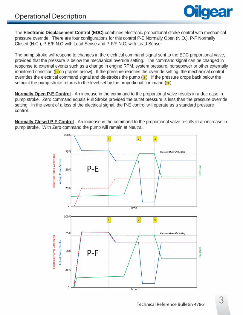
Operational Description
The Electronic Displacement Control (EDC) combines electronic proportional stroke control with mechanical pressure override. There are four configurations for this control P-E Normally Open (N.O.), P-F Normally Closed (N.C.), P-E/F N.O with Load Sense and P-F/F N.C. with Load Sense.
The pump stroke will respond to changes in the electrical command signal sent to the EDC proportional valve, provided that the pressure is below the mechanical override setting. The command signal can be changed in response to external events such as a change in engine RPM, system pressure, horsepower or other externally monitored condition ( on graphs below). If the pressure reaches the override setting, the mechanical control overrides the electrical command signal and de-strokes the pump ( 2 ). If the pressure drops back below the setpoint the pump stroke returns to the level set by the proportional command ( ). Normally Open P-E Control - An increase in the command to the proportional valve results in a decrease in pump stroke. Zero command equals Full Stroke provided the outlet pressure is less than the pressure override setting. In the event of a loss of the electrical signal, the P-E control will operate as a standard pressure control.
Normally Closed P-F Control - An increase in the command to the proportional valve results in an increase in pump stroke. With Zero command the pump will remain at Neutral.
1
3
Elec
tric
al P
ump
Com
man
d
Actu
al P
ump
Stro
ke
Pres
sure
Time
2 3
Pressure Override Setting
1
P-E
100%
25%
50%
0
75%
Elec
tric
al P
ump
Com
man
d
Actu
al P
ump
Stro
ke
Pres
sure
Time
2 3
Pressure Override Setting
1
P-F
100%
25%
50%
0
75%

Technical Reference Bulletin 478614
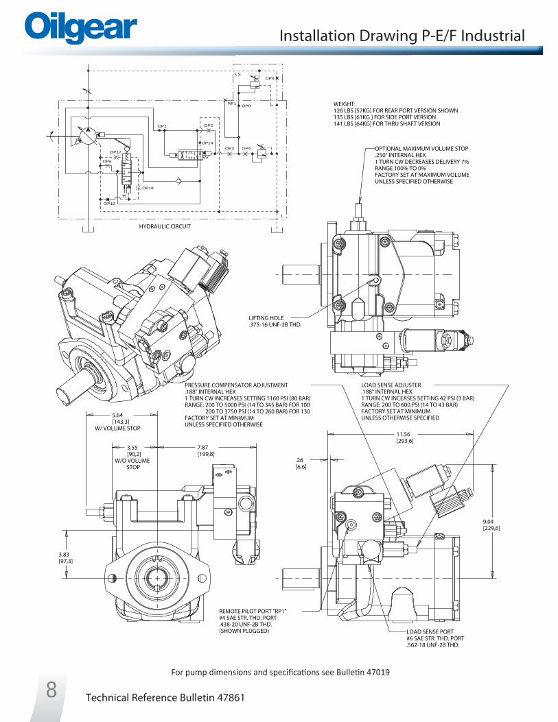
Installation Drawing P-E Industrial
For pump dimensions and specifications see Bulletin 47019
3.55[90,2]
W/O VOLUMESTOP
5.64[143,3]
W/ VOLUME STOP
7.87[199,8]
3.83[97,3]
.26[6,6]
11.56[293,6]
9.04[229,6]
HYDRAULIC CIRCUIT
WEIGHT:124 LBS [56KG] FOR REAR PORT VERSION SHOWN133 LBS [60KG ] FOR SIDE PORT VERSION139 LBS [63KG] FOR THRU SHAFT VERSION
PRESSURE COMPENSATOR ADJUSTMENT.188" INTERNAL HEX1 TURN CW INCREASES SETTING 1160 PSI (80 BAR)RANGE: 200 TO 5000 PSI (14 TO 345 BAR) FOR 100 200 TO 3750 PSI (14 TO 260 BAR) FOR 130FACTORY SET AT MINIMUMUNLESS SPECIFIED OTHERWISE
REMOTE PILOT PORT "RP1"#4 SAE STR. THD. PORT.438-20 UNF-2B THD.(SHOWN PLUGGED)
OPTIONAL MAXIMUM VOLUME STOP.250" INTERNAL HEX1 TURN CW DECREASES DELIVERY 7%RANGE 100% TO 0%FACTORY SET AT MAXIMUM VOLUMEUNLESS SPECIFIED OTHERWISE
LIFTING HOLE.375-16 UNF-2B THD.
RP1
OP1 OP2
OP14OP3 OP4
OP17
OP6
OP18
F
OP19
1

Technical Reference Bulletin 47861 5
Installation Drawing P-E Mobile
3.55[90,2]
W/O VOLUMESTOP
5.64[143,3]
W/ VOLUME STOP
7.87[199,8]
3.83[97,3]
.26[6,6]
9.84[249,8]
9.01[228,9]
HYDRAULIC CIRCUIT
WEIGHT:124 LBS [56KG] FOR REAR PORT VERSION SHOWN133 LBS [60KG ] FOR SIDE PORT VERSION139 LBS [63KG] FOR THRU SHAFT VERSION
PRESSURE COMPENSATOR ADJUSTMENT.188" INTERNAL HEX1 TURN CW INCREASES SETTING 1160 PSI (80 BAR)RANGE: 200 TO 5000 PSI (14 TO 345 BAR) FOR 100 200 TO 3750 PSI (14 TO 260 BAR) FOR 130FACTORY SET AT MINIMUMUNLESS SPECIFIED OTHERWISE
REMOTE PILOT PORT "RP1"#4 SAE STR. THD. PORT.438-20 UNF-2B THD.(SHOWN PLUGGED)
OPTIONAL MAXIMUM VOLUME STOP.250" INTERNAL HEX1 TURN CW DECREASES DELIVERY 7%RANGE 100% TO 0%FACTORY SET AT MAXIMUM VOLUMEUNLESS SPECIFIED OTHERWISE
LIFTING HOLE.375-16 UNF-2B THD.
RP1
OP1 OP2
OP14OP3 OP4
OP17
OP6
OP18
F
OP19
1
For pump dimensions and specifications see Bulletin 47019

Technical Reference Bulletin 478616
Installation Drawing P-F Industrial
For pump dimensions and specifications see Bulletin 47019
5.64[143,3]
W/ VOLUME STOP
3.55[90,2]
W/O VOLUMESTOP
.27[6,9]
8.12[206,1]
9.07[230,3]
11.61[295]
3.83[97,3]
HYDRAULIC CIRCUIT
WEIGHT:126 LBS [57KG] FOR REAR PORT VERSION SHOWN135 LBS [61KG ] FOR SIDE PORT VERSION141 LBS [64KG] FOR THRU SHAFT VERSION
PRESSURE COMPENSATOR ADJUSTMENT.188" INTERNAL HEX1 TURN CW INCREASES SETTING 1160 PSI (80 BAR)RANGE: 200 TO 5000 PSI (14 TO 345 BAR) FOR 100 200 TO 3750 PSI (14 TO 260 BAR) FOR 130FACTORY SET AT MINIMUMUNLESS SPECIFIED OTHERWISE
REMOTE PILOT PORT "RP1"#4 SAE STR. THD. PORT.438-20 UNF-2B THD.(SHOWN PLUGGED)
OPTIONAL MAXIMUM VOLUME STOP.250" INTERNAL HEX1 TURN CW DECREASES DELIVERY 7%RANGE 100% TO 0%FACTORY SET AT MAXIMUM VOLUMEUNLESS SPECIFIED OTHERWISE
LIFTING HOLE.375-16 UNF-2B THD.
RP1
OP1 OP2
OP14OP3 OP4
OP17
OP6
OP18
F
OP19
1

Technical Reference Bulletin 47861 7
Installation Drawing P-F Mobile
5.64[143,3]
W/ VOLUME STOP
3.55[90,2]
W/O VOLUMESTOP
.27[6,9]
8.12[206,1]
3.83[97,3]
9.89[251,2]
9.02[229,2]
HYDRAULIC CIRCUIT
WEIGHT:126 LBS [57KG] FOR REAR PORT VERSION SHOWN135 LBS [61KG ] FOR SIDE PORT VERSION141 LBS [64KG] FOR THRU SHAFT VERSION
PRESSURE COMPENSATOR ADJUSTMENT.188" INTERNAL HEX1 TURN CW INCREASES SETTING 1160 PSI (80 BAR)RANGE: 200 TO 5000 PSI (14 TO 345 BAR) FOR 100 200 TO 3750 PSI (14 TO 260 BAR) FOR 130FACTORY SET AT MINIMUMUNLESS SPECIFIED OTHERWISE
REMOTE PILOT PORT "RP1"#4 SAE STR. THD. PORT.438-20 UNF-2B THD.(SHOWN PLUGGED)
OPTIONAL MAXIMUM VOLUME STOP.250" INTERNAL HEX1 TURN CW DECREASES DELIVERY 7%RANGE 100% TO 0%FACTORY SET AT MAXIMUM VOLUMEUNLESS SPECIFIED OTHERWISE
LIFTING HOLE.375-16 UNF-2B THD.
RP1
OP1 OP2
OP14OP3 OP4
OP17
OP6
OP18
F
OP19
1
For pump dimensions and specifications see Bulletin 47019
Technical Reference Bulletin 47861
3.55[90,2]
W/O VOLUMESTOP
5.64[143,3]
W/ VOLUME STOP
3.83[97,3]
.26[6,6]
7.87[199,8]
11.56[293,6]
9.04[229,6]
HYDRAULIC CIRCUIT
WEIGHT:126 LBS [57KG] FOR REAR PORT VERSION SHOWN135 LBS [61KG ] FOR SIDE PORT VERSION141 LBS [64KG] FOR THRU SHAFT VERSION
PRESSURE COMPENSATOR ADJUSTMENT.188" INTERNAL HEX1 TURN CW INCREASES SETTING 1160 PSI (80 BAR)RANGE: 200 TO 5000 PSI (14 TO 345 BAR) FOR 100 200 TO 3750 PSI (14 TO 260 BAR) FOR 130FACTORY SET AT MINIMUMUNLESS SPECIFIED OTHERWISE
REMOTE PILOT PORT "RP1"#4 SAE STR. THD. PORT.438-20 UNF-2B THD.(SHOWN PLUGGED) LOAD SENSE PORT
#6 SAE STR. THD. PORT.562-18 UNF-2B THD.
LOAD SENSE ADJUSTER.188" INTERNAL HEX1 TURN CW INCEASES SETTING 42 PSI (3 BAR)RANGE: 200 TO 600 PSI (14 TO 43 BAR) FACTORY SET AT MINIMUMUNLESS OTHERWISE SPECIFIED
OPTIONAL MAXIMUM VOLUME STOP.250" INTERNAL HEX1 TURN CW DECREASES DELIVERY 7%RANGE 100% TO 0%FACTORY SET AT MAXIMUM VOLUMEUNLESS SPECIFIED OTHERWISE
LIFTING HOLE.375-16 UNF-2B THD.
LSOP9
RP1OP8
OP1 OP2
OP14OP3 OP4
OP17
OP6
OP18
F
OP19
1
Installation Drawing P-E/F Industrial
8For pump dimensions and specifications see Bulletin 47019

Technical Reference Bulletin 47861
3.55[90,2]
W/O VOLUMESTOP
5.64[143,3]
W/ VOLUME STOP
3.83[97,3]
.26[6,6]
7.87[199,8]
9.84[249,8]
9.01[228,9]
HYDRAULIC CIRCUIT
WEIGHT:126 LBS [57KG] FOR REAR PORT VERSION SHOWN135 LBS [61KG ] FOR SIDE PORT VERSION141 LBS [64KG] FOR THRU SHAFT VERSION
PRESSURE COMPENSATOR ADJUSTMENT.188" INTERNAL HEX1 TURN CW INCREASES SETTING 1160 PSI (80 BAR)RANGE: 200 TO 5000 PSI (14 TO 345 BAR) FOR 100 200 TO 3750 PSI (14 TO 260 BAR) FOR 130FACTORY SET AT MINIMUMUNLESS SPECIFIED OTHERWISE
REMOTE PILOT PORT "RP1"#4 SAE STR. THD. PORT.438-20 UNF-2B THD.(SHOWN PLUGGED) LOAD SENSE PORT
#6 SAE STR. THD. PORT.562-18 UNF-2B THD.
LOAD SENSE ADJUSTER.188" INTERNAL HEX1 TURN CW INCEASES SETTING 42 PSI (3 BAR)RANGE: 200 TO 600 PSI (14 TO 43 BAR) FACTORY SET AT MINIMUMUNLESS OTHERWISE SPECIFIED
OPTIONAL MAXIMUM VOLUME STOP.250" INTERNAL HEX1 TURN CW DECREASES DELIVERY 7%RANGE 100% TO 0%FACTORY SET AT MAXIMUM VOLUMEUNLESS SPECIFIED OTHERWISE
LIFTING HOLE.375-16 UNF-2B THD.
LSOP9
RP1OP8
OP1 OP2
OP14OP3 OP4
OP17
OP6
OP18
F
OP19
1
Installation Drawing P-E/F Mobile
9For pump dimensions and specifications see Bulletin 47019

Technical Reference Bulletin 47861
5.64[143,3]
W/ VOLUME STOP
8.12[206,1]
3.55[90,2]
W/O VOLUMESTOP
.27[6,9]
9.07[230,3]
11.61[295]
3.83[97,3]
HYDRAULIC CIRCUIT
WEIGHT:129 LBS [59KG] FOR REAR PORT VERSION SHOWN138 LBS [63KG ] FOR SIDE PORT VERSION144 LBS [65KG] FOR THRU SHAFT VERSION
PRESSURE COMPENSATOR ADJUSTMENT.188" INTERNAL HEX1 TURN CW INCREASES SETTING 1160 PSI (80 BAR)RANGE: 200 TO 5000 PSI (14 TO 345 BAR) FOR 100 200 TO 3750 PSI (14 TO 260 BAR) FOR 130FACTORY SET AT MINIMUMUNLESS SPECIFIED OTHERWISE
REMOTE PILOT PORT "RP1"#4 SAE STR. THD. PORT.438-20 UNF-2B THD.(SHOWN PLUGGED) LOAD SENSE PORT
#6 SAE STR. THD. PORT.562-18 UNF-2B THD.
LOAD SENSE ADJUSTER.188" INTERNAL HEX1 TURN CW INCEASES SETTING 42 PSI (3 BAR)RANGE: 200 TO 600 PSI (14 TO 43 BAR) FACTORY SET AT MINIMUMUNLESS OTHERWISE SPECIFIED
OPTIONAL MAXIMUM VOLUME STOP.250" INTERNAL HEX1 TURN CW DECREASES DELIVERY 7%RANGE 100% TO 0%FACTORY SET AT MAXIMUM VOLUMEUNLESS SPECIFIED OTHERWISE
LIFTING HOLE.375-16 UNF-2B THD.
LSOP9
RP1OP8
OP1 OP2
OP14OP3 OP4
OP17
OP6
OP18
F
OP19
1
Installation Drawing P-F/F Industrial
10For pump dimensions and specifications see Bulletin 47019

Technical Reference Bulletin 47861
5.64[143,3]
W/ VOLUME STOP
8.12[206,1]
3.55[90,2]
W/O VOLUMESTOP
.27[6,9]
3.83[97,3]
9.04[229,5]
9.89[251,2]
HYDRAULIC CIRCUIT
WEIGHT:129 LBS [59KG] FOR REAR PORT VERSION SHOWN138 LBS [63KG ] FOR SIDE PORT VERSION144 LBS [65KG] FOR THRU SHAFT VERSION
PRESSURE COMPENSATOR ADJUSTMENT.188" INTERNAL HEX1 TURN CW INCREASES SETTING 1160 PSI (80 BAR)RANGE: 200 TO 5000 PSI (14 TO 345 BAR) FOR 100 200 TO 3750 PSI (14 TO 260 BAR) FOR 130FACTORY SET AT MINIMUMUNLESS SPECIFIED OTHERWISE
REMOTE PILOT PORT "RP1"#4 SAE STR. THD. PORT.438-20 UNF-2B THD.(SHOWN PLUGGED) LOAD SENSE PORT
#6 SAE STR. THD. PORT.562-18 UNF-2B THD.
LOAD SENSE ADJUSTER.188" INTERNAL HEX1 TURN CW INCEASES SETTING 42 PSI (3 BAR)RANGE: 200 TO 600 PSI (14 TO 43 BAR) FACTORY SET AT MINIMUMUNLESS OTHERWISE SPECIFIED
OPTIONAL MAXIMUM VOLUME STOP.250" INTERNAL HEX1 TURN CW DECREASES DELIVERY 7%RANGE 100% TO 0%FACTORY SET AT MAXIMUM VOLUMEUNLESS SPECIFIED OTHERWISE
LIFTING HOLE.375-16 UNF-2B THD.
LSOP9
RP1OP8
OP1 OP2
OP14OP3 OP4
OP17
OP6
OP18
F
OP19
1
Installation Drawing P-F/F Mobile
11For pump dimensions and specifications see Bulletin 47019
Technical Reference Bulletin 47861
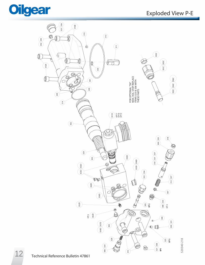
Exploded View P-E
OP
6
OP
4
306
334
328
314
315
325
OP
3
321
338
311
330
305
OP
2
319
323
336
330
303
329
302
308
333
307
312
327
310
331
337
309
335
318
OP
2
OP
3
340
301
304
FOR
OPT
ION
AL
"SN
"M
AX.
VO
L. S
TOP
REPL
ACE
ITEM
S 32
3 &
336
WIT
HTH
ESE
PART
S
OP1
7O
P18
OP1
9
RP1
316A
342
345
316B
313
322
334
RP1
351D
353D
356D
360D
352D
362D
354D
357D
359D
349
355D
358D
350D
338
321
392C
394C
396C
391C
395C
393C
12 5203
40-2
18

Technical Reference Bulletin 47861
Exploded View P-F
OP
6
OP
4
306
334
328
314
315
325
OP
3
321
338
311
330
305
OP
2
31932
333
6
330
303
329
302
308
333
307
312
327
310
331
337 30
933
5 318
OP
2
OP
334
0
301
304
FOR
OPT
ION
AL
"SN
"M
AX.
VO
L. S
TOP
REPL
ACE
ITEM
S 32
3 &
336
WIT
HTH
ESE
PART
S
OP1
7O
P18
OP1
9
RP1
316A
342
345
316B
313
322
334
RP1
351D
353D
356D
360D
352D
362D
354D
357D
359D
349
355D
358D
350D
338
321
363D
392C
394C
396C
391C
395C
393C
135203
40-2
17

Technical Reference Bulletin 4786114
OP
6
OP
9
OP
2
OP
3
OP
4
306
334
328
314
315
325
321
338
321
338
311
330
305
319
323
336
330
303
329
302
308
333
307
312
327
310
331
337
309
335
318
364
350
356
353
354
359
360
362
355
352
359
362
351
361
358
340
348
301
304
FOR
OPT
ION
AL
"SN
"M
AX.
VO
L. S
TOP
REPL
ACE
ITEM
S 32
3 &
336
WIT
HTH
ESE
PART
S
OP1
7O
P18
OP1
9
316A
342
345 31
6B
365
313
322
334
RP1
351D
353D
356D
360D
352D
362D
354D
357D
359D
349
355D
358D
350D
392C
394C
396C
391C
395C
393C
Exploded View P-E/F
5203
41-2
18

Technical Reference Bulletin 4786115
OP
6
OP
9
OP
2
OP
3
OP
4
306
334
328
314
315
325
321
338
321
338
311
330
305
319
323
336
330
303
329
302
308
333
307
312
327
310
331
337
309
335
318
364
350
356
353
354
359
360
362
355
352
359
362
351
361
358
340
348
301
304
FOR
OPT
ION
AL
"SN
"M
AX.
VO
L. S
TOP
REPL
ACE
ITEM
S 32
3 &
336
WIT
HTH
ESE
PART
S
OP1
7O
P18
OP1
9
316A
342
345
316B
365
313
322
334
RP1
351D
353D
356D
360D
352D
362D
354D
357D
359D
349
355D
358D
350D
363D
392C
394C
396C
391C
395C
393C
Exploded View P-F/F
5203
41-2
17

Technical Reference Bulletin 47861
BB
A A31
9
330 O
P 6
330
OP
6314
329
303
302
323
336
321
338
315
307
322
334
309
335
318
310
321
338
308
333
OP
4
304
306
334
OP
2
OP
3
OP
4
OP
1 (E
ND
CA
P FA
CE)
312
327
OP
2
OP
333
1
316A
301
337
FOR
OPT
ION
AL
"SN
"M
AX.
VO
L. S
TOP
REPL
ACE
ITEM
S 32
3 &
336
WIT
HTH
ESE
PART
S
OP1
7O
P18
OP1
9
342
345
311
313
360D
362D
354D
357D
352D
340
PART
IAL
SECT
ION
B-B
359D
349
RP1
RP1
316B
355D
358D
350D
353D
356D
351D
305
328
SEE
DET
AIL
D32
5
OP
14 (E
ND
CA
P FA
CE)
A-A
SECT
ION
DET
AIL
DSC
ALE
4/1
SEE
DET
AIL
F
392C
393C
391C
395C
DET
AIL
FSC
ALE
4/1
396C
394C
Cross Section P-E
16
5203
40-2
18

Technical Reference Bulletin 47861
BB
A A31
9
330
OP
6
330
OP
6314
329
303
302
323
336
321
338
315
307
322
334
309
335
318
310
321
338
308
333
OP
4
304
306
334
OP
2
OP
3
OP
4
OP
1 (E
ND
CA
P FA
CE)
312
327
OP
2
OP
3
331
316A
301
337
FOR
OPT
ION
AL
"SN
"M
AX.
VO
L. S
TOP
REPL
ACE
ITEM
S 32
3 &
336
WIT
HTH
ESE
PART
S
OP1
7O
P18
OP1
9
342
345
311
313
360D
362D
354D
357D
352D
340
PART
IAL
SECT
ION
B-B
359D
34936
3D
RP1
RP1
316B
355D
358D
350D
353D
356D
351D
305
328
SEE
DET
AIL
D32
5
OP
14 (E
ND
CA
P FA
CE)
A-A
SECT
ION
DET
AIL
DSC
ALE
4/1
SEE
DET
AIL
F
392C
393C
391C
395C
DET
AIL
FSC
ALE
4/1
396C
394C
Cross Section P-F
17
5203
40-2
17

Technical Reference Bulletin 4786118
Cross Section P-E/F
BB
A
A
OP
3
319
356
330
OP
6
348
330
358
364
314
329
303
302
323
336
OP
9
340
321
338
315
307
322
334
309
335
318
310 35
2
351
361
354
350
321
338
OP
4
308
333
304
306
334
OP
2
OP
4
OP
1 (E
ND
CA
P FA
CE)
312
327
OP
2
331
316A
301
337
359
FOR
OPT
ION
AL
"SN
"M
AX.
VO
L. S
TOP
REPL
ACE
ITEM
S 32
3 &
336
WIT
HTH
ESE
PART
S
OP1
7O
P18
OP1
9
342
345
311
313
360D
362D
354D
357D
352D
PART
IAL
SECT
ION
B-B
OP
8 (E
ND
CA
P FA
CE)
359D
349
RP1
RP1
316B
355D
358D
350D
353D
356D
351D
305
328 SE
E D
ETA
IL C
SEE
DET
AIL
D
355
325
353
OP
14 (E
ND
CA
P FA
CE)
SEE
DET
AIL
E
A-A
SECT
ION
365
DET
AIL
CSC
ALE
4/1
359
362
360
DET
AIL
DSC
ALE
4/1
DET
AIL
ESC
ALE
4/1
362
SEE
DET
AIL
F
392C
393C
391C
395C
DET
AIL
FSC
ALE
4/1
396C
394C
5203
41-2
18

Technical Reference Bulletin 47861 19
Cross Section P-F/F
BB
A A
OP
3
319
356
330
OP
6
348
330
358
364
314
329
303
323
336
OP
9
340
321
338
315
307
322
334
309
335
318
310 35
2
351
361
354
350
321
338
OP
430
833
3
304
306
334
OP
2
OP
4
OP
1 (E
ND
CA
P FA
CE)
312
327
OP
2
331
316A
301
337
359
FOR
OPT
ION
AL
"SN
"M
AX.
VO
L. S
TOP
REPL
ACE
ITEM
S 32
3 &
336
WIT
HTH
ESE
PART
S
OP1
7O
P18
OP1
9
342
345
311
313
360D
362D
354D
357D
352D
PART
IAL
SECT
ION
B-B
OP
8 (E
ND
CA
P FA
CE)
359D
349
302
363D
RP1
RP1
316B
355D
358D
350D
353D
356D
351D
305
328 SE
E D
ETA
IL C
SEE
DET
AIL
D
355
325
353
OP
14 (E
ND
CA
P FA
CE)
SEE
DET
AIL
E
A-A
SECT
ION
365
DET
AIL
CSC
ALE
4/1
359
362
360
DET
AIL
DSC
ALE
4/1
DET
AIL
ESC
ALE
4/1
362
SEE
DET
AIL
F
392C
393C
391C
395C
DET
AIL
FSC
ALE
4/1
396C
394C
5203
41-2
17

Technical Reference Bulletin 4786120
Control Valve - Exploded ViewIN
DU
STRI
AL
MO
BILE
016
001
021
013
002
017
015
018
014
012
020
007
019
008
003
004
009
005
010
006
011
019
All o
f the
item
s sho
wn
in th
is vi
ew a
re in
clud
ed in
Ite
m 3
51D
whi
ch is
par
t of t
he p
ropo
rtion
al c
ontr
ol
valv
e se
rvic
e ki
t.
4086
73-0
17

Technical Reference Bulletin 47861 21
Control Valve - Cross Section
OP1
7O
P18
A-A
SECT
ION
016
001
013
002
017
021
015
018
014
012
019
003
004
005
006
008
009
010
011
007
020
OP1
9
009
010
4086
73-0
17

Technical Reference Bulletin 4786122
O-Ring Seals
Item AS 568AShore A
DurometerNumber Number Viton
313 -250 70314 -137 Teflon 330 -013 90331 -014 90333 -906 90334 -908 90335 -910 90336 -912 90337 -014 *338 -904 90358t -010 90359t -016 90
* Teflon Backup Ring
Item Number Description Head Size / Type Tightening Torque306 PLUG, END 7/8” external 50 ft-lb (68 Nm)308 SEAT 7/16” external 200 in-lb (23 Nm)309 BONNET, PRESSURE COMPENSATOR 1” external 80 ft-lb (108 Nm)315 SCREW, SHC, 1/2-13 UNC 3/8” internal 100 ft-lb (136 Nm)
316A SCREW, SHC, 1/2-13 UNC 3.25 Long 3/8” internal 100 ft-lb (136 Nm)316B SCREW, SHC, 1/2-13 UNC 1.25 Long 3/8” internal 100 ft-lb (136 Nm)319 PLUG, .062 NPT 5/32” internal 48 in-lb (5 Nm)321 PLUG, #4 HP 3/16” internal 120 in-lb (14 Nm)322 PLUG, END, COMPENSATOR VALVE 7/8” external 50 ft-lb (68 Nm)323 PLUG, #12 HP 9/16” internal 85 ft-lb (115 Nm)325 ORIFICE, .062 NPTF-.040 DIA 5/32” internal 48 in-lb (5 Nm)342 PLUG, #3 HP 1/8” internal 45 in-lb (5 Nm)351 BONNET, LOAD SENSE 1 1/4” external 85 ft-lb (115 Nm)354 SEAT, LOAD SENSE 5/8” external 70 +10 in-lb (8 +1,13 Nm)356 SCREW, SHC #10-24 1.50 Long. 5/32” internal 57 in-lb (6 Nm)364 SCREW, CPS #10-24 0.19 Long 5/32” internal 20 in-lb (2 Nm)
391C BONNET, MAX. VOL. STOP 1 1/4” external 85 ft-lb (115 Nm)
351D SCREW, SHC #10-24 0.50 Long 5/32” internal * 57 in-lb (6 Nm)ASM, SOLENOID CONTROL 5/8” external ** 15 ft-lb (20 Nm)
353D PLUG, #2 HP 1/8” internal 45 in-lb (5 Nm)354D PLUG, #4 HP 3/16” internal 120 in-lb (14 Nm)355D PLUG, #8 HP 5/16” internal 45 ft-lb (61 Nm)
362DORIFICE, .062 NPTF-.062 (PVG-100)
5/32” internal 48 in-lb (5 Nm)ORIFICE, .062 NPTF-.089 (PVG-130)
Screw and Plug Torques
Item AS 568AShore A
DurometerNumber Number VitonControl Valve Assembly
003 -019 90004 -020 90005 -021 90006 -023 90007 -908 90008 -019 *009 -020 *010 -021 *011 -023 *
Item AS 568AShore A
DurometerNumber Number Viton
360t -906 90361t -912 90362t -016 *356D -902 90357D -904 90358D -908 90
359D -136 (P-E) -226 (P-F) 70
360D -013 90394C -014 90395C -912 90396C -014 *
Control Valve Exploded View* Item 18
** Item 19
t Load Sense Only

Technical Reference Bulletin 47861 23
Service Kits
Description Kit No. Series Items Included (quantity is 1 unless noted)Control Piston and SpringN.O. P-E, P-E/F L723987-006
F1 302, 303, 329N.C. P-F, P-F/F L723987-007Pressure Compensator ReliefP-E, P-F, P-E/F, P-F/F L723987-101 F1 307, 308, 312(4), 327, 333Load Sense / Pressure Compensator Relief
P-E/F, P-F/F L723987-108 F1 307, 308, 312(4), 327, 333, 353, 354, 355, 359(2), 360, 362(2)
Pressure Compensator SpoolP-E, P-F, P-E/F, P-F/F L723987-202 F1 305, 328Pressure Compensator AdjustorP-E, P-F, P-E/F, P-F/F L300574HS07 F1 309, 310, 318, 331, 335, 337Load Sense AdjustorP-E/F, P-F/F L318966-002 F1 351, 352, 359, 361, 362, 365Adjustable Maximum Volume StopP-E, P-F, P-E/F, P-F/F L516319-001 F1 391C, 392C, 393C, 394C, 395C, 396CControl Seal Kit
P-E, P-F K520340-001 F1
313, 314, 330(3), 331, 333, 334(2), 335, 336, 337, 338(2), 345, 394C, 395C, 396C, 356D(3), 357D, 358D, 359D, 360D(2), 003, 004, 005, 006, 007, 008, 009, 010, 011
P-E/F, P-F/F K520341-001 F1
313, 314, 330(3), 331, 333, 334(2), 335, 336, 337, 338(2), 345, 358(2), 359(2), 360, 361, 362(2), 394C, 395C, 396C, 356D(3), 357D, 358D, 359D, 360D(2), 003, 004, 005, 006, 007, 008, 009, 010, 011
End Cap Assembly
P-E, P-F L520340-300 F1303, 304, 305, 306, 307, 308, 309, 310, 312(4), 315(3), 318, 321(2), 322, 325, 327, 328, 331, 333, 334(2), 335, 337, 338(2), 359D, 360D(2)
P-E/F, P-F/F L520341-300 F1
303, 304, 305, 306, 307, 308, 309, 310, 312(4), 315(3), 318, 321(2), 322, 325, 327, 328, 331, 333, 334(2), 335, 337, 338(2), 350, 352, 352, 353, 354, 355, 356(4), 358(3), 359(2), 360, 361, 362(2), 364, 365, 359D, 360D(2)
Proportional Control Valve AssemblyP-E, P-E/F - 24V Industrial L520340-304
F1
314, 330(2), 350D, 351D, 352D, 353D(3*)(7**), 354D, 355D, 356D(3*)(7**), 357D, 358D, 359D, 360D(2), 362D
* P-E, P-E/F Control Valve Assemblies** P-F, P-F/F Control Valve Assemblies
P-E, P-E/F - 13V Mobile L520340-305P-E, P-E/F - 27V Mobile L520340-306P-F, P-F/F - 24V Industrial L520341-304P-F, P-F/F - 13V Mobile L520341-305P-F, P-F/F - 27V Mobile L520341-306Proportional AmplifierP-E, P-F, P-E/F, P-F/F - 24V Industrial 407932-902 F1 020
P-E, P-F, P-E/F, P-F/F -13V and 27V Mobile F1

Technical Reference Bulletin 4786124
Electrical Connections and Specifications
C D E F
A B
A 0 Volt SupplyB 24 Volt Supply
C Signal 0 VoltD 3 to 8 Volt Command*E UnusedF Unused
* For use with 4-20mA command source, install a 500W resistor between terminals C and D. Functional command range would be 6mA - 16mA (3 to 8 volt).
Signal 0V and Supply 0V are internally linked. If 0 Volt signals are linked outside of connector use only 0 Volt supply terminal.
12
Industrial 24V Mobile 24V Mobile 12VSupply Voltage 24 Volt DC +0.5V
fused at 1.5 A27 Volt DC
fused at 1.5 A13 Volt DC
fused at 2.5 AControl Signal (Amplifier Only) 3 to 8 VDC =
100% to 0% stroke N/A N/A
PWM* Switching Frequency 150 Hz 180 Hz 180 HzMaximum Continuous Current 1 A 1 A 2 AOperating Temperature -50C to 70oC -50C to 70oC -50C to 70oCNominal Coil Resistance 24 W 28 W 7 W
* Pulse Width Modulated
Amplifier Connections-Industrial Coil Only
Solenoid Connections
Specifications
Mobile Solenoid Connector
Industrial Solenoid Connector
12
1 + Signal2 0V Signal
Mating connector for Mobile Solenoid: Deutsch DT04-2P
Mating connector for Industrial Solenoid: Hirschmann GDM 209
Technical Reference Bulletin 47861 25
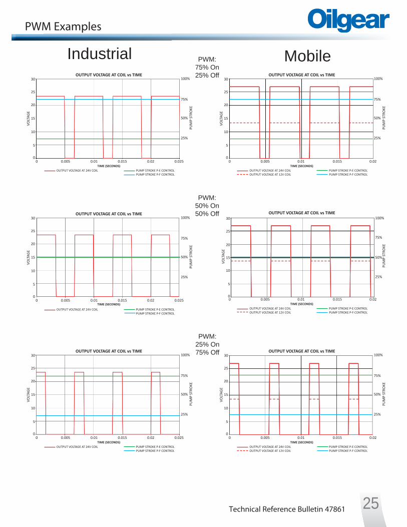
PWM Examples
Industrial Mobile
100%
50%
75%
25%
OUTPUT VOLTAGE AT COIL vs TIME
TIME (SECONDS)OUTPUT VOLTAGE AT 24V COILOUTPUT VOLTAGE AT 12V COIL
PUMP STROKE P-E CONTROLPUMP STROKE P-F CONTROL
0 0.005 0.01 0.015 0.020
5
10
15
20
25
30VO
LTAG
E
PUM
P ST
ROKE
100%
50%
75%
25%
OUTPUT VOLTAGE AT COIL vs TIME
TIME (SECONDS)OUTPUT VOLTAGE AT 24V COILOUTPUT VOLTAGE AT 12V COIL
PUMP STROKE P-E CONTROLPUMP STROKE P-F CONTROL
0 0.005 0.01 0.015 0.020
5
10
15
20
25
30
VOLT
AGE
PUM
P ST
ROKE
100%
50%
75%
25%
OUTPUT VOLTAGE AT COIL vs TIME
TIME (SECONDS)OUTPUT VOLTAGE AT 24V COILOUTPUT VOLTAGE AT 12V COIL
PUMP STROKE P-E CONTROLPUMP STROKE P-F CONTROL
0 0.005 0.01 0.015 0.020
5
10
15
20
25
30
VOLT
AGE
PUM
P ST
ROKE
100%
50%
75%
25%
OUTPUT VOLTAGE AT COIL vs TIME
TIME (SECONDS)OUTPUT VOLTAGE AT 24V COIL PUMP STROKE P-E CONTROL
PUMP STROKE P-F CONTROL
0 0.005 0.01 0.015 0.020
5
10
15
20
25
30
VOLT
AGE
PUM
P ST
ROKE
0.025
100%
50%
75%
25%
OUTPUT VOLTAGE AT COIL vs TIME
TIME (SECONDS)OUTPUT VOLTAGE AT 24V COIL PUMP STROKE P-E CONTROL
PUMP STROKE P-F CONTROL
0 0.005 0.01 0.015 0.020
5
10
15
20
25
30
VOLT
AGE
PUM
P ST
ROKE
0.025
100%
50%
75%
25%
OUTPUT VOLTAGE AT COIL vs TIME
OUTPUT VOLTAGE AT 24V COIL PUMP STROKE P-E CONTROLPUMP STROKE P-F CONTROL
0 0.005 0.01 0.015 0.020
5
10
15
20
25
30
VOLT
AGE
PUM
P ST
ROKE
0.025TIME (SECONDS)
PWM:75% On25% Off
PWM:50% On50% Off
PWM:25% On75% Off

Technical Reference Bulletin 4786126
Notes

Technical Reference Bulletin 47861 27
Notes

. . . . . . . . . . . . . . . . . . . . . . . . . . . . . . . . . . . . . . . . . . . . . . . . . . .. . . . . . .
. . . . . .. . . . .
. . . . .. . . . . .
. . . . . . . . . . . . . . . . . . . . .
The Oilgear CompanyMilwaukee, WI USA
+1-414-327-1700
Bulletin TRB-47861 March 2013 4