Industrial Maintenance - Basic Controls, Model 8036-E - LabVolt
Upload
khangminh22Category
view
4download
0
Verasys System Product Bulletin
Introduction to the Verasys SystemThe Verasys® system provides bundled equipment and controls solutions that use recognizedand trusted brands. Verasys is a plug-and-play solution that is part of the Johnson Controls®SMART Systems. The Verasys system features simple, configurable controllers that you can bundlewith HVACR equipment from the factory or install in the field. You can use Verasys to configuremany HVACR controls applications for one building or an entire enterprise without using specialprogramming tools or control engineering.The Verasys system features advanced direct digital control (DDC) controllers bundled with JohnsonControls single packaged units (SPU), actuators, sensors, and damper assemblies. All devicesself-configure, and the Verasys Smart Building Hub (SBH) monitors the devices. Through thesupervisory controller, you can access the system using either a laptop, smart phone, or tablet. TheSBH connects to an Ethernet backbone to enable remote connectivity and additional features likeemail and text alarms. Verasys supported devices automatically connect the point, alarm, trend, andgraphical definitions. The points appear when you connect devices to the system, thereby makingVerasys an easy-to-use, light commercial building automation system (BAS).Figure 1: Verasys system
LIT-12012342
2020-02-10
Release 3.4

Features and benefitsMulti-client connectivity
Access all identifiable devices connected to the BACnet® MS/TP trunk.
Browser-based interface
Local display replacement solution so you can access device information through anysupported web browser.
Wi-Fi connectivity
Commission, configure, and access building automation equipment usingWi-Fi-enabledsmart devices or laptops.
Advanced features
View alarms, events, and trends. Modify schedules and commission devices.
Browser-based remote building management
Remote management of building systems.
Simple interlocks to IOM controllers
Connects different systems to the Verasys network, such as exhaust and lighting systems.
Schedule synchronization
Combines common schedules with the schedule synchronization feature.
Easy-to-use intuitive user interface (UI)
Uses color-coded bars on point listings so that you can quickly view the most importantstatuses from a long list of points.
Wireless end device solutions
Uses the Verasys Pro Wireless system to connect the TEC3000 Thermostats to a SBH usingwireless signals.
Enterprise connectivity
Verasys Enterprise is a cloud-based solution that provides a multi-site aggregation ofequipment, data, alarms, setpoints, and schedules to authorized users. The enterpriseapplication provides a holistic view of an enterprise and the information that is required tomanage HVAC, lighting, energy, and input and output data for customers who have largebuilding portfolios.
New user experience for facility
Offers continued improvement and equipment relationship for simple user view for end-users and contractors. Included is a summary page for all HVAC devices serving spaces thatincludes indicators for Name, Temperature, Status, and Occupancy, and a single area tochange the setpoint of the facility.
Verasys System Product Bulletin2

Data share
Share data from one source to multiple destinations. For example, share an outside airtemperature (OAT) from a SMART Equipment rooftop unit (RTU) to multiple TEC3000 devicesusing only one OAT source.
Backup and restore
Provides a simple interface to back up all SMART Equipment devices within the system. Storethe backup files on the SBH or download the file to any smart mobile device or computerthat is connected to the SBH.
Support for European light commercial to mid-market architecture
Uses Advanced Terminal Unit controllers (ATC) and application-specific, configurable Verasyscontrollers in Europe only. A typical application contains small mini-chillers, boilers, an airhandling unit (AHU), and fan coil units (FCU).
Support for European light commercial to mid-market by the integration of York mini-chillers to the Verasys system. Chiller model numbers:
• YMAA: software version 3.0.0.1114
• YLAA: software version 3.0.0.1114
• YLPA: software version 3.0.0.1114
SBH user interfaceThe SBH provides a wireless, intuitive UI optimized for mobile use.Figure 2 shows the Facility view. Within this view, you can review the entire system to validate theconditions of the facility by viewing temperature, mode, and occupancy.
Figure 2: Facility feature
The SBH UI scales to the device you are using. The main menus and screens are side-by-side on acomputer screen or tablet. On a phone display, you see either the menu or the screens you selectedfrom that menu, for example, the TEC3000 Home screen. When you view the UI on a phone orsmaller tablet, drag the screen from the left or right to display the required menu or screens.
3Verasys System Product Bulletin

Supported controllersThe Verasys system supports the following controllers:
• Zone and Bypass Damper controllers
• ZEC410 and ZEC510 VAV controllers
• Verasys Equipment and Application controllers
• Smart Equipment controllers
• TEC30xx/TEC36xx Thermostats
• Terminal Unit controllers (TUC and ATC)
• PENN® A52x and MR5 refrigeration controllers
In the following sections you can read about the controllers in more detail.
Zone and Bypass Damper controllers
The Zone Damper (ZEC310) and Bypass Damper (BYP200) controllers are components of theVerasys zoning system. The Zone and Bypass Damper controllers run a pre-engineered HVACzoning application and provide the inputs and outputs required for this application. Thesecontrollers are factory-configured for field installation on a zone or bypass damper assembly whenthey are shipped.The Zone and Bypass Damper controllers include advanced operating modes and multiple featuresthat ensure occupant comfort. A carbon dioxide (CO2) demand controlled ventilation (DCV) modein the Zone Damper regulates CO2 levels within a zone by adding fresh air into the zone duringoccupied times. The controller uses occupancy sensing capability to switch from occupied mode tostandby mode based on local activity. To maximize energy savings, standby mode uses setpointsthat are higher than the occupied cooling setpoint and lower than occupied heating setpoint.
VAV Box controller
The VAV Box zone controllers run a pre-engineered HVAC zoning sequence and provide the inputsand outputs that the VAV application requires.The ZEC controller contains multiple features to ensure occupant comfort. Because of an optionaloccupancy sensing capability, the ZEC controller can switch from occupied mode to standby modebased on zone activity. To maximise energy savings, standby mode uses setpoints that are higherand lower than occupied mode setpoints.The ZEC410 and ZEC510 controllers also use plug-and-play technology to detect which networksensor types are connected.To set up the ZEC410 and ZEC510 controllers, use the Verasys SBH. The VAV controller commissionswith either the SBH or the VAV Balancing Thermostat.
Verasys Equipment and Application Controllers (VEC andVAC)
The Verasys Equipment and Application controllers are part of the SMART Equipment controllerfamily. The VECs run pre-engineered applications that reside on the zone bus of a zone coordinator,and provide the inputs and outputs required to monitor and control HVAC equipment.
Verasys System Product Bulletin4

The Application controllers run pre-engineered applications that reside on the system bus of anSBH, and provide the inputs and outputs required to monitor and control various applications.The Equipment and Application controllers include an integral real-time clock to monitor andcontrol schedules, calendar trends, and to operate for extended periods of time as stand-alonecontrollers when they are offline from the system network.
Verasys Equipment controller (VEC100)
The Verasys Equipment controller controls either VAV or change over bypass (COBP) units. Youcan use this single controller when the unit is not a Smart Equipment unit. Index the controllerto either VAV or COBP to set the control of the zone coordinator and the system. You can use thecontroller options to control an economizer for up to two stages of heat and four stages of cooling.The controller automatically uses analog sensors when it is connected to the controller. If youconnect a return air sensor to the controller and the system is a VAV system, the morning warm-up feature is integrated for control. If a CO2 sensor is connected and an economizer is defined,demand ventilation control sequences are available. For more information on the sequences thatthis controller covers, refer to the Verasys System Operation Overview Technical Bulletin (LIT-12012370).
Verasys Lighting controller (VAC1001)
The Verasys Lighting controller (VAC1001) is a Verasys Application controller that controls up tonine lighting contactors that are grouped in zones. You can control and schedule up to eight zonesfrom a light level sensor. You can connect either a binary or analog light level sensor and drivethe zone control based on light level. The zone also includes an associated schedule that can drivethe output of the zone. You can drive contactors for outside lights because of the flexibility of thecontroller; lights come on when it is dark and turn off at a fixed time or drive other zones based onthe schedule. The first seven zones have a binary input that can override the zone output. You canset the binary input to momentary and allow a set amount of time for the override, or maintain theinput for a more permanent override.
Input/Output Module
The Input/Output Module is a Verasys Application controller (VAC1002). The VAC1002 is a simplepoint multiplexer that monitors up to five analog inputs and four binary inputs. The controllercontrols up to nine binary outputs, connects to up to five wired or wireless NS sensors, and up tofour Johnson Controls’ energy meters. The VAC1002 uses the SBH to monitor and control auxiliarypoints in a facility.You can configure analog, binary, and NS sensor inputs for trending and alarming. The analogtrend samples are set to 200. The binary trend samples are set to 20, but you can adjust the trendinterval. You can configure each input for alarming. For binary inputs, you can define which statetriggers the alarm. For analog inputs, you can set high and low alarm limits. The alarm message isadjustable for binary and analog types.You can connect Smart Edge devices to the VAC1002. The energy meter is compatible with thecontroller and the meter monitors the voltage, amperage, demand, and consumption for eachphase of incoming power. The energy meter and all inputs are available to use with the interlockfeatures of the SBH. You can control all the outputs on the VAC1002 with the interlock feature orwith the scheduling feature on the SBH.
Controller features
• Integrate facility loads, such as lighting or exhaust fans, into building occupancy schedules
• Circuitry and connectors for the five analog inputs, four binary inputs, nine binary outputs, fivewired or wireless NS sensors, and four energy meters
5Verasys System Product Bulletin

• Point interlocking for advanced control of multiple conditions, such as temperature, humidity,CO2, fan status, occupancy status, and control mode
• Customizable alarming for monitoring devices, conditions, or spaces
• Power monitoring to help you understand power usage in a facility
Constant Volume Application
The Constant Volume Application is a Verasys application. You can load the application to eithera VAC1000 or VAC3000 depending on the equipment being controlled. The Constant VolumeApplication adds in features present in SMART equipment and, therefore, extends the capabilities ofthe TEC3xxx series for third party equipment. The application includes support for up to four stagesof cooling and four stages of heating, modulated 0 V to 10 V for heat and cool, and heat pump,with an additional two stages of supplemental heat available. The Constant Volume Application cancontrol a mixed air damper or set a minimum outside air position, and meet Title 24 compliancefor the state of California. Other supported features include occupancy scheduling, outdoor airlockouts, dehumidification, humidification, demand control ventilation, and much more.
Verasys Zone Coordinator
The Verasys Zone Coordinator is used for multi-zone applications as an engine to coordinate acomplete VAV or COBP system. You can order an individual Verasys Zone Coordinator or a panelversion. The Verasys Zone Coordinator automatically recognizes the unit configuration, andswitches to either VAV or COBP based on the system type.
TEC30xx or TEC36xx Thermostat controllers
The TEC30xx and TEC36xx Series Thermostat controllers are Verasys Pro Wireless or BACnet MS/TPthermostats that provide on and off, floating, and proportional control of the following elements:
• Local hydronic reheat valves
• Pressure-dependent VAV equipment with or without local reheat
• Two-pipe or four-pipe fan coils
• Cabinet unit heaters
• Other zoning equipment using an on and off, floating, or 0 VDC to 10 VDC proportional controlinput
Models also provide single or two-stage control of unitary RTUs with or without economizers andheat pumps.The TEC30xx Thermostat controllers are Verasys Pro Wireless models that require additionaldevices for the Pro Wireless network connection to the SBH.
Verasys Pro Wireless Field Bus System
The Verasys Pro Wireless Field Bus System uses Zigbee technology to wirelessly monitor HVACequipment that uses the BACnet protocol. The Verasys system creates a wireless mesh network thatenhances reliability. A resilient, self-healing function in the system uses multiple transmission pathsthat automatically form for the data.The MS/TP trunk and device limits for the Verasys SBH are the same for hard-wired products,wireless products, or a combination of hard-wired and wireless products. The wireless meshnetwork is independent of any building infrastructure and does not require any preexisting wirelessinfrastructure.
Verasys System Product Bulletin6

PENN A52x and MR5 refrigeration controllers
The PENN A5xx Series Wall Mount Refrigeration and Defrost Controllers provide refrigerated spaceand defrost control for low and medium temperature refrigeration applications.The PENN MR5 Series Panel Mount Case Controller controls compressor, evaporator fan, anddefrost cycles to maintain the temperature of refrigerated units.
Ideal applicationsThe wireless products within a Verasys system are ideal for any location where it is cost-prohibitive,difficult, or aesthetically unappealing to hardwire between products. Examples of these locationsinclude the following:
• Office buildings, university campuses, educational facilities, and other commercial structureswith brick or solid concrete walls and ceilings that impede hard-wired applications
• Retail stores and other commercial real estate where tenant turnover is frequent and temporarywalls and ceilings are common
• Museums, historical buildings, atriums, and other sites where building aesthetics and historicalpreservation are important
• Gymnasiums and other locations with large, open spaces
• Buildings with marble, granite, glass, mirrors, wood veneer, or other decorative surfaces thatpresent challenges to hard-wiring
• Buildings with asbestos or other hazardous materials that must not be disturbed
• Buildings with occupants sensitive to disruptions to business
• Regions with high labor costs
• Refrigerator and freezer storage containers
Applications to avoidLocations or applications that prohibit cellular telephones or Wi-Fi systems are unsuitable for thewireless Verasys products. Examples of these locations include the following:
• Operating rooms or radiation therapy rooms
• Validated environments
• UL 864 applications
• Department of Defense applications requiring Diacap certification, such as military bases andmilitary hospitals
Do not use the wireless products in applications that cannot tolerate intermittent interference, or inthe following situations:
• Critical control features that impact life-safety or result in large monetary loss, includingsecondary backup
• Life-safety applications
• Data centers, production lines, or critical areas that shut down
7Verasys System Product Bulletin
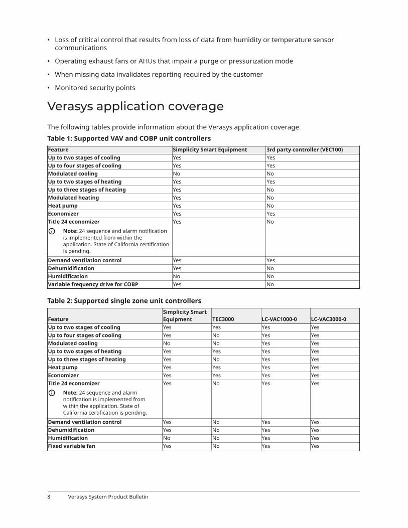
• Loss of critical control that results from loss of data from humidity or temperature sensorcommunications
• Operating exhaust fans or AHUs that impair a purge or pressurization mode
• When missing data invalidates reporting required by the customer
• Monitored security points
Verasys application coverageThe following tables provide information about the Verasys application coverage.Table 1: Supported VAV and COBP unit controllersFeature Simplicity Smart Equipment 3rd party controller (VEC100)Up to two stages of cooling Yes YesUp to four stages of cooling Yes YesModulated cooling No NoUp to two stages of heating Yes YesUp to three stages of heating Yes NoModulated heating Yes NoHeat pump Yes NoEconomizer Yes YesTitle 24 economizer
Note: 24 sequence and alarm notificationis implemented from within theapplication. State of California certificationis pending.
Yes No
Demand ventilation control Yes YesDehumidification Yes NoHumidification No NoVariable frequency drive for COBP Yes No
Table 2: Supported single zone unit controllers
FeatureSimplicity SmartEquipment TEC3000 LC-VAC1000-0 LC-VAC3000-0
Up to two stages of cooling Yes Yes Yes YesUp to four stages of cooling Yes No Yes YesModulated cooling No No Yes YesUp to two stages of heating Yes Yes Yes YesUp to three stages of heating Yes No Yes YesHeat pump Yes Yes Yes YesEconomizer Yes Yes Yes YesTitle 24 economizer
Note: 24 sequence and alarmnotification is implemented fromwithin the application. State ofCalifornia certification is pending.
Yes No Yes Yes
Demand ventilation control Yes No Yes YesDehumidification Yes No Yes YesHumidification No No Yes YesFixed variable fan Yes No Yes Yes
Verasys System Product Bulletin8

Note: The table shows the applications that the LC-VAC1000-0 and LC-VAC3000-0 cover. Youcan add the LC-IOM3711-0 to cover additional applications. For example, the LC-VAC3000-0is a 32 point controller with all of the applications available on the base controller except forhumidification, for which you need the LC-IOM3711-0.
Table 3: Supported VAV controllersFeature Staged Incremental Proportional SCRUp to three stages of box heat Yes No NoIncremental valve for box heat No Yes NoProportional signal for box heat (SCR or valve) No No YesSupports no fan Yes Yes YesSupports series fan Yes Yes YesSupports parallel fan Yes Yes YesDischarge temp monitoring Yes Yes YesOccupancy sensing input Yes Yes YesUp to five net sensors (averaging) Yes Yes YesUp to five CO2 sensors (high select) Yes Yes YesStaged supplemental heat Yes No NoIncremental supplemental heat No Yes Yes
Table 4: Supported COBP controllerFeature LC-ZEC310-0Modulated box heat YesOn/Off box heat YesModulated supplemental heat YesPWM supplement heat (10 sec duty cycle) YesOn/Off supplemental heat YesOccupancy sensing input YesUp to five net sensors (averaging) YesUp to five CO2 sensors (high select) YesExtra output for second damper actuator Yes
Note: Box heat is any heat source that is located in the duct. Supplement heat is any heatsource that is located outside the duct.
Ordering informationContact your Johnson Controls representative to order Verasys system or related products. See thefollowing table for product code numbers and product descriptions.Table 5: Ordering informationProduct codenumber DescriptionLC-SBH200-0 SBH with Wi-Fi adapter; mounting options include DIN rail or surface mounting
Other variants:• LC-SBH200-0S: SBH with Wi-Fi adapter and power supply• LC-SBH200-0E: SBH with a three-year subscription to Verasys Enterprise• LC-SBH200-0LA: SBH for Latin America
LC-VZC100-0 Verasys Zone Coordinator for VAV and COBP applicationsLC-VZCPNL-0 Verasys Zone Coordinator for VAV and COBP applications — panel versionLC-VEC100-0 Third-party RTU (VAV, COBP)LC-ZEC510-0 Configurable VAV Box Controller, all fan types, staged, incremental and proportional SCR heatingLC-ZEC410-1 Configurable VAV Box Controller, all fan types, stage box heating
9Verasys System Product Bulletin

Table 5: Ordering informationProduct codenumber DescriptionLC-ZEC410-2 Configurable VAV Box Controller, all fan types, incremental box heatingLC-ZEC410-3 Configurable VAV Box Controller, all fan types, proportional box heatingLC-ZEC310-0 Field-installed zone controller, no damperLC-BYP200-0 Field-installed Bypass Damper Controller, no damperLC-VAC1000-0 Application Controller with no applicationLC-VAC1100-0 Application Controller with no applicationLC-VAC3000-0 Application Controller with no applicationLC-VAC1001-0 Application Controller with Lighting ApplicationLC-VAC1002-0 Application Controller with Input/Output module applicationLC-VLP100-0 Lighting panel with VAC1001, without relays, without contactorsLC-VLP110-0 Lighting panel with VAC1001, with relays, without contactorsLC-VLP120-0 Lighting panel with VAC1001, with relays, with contactorsLC-IOP200-0 Input/Output panel with VAC1002, with 96 VA power supplyLC-ZFR1825-0 Wireless coordinatorLC-ZFR1822-0B Wireless Repeater Kit Wall mount typeLC-ZFR1821-0B Wireless Repeater Kit Flag mount typeLC-IOM3711-0 12-point IOM with 4 UI, 4 UO, 4 BO, Zone bus, and Sensor bus support. Relays are rated for 120/240
VAC.MR534AFDV-000S PENN MR534 Controller including ADPT- MR5- RS485 for Verasys or standard BACnetA525AEDV-0203C PENN electronic wall mount refrigeration and defrost controller with two sensor inputs and five output
relays. Includes two A99B type sensors, and BACNet MSTP communication option.
• You can order the LC-BYP200-0 and LC-ZEC310-0 controllers mounted on round dampers.
• You can order the ZEC510 controllers mounted and wired in VAV box assembly.
• For the VAC controllers, refer to the Verasys Constant Volume Controller Application Note(LIT-12013067) to find the appropriate accessories on an application by application process.
Table 6: SBH200 AccessoriesCode Number Description Shipped withACC-PWRKIT-1A24AC-PWRKIT-1D24
Verasys LC-SBH200-0 power supply for North America
ACC-PWRKIT-1E24 Verasys LC-SBH200-0 power supply for Europe
LC-SBH200-0SLC-SBH200-0E
ACC-WIFIKIT-0DU Verasys LC-SBH200-0 USB Wi-Fi adapter for North America and Europe LC-SBH200-0LC-SBH200-0SLC-SBH200-0E
Table 7: Supported third-party USB Wi-Fi adapters for SBHManufacturer Model NameD-LINK® DWA-131 ED-LINK DWA-171 AD-LINK DWA-171 CNETGEAR® A6100TP-LINK® ArcherPREMIERTEK® PT-8811AU
Table 8: Zone controller accessoriesProduct code number DescriptionZone temperature sensors (hard-wired) ZEC310 onlyTE-68NT-0N00S Wall temperature sensor, 1000 ohm, nickel with temperature occupancy button
Verasys System Product Bulletin10

Table 8: Zone controller accessoriesProduct code number DescriptionTE-68NT-1N00S Wall temperature sensor, 1000 ohm, nickel with warmer and cooler (W/C) adjustment and
temperature occupancy pushbuttonZone CO2 sensorNS-BCN7004-0 BACnet network CO2 sensor designed to function directly with Johnson Controls BACnet MS/TP
digital controllers, in a 80 mm x 120 mm (3. 15 in. x 4.72 in.) enclosure with terminal block andmodular jack wiring connections.Addresses 212 to 219 only are supported
Second zone damper actuatorNote: You must purchase the actuator and add it to a damper without a ZEC310 controller.
M9106-GGA-2 6 N•m torque non-spring return damper actuatorNetwork sensors for zone temperatureNS-B8BTN240-0 Network sensor, 120 mm x 80 mm, JCI logo, local setpoint, whiteNS-B8BTN241-0 Network sensor, 120 mm x 80 mm, no logo, local setpoint, whiteNS-B8BTN040-0 Network sensor, 120 mm x 80 mm, JCI logo, no setpoint, whiteNS-B8BTN041-0 Network sensor, 120 mm x 80 mm, no logo, no setpoint, whiteNS-B8BTN140-0 Network sensor, 120 mm x 80 mm, JCI logo, warmer and cooler adjustment, whiteNS-B8BTN141-0 Network sensor, 120 mm x 80 mm, no logo, warmer and cooler adjustment, whiteNS-B8BTN242-0 Network sensor, 120 mm x 80 mm, JCI logo, local setpoint, blackNS-B8BTN243-0 Network sensor, 120 mm x 80 mm, no logo, local setpoint, blackNS-B8BTN042-0 Network sensor, 120 mm x 80 mm, JCI logo, no setpoint, blackNS-B8BTN043-0 Network sensor, 120 mm x 80 mm, no logo, no setpoint, blackNS-B8BTN142-0 Network sensor, 120 mm x 80 mm, JCI logo, warmer and cooler adjustment, blackNS-B8BTN143-0 Network sensor, 120 mm x 80 mm, no logo, warmer and cooler adjustment, blackOccupancy lighting switchOLS-2100-1 Occupancy sensing light switch for control of indoor incandescent and fluorescent lightsRIBU1C Enclosed relay for OLS-2100-1 sensor
Table 9: Wireless thermostat controller models
Code number Control output Occupancy DehumidificationJohnsonControls logo Color
TEC3012-13-000 On/off or floating fan coiland zoning
No Yes Yes Black
TEC3012-14-000 On/off or floating fan coiland zoning
No Yes Yes White
TEC3012-15-000 On/off or floating fan coiland zoning
No Yes No Black
TEC3012-16-000 On/off or floating fan coiland zoning
No Yes No White
TEC3013-13-000 On/off or floating fan coiland zoning
Yes Yes Yes Black
TEC3013-14-000 On/off or floating fan coiland zoning
Yes Yes Yes White
TEC3013-15-000 On/off or floating fan coiland zoning
Yes Yes No Black
TEC3013-16-000 On/off or floating fan coiland zoning
Yes Yes No White
TEC3022-13-000 0 to 10 VDC proportionalfan coil and zoning
No Yes Yes Black
TEC3022-14-000 0 to 10 VDC proportionalfan coil and zoning
No Yes Yes White
TEC3022-15-000 0 to 10 VDC proportionalfan coil and zoning
No Yes No Black
11Verasys System Product Bulletin

Table 9: Wireless thermostat controller models
Code number Control output Occupancy DehumidificationJohnsonControls logo Color
TEC3022-16-000 0 to 10 VDC proportionalfan coil and zoning
No Yes No White
TEC3023-13-000 0 to 10 VDC proportionalfan coil and zoning
Yes Yes Yes Black
TEC3023-14-000 0 to 10 VDC proportionalfan coil and zoning
Yes Yes Yes White
TEC3023-15-000 0 to 10 VDC proportionalfan coil and zoning
Yes Yes No Black
TEC3023-16-000 0 to 10 VDC proportionalfan coil and zoning
Yes Yes No White
TEC3030-13-000 Single- or two-stageRTU/heat pump witheconomizer
No No Yes Black
TEC3030-14-000 Single- or two-stageRTU/heat pump witheconomizer
No No Yes White
TEC3030-15-000 Single- or two-stageRTU/heat pump witheconomizer
No No No Black
TEC3030-16-000 Single- or two-stageRTU/heat pump witheconomizer
No No No White
TEC3031-13-000 Single- or two-stageRTU/heat pump witheconomizer
Yes No Yes Black
TEC3031-14-000 Single- or two-stageRTU/heat pump witheconomizer
Yes No Yes White
TEC3031-15-000 Single- or two-stageRTU/heat pump witheconomizer
Yes No No Black
TEC3031-16-000 Single- or two-stageRTU/heat pump witheconomizer
Yes No No White
Table 10: Field-selectable BACnet MS/TP or N2 Networked Thermostat Controller modelsCode number Control output Occupancy Dehumidification Johnson Controls logo ColorTEC3612-13-000 On/off or floating fan coil
and zoningNo Yes Yes Black
TEC3612-14-000 On/off or floating fan coiland zoning
No Yes Yes White
Verasys System Product Bulletin12

Table 10: Field-selectable BACnet MS/TP or N2 Networked Thermostat Controller modelsCode number Control output Occupancy Dehumidification Johnson Controls logo ColorTEC3612-15-000 On/off or floating fan coil
and zoningNo Yes No Black
TEC3612-16-000 On/off or floating fan coiland zoning
No Yes No White
TEC3613-13-000 On/off or floating fan coiland zoning
Yes Yes Yes Black
TEC3613-14-000 On/off or floating fan coiland zoning
Yes Yes Yes White
TEC3613-15-000 On/off or floating fan coiland zoning
Yes Yes No Black
TEC3613-16-000 On/off or floating fan coiland zoning
Yes Yes No White
TEC3622-13-000 0 to 10 VDC proportionalfan coil and zoning
No Yes Yes Black
TEC3622-14-000 0 to 10 VDC proportionalfan coil and zoning
No Yes Yes White
TEC3622-15-000 0 to 10 VDC proportionalfan coil and zoning
No Yes No Black
TEC3622-16-000 0 to 10 VDC proportionalfan coil and zoning
No Yes No White
TEC3623-13-000 0 to 10 VDC proportionalfan coil and zoning
Yes Yes Yes Black
TEC3623-14-000 0 to 10 VDC proportionalfan coil and zoning
Yes Yes Yes White
TEC3623-15-000 0 to 10 VDC proportionalfan coil and zoning
Yes Yes No Black
TEC3623-16-000 0 to 10 VDC proportionalfan coil and zoning
Yes Yes No White
TEC3630-13-000 Single- or two-stageRTU/heat pump witheconomizer
No No Yes Black
TEC3630-14-000 Single- or two-stageRTU/heat pump witheconomizer
No No Yes White
TEC3630-15-000 Single- or two-stageRTU/heat pump witheconomizer
No No No Black
TEC3630-16-000 Single- or two-stageRTU/heat pump witheconomizer
No No No White
TEC3631-13-000 Single- or two-stageRTU/heat pump witheconomizer
Yes No Yes Black
TEC3631-14-000 Single- or two-stageRTU/heat pump witheconomizer
Yes No Yes White
TEC3631-15-000 Single- or two-stageRTU/heat pump witheconomizer
Yes No No Black
TEC3631-16-000 Single- or two-stageRTU/heat pump witheconomizer
Yes No No White
13Verasys System Product Bulletin

Table 11: Verasys Pro Series wireless field bus system components selection chartCode number DescriptionLC-ZFR1825-0 The LC-ZFR1825-0 kit is comprised of the following components:
• ZFR1825 coordinator and mounting base with 110/220 VAC power supply• ZFR1825 antenna with mounting bracket
LC-ZFR1821-0B The LC-ZFR1821-0B kit is comprised of the following components:• ZFR1821 Pro Router, electrical mechanical tubing (EMT) mount, with 3 ft RJ-12 connecting
cable• 24 VAC to 15 VDC power supply for the router• Box mount for ZFR1821 Pro Router
Use the ZFR1821 EMT mount repeater above the ceiling mounting.Use the alternative ZFR1822 Pro Router for flush wall-mount or below the ceiling-mountapplications.
Note: A field-provided ceiling clip is required to mount the ZFR1822 Pro Router below gridceilings.
LC-ZFR1822-0B The LC-ZFR1822-0B kit is comprised of the following components:• ZFR1822 Pro Router, wall-mount, with 10 ft RJ-12 connecting cable• 24 VAC to 15 VDC power supply for the router• Drywall-mounting hardware ceiling clips not provided due to variety of ceiling types
Note: Use the ZFR1822 Pro Router for flush wall-mount or below the ceiling-mountapplications. Use a field-provided ceiling clip to mount the ZFR1822 Pro Router below gridceilings. Use the alternative ZFR1821 Pro Router, EMT mount for above the ceiling mounting.
LC-ZFR1821-0 The LC-ZFR1821-0 kit is comprised of the following components:• ZFR1821 Pro Router, EMT mount, functions with Metasys® BACnet Wireless-Enabled Field
Controller (WEFC) and WRZ Series Sensors• Box mount for ZFR1821
Note: Use the ZFR1821 EMT mount repeater for above the ceiling mounting. Use thealternative ZFR1822 Pro Router for flush wall-mount or below the ceiling-mount applications.Use a field-provided ceiling clip to mount the ZFR1822 Pro Router below grid ceilings.
LC-ZFR1822-0 The LC-ZFR1822-0 kit is comprised of the following components:• ZFR1822 Pro Router and wall-mount• Drywall-mounting hardware ceiling clips not provided due to variety of ceiling types
Note: Use the ZFR1822 Pro Router for flush wall-mount or below the ceiling-mountapplications. Use a field-provided ceiling clip to mount the ZFR1822 Pro Router below gridceilings. Use the alternative ZFR1821 EMT mount repeater for above the ceiling mounting.
Table 12: Verasys application controller selection chartCode number DescriptionLC-VAC1000-0 18 point 24 VAC Application Controller with no application loadedLC-VAC1001-0 18 point 24 VAC Application Controller with lighting controller application loadedLC-VAC1002-0 18 point 24 VAC Application Controller with input and output controller application loadedLC-VAC1100-0 18 point 240 VAC Application Controller with no application loadedLC-VAC3000-0 32 point 24 VAC Application Controller with no application loadedLC-VLP100-0 16 in. x 20 in. panel with LC-VAC1001-0 Controller, with 96 VA power supplyLC-VLP110-0 24 in. x 24 in. panel with LC-VAC1001-0 Controller, with pilot relays, without contactorsLC-VLP120-0 24 in. x 36 in. panel with LC-VAC1001-0 Controller, with pilot relays, with contactorsLC-IOP200-0 16 in. x 20 in. panel with LC-VAC1002-0, with 96 VA power supply
Table 13: ZFR1825 accessories (order separately)Product code number Product descriptionTP-2420 Transformer, Wall Plug Mount, 120 VAC to 24 VAC, 20 VA, Class 2WRZ-SST-120 Wireless Sensing System Tool. Requires WRZ Series Sensor to function as a site survey tool for
ZFR1800 Wireless Field Bus System, or for WRZ-7860-0 One-to-One Room Sensing System.
Verasys System Product Bulletin14

Table 13: ZFR1825 accessories (order separately)Product code number Product descriptionY65T31-0 Transformer, 120/208/240 VAC to 24 VAC, 40 VA, Class 2, Foot Mount, 20 cm (8 in.) Primary Leads and
Secondary Screw TerminalsNote: Additional Y60 Series Transformers are available from Johnson Controls.
ZFR-USBHA-0 USB Dongle with ZFR Driver provides a wireless connection through the CCT to allow wirelesscommissioning of the wireless enabled FAC, FEC, IOM, and VMA16 controllers. Use the USB ZFRDongle with the ZFR Checkout Tool to troubleshoot and validate ZFR wireless meshes using a laptopcomputer.
ZFR-1810ANT-700 Replacement antenna kit for ZFR1825 Wireless Field Bus Coordinator. Includes antenna, coaxialcable, and mounting hardware.
Table 14: ZFR1821/ZFR1822 accessories (order separately)Product codenumber
Product description
ZFR-CBLEXT-0-0 The ZFR-CBLEXT-0 10 ft extension cable is an optional accessory of the ZFR Pro Series Wireless FieldBus System. It is a 10 ft pass-through cable with an RJ-12 connector on both ends and is insertedbetween the wireless controller and the ZFR Pro Router using the included straight through female-female RJ-12 coupler.
ZFR-WallCover The ZFR-Wall Cover is an optional accessory of the ZFR Pro Series Wireless Field Bus System andenables mounting of the ZFR1822 Pro Wall Mount Router to a site-supplied single gang electrical boxor mud ring.
Table 15: TEC3000 accessories (order separately)Code number DescriptionTEC-WALLPLT Wallplate for retrofitting existing installations or concealing mounting surface damage, use with any
TEC3000 Series Thermostat ControllerT-4000-119 Allen-head adjustment tool (30 per bag)
Technical specificationsTable 16: SBH200 technical specificationsSpecification DescriptionPower consumption 38 W maximumAmbient temperatureconditions
Operating: 0°C to 50°C (32°F to 122°F)Operating survival: -30°C to 60°C (-22°F to 140°F)Non-operating: -40°C to 70°C (-40°F to 158°F)
Ambient humidityconditions
Storage: 5% to 95% RH 30°C (86°F) maximum dew point conditionsOperating: 10% to 90% RH, 30°C (86°F) maximum dew point conditions
Transmission speeds Serial communication (SA/FC bus): 9600 bps, 19.2 kbps, 67.8 kbps, or 115.2 kbpsEthernet communication: 10 Mbps, 100 Mbps, 1 Gbps
Transmission range(typical)
Wireless communication: 30 m (100 ft) line-of-sight indoors, 91 m (300 ft) line-of-sightoutdoors
Network and serialinterfaces
Two SA/FC ports (RJ12 6-pin port; connects with 1.5 m [4.9 ft] RJ-12 field bus cable, and onescrew terminal plug, 4-pin)Three USB ports (one Micro-B port, and two USB A ports). All support USB 2.0 and Open HostController Interface [Open HCI] specification.
Dimensions (H x W x D) 190 mm x 125 mm x 44.5 mm (7.48 in. x 4.92 in. x 1.75 in.)Housing White Polycarbonate and Acrylonitrile butadiene styrene (ABS) blendWeight .387kg (.852 lbs)
15Verasys System Product Bulletin

Table 16: SBH200 technical specificationsSpecification DescriptionWeb browserrequirements forcomputers and handhelddevices
Computer:Microsoft® Edge® 17 and Windows® Internet Explorer® 11, or Google® Chrome™Handheld device:Google Chrome for Android™, or Apple Safari®. Other web browsers may display the UI, butthe functionality is not guaranteed.United States: UL Listed File E107041, CCN PAZX, UL 916, Energy Management Equipment, FCCCompliant to CFR47, Part 15, Subpart B, Class A.
Compliance
Canada: UL listed file E107041, CCN PAZX7, CAN/CSA C22.2 No.205, Signal Equipment; IndustryCanada Compliant.Europe: CE Mark - Johnson Controls declares that this product is in compliance with theessential requirements and other relevant provisions of the EMC Directive.Australia and New Zealand: RCM Mark, Australia/NZ Emissions Compliant.
Table 17: TEC3000 Series BACnet MS/TP or wireless thermostat controllersPower requirements 19 VAC to 30 VAC, 50/60 Hz, 4 VA at 24 VAC nominal, Class 2 or safety extra-low
voltage (SELV)USB port power rating 120 mA to 250 mA current draw supportedAnalog output rating (proportionalcontrol models)
0 VDC to 10 VDC into 2000 ohm resistance (minimum)
Relay contact rating(On/Off, floating,or staged economizer control models)
19 VAC to 30 VAC, 1.0 A maximum, 15 mA minimum, 3.0 A in-rush, Class 2 or SELV
Fan relay output rating(On/Off,floating, and proportional controlmodels)
19 VAC to 30 VAC, 1.0 A maximum, 15 mA minimum, 3.0 A in-rush
Auxiliary output rating/triac output(On/Off, floating, and proportionalcontrol models)
19 VAC to 30 VAC, 1.0 A maximum, 15 mA minimum, 3.0 A in-rush
Binary inputs Dry contact across terminal COM to terminals BI1, BI2, or COSAnalog inputs Nickel, platinum, A99B, 2.25k ohm negative temperature coefficient (NTC), 10,000
ohm NTC, 10,000 ohm NTC Type 3 across terminal COM to terminals R SEN or COSTemperature sensor type Local 1000 ohm platinum sensorWire size 18 AWG (1.0 mm diameter) maximum, 22 AWG (0.6 mm diameter)MS/TP network guidelines Up to 100 devices maximum per network automation engine (NAE);4,000 ft (1,219
m) maximum cable length, add repeaters to extend this length.Wireless band Direct-sequence spread-spectrum 2.4 GHz ISM bandsTransmission power 10 mW maximumTransmission range 50 ft (15.2 m) recommended indoor
250 ft (76.2 m) line of sight, maximumBacklit display -40.0°F/-40.0°C to 122.0°F/50.0°C in 0.5° incrementsHeating control 40.0°F/4.5°C to 90.0°F/32.0°C
Temperaturerange
Cooling control 54.0°F/12.0°C to 100.0°F/38.0°CTemperature ±0.9F°/±0.5C° at 70.0°F/21.0°C typical calibratedAccuracyHumidity (On/Off, floating, andproportional controlmodels)
±5% RH from 20% to 80% RH at 50°F to 90°F (10°C to 32°C)
Minimum deadband 2F°/1C° between heating and coolingOccupancy sensor motion detection(occupancy sensing models)
Minimum of 94 angular degrees up to a distance of 15 ft (4.6 m);based on a clearline of sight
Operating 32°F to 122°F (0°C to 50°C); 95% RH maximum, noncondensingAmbientconditions Storage -22°F to 122°F (-30°C to 50°C); 95% RH maximum, noncondensing
Verasys System Product Bulletin16

Table 17: TEC3000 Series BACnet MS/TP or wireless thermostat controllersUL Listed, File E27734, CCN XAPX, under UL60730United StatesTransmission complies with FCC Part 15.247 regulations for low power unlicensedtransmitters; transmitter identification FCC: OEJ-WRZRADIOUL Listed, File E27734, CCN XAPX7 under E60730
Compliance
CanadaIndustry Canada (IC) RSS-210;transmitter identification ZFR1810-1: IC: 279A-WRZRADIO
EuropeTEC36xx-0x-000
CE Mark—Johnson Controls declares that this product is in compliance with theessential requirements and other relevant provisions of the Radio EquipmentDirective (RED), the Low Voltage Directive (LVD), the EMC Directive, and the RoHSDirective.
Australia and NewZealand
RCM Mark, Australia/NZ Emissions Compliant
Models withoutoccupancy sensor
0.75 lb (0.34 kg)Shippingweight
Models withoccupancy sensor
0.77 lb (0.35 kg)
Table 18: Zone Damper and Bypass Damper ControllersProduct code number LC-ZEC310-0: Field installed, Zone Damper Controller
LC-BYP200-0: Field installed Bypass Damper ControllerPower supply requirement 24 VAC, nominal, 20 VAC minimum/30 VAC maximum, 50 Hz to 60 Hz, Class 2 power supply
(North America) or SELV (Europe)Power consumption 10 VA, not including external load
VA ratings do not include any power supplied to the peripheral devices connected to binaryoutputs (BOs) or configurable outputs (COs), which can consume up to 12 VA for each BO orCO, for a possible total consumption of an additional 60 VA, maximum.
Ambient conditions Ambient operating conditions: 0°C to 50°C (32°F to 122°F)Ambient storage conditions: -40°C to 70°C (-40°F to 158°F)
Processor RX630 32-bit Renesas® microcontrollerMemory 1 MB flash memory and 512 KB Random Access Memory (RAM)Input and output capabilities 1 - Universal Input: Defined as 0 VDC-10 VDC, 4 mA-20 mA, 0-600 K ohm, or binary dry
contact3 - BOs: Defined as 24 VAC Triac, internal power source2 - COs: Defined as 0 VDC-10 VDC or 24 VAC Triac BO
Analog input/Analog outputaccuracy
Analog input: 15-bit resolution on UIsAnalog output: 0 VDC-10 VDC ± 200 mV
Mounting Mounts to damper shaft using single set screw and to duct with single mounting screwActuator rating 4 N•m (35 lb•in) minimum shaft length = 44 mm (1-3/4 in)Dimensions (H x W x D) 165 mm x 125 mm x 73 mm (6.5 in. x 4.92 in. x 2.9 in.)Differential pressuretransducer (BYP200 only)
Range: 1.5 in. to 1.5 in. W.C.Performance characteristics: Accuracy ±1.3% Full Span Maximum (± 039 in. W.C.)Typical accuracy at zero (null) pressure is ±-.02% full scale
Shipping weight 0.65 kg (1.45 lb)United States: UL Listed, File E107041, CCN PAZX, UL 916, Energy Management EquipmentFCC Compliant to CFR47, Part 15, Subpart B, Class A
Compliance
Canada: UL Listed, File E107041, CCN PAZX7, CAN/CSA C22.2 No. 205, Signal EquipmentIndustry Canada Compliant, ICES-003
Table 19: ZEC410 VAV ControllerProduct code number LC-ZEC410-xPower supply requirement 20 VAC to 30 VAC at 50 Hz to 60 Hz, class 2 power supply or SELV at 50/60 Hz (20 VAC
minimum)Power consumption 3 VA, not including external load
17Verasys System Product Bulletin

Table 19: ZEC410 VAV ControllerAmbient conditions Ambient operating conditions: 0°C to 50°C (32°F to 122°F); 10% to 90% RH condensing
Ambient storage conditions: -40°C to 85°C (-40°F to 185°F); 10% to 90% RHProcessor 20 MHz Renesas® H8S2398 processorMemory 1 MB flash nonvolatile memory for operating system, configuration data, and operations
data storage and backup512,000 Synchronous Random Access Memory (SRAM) for operations data dynamic memory
Mounting On a flat surface with screwsDimensions (H x W x D) 165 mm x 125 mm x 73 mm (6.5 in. x 4.92 in. x 2.87 in.)Shipping weight 0.65 kg (1.43 lb)
United StatesUL Listed, File E107041, CCN PAZX, UL 916FCC Compliant to CFR47, Part 15, Subpart B, Class A
Compliance
CanadaUL Listed, File E107041, CCN PAZX7, CAN/CSA C22.2 No. 205, Signal EquipmentIndustry Canada Compliant, ICES-003
Table 20: VEC ControllerProduct code numbers LC-VEC100-0 Verasys Equipment Controller 24 Volts with displaySupply voltage 24 VAC, 20 VAC minimum, 30 VAC maximum, 50/60 Hz, power supply Class 2 (North America),
SELV (Europe)Power consumption 20 VA maximum
Note: VA rating does not include any power supplied to the peripheral devicesconnected to BOs or COs, which can consume up to 12 VA for each BO or CO; for apossible total consumption of an additional 60 VA, maximum.
Ambient conditions Operating: -20°C to 70°C (-4°F to 158°F); 10% to 95% RH noncondensing; Pollution Degree 2Storage: -40°C to 85°C (-40°F to 185°F); 5% to 95% RH noncondensing
Addressing BACnet® MS/TP: valid field controller device addresses 4–127Device addresses 0–3 and 128–255 are reserved and not valid field controller addresses.N2: Valid field controller device addresses 1 to 255
Communications bus BACnet® MS/TP:3-wire FC bus between the supervisory controller and field controller.3-wire SA bus between controller, network sensors and other sensor and actuator devices,includes a lead to source 15 VDC supply power from the controller to bus devices.
Processor RX631 Renesas® 32-bit microcontrollerMemory 16 MB flash memory and 8 MB RAM
Verasys System Product Bulletin18

Table 20: VEC ControllerInput and outputcapabilities
Five universal inputs: user-configurable, 3 available modes:• Voltage Input: 0 VDC to 10 VDC• Current Sense Input: 4 mA to 20 mA• Resistive inputs/dry contact inputs
Four binary inputs: defined as dry contact maintained or pulse counter or accumulatormodeThree COs: user-configurable, two available modes:
• Analog Output: 0 VDC to 10 VDC, 10 mA• Triac Output: 24 VAC, 0.5 A, externally sourced powered
One utility output power port (24~ OUT): Ability to deliver 24 VACFour BO (Relays): Single-pole, single-throw. Dry contacts rated 240 VAC.
• UL: 240 VAC 5A resistive, 1.9 LA/11.1LRA, D300 pilot duty, 70°C/158°F (30,000 cycles)• IEC: 240 VAC 3A resistive, 3A inductive, Cos=0.6, -20°C to 70°C (-4°F to 158°F) (100,000
cycles)Note: Reference all relay commons to the same pole of the supply circuit.
Two BOs (Triacs): Output: 24 VAC or 240 VAC, 0.5 A, externally powered.Note: Reference all triac commons to the same pole of the supply circuit.
Analog input/Analog outputresolution and accuracy
Analog input: 12-bit resolution; analog output: 15-bit resolution; +/- 200 mV accuracy in 0VDC to 10 VDC applications
Mounting Horizontal on a single 35 mm DIN rail mount is preferred, or screw mount on flat surfacewith three integral mounting clips on controller
Housing Enclosure material: Polycarbonate Lexan SABIC EXL9330Dimensions (H x W x D) 164 mm x 125 mm x 53 mm (6.45 in. x 4.92 in. x 2.08 in.) excluding terminals and mounting
clipsWeight 0.5 kg (1.1 lb)
United States: UL Listed, File E107041, CCN PAZX, UL 916, Energy Management EquipmentFCC Compliant to CRF47, Part 15, Subpart B, Class A
Compliance
Canada: UL Listed, File E107041, CNN PAZX7 CAN/CSA C22.2 No. 205, Signal EquipmentIndustry Canada Compliant, ICES-003Europe: Johnson Controls declares that this product is also in compliance with the essentialrequirements and other relevant provisions of the EMC Directive and Low Voltage Directive,declared as electronic independently mounted control, suitable for DIN rain mounting.Intended to mount in remote panel.Type 1.C (Micro-interruption), 330 V rated impulse voltage. 125°C ball pressure test.Australia and New Zealand: RCM Mark, Australia/NZ Emissions Compliant
Table 21: Zone Coordinator ControllerPower requirements Enclosure model: 120/240 VAC Primary 50/60 Hz, 24 VAC Secondary Transformer,
+10%/-15%, 400 mA, nominal 12 VABoard-Only model: 24 VAC(15%), Primary 50/60 Hz, 24 VAC Secondary Transformer (±15%),400 mA, nominal 12 VA, 12 VDC (+50%/-2%)
Addressing Addressing is selectable by the MAC Address Switch—8 position DIP switch using switches 1through 7; addressing range 1 to 127
Installation environment Protected, dryAmbient operatingconditions
-40°C to 65°C (-40°F to 149°F); 0% to 95% RH, noncondensing
Ambient storage conditions -40°C to 85°C (-40°F to 185°F); 0% to 95% RH, noncondensingPower Enclosure model: One 3-position terminal block for 120/240 VAC supply power
Board-only model: Removable terminal plug for 24 VAC supply power and removableterminal plug for 12 VDC supply power
Shipping weight Enclosure model: 2 kg (4.5 lb)Board-only model: 227 g (8 oz)
19Verasys System Product Bulletin

Table 21: Zone Coordinator ControllerUnited States: UL Listed 916/FCC Part 15, conducted and radiatedComplianceEurope: CE Mark—Johnson Controls declares that this product is in compliance with theessential requirements and other relevant provisions of the EMC Directive and the LowVoltage Directive.
Table 22: LC-VAC100x-0Product code numbers LC-VAC100x-0 Verasys 18 point 24 V Application Controller with displaySupply voltage 24 VAC, 20 VAC minimum and 30 VAC maximum, 50/60 Hz, power supply class 2 (North
America), SELV (Europe)Power consumption 20 VA maximum for LC-VAC100x-0
Note: VA rating does not include any power supplied to the peripheral devicesconnected to BOs or COs. This can consume up to 12 VA for each BO or CO; for apossible total consumption of an additional 60 VA maximum.
Ambient conditions Operating: -20°C to 70°C (-4°F to 158°F); 10% to 95% RH noncondensing; PollutionDegree 2Storage: -40°C to 85°C (-40°F to 185°F); 5% to 95% RH noncondensing.
Addressing BACnet MS/TP: Valid field controller device addresses 4–127Device addresses 0–3 and 128–255 are reserved and not valid field controller addresses.N2: Valid field controller device addresses 1 to 255
Communications bus BACnet MS/TP, ModBus and N2 through RS-485:• 3-wire System Bus between the supervisory controller and field controller• 3-wire Sensor Bus between controller, network sensors and other sensor/actuator
devices, includes a lead to source 15 VDC supply power from controller to busdevices
• 3-wire one Modbus communication half-duplex (Master RTU port)Processor RX631 Renesas® 32-bit microcontrollerMemory 16 MB flash memory and 8 MB RAMInput and output capabilities Five universal inputs: User-configurable, three available modes:
• Voltage input: 0 VDC to 10 VDC• Current sense input: 4 mA to 20 mA• Resistive inputs/dry contact inputs
Four binary inputs: Defined as dry contact maintained or pulse counter/accumulatormodeThree COs: User-configurable, two available modes:
• Analog output: 0 VDC to 10 VDC, 10 mA• Triac output: 24 VAC, 0.5 A, externally sourced powered
One utility output power port (24~ OUT): Ability to deliver 24 VACFour BOs (relays): Single-pole, single-throw. Dry contacts rated 240 VAC.
• UL: 240 VAC 5 A resistive, 1.9 LA/11.1LRA, D300 pilot duty, 70°C/158°F (30,000cycles)
• IEC: 240 VAC 3 A resistive, 3A inductive, Cos=0.6, -20°C to 70°C (-4°F to 158°F)(100,000 cycles)Note: Reference all relay commons to the same pole of the supply circuit.
Two BOs (Triacs): Output: 24 VAC or 240 VAC, 0.5 A, externally poweredNote: Note: Reference all triac commons to the same pole of the supply circuit.
Analog input/analog outputresolution and accuracy
Analog input: 12-bit resolutionAnalog output: 16-bit resolution; +/- 200 mV accuracy in 0 to 10 VDC applications
Verasys System Product Bulletin20

Table 22: LC-VAC100x-0Terminations Input/output: Fixed spade terminals
Sensor, system and modbus: 4-wire and 3-wire pluggable screw terminal blocksSensor bus tool port: RJ-12 6-pin modular jackField install option:Input/output: Fixed solder terminalsSensor/System/Modbus: 4-wire and 3-wire pluggable screw terminal blocksSensor Bus tool port: RJ-12 6-pin modular jack
Mounting Horizontal on a single 35 mm DIN rail mount is preferred, or screw mount on flat surfacewith three integral mounting clips on controllerMount the controller on a wall or DIN rail inside an enclosure rated at least IP20.
Housing Enclosure material: Polycarbonate Lexan SABIC EXL9330Dimensions (H x W x D) 164 mm x 125 mm x 53 mm (6.45 in. x 4.92 in. x 2.08 in.) excluding terminals and
mounting clipsWeight 0.5 kg (1.1 lb)
United States: cULus Listed, File E107041, CCN PAZX, UL 916, Energy ManagementEquipmentFCC Compliant to CRF47, Part 15, Subpart B, Class A
Compliance
Canada: cULus Listed, File E107041, CNN PAZX7 CAN/CSA C22.2 No.205, SignalEquipmentIndustry Canada Compliant, ICES-003Europe: Johnson Controls declares that this product is also in compliance with theessential requirements and other relevant provisions of the EMC Directive Declared asElectronic Independently mounted control, suitable for DIN rail mounting. Intendedto mount in remote panel. Type 1.C (Micro-interruption), 330 V rated impulse voltage.125°C ball pressure test.Australia and New Zealand: RCM Mark, Australia/NZ Emissions Compliant
Table 23: LC-VAC110x-0Product code numbers LC-VAC110x-0 Verasys 18 point 240 V Application Controller 120/240 VAC with displaySupply voltage 120/240 VAC, 50/60 Hz, power supply Class 1 (North America), SELV (Europe)Power consumption 20 VA maximum for LC-VAC110x-0
Note: VA rating does not include any power supplied to the peripheral devicesconnected to BOs or COs. This can consume up to 12 VA for each BO or CO; for apossible total consumption of an additional 60 VA (maximum).
Ambient conditions Operating: -20°C to 70°C (-4°F to 158°F); 10% to 95% RH noncondensing; PollutionDegree 2Storage: -40°C to 85°C (-40°F to 185°F); 5% to 95% RH noncondensing.
Addressing BACnet MS/TP: Valid field controller device addresses 4–127Device addresses 0–3 and 128–255 are reserved and not valid field controller addresses.N2: Valid field controller device addresses 1 to 255
Communications bus BACnet MS/TP, ModBus and N2 through RS-485:• 3-wire system bus between the supervisory controller and field controller• 3-wire sensor bus between controller, network sensors, and other sensor and
actuator devices, includes a lead to source 15 VDC supply power (from controller)to bus devices
• 3-wire one Modbus communication half-duplex (Master RTU port)Processor RX631 Renesas 32-bit microcontrollerMemory 16 MB flash memory and 8 MB RAM
21Verasys System Product Bulletin

Table 23: LC-VAC110x-0Input and output capabilities Five universal inputs: User-configurable, three available modes:
• Voltage input: 0 VDC to 10 VDC• Current sense input: 4 mA to 20 mA• Resistive inputs/dry contact inputs
Four binary inputs: Defined as dry contact maintained or pulse counter ot accumulatormodeThree COs: User-configurable, two available modes:
• Analog output: 0 VDC to 10 VDC, 10 mA• Triac output: 24 VAC, 0.5 A, externally sourced powered
One utility output power port: Ability to deliver 24 VACFour BOs (relays): Single-pole, single-throw. Dry contacts rated 240 VAC.
• UL: 240 VAC, 5 A resistive, 1.9 LA/11.1LRA, D300 Pilot Duty, 70°C/158°F• (30,000 cycles)• IEC: 240 VAC, 3 A resistive, 3 A inductive, Cos=0.6, -20°C to 70°C (-4°F to 158°F)
(100,000 cycles)Note: Reference all relay commons to the same pole of the supply circuit.
Two BOs (Triacs): Output: 24 VAC or 240 VAC, 0.5 A, externally poweredNote: Reference all triac commons to the same pole of the supply circuit.
Analog input/analog outputresolution and accuracy
Analog input: 12-bit resolutionAnalog output: 15-bit resolution, +/- 200 mV accuracy in 0 to 10 VDC applications
Terminations Input/output: Fixed spade terminalsSensor, system and modbus: 4-wire and 3-wire pluggable screw terminal blocksSensor bus tool port: RJ-12 6-pin modular jackField install option:Input/output: Fixed solder terminalsSensor or system and modbus: 4-wire and 3-wire pluggable screw terminal blocksSensor Bus Tool Port: RJ-12 6-pin modular jack
Mounting Horizontal on a single 35 mm DIN rail mount is preferred, or screw mount on flat surfacewith three integral mounting clips on controller.Mount the controller on a wall or DIN rail inside an enclosure, rated at least IP20.
Method to provide earthing(grounding)
Functional earthing: Terminal W44
Housing Enclosure material: Polycarbonate Lexan SABIC EXL9330Dimensions (H x W x D) 190 mm x 125 mm x 58 mm (7.48 in. x 4.92 in. x 2.28 in.) excluding terminals and
mounting clipsWeight 0.5 kg (1.1 lb)
United States: cULus Listed, File E107041, CCN PAZC, UL 916, Energy Management FCCCompliant to CRF47, Part 15, Subpart B, Class A
Compliance
Canada: cULus Listed, File E107041, CNN PAZX7 CAN/CSA C22.2 No.205, SignalEquipmentIndustry Canada Compliant, ICES-003Europe: Johnson Controls declares that this product is also in compliance with theessential requirements and other relevant provisions of the EMC Directive and LowVoltage Directive Declared as Electronic Independently mounted control, suitable forDIN rail mounting.Intended to mount in remote panel. Type 1.C (Micro-interruption) for relays,2,500 V rated impulse voltage. 125°C ball pressure test.Australia and New Zealand: RCM Mark, Australia/NZ Emissions Compliant
Table 24: LC-VAC300x-0 ControllerProduct code numbers LC-VAC300x-0 controller 24 V with display
Verasys System Product Bulletin22

Table 24: LC-VAC300x-0 ControllerSupply voltage 24 VAC, 20 VAC minimum/30 VAC maximum, 50/60 Hz, power supply class 2
(North America), SELV (Europe).Power consumption 20 VA maximum
Note: VA rating does not include any power supplied to the peripheral devicesconnected to BOs or COs. This can consume up to 12 VA for each BO or CO; for apossible total consumption of an additional 60 VA (maximum).
Ambient conditions Operating: -20°C to 70°C (-4°F to 158°F); 10% to 95% Relative Humidity (RH)noncondensing; Pollution Degree 2.Storage: -40°C to 85°C (-40°F to 185°F); 5% to 95% RH noncondensing
Addressing BACnet MS/TP: Valid field controller device addresses 4–127Device addresses 0–3 and 128–255 are reserved and not valid field controller addresses.N2: Valid field controller device addresses 1 to 255
Communications bus BACnet MS/TP, MODBUS and N2 through RS-485:• 3-wire system bus between the supervisory controller and field controller
addresses• 3-wire sensor bus between controller, network sensors and other sensor and
actuator devices, includes a lead to source 15 VDC supply power (from controller)to bus devices
• 3-wire one Modbus communication half-duplex (master RTU port)Processor RX631 Renesas 32-bit microcontrollerMemory 16 MB flash memory and 8 MB RAMInput and output capabilities Six universal inputs: User-configurable, three available modes:
• Voltage input: 0 VDC to 10 VDC• Current sense input: 4 mA to 20 mA• Resistive inputs/dry contact inputs
12 binary inputs: Defined as dry contact maintained or pulse counter and accumulatormodeFour COs: User-configurable, two available modes:
• Analog output: 0 VDC to 10 VDC, 10 mA• Triac output: 24 VAC, 0.5 A, externally sourced powered
One utility output power port (24~ OUT): Ability to deliver 24 VACFour BOs (Relays): Single-pole, single-throw. Dry contacts rated 240 VAC
• UL: 240 VAC 5A resistive, 1.9 LA/11.1LRA, D300 pilot duty, 70°C/158°F (30,000cycles)
• IEC: 240 VAC 3A resistive, 3A inductive, Cos=0.6, -20°C to 70°C (-4°F to 158°F)(100,000 cycles)
One BOs (Relays): Single-pole, double-throw, dry contacts rated 240 VAC• UL: 240 VAC 5A resistive, 1.9 LA/11.1LRA, D300 pilot duty, 70°C/158°F (30,000
cycles)• IEC: 240 VAC 3A resistive, 3A inductive, Cos=0.6, -20°C to 70°C (-4°F to 158°F)
(100,000 cycles)One PWM output port: 5 V, 12 V, 15 V selectable PWM output voltage, 10 mA(maximum) continuous current, 100 Hz
Note: Reference all relay commons to the same pole of the supply circuit.
Four BOs (Triacs): Output: 24 VAC or 240 VAC, 0.5 A, externally poweredNote: Reference all triac commons to the same pole of the supply circuit.
Analog input/analog outputresolution and accuracy
Analog input: 12-bit resolutionAnalog output: 16-bit resolution, +/- 200 mV accuracy in 0 VDC to 10 VDC applications
23Verasys System Product Bulletin

Table 24: LC-VAC300x-0 ControllerTerminations Input/output: Fixed spade terminals
Sensor, system and modbus: 4-wire and 3-wire pluggable screw terminal blocksSensor bus tool port: RJ12, 6-pin modular jackField install option:Input/output: Fixed solder terminalsSensor, system and modbus: 4-wire and 3-wire pluggable screw terminal blocksSensor bus tool port: RJ12, 6-pin modular jack
Mounting Horizontal on a single 35 mm DIN rail mount is best practice or screw mount on a flatsurface with the three mounting clips on the controller.Mount Verasys controllers on a wall or DIN rail inside an enclosure, rated at least IP20.
Housing Enclosure material: Polycarbonate LEXAN ® SABIC EXL9330Dimensions (H x W x D) 220 mm x 125 mm x 58 mm (8.66 in. x 4.92 in. x 2.28 in.)Weight 0.5 kg (1.1 lb)
United States: cULus Listed, File E107041, CCN PAZX, UL 916, Energy ManagementEquipmentFCC Compliant to CRF47, Part 15, Subpart B, Class A
Compliance
Canada: cULus Listed, File E107041, CNN PAZX7 CAN/CSA C22.2 No.205, SignalEquipment Industry Canada Compliant, ICES-003Europe: Johnson Controls declares that this product is also in compliance with theessential requirements and other relevant provisions of the EMC Directive and Declaredas Electronic Independently mounted control, suitable for DIN rain mounting. Intendedto mount in remote panel. Type 1.C (Micro-interruption), 330 V rated impulse voltage.125°C ball pressure test.Australia and New Zealand: RCM Mark, Australia/NZ Emissions Compliant
Table 25: ZFR1825 Wireless Field Bus ControllerProduct code MS-ZFR1825-xPower supply input Select one of the following power supply inputs:
• 24 VAC +10%/-15%, 50/60 Hz, class 2. Transformer allowance 2.5 VA maximum, 2VA typical. Provided through the three-position 24 V~ screw terminal pluggableblock.
• 15 VDC, 180 mA (7 VDC to 18 VDC, 185 maximum current draw) on the FC busprovided through the FC/SA BUS IN RJ-12 jack from the FC bus jack on a FieldController or NxE supervisory engine.
Power supply output 15 VDC provides power through the FC/SA BUS, FC/SA BUS OUT RJ12 jack for externaldevices.
Addressing DIP Switches, field adjustableWireless band Direct-Sequence Spread-Spectrum, 2.4 GHz ISM bandsTransmission power 10 mW maximumTransmission range 76.2 m (250 ft) maximum Line-of-Sight
15 m (50 ft) (Best practice)Ambient conditions Operating: 0°C to 50°C (32 to 122°F), 5% to 95% RH, noncondensing
Storage: -20°C to 70°C (-4 to 158°F), 5% to 90% RH, noncondensingMaterials Product complies with Plenum Rating per UL2043. Suitable for use in other
environmental air space (Plenums) in accordance with section 300.22 © of the NationalElectric Code.
Terminations Two spade terminals with three-position screw terminal pluggable block for 24 VACpower supply inputFour spade terminals with four-position screw terminal pluggable block for RS-485communicationsRJ12 IN jack for 15 VDC power supply and communications connection from an NxE orFEC FC bus jackRJ12 OUT jack supplies 15 VDC and communications to BTCVT Wireless CommissioningConverter
Verasys System Product Bulletin24

Table 25: ZFR1825 Wireless Field Bus ControllerDimensions 146 mm x 122 mm x 52 mm (5.8 x 4.8 x 2.1 in.)Mounting hardware Four no. 6 trade size sheet metal screwsShipping weight 0.45 kg (1.0 lb)
United States:Intended for connection to an NEC Class 2 power Source; UL 916 Energy ManagementPlenum rating per UL 2043FCC Compliant to CFR47, Part 15, Subpart B, Class ATransmission Complies with FCC Part 15.247 Regulations for Low Power UnlicensedTransmittersTransmitter Identification ZFR1825-0: FCC: TFB-MATRIXLTransmitter Identification ZFR1825-1: FCC: OEJ-WRZRADIOCanada:CAN/CSA C22.2 No. 205, Signal EquipmentIndustry Canada (IC) Compliant to Canadian ICES-003, Class B LimitsIndustry Canada (IC) RSS-210Transmitter Identification ZFR1825-0: 5969A-MATRIXLPTransmitter Identification ZFR1825-1: 279A-WRZRADIO
Compliance
Australia and New Zealand: RCM Mark, Australia/NZ Emissions CompliantEurope:CE Mark – Johnson Controls declares that this product is in compliance with the essentialrequirements and other relevant provisions of the EMC Directive.
Table 26: ZEC510 VAV ControllerProduct code number LC-ZEC510-1Power supply requirement 20 VAC to 30 VAC at 50 Hz to 60 Hz, Class 2 power supply or Safety Extra-Low Voltage
(SELV) at 50/60 Hz (20 VAC minimum)Power consumption 10 VA not including external loadAmbient conditions Ambient operating conditions: 0°C to 50°C (32°F to 122°F); 10% to 90% RH condensing
Ambient storage conditions: -40°C to 85°C (-40°F to 185°F); 10% to 90% RHProcessor RX630 Renesas® 32-bit microcontrollerMemory 1.5 MB flash nonvolatile memory for operating system, configuration data, and
operations data storage and 512k Synchronous Random Access Memory (SRAM) foroperations data dynamic memory
Mounting On a flat surface with screwsDimensions (height x width xdepth)
165 mm x 125 mm x 73 mm (6.5 in. x 4.92 in. x 2.87 in.)
Shipping weight 0.65 kg (1.43 lb)United States: UL Listed, File E107041, CCN PAZX, UL 916FCC Compliant to CFR47, Part 15, Subpart B, Class A
Compliance
Canada: UL Listed, File E107041, CCN PAZX7, CAN/CSA C22.2 No. 205, Signal EquipmentIndustry Canada Compliant, ICES-003
25Verasys System Product Bulletin

Table 27: ZFR1821 and ZFR1822 Pro Wireless Field Bus Router-RepeaterProduct code LC-ZFR1821-0: Wireless Field Bus Router, conduit-mount, for Field Controller Router
ApplicationsLC-ZFR1822-0: Wireless Field Bus Router, wall-mount, for Field Controller RouterApplicationsLC-ZFR1821-0B: Wireless Field Bus Router, conduit-mount, with 24 VAC Power Supply forFieldController Router ApplicationsLC-ZFR1822-0B: Wireless Field Bus Router, wall-mount, with 24 VAC Power Supply for FieldControllerRouter Applications
Power supply input 15 VDC nominal. Provided through the RJ-12 cable connected from a field controller orrepeater power supply.
Addressing DIP switches, field adjustableWireless band Direct-sequence spread-spectrum, 2.4 GHz ISM bandsTransmission power 10 mW maximumTransmission range 76.2 m (250 ft) maximum Line-of-Sight
15 m (50 ft) - is best practiceAmbient conditions Operating: 0°C to 50°C (32 to 122°F), 5% to 95% RH, Noncondensing
Storage: -20°C to 70°C (-4 to 158°F), 5% to 90% RH, NoncondensingMaterials ZFR1821: White plastic housing with Plenum rating per UL1995 UL94-5VB flammability rating
ZFR1822: White PC/ABS CycoloyTerminations RJ-12 plug for connection to field controllers or repeater kit power supplyDimensions ZFR1821: 136 mm x 100 mm x 18 mm (5-3/8 in. x 3-15/16 in. x 3/4 in.)
ZFR1822: 61 mm x 100 mm x 20.5 mm (5-3/8 in. x 3-15/16 in. x 3/4 in.)Mounting hardware ZFR1821: 1/2 in. trade size EMT connector
ZFR1822: Screw mountedShipping weights ZFR1821: 0.095 kg (0.21 lb)
ZFR1822: 0.113 kg (0.25 lb)Repeater Power Supply: 0.227 kg (0.50 lb)United States:UL 916 Energy ManagementPlenum-rated per UL1995 UL94-5VB Flammability RatingFCC Compliant to CFR47, Part 15, Subpart B, Class ATransmission Complies with FCC Part 15.247 Regulations for Low Power UnlicensedTransmittersTransmitter Identification ZFR1821/ZFR1822: FCC: OEJ-WRZRADIOCanada:CAN/CSA C22.2 No. 205, Signal EquipmentIndustry Canada (IC) Compliant to Canadian ICES-003, Class B LimitsIndustry Canada (IC) RSS-210Transmitter Identification ZFR1821/ZFR1822: 279A-WRZRADIO
Compliance
Australia and New Zealand:RCM Mark, Australia/NZ Emissions CompliantEurope:CE Mark – Johnson Controls declares that this product in compliance with the essentialrequirements and other relevant provisions of the EMC Directive.
The performance specifications are nominal and conform to acceptable industry standards. Forapplication at conditions beyond these specifications, consult the local Johnson Controls office.Johnson Controls shall not be liable for damages resulting from misapplication or misuse of itsproducts.
Verasys System Product Bulletin26

United States emissions compliance
This equipment has been tested and found to comply with the limits for a Class B digital device,pursuant to Part 15 of the FCC Rules. These limits are designed to provide reasonable protectionagainst harmful interference in a residential installation. This equipment generates, uses and canradiate radio frequency energy and, if not installed and used in accordance with the instructions,may cause harmful interference to radio communications. However, there is no guarantee thatinterference will not occur in a particular installation. If this equipment does cause harmfulinterference to radio or television reception, which can be determined by turning the equipmentoff and on, the user is encouraged to try to correct the interference by one or more of thefollowing measures:
- Reorient or relocate the receiving antenna.
- Increase the separation between the equipment and receiver.
- Connect the equipment into an outlet on a circuit different from that to which the receiver isconnected.
- Consult the dealer or an experienced radio/TV technician for help.
Canadian emissions compliance
This Class (B) digital apparatus meets all the requirements of the Canadian Interference-CausingEquipment Regulations.
Cet appareil numérique de la Classe (B) respecte toutes les exigences du Règlement sur lematériel brouilleur du Canada.
Product warrantyThis product is covered by a limited warranty, details of which can be found atwww.johnsoncontrols.com/buildingswarranty.
Software termsUse of the software that is in (or constitutes) this product, or access to the cloud, orhosted services applicable to this product, if any, is subject to applicable terms set forth atwww.johnsoncontrols.com/techterms. Your use of this product constitutes an agreement to suchterms.
PatentsPatents: http://jcipat.com
27Verasys System Product Bulletin

Single point of contact
APAC Europe NA/SAJOHNSON CONTROLS
C/O CONTROLS PRODUCT MANAGEMENT
NO. 32 CHANGJIJANG RD NEW DISTRICT
WUXI JIANGSU PROVINCE 214028
CHINA
JOHNSON CONTROLS
WESTENDHOF 3
45143 ESSEN
GERMANY
JOHNSON CONTROLS
507 E MICHIGAN ST
MILWAUKEE WI 53202
USA
Building Technologies and Solutions
507 E Michigan Street, Milwaukee, WI 53202, USAVerasys® and Johnson Controls® are registered trademarks of Johnson Controls
All other marks herein are the marks of their respective owners.
Contact informationContact your local branch office: www.johnsoncontrols.com/locationsContact Johnson Controls: www.johnsoncontrols.com/contact-us
© 2020 Johnson Controls. All rights reserved. All specifications and other information shown were current as of documentrevision and are subject to change without notice.
www.johnsoncontrols.com
Copyright © 2022 FDOKUMEN