Industrial Maintenance - Basic Controls, Model 8036-E - LabVolt
32
Industrial Maintenance Basic Controls Courseware Sample 49408-F0
-
Upload
khangminh22 -
Category
Documents
-
view
1 -
download
0
Transcript of Industrial Maintenance - Basic Controls, Model 8036-E - LabVolt

Industrial Maintenance
Basic Controls
Courseware Sample 49408-F0

Order no.: 49408-10 First Edition Revision level: 11/2017
By the staff of Festo Didactic
© Festo Didactic Ltée/Ltd, Quebec, Canada 2017 Internet: www.festo-didactic.com e-mail: [email protected]
Printed in Canada All rights reserved ISBN 978-2-89789-157-2 (Printed version) ISBN 978-2-89789-156-5 (CD-ROM) Legal Deposit – Bibliothèque et Archives nationales du Québec, 2017 Legal Deposit – Library and Archives Canada, 2017
The purchaser shall receive a single right of use which is non-exclusive, non-time-limited and limited geographically to use at the purchaser's site/location as follows.
The purchaser shall be entitled to use the work to train his/her staff at the purchaser’s site/location and shall also be entitled to use parts of the copyright material as the basis for the production of his/her own training documentation for the training of his/her staff at the purchaser’s site/location with acknowledgement of source and to make copies for this purpose. In the case of schools/technical colleges, training centers, and universities, the right of use shall also include use by school and college students and trainees at the purchaser’s site/location for teaching purposes.
The right of use shall in all cases exclude the right to publish the copyright material or to make this available for use on intranet, Internet and LMS platforms and databases such as Moodle, which allow access by a wide variety of users, including those outside of the purchaser’s site/location.
Entitlement to other rights relating to reproductions, copies, adaptations, translations, microfilming and transfer to and storage and processing in electronic systems, no matter whether in whole or in part, shall require the prior consent of Festo Didactic.
Information in this document is subject to change without notice and does not represent a commitment on the part of Festo Didactic. The Festo materials described in this document are furnished under a license agreement or a nondisclosure agreement.
Festo Didactic recognizes product names as trademarks or registered trademarks of their respective holders.
All other trademarks are the property of their respective owners. Other trademarks and trade names may be used in this document to refer to either the entity claiming the marks and names or their products. Festo Didactic disclaims any proprietary interest in trademarks and trade names other than its own.

© Festo Didactic 49408-10 III
Safety and Common Symbols
The following safety and common symbols may be used in this manual and on the equipment:
Symbol Description
DANGER indicates a hazard with a high level of risk which, if not avoided, will result in death or serious injury.
WARNING indicates a hazard with a medium level of risk which, if not avoided, could result in death or serious injury.
CAUTION indicates a hazard with a low level of risk which, if not avoided, could result in minor or moderate injury.
CAUTION used without the Caution, risk of danger sign , indicates a hazard with a potentially hazardous situation which, if not avoided, may result in property damage.
Caution, risk of electric shock
Caution, hot surface
Caution, risk of danger. Consult the relevant user documentation.
Caution, lifting hazard
Caution, belt drive entanglement hazard
Caution, chain drive entanglement hazard
Caution, gear entanglement hazard
Caution, hand crushing hazard
Notice, non-ionizing radiation
Consult the relevant user documentation.
Direct current

Safety and Common Symbols
IV © Festo Didactic 49408-10
Symbol Description
Alternating current
Both direct and alternating current
Three-phase alternating current
Earth (ground) terminal
Protective conductor terminal
Frame or chassis terminal
Equipotentiality
On (supply)
Off (supply)
Equipment protected throughout by double insulation or reinforced insulation
In position of a bi-stable push control
Out position of a bi-stable push control

© Festo Didactic 49408-10 V
Table of Contents
Preface .................................................................................................................. XI
About This Manual .............................................................................................. XIII
To the Instructor .................................................................................................. XV
Unit 1 Basic Principles of Motor Control................................................ 1
DISCUSSION OF FUNDAMENTALS ......................................................... 1 Control description .................................................................... 1 Safety procedures ..................................................................... 2 Three-phase distribution systems ............................................. 2
Ex. 1-1 Lockout/Tagout Procedure ........................................................... 5
DISCUSSION ...................................................................................... 5
PROCEDURE ...................................................................................... 7 Equipment required ................................................................... 7 Basic setup ................................................................................ 7 Line–neutral voltage .................................................................. 8 Line–line voltage ....................................................................... 8 Lockout/Tagout procedure ........................................................ 9 Fuse replacement ..................................................................... 9
Ex. 1-2 Control Panel Devices ................................................................. 13
DISCUSSION .................................................................................... 13 Push buttons ........................................................................... 14 Selector and toggle switches .................................................. 15 Pilot lights ................................................................................ 15
PROCEDURE .................................................................................... 16 Basic setup .............................................................................. 16 Momentary contacts ................................................................ 17 Maintained contacts ................................................................ 19
Ex. 1-3 Manual Starters ............................................................................ 25
DISCUSSION .................................................................................... 25 Direct-on-line (DOL) starters ................................................... 25 Reversing starters ................................................................... 25
PROCEDURE .................................................................................... 26 Basic setup .............................................................................. 27 Direct-on-line (DOL) starter ..................................................... 27 Cam switch reversing circuit ................................................... 29

Table of Contents
VI © Festo Didactic 49408-10
Ex. 1-4 Contactors and Control Relays .................................................. 35
DISCUSSION .................................................................................... 35 Contactors ............................................................................... 36 Control relays .......................................................................... 37
PROCEDURE .................................................................................... 38 Basic setup .............................................................................. 38 Contactor and control relay operation ..................................... 39 Dual contactors operation ....................................................... 42 Mechanical interlock ................................................................ 44
Ex. 1-5 Current Protection Devices ........................................................ 47
DISCUSSION .................................................................................... 47 Circuit breakers ....................................................................... 47 Fuses ....................................................................................... 48 Overload protection ................................................................. 49
PROCEDURE .................................................................................... 51 Basic setup .............................................................................. 52 Overload protection using the manual starter ......................... 52 Overload protection using the overload relay ......................... 56
Unit 2 Circuit Layout and Specifications .............................................. 65
DISCUSSION OF FUNDAMENTALS ....................................................... 65
Ex. 2-1 Specifications Reading ............................................................... 67
DISCUSSION .................................................................................... 67 Rating labels of control devices .............................................. 67 NEMA and IEC standards ....................................................... 68 Pilot and control-circuit device rating ...................................... 69 Motor nameplate data and wiring information ......................... 72
PROCEDURE .................................................................................... 76 Brake motor ............................................................................. 77 Contactor ................................................................................. 78 Control relay ............................................................................ 79
Ex. 2-2 Symbols, Designations, and Diagrams ..................................... 83
DISCUSSION .................................................................................... 83 Wiring diagrams ...................................................................... 83 Schematic diagrams ................................................................ 84 Graphic symbols ..................................................................... 85 Designations ........................................................................... 86 Target tables ........................................................................... 86
PROCEDURE .................................................................................... 87

Table of Contents
© Festo Didactic 49408-10 VII
Unit 3 Basic Control Circuits ................................................................. 99
DISCUSSION OF FUNDAMENTALS ....................................................... 99 Motor reversal ......................................................................... 99 Control voltage ........................................................................ 99 Brake motor ........................................................................... 100
Ex. 3-1 Motor Starters ............................................................................ 103
DISCUSSION .................................................................................. 103 Inertia wheel .......................................................................... 103 Separate control .................................................................... 104
PROCEDURE .................................................................................. 105 Basic setup ............................................................................ 106 Control transformer output voltage measurement ................ 106 Inrush current measurement ................................................. 107
Ex. 3-2 Two-Wire and Three-Wire Controls ......................................... 111
DISCUSSION .................................................................................. 111 Two-wire control .................................................................... 111 Three-wire control ................................................................. 112
PROCEDURE .................................................................................. 113 Basic setup ............................................................................ 113 Two-wire control circuit ......................................................... 114 Three-wire control circuit ....................................................... 115
Ex. 3-3 Manual Reversing Starters ....................................................... 119
DISCUSSION .................................................................................. 119
PROCEDURE .................................................................................. 120 Basic setup ............................................................................ 120 Reversing the rotation direction by manually changing the line sequence ........................................................................ 120 Reversing the rotation direction using a cam switch to change the line sequence ..................................................... 122
Ex. 3-4 Reversing Starters ..................................................................... 125
DISCUSSION .................................................................................. 125 Push button interlocking ........................................................ 125 Mechanical interlocking ......................................................... 126

Table of Contents
VIII © Festo Didactic 49408-10
PROCEDURE .................................................................................. 128 Basic setup ............................................................................ 128 Push button interlocking ........................................................ 128 Mechanical interlocking ......................................................... 131 Reversing starter with push button and mechanical interlock ................................................................................. 132
Ex. 3-5 Multiple Push Buttons ............................................................... 137
DISCUSSION .................................................................................. 137
PROCEDURE .................................................................................. 138 Basic setup ............................................................................ 139 Multiple push button circuit.................................................... 139 Emergency button ................................................................. 140
Unit 4 Jogging Control Circuits .......................................................... 145
DISCUSSION OF FUNDAMENTALS ..................................................... 145 Friction brakes ....................................................................... 146
Ex. 4-1 Friction Brakes ........................................................................... 147
DISCUSSION .................................................................................. 147
PROCEDURE .................................................................................. 149 Basic setup ............................................................................ 149 Brake torque calculation ........................................................ 149 Brake coil testing ................................................................... 151 Motor stopping with and without friction brake ...................... 153
Ex. 4-2 Motor Starters with Jogging ..................................................... 157
DISCUSSION .................................................................................. 157 Jog/Run circuits ..................................................................... 157
PROCEDURE .................................................................................. 159 Basic setup ............................................................................ 159 Simple jogging circuit ............................................................ 159 Jog/Run circuit with selector switch ...................................... 160 Additional exercise ................................................................ 162
Jog/Run circuit using a control relay ........................................ 162
Ex. 4-3 Reversing Starters with Jogging ............................................. 165
DISCUSSION .................................................................................. 165

Table of Contents
© Festo Didactic 49408-10 IX
PROCEDURE .................................................................................. 168 Basic setup ............................................................................ 168 Reversing starter with jogging circuit using push buttons and a control relay ................................................................. 168 Additional exercise ................................................................ 171
Jog/Run reversing circuit using a selector switch .................... 171
Unit 5 Reduced AC Voltage Starters ................................................... 177
DISCUSSION OF FUNDAMENTALS ..................................................... 177 The need for reduced current starting ................................... 177 Typical starting methods ....................................................... 178
Ex. 5-1 Primary Resistor Starters ......................................................... 179
DISCUSSION .................................................................................. 179
PROCEDURE .................................................................................. 180 Basic setup ............................................................................ 181 Brake motor locked rotor current without resistors ............... 181 Brake motor locked rotor current with resistors .................... 183 Motor power line voltage with primary resistors .................... 185 Motor power line voltage without primary resistors ............... 185
Ex. 5-2 Soft Starters ............................................................................... 189
DISCUSSION .................................................................................. 189
PROCEDURE .................................................................................. 192 Basic setup ............................................................................ 193 Starting voltage setting ......................................................... 193 Ramp-up time setting ............................................................ 194 Ramp-down time setting ....................................................... 195
Unit 6 Time Relay Circuits ................................................................... 203
DISCUSSION OF FUNDAMENTALS ..................................................... 203
Ex. 6-1 Time Relays ................................................................................ 205
DISCUSSION .................................................................................. 205
PROCEDURE .................................................................................. 208 Basic setup ............................................................................ 209 On-delay function .................................................................. 209 Off-delay function .................................................................. 210 On- and Off-delay function .................................................... 211 Flashing ................................................................................. 212

Table of Contents
X © Festo Didactic 49408-10
Ex. 6-2 Plugging with Time Relays ....................................................... 215
DISCUSSION .................................................................................. 215
PROCEDURE .................................................................................. 216 Basic setup ............................................................................ 217 Manual plugging .................................................................... 217 Plugging using a time relay ................................................... 218
Ex. 6-3 Primary Resistor Starters with Time Relays ........................... 223
DISCUSSION .................................................................................. 223
PROCEDURE .................................................................................. 224 Basic setup ............................................................................ 224 Primary resistor starter with time relay circuit ....................... 225
Appendix A Equipment Utilization Chart ..................................................... 231
Appendix B Diagram Symbols ...................................................................... 233
Appendix C Motor Frames Charts ................................................................ 237
Appendix D Basic Setup and Lockout/Tagout Procedures ........................ 239 Basic setup procedure .......................................................... 239 Lockout/Tagout procedure (de-energizing procedure) ......... 241 Energizing procedure ............................................................ 242 Module identification ............................................................. 243
Appendix E Brake Motor and Inertia Wheel Installation ............................. 245 Installation of the brake motor on the mounting plate ........... 245
Appendix F Brake Motor Characteristics ..................................................... 247
Appendix G Glossary ..................................................................................... 249
Appendix H Fault Identification ..................................................................... 253
Bibliography ....................................................................................................... 257

© Festo Didactic 49408-10 XI
Preface
Control systems for electric motors are vital to the proper performance and protection of modern equipment. They are essentially the link in every complex industrial process. These systems may range from the simple starting and stopping of an electric motor to directing energy flow in a completely automated factory. Between these extremes, we find semiautomatic controllers in which a human operator must fill some of the required functions.
The Industrial Controls Training System, Model 8036, and the related modules and manuals, provide a thorough understanding of the theory and operation of electric motor controllers. Many genuine industrial components are included in the system to familiarize the student with the way they actually operate and special emphasis is put on safety.
Training starts with the basic fundamentals, and proceeds step by step, through various types of controls encountered in industry. The student manual explains what kinds of controls are available, how they operate, where they are used, and why they are used in a particular application.
The multiplicity of modules makes it possible to implement setups that fit a large number of needs. Control equipment and components are panel mounted with hidden fault insertion switches in each module to develop the troubleshooting skills of the students.
This program is fully compatible with existing modular components from other training systems.
We invite readers of this manual to send us their tips, feedback, and suggestions for improving the book.
Please send these to [email protected].
The authors and Festo Didactic look forward to your comments.


© Festo Didactic 49408-10 XIII
About This Manual
The exercises in this manual, Basic Controls, provide a foundation for further study in the industrial control branch of knowledge. Additional material is supplied in the following volumes of this series.
The present manual is divided into six units:
• Unit 1 provides basic safety procedures and presents most modules that will be used in this manual;
• Unit 2 gives an overview of the data that can be found on industrial control devices. This Unit also introduces graphical tools used to represent industrial control circuits;
• Unit 3 presents basic motor starter and control circuits;
• Unit 4 is dedicated to jogging and braking features of a control circuit;
• Unit 5 shows methods of starting a motor smoothly;
• Unit 6 introduces time relays.
Each unit contains exercises which provide a systematic and realistic means of learning the subject matter. Every exercise is divided into the following sections:
• A clearly defined Exercise Objective;
• A Discussion of the theory involved in the exercise;
• A Procedure Summary which provides a bridge between the theoretical Discussion and the laboratory Procedure;
• A step-by-step laboratory Procedure in which the student observes and quantifies important principles covered in the Discussion;
• A Conclusion to summarize the material presented in the exercise;
• Review Questions to verify that the material has been well assimilated.
A ten-question test at the end of each unit allows the student’s knowledge of the unit material to be assessed.
Safety considerations
Safety symbols that may be used in this manual and on the equipment are listed in the Safety and Common Symbols table at the beginning of the manual.
Safety procedures related to the tasks that you will be asked to perform are indicated in each exercise.
Make sure that you are wearing appropriate protective equipment when performing the tasks. You should never perform a task if you have any reason to think that a manipulation could be dangerous for you or your teammates.

About This Manual
XIV © Festo Didactic 49408-10
Component specifications
A CD-ROM containing detailed specifications of the components is supplied in the back cover of this manual.
Systems of units
Units are expressed using the International System of Units (SI) followed by units expressed in the U.S. customary system of units (between parentheses).

© Festo Didactic 49408-10 XV
To the Instructor
Before a student begins an exercise, ensure that the equipment is in good condition and does not represent any risk when used.
Make sure that the students understand the objectives of the work to do.


Sample
Extracted from
Instructor Guide


© Festo Didactic 49408-10 125
• Implement magnetic reversing starters.
• Understand the principles of mechanical and electrical interlocking.
The Discussion of this exercise covers the following points:
Push button interlocking Mechanical interlocking
As you have seen in the previous exercise, reversing rotation direction of a three-phase motor is usually done by interchanging any two power lines. When the equipment is sufficiently rugged, motor line reversal can be accomplished while the motor is running at full speed. This has a major advantage: a counter torque is developed and the motor stops faster. This motor braking method is called plugging.
When phase reversal is executed in magnetic circuits, one contactor is used for each direction. But a short-circuit can occur if the two contactors are energized at the same time. Look at the Figure 3-9 power circuit, for example. If all contacts of the F and R contactors close, lines 1 and 2 will be short-circuited. That is the reason why forward and reverse contactors are usually electrically and/or mechanically interlocked together.
Push button interlocking
Avoiding simultaneous actuation of two contactors can be done electrically, by way of push button interlocking.
When the FWD push button in Figure 3-9 is pressed, the coil (F) is energized and the related holding contact closes. If the REV push button is pressed while the motor is running in the forward direction, the forward control circuit de-energizes. At the same time, the reverse contactor (R) is energized and held closed, making the motor run in the reverse direction. Note that it is not necessary to press the STOP push button to reverse direction. This fact facilitates plugging.
If the FWD and REV push buttons are simultaneously activated, both contactors will stay open. That is because push button NC contacts open the control circuit completely, thereby forcing contactor coils to de-energize.
However, if a contactor coil is stuck closed or does not open fast enough, there can still be a short-circuit when the other coil is activated.
Reversing Starters
Exercise 3-4
EXERCISE OBJECTIVE
DISCUSSION OUTLINE
DISCUSSION

Ex. 3-4 – Reversing Starters Discussion
126 © Festo Didactic 49408-10
Figure 3-9. Push button interlocking circuit.
Mechanical interlocking
A mechanical lever is another manner of preventing both starter coils from being energized simultaneously. Figure 3-10 displays the mechanical interlock located between the two contactors of the Dual Contactors, Model 3119.

Ex. 3-4 – Reversing Starters Discussion
© Festo Didactic 49408-10 127
Figure 3-10. Mechanical interlocking.
If you refer to the Figure 3-11 circuit, a mechanical interlock (in dashed lines) is located between the two contactor coils. When one of the two contactors is energized, the contacts of the other contactor are mechanically maintained, even if the second coil is energized. This method provides a level of security against short-circuits resulting from stuck contactors. This explains why mechanical interlocks are so common in the industry.
Figure 3-11. Dual contactors testing circuit.

Ex. 3-4 – Reversing Starters Procedure Outline
128 © Festo Didactic 49408-10
The Procedure is divided into the following sections:
Basic setup Push button interlocking Mechanical interlocking Reversing starter with push button and mechanical interlock
In the first part of this exercise, you will set up a reversible starter circuit with push button interlocking and verify that this circuit enables changing motor direction. You will also observe that motor direction reversing can be accomplished without having to press the STOP push button, to stop the motor faster. You will then verify that both contactors remain de-energized if the operator accidentally presses the two push buttons. Finally, you will simulate a stuck contactor to see that push button interlocking does not protect against short-circuits resulting from that type of trouble.
In the second part of this exercise, you will study, with the assistance of pilot lights, how a mechanical interlock operates. By manually applying pressure on the dual contactors plungers, you will check that it is not possible to activate both contactors at the same time. You will then visualize that, when both coils are powered, only the first contactor has its related contacts closed.
In the last part of this exercise, you will connect a reversing starter with push button and mechanical interlocks. You will see that this circuit, like the push button interlock circuit, enables motor direction reversal and opens completely when both push buttons are pressed. You will also discover that the mechanical interlock included adds protection against stuck contactors.
The Power Supply provides high voltages. Do not change any AC connection with the power on.
Basic setup
1. Perform the Basic Setup and Lockout/Tagout procedures.
Push button interlocking
2. Install the Brake Motor and the Inertia Wheel.
Connect the circuit shown in Figure 3-9.
a Use one of the two contactors from the Dual Contactors, Model 3119, as the forward direction contactor, and the Contactor, Model 3127, as the reverse direction contactor, to make sure that there is no mechanical link between contactors.
PROCEDURE OUTLINE
PROCEDURE

Ex. 3-4 – Reversing Starters Procedure
© Festo Didactic 49408-10 129
3. On the Manual Starter, set the overload potentiometer according to the motor FLA, and the O/I button to the I position.
Manually disengage the friction brake.
Perform the Energizing procedure.
Determine the motor rotation direction as you press the FWD push button.
Clockwise Counterclockwise
Clockwise
4. Press the STOP push button and observe the time taken by the motor to stop.
5. Determine the motor rotation direction as you press the REV push button.
Clockwise Counterclockwise
Counterclockwise
6. Compared to the forward operation, does the motor turn in the other direction?
Yes No
Yes
a The contactors are all AC-4 rated. This class allows for plugging operation (reversing direction of rotation from other than off condition).
7. While the motor is running in the reverse direction, press the FWD push button until the motor halts. Press the STOP push button before the motor starts rotating in the opposite (forward) direction. Repeat if necessary.
a Repeated motor starts and stops may cause the Overload Relay to trip.
Did the motor stop slower or faster than with the STOP push button only?
Slower Faster
Faster

Ex. 3-4 – Reversing Starters Procedure
130 © Festo Didactic 49408-10
8. When the FWD push button was pressed, why were both contactors (F and R) not activated at the same time, thereby causing a short-circuit?
Push button interlocking. Pressing the FWD push button opens the reverse holding contact R and closes the forward holding contact F.
9. What happens when you keep the FWD and REV push buttons pressed simultaneously?
The motor de-energizes. The result is the same as pressing the STOP push button.
10. Describe how the circuit operates while you simultaneously keep the FWD and REV push buttons pressed.
When the FWD and REV push buttons are pressed simultaneously, the NC contact of both directions opens.
11. What happens if you do not release both push buttons simultaneously? Explain why.
The motor will restart. The last push button that is released causes the motor to start in the corresponding direction.
12. Press the FWD push button to start the motor.
To simulate a stuck contactor, manually hold the forward contactor plunger down (using the tip of a pen), then press the REV push button. What happens?
The breakers in the Manual Starter trip.
13. Describe how the circuit operates while you simultaneously hold the forward contactor plunger down and press the REV push button.
A short-circuit is produced because the two contactors had their contacts closed simultaneously.
Ex. 3-4 – Reversing Starters Procedure
© Festo Didactic 49408-10 131
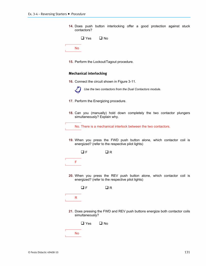
14. Does push button interlocking offer a good protection against stuck contactors?
Yes No
No
15. Perform the Lockout/Tagout procedure.
Mechanical interlocking
16. Connect the circuit shown in Figure 3-11.
a Use the two contactors from the Dual Contactors module.
17. Perform the Energizing procedure.
18. Can you (manually) hold down completely the two contactor plungers simultaneously? Explain why.
No. There is a mechanical interlock between the two contactors.
19. When you press the FWD push button alone, which contactor coil is energized? (refer to the respective pilot lights)
F R
F
20. When you press the REV push button alone, which contactor coil is energized? (refer to the respective pilot lights)
F R
R
21. Does pressing the FWD and REV push buttons energize both contactor coils simultaneously?
Yes No
No

Ex. 3-4 – Reversing Starters Procedure
132 © Festo Didactic 49408-10
22. When both push buttons are pressed, which contactor coil(s) energize(s), in regard to the order in which the corresponding push buttons were pressed?
The first The second Both None
The first
23. Perform the Lockout/Tagout procedure.
Reversing starter with push button and mechanical interlock
24. Connect the circuit shown in Figure 3-9, this time using the two contactors from the Dual Contactors module.
25. Perform the Energizing procedure.
Determine the motor rotation direction as you press the FWD push button.
Clockwise Counterclockwise
Clockwise
26. Press the STOP push button and wait for the motor to stop.
27. Determine the motor rotation direction as you press the REV push button.
Clockwise Counterclockwise
Counterclockwise
28. While the motor is running in the reverse direction, press the FWD push button. Does the motor direction change? Explain what happens, considering that the circuit now contains a mechanical interlock.
Yes. The push button interlock de-energizes the opposite direction contactor. Since only one coil is energized, the mechanical interlock does not react.

Ex. 3-4 – Reversing Starters Conclusion
© Festo Didactic 49408-10 133
29. Press both push buttons simultaneously, and determine which contactor(s) energize(s), in regards to the order in which the corresponding push buttons were pressed.
The first The second Both None
None
30. Press the FWD push button to start the motor. To simulate a stuck contactor, manually hold the forward contactor plunger down (using the tip of a pen). Press the REV push button.
Does the motor still run in the forward direction? Explain why.
Yes. There is now a mechanical interlock that prevents both contactors from being energized at the same time.
31. Does mechanical interlocking offer protection against stuck contactors?
Yes No
Yes
32. Turn the individual power switch of the AC Power Supply off, disconnect the circuit, remove the magnetic labels, and return the equipment to the storage location.
Reversing magnetic starters are built with two contactors, one per rotation direction. If both contactors are actuated at the same time, a short-circuit can occur. This is why electrical and/or mechanical interlocks are used.
Push button interlocking is an electrical means of disabling two contactors actuation. When a push button is pressed, the circuit controlling the other motor direction is automatically opened.
Mechanical interlocking uses a lever to artificially keep the second contactor de-energized, while the first coil is actuated. This method is more rugged in the way that it prevents short-circuits resulting from a stuck contactor.
Plugging is a method of making the motor brake faster. It is accomplished by reversing phases while the motor is running.
CONCLUSION

Ex. 3-4 – Reversing Starters Review Questions
134 © Festo Didactic 49408-10
1. What is the purpose of interlocking in reversing starters?
a. Prevent any contactor from being energized.
b. Prevent any contactor from being de-energized.
c. Stop the motor in case of electrical overload.
d. Prevent two contactor coils from being energized at the same time.
d
2. How many contactors are necessary for reversing starters?
a. 2
b. 3
c. 4
d. 5 or more
a
3. What is the motor braking method that uses the counter torque produced by reversing connections?
a. Inching
b. Plugging
c. Jogging
d. DC injection
b
4. In mechanical interlocking, which item prevents both coils from being actuated simultaneously?
a. Coil
b. Lever
c. Push button
d. Diode
b
REVIEW QUESTIONS

Ex. 3-4 – Reversing Starters Review Questions
© Festo Didactic 49408-10 135
5. In the Figure 3-9 circuit, which lines have been interchanged in the reverse mode compared to the forward mode?
a. Line 1 and line 2
b. Line 1 and line 3
c. Line 2 and line 3
d. Line 1 and line N
a


© Festo Didactic 49408-10 257
Bibliography
Rockis, G., and Glen Mazur. Electrical Motor Controls, Second Edition. Homewood, IL: American Technical Publishers Inc., 2001, ISBN 0826916759.
U.S. Department of Labor, Occupational Safety and Health Administration. Control of Hazardous Energy (Lockout/Tagout). 29 CFR 1910.147.
Wildi, T. Electrical Machines, Drives and Power Systems, Sixth Edition. Englewood Cliffs, NJ: Prentice Hall, 2005, ISBN 0131776916.
Herman, S.L. Industrial Motor Control, Fifth Edition. Clifton Park, NY: Thomson Delmar Learning, 2005, ISBN 1401838022.
National Electrical Manufacturers Association. NEMA and IEC Devices for Motor Services - A Guide for Understanding the Differences. ICS 2.4-2003.
National Electrical Manufacturers Association. Industrial Control and Systems: Diagrams, Device Designations, and Symbols. ICS 19-2002.
International Electrotechnical Commission. Graphical Symbols for Diagrams. IEC 60617.
National Center for Construction Education and Research. Electrical Level 3 Trainee Guide. Upper Saddle River, NJ: Pearson/Prentice Hall, 2002, ISBN 0130472239.

This page should be left blank