Continuous-Flow Grain Dryer - Ag Growth International
132
Part Number: 7713396 R03 Revised: 2018-08-06 INSTALLATION AND WIRING MUST BE IN ACCORDANCE WITH CEC, NEC, AND LOCAL ELECTRICAL CODES Continuous-Flow Grain Dryer Assembly Manual COMMANDER Control Original Instructions Read this manual before using product. Failure to follow instrucƟons and safety precauƟons can result in serious injury, death, or property damage. Keep manual for future reference.
-
Upload
khangminh22 -
Category
Documents
-
view
0 -
download
0
Transcript of Continuous-Flow Grain Dryer - Ag Growth International
Part Number: 7713396 R03Revised: 2018-08-06
INSTALLATION AND WIRING MUST BE IN ACCORDANCE WITH CEC, NEC, AND LOCAL ELECTRICAL CODES
Continuous-Flow Grain DryerAssembly ManualCOMMANDER Control
Original Instructions
Read this manual before using product. Failure to follow instruc ons and safety precau ons can result in serious injury, death, or property damage. Keep manual for future reference.
22018-08-06 Continuous-Flow Grain Dryer 7713396
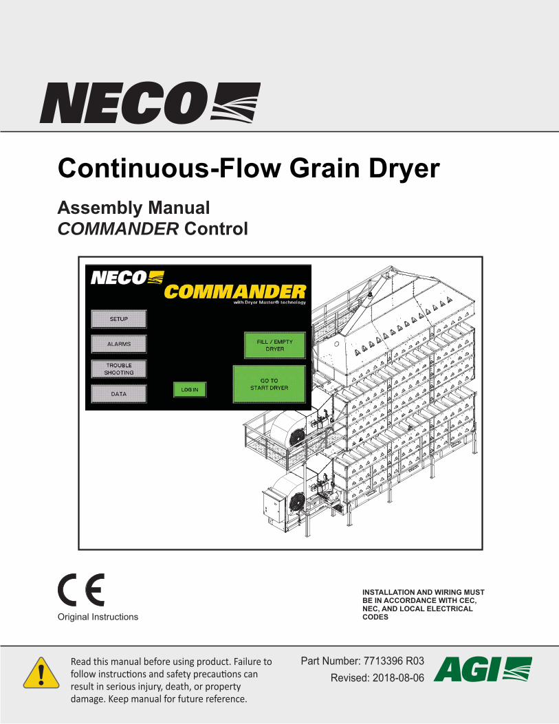
Before you call...
For eff ective communication to either your local dealer, local service tech, or NECO concerningany equipment will require the customer to provide the following basic information. The front cover of this manual shows the Publication Number and Revision Number at the lower part of the page. Please take the time to record the following information for future reference:
Local Dealer’s Name and Address: __________________________________ Phone: ____________________
______________________________________
______________________________________
Local Contractor’s Name: __________________________________________ Phone: ____________________
Service Contractor’s Name: ________________________________________ Phone: ____________________
Model Number: _____________________ Serial Number: ____________________________
Motor #1 is: ________________________________________
Volts: ___________ Phase: ___________ Frequency: ___________ Amps: ___________
Motor #2 is: ________________________________________
Volts: ___________ Phase: ___________ Frequency: ___________ Amps: ___________
Fuel Type: _________________ Number of Blowers: _____________
Wiring Diagram Drawing Number is: ______________________ Manual Level: _____________
Have Questions or Need Help?
Dryer Rating Decal
Intended for Non-Occupied Spaces Only Fuel Type: Natural GasFor Industrial/Commercial Use Max. Inlet Supply Pressure: 30 PSI
Min. Ambient Temperature: 0°FNebraska Engineering Co. Max. Plenum Temperature: 250 °FOmaha, Nebraska, USA Max. Temperature Rise: 230°F
Clearance to Combustibles: 6FTModel: D24240 Perimeter Service Clearance: 6FT
Part / Serial No.: DRYR-1234Burner 1 Top
Voltage / Phase: 575VAC / 3 Min. Input Rate per Burner: 0.5 MM BTU/HFrequency: 60Hz Max. Input Rate per Burner: 5.8 MM BTU/H
Control Voltage: 120 VAC Burner Manifold Pressure at Min. Input: 0.02 PSIFull Load Amps: 150 Burner Manifold Pressure at Max. Input: 1.40 PSI
Largest Motor Amps: 25 Min. Supply Pressure for Max. Input: 5.0 PSISCCR: 15 kA
Burner 2 & 3Min. Input Rate per Burner: 0.6 MM BTU/HMax. Input Rate per Burner: 8.0 MM BTU/H
Burner Manifold Pressure at Min. Input: 0.00 PSIBurner Manifold Pressure at Max. Input: 0.93 PSI
Min. Supply Pressure for Max. Input: 6.5 PSI
Pour utilisation dans des espaces non occupés uniquement type de carburant: Gaz NaturelPour utilisation industielle/commerciale Max. Inlet Supply Pressure: 207 kPa
Min. Ambient Température: -17.8°CNebraska Engineering Co. Max. Plenum Température: 121 °COmaha, Nebraska, USA Max. Température Rise: 110°C
Clearance to Combustibles: 2MModèle: D24240 Perimeter Service Clearance: 2M
Numéro de pièce / série: DRYR-1234Burner 1 Top
Tension / Phase: 575VAC / 3 Min. Input Rate per Burner: 550 MJ/HFréquence: 60Hz Max. Input Rate per Burner: 6300 MJ/H
Tension de commande: 120 VAC Burner Manifold Pressure at Min. Input: 0.14 kPaAmplis de pleine charge: 150 Burner Manifold Pressure at Max. Input: 9.65 kPa
Plus grands ampères du moteur: 25 Min. Supply Pressure for Max. Input: 34.5 kPaCourant nominal de court-circuit: 15 kA
Burner 2 & 3Min. Input Rate per Burner: 650 MJ/HMax. Input Rate per Burner: 8400 MJ/H
Burner Manifold Pressure at Min. Input: 0.00 kPaBurner Manifold Pressure at Max. Input: 6.41 kPa
Min. Supply Pressure for Max. Input: 44.8 kPa
Fan/Dryer Unit for Use in Crop DryingWARNING: For Outdoor Installation Only
Manufacturer:
Wentilateur/Séchior pour le séchage des récoltesAVERTISSEMENT: Installer á l'extérieur seulement
Fabricant:
CSA 3.8 visant les séchoirs pour récoltes
Design Standard: CSA 3.8-2014 Crop Dryer
NOTE: The Dryer Rating Decal is located at the outside bottom-left corner of the control panel door.
Electrical Schematic Drawing (Title Block)NOTE: The dryer electrical schemetic drawing is located on the inside of the control panel door.
DRAWING#
REVISION#

3 Continuous-Flow Grain Dryer 77133962018-08-06
Welcome to the NECO family of products
NECO OverviewSince 1959, NECO equipment has been proudly designed, manufactured, and supported for customers here in the USA and around the world. With proper operation and maintenance, the equipment will provide years of safe and dependable service. NECO is continually testing and improving our products in order to provide you with the safest, most effi cient, and most economical grain handling and grain conditioning equipment available. We welcome your questions or comments and look forward to a continued relationship, ultimately saving you valuable time and reducing your workload.
Watch for This Symbol - It calls your attention to instructions concerning personal safety! It signals a potential DANGER, WARNING or CAUTION.
It means “ATTENTION” - Become Alert! Your Personal Safety Is Involved! Read the message that follows and
Be alert to the possibility of personal injury or death!
This manual should be available at all times to the owner/operator. Contact the manufacturer to request extra copies.
General Safety Statement• This manual is provided to help ensure the safety of the equipment
operator, as well as others who come into contact with the equipment.• Keep a copy of this manual in a safe place for future reference.• Failure to read, understand, and follow the instructions in this manual
by the owner, operators, all personnel, and all construction personnel is a misuse of the equipment and can aff ect personnel safety and the product warranty. We want you as our partner in safety!
• All owners and personnel, including construction personnel must read and understand this entire manual and all equipment operator’s manuals before starting installation.
• Contact your dealer or NECO to obtain additional copies of this manual. • Language translations of this manual are made as accurately as possible. If translation diff erences do occur, the English text will prevail.
PRODUCT CHANGES OR IMPROVEMENTS• NECO reserves the right to make changes or improvements to its products without
incurring any obligation with respect to previously manufactured products.
READand
UNDERSTAND
Become Alert!
42018-08-06 Continuous-Flow Grain Dryer 7713396
Have Questions or Need Help? ..................................................2
Warranty .......................................................................................6
1. Safety ...........................................................................7Emergency Shut Down Procedure .............................................9
2. Warning Labels .........................................................10
3. Equipment Overview ................................................13General Design Criteria.............................................................13
Dryer Tier / Ladder / Shipping Layouts .....................................14
Front of Dryer (From Fuel Train Side) ......................................16
Main Control Box .......................................................................17
Main Control - PLC Details .......................................................18
HMI Enclosure Location ............................................................19
HMI Enclosure - Front Panel .....................................................20
Front of Dryer (From Blower Belt Shield Side) .......................22
Rear of Dryer (From Below) ......................................................23
Topside Filling Options .............................................................24
4. Site Prep ....................................................................25Concrete Work - Overview ........................................................25
Wind Load Data ........................................................................26Dryer Weight Data ....................................................................28Utility Layout and Weight Load Points ......................................29
Set Up Fuel Supply ....................................................................35
Set Up Electrical Supply ...........................................................37
5. Assembly - Tiers .......................................................38
6. Assembly - Dryer Sections ......................................47
7. Assembly - Top Tier ..................................................63
8. Assembly - Topside Fill System ..............................70Roof with Level Auger ...............................................................70
Contents

5 Continuous-Flow Grain Dryer 77133962018-08-06
Roof with Gravity Fill .................................................................76
Catwalk and Safety Cage Assembly ........................................77
9. Installation.................................................................84Install NECO Leg Kit (Optional) ................................................85
Special Assembly for 32’ Dryers ..............................................88
Install Cross-Auger System......................................................89
Stack and Secure Sections.......................................................92
10. Final System Hookup ...........................................103Adjust Control Box Height ......................................................103
Final Electrical Hookup ...........................................................104Blower Motor Wire(s) ..............................................................105Dual Thermocouple Probe .....................................................106Burner Box Cables .................................................................106Fill Switch and Low Switch Location ......................................107Connect Fill Switch and Low Switch .......................................110Connect Moisture Sensors ..................................................... 111Inlet Moisture Sensor .............................................................112Outlet Moisture Sensor / Sample Button ................................112Discharge Plugged Sensor .....................................................113HMI Wiring Connections .........................................................114
Final Fuel Supply Hookup ...................................................... 115Liquid Propane (LP) ...............................................................115Natural Gas (NG) ...................................................................120
Wet Bin Empty and Dry Bin Full Switches ............................121
External Transport(s) ..............................................................122Example: Wet 1 Auger and Dry 1 Air System .........................122Example: Wet 1 and Wet 2 Augers and Dry 1 Auger .............123Example: Wet 1 and Wet 2 and Dry 1 and Dry 2 Augers .......123
Commander Control Setup .....................................................124
Appendix .....................................................................125Standard Model Specifi cations ..............................................125
Main Control Box Terminal Strip ............................................126
HMI Wiring Connections .........................................................127
Wiring External Transports .....................................................128
Wiring NEMA Starters / IEC Starters / Air Systems ..............129

Limited WarrantyFor a period of one(1) year after shipment of goods by the Buyer to the Buyer’s customer, NECO will supply, free of charge, FOB per NECO’s factory located in Omaha, Nebraska, replacement parts for any parts that NECO identifi es to be defective due to workmanship or material.
• This limited warranty does not extend to parts that wear due to normal operation and need to be replaced periodically.
• Goods not manufactured by NECO carry only their manufacturer’s warranty.
• This undertaking is in lieu of all other warranties, expressed or implied, including merchantability and fi tness for a particular purpose.
• You must obtain a “Return Authority” form NECO prior to returning any defective goods. Those defective goods must be returned, freight-prepaid, to the NECO factory in Omaha, NE. See the back cover of this manual for complete address information.
• NECO reserves the right to make changes or improvements to products and goods without incurring any obligation with respect to previously manufactured products.
• Failure to follow the instructions contained in this manual, as well as the existence of any of the conditions listed below, will cause this Limited Warranty to be null and void:
1. Improper assembly. 2. Improper installation, including power and wiring. 3. Unauthorized alteration of the product or components therein. 4. Operation of the unit when repairs are needed. 5. Use of unauthorized parts. 6. Operation by children or uninstructed personnel. 7. Processing of materials that are abrasive, that do not fl ow freely, or that are otherwise unsuited for processing in farm equipment. 8. Misuse of the equipment or any of its components. 9. Damage due to negligence, abuse, or accidents.
LIMITATION OF LIABILITY• Buyer agrees that in no event shall NECO have liability for direct damages in excess of the contract price of the goods for which the claim is made.
• Buyer further agrees that in no event shall NECO have liability for loss of use, loss of profi ts, or for any indirect, incidental, or consequential damages on any claim of any kind.
7 Continuous-Flow Grain Dryer 77133962018-08-06
8
** Federal Occupational Safety & Health Standards for Agriculture Subpart D, Section 1928.57 (a)(6).
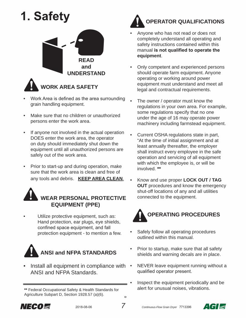
WORK AREA SAFETY
• grain handling equipment.
• Make sure that no children or unauthorized persons enter the work area.
• If anyone not involved in the actual operation DOES enter the work area, the operator on duty should immediately shut down the equipment until all unauthorized persons are safely out of the work area.
• Prior to start-up and during operation, make sure that the work area is clean and free of any tools and debris. KEEP AREA CLEAN.
WEAR PERSONAL PROTECTIVE EQUIPMENT (PPE)
• Utilize protective equipment, such as: Hand protection, ear plugs, eye shields,
protection equipment - to mention a few.
ANSI and NFPA STANDARDS
• Install all equipment in compliance with ANSI and NFPA Standards.
OPERATOR QUALIFICATIONS
• Anyone who has not read or does not completely understand all operating and safety instructions contained within this manual equipment.
• Only competent and experienced persons should operate farm equipment. Anyone operating or working around power equipment must understand and meet all legal and contractual requirements.
• The owner / operator must know the regulations in your own area. For example, some regulations specify that no one under the age of 16 may operate power machinery including farmstead equipment.
• Current OSHA regulations state in part, “At the time of initial assignment and at least annually thereafter, the employer shall instruct every employee in the safe operation and servicing of all equipment with which the employee is, or will be involved. **
• Know and use proper LOCK OUT / TAG OUT procedures and know the emergency shut-off locations of any and all utilities connected to the equipment.
OPERATING PROCEDURES
• Safely follow all operating procedures outlined within this manual.
• Prior to startup, make sure that all safety shields and warning decals are in place.
• NEVER leave equipment running without a
• Inspect the equipment periodically and be alert for unusual noises, vibrations.
1. SAFETY
READand
UNDERSTAND
1. Safety
82018-08-06 Continuous-Flow Grain Dryer 7713396
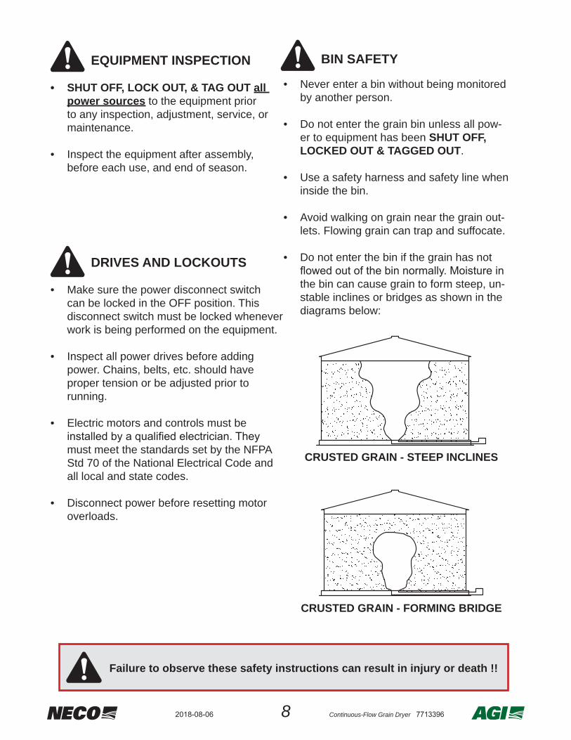
EQUIPMENT INSPECTION
• SHUT OFF, LOCK OUT, & TAG OUT all power sources to the equipment prior to any inspection, adjustment, service, or maintenance.
• Inspect the equipment after assembly, before each use, and end of season.
DRIVES AND LOCKOUTS
• Make sure the power disconnect switch can be locked in the OFF position. This disconnect switch must be locked whenever work is being performed on the equipment.
• Inspect all power drives before adding power. Chains, belts, etc. should have proper tension or be adjusted prior to running.
• Electric motors and controls must be
must meet the standards set by the NFPA Std 70 of the National Electrical Code and all local and state codes.
• Disconnect power before resetting motor overloads.
BIN SAFETY
• Never enter a bin without being monitored by another person.
• Do not enter the grain bin unless all pow-er to equipment has been SHUT OFF, LOCKED OUT & TAGGED OUT.
• Use a safety harness and safety line when inside the bin.
• Avoid walking on grain near the grain out-lets. Flowing grain can trap and suffocate.
• Do not enter the bin if the grain has not
the bin can cause grain to form steep, un-stable inclines or bridges as shown in the diagrams below:
CRUSTED GRAIN - STEEP INCLINES
CRUSTED GRAIN - FORMING BRIDGE
Failure to observe these safety instructions can result in injury or death !!
9 Continuous-Flow Grain Dryer 77133962018-08-06
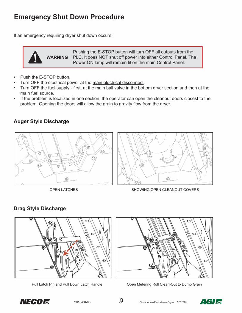
If an emergency requiring dryer shut down occurs:
• Push the E-STOP button.• Turn OFF the electrical power at the main electrical disconnect.• Turn OFF the fuel supply - fi rst, at the main ball valve in the bottom dryer section and then at the
main fuel source.• If the problem is localized in one section, the operator can open the cleanout doors closest to the
problem. Opening the doors will allow the grain to gravity fl ow from the dryer.
Auger Style Discharge
Drag Style Discharge
OPEN LATCHES SHOWING OPEN CLEANOUT COVERS
Pushing the E-STOP button will turn OFF all outputs from the PLC. It does NOT shut off power into either Control Panel. The Power ON lamp will remain lit on the main Control Panel.
WARNING
Pull Latch Pin and Pull Down Latch Handle Open Metering Roll Clean-Out to Dump Grain
Emergency Shut Down Procedure

102018-08-06 Continuous-Flow Grain Dryer 7713396
2. Warning LabelsWarning Label Overview• Occupational safety is one of NECO’s primary concerns. Warning labels that conform to indus-
try standards are provided to identify potential safety hazards that could cause harm and to INCREASE YOUR AWARENESS OF THE HAZARD.
• labels are followed - including any suggested use of personal protective equipment (PPE).
•
3. The NECO part number for that warning label. 4. The location of that warning label. 5. What that warning label looks like - note that label pictorials are not shown full size.• If the warning labels are missing or become unreadable in any way, use the following
information to determine the required part number and contact NECO Customer Service at 402-453-6912 or toll free at 800-367-6208 for replacements.
• Replacement Warning Labels will be sent to you FREE OF CHARGE• Surfaces must be free of oils, dirt and moisture before applying replacement warning labels.
LABEL ID WARNING LABEL HEADER
NECO PART
#QTY LOCATION
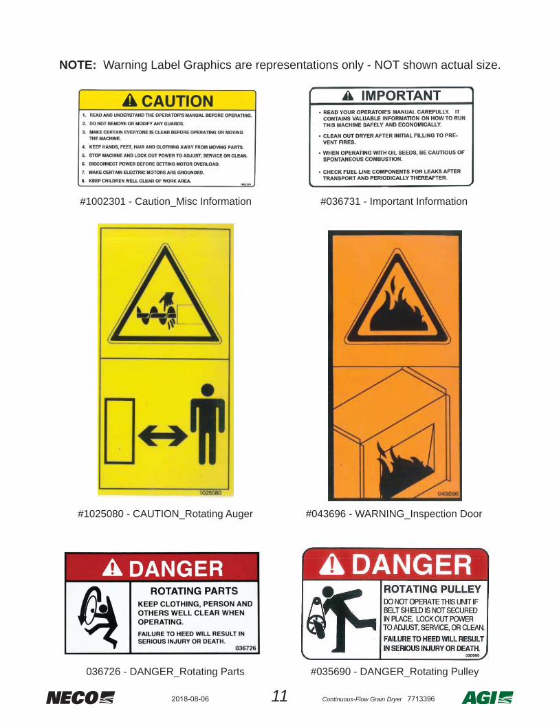
A CAUTION - GENERAL WARNINGS 1002301 1 FUEL SIDE OF TRANSITION
B IMPORTANT - INFORMATION 036731 1 FUEL SIDE OF TRANSITION
C DANGER - ROTATING AUGER 10250801 CROSS AUGER HOUSING
1 ROOF LEVEL AUGER (IF PRESENT)
D WARNING - INSPECTION DOOR 043696 1 FUEL SIDE OF TRANSITION (GLASS)
E DANGER - ROTATING PARTS 036726
1 ABOVE BLOWER GUARD
2 CROSS AUGER - DRIVE END
2 CROSS AUGER - IDLER END
F DANGER - ROTATING PULLEY 035690
1 DISCHARGE MOTOR BRACKET
1 ON OUTSIDE OF BLOWER BELT GUARD
1 ON INSIDE OF BLOWER BELT GUARD
G WARNING - HIGH VOLTAGE 0436951 BURNER CONTROL BOX (ABOVE LOCK)
1 CONTROL PANEL (ABOVE LOCK)
H DANGER - HIGH VOLTAGE 0367251 INSIDE BURNER CONTROL BOX
1 INSIDE CONTROL PANEL / INSIDE HMI BOX
J CAUTION - DO NOT TOUCH 043697 1 REAR PLENUM DOOR
11 Continuous-Flow Grain Dryer 77133962018-08-06
NOTE: Warning Label Graphics are representations only - NOT shown actual size.
#1002301 - Caution_Misc Information #036731 - Important Information
#1025080 - CAUTION_Rotating Auger #043696 - WARNING_Inspection Door
036726 - DANGER_Rotating Parts #035690 - DANGER_Rotating Pulley

122018-08-06 Continuous-Flow Grain Dryer 7713396
#036725 - DANGER_High Voltage
#043695 - WARNING_High Voltage
#043697 - CAUTION_Do Not Touch
NOTE: Warning Label Graphics are representations only - NOT shown actual size.

13 Continuous-Flow Grain Dryer 77133962018-08-06
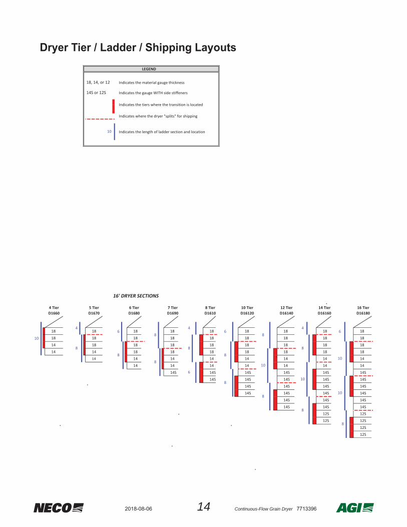
3. Equipment OverviewGeneral Design CriteriaNOTE :Dryer design is based on load factors - if you wish to add more sections to your dryer in the future, please let NECO know when you place your order so it will be designed to fi t to your expanding needs.
TIER INFORMATION :• A tier is a set of parts that make up ONE
layer of the dryer (also called body section).• The top four tiers on all dryers are made up
of 18 gauge material.• The tiers below the 18 gauge tiers will be
made of heavier materials - based on the required strength of that dryer confi guration.
BODY SECTION INFORMATION :• A dryer section may be made up of 3 - 7
tiers, a blower, and a burner assembled together.
• The lowest body section is attached to the dryer frame and includes the entrance door.
STANDARD LENGTHS :• 16’ (192”), 24’ (288”), 32’ (384”)
TOTAL TIER LEVELS PER LENGTH :• 16’ -- min 4 tiers / max 16 tiers• 24’ -- min 6 tiers / max 24 tiers• 32’ -- mins 12 tiers / max 24 tiers
DRYER MODEL # : Example: D 16 60• The two digits after “D” are the dryer length.
This example would be a 16 foot long dryer.• The remaining digits “times 10” would be the
approximate bushel capacity for corn. This example would be (10 x 60) or 600 bushels.
• A model #D32500 would be a dryer that is 32 feet long and have approximately 5,000 bushel capacity.
NOTE: See APPENDIX - Standard Model Specifi cations for detailed bushel capacity values.
DRYER RATING LABEL :
MODEL: D24210 FUEL TYPE:L PPART / SERIAL NO: DRYR-####
SUPPLY VOLTAGE:3 80 VAC PHASE:3FREQUENCY: 50 Hz FULL LOAD AMPS:
CONTROL VOLTAGE: 120 VACS CCR:5 kALARGEST MOTOR AMP:
WARNING:CLOSED EXCEPT WHEN SERVICING.
MAXIMUM INPUT RATE: KW MM BTU/HMINIMUM INPUT RATE: KW MM BTU/H
MAXIMUM SUPPLY PRESSURE: 1723 kPa (250 PSI)MIN. SUPPLY PRESS. FOR MAX. OUTPUT: 89 kPa (13 PSI)MIN. SUPPLY PRESS. FOR MIN. OUTPUT: 14 kPa (2 PSI)
RECOMMEND MANIFOID PRESSURE: 21-55 kPa (3-8 PSI)MANIFOLD PRESSURE @ MAX. INPUT:6 9 kPa (10 PSI)MANIFOLD PRESSURE @ MIN. INPUT:7 kPa (1 PSI)
CLEARANCE TO COMBUSTIBLES: 2M (6FT)PERIMETER SERVICE CLEARANCE: 2M (6FT)
402-453-6912 OR 800-367-6208
HEATER COMPARTMENT MUST BE
120
34
FAN/HEATER UNITFOR USE IN CROP DRYING
WARNING: FOR OUTDOOR INSTALLATION ONLY
REFER TO DRYER MANUAL FOR INSTALLATION, OPERATION, AND TROUBLESHOOTING INSTRUCTIONS.
MANUFACTURER:
TEL:
NECOOMAHA, NEBRASKA, USA
0.918.05300
265
142018-08-06 Continuous-Flow Grain Dryer 7713396
Dryer Tier / Ladder / Shipping LayoutsLEGEND
Indicates the material gauge thickness
Indicates the gauge WITH side stiffeners
Indicates where the dryer "splits" for shipping
18 18 18
18 18 18
14 18 18
14 14 18
14 14
14
18 18 18 18 18 18 18 18 18
18 18 18 18 18 18 18 18 18
14 18 18 18 18 18 18 18 18
14 14 18 18 18 18 18 18 18
14 14 14 14 14 14 14 14
14 14 14 14 14 14 14
14S 14S 14S 14S 14S 14S
14S 14S 14S 14S 14S
14S 14S 14S 14S
14S 14S 14S 14S
14S 14S 14S
14S 14S 14S
12S 12S
12S 12S
12S
12S
10
8
10
8
10
810
8
8
6
6
8
8
4
8
6
8
44
8
8
16 Tier D16180
5 Tier D1670
6 Tier D1680
7 Tier D1690
8 Tier D1610
10 Tier D16120
86
10
4
12 Tier D16140
16' DRYER SECTIONS
14 Tier D16160
6
8
14S or 12S
Indicates the tiers where the transition is located
18, 14, or 12
8
12' DRYER SECTIONS
4 Tier D1240
5 Tier D1250
6 Tier D1260
10 Indicates the length of ladder section and location
4 Tier D1660
10

15 Continuous-Flow Grain Dryer 77133962018-08-06
18 18 18 18 18 18 18 18
18 18 18 18 18 18 18 18
18 18 18 18 18 18 18 18
18 18 18 18 18 18 18 18
14 14 14 14 14 14 14 14
14 14 14 14 14 14 14 14
14S 14S 14S 14S 14S 14S 14S
14S 14S 14S 14S 14S 14S 14S
14S 14S 14S 14S 14S 14S
14S 14S 14S 14S 14S 14S
14S 14S 14S 14S 14S
14S 14S 14S 14S 14S
12S 12S 12S 12S
12S 12S 12S 12S
12S 12S 12S
12S 12S 12S
12S 12S
12S 12S
12S 12S
12S 12S
12S
12S
12S
12S
18 18 18 1818 18 18 1818 18 18 1818 18 18 1814S 14S 14S 14S14S 14S 14S 14S14S 14S 14S 14S14S 14S 14S 14S14S 14S 14S 14S12S 14S 14S 14S12S 14S 14S 14S12S 14S 14S 14S
12S 12S 12S12S 12S 12S12S 12S 12S12S 12S 12S
12S 12S12S 12S12S 12S12S 12S
12S12S12S12S
24' DRYER SECTIONS
32' DRYER SECTIONS
8
8
6
8
8
8
4 4
8
12 Tier D32260
16 Tier D32340
20 Tier D32440
24 Tier D32500
16 Tier D24260
20 Tier D24330
24 Tier D24380
6 Tier D24108
8 Tier D24150
10 Tier D24180
12 Tier D24210
14 Tier D24240
8
4 4
8
8
8
8
8
4
8
6
8
6
4
8
6
8
6
8
4
8
10
8
4
8
8
6
8 8
4
8
8
8
8
6
8
8
6
4
8
8
6
6
8
8
8
6

162018-08-06 Continuous-Flow Grain Dryer 7713396
Front of Dryer (From Fuel Train Side)ATTENTION: Understanding the terms used to identify the various components of a dryer system will make the instructions in this manual clearer and easier to follow.
Front of Dryer (From Fuel Train Side)
MAINCONTROLBOX
CATWALK
BLOWERHOUSING
FUEL TRAIN
PLATFORM
BURNERCONTROLBOX
DRYER SECTION(EACH HAS A BLOWER SYSTEM)
DISCHARGE MOTOR (AUGER UNLOAD ONLY)
SAFETY CAGE
DRYER TIER
LADDERSYSTEM
LEVEL OFPLENUMDIVIDERFLOOR
OPTIONALCOOLING
TIERS
DRYERRATINGLABEL

17 Continuous-Flow Grain Dryer 77133962018-08-06
INSIDE VIEW
ELECTRICALSCHEMATICS
FRONT PANEL
EMERGENCYSTOP
BUTTON(E-STOP)
POWER ONLAMP
NOTE
Pushing the E-STOP button will turn OFF all outputs from the PLC. It does NOT shut off power into either Control Box. The Power ON lamp will remain lit on the Main Control front panel.
CABLE CONNECTONS
BLOWERMOTOR
STARTERS
ELECTRICALDISCONNECT
Main Control Box

182018-08-06 Continuous-Flow Grain Dryer 7713396
Main Control - PLC Details
24V ISOLATIONRELAYS
SEEDETAILSBELOW
DC DRIVE
PLC ASSEMBLYM221
TRANSFORMER1.5 KVA
E-STOPRELAY
24VPOWERSUPPLY
Main Control - PLC Details
ETHERNETPORT
M221 DIGITAL I/O EXPANSION
M221 ANALOG I/O0-10 VDC FOR MOISTURE
SENSORS & DC DRIVE
120V OUTPUTS TOMOTOR STARTER COILS
MODBUSCOMMFROM
BURNERBOX(S)
SD CARDENTRY
M221MAIN BASE
M221 BATTERY (Behind Wires)
19 Continuous-Flow Grain Dryer 77133962018-08-06
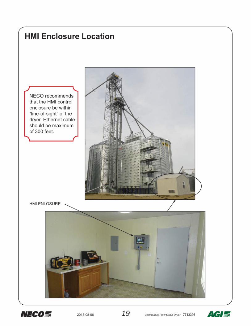
HMI Enclosure Location
HMI ENLOSURE
NECO recommends that the HMI control enclosure be within “line-of-sight” of the dryer. Ethernet cable should be maximum of 300 feet.

202018-08-06 Continuous-Flow Grain Dryer 7713396
HMI Enclosure - Front Panel
HMI Enclosure - Front Panel
EMERGENCYSTOP
BUTTON(E-STOP)
DRYER MASTERCONTROLON / OFF
HMITOUCH
SCREEN NOTE
Pushing the E-STOP button will turn OFF all outputs from the PLC. It does NOT shut off power into either Control Box. The Power ON lamp will remain lit on the Main Control front panel.
HMI Enclosure - Backside of Front Panel
REAR OF HMISCREEN
EMERGENCYSTOP
BUTTON(E-STOP)

21 Continuous-Flow Grain Dryer 77133962018-08-06
ETHERNETSWITCH
MGATE MOXASERIAL TOETHERNET
CONVERTOR
DRYER MASTER CONTROLLER
Inside View - Regular Commander
Inside View - Commander WITH CommandNET Option
DRYER MASTER CONTROLLER
DIGI REMOTE
ETHERNETSWITCH
ANTENNA

222018-08-06 Continuous-Flow Grain Dryer 7713396
METERING ROLLDRIVE CHAINS
METERING ROLL
DC MOTOR
DISCHARGE DRIVE GUARD (CE)(SHOWN IN OPEN POSTION)
COOLING FLAP HANDLE & LOCK (OPTIONAL)
TRANSITIONHOUSING
BELTSHIELD
BURNERHOUSING
UNLOAD DRIVE
METERINGROLLS
BLOWERHOUSING
Front of Dryer (From Blower Belt Shield Side)

23 Continuous-Flow Grain Dryer 77133962018-08-06
GEAR BOX FOR REAR CROSS AUGER
COMMANDERSTYLE
DISCHARGESYSTEM
SEEDETAILS IN
COMMANDERCONTROL
COMOPONENTS
REARCROSS AUGERCLEAN-OUT DOORS
(SHOWN OPEN)
NOTE: The Plenum Door is at the rear of dryer and allows access into the center plenum area. Each dryer section ABOVE THE PLENUM DOOR is separated by a Divider Floor with one Divider Door for plenum access. Divider Doors should always be closed during operation. Optional Cooling Floor(s) & Doors serve a totally different purpose - See Grain Cooling System.
DISCHARGEAUGERS
COOLING FLOOR(S)(OPTIONAL)
SLIDINGDIVIDERDOOR(ONE PERDIVIDERFLOOR)
DRIVE CHAIN GUARD
DO NOT
OPENWHENIN USE
ORUNTIL
COOL !!
PLENUMDOOR
Rear of Dryer (From Below)

242018-08-06 Continuous-Flow Grain Dryer 7713396
Topside Filling Options
Front of dryer with
single burner
Front of dryer with multipleburners
`
ROOFWITH
GRAVITY FILL
ROOFWITH
LEVEL AUGER
ATTENTIONLevel auger system grain intake should be at the end opposite the auger motor and a MINIMUM of 2’ from that end of the auger.
The level auger motor rotation will need to be properly confi gured by the installation electrician for proper fi lling - dependant upon the grain intake position.

25 Continuous-Flow Grain Dryer 77133962018-08-06
ATTENTION
The weight of grain in a full NECO dryer will range from 16 tons to over 200 tons.
• It is necessary to support the frame of the dryer with properly designed and sized footings.
• NECO recommends having a concrete pad under the dryer to allow for easy clean-up.
• The dryer must be anchored and also secured against wind loading. Consult a civil engineer who’s experienced with soil AND wind conditions in your area.
• Work with your millwright or installer & consult NECO if needed.
NECO recommends always hiring an expert for proper advise, accurate paperwork, and safe procedures to complete this task in conformance with local codes.
WARNING
determined from local data. Anchors that
be installed. Consult a Civil Engineer.
WARNING
4. Site PrepConcrete Work - Overview

262018-08-06 Continuous-Flow Grain Dryer 7713396
Wind Load Data
• Refer to the table on the facing page showing necessary dimensions for wind load calculations.

27 Continuous-Flow Grain Dryer 77133962018-08-06
DRYERMODEL
“A”FT [METERS]
“B”FT [METERS]
“C”FT [METERS]
D1660 16 [4.9] 24 [7.3] 15.0 [4.6]D1670 16 [4.9] 24 [7.3] 17.0 [5.2]D1680 16 [4.9] 24 [7.3] 19.0 [5.8]D1690 16 [4.9] 24 [7.3] 21.0 [6.4]D16106 16 [4.9] 24 [7.3] 23.0 [7.0]D16120 16 [4.9] 24 [7.3] 27.0 [8.2]D16140 16 [4.9] 24 [7.3] 31.0 [9.4]D16160 16 [4.9] 24 [7.3] 35.0 [10.7]D24108 24 [7.3] 32 [9.8] 21.7 [6.6]D24150 24 [7.3] 32 [9.8] 25.7 [7.8]D24180 24 [7.3] 32 [9.8] 29.7 [9.1]D24210 24 [7.3] 32 [9.8] 33.7 [10.3]D24240 24 [7.3] 32 [9.8] 37.7 [11.5]D24260 24 [7.3] 32 [9.8] 41.7 [12.7]D24330 24 [7.3] 32 [9.8] 49.7 [15.1]D24380 24 [7.3] 32 [9.8] 57.7 [17.6]D32260 32 [9.6] 40 [12.2] 36.4 [11.1]D32340 32 [9.6] 40 [12.2] 44.4 [13.5]D32440 32 [9.6] 40 [12.2] 52.4 [16.0]D32500 32 [9.6] 40 [12.2] 60.4 [18.4]

282018-08-06 Continuous-Flow Grain Dryer 7713396
Dryer Weight Data
DRYERMODEL
# OF TIERS
DRYEREMPTY
WEIGHT(lb)
DRYEREMPTY
WEIGHT(kg)
EMPTYVOLUME *(bushel)
FULL WEIGHTCORN
@ 68 lb per bushel
EMPTYVOLUME **
(m3)
FULL WEIGHTCORNmetrictonnes
D1660 4 11,051 5023 578 39,304 20.4 18D1670 5 11,941 5416 674 45,832 23.8 21D1680 6 12,831 5820 770 52,360 27.1 24D1690 7 13,970 6336 866 58,888 30.5 27
D16106 8 17,054 7735 962 65,416 33.9 30D16120 10 19,329 8767 1155 78,540 40.7 36D16140 12 21,604 9799 1347 91,596 47.5 42D16160 14 26,405 11977 1539 104,652 54.2 47D24108 6 20,495 9296 1155 78,540 40.7 36D24150 8 23,402 10614 1443 98,124 50.8 45D24180 10 26,821 12165 1732 117,776 61.0 53D24210 12 32,187 14599 2020 137,360 71.2 62D24240 14 36,473 16543 2309 157,012 81.4 71D24260 16 42,709 19372 2597 176,596 91.5 80D24330 20 53,231 24145 3174 215,832 111.8 98D24380 24 63,753 28836 3750 255,000 132.1 116D32260 12 41,222 18697 2693 183,124 94.9 83D32340 16 54,810 24861 3463 235,484 122.0 107D32440 20 68,398 31024 4232 287,776 149.1 131D32500 24 81,986 37188 5001 340,068 176.2 154
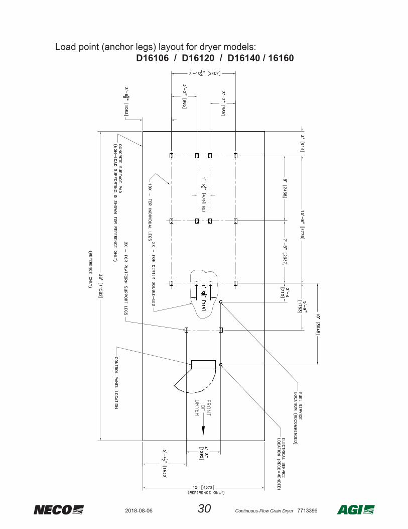
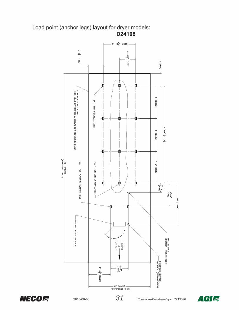
• The following information can be used to calculate the total dryer weight for purposes of transferring those numbers to the load points (anchor legs, etc.) shown on the facing pages to determine proper concrete support footings for the dryer system.
ANCHOR BOLT LAYOUT FOR NECO LEG KITS
* US measurement of dry bushels•• The volume of cubic meters = (# of dry bushels) X 0.0352
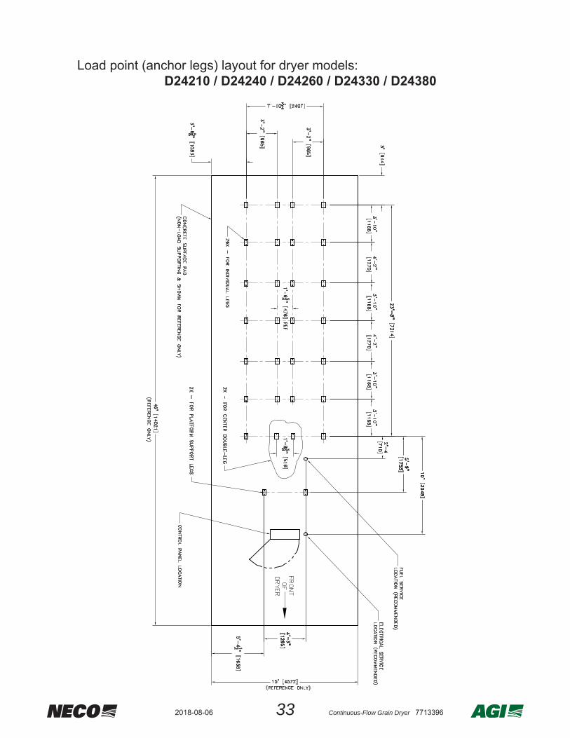
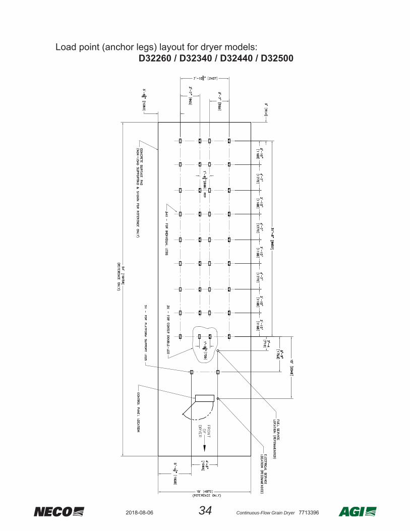
• The following layouts show the dryer load points at the centers of standard NECO anchor legs and column support legs.
• A concrete pad (non-load supporting under the dryer makes cleanup considerably easier - the recommended minimum size is shown as a reference for each layout size. 5” [127 mm]

29 Continuous-Flow Grain Dryer 77133962018-08-06
Utility Layout and Weight Load PointsLoad point (anchor legs) layout for dryer models:
D1660 / D1670 / D1680 / 1690
302018-08-06 Continuous-Flow Grain Dryer 7713396
Load point (anchor legs) layout for dryer models:D16106 / D16120 / D16140 / 16160
31 Continuous-Flow Grain Dryer 77133962018-08-06
Load point (anchor legs) layout for dryer models:D24108

322018-08-06 Continuous-Flow Grain Dryer 7713396
Load point (anchor legs) layout for dryer models:D24150 / D24180
33 Continuous-Flow Grain Dryer 77133962018-08-06
Load point (anchor legs) layout for dryer models:D24210 / D24240 / D24260 / D24330 / D24380
342018-08-06 Continuous-Flow Grain Dryer 7713396
Load point (anchor legs) layout for dryer models:D32260 / D32340 / D32440 / D32500
35 Continuous-Flow Grain Dryer 77133962018-08-06
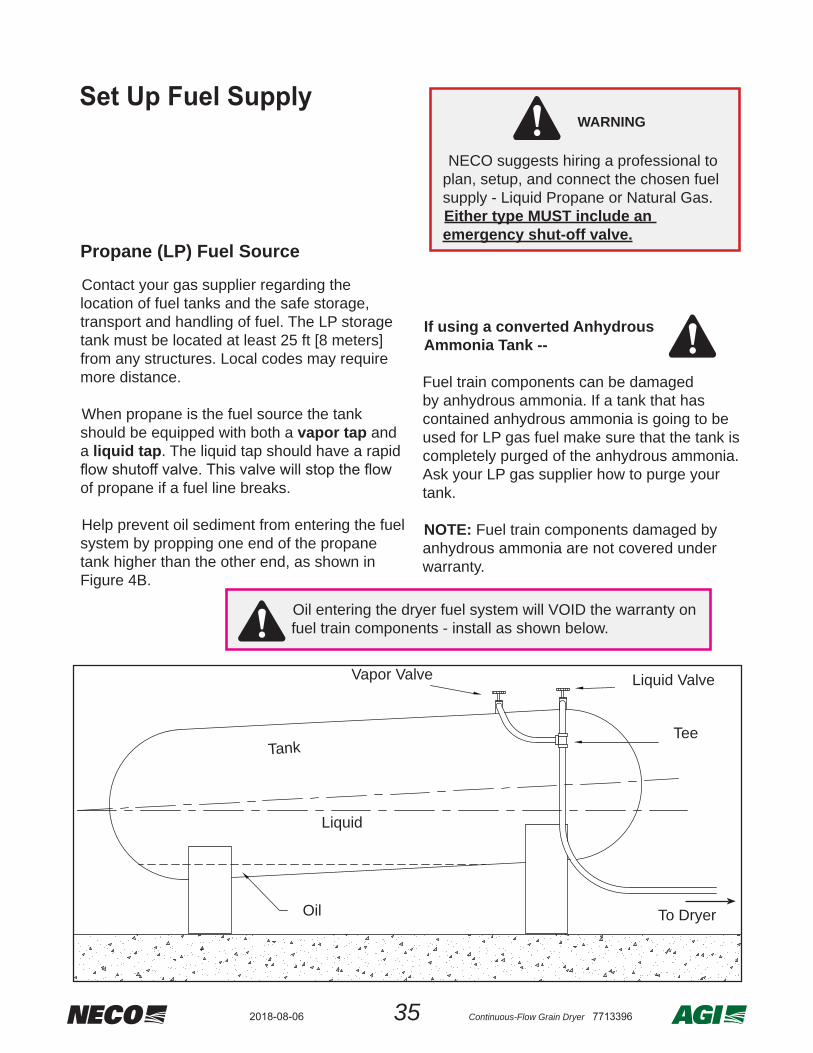
Contact your gas supplier regarding the location of fuel tanks and the safe storage, transport and handling of fuel. The LP storage tank must be located at least 25 ft [8 meters] from any structures. Local codes may require more distance.
When propane is the fuel source the tank should be equipped with both a vapor tap and a liquid tap. The liquid tap should have a rapid
of propane if a fuel line breaks.
Help prevent oil sediment from entering the fuel system by propping one end of the propane tank higher than the other end, as shown in Figure 4B.
If using a converted AnhydrousAmmonia Tank --
Fuel train components can be damaged by anhydrous ammonia. If a tank that has contained anhydrous ammonia is going to be used for LP gas fuel make sure that the tank is completely purged of the anhydrous ammonia. Ask your LP gas supplier how to purge your tank.
NOTE: Fuel train components damaged by anhydrous ammonia are not covered under warranty.
Vapor Valve Liquid Valve
Liquid
Tee
To DryerOil
Tank
Oil entering the dryer fuel system will VOID the warranty on fuel train components - install as shown below.
Set Up Fuel Supply
NECO suggests hiring a professional to plan, setup, and connect the chosen fuel supply - Liquid Propane or Natural Gas.Either type MUST include an emergency shut-off valve.
WARNING
Propane (LP) Fuel Source
Set Up Fuel Supply
362018-08-06 Continuous-Flow Grain Dryer 7713396
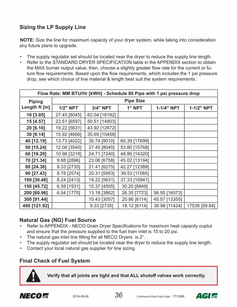
Flow Rate: MM BTU/Hr [kWH] - Schedule 80 Pipe with 1 psi pressure dropPiping
Length ft [m]Pipe Size
1/2" NPT 3/4" NPT 1" NPT 1-1/4" NPT 1-1/2" NPT10 [3.05] 27.45 [8045] 62.04 [18182]15 [4.57] 22.51 [6597] 50.51 [14803]20 [6.10] 19.22 [5631] 43.92 [12872]30 [9.14] 15.92 [4666] 35.69 [10458]
40 [12.19] 13.73 [4022] 30.74 [9010] 60.39 [17699]50 [15.24] 12.08 [3540] 27.45 [8045] 53.80 [15768]60 [18.29] 10.98 [3218] 24.71 [7240] 48.86 [14320]70 [21.34] 9.88 [2896] 23.06 [6758] 45.02 [13194]80 [24.38] 9.33 [2735] 21.41 [6275] 42.27 [12389]90 [27.43] 8.78 [2574] 20.31 [5953] 39.53 [11585]
100 [30.48] 8.24 [2413] 19.22 [5631] 37.33 [10941]150 [45.72] 6.59 [1931] 15.37 [4505] 30.20 [8849]200 [60.96] 6.04 [1770] 13.18 [3862] 26.35 [7723] 56.55 [16573]300 [91.44] 10.43 [3057] 20.86 [6114] 45.57 [13355]
400 [121.92] 9.33 [2735] 18.12 [6114] 38.98 [11424] 17538 [59.84]
Sizing the LP Supply Line
NOTE: Size the line for maximum capacity of your dryer system, while taking into consideration any future plans to upgrade.
• The supply regulator set should be located near the dryer to reduce the supply line length.• Refer to the STANDARD DRYER SPECIFICATION table in the APPENDIX section to obtain
the MAX burner output value, then, choose a slightly greater fl ow rate for the current or fu-ture fl ow requirements. Based upon the fl ow requirements, which includes the 1 psi pressure drop, see which choice of line material & length best suit the system requirements :
Natural Gas (NG) Fuel Source• Refer to APPENDIX - NECO Grain Dryer Specifi cations for maximum heat capacity ouptut
and ensure that the pressure supplied to the fuel train inlet is 15 to 20 psi.• The natural gas inlet line fi tting for all NECO Dryers is 2”.• The supply regulator set should be located near the dryer to reduce the supply line length.• Contact your local natural gas supplier for line sizing.
Verify that all joints are tight and that ALL shutoff valves work correctly.
Final Check of Fuel System

37 Continuous-Flow Grain Dryer 77133962018-08-06
Set Up Electrical Supply
Dryer Model
#
Electric Service (Amps)** See Note below
1 PHASE POWER
3PHASE POWER
230VAC
208VAC
230VAC
380 VAC
460 VAC
575 VAC
D1660 150 105 95 60 50 40D1670 150 105 95 60 50 40D1680 150 105 95 60 50 40D1690 N/A 125 115 75 60 45
D16106 215 145 135 85 70 55D16120 260 175 160 100 80 65D16140 260 175 160 100 80 65D16160 330 220 200 130 100 85D16180 N/A 270 245 160 125 100D24108 215 145 135 85 70 55D24150 260 175 160 100 80 65D24180 N/A 220 200 130 100 80D24210 360 240 220 140 110 90D24240 N/A 285 260 165 130 105D24260 460 310 280 180 140 115D24330 560 375 340 215 170 140D24380 650 435 395 250 200 165D32260 N/A 350 320 205 160 130D32340 N/A 435 400 255 200 160D32440 N/A 565 510 330 255 205D32500 N/A 650 590 380 295 240
** Electric Service amps shown DO NOT include any wet or dry transport motor amperage loads. Auxillary equipment requirements must be added to have accurate total requirement value.
NOTE
• The Dryer Rating Label on the control panel lists the full-load amps required for the dryer and the input voltage.
• Refer to the table at right for service amp information on various size dryers - be sure to add amperage requirements for any additional auxillary equipment.
• The customer is responsible for providing materials and labor to connect the control to the power source, including a properly sized and placed fused disconnect box.
• The elelctrical power supply will have to meet service amp requirements.
• Copper wire of the appropriate size, based on the required amps and distance, must be run between the main disconnect switch and the distribution block located in the dryer control panel.
NECO recommends hiring an expert for proper advise, accurate paperwork, and safe procedures to complete electrical work in conformance with local codes.
WARNING
382018-08-06 Continuous-Flow Grain Dryer 7713396
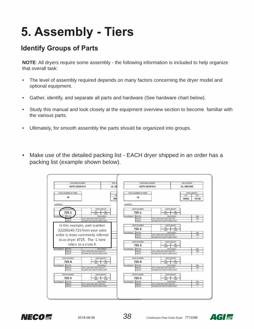
NOTE: All dryers require some assembly - the following information is included to help organize that overall task:
• The level of assembly required depends on many factors concerning the dryer model and optional equipment.
• Gather, identify, and separate all parts and hardware (See hardware chart below).
• Study this manual and look closely at the equipment overview section to become familiar with the various parts.
• Ultimately, for smooth assembly the parts should be organized into groups.
• Make use of the detailed packing list - EACH dryer shipped in an order has a packing list (example shown below).
5. Assembly - TiersIdentify Groups of Parts

39 Continuous-Flow Grain Dryer 77133962018-08-06
Assembly Hardware Key
Tier Parts Overview
• A tier section consists of two end panels, outer side panels, inner side panels, ducts, splice plates, and stiff eners, if necessary.
• Two tier sections, usually connected with an end plenum panel or transition, are also refered to as a tier level.
• Dryer sections can be made up of 3, 4, 5, 6, or 7 tier levels.
• Material thickness - per dryer height, tier panels thicken for greater strength and stability toward foundation.
• 18 ga. end panels will go with 18 ga. body panels / 14 ga. end panels will be used on any body section other then 18 ga. / 14 ga. body sections will be made of 14 ga parts and may or may not have stiff eners / 12 ga side panels always have stiff eners
• Dryers of diff erent lengths will use the same parts, but will have middle side panel(s) to ex-tend the length. 16’ dryers use 2 body panels per side
24’ dryers use 3 body panels per side 32’ dryers use 4 body panels per side
ASSEMBLY HARDWARE KEY
KEY ITEM DESCRIPTION
HB HEX BOLTCB CARRIAGE BOLTFW FLAT WASHERLW LOCK WASHERHN HEX NUTWL FLANGED WIZ-LOCK NUTWN WING NUT
NOTE: Unless otherwise specifi ed, standard assembly hardware should be zinc plated and Grade 5. Tighten all connections fi rmly.
402018-08-06 Continuous-Flow Grain Dryer 7713396
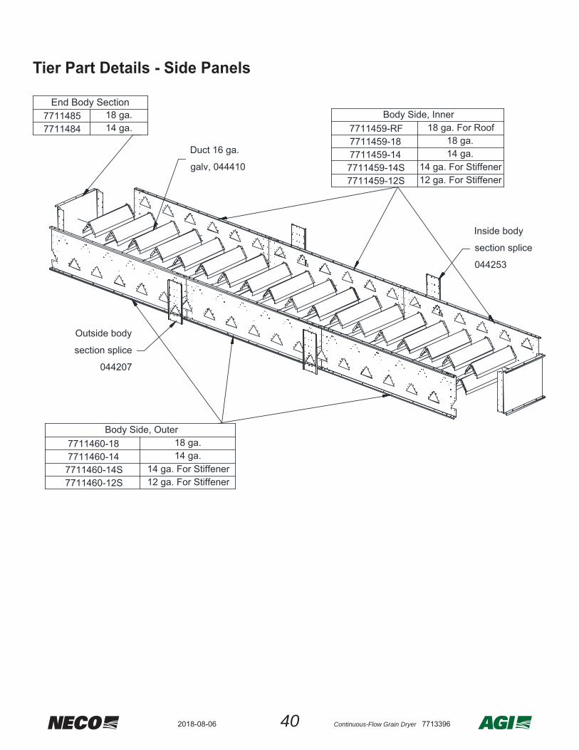
Tier Part Details - Side Panels
Outside body
section splice
044207
Duct 16 ga.
galv, 044410
Inside body
section splice
044253
Body Side, Outer
7711460-1414 ga. For Stiffener
18 ga.
7711460-12S7711460-14S
12 ga. For Stiffener
7711460-1814 ga.
End Body Section7711485
14 ga.771148418 ga. Body Side, Inner
7711459-1814 ga.
7711459-14S12 ga. For Stiffener
18 ga. For Roof
14 ga. For Stiffener7711459-14
7711459-12S
7711459-RF18 ga.

41 Continuous-Flow Grain Dryer 77133962018-08-06
Dryer Sides Identifi cationTOP
TOP
TOP
7/16” HOLES
7/16” HOLES
NOTE: The (2) middle 7/16” holes on the top of the Inner Body Side for Roof are used to connect to the Plenum Ridge Supports. The 7/16” holes at each end of the Inner Body Side for Roof are only used to connect to the Plenum Ridge Supports when these holes are not located at the end of the dryer.
(WHERE APPLICABLE)
OUTER BODYSIDE
INNER BODYSIDE
INNER BODYSIDE FOR
ROOF

422018-08-06 Continuous-Flow Grain Dryer 7713396
Outside and inside body panels made for stiff eners have (16) 1/4” stiff ener installation holes.
• During assembly arrange the outside body panels on one side and the inside body panels on the other.
• The outside body panels have the triangle air vent holes close to the bottom lip and the inside body panels have the triangle air vent holes close to the top lip as shown below.
Inside body panels have duct holes close to the top lip.
Outside body panels have duct holes close to the bottom lip.

43 Continuous-Flow Grain Dryer 77133962018-08-06
STEP #1:• Rivet the corners ONLY of the splice plate between all side panels.
Outside 044207Inside 044253
(Outside shown)
Rivet Corners ONLY of all Splice Plates
Tier Assembly Details
Setup Information1) Per the dryer model number and part number, make certain parts are grouped together properly by style and part steel gauge.
2) Make certain the panels are assembled on a fl at surface throughout the assembly. Check the assembly and make certain it is square.

442018-08-06 Continuous-Flow Grain Dryer 7713396
STEP #3:• Start rivets at each end of the outside splice plates and work towards the middle to ensure
stability.• Rivet the bottom ducts at the same time.
Rivet outside splice plates & bottom ducts
STEP #2:• Rivet the end panels onto the side panels on each end.
Outer Top Panel
INNER BODYSIDE
END BODY PANEL
3/16” RIVET

45 Continuous-Flow Grain Dryer 77133962018-08-06
STEP #4:• Rivet the top row of ducts into place.NOTE: Rivet the rest of the inside splice plates and the top ducts at the same time similar to the previous step.
STEP #5:• • Remove and replace any loose rivets.
STEP #6:• Caulk any gaps that appear where ducts are not FLUSH against the side panels.
NOTE: Do this for all body sections -- this is necessary to prevent grain from leaking.
Rivet Top Ducts

462018-08-06 Continuous-Flow Grain Dryer 7713396
STEP #7:NOTE: Skip this step if side panels are 18 ga - stiffeners are only used on 14 & 12 ga side panels.• Using 1/4” hardware, bolt on stiffners to exterior surface of OUTSIDE side panels.
STEP #8:NOTE: Skip this step if side panels are 18 ga - stiffeners are only used on 14 & 12 ga side panels.• Using 1/4” hardware, bolt on stiffners to plenum surface of INSIDE side panels.
045034 Outside
1/4" x 3/4" bolt
1/4"flatwasher
1/4" whizlock nut
Bolt on Outside Stiffener to Tierl
Bolt on Inside Stiffener to Tier
045035 Inside
1/4" whizlock nut
1/4" x 3/4" bolt
1/4"flatwasher
Bolt on Outside Stiff ener to Tier
Stiff ener
Stiff ener
23 5/8”[600 mm]
23 5/8”[600 mm]
47 Continuous-Flow Grain Dryer 77133962018-08-06
6. Assembly - Dryer Sections
Position Tiers to Build and Stack
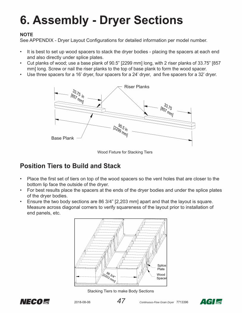
NOTESee APPENDIX - Dryer Layout Confi gurations for detailed information per model number. • It is best to set up wood spacers to stack the dryer bodies - placing the spacers at each end
and also directly under splice plates.• Cut planks of wood; use a base plank of 90.5” [2299 mm] long, with 2 riser planks of 33.75” [857
mm] long. Screw or nail the riser planks to the top of base plank to form the wood spacer.• Use three spacers for a 16’ dryer, four spacers for a 24’ dryer, and fi ve spacers for a 32’ dryer.
Riser Planks
Base Plank
Wood Fixture for Stacking Tiers
• Place the fi rst set of tiers on top of the wood spacers so the vent holes that are closer to the bottom lip face the outside of the dryer.
• For best results place the spacers at the ends of the dryer bodies and under the splice plates of the dryer bodies.
• Ensure the two body sections are 86 3/4” [2,203 mm] apart and that the layout is square. Measure across diagonal corners to verify squareness of the layout prior to installation of end panels, etc.
Stacking Tiers to make Body Sections
SplicePlate
WoodSpacer

482018-08-06 Continuous-Flow Grain Dryer 7713396
NOTEThe transition end (Front) of the dryer will only need one end air plenum on the bottom of a 4 tier dryer section. On a 3 tier dryer section there will be no end air plenums on the transition end.
• Position the #044390 end air plenum to be used as a template on the lips of the tier sections. • Using the holes as a guide, drill eight 0.281” holes into the tier sections.• Using 1/4” hardware, bolt the end plenum to the tier sections.• The completed assembly is considered one dryer tier level.
• Set the next set of tier sections on top of the assembly.
• CHECK DRYER CONFIGURATION.
End Plenum Attachment
Drill Holes
1/4" x 3/4" Bolt
1/4" Flatwasher
044390
End Air Plenum Attachment
49 Continuous-Flow Grain Dryer 77133962018-08-06
separating dryer sections (one blower per dryer section) are basically the same design with the
of cooling can be adjusted - note that divider doors are intended to always be closed for proper dryer operation.
NOTE
dryer sections have been stacked together - SKIP THIS SECTION UNTIL LATER
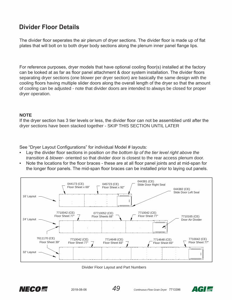
• transition & blower- oriented so that divider door is closest to the rear access plenum door.
•
7710042 (CE)Floor Sheet 77"
7710042 (CE)Floor Sheet 77"
7714648 (CE)Floor Sheet 83"
7714648 (CE)Floor Sheet 83"
7710042 (CE)Floor Sheet 77"
7611170 (CE)Floor Sheet 39"
7710042 (CE)Floor Sheet 77"
07710052 (CE)Floor Sheets 68"
045723 (CE)Floor Sheet x 92"
044173 (CE)Floor Sheet x 69"
044381 (CE)Slide Door Right Seal
7710165 (CE)Door Air Divider
044382 (CE)Slide Door Left Seal
24' Layout
16' Layout
32' Layout
Divider Floor Layout and Part Numbers
Divider Floor Details
502018-08-06 Continuous-Flow Grain Dryer 7713396
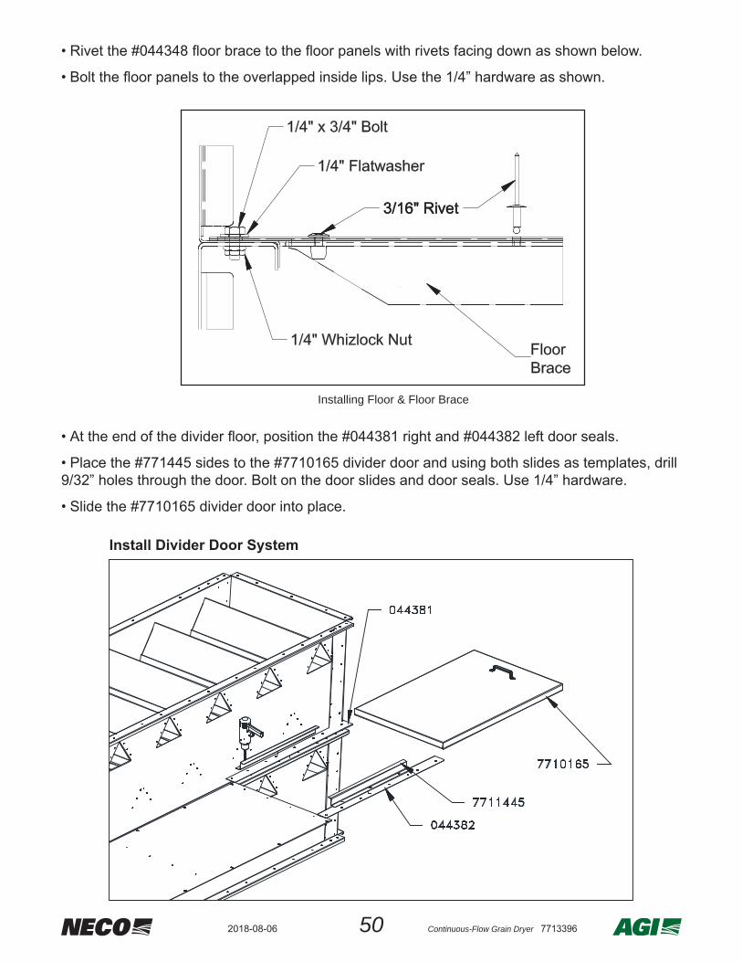
Install Divider Door System
Installing Floor & Floor Brace
• Rivet the #044348 fl oor brace to the fl oor panels with rivets facing down as shown below.
• Bolt the fl oor panels to the overlapped inside lips. Use the 1/4” hardware as shown.
• At the end of the divider fl oor, position the #044381 right and #044382 left door seals.
• Place the #771445 sides to the #7710165 divider door and using both slides as templates, drill 9/32” holes through the door. Bolt on the door slides and door seals. Use 1/4” hardware.
• Slide the #7710165 divider door into place.

51 Continuous-Flow Grain Dryer 77133962018-08-06
• Opposite the transition end, install the next #044390 air plenum end panel onto the body sections with a #044380 air plenum spacer positioned underneath per previous procedure.
• Continue to stack the dryer body sections and install the plenum end panels - showing how the
two opposite ends will look.
044390
044380
1/4" x 3/4" Bolt
1/4" Flatwasher
1/4" Whizlock Nut
044390044380Spacer
044390
Assemble Plenum End Panel and Spacer
Attach Opposite End Air Plenum
Comparison view of end plenum panels
Transition EndOpposite
Transition End
• Continue to stack the dryer body sections and install the plenum end panels. The fi gures below show how the two opposite ends will look.
522018-08-06 Continuous-Flow Grain Dryer 7713396
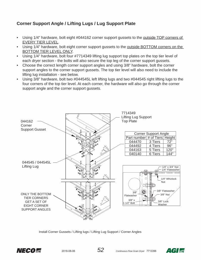
Corner Support Angle / Lifting Lugs / Lug Support Plate
• Using 1/4” hardware, bolt eight #044162 corner support gussets to the outside TOP corners of
EVERY TIER LEVEL.• Using 1/4” hardware, bolt eight corner support gussets to the outside BOTTOM corners on the
BOTTOM TIER LEVEL ONLY.• Using 1/4” hardware, bolt four #7714349 lifting lug support top plates on the top tier level of
each dryer section - the bolts will also secure the top leg of the corner support gussets.• Choose the correct length corner support angles and using 3/8” hardware, bolt the corner
support angles to the corner support gussets. The top tier level will also need to include the lifting lug installation - see below.
• Using 3/8” hardware, bolt two #044545L left lifting lugs and two #044545 right lifting lugs to the four corners of the top tier level. At each corner, the hardware will also go through the corner support angle and the corner support gussets.
7714349Lifting Lug SupportTop Plate
044545 / 044545LLifting Lug
Corner Support AnglePart number # of Tiers Height 044470 3 Tiers 72" 044492 4 Tiers 96" 044163 5 Tiers 120" 040140 6 Tiers 144"
044162CornerSupport Gusset
3/8" x1 1/2" Bolt
3/8"Flatwasher
3/8" Flatwasher
3/8" LockWasher
3/8" Nut
1/4" x 3/4" Nut1/4" Flatwasher
1/4" WhizlockNut
Install Corner Gussets / Lifting lugs / Lifting Lug Support / Corner Angles
ONLY THE BOTTOM TIER CORNERS GET A SET OF
EIGHT CORNER SUPPORT ANGLES
53 Continuous-Flow Grain Dryer 77133962018-08-06
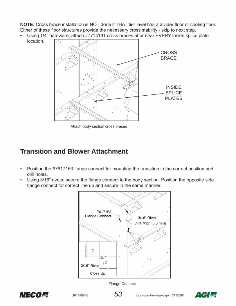
NOTE:
• Using 1/4” hardware, attach #7714191 cross braces at or near EVERY inside splice plate location.
Transition and Blower Attachment •
drill holes.•
Attach body section cross braces
CROSS BRACE
INSIDESPLICE PLATES
7617153Flange Connect
Drill 7/32" [5.5 mm]3/16" Rivet
3/16" Rivet
Close Up
Flange Connect

542018-08-06 Continuous-Flow Grain Dryer 7713396
NOTE:•
and install 3/8” hardware.
• • Install 3/8” hardware - four connections on each side.
3/8" x 1" Bolt3/8" Flatwasher3/8" Lock Washer
3/8" Nut
Bolt on Transition
Bolt on Blower
3/8" x 1" Bolt
3/8" Flatwasher
3/8" Flatwasher3/8" LockWasher
3/8" Nut
Transition / Plenum Fill Strip

55 Continuous-Flow Grain Dryer 77133962018-08-06
• Using 1/2” hardware, lift the assembled platform and secure into position.
• Remove the 1/2” bolt from the single hole side on the corner support / lifting lug connection
and reuse it to secure one end of the #044671 platform brace - do both sides.• Using 1/2” hardware, bolt the other end of the platform brace to the platform on both sides.
Bolt on Platform
Bolt on Platform Brace
044671Platform
Brace
1/2" x1 1/2" Bolt
1/2"Flatwasher
0446711/2" Nut
1/2" x1 1/2" Bolt
1/2"Flatwasher
1/2" LockWasher
1/2" Nut
044049
1/2" LockWasher
1/2" x1 1/2" Bolts
1/2" Nuts
1/2" Lock Washers
1/2" Flatwashers
Platform Assembly

562018-08-06 Continuous-Flow Grain Dryer 7713396
• Using 1/4” hardware, bolt the nine handrail uprights into the platfrom.
NOTEWhen you are at the back of the dryer facing the front, the left handrails will be to your left and the right handrails will be at your right.
• Using 1/4” hardware, bolt the middle rails onto the handrail uprights.
044549Handrail Upright
0445491/4" x 3/4" Bolt
1/4" Flatwasher
1/4"WhizlockNut
Bolt on Handrail Uprights
Bolt on Middle Handrails
044550Middle RightHandrail
044551 Middle Left Handrail
7714678Middle Front
Handrail
Middle Rail
044549 Upright
1/4" Whizlock Nut
1/4" Flatwasher
1/4" x 3/4" Bolt

57 Continuous-Flow Grain Dryer 77133962018-08-06
• Using 1/4” hardware, bolt the left and right handrails to the uprights.
• Using 1/4” hardware, bolt on splice plates.
• Using 1/4” hardware, bolt on upper - middle handrail.
044528Platform HandrailUpper Left 134.125"
044527Platform Handrail
Upper Right 134.125"
Bolt on Left & Right Handrails
7714256Splice Plate
Bolt on Slice Plates
Bolt on Middle Handrail
7714679Platform HandrailUpper Middle

582018-08-06 Continuous-Flow Grain Dryer 7713396
• Bolt the blower motor to motor mount.• Using 3/8” hardware, bolt the screen guard onto the blower.
• Using 1/4” hardware, bolt the shaft cover over the center of the screen guard through the wire
mech.• Using 3/8” hardware, bolt the screen guard onto the right side of the blower.
MOTORMOUNT
3/8" Flatwasher3/8" Lock Washer
3/8" Nut
Bolt on Motor and Screen Guard
Shaft Cover with Screen Guard
3/8" Flatwasher3/8" Lock Washer3/8" Nut
1/4"x 3/4" Carriage Bolt1/4" Flatwasher
1/4" Nut
Motor / Drive System / Guards

59 Continuous-Flow Grain Dryer 77133962018-08-06
• Using 1/4” hardware, bolt the beltshield back bracket into the screen guard with the center of the screen guard over the motor shaft.
• Unbolt one of the 1/4” bolt connections on the transition next to the motor and add the lower beltshield support bracket to that location.
• On the blower shaft - Mount key & 18” blower pulley / bushing. Do not tighten yet.• On the motor shaft - Mount key & motor pulley. Do not tighten yet.• Align the motor and the blower pulleys and tighten BOTH pulleys.
Bolt on Beltshield brackets
BeltshieldBack Bracket7612651
1/4" Flatwasher
1/4" LockWasher
1/4" x3/4" Bolt
Pulley Assembly

602018-08-06 Continuous-Flow Grain Dryer 7713396
Adjust Motor Mount
Motor Mount Nuts
Motor Mount Nuts
• Loosen motor mount nuts and adjust motor mount to put the belts over the pulleys as shown below.
• Adjust to tighten the belts.• Tighten the side nuts of the motor mount.
• Place the beltshield over the top pins of the beltshield bracket and strech the belt shield over
the lower pins.• If needed, move the threaded pins on the sides of the beltshield bracket to the inside of the
beltshield.• Secure the beltshield in place using 5/16” wing nuts.
Wing Nut
Top Pins
Attach Beltshield
61 Continuous-Flow Grain Dryer 77133962018-08-06
Attach Ladder
OVERVIEW
See “Dryer Layout Confi gurations” for ladder layouts per model number.
• LADDER LOCATION - Dryer models with only one blower have the ladder system mounted at the rear of the dryer, to the left of the plenum door. Dryer models with multiple blowers have the ladder system mounted at the front of the dryer, extending upward through the platform fl oors and opposite the fuel side of transition / blower.
• Overall ladder length is made up of 10’, 8’, 6’, or 4’ sections - total length is equal to the number of tiers times 2’ plus 2’ (Example: A 12 tier ladder system would be 26’ long)
• The 10’ (#040370) 8’ (#040369), and 6’ (#7618354) ladder sections include two ladder brackets with each section. The 4’ (#044117) section includes one ladder bracket and is used only as the top-most section in the ladder system - when required.
• The top-most section of ladder attaches directly to the ladder connection plates of the safety cage system using 3/8” hardware and two #088028 ladder clips.
NOTE: Depending on the dryer confi guration, at times the ladder section length used extends higher than the current dryer section - it is best to install the ladder mounting brackets, but do not install the ladder until after those sections are stacked.
• Lay out the ladder sections with brackets and check spacing / location of the brackets compared to the confi guration layout shown in the Dryer Tier / Ladder / Shipping Layouts section.
• Position the brackets on the ladder so that they will rest on top of the appropriate tier “lip”.
• It is suggested to either add each ladder section as the sections go up or to wait until all dryer sections have been assembled - be sure to check fi lling system for catwalk / safety cage to match up properly.

622018-08-06 Continuous-Flow Grain Dryer 7713396
Remove the existing 1/4” hardware from the three tier lip holes indicated below. Place the bracket on the tier lip, and secure with three sets of 1/4” bolts, fl atwashers, and nylock nuts. Tighten 3/8” hardware to secure the connection between the ladder and ladder bracket.
Mounting of ladder brackets.

63 Continuous-Flow Grain Dryer 77133962018-08-06
Refer to ASSEMBLY - TIERS & Part Details showing part numbers for special Roof style top panels for outer sides, inner sides, and ends.
• Place body sides apart with the ducts that are 16 1/8” from the bottom lip facing each other.• The outside of the bodies are placed 86 3/4” [2191 mm] apart.• Place the #044390 end plenum panel between the tier sections and be sure to line up the bolt
holes on the panel lips.• Drill 0.281” holes in the body sections for the end plenum panel and attach using 3/16” pop
rivets.
NOTE: For now, only install ONE of the #044390 end plenum panels. Later on during the assem-
7. Assembly - Top TierRoof Fill Style
642018-08-06 Continuous-Flow Grain Dryer 7713396
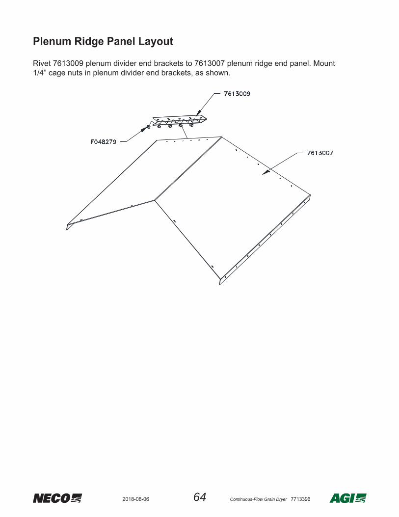
Plenum Ridge Panel Layout
Rivet 7613009 plenum divider end brackets to 7613007 plenum ridge end panel. Mount 1/4” cage nuts in plenum divider end brackets, as shown.

65 Continuous-Flow Grain Dryer 77133962018-08-06
• Using 3/8” hardware, bolt down the fi rst 044424 plenum ridge support closest to the installed end plenum panel.
PLENUM RIDGESUPPORTS

662018-08-06 Continuous-Flow Grain Dryer 7713396
• Install the end plenum ridge panel with rivets. Repeat the process for the remaining plenum ridge supports and panels, working from one end of the tier to the other.
PLENUM RIDGEPANEL
Close Plenum Ridge Panels
• Bolt in the last end plenum panel (#044390) - using the same procedure as before.

67 Continuous-Flow Grain Dryer 77133962018-08-06
Roof Assemblies Overview Drawings

682018-08-06 Continuous-Flow Grain Dryer 7713396
NOTE:Repeat these steps for the remaining roof panels. Refer to the layout on page 67.
Install the End Roof Panel and First Side Roof Panels
• Bolt on a Roof End Panel. Use 1/4” hardware. Then install (1) Right Side Panel and (1) Left Side Panel.
ROOF END PANEL
7613027
ROOF RIGHT SIDE
PANEL045743
ROOF LEFT SIDE
PANEL045742
• Bolt the roof splice channels (#045746) in place. Use 1/4” hardware.
• Bolt the roof support cross channels (#045293) to the splice channels. Use 3/8” hardware.
ROOF SUPPORTCROSS CHANNEL
045293
ROOF SPLICE CHANNEL
045746
69 Continuous-Flow Grain Dryer 77133962018-08-06
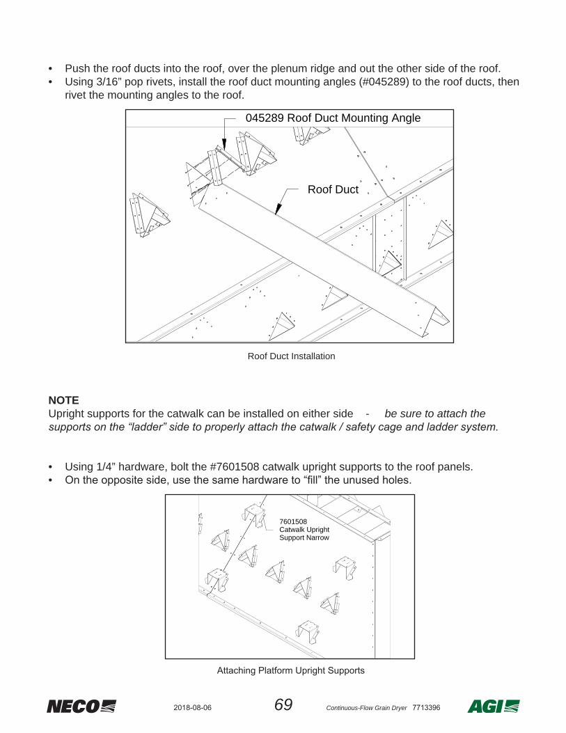
• Push the roof ducts into the roof, over the plenum ridge and out the other side of the roof.• Using 3/16” pop rivets, install the roof duct mounting angles (#045289) to the roof ducts, then
rivet the mounting angles to the roof.
NOTEUpright supports for the catwalk can be installed on either side - be sure to attach the
• Using 1/4” hardware, bolt the #7601508 catwalk upright supports to the roof panels.•
Roof Duct Installation
045289 Roof Duct Mounting Angle
Roof Duct
Figure 7T - Attaching Platform Upright Supports
7601508Catwalk UprightSupport Narrow
Attaching Platform Upright Supports

702018-08-06 Continuous-Flow Grain Dryer 7713396
8. Assembly - Topside Fill SystemRoof with Level AugerNOTE: Also refer to FINAL ELECTRICAL HOOKUP - Level Auger section for planning proper positioning of motor end / grain intake position / sensor end / auger direction / etc.
LEVEL AUGER ASSEMBLY DETAILS
Level AugerDryer Size
Auger Size6” 8” 10” 12”
16’ 7714207 7715174 N/A N/A
24’ N/AN/A
N/AN/A
7714719N/A
0454627601513
32’ N/AN/A
N/AN/A
0450027714709
0454627601513
Idler Shaft
Dryer Size Auger Size6” 8” 10” 12”
16’ 040420 N/A N/A N/A24’ N/A 040419 045004 02320432’ N/A N/A 045004 023204
Drive Shaft
Dryer Size Auger Size6” 8” 10” & 12”
16’ 040419 N/A N/A24’ N/A 040420 04500532’ N/A N/A 045005
DryerSize
End PlatesAuger Size
6” 8” 10” 12”16’ 7714202 7714720 N/A N/A
24’ N/A 7714720 N/A N/A
32’ N/A N/A 7714708 7601514
71 Continuous-Flow Grain Dryer 77133962018-08-06
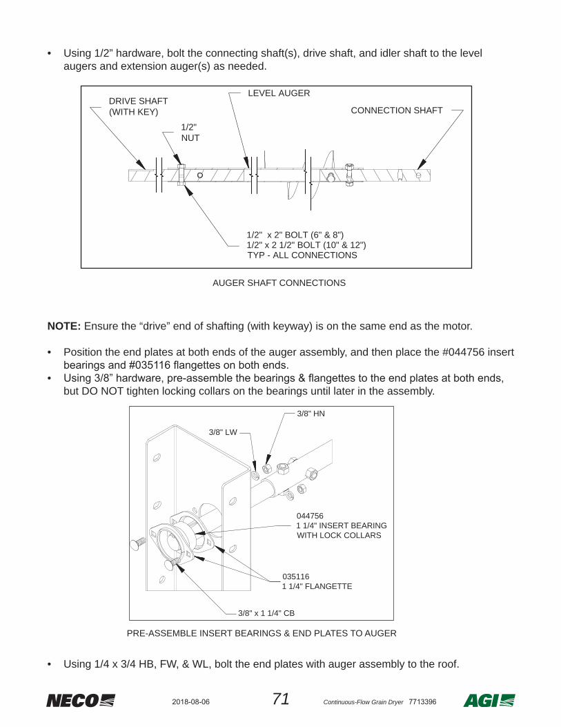
• Using 1/2” hardware, bolt the connecting shaft(s), drive shaft, and idler shaft to the level augers and extension auger(s) as needed.
NOTE: Ensure the “drive” end of shafting (with keyway) is on the same end as the motor.
• Position the end plates at both ends of the auger assembly, and then place the #044756 insert
• but DO NOT tighten locking collars on the bearings until later in the assembly.
• Using 1/4 x 3/4 HB, FW, & WL, bolt the end plates with auger assembly to the roof.
1/2"NUT
1/2" x 2" BOLT (6" & 8")1/2" x 2 1/2" BOLT (10" & 12")TYP - ALL CONNECTIONS
DRIVE SHAFT(WITH KEY) CONNECTION SHAFT
LEVEL AUGER
AUGER SHAFT CONNECTIONS
0351161 1/4" FLANGETTE
0447561 1/4" INSERT BEARINGWITH LOCK COLLARS
3/8" x 1 1/4" CB
3/8" HN
3/8" LW
PRE-ASSEMBLE INSERT BEARINGS & END PLATES TO AUGER

722018-08-06 Continuous-Flow Grain Dryer 7713396
• Using 1/4 x 3/4 HB, FW, & WL, bolt the required side skirts to the roof.• Using 3/8 x 1 HB, FW, LW, & HN, bolt the hanger bearing supports to the side skirts.
• Using 1/2” hardware, bolt the hanger bearing holder halves to the hanger bearing bracket.• Determine correct wood bearing size and place it in the hanger bearing holder halves.
WOOD BEARINGPER SHAFT SIZE
1-1/4" 1-1/2" 2"035297 035298 035299
HANGERBEARINGHOLDER
2X HALVES
HANGER BEARINGHOLDER & SIDESKIRT SPLICE
1/2" x 1 1/2" HB
1/2" FW
1/2" LW
1/2" HN
1/2" HN
1/2" LW
1/2" x 1" HB
HANGER PLATE / WOOD BEARING DETAILS
ASSEMBLE SIDE SKIRTS / IDLER SHAFT SHIELD / HANGER BEARING SUPPORT SPLICE
Hanger BearingHolder Half
Hanger BearingSupport/Splice
Idler ShaftShield
Side Skirt
Diff erences in Side Skirts
6" & 8" Side Skirts
10" Side Skirts
12" Side Skirts
73 Continuous-Flow Grain Dryer 77133962018-08-06
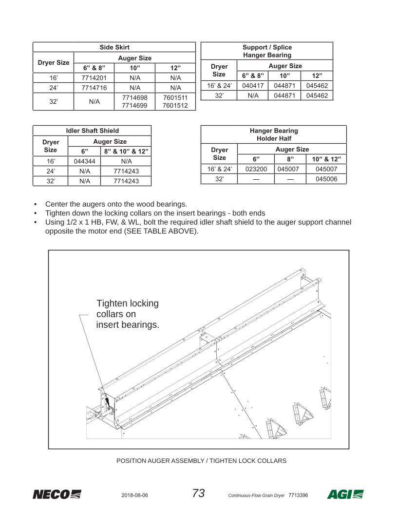
• Center the augers onto the wood bearings.• Tighten down the locking collars on the insert bearings - both ends• Using 1/2 x 1 HB, FW, & WL, bolt the required idler shaft shield to the auger support channel
opposite the motor end (SEE TABLE ABOVE).
Tighten lockingcollars oninsert bearings.
POSITION AUGER ASSEMBLY / TIGHTEN LOCK COLLARS
Side Skirt
Dryer Size Auger Size6” & 8” 10” 12”
16’ 7714201 N/A N/A24’ 7714716 N/A N/A
32’ N/A 77146987714699
76015117601512
Hanger BearingHolder Half
DryerSize
Auger Size6” 8” 10” & 12”
16’ & 24’ 023200 045007 04500732’ — — 045006
Idler Shaft ShieldDryer Size
Auger Size6” 8” & 10” & 12”
16’ 044344 N/A24’ N/A 771424332’ N/A 7714243
Support / Splice Hanger Bearing
Dryer Size
Auger Size6” & 8” 10” 12”
16’ & 24’ 040417 044871 04546232’ N/A 044871 045462

742018-08-06 Continuous-Flow Grain Dryer 7713396
• Using four 3/4” x 6” threaded rod and hardware, assemble the level auger cover plate and motor mount base to the side skirts.
• Using 1/4” hardware, assemble the pitched level auger covers to the side skirts.
3/4" Nut
3/4" ThreadedRod
Motor Mount Hardware
1/4" x 3/4" Bolt
1/4"Flatwasher1/4" Whizlock Nut
Cover Hardware
MotorMountBase
Cover Plate
MotorMountBase
Cover Plate
Level Auger Cover
Dryer Size
Auger Size6” & 8” 8” 10” 12”
16’ 7714206 7714718 N/A N/A
24’ N/A77147177714718
N/AN/AN/A
760151676015177601522
32’ N/A N/A771470177147007714703
760151676015177601522
Level Auger Cover Plate6” & 8” 10” 12”040421 044872 7601552

75 Continuous-Flow Grain Dryer 77133962018-08-06
• Using 5/16 x 1 HB, FW, LW, & HN, bolt the motor onto the motor mount pivot plate.• Using 5/16 x 2-1/2 CB & WN, attach the motor mount pivot plate to the motor mount base.• Using 1/4 x 1/4 x 2” key, attach driver pulley to the motor shaft.• Using 3/8” hardware, bolt the belt shield mounting plate to the level auger belt shield bracket. • Using 1/2” hardware, attach the level auger belt shield bracket to the end plate. • Using 5/16” hardware, bolt the belt shield back plate to the belt shield mounting plate.• Assemble the pulleys and keys onto the shafts and tighten the set screws on the pulleys.• • Attach the belt shield with 5/16” wingnuts.
• Check the completed assembly and make sure all bolts are tight & belt shield and auger
shields are secure.
BELT SHIELD ASSEMBLY

762018-08-06 Continuous-Flow Grain Dryer 7713396
Roof with Gravity Fill• In all instances, use 1/4 x 3/4 HB, FW, & WL hardware. Note that middle panel assemblies
already have the inner splice plates assembled.
• 16’ dryer -- This top section is already pre-assembled. For a 16’ dryer this would be all that is used. Add the assembly to the upper-most tier / roof base section.
• 24’ dryer -- Bolt one middle panel assembly and two corner assemblies together and add the top most pre-assembled 16’ section. Add assembly to the upper-most tier / roof base section.
• 32’ dryer -- Bolt two middle panel assemblies & two corner assemblies together. Atop that, add an assembled 24’ dryer assembly Refer to Figure 5X: and fi nish with the top most pre-assembled 16’ section. Add assembly to the upper-most tier / roof base section.
Roof with Gravity Fill - 16’, 24’, or 32’
16'Gravity
Fill
24'Gravity
Fill
32'Gravity
Fill
NOTE:POSITION FILL SWITCH TOWARD THE FRONT OF DRYER.

77 Continuous-Flow Grain Dryer 77133962018-08-06
Catwalk and Safety Cage AssemblyNOTE: A catwalk system is only used on models with “closed roofs” - if the system is NOT either a Roof With Gravity Fill system or a Roof With Level Auger system skip this section and proceed to the Safety Cage assembly section. DO THIS ASSEMBLY AT GROUND LEVEL !!
• The main catwalk parts required per dryer length are outlined in the following table.• For ease of assembly, note how the various dryer lengths have “sections” of catwalk making
up the required length along the topside of the dryer. See Figure CW4 for reference.
CATWALK PARTS (QTY PER DRYER LENGTH)
PARTNUMBER
PARTDESCRIPTION
16’DRYER
24’DRYER
32’DRYER
7612502 INNER (SHORT) UPRIGHT 2 4 67612507 OUTER (TALL) UPRIGHT 2 4 67712538 TOEBOARD - FRONT RIGHT 106” 1 1 17712536 TOEBOARD - FRONT LEFT 106” 1 1 17712355 TOEBOARD - MIDDLE 96” N/A 2 47612973 TOEBOARD - END WITH HINGES 1 1 17612566 FLOOR PANEL - 103” N/A 1 17612378 FLOOR PANEL - 96” N/A N/A 17612986 FLOOR PANEL - 87.96” 1 N/A N/A7612974 FLOOR PANEL - 80.72” N/A 1 17712569 FLOOR SPLICE / SUPPORTS 1 2 37712573 FLOOR SUPPORTS 3 5 77612976 ACCESS CROSS BRACE 1 1 1035369 HINGE - 3” X 3” 2 2 2
7612975 PLATFORM ACCESS DOOR 1 1 1F118072 HANDLE 1 1 17712895 LADDER SUPPORT BEAM 1 1 17712893 LADDER SUPPORT UPRIGHTS 2 2 27712894 LADDER SUPPORT BRACE 2 2 27712568 HANDRAIL LOWER FRONT 106” 2 2 27712567 HANDRAIL UPPER FRONT 106” 2 2 27712533 HANDRAIL LOWER MIDDLE 96” N/A 2 47712394 HANDRAIL UPPER MIDDLE 96” N/A 2 47712576 HANDRAIL CROSS BRACE 2 2 2080085 LADDER EXTENSION RAIL WALKTHRU 2 2 2
7712583 HANDRAIL DIAG BRACE - END 2 2 27612510 HANDRAIL SPLICE N/A 2 47712584 HANDRAIL DIAG BRACE - SIDE MID N/A 4 4080083 LADDER CONNECTION PLATES 2 2 2

782018-08-06 Continuous-Flow Grain Dryer 7713396
NOTE: Upright supports are factory mounted to the roof side panel.• Using 1/4” hardware, assemble #7612502 inner catwalk uprights to the upper supports.• Using 1/4” hardware, assemble #7612507 outer catwalk uprights to the lower supports.
7612502INNER (SHORT)
CATWALK UPRIGHT
7612507OUTER (TALL)CATWALKUPRIGHT
1/4" x 3/4" BOLT
1/4" FLAT WASHER
1/4" WHIZLOCK NUT
UPPER CATWALKUPRIGHT SUPPORT
LOWER CATWALKUPRIGHT SUPPORT
Assemble uprights to upright supports
NOTE: Position notched ends of these toeboards TOWARD the end of dryer where ladder is.• Using 3/8” hardware, assemble #7712536 front left 106” toeboard and #7712538 front right
106” toeboards to the uprights.
NOTCHEDEND
7712538CATWALKTOEBOARDFRONT RIGHT106" LG
7712536CATWALK
TOEBOARDFRONT LEFT
106" LG
3/8" NUT 3/8" LOCK WASHER
3/8" x 1" BOLT
Assemble front toeboards to uprights

79 Continuous-Flow Grain Dryer 77133962018-08-06
Assemble fl oor supports and splice supports
7712569FLOOR
SPLICE & SUPPORT
7712573FLOOR SUPPORTS
7612973END
TOEBOARD
• Using 1/4” hardware, assemble any remaining fl oor panels required.• Assemble #7712569 splice supports at edge where hinged door shuts & each fl oor panel joint.• Assemble #7712573 supports - one at the ladder end of front fl oor panel & two at mid span.
• Use 3/8” hardware to complete toeboard installation, as per Figure CW3.• For 16’ dryers, install the #7712973 end toeboard.• For 24’ & 32’ dryers, complete assembly of the remaining side toeboards as shown, then
install the #7712973 end toeboard.
Figure CW4 - Toeboard & fl oorboard layout
NOTEFor fl ooring and fl oor supports,
use 1/4 x 3/4 HB & WL.87.96"
103"
96" 103"
80.72"
80.72"
#7712355 (2X)
#7612986
#7712538
#7612566#7612974
#7712536
#7712355 (4X)#7612566
#7612378
#7712538
NOTCHED ENDS
#7712536
#7712538
NOTCHED ENDS
#7712536
#7612973
#7612973
#7612973
#7712569 (2X)
#7712569 (3X) #7712573 (7X)
#7712573 (5X)
#7712573 (3X)
NOTCHED ENDS
#7712569
USES HANDRAILS #7712567 & #7712568
USES HANDRAILS #7712394 & #7712533USES HANDRAILS #7712567 & #7712568
USES HANDRAILS #7712567 & #7712568USES HANDRAILS #7712394 & #7712533
#7612974
16’DRYERS
24’DRYERS
32’DRYERS
NOTEFor fl ooring and fl oor supports,
use 1/4 x 3/4 HB & WL.

802018-08-06 Continuous-Flow Grain Dryer 7713396
• Bolt the #7612976 catwalk access cross brace between the center of the #7612973 end
• Bolt the #F118072 handle and #035369 hinges to the #7612975 platform access door.• Bolt the platform access door hinges to the #7612973 end toeboard.
• Use 1/4” x 3/4 HB, FW, and WL hardware.• • Bolt the #7712893 ladder support uprights to the support beam - be sure to use the TOP holes.• Bolt the #7712894 support braces to the support uprights - use the holes below support beam.• Located directly beneath the ladder support legs, remove the two bolts from the lip of the top
tier / roof edge. Position the support legs so that the base hole lines up with where the two bolts were removed and re-install the two bolts to secure the bases of the support uprights.
035369HINGE 3" x 3"
7612976CATWALK ACCESSCROSS BRACE
7612975PLATFORM
ACCESS DOOR
7712569CATWALK FLOORSUPPORT / SPLICE
7612973CATWALK
END TOEBOARD
F118072HANDLE
7712894SUPPORTBRACE
7712893SUPPORTUPRIGHT
NOTE:USE TOP HOLES TO SECURE THE SUPPORT BEAMUSE BOTTOM HOLES TO SECURE THE SUPPORT BRA
7712895SUPPORTBEAM
Assemble ladder support system
NOTEUSE 1/4 x 3/4” HB, FW, & WL
HARDWARE

81 Continuous-Flow Grain Dryer 77133962018-08-06
• Use 3/8” x 1” HB, FW, & WL hardware.• Bolt the upper handrails to the inner & outer upright supports.• Bolt the lower handrails to the inner & outer upright supports.• Bolt the #080085 ladder extension uprights to the toeboards and handrails.
080085LADDEREXTENSION
UPPER HANDRAIL(S)
LOWER HANDRAIL(S)
Assemble handrails and ladder extensions
• Using 3/8” hardware, bolt
the #7712576 handrail cross braces and the #7712583 diagonal end braces to the end inner & outer uprights.
• Using 1/4” hardware, bolt the #7612510 handrail splice on the underside of top railings - where any two top handrails butt up.
• NOTE: FOR GRAVITY FILL ROOF STYLES ONLY -- Using 1/4” x 3/4 HB & WL, install #7712896 lateral braces between the inner top handrail and re-use existing bolts in the
7612510HANDRAILSPLICE
7712576 HANDRAIL CROSS BRACE
7712583DIAG END BRACE
7712896LATERAL
BRACE(SEE SPECIAL NOTE)
Assemble end rails
822018-08-06 Continuous-Flow Grain Dryer 7713396
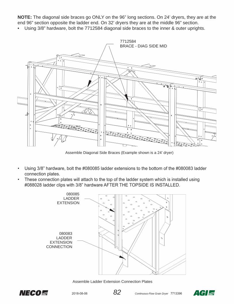
NOTE: The diagonal side braces go ONLY on the 96” long sections. On 24’ dryers, they are at the end 96” section opposite the ladder end. On 32’ dryers they are at the middle 96” section.• Using 3/8” hardware, bolt the 7712584 diagonal side braces to the inner & outer uprights.
7712584BRACE - DIAG SIDE MID
Assemble Diagonal Side Braces (Example shown is a 24’ dryer)
• Using 3/8” hardware, bolt the #080083 ladder extensions to the bottom of #080085 ladder
connection plates.• These connection plates will attach to the top of the ladder system is installed using #088028
ladder clips with 3/8” hardware AFTER THE TOPSIDE IS INSTALLED.
080083LADDER
EXTENSIONCONNECTION
080085LADDER
EXTENSION
Assemble Ladder Extension Connection Plates
• Using 3/8” hardware, bolt the #080085 ladder extensions to the bottom of the #080083 ladder connection plates.
• These connection plates will attach to the top of the ladder system which is installed using #088028 ladder clips with 3/8” hardware AFTER THE TOPSIDE IS INSTALLED.
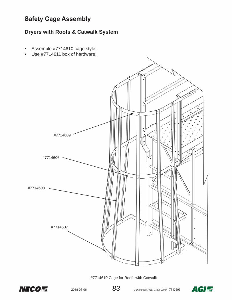
83 Continuous-Flow Grain Dryer 77133962018-08-06
#7714610 Cage for Roofs with Catwalk
#7714606
#7714607
#7714608
#7714609
Dryers with Roofs & Catwalk System
• Assemble #7714610 cage style.• Use #7714611 box of hardware.
Safety Cage Assembly

842018-08-06 Continuous-Flow Grain Dryer 7713396
• Most dryer system utilize a NECO support leg option. Some dryer systems utilize both concrete piers and either the NECO legs or customer supplied legs.
• No matter the method, double-check and verify proper assembly - make sure system is secure.
DETERMINE NEXT STEP --• •
continue with Stack and Secure Sections.
Anchor Lower Section To Pad / Foundation
• Be sure to support the lower section using a crane or setting it on temporary blocks, etc..
Check & Verify ALL anchor attachment systems before installing optional leg kit or the addition of any upper dryer sections.
9. InstallationPosition Lower Dryer Section at Location

85 Continuous-Flow Grain Dryer 77133962018-08-06
NOTE: Skip this section if the dryer system does not utilize the optional NECO lifting legs.
OVERVIEWThe optional lifting leg system is based on requirements that vary with the size and capacity of the dryer. Leg kits are available in 24”, 48”, or 60”lengths. Most dryer systems with legs are set atop a concrete slab. Some do not have a slab, but have individual foundation piers for support and anchoring. The dryer should also be secured in a secondary manner (guy wires, for example). This is especially true for taller dryers, which have greater surface area exposed to the wind.
WARNING
Be sure to support the dryer’s lower section assembly by hanging from a crane or sitting on blocks prior to installing ANY lifting legs.
WARNING
Torque all attachment hardware to the proper values --
1/2” grade 5 bolts -- to 65 ft-lbs torque value
5/8” grade 5 bolts -- to 135 ft-lbs torque value
“C” LEGSCOLUMN“B” LEG(S)
CENTER
“A” LEGSOUTER & INNER
Install NECO Leg Kit (Optional)

862018-08-06 Continuous-Flow Grain Dryer 7713396
SIDE LEG ATTACHMENT
The extra hole is used only for extra high capacity (EHC)frames.
A
SIDE LEGS (OUTER & INNER)
Part Number
Elevation Lengthinches mm inches mm
045592 24 610 41-3/8 1051
045354 48 1220 65-3/8 1661
7714575 60 1524 77-3/8 1965
5/8" X 1 1/2" BOLT
5/8" FLATWASHER
5/8" WHIZLOCK NUT
FRAME TO SIDE LEG HARDWARE ARRANGEMENT
Outer Legs & Inner Legs
NOTE: Extra-high capacity dryers(EHC) use the 2nd set of holes for added strength.
• Use ½” x 1½” hardware.• While the dryer lower section is hanging
from a crane or setting on blocks: bolt the “A” outer side legs only around the outside perimeter of the dryer frame.
• Once the “A” side legs are mounted around the outside, go ahead and mount the inner “A” side legs to the inside frame positions.
Be sure to torque all legs properly as they are being installed - then, double-check torque values upon completion.
WARNING
Leg styles and location:
• “A” Side legs are located around the outside & inside perimeter of the dryer.• “B” Center leg(s) are located in the area where the tongue meets the dryer frame and can be
a single or double leg setup - based on the dryer height and load requirements.• “C” Column legs (if needed) are located to provide column support for the platforms.
USE SHIMS, AS NEEDED
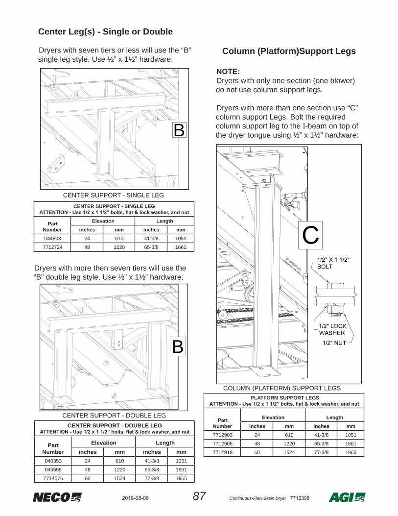
87 Continuous-Flow Grain Dryer 77133962018-08-06
Dryers with more then seven tiers will use the “B” double leg style. Use ½” x 1½” hardware:
Column (Platform)Support Legs
NOTE:Dryers with only one section (one blower) do not use column support legs.
Dryers with more than one section use “C” column support Legs. Bolt the required column support leg to the I-beam on top of the dryer tongue using ½” x 1½” hardware:
COLUMN (PLATFORM) SUPPORT LEGS PLATFORM SUPPORT LEGS
Part Number
Elevation Lengthinches mm inches mm
7712903 24 610 41-3/8 1051
7712905 48 1220 65-3/8 1661
7712918 60 1524 77-3/8 1965
CENTER SUPPORT - DOUBLE LEG
Part Number
Elevation Lengthinches mm inches mm
040353 24 610 41-3/8 1051
045555 48 1220 65-3/8 1661
7714576 60 1524 77-3/8 1965
CENTER SUPPORT - SINGLE LEG
Part Number
Elevation Lengthinches mm inches mm
044803 24 610 41-3/8 1051
7712724 48 1220 65-3/8 1661
CENTER SUPPORT - SINGLE LEG
B
B
CENTER SUPPORT - DOUBLE LEG
Center Leg(s) - Single or Double
Dryers with seven tiers or less will use the “B” single leg style. Use ½” x 1½” hardware:

882018-08-06 Continuous-Flow Grain Dryer 7713396
• Bolt the Control Panel to the angle mounts,
making sure it is mounted for easy operator access..
ATTACH BLOWER SYSTEM
• -
ing upward.• Install bolts - four connections on each side.
Attach control panel
3/8" x 1" Bolt
3/8" Flatwasher
3/8" Flatwasher3/8" LockWasher
3/8" Nut
Bolt on Blower
OVERVIEW32’ units sent in shipping containers require some additional assembly / installation work due to shipping length requirements:• The control panel needs to have a mounting
bracket system added in order to mount and secure it to the proper operator height.
• The blower system needs to be attached to the transition.
• Bolt the #7714697 control panel mounting
brackets to the dryer tongue.
• Make sure the #7601542 angle brackets are
positioned as shown & attach to to the mounting brackets.
Attach Control Panel Mount Brackets
Attach vertical angle mounts
Special Assembly for 32’ Dryers

89 Continuous-Flow Grain Dryer 77133962018-08-06
NOTE: The cross auger system was assembled at NECO, but due to shipping restrictions is taken off as a sub-assembly, and placed within the lower dryer section to ship.
Re-install the cross auger system onto the rear of the dryer.
• Using 1/2” hardware, attach the trough and auger sub-assembly to the spouts at the back of
the dryer.
Assemble Trough to Spouts
Install Cross-Auger System

902018-08-06 Continuous-Flow Grain Dryer 7713396
• Attach the rear chain guard back plate to the spout and attach the side guard back plate to the spout.
Assemble Guard Backing
A -- Side Chain Guard Back Plate7714237 Standard7714290 High Capacity7714335 Extra High Capacity
B -- Rear Chain Guard Back Plate7714234 Standard & High Capacity7714332 Extra High Capacity

91 Continuous-Flow Grain Dryer 77133962018-08-06
• Mount the #036707 sprocket with 1” bore onto the shaft of the gearbox and the #036495 sprocket with 1 1/4” bore onto the shaft of the discharge.
• Mount the idler shaft onto the guard backing. • Line up the sprockets and wrap the #002116 roller chain around the sprockets and connect the
#036131 roller chain connection link.• Position the idler sprocket against the chain to take up slack - do NOT over tighten.
• Using 5/16” x 1 HB, FW & WL, mount the cover guards onto the guard back plates.• Using 1/4” x 3/4 CB, FW, & WL, bolt the cross auger cover to the trough.
036707
036707
036495
036495
036714
036714002116
002116
036714
1/2" Nut
1/2" LockWasher
035332
1/2" Flatwasher
5/8" Flatwasher
1/2" x 2 1/2"Carraige Bolt
Assemble Sprockets and Chain
7714226 Standard7714288 High Capacity7714340 Extra High Capacity
7714234 Standard & High Capacity7714332 Extra High Capacity
7714237 Standard7714290 High Capacity7714335 Extra High Capacity
Attach Covers
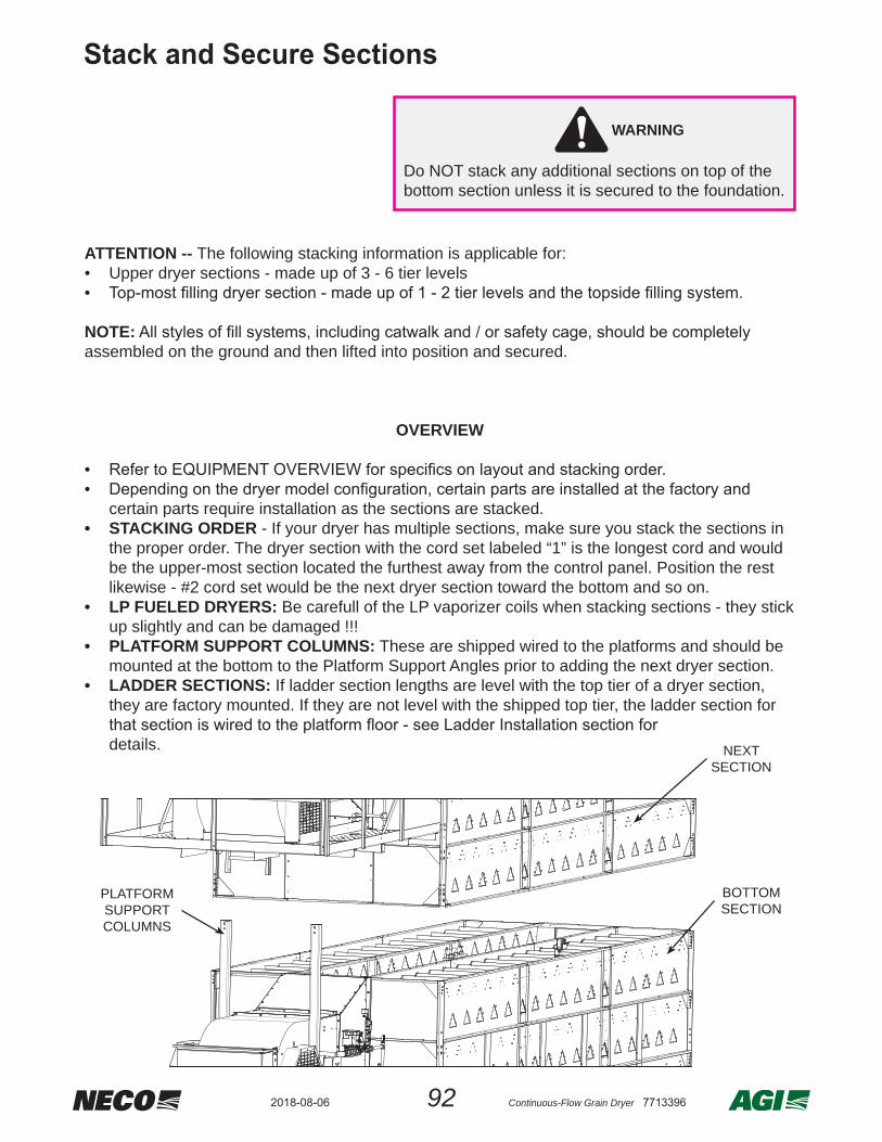
922018-08-06 Continuous-Flow Grain Dryer 7713396
ATTENTION -- The following stacking information is applicable for:• Upper dryer sections - made up of 3 - 6 tier levels•
NOTE:assembled on the ground and then lifted into position and secured.
OVERVIEW
• •
certain parts require installation as the sections are stacked.• STACKING ORDER - If your dryer has multiple sections, make sure you stack the sections in
the proper order. The dryer section with the cord set labeled “1” is the longest cord and would be the upper-most section located the furthest away from the control panel. Position the rest likewise - #2 cord set would be the next dryer section toward the bottom and so on.
• LP FUELED DRYERS: Be carefull of the LP vaporizer coils when stacking sections - they stick up slightly and can be damaged !!!
• PLATFORM SUPPORT COLUMNS: These are shipped wired to the platforms and should be mounted at the bottom to the Platform Support Angles prior to adding the next dryer section.
• LADDER SECTIONS: If ladder section lengths are level with the top tier of a dryer section, they are factory mounted. If they are not level with the shipped top tier, the ladder section for
details.
Stack & Secure Sections
NEXTSECTION
BOTTOMSECTION
PLATFORMSUPPORTCOLUMNS
WARNING
Do NOT stack any additional sections on top of the bottom section unless it is secured to the foundation.
Stack and Secure Sections

93 Continuous-Flow Grain Dryer 77133962018-08-06
Remove Lifting Lug Top Plates
• Prior to stacking any dryer sections, remove all #7714349 lifting lug top plates from corners. - if
• ALL of the factory mounted Corner Support Gussets MUST STAY ATTACHED.NOTE: Lifting lugs can be left in place or removed. If removed, replace the hardware.
Install Air Plenum End Panel Spacers
• Position #044380 plenum end panel spacer for installation where ANY two air plenum end
-gether.
Remove lifting lug top plates
044545, 044545L
7714349Lifting LugTop Plate
CornerSupportGussets
1/4" x 3/4" Bolt
1/4" Flatwasher
1/4" Whizlock Nut
End Plenum Spacer
End Plenum Spacer Plenum EndPanel
Install spacers between any two air plenum end panels

942018-08-06 Continuous-Flow Grain Dryer 7713396
Install Transition / Plenum Fill Strips
• When the transition lip is level with the
dryer sections top tier AND the next sec-tion to stack has a plenum end panel, use
secure the top of the transition to the un-derside lip of that next stacks plenum end panel.
• Use 1/4” x 3/4 HB, FW, & WL to secure the strip at both edges.
Install Platform Support Columns
• SKIP to next step if the dryer does NOT
have multiple platforms.• The LOWER support column weldment
mounts directly to the beam. ALL upper sections use UPPER support columns & mount using #044510 support angles.
• The support column angles are factory mounted and the support columns for that section are wired to the platform for shipment.
• ATTENTION - The support columns must be in position PRIOR to the installation of the next dryer section.
SUPPORT COLUMN SIZE REQUIREMENTS
LOCATION &TIER SPAN
COLUMNPART #
COLUMN LENGTH(“ REFERENCE)
LOWER - 3 TIER 7712914 69 - 7/8”UPPER - 3 TIER 7715019 68 - 3/16”LOWER - 4 TIER 7712912 93 - 7/8”UPPER - 4 TIER 044516 92 - 3/16”LOWER - 5 TIER 7712910 117 - 7/8”UPPER - 5 TIER 040117 116 - 3/16”LOWER - 6 TIER 7712916 141 - 7/8”UPPER - 6 TIER 7714832 140 - 3/16”
UPPER column with support angles
SUPPORTANGLE#044510
Top of Transition
Transition/PlenumFill Strip
LOWERSUPPORT COLUMN
FLANGE WELDMENT
USE 1/2 x 5-1/2” BOLTS &
HARDWARE
USE 1/2 x 1-1/2” BOLTS &
HARDWARE
USED ON LOWESTSECTION ONLY
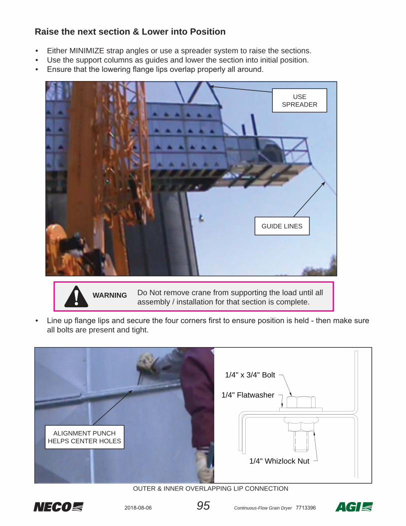
95 Continuous-Flow Grain Dryer 77133962018-08-06
Raise the next section & Lower into Position
• Either MINIMIZE strap angles or use a spreader system to raise the sections.• Use the support columns as guides and lower the section into initial position.•
• all bolts are present and tight.
1/4" x 3/4" Bolt
1/4" Flatwasher
1/4" Whizlock Nut
OUTER & INNER OVERLAPPING LIP CONNECTION
ALIGNMENT PUNCH HELPS CENTER HOLES
GUIDE LINES
USESPREADER
WARNING Do Not remove crane from supporting the load until all assembly / installation for that section is complete.
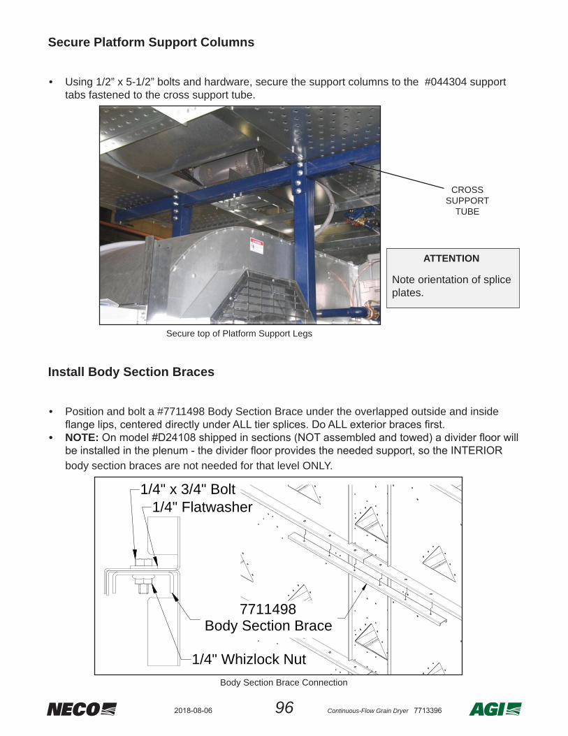
962018-08-06 Continuous-Flow Grain Dryer 7713396
Secure Platform Support Columns
• Using 1/2” x 5-1/2” bolts and hardware, secure the support columns to the #044304 support
tabs fastened to the cross support tube.
Install Body Section Braces
• Position and bolt a #7711498 Body Section Brace under the overlapped outside and inside
• NOTE:
body section braces are not needed for that level ONLY.
CROSSSUPPORT
TUBE
7711498Body Section Brace
1/4" x 3/4" Bolt1/4" Flatwasher
1/4" Whizlock Nut Body Section Brace Connection
Secure top of Platform Support Legs
ATTENTION
Note orientation of splice plates.

97 Continuous-Flow Grain Dryer 77133962018-08-06
Install Divider Floor (Model #24108 ONLY)
NOTE: Skip this section if the dryer is NOT a model #D24108 AND the two sections were NOT assembled at the factory and towed to location as one unit. All other models #’s have the divider
•
access plenum door.•
• •
7710042Floor Sheet 77"
7710042Floor Sheet 77"
7710052Floor Sheets 68"
044381Slide Door Right Seal
7710165Divider Door
044382Slide Door Left Seal
7611170Floor Sheet 39"
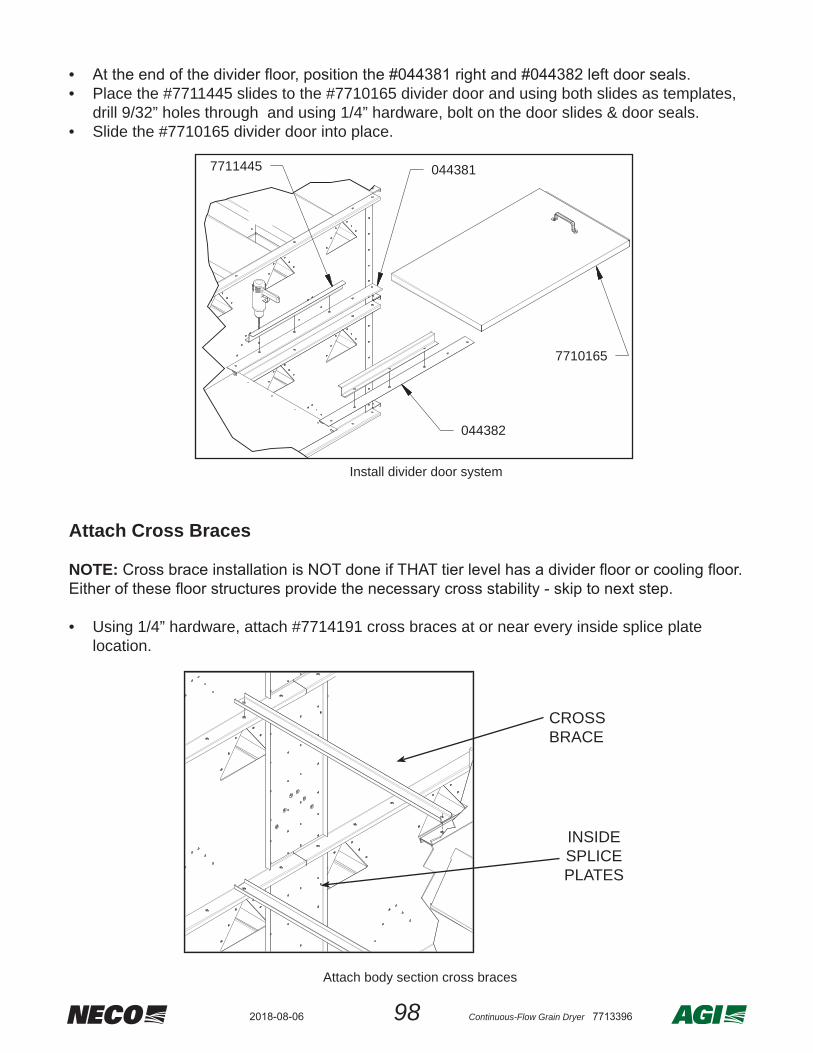
982018-08-06 Continuous-Flow Grain Dryer 7713396
• • Place the #7711445 slides to the #7710165 divider door and using both slides as templates,
drill 9/32” holes through and using 1/4” hardware, bolt on the door slides & door seals.• Slide the #7710165 divider door into place.
Attach Cross Braces
NOTE:
• Using 1/4” hardware, attach #7714191 cross braces at or near every inside splice plate location.
7710165
7711445 044381
044382
Install divider door system
Attach body section cross braces
CROSS BRACE
INSIDESPLICE PLATES

99 Continuous-Flow Grain Dryer 77133962018-08-06
Optional Removal of Platform Braces / Lifting Lugs
NOTE: The following items can be removed AFTER the dryer section has been stacked and secured.• The platform shipping braces can either be left in place or removed.• The lifting lugs can either be left in place or removed.• Be sure to replace all hardware removed if either of these are taken off .
Platform Braces**
Lifting Lugs**
Lifting Lug Top Plates***Removal is optional
*Must be removed beforestacking next dryer section
Platform Braces & Lifting Lugs can be removed or left in place
Attach Ladder Sections
OVERVIEW
• See APPENDIX - Dryer Layout Confi gurations for information on ladder bracket attachment with the necessary ladder section lengths.
• Ladder location depends on model type - single blower units have the ladder system mounted at the rear of dryer, to the LEFT of the plenum door. Dryers with multiple platforms have the ladder system mounted at the front of dryer, going up through the platform fl oors, on the opposite side of transition fuel train.
• The 10’ (#040370), 8’ (#040369), and 6’ (#7618354) ladder sections include two ladder brackets with each section supplied. The 4’ (#044117) section includes one ladder bracket and is used only as the top-most section in the ladder system when required. It will always have to be installed.
• The top-most section of ladder (10’, 8’, 6’ or 4’) attaches to the #088083 ladder connection plates of the safety cage system using #088028 ladder clips and 3/8” hardware.
• It is suggested to either add each ladder section as the dryer sections are installed upward or to wait until all dryer sections and topside fi lling section have been installed.
NOTE: For dryers with a roof and catwalk system, the 6” dimension from the edge of tier to the #080022 ladder bracket edge should be held closely or the #080083 ladder attachment brackets will not match up correctly.
• When ever possible, the ladder brackets should be positioned against the “lip” of a tier section to provide alignment and additional stability.
NOTE: Ladder attachment brackets are positioned above or below any ladder section splice and can NOT be located at the same level or position as the ladder splices.

1002018-08-06 Continuous-Flow Grain Dryer 7713396
NOTE: For dryers with a roof and catwalk system, the 6” dimension from the edge of tier to the #080022 ladder bracket edge should be held closely or the #080083 ladder attachment brackets will not match up correctly.
• When possible, the ladder brackets should be positioned against the “lip” of a tier section to provide alignment and to add additional stability.
NOTE: Ladder attachment brackets are positioned above or below any ladder section splice and can NOT be located at the same level or position as the ladder splices.
NOTE: Ladder brackets can NOT be positioned at either end of a ladder section where splices are used to attach the ladder sections together.
• Fasten the ladder sections to each bracket using two #088028 ladder clips per bracket.
6" (152mm)FROM OUTSIDE OFTIER TO LADDER
3/8" FLATWASHER3/8" x 1" BOLT (3X)
3/8" x 1 1/2" CARRIAGE BOLT
3/8" FLATWASHER3/8" LOCK WASHER3/8" NUT
LADDER BRACKET#080022
3/8" FLATWASHER3/8" LOCK WASHER3/8" NUT
#088028 LADDER CLIP(2 PER LADDER BRACKET)
BOLT ON LADDER
Drill 3/8"(10mm) Holes
6" (152mm)
TRANSFER DRILL HOLES TO MOUNT LADDER BRACKETS

101 Continuous-Flow Grain Dryer 77133962018-08-06
• Between ladder sections, place a #088029 ladder splice into each ladder leg as shown so that both sections are aligned and securely bolted together.
Install Topside Filling Section
to the topmost tier section, should have been done at ground level.• Ensure the topside system is completed to
this level before proceeding further.• Make sure the #7714349 lifting lug top
plates were removed for the section being stacked upon.
• as one completed unit - use guide lines to assist in positioning.
Be sure the safety cage #080083 ladder
up correctly with any existing ladder sections.
• position and secure all around.
WARNING
Be sure to utilize spreader bars or similalr means to properly lift the unit. Main lift component should be vertical - do not use sharp angles on strapping !!
LIFT ASSEMBLED TOPSIDE FILLING SECTION
INSTALL INTO FINAL POSITION AND SECURE
BOLT LADDER SECTIONS TOGETHER WITH LADDER SPLICE
LADDER SECTION
#088029 LADDER SPLICE
3/8" FLATWASHER (2X)3/8" LOCK WASHER3/8" NUT
3/8" x 1" BOLT

1022018-08-06 Continuous-Flow Grain Dryer 7713396
NOTE:
• In most cases, the top-most ladder section is a 4’ section and already attached to the safety cage attachment brackets. If this is the case, use two ladder splices to secure the ladder sections together.
• On some models, the fi nal ladder section may be 6’, 8’, or 10’ and need to be installed to the safety cage ladder attachment brackets.
Install NECO logo bracket
ATTENTION: • Install the NECO logo bracket assembly (1-169876) so that it can be viewed from a main
road if at all possible.• The bracket has four mounting tabs with holes that will line up with dryer tier section
mounting bolts.• Remove the necessary four sets of tier lip hardware, position the bracket, and replace the
four sets of hardware to secure the logo bracket.
See photo below for an example of a mounted logo bracket assembly:
FINISH LADDER CONNECTION
LADDER EXTENSION CONNECTION
WALKTHRU080083
LADDER CLIP AND BOLT088028

103 Continuous-Flow Grain Dryer 77133962018-08-06
10. Final System HookupAdjust Control Box Height
ALTERNATEMOUNTING
HOLES
2” HOLE FOR MAIN POWER
ENTRY
Support the weight of the main control box with a forklift or other secure means when adjusting the height.WARNING
• Loosen the fasteners that hold the control panel in place.• The vertical guide rails can also be adjusted upward or downward.• Position the control panel at a comfortable operator height and secure in position.
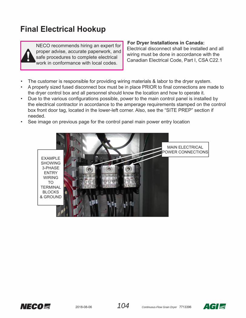
1042018-08-06 Continuous-Flow Grain Dryer 7713396
Final Electrical Hookup
NECO recommends hiring an expert for proper advise, accurate paperwork, and safe procedures to complete electrical work in conformance with local codes.
For Dryer Installations in Canada:Electrical disconnect shall be installed and all wiring must be done in accordance with the Canadian Electrical Code, Part I, CSA C22.1
• The customer is responsible for providing wiring materials & labor to the dryer system.• A properly sized fused disconnect box must be in place PRIOR to fi nal connections are made to
the dryer control box and all personnel should know the location and how to operate it.• Due to the various confi gurations possible, power to the main control panel is installed by
the electrical contractor in accordance to the amperage requirements stamped on the control box front door tag, located in the lower-left corner. Also, see the “SITE PREP” section if needed.
• See image on previous page for the control panel main power entry location
EXAMPLESHOWING3-PHASEENTRYWIRING
TOTERMINALBLOCKS
& GROUND
MAIN ELECTRICAL POWER CONNECTIONS

105 Continuous-Flow Grain Dryer 77133962018-08-06
Blower Motor Wire(s)
NOTE: Blower #1 is always the top most blower
Three Phase (3P) Wiring:• Connect wires T1, T2, & T3 into the bottom
of the respective starter(s).• Connect the green ground wire to the
ground terminal in the Control Box.
Single Phase (1P) Wiring: • Connect wires T1 & T2 into the bottom of
the respective starter(s). Note that T3 loops from the lower-middle position back up to the upper-right position to provide internal feedback within the control system.
• Connect the green ground wire to the ground terminal in the Control Box.
L1 L2L3
MOTOR STARTER
T1T3
T2
SINGLE PHASE (1P)
BLOWER #MOTOR
STARTER
MOTOR STARTER
T1
THREE PHASE (3P)
T2 T3
L1 L2 L3
BLOWER #MOTOR
STARTER
SINGLE PHASE THREE PHASE

1062018-08-06 Continuous-Flow Grain Dryer 7713396
Dual Thermocouple Probe
Burner Box Cables*DUAL THERMOCOUPLE PROBE
Dual Thermo-couple Probe
BURNER BOX CONNECTIONS
YELLOWBURNER CABLE
TEE
GREYCOMMUNICATIONS
CABLE TEE
GREYCOMMUNICATIONS
CABLE
YELLOWBURNERCABLE
• The yellow and grey cables and tees are used to connect the Burner Boxes to each other and to the main electrical panel
• Directly connect the grey cable to the top burner box (do not install grey tee in top burner box).
* Located in Dryer Crate
• The Dual Thermocouple probe is factory mounted for each dryer section and it is used for temperature control and temperature hi-limit control in each dryer section.
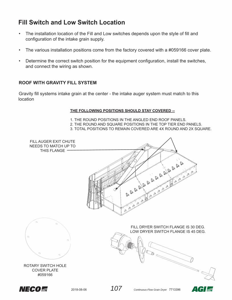
107 Continuous-Flow Grain Dryer 77133962018-08-06
Fill Switch and Low Switch Location• The installation location of the Fill and Low switches depends upon the style of fi ll and
confi guration of the intake grain supply.
• The various installation positions come from the factory covered with a #059166 cover plate.
• Determine the correct switch position for the equipment confi guration, install the switches, and connect the wiring as shown.
ROOF WITH GRAVITY FILL SYSTEM
Gravity fi ll systems intake grain at the center - the intake auger system must match to this location
THE FOLLOWING POSITIONS SHOULD STAY COVERED --
1. THE ROUND POSITIONS IN THE ANGLED END ROOF PANELS.2. THE ROUND AND SQUARE POSITIONS IN THE TOP TIER END PANELS.3. TOTAL POSITIONS TO REMAIN COVERED ARE 4X ROUND AND 2X SQUARE.
FILL AUGER EXIT CHUTE NEEDS TO MATCH UP TO
THIS FLANGE
ROTARY SWITCH HOLECOVER PLATE
#059166
FILL DRYER SWITCH FLANGE IS 30 DEG.LOW DRYER SWITCH FLANGE IS 45 DEG.
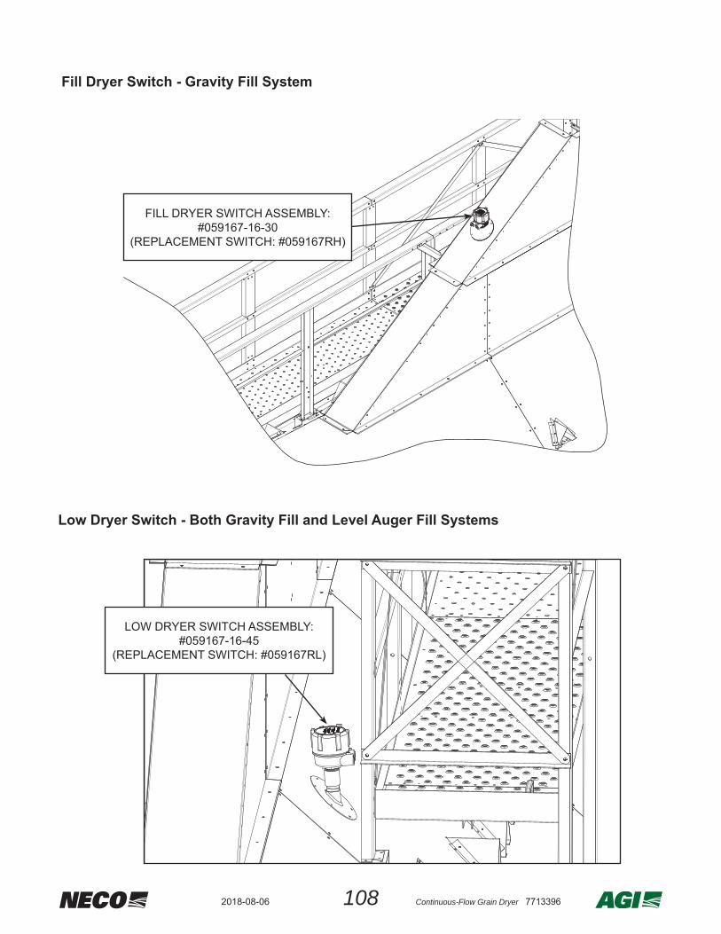
1082018-08-06 Continuous-Flow Grain Dryer 7713396
Low Dryer Switch - Both Gravity Fill and Level Auger Fill Systems
LOW DRYER SWITCH ASSEMBLY:#059167-16-45
(REPLACEMENT SWITCH: #059167RL)
Fill Dryer Switch - Gravity Fill System
FILL DRYER SWITCH ASSEMBLY:#059167-16-30
(REPLACEMENT SWITCH: #059167RH)
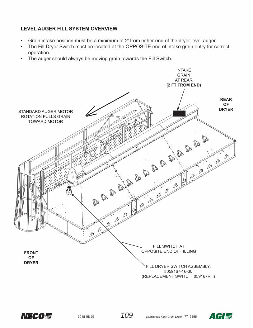
109 Continuous-Flow Grain Dryer 77133962018-08-06
LEVEL AUGER FILL SYSTEM OVERVIEW
• Grain intake position must be a minimum of 2’ from either end of the dryer level auger.• The Fill Dryer Switch must be located at the OPPOSITE end of intake grain entry for correct
operation.• The auger should always be moving grain towards the Fill Switch.
FRONTOF
DRYER
REAROF
DRYER
INTAKEGRAIN
AT REAR(2 FT FROM END)
FILL SWITCH ATOPPOSITE END OF FILLING
STANDARD AUGER MOTOR ROTATION PULLS GRAIN
TOWARD MOTOR
FILL DRYER SWITCH ASSEMBLY:#059167-16-30
(REPLACEMENT SWITCH: 059167RH)

1102018-08-06 Continuous-Flow Grain Dryer 7713396
Connect Fill Switch and Low Switch
• The upper-most dryer section burner box will use the Y-split cables, one cable end marked “Fill” and the other cable mark “Low”. This cable will be in the Dryer Crate.
• Cable length supplied is suffi cient to reach switch locations on all dryer sizes.
• Route the cable above the transition and along the toe board of the catwalk using sticky tabs, till the middle of the dryer. Connect the cable marked “Low” to the low dryer switch and run the cable marked “Fill” to the fi ll dryer switch.
*Cable routes shown of multiple possible switch locations
Gravity Fill Cable Route*
Level Auger Cable Route*

111 Continuous-Flow Grain Dryer 77133962018-08-06
Connect Moisture Sensors
Overview
• The combination sensing unit shown has a moisture sensing “fi n” with the temperature sensing probe directly below it. The moisture sensor provides 0-10V DC signals for both temperature and moisture which the embedded Dryer Master translates into grain moisture and temperature readings.
• A moisture sensor is located at the top of the dryer for reading INLET grain moisture and temperature.
• A outlet moisture sensor is located at the dryer grain discharge chute for reading OUTLET grain moisture and temperature.
MOISTURE FIN TEMPERATURE PROBE 5-PIN MALE CONNECTOR
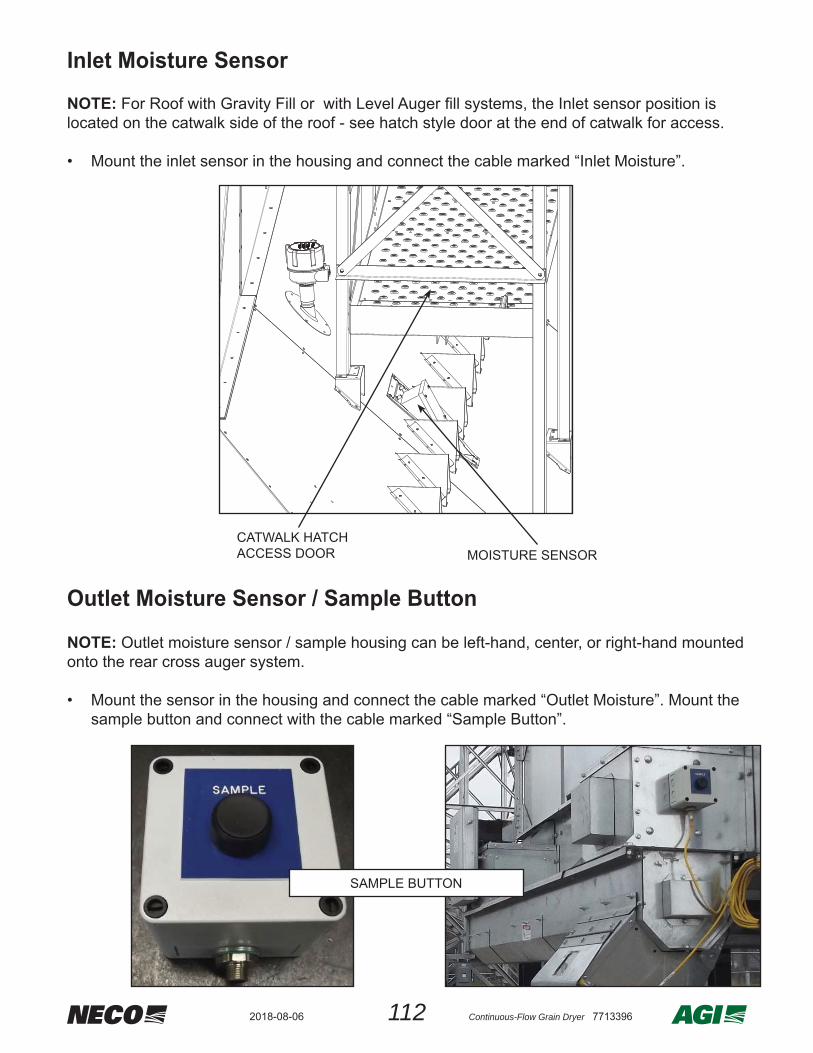
1122018-08-06 Continuous-Flow Grain Dryer 7713396
Outlet Moisture Sensor / Sample Button
Inlet Moisture Sensor
NOTE: For Roof with Gravity Fill or with Level Auger fi ll systems, the Inlet sensor position is located on the catwalk side of the roof - see hatch style door at the end of catwalk for access.
• Mount the inlet sensor in the housing and connect the cable marked “Inlet Moisture”.
CATWALK HATCH ACCESS DOOR MOISTURE SENSOR
NOTE: Outlet moisture sensor / sample housing can be left-hand, center, or right-hand mounted onto the rear cross auger system.
• Mount the sensor in the housing and connect the cable marked “Outlet Moisture”. Mount the sample button and connect with the cable marked “Sample Button”.
SAMPLE BUTTON

113 Continuous-Flow Grain Dryer 77133962018-08-06
COIL UPEXTRA CABLE AND TUCK AND SECURE
UNDER DRYER
Discharge Plugged Sensor
• The discharge plugged sensor(#059118) will activate if the discharge becomes plugged - causing the hinged lid to open and trigger the proximity sensor.
• The sensor must be secured in position to maintain an approximate 1/8” gap between the sensor face and the hinged door face.
Discharge Plugged Sensor #059118
POSITION & SECURE SO THAT THERE IS AN APPROXIMATE 1/8” GAP BETWEEN THE SENSOR FACE AND THE DOOR FACE.

1142018-08-06 Continuous-Flow Grain Dryer 7713396
HMI Wiring Connections
See APPENDIX - HMI Wiring Connections for detailed schematic.
Electrical Wire from Main Control to HMI• Labels are provided - pull the following
wires from the Main Control terminals to the HMI terminals.
Ethernet Cable from Main Control to HMI• Pull Cat 6 shielded Ethernet cable from
the Main Control to the HMI - maximum distance should be less than 300 feet.
• One end will plug into the PLC within the Main Control Box and the other end will plug into the Ethernet Switch within the HMI enclosure.
ETHERNET SWITCH IN HMI CABINET :PLUG ETHERNET IN HERE
PLC UNIT LOCATED IN MAIN CONTROL : PLUG ETHERNET IN HERE
Terminals - inside HMI enclosure
WIRELABEL
WIRECOLOR
E1A BLUEE2 BLUE
E2A BLUE24V BLUE0V WHITE
ATTENTION: The HMI 120V power source needs to be connected to a customer supplied 400 - 600VA battery backup unit.

115 Continuous-Flow Grain Dryer 77133962018-08-06
Liquid Propane (LP)
Final Fuel Supply Hookup
Plumbing assemblies for the liquid propane plumbing are preassembled in sections seperated by pipe unions as described below:
1. Regulator Leg Section - includes Regulator and Pressure Gauge2. Vapor Line Section - includes 3/4” Schedule 80 elbow and pipes3. Vaporizer Section4. Liquid Line Section - includes 1/2” Schedule 80 elbow and pipes5. Inlet Section - includes two 1/2” Solenoid Valves, Two Relief Valves, and “Y” Strainer
Regulator
PressureGauge
RegulatorLeg
3/4" Schedule 80 Pipe(Vapor Line)
#040121 Support Bracket
Vaporizer
1/2" Sch 80 Pipe(Liquid Line)
Solenoid Valves
ReliefValves
Y-Strainer
Inlet Section
Center sections have thru connection with union as shown.The top-most section will be an elbow.
#040120 Support Bar
Liquid propane preassembled assemblies
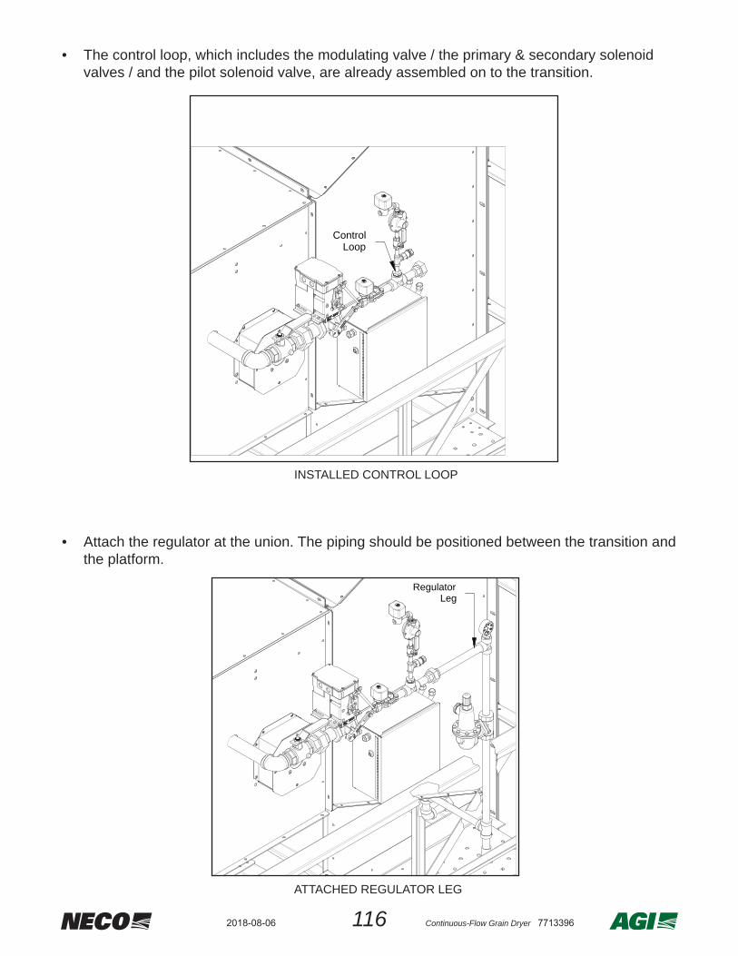
1162018-08-06 Continuous-Flow Grain Dryer 7713396
• The control loop, which includes the modulating valve / the primary & secondary solenoid valves / and the pilot solenoid valve, are already assembled on to the transition.
• Attach the regulator at the union. The piping should be positioned between the transition and
the platform.
ControlLoop
INSTALLED CONTROL LOOP
RegulatorLeg
ATTACHED REGULATOR LEG

117 Continuous-Flow Grain Dryer 77133962018-08-06
• From inside the dryer run the 3/4” vapor line through the top pipe entry hole and connect the union to the regulator leg outside of the dryer.
• Position the #040121 vaporizer tube support bracket so that the union lines up with the 3/4”
vapor line. Using the bracket as a template, drill 5/16” [8mm] holes into the dryer section.• Using 1/4” x 3/4” HB, FW, & WL, bolt the support bracket to the dryer section interior panel.• Clamp the vaporizer to the bracket using the #040120 support bar with 1/4” hardware.• After the vaporizer is mounted, connect the 3/4 vapor line to the vaporizer with the union.
3/4" Vapor Line
Regulator Leg
Connectat union
Top PipeEntry Hole
3/4"VaporLine
OUTSIDE VIEW
INSIDE VIEW
3/4” VAPOR ATTACHED VIEW
040121040120
3/4" Vapor Line
Vaporizer
MOUNT VAPORIZER AND CONNECT 3/4 VAPOR LINE
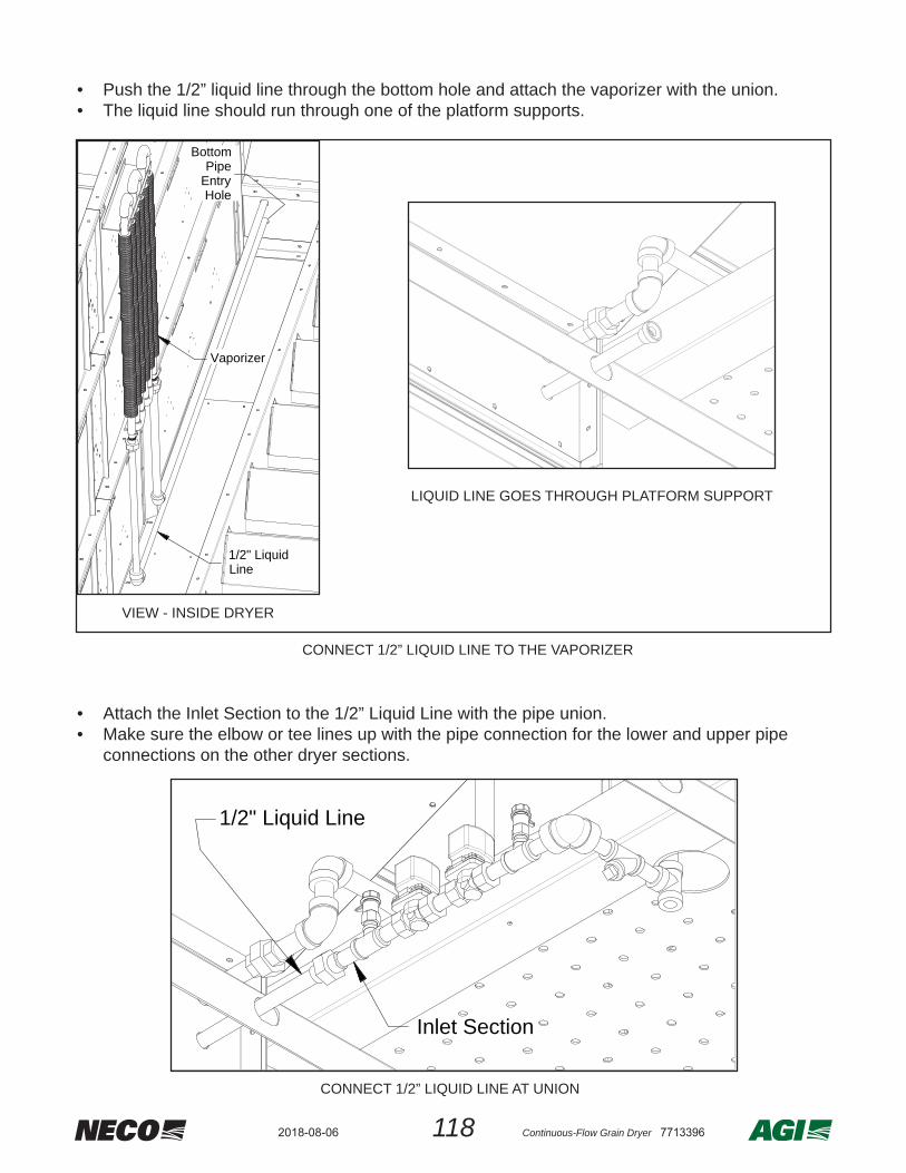
1182018-08-06 Continuous-Flow Grain Dryer 7713396
• Push the 1/2” liquid line through the bottom hole and attach the vaporizer with the union.• The liquid line should run through one of the platform supports.
• Attach the Inlet Section to the 1/2” Liquid Line with the pipe union.• Make sure the elbow or tee lines up with the pipe connection for the lower and upper pipe
connections on the other dryer sections.
CONNECT 1/2” LIQUID LINE TO THE VAPORIZER
Vaporizer
1/2" LiquidLine
BottomPipe
EntryHole
VIEW - INSIDE DRYER
LIQUID LINE GOES THROUGH PLATFORM SUPPORT
1/2" Liquid Line
Inlet Section
CONNECT 1/2” LIQUID LINE AT UNION

119 Continuous-Flow Grain Dryer 77133962018-08-06
• Connect between dryer sections using the 1/2” Schedule 80 pipe provided with the dryer section(s).
1/2" Sch.80 Pipe
LP connection between dryer sections
CONNECT LP FUEL SOURCE
CONNECTLP
FUELSOURCE
• Connect the LP fuel source to the inlet elbow of the lowest dryer section.
NOTE: MIDDLE DRYER SECTIONS WOULD HAVE A “T” UPPER CONNECTION. THE TOP-MOST DRYER SECTION WOULD HAVE AN ELBOW.

1202018-08-06 Continuous-Flow Grain Dryer 7713396
• Connect between dryer sections using the 2” Sch 40 pipe provided with the dryer section.• Connect the NG fuel source to the inlet elbow of the lowest dryer section.
WARNING
After the plumbing is connected, check all connections and pipes for leaks. Because pipe connections can loosen up due to vibrations encountered during shipping, it may be necessary to reseal the pipes.
2" Sch.40 Pipe
NG CONNECTION BETWEEN DRYER SECTIONS & FUEL SOURCE CONNECTION
CONNECTNG
FUELSOURCE
NOTE: MIDDLE DRYER SECTIONS WOULD HAVE A “T” UPPER CONNECTION. THE TOP-MOST DRYER SECTION WOULD HAVE AN ELBOW.
Natural Gas (NG)

121 Continuous-Flow Grain Dryer 77133962018-08-06
NOTE: These OPTIONAL switches are provided and installed by the customer.
• The wet bin empty switch should be placed near the bottom of the wet holding bin. NOTEto dry grain until the dryer goes into a “Low Dryer” alarm status.
• The dry bin full switch should be placed near the top of the dry holding bin.
• Once the switches have been positioned, route the wires to the main control box terminal strip and connect per the electrical schematic below:
DRY BIN FULL
WET BIN EMPTY
Connect wet bin empty & / or dry bin full sensor(s)
Wet Bin Empty and Dry Bin Full Switches
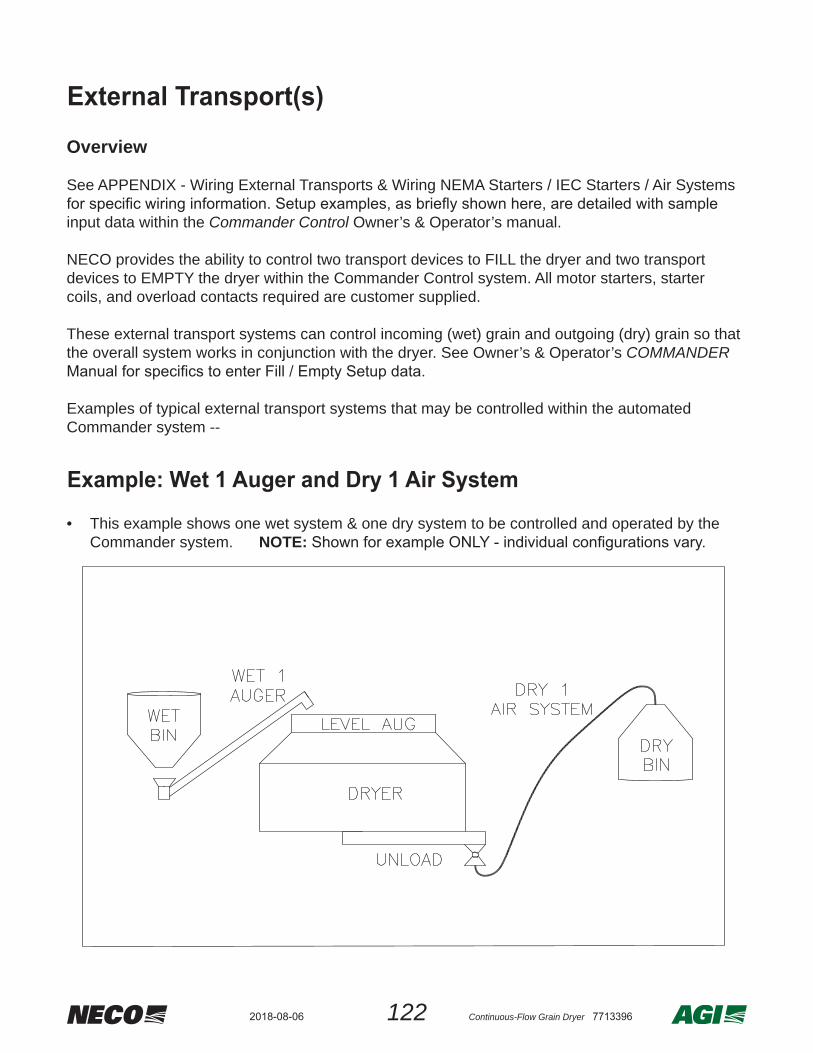
1222018-08-06 Continuous-Flow Grain Dryer 7713396
Overview
See APPENDIX - Wiring External Transports & Wiring NEMA Starters / IEC Starters / Air Systems
input data within the Commander Control Owner’s & Operator’s manual.
NECO provides the ability to control two transport devices to FILL the dryer and two transport devices to EMPTY the dryer within the Commander Control system. All motor starters, starter coils, and overload contacts required are customer supplied.
These external transport systems can control incoming (wet) grain and outgoing (dry) grain so that the overall system works in conjunction with the dryer. See Owner’s & Operator’s COMMANDER
Examples of typical external transport systems that may be controlled within the automated Commander system --
EXAMPLE: Wet 1 Auger & Dry 1 Air System
• This example shows one wet system & one dry system to be controlled and operated by the Commander system. NOTE:
External Transport(s)
Example: Wet 1 Auger and Dry 1 Air System

123 Continuous-Flow Grain Dryer 77133962018-08-06
EXAMPLE: Wet 1 & Wet 2 Augers & Dry 1 Auger
• This example shows two wet systems & one dry system to be controlled and operated by the Commander system. NOTE:
EXAMPLE: Wet 1 & Wet 2 Augers & Dry 1 & Dry 2 Augers
• This example shows two wet systems & one dry system to be controlled and operated by the Commander system. NOTE:
Example: Wet 1 and Wet 2 Augers and Dry 1 Auger
Example: Wet 1 and Wet 2 and Dry 1 and Dry 2 Augers

1242018-08-06 Continuous-Flow Grain Dryer 7713396
OVERVIEW
NOTE: The setup of the Commander Control system is detailed within the Commander Control Owner’s & Operator’s manual.
information includes:
• Language
• The dryer systems measurement units are either set to Imperial or Metric. Imperial units output temperature in Farenheight and volume in bushels. Metric units output temperature in Celcius and volume in cubic meters.
• The type of fuel supplied to the system.
• The dryer systems number of blowers & burners.
• Output gearmotor RPM
• The number of tiers each blower & burner supply.
Commander Control Setup

125 Continuous-Flow Grain Dryer 77133962018-08-06
After Installation, the Fill / Empty Setup and Timers Setup are completed by the customer. This type of information includes:
• If optional sensors are present, such as Wet Bin Empty or Dry Bin Full
• Presense of additional auxiliary equipment, such as Unload Auger System, etc.
• Maximum grain output speed
• Various timers, such as amount of cooling time and metering roll start time, etc.

1262018-08-06 Continuous-Flow Grain Dryer 7713396
AppendixStandard Model Specifi cations• Refer to the following table for specifi cations on standard NECO Dryers - listed per Model Number shown on the rating plate located on the front of the main control.
• If the model number of your particular dryer is not shown below, contact your dealer.
ModelNumber
NumberofTiers
Holding Capacity Number of Burners and Blow-ers
TOTAL Blower Output(Max)
TOTALBurner Output(Max)
Bushels(See Notes)
MetricTonnes
cubic ft / min
cubic m / min
MMBTU /hr kWH
D1660 4 579 15 1 21,500 609 6 1,758D1670 5 674 17 1 23,500 665 6 1,758D1680 6 770 19 1 27,500 778 6 1,758D1690 7 866 22 1 32,000 905 6 1,758D16106 8 962 24 2 36,600 1,035 12 3,517D16120 10 1,155 29 2 47,000 1,330 12 3,517D16140 12 1,347 34 2 55,000 1,556 12 3,517D16160 14 1,539 39 3 65,300 1,847 18 5,275D16180 16 1,731 44 3 78,500 2,221 18 5,275D24108 6 1,155 29 2 41,200 1,165 12 3,517D24150 8 1,443 36 2 55,000 1,556 12 3,517D24180 10 1,732 44 2 62,000 1,754 15 4,396D24210 12 2,020 51 3 82,500 2,334 18 5,275D24240 14 2,309 58 3 89,500 2,532 21 6,154D24260 16 2,597 66 4 110,000 3,113 24 7,034D24330 20 3,174 80 5 137,500 3,891 30 8,792D24380 24 3,750 95 6 165,000 4,669 36 10,551D32260 12 2,693 68 3 108,000 3,056 18 5,275D32340 16 3,463 88 4 144,000 4,075 27 7,913D32440 20 4,232 107 5 182,000 5,150 45 13,188D32500 24 5,001 127 6 216,000 6,112 54 15,826
NOTE:1. Calculations in this table represent data from the U.S. Grain Council website (www.grains.org).2. Holding Capacity values represent corn at 15.5% moisture content (56 lb / bushel).

127 Continuous-Flow Grain Dryer 77133962018-08-06
Main Control Box Terminal StripAfter installation is complete check the motor wires for the correct motor rotation & auger rotation direction.
ATTENTION
DRY BIN FULL
SWITCH
WET BIN EMPTYSWITCH
PLUGGEDDISCHARGE
SWITCH
METERINGROLL
STALL SWITCH
FILLSWITCH
LOWSWITCH
AUXILLARYTRANSPORTRUN RELAY’S
SAMPLESWITCH
120
VAC
24 V
DC
MODBUSCOMMS
E-STOPWIRING
AUX TRANSPORTOVERLOAD & RUN
CONFIRMATION SIGNALS
MOISTURESENSORS
Main Control Box Terminal Strip
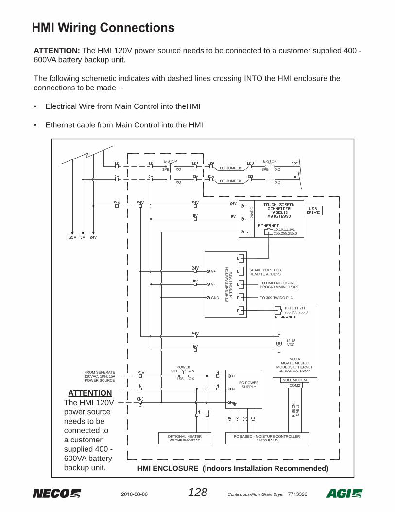
1282018-08-06 Continuous-Flow Grain Dryer 7713396
ATTENTION: The HMI 120V power source needs to be connected to a customer supplied 400 - 600VA battery backup unit.
The following schemetic indicates with dashed lines crossing INTO the HMI enclosure the connections to be made --
• Electrical Wire from Main Control into theHMI
• Ethernet cable from Main Control into the HMI
E-STOP
3PB XO
XO
OG JUMPER
OG JUMPER
E-STOP
1PB XO
XO
POWER
1SS
OFF ON
OX
+
- 24V
DC
SERIAL GATEWAY
PC POWERSUPPLY
PC BASED - MOISTURE CONTROLLER
COM2
19200 BAUD
TO 309 TWIDO PLC
TO HMI ENCLOSURE
SPARE PORT FOR
H
N
V+
V-
GND
NULL MODEM
REMOTE ACCESS
RIB
BON
CA
BLE
PROGRAMMING PORT
OPTIONAL HEATERW/ THERMOSTAT
HMI ENCLOSURE (Indoors Installation Recommended)
FROM SEPERATE
POWER SOURCE120VAC, 1PH, 15A
10.10.11.101255.255.255.0
10.10.11.211255.255.255.0
MODBUS ETHERNETMGATE MB3180
12-48VDC
ETH
ER
NE
T SW
ITC
HN
-TR
ON
105
TX
MOXA
ATTENTIONThe HMI 120V power source needs to be connected to a customer supplied 400 - 600VA battery backup unit.
HMI Wiring Connections

129 Continuous-Flow Grain Dryer 77133962018-08-06
The customer is responsible for wiring any external transport equipment. The following schematics are reference.
Wiring External Transports
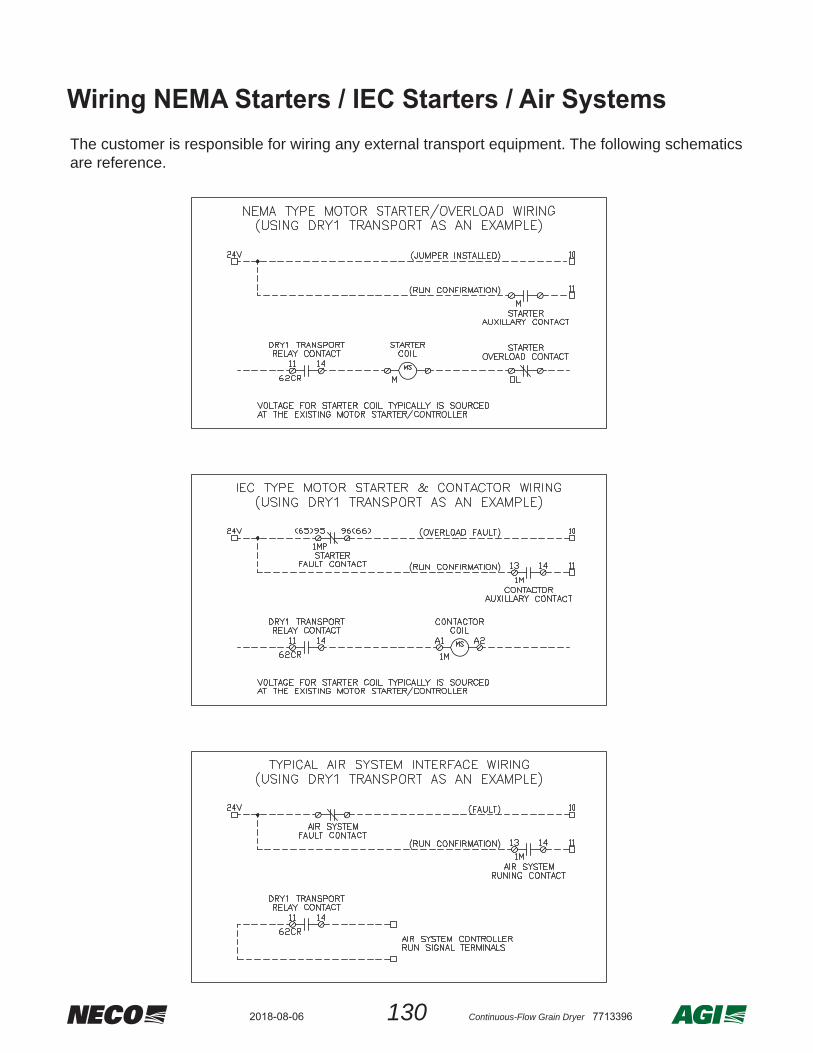
1302018-08-06 Continuous-Flow Grain Dryer 7713396
The customer is responsible for wiring any external transport equipment. The following schematics are reference.
Wiring NEMA Starters / IEC Starters / Air Systems
131 Continuous-Flow Grain Dryer 77133962018-08-06
Recent Signifi cant Manual Changes: 2018-08-06 Rev. 03 Changes
1 Pages 4, 5, 82, and 102. Text corrections were made.
2 Pages 125 and 131. These pages were added.

MANUFACTURED BY NECO
9364 North 45th Street TF 800.367.6208Omaha, Nebraska 68152 P 402.453.6912USA 68152 F 402.453.0471
necodryers.com
aggrowth.com© 2017 Ag Growth International. All rights reserved8