Chassis Torsional Rigidity Analysis for a Formula SAE ...
10
Chassis Torsional Rigidity Analysis for a Formula SAE Racecar Hubbard D. Velie Dept. of Mechanical Engineering, University of Michigan, Ann Arbor, MI Abstract While the general effects of chassis torsional rigidity on vehicle handling and performance are known, exact guidelines to determine the appropriate chassis stiffness for a given vehicle is not known. This project investigates the effects of chassis torsional rigidity on vehicle handling and performance for The University of Michigan’s Formula SAE racecar with the goal of determining a chassis stiffness design target. Investigations include open loop simulation of steady state cornering and speed trace simulation of transient cornering events using VI-Grade CarRealTime. Simulation outputs including tire forces, vehicle path, and driver inputs are used to determine the limits of acceptable stiffness values. In conclusion a theoretical design target for chassis torsional rigidity is determined that is designable, while taking into account that the design must be buildable and FSAE rules compliant to be used in future Formula SAE racecars. The method with which the value is determined is presented in a way that is reproducible, should the vehicle characteristic change in the future and warrant re-investigation of these effects by future team members. Introduction Formula SAE is an international collegiate student design competition focused around the design, manufacturing, testing, and racing of an open-wheel racecar. MRacing, the Formula SAE team at The University of Michigan, Ann Arbor, designs and builds a new car every year. With the design of each new car comes the design of a new chassis. While much of chassis geometry and material choice is dictated by the competition rules, it is possible to build vehicles with a very large range of chassis stiffnesses. Part of each chassis design cycle is the determining of a chassis stiffness target for that vehicle. The purpose of this report is to summarize analysis done during the 2016 design cycle to determine an optimal chassis torsional stiffness design target for future MRacing Formula SAE vehicles. Literature Review Studies have been carried out to investigate the effects that the torsional stiffness (resistance to distortion about the longitudinal axis) of a vehicle chassis has on the handling and performance of the vehicle. Although physical testing has shown that vehicles with higher stiffnesses perform better, the exact effects that torsional stiffness has on performance is not entirely known [3]. CAE simulations on the other hand have shown torsional stiffness to not affect the lateral acceleration, yaw rate, or other critical characteristics, during steady state turns [2][3]. The biggest effect of torsional deflection has been found to be the effect it has on lateral load transfer distribution between the front and rear axle [3]. During a steady state turn an infinitely rigid chassis will cause the front and rear roll angle to be identical, as is assumed when suspension
-
Upload
khangminh22 -
Category
Documents
-
view
5 -
download
0
Transcript of Chassis Torsional Rigidity Analysis for a Formula SAE ...

Chassis Torsional Rigidity Analysis
for a Formula SAE Racecar
Hubbard D. Velie
Dept. of Mechanical Engineering, University of Michigan, Ann Arbor, MI
Abstract While the general effects of chassis torsional rigidity on vehicle handling and performance are
known, exact guidelines to determine the appropriate chassis stiffness for a given vehicle is not
known. This project investigates the effects of chassis torsional rigidity on vehicle handling and
performance for The University of Michigan’s Formula SAE racecar with the goal of
determining a chassis stiffness design target. Investigations include open loop simulation of
steady state cornering and speed trace simulation of transient cornering events using VI-Grade
CarRealTime. Simulation outputs including tire forces, vehicle path, and driver inputs are used to
determine the limits of acceptable stiffness values. In conclusion a theoretical design target for
chassis torsional rigidity is determined that is designable, while taking into account that the
design must be buildable and FSAE rules compliant to be used in future Formula SAE racecars.
The method with which the value is determined is presented in a way that is reproducible, should
the vehicle characteristic change in the future and warrant re-investigation of these effects by
future team members.
Introduction Formula SAE is an international collegiate student design competition focused around the
design, manufacturing, testing, and racing of an open-wheel racecar. MRacing, the Formula SAE
team at The University of Michigan, Ann Arbor, designs and builds a new car every year. With
the design of each new car comes the design of a new chassis. While much of chassis geometry
and material choice is dictated by the competition rules, it is possible to build vehicles with a
very large range of chassis stiffnesses. Part of each chassis design cycle is the determining of a
chassis stiffness target for that vehicle. The purpose of this report is to summarize analysis done
during the 2016 design cycle to determine an optimal chassis torsional stiffness design target for
future MRacing Formula SAE vehicles.
Literature Review
Studies have been carried out to investigate the effects that the torsional stiffness (resistance to
distortion about the longitudinal axis) of a vehicle chassis has on the handling and performance
of the vehicle. Although physical testing has shown that vehicles with higher stiffnesses perform
better, the exact effects that torsional stiffness has on performance is not entirely known [3].
CAE simulations on the other hand have shown torsional stiffness to not affect the lateral
acceleration, yaw rate, or other critical characteristics, during steady state turns [2][3]. The
biggest effect of torsional deflection has been found to be the effect it has on lateral load transfer
distribution between the front and rear axle [3]. During a steady state turn an infinitely rigid
chassis will cause the front and rear roll angle to be identical, as is assumed when suspension

design calculations are performed. Allowing for twist in the chassis will redistribute some
amount of weight transfer between the front and rear tires, causing these values to deviate from
their designed values [1]. Because of these effects, the vehicle will handle more predictably if the
chassis is stiff enough, relative to the suspension roll stiffness, that the twist can be ignored [1].
To achieve this goal, most racecars design to be 3-5 times as stiff as suspension roll stiffness,
while passenger cars design to be 7-40 times as stiff [3]. It can be seen by this extreme range of
values, that no consensus has been made as to the appropriate value for chassis torsional
stiffness. Finding a standard value against which a chassis can be compared would be helpful in
the design of vehicles, but as of current, no standard criterion exists [2].
As well as the effects above, twist in the chassis has also been theorized to have negative effects
on the fatigue of the vehicle, suspension characteristic changes caused by relative hard point
displacement, and transient response time of the vehicle as a whole to driver inputs [1][2][3]. All
of these effects can be easily mitigated by increasing the stiffness of the vehicle, but this has the
direct response of increasing vehicle weight. For this reason it is desired to find the lowest value
of torsional stiffness that will not decrease the performance of the car.
Previous Work
Over the past 30 years, MRacing has taken different approaches to determining the ideal chassis
torsional rigidity value for the vehicle. The team has settled on a general rule of thumb of
designing the frame, the easiest part of the chassis to modify the stiffness of, to be 10 times the
total suspension roll stiffness. It has been assumed that this approach has worked, as past cars
designed by this rule have performed exceedingly well at competition compared to other FSAE
vehicles during the dynamic events. Along with good vehicle performance, the current
generation of MRacing drivers has never indicated that the chassis feels “loose” or is reacting
unpredictably to driver inputs, one of the key signs that a chassis is not stiff enough. Using this
design method, the 2015 vehicle was designed to have a chassis stiffness of 2100 Nm/deg.
Previously, closed loop full vehicle simulations have been used to try and identify an ideal
chassis stiffness target. These simulations have proven unsuccessful, in response the team
requested a new simulation methodology to answer this question. The origin of the motivation
for this investigation is in the desire to find a simulation method that is successful in providing
usable results.
In past design cycles physical testing has been done in an
attempt to determine the total chassis torsional stiffness. This
testing, as shown in Figure 1, involved constraining the rear
spindles, and applying a moment about the front spindles while
measuring deflections. During these tests the springs were
replaced with solid links to remove the effect of suspension roll
stiffness on the measurement of chassis stiffness.
Figure 1: Chassis stiffness
physical test setup

Methods In order to determine the effects of chassis torsional stiffness on vehicle performance and
handling, full vehicle simulations were used to simulate steady state and transient cornering
events. The tire forces and driver inputs were used as outputs from the model to measure the
effects of various chassis stiffnesses. A comparison was done as these output values deviated
from the values for an ideal car with no chassis twist. Finally, these deviations were measured
and a safety factor for manufacturing error was applied to determine a final ideal design target
for chassis torsional rigidity for the MRacing Formula SAE vehicle.
The method for finding an ideal stiffness focused around finding the least stiff the chassis could
be before major performance or handling losses would arise. This method was chosen because
stiffness is so closely related to vehicle weight, and for a Formula SAE vehicle, weight is the
most sensitive parameter on the car. Thus the lower the stiffness can be made, the lower the
vehicle weight will be, which is known to significantly increase vehicle performance.
Simulation Model
All of the full vehicle dynamic simulations run for this analysis were done using VI-Grade’s VI-
CarRealTime (VICRT). VICRT is a full vehicle real time simulation software that takes in
various input parameters about a car and can simulate the performance of the car in both open
loop tests, and closed loop tests with a computer driver. The model of our vehicle in this
software has been developed by the MRacing team over the past few years. The model includes
weights and inertias, suspension geometries, tire models, aerodynamic models, engine power and
torque models, and transmission models. The software includes the ability to include chassis
torsional stiffness as a variable, or it can run the simulations with an infinite stiffness
assumption.
Steady State Turns
Torsional stiffness comes into play in vehicle dynamics as the vehicle experiences cornering
events. For this reason the first step in understanding the effects of chassis stiffness was to
simulate vehicles of varying stiffnesses in steady state cornering events. As the vehicle goes
around a turn weight transfer occurs from the inside tires to the outside tires. For a corner of
constant radius being taken at constant speed, the amount of weight transfer is given by Equation
1, where ∆𝑊 is the weight transfer due to corner, W is the weight of the vehicle, 𝐴𝑦 is the lateral
acceleration of the vehicle, h is the height of the center of gravity, and t is the track width [1].
∆𝑊 =𝑊 × 𝐴𝑦 × ℎ
𝑡⁄ (Eq. 1)
As can be determined by this equation, the total amount of weight transfer for a given vehicle of
a set geometry cannot be changed. For our vehicle, this weight transfer is not evenly distributed
between the front and rear tires. This uneven distribution of weight transfer is referred to as the
total lateral load transfer distribution.

The total lateral load transfer distribution, or the amount of weight transfer handled by each tire,
can be changed by changing or “tuning” the relative roll stiffnesses of the front and rear of the
vehicle. As the weight transfer on the rear or front tires increases, the magnitude of the normal
force measured at that tire will increase as well. If this increase in normal force occurs on the
front tires, the tires will have a decrease in mechanical grip, leading to an increase in the
understeer of the vehicle. This means that for a given steering angle and speed, the vehicle with
more weight transfer handled by the front wheels will take a path with a larger radius.
This difference in weight transfer between the front and rear tires creates a moment along the
longitudinal axis of the car. It is assumed when determining vehicle dynamics characteristics that
the chassis does not react to this moment. In reality, even the stiffest chassis will react slightly to
this moment, wanting to twist about its longitudinal axis. By simulating steady-state cornering
events and allowing for twist in the chassis the effect of this twist can be determined.
For these simulations corners of three different steer angles and three different speeds were
chosen to replicate corners likely to be seen on track. The vehicle was programmed to start at a
speed of 15, 20, and 25 m/s. The vehicle was then told to ramp the steer angle from 0 to 30, 20,
and 10 degrees respectively, over the course of 1 second. The vehicle then held this steer angle
for the remaining 10 seconds of the simulation. These three turns, referred to as tight, mid, and
wide, respectively, were repeated for vehicles of various chassis stiffnesses. The normal forces
from all four tires was then extracted from the simulation.
After analyzing these initial results, it was apparent more simulations were required to analyze
the effect of changing roll rates. For these simulations the same three tracks were used as defined
by the same three vehicle speeds and steer angles as before. In this set of simulations, a baseline
was run with the car having the baseline 2100 Nm/deg torsional stiffness. Then the vehicle was
modified to have a 210 Nm/deg stiffness to represent the extreme of a loose chassis. The effect
that the roll rates of the front and rear suspension have on the vehicle was then investigated by
decreasing the front, and increasing the rear, spring rates by the same amount over a range of
magnitudes. As was done previously, the tire forces were extracted from these simulations to be
analyzed.
Transient Turns
As the car never actually reaches a steady state on track, the next step in the investigation was to
analyze how the vehicle performs during the transient period when entering and exiting a turn.
To view the behavior of the car in a transient situation, a simulation method referred to as “speed
trace” was used to incorporate aspects of both closed loop and open loop testing.
To create the speed trace, first a baseline car is simulated around a J-turn. For this model, the
baseline car was the standard MRacing vehicle setup, but with chassis twist ignored by the
simulation software. The model then implements a closed-loop computer driver to take the
baseline vehicle around the specified turn as fast as the computer determines is possible. For

these simulations, once again a tight, mid, and wide, set of J-turns was used. These turns
simulate turns likely to be seen on track. Once the vehicle had completed the closed loop run the
position and velocity vectors of the baseline lap are extracted. These positions and velocities are
used to form the new input for the other models. As the car is modified from its baseline set up,
each modified car is instructed to attempt to drive the same path with the same velocities as the
baseline model. As the car attempts to drive the same path, the driver inputs required by the
simulated car are extracted from the simulation. By using the required driver inputs as the
simulation output, vehicle performance is measured by evaluating which car is easier to drive.
By using the speed trace method all the vehicles should have nearly identical lap times and
accelerations, but they will all require a different set of driver inputs to perform in the same
manner. The vehicle that responds best to the simplest set of driver inputs will be inherently
better as it will be easier to drive at the vehicle’s limit and will respond more predictably to
driver inputs.
Results
Steady State Turns
A plot of the normal forces on the outside tires for the various simulated vehicles is shown in
Figure 2. The mid corner was omitted in the graphs for simplicity, as it followed an identical
trend as the more extreme tight and wide turns.
Figure 2: Front and rear outside tire normal forces for tight and wide turn at various stiffnesses
where Actual stiffness refers to 2100 Nm/deg.
As can be seen in Figure 2, the tire forces in the front increase and the tire forces in the rear
decrease, as the chassis becomes less stiff. This effect can be explained by the way the chassis
reacts to the moment created by the distribution of weight transfer. As a moment is created along
the longitudinal axis of the car, the chassis begins to twist, this allows for weight transfer to
move from the side of the car handling more, to the side of the car handling less. In the case of
the MRacing vehicle, this means as the chassis twists more, weight transfer should be moved

from the rear to front, increasing the front tire normal forces as is seen in the simulation. This
increased load on the front tires increases the understeer gradient and causes the vehicle to take a
wider turn for the same given driver inputs.
The initial steady state simulations show the vehicle to only be affected by chassis stiffness
because of the way chassis stiffness changes the distribution of weight transfer between the front
and rear. If this is true, the effects on the vehicle due to a loose chassis should be reversible, by
accounting for the chassis twist. If the front roll stiffness is decreased, and the rear is increased,
the vehicle will have a larger difference in the front and rear total lateral load transfer than
before. With the assumption that the chassis can’t twist, this would mean the vehicle would have
different tire loads in the same steady state turns, as the baseline vehicle. But if chassis twist is
taken into account, the redistribution of weight transfer from the rear to the front, as the chassis
twists, will bring the car back closer to its baseline behavior. To test this effect, the vehicle was
simulated once again given the same inputs. A baseline vehicle was set with our 2015 design
target chassis stiffness of 2100 Nm/deg. The stiffness was then decreased by an order of
magnitude and the test was run again. Finally this loose chassis was run with varying spring rates
in the front and rear. The plot of the front outside tire normal forces for these simulations can be
seen in Figure 3.
Figure 3: Front outside tire normal forces for chassis of various chassis torsional stiffnesses and
of various suspension spring rates. Where Delta # refers to a # lb/in spring rate decrease in the
front springs and # lb/in increase in the rear springs.

As can be seen in Figure 3, by increasing the difference in roll rates between the front and rear,
steady-state vehicle behavior of the actual and loose chassis can be made identical. This means
that for steady state events chassis stiffness is inconsequential, as the looseness in the chassis can
be tuned-out my modifying front and rear roll rates.
Transient Turns
A plot of the steering angle against time for the various simulated vehicles is shown in Figure 4.
The tight and mid J-turn was omitted in the graphs for simplicity, as they follow an identical
trend as the more extreme wide J-turn.
Figure 4: Steering angle is shown against time for the wide J-turn event for vehicles of varying
chassis torsional stiffnesses.
As can be seen in Figure 4, the magnitude of the steering events increases as the chassis becomes
less stiff. Along with magnitude change, the input maneuvers have a phase sift and become more
delayed as the chassis becomes less stiff. These same trends hold for throttle control and brake
control, but are easiest to see by analyzing steering angle.
These steering angle magnitude increases and phase shifts indicate that the car will become more
difficult to drive as the chassis becomes less stiff. If the magnitudes of the first steering angle
peak are plotted against chassis stiffness a clear exponential decay trend appears, as can be seen
in Figure 5.

Figure 5: Maximum steering angle in the wide J-turn event against chassis torsional stiffness
A trend of this form holds true for the other features of the inputs as well, but can be best seen
with this example. As shown in the graph, a theoretical ideal value is approached as the
simulation ignores chassis twist all together. As the vehicle deviates from that ideal value it
becomes harder to drive. As can be seen by the phase shift as the chassis acts more like a spring,
the vehicle has a delayed reaction to the driver inputs, and the driver must increase the
magnitude of the inputs to compensate. On track this would directly correlate to a car that is
much harder to drive and control. For this reason, some deviation from this ideal value is
acceptable, but not too much as to allow the chassis twist to have a major, or driver noticeable,
influence on the vehicle behavior. A reasonable cut off point is that where the trend begins to
have major deviations from its linearity and begins to exponentially grow as the chassis loosens.
This transition is seen around the 10% deviation mark from the ideal value. At this point,
increased chassis stiffness enters a zone of diminishing returns, and decreased chassis stiffness
begins to enter a zone of non-linear behavior. This puts the allowable chassis stiffness at
approximately 1550 Nm/deg.
Discussion Along with the results from the vehicle simulation, other factors of the design of a Formula SAE
vehicle must be taken into account. Competition rules are a major driving factor behind the final
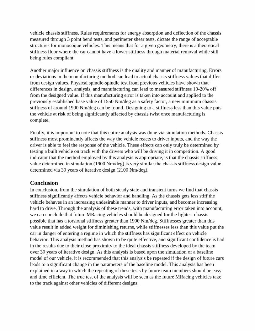
vehicle chassis stiffness. Rules requirements for energy absorption and deflection of the chassis
measured through 3 point bend tests, and perimeter shear tests, dictate the range of acceptable
structures for monocoque vehicles. This means that for a given geometry, there is a theoretical
stiffness floor where the car cannot have a lower stiffness through material removal while still
being rules compliant.
Another major influence on chassis stiffness is the quality and manner of manufacturing. Errors
or deviations in the manufacturing method can lead to actual chassis stiffness values that differ
from design values. Physical spindle-spindle test from previous vehicles have shown that
differences in design, analysis, and manufacturing can lead to measured stiffness 10-20% off
from the designed value. If this manufacturing error is taken into account and applied to the
previously established base value of 1550 Nm/deg as a safety factor, a new minimum chassis
stiffness of around 1900 Nm/deg can be found. Designing to a stiffness less than this value puts
the vehicle at risk of being significantly affected by chassis twist once manufacturing is
complete.
Finally, it is important to note that this entire analysis was done via simulation methods. Chassis
stiffness most prominently affects the way the vehicle reacts to driver inputs, and the way the
driver is able to feel the response of the vehicle. These effects can only truly be determined by
testing a built vehicle on track with the drivers who will be driving it in competition. A good
indicator that the method employed by this analysis is appropriate, is that the chassis stiffness
value determined in simulation (1900 Nm/deg) is very similar the chassis stiffness design value
determined via 30 years of iterative design (2100 Nm/deg).
Conclusion In conclusion, from the simulation of both steady state and transient turns we find that chassis
stiffness significantly affects vehicle behavior and handling. As the chassis gets less stiff the
vehicle behaves in an increasing undesirable manner to driver inputs, and becomes increasing
hard to drive. Through the analysis of these trends, with manufacturing error taken into account,
we can conclude that future MRacing vehicles should be designed for the lightest chassis
possible that has a torsional stiffness greater than 1900 Nm/deg. Stiffnesses greater than this
value result in added weight for diminishing returns, while stiffnesses less than this value put the
car in danger of entering a regime in which the stiffness has significant effect on vehicle
behavior. This analysis method has shown to be quite effective, and significant confidence is had
in the results due to their close proximity to the ideal chassis stiffness developed by the team
over 30 years of iterative design. As this analysis is based upon the simulation of a baseline
model of our vehicle, it is recommended that this analysis be repeated if the design of future cars
leads to a significant change in the parameters of the baseline model. This analysis has been
explained in a way in which the repeating of these tests by future team members should be easy
and time efficient. The true test of the analysis will be seen as the future MRacing vehicles take
to the track against other vehicles of different designs.

References
[1] Race Car Vehicle Dynamics, Milliken, F.
[2] Research of chassis torsional stiffness on vehicle handling performance, Pang, Shu-yi
[3] Influence of Body Stiffness on Vehicle Dynamics Characteristics in Passenger Cars, Danielsson,
Oskar