Postdoctoral Researcher Conference (EPS & LES) - University ...

1 LTE / EPS / SAE Fundamentals
LTE / EPS / SAE
Fundamentals
Centro de Aprendizaje y Desarrollo
Instructor: Julio César López Barragán

2 LTE / EPS / SAE Fundamentals
Índice
Standars, Protocols and Interfaces •LTE RAN Architecture
•Network Elements and Functions
•Interfaces and References Points
Introduction to Diameter •Introduction
•AAA and Diameter
•Diameter nodes and agents
•Diameter messages
•Connection and session
DSR Diameter •Nodes
•Functions
•Routing and Load Balancing
•DSR KPI Summary
Introduction •Mobile Networks Evolution.
•Release 99, R4, R5 y R6.
•Mobile System before LTE 01
UMTS Overview •Network Architecture
•GSM
•UMTS
3G Evolution to 4G •Release 8, R9, R10.
•System Architecture.,
•Core Network
03
05
02
04
06

3 LTE / EPS / SAE Fundamentals
01 Introduction

4 LTE / EPS / SAE Fundamentals
Negocios
01 Introduction
Introduction
Mobile communication technologies are often divided into generations, with 1G being the analog mobile radio systems of the 1980s, 2G the first digital mobile systems, and 3G the first mobile systems handling broadband data. The Long-Term Evolution (LTE) is often called “4G”, but many also claim that LTE release 10, also referred to as LTE-Advanced, is the true 4G evolution step, with the first release of LTE (release 8) then being labeled as “3.9G”. This continuing race of increasing sequence numbers of mobile system generations is in fact just a matter of labels. What is important is the actual system capabilities and how they have evolved. The work on developing LTE and LTE-Advanced is performed as a continuing task within 3GPP, the same forum that developed the first 3G system (WCDMA/HSPA).

5 LTE / EPS / SAE Fundamentals
Negocios
01 Introduction
EVOLUTION OF MOBILE SYSTEMS BEFORE LTE
6 LTE / EPS / SAE Fundamentals
Negocios
01 Introduction
Drivers for LTE
• The evolution of 3G systems into 4G is driven by the creation and development of new services for mobile devices.
• Evolution of processor performance and increased memory size • Combined with a high-speed internet backbone often based on
optical fiber networks. • The natural next step was that those internet-based services also
moved to the mobile devices. • Being able to support the same Internet Protocol (IP)-based
services.
7 LTE / EPS / SAE Fundamentals
Negocios
01 Introduction
Drivers for LTE
• A few services were already supported by the evolved 2.5G systems. • An interesting aspect of the migration of broadband services to mobile
devices is that a mobile “flavor” is also added. • The first data services over GSM were circuit switched, with packet-based
GPRS coming in as a later addition. • This also influenced the first development of 3G. • It was not until the 3G evolution into HSPA and later LTE/LTE-Advanced that
packet-switched services and IP were made the primary design target. • The old circuit-switched services remain, but will on LTE be provided over
IP, with Voice-over IP (VoIP) as an example.
8 LTE / EPS / SAE Fundamentals
Negocios
01 Introduction
IP Requirements
• Data rate. The ever increasing demand for higher data rates for web browsing, streaming and file transfer pushes the peak data rates for mobile systems from kbit/s for 2G, to Mbit/s for 3G and getting close to Gbit/s for 4G.
• Delay. The delay for a packet sent from a server to a client and back is
called latency. • Capacity. From the mobile system operator’s point of view, it is not only
the peak data rates provided to the end-user that are of importance, but also the total data rate that can be provided on average from each deployed base station site and per hertz of licensed spectrum.

9 LTE / EPS / SAE Fundamentals
02 Standards, Protocols,
and Functions

10 LTE / EPS / SAE Fundamentals
Negocios
02 Standards, Protocols, and Functions
Network Elements and Functions
11 LTE / EPS / SAE Fundamentals
Negocios
02 Standards, Protocols, and Functions
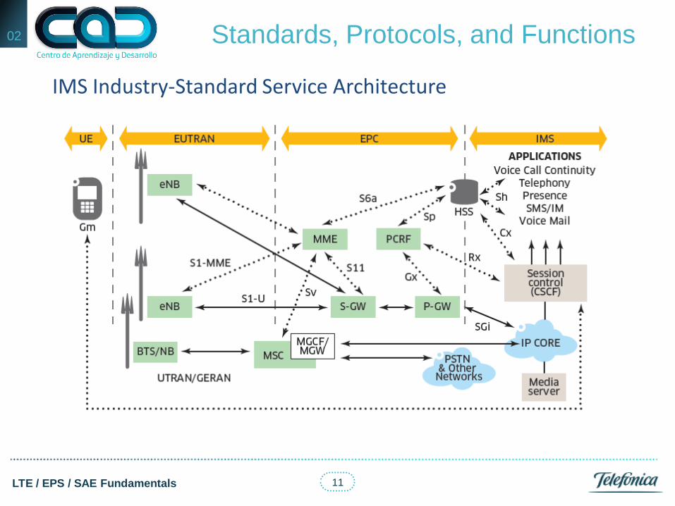
IMS Industry-Standard Service Architecture

12 LTE / EPS / SAE Fundamentals
Negocios
02 Standards, Protocols, and Functions
Circuit Switched Fall Back (CSFB)

13 LTE / EPS / SAE Fundamentals
Negocios
02 Standards, Protocols, and Functions
LTE Basic Nodes and Interfaces

14 LTE / EPS / SAE Fundamentals
Negocios
02 Standards, Protocols, and Functions
Bearer Architecture
15 LTE / EPS / SAE Fundamentals
Negocios
02 Standards, Protocols, and Functions
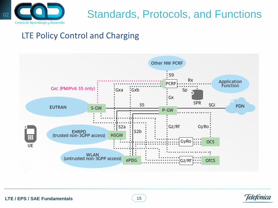
LTE Policy Control and Charging

16 LTE / EPS / SAE Fundamentals
Negocios
02 Standards, Protocols, and Functions
LTE With Legacy 3GPP Interworking (Pre-Release 8)

17 LTE / EPS / SAE Fundamentals
Negocios
02 Standards, Protocols, and Functions
LTE With Legacy 3GPP Interworking (Release 8)

18 LTE / EPS / SAE Fundamentals
Negocios
02 Standards, Protocols, and Functions
LTE With non 3GPP Interworking (Release 8)

19 LTE / EPS / SAE Fundamentals
Negocios
02 Standards, Protocols, and Functions
LTE Security

20 LTE / EPS / SAE Fundamentals
Negocios
02 Standards, Protocols, and Functions
Interfaces, Purposes and References of the Protocols

21 LTE / EPS / SAE Fundamentals
03 UMTS Overview

22 LTE / EPS / SAE Fundamentals
Negocios
03 UMTS Overview
Network Architecture
UMTS maintains a strict separation between the radio subsystem and the network subsystem, allowing the network subsystem to be used with other RATs. (Radio Access Technology). The CN is adopted from GSM and consists of two user traffic-dependent domains and several commonly used entities. Traffic dependent domains correspond to the GSM or GPRS CNs and handle:
• Circuit-Switched-type traffic in the CS domain. • Packet-Switched-type traffic in the PS domain.
Both traffic-dependent domains use the functions of the remaining entities – the Home Location Register (HLR) together with the Authentication Center (AuC), or the Equipment Identity Register (EIR) – for subscriber management, mobile station roaming and identification, and handling different services.

23 LTE / EPS / SAE Fundamentals
Negocios
03 UMTS Overview
Network Architecture
• Thus the HLR contains GSM, GPRS, and UMTS subscriber information.
• Two domains handle their traffic types at the same time for both the GSM and the UMTS access networks.
• The CS domain handles all circuit-switched traffic for the GSM as well as for the UMTS access network; similarly, the PS domain takes care of all packet-switched traffic for both the access networks
24 LTE / EPS / SAE Fundamentals
Negocios
03 UMTS Overview
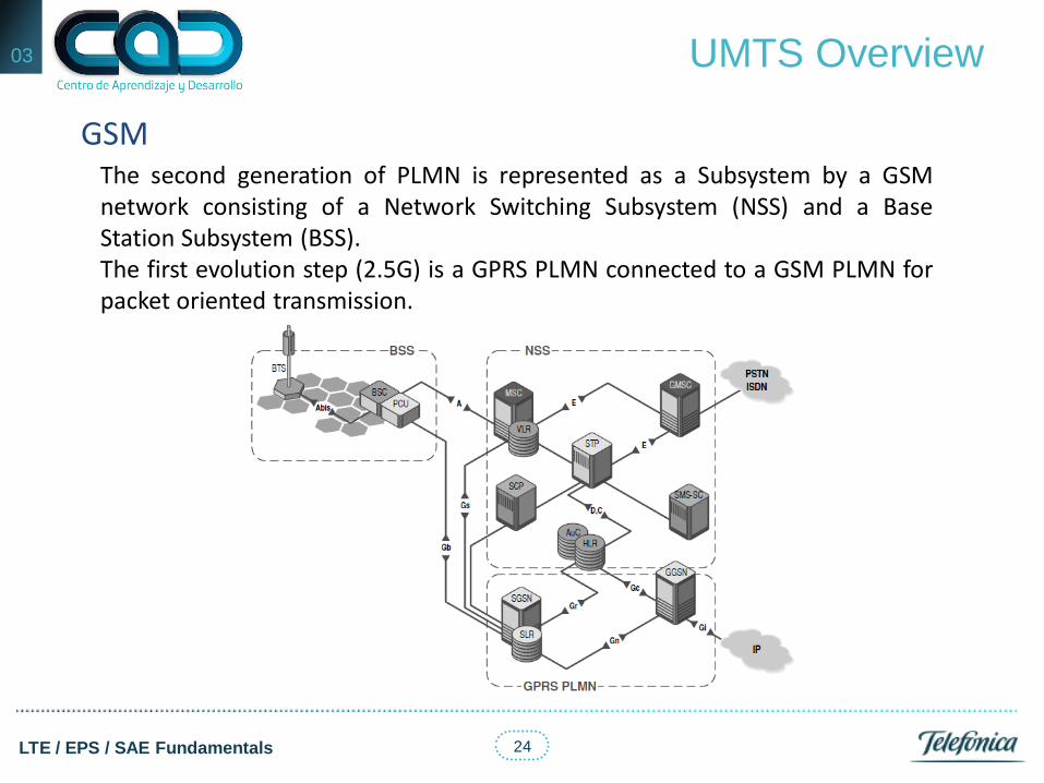
GSM The second generation of PLMN is represented as a Subsystem by a GSM network consisting of a Network Switching Subsystem (NSS) and a Base Station Subsystem (BSS). The first evolution step (2.5G) is a GPRS PLMN connected to a GSM PLMN for packet oriented transmission.
25 LTE / EPS / SAE Fundamentals
Negocios
03 UMTS Overview
GSM
• The main element in the NSS is the Mobile Switching Center (MSC), which contains the Visitor Location Register (VLR).
• The MSC represents the edge toward the BSS and on the other side as the Gateway MSC (GMSC).
• GSM is a circuit-switched network, which means that there are two different types of physical links to transport control information (signaling) and traffic data (circuit).
• The signaling links are connected to Signaling Transfer Points (STP) for centralized routing whereas circuits are connected to special switching equipment.
• The most important entity in the BSS is the Base Station Controller (BSC), which, along with the Packet Control Unit (PCU), serves as the interface with the GPRS PLMN.
• Several Base Transceiver Stations (BTS) can be connected to the BSC.

26 LTE / EPS / SAE Fundamentals
Negocios
03 UMTS Overview
GSM
27 LTE / EPS / SAE Fundamentals
Negocios
03 UMTS Overview
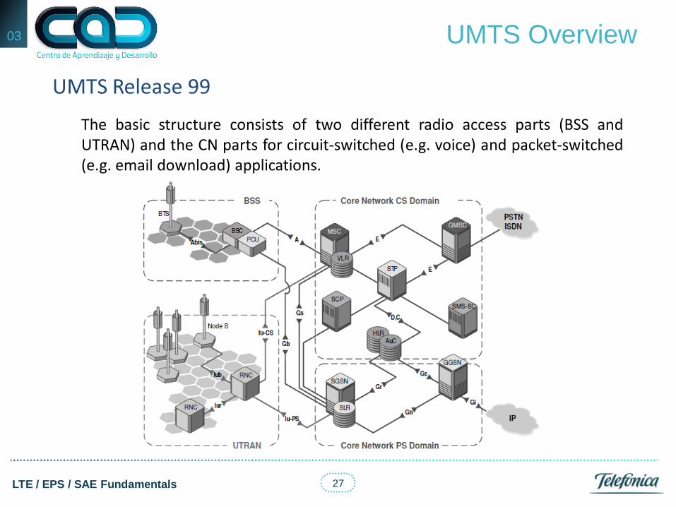
UMTS Release 99
The basic structure consists of two different radio access parts (BSS and UTRAN) and the CN parts for circuit-switched (e.g. voice) and packet-switched (e.g. email download) applications.

28 LTE / EPS / SAE Fundamentals
Negocios
03 UMTS Overview
UMTS Release 99
• To implement UMTS means to set up a UTRAN, which is connected to a circuit-switched CN (GSM with MSC/VLR) and to a packet-switched CN (GPRS with SGSN).
• The interfaces are named Iu, where IuCS goes to the MSC and IuPS goes to the SGSN.
• Alternatively, the circuit and packet network connections could also be realized with a UMSC (UMTS MSC), which combines MSC and SGSN functionalities in one network element.
• The corresponding edge within UTRAN is the Radio Network Controller (RNC). Other than in the BSS the RNCs of one UTRAN are connected with each other via the Iur interface.
• The base stations in UMTS are called Node B, which is just its working name and has no other meaning.
• The interface between Node B and RNC is the Iub interface.

29 LTE / EPS / SAE Fundamentals
Negocios
03 UMTS Overview
UMTS Release 4
30 LTE / EPS / SAE Fundamentals
Negocios
03 UMTS Overview
UMTS Release 4
• 3GPP Release 4 introduces some major changes and new features in the CN domains and the GERAN (GPRS/EDGE Radio Access Network), which replaces GSM BSS.
• Some of the major changes are: • Separation of transport bearer and bearer control in the CS CN. • Introduction of new interfaces in the CS CN. • ATM(Asynchronous Transfer Mode; AAL2, ATM Adaptation Layer Type
2) or IP (Internet Protocol) can now be used as the data transport bearer in the CS domain.
• Introduction of low chip rate (also called narrowband) TDD (Time Division Duplex) describes the RAT behind the Chinese TD-SCDMA standard while UMTS TDD (wideband TDD, TD-CDMA) is seen as the dominating TDD technology in European and Asian standards outside China.
• IP-based Gb interface. • IPv6 support (optional).

31 LTE / EPS / SAE Fundamentals
Negocios
03 UMTS Overview
UMTS Release 5

32 LTE / EPS / SAE Fundamentals
Negocios
03 UMTS Overview
UMTS Release 5
• In 3GPP Release 5, the UMTS evolution continues. The shift to an all IP environment will be realized: all traffic coming from UTRAN is supposed to be IP-based.
• By changing GERAN, the BSC will be able to generate IP-based application packets. That is why the circuit-switched CN will no longer be part of UMTS Rel. 5.
• All interfaces will be IP-based rather than ATM-based. • The databases known from GSM/GPRS will be centralized in an HSS. • Together with value added services and CAMEL, it represents the Home
Environment (HE). CAMEL could perform the communication with the HE completely.
• When the network has moved toward IP, the relationship between circuit- and packet-switched traffic will change.
• The majority of traffic will be packet-oriented because some traditionally circuit-switched services, including speech, will become packet-switched (VoIP).

33 LTE / EPS / SAE Fundamentals
Negocios
03 UMTS Overview
UMTS Release 5
• In 3GPP Release 5, the UMTS evolution continues. The shift to an all IP environment will be realized: all traffic coming from UTRAN is supposed to be IP-based.
• To offer uniform methods of IP application transport, Rel. 5 will contain an IP Multimedia Subsystem (IMS), which efficiently supports multiple media components, e.g. video, audio, shared whiteboards, etc.
• New in Release 5 • All network node interfaces connected to IP network. • HSS replaces HLR/AuC/EIR. • HSDPA integration and all voice traffic is voice over packet. • MGW required at Point of Interconnection (POI). • SGW (Signaling Gateway; MSC Server) translates signaling to “legacy”
(SS7) networks. • AMR-WB, an enhanced Adaptive Multirate (Wideband) codec for voice
services. • New network element MRF (Media Resource Function). • New network element CSCF (Call Session Control Function).

34 LTE / EPS / SAE Fundamentals
Negocios
03 UMTS Overview
IMS (IP Multimedia Subsystem)
• The IMS is a standardized architecture for fixed and mobile multimedia services.
• It is completely IP based and uses a 3GPP version of Voice over IP (VoIP) together with SIP.
• Additionally it supports all existing phone systems. • The IMS will support all current and future services communication
networks. • All services can easily be controlled and charged with this approach. • Users can access their services in their home networks and when roaming. • As the complete IMS is based on IP it really merges cellular networks with
all kinds of internet and multimedia services.

35 LTE / EPS / SAE Fundamentals
Negocios
03 UMTS Overview
IMS (IP Multimedia Subsystem)

36 LTE / EPS / SAE Fundamentals
Negocios
03 UMTS Overview
IMS Protocols
• SIP (Session Initiation Protocol) is a text-based protocol that provides call signaling, registration, status, control, and security.
• SDP (Session Description Protocol) is embedded in order to share endpoint media capabilities.
• Diameter is an evolution of RADIUS for Authentication, Authorization, and Accounting. A peer-to-peer protocol specified as a base protocol and a series of applications.
• H.248 is a device control protocol that grew out of MGCP. Available as a binary or text implementation. It instructs MGWs to setup and teardown voice calls and manages media resources (available circuits and IP ports) and signals endpoint events to the MG (e.g. off-hook, on-hook).
• COPS is a protocol used to transmit media-level access control and QoS policy information. (It is used on the Go interface between the GGSN and the Packet Data Function (PDF).)
• RTP (Real-time Transport Protocol) and RTCP (Real-Time Control Protocol) provide transport of media streams.

37 LTE / EPS / SAE Fundamentals
04 The 3G Evolution to
4G
38 LTE / EPS / SAE Fundamentals
Negocios
04 The 3G Evolution to 4G
Release 8, 9, 10 y 11
• The first release of WCDMA Radio Access developed in TSG RAN was called release 993 and contained all features needed to meet the IMT-2000 requirements as defined by the ITU.
• This included circuit-switched voice and video services, and data services
over both packet-switched and circuit switched bearers. • The first major addition of radio access features to WCDMA was HSPA,
which was added in release 5 with High Speed Downlink Packet Access (HSDPA) and release 6 with Enhanced Uplink.
• The 3G evolution continued in 2004, when a workshop was organized to
initiate work on the 3GPP Long-Term Evolution (LTE) radio interface.

39 LTE / EPS / SAE Fundamentals
Negocios
04 The 3G Evolution to 4G
Release 8, 9, 10 y 11
• During the fall of 2005, 3GPP TSG RAN WG1 made extensive studies of different basic physical layer technologies and in December 2005 the TSG RAN plenary decided that the LTE radio access should be based on OFDM in the downlink and DFT-precoded OFDM in the uplink.

40 LTE / EPS / SAE Fundamentals
Negocios
04 The 3G Evolution to 4G
Overall System Architecture
• In parallel to the work on the LTE radio-access technology in 3GPP, the overall system architecture of both the Radio-Access Network (RAN) and the Core Network (CN) was revisited.
• This work was known as the System Architecture Evolution (SAE) and
resulted in a flat RAN architecture. • New core network architecture referred to as the Evolved Packet Core
(EPC). • Together, the LTE RAN and the EPC can be referred to as the Evolved Packet
System (EPS).

41 LTE / EPS / SAE Fundamentals
Negocios
04 The 3G Evolution to 4G
Overall System Architecture
Core Network EPC Architecture Radio Access Network Interfaces

42 LTE / EPS / SAE Fundamentals
Negocios
04 The 3G Evolution to 4G
MME Mobility Management Entity • Is the control-plane node of the EPC. • Its responsibilities include connection/release of bearers to a terminal,
handling of IDLE to ACTIVE transitions, and handling of security keys. • The functionality operating between the EPC and the terminal is sometimes
referred to as the Non-Access Stratum (NAS), to separate it from the Access Stratum (AS) which handles functionality operating between the terminal and the radio-access network.
43 LTE / EPS / SAE Fundamentals
Negocios
04 The 3G Evolution to 4G
S-GW, P-GW, PCRF and HSS
• The Serving Gateway (S-GW) is the user-plane node connecting the EPC to the LTE RAN. The S-GW acts as a mobility anchor when terminals move between eNodeBs, as well as a mobility anchor for other 3GPP technologies (GSM/GPRS and HSPA). Collection of information and statistics necessary for charging is also handled by the S-GW.
• Packet Data Network Gateway (PDN Gateway, P-GW) connects the EPC to
the internet. Allocation of the IP address for a specific terminal is handled by the P-GW, as well as quality-of service enforcement according to the policy controlled by the PCRF.
• In addition, the EPC also contains other types of nodes such as Policy and
Charging Rules Function (PCRF) responsible for quality-of-service (QoS) handling and charging, and the Home Subscriber Service (HSS) node, a database containing subscriber information.

44 LTE / EPS / SAE Fundamentals
Negocios
04 The 3G Evolution to 4G
S-GW, P-GW, PCRF and HSS

45 LTE / EPS / SAE Fundamentals
Negocios
04 The 3G Evolution to 4G
S-GW and P-GW as UGW , eNodeB
• It should be noted that the nodes discussed above are logical nodes. In an actual physical implementation, several of them may very well be combined.
• For example, the MME, P-GW, and S-GW could very well be combined into a single physical node.
• The eNodeB is responsible for all radio-related functions in one or several cells. • eNodeB is connected to the EPC by means of the S1 interface, more specifically
to the S-GW by means of the S1 user-plane part, S1-u, and to the MME by means of the S1 control-plane part, S1-c.
• One eNodeB can be connected to multiple MMEs/S-GWs for the purpose of load sharing and redundancy.
• The X2 interface, connecting eNodeBs to each other, is mainly used to support active-mode mobility.
• This interface may also be used for multi-cell Radio Resource Management (RRM) functions such as Inter-Cell Interference Coordination (ICIC).
Copyright © 2022 FDOKUMEN