Introduction to SAE J1939
88
Introduction to SAE J1939 A primer for in-vehicle networking PREPARED BY DR. JEREMY DAILY 1 Volvo SuperTruck 2018
-
Upload
khangminh22 -
Category
Documents
-
view
0 -
download
0
Transcript of Introduction to SAE J1939

Introduction to SAE J1939
A primer for in-vehicle networking
PREPARED BY DR. JEREMY DAILY
1Volvo SuperTruck 2018

Agenda• Vehicle Systems and
Communications
• Networking and Wiring Diagrams
• Interpreting Data with J1939
• J1939 Transport Protocol
• J1939 Address Claims
• Diagnostics• SAE J1939-73
• ISO14229 - UDS
• Proprietary protocols
• Cybersecurity Challenges
2

Training GoalsUnderstand the need for in-vehicle communication using CAN and SAE J1939
Connecting to J1939 Networks
Interpret J1939 network traffic using the SAE Standard
Recognize SAE J1939 Transport Protocols for larger messages
Introduction to J1939 Address Claiming
Demonstration of RP1210 functionality for diagnostics
Realize J1939 is inherently an open (and potentially insecure) read-write bus
3

Truck SystemsPrimary Functions Go – Convert fuel into mechanical energy to accelerate heavy loads Stop – Brake the tractor-trailer systems, often with anti-locking air brakes Steer – Give the driver the ability to guide the vehicle Haul – Support heavy loads and pull trailers
Additional Functions Protect – Restrain occupants in a crash. Assist drivers to avoid crashes. House – Provide places to sleep while on a long haul Entertain – Radio, CDs, Bluetooth, and Satellite options Monitor – Telematics and fleet management Diagnose – Provide information related to vehicle operation and potential faulty parts Comply – US DOT regulation, EPA and emissions regulations
4

Ski/Surf Boat SystemsPrimary Functions Go – Convert fuel into mechanical energy to move Float – Displace water greater that its weight Steer – Give the driver the ability to guide the vessel Pull – Provide features for watersports] Display – Give information to the driver
Additional Functions Wake formation – deploy trim tabs and ballast to make
surfing wakes Cruise Control – Maintain speed for watersports House –Provide seating for passengers Entertain – Radio and amplified speakers Diagnose – Provide information related to vehicle
operation and potential faulty parts Comply – EPA and emissions regulations
5

Truck EnginesPrimary function to efficiently produce motive power
Also:
• Comply with emission requirements
• Aid diagnostics and troubleshooting
• Record driving and diagnostic events
• Additional Power for• Compressed Air• Power take off (PTO) equipment• Electrical systems
Computer controls are paramount to realize these functions
6
Engine Control Module (ECM)
The driver’s side of a Navistar A26 Engine in an International LT truck.

Boat Engines• Outboard
• Four Stroke – 2-300 hp• Motor is also rudder
• Inboard• I/O – Inboard engine, outboard drive• Direct Drive – Center engine• V-Drive – rear engine
• Gasoline (Spark Ignition)• Pleasure craft (under 30 ft)
• Diesel (Compression Ignition)• Yachts• Commercial
7

Engine Control Module (ECM)
8
The ECM is an electronic control unit (ECU) primarily responsible for the operation of the engine.
Single ECUs that are engine mounted (Cummins, PACCAR, Navistar)Multiple ECUs communicating over a network (Detroit Diesel, Volvo)
Engine controllers are often the most advanced and expensive electronic units on a vehicle

Data from an ECMLive Status Data Data broadcast to all ECUs regarding
current status and operation Examples: Engine speed, accelerator pedal
position, wheel-based vehicle speed and many others
Configuration Data Does not change with time Features, Parameters, Calibration Settings
Historical Data Data that changes with time Mileage, hours, histogram data for
aftertreatment, et al.
Diagnostics Data Diagnostic Messages including
Failure Mode Indicators and Suspect Parameters (or subsystems)
Freeze Frame Data
Event Data Recordings from Triggered Events
like Last Stops, Hard Brake, External Triggers, or Fault Codes
Useful for driver training and crash reconstruction
9

Electronic Brake Controllers
1. Sense wheel speeds
2. Determine if wheel lock-up is impending
3. Modulate the air pressure to the brake chambers
4. Tell the engine to stop producing torque
10
store.partshighway.com

Boat Throttle LeverNo mechanical linkage from the lever to the engine.
There is a linkage to the transmission toengage forward, neutral and reverse.
How does the engine know the driver’sdesire?
11

In-Vehicle NetworkingHOW DOES THE BRAKE CONTROLLER COMMUNICATE WITH THE ENGINE CONTROLLER?
12

Controller Area Network (CAN) in TrucksIN THE DIAGNOSTIC PORT IN THE WIRING HARNESS
13
Pin C: CAN-HighPin D: CAN-Low
Yellow: CAN-HighGreen: CAN-Low
The CAN bus is typically a twisted-pair of copper wire connecting the ECUs.

Boat to Truck CAN Adapter
14

After Class ExerciseDesign a J1939 breakout box with the following features:
1. Split the signals coming in to two signals going out
2. Connect test points to each signal
25
If you don’t have time to build one yourself, they are commercially available. For example: https://www.dgtech.com/product/j1939-breakout-box/

Connecting to the CAN Bus
26

Controller Area NetworkLow latency with up to 8 bytes of data per frame (Classic CAN)
Bit rates up to 1mbit/second
Required on all passenger cars for emission compliance starting in 2008 (Standard 11-bit CAN ID)
Utilized by SAE J1939 as the foundational networking protocol in the 1990s
27
Introduced by Bosch in the 1980s
Multi-master priority-based bus access with non-destructive message arbitration
Utilizes a 15-bit cyclic redundancy check (CRC) to reliably detect transmission errors
Reliable delivery is built in with an acknowledgement bit at the end of the frame
SOF
11-bit CAN IDSRR
IDE
18-bit CAN IDRTR
Control Field Data Bytes CRC
ACK
EOF
Extended 29-bit CAN Frame

CAN Signaling: Measurement Example
28
PACCAR MX Engine Control Module (ECM) Synercon Technologies Smart Sensor Simulator
Completes the CAN network circuit Provides connectivity for the ECM
DG Technologies J1939 Breakout Box Raspberry Pi with a CAN-FD Hat
Runs embedded Linux with SocketCAN Records CAN traffic using can-utils candump command
Fluke Scope Meter as an Oscilloscope Measures voltage traces between CAN High and CAN Low
Saleae Logic Probe Analog Voltage measurements (duplicating the oscilloscope) Digital measurements from the CAN Transceiver CAN signal decoding features PC application interface
What is on the wire? Let’s monitor the yellow CAN-H and green CAN-L lines.

CAN Signaling:Single Frame
29
CAN High
CAN Low
Each line is at 2.4V for a
quiet bus.
Digital logic from Transceiver RX
Transceiver TX

CAN Measurements ObservationsA bit time is about 4 microseconds. This is 1/250000.
Data that has all zeros still has extra bits in the field. These are called stuff bits.
Stuff bits are inserted after 5 sequential bits of the same value.
At the end of the message, A bit is seen on the TX line, which indicates an acknowledgement the message was received.
The total message length is about 500us.
Signaling is non-return-to-zero (NRZ).
30
Acknowledgement Bit
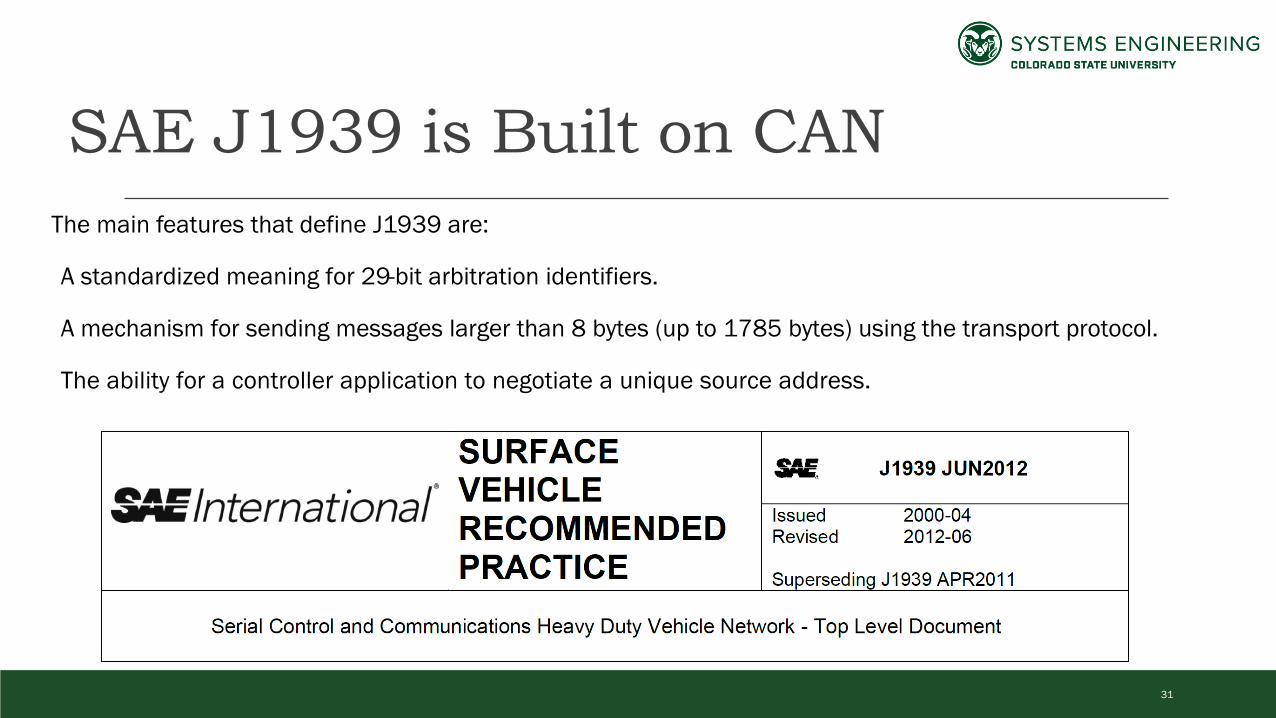
SAE J1939 is Built on CANThe main features that define J1939 are:
A standardized meaning for 29-bit arbitration identifiers.
A mechanism for sending messages larger than 8 bytes (up to 1785 bytes) using the transport protocol.
The ability for a controller application to negotiate a unique source address.
31

Types of J1939 Messages
Broadcast Messages sent for any controller application (CA) to use CAN Arbitration ID specifies a source address (SA) in the last 8 bits of the ID Implicitly defined the destination address as 255 (Global)
Point-to-Point One controller application sends a message to another CAN Arbitration ID specifies a source address (SA) in the last 8 bits of the ID A destination address (DA) is in bits 9-16 of the CAN ID.
32
How do some messages implicitly set the destination address to 255?

J1939 Protocol Data UnitA J1939 message has all the elements in the protocol data unit (PDU) 3-bit Priority 1-bit Extended Data Page (EDP) 1-bit Data Page (DP) 8-bit PDU Format (PF) 8-bit PDU Specific (PS) 8-bit Source Address (SA) Data Field up to 1785 bytes
33
29-bit Extended CAN ID
PriorityEDP
DP PDU Format PDU
SpecificSource Address Data (0 to 1785 bytes)
J1939 driver software converts CAN
message(s) into a PDU.

PDU 2 Format MessagesThe PDU format #2 is for broadcast messages EDP, DP, PF and PS create the Parameter Group Number (PGN) PS becomes the group extension (GE) PF value must be greater than or equal to 240 (0xF0) Destination address is implied to be 255 (0xFF)
Parameter Groups Numbers are 18 bits. Most applications on a truck set the EDP and DP to zero Parameter Groups collect similar data for the PDU data field PDU 2 messages have a hex values where the leading nibble is FExamples: PGN 65265 (0xFEF1) is for Cruise Control and Vehicle Speed PGN 61444 (0xF004) for the Electronic Engine Controller 1 group
34
18-bit PGN

PDU 1 Format Messages
The PDU format #1 is for point-to-point messages EDP, DP, PF and 00 create the Parameter Group Number (PGN) PS becomes the destination address (DA)
Parameter Group Numbers (PGNs) are still 18-bits,but the last 8 bits are set to zero.
Source and Destination are explicit
PGN values in hex do not have 0xF as thefirst nibble.
35
10-bits from PF 0x00
18-bit PGNDestination
Address

Processing CAN IDs
1. Read the CAN ID as a 32-bit integer
2. Separate the ID into the PDU elements using bit masking and bit shifting
3. Determine if it is a PDU1 or PDU2 message based on the value of PF
1. If PDU1, PS is the Destination Address2. If PDU2, PS is the Group Extension, set
Destination Address to 0xFF
36
PRIORITY_MASK = 0x1C000000EDP_MASK = 0x02000000DP_MASK = 0x01000000PF_MASK = 0x00FF0000PS_MASK = 0x0000FF00SA_MASK = 0x000000FFPDU1_PGN_MASK = 0x03FF0000PDU2_PGN_MASK = 0x03FFFF00

Bit Masking and Shifting
37
ID Hex Nibbles 0 C F 0 0 4 0 0ID Binary 0 1 1 0 0 1 1 1 1 0 0 0 0 0 0 0 0 0 1 0 0 0 0 0 0 0 0 0 0
PGN Mask Hex 0 3 F F F F 0 0
Mask Binary 0 0 0 1 1 1 1 1 1 1 1 1 1 1 1 1 1 1 1 1 1 0 0 0 0 0 0 0 0
AND Result 0 0 0 0 0 1 1 1 1 0 0 0 0 0 0 0 0 0 1 0 0 0 0 0 0 0 0 0 0
Shift right 8 bits 0 0 0 0 0 1 1 1 1 0 0 0 0 0 0 0 0 0 1 0 0
Hex after shift 0 0 F 0 0 4
0x00F004 = 61444 dec
Example: Determine the PGN from the CAN Frame Capture

Python Based Parsingdef get_j1939_from_id(can_id):
priority = (PRIORITY_MASK & can_id) >> 26edp = (EDP_MASK & can_id) >> 25dp = (DP_MASK & can_id) >> 24PF = (can_id & PF_MASK) >> 16PS = (can_id & PS_MASK) >> 8SA = (can_id & SA_MASK) if PF >= 0xF0: #240
DA = 255PGN = (can_id & PDU2_PGN_MASK) >> 8
else:DA = PSPGN = (can_id & PDU1_PGN_MASK) >> 8
return priority,PGN,DA,SA
38
PRIORITY_MASK = 0x1C000000EDP_MASK = 0x02000000DP_MASK = 0x01000000PF_MASK = 0x00FF0000PS_MASK = 0x0000FF00SA_MASK = 0x000000FFPDU1_PGN_MASK = 0x03FF0000PDU2_PGN_MASK = 0x03FFFF00
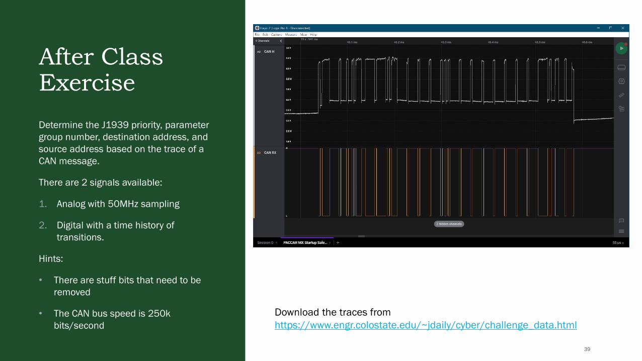
After Class ExerciseDetermine the J1939 priority, parameter group number, destination address, and source address based on the trace of a CAN message.
There are 2 signals available:
1. Analog with 50MHz sampling
2. Digital with a time history of transitions.
Hints:
• There are stuff bits that need to be removed
• The CAN bus speed is 250k bits/second
39
Download the traces from https://www.engr.colostate.edu/~jdaily/cyber/challenge_data.html

Collecting CAN DataLET’S GET SOME DATA FROM A REAL VEHICLE
40

CAN EnabledEmbedded Linux Hardware
120 Ω
120 Ω
Brake Controller Engine Control Module
BeagleBoneBlack
Other ECUs
Diagnostics Port
Raspberry Pi
CAN Controller
CAN Transceiver
41

BeagleBone Black with Heavy Truck Cape
https://github.com/SystemsCyber/TruckCapeProjects/tree/master/hardware
https://oshpark.com/shared_projects/FXh7K628
42

Raspberry Pi with CAN Hat
https://www.amazon.com/RS485-CAN-HAT-Long-Distance-Communication/dp/B07VMB1ZKH/
https://www.amazon.com/Raspberry-Pi-MS-004-00000024-Model-Board/dp/B01LPLPBS8/
43

CAN Logger 3
44
Custom CAN logging device based on the Teensy 3.6 development board (ARM Cortex M4F in the NXP K66 processor)
www.github.com/SystemsCyber/CANLogger3/

Software and Firmware RequirementsLinux with SocketCAN https://www.kernel.org/doc/html/v4.17/networking/can.ht
ml
can-utils https://github.com/linux-can/can-utils
Additional configuration for the BBB can be found athttps://github.com/SystemsCyber/TruckCapeProjects/blob/master/OSBuildInstructions.md
On Windows: PuTTy for a terminal access (SSH) WinSCP for secure file transfer
Connect to the BBB with USB
45

Check Network Interfaces
Once logged in, check for network interfaces:
ifconfig | more
This should produce a list of interfaces that show can0 can1 eth0 (among others)
can1 maps to pins C and D for J1939 on the
diagnostic port
46

Connecting to a Truck and Reading DataCheck the bitrate of the physical channel: ip -details -statistics link show can1
Change bitrate to match system: sudo ip link set can1 down
sudo ip link set can1 type can bitrate 500000
sudo ip link set can1 up
Log the can data to a file: candump -l –e any
47

Logging and Interpreting DataFinding things of interest: e.g. Look for Address Claim messages:candump any | grep 18EE
48

Creating Meaning from MessagesHOW DO WE GET ENGINEERING VALUES FROM J1939 PROTOCOL DATA UNITS?
49

J1939 Network LayersLayer Name Standard Description and Purpose
7 Application SAE J1939-71 (Applications)SAE J1939-73 (Diagnostics)
Defines how to interpret and compose J1939 messages with engineering values
6 PresentationNot Used
These services are built into the Data Link Layer.5 Session
4 Transport
3 Network J1939-31 Clarifies the concept of a gateway between two separate networks.
2 Data Link J1939-21Describes how to make a J1939 PDU. Includes details on sending messages up to 1785 bytes long.
1 Physical J1939-1X Defined connectors, transceivers, wiring, pinouts, and signaling.
50

SAE J1939 Standards OrganizationFollows the OSI 7-layer model for naming, e.g.: J1939-7X are for application layers J1939-1X are for physical layers
The standard collection adds much more definition to the CAN communications
Includes additional “Layers” J1939-8X Network Management J1939-9X Network Security
J1939 is large and not free
J1939 Accommodates Extensions PGN 0xEF00 is Proprietary A PGN 0xFFXX is Proprietary B PGN 0xDA00 is ISO-15765 (UDS)
A Digital Annex (J1939DA) has the applications defined in an Excel spreadsheet
51
Recommendation:• Acquire the Digital Annex first.• Read J1939-21 for details on the PDU https://www.sae.org/publications/collections/content/j1939_dl/

Data Decoding and Encoding:Meaning for Bits and BytesCommon data sizes Bit Mapped, like Switch States, (2-bits) Single Byte Data (8-bits) 2-byte Data (16 bits) 4-byte Data (32 bits) ASCII data (variable)
Exceptions: Field data, engine maps Suspect Parameter Numbers (19 bits) Failure Mode Indicators (5 bits) Others…
Scale, Limits, Offsets, Transfer (SLOTs)
52
Identifier SLOT Name SLOT Type Scaling Range Offset Length1 SAEpr11 Pressure 5 kPa/bit 0 to 1,250 kPa 0 1 byte2 SAEpr13 Pressure 8 kPa/bit 0 to 2,000 kPa 0 1 byte3 SAEtm11 Time 1 h/bit 0 to 250 h 0 1 byte4 SAEtm10 Time 1 h/bit -125 to 125 h -125 h 1 byte5 SAEtm12 Time 1 h/bit -32,127 to 32,128 h -32,127 h 2 bytes6 SAEtm06 Time 1 s/bit 0 to 4,211,081,215 s 0 4 bytes7 SAEad01 Angle/Direction 0.0000001 deg/bit -210 to 211.1081215 deg -210 deg 4 bytes⁞ ⁞ ⁞ ⁞ ⁞ ⁞ ⁞

Bit Transmission OrderTransmission Order: The order in which bits are transmitted over the J1939 Link. Data is transmitted in increasing byte order (Byte 1 first, Byte 8 last) Bits within the byte are transmitted in decreasing order (Bit 8 first, Bit 1 last)
Bit Placement: The location within the byte of the start point of the data J1939 uses a convention of Byte.Bit. Example from PGN 65265 Cruise Control/Vehicle Speed
53
SPN Location Length Suspect Parameter
967 8.1 2 bits Engine Idle Increment Switch
968 8.3 2 bits Engine Idle Decrement Switch
966 8.5 2 bits Engine Test Mode Switch
1237 8.7 2 bits Engine Shutdown Override Switch
MSB – Most Significant ByteMSb – Most Significant Bit
MSb Byte 8 LSb
8 7 6 5 4 3 2 1
1237 966 968 967

Decoding Example:Accelerator Pedal Low Idle SwitchGiven the following CAN message (hex):0CF00300 [8] D0 5A 25 FF FF 0F A0 81
1. Break the CAN ID into J1939 valuesa) 0x0C is priority 3b) F004 is PDU2 format
i. PGN is 0xF003 = 61443, Electronic Engine Control 2ii. Destination Address is 0xFF (implied)
c) Source address is 0x00 = 0, Engine #1
2. Determine some Suspect Parameters in the dataa) 558: Accelerator Pedal 1 Low Idle Switchb) 559: Accelerator Pedal 1 Kickdown Switchc) 1437: Road Speed Limit Statusd) 2970: Accelerator Pedal 2 Low Idle Switche) 91: Accelerator Pedal Position 1f) 92: Engine Percent Load At Current Speedg) 974: Remote Accelerator Pedal Positionh) 29: Accelerator Pedal Position 2i) 2979: Vehicle Acceleration Rate Limit Statusj) 3357: Actual Maximum Available Engine % Torquek) 5398: Estimated Pumping – Percent Torque
54
Byte Position Byte 1 Byte 2 Byte 3 Byte 4 Byte 5 Byte 6 Byte 7 Byte 8Hex Values 0xD0 0x5A 0x25 0xFF 0xFF 0x0F 0xA0 0x81Binary 0b 1101 0000SPNs 2970 1437 559 558 91 92 974 29 2979Engineering N/A On Off Off N/A N/A
Bit 1Bit 8 Bit Encoding for SPN 55800 - Accelerator pedal 1 not in low idle condition01 - Accelerator pedal 1 in low idle condition10 - Error11 - Not available

Decoding Example:Accelerator Pedal PositionGiven the following CAN message (hex):0CF00300 [8] D0 5A 25 FF FF 0F A0 81
1. Break the CAN ID into J1939 valuesa) 0x0C is priority 3b) F003 is PDU2 format
i. PGN is 0xF003 = 61443, Electronic Engine Control 2ii. Destination Address is 0xFF (implied)
c) Source address is 0x00 = 0, Engine #1
2. Determine some Suspect Parameters in the dataa) 558: Accelerator Pedal 1 Low Idle Switchb) 559: Accelerator Pedal 1 Kickdown Switchc) 91: Accelerator Pedal Position 1d) 92: Engine Percent Load At Current Speede) 974: Remote Accelerator Pedal Positionf) 29: Accelerator Pedal Position 2g) 2979: Vehicle Acceleration Rate Limit Statush) 3357: Actual Maximum Available Engine % Torquei) 5398: Estimated Pumping – Percent Torque
55
Byte Position Byte 1 Byte 2 Byte 3 Byte 4 Byte 5 Byte 6 Byte 7 Byte 8Hex Values 0xD0 0x5A 0x25 0xFF 0xFF 0x0F 0xA0 0x81SPNs 558, 559… 91 92 974 29 2979… 3357 5398Engineering 90*0.4 = 36% N/A N/A 160*0.4= 64% 129-125=32%

Byte order for Integers (Endianness)
56
This Photo by Unknown Author is licensed under CC BY-SA-NC
Post office boxes have mail loaded from the inside and taken out through the front.
This Photo by Unknown Author is licensed under CC BY-NC-ND
This Photo by Unknown Author is licensed under CC BY-NC
Mailboxes have mail loaded and removed from the front.

Byte order for Integers (Endianness)
57
This Photo by Unknown Author is licensed under CC BY-SA-NC
Let’s pretend our mailboxes are containers to hold bytes representing integers.
Example: the integer 100,293,486 is 0x05FA5B6E in hex, which is 4 bytes:
0x05 0xFA 0x5B 0x5E
Pretend each byte is a small package. In what order should the postmaster insert the bytes into the mailbox so they are in order when the customer extracts them?
This Photo by Unknown Author is licensed under CC BY-NC
MSB first LSB first
Most Significant Byte
Least Significant Byte

Byte order for Integers (Endianness)SAE J1939 encodes multi-byte integers in the Little Endian format.
This give the appearance the bytes are reversed and need to be swapped to interpret
Intel format = Little Endian = Least Significant Byte first
Motorola format = Big Endian = Most Significant Byte first (as we typically read and write)
58
Byte Length Decimal Hex Big Endian Little Endian (J1939)
1 241 F1 0xF1 0xF1
2 743 2E7 0x02 0xE7 0xE7 0x02
2 25 19 0x00 0x19 0x19 0x00
4 1,890,056,399 70A7F8CF 0x70 0xA7 0xF8 0xCF 0xCF 0xF8 0xA7 0x70
Endianness doesn’t affect
single byte integers.

Decoding Example:Engine Speed (RPM)Given the following CAN message (hex):0CF00400 [8] 31 9D 9D A2 38 00 0F 9D
1. Break the CAN ID into J1939 valuesa) 0x0C is priority 3b) F004 is PDU2 format
i. PGN is 0xF004 = 61444, Electronic Engine Control 1ii. Destination Address is 0xFF (implied)
c) Source address is 0x00 = 0, Engine #1
2. Determine Suspect Parameters in the dataa) 889: Engine Torque Modeb) 4154: Actual Percent Torquec) 512: Driver's Demand Engine - Percent Torqued) 513: Actual Engine Percent Torquee) 190: Engine Speedf) 1483: SA of Controlling deviceg) 1675: Engine Starter Modeh) 2432: Engine Demand- Percent Torque
59
Byte Position Byte 1 Byte 2 Byte 3 Byte 4 Byte 5 Byte 6 Byte 7 Byte 8Hex Values 0x31 0x9D 0x9D 0xA2 0x38 0x00 0x0F 0x9DSPNs 899 4154 512 513 190 1483 1675 Res 2432Engineering 32% 32% 14,498/8 = 1812.25 N/A 157-125=32%

60

Decoding Example:Vehicle Miles
61
Determine the Odometer reading from the J1939 data.
Not all data defined in J1939 is present on the network.
Strategy:
1. Look up the SPN for distance
2. Search the J1939 Standard for the entry
3. Find the message in a log
4. Decode the logged message

62

63

After Class ExerciseSignal Interpretation
A candump data log was capture during a startup seqence for a truck using Linux SocketCAN. The data comes from 2014 Class 6 truck with a box van where the operator started the engine, pressed the accelerator pedal and turned the engine off. The challenge is to determine the highest engine speed in RPM base on the log file.
1. Some other questions for consideration: How many ECUs are on the network?
2. What is the vehicle mileage?
3. Did the vehicle's wheels rotate?
64
https://www.engr.colostate.edu/~jdaily/cyber/KWTruck.txt

J1939 Transport ProtocolHOW CAN WE SEND MESSAGES LARGER THAN 8 BYTES IN A CAN FRAME?
65

J1939 Transport ProtocolData more than 8 bytes in length requires multiple CAN frames to send the data.
Two Approaches that follow PDU formats Request to Send/Clear to Send (RTS/CTS) – point-to-point messaging Broadcast Announce Message (BAM) – global address Approach is determined with the first byte of the Connection Management Message
If 32 (0x20), then BAM If 16 (0x10), then RTS If 17 (0x11), then CTS
Three Parameter Groups to track Transport Protocol – Connection Management (TP.CM), PGN 60416 (0xEC00) Transport Protocol – Data Transfer (TP.DT), PGN 60160 (0xEB00) PGN of the data being transported
66
Details are in SAE J1939-21

J1939 Transport Protocol VIN ExampleThe following data were on J1939:
CAN ID: CAN Data (in hex)1CECFF00: 20 12 00 03 FF EC FE 001CEBFF00: 01 31 58 4B 59 44 50 391CEBFF00: 02 58 37 46 4A 34 36 391CEBFF00: 03 30 35 38 2A FF FF FF
Parse the CAN ID into J1939 parameters: 0x1C000000 -> Priority = 7 (lowest) 0x00EC0000 -> PGN = 60416 (TP.CM) 0x00EB0000 -> PGN = 60160 (TP.DT) 0x0000FF00 -> Destination = 255 (Global) 0x00000000 -> Source Address = 0 (Engine 1)
67

J1939 Transport Protocol VIN Example (cont.)Transport Protocol – Connection Management
1CECFF00: 20 12 00 03 FF EC FE 00 20 – Control Byte = BAM 12 00 – Message size (18 bytes) 03 – Number of packets (3) EC FE 00 – PGN of message(0x00FEEC = 65260 Vehicle Identification)
Connection Mode: BAM Byte 1: Control byte = 32 (0x20), Broadcast
Announce Message (BAM) Bytes 2,3: Total message size, number of
bytes (Big Endian or reverse byte order) Byte 4: Total number of packets Byte 5: Reserved (0xFF) Bytes 6,7,8: Parameter Group Number of the
packeted message (Big Endian)
Note: The destination on a BAM is often 255 for all the nodes.
68

J1939 Transport Protocol VIN Example (cont.)Transport Protocol – Data Transfer
1CEBFF00: 01 31 58 4B 59 44 50 391CEBFF00: 02 58 37 46 4A 34 36 391CEBFF00: 03 30 35 38 2A FF FF FF NN – Sequence Number (01 to FF) Data totaling the number of bytes in TC.CM FF FF FF – Filler for an 8-byte message
A maximum of 255 messages with 7 bytes each means a total of 255*7 = 1785 bytes maximum for each J1939 transport protocol message.
69
Decoded value from ASCII:31 58 4B 59 44 50 39 58 3746 4A 34 36 39 30 35 38 2A
1 X K Y D P 9 X 7F J 4 6 9 0 5 8 *
Or 1XKYDP9X7FJ469058
(VIN is usually 17 characters, so the * is dropped)
1XKYDP9X7FJ469058*

J1939 Request MessagesMany data available from and ECU are by request only. Examples include: Engine hours VIN Component Information
PGN 59904 (0xEA00) is for a Request Only 3 bytes long Data is the PGN being requested Should only be used 2-3 times per second
Example:CAN ID CAN DATA
18EA0FF9 EC FE 00 18 – Priority (6 default) EA00 – Request PGN (59904) 0F – Destination Address (Retarder) F9 – Source Address (249: Off-Board Diagnostic Tool)
EC FE 00 – PGN 65260: VIN (Reverse byte order)
Note: this is a point-to-point request to the retarder from the service tool.
The response may be BAM or RTS/CTS
70

J1939 Diagnostic MessagesUNDERSTANDING MESSAGES RELATED TO FAULT CODES
71

J1939-73 Application Layer - DiagnosticsDefines close to 60 Diagnostic Messages related to troubleshooting and monitoring components on a truck.
Defines lamp status Check Engine Lamp Malfunction Indicator Lamp MIL
Defines Failure Mode Indicators (FMI)
All trucks use some parts of J1939-73 Diagnostic Message 1
Many parts of J1939-73 are not used Components use UDS or proprietary messaging Most concepts are implemented in ECUs in some
fashion
72

Diagnostic Message 1 Example (No Fault Codes)Broadcast once per second
Diagnostic trouble codes (DTCs) have four fields that use 32-bits: Suspect Parameter Number (SPN): 19 bits Failure Mode Identifier (FMI): 5 bits Occurrence Count (OC): 7 bits SPN Conversion Method (CM): 1 bit
PGN for DM1 is 65226 (0xFECA) Broadcast message with global destination Source Address tell which controller application is
broadcasting
Unused bytes should be set to 0xFF
18FECA03 03 FF 00 00 00 00 FF FF
18 – Priority (6 default)FECA – DM1 PGN (65226)03 – Source Address (Transmission)
03 – Lamp Status (0000 0011)FF – Lamp Flash Status (1111 1111)00 00 0 – Suspect Parameter Number0 – Failure Mode Indicator (FMI)00 – Conversion and Occurrence Count
73
CM8 7 6 5 4 3 2 1 8 7 6 5 4 3 2 1 8 7 6 5 4 3 2 1 8 7 6 5 4 3 2 1
Diagnostic Trouble CodeConversion Method and
Occurance CountSuspect Parameter Number (19 bits) FMI OC
Least Significant Byte of SPN
Second Byte of SPN3 most significant bits for SPN, 5 bits for FMI

Lamp Status Bytes in DM1
DM1 Byte 1: Bits 8-7: Malfunction indicator lamp Bits 6-5: Red stop lamp Bits 4-3: Amber warning lamp Bits 2-1: Protect lamp
DM1 Byte 2: Bits 8-7: Flash malfunction indicator lamp Bits 6-5: Flash red stop lamp Bits 4-3: Flash amber warning lamp Bits 2-1: Flash protect lamp
Lamp status bytes exist only at the beginning of the DM1 message
Multiple DTCs can be concatenated and broadcast
74
Lamp Status Bits:00 = Off01 = On10 = Error11 = Not Available (unused)
Emissions Related
Flash Status Bits:00 = Slow Flash (1/sec)01 = Fast Flash (2/sec)10 = Reserved11 = Unavailable (don’t flash)

Diagnostic Message 1Ex: Multiple Fault CodesTRANSPORT PROTOCOL MESSAGES
1CECFF00 20 CA 00 1D FF CA FE 001CEBFF00 01 57 FF 9D 00 03 01 FB1CEBFF00 02 06 0B 32 4A 00 0E 31…(182 more bytes in 26 frames)…
1CEBFF00 1D 09 01 84 06 09 01 FF
57 FF – Lamp Status(0101 0111 1111 1111)
J1939 PROTOCOL DATA UNIT
PGN: 0x00FECA = 65226 (DM1)Dest. Address: 0xFF (Global)Source Address: 0x00 (Engine #1)
Data: (0x00CA = 202 bytes)
57 FF 9D 00 03 01 FB 06 0B 32 4A 00 0E 31 … 09 01 84 06 09 01
75
Last Frame
• All 3 lamps are on• Protect is not used• No lamps are flashing

Diagnostic Message 1Ex: Multiple Fault Codes
DTC 1: 9D 00 03 01 DTC 2: FB 06 0B 32
76
57 FF 9D 00 03 01 FB 06 0B 32 4A 00 0E 31 … 09 01 84 06 09 01
Diagnostic Trouble Code
Least Significant Byte of SPN Second Byte of SPN
3 most significant bits for SPN, 5 bits
for FMI
Conversion Method and Occurrence
Count
9D 00 03 01
Suspect Parameter Number (19 bits) FMI CM OC8 7 6 5 4 3 2 1 8 7 6 5 4 3 2 1 8 7 6 5 4 3 2 1 8 7 6 5 4 3 2 11 0 0 1 1 1 0 1 0 0 0 0 0 0 0 0 0 0 0 0 0 0 1 1 0 0 0 0 0 0 0 1
Reverse Byte order: 0x0009D = 157 3 0 1
Diagnostic Trouble Code
Least Significant Byte of SPN Second Byte of SPN
3 most significant bits for SPN, 5 bits
for FMI
Conversion Method and Occurrence
Count
FB 06 0B 32
Suspect Parameter Number (19 bits) FMI CM OC
8 7 6 5 4 3 2 1 8 7 6 5 4 3 2 1 8 7 6 5 4 3 2 1 8 7 6 5 4 3 2 11 1 1 1 1 0 1 1 0 0 0 0 0 1 1 0 0 0 0 0 1 0 1 1 0 0 1 1 0 0 1 0
Reverse Byte order: 0x006FB = 1787 11 0 50
• SPN = 157 (Engine Fuel 1 Injector Metering Rail 1 Pressure)• FMI = 3 (Voltage Above Normal, or Shorted to High Source)• Count = 1
• SPN = 1787 (Engine Torque Limit Request - Maximum Continuos)• FMI = 11 (Root Cause Not Known)• Count = 50
Use SAE J1939-73 Appendix A for FMIs
Most diagnostic service tools interpret these codes.

J1939 Diagnostics Summary
Diagnostic Trouble Codes are define with Suspect Parameter Number (i.e. the potential part that may be broken) Failure Mode Indicator (i.e. the symptom of the broken part) Occurrence Count (how many times the system sees the indication)
J1939-73 also discusses Firmware updates Memory access Emissions Compliance Freeze Frame Data Data Security
Many vehicles implement onlya small portion of J1939-73
77

J1939 Address ClaimHOW DOES A NETWORK KEEP TRACK OF THE SOURCE AND DESTINATION ADDRESSES IF IT CHANGES?
78

J1939 Address ClaimEach controller application (node) on the network should have its own source address.
Some ECUs have multiple controller applications. SA 0x00: Engine #1 SA 0x0F: Engine Retarder
Address Claims happen On Boot When requested In response to other claims for the same address
Address Claim Parameter Group Number 60928 (0xEE00) Mostly uses the Global destination address (0xFF) Source address is the address being claimed
Transmission Address Claim example:
18EEFF03: 64 00 40 00 00 03 03 10 18 – Priority 6 (default) EE – PGN 60928 = Address Claimed FF – Global Destination Address 03 – Source address for Transmission #1 64 00 40 00 00 03 03 10 - NAME Field
79

How Address Claiming Works
80
See SAE J1939-81Network Management

Address NAME Field
81
• From SAE J1939-81, the following NAME field is 64 Bits (8 bytes) long.
• Value is translated with little endian format (Intel), so the least significant byte is first.
• Example 1: Caterpillar C15 with ADEM4 ECUcan1 18EEFF00 [8] D0 6B 01 01 00 00 00 80
• Example 2: Detroit Diesel CPC3Evocan1 18EEFF00 [8] 00 00 C0 01 00 00 00 00
• Additional Examples
Arbitrary Address Capable
Industry Group
Vehicle System Instance
Vehicle System
Reserved Function Function Instance
ECU Instance
Manufacturer Code
Identity Number
SAE SAE SAE SAE SAE1 bit 3 bits 4 bits 7 bits 1 bit 8 bits 5 bits 3 bits 11 bits 21 bits
CAN ID has:• Priority = 6, • Parameter Group Number = 0xEE00,• Destination Address = 0xFF (Global),• Claimed Source Address = 0x00 (Engine #1)

Example 1: Caterpillarcan1 18EEFF00 [8] D0 6B 01 01 00 00 00 80
Byte 8 (0x80) = 0b1000 0000, which means: it is arbitrary address capable, the industry group is 0 (global), and the vehicle system instance is zero.
Byte 5 -7 (00 00 00), which means: the vehicle system, function, and function instance are all zero,
which is consistent with an engine controller
Byte 4 (0x01), Bits 1-8 = MSB of Mfg CodeByte 3 (0x01), Bits 8-6 = LSB of Mfg Code 0b0000 0001 0000 0001 = 0b1000 = 8 (dec)
Byte 3 (0x01), bits 1-5 = MSB of Identity FieldByte 2 (0x6B) = 2nd byte of identity fieldByte 1 (0xD0) = LSB of identity field 0b0 0001 0110 1011 1101 0000 = 93,136 (dec)
82

Example 2: Detroit Dieselcan1 18EEFF00 [8] 00 00 C0 01 00 00 00 00
Byte 8 (0x00) = 0b0000 0000, which means: it is NOT arbitrary address capable, the industry group is 0 (global), and the vehicle system instance is zero.
Byte 5 -7 (00 00 00), which means: the vehicle system, function, and function instance are all zero,
which is consistent with an engine controller
Byte 4 (0x01), Bits 1-8 = MSB of Mfg CodeByte 3 (0xC0), Bits 8-6 = LSB of Mfg Code 0b0000 0001 1100 0000 = 0b1110 = 14 (dec)
Byte 3 (0x01), bits 1-5 = MSB of Identity FieldByte 2 (0x00) = 2nd byte of identity fieldByte 1 (0x00) = LSB of identity field 0b0 0000 0000 0000 0000 0000 (likely not used)
83

Example 3: Allison Transmissioncan1 18EEFF03 [8] 64 00 40 00 00 03 03 10
Byte 8 (0x10) = 0b0001 0000, which means: it is NOT arbitrary address capable, the industry group is 1 (on-highway), and the vehicle system instance is zero.
Byte 7 (0x03), the vehicle system is the transmission
Byte 6 (0x03), function is the transmission
Byte 5 (0x00), the function and ECU instance is zero, which means it’s the first instance.
Byte 4 (0x00), Bits 1-8 = MSB of Mfg CodeByte 3 (0x40), Bits 8-6 = LSB of Mfg Code 0b0000 0000 0100 0000 = 0b0010 = 2 (dec)
Bytes 3-1 (0x00064) comprise the identity field
84

Example: Vehicle Navigation can1 18EEFF1C [8] 02 04 45 0E 00 00 00 42
Byte 8 (0x42) = 0b0100 0010, which means: it is NOT arbitrary address capable, the industry group is 4 (marine), and the vehicle system instance is 2.
Byte 7 (0x00), the vehicle system is non-specific
Byte 6 (0x00), function is non-specific
Byte 5 (0x00), the function and ECU instance is zero, which means it’s the first instance.
Byte 4 (0x0E), Bits 1-8 = MSB of Mfg CodeByte 3 (0x45), Bits 8-6 = LSB of Mfg Code 0b0000 1110 0100 0101 = 0b111001 = 114 (dec)
Bytes 3-1 (0x050402) comprise the identity field
85
Econtrols owns Perfect Pass and Zero Off, the systems for cruise
control on ski boats.

Example: Ilmor Ski Boat Enginecan1 18EEFF00 [8] C8 2C 42 0E 00 00 00 51
Byte 8 (0x51) = 0b0101 0001, which means: it is NOT arbitrary address capable, the industry group is 5 (gen-sets), and the vehicle system instance is 1.
Byte 7 (0x00), the vehicle system is non-specific
Byte 6 (0x00), function is the engine
Byte 5 (0x00), the function and ECU instance is zero, which means it’s the first instance.
Byte 4 (0x0E), Bits 1-8 = MSB of Mfg CodeByte 3 (0x42), Bits 8-6 = LSB of Mfg Code 0b0000 1110 0100 0010 = 0b111001 = 114 (dec)
Bytes 3-1 (0x022CC8) comprise the identity field
86
Zero-Off (ski boat cruise control) is made by Enovation Controls, which
used to be Econtrols.

Example: Dynamic Claim (Depth Sounder)
can1 18EEFF81 [8] 6D AA EF 10 00 82 78 C0
Byte 8 (0xC0) = 0b1100 0000, which means: it IS arbitrary address capable, the industry group is 4 (marine), and the vehicle system instance is 1.
Byte 7 (0x78), 120, not listed
Byte 6 (0x82), 130, function is not listed
Byte 5 (0x00), the function and ECU instance is zero,which means it’s the first instance.
Byte 4 (0x10), Bits 1-8 = MSB of Mfg CodeByte 3 (0xEF), Bits 8-6 = LSB of Mfg Code 0b0001 0000 1110 1111 = 0b1000111011 = 135 (dec)
Bytes 3-1 (0x0FAA6D) comprise the identity field
87
Note: Airmar produces ultrasonic sensors. Source Address 81 is used to send PGN 128267: Water Depth and PGN 130310: Environmental Parameters

NMEA 2000Example
can0 0DF50B81 42 B5 08 00 00 00 00 FF0D – Priority ( 0b0000 1101 = 3)DF50B – Water Depth PGN (0x1F50B)81 – Dynamically Claimed Source Address
42 – Sequence ID (0x42 = 66)B5 08 00 00 – Depth (0x8B5 = 2,229*0.01m = 22.29m = 73.13ft)00 00 – Offset (zero)FF – Maximum Depth Range (Not Available)
88

Diagnostic Message 1 Example (No Fault Codes)Broadcast once per second
Diagnostic trouble codes (DTCs) have four fields that use 32-bits: Suspect Parameter Number (SPN): 19 bits Failure Mode Identifier (FMI): 5 bits Occurrence Count (OC): 7 bits SPN Conversion Method (CM): 1 bit
PGN for DM1 is 65226 (0xFECA) Broadcast message with global destination Source Address tell which controller application is
broadcasting
Unused bytes should be set to 0xFF
18FECA03 03 FF 00 00 00 00 FF FF
18 – Priority (6 default)FECA – DM1 PGN (65226)03 – Source Address (Transmission)
03 – Lamp Status (0000 0011)FF – Lamp Flash Status (1111 1111)00 00 0 – Suspect Parameter Number0 – Failure Mode Indicator (FMI)00 – Conversion and Occurrence Count
89
CM8 7 6 5 4 3 2 1 8 7 6 5 4 3 2 1 8 7 6 5 4 3 2 1 8 7 6 5 4 3 2 1
Diagnostic Trouble CodeConversion Method and
Occurance CountSuspect Parameter Number (19 bits) FMI OC
Least Significant Byte of SPN
Second Byte of SPN3 most significant bits for SPN, 5 bits for FMI

After Class Exercise
Examine the CAN Log from a boat to identify J1939 and NMEA messages.
Create a plot of depth.
Hints:
• Priority is 3 bits, PGN is 18 bits.
• Bit fields may align with byte boundaries
• Sometime depth signals are unavailable (shown as zero).
90
Download the CAN Log from https://www.engr.colostate.edu/~jdaily/CyberBoat/CSU35036-text.txt

Cybersecurity Considerations for J1939WHAT CAN DO WRONG IF A HACKER GETS ACCESS TO THE NETWORK?
108

Denial Of Service
109
Normal J1939
Flooded J1939

Denial of Service
By repeating high priority messages (ID = 0), no other legitimate message can get access to the network.
This will shut down communications and potentially stall a truck.
There are no native protections against this in J1939; avoid connecting unknown new devices to J1939.
110

Spoofing Messages and Commands
111
Normal J1939 Spoofed J1939

Spoofing Messages and CommandsTwo messages with the same IDs will be interpreted the same way One message is legitimate (right) The other is spoofed (left)
112
The network doesn’t know which message
is legitimate

113

Address Claim AttackIdea: Claim someone else’s address with a higher priority address (All Zeros).
Keep claiming addresses as they are dynamically claimed.
If a system can’t find a claimable address, then it should stop broadcasting (Denial of Service)
The following example shows how to conduct an address claim attack:
https://github.com/SystemsCyber/TruckCapeProjects/blob/master/Jupyter/06%20J1939%20Address%20Claim.ipynb Note: This runs on Linux Socket CAN
114

SummaryThe need for in-vehicle communication using CAN and SAE J1939
Connecting to J1939 Networks
Classify the different types of communication over J1939
Interpret J1939 network traffic using the SAE Standard
Recognize SAE J1939 Transport Protocols for larger messages
Understand J1939 Diagnostic Messages
Introduction to J1939 Address Claiming
Demonstration of RP1210 functionality for diagnostics
Showed examples of Unified Diagnostic Services (UDS) over J1939
Realize J1939 is inherently an open (and potentially insecure) read-write bus
115