For EPS - NASA Technical Reports Server
402
ELECTRON-PROTON SPECTROMETER SPARES REQUIREMENTS LEC Document Number EPS-472 . . _ . ,~:~ ·~·· · .: .. : . Prepared by Lockheed Electronics Company Houston Aerospace Division Houston, Texas Under Contract NAS 9-11373 For It to 6., C, t . - C. H <C) C) ) zyr O t3 t ro _ i t-4 m C) ) z to H U) t , u FH cc o I O, Cr, t-. .C> 1Q. -4 hj O O I- v) National Aeronautics and Space Administration Manned Spacecraft Center llouston, Texas September 1971 ( EPS--472 f
-
Upload
khangminh22 -
Category
Documents
-
view
1 -
download
0
Transcript of For EPS - NASA Technical Reports Server

ELECTRON-PROTON SPECTROMETER
SPARES REQUIREMENTS
LEC Document Number EPS-472
. . _ .,~:~ ·~·· · .: .. : .
Prepared by
Lockheed Electronics Company
Houston Aerospace Division
Houston, Texas
Under Contract NAS 9-11373
For
It to 6.,
C, t . -C.
H <C)C) ) zyr
O t3
t ro
_ it-4 m
C) )
z
to HU) t ,
u FH
cc
o I
O,
Cr, t-.
.C> 1Q. -4
hjO
O
I-
v)
National Aeronautics and Space Administration
Manned Spacecraft Center
llouston, Texas
September 1971
(
EPS--472
f
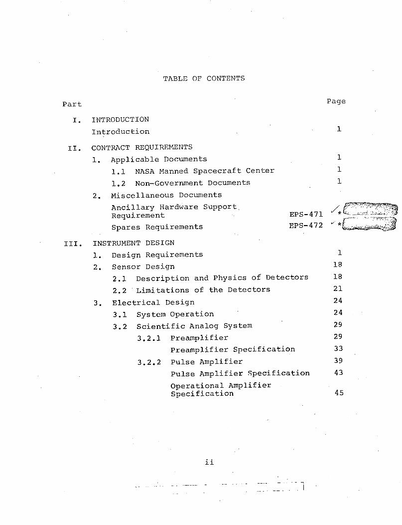
TABLE OF CONTENTS
Part
I. INTRODUCTION
Introduction
II. CONTRACT REQUIREMENTS
1. Applicable Documents
1.1 NASA Manned Spacecraft Center
1.2 Non-Government Documents
2. Miscellaneous Documents
Ancillary Hardware SupportRequirement
Spares Requirements
1
1
1
EPS-471
EPS-472
III. INSTRUMENT DESIGN
1. Design Requirements
2. Sensor Design
2.1 Description and Physics of Detectors
2.2 Limitations of the Detectors
3. Electrical Design
3.1 System Operation
3.2 Scientific Analog System
3.2.1 Preamplifier
Preamplifier Specification
3.2.2 Pulse Amplifier
Pulse Amplifier Specification
Operational AmplifierSpecification
ii
-.- 7 1
Page
1
18
18
21
24
24
29
29
33
39
43
45
v *I L A

Part
3.2.3 Dual Differential PulseHeight Discriminator
Dual Pulse Height DiscriminatorPerformance Specification
3.3 Housekeeping System
3.3.1 Detector Leakage Monitor
-Detector Leakage Monitor.---Specification
3.3.2 Detector Resolution Monitor
Detector Resolution MonitorSpecification
3.3.3 Temperature Monitor
Temperature. MonitorsSpecification
3.3.4 .,Voltage Monitors
3.5.5 .,-Detector Bias Monitor
3.3.6 Heater Control Monitor
3.4 Data Processor System
General Data Processor Specification
3.4.1 Sequence Control, LineReceiver-Counter Control
3.4.2 Counter-Memory
3.4.3 Digital Data Compressor andInternal Clock
3.4.4 Analog-Digital Counter
Analog-Digital ConverterSpecification
3.4.5 A/D Control
3.4.6 Multiplexer Module
Multiplexer Specification
Page
46
51
53
58
62
64
68
69 · ... -. -.
72
73
75
77
78
85
87
89
91
93
97
99
101
103
iii
i - r- Z. ; Z

Page
3.4.7 Output Buffer and Word SyncGenerator 104
3.5 Power System 106
3.5.1 Input Filter 107
Input Filter ModuleSpecification 110
3.5.2 Low Voltage Power Supply 112
Low Voltage Power SupplySpecification 115
3.5.3 Detector Bias Supply 116
Detector Bias SupplySpecification 119
3.6 Heater Control System 120
Heater Control Specification 123
3.7 Performance of the EPS ScientificData Acquisition System 124
3.7.1 Errors Affecting CountingRate Accuracy 124
3.7.2 Errors Affecting SpectrumShape Measurement 126
3.7.3 Maximum EPS Analog ElectronicSystem Error Summary 128
4. Thermal Design 131
4.1 Thermal Specification 131
4.2 Detailed Thermal Design 132
4.3 Thermal Test Unit Results 136
4.4 Thermal Aspects of DeratingRequirements 139
5. Mechanical Design 141
5.1 Design Specification 141
5.2 Detailed Mechanical Design 150
iv
Part

5.2.1 Structural 150
5.2.2 Packaging of the EPS 154
5.3 Mechanical Performance 157
Packaging Specification 158
IV. BENCH TEST EQUIPMENT
1. Bench Test Equipment Description 1
2. Primary Data Display 6
3. Data Display 7
4. Housekeeping Display 8
Bench Test Equipment Specification 9
V. RELIABILITY AND QUALITY ASSURANCE
1. Procurement and Reliability Requirements 1
1.1 Vendor Specifications 1
1.2 Procurement Specifications 1
1.3 Screen and Burn-in Specifications 2
2. Quality Assurance Plan 3
2.1 Introduction 3
2.2 Applicable Documents 3
2.3 Organization 3
2.4 Documentation 6
2.5 Drawing and Specification Review 6
2.6 Quality Planning 6
2.7 Work Instructions 7
2.8 Records 7
2.9 Facilities and Standards 7
2.10 Control of Purchases 8
2.11 Fabrication Control 8
2.12 Handling and Storage of Material 9
v
Part Page

Part
2.13 Inspection and Tests
2.14 Nonconforming Articles
2.15 Failure Reporting
2.16 End Item Report
2.17 Identification
2.18 Acceptance Data. Package
2.19 Contamination Control
2.20 Equipment Logs
2.21 Radiographic and Dye PenetrantInspection
2.22 Electrical, Electronic,Electromechanical PartsQuality Verification
2.23 Government Property Control
EEE Parts List / EPS-469
Single-Point Failure /EPS-424
Quality Assurance Procedurefor Equipment and Parts EPS-434
Safety Assessment EPS-425
VI. CONFIGURATION CONTROL
1. Configuration Management
1.1 Purpose
1.2 Scope
1.3 .General
1.4 Authorities and Responsibilities
1.5 Configuration Management SystemRequirements
2. Drawing Tree
Page
9
11
11
13
13
14
14
14
15
15
1
1
1
1
2
3
5
VII. VERIFICATION PLAN
VIII. END ITEM SPECIFICATION
vi
-- .L._LL..r _;-r.r- ·· *--�---�ui-- ^-, -i· lii--.e L-�i· -- _L.-
/EPS- 435

PART I
I NTRODUCT ION
I
<'d ,, -. ' ,,.li It id.:t- j4i - '. W

INTRODUCTION
The Electron-Proton Spectrometer (EPS) is being developed
for the NASA Skylab Program by Lockheed Electronics
Company, Houston, Texas under Contract NAS 9-11373.
The EPS is mounted external to the Skylab module complex
on the Command Service Module. It is designed to make a
2 E omni-directional measurement of electrons and protons
which result from solar flares or enhancement of the
radiation belts. The EPS data will provide accurate
radiation dose information so that uncertain Relative
Biological Effectiveness (RBE) factors are eliminated by
measuring the external particle spectra. Astronaut
Radiation Safety, therefore, can be ensured, as the EPS
data can be used to correct or qualify radiation dose
measurements recorded by other radiation measuring instru-
mentation within the Skylab module complex.
The EPS has the capability of measuring an extremely wide7dynamic radiation dose rate range, approaching 10 , to
an accuracy generally limited by statistical fluctuations,
thereby making it applicable to long missions of low
average dose rates. Simultaneously the EPS has the
capability to process data from extremely high radiation
fields such as might be encountered in the wake of an
intense solar flare.
1 - 0X-

PART II
CONTRACT REQUIREME.]NTS
I

1. APPLICABLE DOCUMENTS
1.1 NASA MANNED SPACECRAFT CENTER
"End Item Specification Flight Hardware for Electron/Proton
Spectrometer" dated December 15, 1970
Contract Change Authorization No. 1 dated January 11, 1971
"Relocation of the EPS from the MDA to the CSM"
"Apollo Ground Support Equipment General Environmental
Criteria and Test Specification" Document # MSC-GSE-1B
1.2 NON-GOVERNMENT DOCUMENTS
"Skylab CSM/Electron-Proton Spectrometer Environmental
Requirements, CSM/GFE, NR/MSC" Document 4. MH04-02120-434
"Skylab CSM/Electron-Proton Spectrometer Electrical
Requirements, CSM/GFE, NR/MSC" Document #MH04-02119-234
"Skylab CSM/Electron-Proton Spectrometer Installation,
CSM/GFE, NR/MSC" Document # MH04-02118-134
"Skylab CSM/Electron-Proton Spectrometer Ground/BTE
Interface Requirements CSM/GFE, NR/MSC" Document #
IMH04-02121-434
"Electromagnetic Compatibility, Design Criteria, CSM/GFE,
NR/MSC" Document #MH04-02057-234
1 r 6-.

2. MISCELLANEOUS DOCUMENTS
(

EPS-471
ELECTRON-PROTON SPECTROMETER
ANCILLARY HARDWARE SUPPORT REQUIREMENTS
Prepared by
Lockheed Electronics Company
Houston Aerospace Division
Houston, Texas
Under Contract NAS 9-11373
For
National Aeronautics and Space Administration
Manned Spacecraft Center
Houston, Texas
September 1971
( -o

EPS-471
ANCILLARY HARDWARE SUPPORT REQUIREMENTS
1. SCOPE
This document defines the support requirements for the
Electron-Proton Spectrometer (EPS), flight units, flight
back-up unit and Bench Test Equipment (BT'E). Much of
the same information will be contained in the Ground
Handling and Bench Test Equipment Interface Control
Document N/R # MH04-02121-434.
2. APPLICABLE DOCUMENTS
Unless specified revision dates are listed, the latest
document revision date shall apply.
2.1 NON-GOVERNMENT DOCUMENTS
The following documents provide supporting data to the
extent specified herein.
MH04-02118-134
MH04-02119-234
MH04-02120-434
MH04-02057-234
Skylab CSM/Electron-Proton Spectro-meter Installation, CSM/GFE, NR/MSC
Skylab CSM/Electron-Proton Spectro-meter Electrical Requirements,CSM/GFE, NR/MSC
Skylab CSM/Electron-Proton Spectro-meter Environmental Requirements,CSM,GFE, NR/MSC-
Electromagnetic Compatibility DesignCriteria, CSM/GFE, NR/MSC
2.2 MANNED SPACECRAFT CENTER
MSC-GSE- 1B Apollo Ground Support Equipment General
Environmental Criteria and Test Specifi-
cation.
1

EPS-471
3. BENCH TEST EQUIPMENT (BTE)
The BTE will be supplied by LEC and will include ground
handling procedures, checkout operations, and procedures
necessary to maintain the integrity of the equipment and
interface prior to launch.
The BTE shall consist of the following:
1. Bench Test Equipment Controller
a. Honeywell H112 - Minicomputer
b. Behive Medical Electronic Tape Transporter
c. BNC Pulser
d. Lockheed Precision Pulser
e. Ortec BIN
f. Voltmeter Rack - Contains 2 N.L.S. Model X4 DVM's.
g. Power Supplies (Kepco) (2 ea)
2. Hazeltine 2000 CRT Display.
3. Repco 120 Printer.
4. MECHANICAL GROUND SUPPORT EQUIPMENT (GSE)
4.1 SHIPPING CONTAINER
The transportation shipping container will be acceptable for
entry into a clean room. Exterior surfaces will be smooth and
easily cleanable. Interior padding will not generate particulate
contamination. The container described shall not weigh more
than 75 pounds including the EPS instrument.
4.2 PROTECTIVE COVER
The EPS will be supplied and installed with a protective
cover over the detector shields as described in NR
Document MH04-02118-134. The protective cover will be

EPS-471
capable of being removed after installation of the EPS on
the SM to facilitate checkout operations. Final removal
of protective cover must be accomplished prior to
installation of the CSM Boost Protective Cover. The EPS
protective cover may be removed (or replaced) by removing
eight threaded fasteners. The material of the protective
cover will not support combustion.
5. GROUND HANDLING
5.1 HANDLING EQUIPMENT
No special handling equipment shall be required to facilitate
installation (or removal) of the EPS in the SM. Care shall
be exercised during handling of the EPS so that the thermal
control surfaces described in NR Document Mi-104-02120-434
and the detector shields are not damaged.
5.2 MAINTENANCE
Maintenance work on the EPS, except for minor cleaning,
should not be performed while the instrument is installed
in SM. Cleaning materials must be limited to freon
so that the thermal properties of the EPS temperature control
are not disturbed.
6. GROUND ENVIRONMENT
The following represents the test or storage environment
limits to which the EPS instrument may be exposed during
both operating and non-operating conditions at the
3

EPS-471
Downey and KSC facilities. The instrument will be capable
of functioning during and after exposure to any feasible
combination of these environments.
a. Cleanliness
b. Temperature
c. Humidity
d. Pressure
Class 340,000 Test/Stowage Area
72 plus or minus 10 F in controlledenvironments.15 to 105 F in non-controlledenvironments.
70 percent maximum in controlledenvironments. Up to 100% includ-ing condensation in non-controlledenvironment.
Local ambient to equivalent pressureat 200,000 ft. altitude (10 - TORR)during altitude test.
7. CIIEICKOUT
7.1 ACCESS
The CSM installation shall permit access to the EPS test
points electrical connectors for required test operations.
7.2 OPERATING POWER
Operating power for the EPS during the installed system
checkout must be provided from the CSM power bus.
7.3 DATA MONITORING
During checkout operations at Downey and KSC, provisions
shall be made to permit real time readout of the EPS data
parameters. Primary data display during Downey checkout
will be the Telemetry Ground Station (TGS). Real time
data display of telemetry measurements at KSC will be
through the ACE or the NASA Quick Look Data Station (QLDS)
4

EPS-471
facilities. Recorded data tapes or test results will be
provided to NASA/LEC on request. Calibration data for each
EPS measurement shall be included in the EPS end item data
pack at time of delivery to NR integration facility.
7.4 CHECKOUT OPERATIONS
Checkout operations shall be defined in Table I.
8. EPS INTERFACES
8.1 PHYSICAL INTERFACE
The physical interface of the EPS with the SM, including
location, mounting and boost protection requirements shall
be as specified in NR Document IMH04-02118-134.
8.2 ELECTRICAL INTERFACE
The electrical interface of the EPS with the CSM, including
power, control data ana connector requirements shall be as
specified in NR Document MH04-02119-234.
8.3 ELECTROMAGNETIC COMPATIBILITY (EMC)
The EMC interface of the EPS instrument with the CSM shall
be as specified in NR Document MH04-02057-334.
8.4 ENVIRONMENTAL INTERFACE
The inflight environmental interface of the EPS with the
CSM, including vibration, thermal and contamination
sources, shall be as specified in NR Document MH04-02120-434.
5

E?S- 4 71
C)0O0
UE
¢)
0
O >En
4-4 - ) u 4O.ct U C)
-Hr H Cd E
o t 4'p d a )i
Ho O U ) OX
o - o U) a -H m U 0 E~ ,--H4 JC 0-o
- U) O * Z k a,
,rd, a 9 r r
E all C) fd C) (U)
CH -H4 )C o)LO 40 0 r C04.H o E E E-C k>o U) a Q PJ
Pq W E0 w 4I U) P
4)
0=
0
U010
o 4 C
HOrl 0-4 U
ors
H 14-)(
4JU)0)H
U)
a)4Un>1U)
r-d) >
a)4 U)
H 0
>1(d
U )
00
-H H
O O.,, .~
a)4J 4 4
0 o H 4,-. -q O0
w A Z
Cna
a) 0 4 f U
.,, g -q o-q g
UC O E 0· X-'O 0 0 0
U, U O rO
0'd0
o 0o
·2 2HC) -C0o4 C o 4i d
0 -H-
.1: rU O F:mA 4J4- 4 a) a)
U -o uw
Cd Cd r40E; ,, D S g
.,, C d C)4 r 4-1
u S5 max ac )
uJ)x
I
m0U)
U)
C) E-H
E0o )
Cd 4-
H -H UCH 42
En H CU) co
P4 HU
U) U
O C
42 42U)UmWo E-4
U] U)
C)C424U)U)
Q)
U)Oo
oH -.-
qUUC)
*d o o
l4 LO L
42)U)
E-
C)Ft
cs42.r-4 4oH U)
E-1
+a)
rdS4) O
H 4H
U) t¢
U)
C
En u
aCY uIu)
o
1 04-4-H
HO
-- d 042 E
O Q 4 Jrd 4
o) U)0U U)U
O )J) f) a) Cd oDI
o4 0E C cM C
ro ro)
)U) a) uU) )n o
4-) C) i F ho) o Q l 0 Cd (a
C 42 U) D 42 U) U)
· ,-{ H ,-H g.
7
I
c
r)
LO
1
ro
P4
L)rl:jmA
I
0
U )
OC r04-
-H C
H
O) tO
-H CdCd4242
O0
Cd42
HI40
41 m
-H 0U)U
6
rt
p
'N
00142
04-H
~-40U)C1)1:1
H
WI--IH4
4-
E--
0)
Cd
t-1
a)
H
Cd
0
42)U)1o 0
El U
q
t
J
II
A
cu
1
12cu
O
I
/3
I1
I

EPS-4 71
9. FLIGHT CREW REQUIREMENTS
Flight crew training is required for familiarization and
operation of the two command module mounted switches
which place the EPS in the operate mode.
( I
Zl,N" _
mN:r
D
CTI
·---O· 0S -'~ ~
' .WiTCHES .-' " TR('I L E C " DETi-Y L'. L i -- 5' S4 +28V
-ELECT.+2 V
HEATER+28V
Switches S1 and S2 are flight crew operated switches.
Closing both switches puts the EPS in standby mode 1.
Switches S3 and S4 are operated by up-data link commands
from the ground control console. Closing S3 puts the EPS
into standby mode 2. Closing S3 and S4 puts the EPS into
operate mode.
7
I .' -ji-

EPS-47]
10. BASE SUPPORT REQUIREMENTS
The following support requirements will be required at
KSC prior to installation of the EPS on the CSM.
10.1 PHYSICAL SPACE
One room having controlled temperature and humidity of
at least 100 ft2 is required.
10.2 SECURITY
The security requirements for the EPS support area should
be consistent with KSC procedures and with the require-
ments of NASA/MSC program requirements.
10.3 SAFETY
The safety requirements and assigned responsibilities
for safety implementation shall be consistent with MSC
safety program directive No. 1, dated January, 1969 and
KSC safety procedures.
10.4 OTHER
No special requirements have been defined for the
following:
a. Communications
b. Medical
c. Mail
d. Reproduction and graphics
e. Office machines, furniture, etc.
f. Common supply items
8

EPS- 471
Tran-sifortation and Vehicle
Photo -ph i c
., Shop .e-rvice
, iateria's testing chemical analysis, X-ray, etc.
. Fuels, coolants, gases
Ordarlance storage and loading.
.5 UTILITIES
X0.5.1 EBT Electrical Power
.7ihe electrical power supplied to the BTE shall have the
following characteristics.
Voltage: 120 Volts, +3%, -10%Single Phase, 3-wireLine, neutral and ground
Frequency: 60 + 1 Hz
Harmonic Content: 3% R1MS Maximum
Peak Current: 15 Amps, Maximum
10.5.2 Cable Interface
(a) Interconnecting cables between the BTE and the EPS,
as shown on Figure 2, shall be supplied by LEC.
(b) Electrical power cables shall interface with the BTE
as shown on Figures 1 and 2.
10.6 MECHANICAL INTERFACE
No requirement.
9

LG(C K H E F C'ELEC TR ON NCS .- 4
CO.
C CMMERCIAL-/3 PRONG
PLUG
KSC~-- ,FAC ILI TY
COCN NEC TOR
L a LINEN NEUTRALG G RO;U I N D
FED. SPECWC-596STYLE D
Figure 1 POU. .!.LNTE_...:C}' - BD"J A.."'A -'SC
1,)
. C 4 ? 'i
f

YiIrlr. .Id
-~0 1 t i~_ I:
I 9 'I U Io i.¢r .r lA
I t~~~~~~~~~~~~~~~~~~~~~~~~~~~~
~~~~~i IIV. B-Ly mtaA i- !
a)cv
F-
J7*v----
;4 ~::-- ·-- . !
, ~~~~~~~~~~~
I u A 11
L , 2
' j
r[1. 0 (
C"
a a4

EPS-472
ELECTRON-PROTON SPECTROMETER
SPARES REQUIREMENTS
LEC Document Number EPS-472
Prepared by
Lockheed Electronics Company
Houston Aerospace Division
Houston, Texas
Under Contract NAS 9-11373
For
National Aeronautics and Space Administration
Manned Spacecraft Center
Houston, Texas
September 1971
(

EPS-472
SPARES REQUIREMENTS
1.0 SCOPE
This document defines the spares requirements of the EPS.
2.0 REQUIREMENTS
The spares furnished with the Flight units, and Flight
backup unit are as follows:
a. One Preamplifier Subassembly SEC39107185.
b. One Pulse Amplifier Subassembly SEC39107187.
c. One Discriminator Subassembly SEC39106664.
d. One Low Voltage Power Supply Subassembly SEC39106980.
e. One Detector Bias Supply Subassembly SEC39107184.
f. Detectors Assy.
Quantity
8 - 1 mm detectors
16 - 2 mm detectors
g. Heater Control Subassembly SEC39106664.
h. Temp Mon Subassembly SEC39107189.
i. Input Filter Subassembly SEC39107141.
1

EPS-472
j. Data Processor Modules.
Quantity
1 - Multiplexer Module - SEC39106988.
1 - A/D Converter Module - SEC39107003.
1 - A/D Logic Module - SEC39107006.
1 - Voltage Monitor Module - SEC39106987.
2 - Counter Memory Module - SEC39106995.
1 - Sequencer Module - SEC39106998.
1 - Compressor Module - SEC39107001.
1 - Word Sync Module - SEC39107009.
2

PART III
INSTRUMENT DESIGN
/

1. DESIGN REQUIREMENTS
The Electron-Proton Spectrometer (EPS) (Figure 1) will be
placed aboard the Skylab in order to provide data from
which electron and proton radiation dose can be determined.
The EPS has five sensors, each consisting of a shielded
silicon detector, as shown in Figure 2, permitting five
differential proton channels, one integral proton channel,
and four integral electron channels.
Primary dose from high energy charged particles can be
calculated utilizing the range energy relation for
energy degradation; that is, a charged particle of kinetic
energy E will have an energy .E' after penetrating a shield
with a thickness t. The relation between E and E' is given
by
R(E') = R(E) - t
where R(E) and R(E') are the ranges in the shield material
of a particle with kinetic energies E and E', respectively.
The energy deposited in a volume at the center point of a
spherical shell of thickness t is the dose at that point
and is given by
D(t) = 1.6 x 10- 8 d dE0Io dE dx, E'
where dF, is the differential flux at that point,dE'
is the stopping power of a particle with energy E' in
the element of volume at the center point of the shield.
1

P4
p
E-i
E-,
U
0
0
f.,P,c
Fr4
2
/:: .; . ~~~.·:::/ : : :
: . :- : :.:: :

i~~~~~~~~~~~~~~~~~~~~~~~~~~~~~~~~~~~~~-
v,~~~~~~~~~~~~~~~~~~~~~~0
3..~. ? He'.~~F
H
-48~~~~~~~~~~~~~
a~~w~~
H
-I
_,.
W~~~~~~~~~~~
X m- GusO . _ _ _w An=,d
\ _ or- ^~~~~~~~
S ~~~~~~~~~tS -'i~~~~~~~~~~~~~~~~9
3

All the particles in an energy interval dE about E are degrad-
ed to and contained in the energy interval dE' about E', so
substituting
dF dFT dE dE'
into the equation for dose gives
oo
D(t) = 1.6 x 10⁻⁸O (dE dE
R l(t) R [R (E) -ti
where Rl(t) and -it[R (E) -t] are inverse ranges corres-
ponding to energies whose ranges are t and R(E) -t,
respectively. Hence, it can be seen that determination of
the radiation dose inside a shield can be accomplished with
knowledge of the shield thickness and the differential
spectrum, dF, incident on the shield. In the case of thedE
Skylab, the shield thickness comes from the description
of the vehicle geometry and the differential spectrum of
the incident particulate radiation will be determined by
the EPS.
The anticipated differential proton spectrum at an orbit
altitude of 235 nautical miles is shown in Figure 3 and
can be represented by the sum of two expontials
E E
dE 229 x 16 4.88 + 533 104 58.75dE = 2.29 x e + 5.33 x 10 e
4

-~, '
:-1
:~ ~ ~ ~ ~ ~~~.c : ' .I+~fff-':T : :'¢- -; ',F~:-:;"i ' --c~.-'- :' ' =-: '= ~_ ~ ZS: .. .--:'"'!",-
I ~: i ~' .... .... " ... t-' -T. m .I.... - ; EN R
i I~~~~~~~~~~~~~~~~~~~~~~~~~~~~~~~~~~~~~~~~
; I~~~~~~~4- I -
. .. '. ' , ' ~ ' '. ...... _
_177- --- T~~~~~~~~FL' ... Z r. .=.".:-::'±
_~~~~~~~~~~~~~~~~~~~~~~~~~~~71
:in- TM 11=
, ··' T -I ---I-- ------ --'- . .... · . .. . ~: ' : ........ I I .. _ ..... 7=
Y L
.:..;_"; . : '....' ' - -. , ',i,, ; T.;:-
T1~~~~~~~~~~~~~~~~~~~~~1
_I ..... '. " I ;.. -.:2.I-AT
·-1 ~ ~~~~~~~~~~~~~~ , , ....... ' 'I'':~'" ..... ;- : T'~k~--~-- ;'--. ~.:--F-:- ='. ... ' -- L1: . - ' . ' " '-. -~..--
I:-,~"i . .... I:;~}:.... " .. L~:T_' L'.%.: .- Z]_2.'.T.%F Z.LL._L/.;-- ''P' ' ... -'V*.. " -=-' .. ~~ '*'-- ,·t..... 4 .......... -~ .f .;-**. -.....
-_· * r · .C.-].,- .... i.T ~. .. ~4-~.,-- r-- ..... ........... +-4---. .. !- . . . ~.
.....~~~~~~~~~~~~~_ .... .......k. . . ... ... '-4,"r.'hi / I .~.-.-'-~ :-. :4 t-:--!-'. ; i ,· ..- !-=I- ---· ... 7-} . . .T" ' ' "::""'.~ C~~~,% .,c. .,...·~-, , r.. . . t% ~, ,
-'' ~' '-; .... "~-.,...:...:I.--:-..~.. t~~.. 4 - .. -. .f-?-
,~--:- ..-= Ir" :-. t ::: : ' :' '.:. _.._.,< ---s':'~~ ~ ~ ~ ~ ~ ~ ~-:: ': : *=..:..!. :?-.i '':: ' - .:':L.:_I:... :--.. 4-'I -. · L'' .-':'~'-. --. - ... _ ... ;:. -- '=: -
,'~--~ . .. . . '· -T. .. t-- - : 'rl-* ... ... *- ... -...4~~~~~~~~~~~~~~~~~~~~~~~~ ... I...... .L-.~,. ........... ,]...4 ...
... a · - ' .. -'.2:: ' T--T-':--:....-- '~:'! ·': ' :'' :'[''- ; *-Ij' t.'- '4.
-M---:; ; :.Y,-;. .t. ; i. -:-.~ 4"r=L~- '- L= . '= I-...4'~ - ; -- r-' .'',=:.......
~~~~~-;'--... i.i : =-4~_-= :::.i~'... I --' ....-....,4 ._.._. : ;: "---- ~-' .. - -~--} ~ .~ ...
L ~ ~ ~ ~~;:' .~ t!. t! ,t~ ': ' ' · T·-~ f' r'-zr iL ;"~.-:' ,.'~~.,.. .;-T-, ' .... .... : L
tt ~t r , -·-: T - ,_ ··-t
T ' . ~ ~t-,~r:-: Fl--t- ';;~'~,.., -- -----~/ . .I~~~~~~ ," t -i.i i t..-t. 'h-=".. '--'r--
IL
I
(_J
[r
LL Ul7Ia
Iv &v oV qV Du tv iv t 'duV WVU IIV ILU I0 I40PARTICLE ENERGY-MEV
Figure 3. DIFFERENTIAL PROTON FLUXAT 235 NAUTICAL MILES
n

The anticipated differential electron spectrum at the
orbit altitude of 235 nautical miles is shown in Figure 4.
The EPS will be located on the Command-Service Module as
shown in Figure 1 so as to permit a view of approximately
2 7 steradians.
The sensitive element of the EPS sensor is the silicon
detector which consists of a cube of lithium-drifted
silicon crystal, as shown in Figure 5. The detector is
operated as a reverse-biased diode. The ionization created
by the passage of an energetic charged particle through
the sensitive volume of the detector is proportional to
the energy lost by the particle and when collected and
amplified provides a signal which is a measure of the
energy deposited in the detector.
The basis for the operation of the EPS can be explained by
referring to Figure 6. The curve represents the energy
lost by a proton in one millimeter of silicon as a function
of proton energy. Since the detectors are assumed to be
cubical, the curve would represent the response to protons
incident normally to one face. The linear portion of the
curve represents the energy deposited by a particle which
is stopped in the detector. The nonlinear portion of the
curve represents the energy deposited by a particle which
penetrates the detector, leaving only a fraction of its
total energy. Now since a given energy loss can be achieved
by two different proton energies and proton energies
between the two give rise to greater energy losses, use of
an integral pulse height discriminator will permit detection
of those protons whose energies lie between the two limits.
As an example, a 5 MeV discriminator will permit detection
6

i�···__ (:i-,- i-i .1 i.
a ·� ··-· S�i69·I1� i ' -: ··..
--- -- '- i-1 ·--' i .. i--�------ -·· .. ...-- I -tii ·· ·:'i--:- ·- -·1- ··--
·-- ��.�3 I··--·-:F -- · :n. -i"- :-- � --. · .- -- I ' ·:-·'�'�' -· 1 -- ::: :·-·-·
" " · -= -- : ... �L�-tn+- -I ··-·-
d -Ir- 1:LY;·- 1 7----·- rr-
: 1 --- · ·-i·" .:-L.- --- ·: -· _I_· :!-·=-i ··- i - ·� I=T1-·'· -"-' -- ·--- ·--· -·-:- -··-··------rr. -·--· --- -- ·-
·- -··-·-·-· -· - - --- tr-=,1--�-'. - (-J; -·-��·-· --
----' 4�4�cl t;hils� -i"'- -·----- -·-- ·-�-· --· -- ··--- ·- -- · -- ·---��-·- - ���--�- 1-�-� -.- !-
- -. , - Z- --- ~
L .'-h t. m-; . i. ... ...... . ....- ·,
-- ' : i , :. * :.- ~- :*-U.-:- --
· -' '-.'"'-*. . '- .. , "
- _':"'-=?=i' -.--- r?- - I=! : ~"_c-: :- ,. :i'., - '--' *_.-. ~---.5--_.~-i
'- * -T-
~__.J-'- ~-'"-. : ". :.-:.-=N -- _ ---_--- ·-· ·-:'-4- - -~- '~ .- :--:--i . '-~ '---
'"· --.--- I --- :i::-\~- . .L .. ~ . .:--: ' : : _ -
I ~~~~~~~~~~~~~~~~~~~~~~~~~~~~~~~~~--I .
. ._: -.-. ¢ ... : -. ---....I i. - - -1-
I L ....'-- 1~~~i-' -- ---- -:_. -:-::- :.%--'----; ..... ::'-: = , -'- .:*-: :-; ---- i I
I - -1-----?-'~----. -- t-~----t-~ ...... -- ' .... :-~ '_~:__;_.,:...L' . ........ , ...... ~ ' , ! ' ' ' : ~ J ' I , ' · _..... -~ ....... i---:::--. '--; ........... "~. ..... ' ..... :'L." . -· '------:..':'---i-'r--: --:*]' --:7:'- .........u.~_,_: .......- ~ ':"" '~' ' · ........
-- ': .... i ' ' ' ..: , ' .~_~.~___.~.~_ ...._.-.--.----.'~,,.z__~.: ' _' .. -L. ......... .:.--_ m:- _-:--.--;-.-'r----:~-..-1'- -\-'--"-~"-"_-T_': -_ _~-- '. -' ' " ' . ....'4----=...:.:.---~-- ---~ -~-- ~----r: ......~----',r----~--m ........~-- . _~ ~=,~_~. ~-~ , ~' --,. _L * ' t'~-~~~_4Z_.~--~ ~ '.. "* , -~;--_ :;_~_ ....... :. =..~z~ ..................~. --r-. , ' ' - - : =, :· T , ~-~-.-_:~ .... :.:.~ ..___ ......:.~ ....... :\.. ...... ! .. - ....'---1' ....... :: .~.: ~'-'':,* :'% -~ .- .- : 's , ;' ;
7I i � i. - -,-i ....- I-- :
' . '-I- -: - -, _ -, 9
i . . I . . I . . . . . . . . III I I i I .........Icr-II
t
r~--n - - ------- ....~F
:"- ~
*-:~~-~' ~ ~-~-~._,-: . ~ . .~:~ ,_/L-. . .-i-:'''- 7: -;:.r_~u~--_I ': t- ..- ¢
- ' ' '- -- : .................. i- ........- x- ..... ~ . ~__ ~ ....,-- ~-------'-i, '~ 1'::'-: '- : ....... ....... - ........... -. ::-[[ ..... ' - ............ '-:k ::::: ...............................-'....... I - - '~- "-~':-'--~ ....-I ............................. ......, ,
.... ~= .... t' , _,-- _! ..... .L ....... : .........- ...... ' ..........~ .... T --._~:i- : -' ' - -- ' ................... : ........... '-' '............................. i .- ......
. X ......! i:, ...... . "~ .......... ·,,, I ; '. . : - '. 'x !
~' i- .....r--- : , .... "-~. ' .....-~ .......~--:.' ........'::' :.:-'-% ':'4-:-:: -~---q :-. 4.. _~ ...... ..... ,._ . --- :__$ ............. , ............ . .,~ , . __.= ........... ;]' :I ---- k- ..... : .......... ,-;- ............ :_ ............. :-'-::.7'"'?-- ~ ..... ~ ---- i. -.... ,-'---r---' 1-- , '- t ...... ~ .... · ":' '----T-- '-, - ~q%--' : : i- ---- ....6=_J .... ~ - t t-I-=-.
:::
'
-
: "-i"'--~' ........... :' ; -- ' :' "':'-- ' ~ J. ' ':: ".~ ........ '__'...:._4. :: .---- I '"~--: -,--:- ..... ! -:' ..... , _L' ,, -,- .... ..... , ..... .........-- ~ .t~ ..... 1 -- ~ ' ' ' _.~' ............. I ......4 .... ~- ---m.-----_ i '~ ....- '--t ......-- T .....T., ' -i · _.;__._~ ..... 4: ........ :~' --- -:-t ' ;-~.-t"-.-~---t ....... i'T2--:--'~l--'--~ "T': -- -' ~---:-: -~ !
.... ~ ..... , -. . - . :. ' '. . : '-. ' ..... ~ 'i t . . ~---' :-- 1..-"~'"~'~4..... I:'~.-.L:--. - ':-:', . I ..... , .......-- :_.---:':!.~:. .... I .... J .... ._' :-:.~-:--.~
0l
LtlJZ
ICM
ZOn-la
wW.
-' %*- :. - ..- :... .-': ': -"I 1zim --- - :�� , -
· -;-- --~ Z4~' --I_: .: -
--I~-'.----: :-- ';- - -'-.... "-~ :" -'~ i: '-¢ :i. - 'I......-~~~~~~~~ -I: - -.!.- i" '"- '" ~-- : ' :' -:-1-
L-t ~~~t-!L.T~ ' 1 . .. I -....... .-..-c. " :-' ;"
!:'. :-' ':, . .-I.. :
:..-:- :-1-F /---/".. 1"', ; ~,;: i:-:tt- I.. I- 1,.: ,i 'H "I-,l,,,-,
I 5 E0 3 4I 2
..
10"N
IC
iF ·-A - i ;-4 ' -'.- I
6 / .. ... .'"~- '''i' ' .... i
ELECTRON ENERGY-MEVFigure 4. DIFFERENTIAL ELECTRON FLUX
AT 235 NAUTICAL MILES

,-40
4,
4'
ZO
t7C
*n
r.
P:O
EHU
H
HMo
Q)
E 0) H
I %-*! .- En
)

'M.2 , ; ' I .-.2:;- '~I ii:;
..'.... .r~~~rt! .:-:1" ...i.~~~~~~~~~~: '::. t' :. =,-?:I '- i ' ;:"":-:" i"' ' . =i ' 'i~~~~~~~~~~~~~~~~~~~~~~.*r' :J.!iii~~~i .i ~~~ i.- : 1') i i ,:·~~~~~~~~~?i-·-----.-
tR~~::~ L -: - -T. . ... :i~~~~~~~~~~~~~~~~~~~~~~~~
1~~~~~~~~~~~~~~~~~~~~~I.. .... :'- i. .. -- ,iL-TT- .. :i
~~~~~~~~~~~~~~~: "'5; .:'::" ..... .-.: ''
= - - .. ·_ 1:*-. ::-:*]:::z-r,':::*./..; :: ....i : · : 1 i :..~i
)i ~::-: · ~.... :.~.. .... 1. ; .. =
~~~~~~~.-:1: ai-·-' ' ' ":'- , -,.. i: 74 *:i. ::.- ".i ':l~ : :!!t: i' .i; i:
' ~ ~ ~ ~ ~ ~ ~ ~ ::::.~ I..l ......... t . . ... . . . .. . ..: :: .. ,.L-~:I ~: :: L~ :~:~ =-=: : ' ' -::.I ::.' ::..,:...,.: ":' "='" ... ~...:::' ''::I~~~l:: !::: ..::: .... ::::~ i . ,l t.:., ':.:,ll-:,.:i: il.l ''' *::~:.. :--'.. ' :.......:_::r-- ..... _!:i:i; -- · -I :.. · ·::::I:-... .~~~~~:.: : - i :.:_L .::: _ '·i . ' ' : '.-:--. " '
_ ~~~~~.:.. .,.... .:;..-!::~ ...i~~~~~:.:. : ~ i~::'i::: "':.:. :":=: ::i:." ":: ': ::: ".':':- i··· ~ T~:';":-::h::/. :.' :.!:..,
*"-L~~' · . " ~--= :1=-:.- : :: . . . . ''. C-!
~~~~~~~~~~~~~~~~~~~.....:.-'.....::.:::.- ... "'. .
L._~~~~~~ __,=. -. L__; _.: ..... ,':-' .- ......L.../:- )-I~::_ ..::::..:.:-':/:~ i.F : · .: ...1·.:
.. ~ ~ ~- ; ..... . .... \· ' -- :- " 'i-i~~~i~.... i
i~~~~~~~~~_.~. : ..... : ...:: ..
:~~~-~~~ii-- l.------~~~~~~~~ " *-' ': --. --'-" : -:-'-'-'"" ..... '";-
::! ~ ~~~':' '," :! 'k ::-', /
i :-:':- ;:-: -~-;- --'---r..·-~ ~ ~ ~ ~~~ ~ '...'/:· .m'' - ~- 4-·'-, -4.+.?::~ ~..:'.~~~~~~~~~~~'. I.:..':
:':~:~ ~ ..!-::,:'-I'- .- :':'! -.- . . . -:-':':. :...-~!:,-' I-.:_-"'.: .. ."..:: .,.-.L: : .::: .: ·' ~.' :-L.·l4: ="i" ' "- -":---TLF..:::':.~.-:'.i. _i ·; :i-:: L::':: ': ._ :-7'. 'j.. ., .........4 : ..i..... ... ....
., _ .t .. ...... ,..
~I:-: :' "' ... ': :: ·· ;'..J I.i· st~:· ; ' ·: :....... '_LL:'_~_I~ ::':..:: " .: I-· = :=: :...-.=...: .....
". r ll :'::'.' : :.l...... :* :' "' ~'*". "I .~~~:' :. ." ' .' :':J'' .I: ' ::. ' . 1 '::' ' ~:: ' :'::: ~: 'i 4: R::,!:- .. :., :-~~~~~~~~~~~~~~~~:.· ::':' :i~.·: ·:i ::.: .::::. .....¥ ~ : - ll: :....,.':..I·:.,:.I: I......:..
··~· ··- 1:-G~:.~ :m--m.-. ' . ...· ...... .::':! I :iii
0
A3W-SSOO1 Agd3N3
zC;-i0
P4
LOW LOI> P~to w z
I H>- '-q
3Hz ~
L Lw -
Z H
I- U)
O0 o000!0. >
L)
G
PI,
a,I 1I
.1U)
9.
wZ'
I
I
I
I
I
to

of protons between 5 MeV and 21 fleV and discrimination
against all others. In addition, use of an external shield
to degrade the energy of the incident particle allows
further control over the location of the energy channel.
The energy boundaries of the five EPS detector channels
are shown in Table I, along with the required shield
thicknesses and discriminator levels.
Detection of electrons in the desired energy range will be
accomplished by means of a low level discriminator, 200 -
300 keV, on each of the first four detector channels. By
virtue of the low level discrimination the electron
measurements will be integral. Separation of the protons
and electrons will be accomplished by the fact that no
electron can deposit enough energy to be counted in the
proton channels. The electron channels must be corrected
for the response to protons.
The response of the five differential proton channels to
omnidirectional protons has been calculated. The calculation
was based on the range energy relation for energy degradation
and consisted of determining, as a function of angle, the
portion of the detector thick enough to provide a pathlength
long enough to absorb enough energy to exceed the discrimi-
nator level and integrating over 2 E steradians. The
calculated response functions are shown in Figures 7 - 11.
A calibration program is planned to provide data needed to
confirm the analytic response functions. Since the response
function is strongly dependent upon the dimensions of the
detector sensitive volumes, the detector thicknesses will
10

zi I
QCIt Ln CN 00 CDWt-Ofz C r-i CN cn
Iojl . -.- -J IL O 0C b
111H
J C- 00 -I r-. CI CD
(n z-
U)I
Fw-
W O C)Z CD- O OC CD CN CNoW a > c3 L. A o o ' f
< W0 C7 I I .1 I I A
: z'-
o I
O L
Lu
U:J ILuC C ML-) L
11
C.l
LLJ
LU-j
LU
LLJ
M; L -;
CD
Z
--
=L-)

:Lr ? ' - - : = -.:_-=-
: i?.qm =.~.~4:~ ?-]: -:::i i:_.'- ±l:==M~~.::_L:~:: h=
El .. :. t- =- -.5¢ - ;X:_::=
: X ·-t- ier-'' ,4j ii~ ~~ii
~.6 = ::.=!; .: '~?.} -,=!; -,, ! E::% =:±:. - r i~~~4+ -~--__d*F-i *:: :' .:-x= ~ .... P~-- Z. =,--- -- .....
b X [itE! ~~,m ---- |m :si- 'L-:-_:.- :=4: r:=:~t -_:-:'-, :t y~ ::::=::-: ~;-: -t +-E' ~ .....- : :H-:.(-:=-, _H:.___: :.
,·/II ~ ' I~=I~.... = =III
r
'
+_' v .! X^ .... r~-t 0 = -. - ... ~i X
·
'
~~--- r~i-:---:',-L-+?-l -. '""' ¥* ~ '~ '"+rH
'_f "=:~r=+
- "~ :_i";_. J =I 4 i-!-': ti-~"--'T:
-
t --m.
~
'='4t;j L~ =--t.- --;_ 1
--r ._|. -=- ........ L= .... ;4:= -- '-i .... ......I-=' 1- -- , y .... _-t 't ..... .. :-= +t"-: ?-= '--*~~-=:
. . L I: i ] Ii
. l ~i
4T#,Fi
r_.
._': -7 -
_-1
T.--_
-
--r-4'' F ' -TL'- "-- t.+-.~-i..~--z-+. T _
, -= F-~ rlT.F--T=
I
r--~t
t=~=i:: :=! _z _=-. L::.
r-L
-t-
I
-.f.-1-
E=+L~E -1.
_ _.Tr -"
,C.'
.7
:ZC.'
I
-1
i
LA-
I I
I--
.,.
_ ,
12
. t-T -
I-] 2 4-;'I E_ I c,' -N1EPR( TC N E ERGY-MEV
Figure 7. EPS CHANNEL 1 CALCULATED RESPONSE

4
t X + -rm t =:b:~~:~~ ·· t J r[;-X
i4~~~~~~~~~~~~~~~c
:: W i. l X 1ivi
S~~:I i : -'S ~ ! X
g g X X X st1L L G^::= 7L3:g X S rU .
21t z :i,: .. --
;-F·+ X Xrkl! 0 i4'
4 qit~~~~~~~~~~~~~~~~~~-t--tl ·
X_. r - ir
4tt+ 1S4 .t.-:1*i - g l4|: !
r:ir t: i~tz -pr -1ii ~ ~ ~E: -1;;: - =::=F-F.Jtt
F
TtTI
:1-1
i _
,
!44 '
FFF t14 i4-! i%+-t '-FF! -I-titF-.ir i+ it i-H F-t-H
N '
(._)
2_
: ;'k1-
/
LL
<..
t--
LIU
oL0t9 IW,1
---- --- F.,i!7_=,
rv 20 30 G'4C
13
, .4' I
P R T' N E N E R ' -- NM EV
Figure 8. EPS CHANNEL 2 CALCULATED RESPONSE

L~. it-i -- ' ! t -i
_, f:_C 4-C i I = ! . -, Tr. --,; s .- t -- -T; _;_ _,,jL4, . tt~~~~~~~~~~~~~~~~~~~~~~~~~~~~~~~~~~~~~~~~~~~~~r. .-;> r--$.t - I I1 nEr t -,- =. .ti
.:it:'-- i- ttj-1'' Tii4
tH:j. -i-, -":' -l -- |',-:i t__ ._i|
--t~-1_.:
':-:,-.Z -
L t . i .
.'---i-~. .:·_L:i.~:~_~ . ::i-.-..I::~T..TC: . _-r .':i%:.,:' l'~ .'"~ ,.,,,~ i..:~. -~----
r'-?:$:4 -l.~4-7-+'T45. ::U! I :F . ' 'F :I-c: [:'---:z:U2c--F--~~2 2.~:- :i:
~::.~ -: - - ' ' - - " . ~ -- ..
':_::..:'..T,.-.-' ': ,:'
.
~'~~ :~-:~~fi ~ -: ~:'~ '~-? ~:- F~ ~--:---- ~?-:-, L--~,~:L ~ -- ~: '--' '- ' j -
, -~ .:-c:~ i .- ..........~' .--:- '.::.._: : . . -
I -- · · ' ' '~~~~~~~~~4 L'
I = z:4 a-~~~~~~~~~·.
~ ...... .. : .. .-. ....... i.. . ~............~.....'; .... ~... ..
.'
' :
..- :.....
P 1 4t .- 4H
_L: :P-Z-1 -
IG CO20 N., N. 40 0ofPk( TON ENEki-Y-MEV
70
Figure 9. EPS CHANNEL 3 CALCULATED RESPONSE
14
4
C;
I.%!-
iJ
L.9wf;
_
C
rtt 'Z.
- i-,r .F
. L w
.-r
+h4-tH il- it 1iflt
1', _Y-V --' =--~2±-1'::: r5y1 = L-r * ~! : -.t::! . 1- i:r -'-'

TF__ -; -. .
IF i; 111. 11.i:r--jI -- t :r 1-'-·: :-· '-"--L JP·
I w~ ~~#
X ~~~~~~~~~~~~~~~~1- - - 4 - !i t__::=:-_ _
~-IP1,T ~-,. . _ . : = . .-- - ... -X~~t1 = 0,1
zi ~ ~ ~ ~ ~ ~~r~
-- :, : I : ' i, -- i--- - :-T-. =':'l
., _ -IS~ _ 1~ __ ~ q~ _= , S - 1_ .- L,~. . .... .- '-- ........... ~',. ...-- --- ~ ....-- .E-+-- f---'=H5: =-~ -~.- - -
-·. I "-'- =-%L !;-,--. .- ~- ='-'-i i4 ; p.- ....-. - .... -- ;Hh: .~ ..... !=--- .... _~--C''- _...._ ;--_ ... ~';'-;''' -.. FLT---- -.:.
·--:-i,'--i T·:t,,' t
; - -~_' ~F i J ,· · ... i ~, , i~~ ;~,., .. ~. --- -·
Y- ''t .· · - t-; __ N~t- -t- -- L t=
-.--. r * t .....: . .. I ,7L~~~~i
777t- f ;
4:.: "- .
-4 t_ --- Y F'-, .-X- '-' ---.--- i- -- 4
I ; "I I2 J_
PRPT ' N ENERC-Y-M EV
Figure 10. EPS CHANNEL 4 CALCULATED RESPONSE
15
,-
. ..j-'--SlL4l ...tk ..I, .-t -,lr;:f- -,-:l ,.:-8,-:t. = t--,.;2- -::i: :-.t::- t --- -- -:'-S-q-L--;.;-=-1-.H-p- r 1: 't-t:t:-t:.-.-.4 r: .-f -I->F=S=t=X-r t- u
L Itc
-LI-_.-- , I-;-hit:U.. :i:"_, ,.:C::__,-1 -4C
:t2 . -Wt
_,L-
7r---
4_1'�__T.
___r2
_i
-I a V -1-
2,t__FS I
r
t.:.
I

ii~
7:;7 .... ..i. . .:: ...::.. '.. .- J:.]
~'~' ::~ :i~ ]:!7
:: -"~~~~~~~~~~~~~~~~~~~~C-
ii '?: i :/~,:::::~fi/~:
';"~ ~ ~ ~ ~ -'·- ':il.......-r
~~~~~~:=i'·1·::: ::-: ' :J
' i['"
::~~~~~~~~~~~~~~~~~~~~~~~~~~~~~~~~~~~~~~~~~~~~L ~,?~<C|2: if.:ii-:l -"
f - - - - - - - - - - -·-·
I;_~~~~~~~~~~~~~~~~~~~~~~~.
;liiiii;:i: ;:'' i: -jI .. ~.7 ;4
"~~~~~~~~~~' ~~~~~~~~~~~~~i' :.:. :' ~?~' :''
i-! .......
r:li :i.E:: ` :::
-··~~~~~~~~~~·.. r . ~
..~-
i~ ~ ~~~~~~~~~~~~~~~t-~,r~ .2.-_..~..
~~~~~~~~~~~~~~~~~~~~~~~~~~~~~~~~:;;7 7 :i; : fii-.7-i ~ : i 'i :
H,~~~~~~~~~~;:;II i::-: rtll:-. I··-I- li i -L
1, W ~~~~~~~~~~~~~~~~~~-/i·
q
ski
,',II
f -I
t
i4.'L r II -,C: I2 a ! I k: '60J
FPP.' Ir"N FNt LRP'Y -ME V
Figure 11. EPS CIAN4NEL 5 CALCULATED RESPONSE
16

be measured by means of penetrating protons from a cyclotron.
Angular response data will he taken for protons to confirm
or correct the analytic response functions. Electron
angular response data will be taken in order to generate
the electron response functions.
17.

2. SENSOR DESIGN
2.1 DESCRIPTION AND PHYSICS OF DETECTORS
The detectors to be used on the EPS are constructed of
lithium drifted silicon. This type of device is fabricated
by starting with a moderately pure piece of P-type silicon
of resistivity approximately 2500 OHM-CM. Lithium is
deposited on one surface of the silicon and then diffused
and drifted throughout the volume of silicon at elevated
temperatures. The lithium, an N-Type (Donor) material
compensates electrically the principal impurity, namely
boron (acceptor) resulting in a structure of rather high
resistivity.
The detector is operated basically as a reversed biased
diode (Fig. 1). An ionizing particle, for example a
proton, entering the detector loses energy by ionization
in the silicon creating a series of hole-electron pairs
along its path. Under the influence of the applied
electric field (bias voltage) the holes move toward the
negative electrode and the electrons toward the positive
side setting up a voltage pulse across a load resistor.
This pulse is then amplified and shaped by external
circuitry. The number of hole-electron pairs created
and hence the pulse output is linearly proportional to
the energy lost in the active volume by the incident
ionizing particle. In the case where the particle is stop-
ped in the active volume the pulse output is linearly
proportional to the incident particle energy. For particles
energetic enough to penetrate the detector the pulse output
will have a more complex energy dependency but will still
be linearly proportional to the energy lost in the detector.
18

This type of detector has the ability to maintain a constant
gain over a wide temperature range. Moreover it operates
with a modest bias voltage of a few hundred volts and is
relatively insensitive to bias voltage changes.
19

D0-
:D0
.. ,.
F-wz
0¢$u
tN0H-
H
HH
U
.l
U
Ei
z
iD
I

2.2 LIMITATIONS OF THE DETECTORS
The EPS requirements of a 2 r steradian acceptance solid
angle and omnidirectionality within this angle require a
detector of open geometry. Figure 2 shows. the geometry of
an EPS detector. The silicon is mounted exposed on an alumi-
num oxide disc which is mounted on a T05 transistor header.
Electrical contact is made to the top of the silicon by a
fine gold wire bonded with conducting cement. The silicon
cube is epoxy bonded to the aluminum oxide disc. The most
probably point of mechanical failure, if incurred, would be
at the bond between the cube and the disc during temp-cycling
and/or vibration. It is intended to temperature cycle and
vibration test each detector as part of the acceptance testing.
As in any type of solid state detector the EPS detectors
exhibit a standing D.C. leakage current which in turn creates
noise in the detector. The leakage current and hence the
noise are directly proportional to temperature, although non-
linearly. Detector noise affects instrument operation in
two ways: 1) By contributing to the energy resolution and,
2) By contributing false counts. Neither of these are
expected, however, to be significant at the anticipated flight
temperatures.
Construction of this type geometry detector requires leaving
a region of uncompensated P-Type silicon to accomodate the
continued drift of the lithium. The lithium drift rate is
temperature and bias dependent. At the anticipated flight
temperatures, however, the total drift during the mission
is expected to be within tolerable limits.
21

In the EPS detectors particles will enter the five exposed
sides of the silicon cube, and in the case of the more
energetic particles, will completely penetrate. A know-
ledge therefore of the active volume of the detector is
necessary. Previous measurements have shown that the
lateral dimensions can be manufactured rather accurately.
The thickness in the direction of the lithium drift, however,
will be ascertained for each detector by means of nuclear
thickness measurements with a particle accelerator.
22

4)
I ).,-4
Af PDEn
23
a)
0
'0,-40a
>4
0
Eq
o
t)
pAro0
V4UE-q
cr:
tr
O)
+z
U2V
.. 4Sil
.04141I-IH(

3. ELECTRICAL DESIGN
3.1 SYSTEM OPERATION
The EPS electrical package consists of five systems,
namely:
Scientific Analog System
Data Processor System
Housekeeping System
Power System
Heater System
The functional interdependence of these systems is shown in
Drawing SIC39107146, Block Diagram Electron-Proton Spectro-
meter.
The purpose of the Scientific Analog System (see block
diagram) is to detect the random occurance of current
impulses eminating from EPS detectors, determine if the
total impulse charge exceeds a predetermined value, and
if so submit an output signal for recording by the Data
Processor. There are five scientific channels which are:
Independent
Adjustable in counting level to allow use with
detectors having variable dimensions
Capable of single valued counting-rate performance
to 106 counts per second
Immune to detector generated noise
Each scientific channel is made up of a preamplifier, a
pulse amplifier, and a dual pulse height discriminator.
24

U
o0
4F-40
o &
w wi F-
VI I
a U mc 4
25
c4
ml
a a:

CU
CO
2626
4
El
l
i
ii
0
v0i
o
o
0I
cL
E
I .
0I
ii
i

The preamplifier converts the detector's current impulse
to a slowly decaying step function whose amplitude is
proportional to the total charge input. The pulse amplifier
filters this step input producing a bipolar waveform at its
output. The dual pulse height discriminator compares the
bipolar wave form to two reference levels. If the input
wave form exceeds either of these two reference levels,
a corresponding output pulse is directed to a presealer.
The presealer generates an output signal for every other
excitation of the discriminator.
The function of the Data Processor is to digitally integrate
the prescaler outputs individually and present the informa-
tion to the spacecraft telemetry system in an acceptable
form under control of the spacecraft. This integration
provides 12 seconds of counting for every 13 seconds of
real time. In addition, the Data Processor accepts analog
housekeeping signals, digitizes them sequentially and
properly mixes this with the scientific information. The
data processor utilizes high reliability, low power TTL logic
in its digital section and high reliability low power ampli-
fiers in its analog to digital converter section. The
Data Processor consists of the following modules:
Sequence Control, Line Receiver, Counter Control
Counter/Memory Module (10)
Digital Data Compressor and Internal Clock
Analog Digital Converter
A/D Control
Multiplexer Module
Output Buffer and Word Sync Generator
27

The Housekeeping System provides signals to the Data
Processor analog to digital converter that yield information
concerning the operational status of all important EPS para-
meters. Those functions monitored include:
detector leakage currents
detector resolutions
electronic package temperature
detector plate temperature
power supply levels
heater status
A time of 208 seconds is required to transmit a complete
cycle of housekeeping information. Ground based analysis
of this data allows proper manual control of EPS mode of
operation.
The EPS Power System accepts spacecraft power and converts
it to levels required by the EPS. Major subsystems are
the Low Voltage Converter and the Detector Bias Supply.
The Heater System functions in a temperature control
capacity. An internal temperature sensor is continually
monitored by control circuitry. If the package temperature
drops below 0°C, six watts of power is dissipated in the
inner housing structure by skin heaters. When the
temperature rises above 100 C, the six watts of power is
removed.
28

3.2 SCIENTIFIC ANALOG SYSTEM
3.2.1 PREAMPLIFIER
The EPS preamplifier (Schematic SIC39106631) was designed
to provide amplification of signals from semiconductor
detectors which were exposed to electron and proton radiation
in the energy range between a few keV and several MeV.
The preamplifier was implemented using a charge sensitive
configuration whereby an impulse of current produced by
energy deposition in the detector is transformed into a
fast rising and slow decaying (practically a step function)
voltage signal at the output of the preamplifier where the
peak of this voltage is directly proportional to the amount
of energy deposited in the detector.
The charge sensitive preamplifier (see block diagram) is
basically an operational amplifier'with the loop closed
through the charge coupling capacitor (Cf) and provides
good gain stability, linearity, and a fast rise time.
Upon absorbing some amount of energy the detector gives off
an impulse of current containing a charge Q.
The time domain output voltage is given by:
1 tRfCf
Vo(t) = Q eCf
which shows that for very short times the exponential term
will approach 1 and the output voltage be directly proportion-
al to the input charge. The feedback capacitor serves as
the constant of proportionality.
29

In the EPS preamplifier, Cf was made variable so as to
provide a means of adjusting the charge conversion gain.
To optimize the performance of the EPS preamplifier, a low
noise, high transconductance FET (Q1) is used as the input
stage.
The detector and the detector bias filter are ac coupled
to the FET's gate electrode.
The preamplifier was designed to operate from a dual power
source, therefore, it is possible to dc couple the output
to the pulse amplifier, thus improving the system's high
count rate capabilities.
Overall power consumption of the preamplifier is low (144 mw)
and the performance meet all the EPS specifications.
30

+-
0
>
0
/Io' R~~c
jJ~A,~~~~~~~~~~~~~~~~~~~,1
H
-4-
31

0
tI
Q.
tj
zI',
Co'
QA
N
N~ Q
0.
"
%)
0'I
t1)
i
q1 cz I
I
*'t
(-I, IIho
9~: I
4 32
V')
Q
1(
off
'.
-
Lij
NJ
II
c120.c, tz)
u0
fl)
U
Ct
2:
Q<
Kj,Z
N4_
I.')
t')
K
I-L
k
(A-
k'
Is
N
C-
V)Iv1
-4NI
u¾,
U
LI)JJ)
I
1L
10
r\;
hA
a 0

EPS-186Revised 9-22-71
EPS PRt:5AMPLIFIER
SPECI:I ICATION
Lj ramplifier Conversion Gain: 29 c6 mV/Mev.
C&t)\Vilt Rise Time vs Input Capaci:- rice
0 pf 20 pf 68 pf
20 nsec 30 nsec 70 nsec--<
tUtpult Amplitude vs Input Capaci---"<l c e
0 pf 20 pf 88 pf 715 pf
()00 + 3% 100 + 3% 100 + 98 ± 3%
-- OCl)t.put Pulse Amplitude vs Power P 1Y Change:
+7 volts +8 volts +9 volts volts +8 volts
-8 volts -8 volts -8 volts volts -9 volts
3100± 3% 100 3+ 3 0 -- J 1003%
Ilnput Resolution vs Input Capaci->- :_ce: See Figure #1.
.1 n XUt Resolution vs Temperature: ee Table #1, Fig. 2,Fig. 3.
*. Out:put dc Offset Voltage: 100 r Vdc < 300 mV
$. Outlput Pulse Decay Time Constant-
Rf x Cf = 150 11sec.
9. PltA Peak Channel Numbnr vs Prear'- ier Input Capacitance:
.022%/pf
see Figure #4.
10. Outyput Resistance: 4'9.9 Q
11. Prowr Dissipation:
+8 volts at 14 mA.
-8 volts at 4 mA.
PTOTAL = 144 4w

EPS-186Revised 9-22-71
Page 2
EPS PREAMPLIFIER
SPECIFICATION
Table 1
Preamn Resolution as a Function of Temp.
Temp. Ch. # Resol. RMS mV Res. VDC
-350 C 882 5.3 Kev .88 .015 V
-200C 880 5.65 Kev .925 .022
0°C 878 6.0 Kev 1.00 .044
20°C 886 6.5 Kev 1.07 .086
35°C 900 6.66 Kev 1.15 .144
50°C 927 7.4 Kev 1.23 .213
57°C 939 7.6 Kev 1.27 .252
CIN = 0 pf and 2N3251A for Q2 and Q4
34

. .............i.... ....- :
'! j I i
oL-- --. 'J _
EPS-186
Revised 9-22-71
:Page 3
O
--- t , t__ i_ _ _-_. -- -.. '...... ------ t --_ !- .___ _' _. ,_.2t-- --r----' -J--6--__
:[. _..~+~.._ r:_?:! I ,ii- 'i'~'~ "
.... ~~~li--]- < l_ 4
C)a-
..... ..., ... i_._! .......,...... ...."0------.........-i--- ! ..--7"' ..."~- '~-: - i ' 1.':i ' i: ' '
- .-__ __--- . . -
_~~~~~~' --- .. ,..._,0 ..U~ ...... _ 1........__I ~ ~ ~ !-- . [ iO " i-"'
.- .t----------.-.-- - -........... :..................----
-· S_ -t ---- _ .. . . - -- -- ~ ---i L-
,!. --------- t4-w Z
- --J.-i--- L -r----'------l~. -- --- aF
'.. .._ . < .. ..... ....... ... .
jL-7 .- I.... .-. {\....... .i ._
I '' i I
* _
·~~~
ti t1-it i , - - i-- -- ___ - - , ---- l--
'- r t
I 1-- ! · - i -
...... ' ..... I ' ~·i --- - - .-- ---....
.... : ..... .. --....3
D0A 'NOI.l n10OS3CN
35
,I.
; j.. . .. :., _,, _ .... _
5-- .. . . _ ..., .. ._
.. ; ... .
- - - . ..
H
p-4
zH
p:
p 4
v4
u
09
a)
wr
o
$4·rl
6l ....
t-
l-I
-- ----- 11- -i - , J. Ij
_ _ .J ..
,._ i__
: ·
;------~~ - -- ·
_ , ... . .. -i
j..._ | _. ...._
! .
.-- * ' '.

!::-?':I~~~~~~~~~~~~~~---P: ':---7.:1!-''I'-'' ".' ......:--- '-?; :::---- .~ F! ::~i :i:j:!:' :~:~JTi~'i~.I.
.......
j:~~~~~~~ · ':~::I:·'!-.:q-'i,::j- . "!i~::: ' "'' ~ :
::.....: ..... r )
': -i a~~~~~~~~~~~~~7:F
7U-.4i .i
7-1+-:: -F~~~~~~~~~~~~~~~~~~~~~~~~~~~~~~~::
-. ,_., :_j. LL__-L~~~~~ . ,.... L........'?J ...... .... ...... ' .....
.~ ~ ~~~~t :u ~":~ .... I:.~ .-. :i..l
I i'i7 ~ -
:i ::i: :! .. ,.' ~ ' 'i ': . I
:.~~~~~~~~~~~~~~~~~~~~", ' '":- 't '..
t;''~~~~~~~~~~~~~~~~~~~~~~~~~~~~~~.. .. ....... D4
:7=~~~~~~~~~~~~~~:
411 :l .I-i: . -:.'i:'t.L:' ''"'::iLi'ji' ,:; i:::.::..' : .!":u 4 q'; ,: :!u'..:...::':.
-: .......................... ....... ~--r- T -j..... ..... :', ......... -'. ':-''-':..,~ ' -............. '_ :il~ji·:i~j::~l: -i: :! : ;H..
~:~': .,u'h-t ::F- - :::- . '- :---:'=:;~- ..; ....rjiii: -. l:i' .. . "'-: ;- ,,,-:::-::' ....-.-.-:',:~·-: . . . . . . . ' ' ....~l. ':;'
'~.~~~~~': ~:;:.i::: ... :.t::L ..:.,:-I~ !- - : - '~'~' '-~'" ' · .i.:i'J;';i -:.'m:..
~~~~~~~~~~~~~~~~~~-.::... ::i:Iliiii :r:~l. i-!- '~:: .:j x~t:i(::Ii ;F::I-,'i . :.-i'::li:: :. ' ~! ' .;_~il
.. ::.;-..,..!:.-.:.ut. ... :j: '. :!.I
::'.J': ,'::
I'T
:. .. . . .. .... ..... .. ... ... ::
..... .. ..
.....
7.7. .. 7 - : .. ..... .7
..... ~~~~~~~~~~~~~~~~~~~~~~~~~~~~~. -. ,....~..--.. =" ~ i.~- I.'7 ...
.:i: ~ ~~~~~~~~~~~~~~~~~ :'7~:· --7' :%.,.::7 · . C)i~rri:i
I I'-~ ~ ~=~ '~~'-~~ - -~ ,,:,::~-- -t -~- =-~~ ~ :;; + , : .- :,: G --:t-"-
..... . . . . .t::::.7:/;i?· .i...t...... :::-:-:..........
:; = ' . . ........ .
~~~~~~~~~~~~~~~~~~::j::?;i?~: !> 1l?:tiiri:. 22i-.¥ ~::7.i.::..-. -, ..-:::: d ... .- ,--
..... ;:d.. --. : : . --'-~ uu:t.:..~' ...
.... ' i'.·'. ~ -i ~ i'i ·' ~ '? ':' :': :.:: : .: .'......1~~~~~~~~~~~.~:. ::~: . i:.Ii::: - ;....... :-.:: ''.... ...;.::: .... :-"J..... ...~~~~~~~~~~~~~~.......... . . . . -. . . . . . . . . . ..- -
~ ..........II
m a 1:'~ ~ ~~~~~~~~j :i;:_il· ::~
I ~ ~ ~~~~~~~~~~~~~~~~~~~~~~~: -:. ·. ... ::lll:._ :. _i-:.:;::". .:_ ::._: :[:_ ;. .... ~~~~ F ':.: .. I .... .:.': J' ......... ... ', ... ...::'''.'.
, k to-
36
EPS-186Revised 9-22-71
Page 4
.I
/'..3.) N I/F ^-'' 5 'I

' ,+x ', !;: ,--1 , ~ ~ ' Z ; :i I j 1 ' :... -I[ I :.....Z I 1- -7 .............:: !, _ i- -i - - . - 1 _4 1_: ._ :- . . ._..L. . .. j_, _ .
, :i i-ii- .1::: i_l '1 ' I-t - -1- -:iiiii~i ii'li:} ii' l- - i -i:-- 1e l~'i :- :-:·; ! ..i-:ij
.-,,t,!--.,'','i-l[.}: !:iil ', -1,--1-
:, I-- : s ~: Z--- ---- l: -- ..[l [llZ: '[:.:I . ': -l : =;l --~ -- -- .... . . . ..~ ... .....
...~~ ~ ~ ..........
w·i~ :iii!ii
": '--i I"~- 1-- :1 -:<-: -. - -i'1 ! -!: ~ l-'i ji :
: '-,"l:T~~:, "'-r-n-~YT-'% - : ~I'I::.---'T+--T' V----' -.y -'":':-7""-,':"'
r : '1- l -- -l -7 ~ '" :::i ,-- I :-.
I : . -- -i i [: ii - I - ' ' ' '- :- -' ' ' l[' : --- i. i i i i 1I'
I
1-- . I. _' i ___--:I::l;'i[::~ : I-- : : :.:r.
-:::::-:'LL - --: -. :i.- .: -- - -· : -- i- .-: J-- -'-'; -:"-_! t
] } }: [ : ['. ]~: I : ' :N ]- - i: I -I ::l i _l,: , [' . . . . . ]: ':. .. '[ 1 [l
. 1..... I : ,I ... ...... .... lll.,,,1.:,., ', .... [- .:"1--_7 =' 7' 4 1ll- r: 7 -7!
-. l~~~~~~~~~~~~i~-
7' : .. . ... i-
KE.
:]..... 7 [ . .. ..... .
I '- ]] : , ] -i i I ' -, . . . ] [ ' :: --! .! ] : ~:..
..... 't St -. . . -'e- - j . ! '[[] -- -- [r . .... . . ] ' 't -+ :
....
.
: . 'I ' ' " ''' . J ' . . .'
-i .] I[ 3: .::| ,,t] :1 :.L:j 'j ::l~: ~ , -:] : i : : : 1 . } .I . 1:l ! 'il i..... ... - .... ..=-- - ..- .. - .....
171:
':'[ ['[' --i :::I~
o~~~~~~~~~~~~~~~;:i - - I-I.-' 1 :,..---,'!- ,I: I II .'-'1'.'l::--rr:: ~~: :~~:-:-~r ':'r :' ' :~: ::': : !-:Tq:':--
:~~~~~~~~~~~~~~~~~~~~~~~~~~~~~~~~~~~~~~~~~~~~~~~~~~~~~~~~~~~~
I i:: i :': [:'I [II I J~[:.. I '' ~:' , 1.,[::..:+ ... : : ...I : ...
I' "":~--?- ·~:. :~;q:::-:'l' ~-[-'~' "~-, . :~ !--: ·1·r~i:-;~:::.'T':::.i:.- ' ] I ......~....
[ ~~'~~~ i-':i 7' 'i:: : :i;.:-"'"[:J:~ '
r 7 ,:-ii ...[['I- --.. YI J... -t--;-LI.'~~~~~~~~~~~~~~~~~~~~ [__LL [ '''' ' ~~~~~~~~.... '....::[:' :[ '[[' ' ]':::][1' : : ;[[ [' [... ' '' ' : : "' ' ' :[ ':: .-fl . ...- ,
I] ']:['I ..... ... %.'..'ii.~:.iL . . . . . . : ';-··. l;:Z :.]-* !:
':I ::: ... ...... . : ........- :' :::: ' : : ' ........ .. I[['W; ..... ;ii I· ·1:i.~ .. .! ~
p
I
[-4
k.. i
R,.-:
,r.,
>
:a
? OH
,t' 3'
,-,
ri
p ,m2:
mH
F-.H
0.)
,-4D4
37
EPS-186Revised 9-22-71
Page 5
.A-iA.. N ,11 n ,3 1

: : L; ;-
a:. _1
............................... ...... I . -..--.... $ ! -i t .... ,':i:...
., ..... .'. 4 - !-........ , .... r. -. ,4:::.::.. ,.T ' ::j ..-.. :.�u... . _ .. ._ __ _ ::- 1 . - - .... . . . . . -:.: --:l---+-'..::'-: :-._...__ : . :.l: _..::,2 .,--1, :i::. i:i'.-:! .j:.: I -. | -' | i' i. / j!
l :- I .:. I .-+---__ _ _._._
..... :' :i '' "'- '''t'-I .
... iE .... , = .[.. .. . ..... * t .... t_ ;:--+" , \_ -. i - :::i:::1 ::-' -- -'-' |-' : --: :'-[-::'::' -''
:--::- ; - '-:"-:-:':i:--:
:. u- .- 1' .: :: : __ _ _ .. r-":: ,.:- _- i . . !' "I''-i .:--..
.. :'i ." i --I:,-~ :-'."; ''
-
:, I"' -- :-_7 '-T. I,....- 'i '::-::. i::' -- ; '-. ., ~ .: :'-"""'
r' ~ i- -.i._.L:I _1_ _-_ ....... ..... ... 1 1 _ :._ | ..._~ _--_ |_-:_ -_ · -- ....
_ _gX,; w -,2ii . iL--g -,-' --- :1"
" u .~~~~~~i ':: : 4 .: ' "~: . :::- i.:.; I" i :...:" ·:i:-' ': ' i:' !' · i ' : ''..T: ;'·::.: ' ;· ii_ ::,..!:. I:I i...: · :.;·: :.:.::: : · I.:· ,.:I,
i::t...~
-. ;'. " : . · i'i.i::. .' :: ' : i: . : ' :'.-:: :. ' ' : -
-- '- ' ::I i: 'i- -- '-:l-T:":,-!---' 7''f · ,,' ,, -fT- i ---- q r--, -- . : , jq:,T7,< | ' i l .ii -0kiilt| i3'jl ii V")l ;d ! ] i
I
i7
I
I:>
il' i
i-1BIi' :-
P4
3
tlX
z
Ii i
_
-.. Is
OO
P,P4wi)0A.
4
D;
Pr
.1
P4(:: .':i.. I:
i~ ;i H
t'::' t:- : ' : -t:::! :::-:ffl: c k:-r: t .... .... . -':$; ~:..:h r.-T _
c . I . I
i ,D., .:,
rO
38
EPS-1 86Revised 9-22-71
Page 6
1 1::x...:1:':1:.-:1 .:. ,
"'-' I i' :-li:i 'qn:: .::i':i: i:;:,::
.-i, :-. j -:--:.1 1- .... · . . :. i , t;:1:!s
.-. .,.-.... :-:-.- ,.... ,-
·i< ,. I ... . . .. .... ..
I~~~~~:.'I:'.". ' ::1:'l::::uu: : '' ,.i. ::'l;i:;
"-:' I '" -". -: -| -. i. :-:. -: i:-.i!F'u ~~~ :::t : r ' :; ... ':: :""I.
- i'- i' : ' : .i: .- '. , r-
.- , : -- 1-. .i .-'- .....:- .! ! i :~ u<
::"i' i; 'i:: 1U' i '1:.''l : 1~ ' 1': 1: .....j i~ ij:i$',::]:~ : :j Ii' , - ' : -
j,,~,,,::' T''! : . l -. ''. i' T i
' L ! : ;. ;
!!! .: I : t i: '!i .;
ii:i ! ,i i:i"+ ! :: I-_: '.:.... i . ., ' . ' .; -:.', ..i:!! ...~~I F r- ' ' . !. · 7 .. .":'- i ;' , i ! :" i :I :1 :: :ii -... - .'~~P i:: I: I: i:1.;. :r
... : - -r---F-::.:. ......... ..~.?l~:::m~:!~.-: - ~ ii · :'-'.~: '-';:':· :,::~.-!::i.::~.~ '-':> x:,-.'l:.':'-F' .:/-~T~.;~ ::::1:. ...-. ' u !. .i -.. u: ..- ::
1

3.2.2 PULSE AMPLIFIER
The pulse amplifier shapes the preamplifier's output and
amplifies the signal to a level usable by the pulse height
discriminators. Pulse shaping is necessary to minimize
the system resolving time and narrow the bandwidth for good
signal-to-noise ratio. The amplifier output is a bipolar
pulse; this eliminates the need for a baseline restorer
and reduces circuit complexity. Two pulse shaping time
constants are used to obtain the best performance from each
of the two detector sizes which have different collection
times.
Other requirements are found in the "Pulse Amplifier Specifi-
cations" list. The circuit design has been optimized to
meet these specifications with a minimum of power comsumption.
The pulse amplifier is composed of two cascaded active R-C
filters (see pulse amplifier block diagram). Each filter
contains a differentiator, an operational amplifier and
feedback network.
The first differentiator is combined with an adjustable
pole-zero cancellator which is set to cancel the decay time
constant of the preamplifier. This network is shown in
detail on the Schematic SIC39106627 and consists of R1 , R 2,
R3, and C1 . The second differentiator consists of C1 6 and
2 7.
39

The feedback networks consist of C10, Cll, R 1 0 , Rll,
C25, C26, R 3 4, and R35
The operational amplifiers are identical except for the
test output of the second one. This test output is
needed for calibration. To obtain sufficient slew rate
with minimum power consumption the amplifiers are com-
pensated for an open loop frequency response with a 12 dB/
octave roll off. This requires the compensation to be tail-
ored to the time constant. As in the case of the
differentiator and feedback components the compensation
values are not given in the basic schematic but are
listed on the assembly drawing. Diodes CR1 , CR 2,
CR 3 , CR4 , CR 1 1 , CRl CR 1 2 , and CR 1 3 are used for protection
of the transistors. Short circuit protection is obtained
with CR 7 , CR8 , CR 1 5 , and CR1 6 .
The bipolar pulse is obtained by the use of the second
differentiator. Placing this differentiator between
the amplifiers instead of after the second amplifier
results in a requirement for a lower power supply voltage,
therefore, reducing power consumption to about one half.
40

[Do!- 0 0--
-j
..3
D
.- I-i.
H
TI
'-
N
"7
I .d L J H
oz !L
ECV Cr C
I l u
C-'1 U-00 L Q
41
o- I
2 <O
:L- i
* I
T
I
I.LtJ
I-
IL
I
'- Lv.J
J
aaO :_L'
GSZC
L.L'..
_,
1

C) L
I
.f 9
* t
i t
I
~~
C,* X,
V.
a
V. 4
E
Z if
s ii i t
O g; ah!
. v
C ''
42
4

EPS-191
Revised 9-22-71
PULSE AMPLIFIER
SPECIFICATIONS
Pulse Gain: 16.0 + 8%
Gain Stability:
Temperature Stability: Less than .02%/°C
Stability as a Function of Supply Voltage: Less
than .2% for 0.1V change in both supplies.
Linearity: Less than 1.2% deviation from best straight line
to + 5V out.
Input Polarity: Positive
Output Polarity: Positive
Preamp-Post Amp Calibration: +5 out = 10 mev
Pulse Shaping Time Constants: 220 ns and 360 ns
Pole-Zero Cancellation: Adjustable from 40 Us to infinity.
Overload Recovery: Recovers from X10 overload in < 2 normal
pulse widths to less than lower discrimi-
nator setting.
Output Noise: Less than 1.0 mV FWHM for no input.
Average Baseline Shift with Counting Rate: < ± 5 mV
Baseline Stability Based on 10K Feedback Resistor +250 C Value:
6.6 mV max, 2 mV typ.
Temp. Stability: 72 pV/°C max.
As a function of supply voltage: 0.13 mV typ for
a change in both supplies of 0.1V.
43

EPS-191Revised 9-22-71
Page 2
Output Coupling: Direct.
Discriminator Output Load: 1.3 KQ min, 10 pf max.
Power Requirements: +8V @ 10.8 mA typ, -8V @ 12.2 mA typ,
200 mw max.
Output Short Circuit Protected
Test Output Load: 4kQ min, 60 pf max.
Slew Rate: Greater than 36V/ps for a time constant of 220 ns,
Greater than 22V/ps for a time constant of 360 ns.
44

EPS-190Revised 9-22-71
OPERATIONAL AMPLIFIER
SPECIFICATIONS
+25°C except as noted.
Open Loop Gain at 10 KC: 79 to 87 dB.
Open Loop Gain Stability: With temp. from +25°C to -25°C,
less than 10%.
With supply voltage, less than 1%
for 0.1 V charges in both supplies.
Linearity: Less than 12% from -5V to +5V out.
Output: + 5V Maximum.
Input Offset Voltage (Max): 6.0 mv (2 mv typ.) +60 pV/°C
Input Offset Current (Max): 60 nA + 1.2 nA/°C
Minimum Load Resistance (including feedback network): 660Q
Power Requirements:
+ 8V, 100 mw max (90 mw typ).
+8V @ 5.4 ma typ.
-8V @ 6.1 ma typ.
Input Offset Voltage Change with Supply Voltage:
0.13 mv (typ) for any combination of 0.1V change
in supply voltages.
Short Circuit Protected.
For use in the inverting configuration.
45

3.2.3 DUAL DIFFERENTIAL PULSE HEIGIIT DISCRIMIlNATOR
The dual pulse height discriminator consists of two function-
ally identical circuits whose purpose is to determine whether
an energy deposition in the corresponding EPS detector exceeds
two independently predetermined values. Electronically the
two predetermined energy deposition values allow the detection
of electron events above a known energy level and proton
events within an energy window. A functional block diagram
is included.
Due to counting-rate requirements, the portion of the input
signal that is observed for analysis by the circuit is
restricted to 660 nsec for channel one, and 1080 nsec for
channels two through five. The time spent above the circuits
threshold becomes vanishingly small for signals close to the
threshold value, however. This requires the use of an
exceptionally fast discriminator and resulting output signals
may be as short as 20 nsec. Since these signals must
eventually be recorded by the EPS Data Processor which is
interconnected to the discriminator output by several inches
of unshielded wire, a flip-flop is included to increase the
pulse width to one capable of being handled by the lower
frequency low-power counters. An output filter increases
the rise time of signals transmitted to the data processor
to approximately 30 nsec. In this way the possibility of
internally generated EMI is minimized.
46

/ /lApe T
I --
I
f
DUAL DIFFERENTIAL PULSE HEIG1HT DISCRIMINATOR BLOCK DIAGRAM
47
®-sUTPar
oD £z C ro/e ou£rpurL L. /P -L OPc ] Oc/ JPL" 7
F/LL(_ OUTPU/-Q®
1 / - --It.//1
'- -~.I.',A,~l A ---
I ~I !II

The Dual Pulse Height Discriminator Performance Specifi-
cation, included, presents the design criteria for this
circuit. All design criteria have been met.
Drawing SIC 39106633 is the schematic diagram of the
Dual Pulse Height Discriminator. Resistors R1 and R2/R12
and R13 serve as an input signal attenuator to reduce the
value of the largest possible positive input signal to the
derated maximum value of integrated circuit Zl/Z2. Diode
CR1/CR2 serves to clamp the negative portion of any input
signal to a value less than the derated maximum value of
integrated circuit Z1/Z2. Integrated Circuit Z1/Z2 functions
as a high speed differential amplifier. The input signal is
directed to the amplifier's negative input terminal. When-
ever the negative input terminal becomes more positive than
the positive terminal, the amplifier's output switches from
+4 volts to 0 volts. In this way the amplifier functions as
a differential comparitor. The reference value (trip point)
is determined by Resistors R5, R6, and R7/R8, R9, and R10
and the reference input voltage. By adjusting the values
of these resistors, the threshold may be preset to any value
from 50 keV equivalent energy to 10 MeV equivalent energy.
Resistors R3 and R4/Rll and R14 provide the amplifier with
positive feedback to ensure very crisp (non oscillating)
response by making the amplifier reset point 50 keV equiva-
lent energy less than the trip point. Integrated circuit
Z1/Z2 includes a TTL compatible two input Nand Gate. This
gate logically inverts the output signal to one of 0 volts
to +4 volts. The gate's output is connected to the clock
input of one of the flip-flops in Z3. This flip-flop
48

a
6 0a a
I> D a
'o7
U
o
0.4
o Co0 2 4
a O- ,I + 4 +
rOa0
0'3
0
2o7
II4
a
Ca
o
20
a
0
4
xo . 8:
0:'''_,-
C sr9 S
_-* _
as..·
a14 Ir
- 4444"a"
0lir
a 0 ,- o
92r
AAAP~
NC
r-
a
O(0
22
0i0
0
I.,U
t)
0
ID
4 I

changes state each time the comparitor transitions from
0 volts to +4 volts. The signals are transferred to much
longer ones for processing by the EPS data processor.
Resistor R15, R16 and Capacitor C8/C9 increase the rise
time of the flip-flop output to approximately 30 nsec to
remove the possibility of cross coupling in the wires
connecting the data processor. Resistors R18/R19 serve as
cable terminations for test points P3/P4. Inductors L1 and
L2/L3 and L4 and Capacitors C1 and C2/C6 and C7 function as
supply line filters to the differential amplifier Z1/Z2.
50

4-27-'71LindseyEPS-215
DUAL PULSE HEIGHT DISCRIMINATOR PERFORMANCE SPECIFICATION
1.0 Input Characteristics
A. Impedance:
B. Coupling:
C. Signal Range
1) Normal:
2) Overload:
3.85 kQ
Direct
0 to +5 volts bipolar positiveedge leading
+8.0 volts to -10.0 volts continuous
D. Threshold Range:
1) Electron 1 200 keV to 300 keV
2) Electron 2 200 keV to 300 keV
3) Electron 3 200 keV to 300 keV
4) Electron 4 200 keV to 300 keV
5) Proton 1 5.300 MeV to 6.400 MeV
6) Proton 2 6.100 MeV to 7.500 MeV
7) Proton 3 5.500 MeV to 6.700 MeV
8) Proton 4 3.330 MeV to. 4.070 MeV
9) Proton 5 2.880 MeV to 3.520 MeV
10) Proton 6 0.600 MeV to 1.000 MeV
E. Pulse Pair Time Resolution: < 100 nsec
F. Input Rate (Fixed Frequency): > 5 MHz
2.0 Discriminator Level Stability
A. Temperature
1) 200 keV +3.0%
-250C to +500 C <-1.5%
2) 7.000 MeV +0.2%
-250 C to +500 C <-0.4%
B. Power Supply Variation
1) 200 keV
A) +5.0 volt supply (+4.8 VDC to +5.3 VDC)S +3.0%-3.5%+0.5%
B) -5.0 volt supply (-4.8 VDC to -5.3 VDC)< -1.2%
C) +5.0 volt, -5.0 volt supply aggregate (4.8 VDC+3.5%
51 - -4.0%51
to 5.3 VDC)

EPS-2154-27-71
D) +3.000 volt supply - error equal to fractional
error in supply value
2) 7.000 MeV+0.5%
A) +5.0 volt supply (+4.8 VDC to +5.3 VDC) < 0.5%-0.5%+0.1%
B) -5.0 volt supply (-4.8 VDC to -5.3 VDC) < 0.5%--0.5%
C) +5.0 volt, -5.0 volt supply aggregate (4.8 VDC to 5.3 VDC)<+1.1%--0.6%
D) +3.000 volt supply - error equal to fractional
error in supply value
3.0 Discriminator Crispness: < 10 keV
4.0 Discriminator Hysteresis: 50 keV
5.0 Prescale Factor: 2
6.0 Output Characteristics
A. Signal Output
1) DC levels: TTL
2) Fanout: > 3
3) Rise Time Constant - Fall Time Constant: 10 nsec
B. Test Output
1) DC Levels: TTL
2) Output Impedance: 100o
7.0 Power Requirement
-250 C 0°C +250 C +500 C
+5.0 VDC 43mA 44mA 44mA 42mA
-5.0 VDC 18mA 18mA 2lmA 20mA
+3.000 VDC 4mA 4mA 4mA 4mA
52

3.3 HOUSEKEEPING SYSTEM
A definite requirement exists to measure three detector
parameters in order to determine the quality of each detector.
These parameter measurements are required periodically:
during shelf storage of the EPS flight instruments, during
the time each flight instrument is.mounted on the spacecraft,
and during flight. Having the capability for making these
periodic measurements is of paramount importance to the
overall accuracy of the EPS flight data.
Analysis of the data collected as a result of these measure-
ments maximizes the probability of a successful mission, by
providing the capability to detect and replace any degraded
detector prior to flight, and by applying correction factors
to the data, if required, duringflight.
Because of the different non-related but dependent failure
modes of the detector(s), three parameter measurements are
required. None of these measurements can be eliminated due
to their interdependence, as the remaining measurements will
not give a positive indication of the parameter measurement
or failure mode eliminated.
The required parameter measurements are: 1) detector
temperature, 2) detector leakage current, and 3) detector
resolution. These are discussed in detail below.
5-3

Detector Temperature Measurement
Measurement of the temperature of the detectors is required
during flight as leakage current noise and lithium drift
rates are dependent upon the temperature of the detectors.
The leakage current increases 100 percent for approximately
every 8°C increase in detector temperature, and the noise
varies with leakage current, resulting in a deterioration
of detector resolution, and thereby performance.
The lithium drift rate increases with an increase in
temperature in addition to being linearly proportional to
detector bias. Hence a knowledge of the temperature is
required in order to
1) Partially or totally unbias the detector if the
temperature rises too high and
2) Allow analytic corrections to the data to be made,
if necessary, because of the increase of detector
active volume caused by the continued lithium drift.
Detector Resolution Noise Monitor
Although the resolution of the detectors varies directly
as a function of temperature, one failure mode of the
detector results in a degradation of resolution which is
independent of temperature. Therefore, a detector
resolution (noise) monitor is required for each of the
five detectors.
54

The detector noise monitors will be built into each of the
EPS instruments. This approach eliminates any requirement
to disconnect the instrument from the spacecraft to exercise
and monitor the status of the detector resolution prior to
launch. Instead, this measurement may be made by having
spacecraft power applied to the EPS and interrupting the
data fed out by the spacecraft telemetry system. Correction
factors can also be applied to the flight data if required,
by monitoring the detector resolution during flight.
Detector Leakage Current
The leakage current measurement provides a partial indica-
tion of the quality of the detector. Although leakage
current varies directly with temperature, one particular
failure mode of the detectors is that the leakage current
can increase to prohibitive levels independent of the
detector temperature. Therefore, a leakage current monitor
is provided in the EPS for each detector.
Electronic Status Monitors
All voltages, electronics package temperature, and heater
ON-OFF status are also monitored as part of the house-
keeping data, and are necessary parameters for overall
evaluation of the instrument prior to launch. All have
redundant channels on the multiplexer. The voltage monitor
data is especially helpful in evaluating malfunctions
or questions relating to data validity in case unusual
data occurs. Package temperature data is required in
55

evaluating thermal design and in determining the environ-
ment experienced by the electronic circuitry, especially
if the instrument power has been off for long periods in
a cold, or hot environment. The heater monitor provides
status of the heaters, whether in the "On" or "Off" condition.
All housekeeping monitor voltages are conditioned to have
a maximum value of 5 volts.
56

u >il >
o' c' o
H- in I -- in
I
;H
;N
> ;na)
uO(C0n
oc X
CO ) COcoen M M
I
> H (a) O34 xC
I IO O
1 > ) >a;X,
uru .u-4 un 0l t Ln +1 +1 +I +1 +1 t+1 t +1 +1 *
<
U O Uo oU
+ l'
O O
oIn I oO n-I
I oH 1.
0 Ui-4 -HA
OO
E.a) HEP
rd
(d
4 kGOO
d O OJ O a)
4a 4-iCdWW 0
EW
o O-a 4>
NOU~
IHOO 0-4-H >
XC) C1 C
aW
()dU) '4 $4
0,-H r O0
ed Z -H
a4(N C 0 C
.4 5- 5-0 0 4-)
(D 4D a
a
U)
o O0 >
C)H
+>
O - U)U)c 4-)
I EH00 04-)H >'
O CN C )
Q·
0 rl044
.O
0 4.3 4-JW l3H H
aoc coQa + I
oO
0rLn
+l +1 -
r-i r-i
IZnLnO
004 .) 4
O0 00
O - I
.H ..- -H
000
nc) >r)4>
Lr)O n
u > u u0 0Qn 0
,- o> H OH
H .X H4c 'O ) 0 0 (N
O
nX
O N
IO IO
)> -H U >, H> o a) 0 0) >
.M n u M Ln X l * + + +1 +1 +1 +1 +1 +I1
0* H 4i
*- +1 *
n) U) U)4 t4-) 4-)
o o 0 0 0o 0 > > >
:>U XU Xo o In0 'N c, CN - r In
(o o + + +o tn > 'O Ln Oo + o 40 + ( 4o-0 0 0
44 , 4-. 4-) 4-)-o 0 50 0
4 o - 4- o :U UE U)O LnCo LnCO ,L u4 44J 4-)
-4 I I r-- 44 44 r H-0 Oo 00 O O O 00- 4 o i HC -H > .P :> > >In) XI, ) X oC
*-o I (N I CoO C OOC 0o
O L-,-t
-H- QGO0 · a) -;
E i
4-J 0 9 O
0 4d 0'
I h
O za
aWE 0
X U)* 4
H
r, aj-H r O
a4 t4 ~4 ;-4
J4-) 4-) 4-)
4-)4-) 4- 4-)000 W +4o li li Wa) O o t
ia~~u
aa aa +
o o~ O4 OO O 4- 4-
W 40 90
0 GJ O oa
+ I+ I~
0
> E
O
CO
cN1 +1 +1 *
U)4-
0rO
*n
04-)
u4-)
0
OY
0004-) 4-) 4-)-H -H -H
000
4-) 4-) 4-)
000
+ n I
* +1
0
0Co
CD
0
0
* O
0
0
> CU)
LO -HII C
OCOO H H H 0000 o 0o o o H.0 0H
(OO OOOOOO O O H H H 0 0 00 H IOO
H < C : In ' <I N r" m r zi n "O r- o m (NH H H H H HHllri ll (
n Ln C a T LH H H H H H H r l il
57
U
0
+1
ZOH
~D0Lo
u
u
ur
F:
EH
z
:DUt
OWHZ P
H _
O
U)
OUCD
Et5'
mi 2
P
H:E-
:a
I Z HHWH m3FDW Ed
W W
H 0
P1
c
I
I
II
I

3.3.1 DETECTOR LEAKIAGE MONITOR
The EPS Detector Leakage Monitor provides a means of
continually measuring the leakage current through the
silicon energy sensing detector by amplifying the voltage
drop across a resistor placed in series with the detector,
as illustrated in the accompanying block diagram.
The Detector Leakage Current Monitor consists of a single
gain stage utilizing a highly stable operational amplifier.
This amplifier, LM 108/883, was specifically chosen because
of its extremely low bias current (< lmA) and offset
characteristics (< .5mV).
The monitor is capable of responding to a current variation
equal to 1/1000 of the maximum predicted current through
the detector and still outputting a voltage equivalent to
the least significant bit of the EPS A-D Converter (5 mV).
Any residual amplifier output offset can he trimmed to
zero + .5 mV with the offset adjustment network at the
input of the leakage monitor.
*Both inputs of the amplifier are protected by using two
series resistors, R1 2 and R 1 6 as shown on Schematic
SIC39106631.
The amplifier's output has built-in protection; a short
circuit of its output to ground for any length of time
will cause no damage to the IC.
58

v- TCO iTPS PREAMPLIFIER
DE TECTO E.LE KA K 47E TANO E.PG
MC/I ' ANALOG
DETECTOR LEAKAGE MONITOR BLOCK DIAGRAM
5)9
DETECTORBIAS
N F T W C) R K
EPSD E T EC TO R
_Tr
I '- KA(FI !_ R ENT.:, E N . I N(,
CI E MENT
OFFSETADJU STMENT
NETWORK
S.MUX.
L_F
Ir

%-1
;i
q)
za,ZO -ito0
II
I
I
-" I
SIQ -Ii ()3I
O3k t.J
, I" -JI~~~~~~~
ic I .
o'
,~3
-H,
o I I
o,
M
ztOcq
I
Q
N4i
¼)
",,I
11N.
q.
Q
00
ti: vv_ vA
- -- -
I N
01
'4'
0',
I'z
', i,
:, I
t:
U
f)
a
u
,,;r.,~
CE
.. ,
"~ '. '..
O2
K
4:
r 'I-
. ? ---11
Qbv i ,< '1~~~~~~·
P L) ,Y .,
k , t ,. .
N,
A 60
'
'"
_ _1
%k)
1%,Il
Q U ,

Power supply voltage changes have little effect on the
monitor's output. A power supply change of + 1 V
results in a change of ± 1 mVl at the output.
61

EPS-1844-1-71
DETECTOR LEAKAGE MONITORSPECIFICATION
1. Maximum Input Current Range:
la - 1 mm detector = 1 liA
lb - 2 mm detector = 2 IA
2. Maximum Output Voltage into Multiplexer:
5.0 volts
3. Amplifier Non-Inverting DC Voltage Gain:
3a - 100 for 1 mm detector
3b - 50 for 2 mm detector.
4. Amplifier Output Drift with Temperature:
-58°C to +240 C - AVoUt/°C = .32 mV/°C
+24°c to +500 C - AVoUt/°C = .43 mV/°C
5. Equivalent Input Current Drift with Temperature:
-580 C to +240 C - AI /°C = .064 nA/°Ci-n
+24°C to +50°C + AIin/°C = .086 nA/°Cin
6. Transfer Characteristics: AVout/AIin
Aout
6a out 5 mV/nA for 1 mm detectorAI.
in
AV6b - uIt - 2.5 mV/nA for 2 mm detector.
in
7. Input Voltage Offset Control Range: from -2.1 mV to +2.1 mV.
8. Output Signal Power Supply Rejection:
AV less than 1 mv for AV = + 1.0 voltout supply
62

EPS-1844-1-71Page 2
9. Load Driving Capability: 1.3 mA maximum into 10KQ load.
10. Power Requirements:
+8 volts at .7 mA maximum
-8 volts at .7 mA maximum

3o3.'2 DETECTOR RESOLUTION MONITOR
The EPS Detector Resolution Monitor provides a means of
continually measuring the noise provenient from the EPS
detectors. Thus allowing one to evaluate any degradation
of the detectors which might occur during storage or during
flight.
The resolution monitor senses this noise at the output of
the EPS pulse amplifier and transforms it into a proportion-
al DC voltage which is fed into the EPS multiplexer as
shown in the accompanying block diagram.
The EPS Detector Resolution Monitor averages the input
noise and is implemented with three high performance
operational amplifiers. It is capable of responding to
high frequency noise signals, having a 3 dB bandwidth of
300 KHz.
Two hot carrier diodes, CR 3 and CR 4 , shown on Schematic
SIC39106633, are used as the rectifying Detector Resolution
Monitor elements in the monitor's second stage because of
their inherent low threshold voltages.
The output response curve is very nearly a straight line
and is calibrated in volts per keV FWHM of resolution
from the EPS detector. Its slope and intersect can be
adjusted by varying the two potentiometers, R3 6 and R31
respectively, at the monitor's second stage.
64

0-J
Un <: x
I a. Zas
/\ i- -
D
-_ ~
u i
QL D UJ
Z 13~~9
IL
·.)Q LL i;J
z
0. Z.<
,/
(,CLD LiJr cL-; ta
65

.1 ,,.
j 0 a + 5 I
·~~~~~~~~~~~ ~i~~~~~~~~~~~~~~~~~~i "
-o 4Zi!
-E 2
iq I'TLTEJZ F' ~ I L:
a:1
A
J , R uao '
I~ 20 (I9 ~~~~~~~~~o08 4,
5-~~~~~~~~~~~~~~~~~~~~~~~~ 0 o
IL Z6 4 ~~~~~~~~~~~~~~~~~~~~~~~~~~~~~~ai
Ci D 0 0 0
0I' Is IL IL .4? s cs- I- 2 - 0 .
* .2~~~.
I dI N j I -i Es. -0 4
U o> IC $0 . IL 0 0'
IL i > .5U IO1
,-__ 1 "'~? l,:
t I
I~r 00sd
~~A7 VP' 5 LVI: I V:
VI 0
I ~ -: S
.I~ - l~nH~- S
r I~~~~~~~~~~~~~~~~~~~~~~~~~~~~~~~~~~~~~~~~~~~~~~~~~~~~~~I
'H"~~ ~ ~ ~ -- 91
2 cI- * a
~~~~~~~L~~~~~~~~~~~~I~~~~' oarII -J -~~~~~~o
C I
C 4 I~~~~~~~~~~~IU'~~~~~~~81

The output stage can be short circuited to ground indefinite-
ly and the overall circuit may he overloaded to any extent,
without any damage being incurred by the components.
Temperature compensation of the circuit is done with a
sensitor (R2 5 ) at the input of the monitor's second stage.
Power supply voltage changes have little effect on the
monitor's output response; A + 1 volt power supply change
results in less than 10 mV output voltage change.
:67

EPS-187Revised 9-22-71
DETECTOR RESOLUTION MONITORSPECIFICATION
1. Overall Noise Gain:
50 keV FW1M equivalent noise at the input of the pre-
amplifier will produce 5 volts DC at the output of the
resolution monitor.
2. Minimum Input Sensitivity:
5.5 keV equivalent noise at the input of the preamplifier
corresponds to 550 mV DC at the output of the resolution
monitor.
3. Input Resolution Transfer Equation:
After calibration, the transfer function will he 100 mV DC
at the output per keV FWHM at the preamplifier's input with
an uncertainty of +2 keV.
4. Temperature Coefficient: Measured data indicate an
output worst case average temperature coefficient of
.22%/°C of reading from -200 C to +25°C
5. Resolution Monitor Signal Bandwidth (-3 db): 300 KHz.
6. Resolution Monitor Input Impedance: 5 KQ in series with
68 lf.
7. Power Requirements: + 8 volts at + 10 mA.
8. Output voltage offset control range: From -50 mV to
+600 mV.
68

3.3.3 TEMPERATURE MONITORS (DETECTOR AND PACKAGE)
The EPS Temperature Monitors provide a means of accurately
measuring the temperature surrounding the detectors and
electronic hardware in the range between -500 C to +500 C.
The temperature sensors are the PNP transistors which are
biased in their linear region by the resistive bias
network as shown on the Block Diagram.
The transistor DC collector voltage is a linear function
of the emitter-to-base junction voltage and its variation
with temperature.
The temperature monitor response curve is a straight line
given by:
V =2,500 + 50 x T (mV)
Where T is in °C.
The response curve slope and intersect can be trimmed by
adjusting R3 (R1 0) and R6 (R1 3) Potentiometers shown on
Schematic SIC39107145.
In order to increase the circuit's ability to reject
power supply variations, two zener diodes, VR 1 and VR 2,
which are temperature compensated, are used to regulate
the positive and negative supply voltages.
69

0c:u
H
0
70

I r
5o6 ~0 ,~~
I J8 ~ iI c
rn~~~~~~LJ~~~~~~~~~~~~~~~~~~~~~~~~~u zv'
· uf,- O
r---) ---] F: ' W
v. a
z > r Lij W~~~~~~~~~~t~~~~~~~L
C ~ ~ ~
Z~~~~~ | t- -N -t-JND
CC 00 |(% U) i _z .E .
z Z ~
FL~~~~~~~~~)~V
kj;
b!I 1 ,inZ1,~r ?
+~~~~~~~~ o
ul LA
z~~~~~~~-- --- v~. i, J~
.- I0
o
rv
CO Q0 1
r~~~~~
5Z
o,
z
m~
Lu~~~utn~~~(
_ . > n .F
&0
UID
+~~
'~~~~~~~~~~ $~
C.%~~~~~~~~~C IJ ° 1
fs '>~~~~~Q
11s 0'LUw
J0w
o
Z J O ~
D ~rO<
, .
0(0_
| nn,
Ld Ln1LL u 5U,
2 JolY~~~~
ij z D
Lu L
LIJ
ty w
i o~~
0I

EPS-185Revised 9-22-71
TEMPEPRATURE MONITORS (DETECTOR AND PACKAGE)SPECIFICATION
Wide Range:
1. Temperature Range: -500 C to +500 C.
2. Output Voltage Range: 0.0 to +5.0 Volts.
3. Output Voltage Temperature Sensitivity: 50 mV/°C.
4. Worst Case Accuracy: + 1.0°C
5. Resolution: (.10 C).
6. Power Requirements:
25 volts at 8.5 mA
-81 volts at 2.3 mA
Total power dissipation: 231 mw.
72

3.3.34 VOLTAGE MONITORS
As an aid in troubleshooting the instrument in the event
of a failure and to determine the operational status during
flight, the internal voltages utilized by the EPS are
monitored and read out thru the telemetry link.
There are seven separate low voltages within the EPS
instrument, four positive and three negative. As shown
in the monitor module Schematic Diagram SIC39106643 the
monitor outputs for the positive voltages are generated
by resistive divider networks referenced to signal ground.
To generate the monitor signals for three negative voltages,
the resistive dividers cannot be referenced to signal ground
since the EPS multiplexer cannot multiplex a negative volt-
age. For this reason, these networks are tied to the +8
voltage supply, and the resistor values were selected to
give positive voltages proportional to the negative voltages.
The diodes attached to the negative voltage monitor outputs
ensure that large negative voltages will not be applied to
the input of the multiplexers.
The relationships for the various voltage monitors are:
+8 volt monitor: Vmon (+8) = 0.5 V8
+5 volt monitor: Vmon (+5) = 0.5 V5
+3 volt monitor: Vmon (+3) = 0.833 V 3
+25 volt monitor: Vmon (+25) = 0.091 V 2 5
-8 volt monitor: Vmon (-8) = 0.688 V 8 - 0.312 V_8
-5 volt monitor: Vmon (-5) = 0.618 V8 - 0.382 V_5
-15 volt monitor: Vmon (-15) = 0.785 V8 - 0.215 V 1 5
73
rate - _

U
I o -
2 Z 2 :7 o
> > )>
I t t + t t
TTIII TTTT {?
C)
a
0
o
l
c'J
m)
0
in6 Lo
0 o
L) o0 ,
-t--
Zd4
da .
Ei tiul 4.
F 0-
Iy F-
_- W
2 In
LL
5
'r
0)
w
Il
I-
2
A74a

3.3.5 DETECTOR BIAS MONITOR SCHEMATIC SIC39106638
The status of the detector bias power supply is determined
by the +350 volt monitor which is part of the housekeeping
data. The voltage monitor resolution is 500 millivolts.
Resistors R9 and R10 shown on drawing SIC39106638 set the
voltage monitor output to 3.5 volts.

(Y \V
c
'1Z ~~ 0'1¼-I
Ck t W k B
tS ~~~~~~~~~~~~~~~~~~~~~~~~t~~~~~~~
0 0
aI;k ' t q~~~ii
.4. ~ I
-.-- 1 4k
~~~~~, ~ ~ ,
I "Il- 4
Scr 11 t4) - !
'io
.',
I T l'lS I <rJ
N i, ~ - L ~ N
T ,V,K rs .
_X < ,
.. fi2I
"IA ^ - ! N -.AAA
I
4 t_> k-I
N , X - f -I '-.
I ·, N ,, '
I r i I,
t-'7
I LI_h
I~ N
I.
0Q A 76
d0o u
IIJ-
OJ
J
V.,co
4s
,·
k
UZ 1
'J
'
N~s ;
I w
U
Kj
%k)
'4,
'4U
%1
N V.CkIo
-1_ .
v9b
a
3.3.6 HEATER CONTROL MONITOR
A buffered output from the schmitt trigger in the heater
control circuit is fed to the data processor to provide
the on or off status of heaters Schematic SIC39106639.
77
-5C~i 5.i 4i,5>7rwrr,)a~t ,r~v ;>1-apt; .. ,7.r,.. ......... sS§ M,8:tE, . I;

3.4 DATA PROCESSOR SYSTEM
The data processor is required to digitize all data and
present it in the correct format and time to the telemetry
system. The data must be identified so that after shutdown
periods, specific data channels may be quickly recognized.
The data processor section is composed of seventeen modules
mounted on a common motherboard. A pictorial view is shown
in Fig. 1. The module breakdown is as follows:
Counter-Register -10 ea.
Sequence Control, Line Receiver, Counter Control 1 ea.
Data Compressor and Internal Clock 1 ea.
Output Buffer and Word Sync Generator 1 ea.
Analog - Digital Converter 1 ea.
A/D Control 1 ea.
Multiplexer 1 ea.
Monitor Module 1 ea.
The data processor block diagram is shown in Figure 2. Major
interconnect lines are shown and identified to show the
functional relationship between modules.
The data processor power requirement is as follows:
Voltage Current Power
+5 620 ma 3100 mW
-5 2.5 ma 12.5 mW
+8 7.5 ma 60 mW
-8 42 ma 336 mW
-15 1.8 ma 27 mW
Total 3535 mW
78

L,! LY
a N N-: LoLi wLU
2 0-
L Hj,
i
0t '
CZoP0
1:
p0o
o0U)Us;
0o<:04
Ca

4u V
:~~~~~~~~~~~~- -L~' ; J.. i -1- ......
i~~~~
u~~~~~~~~~~' 1 ; ------ ~| --*E.°
5i |i i: ' _ __,_,_. __. ._
.,, i ' ; _ .. _. .---.';L£ i
lij~~~~~~~~~~~.l..:.----............. ...... .,..
· : .I tiI.]IL 1 111 11 -I ILj .L] -IT- I I
1~I 'i ' Ir . .
I .ii :"---- -aI
80r- i
Cl
Er -

There are ten channels of detector information, plus
twenty-one sources of housekeeping information. This data
is processed and formated to be read out on 13 data lines
which are sampled 1 time per second. The EPS Word Format
and Main Frame Format are shown in Figure 3 and 4 respec-
tively. All timing sequences are referred to a single
clock pulse of one Hertz, which is fed to the instrument
from the CSM. This one Hertz timing signal is referred
to in the interface control document Number NH04-02119-234
as the CTE timing signal.
The major events and related timing is shown in the timing
diagram, Figure 5.
The data processor operates properly from -500 C to +700 C.
All digital circuits operate properly over this temperature
while Vcc is varied from 4.6 volts to 5.3 volts. The
digital circuits are Texas Instrument low power T L logic,
except for four standard power packages where more drive
capability is required. There are also four low power one-
shot packages from Advanced Micro, and one comparator from
National.
81

C-wi CD
CD C
zI- 0
00 rH _ _
c. oo
~~LL~~w 0
C ~CIO ~ ~ ~ ~ ~ ~ LI
u
X.
L O C
uj~JLU U
0
.:l
-I
0
U-~~~~~~~~UL1~~~~~~~~~~L
z U)'I co ~-1 p c
CNJ i-H ___ j ? !±(a __LJ - < F-
al a_~~~~~~~l
LuuJ
ii _J I I IL I "I
I~ l C 0
8 2

uJ
3n ~ ~ ~ ~ g yc- e3~~~~~{0 Of}O OO t D~,~~~~~~~~~~~~Ln o - tn c
o -- F -= = = = ~-_0
Ul - $o
r W 0 _j of _aJ
irk
) SeO __ =- r_ _ _=_ ___ zS~~~~~~~~~~~~~~~~~~~~~~~~~~~~~~~~~L) ,
Lu NwC----- ~
W~~~~~~~~~~~~~~~~~O
1.o
O --N rL r,~ ~- ~ ,D
~-O tiU
_-r -
-- ~ · ~ ~ ,~'~ r~ i~ r~'~ ~ ~ --- ,'%1 ~ ~' I~ rf
oa ~~~~~~~~~~~a
1.0 _ajiT
,,-I Tu ~~~~ Irr J) D C r)0 W r U')
1(
4i
i
C
r 2LL O2
1 0
c oEl:3 ~
bi
r0
N\
31a\da- BVN8d_ _ _ _ _V U- . - W
b.BSV'q nN.3aN f)
83

I.
I,.
�Q�z
Z��,1-1�k
ID,
'4
V W
14J J4
____~ _ 4
'C)
U
EnZ
z
0
H
1l
zH
H
w-Mz
i
IiI
I-
I
I ,

EPS-172Revised 9-22-71
GENERAL DATA PROCESSOR SPECIFICATION
The EPS Data Processor consists of a sequence controller,
ten counter registers, a digital data compressor, an
analog to digital converter, A/D control, a 32 channel
analog multiplexer and a parallel output buffer. The
spacecraft information interface consists of thirteen bilevel
data lines and one synchronizing command line. The thirteen
bilevel lines are sampled, in parallel, at a rate of 1 Hz
with each sample occurring a minimum of 20 milliseconds
after the positive going transition of the 1 Hz synchro-
nizing command. Scientific data accumulation specifications
are:
1. Counting Interval - 12 seconds
2. Recording Interval - 13 seconds
3. Fractional Counter Livetime - 92.3%
4. Counter Capacity - 2 -1 = 16,777,215 events/channel
5. Counting Rate Maximum -2.80 x 10⁶ cps/channel for nooverflow.
6. Readout Format - floating point binary compression,seven bit data word plus five bitplace word.
7. Digital Accuracy - ±0.5% of value
The EPS Housekeeping data accumulation specifications are:
1. Sample Rate - .154/sec
2. Sample Rate Per Channel - .0048/sec
3. Conversion Gain - 10 bits
4. Number of Channels - 32
5. Address, Range, Resolution, Accuracy - See Table I
85

U > u > Io ) -io OC)
rH- Lr) - L' X
Oo O C- C",
> :1
> 4I >
c *x Or O fC'q-
>> E
C)
- Ln in -
l .1-OC) O) Cn
U >1- Ua () 0
cXr Xo
+1 +t 4.i +1
.4-)
;1
o 0o - C_
4 CO F < 4In
C 0,-
IC 4-
uC
LnI
I
o4X
IC
> O) >F- a4
inLn Ln L)n in LnI +1 tl +I +1 +1 4
;:} 4
c Or-I >X
('l Or-+
> 4C) ) 0
I ,
C C'l 0CC'CD
a)o E: c;-4 C ) a U
4 C) 1 C) L4J H E -H ©
0 0)4-' 0 0)
E- 4
)U O O O UC) ) O ) 'J ) C)
U 4- - 4) 4J 4 4
Q )j C a) o c
U)
;i r-1o O
Co >
XoC¢4 r-I
+C- 0
0 -4 0
-I -r4
XOC C'O
- )
O-q U) -d 4
4-} 0 C) 4-O ,'"* r. 0
G¢-' r O
J 0r- 0H
42 4': 04-
4j 44r) 2): o CO-+ C- r +
>5E
ol- Lt)(J N
U) '
r- r---q0 0
ir) L)L, C
0 0
mU)
00
4 C- O3-
04- 4
4D -H- r-
r- 0 0
t:) CCI -. ) in
I .+ r
U C> -. Uo Q)cI o
X4 I CO
> r- r-I -r-
* -D C CD N CO
Crc
ofLn ,-
CX CoOCN, C-
:n. C-I Io o
U >i rU > r-d>o ) o >
InX X c° X
r +1 L-n r, + L+ -* +1 +l +! t. +l +l +l +1 *
o
O inCO -
CO C
c)in* C I
4 00 k%4. C,
O..-4 4g 4
:, OC:4 Qri 4- EO .-- , -
> C 04
LC) U)U
Ir-, L)-II0
LO
C) O O-O O>r-d r.-XU Xo
o +> OLi > C) 04J + C 4 0
CL n C' n 4JI ) I r--
O C 0C 0
X ICC Xc c I c) t cD
C)
4-' C)r U)
o) 0
r -,
0O
U
rG, C-C' 0 {
a)rh
O
rS
· +1 I
U)4J
r-4+
04-)
Wi 4.; 4
COO
O OO
r: aE UC_ 3) C
d C- 0 1- 4) 4i 0 0 4 20 0
n L -,I -
0 0000 0 42
U; ' (.) U 0 C) Q)
4i 4C 4C 4J M 42C) 'O C) Q) O) C) Q)J 4a C2 4 + I.,
>> E
o)
ti Ln -*
3>
+1 +- -
Wu)42 4-)
0 0
Ln u
+ n
00
-IJ-
0 0;> >
3
> +:
rI-
oCt
04-
Z
1-l
O
'H
CJ)
uoD
co[a
E
D~w
(1)
'C-,
o:Er
[!
P4
COHU E-iH D
0
o ,D
'WC
U)
r: r-.O .
U2cU
r,
,D S
)* C C 4t -S C
O 0
4 0·*H 4-. 2
r -I t;4
o C:)
4-'- 4-+' Eo o -'-
0 , r k
Lr) -rlI -.I I I
- - O C
CCOO,-,-.0 O
o---i 000 >>
Ln C0C r0 (N Ln
+ I + '
; qH Hq(D 1:E-'
V-1 r,CV) _: :,
rl. L
.o) C :: CI r- r- ,-4 r--- C0 C. C -' --I C rI C . - -I C- ' ' r-1 - C, r-' O C' O C - r- C O C '
CIC 0 C0 C (D .) C-, C .- i r- r--' r. r-: - r-1 C- C:- r- -i O C' -- i re C ;' ,-1 r-t O C. . -,
C:' ,-1 4 ' , :. '.\
, -: , i,-i - i -- .--. - -
I
I-
I'
IIC
! I
C
I
i
IIi
4
4
1
i
.
I
I4I1
4
I
f, ' I , " , . ,: , : , - .,: : . .- : -,. !., ,' ,; , :*: :; :.: , :, , :: ..*eI 15Jn\- - --i .--- -, _.: :-4-I;Jc t--^ r ;c
i

3.4.1 SEQUENCE CONTROL, LINE RECEIVER - COUNTER CONTROL
This module (Schematic SIC39106647) generates the timing
sequence for the thirteen word intervals. The one Hertz
Clock pulse is used in this module to synchronize all data
to the CSMI data requirements. The counter control pulses
are also generated in this module and are used to start
the counter, shift the data from the counters to the
registers and reset the counters.
87

U
A:
tI602 MyO 4O
O0 4 5 A)
!:
4 +- ~ !iI~~~~~~~~~~~~~~~~~
: I;I i
, iI I .
I ~~~~i- . -.
C
a
:o
n -jI,
2VI
11zsIn4:L
A
fr,v
z---+--0
Us IF-
a2
C4
C 4

3.4.2 COUNTER-MEMORY
The Counter-Memory Module (Schematic SIC39106648) contains
a 24-bit counter and 24-bit parallel entry, serial out
shift register. The counter counts pulses fed in at the
PHD input. The counter has a count rate capability of
2.3 Mega Hertz. The counter is gated on by a positive
counter gate signal. The normal count time is 12 seconds.
Data is shifted into the register by the two signals called
Mode and Data Store. The counter is then reset and ready
to start another count cycle. The data is shifted through
the shift register with a 24-pulse train. If the Record
Gate is on, the data stored in the shift register will appear
at the Serial Data output. The 24 pulses per shift cycle
circulate the data by the output gate and-return the data to
its original position in the shift register. The data remains
in the shift register until it is replaced by new data from
the counters during the next data shift operation. There
are ten identical counter-memory modules in the EPS
instrument.
89

14-
4 o

3.4.3 DIGITAL DATA COMPRESSOR AND INTERNAL CLOCK
The Digital Data Compressor and Internal Clock module
(Schematic SIC39107451) generates the memory clock (for
shifting the digital data in the counter-memory modules),
compresses the digital data so that the seven most signi-
ficant bits are read out, and generates the internal, bi-
phase clock pulses. The data from the shift register is
shifted into the data compressor until a "1" is shifted
into the PMSB position, or until 24 shifts occur. The
number of shifts which occur during any one shift cycle is
counted by the 5-bit shift counter. Thus, the data output
consists of 7 bits of data, 5 bits of 'shift data, or "place",
and 1 bit which is called column sync. The column sync bit
is a "0" except during the second word. Then it is a "1".
The bi-phase clock consists of a basic 40 k Hertz oscillator,
two one-shots and a divide by two circuit, giving an internal
clock frequency of 20 k Hertz. The delayed clock output
lags the clock by 90 degrees and is used in decoding cir-
cuits to inhibit glitches on decoded outputs during flip-
flop transitions.
91

J I
V~~~~~~~~~~~
N~~~~~~r N'~ j -, LI,..L- r, ),' J';,'P -,.-.--~
G~~~~~~~~~~~~j.ZO~~~~~~~~~~~~~~~~~~~ ~ ; -~,
e,""~,'" ~ ', % / \ $~ o~
/\ / ~- · · I' :! :Hk?' ] J~';~~~~2222~ o / o . j o-~ ~~~~~~~~~~~~~~~~~~~~~~~~~~~~~S :, <
i~~~~~~i
jo~~~~~~~~
_n 4j - 2":' ..... ~ IIT~~~~~~~~~_
if ~
92

3.4.4 -NALOG-DIGITAL CONVERTER (SCHEMATIC SIC39107024)
The analog to digital converter is a 10-bit unit utilizing
the dual-slope principle and a zero-crossing detector. The
basic circuits are a buffer amplifier, reference amplifier,
integrating amplifier, dual J-FET switch, and a comparator.
The buffer amplifier serves as interface between all house-
keeping data sources and the integrating amplifier. The
reference amplifier provides a very stable source of
current and its reference is a temperature controlled Zener
diode. One of the J-FET switches controls the reference cur-
rent to the integrating amplifier. The other J-FET switch
discharges the integrating capacitor and holds it in a
zero charge state during the clamp time interval. The
integrating capacitor is a 2 microfarad polycarbonate with
very low leakage, low dissipation factor, and low tempera-
ture coefficient. The integrating amplifier provides drive
to the comparator, which has approximately 10 mV of hysteresis
to eliminate false zero-crossing output. The comparator
output is used in the timing control of the A/D Control
Logic.
The timing sequence of the conversion process is shown
in the Analog-Digital Conversion Timing Chart, Fig. 6.
The operation is as follows: The multiplexer is gated on
(enabled) and an analog voltage is fed to the buffer amplifier,
which charges the integrating capacitor through a 49.9 K ohm
resistor for a fixed time (.051 sec.). The capacitor will
assume a charge dependent upon the analog voltage level which
is limited to a maximumof 5 volts. The multiplexer is then
switched off, the reference current is switched in, and
93

u.
a0.4U
0
u(
LI
ci
Ina
0wLuW
i o 's
W ' I
t 4
m Z.
- X uD v
o
u/
O
k-
2Z0
Fow
tu
wO
FJ-u
1-JO A
w
( Li
0 U ~~~~~~~~~~~~~4
a
C"
I
I
iI
i
I
C'
ka u

0 0 i
~~~~~~~~~~~~~~0
LAS~~~~~~~~~~~~~~~~~~~~~~~~~~~~~~~~~L
F-I
I 0
'~, ~. ~-c.J~~~~~~~~~~~~~~~(-4~~~~~~~~~~~~~~~~~o
-4I I
C \
CU I~~~~~~w~~~S : 1 5~~~~~~~~~~~~
Lu
~~I , j r I I I~~~~~~~~~~
~~~1 7~~~~~~aL~~A .LhjL/~~V -~
-' S ~~~lAJ
I"~~~~~~~~~~~~~~I
·I~~~~~~~~~~~~~~~~~~~~~"
.· t~~~~~~~~~~~~~~~~~~~~~~~'
cli~~~~~~~~~~~~~~
U 0 A~~~~~~~~~~~~
n U

the capacitor is discharged at a constant rate from the
reference circuit. When the capacitor charge passes through
zero the comparator changes state and stops the conversion
process. The digital word is generated in the A/D Control
Logic and is discussed in Section 3.4.5.
Sources of error in the analog-digital conversion are offset
voltages in the amplifiers, leakage current through the
J-FET switches, variation in the reference circuit and
comparator offset. The offset voltage of the amplifiers
and comparator are specified to be less than 3 mV.
Leakage current through the J-FET switches was measured
and caused no error under actual circuit operation. The
reference circuit has a temperature compensated Zener
diode reference, and the actual measured temperature co-
efficient for the reference circuit is .0007%/°C over the
-500°C to +700 C temperature range. The maximum analog
voltage which may be measured is 5 volts. The resolution
is 5 '1 or 1 bit.
96

EPS-4679-22-71
ANALOG-DIGITAL CONVERTER
SPECIFICATION
1. ADC Analog Section
The analog to digital converter is a dual slope type, with
the input range of 0 to 5 volts. The output is 10 bits
with an accuracy of ± 1 LSB over the temperature range of
-25° C to +500 C.
2. Reference Amplifier, Integrating Amplifier and Buffer
Amplifier
VOFFSET
VOFFSET Temp. Coef.
OFFSET
Operating Temp. Range
Power Supply Require-ment/Amplifier
Common Mode RejectionRatio
Power Supply RejectionRate
Large Signal VoltageGain
3 mv max
15 PV/°C
.4 na max
-550 C to +1250 C
±8 Volts @ .5 ma
85 dB min
80 dB min
300 V/mv typical
3. Analog Switch
The analog switches are JFET devices with drivers. The
DAS 2132 is a dual unit, each unit having separate control.
97

EPS-4679-22-71Page 2
Power Supply Requirements +8 volts
-15 volts
Logic Level Required for "ON-OFF"
Control (TTL Compatible)
Operating Temp. Range
Resistance of Switch
Turn-on Time
Turn-off Time
2 ma/switch "ON"
0 ma/switch "OFF"
1.6 ma/switch "ON"
0 ma/switch "OFF"
"ON" + 3 Volt
"OFF" 0 Volt
-550 C to +1250 C
"ON" = 80 ohms
"OFF" 200 megohms
.5 psec
.5 psec
4. Integrating Capacitor
Capacitance/Voltage
Insulation Resistance @ 60°C
Percentage Capacitance ChangeOver Temp. Range - 450 C to
+900 C
Dissipation Factor (-500 C to+1250 C)
Capacitor Type
5. Comparator
Power Supply Requirements
Operating Temp. Range
Input Offset Voltage
Input Offset Current
Bias Current
2 pf/50 VDC
3000 megohms - microfarads
+1%, -2%
+.5%, -0.0%
metalized polycarbonate
+8 volts @ 10 ma
-550 C to +125°C
3 mv maximum
10 nA maximum
100 nA maximum
98

3.4.5 A/D CONTROL (SCHEMATIC SIC39106641)
The A/D Control Module provides the control functions for
the A/D converter, generates the 10 bit digital word plus
two sync bits for the housekeeping data word, and provides
four bits of address to the multiplexer. The A/D conversion
occurs during intervals 2 and 8 and is initiated by the 1
pps. The latch circuit is set and remains on until the end
of the conversion. The gate that sets the latch resets all
counters to zero. When the latch is set, the 11 bit counter
starts, the clamp signal goes low, and enable 1 or enable 2
goes high. When the eleventh bit goes to a high state
(1024 clock pulses), the enable line goes low, and the
discharge line goes high. The counter continues to count
until "Zero Cross" occurs, which resets the latch and stops
the counter. The number in the counter is the digitized
equivalent of the analog input to the A/D converter. The
data appears on the output gates and is read out during
interval 7 or 13.
99

i.i1
I
4 td
.1
t
ir E 9
~w~
~. .11.a- -;
a § 18 4.' a: ? ,r ? r £
5 §?W d
e 0 _
2 n4 4I
_ _ d
Ainn
c
--I-- -!I
i l
; I
_i 3 i
4a
I .1
q.II
!,,
! 11 ,j
: i
6
vi
20
b
E
a U
!
i I
IH!o ^
II
I
I i
I

3.4.6 MULTIPLEXER MODULE (SC1HEMATIC SIC39106642)
,j,)}j Multiplexer Module consists of two integrated circuit
p-)ic,kages each containing a 16-channel multiplexer. The two
ulitl:s are operated as a 32-channel unit. There are 21
.,,,illrces of data fed through the multiplexer. However, all
clvnnels are used, which allows eleven channels of redundant
cd;tLa. The multiplexer package contains the decoding logic
required for switching, so it can be operated by the binary
c!ll.puts of a 4-bit counter. The multiplexer utilizes the
1J,'1FT device for switches. Diodes clamps are used to
pjE-cvent negative bias being applied to the multiplexer.
101

IXl ---- t I
_,0 0 OC
I i
-i0_, ............. ,, ._
II V'l C ~lI:FqT ir'COL-01,
sa j
tt1~tN t -'_n313ir ~7C-C -4.<- '~t
aoLlrtJt 3 ··t;'.a* 1-'- '- _ I
ztoltior- .sl* aw7..--,- _. ij
Sttllt5{ .nse s .- _- -_ _ 7tOL1I(CI~ nir a.,_ , ,_ _ l .__i
]vt ftlj: n hZ : e <l-- -L _11t1
o Q
IDO, ul
o F
LI
g . ~.
e ~'gL d'
tS O
° V
i Q F7>
SJ 1 'F
¢ F e
, L F V
3 Z i V
Fo =4 r
`'- |
I _~~ _ 1s ,
i i5
i~~~~~~~-~~~~~~i-
oP~
'~!~~~~~~a
t v k
Io cz F3 , i
.. i1c i d J d
P _ It1 ,q
F o FR' W Ve W
. a19 C
J- 1
a,O
L,
-IlI, ! Ha I -ili - C I CL L 1aoLlt*c - 2c- 3-a 5-

EPS-149Revised 9-22-71
MULTII'LEXER SPECIFICATION
The Multiplexer Specifications are outlined below.
The multiplexer serves as a switching device to route various
analog voltages to the' analog-to-digital converter (ADC).
The individual channel, switches must have an "ON" resistance
small such that the analog voltage being switched is not
lowered significantly. The "OFF" resistance must be sufficient-
ly high to avoid "cro:;s-talk" or leakage from the "OFF" chan-
nels to the channel being measured.
Number of Channels
Power Requirement, Tot:al
"ON" Resistance
"OFF" Leakage Current
Channel Addressing
Cross Talk with V.inEnvironmental
Analog Voltage Range Input
16 x 2 = 32
(+5 Volts @ 9.6 ma) x 2 = 96 mw
(-8 Volts @ 16 ma) x 2 = 256 mw
1200 ohms maximum
< 250 Picoamps
Compatible to TTL Logic
20 VP-P, 100 kHIz - - - -80 dB
MIL-STD 883, Condition B
0.0 to +5.0 Volts
103

3.4.7 OUTPUT BUFFER AND WORD SYNC GENERATOR ( SCIIEMATIC
SIC39106645)
The Output Buffer and Word Sync Generator interfaces all
data fromr the EPS to the CS11 telemetry. The sync word
is also generated in this module. During Word 1 time
interval the word sync gate is enabled and the sync
word (0111000100101) is fed out on the data lines. The
output buffers are standard power T 2 L logic chosen to
special parameters so that they may be driven by derated
low power logic. The inputs to the output buffer are
connected in the WIRED-OR configuration, and input data
originates in the Data Compressor Module (digital data),
the A/D control module (analog data) and the word sync
generator circuit. The output of the buffer is designed
to meet the interface requirements as specified in the
Electrical ICD MH04-02110-234.
The output bits are required to reach their sampled voltage
level within 20 milliseconds after the positive going
edge of the 1 Hertz clock pulse (Section 3.4.1). This
allows approximately 9 charging time constants for the
output positive going pulse. The pulse will rise to 3.5
volts in 5 time constants, giving a large safety margin.
The discharge time constant for a data bit "0" is
approximately 10 times shorter, so no timing problems
occur for the "0" bit data. All output data lines are
fed out through filters.
104

a U
a qtCZ
~~~~~~~~~~~~~~~I --II'--! s e~tII- -t o /f7L".- ti
S8 8, ' , ,, I
ri~~~~~~~
i ~ ~~ ~~~ - .0 j'.-_-\A .....H
. t 01!~ll l s e ON s~~~~~.¥1. it: . . t .. _ Ly
·~ ~~~~·'
I~~_ .. ,.....: J~Fo -_ . 7. ',I i,!: !.JI; - j - --i_ ........... }
p' .___ .... Is....... .. 3e:°w":":--'-i-- -~ -!__ s'rv
l. I--_- _ - ----
t1 1.~-t.:· l~ ---- ~ c - -- tu 1 -
T ,_. vtc-, :--'-r-
· _ v.· ;_ , N /- -4,1I
w Ni--l- :I-
~~ | >X1 -ici~~~~2 i
190~~~~~~~~~~~~~~~~~~~~~~~~~
. #1
5
ff ;° I
.r
0, i'8
X· .02 172fF :
. O
N te '4 ii0 I 2 0 i
,j i i
o
o2d
0
01
S i1t
-
VII
iI
O
.%u-I
1
ay
. / D -u .4
:j
/;Fit 1
'1jI

3.5 POWER SYSTEMS
The EPS Power System was designed to receive the +28 V
available from the spacecraft and provide the proper out-
put voltages to both the EPS detectors and the electronic
subsystems. The design criteria for the EPS power subsystems
were partially specified in the EPS Electrical ICD
NR #MH04-02119-234 and in the Electromagnetic Compatibility
Design Criteria NR Document #MH04-0257-234.
106

3.5.1 INPUT FILTER
The three plus 28 Vdc power inputs and power ground from
the CSM are routed to the EPS power input filter (see Block
Diagram and Schematic SIC39106640). Within the Input
Filter, all four lines are routed through circuits that
protect the EPS from voltages of reverse polarity and
from noise and interferences conducted into the EPS. The
Input Filter also provides filtering for interference
generated within the EPS and conducted out the power lines.
The three power lines are then routed to the individual
subassemblies.
107

cC
cQ
U0.
iD
H
H
p4
H
103

v~~~~~~~~~~
a I i Ni r.. 1 i
+d <e-->hc ,<
-- S. <. => rA% M
': b; oo 'b0fNXk(
-· 4 u u
14,~~~~~~~~~~~~~~~~v
| .
Lk)
t | ! co~~~~~~

EPS-161Revised 9-20-71
ELECTRON-PROTON SPECTROMETER
INPUT FILTER MODULE SPECIFICATIONS
A. Inputs: The EPS Input Filter Module shall accept four
separate inputs. These inputs are:
1. Electronics Power Input: 27.5 Vdc ± 2.5 Vdc
2. Detector Bias Power Input: 27.5 Vdc + 2.5 Vdc
3. Heater Power Input: 27.5 Vdc + 2.5 Vdc
4. Power Ground
B. Outputs: The Input Filter Module shall provide four
separate filtered power outputs to the EPS. These out-
puts are:
1. Electronics Power (filtered)
2. Detector Bias Power (filtered)
3. Heater Power (filtered)
4. Power Ground (filtered)
C. RFI: The Input Filter Module shall provide the necessary
electronic circuits to meet or exceed the requirements of
North American Rockwell Corp., Space Division Document
MH04-02057-234, Electromagnetic Compatibility Design
Criteria.
D. Operating Temperature Range: -250 C to +50°C
E. Survival Temperature Range: -500 C to +650 C
110

EPS-161Revised 9-20-71
Page 2
F. Ground Isolation: There shall be a minimum of 1 megohm
resistance between the power ground and the EPS external
structure (chassis ground).
ill

3.5.2 LOW VOLTAGE POWER SUPPLY
The Low Voltage Power Supply (see Block Diagram and
Schematic SIC39106637) receives filtered +28 V which is
regulated down to +20 Vdc by utilizing a switching
regulator. A switching regulator was used because of
the efficiency required. The regulator output is then
utilized by the dc/dc converter. There are three separate
output windings on the dc/dc converter transformer. These
windings produce six different output voltages. One of
these outputs (the +8V) is also regulated down to +3.0 V
to provide a stable reference voltage for the pulse-height
discriminator subassemblies.
112

! D_ ½1'x. '
u:
,ci ..
_j
O-'I nt
A__
0
O
'ON
0EL)Jul
113
H
U0
0or
C

- I i
I-
0
zV)
Li
U11 4
U
L4:Lu
U
K
La
C.4
ml
4) g ;4 R
1:1.
gt;S§
y '>
I· I
a

EPS-45BRevised 9-20-71
LOW VOLTAGE POWER SUPPLY
SPECIFICATIONS
A. Input Voltage: 27.5 ± 2.5 Vdc
B. Input Current: I. (max) < 557 ma @ 28 Vdc
C. RFI: Must meet or exceed the requirements of North
American Rockwell Corp., Space Division Document
MH104-02057-234, Electromaqnetic Compatibility, Design
Criteria.
D. Operating Temperature Range: -250 C < Topp < +50C
.E. Survival Temperature Range: -500 C < Tsurv < +650 C
F. Outputs: The LVPS must provide the following outputs
(with the given specifications):
Voltage
+8 Vdc
-8 Vdc
+5 Vdc
-5 Vdc
+25 Vdc
-15 Vdc
+3.0 Vdc
Current
175 mamp
150 mamp
900
115
10
1
20
mamp
mamp
mamp
mamp
mamp
Regulation
+0.2 Vdc-0.0 Vdc
+0.2 Vdc-0.0 Vdc
+0.3 Vdc
+0.3 Vdc
±2.0 Vdc
+2.0 Vdc
+0.01 Vdc
MaximumRipple
25 mvpp
25
50
50
150
150
1.0
mvpp
mvpp
mvpp
mvpp
mvpp
mvpp
115
MaximumSpike
50 mvpp
50 mvpp
50 mvpp
50 mvpp
50 mvpp
50 mvpp
5 mvpp

3.5.3 DEITECTOR BIAS SUPPLY
The +28 Vdc for the Detector Bias Supply (see Block
Diagram and Schematic SIC3910638) is regulated down to
+21 Vdc in order that the bias applied to the EPS detectors
will not be affected by fluctuations in the spacecraft
power lines. This regulated +21 Vdc is then fed to the dc/dc
converter which generates a 350 volt square wave. This is
rectified, filtered and applied to the detectors cathode
thru the bias filter subassembly.
116

ZO
0 <
t f UC
I __
II iI
I I
Ci 0n
117
G I
; j111
H
0
U
xn
m
E4
0

0
U) 4
0Jo
-N; t
a.EO 0 u
-·..
I4
i~i
I-
t 0-e '
o 0), _ _. j.... J
%JsA
).. K.,,. ...
,%
k4
In'
LU~
r

EPS 41ARevised 9-20-71
DETECTOR BIAS SUPPLYSPECIFICATIONS
A. Input Voltage: 27.5 ± 2.5 Vdc
B. Input Current: Maximum < 50 ma @ 28 Vdc
C. RFI: Must meet or exceed the requirements of North
American Rockwell Corp., Space Division Document
111104-02057-234, Electromagnetic Compatibility, Design
Criteria.
D. Operating Temperature Range: -250 C to +50°C
E. Survival Temperature Range: -500°C to +650 C
F. Output: The Detector Bias Supply must provide the
following output:
Voltage
+350 Vdc
Regulation
±17.5 Vdc
MaximumRipple
500 mvpp
MaximumSpike
10 mvpp
G. Monitor Output: The detector bias supply must provide
an analog output voltage that is directly proportional to
the bias voltage. The monitor output must have the follow-
ing characteristics:
Ampli tude
0 to 5 Vdc
OutputImpedance
< 1 rlegohm
119
Current
10 pa

3.6 HEATER CONTROL SYSTEM
The Heater Power +28 Vdc line and power ground are routed
to the Heater Control (see Block Diagram and Schematic
SIC39106639) subassembly. The +28 Vdc is regulated to +10
Vdc for use as a stable reference for the temperature
sensing circuit. The temperature sensing circuit consists
of a thermistor and schmitt trigger, with the trip points
set at 00 C (heater turn-on) and 100 C (heater turn-off).
The output of the schmitt trigger is amplified and utilized
to apply power, as necessary, to four individual skin
heaters bonded to the electronics assembly housing. In
addition to controlling the 6 watt heater, the schmitt
output is also buffered and routed to the EPS Data Processor
to provide the status of the EPS heaters (i.e., whether on
or off).
120

w
Fil
w i
I-- |J _1
i. ) I 0
D00
U H
ii i
: ') .g '
I I
p-j
121
JL

i S4

EPS- 4529-20-71
HEATER CONTROL
SPECIFICATIONS
A. Input Voltage: 27.5 + 2.5 Vdc
B. Input Current: I in (Max) = 214 ma @ 28 Vdc
C. RFI: Must meet or exceed the requirements of North
American Rockwell Corp. Document MH04-02057-234, Electro-
magnetic Compatibility, Design Criteria.
D. Operating Temperature Range:
-250 C < T < +500 Copp -
E. Survival Temperature Range:
-500 C < T < +65°C- surv -
F. Operation: The Heater Control will sense the temperature
of the EPS electronics package and provide 6 watts of heater
power when the temperature drops below 0° C. When the
temperature of the electronics package rises to 100 C, the
Heater Control shall remove the 6 watts of heater power.
G. Outputs: The Heater Control shall provide a hi-level
output to the EPS Data Processor indicating whether the
heater is on or off.
123

3.7 PERFORMANCE OF THE EPS SCIENTIFIC DATA ACQUISITION
SYSTEM
Errors, introduced by the EPS Scientific Analog and Data
Processor Systems fall into two catagories, those errors
affecting counting rate measurements and those errors
affecting spectrum shape measurements. The following
quantitative analysis is limited by the accuracy of measure-
ments made to date.
3.7.1 ERRORS AFFECTING COUNTING RATE ACCURACY
3.7.1.1 Data Roundoff
This source is exactly known. Compensation is possible
within ±0.4% as allowed by statistical variations. The
error arises from the detail of the digital readout. Since
only the seven most significatn bits of any counter-memory
module are telemetered per recording the worst case data
loss occurs when the preceeding insignificant counter-memory
bits are all in a logic one condition and is the value of
the least significant recorded bit. The minimum error
occurs when the preceeding insignificant bits are in a logic
zero condition. This error is zero. An illustration of these
two conditions is:
MSSBMaximumError 0. . . 0 0 1 0 0 0 0 0 0 1 1 1 1 1 1 1 1
MinimumError .00 0 0 0 0 0 0 0 0 0 0 0 0 0 0
Nonrecorded Recorded Lost InformationLeading Zeroes Information
124

Since, to a first approximation, all combinations of
unrecorded bits are equally probable a simple solution is
to arbitrarily increment the EPS digital output by one
half the value of the least significant recorded bit. The
error is now ± 1/2 least recorded significant bit.
3.7.1.2 Inaccuracy in Correction for Loss of Data Due
to Pile-Up
Since the role of the EPS is to detect the random occurrance
of charged particle events considerable care was exercised
to insure proper performance in this regard. In nuclear
particle detection systems measuring circuits exhibit a
characteristic resolving time, T. The effect of this
resolving time is evidenced by an increasing loss of data
as the true input count-rate increases. The mathematical
relationship between the true, counting-rate, R, and the
measured counting-rate, r is generally taken to he:
rR -1 - Tr
In actual practice for systems operating at near capacity
counting levels, T is a complex function dependent upon
the counting threshold value, input pulse height distri-
bution, amplifier gain stability, amplifier offset
stability and amplifier overload characteristics. T has
been experimentally determined for one set of conditions
to be .26 + .5psec for the 220 nsec time constant amplifier
(channel A) and 1 ± .5osec for the 360 nsec time constant
amplifier (channels B, C, D and E). These values were
determined for 1 Mev monoenergetic input signals and a
125

counting threshold of 300 keV. Graph (Figure 1) of
measured counting-rate as a function of true input
counting-rate, is included. Optimum values will be determined
for an assumed pulse height spectrum and known counting
threshold values. The error due to this source will then
be reduced to approximately ±3% for an input rate of
250,000/sec.
The total error to counting rate should be less than +3.4%
at counting rates up to 250,000/sec.
3.7.2 ERRORS AFFECTING SPECTRUM SHAPE MEASUREMENT
3.7.2.1 Counting Threshold Settability
The accuracy to which a counting threshold can be set is
determined by the accuracy of calibration data and the
resolution of the threshold control potentiometer. Cali-
bration data is known to within +0.5% and the potentiometer
resolution allows ±1.0% control. The total settability
then is good to +1.0 -0.5%.
3.7.2.2 Counting Threshold Changes due to Temperature
Variation
Data collected to date indicate a change in counting threshold
of ±3% for a temperature range of -25°C to +500 C.
3.7.2.3 Counting Threshold Changes due to, Power Supply
Variation
Data collected to date indicate a change in counting threshold
of 0.4% for worst case variation of all power supplies.
126

'-74:,.: --. _ -7-_-'-r.:,-_._;?.,-,=:-::. i_.'-:-. _- ..'. '-:: l j F-it--.; i. 'iz--i,..-1,,., ..--<9 ---- :.i-+- - -.----- !L
X S > . ........... ,- . t: (
N- ·
? , ,- ---+r o+, --- t 8-----------Li~~~~~~~~~~~9il :~~~~~~~~~~~~~~~~~~~~~~~~~~~~~~~~~~~~~~~~~~~~~~~~~~~~~~~~~~~~~~~~~~~~~~~~~~~~~~~~~~~~~~~~~~~~~~~~~~~~~~~~~~~~~~
'''. C L.- . · JZ ,
'- f - d?'' X "X. ~, t ',, _ ' :,,_.._........... ...- ",, ,'-: .....' ...- ' !-' "-t- .' .........
0 .- v
---->------------- -- ---- -N-- ----1--s- / j- ! -- --·---¢ ' ' i : -
L___. ......... '-. N .. · ....... .......'o-.........l i; ;, .. ,..
m
I ..... ... . .... .· I~ ~~ I
;r> -'. --- _. '-t-~,--_ .4 .... :~-... ...
'_ _= . '_' .'* I I I I . · t
>~~~~~~~~~~ c3
'----+°V r-;--E' '\-- ·----------T-i-i -- i i ··~-;---- .- i I
Y~~~~~~', ........ k.D '%%_ ' - ,c;L i ;
_: i ', '?, |.... i · _ -3 o> '
o i :,'. ' ~~-- - : : D I ' Iw~4 .y
I~~~~'II~~~~~~ -
D: C\Jro :i IL ~..2.Q....J
I _3
·- ,, ,,:,,:i=z )'< --t ' !O~~~~~~~~~~~~~ i %
i: o~ ', · i. ;.:Jt !'
C-
x
o 0
.- (Sd)) 31 VJ IlNfO ) Oj-;VS 3w
127
.... .2, .
L.
* Z,
* UJ2o
E4
z
o
C)
.,4

3.7.2.4 Counting Threshold Changes due to Random Input
Signals
Data collected to date indicate a change in counting threshold
of +1.3% for the 360 nsec time constant amplifier channel
at an input rate of 250,000/sec. Similar data taken for
the 220 nsec time constant amplifier channel indicate a
threshold change of +0.3% (Figure 2 and 3).
The worst case threshold shift is +6.2% for the 360 nsec
amplifier channels and +5.2% for the 220 nsec amplifier
channel.
3.7.3 MAXIMUM EPS ANALOG ELECTRONIC SYSTEM ERROR SUMMARY
Error Type
Counting-Rate Errors
Data Roundoff
Pile-Up Correction
+0.4%
+3.0%3.4%
Spectral Shape Errors
Counting ThresholdSettability
Counting ThresholdTemperature Variations
Counting Threshold PowerSupply Variation
Counting Threshold RateChanges
±1.5%
+3.0%
+0.4%
+1.3%, 0.3%
6.2% 5.2%
128

" 1 t '----f--t- - t S1* ~~ ~~~i \
I-----:---1. .-.--------
._ _, ,, _--- .... r-. ...,..-_.... _ __ ... .... ............ ....... ...i, ._.__,._ ........-- - - - -- · ·------L -t --- .- -- ! ':- ' '
-------- -0-Q.,-C-U
zo i
oi o.,
I ,~ O;
i- -~ 1 ~ ~ * -ii
i _..._... _ ._. ...
;i !: E
< E
r-- 7 '- -6s - C- -I~ ~ ~ _ --.- a 7.. U- _
I,
z;z
/)1)
o
· .1i
1 .. ..... ®
i~ \ 9. _..,.
L _ _
,----. --- 0 ]
I t . ... .., . ..... , _
-- ----- 4 - y ----- -- -t \ -
V 1 'o 0O
0 O o o
129
L.j.
C-zZ
O
fr
()o)
LU
I-
C)
C)
I-
zna-Ln
J
z
cn
w
t0...
E-
ZH
az
t. 1
U. H
*F.>4
-
az
qCQ
c Q .
II _i i
ii
I
-- U --
-a- ()) ':'I9NVHD O1I0HS3dHi

+
I
-24 244 x 103/SECftI II,
II II IIII III
IIII
II
Car I
I
80
POST AMP T =36ON secPROTON PBEAM AT A 2 MevAREAS NORMALI
7 x 10³/SEC
I1
+IZED TO 1.0
320
Figure 3 TYPICAL E:PS I)ETECTOR/ANA.Or. CELECTRONICSEND TO END PERFORMANIICE AT 2 INPUT RATES
130
3'1
20
I0o
0
L
I

4. TIIERPIAL DESIGN
The thermal design of the Electron-Proton Spectrometer
is based on providing thermal control of the instrument
by passive techniques for normal continuous operation.
An integral heater for maintaining the instrument at
survival temperature in the event of the need to reduce
power to the instrument is provided. This heater may be
used to provide additional heating during cold orbits if
required.
4.1 THERMAL SPECIFICATION
Temperature limits for the Electron-Proton Spectrometer
shall be:
Operational Survival
Detectors -58°F to +50°F -580 F to +122°F
Electronics -130 F to +1220 F -580 F to +150 °F
Available heater power = 6.0 watts.
The thermal design shall provide adequate thermal control
for normal continuous operation of the EPS when not
directly oriented toward the sun.
131

4.2 DETAILED THERIAL DESIGN
As can be seen from the thermal control diagram (Figure 1),
the instrument is isolated from the spacecraft structure by
means of glass-fibre bushings at each of the hold-down
bolt locations. This minimizes the effect that variations
in the spacecraft skin temperature has upon the instrument
temperature. The vibration isolators, by virtue of their
material (silicone rubber) and construction, provide
additional isolation of the electronics package from the
outer structure of the instrument.
The top plate and electronics package comprise a unit that
is isolated thermally from the rest of the structure. The
thermal interface between the two assemblies has been
designed to provide a temperature gradient of 30 - 50° F
since the electronics assembly is required to run warmer
than the detectors. Cat-a-lac black, enamel is applied to
the two opposing faces in order that about 50% of the inter-
nal power be radiated to the top plate. Radiant coupling
increases with temperature, thus tending to prevent exceedingly
high or low temperatures in the electronics assembly. The
remainder of the internal power is conducted to the top plate
through four electrical grounding straps and twenty-one
glass-fiber spacers, whose size and material have been
selected to provide a controlled thermal conductance.
The heaters are mounted in the bottom slice of the electronics
package, and their operation is controlled by an internal
sensor monitoring the temperature of the electronics. The
heaters are programmed to turn on when the electronics tempera-
ture reaches +32°F and turn off when the temperature has
risen to +500 F.
132

O tnlit
-fE
' .i:
~r: i -' i 7r
~'T'. \r ,~,
k L
FII
~~~~~~~~~~~C I~
J >
2~~~~~~~~~~~~~~~~~~~~
F. ',1" J
-~~~~~~~~~~~~
I~~~~~~~~I.4 w I '~
·t b : i i. i:.
t~~~~~~~ 0
1 ,~~~~~~~~~~~~~~~~~~~~~~~~~~
133

The anticipated temperatues for the Engineering Test
Unit are shown in Table I.
134

o
I I
N 0U) oI
I I
C)
I
mO L O C
+ + + +
(N N N
+ + + +D4 rH
+D O O
*n H cH
+ + +
S 3 CH Hrl r
CN CN
m m m
V) a4
II : II II
O 0
0
0 4J 4-)U U) U)
o o
0 0m mcd
m F
oPA
>1
IQ
4)U)
4ird
04
o-i
:m
0) 0)
o o
Xa x xa0) a0)
to o
o o
a a
N Na) a)0) 0)
rH Ns ( L0 1D
135
0)0 NW^ oQ o C9)
' - +
Od 3 I
O I
PAH
U)
PA
H
H
E-
U
z
m I
EA
U)
P,
'-I
m
o
o
(0
Cd
Ul
N o

4.3 THIERDIAL TEST UNIT RESULTS
For the thermal/vacuum test of the EPS Thermal Test Unit,
seven test modes were run,
ditions.
simulating various flight con-
These were:
Test Case 1.
Test Case 2.
Test Case
Test Case
Test Case
Test Case
Test Case
3.
4.
5.
6.
7.
Cold Orbit
Survival
Survival
Survival
Hot Orbit
Pre-Docking
Pre-Docking
(B = 73-1/2°)
(B 7.3-1/2°)
(B = .73-1/2°)
(B = 0° )
(B = 0 ° )
(B = 73-1/20)
(B = 73-1/2°)
13.4 W + 6W heaterpower available
6.0 W heater poweronly
No power
No power
13.4 W
Zero power
13.4 W
Heat inputs to the various test cases are shown in Table 2.
Test results for the detector and electronics temperature
are as shown in the table of Table 3.
136

CO O o o U) U) t Ln0 0 0 Lf -
1n In m m- -- N (N
.I I I
o O
N (N
0 m l 0"D m 0
H rH rH u-I H
(N
co
N OD
CO Cor-I N
co CO(N (N,-I H-
4-4 N ) LO kD tN
137
Ln
I
HEH
9
u
WE)H
p.4
E-z0
p4
U)
U:
o
z
H
a
N
x
E-
EH
0Ut
LOU)
W
elWI >-
N K
m 4 oE-4 m
La
Q
0U)
x
N
C
pP:zc
(N
I
I
I
I
IIII
LU)
E-I W0

TABLE 3
TEST RESULTS - THERMAL TEST UNIT
TEST FINAL TEMPERATURE
CASE DETECTORS ELECTRONICS
1 -240 F 54°F
2 -49OF - 70 F
3 -73°F -66°F
4 -45OF -400 F
5 60 F 83 0 F
6 930 F 930 F
7 1140 F 177°F
138

4.4 TH-EIRAL ASPECTS OF DERATING REQUIREMENTS
During the design and development of the EPS printed
circuit (pc) board and welded module subassemblies, due
consideration was given to the elimination of thermal "hot
spots" within these subsystems to comply with the derating
requirements of the EPS. During the design and fabrication
of the EPS Thermal Test Unit, an effort was also made to
simulate, as close as possible, the actual heat profile of
these subsystems. This was done, in part, to determine if
there were components within certain subsystems, which might
reach temperatures approaching the derating temperature
limits of the electronic components.
Data from the thermal vacuum tests during a simulated "hot
orbit" condition indicated that the pc board ground plane
temperatures were only about 20 F higher than the 82°F
temperature of the surrounding structure to which the boards
were mounted. Evaluation and testing of the actual pc
boards indicated that the worst-case "hot spot" of any pc
board in the EPS was located on the discriminator pc board.
This board contained two integrated circuits (IC); a
SE526K Comparitor and a SNC5473T-03 dual flip-flop. These
IC's experienced temperatures of 1090 F and 1360 F respectively
which represented temperature increases of. 25 0 F and 52°F
above the pc board ground plane temperature (84°F).
The temperature of the data processor mother-board,
measured during a simulated "hot orbit" condition, indicated
that it was operating at 88 0 F, which was 60 F higher than
139

the 82°F temperature of the surrounding structure to which
it was mounted. The worst-case "hot spot" measured on
the data processor was within the multiplexer module. This
module dissipated 400 milliwatts and operated at a
maximum temperature of 135°F, which was 470 F higher than
the 88 0 F temperature of the mother-board.
140

5. MECHANICAL DESIGN
The mechanical design of the Electron-Proton Spectrometer
is required to meet the Environmental ICD, NAR document
MH04-02120-434 and the requirements of the end item
specification. Additionally, the design must protect
the electronics package from the extremes of the
environmental requirements, where these are so severe as
to be potentially damaging to the electronics, such as the
random vibration requirements.
The intent has been to meet this requirement as simply as
possible, using basic materials and making one component
serve more than one function wherever possible. Many
aspects of the design have been determined by thermal and
packaging needs, together with the electronics requirements.
5.1 DESIGN SPECIFICATION
The environmental design specification is largely contained
in the Environmental ICD, but portions of it are reproduced
here. The basic requirements are random vibration, shock
and acceleration. A pressure requirement also exists due
to the controlled pressure leak from the spacecraft during
launch.
The requirements for acceleration, vibration, shock, acoustic
and pressure are shown in the accompanying Figures 1 through
6.
141

i i-31;.?~ ~j ;t:-.1:-.l~l :- ; : !,' '' !I; : ~I; I 7 i --, i. 1.: '~ - ,J = j.,_,-i i ! i; i~"'" 't '- J ~" 1-~ .qFZ ::~ ' * * ' il.- '-" j%. · j~[.: :%i~ii Z" .. j7 ' "~ i ;. 1 . :]i 'L t:,-., * !-: Z - _J, _,1 ,
. ,,,1 ' , .... .. ' ' "t ' : '_ ' ! ' . '3i
- ' ,L . .......
; ,] . -:}{ i 4g .........-............... ! . . , ._ ' *. _. ' ' - |--' -% ...... i ]..... "J............... I -...... i....... '......' -' - -
,ij! .'.-i;' , i - A, -- = i - . i .-i. .- .:i-:- . . - i ' !ji- i
4f-!4 .':~ :.'... ;/~i t-;- .5'£:L~. -:."1-:;j ,i,-l-"1 , i..~ ... -, ... t,. -~- 1 ..i.
:ii.!4~ ,.! _':~ :..:... ': ~_-i:; _. !.h,h :';7_ i-' !?i;:r I:' :?'; --. ! |-: ;:: :"-. -:.-E zi-
!.='I- ! t: 7i'l: f .. ::. l,- ·
I , I-
777-~~~~~~~~~~~~~~~~~~~·
j~il; ::::: -EtiT r0 y } ', 7 _-: . -li~i·:;; - ii -·I~e. t ;-i - :: i·::: : L'ii-t* : | --....
-i · Si-, .'i 1.- -~i '-tt -'1 - I 4-i t- fr i: I :: ! 1 t I I: W3
_r'-~ ;~ -3 | , i ' ::-f: T .- :.14 ' { j, :;- |'t: ~; : :z': :':- < < t ~i X ':t:-: :3: ::.'-:- =-: --:
f ;i}J~ !f i!' l;:!.::; ;;|i -;i-' !it!i}::'id L" !;.iiiiEi !!; i;;;-:'-F.? ~-i ; si;
..r.n~jrt-r-,-t ·,l i..... I ::;E 71ti- a Wi T zi ,!. :lt-i li l - |-t - --- -
!· -i::_ ;}i:::':: :: ::_ i.:~: :, .... ''s :.. ::-:- g :1...{...... .:. -....· :i t l - S.- '| *t '! ! . ;-.:."' . '-. i'
-~~~~~~~~~~~~~~~~~~~~~~~~~~~-·
*)t..i- .i :_Sl -o ;--' t-It-l-C? l-r;- IF - i 7
....... .. ... ..... .... I----- -- - : .,
;, -'' , ~: t 'iilT -,i- - ...... l;--ii- .... l ~i ii:... i:l 'I '::'-'T:' i'{-l.:' L'
7
6(//Qn
I
c,.
Z r.
Lir
4
Cl
2: ._]
=)t--
2 '
_2
r I
.I
I
3
"I
I
01 Q12C.TIME (S E'.", t N D
4C
142
Figure 1. ACCELERATION - VARIATION VIITI! TIME.

Random:-
R-Axis
20 to 125 Hz
125 to 500 Hz
500 to 670 Hz
670 to 1100 Hz
1100 to 2000 Hz
X-Axis
20 to 75 Hz
75 to 175 Hz
175 to 300 Hz
300 to 1000 Hz
1000 to 2000 Hz
T-Axis
20 to 100 Hz
100 to 440 Hz
440 to 600 Hz
600 to 900 Hz
900 to 2000 Hz
+12 dB/oct increase
2.0 g /Hz
v9 dB/oct decrease
0.8 g 2/Hz
-9 dB/oct decrease
+6 dB/oct increase
0.085 g /Hz
+6 dB/oct increase2
0,25 g /Hz
-6 dB/oct decrease
+6 dB/oct increase
0.04 g /Hz
+18 dB/oct increase
0.3 g /IHz
-12 dB/oct decrease
For each of the above axes, duration is 140 seconds plus
10 seconds at 4 dB above the nominal,
Sinusoidal:-
Sweep from 5 Hz to 35 Hz to 5 Hz at 3 oct/min. at .25 g.
Figure 2. VIBRATION QUALIFICATION LEVELS
143

SHOCK
Qual. Test:- 20 g, 11 millisecond duration, terminal
sawtooth to MIL-STD-810B, Method 516.1,
Procedure 1.
Bench handling test to MIL-STD-810B, Method
516.1, Procedure V.
Additionally, to meet the requirement of the
shock response spectrum.
CSM fairing
Figure 3. SHOCK
144

l / I !; i i ; , ..... : t-....-+-.....-" _ "t' -- ,tZ11-- 7VV-V TFx: X t
I_) . ._ .t - W W | -! 8 t.t< ~ ~~~~ ' ' ~ ,; : ·5f" ' / i '
· 't ..- . . .. i , ! -~ ' -t4-'--~ ................. ----- i t !~i 'i * ! : | | t 6; : !
i 1.1 I~~~~~~~~~~~~~~~~~~~~~~~~~~~
0O0 V , I - I !-- ='__.._ i 1L ' '. . ..
o ., , c_........ .. _- -1
:: ;; ~~~~~~~~~i~ ....
____ - --_._-. : -. --.. ---- -- -.------I LII ~± i.
-~~~~~~~ ~ ~~~~~~ ;c. i -- -- }. : _- . ------ 'i--- f-I-
___ - + -- --- .I itC~~~~~~~~----+ ..-----
1-- t It-t it -__--
_n _ ; .. L _.' ---- ........ +--t
LlJ,~~~~~ · - - .. + '--t-1--- &'-.t-.-- ? t ............. ..-.........'...;_ . .....?_'_ J = , - -..-.... ' -- I- q! , i
L -" ii'it'~~~~~~~~'
H
---- tt-------
l 2i ' _, I -i--t-l- .1.. .I ' l
:~~·: '~: I i .'~-----r-ft·
i i ! ' I~~~~~~~~~~~~~~~~~~~~~ '
..... i__ i A
I
..... ~~~ii Z1
~
100 Q000 Iu0,Uu.- FREQUENCY-HZ
CSM FAIRING
.Figure 4. SHOCK RESPONSE SPECTRUM
145
IO

ACOUSTIC ENVIRONMENT - CSM FAIRING EXTERNAL NOISE SPECTRA
1/3 OCTAVEBAND CENTERFREQUENCY
(CPS)
25
31.5
40
50
63
80
100
125
160
200
250
315
400
500
630
800
1000
1250
1600
2000
2500
3150
4000
5000
6300
8000
OVERALL
1/3 OCTAVE
BOOSTERENGINE
128
128
129
130
131
133
134
136
137
138
139
139
139
139
138
137
136
135
134
133
132
131
130
129
128
127
149
BAND SOUND PRESSURE LEVEL -dBre 0.0002 uBar
MAXIMUM AERO- TRANSONI(DYNAMIC PRESSURE BUFFETIN(
143 147
145 150
147 154
148 154
149 153
150 152
151 152
150 152
149 151
148 151
147 151
146 150
145 150
143 150
141 149
139 148
137 147
135 145
133 143
131 141
129 139
127 137
125 135
123 133
121 131
118 129
161 165
Figure 5. ACOUSTIC SPECIFICATION
146
CG

N TER NA LPR' E S-i'RE
N C M IN A L .EXTERNAL
- PRESi-QE .AT E/I:'S1 N TE RFAC E-- .
i.
C , C 4. Tliv'lE FkI
.:, ,C
i'4 LIFT--
Figure 6. DIFFEREINTIALL PIPESSU1E ONt EPS
147
_'t
-_
7 i
Y,32 .
.\
4
I
I. !' F F, -. Er ; i ND
. I
!
i'
,.I I
.' ·.!
"
,. . . .
. . ~. :
.II
~~~~~~.. 'ii

A pictorial representation of the instl-ument is shown
in Figure 7, which indicates the axes of the instrument.
The instrument is required to meet the physical interface
requirements of Noith American Rockwell drawing No.
M1104-02118-134, Electron/Proton Spectrometer - Envelope/
Installation.
].48

Figure 7.
x
t/Y
INSTRUMENT AXES
149

5.2 DETAILED MECHANICAL DESIGN
5.2.1 STRUCTURAL
As can be seen from Figure 8 Diagram of the EPS, the
instrument package consists essentially of an outer housing
and an electronics package.
The outer housing is combined with the mounting flange of
the instrument, and is hard-mounted to the spacecraft
support structure. As previously mentioned under thermal
design, the mounting flange incorporates glass-fiber bush-
ings at the hold-down bolt holes to isolate the instrument
thermally from the spacecraft structure. Additionally, a
silicon rubber 'O-ring' cord seal is provided on the
underside of the flange to seal the 1/16" gap between the
flange and spacecraft structure, to maintain N.A.R.'s
differential pressure requirement for a controlled leak
rate of the CSMl. The baseplate is an integral part of
the outer housing and carries the electrical connectors
to interface with the spacecraft wiring. Two grounding
straps are attached to the outer housing at two hold-down
bolt locations and make contact with the spacecraft structure
when the instrument is in position.
The electronics unit is supported within the outer housing
by means of 8 vibration isolators. These isolators reduce
the shock and vibration inputs to acceptable levels for
survival of the various electronics within the unit, and
also provide additional thermal and electrical isolation
from the main structure.
150

-
I-
V9~,)9,ASP. t~~~~~~~~~~e, ~a
A.I

The top plate and electronics housing comprise the
electronics unit. Radiation detectors are mounted to
the top plate and wired to their respective electronics,
and the top plate is mounted on the electronics package
as previously mentioned under thermal design. A
reflective shield covers the gap between the top plate
and outer housing required to accommodate the movement
of the vibration isolators under shock, vibration and
acceleration conditions. Figure 9, cross-section view
of the EPS shows in more detail how the structure and
electronics are arranged.
152

DATA PROCESSOR ANDLOW VOLTAGE POWER SUPPLY
Figure 9. CROSS SECTION VIEW OF EPS
153 ..
I

5.2.2 PACKAGING OF TIlE EPS
The Modular Electronic Packaging Design (Figure 10) made
possible the separate development of the various portions
as the circuit design for the individual functions became
established.
Each slice incorporates its own housing, structural integrity,
circuit board mounting thermal transfer paths, and its con-
nectors.
Each slice is capable of being designed, built, assembled,
and tested as an individual unit.
Each slice in the EPS has been designed for its electronic
circuitry's own peculiar functional requirements.
Each printed circuit board mounts, in a completely enclosed
cavity in the slice (Figure 9). The cards' circuit ground
plane around its perimeter is completely in contact with the
slice mounting flange, thusproviding excellent signal
return and thermal transfer paths. This enables circuitry
such as the detector bias supply, inherently noise, to he
placed in the pre-amplifier slice, avoiding any interference
with the pre-amplifier's sensitive circuitry. Each of the
five data channels are electrostatically shielded from each
other as well as from the other circuitry. The exceedingly
large common ground (Ground Plane) areas reduces noise
pickup and capacitance and also serves as a thermal transfer
path thus reducing component hotspots and at the same time
providing structural integrity at minimum weight.
154

TOP PLATE, DETECTORAND SHIELDS
MOUNTINGSTRAPTYPICAL8 PLACES
5 PRE-AMP CARDSAND DETECTOR
BIAS SUPPLY
5 PULSE-AMP CARDSAND TEMP. MON.
CARD
5 PULSE HEIGHTDISCRIMINATOR CARDSAND HEATER CON-
TROL CARD
FILTER MODULE,DATA PROCESSORAND LOW VOLTAGE
POWER SUPPLY
OUTER HOUSING
Figure 10. PACKAGING CONCEPT OFJ:ELECTPDO!-PROTON SPECTROMETER
155

Each slice housing serves as a basic structure for the
assembly, a chasis for mounting circuit boards and parts,
a transfer medium for signal return, thermal heat sink,
and shielding for electrostatic interference protection.
As can readily be seen, the slice housing must be fabricated
as a precision machined unit. Each slice is machined from
a solid billet of 6061-T651 aluminum alloy, chosen for its
structural strength, light weight, thermal conductivity,
machineability, and nominal cost. Such a fabrication design
would have been prohibitively costly only a few years ago.
However, today, with many common features between the
slices and with tape-driven numerical-control machine tools,
the costs are drastically reduced. Its cost effectiveness
increases on the basis of design advantages and in comparison
with other types of construction.
Among the advantages offered by this packaging design are:
o Provides accessibility to printed circuit boards and their
components.
e Permits removal and replacement on individual slices with-
out rewiring.
* Enabled the utilization of one printed circuit board
layout for the detector bias filter, pre-amp, post
amp, pulse height discriminator.
The slice module concept, as described, demonstrates its
value in providing a soundly engineered packaging method
for the many diverse types of circuitry required for the
EPS, at the same time allowing for the changes and additions
to circuitry without excessive delays in the delivery
schedule.
156

5.3 MECHANICAL PERFORMANCE
The Structural Test Unit of the EPS has been subjected to
the random vibration criteria of the qualification test
requirements and successfully withstood the levels imposed.
Prior to this, sinusoidal scans at 1 octave/min. from
5 - 2000 Hz at 3.0 g had been run, so that there is no
question that the instrument will meet the .25 g level of the
sinusoidal vibration requirements.
Additionally, the 20 g, 11 millisecond, terminal saw-tooth
shock test has been conducted on the Structural Test
Unit with no problems.
Typical responses of the electronic package to the
random vibration input at the high energy level (4 dB
above nominal) were:-
R axis 6.9 g rms The responses are relatively
X axis 7.10 g rms higher in the X- and T-axesdue to lower damping ratio
T axis 4.0 g rms in these axes
In response to the shock pulse, the electronics package
response was in the order of 10 - 15 g peaks.
157

:'PS- 4689-22-71
PACKAGING SPECIFICATION
1. Mechanical Requirements
A. Lightweight yet sufficiently rigid to withstand
vibration environment of spacecraft.
B. Stress-relieving all solder connections on
printed circuit boards.
2. Thermal Considerations
Good internal heat transfer for electrical
components providing adequate thermal management.
3. Electrical Requirements
A. Excellent shielding between analog circuitry and
data channels.
B. A good common high frequency signal return path
for the analog circuitry.
4. Cost/Functional Considerations
A. Modular packaging concept allowing for design
and fabrication of each circuit through tests
independent of other circuitry or changes elsewhere
in the instrument.
B. Standarization of common printed circuit boards and
other circuitry for minimum design, fabrication
time, and minimum spare assembly requirements.
C. Access to circuitry test points, and adjustable
components and easy maintenance.
D. Use of welded cordwood modules for circuitry requir-
ing high packaging density for weight consideration.
158

PART IV
BENCH TEST EQUIPMENT
I

BENCH TEST EQUIPMENT DESCRIPTION
The specification was met by using a Honeywell H112
Minicomputer to process the data, make calculations, and
format the output for display.
The tight schedule, wide range of requirements, and
required ease of modification dictated the choice of a
minicomputer to meet the requirements at minimum cost and
within the alloted time.
The H112 is a relatively simple 12-bit 4000-word minicomputer
which due to its rugged and compact construction and high
quality components is an ideal choice for this application.
Field service is available nationwide if required and any
required components are readily available from Iioneywell
or local stock. A memory cycle of 1.6 microseconds provides
ample speed to perform the required calculations, normalize
the data, label the data, and control the interfaces.
The instruction set is simple but adequate.
The resulting test equipment met the requirements and is
easily adapted to meet additional requirements as they
appear.
The following text refers to the B.T.E. Block Diagram
SIC39106407. There are three sources of power in the B.T.E.
which are used to power the various interfaces as well as the
EPS itself. The computers internal 6 volt supply powers all
logic used in the B.T.E., the ±15 volt dual supply powers
the input interface board and the 8 channel digital to
analog converter, and the 25 to 30 volt supply is used
1 - ,
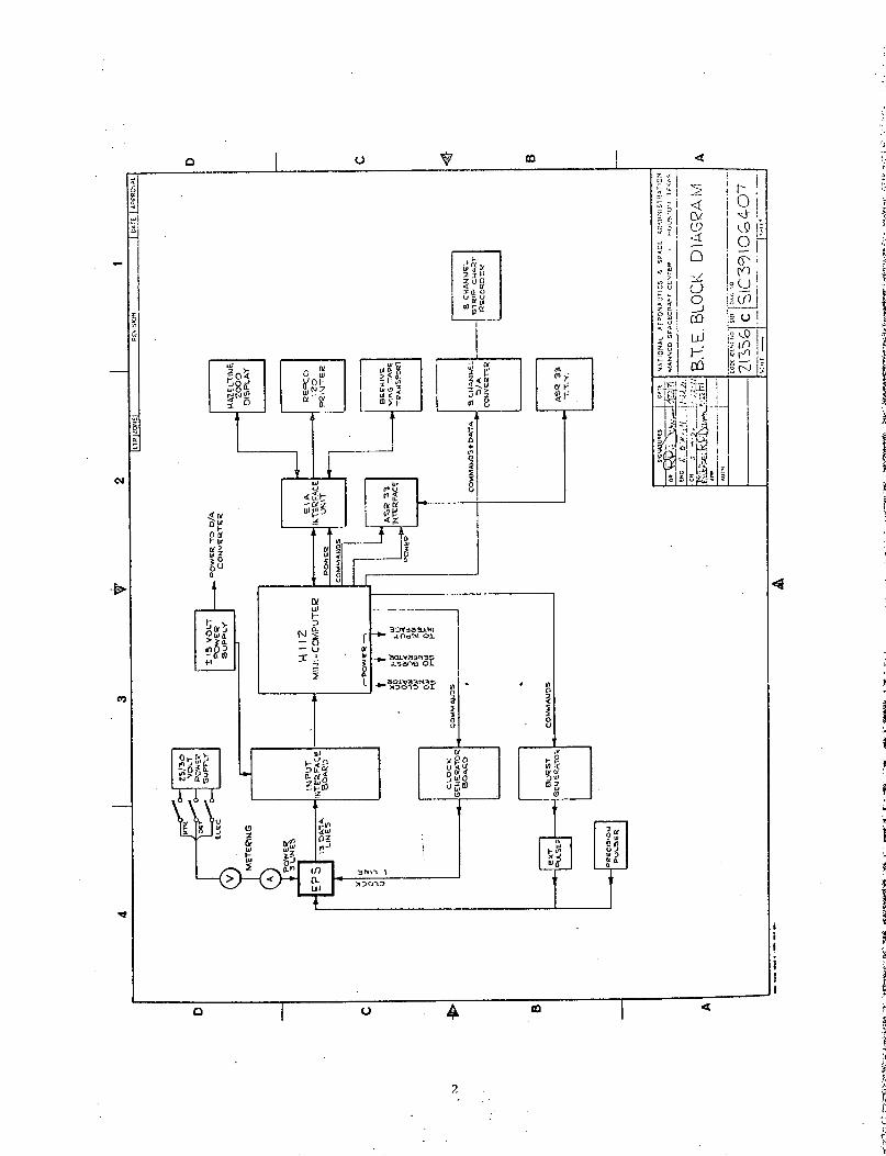
2
. :

exclusively to power the EPS. All power supplies have
internal current limiting and over voltage protection to
completely protect the EPS and the various subassemblies
of the B.T.E. from damage due to power supply malfunction.
Two connectors are used to join the EPS and the B.T.E.
A single coaxial line couples the clock to the EPS while
a multiconductor cable supplies grounding, power, and couples
the 13 data lines from the EPS to the B.T.E.
The clock generator which normally supplies a 1 pps square
wave to the EPS is a programmable counter using the
internal clock of the H112 and requires commands from the
H112 to set the clock frequency from 1 pulse every 64 seconds
to 32 pulses per second depending upon test requirements.
The clock generator is serviced automatically each time the
H112 is started. Information stored in core by the
operator determines the clock frequency.
The input interface board contains 13 comparators used to
reshape the signals from the EPS and convert them to
DTL compatible levels so they can be presented to the
H112 for processing. RF by-passing and internal hysteresis
feedback provide excellent noise rejection by the comparators
as borne out by the tests recently performed by NASA.
The input interface board is serviced by the H112 each time
a clock pulse is generated by the H112.
3

The burst generator provides trigger signals to drive a
pulse generator to evaluate the performance of the counter,
compressor, and output circuits of the EPS data processor
as well as non-precision evaluation of the amplifier and
discriminator circuits. The burst generator is reset after
each prime frame sync is received to prevent pulses being
sent to the EPS during the 1 second per prime frame dead
period. The burst generator is given the quantity of
pulses required from the H112 and immediately upon com-
pletion of resetting by the 11112 begins outputting the
pulses at a 175 kHz rate.
To evaluate preamp gain and discriminator setting stabilities
a precision pulse generator is provided. Output pulse rates
of 60 Hz and 90 Hz are available with an output voltage
range of zero to 10 volts being the normal output amplitude
range.
The EIA interface unit couples the H112 to the Hazeltine
C.R.T. display, the printer, and the magnetic tape
transport. An acoustic coupler or any other device con-
forming to EIA specification RS-232B may be similarly
coupled to the H112 by this interface if required. A huge
saving in time and cost was realized by using this interface
and RS-232 compatible devices. The input-output data rate
is 1200 baud or roughly 100 characters per second, ten times
the speed of a standard ASR-33 Teletype.
The ASR-33 interface permits using an ASR-33 Teletype to
load Honeywell software or provide a backup in case of
CRT of printer failure. Paper tapes of the software may
also be punched to test the EPS as an added measure of
security.
4
i
I
I
I
f

The Hazeltine 2000 normally displays data and allows
program modification through the keyboard using a core
resident editing program. The Beehive Cassette Recorder
may also be commanded from the Hazeltine Keyboard. Up to
2000 characters may be displayed on the screen of the
Hazeltine.
The Repco 120 printer is an electrostatic printer of 100
character per second speed and very low operating noise level.
It provides hard copy of data for permanent records of tests
on the EPS.
The magnetic tape cassette transport enables the recording
of test data on inexpensive, compact, cassettes for
immediate retrieval and display or hard copy. If the test
program is inadvertently destroyed it is normally reloaded
from the magnetic tape in far less time than loading from an
ASR-33 would require.
Continuous analog recording and plotting of up to 8 channels
of data are provided by the 8 channel recorder interface
consisting of 8 digital to analog converters and control
electronics. The 8 desired parameters are selected from
the keyboard of the Hazeltine before the program is
started. During tests the 8 channels are gated as their
appropriate data is transmitted to the B.T.E.
5

o0%
d co
j Lo
H t cM
tI > : 1 U U
( c*4 wP4 H
., ,orH 4 -)
E-i LO 34 9 U U
.
m r
Hl H-0 0o) Hof r,
co 0~- ,-I
0N rH
CM 0UJ S > U H H
E >11n L
I"
cccr.
cr.
c-'
cr'
cr-
r-
4
PL
-I HH H-I H-
D o o o 0-I -I ,-' -I-I,-,-,--
D o o o o
DO O O O
* ,--I . . *
0 0. 0 . 0
-4 H H rH
00 · 0 0 0 0 0
ri h4 r-I hc H H H H
I, . t ft f
H0
H0
0
O ·0H
0o
H
H
H
E-iZ
HH
· ,,-I --i ,-
· H r- H
· I - r- r1
· e' · l ·
O- O
* * 4* * 4
HO O
X J W0 P*H IH (
n 'oD r- CO -0 ,-I , o-i 0 i CI cn
6
r-iO
0r-i0
r-H
0
H
HEC
ri
z
H0HH
H-EHz4
Hr-I0
H
0H0
H0
r-i0
Hl
* f
* f
0
CM4
* ·
O 04J X0P fC 4
HP:04
I N en
0W
0 0:0

U
Hr-i
U
0)
oo
ou)
o
oI
r-
U
u,N
o
oCl
0,
E.
E-i
a)
(u
Ht
l,
a)
* U
C-)
p4
H
CI
0
o >13 UU
-
*rj
C. 0
E H 0
H I -4o U)
u) rd ·rl Q
E-4 0 ' o
HqaE
H 0 ooo co
c H 0C
-I C ·
030Cl O
H
0 0
o
O **
, O
EqUEz X zk
cocoolq
0'
N
N
CO
.0
$4
UQ)0,H
o Co* c0(N
* CN
* CN
'C).0
O
O*
o* 4
* 4
0 a,
* w
H( N M q IA %D
o co o.·CO ·
0 0 a
(N
* * *l
* * 0 *
* . * 4
* 0 0
* 0 4 a
m N w N
Co ocoNN o
0 0
* 0
4 4
a4 P4
4
0
4
4
C -4O H- C- l-HHHHr(U
0
7

u
a,:v a, a
0 O Npo) a) QoS4 D 1: O r
LA 0' 0 LA"+n ++ I
H (lq r-+ . .
O
co oNO
o 0LA
+
0
*00 00
C00
0 O'O O OO O I
* *0 +
O Oco c I+
0O O O O
O L O on
r I ) (i
+ I I +
CO ) ND N * o , icN S . -7 Ln. ";I LA N-
ec4 c4
- m p
a)
tE
Ua)
C.)
CO
a+
pqa f.0)
C.)>1
U)
.,-I.rz
X)':D
ONin 0
pm r 4JX ~..
HH 0
I *. N
1.P cl
*- tD 0,P
H I M4J M.'U)q 44 -4
C. U oa)
a, Ct -q 0H O H Op
a,U)
0En
4r
z
4)
0.XC;
+-4-
0aHO)
Q) 4 U)
a, a) a,
u
9 a-) 0
a
co ro
+ 0+
C'S H+ +
o a. No 1-0 ' Ua, a. CX LA LA N
H * * * *
· LO
P4
4 a
Eo)
Ez *, m O
N X J 4 4J 4JC. I a) O) ( Q)
a, a a, a a,".4hP4 H C, CA o ' u3
N0
trl 4-
~4 9
- +
X
+ 0 *
LO H+ . .
0 0 4-
hh O
4J 4J(a f >
+00:4t +
1~ o0oLAO*D >
CD
+ +
a LA 0D LA Hko H - IOD UL· LA I - C' 0
* * * * C
c'fS H e4'
0 OItI 4- -X -*, 0~4 0
0
'O c4J > 4-a) ur a1a + Q
%D r- CX
N0
( co
tn 4-)0
4 >a1) om +
p0 h 0 4 0 N0 4) .- I 4 04.1- *1 r *-r- 4W
*, ~ O <*
> Cn H Ln
O O O O OO O *O O
00) CN Cf r-I+ ++ I I
00
0~00
C a ele o n
00* * 00@
0 h' CO Y) 0
m4 c4 c4 r4 e4
N4 0 )-h 0 4-) 0 N
0 4-d O 4- *-
0 O X 0
> + + > Ica N m H LnI + + I I
0
44Ia,C.)
U)
0
ooo
+
U)oLA
C'-4
C)
(.
U)
-n0d
.~1r.
a i OH C'4 H er LA '
8
u
C-)
a,
+ o~
+
Cy%0.io9'U
Q.)[4H-
0 LA00 r-,CO LA
C'4 C'.
u9,-Hu9
O O H
D D 0
o. 03Ce) LA0 M
rA cN
o C3 oC C oC
*n * m
LAo0LA
U)
A4H)H
H
O3
U)
0.Z

EPS-220Revised 9-21-71
BENCH TEST EQUIPMENT (BTE)
SPECIFICATION
1. INPUTS FROM EPS
1.1 13 data lines from EPS
1.1.1 Binary "1" 3.5 to 10 volts
1.1.2 Binary "0" 0 to + .5 volts
2. OUTPUTS TO EPS
2.1 BTE Simulates Operation on CSM.
2.2 1 pulse per 64 seconds to 32 pulses per second
clock timing.
2.3 Pulse bursts of from 1 to 3355431 pulses per prime
frame period.
2.4 Precision voltage pulses for discriminator adjust-
ment and testing.
2.5 Power
2.5.1 25 to 30 volts detector power.
2.5.2 25 to 30 volts electronic power.
2.5.3 25 to 30 volts heater power.
9

EPS-220Revised 9-21-71
Page 2
3. DISPLAY OUTPUTS FROM BTE
3.1 10 data and 32 housekeeping channels continually
displayed in either of 3 formats (see illustration) on
a CRT terminal.
3.2 8 housekeeping outputs 0 to 10 volts to drive an
8 channel strip chart recorder.
3.3 Printer to record data in 3.1.
3.4 Power to EPS continually displayed by voltage and
current meters.
3.5 Magnetic tape cassette recorder used to record
software and data for later use.
10

PART V
RELIABILITY AND QUALITY A&,CiURANCE
I-

1. PROCUREMENT AND RELIABILITY REQUIREMENTS
Certain parts required for the EPS were not available as
Established Reliability Parts. Procurement of these parts
was handled in three different ways, i.e.
Vendors Specifications,
Procurement Specifications, and
Screen and Burn-In.
1.1 VENDORS SPECIFICATIONS
When vendors specifications were available, they were
reviewed. If the specifications complied with NASA
Reliability Requirements for flight hardware, parts were
procured on this basis. Specification Test Sheets are
available on request on these parts.
1.2 PROCUREMENT SPECIFICATIONS
To meet the requirements for High Reliability Parts when
suitable vendors specifications were not available, procure-
ment specifications were written to ensure that vendors'
testing programs would-be upgraded to qualify their parts
under NASA requirements for High Reliability Flight parts.
A list of Procurement Specifications follows:
EPS-125 - Procurement Specification for Lithium-Drifted
Silicon Detectors.
EPS-i24 - Procurement Specification for Bourns Potentiometers.
EPS-121 - Procurement Specification for Erie Capacitors
Type 838-lKV-X5T-103M.
EPS-116 - Procurement Specification for Caddock Resistors
Type MK, MG, and MS.
1 _

EPS-168 - Procurement Specification for Caddock Resistors
Type 1712-100 Meg.
EPS-232. - Procurement Specification for Capacitor (Variable)
RVC12.
EPS-167 - Procurement Specification for Nytronics Inductor
PD-100.
EPS-356 - Procurement Specification for Barry Control Vibration
Isolators.
1.3 SCREEN AND BURN-IN SPECIFICATIONS
Some parts did not lend themselves to these approaches and
were purchased as commercial and JAN parts and subjected
to a Screen and Burn-In to qualify them as Hi-Rel Parts.
The Screen and Burn-In was conducted at the NASA White Sands
Test Facility. These tests were designed to meet Specification
for Semiconductors, MIL-S-19500; Test Requirements for Semi-
conductors, MIL-STD-750; Test Methods for Electronic Parts,
MIL-STD-202D; and MSC Reliability Parts Program Requirements,
MSC-3515. The Screen and Burn-In Specification was used on
the following parts.
*Type P/N Manufacturer Specification
Transistor SS3520 Motorola EPS-128
Transistor 2N2609 T.I. EPS-214
Transistor 2N5333 T.I. EPS-179
Transistor JAN 2N3811 Motorola EPS-129
Transistor 2N4878 Intersil EPS-175
2

2. QUALITY ASSURANCE PLAN
2.1 INTRODUCTION
The objective of this plan will be to ensure compliance
with the quality assurance requirements and goals during
development, production, and shipping of the EPS. The plan
identifies the quality assurance task elements and methods
for implementing the quality assurance program for the EPS.
2.2 APPLICABLE DOCUMENTS
MSCM 5312 Reliability and Quality Assurance Manual
NHB 5300.4 (1B) Quality Programs for Space System
Contractors
MSC-KA-D-69-44 Apollo Applications Program Ancillary
Hardware General Requirements
MSFC-STD-271 Fabrication of Welded Electronic Modules
MSFC-SPEC-270 Component Lead and interconnection
Materials for Welded'Electronic Modules
2.3 ORGANIZATION
LEC and NASA/MSC quality assurance personnel will be
responsible for carrying out various tasks in support of
the EPS quality assurance program. These tasks will be
the responsibility of both organizations as shown in
Table 1.
3

TABLE 1
TASK RESPONSIBILITIES
Task
Documentation
Drawings andSpecifications Review
Quality Planning
Work Instructions
Records
Facilities and Standards
Control of Purchases
Fabrication Control
Handling and Storage
Conformance
Solder
Inspection Status
Records of Inspection and Testing
Government Source Inspection
Nonconforming Articles
Failure Reporting
End Item Report
Identification
LECaFunction
Implement
Implement
Implement
Implement
Joint
Implement
Implement
Joint
Implement
Assist
Assist
Assist
Assist
Assist
Joint
Joint
Joint
Assist
NASAbFunction
None
Monitor
Monitor
None
Joint
Monitor
Monitor
Joint
Monitor
Implement
Implement
Implement
Implement
Implement
Joint
Joint
Joint
Implement
4
a'bThese functions are defined on next page.

TABLE 1 (Concluded)
TASK RESPONSIBILITIES
LECFunction
Acceptance Data Package
Contamination Control
Equipment Logs
Radiation and Dye PenetrationInspection
EEE Parts Quality Verification
Government Property Control
Test and FabricationProcedures Review
Assist
Implement
Assist
Joint
Implement
Implement
Joint
NASAFunction
Implement
Monitor
Implement
Joint
Monitor
Monitor
Joint
DEFINITIONS
Implement - The performance of work necessary to carry the
task to completion.
Monitor - To provide assistance and advice, and exercise
surveillance over the implementation of the task.
Joint - The responsibility of both organizations to
jointly implement the task.
Assist - The performance of work necessary for the
completion of the task.
5

2.4 DOCUMENTATION
LEC will provide all information, documents, records,
reports, and assistance to NASA/MSC and its authorized
representative as required by the contract.
2.5 DRAWING AND SPECIFICATIONS REVIEW
Each drawing, specification and procedure released for
use on the EPS program will be reviewed for quality
assurance provisions and inspectability, and will be
approved by the LEC quality assurance engineer.
2.6 QUALITY PLANNING
All quality assurance planning will be developed by the
quality assurance engineer. All inspections and tests
will be planned on appropriate data sheets.
Each data sheet will identify the article under test; will
provide instructions for performing the inspections and
tests; will state criteria for acceptance or rejections;
will provide for recording of required data; and will
provide a means of recording status of test completion.
LEC will initially review all phases of the quality
assurance requirements to ensure that timely provision
is made for special controls, equipment, parts or skills,
which will affect the quality of the deliverable hardware.
6

2.7 WORK INSTRUCTIONS
The quality assurance program will assure that all work
affecting quality will be prescribed in clearand complete
instructions pertaining to the particular type of effort.
This includes purchasing, handling, machining, assembling,
fabrication, testing, and any other procedure that involves
the deliverable items.
2.8 RECORDS
Records will be maintained and used to assure economical
and effective operation of the quality assurance program.
The inspection and test records will indicate observa-
tions made and deficiencies encountered. Action taken
on deficiencies will be recorded on the Discrepancy Record
(DR/MRR), (MSC Form 2176).
2.9 FACILITIES AND STANDARDS
Procedures for assuring adequacy of drawings, documentation,
and changes will generally follow existing NASA procedures
and guidelines. Where it is found that the NASA document
is not applicable or appropriate, a new procedure will be
generated.
Test and measuring equipment will be used which has a
current, valid calibration sticker applied. The objective
is to make measurements with properly calibrated equipment
which has a known relationship to national standards,
and to replace or repair faulty equipment which is to
be used in inspection or testing of deliverable items.
7

2.10 CONTROL OF PURCHASES
The quality assurance engineer will be responsible to
assure that purchases of parts/materials will be of suf-
ficient quality to conform to contractual and good
workmanship requirements. Suppliers will be chosen on
their ability to perform adequately to the quality
requirements of the specified parts and materials. In
all possible cases parts/materials will be purchased that
conform to the Established Reliability designation. If
a particular item is not available as an Established
Reliability item, then a procurement document will be
written which will assure conformance to strict controls
to enable the part ot meet the quality requirements of
the overall system. In all other cases, parts used will
be subjected to screen and burn-in procedures at their
respective rated parameters.
2.11 FABRICATION CONTROL
The quality assurance engineer will review and approve all
work pertaining to the fabrication of the EPS for the
adequacy and currency of all quality requirements of the
contract. Materials procured before establishment of
contract quality requirements will be reviewed to determine
suitability for use in the EPS.
Requirements for supplier data, materials certifications,
traceability, and source inspection will be stipulated
on the purchase orders, as required.
8

2.12 HANDLING AND STORAGE OF MATERIALS
The material control system utilized will prevent damage,
deterioration, or substitution of materials between receipt
at LEC and delivery of the end item to NASA.
Parts and materials that are sensitive to age will be
identified and controlled. This will be accomplished
by a review of parts and materials lists. A log will
be prepared to identify such items.
2.13 INSPECTION AND TESTS
2.13.1 CONFORMANCE
MSC quality assurance will monitor all tests and inspect
each assembly, subassembly and module to ensure that
each article conforms fully with released drawings,
specifications and procedures.
2.13.2 SOLDERING
All hand soldering performed on the EPS will be in accordance
with NASA specification NHB 5300.4 (3B) "Requirements for
Soldering Electrical Connections."
2.13.3 INSPECTION STATUS
A step-by-step inspection status of the part under test
will-be indicated on the data sheet. Parts successfully
completing the required tests and inspections will be
9

positively identified in a manner appropriate to the
size and fragility of the part. Rejected items will
be routed for rework or for disposition by the Material
Review Board (MRB).
2.13.4 RECORDS OF INSPECTION AND TESTS
Records of inspections and tests made during the develop-
ment, fabrication, and assembly of the EPS will be
maintained and be available for examination upon request.
The records will include: part, component or system
identification, inspection or tests involved, number
of conforming articles, number of rejected articles,
nature of defects and basic cause for rejections. The
records will be suitable in format, accuracy, complete-
ness and detail to permit analysis. The data will cover
both conforming and defective items. Where variables
data are required, the actual numerical results obtained
will be indicated, including any instrument multiplier
factors. Where data or information is required to be
recorded, the film, tape or other media will be identified
with the characteristic measured and any necessary
multiplier factors. Where defective or nonconforming
articles are involved, the records will include the results
of analysis or basic causes and corrective action taken.
2.13.5 GOVERNMENT SOURCE INSPECTION
Applicable source inspections required by the Government
at suppliers' facilities will be stated on purchase orders
for new materials procured.
10

2.14 NONCONFORMING ARTICLES
A Material Review Board will be established which will
consist of one engineering representative, the Quality
Assurance engineer and the Government representative(s)
(NASA/MSC). This Board will review, control and make
disposition of all nonconforming end items. Nonconforming
items will be carefully segrated to preclude their un-
authorized use on the end item.
Positive identification of rejected material, where
applicable, will be employed.
2.15 FAILURE REPORTING
The Failure Investigation Action Report (FIAR) (MSC Form
2174) shall be used to report all failures. The FIAR will
be processed in accordance with MSCM 5312 (Reliability
and Quality Assurance Manual) requirements.
Trouble, failure, and quality data on every part, component,
equipment and system will be completely and accurately
collected, processed, and disseminated in a minimum of
time. The data required will include, but not be limited
to., that specified in this section, and may be submitted
in separate reports as generated.
Procedures and responsibilities will be established for
the collection of failure and quality data resulting
from testing, inspection and usage of the articles procured
11

or produced. These procedures will include effective
followup to ensure timely and adequate corrective action
on all deficiencies throughout all tests programs.
Data will be collected and analyzed to:
a. Provide indicators of design and fabrication
deficiencies so that early corrective action and
preventive action can be initiated.
b. Provide corrective action and preventive action
information to improve and maintain required
quality and reliability.
c. Provide complete functional and performance history
on all articles for use in design selection, qualifi-
cation testing, and design improvements.
d. Evaluate quality aspects of specifications, drawings
and other technical documents:
e. Determine the need for special investigations and
analyses.
f. Establish the requirements for process control
charts.
g. Determine the validity of inspections, test specifi-
cations and procedures, and process control.
h. Provide engineering, purchasing and fabrication
personnel with information on actual quality
assurance requirements.
i. Establish and maintain a realistic list of limited
and critical life articles.
12

2.16 END ITEM REPORT
The Quality Assurance engineer will prepare a narrative
end item report for each end item submitted under the
contract schedule. The report will cover item test and
inspection, weight, packaging, packing and shipment. The
report will include, but not be limited to the following:
a. Final configuration.
b. Replacements made during installation, test and final
checkout. Serial and part numbers of articles
removed and those substituted will be indicated.
c. Corrective action taken or pending.
d. Nature of trouble and malfunctions encountered.
e. Total operating time of each end item.
2.17 IDENTIFICATION
Matierals, processes and design parameters will be so
identified in the design configuration and documentation
that the engineering features to be evaluated may be
associated with the particular articles. Each article,
including parts and components, will be identified by a
unique part number and serial or lot number as may be
required. These identification numbers will be consistent
with the engineering drawings and change control system
used throughout the contract. When the contract requires
mechanized or electronic processing of data for distri-
bution, the identification numbers will be suitable for
processing.
13

2.18 ACCEPTACNE DATA PACKAGE (ADP)
An Acceptance Data Package (ADP) will be delivered with
each hardware end item. The degree and contents of the
ADP will vary depending upon hardware class, complexity
and whether such hardware is deliverable by the contract,
or deliverable but not contractually required.
LEC will submit an inventory with each end item, indicating
which of the listed items are included in the package,
which items have already been submitted, which items are
excluded, and a statement covering exclusion.
2.19 CONTAMINATION CONTROL
Cleanliness of deliverable items will be controlled such
that the requirements of interface, performance, and
design are met. Contamination control documentation will
be provided to outline methods and procedures to assure
cleanliness of the end item hardware. A clean work area
and clean bench will be utilized for fabrication and
assembly of the deliverable hardware.
2.20 EQUIPMENT LOGS
Equipment logs will be maintained for all deliverable end
items, including major components, subassemblies, and
systems. The log will contain all information as required
by Paragraph 8.3.5 of Document MSC-KA-D-69-44, Revision A.
14

2.21 RADIOGRAPHIC AND DYE PENETRANT INSPECTION
Inspection techniques will meet the requirements of good
workmanship and applicable contractual documentation.
Inspection techniques and requirements will be coordinated
between the LEC Quality Assurance engineer and the
Government Quality Assurance representative.
2.22 ELECTRICAL, ELECTRONIC, ELECTROMECHANICAL (EEE) PARTS
QUALITY VERIFICATION
All EEE parts shall be Established Reliability and/or JAN TX
where possible. If these parts are not available, procedures
will be written for screen and burn-in of the parts. It will
be required that all parts not having Established Reliability
be subjected to screen and burn-in to assure a high degree
of quality and reliability.
Lot traceability and certificates 6f compliance will be
required on all parts, except in cases where this require-
ment is waived by NASA/MSC Quality Assurance.
2.23 GOVERNMENT PROPERTY CONTROL
LEC will be responsible for all Government furnished
property/equipment in accordance with the provisions of
the contract. LEC's responsibility will include, but not
be limited to, protection of the property, and making
provisions for calibration scheduling so as to minimize
conflicts with work schedules. The calibration and repair
15

facilities of MSC will be used for calibration and repair
of the Government-owned equipment. The same property
control system used on NASA Contract NAS 9-10950 will be
utilized on this Contract, NAS 9-11373. The primary control
point for property and audit is the HASD Accounting Manager.
16

EPS-469
ELECTRON-PROTON SPECTROMETER
EEE PARTS LIST
LEC Document Number EPS-469
Prepared by
Lockheed Electronics Company
Houston Aerospace Systems Division
Houston, Texas
Under Contract NAS 9-11373
for the
National Aeronautics and Space Administration
Manned Spacecraft Center
Houston, Texas
June, 1971
I

EEE PARTS LIST
Prepared by:
Approved by:
Is. GleesonReliability and QualityAssurance Engineer
E. CurtsingerEngineering Supervisor
B. C. HallProgram Manager
Electron-Proton Spectrometer Program
Advanced Programs Department
Lockheed Electronics Company, Inc.
Houston Aerospace Systems Division
Houston, Texas
(t

ELECTRON-PROTON SPECTROMETER
The Electron-Proton Spectrometer EEE Parts List catalogs
the electrical, electronic, and electromechanical (EEE)
parts used in the EPS. The list is divided into sections
each representing a particular assembly. The parts of each
assembly are grouped by their generic name. Parts are
identified by size, rating, material, and part numbers
as applicable. Drawing designation, manufacture, specifi-
cation number, method of qualification, qualification
status, and number required are also shown.
Parts used on the EPS are procured to user's specifications
that include reliability and quality assurance for each
application. Electronic parts have been derated to obtain
the best operating levels for prolonged reliability.
1

H 4 n I n M) u 44 In In o n 0 U)0 o 4- -
-4 -4 H H H H .- 4 H H H N H ( (N H
0 a 0D O 0 0 0( o CY 0a 0 0 0 0
0 >, >, 0 >, a O > .o' , ' > . o ' 0 >0 4 0 >' 0T >h ' >. xl >o4 C)o v o4- 04 ) W - 04- o. o4 4J o) 4 0)4J a) 4J 4 ) 4 1 o) 4S C - d S.2:4 1 S- . 4 U ... .. C : 4L .:- S. 1 v J . S _ C)
In444444-444- H o U)-044 (0H ° ((-4 0W. W)- (( U) (OH O
~~~4 -'In I ~ ~ · ·.- ... , . . -4 -, 1 --s ., , -4 .1. . .l O .
4JI 4V 4JH 4-4H 4.l- H U I 4V H 4V Vl H 4- U44 4).-4 UN
m O u o) a w Q o 4 O 4 0 4 ) 44O 0J W 0a O0 U)OC 00 0 a) U)44 0a)I a) wwa; N XM r4 Z: r. D:: C W M n Wg 5d f C Z 14 cr, ' W 1 lW n
Z o o" - I I. -:
F- H H
U 1 E I I I E W W W II I I I E
u0 - o 0 0 u, o o o1 00 u00 0040 0 0 00n 0c4 0o -3rS 't U 4Z U)U) U ) Z o Z - I U U 00
Xz Y 0 a
_-,-
~o,~~~ O 2 O 2 2 t 2 0 0.r 2 O 2.2 '0 1± 2 .
a Q : t f * . . a c *
r(N ( N v v_ o .u v r. -h r . (N (
N N 0 0 N N H 0 N N- N NH H (N (N H ' H . . -
i° U c V ' ' ' C C 4 C C -
1- ' O X : - - C: 4 : - X Y 0
Z _ O * * U1 O . O. H . O .0 0
W < Ul 1 - N ( D _I H 1 (N 0 0 v v N 07 04O 4 CO
o 9
ow
1.
2
2=,
0
I--4
U
a. >
0WoU
I-CU
IC-
.-
CL
-J
LU-J
knr
C
0WU
N1
0Iw
o ,,
I IU C
I a_
W anVa Z4
4-440
W.00
mC-'E-
P�1-E-
I-
U
CE-Cr�
irL
crE-
040.
44
a0404
04
44a
0)
o
o
rUM;
Z W W0 WW 2 W 2
z Z
> -
CD mI 2
4 WI 0
< <-
(L
U
O zw
z
IW
Z-J
z0
inWX±4.
UIt
i
-I,I

in u� in in in a in in in 0 in in 0
A- .A A.- A. - i N A A N A ,-. N
I C C 0 0 Cc I c 0 c. CI C
aaL ~ aa aa al~ ou .aa me .al o.1· C) C) C)-H IC-H C)- IC-H IC-H
C)C) 00 00 CC) (D C ICC) WC) a) C) C)(4 In c o lin W P( W(11(4 U C4 W ( Q 4( o 11 W(
Ca c CI C
C)4-i .- ,- -4-W A 4 , W A
W C ) a - W C ) - H C ) . 1 d W. C.10 4I- 4.0 ~~~~ ." I ~~I r,,W C r4 W E
N NI CDC)) 0 O 0 -C C 0 -.A 4 0 0 i n in in in i
.4iCo 0 g0 I 1 0 0 in C) 4 in i Ain Ai, -lm AN AO0 CC)
I ).n I I 101 IN 10 I· 00.(4 InN ( U 1 1 .4O 1l~ Crin - n' 114 iN Winl Irn I Il -3 CIn En
H (4C ~ H H H_ H H H r HC(4 cli - in ( (4 C in
W~~~~~~~~~~~ ° o
U -
-- U,
C)
n i" n X in X X I -N A-( ~ n i n c ) A C ) C) C) ( l 4 i A iE
A (4 C~i <in ini C, i iin in HnO F-INI in C n Clin 0 4 0 0 0 4 0 ( n )U tin(4 i 1 r n AO A (0 N inn C A C~ ~A U n
> 0 C N O 04 1 4 N O (40 (40 I-Z CC i <iin~ in X H 4 ( U -e H(4~ ( 4 A 0 A~ N ini ~N
0 1(r- 0 a,FN H3 in
l-)N CA A
0l 4 i 4, ·j .'C-4I
C)C ) U a)V 0LL~~o 0C) ~~~~~4- 4-i '~ - . .~ C) (4 C) C) C) C)o C) X (14 Or g Q 4L C
o t o o 1j4
- i~
4J4
C. .) o0 C) o> C) C; C) C),i41 - C
l, (4 e (4 (4 (4 ( 4El H EH C )
·r ; : ta~~, .O O '
EnI i > , U En 7) En , , ,
I0 0 N 0 0oC 0 0 0 0
C.. *0C~~~U U - E E AEA0, 0 i , ,
A I in U C) ). C)
-1o a ~ P , O ~
C) 0- 0 0 u~ 0-
O ii Cl W i AZ~ I- A~ - c A Ca: ~ ~ C A A, A v -H - 0r 0v C
0 ~z. 14 in r- in * A * A1
in IC I I I c)
.~ B o o o o o o o o 0 ~ I IIE~ I U)
o H -1 HH HF- H H i n i
0
°1 *. - A
Z0z w o0riN0ONn VL r (N na
11 40U uUuUu a U Ui-z
I-
Li
4U.
a.
,¥
I'-M.I
0I-ULn
(A
~0 -
u.'
U
LU
I-J
1CC
LU
-J
OL"
co
C C
in0 Um
(4 OL
r(1I 1
U3
ini
inz4'w -jW 0 c -
2 2 W 0'n Z
0 Z
0 z
U.
in
(4
W(4
0r-
EE
U
0
F-,
0
N C-
040CA Wn01Hc04(4
(4
in
A C ).
iW~
U) Y
cw crw
W 2 i 2
z Z
w a)
oW- W4 42 2
z
I-a:
I-
w
-4
z0U)
W
-1
U
CL
CI
ii
iI
I .

u) m L
a 0 C
(a)41 ) 10 Lol V co to
S .1. 0a) OT(Z41 4' EI 1 4.4vI
O 'V EE 'O - El
I a) 4W,40 o - U I -.- 4 aO I o) -H H H H Hs:vwa 1)XaZZ
0 07 0 0In en
a) U o 0I I Z I
u ) .: .
H 4 - H.
. " H
z r4
I I.0 00
O, n I NI I0 I oI N rl o
o I. :* z I
N N )U') eno0) m e O
*2 8 O .
0 O! !
_I N
0 U
I 0- C) U
H H C)
cI
4 4 1
I0
(14
0~WL
LuceLU
I-
LU
t0nO .
Z I
I- U
LI) a)
I-
11
u-
m m<C4.
zw
(n Z<n
El
E.
O 6
v0 zO
_0 Z
IL 0
-J
I-
* <3; ,O
40:a
C-
u 2 w 2
I I)
UZ a_
N 0
I
0 0,
z v)
4 -
en en.
< *(Lxw
z z
l's
i
I
-15w-J
z0
V)_W
4
I
IIIII
IItE
EI

H _1 H-1 HI HHt H H ('44 ,1 H N HI N N N
C H C- .4 CH C-4 0 ..- cj C NfC ~ O N - N
o ci c0 ci ci ai i oi ci c c c c o ci l c
1, > 0 g > , 'C >,O V 4 O -O 4)4 C' 4-.Co C-H, .0~- ,C"I C--IJ.0 .0 , .0 0-H -HU)~ rl r 0wI0]rl tmq _4 r OH .-n H 40 -,-4 0,,'
H-1 ~ ~ ~ ~ ~ -
4 4-H 4-(H -I ED 44C) ) ) C) Q ) H Q C)
00 00 00 ino 9 '4-' 0EV) Or U} Or~r U}O lO r°
W~~~~~V CvW+W rWA D:
'C>,'4) 44.C
Q /1
4Hq Iq
'1 ' - c)W : 0 E-
Z rs aa:c s o (' O N O N O O0
< O O N 0 O O O H 0 0-0 . N H 4
4 Vl n In N 0 01 a IC On
I4 a a a * I I : I I Ec) I
a ~~~~~~~~~~~~~~~~~~~~,, - W -0 0 W 0 0 W 5 W. W UI, I I I I I I: I'
Oz 0 C040 0 0 0 u 0 0Zomo °
z 0 O ) X 0 0 C- X C H XXn 0 HN 0IL ~ ~ ~ z Sa -O N bzioN o m o xr 27 ff DDUXU f K -*E sv 3 , SNo1, ( ON 1ON NO O4 -nN O 0 : O O O 0 1 N .7.4 00 00v ° 0 O C H i0.-4 00 00 H ° N -4 ON I Zo OH _I 111 NO z I-I UN O HU OH p ' N H )H zn N C,0 a,O e~rl rl mn~~r U~ Um x U UV m o
0 0 ~ ~ ~ ~' 40 CH 0 0 C 0 0 4J 4 44 44 U) - OO
C) O C 1U 4 C U O) O4) C O) a) a5) 0 4h0Ci HO C4
C, C C, tl C4 E E: E E E X Q Xin >O 0Z 8 1 " Z 0 C) x O '4 x4 ) -'
"L~~~ a) O r y X X E~~~~~~n hH rLT Z~~E
o5 oO0 3 0
3 N N 0 H1O N,\ N N ON 0 0 N N\ * ' - H N >
H 4 : d - 0
cV~~~~~~1 Cv X 1
H HP . 4. O NH 41 X 0 : H
C ' ID H I . a 0.v 0: * 0 .v 0
rl ,~~~~~~~E
.4 rn H N K . H HI H- H N W H1 H
I I I I I I
0 0 0 0 0 0 O
W W H W W W H .¢0 0 El E4 E 0 0
.y C · · o y o
a:~ ~ W N W r
M Wx lW r 2 X (
oi H
0
N >o:
O 0,
H I
: H
o o
ooN
. O
I C)
0 0
I 1
0 0E El
H< <
U U
mo
ci4.A
U4
0 0o0
0
0 -
U0 WH
W oa Eu
00
z
°0
z
Zt ~~~~~~~~~~~~N, 0 40 °0 N N
m cm ~~~~~~~~~Uci 0Hv N l( 0 1
Z W .' N ? L)I - r N F )r (
a z m Ir ix " -z WI U U U U U U C), 0 0
F _
a:I
w
z
ciM
Ida
WC
I14.
0
Ido
w
0
oeUY.
LU
I-0v
U
[is
(LU
U U
zW
E-
C~U-C
C414
'4
C-
4'
U
w
-U-z
-J
Z o
wc <a
0O
wUH
m10
H
rlH
C.-
44,
0C
riU00
: Z I Z
z Z
w
o 4
0.
z
14r:1DA
I
111� I
U
z

- -1 ,- U w
. ,- '- U )
COvl
° F- o v oo-
FL) J ' U' ' W'-.4 ',f--W-. uI u ..I - .aI .4J 4
UI) I En 4-I 4)~ -- IL) *.-IC) HU dU m a) aiG)w4 Iv, Iv Io Ivr El E.
IN v 0
- 0 m c~~m ~ H ~ ~~ O O
U) C) x 0U) n -n r -i
S Z. I S
H HH HE Z Z
0
n4
2:
I II > I X I
- Ze N X On ¢ e XD Zn I 0 0 Ed : N
Z:-I Si - 0 >4 U ,4 n 9~
_ U
b 0 0 0
U.§ ....
ow U
e I 3 a a - 0 N
1-0U
OIW
0
10
comU)
wU)Ul
0m
u)LnI)
Ix
F
F-
I-
I
X
z
LUI-
LU
0f,-
I--
L.
w
cn
Zuu
-
VW 0
0flU
E-4
Zn
00
n
U )'>
p v
m W a: Ww 2 W 7<z m z
ZZ Z> Dz z
m (a 4w w(U U0 c4 4
0 . o
z
a:Id
Wu-I
z
S?aac
I

.n In - 10 o N 0 O O 0 0
NA _4 _ N . .'-A .- <NAN N 0 N N N0
_I _IN N f N N N s
O 0c O c Oa CY 01 OC Ca C CO O
Z "'
0- VLLO S (-
I c1i c o.l - ,
I-' Cl-, C- ., l-.H-) f
O O U
w -j
10
2
0o C C
O 01 0 0 0 0 0 0
9 -s -e C
O rCl l O
I N N N N
e N N N N _ N
oz o 04 4 O 4 C e O Cf -II
'0 0- 0 04 0- F 04 0
_ CC
0wc E o r0 ~ ~ I N Nma e
o~
7
LAJ
C
(L
U
A-I
oeLu
ELU
0i-ULi0
ZL_
I -
LO
--I
U
cO
U,
vhe
CI
iiEl
U
1C"
o0
r-ID
0
CC:m Ua
N CL4 A04Cj
0lU2
10CC
w2 w
z z
m m
w w
I t
10 10
wcrt
w-J
z2vJ
zw-IJ
I
I~ ~ ~ ~
I1o

-4 N N .4 .4 N .4 N N N
N N S N N v N O v ._
N N 9r N N N s rr .
o 0 0 0 O C 0 C 0 0 01
l >.C 'O
f. .4 . -.4
· 4. -efl .4
0O
u(
: . , S ,, , , VI
O " 0 14 0 a O a O DOU U OU r U O U
,- - W u'
CC CC
0U 0(U o N omuC 00 oZn ZC
C~t XN
Ya r : Y a Y r
o oU o U U) OZ 0 n Z O N Z-I
OC4 UC C: N
IL
U
2 3 z 2 3~~r 3 3
Cl~~~~C
o o o o o 3 ° °N N N N N 0 3 0 0 Z
0 ~ ~ a C;C:C
.4 _4 @ l - 4 N 3 N aU : 4l NN
. . 4 N r- WJ - 4 _4 .4 .4 (V (Vo a
J ~ El [. P 'V _. El . CO
-2 -- - - -- - - - - -(
o g C C C C X C ,
cc ~ ~ ~ ~ ~ ~ ~ ~
"e My .y C - C * C
-N N * l r O C * * 4a O * 4 * N 0 O o 0 N r.
N N N (A .4 * N . V N N
(A4C
6
W . I I I I I i a a I I IC a C1 C 0 C C C D C
U) U) ((4 () 4 Vl U) U1 U) U) U]H H H F H H H H H H H
Z 40 N 4(4 0O O 4 (A C e.- N5 4r0Ns Dm N .4 fl v, '-w * NI Nn ,o C F : lC CC C: D:C 0 C : C CC CC CC
4W1 N N .Q(A 40 N N 0 .-44( NN 41440 NC, -. .4 ..4 . .4 .. 4 N N.. N.. N..
ow Co CCrl N 1- CC CD C CO W e: a 2 a C: a:a: X ra C: a : XC
0
z14 J-Z
8
o0
aL0.
LA '
I-Lu
0O. CE;
0 e-
uU)
Z 0
Z-
0 =oI-U)
ZLU
UU
W
LU
Ili~
-jLUerco4
i
-
U)
CLr:P1
-4(rAV.4 C
N U)
C C
(AC) W( a
. .
Q> Z
o 2
0 .0o z
a rm II
tr
CC
0E-R
C
C1-40
UW
CC
to
I-
C
NCafi I
(AC
C-C(AC
U
42
C
a
I W
C
WD
H
40I .040NC1
04
W 2 W aw 4 W I4
a Z 2 Z
Z Z
a mW W
o x
zZ
wl-'
I
z0
w
- _-
L
tL
cI

f) wn IN 0 O 0 (N O 0) 0 0 0-1 N H rl
. _ -_ ._ _
H H N N 0 N N N
.N H N N (N (N t N '
o0 0 0 0 0 C0 0 0 0 0 O
a) ) H 4 -, Q- -H 0 . -H
_ H r. .- 4 CI D - . . *dH0- Hf H.0LJ ,I Il E-J El
O H H H H H
u - 01 C 4 10 0 0 0 0
9. 0) * u : t) O U) : : U U -Z
0 o oc
U) C. C )
U U H
0
° 0 z r. J X)C O
( 0
I~
t4 HI I I I)
ZL i. LLo Pr C °1- O O~. HX~ 1- N I- 44 r( aE O O
LLo - 44 4.4 4 44
UC Uu" o o ug o o o u
0s U x Z4 0) X .
O Isn H H 0 (N 0 ._ _
. -4
O
JI a 0 o 0 0 0 0 0 0 0 0'
Z0 0 E_ E - - - - - - E-.
E n U. U U U4 U U UO UU
2 o c N N 04 ( 1 r4
Hs H H4 rU H H (N (N 0U , UU
tU U U U U U U
V U ) 1 C Cl. Z P 2 f e" 4 G G C P
0C U U UUU U U U U UO U UUb-z . _
9
U-oI0
wIa
(L
I-
.I-
0,j
Ir--ua
.LU
J.
U
L1
0)
Ur.
w
WH
04H 0
U U)fi
. .
)- crw-JwIO (D <Z : Z
ZV) )U)Z4,
Z0)Z)
EUr-
MI0E-'rC0-C.
C0)I El
U
U)
Ct
U
U)
0)
U)U)
0)
U)U)
0)
U
U)
Ecn
ww Mww 2 w 2(D < to <:E Z 2 Z
z Z
c 0I Io wU U
U) U)4 49
C-o
Z.
awIL-W
J
ZO
wz
I1 -I - --- ·-

O co "N 0: N CO (N 0 N N
I~~~~~~~~~~~~~~~~~~~~~~~~~~~~~~~~ -" N N N N N
NN N N N
0 0 C 0 0 0 0 0 0 0 0
z . )
J I U I 0OCt
0 :a
tL ,
ou
o 0H
W- 0(
z _ 3 .C C E l ~ . .
o U)
: I
,,0~ · . , _ ; . ....
U_
Z o>N o Uo o o >
0 0 0 0 0 0 0 0 0 0 0
Z Li Li Li i U Li L iUU
ao , ) a a o O
C1 0 i D
z r-
o °4 _IN N N N N C N N 0 Ca C4,-
Li~i Li L Li L i L i L i L
10
Li0
wO4a-
LU
I-=U
U
Z V
LW
O
Ual--LU
I-
Li
Li
W~
(A
a)
E-
0m
El
U
4-
C
(A2)
0
a)
CC
4-0LzI0MI1eC)W
r0W
E-
Li
a)OH
Li
O* aI1ESro
sn mWU
Z Z
m I
W WW (
o WZ
z
wIcr
uiW-az
4,4It2LA
I -- - - I -

N N N C
1-0
n S J I ~ s m -Iw1 H~~~~~r
- I r - 4 4 r4
O O O o O o
ILO e . , 4'0
O r -4 04- 012ASl -4. 0 a0
I- 41 0 1-0 C A 0: 4 C 4 I U_ ro O i 4-4 Im I0u- < o I0 4I t ) U)
4 0. ' 0. 04 01 01
_ I NO O H O~l zX W) OM . o O
c o
O O0 0 -oo_ o i o o
o z 0 1N .- r- NN )-XU) -4t _, H n
3 ' .0N ' .l ' 4 < NZ OZ z9r cn cVm
4. 44 4404 0 0
iz 0 0 o
a - ° '4 Z ' '
W C4 O O
O - 4- E- 0 0, -) 0 EH HH U
z
OW W44)0r lr9~ 2
11
IL
W
4
m-jIDIO
a:10
40
I-
a:
t-
Z4:2
.t
.4 y
a
I
-JmmaJLiWn'A4
LUJC-
0O
I -
O-)CU
-
CL
40
0 LU
U-
(n
3-
Ea
E-0
_0.0
El
4-
Z-
W
ce
1'1
Ii
UoW4Mn,
I:W a: WW i W Xco 4 W 4x Z M Z
:2Z Z
-J JIW m
I.
4 4
a.o
I.-
L
Ia:UL
S
z0
WIn
5:
I
.--

H N N N N (N N H H H
.J~Ci co a a a C a o of ca
oinz
0 W -' 4 04 04 4J< 0 .l4 .~ d .S -H .W d S .
00 E- W4 OH nH Wa E u- ' W V- -,t, tp % -. (- .H, c i - HH.-- ci ci
V r H H. HC.-(.C H HCH3.-(0 HC.-4C,- _ o3 * w w w0 C).d 3 w , o o
.4, C... I W .. ~ V4 '..V. 4 , o 2
2 ~~~~~~~~~~~~~~~~~C : - o o o o~ ~ o ~ o~ oo § o (N N (N N ( 0 O
I- H 0 0 Ho i o i4 in (N inS (N 11- 0% cn
V n (r N in (N il -H H4LL ¢ :*A E*IUVi I I I I I I IU ! I I '
'0 z ~ ~~ niio o_O z 10 O x r oJ o
U F 0 o o 0o o v" o 7 o o1-
~ 3 ( o o ooon 0 0
0 0 v 0 0 in In0 H U (4 0 U) U C) C XD tn U r0 .0 i
U r O.. 0a
W-J
0 F
E C) zaU
On 4 14 40 c
0
a (Nau ~ . a
0 0 H0 0 n 0
H 0 o H o
O O H 0 0 HE 0
en v; E uz ut z u. u
O o Wx W'o
_lzv _ _ _ _ _
O 4D0 (
z Z
14 (-4V C
C rV 0DN n
I I
0 ao 00 0
zo 0 H (N
~~O ~~Nn~~~~~~~H (Z ( ( a i: A N: y a . .~ .z;v ;' . .. "WfW w c: 0 c: C:: 0: X: 0 W: > >
ow0Wa
I F-Z
12
.3
a.
LUI--
e0I-U
Zalo
I--
Z u
-IW
-Ul
JU
v
in
in
IL
)7
Eiin
r-
Q
C,)in
w~ w~2: W 2 W
W 2 W 2{D - co <
).. ..z z
o Wa 2Wn W
4 4
0 Wz
Ia:w
t-W4
Jz
0
LAWcc
U
aI
ar-,E-:.E
C
E-C
r-U.2C
C.
Ia
C
I

0 0 Cl H H H H H H .H H H H _I
N (N H , H
(N eN H H H
NN '4 H H H
A Ca C , c Ca C0 C1 of c cl CY C, C-l c O
c r~l c- -4,-, -
C) o4- o 4- 0 4O
-x~~~H,-¢CH CH -,4 .1 -,:c: -,-H 0-H . - 0H -q In -2H ,j, ·ox ~ ~~~~~~-H , , t- -IH.
'~nr n R '·"~", C o C O
4-OH 4-OH I0 10 I O O uI I I U4- 4-IH00 -HO rlO -H O -HO HO -H O 0 0 00 0
W~ C: Wn r( Eq1 E x d
Z
o'. io U
.l0 oz
IL Z ° O Oi N e eJ oCir o X oo
I OIr Utn UD U' 2P Uo 0 < Uo Uu UP uo cn
o 8 C o
0( 0 0 0 0 00
H N N N N N Nl ( (N &. 0o HEH H H H U n mU r7 n n n n ( N
W a · · · - -H 00J H co 0 0 00 d 00 ao 00 50 0 - H
O _ . H H H 0p Y
wn4 < on H H H In En 17 t U)n N N N H H
o r I I , , I I I I
WoI..
13
I
0
w(0
a-
itJ
tL
wU
0I-U
Z-
O I-axI-J
LU
Ir
E-.W
0~
U
0c2-
2
0
Il
C
Cr
Cr4U]I(I
:E Z w Z
z z
J j
wU,
4 4
m-0 t
z
I
2--w
zi0:
UC
CL
CI

ILO0
1
Li0-.VL
IA-
u
O
LQ
wO-J
LUceL)_l-jtLL"11
v 0L
LUH
-a
0
cE.
0 c
V]Ul
0n 1- I 00
W W Z E Z
z z
I r
W W0 *
U) U)
~z 2 Z
10
4 4
C-I-
H
,.-4 a O a- (Di -4 a ,'-4 - C ," - 0 -.4 Cc
>>4 d'tr~~~~~~~~~~~~~~~~~~~~~~~~~~-
oj Z 4 C 4laH oH o0 PI 4 ( N -4 -O
or
\~- -_~~' - (N .4
"
ol ._ ._ el
Jotz ci c i ~N '4. - -
'4 ., _
Z I r- N N I-. (N No9 ON O UOO O H O O
0 H H o 0 0 H
4 IN N U) In N N U) U1
_ I I : : : I I I 'I C
O~
z C:
F o m u mo It o ctl F- El oo o1 o o Z -, N 0.0 0 CJ -(UZ\ Z (N
0- 0 0 0 00 O D N4N 0LI 0 0 EnN 0 O 0 4
t Ni N(N 0 0( C(n E( U- .
0 3: 0 0 0
- a a 0 0 d: 0: a a
O) 4 .^ . ~. Z g4J.
:W [ E c o X N N * * ¢4 El ° * * N0
°o UC N B I- I II I ( ( N IN
,, 0 N. N^ 'N N
o 0
ow :a a a ,o C Cr0 a ~ ~ o
Id 0 , C UIC CI-z Y 2
14
ItC
W
WJI.-
Z9tu
0
Wm
_
u
C
>h

H o Il) o 14) 0 o U) 1) 1) U) u) u) U)H -H 4 N4 H
N H N N m N H H H H H ( H
4 H N n N 04 H H H H H H H
N H N N O N I H. H _ rH H I H
H sN H N N or
I aC aI a a a a a 0 a a a a
LC) 0) '3X )J4 cC oC U ) O)4
C °]H 0 _I f H 4 U (H
F I -- .c 4 .~ .0 .0 . 0 a)
- I (n 4' H 4.i I U) ,4 iH VH .I-H I. u
4- o C. O
I o CH oU) C0a U 0 0:
O. H H H Hd
° Z
IL O C O O O
, - 1 o o M H In0.0U " H ).4 .- UI~NU CU
1. 0 0I C'' ' ' 3 o ' ' ' 3
C 0 0 :
': : 0 : : ~ ~: 2 ; =: 20 : 0 2 2 0
3 O CO O NO O O ON o O
W S . S . H sP dA H X H dEO H aP
F 0 c4co -4C C - 4 C 0 N 04 0 4 0
C 0 0 . 0 0 . . 0 . 0
p N E. 04 H G. N. H El H C: X- C:
N N H N H H H H D I
W ~
0
n-0 * a H a r- a H
U) U) ^ C) ), N C N r7 rl U) C N CC
H, , 04 N N 04
I-Z
15
L
IIU.
0
1
WU'
0r.-
LU
O
Z Ul
I-LU
-J
cne
I--all-jW
Cai 01
El
C-'
0C4a,
LI
0WC'
I.)
CC
C-:IE.4
N0
U)H -
to
C) -~
U) C
2.
D
z z
). ) *
I F
o° tI- Ww
z
Iii
t
t-WW
-i
z0L)
wWZ
. I1
UC
LLeC
0

n o o In n 0 In 0 m n m(r- (N HN k t r( rH rH rH
r- N r- .o Nc ,-- r- N r- (N .- N N r4 r-
N N r t (N Hq C H HSN H ( IN H H
r .N H .N H I H r - -4 r- H (N -- -4
r - IN H N H - H N H (N , N (N r H- r-
p N~~~~~~~~N ~ ~ ~ ~ C~~~~N~~~~N~~~~N N ~ ~ - ~I
C o 0 CY O O 0 0 0 0C 0 0 a
(044 0C V4J 0 4J O) a) 4 (0 4J ) 4r -H H4 S 4 -r E- 0-H r (-4 10-H
__ __ _ _rl r4_ _ r4-H Hl *- -- 4- rlH -r r rl -1 I
H.3~ H HP Hfl . Hc ,1 *-4. H ' '°
4) rq 4J r1 I 4J r Z4I I<.. -O V ( r( J. ' V- U Ul0 0 Oa) O · u9 r4 l O rl r0~ D aU O O O 0 0 rl O -0H1 04 rl Oa
(4 (0 *n -H (0 -'- 4 w W E E
N rn (N In 1C 0 > n '0 0 0
-4 0 H 0L0 0 0 0
r4 o- cr c O
0 0 0 O (N H 0o0 In r4 r4 H- H § , ,
H H H H H HO HO1 _ H , H H HO PHO c H HZ: ~ OO zO o (n
0 I In In
a a mm a a , ,.- >: I 0 NW r-- \N X In E t 1 1(N I
ID0 In H 0n (0( Hn r i I 0a E~ N 1 N I 0 1 HOO ON t H 00 00 00 0 O I(H r P( v N ) = 8
H _ N 'HO _ o H ri r( ri rH H 2 O n In In I rHi 01 0WC
om uO E-'O 00m UO 1- l( X CCO 0 i W 0 W OO r( N
rnu
g E a : rQ >O X 1 3o t·a X r1 $ g4 O O o
X X *rl~ < r E-01 C ° 0 0 i
4j 4J 0~~~~~4 4 (00 ( C (0 04 -
10 Il (0 0 (0 ' 0 4, 4, 4
E E: " ~~~~~~~> rj X w ~ u x V 41 o44. 0(00 '0-r '0rl '0r: m ~ ·~· m C m a, ·r )c!
u x ~~~~~r. ~~~r EIE~H - P t U) E m
a
U U'
0 Hi
00 C' 0 0: 010 O O
0 O >0 0 0(N ( q
O 0
H 0 N m
F H (N 0U O 0 F
u U U H
4,
C rl. 14 0
-44 0
V 0 C 0
0 o o0 0 0
ri 0 i 0 1 0
(0-10z
30Uo
W
o
0o
z0U
z °Nr 00o 0 .- 4H 0
tC V O C, C O tCO N t) OO N C u g U] -,w -
-H -°
t~~~~
UJ~~~
_ _ W~~~,
I_
16
IC 0a 0
I0I
w0,401
LUJI-
0I--
Z U
U
J-
tu
aLU
vehe,
o
m
0
H
C4
2
0H
crZO
Ui
W
C2(0-
C)p0
O-,(N 0
C) (WNU
U
OH
rll
ritFi
r- ,00
CC
mlO t
W F
W-J
z
0 -,1-0
O) Z W 4O 0
a
a: W tl W~W 0 W
Zi Z E z0D' 0~
z z
). ~..J J
m m2 Iw w
I n iv 4
o C0 wz
I
za0
0
wA
wm
I
IIi
I
-4

r 1 _ I rH 4 ( rl -- H 4 -4 rl r-( i
- 4 - H 4 -4 4 4 1
oJ 0 O O CY CY CY o 0 0a Cl 0 0 a 0o
Or z
-Ou 1. 1 4I
W< 4-D w O)
LW - O H -0
o In (fln In ' n
IL H H H 14In ':
0 ZV 00
a IeEo
= o = U)): U ) _ =a: =U m a = D = C = = C 0 OOL Elr.01)L OLOL 0o. oo o ort4 o o i o o. r , ( r( I-u o( ' UN OInN n 1N eOInUN n- 0N400 U)O nl n mN Ln O OU- l O U U - U U U C U O U U C, 'iH U-e U o Un W0 z0
Z m U" Is Iv a v mv =S t" -4 Is a" Hb P4 M
o. o O ° '0 O ' a 4.
o 0 0 0 0 0 0 0 03 NN N N N 0 N N 3 N 0 3°m E n . 0 En t W (' O N N
-4
a i (
o I I
Q\ oC sn C: C: C: .- c: en C I I40 c -e e l n r IO CI W C: tD - -
U
I ~ ~ ~ ~ ~ ~~~~~~.
17
U.
0
0~
LU
0
O
I--
U
all
Ul
ZLn
>-v-
4-E)
ED
0
E4-
uW cr W
uIC
I I
XE Z :E 2
Z Z
V)
1E eE
W Wu. U
w4 04222 2
0
Wz
1. .U)
0:wI.-I-WJ
z0In
9
Vl_El
L
I
c

H H -< , H - H CM N H H H
co a a a oa
'C).,
044
- J(4 H
44 H
0 0 a o a a C
l >. l >. C >
. H4i Q 4 H)
UNO MO
W UH H 4Y n00 (0C 00 00
z
C Fi Ce ce a. ar o' c o -Wo in en 07 en n 0 CM 0> H
_ , : , : :I I I. N.C\ I\ F I C 2 0 U oo to too en t o
hl 0 .0 .0 .0 ,itn .0. Ato ,.e ito1P 4U
o ° U V~o U14V~o ~n X
,m ° H _ H Ho HOe HOe H O HX X
1 I nOC:>=1 { l_ 12H E H CD EO O 2E
=2 C1: C C.C (0 C O~ Y uX Y un Y sr Y ~ Y K Z Z ,. 1- Ce 2V) Irl ~~~~~~~~~ ~~ r03 2~C C e
LL a:.c DU( SI OgXV O<Z¢m z 5 D<
~~~~~~~~~~ o0 0 o142o2 Htt e C MN 0
O C'4 2CM 2H OH 0 OH C:CM O-~en eCa : H a)H0 >. W 2 - 3 0 > O
a~~~~~~~~~
_I _t 1 ' d 0 C0 U
0 CH 4i ', e41 (4o EO 1414
ZO~~~~~~~~~~~~~~~~~~~~~~~~~~~~C
0 0 0 4
OL oF PC ma uNa mr ¢a Go Vl
a: C 2 C 0 C CC Z Z
_ Ur Uo Co n O v C ~ S3 Y ~ O r Zr CQ G~ h *
,U Z H H . a 0 LI,
1/) Ot ~ v ~ N N N E _X vo I% I~ I2 V
C0 0 C
110 - .I I E- CEN l El H E0 CC . C. 2 -. C.
* l l W E U U U) M M H h
W W W W M Z - Z ,1 C
UUEIE E
I(44 O C'C CM C H HI I I 4-'
zo a c co
g Zr r O O o p. pr Z
F-' °' F' F- F- H H H H H 2 Y
to t
4( 0 ..
M 0 U U 0 ol 0 l
w06 C
wo
18
OI
U
0
VC-W_
ceLuI-
LE0
O
z L
V
I-)O E
UuJ-
C2
a: W
W h
: Iz
C-)
U
Is 1.4
w
UO
n
0 4H-
enU
(Htoo
4 4co W
I m
en
W U)
In E4 4
0.0 F
WZz
CZW
W-I
Z0en-
W:
Ca0:wE W SE
Z <D!I

LAK H -4
-i --H VD H (S~~~~~~~~~~~~~~~~~~~~~~~~~~~~~~~~~~~~~~~~~~~~~~~~~~~~~~~~~~~~~~~~~~~~~~~
01 C 0 0
It >,
, C , C) V a ,
Cl -H C)-H U)- CI
I4-' rf.- Iv I1l'I tI I U) U U) 4-'
-H ) -H0 C 120 U) C-EL M E-. W. ) C I :
o o o -4noren N a 0
m
I I I IU U U) UI I I ,4 4 4 411H H ( 1 -
U: r:
N N LU- - en ,-
N N N 0 n en I H LAn n Z Nr-m 0 N E- O
V- 4 4, 0 o o
W >
z F
W o &o
W. z
Z m4Cg ~ U
t z
U.0
O
Li
(S
uJ
0
L;
vL
I-{
Z I
Z UA
-J
LU
- -
UYq
-i
C:
W
8CL)R0C):Efi
U)
Wr-I
z
oC
0
E2U
W
CL
0.
CcIf
CLCC
C
0
r-
U12U)
: w W w
z zZ Z-
W W2 W
4 4
CL
4 WZ
w
I-
Wwi
z0In
Wit
19
� L,
II
I
L
I

ILL0
ww
ceOfLJ
at
I I0
Ie-u,L
-J
ZJ
LU
no-
4A0 c.w
20
w
w-J
z0
Lo
irwe
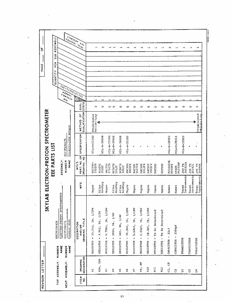
_ C .9 -4 N- _ -4 I -4 .N _ -4 .9 "
. C 9 . 9 .'- "9 9 .- '-
0 0 0 o 0 0 0 0 0 0 0 0 0 0 0O 0
·C ,4 ., -,q-
4J). 4J.-9
0W ~~~~~~~~~~00
.9 0 .9 0 .90 0 V
tn CC 'CC C C C C C
r e se ·
0I) 0 CI
N 5C NC CO CO N m - 0CO O 0m0 0 C 00 C O
u, o, L? a ce~ LO en 0
I I I I I c I I i i I,-4 o -4 o .o ,- o 4C-C H( Hl Cl Cl H H H HI
Lo n-C a. O - C G C _a -e0 0-: 0 0 -M- N s {I X N X{ X'C.n . oCa) L'i I . Cir- a o 1 O . O a o O o o 0 D U). N 'CCM N E -CM N - TU'l NCM' LUt_ Ofrl O L 1 10.9 11'1 _ )N 1 L0 . U'l 00 0M N CUN C UN O _ aO UN U C ON V OC - 1 a. 91 ZN Zn ZZ Un u C Z- uo OZ'o Z Z. Z Z Z C0 NO CX C Z < Z <
G~ C~~C.o90 G a O C o:m a CM N Gl 0 0 Ex 0m 0CEMN UC N N
01 U 01
Co o C B w
O _ h o o 09 o o C o o .oo CL E C o C) C)40 - C) < C) Z CZ . Z C x CC E c.COO F0 D0 , Z 0 0 0 0 0 ElH EH- l.
3 3o
o 0 0 00u r H_
.9 N. .9 2
H . .H - - e N.
_C 01 _ -
an e
cM .0 10n
N V U) G v)
* CC N 0 0M
Cl0
G Y C 1
Cl Cl O - .
E-l El El El E-
'C 'C 'C 'C 'C
'C 'C 'C 'C
o o oo
0 0 0 0
M CM N CM
* 'C Cl M :
M U)I Ul ; Ef El
'C 'C 'C '
'C C ' '
C C
o !
o C
0 0 0 0" C . 0- 0
N 0
a o 0 0 0
E El. H H H H
E oU En En EL
Nm m
< 0 O CC CC
0 N
1 CZ Z Z Z 0 Z C4 0 0 0 00 U C, ) 0
21
I.'
0
wW.t9
Iv
0iC
U
0.
Z
I-'
W <
ZLU
IYU
LU
-
-
vZ0o 0
'CO
m Z.91.
>- c W
E E ZIn
v4cn Z
Zr4
0
Z
E
cC
0o
0n~0
vr l XD t
El
0
" Z ZVEl
an U C 0
ai 4 ; G4CM . 1 Ln H-
W
cr4
ZZ -Z'I cc
0
az z
zD
Z Z
v) mn4 4
wz
W-w
w-i
Z0
w
r-
I
II
LI
u
I4
II
II

(N -4 -4 r(
Ni .-4 r ..-4
zLL- 0' 4
o [ o',. cr ~ o',, to0 4 a 4 41 SH 01 4
Do u 14 1 Cu M4 L1
W (d.01 4.1 ( Y O 1Y U.
- , ,) a) m 01.-i t,-
Z
9) o o o o o
( 00
Oz- Z Z O
C3 0 V0
LL 0 0
lU . .xO O O O)r
_z, U
0 - 0
PCC, 0I 0
Z 0 < 20
0 0Z H
22
ILLO
W4a
0
0.
01
WI
n;
V)
02I
w0.
I-
t
F'z4
ci
C3 1Or6Ak
N
(0r
,_' F-
U, c
W t.
o24
zm aW 1Xfn_
u 2m <
I:E Z
, z
MLU
Mi
ZL0
I-
,-
vLZ
0 jI.-
I L
LU
.-
U)
m
O(AU)
O
F'
-1
0C4
c,
urrr
04
z0El0
0.
C4
-4IU)
C-cfn
a
u
\4
W
(01m
C:
0.
COWZ)
WZ
z
-im
en
0.
0,
w 2
2 Z
z
-JmIwn
xwz
w3-
I-0:
w
z0
U'wa:
0.1
I
n
z
\·i

iL0O
u
(L
i-U
0'aO -
O-
lY
.u
>-
v,
co
LI~
toenCD4ci
01
wa
I-
I-2C
4 r s
W
LI-1
0
I0
2
0H
0C)
Iu 0
WI0n nu
)- wW4v) wo C
_ aZ
ui O
enZu
V) mV)
a
4-o
4)C
U
4)
u
(a
(n
4)4)4)
02
IC:
'02 04) I
4
I--0 )
0 0.
w 4)Li .4)4)
en4)
01W G W)owa wci44
Y Z E Z
z z
J 2m, m
w . w
0 va< 4
IL I._° x
w
a0
I-
z
..... - -4 - -4 N CN m -4
-4H H -_ _ -4_ N N e
< Oc 0' Ci cl C- a C- Ol a Ci c a
J 4
0O
5 F 4,O o o n V1
0 0 0 o 0
_ oo o o o
F_ o o o o~
o
o i c o I a
U: ' : ,
Oz
I N I0, 0 0 I H Z - I) XI IX1 F ~ a~ r -e si rs , oa oa O a ffia 4 l 4 E o El (E4
-- FF b& U1 0 04J 4V 4 4J 4V
CL o o o o oo ,, 4, , _ 4_ v) QM z 6 E Dl L1
IQq U C) 4ao I U rl M 4 1 4) 4) 4) 4) 4)
a aCII a a S £ x x E^Fs Ew E EE
3 0 3
O > o
- z x a -u 0 Hcn o e up H -
w <U - 0 1 0 O N o
El 4 E- °
0 ] U) U) Ln 0n U U L 0E- - 4 - H ¢ < a a a z HEn en en En En & 0 O O en m a; ffi G m u o i E( El
z
4 u , 0Hv H - n en ,r 4) 4) 4) '0-OW 4) ) 4) ) 4) i u u Li Li 000
4)0
23
I-
w
w
-J
ZOv,
rz0In4
'4'
II
2
i
u
z
II
II
qI

-I
: -
W-X0 - 1 t
:-
1
-J
P
O
U4
U
W
F'
i0
V)
C,.r-W
t1tz0F'
(Nc,
IAZ00
-' Cm mrifr
U.,
E 4
z
-JCD
w
4
0-0
6'
CC
0I
U)
o Im El
rI
U' -W $
CJU]a: w
LZ
604
Ez
r w
z
i
wZ
4
z
N N IN CN
N N N N
o , oz
° 4 O 4V O) 4 O
OI - rl a lrl * ,rl 1
LLOI- U -5 _
_ 1
Z
_ NO O (NO -Z
Vl Z l Z4
Eo 4 a, ao
_ V 0
o o
0) O o0 0 0
4 4 V 0
4 0o u CJ o
oU~ ~U
Z_ .
W uO o1 : u r,~z o z° r .
0
I.-z
ffi C D;
<: ¢ S, m
FLC Z tO~ . _
24
I0
W
O40.
m2W-JV,
WU,
n(A,
cr-40.,
(I.,
aIU0.
I-
I-
z
uIOrI.
I-LU
0
I-.
,I-
UCZ _
O
ZLU
IO-
-I
-C
LO
a:I-I-W
W-J
Zz0U,
W9>)er
i

Ia
U)cC)(3w
V)
a:Iawa.
t·1.-z4.
:3;0toe.
6._~0
4,sI~s GC
H H
Hl H
oJ :
o c,
0.
< -O4.a) C)l
o z
Z
h, OO. N 0
w
Z C
NO N
U Z N
< 3 c _
*
O W : C
F~Zz z :
z oat . >
z
O
Ia00£
M
II.
0Cae
,..1-
'IC0-
>a.
v(
LILU
-J
-jCD2wInInO
O
m
U
w
E-
C'U
rs
U
C-C
U)UNI
Ia-U)
'0 U
, I
U)
aW
Z
wZ
:3
tW
Z
w
z
U'
xjwD
CD4Z
z
m
0
In
I-
a:4
2
z
_,
U
25
I

1L
I-
0
w
a.
LU
:E0I-
UOd
tL
U.
w
V
LU 1-i dZLU
-JJU
ax1
U,
_l
0
-I'w
X -
w >v)0.en
V)-
I-
4)4
ci
a~O
f:
C:
COC
0mE-.
en ZHo H
co K
eno41 H
enO)- uw
. .
IJ Wx
V) Z
ix
a-1
P..
ICA)
01C
UalLz-a-a-
en P
0 e4
'-4C)
enc
,V WI 11 Ww2 w 2.2 z m <
Z Z
.... j'>, >.
m C
IIJen U)
F 4
W
0.
w2
- IN . -4 -4 -4 IN IN N ,-4
' IN .4 _l4 '- .4 IN IN IN -
< CY ci 01 0 c0 Cf O Ca 0 co Of
0 C44) a)44 O ~ -C ( .41.
0I IL R 0 V
o0-
_< 41. o
w UC 4o_ OC) 04: D U C )
o 0 c - a 0 0
0 o
$zo0 0 0 0 0 0 n0
_0 x O X "mu <1V m u 0 - 0 O e On Om D n H c a a. E WU. CC, In" , I F U - H o z oI V :4 o o - o ',tI4 0 4) 4) en 0 X 0 4N rk 4i dz
n. Ha H U n. V H H E E X
£ -2 Z-4en°° ° 4
DI 10 1 0
0~~~~~~
N N 3~~~
0 4
0~ C4 3 N >
U. 0 0 F. 0 -" H N o >4> '
- U o , U . C: o ) 04-'
U _ H . - ,r _I _l < Nh
4) 4) W.4 En II. 9)~ 0) 4 ) 4
a) U4 1/) U] U O O O O 1
0 0
aw U c- U C.
O N ,0 N 0 °
I _ N .-4 *n CD C _ _OWO K K K- K 0 o O 0 0
0 z_
a~ ~~ ~ ~ ~ _ en _ -'- - - 4
26
li
xI-
a)
-I
I

04, c
10~S~ f::~
N (4
o a
z
0 u
Z
r4
o o
L Z
U 0
C'
o I o
7 -
I_
o
0 04 I1- 1e- -
0.
2
0-
3Z
I* z.
IL I
0 1W
.4a_
co
:3tnw
z
U)U)
LUJ
U.
0
aZI-
z-Zu.U
LU
CLor
ce-JJ
m
JA
SE
1.4-j
C
eN1--
U 'CCU)W'
aI- E
L
C-a C0
U
U) -
. .
-JIZ:In 24r
C-
UI
C~t
c
C) L0 UC'Cten
U EO
W.<
cn
dw a:Ww XE w X
2 Z 2 Zm.4 04
z z
m gI I
M 0
1- )
U ) )
t 4
0 x
Wz
ItW
WI--J
z0
wa2
27
I r .
cI I
--- _
af-F
E-
r
xI
II
I
IS
II

A t 4
I
6jO t A loO
. 7'
' ge 7
H '4 N
H 4u N
4, ...... ..o5 .o Q o o
O~ 4J*-..4w ..w-4 .M...
_ o 0
Io I cI
(4 H H H
U UmO'
oO
ILZ '44'C)
0 IIL g )
> 0
z _ N
w 6
40
wdtZ~~~~~~~~~~~~~~~~~~~~~~~~~~~~~~~~~~~~~.
0
O
w
4a.
w"aUw
c4'4
U)a-
I-
I-z
4
=1
r a:'4
v DIN H
. .
040-
m mE<U) " 4
>- XZCD
VE D
<nQ
U-
CL
0
I-
LwUI-J
U
-Jco N
aE-
j
020o'4
0-(2'4C-U)'4
'4C-
'40
w.-I
00
E-1
0-:4
0r,z
ElCH
u
(4
a: w aww a j 2m <s m <tYE Z :E Z
m m.z ~ z
- Z4 4
0 X
I Iw U) U)U) (44 40.0 1I.-
z
w0-
0AU,
w9
28
1 -
I
I-
I-
I
I-
I-
I-
I-

" sr H H
z
'CC3
W * I I 4U H 4' U
o. 3
p4G) WO U mm
, o 0 0
o
I- U) U) 0U
LL 0 4 w
c a ct > 1 ~o ·~ rr( a
1 " 4 ' r4 o
-. 1 I. I1 I ,1
0 I c rw cl , r
0 H H H p-
vi I - U m HO
a a a
* U a *
e- I I ,U ) U U) U
4I
o
1.10 .a
29
I
w
0
.1
[L
wLUII-LU
U
O
LUZUJ
z Ln
0 -
QI--LUL
-J
0 u
LU
-I-
UP
II-i
aI(N'
E)0
U.
U)U)
rnA0
LI
U)
U) E
Z W W
Z Z
z z
ID IW Ww ,
4 4
W
z
wI--
w
z2
wc c
I ,
UC
Li
I
I
I
I
II
i

N N N _I N-4
rN N N _I (N
0 0 0 0
z,,Z : ·x<
OS I O Uld -Cl
W 4 -I aH 1.a O i 4
* * oo
o ' , o -
o° ~~ _- XE-. ~~~~~~~ E-I
u O l O 0°
z o co x
02 ,-1 0 0
cc H
Z H_ H H H Hz v
m0 0, E(N 4- 0 . x
o z o . a o
r~ 0] U ~ 04 -
i _ _ H
44
_ oa aIn03 4 44 , 0 C Q 1 A
V ° *H . s H 4i X
H u u 0
W U
goa a
0 4 0 -I * H
I - 0
o w f a u
EzolH U C0 0
30 .
I1
I0
w
OCL
LUI--
0I-
U
-j
o.,Z u
ULLI-ALU
O-
U- n
4
a
C'4
CI-Caa
Ca4-44-
a
C4,U
4-
a
4-
w
LU4-4,
a w w
Z Z
4 I
o
V-Iii
I-ft:
-I
40
In
WW
II
I
U

- ,i H H H CM H m C . H . NC H-
0 0 0 o 0 0 0 0 0 0 0 0 0 0 0
-0 v -0 > H H > H H >1 1 HOC -0 -,. C . .0 0.- .c) C .0- , -. , ' ,-.
s)- 4.: )H CH C 4 C: 0 ' . 1C 4H Cs C4 04-' C C
0q 4 0 .0 00 C U) 0. 01 I-0 -0 I40 - P 00 - 01
W t Wm 4 W A 4 E W 0e4 W0 W 4 3: E0 0 E W E 3: E W 01
C ( ( N aC ¢4 4 o 40 Ino 0 (0 co H O *o o Co s o o _1 I .- H .n C _A 1 o0
o CA n C C > 0>n0>-c >- U~~~~~~~~~~~~~~~~~~~~E< un l~~ sn In I Cf) I (QIn LI u
L u a > a a a 1 u u
o I I I II I ,I I IW . C) cl .h .2 4n n a t
F H H H H H c HO HCO H H Ho z xcoz OZoZ E Z
_ C)-I
C) Z: 001 001 0o ZC' 001. 0
v2: tr m Wo- N C Cm
ZC) ~ ~ ~ ~ ~ ZCC ,, , 01 01: .IZCA C cnn
4'a
--: :A 4 0 cr u U U aol, c P Z o o X~ o o oo, coX z e Z
C4~~~~~~~~~~~~~~~~~~~~~~~~~~~~~~~~~Cc N U1 O, )N N O Cl 0 0 U _ . Un U W r lan "o U oV 0
-L ZC Z Z N. Z0 Z0 0 0 Z> 0 Z 0 0 01
a a (C U '0 .,a -4 ., ) o U 21 01 .c:0 0 0 esvc za a H E-x
A - H C: Hi H
' VP
.01 .10 o .10 * .1 .1
IL o o o I o o o o 0 o)o C C1 U U C)
Da. _ O CA J 4 > O > O X *H >
C, 0 01 4 0
o e~ Cl 0 e 10 C 1 o 1 01 o.
C-C
LJ - S C d.5 d'~~~~~~~~~- Z r i Z n C C C
OH 0_ H H H H E- E. 01) 0 0
-tlC F C: G C C1 C-
-E E R E Y O I U
W En LO - S .HH H D 0 UH H W I I I I W a D °:
cn n ) E E U) (n El H - 0
z
O X X c: O X X M CM C eC OO O H H O
-. C -i HZ 01 (4 F1 FCMX a
W(0 ('H t- lO Q (' 0 W .4~ CA CA H 9
0 W r4.)
_ zP I% D: C4 C4M 0: 0 F WN N x a a F u
2~ F , I oC
_ t4 )0 U 1
W z
yZ . rO .,~OO
31
i
I(L0
1
u9
0
uJ
I--
u.
ZVLU
0-Z c
-
J
al-J
1011E-
,U
CAC W
CL C) <. Zw
WZ
4.a
C
E-
un asr
,2
C
ce
t
m -
-m L
00iWI q
C)
Cr-
a
a,
icOEnq
W 2 W acZ z4
Z Z
z 4
W W
Z I
O
z
wW
-L
z
CO
r
II
I

0 o
w
0.
m-1
a-.
z -D
0
lot-tooOn;
§o Oa of
z
4O .*H . I .-
uj 14 11
o a c o w o a mO'4± WC: w
(n
z
o o'o
° _ o0 0Z X X X
z z a a c
U. .4) V4 4
U U U u
er m r Dr._)< H
Ow uucro U uoU
,o
0 O -,,
o 4 44 4
I -
32'
I0
L)
0
-
ul
I-
E
LUI-m
CL
0
Z0(
Zu-
I-
U
-
vL
0 w
N
U,
C.)
14In
a4w
o S)II
r
0040
U 0
i0:<
Iw :E?c al !:EJ
IZ
-J0
wLnIA4,
4-L
E-
r)
1-
AU02
C4)-
C
aCE-C4:a
0.
C
OrC
(4U
U
U
C-
CL
m
oC
m
wEn.
Z Z
J .
o m
X
- . .
U) U44
44 44
l
.I
W
w
I-I-)
z0
41lU)
C~ r c nL
I
IL
I
II
s< ts,
11
I

·r n 9· ct CV (V r( r( r(
O N r( rl r( N r( N r( r( r(
0 0 a a a a a a a a a a a a a a-'vA
U.00 .
l o o 4-- 0 4
Lo -44J -I
'0a t. 0 '
., IL 0'.1F.E I O ._L E W 4J CU En U) I r
O 3- n 1 S N _
_ HrO .- O HO I -O I · O cO lO H O H I
0 zI--
OZ N O ZO _O Z C OO El 0 J 0 N
0L Fr 01 0 Ci o U0 1 0 IN 0 .U -o OIa l0 > EnOCNn O N m W U E X
O C W M En 4 0 U W C i W O o
Ir x xvW xCI >0 v Xiv Xl Xv n 0. U E° E°
O 0 C i~i Oi~i4 W O OO W O (CO Ci O W W)E. Es H E- H Ee F E H H El H H H 4
3 0 3
W H N 0
vnO E-X O O O
.Z N ·r ~o ~e ~p~e -ro o 04 It
o . 1 1 ' * * ' X u X < < <
Z Z-. N1 N4 N NONN U U U
F0
W~~~~~~ ~ In
H C) C) C)
2 1"I"eI,- -w I-~~~~~~~
-10 (f.4 .H ~ a:a
0 .4.a%0W H '.I.1 0 . 4 . l
*~au2
33
LIC
II
4
a
I
.L
oeLU
CieC.
Ln
-j
LU
LU
-J
F
E-
10U1') oC
XU.
0]
In
ICi
m
AI
I E
0 0
Ic
Ww c Ww a w a
z z
..2 .
W J
ww
o 04 4.
0.00 x
Wz
wI-
o-
w
_I
w
I I
I~~ - --
II
I

0
Vl
36)CJ
I r N r4 -H H H H - -4
414
Cy a: a co co . of O Ofi0 -
,CA : -C4 , , ,
a-· i , - I 4f .--4 4d
o 0zn- 4
U
IL - o o o oe q o o oE .o o N o X r
=¢ S s t z S * Z"- Z S N -Z
o n fr- 0r r m
U. Xo
o00
, Z
z 00 e H 0~DU0 UNONUI 4 Z X
O a-
W W Uto 0 0 E u
or a: l l l l o C C C C l
4 Hl F " (N H H N ( H 0
W
I 0
z Z
34
co
mW
V)
(A
W
W0wC-
I-
4
0N
ffi
wa
tc
I-
LV
ad
uLLU
C4F-I
L
CDF-C
U
IA1)
()
'32CcH oF(- (
(fC
0N-O
'I
e ZO 000O
es
a3
0z C.
la
0 0
. . 4
Oft>
U- -
W 0<t4,
0c
v
'O
4
-W
IU]
Z Zz 2
4 4
O 04 4aI0
z
"s" - -4 · _ _ n

H D 0 D H H H H H1
H ) -H H H H
a0 0 0 0 0 0 0
F :: V V .,W i . - C co Hl U VV
O~ II) 1. 4. 4 O.4)Z F z r F O' N 0
HO H HFO H H" 0` F1I C) E nC) IC) 0 0
' F n ZI 1 °o D I ' l ) Vl
p um HI =00 H'0 _ H 4 H
Z Xo X0 0 C4 HO
mmCC C)4C) C° C H° HO t X W
El , :e Y. F 8 F u: -or 1I
II4U U o H
0 _ o N 0 0 o
J ~. ~ a * -.
.- 0 0
U o . U o U U
Z tt IZ 0 N N
U _
W Z
El 00 0 "H
Ht C~so.-4 Iflr~-,-I H N n (
35
ILL
I040<
LU0
U
CL,
U
U
L U
-J
Be
-I
mc
crD
o
rl
004
u
U)Z
Z
WaEn
0EE
MIn
2.
ura r-VD II uD
o
°\ IoI W
7 c c G
000a
111 WI U)
I W If Z to
0)HO)
nW U)
IW IWW~ W~
Z Z
z z
CD a)4 4
W W0 0
vv U)
° 4
CL0 W
Z
wt-F-w
z0
'iWW
_ _
II
I
I
II
i
II
I
I
II
II

I I
o CC
0
o
__. -
LU
:-
O
U
ZujLLI
LLJ
'. I 1I.
u0
C
-I
:1
:2w
Z Z
>- >.
-Iw
z
i X E3 } V! < <1v
| -
· :~ ~; ,'5 *~' ~? . ! ~'~ ~ p-- ~ ~', ,--~ ~-I
_ rLO ',O,,C>
4 I -,: ...
-° --'
- , ,.. , ._...Z , =: _ -- crt r
I r' - ( _
_ tJ1 a : .] .a s Si! U .:-4 -. :: _ -} -4
u I n _ . . -^ _ ^. E ( ~ F .: r . C 2 2 7 4 r J r _ . __i~1 II : i I i_w~~~~- ! :0
zoc
cr (
Vi -I
J Z
Q-o
L^,
.....~0 ' ... L': 02.~(0 40 (4 0 (-0 (.0 - C
OF 2 - 2.:77' 20 0 42 - ' 4
-.: ." 00 (-0 (0 2
; .. S; a-. C7 _.r - .- C' - t C _ C v
- -C E; C r.=-_.2' I a ' U C
r t4 0 4 7
((4- (.** ii .7-I - O , ;
.. ~i ci TL ; .. ,4
i:~~~~~~~~~~~~~~~~~~~~~, ;.,r
Z F . ..X r.
, 0 . . . .I-
o .. 'I
W | . - 1
0 -
°~~~~~~~~~4 - C r.- -, I . . C ,^.. ,4 _0 ' - 4
U ~4' * Z (' ' ° -°4
Z4 4 .40 rIwo
i· Z· t_ c -
LI.IDa
)I (
I,Il
Cw IWi
J-
..2',7.1
Ii
II
I
~;~ C~ ~ ~i' -~- .--4 ~ ~ [~
I

4 <
° C C
..... ~., = e-4 '' -e r
;O -' _-._L^-,, ' L
F 5·X 4·C H U . 0 0_ - 0 r C:
O Lf C C 4 ,3 L7 o rv r 4 ru L. r Ln _ n
O Z I _
6, -'_ C - CL- -' ¢
j._
U =
o z I , - O Oo - U r- 0 0 C
w ...
37
I-
LL IO
iU'
4C- I
wLuL
0>-U
0--C
I-)
LU
-J-
F:
rr-
CC
C)Ur
c :
_ Cv,: Z:
I
ci
_ _y -I' l
-Iw,z zZ TZ
z z
4 J
v, vw
x
w
CxUz
'Iui
t--
I -r
Z
9Q>
1-
7
(71 2 c I
(- <

'1U-J0
wW
0a.
-JCDW0Uin
t0
ain
a.
z
0
LU
0I-
O
CL
-t
0
ZU
I0
LU ..I
a u
r,
7 I
W
ei
Li
wH
WI-
U-J
.in
5en
W&rIa
o Io 00 MN, IC
Cre u002Iv I
0IL
71 i
z
u, Z
W w
0 m 4Z
Z Z
31 >.
mo m
W ).
w wj
V) O! 4 4
0 oI.- W
z
zio
oFOv
Ia0
0 u
I
J 42 D
a
n - I e H e e
rl rl r( rl ri N 3 g ri O
0, C1 C~ O 01 CY I OI C~ OI O
*.-C -.10 -- 0i7, In-t CnC-2 C-2 _ lilb X -i_El
Zr o a r r
o en -~ i- oe_ u7% o o o _,
L.C < r U U i 6 u7I I I I I
ei en i-i H I- I-.
o C,
. z ,
0 a en z
7 Z v C _ n U *IL4 Fn-~ H ,8 c~. ,- C- r. Cm i- *E El El.- -. u o ot
u e 3 Ze uIti _-n to Uev re Ze i,
I~~~
Li V C C 0 Ci -i 1- C-n-i: V v v ) O O U UJ U Ct -7 0 C'- ' Xu. E E C. - C' e ' -C
in C ' . O oi l C) _, Ci _i _ ,-iH-' =) - ,, . . - ,<: _ t -<
>' 6
°
Iii 0 o u7 c' cc o-
O~~~ in -e -i . 9-u 7 u_ a~~~~: ! -,z o -g_1... .. , i_
io 0i - _i .i ._Ho a c: ~ e r.
on -o o o en~~ : c
0: Eq Fa tn cC I C I
,, H _- tH H 0 0z 0s F v P
in v .v n vn v in.^ 7 ._. e, < ,C CC ,inH
z 0) ° ON en en - *
_ < v'vr - Xic ~ -oi
C C) ^- - . .;- en -. - . . 1 n. Cr u7 .en ,-i _ *a-r vn rn ine r:a inN* - -rn ee.7-_ .
W °
_U0
I
I

c7 CY C0 C0 0 0l 0l 0
U-
oz
L(.O
2 0 0 G El G7 G G0
I N O I4 c ( -
- J , o ' E E El UE'
_ I O o IC I O O
0 F O C O O U EO
0
v v v r 2 V LC o O O O O
E- H - E- . E H E H- He' H E-H
O E
0
o 1 v -o t4 * C' N
01=), CC0 CC ((C C CC (( CC
1")
I
LL
0
1
Ld011
LUI-.LA
0
U
-I
P-
U
UL
-uJU
-
.-I
LrF
t
D(CCL
E)0C
C.Cr(2
4
F-(2
U
C.
UC
5)
C.
F
E
C-
C)(2
C)C.C;
tt WW In <a J
z
-JID
to0
k-
(4I'-
-J
z
2
Cc
nW4m <EZ
z
-J
itwL)
xCw
LI(
II
I

I en .4 . - N
I~~~~r
I - H - enN
0 0a 0 0 0y 0x 0
rro~~~~-~~~~" fle>
o r4
Zo SH ' ' E
H r0 r0 0 0 0
en en en en en rn >Q>
L I I 4 a I I 1
0°O en >.
E 1 0 en 0 2( ar
wZ v
.1cu .
C >' O > O' > E E
i Cl r o r C Q (n l0
0 0 C 0 E E H -
oh Z Z-e _,' G E _ Jn *n rn o a C1 D:
O E . ° C O EA ° u e0
If4 F e . _ 0 0 rs .- a r
¢ Z : r - 2- - N aS
H rH . C. H o . o 0e n _.
U0 a H 2I ~ nr
40
. X~~~~~~~~~~~.
. Xi
)o
J,·
0~"·
s,, , t
-jIwLULn0Oco
nCLi
Hzw
4
F
Z
OU
0-
H
Hz4
LULULU
r.oE-
I
O z
44
. .
ol C
m w E*nl
I I
0~V, Z
4rr
H
:4C-If.
o C
01 0
C) - L:<
In m n
0 C z
H'I tIr
HW a:W
0 D
Z Z
J Jm m
0
z
r

EPS-470
ELECTRON-PROTON SPECTROMETER
FAILURE MODE EFFECTS ANALYSIS
LEC Document Number EPS-470
Prepared by
Lockheed Electronics Company, Inc.
Houston Aerospace Systems Division
Houston, Toxas
Under Contract NAS 9-11373
For
National Aeronautics and Space Admir .:t...r .
Manned Spacecraft Center
Houston, Texas
September 1971
(

FAILURE MODE EFFECTS ANALYSIS
Prepared by:
Approved by:
7
P. GleesonReliability and QualityAssurance Engineer
B. E0 CurtsingerEngineering Supervisor
B. C. HallProgram Manager
Electron-Proton Spectrometer Program
Advanced Programs Department
Lockheed Electronics Company, Inc.
Houston Aerospace Systems Division
Houston, Texas

EPS-4709-24-71
FAILURE MODE EFFECTS ANALYSIS
1. GENERAL
1.1 SCOPE
This Document defines the various types of failure modes
and their effects on the Electron-Proton Spectrometer.
The material presented is based on NASA Program office
requirements. The Failure Mode Effects Analysis presented
here was analyzed in terms of application to a subassembly
level and does not constitute a complete component failure
analysis.
The information which is required to perform a critical
analysis in strict compliance with Skylab procedure, is
lacking in numerous respects at this level of analysis.
In lieu of a detailed analysis and criticality computations,
failure rates are computed and supplied on a subassembly
level based on environmental and operational stresses.
(Operational stress are those nominal operating conditions
to which all electronic parts and subassemblies are exposed
during system operation).
1.2 FUNCTIONAL DESCRIPTION
1.2.1 Detector Assemblies
The EPS incorporates five independent detector assemblies
each consisting of a lithium-drifted silicon detector and
an energy moderating dome. The function of the dome is to
1

EPS-4709-24-71
reject particles having less than a predetermined minimum
energy. Since proton energy deposition is a strong function
of incident proton energy, counting protons, whose corres-
ponding energy deposition exceeds a predetermined value,
establishes an overall counting window of known width.
Electrons, due to their low mass, tend to scatter heavily
resulting in a rather constant energy deposition independent
of incident energy over the range of electron energies
covered by the EPS. This physical phenomenon results in
single-sided electron energy channels (integral channels).
Table I gives the nominal boundary values for both proton
and electron counting. As is seen from Table I there are
six proton channels and four electron channels.
TABLE I
CHANNEL BOUNDARIES AND ENERGY LEVELS
DetectorDetector SizeChannel (mm)
1 1
2 2
3 2
4 2
5 2
Proton ShieldBoundaries Thickness
(Mev) (cm)
10 - 20 .037
20 - 40 .180
30 - 50 .406
40 - 80 .710
80 - 120 .890 BR
> 120
Pisc.Level(Mev)
5.9
6.8
6.1
3.7
3.2
~1.0
ElectronThresholdEnergy
0.45
1.22
2.38
3.90
2

EPS-4709-24-71
1.2.2 Electronic Systems Operation
The EPS electrical package consists of five systems,
namely:
Scientific Analog System
Data Processor System
Housekeeping System
Power System
Heater System
The functional interdependence of these systems is shown in
Drawing SIC39107146, Block Diagram Electron-Proton Spectro-
meter.
1.2.2.1 Scientific Analog System
The purpose of the Scientific Analog System is to detect
the random occurance of current impulses eminating from
EPS detectors, determine if the total impulse charge exceeds
a predetermined value, and if so submit an output signal for
recording by the Data Processor. There are five scientific
channels which are:
Independent
Adjustable in counting level to allow use with
detectors having variable dimensions
Capable of single valued counting-rate performance
to 106 counts per second
Immune to detector generated noise
Each scientific channel is made up of a preamplifier, a
pulse amplifier, and a dual pulse height discriminator.

0 U
; j 0.
5 B
A 0a,
CC >
R W -4 e
In
0
.4
4a
D
o
4
U o~1
~
1
'
f I
U2I U 2
nofk Z ivI.- *I
U
EPS-4709-24-71
c"a
Cm
II-r
a cx 4

EPS-4709-24-71
. . . | . . _ . . . .. ,
iY r--f---Y-~~:r l
1-I Uo I _ J° 4 8@6>0
. LC) x% oC
fi x-H
I I 1 If u
, u ._ I 0 _ I
a~~~ 05 4 ]
n L) 4 co

EPS-4709-24-71
The preamplifier converts the detector's currenit- impulse
to a slowly decaying step function whose ampli-tilde is
proportional to the total charge input. The pL]eSC amplifier
filters this step input producing a bipolar wawe for m at its
output. The dual pulse height discriminator cjflpares the
bipolar wave form to two reference levels. If the input
wave form exceeds either of these two reference levels,
a corresponding output pulse is directed to a ,ir(esealer.
The presealer generates an output signal for e'/vtry other
excitation of the discriminator.
1.2.2.2 Data Processor System
The function of the Data Processor is to digit.1IlY integrate
the prescaler outputs individually and present the informa-
tion to the spacecraft telemetry system in an .mcceptable
form under control of the spacecraft. This inrjgration
provides 12 seconds of counting for every 13 scconds of
real time. In addition, the Data Processor accrpts analog
housekeeping signals, digitizes them sequentia'lly1 and
properly mixes this with the scientific informr!ition. The
data processor utilizes high reliability, lo-w prower TTL logic
in its digital section and high reliability lov power ampli-
fiers in its analog to digital converter secti,,n. The
Data Processor consists of the following modul,~s:
Sequence Control, Line Receiver, and Counter3 Control
Counter/Memory Module (10)
Digital Data Compressor and Internal Clock
Analog Digital Converter
A/D Control
Multiplexer Module
Output Buffer and Word Sync Generator
6

EPS-4709-24-71
1.2.2.3 Housekeeping System
The Housekeeping System provil,! I,-i.gnals to the Data
Processor analog to digital cci'j! '/tr t e r that yield information
concerning the operational statL11! of all important EPS para-
meters. Those functions monit,Io('
d include:
detector leakage currents
detector resolutions
electronic package temperaille
detector plate temperature
power supply levels
heater status
A time of 208 seconds is requJll-lI to transmit a complete
cycle of housekeeping informal;0" . Ground based analysis
of this data allows proper mal,,irl. control of EPS mode of
operation.
1.2.2.4 Power System
The EPS Power System accepts Srl"l" e craft power and converts
it to levels required by the YIl'O, Major subsystems are
the Low Voltage Power Supply t,fiji lhe Detector Bias Supply.

EPS-4709-24-71
The Low Voltage Power Supply (LVPS) provides the following
outputs:
Voltage
+ 5 Vdc
- 5 Vdc
+25 Vdc
+ 8 Vdc
- 8 Vdc
-15 Vdc
Current
905 ma
116 ma
11 ma
175 ma
152 ma
2 ma
The Low Voltage Power Supply provides analog voltage
monitor outputs directly proportional to the various
outputs.
The Detector Bias Supply provides the following output:
Voltage
+350 Vdc
Current
10 pa
1.2.2.5 Heater System
The Heater System functions in a temperature control
capacity. An internal temperature sensor is continually
monitored by control circuitry. If the package temperature
drops below 0°C, six watts of power is dissipated in the
inner housing structure by skin heaters. When the
temperature rises above 100 C, the six watts of power is
removed.
8

EPS-4709-24-71.
2. SYSTEM - SUB-SYSTEM
2.1 SUMMARY METHODS AND EFFECTS
A study of parts and materials has been made to determine
the best high-reliability parts possible. All parts were
selected from established reliability parts, specific Hli-
Rel and TX programs, and parts that were 100% screened
and burned-in according to reliability requirements. Each
part was further screened to include lowest failure rate
possible.
Alerts, failure data and other sources were consulted to
determine part selection.
2.2 CIRCUIT ELECTRICAL STRESS
The term electrical stress and the possible value of
derating the circuit according to this stress standard
were studied. In discrete circuit components, derating has
a definite value in prolonging component life or increasing
the Mean Time Between Failures (MTBF) by using components
below designed capacity. Where current or power are stress
criteria, such as in the case of resistors or transistors,
derating results in a longer life through a lower operating
temperature as a result of less dissipated power. The
established criterion for capacitors is the applied voltage
or electrical field. Derating is accomplished by reducing
this voltage or field, which will result in a longer margin
for transients and slower ionization effects.
9

EPS-4709-24-71
As a precaution and to assure increased reliability of the
intergrated circuits, fan-in and fan-out loading were held
to 75% of manfacturer's rated load whenever possible.
Voltage swings of the power supply and input signals are
held to 75% of the acceptable limits of the manufacturer's
data sheet.
3. FMEA SHEETS
The FMEA sheets included herein are performed at the major
Sub-system level only. Criticality ranking and failure
modes are general and do not reflect a component level
analysis and its effect on the systems.
10

EPS-4709-24-71
I
a:
I
an:
H o0
, u
i00
' H
_c U
>, 4' 44
i 0.ri ,0 4'
· C0
' D0
DI E .i:: .U
>41 >
o0
-. 4, UiCo
-H 4) CI
O
s F. -H0CC).
I I>4
n ,
S Cr)-r E C
r-4r
-11 o -H0
.~C-,
-i C 0
H O 0
1 C r 4
s04.i
HVC O0'H 0 O
HO-0 C) C) .0, 0 U4
I mi0 -H
-HU0
?i oF.
Cl.C) ·.>0I
0 -.O (0 CO
u)C h
0I
U)
-H..r- 0Hi
-i O 0
r0 Cli Oi
-H 04 C
'HOC)O0-H > 0.
C).4 0C;C) 'H
-Hi 0 CO) 0:= Lo0
El0
41H 44'H= 0
- O O
cJ mi0 4.4 U
0 0
'HO 0|7[4C) 0 --0 -( 0
C)( C0=U),a
o 0 I0 4 0
41 Ily, m lm n a m I 0 ( a - ao C)U ~IC)L( 0 C) C) 0I o ) oC U- C 4)
W 0 C C)O CO C)0 0 C) -H -Hu -H1 )C I CC4' C) C)
~- =I `a 15 a 0o~rj Ieu ~ I o n o o ~o= I ..... ~rlH
w~~~~~~~~~~~~~~~~~~~~~~~~~~~~
C)Q C I 0 CI C U C) o 4 I O a, r~o cl4 C C
-i 'I ' 4 4' 0 C) ,C4 C 'HO :4 'H 4 =L C)00 COOC) r-C4 C) r (0C) 0 - 44 OC) 4 4 CC) 44 In 44
0'HC) jc~o ,t a o.-C) cC).-4C) 0 ' C I *- 'C0 r 0 r'4 -4 C 44
0 -i C)D -~ -4 V C)N40 C
~~~t I \2 I ~~~~~~~~~~~~~~~~~r
' 4 C) 4)r ,C) 4H ,.- C 4O ,-'-4-J4~~~~~~~~~~~~~~~ 0 o ', -iC' ) 4' O) > '4 0 4 44-44L.J C4O C)C4W40' E. C 004-) 00 44CC ~-4C0 0,.-, · m m m
I- 0 -4 · o 0 0 o · 0 .co . 0 0o 0o4
a. 0044-4 09 In 00 *H44OC) 44 C * - C)
>00,-4 0 0n C)4' v 4C)4 C:C 0 C I IC; CC0I~~~~~~~~~~ OVI~~~~~~~~~~~~~~~~~~
0C)-44O ~o ,C)4'.-4·--. 'C'C CO H0 .4' )C' 0 0,
104 04 044 00 C 04' W 4I OC) IHC),00 Qc) 000,0~r 04 C C)0C)C0 c 0>'J 0 O.- C 0 C)0 0 0'C U) 0 0 0 IC 04 In C) 4 C'00 4
410VW) C0 4J> 04- 00 C) '0 004 'H 00 00 4 '- 0 'H
14- .I 'C)- 4'4 4404 ," 00 440044 00 -'-:riI4 C 0~v 40 0I -H -H
IL 044004' '00~CC. 00 C)4444 0C)00 -H 0 0)-.--4 -' C~O~rO 0; WI ° C)0>,C C C) 00- .000)C 10 .0000 0-C) * Ci - .0C0 .
C~~~~ ~ ~~ ~ ~ ~~~~ O) (4D-~J
C)4' 44. OC) C) 00- H 04'.- 44~rj~ H 0H4 'HC 00'H 'H C
0.00 000 04 ) 4 00 ~4' 04 40 4C) C." I404 la L0.'H4 HId C) C)E 0-HO OCZ)00 CC C 0.-I4C) O VO 00444 O) 44 U)0 )C).0V 444'3 04 4444n 04' 4') 'H CC) H0C)V 0-H 0 000tu 0.) Q C) 0el,
000440 C)WD -P004 C O C) 0 00 C)0 >. 0440 V,4, 0 r44 4
*HCO ' :-1444 0440 404 C4 Ca4 4444440 C) . 440000 44 0
0~ C0 C; 44
· 440 HO a) 40 C C'- 04: C-..-:C 04' "O, C-'
cc), : la 0 U0 ri 0 m G' (z r 0a~U 9 iC 0 : W 4-2 4 ' i.'E-'4''U C m0C ri CC)CO V 0C0O 0,0>C 4U C) O
~~~~~~~~~~~~~~~~~
-4 04' " 044 044 0 I0- 444 (n
C'U I~~rlO ~J UC1~ I1B1~0·ril~r( O~~ 3-rlmr: 35L~a C'-J O t0 ~t
000LL ~ lj . r 4C) ll 440 44CC) il C )4 0CC) 4' C)
U. 11 a. 0 U)Um C) C-, W C.~ m- C) 0 C"0I· ' r v4 U-~ Q)
44 CO4 0' 00 0440 044400 0440l4.C:04 44CCC 44CC 44CC 44H 4-H-OC 44H4
c~.u- 0C.' 'HOC. l 'HO 'HOCl0a0 004 00,0- 0U)
-HO141C) 4 U)04'0 0'0 04C a400 ', 0-H OH 4C 0-HOC)0C r V
14 4 11 >4 0- 44 'HC)04
-o 0. 44 0 H: H 0440,0r I m ml w
- 3 D0 C) C , 00 44 00.440 0II~om 444' 44 44 - - 0 00 0 .- 4'H04440 04400 4400 440044 4~~~~~~~~~~~~~~~04 0 C)0 'H 0-H 0 44 0)0000
S 04 400 044 104400 44-H 4'.HO 4400 0 'Z 4400 ~~~~~ ~~~~~ ~~440 440 4400 00 00 0H 40)40 4 ~ -
. -HOC) HH -O -HC4d44 C4 00 0 0C ) 4 'En4 004444 C) : U0 o:
044-H 0044.-): 044 0 1044044 IC044~ . )C 440 0C;-H 44000H 4404 40
E-. IC P P, O C -IC
020- ______ 4: C tnE~cC
41 C) C) 41 c 14 4 OOI 0 Q 5
0 C)+1 C) la C) IO 1451i WC) C) la -P OE E U0)
·~~I U II) I a ·r( ·r( C, ·i O a II., orU L4 VU~(CIrU 14 II 0 -v0 cr:l 0 LI m C:Ir Ee nL It :Irc, C.0:s c c 03Io c 0 , z ;3
LL II 04 0 UO 03 C) U C)Ua, - (v I 40 Lc)rJ~
W -A 13: >= za Irc~u ~i'=U e ~ 4 4J·nc lcfu; :~U~
n .I _
CUU
rm~~~~~~~~~~~~~~~~~~~~~~~~~~~~~~~~~~~4
z )U.M)I5,~~~~~~~~~~~- $ ~
0 4r jr,w~~~~~~~~~~~~~~~~3E ,4
L~~~~~~~~~~~~~~~mt ~ ~ ~ ~ ~~~~~~1 0.' 4 3 . 1 e W0)I Wlm 0o
U 1:o WC J 1 I0
nm
,ICDo z
W -44
40
.I r.0 4'
003Z
0 400
04 0
0O
Ev'o
Di r 00 0
1 UZ
.4-
V (
O 40440-H
H 0, 44 0
· r. U
3 hO--044
O -H.t0t0
44 0
o
0 O
O O
0 Ci
CJ 04 .. O
0
O
O 0
4 CO 0 0
0 a 000
0 0
0ci 0
VaE h 'OOC~ C~
LJ
oi
C.
Ct
a.
m, < m
>' 1 E
44Ch
000r0l
I
I
I
I

n.
w4,
U) <I0
-'.-i 014-PH 04
'H 0' Ur
HO 0
-H 04"H0'H0 M0 -U)
0El<
CON
..-- 4 t0 co r
U,00
.-H U~ Uo 0CO CC 0
FPS- 4709-24-71
:SC0-Hi 0 0'H( 0 0
0Q 44000a
-*44 U-r-~'O)0 0C0
C-too.0 0,'
-H 0 05~- U00
-60
-. 44
'H 0000o:0 n
-H 0 lo-0U01
.. 0
-rq
H0 0J
'H 0 0'=-- 0.
-Ho
'HJOG
c,)
J'G
0 D
-4 "'H
B:.044 ,0k
.t -H
'-'HO .
-H 0
-H 440'HU0
.0 :J.
H I0 0j=U"
<
4J ~'." 0'
0 0'HA'J
vC00
,04- ~ I *3~; I 0 0
~ , ,3 0 0 0 'IAJ 'a C.0 ~ a
0a lo~til.4 C) -J r 0 0 0 00 000I C) H -H 0 0 0 0 0Q4 0-
.OJ 0 0 0 ' . ~ 00 0o 0 0,
0~~ ~~~ ~~~~~~ ~~0 00 00000000
Orl, ·:s .,4 UU0-H0 0-HCOC I 'H -'HO 'O 'O'O'0 H)
"' t- o t o oto- ft~~~~ ~~ CA to o 0 :$- i 0 0 (0 'O 0 00 '04 (400 ~~~00 000 (000 0.00 t0'H0 CO-CO~~~~.. (4.00 O
0' :I: 1. II 4 u -e l 41to-H C. 0 C
000, 00 00 0(0 0 '000,, 0n0L
..~~~~~~~~~~~~~~~~~~~~~~~~~~~~~~~~~~~~~~~~~~~~
Cd 0,~~~~~~~~0 ) 00 H 'HC 00(
a-J0 0 0 0 0C
,...
-,0 U a
0 0 ~ ~ ~ ~~~~ 0 0 C)C044 -4
1, ~ ~ 0 t-. ='H. 044.0S '-C 04-'=-H4'~
4 lcl ~ 0, 0 4Kz :r LI la 0C
o1 C -~ ~ -J 'a: 0 a~'w .
r 0 0 > U) > 00-As 00-CO0 0~~~~-CO 0 00~~~~d4-' 00d4-' rr 4 0 U)
LfJ C00 '-C; 4444 000 (900 0I-00..I0 eSC-,-A U-)-.'00-' 00,40 0 0 -C-' 00 .0. 0 0 00~40 0. C'. 4-'0 0k-HO '-.9*0 0-HO~~~~~z C 00 C, C0 0 00
Cd 000 00 '~~~~~~~~~~~~~o <0 '-'~~~~~~Q.0 -HP c O 00-n- 004-cr 0 ~ 44 00 <0' 0 <0 C)* H 00a04' 0 4-
LI -- ~ 0 4 0 C) 0U . r-' -00LC. O,'~ -HC) I e) O 0- C, '0- C a4-O- 00 k- -H '0
L -H 44 440 -HO -H- '' HkC ZHtt'- H4 InO 0 H Itm' 00-H~ 00 C)O'- 00 4'a0A 0 00 J0014-H A0
El00llr IC,. 0=00- 0,44 In0CO 40000,
Cd ~ ~ ~ ~ ~ ~ ~ ~ ~ ~ ~ ~ ~ ~ ~ ~ ~
=g~~~~~~~~~~~~~~~~~~~~~~~~~~~~~~~~~~~~~~~~~~~~~~4: w 1"'
I0 040J-O 4-O 4-O 40 440 4 440
LL 440-H ~~~~~~~~~~40 -H 0 &0 -H 0 H00- 400- 00-
0' 0' ~ ~~~~ 0'~0 H0II
Z 000-0_ C'P In C; In 0, 0, 0 0 0
U. 0. 0 0C) 0 C 0 0 0044 -OH
C3-J
mDm<.'Jo
w (nz 64
ir
0Zoz
z a.
00In
0 00o
000r 0 0 -1z
0 1 (
0 C
00:
C) 000-
04444 'H0 -
00
0 0 r* kI I0
00; 00 >'0 0 ~ .
00
0UU000'0C0
C,00
m<H
00c~
ao0,U,0 44
r4 '-00
0 ::
00.0,>
I000,O
-H m
00::
0440,,O0-r-
-'H
0,0
.0
I000(
P4 t'
40
a 0C
rk
A,4
u~j
J
g
0'
C=
1:6
b4
D
(2
0
0wF. v)
C kv)
-1
-ff
I
I

U)
a:
mEwcr
0 4
0 -
I r C.,C : .0
.I r
-I 1o 4 >,
0 -.- I
0. 'v OH: 0-Hr.
rC
n
r,1)
C:
- '0O UC10.0L- to
- .0 1,r:,
C) 14 .C.CO ,1
,C, .1G
Ua0
0'
r
1O)04
1)rB
U
LI
'-0l
0r1¾
rt sc ,'r.0
.- Hi
4 i4Ar-I n- .1 ,.4-1 14
0 0 C0
rlu0 -'
-.-,0-H4
00.0
H U o)<10L,)2
t1
r3
0
UC)
~4Ij
00
0140
0
C ) o l
I --I I
I GH . ri'I
100 3vI U0Lr O1I
1O :C > 4Iq O 4 ,4
O -H U0C1)-H I)IE o -oI
I O .- -,-I
to o ~ ~ ~ ~ ~ ~ ~ ·
10 0, G<u" f 0.
I' 'rt
0'OOH. Gl
I 0 r',U
1 4J i)
CO iv >
O ,i
Q4ir
U Or
0>10
I .) _I _(*.H
| ) . .L
TW .4- 1- .~ ' '-
Ln ip i'vU)
. O 0 O z4 O l 4q , o o o i· 0 0 00 0, '00 0 00
: o i o04 ,- -0 0 4 C' 04 a-l 4I
004 001~ -~V4 0)4' '001a. D. C 4O . O14Q-O O Qi- v 4O
E0 11 ' - O FEv0 tI E- 0Eor
<. . HO G)'H v O O ~ Kn 4 :D OG .$ OOT
L. 0 o0 1)0
'4~~~~~~~'
w~~~~~~~~~~~~~~~~~~~~~~~~~~~~~~~~~~~~~~~~~~~~~~~~~~~~~~~~~~~~~~~~~~~~~~~
I~°~~P4) w
o t4- O 4 .o .
1L 014.00 l40'- ' D 0 i o.o I
0 > ) .4. OH' * ' -I4 HEO r
I
414 i0. 4-' 44 44
> a, > m < oz$ 433 v '0 Q.Q 140 0 'J 0
w | o C. C ri i4 EO0, 0 4 o to 4 cm*o
O 114) 0 rl~ 04Jo
04J 4J 4- 0 L o _ 4d
-v4 £, 3 00 4'-c OH 3 0
|w 4~l X) 1 o30 O O O0v .
LO 0-I ,_,I, O
.- 400 I4 H
U. I0
4 o , 0 4 ' , ., 01 '
0'~~~~~~~~~~
| Z0 00 aC | 0 V
Oc., oo |, - |cL o o Go l
| >|- o |4 o r |>0.>>. 1' 4 C ' 04 o
m-J
00.
-1 -1 14 C> v 1 4 I a i O <Lq I C = q O C i Or<V. 4
I 4J ,IV O~ O 11 4JUO OO l = O VI JV~ O C _i iOCi C: i_ I O _i_ 11 4 CZ5 1o I= s- c: 0 v :; UC C.- U v; c: Q2 ..- J- , .,,E :|L H fv - qi C
t i0m V Vi Ci |V .V O | -
I~~~~~~~a 11: q5tD I, l | . I w >.0
0 L11H 0 -1 i 0W:GCi 'iIG C, V 1 0 >L> > r 'U G tCr a EH E C, G r U _
|KCDF|
.Z I.JII a1, :
wm
C 3Z
< <Iz a
11
00.'IVL. *D .
I iv C.
CO O
I::s
- t814140C: 06
I -4 1).
10
0IIo
|.
14
F r
E 0 *-i4 vi r
0 '4 0'O-H 0 C) 242 In - U,C. -1CC
E I140 H
ir vq
130
14 >,
I O H§
w
14I u'0
CIO
U
EPS-4709-2-1-71
¢
oU10
lr
U
L-
a m
0
=,S
gL..IEJa9
I Inm )' w a)
mi < c)
zZ
Z > >-44 44
m n
,A V) t0V- I/ cAV' q- <
I
i
11
I
m1
III

UnW
m
crto
Cd
-40440
clC O >.
0'0 01
O
O 144$- 4-'4L) ~J
. UE--
C H
0-1-I H
'' 1.
~4
o
ou<
O >u
0 4
:2 r,
00~r
0oUC'<C "
0J -OUo0
O.U
O U
.1 G4
0=1
LU
OC,
t--W
w
Q.
I- -~~~I -I
= 5 o I C6 - i
0 0
0. o .,~ ouc .~ ~
-t~~~o~°
-~o o m i
041 4
00000~~r 0C s~
Z IC 1 4-' 0
zc ~.. u ~.u o~ '"
11 C 1 ro o 40
:30 4 U U 4J c4
C $1.'0 Q -40C
W " MI1 C r ·r(: .LL , -. 0 -SP ' l
~~4 ~: 0 C)0 0
U) 040 -'m , 0
o '00O '4Cul
cn:
I-I I, 4- O 004O 0- 0$4444-C
Ur 0 C -400
00--U0 O L. C, I
0:W m 4
~LW '0 0 ~ '0 "-40
C 0
_j 0 UC~l CrL.J J a,$4-H00 4-'001 U4
00 010 ~~~~~~ $1-HC
rr, 0 0
u 0 4.'0 r ~~~~0 c0li >~ .~ ~i0 U 0 0U0 I
t ~ ~ ~ ~ ~l
_ 04 _ e).
U -HO U40010 15-40
U jl V ·~~aE C m 0 j cA rm¢B~ 005-- !,.....1 Ur',, :O C..
Z 0 En E - n 8 O U) Z. 1 F. C v
LL :5 4 ~'0L4 0 4 l L : r O
a -I
Z 0
crwmm
'0-.'14'0-
00 0 0
a:
m0I
o Z
Z tcrZ IL
0,C.ra
w >,0J-o n
00,n0, 0~00 Hjor
C O q- cr
U C
;av
'-00
- Cv I
PI'S-4709-24-71
0m
W
gt
h
tD
I wuv I'J Co
ZZm
Jmm
>-0 n t
v0 < <I+

EPS-424
ELECTRON-PROTON SPECTROMETER
SINGLE-POINT FAILURE REPORT
LEC Document Number EPS-424
Prepared by
Lockheed Electronics Company, Inc.
Houston Aerospace Systems Division
IIouston, Texas
Under Contract NAS 9-11373
For
Ia-itional Aeronautics and Space Administration
Manned Spacecraft Center
IHouston, Texas
August 1971
(

EPS-424
SINGLE-POINT FAILURE REPORT
'V''pared by:
-,''roved by:
P. GleesonReliability and QualityAssurance Engineer
B. E/ CurtsingerEngineering Supervisor
B. C. HailiProgram Manager
",Jctron-Proton Spectrometer Program
Advanced Programs Department
-*ckheed Electronics Company, Inc.
'o'uston Aerospace Systems Division
Houston, Texas

EPS-424
SINGLE-POINT FAILURE
ELECTRON-PROTOTN SPECTROMETER
1. PURPOSE
A single point failure summary identifies the critical
areas that will, as a result of a single assembly failure,
cause a complete or partial loss of the experiment,
questionable data, or complete loss of data acquisition.
The following information must be delineated:
Corrective action taken
Experiment objective and,
Justification for retaining a single point failure
2.0 CORRECTIVE ACTION
The requirements of the Electron-Proton Spectrometer (EPS),
such as weight to power limitations, logic, and electronic
circuit packaging, limit redundant circuits and components.
As a result, corrective action to reduce the possibility
of critical failures is applied through careful selection
of the best available high-reliability components, screen
and burn-in tests, and derating of components used in the
circuits.
3.0 JUSTIFICATION FOR RETAINING SINGLE POINT FAILURES
Space and weight are important factors in the EPS; conse-
quently, there are no redundant logic and electronic
circuits. Most of the components used have a long life
expectancy. Hi-Rel micro circuits have a predicted
Ilean-Time-To-Failure (MTTF) rate of five to ten years.
1

EPS-424
Discrete components have been selected to the high
reliability requirements of MIL-STD 883, MIL-STD 202,
established reliability programs, or have been screened
to Hi-Rel requirements. Component derating further
increases the life span. Worst case analysis of the entire
system estimates a MTTF of 21,500 hours. This is several
times the hours required by mission objectives. The above
MITTF does not include the detectors.
4.0 MISSION OBJECTIVE
To measure electron and proton radiation the instrument
accepts charge pulses from the detectors. These pulses
are shaped and amplified and trigger discriminators at
different energy levels. The discriminators outputs are
fed into the data processor for telemetry processing.
5.0 SINGLE-POINT FAILURE ANALYSIS
5.1 DATA PROCESSOR
5.1.1 Counter Memory
Ten channels of input information from the discriminators
are processed and shifted to the Sequence Control and Digital
Data Compressor. The data consists of 4 channels of
electron and (, channels of proton information. A
failure of any one channel would result in 10 percent
loss of data critical to the mission.
2

EPS-424
5.1.2 Sequence Control
A failure of the Sequence Control could result in no
data output from the Data Processor, including housekeeping
events. All common Digital Data Output, Column Sync, Word
Sync, Multiplexer Address Advance, housekeeping gates,
A/D Converter Start, etc., are dependent on the Sequence
Control.
5.1.3 Digital Data Compressor
Failures in the Digital Data Compressor could result in no
output data from the Word Sync Generator and Output Buffer,
resulting in no data readout to telemetry.
5.1.4 Multiplexer A/D Analog Section
This section of the Data Processor handles housekeeping
events. A failure in any part of the Multiplexer would
have very little effect on the mission critical data.
5.1.5 Multiplexer A/D Converter Logic
A failure in this section would not effect mission critical
data.
5.1.6 Word Sync Generator and Output Buffer
Failure in this section of the Data Processor could result
in complete loss of output to telemetry.
3

EPS-424
5.1.7 Filter Module
This module contains one Output Filter for each telemetry
data channel. Failure of a data point filter would result
in no data out on one telemetry data channel.
5.1.8 Voltage Monitor
A failure of the Voltage Monitor would have negligible
effect on the mission critical data of the EPS.
5.2 LOW VOLTAGE POWER SUPPLY
5.2.1 Preregulator
Failure of the Preregulator could result in erratic output
or no output from Preregulator with a possible loss of
power to the EPS.
5.2.2 Core Driver
A failure of this driver would result in erratic operation,
loss of switching or possible loss of power to the EPS.
5.2.3 Transformer Assembly
A failure of the Transformer Assemblv could result in
possible loss of a portion of the power to the EPS or
possible loss of all low voltage power.
5.2.4 Discriminator Reference Regulator
A failure of the Regulator could result in reduced power
input to the Transformer Assemblv, power loss to transformer,
or possible loss of all low-7 voltage functions.
4

EPS-424
5.2.5 Inductor Assemblies
Failure in an Inductor Assembly could result in erratic out-
put or loss of one or more of the power supply outputs.
5.3 DETECTOR BIAS POWER SUPPLY
Loss of Detector Bias would result in no primary data.
Detectors would not function. Secondary data (housekeeping
information would still be obtained).
5.4 HEATER
5.4.1 Heater Control
Loss of the Heater Control Circuit would result in a possible
temperature variation that could cause loss of or erroroneous
data.
5.4.2 Heater Circuit
The Heater Circuit is not normally on during EPS operation.
During down or storage time the effect of failure in the
Heater Circuit would depend on orbit mode. At Beta 00
no effect would be noticed. At Beta 730 the EPS survival
could be effected.
5.5 NOISE MONITOR (5 each)
Failure of the Noise Monitor function would result in a
loss of housekeeping events. Effect on the operational
data of the EPS would be minor.
5

EPS-424
5.6 LEAKAGE CURRENT MONITOR (5 each)
Failure of the Leakage Current Monitor would cause a loss
of housekeeping events. This event would have minor
effects on the primary data received from the EPS.
5.7 PREAMPLIFIER (5 each)
Failure of any one Preamplifier would cause a loss of
20 percent of the primary data inputs to the Data Processor.
5.8 PULSE AMPLIFIER (5 each)
Failure of any one Pulse Amplifier would result in the loss
of 20 percent of the primary data to the data processor.
5.9 PULSE HEIGHTS DISCRIMINATOR (5 each)
Failure of any one of the Pulse Height Discriminators
would result in 20 percent loss of primary data to the Data
Processor.
5.10 INPUT FILTER
Failure of the Input Filter would cause the loss of either
all data, primary data only, or Heater Control only.
5.11 DETECTORS
If one of the Detectors failed, two channels of information
would be lost (1 Electron, 1 Proton). Twenty percent of
mission critical data would be lost.
6

5.12 CONNECTORS
5.12.1 1 PPS
Clock Sync Pulse for cycling data and timing for data
processor. Failure of 1 PPS would result in loss of all
data.
5.12.2 Input, Detector Bias Supply
Failure of input to bias supply would result in loss of
detector operation.
5.12.3 Input 28 Vdc To Instruments
A failure of input power would result in loss of all power
to instrument.
7

0
>~~~~~~
0
-0LJ
of~
o~~~~~~~~~~~~~~~~~~~~~~~~- o T c a
J ~ ~ ~ ~ ~~~-
O~, .J rL=0I
0 w~~~~~~~~~~~~~~~~~~~~~
v ID~~~~~~~~~; ~C".~
cli~~~~~~~~~ 0 Z CI
0 ~ ~ ~ ~ ~ 0
Li ~ ~ ~ ~ ~ ~ ~ ~ ~ ~ ~ 1
~~~~~~~~~~~U oU ~ -- 1' Y '
c2 0
202'
i~~, C3i·k~~= ._ t ~
oO~~~~~~~~~~~~~~Y
i~~~~
----------- -- -- - --4
tY~~~~~~~~~~~~~~Y tJ be-:~
i~ _, ~ ~
2 U J a r~~~.--- U. III K n~~~~~~~~~~2 2
/ ....
wOU~~ ~ ~~~~~~~~ ~ 44 4
~o0c,~~~~~~~~~~~~~~~~~~~~~~~~' %
wi~~~~~~~~~~~~~~~~~~~~~~I I- .
I.................
070 "~~~~~~~~~~~~~~~
0 C. 4;

ELECTRON-PROTON SPECTROMETER
QUALITY ASSURANCE PROCEDURES
FOR
EQUIPMENT AND PARTS
LEC Document Number EPS-434
Prepared by
Lockheed Electronics Company, Inc.
Houston Aerospace Systems Division
Houston, Texas
Under Contract NAS 9-11373
For
National Aeronautics and Space Administration
Manned Spacecraft Center
Houston, Texas
July 1971
f

QUALITY ASSURANCE PROCEDURES
FOR
EQUIPMENT AND PARTS
Prepared by: P. , L-..leeson ..P. GleesonReliability and QualityAssurance Engineer
Approved by: E .t Et si. E. ~urtsingerEngineering Supervisor
f
I-__? .a-/ZB. C. HallProgram Manager
Electron-Proton Spectrometer Program
Advanced Programs Department
Lockheed Electronics Company, Inc.
Houston Aerospace Systems Division
Houston, Texas
I(
fJo -<jk7A III

1. INTRODUCTION
The purpose of the "Quality Assurance Procedures for
Equipment and Parts" procedure is to establish guide-
lines and procedures for Lockheed Electronics Company
(LEC) and NASA/MSC personnel who are concerned with receiv-
ing, storage, transfer, inspection and use of flight or
mission related hardware within LEC.on the Electron/Proton
Spectrometer (EPS) Program. While general guidelines,
designed to cover all situations, exist (see MSC "Manned
Spacecraft Center Reliability and Quality Assurance Manual",
M1SCM 5312) this document provides guidelines and procedures
specifically designed to supplement the QA activity on the
EPS Program. It is the purpose of this document to insure
that all equipment, parts and other hardware received and/
or used in the EPS program meet or surpass the standards
and requirements established by cognizant authorities.
2. ADMI r ISTRATION
2.1 Scope
The procedures in this document are restricted primarily
to the quality aspects of receiving, storage, transfer,
inspection, usage, and delivery of flight-oriented items.
1

2.2 Issuance and Maintenance
The LEC Quality Assurance and Reliability Engineer has
the responsibility of the issuance, maintenance and revision
of "Quality Assurance Procedures for Equipment and Parts",
with the approval of the Program Manager. Adherence to
the guidelines in this document shall.become effective the
date of official approval.
2.3 MSC Inspection
All drawings, procedures, and specifications used on the
EPS Program will be reviewed by MSC Quality Assurance
Organization before work begins. The assigned Q. C.
Representative or his alternate will monitor all tests,
inspect each module, subassembly, and assembly to ensure
conformance to released drawings, procedures and specifications.
2.4 Test- Preparation Sheets
All work will be authorized and documented by Test
Preparation Sheet (TPS) and modification sheets where
applicable. TPS's will be signed by Contractor Representa-
tives. All TPS's and mod sheets will be reviewed by the
assigned Q. C. Representative or his alternate prior to
start of work. The review will be designated by MSC Q. C.
conformance stamp and date in block number 18 of the TPS.
All worked steps of the TPS will be initialed and dated
or stamped and dated (block 21) by the person performing
the work. Final acceptance and close out of work will be
stamped and dated by the assigned Q. C. Representative or
his alternate.
2

3. RECEIVING AND STORAGE OF FLIGHT ITEMS
Each component, subassembly, and completed assembly
to be utilizedin flight hardware shall be received,
processed and stored according to the following procedure.
3.1 Visual Inspection
Incoming components, subassemblies, and completed assemblies
will be checked for shipping damage, proper identification,
and count as specified on the purchase order. Unacceptable
items or shipments from vendors will be returned to the
vendor for replacement.
3.2 Card File Log
The receipt of all acceptable flight items by LEC shall
be entered in a card file log. Each card shall contain
all applicable information listed below.
Part name
Part number
Value, Serial No.!
Manufacturer
Quantity ordered
Quantity received
Lot number-Date Code
Date ordered
Purchase request number
Purchase order number
Date order received
Location
Certification of Compliance status
3

3.3 Quality Assurance Data File
All relevant quality assurance and reliability inspection
data for a particular item or group of items received prior
to withdrawal for use will be filed in a Q. A. Data File.
This material will be filed by manufacturer with the follow-
ing subordination:
Manufacturer
Purchase Order Number
Line item on P. O.
Partial shipment as received
At the time of release from the controlled access area one copy
of the releasing document will be inserted in this file
under Releasing Documents. These records shall be retained
for the duration of the program and then turned over to
the cognizant NASA engineer.
3.4 Controlled Storage
A controlled storage area with limited access (referred to
in LEC as bonded stores) will be located in the immediate
vicinity of the fabrication area. All parts, subassemblies,
and complete assemblies to be used in qualification or flight
units will be stored in this area.
A

4. RELEASE OF FLIGHT ITEMS
4.1 Documents for Release
Flight or mission related items will be released from the
controlled storage area on receipt of one or more of the
following documents, properly executed:
Test Preparation Sheet (TPS (MSC Form 1225)
Discrepancy Report (DR)
Failure Investigation Action Report (FIAR)
Material Review Record (MRR)
All TPS, DR, FIAR, and MRR number will be issued and
controlled by Lockheed. One copy of the form (s) (TPS,
DR, FIAR or 1MRR) shall be retained in the Q. A. Data file.
4.2 Card File Log
The release of the item(s) shall be entered into the card
file log. Each item released by the TPS or other release
document, shall be entered on the appropriate card and
shall include quantity issued, person issued to, serial
number(s) (if applicable), date issued, circuit to be
used in, TPS number, and balance on hand.
4.3 Acceptance Data Pack
All Quality Control records orginated after original
removal of components from the controlled access storage
shall be accumulated in an Acceptance Data Pack which will
travel with the hardware and will be delivered with each
Hardware End Item. The data packs for the various
5 .

subassembli/f and assemblies shall be combined as the
hardware isn ,<;.:emblied. However, care will be taken
to ensure ~t? the data pack for a particular subassembly
or assembly ,,,,es not lose its identity. This will be
accomplishe"/ I/' assigning a part number and serial number
to each mcro<:'-< subassembly, and assembly.

EPS-425
SAFETY ASSESSMENT
FOR
EPS ELECTRON-PROTON SPECTROMETER
LEC Document Number EPS-425
Prepared by
Lockheed Electronics Company, Inc.
Houston Aerospace Systems Division
Hcuston, Texas
Under Contract NAS 9-11373
For
National Aeronautics and Space Administration
Planned Spacecraft Center
Houston, Texas
August 1971
C

EPS-425
SAFETY ASSESSMENT
FOR
EPS ELECTRON-PROTON SPECTROIMETER
Prepared by:
Approved by:
Approved by:
P. GleesonReliability and QualityAssurance Engineer
. E CursingerEngineering Supervisor
B. C. Hall.Program Manager
Electron-Proton Spectrometer Program
Advanced Programs Department
Lockheed Electronics Company, Inc.
Houston Aerospace Systems Division
Houston, Texas
?t'.

EPS-425
SAFETY ASSESSMENT
1. PURPOSE
The purpose of this safety analysis is to identify the
efforts required to assure relatively hazard free operation
of the EPS and to meet the safety requirements of the
program.
Safety engineering criteria, principles, and techniques in
applicable disciplines is stressed in the performance of
system and subsystem studies; in test planning, and in the
design, development, test, evaluation, and checkout of the
equipment, and the operating procedures for the EPS program.
2. DATA
There are no formal data submittal requirements specifically
associated with the EPS system safety engineering program
listed in the contract. However, letter reports and safety
assessment requiring the attention of NASA/MlSC will be
transmitted when appropriate and any accident/incident
reports prepared in response to NASA/MSC direction will
be submitted.
3

EPS-425
3. SYSTEM SAFETY ASSESSMENT
3.1 TOXIC FLUIDS OR MATERIALS
No toxic fluids or materials will be used during the
processes of manufacturing, testing, or handling of the
EPS.
3.2 FLAMMABLE FLUIDS AND MATERIALS
No flammable fluids or material will be used in the
manufacturing, testing, or handling processes of the EPS,
except isopropyl alcohol for cleaning the electronic
subassemblies.
3.3 NUCLEAR COMPONENTS/RADIATION
The EPS instrument itself does not contain any nuclear
components; however, the laboratory equipment will contain
radiation sources. LEC has been licensed to use radioactive
sources.
2

i.. .J . _
3.4 RADIOACTIVE SOURCES
Radioactive Material Quantitty
Barium-133* Solid, Elemental 2 sources not to exc,:ed100 microcuries each
Cesium-137* Solid, Elemental 4 sources, each of threenot to exceed 100 r:micro-curies, one not to exceed1 microcurie
Bismuth-207* Solid, Elemental 4 sources, each of tlreenot to exceed 100 micro-curies, one not to (exceed1 microcurie
Americium-241** Solid, Elemental 1 source not to exct'cd0.1 microcurie
*Evaporated onto plastic film (Typical Bionuclear Inc.,Houston, Texas.)
**Electrodeposited onto platinum foil (Typical Ortec Inc.)
These radioactive sources will be used for routine check2;
and calibrations of lithium-drifted silicon detectors,
either in air or in a vacuum chamber. Because of their
solid form and low activity, it is necessary to handle
the sources with only a pair of small tongs.
3.4.1 Radiation Protection Program
The sources will be stored in locked, appropriately marled
cabinets when not in use, with access to authorized users
only. While the sources are not in use, they will be
stored in a locked cabinet such that the dose level at
the surface of the cabinet is < 2 mr/hr. While in use,
appropriate radiation signs will he placed at the 2 mr/iir
locations.
3 -

EPS-425
In addition, personnel using the sources on a routine basis
will wear film badges available from R. S. Laudauer, Jr.
and Company.
3.4.2 Waste Disposal
At the end of the EPS program, the sources will be turned
over to the NASA/MSC Health Physics Group for either storage
or disposal. No wastes or disposal are expected to be neces-
sary for these sources during the duration of the EPS program.
3.5 VAN DE GRAAFF FACILITY
An adequate safety program is already in existance at the
Van de Graaff facility, and consists of the following:
(1) The first time the accelerator is operated in each of
the three modes, (low energy proton, high energy proton,
and electron mode) Health Phvsics will be notified to
perform a radiation survey for that mode.
(2) Prior to each accelerator startup, the operating super-
visor or his alternate shall be responsible to see that the
following control procedure is accomplished:
a. Physically check each entrance into the target area to
insure that the interlock system is functioning correctly.
b. Inspect the target room before each accelerator startup
to verify that no one is present.
c. Check the visual warning system to insure that all units
are operating correctly.
d. Check the area monitoring system panel to insure that
all monitors are operating.
4+

EPS-425
e. Announce over the building intercom system, two (2)
minutes prior to each startup, that accelerator opera-
tions will commence immediately.
f. Check the roof area for occupancy restrictions when
required for a particular mode of operation.
g. Insure that an approved operator is at the console panel
during accelerator operation.
3. It shall be the responsibility of' the facility super-
visor to maintain an OPERATION LOG. This record will
indicate modes of operation and duration of each operation,
e.g., target used, current, voltage and time spent on each
mode of operation.
4. Approval must be received from the Radiological Control
Officer (RCO) before anyone is allowed in the target room
during radiation producing operations.
5. During the period covered by Machine Use Request 000225
(April 15, 1971 to February 1, 1972), no modifications will
be performed on the accelerator facilities without authori-
zation from the RCO.
6. In the event of a RADIOLOGICAL EMERGENCY, operations will
be suspended and Health Physics notified immediately.
7. The roof area will be roped off and posted "Caution
Radiation Area" during electron, proton and neutron
production.
8. The doors to the accelerator target room will be posted
as restricted areas at all times and will be posted "Caution
High Radiation Area."
5

EPS-425
3.6 ENVIRONMENTAL CHAMBERS FACILITIES
NASA/MSC Environmental Facilities will be used for Quali-
fication Testing and other environmental testing. These
facilities have their own safety program approved by
NASA/IMSC.
3.7 CONTROL SYSTEM TEST FACILITIES
All environmental chambers located in the Lockheed Facility
test area have been checked for safetv features, and per-
sonnel using these facilities are aware of the procedures
and cautions.
3.8 END ITEM ASSEMBLY
Maximum efforts have been made (during design to ensure
that the optimum degree of inherent safety has been
included in all equipment, designed, procured, or leased
for the EPS Program through the selection of appropriate
equipment components and design features, and throughthe
use of materials which are known to be hazard free.
Appropriate action has been taken to assure that necessary
functions of the system will occur as required, and that no
primary failures will cause a chain of dependent failures
which would degrade system safety and create hazardous
conditions.
6

EPS-425
The environmental and acceptance test procedures will be
designed to reflect safety considerations in their testing
operations. The safety of the operations as well as the
ability of the procedures to enhance the inherent safety
achieved in the subsystems and equipment is a prime
consideration.
3.9 RADIO FREQUENCY (RF) RADIATION HAZARDS
The limit for equipment exposure to RF radiation has been
established at 0.01 watt/square centimeter (CM 2 ) at any
frequency. It is possible to encounter even higher power
densities than this established safe maximum limit during
the tests required by the Radio Frequency interference (RFI)
tests; however, these high densities are localized.
Susceptibility to fields and voltages from other circuits
and equipment in the spacecraft was reduced to a practical
minimum in the basic design of each assembly and sub-assembly.
Primary consideration was given to components and circuits
that are inherently free of susceptibility to magnetic
fields at dc and audio frequencies. Preference was also
given to circuits and components which are optimally free
of susceptibility to transient voltage fluctuations and
response to signals outside the intended operating
frequency bands. The EPS is designed to withstand the
transient supply voltage changes caused by the operation
of other equipment in the spacecraft without degradation
of operation. All digital logic has been designed to
operate at as high a triggering voltage as feasible,
definitely above the millivolt level. This design objective
will provide optimum freedom from inadvertent operation due
to stray pulses.
7
PART VI
CONFIGURATION CONTROL

1. CONFIGURATION MANAGEMENT
1.1 PURPOSE
The purpose of this plan will be to establish uniform
configuration management methods and procedures which
will accurately define the hardware at any point in time.
1.2 SCOPE
The requirements established herein will be applicable to
all personnel participating in the Electron-Proton Spectro-
meter Program.
1.3 GENERAL
Configuration Control is the systematic evaluation, coordi-
nation and approval or disapproval of proposed changes to
the baseline. Configuration Control involves the technical
documentation of the approved configuration of the Electron-
Proton Spectrometer throughout design, development, manufacture
and testing. Formal control of the configuration, therefore,
will commence with the establishment of the baseline and will
continue through the completion of all project objectives.
The baseline will be established upon completion of the
Critical Design Review and the specific documentation consti-
tuting this baseline will be recorded. The configuration of
the end item at any later date will be identified by the
original baseline configuration plus all of the ensuing
changes approved and incorporated since that time.
1

1.4 AUTHORITIES AND RESPONSIBILITIES
1.4.1 CONFIGURATION CONTROL MANAGER
The Configuration Control Manager will have overall responsi-
bility for the Electron-Proton Spectrometer configuration
management, including issuing policies and requirements and
assuring that followup action is taken on Engineering Change
Proposals approved by thie Change Control Board. This includes
maintaining a log book containing all of the Engineering
Change Proposals and processing Engineering Change Orders.
The Configuration Control Manager will also exercise complete
control over drawings and other associated documents. The
issuance and maintenance of these functions will be the
responsibility of the engineering supervision.
1.4.2 CHANGE CONTROL BOARD
The Change Control Board will have the responsibility of
reviewing and approving/disapproving all changes submitted
on an Engineering Change Proposal or Specification Change
Notice. The Board will be responsible for preparing any
documents required and for securing approval of NASA when
required. The Change Control Board will consist of the
Program Manager, Project Engineer, Engineering Supervisor,
Cognizant Engineer, and the Configuration Control Manager.
2

1.5 CONFIGURATION MANAGEMENT SYSTEM REQUIREMENTS
1.5.1 ENGINEERING DRAWING SYSTEM
Although formal control of the configuration begins at the
Critical Design Review (baseline), Configuration Control
will be exercised from the End Item Specification by means
of the controlled drawing system.
Engineering drawings will be prepared to normal drafting
standards using NASA Engineering Drawing System Manual MSCM
8500 as a guide. The numbering and coding of the drawings,
associated lists, and documents and revisions to the
drawings will comply with MSCM 8500. It will be necessary
to release manufacturing specifications and drawings prior
to the establishment of the configuration baseline due to
the limited time span of the contract.
The Configuration Control Manager will exercise complete
control over the drawing system throughout the program.
le will permit only those persons having authorized sign-
out approval access to drawings and associated documents.
A locked file system will be used to secure the drawings
and documents. After the Critical Design Review, no
changes or additions to drawings will be made without an
Engineering Change Order from the Configuration Control
Manager preceded by an Engineering Change Proposal approved
by the Change Control Board. In addition, configuration
control will be further enforced by requiring the release
signature of the Configuration Control Manager. prior to
3

release for manufacture of any item occurring after the
Critical Design Review. The drawings will be prepared in
a tree which progresses from the top assembly drawing to
detail component and part drawings. They will provide
directly, or by reference, all data required for use in
conjunction with other technical data such as specifi-
cations, test and screening procedures, test reports,
inspection procedures, acceptance and rejection criteria,
processes, manuals, operational procedures, etc.
1.5.2 PART AND SERIAL NUMBERING
The part number of all parts, assemblies, and installation
detailed on engineering drawings will consist of the
engineering drawing number, a dash, and three numerical
digits as outlined in MSCM 8500. All deliverable end
items, assemblies and subassemblies will also have a serial
number which will consist of four numerical digits. As
indicated in the drawing tree, a change of a part or component
changes the part number of the assembly or subassembly of
which it is a part, which in turn changes the next higher
assembly, etc., until the final (or top) assembly receives
a change in part number. The Configuration Control Manager
will keep a log of all items and their associated part and
serial numbers.
4

2. D.RA; Z TJRI
EPSFIKAL ASSY
SEC30w23 4Z5-301J
_--SDC3lO6,1t6r-OOG 1 TOP PLA,TE
-T~Dc~s 106636-001 COFR PLAT-,--:)
-.-C3C9 l 07 164-7o EF LSCTVN. S -I L3
?EFLECCTl\/ SA i 1 LD
I I- -CFC39 107457 0 1 G o S oUSJG B U I 5
39loS7C 3 O -G3!O l 4O'U G S.E AS?
-- SEC3910T 74GZ-70 \ OU7T ER. SG A SY
-SD C 39 1074 G G- O o i-- ~~,
MTG WASH ERS
StC3 - 1C)74_8-° Oi,0° Z MTG WASHEQ'
F IC39 1G614- 00WET S'TATDOFF
COTE: A BOLD OUTLIME !JDIC. TES A FOLLOWING BOB-,E)O,;0iW
EFP A/I/\fl T'PFF
I I
,~~~~~~~ .- _ _ __
---. 35c"59 0 1 ,5-7 1
IFLANGE CO\1'/ - I
-- ~5DC 39 "7~5 6- 001 :,Zo

O 6O 7- 3o D:T ' : B" DA
SEC39 ! C67-35 -3 C " AASS
BECB01 l O 6 i3 - O DET "9 :' A:)Y
SEC%3 O&Q,--&-0-'~OI AVMP S L\CE ,S(Y
SEC3910613-30I. DFTSC SLICE \SSY
,EC39\0~630-30\ I~F~PLS SUCCZ k\F~y
SDC3c l- C7 5 VI 1 D ISO MCG S7RA?
D2AW\+!13 G TlE S S 7
9 JE E EiEC-4S S E. M 8 L
SE C3' I0 G 42 2Z· 3 C

0 ACKSI E LD
TOP SW\EL
S0C'39 I 0GGO -O0 \
SDC 39 1 06602- O0 \
IS1C%95107OZO-3 3O
G A ST
PW: SPAC E t
SDC39107019-0O1 PWBDEP_.T MTG
SD C 39 1 C 6 C, 4 - GC I
SDC C39 C0_,; - 0.1
SE C Ic C -2rC, -3 C3
TOP -ISHLD
IPW B SPACET
PW\F3 ASSY
II
__ ___- ILsD C39 l070 1 9 - 0
DQ .4\,Jt.I JG -TREE
PWB,,BJT M7TG
SHEET 3
7
DET EC'.OR "A"ASSE B':-Y
SEc 39COI r97-30 2
DCEtTCR 'B
ASS E I\4 E3LY.SE C391Q0 G5 97-30 3
II
I I
I
I
IEC3 \6 _715-~EC'3( /OG~.~8-7 0l
1i1
IPW B AS SY
I
--- :Ec 9C 0, :,- 70 ', If
II
I
_ .I

i CET-ECTCG CI A7_y's Y'r IISEi30100597-305i_._ __ __
BAC KS'.- I' LD
---- SDC 3 66 8- 0 03
·--SC60-oC
-SEC 3Ot 0'70-%03
I
7PW B SPAC E.
Pv\l 3 ASSY
DE-'EC:TC'--R GI-i tA kSt3LY
. :.... ..... .. _
SDC39\07CV- t- 3'i 'A,,E T MTG
r--S c3 \G6600-7 1- C S - LCD D
c- S) o-- 4 SDc9 O66Co6- O1
--.-sDC39 1 o G60oZ-Oc I.i .
-rOP Sk I.=LD
AS S TE
PW VB SPAC E
.............. ...... . -,.. -,.
-- I1~_____ __ _,
KcsU)C \ C7c1- oo00 I __
D-. ARN WJG TEPEf,
PW 8,)E.T MT G j.
51-rET 44
riS C39 1 0365<CC-1 5 1
+-SD C3.' i0G605- O0 I l
I-i
I

AS--)ECS39106I60 1-7 o0_ACK:: _ I ELD -
BACk<ZWLEAD I
SDCO39106o07- o\ TOP SHIELD
ISDC39 i O6608-OO G A1k T
pwB %PACO_PWB SPPACE2 |
-5 EC34) 1 070ZO0-3 03 PW-3 ASs Y
TEMP 1)ET ASSY
cSDC3 610- oo\ P~WS TEMP DET|IIslc-:ICG~o-01 IWI 7-MPIDa
, StC3C) O660Z-003 PW\g SPACERF
SHEET 5
k-
DET CTO R E |I ASS EM t3 YSE C39 I 0661Z-31O
DRAW\IVG T¥E·E
9
I~~~~~~~~~~~~~~~~~~~~~~~~~~~~~~~~~~~~~~~~
I . ,SDC3e"o1070\9 -00o PW\DE..T M'G
---- SDCS39loI0 - z oo lI
I
-- SEC ~IO GE l -30%
II

-SEC39: 10661 --7o PPE.-AMP SLCE ASSY I
PRE-AM P COVER
---H5EC3917 184-301
--H c \074-E5-30 1
-]'SEC 39 0'487'-301
i/SEC3e 0 \ 7488-30l
DET BlAS SUPPLY
DET aIAS FI17LT
SE C 39 074 6- 1 DET B1 AS F ILTE
DET 8IAS F \CT$ I
::E' E AS
D2AWUI\klG T7REE
1
PRE-AMPLI FIERSLICE ASSY
SEC39)07190-301
S EC39 107 l aS3 -30 1 PRE-AMP ASSY
eSEC39 17 1 8 6 -3o\ DET Bl AS FiLTE. |
I~~~~~~~~~~~~~~~~~~~~~~~~~~~~~~~~~~~~~~~~~~~~~~~
__#
S-~amoCWIO66\9 os
I
I
I
SHEE- 6
P I L-T IF-R

5EC399iO620-707
a-i5COfO \ 018T-3O1
ISEC39 1O7i 89-30o
AiMP PCB
T EAP MOIJ PCoe
SDC O3eGO 62 OL TOP AMIP COV ERI
9C3906bo2l-0o0 T30 O AMP COVER
CSDC39 1 0 6 b l- 0 09 TE MP M09 C0V E R
tSDC3ClO6rZ1I-0V3 TEP MOV4 Cov =_
DISC SL\C.
-: R/EC%°) 4-31 :\SC PCB SLE CE
ISEC39c\O6C669~-30)1 NEAT CO4T PC, I1\SC COV EQ
LC SDC 3ClO 6 62 \ - 0 IEACV CZDCT COVER I
SR NT 7.DQ AW t,,G 'T2 E.11
AMPLIFIERSLICE ASSYSEC9 106670O 301
DISCR\tMtNAo, T'S\CE ASSYSEC391G6615 -30l
1
L~~~~~~~~~~~~~~~~~~~~~~~~~~~~~~~~~~~~~~~~~~~~~~~
I~~~~~~~~~~~~~~~~~~~~~~~~~~~~~~~~~~~~~~~~~~~~~~~~~~~~~~~~~~~~~~~~~~~~~~~~~~~~~~~~~~~
I
I! - - I
. . .~~~~~~~~~~~~~~~~
I .I
I
I\ AMP SL -CE
A,% s Y
_ 5EC39 IG7 -" 5 1OII
--- SC39' O GZt-O05 II

__.C: lo7-7-'7=OI 2DA'TA PROC/L\IPS SLCEF
SEC3 7- 1 DATA PRO° C AS\' Y
5EC3"I107 S18-30o1 IMWER COgNEC7T PWNB
-SEC39&1 06980-30 1 LVPS ASISEMBLY
-SEC'391074D-3-O .\PUT FILUTER At5SY
]SDC3: :\07464-0 \ CONMECTO.r T-rAY
SOC399\014G7-001 COWSNECTOQ BRKT
ISDC30)1O74G-o001 DATA SYWC 45 G
SDC3)IT"074G69)-O0I CABLE 'TIE STRAP
s5C-~ \c74TO-QOl DATA YN4C COVER
sC3sso\047\-0oI FILT.ER MOD \ S
;SEC3910747Z-D0i CABLE 7IE SQRP
iSDC3980o474-o00
_ sDC33sl7476--ooo DASrA POC C0\TE\
>c 39 \0 0 1 -7477-01 BUS4 F\LTER MOD
I~ .. I .
S5DC3o710478-OD1 MTGNWASlE4 F.M. |M
SDC39Ic\47 )9-) LVPS ACCESS COV EQ
D AW IMG T.E7_ S EET 8a
12
DA'TA PROC/L/PSSL lCE ASSYSEC3 \ 06 G9)-3O0
I
,ACW.SH tE=LD LIP'S

DAT-A PROCFJIAL ASS-SEC3910 G73-30 1
IC I7l~0 /T P0 \V
-'- D C' 107 480-GO1
-ISECB9 \ 07001-301
--i SC39 \07006-301
---I C3 1 i07009 -3 \
liKS S7Z\P
II
A/D LOG\C MGD
WORD SYfC MO)D
I , II SECD 3C1 1 W C7UT\ n\
SDC3c) I070Z3-C o EXT SPAC ER
S~e 0> t07023 - 0 \ X TSP~CE I1
H l=DC3':7 02" -0_ i,/bC \4-OuSIMG
SA EET 9
I I
I __j
I
r---J sb C-3o-q 0- 00 1 IDA ,T', PROC P w3
Il
ICOMPRESSORs? V\G IC)
II
i1
I
DPAV\W C- T£EE, 1

H 5DC3°)o64I 8,-OO 1
It-R EC39,i 070 14 -301
i EC3' I 07 1 63-0 1
4H I ELD
PW B ASY
P\w ASS'SY
"i3C ,.I
LOW VDLTAGE i
POCER SZUPPLY-SEC9I C-)0-30
SD C39 1 686- GOO I
--- 3%DC%~I 0-1 I-OO1
iS bc3, o7 1 5'1- O ol
.SDCC3O-7 157 - 003
-SE C3 0 O 6- \-30 \
4OtS' IG
-701P COV E0
-TOP COV R
PW S ASSY
ISC
-I.
'-]5$.C39 \0667 2-30i PW B A\SY
SDC39 CO7 0 \ Z-OO PW B ,SEQCODARY(
-TREE S, EET 10
14
FiLTEi K OLDULEI ASS-tvBELY5%-10¥7-"0
.DE AW I G
ILOn C39 i \ 013 -Oi PW I
I
I
I
SEC-TI,, T\V\DE..D I
I
I
III

PART VII
VERIFICATION PLAN
/

EPS-435
VERIFICATION PLAN
FOR
ELECTRON-PROTON
SPECTROMETER
LEC Document Number EPS-435
Prepared by
Lockheed Electronics Company
Houston Aerospace Division
Houston, Texas
Under Contract NAS 9-11373
For
National Aeronautics and Space Administration
Manned Spacecraft Center
Houston, Texas
September 1971
i ,

VERIFICATION PLAN
FOR
ELECTRON-PROTON
SPECTROMETER
Prepared by:
Approved by:
Approved by:
. GleesonReliability and QualityAssurance Engineer
B. E. turtsingerEngineering Supervisor
B.·C. HallProgram Manager
Electron-Proton Spectrometer Program
Advanced Programs Department
Lockheed Electronics Company, Inc.
Houston Aerospace Systems Division
Houston, Texas
//I

EPS-435
EPS VERIFICATION PLAN
TABLE OF CONTENTS
1. INTRODUCTION 1
2. DEVELOPMENT TESTS 1
2.1 Structural Unit Test 1
2.1.1 Objectives 1
2.1.2 Description of Test Unit 1
2.1.3 Instrumentation 2
2.1.4 Vibration and Shock Tests 2
2.1.5 Success Criteria 2
2.1.6 Test Reports 2
2.2 Thermal Unit Test 3
2.2.1 Objectives 3
2.2.2 Description of Test Unit 3
2.2.3 Instrumentation 3
2.2.4 Test Apparatus 4
2.2.5 Thermal Tests 5
2.2.6 Test Reports 5
2.3 Engineering Test Unit Test 6
2.3.1 Electromagnetic Interference 6
2.3.2 Vibration and Shock Tests 6
2.3.3 Thermal-Vacuum Tests 6
2.3.4 Humidity 6
2.3.5 End-to-End Test 6
3. QUALIFICATION TESTS 8
3.1 Qualification Test Unit 8
3.1.1 Subassembly Acceptance Test 9
3.1.2 Humidity 9
3.1.3 Shock 9
3.1.4 Vibration Test 9
ii .

EPS-435
3.1.5 Acoustic Test 10
3.1.6 Thermal-Vacuum Test 10
3.1.7 Electromagnetic Interference 11
4. ACCEPTANCE TESTS 12
4.1 Thermal Tests 12
4.2 Vibration Tests 13
4.3 Functional Tests 17
4.3.1 Test Setup 17
4.3.2 Test Procedure 17
5. DETECTORS 19
5.1 Detector Screening 19
5.1.1 Visual, Thermal and Vibration Tests 19
5.1.2 Electrical Tests 20
5.1.3 Short Term Burn-in 21
5.1.4 Extended Burn-in 22
5.1.5 Detector Charge Collection/Radiation
Effect Tests 22
5.1.6 Detector Selection 22
5.2 Calibration 23
5.2.1 Low Energy Proton Calibration 23
5.2.2 High Energy Proton Calibration 23
5.2.3 Electron Calibration 24
5.2.4 Sensor Response and Selection 25
5.2.5 Detector Thickness Measurements 25
5.2.6 Data Analysis and Response Calculation 26
5.3 Detector Resolution 26
5.4 Documentation 26
5.4.1 Procedures 26
5.4.2 Reports 27
6. VERIFICATION MATRIX 28
iv

EPS-435
Appendix
A Vibration Tests A-1
B Thermal-Vacuum Tests B-1
C Electromagnetic Interference C-1
D Humidity Tests D-1
E Shock Tests E-1
v

EPS-435
EPS VERIFICATION PLAN
1. INTRODUCTION
The Verification Plan shall define the specific methods
to be used to verify that the Electron-Proton Spectro-
meter meets the overall system and subsvstem performance
in terms of required functions and design limits.
Verification by test shall be used to demonstrate that
the EPS will meet the applicable technical requirements.
The tests shall include the significant parameters that
define the expected performance of the hardware.
2. DEVELOPMENT TESTS
2.1 STRUCTURAL UNIT TEST
2.1.1 Objectives
The test objectives are:
a. to verify the integrity of structural design of the
EPS to withstand the imposed vibration criteria.
b. to provide additional data on the vibration levels
experienced by the EPS electronics and detectors.
2.1.2 Description of Test Unit
The EPS test article will consist of a simulated electronics
unit housed within a proposed "flight-type" outer structure.
1

EPS-435
2.1.3 Instrumentation
Approximately 17 channels of vibration data will be
recorded during the tests. The accelerometer locations
will be determined prior to start of the tests when the
EPS and vibration fixture are setup for tests.
2.1.4 Vibration and Shock Tests
The test unit will be subjected to the vibration levels
specified in Appendix A and the shock levels specified in
Appendix E.
2.1.5 Success Criteria
The structural development testing of the EPS will be
deemed satisfactory if no major structural failure of
the EPS structure occurs. The fulfillment of objective
(b) of paragraph no. 2.1.1 will be the recording of
accelerometer data in the locations selected.
2.1.6 Test Reports
The test program shall be documented by photographs
including general test setups, instrumentation
installation, and details of any failures. The only
report required shall consist of a compilation of the
testing and a data appendix. The data appendix shall
consist of read-outs of all accelerometers for all
vibration test conditions.
2

EPS-435
2.2 THERMAL UNIT TEST
2.2.1 Objectives
The objectives of the thermal engineering test series
is to verify the analytically predicted electronics
and detector temperatures for the specified flight cases
defined below, and to determine whether isolated "hot
spots" on some circuit boards within the electronics
unit will be a potential problem.
2.2.2 Description of Test Unit
The test unit will consist of an electronics unit housed
within the proposed "flight-type" outer housing. The
outer housing will exactly simulate the proposed
flight unit, both in materials and exterior finishes.
The electronics unit will be comprised of printed circuit
boards of similar configuration to those to be used in
the flight unit, with the power distribution for each
board being simulated by an equivalent resistor network.
If an actual circuit is available, this will he used
within the Thermal Test Unit. These circuits will be
mounted within electronics housings identical to those
proposed for the flight unit, so that the electronics
unit is a close simulation of the EPS.
2.2.3 Instrumentation
Thermocouples will be used to measure temperature at
points within the electronics assembly which are
indicative of critical elements, at points on the
3

EPS-435
electronics module structure, on the baseplate, the
EPS outer structure walls, mounting flange, and on the
detector housings. For control purposes, the temperatures
will be measured at points on both the simulated CSM
fairing support structure and the simulated cavity enclosure.
An estimate of the thermocouple requirements is as follows:
Electronics 20
Case 4
Detector Plate 6
Base Plate 2
Flange 4
Structure & Shields 1450 maximum
2.2.4 Test Apparatus
The test apparatus will be installed in a vacuum chamber
with a LN 2 cold wall and heat source capability (to be
defined). Hardware shall be provided to simulate the
NAR CSM fairing to which the EPS will be attached, as
in flight. An enclosure consisting of metal shields
shall be placed around the EPS on the "inboard" side
to simulate the interior cavity formed by the CM heat
shield and the SM.
To simulate the external environment, a lamp bank (to
be defined) and shields shall be provided. The lamp
bank system will require calibration through use of
calorimeters on the detector plate and sides of the
4

EPS-435
EPS Thermal Test Unit. Design of the lamp support system
will take into account the vieVw of the EPS to the cold
wall of the vacuum chamber.
The test apparatus should be designed to allow insertion
of the Thermal Test Unit and subsequent engineering test
and flight qualification units.
2.2.5 Thermal Test
The test unit will be subjected to the thermal-vacuum tests
specified in Appendix B.
2.2.6 Test Reports
The report shall consist of a compilation of all testing
data and details of any failures. The data appendix
shall consist of read-outs of all of the thermocouples
and thermal/vacuum test instrumentation.
5

EPS-435
2.3 ENGINEERING TEST UNIT TEST
2.3.1 Electromagnetic Interference
The anticipated electromagnetic interference tests are
specified in Appendix C.
2.3.3 Vibration and Shock Tests
The Engineering Test Unit will be subjected to the
vibration levels specified in Appendix A and the shock
levels specified in Appendix E.
2.3.3 Thermal-Vacuum Tests
The Engineering Test Unit will be subjected to the Thermal-
Vacuum Tests specified in Appendix B.
2.3.4 Humidity
Humidity Tests will be run in accordance with the methods
specified in Appendix D.
2.3.5 End-to-End Testing
End-to-end testing will be performed on the completed
Engineering Test Unit. This testing will enable experi-
mental verification of the analytical detector shielding
configuration design. It will also provide a complete
functional performance check of the instrument from the
excitation of the sensors to and including the data
processor and equipment test set.
6

EPS-435
To fully exercise all channels of the instrument the
following tests are currently planned:
a. Low energy proton tests will be performed over the
energy range from 13 to 60 pleV at the Texas A & l!
University Isochronous Cyclotron Facility.
b. IIigh energy proton tests over the energy range from
50 to 135 MeV will be performed at the Harvard Uni-
versity Cyclotron Facility.
c. Electron tests will be performed over the energy
range from 0.6 to 4.2 MeV at the National Bureau
of Standards Van de Graaff, Washington D.C. Laboratory.
7

if>; <$jEPS-435
3. QUALIFICATION TESTS
A qualification test procedure shall be prepared and sub-
mitted to NASA/MSC for review. Complete acceptance testing
will be conducted on qualification test hardware prior to
qualification tests.... Tests to determine whether the
qualification test hardware is performing within specified
tolerances shall be conducted before and after each
environmental exposure. Qualification tests shall be
performed under strict control of environmental and test
procedures.
All general tests such as, humidity, shock, vibration
acoustics, thermal-vacuum, and EMI tests will be conducted
on the completed end item. Subassembly acceptance tests will
be run on each subassembly during and after fabrication.
These subassembly tests will he identical to those used
for the flight hardware.
A formal report of the test results shall be submitted for
approval within 30 days of qualification test completion.
3.1 QUALIFICATION TEST UNIT
The qualification tests will be conducted on one end item
and its component subassemblies. The qualification test
hardware will be identical in configuration and production
processing to flight hardware.
8

EPS-435
3.1.1 Subassembly Acceptance Test
Design specifications for the various modules and/or
subassemblies are not a contractual requirement, therefore,
a detailed fabrication and test procedure must be prepared
for each module and/or subassembly. Each will be a de-
tailed step-by-step procedure for fabrication and for
conducting and recording the tests. An individual test
procedure will be developed for each type of module
and/or subassembly. If space for recording test data
is not incorporated in the test procedure, a test data
sheet shall be used in conjunction with the test procedure.
If used, the test data sheet will include required test
parameters, tolerances, and an approval block for NASA/MSC
inspection personnel.
3.1.2 Humidity
The humidity test will be run as specified in Appendix D.
3.1.3 Shock
The Qualification Test Unit will be subjected to the
shock levels specified in Appendix E.
3.1.4 Vibration Test
The Qualification Unit will be subjected to the Vibration
levels specified in Appendix A.
9

EPlS-435
The test program shall be documented by photographs
including general test set-up, instrumentation install-
ation, and details of any failures. The report required
shall consist of a compilation of the testing and a data
appendix.
3.1.5 Acoustic Test
MIL-STD-810B, Method 515, Procedure I, shall apply except
that test time shall be ten minutes for each of the
three orthogonal axes. If the test facility permits
exposure to all sides, the total test time may be limited
to ten minutes.
The acoustic test will consist of exposure of the test
unit on each of its three orthogonal axes to a sweep of
from 25 to 8000 cps at 160 dB for ten minutes (total
exposure of 30 minutes). At the conclusion, the unit
shall be functionally tested and the results compared
with previous functional test results.
3.1.6 Thermal-Vacuum Test
The Qualification Test Unit consists of an electronics unit
housed within the outer housing. The outer housing will
exactly simulate the proposed flight unit, both in materials
and exterior finishes. The electronics unit will he com-
prised of printed circuit boards of the exact configuration
to those to be used in the flight unit. These circuits
will be mounted within electronics housings identical to
those proposed for the flight unit.
10

EPS-435
The test criteria are specified in Appendix B.
3.1.7 Electromagnetic Interference
The Qualification Unit will be subjected to the electro-
magnetic interference tests specified in Appendix C.
11

EPS-435
4. ACCEPTANCE TESTS
Acceptance tests consisting of thermal, vibration, and
functional tests shall verify that each complete end item
for flight use meets the requirements of the end item
specification and intent of the EPS requirements.
The acceptance test procedure shall define the limits
and methods for each test and shall be submitted to
NASA/MSC for review. The severity, duration, and number
of tests shall not result in overstressing or degradation
of the hardware capability.
4.1 THERMAL TESTS
Each end item shall be temperature cycled over the range
specified in the following table allowing-specified
times at each temperature. After each temperature soak,
proper electronic operation shall be verified.
TEMP. OC TIME MINUTES
-50 30
+25 15
+50 (detectors not 30
+25 operating) 15
Note: All temperature ranges +5 ° C. All times minimal.
Exceeding -50° voids detector warranty
12

EPS-43.
4.2 VIBRATION TESTS
Each complete end item will be subjected to an acceleration
spectral density (ASD) increasing at the rate of 3 db per
octave from 20 to 80 Hz. CONSTANT at 0.04 g 2 /Hz from 80 to
350 Hz; and decreasing at the rate of 3 db per octave from
350 to 2000 Hz (Figure 1). The vibration test duration
will be 90 ± 10 seconds per axis, including specimen equali-
zation time in each of three orthogonal axes. Should reruns
be required in any axis following rework or modification,
the duration will be reduced, wherever possible, to 15
seconds minimum per axis, and the total accumulative
vibration test time in any axis will not exceed 5 minutes.
Functional/continuity tests will be conducted on all items
before, and after acceptance vibration tests. Where possible,
vibration fixtures previously approved for use in qualifi-
cation tests will be used for AVT. The acceptance vibration
test tolerance will be as follows:
1. Overall root mean square (rms) +10 percent, -15acceleration: percent
(with a sharp cutoff filteremployed to eliminateacceleration responsesoccurring above 2 KHzfrom the g rms readout).
13

~ ~TOLERANCE PANDS
I------ NOCMA INAL
THE grms TOLERANCE IS +10, -15 PERCENI
* OVERALL LEVEL EQUIVALEN T TOSPECTRUM ,' INDICATED
\ 7.4 Srrns
\ 6.3 9ms *
\ 4.2 grms
I Ii Ii I I ! ' I II f 1 l{ICO
I I I I I II!1000 1I '4,C'.
FPEQUECY (Hz)
Figure 1. Acceptance Test Vibration Spectrum Requirements
14
0.1
0.01
23. I I I
-- - -- i -
I-
0 C01

EPS-435
2. Acceleration spectral density: +1-1/2 db, - 3 dbfrom 20 to 1000 HIz
+2 db, -4 dbfrom 1000 to 2000 IHz
The following additional ground rules will apply to the
evaluation of acceptance vibration test results.
1. Acceptance test levels that exceed the specification
by more than 2 db at frequencies below those of the known
resonances are acceptable if the level achieved is less
than that of the known response at resonance during
qualification testing or overstress testing.
2. Acceptance test levels that exceed the above tolerances
are acceptable if limited to three separate instances where
the bandwidth is less than 5 percent of center frequency.
Bandwidth to be measured at the point where the tolerance
is exceeded.
3. In cases where fixture resonances limit capability to
meet the above tolerances, the input level should be
reduced at the resonant frequenceis rather than overtesting
the component.
4. Any other instances of acceptance test levels being
exceeded which are considered to not disqualify the unit
for flight will be justified using the normal procedures
for handling test deviations.
15

EPS-435
5. Reduction in acceptance test level above. 500 Ilz to
lower than the minimum tolerance at demonstrated critical
fixture decoupled frequencies are acceptable if the
maximum capability of the shaker has been used.
6. Reduction in acceptance test levels to no more than
2 db below the minimum tolerance is permitted at any of
three separate bandwidths no wider than the filter used
in the spectrum shaping network.
7. Reduction in acceptance test levels other than given
above will require a delta test to make up only that part
of the spectrum for which the reduction occurred.
8. Equipment will be operated and monitored as specified
in applicable specification during the acceptance vibration
test.
16

EPS-435
4.3 FUNCTIONAL TESTS
The test procedures will include a list of the test
equipment (name, quantity and number) required for the
test, as well as calling out any particular environmental
facilities that are required to support the test.
A description of what visual inspections (calibration
stamps, equipment damages) and functional tests are
required to validate the test equipment prior to the
start of the test will be included.
Precautions to be observed while handling test equip-
ment and test unit will be included in order to-prevent
injury to personnel and damage to hardware involved.
4.3.1 Test Setup
The test setup will describe the test equipment or console
with which the complete end item will be tested and will
include any schematics or drawings necessary for
clarification. Inspection and/or validation checks to
verify that all components and test equipment have been
properly connected into the test setup will be provided.
This will include test preparation sheets specifying
methods to validate integrated test setup prior to
commencing test.
4.3.2 Test Procedure
The test procedure will be a detailed step-by-step
procedure for conducting and recording the test. Where
possible, all normal, alternate, redundant and emergency
1/7

EPS-435
operational modes shall be tested. The end item shall
be electronically calibrated, and aligned prior to con-
ducting acceptance tests. Acceptance tests shall be
performed under strict control of environment and test
procedures. Adjustment of end items will not be permitted
during tests unless it is normal to inservice operation.
Any repairs, modifications, or replacement after conm-
pletion of acceptance testing shall require retesting
to assure the acceptability of the change. The degree
of retest necessary shall be proposed and submitted for
approval.
A test data sheet will be used in conjunction with the
test procedure to record the test data obtained while
the test is being accomplished. Upon completion, test
data sheet(s) will be kept with the end item being
tested.
If the test data sheets do not provide a record of
necessary test data, test summary sheets containing
supplementary information, such as downtime, peculiar
difficulties encountered, replacement of components, etc.,
may be used. These sheets if used should include test
certification statement, to be signed by the test
conductor and MSC inspector, verifying the successful
completion of the test.
18

EPS-435
5. DETECTORS
The detectors proposed for use in the EPS are made by only
one known manufacturer and are not available as established
reliability parts. Therefore, an intensive screen and burn-
in program is planned during Qualification testing to qualify
the detectors as part of the instrument. The performance
of this program will follow the recommendations of "Sensor
Design and Calibration, Electron-Proton Spectrometer", LEC
Document No. OA5005. Test levels are shown in "Detector
Screen and Burn-In Test Plan", LEC Document EPS-456.
5.1 DETECTOR SCREEN AND BURN-IN
Detector screening will encompass all testing performed
on the detectors from their receipt to their mounting
on the spectrometer units, with the exception of calibrations
at accelerator facilities. It will encompass additional
testing on the detectors to be used for spares.
5.1.1 Visual, Thermal and Vibration Tests
o Visual
The detectors will be mounted individually and examined
under magnification for broken or loose silicon elements,
loose or broken leads, bent mounts, or any other visually
observable defect which might impair performance.
o Thermal
Detectors which pass the visual tests will be mounted on
a plate and subjected to a thermal cycle over their
anticipated environmental range in order to flex the
mounting bond, the silicon cube, and the electrical contacts.
19

E PS-435
e Vibration
The detectors will be subjected to anticipated vibration
levels for their projected use, in order to ascertain
the integrity of the bond between the silicon cube and its
mount.
a Visual Recheck
Each detector will be rechecked visually under magnifi-
cation for loose leads or loose silicon cubes.
5.1.2 Electrical Tests
These tests are typical of those which will he performed
routinely throughout the program. They are designed to
measure the leakage current, noise, and response of the
detectors to a radioactive source.
* Leakage
The leakage current of each detector will be measured at
specified temperatures.
e Response and Noise Tests
The response of the detectors will he measured, utilizing
appropriate conversion electron sources, such as Cesium-137
and Bismuth-207. Also, a pulser will he fed into the
electronic system, yielding information on the detector
noise.
20

EPS-435
5.1.3 Short Term Burn-In
Short term burn-in tests will be performed over a period
of approximately 30 days. The detectors will he sub-
jected to their full operating bias during this time,
and the leakage, noise tests and response tests of 5.1.2
will be performed five times during the 30 days.
Continuous operation of the detectors for 30 days should
eliminate the detectors of poor qualitv, and also provide
data toward the determination of failure rates.
'21

EPS-435
5.1.4 Storage
Detectors which survive the 30 day burn-in of 5.1.3
and which are not required for other purposes, i.e.
calibration, qualification and flight EPS units, will
be placed in long term storage until needed. During
this period the detectors will be kept under bias, and the
leakage and noise tests of 5.1.2 will be performed weekly.
The response tests will be performed approximately monthly.
Detectors surviving this extended operation should be well
qualified to serve as spares for refurbishment of the
flight spectrometers as needed until' launch.
5.1.5 Detector Charge Collection/Radiation Effects Tests
Because lithium-drifted silicon detectors show a deteriora-
tion in response to large integrated proton radiation doses,
the response of several of the detectors will be examined
for doses of the order of those expected on the Skylab
mission.
5.1.6 Detector Selection
Immediately prior to the need for detectors for the qualifi-
cation and flight spectrometer units, data accrued on the
detectors will be reviewed. Detectors for these units will
be selected on the basis of the history of the best values
of bias, leakage and response*. Leakage, noise and
*Results of the detector thickness measurements from the
Calibration Program will also be considered.
22

EPS-435
response tests of 5.1.2 will then be repeated at this
time on the selected detectors.
Data on the remaining detectors will be reviewed and suit-
able spares will be chosen. The leakage, noise, and
response measurements will be repeated on the chosen spare
detectors.
5.2 CALIBRATION
A series of calibration tests will be performed to provide
data needed to prepare and confirm the analytic response
functions. Data will bie taken from two different cyclo-
trons to cover the required proton energy range. A Van de
Graaff accelerator will be used which can provide electrons
with energies up to 3 MeV.
5.2.1 Low Energy Proton Calibration
The low energy proton calibration measurements will be
made with a cyclotron such as the one at Texas A&Mr
University. This machine has a maximum energy capability
of about 60 MeV and is adjustable so that the required
lower energies can be supplied.
5.2.2 High Energy Proton Calibration
The high energy proton calibration measurements will be made
with a cyclotron such as the one at Harvard University.
The Harvard Cyclotron has a fixed energy of 160 HleV, but
the beam can be degraded to provide lower energies. The
23

EPS-435
beam energy can be satisfactorily degraded enough to over-
lap with the energies available from the Texas A&M Cyclotron,
but because of the energy broadening, cannot be satisfactorily
degraded enough to cover the entire energy range of the EPS.
5.2.3 Electron Calibration
The electron detection efficiencies will be measured as
a function of energy and angle over thec sensitive range
of the instrument. Since the electron channels are all
integral discriminators with a relatively low discrimination
level (200-300 keV), the detector response function will
not be as sensitive to the incident direction as the proton
channels. Also, the much greater scattering-of the
electrons in the shields reduces the effect of the shape
of the detector itself on the angular response. The
computer programs are not suitable for calculating energy
loss by electrons, hence the primary emphasis will be
placed on experimental calibration.
The electron response function of each type sensor will
be determined by data at the calculated threshold level,
the calculated effective level, and four higher levels.
For each energy, angular data at four angles (0° , 450,
67.50 and 90° ) will be taken and should adequately determine
the angular response.
24

EPS-435
_~.24 Sensor Response and Selection
_ z-cn:puter program will be selected to calculate the
--::rdirectional response of each of the five EPS sensors
-r-;' their energy ranges for each of the several discrim-
i-etor levels. From the plot of these response functions,
--e discriminator settings which give the best combination
= response functions will be selected. The unidirectional
_es=onse function will be calculated for each of the EPS
sen-ors using the selected discriminator level to aid in
%?:e selection of experimental calibration energies and to
...rr-it comparison with the experimental results.
5.2.5 Detector Thickness Measurements
:ach detector requires a set of measurements to determine
the nuclear thickness of its sensitive volume in order
to rermit the calculation of its sensor's energy response
f-unction. In effect, the thickness neasurements permit a
-;3lculation of correction factors necessary to be applied
to the energy response functions determined on other
detcectors.
;1ll of the detectors which would be used either in the
calibration program or could conceivably be used in a
flight instrument will be measured by penetrating each
detector with a proton beam normal to a surface in each
.>f three orthogonal directions. The known proton energy
and measured energy disposition in the detector will
P-r.rmit the determination of the detector thickness.
25

EPS-435
5.2.6 Data Analysis and Response Calculation
The calibration data will be utilized to generate
experimental response functions and to further evaluate
the computer program. Analytic response functions will
be calculated from the thickness parameters and normalized
by the experimental response functions.
The experimental data consists of three different types of
data: thickness measurements, proton calibration, and elec-
tron calibration. The thickness data must be converted from
energy loss data to equivalent physical thicknesses and the
detectors categorized according to the spectral shape for
purposes of later selection for use in the EPS.
5.3 DETECTOR RESOLUTION
A method to suitably evaluate detector resolution is under
study. Definite plans for testing detector resolution
are awaiting outcome of this study.
5.4 DOCUMENTATION
5.4.1 Procedures
A detailed procedure will be written to cover handling,
transportation and testing of the detectors for the
thickness measurements.
26

EPS-435
5.4.2 Report..
A final report \- Xii be written describing the techniquesandc parocedurs '.,'ciated with, and the results of, the
calibration of eecrs' !. detectors.
27

EPS-435
VERIFICATION MATRIX
VERIFICATION METHOD:
1. TEST
2. ASSESSMIENT
A. SIMILARITY
B. ANALYSIS
C. INSPECTION
D. DEMONSTRATION
TEST TYPE
NR - NO REQUIREMENT
A - DEVELOPMENT
B - QUALIFICATION
C - ACCEPTANCE
D - PRE-INSTALLATION
E - INTEGRATED SYSTEMIS
F - PRELAUNCH
G - OTHER
Section 3.0 VERIFICATION METHOD VerificationEnd Item _ PlanSpecification ReferenceReference NR A B C D E F G
3.0
3.1
3.1.1
3.1.1.1
3.1.1.1A
3.1.1.1B
3.1.1.1C
3.1.1.1D
3.1.1.1E
3.1.1.1F
3.1.1.1G
3.1.1.2
3.1.1.2.1
3.1.1.2.2
3.1.1.2.3
3.1.2
1
1
1
1
1
1
2B
1
2B
1
1 1
2.3.5
2.3.5
2.3.5
2.3.5
5.2 & 5.3
2.3.5
2.1 & 3.1
2.3.5 & 4.3
28
X
X
X
X
X
X

EPS-435
Section 3.0 VERIFICATION !METIIOD VerificationEnd Item _ PlanSpecification ReferenceReference NR A B C D E F G
.,
3.1.2.2
3.1.2.2.1
3.1.2.2.la
3.1.2.2.lb
3.1.2.2.1d
3.1.2.3
3.1.2.4
3.1.2.5
3.1.2.6
3.1.2.7
3.1.2.8
3.2
3.2.1
3.2.1.1
3.2.1.1.1
3.2.1.1.2
3.2.1.1.4
3.2.1.1.5
3.2.1.1.6
3.2.1.5
3.2.1.5C
3.2.1.6
3.3
3.3.1
3.3.1.6
3.3.1.7
3.3.1.7.1
3.3.1.8
3.3.2
2C
2C
2C
2B
2B
2B
2B
2B
2B
2B
2B
2B
2C
1
2B
1
1
1 4.
3.
3.1.2 & 3.1.3
2.1
29
X
X
X
X
X
X
X
X
X
X

EPS-435
Section 3.0 VERIFICATION METHOD VerificationEnd Item - PlanSpecification ReferenceReference NR A B C D E F C,
3.3.2.3
3.3.2.4
3.3.2.5
3.3.2.6
3.3.2.7
3.3.2.9
3.3.2.10
3.3.2.11
3.3.2.12
3.3.2.13
3.3.2.14
3.3.2.15
3.3.2.16
3.3.4
3.3.4a
3.3.4b
3.3.4d
3.3.5
3.3.6
3.3.6.1
3.3.6.2
3.3.7
3.3.8
3.3.8.1
3.3.8.2
3.3.9
3.3.10
X
x
x
x
2B
2B
2B
1
2B
2B
2B
2B
2B
2B
2B
2C
2B
2B
2B
2B
2B
2B
2C
2C
1
1
1
2C
2D
2C
1
2.3.3 & 3.1.6
3.]1.2
4.3
2.3.3 & 3.1.6
30
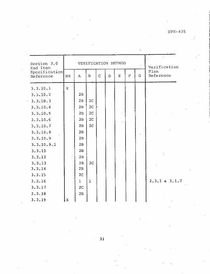
EPS-435
Section 3.0 VERIFICATION METHODEnd Item VerificatiorSpecification PlanReference NR A B C D E F G Reference
3.3.10.1
3.3.10.2
3.3.10.3
3.3.10.4
3.3.10.5
3.3.10.6
3.3.10.7
3.3.10.8
3.3.10.9
3.3.10.9.1
3.3.11
3.3.12
3.3.13
3.3.14
3.3.15
3.3.16
3.3.17
3.3.18
3.3.19
X
X
2B
2B
2B
2B
2B
2B
2B
2B
2B
2B
2B
2B
2B
2C
1
2C
2B
2C
2C
2C
2C
2C
2C
1 2.3.1 & 3.1.7
31

El S-435
Appendix A
Vibration Tests

EPS-435
Appendix A
Vibration Tests
The test article will be mounted on a vibration fixture
V6-1-166, with a dimensionally similar mounting hole
pattern to the EPS location on the CSM. The fixture in
turn will be bolted to a vibration exciter.
Prior to test article installation on the test fixture, a
vibration survey will be performed to insure that the
fixture is capable of transmitting the required vibration
levels and to determine the optimum control accelerometer
location.
All tests shall be performed under the prevailing
laboratory conditions.
The tolerances on the test conditions shall be:
a. The test tolerances for equalization bursts at any
level are 2 dB above full levels from 20 to 1000 HIz
and 4 dB above full levels from 1000 to 2000 IIz.
There are no minimum tolerance requirements.
b. The test tolerances for full level test runs are
±2 dB from 20 to 1000 HIz and -4 dB from 1000 to
2000 Hz.
c. The overall g rms tolerance is +15% and -5%,
applicable both to bursts and test runs. (Note:
g rms values are to be read out of the control
console meter)
d. Compliance with the tolerance shall be verified by
analysis of the input spectrum.
A- 1 -

EPS-435
e. Three separate exceedances whose bandwidth is less
than that of the shaping filter (up to 25 IIz) or
less than 5% of the center frequency, whichever
is larger, are acceptable.
f. Reductions below tolerance, whose bandwidth is
less than that of the shaping filter (up to 25 IHz)
are acceptable, provided the maximum capability of
the shaker system has been used.
The test article shall be subjected to the following
vibration levels along the three orthogonal axes (Figure
A-1) in the order shown below. This sequence may be
altered at the discretion of the test conductor with
concurrence of the NASA/MSC and LEC representatives.
Random:
:-Axis
20 to 125 Hz
125 to 500 HIz
500 to 670 lIz
670 to 1100 Hz
1100 to 2000 Hz
Y-Axis
20 to 75 IIz
75 to 175 Hz
175 to 300 Hz
300 to 1000 Hz
1000 to 2000 lIz
+12 dB/oct increase
2.0 g2 /H.z
-9 dB/oct decrease
0.8 g 2/Hz
-9 dB/oct decrease
+6 dB/oct increase
0.085 g /Hz
+6 dB/oct increase
0.025 g /Hz
-6 dB/oct decrease
A-2

Z-Axis
20 to 100 Hz
100 to 440 HIIz
440 to 600 Hz
600 to 900 IIz
900 to 2000 Hlz
+6 dB/oct increase
0.04 g2/IIz
+18 dB/oct increase
0.3 g2/HIz
-12 dB/oct decrease
The excitation shall act along each of the above axes
for a duration of 140 seconds per axis. In addition,
the spectral density shall be increased by 4 dB above
the nominal for a duration of 10 seconds per axis.
Sinusoidal:
5-35 lIz @ ±+ .25 along each of three orthogonal axes
as follows: Sweep at 3 octaves per minute from 5 to
35 to 5 IIz.
A-3
EPS-435

-- - 2
-- iC
I <e I !
IY
FIGURE A-1 - INSTRUMENT AXES.
A-4
.
AX

EPS-435
Appendix B
Thermal-Vacuum Tests

EPS-435
Appendix B
Thermal-Vacuum Tests
The tests will be conducted in a vacuum by applying the
prescribed heat loads via the lamp banks and simulating
the EPS interface with the CSM via temperature control
(strip heaters) and application of the prescribed internal
power levels.
It is anticipated that all test modes will be of a steady-
state nature; i.e. variations resulting from orbit position
will not be simulated. The time required to reach a
steady-state condition has not been defined, but is
anticipated to be in the order of three to eight hours.
The following test cases are prepared for the test unit:
1. Cold - operating:
2. Standby - 6W heater power:
*3. Standby - no power:
*4. Standby - no power:
5. Hot - operating:
6. Rendezvous & Docking -
Power off:
7. Rendezvous & Docking -
Power on:
B angle = ±73-1/2°
B angle = ±73-1/2°
B angle = ±73-1/2°
B angle = 00
B angle = 00
Direct sun exposure
Direct sun exposure
(The above is the sequence in which the tests will be run.)
* Test cases 3 and 4 are required on the Thermal Test Unit
only. These tests will not be run on units containing
flight type electronics.
B-1

EPS-435
Appendix C
Electromagnetic Interference
The tests outlined describe the anticipated design and
test requirements for the electromagnetic compatibility
(E1TC) with the operational environment of the EPS, the
associated ground support equipment (GSE), and with other
space modules.
C-1

- rU)
·rl 1
NOU h>
·:; H O >
a Ud O Q 4
fl *-O4:>- cd
I
P4
c0
o
N
I
N
:'
Z H
4)
rH ¢} 0 4-) rH -- a) 0 O --H 4W
P4 0Oo1 r En 4 (C
O 4-4J Cd )OU d-,H 0 0 0
U) 4 3 - 04 U
4-).,
-H tnO O
4J
*H a0U )r)
ONrIn
Lno(N
0im
N4N -
In
N II NN
M OUm
4E
-i
\r,
1m
r-q
r-I
.;
m:,
L 0iO
c) c
-H 4-L
N N
N
N N
4i
LC4I H* C f_
Ln 4-n
N N
O HoU ;: o
44o
O nI
N
U) (N
O ON
I IN
N N
.Q O N. 4JJ:; o
LU {4J I* 0 O H; 'r E Z-(-
-i
'4
E- a) 0o
tH ' o oW ro 0f' E 4J .- 0
H U H: 0
O O OO9 Q 4
Ck. 0 H
o E: n U o O
C -) H Z::4J0a 4- a) a)04-)
0 Z) Cd a)09
C-2
oHH
UH
H E-UHPH
U) aq
>HU
3 XOZ w
(D U1-.HH
W
E-e
U
H
zH
C4w
W
:r:
Cj
co
0%o
U
c'}
O r
NhoN
$4 I
090:t-
N
,I O
000O oo C
.O C. ) ,,_ C
. C) (2 -_- EH ,
NrI
)InCD(N0I
C)oi
'-4
4-4'c0
rd
4J - 09
.*H o O
:d - -
Co
--I C) r_
4C:. aH _::

(nU)0)
d 4J0o> )0 (fr
C0)k4 4 -
00o0
oor(
I NN
X o
OOU
0 PI4o
a) m 9 LO 44 UO~ 0'
,-4-)
U) -4
E 'O.
fC4 I P 4--I
W UO
>4 a
P V ;n C4
O 0cN
" I
i _
tL'-4 Icd .
a4 9o
N
0LnIN
0 0--4 3 -I CI
'D U) 4-3 I· O ) rU)
cq(4
Z;
-4
0
-J
Cd
Q)
0LA
0-!
U,I
03
4
-4C).)
03
E(o
co
Ln
o
0
')En
o-l
U)
P4
0r-
40 O
.O 1 (0 00o3 m C , O
4- 1 (d-r 4-v0oU) c Nq
U E -IE -
-4
snLr
0
Cd
4-U)
4.J 4Pqrl u3
on o
0 0)4-) i4
*., 0) 4-
C.~~~~~~~~~~~~~~~~~~~~~~~~~~~~~~ i1
o
4 Hs-'UJ
O U
4En~
r.I-IC
o v4- N
r-q ·
0
t U 4-J·*()0
E C
r54 0)H 4-
LO4-
N. 4
00
4J
('4 CN D
rd
I "- u) 4J 1c · O e.J
z SvElq
r4
r4
40--ir-I co-.,- -
ra m· H O)-'.4c)
r-i
Ud
o0- 0
C-3
H
HE-4
U
HH EAC H
U) 3
>1
z
:D Wcou
Co
U)
0
HHU)CE
E
H
HH
CW
Eq
C.)U
U)
HD
U)
r-
CD
4m

ha Qq N \ > - a)O O , I Ln aQH .. N r--I - in -E- X U) I I u
U 0 caln 4 4H r1 0 CN CO O , . ODt U) NIq C CN OCF Ul r4 Q4H 0 I I EO :- EtH 1 -1 00 I 0O3 C.x O o r- oP4 H * U) Lf) (CN 0 O ,: 4- 0r .- ,-- d tN r a' ,.- 4-. 0 'r
N
U Z
O N N
D 0o: 0Z a -00 0 C
H 00 OO-
m z 4)& H U rNU)4-3
Ur) rL O 'm I zl .E r e
¥ ~ ~~ 0~~E E 4 ·r 4-
4, r r
O d,.-E d ~1Z
o-4 fl--4Ord UG)Q d4-
PI 7O.4 .- 4 c04 -, cL
H) OWI HU) U
C-4
- ' . ' ! :. '..

EPS-435
Appendix D
Ilumidity Tests

EPS-435
Appendix D
Hlumidity Tests
The humidity test will be run to MIL-STD-810B. Method
507, Procedure I, except that the minimum temperature shall
be 680 F and the maximum temperature shall be 1200 F. This
test shall be repeated for five cycles only.
In general Procedure I consists of exposing the unit
under test to the following conditions.
1. Raise temperature and humidity from ambient to 1200 F
and humidity to 95% over a two hour period.
2. Reduce temperature to 68° F and 85% or greater relative
humidity. Maintain this condition for 16 hours.
3. Repeat steps 1 and 2 for 5 cycles (120 hours).
4. Functionally operate test unit at ambient conditions
and compare with previous results.
D- 1 -

EPS-435
Appendix E
Shock Tests

EPS-435
Appendix E
Shock Tests
The shock test will be run to DMIL-STD-810B, Method 516,
Procedures I and V. The shock pulse shape for Procedure I
shall be as shown in figure 516.1-1 of PMIL-STD-810B. The
peak value for Procedure I shall be 20 g's and the nominal
duration shall be 11 milliseconds.
Procedure I consists of three shocks in each direction
applied along three mutually perpendicular axes of the
test item (total of 18 shocks). The shock pulse shall.
be of a saw tooth shape with an amplitude of 20 g's and
a duration of 11 milliseconds. The unit shall be operated
after the test and the results compared with functional
test results obtained before the shock test.
Procedure V consists of placing the unit on a wooden
bench top at least 1 5/8 inches thick and performing
the following: With the unit resting on its one flat
surface lift one edge of the unit four inches and allow
the unit to drop back freely to the horizontal bench top.
Repeat using the other three edges as pivot points for a
total of four drops. Functionally test unit and compare
with previous test results.
E-1- a

PART VIII
END ITEM SPECIFICATION

NATIONAL AERONAUTICS AND SPACE ADMINISTRATION
END ITEM SPECIFICATION
FLIGHT HARDWARE
FOR
ELECTRON/PROTON SPECTROMETER
DECEMBER 15, 1970
SKYLAB PROGRAMC
.MANNED SPACECRAFT CENTEac ~.'
IlI/ J'3 I L/, I L AtA3
R

ENDT ITE}I SP}Xi iiFICATION
FLIGHT IINRDXWARE
FOR
irLEC'-'ICOI/PROTON SPECTROiM'TER
DECIVNBER 15, 1970
Approved by:
)
Paul H'. Vav-raChief. In-formaition Sys.tems Division
Reginald M. MiachellManager, F2:kylab Project Office
Manned Spacecraft CenterT-Ho.-;ton, Texas 7-058
'C e

1. .
I . f:N:T 1RODUICT)JIONI
'I'i, I\ A ' I/\t,,, il;it'.y IlI i:I..r:ltr , IG I: r:tl l,. J-ll i. r I .: ll:i l.:: I()( .- :Jlni:rlril. I I',(-KI A-)-(A')-l-,-t',.v i.::L,~lJ /, rbA l.,: II ; 'luJ. ry )1, I //(), i.:: al.pp'lI.ci L:_' a.:; Il l d. II, r(.'iIl. I"i:,,~ I
LI': I : t LI )|II i : I J::r ; j I )I | .I i. : ;:I i l.: I I : ;I)(:( i. i' i :.t.i. 11 (: ( )r' '::;|() r:; *I.ndI I. : :; Lur:.rii,( : i. ;r I., AAP /'Ai<.-i I It'y ll:,, dw: rI G¢:ll. r'l '.'r' l ql,; r;tll:rll, I;t_:l1,.
I':.('t II);'I,;L ':I; i(il rI1 tIl. L ,,rd ' I. i.i ; (:I iJ. i I .t(I:::; ::l),:(' i. I'ic ;li ,)]rl lI.IIr'l2 ( :rr,: I,:(r l¢l
,;1i. Ilti :, .rr:r' . 1, I ' I.I:,. AAPj I' i l. ry:l rdw;r'(: (-1 :o.'r'; . I'h:_l i.k r' l .rI,.
A.. AfI ,!.; . :Tl ,
11. A 1. Ii._: )L;; i. Iw'. t ;1t: I'Iil')wi , : T (. 7i. Il IftI N, b:N I[d,: If .i y Iwti (:
6I '
(:tJ.rJ. d f , LI: 1,s, " " O tn I ., r' o r)' "a;J_ .l(' ;q.:.;r.(: jo i. r(:d t)y :.: r i 1 i :: .r l li (j. .")
. No fr f ' 'l ' I, 1 r .
(.1 I:;( (Ul.iV [,v rI' ;./'l)I I : . r,(ifI' , : .. ': IJ I))L.i. ':aI t.r lJ r ,I:i:'ll..V f )rrrr;.rtf,:;/wIt i , i :.r : "ri,, .':jri, i. : j .t " ; r :' f ih i 't l.r 1 : ; *l ) i fl r I,, !' 1 1i L J.-t
.:.t [), ·
( ., .,?,:'. I) - A I q I i it I.'
I''l i].hll. I:.r' h;. ' ; )I;;.r'l;Jr',:, .ll ] i'i. ~';:l.,r, I.j:;;I . ;.r'dWu :r',. ;-J.'i . I' II I ...1/t;,. I.~'~.illiri. iIi W '', : :I ,:I.'1 II. I ,- ,.I' , d I i : . '(','/ ..... d Ii.l tI I.fI : r-quir',.-
:;:l¢.tll t(. ~:t'>1t",',l ,:L l.. ' I t ' l..' - ' tl I r, v:.dl o I ,:r ,~i.rf ::r' i r;.' ,'~:i.rl/.f p>r' o:;al ::/
(.; I.i, ln: ';t~;t.1 1 ~,. D r',.r Itr' -, ill ;.-, r'()r'(;].tl: I. Wi.l.li I. r,-qili 'r tt:Lil.'; o1' ;s(.( l.'rln
;'. 1, I .
I .1 . ~ , ' I (.y,1, ,,' ^ ~L'(' y [*l'UI', - fl, :]jL i i. : ( l.:
.1 .; (':1.1.1 5tl y CL: - ftJ,,. :lffI,.i,-;l,1,
: l,,' ,ry I :.I:If:lA - Al1l.i.:t1hf .I . '

Category IIIB - Not applicable
1.2 Ancillary Hardware Definitions - Applicable
1.2.1 Flight Hardware - Applicable
1.2.2 Backup Hardware - Applicable
1.2.3 Qualification Test Hardware - Applicable
1.2.4 Mockup Hardware - Applicable but revised as follows:That hardware which is a model of the Flight Hardwarewith the same external dimensional configuration, mountingprovisions, and external color.
1.2.5 Mass Mockup Hardware - Applicable
1.2.6 Training Hardware
through
1.2.6.4.2 Simulators - Not applicableAdd the following new paragraph:
1.2.7 Ground Support Equipment - That support equipment whichis required for servicing, testing, handling, maintaining,and transporting the deliverable end items.
1.3 Applicability of the AAP Ancillary Hardware GeneralRequirements - Applicable with the following change.Add: Paragraph 1.2.7, and delete: Paragraphs 1.2.6through 1.2.6.4.2.
.1..4

2.1
2.0 APPLICABLE DOCUMENTS
Specifications
Military - Applicable
Federal - Applicable
Standards - Applicable
Military - Applicable with the following changes:
Number Comment
MIL-STD-100A Delete and substitute MSCM 8500,Volumes I and II
MIL-STD-130C Delete and substitute MSC-SPEC-M-1,Revision A, dated June 1967
Other Documents - Applicable
NASA - Applicable with following changes:
Number Comment
MSC-KA-D-68-1 DeleteRev. B
Military - Appiicable
Other - Applicable
2.1
2.1.1
2.1.2
2.2
2.2.1
2.3
2.3.1
2.3.2
2.3.3

3 .1
3 .0 TECH'TICAL REQUIREVENTS
3.1 Performance - Applicable
3.1.1 Functional - Applicable
5.1.1.1 Overall System Requirements
A. Proton Spectral Measurements - The spectrometer willmeasure proton fluxes in five differential energyincrements in the energy range from 10 MeV to 150 MeVand the total flux greater than 150 MeV.
B. Electron Spectral Measurements - The spectrometerwill measure integral electron fluxes in four incre-ments in the energy range of 0.5 MeV to 4 MeV.
C. Viewing Angle - Total viewing angle by each detectorwill be 27 steradians with less than 35 of the viewingangle loss due to adjacent detector's shields.
D. Count Rate - The spectrometer will process countrates up to 250,000 counts per second nominal or aslimited by the detector configuration.
E. TIhe EPS sensors are manufactured by only one knowncompany and are not available as a high-reliabilitycomponent. The contractor will attempt to qualify thesensors as part of the instrument during the Qualifi-cation Test Program. Therefore, there will be noseparate Qualification Test Program for the sensors.The contractor will acquire a supply of sensors andscreen them during the design phase to determine theidentity of those sensors most likely to functionsatisfactorily for the required instrument life.
F. An end-to-end test will be performed to verify thatthe electron/proton spectrometer functions.
G. No requirement is included in this specification tocalibrate the instrument using actual electron orproton sources. All calibration shall be made usingsimulated charge pulses at the output of the electron/proton detectors. An analysis shall be made and sub-mitted to NASA to determine the probable accuracy ofthe total instrument.
Subsystem Requirements - Applicability to be determined.

3.2
Mechanical - Applicable as specified in the mechanicalICD.
Electrical/Electronic - Applicable as specified in theelectrical and instrumentation and comnmunications ICD's.
Other - Applicable with the following change. Add:
"The Flight Hardware with the exception of the electron/
proton detectors shall have a iminimum life of 1500 hours
of operating time over a period of one year. No reliability
verification and testing of the electron/proton detectors
is included in this program. A portion of the 1500 hours of
operating time is assumed to be utilized in the standby
mode of the system in orbit, and may not necessarily mean
that the system is operating on other than internal heaters
to insure survival of the system in the space environment.
The orbital useful life of the Flight Hardware shall be
sufficient for a total. mission consisting of' a 28-day
mission (48 hours of operation minimum), a two-month
orbital storage, a 56-day mission (80 hours of operation
minimlum) one-month orbital storage, and a 56-day mission
(80 hours of operation minimum). wi'unout preventive mainte-
nance.
Operability - Applicable
Reliability Design Goals (Numerical). - Not applicable
Maintainability - Applicable
General Requirements
-.3.1,.2.2.lb
3.1.2.2.1c
3.1.2.2.l1d
3.1.2.2.2
3.1.2.3
3.1.2.4
Applicable
Not applicable
Applicable
Additional Requirements for In-flight Maintainability -
Not. applicable
Minimum Useful Life - ApplicableThe minimum useful life of the Ancillary Equipment Hard-
ware s:hall be as follows: To be determined.
Natural Environment - ApplicableThe experiment hardware shall be capable of successfully
performing the required functions while or after, as
applicable, being subjected to the natural environmental
conditions specified in Table I (to be determined).
3.1.1.2.1
3.1.1.2.2
3.1.1.2.3
3.1.2
3.1.2.1
3.1.2.2
3.1.2.2.1
through

3.1.2.5
3.1.2.6
3.1.2.6a
3.1.2.6b
3.1.2.7
3.1.2.8
through
5.1.2.8i
3.2
3.2.1
3.2.1.1
3.2.3.1.1
3.2.1.1.2
3.2.1.1.3
3.2.1.1.4
3.2.1.1.5
3.2.1.1.6
3.2.1.1.7
3.2.1.1.8
3.2.1.1.9
Induced Environment - ApplicableThe experiment hardware shall be capable of successfullyperforning the required function while or after, asapplicable, being subjected to the induced environmentalconditions specified in Table I (to be determined).
Transportability - Applicable
Not applicable
Not applicable
Iuman Engineering - Applicable
Safety
Applicable
Interface Requirements - Applicable
Flight Hardware - Applicable, to be determined.
Flight Vehicle Interface - Applicable, to be determined.
Location, Envelope, Weight, and Center of Gravity -Applicable, to be determined.
Structural - Applicable, to be determined.
Fluid - Not applicable
Electrical - Applicable, to be determined.
CommuIlications and Instrumentation - Applicable, to bedetermined.
Environmental Control - Applicable, to be determined.
Controls and Displays - Not applicable
Lighting - Not applicable
Other - Not applicable
Interfacing with Other Experiments - Not applicable3.2.1.2

Ground Communications Interfacing - Not applicable
Flight Crew Interfaces - Not applicable
Mission Interfaces - Applicable
Not applicable
Not applicable
Times of Hardware Operation - ApplicableOperating lifetime of the Spectrometer is specified inparagraph 3.1.1.2.3.
Not applicable
Ground Support Equipment Interfaces - ApplicableTo be determined
Zero Gravity Type Training Hardware
Simulators - Not applicable
.353
5.3.1
5.3.1.1
through
5.3.1.5
5.5.1.6
3.3.1.7
.5.1.7. 1
5.3.1.7.2
,/ ,J 1.1t_
Design and Construction - Applicable
Mechanical - Applicable
Rigging Devices
Mechanical Locks - Not applicable
Weight and Size - Applicable
Factors of Safety - Applicable
Structural - Applicable
Fluid Systems (Gas and Liquid) - Not applicable
Lubrication - Applicable
3.4
.2.1.5
5.2.1.4
> .2.1.5
5.2.1.5c
5.2.1.5d
through
3.2.1.5k
5.2.1.6
5.2.2
through
5.2.4.2

3.5
Electrical and Electronic - Applicable
Flanmability of Wiring Insulation, Materials and Accessories -
Not Applicable
Toxicity of Wiring Insulation, Materials and Accessories -
Not applicable
Electrical Connectors - Keying
Electrical and Electronic Piece Parts -- Closure - Applicable
Protection of Exposed Electrical Circuits - Not applicable
Protection of Electrical and Electronic Devices - Applicable
Corona Suppression - Applicable
Moisture Protection of Electrical and Electronic Devices -
Applicable
Redundant Electrical Circuits - Applicable
Electrical Operating Requirements - Applicable
Temperaturie Control - Applicable
Wire Splicing - Applicable
Wire Bundle and Harness Protection - Applicable
Fluid (Gas and Liquid)
Hazardous Fluids System - Not applicable
Debris Protection - Applicable with the followingchange:
Not applicable
Cleanliness - Applicable
Test Provisions - Applicable
Test. Points - Applicable
3.5.2
53..2.1
3.3.2.2
5.5.2.3
through
3.3.2.7
3.3.2.8
3.3.2.9
3.3.2.10
5.5.2.11
3 .3.2.12
,.3.2 .15
3.3.2.14
3.3 .2.15
5 .3.2.16
3.3 *3
through
3 .3 .3.11
3.3.4
3 53 54.5.6.1
".5.6.1

3.6
3 .3.6.2
5.3..7
5 .3.8
t;:L'Oug} I
5.3.8.2
b. a,5
through
3.5.10
3.3 .10.1
5.5 .10.2
through
3.3.10.9
5.3 .10.9.1
3.3.10.9.2
3.35.11
through
3.3.16
3.3.17
3..3.18
3.5.19
Test Equipment - Applicable
Single Point Failures - Applicable
Redundancy
Redundant Paths - Applicable
Selection of Specifications and Standards
Materials, Parts and Processes - Applicable
Toxicity of Materials - Applicable
Restlriction on Use of Transistors end Capacitors
Parts and Material Selection - Applicable
Applicable with the following: Add "Select MIL-STDqualified parts as a minimum with active components aged167 hours at rated voltage and current."
Non-metallic Materials - Not applicable
Standard Parts
Electromagnetic Interference (EMI) - Applicable
Identifir:ation and Marking - Applicable with the followingchanges:Delete speciFication reference "MIL-STD-130" and insert"MSC -SPEC -M- 1."
Storage - Applicable
Pyrolechnic Devices - Applicable (Pyrotechnic deviceswill not be used. in the Electron/Proton Spectrometer.)

4.1
4.0 QUALITY ASSURANCE REQUIRENMTS
4.1 Quality Assurance Requirements for Major AncillaryHardware - Not applicable
4.2 Quality Assurance Requirements for Minor AncillaryHardware
through
4.2.9.4 Handling, Storage and Delivery - Applicable
4.2.9.5 Sampling Plans - Not applicable
4.2.9.6 Indication of Inspection Status - Applicable with thefollowing: Add "Government Inspection may be performedin accordance with MSC standard practices."
4.3 Inspection System Requirement for Ancillary Hardware -Not applicable
4.4 General Quality Assurance Requirements for AncillaryHardware - Applicable
4.4.1 Government Source Inspection
through
4.4.6 Contamination Control - Applicable
4.4.6.1 Contamination Control Plan - Applicable
4.4.6.2 Fluid Systems
through
4.4.6.7 Other Requirements - Not applicable
4.4.7 Equipment Logs
t.hrough
4.4.11.5 Contractor Quality Assurance Action - Applicable

., . 1
5.0 RELIABILITY REQUIRDEIvNTS
Organizati on
Reliability Plan - Applicable
Government Furnished Property - Applicable
Reliability Tradeoff Studies - Not applicable
Failure Mode and Effect Analysis Single Failure PointSummary and Hazards Summary - Applicable
Failure Mode and Effect Analysis - Applicable
FKEA Procedure - Applicable'with the following: Add"FfEA will be supplied on a major subassembly level alndinclude modes of operation, channels, and functions."
Single Failure Point Summary - Applicable
Hazards Summary - Not applicable. Will be satisfied bySafety Assessment Report per paragraph 3.1.2.8.
Non-confornmance Reporting and Corrective Action - Applicable
Subcontractor and Supplier Control - Applicable
Design Revi,,w Program - Applicable
Subcontractor and Supplier Design Reviews - Not applicable
Engineering Design Changes - Applicable
Standardizat.ion of Design Practices - Applicable
thrcuc"
5.2
5.3
* 14
5.5
5.5.1
5.5.1.-
5.5.2
5.5.3
5.6
5.7
5.8
5.8.1
5.8.2'
5.9

6.1
6.0 VERIFICATION REQUIRDI.NTS
6.1
through
6.3.2
6.3.2.1
6.3.2.1.1
through
6.3.2.1.2
6.3.2.1.2.1
6.3.2.1.2.2
6.3.2.1.2.3
6.3.2.1.2.4
6.3.2.1.2.5
6.3.2.1.2.6
6.3.2.1.2.7
6.3.2.1.2.8
6.3.2.1.2.9
6.3.2.1.2.9a
6.3.2.1.2.9b
6.3.2.1.2.9c
Verification and Technical Requirements
Qualification Tests - Applicable
Flight Hardware - Applicable with following change:Delete the sentence, "Qualification Test Hardware shallnot be used as Flight Hardware or Backup Hardware" and
"Qualification Test Specifications shall be prepared andsubmitted for review."
General Requirements
Test Environments and Methods Applicable
Humidity - Applicable with the following change. Testshall be conducted for 5 cycles only.
Salt Fog - Not applicable
High Temperature - Not applicable
Low Temperature - Not applicable
Shock - Applicable with the following changes: Test shallinclude procedures I and V only.
Fungus - Not applicable
Pressure (Positive) - Not applicable
Acceleration - Not applicable
Vibration - Applicable
Sinusoidal Resonant Search - Applicable
Sinusoidal Cycling - Not applicable
Random Vibration - Applicable, to be determined.

6.2
6.3.2.1.2.10
6.3.2.1.2.11
6.3.2.1.2.12
6.,.2.1.2.13
6.3.2.1,2.14
6.3.2.2
6.3.3
6.3.4
through
6.3.6
6.3.7
Acoustic Noise - Applicable
Altitude - Not applicable
Space Simulation - Applicable with the addition of the com-plete therrnal/vac environment. To be determined.
Atmosphere Compatibility - Not applicable
Other Test Environments and Methods - Applicable with thefollowing: Add "Electromagnetic Compatibility - Shall beverified in accordance with the requirements of MIL-STD-461."
Other Ancillary Hardware - Not applicable
Acceptance Tests - Applicable with the following: Add"Environmental test shall include thermal and vibration asspecified in enclosure 1."
Preinstailation Tests
Prelaunch Tests - Applicable
Other Tests - Not applicable

7.1
7.0 COINFIGURATION tANTAGEMENT RFQUIRMI.NTS
7.1 Configuration Identification - Applicable
7.1.1 Preliminary Design Reviews (PDR) - Applicable with thefollowing: Add: "The intent of the PDR can be satisfiedby a TDR (Technical Design Review) with submittal of thenormal program documentation at the appropriate milestone.Documentation requirements shall be as specified in section8."
7.1.2 Critical Design Reviews (CDR)
through
7.3 Configuration Accounting - Applicable

8.0 DOCUMEINTATION REQUIRiKITTS
Add the following between first and second sentences of the first paragraph:
"All documents required by this section should be submitted in theformat normally used internally by the contractor, i.e., the documentsshould not be retyped, reformatted, edited, or upgraded through theaddition of illustrations for purposes of the NASA submittal providedthe original form of the document meets the content requirementsdefined in this section."
In the first paragraph, change: "14 days" to "7 days."
8.1 Configuration Management Documentation
through
8..l.la Flight Hardware - Applicable
8.1.lb Mockup Hardware - Not applicable. A data sheet describingthe mockup will be provided.
8.1.1c Mass Mockup Hardware - Not applicable. A data sheetdescribing the mass mockup will be provided.
8.1.1d Zero Gravity Type Training Hardware - Not applicable
8 .1.le Neutral Buoyancy Type Training 'Hardware - Not applicable
8.1.1f Simulation Device - Not applicable.
8.l.lg Simulators - Not applicable
8.l.lh Ground Support Equipment - Not applicable. A data sheetdescribing the equipment will be provided.
8.1.2 Configuration Specifications
through
8.1.2.4 Section IV - Configuration Status - Not applicable,however, a design summary that includes the drawing treeand top level drawings will be provided to satisfy the intentof the Configuration Specifications Sections I, II, and IV.Section III (Qual Status) will be provided as part of thebimonthly progress report.
8.1

8.2
8.1.3 Engineering Change Proposals (ECP) - Applicable
8.1.4 Specification Change Notice - Applicable, however, thechange wording will be compatible with the requirementsof paragraph 8.1.2.4.
8.1.5 Specification Change Logs - Not applicable, however, achange log will become part of' the design summary.
38.13..6 Specification Revision Charts - Not applicable
8.1.7 Engineering Drawings - Applicable with the followingchange: Delete the last two sentences of the paragraph.
8.1.7.1 General Requirements
th rough
8.1.7.2 Standards - Applicable with the following change:Delete section 3 and 5, Chapter I of' MIL-STD-100 andsubstitute MSC-8500 Volume I and II.
8.1.8 Technical Reports - Applicable with the following changes:(1) Delete the second sentence starting with "The reportsshall .... " (2) Add the following sentence, "Submittalof the material to be incrementally as the reports are com-plete."
8.1.9 Review Minutes - Applicable
8.1.10 Acceptance Review Reports - Not applicable
8.2 Management Plan - Applicable with the following: Add:A brief narrative Management Plan may be provided as longas each major item is included.
8.2.1 Section I - General Management
through
8.2.8 Section VIII - Development Schedule - Applicable
8i.2.9 Section XI - Nonmetallic Materials - Not applicable
8f.2.10 Section X - System Safety - Applicable
Quality Assurance - Applicable

8.3.1 Failure and Unsatisfactory Condition (UC) Reports -Applicable with the following: Add: The failure orunsatisfactory condition will be reported on the FailureInvestigation and Action Report (FIAR) MSC Form 2174.
8.3.2 FA and CA Reports - Applicable with added sentence: Thecontractor shall not be responsible for analysis of partfailure.
8.,3,3 Acceptance Data Package
through
8.3.3.g Listing of all Material Review Records - Applicable
8.3.3.h Configuration Specification - Applicable as redefinedin paragraph 8.1.2.4.
8.3.3-i Certification That The Hardware.......
through
8.3.5 Equipment Logs - Applicable
8.4 Reliability Documentation - Applicable
8.4.1 Failure Mode and Effects Analysis Report - Applicablewith the following changes: Delete the last sentence ofthe paragraph.
8.4.2 Electrical, Electronic and Electromechanical (EEE) PartsList - Applicable
8.4.3 Nonmetallic Materials List - Not applicable
8.4.4 Electrical, Electronic and Electromechanical PartsSpecifications
through
8.5.1 Verification Plan - Applicable
8.5.2 Test Specifications - Not applicable
8.5.3 Test Procedures - Applicable
8..v4 Test Reports - Applicable
8.3

8. 4
Calibration Data Reports - Applicable
Development Status Reports
Delivery Status - Applicable
Operating, Maintenance and Handling Procedureswith the following changes: Add the followingfirst and second sentences:
- Applicablebetween the
"The contents of these manuals shall be restricted to thoseoperations which will be performed by the flight or groundcrew during installation, checkout, and operation. It isexpected that the hardware will be returned to the factoryfor any significant maintenance or repair which may berequired, and therefore procedures for this type of activityneed not be included."
Preparation
Section 2 - Subsystems - Applicable
Section 5 - Controls and Displays - Not applicable
Volume II
Volume III - Applicable
Ancillary Hardware Support Requirements - Applicable
Flight; Crew Requirements - Not applicable
Base Support Requirements - Applicable
Spare Requirements - Applicable
8.'3 5
08.6
th rough
8.6.5
8.7
8.7.1
through
8.7.1.lb
8.7.1.1c
8.7.1.2
through
8.7.1.3
8.8
8.8.1
8.8.2
8.9

M H H Ha H H H HSC > D~~~~IH
3-3
o o
P .
Co oId Id ! O Idtl I a
·0 a :E a.) a- o -) c
¢ *H 00 0 H H *HH:I: b.04-0 c: > CO V)a) - _ ) 0) Q) C
H u · d c o , o
S t X ~ X q o S
A H a P
Eq *dl s O ' 'oEH > . 0 o C' v ) U
·, 10 <. > 0d 4 :
:r-O t o H 0) A U) a O >, · e S I· C ) a
¢- o a i- a aI d4 0 -P*H 'd) t4C d Id 0
E + ' a) *r a .<·r > 0 C aPA0C) 0 PA gl, > +) aA >) C ::5
H S- j a aH S id 0A l
o 0 ' C) C s° Z 0
pq .H Id -C CHj C < a4Cd ,
0 S-. - Ed O
D0 I -P - ' -.
o 0 a) A r
) ) -- ,
.Cd C H a CJ
E: P, ±' ) 0W .,
Ca c Q O O S0 1' t - c
W H EH H H
o. coo c c: 1-.-
.. _U _ ._
a)rJH
+)
o
o
0
cO
Q-
C-)
0 )
E0
i1 '

,i' - H -H H HuE- H
a H H) H H HC
r- I X0 O 0 rZ CJ b.9 :, r 0 : ~: Id Id Id
,'-U4 0H 0,--I ,U t -H r; h 4-'H 0'd rt Id
V A) Ocd cdo . ,I .
.d; ) ~ O : (- h ,4- r31 ' C l 0 0 0o 0 o- 0A2 *r4 H c O¢
. _ : .HH 0
E ~ A-4 h- O-4 PARI , . o , .H .HEl D Cc > ICd I 0 4 O
co t)-4 V ) O r-4 ', Cd i ,r
H , U> C) 4 OH >O
E d0 U) R OR Hq > o Fi :~ 0 4J I
,- o . I C),)~ H .. :o U I:
4H *r4 U1 S 4 Cd -O -P O0r-4 0 -i ¢ H r-is 04 C) 0' Cd j
·, M bD O
::. H.- O .a .u O3
O. o C) tD ^:: ..p aH , -I .R 0r4 0 m C .-- OE-q vz 4a I d U
H, Sd U AU, 4-A M-'
-cl) a o) 0-h rd
C) POi d O h H OR Z1
O -4 r , ·l ' 0U) H O h
Q) ID p; r) 4 O t 4 d -H U E-4
,, rla >- , r PA r-H A ¢- m
~Ej~
c3 hOU 4 c dO
-Coa CI cn-,k C
. 'd R) U I.-t
3z

? H H HF H H H H~~nl I H H H H
O
Eo 0 0 r)
W rrr, ~ . I j rd . 4
Id In I-i -H
¢4 0r 1t 1 0 01 0- 4: o d
0) ) U) a) U)
4-· 4 0 + 4
i~A ' il
C.) z 0 zd H
+- -dH · O , :
H¢ $~U 4-' $-r U) U , UP
EJ 0S O ' o 0 rlEq) (3 rn c rr .< cEH Gr) h t f\.H> O 0 H0 4 0 )E--i'IC Ccd C 4CU O > l r r OV0 0) ~-, 4 4* -1 - -4: - . I .r>H 'cn i . N cr3 -rO r cr3 0 4-' rJC¢1 05-1 H .r1 *ri r- r I rC H 0dH wk tr3 S4 cd r_
H O O r )HO .0 O H 0rl cd 0 hZ E -PH 4' - O r 4 -)4c 0 -4) 4 0 _ 0 > -H O *Hcd -r1 H cn)-o *Hr1 U r n *,r n *C c WP
C\1 O 3 G4 3e cd *r1 c 3 cd *i 3 cd *r1 - -: cd
I _
0c 0 a) *rcO-- k O O)
o r, 0 b cdcd 0 O 0
C-) C la cd * h
-U 0 _ '*
r: U)$m cd *H *$ crE-e od Hd 00 0 J o )) O ) c
b( rl 0) ¢ '-l 0d r0)) . U * d, 00 hc0 cdO * *-U c O0E: 0 0 cd .-4 U cd ,
5* ' C12Cd C0 EJ, E lo
co
:DC;.
a)
o
Ha)U)
o
r2
o 0
c \
4E-
00)
Cd
0)

T. H -4 1 H H H -4E- H
0
.o H' .l .c O > U) P4 OC
CC a4.)C) ((12 .d ... . .12 o
Cd ) a , -tD .*
rd0 Cd Ird rd *r1 0I(d Id
¢ .) O O4 O h
r Oid rw O *d
tHo) a) 4 ICJ )D U H O t E U),H HO ~ H ~-4" H "Ca4 0 a ) .
¢ hd ¢ r C6 co I .4 ¢ ¢ h l i ¢I
w I H h0U Cd0'U-a) 04*r -' 4.' 4.'PA 0 > Ou > H O 5p ao> O >: a 3: Q) a) aO *rd ) O Cd 0 ID'a ) Id SC
Ei *1 C) = h H h-C D a) ) h a Ca),hCd
dC) I + Cd d -I l hd --I h i h c d 4) 4w)
E d -4 ¢ *r' d , d d O r C td O Cd -c-) ° d +
H - P4 H c, 4->. a).p 4, a) .- _ c$ HHD -H> >C) o C) H a)4.o H a)-p oD 0 l U O da o cd m O Urd
¢Z~~ OR ) P i- O O rHOP 4 C rQH *H *r- 4 C C
H bO 'U> -ri h 4-) +C o 4 h H ri )
FH 4 0 r r O rl O 4 rd C 94- P
Or aI
Cd 4 O
u uH ( Gnr- a
_ .) .,4H
C) Cd VCd0
co CC)
Co
oD
a)10
o
o
+)rDC)
0o
Cd
E4.
ra
Hl
0
aP90

E0 1 -H H H H H v- H f
-DH H H H HHf H HO
G^, tf r g rU rd q " r.,1W 1) a) 1 ) a) 1;a a.
Ua) U) aL I) ) . a(1 C C,) C)) (12'<1 t
-4
40
:;rd
·d C-)kpU C
Cd
-I
+dCd
.1
a)
I o)Cd 0J -
O 0l 0 Cd·4 - f , 440 4
0Cd 0 0
t O O- OO 4 *r) O
a) -4 -I 4 ) V.
- )50 .)d 50
o 4-t-' .P 4-U
a
U)(U
aQ)
E-
a)i
I
a
04
43
F:+3
a)
(Ur,la)-I
0) aO t+
0n E
o o
0d 0
r. a).,-I o E.
.r 0) (.(· Ca) . 4*r S rdj
Cd
} I2
· -r! U)4-) s E- o
Cd _: 4- 0 cd0 ' ' , C)
O +) *r1
.-d r-1 rO -' ;-I U.
C, E u. o'f
4)O)
EH
o
r 1
+ 0t lO
UO-4 5-4
F-. C-4
0
ECo+3
(n
.- , -H,..0 4qri ri oX
0 0C.' -+30
of- -n t-'
LI)+.3
o
4°
a)
(A'4-:r
I- 0V O
O a
a; 4-
a)0
S c-
E oO &
a H
_r _ __ ... -
E-
IZV --t rLC LC\ LC\
H
f--I
a)
a)
o
Cd
r.
C) U\0n a)
P
Cdl)
E4
ON'
C.~,
H
ri
d
+3
+3*,laHCdC1
U;
Cd
EdH
U1
I-I
E-
F-f
U1
=)
o0)
0U)
4-4
U.i
U)5-
Cd
C-CI
4
I
in
4
1t:
I
I
III.1III
I

C-,
2P' H H H H H
CHH IH IH
t d) cd , t ,r
t -- 1 '1) CJ C( a) tD:t . -u, .- .,-
(U Cd Id (U X)
u )D . + \nIf) > " 4- C
(U r(
N o
. ~ I C .Jd td O
E-i .- IJ ( O O --. cp 4H C) S 14H FD e. , cd
H 0 O ¢ - 4- ) - ') O) I
P H ,1 -O- U) H*O (U C- .- ,..U :> n ') Q) (. - - . O
:H _n ) ~ ID - O Cc1 0E 4E n 4)-) f O ICEL C(D *rl aa 4c E H .. _d .
HI P c) -d O A4 P~AH a4-') D 3H ·--CH (Hd ad Ja £3cd (UH
0 O o::
Cc- c) / )
cn c~ o c cn
. Cd . a. d a I
C0 rdU) ' C *, 3do ) - . Cd
L V: 4 o: o cn0 - cO O
cO R ^ cO ca *,' D bD >, a
c] Qd . U: Cd (
a, a . .a a)
Ea - U)H oco 001 ci
It;
0
OD0:11

'.n .1^': 5cslre
ENVIRONMENTAL ACCEPTANCE TESTGROUND RULES
-. 'ACCEPTANCE THERMAL
Components identified as requiring acceptance thermal testing
will be subjected to such tests in accordance with the following ground rules:
1. The thermal envelope specified for acceptance testing of a specific... component will not exceed that employed for part certification/verification (C/V) and should approximate the profile shorwn inFigure 1. The upper and lower thermal plateaus will be limitedto levels at least 20 F above the rminimum and below the maximumC/V temperature extremes, and the minimum temperature excursionbetween the upper and lower thermal plateau shall be 1000 F.
2. The test item swill be placed in the test chamber so that the heat istransferred in the correct vehicle mode. Equipment that is notcoldplatc-mounted xwill be supported in the test chamber so thatheat flow in the holding fixture is negligible compared to therequired heat transfer mode.
3. The high- and loxv-ternrerature soak periods will be of sufficientduration to bring the test time temperature to equilibrium, but willnot be less than one hour.
4. The control temperature for ambient pressure tests with forcedconvective heat' exchangc will be measured within three inches ofthe test article or directly on the test article, but not betv.'cn thetest article and the heat exchanger.
5. For coldplate-mounted equipnment, coldplates wvill be used whenrequired to protect the equipnent. The requirement for coldplateoperation will be avoided wherever practical.
6. The control temperature for coldplate-cooled equipment will bemeasured at the coolant inlet to the coldplate. Where the equip-ment mounting and coldplate configuration cannot thermallysimulate the flight vehicle configuration, the temperature atl: themounting flange root may be used as the control temperature.
1-

1jce I
Let
0n--
0: z0'
LU~~ ULU . Z D wz
ZZ ~ -~ - Op . /0 I
LU I-- .
z o C L
"~~: 0U~~~~~~~~~~~~~~~L
/ Z I0 Z)v, c,~cui z c Zo
o ~~~~~~o< Z
1 ~~~~~~~~~~~~~~~~~LI4iZ I0 91
0 z :~~5-.J L~~~~~~~~~~~~~~~ &
a-ez~~~~~~~~~~~
% LL ~0
LU < = _- I.- 0\ I o~~~~~ (FII
~~~~~~~o < H
~~o0 _~~~~L ~ ~ ~ ~ ~-I L ' -
-LUJ
I 0v)~c wQ(
ZP
I.-
-' -J-< FU~~- <u
Z,: Z "",
~~~~~~ o
I .~~~~~~~., LLLL.~~~~~~L. L7-~~~~~~~~~~~ ct o~~~~~~~~~~~Cr-.c
LI.c
0
LLJ C.L. z c
10 ui
c~~~~~~~~~~~Uc
c~~~~~~~~~~~~~~~~~~~~~~~~~~~n c
~~~~~~~ r~~~~~~~~C
o~~~~~~~~~~~
LS0 cec
(j,) 3~~~~~nl~~t13d;'131 ~~~~~~OYIN4 0

When flange root temperature is used, the temperature limits willbe adjusted to account for the difference in temperature betweenthe coolant and the flange. Where the surrounding environmentdeviates significantly from the coolant temperature for coldplate-mounted equipment, both the surrounding temperature (not on theequipment) and the coolant temperature will be used for tempera-ture control. For coldplate-mounted equipment, the coolanttemperature will cycle in-phase with the surrounding temperatureto the coolant design temperature extremes.
7. Major repair or modification to equipment will require rerunthrough the thermal acceptance test cycle. The number of thermalcycles permissible for flight equipment will be specified, wherenecessary. Minor rework that is readily inspected by normaltechniques will not require a rerun of the thermal cycle test.Requirements for retest wvill be specified for each applicable case.
8. The stabilizing temperature, which is the temperature of thelargest centrally located thermal mass of the test article, isachieved -when the temperature at this point does not change morethan 3 F per hour. W\hen instru-nentation to ascertain temperaturestabilization is not practical, the detailed test procedure willspecify soak time for stabilization.
T. he initial temperature excursion may be in the direction ol theequipment nomi.al operating temperature ('not or cold) so that thespecified temperature extreme is achieved twice in this directionduring test.
10. The rate of temperature change during transient phases will be thepredicted rnaximum rate during flicht for the article being tested,but deviations are permissible under the following conditions:
a. Higher rates may be used if the qualification test has sub-stantiated the capability of the equipment to operate at thatrate.
b. A rate of 10 F per hour may be used where the maximumflight rate is less.
11. Equipment will be operated continuously during the entire testcycle, except where this would result in excessive operating oflife-limited equipment. Life-limited circuits or equipment mayremain nonoperating during transition and stabilization phases,and operated only during the functional tests.

12. Equipment primary circuits will be monitored continuously forcontinuity during the thermal cycle. A pre and postfunctional
-. test will be conducted at ambient room temperature (70 F) oneach component.
13. A functional test will be performed at least once at each tempera-ture extreme after the temperature has stabilized. If a tempera-ture extreme occurs twice, and only one functional test is to beperformed, the functional test will be performed at the last cycleto that temperature extreme.
Where the article has two or more modes of operation, all com-binations of temperature and modes of operation v.ill be selectedduring the test. The changing of operating modes during the testwill be programmed so that the total test duration is not increaseddue to operation in more than one mode.
1.4. Where complete functional tests for complex test articles wouldresult in excessive test time, an abbreviated functional test ofcritical circuits may be performed, within the followingconstraints:
The abbreviated functional tests will include alloperations affecting crcxv safety. Selection ofV;IIG VJ2J:A upV u< ;JtWW ;L' LAf CL@ U i _ i Ma Adfunctional test will be based on descending orderof mission criticality. The detailed test plan orprocedure will list all circuits and modes ofoperation not tested.
15. The actual control temperatures at the extreme ter-iperaturelevels will be within 10 F of the specified levels. in no case willthe control temperature excced the maximumr nor be less than theminimum equivalent qualification test temperature. The averagetemperature during the soak periods will be 20 F below the maxi-mum and above the minimurn qualification termperature. Theaverage rate of temperature change bctw.'een successive tempera-ture levels will be within ±20 percent of the specified rate, butnot more than ±10 F per hour. The instantaneous rate of changewill not exceed the specified rate by more than 40 percent. Theactual average and instantaneous rates will not exceed the temper-ature change rates in the qualification test.

ACCEPTANCE VIBRATION TESTING
Components identified as requiring acceptance vibration testingwill be subjected to an acceleration spectral density (ASD) increasing at therate of 3 db per octave from 20 to 80 Hz; CONSTANT at 0. 04 g2/Hz from80 to 350 Hz; and decreasing at the rate of 3 db per octave from 350 to2000 Hz (Figure 2). The vibration test duration will be adequate to perform
functional and/or continuity tests, but will not be less than 1 minute norgreater than 5 minutes per axis, including specimen equalization time ineach of three orthoaonal axes. Should reruns be required in any axis follow-ing rework or modification, the duration will be reduced, wherever possible,to 15 seconds minimum per axis, and the total accumulative vibration testtime in any axis will not exceed 5 minutes.
Functional/continuity tests will be conducted on all items before, dur-ing, and after acceptance vibration tests. Functional verification during thevibration test will be made for those outputs significant to the mode of flightbeing simulated. All other electrical circuits will be continuity monitoredduring the vibration test to check for intermittents and opens. Where com-plex multi-mode equip:i-ent requires testing in more than one phase/axis,the vibration time per phase per axis will be 15 seconds minimum. Wherepossible, vibration fxtures prcviously approved for use in qualificationtests will be used for AVT. The acceptance vibration test tolerance will beas foliouw.
1. Overall root mean sua re (rrns) +10 percent, -15 percentacceleration:
(with a sharp cutoff filteremployed to eliminateacceleration responsesoccurring above 2 i-7-zfrom the g rms readout).
2. Acceleration snectral density: +1-1/2 db, -3 dbfrom 20 to 1000 Hz
+2 db, -4 dbfrom 1000 to 2000 Hz
This acceleration spectral density tolerance is based onanalyzer filters with the folldwing maximum effectivebandwidths:
5 *

TOLERANCE BANDS
, ....... NOMINAL
THE 9,Sims TOLERANCE IS +10, -15 PERCENT
*OVERALL LEVEL EQLU'VALENT TOSPECTRUM INDICATED
0. 057 g2 /Hz
I I I III I 1 ,i I I I I I i i100
\ 7.4 grms*
\ 6.3 grms*
\ 4.2 grms ~1:
I I I I I I I1000 10,000
FREQUENCY (Hz)
. Acceptance Test Vibration Spectrum Requirements
('·
0.1
0.01
0.00120
L ~ ---. I--~--- -- -

Maximum Effective Bandwidth (Hz)
10 to 100
100 to 500
500 to 2000
'5
10
20
Sample record time or tape loop time (T) will be a minimum of 5 sec-onds, and preferably 10 seconds. Analyzer filter scan rate (SR) will notexceed B/T (Hz/second), where B is the effective bandwith of the filter used.It is recommended the averaging be obtained by using linear integration ,.viLhan integration tinme of T. However, if averaging is obtained by smoothingwith an equivalent RC low-pass filter, a time constant RC > T/Z will beused. In this case, the scan rate will be B/4RC. To reduce equalizationtime, it will be permissible to utilize one-third octave bandwidth (maximumeffective bandwidth) analyzer filters for acceptance tests.
To assure a margin of safety, certification/verification testare to be subjected to acceptance vibration tests will be tested forper axis minimum at the follov,'ing minimum vibration level:
- 1. ASD increasing at the rate of 3 db/octave from 20 Hz toHz at 80 Hz
items that5 minutes
0. 067 2Z /
2. Constant at 0. 067 g 2 /Hz from 80 Hz to 350 liz
3. Decreasing at a rate of 3 db/octave from 350 l-Iz to 2000 Hz.
The test tolerances will be as follows:
1. Overall rms acceleration: +10 percent
2. Acceleration spectral density:
20 Hz to 1000 Hz1000 Hz to 2000 Hz
-+5 db, -3/4 db--+6 db, - zero db
These tolerances are based on analysis methods as specified in the previousparagraph, except that 1/3-octave filters will not be used. This test is inaddition to the vibration tests required for certification/verification.
7
Frequency Range (Hz)

The following additional ground rules will apply to the evaluation ofacceptance vibration test results:
1.A. 'cceptance test levels that exceed the above tolerances are.acceptable if the' level achieved does not exceed the qualificationspecification..
Z. Acceptance test levels that exceed the qualification specificationby more than 2 db at freauencics below those of the knownresonances are acceptable if the level achieved is less than thatof the known response at resonance during qualification testing oroverstress testing.
3. Acceptance test levels that exceed the above tolerances areacceptable if limnited to three separate instances where the band-width is less than 5 percent of center frequency. Bandwidth to bemeasured at the point where the tolerance is exceeded.
4. In cases where fixture resonances limit capability to meet theabove tolerances, the input level should be reduced at the resonantfrequencies rather than overtesting the component.
5. Any other instances of acceptance test levels being exceeded whichare considered to not disqualify the unit for fli2ht will be justified.i;.;.. G ..... ,,a. pikucedures for handling test deviations.
6. Reduction in acceptance test level above 500 Hz to lower than theminimum tolerance at demonstrated critical fixture decoupledfrequencies are acceptable if the maximum capability of the shakerhas been used.
7. Reduction in acceptance test levels to no more than 2 db below theminimumn tolerance is oermitted at any of three separate band-widths no wider than the filter used in the spectrum shaping network.
8. Reduction in acceptance test levels other than given above willrequire a delta test to nmake up only that part of the spectrum forwhich the reduction occurred.
9. Equipment will be operated and monitored as specified in applicablespecification during the acceptance vibration test.
10. The maximum allowable relay switch chatter during AVT will bebased on the applicable system design requirements as determinedby the responsible design engineer.
NASA-- MSC - Coml.. Houston. Texas

ATTENTION REPRO:
.BEFORE PRINTING, CONTACT INPUT FOR PAGINATION.
PROCESSOR
NTIS-185 (3-72)
7- ( 4- 73
I
A:t

ReproducedOF
Reproduced for NASA
by the
NASA Scientific and Technical Information Facility
FFNo 672 Aug 65
I \I
d
//
A Copy