19800014286.pdf - NASA Technical Reports Server
175
N O T I C E THIS DOCUMENT HAS BEEN REPRODUCED FROM MICROFICHE. ALTHOUGH IT IS RECOGNIZED THAT CERTAIN PORTIONS ARE ILLEGIBLE, IT IS BEING RELEASED IN THE INTEREST OF MAKING AVAILABLE AS MUCH INFORMATION AS POSSIBLE
-
Upload
khangminh22 -
Category
Documents
-
view
1 -
download
0
Transcript of 19800014286.pdf - NASA Technical Reports Server

N O T I C E
THIS DOCUMENT HAS BEEN REPRODUCED FROM MICROFICHE. ALTHOUGH IT IS RECOGNIZED THAT
CERTAIN PORTIONS ARE ILLEGIBLE, IT IS BEING RELEASED IN THE INTEREST OF MAKING AVAILABLE AS MUCH
INFORMATION AS POSSIBLE

---A*
DOE /NASA CONTRACTOR
DOE /NASA CR-161413REPORT
SOLAR HEATING AND COOLING DEMONSTRATION PROJECT ;'.TTHE FLOR I DA SOLAR ENERGY CENTER
Preixt red by
Florida Solar Energy CenterUniversity of Central Florida.100 State Road 401Cape Cnnaveral, Florida
Under DOF: Contract F.G-77-A-01-407.1
Monitored by
George C. Marshall Space Flight Center, AlabamaNational A _- ronautics and Space Administration
For the U. S. Departniviit of Fnertry
^- (NASA-CP-161413) SULAh HEATING ANC COGLING NeO-22774DEMONSTBA 'IION FfiUJEC1 Al 'IHE ELCBIDA SCLAb ^-ENE'tGY CENTEF Final beijcrt (Florida Solar iEnergy center, Ca1.e CandveLal.) 175 F OnClasHC A08 / HE AU1 C SCL 1CA G3/44 17980
U. S. Department of Energy
Solar Energy

fIlk,
Table of Contents
Final Report 1
System (Acceptance Test Data
17
Sequence of Operation 39
Circulating Pumps and Motors 47
Solar Collectors 83
Automatic Control System 89
Absorption Chiller 121
Cooling Tower 122
Filters, Valves and Miscellaneous 128
Drawings 152
k'
PRWWWG PAGE BLANK NOT FILMEU

r ^'
Final Report
INTRODUCTION
The Florida Solar Energy Center (FSEC) has retrofitted one of the
Center's office buildings, approximately 5,000 square feet of space, with
solar air conditioning and heating as a demonstration of the technical
feasibility to the many visitors to the Center and the residents of East-
Central Florida. The project provides a unique opportunity to compare
high-temperature, non-imaging, non-tracking, evacuated-tube collectors
B with the imaging and —asking collectors used in the Disney World and the
Florida Welcome Static;:i solar heating and cooling (SHAC) demonstration
projects, since the three projects are similar in envrironment413. conditions,
size and configuration. The project is part of the Department of Ener^Zy's
Solar Heating and Cooling Demonstration Program Second Program Opportunity
Notice (PON-2).
The project is situated just north of Port Canaveral and south of the
Cape Canaveral, Air Force Station and is visible to the hundreds of persons
entering and leaving the Air Force Station each day. Percentage of avail-
able sunshine is nearly uniform at 60 to 70 percent throughout the year.
Daytime temperatures average 86F in the summer and 65F in the winter, with
overnight freezing extremely rare.
The building which is serviced by the SHAG project provides space for
electronic data processing equipment and offices for 20 persons and also
includes a small mechanical shop for prototype and maintenance functions
and an electronics shop. The building is of single-story cement block con-
struction on a concrete slab, with a flat roof of built-up tar and gravel
on an insulating roof deck.. Ceilings are fiberglass tiles suspended one or
more feet below the roof. building dimensions are approximately 50 feet by
100 feet by 12 feet high, with the length of the building oriented east-
weot. The roof has 6 foot overhangs on east, west and south sides. There
is very little window area in the building.
DESIGN PHILOSOPHY
The system was originally designed to supply approximately 70 percent
1

of the annual cooling load for one building and 50 percent of the annual
heating load for three buildings. This latter objective of providing 50
percent of the heating requirements for three buildings was changed to
provide 100 percent of the heating load for one building (the one which
is also cooled) as an economy measure.
The solar mergy system for the
Research, Development and Demonstra-
tion. Division (RD&D) building is shown schematically in Figure 1. Thedesign of the system Was kept sill ► lo and employs five hydronic. loops:
& Energy collection 'Loop
• Chilled water production loop
• Space cooling loop
• Space heating loop
• Energy rejoctlon loop
Use of both hot water storage and chilled water storage effectively
decouplos the loops, facilitating analysis and operating controls. Since
cooling is the major energy consuming mode in Florida, the collectors aretilted to the south at 15 degrees (latitude minus 13 1,io), to maximize. summer-
time collection. Pump hev,,d and pipe sizes were optimized (consistent with
construction cost) to minimize porasltic power. Tank insulation was applied
to limit unwanted thermal losses and gains to approximately 6 percent of the
collected heat.
Collector
Absorption chillors available for use in SJIAC systems typically require
high-temperature (1801' to 2001') water, and till such devices which may become
available are expected to require relatively high-Lemperature water. Floridaskies are freCILICIALly subject to intermittent cloud cover, so it was felt that
an evacuated collector making use of diffuse insolation would be more effec-
tive than a concentrating collector For producing high-temperature water in
the Florida environment. General Electric's TC-100 was the collector chosen.
The collectors each have 10 evacuated tubes and employ a single "sawtooth"
Coilzak reflector underneath the tubes. Total collector aren wws sized to
match tlie building's normal maximum 000.11ng load, 216,000 Btu/11r.
2

a
rlcu
Nf.N
N
Q
O
c{O
EMt
ca
a
Vd
CLE
m
a!LL
F
i
1
,g
chi U I1^
V
f•
ASS
1 m ^ Elt2 H
= W >1
E y
r y ;Q 1U. 0.^
Q C ^,
c .2 w
X ^ ^W I ^
cI o
iCL ;, m
1
V L=_.._.C
N T
O
41
p ^ rna m O
1 o 081 Scov
H
N
rCL

4
-A
Chiller
The water chiller is the Arkla model WVD-300 which has a nominal
rating of 25 tons. It is supplied with hot water front storage and de-
livers its chilled water to , storage. The controls are arranged so that,for the chiller to turn on, there in suf ficient thermal energy In hot
water storage for approximately one hour's operation of the chiller andenough chilled water storage capacity to receive the chiller output forone hour. These operating conditions were chosen to prevent short-cyclingof the chiller and the resulting lower COP.
S t RKav
In specifying storn^,e it is important to consider the relationship
between storage, size and area of collectors, energy available for opera-
tion at night and on cloudy days, system thermal inertia, and cost. Con-
sidering those factors, design was established at 3.000 gallons for hotwater storage and 6,000 ga.1 lons for chilled water storage. The energy
budget allowed for 6 percent loss of beat collected front storage and pip-ing. Comparative energy capacities of the system are shown in Table 1.
Table 1. Energy Capacities of SHAG System
t
QL1,111 ti ty
Solar thermal energy collectionHot water storage (ref. 165V)
Hot water demand
Chilled water productionChilled water storage (ref. 5310
Chilled water demand
Capacity
Millions of Btu l s, Per day
utnim"ro- tai titer
up to 1.9 t ip to 1.3
I II) to 1.4 up to 1.4
LIP to 2.6 UPto
1.0
tip to 1.3 tip to 0.8
up to 0.75 up to 0.75
tip to 1.0 tip to 0.5
Note. that the maximum energy Hint can be stored as hot and chilled
water combined is almost exactly that required for a day's cooling.

Controls
System controls are standard pneumatic devices. Exceptions are the
solar intensity controller, the temperature differential controller and
two time-out relays, which are all part of the collector pump controls.
Figures 2 through 9 show each made of operation and the logic statements
by which the system is controlled for each mode.
} ng
All outdoor piping, except the small diameter tubing connecting the
collectors to the headers, is copper pre-insulated with polyurethane foam
and having an overall 60-mil wbire PVC jacket, it Provides very food in-
sulation, is well protected from wenthur and Physical damage, is attractive
in .appearance, and seems to be cost-effective in its application.
PROBLEMS ENCOUNTERED AND THE SOLU'T'IONS
During evolution of the design, two significant details were changed.
We were concerned about a high likelihood of air entrainment and/or entrap-
ment in high points in the collectors. The Generni Electric TC-100 collec-
tor uses a continuous copper tube waterway which GE refers to as a serpentine
and which contains, in each collector, 12 non-ventable high points (see
Figure 10) when the collector is normally mounted tilted to the south from
horizontal and the tubes and reflectors are oriented north-south as recommend-
ed by GE, It was concluded there was insufficient data to ,justify ignoring
widely proven good engineering design practices by designing a system having
1,200 known non-ventable high points. This system, therefore, has the tubes
oriented cast-west to minimize the potential risk. (It should be noted that
the risk cannot be eliminated, as the M TC-100 uses a 3600 loop in the copper
tubing at each inlet and outlet.) Also, thermal perfc- aance data latest, sup-
plied by GTE suggest performance may be Improved when mounted with the tubes
east-west,
^ r
G 5

I I
(
..
| , |2
^ ! ^ ^ | ^1
^ | .
.
| ^ ,
: |
^ | ^. , ^. .
( ' ^, | ^
| ^ ^^
- I -
A "
I
n
I
§ /^
E
09 .8
E2 \n q ^
^ ^ \% ^
^ k'2 I \CL
00" ^sa 3
k1c,1; L:
0 "s 0IS a E'o
j'S WE
n mU:
r7^^ - .2
^/o E E All 2 Vp
0.E g 3' PE A0 so n 0
m
301
f3^} \ ^^ q0 31
078 c,4CL C %
So C4J.3CL
u 0cT
m E
E a 2 Cox-OR
LL d, In,
kLL Do '-'- wm 0 .
000 U) I tM
A CL019
In U>
E E mz cc,% 0 U- U.U. LL 2Soto Low I,
At Mi
Q. Q.
At M, E E
Z) 3 0W49ppz0 0 0 0 n
13
f$ |

WaterChiller
s
Tb Q 1
Chiliad Wetet$1000"4,000 161.
T6 p
f L T4 QP!
T2-^7
NA4 WstrrSlorwa9,000 9d.
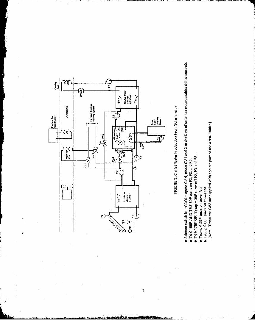
FIGURE 5, Cooling From Back-UP Cv 1,
PIGT6
• Selector switch in "COOL" AND TG>62F enables back-up A/C and turns off P4,• flock-up A/C controlled by at4(sting controls,
[siaW4A1eCend+tlsnsr Qeelir0r
coo
!!+444+4 Al+ N«>tMaCall
few... N Y► ^.^^. AI.}I. ^^^a .. Y^1 y,^w^ui M. /1. 1. •..^^^r. a..s .r s . w^ww ^,14r fi M
n %
FIGURE 4. C"ino From ChOW Water tv
Ya/010al C014114CV
11001160 syllom
?1
P4
P4
0 Selector switch In "COOL" enables relay controllin g P4, and Cold-dockcontrols for CV5.
• T6 A 52F turns on P4 and disables back-up A/C.• T6= S?F turns off P4 and enables back -up A/C.
t wore.WalesCoolingTower
&011tnng AirCOndrtionor Cpolin9
Cnil
4
s
Y

r
gsistimlif lltt
.. }CviWilipnot Cool"
^+.,^+„ w sr .^ w w,sr sww^w w r
rw iq.+s^..ss+ine^ ut w «w w w Aen.wnw^wew er ft w
Noun 11, Hooting Front Solar Energy Cv f
Pa
9 Selector switr h In "HEAT" AN T4I125F° opens Cv1 and CV2 tothe flow of solar trot %v itor to the existing hot dock and turns on P2.
613olactor twitch 1n "f4IAT" AND T4a'j 1?' f : -;:rnt otf P2, clnscs CV1and CV2 to the flow of solar hot water arvi rI ivk thole to the flawof conventional hot water to the hot dank.Existing hot fleck controls regulate tomp tirotura ol" hot sleek.
Exifnng LatCnnd^;^.inet Cooling
pet
r
tlealnty Alt HendlgrC
Cod
CV 5^.
Vt
n:5
FIGURE 7. Heating From BackupC =
Tofr,am EMiftinp. CV 2 HuUna; Yllern
Tt cv,a
CVO Ahwrplion f'2t^r1+^
T4 0
6
P2 WearChillor T6 0
T3 TOHot were( cv- Chilled WillerSlorw starete
I'M $,000 gel. 61009 pd.r.t
TO Cy
P T9
Evap.* Selector switch in "HEAT " AND T4 412OF opens CV 1 and CV2 Water
to the flow .T conventional hot water to the hot dock, P43 Coiling
a Existing hot deck controls regulate temperature of hot flock, Tower
P4
t^
-t n ..A

W►tuChtll►r
PxTO V t
Chiliag war$swag ►0100000,
TO V
TA V72 Not Wolof
i^ stormr 3.000 gal
•T1 OR 12^ 3811- turns on P1,OT1 AND T2k 42F turns off Pt,
EJ^ hC
FIGURE 9. Freeze Protection cY t
Ev►p.W►lvCoolingTown
i
4
$ riluols AltGndltlan+r CadMa
coolatu,s,.ssrawr.r w wsa,ssMSM M wR r sr r sal rerwriw.a ^r ^.+ rwM + aw,M s,i w sw. rw^.rr^+ r ^ ^^:
####two Air Hon"Cod
.a^...ra^r.r ^ ! .r ..a.,.^.a.wr a. ra. wrr..+a,.. w w. a. w.r.*...... r .r.aw..n! r w w w. r
CV4$
t`Y•tFIGURE 4. Exam Heat 116*11utt ^^1. "'"""'"
T41lrl.lnl EtagfneCV ! H►►NryYSStnI
TO
•T4 Z20SF turns on P6, opens CVO and placer selector switch (eleatriceOY)In "COOL" mode.
9 Teti 20OF reverses the above,
Oval,Wn►rCoolingTower
E^iltina AirConditlon►r c"i"
Coll.
r
10

. A
IBLAM AMOULIr
got
000101tPIGIAlk
001A1AINIMMO
Figure 10
View of GE TC •100 CollectorShowing "Heir Pin" Waterways
Cost was the project's biggest problem. The proposal was submitted
on Novemt-er 17, 1976, and the signed contract was received in late September1977. During chat interval, construction activity grently increased in
Brevard County, and construction costs rose 20 to 25 percent. Steps taken
to offset cost increases includedt
e Eliminating a sepnrite heat, exchanger for rejecting thermal energyoff the Col,lectors when surplus beat is collected. Instead, excess
heat is absorbed by chilled water from storage, which eventually re-
jects the oxoess hoat through the absorption chiller and then through
the water tower (see Figure 8).
o Equipment building was re-designed and reduced in size.
e FSEC constructed the building and concrete pads for storage tanks and
water cooling tower.
a FSEC purchased and mounted the collectors, the chiller, and the cool-
ing tower.
11

To be sure, the pSEC accepted greater risk than had a turn key
construction contract been awarded, but the result was financially satis-
fying. The project met its re-estimated cost at completion of $220,800,
compared with the negotiated estimated cost of $215,502 and an estimated
cost without the cost reduction effort of more than $270,000.
M&
Other problems encountered during construction and start-up included
numerous late receipt of parts and a controls problem. Careful planning
to .Adaure solar-heated hot water to operate the chiller went for nought
because of a misunderstanding b,;etween the detail. design engineer and the
contractor regarding operational controlo on the chiller. The contractor
believed he was following the engineer's instructions when he (a) discon-
nected the motor-operator of the hot water input diverting valve, (b) re-
placed the electric motor with a vacuum-operator, and (c) connected the
vacuum-operator to the system controls. The chiller was not designed to
operate in this way, and, in fact, will not operate when so disconnected.
Consequently, the contractor had to reinstall the chiller controls and
interface system controls and the chiller differently.
During installation, in early May, only ;:,tree glass collector tubes
were broken. An additional 36 tubes self-destructed by June 28, 1979.
Since June 28, however, only one tube has self-destructed.
SUMMARY
The system has operated well, as planned, and without problems since
the chiller was turned on May 24, 1979. It is not instrumented, so a
quantitative performance evaluation is not possible. However, a count of
the number of hours of space cooling from solar and a count of the total
number of hours of space cooling indicates a solar fraction of about 50
to 60 percent during the summer cooling season.
Experience so far has been good with the collector tubes mounted in
the east-west orientation, with both flow and performance seeming to be
normal at all times. The reflector troughs have remained clean and clear,
any dirt or debris being removed by rain. We think we made a good choice.
3
12
c

The problems encountered are considered tin be typical In, magniLudc
and were easily handlvd. System activation d.ate of May 24, 1979, was
32 days late, primarily due to Into pnrts dolivory. Cotit perrormance
turned out well, too, as final project oost wa.q Just over the r4 -c.L41-
mated figure of $220,800.
13
M* & dell

{
PROJECT, COST SUMMARY
Y
'^ 1
Cost Element Materials Libor 'Total
Design - $14,438 $14,438
Construction & Installation
Frames $11,960 10,540 22,500
Collectors 38,688 720 39,408
Tanks 12,600 720 13,320
Chiller 18,595 - 18,595
Water Tower 1,794 62 1,856
Plumbing 32,880 21,795 54,675
Controls 6,690 6,x85 13,275
Insulation 4,471 6,710 11,181
Pumps 4,200 1,200 5,400
t Masonry 3,407 5,507 8,914
Other 6,710 4,540 11,250 j
Project Management ---
6,032-
6,032
Total Project Cost $142,307 $78,5371
$220,844
i
14

PROJECT CHRONOLOGY
'4
76 Nov 17 Technical Proposal submitted to Energy Research and De-
velopment Administratio^ in. response to PON DSE-76-2.
77 Mar 11 Cast Proposal sub ,%wh ed to ERUA.
77 June 22 Cooporat'tve Agr,cen nr, negotiated with E.RDA.
77 Sept 20 Cooperative Agro mont signed by the t., ntraeLing Officer.t
77 Nov 14 Coatrac?t awarded to Stot:t),er-Stagg and Associates to
porform dotalled construction drawings and speci,ficFations
for the system.
78 Jone 16 Final design revl(!w with the governmont's Pro ,jert, Manager.
78 June 27 Construction drawings approved subject to the incorporntion
of comments.
78 Aug 24 Construc-Lion bids opening. 'Island Mechanical Contractor
ttpp,iL'e'ltt SU0V..VS g fUl, (low) bidder. (Island mechanical Con-tractor later ctliingvd name to S.,1.. Goldman. Company.)
78 Sept 24 CotXmnotor notified to proceed.
78 Nov 28 Chiller dollvered.
79 Mar 8 Storago tanks delivered.
79 Mar 19-21 Collector frames installed.
79 Apr 30 - Evacuated glass tubes installed on collectors and energy
May 2 collection begun.
15

e;,
4
Project Chronology
Page 2
79 May 24 Chiller activated with solar-heated water. Scheduled
date was missed due to chiller controls being inadver-
tently disabled by contractor.
79 June 29 Dedication by DOE's Omi Walden, State Senator John Vogt
and State Senator Clark liaxwell.
79 Au,g'16 Acceptance Test complete.

SYSTEM ACCEPTANCE TEST DATA
17

i
WM E-4
44 E4 E0 41
O0
41
O
O QN E
413 3
w cry ^a u^o^n
N Ln W 'D
W c^
w w
WaaH
E-1
W W ^
u 0
H
ZpWp,^ pWp,^
W W E-4 W>4 E-4 W
a E4 E-H E-4W
aa
E+
^
E u
0 04 ofoz0 a Cl)0
w H E-0 u
W E H Z0 a a a a x a 0 g o
^ N Di H H' E-+ H I H H E-+ H
H H
a4 N 0 W Ha
Q w ^Q
0 0'H H H a H ^ a ^ ^ ^ 0 r.E4iW° °x u u u u u u x u u u y
r-11
NI
r1I
ITI
U1J
kD1
h co r-1 N fn R}' U1 W
H H H H H Hf
0 1E-4 Ia1
a1
a1a i
a1a
18

OD W 00 OD W W OD. QD OD 0 co co co W )D m (i)
hI OD OD OD h h O OD OD 00 OD (n O CD OD co N 01
H ID w In IT v qr v sir N? v In v v er v In in
IH
iDiD
1G1D
Oh
MW
ODID
Oh
Oh
0h
r-ir
rlr
iDR
cor
Q1r
oCo
OOD
r-r
I`,
HHW
W
W1)H
ODkC
tlnW
ODin
wv
I'DMW
r h h t`-T
0dr
NIn
P-v
r-a sl'
r-dr
hv
NIn
Into
(14 N N r-1 r-I r-1 e-1 r-I r-1 0-1 N N N N N N Nin Ill N to In in In In in U) in in In In in In In
In h In O 1D iD w ID iD iD W % r in N N O 0P. r- co co h r r h h N h I` n r- n h hH r-1 H r♦ r-1 r-1 r-1 r-1 r-1 r1 r1 r-1 r-I r-1 r-1 r-1 r--1
it) to In C O, O N N N In OD h co in dr Oits W W h h h r r r r h h h r h h rr1 H r-1 r4 r-4 r-1 r-4 H r-1 r-1 r-1 ra r-1 r-1 r-1 r-1 r-I
rI O N in O v tr In In In In In dr N O lD O O1 0) 0) () O 0) 01 CA 0) 0) 01 (n 0 01 0) CJ co m
E I r-1 r-i r-1 N r-1 r-4 r+ r-4 r'1 r4 r1 r-1 H 4-1 H r-I rI
r,
In In In In In InW in r4 qzr r-1 10 r-1 dr in in In 1n In in in in In In
IT .. .. to •• as .o r-4 br r-.1 It 9-1 'dr r-4 dr r-i qH •• O O H r-1 N N to Of •• r ♦ rr ar •• •r r• uH 01 r1 r-1 ri r-1 '-1 r-1 r-I r--i N N lrl I`) dr dr In In
19

r
HH I ! zO
zO zO zO zO zO zO zO `zO zO z0
.,u
! 1
z
w' 1 z z z z z z z z z z zE+
1 1 O O O O 0 O O O O O OU 1 I
1 1 ! t 1 ! 1 S 1 I F 1 !
0 1 1 1 z z z z 8 z z z rg z z z z ( 1O O O O O O O 0 O 0 O O OH i^^
HUQ
^i I 1 I z z z z z z 7. ! i ! I 1 1
pa p, O O O O O O O
1 i O OZ O n 4 O O O O O O1 1a O O
1 1 0 0 0 0 0 0 0 0 0 0 0 0 0! l0
rI I '^+ 7i z z z Z z Z z z z z '^^ '^+ I 1w 0 0 0 O O O O O O O O O O O O
c u,dr
LnF-4of
inqw••
Lnr-1
00
Lnqwof
Lnri..
Lv... LnH myv
LnH
Lnn.VcnH.
LIV
►nr-4 tn.V'Ln1"{
tnytV'
yH[-4 M r-1 r-I r1 H r-1 r-I
of
r4to
rl••
N..
Nof
M..
M.r
lwof
'd'of
toof
Ln
20
LM ==z- _..

CONTROL SYSTEMS CHECKOUTAND CALIBRATION
A. Solar Energy Collection, Conversion and Storage Subsystem
5„ TEP ACTION/RESPONSE
1. Establish following conditions:
1.1 PE-1 actuated (R and B contacts OPEN) PE-1 ACTUATED okbecause temperature at solar arraysupply (outlet)(T-1) not below 380F. PE-1purpose (array freeze protection) will betested in Steep L_.
12 R8 actuated (1 and 3 erntacts CLOSED be- R8 ACTUATED P-1cause water in T1W storage tank is above running oklow water level. 11W low water levelswitch will be tested in Step,___^^_.(Omega Mod. 2176A, W/ 1 T' thermocoupledigital thermometer used as standardat all dial thermometer locations: )
1.3 Place hand-off-auto- switch on P-1 Switches in AUTOstarter and P-1 on-off-auto switch position yeson control panel in AUTO positrons.
2. Test timer contru%of subsystem:
2.1 Turn solar controller Or, F. R9 DEACTIVATED-Solar controller
NOTE - Step 2 accepted without test, light OFFtimer having already proven itself.
2.2 Check to see that R1 is deactivated (1 and R1 DEACTIVATED4 contacts CLOSED) because daylight isbeing detected by photocell (unless weare doing this at night). Photocell con.trol will be tested in Step 4
2.3 Time operation of timer-1 and timer-2:
! 21
^. a_

2.3.1 Wait until P-1 is running. Then measure Time between. P-1time between when P-1 STOPS and P-1
STOPPING and P-1STARTS again. STARTING is - .
NOTE - P-1 red and green indicating Should be time not onlights on control panel can be used as timer-1 dialindicators of P-1 operation for thisstop and steps following for this subitys-tem.
2.3. Z Then measure time between when P-1 Time between P-1STARTS and P-1 STOPS again. (See STARTING and P-12.3.1 NOTE) STOPP1r4q ^-.
Should be time set ontimer-2 dial.
3. Test solar controller control ofsubsystem;
3,1 Calibrate_11V^-_ltransmitter, RC-1receiver controller and T-1 temper-ature readout
on control panel using dialthermometer near T-1 Cransmitteras standard:
3.1.1 Note the input temperature to PORT #I Input temperature 185OF
of receiver controller. at dial thermometer loca-tion
NOTE - Input temperature to PORT #1of receiver controller is to 'be taRen astemperature being read on dial thermo-metez near T-i transmitter.
3.1.2 Note temperature indicated on T-1 Temperature on T-1temperature readout on control panel. control panel readoutIt should be same as input temperature 185 OFto PORT # 1 in Step 3. 1. 1.
NOTE - If temperatures are not the same,remove cover from T-1 transmitterand turn adjustment screw until T-1temperature readout on control panel isthe same as the input temperature toPORT #1.
U

M_
3.1.3 Set the desired throttling rank of
TR at _2LJoRC-1 which is 21€'n
3.1.4 Turn the control paint adjustment screwon receiver controller CLOCKWISE untilPE switch clicks or temperature scalerotates 1 1/2 revolution. Then turn con-tol point adjustment screw COUNTER-CLOCKWISE until PE switch clicks.
3.1.5 Litt the control point scale on receivercontroller to diBov,, ►\ga the gear teethand set the scale to the temperaturenoted at PORT #1 in Step 3.1. 1. Releasethe control point scale so that it willreengage the gear teeth.
CW until click-or-
CW until 1 1(2 rov.-CCW until click.
Control point scalereads 1. $5._.°F
3. 1.6 Turn the control point adjustment screw Control point scaleon the receiver controller i., atil the indicates 45 °Fscale indicates the desired receiver con-troller sot point. RC set point is 45oF
3.2 Calibrate T-2 transmitter and T-2 tern. Temperature on dialperature readout on control panel by thermometer near T-2repeating; Step 3. 1.2 substituting T-2 for 176.2 of
T-1 .Temperature on T-2control panel readout
176 of
NOTE - No receiver controller is usedwith T-2. Temperature to PORT #1 istaken to be temperature on dial thermo-meter near T-2 transmitter.
3.3 Turn solar controller ON
3.4 Wait for or cause solar controller tosense TA4 150F. Solar controller willcause P-1 to run by actuating R9 whenA of 15 o F is reached. P-1 will con-tinue to run until TA? 5'F. (See 2.3. 1NOTE)
NOTE Steps 3.3 and 3.4 acceptedwithout test, as solar controller wasproven already through daily operation.
Solar controller lightsON
TI when P-1 STARTS - ofTZ when P-1 STARTS ofT1/TZA - of
T1 when P-1 STOPS ofT2 when P-1 STOPS ofT1/T2A of
4 ..23

j
4. Test Rbgjorxglj control of subsystem-.
4,1 Repent Step Z. 3. 2 and while P-1 to run- P-1 STOPS with tapeaing place tape over photocell. P-1 over photocell --- YS is.should stop running after time delay.Removing tape.
over photocell P-1 STARTS after tape
should cause P-1 to start running again is removed from photo.after time delay. cell. ves
NOTE - Some delay in P-1 starting mayoccur due to timer actions.
S. Toot frCoze RrOtCE,0011 Of Solar array:
5.1 Turn OFF solar controller. Solar controller lights
0 T'1"', _YRs
5.la PULL R-9. R-9 OUT yes
5.2 Remove T-1 transmitter from well. T-1 transmitterremover-^--yaq.8—
HOLD transmitter until reading on T-1 T-1 control panel read-control panel readout settles. out while T-1 air out
of well not read OF
5.3 Place T-1 transmitter sensing elementinto an ice bath with 4. test: electronicthermometer. Note bat P-1 starts at38OF and remains running as tempera-ture drops further. 11 P-1 does notstart at 38O F recalibrate RC-1 controlpoint using test thermometer as stan-dard. Set RC-1 control point dial at3 8OF .
5.4 _01"OWLY add tap water to ice bath andnote that P-1 STOPS at 45O F and re-mains stopped as temperature rises.
T-I in ice bath test xthermometer in bath- x
P-1 STARTS— 38 OF on test thermo-meterP-1 STOPS:45 OF on test thermo-meter
5.5 Remove T-1 from ice bath, reinstall Install T-I in well xT-1 in well, turn ON solar co troller. Solar controller lights
ON yes
5.6 Check calibration of T-1 transmitter, Input temperature_j_942Fand T-1 temperature readout on con- (ref. 3. 1. 1)trol panel by repeating Stop 3.1. 1 and Temperature on T-1 con-3.1.2. trol panel readout^ 194 OF
(ref. 3.1. 2 )
24
--I

L1 Y
N
I y N --' Figure 1. Solar Energy Collection, Conversion and Storage Subsystem25

B. Excess Heat Rejection Subsystem
Establish following conditions:
R7 actuated (l and 3 contacts CLOSED)because water in chilled water (CW )storage tank is above low water level.CW low water level switch will betested Li Step____.
Place hand-off-auto switch on P-6 starterand P-6 on-off-auto snitch on controlpanel in AUTO positions.
ACT ION/RESPONSE
R7 ACTUATED yes
Switches in AUTO-)osition yes
Input temperature181.6 OF
STEP
6.
6. 1
MI
6.2
7. Calibrate T-3 transmitter: RC-3A,R.-3B, RC-3C, RC-3D receiver control-lers and T-3 temperature readout oncontrol panel using dial thermometer nearT-3 transmitter as standard:
7.1 Note the input temperature to PORT #1 ofreceiver controllers.
(NOTE - Input temperature to PORT #1of receiver controllers is to be taken astemperature being read on dial thermo-meter near T-3 transmitter.
7.2 Note temperature indicated on T-3 temper- Temperature on T-3ture readout on control panel. It• should control panel readoutbe same as input temperature to PORT #1 182 ofof receiver controllers in Step 7. 1.
NOTE - If temperatures are not the same.remove cover from T-3 transmitter andturn adjustment screw until, T-3 tempera-ture readout on control panel is the sameas the input temperature to PORT #1 ofreceiver controllers.
w
26
I^
., .
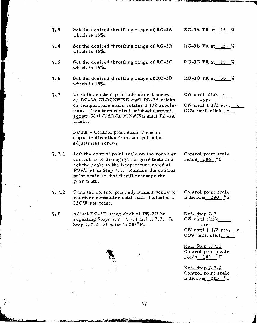
7.3 Set the desired throttling range of RC-3A RC-3A TR at 15 O,which is 15%.
7.4 Set the desired throttling range of RC-3D RC-313 TR at 15 °,10which is 15%.
7.5 Set the desired throttling range of RC--3C RC-3C TR at 15 "jawhich is 15%.
7.6 Set the desired throttling range of RC-3D RC-3D 'TR at 30 0
which is 15%.
7.7 Turn the control point adjustment screw CW until click_xon RC-3A CLOCKWISE until PE-3A clicks -or-or temperature scale rotates 1 1/2 revolu- CW until. l 1/2 rev. xtion. Then turn control point adjustment CCW until click xscrew COUNTERCLOCKWISE until 1Z -3Aclicks.
NOTE - Control point scale turns inopposite direction from control pointadjustment screw.
7. 7. 1 Lift the control paint scale on the receiver Control point scalecontroller to disengage the gear teeth and reads 184 ofset the scale to the temperature noted atPORT #1 in Step 7. 1. Release the controlpoint scale so that it will reengage thegear teeth.
7. 7.2 Turn the control point adjustment screw on Control point scalereceiver controller until scale indicates a indicates 230 of230O F set point.
7.8 Adjust RC-373 using click of PE-3133 by Ref. Step 7.7repeating Steps 7. 7, 7.7. 1 and 7.7.2. In CW until clickStep 7.7.2 set point is 205 0 F. -ox -
CW until 1 1/2 rev. xCCW until click x
Ref. Step 7.7. 1Control point scalereads 183 OF
Ref. Step 7. 7.2Control point scaleindicates 205 of
27

7.9 .Adjust RC-3C using click of PE-3C by Ref. Step 7.7repeating Steps 7. 7, 7. 7. 1 and 7. 7.2. CW until clicklit Step 7.7.2 set point is 1250 '. -or-
CW until, 1 1/2 rev. ` xCCW until click x
Ref. Step 7. 7. 1Control point scalereads 183 OF
Ref. Step 7.7.2Control point scaleindicates 125 OF
7.10 Adjust RC-3D using click of PE-3D by Ref. Step 7 7repeating Steps 7. 7, 7. 7. 1 and 7. 7.2. CW until clickIn Step 7.7.2 set point is HOOF. -or-
CW until 1 1/2 rev. xCCW until click x
Ref. Step 7. 7. 1Control point scalereads 183 OF
Ref. Step 7.7.2Control point scaleindicates 180 OF
NOTE - RC-3A, RC-3B and RC-3Dare not used in this subsystem. but arenow adjusted for other tests of othersubsystems.
8. Test T-3 control of P-6 and CV-6:
NOTE The approach to be used todemonstrate this control is that insteadof the T-3 transmitter sensing the setpoint tca-itperature, the set point of the
w
receiver controller will be adjusted tothe temperature being sensed by T-3transmitter to prove that when T-3transmitter temperature matches setpoint of receiver controller PE-3B willactuate.
nP
;I
28

8. 1 Note temperature on T-3 temperaturereadout on control panel.
8.2 Adjust RC-3B receiver controller controlpoint by turning control point adjustmentscrew to indicate temperature read inStep 8. 1 This simulates T-3 temperaturemoving to set point. PE-3B should •,actuatestarting P-6 and opening CV-6.
8.3 Increase RC-313 control point by 5 oF sim-ulating T-3 temperature decreasing 500F.PE;-3B Lould deactuate stopping P-6 andclosing CV-6.
8.4 Return RC-3B control point dial to RC-3Bset pu^int, of 205oF.
C. Cooling From Chilled Water Subsystem
STEP
9. Establish following conditions:
9.1 Place heat-cool switch on control panelin COOL position.
9.2 Place hand-off-auto switch on P-4 starterand P-4 on-off-auto switch on controlpanel in AUTO position
10. Calibrate T 7 transmitter, RC-7 receivercontroller and :T-7 temperature readouton control panel by repeating Steps 3. 1.3. 1. 1, 3. 1.2, 3.1.3, 3.1.4, 3. 1.5 and3. 1.6 substituting T-7 for T-1.
NOTES -aef. Step 3.1.3 throttling range for RC-7is 30%.
Ref. Step 3.1.6 set point for RC-7 is 550F.
T-3 temperature oncontrol panel 188 o P
Control point scaleindicates 184 of
PE-3B ACTUATED yesP-6 RUNNING YesCV-6 OPEN_ ves
PE-3B DEACTUATED191 of
P-6 STOPPED yesCV-6 CLOSED yes
RC-313 control pointdial at 205 of
ACTIONLRESPONSE
Meat-cool switch in0,001, position ves
In AUTO positions yes
Ref. 3. 1. 1,Input temperature 153.4 of
Ref. 3. 1. 2Temperature on T-7 controlpanel readout 15Z. 9 F
Ref. 3.1.3TR a t 30
Ref. 3.1.4CW until. click
-or•CW until 1 1/2 rev. xCCW until click x
is
29

i
Ref. 3. 1.5Control point scalereads 53 OF
_Ref. 3. 1.6Control paint scaleindicates 55 OF
11. Calibrate T-6 transmitter, RC-6 receivercontroller and T-6 temperature readouton control panel; using a'test thermometer(remove dial thermometer near T-4 anduse as test thermometer) as standard:
11. 1 Insert test thermometer into A1-JU plenum Test thermometeradjacent to T-6 transmitter sensing inserted yeselement. Allow time for test thermo -meter to stabilize.
11.2 Repeat Steps 3. 1, 3. 1. 1, 3. 1.2, Ref. 3. 1. 13. 1. 3, 3. 1. 4, 3. 1. 5 and 3. 1.6 substi- Input temperature 61 °Ftuting T-6 for T-1 and test thermometerfor dial thermometer. Ref: 3. 1.2
Temperature on T-6control panel readout
61 OF
NOTES -Ref. Step ,j, 1.3 throttling range for Ref. 3.1.3RC-6 is 10%. TR at 10 000
Ref. Step 3.1.4 Responsive item isCV-5 positioning ^o mid (approx. ) posi-tion.
Ref. Step 3.1.6 set point for RC-6 is Ref. 3. 1.655v F. Control point scald
indicates 55 O F testthermometer out yes
11.3 Remove test thermometer.
12. Test T-7 control of chilled water circu-lation to cold deck and automatic change-over to existing backup DX system:
30

M,
12.1 Note: temperature on T-7 temperatureat RC-7 set poilat by adjusting RC-7control point dial to T-7 temperatureread iii Stop 12. 1. PE-7 should actuateSTOPPING P-4 and STARTING backup DXairconditioning system compressor.
*12.2 Simulate T-7 temperature at RC-7 setpoint by adjusting RC -7 control pointdial to T-7 temperature read in Stop12. 1. PE-7 should actuate STOPPINGP-4 and STARTING backup DX aircon-ditioning system compressor.
T-7 temperature res.rlout on control panoi
5 2 OF
RC-7 control point di:0at 56 1/ z OF
PE-7 DEACTUATFS__yfLP-4 STARTEI)^esBackup DX systemSTOPPED ves.
NOTE Backup DX system t'stat mustbe calling for COOLING for DX systemto start during this test.
411\0TE - In Steps 12. 2, 12. 3, 15. 2, 15. 3,20.3, 20.5, 21.3 and 21.4, if the PEswitch is already actuated, the simtdatedadjustment is equal to the PE switch differ-ential from the activation set point. Thisresults in actual "act.on/res Pons e" beingopposite to that originally indicated.
12.3 Decrease RC-7 control point by 5o F simu-lating T-7 temperature decreasing 50F.PE-7 should de actuate STARTING P-4and STOPPING backup DX airconditioningsystem compressor.
12.4 Return RC-7 control point dial to RC-7set point of 550F.
RC-7 control *o intdial at 51 1 12 OF
PE-7 ACTUATES_yesP-4 STOPPED, yesBackup DX systemSTARTED yes
RC-7 control, pointdial at 55 of
13. Test T-6 control of CV-5CV-5 NOT TESTED
31
D. Heating From Solar Energy and Floating From Backup System Subsystem
STEP ACTION/RESPONSE
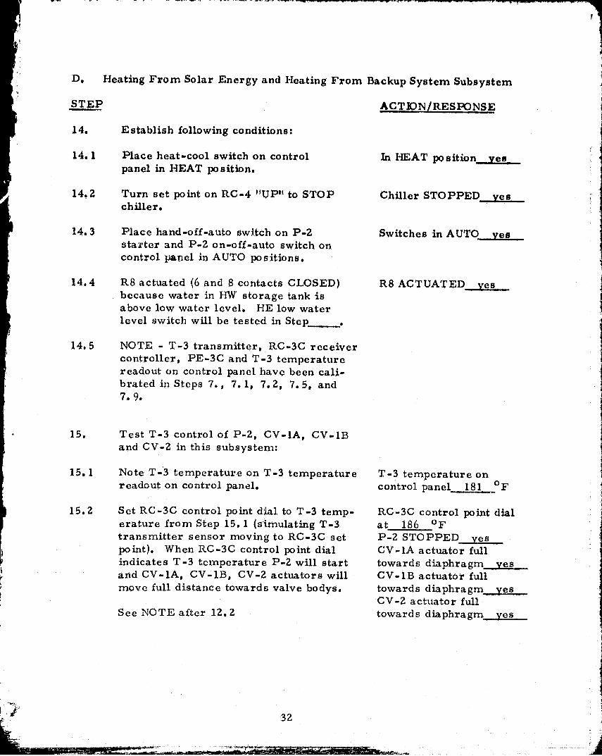
14. Establish following conditions:
14.1 Place heat-cool switch on control In HEAT position veepanel in HEAT position.
14.2 Turn set point on RC-4 "UP" to STOP Chiller STOPPED veschiller.
14.3 Place hand-off-auto switch on P-2 Switches in AUTO vesstarter and P-2 on-off-auto switch oncontrol panel in AUTO positions.
14.4 R6 actuated (6 and 8 contacts CLOSED) R8 ACTUATED vesbecause water in F1W storage tank isabove low water level. FIE low waterlevel switch will be tested in Step
14.5 NOTE - T-3 transmitter, RC-3C receivercontroller, PE-3C and T-3 temperaturereadout on control panel have been cali-brated in Steps 7. , 7. 1, 7. 2, 7. 5, and7.9.
• 15. Test T-3 control of P-2, CV-1A, CV-1Band CV-2 in this subsystem:
15.1 Note T-3 temperature on T-3 temperature T-3 temperature onreadout on control panel. control panel 181 of
15.2 Set RC-3C control point dial to T-3 temp- RC-3C control point dialerature from Step 15. 1 (simulating T-3 at 186 oftransmitter sensor moving to RC-3C set P-2 STOPPED vespoint). When RC-3C control point dial CV-1A actuator fullindicates T-3 temperature P-2 will start towards diaphragm vesand CV-lA, CV-1B, CV-2 actuators will CV-lB actuator fullmove full distance towards valve bodys. towards diaphragm__yes
CV-2 actuator fullSee NOTE after 12.2 towards diaphragm ves
32

NOTE - Subsystem is now in heating fromsolar enorgy mode. These valve actuatorpositions will result in:
CV -1A CLOSING stopping 11W fromcoil returning to existing TJW boilerreturn.CV-113 OPENING allowing FAV fromcoil to return to hot water storagetank.CV -2 OPENING between NC and Cports allowing supply hot waterfrom bot water storage tank to flowto coil.CV-2 CLOSINO between NO and Cports stopping supply hot waterfrom I-INV boiler supply to flow tocoil.
15.3 Increase RC-3C control point dial Sor,(simulating T-3 temperature decreasing50F) causing a switchover to HEATINGfrom backup system mode. When thishappens P-2 will stop and CV-1A, CV-113.CV-2 actuators will move full distancetowards diaphragm.
See NOTE after 12.2.
NOTE - These valve actuator positionswill resultin-
CV-lA OPENING allowing HWfrom coil to return to existingHW boiler return.CV-1B CLOSING stopping FTWfrom coil to return to hot waterstorage tank.C'V-2 CLOSING between NC andC ports stopping supply hotwater from hot water stvragetank to flow to coil.CV-2 OPENING between NO andC ports allowing supply hot waterfrom 'ZTW boiler supply to flowto co il.
P-2 STARTED yesCV-lA actuator fulltowards body. firesCV-1B actuator fulltowards body _2sCV-2 actuator fulltowards body yes
33

0, ,
15.4 Return RC-3C control point dial to IZSO F RC-3C control pointset point. scale reads 125 OF
15.5 RE-SET RC-4 set point to 500F. Set point 50 $1
is. 6 Place heat-cool switch on control panel In COOL pooi6on_ yes-in COOL position.
E. Chilled Water Production From Solar Energy
STEP ACTION/RESPONSE
16. Establish following conditions;
16.1 R8 actuated (6 and 8 contacts CLOSED) R8 ACTUATED yesbecause water in IIW storage tank isabove low water level. IIW low waterlevel switch will be tested in Step
16.2 R7 actuated (6 and 8 contacts CLOSED) R7 ACTUATED yesbecause water in CW storage tank isabove low water level. CW low waterlevel switch will be tested in Step_.
16.3 Place hand-off-auto switches on P-2, P-3 8 P-2 in AUTO yesP-5 and CT-FAN starters in AUTO P-3 in AUTO yespositions. P-5 in AUTO yes
CT-FAN in AUTO yes
16.4 Place P-2, P-3, P-5 and CT-FAN P-2 in AUTO . yeson-off-auto switches on control panel in P-3 in AUTO yesAUTO position. P-5 in AUTO yes
CT-FAN in AUTO yes
16.5 Place chiller off -auto switch on contro,',' Chiller switch in AUTOpanel in AUTO position. Status of chiller position _.yesindicating lights on control panel willdepend on T-3 and T-4 temperaturesdisregard at this time.
16.6 Place switch in "COOL" position In "COOL" position?___yy-.2___
16.7 Disregard flow switch FS-3. Contacts Ok okDave been shorted out.
34

17. Calibrate T -4 transmitter, RC-4 receivercontroller and T-4 temperature readouton control panel by REPEATING.
Steps 3. 1, 3. 1. 1, 3. 1. Z. 3.1.3, 3.1.4,3. 1.5 and 3. 1.6 substituting T-4 forT-1 and RC-4 for RC-1.
NOTES -Ref. Step ,3 1.3 RC-4 throttling range
' is set at 30%.
Ref. Step 3. 1.6 RC-4 set point is 500F.
Ref. Strap 3. 1. 1Input temperature 53 "Ir
Ref. Step 3. 1.2Temperature on T-4 controlpanel readout 53. 7 of
Ref. Step 3.1.3TR at 30 %d
Ref. Step, 3. 1.4CW until click x
-or-CW until 1 1/2 rev.CCW until click
Ref. Step 3. 1.5Control point scalereads 54 of
Ref. Step 3.1.6Control point scaleindicates 50_ of
18. Calibrate T-8 transmitter, RC-8 receiver Ref. Ste] 3. 1. 1controller and T-8 temperature readout ]Input temperature 84.5 ofon control panel by REPEATING Steps3.1, 3.1.1, 3.1.2 9 3.1.3, 3.1.4, 3.1.5 Ref. 3.1.2
' and 3. 1.6 substituting T-8 for T-1 and Temperature on T-8 controlRC-8 for RC-1. panel readout 84.2 OF
NOTES - Ref. Step 3. 1.3Ref. Ste] 3. 1.3 RC--8 throttling range is TR at 30set at 30o.
Ref. Step 3. 1.4W Ref. Step 3. 1.6 RC -8 s et po int is 850 F CW until click x
-or -CW until 1 1/2 rev.CCW until click x
Ref. Ste] 3. 1.5Control point scalereads 84 of
Ref. Ste] 3.1.6Control point scale a'indicates 85 of
35 a
t

1 Sa. Calibrate T-5 Temperature gauge oncontrol panel 4 4 6..`FTemperature at dialtherrnotncter OF
I
19. NOTE - T-3 transmitter, RC-3D receivercontroller, PE-31) and T-3 temperaturereadout on control panel have been calibra-ted in Steps 7. , 7. 1, 7. 2, 76 and 7. 1, 0.
20. Test T-3 control of this subsystem;
20.1 Set RC-4 control point dial to T-4 temper- RC-4 control point dialattire on readout on control panel. This reads 53 1(2 OFwill actuate PE-4 so that PE, -3A can be PE-4 ACTUATED yesmonitored.
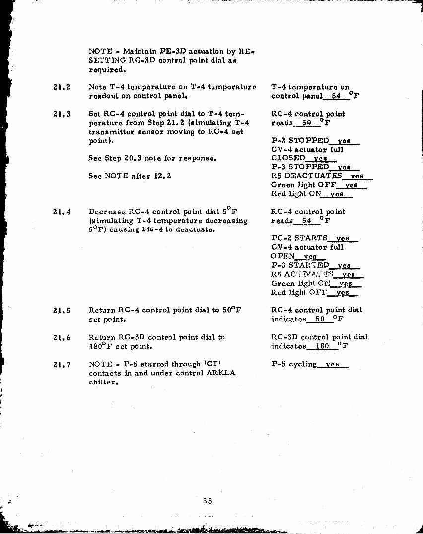
NOTE Maintain PE-4 actuation byRESETTING RC-4 control point dial asrequired.
20 1 2 Note T-3 temperature on T-3 temperaturereadout on control panel.
20.3 Set RC-3D control point dial to T-3 tem-perature from Step 19.2 (simulating T-3transmitter sensor moving to RC-3D setpoint). Note when RC-3D control pointdial indicates T-3 temperature; P-2 willstart, CV-4 actuator will move full dis-tance towards valve body opening valve toallow lIW to circulate between HW storagetank and chiller which will be detected byflow switch FS-1 CLOSING its contacts.FS-1 closing will start P-3. Chiller isenabled by R5 actuating.
See NOTE after 12.2
Green chiller indicating light on controlpanel will come ON. Red indicating lightwill be OFF.
T-3 temperature oncontrol panel 177 or,
RC-3D control pointreads_ 187 OF
P-2 STOPPED vesCV-4 actuator fullCLOSED firesP-3 STOPPED vesR5 DEACTUATFS yes
Green light OFF YesRed light ON yes
36

i
3
120.4 Test T-8 control of CT-14'AN at this point
a20.4.1 Set RC-8 control point dial to T-8 temper- RC-8 control point dial
aturo readout on control pano t (simulating reads- 84 FT-8 transmitter sensor moving to RC-8set point).
Wb,cn RC-8 control point dial indicates T-8 CT-FAN STARTS Xogtemperature CT-FAN will START.
20.4.2 Increase RC-8 control point dial S oli" RC-8 control point dial(simulating T-8 temperature decreasing reads §22 of5 0 F) causing CT-FAN to STOP.
CT-FAN STOPS gg__
20.4.3 Return RC-8 control point dial to 85°F RC-8 control point di tlact point reads 5 of
20.5 Decrease .RC-3D control point dial 100F(simulating T-3 temperature decresing100 F) causing PE-3D to deactuate. WhenPE-31) deactuates P-2 will stop, CV-4actuator will move fall distance towardsdiaphragm closing valve stopping HW cir-culation between HW storage tank andchiller which will be detected by T'S-1OPENING its contacts. FS-1 opening willstop P-3. Chiller will become disabledby R5 deactivating as chiller red indica-ting light on control panel will come ONand green go OFF.
RC-30 control point dialreads,_ 177 OF
P-2 STARTS vcsCV-4 actuator fulltowards body—yesP-3 STARTS yes115 ACTIVATES =sGreen light ON__MraRed light OFF ves
20.6 Return RC-31) control point dial to 180OF RC-3D control poinh dialset point. indicates 180 of
20.7 Return RC-4 control point dial to 50°F RC-4 control point dialset point. indicates 50 OF
21. Test T-4 control of this subsystem:
21.1 Set RC-3D control point dial to T-3 tem- RC-3D control point dial! perature on readout on control panel. reads °'
This will actuate PE-31) so that PE-4 canbe monitored. PE-31) ACTUATED yes
37
NOTE - Maintain PE-31) actuation by RE-SETTING RC-31? control point dial asrequired.
2112 Note T-4 temperature on T-4 temperaturereadout on control panel.
21.3 Set RC-4 control paint dial. to T-4 tem-perature from Stop 21.2 (simulating T-4transmitter sensor moving to RC-4 setpo int).
See Step 2Q.3 note for response.
See NOTE after 12.2
21.4 Decrease RC-4 control point dial Sox,(simulating T-4 temperature decreasing5 0 F) causing PE-4 to deactuate.
2115 Return RC-4 control point dial to 50oFset point.
21. 6 Return RC-3D control point dial to180°F s et po innt.
21.7 NOTE - F-5 started through "CTIcontacts in and under control ARKLAchiller.
T-4 temperature oncontrol panel^544 OF
RC-4 control pointreads., a2k
P..2 STOPPED yesCV-4 actuator fullC,IX)SInD desP-3 STOPPED YasRS DEACTUATES yesGreen lIght OFF vasRed light ON yes
RC-4 control pointreads 54 0l'
PC-2 STARTS yesCV=4 actuator- fullO PEN sP-3 STAR:'CED__yes25 ACT.n,'A,';"V'(; yes -GreenRed liglil. OFF' Yes
RC-4 control point dialindicates 50 of
RC-30 control point dialindicates 180 or
P-5 cycling yes
I .- 38

SEQUENCE OF OPERATION
39

-
t
FTU Solar Domotts rzition t'r-,,Q-ort
SE UI:N 2 OF OPERATION
(1) 'SOLAR ENERdY COLLECTION, CONVERSION ANY) STORAGE''
WHEN TEMPERATURE (T-1) AT THE. SOLAR COLLECTORS t:XCh;(,1):q 11111UTEMPERATURE (T-2) AT THE HOT WATER STOCtACE' TANVK BY IS DF,rNBUMA TIC -ELIXTRIC SWITCH (PE-2) WILL MAKE, ALLOWJ' Nb DUMP(P-1) TO OPERATE. PUMP (P--1) WILL CONTINUE TO RUN (INTIL
THE DIFFERENCE IN TEMPERATURES (T-1) AND (T-2) DROPS TO5°F. WHEN (PE-2) BREAKS, TIMER 1 ACTIVATES. WHEN TTMI R XTIMES OUT TIMER 2 IS ACTIVATED AND TIMER I IS RESET, RE-STARTING TIMING SEQUENCE. TIMER 2 OVERIDL.0 (1 7 R3--2) TO ACTI-VATE PUMP (P-1) FOR SELECTED RUN TIME, (TIMP,11 .2 SPLEC'1'$RUNNING TIME 01-` P-1; TIMER I SPILECTS `I'IMI.-t BETWEEN RUNS) DUR-ING NIGHT HOURS PHOTOCELL ENERGI7,ES RELAY (N-1.) W11IcFP DC-N;NERGIZES TIMERS . UPON RISE IN HOT WATER TEM11 8RATURE (T-3)ABOVE 2:30 11 r, PE SWITCH (PE-3A) WILL MAKE, OVERRIDING PE-2AND TIMERS AND SHUTTING DOWN PUMP ( P-1) UNTIL VALL IN f T-:3)
BELOW 2250F.
(2) EXCESS HEAT REJECTION
UPON RISE IN IIOT WA'T'ER TEMPERATURE (T-3) ABOVE 235-F PrSWITCH (PE-3B) WILL CLOSE ENERGIZING PURR (P-6) AND VAL,VL(CV-6) FOR EXCESS HEAT REJECTTON UNTIL FALL IN (T-3) BLC,oW230° F.
(3) ABSORPTION CHILLER, COOLING 'POWER AND C,11ILLI, WATERSTORAGE
WITH THE CHILLER SELECTION SWITCH IN THE' "AUTO" POSITION ANDTHE SYSTEM SELECTION' SWITCH IN THE COOL POSITION TIT)-, POLLOWINGSEQUENCE IS ACTIVATED: UPON RISE IN HOT WATER '"1 MPL'I'.A`I'URR(T-3) ABOVE 1.80° F AND RISE IN CHILLED WATER TEMPSRA'T LI N2 (T-4)
ABOVE 500 F, PE SWITCHES (PE-3D)AND (PE-4) MAKE, UPRN.TNC; VALVX,(CV-4) TO ALLOW HOT WATER rLOW TO CHILTH,% AND I. NI;ItGIZ1NG RELAY(R-4) WFIICH ACTIVATES HOT WATER PUMP (P-2) , THREE WAY CONTROLVALVE (CV-3) RE, GULATES THE FLOW OF
40

C.
HOT WAT R A.x RRVIIIZED VOR 0111'1,1,1''!: OPERATION TO P1711VID0 AMINTM11N1 c 1 I1ILLE'D WA'I'XR SUPPLY T1,MP .1+.AT1 1R1 (T-5) or 4Q°rUPON l ISN TN C ONDE.NSER WA']'RR T1 :.MP1,RATt1Rr, (T-8) ABOVE. 85 '17P1, SWITC'11 (P .-1i) MAK1,38, X-NEROi'CZING (.`00fANG TOWE..Q FAN t1N'11l'1,FALL IN (T-8) DX LOW 80 0 F. UPON FALL IN SCOT W11'1'8,R( 1,11-3) 131-3,0W 170 4 V OR FALL IN C HT'LLE D W11'P(.R TrMl nfI ATURC (11 4)
DI*-,1L0W 4 1i"F, PUMPS (P--2), ( P - 3 ), (P-5) 0 ('1111.141#11 AND COt3LT N(`a'OWi,R FAN ARE SHUT,' DOWN.
t (4) A IR CONDITIONING SYSTEM CONTROL
WHEN SYSTEM SELECTION SWXTCH IS IN COOL POSITION,ITION, 1wUN ItIfi 1,IN CHILLED WATER T1;MPERATURC; ( ,T'-7) A13OVE 52'F, PE 5WIT(:TJ (P!,--7)WILL MAKE., ACTIVATING, RELAY (R-2) WHICH 1 N11I IX'S nAC'1C-CIE ► C112LT X11
C TO OPVP)1T AND 10IILII D1:;--ACTIVATES CHILLED WA'I'8,R PUMP (P-4) ,STOPPING FLOW TO THE. AIJU. (PIS,-7), UPON RISE TN (T-'7) ABOVE52° F,
ALSO 1?1,-ACTTV71'1 US PUMP (P—G) AND VAT,,VF (CV-0 tJWJ'TL I-ALL
IN ( 11'-7) 131,3,014 47" F. CON'3'IZOL VALvI (CV-5 ) tS MODULA I N,:13 TOMAINTAIN A 4'014 DECK TEMPERATURE (T-C) OV 550 P.
(5) III,ATTNG SYSTEM CONTROL
WHE,11 SYti': I BM S1,Ll CTION SWITCH IS IN HEAT POSI'T'ION, UPON RISE `TNHOT WATER 111 C,MPT-DZATURE (T-3) ABOVE 1250 F, PC; ;WITCH (PE-3C,`) r111hC^5,
ENI.;i',GXZXNG VALVE'S (CV-1A), (CV- 10, (CV-2) WIIC H ,W3TCi1 TH E
C AIIU 110T WA' E'R SOURCE FROM BOILER TO SOLAR HW STORAGI, TANK.(PT,-3C) ALSO 1 NERGIz S RELAY (R'-3) WHICH ACTIVATES HW PUM';) (P-2).
(P1,-3(`) RX'MAINS ENMRC. IZED UNTIL VALL IN HOT WATER T1-,'MPXI'..r1'1 UR10;
(T-3) DELOW 12Cf F. CONTROL VALVI, a (CV-1A), (CV-10 AND (QV-:?)ARE NORMALLY OPEN FOR FLOW OF HOT WATER T11ROUG Tfir:1 EXISTING
BOILER SYSTEM.
(G) FREEZE PROTECTION CYCLE
WHEN COLLECTOR TEMPERATURE) ( T-1) FALLS BE. LOW 30'J F' P1, (SWITCH
(P1,-1) WILL BREAK, RVERGIIIN(, PUMP (P-1) FOR11t1,1^ ^1. PR4 TI-:0 lIONt CYCLE UNUIlL RISE IN (T--1) AIOVr rya°L'.
(7) LOW WATER CUT--OFF S WITC 11 PS
3
TWO MC DONNELL MILLER MODEL 150 LOW-WATER tnUT-OFFS ARE 1?12C)V11)Nil
AS TNDICII` Il ';O. ONE LOW WATER CUT-OFF S11AIJ., f'R2V1-;N1' PUMP (P-1:)
AND (P-2) 1''1 OM OPERATING WHEN TIME WATI;R.LEVC{.L IN 1 11 10'.1 :;OT,AR [loll'
WA'T'ER STORAGE TANK IS BELOW THE CUT-OFF PDXN'1 1 . THE OT11L1: LOW
WATER CLIT-OFF WILL k REvENT Pump (P-3) , (p_4), 111 1.) (P-6) FROM
OPERATING W11EN THE WATER IN THE CHILLED WATER 'ITAN < IS BELOW
ITS CUT-OFF POINT.
C1
I41
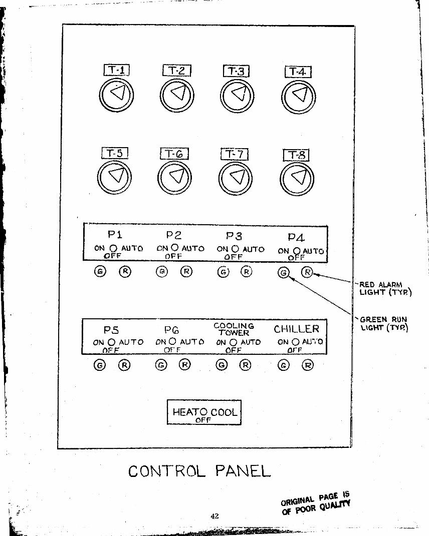
T^1 T^2 T^3 TA
O O O O
T-5T-6 I
O O O O
P1 P2 P3 P4
Ohl O AUTO 04 O AUTO ON O AUTO ON QAUTJ
OFF OFD= OFF taf o
O `.JC O c R*
P,S ProCOOLIN G
0WER CHILLERON O AU T O DN O AUT O ON O AUTO ON O AM 'D
AF F=OF r OFF tl r F
Q
O lJ
HEATO COOLOFF
CONTROL PANEL
ORIGINAL PAGE %$42?Wit lQoktj"
I
-RED ALARMLIGHT (TYP)
GREEK RUNLIGHT (TYR)

oaooR1 R2 R3 R4 R5 R6 R7 R8 R9
TIMER1 Tlh1rbd') t J l J 1 J^. E'er '. AT CONTROL.
a a ojRC 1, RC 3B
RCB'D 01 01
RC4 kGiA a
01 0 01c.^^•^ RC 7 _ RC8
CONTROL PANELINT ERMK,
i
43

>r` ITR0Lr3 COMPANYOne-Line Division
.,.1.. U. In.gwlly 1... „/.1 .n Our gem.,W, It nu,nllr. 1.1
w 111 IIM^ , ^ Jo . n.Ht 111/11• /Use
. .'•1 I'. ' I' q' • • '. •, hlul0,de Into U1/f'dn, , 1 ,. . U..• . ..y. let Ism 18 1 0,100 '1 11.1
III. 1U , ynln lxl;,. . ,. IfnIM'. r.V ul In. ,.1mlk.vflurl to..nl V..1. will I• ... . mn I.I still telryyvl'. ,Irulnwrno of If1Ut
es/et •edes rho. Ien Ile 11uv.trWnlfl let it... I,1.n6n• .Hurf Con•.• V.,.. 1/.uV.utr d.01i I . y11„ 1 u.l rf/nuvo twooterl AYwnfltWnl
I'eses/lr Vm, ely.l nosiest Lun111tw. the elfl:l/ ICfI p0w4r.. ru st.'I 10 pryVoth , IOIV pr ul lll r Mwiu. (roof ♦ n Ovy lfoge Ut
.OI nU.M' • elyd:ldxin w.l,s is He4e65.11V to VUU n o w let plovulu, .IU J..IrnS Ur 1NId..7el.lr/
Ai"R COMPRESSPORSI7 a:`9G W ORIMP.TION
'tour fv lrL1..//. .hutsho le' I.a ►rd .qw.. .. n....,1 l.l.. 0u11 d1 1 . - .
1. Toed , %soNwu . ...I 1e'14 .r.... w.-1^. 1•rrl wool •.1 u1 N'I el,.11l I'mos Ut It's-
Sto gy UI • , l .e. f,vot
In Order 10 O..1v1.11•etf rose luldl I ' . n • lp...... nuns of I ► .•!'ce'. •••u l l..ed0 u11 I rtf L11y1 dU u•.1!W UI ell .1. • v...• . wool. • .. feet , esw11es411 fill. ...y ese FM eof ,leh . HQev.f xedesl 11 1.11... • / W.x. win ..r,. 0 11W.61 n.61 .. ...,1/ldllf If 1 '.Ili ,l ^ 1/Vy wfV1 ^1.e (, . /1 W .1.,.11 .0...r J1.' ^nl' r 1.,..111 uff the UM I,, y1xL n...11.,1 lot .. ....nu1, 1 I..lu10, I,,W.I L.. . .. 1.deV.cll UV u1n,y Mew t-yu.ees 40.0 .1.'Ini ill....... 1 llov tUl.. l 1 Ott ,.14.vy ill Uf eblw let 0..eu0e14- 1 V Clleul,01r 1h1r m.I. -n l Lpr (;1 M "%..., Un.lurn.ule esn0w ,• I.r • UW. I euly 1 lot., 1 ,0'.- 11 M • 1 In.- d.1u.1 .p .1n1 IrUI .tor eva-I6111e 101.11. a 'ev,1 ., lun . l • 1. "4 .. ,.. • d . •, ,.,11,11 . ..1 IM • ♦ . . . 1 . . .'.1w.rllh h.Ohlrr p-/lo. , .lull .0 rrllvl .l CF M 11 •.x • 11 UV •.,.,na m,,uu t ... 1u•1
FA(' TQ11 V^-UUANTITV UNI LINE NUM11tit ( MUU! ► CIIN TUfAL
I TP7710.O1b T l ;. I 1 i
To J: 10 . 01U I Tlt. 1I-
1 f l o od 1., 0114, 11N-- T^tl^•._- t---- 1 • . }
--- -_^ 7Pt211 019, 1 .19 T19
- TP1/14 T 21 Jll
1 26 X)
r^ ^T0L110 . 031 TJ 1TP77la•032, 172 1 16 PSI I TJ!TP1215 032, •171125 PSI) TJ7 11'
—1 .
10 2720 OF3 _ TbJ
i { Mot) I / I_HP2230.010
_ • -- _ rT/^1l1 -HP2730.019 IRA W 20 PS1t11.- HP2230.010 IUA d 20 PSIVI -^^HtN _~•__ _ 1 ^._ ..... ._
H#12232 -0117- --- --- 1461 1(t
TP2.232_06]^^__._- ._^►.^..._HP2234^_ I H 100 /tt 1
_ ._ ._ .-_ _..._.•1 -•-'. -._-^_.....^^^- _.-J'1
• ... 1tP "1240 T 1 W
-tTP72A? - - 'r T101^ Ah •I- -^_ I
11`7244 I T110
.... ._. I- -..
rP2?1.0 I T 140L.
TP225? -T1 hU_ -._let 2 4 V
T201 P.
TP2264 . 701 T211 .t.----- . .__ TP2764 711~ --_
. _ - - -r:J1 •111
- - - - 1 TP2200 0(10 125 PSI I I T4 61.11
I TP221I0-060 I I "II Texu-I Il nl CI-2-4^Ski AUUITI()NAI 111011 1/'1 S ( t o ' "'THEN SIM
Ililvl 1, 0 I W U J ^ ORIGINAL PAGE IS ^" It ' ll ',.II I
OF POOR QUAL"44

If
C
k
IA/ 1 1i1.Iw.► N111 ► uti, ^ Iwt NIIAuu N M111 , 1.,1.^
IF., ,, Ott W.: 1111 P•.11
1 PI': 111 1' GI N#
1•v; 10b r ,, ,,,,, I
1 ,1 YY/ I IU ' 1 •f
1' 1 1 , , 1 rlrP1Jl4 ^ VJI•. 1.,rrlJll ^- ^ VIII 1 1 ^ .
ti PV 1341 M1'll? y l)
HPJJhJ 001, 002. AO] --- _-ILIU 1 -- -f1400.1.154 001 - .. "4114 1 , 1 1 11
-- ( 14P2 JS'1.06dM.1J4 /UI
1101 2J60 µ N414 1•, --
1(P1344 jt1 -^ 644 ?1
r1 t i p
l]1J INSIn AS V(JLUM! MUf11 1 l pl ^ 1+4 1, • , _ -
' 140"2712 Jb1 - _ - ~—r-144 Q
II l v1771 76%
g P2771 I44-Ib J' 1 1
•f
r 14023110
Me.1386 044)0
^ SP2]02 i 3?U1'
u '
iP2JV4 YJU -f— - U
ti►2]Y^ $4Q I
_
MP24b2 IW/0"2 POSITION[RI -Mbb7 11^ -
MP24bJ (W/P2 POS I TION ► MI ML'..1 111,
MPJ4b4 iW/ ► J PUSITION!111 _lMb44 /l - r
MP21671W/V?POf.1T ION EMI M'14J- —_M, - 117 1
MI1 ?464 IW/0"2 POSITIONENI Mh4A N
M3 14,411 011 iW/PUSITIONkt11 `- Mbl►1. I.N
VALVES WITH 0"20 37% POSITIONl q b''T
I>ULTON %LVI- MIN DIVISIONSINOLI PtN RkCOMOtN
FULTON %LVPHUN -DIVISION2 PIN 11LC(1MOf N 14U
ASPIRATING ROX 0`70 . 09@1 L P20 696
UAMPEII.ACTU.. T ()g WITHOUTVOtiI TIUNE R 11
IL701 4L CIM
/UTAI IMI%PA ►.t101/11 1'14 ► V1UU'.YAI.t --f '7a,)
0.32 CFM 555 CIM10 T Al -- - . ..
NOTE:: PL Switches take 0 CFM
ROBERHAW CONTROLS CO. • UNI-•Z W RE DIVISION O. BOX 2000, 4190 TEML&CAL ST., CORONA, CA 417:TB U

40L
C►
la.. -dN ^
.. _. •AR-KLA4l ju', fNIES ING. r'0 ),QJK , .4 ..AN 414A
•;i .....J.1... 171 L ..___. _.r.^ --. - --
a •,
N N
r
2 ^ I
n -^
L
zz
V)
-j Lai
W
moo— o s t
1i u vi
7
,
I ^L^t I ^-
^ iI
►- J 1' 1-I - -L7 < l ^ ^^Q --- J ^,1
•- w
- Ln :"
- iii j w _3 ►-W Lo (1. •J)'C ," Q
UJ lL LL LL) ')m ►-
►- n j to
cc D:z -C L^
J W U ^^ .. i J 2 U L', ^•^— ►- Ly.- Lai
UNIQINAL PAGE ISOf POOR QUALITY
t OO-
W C) I —I
^ J4 I
U yp
W W)
U c^
LL.
4 3 ^ C7^
ioI I
T°-
`bodU I- LL
46

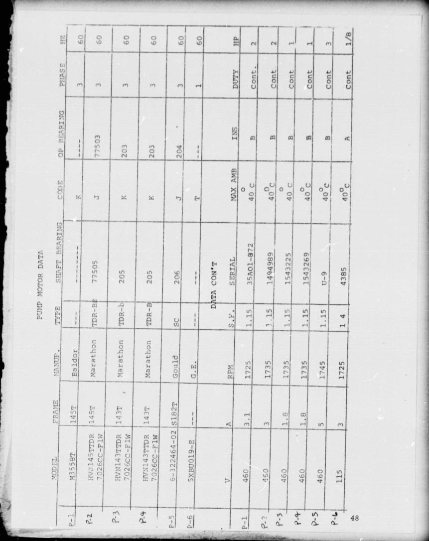
CiRGUI,A'J'fNG PlIMPS AND MOTORS
^. w47
Y
E-^
Q
a0
an;
fi
k1
IA
Ai;
i^Oo f o
IOoIO
l ato to
ntoo
'y'a
N N e-+ I .-1OD
r1 .-+
'.1'n
^.v tJ
C GJ3C
Jj 41
C c.J
C]. M r^ M M M .-r Q U0
01U O U U U
^
1
I
a ►',':, I
^,o m as as w cad a
!1^. I
tor
r'1o
rn0 O
I r- N N N I
1 ^
.xtt o0 00 0a1 0 001 0^ x h 94 X 17 H F d' d' V' v d' et
1
i I iIi I
^i!
II1 Ill
o
aH Q ►-1
00 CIAON N N'
Ln In In ID I Z a R (r. IV I v l rn U4) 0aI
Ir-r
0N
0N
oN
II
O W( J (n
InM
V
U"
In.-1
I"^
r~,!T I
E+
ACl .:^ Cq
II
r3:
q Ak^
Ias
Ui
Ia
In.-4
In u,
-1
In u,
E^N
(n 1 (n ^ r .-1 ^^ r-1 .-1
r_O
cO
cO
O v 41'vr-I
Mf4
M3 4
m►4
r-A1.1 W X
InN
to Inm r1
InM
Ind'
toNr0 t0 (C m
a .r-1 ^ r-4 :.4
E^ E-+ f-u I Irl M M 00 I CD cor--.. r-1 rl (n I a. M M r 1 r/ In M
a^ a s a 3 aIi.
CUIn w.--1
EE-4 ^iE+I
^ N.--1 ^^
rn
^I
InM t-)N
ci:; N ;? N rn
Q c7 1(Y^
? :0^0
O hv^ ^D
G Q Illto ^D .-a... r- ... r^ r kD In ^> '1 V. v a .-4
toI 4ri[, tL

^LE•
Q
aK'
a.
0 0 0 0 0r"td •ut i t
F F Ey
O O Q O OLn to In 1n In 1
4 h r r rr . r Ir4 r^ 1
4
11I
I N ^ r-+ ^ 1
7
•In In Ln V Ln
I1
^D • 7' N M ^p 1
I
J O O W O 1M m ^n M rn I
rn m rn rn rnr1
rI
r1
r1
r1
i
M M M M M(I
u1
In Ln LO Ln
mI
a^1
•tI^
1m
1.1
rn Ir, m r• O M O
*1)• 0r ► ! r .7 u^ ► 7 In O r .]
co N co N J N CO Nn U O Cj 0 m O N 0 0C-^ N C, c •1 O N O In NN m N 14 N m N (14 N m 1W ,n m u-N m In m m Ct1 In 1mn, rnIQ < m In ma, I
r^ tJ In S^ a7'
a ti ^- r1 a w49

vvIH 0.a X
I
I q G !r; f,'!', rrI
C..
F G7 N
^ IL ( N ►ft
I
W M
I aK9
I I
,,^O
v1
-..I

B SE MOUNTED e , id 2008_ CLOSE COUP LE D_PUMPS 1750- 3 450 RP M
EFFECTIVE JUIV 31, 1971 ! SUPERSIM SD 34W341 demel 10/31/7? y
SD 300-3-8 0e.
tPECIi1CATIONS
RMIWN 09M19 p o-
9aoclN.e 6
For Urpr FoOomann Corm fee Catalog N•, 300 3 1
_ V k-. •d . I • I ► I , ..... --- __— -- --
DATE SUBMITTED: ., c. '&, , L :711: 61 A.a i► I .
leoedor Mndel mo. ►,",prod I.W10-f Sete ON Need YeM•p N661
7.,
7. • !W 45 • 3 ^ • . .
SAM /1arr^_t11ed1 feel
I S Shd ► t Nub
Shen 419916
MpeMerSprJN Iwr. QifMNa OOP60 a rde 3Ph 4w 230/460PWMN FilterCqmJ*w_hU!s!M Corkst
Cm* RRra"m
71
71)
U
0
.950
a^
30
TA
wrwsww Iawrww111141 Sleet
All" Stl q otoh*«Alloy "Alloy SO- _ Mtr Man) _sbelhleerlrh 1 ►errnelll6 1 rmellle 1 ►ererelMe ?•
(2W) Q S2W- c300—q—[7•w _ ^_au^ ► 1J ^wwllh 11" With T—_
Sluff eft— Stuff see Stuff 6w
Cpre Nhrr1 Cuprtr Nk&W Cupp Nk' W/Stuff 1109Cat Im Cad Irte Cad Mr• CNI fir=.
Ej r«
1750 M 17W Se 17So se q13 3190 M 3450 N _
YES
t l TwI'
D
AWIW
vtt>r. ^.^ .,. .>M^ rw•r007e 4• Q ... ► ..++..►
Nf M atpe.., I r nr /:^ Ce
IONS
too► .
,. -•► 1Y 140
1111 ► r....41111,1111w , o t o x110%ur^^ t,l cJ'Yl'C
' Iw."w a1 : Iw Muljyo
.^ t a Cc 1
Wrwrn- w_wr RITorAn11 Preuure I 1 7SPSITeo Prawn 250 PSI t
•t4M leolldld N t#e" W I-, wxo rdenCo wuh A;,A 816 1
SIZES AND DIME
^ to
Its10 ,^
1Is
6•! r Y1a 1 zpgvm
_--Product Ole.
^'-MetorMotor RIM NP
Wctlen iOle. Conn. G C K
^e N
1---^-A D
-rX N M E
8 2008a 88 2008 1750 I 1 1 ? 11 ?I' !1 /1 1 1 1 '26% 3 % 26 4 U(,
18 /r 61 K,
rr
J12116,
n33 Ij33' 66C
i—3 7 I, 13 S, 341
c 10 3514 33^p_
81y is 46 /1Cd 982008 3450 IS
202 13 35 1
4110 1/2 5 1/,
133/11914
4 % 6 1/ 4l(, 8 1/1 8 1/11 W4
1516'!
4854
r CC2008
t iCC2008
17501 1/1
2 23 _
12 6 1/4 6 1/2 Sy, 41/1 1 % 7 41(, 1 1A661
I 1 k,11k,12N
2214,22'(123'y2
74501015 220
121214
6 1/46 14
13
61/161/2
10
51h5 1/,6
41/141/1
10'A
11I s/
%%'/,
61,1, 4)(, 1/181)(►8 1 )(,
10:(
14 1/r14 1/,15
29r1G711!(629"
51 r.
TACO HEATERS OF CANADA, LTD.3090 Lenworth Drive, Missmauga. Ontar,n TACO, Inc., 1 160 Cranston St., Cranston, R.I. 02920 0. nred in USA.
()OR QUAC'A- PACE r;

)ATE SUBMITTED: ,r ,_' .. , 1 "'VY: , 1,/•_,... . r.., .ow"al IWO Me Pwnpsw In PON@ !ha am Need Veftse F&W
/1 4 .u'
bi•
C
?
/M WIN hMxRURM Cufw 3 110 CMt ' .y ft. ?00-3-1
3008
1250 R►wt 1111l5^
w 1.ti
w b AGE
u
ID
Prb
9
, •Yt11IJN• rrt•u''
M. ,.
n
1 10
. , 1 , 6 1 ` , , / u I . .'
1111 CAVE JULV 31, 1914
; ^rV O^'i-3 550 RPM
SUPS RRt UES SQ 300 3 1 dated 10/31 ^ 12
on. ..r, ... _ rL
..PCCPICATIorlcc.:F-.7 3 a -:.-iRSL 3 ornm
fklcd•.-'.911 Z•
r:.75
C::"
elm
Cc:ple/fame =tt:reCe • !M • l"op^'1N
eac--Iete
AeA P{r^1q
t I !' - '1
"W
piwolow 2*Q 13010 TM
1 IP" :'1)
it .9rn In
I.'h. slisR)
P, MollieIts.%)VrA l
?Srf.c m P I : • 4 n
5.11. t41:lt arl'1 r.:.l with
uff ft—
!left V""IRi-::lerf_^arl Inn. Cut
, I"'"1I
t' I Ir;1C1• ?iife rItNuCr -1 It;'
rupre f11ri 1Cost Ileli
0 st st ww//sw" 0ac0 Cal M.
rMtacit, 0.0 P.61 r,-a& s fl " - 1 ['3 1r.0 is 0 1rM n 0 T
^^•eft. fiQf"t —
ATA —J' 1tES•!rR!e titer Ping I YESCcrf!Ra l'►etsuTrtt Prte-cry
I •. • Mf"..t
1 751'sl' •2•.0 PSI
I YSPS1•'250 /•
'It_t M1_! ,jt:! le Iboane w•• In •/(,v•1,i,,cs w,th ASA 616 1
_ r _
C 1 v.^.
I+rMeA 116, M.tw INIeelw
NPIa•rM IN Cann. 1
-
C 1 1 IF N I
(nr,»
I N A I 1 a N r
33 %ec,aol 1150 : 1: 22x I l i /^ 3 IK a 1yti I'1(,— _ G%
981001 3150 53 2I
11 27% 1'6 1 14 2656 1 % 6% 1 I 1A 7 11%11' .13 11,0 35 %
1 I I7
i
CC2006 1750 1 to 6 1,1 5% 4% 41/1 1 % I 6% 1 11/1 / 10"43 211
CC2006 3150 S 2 17 6 1 , 6'h 1I5'A. 4% 1 Mi • 1/• 1 1y3 1 1111zz
231 1__ 1 _l — _121
TACO HEATERS OF CANADA, LTD.090 Lenworth Drive, Mississauga. Ontario TACO, Inc , 1160 Cranston SL, Cra^sto p , R.I. 07920 printed . n u.S.A.
52
,1 IN
1 • ^^ . 110
,m? u . 1 ^IGo
^rftln:' lass ^
. M
1
O
D 10 ' 20 33 M I' C3 • 19 MnM1 -GAIJD''9 PM 1 tt: '•fi
tt-^
S 15 ^ ^.. ^/^^, `Z X11
Sri-'/. -.•^"`+'^ ^^.
. ... .-..• may.' w• ^ti.+
0 a art 0 00 t00 Ito INrLOW GALLONS PER blDR1TE
100
10
7.0w
5.0 .9
2.5
tW

Q
t+1 %Vk-*tttfn MAV tK0 M ••r
atft.• .
,,
/VIEW .Irinw, IaErieatiaw
•, tr ^br+l^r ^ rw o
r w B' SE MOUNTED c -id
Z5U5CLOSE COUPLED PUMPS 1750-3450 RPM
11111111 11111 31, 1011 1111141511111 1111 112Mfod 10/31/72
ft }`^
SD 300-3-12w
TE SUBMITTED: , c s _ 1` , 7SP E C I / ! CA TI 0 N: .uN.n Model No Pumpaln ` Ifnpel4f $1n GPM Heed VoMap P%s w
nRI iI^R11^ pwtMletMU Srt1111^
Ild Maws amSawtpw^ eat1" e wlaulfy t.•d►1411 sell IINM e'^t
7 . y(' L 5 11 wN 1.141-Fla faf ►1'1/41 1 1*1v 4r1a4 Cwm In CatNa6 Na. mtI
^1aNStruct"M4M
ftrwdwsi5W1—
>4 T-- —>o
, —"Iff go p s1.w114a , nso call
MINI m ell Mb. StaN \
Mad, !adForme Ia
1?ftmeft 1
(2501)hmaNN I
(1S0^hneallb
(1001 ys' ,ao * \\ •%tuning - eR, ?501 -- - 7501 0 P46efofu2 Gland wla Via •la9.3 studs a mkft stun eu stun eu Mrfn on
sNat1 slum Cup- 14WA4 C_uoro NIc1114 cop-J N_ r/ „ 809Imp.ltaf GN Ifaa Cad If m- Coat If"sDwN 1^. _
f
Mohr, 0 O V`60 cyft S 1150 M I IN MI O lm ee p ^^M" 230/460 SIsoea 3rso 8e __ I►ufoea tl flit@( L s! Guar.
. r...•.W" of tfrv,
Cant' novicesASA
Ifom w_.n Rln! — —
Working P►44wn 175P51 • • 175PS1 • • 115oS1Tad Pr mute 250 PS I 250 PSI 250 PSI
•IM Ifwr4.d Is tlr.uN c.A -- -•• In d^turrl^ r r • w L l • , ASA A1 (j 1
SIZES AND DIMENSIONS
01^))
IPTa MUMI NO
0 40 0 Iw IN 700 so All 3mr1.OMr 413AUX*5 Pn tatNt7Tt
I
b—_ 400
Ifa0 n
30to
in ico
t
Mato( I SYCilan a ^Product No Motor RPM NP
17502'/(
I off.. Cann. I C C K f e 1 N A^
0 x I N
1 711^2'13^!61
M
341/4
1 34$%B 2508BB 2508 11 27 1/• 9 1h 11ti 26!^ 3 )1,{ 1 1 f»,
'7 13 35
i as 881508 34502S
2 1i4 13 i 35% 5'/433 1/4 4 % 171A 1 1/4 0
e1 Wif 16% ^ 41%I10:' 16 43111
2 i 6 11% 22„nCC2508 1750 3 11/2 1? 61/• 6'/2 5 1/4I 1 1/21 % 7':{• 11/• a 2 3 %,_-- _
S
!
12Ve ju
IS 11? 6'/• 6 1/2 5 1/. 11 l110 1 j
bi t'i• 14%27%CC2%08 31910 20?5
1 11211 1311 13
1010
611'b6 _ 10 1 i 1 1/,
1/.1^
7"^^ 11h 8 1011, 116% 30•x.10'•, .16'_ k, 31'^
TACO HEATERS OF CANADA. LTDTACO, Inc., 1 160 Cranston St., Cranston, R.I. 02920prmted it U.S.A.3090 Lenworth Drivf , Mississauga, Ontario
5?

ft. 6 W
IV.5 v
•^ QW
-3 2:J
2 ^..0
.7
—
112
— --
--111 ---
110 & 1179----
120
25
SPECIFICATIONS
• Motor — Resilientent mounted, split phase W 20Built-in overload protector. IJ I
• Body - Cast iron or brurr315
• Impe!ler — One piece, dyn.lmically hal Qanted, non-ferrous W_
• Coupler -- Ond piece, spring 1 0J• Shdit — Stainless steel
• Beatings — Bronze s4lve type O
• Seal — Two piece, carrion/ceramic f— 5
• Standard flanges — Cast iron or bronze• Shia-,iff flanges — Cast lion, bronze all
h
Job: giCit"4t & CM1,11"G r7'C:'3TfU
Submittal Date: 1 J L•._., %J! .'1 1. i 1 .' ' -11 :.LSBy: V. -.6;L. ,,%'. 1?. A!, 73
Location Put.-,p Site Model Number GPM Head
Vast 1" 1123 23 0
10, 111, 112",113, 1178, 120 30
FLOW MYH2 4 6 8 10 12 14
Y —
Nl/M9f F^T
Effective March 15, 1978
SD 100-1 5) Supersedes : SD 100 15Dawd 1/31/73
CURVES
0
l
0 ; 10 201 30 40 50 60 70., -,. t ,- i FLOWN GPM
It cl 'CL.%Ptf I-.' : ' „ r• Ai 1
:han;el to DIMENSIONSt^1 in er.Nuret e IL.• . ' r
0-L•rr.
Anrtn^ ,od Al N-111 ) ^•Pprov •chlu Exe^P1 • '
1 _
k }1 . • ,
^--•► 1. When specllyine s'I hronte construction add teller "l1" alter prolucl number, Ie: 1108.2. Motors are available with other electrical charscteristies — consult your Taco representative3. 240 Intermittent. 200 Continuous
Taco, Ir.c. 1160 Cranston Street, Cranst054
ie. 1401) 942 8000 — Telex: 92 7627
Taco 1Canadal, Ltd. 3090 Lenworth Dri 116! 625 2160 Telex 06 961179
Is
r
r MOTOM' DIMENSIONS Ne0401^MVeINOPn/e9UNr
A • e 00110DUCT ILASPI -- -- AU IIMUAI w11GOTNurs[a '^\/[ 11sv 00
t Vn a•'A1'r MV IU T)NG
Lef eoIN MM IN him IM WhIl IN MV
110 1t,.1 . ,; Y/1I ,Lt7:^ t>NP° (f' 126 1 sl /IMt 371.6 1:'1 Y97 ^
1.
111 1'h' vi . 1725, lw0 i! 106 jol
-
16 11. 412.8 13',.
—
252.4 20'4 2601 ey, 2222 28 11.81v:',
210° F 125 1e'4 419.1 14'6 0.2I 7',.
240' F s112 1v!' 1".' 1/8 1725 125 ps i 1 41% 4t .3 -. k 11 35S.8 10'h 257.2 e'; 215.1 27 12.2
1176 1" Sweet 1112 1725 240° F 125 psi
125 psi
14
141h
355.6
42S 6
IVo
14 1/.
3218
362
17% 45e n e' 1.5 1I
120 1 2" 1/e 1725 240' F ON 342.9 1 11 279.4 1 46 209

ItC "^ INO ^EYV13W_. _.a
JIf r•' W If ch•tcked belcm, fnbtit1:r MIANtrt^!e' r
NOT to undettelrrn 5 ihmr rr►^ t•1R ^tl^^ to C*' corlceted drawings for it rrd ^/l11^ In selmo^ ploval. c0floctlull Shall 1.On , pr. Item% n`atki'll.
I 1 ^, . ,, 'luR", q^n t^llevlse S Hri, / tm+it/Nn e• ^f. Lr ' .
1 A 1 1 fiapt txf/Curltments At., I '
.,„•,• mth thu design r ucept u, U.
. the .. rlrif r 7lf.I umtnts. ^C 1 ^
44W • till r lit I 0Z ES AR^ I IITECIw
1► L
n► __ ^^ _Dal,'
r^
_ r
SPACESAVING
r •
fCV /^ Ak ^Vgcf . ^S
C •
r:IS
JU='^i^'
ma- 0,
. ^ o
^^^nucty
Suction'Diffuser
1: A 1 A I t, t.,
400.5
ir t11 onu turn c. 'w th , re p, awlnys ,.Old sp drp,nhn ttstreol. 1T" 7tlauor-ts p for quentltfo* fitans to 1'e conilr' • Ied wwd"e"j, $I .is e^rd N. 1, Infor run that nt^t .^, r • , r
1, IN{ee' tha m llwds. tr u's, tequ, • e•t 'sdrw / coml r crw'O „rs of Ilia ,dl trade. enJ Iu' tilt
^^ It ', i. it t
TACO, INC.t RANSION 1611-100t IMAND 01920
TACO HEATERS OF CANADA, LTD.M 1 5 5 1 5 S A U G A, O N I A R 1 0 C A N A D A
INCREASEDPUMPEFFICIENCYfrom
55

r-,
ll aco
Saves Space For optimum pump effi-i irnc.y, provision for straight pipeor straightening vanes ahead ofthe pump is regwrird The SuctionDiffuser is an e':,ow with integralstraightening vanes.
Good design prac t ice dictates astrainer ahead of each pump Anintegral strainer is included.
Flexibility Suction Diffusers are avail-able with equal or reduced flangesizes.
Start Up Protection A fine meshthrow away start up strainer is pro-vided with the Suction Diffuser.
Permanent Strain-jr The permanentstrainer provided has more free areathan conventional strainers
Ser.lceability Water flows from in-side of the strainer to the outside,thus simplifying the cleaning and re-moval of the strainer.
SPRINGHANGER
TS B ^ l oie!ion Diffuser eliminates thenr • 1 tier
i. Lr`rg entratice pipe2. An ^'how3. Tvin f'r-ingcs4. A convnnVonal strainer5. Three welt'sG. Gaskets and 13olfinq
Pipo thrc .%rl:,. Flovr riancle
GATEVALVE
MULTI PURPOSEVALVE
GATEVALVE
PRESSUREGAG,-
SUCTIONDIFFUSER
56
.rim/.• --1 . _
3

^- tlL O^tl OOWM
f ^
1[tl1/16
0RIG INAL PAGE tSfo f^„°^ .QI IAI "Y
SPECIFICATIONS
BODY Cast IronSTRAIGHTENING VANES Cast IronSTARTUP STRAINER BronzePERMANENT STRAINER Stainless SteelPRESSURE up to 175 PSI in accordance with ASA B16.1TEMPERATURE up to 250 F
TYPICAL SPECIFICATIONSProvide at each pump a Suction Diffuser Taco Model(s) of size and type shown ondrawings. Units shall consist of an angle type body with inlet vanes and a combina-tion Diffuser strainer with lib" diameter openings for pump protection. (Unit shallbe equipped with a disposable fine mesh start up strainer which shall be removableafter 30 days). FLOW DIRECTION SHALL BE FROM INSIDE THE STRAINER TOOUTSIDE FOR EASE OF SERVICE AND CLEANING. The body shall fit the pumpand connecting pipe size. The ur)it shall be provided with an adjustable support footto relieve piping strains from the pump suction. The contractor shall providevalved gauge connections at diffuser inlet and pump suction to indicate whencleaning is needed.
i 57
A

' N ^t• .^ .n „ n.
Pl. In 115 PSI m er,n.dd". wrth ASA HIfi 1
T, tov to 75U^' f
v pr .r
FLOW RATL`18
r
GPMi, S A
DimensionsP- I , P- Z', P- 3, P- 4- * -3:50
p-5 # 35 1
MWNSION I)HAAINIi
N • .M run A1
5111
-1pump
o j'
M ..V{M!M f
Wwa , .n . .wr
t/f -a
aOfs
wCC
N:U
^ I
WDEL SYSI I M 1'llh1l' C V 1 actor1 rtv Art• ,• UIMI NSIUNS Ship Wf,tSq In A ( H C
.Ip H 1 I bti
350 3 f Ig. 2 Fig 110 40 7'1• 7 )r 81/4 't/4 ?% 1 .1 ^, 45351 3 Flg. 21/7 FI^
t110 40 7a{. 71a 81i4 y4 23A q%N 45
352^
3 Fig. 3 FIg. .'00 50 7 e 1 ,'a 814 1—
2'). •1 57353 4 F Ig. 3 Fig. .100 50 7 • tt 1 Ib h 1 4 1 ^ 2 1 ,. 41 ; 6:'354 •1 Fig, 4 F i g 350 80 911. 714 9';, l 3!;. t)'„ 95348 5 Fig 4 FIg .150 80 9"' 114 tit . l 31,134() 5 Fig. 5 f Ig. 520 1.15 10 41",. 1 1 ' K l 3 150155 6 Fig. 4 Fig. 350 80 9'.. 714 31ii 5 +H 1251_150
3576 Fig. 5 Fig. 5:'0 1:15 10 911,. I 1 !.tl t 3_ r 5 j H 1606 fig. b FIg. 760 150 11 8 i .1 11 1 3 5' • 180
358359
8 F Iti.8 FIg.
i 6 FIg.} 8 FIg. -
I 760 1501000 275
i tI1 14
8 ' .t13",.
l i%16
- 3 - _r1 j11/4 27/11
5'1.5 1 /
-)05280
370^ 10 F Ig 8 FI g 1000 275 11 3/4 ^ 3"1. ,. 16 4 -- 711/4 I 2 ,4 15 . 4 298
PRESSURE DROP CURVE.o ro r, ,o ^ .^ .r ,,. .a. u., ,^ ^ qw. w,^., nrn :r w .r w r w w .rt
r.
.1.
•1
-i
if/1 i^ 1 t l
I•

- -- - -- HORIZONTAL A VERTICA L CINC:ULA IOUb
W9 NUMBERNos. 110 thru 120 and all Vertical Models
ISIOO-21 EI ► EC TIVE. JULY 1. 19t,111su•rwsrocs. ICS 100 . 21 DATr p 10/ 1'ft'S ANo
16300 . 7 6 4710103A
TO REPLACE MOTOR
2 I , it t% o .et sire%% at primp roll of %fling 4-oupling. remove Moll% b4•1%et'nI, I .0 ket and motor And ,-palate.
IO 0 n 1 I.1N1•4•n other %t-1 ill votlf)ling and 11'111.1%t' tollplillg 6'.111 ()lit m(,tulp '•s ^. •1 Slide c• oullcl %%lih single stet screw mul tit • %% m4tiol slialt and tighten again.t flat:J y pt ty %lirfart. of shalt.R G 5 I'larc new 11111101 .tSWIllhh into blarkrt .Ind It plait •INIIt% (als) springs oil Verticalw 4. y n' 1 \ 1(x161% 1,
O J d 6 Extend Ilulnl end of %lung cost • r .aft 3%16" lrmiiontal \to(IelsCline ovty imim-1h h1 ,^ or 5/16' 011 Veitill-, \lu(lek and ti',htet 114,111 %t'1 m iu .'s. If inllellel and shalt 1110%4-
;-- CL into INxfy (luring this opt-lation, %ate' will Ilt 'H hom %cep hole in bracket. If this (Ilm-%N
W C y
tl(ctr. evend %fumg coupler a little moor (it until %%ate' stop flowing. CAVTION:r IJ ', l'\ItI:It No l'lltl 1 I'\1 1^"I'A\l'I:S `,II( L • I.1) IIII •: WEEl l 110LE BF 11LL'GGE111.
OD N 7— k, a motor.w,+ O
GC A TO REPLACE SPRING COUPLING
f3. LL Fultti%% %aide f1t'at-duat • outhmd alK'vr.
REPLACING SEALS\\.ucl 11o%%4nt4 II'un %ct-p hole In hiall,ct nolnilllc indicaU • s (lilt nil lilt- %cat or .calneeds replact • ::it-ilt lielore taking pu11tfl ap,u1 t-vt-nd %piing coupling and impellershaft 4110 h(Kll .11 far . I , it will go. '1 . 111% %till st-l.crate the seal halve ► and pt'Inlit .1greate ►' flo%' thm tilt- %t-cl hole .md %as p .ul\ loleitm p latter oil the seats ReleaseAnd if No%' %tolls, it indicate-.4 that till . scats (lo not Icyute replaL-ellicnt If the flow dot..nut %toll, loo.en the two set screws (In the cotplim; and extend as far A% it Ail[ g0. IfIcak stops it Inc.uls there %'.a% in%ullicit-tit lcmiou tilt the coupling. If leak cunti/lues.Indltattnlls aw that Till' sual Ilred. It-ll:µ'1 • Illt-lli. I^l'K et'll A% follows: --
1 I )i.crntu •ct %414.111,2 \'.a p t- till or drain system
3 KI-olo\t• body halt% And 111111 t • lltire ,Is%,'nt111% op t 01 INKIV.4- Loosen the t%o sit Wrt-%'s At lump cml of spun;g coupler, file oll any hurts oil
.► nd 11111 ililleuel am p%haft from I ' lai kt-l.5 I'tv out old %(-.It scat 110111 bracket %lilt a %t1t-%dtiver and (,lit part from imlcller
%haft N • Itll ,1 pall Ill Idler%.
6 Cli-an %haft and sea! hearing surface% 1lunoue111% with cic.nt (.loth.7 -- I)Ip C AMII )N pail of %cal lit %%.ltel It/ 14111111.11. , place' till till of llllpcllel shaft wllll
(albon faring ill. Pu%p do%%n till .14.41 „lilt p.ilm ill band a% fat a% it win go. Then%1111 twill 01111111) % push all till- \%'.N alt • \%11 Ill.11,1w! lt'Itaill Illat prn11Qs t-tigage tall' t%%uholes in the impeller. It there .ft- till lit i11lflt'Her, break off the prongs with.1 pair of phcr% and smooth hurts with .a 111c.
8 Separate lubber from ct-r.tnic part. %%t-1 it antl s1 . 1 into rece%% ill Set ceramic%eal into 1n pl,er with seat facing nut 11v .1,uting At a %light angle first. the. ,flushingam.-Ay alld do%%II %Ir1111ltallroll%k• . l lle Illbllel Illle, .lim ild not he folded o%4-r duillIQ the..operation Make certain that both I;.c ruh1)t-r and ceramic are "bottomed" ulu.uck.
9 l: cats both se ll .Ilrfacm Aitl a clt • .III Iltit ic, cloth.10 Platt . .1 It-%% Mops (if illl alorlg 1111' im K'llt'1 %lialt And p11%ll %lowly with .1 I%I%I IIIL
motion through t-eranlic part into bracket and .print; coupling.11 - While holding impeller and shaft %'ith %cal fact-, malimt, in%t • rt an Allen wrench Into
ont- of the %et screws in the coullint•, extend spring '1 1 16" fo p llorimntal Modek or5!16" for Vertical Models and tighten set screw. 'I'hcn tighten the second set screw.
12— Remove old hodv gasket, clean surfaces and replace %%ith tie%' gasket.13- Place ender a%.embly into holy, n • place and rit;hterl IK)11% Gradually .till evenk • all
around.14- - Refill system. If %%,ter leak% from %ct-p pole m hracket increaa•tension on %'ring
coupling slighll% mort- or until Icak %tops.15 Rewire motor.
LCAIMON: The ad4litwn,.f rert:"rt thenmal additiv" b' -y -tem. utlhrtny TM o Fgtnlunrnl, c„u1+ the %arrana1
Taco Heaters of Canada. Ltd.3090 lenwotth Drive T A CO. INC. 1160 Cranston Street, CralmOom, Rhode Island 02920
Cooksv111e, Ontario ►t..t.d In u s A59
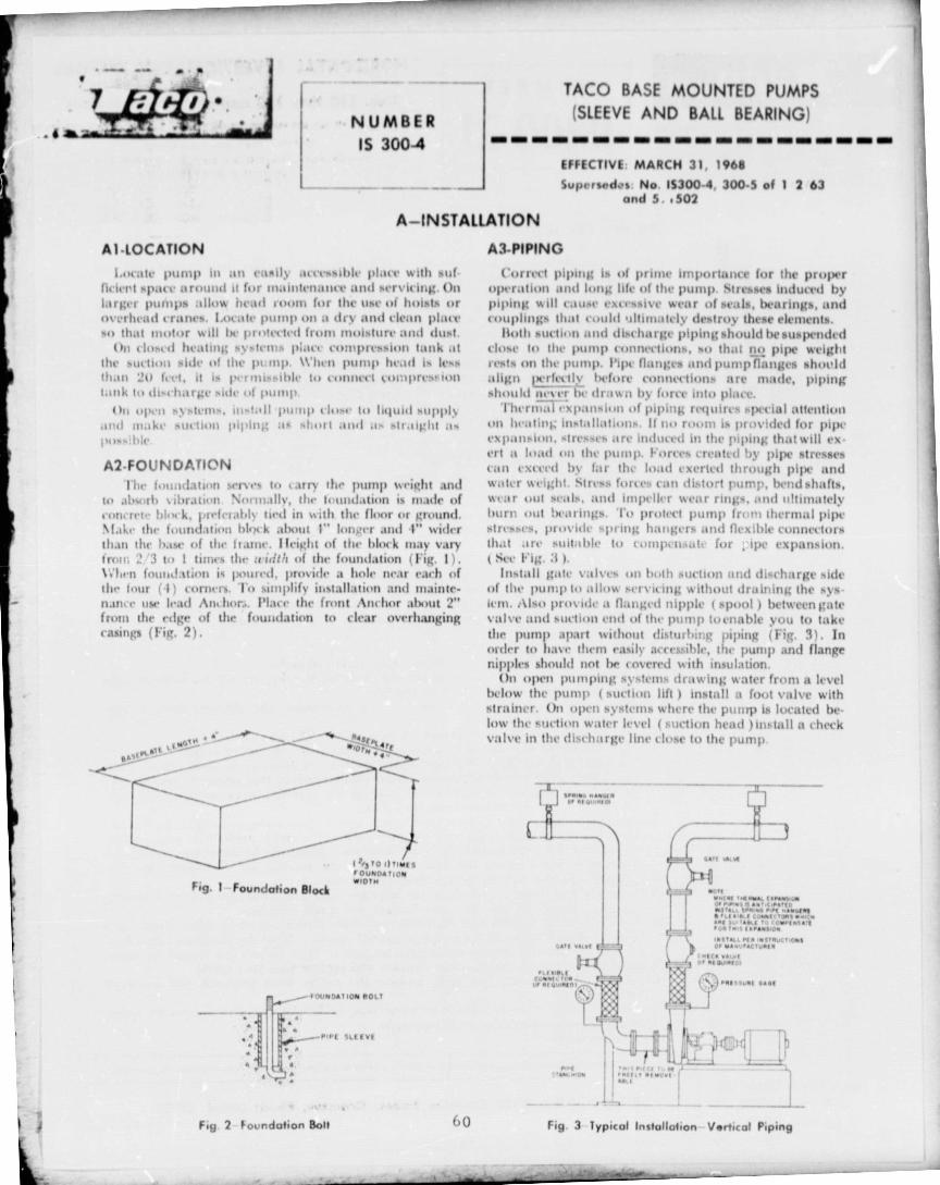
-^- TACO BASE MOUNTED PUMPS
NUMBER (SLEEVE AND BAIL BEARING)•
IS 300-4
11 EFFECTIVE. MARCH 31, 1968l^ Supersedes. No IS300-4, 300-5 of 1 2 63
and S .502
A - INSTALLATION
A140CATION A3-PIPING
1.ovitte I )it ► nll all raspy accessible pi with suf-ficierl spurt, an I it fur mainlenante and 1 % • icing. Onlarger primp t .,.. , N head room for the list , of hoists oroverlivad cranes. Locitte pump oil dry and clean platyso that motor will Ile prt ►tecled Iron ► moisture and dust.
Oil closed healing systems place compression lank atthe suction side of the pump. When pump head is le,sthan 20 fct,t, it 1a Iwo imssihle to connvvt col:lprt • s• 1011lank to discharge side 01 pump.
()It s%slcros, 111,1:111 pulup c14— 10 liquid soppl^io • ,' make suction piping as short .%tut a- straight :1s1 ,.. v
A240UNDATIONIht• i••uadatlon m-mes to tarry the pump %%eight and
to al ►.trrh vibration Normall y, the foundation is made ofrunt ret. • 61171 k, prefe ► ably tied lit the flot7r or ground.NIAv the foundation 1)17K k alxaut I" loner and I" widerthan the haa • of the lame. Height of the Wool k stay varyfrom 2 '3 to I times the ccidth of the foundation ( Fig. 1) .VOirn frnmdation it, {wined, provide it hole neat each ofthe tour (•I) corners. To simplify installation and mainte-imm a list • It-at] An, hor.,. Place dir front Am hor .aluitit 2"front the• edgr of the fnmidation to clear overlimigingcasings ( Fig. 2) .
s•
r 0U0004TIOM
Fig. 1 Foundation Bloc`viol"
1 OU N 0.11011 0011
no[ sul:vr
"•1 •
l'mict-1 piping ill prime importance for the pru{x•ropt-ration and lung life of the pump. Strehlies induced bypiping will cause excessive wear of seals, bearings, andcouplings that could 1.tltimalely destroy these elements.
Both suction and discharge piping should be sus fx•ndrdclose to the primp uonnecliuns, so Thal tit) piles weightretats on the pump. Pips • flanges andputnpflunges shouldalign t f!1!Iv lxdore connections are made, pipingshould never 1)-4 • drawn by force into place.
1'ht,rni;al xpunsiun of piping requires sptvial attentionon heating; installations. If no rt)t)m is provided for pipeexpansion, •tresses are induced in the piping; that will exert it load lit the pump. Fortes created by pipe .stressescan exvcvd b1• [:u' the load exerted through pifx• andwater weight. Stress fortes call pump, bendshalts,wear out seals, and impeller wear rings, and ultimatelyburn out ix-a rings. To prof vl pwnp from Thermal pifxstresses, provide spring hangers and flexible coilnectorsthat are suitable t0 compen;att, for , ipr expansion.I ties Fig. :1 1.
Install gale valves on both suction mid discharge sideof the pump to allow servicing without druining the sys-ic• m. Also provide it flanged nipple ( spool ) between gatevalve and suction end of the pump turnable you to takethe pump apart without disturbing piping (Fig. 31. Inorder to have there easily accessible, the pump and flangeripples should not [or covered with insulation.
()it punilmig systems drawing water from a levelbelow the pump ( suction lift ) install it valve withstrainer. Oil open systems where the pump is located be-low the suction water level ( suction head )install a checkvalve in the discharge line close to the pump.
SPA a
`^ t•r1 WN
LL.t
.OwIN ry .0W1 t.1N/MOra 1rl,rt h
1•/•" ..P tT[0
.1 Tti, r,r1 1a/7TON SA I 11 0. VA CO", Io lt.%4-1
API b^
^ I001T•.11/r•r1100
,r/TALL PIP .r 7TryC Ti0r/1 01 WwIKrVMr
-tc n r•ur1t gar r/ &•r101
►4111.01 t•tl
^T w '^'rt0ror4
Fig 2 Foundation Bolt
6o Fig 3 typical Installation Vertical Piping
..att^lArr4 ^ ^ ---- -

A—IN STALLATION-Continuedcwt n v.,"
o ► MGU,utm•,vt
.nsar,t r^
NN^looMC MOM
"To valve
rI Ill"'+ Tr `e
my ", t MCI 10/ ^ - --
t,.M(M.OUwj w7Vl,Ml1I
Fig. 3 Typical Installation Herhiontal piping
A4-PUMP SETTING
When pump is set on its foundat000, mike sure tohave it proWrly Icvelled. Plave haseplaleo%crfoundtatiunbolts provided for it, platy shims alt corners of baseplatewhen required and level with a spirit gautge. Tightenhaseplate firmly to its foundations. Check also level ofsuction and discharge na ngek.
AS-COUPLING ALIGNMENT('roper ulignmunt ul pump aitei driver will assure
trouble flew, operation and lung life of the ptimp. Mtsalignment will t ause rapid wear of seals, couplings, andbearings. All pumps are carefully aligned hefure leavingthe factory. llowever, experience indicalus th;rt:elignmentin v ariably changes in shipping and hundlutg. Therefore,it is of utmost importunce that alignment he checked titvarious steps of the installation process. i e., after level-ing, after piping, and after first few weeks e►f operation.
Check alignment by placing a slotted Straight edgeacross the coupling halves tit top, bottom, and lit thesides. if ally light is seen hetween the straight edge andone of the coupling flanges, it means the unit is out ofuligrrmcnt. ( Fig. 4
If light is seen at top and bottom pusiliuu of thestraight edge, alignment is out of height. UsuLilly shimsare plaevd under the motor feet. Loosen the four motorbolt,%, remove or Ladd shirns its required locorrect properheight. 'righter, the motor halts and cheek to make sureulignment was corrected pruikrly.
If ulignitienl is out tin the sides of the coupling, loosenthe four motor bulls and lightly tap the motor in the direction it-quired. 'r ightei, the four motor bulls allot checkto make sure alignment was corrected prolmrly.
As alignment in one direction may alter the alignmentin another, hie sure to cheek till ulignments made.
66 I r I --
r.uuwwr, . ..• .vw v^
Fig. 4 Coupling Alignment
A6-CONNECTING PIPINGPiping nuts mw. he connected to pump. Makesure that
pump and pipe flanges tare strictly purallel and prupe•'yspare,( for the gasket that will he used. Also check thatpipc , ;ur ' upported properly and do not rest on pumpna ngcs \re • er draw pipes by force to pump 11-.u ► ges. Hecheck ;alig;ninew after piping e•onnections Lire made. Ifmisalignment wits caused by piping, it isasign that pipestr , distorted the pump. Correct piping; tc► relieve
B—PUMP START-UP & OPERATION%•timer, till punig, tnr the fu-•t time several item-heeked to avoid damaging pump.
I
BI-LUBRICATION crave'
Sleeve Bearing l ,unnp. .,r,- filled 'h lorl .ot the factory
but done oil nitwit he lust duririgt ^trnu'nt. As .a nnatter
,if l)reK • uutlun, check loll level but %tiny,, up pump.
I ingwr leii-el is tit the center lof the rbtss. If 'Ill IPPeI
is tau low. remove till) river , FIJI u,l refill.
Drain and refill oil well once ;r ir. Initial filling isSorony M oh il D'I'P. Heavy Mt-dn, t h l. b il l al ly prenai-Ball Bearing plump% are greasrol at the laclor. • . Grease-
g at, trot that% out during shipnurral, Sol rtucheckiog; will berequired tit startup.
liegicase hail] bearing every two year, or 3,000hoursof operutiotn. Initial filling; is LI 'I1liIK0-greiase, (tensity,\13 1, manufactured h .N Master I,ubt icanl% l'on ► pany.Philadelphia.
1ny general purpose ball ht-M-ing g;re.i:c \o ;1 NIA;It National Lubricating 914case Inshtritt , ► harllr,rss mayhe used.
1'o grease bearings open side covers ' !'ig. :, ), sl,d,-61
kill, SAF: Grade 20 Non-Detergent Motor Oilcan he used.
Motor hearings also might louse oil during shipment.Check oil level as indicated on motor instruction. Electricmolars have either an oil cup or a pipe plug for filling.An overnuw is lucuted ut the side of the hearing urea.liefure starting: unit, fill motor hearing with tin oil (-.ailuntil oil Flom., ou t of overflow.them about 1,/2" to the side and introduce greae I^iruthe opening with a putty knife. Fill grease chamber 2/:1high. Excessive grease causes unnecessary friction andwill overheat bearing. If hearings rain hot after regreasing, still ► pump, open side cover, and wipe out excessivegrease. Overheating will then cease.
Motor hull hearings also are greased at the factory.Grease should be replaced as indicated by motor manu-facturer's instrueta.m. Normally greasing is requirede\eaol , taco years. ()n clertric motors grea.c is usually
,diced through it grease fitting with a grease gun.

B-PUMP START-UP & OPERATION-Continued
flop .... • • s / lo .p0 ,lop
- 7 l tt; AR qG
.•« w• w.Fig S -Lubrication Points
I
02-MOTOR WIRING & SENSE OF ROTATIONCluck wiring of motor before starting to make sure
that connections are wired prulivrly for the voltage in use.th•ervoltaKe can burn out motor windingl. Check heaterclement in magnetic starter to %ce that it it. rated the sameas the muter
AMP RATINGFOR
3 PHASE SQUIRREL CAGE INDUCTION MOTORSMotor 220 Volt 440 Volt
HP 1750 RPM 3450 RPM 1750 RPM 3450 RFM
'/p 1.0 - S'/i 1.4 - 7 -1 h 1.8 - .9 -
r/p 2.4 2 2 1.2 I.I1 3.6 3 4 1.8 1.71 1 h 48 46 2.4 2.32 6.2 5 6 3.1 2.83 90 80 45 4.05 144 I'J4 72 677 1 /1 200 192 10.0 96
10 264 256 13.2 12.8I S 39.0 38.0 19.5 19.0
20 51.0 50.0 25.5 25.025 620 60.0 31.0 30.030 74.0 72.0 37.0 360
40 96.0 -- 48.0 -
50 120.0 - 60.0
Before attempting to check out sense of rotation ofpump, fill pump with water to provide lubrication of theseal. Do not operate pump dr y for motor checkout .
Next throw the switch and bee if direction of rotationcorresponds with arrows 41n frame of pump. The dlrec-non of rotation is counterclockwise facing the suction endof pump. Direction of rotation of three phase motors canhe easily reversed by interchanging two of the three wiresit! the terminal board of the motor. Reversing of singlephase motors Is dune by interchanging some internal,.\ires or clamps. Inoructions for reversing are foundeither tin the motor nameplate or inside the motor term-inal cover.
B3-PUMP START-UP
After you have checked lubrication and wiring you areready to start the pump.
Open the late valve in the suction side and close thevalve on the discharge side. ~taut motor, witit lnnil unithas c41me ti p lull speed a tid then opcii discharge calveI()% 1\ Do not run pump for nu1ry than ,a tcv' 1•iinutes
w ill) complctcl\ ~hilt valve.. It -%- stc11 aollifiliovis 1 ,111 forpail Ilint' operation 'Igilinsl hlit \ . 1 lnsli.11 ,1 i1., 1iaw.t ine 1141111 di,chaugc Io suetiol,
62
84-MECHANICAL SEAL
AND STUFFING BOX CARE
Mechanical Seal (See caution below)*
,fechunical sealb are the most delie-le component ofthe pump. Spacial care has to be given to them to assuretrouble-Irec operation.
'I'he sealing clement of it mechanical Beal consists of ucarbon washer rotating against u stationary tvrurnicring.
Surfaces of both are highly lapped tit assure sealing.Any dirt that penetrates between the two mating parts
will cause a rapid wear of the seul faces and willultimately result in seal leakage.
New heating systems are usually contaminated by var-ious materials such ab construction debris, welding blugs,pipe joint compound mill scale, etc. It is of utmost im-portance that such systems be cleaned out thoroughlybefore putting; purnp into continuous operation.
Cleaning tit a heating system ib simple and easy. Firstflush out sybtem with cold water at city pressure to re-move all louse foreign matter that penetrated Into thesystem. Afterwards boil out system with chemicalb to re-Move dirt adhering to pipes.
Chemicals most commonly used fur this procedure aresodium triphosphate, sodium carbonate, or causticsoda,but any nonfoaming detergents as used In dishwasheiscan he applied.
Fill system with clean water, add cleaning chemicals( 1 ) lb. for every 40 to 50 gallons of water, (or %tirs.Instruction ) start pump and heat up system. 1.0 systemrun for a few hours, then drain and refill with freshwater. Your pumps are now ready for continuous duty.See caution ilelow 1.
Sttiffing bnxc• .are less delicate in operation than me-cnanlcal seaais. No chemical cleaning is necessary us onmechanical seal putnps, but flushing out with cold wateris beneficial on this type of purnp too.
After punip is started up adjust gland of stuffing boxevenly so that it drips front to three drops of waterper minute. 'Phis drip is ansolutely essential to pre•'enldamage t41 packing; and shaft sleeve. It also preventsoverloading of motor. Excessive dripping may causeair to enter pump under certain conditions.
Sump of pump should be piped to any convenientsewer or drain. A pipe tapping is provided for this parpose at the side of the sump. Never plug this dramtapping;.
CAI"I It i\ -I'he ndliit l,-n •,f . i l t.im a hemrcid aaddariws to
- y am• F:I11jil111nent. %md- the wa riant%.
.;

I. Attachframe
2. If Reciinsert f
3. A"ach
INSTALLATION OF EXTERNAL CIRCULATION TUBE
I31umen:iuer mnd A%sociaicsMechanic:ul Equiptinent207 E. Lancaster Road
Orlandot Fl. 381119Phone-305-1355-2111
IMPORTANTBelo • ► filling system with water, assemble mrteroa; circulationtube to pump casing as follows:
I. Screw nut into body unfit hand tight.
2. With a wrwnch continue tightening for about one and one-half full additional turns. flt is not n.cessary to tighten nutall the way down
INSTALLATION OF PUROCELL FILTER
TACO, INC.Printed in U.S.A.
► 1 160 Cranston Sireet, Cranston, R t, .de Island 02910 63

T ACO IW SERIESNUMBER BALL & SLEEVE BEARING BASEMOIJNTED
AND CLOSE COUPLED
Is'
300-3-1 per..^^er.^e^e^ri^^^^^e^w ►► •I^wr.^EFFECTIVE: 2/1173SUPERSEDES: IS 300 3 1
-^ dtd. 3/31/68
MAINTENANCE AND SERVICING
1114,11 10 N•, 00, 1•,q
CI-GENERAL
Before undertaking any wrvicr work on the pun ► p, readth,•se instnictions careful' ►' to I ►t' readil y pr1,parrd for thedoh B tY %otir com o -nience 'hACO en, lo-e. ►, ooh theM' tit-•11u(tiOns r list of replacement parti, for each 11111111 Order
puts tr•titaired for maintenance 1t„rk In li+,tilli , 111 ,111 nuns-Iw,'r, number recluirrd. dest-rption. and pai i milt, 1 R1,-lore taking puny) apart. tlance gaikelit for pils1 • traua • t 1141111,and a purnl ► gaski-i kit should he available.
A step bV $tep 1 111„edun• of the fluwst 44,1111114111 ulain-(rname iuhs is gr\en 1 ►t1 ►►,. rollow it twit the r\pl,al1,dviews in the replacement I ►arts list. In the cll-so • ripiioolt -miltill the dia%%ines all parts are rt'ft'rr1,11 to by iwin nurull,-1.'170 start am lnaintrnant a Wilk •top 1 111111 and , I,•., %114'-fig-it .111,1 disch.slee lines. To gain access to internal 11111% of111in1p remove flanged nipple ,spool pict i-1 th.it 1 1.1. IN , nI)m%-i(l(tl oil side of the pump.
It no treely remuvuble piece is provided on suction .1111'of pump, you can service the pump by dh•connet ti igbooth -uclion and discharge nanges and removing thefrom^ hold down bolts. The whole pump can noow Itt.moved for convenient servicing.
C2-REPLACING IMPELLERRtttuireil repliterrnent parts
Item No. 6 ImpellerItem Nu. 3 Suction Cover "0” Boni;I Pair of Pipe nange gaskets
DISASSEMBLY
Disconnect suction cover ( 1 ► by removing suctioncover bolts ( 2 ).
Itemove Impeller bolt ( 4) with it socket or offset boxwrench. Roll hits right hand thr('ad. Place wrench overbolt head, hold wrench hundle horizontalh and hithandle end sharply with a pla+llc hammer. This shouldlousen bolt ( Fig. .) ). If this method is unsuccessful holdvxl)o%e(i section orrnotor shalt with a pipe wrench.
Remove Belleville Washer ( 66 ), impeller washer (51.1111 ;mpt ' ller %patvr ( IS (where used ) together withimlwller bolt ( a )
Pull out Impeller ( 6 ) and impeVer key ( 7 ). 'I'lie useof a wheel puller may be helpful in removing the impel-ler. If nc► wheel puller is available, insert impie ller hull1 4 ) in •haft ( .12 ) and bring halt head down on it. ( lilta drift against the bolt heud and hit it 'l or :1 time,sharply with it hammer. 'Phis will normally looses impc'ller from shalt ( Fig 3 ). Next insert twoo .crcwdr fiver»,one on eac h side in the grooving of the impeller iiemrings :and pry out, taking care not to darn age the wearrings ( Fig. ; ►. If any bum develop %muolll „tat will,emery cloth.
♦1 •
or r 1 v 3i..r
Fig. I — Disassembly
1
t _J
ReassemblyFig. 2 Removing and Replacing Impeller 8011
r •fir►
^, 1
^, r
1
Fiq. 3—Hitting on Drift—Impeller Bolt
Fi'• 4 — Prying Out of Impeller
64

Fig. 5 -- PRESSING SEAL OFF SLEEVE
t-4
MAINTENANCE AND SERVICING
Clean, If necessary, with fine emery cloth, exlx►sedshaft end ( 42 ), sleeve ( 35 ), impeller spacer ( 9 ) andseal retainer cap ( 32 1. Cletus also portions of casing( 8 ) which came in contact with seal ( 29 ) and throttlebushing ( 10 ) which is pressed into casing.
65
C2 REPLACING IMPELLER .Continued
REASSEMBLYClean shaft end ( 42 ) and key alert. Appl} -omc gr•a-e
or oil and insert key lit way.Apply grease to wear rings oil sides to replace-
mew impeller (6 ) and slide over shaft end.Apply grease or ail to the threads of impeller boll (4 1,
slide Ih-Ilc%ille washer ( 66 ), impeller washer ( 5 ► andspacer ( 16 ► ( where used ► over it. Insert bolt (4 1 intoshaft ( 42 ) and tighten firmly down by hitting sharplywith it haninwr oil handle end ( F'ig. 2).
Replace suction cover "U" ring ( 3 ) on suction cover( I )
Reassemble suction cover ( 1) to casing ( N ) andtighten cover bolts ( 2 ) evenly.
C3- REPLACING SEALItt •tluin-d replacement parts
Item No. 29 NVittersealItem No. 90 Gasket KitItem No. 9 Impelle r Spacer ( If badly worn ►Item No. 35 Sleeve ( U bully worn )1 pair of Pipe flange gasketsItem No. 26 Cooling jacket "U" ring
( where applicable ►Item No. 33 Casing "O"ring (where applicable)
It is difficult to determine which concealed parts areworn set It Is recommended that if the pump hits beenin operation for some length of time that these conceuledparts (itcrsi 9 & item :15 ► ar, al.,, available before• du-mantling pump.
DISASSEMBLYFollow disassemble, ); % t, I,. .,I impeller replacement,
paragraph C 2. Disconnect ( %% here applicable )coilingjacket ( 27 ) pipe c•onnection%. Remove seal retainer cupbolts ( 30 ) with it ratchet type sot • ket wrench. (h ► largermodels u 12 point box wrench sta y also be used. Tapseal retainer cap ( 32 ) to loosen it and slide It buckon the shaft.
Remove casing ( M ) from frame 1 15 ► by taking cas-ing boils ( 16 ) out. Cooling jacket ('27 1 ( where used )will slide out with ceasing ( M I. Pry cooling jacket ('27 )off ceasing ( M ) by inserting screwdrivers in the ci ► sing"0" ring ( 33 ) slot. Slide impeller spacer ( 9 ), sk-eve( :15 1 with waterseal 1 29 ► oil slcti►ve gasket ( 67 )and seal retainer cup 1 :12 ► off the shaft ( 42 ► .
Remove spring retainer ring and spring of the sealfrom sleeve (:15 ). '1'o remove rotating seal part fromi4eeve, place sleeve ( 35 ) chamfered side down on uhorizontal surface, slide seal retainer call :12 ) over topof sleeve ( 35 ) and push down with both hands( Fig. 5).
Remove stationary seal seat from seal retdiner cap132). cap 1 32 ).Discard old seal parts ( 29 ), sleeve gasket ( 67 ) and
paler cap gasket ('2M 1. Discard also imlx • Iler spacer( 9 ) and sleeve ( 35 ) if badly worn. Where coolingjacket is used, replace casing -- and cooling jacket "U'rings ( 26,3:1 ).
REASSEMBLY
Place new seal seat in seal retainer cap (32). For easeof assembly, wet O.D. of seat with water. Hold theseal retainer cap (32) with both hands and press dowrioil seat with thumbs. Push alternateiy left andright hared side IFrg A) . Another method of placingthe seat is to put the ,.ardboard disc of the seal packaging on the top of the seal seat did their push downon it with a hdnirnef handle IFig.7). After the seat isplaced oil seal retainer cap (32), check on theback side to see that the seal seat is properly seatedagainst the seal retainer cap shoulder.
AppiV some grease or oil to exposed shaft end1421. Slide sleeve gasket W71 and sleeve (35) overshaft Chamfered side of sleeve should point towardimpeller end (Fig 8). Place cap gasket (28) on seatretainer cap (32) and accurately line up bolt holesTwo drops of oil orgrease on the contac( face of theedit and gasket will gold parts temporarily together. Slide seal retainer cap (32) with seal seat andcap gasket (28) over the sleeve (35) as far as it will goBe careful not to damage seal seat.Wet I.D. of rotating seal {tart (29 rubber) with waterSlide it, carbon washer taking seal seat, over sleeve135) Push seal 129) all the wdy back until it gentlytouches the seat. Slide the seal spring over the sleevefollowed by the spring retainer ring with the raisedportion toward the spring (Fig.8),
Clean—where applicable—cooling" jacket (27) andreplace "O" rings 1 26 & :13 ). Mast cooling jacket overbuck of casing ( N ► .
Assemble casing ( M ) to frame ( 15 ) and firmly tightencasing bolts ( 16 ) -iIterni► tely.
Fig. 6— PRESSING IN SEA( SEAT
Fig. 7-11 RESSING IN SEAL SEATWITH HAMMER HANDLE

ti
I. i
MAINTENANCE AND SERVICING
ceramic Rotating Spring SpringSeal Part Reta iner
Ring
ll
^S Sleove Sleev! 351Impeller
Goslet Ie^ I 1 Spacer 191
r .Fig. & -Sael Arrangement on Shaft
C3 REPLACING SEAL-Continued
I'lact- impeller spuevr (9) on shaft 1 I.' ► It will fitthe apace bx • Iwern throttle hushing ( 111) and shall.
Next follow r a%%embly drr •erlions (or imix•lk-r.Ik•fore reassentblulg suction cover ( 1 ) insert lilt , two
.lilt- tap bolts (30 ) through seal retainer cup (:1'l )
.61141 4 .1p gasket (2h ) anal .lids them hrwurds rear end►►I c.t•atµ (M) (Fig. 9 ) Start k bill. m threaded hole%And take up cup evenly bN turning boll 1 :14) ) alleruilt-lylilt cacti side. Do tilt% olmratirm very carefully in orderstill to break se it When cup reaches cluing;i N 1 inserl also tub ► :otd botlorn hilt 1 :1111 and tig;hlt-tl.ill tour allertlalely and evenly.
Itivonuect 1 where applicable) cooling; jacket 1 27)I I ic coIII m . 11i lit is.
L
Fig, 9 — Reeuemblinq Semi Rot. Cep
C4-REPLACING PACKINGItt-mmc I..0 kutl; I;i.utt: uni I unit 'tide Inland
1 2:1 ► hack .ts lar it, it Hill go.ltemove all old pa, ka1t, I rig ('less ► with a (lcxihlt
It,tt king; hook or ont- Horde u..n1 it wire %%ills It-hurt sharp hook.
Ituplaut , wilt gral)hllt impregnihed ashestt ►s rings b}It reliable packing man61faclurer. Packing; ring; site►;are as follows :
PUMP SIZE NO. Of RINGS RING SIZE
I.D. O.D. ThicknessI '/. 5. 1'/. 6. Ph 5 4 I sh ••„ 13h..0h..
Ph-6, I'fi 8, 2 S.2-6
2 1h-5, 2 1h-6. 3 S. 3-6
2 8, 2'.h S. 2 1h 10, 3 8 5 11/,••s2,. s ,A..
46
3 10, 4 8, 4 . 10, 4 . 12, 5 . 8 6 11h "X2 1/4 It >f^"510,5.12,610
6 . 12 5 2., s 3 .. s 1h..
Solid rings should (x • split diagonally oil side.If a It-ng lli of spiral packing Is used, rings should Ix-(-ill l0 Ill's its .honk ► above. Butts at joints should ht-made dtag;umalk.
Aflcr r utg;s 1 241 ) are ready to use, ulx i first rhtg;. ifficivnllN Ili place around shaft ( 42 ) with olx • ning illhil4lom and push into Mulling box churnlx • r with the-pac iiiµ ghowd ( 2:1 ). Next, pull gland ( 23 1 back andhtst-ri next ring ('20 ) with olx-ring, un t.o^L,►. and againpush hito place with gland 1 23 ► lielx• al ITiis operation,allernaang cuts in rings for lilt- required numb cr.
Slide gland (23 ) squarely up to the lust packing ring;( 20 ) and hand tig,hlt-n nuts ( 24 ) ( Uo t. rt arc itIll this tin) • I. (Ilx • n discharge and suction valves. Ifpacking drx's not k•ak or leaks slightly, pump may Ix-startud If packing; leaks excessively, lighten nuts ( 24 ),Aith it wrenrh one or two turns, before startingpump. Permit more than normal ( 1 to :1 drops, permmule ) leakage while purnp is running for approxi-mately :111 to (it) minutes. baring this running illlake up lilt the nuts ('l4 ) t-tgually about t,ne hill! ( 112 )hint every five ( 5 1 minute. or so until .:t the end ofthe Ix •riod you are };elanµ a normal leak of 1 to 3
drops lx•r minute. While pulling up nn lilt- nuts it ),make cur lain Una gland ('l:1 ) is being; pulleyl up evenly.
66

INSTALLATION OF EXTERNAL CIRCULATION TUBE
IMPORTANTBefore filling system with water, assemble external Circulationtube to pump casing as followsI. Screw nut into body until hand tight.2. Wi ►h a wrench continue tightening for about one and one•
half full additional turns. (It is not necessary to ► ightrn nutAll the way lawn)
INSTALLATION OF PUROCELL FILTER
TACO, INS:,1160 Cranston of, Cra.iston, Rliod IA)nrl 02920
I,rinfed in U.S.A.
67

REPLACEMENTPAR TS
N , MH1 ri Effective- De
NI.00PL-7 Supertedef
C ^ ^ ^. ^ 110 111 11 Y • 113 1175.120D p^ ty
REPLACEMENT PARTSFOR 110 through 120CIRCULATORS 007,
195, and 102B
REFER TO 100RL 7for LIST PRICES
Fit
L t W c9 L'
cD
a _ -
d 1
PARTS FOR 110 to 120 CIRCULATORSRePlatNnvnt Pmts Kits
ITEM 8 ITEM 25 ITEM 31 ITEM 74 ITEM 161 Llstad on this Meet fitNAMEPLATE IMPELLER BEA9ING all models, 110 170MODEL NO. BODY
I8 SHAFT MOTOR BRACKET GASKETS
Circulators except e{noted.
Ili
HC, 110, 110C 11C 226-R-P'-l-l^- 1-
10 207111" I 1 10 223RP 110 . 361 R_P 110.127RP_ • A t ^,HRH, 111, 111C 111.004RP ( 111 .053RP 110-185RP 111 .05_8RP 110.1_27RP
,Zfir•
112 110.226RP 112.043RP 112 .074RP
_
112 . 12ORP 110.127RP 1t6 ►a2tij. • •^vvow.iMd11A^7P.Pp
03 513-001 RP_ 113 003RP 110 . 185RP 113 . 011RP 110.127111" ,? ; .120 . 1 to 120-6 120.083RP 120.055RP 120-105HP 120 076R 120-073RP ,
120 .6 to 120 . 12 120-083RP 190-038RP 1120 . 105RP 120 .067RP 120 073RP
ITEM CZ .113C 110 225111" j 112 . 05 91" 112-074RP 112 . 103ORP 110 . 127RP C tanArti tiro-Obst:f113C 113.001 RP 113.009RP 110 . 185RP 113 . 013
-RP-
--1-10.127RP-120C•1 to 120C-5 120 .083RP 120.08ORP 120. 105RP 120 .078RP ' 120.073RP120C 6 to 120C - 12 1120 - 083RP 1 120 05 ,1 RP 190 105RP 120-069RP I 120-073RP- f'a^o•
••ti ..wi g :•.c-.. t '^•. ^ftir^:^r:.Yfi.,t 1). •^..^` Int^rCAa np^^f?lI.
HCB, 1108
1118
110.226URP 110.207RP
111-053RP
110-223RP 110 . 362BRP 110.127RP
111.0448RP 110 . 185RP 111-059RP 110.127RP
1128 110.2268RP 112-055RP 112 .074RP 112 1038R 110.127RP
1138
117B
1178-S2, -S31206•1 to 120B-5120B 6 to 1208 . 12
113.0018RP 113 009RP
110.207RP
110.207RP120.060RP120 054RP
110 . 185RP
110 .223RP110.223 RP
12_0 . 10511 1"1 120 105RP 1
113-01 2 RA
110-3628RP110 .2628RP120 077RP120 0158RP
110.12 7RP
110-127RP11 7.00IB RP117 -0028RP 110 -127RP-
120.073RP120.073RP
120 .08308P120 .0838RP
-Aefet 10 Price bheets100•T or 100-W. Fw120 nlodola with 2 holes,alocrfy 1600.032NRP
r iot Bronze, 1600-037RP- for C"t If"
For 170 mr •felI vvi01 4- holq%, satctfy 120-044RP
Mir Cwt Iron, 1700448HPfor Brenre.
(1) For Mode: 110 0. Pert No is 110 285RP Body Assembly
TACO. Ine., 1100 Cranston Street, Cranston, Rhude Island 02920 11 S A Tvi (401) 941 8100 Te'ex 02 7627
1
Taco Nee" of Cen.ee Ltd XIW Le- th O.n.e, Mnass-gs 0,oe , o 'e1 V 16! 625 21W 7... Of, 4ri 11 r9 „f .1 ,. +.] 1 f l
r 6 8 4 ^d

-e
19!) 00/
I
TWIN amil
_ - jL_ttr .....
PARTS FOR 001 and 196 CIRCULATORS II I FOR THREADED BODY, SPECIFY PART NO U07 00!,RPFOR FLANGED BODY, SPECIFY PART NO 007 006141'
PART
NO DESCRIPTION PART Nq 007 PAN NO, 195
3
8
Body Gasket Only
Body with Gasket
007003RP 151 009RP
152 012RP1
111 --_
25 Inlpellar
-_
152 071 RP 152.071 RP I
31
36
119
120
Motor & Impeller 007.004RP
ROof to 100 T a
007 001 RP
195001 RP
100 W P► tco Sr„-,•t
152 04 1 HP
F Lange Sets - Same as 110 113
Capacitor Cover
Capacitor Only
"0" Ring Gasket Kit
—007 002RP
Not A,wilanie
Consult Foctofv
152 1 1 1 RP161
PARTS FOR NO. 102 B CIRCULATORue 120
(. ... J' -2e 25 let
^ -- - I I31
PART NUMBER REPLACEMENTPART NUMRE R DESCRIPTION
8 102.001 RP
1 00.064 RP -Body
- Seal Assembly -Gasket Kit
_ 29
101 ! 1004)80 RP
^- 31 102-002 RP Motor AssemblyImpeller Assembly25 100.029 RP I
09

t•
1
11 l
b
ITIF]Ir fl-k
17 a 107 2h m 34 16
REPLACEMENT FOR FOLI OWING 111AODFt. N06.
PARTS BM or CC 2 5 2-6 2%-6 2%-6 3-5 isad 3 6LIST BM or CC. 2005 2006 21505 2506 3005 anti 3006
SO or BB 2005 2006 2505 2506 3005 and 3006
I l i 111E1lit AC/MINT PAN TN PION
Eflettive Docerrmber 1, 1976 Close Coupled (CCI Pumps a Base Mounted IBM) Pumps300 PL 2
Supetsede11 300PL2, 7130/75 Sleeve Haanny ISO) Pumps a Hall Hearing IBH) Pumps
WHEN SELECTING AND ORDERING PARTS, ALWAYS REFER TO SERIAL NUMBER ON NAME PLATE-Example -
v 1 ACTUAL IMPELLL04 DIAMFTFR FRAME SIZE A STYLE e. 2
NOMINAL IMPELLLR DIAMETER --11 (
1 . 6 . 5 9 AIDI
OR
2006 5.e A%OI
1 IP 2 FRAME SIZE A STYLE __— _ _. SEAL OR PACKING DESIGN P.3
BASIC PARTS FILTER KIT (900 1)^-t--- Repl Cartridge for above (900 439)
5117 1 ( Filter Cap Gasket (900All arms above nor sAow
itn
onon rbr11 cheer.
ItemNo.
No.Reqd. 0 E S C R I P T 1 O N
PAR1 NO PER PUMP SIZE2- s 2 6 2vr S 214 { 7!
3R
2005 2006 2503 2506 3005 7006
REMARKS
1 1 Suction Cover 917003' 918 003 925003 • 926 003 930 003 932 003 Add -8- after No tot Bronze2 1-11-tlon Cover Bolt 10.230(4) 10 . 230(s) 10230141 10 . 23018) 10 . 230(4); 10 2301st 3 /8 1 6 x 13 1 Suction Covet 'O' Ring 903-005 918005 903 .005 918-006 903 006 9180054 1 Impeller Belt (SS) 10-258A 10 258A NIA N/A N,A N/A 318 - 16 x 518 St. Stee l4 1 1rnpelle ► Bolt ISS I N/A N/A 10-254A 10 254A 318 16 it 7/8 St. Stee l10-254A 10-254A
1 Impeller Washer 400 008 900 .008 926-004 9264004 926 004 --9264046 1 lr»peller ~ — 917002' 918-002 925 002 • 926002 932 002930- --- Add -B—' after No. for Bronze7 1 13.107A 13107A N/A N/A N/A N/A 3/16 x 3/ 16 IS 3/4 S t. SteelImpeller Key ISSI r7 1 Impeller Aey ISSI N/A NIA 17 . 105A 13 . 105A 13 . 105A12.105A 3/16 x 3/16 IS 1-1/8 St. Steel-8 1 Casing (1 1 -- t 1 1 001 • 918-001 925 .001' 926 .001 930 001 • 932-001 Add "B" af ter No. for Bronze
16 4 Casing Bolt- —
10 201j
10201 10 201 1 0.201 10 201 10.201 318 - 16 IS 1-1/8—17 1 Drain P l ug~ 16 102 116 102 16 1 02 16.102 16.102 16.102 3/8 NPT Steel
18 1 Spates, 900 007 900 007 N/A N/A N/A N/A
34 1 Simper Ring !+00 040 900040 900 040 900 040 900-040 900-040 For Close Coupled OnIV.i4 1 Slinger Ring 900-044 T 900-044 900044 900 044 900-044 900 044 For Base Mounted Only66 1 Belleville Washer 9(1(1 053 1 900 053 900 053 900 053 9170 053 900-053
. 1 22 1 - - -F ttulg 90o')66 900 566 900-566 9170 566 900 566
t900 566
--.
? IS 2 1 r t u tg- -
9w 798 900 718 900 798 900 798 900 198 900 79876 1 T ube 900 128 900 728 900 728 90n 128 900 128 900 72H
t 1l Ihr rattle timlurtg (firm 10) lour .r al Sechnn n1u%I be ordetrd With each casing,' N11 111n irr available, cnrlsult lac tot, 1 . renlac Pr»Prat
I TACO h i0 Cran,h n S ;nrt Cranston Ile Al,- 1.1,-1 024, 1011,5A 1,,l 14011 9418(X,,, 1 P l r. 92 76271. .1 10f1eA or r- b l Id . 'r' •1*% OnrFne Tel 14 ;s,1 F 75 71M Tel,. self 9(11179
70

Is M
i
Item No. No. Req. D E S C R I P T I O N PART NO. REMARKS +
74
14
1
1
1
Frame Assembly (complete)
Pipe P lug -- -
820.797HP
16. 102 3/8 NPT Steal
42 Shat t 8204)48
44 1 Cone Point Sat Screw 1 0.310 5/16 - 18 x 3/8 S tee l
45 1 Cup Point Set Screw 10.301 5/16 - 1 8 x 5/16 Steal
46 1 Thrust Collar 820-423
50
54
59-84
1 Bur ing Plata Gasket 820.791
840.129
/6.111C
1 Oil Seal _
i/B h Brass1 Drain Plug
1 Fran* Sub A ssembly 820.798
820 052
870115885 2 Thrust Washers
Bearing Support Assembly -- -----_^—---86 _— 1— _ -- ^_—^^
71
FRAME SIZE & STYLE 0000 00 X(00
A 1 BALL BEARING DESIGN: Update pump with 820 795RP Complete frame assembly. Please furnish allnameplate data to insure proper updated nameplate.
A7 SLEEVE BEARING DESIGN: Update pump with 820 797RP Complete frame dssembly. Please furnish allnanrepidte data to insure proper updated nameplate
A3 SLEEVE BEARING DESIGN: Update pump with 820 797RP Complete frame assembly. Please furnish allnJmej)ldir ddla to insure proper updated nameplate.
A5 BALL BEARING DEStGN:
a W s+,/ w v a Iii
^ If11
Item No No. Req. D E S C R I P T I O N PART NO. REMARKS74 1
1
1
142
1
1
1
1
2
Frame Assembly (complete)
P ► ame — - y
Shaft
870 /95RP
870 196
820-785
870.791
10230 ,
16.111C
820-784
870-067
15.103820788
15 700
16
42 Add SS for Stainless Steal50 Bearing Pla ta Gasket52 Bearing Plata Bolt
Drain Plug
Ball Bearing —
Ball Roaring
Retainer Ring
Bearing Cover Plata Assy.t uhf ic•tuon Fitting
318 - 1 6 x 159 1 /B NPT Brass63
821 91
289
— ?90
A6 SLEEVE BEARING DESIGN:116 W N 1111111 S^
44 as r 46 M
--^ i

i
SEAL OR PACKING DESIGN 0000 00 00X0
MECHANICAL SEAL
1
1^-
/3 1 Ih 1 I i 10 A 7a M •
t 111^ Js
PACKING
1 —
3 71 N 6 7
^V2 1 15
Ilia#
1. 1
I!0 20
TYPE B STANDARD. 1 YPE D HI TEMP. TYPE P PACKED. TYPE E CERAMIC.
ItemNo
NoRayd. DESCRIPTION _ SEAL OR PACKING .DESIGN
TYPa "B" iYDe 'D' j Type •P'REMARKS
l 1 Suction Cover 'U' Ring .tier P.iyr 1
11 1 Impaller Spacer 900026 900026 Not Used10 1 1 hrottle Rushmq 900 009 9W 009 903001)
f20 1 I'acksnq Set _ _ 900240?? i 1 slier Ring_ (No t shown) ^ Not Used Not Used 905 001?.I 1 Gland 903 008 Add Suffix 'B' for Bronze
^--:•i 7 Nrr Nut{ _'— ^_ _ 12 129 3/8 18-28 1 Ht-tamer Cap Gasket 900 011 900 01 1
29 1 '.Nater Seal (1) _ _ 900 0:14
9000 8"
r 11 1 WATER SFAI KIT (1) 840 128RRP 840 1?8DRP Not Used Incl. Items 28. 29, 35 d 67'10 4 Retainer Cap Bolts_ 10.708 1020R 3/8 16 x 7/8_37 1 Seal Retainer Cap
— —900 026 1 900-025
V35 1 Sleeve -190(10278 900 0278 921) OOfi-
61 1 Sleeve Gasket
- -
!1? 0 007 970.001 920001
21 2 Stud Not Used Not User1 1 900 029(I) ForCeramic,@al. order ';00215 or Ns0-12tFRPKit.
CLOSE COUPLED (CC)CC FRAMES •- - A4
14
NEMAFRAMESire "T"
NEMAF14AMEtiro "U"
ITEM 13FR BOLTPart No.
ITEM 13FRAME BOLT
Sire
ITEM 15PUMP
FRAME48 10 201 (4) WR 16 x 1 1 /8 900 001
-_ 56 - - 10.231 (4) 3/8 16 x 1-1 /8 900-001143 182__ — 10.201 14) 3/8 • 16 x 1-1/8 900.001145 -- 184 10 201 (4) 3/8-716 x 1 - 1/8 - 900-001182 213 , 10.201 (4) 318 16 x 1-1/8 900-001184 215 10201 — (4) 318 • 16 x 1-1/8 900-001
13 — 2594 10 701 (4) .1 18 • 16 x 1-1 /8 -- - 900-001215 ?56 10 201 W3,18 16. 1-1 /i 900 -001
72

MOTOR PARTS NOT PART OF SERIAL NUMBER—Motor Frame Sites Must be Specified When Ordering Parts Shown Below —
•
C C ov ^r ^ ^^
w C- m n I ^--- ^• rill+ 3
Ulf .a 13
rn w C_ l-N U ft ,rf ,—.
C O
CL
n
ItemNo
Noacid DESCRIPTIUN MOTOR FRAME SIZE (NEMA STO.) 'T'
- - -143 -146 162 164 213 215 164 !f•REMARKS
gy11
1
2
11•ss Plate (1)Spacer
8.10090
820-098870 090
8200038?0 cr10 820.109
820004 N/A820 109
N/A820 . 109
N/A --StsN
--- -78
56
2
1Frame SpacerCoup ler _
N/A9130 193
N/A900 '06
N/A N!A900 206 900 195
N/AI 900197
_N/A.900197
3838386213
44444
Motor Lock WetherMotor Lock WasherMo or Lock Washerli Lock WasherMotor H#% _Hd Bolt
14 104N/ANIA_14 10'!10 251
NIA-- 14 101
N/A-11.10?
N/A
N/A NIANIA14101 14 101N A -- N/A---14 102_ 14.10?N/A _ N/A
r N/AN/A14•_10014-102N/A
_N/A_ —_
N/A14-100
5/16 V8
7/16112^6/ 16 • 18 r 1 'b—
14102N/A
10.221
NIANIA ^,-10 20213
3--44 -
Motor Hex. Hd. BollMotor Hex.Hd Bolt
NIANIA
10 22. 1 10 ?21NIA N/A
-N/A--11 0. 202
J/8 . 16 x 1147/16 11 x lk
61 4 Frame Her Hd Bolt 10 238 10.239 102 10 238 N/A N/A 1/2 •13 x 1-5/861 4 Frame Hex Hr• Bolt N A N/A N!A N/A 1/2-13%2%10.217 10.2177955
41
Spacer Hex Hd Bolt.Coupler Key
_10 23013 100
_
- .10 23013100
_10 730_ N; A _13 i(X) 13 100
_ N/A13100
NIA 318 - 1 6 it 113100 114 x 114 x 1%
1/1 • 20 x 3194748
14
Couples GuardC G Rd Hd. Scts^
820 79610 400
820 79610400
820 796_ 820 79610400 10400
1820 19610100
820796110-400
1 1 1 1 coup le , Insert 900 57 2 900 512 90-015.1.2 900 513 900 5 14 900514(1) Add "A" to bass p late oumbet when couplet g uard is to be used
ItemNo
NoHoqd. DESCRIPTION
MOTOR FRAME SIZE INEMA STD.) 'U'ff T 1112 164 213-216 264 — 256- REMARKS
6517
78
56
3838
38
62
13
1313
61
81
79
55
4 7
48ill
1 Pass Plate (1)
Spocer _
Frames Spacer
"ouplor , —
92U 090
920103_
N/A
9_00.19214 . 104
N/A
N'A
14 102
10 ,51
N A
N/A
10 . 238N/A
10230
13100
870 796
10400 -9100 512
820 090
820003N!A
820490
820004N/A
820.109 820.108
N/A
820.109
N/A---
Steel
--2 N/A
2
1
44
4
4
444
44
4
1
14
t
N/A N/A N/A
—9_00.193 900.193 900.206 900.195 900.195
color Lock Washer
otor Lock Washer
otor_Lock Washar
ran* Lock Washer
color Hex. Hd. Doi t
MotorHex.Hd Bolt
MotorHex,Hd Bolt
F term Hex. Hd. Boll
FromeHex.Hd.Boll
Spacer Hex.Hd Bolt
Coupler Key
Coup ler Guard
CC, Rd ►/d Scree.-coupler insert
N/A N/A NIA N/A N/A 5/16_
14.101
N/A
1 14 . 101 14.101_ N/A N/A 3/87/16
1/2
5116-18 %1%
3/8 - 16x 1%7/16-14 x 174
1/2 • 13 x 1-5/8
N/A14 102
N/A14.102
14 100 14.100
14.102 14.102 14 - 102
N/Al N/A10221
N/A^
10221N/A
10238
N/A
N/A
13 100
820 796
10 -400900 512
N_1A N/A10.221N/A -
10-238
N/A
10 . 230
N/A N/A
N/A
10238
10.202
N/A
10-20_2
NIA
N!A
10230
10-217 10.217 1/2-13 % 2%
N/A N/A
13 100 13.100
820 796 820-79610400 10400900 51 3 900 51 3
3/9-16%1
114 x 1/4 x 1'A
1/4-20%318 —
13100
820 796
I 10400I 900 512
13 100
820 796
10400 _ -900 512
(1) Add "A" to Raw plate Number when Coupler Guard H to 00 uMd. 13

1 a
REPLACEMENT FOR FOLLOWING MODEL NUMBERSPARTS BM or CC 2 8 2 112 8 2112 10 3 8 is 4 6LIST BM or CC 2008 2010 2012 2508 2510 3008 14 4006
SR or BB 2008 2010 2012 2508 2510 3008 Iii 4006• lit n
300 ^^ w Ellectiv0 December 1, 19/6
"v{ Sul>orwdes 300PL3, 1/30/15
WHEN SELECTING AND ORDERING PARTS, ALWAYS REFER TO SERIAL NUMBER ON NAME PLATE-Example -
o I ACTUAL IMPELLER CIAMETER FRAME SIZE A STYLE a
NOMINAL IMPELLER DIAMETERl (
.i I 1
2 . 8-7.8 - " lleior
2008 7 e - HCRI
P 2 FRAME SIZC A STYLE _j I_ --__ SEAL OR PACKING DESIGN 0.3
BASIC PARTS -FILTER KIT 1900 1)Repl Cartridge for above (900 439)Filter Cap Gasket (900 783)
All rrems above nor shown on this sheer
J 1 1 66 6
11 s 2A 2/s m M ) 16
ItemNo.
NoRego. U E S C H I P T 1 0 N
PART NO. PER PUMP SIZE--2 e 2 10 - 2 12 - - 2vs - 8 21n 10 -- - 7 -8 - 4-62008 2010 2012 2500 2510 3008 4006
1 1 Suction Cover (1) 920.003 883-003 884-003 _928.003 922 003 934_-003 9380032 8 Suction Cover Bolts 10-216 10.21_1 _10.211 10-216 10.211 10.216 10.230
Suction Cover '0' R ing _9 1 2 .005 _862.005 868 004 912005 _862.005 05_91 2_-0_ 91 8 -0053 1
10 - 251A 10 25 7A4 1 Impeller B oltlSS)
-
10 25 7A 10 259A 10259A 10257A IO 257A
926.004 926.004 9264M5 1 Impeller Washer 926.004 926 004 926.004 926-004
922.002_6 Impeller (1) 920002_ 8_83-00_2_ 884002 928_-0_02 9344)05 938-002_
Impeller K_ey 1SS1 13-104A 13.104A 13.104A7 1 13" 104A ____13 -105A 13 105A 13 104A
8 _1 Casing (1) (2) 920-001 _- 883 001 884-001 928001 922001 934-001 938.001
10-201 10.201 10.201_16 4 Casing Solt _10.201 10.201 _10.201 10.201
17 Drein Plug _ — 16_-102 16-104 16-1041 _ 16 . 102 16.102 16.102 16.102_
040_900 .34 1 Slinger Ring( 3) 9_00 .040_ __N/A _ NIA 900040 900-040_ 900.04034 1 Slinger Ring (4)
---
_0-0-9044 - )00.044_ 900-044 900 044 _900044_
900 044 900.04466 1 Belleville Washer 900 (1S3 900 .053 900-053 i 900-053 900 053 _ 900,053-3-05 --900-900-053
900-566 900.566I Fitting 900---
Sub- 6
900 566 900"566-
900 566 900.56621b -?
--Fitting 900 / RJR 900 7n9__ 90V 198 930 798 900798
-900-798
—900.796
1(i
I1 Tube --- 90(1728 900 7;d 900-7 2S Itto0"778 900 7JR 900 778
-900 77A
1 ;)Add • '0" after No. i,)t lirtnl:e. (3)' or Clnse Ccuplea Only.(.• I l tlrottre Rum nlq (It ern 101, Inund in Seat Set tinu, - -st it w 1 % ." 1 oact', a •nq - 4) F of Rase M lunted Only.
i AC() 11x: I Iu0 ( --r.u+ttnn Ctrw-t 14011 q4) 8000 T• 4• n 92 ?627
r,K, H«y.• r • , r i.^ , gyro
74 i 'f.ri I-,. - •b. 44119

15 M
1
136 SLEEVE BEAR I NG DESIGN
/-JM 85 42 46 rS SJ
^ So I. M os
14
FRAME SIZE & STYLE 0000 . 00 U00
H1 HALL 13EARING DESIGN: Update pump with 840 124RP Complete Frame Assembly. Please h • nosh allnameplate data to insure proper ulxtated nameplate. N
B2 SLEEVE BEARING DESIGN: Update pump with 84011ORP Complete Frame Assembly. Please furnish allnameplate data to insure proper updated nameplate.
H3 SLEEVE BEARING DESIGN Sams as 82(Jssryn
E15 BALL BEARING DESIGN
r
m 191
Item No No. Req DESCR OPT ION PART NO REMARKS
14--
1542
50
1; -..
1_ 1
- _ 4
2
- 1
1
1
1
2
Frame Assembly Icomolate)Frame - -- — -- --
1340 1141-11"840-111
840.113
H40 123 -
10230 _16 111C
840114
940471
15 105
H40 120
15 700
— - ---- -- - - -
Add SS for Stainless SteelFhaft
Bearing Plate Gaake_t
Bearing Plate Bolt
Drain Plug ---
Ball Bearing
Ball Hearing
Retainer Ring
--
52 —
_59
63 --
3/8 16 x 1
118 NPT Bross
-82191
_289290
Beating Cover Plate Assembly
Lubrication Fitting -- —
Item No No. Req. DESCRIPTION PART NO REMARKS
74 1
1, 1
1 _
1
1
1
1
11
21
Frame Assembly (completel 840 1 IORP
16 102
8:0-)48
10.310
10301
9700-423
9412_3
840.129
16.111C
940 126970-052
8404)(19
14
4244
4546
50
Pipe Plug 3/8 NPT Steel
Shaft Add SS for Stainless Steel
5/16 18 to 318 SteelCone Point Set _Screw
Cup Point Set Screw
Thrust Collar
Bearing Plate Gasket
5/16 • 18 x 5/16 Steel
- — --
54 Oil Seal
Crain Plug
Frame Sub Assembly
Thrust WashersBearing Sub Assembly
_
59
84
85
86
1/8 NPT Brats
I

10111
15 13NEMAF RAMFSize "T"
NFMAF RAMES1.0 "U"
ITEM 13FR BOLTPart No,
ITEM 13FRAME BOLT
Si l o
ITEM 15PUMPFRAME
4H 10 223 (4) 1 920004
56 10.223 14) 1 13 x 1'. 920-004
143 182 10223 (4) 112 1 .1 x 1'. 9204)04
145 184 10.223 (4) 112 11 x 1 920-004
1 8? —213 10223 (4) 112 1 4 x 1 928004
1 A4 215 1 —1 (41 1 1 1 ot V/4 928 004
21 ':':3 1 1 1 x 1'/4 -9284)04
?I 1-1 '23 (4) 1!. 1 1.1 x 1'/# 928-004
?(14 285 10223 (4) 112 . 13 x V/4428900-126U
7".G 286 10-223 141 112 . 13 x 1'. 900 126 9 0 126
2134 1 1 10223 1 41 1 12 13 ot 900.126
SEA( OR PACKING DESIGN 0000 00.00A0
MECHANICAL SEAL
I T
►* 39 is as a1I /
^ f1L'I1. .
$401
PACKING
10 20
TYPE B STANDARD. TYPE D HI-TEMP. TYPE P PACKED. TYPE E CERAMIC.
ItemNo
No,Re d.
DESCRIPTIONSEAL
L OR PACKING DESIGN
Type '15' Typo 'D' Type 'P'REMARKS
10
20
21
22
24
213
29
91
30
32
1
I
1
1
2
1
I
2
1
1
1
'0' Hong
Impeller Spacer
Throttle Bushing
Packing Set
9004126
920 016
Not Used
See P,#qe I
900026_
920V16
Not Used
970008
900741
400029
900030
920015
12-129
Not Used
9204)06
4120 007
Stuck
Filler Ring lNot shown) Not Used
Add "B" afteo No. for Bronze
3/8- 16
Gland
Hem Nuts
Retainer Cap Gasket 920-014
900-024
830-1 288RP
- -10-20
-8--
920Z14
900.087
840-12R DRP10-208
Water SP61 (1)
WATER SEAL KIT (1) Includes I tems 28, 29, 35 A 67
318 • 16 x 7/84
1
Retaine r Cap Bolts
Seal Retainer Cap 920020 920-020
9000278
920007
1 sleeve 9000778
920 00767 11 Sleeve Gasket
(I) For Ceramic Seal. order 900 .215 of 840 . 179 F RP Kit,
CLOSE COUPLED (CC) FRAMES --- ------ 134
0
f t o

M01011 VARTS NOT PART OF SERIAL NUMHFRMotor Frame Sites Must be Specified When Ordering Parts Shown Below
O
CG1 A "fit _ "W c i I u
01 p7 Jvi ri I
1J—
u
.a a {1 J
r N '1 ^ Vt 1 ' - -^t ..- y "-^.
X0703 o In
jua^A
Item Nu FRAME SIZE (NEMA STO.)'T'__ ___ _MOTORNo Rpd DESCRIPTION
t47 . 14fT 1{7T 1{4T 217T JIeT 2l4T 21167'1{4T 7{4Tf !{{TfREMARKS
65 1- 8,050 Plate 11 1 870 090 820 090 820 090 820 109 820 109 820 109 820 109 820_79_0 820 790 820.79017 2 Spacer_ _ 840008 840 003 8404D04_ 8404_0_6 840-006 840 04_1_ 840 040 N/A N/A _ N'A
810. 10418 ? F rame Spacer NA N/A_ N'A N/A NIA NA WA 840 106 840 1011156 1 Coupler `_ 900 . 19 3 900 . 2_082_08
-N/900. 900 206_ OW- 1 9. 6 }} 900195
_900 197 900-1 97 900 .6. 3. 8 9001_9_ 7_ 9W 199
38 1 Mt,. Lek. Wehr 14 1 0.4_ _ N/_A_ IN/A IN A 14/A N/A_ N'A 6)1•38 4 Mi r Lek Wshr NIA 14 . 1 01 _ 14 101_ 14 101 _ 14 . 1 01 N/A N/A_ NIA N/A NIA^ 31_38 4 Ar Le k With, N'A^ N/A NA N/A N/A 14 100 14 100 14 100
_14 100_ 1 4 . 100 7)18 i
14 . 102 11 . 10262 4 Frm. Lek . Wshr. 14 102 14 10.2_ 14 . 102 14 102 14102 14 102INIA
14 102 1410_2 1/2 —_1 3 4 Mir. Hx. Hd. B it. 10 254 N/A N/A NIA NA _NSA /A_N NIA_ 5 16 18x_1 .13 4 Mir. Hx Hd Bli N'A_ 10 . 221 102.2 1 102_2_1 10 221 NA NIA N A N/A NIA 3'e 18x1'y13 4 Mir Hx. Hd Bit. NIA _ N'A N/A N/A N,A 10 209 N/A NA N/A_ N/A 7,16 14x 1',13 4 My Hx Hd. Bit. N/A N'A N/A N/A N/A' N-A 10202 10202_ 10 . 2.0.2_
_10.202 7 114_• 14x 1'.
61 4 Fr. Hex. Hd Bit 10238 10 738 10 238 10 238 10 238 10 238 10 238 N'A_ N/A_ N/A 1/2 13 x 1 5 861 4 Fr Hex. Hd Bit N/A NA N1A WA NA N A N/A 10217 10. 217 10217 1'2 13M2',79 4 Spr _Hx Hd. Bit. 10 230 10 230 10 230 10 230 10230 N/A N/A N.A N_/A ` N.A 3 8 16 n 155 1 Coupler Key 13 100 13 100 13 100 13 100 13 . 100 13 100 13100 13 . 100 13-100
_13 . 100 1 N x 1 r4 x 1 ' ,
147 Coupler Guard 820 796 820 796 870 796 820 796 820 796 820 796 { 820 796 820 7% 820 796 8_20 79448 4 66. RdHd Scw. 10 400 110400 10 400 10 400 10 400 10 400 110 400 10 400 10 400 10 . 40 1 1 /4 -20 %38 '
1 1 1 Coup. Insert 930512 900 512 1900 512 900 513 9005 14 5900 513 900 514 900 515 900 514 900515(1) Acid "A" to base plate number when coupler guard o to be used.
AGE I'-'Of FOOIR QUALITY
OF
ItemNo
NoRegd DESCRIPTION
MOTOR F RAME SIZE (NEMA STO.)'t1'102U 154U 2' 7U 21SU 2%4U tf{u
REMARKS
6b 1 Base Pidle (1) 8: 0 090 870 090 87) 109 870 109 820 109 870 109' 1 7 Spacer --- 1340 003__ 840 004 840 005 8411 006 810041 840040/8 2 F rime Spacer N'A _ N'A NA NIA NA N /A56 1 Coupler 900 193 900 193 900 706 900 706 _ 900 195 900195 -_38 4 Motor Lock Wshr. 14 101 14 101 114 101 14 101 N'A N'A 3 1838 4 Motor Lack Wshr._ N'A N/A NA N/A 14 100 14 100 7/1467 4 F rime Lock Wshr 14102 14 102 14 102 14 102 14 102 ' 14 102 1121.1 4 Mir. Hx. Hd. Bolt 10221 .1022 - I _ 10221 10 221 NA N/A - 3'8 is x Ik13 4 Mir Hx Hd Bolt N/A N/A N/A
_N/A 10 709 10 709 ' 16 14 is 11ti
61 4 F rm. H x Hd. Bolt 10 238 10 738 10238 10 238 10 738 10 738 1'2 13 x 1-51819 4 Spce. Hx. Hd Rolr 10 730 10 730 10 730 10 730 _ NA
-N/A +'R 16 x 1
I' S 1 Coupler Key 13 100 13 100 .3 100 13 100 13 100 13 100 1 •1 x 1'4 it 1'.41 1 L.nupler Guild 8?0 796 820 796 820 196 620 )^16 y 870 796 870 79648 4 CG Rd Hd Srrw 10400 10400 10400 10400 10400 10400 1 4 70x318
t 1 1 t Coupler Insert 1 900 517 1 900 512 9011 513 900 513 900 514 900 514(1) Add "A" to baee plate number when coupler guard ,% to be used.
7?

.,,LE
o AL'. T TINGSCALE
CLOSED• OPEN
Fig R
DISCONNI. '
TYPICAL ROE' VALVE
i
AWz
INNER SCALE VALVE SETTING2 3 4 S 6
Fig. C Flow raM ,n GPM
mstrong HYDRONIC CIRCUIT BALANCING VALVES
-PUMPS INSTALLATION AND OPERATING INSTRUCTIONS
HAND WHEELPOINTER (MAIN
CONNECTIONb" I7USTCF'IAL
NSESHUTF F FOR
INNER LMAlNsc; AL E
LOC K I
NU' .
TYPE "CO" CIRCUIT BALANCING VALVE1 CB" Valves may be installed In any direction Install valve In a location allowing easy
access to (a) Adjustment Handle, and (b) DisconnectsCaution If drain Connection Is going to be used, the valve must be installed with drainon the downstream side
2 Be sure the two disconnects are In a shut-off position by turning the 3/16" Wuare knobon each filling Clockwise
3 Be sure drain shut - off Is In shut-off position by turning 516" square knob clockwiseConnect meter quick-disconnect hoses to valve disconnects as follows
Green hose is connected to the downstream fillingRed hose Is connected to the upstream fitting
S Open disconnect shut-off valves by turning 3/ 16'' square knob on each fitting counterclockwise
6 Adjust the valve setting from 1 to Bon the i nner SC# !9 (not outer scale) Valve is in rhut-off position when handwheel pointer Is on "('1" on the inner scale
7 Read pressure drop of valve on CBM-60 meter Locate meter reading on left side ofcapacity curve Follow across chart to function of valve setting indicator Imes (diagonalImes) Then read GPM at bottom of curve, see Fig °C" By using the capacity curve,adjust valve setting by turning handle of valve until desired flow rate Is obtained
8 Memory feature If desiredLoosen lock nut which holds scale in position Turn scale clockwise until stop restsagainst handle wheel pointer then tighten locknut to secure SCdle Now, If valve Isclosed, It can be opened to corrwr t setting by just turning handle until pointer restsagainst stop A small hole is provided in the stop to enable the handwheel pointer to besecured to the collar.
9 Close disconnect shut off valves Remove meter quick-disconnect hoses and drammeter
TYPE "RDB" CIRCUIT BALANCING VALVE1 Install with arrow on valve body In same direction of flow In the pipe line and In a
location allowing easy access to (a) Adjustment, and (b) Disconnects.
2 Be sore the two disconnects are In a shut off position by turning the 3/16" square knobon each filling clockwise
3 Connect meter quick-disconnect hoses to valv e disconnects as followsGreen hose Is connected to the downstream fittingRed hose Is connected to the upstream fitting
4 Open disconnect shut off valves by turning 3/16" square knob on each fitting counterclockwise.
5 Adjust the valve setting from 2 thru 8 with sp ecial handle w rench An arrow on thespindle Indicates the setting
6 Read pressure drop of valve on CBM-60 meter. Locate meter reading on left side ofcapacity curve Follow across chart to junction of valve setting Indicator Imes (diagonalImes). then read GPM at bottom of curve (See Fig 'C') By using the capacity curve,adjust valve setting with special wrench until desired flow rate Is obtained.
7 Remove handle
8 Close disconnect shut off valves Remove meter quick disconnect hoses and drainmeter
OISC,ONNI3 16 SOUS
KNOBSHUT 0111
Fig A
TYPICAL "CS VALVE
TYPICAL CAPACITY CURVE A rm !-3-t r /o ncARMSTRONG PUMPS INC • 93 East Avenue Ncrrth Ton,.wancla N Y 14120 U/rr^PS
FM NO 65A3 W SCE
78
1 716) 693 8813LITHO IN U S A

79
O ('^ O O O aD W V1 f 1.1 h ^' ap Ip IA f n
I!1 f M N O p O V OJM 1N1 ur do1P a.11pay
O O O O O O O O C aD 'D In • r1 nIfl O O ID 31 • t^ h -
u1 delp annard Form No. 6564 • PaR 4 of 4.ARMSTRONG PUMPS INC., NORTH TONAWANDA, N.Y. 14120 litho in Cana.la
A
witCD
r 'n y
N rt = j
0W>Ja
zUzaJaco
I_
Uf^
Uco
JW
Q
a
4--- -44 ..... .....
N ^ N ^ • 10 Iff P•• N ^ ^•tlff ^ ^P.7 fD
too+ ul du ♦ P
o
o .n
s
s*Jd
sppJM yO JI + f^1 N R • 1^ •II • IA N
!r IQo
OdI u} duip • n11-111111'.d
-
aqr0
O
. •1 t
`t
Yr
r
V
l- In tuN
7 y
coM
H
•
'e
N
w
N
C00
_ d
a_o0

-s u-^ Mo
^^
_. s-M
NW
i J
K's,
E
t
ZYCQJQmH
NQU
mU
JwOO
J
3
t ARMSTRONG PUMPS INC., NORTH TONAWANDA, N.Y. 14120Form No. E144 • Pop 4 of 4Litho In Gnt1•
w ^
w
to
n
H
z
• •
2-
,_ .. , :. •
tit ^:• i • z
!qt rrOM + eel ui do.p •.nh•.d
I— T8 3 s S
•d M ul dojp OJ"BfsJd
o oo a31. t : ::.
- = .rSao a d
N! r N rf N ^
R f`

10
6
6
5
4
PILL 000: 1jm.e311DATI: W. 30, 11)1SUP ASI Dl1 N.wDATI:
ARMSTRONGPERFORMANCE CURVES
.
l'
CIRCUIT BALANCING VALVES MODELS ROB-2K TO HDB 6
k P• F*et WG valve Setting 2 3 4 5 6 1
150 50
10040
r ! i 1 r i ^ +^ 1 t J 130 _, -! r I
so ^- { 6
60 20
50
30
20 G
3 {
6 2
5
08J.
t4
.0,3
4 5 6 6 10 20 30 40 50 60 10 100 200
L J 1 . . . . l
Flow US GPM, . . n J
0,2503 04 u 0,6 0,1 1 1,5 2 3 4 5 6 1 10 16
Flow in 1/e
fo" No, 6585Litho .n Cen.oe
ni
ARMSTRONG PUMPS INC.P.(>. 1 o13• PNORTH TONAWANUA, N.Y. W71)
81
A

in
-0
f"
I f.
qf
r"
Ln
r. ft
8a - A •V ed
C
0
0
cm
eo
all4. kn
CD 1040
0Ir rl
cz
C3
go
C^
c3Fcp CD C3 40 La .040 r" 04 esd do flo Ln f
C5 cr C** a
0 C* C3 CD cm cz CD in V51 w -COO m V4
to co
C3
O
0go
caO w
O Ln00
OO
OLn
C).tp
P41S
C3
C)UDci,
+
-7-r7
oca u3 Ln 40 in•kn C.4 co to Ln litI= C3 c=^ c:l' cr
C3 Cm Ln q* mLo 6n V4
"eNnrU Tn4')AVVA%Irjl% 82 F--
V)uj
ZUZ
-j
co
cc
co
1

w
SOLAR COLLECTORS
,
83

r
I • 3,1,,
r w nutr^1^
r 1
• . . w^ 1
•. MI M'^^^
± u^ t
OPt RAI IONAt
British SI
0 to 40Q 0 to 108BTU /'t /hr largleys
MODULE AREA
Gross (Frame)Net (Active)
Q -,(Jo, x1" OuaChlol IdesSullalosBicai bonates
17.4 tt-'14 8 112
MN , W Ire
1 00 1111m• l lxl 1111m
100 ppm
GENERAL ELECTRICVACUUM TUBE SOLAR COLLECTOR SPECIFICATION DATA SHEET
SOLARTRON' MODEL TC-100
I 'I
Flan ,^ 18 Ga aluminited steel (51 6 millReflector Alglas GtInsulation Fiberglass
Fh v id Lines 114" lvpe L copperClass Tubes 008 soda lone
CONNECTIONS
Hydraulic t3rass 1/4" 450 Flare Nut
`tiuctui at Alt.it hmr• nts Stainless Steel or aluminum
EQUIPMENT SIZING GUIDELINES
r -. r
r
Insolation
Fluid
Operalinq Tenmerattue 100 to 300OF .18 tc 1490C
Composition n "Good" water with 35/50%L—, Plestonr IIO
MODULE DESIGN CONDITIONSPlessull' Olo11 Dt'%I(Ifl 7.0 P,-,
(,v)1800F
M11111111,1111 5 0 psiFlow Rate 0 22 qpm
0) 180OFWind Velocity (Max) 100 mphIce Lo.xt (Max) 13 psfSnow Lo,od (Max) 20 psfCombined t oast (Max) 33 psfM11unnn Array Pressureu 45 psig
PHYSICAL_WEIGHTS
British SIFrame Only 35 Ibs. 16 kgGlass Installed
DIV 5l Ibs. 26 kgWi l l 59 Ibs. 27 kg
COMPOSITION
48.2 kPa
id 8200345kPa
0 83 1,'n,(W 82oC161 km/hr63 5 kg/n,2
97 6 kg/m2161 1 kg/m2310 kPa
Heat exchanger areaHeating 1 I tt 2/modu l e 016 m2!moduleCooling & Ift•atulg .35 t1 2 /inodule 033 n,2 /m0dule
Storage VolumeHeating Only 15 gallons/ 56 8 liters/
module moduleCooling R FII ating 22 gallons/ 83 3 liters/
module module
1 62/m2
1 38/m2
1 otal 11.utiness '1.10 111)111
84

MODULE PRESSURE DROP Uc+ 180'F1
FLUID P (PSI)
100% water 5.335% glycol/weal 6.250% glyCol/water 7.0
Ao NOMef A Or CO► L ICTOat • ANNUAL
bf MA110..... aIU Val
. AAAAVVI11 (ACTON
A
TYPICAL DESIGN CONSIDERATION
COLLECTOR LOOP SCHEMATIC
^
*^LAACTaOU 1 A
1o► AaCOI UCTOaI
<)CTI
VINT IaV 711 n rK 1O1
OIVt#Tla.Ill/ VA ► V! IVJI .uaa^ pNJ1U1/V(blrT_- viol1
Ill ►
SINGLE ROW PLUMBING CONFIGURATION
My
Z DUAL ROW PLUMBING CONFIGURATION
! x"All"O",ANN ITAtII INt 11
mow.. r .w.It 1.1.1 r.. 11cw 11. 1.r. ... .1tw.N•M 1OACt
.111"LlaI VACUUMI'l l, all! Ax
Ivtl
NI At t tl-NANUt MPaulo
lIOIIAIP! y^—"{{^^IN . y r.( = t. i • .tt •. t t q iT^ }I{ pl ^}^- /i .r
.UM. I .11 AlaIt (Ali ATOa
w wNr .. ,
r..u.... .a ar
All
PRELIMINARI' SOLAR ARRAY SIZING
'Q
o•
o •
VI1aLT IIOAItOAIi At 1NWlAT1ON ` 10 ! aTU/.T2 VIAAI I I I I I
alI► TON DC AT/ANIA OKLA IOa ANlil Lla MOf NI n1'IT•
I I I i
MAD11kOM WON ANI r ( Ml'.ATH MIAMI
HEADER
TUBE TYPE MAXIMUM NUMBERSIZE COPPER OF PANELSIRO'h
3/4" L 181" L 36
OP T I ON A L ACCESSORY HARDWARE
HEADER KITMOUNTING KIT
SOLAR CONTROLLERLEXAN OR ACRYLIC W'4DOW
For Fu •ther Information Contact:Manager. Solar Hosting and Cooling MaAetingGeneral Elactrlc CompanyF O. Box 13601,Philadelphia PA. 19101Ph3rle — 1215) 962-211212113
.1 AAIll C ON t 01 IOU 110%
y
1
i
G E N E R A L ELECTRIC
85

SPECIFICATION
EVACUATED TUBE HYDRONIC SOLAR COLLECTOR
GENERALT her solar collector shall be an evacuated tube liquid type de•signed for efficient operation at fluid temperatures ranqinq from100 to 3001 Farenheit (66 to 1490 Celsius). The collectormodule shall be furnished with all the necessary cumponents,excluding support attachments, ready for field attachment tosupport and piping systems. Specifications and requirementsstated herein shall not supersede applicable Federal, State, orLocal Codes and Regulations.
SOLAR COLLECTOR MODULEGeneral Construction
The solar collector shall be composed of standard manufaclured modules which are designed for simple attachment tothe support structure and pipin g system The modular unitshall have a gross dimensions o r approximately 4 feet by 4 feet(1.2 by 1 2 meters) with an active to gross area ratio greaterthan 0.85. The active (ef + ective) area, as defined by the manu-facturer, is the planar area onto which incident energy isdirected to the absorber surface (s) The gross operating weightof the sclar collector shall riot exceed 4 0 pounds per square
foot (19 5 kg/m 2 ) of gross area The collector assembly shall
be capable of withstandinq wind velocities of up to 100 mph
1 161 km/hr) with an ice and snow load of 20 lb/ft 2 i91 kq/m 21
without structur,rl damage
Glass Tubes
The module shall consist of evacuated glass tubes which arecomposed of two concentric glass tubes separated by a vacuumof less than 10 -4 Torr. The glass construction shall contain thevacuum without the usage of mechanical seals. The vacuumshall be maintained for the life of the tuber at temperatures upto 650O F (3430C) with an active getter.
The outer radial surface of the inner glass tube shall have acoating with an average hemispherical emittance less than 0.05at 2121 E ( 1 000C) and an absorptivity greater than 0 85.The solar absorptance of the glass shall be greater than 87percent of the visible light spectrum.
Long-term de g radation of coating and glass properties shallhave a combined effect of less than 10 percent of the totalabsorbed energy.
Fluid Passages
The collector unit shall be suitable for use with water or amixture of water and anti freele solution (up to 50 percentby volume) as the heat transfer fluid.
Fluid passages shall rot be restricted, when the specified fluidquality Is maintaineu, to the point that collection efficiency(a% a function of flu d flow) is decreased by more than 5percent over the design life of the collector.
Fluid passages shall be designed to withstand, without degradalion, the effect's of no fluid flow and high Insulation cundilion. Fluid passages shall be designed for operational pressures
up to 80 psi 1551 kPa) arid fluid temperatures up to 300" F
(1490C)
Insulation
There shall be at least 1.5 inches 13 80 cm) of 3 Ib/h 3 fiber.glass (48 kg/m 3 ) or equivalent insulation surrounding all fluidcarrying components which are not thermally protected by thevacuum from the ambient environment. The insulation will beproperly protected from the ambient environment to precludesignificant insulation performance degradation resulting fromambient conditions Fluid temperatures up to 650O F (3430C)shall not affect the performance or integrity of the insulation.
PERFORMANCECollector performance shall be defined by its instantaneousefficiency based on active collector area In graphical (Figure 1)and equation form as
q=A-8v
where
rr = instantaneous collection efficiency (active area)
W (Tcoi - Tarnb ) / Or O F hr ft2/BTU
Tcolaverage collector temperature, OF
Tamb ambient temperature, OF
Q i insolation on the plane of the collectorBTU/hr ft2)
or
0b
U ca
O 7 MINIMUM VI 111 UNMAN, 1
ITIT
u02
6" or
I _ 1- _..L^.__L—.1__l0 0 o^ ] 03 04 05 06 O1 08 00 10
IT CUI 1AM0' U -I n, 11 1 STU
Figure 1. Instantaneous Collector Efficiency
86

The comtJ111% A and H arr olitim,41 by l e licitul J least ultialed%tl JIg111 lint . thluuyll Iflr t1.11i pouts It►call^tl betwillt.11 „ 00end ^ 1 0 Cd'1i1111'd Irsi 1f JIJ (10111 J 11Y1Ig111 ^1Y1 Ilidt'pr11dellt1,-%Ling agway, ilooil with ndmulictulrt'% tt.%t data, shall LeIdeolifled on Fulurt. 1 anti utlll red to dehnt. the constantsA ind H Collector efflcit-mv %hill he deteonmed Ili accordNice with ASHHAE 93 77 lest wmedutev
The solar collector shill have Jn ef11clency plot which IsWealel than the nummum prlfolmance I nlr of Flqure 1 Theconstant A %hall Ile +pe,ltet than O 58 and H shall hr less than
0 37 HTU/hl ft ? of
OUAI ITY ASSURANCEManufacturer
The nimufdctuler of the solar energy collector shill he Jrevogm.recd prelducer of said equipment and shall submit docuInenlJhun drinowllitmil a hlgll cipahlllty III 'tt .slgn rngmleet1414 1, testing fabrication. II1stilIJf1Un and malrltenarl('e of equipmeat the %ame as or s1mllit to that called for on the dlawmy%and In the speclllcatlon(s)
All Other
All materlJh, assemblies, coatings, theimil bund connection,fluid connections, vacuum seals, stiuctuiil members and hour
Iny cuoh(puatiol1% shall hr of Iht. 1114011 • %1 Ilu.dlly ,11111 %hallfully IneY• t Ihose s1a vtfald% called fill e11t) requued to the"11114 . 11111 Prllotnialma CI Vella for %olal Heahnq alld Cc ►c1IU111Sv%leim In Commercial Hudd14 ►gs' (NHSIH /ti 1114/ 111/hlAlly c11jogv Jlltf /ol devoillt ►11 from the-a- 11111'lIJ 11111% I lov
fully cldrifted. Stindatd% and work of .I hulhet quality thanIn the allove cited, called for Io tht.sr %1mcificdtluns and;ulon the dlawrllq% shall hr n ►et by Ihr III jilts f,t(:tctrel
OPERATIONAL DOCUMENTSThe manufacturer shill provide, within orw (1) week of collector delivery, 111%ldllilloll dockill►entitlon for the C01114 1114These milludls %hall dv%crihe preventive m,untendnnr, y-livi lmaintenance, fluid quillty control iod IrplJl,-lnent tellulrl,1"t-Ills and materiel Irpl,ll;enuvll and control Inst ► uctlol ► %
WARRANTYI hr n1,1111II'm 11111 . 1 %hall warrant that it time of dehllrry,the %olJl collector will he flee Irurll defects In nldtell,l andnldnul,a•ture dnd will he of (100(1 eluJllty and w0tkml,ul%h1pThis watianiv shill provide lot the replacemem or irpdo,at the nldnufil turn ' s election, of the collector 111 part% Ihen"of , pnlvided that wlltten notice of the defect shill be given tothe rndnulacturel w thus one (1) year after collector delivery
87

U
0Z
tip
W U1
Q
Q
UJLLLLJft
0
N
Lf)
Nco
nM
0
a JNN o4t C'q
^ MCIO0 , --^Do
a^oto -. Nr N .
NO
Z 0Q!
Q ^a
0
0 p to 04
ate_ U
SU N0w
wuV4
u1-JOH
nuU
^- M u
0ua)
GH
UJ 'dU roQU—
60G•4
wz
2r
a \`Nq1t
ORIGINAL PAGE IS
Of POOR QUAL"
88
r

r1'
AUTOMATIC CONTROL SYSTEM
89

K 111 1 N INDICATORLAMP RELAY A yene641 purpose relay In-
nQ .1 lamp to rndicale current or'' lily In power clrtult Con-
, Ilum 011lde r,lled 10 ampY (mear. Ilu , licarh4n. • Ic' dull coverIno.ofd octil Ill ,Iy /Io
i r. alnlalely J Ots Y,n spring (VlCasa sue Pa 0ys 41 ,u•1 . u.r' ' , ►t 15 a cledr polycatbonate case lot
J it.clitlt• rs. capdcilorjo, rebofofs Ornpunonts Octal Iypa torminatlon,1017 11 pin. 3::10072 Comer withw► weight. 0 5 01
35O070 LIST S 80]51)072 LIST S 96 f^,•^
Uuwo spring for P Case. and KHP
i
rerlays will accommudate macnlnerv •. 101 rivetsI
2OC176 UST t 20
OCTAL-STYLE SiUCKETSI .,, KIIP KRP:i N KAP. K131 2 . KCN LBT andFl IA Ir•i,lya CD- !1. CD- A. Col. UK. ,Ind CHI 1.11 t l-: l .Iy ,. dod CS Wrlsor
M..IdI'tl polycafbonale, 8-pin sc,fevv terminals,,, hl •I 'aled 10 'Inlowr"
IF 172 LIST $2.83
M„1.1c0IlulycalbUnale, 11-pul1,0Vv-, I6r/R,nalsuLkrl r.tled 10 ampules f27E 123 LIST N 24
TRACK MOUNT SYSTEMFOR SOCKETS
m,nunl 1111UP-10101 '•00101`1 withon b' .., entur! fur M8 SCrvwb
lAUb4 NET $2 27
. n fur mounting sockets 271121 n41dI .•u,) ytl anti Socket ?lElik n . lgu 41,, u 'VU lred pu t Isockel
24AO71 NET $AllAlunlwurn retainer wdn 06 40 Inpped holefor muunhng ^,uckefs 21EI71 (pape 7)
,0 7E 1:2, 27U 113, and 27E 166 Includes Oneah-40 or - M:rew Two rel;hncr , and 9cfeT,r, rlu.1 ,•J pe r Stickel
24AC T I NET 6 07Plab11I; twist Lisp rep101 r t11 410 sLluws. will111, ,.111 21E 1i 1 only 1 wo ruqu10ecl Per SOCkcl
24AO67 NET S 10
Slerl hold-down (hp rellrl,;t5 i' nl ul 1.4,11 rlunu.16 0 In Sink -t
'1 TIn.IUlparryuulldperSOLkc•t
1101 2S^ NET S 09
"1•
^I I
r.I.. . 00111 , ..
POTTER .. RELAYS
KNIT E and MR14 1 SENIES Nulrnu st AlivI It m .r n1r1A1 t.rn t.r1 lylw plull .tnt1
11,tsh,•u .Aver LvnlaCls 1 61w1 " .101114 (oil /JIAC dO% P F ur. tsv r)r. f en i,iove, ,ul ",., v s','I d•'6'olw Silver c.alnl,ten nude cun-
1., 11 1.11. u 10 amps ud l A)V AC do`t. I' F or211V 1'C r•fs,.11.e r Krtr 11KRPSEAIESVvr ►a11Ie nndll L•IrllaLlalrange-
1 'I lusc , l 1rl to, Itfnr INdyl.alilrunale dust• I^ 1-
I (/^^,'Rt '/-^',1 lr,u.uo 8-p•n tuehll lypu plug lo, 4f1 I
IKNP11 II-y1., fill KHP la Wrlghl .{!,..►'1 110. CunLlcls ', 4mp t.uld flashed
^u anp lllvef Cd•Imlur ►1 uK1Je Set 1,10-14•' Ill' hold down .1«,414 lot special
IC^huns141,pI SI•e KI/P N 1nd'Catur= _
'J W ;W,.IV our curreflo rllur.ltunnot) apphca- •^
GENI NAL PIINP0%1. IILLAVS•
T—'1 1111 k 1'I IN 1 .., 11' y P! i q.•. fllGt.
I A u. Its I Mt1 11yw1 ill Nu«I I A.I,«.II 104.0 I >;Alt
4141',.,h ' 1 .'VA I J'1" ) ,,1 I ^ ; w•
I V '• ; ,y1
K ► 11". 1 .^ ^• IV n . : VA ',1'1 • 1 111 r w. 'ny I
^^ , ly1Iv , 1 t •
^,1W W6/N 1 'V 1. U I: W 1 111 1..'IV 1 1/:'
I
11110 1 110 U1rl
KN /'^I 11 ,^ II.V
I V 1 I,hl 1 1 .'W ^:.1'lll I lU . ;11IV 47'1 11 ,dI
I • ,v 110111111 1 rl .,,v I. i I w
= I 1 I. luI11,14M1 I Al „ 14.1 . IVA ! 1'6 .1 11 1 II ^e' .' .11 1 I tl .r
tolov '/ ,, I0 I ,
8 v I 0 1 t --I ► 21 I Is I „KIWI 't 's
24v 05 2VA OPOT 10
wmolr lia• 2.zSa240. 9,110
1
't I1 ,v (NNI' 111 I t. , • 1•: 1 •yy 1 1'14 11 I n r.IIN
IN wl
11110
--I,1, 1 11 1.'.
K/IPI I Iri.11i 1 .4V 1. t .'1M1 111111 I IU huf.IN\' , I 'ln^ •1 1'^
11,1\ 4'.INI 1 4 :KI
1,V^j 1• v l 1
Kn- 1AA4' I V q'.10 1•I
^ i III .Ih
'VA .11'1)1 I h 1 161 •Ih1. IIV 1 ,' 1 .• 111
I111 1.
,• b'0 'I 111, ' I
Ito 1,y 1101611
( , 'V '1 , I Ito tit.9AI I I4Atill' IV a' 'VA 16'111 Ip le,y,
1.'I,v I ':'d , 111 tillI:' Il/y I q IRI I I 11 K
I,y 1.' ( I,1 .1'.1!\' I;u I 1 110 .P•
KIIPI^IIq :'4V I I' I, A I 11'1 , 1 I toISINN I IK.1 111 v.
1 111\, III Us ► l I 11 Oilt. y _ i sit
11
1.'V i 1. • 10 , 110 . t1I IKIIP I J( ,1.^^ .' IV 4 1 . 1 11 111 111 1 it Dl ,U ILI. I.y I MIN
I1 1 • 1 ,y,
l lly'I X911 ,I ltl I I 1 I , •...j111
I,0 } . y ,• .1 y i . , 1 q ,14
K/1r', I AN', I V .'vA I,a Ill ' 1,1I ,•.,
. t I ^. 11,1
^I I I I1', I, I
^.I I.
^^^,.1 ^ ^^tI 1y;ill
I1,KI0 I I 1014114,1 61 i .'Vr I Ilt'111 I Id .6 !kiI
f ry II,..to
i I I II I 011
..v 1.' 116• v I 1,' h6
1KI41 1 1 IAN! ': 1•. 1 . 111 11 11.' 1,11 ..V
1I I ' 1. •11
^-'r— I VK IV111'I II,N•; 1 1 '\'11 i II 1 , 1 11'•.
1
1
110 ' .11,1 N,N1111 611h,
A Anernalulg Currenl c' q PIlU3A (nClo.c l 1 I ' 1y t I1, - 11.441yD UIIL•LI Current, c g PRD3D
ORIGINAL PAGE IS6
90 OF POOR QUAL"
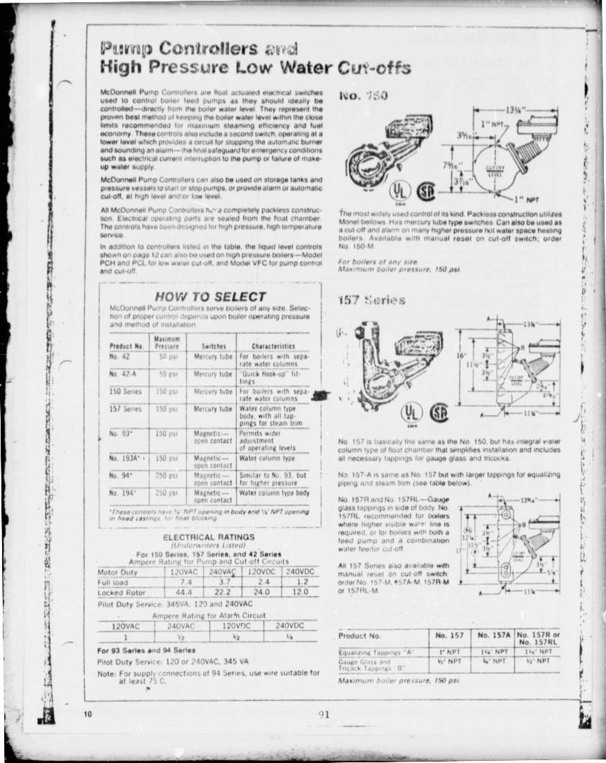
Pitiv to Controllers1-iigh Pressure Low Water CuY-offs
IN
yc'
t
'l
i
i
lip
A4c0twinell Pump Controue.s are fioal actuated eler,irifal ;witchesused to control boiler lined pumps as they •houkl ideal l y becont r olled—dreetly from the huger waxer level they represent meprovi.n best metnod ul keepiny the boiler water level *.thin the closelimits recommended lot nndunium steaming efficiency and fuelecont>.ny These controls also include a secoiM switch, operating Alalower level which provides a circuit lot stopping the .wtomatic burnerand sounainq an alarm— the hnnl sa feguard lot onwrfancy conddicinssuch as electrical current .ntvrtuplion to the pump a failure of make•up water supply
McDonnell Pump Controllers cell also be used on storage tanks andpressure vessel s 10 slaty of stop pumps or provide alarm ul automaticCut 0". at high level and or low level
All McOunnel Pump Controllers h. • a completely p.kkless conslruceon Electrical opotdlrng pans aie sealed front the heat chamberThe controls have Bunn designed tot high pressure, high temperatureservice
In addition to controllers listed dt the table the liquid level controlssho.vn on page 1.1 ban also bo used on high pressur y boilers —ModelPCH and PCL lot low wrier Cut-oM, and Mo0w VFC lot pump ControlAnd Cut-off
HOW TO SELECTMcDonnell Pu^rp Co ntrollefs serve txm pts of any size Se lec Ilion of proper Wntrol depends upon but ler operating pressureand method of installation — — —^^r
Ma,imumOfe^Ytf elf ^fefferf
i No 42 —
50 psi`
No 42-A I 50 psi
150 Series r 150 psi
ELECTRICAL RATINGSIfl'ultvnnrrtr •r! l rSrr•i //
For 150 Series, 157 Series, and 42 Series_ Ampere Hating for _Pump and Cu t-off Circuits
Motor Duty 12AVAC240V4 1 20VI _240VDC _Full load 7. 4 3.7 2.4 1.2Locked_ Rotor _ 44.4 22.2 1 14.0__jPilot Duty Service 345VA, 120 and 240VAC —
Ampere Rat ing, for A13r.4n C ircuit
120VAC 240VAC 120V 240VDC^C
--1^Vi - – Vz4a
For 93 Series and 94 Serles
Pilot Duty Service: 120 or 240VAC, 345 VA
Note: for supply connections of 94 Series, use wife !.uitabbe forat least 75 C.
ItiO. 'i;;0
ii.
Tt he most widely used control of its k nil Paclito" construction utdlaesModel bellows Has mercury tube type sw-tches Can also be used asa cut off and alarm on many higher pressure nut water space heatinghode r s Available with manual label on cut off 3wdch, orderNo 150-M
for boilers of any storeMax "'turn bullet ptetsure ISO psi.
1 Vii? ` tlriia
w A-^
37
r ^ I3^"—
.44
1 A Ili"—
No 157 is basically the same As the No 150 but has integral v,etercolumn type of float Chamber that simplifies installation and includesall necessdty tappings for gauge glass and tricot ks
N3 157-A is same as No i S 7 bul w.lh larger tapp,ngs fur equalizingp,ping and steam trim (see table below)
No 157R and No 157RL—Gauge A- ---13%6"glass tappings in side of body No {---1S1RL recommondetl for boilerswhere
uwhere fugher visible *,A , - lone is S- --- >terequired, or lot boilers with truth a 'c I ji. food pump and a combination ;— 'water fevilef cut off r Ili" ' r'
' ice.All 157 Sines also available with tom_ ihmanuai reset on cut off switch t ceder No 157 M, 957A-M 151R M t Zor 157RL M 1IIw ---of
Product No. No. 1S7 No. 157A No. 1S7R orNo. 15 7RL
—4 ina Tappings "A'FQU Ta N1' PT Ma'_
I N OT i sx' NPTGaulle Gins, and hi' NPT L' NPT th- NPTTncock Tapfi.ns, 8°
Maximum baler pressure, ISO psi
r.
rfi
1
Seltclles __characterlfticf __Mercury tube For boilers with sepf•
rate water colu mns iMercury tube "Oulck Nook -up" fit
_
__ linksMercury tube for boilers with stpa-
rate water columnsISI Serves 150 psi Mercury tube Walef col umn type
body, with all tapI
_ - Dings lot steam trim
No 93' 150 psi Magnetic - Permit-, *.der Iopen contact adjustment
of opef Along levels I
No. 193A' • 150 psi Magnetic— Waiec column type_ - optn contact----
No 94' ?50 psi Magnetic -- Similar to Nc 93. but__ open contact for higher ptessurt
No 194' 25U per Magnetic— tNster column Grp: body Iopen con tact _ I
'IApecvnrro1shavr'4 NPl opening onbudy end 'lt-NPTuperompofthood cest ,ny3 ' floor blacking
13'A°1.. Nm7
A 10 1) 1

Flog Switches
I
No. FS4-3 find No. F A-3D3"
Y l•;. ♦ 1
TtI
l^ JIs1 I NVTWa No, FS4 3
31/16•,
i
Extended paddlefor larger pipe
Included.
Compact moderately pnced Mow swrlch lot service on water Jonesprincipally Has slnyle pole douole Into* switch-can tw wired tomake one circuit Weak a second. when flow it no flow occur% Allpans on contact with squid in pope are ul Dress solder Arid MonetFeatures inc l ude completely packlo%b construction and easy adjustment of smich sensitivity It • drvodual paddles are adaptable for pipe 1to 3" NPT. an extended paddle for larger pipe also included InstallsIn tee or we lding neck In horizontal pipe, has V NPT threadedoonnor'tron
No FS4 3 has one SPOT switch No FS34 . 3D has two SPOTswitches to handle two separate circuits E lectrical ratings page 15
These Now swdcheb are Also AvarlatAe with time delay relays, toeliminate fuf se signals caused by turbulence r she page 191 Order NoFS4 3-5R for 5-5ecured delay on break. No FS4 3 20 for 20 seconddelay on makeMaximum pressure, 1 50 psiMaximum temperature, 300 f
Flow Rates Required to ActuateNo. FS4-3 and No. FS4-3D
Water flow rates in yauons per minute IIiPMI shown .n blackVelocity in lest per second (FPS) shown in color
Plot SiteFmelerLer N I_slwso AI(estslesl
FLBW NO FLOWGPM FPS GPM 11 P1
FLOWGPM_I'PS
10 2
- M811mvrtl
391
A/feslaleatNO FLOW
GPM_!92
_
"N
343V 60 214 31 234%, 94 2 11 54 1 21 lb 8_1 62 15.0 3 ?.1I 12.7 2 00 70 1 10 23 0 ib2_ 19 5
24. 03 072_: q r 18 8 1 80 9.4 0'In 32 8 5 I t
244" 241 163 11.6 0 7 8 42452 1
7 7471,
37 546 1
2 'r i7 UOr 30 0 1 30 120 0 52
4"' 39 f-f 00 1 9. 8 0 50 73.5 186 W 2 1 ;25"' 58_ 7 0 w 293 0 4/ 1150 1 45 92,0 1 48
79 2 0 8-8 39_6_ fl 44 1 Ce If 1 4A 123.0 1 17_'EQwPper! with extended paddle (cut for 4" and 6.. pope)flow, retire ere everapes which may very - 10% from rabulaled values
No. r;7W
M' NOr
""^• 1 tz-1i14`- 1
^^Nre
GO 1 Near
No FI'aV 3is..,LAtefilded 1,.eddl0for Isn;er pope
included
Provides vapo r p 'ruot roostru .:pun In an economically priced.cnrTr,rul Stii+lrt7ti^WRch Vunrculterly buffed tot use in areas of highhurntdrly, and fir out uf •000rswst lAW Has adlustrrwnt for senealhr-oty to flow pack!ues c , ruCt,on, welled pans of brass, solder a-idMoines Indlvrdurl pd00105 are adaptdWe to, pop* 1" to 3'. extendedpaddle for larger pope os a13r1 uxrucW kinlaks In tell or wokbng rack onhontpnla o pope. 1 Iftfedied Mnnot fion
Electrical ratings brown on Faye 15
Time delay relays are avadaWer to euminal9 14144 algnals caused byturbulence •.ire page 19M,rxrmrsm pressure 150 ps1.Maxlmu r; rernperarure, 126 f
Flow Rates nequl.ed to Actuate No. FS8VWater flow rates on gauorls per minute (GPM) shown to Mack
Velocity in war second !FPS) shown on color.
feetery or NrMlaoMl A4fuslrxext-
Name"" AIIall sNt
Pope Soso FLOW NO FLOW FLOW NO FLOWG3M p' GPM r!S ^rPM--IP^ ream FPS
V 4.9 1 A2 3.4 1.2ti 17.6 6 SJ 1_5 0 5.;6I . nil S. 3 l 29 . 0_6.23 24.6 S. 28-
9 4 1 .;(3 6. 7^ 1.u, 3 7.8 5 95 32 2 S.07F114-
13 177 94U. ,'ti 56.4 5.39 47.4 4.h3_245' 1 7 . 9 :.'U 12.1 0 8 1 7 1 . 3 4711159. 2 '1 .973" 24.2_1 U' 164 U 11 8_9.0 3.87 72.5 3.154- ' 35.3 0 49 27 0 0 68 11 8.0 2.98 , 10S.0 2.645"' 48. c_0 /f 37 4 f1U_U 178.0 2 66 160.0 2.576"' 60.3_0 67 46.8_0.5: 245.0 2 72 225.0 2.50
'EVurvoed w,th extended vaddrr Icuf for r end 5' prpislflow rotes Jre averdper winch may very t ro% from tabulated values
Poo. FS4-3F and No. F57-41: Minimum Flow Rates Retuired to ActuateWaterflow.indicrtors
Waterllow Indicators
I Listed by Underwriters Laboralones for service as a waterflowIndicator on branch piping of fire sprinkler systems Used topinpoint location of open sprinkler heads-to speed life f ynt
No. FS4.3F.-F,,. 1 1 : and 1St' branch piping
No. FS7 . 4F--For I s,.' o'v'a and 2 t 'i branch piping
Both W AlerfloVlr In(sc alor:S are actudled by a (low riles o f 4 to 10ng and minimize walor damage Construction dimensions andgallons pe r minute kGPM) In all pope sow. Irsled about.electrical ratings same as for No F34 . 3 (page 15) and No
FS7-4 (page 18)Maxlrnum prtssu,e' Nu. FS4 3F, 150 psi. AI No F54-3F can be furnished with lime de lay relay (%ee pays 19).
No fS7. 0, XA psi \Z L/order No FS4 3F 20 Time delay re l ay is also available for use withMaximum fernperarure, 300 F. pionNo FS7-4F (see pago 19)
11
- - - - - _--- Tjtr••••F
16 --,-.., - - -- a► , >, .IFpr TL.. ^.i^ `c-saAft.Bi#^.:^:...:.^sotltrt
rX11,... •=_-- - - - - - - - ...A
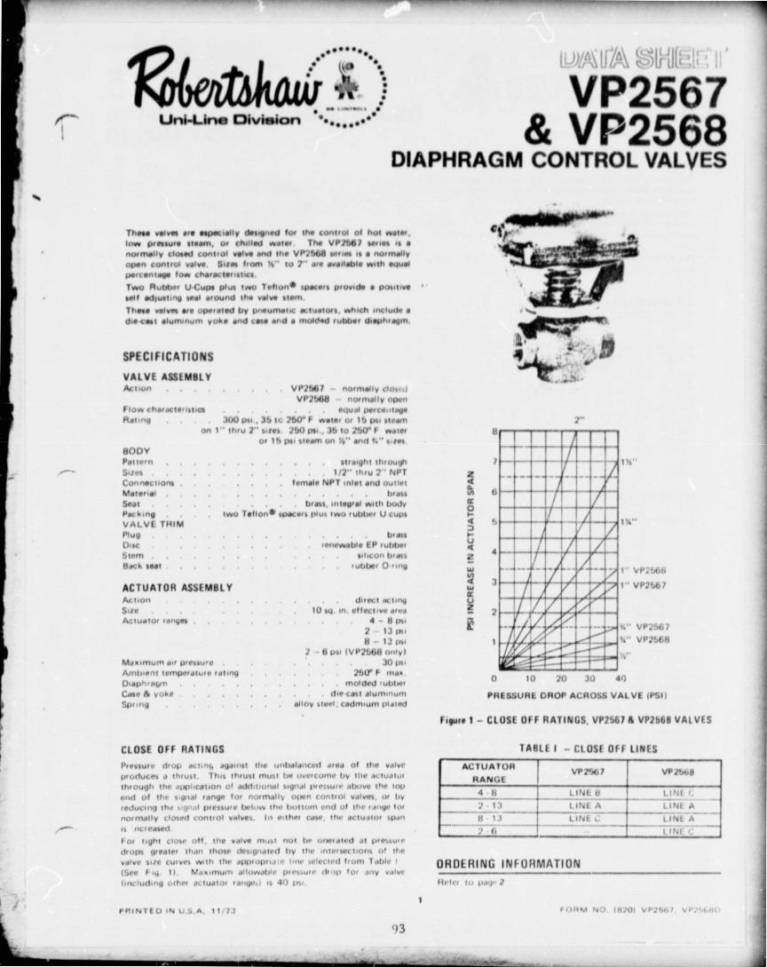
•Win
of
Uni-Line Division ••.•••e.•VP2567
& VP2568DIAPHRAGM CONTROL VALVES
°frr+
ij,i .'r
These valves are especially designed for the control of but pester.Ines pressure warn, or chilled water, The VP2661 s.naa is anormeliv closed control valve and the VP2bb8 series is a normally,)pan control valve. Sites front 'h •• to 2" are available with actualpert entaga foes characteristics.Two Rubbe r U Cups pl us two Teflurt e spacers provide a positivesell adlusWiV seal dround the valve slanThose valves ue operated by pneumatic actuators, which include adie cwt aluminum vuka and come and a moNAed rubber diaphragm.
SPECIFICATIONS
VALVE ASSIMIJLYAction VP1b67 — normally clospef
VP2b68 normally openI low characteristics ectual perca^rteyeHating 300 psi , 3b t(. 250• F want of 1b per sit-din
on 1' • thru 2" sites 25U psi , 3b to 250• F waterOr 1 h psi %loam to %s • ' Mt) 1 4° sslfN.
BODYPattern straight through
Sites 1/2" thru 2" NPTConnections female NPT inlet and outletMaterial brass
Seat bras, integ r al with budvPacking two Teflon' .pacers plus two rubtwr U cup%VALVE THIMPlug brassUtsc rneweble EP rubtwtStem %ilicun brdss84r:k seat ubber O 11#19
ACTUATOR ASSEMBLYActionSite
Actuator rattles
Maximum air pressureAmbient temperature ratingDiaphraw)Case 6 yoke$pang
. direct dcLiny10 sq.in . effective area
4 - 8 in,2 13 lis p8 - 13 psi
1 6 psi IVP2b68 only)30 p».
260' F tuh.molded ubtwr
are cost alumuiuttalloy steel, cadmium plalnd
H
/ 1'1
b
Is.,
1 • ' VP2b6H1" VP2Lb1
%" VP2567W , VP2!i6H
10 20 3U 40
PRESSURE GROP ACROSS VAl VE (PSI)
figure 1 — CLOSE OFF RATINGS, VP25676 VP2b68 VALVES
ZQ0NtY
0QHUtZW
WCr
U2
K
ti
4
3
2
1
0
CLOSE OFF RATINGSPressure drop dctnk J6Jnilot the unitalanced dtea of the valveproduces d thrust. This thrust must Ire nvereunte by fli p m twilurthrough the application of aslditiunal signal pteitco • aletve the loppod tit the s gttal range for nurrnalls open control valves, ut byreducing the + 9r.rl pressure below the liulturn end of Iht • rang%• luxnormally closed control valves, lie either caw, the detudtut spinis ocreased
too light close off, the valve must not bu r urwialed at pie»uredrops greater than those designated by the inletsecliorrs u! thevalve site curves with the appvoprra •• Imp selected from Table I(See Fig. 1). Naximum JII11Wd6le pleswi p drop fu oily valve(irli lulling other do.ludlut tdn44 • .1 is 40 go%.
TAHLE 1 — CLOSI Off LINES
ACIUATUR VP2%7 VP1bb8RANGE
4 is LIN E 8 LI N! i.2- 13
_ _LINE A LINE A
8 13 LINE : LINE Ai1Nf`r
OHDEHING INFORMATIONHr•Iry lu pdy 1
PPINTEU IN U.S.A. 11/73 FORM NO. (11701 VI'756/, VP.,!,,
93

s
1
t
f sax c
aj }
I II
i rro
_ t r
r 080/ k rsc
'n oap^ox, 1 ^ ^ es
1
IILNQO
r-UQzWIaU2
K
lMANG°a MWk2kIf
VP2566CONTROLS COMPANY DIAPHRAGM CONTROL VALVE
Uni-Line Division 3-WAY MIXING
Tt1is valve is especially designed for the control of either hot wateror chilled water, and it available in soles 1/2" through 2" withlinear flow characteristics
Two Rubber UCups plus two Teflon* Spacers proved6 a positivesoil s4usting seal around the valve stem. Service lore of the seal isgreatly extended by the use of a stem "de of ontofoul-ng siliconbf assThe valve U operated by a pneumatic actuaror, which includes adiecest aluminum yoke and case and a moldrrl rubber diaphragm
SPECIFICATIONSVALVE ASSEMBLYA, ilull toes port normally <losrd
bottom port normally openFlow character.st.c linear Iconstant total flow)Hating 300 psi, 35 to 250' F water 1" thro •Agh 2" %rtes.
250 psi, 35 to 250' F water - K" arid ti" sites.RODVPattern a 3-way (integral bonnet on 'b" and fi" sites)Sites 14" through Y' MPTConnections . . . . female NPTMmof ivl . . . . . brassSeat . . . . . . . brassPack ng . . . , two rubber U-cups plus two Tefton e spacersVALVE TRIMPlug . bras%Stem silicon brass
ACTUATOR ASSEMBLY5.[e 10 W. in, effective areaSpr ' ng ranges 1 - 5 psi
4 -8psi2 - 13 t„•8-13 psi
5 - 9 ps. iti", 1i" 8 1" site% only - also suppledon valves with positive pusotouners
Md n utium air pressure . 30 psiAmbient temperature rating . . . . . . . 225' F max.Diaphr4gm . . . . , molded rubberCase and yoke . doe -cast aluminumSp • .ng alloy steel, cadmium plated
0 10 I,, 10 bPRESSURE DROP ACROSS VALVE (PSI)
CLOSE OFF RATINGSPressure drop acting against the unbalanced area of the valveproduces a thrust. When the pressure in the normally open port isgreater than the pressure in the normally closed port, the additionalthrust must be compensated for by additional signal pressureapplied at the top limit of the actuator range.Conversely, when the pre.sure in the not really-closed port isgreeter than the pressure in the normally-open port, the additionalthrust must be compensated for by a decrease in signal pressure
at the low limit of the .cauator range (See Fig. 1)
For tight close off the valve mutt r,ot be operated at pressuredrops greater ther th a ne designated by the intersections of thevalve site curves h.th the appropr s i no selected from Table 1$See Fig. 11. Maximum aflowdb iressury drop for any valve(including other actwtor rdnges) Is 40 I s..
0RIGIr,IAL PAGE ISOF POOR QUALr y
Figure 1 — CLOSE OFF RATING, VP2566 VALVE
IABLE 1 — CLOSE OFF LINES
ACTUATORRANGE
IPSII
NORMALLYOPENPORT
NORMALLYCLOSED
PORT1 -5 LINE C LINE D_
4-8 LINE C B
8 - 13 c IN E A LINE C
2 13 LINE A LINE A
5 9 LINE E LINE E
ORDERIN G INFORM A TIONHefei to pile 2
PRINTED IN U.S.A. 11/73 FORM NO. 18701 VP2566D
0/4 1 560

95
9N _WRING RANGE
1 5
4.82.138.1315 .9►OSITIONER1 5^ 8
2.138 11
5 9
POSI T I ONE 111 5
4.8
2.139 11
5 9
POSITIONEN1.5
4 8
1 13
8 11
POSITIO'IER1 5
4 8
2.138 13
POSITIONER1.5
4 8
2.11B-13
POSITION[ N

TABLE I I - VP2566 DIMENSIONS AND WEIGHTS
71A SIZEDIMENSIONS IN INCHES WEIGHT
ILBS)A 8 C D E F
1/2 4 .9/16 1-15/16 4 .5/16 1 .3/8 1-3/8 2.3/4 3.1
3/4 4 .23/32 2.7/32 4.5/16 1.19/32 1.19/32 3.3/16 3.4
1 5.29/32 3 .318 4.5/16 2 .1/2 2.1/2 5 6.9
1-1/4 5 .29/32 3 .3/8 4.5/16 2-9/16 2.9/16 5 .1/8 8.0
1 .1/2 5 .29/32 3 .3/8 4.5/16 2 .9/16 2-9/15 5.1/8 8.0
2 6.5/16
1
3.25/32 1 4.5/16
13 .3/8 1 3.3/8 1 6-3/4 1 16,3
TYPICAL APPLICATION
TP2210b M
SPACEITHERMOSTAT
D. A
VP2G66TO f VP.?66d
N.C. COIL N,O, TO COIL8 TO 13 PSI f' m TO 8 PSI
CXR.C N. C. N. C. C N.W.R.N. 0,AIR
IR
C'W.S.N, 0=
A
.f— H.W,S.
OUTSIDEAIR
DIS A ARRGE
RETURN ,_,O_\ --/"' COL OLIN HEATINGATI^NyGAIR / COIL COIL
A. H. UNIT HEATING AND COOLING COIL CONTROL
INSTALLATIONControl v:,^Nes are sized to the demand of the system to be 1, Install a pipeline strainer lust ahead of the valve.controlled and are frequently smaller than supply lines. They 2. Allow sufficient clearance that the valve may be easily servicedshould be installed as close as possible to the coil being controlled, if necessary.Preferably, a control valve should be Installed in the vertical 3. A minimum clearance of 3'h" must be allowed between theposition so the actuator will be over the valve, but can be installed extreme top of the actuator and the nearest obstruction, ThisIn any position If necessary, permits removal of actuator yoke and parts required to replaceWhen Installing a valve, these simple precautions should be taken: packing, '
p_E^1
_ '-1
IL 96

MAINTENANN AND h[PAIR
Thor VP.'ll" • r,148 11 rs %*IV molls , nN1111/ r1 M p 0 Gflrl pf,ywo nl\l./ll ♦ follow '.lj I 'll„ %14%U1 I,aH\ IlroNnl/rll44 ,111 11 . 1 Iw.•/n11Nn.Mo1 that looilo 10114.44 Iw h44lrl yd h1 It...
Y 111 go% I
a_ 1.
1♦ ^1 1
Tor i
" I
N ^—
I
L
V ti1.'1
„t '.1' 1r • . 111M1
♦ ^ '•111
1 F4 1
y. o
•vvl 1
,1, ., I lil'1e11 luSue
Im P,u1 Naim- 1M
l lyulr 1 vrih li VAI VI ASS! 441111 Y
M:KING NI PI AI'1 %1t N 1 li NN.n.Nlll• . 1 Ill, SlNUIy Seat 161 Mhl Sprang Atllollh•1
11 11rm ir,11,.W . ,•^. r U ^'up 11.11'Alnpw r th Ihl Nr„ .,1a "A" a" towo11Mll ul S tott • tioovNN/
I Iolloo", / 1. ,I A\wIIIIolt11 1'.111" (. .1 dlhl 41 tNl
1 IiN111,,1r 1 ,• N. 11i I N ,,Ar 1' .11111 AN191111 ,y1 1 1`I nr W 1 11 , Damp Noll (131.
1'.111• I. 1 1' i "h,111N11 hull N1 .
A11 1 .N11 1 1' 1 /N P410 111Stem ."M 1'111/).00, '. l Ills\ ,,Ih • 1 .1111N1,
VAI VI I'I UL III Pt ACI MI N I.rl
If r rn,, ,unlrn`11 ,1hr^ , ,I .^ 11 111y III
til,'^^' ' I I1 r' (I,M - ^ 11111 \I1, 111111
1 1 1 111 p PMkofwj II.I Ih• r111tH^ 1\ It'11.h '1'll11 111 the 11111`111.1 ) 11.',` ',v1to", 1'.h'A 44111 Hold al r
1 I; Ilil •.11 11!0) lirul,rvr ,Hd
1 I 117` vIW Valve li,vly I1!11 .144.1
^. •1 1' ,nkitll "1'.h A,nl IIrIH,h r
1
ROBERTNH AW CONTROLS CO. UNI LINE DIVISION P.O. BOX 2000, 4190 TEME ° CAL ST., CORONA, CA 91720
47

ACTUATOR ASSEMBLY VP2510
ACTION ON SIZESFor use on VP2610
Direct acting 30 and 80 sq.in.offective area.
Reverse acting 30 sq. in, effective area,For use on VP2511
Direct acting 80 sq. in, offoctive area.
VP2510 and VP2511 are available with positive positioning relays,
ACTUATOR RANGES 30 in,2 size 80 1n. 2 size
2.13 psi 3,12 psi2.7 psi 3.7 psl
8.13 psi 8.12 psi
••
1 +..*4
CONTROLS COMPANY •' • .. • ..:Unl•Lino Division
[I-NAIM SHIIE(EU
VP251 &VP2511
DIAPHRAGM CONTROL VALVESSINGLE SEATED
These Control Velvet are especially designed for the control of hotwater, low pressure %foam or chilled water,
The velvas are single seated with renewable discs, Sizes f--;-m 1.1/2"to 4" are available on the VP2610 Series, while the VP 4, r , Series Isavailable in 2-1/2", 3" and a" sizes,
On sizes through 2", the characterized plug is stem guide dmounted by an antitorque swivel .arrangement. The sizes 2.1/211,3" and 4" ire double guided, These features provide accurate seamIng alignment and quiet operation under high flow conditions, Onsizes through 2" the valve body and bonnet are provided withconical seating surfs to Insure accurate alignment and to providea leak-tight Joint which can be readily loosened for servicing, Onlarger sizes the bonnet is bolted to the valve body, A locating bosson the bonnet insures accurate alignment.
The valve Is operated either by a 30 square inch or an 80 square Inchactuator assembly depending on valve size and type of service. Thedeeply convoluted molded diaphragm provides constant area charac-terlstics throughout the stroke for excellent linearity.
The actuator assembly can be easily detached from the valve withoutaffecting the valve body or its components.
All parts con be replaced without the use of special tools.
SPECIFICATIONS
VALVE ASSEMBLY
Valve action . . . . . . .
VP2610 — direst acting IN,OJVP2511 — reverse acting XC.I
Nominal size 1.1 /2"--2" 2.1 /2"-4"
Connection NPT Flanged
Service rating 300 psi for 260' FWater or 80 psi steam
125 psi for 260° FWater or 80 psisteam
Disc material Renewablecomposition
Renewable hardrubber
Body material Brass Cost iron
Seat material Brass (integral) Bross
Valve stem material Stainless steel Stainless stool
Flow characteristics Equal percent Enual percent
STEM PACKINGSteam .WaterClose off rating
ORDERING INFORMATION
? Refer to pages 3 and 4
^'^ ►.c= .1rYle^
^r
r
MODEL VP2510
Maximum air pressureAmbient temperature ratingDiaphragm
Case . . . . . . .
35 psi200O F Max.
Molded rubber, nylon reinforcedMe cast aluminum on 30 sq. Inch size
Pressed stool on 80 sq, Inch size, Cast iron
Alloy stool, Cndmium platedTeflon, spring looded Yoke. . Rubber U-Cup Spring
. . . . . . . , see next page
PRINTED IN U.S.A. 12/73 -98 FORM NO. 1820) VP2510,VP2611'

CLOSE OFF RATINGS AND ACTUATOR SPRING ADJUST-MENT aPressure drop acting 0gtutst the unbalanced area of the valve For tight close ,olf, the valves must not be operated at pressure
k iuhowset a thrust which mutt overcome it ►e actuator as drops
rforan b ►
'3 those t^^f tN u
anI
i inte rsection s to the valvesrxa ctpvas will) L ino A far an 1 t ►si or fJ
psipit actu at or stkn or
Normolly--Open (;antrol Volvas• The , thrust must ba compensatedfor by additional signal preoura applied aft ilia top linut of tit+ Normally ppan Control Valves require oil to signal above jactuator ra ►tga, the tap and of tongo to compensate for pressure drop across valve. 1Pressure drop across normally-closed control valves requires r INormalty , Closed Control Valves. Tile thrust must be applied say decronse in signal below the low end of 101190, or an adjustment inadditional spring load at tilts low limit of the actuator ronlio, sprbt9laodin(l. fEither of these Conditions increases the actuator xpon when iliavalve is operating under 0 pratsure , diflownti,d, Faltuto 1 illustrates
TABLE I ACTUATO R SPRING ADJUSTMENT DATA
ACTUATORNOMINAL
ARFA1111,2 )
ALLOWABLE ADJUSTMENT OF STROKESTARTING POINT
2.13 2.7 8. 13 342 34 0.12
30 Oto a OtoO oto la -ba acaEi atn,t Uta ti
30 IN ACTUATORAO IN ACTUATOR
f!IA 00
7
e
O S
t 4
WN9^3^s 2
r1
0 20 40 QO 80 100 120
PRESSURE DROP ACROSS VALVE: (PSI)
ie,
a
i a'"
t
1W
V
z
U 10 20 30 40 $0 e0
PRESSURE DROP ACROSS VALVE (PSI)
Figure 1 —CLOSE OFF RATINGS OF VP2610 & VP261i VALVES

100
:. e^t"y6..d 1, - ...ce^f?hs'w^,4^tl3Rai•rl^ it
ACTUATOR
EFFECTIVE SPRING RANGE ORUNI•LINF.. FACTORY SIZE Cv ACTIONTYPE
NUMBER MODEL ( NPT) AREA POS, POSITIONER PACKING
VP2510 .001 V1002.35406 AIR 2-13 VP2510 .002 V 1 002.35404 TO 2.7VP2510 .003 V1002-35407
CLOSE6.13
VP251.0 .00A V1002364iD POSITIONER TEFLONAIR 2 • '`3VP2610.008 V002.3ti606
VP2510;000 V1002.35604 TO 2-7 VP2510 .007 V1002.35607 OPEN 8.13VP2510 .008 V1002-35619 1.1 25
AIR
POSITIONERVP2610 .003 V1tlAU•3640 1'' 13VP2610.010 V1000-35404 TO 2-7 VP2510,011 V1000 .36407 CLOSE 8. 13Vp2510,012 V1000 .35414
V10'Ua"J6'roPOSITIONER U•CUP
I'ZG1 4113 2.1VP2510=014 V1000.35004 AIR 2.7VP:N310.015 V1000.35607 OPEN 8.13VP261D•016 V1000.35619 POSI TI ONERVP2Ri1t7 .017 V1002••10,106 AIR Z.1,1VP2810,010 V1002-40404 TO 2.7WM10•010 V1002.40407 CLOSE 8.13'a251D 02U V1,002.40919 PG?SITIONER TEFLON
AIR 2 1.1/P2610 .021 V10'd,.A0606VP2610 .022 V1002-40604 2.7VP2610 .023 V1002.40607 OPEN 8.13VP2510.024_^. V1002•40619 2" 40 30 POSITIONER
AIR 2 ^ 13lr
VP2510 .026 V10UU=+^OtlUlVP2510 ,026 V IODO .40404 TO
2-7V02610,027 V 1000x$0407
CLOSE11.13
VP2G10.028 VI 000-40 ,119 POSITIONER U•CUPV1000.1006 AIR 2 = 13VP2510 .026
VP25iU-030 Vi 000.4010 2.7VP;510.031 V1000 .40607 OPEN 8.13VP2510.032 VIOOO .410019 POSITIONERVP2610.033 V 1002•,16405 AIR : • 13VP2510 .034 V1002.46404 1 O 2.7VP2610 .035 V1002-45407
CLOSE0-13
VP2510.036 V1002 .46419 POSITIONER TEFLONVi02 .46606 A11j 2 •13VP2510•637
VP2510 .030 V1002 .45604 2.1/2" TO 2.7VP2510.032 V1002 .46607 FLNGD. OPC N 8.10VP20io•D40 V1002.45619
AIR
n POSITIONERVP2510•o41 V1061 5406 2.13VP2G10 .042 V1000 .45 ,104 TO 2.7VP2510,043 V10D0.45407 CLOSE 8.13VP2610.044 V1000•9C91 72 POSITIONER U•CUPVP2.510 .045 V100045606 AIR 2-13VP2510.04 6 V1000 .45604 1.0 217VP2510.047 V100U•45607 OPEN 8.13VP2510,048 V1000 ,46619 POSITIONER
3 = 12VP2G10•04J V1 g02•%16515VP.2510 .050 V1002.45503 2.1/2" 1'10 >
3 TEFLONV1,2510-051 V1002.46617 CLOSE
8 .12VP2510•082 V1002.15519 80 POSITIONERVP2510.053 V100046515 Al
3.12-
VP2510 .054 Vi0D0 .45503 103.7 U•CL1P
VP2510 .055 V1000.45617CLOSE
8.121lP2510•056 V1000.4551fl POSITIONERVP2510,657 V1002.61406 AIR 2.VP2510 .058 V 1002-61404 TO 2.77VP2510 .059 V1002 .51407 CLOSE 8.13VP2510060 V1002 .51119 _ POSITIONER TEFLONVP2G10 .O6) V1002 .51606
IR2.13
VP2510 .062 V1002.51604 TO 2.7VP2510 .063 V1002•51607 OPEN 8.13VP2510 .064 V1002.51619 3" 102 30 POSITIONERVP2510-065 -0000r6 1406 AIR 2.13VP2610 ,066 V1000=51409 TO
2.7VP2610-067 VIUOO.51407
CLOSE8.13
V132610-0680^OG8 V 1000 .5141 fl S(, JONER U•CUPVP2510.069 , V1000 51606 AIR 2 ` 13VP26WO70 V1000.51604 TO 2.7
_EVP2610.071 V1000.51607 OPEN 8-13_VP2510-072 M1000,61619- POSITIO'NPR
ORDERING tIfFORMATION
VP2510 SINGLE SEATED CONTROL VALVES .- EOUAL PERCENTAGE FLOW CHARACTERISTICS

IANOE ORATIONEN
TY ►EPACKING
I ON E R
TEFLON
ION E R
U•^ UP
TEFLONIONF-N
1 ON E H
IONEH UCEN
ONE R
IONE R
TEFLON
U CUP
INNER
VP2b 11 001VPI511 002VP2S11003
VI 102 45515VI 1024550)V1102-46617
3 123-78.12
TEFLON
VP2511 004VP1l,II oob
_ V110245519V11004 SIS
1!2" 72 PO ITIONI H3.12
vP2l,1 1 We-VP2511 0411
V 1100 45b0JVII(X)45517
3 78 12
U Cup
VP2511 008P.,!,1 1 oo9
VII01145519—V 1-1y5 1s-1
POSITIONER1
VP2511010VP2511 011
vI10. 51503V110: 51511
AIR 3. 78 12
TEFLON
VP2511 012VP2511013
V110251519 3. 102TO
OPEN 80 POSITIONERV1 loo.51b15
3 12
VP2511 014VP2511 015
V 1100 51503VI 100 .5151 1
3- 7S. 12
U CUP
VP2511 016VP?511017
VIIW-51519 POSITIONERV1101 bb l, 15 3 12
VP:511018VP21 ,11 019
VI102.55b03V 1 102 5551 1
3 78 - 12
TEFLON
VP2511 020 V110: 55519 4 164 POSITIONERV1100 55515V 1 100 55503V1 100 5551 1
3 123. 18 12 U CUP
VP2b11021VP251 1 022VP2!,1 1 023VP2511 024 VI10055519 POSITIONER
101

ka - c ..I
AUXILIARY VIEW
G- DIA. OF FLANGE
H—NO.OF HOLES
J- DIA. OF HOE ES
orve
#rower
n a
INSTALLATION
lwrtr of valwir err srteJ to the Mmend of the lyslem to tw aon-trolled and see Iresluently smaller than sulgtly line Rtes. Theythould use rrs.tallel M close as possible to the tool b.imgconlrolledPrebrMsly a Control valve should M installed on the vertical positronso the actuator mill be over the valve but can use installed in any{KHriron if necessary
When installing a valve, these simple su r0cautiont should be takvn
1. Install a pgselrne strainer lust arteatl of the valve
2 Install the valve so of c loses a,ja-nsI the flo tiv— 1
J. Allossr, sufficient Clearance so that the valve may tar #•asilyserviced
For a VP2b10 Set es Control Valve. Clea r ance is #*Quoted only abovethe Kluator. With sufficient Clearance above the aCluator, both the -7actualor and valve plug can be easily removed. See Tabl e It 1nrrequired cl*a,vuces (dimension E)./or a VP2511 Series Control Valve, the same clearance is re#pu,edattov* the actuator as #s required for VP2510 normally open tontrolvelvet. Hot revvr due to the fact that the va've plug assenthly #so
be removed front the bottnrn of the valve body, clearance :,1st roeallt,"d for this purpose Sir Tal,le 111 for clearance (domor,is-oot F). (—T^1 ] A
ACTUATGRSIZE Itn -'1
NP (Inc hiss I
30 I'If
10 1 to
K•- DIA OF BOLT CIRCLE
Ftgtlre 2 - UIME NSIONS
DIMENSIONS AND WEIGHTS FOR VP2510 VALVES WITH ACTUATORS TABLE It
r
___FSIZEACT.
ARFAACT. ` DIMENSIONS IN INCHES _
ACTION A B C O F F G H J KWT
MBS I
1 1 2
1112
30 DA 17.7/16 1.718 5.118 9 3 1
1
1
— — — 21
30 RA 18.3132 1-778
2. 118
6.1/8
- 6.3/4
8.314
9
11
3
3
- - - - 21
2 30 D.14 11314 _
18.13/32
- -
-
- - 28
2 30 RA 2-1/8 9
9
3
6
1
1
- - - 28
2. 1/2 30 DA
RA
?3.13/32
24.1116
358 10.7/8 1 7 4 3/4 5 . 1/2 61
2 . 1/2 3,; 3.5/8 107/8
10.7/8
11.3/4
9
13 . 61
9
6
6
- x
1 7 4 ;14 5. 1/2 51
2. 1/2 BO DA 24.25/32
24 3M
3.5/8
3.15/16
- 1
1
7 4 3/4 5 . 1/2 96
3
3
30 DA _ 7.1/2 4 314 6 59
30 RA 2513/32 3. 15/16 1 1.3/4 9 b 1 7.1/2 4 314 6 59
3 80 DA 761/8 3.15/16 11.3/4 13 .518
_9
6 1 7.1,12 4 3/4 6 104
4 30 DA 25-31/32 4. 23/32 13.718 G 1 9 8
9
9 v
3/4 7-1/2 83
4
- 4
30 RA 2658 4.23/32 13.7/8
13 7/A
9
13 .5 B
6
6
1
1
3M 7 . 112 83
80 OA 21 1 71/32T4 ?.t' 3? 3/1 7-1/2 12i
DIMENSIONS ANC WEIGHTS FOR VP2511 VALVES WITH ACTUATORS TABLE 111
SIZEACT.
AREAACT
ACTION__ __ _ ___ _ _,-DIMENS I ONS
A B C
IN INCHES _
D E F G H J KW1
iLBS.)
962-1/2
3
4
RO
80
OA
DA
24-31!32
26 . 1 3/3227 11116
4 : 1 32
5. 25132
6713?
10.7,8
11.3/113.7/8
13 .5;8
13 .5/8
6
6
13
14
7
7 1 /2
4
4
314 5 . 112
3/4 6 104
81 DA 13 5r8 6 15 ' 9 - - A 3i4 71 '2 178
NOTES 1 Add J/4 • ' to dimension ' A when a Positive Pos uononq fit-lay is used2. Add 3 . 3/4" to dimensions "A" when 8 12 psi spring n used with AO in 2 Actuator
102

2 1/2" Through 4" Site
ACTUATOR stemAY11aa1 v
IPLit NUT
TRAVI L 11100ICAT 10
TRAVIL INDICATOR KALI
VA► VI $TIm
ADAPTI R C t A:aP a Got It
7
VALVE STF.
PACKING Nl
E PACKING EOLLI
PACKING
I---^{ SPACER
ADJUSTMENTS
he* ause of pressure aondruOns in the system, It may be necyayry to turn 1 ►Ie SPnnq Adjustor cluckwrse, looking at the top of a DAM1lust the actuator stoke starting point To raiM the Itat t Ikvnt, actuator and counterclockwise on an RA actuator
M AI NTE NAN C E AND REPAIR
The VP2510 and VP1511 Series Valves requne little maintenance field repairs tre foonsted to replacement of Packing and Valve Discsafter proper Installation and adjustment 11 is recommended that
ACTUATOR REMOVAL ISae Fig. 31
to wevrce the valve, remove the actuator as follows
1. Disconnect Valve Stem (21 from Actuator Stem Assembly IF 1
Orr normally-closed valve aCtuator assemblies, appl y sufficientair to move valve disc off seat Remove Pin Connector111 or Spli t ";at IKI
2. Where applicable remove Indicator IWI Nrinove Clamp Nut(171 or A.taotaa anti Bolts (321, and drsenipy actuator assembly
F ACTu CtoN slimAwl met .jl.
M I I Tr,AVII INDICATOR
1 PINCOMNICTOR
s ) TRAM 1,INDICATOR KALI
VALVI Slim
CI Ante NUT
1 1 /2" Through 2' Site Figure 3 — ACTUATOR REPLACEMI NT
O
1 VALVE STEM
1 PACKING NUT 3
1 PMSNER" y,
4 PACKING FOLLOWER 4`
1 PACKING 1
^' / SPRING PLATE 1
^^'PACKING SPRING I
1 1/2" Thruugh 1" SizeTEFLON " V RING PACKING
2 1112".Through 4" SiteTEFLON II ' I V RIN1; PACKING Through 2" S1ta
2-1/2" Through 4" SiteU CUP PACKING
U CUP PACKING
Figure PACKING REPLACEMENTPACKING REPLACEMENT ISee Fig. 4)
If valve stem leakeue .s encountered. Pack,ng (51 should be replacedas follows
1. Remove actuator as outlined under Actuator Removal."
2. Rernc .e Packing Nut 131
3 Remove all parts from packing cavity
4 HP sure packing cavity in Bonnet and Valve Stem is Clean.
5 Installation of new packing.
a. Teflon V•Rong Picking
Install Packing Spring IS) and Spring Plate (7) Install newPacking (5), Pat king Follower 14) and Washer let Beforeinstalling new Racking (5) apply a small amount of valveseal lubricant to valve stem under each V Ring. When sliding
Packing 1 5) over Valve, Stem (2) DO NOT DAMAGE SEAL-ING LIP Install Packing Nut 13).
b Rubber U•CuP Packing.
Install Spacer 16) Apply a bead of valve seal lubricant,round valve stem and push a rubber U Cup Packing (5)over stem and into packing cavity, thereby l ubricating theInside dianio-let of the U•Cup and filling the annular grooveIn the U Cup with lubricant.
Repeat this procedure with it U Cup Packing 15),tak-nq care with each V Cup not to damag e the sealing lopInstall Packing Follower (4) and Packing Nut 131.
6. Tighten Pdckinq Nut (3) to positive stop.
ORIGINAL PAGE IS103 OF POOR QUALITY

,v1 *ter
r4g yut400"P,
#`P16 t C
vt now
MAINTENANCE AND REPAIR (Contlnugd)
VALVE DISC REPLACEMENT
It ind#ccations of Volvo Mal lea► aur are encountered. the Valvv UNK1121 should tre #*paced w oullrrsed ttelow.
• NOTE Whole handling the Valve Plug A ►sembly, s air should Ireer*rated to prevent damage to the highly finished ;wking andbeet o nit fur faces.
A. VP2510 V alma I See F ig. 111
1 Nennne Actuator as outlined under Actuator 1}movai a#tdremove Honnet IQ) wrlh Valve /sup Assembly
2. Loo-.on PaLking Nut 131 to free Packing on Vs I ve Stern {21
1 1)..rrtgaw Va ive Ptug Assrrrittly filUn llonnet 191
4 Dnassrttsble Valve Plug Assembly* and restlace Valve Disc1121.
S Realism bl le all parts in reverse order using care not to damagewalnrg iy+ of Pac ► urg
6 Tighten Parkntg Nut 431.7. Chock narration to he sure actuator will operate valve
properly
1 . 112" Through 2" Site 2-1/2" Thrut#uh 4" Sri*
Figure 5 - VALVE DISC KP1 ACEME NT, VP2510 VALVES
B. VP2511 Volvos IS" Fog 61
NOTE Actuator need not be removed from valve body.
1 AppIV sufficient air pressure to actuator to move Valve Disc(12) off seat, and remove Spl it Nut Connector
2. With no pressure on actuator, loosen Parking Nut (J) to linePacking on Valve Stem 121
3 Rernove Bonnet (9).
4. Remove Valve Plug AtwnlblV
5 Drtassettstrir Valve Plug Assembly" and replace Va l ve Disc1121
6. Rrassemble all puts in reverse order, taking taro not todamage sealing lip of Packing.
7 Tighten P.k kut+t Nut 1J)
R Check ope#atoun to hr suer ai tuatur w^, opvrite valveproperly
—©vows ItPACs irro Nut
tJIwo tiC"t 4#Oil rAr"W1
2-112- Through 4" Site
figure 6 — VALVE DISC REPLACEMENT, VP2511 VALVES
104

TUAIOa sTIMAUIMel v
AVOL 'NOICATOR
CONNICTOR ^^►
►VILtrCATOA KALI
LVI ITIM
►MP NUT
ACTUATOR PIM AfSI Mel V
/t IT NuI
TRAVIL 1401CATOOI
TftAVIL INDICATOR KALI
VALVI ITIM
ADAPTIA U A0,0 4, DOLT S
VALVE STROKE AOJUSiMENT
11 bft*UW Of parts replacement, volvr bevel odfustmonl is reclunall. Valve Stem 121 in or out of the split Nut M re lknred andof can be accompl-sheA V. follows thin ratighloning the $pl it Nut IK 1
A. VP7%10 Valves 4. for arcs 2 1/2"•1" with 11 sq inch RA actuator IFig 791
1. FOi ► -let 2" with 30 sc1 inch OA actuator lire 7A) a Alp y y air to actuator until valve plug assembly lifts oil
s With no pressure on the actuator remove Pin Connector Nat
111 and adjust position of Trawl Indicator Scale ILI W 0. Disconnect Spate Nut IKIthe valve oFwri mark to aligned with Travel Indicator IWI. e. Allow Valve Plug Assembly to rest oil
b Raise Valve Siam 121 through rated stroke When this M it Reduce air tin actuator ;mail actuator i* appeo n 'mstelydone, adjust Stem Connector 10 align hol" in Seem 121 1,16'' off slopand Stern Connector Replace Pin Connector (I)
2. For eras through 2 with y0 sy inch RA actuator IFig 7Al It Secure Valve Slem 121 to Aclustor Stem IF) with SplitNut IKI.
a ApWV air pressure to the actuator until the Va l ve Plugf Adjust Travel 'ndKalor Illy ) so it align* with -valve
moves Off Natclined" ma r k on Trave r Indicat or Scale ILI
b Romoire Pon Connecter 111 a, V► 2511 Valvesc With no pressure on actuator, move Valve Plug against 1• For arcs 1 1/Z - -1 'with 80 sit inch actuator only liip ltll
seat Aitjust Stem Connector KI that trio hote through itU opproainialrly till" INIchN hole in Valve Stem 12). a• Apply act ptess•ire to the actuator until Valvi Plug
Mwmwv moves Off bastpressure until the Ia holes are aligned andd APWpressurew
replace P.n Connec fur I I) b 04w onnect Split Nut 1K)
a Eshatsl air from actuator rid adjust position of Travel c With no pressure on the actuator, raite Valve Seem (2)Indic slot ScalelLl w "Valve Closed" mark is aligned with until Valve Plug Assembly touches seatTravel Indicator IWI d Allusl Travel Indicator IWI to it align ► with -valve
l For tries 2 1/2--A" wllh 30 sq In ► h DA actuator or iq closed" mark on Incbealor Shale 121.inch actuator Will 79) e. Appl y air to move actuator about 1/iC" oil sicn) anda With no pressure on the actuator, disconneLl Split Nut secure Valve Stem (21 to Actuator Seem IFI wish Split
IK I and place Valve Pluq gasernbly on seal Nut IKI.
b. Adjust the Travel Indicator IWI to it align* with the f Exhaust air from actuator and reaulust Indicator IWI of"valve closed" mark on Travel Indicator Scal y ILI necessary.
e. Lift Valve Plug Assembly the rated life Ito valve open NOTE To tree sure the above adjustments have not changrel Ihrrnaill) and secure it to the Actuator Stem IFI with Split intended operating rontws, recheck thr ntiersting pressures andNut IKI Fine stroke adjustment may bee' obtamec) by readjust actuator range as necessaryloosening the Sp lit Nut IKI slight1v and screwing the
Figure, )A VALVE STEM ATTACHMENT Flgurr IR - VALVE STEM ATTACHMENT(Sires Throuqh 2" with 30 Sq. In.) (2.112" Through 4'' with 30 Sq. In. or 80 Sq. In.)
105

•.1. ^ ...•••.
tlr. pM..0o-
Q t.•r•1•
lueN t0 Ktt.• .,o•1"•efUAtl 1 aM.ra»wwSMINr www•rlOAO e^•pewl^ a..we
1 We WATO•(, r oou• tr tn•
"1'^w^l olvr_ I ••.rr, MdC. A IM t..l
Q
li
O D
rsQQ
lu I
Figure 10 — 80 SO. INCH ACTUATORSPACFR IS REQUIRED FOR 60"W/8-11 PSI ACTUAIOR1
80 SA. IN. VV /POSITIONS R
REPO, ACEME NT PARTS
Actuaw Awe1MIM1 (Sao I quln 8 Ihrut* 101
Should of beturrle necrissery to replace Nlv pail of the actuator, et tong ectueloreenotdONlwtN lo, reverie Kf'oyKtuelOrl All /yrrtreleaw the eltuMO r +Wing Inac1 by lur nr nff the Swing Atllustoo (J) rnev now be rvmVyvid.cpwnfe c Ipckw.w tloo\Ing at the top of the actuatorl to/ (f•rect
rw. W parpal •.rr. • L
o••tr•r.r•.r
eut 1
.roll. •twem"(1ytoo •rlrA0, • ^VLJ!K •w •ee eorr (11
Y .v. •M Mw 7 1
par w ere• 1••.N, uwt.nr t
tMt
.•r.tr.a..e.p(0-
1<iLug"
t 'OAOo
w.• mar
^^ 1
r w•.ae weiellie>»ir .wl^il
t
o-•r.l•.^, 1 ,./et. o . M^..^1
.Yet^e•tuee irewtr.n
figure 8 — 30 SO. INCH OA ACTUATOR. ACTUATE!" FORVALVE S'ZES 11/2" THRU 2" SHOWN. FOR SIZ . ..a"THRU 1" THIS ACTUATOR HAS SPLIT NU I CONNICT011.
Flqure 9 30 SO INCH RA ACTUATOR. ACTUATOR FORVALVE SIZES 2 . 112" INNU 4' SHOWN. For SIZES 1.112'THRU 2" THIS AC TUATOR HAS ► IN CONNECTOR.
1
106

ADAPTIR CLAMPa Ban
i
i
VALVI $TIM 0..PACKING NUT Qo" t•AC K IrtGMI t10UA/ el
TOP QVIDI
VAI VI 10DVII'I
`VALVI PLUG (^s1
RAT KING
DIC Of TAINIII N
LOCK Nur
SOT TOMOUIDI ^a_
GARIIT tTel
10NN1 T ova\
CA, ICA/M iq}-
TRAVELINDICATOR A LOCK NUTS O c^a
pp
IE/LACLMENT PARTS (Continued)
VAIVt BOO ASSEMBLIES 11 . 1/2" Thruush 1" Sire)
I (VALVE $TIM
OPACKING NUT1/On PACKINGsit t IGUnE 41
(D PW Cc#fN1,TOR
—^--^^ONNET
N IOCKNUT
^M$C n$TAINIT(
11 $?IMPIN
11 DISC
• 13 PLUG S► HING
®VALVE PLUG11 CLAMP NUT
M► -----Zl VALVI 800V
tlqur y 11 — MODEL VP2510 DIRECT ACTING
VALVE BODY ASSEMBLIES (2 . 1/2" Thrnugh 4 ' Sire)
VALVI 61 (#A
^1 ACKING NUT
t,K ",:' PAC :1006RI r IGUI(l eICAP ICMt1Y
/
Is top Gulal
1 „— ^ONNIt
/-^-^^
J OAIIt t T
- VALVI OOOv
^N Lots Nur
H DI/CrlttuhlK
It DIK
N VALVI FLUG
^,. >7 "At KING
it eDTTOMUUIO!
aid, ^ I irk► ^TRAVEL
r(e) INDICATOR a LOCK NUTS
!)ADA ► T FQ CLAMP a aOLTS
Dlt^ 1tK
Figure 12 -- MDDEL VP2510. DIRECT ACTING Figure 13 — MODEL VP2511 REVERSE ACTING(For 80 Sq In. Actuator Only)
107

PC " 71n RaEE 7TP2252
CONTROLS COMPANYUrii-Line Division
PNEUMATIC TEMPERATURETRANSMITTERS
TP2252 pneumatic tempetIfutill tt406tn.tters are dls.gr-rd tottMNWe •tr Ur pf lu.d Inpl t oolules to prym onu/trc con trol sv/term and/rinsm.t a Il aold 1040 , 3 t0 stg15 p signal to cOMrpll.rtg pert. ndscat. •p devices, such M rocetver conlrol l ets, tecervet pu9es 1ridsens.t,vr pr Msu r e svvtlsh" The" frinsmoffers ae at vauabl r vvilhsev eral lvpp of slnstng Norments Ir.grd stem, evr r sg . ng, • lmOte uulbOr a r.gtd cool for lest tesppnsel s td venous Irnnpet al ure reng/s lomeet most control /dolt rn spp i tcation repuvarnentsTP2252 transm.rter s are "one pope devtca rryutrttg on 11teenNty,rsir-cled 11OW1.0 Of COns11n1 Pt ►NWe control etr Thrrr VHtVntelfutes pneumalsc feedback to essu r e accur acv and ltsbtltty Over 1vv,(" temperature spanE sternal mounttrtg eats err prrov.ded for sloam free mounting onducts or ot^r r, h at su rface$ 6N14 r 411ole wllls 1rr avlolWee fo r 1,0,dstem elemooits for tmmsrsiVn te nsmq in Ilu.d sWtems.
SPECIFICATIONSAction direct - propotbonal
OROERING INFORMATION AdlustmltHs none- supWv prrNutr 20 onto to g I%.
Epeetfv Output pressurr 3 to 15 w.1. Model number Man-mum safe Pressure 30 psn2. Accessor.es tat roqu.red) A.t connfs I.on 118" 27 tertyle NPT
Maximum In.ti-ent trmpersture . . . . 140' iMammal
copper alemertt, cost stunl.num baN,c/dm.um platrd steel cover
We ght 15 OtA.t use 0.017 CFM
TRANSMITTERS - HIGIU E! EMENIyDESCRIPTION
UNI LINE FACTORYNUMBER MODEL RANGE THERMAL ELEMENT
TP2252 510 T150 1011 40 to 140' F 1/4" DI A. K 9 1;4"
TP2252 250 TISO.1021 0 to 100- F 1/4" DI A. so 9.1/4"
TP2262610 T160-1031 40 to 240'F 1 /4"OfA to It. 114"
TP2252 110 T150.1041 .40 ► ,) 160'F 1 1/4" OIA it 7-1/4"
TRANSMITTERS - FLFXIBLE ELEMENTS
iP2252 601 T 160. 1012 40 to 140" F
TP2252 251 T150 1022 0 to t00' F
TP2252 602 TI W-1013 40 to 147 F
TP2252 252 T 150 1023 0 to 100" F
TP2252 1 51 T1501054 -25 to 125'F
ACCESSORIES
20' AVERAGING
?0' AVERAGING
COILED ELEMENT, APPROX. 12" L
COILED ELEMENT. APPROX 12-L4" it 1/4" BULB 00 1 3' CAPILLARY
UNI-LINEN UMBE R
FACTORYMODEL
DESCRIPTION
P20 . 182 100.25 WELL tCOPPERI FOR TP2252 WI TH RIGIDELEMENT
P10 803 10047 ADAPT ER FOR MOl1NTING TP2252 INSTANDARD WELL
920805 10049 WELL IST STEEL) FOR TP2252 WITH RIGIDELEMENT
P20 . 938 N4.31 RESTHIt, fOR TEE FOR USE WITH 114" O D.POLY. TUBING ONLY
IJ 20 944 N4 32 RESTRICTOR TEE - COMPRESSION FOR USEWITH 114" O.D. COPPEn OR POLY T UNING
PIItNTED IN U.S A. 204 108 FORM NO. 10201 TP226201.543

DIMENSIONS
RIGID STEM LENGTH!TEMPGFIATUf1E RANUE DIM "A"
0 to 100'. 44 1 to 140" F 93,8..
40 to 160', 40 to 74(r F 71/16"
RIGID STEM
NO 10-:4 UNC 2b(LOCKING ;a "A"SE T SCREW FORWELL ON RIGIDSTEMELEMENTSONLY USE i'.ALLEN WRENCH) ytrt'ii
IA
E EMEN►TOIf
's NIT20' L ONG - % -
RIGID (COOLED)ELEMENT
•r%w'LONG
3 yis his
'^DIA 1 !>,
r/DIES rQf _ *,L_ - _ I
• ^ObG'ilJF1aW 1' / 1
I
3!4a _- I REMOTE BULB
ELEMENT39'LONG
Figure 1 - TP2252 DIMENSIONS
MAINTENANCE AND REPAIRTP2252 Iran Jnittvt% lvoiure cfesjyn ump,,uty whir h insures Collthnued efficient opr r ahon wrthcut special maintenance requirement%.In the event of a malfunction that is determined riot to be causedby a clogged filter or re%trrctor in the air line , replace, thedefective unit with a new device.
I ""OL 1 ► 0f%RIOI0ICO1L1,01 TH!RMALIIIMlNrM" NMI ►011All OTN
Fool W N
• sc oq t IIIt
1011 NO tiC p t tti 112 "O/Esl7 r111
I
'F11^
>flfa
Figure 2 - SURFACE MOUNTING HOLE DIMENSIONS
L A.• i% I.M'
MODEL P20 r 012 COPPER WELL (ST 0.1
N '. N'
MODEL P20 805 STAINLESS STEEL WELL
-i^ MODEL P20 803 ADAPTERAdapts existing female threaded
iwells 17/16" 24) for TP2252%et screw mounting.
' \mo w u.. t• rr.orr V r.
Figure 3 - TP2252 IMME RSION WELLS FORRIGID STEM ELEMEN iS
TYPICAL APPLICATION
AIR SUFPLY 70 PSIG
BRANCH AIR
I II _ I
AIR GAUGE 1 I }
PP2340RECEIVER I O M 2 1 I
CONTROLLER —^_ II II Ii l
LOCAL PANEL
_—TP2252 PNEUMATIC_
TEMPERATURE
TRANSMITTER
`— RESTRICTOR REMOTE RECEIVERTEE GAUGE
^- LOCAL RECEIVERGAUGE MAXIMUM RECOMMENDED TUBING RUNS
Restrictor to transmitter: 200 ft.Restrictor to controller: 1000 ft.
Fiquri' 4 - TP2252 TYPICAL APPLICATION
000ERTSH4'.V CONITRC' S CO. UNI-LINE DIVISION P.O. BOX 2000, 4190 TEMESCAL ST., CORONA, CA 91720'109

SECONDARYTRANSMITTER EFFECT
IAUTHORIIY) ADJUSTMENT
I
f`
i
PR2341CONTROLS COMPANY PNEUMATIC REI;EIVER
Uni-Line Division CONTROLLER(SINGLE AND DUAL INPUT)
M. eSol PP2341 Hof ewer Controllors srr uwd with fomulo prseung lra tranu"motit to pfuvutr pfupurUulyl cu11UUl of are fundrllu11nil sysvms They are dap ipted prrmanly for use with Rotroot%llawpneumahf tenlplralufr If erHmU qrs. huwevrr. IIwV can time itselfWllh afly pneuma #t device having a Cahlnaled Uutpul 411 ,1 Its 1!lps.4, such os 4.elateve humidity of pressufe lowisinillers, tharmuvJalsor hunndntatsThr PP?.141 IMugn nlcoillmates the INIot b r ead relay and llneunsa U. fealhosl, P(mceples usually found nl mdleslllol lv/w ImIlts01110 " Ill Tne►e assure accufacy Ind slalvlll^ oval file erfll(4r upelalirigfa.1ge The instrument two tee itself hoth vtiple and dual inputre.jurronlents. When ustr^ U a senyie Input nlstfufnellt, srrny/dc coned air hoe Irum pfnnaly liatism-lier Its pWt 01 .01141 leavetou r t1 /2 ar-d I3 open to atmosphere1hr throttling renoe and the submaster r1lr4l M the sellnlfMryulpul Idual input ropplicsillrorisl are fully adlustalde.
ORDERING INFORMATION
: rp4n l f y1 fvkxlal number2 Acce►sones if reou-red
CONTROLLER
UNI LINE FACTORYNUM IIER MODEL
r PP2341 001 P141
_INPUT
DUAL W/FILMUIL SET
COMMI NTS
COVtR INPOINT ADJUSTMI NT CLUULDCAN 13L USLI) ASSINULL INPUT OHDUAL INPUT MUTE SETPUI
NTNT
AUJUSfMI.NT
Or
SPECIEICAIWNS
AI 11011 der lw t a fevers'Selpninf adjusfatele, ljraduatrd dial with U 25 Pit dwlUorlsImollimt) i,ulyf • oflnestable 4 to 40% 1 5 to 5 0 putAuthuilty adjustable 20 to 200% of pnnfery transmitter
elfe4.1 (sut"naster affect of secondarytransfnlller
off
Hefilule ailluv pnont effect oil selpufrit .flb%ul Pnmery t ►plsmlttef span Uuect acting
Input signals poet BI - 3 15 fport 02 - 3 1 b Iw•port #3 3 15 jn-g
Supply elf pit-liwle 20 polo
Maliinurn uu pressufe 30 PG .,aAlf coloneu o11s 3I1G" dla nµgnlos for 1/4" OD polyelhylette
iubmg P20 804 .pang clips (Included) muttIll used
Air use Jtl scamACCESSORIES Anib silt tanipeeetur y limilt 40 to 14Qo F
UNI LINE FACTORYUenlrrns11alit flee fl94reI'milill b.rsa natural, cover — grev Letlen
NUMBE R MODEL _ DESC RIPTION Muu11ling I i8 sclom
P20-983 N4 517 HEX HL A1) lib MPI FUH PLUG 'For 1eveow is uu11 site HP2J60 151 reversing follyGING UNU5LU GAUUL PUHTS Ill branch InneL—
DIMENSIONS
I
f '1.r
® 1 \ o i
ll ill • (a s^ -
f s Is.w — » III s r r w ' ^^l
THROT 1 L INU RANGEAOJUS 1 Mt N TION PERCEN 1 AGE)
1 CONTROL POINTADJUSTMENT
I sli
I CONTROL POINT SCALEII
► ORM NU. 18201 PP2J4 tHINTEO IN U.S A 51151 1 0 Ht V 1/76 1.581

CON I ROM H11N1 I INt I ACT0HV MA\IMLIMNtIMH( If 1 HANGF PHI 5511111 1 INISH
:,AI INPP; 310 JO1 r tit) 03 0 b 110 0+ • W1 psi CHHl1N11
1 NAMI I
C/A\ ^ I (^ -,LT 1 t i
Ppz.310Uni-Line! Oivltsion
1110 Made, PP7310 Mflerrnt.al Pt Maur Contr1111ar 4s a pn•um•trcInsuunrm dOS.glwd lo. Ap{11v'at o01s vvhrw a totlstatlt p,rssurstiff tp0 is to 110 ma41cla , nrtt Irelvvrr„ I~ pomts lhn unit.twotpm Al Pt the /cell blord Pel f v Arid pewismatlt IrrAII'm kprint.plrs usually found m mkk.vtuAO Iglu • msl, ullr01h, tit At wraccutaa'V And stwhrlllV liver Ihr 0011410 tMte'1aL111g help!Th.% devts'r is nutmAlly used 0111 folcrtl ttltulat/on wAta1 systemshavmq tsvo Was vAlve t11,1Uol At Ihr tremmal wilts . In mamism Icoml.4m pie%%tur 411lle.e.1te a..ots Ihr sultoly slid lelutrl mainsF trial com"ll .+ .4 11114111111141 vAlvr lovatr41 r,lhr, ,11 a frump bypAaalie 4I41rt 01v .n the pump d . at'ha1411 • Idle
Thr dJf010MO-11 r0rnrnl 1+ a 413101r,lttln AssrnitllV With OpIkN11q11Wve111r/1ts WIl1• ,1 Isvtr {Mrts10.t • s .4" . .41111'ed tilt- . ewlt'llif forte 1sIlansm,ttrtl to Ihr 101sUUnr011 At potrl,w• linear mov0011111%, thussllow,01.4 Ill y d,Al gt adu.dutns to hr 10,141111111 ovrr Ihr op e"41,1144 1.41100.
Tha un10 can br firm .Nhusted In prrlo.ln r,lhrl pttg1011honal 110I0W1 p0110t1 CUIIUtd, W-IIt 0.0101 Jilt% I of 10v0114- A: Iron Throttling#Alto* of dlftotenteal I, Also fn • Id Atlluttahle All A411uNments air t1-1wI tat jr_ Press to to ti, tAi,b , Aled Aral, that .Ire contralr,) when Thelive, -•. mt.0 t letd l hr cowl Alld 11.1%epl.1lr AIr t1.r t.ntmir, toolpon0011 r mr alurn,num slid stamlrst steel And till- d "")It"tilm% jw
,,n nylon to lnsul y 1011.4 opelaTin41141e the altematr pylu,g10 lMllltlt the u r lll 111 Ile 1%01101 Itlolnllld W.ih .111 pyr
• , uncr ,,, ,1 f11u , ^ neat from of hoa.tl .yt{le•.uancr
•RIIIIERING INFIRMAIIIN
;,lrc, t vI motlel 01ungr,2 Atces olw% -1 ,equnt4l (ser , (blow)
DIFFERENTIAL PRESSURECONTROLLER
'00000
1 hr versatdrty des,g01rtl mlo the PPI310 makrs .I ad.yrl,dsle for u+ra+ a
• Controller with ptopolt1onA1 output ugnAl• Controller with twit ;% ts,l1o11 output s.41nal• D11fetemial ltw%strle trAnsm.ltr, it pneumatn• tr A11+111.,1^11^.
sirrslrms
SPE!'IFICATIONSi rngn • .,uurr 11nvt ill rlrnrnlAtUOn
1hlutttnly langrh.11rn•nt,at
Attlustmrnt mra,l,
. t lrt• Ialu4y pn•sunr+
Comuh lionsAir useWright
:lit„7:01~1p1 olxlr i nulAl 4101 w-t 111 l rvr.+ttwo ptn.t,on 41.11.4 t of I eve. le
adlustehle 1 to [11 1 0,.wllustah l e 1 to H It„
graduated dials changeover I-efill adltlst , l lg direct Of leverse .11: t../l)
nla,n .. Ih to 70 psi sts01daldblanch presw,r 1 t0 IS lh.
111Atnllum 7b 1%,1 N NPI
11 0: I t ( , I ht1 I h+
ACCESSORIESUNI LINENUMNtR
FACTORVMODEL DESCRIPTION
P" 11111
P20 %41-
P20 97.1
100 71 S• 1 POI N T ST OP KI T
N d A 11ANO VAt VF 1 A NPI
N4 !l f1ANOVAIV1 1 7"N PI
GENERAL INSTRUCTIONSI 0o nol .%. rr.I I1, 1..,010 ,wo Irmpe,mun • InmtAtans7 Controller should Ile nxlunted an a sulfate thAt is her 1,0011
e%re%%,ve vdllm."llJ this devte is to Ile used ONLV ON WAILH AND AIR
SVS11 MS DO Nl1T USE ON ANN 01111 )1 %if ILIA
PO4INI111 IN Ii.'. A. to 11 FORM NO. 18:0 1 PP;AIOV
III
1 512I' T

BRANCH LINEMAIN1 .` J
3PIPING CONNECTIONS it N►'T
^+l
COVER SCREW INBOTTOM OF CASE)
' a NPT PIPE
%i
>tn. 1 e;
FRONT VIEW n• l_ CINTt1L1141 ofCONTtCNtle
• >t MOlit 7f1
INSTALLATION
1♦ Du
'tiro )v t»Itt {os I 1 , 1
PANEL CUTOUT f 7 Nottsvr • nu
Fiqure 1 -- INSTALLATION PIMFNSIONSMOUNTING
REAR VIEW
The PP2310 should be located near the point of ddlerential Remove the Cue- uy loosenlny thu Cover Sc,ew r -rd lifting thepretsuTe measurement to keep the sensing lines as short as possible, cover out and up.IF LOCAL CODES APP I-Y, THEY MUST BE OBSERVED. Remove the plastic plugs from connections (H) and IL). InstallCentral control panel mounting IS NOT RECOMMENDED of the 118" street elhows m these connections and face them throughsensing Imes must exceed 50 feet. Pneumatic transmission is the two access holes.recommended for this typo of application Panel mounting is Attach the Controp rr %rr_urely to the panrr with twt, r8 rounddmc+rbed below for the installations meeting the above requuerrwnts. head mach tie scrrtwsAlways mount Controller in the vertical pos tion with the p,e%%ureconnections 11-11 and (L) on the bottom.
R "pl+ice t: a Covnr
PANEL MOUNTING —Controller should he located BELOW other WALL MOUNTING - Select a l ocation that is free from excessivevibration and where the Controsror wrlr be accessible for calibration,
devices as a precaution against damage due to possibl e sensing line inspection end servicing.leaks. Provide a panel cutout, two mounting holes and two pressureconnection access holes as shover m Fig. 1. Remove the Cover. Hold the Controller in place and mark the
mounting hole locmiuns. 001 mounting holes as required by theRemove the pipe plugs from the connections in the back of the type of surface. Attach the Controller securely to the mountingbase plate, using a 3/16" Allen wrench. Install these pluys in the surface using e8 round-head machine screws, wood screws, orconnections on the tap of the hale plate Install the prntecthve toggle bolts lies required by the anplrcation) in the slotted holes inplastic plugs in the open connections. the hasrplate Replace the Cover.
r PP231U
'` ` ORIGINAL PAGE ISOf POOR QUALMY
PRE°_SUREGAUGES
P20 969 1P20 969
HAND VALVE / 10000 BAND VALVE
r
HIGH PRESSURE LOW PRESSURE
UNIONS
FINE MESH STRAINERFigure 2 — TYPICAL INSTALLATION ON A WATER SYSTEM
112
r

CONTROLLED ►RFSSURE PIPING
Piping to the PP)310 Mould not lw smaller than U4 - I.U. Atweys cafiMation Arid servicing. Fine mesh situ neol should be 11nlallwlIxovute Rouges or gauge tees, aloof shut till valves to facilitate to protect the instrument IFrg 71,
PNEUMATIC PIPING
Remove the plastic plugs from the piping connections Inspect eachconnection to be sure Filters are in piece Replace ani, that aremissingConnect main air 115 M i l to the center port IMI Connect branchline serving the controlled device to the left hand pool 181 theright hand port (R) is not used oil PP7310, however, it NEEDNOT BF PLUGGEDWhen the Controller is wall mounted . a gauge tee anti Rauye Mouldbe installed in the branch line It i maul w yauyr % requited, installa 1!8" x V brass pipe nipple and coupluig tx • twern the "M" prior
ADJUSTMENTS
and gauge tee, as shown in Fig 3, to provide thr proper gauilra+arancr Gauge tees MUST 8E INSTALLED PRIOR to mnum—Y
the controller %mce clearance is not sufficient to permit installAUtrnAi TE R mountingA panel mounted Controller will lx back connected and indicalmyHAuges will be flush mounted oil panel.Roam control an piping or tubing and keep it free of dirt, chign•nxf excess prpe compound When installing fittings, a pply pilot,comlxsund spannrllV to Me male threads only, leaving the firsttwo threads clean
- MAIN AIR
RRANCH IINE --
(ol
ENLARGED VIEW Of IEAK ►ORT
HIGH PRESSURE LOW PRESSURE
COVER SCREW 6
Figure 3 — PP2310 WITH COVER REMOVED
INDICATOR TAR
RELAY UNIT / 11
DIAL SCREWS ^^
SET POINT LOCK SCREW C
SET POINT
LOCK TAR 1^
LEAKPOR T LEVER CPRELOAD SPRING 4ACTORY $11 DO AADJUST IN THE FIELD
THROTTLING CRANGE DIAL
^_ 1 SET POINT SCREW
/Z^ SET POINT SCALE
^ry L 7) FKTER CAP
-J@ RESTRtC1011 COVER SCREW
MOUNTING HOLES (2)
Tr 4. I CHANGEOVER LEVER
113
i

ADJUSTMENTS ICont ► nued)
The PP2J10 may be adjusted to perform the (imtrof functionsoutlined under "General Description" After flit- dvvtc p has (%ernou)utilvd and piped apply 15 cO psi main ate to port 'M' removetrip Cover acrd Mhusl as follows
STEP I Set the action, Direct or Hevorsa.STEP 2 Set the Throttling Range or Differential.STEP 3 Calibrate and sal the Control Range. Too►tten Set
Point Lock Screw 112).The following outimes the above steps in detail'
ACTION — Determine the action IDA or RAI required by theo p i .cation The unit 4s shipped from the facttsty set for DirectAt Ling, the Changeover Lever 451 is on the right hand side of tineSet Point Scale 121 in CONTACT WITH THE STOP MARKED"U The Sri Point Scale (2) is marked "DA"The controller may he changed to Reverse Action by moving theChangeover Lever 151 from the right hand tide to the IrfI hand sideo r the Set Point Scale 121 and -if CONTACT WITH THE STOPMARKED "H" loosen Set Point Lock Screw (12) and 4emotySri Point Lock Tab (13) Remove the two Dial Screws 11111 ,endturn the Set Point Scale over to the side marked "RA" floplar,Uri D.ai Screws 110) and Sot Porn1 Lock lab 1131.
THROTTLING RANGE — The correct TR setinng will It , deternioled by Uri roqu , rements of each mdiv.dual nn4allatiorn It thesett.ng is too wide, there may b y wile deviat.ons trainpoint. If the setting is too nar r ow, their will be a tendency io"hunt" or cycle In gener al the TR setting should be as narrow aspc»uble without producing a "hunting" condition.Using a screw driver, turn the Throttling Range Dial 171 to liferequired setting. The TR is equally divided on fiilhor side of theSet Point. For example, assume the set point rs 20 psi and the TRsetting is 10 psi. The branch line pressure will then graduallyincrease from 3 to 15 psi as the diffrientral pressure chanlge% from15 psi to 25 psi of the PP2310 is DA, and vice versa for RA
DIFFERENTIAL — Turn the Throttling Rangy Dial (7) counterchw• kw.se pint zero to the portion of the scale marked "DIFF." .slidmake the requited %.• tong The Differential is equally divided fill0,11w , side of the Sat Point. For e x ample, assume the set point is20 1x4 and Differential Nltinq ro 10 psi The branch trine piessurewill be 0 p%• at 15 psi ID/PI and I b psi at 25 p%i (D I P) if Ihr PP2310is DA, and vice ve.%a for RA
CALIBRATION AND CONTROL POINT — Check the exisirn•tdillp•e..t.al pw%surr on Ihr D P efensrnt This MUST BE WITHINTHE HANGS of itseconit4llar and temonsteownafy If this cannotbe accrrnlslrshod, "bench calrbralron" using au pressure will benecessary. Loosen Dial Screws 1101 and Set Point Lock Screw 1121w the set Point Scale 171 will ciliate lively Turn the Set PointAdlustmenl Screw (1) rrntrl the branch line gauge indrLates 9 qnrIM-tipouV of the 3 lb Inc tanq.• I This is the normal calibrationIMrnt however, of the contfol jed device oprrates on some othertartge, the calibration prnnl should be the MIDPOINT of that raogr.Turn Ihr Set Point Staha 171 until Ihr dia l marking correspond nq tothe measured differential pressure value is lined up with thetidieator 141c (11). Tughten the Dral Screws (10)Using a st irw driver in the Sr • t Pones Adjusting Screw 111 turn theSet Point Scale (2) to the desoed control point setting Insect theSol Point I sick Tab (131 into the slot provided on the IndicatorTab 1111 and 1,(Il n the St e t Pomt Lock Screw 112) to secure. Twoslots are pitiv.ded on Indcator lab (111 sin the event flip tab on theSet Point Scal p (7) falls .n 1114 • point where Set Point Lock Tab 113)is shown sir fig 3,
ADJUSTMENT WHEN USED AS A DIFFERENTIAL PRESSURETRANSMITTER - Ihr lhunitlmq Ffang4 • ;etlUnq must beIDI N I ICAL to flip wale ra.nW of the pneumatic receiver gaugeThe rargpr of fli p gamle and;m the Heteivor Conlroller must be3 1tr psi ;he PP2310 tier Point roust be identical to the midpointof Ihr gauge %cale Famed' Calfbinlnoo is the .amp as described above.
OPFRATION CHECK OUT When the control system is placed innln • r.uinn ,end the controlled media has been balanced, the PP2310should use checked to insure its correct operation in the system.He adjust a% necessary Owe Adju%tmentcl. Control Point settingsmay Ise changed without it-, ahbration but changes in Action,Throttling Range or Diflrvenf-al rirquuc re-calrbration.Covers should be %acutely mimhed after adjustments have beenrnrnplr•ted
114

WtHAIIUN
t tEAKroar t
^illtttAr 1
FIXED tf)/1101 CNAMBfR
tEAKPORI IEVER`^--- ^/ RFSIRICIOR U r,
p "I PILOT DIAPHRAGM
s e+^^ EXHAUST16^WAACE SIRING
OUTPUT LIVER (I) -^ FKTERl _ FII DBACK
DIAPHRAGM' 11 RAGM
1
MAIN AIR y6RANL. H LINE1 1f)VAtV1 SPRING
sjRA DA IFVfRis MAIN VATHROIILING E $11 POINT DIAL wE
RANGE DIALQ1 I 11)OPIRAIING^- ' M • • ^^{ )CHANGEOVER LEVI t DIAPHRAGM
A 1)SE1 POINT LEVER
1 ) INPUI IEVIRPRELOAD SPRING i t s 4__^
FEEDBACK ^^ ^'• ^+. • FIXED SUPPORT
ASSIMBLY Ill(EVER lT W4•
FEEDBACK DIAPHRAGM {^INPUT FROM
^, SENSING EIEMFhII
Figure 4 -- SCHEMATIC DIAGRAM
DIRECT ACTING - Changeover Lever 161 rte the "D" positron. Ooan increase in differential pressure the sensing element imparts anupward force on the Input Lever (8), causing r to pivot an axis 1 1.This movement is received by the Set Pont Lever 11) at point "A"and it pivots on axis 8 C. Point "D" moves down and flit , RA 0ALever (4) moves down, pooling on axis 2 2 This movement isre•eeived bV the Output Lever (131 it point "X". Point "X" movesdown (point "Y" is fixed), thus pe.nolting the Leakport Levi-, 11)to move down (pivoting on axis 3 3) and close the Leakport 12).The hranch line pressure increases.
Branch line pressure is connected to the feedback Diaphragm (9)Pr• load Spring 111) is factory set so the feedhaek is not effectiveuntil the branch Inre pressure is 3 par. The feedback mechanismprovrdet a true proportional relationship between flit, sensing element movement and the branch pressure In addition it providesTH and DIFI- ad j ustment. Thrnttfinq Rantie Dial 1121 is used titadjust the positron of Point "N" off Feedback AssemblyLever 1101.Moving the position of Point "N" to the left of axis 5 5 vane, theeffect of the feedKick from minimum to maximum, giving anadjustable throttling rangeWith the Point "N" to the left of axes 5 5, as the branch Ium pressureincreases, Pone "N" p s moved up, pivoting on axis 44. This movement is received by the Output Lever 113) it Point "Z", moving theOutput Lever 113) up, thus raising the Leakport Lever 111 to openthe Leakport 12) and balance the Relay (3) at the correct branchtitle pressure.
Moving the position of Point "N" to the right of axis 5 . 5 results innegative feedback, which, in turn, changes the action to twoposition control with ;us adjustable diffewritial.
With Point "N" to the tiqht of axis 5 5, as the branch line pressureincreases, Point "N" p s moved down. This movement is received byOutput Lever 1131 at Point "Z", moving Output Lever 1131 down,thus lovw• ring the Lvalsport Lever (1), clnsinq the Leakport (2), andthe Relay (J) cannot balance m an intermediate branch Irne pressureDecreasing differential pressure at the sensing element causesreverse lever movements from lhrse above described.
REVERSE ACTING - Changeover Lever 161 in the "R" positionOn air in differential pressure the sensing elvm^nl imparts.in upwa id force on the Input Lever 181, causing #I pivot onaxis 1 1. This movement is received by the Set Point Lever 171 atpoint "A" and if pivots on axes 8 C. Point "R" moves up and theRA DA lever TAI move% up, pivoting ors stri p s 2 . 2. This movementis received by the Output Lever 1131 at point "W' Point "X"moves up (point "Y" is fixed), thus lifting the Leakport Lever (1)and openetq the Leakport (2), The branch line pressure decreases.The feedback mechanism operates as descntsed under DirectAi Will
RELAY UNIT - The relay unit IS a 2 1 ratio, pilot bled es py Theeffective ar ea of the Pilot Diaphragm 1191 is twice that of tAeOperating Diaphragm (20) With the Leakport (21 open, the PlotChaunbes I1b) pre%%toe cannot open the Mau. Valve 1181 due to theHalarx a Spring 1161. As the Leakport (2) is gradually closed by theLeakport Lever (1), the pressure in the Pilot Chamber (15) increasesthe downward force not the Pilot Diaphragm (19) overcomes fit,-Halmsp-e Spnnq (16), closes the exhamt port and opens she MaurV,ve (181 Mam an enters the branch ch,imtxr, hranch line andFeedback 0--iphratlin 191 until the upward force on the OperatingDvrphragm 1201 plus she Balance Spring (16) exceeds the downwardforce on flit , Pilot Diaphragm (19). When this occurs, the MannValve 118) is closed by the Valve Spring (17) and the relay is ntbalanee.When the Leakport Lever (1) moves away hom the Leakport (2)the Pilot Chamber 115) pressure is reduced. The excess upwardforce on the Optvateng Diaphragm (20) opens the exhaust port fitatmosphere The hranch Irne is exhausted until the forces are againsit it which time thf • exhaust port closes.The Main Valve (181 rs non bleed and only uses air when increasingthe li p -inch line pressure. Leakport Lever 11) moveme n ts are verysmall and of is never necessary that the Leakport (2) he completelyclosed.
115
_.^.

MAINTENANCE AND REPAIRS
The PF2310 rerNrnes very little maintenance due to the s,mpl-J-exldetyn, millifeW of the eomponenh and snsali mtivemenits of theoperating partsThe unit Mould he inspected yearly to insure correct systematwratron, .r. IrNlows ISee Fig 31
1 Remove CoverDirt or dust accumulation/ Mould be removed with a softbrush Or a low pressure all Stevens
3 Make sure pe essue sensing ling are riot restricted4. Check Throttling Range try turning the %of Point Ailluslung
Sc,rw (1) until the branch Irne gauge reading ,s 3 psi. NONthe Set Point and lu s ts Set Point Adjusting Screw (11 untilthe branch I ire -s IS pis Note the Set Point. The differencebe tween the two Set Point readings is the actual TR of theController. If necessary, readjust the TH and recalebtaN(see Adjustments)
5. Check calibration by measuring the differential pressure withaccu , ale gautws Divide 12 psi by the TH wtt-nq to telvi,embranch pressure change per 1 (ere difterterit-.i l pressure chdngr•Multiply this value by the difference between the set poin•and the measured differential pressure. Add this value- to9 psi 1 measured differential pressure is Awssie Set Point,subtract of below Set Point. Totals will tie • within the 0 15pa r ripe if the measured differential pressure is wuhnn theTH setting. This is reversed for a "Hesseiso Acirng' controller,If the original ca l -brafion point was not 9 psi, compute valuesbased on the Original pant.
If the abu.e indicates a need for to-caliMation, toter to "Adjustrte• n is"Feld Repairs should be limited to:
1 Replacement of the Filter, Leakpnit, and ReslncioiIf morn extensive repairs are nocre ssaiv, replace the PP2310 with anew or factory reconditioned unit and return the ,Iefeclive unit totine (actory
CORRECT OPERATION OF THE RELAY UNIT Inay tw determined as follows Isee Fig 3)Loosen Set Point Lick Screw 1121 and turn Set Point AdjustingScrew (11 unt l the Leakport a closed. Branch line pressure, should
inefease quickly to 15 psi Than lift Leakporl Lever 191 to o/Na,the Leakport Waste if terse pretaute sh ss,-d decrease quickly to 0 psiHelene Leakpoet Lever (9) ltrarluahy SO IT DOES NOT HIT theL eJkp, n l11 the branch fine pressure WIL T "J1 INCREASE to 16 psi, or theincrease rs slow, .1 parlsally closed f -erne and/or Ratlrictor issod-caied 11 the branch line pressure will riot decrease to Opts, orf the decrease it s l ow, a restricted l eakporl is -ndscatedIt the atww test nutncates the Filter, Restrictor and Leakport MouldI%- replaced, proceed .n follows
1 D'sconrNCl mare ai r Ime ,ux1 plug -t 10 prevent lost of an,
2 Remove Filter Call 131 and remove Filter *lift pill# oftweere,s Install new I slier and replace Filter Cap 131
3 H--move Hess, rclor Cover Screw W. Remove Freed Restrictor, using a 1/16" Allen wrench Install replacementRnlnelnr, making sure is is screwed in until it bottoms inthe opening Ti11S IS VERY IMPORTANT ReplaceHestnctoi (.over Screw (4)
4 Remove Set Posit t rick Tab 1131, Ural Screws 110) and Si"Point Scale 121 Remove Set Point Adjusting Screw 111,turning counter clrx'Iiwise Lift Leakport Lever 19) off itspivot points amts turn it to the rsyht until the Leakport isexposed Hennwe Leakport, using a 1/4" socket or boxw1ench
5. Install ii-placement Le,llepusl securely Repro,lion Loakpo,tLever 19) nn rte psvol points and user, the Leakport
1 Reconn,r:t mash ,tn to the Controller.7 Merkur„ dsfferenual pressure with accurate q:wsges.H Hepl wo Set Point Adlu%lnnq Screw 111 and turn -t clockwise
untd the branch fine g,rurte reads 9 psi Hoplace Set PointScale (2) anti D*,,I Screws 1101. Turn Set Posol Scale 12)until the dial m,uksng corresponding to the differentialpressure gauge reading (Step 7) is lined up wrath the pointer.Tsgltlen Dial St - wi s 1101 Repl ice Set Potent Lock Tab (13)and secure sit The PP2310 is now in calibration.
9 Replace Covel and tighten Cover Screw.
RORERTSHAW CONTROLS CO. • UNI LINE DIVISION • P.0 BUX 1070, 16072 GOTHAHD ST , WIN IINGTON HEACH, CA 92647
116

J2CONTROLS COMPANY
Uni-Line DivisionIhr (4PJ422 1411 ► H .'iAUQIL UN KIIS nuM ,,it- rrrvrntang, s, air owl lav ., r hsl lwlow Out ta—les No lout.- ,,,. owl mil 11•rso airs and gauw% srtatt ably Ihry ate ltd. ► a,N• d luq•ttwt
Unt kit Homier, Itaugr y atu ava,lattle m 2" 2112' sold 3 1/J'soles The (il'141200.1 1;"1 Necr .t•r Gaugtn air stem muunsoolll,1»ck conoticled Ivpe ,pones and air mmtl son Ihrse appimitions outte,luu,ng flush muunting son a Vanrl Iha clsv is a 4'av Lettat"andIhrs1 gauges allu we a I)1Utd1n lutM 10 acluatr a Iuass gnat nhavrrnr n 1
Thr OP2422001 111/1'1 and GPi422002 IJ 112' 1 ,wugvs atu aflush mounluig Ivsw Thew gaugt •s have lvnc plsled vlr i I talcs *1111chronw plated seal s out nnys They air x soval yd Itv a Ixi.ndur.Iubr through %tunly !tats dears A Uclamltmosnumgutatq•m,•nl1s standaid lot use sot t"ounlitig these wiuNrs on a I tanel An adlusla0le twinlet allows At.cutalu /vto edluslownl son Ituut muclets
III `mot
RECEIVER GAUGES
LI NI-KITS 410
^t :•^ , t /tI t
feanq• sally uvurlays lntlutiud
4U to 16111 f26 l0 1 ?br fU to 100 11 f UNI KIT
401. 10400; MOOLL FACTO14V I GAUGE SIGNAL40 to 1401 4. NUMBER NUMBER SIZE IPS11 MOUNTING40 to 2400 1• '-b(1 to NO`tF OF2422.001 Alb' 2 1 12" DIA PANEL r
6?51.-g Y ► —- — — — —'— 3 W1rN1/4'
Ulu . U W ( GP242ZO02 Alb: 7L 1 12' UTA TO HAHB CON I
U / U" W C lb NECTIONluJO to so". felt GP242? 003 A763 11 ? OIA. ST^M TVPE^
Eifa'Ik ^^ 1 1/H" PIPE j
MOUNTING D IMENSIONS
DIMENSIONS IN INCHES
MODEL A 0 C D —E F G H J
_GP_2422 .00 1 1 18132 1-J/1 6 1_ 3/4 1 1 1 1 . 718 1 318 2.41,31 214!/32 1116
GP2422002 4 1 :106 3!1 1 2 tb/16 1 11/31 J 16/GI I J•23/32 1/16 1
h +1 I
^ ' .. - Mrs
r1 1I
— Y^MtI ^ 1 / 1 1 I! i
1 1 u
is
MODEL GP242: 001 .. — woo
_ I
MODEL GP7422 002
b 71 "r 1ORIGINAL PAGE IS
14 OF POOR QUALr y1
MODEL GP2422 2" FIXE 0 SCALE MOOLLS
ROBERTSHAW CONTROI S CO. UNI-UNE DIVISIO!: P.O. BOX 20120, 4100 TUAESCAL 8T., CORONA, CA 91720Pfur.TL0 IN U:..-` 11, 1-i J-014M NO, M101 (•P14;'
ALV 6/16 1 b(11
^rt.^attisl.-°-

:4
t►
ST3990 SERIESCON1 - ROLS COMPANY •'• SOLAR COMMANDER
Uni-Line DivisionP.O. SOX 2000, 4190 TEMESCAL OT 00
CORONA, CA 91720
The ST39W Solar Commander provides sensitive temperature toliponse andso l id slate svwlching to effectively ntsetate a circulatingpump n a liquid fil led so l ar heat sto r age system
The ST39W So l ar Corrim4nder provides pump circulation cut inwhen the co l lecto r pane , temperature is higher than the storagetank The Solar Commander rut in temperature differential isadjustable from 8 to 20 11 1- Temperature differentials of bo or lessfsefwoon these points will signal ter sol ar Commander to tu'n thecirculating pump off. The pump sw ich action is accomplished wishsolid stab compone n ts, capab l e of handling I nads up to 38 ampinductive, e l iminating the nerd for any Moving palls oft con.Iroller cucu.I
The Solar Commander circuit incorporates electrical isolation profaction for troth mpul and output signa l The entire electrical circull it protected ^)y space age encapsulation
The Soli Commander comes equipped with an easy access terminalstrip lot the low voltage sensor circuit and line leads hook up Thecase frame is equipped %.th line lead conduit adapter access.
Sol id State Thermistor Sensors, of special desigrn, are utilttstd toaccurately signal tempe r ature drfferent,41 to the r ontrol circuit fromthe sol ar collector and the storage tank with maximum accuracyfrom extended distances it necessary
The So lar Commander sensors a r e conveniently encapsulated in5/18 • it 1 . 1/4" ropper tubing and come with 6" lead lengths
ORDERING INFORMATION
All models have the futures listed under specifications except asrio ted u nder comments below.
ORDER FACTORYNUMBER NUMBER COMMENTS
ST7990 . 101 • SO 1 0 2601 Standard deviceSD1 1
D}:KTr9Q•1Q • includes free ze Pf tection
Withou t hi limit lea turjTJ9 •
P30.091 I 5510 . 1001 Replacement sensor I t) It
'Includes 12) P30-098 sensorsI Sensors are interchangeable
SPECIFICATIONSCut in r0fooitential adjustable 8 to 20OFCut out differential
fixed 50 1 30FSensor
3000F rated Ihermisterfort terch4ngeable)
Sensor sire by 16" (Ira a 1 1/4" lon g with 6" leadstiecyrling upper limit 190OFThree position switch on off autoPilot lights powe r on
pump onFroots protection . . . . . . . . . . . . . . .. . . cut in 370FIModel ST3990 103 only)
cutout 41•F.Ambient terntwiatu+e 370 to I 500
ELECTRICAL RATING80 to 130 VAC, 50 or 60 Hr (cycles)
3 8 amps full loaf inductive, 29 amps locked rotor
SENSOR INSTALLATION INSTRUCTIONSGood thermal transfer from the controlled medium is important.A most sensitive com pound such as GE Insulgresse #'640 or DowComing f340 Heat S nk Compound ma y be used between thesensors and the surfaces to which they a r e being applied
The Solar Commander Sensors are designed for surface mounting.To facilitate this. two mounting clips are included with Path SolarCommander Usually the Collecto r sensor should Ur mounted oftpart of the collector panel which will to directly exposed to solarinput. It snou l d also be near the collector outlet to the sensor isalso reading outlet water temperature.
Sensors are rated at 300OF. maximum Excessive time exposed totemperatures over 300oF will degrade the sensor dflecting its
calibration (For conditions above 300oF, an optional 4000F, ratedsensor it available ) Figure 1 shows a set of representative resistancevalues to use
-it the sensors II a faulty sensor a sus
petted, disconnect the sensors from the controller and measurs theresistance of the sensor with art This resistance shouldbe compared to the temperature measured at the sensor using thechart in Figure 1 as a guide An open or short circuit would indi•date that the sensor should be replaced using a P30-098 Thesevalues may be used as a guide to the operation of the control butshould not tw used as a calibration check.
To wire the sensors, 018 wire may be used. If the sensor leadsparallel the lute voltage wiring for any distanc e , shielded cable ortwisted w re must be used to ninimize interference.
118

iE"0NS
J
f
UNSONS
i ^Air
HOTWATF P
FIGURE 1. 9104604CHARACTE111blICSCHANI FIGURE 2 WINING SCHEMATIC
N AtNiTANC! N400 NJ 164 141310bw 64.1151 160"6/Y' 41,211 16(01lY' .16,067 I 1100SLID 21,116 I 1":900 21.b!)8 I
1O0" I,,U6U ?W"110" 13.791 2100
12vi 10,bfb 220"
1200 8,430 230"
CONTROLLER I'4STALLATION INSTRUCTIONS
NOTE All wring must c-(dorm 10 ell local electrical cores orordinances
1 furnove the cover and mount control A wiring dyQrern nfixated inside the cover, and ri a l to shown in Figur• 2
2 Mounting of the ST39W Series controls is made through theholes in the back of ;he case The control is not positronsensitive and may to mouioted in any p lane Each cow has an-01111 for high vo'sage leads accepting 1 /2'' condu , t fittingsand a separate op ,.•nrng for Class 7 sensor wrung
3 All power to f i re control should Lw drscormecled prior to wrungPower supply terminal rs marked "LINL
NOTE Before wring the Solar Commatide, ai the cuculamigpump, tM sure to check Iris- pump circuit t(rr (wad Short circuit us-(round fauns Du not lest pumt) mulor Iry lumping vornmon Aridload terminals Pi-mianenl damage to the Ts-rar wi ll result and void(w,'ronty.
4 Connect motoi loath to terminals "LOAD" aridThe full ampere rating of the motor must .ol exceed3 5 amps al 120 VAC 50/60 H2 11 7 amps at 240 V ACI Theconitol should riot lie used where ambient tomperathue exceedsI')OoF
5 The selector switch .'.uuld be in the "OFF" positron prior toapply inq 1Mwet to the control. With the power a pp lied, thepump motor will not run. The red light will to on indicatingpower to the control Moving the selector switch to "Manual"will permit the pump motor to run. The motor will runcontinuously regardless of sensor condition, and the amber lightwill tie on Moving the selector switch to "OFF" w,ll turn offthe Iwmp motor anti amber light
6 The following procedure should be used to check out the automatic operation of thy control module prior to connecting thesensor;
A By lumping the ser•ir r terminals "COLLECTOR" to senior'COMMON'' wal tia-mit the motor to operate once the
selector switch is moved from the "OFF" to "AUTO"position, checking the cut in circuit of the module Removejumper
R With the "TANK to "COMMON' jumped and "COL.LECTOR" to sensor "COMMON opened, when movingthe selector switch from "OFF" to "AUTO," the motor willnot run. This checks the differential cut out portion of themodule
DIFFERENTIAL (CUT IN) ADJUSTMENT
The ST 3990 Series Controls come factory set at 200F. cut indifferential It adjustment is neces%ary, it i1 made Orr the cut inadjustment pot located in approximately the center of the control.Rotating the adjuttnsent counter clockwise decreases the cut-indifferential.
CAUTION
THIS DEVICE SHOULD EIE INSIALLEU BY A OUALIFIED PENSON WITH DUE FIEfrARD FUN SAI I TV AS IMPFiUPER INSTALLATIONCUULD RESULT IN A tlAZAH000S CONUITION
1 COMM.
PumpL- J
LION
0lOAO 120 VAC
so Hz
FIGURE 3 HOT WATER APPLICATION. INDIRECT SYSTEM
Shown is the dregiam of a typical hot w • tar system installationShown are the lyp¢al IoeatiUrls for the V'mortis: controllersensors The controller may he locatad in any i 'nveniont locationto facilitate ease in wirurg
COLLECTORS
TYPICALEl NtORLOCATION
pump
FLOWCONTROL VALVE
COLD WATER--i► I N L E T
I Ye1CAL STORAd.t TAKx DOMI%TICSI NSOR AND HI AT WAIL ALOCATION t XCHANI;t R HE ATI R
P R I N T I Is- IN 11 S A 4'1H FORM NO ] 690A
119

wavy IJuts rrc.ture ttA41the4 feet hit comprraurtcrtice. C41nrA4tt OPEN on tiling pressure.14tailahle with 2•wdt pressure relessc tahr Inrll0mpr4?t4..r st.tcmt cquippcd with Auailiar/ tankIlr hlvrdinw 411Ambcr
(--1 0 awe•note r--Cet. I oO Min
o w,. O10•ront..l A.i (p•1)NVTAI/ Ma• .rttowC
NO VALVE
P 110A• I 10 1. 2S0 70 56
2-WAY VALVE
i 11100-1 1 10 to 250 _ 1 26 ._ !A
TO 00D111: "I'ttih 1 AlAlulL Nuailvr .troy.
1LICTGICA! •AVIN*$-01. p h... /olrpl.eN D C
Vela. AC AC. 170 140VIIi0 M ► r— 1 M /
j 240 350 761 ► 5M• 1Np.Il A C NON 114D11:TIV1 - 25 A.wpl 170 V , IPA.
ro.torr l.It^nO No e1 /rrnrr• SA.p^nepole. cownoaot WI
Open close. /NIr/I
lbt
32 . P10, -es iLa PRESSURE AITCH
1 P10 SERIES LOW PRESSURE CONTROLSINGLE OR TWO-STAGE
Ihr.. •PI11 pr4.44... nt ► .dt .•pen .r an U. Outer a s1.1/1 1e 4allhtale4l .tale &%.1
•^^414.411.41 .bawl It. A .hang. In I•. AtPressure
&11.—.1.1% 1.614/ It 41not4r•dl tIw N61111n1' I . t A. INI
Ilk F It. A rrA 1 1' ..I l •pll4d A. Nan.lal.l 141..141
tTls1oN eMMle61ew• M4MrIe1 I'nfUmalll NA/f 111..I'll-it 1 led% A 11611114t, In.l Alled on Il.e 4.M/llh Hl
M.Y141 1'11.111 1 1.414.1 1.t► !1►r ► nu.141. 1- step•.d pump. . r .all ur ."m rr•w th died^..wpressure -clfcva oroor .
mw ► oil Auld 4toreel4 Men uwl41,nt4 t 1^4% .14,411.Al titioow.1.
• ^^w
R tit l4rminal. nla►c (4u11n) 4.n pIC4.4u4 moalmwm AllevNle pre•wrel I S I S polls._,,..
V(tot, Few t0 000101 l A4.I6-4 Number ..altse
1IlIC1GICA! GATING! — ( p er seek pa—sal-t.h) 11001
/IOK•1' 11941c. 1110 IOIC1,r.tr • t'.o G011aA o00 400•sn eo.,we .20 V :W v , Lao V V Moto. p.1.we 170 if 70 V 740 r 17 ? V 000 V
A ^ ► rl' 1•ed Atwo. '10 92 so 'a I A C 0.60 Irw1 A.-P. 100' 113 0 0&C "eld. 14 •r A+•. 61 0 $1 1 480 47 0 A C Lo . Ao/ 0.tte. A+y %o !! 7 led 0 - -
tNew I wIV. t• ro A-00 1 .0 0,1 ' so 1 7 ' Now lk,0- V Th.o. 160 Io 0 is 0 ode 1601 +el^^•1^^ ► ,1.1 DY• . 1» VA 4- 74 r. to v AC ' A-pa, •••
A' p' I, ^Y1. tl ra r 74 0 71 D 71 0 7.0 i1 UIL 1 `Trr
.4011 0. 2600%. w..e•I. 1rN w.4.. -. M1 . Mn•' led lardMel1 nose se..o•I ^VA 1.100 DVtse 175 VA • t 24 to tow V AC.
..t._ rte.-.. tw" „A~ C•r•b•r serve r -
_ae rr•.wre 1
I IlA.pe.we.^N1•o^ !•M.
/10FC•1ce te l tleNuw•Fr. 1retlN Adi•w !p4.01 1..1414 UtN C Mp 1Te' 1 W1le )
-01 1000-T 1 SPOT I I or 70 11 0 t• T Ct+l .w) 7 . 10iI PIMA 1 spot 7 to 70 1 e is T Cot lw 7 '• 104 CV1.141' G T CV/.VII M..A lo.
PI ot[ o 2 ' ► DT 7 to 70 ~.»• Hein• stay flee• N" 1 7
P11 SERIES HEAVY DUTY AIR COMPRESSOR SNITCHES
l
NREISURE RANGES TO 250 PSIG
1
-jmw wmm
fiti
tiJ
► I IBA 1
110 170 7 'K' •^ _
I30 120 7 'A' •1 __^
For Optional Ranges and Connectors, write 'Customer Service.
ORIGINAL PAGE IsOF POOR QUALITY
^e• tt
/1100 1
12 r•

121

COOLING TOWIFR
122
INSTALLATION &MAINTENANCEINSTRUCTIONS
s Am
COOLING TOWERS
RQS,ti+aHT OUG. 51ilf: 1175104 !1. n44r4r1 H IOSSJM NAIL
F"' (305) 2331'405O QtAN00. Fl 329OA
ORIGINAL PA GEOF POOR QVALIry

GOODFELLOW Induced shaft Cooling Timer% haveI -vrn de%tgned to give the utmost tit longlife mid trouble free u• n Icr 1 hr su::rvslol ulx ration oftills t ype ct►oling lower depends mainly ul ►on it%installation. It I% desired that the imtaller follum thein%tructiom contained herein a% :lowly a% conditionswill Iwrmil.
SETTING TOWER
The timer should tx- set till firm a foundation isIwt%sible and preferably anchored. Tilts is ,i MUST%there high minds are expected. Thr tower should hr %ctIc%c• I to all directions, othermi%c there will he animprolier di%tribution of mater user the wrtit • d decksurfaces Should the lower be tilted, the mater will tunto the low side, thus bypassing a l ►c►rtion tit the %urface%.'Phis will greatly impair the tower elliciency. After tilt•tower h.i% been placed in operation, recheck and makecertain that the water is falling evenly through theentire wetted deck area. Timers equipped mull %ptaynoiilr% tit, not require the Ie• % eling a% do tho%c w ht: hdepend upon gravity fall for mater distribution.
INDOOR INSTALLATION
Make cert;urt that there is more• than ample fresh aira%ailablc near the air Intel of the tower. Ke%trietetlamounts of fresh air mill cause mmc:o%%, ► ry overloadingof tile fan and make for pot ► r performance. It will hrnocr%%ary to attach it discharge duet to the fan tits-charge to convey the hot humid air to the outside. Thisdust should he kept a% %hurt and straight as lio%%tble.DO NOT decrea%e duct %iie smaller th.u1 till- fan open-ing. For very quirt operation connect file du:t to thetower with a canna% or tither flexible material. Cover theoutlet with ;I coarse %cretin or %mall %irc chickenwire to prevent foreign objects from entering. Do notrestrict the air flow any more than i% necessar y . Shouldprey ailing %%inds blow into the discharge. it I% suggestedthat a %uitahlc windbreak he installed %: ► oral fret imay.If tilt% i% not po%sihle, an clilow directed downward%hould be imtalled. Ill cases whore the tower isrgmplict1 mith it fall
this should hr remoNed.
OUTDOOR INSTALLATION
PIPING CONNECTIONS
It m ,tit l ►t ►ssiblr, nom gabam/rd pile %huuld hr used.Ku.. all lirci, as Olort .end straight a% po%%ible. lit is wellto relilen • her that tine ell w Ill cau%e a% in11: h friction lossa% several feel of %tralght pilx.l lit to minimirfriction Ic.r•. we a% Loge - stir pipe as po%k ible. Thrgpm requirenit-m% of Ihr %y%tem will dictate thesmallest pipe site that can hr used. Conwlt is pilxcapacity-friction chars, if in doubt.
In where the tower I% installed lower than thecondrn%rrs, %i11honulg will take 111.t:e. Phis ma y hrpre%emcd by several mcthod%, however, tine of the hestmid easiest is to install a good quality swing-type check%al%c in the 11unlp discharge line.
It will he dc%u.tble to r11%tall a gate vahe in the pumpdn:harge Imle. Should the Intnil ► ing (trait of the in%ta11.111on he le%% than that calculated, or should the111111111 have more capacil% than required it henecessary tocontrol Ihr .t mount of mater o%er the It mcr.Phis I% de%irable fur two Important reasons: the moremater that is pumped, the more the hor%rpi mer re-quircntent: con%cquentl y , unnecessary current wouldhe used. Also, lit cases loo much mater over thetower will nut give proper o11erati ► ,g trmperautex.%%'till all GOODFELLOW cooling towers with opendistribution pail%thc tt.itcr level should he at least I - Vjinches from the top of the distribution pan.
Tower% equipped with %pray mouse% should have awater 11tr%sure of 5 pounds at the lower header. Thispressure Indicates .i gpm per tun i% flowing through thesv%tcm.
MAKE-UP
Check the float hall and y ;the for freedom of move-ment When properly adjusted the float valve shouldclose tilt w hen Ihr basin i% approximately half full of%mer. In %onl y instances %time %iiihuning action maylake place its Ifc Ir11e.:au%mg the lower to overflow onthe offcvclo, and it maY ho tic-- %%ar y to reset the floathall. At lit, time %hould the float hall he so set as topermit cavitation to take place at the suction. Aseparate %hutoll valve %hould I •c installed in :hc make-up line.
Place tower so that prevailing winds blow into the inletend and not the discharge. ll' this is not possihlr pro-tect the discharge a% outlined above. Install weather-
ELECTRICAL
roof hou%ing over motor. All Powers have their Check motor nameplate and make certain that thesupports drilled for anchoring bolts. n• .,, r source is suitable a% to voltage, phase and
t
124

frequency. Furnt.h .and : onnr: f 111111111 starter mill
ctintrols. 1'towrr%equillived wtlh twit driven lans Jtould
ha%v tilt- motor Checked lilt pitycr rtvi anon %lilt Ihw
licit. of hrlI's. removed. the I.m% til t Al fortil,t• Ilcr Ivlwloners should bull file all tluough fhr tower and th%
charge from flit , (ton(
TOWER OPERATION
Alter checking all electrical connection., tower hasin
should lie filled %%lilt %%aver. Hettire doing hits, remove
any def► ns that may h.oe jectimol:ted in file lower
hawi. Check su:tum screen, tn.tkmg cert.un it t%
scCUre• ly tit plate. Ptitge all .ur fionl the pump volute
Start the found, avid adltnf the make ltp v •ditc, rrmcm
1 ►t• ring that flit- %► .ter level rises when III,- pump .hut%
al] due to flit- .%mount al' water tit dtstributum pan
:Ind deck fallutg two Ihr basin. Attcr making :crtain
111.11 all l%1pr Conne: f ion..trr good. the warm should he
put in operatttm and fhr flit-it %.1tic rechecked.
Stil l FFINC, DOWN. If the lower iv to lic .hut do-Art.
during the winter. or flit att y lengthy Actual of tint • . tilt-
cold water hasin should hr completely drained At tilt%
tittle it i. desirable it) Ilusli the tower wt(h clear wafer.
Should the timer hr %lilt( clown for if
l ►t•tiod of tint• , Ian licit% should hr removed and stored
Ili a dry place. Grootics to flit , .hra%t• ..hould he cleaned
1 Auld paintrti to prevent ru.(
slcwve hearings are gent-rally shililled without toil. 11 is
reconuncndcd that flit- pn ► l ►c• r grade al till %hould hr
S.A.1 Ill that hats no additive%. In anv rase. check flit
lubricattto ►t instruction% supplied by tilt- h1mitificitit •r
%%ht:h are .tla:hed it) cash minor.
tan %halfs w th hall hearings should have gna%c added
once a month ,luring normal ol ►t • r.uimi A high gr.utr
walt• rptool ball hcanng grt • .i%c should tic• uited Ililt
gre:aw should have Lithitim tit Strontium hale oil N14;1Nu. 2 comtsfeney. DO Nl)'1' overgrcaw. Hronir or
graphited brume team .g. should hr lubricated as
loll„%%; Ientl ►c r Lure range of 70'-120". SAF No. SO.
Range tof 411" 7l1", SAF. No. .10. High grade mmilefer
gent till should he uud. Oil Cups should ht- filled al
Ica%t every two months of operation and at Mart tilt or
ai'ler it prolonged %hut flown.
Gear reducers should he %ervv iced and IubnCaled in
%Irict accordance with manufacturer's reconinict la
tiom. which are attached to each unit.
Hell lensimi should he checked alien the first week of
o1wilatimi and 1%%wc a itimith Ihercatler. Shmild .a,:%
apparent .frcich be noliee•tt the motor haw should ht-
aditmcd tilt fortifier hell te•nston. Oil that hot-
Iwo tie nit,:. bells• never replace a single hel!. Replarr
%%tilt it MA I: HEI) sct of Lich% of flit- %amc stir ant(
h PC.
RIA11014 1". (JPFRA I ION. lit anv Cars where it towerI% tit operated during flit- %%mler month. to Cold
:linialc., it v%ill hr necc%%ary tit a maler collecting
hasin %%ithin the building. 1111% Collecting basin .Itould
consist of a make up and float hall vatic. .crrrnrtl
.union, overflow and drain Comiectimm. With tilts type
of tmtallation, no float or ovcr1111% should tr in Ihr
ltmcr ba.nt. I hC.e fillinp should be plugged II %% Ill he
desirable tit the suction screen Ill Oit- lower basin
.Intl install an :additional .aac •tion sa tern in flic inside
cdl.,h basin. 'I'hc Catch basin should he of sullicient
Capacity tit all flit' water used to flit- symem. It
tilts is done, flit , IcttJwncy to overflow will h,-
ill ill ill ivrtI
MAINTENANCE
'fatally enclosed molors %%tilt direct driven Gans arc
l ►ermanewltv lubricated tilt their total life. Motors
equipped with hall hearings are factor y Ilthricated fiat
.11 (cast t%%o ), car% tot normal opcialion. M41101. mitt)
BLOW DOWN
I he toleration of a culling tower causes a Certain
.ltnounl of evaporation at Ihr water circulated. I ht%
evaporation dons not remove any ol' Ihr diwoked .ohds
that air present in flit- water. Continual Imiddup tit
these solid% will eventually Cause a buildup of sc•alc
%%ithm the piping and condenser unit. In order to
nnnunvt this cITcct it I% tilt cn desirahlr to waste it small
.unount of Ihr water circulated. In mint Cases. a waste
of .2S" , to .S"b of the water circulated will materially
alleviate (his situation. 'I'he blow down, tit lilt-wd line.
stay he connt-ett-it In any part of the system. However. it
Iva% been fount% nlosl desirable that flits he done by
making the connenion in flit- hot water lane at flit, lower
tie From it connection front file dislrihulion pan. In Ilia%
manner, minitimin waste would he obtained. It is
recomnicndrd that .I wrench operated vatic he in%tallcd
tit flit- Wit% down hnr lilt proper control. It is also
desirable that all waiter be drained from the .%%fcm of
l ►erit ►tlic intervak and replaced with frc.11 water
125

A^R.C^ti
00, A P^gCF ^^r
ALGAE. Under certain operating condition% a greenmoss, or algae. may make its appearance in the tower.Chemical% %uch a% potassium permanganate. coppersulphate, or chlorine, may be added in %mall quanti-ties. Should copper sulphate be used, do not add morethan one ounce for each fIW gallon% of water in thesystem as thi% chemical, while effective, is very cor-rosive. Other factors al%o cause algae, and, shouldtreatment with the above chemical% not %uffic ,:, a competent Water Treatment Engineer should be consulted.The use of tower cleaning chemical% and scale removersis not recommended unle%% the composition of the s, •aleis known and the proper chemicals used. The servicesof a competent Water Treatment Enginect `could beobtained and his ad%ice foilowed. (drain chemicalshave strong acid content that is injurious to both wieef
and metal. In this ref;..rd any treatment that addssodium carbonate such as the Zeohte process, shouldhe avoided. Great care should be takes, , in the- selectionof cleaning compounds. Avoid those that have an acidcontent that will attack zinc. Phis is most important as
most cowling towers manufactured today have hotdipped gal%aniied ca%ing%, ha%in% and other com-p.onent%.
CLEANING A ND PAINTINGAfter the tower ha% been shut down all dirt and trashwhich may ha%e collected in the water basin %hould heremoved. The entire tower %hould he flushed with cleanwater. It' any ahr^%ions are noticed on the towerexterior, they %houh, he sanded and primed with a coatof Zinc Chromate. After allowing sufficient time fordrying, fini%h color should then be applied. Should it benece%%ary to remove the deck filling for any reasonwhatsoever, it should be replaced in the opposite man-ner from which it was removed. When replacing thedeck filling make certain that all part% tit properly so► h..t the deck filling will assemble in an even and levelmanner.
Shoved any problem arise not covered in these in-structinns, please communicate with our nearestrepresentative or the factory direct.

Hot w0fer 10 57 95 YZ 16 916 95 91 ff 9* 94, 960 q8
Cold Walt? ^O 77 is 8 2 85 AV 85 37 65 5*1 .00 1% As
wet B '1 6 bs 70 71D 12 72 73 73 75 78 78 79 80 82
3.2
F 10
F- 2 S
f 3
Pso
P&D B94 511IS "A 71.1 90.1 93.9 76-2 M• 6a 67.4 61.4 56.1 51.5
F 7; 111.2 r; 2 1 1.. 1 11.
Ploo14b 2
. 165J. 1 1,
P125 1182.0 105.0 '05.0I1 V.3
ri so 222.3I1 126.3 281.4
1177.9 -71 1.1
—A I
For I I.J.•IORIGINAL PAGE IS
127 OF POOR QUALITY
•
I
tage of doulil-ng singli: fu n perfirmance in a ainjile tower,F'or larger capacities. these twu-fan units provide the advin-
Flexibility of owrotiun is
appeirvrit i ts clow control of watertemperature is possible by fan ls) control. When so ordered,a partition would be installed in the tower center. thus makingthe tower a two cell urut. All models are normally shippedconiplet,Ay asseinbW, to permit fast, economical installations.
FRUGHT CLASSIFICATION: All cooling tower•, of steel 20 ;00
l(augo and thicker, or steel and wood combined, are nowclassified as Class 100.
............
J--T
. . . . ...... rj^
I /^
•
AA4 dwl-
Ct
L
DIM!' I'MON'. t AN
Refrijeration c- ,:!y
TONS OF REFRIGERATION VMEW CIRCULATI W r, 3 6PM PE R -r60

III TERS <',1L\'1:5 AND MISCh:1AAN1'01'^:
128

r
Models SS-1 and SS-1Navy Duty Filtersfor point-of-useand small systems
- ►t ,Almost everyone reacts negatively to water thattastes and smells bad ... or looks cloudy from "un-Identified" particles. It creates a poor Impression,destroyys good will, hurts business. The worldleader in solving bad water problems Is AMF Curio.This bulletin describes heavy duty filtration unitswhich can be Installed at the point of use or manl-folded In groups as sma;l systems. Filters can beinstalled to clean up all the water In an establish-ment, or just the water In certain areas. Kitchens,dining rooms, guest rooms, special facilities Inhorpilals, 6shwashers, Ice makers, laundries, thelist Includes every facility and every use whereclean, cler.r, good tastirp weler Is a mw^ ,4 , . Aj*wr
AMF Cuno Aqua-Pure Taft/Odor and Dirt/Rustfilters are the low-cost, high-eMclervy answer toremoving dirt, algae, sediment, rust, slit, bad tasteand odors from water — either from well or munici-pal supply. You get rid of deposlts that clog pipes,filters, shower heads, toilets, dishwashers andother types of water-fed a9uipment. The ModelSS-1 and SS-2 can be used singly or In system5 fnrremoving either dirt and rust or bad tastes andodors, depending on the fitter cartridges used.
Good filtration saves money, and Aqua-Pure Fil-ters uffer the best protection available. With Aqua-Pure, there' no fuss or messy collapsed filters orloose carbon to contend with. Rugged, self-con-tained cartridges are changed In minutes DisposalIs quick and easy. Your water system is back Inservice immediately. And an Aqua-Pure HeavyDuty Filter System can provide high flow rates. Forinstance, with a multiple filter Installation involvingfour SS-2 filters and an AMF Cuno Model M14Manifold, you can get tip to 24 GPM. Other ar-rangements can deliver even more.
Natlon„i Sanitation foundation TestingLaboratory Seal Ague-Puree products with,I Ns f this Nal are listed with official healthdepartments throughout theUnited Slates.
Aqua-Pureall "Commercial DutyWater Filters
129

JI! I`Y!L
I
s
AP112 AP110
AP124
There's an Aqua-Pure long-life filtercartridge to make watersweet, clean and clear underalmost any set of conditions.
For Dirt/Rust Removal
A selection of Aqua-Pure Dirt/Rust Filtersis available to remove dirt and rust youc..inot see from water, particles as finea, a single gra .i of talcum powder. Theytrap sand, silt, dust, algae, worms andother particles, asso, r ing clear, clean, safe,sparkling fresh filtered water. Resultsclear, pure, drinking wat r, brighter laun-dry, clean and unclogged water appli-dnces, stain-free sink and toilet bowlwater. Aqua-Pure Dirt/Flust Filters areavailable in models for both cold and hotwater service. Their use before water soft-eners removes dirt and rust and extendsthe He Of the salts
HOW AQUA-PURE LONG-LIFEFILTERS SCRUB DIRT/RUSTOUT OF WATER.Aqua-Pure Dirt/Rust filter cartridges art,made by an exclusive. scientific process inwhich pure white cellulose fibers arelocked permanently in the form of a po-rous, rigid cylinder with spaces betweenfibers gradually growing smaller towardthe center hole. As water passes throughthe body of the cylinder, solid matter isremoved, water then flows i,p throughcenter hole and into faucets and appliantes The annu-lar grooved cylin-der provides 60%more surface area rthan o-dinary fil-ters Section viewsshow how water ,tflows through cel-lulose filter and is rscrubbed clean.
COLD WATER SERVICE
Rated for 100" F maximum water temperalureuro Water Dirt/Rust Filter Cartridge iasfiltration capability of 5 microns andlarger For heavy dirt loads, use AquaPure AP124 Heavy Duty Dirt/Rust FilterCartridges with filtration capability of 50microns and largor.
HOT WATER SERVICERaled for 210" F maximum water ternpertrlure. Aqua-Pure AP! 12 Stmidard Duty I loiWater Dirt/ Rust Filter Cartridge has hltration capability of 5 microns and larger.
FILTER CARTRIDGESPECIFICATIONS.All AP110, AP124 and AP112 Dirl/RustFilter Cartridges are 9'n high x 2^,tdiameter x 1" center hole Dirt/Rust Filtercartridges have a maximum flow rate of 6GPM. Filler cartridges are packed twoca , !rrdgos in a box, twelve boxes in amaster carton. Shipping weight approxi-mately 12 Ibs Also bulk packed 36 car-tridges to a carton Shipping weight20 lbs.
;INAL PAGE ISOF POOR QUALITY
130

^s
t tI
SPECIFICATIONS — Aqua-Pure Models SS-1 and SS-2 Housings
Model SS-1.This Is a single filter cartridge housing with brushed stain-less steel sump and nickel-plated cast brass head andthresdod ring unit Because of their tugged construction,they a r e recommended for commercial application or largeresidences. They are designed for high water pressureapplications.
Model SS-2.This housing Is identical to the SS-1 but contains two filtercartridges to Provide higher flow rates and greater dirtstorage capacity. Model SS-2 is equ.pped with a stainlessatr-el contonng guide that automa t ically aligns filter car-tridges end-to-end for single unit iemoval and replacement,
PACKAGING ANU S141PPING
ModelNo.
PipeSize
DimensionsHeight Diameter
Flow GPMMax.
PressureS
011111/MUST
6
rAb7rV0001431 12" 4
S-2 Sit" ?2"' •" 6 300 PSI'Flow rate Is limited by a mttITW11 velocity of a It /Mb as required byNational standard Plumbing Code for water piping systems At a velocityof 10 it /Mc th ose valves con be I n creased bT 25% Filter liferncroasnob the addition of cartridges for e n emple an 53 . 2 hoe twice rite life of theA. I
SS-1 Housings are Individually Wviied, Includes mountingbracket and (nstalldtion Instructions Packed four filters toa master carton. Shipping weight approximately 20 lbs.Housings are packed without filter cartridges.SS-2 housings are Individually boxed. Includes mountingbracket, centering gul(le and Installation Instructions.Packed one filter to a master carton. Shipping weight ap-proximately 5 1/e lbs Housings are packed without filtercartridges.
For Taste/Odor Removal
The new long-life AP11' T aste/Odor Filter FILTER CARTRIDGECartridge eliminates itie taste and odor of
SPECIFICATIONS.chlorine, sulphur, musty, stale and metallic tastes and odors from drinking andcooking water. This unique cartridge con-tains hundreds of thousands of activatedcharcoal granules thdl soak up taste-spoiling contaminants and delivers fresh-lasting, sparkling clear water As a result,the flavor of everything prepared with wa-ter`is\Ightfully improved
The AP117 Taste/O Filter Cartridge is9 1/4" high x 3" di. etei x 1" center holeTaste/Odor fill cartridges have a maxi-mum flow r- . of 3 GPM of interrmittentuse. Filter artridgos are packed two car-tridges ' a box, twelve boxes in a mastercart^hipp,ing weight approximately 10
"r' Also bulk packed, 36 cartridges to aton. Shipping weight 46 lbs.
HOW AOUA-PURE TASTE//ODOR FILTERS RESTOR6-SPRING-FRESH'-TASIF 40DRINKING AND C KINGWATER.Witter enters the ow 111
11through holes n r both ends where dirtand rust par}rtles and other sedimeare trappe¢!Yhe clean water then passes'\throug AI deep bed of premium activated \char • al where tastes, odors, and colorarjKremoved. and then out the middle ofli(ie cartridge through a puro white post-filter disk before flowing up and out of thefilter. Section view shows how water flawsthrough the filter.
COLD WATER SERVICE ONLY.
l Aqua-Pure AP11 Tastet0dof Filter Cartridge rated for 100 F maximum water rem
AP117 perature.
131

Pal No 69379.31
INSTALLATION ANDOPERATING INSTRUCTIONS
AQUA-PURE' STAINLESS STEELFILTERS
M"+•::j
earsM^I.r
Ul 1f
A
A qu• Purr .. 1 J 11
#U r1.Ru.1U1
/1Aur,
^ ^'
CITY WATER "."no. Sink y^r—
m
AVU• V•^r'n'
n'61
tmfr^
UlAqu. Pur.Tar 0001alrr Una.r
Mar Mn Sink
• VIN r
r•w,^-"^A 9A,Vua•Pure'
wear Filler
WELL WATER
11. ^ ^ ^ rn ^1 tom' ^
U Ul^^^^ Aqu• Purr
Orrt Ruslia1M
AP100
9 M01 wale,M.e101
HOT WATER
CAUTIONNOTE:
Do NOT use Water Pressure exceed► ng 300 lbs. or temperature as indi-cated on Filter and Cartridge Labels.
Allow Minimum of ?' clear space underF ilter to facilitate cartridge change
132

O
^ •`'
a
T `
r
,t JI
M^II INIINI• IWALKII
PROCEDURE FOR INSTALLING DIRT/RUST FILTERON HOT OR COLD WATER LINE In EPENDi NC O N ritTFA CARTRIDGE usFD ►
Required M.teriais:e Tube Cuttere Teflon Tape0 44" SW Gate v a lve
• V4" x M ST Adapter Wrot
e 44 CXM Cast Union(Valve at Main Water Meteror Hot Water Heater May BeUsed As Second Valve)
T~ rwti aw
IIaN VYA -
1 uM C.Ow ♦ (NIA cam Uw.w ♦ . M " • y y. A -
Note: Filter can be adapted to various pope sizes by change Filter can be installed on Hot or Cold Waterusing reducing adapters on either end Installation fine depending upon Filter cartridge usedfittings can be sweated or threaded Use galvanizedfittings for installation on galvanized pine. Be sure to Instatiation Procedure: See diagrams for correspondleave suitable space under Filter to allow cartridge ing steps First read ''Caution Note'' on page one
BEFORE STARTING, SHUT OFF MAIN WATER SUPPLY AND DRAIN PIPES
i,I It 1 ,tk
• ---^St*p 1: Snug fit all component partsand calculate length of tuting to be
Step 4. Sweat SW Gate Valve ontoline backward so drain can later beused to release pressure when chang-ing Filter cartridge
Step?: Gut tubing
n.1,INurl
0 0 ` +
Step S: Cover threads of M ST Adap-ter with Teflon Tape and screwfirmly into Filter head making lightConnection.
rI
swI \^ .,a
Step 3: Install sweat side of CXM GastUnion onto tube.
_3v r
Step 6: Sweat M ST Adaptor withfilter head attachod to Valve makingsure that filter head is vertical fitmay be necessary to temporarily support weight of filter until Filter Bracketis permanently installed. See Step 9 )
Ij
Step 7: Screw CM part of Union intoFilter It may be necessary to slightlyspring tubing temporarily out of alignment in order for tubing to enterUnion.
Step 8: Connect two halves of Inionand tighten. making sure Filter is instraight vertical position
133
Step 9: Mount Filter Hracket to wallor suitable support

1.4m Cv .
Required A/aterlals:e Tube Cutter
Teflon Tape• (2) %" CM Adapters
(Cast or Wool)o i" SW Gate Valve. 11) % " SW Efts. 2 Ft. niece 4,4'
Copper Tubing
J'~ TopTop
. rwOw vow C
Ito r.0 ►
R
f.M.• ► 11.111
? r41•
^O^wl•,•
- 1.w
^--•• f - 1 .H M MrM,
BEFORE STARTING, SHUT OFF MAINWATER SUPPLY AND DRAIN PIPES
I
^i N
t
..1
1.
PROICEDURF FOR INSTALLING TASTE/ODOR FILTERUNDER KITCHEN SINK ON COLD WATER LINE
Note: Filter can be adapted to various pipe sites byusing reducing adapters, on either end. Installationfittings can be sweated or threaded Use galvanizedfittings for installation on galvanized pipe.
Installation Procedure: Filter can be installed on ColdWater Line. If space under sink does not permit in-Mallation there, then Filter t>ihould be installed backon cold water line just as close to sink as possible.Gate Valve should be installed backwards so draincan later be used to release pressure when chgngingFiller carind{le
Step 1: Cut out approxi-mately 8" section of pipestarling 12" off the floor.
Step 2: Sweat SW GateValve onto water line
4C3}
f
Step 3: Sweat SW Ell onto Step 4: Sweat SW Ell (Steppiece of copper tubing and 3) to one Adapter using5weal tubonq to Valve piece of copper tuhlnq
e • i^
1.,1
i
11^
Step S: Cover threads ofbath Adapters with Teflontape and Screw one adapterinto "IN" side of Filter
u rlM/^ .1ur,r 1
..JIL/j/)JI^
\
Step 6: Mount F:Iter bracketit) wall or suitable support.
Stop 10: Now pruceed tosweat remaining fittings.
-R I, ", AL rRr,E IS
Of PUUR QUALrN
Step 1: Screw remaining Step 8: Swe,it Ell to tube Step 8: Loose fit (A) Hl t.,adapter into "OUT side of connected to (Hight) water line coming downt otter and than sweat a Adapter from sink Measure (B) andpiece of tubing to the cut tubing to go acrossadapter Filter Loose fit (C) Ell nt
end of tubing Measure (D)and cut tubing to tit to EllSweated to (Right) adapter
134 on Filter

^sZHy -PASS SECTIONi, an be installedaround unit if de-sired using eitherthreaded or sweatedfillings.
;T
1-,Tr
3556 1 01Mounting Bracket
63977.31
Head ( Li" NPT)
3473'-13 Gasket
635 71-02Centering Guide
Cartridge (two required)Dirt/Rust
API 10. API 11 or API 24for Cold WaterAP112 AP125for Hot Water
Taste/OdorAP117
- 64462-02 Sump
64486.31
.t Ring Nut
6JS6?•01Wrench
REPLACEMENT PARTS" AP2600 ' SERIES
T .^•~
IIII
OPERATING INSTRUCTIONS:Cartridge Aeplacemvnt. Ut-girliil Car Itidge may haveshorter than normal life due to disturbing pipes oninstallation
Replace cartridge when there is a decided dr.)p inwater flow at faucet or tap
To Replace Cartridge:1. Shut off Inlet and outlet valves Open drain on Gate
Valve. Installed backwards at Filter. to relievepressure In Filter
Z. Insert wrench (see drawings below) Into hole pro-vided in ring nut and unscrew to remove nut
3. Remove sump and empty water.
4. Lubricate gasket with Vaseline
5. Place new Aqua-Pure cartridge' on seal plate iiisump Bring ring nut over sump and hand tighterto head
6. Turn on inlet valve and bleed air th rough GateValve drain until water appears Then close drainand open outlet valve.
T. If Filter should leak. tighten ring nut with wrenchuntil leak stops. Do not overtighten.
Double cartridge filters have cartridges Nipped over cenlermVguide provided
1
^TT 35581.01
Mounting Bracket
C^ Head (31
Head >Vi"NPT)
\ 34737.13
Gasket
Cartridge^ ^{I Dirt/Rust
API 10 API 11 or AP124for Cold WaterAP112. AP125for Hot Water
Taste/OdorAPI 17
y •.
1 - - 63626-04 Sump
64486-31
Ring Nut63562-01
10 P,P1600 SERIES
CjR^!N, . -
Wrr+rch REPLACEMENT PARTS
135Printed in U 5 A

Part N •i 69632 31Effectovd Jan. 1, 1911
AMF CUNO DIVISION a AMF INCORPORATED400 RIMIrfh P i r kwar M.,-dan, Cann 06450. USA
Cuno
LIMITED ONE YEAR WARRANTY
AMF CUNO DIVISION warrants to the original purchaser consumer of Its Product that it is free ofdefects in materials and workmdnshop Any defect, malfunction, or other failure of the product to conformto this Warranty wil' be remedied by AMF Cuno in the manner provided below,
This Warranty, • ogether with any and all warranties implied by law, shall be limited to a duration ofone 11) year from the date of original purchase by the consumer.
This Warranty does not apply to defects that result from abuse, misuse, alteration or damage notcaused by AMF Cuno,
IMPORTANT: To file a claim under this Warranty, you must complete and mail the Warranty registratron card supplied with this Product to AMF Cuno at the address below within ten 110) days of originalre-tail purchase.
THIS WARRANTY DOES NOT COVER, AND IS INTENDED TO EXCLUDE, ANY LIABILITYON THE PART OF AMF CLINO, WHETHER UNDER THIS WARRANTY OR UNDER ANYWARRANTY IMPLIED BY LA;"', FOR ANY INDIRECT OR CONSEQUENTIAL DAMAGESFOR BREACH HEREOF OR THEREOF.Note: Some states prohibit limitatinns on the duration of implied warranties and on the exclu•swn of Indirect or consequential dama ges and so the above limitation on Implied warranties andon Incidental and consequential damages may not be applicable to you.
RESPONSIBILITY OF AMF CUNO
AMF Cuno's responsibility under this warranty shall be to repair at its expense, at no charge to theoriginal purchaser consumer, any Product that is actually defective, malfunctioning, or otherwise in violationof this Warranty.
If AMF Cuno for any reason cannot repair a Product covered hereby within two 12) weeks afterreceipt of the original purchaser consume:'s notification of d Warranty claim, then AMF Cuno's responsibility shall be, at its option, either to replace the defective Product with a comparable new unit at nocharge to the consumer or to refund the full purchase price AMF Cuno's obligations of repair, replacement,or refund are conditioned upon the consumer's return of the defective Product to AMF Cuno.
If any Product covered Hereby is actually defective within the terms of this Warranty, then AMF Cunowill bear all the reasonable and proper shipping or milling charges actually incurred in the consumer'sreturn of the Product as set forth hereon. If the Product proves not to be defective within the terms of thisWarranty, then all costs dnd expenses in connection with processing of the consumer's claim hereunder shallbe borne by the consumer
RESPONSIBILITY OF THE CONSUMER
The original purchaser consumer's sole responsibility in the instance of a warranty claim shall be tonotify AMF Cuno of the defect, malfunction, or other manner in which the terms of this Warranty areviolated. You may secure performance of obligations hereunder by (on writing):
1. Indentsfying the Product involved (by model or serial number or other su cient descriptionthat will allow AMF Cuno to determine which product is defective).
2. Specifying where, when, and from whom the Product was purchased.
3. Describinq the nature of the defect, malfunction, or other violation of this Warranty.
4. Sending such notification together with the defective Product to:
AMF Cuno Division47 Main StreetTalcottvllle, Connecticut 06066
THIS WARRANTY GIVES YOU SPECIFIC LEGAL RIGHTS, AND YOU MAY ALSO HAVE OTHERRIGHTS, WHICH VARY FROM STATE TO STATE
^ 136

r
a
CORROSION INHIBITORS FOR
CLOSED WATER SYSTE IS
Ceneral
To provide a corrosion inhibitor for total corrosionprotection in a hot or chilled water closed system,the selection depends on water quality, type of seals,and component metals in the system. The productrecommended for your system is circled.
Branchemco 266: A liquid buffered chromate. Use at150 ppm where mechanical seals are present.
,Branchemco Z41A non-chromate liquid type inhibitor,for closed trot and chilled water systems. This isprimarily a Llend of sodium nitrite, sodium borate,2-MBT, and solublizing materials. Use at 6 pints per100 gallons, or/and 8 gallons per M gallons.
Chemical Balances:
800 - 1000 ppm: NO280 - 100 ppm: 2-MBT
Bra::chemco 243: Powdered phosphate based corrosioninhibitor for closed systems. Control at 4000/6000 ppmT-PO4. Prefer to use soft water for make-up, but if notavailable then system will require periodic manual blow-down for removal of sludge. This product is manufactured
I from only food codex grade materials, and should be usedin all closed water systems where there is potential fora leak into food.
This treatment is compatible with glycol systems. In allfood related systems propylene glycol is used.
The ingredient in No. 243 is approved for use in foodplant cooling systems by FDA.
Start at 5 pounds per 100 gallons water capacity.
A powder version of 241 is available as Branchemco240. This material should be dissolved in water orglycol mixture before application to the system.
Revised 3/17/78.137

4ihoratory Procei htm
NMT1F. (11)2)
CA-rit ml Range: 800 - 1(XX)
1. Meascffe a `10ml smiple with a clem 5Oml graLhvited.y1 incler .
2. Pour into a clemi casserole.3. Add one drop Nitrite indicator, swirl to mix.4. Add Cerric Sulfate frcn the buret iQitil the color
clvmges frr4n orarigish red to lipja blue or clear,and rcmiltis light blue or clear for 15 seconds.
5. Read the buret.6. The nitrite (NO2 ) in the sanple in pi-xn (no;/L) is
equ l to the buret reading times 50.
MVTly :For a 50 it smiple: Tn:e buret readinf, is 10.6til then the
nitrite (NO2) is:10.(x»1 x 50 530 pp ii
ACTION:
A. If Nitrite value is less than 800 plan (nQ;/L) then addBranchemco No. to the systoILS.
B. If Nitrite val-ae is greater than 1100 plrn (q ,,M) thando not ad(l any Brmchmmco No. to the system.
FJAC1-NM & APPARMI S :
10037 Nitrite F4.Vmt10036 Cerric Sulfate Titratirip SolutionP-130 Graduated Cylinder, 50nl10131 CasseroleP-516 Stirring. Rcx110075 Buret Autcxnttic 2 aid
OPTIONS:
10086 Stirring Ph.teP-517-0006 St irrirti; liar
BRtAMI U111CO , W.8286 Western Way Circle D-9Jacksonville, Florida 32216
{
138

IS- J(M) t
Me apnefly, it ptotech,k njur natne
-A
Series 700DOUBLE CHECKVALVE ASSEMBLY
SIZES 3/4 ", 1", 1 112 " , 2"
Y V.^
Approvnd by: I.A.P M O.
CROSS CONNECTION CONTROL
* INS TA L LA TION9 FIELD TESTING• MAINTENANCE
.^A1 I'. 1 r, '0H ('')MPANV 0
1 01 C"; r t MASS., U S.A
Hrl. ANO
I,Lf.^ ,"^ r r
.11.
l rontrah
i _4

Figure 2
WATTS
Basic Instahation InstructionsA. WATTS Series 700 Double Check Valve may beinstalled In either a vertical or horizontal position. Ifinstalled vertically, the direction of flow must be • INDOORS, MAIN LINEvertically "down".
►9. They should always be installed in an accessible
yy/No
location to facilitate testing and servicing. itC. Pipe lines should be thoroughly flushed to remove 5 , t1 Iforeign material before installing the unit A strainershould be Installed as shown, ahead of backflowpreventers to protect discs from unnecessary fouling.
CAUTION: Do not Install with strainer when backflowpreventer is used on seldom-used water lines which arecalled upon oily during emergencies, such as firesprinkler lines, etc
D.It is Important that Series 700 be tested periodicallyin compliance with local codes, but at least once a yearor more often depending upon system conditions
E. For Indoor installations, it is important that thedevice be easily accessible to facilitate testing andservicing. Fig. 1.
F. In an area where freezing co editions do not occur,Series 700 can be installed outside of a building. Themost satisfactory Installation is above ground andshould be Installed Ir this manner whenever possible.Fig 2It Is generally recommended that backflow preventersnever be placed in pits unless absolutely necessary andthen only when approved by local codes. In suchcases, a modified pit Installation is preferred.
G. An optional installation of Series 700 Is the use oftwo or more smaller size devices piped in parallel toserve a larger supply pipe main This type ofinstallation is employed whenever it Is vital to maintaina continVsus supply of water and where interruptionsfor testing and servicing would be unacceptable. It . alsohas the advantage of providing increased capacitywhere needed beyond that provided by a single valveand permits testing or servicing of an individual valy(without shutting down the complete line.
For a two-valve installation as shown, the totacapacity of the devices should equal or exceed tharequired by the system. See table 1.
TABLE 1Table shows number of smaller site devices of samsite requireci to meet capacity of a single large val,
CAPACITY REQUIRED FOR SYSTEM
Figure 3
50GPM 100GP.M 1 150 G.P.M. 200GPM 1250GPM 1300GPMTwo 1G"Devices
Two 1"Devices
I Two 1%,"Devices
Two 1'/:"Devices
Two 1'/,"I Devices
1 Two I"',Devices OF POOR QUA JW
140

field Testing Procedure
SIGHT 11 ,141
11U1 Of 1 VAI V{ 1 ( . I COCK J^ SHUT of! VAl VF J
CM, 0, VAI V1 No 1 C11f CK VALVE No 2
series 700 DOUBLE CHECK VALVE ASSEMBLYNO f E: Leaky shut oIf valves will (live erroneous test results and should be verified before test(rml
the check valves
t'<<I^'c • No y . IPURPOSE:
lo test check valve NO 1 for tightness against reverse flow.
REQUIREMENT:V,IIve nulst he 11(lllt aq,unst rever%o flow under all pressure differentials.
STEPS:1. Install slllht tube in Test Cock 3. Omen Test Cock 3 and allow waver to fill the tut )(,. to the top
Use a tube len(tth of at least 42 inches. This will provide a head of 1 1/, PSI. Close Test C(x:k 3
2. Close Shut off Valve No. 2.
3. Close Shut off Valve No. 1.
4. Open Test C( ,r.k 3.
5. Oven Test Cock ?. The water should maintain its position in the sight tole. If it slowly drop ► %
and runt out throm1h Test Cock 2, the check valve No. 1 is leaking and must he serviced.
I;. Test cft' Check V111ve No. 2PURPOSIL
To test check valve. No. 7 for tightness against reverse flow.
REQUIREMENT:Valve must he willt against reverse flow under all pressure differentials.
S EPS:1. Install sight tube in Test Cock 4 and fill with water as before.
2. Open Test Ccx:k 4.1 * ) .
3. Open Test Cock 3. The water should maintain Its pro ,-ition in the sight tuhe. If it slowly drop),and runs out through Test Cock 3, check valve No. 2 is leaking and must be serviced.
141

DISC HOLDER STEMRING
INLET ADAPTER BOITS
INLET ADAPTER
OUTLET AOA ►TER
BODY
"0" RING
CHECK MODULE
SPRING
DISC HOLDER STEM
CHECK VALVE WASHER
SEAT
LOCK NUT
'em—N*--TAR
Service, Replacement Parts and Ma%nte;; .n C. eDISASSEMBLY OF No. 700:
1. Remove the No 100 head from Lilt i,in' (tulron nuts anuadapters remain In the line).
2. Remove inlet ddapter bolts.
3. Remove the adapter and "0" ring. Lift out the firstcheck module and "0" ring.
4. Disc can be exposed for cleaning by madman ing pressureon disc holder stem to overcome spring preload
5 To remove the outlet adapter dnd second I heck ascemhly,repeat steps ? and 3.
6. The check module can be disassembled by iemc,ving locknut while maintaining pressure on the dise' holder stem.Disc can now be cleaned, or replaced
NOTE: First check module and second check mfxlule areIdentical dnd can be Interchanged. Inlet and outlf • t ad,ipterF.and "0" rings are also Identical and can he Interchanged.
REASSEMBLY OF No. 700.
7. Pldce the check valve washer drift spi it ,y over tri p stem, andplace the seat casting over the stem. Push down tocompress the ,pang until stem projects beyond the seatr Ing.
8. With sb'm pfnlectfny out, place the disc washer on thestern. Place the disc holder with the rubber disc on thestem. Thread on the lock nut, tighten the lock r ' itsecurely while , holding the head of the stem.
9. Repeat steps 1 0 for assembling the other check module.To assemble the inlet side of the valve, place the "O"ring nit the burly, take either check module and align thetabs of the check mcxfule with the slots in the body.(Note: Tabs on check module prevent misassembly ofthe check module with relation to the direction of flow).The spring end of the module will be out of the bodyon the inlet end.
10. In assembling the outlet side of the valve, repeat aboveprocedure However the spring end of the module will bein the body.
11. Place "O" ring on check module. Place the adapter onthe check valve module, insert bolts and tighten
T
d1nne
ramr IN,tiq°oR
P qr
W ATT STORONTO. CANADA OR COPA1'ANV
GLOU
LAW R E N CE,S1RSH RE,SENGLAND
Q114^5
Manurial: turors of the largest e •td mnct compare fine of plumhrng end A -sung safety valves and controls,
UMttEDWARRANTYWs11: Requle t ar Compary warrgntl each prnducl against d ,, ' # cis ^n mate ial and worMmansn ip to • •pwn nd or one year from IhR date n nr anal shipment In ^rw nrrnl n1 such Awlec is wttt the warfanly period, the Company w.11,at .lsophnn, rePlacR Wraccendieat 'he PrrNturl without cnetge This Shan tons ! is the fi sCluetve rwmedyy for breac h "fach nly, and the I:nmpany shall not r restionsible for any incidental of consequent damap w• includ j, wtlftoul hmttslu n, 1 A z
damages or of ratio: rssuning h n falterer chargati, rtwiay:, vandalism, negnge e. fouling cau*wd by foreign material, t'!damaQR from advR r se welef I art cnnd, t nine, Chomicalei, or any nlhse ct rcum 4itancws nv shah the Con pwny has no control thisw ri, anlyshall bw invalidated to an • rues, muse, rrotiappltraeon of, mprnper in •lotion or Me p'nduct THE COMPANY
IS-700-1 7710 MAKFSNOOTNFHWAHRANTCFStr•pRf%fiORIMPIIFOI,'CFPTASPR()VIDFt IN 'ISFIM-iFOWARnANTY PRINT11 IN ll'. A

13
"MWTTONSTATION
STMT STOP. L.
C-or-L16--
10 SUPPLY
11
MIRING DIAGRAM
Fig. 2
Sf LECTORSWITCH
AUTO OFFMANn
A C H
21
PILOTSWITCH
TO SUPPI Y
L
L2 t3
w
Fig. 3
TERMINAL 7 t
PUSH BUTTON& SELECTOR SWITCH KITS
S0•MDS4688
14 8, 40 OP EN b NEMA 1
0 0.0.1.1 P.1%
DECEMBER 1971
SELECTOR SWITCH
Au
0MAN
I
A C H
TERMINAL 3
TERMINAL I
^^ A
1
PUSH BUTTON _..
-
START C
3^ 1
Fig. 1
CAUTION -- Be sure power Is disconnected before remov-ing the enclosure cover
A. Mount pilot controls on starter as shown in Fig 1,using t he two captive self-tapping screws.
B. Use red wire in kit and make connections as shown inwiring diagr.rm
PUSH BUTTON XIT 50DS4688 START-STOP (Fig. 2).
a. Connect push button terminal 1 to starter terminal 1with long jumper.
b. Connect push button terminal 2 to starter termina l 2with short juniper.
c. Connect push button terminal 3 to starter terminal 3with long juniper.
SELECTOR SWITCH KIT 50D25168 : position.
a. Connect selector switch to starter terminal 1 and 3as required for application.
SELECTOR SWITCH KIT 5OD54773 3 position. (Fig. 3).
a. Connect selector switch terminal H to starter ter-minal 1.
b. Connect selector switch terminal C to starter ter-minal 3.
c. Connect one terminal of the pilot control switch(pressure switch, thermostat, etc.) to terminal 1.
d. Connect the other side of the pilot control switchto selector switch terminal A.
NOTE: When using a NEMA 1 enclosure, remove theknock-out in the cover.
FURNAS ELECTRIC COMPANY n 13ATAVIA, ILLINOIS
FURNAS
143

A I
_ F0
UNIGUYAL PAGE
Of POOR WALM
P
Innova 45l.gr • v.N. L.w of
MAGNETIC CONTROLS
fib We. 1,i GCf—^
C« N..«cb« bMIM
148F, 14CF, 140F, 14EF40BF, 40CF, 400F, 40EF
s 't• 00, 0, 1 1 P a 1
SEPTEMBER 1975
VM
164
^0i ^ _ D
HC E
1
•nB
'y
Kh •
G F
ITEM /ART NAMEPART NUMBER
14M r 14cF I 14CfSite 00 Sn• 0 Site I Sit. I ► & I V4
Power Pole 75BF 14 75CF 14 75DF 14 75EF 14A Contacts & Spring, One complete pole -- Interlock Pole 75AF 14 75AF 14 75AF 14 75AF 14B Cross Arm (less contacts) D54670 001 j D546'0 .001 j D54670-001 I D54670-001C Cross Arm Base D54873-001 D54873-001 D54873-001 D54873-001D Cross Arm Springs D24826 001 D24826-001 i D24826-001 D24826.001E Cross Arm Screw D25013-001 D25013 . 001 D25013-001 I D25011001F Contact Board Cover D73062.001 i D73062-001 D73062-001 D73062-001G Contact Board (less contacts) D731 16 10221 D73116-021 D73116-021 D73116-021H Armature Spring Clip D24817.1 D24817-00' j D24J17-001 D24817.001J Magnet and Armature D25551-001 D25551 . 001 D25551-001 D25551.001K Contact Board Screw D24827-001 D24827 . 001 D24827-001 D24827-001L Base D73060-001 D73060-001 D73060-001 D73060-00'M Coil 60 Hz. 110-120,, 208-240 Volts 50 Hz. 110 Volts 75D73070A 75D73070A 75D73070A
I75D73070A
208-240/440 480 Volts 220 Volts 75D73070C 75D73070C 75D73070C 75D73070C550-600 Volts 550 Volts 75D73070E 75D7307')E 75D73070E 75D73070E
N Coil Spring Clip1 Pole 48DClIA2 48DCllA2 48DC11A2 I48EC11A2
Melting alloy (std.) 3 Pole 48DC31 A2 48DC31 A2 48DC31 A2 48EC31 A2I Pole 48DC 1 7AA2 1 48DC 1 7AA2 j 48DC 1 7AA2
i48EC 17AA2P Overload Rela s Standard Bimetal
y 3 Pole 48DC37A2 48DC37A2 1 48DC37A2 I48EC37A2
Amb. Compensated Bimetal I Pole 48DC 18AA2 48DC 18AA2 ! 48DC 18AA2
(48DC38A2
1 48EC 18AA2
3 Pole 48DC38A2 48DC38A2 4BEC38A2
NOTE: When ordering rep'acement parts, give catalog number of control and part name and number.
FURNAS ELECTRIC COMPANY n BATAVIA. ILLINOIS
r.,URNAS
76
144
W-.

1401 DING^INTFRLOCK
SIAIIONA14VCON 1 AI; ISCNI WS
M(-VANLt^ I SIAIIONARVCON IACIS
OVERLIP
Ilr%tIL^P-'NF n t I N %( RI W^7
/t1
(OI
1'of^l^un
t t t CTO14,St1
OPNATING INSTRUCTIONS i PARTS LISI
J AC MAGNETIC MOTOR STARTERS SIZES 00-2
MODELS 5X150-5X151-5X152-5X153A J5X154A-5X155A-5X156A-5X245A I '°""'t1A17
svt . III'
/tanA R.f.l
/ .. IJUSTINGKN(1H
CON f A('1\ll\1 Ht,won I. NOP F N
RELAY LNnPnSIS COVER
OVERLOAD •CONTACT CARRIER RELAY
BASE ASSFMRLY ASSEMBL Y PI LJG IN C(IN 1 I4, 1111 IMiNAI S
SHngT WIRt
LONG WIRE y /0I V
REPLACEMENT
CONTACT KIT MAGNET COIL HIGH VOLTAGE LOW VOt SAGECONNECTION CONNECTION
RENEWAL PARTS AND ACCESSORY KITS
MAGNE T COIL 60 HiNEMASIZE005X153A
NEMA NEMA NEMA NEMASIZE (^
SIZE 15X11111 5X161 517E 1' SIZE 1`5X 154A bXi55A 5X15"1 5X745A
NSI5!
115 '108 130 VOLTS 5X171 -
708 230.440 460 VOLTS 5X172 61
74 VOLTS 5X175 5:
170 VOLTS 5X176 51600 VOLTS 6X224 6:
CONTACT KIT(3 POLE SET) 5X161 5X167 :iX163 5
OVERLOAD RELAY(HANOAUTOMATIC
RESET TYPE)
J'5X161 5X166 5X167 5
NOTE FOR OTHER ACCESSORY KITS, SUCH AS COVER MOUNTED PUSHBUTTONS.SELECTOR SWITCHES OR REMOTE START STOPt)iATIONS, CONTACT YOUR
Pc No 406530 DAYTON DEALER 145
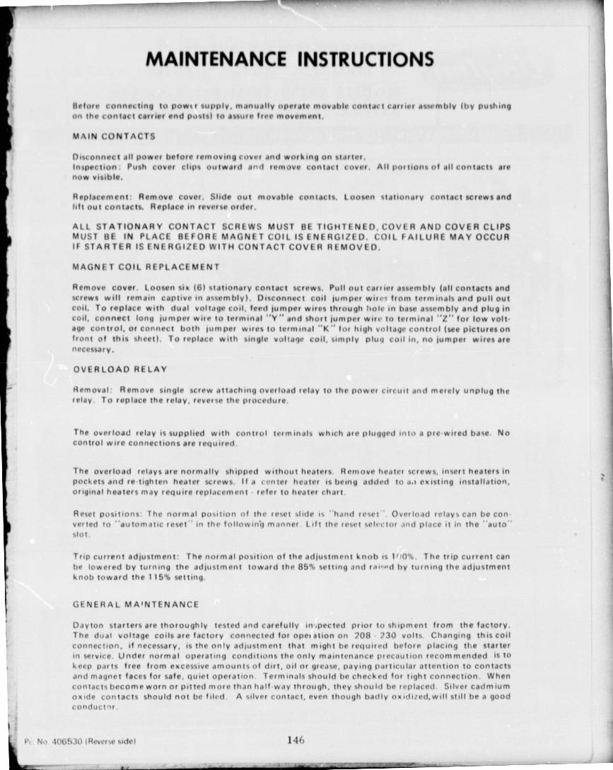
MAINTENANCE INSTRUCTIONS
Before connecting to powe r supply, manually operate movable contact carrier a%%vmhIv Iby pushingoil contact carrier end posts) to assure free movement.
MAIN CONTACTS
Disconnect .ill power before reinovuig cover and working on starter.Inspection Push cover clips outward and remove contact cover. All portions of all contacts arenow visible.
Replacement. Remove cover. Slide out movable contacts. Loosen statronary contact screws andlift out contacts. Replace in reverse order.
ALL STATIONARY CONTACT SCREWS MUST BE TIGHTENED, COVER AND COVER CLIPSMUST BE IN PLACE BEFORE MAGNET COIL IS ENERGIZED. COIL FAILURE MAY OCCURIF STARTER IS ENERGIZED WITH CONTACT COVER Fit MOVED.
MAGNET COIL REPLACEMENT
Remove cover. Loosen six (6) stationary contact screws. Pull out carrier assembly (all contacts andscrews will remain captive in assembly). Disconnect coil Jumper wires from terminals and pull outFoil. To replace with dual voltage coil, feed Jumper wires through Bole in base assembly and plug in.oil, connect long juniper wife to terminal "Y" and %hurt juniper wile to terminal ""Z" for low volt•age control, or connect both juniper wires to lern ► inal "K" for high voltage control (see picturesonfront of this sheet). To replace with single voltage coil, simply plutj coil in, no jumper wires arenecessary.
OVERLOAD RELAY
Removal Remove single screw attaching overload relay to the power circuit and merely unplug therelay. To replace the relay, reverse the procedure.
The overload relay is supplied with control terminals which ate plugged into a pre wired base Nocontrol wire connections are rwjuired.
The overload relays are normally shipped without heaters. Remove heater screws, inert heaters inPockets and re-tighten heater screws. If a renter heater is being added to apt existing installation,original heaters may require replacement - refer to heater chart.
Reset positions: The normal position of the reset %title rs "hand reset ' Overload relays can be con•versed to "automatic reset" In the followinij manner Lift the reset %elector and place it in the "auto"%lot.
Trip current adjustment The normal position of the adjustment knob is I f j0%, The trip current canbe lowered by turning the adjustrnent toward the 85% selling and rol-od by turning the adjustmentknob toward the 1 15`t, setting.
GENERAL MAINTENANCE
Dayton starters are thoroughly tested and carefully m-,peeled prior to shipment from the factory.The dual voltage coils are factory connected for opeiation on 208 730 volts. Changing this coilconnection, if necessary, is the only adjustment that might he required before placing the starterin service. Under normal operating conditions the only maintenance precaution recommended is tokeep parts free from excessive amount%of dirt, oil or grea%e, paying particular attention to contactsind magnet faces for safe, quiet operation. Terminals should be checked fnr tight connection. Whencontacts become worn or pitted more than half way through, they should be r(!placed. Silver cadmiumoxide contacts should not be filed. A silver contact, even though badly oxidired,will still he a goodconductor.
No 406530 (Reverse side) 140
1
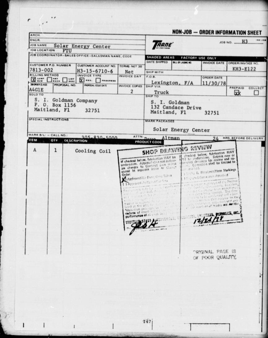
r
F
AW
AT _Ao lsir Energy Inter100 LOCATION r lU
rJO. COOf>101NATOR-$ALIS OFFICE -SAL!{IMAN NAM!. COO[
_1NON-JOB — ORDER INFORMATION SHEET
,oe NO. -- H3 _ ,••rnq/lM 4.
CUBtOM[11 ► .p MUMSIA CLiTOMIt1 AGODUNT NO TEMn NEt 707813-002 H3-15-6710-6 NotBILLING MITNOO INVOICE TYPE INVOICI OAY® IVY• q q. ♦ q t,t•
tVr ••tn M•t- •••.••tt—®^areeaM{
--- —`_^F10'OSAL NO. ItlliOik Ietut 01Iq ^— INVOICE COPT"
A4G1E , ^ 2SULD TO
S. I. Goldman CompanyP. 0. Box 1156Maitland, F1 32751
S P FCIAL INSTRUCTION!
MARK B/L' - CALL NO.:
A 11 Cooling Coil
ATTN
UA11 INVOICE UA1l 1()I4otP1/1NV ,)0C1 W
SMI/ WIT" 1 - Kx--3-E1226/10t i DATE
Lexington, F/A LUL3_ l78INI/ VIA PREPAID COLLti t
H—IW Truck ( q
S. I. Goldman132 Candace DriveMaitland, F1 32751
7A WW_W AZRXt;>E' r! —
Solar Energy Center
HAS BfiORE OELIVe11Y
r
SHE • '0`oo"_ rr y I ,,,/ h,h ► icatr^n tv1AYtAY bo 1 t^^..,t •d ^° c mI. Lti ►bmrt new cr
1 ^N, fnb i,.t.1^n . ^^..It cMAIA hr ._tn^ta:;'1 .^• f ,^ t tOr r,.nitw end wurfUrt"t '4'nIKI1A^ ' > >N.4II he hm't^d^e chMp^s to Lo ^rLured Irt 1"p"214 Ira r 'riot# Mrk-Vold-if n
.. t' ^ ^1 Ptt f
I
f `'^'
arQ ArM,
h1!1.
py^^rn,.><w at
' 1 Rfr1NA1. PAGE US
Of f'VOR VUAUrl,
II
-147

C' l3rap e, Poor CIAOI•dNI • cvwmw, ovft
A'jp^a& NOARO to lls
f.v row
IS
[nitt gars[ god
tu4twa One" ow fie. t\dMr • by.• I1r. W060111 • .0 040 Nu► • U Y •
1 -1-1 rut wtwn...S IA.- ► -t -t rift fr9•wwO
1D I.IJI.! e,lNov -alaw
1crak.-ob, Yt (orl•Y+.O mw" Of I, ,.•1 &.01,
Th
r\\IIIr`•c r1 iAd p•.
V'u•\and IW
► [r T wou (^
r1- lit -v a..• L.H. Ur e, -IA-IS-P.w.t oLww
Iat
•+ I G011tCOOLING COILS N I_ P_A ES l -11y1d•Mt. Ow. W 0111
ORDERING NO - IL' ll^lge0 f A(t RNLI• -- -so r.ttt• Dft to CAM
1111ALai SuIR\utal Dw/ TAGGINGINSIOUCfION 111 lot IONG %!111!1 1Ow pl I NI IDTTALI-erE•TrYMA.tYmai
i v t f W CAM 1041 .w.
N .3160 NO MU---'O
`u
v [ f O AN - W#o ► •.. OW W 0101m, t' 1UC - Via r••• >_ W Ow UT A h - Mat' • T..ft we trw•
tnd Gttw 104 a .w.
H °
r[ f OLL--.Y.
V
TT -1 raft w1.. awt WCOA 1 M I .w.
CL N O Now tied (9.wFIN MATERIAL
A-Ai.ri9.i tL•1rc-CarrHO
IAl EA tTUBE MATERIAL
A - Qw.dr d Ome
^kl! ^ '. 4 ;,-wd fw
gay Ow
c-.w \ tLa01 t-.wa0
l r.ttt0 Ora O•A 1
CAPACITY AIR TEMP. ' F PLU.Oldl PftllUft DROP
I TEMTAGGING
INST RUCTIONS
AIR FLOW ANNN CTI N AD^r Q_ -_ -^^1"T"^
ttnw. ort^• .ow ^yyKSCiM
ArVIX4.n/• w MANtN1efING
Ut / wtIt.v1NGDt/wt
G.A. Of► 11G
'•.'rb.1ww . •
••M(rt{w«.0
.Add••111w,0
78 .2/ 54.8/ ..Y .Ar4«.r .•...
A f.K w.w.wM I.wVW V ..r •. IN fi+._
ytV
VIA V•.N•. UP .LANVDf V•.NH D9... • 9.9mv0. V•.w.H Dtr., L9A
Z SUPPLY. P.P. c_ f•H..d N._t 6.. 1r9. • . 1• d C•.1
2tY - Ivf[u ► Aron of clgalnU.atW
w ♦ E1 11S Ct t..• t..b a.•.O 9 .• A.V. 1r\..•.M.^
b•w..b. •1 (.....• .••.•.••.t.b. e,.1..
FLUID TYPE1^1 :tv .•.. 13
1 \~•[NT[11[D g . •.M0
{A 1111 090111 wUwf I rMECHANICAL SPECIFICATIONS — STANDARD HEATING COOLING COILS
nndd V. oo bra• ^. 3 . w^• •rP. w r Aal 4M1,• •data ,•r • u•• • .•M •J••A9.+r /r. •,. A.A d .PAYf AND •AIdA UAt, OVdA AM• ndA W E
^^W y u a•a t a r vv O• • .r••.• t..•w...^Aw ^.w•• ..r •..••.. r•r •..+• .P.•t Ad Ur.• ..•..•. •.w.+ 1.r^•.^ ^•
t,AA1f.w Ap MA..wG • CODLAROGm.VIV $
I 0•916wdtC. •.. \,Ar Mllo -*A1.•.G • C00 1011 COILS
r•r , t n u • . .+n ..• .... r. w r 1 (_ .+. •r. i A. w•....... IF n. •..a.._•... •r r..... w• ,.r 6-.- .•w• ... A.. ^... r«. P. • r) ee••. tap
A ., A. • • ..r...r • .^.•.•• • a.— gwP •r ••000 co..A..^•........... 11Ic— •..rd. .....r.«,.... f.......U...^.•... ^..... .... _•.. ,. P.. A.. ,........ 148
w/
SO41171 Or T
SUBMITTAL DATA
. .11n IAA lfrfl
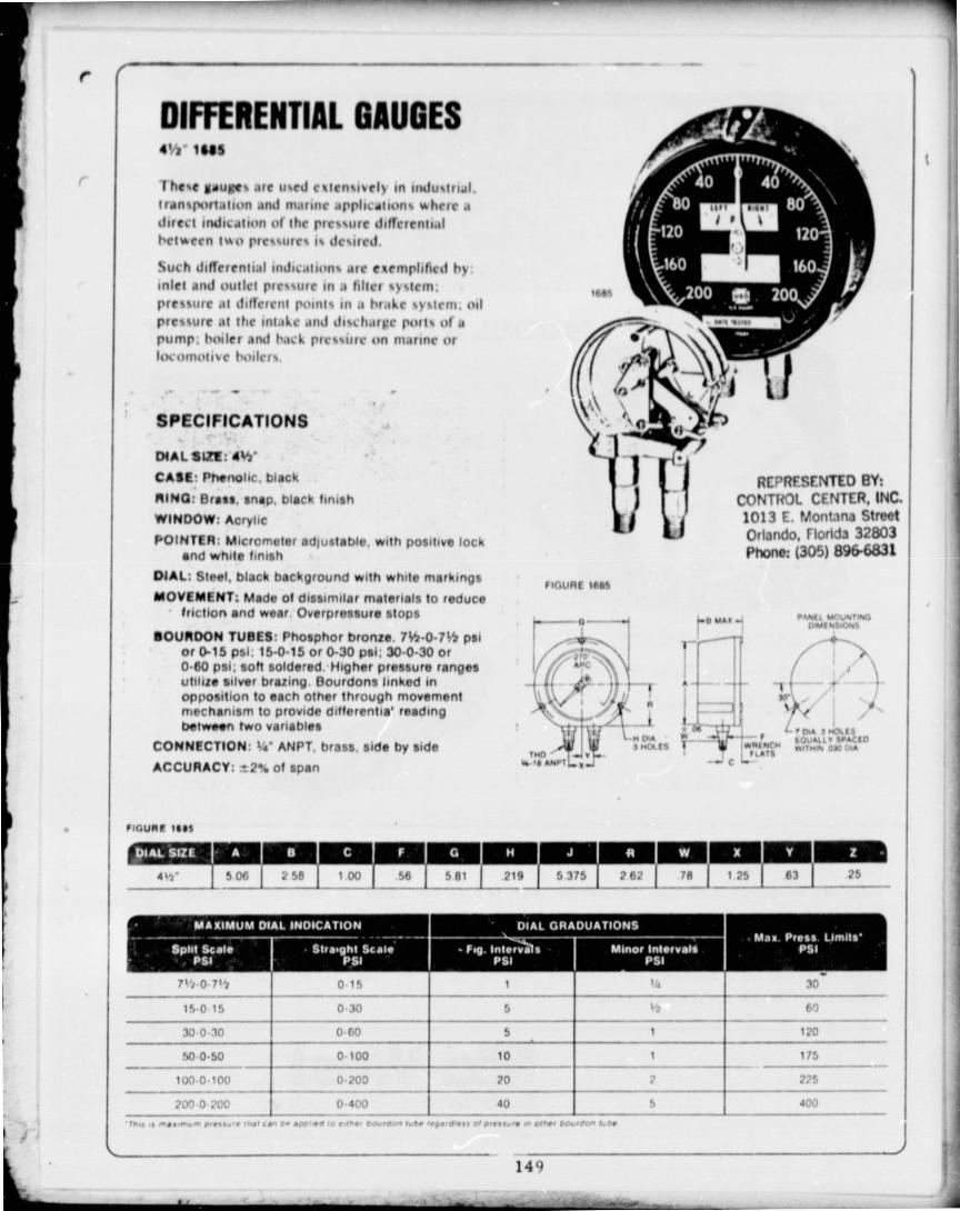
Ar.0
i
THOW VIY-4 AIIIiT :I.
r
DIFFERENTIAL GAUGES4'h' 1NS
1 he%e Saujlte% are u%ed c'rtcn%rveIy in imitiorral,rran%portahon and marine .lppircahon% %hrrr rdirect rndrealion of the prr%%ure diffrrenhrlheliAcen 1,Ao I+rr%%urr% I% dc%ired
Such diflerenh:rl nldic.Urun% arc e'ct • ml+lrficd hy:Inlet rnd outlet pre%%ore in a filter %%%tcm:pressure at different point% in a brake %y%trot, oilpre%%ure M the Inuke and dr%charhr pore% of apump, tWer end hack pfc%%urc on rnar ► ne orl(womolive killvi%
SPECIFICATIONS
DIAL SVT. 01"CASE- Phenolic, blackAIN0: Brass, snap, black finishWINDOW: AcrylicPOINTER: Micrometer adjustable. with positive lock
and white finishDIAL: Steel, black background with white markingsMOVEMENT. Made of dissimilar materials to reduce
friction and wear Overpressure stops
BOURDON TUBES: Phosphor bronze 7 16 . 0 . 755 psior 0-15 psi 15-0-15 or 0 . 30 psi; 30-0 . 30 or0-60 psi; soft soldered. Higher pressure rangesutilize silver brazing Bourdons linked inopposition to each other through movementmechanism to provide differentia' readingbetween two variables
CONNECTION: 1/4 ' ANPT, brass, side by sideACCURACY: i2% of span
FIGURE 16611
1. 11 MAR .4 PA0611 101001000l I DWI M%-0041,
i
w W ' IAwa. w r +aA 3T.OL[•
7 ..O1 [{ 11 Iwilf ALCM W1iMft OWE"Lot
r
IF.
INC.reet
VTIariUV, r IVIVUJ ., -303Phone: (305) 896-6831
/IGU11r ISIS
4It'_
S 06 2 SB 1 00
56
219 5 375 1 262 1 'A 1 25 1 63 25
7 ►/i•0 7 1 't
15 . 0 15
0 15 1
0-30 5
060 S
h
1
30
60
30 0 . 30 120
SO . 0 . 50 0 100 10
0.200 20
1
2
175
225100-0 . 100
200-0 700 0400 10 S 400
• rllq q rw1..Lly- py..Y7 Mae LM P . 1pp"+E 4. •dbp ba.wlAo- rub. logo Qra. O F OOH... If ,n Who, ba.,~ fYb+
149
OWL

sulwon No 89079
MODEL 820 FLOW TEST KIT
Yew- 1,
►510 ?,v
rOwr^N ft
^ aataMl^/ ,
21/2 DIAL GAUGE
0-2 TO 0-100 PAID RANGE.
SOO PSI S.W.P.
COMPACT, LOW COSTDIFFERENTIAL PRESSURE
FLOW TEST KIT
d
The Model 820 is a compact, low cost flow idst kit for monitoring and setting flow rates thru orifices. van-turrs, adjustable restrictions, pilot tubes or other flow devices--or anywherr ► drfferontial pressure measurements may be required in the field. The pressure gauge is a Mid-West Model 120, with a 2-1/2 inch dialPressure Ranges are available from 0 . 2 to 0 . 100 paid '- 0 . 0.14 to 0-7.0 Kp /cm'2_1.The gouge is installed in a compact, rugged carrying case of tough plastic material end is supplied completewith five foot long flexible hoses for connecting to the flow device. The Model 120 gauge is a free floatingpiston gauge and has a very ornall but continuous purge flow across tho piston, r ► oxt separate bleed-drainvalves normal for flow test kits are riot requirod.
MidsomWestInstf1.1t1wnt(Itic Innovators)P .Ir,rAcr '73 1i . Troy Michrgon 48000 • Ph 13131 585.09010286 Executive Dr • Troy Michigan 48084 • Telex No 23.5798
150

MODEL 820 FLOW TEST KIT
STANDARD DIAL RANGE
RANGE ACCURACY
0-2 PSID t0.1
0-5 PSID t0.2
0-10 PSID t0.3
0 . 15 PSID t0.4
0-20 PSID 30.5
0- 25 PSID t 0.7
0-30 PSID ''-1.0
0-50 PSI D ± 1.50 - 75 PSID 1 2.0
0-100 PSID t2.5
0-60 H 2O !3.0
0-135 H 2O !6.0
Square Root and Metric Scales available
SPECIFICATIONS:
• Pressure Range - See Table
• Working Pressure - 500 psi maximum
• Working Temperature - 200 F maximum
Hoae Connections - Very Flexible, Buna N
Liner. Neoprene Jacket, with Knurled
Swivel End (Quick Cnnnect) Fittings for
1i4 Male Flare Tube Connections--5 foot
length.
• Fluid Media - uses or Liquids Compatible
with: Nylon; Buna N Rubber; Brass; Alum-
inum; Stainless Steel.
Note - Most Ranges available irt dual scale (English & Metric Equivalent) at no dddit:onal charge.
REPRESENTED BY
Instrument (The Innovators)P U Drawer 939 . Troy. Michigan 48099 - Ph (313) 585-0900286 Executive Dr. • Troy. Michigan 48084 • Telex No 23-5798
151

DRAW] NGS
U.S GOVERNMENT PRINTING O F FICE. 1980 640 7471466 RE GION NO.

CZ
:13r, n
' .. ^..\ ." rl ^...., r^ r. I.I.,
f74+'^ i'NA^. ^'r r^E
u \j
BEING
CONSTRUCTED
DEPARTMENT OF GENERAI !
THOMAS R. BROWN - EXECU FIVE
sht nod.
H I,f-6 TITLI- 2-,6 SITE
4-6 S O L<Alctss.c.o f e j
r_ J
PR OJECT r
5-t6 FLUV
to
^^-- 1 '„ n 6.6 ELECTT'IT (AhA-4 EZAL MAP OCR-CR
LOCATION h1APSCALE 1 40— 00
C^ stottler stagg&associatesarchitects engineers planners , inC.
CC- ,a, brevard engin°enng company

/^ r 1I
url
^ Jri
IL
^IJ
/^`(
1 cc_t/ r 3 r ^^"
A r
CONSTRUCTED BY :
NT OF GENERAL SERVICES
R. BROWN- EXECUTIVE DIRECTOR.— -- - - __ - SHE E T INDEX
_..
shtnol - ,Ifle ~ drwg no
I M 6 TITLE SHEET, INDEX 8r LOCATION MAP SI-I2 , 6 1
SITE PLAN, LEGEND Q DETAILS SI-2
3 cf 6 PIPING a EQUIPMENT PLAN
M-14,6 SOLAR COLLECTOR FIELD PLAN 8 DETAILS
M-2
5 6 FLOW SCHEMATIC, FA CONTROL PANEL
M•3
6 6 1 ELECTRICAL
E-I
F" r
11 V^SiONS ^..y^ P..1 •[^U rnU b041 y, ftX A ONA \ W► 0-0 %0 Sr''.-^_ ,_ MN•1 Mn a.w.. p
--- _ ls^(Lg r , ,.•, n• »t^^ ^,. s :o^ r 'tv^.sr^at + ►.acct_^—. ._... -------_ MwyN r .rc•u r .. !7•^+M ^: iM tf,tr:. ,^htt•
roe No ♦ ri)s - i
YU . (AM UWVMl1:. 9 104 100 M-4tl Me •'o
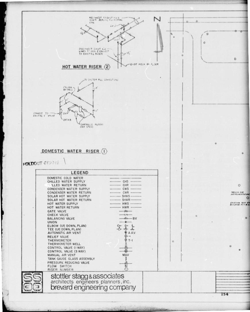
0
0
C-
Y
i
X11
6, 41' ncc w R• . r. VR
0f5c %%1 T ,, ,..,b44: T cc , j CO%ATO Slit , AtSLR
HOT WATER RISER
11 ^l rt JtR. ^, .. .• ,/y1.l 71{ y
r -ri t ; ,1
+^ccr T^ --^ ^ •v •j,r n^TNfi 1 YA.v[
J14' w e
URIk^L •. r1LT-11°rscr b • t c )
DOMESTIC WATER-_RISER G
fnLT)0 4,ff T i ' ..
LEGENDDOMESTIC COLD WATERCHILLED WATER SUPPLY — CHS --
LLED WATER RETURN CHRCONDENSER WATER SUPPLY CWSCONDENSER WATER RETURN CWRSOLAR HOT WATER SUPPLY -- SHAIS
SOLAR HOT WATER RETURN - SHWRHOT WATER SUPPLY HWS --
HOT WATER RETURN HWR
GATE VALVE —do—
CHECK VALVE —+^^-BALANCING VALVE BVUNION — ^-ELBOW (UP DOWN, PLAN) 0-TEE (UP DOWN, PLAN) -6 .}.AUTOMATIC AIR VENT A AV
RELIEF VALVETHERMOMETER Q T-1THERMOMETER WELL ICONTROL VALVE 0 WAY)
CONTROL VALVEVALVE (3 WAY) —-
MANUAL AIR VENT MAV
TANK GAUGE GLASS ASSEMBLY D
PRESSURE REDUCING VALVE —^y —FLOW SWITCH Fi)
RISER NUMBF R
stottler stagg & associatesarchitects engineers planners,)nc.
ED brevard engineering company
0
0
O
nllr.rw 01wWS MOAWYMA r.NM
Orlbsr.uf rffr f9k .LO...v /, . R 11
00
u
u
0

v
1v
0
I I 1 ^
r -- — -e-
OO
VIL
i
o ^^
I
Ir 0 0 ^e 1• — _ 3L ^t—= L -- L^ ^
a
1,
M o' I p
rypr.••^" rr.trw11'ruwvr.r.W tv.i
NEW EQUIP BLDG— o "r ^ .w
or*.+rw tw cwul ! ^'f
1
O_
b y, u^ rt•1 f 1. wry—
^A.V." .8r44 c asC^w3c 110 1. lOO.GW7pttl •> O'+I/ ,rVl
Ctrs/ r ySC M4R
<t. ,ca•u ... ^.r^ { A ^t'^ ^^ ^' Est e° _ ^.. -- ,ev t'1111"-- _ 01% w ,^. ^,
— 0 — El-0 0 — °^---
swy
o 0 \ o t
r^ww
41
lee e0wrtre 0%ps
•.+ ^ MIWMdM Du t1 Ol17w t4'W OO /rIr r. fub
COME CTOR FIELDCSEE DWG. NO M•21
j-uLDC/;,,T -C ' ' ... Z

IIV/AVt Jr•.O .i -
m t /AII AI /[ AM
•ww I. ..• rI _
N
_ 1
M./C PAPA !T v,
a-yfNt[1 M(LAd Co3flq )OMu7/[/ IY1/ I•/ /NI w/A •nfr
At N AII 4IM t•t 4060,
t/J :i ' t - JAWIT A/!
I I _
SFOO TANA
rV!-_
-- -- v-•_-__ "1
►►-}J .I ^T - Gera t t A
JN•
. . > . A 1 •
ILL.
r 1
^a IILr AYe
CV /
L LW PA/V^CUr -cwp7-I
~F". MA' III fM% Ar J9wd Nl.r
400 / //aY / N♦. M•0) A♦I .0 w to . .yt'tytA•aw
JItN/ AwAlM are Ma c
I I Ltr.w NaA cwr/i-a0
1 `I A/. • l.w1 e4l o.fi. I .Ar plgy ./AoMo IIAWAY
_ ^ qfo rvef/ ro t//J/ /t♦ '
L '^ 7-• AYwJ f .VIII 41*01
%r A/!M fM /.I^Mt //./J - -^• d.W AI 1.. Al t 1
^b \ A ^ /Il c (N /t 1♦ I 1
SI^ IVA".v /Ar Crawl)
_
t
L•^CA^AtwCrticK nrJf.A&* TO 0OL d 4 RINI wt/a
1 •.t ♦ S TO Coon/ui A'AN! N .>r^aAY NQ e^ fof ft
;... „ C.41a
L4-
--LL>r^t-_1Klr-1
t^JJ GILLOn !A.•L/I ^ ^•''r- ,yr,'W/ /,/1tS
.C'OIAaI PAM.* * sra+ /iaNA,^ Arrp /irlr t3/'wn tN^
/1/ ar rA'd /M., 7AIAJ.vr
!3! AAI7fAr/J • -•l671E
T-7
I
1
•
•
IC(i/ov ro. fe w /J'•/r' /!„tai /Y, 0
PIPING __81_ EQUIPMENT PLAN_ iSCALE 1/4.1'•0'
*!b • ^^ r
LCAL3L Y
IL r •
BALANCING Y
6A71 Cw Ab / 't rrt 1' ^ s"tVA[ Y! PRESSURt DIFFERENTIAL C.AL4Lrvr or/
LlvsL I'Aa1r .Iwi
- ^/LCJ:DLC PUMP CJr,Y, av ^^ lls•Aw1
_ NO'E
LLVEL.SMI444ROUT SAS[ INCTP/N DIIrUSIR ACCORDANCE WON P'1`44
tIV I Ape C) INSTALLATION INSTRUCTIONlWIORT TO FLR
WORAPN VALVE . ---^ L - STEEL PUMP, CaSt
TYPIC A L PUMP MOUNTING DETAIL_SCALE NONE
FO1.000T FRAW •
LOW WATSCALE- NONE
stottler stagg & associatesarchitects engineers planners, Inc. ----
( brevard eng ineenng company -=
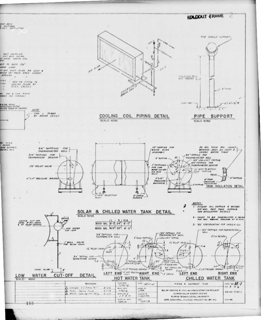
IOCArs rwr tfrrLAYAa r MR- IIOrJt al, "dw /MAw1
SOLAR a CHILLED WATER TANK DETAILSCALE NONE f- --- -
L I S 01A3000 GAL Q 24 •'-0
Ar OVAMr 6000 GAL 6 CP 32-1 e' • 0'Orr
"I It ,`I
t1'AVA r R!3lNKLVM3 r r' O+A/NrAAn •
BSI
1
s
lr
rnP tur to
tI / N[[0[D f
CCwt HM : L : 1(/'?
COOLING COIL PIPING DETAILSCALE NONE` -- - —
PIPE_ SUPPORTSCALE NONE
LNJ' rJ/V/N6 /01 70 AI.'l rMlem /Yf J/47A91IJVr/ 6!/11 Awl'o.Al JIAL ALl JAM'11 I'A SAAIsIY ffJA,f Ir//11 rl~
AN' "Opp'" /ft+M
'WAWAff7lI AW4S'riN AN 31I'JOr Jr./rr rA//MI
Ir A41'1A0-W6 /0!
/' /JA•S'NN ♦ fw/(+AM..r/L+ JLNJO!/AI aM'AiA /rw
^
• 7LaM rArn/NSOw. r rIA.<
I/'r /1' PIANO{ f/+luu+A 111
•' /nNOrA/J..VOIb / / 3 I/µ_A'rwrw.N
TANK INSULATION DETAIL
J.vl fl
C'k LOV r7R CL/*Or/ 7'N r 1^ ou I- Lt' TA/r.f tat FTIcjr sVr-^ ^- II', rS n ISSYRt f7ANMeLI - -. ^1 7'frf -^ ll'•IJ-/^S.W/ AAAMI - r,LEFT END `, °!"r'RIOHT EN. D purA LEFT END. RIGHT END
NOT-WATER TANK .CHILLED WATER=SAND.aa,A Y • 1 u•tl ► IrIN* • MMM1t.Nt PLAN 4••G -Af -1
y^ w•.r an o.. a - -- swr ! a G.Mr _ 7/:Y^7i .N•A' _^ SAN -RATING A COOoNO DENO% frNATION PROJECT Tt .0 trilt•r
A.•.O.11 4 c-a.0 f• fLOMMA SOLAR MIRSt CIN/IR`l Vy_ 0L noRrOA nO.NOL001CAL uNIVIRfnr
__ A^.O,M f• •1 p.q CA PE CA%AVMAL. rL0 • IDA- ►ROJIC T NO 80 - 421 -1 40
FDLDDUY
MI/ NC.• .
,"owV IC. • 4.J •w .J•W
w -1 a .rJ aA /s•.W4
rn /O Awi, /y^•
/1 . Or/ /r•^r /I.N /A O31IM1'/P/ V/' M11Ar IALr !s!v/.v
OA'a,Ar ta L
!r //nws /0._..1. r.A&,AJ 7.'.A+ Ir
6f4.. • /wJ C.. MLA i
/ fK f1/ruGOL V7AJi MM rAIui owe N OMMLC NO„
0004 . ,ro A6rJ I , "w"'t (N f L )
ra erA
~ rf f 1., f 7.vl+AfOML7!/ N!l L f
//1' I!L/er rilr! / 'O I ^^
//'r/f' /!1111/+! A/A.A40, -
JN rA/' n^syS /OR /LN-- rNl+Mpyl7lR N3TLTMMr[YILTCR VCII --
J-/LOVrA///4't LOVUfvr rAr►iv^Ail rr[ 3! I$ ITI VLN/ nf:slaw OV..,.
14 - R1L!/
. TAP/INS /OR =TJN/Y+Arkm s1*wr
T-1
CO4fC la AsI r
LOW WA1 ER CUT-OFF DETAy,SCALE—NON _- —
11 VISNONS..C.f.`tp t v n,...y_Ar^
AIP f!1
I . flffA/O All 7A//i4// / AOJ][]A" AfAV 0117 7AW* Ju+/I [IJ!s l*f4LJ7i0AV Ol1J1L3
J- Y! S/YC11/CA7Acw /W /A'wl A•va
- j/r'/,l/Y/AID ] /O/ 7.IfRMJMI I/tNEIL
J - f V R``L1Ld/r//l
^lilll^
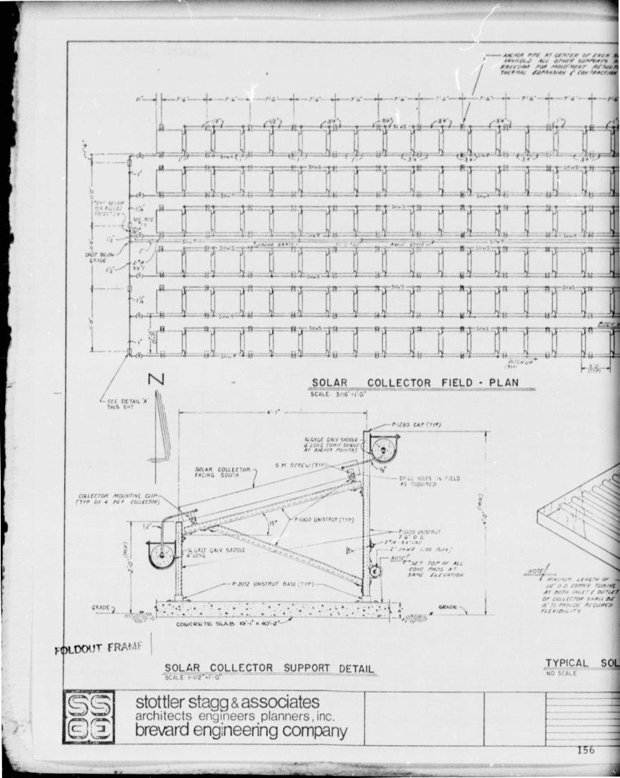
A ft*,- I /.N r • Gy r •/ 0' A/ /.ICIIMvlg t r' Alv! 0/p I JI•NII/7
IIII IM IpI ~W Q,r/ AY U/TAy I M•{, AL/KwLAV / fM •Iwf/
Is
1 j
I' - ^ -s ^ •
-+^ l I --'t• -/ A • -1•i T i• ^
/t' I Ut•
as- s^r«w. I • - -4.•
16
=Wl
L _
NSOLAR COLLECTOR FIELD - PLANscan3 . o”
Sri DETAIL 'ATHIS Sw•
I w'
Icap si,o.f^Ja
Lv^ ,
.o
L_.
1"
h r j^t.•e_ -• ^ei=F
_t t!-'!i t ?t -
16 4A (.t GIlV 5.41"AL LG^ (O+r/ iaariAr AA!'.vt roiw„^
^-F1710 CAI (II►1
—
S N StRfwr(Tn'L"\JI
SOLAR COLL[tTOM ^^ ^.- vtCACINQ SOU • N i-" --Dp.LL HW1 '1 1410
CLIILfofL MCy a L/4 ltr^ or w i!•,
covtadttsel)
_ ..
- i
_ ^ \M• ► 1000 UNISI ►UT(7V ► ).^^
i I \ -Ic 4&6r ^AIV SADDI[ `\^ t , I+.6•L01;
76* O G
Jr NI ... 3 •,
^ 4 °'f
^ A COW A0.13 wNA6MI f,.-614114W
- ► To11 UNISTRUT NASI ( T I/) ^"\
GRADE
vo.: .• A - • •`• - • ' • • ' • . • • . A• firm
' r 1WwCJlGTi SLAH 101'•1 r Ap'-!
^6Lt"yT ERA0F
^olt^2I i• J,. •bM [Lv0 •N O,
As wrw iN.! ' ai,Or tArl tt!p, s-4!I' J ro. ar Aw a/",L►rttrrtsu i,v
SOLAR COLLECTOR SUPPORT DETAIL TYPICAL S01- NO SCti.E
SCC.E i 117 • 0 G'
stottler stagg & associatesarchitects engineers planners, Inc.brevard engineering company
-r
No
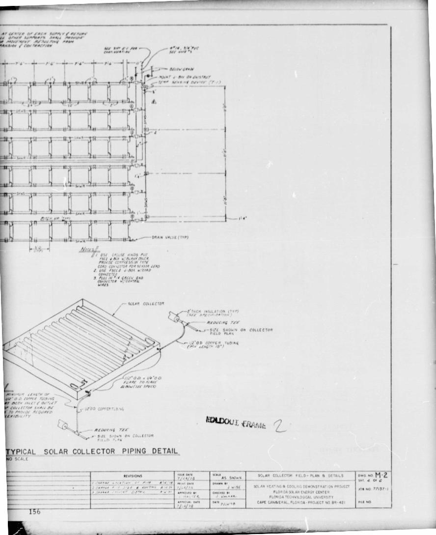
Sr.-At COLLECT I P' ' 0- PLAN S (. S
SDI IA ,t 1:^.,•G t C ' IE00%STRAT:01. 001JECT► Uf e DA Y. a. tNf0rrl CEWtR
rltll► i;A TEC HWXOWCAI MVE4SIT1CAM UN*E •JI. 'LO U U-PROJECI %0 04-42i
OwG •,o ri•CV., 4 Or Q
,no No Yr13I 1
nU NO
Al pl e y f OJ' l I! 3 f3M r jr N ProwV4 OPV/ Ir„wers Aw4ed lwwp riM -rvrr Wof AV fey/ P.►er 0~J4/ • •- A. / claw "WrAW
•^iI { V I
)• v
F
d[. t ^ -TSt--t'-1I T '.•r^
4Ii Sr i i — r-
r1r —
iY(.I• IWO AV fVI .•N •I
7 • - !!. NtJr.r.Ar
I . spa • • .0 M 1• 0. .. •f3^ ^7^^ Jy.f •I N• n ^
I` •f
^ls.... W44 -- – a J2
Yull'--. - - - — &01 .-
"S..N •).1
D44.10 VA&79 (TVP)-- -- K 5.. 11 H -
^..
I
,ft/ I AL J .. A.A.61 i%,CfMort :: " P+/S S r /r-KCOI? (4 • •!: 'o/ Pr1 N..OI !!/O
1 L7! ISCC! .1 J{ol r!J/pCO..lCT.I
CWOVC •ff w,'CO•^I4M/A!{
.- S64Ar f0«l001t
•may
^''00 i/i 'ODll A Af !O A.
-1 IMK q INSULAT.Of. (71I)u! ! [n• NVL• ^
RIO3C^M^ 7A'Sr
^•_^-SVf SNOWS ON collECTO'r► IEID P A4
' o .? tore r rue^tiiep lw iMl! ! / A3 L!r
`e4, dlcrAr9 rA!!A! , • JD CJVVLe•.!^i5
Ar/et'd Pry
• S: 7 0 • • .. ECTORr ,
PICAL SOLAR COLLECTOR PIPING DETAILASE
tE h SIOMS -WA Odle N:...,,. 4,^ _ AS SNOMN
../. ; r.
/ I -"•lwlea / .•Y
__ ,. ..Si..+..• I . •r.W.lo e. CMa1e b -
- - --- -- 1. l c J ,,...41-
We

INIaI
RPM AIP ^;;J' AZ
lip" I am !
JrN / • w1±
do's •,/ rI. • re -*A
CO'.
Avml
Jf d , ri• N ^l arf^ ^^ ar . ^ --^
- -^------L-
PUMP SCHEDULEMO► . . (frtl rtlM /IN
ro rrr l [rfrel
/IN • .tr II N II III/ r •^ I1n /
r••+u^Lsap •( Itsf. •OWWI"
:e.
Rr• 1 r__ 1 ^• f1 li ^ •
P OP Oft " ass,YI
.6 IAWIW
NI 6 f lass►
IF
NMI/IIr Itr1 •!► MI
, •
/^ 0 tyrJ w •-^• •w•r• •
I• / /ti` •.M .ayw..•I.
WY NiI.•nH
•
~~
I 1 1I ' ,
—f'fj, •46/ IY • 74 S %
I too
!' . IO C l _
^'ar r!•:,vj!•••rl,, vtAe^-.i/C^10r I''.. i1, c ••'• r•r • r a 1
• • _ rflw #J .,C
u .f!. y .u^ • rat .14,fA•A.
1
WATER TREATMENT INJECTION FITTING
^• • •FI
^t'./.aI I. I.•
AofN^t/ 1 /v ^ .^}
,ltr
L 1T s IM/
77 M07 CJ U . ..., r V r.s/J; 4(4
to If Irie 1 .. J,
FLOW SCHEMAI
N,r;yy^.. ^l I

"' O O UJ O © O O O 10 ^..^^ c^
1n.^r NrK^ 0 C
d^„
00o•r
A% 60^,. o., ^• c
^. rI ,.ee..
♦1
O• 0• Q' U 0 U O 0 0 0 0
/ ' w ^k)I. r L tOA// //rte.dY/tiCAA1 Q^er A h'AAVAMi [!fM/ `/II
.^ cer^RO• wire CONTROL PANEL
r4W Nw1rcr
rN1 ^^ •
'J Y woo f.•".r ( II ,'a 40
""AIL WLAU cMRNOE.fyf[r SAWAfn % ter,'
CCII T ^O►lf [[
I{ I 4
_ f :. Il oW
• rJ ;rJ
'— T
• j } tv•
ft
r ,
view Sw rcr API
I'R'
1• f ^,.^ (so anv
("'' N'uw/ ^auJ
I
f•4 ^ AIAeM^(Y
I 7
1
f t.
IIII MAV
le.s t l-c^ G all
z
rl1
Ak 4
fed • /N/P A M. I ^
$cc: ai..o.:.._towi-tA S7< f.ASI v...
N SCHEMATIC
V.
11VIS,ONS ;•,^" 'r---- - w• ' r —11tDr fcrtw.r c.cC,, • R.L P&%(, p 511 ^rENC[ Of a[RAnOA o..c w M-3
_^ _ r •• s•n a•r. .•r ; 1 JInI/ AI/ /N SGIIR Ir[ITIhG a CJ04 n,G CtvGtiSTRA T ty1 ► P CKCT
Joe 40
/ .IC-If ...r Ja_ _ ILDRICAT IEW.OL AICA6~ 45ITt-._.._,_•. o•rf o•.. 7f CAI[ CANA.(RAt,rl,d'DA • cr-SECT %) fA•It, 4n11 NO
21
1 .

Olt".140 We
.,.Of ryer ^
1 tvtvic ^I tuIC) I
I I
.^ ^I1I111ta. r. • s • •+.
^ r titw• y tN1.11 '• ^• L• •tr•
I1w A
ty^^..^•• Ott
I
Irt (^rN1 !.. •YI •
IW.-rec -
AI ♦/L I7
Ulei' ILL
Paw rOr3 J'40 M 1 I • I . , ,IlJ. td
W.-•rl,!•/11're, I/./^I'• :./l. 'N_ _ aI MAYA "Of /'/ Y
r ^—
lLL '-"r•
1 rar to •.._ . r---- • -- ^^N-^^- -•_IMI If ^ r^/rr• ••t♦I^f
/ rLN ^_ f•IIN/I III/ •MII/I Icrl?tn./
i . • a I C'r llbaf S.v llAll I.sy :It 3. IYN40 ft•/
IOiA• /Ia •opt //L V'W.I:frrn I Y/ /t 1 •." rA /Mf
1
C _1
ELECTRICAL FLOOR PLANSCALE 1/4 • • 1'-0•
J stottler stagg & associates -architects engineers planners, Inc
Q ;^, brevard engineering company
~aA I'
Ij-
N • lbw_ t _^y_r es •+
•^ f w'0•64 614 of...
' tiNII
J
I. _ ---
OK

1.
1 -/r N • ^1//V I• ,
I•►y.J. 1iw./D
LE6(r.1G) ,li$ IPiCfP TA:Lf liArAP! S/•fUiN,A1/41/
AALf .rrC-- /' Alorl ft?:'t
-- 4 14 V A"VO C9uta+r IIIA/11' ^ L, 
,JI
t i
^ •L 1 .I 0 11
^
♦ l
Z'•0 0 w
`$119-01 H MI ► t (VI,* f AC• Jrnl
FRAMING PLANVs --1,-0
I
I•\Yr1 Jr^Y, ^• ••,f • ALU64 LouVtf Dt
f1^Ya I ►AS MIM• — •\Yy 1•.N inMtl YY UuT Nr,s. ♦
Cf•N L,ar• — — , A► ^r\r A
►u►r IfAtrl^—
^.^_, ^ '11YT1D Af1A` .yam-^ ^ ^_CMN •^ f•p ,• A /NDIY• ^^ h'vlf0 { M w •
10 Tr ^ t. ^ yr•,, _ ^....^grt slo 4^v ►?ION ON ELEVATION RIGHT• ,IDEAL YATI )N
4 o o^e • ,
•^ -.. I II ^y ^ II^u•
I i ^ CrYC 4Mr )OYp ,4 • ^ w •.• /l[tA..
• I I •^w„^ •{ ltwwil ^8 ► ,..Tfl MI I 0710 Cuui
^r. C , co.rrAd40 r.^► As rfv'e ^
c ^
♦ a •.• lu'• • I —
rb 1.'tur,.o.uD ') ► ..o p
r '
FOUNDATION PLAN.W.".0
•I
Exi57^^ Ew ► oitiG M1CrAU,1A ►i f DuvA•,[Nt
^II
•; ( y / ;"+.p ,.TwojI lS,•O
d as LA•,t.D star { .,Ir yw•{ - To 1 U{w ,. ,.
O - rLOOf D4,N.
i.JVI' A i C1 ^1.. N C M u JF-4o 4^ C—.LS1L-AwD I' ^ ) Vt Mt.--r fit r14 to iy O1AM
't
l..•
F
J
FLOOR PLAN114 • .,'•u
r
259

--T.3a: S'—JOAN SC LS f is JOISTi-11.11'5 61 Sf ► kV
- f - ^.• Two. ALY•• /tAft . Q.wC
1. . la l TrYM--a
5 -• i•5 1r•.•It5^f1C
i•
TII^ /1[I ,OI LY/IYN /LI [ ...7 V.I ALU MIMI.. •KL
'1(' A4:.C1f0 C
t _
ROPE _S TICN AT CEN T ER COLUNINr'/t ' • 1' u
41-ft, ASONALT O U tau0Yf'(t4 /,.1 ra r,• •• v Du•IMc-,\^
r • 1r^l--w- l rna•/ ^u001
.•6r1
M Ar,11N4 (^•••^ ^•' GAM, -- Olt At.M 0A1L1A
-MVu w" *e ac IJu, Sf
--Au, 1 14W SU I0J
'c aul. fM,1 - S r 44 ' tor•fT elALL r6ALL1 ,•
4. r•4 r1 i.r ri ►IATL AU, 10O1L 0
M/tj Ar /t VL,' t -u
1I• co.l LA , OU,r f.k."D../t«c / t• • ) #•Aa5
1 1 r 4 fl• • 64o.41 'No.Sou TM .. A ,L Al 116 04 L
^ , I faa 51.^a^ti iA.w /r Nn
E SECTION AT ROOF OVRHANG_ _=.^r.,^=.. , ..^..
fir. /. '%w rrr
ML /AL TiACIt t 11"Ll
11a :f t•Y • T —^ ^ IL •r ► LLITIAL 41LAoL I • ^.owl PiJofit
_ O.O MtSO"r Lot , ► • r ^- I . t f !u cOUTAt rr lrNr.11L5 1.1 • 5 TTL.IM M/1.1151• . It• U — ---- ♦ i FILIlO r/Lwc
`-- }5 v^ AO t, t u oL ^B^FOOTING AROUND PAUC14U oil .% *Aa V ., u
1 / eel 6•4 "Aa wM/ -• - ,AGM JA ►1I --_. --7^ I•CMUC41M•JM I.ILWIAMB AT OVERHEAD DOOR f • ^___ ^^ rl., .r/It
GwT $a ' r frL rISQULIU \
o1Dt^^l VATI )N J 1•rTr• h.. s^ A ' • S'S • ,n, ►A( 1
I# •• e _ rf ---'ILIT ALUMet1Mf _— _- - 2 4OOr1rWAL O 1 • 5 ` O a•
I
wip'LLlV
f
tto
iLL
CO r i'- o 1
w/rldY C
I -J.II
III • t r .a
Ito 6 •^1y1 y1
T
^•TO^o
I I I
• Nuft Ca191N JOKT
PLAN
.1.
IAMB AT ENTRANCE (AIFWTING_AT MASONRY SO U. MISJ. I 1'-o .I,.a
-...-
iC FOOTING AT CMU WAIF
1 • 1' (1
.j
3•4 1 • 1... • .tL w/VLfI ST UVS1` • oC /'^•CV0AIIIH II • •M 1Nf• To a111i STMu,TuaC
4 VI t, U ROM u/AAlx144It's... ^i _..a{ Ij ..(t Nom) •. r.^000
I
I Cl^c.N61 ^^
__ _ -..^_ 5L a_i K_'1 SL AD
P , u r, a.' f, w/t ' • S t 77("A411N000S Atauuo IP, LIm/ TLa
I CNJ ( ANON IJN7LAW r/ T yr, M r/Xp•
i uAl /t M9/C I Co•Tt/O INT, 1•IAjrN IA^ST^u^fa,.OIL r 14 S.75 I W T _.-.
ti
['U rJV
1
I
rL1 Y ' Sur. TOO •, r5 r1 :.NC r.^'^o woo
T
I
' r
t
s.I•
I i
I ►L.C ., AI/k1 'et
V ps 511 ILAln 4A
/aTf NO R.' rN.i /(LT54 - A11aL TOO Or c"T-
r 41UM r..5.4- TO1 IcAf ^»s Aru.L1 `
AS/MAC I 1M/f,L 6n•rT ^L
F FLASHING DETAIL
NOTESI- PL.LSSui! Ta11Ar[o ...,,, us(0 uM[et
C04Lti T/ Ot MAScut, it L7 4 TAl Ti D.t. /ooT.U65 1 SL he ILRN I Tf TRLAT117.
SOIL „uDaa fooT1011. 4 St A• 1.0-fhr LASa(V D To Ff.".Oi zoo. / S rNl Aa1M6 CA/ALIIv
If SLAT • XWO ►5 Co»
^Y AIL VtSUUkIM .-) Is 1 1• • 4 WL1
CROSS SECTIONVi " .10
m_
'r 4^ •
ORIG NAL PAGE ISOF PUOK QUAL" BROVAROR ENGINEERINGSCOMPANY
PROJECT NO dR-421
---- — 159
AS BUILT I
ARCHITECTURAL PLANS i DETAILS DA, -41 A 1
SOLAR HEATING S CJOLIN' L EAI)NSTI,AI1Jr4 PROJECT SH' I OF _I ---FLORIDA SOL A R ENERGY CENTER LIA'E 0/1•!117
U NI V(RSITT O r CF»'PAL FLORIDA )AN by 0 4-0.0.0,9CAPE CA10AtERAL, FLA. ' ICI.•
Art
.^^ 0000.

1
A
a^
I
i
i^
^ u I I
N • .. ,-may ^
l
I N 1
I
r. -t- J
V !^ Pl h P N ^ ^U o^^ 1t U v
0reo^ p v,,n°,
ih
Qv0 Q ^JdJY,(,1. ^1In^ N 1
J ^ ^^ j; ^^ oo.v J Q
Q, W ^ c ^ 4 ^ ^^10
^, u Q N WM C N ^1 N N
'' ° rV nl far
ti nyyV
y
1. a;Ll y
A `
r
Ja
N
Nt
"II
t T ',
I►
1'
L ; •li
t
I
^ I ^
O ^
' T•i
I_r
iI
J
r ..
Ali1
^ J Z
A
It r- a ^- --•--1 ?1 ^
,^ J11 •
' ^ A
I
i 1 ,
f
^" 1 Lit = ,
I , ^I•
I -1"—^—^ I I
lll^^^JJJ - y - -
I }J
a
♦ 2
160

• Z
J _-
1
C6_1w
-'/
1
P,
,a
I(
^n
i
T., 1 y
^ 1U 1 T , 1
W
I e ,4
l e^ u ^ V
l cr ^ I
i
1 1 ° ^^ y
I Y
4L,
Y
1 -
v I n y
_
•Yf^
' u
I
Y j•
49 v ►^ Vti s
V
1h ^ 1 1 ^ _
ti I ^ V -^ ^ 1
Ier1
e,,,,t.
,^,-
4
L W^^
ICA
^ Io I
1
N ^
o I► I
© II
a
' Ir
^ u t I
I
r^ I
I
Oc
mt W` J
J
V mVJ<
O n4c`i Q
fl10 ^^
^ z3 V
ono^
d ^1
G
C v
^-ZJ^ x?
O w ► Z Cr!
—' ^I j f
O Q
In 1^ n lk-Q Q
F
41 `rl
I
I
• s ^ ^
160

WW
r131
IL J
k Y 3
c ^J . ♦.,
V Al
VI Q
a a" a
ly
^. Wr
~ 1 ylN n^ ^1^ ^^
FOLDOUT MAW ^ N
4JR^
Y^.1 `
n~4Y ..♦
Q^I ^^ M N
v^^ ^ o Ia
I T Y
• •^. iy I^
l) OH
OI^ ^ O
•Q
VJ ^
41 11
W ^ ^
V `
vV ^J
t41.14-NAL, PAGE i:,OF ;OOR QUALMW
V^r ^L
F ; ^'
lL v v
2I^ N
lt,l

d ^ n,.y ^' v ^ r`J 4y ^^
V •
C3 f —
U ^ ^^
A
J^
' • a
6itiN ^
V ^ ^ N ^ J
n'y ^ h ^; ♦. ^ ^ W 1^ MI
v"I Q Ov► ^,,
l^ ,^ ^ `^^ ^ C ^ ►1 0(1.10F .TbQ J^ j:t^iJ^
4 ^h W O?^`J
CL Q
It
J H06^IL^W1J h h ^"
JMl { (^,, 0 k
lic k_
: QC 4 Z N
W II o^ ;^^.t % ^' ^'1 4 ^' - v V :L
ry-. n
J
z
r'
40 !
-, m
I
RI(s,'NAL. NAVE , -
POOR QUALR" v
'^WC^I ^,RME
V ^^
•
( v I .z v tY V .,tiF- u
u11o ►, - 4
^^ I O p u YzMW^ Jv n a
ofj 2 ^ u a v ti u
i ►. I Q 01 Z Y --' v F N
I ► v ► a tu p Q c)`'
^ Q^ lY J
V 1 ^i
c,IW ►^ 1 f L O z ^!
l w 2 p zac ^ n ^•' V m 3
161
^. w

I ^ I I
•) 7i
T
1
1- IT T• ••
sI ,.!i
^ L
11 L
RtV I 0!
2 A$
i
Y 1 ►.,^Y jtI
CGNZ RO L
?/1N E L
Ty '•.. A I'• 't it N, 1. ).. ly
eYV ,(NI l=. __
co•,licr3 i.c
1 i=•,
Ir--
T I I PHOTO GCI,Y1I ;TORK c'wl
rr17•I.9I W %, I/)1•
I
5` AIR" cR- °l ^h^'^E r? - P2 I _"N4 7 -R - b5 I `T1^n Tr. t - P4
FOLDOUT -FRAME
162

RtY
I J I_ ^ s ej,Lr 1 s-1- 7? 1
2.100 )
S ^.. C G>r C Ih. ^. s1 r 01^, ^`,;^ y .r1ECu^.N iCAL CcyT7 ACTvr^
- PC). 150K 11510 Mt►1T^ Qt ► C .f .4n. .«ra LAU nG.lab(.NC, NO. 1Oo1 a
H .w n ew.tr. wyp Uw..4. f^.. MOI
I ^• L.
.le W r1^^ llvALL GvNltic^^ w ► ^.1 ^/^^
Elltz L'A
w^
1 "I 40 ti
^ i I
I
i
! ! f „1 Olt >ol I i
1. 1.►_ .I. i ^_ I 1 l I (.^ l• ^.^ + ^ _
c "'1,hTr 1^-P4 I ^'.a^` Ttlz- "'^ `J^";.^Q^^ F, -^ ^ ^^CT::F'•"'f^tr,
[^1.i^IJT MFR,^,^n ►
paoYG cFl.l.`}- I .TORvc t'^^p>r'..
162