19720007957.pdf - NASA Technical Reports Server
526
NASA CONTRACTOR REPORT U-J CN Os CO NASA CR-113925 CONCEPTUAL DESIGN STUDY OF A NUCLEAR BRAYTON TURBOALTERNATOR-COMPRESSOR frepared by GENERAL ELECTRIC COMPANY Cincinnati, Ohio 45215 for Lewis Research Center NATIONAL AERONAUTICS AND SPACE ADMINISTRATION • WASHINGTON, D. C. • NOVEMBER 1971
-
Upload
khangminh22 -
Category
Documents
-
view
0 -
download
0
Transcript of 19720007957.pdf - NASA Technical Reports Server

N A S A C O N T R A C T O R
R E P O R T
U-JCNOsCO
N A S A C R - 1 1 3 9 2 5
CONCEPTUAL DESIGN STUDYOF A NUCLEAR BRAYTONTURBOALTERNATOR-COMPRESSOR
frepared by
GENERAL ELECTRIC COMPANY
Cincinnati, Ohio 45215
for Lewis Research Center
NATIONAL AERONAUTICS AND SPACE ADMINISTRATION • WASHINGTON, D. C. • NOVEMBER 1971
1. Report No. 2. Government Accession No.
CR-1139254. Title and Subtitle
CONCEPTUAL DESIGN STUDY OF A NUCLEARBRAYTON TURBOALTERNATOR-COMPRESSOR
7. Author(s)
9. Performing Organization Name and Address
General Electric CompanyCincinnati, Ohio 45215
12. Sponsoring Agency Name and Address
National Aeronautics and Space AdministrationWashington, D.C. 20546
3. Recipient's Catalog No.
5. Report p»teNovember 1971
6. Performing Organization Code
8. Performing Organization Report No.
GESP-49310. Work Unit No.
11. Contract or Grant No.NAS 3-13449
13. Type of Report and Period Covered
Contractor Report
14. Sponsoring Agency Code
15. Supplementary Notes Work done in conjunction with subcontractors, Mechanical Technology, Incor-porated, and Westinghouse Aerospace Electrical Division; report edited by R. D. Brooks, GeneralElectric Company; Project Manager, Joseph P. Joyce, Space Power Systems Division, NASA LewisResearch -Center, Cleveland, Ohio
16. Abstract
The NASA is engaged in a research and technology investigation of nuclear powered Brayton cyclespace electric power systems. The turboalternator-compressor (TAC) component of the systemis one of the most critical. As part of this program, the General Electric Company has per-formed a comprehensive analysis and conceptual design study of the turboalternator-compressorcomponents using HeXe as the working fluid. The study was conducted in three phases: generalconfiguration analysis (Phase I), design variations (Phase JJ), and conceptual design study(Phase DJ). During the Phase I analysis, individual turbine, alternator, compressor, and bear-ing and seal designs were evaluated. Six turboalternator-compressor (TAC) configurations werecompleted. Phase n consisted of evaluating one selected Phase I TAC configuration to calculateits performance when operating under new cycle conditions, namely, one higher and one lowerturbine inlet temperature and one case with krypton as the working fluid. Based on the Phase Iand II results, a TAC configuration that incorporated a radial compressor, a radial turbine, aLundell alternator, and gas bearings was selected. During Phase III a new layout of the TAC wasprepared that reflects the cycle state points necessary to accommodate a zirconium hydride mod-erated reactor and a 400 Hz alternator. The final TAC design rotates at 24, 000 rpm and pro-duces 160 kWe, 480 V, 3-phase, 400 hertz power.
17. Key Words (Suggested by Author(s))
Turboalternator compressor designBrayton cycleSpace electric power
18. Distribution Statement
Unclassified - unlimited
19. Security dassif. (of this report) 20. Security Classif. (of this page)
Unclassified Unclassified21. No. of Pages 22. Price*
526 $3.00
For sale by the National Technical Information Service, Springfield, Virginia 22151
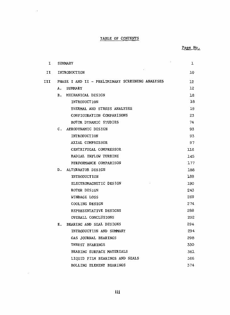
TABLE OF CONTENTS
Page No.
I SUMMARY 1
II INTRODUCTION 10
III PHASE I AND II - PRELIMINARY SCREENING ANALYSES 12
A. SUMMARY 12
B. MECHANICAL DESIGN 18
INTRODUCTION 18
THERMAL AND STRESS ANALYSES 19
CONFIGURATION COMPARISONS 23
ROTOR DYNAMIC STUDIES 74
C. AERODYNAMIC DESIGN 93
INTRODUCTION 93
AXIAL COMPRESSOR 97
CENTRIFUGAL COMPRESSOR 116
RADIAL INFLOW TURBINE 145
PERFORMANCE COMPARISON 177
D. ALTERNATOR DESIGN 188
INTRODUCTION 188
ELECTROMAGNETIC DESIGN 190
ROTOR DESIGN 243
WINDAGE LOSS 269
COOLING DESIGN 274
REPRESENTATIVE DESIGNS 288
OVERALL CONCLUSIONS 292
E. BEARING AND SEAL DESIGNS 294
INTRODUCTION AND SUMMARY 294
GAS JOURNAL BEARINGS 298
THRUST BEARINGS 330
BEARING SURFACE MATERIALS 361
LIQUID FILM BEARINGS AND SEALS 366
ROLLING ELEMENT BEARINGS 374
111
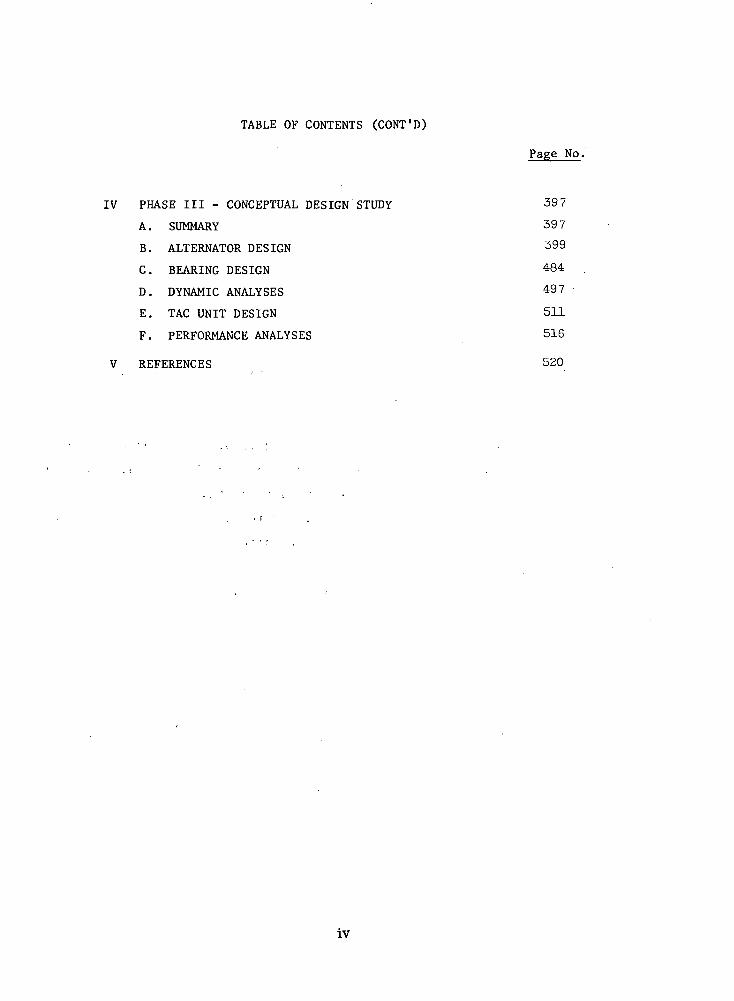
TABLE OF CONTENTS (CONT'D)
Page No.
IV PHASE III - CONCEPTUAL DESIGN STUDY 397
A. SUMMARY 397
B. ALTERNATOR DESIGN 399
C. BEARING DESIGN 484
D. DYNAMIC ANALYSES 497
E. TAC UNIT DESIGN 511
F. PERFORMANCE ANALYSES 516
V REFERENCES 520
iv
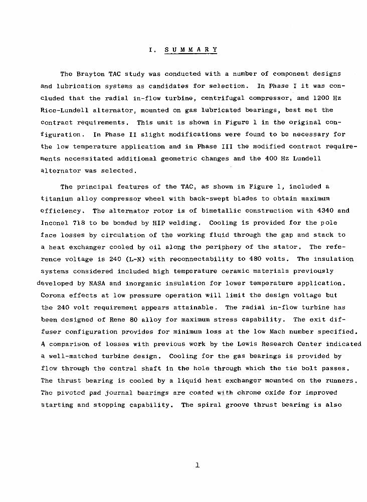
I . S U M M A R Y
The Brayton TAG study was conducted with a number of component designs
and lubrication systems as candidates for selection. In Phase I it was con-
cluded that the radial in-flow turbine, centrifugal compressor, and 1200 Hz
Rice-Lundell alternator, mounted on gas lubricated bearings, best met the
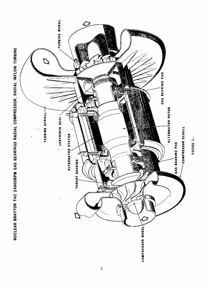
contract requirements. This unit is shown in Figure 1 in the original con-
figuration. In Phase II slight modifications were found to be necessary for
the low temperature application and in Phase III the modified contract require-
ments necessitated additional geometric changes and the 400 Hz Lundell
alternator was selected.
The principal features of the TAG, as shown in Figure 1, included a
titanium alloy compressor wheel with back-swept blades to obtain maximum
efficiency. The alternator rotor is of bimetallic construction with 4340 and
Inconel 718 to be bonded by HIP welding. Cooling is provided for the pole
face losses by circulation of the working fluid through the gap and stack to
a. heat exchanger cooled by oil along the periphery of the stator. The refe-
rence voltage is 240 (L-N) with reconnectability to 480 volts. The insulation
systems considered included high temperature ceramic materials previously
developed by NASA and inorganic insulation for lower temperature application.
Corona effects at low pressure operation will limit the design voltage but
the 240 volt requirement appears attainable. The radial in-flow turbine has
been designed of Rene 80 alloy for maximum stress capability. The exit dif-
fuser configuration provides for minimum loss at the low Mach number specified.
A comparison of losses with previous work by the Lewis Research Center indicated
a well-matched turbine design. Cooling for the gas bearings is provided by
flow through the central shaft in the hole through which the tie bolt passes.
The thrust bearing is cooled by a liquid heat exchanger mounted on the runners.
The pivoted pad journal bearings are coated with chrome oxide for improved
starting and stopping capability. The spiral groove thrust bearing is also
00cc=3I-
5o
oeo
Ofa.SOo
K
V)Oza:<iuOD
(O<a
a.ocooo~OJ
a:00
w
g
oo

similarly coated. Both designs have been successfully applied in gas lub-
ricated rotating machinery. Thrust balancing of the compressor and turbine
will be accomplished by scalloping of the turbine and appropriate selection
of seal diameters. Labyrinth seals are used to isolate the high pressure
turbine and high pressure compressor regions from the bearing cavities. The
dynamic response of the machine indicated a third critical for the Phase III
design of over 40,000 rpm.
The performance of this unit is shown in Table I for the Phase I study,
Phase II low temperature case, and Phase III. The windage losses of the 2-
pole machine are slightly higher than the 6-pole machine due to the longer
alternator rotor. The turbine pressure ratio increase specified for Phase III
has improved the cycle efficiency obtained significantly. To assist in
achieving the low system pressure drop suggested by this change,' the compressor
discharge Mach number was reduced to .005. The alternator electromagnetic
efficiency for the 2-pole machine is shown for the 60 slot design. On the
basis of the overall machine performance, the 2-pole, 400jHz alternator is
found to be feasible with no additional major development problems. The
magnetic unbalance forces of this machine*were estimated on a simplified
basis providing what is considered a very high value." The magnetic unbalance
did not produce design problems for the gas bearing system. An improved cal-
culational method to account for the rotating flux influence will be neces-
sary .for final design purposes but the values are expected to be substantially
less than those estimated. If the spacecraft requirement is for 400 Hz power,
the development of the TAG to directly produce that power appears feasible
and practical. The major alternator problem is the state-of-the-art of rotor
bonding that must be solved for any Lundell design, which is the only develop-
ment problem in this unit.
One of the major critical design problems for the TAG is related to start-up
procedures. These procedures will produce transients in temperature, voltage,
and pressure which have not.been evaluated by the study. The number of such
transients and their severity could require modifications to the design or its
operating characteristics. Jacking gas provisions have been made for starting
and the machine should be compatible with gas injection or motor starting with
the alternator.
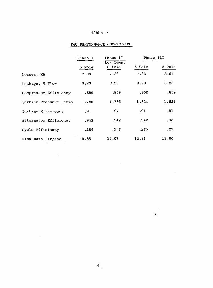
TABLE I
TAG PERFORMANCE COMPARISON
Losses, KW
Leakage, % Flow
Compressor Efficiency
Turbine Pressure Ratio
Turbine Efficiency
Alternator Efficiency
Cycle Efficiency
Flow Rate, Ib/sec
Phase I
6 Pole
7.36
3.23
, .859
o 1.786
.91
.942
.284
9.85
Phase IILow Temp.6 Pole
7.36
3.23
.859
1.786
.91
.942
.257
14.07
Phase
6 Pole
7.36
3.23
.859
1.824
.91
.942
.275
12.81
III
2 Pole
8.61
3.23
.859
1.824
.91
.93
.27
13.06

In the turbomachinery, matching of the compressor rotor and diffuser and
maintenance of operating clearances will be critical design problems. For the
turbine, the casing design to obtain acceptable deflections in the maintenance
of clearances must also be verified. The pressure balance of the turbo-
machinery for the TAG at all loads must be similarly determined experimentally.
For the alternator, the problems include the magnetic unbalance analysis, the
cooling design and the pumping performance obtained with a conical rotor sec-
tion. The current work at the Lewis Research Center on windage losses and
pumping will be important to this program. Corona effects for the high tem-
perature insulation at reduced pressures in helium mixtures must be verified.
The use of Anadur as the high temperature insulation appears questionalbe due
to flaking problems and a substitute material must be selected. The alter-
nator design also requires a non-conducting baffle to guide the returning
cooling flow to the gap region. The selection of this material and method
of attachment are at present undefined. The non-uniform strains with the
bimetallic rotor construction will require analysis, particularly with res- .
pect to start-up transients. The critical design areas for the bearings will
include verification of cooling adequacy to minimize distortions, thrust
bearing mounting, and verification of the magnetic interaction effects. The
dynamic response for the rotor and the characteristics of the principal
resonances must also be investigated. Other areas requiring design study are
discussed in the body of this report. Research packages for the individual
components and a dynamic simulator would be expected to provide results for
most of these critical design problems.
The contract requirements for the Phase I study are shown in Table II.
These conditions were used for the study of six machines to determine the
unit most suitable to the reactor Brayton system. It was found that the
36,000 rpm designs required evacuation of the alternator cavity and that
this could be accomplished with external gas pumping. The sealing of the
cavity by oil or gas was deemed feasible. The oil bearing machines, however,
had excessive parasitic losses and particularly low efficiency resulted at
part load operation. All conditions were met by the Phase I unit shown in
Figure 1. The system for which this unit was considered is shown in Figure
2 with the operating temperatures indicated. The characteristics of the TAC
would appear to integrate well with such a system and to provide high per-
formance for a very wide range of power output with only modest control
5

TABLE II
CONTRACT REQUIREMENTS
SINGLE SHAFT TURBINE ALTERNATOR COMPRESSOR FOR BRAYTON CYCLEPOWER PLANT
160 KWe DESIGN PT. LOAD, 3 PHASE, .75 p.f.
40-160 KW OPERATING RANGE
24.QOO OR 36,000 RPM GAS OR OIL BEARINGS
5 YEARS CONTINUOUS OPERATING LIFE
HIGH EFFICIENCY LIGHT WEIGHT FLIGHT PROTOTYPE MACHINE
1.9 COMPRESSOR PRESSURE RATIO
1.786 TURBINE PRESSURE RATIO
700°R COMPRESSOR INLET TEMPERATURE
206.0°R TURBINE INLET TEMPERATURE
55 PSI COMPRESSOR INLET'PRESSURE AT 24,000 RPM
120 TO 300' PSI AT 36;,000 RPM
39.94 GAS MOLECULAR WEIGHT;
107 RADS TO13 NVT FAST NEUTRON RADIATION LEVEL
SHOCK, VIBRATION, ACCELERATION PER NASA SPECS P2241-1 AND P2242-2
496°F ALT. COOLANT TEMPERATURE
185°F BEARING AND LIQUID SEAL COOLANT TEMPERATURE
120 TO 480 VOLTS
FREQUENCY-MULTIPLE OF 400 Hz
ALTERNATOR DESIGN TO MEET SPEC MIL-G-6099 (A) WITH MODIFIEDPHASE BALANCE REQUIREMENTS
OUTPUT VOLTAGE .5 PERCENT MODULATION
320 KVA .9 p.f. OVERLOAD FOR 5 SECONDS AFTER TEMPERATUREEQUILIBRIUM
SUITABLE FOR PARASITIC LOAD FREQUENCY CONTROL AND PARALLELOPERATION
STARTUP BY MOTORING OR GAS INJECTION

oo
o:oo
O
O
O
Sis'i.D V £ § £O ^ 5 OC H° g o •=> -I5 3 O i- <

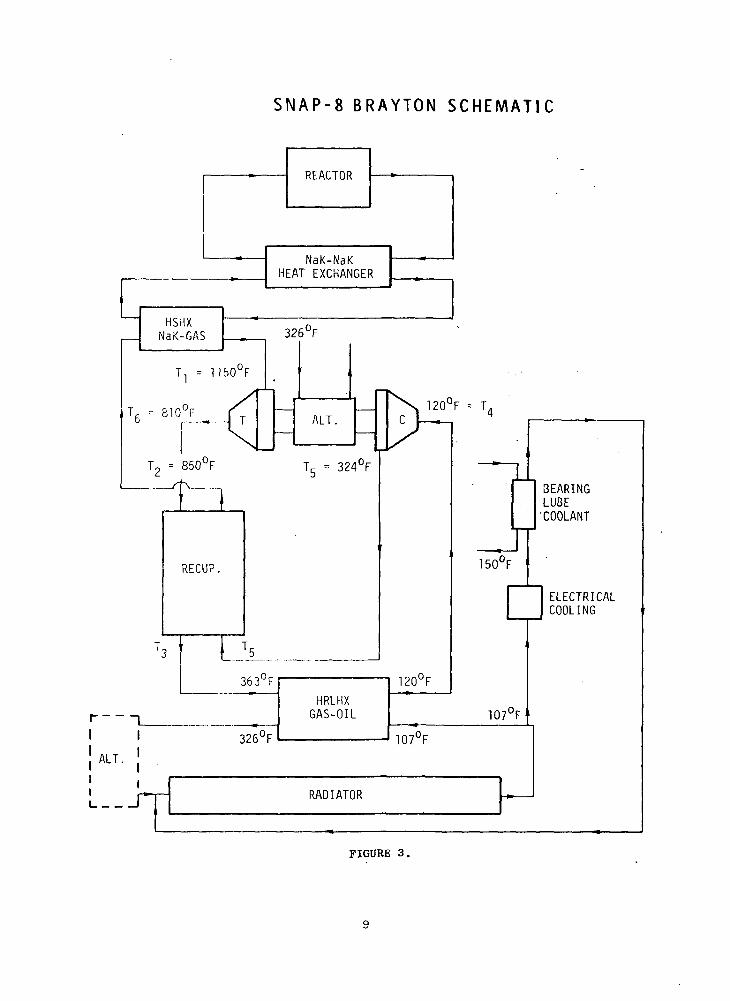
requirements. In Phase II consideration was given to the low temperature
application, the use of high molecular weight gas and a high temperature
application. The low temperature application was for the SNAP-8 Brayton
system as shown in Figure 3. For the Phase III study the contract require-
ments were modified to include:
Total He-Xe mass flow rate 13.73 Ib/sec
Turbine pressure ratio 1.824
Compressor inlet pressure 70 psiao
Turbine inlet temperature 1610 Ro
Compressor inlet temperature 580 R
Test working fluid Argon
Rated voltage 240 L-No
Alternator coolant temperature 325 F
Direct substitution of organic insulated windings with a coolant temperature
of 107 F will be possible. The environmental acceleration was reduced to
1.5 g's during operation. In addition, the capability for operation at a: o
turbine inlet temperature of 2060 R to produce 160 KWe was maintained.
The results of the Phase III study demonstrate the versatility of the TAC
to operate over a range of power levels and temperatures with only minimum
modifications. This flexibility permits it to be used for many module sizes
with the appropriate heat source system.
S N A P - 8 B R A Y T O N S C H E M A T I C
NaK-NaKHEAT EXCHANGER
120°F = T
RECUP.
T3 ' LA
I 1_I I
363°F
326°F
HRLHXGAS-OIL
120°F
107°F
RADIATOR
150°F
BEARINGLUBE'COOLANT
107°F'
ELECTRICALCOOLING
FIGURE 3.
II. I N T R O D U C T I O N
This program, which included a preliminary screening analysis of applic-
able turbomachinery followed by a conceptual design study of one turbo-alter-
nator-compressor, has been conducted by an engineering team from General
Electric, Mechanical Technology, Inc., and Westinghouse. The work of the
program was planned to utilize the pertinent capabilities of each organi-
zation in the design and analysis of the candidate TAG units. The Aircraft
Engine Technical Division performed the definitive studies for the turbo-
machinery and provided key inputs on material selection and rolling element
bearing practices. The gas lubricated bearing and oil film bearing and seal
work, as well as the bearing rotordynamic evaluations, were conducted by MTI.
The alternator studies were provided by the Aerospace Electric Division of
Westinghouse. NSP has provided overall management of the program, conceptual
integration of components and mechanical and thermal integration of the total
package. The extensive resources of each company for analysis and design in
each of the major disciplines required by this complex unit have been applied
to this program. Individual computer programs are identified in each section
of the report. The most recent engineering practices as well as results of
operational and development programs have been integrated into the considera-
tions of the study. As the contract requirements have changes, the response
by the program team has reflected the new emphasis.
At all times, an attempt has been made to bring realism to the program
in terms of providing designs with a high degree of producibility. It was
recognized that the best design must still be built with the practical pro-
cedures used in modern aircraft engines and aerospace electrical equipment.
Of course, it is also evident that special attention must be given to those
requirements which cannot be met by existing techniques. A particular case
in point is the Lundell bimetallic alternator rotor for which NASA has
prudently initiated development in advance of the present program. Where
10

possible, extra design margin has been provided to improve the reliability
of the unit and increase its flexibility for application. One example of
this is in the cooling of the alternator which will operate at 100 F below
the maximum established by the specification and the dynamic response which
indicates an overspeed design margin of over 50% compared to the 20% require-
ment. Wherever practical, such features have been incorporated and are des-
cribed in the report.
11

TABLE III
T U R B O M A C H I N E R Y S U M M A R Y
• COMPRESSOR
TYPE
SPEED, RPM
NUMBER OF STAGES
INLET TIP DIAMETER, IN.
INLET HUB DIAMETER, IN.
EXIT TIP DIAMETER, IN.
EXIT BLADE HEIGHT, IN.
LENGTH, IN.
TIP SPEED, FPS
CHORD, IN.
REYNOLDS NUMBER, pVL/y
CLEARANCE, MIL
FLANGE TO FLANGE TOTAL EFFCY
ONE QUARTER POWER EFFCY
• TURBINE
TYPE
SPEED, RPM
INLET TIP DIAMETER, IN.
EXIT TIP DIAMETER, IN.
EXIT HUB DIAMETER, IN.
INLET BLADE HEIGHT, IN.
LENGTH, IN.
TIP SPEED, FPS
REYNOLDS NUMBER, W/yRtCLEARANCE, MILS
FLANGE TO FLANGE TOTAL EFFCY
ONE QUARTER POWER EFFCY
RADIAL AXIAL
240001
7.25
2.62
10.36
0.4203.01086
_
12.9xl06
10
0.862
0.860
360001
4.84
1.75
6.91
0.2802.01086
_
18.7xl06
10
0.862
0.860
RADIAL24000
11.117.76
3.120.9563.61163
4.5xl05
10
0.9170.902
240007
8.10
6.05
7.52
0.734
6.67849
0.6
3.61xl05
10
0.866
0.837
360007.40
5.18
2.070.692
2.41162
6.8xl05
10
0.916
0.901
360006
5.50
4.10
5.09
0.4954.00864
0.4
5.38xl05
100.862
0.840
14

cavity to about 2-4 psia and sealing from the working fluid pressures. The
rotor stress levels were also sufficiently high to make this design unattrac-
tive. The Lundell unit at 1200 Hz was: found to meet the electromagnetic
requirements at reasonable stress levels and to have acceptable windage losses
operating at compressor inlet pressure for the 24,000 rpm unit. The diffusion
bonding of the bimetallic rotor is currently under development and requires
further work for this application. Corona considerations were found to limit
the machine to 120 volts (L-N) for a minimum operating pressure of 16 psia.
Bearing designs were established for both, gas and oil lubricated systems.
The tilting pad journal and spiral groove thrust bearings are adequate designs
for this application. The gas bearings are sized to provide overload capacity
margin at all conditions. The ,4-G load environmental requirement at the 40 KWe
power level does impose severe loading of the thrust bearing which will be
further examined in Phase III. The bearing surface material will be CrO to' £i
provide start-stop.";and high speed mmf capability. .'The gas bearings offer
minimum losses and design simplicity without contamination by the lubricant.
The oil film journal and thrust bearings are lightly loaded and would have
high reliability. The rolling element bearings are relatively highly loaded for
the 5-year life requirement and represent an extension of existing practice.
The advanced SNAP-8 spiral groove face seal was evaluated for use in isolating
the alternator cavity. The oil mist lubrication system from the Brayton "A"
engine program was adopted to'the TAC requirements. On'the basis of the
relative simplicity and low parasitic losses, the gas lubricated bearings offer
the most favorable design approach. • ' • '
Prom a comparison of the mechanical designs it is concluded that the
24,000 rpm centrifugal compressor with the 1200 Hz Lundell alternator, radial
in-flow turbine on gas lubricated bearings, as shown in Figure 5 , provides
15

OCO
>- IO O£
00
Ooo
16
the most suitable unit for the design conditions. The overall performance of
this unit offers a cycle efficiency of 28.4% at 160 KWe and 24.7% at 40 KWe.
When operated at SNAP-8 conditions it offers a cycle efficiency of 24.2% at
160 KWe due to the lower turbine inlet temperature. The Lundell alternator
requires no isolation by seals to meet the windage losses. Further considera-
tion of part-load corona effects and rotor bonding will be required in Phase III.
The tilting pad gas bearings provide a high over-capacity and the dynamic
response analysis shows a third critical of 48,930 rpm. This unit was recom-
mended for conceptual design in Phase III.
17

B. MECHANICAL DESIGN
INTRODUCTION
^2 mechanical design studies can be roughly. divided into component
design and configuration design. The component mechanical design- studies
dealt with all the problems which had to be solved in Border to make each
of the components practical and reliable. In these studies both centri-
fugal and axial-flow compressors .were studied but the .study was .limited.
to radial-inflow turbines. .The 'gas bearing sizes and design details had
to be determined along with the necessary seals and coolant passages.
Both hydrodynamic and ball bearings lubricated with oil were considered
and the proper seals and cooling for these systems were designed. Design
studies were made of various problem areas associated with the rotor, the
casing, the scrolls, and the ducting.
Six different configuration, designs were made, with each assigned. a
designating symbol, in order to quickly identify it. The.:first two digits
identify the rotative speed in thousands of revolutions per minute, fol-
lowed by either an R or an A for radial-flow and axial-flow compressors.. . ' . - • ; - •.;.;. .- : < . . • ' ; •;;.<•. '• . ' •• ...... ,.- -. •The fourth symbol is a G for gas bearings, M for mist-lubricated ball
bearings , or L for liquid film bearings .
Three TAG units on gas bearings were selected for study under this
program. The 24 RG and 24AG are TAG units rotating at 24,000 rpm, the first
having a radial-flow compressor, and the second having an axial-flow com-
pressor. Both of these machines had no seal between the alternator and
the bearing cavities. At 36,000 rpm'- a gas bearing machine '(36AG) was
designed with an axial-flow' compressor. ' 'Because of the high compressor '
inlet pressure specified it was necessary to provide a spiral-groove
(hydrodynamic) gas face .seal .between the alternator and bearing .cavities.
All of the oil-lubricated bearing machines were designed' for a rota-''
tive speed of 36,000 rpm. Both axial-flow and radial-flow cpmpressors
(36RM and 36AM) were used in the two ball-bearing machines. Only one
liquid film bearing machine (36RL) using oil as a lubricant was designed,
which had a radial-flow compressor.
Before discussing these mechanical designs, the design specifications
will be summarized. The alternator output power, range was,, .to be from 40
to 160 KW, electrical, with a power, factor of 0.75, lagging'. The alternator
18
was to produce 3-phase power. Mechanical design considerations were to
include operating speeds from 0 to 120 percent of the design values. The
compressor inlet pressures were to be 55 psia for 24,000 rpm and from
120 to .360 psia for 36,000 rpm. Although the turbine inlet temperature
was specified as 1600 F, it was necessary to design the turbine for opera-
tion at 1640 F due to the deadband anticipated in the reactor. The'com-
pressor inlet temperature was specified as 240 F. Two heat sinks for
cooling were specified. The oil coolant for the alternator was to be
supplied at 496°F and oil to cool certain seals and the oil absorber was
to be supplied at 185°F.
For the gas bearing machines the working fluid was to act both as
coolant and lubricant. Argon was specified for development but the final
spacepower plant was to use a helium-xenon gas mixture having the same
39.94 molecular weight as argon. Both paraffinic- and napthenic-base oils
were to be considered as the liquid coolant and lubricant.
The powerplant was required to operate in a radiation environment
having an integrated gamma dose of 10 rads and a neutron flux of 10 nvt
fast neutrons per square centimeter (> 1 Mev).
Environmental specifications P-2241-1 and P-2241-2 were adhered to
for the TAG unit. Although these specifications are quite detailed, the
most severe condition is the 3.5G acceleration maneuver load the power-
plant is subjected to in space flight. This load sizes the thrust bearings.
The design life of the TAG was specified as 5 years. This puts em-
phasis on high reliability and encourages simplification of the designs.
For the mechanical design of the compressor and turbine and for the
integration of all the components into TAG configurations several programs
were utilized.
THERMAL AND STRESS ANALYSIS
The transient heat transfer computer code THTD was used to determine
both transient and steady state temperature distributions. This is a
finite-node heat-transfer program which has been well developed through
years of use in GE-AEG and NSP. The static and rotating parts are divided
into three-dimensional elements, with the program able to model blade
elements and flowing fluid nodes when required.
19

Provisions are made for body and boundary radiation, surface heat
flux, internal heat generation, variable material properties, variable
boundary conditions, and phase changes.
Output may be called for at selected time intervals so that transient
temperature plots may be made.
The TAG models utilized about 1000 nodes and output was printed at
1, 10, 100, 1000, and 10,000 sec.
ROTOR is an important new finite-element computer program developed
by GE-AEG for the GE-12 engine to determine the stress and deformation of
centrifugal compressors. The program permits the efficient and accurate
analysis of three-dimensional axisymmetric stress distribution in solids
of revolution, with or without radial blades attached, and subject to
static, thermal, and centrifugal loads. It calculates the variation of
material properties with temperature and the ratio of allowable stress to
imposed effective stress. Automatic plotting is available.
The SNAP program analyses structures as systems of cones, disks,
cylinders, and toroidal shells with or without rigid ring connectors.
Unusual elements such as cutouts can be analyzed provided the equations
of compatibility can be written. It is particularly applicable to the
TAG casings.
The program allows the imposition of axisymmetric loads, including
centrifugal loads, and temperature variations. Elastic stresses and
deformations are determined at a number of stations for each structural
element. It is widely used in GE-AEG but is limited to relatively thin
structures to which small deflection theory is applicable and materials
which follow Hooke's Law; it excludes buckling.
MASS is an elemental or lumped-parameter approach for the analysis
of redundant structures. Stresses, loads, and deflections are obtained
for mechanical loadings, thermal gradients, and sinusoidal forcing func-
tions. This program was used to ascertain critical frequencies and mode
shapes of the casing of one typical TAG configuration.
RECAP (Rolling Element Computer Analysis Program) is a well-established
computer program used by many organizations throughout the country to
analyze rolling-element bearings. Standard AFBMA formulas are used, with
the addition of centrifugal loading of the outer races by the balls.
20

The following two basic bearing systems may be evaluated:
- A rigid system, where all deflections occur in the bearings.
- A flexible system, where shaft and housing deflections are also
considered.
The program considers the effect of external radial and axial loads
imposed on a set of two bearings as well as the ball centrifugal forces.
Stresses and predicted B._ life are calculated, based upon the use
of bearing quality 52100 steel. Adequate lubrication at all times is
assumed.
In addition, both critical speed and forced (unbalance) response
computer programs were used which take into account bearing mass, bearing
support stiffness and damping, stiffness and damping of the lubricant
film itself, rotor flexibility and gyroscopic effects, and effects of
couplings. The programs permit analysis of the effects of casing flexi-
bility on rotor critical speeds and response. A computer program is also
available to determine lateral response of rotors supported by rolling-
element bearings having non-linear stiffness characteristics.
TAG Material Allowable Stresses
The principal materials considered for use in the TAG machine are
listed in Table IV, with the alternator materials discussed later. The
compressor material is the titanium alloy Ti-6Al-5V, which is used in
aircraft gas turbine engines and airframe parts. The principal range
of temperature interest for this material is 250-500 F. At the lower
temperatures the short-term 0.2 percent yield stress and ultimate tensile
stress can be of more importance when they are less than the long-term
properties. This is because the allowable design stresses for the short-
term 120 percent speed conditions are reduced by an overspeed corrector
below their average properties minus three standard deviations (99.6 per-
cent assurance against receiving material with lower properties). By
doing so, the rotor components may be analyzed at design speed only, with
conservatively safe assurance that the rotor stresses will not exceed
the allowable stresses at overspeed. At about 550 F the five year 0.2 per-
cent creep and rupture properties of Ti-6Al-4V become less than the ad-
justed short-term properties. No overspeed correction is applied to the
21

TABLE IV
TAC MATERIAL ALLOWABLE S T R E S S E S
COMPRESSOR MATERIAL
MATERIAL
T1-6A1-4V
TEMPERATURE°F
250500
0.2% Y.S.KSI
96.0'
5-YR0.21 CREEP
KSI
-66.3
UTSKSI
100.0-
5-YRRUPTURE
KSI
-80.3
ROTOR MATERIALS
RENE 80
H-ll
8001470
500800
84.0
124.8
17.2*
53.6
109.0
137.1
21.0
81.4
*0.1% CREEP
CASING MATERIAL
HASTELLOY X 2501640
38.4 _ 95.7
2.4
22
five year properties because overspeed will occur for only short periods
of time.
The turbine material considered, is the nickel-base superalloy Rene' 80
which is used in aircraft gas turbine blades and nozzle vanes. Its princi-
pal range of interest is between 800-1470 F. The dominance of the five
year properties over the adjusted short-term properties starts about
1100°F.
The iron-base alloy H-ll is considered for use in the stub shafts,
bearings, and seal plates because it is one of . the materials which might
be used in the alternator and is typical of the other materials which
could be specified. It is one of the hot-work die steels. The five year• • • • " ' • ' . . ; . Q
, properties of H^-ll are of primary importance above 700 F. 'i ' - . ' • " " • :
• The casing material considered is Hastelloy X, a nickel-base alloy
used in a-ircraft gas turbine blades, nozzle vanes, and sheet metal com-1 ponents." Its-primary range of interest is from 250-1640 F. It possesses
more strength than needed for the casing forward end to the aft end of the
alternator and. a cheaper- materia-l.-could be substituted. At the. highest
•I temperature'•in'1'the !turbine inlet scroll, a 'material of even higher strength: ' • *1 will be needed unless the scroll can be effectively cooled.
/ CONFIGURATION COMPARISONS ; - ;; .,'* • ' f *'
'• . -. -. •- - • •.. -..-.. /The 24RG Configuration. 1. . -. .. .i';):;v.' :,; :";-The configuration drawing of the 24,000 rpm, centrifugal compressor
TAG on gas bearings is shown by Figure 5,. 'The argon or helium-xenon
mixture gas enters the TAG from the left side of the figure at 240 F and
.; 55 psia a.nd passes through the centrifugal 'compressor, which has eye andI •> • : . ' : : "
.; tip diameters of 5.25 and 8.8 inches, respectively. The diffuser has
three vane rows. The working fluid leaves the compressor at 105 psia and
500°F. It returns from the reactor at 1600°F with a slight decrease in
pressure to the turbine inlet scroll at the aft end of the TAG. Passing
through the turbine nozzle vanes, the gas enters the turbine rotor at
1400°F and is discharged at 1310°F and 56 psia. The mass flow rate is
11.1 Ib/sec. The turbine inlet tip diameter is 11.11 in. and its exit
tip diameter is 7.76 in.
23

onoto«/>UJO£D_
UJS-J O
£Yo a:
CDi
OCDO£
oo ts os: zLU •-' ce_i o o
.CQ 2: i— t/io o o uiQ: OQ Q£ 4JO. Z
o£ ce<roc o o i
o: ceoUJ UJ(-1-0-
§
LU fcO _lO O -J«« «-i<C CC|_ £ UJ UI2: «t to 3
> >• ac o.o o o<C t— t3
cc <t :z_l OZ 1-1<C i— oe o:1-1 O Ul<t(— a: i— uiz _i CQUI O «X1 - 0 3O O O O0. O Z _J
24

The rotor is supported by tilting-pad gas bearings which straddle
mount the alternator. The compressor and turbine are overhung. The
tilting-pad gas thrust bearing is located between the compressor and
alternator. The bearing cavities are vented (by means not shown) to the
compressor inlet pressure. The heat generated in the gas journal bearings
is removed by a flow of cooling gas ducted from the compressor discharge
to the aft end of the hollow tiebolt. The gas flows through fins inside
the two journals, discharging along the turbine disc forward face and
into the forward bearing housing. The thrust bearing stator is an oil-
cooled heat exchanger which removes the heat generated in the bearing.
The rotor is joined by curvic couplings which are clamped by an
axial preload provided by the tiebolt.
Because the Lundell alternator has low windage losses, it is possible
to minimize the sealing problems by allowing the alternator to operate in
an environment of gas at compressor discharge pressure. Simple labyrinth
seals are needed only aft of the compressor and forward of the turbine.
The thermal analysis of this machine, typical of the rest of the
configurations, used a thermal model of about 1000 volume elements. The
assumed temperatures used as boundary 'conditions are shown in rotor and
stator cavities and the alternator, with another number in parentheses
which is the surface heat transfer coefficient for all surfaces bounded
by the cavities. At lines indicating the contact of two different com-
ponents the figures in parenthesis indicate contact coefficients. The
10,000 second temperatures are considered the steady-state conditions,
which can be verified by plotting the temperatures of selected elements
versus time. Such plots also identify areas of high thermal gradients.
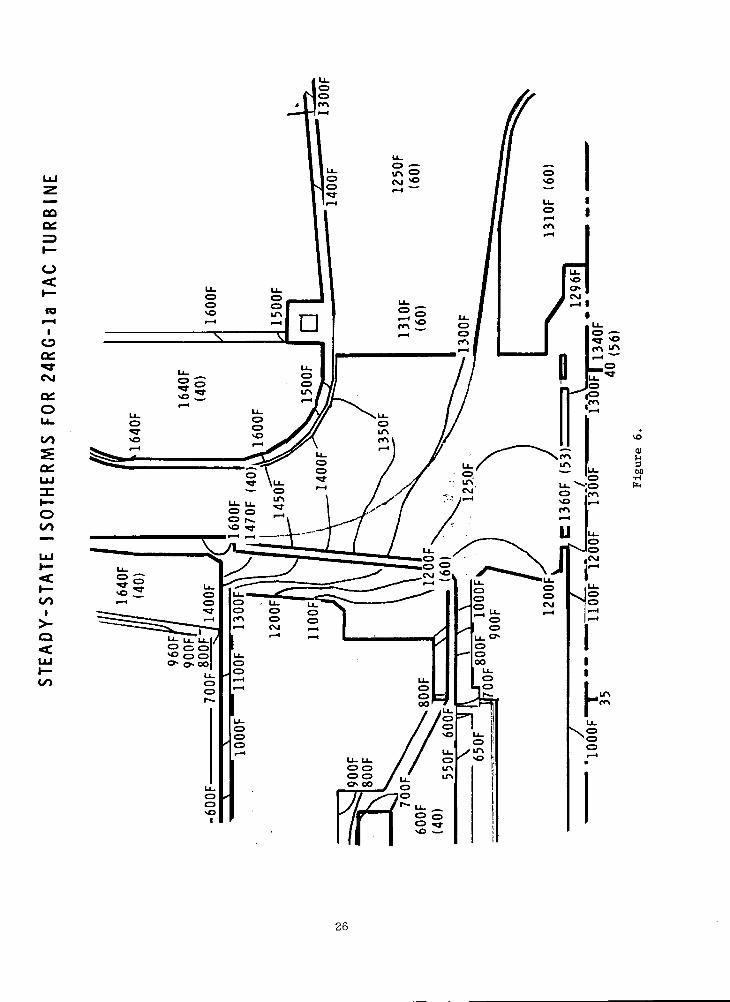
A more detailed representation of the isotherms of the 24RG turbine
is shown in Figure 6. The maximum turbine temperature of 1470 F occurs
at the blade inlet tips, where the stresses are very low. The temper-
ature of the most highly stressed point, the hub bore directly beneath
the hub tip, is 1225°F.
The thermal expansion of the 24RG configuration is shown on Fig-
ure 7. This is based upon the thermal analysis, the thermal expansion
properties of the materials, the original lengths of components, and the
combined thermal and dynamic distortions of the rotor components as
25
toI— II
Oa:**<M
a:
Ooo
i>-o
(11M
I
26

o
< 2h- <
Q.
00UJ
\
I—<us4ffc
27
calculated by the stress analysis computer program. The thrust bearing
is considered the fixed point axially. The thermal expansions are shown
by the sets of two numbers, the number followed by "S" being the expansion
of the stator and that followed by "R" being the expansion of the rotor
over the indicated length. The groups of three numbers at points where
clearances are critical identify the opening or closing of the gaps due
to centrifugal and thermal deformations (6), the required or allowable
assembly clearances (Assy), and the resulting hot running clearances (Hot).
These indicate that it might be possible to achieve the desired ten mil hot
running clearances. However, there are other clearance considerations.
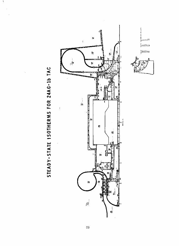
The steady-state isotherms from the thermal analysis of the 24RG
configuration are shown in Figure 9. The figure defines a zone of
temperatures less than 500 F which includes the forward end of the rotor
to the alternator, and the tiebolt and the forward end of the casing to
the aft end of the alternator. The thrust bearing is slightly above
500°F. Temperatures between 500-1000°F exist in the alternator rotor and
stator, the aft stub shaft, short lengths of the tiebolt and aft bearing
housing (casing), and the insulation around the turbine inlet scroll and
exhaust duct.
The other clearance considerations are listed in Table V. A principal
one is the practical assembly consideration that the desired dimensions may
be missed by 2.5 mils even with the greatest of care. Also, interference
between components can be excluded. The assumptions for thrust- and journal-
bearing deflections are listed. No casing deflections have been determined.
The minimum clearance is set by bearing deflection caused by operation at
an acceleration of 4G.
The synopsis of clearances at zero G are shown in Table VI. The
opening or closing of the critical gaps is the first item listed for each
clearance, and comes from Figure 7. The next is the zero bearing de-
formation with its 4G limit. The third is the desired assembly gap
clearance with its tolerance. The last two figures in each group are
the minimum and maximum hot running clearances, with the maximum being
of most importance because of its adverse effects on efficiency. The
table shows that it will probably be impossible to guarantee ten-mil
clearance at the turbine inlet blade tip axial gap, the turbine exit
blade tip radial gap, and the compressor exit blade tip axial gap.
28
o<
CM
egO
i>-o
29

TABLE V
DIFFERENTIAL THERMAL EXPANSION ANDTAG TURBOMACHINERY CLEARANCES
• MINIMUM ASSEMBLY CLEARANCE + 2.5 MILS
• TOTAL THRUST BEARING DEFLECTION AND DISPLACEMENT (4G), MILS
- GAS BEARINGS 13.2
- BALL BEARINGS 1.0
- LIQUID FILM BEARINGS 4.0
• TOTAL RADIAL BEARING DEFLECTION AND DISPLACEMENT (4G), MILS
- G A S BEARINGS . 7 . 1
- BALL BEARINGS 4.2
- LIQUID FILM BEARINGS 4.0
• NO CASING DEFLECTION ASSUMED
• TARGET TIP CLEARANCE (ZERO G) 10 MILS
• TARGET AXIAL CLEARANCE (AXIAL COMPRESSORS) 40 MILS
• MINIMUM CLEARANCES SET BY OPERATION AT 4G
30
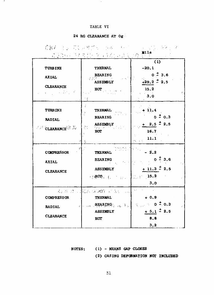
TABLE VI
24 RG CLEARANCE AT Og
Mils
TURBINE
AXIAL
CLEARANCE
TURBINE
RADIAL
.<• • i -' , t '" I 1 '
•" CLEARANCE^-'-
...
COMPRESSOR
AXIAL
PI FARANPF\f Aj£tfumii w EI
~', , ] , _ • " - ! . .
COMPRESSOR
RADIAL
CLEARANCE
THERMAL
BEARING
ASSEMBLY
HOT
• .r
THERMAL
BEARING
ASSEMBLY
HOT
,,.
THERMAL
BEARING
ASSEMBLY
-<>HOTv |. • ....
<•.;-. :^>.nn j . - . x - . , . ,THERMAL
._,, .BEARING:. : ,-_ i ._ ,
ASSEMBLY
HOT
(1)
-20.1
0 - 3.6
+29.2 1 2.5
15.2
3.0
+ 11.4
0 - 0.3
+ 2.5 - 2.5
16.7
11.1
- 2.2
0 - 3 . 6
+ 11.3 - 2.5
' / . - ' " 15-2
3.0
+ 0.9
. .-.. 0 - 0.3
+ 5.1 * 2.5
8.8
3.2
NOTES: (1) - MEANS GAP CLOSES
(2) CASING DEFORMATION NOT INCLUDED
31

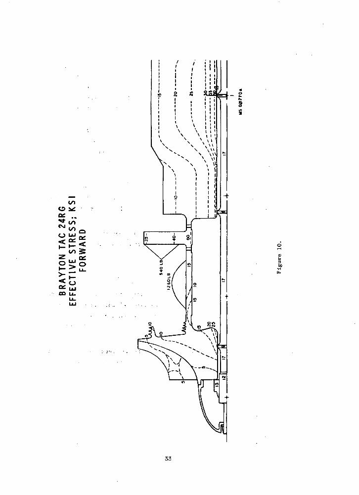
The effective stresses calculated for the 24RG configuration, based
upon centrifugal and thermal stresses and external loads, are shown in
Figures 10 and 11 . The external loads include the tiebolt preload of
5000 pounds and the journal- and thrust-bearing loads distributed as
indicated. The most critical compressor stress is 26 ksi at its aft bore,
which gives a factor of safety of 2.1 with respect to the material allow-
able stress. The 60 ksi thrust bearing bore stress gives a factor of
safety of 1.8. The alternator stresses are explained in more detail later,
but its maximum indicated bore stress of 55 ksi gives a factor of safety
of 2. The critical turbine bore stress of 40 ksi uses all of the
material strength, giving a unity factor of safety.
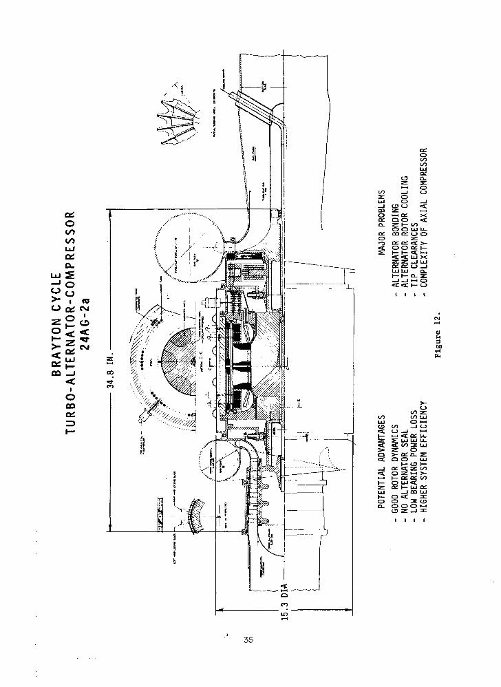
The potential advantages of this arrangement are that it has good
rotor dynamic characteristics, requires no alternator seal, has low bear-
ing power losses, and higher system efficiency than the similar TAG with
a radial compressor.
Major problems of the design to be overcome include the alternator
bonding problems, alternator rotor cooling problems, and the maintainance
of tip clearances.
The 24AG Configuration
The configuration drawing of the 24,000 rpm, axial compressor TAG
on gas bearings is shown by Figure 12. The major details of this machine
differ from those of the previously described 24RG TAG only in the com-
pressor details. The 7-stage compressor has a maximum diameter of 8 in.
The compressor blading is followed by an outlet guide vane and a diffusion
scroll.
For best clearance control the thrust bearing has been placed forward
of the turbine, since the axial compressor can tolerate axial displacement
better than the turbine.
Other details shown are the compressor blade locking method and the
scalloped turbine hub required to decrease the stresses in the turbine bore.
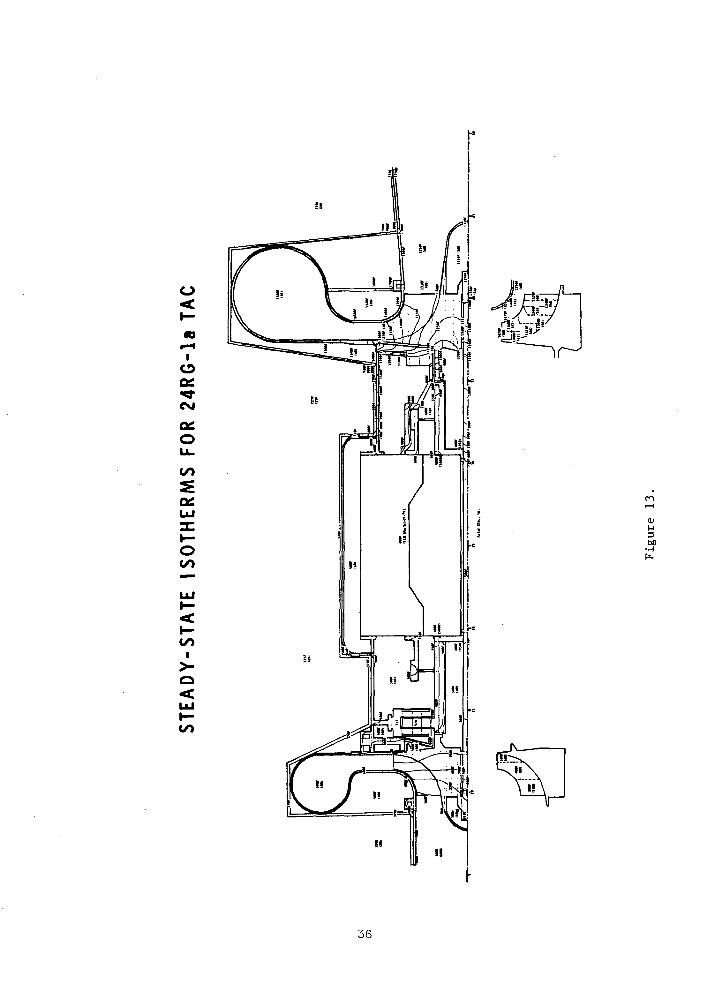
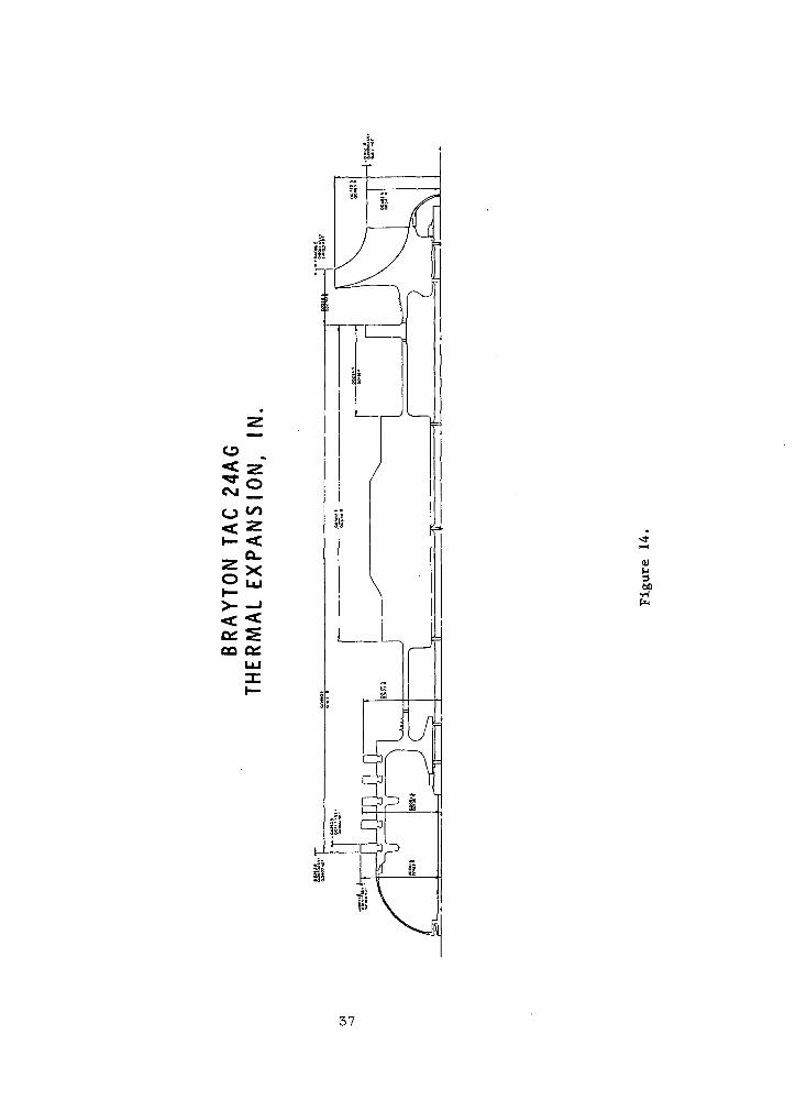
The steady-state isotherms of the 24AG TAG shown by Figure 13 are
very similar to those of 24RG. Its thermal expansions are shown by Fig-
ure 14 and its critical clearances are summarized in Table VII. The
turbine inlet blade tip axial gap, turbine exit blade tip radial gap,
• 32
00O
CSJ
O
CD U.
3<n
60
33

COo
OQ U_
00
34
OCOCO
>• i coo c£ «M
CD
lOooOf
COLU
_l CO O «Cco z i-;O •-• CC Xo: o o <ca. z i— to
o o LU u_ex. co o£ o oo z•-3 o: o; < s-< o o 3. (—S l— i— «c 1-1
«C <t LU Xz: z _i LUa: ce: o _jLU LU D-
.•-i OH- O
t>0•H
CO 4/1 LULU O >-t<J OO I O< O _J •-"h- >-i *f. O£. U-z s: LU LU u_CC CC OO 3 LUs» z oa >- a; a. 2:ct Q O LU
I— tfl I—_j o: ec z oo«*: o ZI-H >-i—i t— o: a? to(— O LUctz ct: i— LU a:LU _i co LUt— a <C :ro o 3 toa. o o o •—i
i
35
o<
IoO£«*CM
0£OLJU
CO
5OHUJ
I—OCO
LUI—<
li...
0)M350
36
o
sio >< zh- <
Q_
00
37
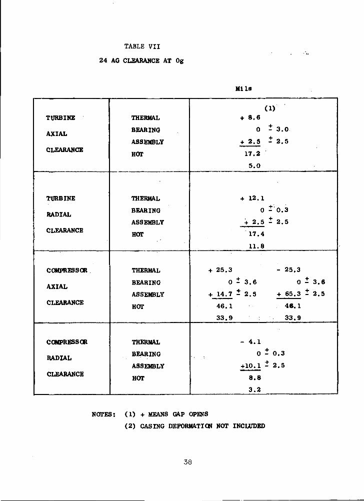
TABLE VII
24 AC CLEARANCE AT Og
Mils
TURBINE
AXIAL
CLEARANCE
TURBINE
RADIAL
CLEARANCE
COMPRESSOR
AXIAL
CLEARANCE
COMPRESSOR
RADIAL
CLEARANCE
THERMAL
BEARING
ASSEMBLY
HOT
THERMAL
BEARING
ASSEMBLY
HOT
THERMAL
BEARING
ASSEMBLY
HOT
THERMAL
BEARING
ASSEMBLY
HOT
(1)+ 8.6
0 - 3.0
+ 2.5 - 2.5
17.2
5.0
+ 12.1
0 - 0.3
+ 2.5 - 2.5
17.4
11.8
+ 25.3 - 25.3
0 - 3.6 0 - 3.6
+ 14.7 - 2.5 + 65.3 - 2.5
46.1 46.1
33.9 33.9
- 4.1
0-0.3
+10.1 - 2.5
8.8
3.2
NOTES: (1) + MEANS GAP OPENS
(2) CASING DEFORMATION NOT INCLUDED
38

and compressor blade axial gap maximum hot running clearances all exceed
the target values. The desired axial clearance between the axial com-
pressor blades and vanes is 40 mils or slightly greater.
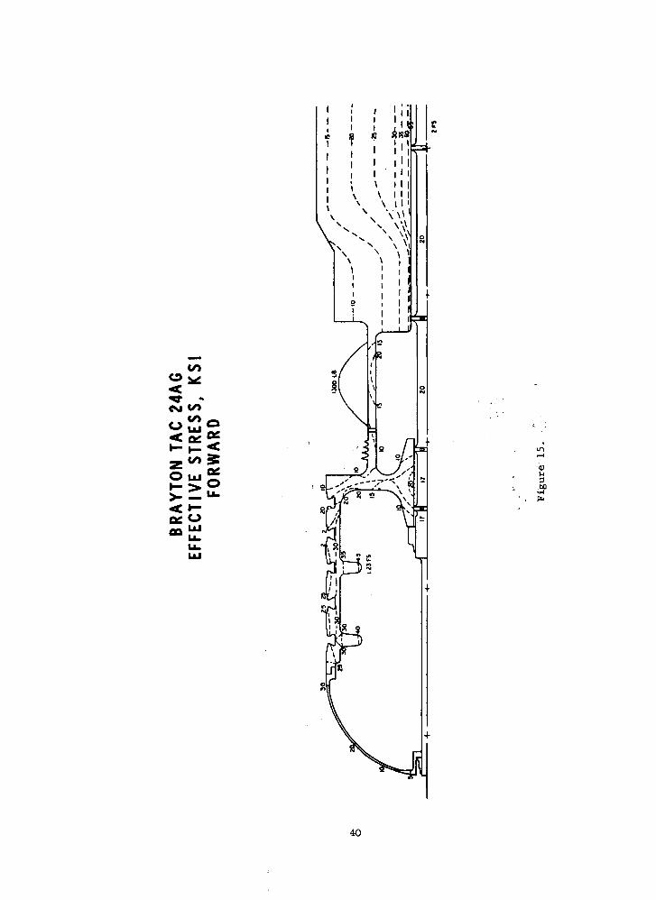
The effective stresses of the 24AG TAG are shown in Figures 15 and 16.
The maximum compressor effective stress of 45 ksi at the center support
ring gives a factor of safety of 1.23. The critical stresses and factors
of safety in. .the other rotor components are the same as for 24RG. Fig-
ure 17 shows representative compressor blade principal stresses for
both 24,000 and 36,000 rpm axial compressors. The factors of safety for
all locations and speed conditions are quite generous.
Blade vibration calculations made using theoretical and empirical
formulas from the literature' ' are summarized in Table VIII. Thee
ratios of exitation frequency to critical frequency f /f are closer than"X
desirable for the. third critical frequencies of the initial stages of both
24 and 36 krpm axial compressors, for the second and third critical fre-
quencies of the 24 krpm axial compressor final stage, and for the third
critical frequency of the 36 krpm axial compressor final stage. The
problems can be minimized by shifting half of the nozzle vanes circum-- v ' - 0
ferentially'-*' and by changing the number of nozzle vanes per stage.
The potential advantages of this arrangement are that it also has
good rotor "dynamic characteristics, requires no alternator seal, and has
low bearing power losses.
The major problems to be overcome include those of rotor bonding,
alternator rotor cooling, and maintenance of tip clearances.
39
Ill
V
o <^ -CM «/>
< i-
.00
40

o<cCM
O tu>— >>- —< *—o: o-s
0)
00•HPu

R E P R E S E N T A T I V E A X I A L C O M P R E S S O R B L A D E A N DD O V E T A I L S T R E S S E S A N D F A C T O R S O F S A F E T Y F O R
Ti-6A'l-4V M A T E R I A L
MAX. BLADEBENDING STRESS
ROOTCENTRIFUGAL
STRESS
100% SPEED (CREEP)
BENDINGFORCE
: NECK CENTRIFUGAL STRESS
MAXIMUM COMBINED STRESS
BENDING STRESS
COMPRESSOR
STAGE
TEMPERATURE, °F
ALLOWABLE STRESS, KSI
ROOT CENTR. STRESS, KSI
FACTOR OF SAFETY
COMBINED STRESS, KSI
FACTOR OF SAFETY
120% SPEED
24 AG
(YIELD)
36 AG
350
87.7
12.7
6.9
15.2
5.8
I
79.0
11.9
6.6
10.3
7.7
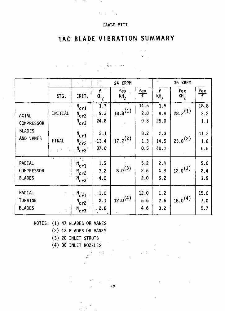
TABLE VIII
TAC BLADE V I B R A T I O N SUMMARY
AXIAL
COMPRESSOR
BLADES
AND VANES
STG.
INITIAL
FINAL
RADIAL
COMPRESSORBLADES
RADIAL
TURBINE
BLADES
CRIT,
N
Ncr2Ncr3
NcrlNcr2.
::Ncr3
N icrlNcr2Ncr3
• NcrlNcr2'N 'cr3
: 24 KRPMfKHZ
1.3
9.324.8
2.1
13.437.6
1.5
3.2
4.0
..il.62.1
. 2.6
fexKHZ
18.8(1)
17,2(2),
/o \8.01 '
*,«>
fexf
14.52.0
0.8
8.2
.1.30.5
5.2
2.52.0
12.0
5.6
4.6
36 KRPM
fKHZ
1.5
8.8
25.0
2.3
14.540.1
2.4
4.86.2
1.2
2.6
3.2
fexKHZ
28. 2 )
25.8 )
/ - \12. 0( >
18.0(4)
fexf
18.8
3.2
1.1
11.2
1.80.6
5.0
2.4
1.9
15.0
7.0
5.7
NOTES: (1) 47 BLADES OR VANES(2) 43 BLADES OR VANES
(3) 20 INLET STRUTS(4) 30 INLET NOZZLES
43
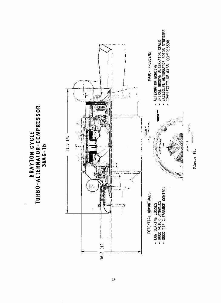
The 36AG Configuration
The configuration drawing of the 36,000 rpm, axial-flow compressor
TAG on gas bearings is shown in Figure 18.
The arrangement of the major components is very similar to that
of the 24AG TAG previously described, the primary differences being in
the areas of gas properties, component sizes, and the need for alternator
seals. While the rotor cooling system is shown as being different from
that of the previous machines, it could actually be the same.
The argon or helium-xenon gas mixture enters the TAG compressor at
240°F and 120 psia and passes aft through the axial compressor, which
has a maximum tip diameter of 5.3 in. Turning ninety degrees through
a diffuser, the gas enters the compressor discharge scroll at 228 psia
and 500°F. It returns from the reactor at 1600°F with negligible
decrease in pressure to the turbine inlet scroll. Passing through the
turbine inlet guide vanes, the gas enters the turbine rotor at 1400°F
and is discharged at 1310°F and 125 psia. The mass flow rate is 11.7 lb/
sec. The turbine inlet tip diameter is 7.27 in. and its exit tip diameter
is 5.18 in.
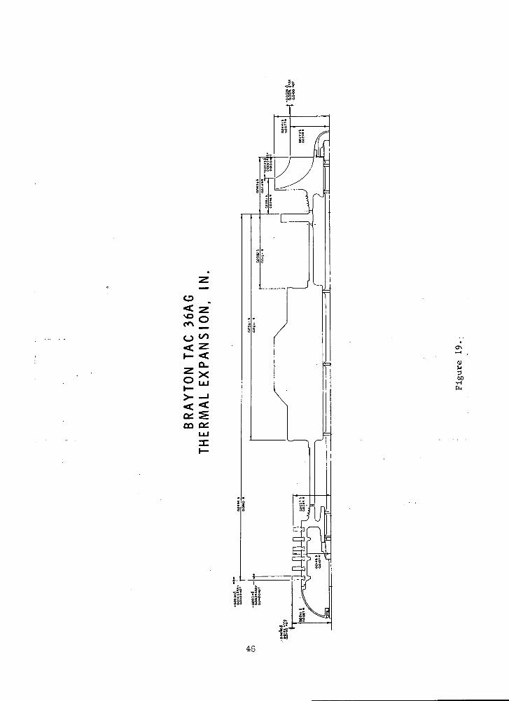
The thermal expansions and clearances of the 36AG TAG are summarized
by Figure 19 and Table IX. Only the turbine inlet blade tip axial
clearance and the compressor axial gap exceed the target values slightly.
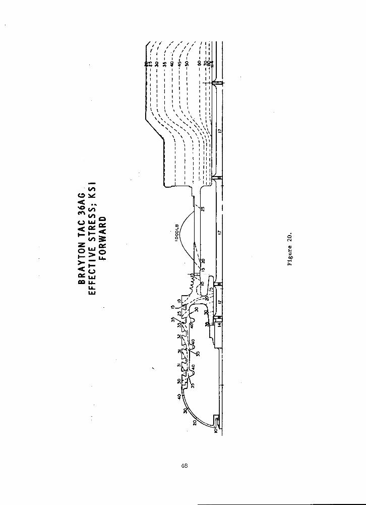
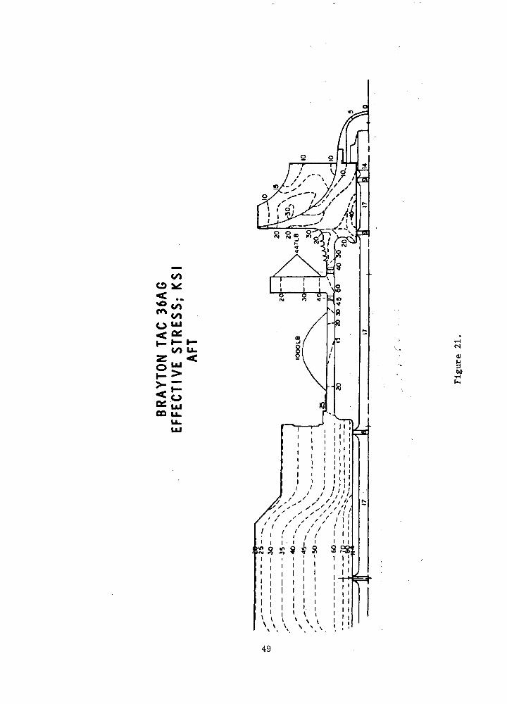
The rotor effective stresses are shown on Figures 20 and 21.
The minimum compressor factor of safety is 1.2, alternator minimum
factor of safety is 1, thrust bearing minimum factor of safety is 1.8,
and the turbine minimum factor of safety is unity.
The alternator seals (described later) are items of considerable
complexity and are required because of high windage losses which would
occur if the alternator were operated at the compressor inlet pressure,
even though the smooth outer surface of the Lundell alternator rotor
minimizes windage losses.
The major potential advantages of this arrangement include low
bearing losses, good rotor dynamics, and good tip clearance control.
44
00
IOOQQg
< zI- <
a: S00 OH
0)P
•HP-H
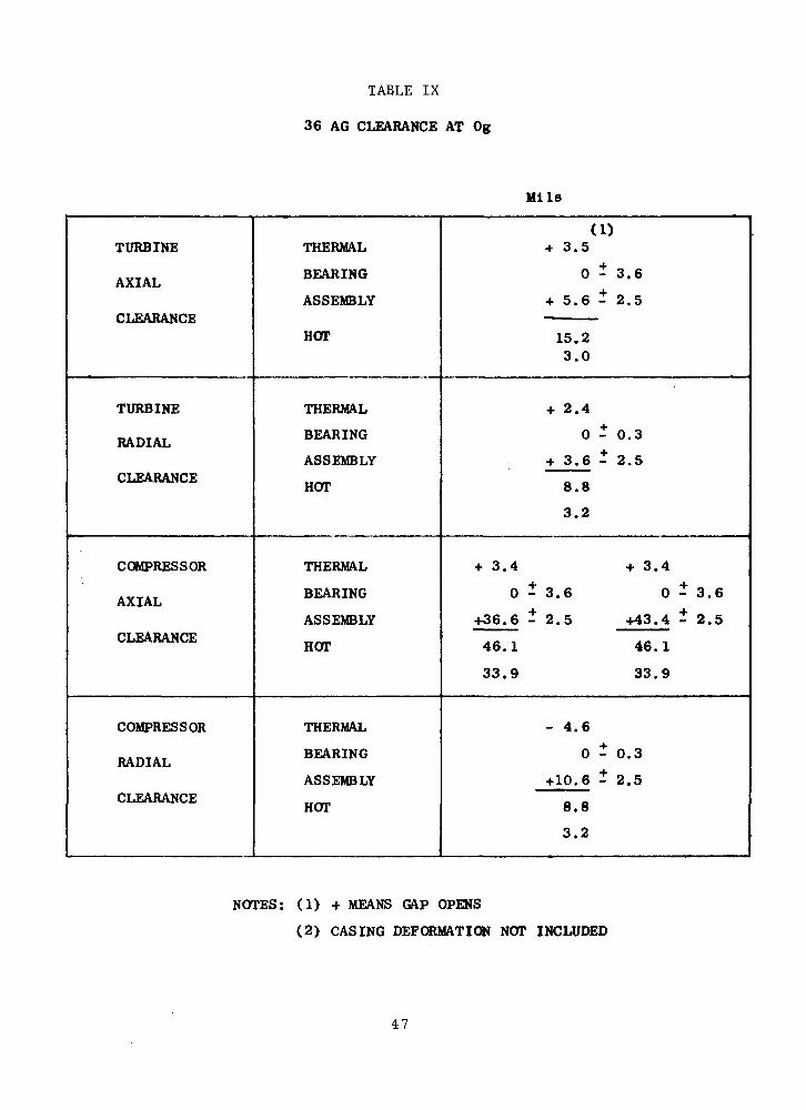
TABLE IX
36 AG CLEARANCE AT Og
Mils
TURBINE
AXIAL
CLEARANCE
TURBINE
RADIAL
CLEARANCE
COMPRESSOR
AXIAL
CLEARANCE
COMPRESSOR
RADIAL
CLEARANCE
THERMAL
BEARING
ASSEMBLY
HOT
THERMAL
BEARING
ASSEMBLY
HOT
THERMAL
BEARING
ASSEMBLY
HOT
THERMAL
BEARING
ASSEMBLY
HOT
(1)+ 3.5
0 - 3.6
+ 5.6 - 2.5•
15.23.0
+ 2.4
0 - 0.3
+ 3.6 - 2.5
8.8
3.2
+ 3.4 + 3.44. 4.
0 - 3 . 6 0 - 3.6O. 4.
+36.6 - 2.5 +43.4 - 2.5
46.1 46.1
33.9 33.9
- 4.6
0 - 0.3
+10.6 - 2.5
8.8
3.2
NOTES: (1) + MEANS GAP OPENS
(2) CASING DEFORMATION NOT INCLUDED
47
o<NO
<?*oCM
60•H
48
COo
CO LUz <
5^06 UJCD U.
u_UJ
I \
!0
'*
<u
*60•Hfc
$S8 S S
•7*t
49
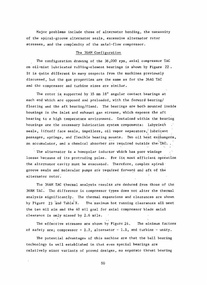
Major problems include those of alternator bonding, the necessity
of the spiral-groove alternator seals, excessive alternator rotor
stresses, and the complexity of the axial-flow compressor.
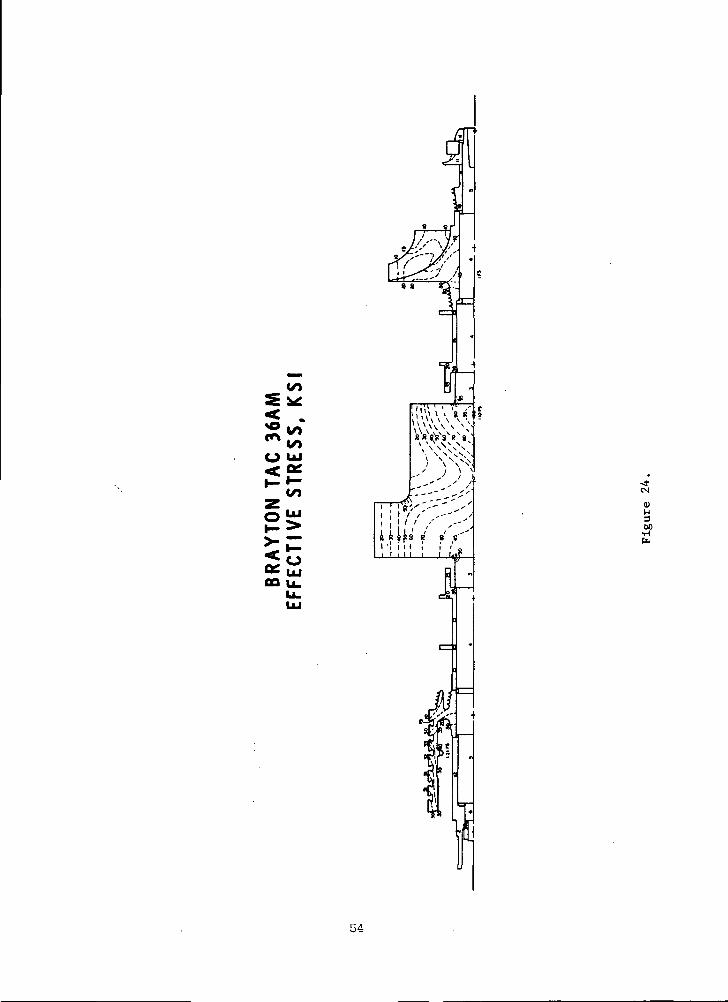
The 36AM Configuration
The configuration drawing of the 36,000 rpm, axial compressor TAG
on oil-mist lubricated rolling-element bearings is shown by Figure 22 .
It is quite different in many respects from the machines previously
discussed, but the gas properties are the same as for the 36AG TAG
and the compressor and turbine sizes are similar.
The rotor is supported by 35 mm 18° angular contact bearings at
each end which are opposed and preloaded, with the forward bearing/
floating and the aft bearing/fixed. The bearings are both mounted inside
housings in the inlet and exhaust gas streams, which exposes the aft
bearing to a high temperature environment. Contained within the bearing
housings are the necessary lubrication system components: labyrinth
seals, liftoff face seals, impellers, oil vapor separators,' lubricant
passages, springs, and flexible bearing mounts. Two oil heat exchangers,
an accumulator, and a chemical absorber are required outside the-TAG'. ,
The alternator is a homopolar inductor which has poor windage
losses because of its protruding poles. For its most efficient operation
the alternator cavity must be evacuated. Therefore, complex spiral-
groove seals and molecular pumps are required forward and aft of the
alternator rotor.
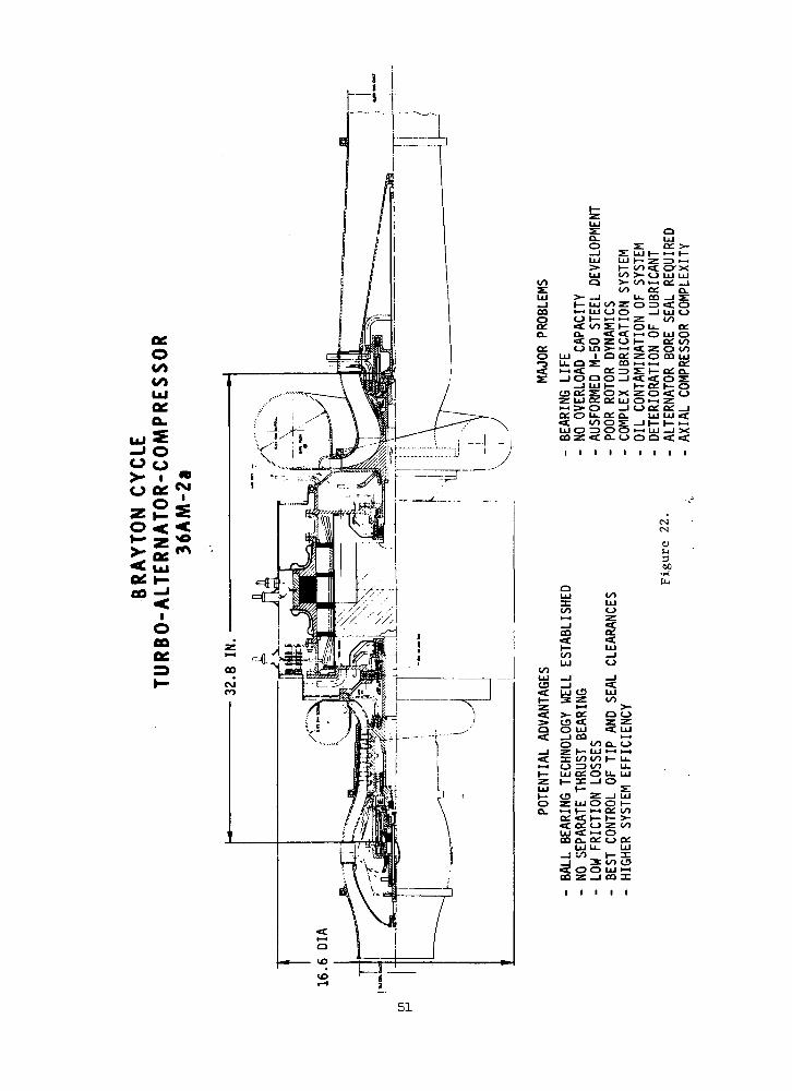
The 36AM TAG thermal analysis results are deduced from those of the
36RM TAG. The difference in compressor types does not alter the thermal
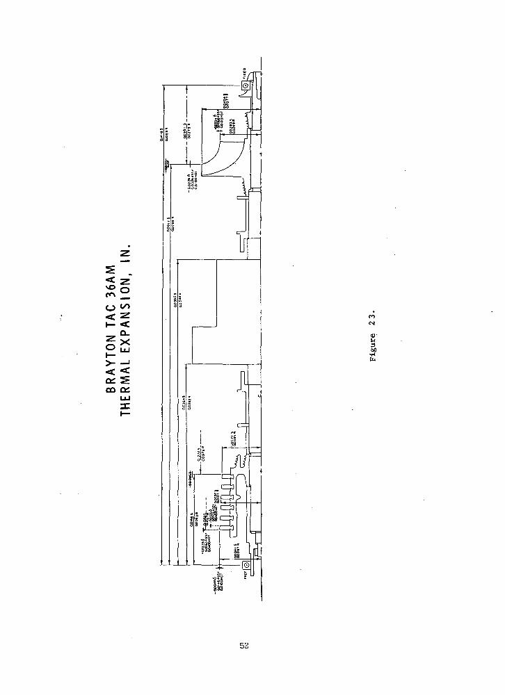
analysis significantly. The thermal expansions and clearances are shown
by Figure 23 ;and Table'X. The maximum hot running clearances all meet
the ten mil aim and the 40 mil goal for axial compressor blade axial
clearance is only missed by 2.6 mils.
The effective stresses are shown by Figure 24. The minimum factors
of safety are; compressor - 1.2, alternator - 1.1, and turbine - unity.
The potential advantages of this machine are that the ball bearing
technology is well established in that even special bearings are
relatively minor variants of proved designs, no separate thrust bearing
50
oCOCO
a.SO
25>:£
iO
a.o
CO
ga.a:o
3:o
LUu. a•-.<£
LU COO >-
oo• I• LU CO Zi LU O OI I— ,-. K-l
CO S I—
O Z O
! LU I—: s o xi 52 a: LU
0:0LUOCQZ
u_ a: o_co o s
QLU
s: o: >-z: LU »- •-• i—
t^>«a; o-x>- O UJ UJ00 i-i Qi _1
cc a.u. co _i s:O^3 <f O
—I LU Oz ooO U- QiI—I O LU Oi— a: oo«C z: o ooZ O CO LUi—11—i a:
Sillzo < oOi-H 2E<_> a: a: _j
LU LU <t
a ac.00
«c a. ii i
I OO c£ .
I I I
CMCM
<UiJ3t>0
•1-1ft)
oo
oo
CO
00LUO
O
!* Si Wz •-• >-<C >- oe a o;> is «=C z zQ O LU ^ LU«C i ca 1—1
O co a. o_l Z H- LU >-i »-i<c a: oo oo t- u.>—< O Z3 CO Ll-I— LU Of O U. LUZ t— 3C —I OIU t— SII— CO Z _J LUO Z LU O O I—o. >-• t— 1-1 o; oo
Qi <C t— »— >-«C a£ <-> z ooLU <C >-" OOO O. O <-> CC
LU U- LU
Ij *" 3 CO C3«C OO LU >-ioo z _i ca DC
51
< zI- <
o:oo
fl
00
13!
52
TABLE x
36 AM CLEARANCE AT Og
Mils
TURBINE
AXIAL
CLEARANCE
TURBINE
RADIAL
CLEARANCE
COMPRESSOR
AXIAL
CLEARANCE
COMPRESSOR
RADIAL
CLEARANCE
THERMAL
BEARING
ASSEMBLY
HOT
THERMAL
BEARING
ASSEMBLY
HOT
THERMAL
BEARING
ASSEMBLY
HOT
THERMAL
BEARING
ASSEMBLY
HOT
(1)- 22.6
0 - 0 . 1
+ 25.6 - 2.5
5.6
0.4
+ 3.4
0 - 2.0
+ 2.5 - 2.5 .
10.4
1.4
+ 33.5 - 33.5
0 - 0 . 1 0 - 0.1+ 4-
+ 6.5 - 2.5 4- 73.5 - 2.5
42.6 42.6
37.4 37.4
- 4.6
0 - 2.0
+ 9 . 2 - 2.5
9.1
0.1
NOTES; (1) -MEANS GAP CLOSES
(2) CASING DEFORMATION NOT INCLUDED
(3) TURBINE BEARING FIXED
53
8 8
O ui< °£>-•-
to
CD U_
TVf-t
sa-cs
00
54
is required when angular contact ball bearings are used, the bearings
and seals have low friction losses, the best control of tip and seal
clearances is provided because of the small bearing clearances, and the
axial compressor offers higher system efficiency than the comparable
machine with a radial compressor.
Major problems are that the bearings have no overload capacity
since five-year life cannot be guaranteed at the expected normal operating
conditions, the bearings require the use of ausformed M-50 steel which
is still a development item, the small diameter shafts dictated to achieve
best bearing life and the long bearing span give poor rotor dynamic
performance, the complex oil lubrication system which is very likely to
contaminate the system power fluid, the probable deterioration of the
lubricant in the high temperature and radiation environment for five
years, the complicated alternator bore seal required, and the complexity
of the axial compressor.
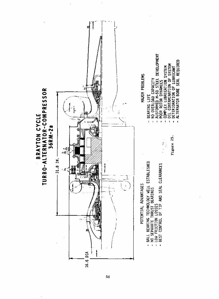
The 36RM Configuration
The configuration drawing of the 36,000 rpm radial compressor TAG
on oil mist lubricated rolling-element bearings is shown by Figure
It is similar in all major respects to the 36AM TAG except for the
substitution of the compressor.
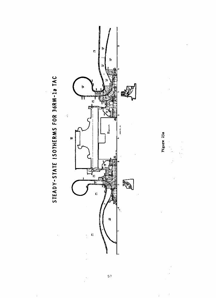
The results of the thermal analysis of the 36RM TAG are shown by
Figure 25a. The temperature distribution is similar to previous ones,
with the forward end of the stator and rotor less than 500°F, the
alternator stator rotor, aft seals, and aft shaft between 500-1000°F, and
the turbine, its inlet scroll, and exhaust duct, including the aft
bearing housing, between 1000-1640°F.
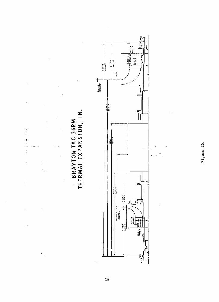
The 36RM thermal expansions are shown by Figure 26 and Table XI
synopsizes the clearances, all of which meet the 10 mil goal or exceed
it insignificantly. The forward bearing is fixed in this machine.
The minimum factors of safety in the 36RM TAG are: compressor - 2.2,
alternator - 1.1, and turbine - unity. The effective stresses are shown
on Figure 27.
Although the centrifugal compressor reduces the complexity of the
configuration, the shorter length permissible does not improve the rotor
55
UJaca.
O ^, egZO J-
> ^ m
iO00oc
56
o<K-
to' r-4
I
a:O
Q£.LUXI—O
UJ
57
on
< ZI- <
QiCQ
0)M
60•H
58
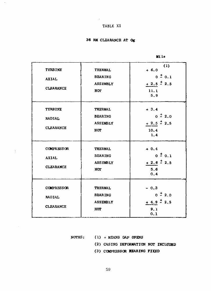
TABLE XI
36 RM CLEARANCE AT Og
Mils
TURBINE
AXIAL
CLEARANCE
TURBINE
RADIAL
CLEARANCE
COMPRESSOR
AXIAL
CLEARANCE
COMPRESSOR
RADIAL
CLEARANCE
THERMAL
BEARING
ASSEMBLY
HOT
THERMAL
BEARING
ASSEMBLY
HOT
THERMAL
BEARING
ASSEMBLY
HOT
THERMAL
BEARING
ASSEMBLY
HOT
(1)+ 6.0
0-0.1
+ 2.5 - 2.5
11.15.9
+ 3.4
0 - 2.0
+ 2.5 - 2.5
10.41.4
•f 0.4
0 - 0.1
+ 2.6 - 2.5
5.60.4
- 0.3
0 - 2.0
+ 4.9 - 2.5
9.10.1
NOTES: (1) + MEANS GAP OPENS
(2) CASING DEFORMATION NOT INCLUDED
(3) COMPRESSOR BEARING FIXED
59

Of,NO -m CO
O uj
5:>< I-QSO00 lif
. -1 —.-*'
.i'1,'1, \\x\ij
Csl
01
300
60

dynamics substantially over that obtained in a 36AM configuration.
The potential advantages and disadvantages of this machine are the
same as for the previous one except that some loss of efficiency is
associated with the more simple radial compressor.
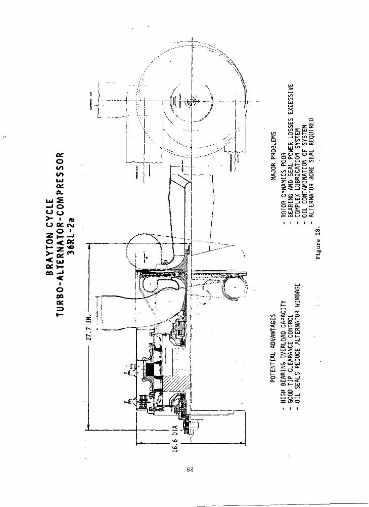
The 36RL Configuration
Shown in Figure 28 is a 36RL configuration which is completely
different from any of the five configurations shown previously. A major
difference is that both the compressor and turbine are overhung together
from one side of the homopolar inductor, alternator which is straddle-
mounted on the oil film bearings. The compressor and alternator are
overhung considerably aft of the aft bearing, a combined journal and
thrust oil-film bearing. The primary reason for the large overhang is
the space requirement for the compressor inlet scroll. All of the previous
machines were able to use compressor inlet ducts. Combined molecular
pumps and recirculating seals giving minimum leakage of oil vapor into
the alternator cavity are required.
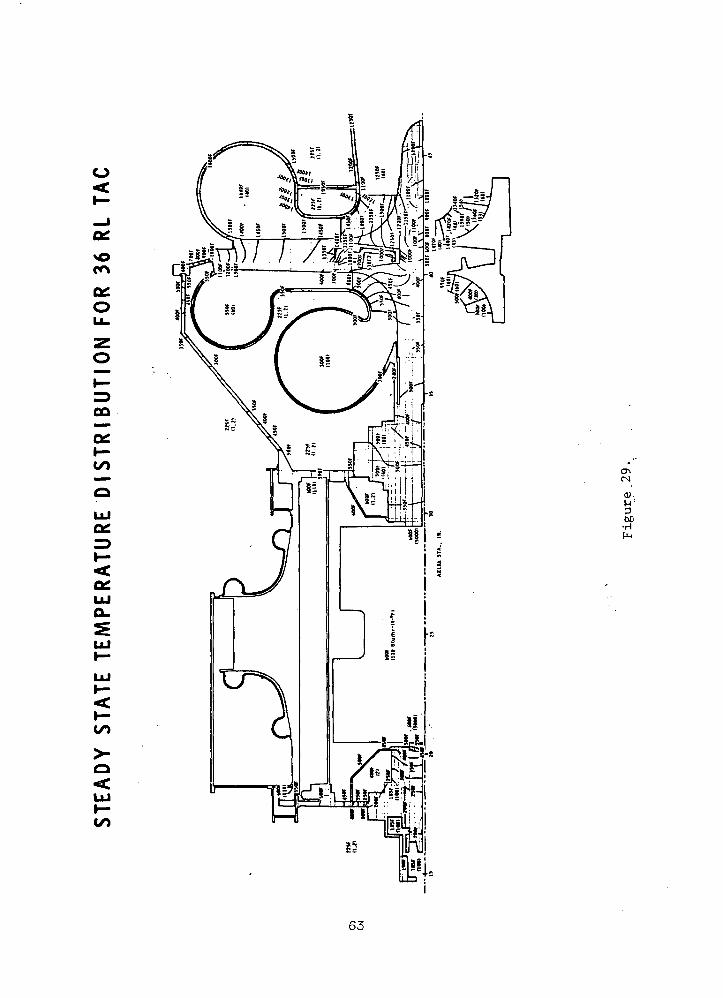
The temperature distribution in the 36RL TAG is shown by Figure 29,
which shows a pattern quite different from the other machines because
the compressor and turbine are mounted back-to-back. In this machine the
region of temperatures below 500°F includes not only the stator and rotor
forward of the alternator but also the stator and rotor from the aft
bearing to the center of the compressor. The rest of the compressor,
most of the compressor exit scroll, the aft end of the shaft, and the
alternator stator and rotor are between 500-1000°F. The turbine, turbine
scroll, and exhaust duct are 1000-1640°F. This design produces high
thermal gradients in the vicinity of the compressor and turbine.
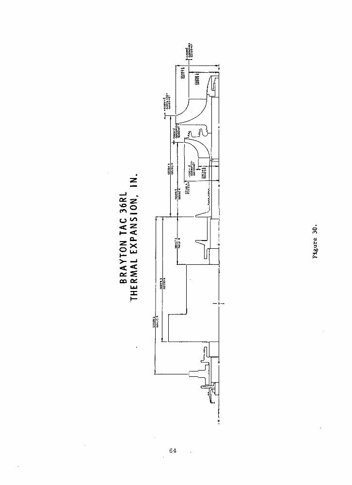
The 36RL thermal expansions are shown by Figure 30 and the
clearances are summarized in Table XII. Despite the adverse thermal
patterns, the 10 mil clearance goal is met at all critical gaps except
the turbine inlet blade tip axial gap of 15.4 mils maximum.
At this point all of the TAG clearances have been described and are
summarized by Table XIII. It should be remembered that the casing
deformations are not included and that for all of the machines with axial
compressors the axial compressor gap goal might be slightly greater than
40 mils. The 36AM TAG had its aft ball bearing fixed while the opposite
61
ocO
UJO£O.
UJ5
— " O00
> •O OS.
oc03
IOCDoe
i/oooUJoX
00ooz
OO O UJ
UJ 00_l OL >-CO LU OO
a: CC.Q-Z.o. o o. o
o •-«ac. a—ii—O «C <f.•-3 00 UJ O
oo cy>- LUOO C£
o oo i—i , I f^f -^
•Si O CO >-i
>-O CD X :
o;oco
ceo
:ui oz;
o o: Q.i- <t s:O UJOC£ CO C_)
I I Io«a:i i
00CM
<u1-100
CO
OO eC .UJ Q- <CO <£ l=C O I
Z O<t <£> o
Z C£O UJO h-
i— a:o <ta. uj
ca:ctD
: cji •z. LU
< oUJ UJ_i ceCJ
oo°- =i1-1 <£I— UJ
ooQO —IO i-tCD O
62
Ou.zO
H-
00
I—CO
CO
00
0).u'360•H
63
CO _
O ^< ZI— <
Q_
SB>- -j
oo
oil
0)M3
4?
64
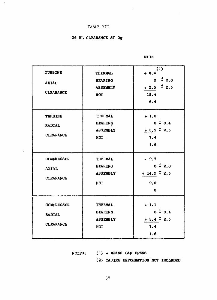
TABLE XII
36 RL CLEARANCE AT Og
Mils
TURBINE
AXIAL
CLEARANCE
TURBINE
RADIAL
CLEARANCE
COMPRESSOR
AXIAL
CLEARANCE
COMPRESSOR
RADIAL
CLEARANCE
THERMAL
BEARING
ASSEMBLY
HOT
THERMAL
BEARING
ASSEMBLY
HOT
THERMAL
BEARING
ASSEMBLY
HOT
THERMAL
BEARING
ASSEMBLY
HOT
(1)+ 8.4
0 - 2.0
+ 2.5 - 2.5
15.4
6.4
+ 1.0
0 - 0.4
+ 3.5 - 2.5
7.4
1.6
- 9.7
0 - 2.0
+ 14.2 - 2.5
9.0
0
•f 1.1
0 - 0.4
+ 3.4 i 2.5
7.4
1.6
NOTES: (1) + MEANS GAP OPENS
(2) CASING DEFORMATION NOT INCLUDED
65

X
wfjPQ<H
CJO
o:<c
oo
UJ<_)
I«cLU_J<_>
O »
O
oCC
CJ3OC
CM
CDCC
CM
CM
OHVOCO
<CvoCO
BLUD
<£>
CMo
UT)
CMo
~
•-
•~
voo
IT)
oLO
CM0
LOr—
LU
ui z:•— i _j o;co <C <cDi >— i UJ^> X _Jh- et <_>
oUD
o
*~
fO
O
r~-
ooCO
UJo
LU 2:Z _J CCI-H «C S
OQ I— i of(V r-i iii
(— § 0
CM
LO
i— 01
\O CO•* CO
LO
LO
CM t-v.
O
vo co<- co
COM
PRES
SOR
AX
IAL
CLEA
RANC
E
CO
CO
COa
OO
,_0
a»
r—
00o
CO
COM
PRES
SOR
RA
DIA
L
CLEA
RANC
E
66
was true for the 36RM TAG. The 36AM and 36RM machines meet all hot
running clearance goals because of the superior clearance and deformation
control inherent in the angular contact ball bearings. The 36AG and 36RL
machines meet the clearance goals at all the critical gaps except the
turbine inlet blade tip axial gaps, which are slightly greater than 15
mils. The 24AG TAG exceeds the 10 mil goals at the turbine inlet blade
tip axial gap and turbine exit blade tip radial gap by 7.2 and 7.4 mils.
The 24RG TAG misses the goals by slightly less at the same two locations,
but also misses the goal at the compressor exit blade tip axial gap by
5.2 mils. The effect of the greater gap clearances is discussed later
The effective stresses in the 36RL TAG are shown in Figure 31.
The minimum factors of safety are 2.3 for the compressor and unity for
the alternator and turbine, assuming the use of Rene1 80 for this
compressor because of its higher temperature than any other compressor
considered.
The advantages of this machine are that there is high bearing
overload capacity, good tip clearance control, and the oil seals reduce
the alternator windage to a palatable value. However, the reduction in.
windage loss is overridden by a large bearing and seal loss. As was
the case for the other oil lubricated configurations, a complex
lubrication system is required to prevent oil contamination of the entire
Brayton system. And, as before, an alternator bore barrier is required
to prevent carburization of the oil on the windings. In spite of reducing
the number of seals required for this configuration to reduce losses by
overhanging the compressor and turbine on the same side, the bearing and
seal power losses are excessive. In addition, because of the overhang
of the compressor and turbine on one side, the rotor-bearing response is
very poor.
TAG Weight Summary
The weight summary for all the machines which were investigated is
shown by Table XIII. It is seen that the 24 krpm compressors and turbines
weigh about three times as much as the 36 krpm components because of the
difference in sizes. The axial compressors weigh about twice as much as
the comparable radial compressors (36RL has the only Rene' 80 compressor).
There is little variation in the stubshafts and tiebolt weights. The
67

GO
CD u_
t—
mu)uao•H
68

TABLE XIII
T A G W E I G H T SUMMARY(POUNDS)
COMPRESSOR
ALTERNATOR-ROTOR
TURBINE
STUBSHAFTS/TIEBOLT
TOTAL ROTOR
ALTERNATOR-STATOR
CASING
TOTAL STATOR
TOTAL WEIGHT
24RG
10
98
25
19
152
181
265
446
598
24AG
20
98
25
22
165
181
259
440
605
36AG
6
92
8
17
123
180
160
340
463
36AM
6
83
8
22
119
155
170
325
444
36 RM
2
83
8
19
112
155
167
322
434
36 RL
5
83
8
22
118
155
153
308
426
24RG*
8
135
22
22
187
331
351
682
869
* PHASE III
69
alternator rotor weights are 60-75 percent of the total rotor weights,
with the Phase I Lundell stators weighing about 18 percent more than
the homopolar inductor stators.
The Lundell alternator stators weigh about 16 percent more than
the homopolar inductor stators and are 41-53 percent of the total rotor
weights. The 24 krpm casings weigh about 60 percent more than those of
the 36 krpm machines because of the size differences.
The net result is that the Phase I 24 krpm TACs weigh about 600
pounds, about 37 percent more than the 426-463 pound weights of the 36
krpm machines.
Mechanical Design Comparison
Now that the details of the design studies in the mechanical design
area have been presented, the configurations will be compared and the
mechanical designs will be evaluated.
Shown in Table XIV is a mechanical design comparison of the six
configurations. The first line shows the designation of the various
configurations previously explained and the second line distinguishes
between the radial- and axial-flow compressors. The number following
the letter A designating an axial flow- compressor specifies the number
of stages. The table indicates that all of the axial-flow compressors
have peak stresses of 46,000 to 47,000 psi. Since all the radial-flow
turbine designs are similar, a peak stress of 40,000 psi is encountered
in the bore of these turbines, and is considered to be barely acceptable
The peak alternator stresses in all of the 36,000 rpm designs are
almost 100,000 psi. However, the Lundell alternator at 24,000 rpm has a
peak stress of only 56,000 psi at 100 percent speed.
The significant comparative bearing values are the bearing lives.
All configurations meet the 5-year life with the exception of the two
ball bearing configurations, whose life is predicted to be less than 3
years. Therefore, they have no overload capability.
The comparison of the configurations in terms of rotor dynamics is
clearly in favor of the 24RG configuration, which has a third critical
rotative speed 68 percent beyond the 20 percent overspeed point. The
two axial configurations at 24,000 and 36,000 rpm have third critical
70
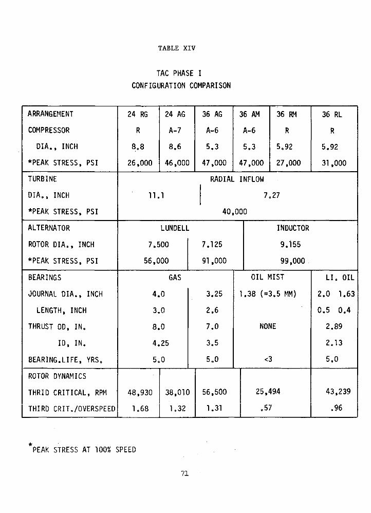
TABLE XIV
TAG PHASE I
CONFIGURATION COMPARISON
ARRANGEMENT
COMPRESSOR
DIA., INCH
*PEAK STRESS, PSI
TURBINE
DIA., INCH
*PEAK STRESS, PSI
ALTERNATOR
ROTOR DIA., INCH
*PEAK STRESS, PSI
BEARINGS
JOURNAL DIA., INCH
LENGTH, INCH
THRUST OD, IN.
ID, IN.
BEARING. LIFE, YRS.
ROTOR DYNAMICS
THRID CRITICAL, RPM
THIRD CRIT./OVERSPEED
24 RG
R
8.8
26,000
24 AG
A-7
8.6
46,000
36 AG
A-6
5.3
47,000
36 AM
A-6
5.3
47,000
RADIAL INFLOW
36 RM
R
5.92
27,000
36 RL
R
5.92
31 ,000
11.1 7.27
40,000
LUNDELL
7.500
56,000
7.125
91 ,000
GAS
4.0
3.0
8.0
4.25
5.0
48,930
1.68
3.25
2.6
7.0
3.5
5.0
38,010
1.32
INDUCTOR
9.155
99,000
OIL MIST
1.38 (=3.5 MM)
NONE
<3
56,500
1.31
25,494
.57
LI. OIL
2.0 1.63
0.5 0.4
2.89
2.13
5.0
43,239
.96
PEAK STRESS AT 100% SPEED
71
speeds around 30 percent greater than the 100 percent overspeed condition.
The rotor-bearing response of the oil-lubricated configurations is very
poor.
Shown in Table XV is a mechanical design evaluation of the six
configuration studies. For the 24,000 rpm configurations, the stress
levels are safe for all three components, the compressor, turbine and
alternator. The clearance control on these two configurations is rated
poorer than for all the 36,000 rpm configurations. The bearing life is
good for all configurations except for those having ball bearings. The
rotor bearing response is best for the 24RG configuration and only fair
for the axial compressor configurations designated 24AG and 36AG. Poor
response is indicated for all of the oil lubricated bearing configurations.
For both of the 24,000 rpm configurations, the three developments
needed are the alternator rotor bonding, alternator stator cooling, and
thrust bearing development. The thrust bearing development can be
removed if a lower maneuver load is specified, which would make the
thrust bearing a size within present developments. The 36AG configuration
has two serious development problems. The bonding of the 36,000 rpm
Lundell rotor is serious because of the high stresses. The helical-
groove face seal needed to reduce the pressure in the alternator cavity is
considered a difficult development because of small running clearances
and large probable distortions of the runner and stator. The helical
groove face seals for the oil-lubricated film bearings are considered
to be a development of a lesser magnitude than the gas helical groove
face seal for the 36,000 rpm gas bearing configuration. No risk items
are listed for the 24,000 rpm configurations and the only other drawback1
is the complexity of the axial-flow compressor. As a result, the 24RG
configuration was considered to be the best choice from a mechanical
standpoint for the TAG unit based on the specifications provided in
this study.
72

TABLE XV
TAG PHASE I
MECHANICAL DESIGN EVALUATION
ARRANGEMENT
STRESS SAFETY FACT.
COMPRESSOR
TURBINE
ALTERNATOR
CLEARANCE CONTROL
BEARING LIFE
BEARING-ROTOR RESPONSE
DEVELOPMENTS
ALTERNATOR
BONDED ROTOR
STATOR COOLING
BORE SEAL
HELICAL GROOVE FACE SEAL
THRUST BEARING
RISK
ROTOR STRESS
OIL-GAS MIXING
BEARING LIFE
COMPLEXITY
OIL HANDLING SYSTEM
AXIAL COMPRESSOR
BEST MECHANICAL
24 RG 24 AG 36 AG 36 AM 36 RM 36 RL
VERY SAFE
SAFE
SAFE
FAIR FAIR
GOOD
GOOD
X
X
X
X
FAIR
X
X
X
X
UNSAFE
GOOD
FAIR
XX
X
XX
X
X
X
GOOD GOOD
POOR
GOOD
GOOD
POOR
X
X
X
X
X
X
X
X
X
X
X
X
X
X
X
X
X
X
73
ROTOR DYNAMIC STUDIES
The primary purpose of the rotor dynamic studies was to establish
the vibrational behavior of the rotor-bearing system when subjected to
rotating unbalance. Several analyses were made during the course of the
Phase I study on several different rotor configurations for each machine
concept. These analyses led to a specification of the rotor geometry,
size, and arrangement which resulted in acceptable vibrational behavior.
Rotor-bearing resonances were defined, arid the rotor vibration amplitudes
as a function of speed driven by rotor unbalance, were calculated.
Included in the studies were the rotor .flexibility and the support
compliance where significant. The influence of bearing film stiffness
and damping as a function of operating conditions was also included.
Furthermore, the location of the exciting force (mechanical unbalance)
was evaluated and worst case situations are presented.
The following sections summarize the results of the final Phase I
machine configuration- dynamic studies. Oil lubricated and gas lubricated
machines are discussed separately since their dynamic behavior and ap-
proaches taken to achieve a solution are somewhat different. •
' Gas Bearing Machines. ... . :
The component arrangement for the gas bearing machines studied in
Phase I typically had the alternator mounted between journal bearings
with the turbine and compressor overhung from opposite shaft ends. This>"
arrangement leads to the most straightforward entrance and exit ducting,
minimizes seal problems, and generally leads to the'simplest machine
assembly.
With this type of arrangement and particular mass distribution the
third critical speed has a mode shape with the nodes typically near the
bearings as shown pictorially in Figure 33 . Such a situation leads to
little or no relative shaft-bearing displacement near the third critical,
thus little potential for squeeze film damping. Without significant
damping in the rotor bearing system, operation near such a bending criti-
cal would result in excessive vibration:amplitudes possibly leading to
failure.
74

TYPICAL 3rjl CRITICAL MODE SHAPE
Figure 33
c1/1
LOG STIFFNESS
CRITERIA FOR 3r-^ CRITICAL SPEED
Figure 34
75
por this reason, all the gas bearing machines have been designed to
operate below the third critical speed and have at least a 30% margin
between the 20% over speed condition and the third critical (see Figure
34 ). The 30% minimum margin (u/wn = .78) is a standard MTI design
criteria which usually results in acceptably small amplification factors
(typically less than 3) at the upper speed limit. This can be seen on
Figure 35 which shows the amplifications as a function of critical
speed for a simple mass-spring system.
The critical speed maps for the three gas bearing machines (36AG,
24AG, and 24RG) along with mode shape diagrams are shown on Figures 36, 37
and 38 . As can be seen from these figures, the rotors are extremely
stiff and the first two critical speeds are rigid body modes as is evi-
denced by the mode shape plots and the straight line critical speed-
bearing stiffness characteristics. The third critical, which of course
is bending, is in all cases well above the 20% overspeed case as is
summarized below.
3rd N (at K = 105 Ib) .n c. cr T— N /I.2 x N,Configuration in cr des
24 AG 38010 1.32
24 RG 48930 1.68
36 AG 56500 1.31
Typical bearing stiffness versus speed characteristics for Ig (hori-
zontal) operation are plotted on Figures 37 and 38 for the 24,000 rpm
machines. In addition to the stiffness-speed characteristics, damping-
speed characteristics were also calculated and used in the rotor response
analyses for the 24,000 rpm machines shown on Figures 39 and 40 . For
the purpose of calculating the bearing dynamic characteristics the follow-
ing significant assumptions regarding the journal bearings were made:
Number of Pads: 4
Diameter: 4.0 inches
Length: 3.0 inches
Rpad~Rshaft: .004 inches**
Radial Clearance: .002 inches
*Clearance at 24,000 rpm. At other speeds, clearance changes due to (.25inch thick) rotor centrifugal growth variation and pad load variation causingpad flexure displacement. These variations are computed at each speed.
76
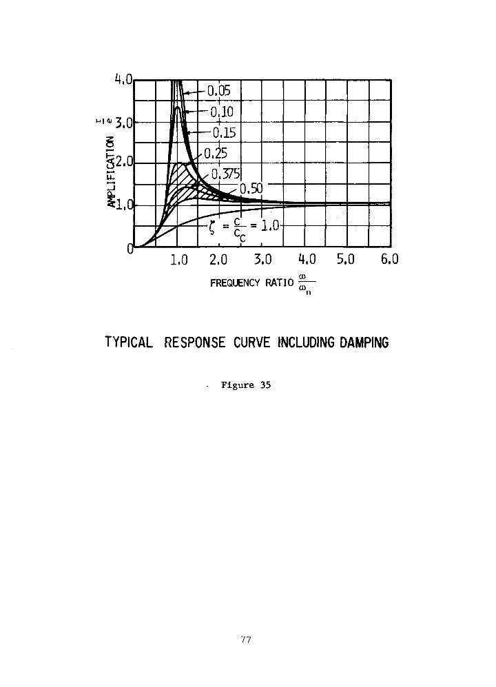
4,0
3,0
§2,0
cl.O• C - C - - L O
1,0 2,0 3,0 4,0 5,0 6,0FREQUENCY RATIO %—
TYPICAL RESPONSE CURVE INCLUDING DAMPING
Figure 35
77

78
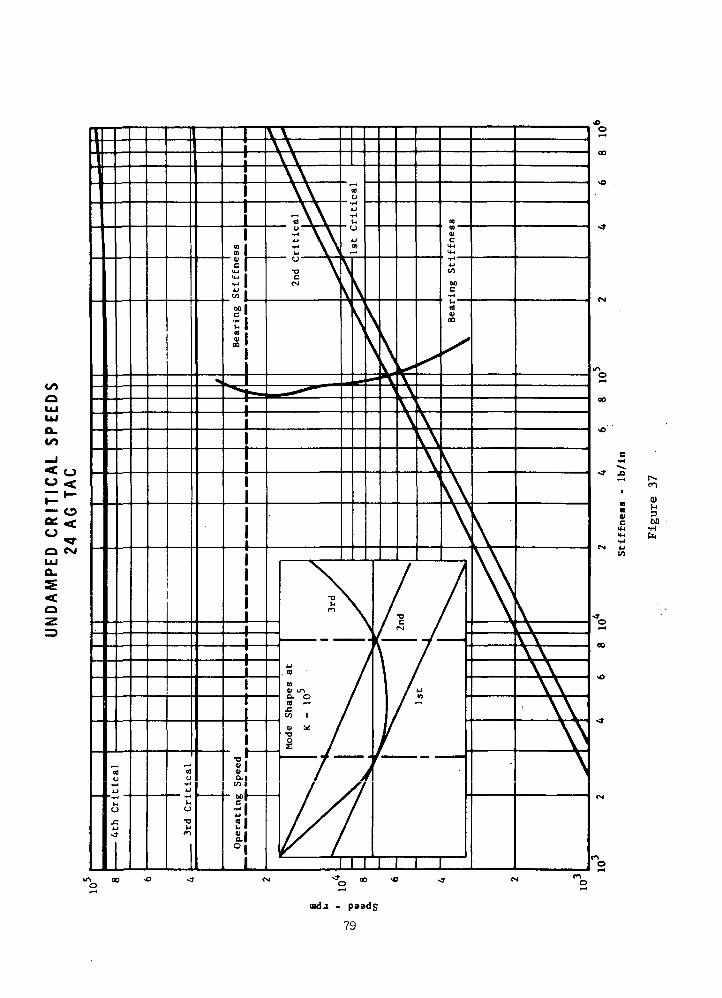
c*4.
JO
to
uida -
79

mdj -
80
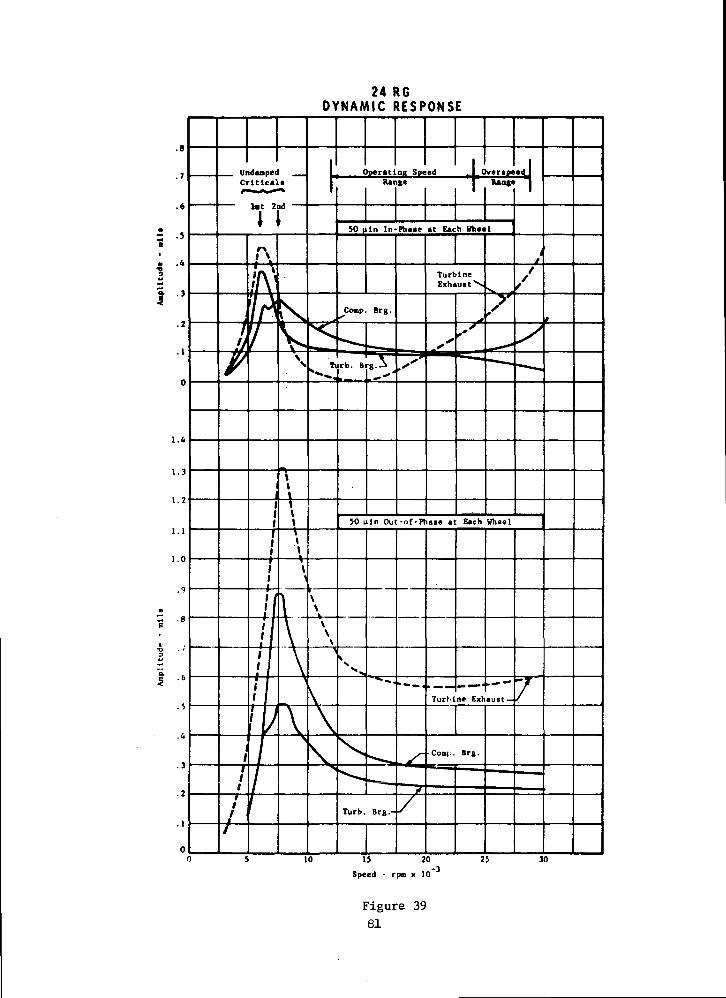
24 RGDYNAMIC RESPONSE
I '
Speed - rptn x 10
Figure 3981
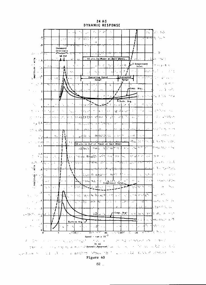
24 ACD Y N A M I C R E S P O N S E
50 utn in Out' ol Phase at Each Wheel
Compressor Inlet
Speed - rpm x 10
24 AC,-, .i-f. . • -.'' Dynamic'jRsjponst "
Figure 40
82 ..
Lubricant: < '•', ,2?.9A,He-rXe at 60 psiia
Pad Flexure: - 1.5 x 10* Ib/in on two adjacent pads
•'••'. .'• 't*0ix 10 :lb/in on opposite twq^pads
For the rotor response analysis, unbalance .equivalent to 100 v inches
of rotor;weight displacement was assumed and divided equally between the
compressor and turbine wheel back faces. Both the in-phase and out-of-
phase unbalance orientation was calculated. The -unbalance placed at
each wheel produces the worst case situation (see mode plots). Also as
can be seen from the mode plots, out-of-phase unbalance will accentuate
the first two rigid body criticals while the in-phase unbalance at each
end will accentuate the third critical.
: Referring to the response plots on Figures 39 and 40 , which show
the .amplitudes at the bearings and the largest amplitude location on the
rotor, clear evidence of the rigid body criticals can.be seen occurring
between 5000 and 8000 rpm. As would be expected from their mode shapes,
the amplitudes are greatest at the rigid body criticals when excited by
out-of-phase unbalance. These amplitude peaks, although sharp, are hot
excessive in magnitude and are reasonably well damped. Furthermore, they
lie comfortably below the operating speed range.
It may be possible to reduce the rigid body critical amplitudes by
increasing the bearing length as this would increase the damping. The
effect of increased damping may, however, be negated by the higher stiff-
ness that would also result' from longer bearing length since increased
stiffness would raise the criticals to nearer the operating speed range
and raise the driving force at the critical speed (speed squared effect).
At the higher end of the overspeed range the amplitude of vibration
at the shaft ends increases sharply as the effects of the third critical
speed begins to be felt. This effect, as would be expected, is accentu-
ated with in-phase unbalance as a result of. the third critical mode shape.
The increase in amplitude in°the overspeed range is more severe with the
machine with the axial compressor (24AG) because of its lower third criti-• •'• - ?'•'•. • ' ' -jr.'" • : < ' • • ' . ' • • ' ' • - :
cal speed (38010 rpm as compared.to 48930 for 24RG).
The sharp increase in amplitude above 25,000 rpm experienced with the
24AG machine could be significantly reduced by increasing the compressor
and journal bearing diameter. This would stiffen the shaft with a resulting• • - - • . * - ' i-. * - " ' ' * ' • •
' ; 83'-' •" . . ' ' • • " • • ' •
increase in the third critical speed such that its effect within the
overspeed range would be minimal.
In summary, the results of the Phase I rotor dynamics studies in-
dicate that the three gas bearing machine concepts presented have accept-
able dynamic characteristics. All have a margin between the 20% over-
speed and third critical speed of at least 30%. In the case of the 24AG
machine, a greater margin is required but this can be accomplished by
stiffening the shaft with a larger diameter journal at the compressor
end.
Both the 24,000 rpm machines experience resonances at the rigid
body critical speeds but it may be possible to reduce these amplitudes
by increasing bearing length. The maximum amplitudes with the bearing
sizes used for these studies are less than 1.3 mils at the shaft ends
which is acceptable. Over this operating speed range (11,000 to 24,000
rpm) maximum rotor vibration amplitudes never exceed 0.6 mils with the
assumed 100 y inch balance.
Oil Lubricated Machines
With the oil lubricated machines one is motivated to minimize shaft
diameters in the bearing and seal areas so as to achieve an acceptable
level of parasitic power loss and, in the case of ball bearings, maintain
low DN values. Small shaft diameters leads to a situation where oper-
ation through or near bending criticals may be required and where the
introduction of damping is mandatory.
In the case of the oil film lubricated machine (36RL), two approaches
were considered. One was a machine arrangement similar to the gas bearing
machines with the turbine and compressor overhung from opposite shaft ends
and the alternator straddled between bearings. The other approach was to
have both the turbine and compressor overhung from the same end. These
two approaches are pictorially shown on Figure 41 .
The first approach (Configuration 1 in Figure 41 ) requires the same
third critical speed criteria as for the gas bearing machines because of
the potential for poorly damped resonances resulting from the proximity
of the nodes to the bearings. In the case of Configuration 2, it is
possible to operate near or on a bending critical, because the bearings
84

BEARING AND SEAL LOSSESFOR 36 RL TAC
1.63
TYP. 3RD CRITICALMi'DK SHAPES
CONFIGURATION 1 CONFIGURATION 2
100
90
80
eninO
60
% 50
40
30
20
DESIGNSPEED
30
207OVERS PEE I) '
-CONFIGURATION 2
307.MARGIN
CONFIGURATION
40 50 60 70
3RD CRITICAL SPEED, RPM
80
Figure 41
85
are far displaced from the nodes and the full fluid film damping effect
can be realized. ^ • • :
To achieve a 30% margin between the 25% overspeed condition and the
third critical speed with Configuration 1 the bearing becomes so large
that 50 kw in combined bearing and seal losses result as is shown in• • , , * - ' • ' • . . : . - . - . , • - . - - • - • • -
Figure 41 . : ;
This is obviously an intolerable situation for a unit designed for
40 to 160 kw of useful output, to achieve the same margin with Configu-
ration 2, even larger bearing power.loss results (see Figure 41)..
However, if the full .damping potential of the bearings is utilized,
design speed operation near the third critical is no penalty. For this
reason the.major emphasis has been on the second approach (Configuration
2) where small diameter bearings resulting in about 24 kw of power loss
could be utilized. (Although 24 kw is still a sizable loss, smaller
sizes are impractical as the seal becomes prohibitively small to support
the required pressure difference). :
The critical speed map of the 36RL (Configuration 2) along with the
normalized mode plot is shown in Figure 42 . As can be seen from
Figure 42 the bearing stiffness curves intersect the undamped third
critical speed curve.at approximately 40,000 rpm. However, the response• ' ' ' ' :. '.••'>"'•'" •' ' • v'f ••'"•''*''--• :•«';'•'. '..'. •,'•,'. • - . - - ' . '
plot shown on Figure 43 which includes the bearing fluid film stiffness
and damping reveals no amplitude peaks in the 'speed range to 55,000 rpm.
This indicates that the bearing-rotor dynamic system is, for all practical
purposes, critically damped. : ''• - '• .,• \
The ball bearing supported rotors have all components (turbine,
alternator, and compressor) straddle mounted'between the bearing located
at each end of the shaft. This arrangement was necessary to keep the
ball bearings at a size small enough (35 mm max.) to assure a reasonable
life expectancy. Such an arrangement obviously results in an extremely
limber rotor as is evidenced by the 36RM critical speed map shown on
Figure 44 . Here it can be seen that, unlike the rotors discussed previ-
ously, the 36RM has first and second critical speeds that are bending in
*The reader is referred to BEARING AND SEAL DESIGNS for a detailed discussionon bearing and seal design and loss breakdown. ,
86

t- nu•o0)a.gto-o
00•H
87

2.0
1.8
1,6
1,2
1,0
.8
.6
.2
0
1•
ii,61,11.2
36 RLDYNAMIC RESPONSE
OPERATINGSPEED RANGE
OVER-SPEED.RANGE
50 IN, IN PHASE AT .COMPRESSOR AND ALTERNATOR
TURBINEEJMAUST
1.625" ALTj
7BEARING
2" MAINBEARING
50 IN, OUT OF PHASE ATCOMPRESSOR AND ALTERNATOR
10 20 30 WSPEED, RPM X ID"5
50
Figure 43
88
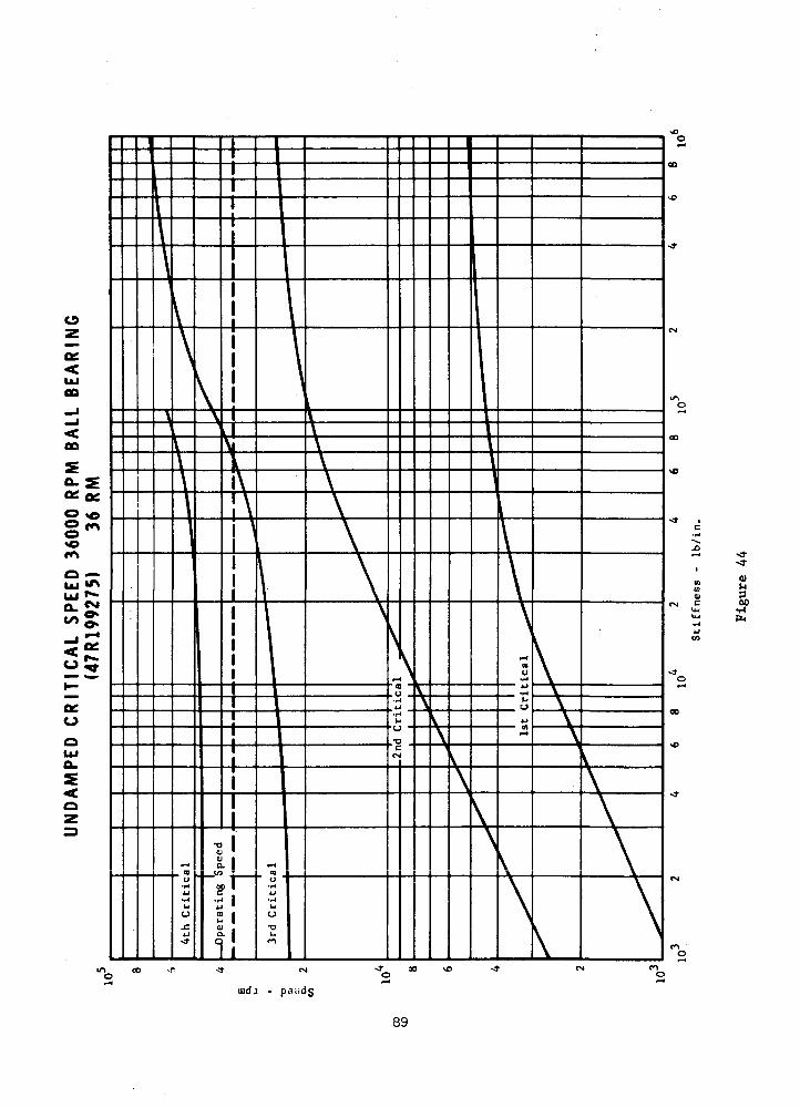
DO
uidj - p.i.idg
89
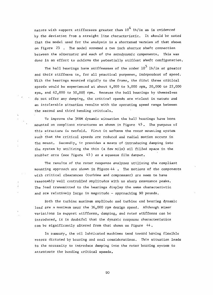
nature with support stiffnesses greater than 10 Ib/in as is evidenced
by the deviation from a straight line characteristic. It should be noted
that the model used for the analysis is a shortened version of that shown
on Figure 25 . The model assumed a two inch shorter shaft connection
between the alternator and each of the aerodynamic components. This was
done in an effort to achieve the potentially stiffest shaft configuration.
The ball bearings have stiffnesses of the order 10 Ib/in or greater
and their stiffness is, for all practical purposes, independent of speed.
With the bearings mounted rigidly to the frame, the first three critical
speeds would be experienced at about 4,000 to 5,000 rpm, 20,000 to 22,000
rpm, and 42,000 to 50,000 rpm. Because the ball bearings by themselves
do not offer any damping, the critical speeds are violent in nature and
an intolerable situation results with the operating speed range between
the second and third bending criticals.
To improve the 36RM dynamic situation the ball bearings have been
mounted on compliant structures as shown in Figure 45 . The purpose of
this structure is twofold. First it softens the rotor mounting system
such that the critical speeds are reduced and radial motion occurs in
the mount. Secondly, it provides a means of-introducing damping into
the system by utilizing the thin (a few mils) oil filled space in the
snubber area (see Figure 45) as a squeeze film damper.
The results of the rotor response analyses utilizing the compliant
mounting approach are shown in Figure 44 . The motions of the components
with critical clearances (turbine and compressor) are seen to have
reasonably well controlled amplitudes with no sharp resonance peaks.
The load transmitted to the bearings display the same characteristic
and are relatively large in magnitude - approaching 90 pounds.
Both the turbine maximum amplitude and turbine end bearing dynamic
load are a maximum near the 36,000 rpm design speed. Although minor
variations in support stiffness, damping, and rotor stiffness can be
introduced, it is doubtful that the dynamic response characteristics
can be significantly altered from that shown on Figure 44.
In summary, the oil lubricated machines tend toward having flexible
rotors dictated by bearing and seal considerations. This situation leads
to the necessity to introduce damping into the rotor bearing system to
attentuate the bending critical speeds.
90
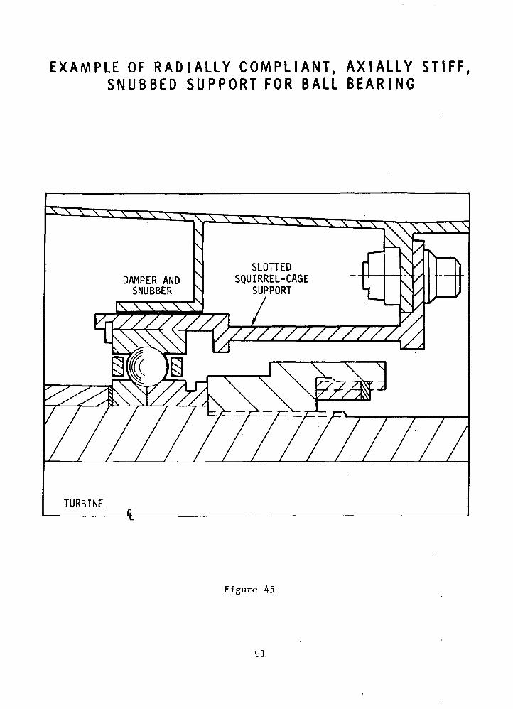
E X A M P L E OF R A D I A L L Y COMPL IANT , A X I A L L Y ST IFF ,S N U B B E D S U P P O R T F O R BALL B E A R I N G
SLOTTEDSQUIRREL-CAGE
SUPPORTDAMPER ANDSNUBBER
Figure 45
91

Both the oil lubricated machine approaches, with proper damping
included show no evidence of critical speed problems and vibration
amplitudes can be maintained at less than 1 mil with a total rotor
unbalance of 100 y inches. The dynamic loads transmitted to the ball
bearings are high - approaching 90 pounds - and are a maximum near
design speed.
92
C. AERODYNAMIC DESIGN
INTRODUCTION
The turbomachinery design studies include conceptual designs of
axial-flow compressors, centrifugal compressors, and radial-flow turbines.
Six configurations in all were requested; two at a rotating speed of
2 ,000 rpm with a compressor inlet pressure of 55 psi and four config-
urations at 36,000 rpm with a compressor inlet pressure varying between
120 and 360 psia. The design requirements for these studies are presented
in Table XVI.
The prime objective of these studies is to obtain the highest
possible component efficiencies consistent with the best TAG performance
but within mechanical, vibrational and material constraints.
APPROACH
The approach to the axial-flow compressor design studies was to use
a computerized pitchline computer code called the Compressor Unification
Study. This computer code was developed by the Aircraft Engine group
of the General Electric Company and is based on a large amount of
compressor test data. Through the use of this computer code, the stall
potential of a new compressor is obtained from that observed in the test
of a base compressor by making rational adjustments for blade speed, axial
velocity, swirl level, blade solidity, aspect ratio, tip clearance and
Reynolds number. It is assumed in the design of the compressor that
adjustments will be made in the blading to assure the radial flow
balance of the working fluid and that the Mach number effects will be
accounted for by adjustments in blade thickness. These variations can
then be removed from consideration in a pitchline design model. The
design calculation is based on the static pressure rise achievable in a
blade row divided by the inlet dynamic pressure. Basically, the method
of calculation takes the measured differential pressure over dynamic
93

TABLE XVI.
• DESIGN REQUIREMENTS
TURBINE INLET TEMPERATURE, T600°F
COMPRESSOR INLET TEMPERATURE, 240°F
COMPRESSOR PRESSURE RATIO 1.9
DESIGN POWER OUTPUT(40 KWe AT REDUCED PRESSURE) . 160 KWe
WORKING FLUID (HELIUM-KRYPTON) MOLECULARWEIGHT 39.94
TURBINE DIFFUSER EXIT MACH NO. <0.1
94
head from each state in the base compressor at design speed stall,
adjusted in a rational way for,solidity, aspect ratio, clearance, and
Reynolds number and applies it to the corresponding stage in a new
compressor. The blade speed, axial velocity, and'"swirl level of the
new compressor lead to values for the dynamic pressure and these are
used with the;new values of static pressure rise divided by dynamic
pressure to obtain the stall pressure rise.
Compressor' stall experience has'been .unified by demonstrating that
the measured loading parameters of a large number of compressor stages
are mutually consistent within the framework of the method. The details
of the method are considered to be proprietary to the General Electric
Company.
The efficiency level was calculated .using a loss model based on
the compressor test experience of the Aircraft Engine group. The effect
of diffusion parameter and Mach number were taken into account in.*'..• "' ''J?1' • - " ' • ' • • • .
determination of the profile loss. Corrections to the total pressure
loss coefficient are made for the effects of secondary flow and annulus
drag. For small machines where the. tip clearance is important, a^ i'
correction is also made for this loss. Finally, the calculated effi-
ciency is corrected for the Reynolds number.
The prime aerodynamic variables investigated in the axial-flow
compressor design studies included the number of stages, the blade
chord, the axial-velocity level, swirl level, inlet radius ratio, and
solidity. Since the compressor length affects the rotor-bearing response
and in turn is affected by the number of stages, blade chord and swirl
level, the parametric data was plotted against length. The final
selection and recommendation of a design were tempered by considerations
of the exit system which has a significant effect on axial—flow com-
pressor performance.
With regard to the centrifugal compressor design studies, a meridional
analysis was made in an attempt to optimize the main geometric features
of the compressor utilizing realistic loss data and taking into account
the important flow problems. The prime variables in this meridional
95
analysis were the inlet radius ratio, the hub radius, the. exit blade
height, the slip factor, the radial extent of the vaneless space, the
vaned diffuser chord and the flare of the vahed diffuser section. The
consideration of a large range of slip factor value brought into the
study a range of values of the blade exit angle. The object of the
meridional analysis was to optimize the configuration of the centrifugal
compressor overall efficiency. Several configurations were laid out
under selected optimized conditions.
Special flow problems in the centrifugal compressor included three
dimensional effects in the impeller and problems associated.with the
exit system. With regard to the impeller, a computerized design technique
was utilized to determine the flow characteristics of a given impeller
on axisymmetric stream surfaces and then the blade-surface velocity
distributions were calculated on the surfaces. With regard to the exit
system, a three vane-row diffuser was designed with a matching scroll
giving an exit Mach number less than-0.1. . ; . .
With regard to the radial turbine, a meridional analysis was
carried out to optimize the: turbine configuration including an -exit
diffuser for highest efficiency. The prime variables investigated were
the stator exit velocity, stator exit angle,'tip speed, ratio of the .
rotor exit to inlet relative velocity, the-rotor exit mean-to-inlet
diameter ratio, and diffuser included'angle.- . • .
Special flow problems included the three dimensional effects in the
runner. These were explored using the' same computerized technique as '
described for the radial flow compressor. Special studies were made of
the exit diffuser to assure high performance arid a good margin between
operating point and stall at an exit Mach number of 0.1. " :
It was not possible to divorce entirely the aerodynamic studies of
the turbomachinery from the complete TAG unit itself. For example,
because the adverse effect of tip clearance on turbomachinery components,
it was considered important to minimize the operating tip clearance.
However, the minimum tip clearance which is practical is heavily
influenced by the differential thermal expansion of the rotor and stator
96
parts, as well as the deflection of the rotor and stator parts under
load. Since the means for making the TAG operate over a U to 1 power
range was to, reduce the compressor inlet pressure at low values of power,
reducing the. Reynolds number, the effect of the reduced Reynolds number
on the turbomachinery performance was considered. The rotor dynamic
response of the TAG unit is sensitive to the mass and overhang of the
compressor and turbine wheels. Thus the design of the turbomachinery is
influenced by the effect that certain configurations would have on rotor-
dynamic response. The temperatures experienced in a turbomachine affect
the allowable stress and the tip speeds of a turbomachine and certain
dimensions affect the actual stresses which in turn are limited by the
allowable stresses. Because of the large life or power loss penalty
of thrust bearings, the aerodynamic thrust loads on the compressor and
turbine must be balanced. Compressor-turbine thrust balancing usually
requires the use of labyrinth seals, sometimes at large diameters,
resulting in costly leakage losses. The use of the working fluid as
coolant means that a larger flow rate will pass through the compressor
than through the turbine, resulting in a reduction in the performance of
the TAG unit itself-which is significant. In addition, the returning
of the coolant gas to the flowing system often causes additional losses
due to the disturbance of the main flow. Since rotor-bearing dynamic
response is affected by component weight, length and overhang, the
aerodynamic design of the components influences rotor-bearing response
and may be constrained by it.
AXIAL COMPRESSOR ""
!
Axial flow compressor designs were carried out for two rotating
speeds. At 2*1,000 rpm the compressor inlet pressure set by contract
was 55 psia; at 36,000 rpm the compressor inlet pressure of 120 psia was
chosen as the value giving the highest component efficiencies for the
radial flow components.
Basis for Comparison
As indicated previously, the highest efficiency axial flow com-
pressor configurations were sought as a function of the axial length
of these machines. The axial lengths were selected as a parameter of
97 . - - ' '

merit because of a significant influence axial length has upon rotor
dynamic response of the entire unit. The design specifications shovn
in Table XVII were utilized in the axial-flov compressor studies. The
design parameters which had the most influence on the design were as
follows: number of stages, blade, chord (which means Reynolds number.•- • • i > /"
effects and aspect ratio), axial velocity level, swirl level, radius
ratio (which means mean blade speed), and solidity. Early in the
study it was established by parametric analysis that a pitchline solidity
of 1.25 was a level which would avoid excessive choking at the hub and
excessive loading at the tip of the blades. For 7 stages.a radius
ratio of about 0.75 gave close to the optimum efficiency and was used
throughout the remainder of the study.
The designs were constrained by using a constant axial velocity
throughout the compressor and having the same pitchline velocity
diagrams for all stages. ''''••' • -•'"•-'
The analytical model which was used as a- basis of comparison of
the various compressor configurations was developed for Aircraft Engine
use. The stall prediction capabilities of this computer code discussed
above are based fairly well upon experimental data. The efficiency
prediction method is still under development but it was felt this
method was far enough along to give consistent trends of compressor• . s * , • '•
performance over the ranges of the prime design parameters of this study.
The analytical model used to compare the various configurations evaluates
the effects of the blade loading, Reynolds number, clearance, stator angle
and the reaction on the compressor performance. From the calculated
variation of efficiency with compressor length a compressor configuration
was selected. Then the efficiency level of the selected blading design
was adjusted to the level of efficiency demonstrated in the T-58 compressor
which is approximately the right physical size and was adjusted for
collection system losses.
There were some additional constraints and evaluation criteria which
were applied to the design studies. A chord of O.i+-inch was selected
as the minimum value for accurately machined blades to the usual tolerances.
As indicated earlier, the length of the axial compressor was considered
98

TABLE XVII. •
AXIAL aOW COMPRESSOR DESIGN SPECIFICATIONS
RPM 24000 36000
Inlet Temperature 700°R 700°R
Inlet Pressure'-psia 55 (I307) 120(30)
Pressure Ratio I09 I09
Gas Molecular Weight 39.94 39.94
Corrected Mass Flow 3.41 1.56
•Modulation to 1/4 power by inlet pressure level
99
to be a significant output since it had a noticeable effect on rotor
dynamics. Most of the compressor design studies were carried out without
consideration of the collection system. The collection system of the
axial compressor was found to have a significant effect on the ef-
ficiency. Therefore, the collection system was studied in some detail
and certain constraints were placed upon the axial compressor design to
favor the collection system. The actual parametric data, however, was
computed without regard to the losses in the collection system. The
final assessment of the recommended compressor configuration efficiency
was adjusted to take into account the effect of collection system on
efficiency.
THE COLLECTION SYSTEM
Because of the relatively low compressor pressure ratio, 1.9, the
energy tied up in the collection system of the compressor is large
compared to the total energy added to the gas in the compressor itself.
In order to determine quantitatively the effect of the collection
system on the compressor performance the number of points in adiabatic
efficiency associated with the collection system was determined for
several exit absolute Mach numbers. At an exit absolute Mach number of
0.33, 15.7 points in adiabatic efficiency are tied up with the
collection system; at an exit absolute Mach number of 0.26, 9 points in
efficiency are tied up with the collection system.
Reneau, Johnston and Kline (Ref. 6) have shown that for a two
dimensional diffuser design the absolute maximum pressure recovery occurs
in long diffusers with high length to width ratios. The value and
location of this maximum recovery depend largely on the inlet boundary
layer thickness. The bulk recovery obtained by them was 85% at a
value of nondimensional boundary layer thickness which is highly
optimistic considering that the diffuser follows a turbomachine.
The results of Sprenger (Ref. 7) show that at an area ratio
of U, the best diffuser at all boundary thicknesses investigated by
them was a straight circular one with a total cone angle of 8°. The
best recovery obtained by Sprenger for such a diffuser was Q6%. These
• 100
results indicate that even at the best values of boundary layer thickness
it has not been possible to obtain greater than Q6% recovery.
The boundary layer condition at the exit of the compressor will not
be as favorable as the best ones obtained under the experimental
conditions of Reneau, et al. and Sprenger. Hence, assuming only Q0%
recovery from the exit of the last compressor rotor, it is possible to
obtain an overall compressor efficiency based on the inlet total and
collector exit total conditions.
A schematic diagram of a typical collection system is shown in
Figure k6. For such a collection system the last compressor stator
would be designed for static pressure rise which was 55% of the dynamic
head leaving the rotor. This corresponds to a total pressure loss of
0.1 dynamic head for the last stator. The recovery of 50% of the
kinetic energy remaining in the outlet guide vane, diffuser and scroll
was estimated. This results in static pressure rise of 72% of the dynamic
head at the last rotor exit or an overall total pressure loss of O.l8
dynamic head. Later, when overall compressor performance is presented
the above values of pressure recovery will be used to characterize the
collection system. As a result of the study of the collection system,
the exit axial Mach number in all of the compressors studied was O.l8
which results in a 0.26 absolute exit Mach number for a swirl level of
U5°.
PARAMETRIC STUDIES
As mentioned earlier in the section, a systematic variation of the
different parameters was carried out using the Compressor Unification
Study model in order to arrive at the final choice of the design. The
final choice depended not only on the overall adiabatic efficiency and
the compressor length but also on the pitch line vector diagrams, rotor
and stator camber and stagger angles, blade loadings and stall margin.
Designs with highly loaded blade rows, very low stall margin, and camber
and stagger angles outside the realm of past experience were eliminated
from comparisons. The designs found acceptable after meeting the above
criteria were then compared in order to optimize efficiency with respect
to the length at full and one quarter power.
101
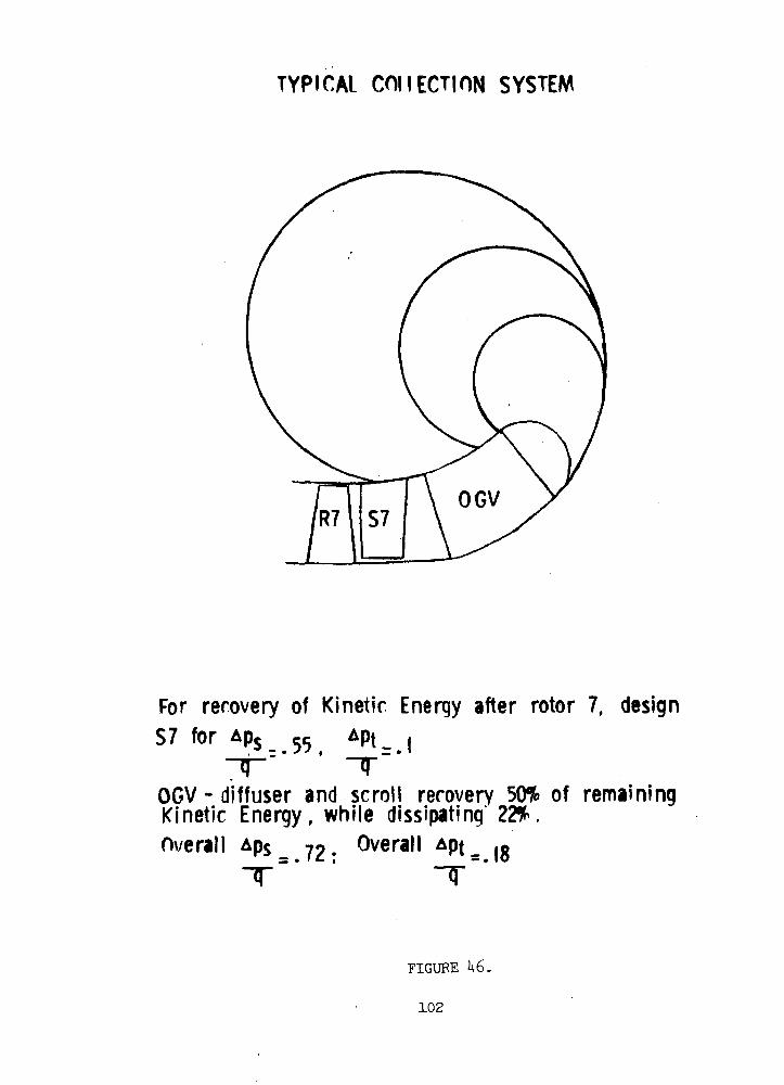
TYPICAL COIIECTION SYSTEM
For recovery of Kinetic Energy after rotor 7, designS7 for
' TOGV - diffuser and scroll recovery 50% of remainingKinetic Energy, while dissipating 22%.Overall Aps 7o Overall Apt_ IRs • * f- i — • IO
T
FIGURE U6.
102
Having chosen a pitch line solidity value of 1.25, the effects of the
variation of radius ratio and number of stages on efficiency vere
studied. The efficiencies were obtained for full and one quarter power
and for five- and seven-stage machines at a pitch line chord value of
0.75 inches. The swirl entering all rotors was 1+5°, thus making each
stator remove just the additional swirl introduced by the previous rotor.
The swirl leaving the last stator was assumed to be 5°. The results
show clearly that a radius ratio of 0.75 for seven stage compressors has
the best full power and one quarter power efficiencies. It was also
found that at a radius ratio of 0.8 for seven stage compressors and
0.85 for five stage compressors very low flow coefficients resulted
giving rotor cambers and staggers outside the realm of past experience.
The efficiency gain for more than seven stages is more than offset by
the increase in length beyond mechanically accepted limits.
Shown in Figure U7 is the variation in adiabatic efficiency with
compressor length for different numbers of stages and different values
of blade chord. The blade chord values are at the pitch line and are
held constant for all rotors and stators, causing a very small variation
in pitch line aspect ratio due to the slight convergence of the flow
path. The radius ratio chosen for Figure U7 is 0.75. It is noted that
there is a progressive improvement in adiabatic efficiency with in-
creasing number of stages, due to lighter loadings of the blade rows.
The trend appears to indicate that considerably higher efficiencies can
be obtained by increasing the stages to 8 or 9. A careful study shows
that the gain in efficiency from increasing the number of stages drops
progressively and that the overall compressor length increases consid-
erably with the higher number of stages for the same .value of mean
chord. It was found that an 8-stage compressor gave a very small
increase in full power adiabatic efficiency and a much-higher length,
beyond the length limits set by mechanical considerations, for the same
chord value as compared to a 7 stage compressor.
The effect of blade chord (and consequently aspect ratio) on
length and efficiency is seen in Figure Vf. At the higher chord values,
the effect of low aspect ratio dominates the behavior of the full power
103

0.89
0.88 .
0.8T
§0.86
IM
So.85
0.83
0.82 „
0.8l
BLADE CHORD-
NASA NUCLEAR BRAYTON CYCLE DESIGN STUDY
BLADE CHORD AND STAGE NUMBER EFFECTS
N=2>fOOO rpe><y-= 1.25
rh = 0.75rt
SWIRL=1»50 AT ALL BOTOR INLETS
1.0"7 STAGES
BLADE CHORD0.3"
7 9LENGTH (inches)
11
i r; tl-L.T
1A POWER
IT
FIGURE
104
efficiency in spite of-the favorable effect of the Reynolds number on
efficiency. On the other hand, at'the-one-quarter power condition
superimposed in Figure U7 the Reynolds number are low enough that the
increase in Reynolds number at high chord makes a significant contribu-
tion toward the efficiency outweighing the adverse effect of the decreasing
aspect ratio. It is seen from Figure U7 that a chord of 0.6 inch will
give.the best compromise between full and .one-quarter power efficiencies
and yet keep the Coverall length of the compressor within 6.67 inches.
After the number of stages, pitch-line chord, radius ratio, and
solidity were selected the effects, of the variation of swirl and exit
Mach number were re-examined. Shown in Figure U8 is a plot of the varia-
tion of efficiency with compressor length at different exit axial Mach
numbers and swirl levels. For any particular case, the pitch line swirl
at all rotor inlets and the compressor exit were held constant at a given
value. Three values of swirl, namely, 25, 35 and U5° were considered.
At each of these values of swirl the exit Mach number was varied. The
absolute Mach number desired at the exit of the collector flange is 0.1.
The higher the Mach number at the compressor exit, the higher will be
the losses through the collection system diffusing to a Mach number of
0.1, but at the same time, the higher is the efficiency of the compressor
alone.(total inlet to total exit). Hence it is necessary to pick an
optimum Mach number at the compressor exit to optimize the overall
compressor inlet to collector exit efficiency.
For a given swirl level, the compressor exit absolute Mach number
was varied by increasing the flow path area by 10 and 20% from the minimum
area required to pass the given mass flow at an exit axial Mach number
of 0.18. The inlet to exit area ratio was maintained in all cases at a
value which permitted a nearly constant- axial velocity through the
compressor. For example, the line'marked'swirl, U5ai is obtained by
varying the areas' as mentioned above. The line marked "axial Mach number,
O.l8l" is obtained by'varying the- swirl angle and keeping a certain flow
path with exit area adjusted to pass a-given weight flow at axial Mach
number of O.l8l. It is noticed that keeping a higher swirl level through
the compressor at a constant axial exit Mach number results in higher
105
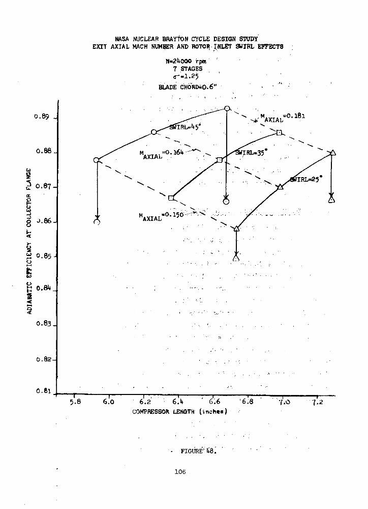
MASA NUCLEAR BRAYTON CYCLE DESIGN STUDYEXIT AXIAL MACH NUMBER AND ROTOR INLET SWIRL EFFECTS
0.89 -
0.88.
3 0.87-01
g 0.66.
•X
1 0.85-o
^r
2
0.83.
0.82-
rptn '7 STAGES<r=i.25 '
BLADE CHORDiO.6'"
=0.l8l
0.61
5.8 6.0T T T6.2 6.1* ' 6.6
COMPRESSOR LENGTH (inches)
'6.8 7.0 1.2
FIGURE'1*8 J
106

efficiencies at shorter lengths. This is partly due to the higher
absolute Mach numbers at a higher swirl for a given axial'Mach number.
It can be seen from Figure U8 that;at.a .constant swirl angle of U5°
a flow path designed to give an exit axial Mach number of O.l8l gives
the highest full power efficiency within the allowable length. The
efficiencies in Figure ^8 are the result.of applying the collector
losses mentioned in a previous section to the parametric data presented
in Figure It8. From the figure it is seen that there is no compelling
reason to depart from the k$0 of swirl and the axial Mach number of
O.l8l. The low swirl angle and high axial Mach number result in a very
slight increase in efficiency with a large increase in compressor length.
As a result the design characterized by the highest swirl angle and
highest axial Mach number was selected for the TAG compressor operating
at 2U,000 rpm.
AXIAL COMPRESSOR EXPERIMENTAL BACKGROUND
As indicated earlier the efficiency prediction feature of the
Compressor Unification Study computer code is. still undergoing develop-
ment. The computer code gives the correct trends of compressor efficiency
with the main'variables under investigation. However, at present it
is necessary to adjust the level of efficiency calculated by reference to ''
background experience on compressors of a similar type. The T-58
compressor has features which make it comparable in many ways to the TAG
axial-flow compressor. Among these are small size, including chords of
O.U inches and blade heights of approximately 1/2-inch in the latter
stages. Unlike the TAG axial-flow compressor the T-58 compressor is
designed for transonic relative Mach numbers in the front stages. In
addition, as is the case with all gas turbine compressors for aircraft,
the T-58 compressor is designed to operate over a range of flow and
pressure ratio conditions., .In contrast the.TAG axial-flow compressor
operates at essentially one operating point on the compressor map. And,
as such compromises are not necessary in the TAG axial compressor for
off design operation. Another significant difference between the T-58
and the TAG axial-flow compressor is that the former has a large number
of stages and generates a rather large pressure ratio compared to the
' ; 107
1.9 pressure ratio of the TAG compressor. Because of the differences
in the number of stages and pressure ratio of the two compressors the
most logical way to compare them is on the basis of small stage or
polytropic efficiency.
Shown in Figure H9 for the T-58 engine along its operating line
is the variation of compressor efficiency with gas generator corrected
speed as percents of design-speed values. It is apparent from the
curve that at design operating conditions the compressor efficiency is
somewhat lower than the peak value. However, at design conditions the
T-58 compressor is operating transonically in the front stages and the
stages are not fully matched. Therefore, it is reasonable to compare
the TAG compressor and the T-58 compressor where the T-58 stages are
well matched. This is at the T-58 compressor maximum efficiency point
which occurs at approximately 89$ of corrected design speed. At this
point the T-58 polytropic efficiency is .886. When the Compressor
Unification Study computer code is used to predict the T-58 performance
at this condition of 89% corrected speed the polytropic efficiency is
.909. This amounts to 2.3 percentage points in efficiency difference
between the actual measured performance of the compressor and the value
calculated by the computer model.
For the TAG axial flow compressor having 7 stages and a chord
length of 0.6 inch the Compressor Unification Study computer code yields
0.928 as the TAG polytropic efficiency. When this is decreased by the
2.3 points compressor efficiency difference between the T-58 model and
measured data, the TAG axial-flow compressor polytropic efficiency is
0.905. For the TAG compressor at a pressure ratio of 1.9 when the
polytropic efficiency of 0.905 is converted to adiabatic efficiency the
value is 0.893. Finally, when the overall efficiency is calculated
including the exit system loss, the efficiency becomes .866. This
efficiency is based on a radial tip clearance of 10 mils.
There are a number of reasons why the Compressor Unification Study
code gives a higher polytropic efficiency to the TAG axial flow compres-
sor than for the T-58 compressor. The TAG axial-flow compressor has a
108
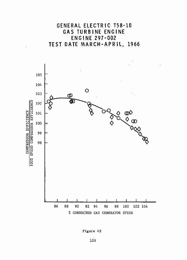
o55wHuMfnfeW
P£iOCOCO
wMc_>M
&w
RES
QW
CJ (X,CO
oo
G E N E R A L E L E C T R I C T58-10G A S T U R B I N E ENGINE
E N G I N E 297-002T E S T DATE M A R C H - A P R I L , 1966
105
104
103
102
101
100
99
98
1 1 1 1 I 1 1 1
86 88 90 92 94 96 98 100 102 104
% CORRECTED GAS GENERATOR SPEED
Figure 49
109
higher Reynolds number due to the high inlet pressure and it has
lighter blade loading and a more favorable tip clearance.
AXIAL FLOW COMPRESSOR DESIGN RECOMMENDATIONS
Shown in Table XVIII is the design recommendation for the TAG axial
flow compressor at 2U,000 rpm. The compressor has 7 stages with an
inlet radius ratio of 0.75. The blade chord length is 0.6 inch. The
swirl level entering the rotors is U5°. The overall length of the
turbomachine, exclusive of the exit system, is 6.67 inches. For a
clearance of 10 mils the adiabatic efficiency is 0.866 including the
collection system.
Shown in Figure 50 is a schematic diagram to scale which depicts
the recommended TAG axial-flow compressor for 2U,000 rpm. The hub radius
is slightly in excess of 3 inches. The tip radius varies from slightly
in excess of k inches at the inlet to about 3.8 inches at the exit. The
axial length of the blading exclusive of the collection system and inlet
guide vanes is 6.67 inches.
A study similar to the one reported in detail in previous sections
was also carried out at 36,000 rpm. For these compressor .parametric
studies the inlet pressure was specified as 120 psia instead of 55 psia
specified for the 2U,000 rpm case. The Reynolds number for the 36,000-
rpm compressors were high enough that a smaller penalty was paid for
off design performance, namely at one-quarter power, than for the
2l*,000 rpm compressors primarily due to the higher compressor inlet
pressure at 36,000 rpm. This made it possible to obtain a efficiency
comparable to the selected 2 ,000 rpm compressor with the use of six
stages. The recommended design for the 36,000 rpm compressor is shown
in Table XIX.. Like the 2 ,000 rpm compressor it has an inlet radius ratio
of 0.75 and a swirl level entering the rotors of 5°. However, it was
possible to use a chord length of only O.U, resulting in an overall
turbomachine length of 3.8l inches. The adiabatic efficiency of this
machine is 0.862 including the collection system.
Shown in Figure 51 is a schematic diagram to scale which depicts
the recommended axial-flow compressor for 36,000 rpm. The hub radius is
110

TABLE XVIII
DESIGN RECOMMENDATION
At 2U,000 rpm Number of Stages 7
Swirl level entering rotors, degrees,
Axial velocity level, ft/sec
Chord Length, inches
Overall Turbomachine Length,
Radial Clearance, mils, ;
Adiabatic Efficiency (incl.
collection system)
Radius Ratio 0.75
U5
215
0.6t 4 "
6.67 : . •.
1 0 . : . . - - .
0.866
111

CO
oCO
o>
— ^^™ ^z a. *2p os
00 ^1 JC
a: ?
o
CO<
112
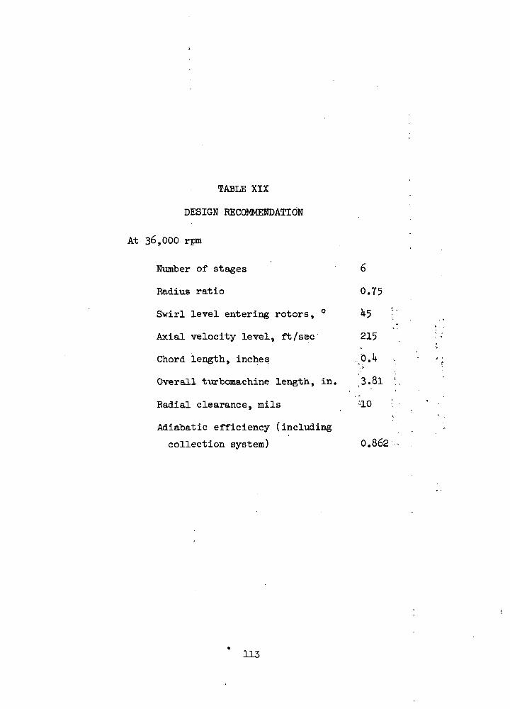
TABLE XIX
DESIGN RECOMMENDATION
At 36,000 rpm
Number of stages 6
Radius ratio 0.75
Swirl level entering rotors, ° ^5 :
Axial velocity level, ft/sec 215
Chord length, inches ...jO.h
Overall t-urbomachine length, in. 3.8l
Radial clearance, mils :10 :
Adiabatic efficiency (including
collection system) 0.862
113

CO
coUJo
§ 2 ' • ' • • " 'O ,
z f . - ^ -2S I 5>- O£ O
I § u
2jO
<OO
o
w•gM
114

slightly in excess of 2 inches and the tip radius varies from about
2.75 to 2.1*5 inches front to rear. The overall length of the blading
from the exit of the inlet guide.vane to the exit of the last stator
is 3.8l inches.
CONCLUDING REMARKS
A very careful study was made of the axial flow compressor, "both for
2U.OOO and 36,000 rpm as components for the TAG. Because of the low
pressure ratio required by the recuperated Brayton system for the TAG
the energy leaving the axial-flow compressor is a large portion of the
energy put into the gas. This emphasizes heavily the careful design
required for the exit system. Since the axial-flow compressor does not,
by definition, impart a radial component to the flow of any significant
value, the collection system must be added to the compressor in the axial
direction. As a result the overhang of the compressor for the bearing
becomes an important input to the rotor-bearing response of the TAG
unit. Thus, although an efficiency can be substantiated at a competitive
level for the axial-flow compressor it is not recommended for use in the
TAG where the pressure ratio is so low that the advantages of the axial
.flow compressor cannot be fully utilized.
115

CENTRIFUGAL COMPRESSOR
A preliminary design study was carried out for a centrifugal
compressor with a maximum efficiency stage of 1.90:1 total pressure
ratio. Weight or size were not a major factor because of other system
characteristics.
The results of this study consist of a parametric study for the
24RG and 36RL compressors, performance estimates for radial and backward-
curved impellers with vaned diffusers, and a comparison of the objective
performance with experimental data. A rather detailed aerodynamic
analysis is carried out for the rotor and diffuser in order to substan-
tiate the expected performance.
Parametric Study For Impeller Geometry
A parametric study was carried out for each compressor to analyze
the inducer and overall impeller performance at a nominal level of
diffuser loss. The analytic model considered the losses associated
with the impeller blade loading, skin friction, clearance, mixing, and
• disc windage. The basic parameters which were varied were:
1. Inducer hub diameter2. Inducer hub/tip ratio3. Impeller tip widthA. Impeller work coefficient (AH/yt2)
The model iterated for the impeller tip diameter using the above
losses to satisfy the required overall pressure ratio of 1.90:1.
The parametric analysis examined the general trends of geometry on
performance level in order to locate the design in an efficient area,
but it should be pointed out that it is basically a one-dimensional
analysis and some judgment is required to interpret the results. The
empirical factors for the loss estimate are limited to current design
practice and any results for extreme departures from the norm cannot at
this present time be considered completely valid.
The general procedure for the parametric study is first to analyze
the inducer in order to locate a region of low relative Mach number and
flow angle, and second to analyze the impeller tip holding the inducer
geometry constant. This method typically reduces the number of configura-
tions from 1050 to only 64, since any design with a poor inducer would be
ruled out.
116
There was no inlet pre-whirl because the level of inducer tip Mach
number was not excessive. A combination of low inducer relative Mach
number and turning occurred for the 24RG at a hub radius of 1.3125 inches
and a hub/tip ratio of .50. The 36RL inducer design point was at a
hub radius of .788 and a hub/tip ratio of .4375.
The impeller tip width and work coefficient was varied using the
above inducer designs. The range of impeller work coefficient was
from .63 to .98, which would include designs from backward-curved
to forward-curved impeller blade designs. The calculated impeller
efficiency is shown in figures 52 and 53. The peak impeller efficiency
varied from 92.5% for the .98 work coefficient to 91.8% for the .63 work
coefficient.
The .98 work coefficient has a high exit Mach number and the overall
performance calculated from a diffuser total pressure loss coefficient
(APt) of .16 shows this somewhat higher impeller efficiency offset by
increased diffuser loss (See Figures 54 and 55). Note that the exit blade
height for peak overall efficiency does not necessarily correspond to the
blade height for peak impeller efficiency because of the effect of inlet
Mach number on the actual diffuser loss. The estimated overall diffuser
loss of .16 was reasonable since the actual Task I designs were .153
and .140 for the 24RG diffuser and .148 for the 36RL diffuser.
To carry out the preliminary design study, a work coefficient of
.88 and .63 was selected for the 24RG and .88 for the 36RL compressors.
These levels would cover the range of radial and backward-curved blades.
The backward-curved blades were considered because analytic and experi-
mental results have shown performance improvements with backward-curved
blades. Because of the amount of work involved for an axisymetric flow
analysis of each design, the alternative design at the lower work
coefficient could not be considered.
Overall Performance For Turboalternator-Compressor
A performance assessment was made for the 24RG with a .63 and
.88 work coefficients and for the 36RL with a .88 work coefficient.
The resultant flow paths are shown in Figures 56 and 57 for the 24RG design.
An alternative 36RL design at a lower work coefficient was not made
because the concurrent design studies indicated the 24,000 RPM machine
117
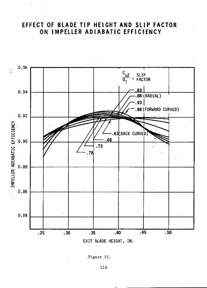
EFFECT OF BLADE TIP HEIGHT AND SLIP FACTORON IMPELLER A D I A B A T I C E F F I C I E N C Y
0.96
0.94
0.92
LU
O
CO
0.90
O
•* 0.!ce.
0.86
0.84
7
.25
.78
u2 SLIP' FACTOR
-.831-.88 (RADIAL)
-.93 |'.98(FORWARD CURVED)
.73
.30 .35 .40 .45
EXIT BLADE HEIGHT, IN.
.50
Figure 52.
118

EFFECT OF BLADE TIP HEIGHT AND SLIP FACTORON OVERALL EFF IC IENCY
0.88
0.76
.25 .30 .35 .40
EXIT BLADE HEIGHT, IN.
Figure 53.
119
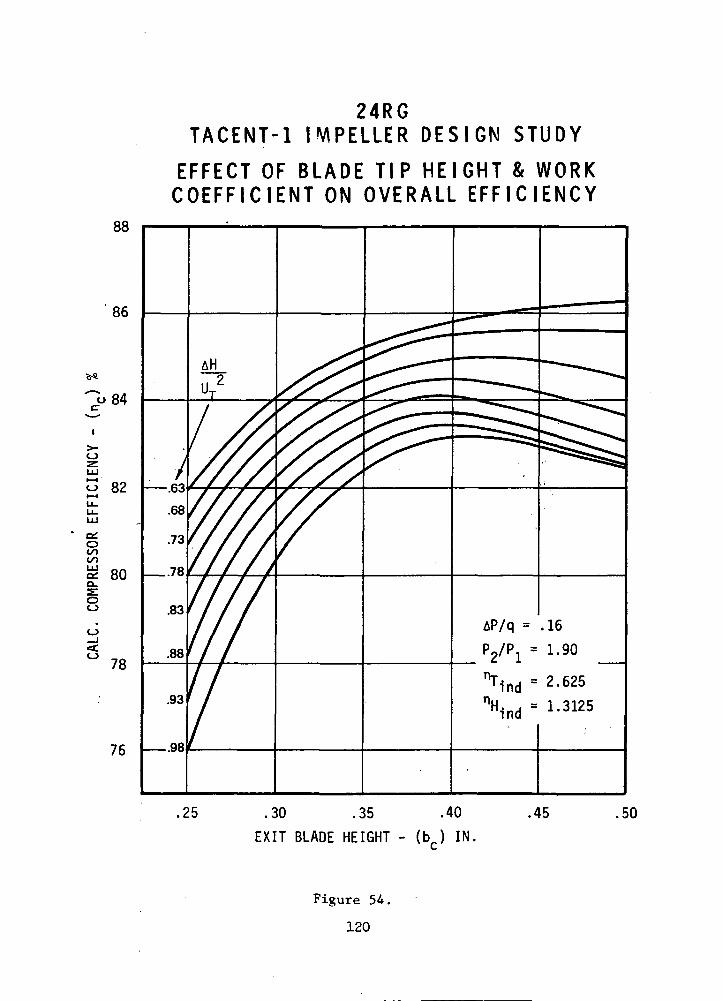
88
86
o84c
I
01oCOCOUJ
oo
78
76
24RGTACENT-1 IMPELLER D E S I G N S T U D Y
EFFECT OF BLADE TIP HE IGHT & W O R KC O E F F I C I E N T ON OVERALL E F F I C I E N C Y
o 82 —
80 —
.25 .30 .35 .40
EXIT BLADE HEIGHT - (b ) IN,
.45 .50
Figure 54.
120
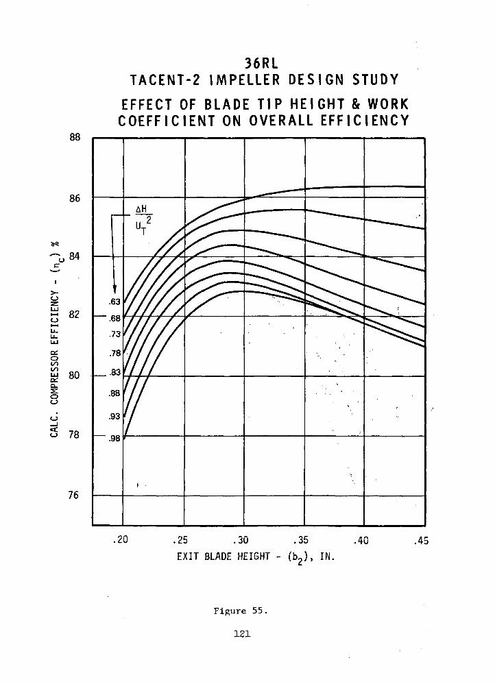
88
86
ocr
o
84
02
O00GOLLJa:Q-
OCJ
O
80
78
76
36RLTACENT-2 IMPELLER DESIGN STUDY
EFFECT OF BLADE TIP HEIGHT & WORKCOEFF IC IENT ON OVERALL EFF IC IENCY
.63
.68
.73
.78
.83
.88
.93
.98
,20 .25 .30
EXIT BLADE HEIGHT
.35 .40 .45
>, IN.
Figure 55.
121
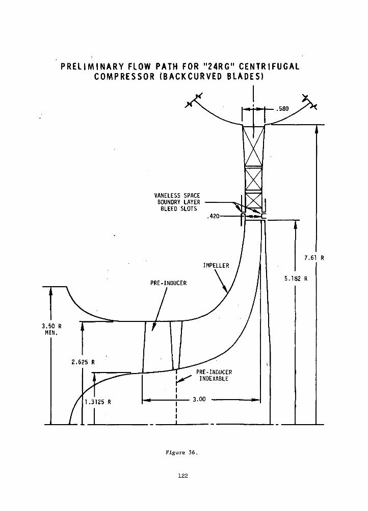
P R E L I M I N A R Y FLOW PATH FOR "24RG" C E N T R I F U G A LC O M P R E S S O R ( B A C K C U R V E D B L A D E S )
VANELESS SPACEBOUNDRY LAYERBLEED SLOTS
Figure 56.
122
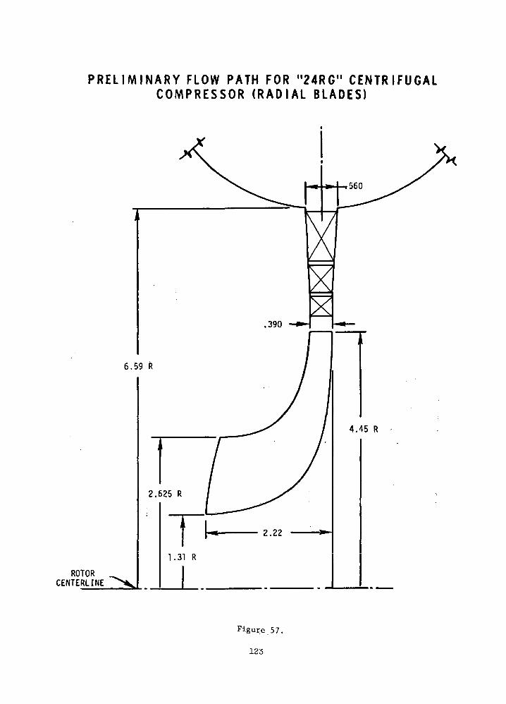
P R E L I M I N A R Y FLOW PATH FOR "24RG" CENTRIFUGALC O M P R E S S O R ( R A D I A L BLADES)
ROTORCENTERLINE
Figure 57.
123
would most likely be selected for the final study, and the performance
for the two design speeds is nearly identical owing to the near constant
specific speed. This closed cycle compressor operates at a constant
mechanical speed, volume flow, and inlet temperature so that changes in
output power are accomplished by changing the inlet pressure. This
mode of operation resulted in Reynolds number changes proportional to
power changes; therefore potential deterioration of performance down to
1/4 power was important.
This compressor system consisted of a centrifugal impeller followed
by a three-vane row cascade diffuser which delivered the flow into a
difusing scroll. The overall performance estimate is "flange-to-flange"
and a breakdown is also presented for the individual components. A
summary of the design input data is presented in. Table XX.
The general level of Mach numbers in the machine are low because
of the high critical velocity and low overall pressure ratio. The tip
speeds for the stage are higher'than with air for the same pressure
ratio because of the high specific heat'ratio of 5/3.
The performance of the .88 work coefficient designs are presented
in Tables XXI and" XXII; for "the 24RG and.36RL compressors,, T-espectively.
The design point efficiency ;was/.84.4% for.each, design. No deterioration
in performance is expected down to 1/4 power since the Reynolds numbers
do not go below 2x10° where the effects of Reynolds number becomes
measureable. •
Recent test data at various Reynolds numbers on the compressor
using reference 8 is plotted in Figure 58. Earlier results, reference
9, show for low Reynolds numbers below 2x10 the Reynolds number
various to the 1/5 power.
This characteristic line is also shown in Figure 58 for the NASA
6-inch compressor and agrees well with the test data. The Reynolds
number losses of the NASA 6-inch compressor level off about 1.5x10 .
Analytic computations using the design computer program at 1/4 power
for the 24RG and 36RL compressors showed negligible effects. The
first vane row inlet flow angle decreased only .1° and overall efficiency
was .2% lower. ' The match of the diffuser-to-impeller should not be
adversely affected by Reynolds number because the inlet flow angle is
constant.
124
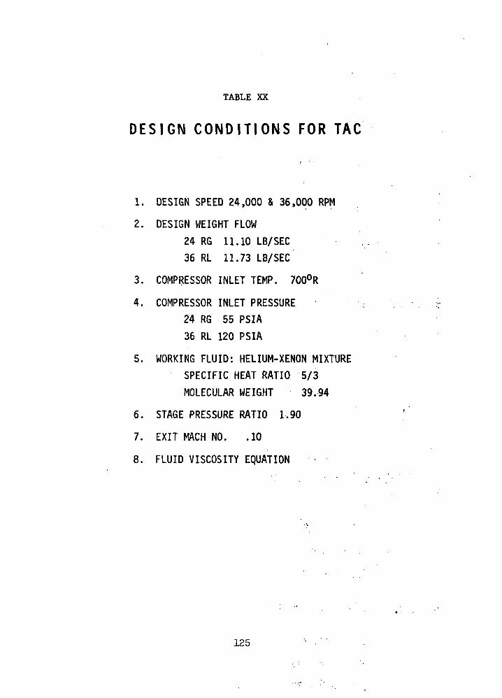
TABLE XX
DESIGN CONDITIONS FOR TAC
1. DESIGN SPEED 24,000 & 36,000 RPM
2. DESIGN WEIGHT FLOW
24 RG 11.10 LB/SEC36 RL 11.73 LB/SEC
3. COMPRESSOR INLET TEMP. 700°R
4. COMPRESSOR INLET PRESSURE24 RG 55 PSIA
36 RL 120 PSIA
5. WORKING FLUID: HELIUM-XENON MIXTURESPECIFIC HEAT RATIO 5/3
MOLECULAR WEIGHT 39.94
6. STAGE PRESSURE RATIO 1,90
7. EXIT MACH NO. .10
8. FLUID VISCOSITY EQUATION
125
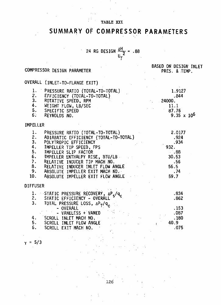
TABLE XXI
SUMMARY OF C O M P R E S S O R P A R A M E T E R S
24 RG DESIGN y = .88UT
BASED ON DESIGN INLETCOMPRESSOR DESIGN PARAMETER . PRES. & TEMP.
OVERALL (INLET-TO-FLANGE EXIT)1. PRESSURE RATIO (TOTAL-TO-TOTAL) 1.91272. EFFICIENCY (TOTAL-TO-TOTAL) .8443. ROTATIVE SPEED, RPM . 24000.4. WEIGHT FLOW, LB/SEC 11.15. SPECIFIC SPEED 87.766. REYNOLDS NO. 9.35 x io6
IMPELLER1. PRESSURE RATIO (TOTAL-TO-TOTAL) 2.01772. ADIABATIC EFFICIENCY {TOTAL-TO-TOTAL) .9243. POLYTROPIC EFFICIENCY .9344. IMPELLER TIP SPEED, FPS 932.5. IMPELLER SLIP FACTOR .886. IMPELLER ENTHALPY RISE, BTU/LB 30.537. RELATIVE INDUCER TIP MACH NO. .568. RELATIVE INDUCER INLET FLOW ANGLE 56.59. ABSOLUTE IMPELLER EXIT MACH NO. .7410. ABSOLUTE IMPELLER EXIT FLOW ANGLE 59.7
DIFFUSER1. STATIC PRESSURE RECOVERY, AP./q. .8342. STATIC EFFICIENCY - OVERALL b • .8623. TOTAL PRESSURE LOSS, APT/qr
- OVERALL ' c .153- VANELESS + VANED '-• .087
4. SCROLL INLET MACH NO. .1805. SCROLL INLET FLOW ANGLE , 40.96. SCROLL EXIT MACH NO. .075
Y = 5/3
126

TABLE XXII
SUMMARY OF C O M P R E S S O R P A R A M E T E R S
36 RL DESIGN
BASED ON DESIGN INLETCOMPRESSOR DESIGN PARAMETER PRES. & TEMP. '
OVERALL (INLET-TO-FLANGE EXIT)
1. PRESSURE RATIO (TOTAL-TO-TOTAL) 1.9086 .2. ADIABATIC EFFICIENCY (TOTAL-TO-TOTAL) .8443. ROTATIVE SPEED, RPM ; 36000.4. WEIGHT FLOW, LB/SEC 11.73 .5. SPECIFIC SPEED 91.83 .,6. REYNOLDS NO. 13.8 x 10°
IMPELLER
1. PRESSURE RATIO (TOTAL-TO-TOTAL)"^ -"" ' 2.00852. ADIABATIC EFFICIENCY (TOTAL-TO-TOTAL) - .9203. POLYTROPIC EFFICIENCY (TOTAL-TO-TOTAL) :"• > '.•.''- •. .:9304. IMPELLER TIP SPEED, FPS . ,- - 930.55. IMPELLER SLIP FACTOR ^'i " : . .886. IMPELLER ENTHALPY RISE, BTU/l'B . >.'? - .-.•-> 30.437. RELATIVE.INDUCER TIP MACH NO/ - - " : •::' "--.,•. ..-568. RELATIVE INDUCER INLET FLOW5 ANGLE " " •'-.' . • 58.69. ABSOLUTE IMPELLER EXIT MAOH" NOv v " - :.* ':. .73
10. ABSOLUTE IMPELLER EXIT FLOW ANGLE • •: - - - -"• " - 60.2 . :
DIFFUSER - , - ' - . - _
1. STATIC PRESSURE RECOVERY,' AP'/q^ "^'• - ; .840 •2. STATIC EFFICIENCY - OVERALL bl - *:.'-••• .8673. TOTAL PRESSURE LOSS, APT/qr ,
- OVERALL ' c .148- VANELESS + VANED t--- : 1- lV ??- "•^- .093
4. SCROLL INLET MACH NO. v' . .177 .5. SCROLL INLET FLOW ANGLE " • . 40.96. SCROLL EXIT MACH NO. -• • .073
Y = 5/3
127

00OOo
QCOOOOO °°
az za. ._
o
oz
cc
0)M3or
A3N3IDIJJ3-1 'SS01
128
The performance level for the TAC impeller is nominally 92%
at design speed in order to achieve the objective performance. This
performance level is considered equivalent to the performance level (10)
measured for the GE 2.2 Ib/sec compressor. The efficiency for the 2.2
Ib/sec compressor is plotted in Figure 59, where 91% efficiency was
recorded versus its design objective of 90%. The specific speed for the
2.2 Ib/sec stage was 70 versus about 90 for the TAC. Considering the
lower Mach number level, the higher specific speed, and the more lightly
loaded compressor it would seem reasonable to expect a 92% level for the
TAC rotor efficiency.
The parametric studies indicated superior overall efficiency for
the lower work coefficients. The lower work coefficient resulted in
backward-curved blades, higher reaction, and lower diffuser inlet Mach
numbers; hence lower diffuser losses. The backward-curved blades have
more conservative blade surface velocities when compared to radial
blades. For the above reasons a .63 work coefficient stage was considered
for the 24RG requirement. The nominal blade tip exit angle of 45° for
the .63 work coefficient was considered a;good compromise between lower
blade surface velocities and higher blade skin friction. Stress was not
a factor because of the low mechanical tip speed.
The performance results for the 24RG and 36RL conditions are
summarized in Table XXIII. The estimated adiabatic efficiency is .844
from the parametric studies for both cases.
Balje 0.1) has shown the effect of the degree of reaction (Rjj)
on the overall efficiency by the following expression:
n = nR - ( i - RX) ( i - nd) >
The degree of reaction is increased from .415 for the 24RG radial
blades to .599 for the 24RG backward-swept blades. The above expression
estimated the overall efficiency at 86.8% for a 91.9% rotor and an
86% diffuser. The efficiency level appears reasonable from the parameter
comparison in Table XXIV and GE's 2.2 Ib/sec data.
The parametric studies for the 24RG and 36RL rotors established
the inducer and impeller tip dimensions as well as the expected performance
level. This phase of the effort investigated the impeller blade surface
129
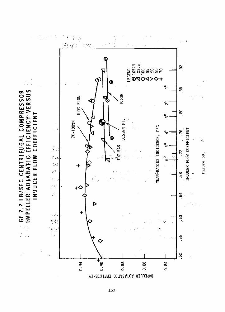
O =>oo </»on OS
CSJ
u-l
a/MM
•H
ADN3I3UJ3 ouvaviav
130

TABLE XXIII
C O M P A R I S O N OF TAC R A D I A L COMPRESSORSFOR 24000 AND 36000 RPM
DESIGNATION 24 RG 36 RL
• GENERAL
- ROTATIVE SPEED, RPM
- FLOW RATE, PPS- SPECIFIC SPEED, CFM, RPM, FT
- REYNOLDS NUMBER X 10"6
24000
11.188
9.4
36000
11.792
13.8
IMPELLER
- INDUCER TIP RELATIVE MACH NO. 0.56 0.56
- INDUCER TIP RELATIVE FLOW ANGLE, DEG. 56.5 58.6
- TIP SPEED, FPS 932 930
- IMPELLER EXIT ABSOLUTE MACH NO. 0.74 0.73
- IMPELLER EXIT ABSOLUTE FLOW ANGLE, DEG. 59.7 60.2
- SLIP FACTOR . 0.88 .0.88
- ADIABATIC EFFICIENCY : *' .924 .920
DIFFUSER AND SCROLL
- TOTAL PRESSURE LOSS COEF. .153 .148
- SCROLL INLET MACH NO. .180 .177- SCROLL INLET FLOW ANGLE, DEG. ; 40.9 40.9
- SCROLL EXIT MACH NO. .075 .073
OVERALL
- ADIABATIC EFFICIENCY .844 .844
131
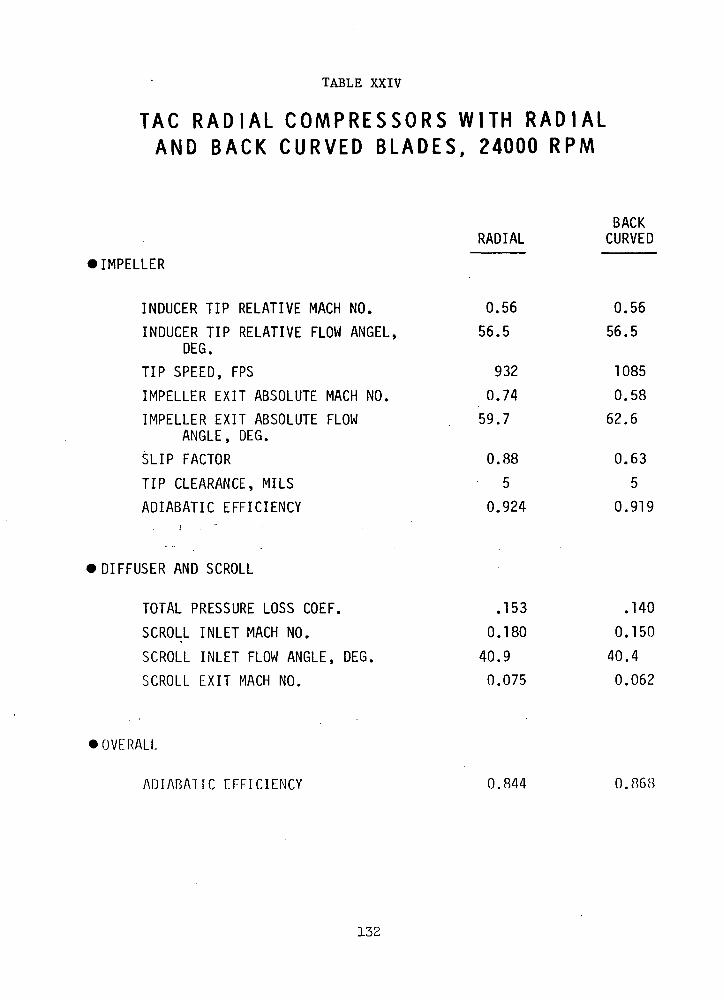
TABLE XXIV
T A G R A D I A L C O M P R E S S O R S W I T H R A D I A LAND B A C K C U R V E D B L A D E S , 24000 RPM
• IMPELLER
BACKRADIAL CURVED
INDUCER TIP RELATIVE MACH NO. 0.56 0.56
INDUCER TIP RELATIVE FLOW ANGEL, 56.5 56.5DEG.
TIP SPEED, FPS 932 1085
IMPELLER EXIT ABSOLUTE MACH NO. 0.74 0.58
IMPELLER EXIT ABSOLUTE FLOW 59.7 62.6ANGLE, DEG.
SLIP FACTOR 0.88 0.63
TIP CLEARANCE, MILS • 5 5
ADIABATIC EFFICIENCY 0.924 0.919
• DIFFUSER AND SCROLL
TOTAL PRESSURE LOSS COEF. .153 .140
SCROLL INLET MACH NO. 0.180 0.150
SCROLL INLET FLOW ANGLE, DEG. 40.9 40.4
SCROLL EXIT MACH NO. 0.075 0.062
•OVERALL
ADIABATIC EFFICIENCY 0.844 0.868
132
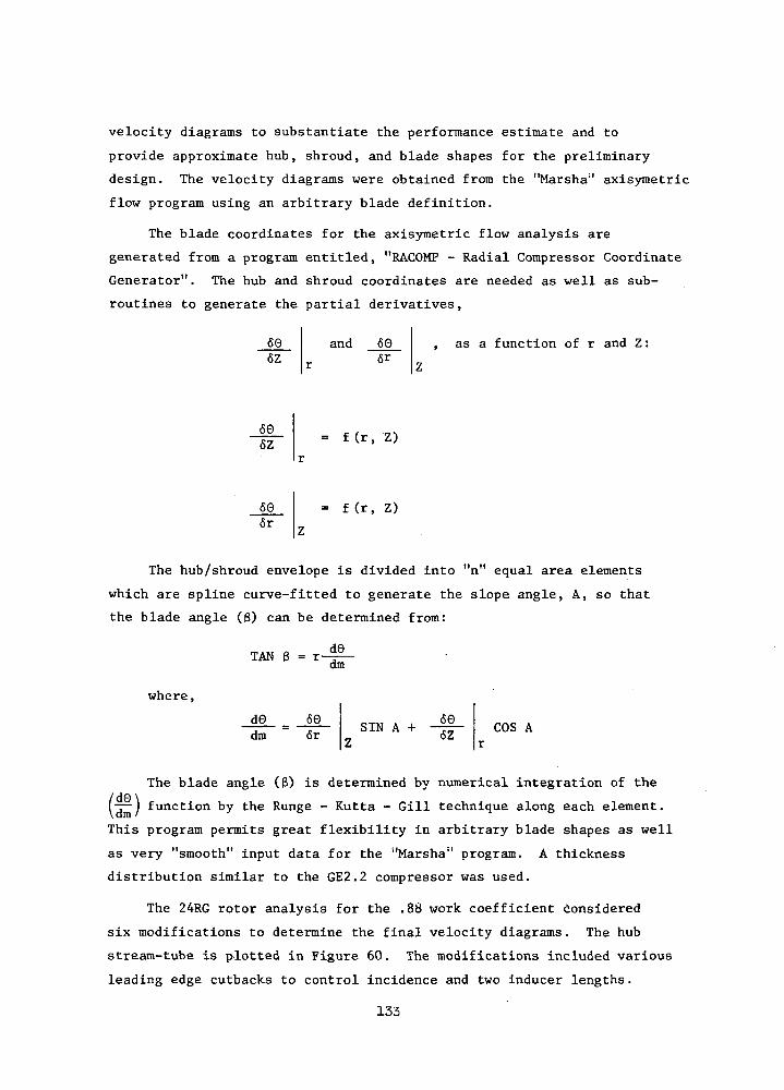
velocity diagrams to substantiate the performance estimate and to
provide approximate hub, shroud, and blade shapes for the preliminary
design. The velocity diagrams were obtained from the "Marsha11 axisymetric
flow program using an arbitrary blade definition.
The blade coordinates for the axisymetric flow analysis are
generated from a program entitled, "RACOMP - Radial Compressor Coordinate
Generator". The hub and shroud coordinates are needed as well as sub-
routines to generate the partial derivatives,
606Z
and 60 as a function of r and Z:
_60_6Z = f(r, Z)
606r
= f(r, Z)
The hub/shroud envelope is divided into "n" equal area elements
which are spline curve-fitted to generate the slope angle, A, so that
the blade angle (3) can be determined from:
where,
TAN 3
d0
d9dm
dm606r SIN A + 60
6Z COS A
The blade angle (3) is determined by numerical integration of the
IT") function by the Runge - Kutta - Gill technique along each element.
This program permits great flexibility in arbitrary blade shapes as well
as very "smooth" input data for the "Marsha" program. A thickness
distribution similar to the GE2.2 compressor was used.
The 24RG rotor analysis for the .88 work coefficient considered
six modifications to determine the final velocity diagrams. The hub
stream-tube is plotted in Figure 60. The modifications included various
leading edge cutbacks to control incidence and two inducer lengths.
133

CO
on
- UJLU /v;o?:< 00LL.OC 00
</> 33
<_JCQ
O
CM
voCO
CMro
ooCM
o
O »-l
O•—iO
a:LU
3oc•H
CM
ooo
o<c
Iooo
§ ooooCM
03S/JJ 'Ail3013A
134

The amount of the leading-edge cutback is dependent on the inlet
shape and the 24RG rotor used a spxnner. The resultant flow angle
blade angle, and relative inlet Mach number is plotted in Figure 61 .
The amount of the cutback was larger than anticipated' and in a 24,000
RPM, Task III design, the impeller axial length would be increased about
10%. The 24RG velocity diagrams were obtained using -19 blades and are
only nominally loaded. A comparison of these velocity diagrams to the ••-
GE 2.2 Ib/sec rotor is shown in Table XXV.
The 36RL rotor was designed using the same procedure and the •»'.
resultant velocity diagrams obtained . The inducer cutback was somewhat
different than the 24RG design- since an annular duct preceded the s
impeller (See Figure 62).
The performance level estimated for these impellers is summarized
in Table XXUI.The polytropic efficiency of .934 and .930 for the 24RG and
36RL impeller designs compares favorably with the .933 polytropic efficiency ..
achieved in the radially-bladed, -GE 2.2 Ib/sec impeller. •-./ '-- , f J
... v j
The velocity diagrams for the backward-curved rotor would be more •*, ••>••'-
conservatively loaded than for/the equivalent radially-b laded rotor. •.''' ».»•" ' ' . < •. "j • - ••••- , •
;..' Preliminary Diffuser Design Study *v .».'
• The preliminary vaned diffuser design study investigated the. JV-i •*• i
effects of vaneless space size, vane loading level, and scroll inlet i'*.,'"-;
swirl in order to arrive at the proposed design. The diffusing system "'••
consisted of a vaneless diffuser followed by a vaned diffuser which dumps >.•;.
into a collecting scroll, the losses for each section of the diffuser -I
are calculated in the same fashion as the GE 2.2 Ib/sec diffuser since
good correlation with experimental data had been achieved. The vaned '-|
diffuser losses include profile, wall, and secondary flow losses; hence *'-
preliminary diffuser blading was designed for each case to arrive at these .•••
losses. A second method was also used to estimate the performance by
computing a diffuser overall effectiveness to determine the diffuser
recovery. •
Experience with vaned diffusers with supersonic.inlet Mach
numbers has indicated vaneless space widths in the !.;,! to 1.2 r/rt
as optimum. Small vaneless spaces have lower vaneless losses;.but
larger vaned losses from the higher vane inlet mach numbers. "The
135
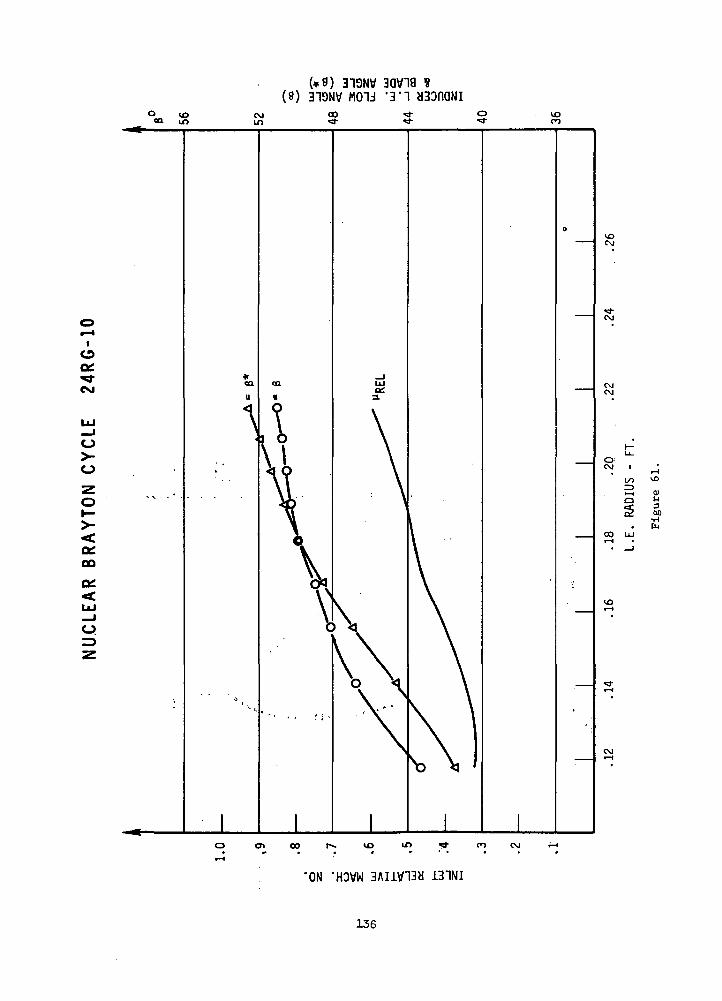
(*9) 319NV 3QV19(8) 319NV M01J '3'1
O USQu if)
CVJin
o«—II
ogCM
o
oi—
CO
UJ_Jo.
CMCM
O'CM
00 LjJ
"ON 'HOVW 3AIitf13a 131NI
136

TABLE XXV
COMPARISON OF ROTOR VELOCITY DIAGRAMS
ITEM
l' Vmax, S/V1- SHROUD- HUB
2. V /V
- SHROUD- HUB
3 V s/VJ' vmax, S/V2
- SHROUD- HUB
GE 2.2#/SECCOMPRESSOR
ROTOR
1.2531.227
1.356.935
1.6991.147
24 RGROTOR
1.2131.723
1.409.825
1.7101.412
36 RLROTOR
1.2291.624
1.495.961
1.8391.561
VV2
oo
V2
nrin,p
MERIDIONAL DISTANCE
137
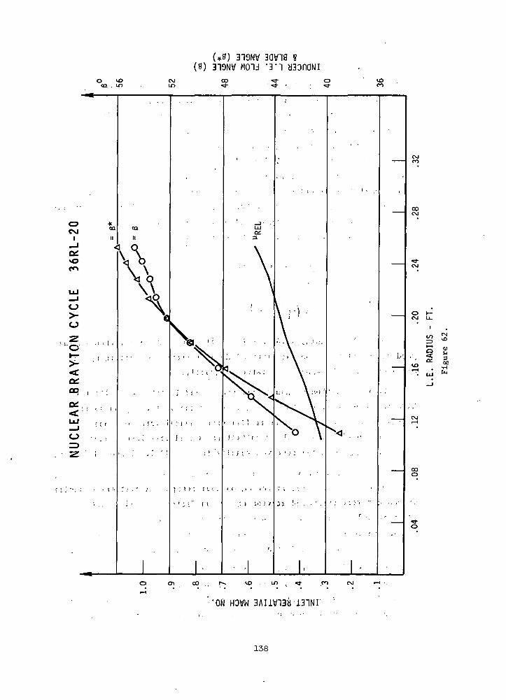
(#8) 319NV 3QV19 S(9) 319NV MOU '3'1 H30nONI
•'OKI HOVW 3AIlV13b 131NF
138
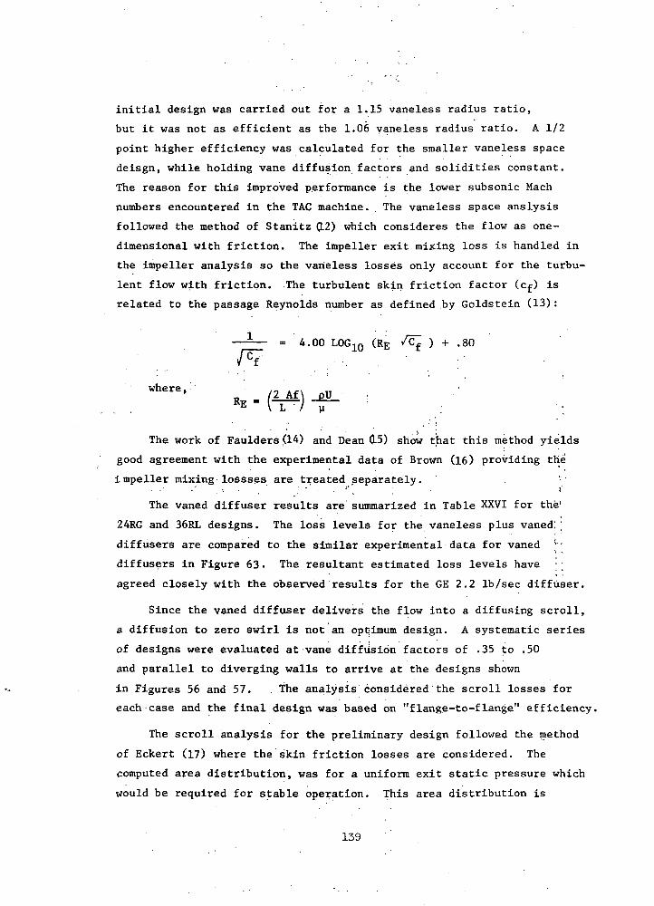
initial design was carried out for a 1.15 vaneless radius ratio,
but it was not as efficient as the 1.06 vaneless radius ratio. A 1/2
point higher efficiency was calculated for the smaller vaneless space
deisgn, while holding vane diffusion factors and solidities constant.
The reason for this improved performance is the lower subsonic Mach
numbers encountered in the TAC machine. . The vaneless space anslysis
followed the method of Stanitz (L2) which consideres the flow as one-
dimensional with friction. The impeller exit mixing loss is handled in
the impeller analysis so the vaneless losses only account for the turbu
lent flow with friction. The turbulent skin friction factor (cf) is
related to the passage Reynolds number as defined by Goldstein (13):
—-— = 4.00 LOGIO (RE /cf ) + .so
where,
«• - (V1) -fvThe work of Faulders ,(14) and Dean 0-5) show that this method yields
good agreement with the experimental data of Brown (16) providing the
impeller mixing lossses are treated separately.• • ' • • ' • • • ' , . ' " - • ' ' , . ' 'The vaned diffuser results are summarized in Table XXVI for the1
24RG and 36RL designs. The loss levels for the vaneless plus vaned; |
diffusers are compared to the similar experimental data for vaned
diffusers in Figure 63- The resultant estimated loss levels have ;;
agreed closely with the observed results for the GE 2.2 Ib/sec diffuser.
Since the vaned diffuser delivers the flow into a diffusing scroll,
a diffusion to zero swirl is not an optimum design. A systematic series
of designs were evaluated at vane diffusion factors of .35 to .50
and parallel to diverging walls to arrive at the designs shown
in Figures 56 and 57. The analysis considered the scroll losses for
each case and the final design was based on "flange-to-flange" efficiency.
The scroll analysis for the preliminary design followed the method
of Eckert (17) where the skin friction losses are considered. The
computed area distribution, was for a uniform exit static pressure which
would be required for stable operation. This area distribution is
139
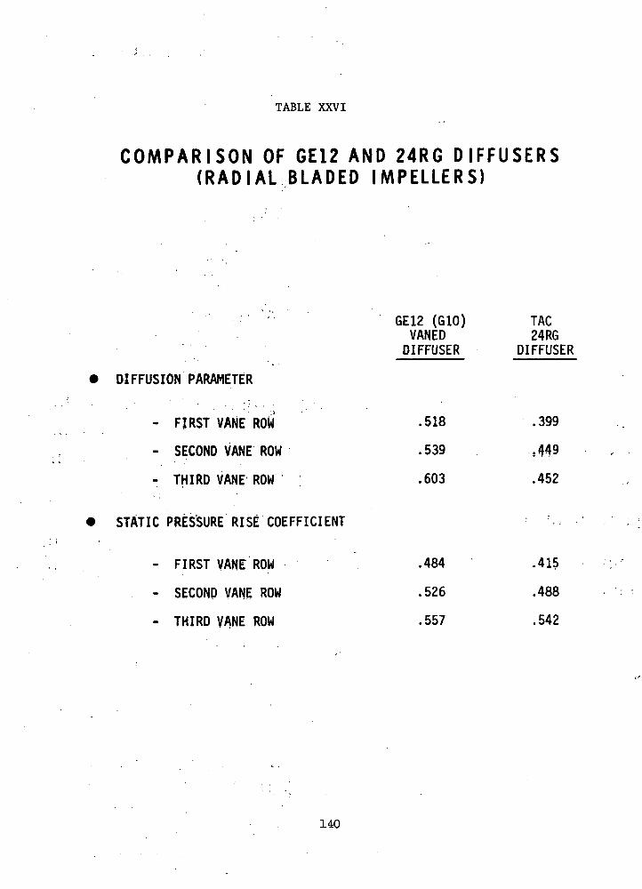
TABLE XXVI
C O M P A R I S O N OF GE12 AND 24RG D I F F U S E R S( R A D I A L BLADED IMPELLERS)
GE12 (G10) TACVANED 24RGDIFFUSER DIFFUSER
DIFFUSION PARAMETER
- FIRST VANE ROW .518 .399
- SECOND VANE ROW .539 ,449
- THIRD VANE ROW .603 .452
STATIC PRESSURE RISE COEFFICIENT
- FIRST VANE ROW .484 .415
- SECOND VANE ROW .526 .488
- THIRD VANE ROW .557 .542
140
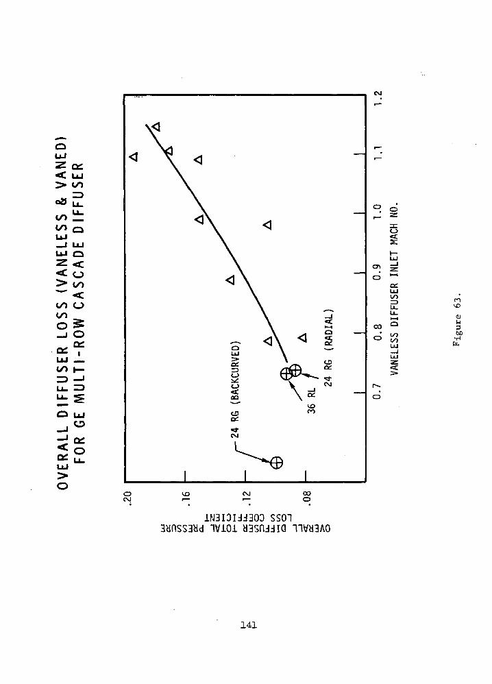
*f. LU> 00
CO Q
LU_J LULU Oz << o5 °°00 O
LU _00 I—ID -
O LU
_J
-J Ql<0oc SLU
CVJ
OCM
cvi
cc:UJ
=>
00
CD
rovo
300
COO
1N3IDIJJ303 SS013ynss3cJd ivioi y
141
sufficiently accurate for a preliminary design study. A more rigorous
analysis should be carried out in Task III where the effects of finite
recirculation and local skin friction would be considered. This method
would be used to more accurately design the tongue area of the scroll
but is not expected to have a major change in other regions.
A second method of estimating the diffuser performance employed
the method of Sovran and Klomp where the effects of blockage and loss
are included in an expression for the overall diffuser effectiveness
(e0). The diffuser overall effectiveness as defined by Sovran and
Klomp (18) is: -CP
O n *S*
where, C_ , is the actual static pressure recovery and Cp* is the one-
dimensional ideal static pressure recovery factor.
_ pS2 -C =P
As indicated by Runstadler and Dean (19) the C«* for compressible
flow is somewhat higher owing to compressibility effects. Sovran and
Klomp related'the diffuser overall effectiveness (eo) to the -diffuser
blockage, geometry, and core total pressure loss
1El2, (E1/E2)2
1 ~ AR*
1 - IF
urn
1 - IF
For the GE 2.2 Ib/sec vaned diffuser, the overall effectiveness
was .7508 for a loss .16 at an inlet Mach number of 1.05. The ideal
compressible pressure recovery is .965 so the computed recovery with
loss and blockage is .725. This computed recovery.can be compared to the
observed recoveries of .695 to .771 for this diffuser at this level of
loss and Mach number. This method was applied to the 24RG vaned diffuser
in order to account for the change in loss, exit blockage, and Mach
number level expected for this design. The exit blockage resulting from
decreased vane wake thickness is estimated at .55 versus .48 for the
GE12 (Note: Blockage defined by Sovran and Klomp is based on core velocity)
The overall diffuser effectiveness for the 24RG, .88 work coefficient,
is computed to be .9041 for the loss level of .087. The ideal compressible
142

recovery is .914 so the computed static pressure recovery is ,827. The
static pressure recovery determined from the other design
for the vaneless plus vaned diffuser is .813 for the 24RG diffuser.
The development of the vaned diffuser for the TAG would require
a minimum of two diffuser flow sizes to properly match with the
impeller. Previous experience has indicated that this matching is most
critical to the achievement of the design objectives and it would be
folly to attempt this sensitive match using a single diffuser design.
Another area in question is the required stall margin for this machine
since a large stall flow range-would necessarily compromise the design
point performance. The stall margin reflected in these design estimates
would be about 8%, based on flow at design speed. Additional margin
beyond this limit would need serious study in Task III. The indicated
mode of operation is at a constant corrected flow and speed so a large
stall margin requirement would seem unlikely at this time.
Concluding Remarks
Preliminary radial-bladed compressor designs were carried out
for both the 24,000 and 36,000 rpm centrifugal compressors. The estimated
performance of these designs was substantiated by the experimental
performance of GE 2.2 Ib/sec compressor performance. However, one
dimensional parametric design studies indicated that even at the low
value of Mach number encountered at the entrance to the vaned diffuser,
an improvement in efficiency could be made by using 45-degree back-curved
blades. A preliminary design of such a compressor was carried out for
the 24RG TAG configuration. This compressor had a three-vane-rpw,,. .
diffuser and scroll. The design-point efficiency at a radial tip;
clearance of 5 mils was 0.868.
143

GLOSSARY OF TERMS
Symbol Description
A Flow angle to axis - degree2
A^ Vaneless Diffuser Flow Area - Ft
AR Diffuser Area Ratio
Cf Skin friction coefficient
Cp Diffuser static pressure recovery
Cp* Ideal static pressure recovery
EI Diffuser inlet blockage based on core flow
E£ Diffuser exit blockage based on core flow
H Enthalpy, BTU/LB
L Vaneless diffuser passage width, feet
M Mach number
m Meridional^distance, feet
PT Total Pressure, PSF
Ps Static Pressure, PSF
qc Compressible dynamic head, PSF
Re Reynolds Number
Rx Degree of Reaction
r • Radius, feet
U ' Velocity, FPS
Z Axial distance, feet
3 Blade angle, degree
6 , Specific heat ratio
eQ Diffuser Effectiveness
n Efficiency
0 Angular coordinate, radians
y Viscosity, lbm/sec-ft
p Density, lb/ft2
(o Total pressure loss coefficient based on compressibleinlet head
144

RADIAL INFLOW TURBINE
Introduction
Design Requirements
Design requirements for the turbo-alternator compressor (TAC) drive
turbine discussed in this report (24EG) are as follows:
Turbine Inlet Temperature 2060 deg R
Pressure Ratio 1.786
Molecular Weight of Working Fluid 39.94
Ratio of Specific Heats 5/3
Rotational Speed 24,000 rptn
Turbine Inlet Pressure 101.4 psia
Mass Flow 11.1 Ib/sec
Diffuser Exit Mach Number 0.1
Specific Speed 83 rpm ft3'4/sec1/2
A second machine of approximately .equal specific speed was also
investigated. Design requirements for this turbine (36RL) were identical
to those given above except for the following three quantities:
Rotational Speed • 36,000 rpm
Turbine Inlet Pressure 221.1 psia
Mass Flow 11.73 Ib/sec
Because of the equivalence in specific speed, the two machines are
essentially scaled versions of each other. As a result, the optimization
procedure described in the next section resulted in very similar aero-
dynamic designs for the two stages. To avoid repetition, only the 24,000
rpm design is described in detail. However, the final overall dimensions
of both turbines have been included in the design summary. The slightly
different mass flows projected for the TAC configurations utilizing axial-
flow compressors (24AG, 36AM, 36AL, 36RM) have not been treated in detail,
since the general trade-offs underlying the preliminary turbine design
would not have been affected.
Design Limitations
Three constraints were imposed to define the range of mechanically
and aerodynamically acceptable design variations. Rotor exit absolute
swirl was limited to ±15 degrees to eliminate the possibility of unsteady
145

or recirculatory flows in the diffuser. Rotor exit hub/tip ratio was limited
to a minimum of 0.4 since blade attachment problems and excessive trailing
edge blockages would be encountered below this value. Finally, the ratio
of exit shroud diameter to inlet tip diameter was limited to a maximum of
0.7 so that flow separation would not occur at the shroud. There is little
incentive for using values of hub/tip ratio lower than 0.4, since only 16%
of the maximum possible annulus area remains unused at this limit. The
choice of 0.7 for the shroud curvature index is somewhat more arbitrary,
being based primarily on good design practice.
The use of radial element rotor blading in the final design was anti-
cipated. However, this limitation was not imposed during the preliminary
meanline optimization in an effort to discover whether non-radial blades
offered any significant performance advantages.
Parametric Meanline Design Optimization
Values of six parameters in addition to the design requirements are
required to define the meanline velocity triangles completely. These are
the following:
1. Ratio of rotor-exit to rotor-inlet relative velocity.,..?• • .
2. Absolute stator exit angle.
3.' Absolute stator exit velocity-.
4. Ratio of exit mean to inlet tip diameter.
5. Blade speed.
6. Efficiency.
For each set of values of the first five parameters, a value of effi-
ciency was calculated iteratively using standard aerodynamic relations
, and the loss equations given by Rohlik in Reference 20. In this formula-
tion, stator and rotpr losses are based on a simplified form of the Stewart
correlation (Reference 21). Clearance loss is assumed to be proportional
to the average value of the ratio of clearance to blade .height. (Fixed
axial and radial clearances of 0.010 inch were assumed for this study.)
Windage loss is calculated from a relation given by Shepherd in Reference 22-
In computing static efficiency, the dynamic head corresponding to the abso-
lute exit velocity is assumed to be lost. (The diffuser exit loss in addi-
tion includes the tangential component of the rotor exit head.) Finally,
the conical diffuser performance correlation given by Henry in Reference 23
was employed to estimate diffuser losses.
146

Clearance and windage losses were treated as "external" losses, Ahext,
which act to reduce the useful work output below the value, Ah, implied by
the velocity triangles; the remaining losses constituted "internal" losses,
Ah. , which act to increase the pressure ratio required to obtain a given
set of velocity diagrams. The efficiency is then defined as
h s (Ah - Ahext)/(Ah + Ahint).
Total-to-static efficiency based on diffuser exit conditions was
chosen as the performance index which was to be optimized. The effects
en this efficiency of each of the five independent stage design parameters
are described in the following paragraphs.
Relative Velocity Ratio
The exit-to-inlet relative velocity ratio fixes the overall accelera-
tion of the flow relative to the rotor blades. Large values of this ratio
lead to high rotor exit relative velocities and therefore to increased
losses. On the other hand, low values of acceleration require high solidi-
ties to avoid excessive blade surface diffusion, and thus again to large
kinetic energy loss.
Details of this trade-off are presented in Figure 64 for three levels
of stator exit velocity. In generating these curves, stator angle and
exit-to-inlet diameter ratio were held constant at 74 deg and 0.49, re-
spectively. Blade speed was varied to obtain the best efficiency at each
point. The trends of efficiency with velocity ratio were found to be
essentially independent of stator exit velocity level; in each case a
velocity ratio of 1.6 proved to be optimal. However, the effects of blade
speed and flowpath curvature are to decrease the acceleration near the
hub section. In anticipation of this situation, a velocity ratio of 1.8
was considered more desirable than the absolute peak point. This choice
entailed a performance penalty of less than one-tenth point, and was in
feet required to satisfy the 15 degree exit swirl limitation.
Stator Angle
The effect of varying the stator exit angle at a fixed exit Mach
number is to vary the rotor tip axial width. Ths loss correlation em-
ployed in the parametric study assumed that the stator chordal aspect
ratio was a constant. Hence low stator angles correspond to small tip
147

V A R I A T I O N OF E F F I C I E N C Y WITH A C C E L E R A T I O N(OPTIMUM E F F I C I E N C Y POINTS)
.880
1.
EXIT TO INLET RELATIVE VELOCITY RATIO, rp-Wl
FIGURE 64
148
widths, short chords, and high blade loadings. Conversely, high nozzle
angles imply long blades with large frictional losses.
The effect of these factors on stage efficiency has been plotted in
Figure 65 . Rotor velocity ratio was set at its most desirable value as
determined from Figure 64; the level of stator exit velocity which yielded
the highest efficiency in that study was also employed. Predicted effi-
ciency was found to vary substantially with moderate stator angle changes.
Optimum efficiency of approximately 90.5% occurred at a nozzle setting of
74 degrees.
Stator Exit Velocity
The tangential velocity upstream of the rotor is determined by the
stator exit absolute flow angle and velocity. Efficiency variation with
the second of these parameters is shown in Figure 66. Stator angle, rotor
velocity ratio, and blade speed were held at their optimum values. The
results showed that the 1130 fps value used in Figures 64 and 65 were
close to, but slightly below, the absolute peak value of 1160 fps. How-
ever, when the constraint of 0.4 hub/tip ratio is imposed, the predicted
performance benefit of the higher stator velocity amounts to only 0.1%;
that is, the curve of Figure 66 is flattened in the region of the opti-
mum. In addition, the higher velocity would require considerably larger
rotor incidence if radial rotor blades were used. It was therefore de-
cided to avoid excessive blade loading near the leading edge by employing
the slightly smaller exit velocity in the final design.
Exit-to-Inlet Diameter Ratio
The ratio of exit geometric mean diameter to tip diameter was used
to relate inlet and exit blade speeds. A value of 0.49 was employed for
this parameter in the three previous studies, so that the constraints on
hub/tip ratio and shroud curvature would be reached simultaneously as
exit annulus height increased. To investigate the possible advantages of
departing from this procedure, the diameter ratio was varied from 0.45
to 0.52 with the other parameters set to optimum values. Results are
given in Figure 67. No significant effect on performance was predicted.
Since designs near the hub and shroud constraints were required to obtain
the best efficiency, the 0.49 diameter ratio was retained for the final
study.
149
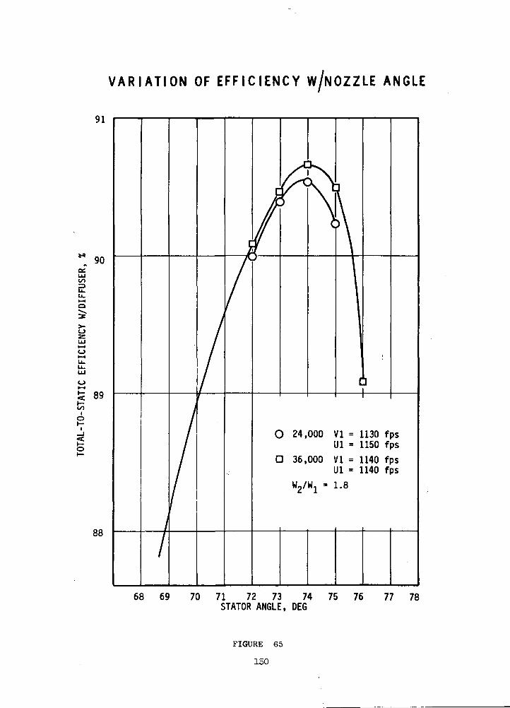
V A R I A T I O N OF E F F I C I E N C Y W/NOZZLE ANGLE
91
90OSLU=>
89oo
o
88
VI = 1140 fpsUl = 1140 fps
68 69 70 71 72 73 74STATOR ANGLE, DEG
75 76 77 78
FIGURE 65
150
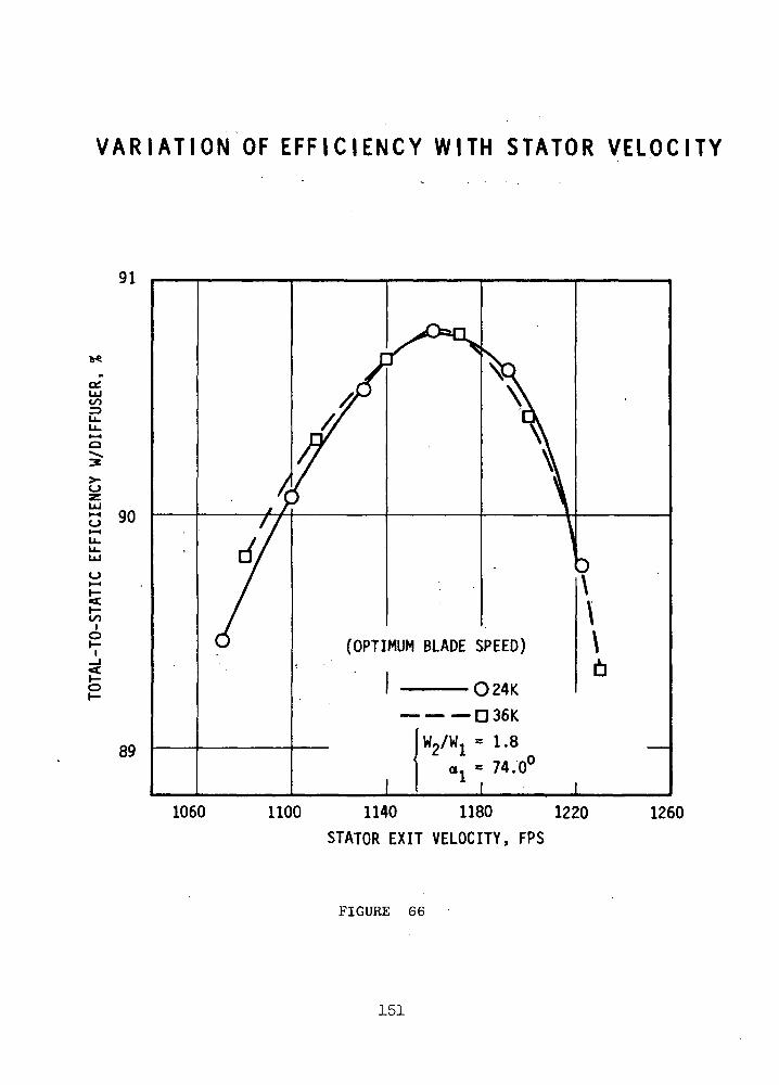
V A R I A T I O N OF EFF IC IENCY WITH STATOR VELOCITY
91
ce
90
oI—«
S
Io
89
(OPTIMUM BLADE SPEED)
O24K
D 36K
2/Wj = 1.8
o. = 74.0C
I I1060 1100 1140 1180 1220
STATOR EXIT VELOCITY, FPS1260
FIGURE 66
151

V A R I A T I O N OF E F F I C I E N C Y WITHD I A M E T E R R A T I O
91
90
= 1160 FPS
= 1.8
0.45 0.47 0.49 0.51EXIT MEAN TO INLET DIAMETER RATIO
0.53
FIGURE 67
152

Tip Diameter
Calculated efficiency is presented in Figure 68 as a function of
blade speed, using the optimum values derived in the previous studies for
the four remaining parameters. For purposes of comparison, curves repre-
senting rotor velocity ratios of 1.6, 2.0 and 2.2 have been included. To
illustrate the influence of the constraints, calculated exit swirl angles
and hub/tip ratios are also shown. It will be observed that no 1.6 velocity
ratio design satisfies the 15 degree exit swirl limitation. Secondly,
whereas hub/tip ratio at the optimum efficiency point decreases as velocity
ratio is reduced, efficiency at the 0.4 hub/tip ratio point increases,
reaching a peak at a velocity ratio of 1.8. Predicted efficiency (exclud-
ing scroll losses) at this constrained optimum is 90.4%; the corresponding
value of blade speed is 1163 fps. Exit swirl at this point is only a
fraction of a degree beyond the nominal limit. Hence this point was chosen
as the final Task I design point.
Optimized Designs
A parametric study very similar to that .described above was also con-
ducted for the 36,000 rpm turbine. The optimized values of the independent
parameters for the two designs, subject to the constraints on hub/tip ratio
and exit swirl, were as follows:
24,000 rpm 36,000 rpm
Rotor Relative Velocity Ratio 1.8 1.8
Stator Angle 74.0 deg 74.0 deg
Stator Exit Velocity " 1130 fps " 1140 fps
Exit Mean-to-Inlet Diameter Ratio 0.49 0.49
Inlet Blade Speed 1163 fps 1162 fps
The implied values of the dependent variables are as follows:
Inlet Diameter 11.106 in. 7.398 in.
Exit Shroud Diameter 7.759 in. 5.182 in.
Exit Hub Diameter 3.124 in. 2.068 in.
Hub/Tip Ratio 0.4 0.4
Inlet Relative Flow Angle -13.8 deg. -11.9 deg.
Exit Relative Flow Angle -56.4 deg. -53.1 deg.
Exit Absolute Flow Angle 15.6 deg. 17.1 deg.
Blade-to-Jet Speed Ratio 0.704 0.702
Predicted Overall Total-to-Static Eff. 90.4% 90.2%
153
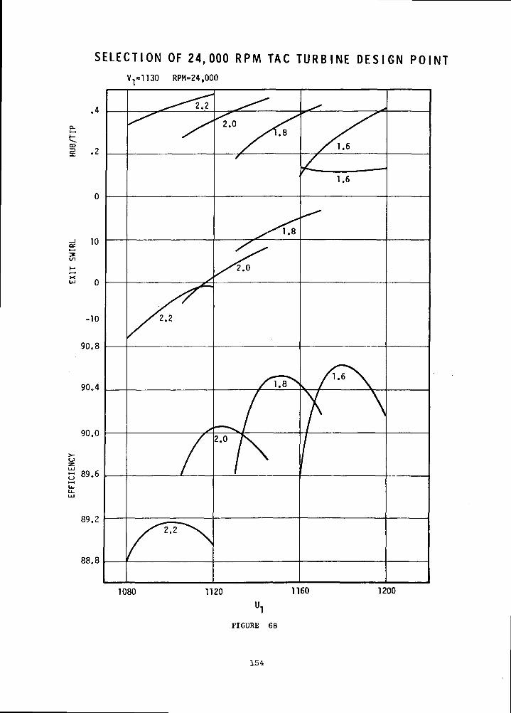
S E L E C T I O N OF 24,000 RPM TAC T U R B I N E D E S I G N POINT
oe»-H
l/l
10
UJ 0
-10
90.8
90.4
90.0
5 89.6
89.2
88.8
1080
RPM=24,000
2.2
2.2
2.2
2.01.8
2.0
1.6
1120 1160 1200
FIGURE 68
154
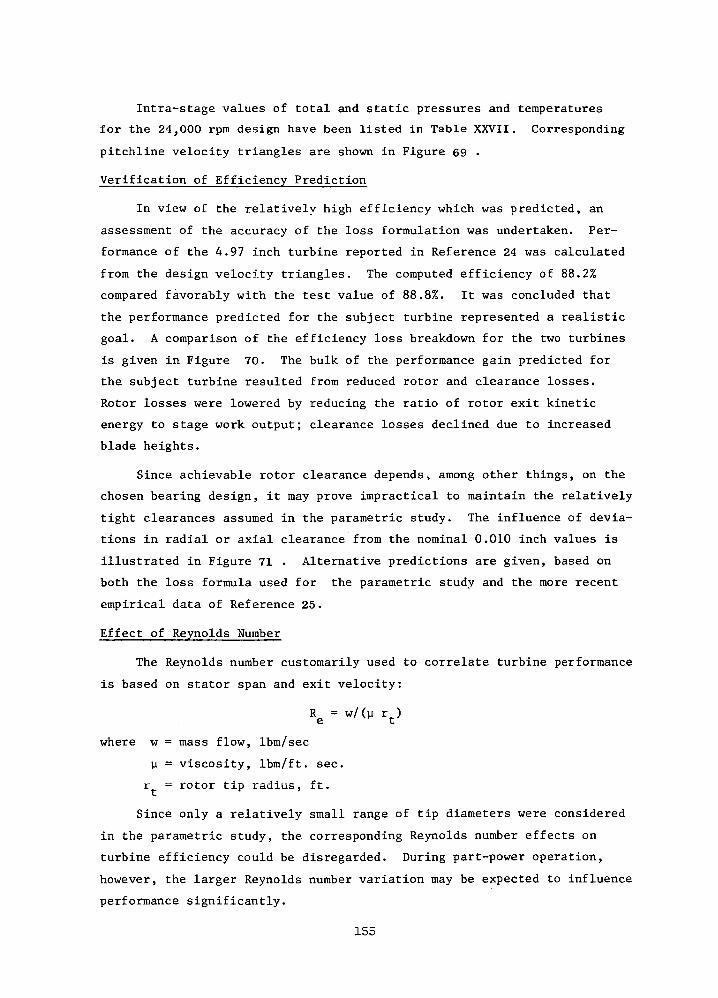
Intra-stage values of total and static pressures and temperatures
for the 24,000 rpm design have been listed in Table XXVII. Corresponding
pitchline velocity triangles are shown in Figure 69 •
Verification of Efficiency Prediction
In view of the relatively high efficiency which was predicted, an
assessment of the accuracy of the loss formulation was undertaken. Per-
formance of the 4.97 inch turbine reported in Reference 24 was calculated
from the design velocity triangles. The computed efficiency of 88.2%
compared favorably with the test value of 88.8%. It was concluded that
the performance predicted for the subject turbine represented a realistic
goal. A comparison of the efficiency loss breakdown for the two turbines
is given in Figure 70. The bulk of the performance gain predicted for
the subject turbine resulted from reduced rotor and clearance losses.
Rotor losses were lowered by reducing the ratio of rotor exit kinetic
energy to stage work output; clearance losses declined due to increased
blade heights.
Since achievable rotor clearance depends, among other things, on the
chosen bearing design, it may prove impractical to maintain the relatively
tight clearances assumed in the parametric study. The influence of devia-
tions in radial or axial clearance from the nominal 0.010 inch values is
illustrated in Figure 71 . Alternative predictions are given, based on
both the loss formula used for the parametric study and the more recent
empirical data of Reference 25.
Effect of Reynolds Number
The Reynolds number customarily used to correlate turbine performance
is based on stator span and exit velocity:
Re = w/(ji rt)
where w = mass flow, Ibm/sec
H = viscosity, Ibm/ft. sec.
r = rotor tip radius, ft.
Since only a relatively small range of tip diameters were considered
in the parametric study, the corresponding Reynolds number effects on
turbine efficiency could be disregarded. During part-power operation,
however, the larger Reynolds number variation may be expected to influence
performance significantly.
155
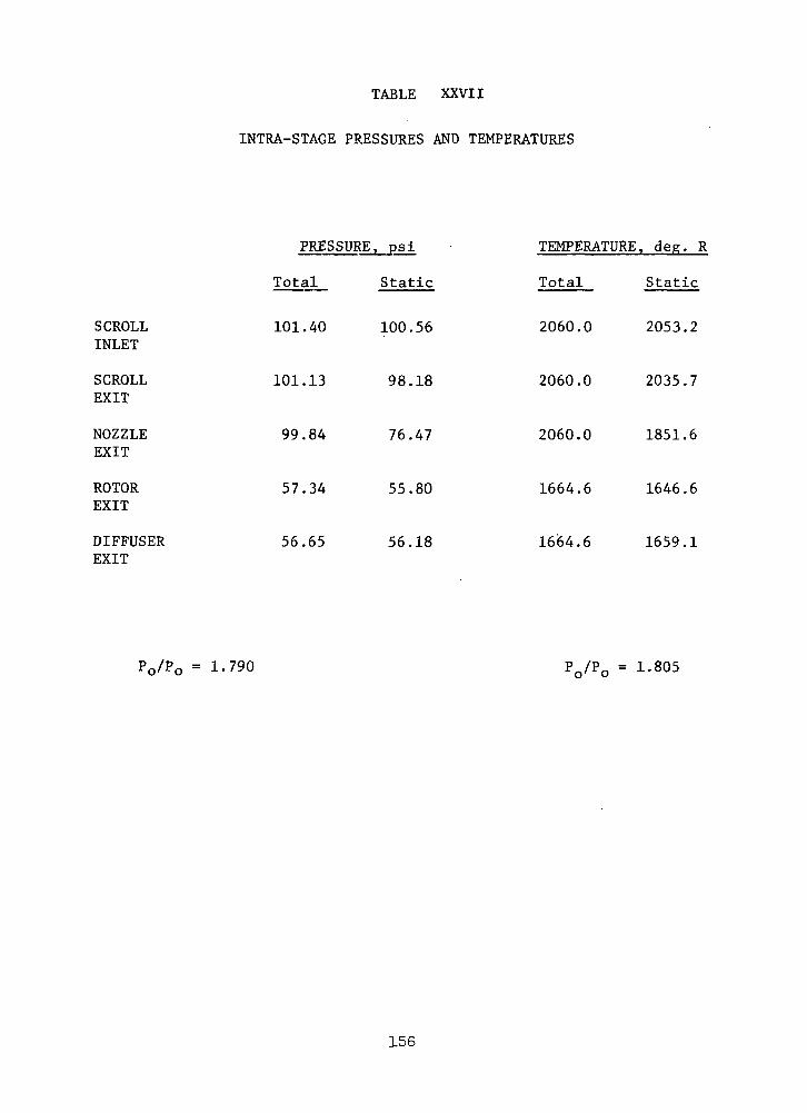
TABLE XXVII
INTRA-STAGE PRESSURES AND TEMPERATURES
SCROLLINLET
SCROLLEXIT
NOZZLEEXIT
ROTOREXIT
DIFFUSEREXIT
PRESSURE, psi
Total Static
101.40 100.56
101.13
99.84
57.34
56.65
98.18
76.47
55.80
56.18
TEMPERATURE, deg. R
Total Static
2060.0
2060.0
2060.0
1664.6
2053.2
2035.7
1851.6
1664.6 1646.6
1659.1
P0/P0 = 1.790 P0/P0 = 1.805
156

P I T C H L I N E V E L O C I T Y T R I A N G L E S
STATOR INLET(R = 6.791")
= 0.216CR
STATOR INLET(R = 5.830")
ROTOR INLET(R = 5.553")
ex., = 74.2° V= 0.178
CR
= 0.608
"U2 .= 0.584
= 0.355"CR
= 0.206
ROTOR EXIT(R = 2.721")
= 0.354'CR
FIGURE 69
157
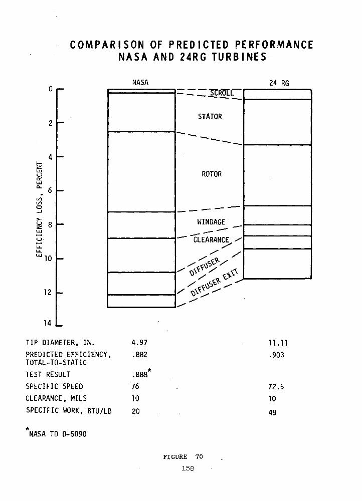
C O M P A R I S O N OF P R E D I C T E D PERFORMANCEN A S A AND 24RG T U R B I N E S
NASA 24 RG
LLJ
OCUJO-
«t
GO
O
10
12
STATOR
ROTOR
WINDAGE
"CLEARANCE
14 L
TIP DIAMETER, IN. 4.97
PREDICTED EFFICIENCY, .882TOTAL-TO-STATIC
TEST RESULT .888*
SPECIFIC SPEED 76
CLEARANCE, MILS 10
SPECIFIC WORK, BTU/LB 20
*NASA TD D-5090
11.11.903
72.5
10
49
FIGURE 70
158
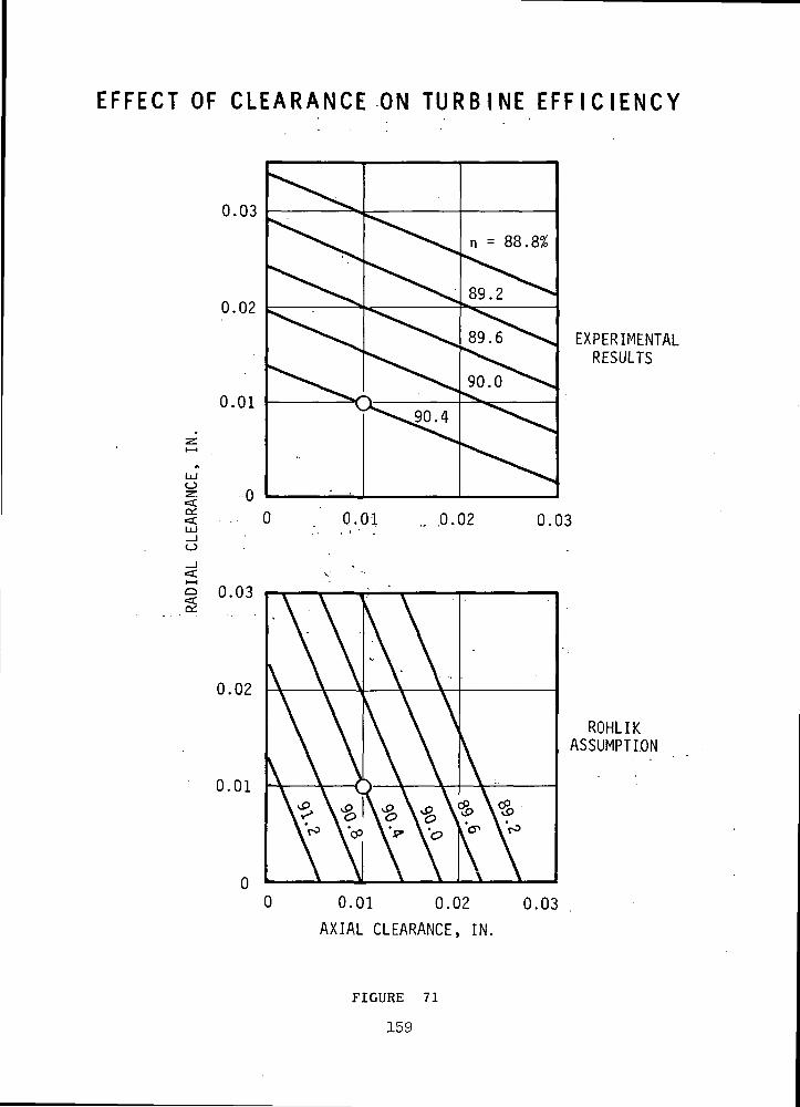
EFFECT OF C L E A R A N C E ON T U R B I N E E F F I C I E N C Y
0.03
0.02
0.01
o
a:
EXPERIMENTALRESULTS
Q.01 .. .0.02 0.03
0.03
0.02
0.01
ROHLIKASSUMPTION
0 0.01 0.02 0.03
AXIAL CLEARANCE, IN.
FIGURE 71
159
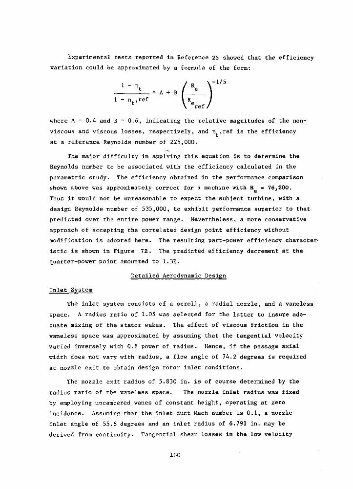
Experimental tests reported in Reference 26 showed that the efficiency
variation could be approximated by a formula of the form:
= A + B1 - nt,ref
where A = 0.4 and B = 0.6, indicating the relative magnitudes of the non-
viscous and viscous losses, respectively, and n,ref is the efficiency
at a reference Reynolds number of 225,000.
The major difficulty in applying this equation is to determine the
Reynolds number to be associated with the efficiency calculated in the
parametric study. The efficiency obtained in the performance comparison
shown above was approximately correct for a machine with R = 76,200.
Thus it would not be unreasonable to expect the subject turbine, with a
design Reynolds number of 535,000, to exhibit performance superior to that
predicted over the entire power range. Nevertheless, a more conservative
approach of accepting the correlated design point efficiency without
modification is adopted here. The resulting part-power efficiency character-
istic is shown in Figure 72. The predicted efficiency decrement at the
quarter-power point amounted to 1.3%.
Detailed Aerodynamic Design
Inlet System
The inlet system consists of a scroll, a radial nozzle, and a vaneless
space. A radius ratio of 1.05 was selected for the latter to insure ade-
quate mixing of the stator wakes. The effect of viscous friction in the
vaneless space was approximated by assuming that the tangential velocity
varied inversely with 0.8 power of radius. Hence, if the passage axial
width does not vary with radius, a flow angle of 74.2 degrees is required
at nozzle exit to obtain design rotor inlet conditions.
The nozzle exit radius of 5.830 in. is of course determined by the
radius ratio of the vaneless space. The nozzle inlet radius was fixed
by employing uncambered vanes of constant height, operating at zero
incidence. Assuming that the inlet duct Mach number is 0.1, a nozzle
inlet angle of 55.6 degrees and an inlet radius of 6.791 in. may be
derived from continuity. Tangential shear losses in the low velocity
160

>-o
00
LUCO
o_jO
>-LUa:u_OH-O
wa:aMPM
ADN3IOIJJ3 ItfiOi
161
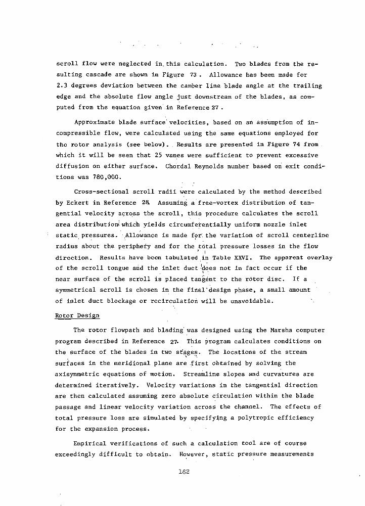
scroll flow were neglected in.this calculation. Two blades from the re-
sulting cascade are shown in Figure 73 . Allowance has been made for
2.3 degrees deviation between the camber line blade angle at the trailing
edge and the absolute flow angle just downstream of the blades, as com-
puted from the equation given in Reference 27 .
Approximate blade surface'velocities, based on an assumption of in-
compressible flow, were calculated using the same equations employed for
the rotor analysis (see below). . Results are presented in Figure 74 from .
which it will be seen that 25 vanes were sufficient to prevent excessive
diffusion on either surface. Chordal Reynolds number based on exit condi-
tions was 780,000.
Cross-sectional scroll radii were calculated by the method described
by Eckert in Reference 2£L Assuming a free-vortex distribution of tan-
gential velocity across the scroll, this procedure calculates the scroll
area distribution! which yields circumfeirentially uniform nozzle inlet
static pressures. .Allowance is made for. the variation of scroll centerline
radius about the periphery and for the total pressure losses in the flow
direction. Results have been tabulated .in Table XXVI. The apparent overlay
of the scroll tongue and the inlet duct 'does not in fact occur if the
near surface of the scroll is placed tangent to the rotor disc. If a
symmetrical scroll is chosen in the final'design phase, a small amount
of inlet duct blockage or recirculation will be unavoidable.
Rotor Design
The rotor flowpath and blading was designed using the Marsha computer
program described in Reference 27- This program calculates conditions on
the surface of the blades in two st'ages. The locations of the stream
surfaces in the meridional plane are .first obtained by solving the
axisymmetric equations of motion. Streamline slopes and curvatures are
determined iteratively. Velocity variations in the tangential direction
are then calculated assuming zero absolute circulation within the blade
passage and linear velocity variation across the channel. The effects of
total pressure loss are simulated by specifying a polytropic efficiency
for the expansion process.
Empirical verifications of such a calculation tool are of course
exceedingly difficult to obtain. However, static pressure measurements
162
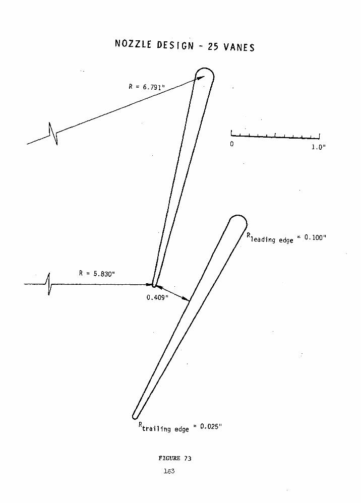
NOZZLE D E S I G N - 25 V A N E S
R = 6.791"
leading edge = °-100"
trailing edge = °-025"
FIGURE 73
163
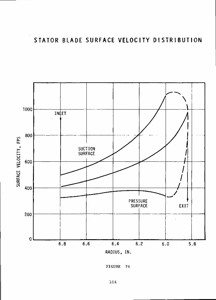
STATOR BLADE SURFACE VELOCITY D I S T R I B U T I O N
1000
6.4 6.2
RADIUS, IN.
FIGURE 74
5.8
164

along the shroud of machines designed by this technique have generally
shown good agreement with the numerical predictions, in cases where gross
flow separation is avoided. In addition, indirect evidence for the ac-
curacy of the solution may be obtained by comparison with the results of
wholly independent calculation schemes. In one published comparison, for
example (Reference 29), the method of Katsanis computed significantly
different velocities only near the blade trailing edge at the shroud.
Radial and axial flowpath coordinates of hub and shroud are given in
Table XXVII. A total of 22 blades (whole plus splitter blades) were speci-
fied for the design, based on the correlation given in Reference 30- Both
the hub and shroud contours are defined by circular arcs, thereby minimiz-
ing the meridional curvatures. The hub blade angle distribution was chosen
to satisfy the following requirements:
1. Zero blade angle at tip.
2. Acceptable hub suction surface diffusion.
3. Minimal upguided turning downstream of the throat.
Meridional mid-stream tube locations calculated for the design are
shown in Figure 75. The distributions of meridional velocity along these
streamlines are presented on Figure 76 • Apart from the unavoidable dis-
continuity due to blockage at the trailing edge, the meridional velocity
distributions are smooth and show no abrupt decelerations. Corresponding
relative velocity distributions are given in Figure 77 for the preliminary
case of 22 whole blades and Figure 78 for the recommended configuration
with 11 whole blades and 11 splitters. It can be seen that the flow
generally accelerates along the entire blade, except over the initial
portion of the hub suction surface and the latter portion of shroud suc-
tion surface. In both these latter cases only moderate diffusions which
should not cause flow separation are encountered. Flow reversals are
entirely absent. The light loadings on the downstream third of the blade
are a result of the attempt to minimize upguided turning. The substantial
loading predicted at the leading edge is a consequence of the effective
positive incidence required by the design velocity triangles.
Blade exit conditions were calculated at both the trailing edge plane
and at diffuser inlet, 0.1 foot downstream. It was assumed that mass,
energy, and momentum were conserved in the blade-free space. Use of
165

TABLE XXVII
COORDINATES OF ROTOR HUB AND SHROUD CONTOURS
HUB SHROUD
RadialDistance, ft.
0.4625
.4230
.3850
.3460
.3060
.2670
.2300
.2130
.1970
. 1810
.1680
.1550
.1450
.1390
.1350
.1320
.1300
AxialDistance, ft.
0.0000
.0000
.0050
.0160
.0320
.0550
.0840
.1020
.1210
.1430
.1660
.1920
.2190
.2400
.2600
.2800
.3000
RadialDistance, ft.
0.4625
.4380
.4150
.3928
.3731
.3558
.3419
.3360
.3316
.3278
.3250
.3236
.3233
.3233
.3233
.3233
.3233
AxialDistance, ft.
0.0797
.0814
.0876
.0980
.1118
.1288
.1486
.1600
.1708
.1824
.1943
.2068
.2189
.2400
.2600
.2800
.3000
166

ROTOR STEAMTUBE LOCATIONS
0.5
0.4
LUO
IC/)•—Io_j<ti—iocc
0.3
0.2
0.1
—STEAMTUBE 11
STEAMTUBE 6
• -._..'_,_ STEAMTUBE
,1 .2 .3
AXIAL DISTANCE, FT
.4 .5
FIGURE 75
167
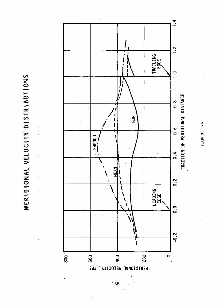
GO
01
Oo
O
o
co
§
oo10
ooooCM
Sdd 'A1ID013A IVNOIQUGW
168
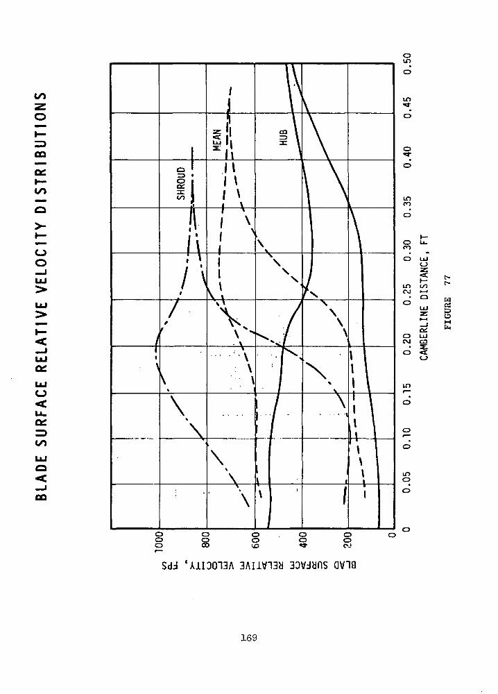
CQ
a:H-to
O
oo
<UJegLUO
LUO
00
oino
in•
o
o•
o
Lf>CO
o
o
in coc\j •—i
• oo
QiO UJCM ca
in
o
o
unO
'AH3013A avia
169
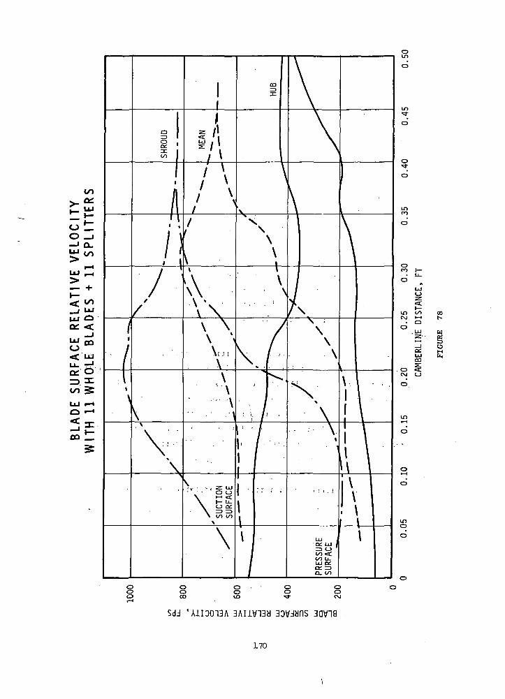
o L.O _J—' D.
__, UJ
LU OK <_J
LU Q3O< LU
Sdd 'A1I0013A 3AIiV13d 3D\/dbnS 3QV18
170
splitters shorter than those indicated in Figure 78 would be desirable
in that blade wetted area could be reduced. However, the calculated sur-
face velocity distributions show that any significant reduction would
lead to greatly increased diffusion at the exducer shroud. Since this is
normally the portion of the flowpath most susceptible to separation, the
splitter trailing edges have been conservatively located at an axial
position of Z = 0.2 feet.
Exhaust System
The dynamic head at rotor exit represents the equivalent of nearly
four points in turbine efficiency. Hence the design of a highly effective
exit diffuser is of considerable importance to overall stage performance.
Unfortunately, the performance obtained in practice has traditionally been
quite low. However, it is difficult to determine the extent to which this
behavior has resulted from poor rotor (or diffuser) design practice. There-
fore, the preliminary diffuser design has been based on the diffuser data
published in References 23 and 31 without applying any arbitrary correction
factors.
The performance of three alternative diffuser configurations was in-
vestigated as a function of axial length. The first design was an annular
diffuser with constant inner diameter equal to that of the rotor hub, and
exit outer diameter equal to that of the exhaust duct. The second design,
also annular, had the same inner diameter but slightly increased exit
diameter so that the diffuser exit velocity equalled the velocity in the
exhaust duct. The centerbodies of both annular diffusers were supported
by tilted struts fastened near the discharge flange. Strut loss data were
taken from Reference32 • The final configuration which was studied .con-
sisted of a conical diffuser with a rotating centerbody at rotor exit.
The calculated variation of overall stage total-to-static efficiency
with diffuser axial length is shown in Figure 79 . Stall lines based on
correlation of empirical data given in Reference 31 have been included.
The larger annular diffuser was found to offer a potential performance
improvement of approximately one percent over the conical design. There
was little advantage in increasing diffuser length beyond that requiredi \
to avoid stall, which was 8.2 inche"s-at an area ratio of 1.76. However,
in view of the nonuniform velocity profiles which may be expected at
i V ^171 '
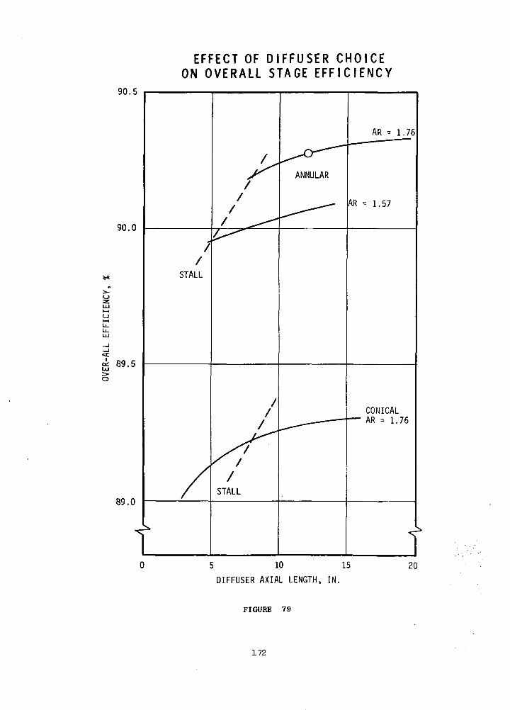
90.5
90.0
<i 89.5Ul
O
89.0
t
EFFECT OF D I F F U S E R C H O I C EON OVERALL STAGE EFF IC IENCY
/STALL
AR = 1.76
= 1.57
CONICALAR = 1.76
T5 10 15
DIFFUSER AXIAL LENGTH, IN.
20
FIGURE 79
172

diffuser inlet, a conservative length of 12 inches was selected for both
the conical and annular designs. The resulting configurations are shown
schematically in Figure 80. Since a short transition region is required
downstream of the annular design, its actual overall length will be ap-
proximately 14 inches. The final calculated efficiency of this design
was 90.25% including inlet scroll losses.
If the predicted performance can be achieved, it is clear that the
annular design should be used. However, it must be admitted that a recent
test of a similar configuration (Reference 24) demonstrated an effective-
ness of only 47% as against the 80% implied for the present design by the
data of Reference 31. A possible explanation of this situation is illus-
trated in Figure 81 where stall is indicated at the diffuser design point
employed in Reference 24. However, since no detailed diffuser exit tra-
verses were reported, it is unfortunately not possible to verify this
prediction. It would therefore be desirable to test both alternative
diffuser configurations to determine whether the increased mechanical
complexity of the annular design is justified by its performance.
A schematic view of the overall design, showing the relation of inlet
scroll, radial nozzle, rotor disk, and exit diffuser is given in Figure g£
173
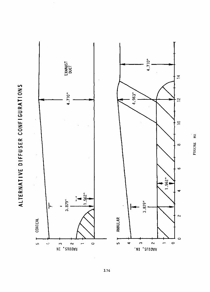
CO
x o
uo
o
O
u_
OO
0£UJ
>»—<
0£LU
CO
CO
oo
o00
a
i— O
NI 'smavy 'sniavy
174
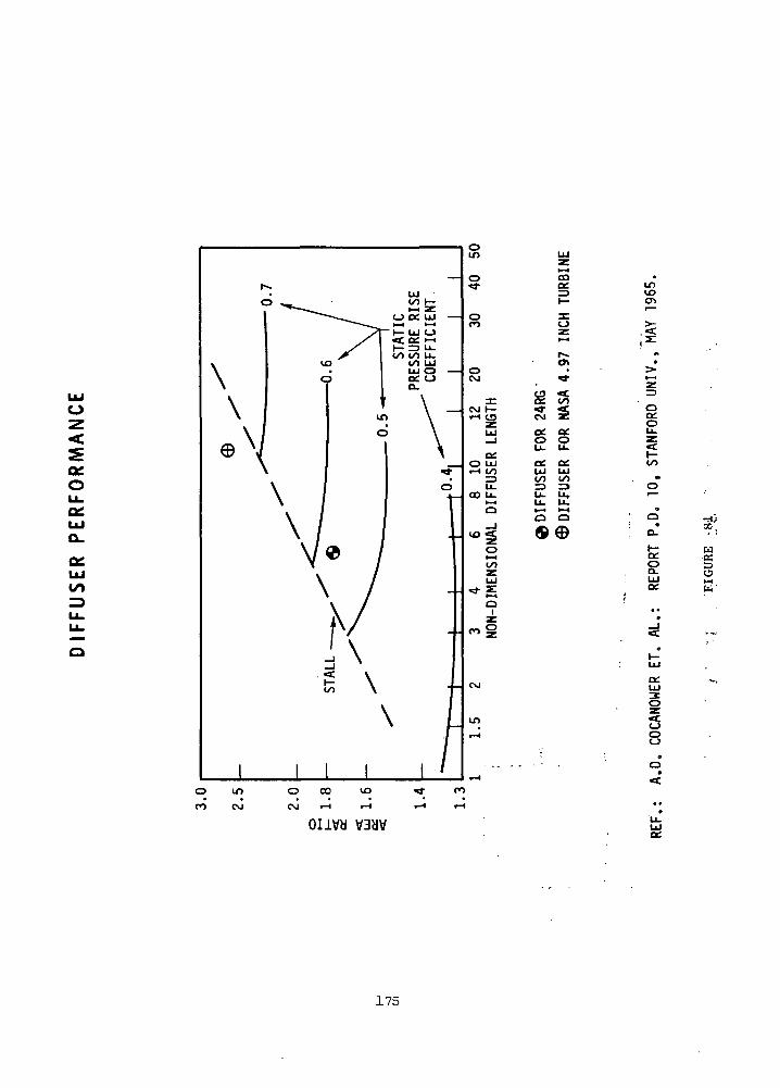
01oLL.0£UJO_
UJto
COcc
O
CO
g
cc. oc.LU LUCO CO=3 3
o a
0Q£0
CO
o
sLUo;
u
o
a:UJ
oo
o
C\J i-H r-H
oiivy VBHV
175

MERIDIONAL VIEW OF OVERALL DESIGN
CENTERLINE
FIGURE 82
176

PERFORMANCE COMPARISON
The performance of the six TAG configurations was estimated to
assist in the selection of a configuration for design in Phase III. To
do this it was necessary to estimate the various losses, which are
summarized in Table XXIX. The bearing and seal losses of Configurations
4f 5 and 6 are high because of the alternator cavity oil seals, and
Configuration 6 has the additional loss of the liquid film bearings.
The alternator windage is less for these configurations because the
seals permit a lower pressure in the alternator cavity. However the
reduced alternator windage does not compensate for the greater losses
of the oil seals. The 24,000 rpm machines have lower total losses, with
Configuration 1 having a slight advantage over Configuration 2.
Shown in Figure 83 are the effects of losses and component
efficiencies on cycle efficiency. It can be seen that bleed has a
major effect, almost 3% change in cycle efficiency for 1% bleed. Each
kilowatt of parasitic loss reduces cycle efficiency about 1/2%. A 1%
change in alternator efficiency reduces the cycle efficiency about 1%,
while 1% changes in compressor and turbine efficiencies reduce the cycle
efficiency by 1.6 and 1.9%, respectively. >
Shown in Table XXX is a performance comparison of the six TAC ;
configurations studied. The first three configurations, with gas
bearings, have better cycle efficiency than the other three configurations,
which have oil bearings, primarily because the parasitic losses and
leakage are less.
Shown in Table XXXI is a loss summary for the TAC designs operating
at one-fourth power. The only change from the full load losses in
Table XXIX is that the alternator windage is reduced for the gas bearing
machines because of the lower pressure levels in the system at part
load. The performance comparison of the several configurations at one-
fourth power is shown in Table XXXII. Again the gas bearing designs have
the better cycle efficiency, and by a greater margin due to decreased
windage losses. The TAC Configuration 1 has the best cycle efficiency
at part load, primarily because the radial compressor has less decrease
in compressor efficiency at the lower Reynolds numbers associated with
reduced pressure levels. Since the radial and axial compressor
.configurations had almost identical performance at full load, the better
177
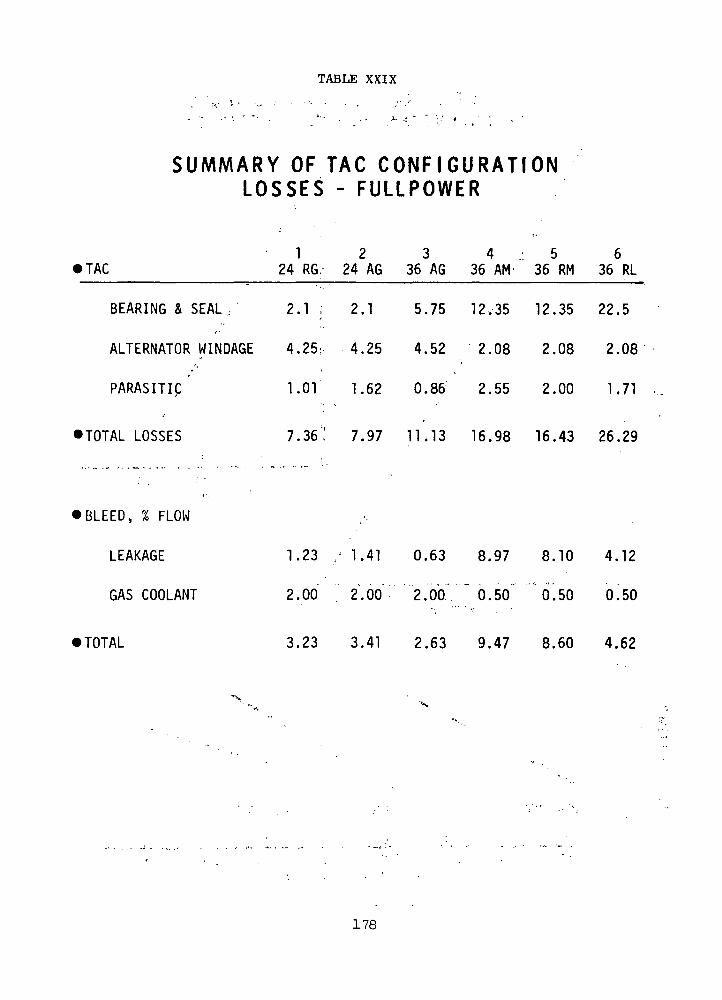
TABLE XXIX
SUMMARY OF TAG CONFIGURATIONL O S S E S - FULLPOWER
1 2 3 4 5 6• TAC 24 RG. 24 AG 36 AG 36 AM' 36 RM 36 RL
BEARING & SEAL / 2.1; 2.1 5.75 12.35 12.35 22.5
ALTERNATOR WINDAGE 4.25; 4.25 4.52 2.08 2.08 2.08
PARASITIC 1.01 1.62 0.86 2.55 2.00 1.71
• TOTAL LOSSES 7.36.' 7.97 11.13 16.98 16.43 26.29
• BLEED, % FLOW
LEAKAGE 1.23 / 1.41 0.63 8.97 8.10 4.12
GAS COOLANT 2.00 2.00 2.00'."" 0.50: * 0.50 0^50
• TOTAL 3.23 3.41 2.63 9.47 8.60 4.62
178

.30
.29
.28
0zLU
5 -27u.u.LU
LU
g.26
.25
.24
EFFECT OF L O S S E S AND COMPONENTE F F I C I E N C I E S ON CYCLE E F F I C I E N C Y
I10 20LOSS, KW
30
.02 .04 .06 .08 .10BLEED FRACTION
.30
.29
.28o>-o
COMPRESSOR
I I I
TURBINE
I
ALTERNATOR
I.85 .86 .87 ".91 .92 .93
COMPONENT EFFICIENCY
Figure 83.
179
.94 .95

TABLE XXX
TAG PERFORMANCE C O M P A R I S O N - FULLPOWER
1 2 3 4 5 6TAG 24 RG 24 AG 36 AG 36 AM 36 RM 36 RL
LOSSES, KW 7.36 7.97 11.13 16.96 16.43 26.29
LEAKAGE, % FLOW 3.23 3.41 2.63 9.47 8.60 4.62
COMPRESSOR 12 10 10 10 10 10CLEARANCE, MIL
TURBINE 16.0 17.3 12 10 11 11.4CLEARANCE, MIL
COMPRESSOR TOTAL 0.859 0.866 0.862 0.862 0.862 0.862TO TOTAL EFFICIENCY
TURBINE TOTAL 0.910 0.9Q8 Q.915 0.916 0.916 0.915TO TOTAL EFFICIENCY
ALTERNATOR EFFICIENCY 0.942 0.942 0.943 0.931 0.931 0.931
CYCLE EFFICIENCY 0.284 0.285 0.287 0.242 0.243 0.251
FLOW RATE, LB/SEC 9.85 9.85 9.68 12.80 12.01 11.22
180
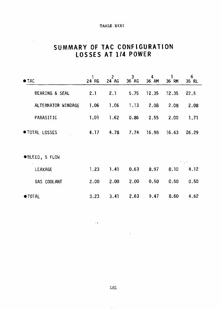
TABLE XKXI
SUMMARY OF TAC CONFIGURATIONL O S S E S AT 1/4 POWER
1 2 3 4 5 6• TAC 24 RG 24 AG 36 AG 36 AM 36 RM 36 RL
BEARING & SEAL 2.1 2.1 5.75 12.35 12.35 22.5
ALTERNATOR WINDAGE 1.06 1.06 1.13 2.08 2.08 2.08
PARASITIC 1.01 1.62 0.86 2.55 2.00 1.71
•TOTAL LOSSES 4.17 4.78 7.74 16.98 16.43 26.29
• BLEED, % FLOW
LEAKAGE 1.23 1.41 0.63 8.97 8.10 4.12
GAS COOLANT 2.00 2.00 2.00 0.50 0.50 0.50
•TOTAL 3.23 3.41 2.63 9.47 8.60 4.62
181

TABLE XXXII
TAC PERFORMANCE COMPARISON - 1/4 POWER
1 2 3 4 5 6TAC 24 RG 24 AG 36 AG 36 AM 36 RM 36 RL
LOSSES, KW 4.17 4.78 7.74 16.98 16.43 26.29
LEAKAGE, % FLOW 3.23 3.41 2.63 9.47 8.60 4.62
COMPRESSOR 12 TO 10 10 10 10CLEARANCE, MIL
TURBINE 16.0 17.3 12 10 11 11.4CLEARANCE, MIL
COMPRESSOR TOTAL 0.857 .- 0.837 0.840 0.840 0.860 0.860TO TOTAL EFFICIENCY
TURBINE TOTAL Oi895 0.893 0.900 0.901 0.901 0.900TO TOTAL EFFICIENCY
ALTERNATOR EFFICIENCY 0.890 0.890 0.884 0.862 0.862 0.862
CYCLE EFFICIENCY 0.247 0.231 0.226 0.164 0.175 0.165
FLOW RATE, LB/SEC 2.86 3.08 3.11 4.64 4.23 4.33
182
performance of the centrifugal compressor at part load is a significant
factor in the selection of a TAG design.
Phase II activity consisted of three off design calculations for
the 24,000 rpm configurations, one at low turbine inlet temperature, one
at high turbine inlet temperature and one for a high molecular weight
gas. The off design calculation consists of matching the compressor
and turbine speed, pressure ratios and flow rates at the specified
conditions. For the 24 RG unit a typical compressor map was selected
from Figure 13 of Reference 33. Turbine performance was taken from
Figures 7 and 8 of Reference 34. These references were used because
the turbomachinery had specific speeds close to those of the TAG designs;
85 for the compressor and 76 for the turbine compared with 83 arid 73
for the 24 RG TAG components. Multipliers were applied to corrected
flow, corrected speed and efficiency to convert the referenced maps to
the TAG design values. The compressor design point was selected at a,
pressure ratio of 1.9 and a corrected flow of 3.06 (1.15 on the map).
The corresponding turbine corrected flow was 2.755 (0.503 on the map)
at a pressure ratio of 1.786. • ;
' ': i-.For the low temperature application the compressor corrected speed
is increased by JTOO/580 or about 10%, and the turbine corrected speed
is increaded by ,72060/1610 or 13£. An attempt to operate the compressor
at a pressure ratio of 1.9 was unsuccessful because the compressor' flow ..•-'
was to large for the turbine. The two components were matched at' a
compressor pressure ratio of 2.08. A cycle calculation at the low
temperature gave a cycle efficiency of 0.242, which means that the
system could produce 145 kw with 600 kw thermal input. The compressor
inlet pressure required to satisfy the power requirement and the compressor
flow function is 56 psia, and the flow rate is''12.4*6 Ib/sec. • •
An axial flow compressor map was converted to the TAG design values
by multipliers on corrected flow, corrected speed and efficiency. The
results of the off design calculation were similar to those for the
24 RG unit- and are shown in Table XXXIII. ...
For the high temperature off design case the compressor corrected
speed is practically unchanged as the compressor inlet temperature is
691°R compared with the design value of 700°R. The turbine corrected
183

TABLE X X X I I I
C O M P A R I S O N OF 24000 RPM TACAT SNAP-8 C O N D I T I O N S
COMPRESSOR PRESSURE RATIO
COMPRESSOR CORR. SPEED, %
COMPRESSOR EFFICIENCY
COMPRESSOR INLET PRESSURE, PSIA
TURBINE EFFICIENCY
ALTERNATOR EFFICIENCY
BLEED, %
LOSSES, KW
OUTPUT, KWe
INPUT, KWth
FLOW RATE, PPS
CYCLE EFFICIENCY
24 RG
TAC
1.9
100.
.859
55
.9105
.942
3.23
7.36
160
564
9.85
.284
SNAP-8
2.08
110.
.852
56.
.901
.942
3.23
7.36
145
600
12.46
.242
24_
TAC
1.9
100.
.866
55.
.9085
.942
3.41
7.97
160.
562
9.85
.285
_AG
SNAP-8
2.1
no..852
54.
.897
.942
3.41
7.97
142
600
12.4
.237
184

speed is reduced by y2060/2560 or 10%. The two components were
matched at a compressor pressure ratio of 1.91. A cycle calculation
at the high temperature condition gave a cycle efficiency of 0.353.
The compressor inlet pressure required to satisfy the flow function is
37 psia, and the flow rate is 6 Ib/sec. for 160 kwe output. Similar
results were obtained for the axial flow compressor and are shown in
Table XXXIV.
For the high molecular weight case, the corrected speeds are
increased by 783.3/39.94' or 44.5%. In order to carry out the matching
for this off design condition it was necessary to extrapolate the
compressor and turbine maps to such a large extent that the validity of
the results is questionable. The components were matched at a compressor
pressure ratio of 3.04. A cycle calculation gave an efficiency of 0.135,
which means that 1185 kw thermal input are required for 160 kw£. The
flow rate was 30.27 Ib/sec. and a compressor inlet pressure of 130 psia
is required to satisfy the compressor flow function. If the thermal
power input is limited to 600 kw, the output, flow rate and pressure
level are sealed down by the ratio of 600 to 1185. A similar extrapolation
was made for the axial compressor map and the results of the off design
calculations are shown in Table XXXV. The increase in parasitic losses
is due to greater alternator windage at the higher pressure levels.
185

TABLE XXXIV
COMPARISON OF 24,000 RPM TAG AT 2100°F TURBINE INLET TEMPERATURE
24 RG 24 AG
1600°F 2100°F 1600°F 2100°F
Compressor Press. Ratio 1.9 1.91 1.9 1.95
Compressor Corr. Speed % 100 101 100 101
Compressor Efficiency .859 .864 .866 .87
Compressor Inlet Press. Psia 55 -3-7 55 36
Turbine Efficiency .9105 .8905 .9085 .8885
Alternator Efficiency .942 .942 .942 .942
Bleed, % 3.23 3.23 3.41 3.41
Losses, kw 7.36 7.36 7.97 7.97
Output, kwe 160 160 160 160
Input, kwth 564 440 562 439
Flow Rate, PPS 9.85 6.02 9.85 5.90
Cycle Efficiency .284 .364 .285 .365
186

TABLE XXXV
C O M P A R I S O N OF 24000 RPM TAG FORHIGH MOLECULAR W E I G H T GAS
COMPRESSOR PRESSURE RATIO
COMPRESSOR CORR. SPEED, %
COMPRESSOR EFFICIENCY
COMPRESSOR INLET PRESSURE, PSIA
TURBINE EFFICIENCY
ALTERNATOR EFFICIENCY
BLEED, %
LOSSES, KW
OUTPUT, KWe
INPUT, KWth
FLOW RATE, PPS
CYCLE EFFICIENCY
24 RG
TAC
1.9
TOO
.859
55.
.9105
.942
3.23
7.36
160.
564.
9.85
.284
HIGH M.W
3.04
144.
.774
130.
.881
.942
3.23
13.01
160.
1185
30.27
.135
24 AG
TAC
1.9
100.
.866
55.
.9085
.942
3.41
7.97
160
562
9.85
.285
HIGH M.W
2.98
144.
.792
127.
.879
.942
3.41
13.62
160
1060
27.46
.151
187
D. ALTERNATOR DESIGN
INTRODUCTION
The majority of the Phase I study effort was directed toward preliminary
screening studies and concluding performance analyses of selected alternators.
The screening analyses concentrated upon (1) analysis of the influential
design tradeoffs associated with Lundell alternators and Inductor alternators,
(2) the choice of rotor materials and construction for each, and (3) the
losses and cooling of each type alternator. Special attention was also given
to determining methods that predicted their windage losses accurately.
The ultimate choice of a Lundell over an Inductor alternator depends
heavily" upon the decision to either rely on a multipiece bonded rotor
(Lundell) or rely upon a scavenge system to evacuate the rotor cavity (Induc-
tor), the latter alternator having a solid, single-piece rotor but requiring
a "bore-barrier" separator. Between these two extremes exist a multitude of
secondary influences which sway the decision and which represent the bulk of
the content of the Phase I screening studies.
In relation to one of the main influences, the Lundell rotor fabrica-
tion, recent developments indicate there exist rotor bonding techniques that
are amenable to the TAG requirements of high reliability. This lends more
credence to the Lundell alternator choice and because of it, concentrated
evaluations were carried out to determine how the bonded rotor construction
approach could be improved by either (1) making better use of the present
concepts utilizing a 4340/Inconel 718 combination or (2) by selecting better
material combinations and/or processes. The conclusion reached was that the
combinations showing the best possible design improvements were not sufficiently
better to warrant the development costs required to reach the same level of
technology as the 4340/Inconel 718 combination. Furthermore, since even the
known 4340/Inconel 718 technology must be expanded to meet the more stringent
TAG strength requirements, the efforts are better spent there.
The initial screening analyses showed that from a purely electromagnetic
alternator design standpoint, an 800 Hz Lundell and a 1600 or 2400 Hz Induc-
tor appeared to give the best designs; however, from a combined alternator,
188
system-utilization standpoint, a compromise of 1200 Hz for both was con-
cluded to be more desirable. Also, from an electromagnetic design stand-
point, there appeared to be no distinctive differences among the voltage
choices of 120, 240, or 480 volts (L-N). From a corona breakdown stand-
point, however, the selection appears limited to 120 volts. Even at that
low voltage, the TAG alternator voltage can possibly put restrictions on
the minimum load the TAG can ever be operated at. For example, at 1/4 P.O.
load, the compressor inlet pressure may be as low as 14 psia which, according
to corona calculations, is too low to guarantee prevention of corona break-
down. This is distinctly different from the previous NASA BRU alternator and
is a characteristic of the insulation systems required for the higher tempera-
ture alternators.
The first reaction to the cooling design selection was to minimize the
amount of cooling ducts and penetrations used because of the specified
redundancy requirement. However, in the final analysis, a conservative design
utilizing several coolant sinks appeared as the most practical approach.
Of the alternators screened, the 24,000 rpm Lundell appears as the most
desirable and practical. The 36,000 rpm Lundell shows little promise and must
be classified as a borderline design, relative to rotor stress, that requires
more background technology development before one can commit to actual alter-
nator fabrication. Substitution, however, of the 4-pole solid rotor inductor
for the 36,000 rpm Lundell design does not result in a significantly more
reliable rotor since the Inductor rotor stresses are sufficiently large to
obviate the gains associated with the greater, single-piece material strengths;
this is in addition to the disadvantages of the scavenge system and bore-
barrier requirements.
As a result of the studies, it was concluded that the Inductor alternator
should not be considered as a prime choice and the choice should be made be-
tween the 24,000 rpm/Lundell TAG system and the 36,000 rpm/Lundell TAG system.
It must be recognized that the latter has an alternator with little design
conservatism which must be traded against any other system benefits which
might occur as a result of using the higher speed system. The alternator
data provided in the following pages is presented to aid the NASA in reaching
that decision. Westinghouse strongly recommends that the 24,000 rpm/Lundell
system be selected but acknowledges that, without the central rotor hole, the
36,000 rpm Lundell could be made to look both as feasible and practical.
189

ELECTROMAGNETIC DESIGN
A. Introduction
Alternator design screening studies were performed to obtain three con-
ceptual configurations to be utilized for interface studies with the various
turbine-compressor configurations selected by the prime contractor for the
Brayton Cycle Turboalternator-Compressor space electrical power system. The
output rating of the conceptual alternators is 214 KVA at 0.75 lagging power
factor. Alternator design speeds studied were 24,000 rpm and 36,000 rpm with
120 percent overspeed capability. The alternator rotor cavity environments
considered are the gas bearing lubricant at the compressor inlet pressure for
the lower speed, and either bearing lubricant oil vapor at lower than sub-
system pressures or bearing lubricant gas at compressor inlet pressure (or
lower) for the higher speed. Cooling fluid inlet temperature to the alter-
nator is 496 F.
The possible requirement for rotor cavity operating pressures greater
than 1 atmosphere and maximum windage losses of 6% of the alternator rated
power output dictated that prime consideration be given to minimization of
rotor diameter and to the rotor configuration. These same considerations
are related to rotor stress and dynamic response and for these reasons two
different types of stationary winding radial gap alternators were included
in the studies . These types are the inductor alternator and the bonded-
rotor Lundell alternator. The inductor alternator rotor is machined from a
single forging and requires no joining of magnetic to non-magnetic metals.
The rotor contains salient poles on each end which act to create high wind-
age loss. For the 36,000 rpm speed case, however, the rotor cavity can be
scavenged to less than subsystem pressures and the windage loss can be
greatly reduced. The Lundell rotor requires bonding of dissimilar metals
but the resulting smooth surface acts to provide low windage losses. By
performing comparative studies of both alternator types, the trade-offs be-
tween inherent design advantages and/or disadvantages for the two alternator
types could be determined and evaluated in arriving at the optimum alternator
conceptual configurations.
190
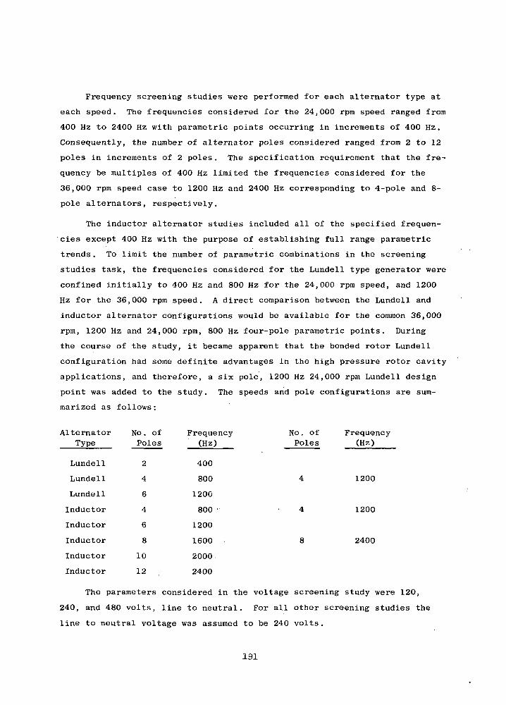
Frequency screening studies were performed for each alternator type at
each speed. The frequencies considered for the 24,000 rpm speed ranged from
400 Hz to 2400 Hz with parametric points occurring in increments of 400 Hz.
Consequently, the number of alternator poles considered ranged from 2 to 12
poles in increments of 2 poles. The specification requirement that the fre-
quency be multiples of 400 Hz limited the frequencies considered for the
36,000 rpm speed case to 1200 Hz and 2400 Hz corresponding to 4-pole and 8-
pole alternators, respectively.
The inductor alternator studies included all of the specified frequen-
'cies except 400 Hz with the purpose of establishing full range parametric
trends. To limit the number of parametric combinations in the screening
studies task, the frequencies considered for the Lundell type generator were
confined initially to 400 Hz and 800 Hz for the 24,000 rpm speed, and 1200
Hz for the 36,000 rpm speed. A direct comparison between the Lundell and
inductor alternator configurations would be available for the common 36,000
rpm, 1200 Hz and 24,000 rpm, 800 Hz four-pole parametric points. During
the course of the study, it became apparent that the bonded rotor Lundell
configuration had some definite advantages in the high pressure rotor cavity
applications, and therefore, a six pole, 1200 Hz 24,000 rpm Lundell design
point was added to the study. The speeds and pole configurations are sum-
marized as follows:
No. of FrequencyPoles (Hz)
AlternatorType
Lundell
Lundell
Lundell
Inductor
Inductor
Inductor
Inductor
Inductor
No. ofPoles
2
4
6
4
6
8
10
12
Frequency(Hz)
400
800
1200
800 •
1200
1600
2000
2400
1200
1200
2400
The parameters considered in the voltage screening study were 120,
240, and 480 volts, line to neutral. For all other screening studies the
line to neutral voltage was assumed to be 240 volts.
191

Prior to performing the frequency and voltage screening studies, a
series of trial designs were made at 24,000 rpm, 1600 Hz and 36,000 rpm,
2400 Hz to determine the approximate values of the internal design factors
to meet the specification requirements and evaluate preliminary design
tradeoffs. As a minimum, synchronous reactance and radial gap length were
investigated. Initial studies were performed at the continuous duty rating
of 214 KVA, 0.75 lagging power factor and 240 volts L-N (line-to-neutral).
The materials selected for the screening studies are given below:
ELECTROMAGNETICCOMPONENT MATERIAL
Stator Frame Hiperco 27
Stator Laminations Hiperco 27
Rotor Hiperco 27
Slot Liners Alumina
Conductor Insulation "Anadur S"
AC Conductor Nickel Clad Silver
Field Coil Conductor "Cube" Alloy
Alternate materials evaluations were performed for several of the
electromagnetic components after completion of the screening studies.
Primary emphasis was placed on materials for the critical rotor component,
especially for the Lundell alternator where bonding of magnetic to non-
magnetic alloys is required.
Finally, parametric optimization studies and performance analyses were
performed for the three alternator configurations selected for the turbo-
alternator-compressor conceptual designs .
Because of the unavoidable complexity in fully screening designs
relative to the complete alternator specifications, the specifications were
divided into two groups. The first group, listed below, contains those
directly considered in the screening analyses.
(a) The alternators shall have a maximum continuous rating
of 160 KWe with a 3 phase output at a 0.75 lagging load power
factor for 5 seconds after temperature equilibrium has been
reached. Spec
design speed.
reached. Speed regulation shall be assumed to be -1% of
192
(b) The alternator designs shall be capable of operating at
120% of design speed without a catastrophic failure under all
loads up to and including rated TAG load conditions (160 KWe,
0.75 lagging power factor) for a limited time.
(c) The design life criteria for the alternators shall be 5
years operating time under the specified conditions for the
TAG assembly.
(d) The alternators shall be in accordance with MIL-G-6099A
(ASG) in accordance with the latest revision in effect on the
date of contract for the following:
(1) Short-Circuit Capacity. Paragraph 4.5.12 for a
minimum time of 5 seconds for each occurrence.
(2) Phase Balance. Paragraphs 4.5.10, 4.5.10.1 and
4.5.10.2 except that paragraph 4.5.10.1 is amended
to read "... the individual phase voltages shall not
deviate from the average by more than 2.25, 4.5, and
9 percent , respectively."
ii> '(e) The alternators shall be designed to the maximum extent
possible so as to reduce to a minimum windage losses. The
6 percent windage specified for a pressurized rotor cavity
shall be considered a design goal.
(f) Temperature Level. For systems radiator size and weight
considerations, it is desired to operate the alternator stator
at elevated temperatures. The contractor shall select the high-
temperature magnetic, electrical and insulation materials and
employ the design techniques as described in NASA Reports SP 3043-
Magnetic Materials, CR 54690 - Summary of High Temperature Materials,
CR 54092 - Electrical Conductors & Insulation which are incorporated
herein by reference and made a part hereof. These materials include
* The individual phase voltages shall be 2.25, 4.5, and 9 percent in thePhase I studies but 1.5, 3 and 6 percent figures shall be a goal forthe later Phase III studies.
193
the use of Inconel-clad silver for the conductors, Anadur "s"
for the insulation between conductors, and high-purity ceramic,
99.5 percent alumina for the slot insulators. However, a maxi-o
mum of 300 F temperature increase shall be permitted between
the coolant supply temperature and the alternator hot spots at
the 160 KWe power level.
The second group of specifications listed below, though not con-
sidered directly in the screening analyses, are applicable to all
selected designs.
(a) The stator cooling configuration shall be such that it
does not permit adverse heating in the rotor or rotor stub
shafts due to the higher stator temperatures (i.e., higher than
the cooler rotor temperatures.)
(b) Specification MIL-G-6099(A) (ASG).
(1) Waveform. Paragraph 4.5.16 - In addition, the
total rms harmonic content of the line-to-neutral
voltage wave, when the alternator is operating
into a purely resistive load, shall be less than
5 percent from 10 percent to 100 percent maximum
design load of 160 KWe.
(2) Output Voltage Modulation . Paragraph 4.5.13,
except that modulation shall not exceed 0.5 per-
cent .
(c) Shock, Vibration, and Acceleration. Alternators shall be
in accordance with the environmental specifications NASA Nos .
P1224-1 and P1224-2.
(d) Radiation Environment. The design radiation environment7 13
shall be 10 rads, 10 nvt fast neutrons per square centi-
meter (> 1 Mev) unless otherwise specified.
* This shall be a design goal without analytical verification,
194
(e) Position Sensitivity. The alternator shall be designed
to operate in any position in both zero "G" and one "G"
environments.
(f) Voltage-Regulator-Exciter and Speed Control. While
the VRE, speed control, and power conditioning equipment
are not a part of the study, their effects on the alternator
shall be considered in the design study. The speed control
for transient load changes shall be of the phase-controlled
parasitic load type. Frequency regulations shall be assumed
to be within -1 percent of design frequency for a change in
external load of from 10 percent to full design output power.
Some form of system gas pressure modulation is contemplated
for long term or scheduled control of power level.
(g) Parallel Operation. It is anticipated that the TAG
units described herein shall be employed in multiple units
thus they may be required to be electrically paralleled.
The contractor shall consider this requirement in his alter-
nator design.
195
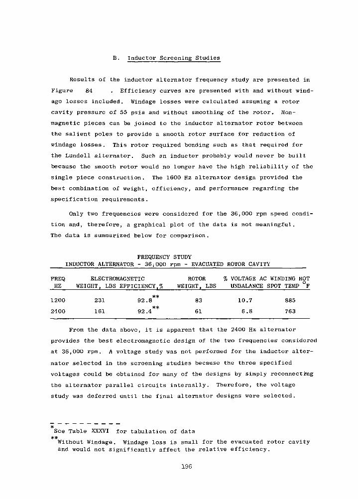
B. Inductor Screening Studies
Results of the inductor alternator frequency study are presented in
Figure 84 . Efficiency curves are presented with and without wind-
age losses included. Windage losses were calculated assuming a rotor
cavity pressure of 55 psia and without smoothing of the rotor. Non-
magnetic pieces can be joined to the inductor alternator rotor between
the salient poles to provide a smooth rotor surface for reduction of
windage losses. This rotor required bonding such as that required for
the Lundell alternator. Such an inductor probably would never be built
because the smooth rotor would no longer have the high reliability of the
single piece construction. The 1600 Hz alternator design provided the
best combination of weight, efficiency, and performance regarding the
specification requirements.
Only two frequencies were considered for the 36,000 rpm speed condi-
tion and, therefore, a graphical plot of the data is not meaningful.
The data is summarized below for comparison.
FREQUENCY STUDYINDUCTOR ALTERNATOR - 36^000 rpm - EVACUATED ROTOR CAVITY
FREQ ELECTROMAGNETIC ROTORHZ WEIGHT, LBS EFFICIENCY.% WEIGHT, LBS
**1200 231 92.8 83
**2400 161 92.4 61
% VOLTAGE AC WINDING HOTUNBALANCE SPOT TEMP °F
10.7 885
6.8 763
From the data above, it is apparent that the 2400 Hz alternator
provides the best electromagnetic design of the two frequencies considered
at 36,000 rpm. A voltage study was not performed for the inductor alter-
nator selected in the screening studies because the three specified
voltages could be obtained for many of the designs by simply reconnecting
the alternator parallel circuits internally. Therefore, the voltage
study was deferred until the final alternator designs were selected.
*See Table XXXVI for tabulation of data**Without Windage. Windage loss is small for the evacuated rotor cavityand would not significantly affect the relative efficiency.
196
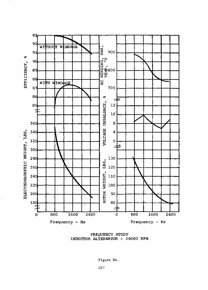
dP
^
oHOH
CM
LB
SIG
HT
ET
.IC
EL
EC
T
0 800 1600 2400
Frequency - Hz
0 800 1600 2400
Frequency - Hz
FREQUENCY STUDYINDUCTOR ALTERNATOR - 24000 RPM
Figure 84.
197
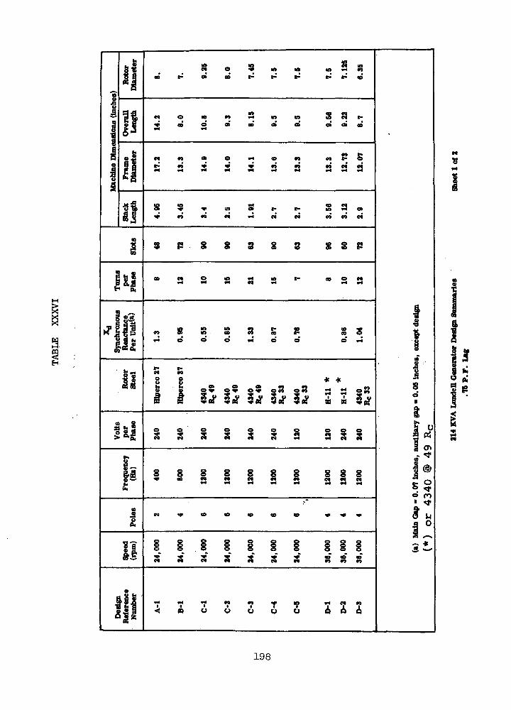
aH
-9
1
2g
I
i
]
i
S
1
1!
5 H
•I
||
il"I»3
i
1*1
?«&
I*3
K n
US!M
Freq
uenc
y(ttO
a
!!
Ref
eren
ceN
umbe
r
8 o S » „ „ 3 8
S CO CQin to 5 c« t-
^* OD o o> oo o» o» o » o » e o
a a s s s 3 3 a a'a
8 ? * « S ^ t- S S o,
3 P § S S g S $SP
• s s a s a ' - - s s
in n in n t- o c o - 4 *co S in oo n co c- eoo
t- e-£4 CQJ
8 8 * *|| o2 o2 02 |S? 08 s - 08
i i i i i i a a i s
S S S 8 S S S S S S" " 3 3 3 3 3 3 3 3
C 4 < * < O C O < 0 « O C D • * • * • * •
S" ^*" *** 2S^ S^ ^ *<^ *> Q ^W C4 M M M TC 99 ^9 M
' T 7 T 7 7 T ' ? t i ?<: » o t> o o o Q 6 6
1
S0i
s5O {^
• ^tIg3t
I
198

•H•P
I
W |UH
!
i
£ * C 0S 5 N •** « ! ^ «
oo oa in
00 in atfr*
$ S S § S2
S S S S S S
•4 v4 *4 V* *4 *4 v4
8 3 3
S S S S S £
<t> <o>n *<M A
in eo rt r. ,H»< e oo n «
9 Oo c o5 > - <e a c a
•< « o o o o o
o01
1
3«i
199
Additional design study details are reported in a subsequent
section the reader is referred to that section for additional details
on the inductor alternator design procedures and assumptions.
200
2
4
6
4
24 , 000
24 , 000
24 , 000
36,000
C. Lundell Screening Studies
1., Study Variables and Assumptions
Variables
The following variables were considered in this study.
Phase Voltage: 120, 240.
Rotor Steels: Hiperco 27, H-ll, 4340 @ R 33 and4340 @ R 49. °
cMain Radial Gap: 0.04 to 0.16 inch.
Synchronous Reactance (X): 0.55 to 1.3 (Turns per phase:10 to 21 for 240 L-N Volts);
Frequency: 400,800,1200 Hz.
Poles Speed (rpm) Frequency (Hz) Design Ref. Letter
400 A
800 B
1200 C
1200 D
Assumptions and Constants
Stator Steels: Hiperco 27 for frame and punchings (0.004 in.thick). Hiperco 27 steel was chosen for"itsgood magnetic characteristics at high tempera-tures .
Auxiliary Gap: 0.05 inches.
Gap at Conical Section: Rotor dia/100, (used for windage).
Flux Densities:2
Main Gap: 52 Kilolines/inch .2
Auxiliary Gap: 55 Kilolines/inch .2
Rotor: 67 to 97 Kilolines/inch . Plus densities werechosen depending on the steel to give approxi-mately 60 amp-turns/inch. Higher flux densitiescould have been chosen but increased field lossand/or field weight would have resulted.
2Teeth: (Hiperco 27): 130 Kilolines/in , approximately.
2Back Iron (Or Depth Below Slot): 66 Kilolines/in ,
approximately. At this density the differentialiron weight versus core loss in the back iron isin the order of 30 Ibs per KW loss.
2Frame and End Bell Frame: 115 Kilolines/in .
201

Current Densities:2
A-C Armature: 4300 to 6700 amps/in . The currentdensity was chosen to give approximately 795°FA-C winding temperature determined by a computercalculation which assumed conduction of heat tothe stator punching O.D. and assumed radiationof heat from the winding end turns with anemissivity factor of 0.4.
2Field Wire Current Density: 2000 to 2600 amps/in .
The field winding was sized and determined tomatch the total field amp-turn requirements ofthe generator. Thus, more and more field turnswere added to the field until the increase inweight of the field and resulting decrease infield losses gave a figure of approximately 30pounds per KW loss.
Armature Stacking Factor: 0.9.
Slot and Wire Insulation: Wire insulation assumed0.0055 inches per side. Slot cell liner =0.018 inch. Slot phase separator = .021 inches.
Total accumulated clearance in slot: 0.018 inch (width)and 0.02 inch (depth).
Winding: 60 phase belt and 2/3 coil pitch. No skew.
Rotor Bore Dia: 1.0 inch.
Pole Embrace: 0.667.
Per Cent Rotor Steel: 55% magnetic. That is, a crosssection of the rotor at any point under the statorstack is 55% magnetic steel.
3Gas in Cavity (for windage): 0.1764 Ibs/ft
(He-Xe at 55 psia) at 24,000 rpm, full-load and0.384 Ibs/ft3 (He-Xe at 120 psia) at 36,000 rpm,full load. Gas pressure was assumed to varylinearly with generator input power requirements.The kinematic viscosity assumed was 0.0000792ft2/sec.
Stray Loss Factor: Based on experience with actualmachines, it was assumed that the ratio of actualcore loss to the Epstein core loss is 2.5.
202
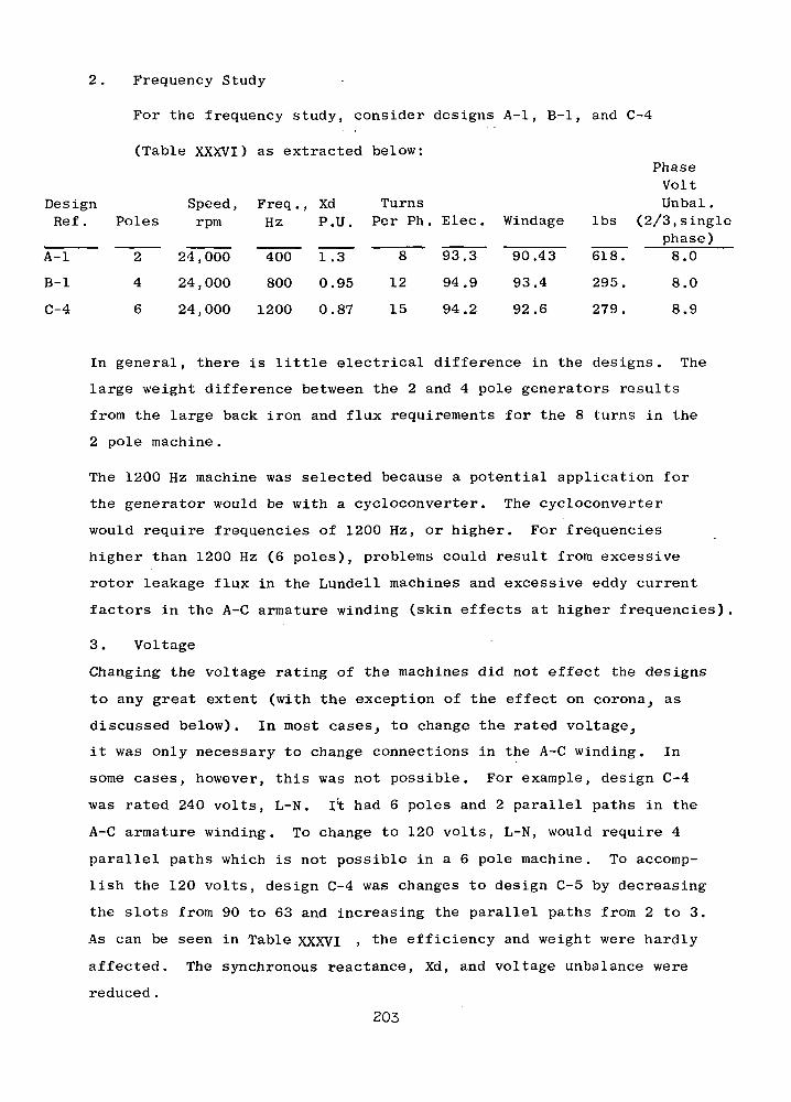
Frequency Study
For the frequency study, consider designs A-l, B-l, and C-4
(Table XXXVI) as extracted below:
DesignRef .
A-l
B-l
C-4
Poles
2
4
6
Speed,rpm
24,000
24 , 000
24,000
Freq . ,Hz
400
800
1200
XdP.U.
1.3
0.95
0.87
TurnsPer Ph .
8
12
15
Elec.
93.3
94.9
94.2
Windage
90.43
93.4
92.6
Ibs
618.
295.
279.
PhaseVoltUnbal .
(2/3, singlephase)8.0
8.0
8.9
In general, there is little electrical difference in the designs. The
large weight difference between the 2 and 4 pole generators results
from the large back iron and flux requirements for the 8 turns in the
2 pole machine.
The 1200 Hz machine was selected because a potential application for
the generator would be with a cycloconverter. The cycloconverter
would require frequencies of 1200 Hz, or higher. For frequencies
higher than 1200 Hz (6 poles), problems could result from excessive
rotor leakage flux in the Lundell machines and excessive eddy current
factors in the A-C armature winding (skin effects at higher frequencies).
3. Voltage
Changing the voltage rating of the machines did not effect the designs
to any great extent (with the exception of the effect on corona, as
discussed below). In most cases, to change the rated voltage,
it was only necessary to change connections in the A-C winding. In
some cases, however, this was not possible. For example, design C-4
was rated 240 volts, L-N. It had 6 poles and 2 parallel paths in the
A-C armature winding. To change to 120 volts, L-N, would require 4
parallel paths which is not possible in a 6 pole machine. To accomp-
lish the 120 volts, design C-4 was changes to design C-5 by decreasing
the slots from 90 to 63 and increasing the parallel paths from 2 to 3.
As can be seen in Table XXXVI > "the efficiency and weight were hardly
affected. The synchronous reactance, Xd, and voltage unbalance were
reduced.
203
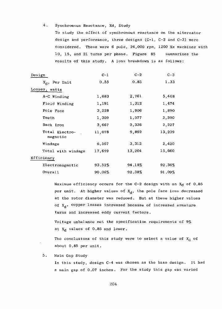
4. Synchronous Reactance, Xd, Study
To study the effect of synchronous reactance on the alternator
design and performance, three designs (C-l, C-2 and C-3) were
considered. These were 6 pole, 24,000 rpm, 1200 Hz machines with
10, 15, and 21 turns per phase. Figure 85 summarizes the
results of this study. A loss breakdown is as follows:
Design C-l C-2 C-3
Xd, Per Unit 0.55 0.85 1.33
Losses, watts
A-C Winding 1,683 2,761 5,448
Field Winding 1,191 1,312 1,474
Pole Face 3,228 1,906 1,890
Teeth 1,309 1,577 2,200
Back Iron 3,667 2,336 2,227
Total Electro- 11,078 9,892 13,239magnetic
Windage 6,567 3,312 2,420
Total with windage 17,649 13,204 15,660
Efficiency
Electromagnetic 93.52% 94.18% 92.36%
Overall 90.06% 92.38% 91.09%
Maximum efficiency occurs for the C-2 design with an X^ of 0.85
per unit. At higher values of Xj, the pole face loss decreased
at the rotor diameter was reduced. But at these higher values
of Xd» copper losses increased because of increased armature
turns and increased eddy current factors.
Voltage unbalance met the specification requirements of 9%
at X<j values of 0.85 and lower.
The conclusions of this study were to select a value of X^ of
about 0.85 per unit.
5. Main Gap Study
In this study, design C-4 was chosen as the base design. It had
a main gap of 0.07 inches. For the study this gap was varied
204
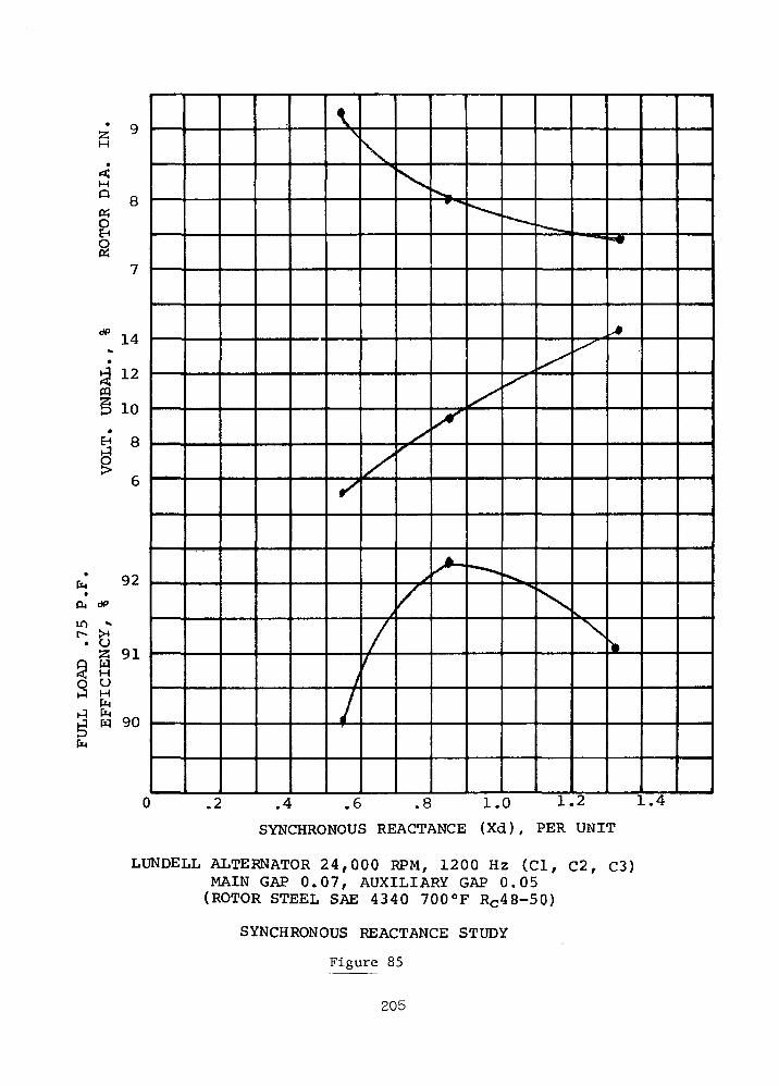
52H
8
§
PQ12
10
6
fa 92On <#>
m •»
W 91
O O
j w 90
0 .2 .4 .6 .8 1.0 1.2 1.4
SYNCHRONOUS REACTANCE (Xd) , PER UNIT
LUNDELL ALTERNATOR 24,000 RPM, 1200 Hz (Cl, C2, C3)MAIN GAP 0.07, AUXILIARY GAP 0.05
(ROTOR STEEL SAE 4340 700°F RC48-50)
SYNCHRONOUS REACTANCE STUDY
Figure 85
205
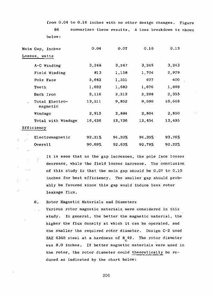
3,248
813
5,642
1,692
2,116
13,511
2,915
16,426
3,247
1,158
1,551
1,683
2,213
9,852
2,884
12,736
3,245
1,704
677
1,676
2,288
9,590
2,864
12,454
3,243
2,979
400
1,669
2,355
10,646
2,850
13,495
from 0.04 to 0.16 inches with no other design changes. Figure
86 summarizes these results. A loss breakdown is shown
be 1 ow:
Main Gap, Inches 0.04 0.07 0.10 0.13
Losses, watts
A-C Winding
Field Winding
Pole Face
Teeth
Back Iron
Total Electro-magnetic
Windage
Total with Windage
Efficiency
Electromagnetic 92.21% 94.20% 94.35% 93.76%
Overall 90.69% 92.63% 92.78% 92.22%
It is seen that as the gap increases, the pole face losses
decrease, while the field losses increase. The conclusion
of this study is that the main gap should be 0.07 to 0.10
inches for best efficiency. The smaller gap should prob-
ably be favored since this gap would induce less rotor
leakage flux.
6. Rotor Magnetic Materials and Diameters
. . Various rotor magnetic materials were considered in this
study. In general, the better the magnetic material, the
higher the flux density at which it can be operated, and
the smaller the required rotor diameter. Design C-2 used
SAE 4340 steel at a hardness of R 49. The rotor diameterc
was 8.0 inches. If better magnetic materials were used in
the rotor, the rotor diameter could theoretically be re-
duced as indicated by the chart below:
206
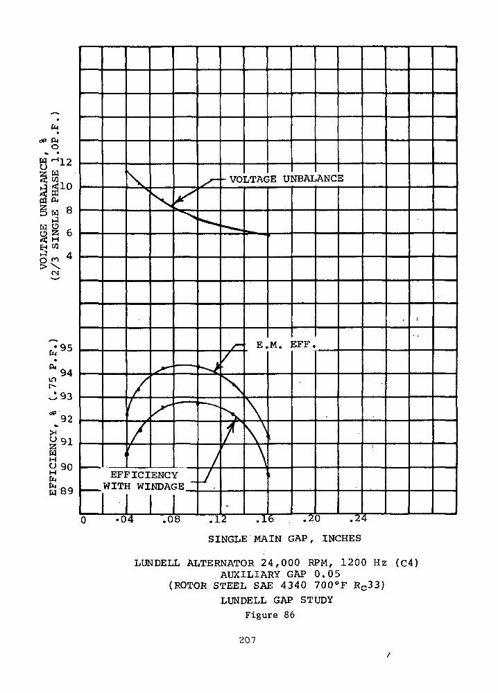
dP
3
OP
Il-
1 toS
EM O
WaEH
^
2/3
S
ING
LE
P
75
P.F
%E
FF
ICIE
NC
YCD
V£
> 10
VC
vo
OM
ro
EFFICIENCYWITH WINDAGE
_y
VOLTAGE UNBALANCE
\
^
E.M. EFF,
•04 7 0 8 7 1 2 716 . .20 .24
SINGLE MAIN GAP, INCHES
LUNDELL ALTERNATOR 24 ,000 RPM, 1200 Hz (C4)AUXILIARY GAP 0.05
(ROTOR STEEL SAE 4340 700°F RC33)LUNDELL GAP STUDY
Figure 86
207
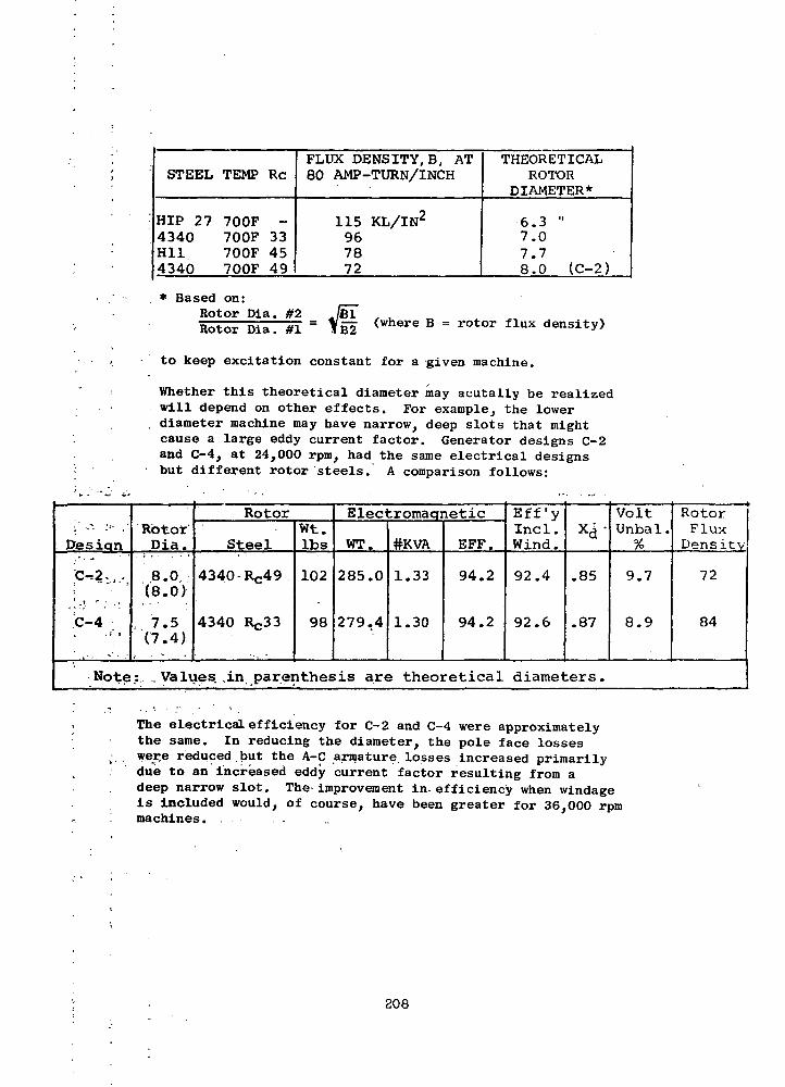
STEEL TEMP Re
HIP 27 700F -4340 700F 33Hll 700F 454340 700F 49
FLUX DENSITY, B, AT80 AMP-TURN/INCH
115 KL/IN2
967872
THEORETICALROTOR
DIAMETER*
6.3 "7.07.78.0 (C-2)
* Based on:Rotor Dia. #2Rotor Dia. #1
. , ,_= (where B = r°tor flux
to keep excitation constant for a given machine.
Whether this theoretical diameter may acutally be realizedwill depend on other effects. For example, the lower
. diameter machine may have narrow, deep slots that mightcause a large eddy current factor. Generator designs C-2and C-4, at 24,000 rpm, had the same electrical designsbut different rotor steels. A comparison follows:
Desian
C~2 .-:1 _T r • >
C-4. . 1 ' s
RotorDia.
8.0(8.0)
, 7.5(7.4)
Rotor
Steel
4340 RC49
4340 Rc33
wt.Ibs
102
98
Electromagnetic
WT.
285.0
279.4
#KVA
1.33
1.30
EFF.
94.2
94.2
Eff'yIncl.Wind.
92.4
92.6
xd"
.85
.87
VoltUnbal.%
9.7
8.9
RotorFluxDensity
72
84
Note: _ Values, , in parenthesis are theoretical diameters.
The electrical efficiency for C-2 and C-4 were approximatelythe same. In reducing the diameter, the pole face losseswerre reduced.but the A-C armature losses increased primarilydue to an increased eddy current factor resulting from adeep narrow slot. The improvement in-efficiency when windageis Included would, of course, have been greater for 36,000 rpmmachines.
208

D. Selection of Three Representative Designs
The final selection of three alternator configurations was coordina-
ted with the prime contractor and the NASA in order that pertinent turbine
and system considerations could be factored into the selection.
All of the 24,000 rpm inductor alternator designs had high windage
losses . The high windage losses were caused by the dynamic effect of the
rotor salients at the compressor inlet pressure of 55 psia. The 24,000
rpm bonded rotor Lundell alternators have smooth rotor surfaces and were
characterized by relatively low windage losses at the high cavity pressure.
At the 36,000 rpm speed, the pressure of the rotor cavity was scaven-
ged to less than the system compressor inlet pressure and windage losses
for the inductor alternator were reduced to secondary significance. At
this high speed, rotor stress became a predominant consideration. The
alternator designs considered in the selection process are presented in
Tables XXXVI &XXXVII, the latter being limited to designs A-l, B-l & C-4.
An evaluation of all the designs was made based on an adaptation of
the U.S. Army, Modified Improvement Coefficient procedure (reference- 35 )
which utilizes weighting factors for the various generator design para-'v j
meters considered. A top ranking was obtained for the 24,000 rpm, 800 Hz [
Lundell alternator with the ranking for all other alternators falling
lower but very close to each other. Based on electric power.utilization .;
considerations, however, the 800 Hz frequency does not appear attractive. . J
because the use of cycloconverters for frequency conversion to 400 Hz
require at least a three to one frequency conversion ratio. Based oh this
consideration, the minimum alternator frequency is 1200 Hz unless -the' • ; ' •*.".'
direct generation of 400 Hz total power is required for the system.
The Lundell alternator type proved to have definite design advan-
tages over the inductor type for the 24,000 rpm pressurized rotor cavity
study condition, primarily due to the lower windage losses. The 1200 Hz
6 pole, 24,000 rpm Lundell alternator configuration was selected as one .of
the candidates for final consideration.
209
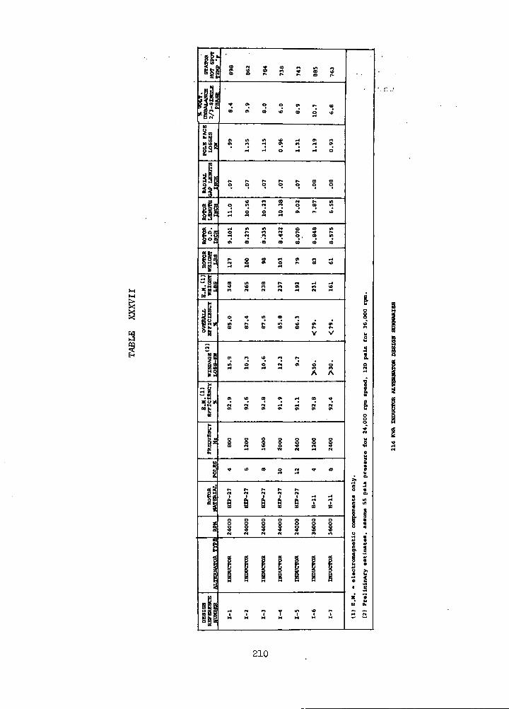
(i'•» BB E 1
'ISu
"1H CO k
83
S!Bi|MgEa
IP
|Q.J
s°s
|]aSLM *
OV
ER
ALL
EFFIC
IEN
CY
X
r»
* S
5J"1
FR
EQ
UE
NC
Y
Hz
I
i
ALTE
RN
ATO
R
TY
PE
§EsSfiSSg^
S 2 S *° « « «<" * CO PI ^ CO iOco CD r* r*. r» co ?
* * o o w r- coco eh co *o OD o to_(
s s s s s s s^1 i-4 O ^4 <-l O
to n co M r- m
r4 O O O 01 r> ID
S r* «n w r* ^ i*-M ft « O , CO tf)
Ch CO CO 00 CO 00 CO
r* o co n ch «n ric« o o» o r* co »oft r4 <-l
CO m CO r- M iH H
« W M N -4 W ^
O ^ in co mM r* r* m «D eh <r»co co eo eo co r- r*
V V
,«J 0 0 JJ »• 0 0
A A
0. W 0 9. - <0 V
. . . . . . *
§ § § § § § §CO W ID O ^ W •»
«-« H "N M i-l M
<<T t£> CO O r* <T CO
1 1 II | i-l ^4
S S § S § S So o o o o o o
i i i i i i i
mimi i i i i i i
•
IS
8
iog
1o
§•i 5O a
CL4> ine m
! io *
• ele
ctro
magnet J
ioin
ary
eatim
ate
i
S 1f4 fH
210
Of the three alternators screened for the 36,000 rpm speed, the
4 pole, 1200 Hz Lundell alternator and the 4 pole, 1200 Hz inductor
alternator were selected for further consideration. The 2400 Hz
frequency of the 8 pole inductor alternator was considered higher than
desirable for the electrical power distribution system.
211

E. Detailed Electromagnetic Design Performance Analyses
A preliminary optimization of design and performance parameters of
the recommended alternator configurations was performed and electrical
performance was determined at design power output and 0.75 lagging
power factor.
1. 24,000 RPM Lundell
Design C-4 was the final 24,000 rpm Lundell design. The lay-
out of this design is shown in Figure 87 and the layout of
the slot is shown in Figure 88. Table XXXVIII presents a
summary of the design details. The saturation curves are
shown in Figure 89 . This design has an electrical effi-
ciency of 94.2%, decreasing to 92.6% when windage is included.
Figure 90 shows the efficiency variation with load. A break-
down of losses versus load (0.75 P.F.) is shown below:
Power Output, KWe 40 80 120 160
Losses, watts
AC Winding
Field Winding
Pole Face
Teeth
DBS
Electromagnetic
Windage
Total Loss
Efficiency
Electromagnetic 89.32% 93.24% 94.14% 94.20%
Overall 87.8 % 91.7 %. 92.6 % 92.6 %
The efficiency is relatively constant from full load to half
load but begins to fall off at 1/4 load. The efficiency at
1/4 load could be improved by reducing the iron losses. For
example, if the back iron were increased 30%, changes would
result as follows:
212
180
473
521
1,560
2,051
4,785
768
5,553
732
634
735
1,600
2,104
5,805
1,471
7,276
1,732
854
1,086
1,642
2,158
7,472
2,158
9,630
3,247
1,158
1,552
1,683
2,213
9,853
2,884
12,737
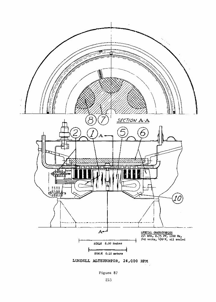
SCALE 6.00 Inches
SPECIAL CHARACTERICS214 kVA, 0.75 PF, 1200 Hz,
J 240 volts, l*?b"?, oil oooled
SCALE 0.10 meters
LUNDELL ALTERNATOR, 2 4 , Q O Q RPM
Figure 87
213

ENLARGED DETAIL OFSTATOR SLOT
SCALE =4:1
LUNDELL ALTERNATOR24,000 RPM
Figure 88
214

TABLE XXXVIII
INTERNAL DESIGN DETAILS SUMMARY:
60° Phase Belts, 2/3 Pitch; 90% Stacking Factor:
Current Densities - Armature(amps/in2) - Field
Flux Densities - Back Iron(kl/in2) - Teeth
- Main Air Gap- Pole- Frame- Aux. Air Gap
Rotor % Magnetic Steel -
% Harmonics - Third- Fifth,- Seventh
F.L. Losses(watts)
Pole FaceBack IronTeethArmatureFieldWindage(@ psia)
- TotalOverallEfficiency-
No Load Loss -
Electrical Weights - Armature(pounds) - Field
- Frame- Stacks- Rotor
- Total
6-POLELUNQELL (C-4)24,000 HPM
50712014
.64129528411057 ,
55
. 0'. 3.3.;2.0
155222131683324711582884(55)
12.73%
92.6%
5200
1349853598
4-POLELUNDELL (D-2)36,000 RPM
56251165
65124.467511557
55
03.32.0
253829358412236116513065(120)
22780
87.6%
6000
942884192
4-POLEINDUCTOR36,000 RPM
47883885
591355680112N.A.
N.A.
01.31.7
10894771798
321819902080(1)
13.946
92.0%
1622368183
280 272 238
215

TABLE XXXVIII (Continued)
INTERNAL DESIGN DETAILS SUMMARY I
60* Phase Belt*, 2/3 Pitch; 90% Stacking Factor:
Dimensions - Rotor O.D.(inches) - Rotor Length
. stack Length- Stack O.D.- Overall O.D.
-: - Overall Length
Rotor Steel -
Number of Slots -
Conductors per Slot -
Series Turns -
Parallel Paths -
Parallel Strands -
Resistances, Hot - Armature(ohms) (Per Phase)
- Field Coil
Main Gap, inch -
Auxiliary Gap, inch -
Reactances - Xd (onsat.)(P.O.) - X'd (Sat.)
- X«d
i - - x"qf -•" ' -" - X2 -••
- xo
Time Constants, Hot - T'Dl<a)(seconds) - T'DO
- TA
-Td-
6-POLELONDBLL (C-4)24,000 RPM
7.59.52.712.01613.569.5
4340 RC 33
90
2
15
2
8
0.0125
0.152
0.07
0.05
0.8670.4620.4620.4340.4340.4480.0177
0.403
0.0040.0017
4-POLELONDELL (D-2)36,000 RPM
7.1259.223.1211.30512.739.22
4340 Re 48
60
2
10
2
6
0.0084
0.159
0.07
0.05
0.860.330.330.410.410.370.01
0.37
0.0050.0017
4-POLEINDUCTOR36,000 RPM
9.1557.592.85613.00015.2312.97
H-ll
108
2
9
4
2
0.0126
0.327
0.09
—1.2160.3410.3410.5940.5940.4670.0119
0.1562.090.0061
(a) T'Dl is T'DO except it does not assume a solidsteel flux circuit.
216
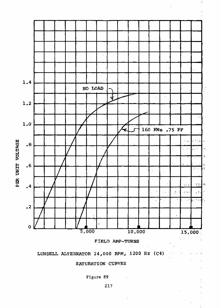
wI
1.4
1.2
1.0
-8
8.4
.2
0
NO LOAD
7160 KWe .75 PF
5,000 10,000
FIELD AMP-TURNS
LUNDELL ALTERNATOR 24 ,000 RPM, 1200 Hz (C4)
SATURATION CURVES
Figure 89
217
I15,000
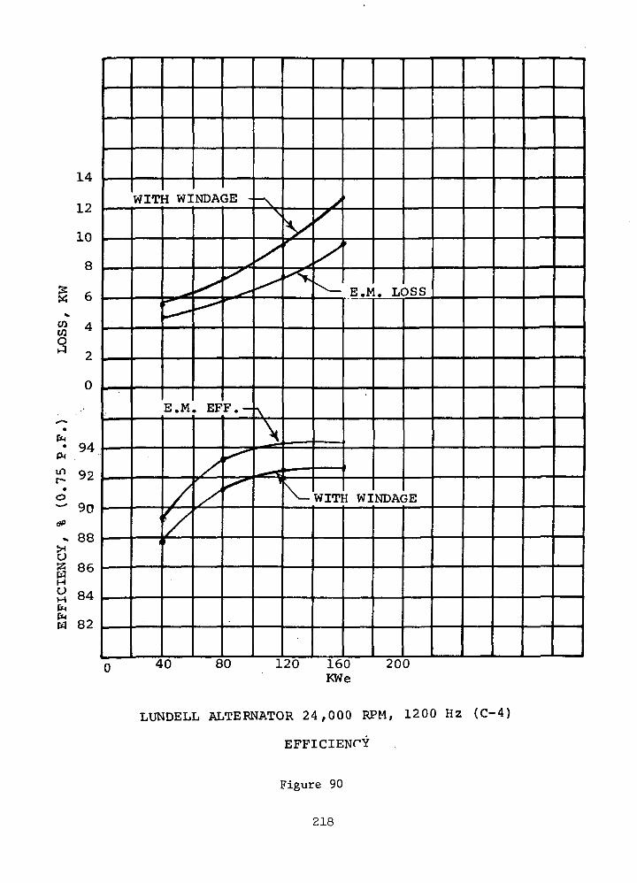
14
12
10
8
6
4H
2
0
94
92
90
88
ee
8482
WITH WINDAGE
COCOo
LOSS
E.M. EFF,
WITH WINDAGE
dP
8HOHEnCMW
80 120 160KWe
200
LUNDELL ALTERNATOR 24 ,000 RPM, 1200 Hz (C-4)
EFFICIENrY
Figure 90
218

Design: C-4 Back IronModified
Back Iron Thickness, in. 1.245 1.62
Frame, O.D., in 13.56 14.31
Back Iron Losses, watts
Full Load 2,213 1,883
1/4 Load 2,051 1,745
Total Electromagnetic Losses, watts
Full Load 9,853 9,523
1/4 Load 4,785 4,479
Electromagnetic Efficiency
Full Load 94.20%, 94.38%
1/4 Load 89.32% 89.93%
Electromagnetic Weight, Ibs. 279 290
2. 36,000 RPM Lundell
Design D-2 was the final electromagnetic 36,000 rpm Lundell
design. The layouts of this design and slot punching are shown
in Figure 91 and 92. Table XXXVIII presents a summary of
the design details. Saturation curves are shown in Figure 93 .
Efficiency curves are shown in Figure 94 . A breakdown of
generator losses versus load (0.75 P.F.) is shown below:
Power Output, KWe 40 80 120 160
Losses, watts
AC Winding 117 484 1,157 2,236
Field Winding 468 631 853 1,165
Pole Face 915 1,246 1,784 2,524
Teeth 804 816 829 841
DBS 2,804 2,847 2,890 2,935
Total Elec. 5,108 6,025 7,512 9,702
Windage 3,529 6,787 9,842 13,065
Total Loss 8,637 12,812 17,354 22,767
Efficiency
Electromagnetic 88.68% 93.00% 94.11% 94.28%
Overall 82.24% 86.20% 87.36% 87.56%
219

A-45 (6
H r -:\SPECIAL CHARACTERICS214 kVA, 0.75 PF» 12°° Hz,2Uo volts, k?6°P, oil oooled
SCALE 0.10 meters
| 1SCALE £.00 Inches
LUNDELL ALTERNATOR, 36,000 RPM
Figure 91
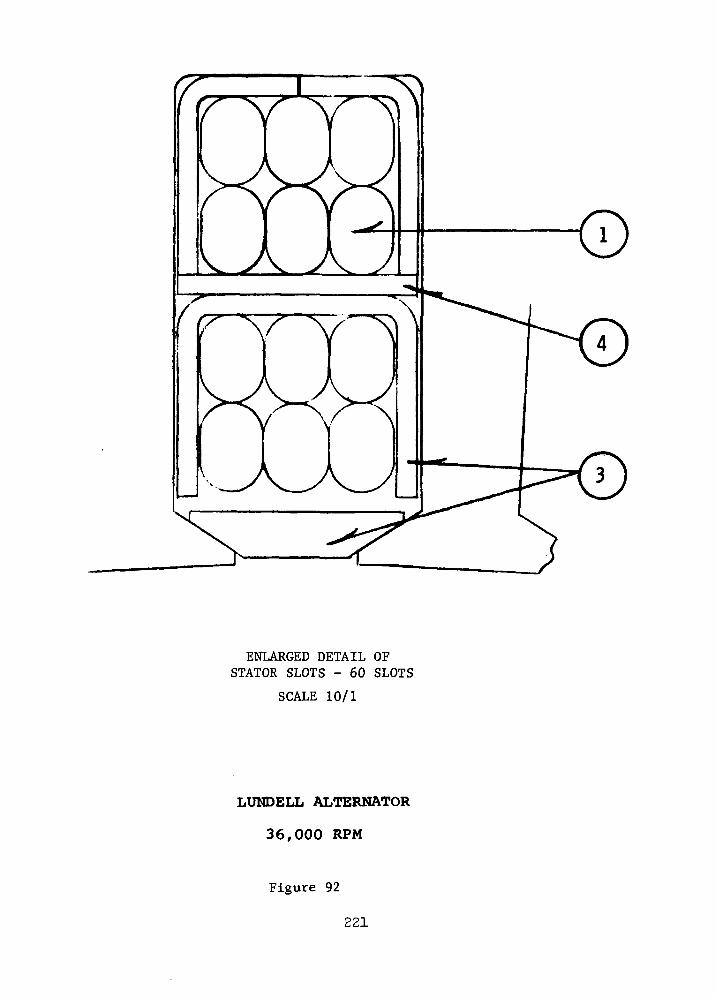
ENLARGED DETAIL OFSTATOR SLOTS - 60 SLOTS
SCALE 10/1
LUNDELL ALTERNATOR
36,000 RPM
Figure 92
221

1.2
1.1
1.0
w
IEHH
4
3
2
NO LOAD
X.)160 KWe .75 PF
5,000 10,000
. FIELD AMP-TURNS
LUNDELL ALTERNATOR - 36,000 RPM, 1200 Hz (D2)
SATURATION CURVES ! . - ' . . - ; • '
Figure 93 .
2 2 2 " ' • - . ' :
15,000

COCOO
24
20•
* 16*. •
3
] 12q
" 8"
4
0
94
?92T
;go9
.88H
r86qH
\ 84
1-82
Q
;
»«i, ,..i
"
WI
•'
;
1
*
40
*
TH V
^*
B>
/
/
- /
/
•*
FIND
^
... —
1. E
/"
X
£
AGE
/
FF.
^
. .*•
-;» .
-\
^t^
^•IHMH^
•~ \
- »,
3K
- :
V
!
X
^^E.F
. .• i • i
wn
I. L<
'H W
DSS
INDflLGE
80 120 160 200
POWER OUTPUT, KWe
in
u
Hfafa
LUN.DELL ALTERNATOR - 36,000 RPM, 1200 Hz (D2)
EFFICIENCY
Figure 94
223
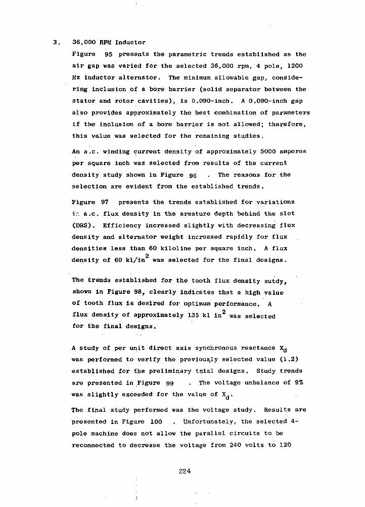
36,000 RPM Inductor
Figure 95 presents the parametric trends established as the
air gap was varied for the selected 36,000 rpm, 4 pole, 1200
Hz inductor alternator. The minimum allowable gap, conside-
ring inclusion of a bore barrier (solid separator between the
stator and rotor cavities), is 0.090-inch. A 0.090-inch gap
also provides approximately the best combination of parameters
if the inclusion of a bore barrier is not allowed; therefore,
this value was selected for the remaining studies.
An a.c. winding current density of approximately 5000 amperes
per square inch was selected from results of the current
density study shown in Figure 95 . The reasons for the
selection are evident from the established trends.
Figure 97 presents the trends established for variations
ir. a.c. flux density in the armature depth behind the slot
(DBS). Efficiency increased slightly with decreasing flux
density and alternator weight increased rapidly for flux
densities less than 60 kiloline per square inch. A fluxo
density of 60 kl/in was selected for the final designs.
The trends established for the tooth flux density sutdy,
shown in Figure 98, clearly indicates that a high value
of tooth flux is desired for optimum performance. A
flux density of approximately 135 kl in2 was selected
for the final designs.
A study of per unit direct axis synchronous reactance X^j
was performed to verify the previously selected value (1.2)
established for the preliminary tijial designs. Study trends
are presented in Figure 99 . The voltage unbalance of 9%
was slightly exceeded for the value of X..
The final study performed was the voltage study. Results are
presented in Figure 100 . Unfortunately, the selected 4-
pole machine does not allow the parallel circuits to be
reconnected to decrease the voltage from 240 volts to 120
224

ectr
om
ag
neti
c W
eig
ht
Eff
icie
nc
y
,%
Ro
tor
O.D
. -
Inch
h-1
M
N)
M
S>
N
J 00
V
O
OO
to
*»
CT
i 03
G
O
00
VO
V
D
VD
•
• •
M
o o
o o
o
).)
o>
-c
o
o
to
£»
i\o
° °
X
wnWI1
*s
-
HOU1
DAG
<S
r
//
\
MI
V
I GA
X
^f
— -^p —
/r
^^. ^3/INT1 P£
X«*^
j
1
-^THAGEIA
X
100
900](00)
4-1
° 80
<u" 70ro(1)
•^ 60
. 1100t7>
C 1000H pL|
So
. 900
|| 800
700
dp
£ 20u(d l fi
1 12
J 8
1-1£ 4
>
^
X
V\s
. -.,.
1
/I
A/
'
\- 5
0 .02 .04 .06 .08 .10 .12
Radial Gap - Inch
0 .02 .04 .06 .08 .10 .12
Radial Gap - Inch
RADIAL GAP STUDYINDUCTOR ALTERNATOR - 6000 RPM - 4 POLE
Figure 95
225
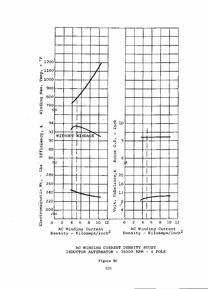
fc0 1200
Q,1100
£ 1000
X 900(0sD, 800c'-a 7005 cs
94
£ 92og 90
•H0
•H 88
w 86
(0aI 280•
-P 260
•H 240(DC 220i CT>
'(0 .
6 pOOJj <=u
^^
wn
-~r
^S
t
HOU
»
//
F
t_
:
5s •
-
//
^sNDA
*=^
y
/
3EV
•— *.
f
V
^
bala
nce,
%
Ro
tor
O.D
. -
Inch
-'
MM
M
J C
Ti
O
.•
00
^>
O
G J-^-D
• R
3.-°P 4> **
2
X4-•• I •• i HM*« m
^ J n o / I C Q i n 1 0 r > 9 A £ P i n i 9
AC Winding CurrentDensity - Kiloamps/inch
AC Winding CurrentDensity - Kiloamps/inch
AC WINDING CURRENT DENSITY STUDYINDUCTOR ALTERNATOR - 36000 RPM - 4 POLE
Figure 96
226
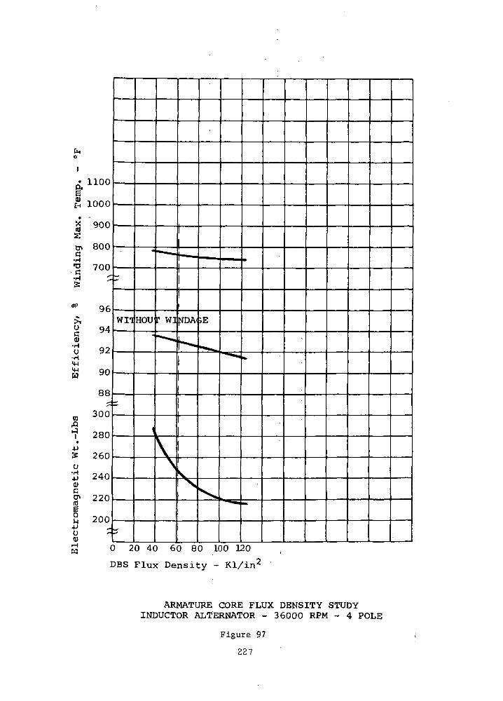
Cno
1• 1100
046EH 1000
g "900s0> 800«•g 700
S '
"" 96£g 94(U
o 92•H4-1
H 90
88jf-
« 300flI1 280
•
+J5 260o'5 2400)
| 220
S 200-Pu -<u
wn
«
HOU
••
1
- —
[" Wl
- *
v\
-— .
«IDA(
,
VV
" .
;E
2a».
^
••««
-*^=
*- 5
»
*
Mft
0 20 40 60 80 100 120
DBS Flux Density - Kl/in2
ARMATURE CORE FLUX DENSITY STUDYINDUCTOR ALTERNATOR - 36000 RPM - 4 POLE
Figure 97
227
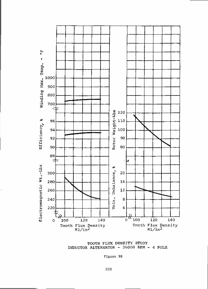
CMo
g1
0)EH
1 fiOO
ss PODo>C onn•H ouuT3
•H 7fif)H 700
* 96
*N
S 94C ^H
(I)•HO 92u yz
mM 90pq ^u
to3i ^nn•
+j15 pen
U
jj 260<uCtJi 94/-v(0 A^U
8 22O-Pu(1)
-
^-)•)
\s\
>
•* -
S 120,Q J-^wJ
-P 110
tn' J 100>»
•n 90O4Jo 80
dP
(i) 20uC10 16H -1-0
id
•8 125
' R4J 0H
^ 4
>
^
•
}•)
\s
• .
VN
•^ •
Sy
^S
^-*
X
•*• — f
0 100 120 140 0 100 120 140
Tooth Flux DensityKl/in2
Tooth Flux DensityKl/in2
TOOTH FI.UX DENSITY STUDYINDUCTOR ALTERNATOR - 36000 RPM - 4 POLE
Figure 98
228
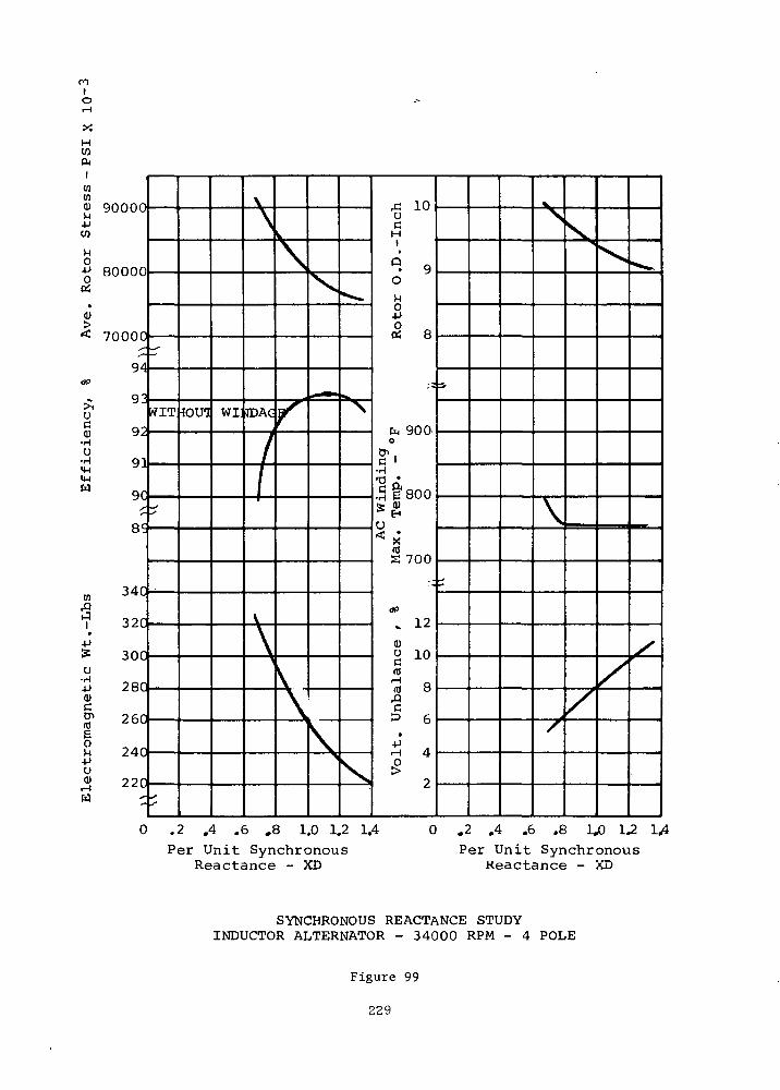
nIo
XHWCu
atmm annnn-PW
1-1O•p ROOOO
•
>< 70000
,-—
Q4dP
- 9^uS 92
•HU
S 91W 9C
t
340w -"^^
*? 320+J^ 300u'.p 2800)
| 260
° 240•po* 220
W ^
r
WIT
^
J
IOUG WI
\\
IDAC
/
1
\
\
\
f
\\
^
^ •
\
^
W^
\
X
AC
Win
din
gV
olt
. U
nb
alan
ce
r %
M
ax.
Tem
p. -
°F
Ro
tor
O.D
.-In
ch
~J
00
U3
\->
t->
O
O
O
M
NJ
£>
CT
i C
O O
to
.
, O
O
O
•<
C
O
^D
O
*
^
>S
V
/
^
/
^
/
•**-.
/
0 .2 .4 .6 .8 1.0 1.2 1.4Per Unit Synchronous
Reactance - XD
.2 .4 .6 .8 U) 1.2Per Unit Synchronous
Reactance - XD
SYNCHRONOUS REACTANCE STUDYINDUCTOR ALTERNATOR - 34000 RPM - 4 POLE
Figure 99
229
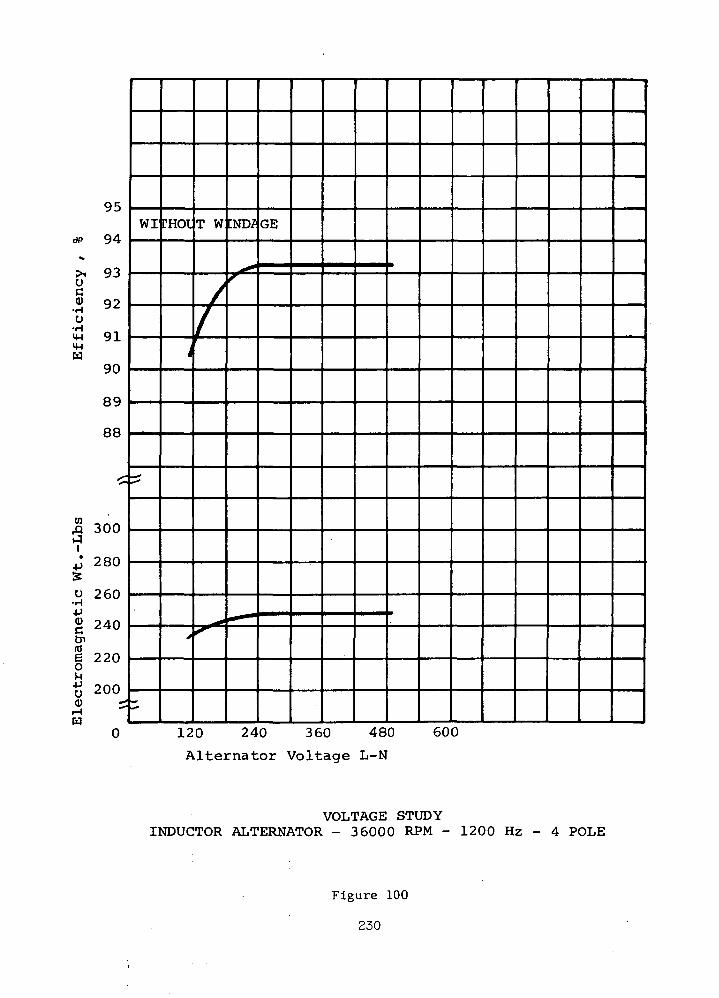
9S
dp 94^
•V, Q-3
uc(U 09
•rH ^^U
I4J Q14-1u
QO
oq
RR
£
S 300J
• oon^j Z OU
SO 7P.O4J<u ?4nc ^u
Cnmp oono u
M•*J ?nnU ^uuQ) itHCd
WI
— '^*
^
CHOI
'
>
T W
//'
irllT< "
:ND/
f
• *"
GE
0 120 240 360 480 600
Alternator Voltage L-N
VOLTAGE STUDYINDUCTOR ALTERNATOR - 36000 RPM - 1200 Hz - 4 POLE
Figure 100
230
volts as the maximum number of parallel circuits was utilized
in the initial design. Therefore, the number of stator slots
had to be reduced to obtain 120 volts line to neutral and
this resulted in reduced efficiency for the alternator.
The layout of the 36,000 rpm inductor alternator design is
shown in Figures 101 and 102. Table XXXVII presents a
summary of the design and performance details . Saturation
curves are shown in Figure iQ3
Alternate Stator Material Analysis
Alternator stator materials were evaluated as a part of the
electromagnetic design analyses task to determine if any
significant design advantages could be obtained by their use.
Specifically, an alternator conductor for the a.c. winding
was required to replace the nickel clad silver conductor be-
cause of the possibility of the conductor operating tempera-o
tures being lower than the 680 F curie temperature of the
nickel cladding. -Operation below the curie temperature of
the nickel cladding would create high magnetic losses in trie
nickel. Nickel clad silver conductors were initially selected
because of the better coil forming characteristics of this .
clad conductor. A 321 stainless steel clad silver conductor'1
.was selected to replace the nickel clad conductor as the 321 .
stainless steel cladding is non-magnetic arid.the conductor
has better coil forming characteristics than Inconel clad
silver conductors (which were also considered).
The use of mica mat slot liners to replace the alumina sloti. >
liners and the use of bare dispersion strengthened copper
"Cube" alloy conductors were also evaluated. The effects of
the use of these materials on alternator efficiency and
weight, together with notations regarding evaluation of the
materials is presented in Table XXXIX •
231

X N\
\
/ m
' '
_^
\ i f
^\ \ \
^ Y 'x \ \\ 1 1secrio* _tV-.
SPECIAL CHAHAOTERICS214 kVA, 0.75 PP, 1200 Hz,240 volts, 1(J6°F, oil oooled
SCALE 6.00 Inches
SCALE 0.10 meters
INDUCTOR ALTERNATOR, 36,000 RPM
Figure 101
232 '

ENLARGED VIEWOF STATOR SLOT
SCALE' 10/1
INDUCTOR ALTERNATOR36,000 RPM
Figure 102
233

1.8
1.6
1.4
1.2
g.1.0
wEH .8
H
o.
160 kWe - 0.75 P.F
10,000
FIELD AMPERE-TURNS
INDUCTOR ALTERNATOR-36000 RPM, 1200HZSATURATION CURVES
15,000
Figure 103
234
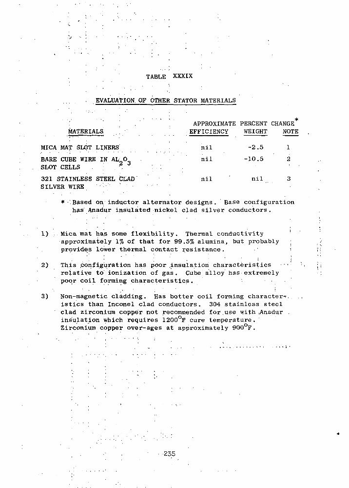
TABLE XXXIX
EVALUATION OF OTHER STATOR MATERIALS
MATERIALSAPPROXIMATE PERCENT CHANGEEFFICIENCY WEIGHT NOTE
MICA MAT SLOT LINERS'
BARE CUBE WIRE IN AL 0SLOT CELLS . ';. '.
321 STAINLESS STEEL CLADSILVER WIRE
nil
nil
nil
-2.5
-10.5
nil
1
2
1)
* Based on inductor alternator designs. Base configurationhas Anadur insulated nickel clad silver conductors.
Mica mat has some flexibility. Thermal conductivityapproximately 1% of that for 99.5% alumina, but probablyprpvides lower thermal contact resistance.
2) This .configuration has poor .insulation characteristics •relative to ionization of gas. Cube alloy has extremelypoor coil forming characteristics. •
3) Non-magnetic cladding. Has better coil forming character-,istics than Inconel clad conductors. 304 stainless steelclad zirconium copper not recommended for.use with ,Anadurinsulation which requires 1200°F cure temperature.Zirconium copper over-ages at approximately 900 F.
235

P. Corona Considerations for Voltage Selection
The ambient atmosphere in which the stator winding of the TAC
alternator will be operating is composed of a mixture of helium and
xenon gases approximating 72% helium and 28% xenon by volume.
Dr. T. Dakin of Westinghouse Research and Development Laboratories
was consulted for information regarding the properties of the helium-
xenon gas mixture in the stator cavity. Accor ing to Dr. Dakin, helium
will have a predominant influence on the gas mixtures' electrical charac-
teristics. Therefore, the properties given by Paschen's curve for helium
are used to determine the maximum preraissible voltage of the armature
winding to preclude corona.
The minimum spacing between phase conductors is 0.029-inch (equal
to the thickness of the slot liner and conductor double insulation
thickness). An a.c. winding voltage of 415 volts rms or 587 crest volts
line to line is assumed for this analysis. The corresponding crest volt-
age is 881 volts when allowance is made for a 50% voltage transient.
The minimum pressure for voltage breakdown at 881 volts and 0.029-inch
gap is 25 psia according to the Paschen's curve for helium, which would
be the case for a break in the insulation.
The case of a helium gap in series with solid insulation between
conductors must also be considered. A basic law of electrostatics states
that the total voltage "E " across series dielectrics is divided in pro-
portion to the ratio of the thichnesses "t " of the individual dielect-n
rics to the respective dielectric constants "K " as indicated byn
Equation 1.
E,D (\ *2 *-3 \= W + s + /T
<-> \ 1 'A 3
D = electrostatic flux density
e = permittivity of free space
A result of this relation is the concentration of voltage across the
low dielectric constant media, such as a gas, when it appears in series
with high dielectric constant solid materials. Ceramic insulations are
particularly poor in this respect because of their relatively high di-
electric constant.
236
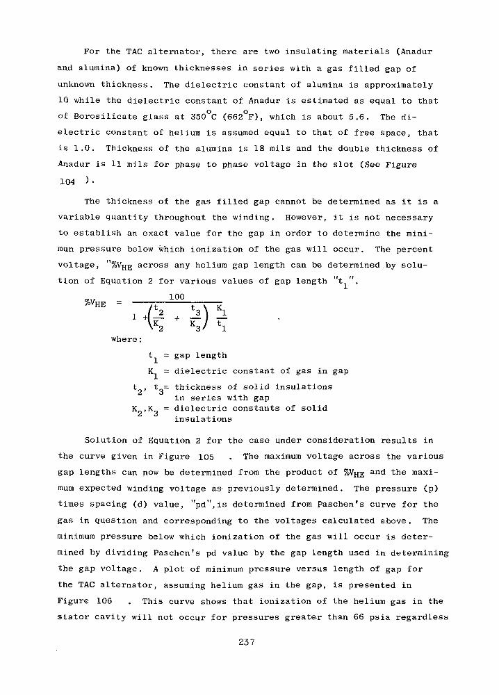
For the TAG alternator, there are two insulating materials (Anadur
and alumina) of known thicknesses in series with a gas filled gap of
unknown thickness. The dielectric constant of alumina is approximately
10 while the dielectric constant of Anadur is estimated as equal to that
of Borosilicate glass at 350 C (662 F), which is about 5.6. The di-
electric constant of helium is assumed equal to that of free space, that
is 1.0. Thickness of the alumina is 18 mils and the double thickness of
Anadur is 11 mils for phase to phase voltage in the slot (See Figure
104 ) •
The thickness of the gas filled gap cannot be determined as it is a
variable quantity throughout the winding. However, it is not necessary
to establish an exact value for the gap in order to determine the mini-
mun pressure below which ionization of the gas will occur. The percent
voltage, "%Vfjg across any helium gap length can be determined by solu-
tion of Equation 2 for various values of gap length "t ".
1 -f I _ + _r<K2 K3
where:
t., = gap length
K = dielectric constant of gas in gap
t , t = thickness of solid insulationsin series with gap
K ,K = dielectric constants of solidinsulations
Solution of Equation 2 for the case under consideration results in
the curve given in Figure 105 . The maximum voltage across the various
gap lengths can now be determined from the product of %Vjjg and the maxi-
mum expected winding voltage as- previously determined. The pressure (p)
times spacing (d) value, "pd",is determined from Paschen's curve for the
gas in question and corresponding to the voltages calculated above . The
minimum pressure below which ionization of the gas will occur is deter-
mined by dividing Paschen's pd value by the gap length used in determining
the gap voltage. A plot of minimum pressure versus length of gap for
the TAG alternator, assuming helium gas in the gap, is presented in
Figure 106 . This curve shows that ionization of the helium gas in the
stator cavity will not occur for pressures greater than 66 psia regardless
237

lunv
ina
<;
MiceMat
S
Alu
min
a
nad
ur
«;
Vi
/
Ana
dur
/• Co
nd
uct
or
<
1
4
~>
Co
nd
uct
or
I^inin
&irHO
i •k00rHO
•
'»,8
I
y
"N
\
r~COssO M> »4
S 00*Sj 00
1
tlkl
a;M60
•H
238
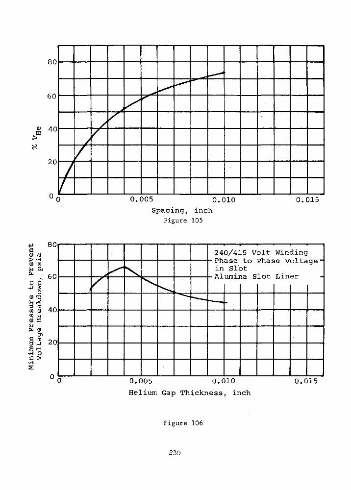
80
60
40
20
0 0.005 0.010
Spacing, inchFigure 105
0.015
Min
imum
P
ress
ure
to
P
rev
en
tV
olt
ag
e B
reak
do
wn
, p
sia
-i to
4^
cr
> a
J
0
0
0
C
(
>
/
XX ,*««. .
24
in_ A I
— — .
0/415 Volt Windingase to Phase Voltage-Slot
umina Slot Liner
»
0 0.005 0.010
Helium Gap Thickness, inch
0.015
Figure 106
239

of the length of the gap (containing helium) in series with the Anadur
and alumina insulation, assuming, of course, that the maximum expected
winding voltage is not exceeded. The gap length at which ionization
would occur is 0.004-inch from Figure 106 . The probability of this
gap length occurring in the alternator is very high and therefore it can
be concluded that stator cavity pressure must exceed 66 psia to prevent
ionization of the gas mixture in the stator cavity for the insulation
configuration and voltage described in Figure 104
Other conditions investigated are conductor to stack voltage in
the slot, Figure 107 , phase to phase voltage in the slot with mica
slot liners, Figure 104 , phase to phase voltage in the slot with
alumina slot liner and 10 mil mica mat phase separator, Figure 104 ,
and 120/208 volt connected winding. Results are presented in Figure
108 •
The pressure in the stator cavity will decrease when system load is
decreased. For this reason, it is recommended that the 120/208 alter-
nator voltage be selected.
A voltage transient of 50% was assumed in the corona analysis. If
actual systems voltage transients are less or if a gas with a better
Paschen's characteristic is selected, the minimum pressure values given
in Figure 98 would be lower. In any case, the minimum allowable
stator cavity pressure should be determined by test under conditions
selected for the final configuration. At present, however, a minimum
cavity pressure of 16 psia is recommended.
gas
COO
L-N-•VOLTS'
FIGURE 107
240

O S3
<H <W W
ww
HS
80
70
60
50
40
30
20
10
0
_ _ _
/\\\i¥
//
ArM3
X^
^
x:N.
/
PHASE TO PSLOT WITH50% VOLTAG
X1 v
+^~
SYST
X
^
^a"
EM :
"•"•••».
••••
?RES
HASE VOLTAGE IALLOWANCE FORE TRANSIENT
-^™^S
SURJ
= :
-— -.
3
/"
ATM3
.005 .C
ALtJ240
.M]
- 2.i,,UMI:CA
- AL
NA
MINJ/41!
CCA10/4
NA £SEP;
UMI!-120/2(
|1
\ SLOT I5 VOLT
iSLOT LI15 VOLT1 1>LOT LI1SkRATOR
^A S)8 V
LOTOLTJ
,INE
. ' 'HER
lIER 1
R :
*ITH
LINER ,3 • ': -.-"
1.015
HELIUM GAP THICKNESS - INCH
ALTERNATORVOLTAGEWYECONNECTED
240/415
120/208
240 DELTACONNECTED
MINIMUM ALLOWABLE PRESSURE TO PREVENTIONIZATION OF GAS, PSIA
PHASE TO PHASEIN SLOT
40 (with Micaseparator)
13
13 (with Micaseparator)
PHASE TO STACKIN SLOT
26
2 ,
26
HELIUM .GAP OF29 MILS, NOINSULATION
25
8
10
IONIZATION OF HELIUM IN TAGALTERNATOR
Figure 108
241
G. Conclusions
Three alternator configurations were selected from results of the
electromagnetic screening studies for consideration in the turbine-
compressor-alternator final performance analyses. These are, the
24,000 rpm, 1200 Hz, 6 pole Lundell alternator (design C-4 of Table XXXVI),
the 36,000 rpm, 1200 Hz, 4 pole Lundell alternator (design D-2 of
Table XXXVI ), and the 36,000 rpm, 1200 Hz, 4 pole inductor alternator
(design 1-6 of Table XXXVII) with evacuated stator cavity.
As a result of the corona considerations study for voltage selec-
tion, the recommended alternator voltage is 120 volts per phase with a
minimum stator cavity pressure of 16 psia. It is recommended that
corona testing be performed before the- final stator configuration is
selected. The effects of changing the alternator voltage from 240 volts
per phase to 120 volts per phase for the 24,000 rpm Lundell alternator
were insignificant as shown by comparing designs C-4 and C-5 of Table
XXXVI; thus the subsequent analyses carried out on C-4 (see following
sections) for example are applicable to the design eventually recom-
mended for Phase III consideration, e.g., design C-5.
Relative to the 36,000 rpm Lundell design (D-2),, the original con-
cept utilized a central hole in the rotor, thereby requiring a high
strength steel, e.g., H-ll or 4340 @ 49R . Late in the Phase I study• * . cit was recognized that it is also possible to assemble the TAG unit
without a central hole in the alternator rotor, and a lower strength
alloy could be used, e.g., 4340 @ 33 R . In that case, the D-3 design. C
(Table XXXVn) is recommended over the D-2 design for subsequent Phase
III consideration.
242
ROTOR DESIGN
A. Introduction
A distinct advantage offered by the Lundell alternator configuration
is that it is feasible to construct a rotor which has smooth exterior
surfaces. This feature produces acceptable windage losses even when the
rotor is operated in the working fluid at compressor inlet pressure.
Techniques for construction of a rotor with smooth exterior surfaces for
the inductor alternator were considered also. However, this was considered
a technically unsound solution to the windage problem associated with this
type of rotor. A less sophisticated solution for the inductor alternator
is offered by reduction of the pressure within the rotor cavity.
The solid Lundell -rotor is formed by bonding a non-magnetic material
to the magnetic material. Development effort has been focused upon various
techniques for bonding of Inconel Alloy 718 to SAE 4340 steel. The pre-
ferred process consists of subjecting the materials to heat and pressure
in an autoclave. A loose-fitting assembly of the magnetic parts and the
non-magnetic filler alloy is hermetically canned to exclude the autoclave
pressure from the interfaces. Compaction of the container and assembly
is produced by gas pressure at an elevated temperature. The surfaces
are forced into intimate micro-contact whereby thermally activated diffusion
bonds are produced.
The time-temperature-pressure cycle is controlled to accelerate
diffusion and to produce the proper heat treatment of the alloys. The
diffusion bonding technique within an autoclave can be used to fabricate
a rotor with a magnetic material other than SAE 4340.
The results of a magnetic material screening study for the Lundell
alternator are summarized here.
B. Magnetic Material for Lundell Rotor
Table XL gives four magnetic materials, including 4340 steel, which
are candidate for high speed rotors which operate at or below 700°F.
The materials are listed in order of magnetic preference.
The smallest rotor and the highest efficiency are provided by the
Hiperco 27 alloy. Smaller rotor diameters are obtained by virtue of the
superior magnetic properties of this material; efficiency is higher by
243

oOO
©
|
w
CO
oEHO
S3OHEHH
OU
«•
CO•
J3
•01•
"*
"o"CN
*
»->J2jg?2o•— •
PHS3M
EH
WOHEM
EH
HS
^HsM1
QCx]1-5
W QS3 WS3 O<C " C
»• «•H H WCO CO >£^ HM O
• t pQ
^* r~l f£O COrH rH CO
H H 201 CO 5JX X co0 0
• •VD ^<* in
rH
* O^0 C• -H -
o <3i CT>PM-P - ido
u ora • ,c ra in •^ U 0 3 H tjrH • rH rH H •pf CM s. Pi rfj
* CM OCM (-1 o CM JJ *0 ,C O 0 • >-|
in o o in u .CCN rH CN CN •+ |\i-H + |CM Oin CM @ in • rHCN 0 CN H\CT* o (j) fV, 00 rC °rH O t7>O rH O
t rfj oo in@ rH @ \rH
@ - CM rHrH £LI i-H ofO CT*° rtj m @J<D PI O Q) CNC -H o C m 0)C CnfN C rH Oril nj ^ rtj @j nj
u00 H•H EHF~~ W
J 0
*3 «E!O 1U S3S3 On t^
QWi_I]
MZ23rij
O•
0^
o•
r^ro
iA
*O(DCCD,C4Jcnc(U -PV-i C•P 0)n g
4JCD m
M•P 4->0C -Pc mm cuu ,c
m•d0)
r ra CT>fN >H O
1 In <D H80 O -H
0 XDH O OW f» O CNft II rH CNH £H 11 IItc a «
H CNrH f")
u u
in m• •
O rHt^ n
rH
in in• •o min rH
rH
o 'O0 0)m Min-HrH CO
1 0)OT3Om orH-p
0) rlfr-t V-i Oo 3 ao -P Em m a)in ^ -PrH 0)
1 CLTJo E Cin <u nj^* -PrH ^
Cr> u@ C C ra
•H a> rarH C 3 0)nj 0) tr cQ) 'O 'OC >H H Mc nj -H BJ< td o ^:
,• Cr
H OCM (D rHo O "HOH XO H O
O r- II O vO<* II U i-l rHn EH »; n u<* ffi CQ
•
O• rH
rl -H
d) Xo
o o •in o II rH rHU II II( X t c m
t
oo
• rHrl -HQ) £4
OCN COCO O •II O VDU rH rH& II II
ffi CQ
nnUfV
«
QW
<M
|*^3
rHCNrH
•
OrH
O-P
rH
H
Om
TJrH0
_<"]
.
CM0
inCN+oin00rH
O•P-Pn)(U
rHrH
1ffi
in^*
Ufrf
|-
00rH
.•
Oini-H
"UrC COu raC 30)
t^rC M
m mVi in ^
•H • CMfd rH o CJ
0 «cu a) mO 0) rH Orl H i-H 4-10 ,Cm 4-> o ra
4-> CQ>i O <U
^5 4J O Cin T3
s o o nO S rH (0rH 4-J f.rH @0 « CJm • ra C
EH rl -H• • CO in
J_l p^ pt ^Qr; g
O 0) OVD 4J 4-> 4J
0 •
O • CTiO >H Or^ co HII O -H
p . i^s
- oin o in1- rH rHU II IIpd ffi ffl
*CMoO0ini-H
@Hn]0)
Cn>go-H4J
rH0
CQ
Cr
-HD(d
i•rl
*|
COi-H
_
OoCN
H
JHEH
Q
O
1
CN
rH
•OvDrH
©
0)(7> ra< M:
• VDEH
• OOH 4J
O n-P
rH OO «4HOU CM
oM O
•H O< Oi
8"• rH
rl'H
CM Q) Wo OO CNo o •Is* O fNII rH rH
EH II IIffi ffl
244

virtue of lower excitation, pole face, and windage losses. In general,
a Hiperco 27 Lundell alternator rotor has approximately 1.5 kw less loss
than a design with an SAE 4340 rotor. Hiperco 27 alloy can only be
strengthened during the forming process (work-hardening). Thus, a Hipsrco
27 rotor which is fabricated in an autoclave at an elevated temperature
can be expected to have a strength equal to that of the annealed alloy.
Annealed investment castings of Hipsrco 27 have a 0.2% yield strength
of approximately 37,000 psi at 700°F.
From the standpoint of strength, these limitations and requirements
are imposed upon a Hiperco rotor for a Lundell alternator:
(a) The strength of Hiperco 27 alloy is not adequate for a
36,000 rpm rotor.
(b) The strength of Hiperco 27 alloy is adequate for a 24,000 rpm
rotor provided the rotor does not have a central hole.
(c) The diameter of the rotor is limited to 7.0 inches (stress
intensity equals 35,200 psi at 20% over speed); electro-magnetic
requirements of the alternator require a 6.9 inch diameter for
the rotor.
(d) A high joint efficiency between the Hiperco 27 alloy and
alloy 718 is required since the strength of one of the parent
materials has imposed design limitations.
Since a Hiperco 27/Inconel 718 rotor offered only a small performance
and weight advantage over a 4340/718 rotor, it would be economically and
technologically unsound to recommend a Hiperco 27 rotor for the 24,000 rpm
Lundell alternator. This conclusion is supported by the fact that a
rotor without a central hole requires a sophisticated turbine-alternator-
compressor arrangement.
SAE 4340 steel offers good magnetic properties for the rotor. Direct
current magnetization tests at 700°F for annealed material (R 11) and for
normalized material (R 32) show the magnetic properties are not sensitivec
Or any higher strength material having magnetic properties as good sincethere is no apparent system advantage.
245
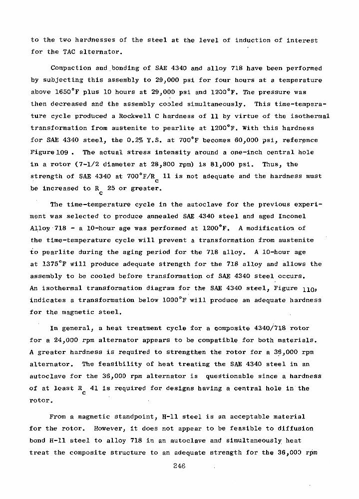
to the two hardnesses of the steel at the level of induction of interest
for the TAG alternator.
Compaction and bonding of SAE 4340 and alloy 718 have been performed
by subjecting this assembly to 29,000 psi for four hours at a temperature
above 1650°F plus 10 hours at 29,000 psi and 1200°F. The pressure was
then decreased and the assembly cooled simultaneously. This time-tempera-
ture cycle produced a Rockwell C hardness of 11 by virtue of the isothermal
transformation from austenite to pearlite at 1200°F. With this hardness
for S.AE 4340 steel, the 0.2% Y.S. at 700°F becomes 60,000 psi, reference
Figure 109 . The actual stress intensity around a one-inch central hole
in a rotor (7-1/2 diameter at 28,800 rpm) is 81,000 psi. Thus, the
strength of SAE 4340 at 700°F/R 11 is not adequate and the hardness must
be increased to R 25 or greater,c
The time-temperature cycle in the autoclave for the previous experi-
ment was selected to produce annealed SAE 4340 steel and aged Inconel
Alloy 718 - a 10-hour age was performed at 1200°F. A modification of
the time-temperature cycle will prevent a transformation from austenite
to pearlite during the aging period for the 718 alloy. A 10-hour age
at 1375°F will produce adequate strength for the 718 alloy and allows the
assembly to be cooled before transformation of SAE 4340 steel occurs.
An isothermal transformation diagram for the S.AE 4340 steel, Figure IIQ,
indicates a transformation below 1000°F will produce an adequate hardness
for the magnetic steel.
In general, a heat treatment cycle for a composite 4340/718 rotor
for a 24,000 rpm alternator appears to be compatible for both materials.
A greater hardness is required to strengthen the rotor for a 36,000 rpm
alternator. The feasibility of heat treating the SAE 4340 steel in an
autoclave for the 36,000 rpm alternator is questionable since a hardness
of at least R 41 is required for designs having a central hole in thec
rotor.
From a magnetic standpoint, H-ll steel is an acceptable material
for the rotor. However, it does not appear to be feasible to diffusion
bond H-ll steel to alloy 718 in an autoclave and simultaneously heat
treat the composite structure to an adequate strength for the 36,000 rpm
246
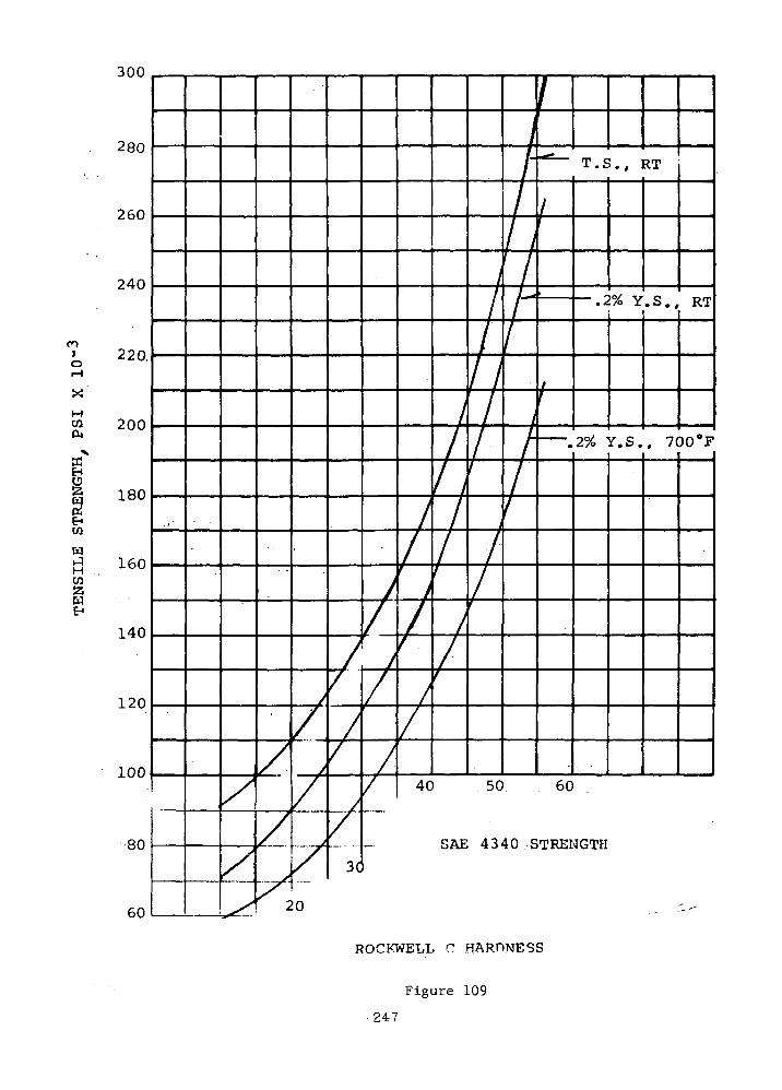
300
280
260
240
roIo
XH
S3
1W
wJH
220.
200
180
160
140
120
100
80
60
\
7
L1
L
T.S., RT
.2% Y.S., RT
-.2% Y.S., 700°F
40 . 50. 60
SAE 4340.STRENGTH
20
ROCKWELL O HARDNESS
Figure 109
247
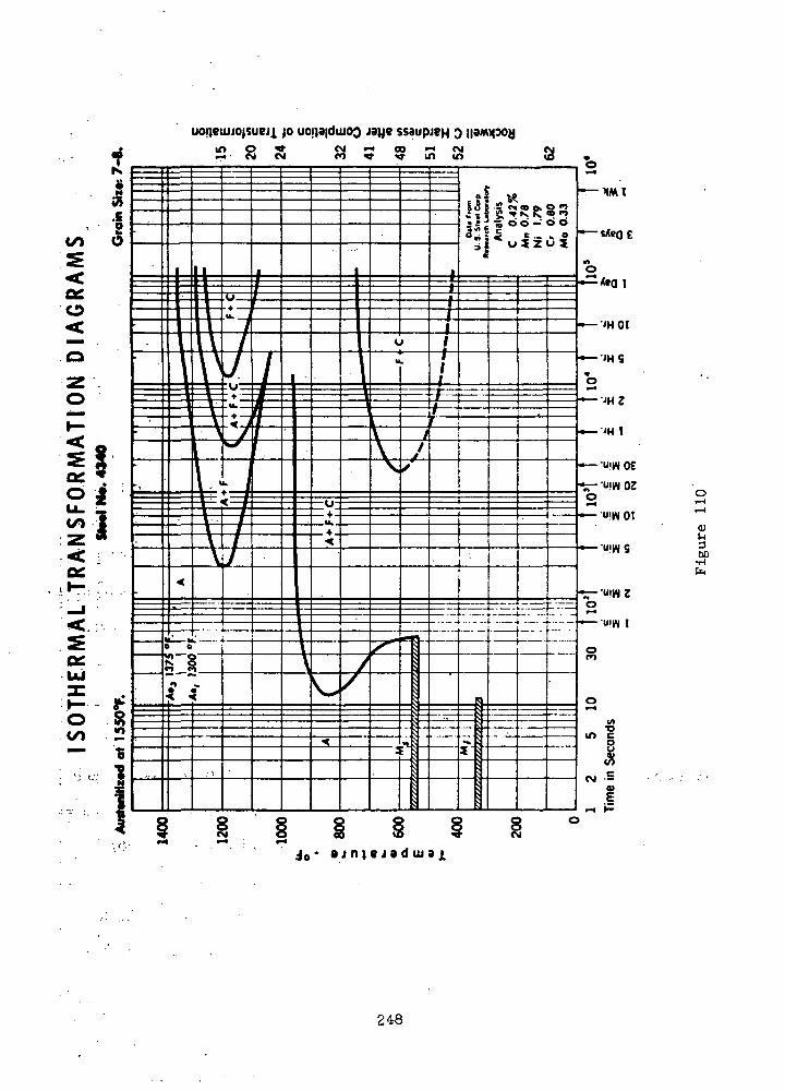
jo uoij3|dujoo
60•HfK
248
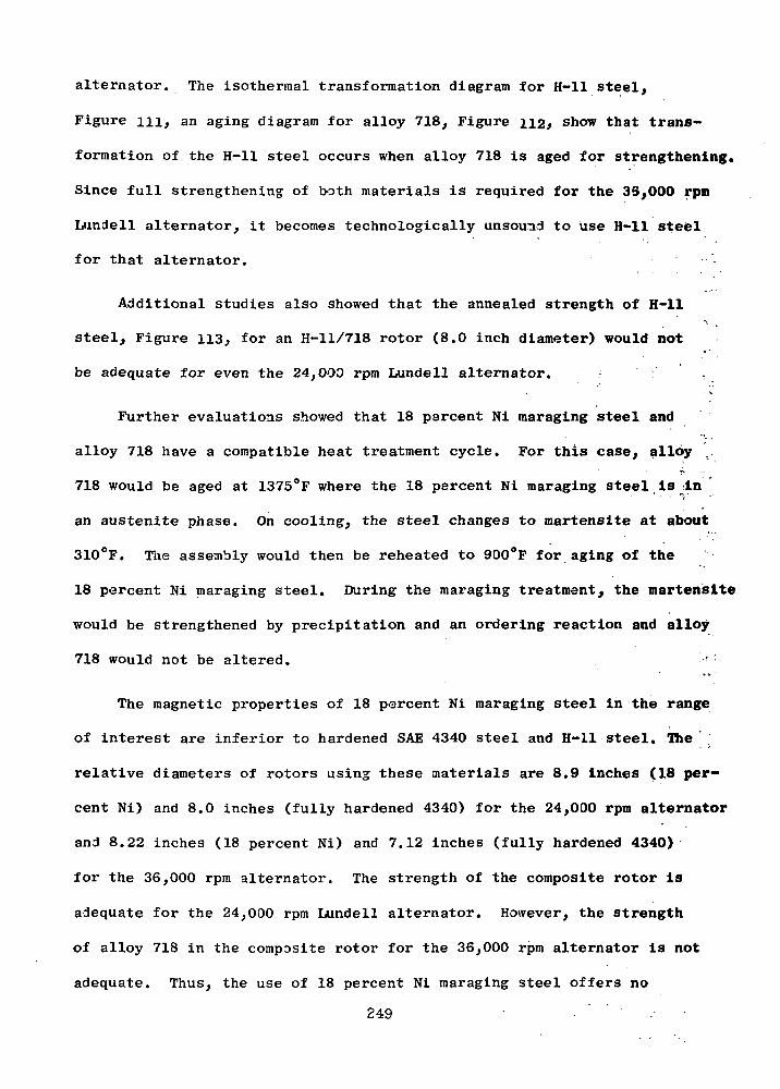
alternator. The isothermal transformation diagram for H-ll steel,
Figure ill, an aging diagram for alloy 718, Figure 112, show that trans-
formation of the H-ll steel occurs when alloy 718 is aged for strengthening.
Since full strengthening of both materials is required for the 33,000 rpm
Lundell alternator, it becomes technologically unsound to use H-ll steel
f o r that alternator. • • • • ' .
Additional studies also showed that the annealed strength of H-ll
steel, Figure 113, for an H-ll/718 rotor (8.0 inch diameter) would not
be adequate for even the 24,000 rpm Lundell alternator. . ;
Further evaluations showed that 18 percent Ni maraging steel and
alloy 718 have a compatible heat treatment cycle. For this case, alloy
718 would be aged at 1375°F where the 18 percent Ni maraging steel;Is jin
an austenite phase. On cooling, the steel changes to martensite at about
310°F. The assembly would then be reheated to 900°F for aging of the
18 percent Ni maraging steel. During the maraging treatment, the martensite
would be strengthened by precipitation and an ordering reaction and alloy
718 would not be altered. <
The magnetic properties of 18 percent Ni maraging steel in the range
of interest are inferior to hardened SAE 4340 steel and H-ll steel. The
relative diameters of rotors using these materials are 8.9 inches (18 per-
cent Ni) and 8.0 inches (fully hardened 4340) for the 24,000 rpm alternator
and 8.22 inches (18 percent Ni) and 7.12 inches (fully hardened 4340)
for the 36,000 rpm alternator. The strength of the composite rotor is
adequate for the 24,000 rpm Lundell alternator. However, the strength
of alloy 718 in the composite rotor for the 36,000 rpm alternator is not
adequate. Thus, the use of 18 percent Ni maraging steel offers no
2 4 9 . ' ' • . . • •

£000
IBOO -
3 4 56 6 K> IS X 30 45 SO 132 3 4 5 9 8 0 15H X 45 SO a I 3 4 3 6 to IS SO 3O 49 6O
too
ISOTHERMAL TRANSFORMATION DIAGRAM H-ll STEEL
Figure 111
250

1800
o>ZJ
•+-•03
OJQ.
ao!,"
"£b
1300
1200
11000.05 0.1 0.5 1.0 5
Aging Time, hr
HARDNESS OF ANNEALED ALLOY 718FOR VARIOUS AGING OONTDITIONS
100
Figure 112
251

roIo
X
HCO
CO
w1-3H
3
240
220
200
180
160
140
120
100
10 20 30 40 50 60
ROCKWELL C HARDNESS
H-ll STEEL STRENGTH
70
Figure 113
252

advantages for the 36,000 rpm Lundell alternator. The only advantage
18 percent Ni maraging steel offers over SAE 4340 steel for the 24,000
rpm Lundell alternator is a less sophisticated heat treatment cycle of
the alloys in the autoclave.
The preferred composite construction for the Lundell rotors is
SAE 4340 steel pressure diffusion bonded to alloy 718 in an autoclave
cycle. Both of these alloys must be strengthened during the bonding
process to satisfy the specific requirements for the TAG alternators.
To accomplish this, alloy 718 must be age-hardened at a temperature
which prevents the SAE 4340 steel from transforming from the austenite
phase to the pearlite phase. A transformation temperature of approximately
1000°F is required to strengthen the steel for the 24,000 rpm alternator.
The strength of alloy 718 as a function of hardness is given in Figure 119.
The feasibility of heat treating the SAE 4340 steel in an autoclave
for the 36,030 rpm rotor can probably only be clarified by experiments
since a hardness of at least R 41 is required for this alternator.c
The critical crack size at the bore of the rotors was investigated
using fracture toughness data corresponding to R 48. The calculatedc
minimum critical defect size (0.1 x 0.5 inches) can be readily detected
by non-destructive inspection techniques. Thus, fracture of the rotors
due to defects does not appear to be a problem.
C. Rotor Design Summaries
The maximum stress intensity within a Lundell rotor occurs around
the central hole at the center of the rotor. Judgement of the integrity
of the rotor was based upon the criterion that the maximum stress intensity
must be less than the 0.2 percent yield strength of the materials. A
safety factor is introduced by using the stress associated with a 20 per-
cent overspeed condition provided the tensile strength of the joint between
the magnetic and non-magnetic material is greater than the yield strength
of the parent materials. Tensile tests of diffusion-bonded SAE 4340 and
alloy 718 demonstrate that the strength of the joint approaches the ultimate
strength of the 4340 steel. If this characteristic continues when the
4340 steel is strengthened for the specific requirements of TAC, the
criterion for judgement of the integrity of the rotors will have been
253

ALLOY 718
200
CO
S 180
. x:- •H ,Wto 160
%t
K
w 140£CO
wH 120CO
100
80
60
40*"/
^
/
••
// y7
// /y
/
y'
>/7/
/
A7/
//
T;
V .2% Y.
X .2% Y.S.
s., RT
,
, 700°F
10 20 30 40 • 50
ROCKWELL C HARDNESS
ALLOY 718 STRENGTH
Figure 114
254
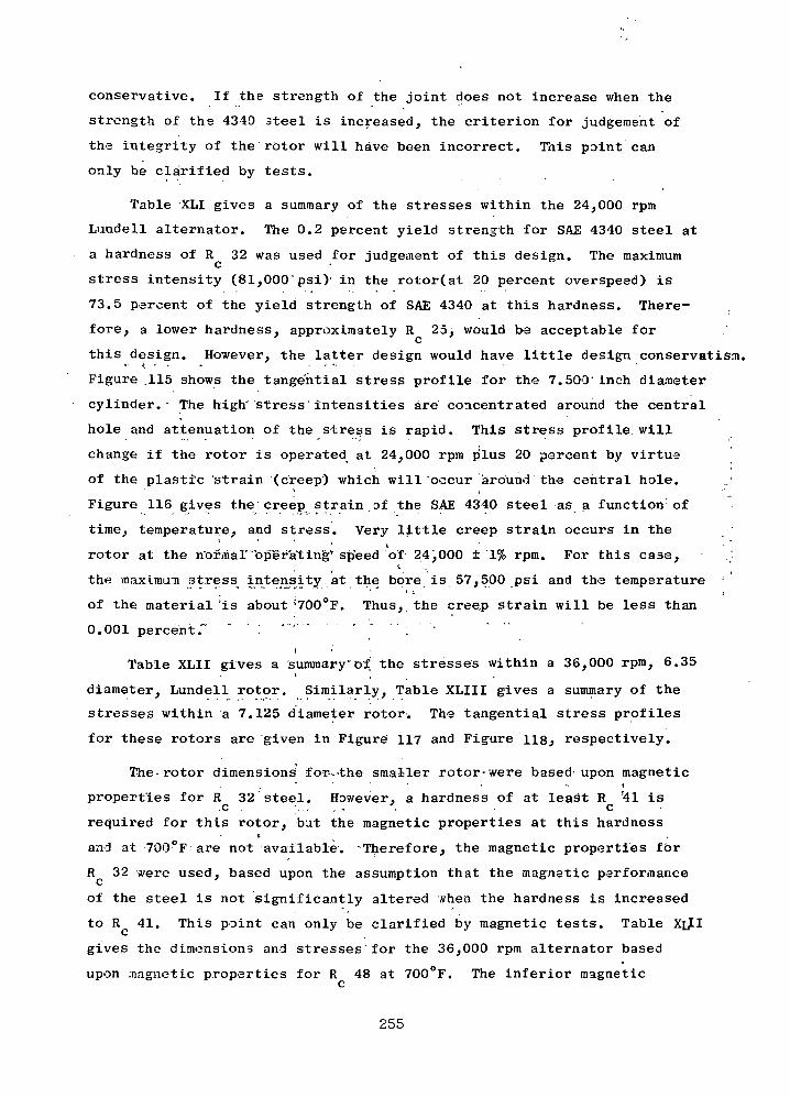
conservative. If the strength of the joint does not increase when the
strength of the 4349 3teel is increased, the criterion for judgement of
the integrity of the rotor will have been incorrect. This point can
only be clarified by tests.
Table XLI gives a summary of the stresses within the 24,000 rpm
Lundell alternator. The 0.2 percent yield strength for SAE 4340 steel at
a hardness of R 32 was used for judgement of this design. The maximumc *
stress intensity (81,000'psi) in the rotor(at 20 percent overspeed) is
73.5 percent of the yield strength of SAE 4340 at this hardness. There-
fore, a lower hardness, approximately R 25, would be acceptable forC
this design. However, the latter design would have little design conservatism.• • f. • . i ; -
Figure .115 shows the tangential stress profile for the 7.500' inch diameter
cylinder.- The high" stress intensities are' concentrated around the central
hole and attenuation of the stress is rapid. This stress profile will
change if the rotor is operated at 24,000 rpm plus 20 percent by virtue
of the plastic strain (creep) which will occur around the central hole.
Figure 116 gives the'creep strain of the SAE 4340 steel as a function1 of
time, temperature, a.hd stress. Very little creep strain occurs in the
rotor at the rior/maT'oper'ating'' speed of 24,000 ± 1% rpm. For this case,i
the maximum stress intensity at the bore is 57,500 psi and ths temperature
of the material'is about'700°F. Thus, the creep strain will be less than
0.001 percent." " . •>-,• — * " ,
i 'Table XLII gives a summary"Of the stresses within a 36,000 rpm, 6.35
diameter, Lundell rotor. Similarly, Table XLIII gives a summary of the
stresses within a 7.125 diameter rotor'. The tangential stress profiles
for these rotors are 'given in Figure 117 and Figure 118.» respectively.
The-rotor dimensions for—the smaller rotor-were based-upon magnetic- i
properties for R 32 steel. However, a hardness of at least R '41 is.c ; . . . . ; , '. c
required for this rotor, but the magnetic properties at this hardnessB
and at 700°F are not available. -Therefore, the magnetic properties for
R 32 were used, based upon the assumption that the magnetic performance
of the steel is not significantly altered when the hardness is increased
to R 41. This point can only be clarified by magnetic tests. Table Xif.1C
gives the dimensions and stresses for the 36,000 rpm alternator based
upon magnetic properties for R 48 at 700°F. The inferior magneticc
255

oao
I
•(0
w
a wacuo oooo O• * »o oco in
a aOuaoooo
8(0wo
0) CM
m•r>
r-
00
O vO
00 CO
iooo^tfM
m CM
•H-HW 10CU04
00in rH
vX> vOin CM
CM 00com
00
(O
(O
o
(0 en
•fi affH
CO
Hfto
s •oopvO
in »HM1 CM
« %•rt -rt0) W
0 0in int^ CO
CM
•H -Hco macu
CN r-in r-in in
COn(Xooo
GOit(0CO§
•E3
HO
EN
GT
HS
ILE
S
SPO
NT
ER
BA
SED
AR
co EnvO O
EF
FIC
I
HO
Q
§H
CO
^3
Hfn
OO
53H
W
O
256

n
150
140
130
120
110
100
X! 90
80
wCO
CO
70
60
50
40
30
20
10
_L
:!8,8DO;i
::4,ooo i
st
1PM
1PM
ess 7,600;
1.0 2.0 3.0 4.0
Radius - Inch
24,000 RPM LUNDELL STRESS
Figure 115257

CO
o•H
8
5.2
5.0
4.8
4.6
4.4
4.2
4.0
% CREEP5 YR.
-•
1.
S
1 SI
AE
***-_™
^-
4340
l.C
R
1
Y F;
ST3
% :
\i
,35
>«
^CTO
2EL t
.% (
\ l\\ \
1.0
X^
R—
.01
P
x/"s
%o .oc'00°\i7
^
1%F
0.050f
.C29
^
^
01%
C "
l\
\\\\
$1
\] RC31
,pn
•60
20
>i n
12 16 20 22 24 28 32 36
Io
PS
IS
TR
ES
S
T-200LOG CR + 30
MANSON-HAFERD PARAMETER PLOT OF CREEP RATE VERSUS STRESSCR = CREEP RATE, AL/L/HR., T = TEMP., °F
Figure 116
258
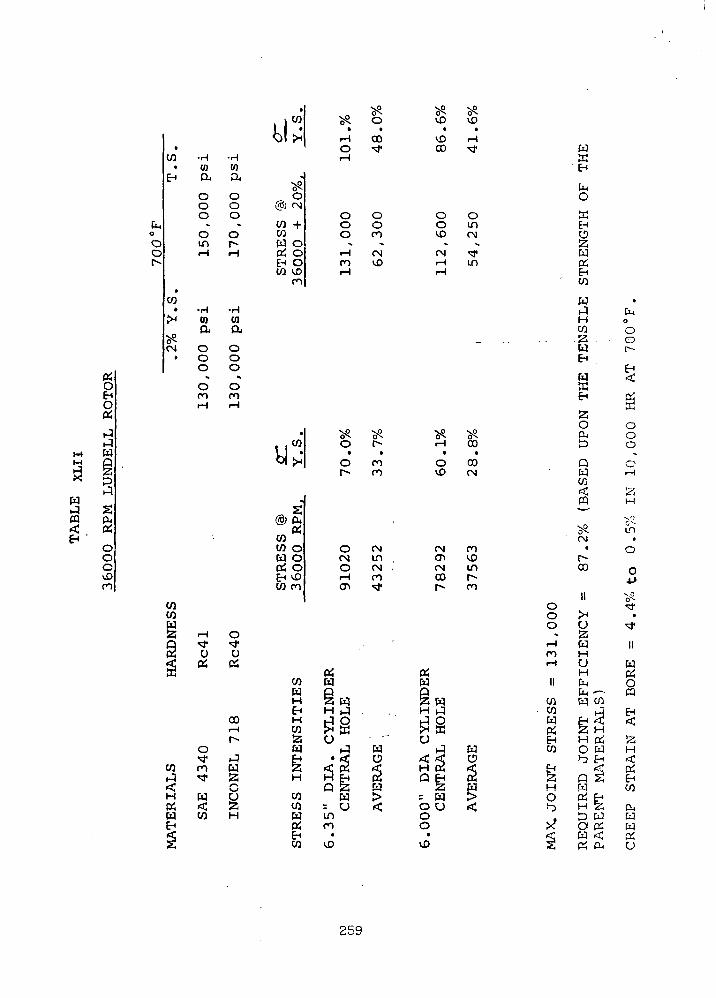
p^
8op*
1-4t-3frT
sS3p.4
2^,
OH
oOO*Dn
•CO -H -H
• CO 01EH DJ QU
O 00 00 O
t,o O Oo ID r-o <-* Hc-»
•
CO• -H -H
J* CO 01p, p,
CM O O• O 0
O O« *
O On nrH r-l
COCOW2! -H 0Q ^J" ^S o u<J pi OSa
COr-H
r-o^j* J
co co W
H W U0£ rtj 2iW CO HEH<fS
.
US«s^ V^
^ O VD
iH 00 v£>O ^ COr-l
-
O@) CN
CO +COW 0OH ^DEH 0CO <£
ro
O O 0O O OO CO >£>
^ •» -•H CN CNCO VD i-HiH r-H
•. ,wbj>;
^s. ^x ^O f - r H• • t
O CO Or^ ro ^O
„,g
rt8i fiip;
COCO OW 0OH ^^EH vDCO CO
O CN CN<N in CTiO CN , CNr-l CO 00CT* ^J1 C^
PH P^CO W W
WEH H ^ , . H JH i-3 O h-1 OCO ^ hr] ^H jrl2J O " OW ^ W JEH • rf O c^ ^24 <J PM <C H K
CO """' S > = WCO = C_) < O UW in oOH CO COEH • •CO VD ^D
v^SD
ti-tM-
OinCM
»
in
00•
COCN
COv£mr~-co
WO
$%<
oooi— ico•H
II
COCOWeyg_l
CO
g
HO
?SS
WffifH
CM0
ffiEHO
W05EHCO
W."1
HCOP^
WEH
WaEH
23OOtp
QW
rt*ffl
voCN
•r-00
n
^H0
WHuHCntn —W CO
EH ^23 HH 05O W*"3 EH
P 2JW
H feP WO O5W <P5 &
•rT
O
0or-
EH
05S0o0
V
0
¥lH
vO
LO
•
O
o
•JjO
^f•
*3*
IIWDH
ooEH
j2H<c05EHCO
PU
W
0
259

Cn0
OOr-
PiOEHO
• -rH
CO WCL
EHOOO
^0corH
• -Hco ca
a!"
0^x 0CN O
• «.
in\DrH
Pi
rJ. THH
M (y1— 1 Q
^ ri
S DJMJ 2W Ou< PiEH
OOO>J3ro
COCOM CO4Q *N^
2 PiK
Oxt
co nr-3 '
'-CH WPi <W COEH
•H(0CU
OOO
•»
OcorH
•HCOCL
OOO
X
O•*rH
^^PWo<>Jh3D
SiCN
<*UPi
COrHr~-
rJ
OU2iH
•
i iw1 •6|><
^^x ?Qr^ •i-H CTirH xt
©
CO ^co oW CNPiEH +CO
O00
*
&m
O OO OO 0
•. «.
m r^\o r-rH
•. ,cok •VJljX
® S04
CO OSCO OW 0e°.CO vO
m
xp xPtfx 5 -in rH
• •rH COco n
^ ^
o enr CNxt xt
xt COrH inrH
PiW
CO QW §H H WEH J (JH £ OCO UKaW • hi WEH < < Oa H pi <cH P EH Pi
a HCO r W >co m u <W CNPi rHEHco r-
in•
xtCO
OOrH
-mr-irH
vPo^m
•inin
«
r^JDm
•k
COr-
esu§H WH rJ? O0 K
• KH
< <cH c2
P ^= W0 Uoo•
vD
XPv^o•
\Dco
OinCN.
• fin
°-cVi•
vD<N
^
'ta\^D
r^m
Wig<
•rH
10
aooom<£>i-H
IICOCOWPiEHCO
HOin•
1
ft]h-1r -l
EH
tnO
tcEHO^1WPiEHCO
WJHWS3wEH
WacEH
20O4t— iP
OWCO<5c&in
•rHCTi
II
UlawHoHCnt, ~W W
^EH ft,'^\ HH p;O uI-J EH
P£WA EHH fejID WO «W <K Oj
260
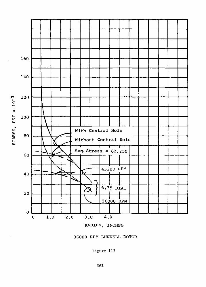
orH
X
CM
CO
160
140
120
100
80
60
40
20
1\\\\
—
A-\
• —
X/*'y\\
*~~"
s,V i
^ \>.
^
With Central Hole
. Without Central Hole
Av
s\
*
=v
g. Stress = 62,250
<T\(V
MBB iHM
O
,}
432
6.3
36C
00 I
5 D]
00 1
1PM
CA.
^PM
0 1.0 2,0 3.0 4.0
RADIUS. INCHES
36000 RPM LUNDELL ROTOR
Figure 117
261

n
or-l
CO
COco
EHCO
3.0 4.0
Radius - Inch
36,000 RPM LUNDELL ROTOR
Figure 118
262
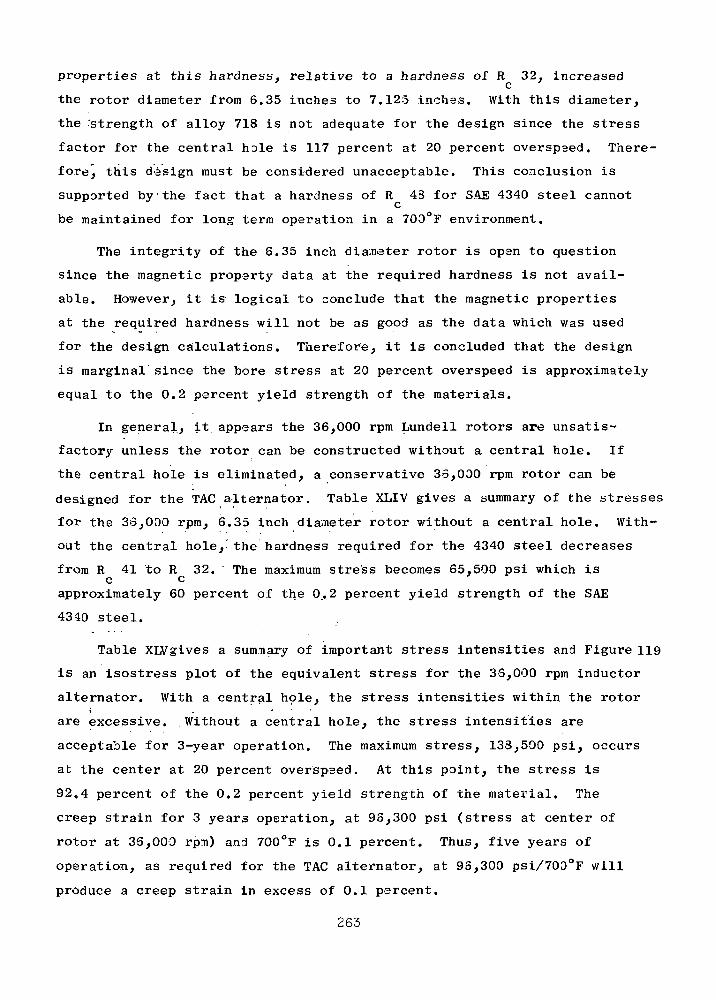
properties at this hardness, relative to a hardness of R 32, increasedc
the rotor diameter from 6.35 inches to 7.125 inches. With this diameter,
the 'strength of alloy 718 is not adequate for the design since the stress
factor for the central hole is 117 percent at 20 percent overspsed. There-
fore, this design must be considered unacceptable. This conclusion is
supported by the fact that a hardness of R 43 for SAE 4340 steel cannotC
be maintained for long term operation in a 700°F environment.
The integrity of the 6.35 inch diameter rotor is open to question
since the magnetic property data at the required hardness is not avail-
able. However, it is logical to conclude that the magnetic properties
at the required hardness will not be as good as the data which was used
for the design calculations. Therefore, it is concluded that the design
is marginal since the bore stress at 20 percent overspeed is approximately
equal to the 0.2 percent yield strength of the materials.
In general, it appears the 36,000 rpm Lundell rotors are unsatis-
factory unless the rotor can be constructed without a central hole. If
the central hole is eliminated, a conservative 35,000 rpm rotor can be
designed for the TAG alternator. Table XLIV gives a summary of the stresses
for the 35,000 rpm, 6.35 inch diameter rotor without a central hole. With-
out the central hole,- the hardness required for the 4340 steel decreases
from R 41 to R 32. The maximum stress becomes 65,500 psi which isc c
approximately 60 percent of the 0.2 percent yield strength of the SAE
4340 steel.
Table XLVgives a summary of important stress intensities and Figure 119
is an isostress plot of the equivalent stress for the 35,000 rpm inductor
alternator. With a central hole, the stress intensities within the rotor
are excessive. .Without a central hole, the stress intensities are
acceptable for 3-year operation. The maximum stress, 133,500 psi, occurs
at the center at 20 percent overspeed. At this point, the stress is
92,4 percent of the 0.2 percent yield strength of the material. The
creep strain for 3 years operation, at 95,300 psi (stress at center of
rotor at 36,000 rpm) and 700°F is 0.1 percent. Thus, five years of
operation, as required for the TAG alternator, at 93,300 psi/700°F will
produce a creep strain in excess of 0.1 percent.
263

>rH
dX
»J
1tr<
woK
rH-
0?£J3wU
EHDOffiEHH
ago
1-9Mw§f^
ft04
Ooo>£>ro
faoOOr*
•H -H• (0 111
co a aE H 0 0
0 00 0
0 0ro mrH rH
•H -H• (Q 0)
co a. a*JH O O
0 0^ 0 0CM <• o m
O rH CNrH rH
' ^
o', ;
f ' C '
CO •COW (N CD53 ro COQ O Uft 04 04
*rj*
•' ' P> W '**•
<••- •*> -V * ..
' 00. rH
t<o. :
co n w
< OH W U04 < S3W CO H.EH
s
0 .
. to I . Si ' ?* cv 01I 1 •! • • • •VI >H| . <T> r-- rH O
in * in <vj*
.
@ S "ft
CO g " "' O ' O " O OCO O O O Owo m in rf o04 o m CM <& inEH-CN \o : in in tCO CO• ^j«
- - * ••1 **P vp vp ^J1 o^ o^» O^ u^i col n : CN vo ^t
^1 >H| ' rH p") in 00^ • CO CO CN
. j •' t ; . .®K - , : ' "< '••'CO S O 0 ' . O 0?co ,00 m o-;
wo .m m rH CN'04 O in vD CT) <H 'EH O ^J* co • oo rrCO AD
CO
* . -t • . . '
'04 04w - w
CO Q CO Q CO" 'W S CO • S3 • CO>• H .H ' W • ' H ;. W". *EH J - 04 J ' Oi
' H P 'CO EH " ? CO' EHCO rj CO ' CO - O CO COa w - wW • • 04 W • "04 WEH < EH O «=C EH O. a H co rt H co <;H Q CC Q 04
CO •= •§'• ^ = § ^co 'O § rt! OS ^CW m o04 co oEHCO VO vD
i-lsfM
WEH
£5s'FnfeMft<jjft
O*-r«M-(
0
Wft
'£-<- CO
W
- HCO
w
S3OftD
Q
CO<mI-M
•in' *
O-H m
pi •>!!
O ' '.J0 .'Um S3in wvD H
OII H
CMCO CMCO WUft EHEH* 23CO H
o
H QO CO
HD
X 0< WSj ft
DMO
0o
2ftfto00vDcOj
®
CO
s:?m
S3^H
S;
O,.O.
g
o-
IIOH]
8oftW"oftw -2wCJ
g^
<cS3H
EHCO
ftTrT
TT^
ftU
264

tnoOO Or- oMl) O
• r-w co
• rH
o W
o oCM SB
+ EH
O O
vD H
•H(0cuooinroCO
in
oCO
CM
oovOoCM
ooIDCO
COHH
5sHgH
CO
w
CQ
§£•40Q
|gH
£
2o
o0-rl
r- a© a• o
en o• oo
3? m(N rH
0
. .0)Cfl0)C m•d-*rl O<d «
CM
ooovDm
•rlu>a.0dinroCO
s04
K
oo0vCro
•rl10ainr-o.COin
ooroOrorH
rHCfttn0
oovO
0)0)-p
(0 '•rl i
01+>
(0(00)
4JCQ
4JO
0)rHO
04
OoovOO
ooo a\
oCM
CM00mco
n
m<orHO
04
. to a>n o>at $4J a)0] ffl
•OS:
53<2
•OC
nai a>rl
0)rH
<0 IHrl 4J0) C> «
n
,*BgiC 0) *>0) 3 3
0» O•P 01 0110OS f8 **H -CO % -P<u wUTJ (8p-rlrH
W S M
(j) grH -H<o nt'> K•H 4J
crw
H O' ••*'
•H 4Jit tn4J fl
265
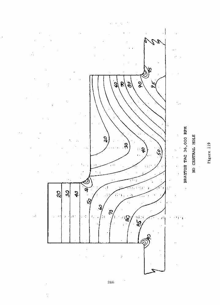
wO tJ§ §ro
O
O1bO
266
; D. Conclusions
1. The preferr.ed materials for the Lundell rotor are SAE 4340 and
alloy 718. ' This combination of materials can be bonded in an
autoclave. . Compaction of a loose-fitting assembly is produced
by gas pressure at an elevated temperature and thermally activated
diffusion bonds; are produced.
2. The time-temperature-pressure cycle in the autoclave, which has
been developed for bonding rotors with lesser strength requirements,
should be modified to produce a higher strength SAE 4340 alloy.
(See items 3, 4, and 6 below.) This can be accomplished by aging
alloy 718 at a temperature which prevents transformation of the
4340 steel from Austenite to pearlite. The assembly should then
be cooled from the aging temperature before transformation occurs
to obtain an adequate hardness and strength for the TAG application.
3. The maximum stress intensity within the 24,000 rpm Lundell rotor will
be 81,000 psi at 20% overspeed. A hardness between R 25 and R 32I C C
in the SAE 4340 steel is required to obtain adequate strength for
the overspeed condition.
4. The maximum stress intensity within the 36,000 rpm Lundel rotor
with a central hole at 20% overspeed is 131,000 psi. This stress
intensity .is approximately equal to the 6.2% field strength of alloy
718 at 700°F. A hardness of at least R 41 in the SAE 4340 steel• • • • ' • c . •
is required to obtain adequate strength for this overspeed condition.
Experiments are necessary to determine whether a hardness of R 41'•' . . ' C
can be produced by a time-temperature cycle within an autoclave.
Furthermore, magnetic properties of,SAE 4340 steel at R ,41 and
700°F are needed before positive conclusions can be made relative
to the feasibility of this design.
5. A conservative 36,000 rpm Lundell rotor design is obtained by
elimination of the central hole. It must be recognized that this
design requires .a sophisticated turbine-generator-compressor
coupling arrangement. ;
267

6. The strength of the joint between the SAE 4340 steel and alloy 718
must be greater than the 0.2% yield strength of the parent materials.
7. The stress intensities within the 36,030 rp-n inductor rotor with a
central hole are excessive. A rotor without a central hole is
marginal from the standpoint of strength.
268

WINDAGE LOSS
A. Introduction
Windage losses are a significant portion of the combined losses
within the alternator. Obviously, accurate calculation methods are
needed since the magnitude of the windage loss influences the selec-
tion of the cooling scheme and the selection of the best alternator
for TAG. A comparison of four calculation methods was made to deter-
mine their applicability to the Lundell alternators. The relative
magnitudes of the windage loss for one rotor configuration and one set
of operating conditions are presented in Table XLVI.
In general, the formulation of Vrancik given in NASA TND-4849
gave much higher losses than the other methods. The lowest losses
were obtained by using a skin-friction coefficient from Gazley's exper-
iments with concentric, rotating cylinders (Trans ASME, Volume 80,
No. 1, Jan. 1958). Vrancik's correlation was also based upon Gazley's
skin-friction coefficient. However, there appears to be an error of a
factor of four introduced when the skin-friction coefficient was sub-
stituted intro Vrancik formulation of the power loss equation.
Gazley defined
Cf = T/U/2 pu2)
where (Cf) ~1/2 = 2.04+ 1.768 In Re v jT
T = fluid shearing stress
p = fluid density
u = u /2 = one-half of the peripheral velocity
of the rotor surface.
Re = Reynolds number based on the peripheral
velocity and the radial clearance between
rotor and stator
Vrancik used the same equations except that y = y was used in place of
y = y /2 as defined by Gazley. This difference produced a factor of
four difference in the power loss equations as shown below.
Power loss (cylinder) = (shearing stress)(area of cylinder)
(radius)(speed)
269

S3
1'
0 DCC • Otd a, CQ
•rlI>l r— | ^ LO O
U rd id • ••d u Q n rHM -HE3 CU OU P>iUU E-i
OCT> <\4
1 • • 1O rH
•
^1iH-PrC
CO•HrH
COid
-CoCOrH C
om -H13
4->CJ
O -HU 0
CO
U 1co
<J • C
£3 : if^ • '
CO 'CO <O !
TW <O .1< tQ "'
H r
CM-i nJ ^4*H m
0 M OS3 O UD 4->= id <-> C co1} Vl * !SO) S3
4J3 r-l
o id ~- . -t-1o u <j! i 'dH < •* C
3 t S30) ii,C g )H
rl1m
0) fl)>i a. >rl >1 OO 4-1 ftQ) Id,£ *iB TJ fl)
rH O .*"!VH O [ *f l ) «S^*t O C(d S5 C -HiJ o tr>
C co
VI 00 fl) Vl U
•O • nj a) a)C rH ^3 ft V43 O CO fl)O > CO *W
•afl)•Hm•rl
T3Og«
CO
• r-l
4-1id•HnE
o
CT1
c•H4J
U•rl
•-I
UCO
T3
fl)rlO
rQ
r;jjooECOiCo(5
rlO
MH
^1O4->0id
<4H
rH
•
r-l
0)(U 4-»g r^
"rH C*
4J 0)Jj
.4->
C COQ) 3!5
fl)co a<3 id
0
-O0)
•rl (1)M-l i — 1•H tQT3 idO ' — 1g '"-I
id>i >
rH HJ4-1rC CO
CT1 fl) ••rl g rHrH O fl)CO O 'O
0 O- rQ E
COCO rd MO 4-i rd
r-H rd rHt3 -iH
r^ gCO U -H
•rl p^ CQ
t3 fl)
» — x01 < g•H < 2
rC
0 C CO*H Q) -prH ,C rH
"o coCO CT1 Q)
C ^ i
CO 4-) T!P id C
rH rdI 0
o n J,P.CO O O MrH 4-1 (NO(=3 U 4-'
P C OfCJ fO 'M
• c x:W -H 4J CO (1)-P g rl ,C
O Cb (U >>H >H CO
o cu0O rH CT>
rH O U IdO 0 T)Cu cyi 0 c
n ,Q -rH
oo 50
— 5 4-1 C0 £i O
CO 0P o en 4-iO O rd O.C <N T3 0tn c IH
•rl rH SQ)
4-1 OU5 CU 13 00 0 pC[g O ' 4J 4-1^ rH fj
•H •>rC (d 'CO
4J. 0 C•HE : rl Xgo a
CO rl 4-1
MH • Q) O
O id E • 4->• 4-1 rl O
o id <. 0 -a^3 0
CO CO d) T3 (U C 1 ^H i Q) * -M CJ *r3 O < -O 4-» CO H
» CO C rl> W CO (d
•H P£ EH tP 5u O M>(H >i s S3 4-)
> -rl « H
TrH rx O
3 .H -H —
C CO rH CO fl)•rl ^ p,
4-1 CO•C *• O -|J "U >1"H U rH
fd
4JT)£
OIs
S-iCL,-Hid ^O
>1rl M
"rH f3^ «H
CO H !-(fl) O 0O U (!)rd fl) ;C
UH M 4->rl^3 d) rH
CO 4-> (1)
,c ^ co c 5 u)4-> 4-i • ro 0
•H JD J-i Q) * — 'co ^ rd co Ord O p 3 Cu£ 4J 4J cr-ro
•rH (J ^J*I"CJ tp -> d)
fl) >Q U "H fl) 4-) (fl rd "O r-l (0 <O 0 T) C 0 ,£) >14J (^ CMid u m ,cr
r*J -ri ^| OH rH > >
^H rH O H-l,C N -HO ftJ M 4**
CO O fa W
0)4-»U0)
Id CX rH> CUw id
r*r1
<T
1
H
HHU3•*
33
fl)CO
1
C -rH
•H Xffl ^s<
fl) p4 O
C -n go oO -H T3
4-1 0C to< D
i i
O4-1U3TiCH
03 C) -H C rHP SH tn C r-i c
fl3 C ro fd O(d cu o us4J E r-l 4J U)
• (d O- 0 0 0 re
1 1
270
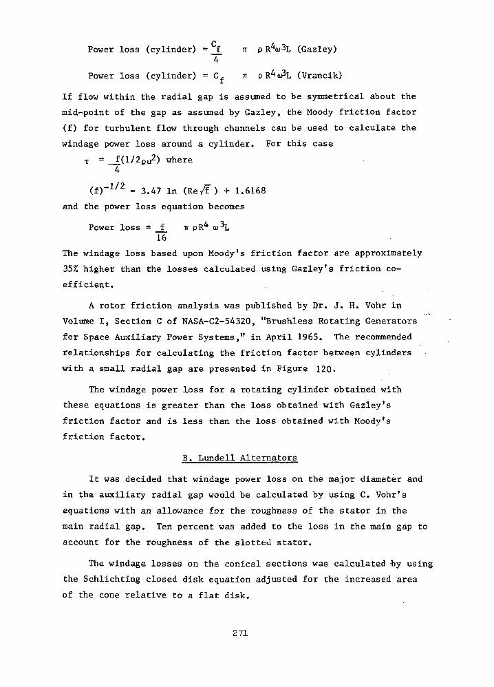
Power loss (cylinder) = f ir p R U L (Gazley)4
Power loss (cylinder) = C, IT pltAaPL (Vrancik)
If flow within the radial gap is assumed to be symmetrical about the
mid-point of the gap as assumed by Gazley, the Moody friction factor
(f) for turbulent flow through channels can be used to calculate the
windage power loss around a cylinder. For this case
T = _f(l/2pu2) where
4
(f)-1/2 = 3.47 in (Re/F) + 1.6168
and the power loss equation becomes
Power loss = f IT pR^ co^L16
The windage loss based upon Moody fs friction factor are approximately
35% higher than the losses calculated using Gazley 's friction co-
efficient.
A rotor friction analysis was published by Dr. J. H. Vohr in
Volume I, Section C of NASA-C2-54320, "Brushless Rotating Generators
for Space Auxiliary Power Systems," in April 1965. The recommended
relationships for calculating the friction factor between cylinders
with a small radial gap are presented in Figure 120-
The windage power loss for a rotating cylinder obtained with
these equations is greater than the loss obtained with Gazley 's
friction factor and is less than the loss obtained with Moody 's
friction factor.
B. Lundell Alternators
It was decided that windage power loss on the major diameter and
in the auxiliary radial gap would be calculated by using C. Vohr's
equations with an allowance for the roughness of the stator in the
main radial gap. Ten percent was added to the loss in the main gap to
account for the roughness of the slotted stator.
The windage losses on the conical sections was calculated by using
the Schlichting closed disk equation adjusted for the increased area
of the cone relative to a flat disk.
271
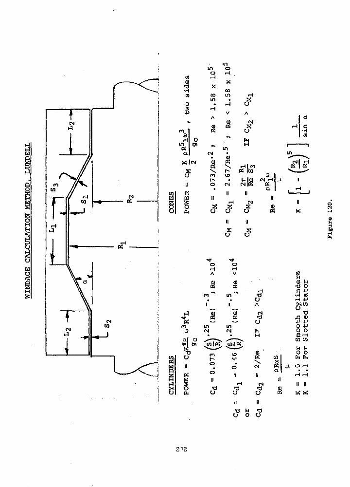
H
oHEH
CJ
g
O
COHI
010)•o•Hto
intfa
u
Oft
ro3
o
•a
inin oo H
XCDin
A
0)
CM
snt^-o
SU
o
A
cn
inCM
CO
oo
•dO
COin
in
vo•
CM
CM
u
Hlcn« ICQ
CM
SU
oV
a)
inCM
vo••a1
•au
CM
•ouA
CM•du
CM
CM•du
10M0) M•O OG -P
•rl (d
•O
O 4JO O6-H
CO 03
Q) O OCO I fa EM(2J 3. O rH
II
s II II
OCM
2
•d ^ 'du o cj
272
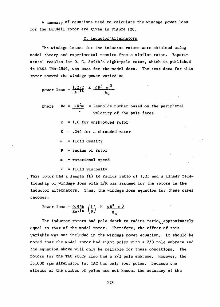
A summary of equations used to calculate the windage power loss
for the Lundell rotor are given in Figure 120.
C. Inductor Alternators
The windage losses for the inductor rotors were obtained using
model theory and experimental results from a similar rotor. Experi-
mental results for 0. G. Smith's eight-pole rotor, which is published
in NASA TND-4849, was used for the model data. The test data for this
rotor showed the windage power varied as
. 1.272 K PR5 a)3power loss = ^ —
where Re = PR*o) = Reynolds number based on the peripheral
velocity of the pole faces
K =1.0 for unshrouded rotor
K = .244 for a shrouded rotor
P = fluid density
R = radius of rotor
a) = rotational speed
V = fluid viscosity
This rotor had a length (L) to radius ratio of 1.33 and a linear rela-
tionship of windage loss with L/R was assumed for the rotors in the
inductor alternators. Thus, the windage loss equation for these cases
becomes:
Power loss = 0.956 / L\ K pR5 u 3Re-H \R) 8C
The inductor rotors had pole depth to radius ratio, approximately
equal to that of the model rotor. Therefore, the effect of this
variable was not included in the windage power equation. It should be
noted that the model rotor had eight poles with a 2/3 pole embrace and
the equation above will only be reliable for these conditions. The
rotors for the TAG study also had a 2/3 pole embrace. However, the
36,000 rpm alternator for TAG has only four poles. Because the
effects of the number of poles are not known, the accuracy of the
273
windage power equation when applied to a four pole rotor can only be
clarified by obtaining further experimental data.
COOLING DESIGN
A. Introduction
The purposes of the alternator cooling studies were (1) to deter-
mine the techniques required to limit the rotor and stator hot-spot
temperatures to 796° F, and (2) to provide preliminary alternator
thermal maps. The emphasis of these studies was placed on the Lundell
alternators because the thermal aspects of Inductor alternators had
been fully studied for the Potassium Turboalternator (KTA) Preliminary
Design Study (ref. 36 ).
Computer programs were utilized to perform all analyses, excepting
liquid coolant and gas flow and the pumping requirements. Initial
estimates of the stator stack and winding temperatures, including the
effects of windage and pole face losses-.passing through the stack,
indicated that excessive winding temperatures would occur. During sub-
sequent detailed analyses, gas flow over .the rotor surface was found to
limit hot-spot temperatures to the specified level. These analyses
excluded only the alternator field coil, which was considered .separate-
ly because its thermal performance would be nearly independent of other
alternator temperatures. . .,
B. Stack Heat/Temperature Influences
The major portion of the alternator losses are to be removed by a
liquid coolant flowing through non-rotating parts of the machine.
However, some additional thermal paths will be provided by the rotor
shaft extensions, the frame mounts and through radiation and convection. L.
to the structure surrounding the alternator. The use of a coolant
flowing through the rotor has not been considered because it does not
appear to be necessary for the TAG alternators.
For the Lundell alternators, the losses are generated in the
following areas:
(1) Field coil windings
(2) Armature windings
(3) Stator laminations (both teeth and back iron)
274

(4) Rotor pole faces
(5) Rotor-to-stator "air"-gaps.
The "air"-gap area is subdivided into the main gap under the stack, the
auxiliary gap at the end bells, and the conical gap which connects the
main and auxiliary gaps. The windage loss determination methods for
these gaps are discussed above in this report. The losses in the
other areas are determined in the electromagnetic design section.
The inductor alternator losses occur in the same basic areas.
The major difference is that there are no auxiliary or conical gaps.
The windage losses are generated in the pole to stack gaps of the
salient poles, and on the pole end faces. A complete understanding of
inductor alternator thermal considerations can be obtained from
reference 36, although much of the following is generally applicable
to this machine.
Within the Lundell machine, field coil losses and temperatures
will be nearly independent of other alternator losses and temperatures.
This results from the intimate contact of the field coil outer surfaces
with the liquid cooled heat sink. Losses from the stack, armature
windings, rotor and "air" gap will not pass through the field coil
unless extreme temperature differentials occur. Within the coil,
spiral windings with thin interlaminar insulation and high thermal
conductivity ceramic plates potted to the ends of the coil winding
sections will be used to reduce the radial thermal gradients. The
field coil temperatures, even with cavity gas at about 800°F, can be
maintained below the limiting hot-spot temperature of 796°F. The
calculated (650°F) temperatures indicated on the thermal maps pre-
sented later in this section are considerably below this level.
The armature winding temperatures and losses are interrelated in
that increasing losses result in increasing temperatures and
further increases in the losses. Directly influencing the tempera-
ture distribution in the windings are the slot insulation system, the
end turn lengths and the end turn surroundings, while the stack and
liquid coolant temperature levels, and the thermal path for windage
and rotor pole face losses have indirect effects. Because convective
and radiant cooling of the end turns will generally be inadequate for
275
the losses in these areas, increased end turn lengths will magnify this
deficit. Thus, the hot spot temperature would occur in the end turn
and could be decreased by decreasing the end turn lengths. Within the
slot, the thermal path from the conductor to the iron tooth is through
a solid or flexible insulating slot liner and unavoidable, gas filled
clearances. While some thermal contact (no clearance) will be normal,
its magnitude and effect are uncertain. In addition, as discussed
below, corona effects and operating gas pressure levels must be
considered in the selection of the slot insulation system. Generally,
the gas will present the greatest resistance to the thermal path,
therefore minimum tolerances of the conductor, slot liner, tooth
dimensions and stack slot alignment are necessary to obtain a low
temperature rise from the tooth to the conductor. The indirect
effects of the stack and coolant temperature levels on conductor
temperature are generally set by the basic design. The rotor pole
face and windage losses, if transmitted to the heat sink through the
stack iron, will also increase the temperature levels of the teeth and
the conductors. Therefore, an alternate thermal path for these losses
is desirable. In the TAG Lundell designs this is
accomplished by providing a path for the gas in the air gap to flow
through the frame-to-stack separator which also provides the flow
path for the liquid coolant. This gas circulates through the air gap
and the separator, transporting windage losses and rotor pole face
losses to the heat sink.
C. Preliminary Thermal Analyses
For the TAG alternators, it was assumed that the effective heat
sink temperature would be 525°F, except for the case using a coolant
at SNAP-8 temperatures where the heat sink is assumed to be at 345°F.
These temperatures are based upon a redundant coolant path system,
where the two coolant paths have reversed flows (or counterflow). For
the system shown in Figure 121, the 24,000 rpm Lundell alternator, a
total flow of about 6,000 Ibs/hr would require a temperature rise of
11°F and 1230 watts pumping power (within the alternator envelope).
Should one of the paths fail, the flow remaining constant in the other
path, the flow of 3,000 Ibs/hr would require 615 watts pumping power,
but the temperature rise would increase to 22°F. This would result in
276
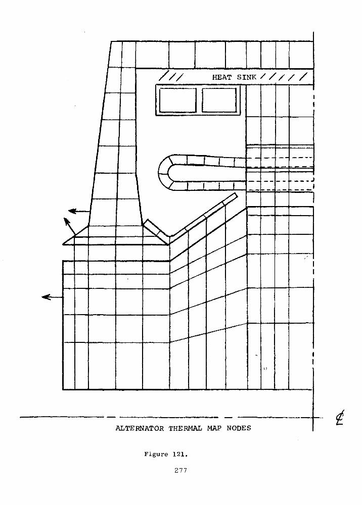
HEAT SINK / / / / /
ALTERNATOR THERMAL MAP NODES
Figure 121.
277
an alternator axial temperature gradient approximately equal to the
coolant temperature rise (there is no gradient in the full flow case).
Reduction of the coolant flow rate would result in significant power
savings, but more serious temperature gradients, as shown by the
relationships of pumping power to coolant temperature rise, Power
<x (At coolant) 2.75.
Preliminary estimates of the stator armature and stack tempera-
tures are obtained in the electrical design and performance programs.
However, these programs do not include the effect of heat transfer to
the stator teeth from the rotor or "air" gap. A brief analysis was
made of these effects, revealing that excessive winding temperatures
would be incurred if windage and pole face losses were removed solely
through the stack. Since direct rotor cooling by passage of a fluid
through the rotor is difficult and results in considerable complexity,
cooling by means of a fluid flowing over the rotor surface was deemed
necessary.
Preliminary estimates of the feasibility of pumping the cavity
gas indicate that a pressure head of approximately 1.0 psi can be
developed in the conical gap. Using the 100°F temperature rise
assumed for the gas in the thermal map study, the specific heat of the
helium xenon mixture, and the energy removed at the "gap heat sinks",
the flow rate would be about 860 pounds per hour. Assuming the gas to
divide and flow through 205 slots, 0.05 inch wide by 0.2 inch deep over
each stack, the pressure drop would be less than 0.1 psi. Similarly,
the estimated drop in the "air" gaps, and radially between the stack
sections, would bring the total pressure drop to about 0.25 psi. Thus,
the flow rate will be greater than was assumed for the thermal maps,
and the gas temperature rise in flowing through the gap will decrease.
Thus, the assumed temperature rise leads to conservative results in
the thermal mapping.
D. Thermal Map Study
The thermal map studies for the Lundell alternator were performed
in two segments - (1), the complete alternator except the field coil,
and (2) the field coil alone. This was feasible because the thermal
performance of the field coil is nearly independent of other alterna-
278
tor losses or temperatures, field coil losses being conducted directly
to the heat sink liquid.
Surfaces of the field coil which "see" other alternator areas will
absorb or transmit little thermal energy unless temperature differences
exceed about 200°F. In that case, the higher temperature would be more
than 300°F above the liquid coolant temperature, violating the speci-
fied hot spot limitation for the TAG alternators.
1. Alternator Model for Thermal Maps
The Lundell alternator thermal analyses were performed using a
steady state version of the TOSS program (ref. 37). The nodal map
is illustrated in figure 121. Approximately 200 nodes, 380 inter-
nal conduction paths, 45 connection paths and 11 radiation paths
were utilized. In the stack back iron, the nodes are two deep,
while in the slots the nodes are four deep (insulated wire, slot
liner, clearance and tooth). In all other areas (frame, end bell,
rotor, baffle and end turns), the map is only one node deep. The
indicated thermal path at the left end of the rotor represents a
thermal path to the shaft. The similar paths on the end bell
represent redundant coolant loops that may be provided in the end
bells. . . •
The nodes in the air gap were required to provide heat
sources (windage losses) in this region. Fluid flow was simu-
lated by attaching each "solid" gas node to a heat sink whose
temperature was adjusted to proportion the fluid temperature
rise to the relative rate of windage loss generation. Heat
transfer through the "solid" node is by conduction, the convec-
tive heat transfer coefficient being used to establish an equi-
valent thermal conductivity (e.g., K = h Z c). The heat transfer
coefficients are based upon the empirical equations developed by
Becker and Kaye (ref. 38) and supported by the work of Bjorkland
and Kays (ref. 39).
2. Alternator Thermal Maps
The first thermal analyses were performed assuming little, or no,
gas flow in the air gap, but providing coolant for the end bell.
Figure 122 presents the thermal map for one such case in which
279

600
///525 F HEAT SINK//// /
600 T
670
930
REPRESENTATIVE THERMAL MAP 24,000 rpm LUNDELLCOOLED END BELL, NO GAS FLOW
Figure 122.
280
about 700 watts (15%) of the windage and pole face losses were
carried out by the gas. This thermal map illustrates that with
no gas flow, and nearly all windage and pole face losses passing
through the gap to the stack or the end bell, the maximum rotor
temperature will exceed 900°F. In the highly stressed center hole
regions, the temperature would reach 870 F. For the proposed
materials, the temperature would be excessive. In addition, the
armature winding temperatures are slightly in excess of the speci-
fied hot-spot limitation of 796°F.
To reduce the rotor and winding temperatures, gas was per-
mitted to flow through the gap, using the conical section of the
rotor as a pump. Assuming a gas temperature rise of 100°F as it
flows through the auxiliary, conical, and main gaps to the center
of the stack, the maps of figures 123 and 124 are obtained. As these
maps show, it is desirable to assure a coolant temperature of not
more than 625°F at the entry to the auxiliary gap. If this condi-
tion is met, the maximum rotor temperature at the central hole
would be about 705°F. Calculations of the heat transfer in the
heat sink area indicate that the gas will leave the finned passage
at about 30°F above the heat sink temperature, or about 555°F.
Assuming some heating before entering the auxiliary gap, it is
probable that the gas temperature at this point will be in the
range between 580 and 625°F as shown in the figures.
The inclusion of end bell cooling ducts adds considerable com-
plexity to the end bell, and with a failure of one flow path, a
circumferential or diametral temperature gradient would be created
in the end bell. To evaluate the necessity for end bell colling,
the map of figure 125 was obtained. This map can be compared
directly with figure 124. The comparison indicates that only the
end bell and baffle temperatures are significantly effected by
elimination of the end bell cooling ducts. However, this cooling
method should be retained for consideration in the next phase of
study in that it may prove of greater merit at that time.
During the final stages of the phase I TAG effort, it became
281
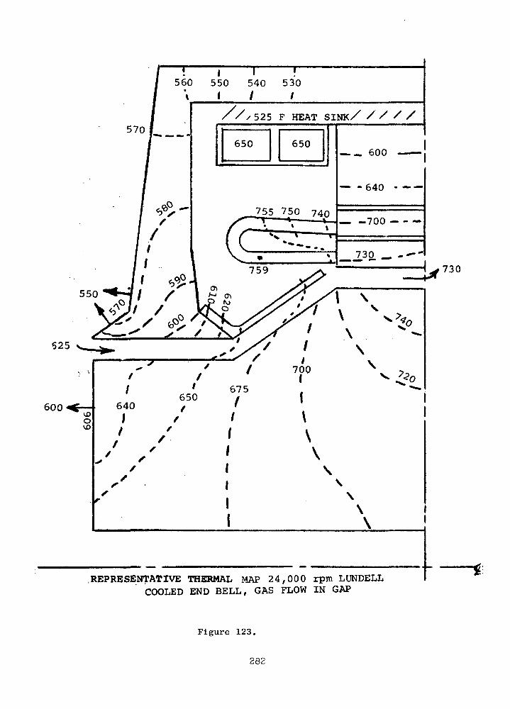
570
550
525
600
730
/•//525 F HEAT SINK/ / / / /
.REPRESENTATIVE THERMAL MAP 24 ,000 rpm LUNDELLCOOLED END BELL, GAS FLOW IN GAP
Figure 123.
282

550 540 570
I
1 525 F HEAT SINK/ / / / /
. 580
1600
620
640
550
580
600
REPRESENTATIVE THERMAL MAP 24 ,000 rpm LUNDELLCOOLED END BELL, GAS FLOW IN GAP
Figure 124.
283
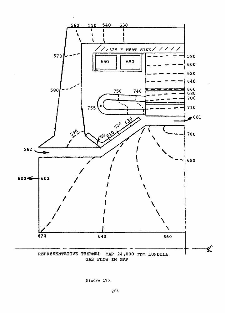
560 550 540 530
///525 F HEAT SINK/ / / / /
600
582
600
REPRESENTATIVE THERMAL MAP 24 ,000 rpm LUNDELLGAS FLOW IN GAP
Figure 125.
284
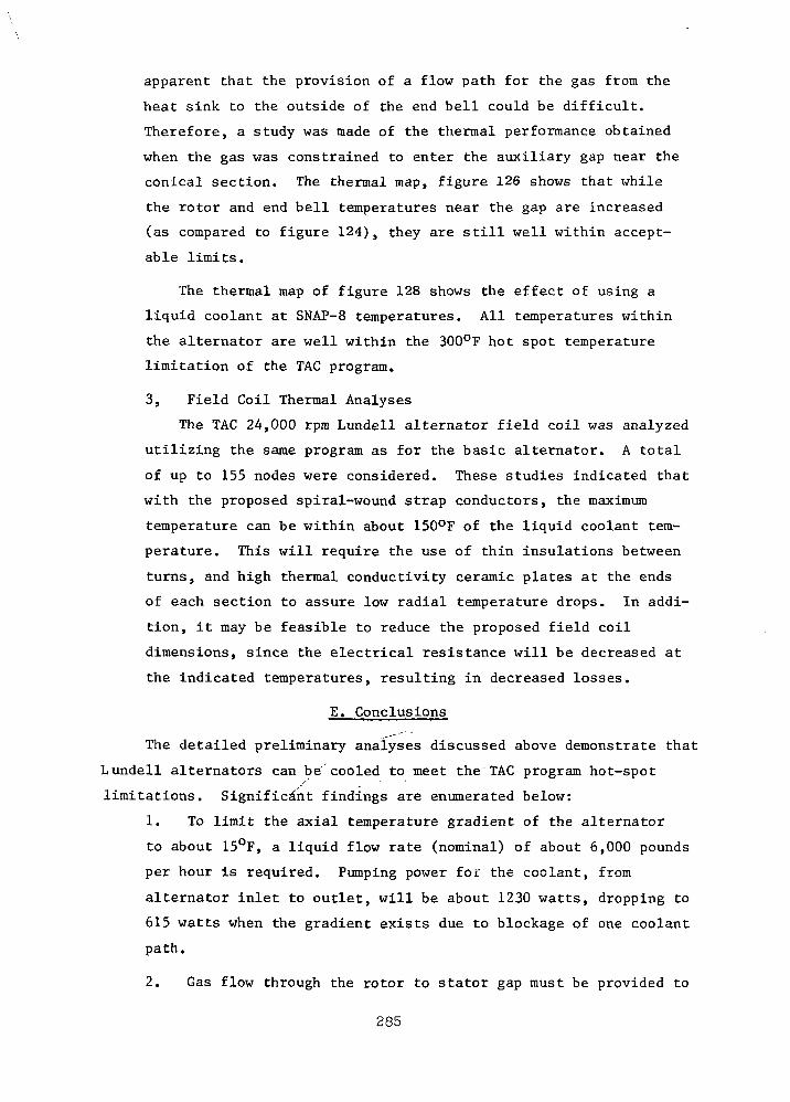
apparent that the provision of a flow path for the gas from the
heat sink to the outside of the end bell could be difficult.
Therefore, a study was made of the thermal performance obtained
when the gas was constrained to enter the auxiliary gap near the
conical section. The thermal map, figure 126 shows that while
the rotor and end bell temperatures near the gap are increased
(as compared to figure 124), they are still well within accept-
able limits.
The thermal map of figure 128 shows the effect of using a
liquid coolant at SNAP-8 temperatures. All temperatures within
the alternator are well within the 300°F hot spot temperature
limitation of the TAG program.
3, Field Coil Thermal Analyses
The TAG 24,000 rpm Lundell alternator field coil was analyzed
utilizing the same program as for the basic alternator. A total
of up to 155 nodes were considered. These studies indicated that
with the proposed spiral-wound strap conductors, the maximum
temperature can be within about 150°F of the liquid coolant tem-
perature. This will require the use of thin insulations between
turns, and high thermal conductivity ceramic plates at the ends
of each section to assure low radial temperature drops. In addi-
tion, it may be feasible to reduce the proposed field coil
dimensions, since the electrical resistance will be decreased at
the indicated temperatures, resulting in decreased losses.
E. Conclusions
The detailed preliminary analyses discussed above demonstrate that
Lundell alternators can be'cooled to meet the TAG program hot-spots' -
limitations. Significant findings are enumerated below:
1. To limit the axial temperature gradient of the alternator
to about 15°F, a liquid flow rate (nominal) of about 6,000 pounds
per hour is required. Pumping power for the coolant, from
alternator inlet to outlet, will be about 1230 watts, dropping to
615 watts when the gradient exists due to blockage of one coolant
path.
2. Gas flow through the rotor to stator gap must be provided to
285
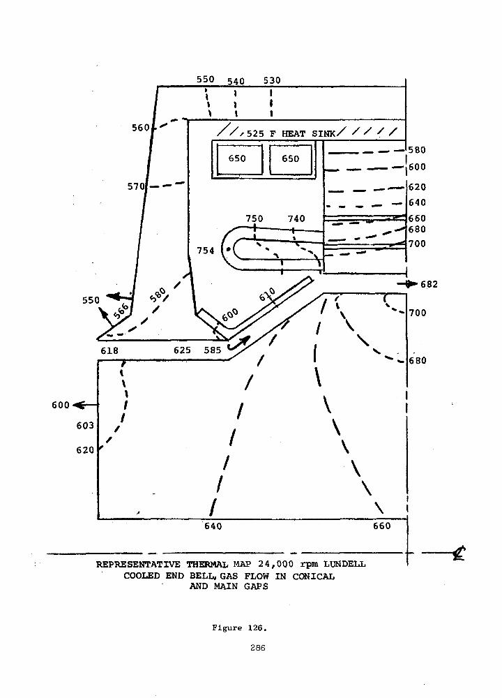
550 54Q 530
560
550
X/x525 F HEAT SINK/ / /
600
REPRESENTATIVE THERMAL MAP 24,000 rpm LUNDELLCOOLED END BELL, GAS FLOW IN CONICAL
AND MAIN GAPS
Figure 126.
286
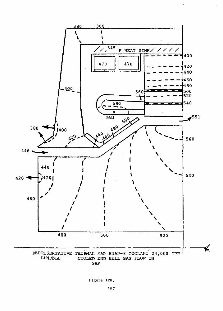
380 360
f v>
U>°
•
1\
& i//x345
470
F HEAT SINK/ / / / /
470
560
/^~ £U~5-2°-,v •
1 col1
:::::::400
420440
460480500520
540
380
^446 s^.
420 ^r-
460
**-J;4oo ^y /< (
X ?'' &r/f v ^-' * t\' /" ' \-^ //' ' \• "•' r / ' \H / / \ v-''' / i \
/ ' x
/ ' x
/ ' \480 500 520
REPRESENTATIVE THERMAL MAP SNAP-8 COOLANT 24,000 rpmLUNDELL COOLED END BELL GAS FLOW IN
GAP
560
540
r/5
$t
Figure 128.
287

limit the rotor temperature to 700°F. Pumping for this flow can be
obtained by placing a conical baffle over the conical portion of
the rotor.
3. The "air" gap gas flow can be restricted to the conical and
main gap regions with little effect upon the rotor temperature.
4. Addition of liquid coolant passages in the end bells has no
significant effect on rotor cooling. However, such coolant pass-
ages could reduce the axial temperature gradient caused by loss of
one of the redundant cooling flows.
5. Hot spot temperatures, occuring in the armature winding end
turns, will be less than 300°F above the liquid coolant tempera-
ture.
6. Field coil temperatures will not exceed the hot spot tempera-
ture specified for the TAG alternator.
7. If the coolant temperature is changed (e.g., SNAP-8 coolant),
all alternator temperatures will change by approximately the same
magnitude. However, some deviation from the patterns will result
from changes in the losses due to temperature level.
REPRESENTATIVE DESIGNS
This section summarizes details of the two final Lundell alternator
designs and the final inductor alternator design to facilitate direct
comparisons. The design performance and machine details are presented
in Table XXXVIII. Figures 87, 91 and 101 are the configuration layouts
for the three designs. The ballooned numbers in these figures relate to
the materials used for the indicated areas, the materials list being
provided in Table XLVII. As seen on the figures, the basic alternator
is made up of the rotor, the magnetic frame, the Hiperco-27 stacks, the
armature coils, and the field coils. The rest of the configuration
around these fundamental components are to transfer the coolant in and
out, transfer the power out and support the stator and rotor. The
mounting of the bearing housings to the stator frame is a part of the
total TAG configuration (not shown) and is done by mechanically
fastening directly to the magnetic frame to utilize the structuralrigidity associated with the relatively large magnetic frame.
288
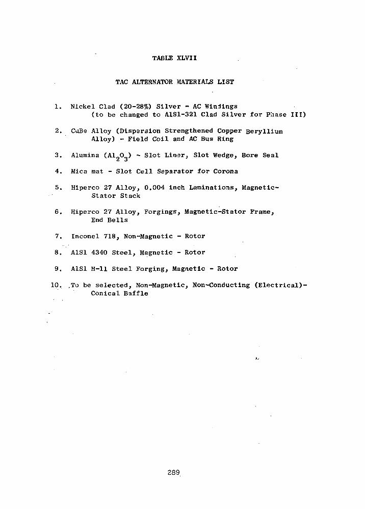
TABLE XLVII
TAC ALTERNATOR MATERIALS LIST
1. Nickel Clad (20-28%) Silver - AC Windings(to be changed to A1S1-321 Clad Silver for Phase III)
2. CuBe Alloy (Dispersion Strengthened Copper BerylliumAlloy) - Field Coil and AC Bus Ring
3. Alumina (Al O ) - Slot Liner, Slot Wedge, Bore Seal
4. Mica mat - Slot Cell Separator for Corona
5. Hiperco 27 Alloy, 0.004 inch Laminations, Magnetic-Stator Stack
6. Hiperco 27 Alloy, Forgings, Magnetic-Stator Frame,End Bells
7. Inconel 718, Non-Magnetic - Rotor
8. A1S1 4340 Steel, Magnetic - Rotor
9. A1S1 H-ll Steel Forging, Magnetic - Rotor
10. ,To be selected, Non-Magnetic, Non-Conducting (Electrical)-Conical Baffle
289
The armature coil leads pass through end bell (or not at all) to
the bus rings. In passing through the end bell, one-half inch spacing
is required around each lead. This is to minimize eddy current heating
due to the high frequency alternating flux surrounding the lead. This
half-inch spacing is adhered to as a general rule for all the electri-
cal leads of the ac armature coil.
The stators are hermetically sealed by the can mounting the termi-
nals. This hermetic shroud is a thin wall reinforced can whose thick-
ness is 30 to 40 mils. There are reinforcing rings around the can.
The stator punchings are 0.004 inch thick Hiperco-27 magnetic
alloy, have a semi-closed slot to reduce pole face losses, and are
assembled into an unwelded stack to reduce iron losses. A 0.0004 inch
thick layer of plasma-arc sprayed alumina constitutes the interlaminar
insulation. The small block of material shown dotted on the ends of
the stacks are small tabs on the ends of the slot liners. Those hold
and align the unwelded stacks preventing the thin teeth from flaring
excessively. The bottom slot liner must be slit into an "L" shape in
order for the slot liner to be assembled into the semi-closed slot.
The upper slot liners are "U" shaped and can be assembled from the ends
of the stack at the time of winding.
The field coil is wound into series connected toroids of flat
straps. They are electrically insulated from each other and the cool-
ing ducts. There is a flat-to-round transition section between each
coil bundle and terminal.
There are four bus rings in each generator. The parallel phase
groups of the armature are connected to each bus ring in such a
manner that the bus ring I^R losses are held to a minimum which in
turn permits the rings to be cooled by radiation to the stator cavity
walls. The maximum bus ring temperature can be expected to be less
and 800°F with a 500°F sink temperature. The bus rings are supported
by ceramic insulation and a mechanical mount as illustrated in the
various views. The rings are not continuous rings, but are partial
arcs to permit thermal expansion without diametral growth. The
insulation pieces are spaced quite widely on the rings to permit a
good field of view for radiation cooling. The leads come directly off
290
the armature coil into bus rings as seen in the figures and the exposed
lead ends are bonded into the bus rings. This is important to the
design of the alternator since it simplifies making a sound electrical
joint at the time of final assembly. This is even more important
should it be necessary to bake out the Anadur and fire it prior to
assembly of the windings. This pre-bake will obtain a better slot fit-
up at assembly by accounting for the 35 percent Anadur shrinkage prior
to winding. Thus, by attaching the wire ends to the bus rings in
readily accessable areas, bonding problems are minimized.
There is one terminal per bus ring, centrally located about the
armature connections. Because of the temperatures brought on by the
high current density and because of the limited space, special terminal
studs are required. They are sized rather large to have sufficient
cross sectional area to permit them to be self cooled by radiation.
Nickel plating is used to obtain an emmisivity of 0.4 on the outer
surfaces. They can be cooled by radiation alone to less than 800°F
in a 500°F ambient.
The features of the rotor design are found in the bonded construc-
tion and slotted pole faces. The slotted pole faces have 0.006 wide by
0.100 inch deep slots, approximately 30 per inch, that are cut with
gangs of carbide cut-off wheels. The process for doing this has
previously been developed by Westinghouse.
The central hole shown dotted in the rotor core serves an assembly
function. It is not used for cooling and may not be necessary for the
heat treatment to obtain the desired hardnesses. The angled lines,
also dotted, on the two Lundells illustrate the minimum volume needed
for magnetic flux carrying purposes.
The cooling system for the Lundell alternators (figures 87 and
91 utilizes the non-magnetic separation between the stacks and the
frames. For each machine, this member would be constructed in two
sections, one for each half of the stack. Liquid coolant flows
through helical grooves near the inner surfaces, parallel grooves in
each part being provided to meet the redundant cooling system require-
ment. The finned outer portion of this separator provides cooling
passages for gas pumped by the rotor's conical sections from the end
291
bell to the center of the stack. The gas will transport pole face and
windage losses from the "air"-gap to the separator, providing rotor
cooling without overheating of the stator armature windings. The
baffles (item 10) are required to assure and direct the pumping action
noted above.
The stator can be assembled as a unit separate from the rotor and
stub shaft assemblies. This is an important feature for assembly into
the TAG or for separate assembly for TAX pre-assembly tests. The
alternator is mounted to the TAG through conical frames that mechanical-
ly attach the magnetic frame.
Most of the tubing for coolant flows, leads, etc., are not shown
precisely due to the lack of definition at this stage of the design.
The few tubes shown will actually be parallel tubes spaced 180 degrees
apart to equalize the disturbances due to the penetrations. This
equalizing rule will be adhered to for all penetrations in general.
The summary data for the three representative designs shown are
listed on Table XXXVIII. The losses of the bearings and seals and the
weights for the stub shafts, bearings, bearing housings, etc., are not
included herein.
OVERALL CONCLUSIONS
The recommended alternator design is the 24,000 rpm, 6-pole Lun-
dell at 120 volts (L-N), the latter being limited by corona considera-
tions which in turn limits the minimum stator cavity pressure (and
minimum system pressures indirectly) to 16 psia. Testing is recom-
mended to verify this prior to "freezing" the minimum specified
pressure. The rotor for this configuration is constructed of SAE 4340
and Inconel 718, diffusion bonded and hardened to 33 Rc and 38 RC
respectively in an autoclave. The hardness requirements are dictated
by the strength requirement and are within the realm of practicality
for hardening as a bonded unit within the autoclave. No significant
gains could be identified utilizing other magnetic materials having
superior magnetic properties or more compatable "heat-treat-as-a-unit"
characteristics.
The impact of designing without a central hole in the rotor was
292
found to be significant to the design choice. With the hole, the
36,000 rpm designs are overstressed and impractical; the 24,000 rpm
designs require the magnetic steel to be hardened to 33 RC. Without
the hole, the 3 6,000 rpm Lundell only requires hardening the 4340 to
33 R to make it strong enough; the 24,000 rpm Lundell 4340 may be left
in a fully annealed state (RCH) for adequate strength.
Windage losses are well below the 9.6 kW limit but are very signi-
ficant to the choice of cooling configuration. A circulating gas,
completely within the alternator, is required to limit hot spot and
rotor temperatures below safe levels. This gas flow is generated by
the dynamic head created in the conical sections of the rotor and the
flow need not pass through the auxiliary air-gap sections for adequate
cooling. Preliminary calculations indicate the inherent gas flow to
be two times the minimum requirement.
End-bell cooling appears to be unnecessary but is being retained
for further study in Phase III relative to redundancy requirement in
case only one of the two parallel cooling paths is operative.
The alternator meets electrical specifications but we expect to
see further improvements in the Phase III design. In particular, the
8.9 percent calculated voltage unbalance appears to be conservatively
high and, with improved calculation techniques, should drop below the
6 percent goal. Also, the efficiency at 1/4 P.U. load will be
improved low-load performance.
The location of electrical leads, bus rings, terminals and cool-
ing tubes are significant to the TAG assembly configuration. Prelim-
inary agreement on basic configurations must be reached early in
Phase III prior to initiating the detailed design analyses as their
location can affect all components with the TAG unit.
293
E. BEARING AND SEAL DESIGNS
INTRODUCTION AND SUMMARY
This chapter of the report describes and provides the results of the prelimi-
nary analysis that was conducted under Phase I of Contract NAS3-13449, to
select journal and thrust bearings for the 24,000 rpm TAG. Table XLVIII itemizes
the principal factors that were included in this analysis.
Primary emphasis in the selection of both the journal and thrust bearings
was placed on achieving ample load capacity margin against transient and
dynamic loads. In particular, the bearings were sized to support a 4 G.
load while still maintaining a conservatively high value of the film thick-
ness both at design speed and in the overspeed range. The calculations of
bearing performance were made both for the full power, 160 KW(e), and the one-
quarter power, 40 KW(e), TAG output levels. To permit optimum,overall de-
sign of the TAG, all bearing cavities were maintained at compressore inlet
pressure, i.e.,55 psia at 160 KW(e) and 15 psia at 40 KW(e).
The bearing types and sizes selected, based on the performance calculations
over the full range of operating conditions of the TAG were as follows:
Journal Bearings: Type - tilting pad
294
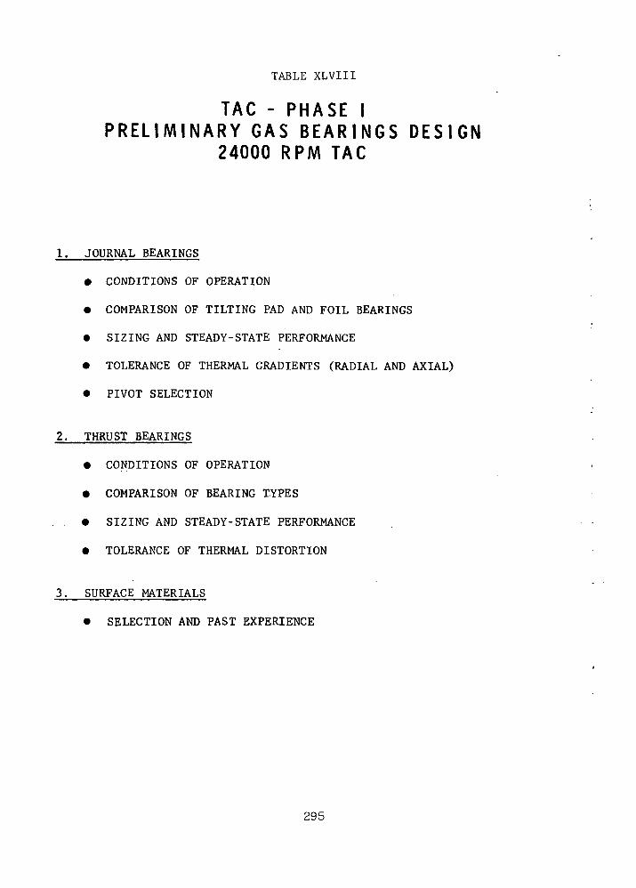
TABLE XLVIII
TAG - P H A S E IP R E L I M I N A R Y G A S B E A R I N G S D E S I G N
24000 RPM TAG
1. JOURNAL BEARINGS
• CONDITIONS OF OPERATION
• COMPARISON OF TILTING PAD AND FOIL BEARINGS
• SIZING AND STEADY-STATE PERFORMANCE
• TOLERANCE OF THERMAL GRADIENTS (RADIAL AND AXIAL)
• PIVOT SELECTION
2. THRUST BEARINGS
• CONDITIONS OF OPERATION
• COMPARISON OF BEARING TYPES
. • SIZING AND STEADY-STATE PERFORMANCE
• TOLERANCE OF THERMAL DISTORTION
3. SURFACE MATERIALS
• SELECTION AND PAST EXPERIENCE
295
Size - 4" diameter x 3" long
Thrust Bearing : Type - double acting (equal forward and reverse faces),
helical grooved
Size - 8" O.D. x 4 1/4" I.D.
The preliminary bearing analysis reported herein, which is based on existing
and well proven gas bearing theory, did not reveal any serious problems and
showed that reliable, conservatively sized gas bearings can be designed and
built for the TAG. It should be observed, however, that the 4 G load re-
quirement imposed to meet the orbital requirements described in NASA Speci-
fication No. P2241-1, results in loads of 320 Ibs. on the journal bearings and
640 Ibs. on the thrust bearing. These loads are greater, by about a factor
of four, than those carried under steady state conditions on self-acting gas
bearings in earlier turbomachinery. In this sense, the TAG bearings repre-
sent an extension over past laboratory-test and field experience. Later this
year, tests are to be conducted at MTI with gas lubricated bearings carrying
loads comparable to those of the -TAG, in connection with the development of
gas bearings for an advanced air breathing engine (Army Contract DAA 302-69-C-
0062). These tests should serve to assess whether any currently unanticipated
problem areas will result from the high bearing loads.
Consideration was also given in this preliminary study to the selection of
surface materials capable of withstanding, without damage, dry starts and
* Under 4 G load at 15 psia ambient pressure this bearing is marginal and mayhave to be increased in size. All other bearings satisfy the criterion es-tablished for load capacity that h . > 10" D under 4 G load, where h . is
the minimum film thickness and D is the bearing diameter (the outer diameterin the case of the thrust bearings).
296
stops as well as incidental, short duration impacts at design speed. Self-
mated chrome oxide is the preferred materials combination for the TAG bear-
ings, based on the earlier experimental studies of gas bearing materials con-
ducted for the NASA and its excellent performance in the NASA's "A" Engine
turbocompressor simulator and turboalternator, as well as several other gas
bearing turbomachines.
297
GAS JOURNAL BEARINGS
Operating Conditions
The conditions of operation of the gas lubricated journal bearings are shown
in Table XLIX for the 160 KW(2) and the 40 KW(e) power levels. The design
point speed is 24,000 rpm, however, the bearings must be capable of stable
operation and support of the applied loads over the speed range from 50 per-
cent to 120 percent of design speed.
The bearing cavities will be maintained at compressor inlet pressure, i.e.,
the ambient pressure of the bearings will be 55 psia at 160 KW(e) and 15 psia
at 40 KW(e).
The bearings are subjected to a number of load components as follows:
a. Gravity Load
The rotor weight is approximately 160 Ibs., with the center of gravity
of the rotor at about the mid point of the span between journals. Thus,
when the TAG operates horizontally in a 1 G field, the gravity load will
be about 80 Ibs. per bearing. When TAG operates vertically in a 1 G
field or in any orientation in a 0 G field, there is no gravi.ty load com-
ponent on the journal bearings.
b. Alternator Load
An estimate of the force gradient due to displacement of the center of
rotation and the magnetic center of the alternator was requested from
Westinghouse. Mr. A. King of Westinghouse estimated that this gradient
will be about 34 Ibs/mil at full power [160 KW(e)] and 8.5 Ibs/mil at
298

TABLE XLIX
TAG - PHASE IGAS LUBRICATED JOURNAL BEARINGS FOR 24000 RPM MACHINE
1. CONDITIONS OF OPERATION
160 KW(e)
DESIGN POINTS
OG OR 1G VERTICAL
1G HORIZONTAL
OPERATING RANGE
LOADIbs.
0
80
0 to 165*
SPEEDrpm
24000
24000
12000 to 28800
AMBIENT PRESSUREpsia
55
55
55
40 KW(e)
DESIGJJ_PO_INTS
OG OR 1G VERTICAL
1G HORIZONTAL
OPERATING RANGE
LOADIbs.
0
80
0 to 102*
SPEEDrpm
24000
24000
12000 to 28800
AMBIENT PRESSUREpsia
15
15
15
ORBITAL LOAD: 320 Ibs. (MAXIMUM) IN PREFERRED DIRECTION120 Ibs. (MAXIMUM) ALONG OTHER AXES
LUBRICANT He - Xe MIXTURE, MW = 39.94
* INCLUDED ALTERNATOR LOAD CORRESPONDING TO 5 mils MAXIMUM DISPLACEMENT OFMAGNETIC CENTER. ALTERNATOR GRADIENT = 34 Ibs/mil AT 160 KW(e) AND 8.5Ibs/mil AT 40 KW(e) .
299
quarter power [40 KW(e)].
The displacement of the center of rotation relative to the magnetic
center of the alternator will be a function of several factors includ-
ing:
• Manufacturing and assembly tolerances of the alternator stator
and rotor.
• Manufacturing and assembly tolerances of the bearings.
• Assembly tolerance of bearing center relative to alternator
center.
• Static deflection of the rotor between the alternator center and
the bearing centers.
• Eccentricity of the journal in the bearing clearance.
• Deflection of the bearing supports.
• Additional eccentricity due to differential radial thermal growths
between the alternator housing and the bearing housing.
In the preliminary design analysis conducted under Phase I, it has been
assumed that the total eccentricity between the center of rotation and
the magnetic center due to the above causes can be limited to about 5
mils leading to a maximum additional load of 85 Ibs/bearing at 160 KW(e)
and 22 Ibs/bearing at 40 KW(e) power levels.
c. Aerodynamic Unbalance Load
If the gas pressures are not uniform circumferentially around the turbine,
compressor and seals, there will be a corresponding radial load component
.'n the journal bearings. Such non-uniformity of the pressures should be
300

very small so that the bearing load component from this source is not
expected to be significant, when compared with the gravity and magnetic
load components.
d. Orbital Loads
A requirement of specification P2241-1 is that subsystems and components
shall be capable of operating under acceleration loads of 3.5 G in one
direction along the lift-off axis and + 1 G in all directions in the
plane normal to the lift-off axis, for short durations up to 5 minutes.
In addition, short duration vibration loads of 0.25 G peak-to-peak must
be supported in each of three mutually perpendicular axes. The sub-
systems and components must also be capable of withstanding a continuous,
unidirectional acceleration arising from a 4 rpm spin rate of the space-
craft, the corresponding G loading being a function of the radial loca-
tion of each subsystem or component with respect to the spin axis.
In view of these requirements and since the location and orientation of
the Tac in the space vehicle are not yet defined, the bearings should be
designed to support a 4 G load along the axis of the TAC as well as in
one radial direction, and 1.5 G in the other radial directions. This
operating condition is noted in Table XLIX.
e. Mechanical Unbalance Loads
Dynamic loads will be imposed on the radial bearings of the TAC due to
any mechanical unbalance in the rotor. These loads will be a function
of the magnitude and location of the unbalance, as well as of attenua-
301
tion or amplification factors that depend on the proximity of critical
speeds. These dynamic loads are computed in the rotor response calcu-
lations.
Alternate Journal Bearing Types
The Work Statement specifies that the TAG units requiring gas lubrication
shall employ hydrodynamic gas journal and thrust bearings. In the case of
the journal bearings, foil type bearings (of the type that Ampex Corporation
is currently studying under a separate NASA contract) and tilting pad bearings
are to be studied. Gas bearing designs that do not require hydrostatic jack-
ing are preferred.
Figure 129 illustrates schematically the two types of journal bearings. The
foil bearing (left hand side of Figure 129) consists of a thin strip of metal-
lic foil that is wound around the pins to form three support pads. After
the desired tension is achieved, the pins are used to clamp the ends of each
pad of the foil bearing. Parallelism between the pins is important to main-
tain constant tension axially along the foil.
The tilting pad bearing (right hand side of Figure 129), consists of a number
(generally 3 or 4) of individually pivoted pads. Spherical pivots (or flex-
ure pivots as described later in this section of the report) are used to
provide self-alignment capability in addition to allowing the pads to incline
circumferentially. The pivots are attached to the housing, generally by
means of beam type flexures. In order to allow for relative thermal growths
between the housing and the rotor, one or more pads are supported on rela-
302

o
as
IazM
5
0. <LU
I QQ
O -J
=3O
CNI
t—t
0)
60•r-lPu
wCO
.Jl-lo
303
tlvely soft flexure beams.
Both bearing types have very high thresholds of instability, as required in
high speed turbomachinery and, particularly, for space operation where stable
operation is necessary even under zero applied load.
Both bearing types also afford good tolerance of relative thermal growths be-
weeh the rotor and the bearing housing. In the*case of the tilting pad bear-
ing, this is achieved by the flexure mounting of one or more pads, so that the
| relative growth is taken up^principally by the deflection of the pad support.
In the case of the foil bearing, the relative thermal growth is taken up
largely by extension of the foils.
The comparison between the two bearing types was made on the basis of:
i . , . . ... ;a. The current ••• status of the two bearing types and the extent of devel-
opment required in each case for the TAG application and,
t
b. The calculated steady state performance at design point and under
4 G load, in each case.
? The first'of'these is,,illustrated in Table L. The principal point of the com-\ . ~
parison is that the tilting pad bearing is, presently, a well developed bear-
ing that has been extensively used in prior gas bearing turbomachinery, while
the foil bearing is still a relatively new, although very promising concept
for such applications. The areas of technology development that need to be
pursued in the near future in order to develop the foil bearing for space
power turbomachinery are listed in Table L.
304

TABLE L
TAG - PREL IMINARY JOURNAL BEARINGS DESIGNC O M P A R I S O N OF TILTING PAD AND FOIL BEARINGS
A. CURRENT STATUS AND REQUIRED DEVELOPMENT
TILTING-PAD BEARING FOIL BEARING
STATUS
TURBOMACHINERYAPPLICATIONS TODATE
TECHNOLOGYDEVELOPMENTAREAS
DEVELOPED BEARING CONCEPT,WIDELY USED IN HIGH-SPEED,GAS LUBRICATED TURBOMACHINERY
FOR NASA. L.R.C.:
"A" ENGINE RADIAL TURBOCOM-PRESSOR
"A" ENGINE TURBOALTERNATOR"A" ENGINE. AXIAL'-TORBOCOM-
PRESSOR"B" ENGINE - BRU "
OTHER:
24000 RPM, 1100 F, N2 TURBO-COMPRESSOR
120 LBS. ROTOR, 24000 RPMATR COMPRESSOR
VARIOUS MOTOR-DRIVEN, NUCLEARLOOP COMPRESSORS
1. MATERIALS RELIABILITY
IN EXPERIMENTAL DEVELOPMENTSTAGE
FOR NASA. L.R.C.:
SMALL,.HIGH-SPEED ROTORTESTS
OTHER; .
SMALL (< 20 LBS.) ROTORS
1. REDUCED BEARING DEFLEC-TIONS AND DYNAMIC ROTOR,ORBITS : ' '' ''"
2. COATED FOIL MATERIALS3. REDUCED START-UP PRELOAD4. SELF-ALIGNMENT5. JACKING THROUGH STATION-
ARY MEMBERS6. GENERALIZED ANALYSIS
POTENTIAL OF FOIL BEARING: VERY HIGH TOLERANCE OF OFF-DESIGN CONDITIONS DUE TO"CONFORMABLE" BEARING SURFACE.
305

The second comparison required calculation of the performance of the two bear-
ing types. This was done utilizing our computer programs for tilting pad and
foil bearings. The computer program for tilting pad bearings has been used
extensively during the design of the NASA's "A" Engine bearings (Refs. 40 and
41) and the back-up bearings of the "B" Engine, as well as other gas bearing
turbomachinery. It provides accurate data that has correlated very well with
laboratory tests and field experience obtained with pivoted-pad gas bearings.
The foil bearing program was used during/an analytical study of foil bearings
for very high operating temperatures -(up to 1400 F) and in the presence'of
large thermal gradients (up to 400 F between shaft 'and housing) that was con- -.
ducted for the NASA (Ref. 42). First, however, the foil bearing program was
revised and up-dated to ••incorporate the. more recent analysis developed at Ampex
Corporation under their study and test of this bearing type for the NASA (Ref.
43). The accuracy of the up-dated; foil-bearing program-was -then tested againsj:
the experimental results of Ref. .43. ' "- • '.: ' :
t. •
Figure 130 is a plot of th'is comparison and it shows that the calculated film .
thickness is generally smaller than the measured one. The experimental data,:' '; f
however, shows significant',.differences. between the film thicknesses measured
in the three pads that support the vertical rotor, so that there may have been-- * * '' ~
some differences" in fcervsion be'tweefr "the three pads during.the test. At the
bottom of Figure 130 the comparisons between measured and•calculated critical
speed and amplitude amplification factors are given. Since the test rotor
was completely rigid over the test speeds, the critical speed comparison is
a good assessment of the calculated foil bearing stiffness. As noted, the
measured and calculated critical speeds (and, hence, foil bearing stiffnesses)
correlate very well.
306

£
TJ
vOm<f
O-j uj< O
o u.UJ OC
o_ a:
UJ
s*u. <
Q. Q-
oO "
OSoQ-WBJ
I
QOvD
HB:2aB:x
B-£<
Ooe
OS
sX
wa.
OSo
zoMH
U
PM
<
O
z
oooo
oV
B;o
o-
A30-
l-so wPi
•
oo
u"> O•-i C
oo oo
II It
u o
H Q
3s
'SS3NXOIHI
307
Similarly, the comparison of measured and calculated amplification factors is
a good comparison of measured and calculated foil bearing damping. As noted
in Figure 130, the calculated amplitude magnification factor (Q) was 13.8. The
test data of Ref. 43, did not provide an exact, measured value of this factor
since the residual unbalance in the tests was extremely small and could only
be ascertained as being less than 0.8 x 10 oz-in. Thus, the test data could
be used only to set a lower bound on the amplification factor. On this basis,
the test data shows only that the experimental factor was equal to or greater
than 6.5. This does not contradict the calculated value of 13.8.
Based on the above described comparison with the test data of Ref. 43, the foil
bearing computer program appears to provide reasonable and conservative esti-
mates of steady state performance so that it can be used to estimate foil bear-
ing performance.
The comparison of the calculated performance of tilting pad and foil bearings
for the TAG application is given in Table LI. This comparison was based on a
3 pad tilting pad bearing, 4" diameter x 3" long with a radial clearance of
1.4 mils at 24,000 rpm and zero applied load. The foil bearing was a 3 pad,
4" diameter x 4" long bearing using 3.5 mils thick steel foil with an initial
tension of 30 Ibs. In general, the comparison shows that the foil bearing has
*somewhat smaller calculated film thickness and higher power loss . However,
the calculated data on stiffness and damping of both bearings appears to be
of satisfactory magnitude for good rotor dynamic performance.
* This can be improved by using thinner foils and lower initial tension. Ananalytical and experimental study would probably be required to select op-timum foil bearing geometry, foil thickness, material, and initial tensionfor the TAG application.
308
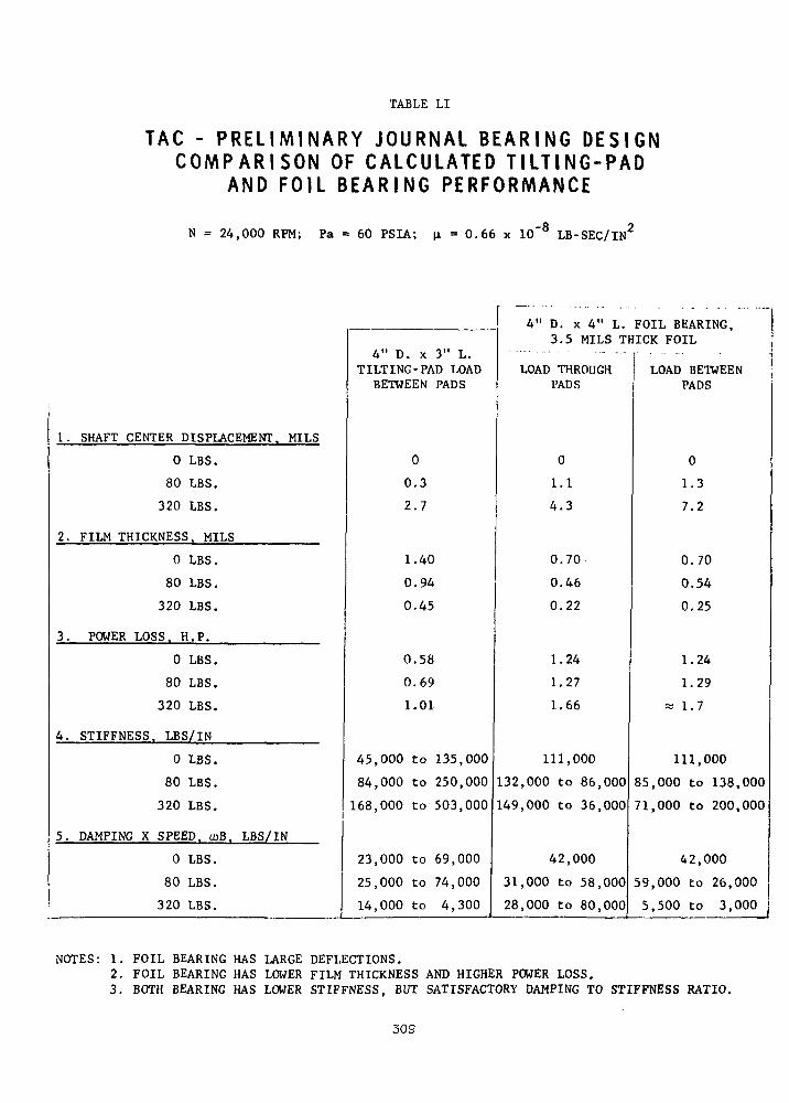
TABLE LI
TAG - P R E L I M I N A R Y JOURNAL B E A R I N G D E S I G NC O M P A R I S O N OF C A L C U L A T E D T I L T I N G - P A D
AND FOIL B E A R I N G PERFORMANCE
N = 24,000 RPM; Pa = 60 PSIA; = 0.66 x 10~8 LB-SEC/IN2
1. SHAFT CENTER DISPLACEMENT. MILS
0 LBS.
80 LBS.
320 LBS.
2. FILM THICKNESS, MILS
0 LBS.
80 LBS.
320 LBS.
3. POWER LOSS, H.P.
0 LBS.
80 LBS.
320 LBS.
4. STIFFNESS. LBS/IN
0 LBS.
80 LBS.
320 LBS.
5. DAMPING X SPEED. ooB. LBS/IN
0 LBS.
80 LBS.
320 LBS.
4" D. x 3" L.TILTING-PAD LOAD
BETWEEN PADS
0
0.3
2.7
1.40
0.94
0.45
0.58
0.69
1.01
45,000 to 135,000
84,000 to 250,000
168,000 to 503,000
23,000 to 69,000
25,000 to 74,000
14,000 to 4,300
4" D. x 4" L.3.5 MILS Tl
LOAD THROUGHPADS
0
1.1
4.3
0.70
0.46
0.22
1.24
1.27
1.66
111,000
132,000 to 86,000
149,000 to 36,000
42,000
31,000 to 58,000
28,000 to 80,000
FOIL BEARING,iICK FOIL
-
LOAD BETWEENPADS
0
1.3
7.2
0.70
0.54
0.25
1.24
1.29
« 1.7
111,000
85,000 to 138,000
71,000 to 200,000
42,000
59,000 to 26,000
5,500 to 3,000 j
NOTES: 1. FOIL BEARING HAS LARGE DEFLECTIONS.2. FOIL BEARING HAS LOWER FILM THICKNESS AND HIGHER POWER LOSS.3. BOTH BEARING HAS LOWER STIFFNESS, BUT SATISFACTORY DAMPING TO STIFFNESS RATIO.
309

For the present, we recommend that the tilting pad bearing be used as the pri-
mary journal bearing for the TAG, based principally on the fact that it satis-
fies the required criteria on load capacity and stability and is much further
advanced than the foil bearing. The latter, however, should be retained as a
retro-fittable alternate bearing, pending the results of the future development
efforts. Table LII summarizes the conclusions drawn from the comparative study
of the two bearing types.
Calculated Bearing Performance
Table LIII shows the design targets established for the tilting pad journal bear-
ings. The objective of these design targets was to provide a bearing system
that can tolerate the specified conditions of operation safely and without mar-
ginal performance. The requirement for zero preload at start-up was imposed
in order to minimize or altogether eliminate the need for hydrostatic jacking.
Table LIV lists the important performance characteristics of the journal bearings
that need to be satisfied or optimized during the final design of the bearings.
The principal design variables that have to be selected to satisfy or optimize
the various performance characteristics are also listed in Table LIV. Pending
detailed optimization studies, the following values of the design variables
were selected:
Diameter ,. : 4" - selected based on rotor-dynamic studies
Length : 3" - minimum required' for adequate load capa-1 ; '
..;. city under 4-G condition
Number of Pads : 3 or 4 - see comparison in Table LV.
Machined Clearance Ratio : 0.0025 in/in at design point - nominal value
.used in prior turbomachinery
310
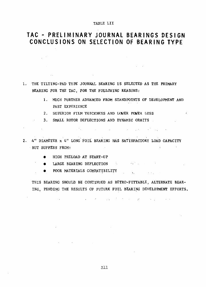
TABLE LII
TAC - P R E L I M I N A R Y JOURNAL B E A R I N G S D E S I G NC O N C L U S I O N S ON SELECTION OF B E A R I N G TYPE
1. THE TILTING-PAD TYPE JOURNAL BEARING IS SELECTED AS THE PRIMARY
BEARING FOR THE TAC, FOR THE FOLLOWING REASONS:
1. MUCH FURTHER ADVANCED FROM STANDPOINTS OF DEVELOPMENT AND
PAST EXPERIENCE
2. SUPERIOR FILM THICKNESS AND LOWER POWER LOSS
3. SMALL ROTOR DEFLECTIONS AND DYNAMIC ORBITS
2. 4" DIAMETER x 4" LONG FOIL BEARING HAS SATISFACTORY LOAD CAPACITY
BUT SUFFERS FROM:
• HIGH PRELOAD AT START-UP
• LARGE BEARING DEFLECTION -
• POOR MATERIALS COMPATIBILITY
THIS BEARING SHOULD BE CONTINUED AS RETRO-FITTABLE, ALTERNATE BEAR-
ING, PENDING THE RESULTS OF FUTURE FOIL BEARING DEVELOPMENT EFFORTS.
311
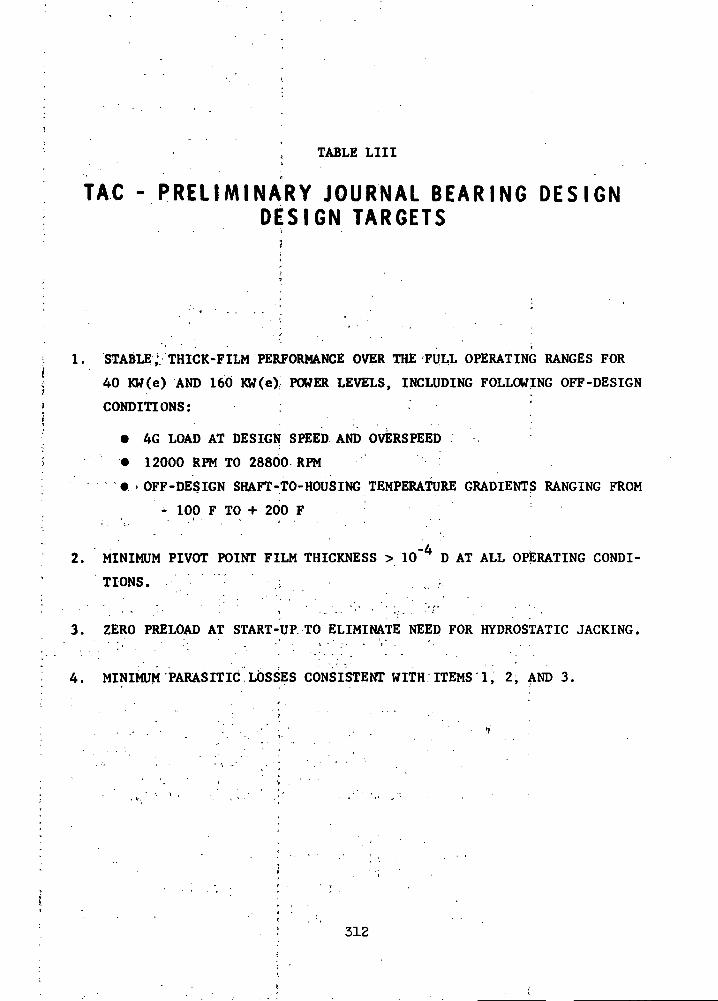
TABLE LIII
TAG - PRELIMINARY JOURNAL BEARING DESIGNDESIGN TARGETS
i. STABLE; THICK-FILM PERFORMANCE OVER THE FULL OPERATING RANGES FOR40 KW(e) AND 160 KW(e) POWER LEVELS, INCLUDING FOLLOWING OFF-DESIGN
CONDITIONS:
• 4G LOAD AT DESIGN SPEED AND OVERSPEED .
• 12000 RPM TO 28800 RPM
- - ' • « > OFF-DESIGN SHAFT-TO-HOUSING TEMPERATURE GRADIENTS RANGING FROM
- 100 F TO + 200 F
2. MINIMUM PIVOT POINT FILM THICKNESS > 10"4 D AT ALL OPERATING CONDI-
TIONS.
UP TO ELIMINATE NEED FOR HYDROSTATIC JACKING.3. ZERO PRELOAD AT START-
4. MINIMUM PARASITIC LOSSES CONSISTENT WITH ITEMS 1, 2, AND 3.
312

TABLE LIV
TAG - P R E L I M I N A R Y JOURNAL B E A R I N G S DESIGNT I L T I N G PAD B E A R I N G S OPTIMIZAT ION A N A L Y S I S
PERFORMANCE CHARACTERISTICS
STABILITY
LOAD CAPACITY (PIVOT POINT FILM THICKNESS)
FRICTION LOSS
STIFFNESS AND DAMPING
TOLERANCE OF RADIAL THERMAL GRADIENTS . -
TOLERANCE OF AXIAL THERMAL GRADIENTS INDUCING CROWNED' SHAPE
BEARING SET-UP CHARACTERISTICS (START-UP LOAD AND CLEARANCE)
PAD-FILM-FLEXURE NATURAL FREQUENCIES •
DESIGN VARIABLES
DIAMETER ' ;V
LENGTH• •. . . . j . . ; . ' • ' ) , " ' - ;'. •
NUMBER OF PADS
MACHINED CLEARANCE
ASSEMBLED CLEARANCE (PRELOAD)
FLEXURE STIFFNESS
PAD MASS
PAD MOMENTS OF INERTIA
313
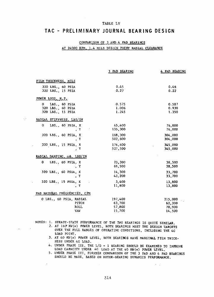
TABLE LV
TAG - P R E L I M I N A R Y JOURNAL BEARING DESIGN
COMPARISON OF 3 AND 4 PAD BEARINGS
AT 24000 RPM. 1.4 MILS DESIGN POINT RADIAL CLEARANCE
3 PAD BEARING 4 PAD BEARING
FILM THICKNESS. MILS
320 LBS., 60 PSIA 0.45 0.46320 LBS., 15 PSIA 0.27 0.22
POWER LOSS. H.P.
0 LBS., 60 PSIA 0.575 0.587320 LBS., 60 PSIA 1.006 0.930320 LBS., 15 PSIA 1.245 1.350
RADIAL STIFFNESS. LBS/IN
0 LBS., 60 PSIA, X 45,400 76,000, Y 135,300 76,000
320 LBS., 60 PSIA, X 168,300 304,000, Y 502,600 304,000
320 LBS., 15 PSIA, X 176,600 . 345,000, Y 527,500 345,000
RADIAL DAMPING. coB. LBS/IN
0 LBS., 60 PSIA, X 23,300 38,500, Y 69,500 38,500
320 LBS., 60 PSIA, X 14,300 33,700, Y 43,200 33,700
320 LBS., 15 PSIA, X . 3,400 13,800, Y 11,800 13,800
PAD NATURAL FREQUENCIES. CPU
0 LBS., 60 PSIA, RADIAL 197,400 215,000 .PITCH 63,700 62,300ROLL 57,800 70,900YAW 15,700 14,500
NOTES: 1. STEADY-STATE PERFORMANCE OF THE TWO BEARINGS IS QUITE SIMILAR.2. AT 160" KW(e) POWER LEVEL, BOTH BEARINGS MEET THE DESIGN TARGETS
OVER THE FULL RANGES OF OPERATING CONDITIONS, INCLUDING THE 4GLOAD POINT.
3. AT 40 KW(e) POWER LEVEL, BOTH BEARINGS HAVE MARGINAL FILM THICK-NESS UNDER 4G LOAD.
4. UNDER PHASE III, THE L/D = 1 BEARING SHOULD BE EXAMINED TO IMPROVELOAD CAPACITY UNDER 4G LOAD AT THE 40 KW(e) POWER LEVEL.
5. UNDER PHASE III, FURHTER COMPARISON OF THE 3 PAD AND 4 PAD BEARINGSSHOULD BE MADE, BASED ON ROTOR-BEARING DYNAMICS PERFORMANCE.
314
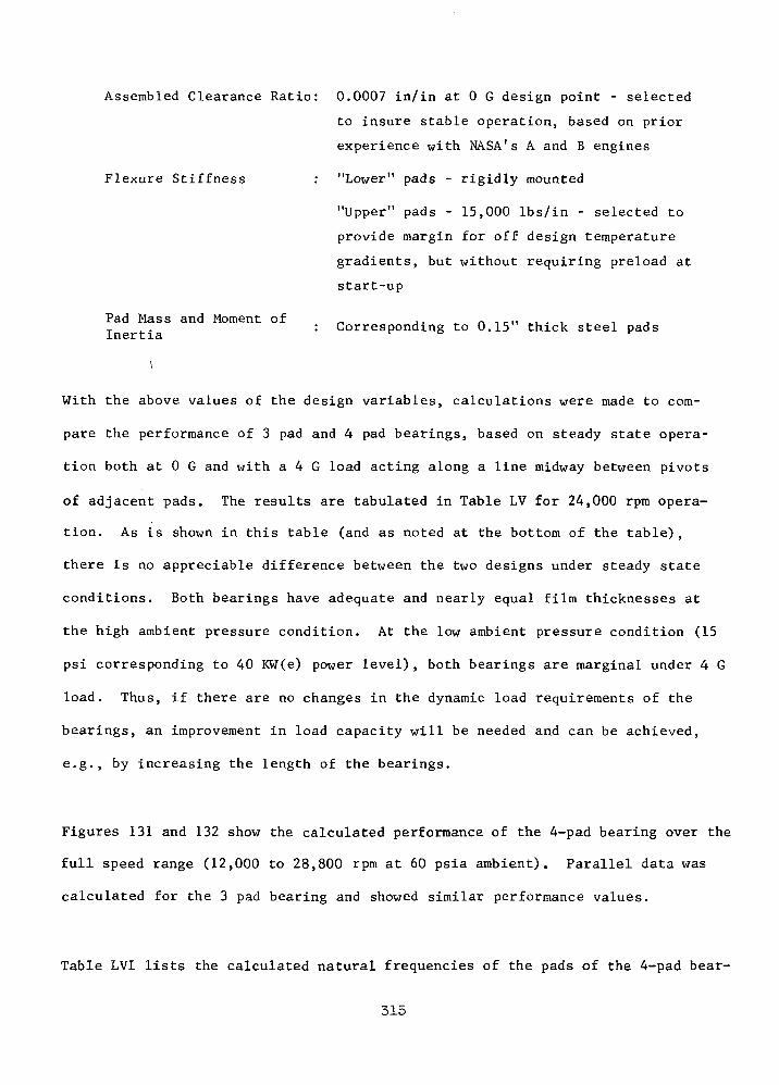
Assembled Clearance Ratio: 0.0007 in/in at 0 G design point - selected
to insure stable operation, based on prior
experience with NASA's A and B engines
Flexure Stiffness : "Lower" pads - rigidly mounted
"Upper" pads - 15,000 Ibs/in - selected to
provide margin for off design temperature
gradients, but without requiring preload at
start-up
Pad Mass and Moment of _ ,. . n .. .... , . , , ,: Corresponding to 0.15 thick steel pads
With the above values of the design variables, calculations were made to com-
pare the performance of 3 pad and 4 pad bearings, based on steady state opera-
tion both at 0 G and with a 4 G load acting along a line midway between pivots
of adjacent pads. The results are tabulated in Table LV for 24,000 rpm opera-
tion. As is shown in this table (and as noted at the bottom of the table),
there is no appreciable difference between the two designs under steady state
conditions. Both bearings have adequate and nearly equal film thicknesses at
the high ambient pressure condition. At the low ambient pressure condition (15
psi corresponding to 40 KW(e) power level), both bearings are marginal under 4 G
load. Thus, if there are no changes in the dynamic load requirements of the
bearings, an improvement in load capacity will be needed and can be achieved,
e.g., by increasing the length of the bearings.
Figures 131 and 132 show the calculated performance of the 4-pad bearing over the
full speed range (12,000 to 28,800 rpm at 60 psia ambient). Parallel data was
calculated for the 3 pad bearing and showed similar performance values.
Table LVI lists the calculated natural frequencies of the pads of the 4-pad bear-
315
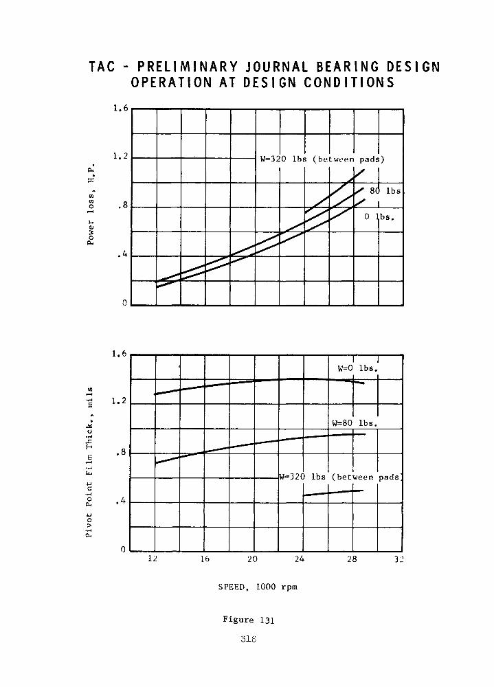
TAG - PRELIMINARY JOURNAL BEARING DESIGNOPERATION AT DESIGN CONDITIONS
01COO
3O(X
1.6
1.2
.4
W=320 Ibs (between pads)
80 Ibs
0 Ibs.
1.6
1.2
.cH
oCL,
o>
12
W=320 Ibs (between pads
16 20 24 28
SPEED, 1000 rpm
Figure 131
316
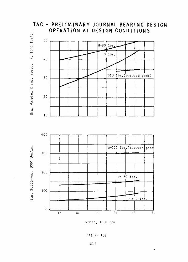
TAG - PRELIMINARY JOURNAL BEARING DESIGNOPERATION AT DESIGN CONDITIONS
coo
-o(U
a.<n
accra
X
00
50
40
30
20
10
320 Ibs . (be tween pads)
UiJD
OOO
o.c
ocVj
CD
400
300
200
100
W=320 Ibs . (be tween
12 16 20
SPEED, 1000 rpm
Figure 132
317

TABLE LVI
TAG - P R E L I M I N A R Y JOURNAL BEARING DESIGNOPERATION AT DESIGN CONDITIONS
N A T U R A L F R E Q U E N C I E S OF BEARING P A D S
Load SpeedIbs. rpm
0 12000
24000! 28800
80 12000
24000
- -28800
320 240001 ' 28800
Natural Frequencies, rpm
Upper Pads
Radial
95,900
117,800
128,900
83,700
109,300
121,300
96,900
119,980
Pitch
43,400
54,100
60,100
37,500
49,800
56,100
43,600
50,200
Roll
55,700
70,900
78,600
47,200
65,000
72,900
.56,100
64,600
Lower Pads
Radial
1 195,000
215,000
224,000
249,000
25 6; 000
262,000
369,000
367,000
Pitch
51,500
62,300
67,900
87,700
91,200
94 , 900
154,000
157,000
Roll
i
55,700 1
70,900
78,600
109,500
110,300
114,100
268,000i
280 , 000
Thus, over the range of design conditions,
Ncrit
N> 1.7 for the upper pads,
N ...C T*l_ t
and —-— > 2.3 for the lower pads.
318'
ing in the radial direction and in pitch and roll. As noted in this table,
the operation* is'always substantially subcritical-, so that the pads should
track rotor orbits quite clo'sely arid without significant amplitude magnifi-
cation.
Figure 133 shows the calculated decrease in pivot point film thickness (and the
corresponding increase in power loss) as the ambient pressure is reduced. It
shows again (as was noted earlier in Table LV) that the film thickness under
4 G load is satisfactory at 55 psia (h > 0.4 x 10 inch) but becomes marginal
at 15 psia..(h » 0.2 x 10"3 inches).
- '. . . Effect of Thermal Gradients
Tolerance of large thermal gradients between the rotor and the bearing housing
is necessary for successful application of gas bearings in high speed turbo-
machinery. Becauserof the very low mass flow of the lubricant gas in self-
acting, gas bearings (and its correspondingly small thermal capacity), the bulk
of the heat ..generated in.the bearings has to be removed by conduction through
the stator and rotor. Thermal gradients are. thereby set up in the bearing re-
gion which can produce severe distortions of the bearing surfaces and conse-
quent loss of load capacity. Also, before reaching steady state conditions,
significant, transient thermal gradients can be set up in the bearing region
due to heat flow from other parts of the turboraachinery.
To prevent large clearance changes due to transient or steady state thermal
conditions, one or more of the pads of the tilting pad journal bearings are
mounted on relatively soft flexures, as described earlier. Figure 134 shows the
calculated film thickness and power loss of the journal bearing as a function
of off-design thermal gradients between the housing and shaft. These calcu-
lations were made assuming a three pad bearing with one of the pads supported
on a 15,000 Ibs/in flexure.
319

TAG - PRELIMINARY JOURNAL BEARING DESIGNEFFECT OF AMBIENT PRESSURE (N-24/OOORPM)
(Atao
1.2
0.8
0,4
320 Ibs.
80 Ibs.0 Ibs.
(0to*
e"
1.6
1.2
0.8
C 0.4
]0 10 20 ; 30 40
: Ambient Pressure, psla
50
0 Ibs.
80 Ibs.
320 Ibs.
60
Figure 133 :
520 •' : ••' •
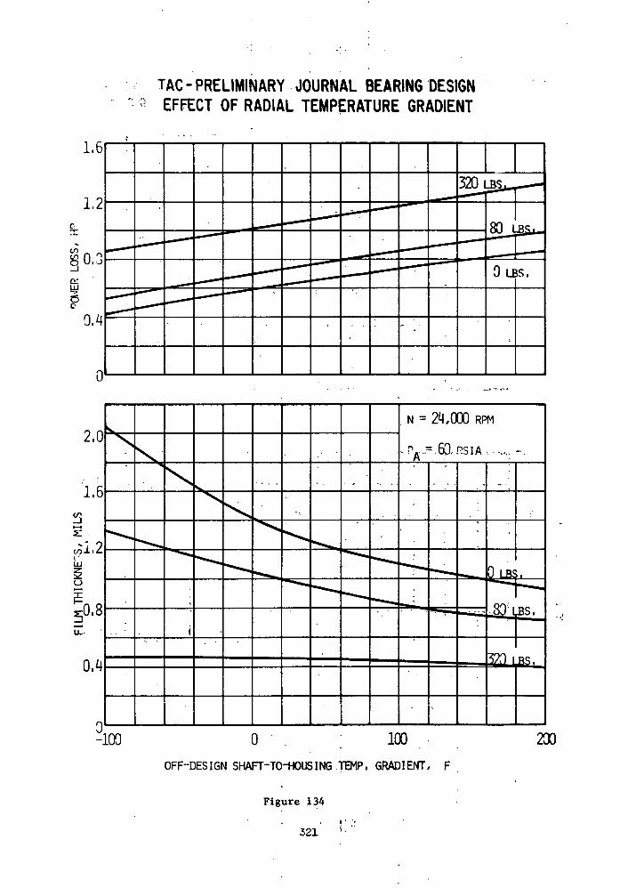
TAG-PRELIMINARY JOURNAL BEARING DESIGNEFFECT OF RADIAL TEMPERATURE GRADIENT
-100 o ; looOFF-DESIGN SHAFT-TO-HOUSING TEMP, GRADIENT, F
Figure 134
. t • •'321 '•*
Figure 134 shows that large, positive values of off-design thermal gradients
between the shaft and housing can be tolerated without severely affecting the
film thickness and, hence, reliability of the bearing. For example, when the
shaft and bearing are at their design value temperatures (i.e. the"off-design
temperature gradient is zero), the minimum pivot point film thickness is 0.45
mils under a 4 G load. This film thickness'stays almost constant, dropping
by only 50 u, inches to 0.4 mils,, under a 200 F off-design thermal gradient.
Figure 134 also shows that negative values of off-design thermal gradients will
result in an increase in minimum film thickness. This is due to the fact
that, when the housing temperature rises relative to the shaft temperature,
there is a corresponding increase in radial clearance and reduction of pre-
load. The bearing film thickness is thereby improved, but unstable operation
can result at zero or low bearing loads. In view of the large thermal mass
of the housing, it is unlikely that the housing temperature' can show large
temperature rises relative to the rotor, so that the presence of large nega-
tive, off-design thermal; gradients appears to be remote. Nevertheless, de-
tailed thermal analysis of the system under transient as well as steady state
conditions should be made later in. the design of the TAG to ascertain the • •
complete, anticipated ranges of housing and shaft temperatures. If these fu-
ture thermal studies show that bearing instability is a potential problem . .
area due to off-design increases in bearing clearance, the bearing design
would have to be adjusted, e.g. by increasing the preload.
Tilting pad bearings have a very high tolerance to axial thermal gradients,
provided that these gradients are monotonic, i.e. provided that the tempera-
ture difference between the journal and pads is highest at one end and lowest
at the other (Ref. 42). Under this condition a "coning" type distortion of
"Positive" value is used here to define off-design thermal gradients wherethe shaft temperature rises relative to the housing temperature. Converse-ly, a "negative".value denotes that the housing temperature increases rela-tive to the shaft temperature.
322
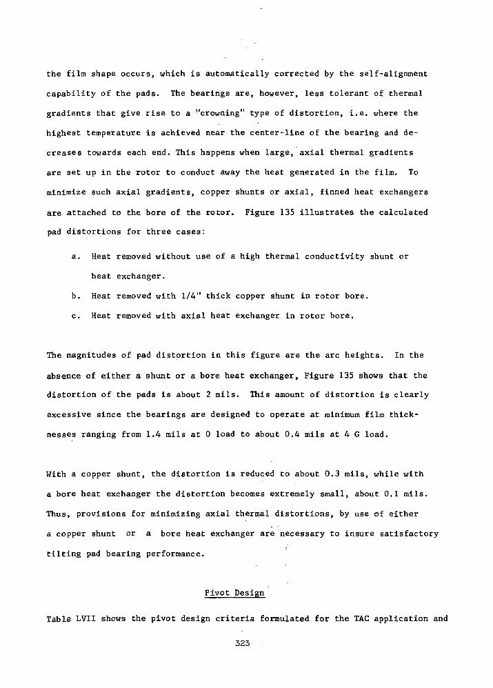
the film shape occurs, which is automatically corrected by the self-alignment
capability of the pads. The bearings are, however, less tolerant of thermal
gradients that give rise to a "crowning" type of distortion, i.e. where the
highest temperature is achieved near the center-line of the bearing and de-
creases towards each end. This happens when large, axial thermal gradients
are set up in the rotor to conduct away the heat generated in the film. To
minimize such axial gradients, copper shunts or axial, finned heat exchangers
are attached to the bore of the rotor. Figure 135 illustrates the calculated
pad distortions for three cases:
a. Heat removed without use of a high thermal conductivity shunt or
heat exchanger.
b. Heat removed with 1/4" thick copper shunt in rotor bore.
c. Heat removed with axial heat exchanger in rotor bore.
The magnitudes of pad distortion in this figure are the arc heights. In the
absence of either a shunt or a bore heat exchanger, Figure 135 shows that the
distortion of the pads is about 2 mils. This amount of distortion is clearly
excessive since the bearings are designed to operate at minimum film thick-
nesses ranging from 1.4 mils at 0 load to about 0.4 mils at 4 G load.
With a copper shunt, the distortion is reduced to about 0.3 mils, while with
a bore heat exchanger the distortion becomes extremely small, about 0.1 mils.
Thus, provisions for minimizing axial thermal distortions, by use of either
a copper shunt or a bore heat exchanger are necessary to insure satisfactory
tilting pad bearing performance.
Pivot Design
Table LVII shows the pivot design criteria formulated for the TAG application and
323

T = 550 F
A1S1 4340 Shaft 25
' Copper Shunt or Finned Heat Exch. .25y2.0R
12
11
10
•** 6•oco
EC
Finned Heat Exchanger
Copper Shunt Finned Heat Exchanger
K = 200 BTU/hr-ft-°F 80 Fins -- .062 thickThickness - .25 inch Passage = .075" wide x .150" deep
Effective Area = 84 inh = 75 BTU/hr-ft2-°FCD = . 1 Ib/secT -- 500°F
1.0 1.5 2.0 2.5 3.0 3.5 4.0 4.5
Distance from Alternator - inch
5.0 5.5 b.O
Figure 135
324
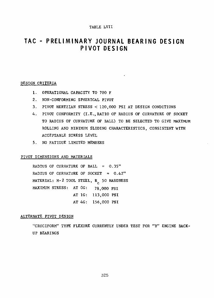
TABLE LVII
TAG - PRELIMINARY JOURNAL BEARING DESIGNPIVOT DESIGN
DESIGN CRITERIA
1. OPERATIONAL CAPACITY TO 700 F
2. NON-CONFORMING SPHERICAL PIVOT
3. PIVOT HERTZIAN STRESS < 120,000 PSI AT DESIGN CONDITIONS
4. PIVOT CONFORMITY (I.E..RATIO OF RADIUS OF CURVATURE OF SOCKET
TO RADIUS OF CURVATURE OF BALL) TO BE SELECTED TO GIVE MAXIMUM
ROLLING AND MINIMUM SLIDING CHARACTERISTICS, CONSISTENT WITH
ACCEPTABLE STRESS LEVEL
5. NO FATIGUE LIMITED MEMBERS
PIVOT DIMENSIONS AND MATERIALS
RADIUS OF CURVATURE OF BALL = 0.35"
RADIUS OF CURVATURE OF SOCKET = 0.42"
MATERIAL: M-2 TOOL STEEL, R 50 HARDNESS
MAXIMUM STRESS: AT OG: 78,000 PSI
AT 1G: 113,000 PSI
AT 4G: 156,000 PSI
ALTERNATE PIVOT DESIGN
"CRUCIFORM" TYPE FLEXURE CURRENTLY UNDER TEST FOR "B" ENGINE BACK-
UP BEARINGS
325

the pivot dimensions and materials selected to meet these criteria. A non-
conforming ball-in-spherical socket geometry with a radius ratio (i.e. ratio
of socket radius to ball radius) of 1.2 provides for free rolling motions and
minimum sliding in the pivots. The geometry and materials noted in this
table were successfully tested in Ref. 44 at stress levels up to 200,000 psi
and temperatures up to 1000 F. This type of pivot was used successfully in
the turboalternator of the NASA's "A" Engine (Ref. 41) and other gas-bearing
machinery.
An alternative pivot design that uses, basically, a dual flexural gimbal in
place of the Hertzian contact ball-socket arrangement is illustrated in Fig-
ure 136. This is the "Cruciform" type of flexural pivot that was developed as
the alternate flexure for the back-up bearing system of the NASA's "B" Engine.
The "Cruciform" pivot arrangement is designed to have angular stiffnesses in
the pitch, roll and yaw directions that are at least two orders of magnitude
smaller than the corresponding, calculated angular stiffnesses of the fluid
film at its design point operating condition. Under Contract NAS3-10951 tests
have been conducted with a bearing pad supported first on a standard ball-
socket pivot and then on a "Cruciform" pivot. The test data indicated that the
load capacity and threshold of instability were about the same with both pivot
types.
The "Cruciform" pivot eliminates unlubricated sliding and allows easy introduc-
tion of hydrostatic jacking gas through a capillary tube at the center of the
"Cruciform". It also avoids the problem of brinelling of the Hertzian contact
members under repeated, high shock loads. However, the "Cruciform" pivot has
not yet been fully evaluated and tested in an actual machine, and in particular,
it has not yet been subjected to high G vibration and impact tests.
326
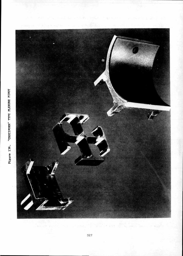
w
Xw
d-
I
ct•H(t.
327
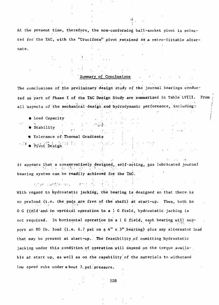
At the present time, therefore, the non-conforming ball-socket pivot is selec-
ted for the TAG, with the "Cruciform" .pivot retained as a retro-fittable alter-
nate. • .
Summary of Conclusions . • ' , :
The conclusions of the preliminary design study of the journal bearings conduc-
ted as part of Phase 1 of the TAG Design Study are summarized in Table LVIII. From ,
all 'aspects of the mechanical design and hydrodynamic performance, including:
; • . ; • • : . - • - • • • • ; • - |• Load Capacity , . . ' . . . . !
- v . • -. • • • . v / ,t .-••.;.- -• Stability • -"^ ^
• Tolerance of Thermal Gradients' • j - .'* • ' './.:'-• Pivot; tle'sigh ' ' :
it appears that a conservatively designed,, self-acting, gas lubricated journal
bearing system can be readily achieved for the TAG.
With regard to hydrostatic jacking, the bearing is designed so that there is
no preload (i.e. the pads are free of the shaft) at start-up. Thus, both in
0 G fi;e;ld'and. in vertical,opjer.ation in a 1 G field, hydrostatic jacking is
not required. In horizontal operation in; a 1 G .field, each bearing will sup-
port an 80 Ib. load (i.e. 6.7 psi on a 4" x 3" .bearing) plus any alternator load
that may be present at start-up. The feasibility ..of ommitting hydrostatic
jacking under this .condition^ of operation will depend on the torque availa-
ble at start up, as well as on the capability of the materials to withstand
low speed rubs under a bout 7, psi.pressure.
I 328
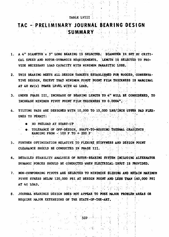
TABLE LVIII : . - - • • . ; ;
TAG - PRELIMINARY JOURNAL BEARING DESIGN^SUMMARY :
1. A 4" DIAMETER x 3" LONG BEARING IS SELECTED. DIAMETER IS: SET;BY CRITI-
CAL SPEED AND ROTOR-DYNAMICS REQUIREMENTS. LENGTH IS SELECTED TO PRO-
VIDE NECESSARY LOAD CAPACITY WITH MINIMUM PARASITIC LOSS.! ;
2. THIS BEARING MEETS ALL DESIGN TARGETS ESTABLISHED FOR RUGGED, CONSERVA-
TIVE DESIGN, EXCEPT THAT MINIMUM.,PIVOT POINT FILM THICKNESS IS MARGINAL
AT 40 KW(e) POWER LEVEL WITH 4G LOAD. " . ' - . _ ] . .' ' . .;
3. UNDER PHASE III, INCREASE OF BEARING LENGTH TO 4" WILL BE CONSIDERED, TO
INCREASE MINIMUM PIVOT POINT FILM THICKNESS TO OiOOOA". : .y Y ' :
4. TILTING PADS ARE DESIGNED WITH 10,000 TO 15,000 LBS/INCH UPPER PAD FLEX-
URES TO PERMIT: . .-. .. .; '...-'...'..-.'.' ''.-.'• -.''•".':.'-. .''.'• Y*
• NO PRELOAD AT START-UP
• TOLERANCE OF OFF-DESIGN, SlV FT'TO-HQySING: THERMAL^GRADIENTSRANGING FkpM -: 100:F.TO*f 200 ;F • ; •' ''~ •'.'.'.. ':-:\ >
- ' " " . ' . . * • ' • ' •' jj
5. FURTHER OPTIMIZATION RELATIVE TO FLEXURE STIFFNESS AND DESIGN POINT
CLEARANCE SHOULD BE CONDUCTED. IN PHASE HI.
6. DETAILED STABILITY ANALYSIS OF ROTOR-BEARING SYSTEM INCLUDING ALTERNATOR
DYNAMIC FORCES SHOULD BE CONDUCTED WHEN ELECTRICAL>INPUT IS PROVIDED.
7. NON-CONFORMING PIVOTS ARE SELECTED TO MINIMIZE SLIDING AND RETAIN MAXIMUM
PIVOT STRESS BELOW 120,000 PSI AT DESIGN POINT AND LESS THAN 160,000 PSI
AT 4G LOAD. ^ ^
' ' ' ' ' , ' • ; ' • ' ' C' ' ' ' '''' '"' ' :i8. JOURNAL BEARINGS DESIGN DOES NOT APPEAR TO POSE MAJOR PROBLEM'AREAS OR
REQUIRE MAJOR EXTENSIONS OF THE STATE-OF-THE-ART. ; «
329 • • :;
THRUST BEARINGS
Operating Conditions
: These are summarized in Table-LlX. As in the case of the journal bearings
discussed earlier, the self-acting thrust:bearing must support the applied
load over a speed range from 50 percent to 120 percent of design speed. The
bearing cavity is maintained at compressor inlet pressure, i.e. at 55 and 15
psia respectively for the 160 KW(e) and the 40 KW(e) power levels. A double-
!acting thrust bearing, both faces having the same geometry and load capacity,
i s used. • . . . . . . . .
The operating load of the bearing comprises:
a. Gravity Load ' '.,....'..'.,.'.'.. , , . . . . . - . .,
The thrust bearing must support the full weight of the rotor (160 Ibs.)
when the unit operates vertically in .1 G environment. There is no
gravity load when the unit operates horizontally or in 0 G environment.
• b. Aerodynamic Thrust Load ' '* * •' " -
The design of the aerodynamic components will be such as.to achieve very,
close balance of the thrust load, within about 100 Ibs. This residual: ; ' ; > : ; : ' < • . : ' • • / . \ ' • • ' < : ' ' . - . ' . '
unbalance will be supported by the thrust bearing.
c. Alternator Loading
Axial displacements of the alternator rotor will give rise to small mag-
netic and electrical loads. These, however, are expected to be small in
comparison with the gravity and aerodynamic unbalance loading.
330
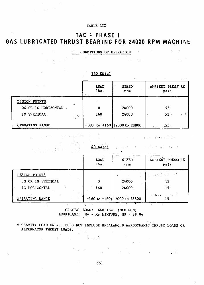
TABLE LIX
TAG - PHASE IGAS L U B R I C A T E D THRUST B E A R I N G FOR 24000 RPM MACHINE
1. CONDITIONS OF OPERATION
160 KW(e)
DESIGN POINTS.
OG OR 1G HORIZONTAL ,
1G VERTICAL
OPERATING RANGE
LOADIbs.
0
160
-160 to +160
SPEEDrpm
24000
24000
12000 to 28800
AMBIENT PRESSUREpsia
55
55 • J
• • : , . -.55
40 KW(e)
DESIGN POINTS
OG OR 1G VERTICAL
1G HORIZONTAL
OPERATING RANGE
LOADIbs.
0
160
-160 to +160
SPEEDrpm
t
24000
24000
12000 to 28800
AMBIENT PRESSUREpsia
15
15
15
ORBITAL LOAD: 640 Ibs. (MAXIMUM)LUBRICANT: He - Xe MIXTURE, MW = 39.94
* GRAVITY LOAD ONLY, DOES NOT INCLUDE UNBALANCED AERODYNAMIC^ THRUST LOADS ORALTERNATOR THRUST LOADS. •
331
d. Orbital Loading
As in the case of the journal bearings, the thrust bearings must support
a 4 G load during orbital maneuvers for short durations.
Selection of Bearing Geometry
Figure 137 illustrates, schematically, several of the conventional gas thrust
bearing geometries. For the purpose of the TAG application only the first
two of these (the helical grooved and the shrouded step bearings) were analy-
zed. The last three bearing types (the plain-step, the tapered land, and the
tilting-pad) all have been shown in previous studies to have substantially
lower load capacity. The principal reason for this is that they all lack end
sealing lands, so that their side leakage flows are higher and their hydro-
dynamic pressures (and, consequently, load capacities) are lower than those
of the shrouded step bearing.
Figure 138 illustrates the full annular shape of the two, initially selected
geometries. As noted in this figure, the helical grooved bearing has been
used extensively in prior turbomachinery, including both the turbocompressor
simulator and the turboalternator of the NASA's "A" Engine. The NASA's "B"
Engine (the BRU) uses a plain step thrust bearing.
The next step in the selection of a pad bearing geometry was made on the basis
of comparison of calculated load capacities of the helical grooved and shrouded
step bearings for the operating conditions of the TAG. This comparison is
illustrated in Figure 139 assuming in both cases an 8" O.D. x 4.25" I.D. bear-
ing size. This figure shows that, at the 55 psia ambient pressure correspond-
ing to the 160 KW(e) power level, the two bearing types have virtually the same
332

T H R U S T FACE G E O M E T R I E STAC - P R E L I M I N A R Y T H R U S T B E A R I N G D E S I G N
/ / / / / / / / / S A .
HELICAL GROOVED
L J
IX X
SHROUDED STEP
L. t_ _J
/ / / / A V / / / / / / / / / A
TAPERED LAND PLAIN STEP
Y / / / / / / / / / / /
NOTES
1. HELICAL GROOVED AND SHROUDED STEPBEARINGS HAVE HIGHEST LOAD CAPACITY.
2. PLAIN STEP, TAPERED LAND AND TILTINGPAD BEARINGS HAVE ONLY 507. TO 707. OFLOAD CAPACITY OF SHROUDED STEP BRG.
3. TILTING PAD BEARING HAS BEST TOLER-ANCE OF DISTORTION, BUT POOR LOADCAPACITY AND COMPLEXITY DUE TO PIVOTSAND NEED FOR LOAD EQUALIZER MECHANISM.
TILTING PAD
Figure 137
333
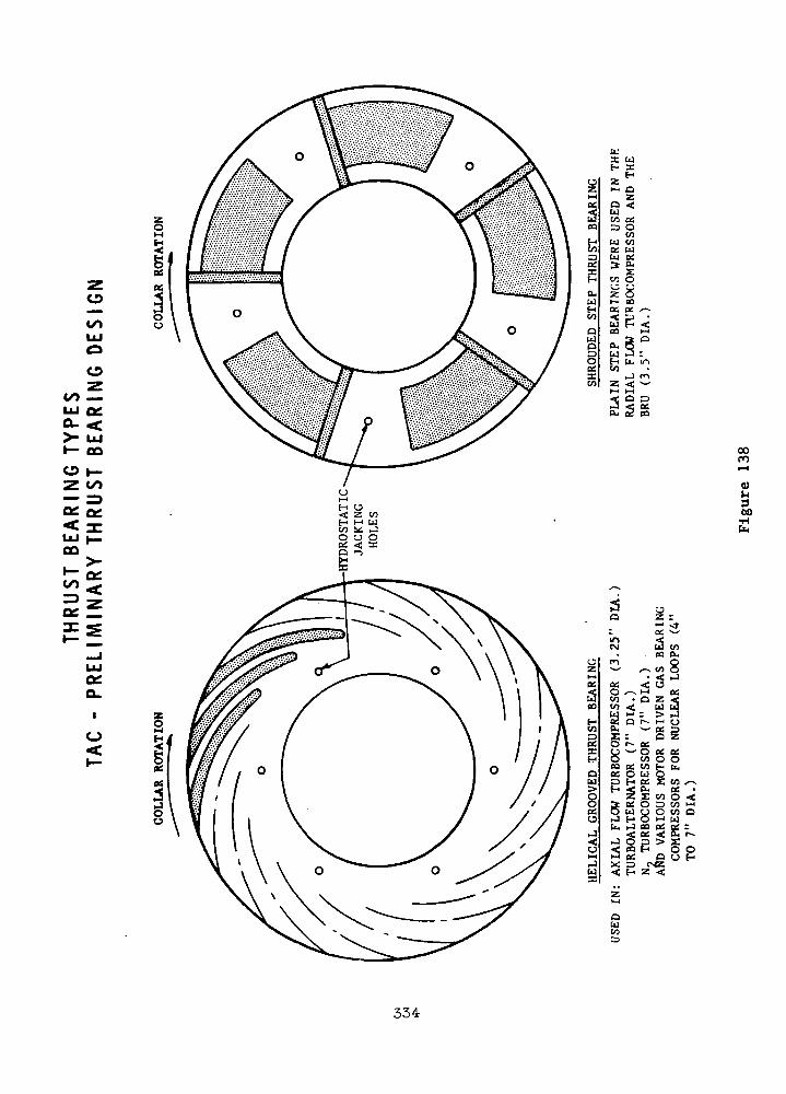
o
coUJ
o
CO —
o
Q£<UJCO
CO
I—CO
QC
t—
>-0?<
Q.
I
uX UH SE
ol z H
Z| H- O
§COcoU
£§
B<h-l
3 O
iJ CO<* s"^M
Q 3OSCOS<sp- 2
00
oo•H
11*1CM
M r£2W COCO PL.
/-v CO• <<; o
--v M• O Z
< Ulfl : >O r- M
^ ocI : O
r a.i ^ O B£
co OPS co HQ U O
! § £ *Z Z COPS O 3W O OH O M
i i-J 00 PS<; os <:
BE,g
X
QUCO
cv«5Z <
CO ^OS •o <.CO MCO CIdg:^§0U H
334
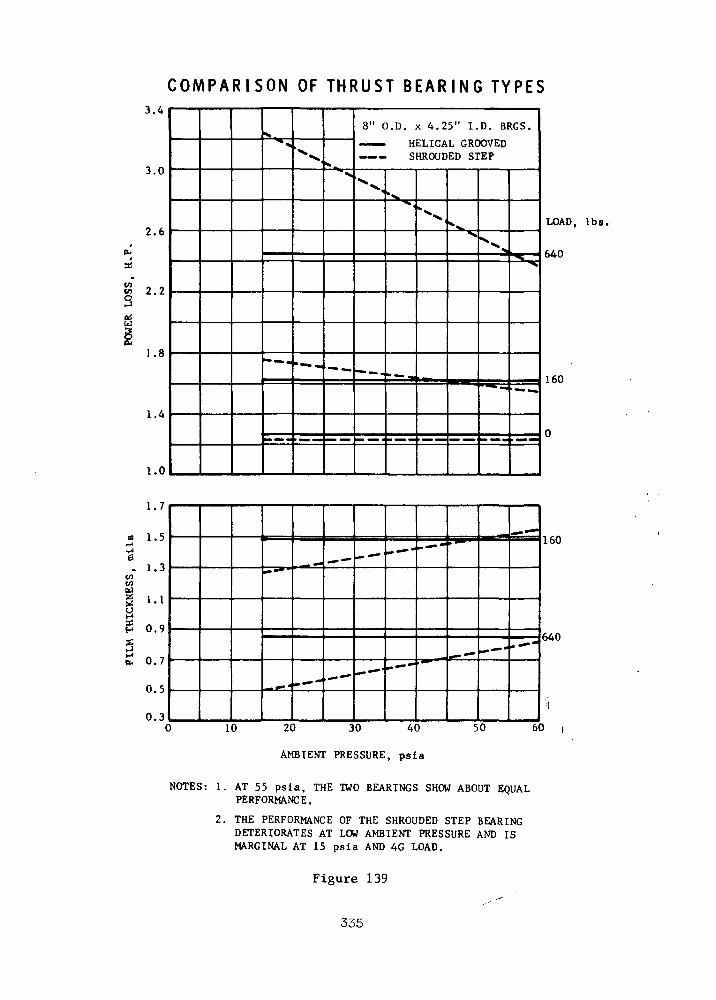
C O M P A R I S O N O F T H R U S T B E A R I N G T Y P E S
s
•rl6
gH
J.4
3.0
2.6
2.2
1.8
1.4
1.0
1.7
1.5
1.3
1.1
0.9
0.7
0.5
0.3C
»." ^
•" — -
'xv%_^>
—
8" O.D. x 4.25" I.D. BRGS.
— — HELICAL GROOVEDSHROUDED STEP
.•x.
"*,
._^
'--, »%.
^X-,
~~"
_ ...
__
~~
--
- — '
'"""
^_
^
^_<—.
_,—
LOA
640
160
0
160
640
'-I
10 20 30 40 50 60 |
AMBIENT PRESSURE, psia
NOTES: 1. AT 55 psia, THE TWO BEARINGS SHOW ABOUT EQUALPERFORMANCE.
2. THE PERFORMANCE OF THE SHROUDED STEP BEARINGDETERIORATES AT LOW AMBIENT PRESSURE AND ISMARGINAL AT 15 psia AND 4G LOAD.
Figure 139
335
load capacity and very nearly equal power loss over the full range of loads
up to 4 G. However, while the helical grooved bearing maintains its load
capacity, independently of the ambient pressure down to the value of 15
psia that corresponds to 40 KW(e) power level, the shrouded step bearing suf-
fers a significant loss of load capacity as the ambient pressure level is re-
duced. In fact, at 15 psia ambient pressure and 4 G load, the film thickness
of the shrouded step bearing drops to 0.5 mils which is marginal for an 8" O.D.
bearing. The power loss, which in the case of gas bearings is very nearly
inversely proportional to film thickness, increases correspondingly in the
case of the shrouded step bearing thus magnifying the problem of heat removal.
Since there are no other significant advantages of one bearing type over the
other, the helical grooved bearing geometry was selected for TAG application.
Bearing Size and Performance Calculations
Table LX summarizes the design targets selected for the thrust bearing. As
in the case of the journal bearings discussed earlier these targets were chosen
to provide a factor of safety and to avoid marginally small film thicknesses
under any of the specified load conditions, including 4 G loads for short dura-
tions.
Figure 140 is a comparison of the calculated film thickness and power loss for
double acting, 7" O.D. and 8" O.D. helical-grooved thrust bearings. As shown
by this figure and the table at the bottom of the figure, the 7" O.D. bearing
would be entirely adequate except at the 4 G load condition where its film
thickness reduces to 0.52 mils which is somewhat marginal. The 8" O.D. bear-
ing has calculated film thicknesses in excess of 0.8 mils under all loads up to
336
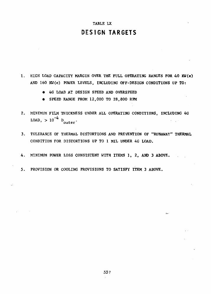
TABLE LX
DESIGN TARGETS
1. HIGH LOAD CAPACITY MARGIN OVER THE FULL OPERATING RANGES FOR 40 KW(e)
AND 160 KW(e) POWER LEVELS, INCLUDING OFF-DESIGN CONDITIONS UP TO:
• 4G LOAD AT DESIGN SPEED AND OVERSPEED
• SPEED RANGE FROM 12,000 TO 28,800 RPM
2. MINIMUM FILM THICKNESS UNDER ALL OPERATING CONDITIONS, INCLUDING 4G
LOAD, > 10"4 D t . .outer
3. TOLERANCE OF THERMAL DISTORTIONS AND PREVENTION OF "RUNAWAY" THERMAL
CONDITION FOR DISTORTIONS UP TO 1 MIL UNDER 4G LOAD.
4. MINIMUM POWER LOSS CONSISTENT WITH ITEMS 1, 2, AND 3 ABOVE.
5. PROVISION OR COOLING PROVISIONS TO SATISFY ITEM 3 ABOVE.
337

TAG - PRELIMINARY THRUST BEARING DESIGNEFFECT OF BEARING SIZE
1000
100T><do
10
I
\\\
\V
\%
\1
\<
V
N
ik
\
s%N
V
\\
'*.
V^
X
^
\
1kV*\s\-
*
***.,
v\\
—kX\\
V\
y/
••*• —
V\/\
\\
Power Lose
£- 8" Di«.
/- 7" Dia.
—
Load^7" Dia.
• S" Dia.
C\
\\
1.0
0.10 1.0 2.0 . 3.0
Film Thickness, mils
<03
I
LoadIbs.
0
160
640
Diameterinches
8
7
8
7
8
7
Film Thick,mils
3
3
1.48
1 .09
0.85
0.52
Power LossH.P. -
1.26
0.71
1.62
1 . 12
2.45
2.00
Figure 140
338
and including 4 G and was therefore selected in this preliminary design.
Figure 141 shows the selected geometry for the 8" O.D. thrust bearing. The
geometrical parameters such as groove-to-land width ratio, and groove angle
arc near the optimum values for this type of bearing (Ref. 45). The groove
length selected is a little smaller than optimum to provide adequate radial
land lengths on each side of the hydrostatic jacking holes. The groove depth
is optimized for thin films (about 0.7 mils), in order to provide additional
load capacity margin.
The calculated performance of this bearing over the full speed range (50 per-
cent to 120 percent of the 24,000 rpm design speed) is plotted and tabulated
in Figure 142. The data in this figure is for the complete, double-acting
bearing with 6 mils axial play. The data shows adequate film thickness over
the full, specified range of operation.
Effects of Thermal Distortion
Analysis of gas bearings as well as past experience clearly shows that one of
the most critical elements in design of high speed, gas-lubricated thrust
bearings is the control of the thermal distortions of bearing and collar sur-
faces. Since the thermal capacity of the gas flow through a self-acting
gas bearing is small, the heat generated has to be removed by conduction. To
remove this heat, thermal gradients are set up in the bearing elements and
these, in turn, can distort the bearing film resulting in loss of load capa-
city. In extreme cases, a runaway condition can occur whereby the distortions
caused by the thermal gradients result in sufficiently severe loss of load
339
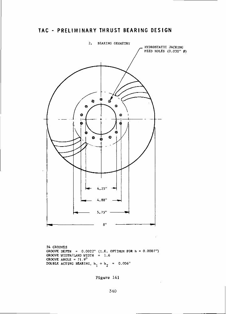
TAC - P R E L I M I N A R Y T H R U S T B E A R I N G D E S I G N
2. BEARING GEOMETRYHYDROSTATIC JACKINGFEED HOLES (0.030" 0)
24 GROOVESGROOVE DEPTH = 0.0022" (I.E. OPTIMUM FOR h = 0.0007")GROOVE WIDTH/LAND WIDTH = 1.6GROOVE ANGLE = 71.9°DOUBLE ACTING BEARING, h + h = 0.006"
Figure 141
340

EFFECT OF SPEEDT A C - P R E L I M I N A R Y T H R U S T B E A R I N G D E S I G N
1000
800
200
100co 80
20
10
\S
G:5\S
Sv
\\
10.0
- LOAD
--- I'CJEK LOSS
—-=-— 28800 KPM—1--,-- p-1
\V
24000 KPM
3 i
1.0 2.0
V 1 I . M T H I C K N E S S . MILS
0. I3.0
LOADI. US.
0
I h O
640
SI 'KEDK I'M
1 2000
24000
2HKOO
i 2000
24000
28800
24000
28800
F I L M T M i r . K M K S SMILS
3
)
j
1 . 1 1 .
1 .W
\ .580.850.93
iWK.R LOSSI I P
0. 12
1 . L'f
1 .f>
0 . 4 H
1 . i , 2
• > . ? 5
2 . 4 3
3.30
Figure 142
341
capacity that the mean film thickness in the bearing is severely reduced.
This leads to still larger power loss, thermal gradients, distortions, and
ultimately, a failure of the thrust bearing.
Major emphasis was therefore placed on the present preliminary design study
on thrust bearing design to minimize thermal distortions. This is separate-
ly discussed in this report. Specifically, a liquid cooling scheme for the
thrust bearing stator that was successfully used in both the turbocompressor
simulator and the turboalternator of the "A" Engine (Refs. 40 and 41) is re-
commended also for the TAG. This design scheme, by maintaining the rear por-
tion of the thrust housing isothermal,stiffens it and minimizes thermal dis-
tortions.
In parallel with the mechanical design study, calculations were made to assess
the loss of film thickness and increase in power loss that will accompany dis-
tortions of the film shape in an 8" O.D. helical grooved bearing.
The calculation results are given in Figure 143 and show that over a range of
distortion up to +0.6 mils, the effect on film thickness is quite moderate.
Figure 143 shows that, within this range of distortions, the loss in minimum
film thickness is less than 0.6A, where A is the magnitude of the distortion.
The corresponding increase in power loss is very small, less than 0.16 HP
throughout, since the mean value of film thickness is little changed by the
distortions. These changes in film thickness and power loss are acceptably
low and show that the bearing has adequate margin of safety.
342
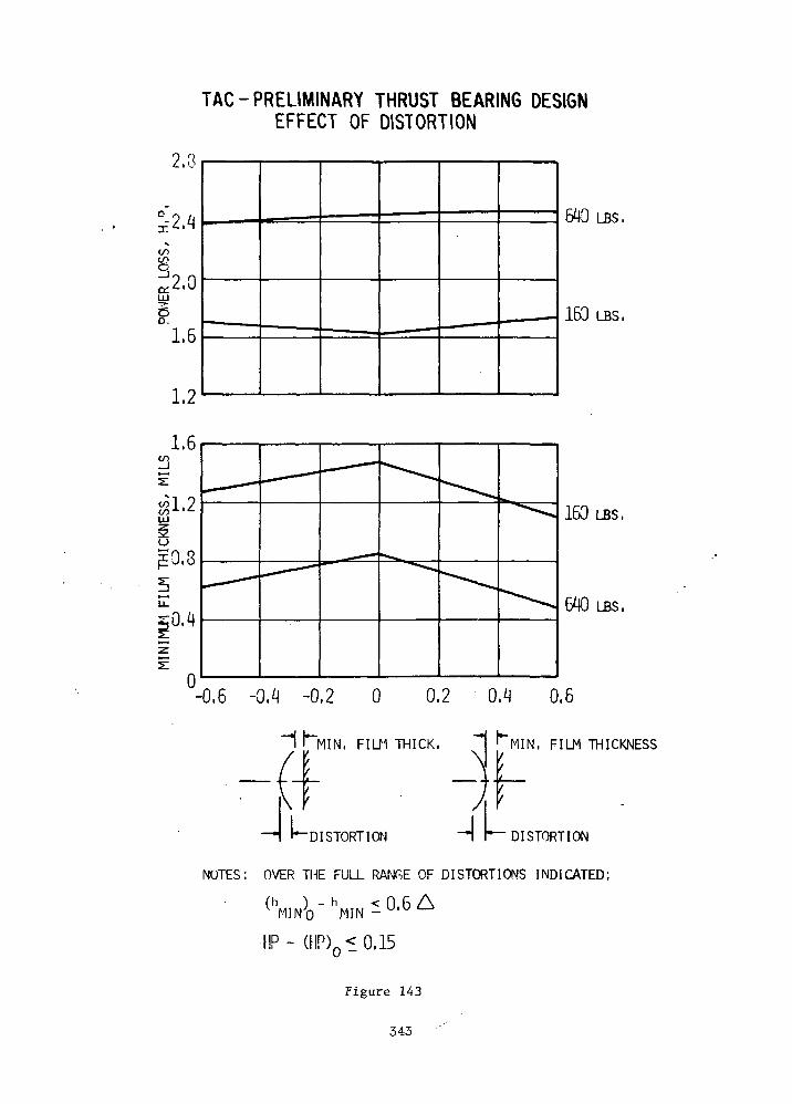
TAG-PRELIMINARY THRUST BEARING DESIGNEFFECT OF DISTORTION
2.3
£2.4inCO
a:2.0
1.6
1.2
1.6
640 LBS.
160 LBS,
UJ
uJE0.8
0
160 LBS.
640 LBS.
-0.6 -0.4 -0.2 0 0.2 0.4 0.6
"1 I*~MIN. FILM THICK. ~"
4UDISTORT I ON -I
MIN, FILM THICKNESS
DISTORTION
NOTES: OVER THE FULL RANT.E OF DISTORTIONS INDICATED:
(h ) - h < 0 6 AV MIN - UlU^
•HP- (HP)0 10.15
Figure 143
343

Summary of Conclusions
Table LXI summarizes the conclusions of the preliminary design analysis of
the thrust bearings. As in the case of the journal bearings, the analysis
and computations indicate that a self-mating, gas-lubricated thrust bearing
can be designed to meet the specified operating requirements of the TAG.
With flexure mounting to compensate for static misalignments between the rotor
and stator, a potential problem of instability or high amplitude resonance of
the combined thrust bearing-flexure mount system may be encountered. This was
not analyzed in the present preliminary design study. This problem was not
encountered in either the turbocompressor simulator or the turboalternator of
the "A" Engine. Nevertheless, a detailed analysis of the stability of the
thrust bearing and mount system should be made, using the existing analytical
tools, when the design details of the mount are prepared.
344
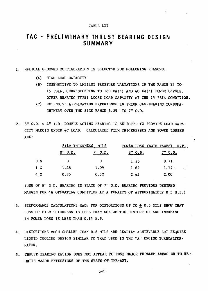
TABLE LXI
TAG - P R E L I M I N A R Y THRUST B E A R I N G DESIGNSUMMARY
1. HELICAL GROOVED CONFIGURATION IS SELECTED FOR FOLLOWING REASONS:
(A) HIGH LOAD CAPACITY
(B) INSENSITIVE TO AMBIENT PRESSURE VARIATIONS IN THE RANGE 55 TO
15 PSIA, CORRESPONDING TO 160 KW(e) AND 40 KW(e) POWER LEVELS.
OTHER BEARING TYPES LOOSE LOAD CAPACITY AT THE 15 PSIA CONDITION.
(C) EXTENSIVE APPLICATION EXPERIENCE IN PRIOR GAS-BEARING TURBOMA-
CHINERY OVER THE SIZE RANGE 3.25" TO 7" O.D.
2. 8" O.D. x 4" I.D. DOUBLE ACTING BEARING IS SELECTED TO PROVIDE LOAD CAPA-
CITY MARGIN UNDER 4G LOAD. CALCULATED FILM THICKNESSES AND POWER LOSSES
ARE:
FILM THICKNESS. MILS POWER LOSS (BOTH FACES). H.P. ,
8" O.D. 7" O.D. 8" O.D. 7" O.D.
1.26 0.71
1.62 1.12
2.45 2.00
(USE OF 8" O.D. BEARING IN PLACE OF 7" O.D. BEARING PROVIDES DESIRED
MARGIN FOR 4G OPERATING CONDITION AT A PENALTY OF APPROXIMATELY 0.5 H.P.)
3. PERFORMANCE CALCULATIONS MADE FOR DISTORTIONS UP TO ± 0.6 MILS SHOW THAT
LOSS OF FILM THICKNESS IS LESS THAN 60% OF THE DISTORTION AND INCREASE
IN POWER LOSS IS LESS THAN 0.15 H.P.
4. DISTORTIONS MUCH SMALLER THAN 0.6 MILS ARE READILY ACHIEVABLE BUT REQUIRE
LIQUID COOLING DESIGN SIMILAR TO THAT USED IN THE "A" ENGINE TURBOALTER-
NATOR.
5. THRUST BEARING DESIGN DOES NOT APPEAR TO POSE MAJOR PROBLEM AREAS OR TO RE-
QUIRE MAJOR EXTENSIONS OF THE STATE-OF-THE-ART.
345
0 G
1 G
4 G
3
1.48
0.85
3
1.09
0.52

Thrust Bearing Distortion Analysis
As was discussed in the previous section, maintenance of the flatness of the
thrust bearing surfaces is extremely important to the successful bearing
operation. Both the runner and stator become distorted during operation be-
cause of film pressure forces and thermal gradients resulting from dissipation
of bearing film generated heat. In addition the runner is subjected to centrifugal
distortions. Proper control of thermal distortion is extremely important as a
potential for thermal run away always exists. This is a situation where dis-
tortions lead to loss of load capacity which results in reduction in film
thickness and increased heat generation. To dissipate the additional heat
larger thermal gradients result which increases the thermal distortion, etc.
For this reason overdesign of the cooling system is required.
The distortions that are of importance to the TAG thrust bearing are pictorially
indicated on Figure 144. As can be seen from these sketches, mounting of the
stator by its outside diameter and the rotor by its inside diameter results
in a tendency for the rotor and stator distortions to compensate for one
another in the case of axial thermal gradients and film pressure forces. This
is the basic reason for such a mounting scheme in the TAG.
Because of the criticality of the thrust bearing, detailed thermal and dis-
tortion analyses were performed on several design iterations until an
acceptable solution was obtained. The final model of the thrust bearing is
shown on Figure 145, which shows all the pertinent dimensional and other data
assumed for the analyses. Analyses were performed utilizing both AISI 4130/4340
and H-ll as these represented the two most likely alternator rotor thus, shaft,
material choices during the course of Phase I. It should be noted that the
346

V)
O
i—oe:O>—01
O
O
CD
I—CO
01
I
111u
r111Lr111L
ic
f— •• * -~
^ —
U— -"~
^
* i . .. ^
^» *"
•— »_^^* ^^-
^^^ ^^^*
^ ~ " "
* A c3 " i-
4JCC7
E
CA
(UP30)CO CO0) 3}
<060D
r-H Ci-i (0 0)id E -H• t-i -o•o <u ca* j3 urt H u
(UM360•H
^H C
^H fO 4(CO E - i
•^ V* T3X 0) CO< Si V-
H O
OO
t> 1-1Oi O
cfl CO
34=7

o
•-21Q_OH__
W^
^^^J^^^
^**
V)4->CO *^-•-< Lu0 O
«J .r1 'l_i_J i*"h^J U-l 4_)
^^ ? '-J
O <5 js< u -^^ Hi O
y-i £-<
00 £ °°«_ cQ tl
lOO H .c-^ V •
^" 4J1 «
•— ' <LI< *
r~i c-i <X>O ooi—1 • — i
OO
tilu t-co 01
«-• cb C3 3
cn a: Q0
C to 4-1J-I U-lto CL to•" to J=en o i/">
<
Ol_l>>Q•
1—»X\V* <u_ c
c•— • n otf
1— 1I— 1
1X
o o oon
0) £
O) O00 -COen «to 111CO to }_ja, T3 3
O C 4-14J H-1 U COC ljCO 4J 4J 01
r— ( Vi 14-1 O.
O to to 6O X JC 01u co en f-c
LO \o--ir-v COi/1^ lO iiO
1 1vO ^OO^ O^<T <t
^-^o ^M
01 0-(o -o4J 01 -r-l Z
•O C/l ->O '-^O en "o u^ • a i 3
T3 -a n4J 4J 0) CO CC C T3 O M01 tO CO i— i••* 1— 1 O C 4->
-Q O iJ 3 tOE 0 01< 0 X
oo m oo
-i 0<tn<f^^Oroi — i<t
E
E ^H>— t tU
•^ Qfa "O O i-H
01 COTD T3 >J -i-l0) CO 41 \J•0 O C 01CO •— i C 4JO C 3 CO>J 3 K S
0f-H
CO U1 <f X• oo oo ro
V4O • CN OOr-^ ^O
o""'
^4t>
o
LO <f ^
^ oo oo r-iCM - CM OO
o
s~\ / ~~
O O
4-1 cro CM<4J -H C C
3 C - — -•»H -H JO PC •< i— 1 i— 1s . -_^ /
1o-t
"a ij cu41 M TD >j C 00•a Ci ai o to toC 0 4 - I 4 J Uj "O 4J t— * COC c O ' - i M O t f l c O O W
' - * 4 - i c O r ^ - O 4 - i O t Oc en si vo j en oixa en ini i 11 l
01t-l3tx>•H
CMo
o:
UJca»—oo
1J-I — H"t J
O
\ \ ^\ ^ 1DvD D D D 1
a D a D D
X1
T
o
"*
0^
^
m
^
C
00
x \J r, r,Vna D D a a
D'D D D D
JI ^1
r--
t -
1
348
heat input assumptions shown on Figure 145 are different from those previously
discussed as they were derived from a preliminary design which had no pro-
visions for hydrostatic jacking. During the course of Phase III the analysis
was refined to reflect the final bearing load and heat generation
parameters.
The thrust bearing stator has internal cooling passages which utilize the same
coolant as the alternator (Humble 3152) introduced at 496 F near the OD where
the bulk of the heat is generated. The cooling passages are relatively close
to the bearing surface while the stator thickness behind the cooling passages
is large. The thick portion of the stator is nearly isothermal thus free of
thermal distortion and is of course stiff. This portion gives the stator its
"backbone" and resists the thermal forces generated by the gradient in the
portion between the bearing surface and cooling passages.
The details of the cooling passages (heat exchanger) are shown on Figure 146
along with the pertinent heat trancfer, flow and pressure drop data. Since
the design analysis of the heat exchanger and the nodal~point thermal gradient
analysis of the thrust bearing are accomplished separately there is necessarily
a certain amount of iteration between the two until all assumed inputs are
matched. The significant parameters resulting from each of the analyses are
summarized in Table LXII. As can be seen the significant heat transfer
parameters for the two analyses are very close and a good match was obtained.
The total distortions of the stator and runner as a result of the maximum
thermal, pressure and centrifugal forces are summarized in Figure 147. These
curves show the shape of the distorted bearing film for both alternator
rotor materials. The thrust bearing made of H-ll has a greater distorted film
349
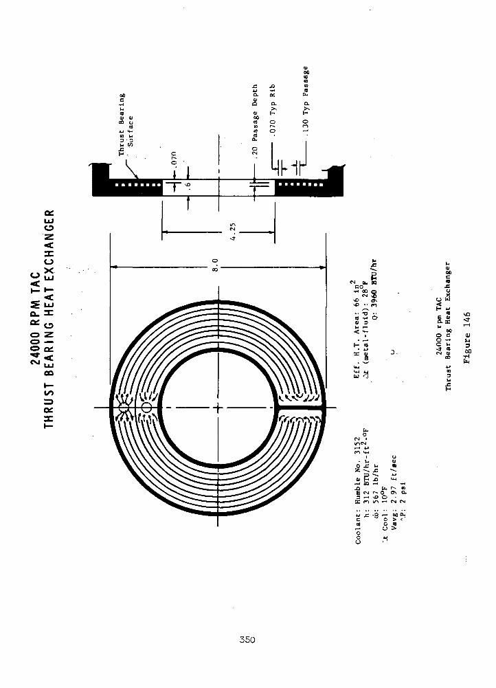
DCLUO
XOX
Q. -C
^Oo zo —o Q:
OQi—
nocCO
o u
VD
ocO C (!)§r g*! tf
350
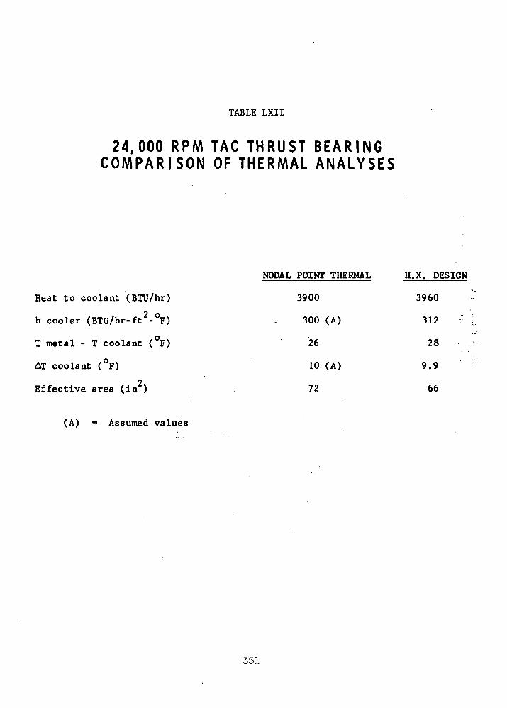
TABLE LXII
24,000 RPM TAG THRUST B E A R I N GC O M P A R I S O N OF THERMAL A N A L Y S E S
Heat to coolant (BTU/hr)
h cooler (BTU/hr-ft2-°F)
T metal - T coolant ( F)
AT coolant (°F)
2Effective area (in )
NODAL POINT THERMAL
3900
300 (A)
26
10 (A)
72
H.X. DESIGN
3960
312 :•
28
9.9
66
(A) Assumed values
351
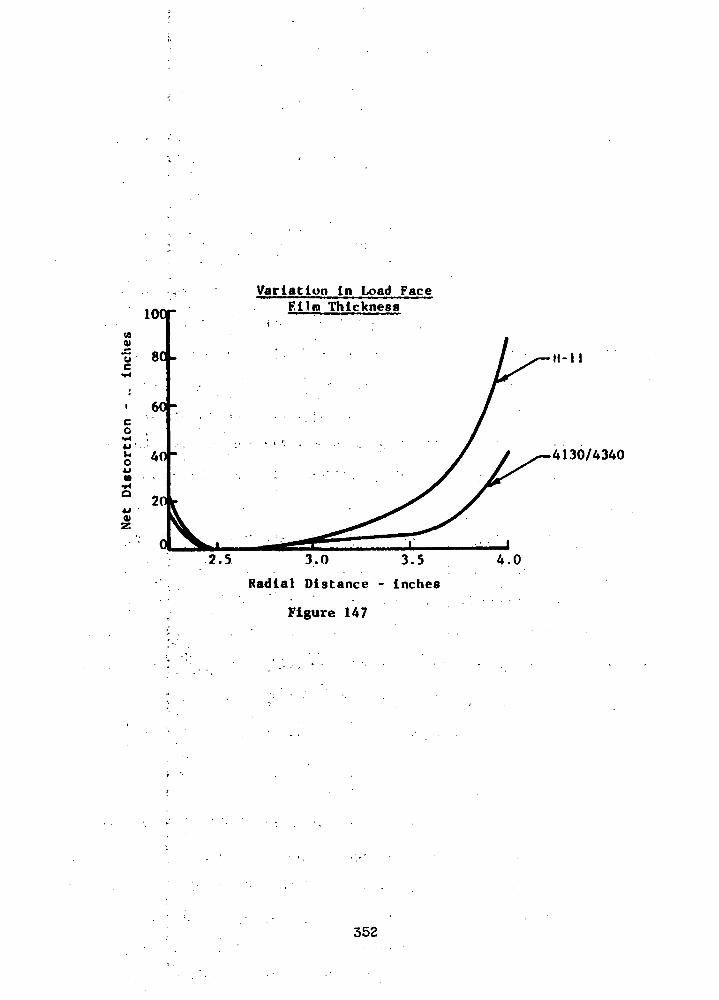
loorVariation in Load Face
Film Thickness
11-11
4130/4340
2.5 3.0 3.5
Radial Distance - inches
Figure 147
4.0
352
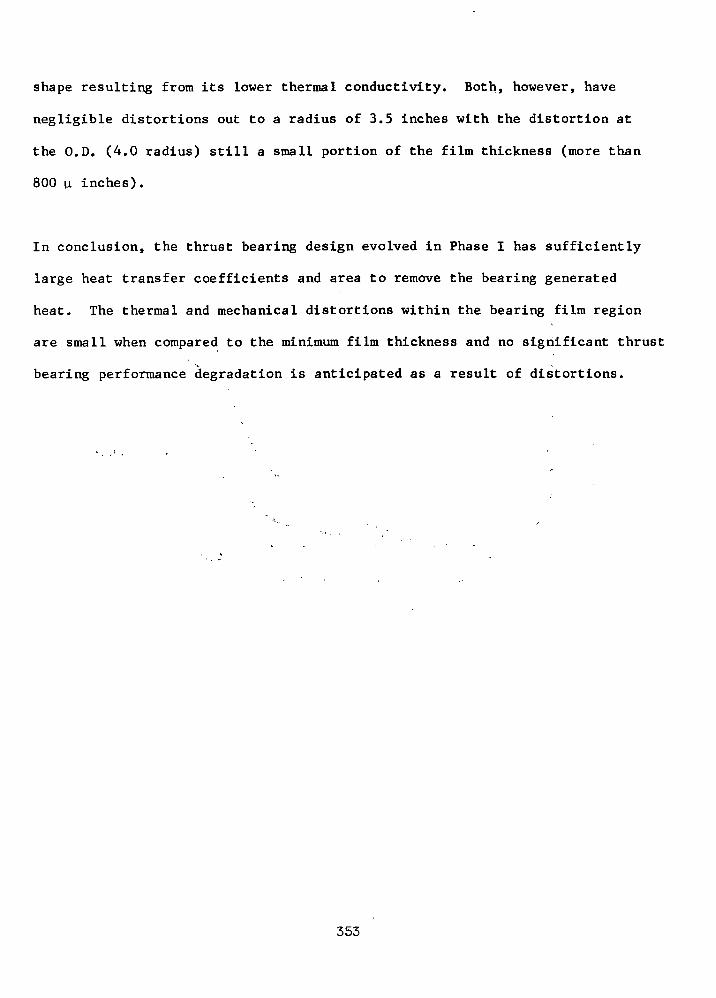
shape resulting from its lower thermal conductivity. Both, however, have
negligible distortions out to a radius of 3.5 inches with the distortion at
the O.D. (4.0 radius) still a small portion of the film thickness (more than
800 u inches).
In conclusion, the thrust bearing design evolved in Phase I has sufficiently
large heat transfer coefficients and area to remove the bearing generated
heat. The thermal and mechanical distortions within the bearing film region
are small when compared to the minimum film thickness and no significant thrust
bearing performance degradation is anticipated as a result of distortions.
353
Alternator Cavity Seals for Gas Bearing TAG
One of the major disadvantages of the 36,000 rpm TAG mounted on gas bearings
was the high alternator windage losses occurring because of the high cavity
pressure (approximately 120 psia min) and the high rotative speed. With this
combination of factors, it was not possible to maintain the maximum windage
loss below 9.6 KW.
However, by sealing the alternator cavity from the rest of the interior of the
machine which is necessarily at some pressure above compressor inlet (120 psia)
and reducing the alternator cavity to some low pressure, it is possible to reduce
the alternator windage losses to an acceptable level.
To establish the feasibility of such an approach, a preliminary study was
accomplished during Phase I in which both hydrodynamic and hydrostatic/hybrid
face type seals were evaluated. Figure 148 shows a conceptual arrangement of an
alternator cavity seal adjacent to the compressor end bearing. Conceptually,
the seal can be either hydrodynamic or hydrostatic with the major difference
being the radial width.
The hydrodynamic type seal schematically shown on Figure 149 is basically a float-
ing spiral groove thrust bearing which acts as a visco pump. The seal is de-
signed in such a manner (by proper relationship of pumping groove geometry and
balance of secondary seal diameter) that an equilibrium film thickness — of
the order of a mil or less — is achieved at some predetermined pressure differ-
ential across the seal face. Under this equilibrium condition there is no net
flow across the seal, thus it acts as a high head- zero flow pump.
354
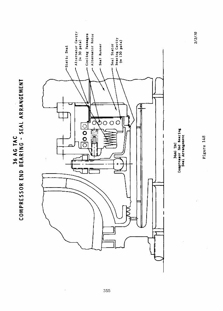
o
<on
CO
o
UJ
Oo
or^
IN
)- U<e c0) «l
O <
V «U VO.CA
oo
00
00
355

CO
Q_LUO
OO
UJCO
300•H
onO
orUJ
356
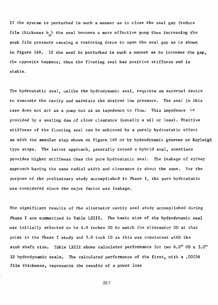
If the system is perturbed in such a manner as to close the seal gap (reduce
film thickness h ) the seal becomes a more effective pump thus increasing them
peak film pressure causing a restoring force to open the seal gap as is shown
in Figure 149. If the seal is perturbed in such a manner as to increase the gap,
the opposite happens; thus the floating seal has positive stiffness and is
stable.
The hydrostatic seal, unlike the hydrodynamic seal, requires an external device
to evacuate the cavity and maintain the desired low pressure. The seal in this
case does not act as a pump but as an impedence to flow. This impedence is
provided by a sealing dam of close clearance (usually a mil or less) . Positive
stiffness of the floating seal can be achieved by a purely hydrostatic effect
as with the annular step shown on Figure 149 or by hydrodynamic grooves or Rayleigh
type steps. The latter approach, generally termed a hybrid seal, sometimes
provides higher stiffness than the pure hydrostatic seal. The leakage of either
approach having the same radial width and clearance is about the same. For the
purpose of the preliminary study accomplished in Phase I, the pure hydrostatic
was considered since the major factor was leakage.
The significant results of the alternator cavity seal study accomplished during
Phase I are summarized in Table LXIII. The basic size of the hydrodynamic seal
was initially selected to be 6.0 inches OD to match the alternator OD at that
point in the Phase I study and 3.0 inch ID as this was consistent with the
stub shaft size. Table LXIII shows calculated performance for two 6.0" OD x 3.0"
ID hydrodynamic seals. The calculated performance of the first, with a .00056
film thickness, represents the results of a power loss
357
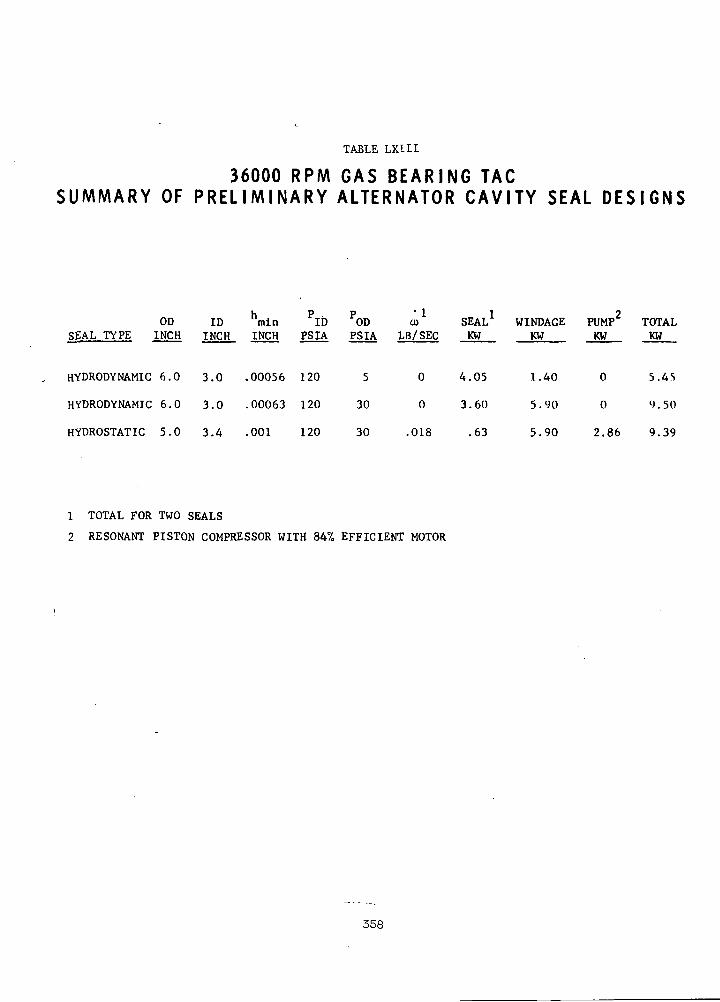
TABLE LXIII
36000 RPM GAS B E A R I N G TAGSUMMARY OF P R E L I M I N A R Y ALTERNATOR C A V I T Y SEAL D E S I G N S
OD ID hmln ?I P~~SEAL TYPE INCH INCH INCH PSIA PSIA LB/SEC
HYDRODYNAMIC 6.0 3.0 .00056 120
HYDRODYNAMIC 6.0 3.0 .00063 120
HYDROSTATIC 5.0 3.4 .001 120
ODPSIA
5
30
30
CD
LB/SEC
0
0
.018
SEALKW
4.05
3.60
.63
WINDAGEKW
1.40
5.90
5.90
PUMPKW
0
0
2.86
TOTALKW
5.45
«•) . 50
9.39
1 TOTAL FOR TWO SEALS
2 RESONANT PISTON COMPRESSOR WITH 84% EFFICIENT MOTOR
358

optimization which considered both seal power and alternator windage loss to
achieve minimum combined losses (5.45 lew). Although this operating film
thickness resulted in minimum combined power, the resulting cavity pressure
(5 psia) was insufficient to provide adequate heat transfer properties to
remove rotor pole tip electrical losses. It was determined that a cavity
pressure of at least 30 psia was required, thus the second hydrodynamic seal
design with the larger film thickness. As can be seen in Table LXIII the in-
creased film thickness reduces the seal loss but the resulting higher cavity
pressure causes a. significant increase in alternator windage. The combined
loss is, however, still within the 6 percent allowable.
The major potential problem with the hydrodynamic seal, like that of the thrust
bearing, is distortions and possible thermal runaway. The problem is much more
acute with the seal than with the thrust bearing, however, because of the former's
thinner film and higher heating density. Such a seal would necessarily require
a sophisticated cooling scheme.
The seal distortion problem is considerably simpler with the hydrostatic or hybrid
type seal because smaller radial widths and larger film thicknesses can be em-
ployed to reduce the heating density and the leakage flow can be utilized as a
partial coolant. The hydrostatic seal shown on Table LXIII was sized (5.0" OD x
3.4" ID) smaller than the previously discussed hydrodynamic seal to reflect
later iterations of the alternator and stub shaft sizes. The film thickness
was set at .001 inch to be consistant with normal bearing practice for the
size. The power loss of this seal is extremely small because of its small size
and large film thickness and of course the alternator windage is the same as
the 30 psia hydrodynamic seal case.
359
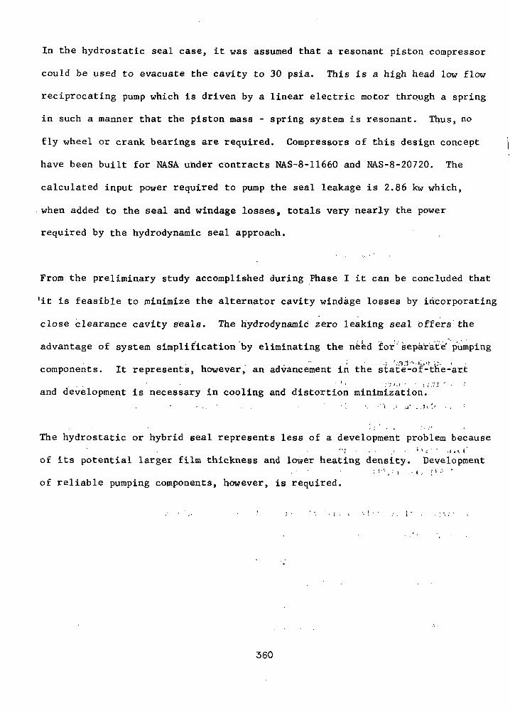
In the hydrostatic seal case, it was assumed that a resonant piston compressor
could be used to evacuate the cavity to 30 psia. This is a high head low flow
reciprocating pump which is driven by a linear electric motor through a spring
in such a manner that the piston mass - spring system is resonant. Thus, no
fly wheel or crank bearings are required. Compressors of this design concept
have been built for NASA under contracts NAS-8-11660 and NAS-8-20720. The
calculated input power required to pump the seal leakage is 2.86 kw which,
when added to the seal and windage losses, totals very nearly the power
required by the hydrodynamic seal approach.
From the preliminary study accomplished during Phase I it can be concluded that
!it is feasible to minimize the alternator cavity windage losses by incorporating
close clearance cavity seals. The hydrodynamic zero leaking seal offers the
advantage of system simplification by eliminating the need for"separate' pumping
" • • • -i ';3'1"%'K,f? '.'.' <components. It represents, however, an advancement in the state-of-the-art
... ' • . ' ' • . : ? > . > • • : (.I* " •and development is necessary in cooling and distortion minimization.
The hydrostatic or hybrid seal represents less of a development problem because"; • • .; •' s <; - - .!,*!'
of its potential larger film thickness and lower heating density. Development• - • • ; >•'',•' i --.<.- :'.''• '
of reliable pumping components, however, is required.
360
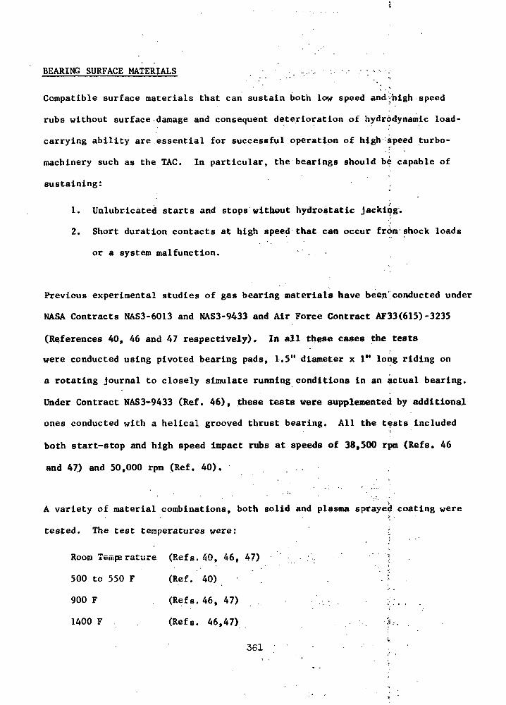
BEARING SURFACE MATERIALS
Compatible surface materials that can sustain both low speed and;high speed
rubs without surface damage and consequent deterioration of hydrodynamic load-
carrying ability are essential for successful operation of high 'speed turbo-
machinery such as the TAC. In particular, the bearings should be capable of
sustaining:
1. Unlubricated starts and stops without hydrostatic jacking.
2. Short duration contacts at high speed that can occur from shock loads
or a system malfunction. .
Previous experimental studies of gas bearing materials have been'conducted under
NASA Contracts NAS3-6013 and NAS3-9433 and Air Force Contract AF33(615)-3235
(References 40, 46 and 47 respectively). In all these cases the tests
were conducted using pivoted bearing pads, 1.5" diameter x 1" long riding on
a rotating journal to closely simulate running conditions in an actual bearing.
Under Contract NAS3-9433 (Ref. 46), these tests were supplemented by additional
ones conducted with a helical grooved thrust bearing. All the tests included
both start-stop and high speed impact rubs at speeds of 38,500 rpm (Refs. 46
and 47) and 50,000 rpm (Ref. 40). ..
A variety of material combinations, both solid and plasma sprayed coating were
tested. The test temperatures were:
Room Temps rature (Refs. 40, 46, 47) :',;
500 to 550 F (Ref. 40)
900 F (Refs. 46, 47) :
1400 F (Refg. 46,47)
361

At room temperature and in the 500-550 F temperature range, the combination
of chrome oxide vs. chrome oxide proved to be far superior to any of the
other combinations tested and it exhibited excellent tolerance of both re-
peated starts and stops and repeated high speed rubs. At 900 F, however,
the wear rate was quite high so that other combinations, notably aluminum
oxide vs. nickel chrome bonded chrome carbide, were preferred both at that
temperature and at 1400 F.
In view of its excellent performance at temperatures up to 550 F, chrome
oxide vs. chrome oxide was used for the bearings of the NASA's "A" Engine
turbocompressor simulator and turboalternator. It has also been used suc-
cessfully and without any incidents in a variety of other gas lubricated ro-
tating machinery. Table LXIV lists the field experience with this material
combination.
Under NASA Contract NASwl713 the turbocompressor simulator of the NASA s "A"
Engine has been used to experimentally evaluate the dynamic performance of
gas bearings under vibration and shock conditions. Table LXV, lists the prin-
cipal tests that have been conducted to-date. Here again, the material com-
bination is self-mated chrome oxide and it has demomstrated the 'capability of
withstanding repeated high speed contacts without significant wear, surface
damage or consequent deterioration of hydrodynamic load capacity.-
Presently, in connection with the preliminary design and development of an
advanced gas-lubricated, air breathing aircraft engine for the U.S« Army,
under Contract DAA 302-69-C-0062, additional material testing under start-
stop conditions is in progress using the following material combinations:
362

COEH£5W
s"
EHOS<EHCO.
Q
os<CO
Q
OS<HCO
Q
- OS<
CO
Q
QHQt-H
OOS
o
3o<^
<;i— <Q
SS<
CO
£xOSQ
QWQr-4
OOSao
3o<ID
t
EHCO
OS
H
OSOfa
US
8££i— iHEHXH
>i
t-HEHCOWEH
Ot— 1
§CQ1-1>
.H
ajH
Z
0^^
OOUJ
0
o"^•^ '
C£^c1 B 1
CQ
^_
Q£
_ _
^£-
—
^M»
-"J
UJO£o_
'o^_•
COPS
co Q a
oisrHos<Wm
wrH
E0
Sootf
BQHEH<0
Saa3<oQHEH<
8«
oN
OSO
•gCH
HO
H
S
1H
Q
HMCM
H OEH K<J O
S t-H
t3 EH
8.5o
O OO 0O O300
D
asOS H
P3 r-(
>- ijHQ
(D CO
O} CJ}rH r-l
OSrq Q
^ WS wOiCO
QH Q
. H Z
S <
S a^ f e
rt OO r-l
B m o•p
00 ff>i-l r-l (N
t2MOSQ
OS 030 0H EH0 O
os S osS5
1—4EH<O
<
O O O
WPi OH F^ fid
O 55 OEH Q W H
OS > ft OS
CJ < W O
O
oooCO
Hi0
Sos|Vj
Jo
iH
S
1
Q
O
O
o"1-1
z
<<
§os0H<
0OIN
00<D
r-l
-Boi
OD< OB 0
oo m
.
os
s
rH
8 So'" asOS W rH
O CM OSO S O
W O B
O O 0o o oCV1 •H* Tf
1-1
CO
E- CO< > w
O HQ O <W OS rJ S CO
O f- ^ O O < <
O c^ «£ B O1-1 H H W (K o
•K 'S EH (X fa
•JJ ^S S B
+-| S -P S 0) Ort ni +J n
O O rtOH O CM O rl OBO B O W +J
- O.00 CD M IN O &i-l IN r-l i-l ^ 3
W WOS S5 Sz;O - 1— 1 1-H
1 1 1 "H EH
OS<N OS O
CH OS O CO
8 O ' H COfa O <C W
•J Z is OSOJ . H OS W u.
> H O H Z W S S O SO S C O r - l M H M O O
Z OS WO W O rJO P< OS m CQ Dc j s o - S - S sWOH <D < P MW O B = E H r f - W
363
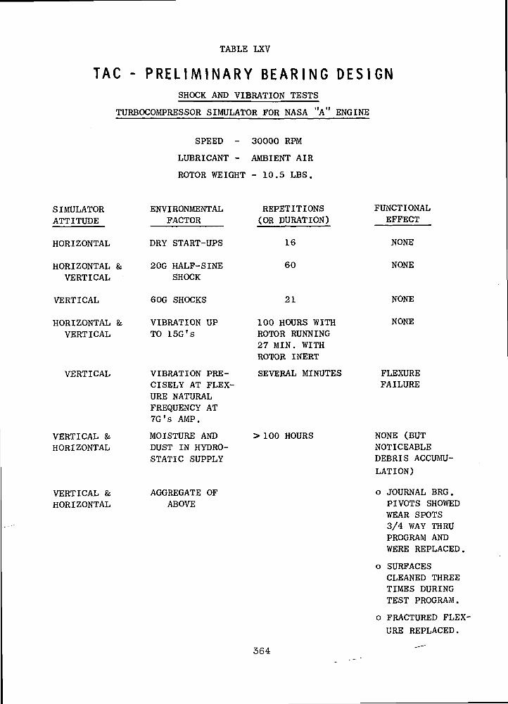
TABLE LXV
TAG - P R E L I M I N A R Y B E A R I N G D E S I G NSHOCK AND VIBRATION TESTS
TURBOCOMPRESSOR SIMULATOR FOR NASA "A" ENGINE
SPEED - 30000 RPM
LUBRICANT - AMBIENT AIR
ROTOR WEIGHT - 10.5 LBS.
SIMULATORATTITUDE
HORIZONTAL
HORIZONTAL &VERTICAL
VERTICAL
HORIZONTAL &VERTICAL
VERTICAL
VERTICAL &HORIZONTAL
VERTICAL &HORIZONTAL
ENVIRONMENTALFACTOR
DRY START-UPS
20G HALF-SINESHOCK
GOG SHOCKS
VIBRATION UPTO ISG's
VIBRATION PRE-CISELY AT FLEX-URE NATURALFREQUENCY AT7G's AMP.
MOISTURE ANDDUST IN HYDRO-STATIC SUPPLY
AGGREGATE OFABOVE
REPETITIONS(OR DURATION)
16
60
21
100 HOURS WITHROTOR RUNNING27 MIN. WITHROTOR INERT
SEVERAL MINUTES
>100 HOURS
FUNCTIONALEFFECT
NONE
NONE
NONE
NONE
FLEXUREFAILURE
NONE (BUTNOTICEABLEDEBRIS ACCUMU-LATION)
o JOURNAL BRG.PIVOTS SHOWEDWEAR SPOTS3/4 WAY THRUPROGRAM ANDWERE REPLACED.
o SURFACESCLEANED THREETIMES DURINGTEST PROGRAM.
o FRACTURED FLEX-
URE REPLACED.
364
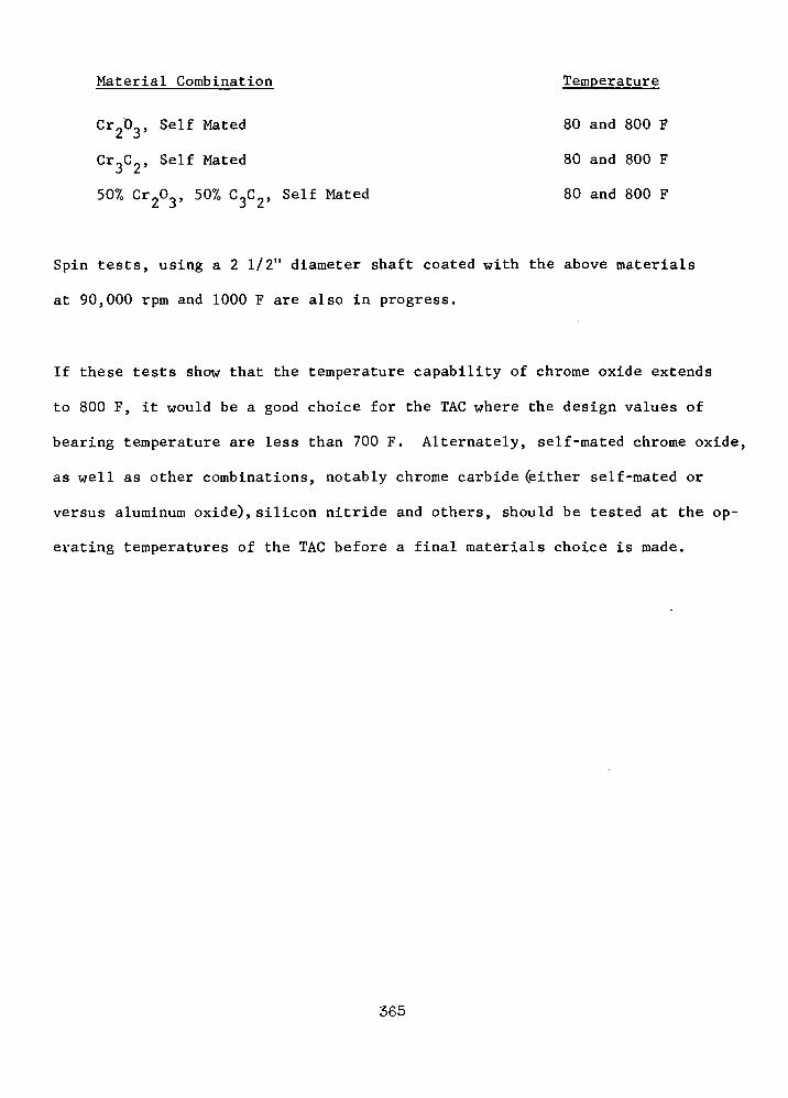
Material Combination Temperature
Cr 0 Self Mated 80 and 800 F
Cr C , Self Mated 80 and 800 F
50% Cr203, 50% C3C2, Self Mated 80 and 800 F
Spin tests, using a 2 1/2" diameter shaft coated with the above materials
at 90,000 rpm and 1000 F are also in progress.
If these tests show that the temperature capability of chrome oxide extends
to 800 F, it would be a good choice for the TAG where the design values of
bearing temperature are less than 700 F. Alternately, self-mated chrome oxide,
as well as other combinations, notably chrome carbide (either self-mated or
versus aluminum oxide), silicon nitride and others, should be tested at the op-
erating temperatures of the TAG before a final materials choice is made.
365
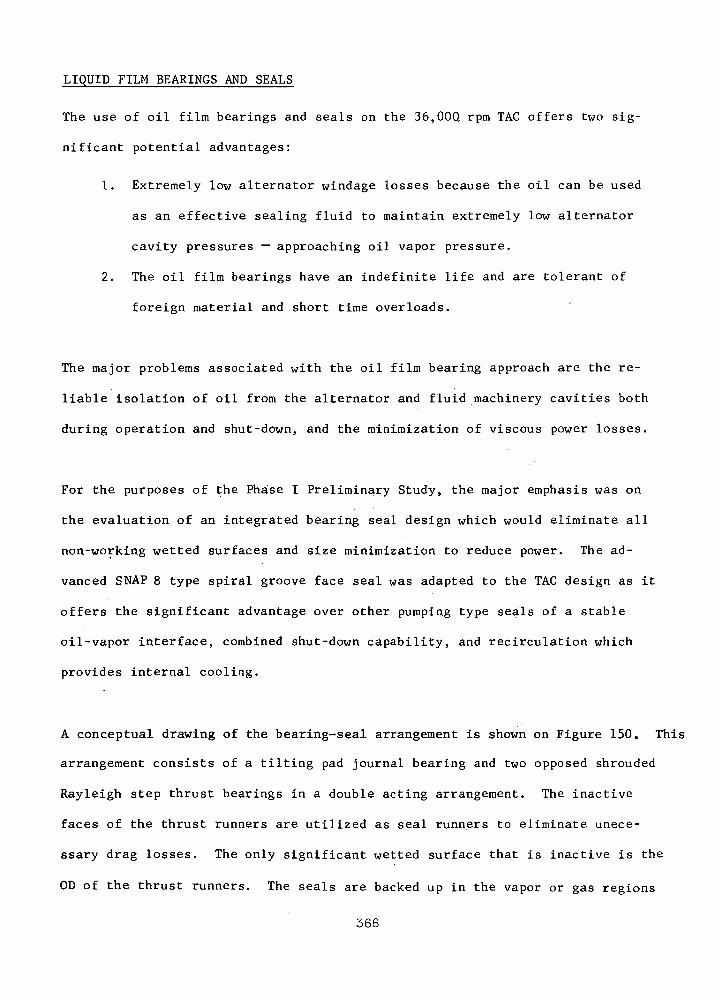
LIQUID FILM BEARINGS AND SEALS
The use of oil film bearings and seals on the 36.00Q rpm TAG offers two sig-
nificant potential advantages:
1. Extremely low alternator windage losses because the oil can be used
as an effective sealing fluid to maintain extremely low alternator
cavity pressures — approaching oil vapor pressure.
2. The oil film bearings have an indefinite life and are tolerant of
foreign material and short time overloads.
The major problems associated with the oil film bearing approach are the re-
liable isolation of oil from the alternator and fluid machinery cavities both
during operation and shut-down, and the minimization of viscous power losses.
For the purposes of the Phase I Preliminary Study, the major emphasis was on
the evaluation of an integrated bearing seal design which would eliminate all
non-working wetted surfaces and size minimization to reduce power. The ad-
vanced SNAP 8 type spiral groove face seal was adapted to the TAG design as it
offers the significant advantage over other pumping type seals of a stable
oil-vapor interface, combined shut-down capability, and recirculation which
provides internal cooling.
A conceptual drawing of the bearing-seal arrangement is shown on Figure 150. This
arrangement consists of a tilting pad journal bearing and two opposed shrouded
Rayleigh step thrust bearings in a double acting arrangement. The inactive
faces of the thrust runners are utilized as seal runners to eliminate unece-
ssary drag losses. The only significant wetted surface that is inactive is the
OD of the thrust runners. The seals are backed up in the vapor or gas regions
366

36000 RPM OIL L U B R I C A T E D TAGB E A R I N G - S E A L A R R A N G E M E N T
CompressorInlet Duct
Buffer Gas& Oil Vapor
AlternatorRotor Cavity
ShroudedStep Thrust
HydrodynamicSeal
36000 rpm OH Lubricated TAGBearing - Seal Arrangement
Figure 150
367

by molecular pumps on the shaft to aid in returning oil droplets to the hydro-
dynamic seal. On the compressor side is a gas buffer seal to insure that no
oil vapor enters the cycle system. The buffer gas-oil vapor line would be
connected to the separation system which is discussed in Section
The power consumed by the bearing seal arrangement shown in Figure 150 is shown
in Figure 151 as a function of shaft diameter. This is the sum of one journal
bearing, two thrust bearings, two seals, and the losses at the runner OD. The
journal bearing has a length to diameter ratio of 0.25 and the thrust bearing
was sized to carry 600 Ibs. (ss 4 G) at a film thickness of .0005 inches. Since
most of the power is consumed by the thrust bearings, particular care was taken
to insure that they were made no larger in radial width than was required to
support the thrust load. The affect of reduced OD to ID ratio with increasing
shaft diameters (ID) has been factored into the power loss calculations.
As can be seen from Figure 151 the losses associated with a single, bearing-seal
are large and increase very rapidly with diameter. Furthermore, the flow re-
quired to be pumped through the system to remove the heat generated is sizable.
It should be pointed out that the 25 F At used in calculating the Figure 151 flow
curve may be excessive when considering lubricant life. If lower maximum lub-
ricant temperatures are required, the flow rate will either have to be increased
or a cavity cooler utilizing the lower temperature coolant will have to be in-
corporated.
Performance calculations were made on one configuration of the SNAP 8 type
hydrodynamic face seal to establish its feasibility to the TAG application.
This seal is shown schematically on Figure 152. The size shown was the mini-
mum conceivable that could be incorporated into the aft end of the TAG arrange-
368

36000 RPM OIL L U B R I C A T E D TACBEARING AND SEAL LOSSES
ALTERNATOR D R I V E B E A R I N G CONFIGURATION
.016/- Shroud
I i ipThriist N » I I II I SealA J L\
Journal
Q.250 Min
| j-.25-.
— *
J^!^L
— .002 —
•^MB
_
ShaftDia.
70
60
<n 3
§ 5 40
3 -H -if.Q t-l JO
ft, O
H <20
10
Speed = 36000 rpm
Lubricant = Conoco 73-L at 496°F
' Power Loss
I1.0 2.0 3.0
Shaft Diameter - inches
Total Power = Sum of:
1. Journal at 100 Ibs.2. Two Thrust Bearings,
0 Load.3. Two Seals = Thrust
Bearing Power.4. Two Shrouds
Thrust Bearings Sized For:
600 Ibs at h = .0005 in.
Flow Required toLimit Nt to 25°F
4.0
Figure 151
369

T Y P I C A L H Y D R O D Y N A M I C OIL SEAL
R 1.70 Dia.
\
16
agag + ar
2.125 Dia.
.0006IIII /- Pump-Out Desigjn4 - -*- -.
< v
120 psla
0. 1 ps
.08"-
.07
-.07'
.001
120 psia
Operating Condi t ions :
N = 36000 rpmLubricant - Conoco 73-L at 496°FStiffness - 1.2 x 10⁵ Ib/inPower Loss - % .6 H.P.Circulating Flow - 26.2 Ib/hrAdiabatic At - 84°F
Figure 152
370
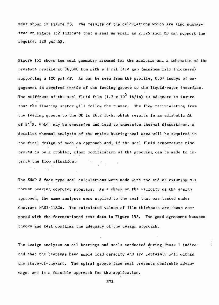
ment shown in Figure 28. The results of the calculations which are also summar-
ized on Figure 152 indicate that a seal as small as 2.125 inch OD can support the
required 120 psi AP.
Figure 152 shows the seal geometry assumed for the analysis and a schematic of the
pressure profile at 36,000 rpm with a 1 mil face gap (minimum film thickness)
supporting a 120 psi AP. As can be seen from the profile, 0.07 inches of en-
gagement is required inside of the feeding groove to the liquid-vapor interface.
The stiffness of the seal fluid film (1.2 x 10 Ib/in) is adequate to insure
that the floating stator will follow the runner. The flow recirculating from
the feeding groove to the OD is 26.2 Ib/hr which results in an adiabatic At
of 84 Fi which may be excessive and lead to excessive thermal distortions. A
detailed thermal analysis of the entire bearing-seal area will be required in
the final design of such an approach and, if the seal fluid temperature rise
proves to be a problem, minor modification of the grooving can be made to im-
prove the flow situation.-
The SNAP 8 face type seal calculations were made with the aid of existing MTI
thrust bearing, computer programs. As a check on the validity of the design
approach, the same analyses were applied to the seal that was tested under
Contract NAS3-11824. The calculated values of film thickness are shown com-
pared with the forementioned test data in Figure 153. The good agreement between
theory and test confirms the adequacy of the design approach.
The design analyses on oil bearings and seals conducted during Phase I indica-
ted that the bearings have ample load capacity and are certainly well within
the state-of-the-art. The spiral groove face seal presents desirable advan-
tages and is a feasible approach for the application.
371
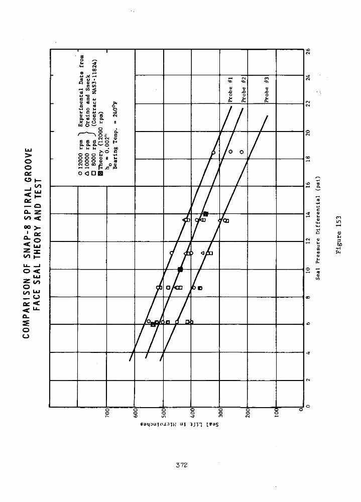
oo
_l *"
— oa. zon <oo >-
|2on JEu 1O <
LU2 on
oo
oo
uf
372

The seal, however, still represents a development item since its performance
has not been demonstrated at TAG speed and pressure conditions. Also of
significant system importance, the power consumption of the oil film bearings
and seals represents a sizable percentage of the TAG output.
373
ROLLING ELEMENT BEARINGS
There are a number of very good reasons why rolling element bearings
should be given full consideration for use in the Brayton TAG system:
Ball bearing technology is well-established by years of analytical
and empirical experience. Applications have recently been made in
increasingly hostile environments. Bearing material technology advances
steadily, allowing significant increases in life. While the required
bearings would not likely be standard or easily obtainable, they would
probably be relatively minor variations not requiring analytical design
studies to the extent required of gas or oil film bearings.
Ball bearings would be smaller in size than gas or oil film bearings
supporting the same loads.
Angular contact ball bearings can support thrust loads without the
need for the separate thrust bearings which gas or oil film bearings
require.
Short interruptions of the lubricant supply can be tolerated by
ball bearings without the catastrophic results which would occur in
fluid film bearings.
The friction losses in mist lubricated ball bearings are relatively
low - comparable to or less than for fluid film bearings, depending upon
the conditions being compared. • .
The starting torque is low because of rolling contact between the
ball bearing components instead of the possibly dry sliding contact
between fluid film bearing components. .
The internal clearances of ball bearings will probably be tighter
than those of fluid film bearings, therefore providing better control
of blade tip and seal clearances.
These arguments are summarized in Table LXVI.
Approach to Ball Bearing Analysis
The basic analysis tool used was the RECAP computer program, a
well-proved code used generally throughout the country. It is based
upon the standard AFBMA formulas, with certain improvements such as the
addition of centrifugal loading of the outer races by the balls. Bearing
374
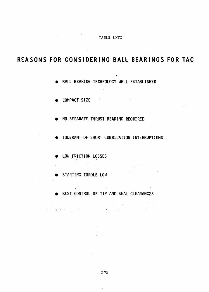
TABLE LXVI
R E A S O N S FOR C O N S I D E R I N G BALL B E A R I N G S FOR TAG
BALL BEARING TECHNOLOGY WELL ESTABLISHED
COMPACT SIZE
NO SEPARATE THRUST BEARING REQUIRED
• TOLERANT OF SHORT LUBRICATION INTERRUPTIONS
• LOW FRICTION LOSSES
• STARTING TORQUE LOW
BEST CONTROL OF TIP AND SEAL CLEARANCES
375

B-LQ lives (90% survival) are calculated for the bearings, assuming
"bearing quality" 52100 steel.
An increased life factor of 20 was applied, assuming the use of
ausformed M-50 steel. This factor is believed to be conservatively
realistic, based upon recent tests.( 8) ^he ausforming process does
introduce considerable complexity in the fabrication process.
Since the BIQ life criteria is not considered sufficiently reliable
for a space system, it was attempted to find design solutions based upon
B0<1 life (for two bearings, 0.9992 = 0.998 survival) without success
for the required five year life. Therefore, the B^ life criteria
(0.992 = 0.980) was used. The bearing life factor used to calculate
time to failure was reduced from 1 to 0.1.(49 '
•• A criteria which was added to the computer results was that of
comparing the bearing DN values (bearing bore diameter in mm x operating
speed in rpm) for each possible solution with DN values of bearings in
service and their survival potential.
Computer calculations were made for several fixed loading conditions
to determine the optimum bearing sizes within practical limits to produce
maximum life. Also .considered were different number of balls, several
ball contact angles, and the feasibility of using hollow balls to
decrease internal bearing centrifugal loads.
Necessary items of input information for the computer analyses
were the bearing equivalent load, composed of rotor weight, dynamic
radial load, axial thrust, and bearing preload components. In order
to reduce the dynamic radial loads by providing some measure of damping,
not provided.by the ordinary bearing designs, radially compliant
mountings described later were used.
With all input information calculated by hand, the computer
analyses were made for several loading conditions, corrected using the
material and B, life factors, plotted, and the B-, lives were calculated
for the design point.
The same life versus load curves for various bearing configurations
were used to estimate B, lives for off-design conditions, including
maneuver loads greater than normal loads.
376
The effects of decreased race hardness and oil viscosity at elevated
temperatures were estimated. '
The effects of elastohydrodynamic lubrication parameters on life at
different operating conditions were estimated from the same literature.
Assuming the lubricant supply system to be similar to that of a
previous NASA study (5^ ), as directed, the lubrication system power
losses were estimated.
This approach is summarized in Table LXVII.
Parasitic Power Losses in Lubrication System of TAG on Ball Bearings
The parasitic power losses of the lubrication system required to
support the ball bearings were estimated from ^ ' for a 35 mm bearing
operating at 36 krpm. The two compartments are the same except that the
forward bearing compartment has a probe disk and a separator which the aft
bearing does not have, giving the forward compartment increased losses of
40 watts. The total loss for both compartments is 1.760 kw, as shown by
Table LXVIII,
The referenced bearings had lighter effective bearing loads-than
expected for-the present system (about 150 versus 350 pounds), but the
increased load will not significantly affect bearing heat generation.
Radially Compliant Support for Ball Bearing
An example of a radially compliant support for a ball bearing which
is presently being used successfully in a major aircraft gas turbine is
shown by Figure 154. Radial compliance (radial spring rate of about
10,000 Ib/in) is provided by a circumferentially slotted cylinder which
is fixed on one end and has the bearing mounted in the other. The material
left between slots forms a number of axial beams of high axial stiffness
which maintain good axial position control. The OD of the end of the
slotted cylinder which contains the bearing fits with a clearance of a
few mils inside a static ring. Oil is introduced between the ring and the
end of the slotted cylinder to provide oil-film squeeze damping. The
small radial clearance also acts as a snubber to limit radial motion of
the ball bearing and main rotor shaft.
With this system significant improvements in dynamic rotor response
were obtained over that of a conventionally stiff-mounted ball bearing,
377

TABLE LXVII
A P P R O A C H TO BALL BEARING A N A L Y S I S
• UTILIZE RECAP COMPUTOR PROGRAM TO CALCULATE BEARING BIQ LIVES
- 52100 STEEL ASSUMED
• APPLY INCREASED LIFE FACTOR OF 20 FOR AUSFORMED M-50 STEEL
• APPLY DECREASED LIFE FACTOR OF 0.10 FOR B] LIVES
- BQ 1 LIFE DESIRED BUT NOT POSSIBLE
• COMPARE BEARING DN VALUES WITH EXPERIENCE
• OPTIMIZE BALL SIZE
• CALCULATE BEARING EQUIVALENT LOAD CONSIDERING ROTOR WEIGHT,DYNAMIC RADIAL LOAD, AXIAL THRUST, AND BEARING PRELOAD
- USE RADIALLY COMPLIANT MOUNTING TO DECREASE DYNAMIC LOAD* i . * '.
• CALCULATE B] LIFE AT DESIGN POINT
• ESTIMATE EFFECTS OF LOADS GREATER THAN DESIGN LOAD
• ESTIMATE BEARING LIFE EFFECTS OF DECREASED RACE HARDNESS ANDOIL VISCOSITY AT OPERATING TEMPERATURE
• ESTIMATE ELASTODYDRODYNAMIC LUBRICATION EFFECTS ON LIFE
• ESTIMATE LUBRICATION SYSTEM POWER LOSSES BASED ON PREVIOUSNASA WORK
378
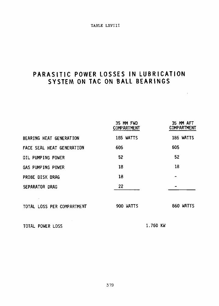
TABLE LXVIII
P A R A S I T I C POWER L O S S E S IN L U B R I C A T I O NSYSTEM ON TAC ON BALL B E A R I N G S
BEARING HEAT GENERATION
FACE SEAL HEAT GENERATION
OIL PUMPING POWER
GAS PUMPING POWER
PROBE DISK DRAG
SEPARATOR DRAG
35 MM FWDCOMPARTMENT
185 WATTS
605
52
18
18
22
35 MM AFTCOMPARTMENT
185 WATTS
605
52
18
TOTAL LOSS PER COMPARTMENT 900 WATTS 860 WATTS
TOTAL POWER LOSS 1.760 KW
379

E X A M P L E OF R A D I A L L Y C O M P L I A N T , A X I A L L Y ST IFF ,S N U B B E D S U P P O R T F O R BALL B E A R I N G
DAMPER ANDSNUBBER
SLOTTEDSQUIRREL-CAGE
SUPPORT \
TURBINE
Figure 154,
380
as reported earlier. The damper provides about 20 Ib-sec/in of damping,
which reduces the dynamic radial load on per bearing to 105 pounds at
36,000 rpm.
Ball Size Optimization
Computer calculations were made for 35 mm bore angular contact
bearings with 18° contact angle and balls of 0.188 - 0.500 in. diameter.
The two equivalent loads used covered the range of interest, the 39
pound equivalent load per bearing being overly optimistic and the 512
pound load overly pessimistic. The computer calculations were adjusted
for B^ life and ausformed M-50 steel material.
The 5-year (43,829 hours) life line of Figure 155 shows that the
heavier load has no chance to meet the life requirements. Both loading
conditions indicate optimum ball sizes in the range of 0.375 in. or
slightly greater. For all subsequent calculations particular attention
was given to these sizes.
Not shown are the studies made using different bearing sizes, contact
angles, numbers of balls, and hollow balls. The latter produce
significantly longer lives by decreasing the centrifugal stresses due
to the mass of the balls. However, hollow balls cannot be produced by
ausforming and therefore are of no value because the favorable gains
do not offset the loss in material life factor. Also, hollow balls have
reliability problems at the seam where two hollow hemispheres are joined.
The elimination of the 50 mm bearings from consideration appears
proper from empirical experience. The 35 mm bearings have a DN value
of 1.26 x 10^ mm-rpm while the 50 mm bearing DN is 1.80 x 106 mm-rpm.
The empirical DN value for reliably achieving long operating lives is
about 10 mm-rpm.
Calculation of Equivalent Loads
Using the formula: P = XVFr + YF0 ^53 ^
*• 3.
where Fa = axial load, Ib.
F = radial load, Ib.
P = equivalent load, Ib.
V = rotation factor, unity when the inner ring rotates with respectto the load
X = radial factor (tabular function)
381
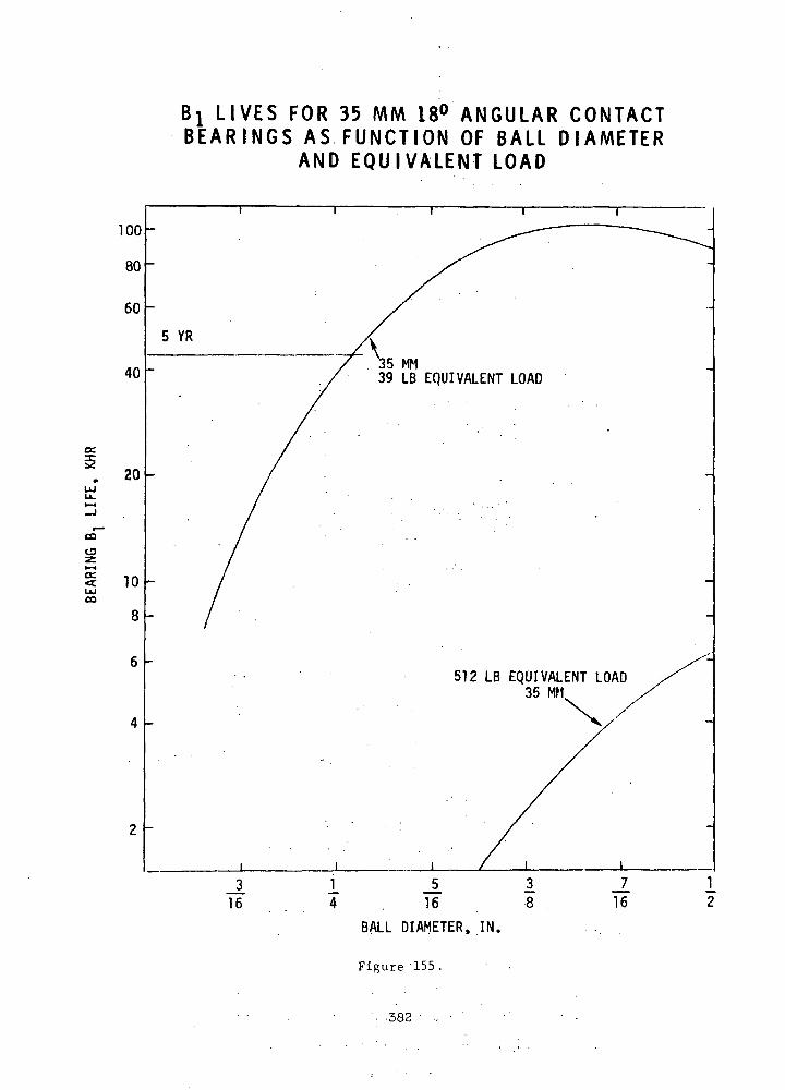
B! LIVES FOR 35 MM 18° ANGULAR CONTACTBEARINGS AS FUNCTION OF BALL DIAMETER
AND EQUIVALENT LOAD
100
80
60
40
5 YR
39 LB EQUIVALENT LOAD
20
CO
C3
oc.<:CO
10
8
2 -
512 LB EQUIVALENT LOAD35 MM
_L_316
1 JL4 . 1 6
BALL DIAMETER, IN.
Figure '155.
!8
J_16
'. 382
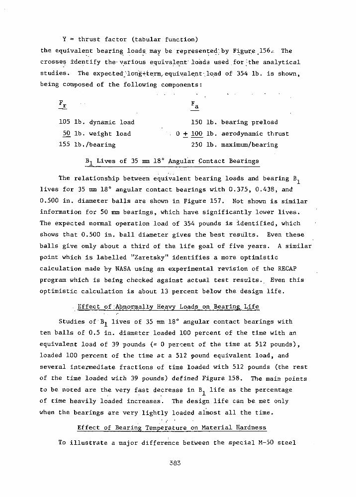
Y = thrust factor (tabular function)
the equivalent bearing loads, may be represented;. by Figure 156.. The
crosses Identify the- various equivalent loads used for : the analytical
studies. The expected 'iongTterm. equivalent -load of 354 Ib . is shown,
being composed of the following components :
£r '• *a '
105 Ib. dynamic load 150 Ib. bearing preload
50 Ib. weight load ° ± 10° lb« aerodynamic thrust
155 Ib . /bearing 250 Ib . maximum/bearing
B-^ Lives of 35 mm 18° Angular Contact Bearings
The relationship between equivalent bearing loads and bearing B
lives for 35 mm 18° angular contact bearings with 0.375, 0.438, and
0.500 in. diameter balls are shown in Figure 157. Not shown is similar
information for 50 mm bearings , which have significantly lower lives .
The expected normal operation load of 354 pounds is identified, which
shows that 0.500 in. ball diameter gives the best results. Even these
balls give only about a third of the life goal of five years . A similar
point which is labelled "Zaretsky" identifies a more optimistic
calculation made by NASA using an experimental revision of the RECAP
program which is being checked against actual test results. Even this
optimistic calculation is about 13 percent below the design life.
. Effect of : Abnormally Heavy Loads on Bearing Life
Studies of B-i lives of 35 mm 18° angular contact bearings with
ten balls of 0.5 in. diameter loaded 100 percent of the time with an
equivalent load of 39 pounds (= 0 percent of the time at 512 pounds),
loaded 100 percent of the time at a 512 pound equivalent load, and
several intermediate fractions of time loaded with 512 pounds (the rest
of the time loaded with 39 pounds) defined Figure 158. The main points
to be noted are the very fast decrease in B, life as the percentage
of time heavily loaded increases. The design life can be met only
when the bearings are very lightly loaded almost all the time.
Effect of Bearing Temperature on Material Hardness
To illustrate a major difference between the special M-50 steel
383
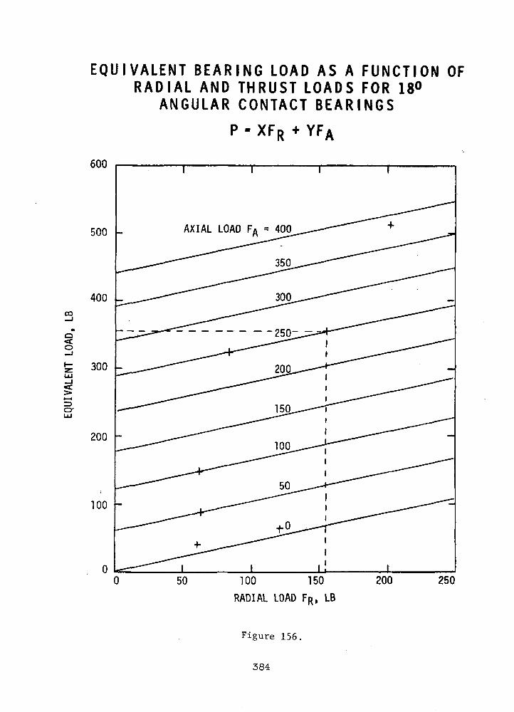
CO
o<co
o-
EQUIVALENT BEARING LOAD AS A FUNCTION OFR A D I A L AND THRUST LOADS FOR 18°
ANGULAR CONTACT B E A R I N G S
P - XFR + YFA
600
500 -
400 _
300 -
200 -
100 -
AXIAL LOAD FA - 400
50 TOO 150
RADIAL LOAD FR, LB
250
Figure 156.
384
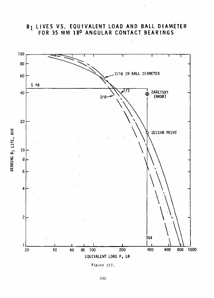
L I V E S VS. E Q U I V A L E N T LOAD AND BALL D I A M E T E RFOR 35 MM 18° A N G U L A R C O N T A C T B E A R I N G S
100
80
60
40
l l l I
5 YR
20
10
8
LUCO
20
7/16 IN BALL DIAMETER
ZARETSKY(NASA)
DESIGN POINT
j I40 60 80 TOO 200
EQUIVALENT LOAD P, LB
Figure 157.
400 600 800 1000
385
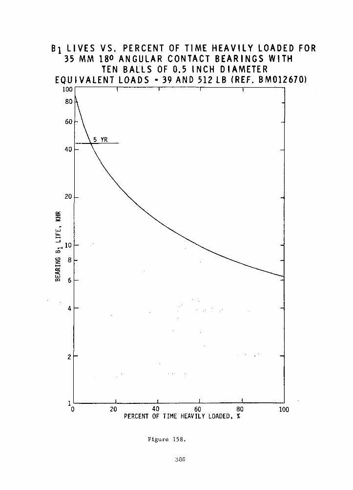
I L I V E S VS. P E R C E N T OF TIME H E A V I L Y L O A D E D FOR35 MM 180 A N G U L A R C O N T A C T B E A R I N G S W I T H
TEN BALLS OF 0.5 INCH D I A M E T E RE Q U I V A L E N T L O A D S - 39 AND 512 LB (REF. BM012670)
20 40 60 80PERCENT OF TIME HEAVILY LOADED, %
100
Figure 158.
386
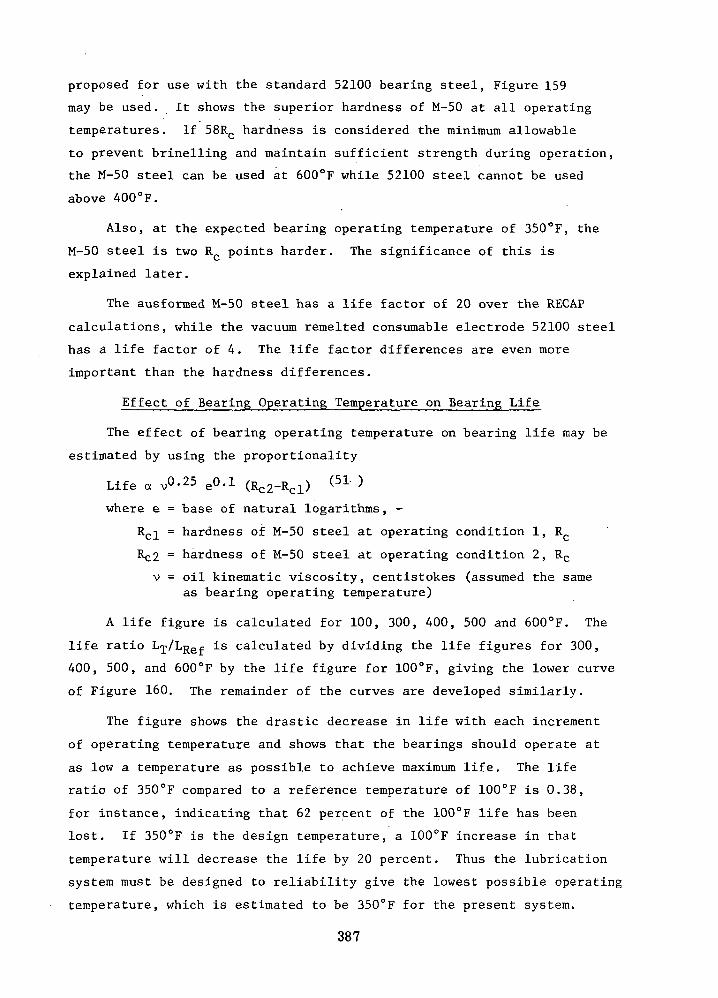
proposed for use with the standard 52100 bearing steel, Figure 159
may be used. It shows the superior hardness of M-50 at all operating
temperatures. If 58RC hardness is considered the minimum allowable
to prevent brinelling and maintain sufficient strength during operation,
the M-50 steel can be used at 600°F while 52100 steel cannot be used
above 400°F.
Also, at the expected bearing operating temperature of 350°F, the
M-50 steel is two RC points harder. The significance of this is
explained later.
The ausformed M-50 steel has a life factor of 20 over the RECAP
calculations, while the vacuum remelted consumable electrode 52100 steel
has a life factor of 4. The life factor differences are even more
important than the hardness differences.
Effect of Bearing Operating Temperature on Bearing Life
The effect of bearing operating temperature on bearing life may be
estimated by using the proportionality
Life a v°-25 eO-1 (R -Rd) (51 }
where e = base of natural logarithms, -
Rcl = hardness of M-50 steel at operating condition 1, RC
Rc2 = hardness of M-50 steel at operating condition 2, Rc
v = oil kinematic viscosity, centistokes (assumed the sameas bearing operating temperature)
A life figure is calculated for 100, 300, 400, 500 and 600°F. The
life ratio LT/LRe^ is calculated by dividing the life figures for 300,
400, 500, and 600°F by the life figure for 100°F, giving the lower curve
of Figure 160. The remainder of the curves are developed similarly.
The figure shows the drastic decrease in life with each increment
of operating temperature and shows that the bearings should operate at
as low a temperature as possible to achieve maximum life. The life
ratio of 350°F compared to a reference temperature of 100°F is 0.38,
for instance, indicating that 62 percent of the 100°F life has been
lost. If 350°F is the design temperature, a 100°F increase in that
temperature will decrease the life by 20 percent. Thus the lubrication
system must be designed to reliability give the lowest possible operating
temperature, which is estimated to be 350°F for the present system.
387
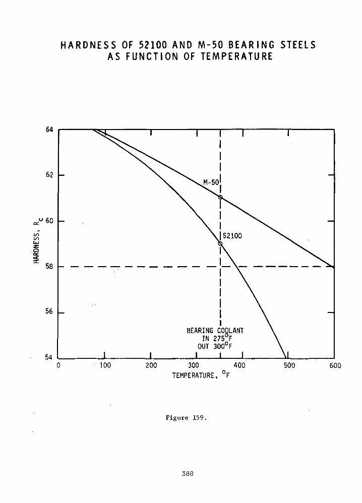
H A R D N E S S OF 52100 AND M-50 B E A R I N G STEELSAS F U N C T I O N OF T E M P E R A T U R E
64
62
60
oo(/5LM
I58
56
54
BEARING COOLANTIN 275°F
OUT 300°FI I I
100 200 300 400TEMPERATURE, °F
500 600
Figure 159.
388
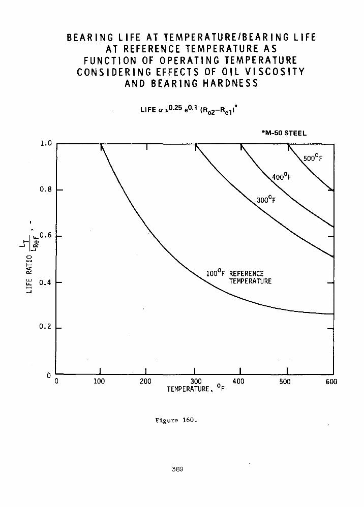
B E A R I N G L IFE A T T E M P E R A T U R E / B E A R I N G L IFEA T R E F E R E N C E T E M P E R A T U R E A S
F U N C T I O N OF O P E R A T I N G T E M P E R A T U R EC O N S I D E R I N G E F F E C T S O F O I L V I S C O S I T Y
A N D B E A R I N G H A R D N E S S
LIFE«,A25e0.1
•M-50 STEEL
1.0
0.8
0.6
0.4
500°F
100"F REFERENCETEMPERATURE
0.2
100 200 300TEMPERATURE, °F
400 500 600
Figure 160.
389
Elastohydrodynamic Effects on Bearing Life
A ball bearing film parameter A may be calculated from the relation-
ship shown in Table LXIX. "
A = H (V0 a)0-7 N0.7 -0.09 (50 )
where H = factor from reference, which is a function of bearing diameterand series
N = operating speed, rpm
P = bearing equivalent load, Ib.
A = bearing film parameter -
P0a = viscosity - pressure factor, which is a function of oilkinematic viscosity
The table shows that the light and medium series bearings have
film parameters which are so low that lubricant-related surface distress
will occur because their elastohydronamic films will not separate the
contacting surfaces. Extremely short bearing lives will result. While
the heavy series has a thicker elastohydrodynamic film, surface distress
can be expected to produce lives lower than the standard expectations.
Therefore, the previous life estimations must be revised downward.
Lubricant Loop for TAG on Ball Bearings
A schematic of the lubricant loop for the TAC on ball bearings,
similar to that of Reference ^52 ), is shown by Figure 161. Dry cycle
gas, cycle gas mixed with oil mist, and liquid oil flow loops are
identified with their rates in Ib/hr.
Shown on Table LXX are the major parameters of the lubrication
system. The parameters are based upon the 10.5 kw power level of
Reference ( ), but would be maintained as listed in every respect
unless the present TAG system required variations. Certainly, adjust-
ments in pressures and temperature would be required because of the
different compressor operating conditions, and these changes would
require flow rate adjustments. A complete lubrication system analysis
would be required in a later phase of the program.
The referenced-study had a 6 kw system operating at 36 krpm. The
turbine and compressor operated at temperatures similar to the present
system, but with compressor inlet gas at 14.2 psia through a 1.9
390
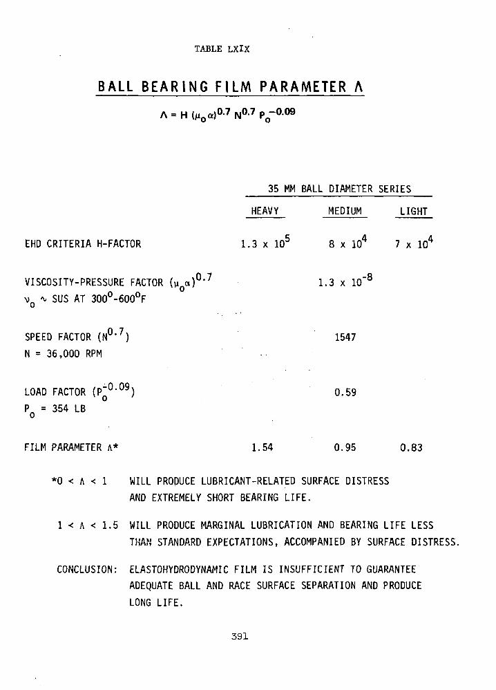
TABLE LXIX
BALL B E A R I N G FILM PARAMETER A
EHD CRITERIA H-FACTOR
35 MM BALL DIAMETER SERIES
HEAVY
1.3 x
MEDIUM LIGHT
8 x 10⁴ 7 x 10⁴
VISCOSITY-PRESSURE FACTOR
VQ * SUS AT 300°-600°F
SPEED FACTOR (N0>7)
N = 36,000 RPM
1.3 x 10
1547
-8
LOAD FACTOR (P~°'°9)
PQ = 354 LB
0.59
FILM PARAMETER A* 1.54 0.95 0.83
*0 < A < 1 WILL PRODUCE LUBRICANT-RELATED SURFACE DISTRESS
AND EXTREMELY SHORT BEARING LIFE.
1 < A < 1.5 WILL PRODUCE MARGINAL LUBRICATION AND BEARING LIFE LESS
THAN STANDARD EXPECTATIONS, ACCOMPANIED BY SURFACE DISTRESS.
CONCLUSION: ELASTOHYDRODYNAMIC FILM IS INSUFFICIENT TO GUARANTEE
ADEQUATE BALL AND RACE SURFACE SEPARATION AND PRODUCE
LONG LIFE.
391

COo
CO
O<
Oo
o
CO
\o
oo•H
392
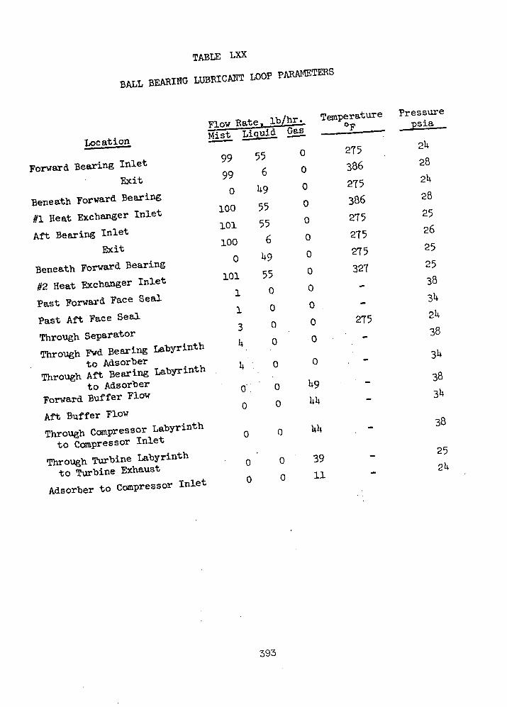
TABLE LXX
BALL BEARING LUBRICANT LOOP PARAMETERS
Location
Forward Bearing InletExit
Beneath Forward Bearing
#1 Heat Exchanger Inlet
Aft Bearing InletExit
Beneath Forward Bearing
#2 Heat Exchanger Inlet
Past Forward Face Seal
Past Aft Face Seal
Through SeparatorThrough Fwd Bearing Labyrinth
to AdsorberThrough Aft Bearing Labyrinth
to AdsorberForward Buffer Flow
Aft Buffer FlowThrough Compressor Labyrinthto Compressor Inlet
Through Turbine Labyrinthto Turbine Exhaust
Adsorber to Compressor Inlet
FlpwRateJ b/hr^ TemperatureMist Liquid, gag. ;
99 55 °
99 6 0
0 H9 °
100 55 °
101 55 °
100 6 0l.n 00 U9 u
101 55 °n 0 °1 u
1 0 °, n 03 u
U 0 °
U 0 °
l.no o U9
o o w»
o o UU
0 ' 0 39
o o 11
275386
275386
275
275275
327**
275
; —
-
-
"
Pressurepsia
2U
28
2U
28
25
26
25
25
38
3U
2U
38
-3k-34
38
3U
38
252h
393

pressure ratio and turbine inlet gas at 25.8 psia through a 1.75
pressure ratio.
The study considered a 20 mm compressor end bearing and 35 mm
turbine end bearing, both being extra-tlight series of M-50 steel with
one-piece cages. The bearing lives were controlled-.by the larger
bearing, and a Bj life of 13,400 hours and B^Q 1:ife of. 58,000 hours
were predicted for effective .loads of approximately 150 pounds.
The face seal life, based upon carbon wear, fell within the same life
range. Oil contamination of the power system, with mean seal diameters
of 2.0 in. at the compressor end and 1.5 in. at the turbine end, was
estimated to be about 0.05 .grams in 10,000 hours.
Immediately inboard of each bearing was an impeller machined'into
the sealplate to act as a-scavenge pump for the oil mist passing through
the bearing and seal." ' ' '
• ' ' : . ) ' . • • - . , . , ! , : • . . •Compact tubular heat exchangers outside the TAG cooled the two-
phase oil-gas mixture as it was pumped between bearing compartments.
. •: • . '.-•.' --' '/ . •*.,,. . '• ;<•;:.• ,<i :jr. , ^ - , : • ' •The separator overhung from the compressor end of the shaft was a
conical housing assembly containing a woven metallic matrix to condense
oil vapor carried in'the gas\ :: This'!gas''wa's"used to "replace leakage :
through the two?face seals.' An1 external absorber with'polyurethane
prefilter and glass wool further purified the maKeup gas. • :
An'oil inventory control system mainta-ine'd the1 oil level in a '•
rotating pool with'an immersed''stationary'scdcip;connected by piping to an
external accumulator. . :°
The lubricant used in'-the design study was a 5P4E polypheriyl ether
oil: ' :' - :' • - • • " • . ; : - • • ' . : ^
. • . . •Buffer labyrinth seals were used to prevent the oil mist from entering
the-compressor inlet or turbine exhaust. Clean compressor gas flowed
toward each bearing through an adjacent labyrinth seal,'with most'of the
buffer seal flow directed to the compressor inlet through an adjacent
labyrinth and to the turbine exhaust through an adjacent labyrinth.
Summary of Ball Bearing.Problems
Ball bearing bore size, series, contact angle, and number and size of
394

balls were optimized. The latest and best bearing material and processing
technology was assumed. Realistic long-term bearing loads were applied.
A reliable bearing life computer program was utilized. The latest method
of decreasing bearing dynamic radial loads was incorporated. The desired
bearing reliability of 0.998 (two bearings at B0>1 life) was reduced to
0.980 (two bearings at BI life) . All of these were considered as being
reasonable and prudent approaches, neither overly optimistic nor
pessimistic. Even so, the calculated bearing lives were only 36 percent
of the desired five year life.
Further consideration of the decreased material hardness and oil
viscosity at elevated operating temperatures showed that the elastohydro-
dynamic film between bearing components would not guarantee their
separation, and would lead to bearing lives less than 36 percent of the
goal. It also pointed out the necessity of having a support system
which would reliably guarantee the lowest possible bearing operating
temperatures. This, in turn, requires extensive lubrication system
analysis and development.
Since the bearings selected would not meet the life goal under
normal operating conditions, they have no overload capacity.
The assumption of ausfo'rmed'M-50 steel as the bearing material and
processing method implies the need for a development program and very
expensive bearings with long procurement times.
The lubrication system required has many components, some of,complex
design. It will require further study and development beyond presently
available analyses. . .
It is expected that the lubrication system will contaminate the cycle
fluid more than is allowable, especially during startup, even if extreme
care is taken during these periods.
The lubricant is likely to deteriorate in five years under exposure
to the high temperature and radiation environments.
These arguments are summarized in Table LXXI.
Supporting the TAG on oil mist lubricated rolling-element ball bearings
for five years is not recommended.
395
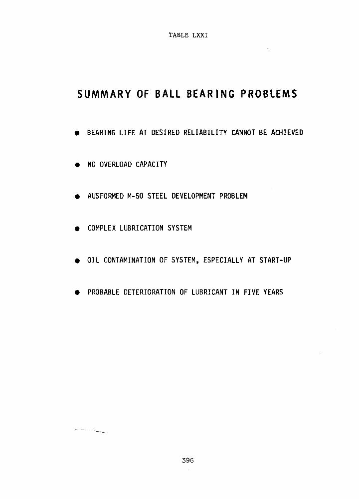
TABLE LXXI
SUMMARY OF BALL B E A R I N G PROBLEMS
• BEARING LIFE AT DESIRED RELIABILITY CANNOT BE ACHIEVED
NO OVERLOAD CAPACITY
AUSFORMED M-50 STEEL DEVELOPMENT PROBLEM
• COMPLEX LUBRICATION SYSTEM
OIL CONTAMINATION OF SYSTEM, ESPECIALLY AT START-UP
PROBABLE DETERIORATION OF LUBRICANT IN FIVE YEARS
396
IV. PHASE III - CONCEPTUAL DESIGN STUDY
A. SUMMARY
The main effort in the third phase of the subject design study was
applied to the feasibility study of the two-pole Lundell alternator and
to the completion of the TAG design based upon the revised design con-
ditions.
For the alternator the ANADUR wire insulation was ruled out for the
case of five-year life because of the likelihood that it would enter the
main gas circuit of the powerplant in the form of abrasive dust. Pre-
ferred would be bare wire with mica or alumina in the slots and mechanically
separated and plasma-sprayed end turns. As a result the alternator
cavity pressure would have to exceed 14 psia for a 2HO-volt winding and
53 psia for a U80-volt winding to avoid corona effects. Organic insula-
tion would eliminate the corona effect but require a 107°F coolant sink.
A 60-slot two-pole Lundell alternator is feasible. However, an 8U-slot
alternator would result in a smaller-size alternator having better part
load efficiency than the six-pole configuration but slightly lower full
load efficiency. In order to retain the flexibility of reconnecting the
alternator winding to go from H80 to 2^0 volts and replacing the stock
and winding only to go to 120 volts, a third material is recommended to be
introduced into the rotor. Several cooling configurations can be designated
into the alternator to cool it.
The designs of the journal and thrust bearings have been revised
such that they meet all design requirements. The film thicknesses are
adequate for design load and both the thrust and journal bearings have
adequate overload margins.
The third critical speed is safely Ck9%] above the 120 percent
speed point. The second critical speed (12,000 rpm) which must be
damped, can be well controlled if the total unbalance is kept below
O.OTO in-oz. Even with the use of a steel compressor impeller rotor
response is little affected below 30,000 rpm.
397

In addition to the decreases in turbomachinery dimensions from the
Phase I design, an important change was to eliminate the control hole
through the turbine rotor to reduce stress, making all turbine stresses
within the allowable values. This necessitated introducing the journal
coolant gas at the compressor end of the rotor, a slight complication.
The weight of the TAG unit went up k5% from Phase I due mainly to the
increased size of the two-pole alternator. The cycle efficiency dropped
from 0.28U in Phase I to 0.270 inspite of a higher turbine pressure ratio
Clower heat-exchanger and piping relative pressure drops) because of
reduced turbomachinery inlet temperatures, decreased alternator ef-
ficiency and increased windage. The 8 -slot two-pole alternator would
slightly increase the cycle efficiency because the windage loss would
be less than for1 the 60-slot configuration.
398

ALTERNATOR DESIGN
INTRODUCTION AND SUMMARY
The Phase III studies were directed toward determining the feasi-
bility of a 400 Hz, 2-pole Lundell alternator for the TAG configuration
and the preparation of a preliminary design. Several conditions were
investigated to determine the versatility of the design for various
potential applications. Areas of concentrated study included electrical
design selection for armature reconnectability from 120 to 480 volts
(L-N), thermal analysis for several pressures and temperatures based on
HeXe and Argon gases, part load analysis, corona conditions, and the use
of substitute organic insulation systems.
Comparison is made between the present design and the 6-pole Lundell
alternator design recommended in Phase I. However, the designs are not
directly comparable since the 2-pole alternator in Phase III is more
conservative than the 6-pole of Phase I. This is because of the conserv-
ative assumptions used in the initial design selection in Phase III.
Their selection was based upon concern over the ability to adequately
cool the 2-pole alternator. Subsequent thermal analyses late in the
Phase III revealed that the assumptions were conservative. Due to the
limited period of Phase III, there was not sufficient time to go back
and re-evaluate the design in line with the Phase I, 6-pole. However,
a non-optimized two pole design, having a current loading level close
to that of the optimized 6 pole design was identified at the end of
the effort. This design, for operations in the \ to full load range is
more attractive than the 60 slot (conservative) 2 pole design.
The results of the studies indicate that the 2-pole, 400 Hz Lundell
TAG alternator is both feasible and practical. Although the 2-pole is
not as attractive as the Phase I, 6-pole selection in many aspects, the
results did not reveal any aspect of its design which would definitely
preclude its use. A cooling circuit was devised which would cool the
alternator more than adequately; the electromagnetic efficiency was
found to be 1.8 points lower than that for the 6-pole at full load and
399
1.6 points higher at | load. For overall efficiency, the spread is 1.5
points at full load to 0 at £ load. The weight of the 2-pole alternator
is 1.67 times that of the 6-pole alternator weight; the 2-pole rotor is
about 35 percent heavier than the 6-pole rotor. Optimization of the 84
slot 2 pole design should reduce the weight differences, and could also
improve the 2 pole design efficiency, particularly at full load.
The voltage unbalance is within the 9 percent limit (based on an
Improved analytical method adopted during Phase II studies).
The magnetic and mass unbalance forces were analyzed and appear to
have technically feasible design solutions, even though the 2-pole has
inherently more difficult problems. One area of concern for both the
2-pole and the 6-pole is the magnetic unbalance in the auxiliary gap;
further analyses will be required before solutions can be defined which
are compatible with the bearings and alternator. Certainly one solution
is to increase the gap to the point that percentage gap variations around
the periphery are small.
The pressures at which corona may occur differed little with those
presented in Phase I. Unless subsequent development tests prove other-
wise, it appears reasonable to ignore the transient (peak) voltages in
setting the allowable minimum-pressure/maximum-voltage combinations.
This alleviates problems somewhat by permitting lower pressures to be
specified for the 240 volt winding, but it still does not eliminate the
concern-for the potential corona inception. Corona related to the use
of the organic insulation is discussed with the text.
The thermal analysis and maps revealed three interesting design
aspects. First, the temperatures at the higher pressure (86 psia, 59.32
nt/cm ) and higher windage loss are as low as those for the lower pressure2 • • -
(70 psia, 48.3 nt/cm ). This is because, at the higher pressure, there
is a greater mass flow of gas in the gas recirculation cooling system
which carries off the heat from the higher losses. Secondly, for the
stub shafts analyzed, the rotor will absorb or reject negligible heat
from or to the 500°F (approximately) bearings (533°K). Thirdly, the
hottest gas temperature occurs in the auxiliary gap. The thermal analyses
also showed that end bell cooling should be used in the absence of a gas
flow through the auxiliary gap.
400

Comparison between the 2-pole and 6-pole alternators indicates that
with the exception of increased weight and lower full load efficiency,
there are few critical differences between the two; that is, any dif-
ferences that could be distinguished as major criteria for selection or
rejection.
ELECTRICAL DESIGN CONSIDERATIONS
A. Summary of Requirements
Preliminary design and performance parameters for a 400 Hz, 2-pole,
240 volt L-N Lundell alternator with high temperature insulation were
established to determine the design feasibility specifically with regard
to the following:
a. Weight and efficiency at design power output.
b. Magnetic and mass unbalanced forces on the rotor.
c. Rotor stresses at 24,000 rpm and 20% over-speed.
d. Windage losses with Helium-Xenon mixture in the rotor cavity
at a full-load compressor inlet pressure of 70 and 86 psla2
(48.3 and 59.3 nt/cm ) for a coolant temperature of 325°F
(436°K) and at 70 psia (48.3 nt/cm2) for 466°F (514°K) coolant.
e. Temperature distribution for coolant temperatures of 325°F
(436°K) and 466°F (514°K) with argon in the gap except that
windage losses for the HeXe mixture shall be used to determine
the temperature distribution.
f. Voltage limitations due to corona as a function of pressure
of a helium gas.
g. Voltage unbalance.
h. Reconnectability between 240 and 480 volts L-N.*
Specific electrical specification requirements for the alternator
are listed below:
a. The alternator shall have a maximum continuous rating of 160
kwe with a 3-phase output at a 0.75 lagging load power factor
and an overload rating of 320 kva at 0.9 lagging load power
factor for 5 seconds after temperature equilibrium has been
reached.
401

The alternator shall be capable of operating at 120% of design
speed without a catastrophic failure under all loads up to and
including rated TAG load conditions (160 kwe, 0.75 lagging power
factor) for a limited time.
The design life criteria for the alternator shall be 5 years
operating time under the specified conditions for the TAG
assembly.
The alternator shall be in accordance with MIL-G-6099A (ASG)
in accordance with the latest revision in effect for the
following:
1. Short-Circuit Capacity. Paragraph 4.5.12 for a.minimum
time of 5 seconds for each occurrence.
2. Phase Balance. Paragraphs 4.5.10, 4.5.10.1 and 4.5.10.2
except that paragraph 4.5.10.1 is amended to read " . . .
the individual phase voltages shall not deviate from the
average by more than 2.25, 4.5, and 9 percent, respectively."
The alternator shall be designed to the maximum extent possible
so as to reduce to a minimum windage losses. A windage loss
less than 6 percent of the rated output for a full-load pres-
surized rotor cavity shall be considered a design goal.
For systems radiator size and weight considerations, it is
desired to operate the alternator stator at elevated temperatures.
The alternator shall utilize high-temperature magnetic, electri-
cal and insulation materials which.include stainless steel or
Inconel-clad silver for the conductors, Anadur "s" for the
insulation between conductors, and high-purity ceramic, 99.5
percent alumina, for, the slot insulators. A maximum of 300°F
(167°K) temperature increase shall be permitted between the
coolant supply temperature and the alternator hot spots at the
160 kwe power level.
The individual phase voltages shall be 2.25, 4.5, and 9 percent initiallybut 1.5, 3 and 6 percent figures shall be a design goal.
402

Specification MIL-G-6099 (A) (ASG).
1. Waveform. .Paragraph 4.5.16 - In addition, the total rms
harmonic content of the line-to-neutral voltage wave, when
the alternator is operating into a purely resistive load,
shall be less than 5 percent from 10 percent to 100 percent
maximum design load of 160 kwe.
$2. Output Voltage Modulation. Paragraph 4.5.13, except that
modulation shall not exceed 0.5 percent.
Shock, Vibration, and Acceleration - The alternator shall be
in accordance with the environmental specifications NASA Nos.
P2241-1 and P2241-2 except paragraph 2.3.3.1 of specification
P2241-1 shall be replaced with paragraph 3.5.1.4 from environ-
mental specification No. 417-2, revision C, dated June 1, 1969.
Assumed acceleration is 1.5 g's in both directions along mutually
perpendicular axis.
Radiation Environment - The design radiation environment shall7 13
be 10 rads, 10 nvt fast neutrons per square centimeter
(>'l.Mev) unless otherwise specified.
Position Sensitivity - The alternator shall be designed to
operate in any position in both zero "G" and one "G" environ-
ments .
Voltage-Regulator-Exciter and Speed Control - While the VRE,
speed control, and power conditioning equipment were not a
part of the study, their effects on the alternator were con-
sidered in the design study. The speed control for transient
load changes shall be of the phase-controlled parasitic load
type. Frequency regulation shall be assumed to be within ± 1
percent of design frequency for a change in external load of
from 10 percent to full design output power. Some form of
system gas pressure modulation is contemplated for long term
or scheduled control of power level.
* .This shall be a design goal without analytical verification.
403
1. It is anticipated that the TAC units shall be employed in
multiple units, thus they may be required to be electrically
paralleled.
m. The alternator stator winding shall permit the direct sub-
stitution of organic insulated windings at some future date
with a reduced coolant supply temperature of 107°F (315°K).
n. Rated voltage shall be 240 volts L-N, 3 phase, wye connected
initially; however, the stator winding design shall permit
reconnecting the above coils to produce 480 volts L-N. In
addition, the feasibility of bonding a high magnetic perme-
ability pole face material to the rotor (in order to reduce
pole face losses) shall be investigated. If the above is
deemed feasible, a stator shall be designed which then permits
120, 240, or 480 volts L-N windings.
Configuration Design Selection and Features
During the Phase I studies, a preliminary 2-pole, 400 Hz Lundell
alternator design was derived. This design had 48 stator slots, 8 series
turns per phase, an 8 inch rotor O.D. (20.4 cm), and used Hiperco 27 for
the rotor magnetic material. SAE 4340 alloy was selected for the rotor
magnetic material for the Phase III, 2-pole, 400 Hz alternator design
and a design analysis using the Phase I selected parameters (i.e., 48
slots, etc.) was performed with the SAE 4340 magnetic alloy in the rotor.
This design required a rotor O.D. of 8.4 inches (21.4 cm) and had pole
face losses which were approximately 3.4 times as large as the previous
design. The higher pole face losses were caused by the lower permeability
of the SAE 4340 material as compared to Hiperco 27. A radial gap study
was performed to evaluate the effect, on alternator weight and efficiency,
of increasing the radial gap to reduce pole face losses. Results of this
study are shown in Figure 162 . Indications are that radial gaps in the
range of 0.100 to 0.120 inches (0.254 to 0.305 cm) provide optimum results
regarding alternator weight and efficiency. As shown in Figure 162,
pole face losses decrease and stationary field coil losses increase with
increasing radial gap. Increasing the radial gap transfers some of rotor
surface losses to the stator field which normally is desirable from heat
404
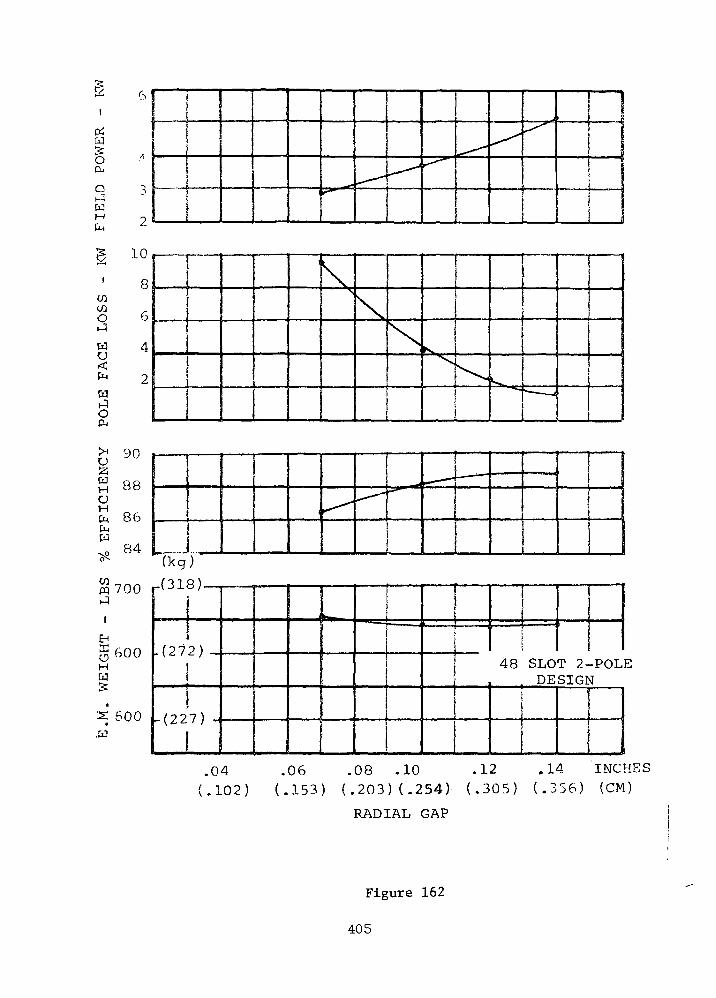
OSCO5OCu
QJWMCM
PO
LE
F
AC
E
LO
SS
EF
FIC
IEN
CY
LB
SW
EIG
HT
E
V
y\J
R8
86
R4(kg )
^-"^-
. ••nn.ii !•
IL •
•- 'n»^
,
r 1
700
600
500
|-V J-L
- ( 2 7
- (22
1
a / —
2 )
7 >1 —
1 ^— ^•ea L — .... .1
'
i _
48 SLODE
T 2-SIGI
-POL\F
.04 .06 .08 .10 .12 .14 INCHES(.102) (.153) ( , 2 0 3 ) ( .254) ( . 305 ) ( . 3 5 6 ) (CM)
RADIAL GAP
Figure 162
405

transfer considerations. A radial gap of 0.120 inches (0.305 cm) was
selected; however, this can be reduced to as low as 0.100 inches (0.254
cm) if this later seems desirable.
Preliminary indications were that the 8.4 inch (21.3 cm) rotor O.D.
was too large. The stator slots were increased to 60, thereby increasing
the number stator turns from 8 to 10 for the 240 volt L-N case. This
configuration resulted in a rotor O.D. of 8.0 inches (20.4 cm), and
reduced the total pole face loss. This is because the greater number of
slots decreased the tooth ripple (or no-load) component of pole face loss
(which was predominant for the 48 slot design). The load harmonic com-
ponent of pole face loss became predominant for the 60 slot design, and
a further increase in the number of stator slots (and turns) would further
increase this loss component.
It is most probable that a higher number of stator turns and slots
can be tolerated from a pole face loss standpoint if a further reduction
in rotor diameter is deemed necessary. This conclusion is confirmed in
the 84 slot design summarized in Table LXXII. However, the 60 slot con-
figuration was settled upon because of considerations regarding the gas
recirculation scheme utilized for cooling. The pressure for gas cir-
culation is created in the tapered cone section of the rotor. Preliminary
indications were that the larger radius and height of the cone section
provided by the 8 inch (20.4 cm) rotor O.D. design would be desirable to
provide satisfactory pumping head for forced convection cooling, and that
rotor stress levels were satisfactory. Later thermal analysis indicated
it ensured a conservative design; further optimization may show that a
smaller rotor O.D. would still produce adequate forced convection cooling
for a 2-pole machine. This is the case with the 84 slot design of
Table LXXII .
The 60 slot alternator configuration was designed for 240 volts
line to neutral; however, the alternator windings can be reconnected to
produce 480 volts L-N. This is accomplished by connecting the two
parallel circuits in series. Because the stator is wound for the minimum
of two conductors per slot and the maximum number of parallel circuits is
two, the 60 slot stator cannot be reconnected or rewound to produce 120
volts L-N. In order to provide a stator that can be reconnected and/or
406
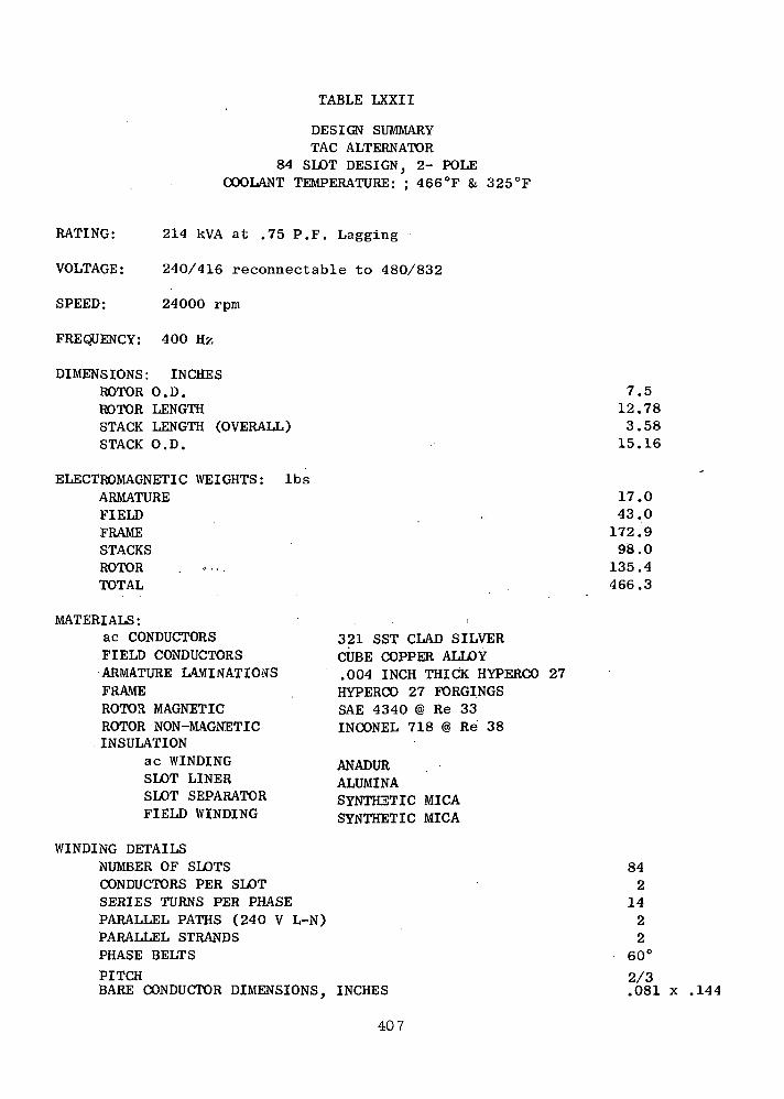
84
TABLE LXXII
DESIGN SUMMARYTAG ALTERNATORSLOT DESIGN} 2- POLE
COOLANT TEMPERATURE: : 466°F & 325°F
RATING: 214 kVA at .75 P.F. Lagging
VOLTAGE: 240/416 reconnectable to 480/832
SPEED: 24000 rpm
FREQUENCY: 400 Hz
DIMENSIONS: INCHESROTOR O.D.ROTOR LENGTHSTACK LENGTH (OVERALL)STACK O.D.
ELECTROMAGNETIC WEIGHTS: IbsARMATUREFIELDFRAMESTACKSROTOR .TOTAL
MATERIALS:ac CONDUCTORSFIELD CONDUCTORSARMATURE LAMINATIONSFRAMEROTOR MAGNETICROTOR NON-MAGNETICINSULATION
ac WINDINGSLOT LINERSLOT SEPARATORFIELD WINDING
WINDING DETAILSNUMBER OF SLOTSCONDUCTORS PER SLOTSERIES TURNS PER PHASEPARALLEL PATHS (240 V L-N)PARALLEL STRANDSPHASE BELTS
PITCHBARE CONDUCTOR DIMENSIONS, INCHES
321 SST CLAD SILVERCUBE COPPER ALLOY.004 INCH THICK HYPERCO 27HYPERCO 27 FORCINGSSAE 4340 @ Re 33INCONEL 718 @ Re 38
ANADURALUMINASYNTHETIC MICASYNTHETIC MICA
7.512.783.58
15.16
17.043.0
172 .998.0
135.4466.3
842
1422
60°
2/3.081 x .144
407
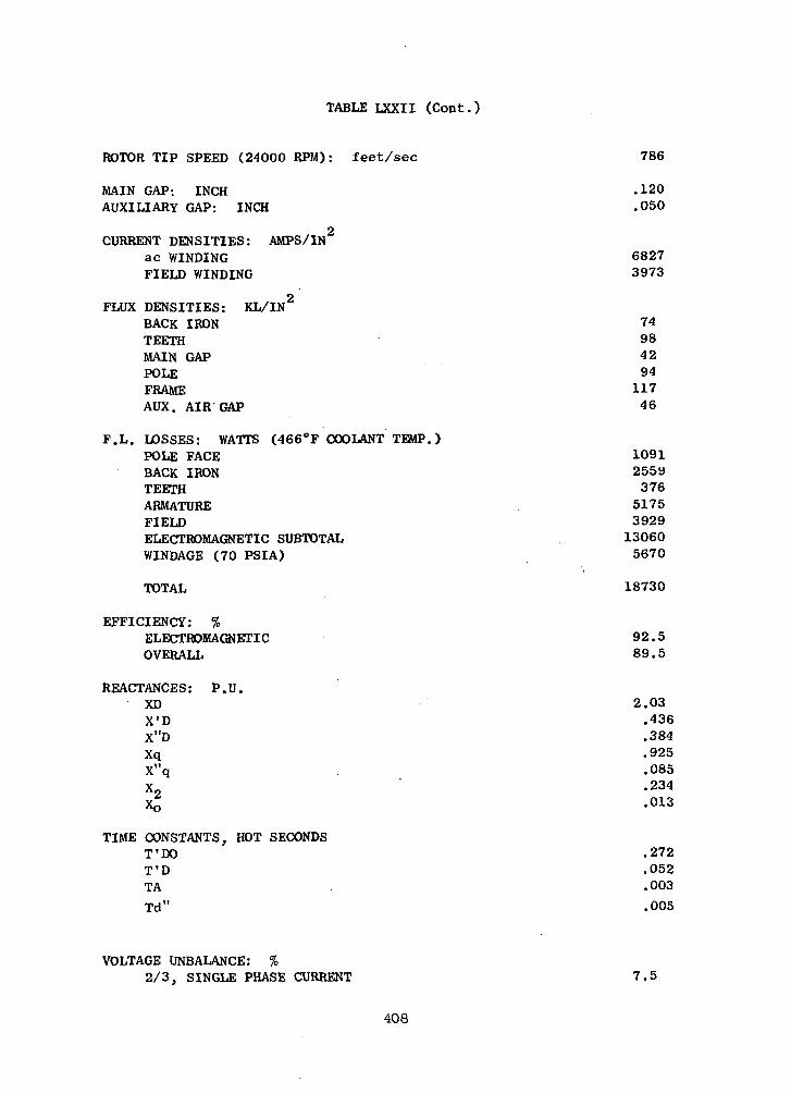
TABLE LXXII (Cont.)
ROTOR TIP SPEED (24000 RPM): feet/sec
MAIN GAP; INCHAUXILIARY GAP: INCH
2CURRENT DENSITIES: AMPS/IN
ac WINDINGFIELD WINDING
FLUX DENSITIES: KL/IN2
BACK IRONTEETHMAIN GAPPOLEFRAMEAUX. AIR GAP
F.L. LOSSES: WATTS (466°F COOLANT TEMP.)POLE FACEBACK IRONTEETHARMATUREFIELDELECTROMAGNETIC SUBTOTALWINDAGE (70 PSIA)
TOTAL
786
.120
.050
68273973
7498429411746
1091255937651753929130605670
18730
EFFICIENCY: %ELECTROMAGNETICOVERALL
REACTANCES: P.U.XDX'DX"DXqX"qX
92.589.5
2.03.436.384.925.085.234.013
TIME CONSTANTS, HOT SECONDST'DOT'DTA
Td"
.272
.052
.003
.005
VOLTAGE UNBALANCE: %2/3, SINGLE PHASE CURRENT 7.5
408
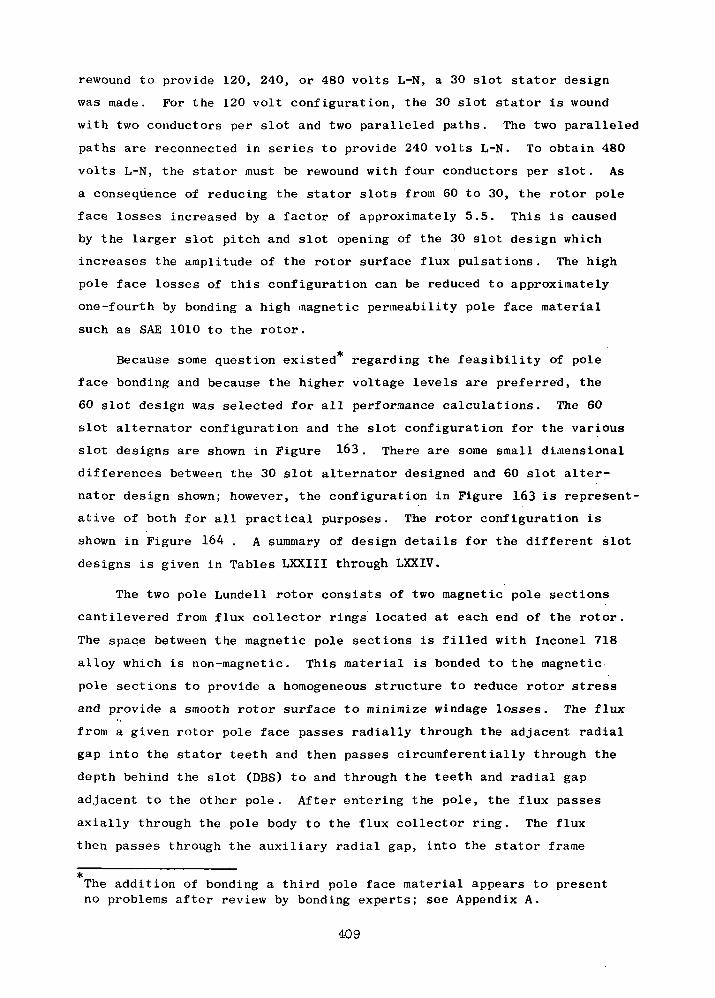
rewound to provide 120, 240, or 480 volts L-N, a 30 slot stator design
was made. For the 120 volt configuration, the 30 slot stator is wound
with two conductors per slot and two paralleled paths. The two paralleled
paths are reconnected in series to provide 240 volts L-N. To obtain 480
volts L-N, the stator must be rewound with four conductors per slot. As
a consequence of reducing the stator slots from 60 to 30, the rotor pole
face losses increased by a factor of approximately 5.5. This is caused
by the larger slot pitch and slot opening of the 30 slot design which
increases the amplitude of the rotor surface flux pulsations. The high
pole face losses of this configuration can be reduced to approximately
one-fourth by bonding a high magnetic permeability pole face material
such as SAE 1010 to the rotor.
Because some question existed regarding the feasibility of pole
face bonding and because the higher voltage levels are preferred, the
60 slot design was selected for all performance calculations. The 60
slot alternator configuration and the slot configuration for the various
slot designs are shown in Figure 163. There are some small dimensional
differences between the 30 slot alternator designed and 60 slot alter-
nator design shown; however, the configuration in Figure 163 is represent-
ative of both for all practical purposes. The rotor configuration is
shown in Figure 164 . A summary of design details for the different slot
designs is given in Tables LXXIII through LXXIV.
The two pole Lundell rotor consists of two magnetic pole sections
cantilevered from flux collector rings located at each end of the rotor.
The space between the magnetic pole sections is filled with Inconel 718
alloy which is non-magnetic. This material is bonded to the magnetic
pole sections to provide a homogeneous structure to reduce rotor stress
and provide a smooth rotor surface to minimize windage losses. The flux
from a given rotor pole face passes radially through the adjacent radial
gap into the stator teeth and then passes circumferentially through the
depth behind the slot (DBS) to and through the teeth and radial gap
adjacent to the other pole. After entering the pole, the flux passes
axially through the pole body to the flux collector ring. The flux
then passes through the auxiliary radial gap, into the stator frame
*The addition of bonding a third pole face material appears to presentno problems after review by bonding experts; see Appendix A.
409
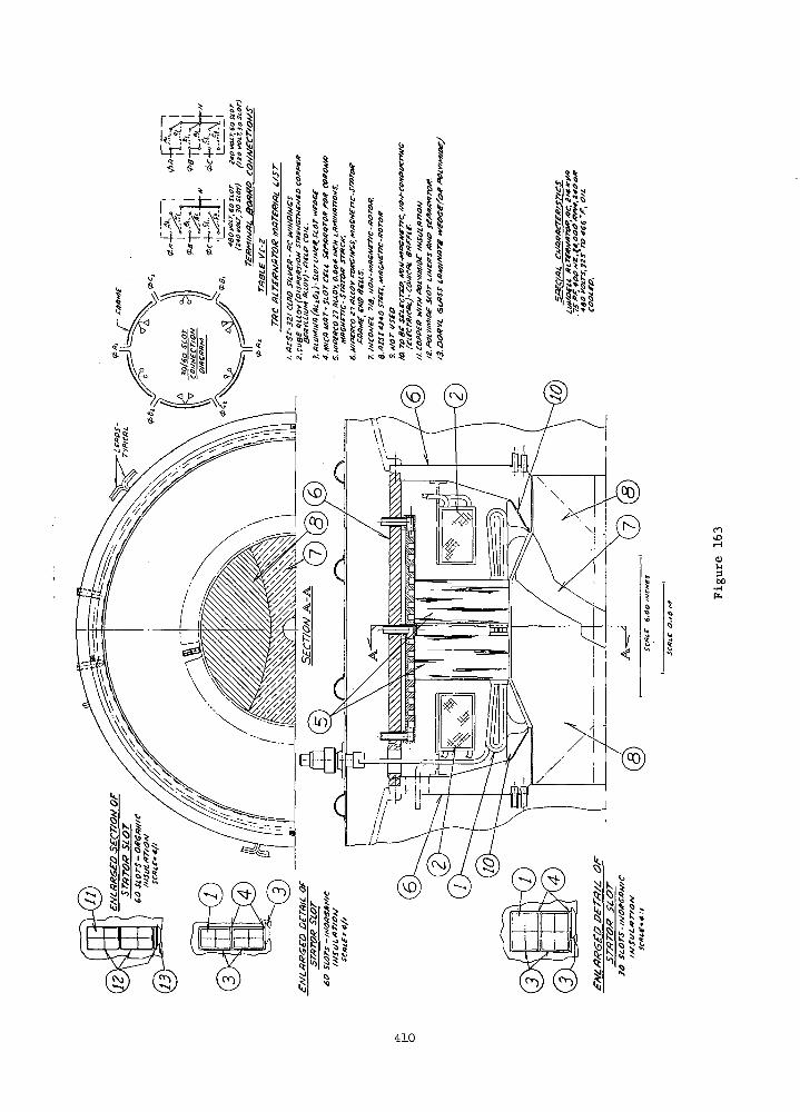
rovO
300
410
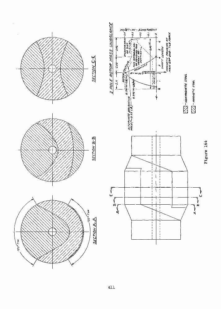
rT"
01l-l
00•H
(=)
411
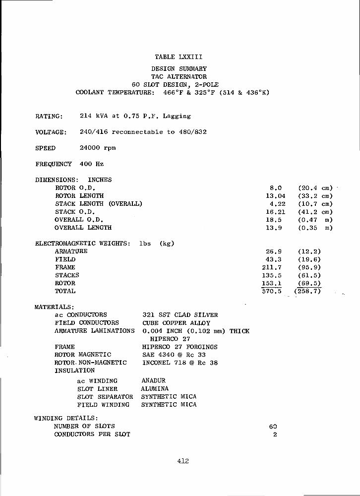
TABLE LXXIII
DESIGN SUMMARYTAG ALTERNATOR
60 SLOT DESIGN, 2-POLECOOLANT TEMPERATURE: 466°F & 325°F (514 & 436°K)
RATING: 214 kVA at 0.75 P.F. Lagging
VOLTAGE: 240/416 reconnectable to 480/832
SPEED 24000 rpm
FREQUENCY 400 Hz
DIMENSIONS: INCHESROTOR O.D.ROTOR LENGTHSTACK LENGTH (OVERALL)STACK O.D.OVERALL O.D.OVERALL LENGTH
ELECTROMAGNETIC WEIGHTS: Ibs (kg)ARMATUREFIELDFRAMESTACKSROTORTOTAL
MATERIALS:ac CONDUCTORSFIELD CONDUCTORSARMATURE LAMINATIONS
FRAMEROTOR MAGNETICROTOR. NON-MAGNETICINSULATION
ac WINDINGSLOT LINERSLOT SEPARATORFIELD WINDING
WINDING DETAILS:NUMBER OF SLOTSCONDUCTORS PER SLOT
321 SST CLAD SILVERCUBE COPPER ALLOY0.004 INCH (0.102 mm) THICKHIPERCO 27
HIPERCO 27 FORCINGSSAE 4340 @ Re 33INCONEL 718 @ Re 38
ANADURALUMINASYNTHETIC MICASYNTHETIC MICA
8.013.044.2216.2118.513.9
(20.4 cm)(33.2 cm)(10.7 cm)(41.2 cm)(0.47(0.35
m)m)
26.943.3
211.7135.5153.1
(12.2)(19.6)(95.9)(61.5)(69.5)
570.5 (258.7)
602
412
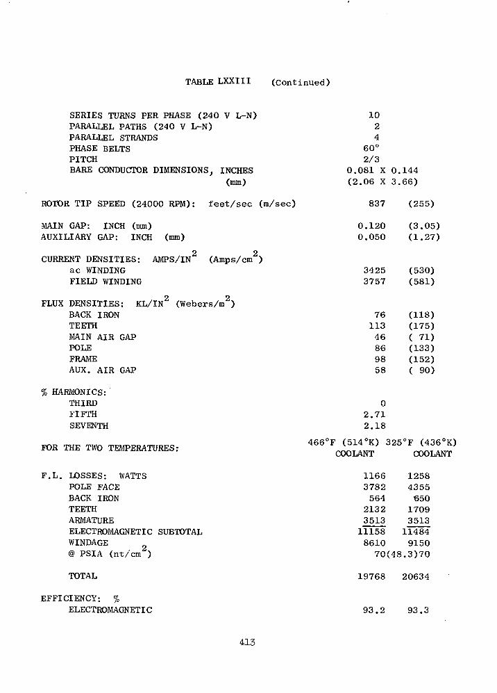
TABLE LXXIII (Continued)
SERIES TURNS PER PHASE (240 V L-N)PARALLEL PATHS (240 V L-N)PARALLEL STRANDSPHASE BELTSPITCHBARE CONDUCTOR DIMENSIONS, INCHES
(mm)
ROTOR TIP SPEED (24000 RPM): feet/sec (m/sec)
MAIN GAP: INCH (mm)AUXILIARY GAP: INCH (mm)
CURRENT DENSITIES: AMPS/IN (Amps/cm2)ac WINDINGFIELD WINDING
FLUX DENSITIES: KL/IN2 (Webers/m2)BACK IRONTEETHMAIN AIR GAPPOLEFRAMEAUX. AIR GAP
% HARMONICS:THIRDFIFTHSEVENTH
FOR THE TWO TEMPERATURES:
1024
60°2/3
0.081 X 0.144(2.06 X 3.66)
837 (255)
0.1200.050
34253757
7611346869858
(3.05)(1.27)
(530)(581)
(118)(175)( 71)(133)(152)( 90)
02.712.18
466°F (514°K) 325°F (436°K)COOLANT COOLANT
F.L. LOSSES: WATTSPOLE FACEBACK IRONTEETHARMATUREELECTROMAGNETIC SUBTOTALWINDAGE@ PSIA (nt/cm )
1166 12583782 4355564 6502132 17093513 351311158 114848610 915070(48.3)70
TOTAL 19768 20634
EFFICIENCY: %ELECTROMAGNETIC 93.2 93.3
413

TABLE LXXIII (Continued)
OVERALL
REACTANCES: P.U.XDX'DX"DXqX"qX2Xo
TIME CONSTANTS, HOT SECONDST'DOT'DTATd:
VOLTAGE UNBALANCE: %2/3, single phase current
89.0 88,6
1.210.2770.2440.550.1480.1460.008
0.2910.0590.00520.0051
3.0
414

TABLE LXXIV
LiKSIGN SUMMARYTAG ALTERNATOR
30 SLOT DESIGN, 2-POLECOOLANT TEMPERATURE: 466'F (514°K)
RATING: 214 kVA at 0.75 P.F. LAGGING
VOLTAGE: 480 VOLTS L-N, reconnectable to 240 V L-N, rewind for 120 Volts L-N
SPEED: 24000 rpm
FREQUENCY: 400 Hz
DIME NSIONS: INCHE SROTOR O.D.ROTOR LENGTHSTACK LENGTHSTACK O.D.
(RADIAL DUCT NOT INCLUDED)
ELECTROMAGNETIC WEIGHT: Ibs (kg)ARMATUREFIELDFRAMESTACKSROTORTOTAL
MATERIALS:ac CONDUCTORSFIELD CONDUCTORSARMATURE LAMINATIONSFRAMEROTOR MAGNETICROTOR NON-MAGNETICINSULATION
ac WINDINGSLOT LINERSLOT SEPERATORFIELD WINDING
8.012.323.5
16.51
26.244.4
204.3136.3145.0556.2
(20.4 cm)(32.6 cm)( 8.9 cm)(42.0 cm)
(11.9)(20.1)(92.8)(61.9)(65.7)(252.4)
321 SST CLAD SILVERCUBE COPPER ALLOY0.004 INCH (0.102 mm) THICK HIPERCO 27HIPERCO 27 FORCINGSSAE 4340 @ Re 33INCONEL 718 @ Re 38
ANADURALUMINASYNTHETIC MICASYNTHETIC MICA
WINDING DETAILS:NUMBER OF SLOTSCONDUCTORS PER SLOTSKRIb-S TURNS PER PHASE (480 V L-N)PARALLEL PATHS (480 V L-N)PARALLEL STRANDSPHASE BELTSPITCHBARE CONDUCTOR DIMENSIONS, INCHES
(mm)
304201260°2/3
0.182 X 0.128(4.62 X 3.25)

TABLE LXXIV (Cont.)
ROTOR TIP SPEED (24000 rpm): feet/sec (m/sec)
MAIN GAP: INCH (mm)AUXILIARY GAP: INCH (mm)
CURRENT DENSITIES: AMPS/IN2
ac WINDINGFIELD WINDING
FLUX DENSITIES: KL/IN2
BACK IRONTEETHMAIN AIR GAPPOLEFRAMEAUX. AIR GAP
% HARMONICS:THIRDFIFTHSEVENTH
837
0.1200.050
33043921
75103558510258
02.712.33
(255)
(3.05)(1.27)
(513)(607)
(116)(160)( 85)(132)(158)( 90)
F.L. LOSSES: WATTS (Doesn't account for forced convection cooling temperatures)POLE FACE (SAE 1010 pole face) 1485BACK IRON 3762TEETH 468ARMATURE 2324FIELD 3946ELECTROMAGNETIC SUBTOTAL 11985WINDAGE (apprgx.) 8600i> PSIA (nt/cnr) 70 (48.3)TOTAL 20585
EFFICIENCY: %ELECTROMAGNETICOVERALL
REACTANCES; P.U.XDX'DX"DXqX"qX2XO
TIME CONSTANTS, HOT SECONDST'DoT ' DTATd"
93.088.6
1.10.2620.2300.504
0.007
0.2340.051
0.005
416
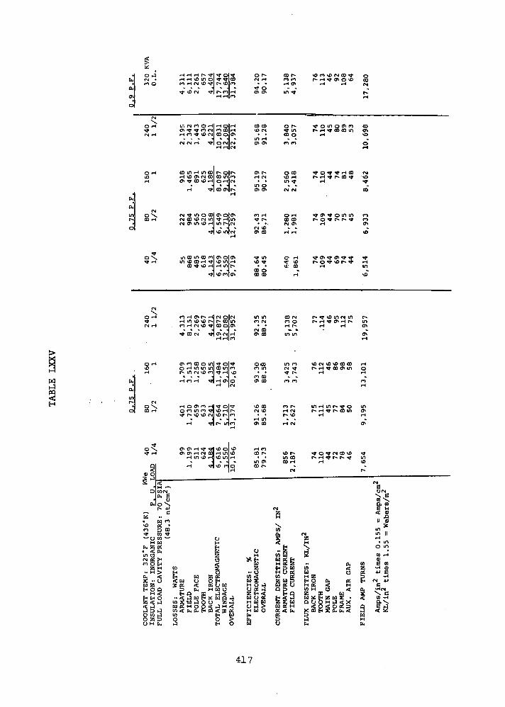
0 iJ
ro O
(N
O »-l
CN rH
rH
r>
^*
;.*.Q\rH
rH vo m ol «* rlco•—i CN vo *3"[ r^ \olro
\O CM ^f f^ flliHrHrH|m
CJ m O -Hi rH OlrH
- _ J & J ~
o r-CM rH• •
^r o
CO CO
tn —A
co r-m mrH CH
m t
o r-00 O
\O m vo rr- rH^j- c
^- o m r.rH
g CO <th O vO
rH
DS n
COCMr-rH
CO
vO
co m rH m co r*» olr-rH vO Cn M COl CO inlroCn TT 00 v£> rH O rH fM
TT r-n *£en co
^ O t rH 00• T r* CD j-
OrH ^cn^otnm <nCM O\ r-4 Cft
o\. mOOincocnlcn o|cr»Tfr (H mvOOOrH^lvD tnlrH
co ^ o r-d <H m r*.lu> 1 *
tt in
CO O00 00
o rH - en «» on ^*c ID r» o ^ vo rIt GO rH
rH
•» - rHin
fO rH O\ f*. r-d CN O|CN•H m \s> vD M r* col inm rH CM VO 00 OlO>
- " - 1 * 1 *1 Cn CM rH
rHrH|rtCO CM
IN COen co
CO CMm o
en
Ch
§>
o rH m in in] co ml*r- m CM ^
rH O Cn ro rn in T ol^r
n coen co
rH inen co
\OCN IDX0CO COt-«-4 ^ COO> 10
in01
o
o§
s^Dn
^rH
9SME>
0.'
O
^ en cr> »H ^Cn en rH r«j
t-t in vo
rH
H ^0)<Ncu e
° +JcU to
J3 COW Tf10 —
H U
in
(*i4I
^H \D O U0
rHl 10 inlrH
•OlvO r-)oM
CJHFH
g* s1H
EHH U> H
CM «£ EH U£ •• U < H Uu a * o; <H O Q 5 fc.
H < HO XHE-IO -<i4iaEHZ<>4 W S U ij O
2 j u 2 H o oa j w < fc, a, Ho w »j to
U
1
BA
CK
IR
ON
TO
TA
L
ELE
CT
RW
IND
AG
EO
VE
RA
LL
rHCO
m
«r*.
enCO t~
oH
^B2
.. 0
EF
FIC
IEN
CIE
SE
LEC
TRO
MA
OV
ER
ALL
VD ^in COCO <H
CN
MzH
X.
q.
< ,,
co uH S §EH P WH D d
CU
RR
EN
T
DE
NS
AR
MA
TU
RE
FIE
LD
CU
R
CMZ
<sU)u
FLU
X
DE
NS
ITI
f Of <N CO U)r- rH *f t~ r^ *f
rH
Pio
2O tX tfOS < HH U <
* t- z u 2 •o OH h) «s X< o < o « sCQ EH £ CU Ch <
inID
fN
oN»
i<ummrH
o00
(n e
S 3
FIE
LD
A
MP
TU
Am
ps/in
2
6
U
SfflSIIin
rH
ms4
4-1
N
•H
417

\£,
OCN
•• rH rH «D in Ol COlfN
O m rH CN ^o ^JMr"* mjfi
Men
\ ^olrH
CN
O&rH
rH rH f> TJ- VO CNJCO COl^D
CN CN r-f lO H'*rH rHJCN
rH CO U"l rH in COlCO OI10
r-t VD Cn CN COJCO ^"[CNcn ^ co <o rH|o ^n'n
1 * 1 *H ^r co o oo
o \ CN ^ in o col co o! coCO ""H CN CO *0 CN in) 1 CNJ^D
CN cn in ^ r-(|in m|o
o
"I""13
\ in co m co colo olorH in ID co rH *t r~ vo co
CO «» 1C rH rH O KMJ . J ."*r *|s
o *H fi rH cn r-* I-H|CN olCN
I-H in \D vfl p*-l r o| i**r-t <*) rH CN vD ^J-ICO CQlvO
. * * J * J *^* CO <N ^"[O fll 1
CN rH|fO
O rH cnrocOomlmoltni-
oCO
0^t
§3
0 *
s *-*1
&
£0
n
— ut-
o <in c<N «n o
OO
LAN
T
TE
MP
:N
SU
LA
TIO
N:
IN
0 H
o <-H m m inlco ^"IfM
rH f*l rH -IrH OJ H
CN\ rH o cn rn rHlm oif^rH o cn in m *t\\D CN co
t r*« vD ^D CN|^O in[rH
*r nS
•<*""" cn cn rH ^•Ir^- olf"*"
rH in li> rHIvO Ol
•»]vD^|o
CNg
< otn *Jcu C
CO *
..in9*^
Bw UU HOi &H0, g
>< oH M 2> H O< H w a n ;o < w u OH
20; < K o uQ P [14 H M Ua e* Q g ^^^
J W t> Hso o ^ *& , a H O
CN VD
rr'<^
CD cnVO i£
in ocn cn
cn f\irH VD
in cncn co
n v£)
CM incn oo
^c nvo »o10 cnCO I-
O CDO <">
CN r-cn co
o incn (Tiro r-cn co
VO <3"CN cn
rH Tj1
ON CO
l-l COCO cn
in COCO 1
UH
« H
FF
ICIE
NC
IES
: '
ELE
CT
RO
MA
GN
OV
ER
ALL
a
cn corH Cn
or-t in
CO O
CO CO
S COrH
Ul^t
CN CN
O rH
CO COCN cn
t %l-l 1-1
0-H
S ^DCO
rH
CO CMrH O
in in
m mCN f^ r*-nm
ro r*-rH n
r-t CN
<^> r-CO rH
<N
CN
H'.\CO
CH
CO Uw 93 fcH 2 a
UR
RE
NT
D
EN
S I
TA
RM
AT
UR
E
CU
FIE
LD
C
UR
RE
U
f** rH CJl C VOi-H r-i
^ o in o CT> nP- rH - CO CO in
rH
•<t O *f tf H COP- rH " f~« CO rt
rH
Tj1 cn ^ o "i u"*t"« o ^" P"* r** *
rH
^« cn ^* cn m "sj-r** o ^r 'D r- TJ*
rH
r*- j ^o in CN vot*. rH *t cn H vo
r-t rH
\D CN \0 ^O CO 00r* r-t f co o> in
rH
in rH in \o or- I-H ^ r^ CO m
rH
•<}• O ^ fN CO \O
rH
CN
H
£a,
w <w oH aE-i O 0. CAH U if HW H O <2 X Wta x f z;u a •Q U O H iJ % X
< O < O « 3X 00 f S Q. &. <
Jb
OCOCN
rH
COCnVD
OrH
CN
^"
CO
CO
cn
*
rHin\o
r-incncnrH
rHOrH
rH
incnrH
'tf
VD
r-
co%
i3UH[M
^eu
to
E<1!
inin
otoe
•H4J
fNC
•H
tnae
CN
0]Vt
rS
"*
U
minrH
01
•H
CNC
\
418

where it returns axially to the other end of the alternator and to the
pole of origin through the other auxiliary gap.
The.stationary field coils are located above the end extensions of
the ac winding. As shown in Figure 163 , there is an excess of space
available for the field coils; as a result, the size of the field coil
can be increased in order to reduce the field coil losses and amperes
required from the voltage regulator-exciter.
Because the end extensions are long and the depth of the magnetic
section behind the slots is large for 2-pole machines, the 2-pole con-
figuration does not lend itself to efficient cooling by conduction of
losses to the stator O.D. Because of this, forced convection cooling
was adopted to cool the end extensions. The stator stack was divided
into two sections to allow room for a 0.5 inch (1.27 cm) passageway for
radial gas flow. A detailed description of the forced convection cool-
ing scheme is presented in MECHANICAL DESIGN CONSIDERATIONS.
The configurations of the alternator slots are designed so that the
alternators can be rewound using an organic insulation system for the
107°F (315°K) coolant temperature condition. Two different sizes of
quadruple layer polyimide insulated rectangular wire are used to obtain
a proper fit in the slot. The slot liners are composed of a double
layer, polyimide film insulation. The slot liners are overlapped between
phases to provide added high voltage protection as shown by the slot
detail in Figure 163. Organic insulations degrade with time and tem-
perature; therefore, if long life is desired, the operating temperature
of the insulation must be limited to achieve the desired life. Avail-
able data for a selected polyimide insulation system indicated that the
winding temperatures must be less than 417°F (487°K) to achieve 5 years
thermal life. Average winding temperatures using a coolant temperature
of 107°F (315°K) are well below this limit, as indicated by the thermal
maps given in MECHANICAL DESIGN CONSIDERATIONS. A summary of the design
for the low temperature organic insulated 60 slot TAG alternator is
given in Tables LXXVII and LXXVIII.
419
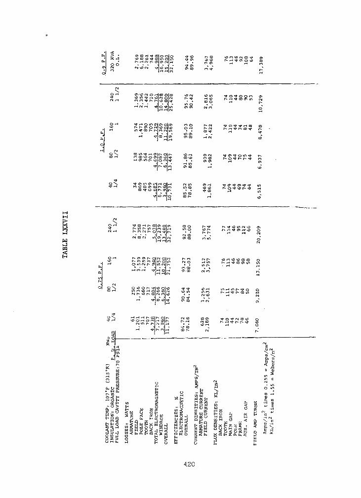
En > -
CU •0 O
en <N• r->o
CN\
O rH
<J"
CN rH
O rH
<J3
• rH
EH
Cn
0
•-H CNOXCO rH
0\<# rH
CN1
X.O rH
rM rH
O rH
VD• rH
Cn
cutnr-
• <N0 0\
CO rH
T
^ rH
9is~
D H
, • CUa,
o
o W
r". W
wen u cn
CO
OLA
NT
T
EM
P:
107°
INS
ULA
TIO
N:
OR
GA
NI
FU
LL
LO
AD
C
AV
ITY
P
cn co rH ^ col o ol o ^ vo r- HIvo co vo ^ co m o m •* en ^> $r- rH CN r- e.njcn <v\<-t • . r- en
M vD <N ^jvo mjcN en co cn <*|I-H r-t|ro
en vo CN o rHlco olco \D rsj tf> inV0 in <tf rH vpjoj O (N r - ^J- rH <£
ro ro c r- I-KD coKt • . co orH 0? rH H-l 1 "^ ° * *
^•r-tomcnltnolcn no r-cNr^* r~ en o <^ijvo olvo o rH t*- ojin^cor-r-jmcNjlin • « co^-
•-< ^Jco rHJcn en co rn" <N"1 H -*
co m ^ enlt^ olr- ^o I-H en cjm co vo o en co VD NT co «JD ro co
*j - -j - rH IT)
•sjMr* voin en co I-H1 !«-«
rr en m en m rH olrH CN m cr» rHnvocoencor^vDlm mco VD^D
co^pOior-cn]r- • • ^ c o• * -1 * m CD
f <^> mjo co P*- rHI>H
^- co rH r- co en olcn co o r- <*r^ m r* in r^ ro col <— i in o vo r*-
CN co rj m cr- rojcN en co n m"rH rHJn
h»enchr-o|rNolcM r*-n f\r^-r^ n in m in o in CN o rH inoinrgf^cnjinrjjt^ • • mr*-* - - H - H - roco » »
•-H rn rH rr «H olrH en co CN ro|rH rHJfN
O ^ O r- ^\\O Q\*£> rj- *t vO rHin ro \Q rH o Ko ^ItN vo m in mr-j t^- \o r~ co CM rojvo • • CN vD
-H tt CO \D\^ <n CO rH CN
rH r-i rH r- coir* ol r- oj VD co enCN S S PS cS'S ^. rt w °°
1 " 1 " M- COrH ^fjr^rnji-H cor- CM1 M
fj2
«_ Oj rg° § aS rf, H
I 4 H'L ?S S 5 H »a w
§i s iL a!, 11 IIII til I
S5rH?2S- : i H« oj£ Sss °«<ft ,0 ,^«<Sg MMO ggft, g
s e 1 g 5 a
VD m VD (N co ^ enIs- rH j- en o *£> co
rH rH 01
r-rH
^T o ^* o o n enr-- rH co en m CN
rH r*
0r-t
t O ^ ^" iH CO COr*- rH f^- co * r*-
rH .
CO
^3* <n ** o in r^r*- o ^ r- r^ f m
•H cn
vo
rH in
VO
r- ^f \fi m CM to cn
rH rH CN
o(N
r r-i co cn in ini-t rH
mrH
m «-4 in r- ^ o oC"» rH r r** oo in r-t
rH CM
cn
^r o ^ (N co ip oMJ
l 1
eo01
6
11
in
o
w
10, W -H< Z *jO pj
00, a, & ™cK < M -HH O < Q , N
P- td S tnX P Z a g . < Q,O O H J r f X E< o < o 2 D q ^(OHEa, fc ,< 3
uHft.
(N
E
CO
JSosIIinin
rH
[QOJH
•rHJj
(NC
X
420
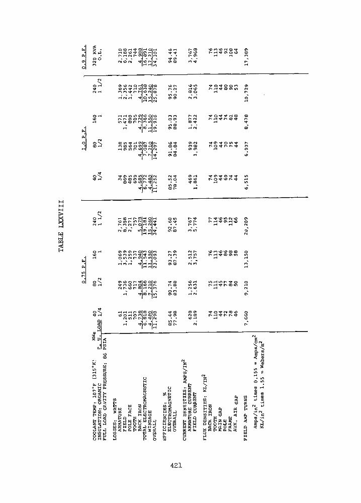
w
sH
> J
0 OCMn
(NX
O rH
O rH>0rH
CMOXCO rH
"*OX
CMX
O i-H
fj rH
O rHID•-H
rvlOXCO rH
0^r -H
9s§ a a:
H• U]
IDCO
&* **o Uin a.m K— (0
0 M 04
r- 2o< ><rH O EH
C! H
CO
OLA
NT
TE
MP
:IN
SU
LA
TIO
N:
0FU
LL
LO
AD
C
AV
O CO r-t «t GOJrH Oli-H
* * ~ I * \ *<N lO (N ^*I*O r^-lTJ'
ch ^D (N o -H] oo ol coKOm ^r ^H tf>ro r-
rH <N rH wo ml in|rH r-ll(M
rH r-l O in CTiJ^D OJVD
m ^r co r- r-lr*> m cr»1 * \ -
rH -=t CO HO*
1 ^M
co m ^ <H cf\|r* ojt^-ro CO v£) O 0MCO iHlO^rH cn m p» 0[o cNjrM
I !-<
TJ- CT* in o> inlCM oloam i^o co cr» coir- cofin
co ^j \s> \DIr- rlrsi
T*]3
•H CO rH r- COlrH Ol*HVD m r* in p-lco vol^1
r- co oj r* oj*"* l 1
fvi co CN tnlcrt tn/Tj"
en en eft r- olco ol^o
o m cJ r- 0Min m]o- > . J . J ,rH CO r-» <fr rH rH rO
IrHrHJfM
cn "i> o r- ^tlvo olvoT* fO V£) rH O\\O rH f-(N r- vD r- colrH r«j|ro
rH ^"JCO fMin
rHrHi-*r-CO|CO OCO& O rH O CO rH CO 0^
CM in r- r^jco ^p CM
rH ^1(0^41 ^
UH
1o
M £H OEH Id Z «rt tl U OHS 2 <t « U W
3 b w U O
..SSug^gjW g U J O U S r J
W 2 n O O < ^ H r fw < ( t , G J E - t £ n < S a10 £•* W0 0 5J £ 0
\£> rH•cj- -*t
^f CTVCh CO
vo r-r* <Nin oeft en
CO COo enm co
CO CO
rH ^J1
en co
CM fin o
m coco r-
o mno rCM r -en co
r- enCM CO
fo r»en CO
«* COr- co
o coen co
*fr CO
in r*co r-
UH
5
EF
FIC
IEN
CIE
S:
ELE
CT
RO
MA
GO
VE
RA
LL
r- coVO vD
.. .ro TT
rH \£>CO O
CM co
r- (N
CO *t
rH 01
CO COon en
rH
O IDTj- CO
rH
I** "
r- r-m in
•H mm r-<N CO
^O rHin m
rH CM
CO CnCM COV£> rH
oT
sH\W
2
j,iu rt f*EH B W
CU
RR
EN
T
DE
NS
IA
RM
ATU
RE
C
FIE
LD
C
UR
R
r— rH CT* O VOrH rH
t o<* o o cor* •-* <cr co en m
tr o-^r f rsoot** r-t *t r* CD *t
rH
Tj* cn ^ o m *j"1** O ^ (*- 1** ^"
rH
(-• o ^* vo r* j-rH
(*• * \D in <N vD
rH rH
VD CO vD ^0 CO COr— "H ^* co d\ m
rH
m rH m r- ^f or- rH ^ r- co inrH
,0^00*
rH
CM2H
$a,
U) <Ed UH ZEH O O< 0!H U < HW H O <2 DC WU X P Z U g •o o o H j a; w
rt p < o 2 BX « P 2 o. &, <
[L,
Cf>COm
«r-T-t
CM<v
^orH
COr**ta>
c^fOo\lO
inin•o
CMoIN
or>4
oinrH
f>rH
OrH(N
CM"
o
r,-
2
FIE
LD
A
MP
TU
R
(M
O (NX 001 Xa u1 1II 01sinin ItrH
• ino m0} rH
S a>•H 0)•p e
rj 4-1C•rl tN
X C01 -rt
IS
421
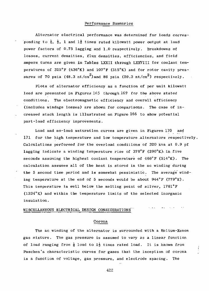
Performance Summaries
Alternator electrical performance was determined for loads corres-
ponding to \, J, 1 and lj times rated kilowatt power output at load
power factors of 0.75 lagging and 1.0 respectively. Breakdowns of
losses, current densities, flux densities, efficiencies, and field
ampere turns are given in Tables LXXII through LXXVIII for coolant tem-
peratures of 325°F (436°K) and 107°F (315°K) and for rotor cavity pres-2 2sures of 70 psia (48.3 nt/cm )and 86 psia (59.3 nt/cm ) respectively.
Plots of alternator efficiency as a function of per unit kilowatt
load are presented in Figures 165 through 169 for the above stated
conditions. The electromagnetic efficiency and overall efficiency
(includes windage losses) are shown for comparisons. The case of in-
creased stack length is illustrated on Figure 166 to show potential
part-load efficiency improvements.
Load and no-load saturation curves are given in Figures 170 and
171 for the high temperature and low temperature alternators respectively,
Calculations performed for the overload conditions of 320 kva at 0.9 pf
lagging indicate a winding temperature rise of 376°F (290°K)~ in five
seconds assuming the highest coolant temperature of 466°F (514°K) . The
calculation assumes all of the heat is stored in the ac winding during
the 5 second time period and is somewhat pessimistic. The average wind-
ing temperature at the end of 5 seconds would be about 944°F (779°K).
This temperature is well below the melting point of silver, 1761°F
(1234°K) and within the temperature limits of the selected inorganic
insulation.
MISCELLANEOUS ELECTRICAL DESIGN CONSIDERATIONS'
Corona
The ac winding of the alternator is surrounded with a Helium-Xenon
gas mixture. The gas pressure is assumed to vary as a linear function
of load ranging from \ load to lg times rated load. It is known from
Paschen's characteristic curves for gases that the inception of corona
is a function of voltage, gas pressure, and electrode spacing. The
422
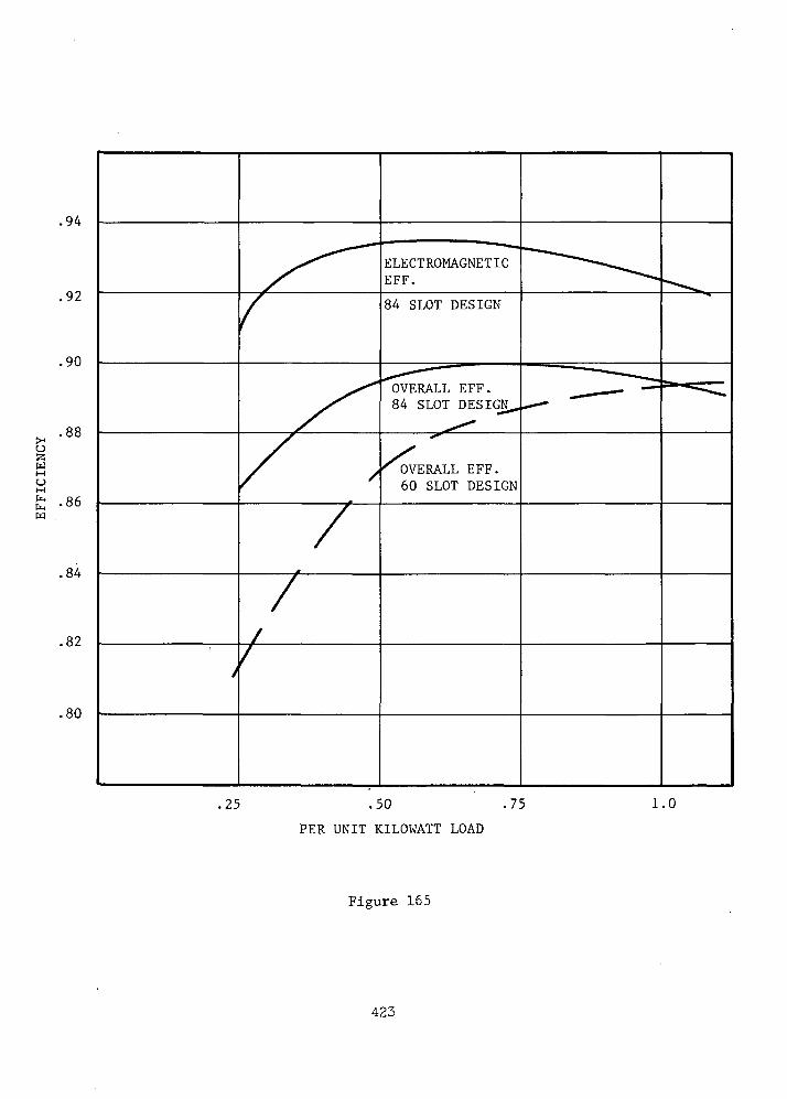
.94
.92
.90
ELECTROMAGNETICEFF.
84 SLOT DESIGN
OVERALL EFF.84 SLOT DESIGN
(H
S3w
w-86
.84
.82
.80
/nvOVERALL EFF.60 SLOT DESIGN
,25 .50 .75
PER UNIT KILOWATT LOAD
1.0
Figure 165
423
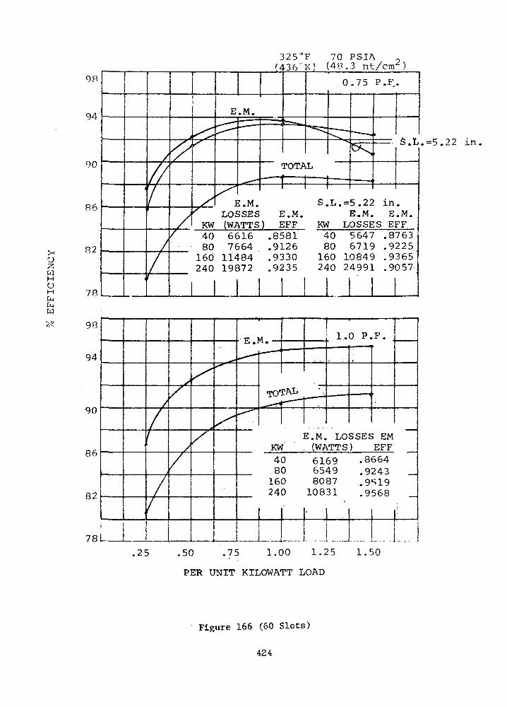
wMOMCna.w
325"F 70 PSIA( 4 3 6 " K ) (4P .3 nt/cn/
98
94
90
R6
82
70
i
/
ft
1
f
/
A
//
'
S'
,\r
KW4080
160240
E.M.,-
ILO£(W/
•• •-
•i•• ' ••^
t
1
==*.
rOTA
0.75 P.F.
"
L
:.M. s.
— — .
11 1
T,.-
- — -.
t>Sl
1
S.L
5.22 in.>SES E.M. E,M. E.M.iTTS) EFF KW LOSSES EFF
66167664
1148419872
I
.85
.9]
.9:
.92
581.26!30!35
A£
ie24
toSO>0 1tO 2
5647 .87636719 .92250849 .93654991 .9057
.-5.22 in
98
94
90
86
82
78
/
/
\
/
/
s/
/
/
X
/
^^
^
E M
^*^
^-^
- — -
TO'CAL
r — 1]
.KW'4080
160240
.25 .50 .75 1.00
_«.•«
_ —
E.M.(WP
i.•— — —
- ~
LOiTTS
616965498087
10831
1 1
i.:> 5
0 P.-• ••
•-• i'i"—i
SSE£) ..
F.
; EMEFF
—
.8664
.9243 _
.9S19
.9568 _
. . ..-.. . ,
l . f >0
PER UNIT KILOWATT LOAD
Figure 166 (60 Slots)
424
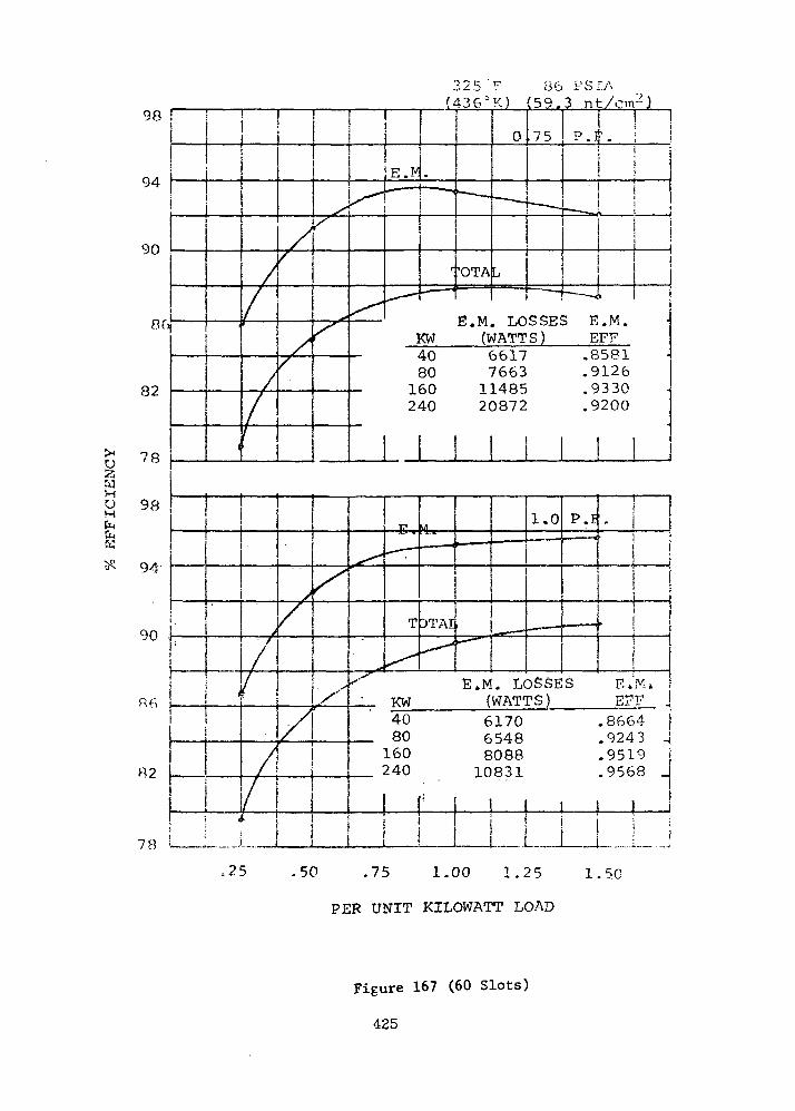
HuMCMCMK
98 \
82
78
98
94-
90
82
78
3 2 5 ' F 36 PSIA( 4 3 6 J K ) (59.3 nt/cm2]
KWE.M. LOSSES E.M.
(WATTS) EFF4080
160240
66177663
1148520872
.8581
.9126
.9330
.9200
I
iI•
.
! *
'
>
//
/
//^
x/\
1 \\
^
V
.— —
T
"
"I.
DTAI
^
i—
•-- — -
• "•"
_«*— •*
1.0..— i. •-
— — — •
P.I
^
1 — i•
1• | |
• ii
«^ E.M. LOSSES E»VuKW (WATTS) SFF j4080160240
11 ii I
>
617065488088
10831
\ 1 '! i„ i 1 ,
.8664 |
.9243 j
.9519 j
.9568 _
1
= 25 .50 .75 1.00 1.25 1.5.0
PER UNIT KILOWATT LOAD
Figure 167 (60 Slots)
425

0&
63HuHCMfcW
98
94
90
86
82
78
98
94
90
78
107 "F 70 PSIA 7315°K) (48.3 nt/cnr )
1
I
/
1r
/
/
//
4y
X-*
^
^~—
V^
E.I. — — <
4.> 1. • !.• • ~ i "
TOTAL^^•gT^^^T*' i JJ3S5
E.M, LCKW (WAT
0
•*• —
.75
— — -,
P.F
L
)SSES E.M"•TS ) EFF
40 7217 .847280 8266 .9064
160 11552 .9327240 19239 .9258
1 1
i
- • • - • • •
^
'/•
/
. 1
r' L.
/
/'
|
' E . M . '
X
/f
"•
^
^
Ii
1. . ..<^\
!•
POTA
-
' ECW
4080
"160240
L
r— —
.M.'(
•. -
. "
'v
LOSWAT
67717087
"836910628.
i1.0 P
t •
_ i-
SESTS)
.
1-
E.EF
J
.F.
MLF
.8552
.9186
.9503
.9576
1-
.50 .75 1.00 1.25 1.50
PER UNIT KILOWATT LOAD
Figure 168 (60 Slots)
426
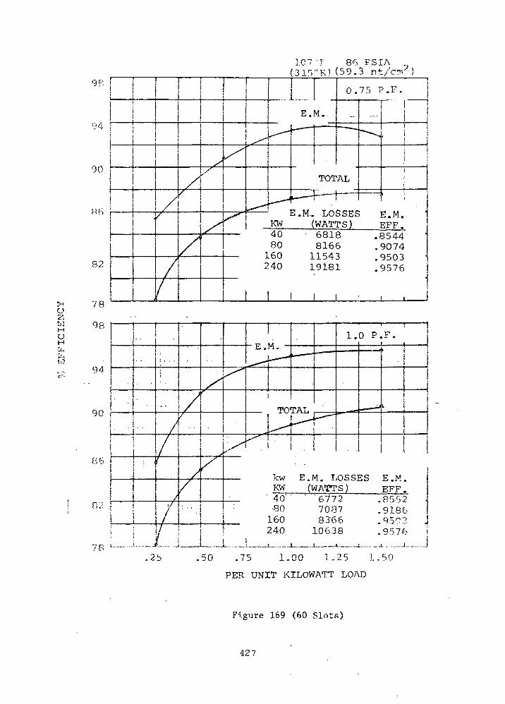
78
107 ~r 86 FSIA(31VK) (59.3 nt/cmx)
QP'
94
00
KCi
82
>< 78O
« 98uHU.&-.CJ
94c'--
90
86
! °2•
ii
j
E.M....
^
,
^
ii
//
X1/
'
/
,/X
x
i
P "'
KW
!
j
0.75 P.F.
TOTAL
k" " 1 j
E.M.. LOSSES(WATTS)
" !j
i
i
!
i ;
; E.M.EFF.
40 • 6818 .854480 8166 .9074160 11543 .9503240 19181 .9576
! ! i
t
•
'
•
i , . .
i
, t ,
*
//•••/r
/
/
/
•
^
/
/ !•••/!/ ' *f / i t/ t i •
!.1VA.
'>•
TOTAL r- —
kwKW
E.M. L(WATT
1.0 P.F.I i
•««••*
P— «
OSS]s)
,
ES
'
1 j
1i
!
E.M.EFF.
'40" ' '6'772 .8552•80 7087 .9186160 8366 .9503240 10638 .9576 J
.25 50 .75 1.00 1.25 1,50
PER UNIT KILOWATT LOAD
Figure 169 (60 Slots)
427
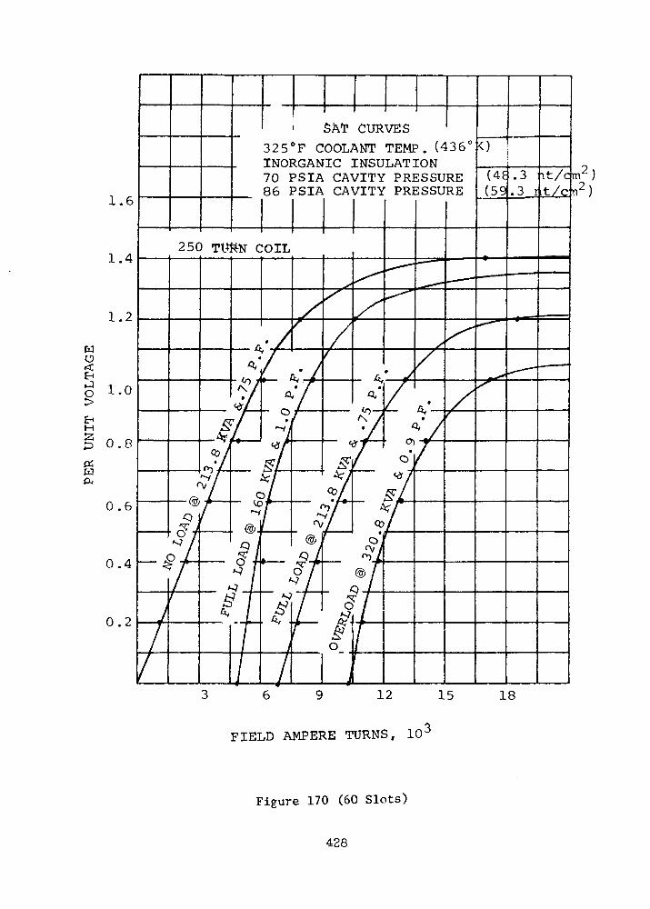
1.6
1.4
1.2
O
H
gPi
1.0
0.8
0.6
0.4
0.2
' SAT CURVES325°F COOLANT TEMP. (4361
INORGANIC INSULATION70 PSIA CAVITY PRESSURE86 PSIA CAVITY PRESSURE (59
.3.3
it/cm"t/cn2
18
FIELD AMPERE TURNS, 10'
Figure 170 (60 Slots)
428

oIS
E-iHS3
Piw
SAT CURVES
107°F COOLANT TEMPERATURE (315°K)ORGANIC INSULATION70 PSIA CAVITY PRESSURE (48.3 nt/
1.4
1.2
1.0
0.8
0.8
0.4
0.2
cm2)
15
FIELD AMPERE TURNS, 10'
18
Figure 171 (60 Slots)
429
voltage gradient through the gas is dependent upon the dielectric con-
stant and thickness of the insulation materials between the electrodes.
Because the gas pressure in the stator cavity of the alternator is vari-
able, calculations were made to determine the minimum allowable pressure
to prevent ionization (corona) of the gas for the three specified alter-
nator voltages. Results of these calculations are presented in Table
LXXIX.
The first three lines in the table present results for the inorganic,
high temperature insulation system. In order to portray the effects of
increasing the insulation thickness on minimum allowable pressure, cal-
culations were repeated for the case of phase-to-phase voltage in the
slot assuming that all insulation thicknesses are doubled. The results
indicated in Table LXXIX show that the minimum pressure is reduced to
approximately one half of the previous quantities.
Calculations were repeated for the organic, low temperature insula-
tion system assuming that the winding is not impregnated with a varnish.
The minimum allowable pressures calculated for this case are approxi-
mately the same as for the inorganic insulation system. This seems
surprising in view of the lower dielectric constant of the organic in-
sulation; however, the insulation thicknesses selected were less than
for the inorganic insulation system. This was done primarily because
of higher available dielectric strength and poorer heat transfer pro-
perties. Increasing the thickness of the insulation would result in
lower minimum allowable pressures as indicated previously for the
inorganic insulation system.
The fact that no varnish impregnation was assumed in the organic
insulation system calculations is significant. If it is assumed that
the winding is completely impregnated with a compatible varnish, then
the minimum pressure for corona inception cannot be accurately cal-
culated. Theoretically, a varnished winding is solid and does not
contain any gas filled spaces. In reality, however^ small bubbles or
cavities do occur. The type of gas and the pressure in these cavities
cannot be accurately predicted. In general, the use of a varnish im-
pregnation will significantly increase the corona resistance of the
winding. The mechanism of failure would be caused by the presence of
430
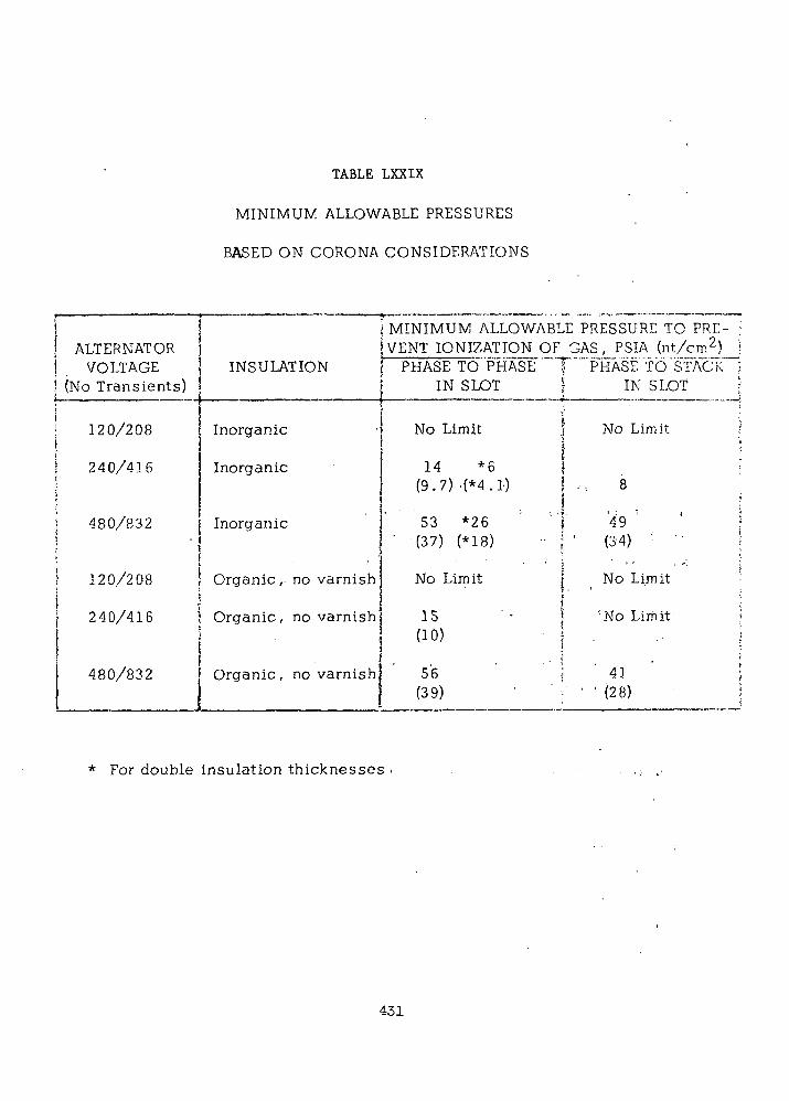
TABLE LXXIX
MINIMUM ALLOWABLE PRESSURES
BASED ON CORONA CONSIDERATIONS
ALTERNATORVOLTAGE
(No Transients)., ,
120/208
240/416
480/832
120/208
240/416|)J
480/832
INSULATION
•
Inorganic
Inorganic
Inorganic
Organic, no varnish
Organic, no varnish-
Organic, no varnish
i MINIMUM ALLOWABLE PRESSURE TO PRE-;VENT IONIZATION OF GAS, PSIA (nt/cm2); PHASE TO PHASE f PHASE TO STACK
IN SLOT j ' IN SLOTV
No Limit ) No Limit|
14 *6 J(9.7) -(*4.1) . | -•: 8
53 *26 ' l l
(37) (*18)
No Limit
15(10)
56(39)
.49 '
" (34) ' ' •
No Limit
'No Limit'
41' ' (28)
* For double insulation thicknesses .
431
corona pulses occurring in the entrained cavities in the solidified
insulation. The electrons and ions in the gas bombard the insulation
on each pulse and erode away the insulation. Harmful chemical reactions
can occur. In general, for insulating materials, the time-to-failure at
any applied voltage is a measure of corona resistance. Inorganic in-
sulations are much better in this respect than organic insulations. An
inorganic insulating material such as alumina may induce corona in a
gas at a lower voltage than for an organic material such as polyimide,
but it is better able to withstand the effects of the corona pulses.
Long life can be achieved for organic insulations by operating the in-
sulation at reduced voltage stress levels. ,
Voltage Unbalance
The unbalance in the three-phase voltage of the alternator when
operating with a single-phase current load equal to 2/3 of the rated
current was determined for the alternator designs presented in Phase I
and Phase III. The method of calculating one of the reactance values
that indirectly effects voltage unbalance was changed during the Phase. ' • ' • , - ' • - - M I
I to Phase III interim. The quadrature-axis sub-transient reactance
(XIlq) which is used in determining the negative sequence reactance (X2)
was previously determined by neglecting the quadrature axis damping
provided by eddy currents flowing in the solid rotor surface. The pro-
cedure now used for calculating x"q is based on a modification of
procedures outlined in the Westinghouse East Pittsburgh Design Manual
for turboalternators which accounts for sub-transient damping effects.
A check on the new calculation procedure was made by comparing cal-
culated results and. test results for the .1200 Hz alternator of the
Brayton Rotating Unit (BRU). The value of voltage unbalance ob-
tained by test is 5.2 percent for a 2/3 rated current, single phase,
unity power factor load. The calculated value is 5.85 percent. It
was previously calculated to 11.8 percent using the initial methods of
Phase I.
432
MECHANICAL DESIGN CONSIDERATIONS
Thermal Analysis
1. Method of Cooling
Direct conduction of the internal losses to heat sinks on the
magnetic frame was not considered for the two-pole alternator since
previous studies of the six-pole alternator, which offered more favor-
able conditions for direct conduction, revealed this mode of cooling
was not adequate. A portion of the losses generated within the pole
faces, conductors and gas must be transported by forced convection.
Forced convection within the alternator is obtained by recircula-
ting the cavity gas through the conical gap around the rotor whereby
the rotor produces a pumping action on the gas. The gas then passes
through the main gap between the stator and rotor. A split stack pro-
vides a radial passage from the main gap to a heat-exchanger which is
located between the stack and the magnetic frame. The heat-exchanger
also serves as a non-magnetic separator between the back-iron and the
frame. After the gas passes through the heat-exchanger, it flows a-
round the field coil and through the end extensions of the windings.' . . ! •
Special baffles are used around the conical sections of the rotor.
These baffles are designed to (1) cause the gas to enter the conical
gap near the end of the auxiliary radial gap, (2) cause the gas to flow
into the main gap with minimum leakage at the ends of the stacks, and1
(3) cause some of the gas to flow through the ends of the windings.
2. Pumping of the Gas
Pumping of the gas is produced by the action of the conical surfaces
upon the gas within the gap. The head developed by this action was
estimated from:
AP = 1/2K
433
where
_2AP = pressure head, Lb in
_3p - density of gas, Lb in
w = rotor speed, 800 77" radian sec
R = rotor radius (main gap) - 4.0 in
R. = rotor radius (auxiliary gap) = 3.25 in
K = 0.5 = average circumferential velocity of gas
relative to the circumferential velocity
of rotor surface
gc = 386.4 Lb in Lb ~1 sec~2m f •
In general, it was assumed that the head developed within the
conical gap was equal to the centrifugal head which would be developed
by solid body rotation of the gas at one-half of the speed of the rotor.
3. Pressure Drop
The -pressure drop within the gas flow circuit was estimated from:
! . •' * ' '
AP = l/2PVH2(^+Z:Cdh);+l/2pVR
2S.CdR^ ._.._
where
V = velocity of gas in the heat-exchangerH . . . .
V = velocity of gas in baffles and gap around the •R
rotor
C_, = loss coefficients ;for he at-exchangerd h . . . - . - . . .
(entrance, exit, turning, etc.)
C = loss coefficient for baffles and gapsuR
fl/D = friction factor for heat-exchanger
D/V0 = constant =3.0 in/2.75 in = 1.091H R
434

With an allowance of one dynamic head of loss for each entrance,
turn, and exit plus an adequate allowance for the friction factor, the
pressure drop for the flow circuit became:
P = 1/2 p V__2 (9.34)£1
and equating the pump head to the pressure drop gives:
V., !=« 80 ft sec" (24.4 m sec" )H
V ra 73.2 ft sec (22.3 m sec )R
In general, the volumetric flow rate through the circuit was con-
sidered constant since Reynolds number effects upon the friction and
other loss coefficients was neglected.
4. Coolant Flow Rate
The flow rate based upon a velocity of 80 ft sec (24.4 m sec )
in the heat-exchanger is given in Figure 172 as a function of pressure
and the average temperature of the gas. These flow rates were used for
the heat transport calculations.
5. Heat Transfer Coefficients
The heat-transfer coefficients for argon gas within the heat-exchanger,
auxiliary gap, main gap, and on the windings are given in Figures 173
and 174. The surface area on the gas side of the heat-exchanger was2 2
considered to be 7.51 ft (0.697m , both sides of the split stack).
Each side consists of 275 parallel passages (4.38 inches (11.1 cm) long)2
with a flow area per passage of 0.01 in (0.2 inches x 0.05 inches;
0.508 x 0.127 cm and 0.0645 cm ).
6. Windage Losses
Windage losses were calculated for HeXe gas since this gas produces
a lower Reynolds number (higher drag coefficient) than argon gas at the
same conditions. Windage losses as a function of gas temperature are
given in Figures 175 , 176 , and 177. Drag coefficients from NASA TMX-
52851 were used. A comparison of the windage loss in the main gap obtain-
ed by the method used for the Phase I study and by the recent data reported
435
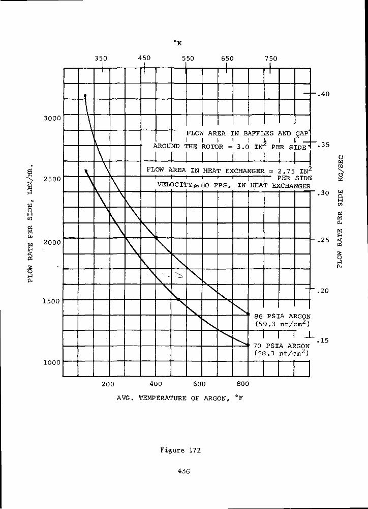
'K
l%
w
tn
w
3000
2500
2000
1500
1000
350 450 550 650 750
t\\)\N
v\V
\V
\V\\\\s
;
_J
^ROUND 1
FLOW AR
HE ROTC
EA 3
)R =
CN BAFFLES AND GAP'! 1 , 1 r _3.0 IN^ PER SIDE'
FLOW AREA IN HEAT EXCHANGER =2.75
\
\s
VELOCITY jss 80 FPS.
ss
\\.N
\
s"
<vx
X
X
^
IN
Nv^
PER
HEAT EXCHA
86(5
70(4(
PS39.3
PSI3.3
IN2
SIDENGER
A ARGONnt/cm2 )
A A!nt/c
J
ICON:m2)
.40
35
.30
,20
,15
200 400 600 800
AVG. TEMPERATURE OF ARGON, °F
UwCO
HW
O4
W
I
Figure 172
436

°K
Cno
tNEHPn
102
98
94
90
86
82
78
74
70
66
. 3f° 4"S
V
•v
^^)
\
^v
V.^X
^
\
x
^v
•
Vs
\
x^
7C8(
^^*>,
50 55^) 6^0
X
^
^
750
^.482 '.241Nu = .409 (Rn) " . (b/R)
V-
^xj
^v.
I PSIA =j PSIA =
- ,"-
W
Nu
v^
^
"~^
= 48= 59
"•*
1 I I II = gap to radius ratio
and
^
""->
*• —
RnR
"
^^
' — ..3 nt/ci.3 nt/c
^> •--
= Nieync
*«^
-* ,
— ^.
m?)m")
••*«-,
jsseaids
•**-,
a— -i
' ,
tt c
Nur
86' AH
mdnber s — ^nmt^i^
PSIA —X.. GAP
70 PSIAWX. GAJ
—
- 86 PSIAMAIN GAI
7(M/
D PSIAMN GAP
D
3
.055
.050
'.045
.040
200 400 600 800
AVG. TEMPERATURE OP ARGON, °F
Figure 173
437
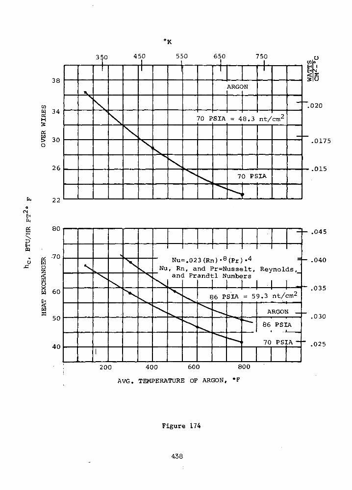
'K
w
H
«
£O
o<MEHfr.
E"m
W
ffi
38
34
30
26
22
80
70
60
50
40
350 450 5<
K>
1
\">
\\
1
N\">\
>0 650 750
70 PSIA
X\,v^
ARGCw
= 48.3j
nt/cm
70 PSIA
'r-
WA
TTS
Nx
I
>
X
X
X
X.X
X"X
Nu
N
x
-
Nu=.023(Rn) -8(Pr) -4
, Rn, and Pr=Nusselt,and Prandtl Numbers
^
^ '
x
v
Reynolds,_
86 PSIA =59.3 nt/cm2
\
^
^ .
^ .
- >
' — >
"* .ARGON _
86 PSIA
70 PSIA ~
.045
.040
.035
.030
.025
200 400 600 800
AVG. TEMPERATURE OF ARGON, *F
Figure 174
438
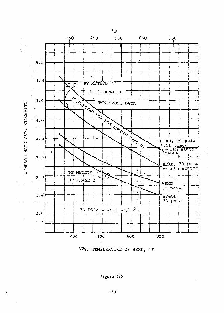
350 750
H
H
o
5.2
-4.8
4.4
4.0
3.6
3.2
2.8
2.4"
2.0
200 400 600 800
AVG. TEMPERATURE OF HEXE, *F
Figure 175
439
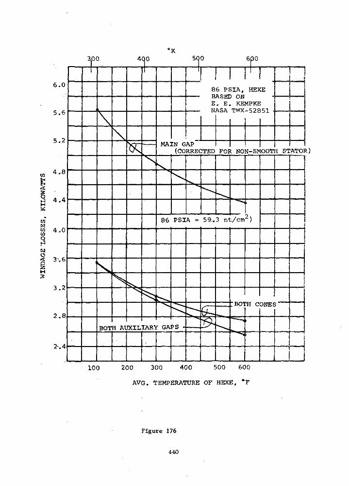
6.0
5.6
5.2
4.8
4.4
CO
wog2H
3.2
2.8
2-. 4
300 400 500 600
1
i
\
^
:BOT
\
k
H At
^
5^
^
JXIL
1
s
1
MA:
X
86
>-."
IARY GA
EN G(CO
\
! 1
86 PSIA, HE>BASED ONE. E. KEMPKENASA TMX-52S
APRRECTED
PSIA =
PS *
"-^^
"
59.
GL,•&
FOI
^
I NO
-«*
3 nt/cm
=* .
•"
HO1
^=;^TTtaiii
^"^
N-S1V
i
2)
'H C
»
I
:Ei
ci .
OOT
ONES
i
I STATO]
1
*)
100 200 300 400 500 600
AVG. TEMPERATURE OF HEXE, *F
Figure 176
440

350 450 550 650 750
wW
a
& °O u03
3.4
3.0
2.6
2.2
O 1.8H
1 I!i(
v|
!
\
<T
^
s
^
\
"
I
KEMPKE DATA
PHASE I METHOD
X,S
^V^^>-p
70 PSIA = 4 8 . 3 nt/cm )
•!
708,0
JPS:
" D:j
, GAPRAI
^^
<^
)IUS
fe
: 1 !CA, HSXELA. TO 6.5"
iDIA.
1 I ! (= CONSTANT _|= 0.03 \
I
n
Wto
swoQ2 WM W
COO
3.4
3.0
2.6
X 2.2§
1.8
\\xx
\^
6
S -
.5"
^
70 PSIA,
DIA. E. E.I
"
^ >
HEXE
KEMPKE DATA
i
t
i200 400 600 800
TEMPERATURE, OF HEXE, °F
Figure 177
441

in TMX-52851 by E. E. Kempke is given in Figure 175. The new data
gives approximately 30 percent higher loss. Therefore, the new data
was used for the cooling studies.
7. Thermal Maps
Computer programs were utilized to perform all analyses excepting
the temperature rise of the liquid coolant and the maximum and minimum
temperature of the gas. A 30°F (17°K) temperature rise of the liquid
coolant was used for all calculations. The mean temperature difference
between the gas and liquid in the heat-exchanger and the temperature
rise of the gas were obtained by iterative calculations. The gas tem-
peratures were treated as boundary temperatures which were improved
after each iteration until the temperature rise of the gas correlated
with the heat flow into the gas at each point along the flow path. The
analysis did not include the alternator field coils since their thermal
state is relatively independent of other alternator temperatures. The
field coils can be cooled by coolant coils which are an intimate part
of the field coil package. The field coils do not represent difficult
cooling problems as indicated in the Phase I studies where a more
compact field coil design was analyzed.
Thermal maps are presented in Figures 178through 187 for the
conditions and situations listed in Table LXXX.
All of the cooling configurations and conditions which were in-
vestigated fullfllled the requirement of the investigation since the
hot-spot temperature for all designs was less than 300°F (167°K) above
the coolant supply temperature.
Design No. 5 from Table LXXX represents the design with the
least merit for a coolant supply temperature of 466°F (514°K) since
the temperature at an adiabotic interface between the rotor and bear-
ings is high, 693°F (640°K). Approximately one kilowatt of heat must
be conducted through the interface to decrease the interface tempera-
ture 100°F (55°K). Addition of coolant within the endbell, as re-
presented by Design No. 3, decreased the temperature of the adiabatic
interface from 693° to 623°F (640° to 602°K). Similarly, the addition
of a small gas flow through the auxiliary gap without coolant in the
442
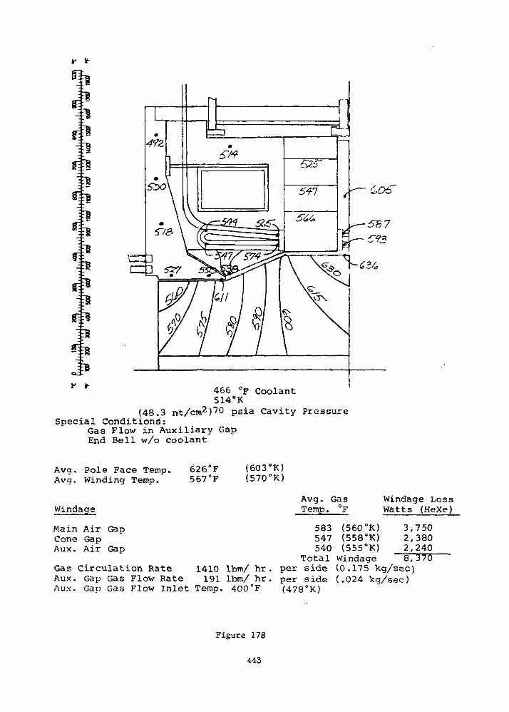
— -~5l
ii
' 466 °F Coolant514°K
(48.3 nt/cm2)70 psia Cavity PressureSpecial Conditions:
Gas Flow in Auxiliary GapEnd Bell w/o coolant
Avg. Pole Face Temp.Avg. Winding Temp.
Windage
Main Air GapCone GapAux. Air Gap
626°F567°F
(603°K)(570°K)
Avg. GasTemp. °F
583 (560°K)547 (558°K)540 (555°K)
Total Windage
Windage LossWatts (HeXe)
3,7502,3802,2408,370
Gas Circulation Rate 1410 Ibm/ hr. per side (0.175 kg/sec)Aux. Gap Gas Flow Rate 191 Ibm/ hr. per side (.024 kg/sec)Aux. Gap Gas Flow Inlet Temp. 400°F (478°K)
Figure 178
443
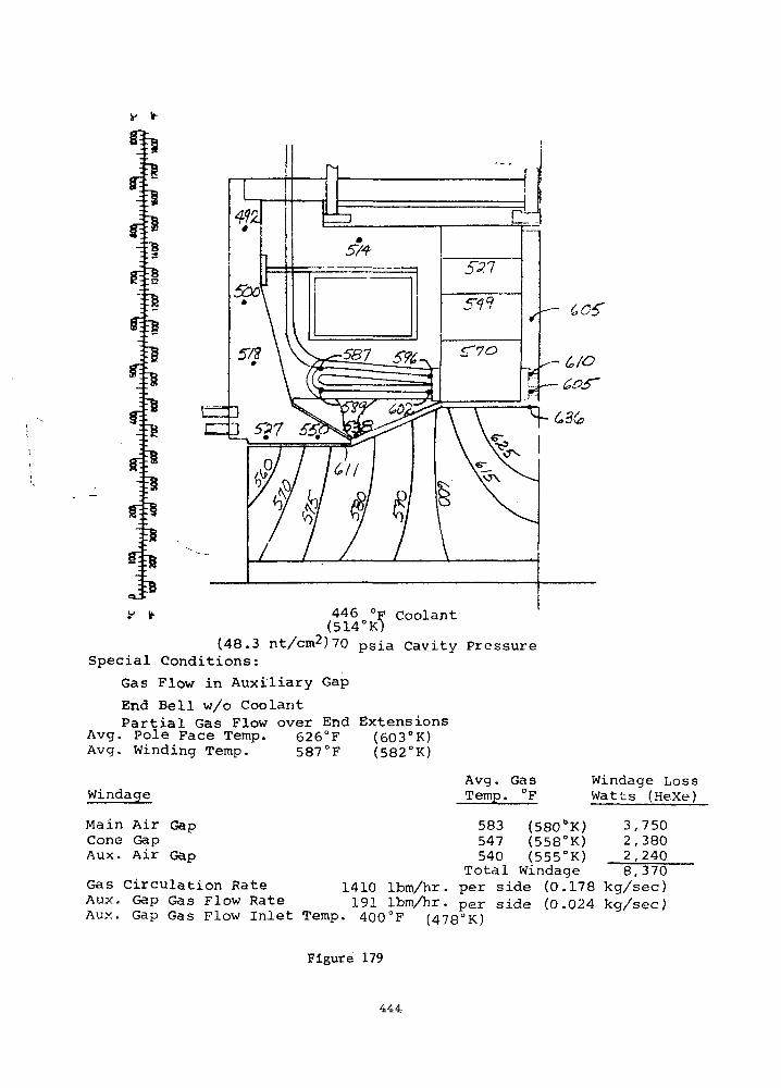
*
!===»
°F CoolantK)
J*« * 446
(514°K")(48.3 nt/cm2)70 psia Cavity Pressure
Special Conditions:
Gas Flow in Auxiliary Gap
End Bell w/o CoolantPartial Gas Flow over End Extensions
Avg. Pole Face Temp. 626°F (603°K)Avg. Winding Temp. 587°F (582°K)
Windage
Main Air GapCone GapAux. Air Gap
Avg. Ga sTemp. °F
583 (580&K)547 (558°K)540 (555°K)
Total Windage
Windage LossWatts (HeXe)
3,7502,3802,2408,370
Gas Circulation Rate 1410 Ibm/hr. per side (0.178 kg/sec)Aux. Gap Gas Flow Rate 191 Ibm/hr. per side (0.024 Teg/sec)Aux. Gap Gas Flow Inlet Temp. 400°F (478°K)
Figure 179
444
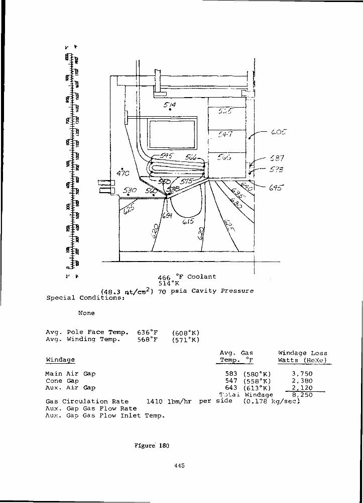
81
l
¥ it- 466 °F Coolant514°K
(48*3 at/cm2} 70 psia Cavity PressureSpecial Conditions:
None
Avg. Pole Face Temp.Avq. Winding Temp.
Windage
Main Air GapCone GapAux. Air Gap
636°F568°F
(608°K)(571°K)
Avg. GasTemp. °F
Windage LossWatts (HeXe)
Gas Circulation RateAux. Gap Gas Flow RateAux. Gap Gas Flow Inlet Temp.
583 (580°K) 3,750547 (558°K) 2,380643 (613°K) 2,120
TjLal Windage 8,2501410 Itm/hr per side (0.178 kg/sec)
Figure 180
445

g
iiiill
£05
tc6 °F Coolant14°K)
(48.3 nt/cm2) 70 psia Cavity PressureSpecial Conditions:
End Bell w/o Coolant
Avg. Pole Face.Temp.Avg. Winding Temp.
Windage
Main Air GapCone GapAux. Air Gap
652'568'
1410Gas Circulation RateAux. Gap Gas Flow RateAux. Gap Gas Flow Inlet Temp.
(637'(570'
K)K)
Avg. GasTemp. °F
583 (580°K)548 (559°K)758 (676°K)
Total Windageper s ide
Windage LossWatts (HeXe)
3,7502,3802^0008,130
(0.178 kg/sec)
Figure 181
446
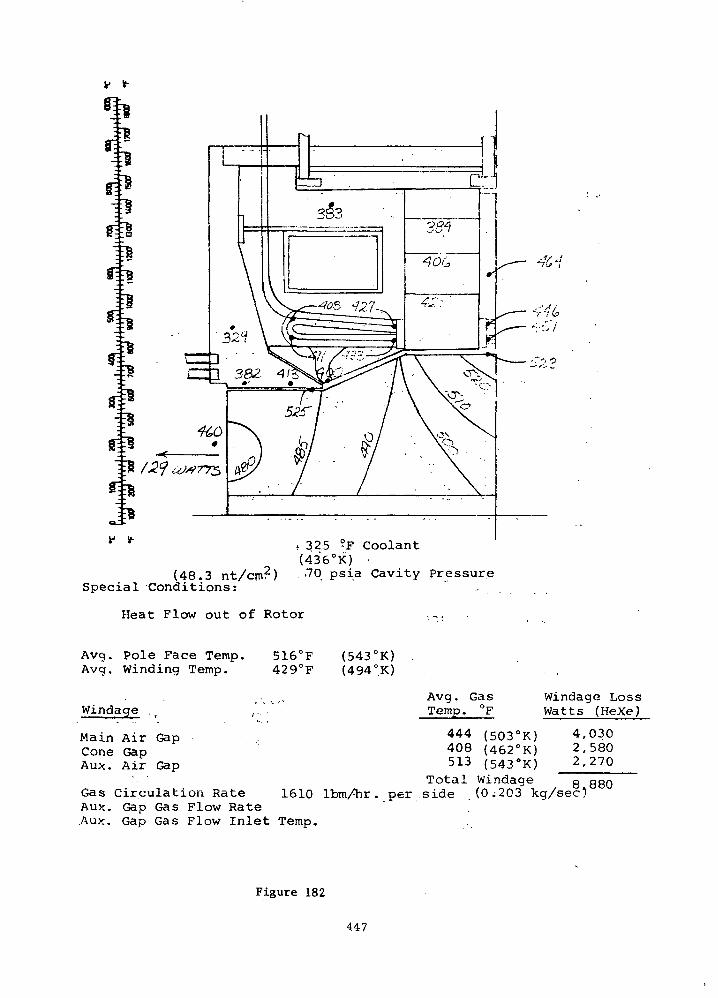
** *" * 325 °F Coolant(436°K) •
(48.3 nt/cm2) -70 psia Cavity PressureSpecial Conditions:
Heat Flow out of Rotor .-,
Avg. Pole Face Temp.Avg. winding Temp.
Windage
Main Air GapCone GapAux. Air Gap
516°F429°F
(543°K)(494°K)
Circulation RateAux. Gap Gas Flow RateAux. Gap Gas Flow Inlet Temp.
Avg. GasTemp. °F
444 (503°K)408 (462°K)513 (543°K)
Total Windage
Windage LossWatts (HeXe)
4,0302,5802,270
O QQQ
1610 lbm/hr. per . side . (0 i203 kg/sec)
Figure 182
447

v v-
•h
•ib
^
IBf V- 325 °F Coolant
(436°K)(48.3 rtt/cm2) 70 psia Cavity Pressure
Special Conditions:
None
Avg..Pole Face Temp.Avg. Winding Temp.
Windage
Main Air GapCone GapAux. Air Gap
522°F429"F
(547°K)(494°K)
Avg. Ga sTemp. °F
Windage LossWatts (HeXe)
Gas Circulation RateAux. Gap Gas Flow. RateAux. Gap Gas Flow Inlet Temp.
445 (503PK) 4,030408 (461°K) 2.580531 (551°K) 2,250
Total Windage 8,8bO1610 Ibm/hr per side (0.203 kg/sec)
Figure 183
448

v v-
il
(48.3 nt/cm2)Special Conditions:
Heat Flow into Rotor
325 °p coolant(436°K)
70psia Cavity Pressure
Avg. Pole Face Temp.Avg. Winding Temp.
Windage ' -
Main Air GapCone GapAux. Air Gap
527°F42 8° F
(548°K)(493°K)
Avg. GasTemp. °F
445 (502°K)408 (482 °K)537 (553°K)Total Windage
Windage LossWatts (HeXe)
4,0302,5802,240
iutoj. wj_iiu<aut: o ocn
Gas Circulation Rate 1610 Ibm/hr. per side (0.203 kg/secT'Aux. Gap Gas Flow RateAux. Gap Gas Flow inlet Temp.
Figure 184
449

(59.3 nt/cm2)Special Conditions:
325(436°K"
F Coolant
psia Cavity Pressure
None
Avg. Pole Face Temp.Avg. Winding Temp.
Windage
Main Air GapCone GapAux; Air Gap
504°F (536°K,)424°F (491°K)
Avg. Ga sTemp. °F
433 (497°K)400 (478°K)526 (548°K)
Windage LossWatts (HeXe)
4,5902,9402,660
Gas Circulation RateAux. Gap Gas Flow RateAux. Gap Gas Flow Inlet Temp.
Total Windage 101990 Ibm/hr per side .(0.25 kg/secJ
Figure 185
450

si
•rgsi*
€k
f *• 107 °F Coolant(315°K)
(48.3 nt/cm2) 70 psia Cavity PressureSpecial Conditions:
None
Avg. Pole Face Temp.Avg. Winding Temp.
Windage
Main Air GapCone GapAux. Air cap
257°F (398°K)192°F (363°K)
Avg. GasTemp. °F
218
261
(377°K)(358°K)(401°K)
Windage LossWatts (HeXe)
4,5502,9402,710
Gas Circulation RateAux. Gap Gas Flow RateAUX. Gap Gas Flow Inlet Temp.
Total Windage -J.Q 2002200 Ibm/hr. per side (Q ,211 kg/sec)
Figure 186
451

--*
;^S
-S~fsJ8St^
fi*"£8
107 °F coolant(315C'K)
(59.3 nt/cm ) 86 psia Cavity PressureSpecial Conditions:
None
Avg. Pole Face Temp.Avg. Winding Temp.
Windage
Main Air GapCone GapAux. Air Gap
253°F194°F
(397°K)(363°K)
Gas Circulation RateAux. Gap Gas Flow RateAux. Gap Gas Plow Ir-.let Ttsrop.
Avg. G-'i sTemo. "F Watts (Hex-.-)
268Total
2710 IfcrVhr. oer side
( 3 7 7°K )
(0 .341
3 . 100
11,550
Figure 187
452

CO
a
W
O
O
ICO
3
2 2 '2 ~<£ P H 2 tr> to to to CMO cn^r to ^H o co to to o cocj H 2 W t^t uoirt in 10 to to 10 to ^rm ioin tnio mmco co S H o — ' — ' — - ~^ ~^ — " —
O2.3o,"Z ^^ ^__ ^__ ^ ^ _ ^
< J £ 3 ^ cf>oo ^^cr> cnoo cnco 1/50 mo mo «q*o2 § E H « •«£ ^ij «£ "^2 *e "e "s "e
•2.T W W « °^ yj QQ ^ ^Q y^ ^Q ^^ (VJ ^ QQ QQ ^( ^5 O CT>
3/- \^2 COO COO ^*H IrtCM CM'fl' CM^1 COtO ~HCO
X H ^ S - ^ «5CO toS" in<^ CMO* Co'fC COCO Ot5 OCTJ
S O c u U C M tOtO U3U5 tOtO tvlO IDI/3 lOlrt in^3 l/>^
22 o f-l CM COl ^ c t J - t D rv co en *-* ^H ^-t ^5 ri M 2 ' ' ' ' ' ' ' 'C z E n g a 3 3 3 3 3 3 3
^^ o; O °*
" 3 2 ^ 0 0 O 0 0 D O 2 0a S a o s Z 2 2 2 o z a z
CO2
ffi O
D 2
J O B i Q E H C O ,-, CO CO CO CO CO COp j a Z x u g w K i y u w uC L , [ L , H U U > I Z >< >< >< >< >< ><
Ko
S a S ^ S w o. o o o o oC S S - d i * >1 z a z 2 z 2
EH
J 22 M f j / - . .-i co /-, co co co co\J w rj tj W r.-fl W [J LJ Cl4 M
O S 3 2 Z S Z X >H >< >i
M C O ^ ^ 'co* ^ "r? co *m "n co*
^ y * ^ oco oco oco ooo oco oco oco tocn
H2
^0;? _ „ „ ^ ^ ^^^ ^i) S4 ^^f to ^* to ^* to ^* to ^* in to in to m to in toQ^« tO^-t tOrH tO--» <O-H CMtO CMCO CM^CO CMCO
O C O H O ^^3 i°, ^i3 '*t^°, m 3> n -S ^- ^^
Zow O ^ H CM co ^« m to rx. coQ 2
— ^^
••a* co m 01CM CO C*J CO
CO " CO "O (** O PN.CM CO CM CO
T ^ O O"to o to oCM r CM r
•^ CM O O
CM rr CM J1
1 1I— 1 (-<
§ g
CO COw u
0 0z z
CO COW f.]
to co
S ? S S
^ ^0 rH O ^
<—« CO •— t CO
oen --•
453
end bell, as represented by Design No. 1, decreased the temperature of
the adiabatic interface from 693° to 561°F (640 to 567°K). In general,
it appears that either the addition of coolant in the end bell, the
addition of forced circulation through the auxiliary gap, or a combina-
tion of both can be used to obtain desired interface temperatures be-
tween the rotor and stub shaft. '
Design No. 2 of Table LXXX is a slight variation of Design No. 1.
For this design, the forced convection mode of heat-transfer from the
end extensions to the gas was reduced by decreasing the heat-transfer
coefficient by a factor of four. The maximum temperature of the windings
increased from 593 to 610°F (585 to 593°K). This means the flow pattern
over the conductors will not be critical to the thermal state of the
windings. Furthermore, the likelihood of damage to the ANADUR insulation»._..
on the conductors when subject to a high velocity gas stream precludes
the use of a cooling scheme which requires a high convection mode of
heat-transfer from the end extensions.
Design No. 5 through No. 8 of Table LXXX ' are cases investigated
for a coolant supply temperature of 325°F (436°K) . Heat flow in and out
of the stub shaft interface was considered. Figure 188 gives the heat
flow rate across the interface as a function of the interface temperature.
An adiabatic solution for the turbine and compressor components'gave 503
and 499°F (536 and 533°K) for the turbine and compressor stub shaft,
respectively. It can be noted from Figure 188 that little heat will
flow into or out of the rotor for this coolant temperature.
A comparison of Design-No. 9 with Design No. 7 and a comparison.of
Design No. 10 with Design No. 11 shows the influence of cavity pressure
upon the temperatures. In general, increasing the cavity pressure from
70 to 86 psia (48.3 to 59.3 —2) did not have a significant effect uponcni
the thermal state of the alternator. Windage losses increased, the gas
flow rate, and the forced convection mode of heat-transfer increased
also. However, the net change in the thermal maps was slight.
With the low temperature windings and coolant supply temperature,
there appears to be a significant temperature difference between the
rotor and bearing system based upon an adiabatic interface with coolant
in the end bells. A cooling scheme without coolant in the end bell
454
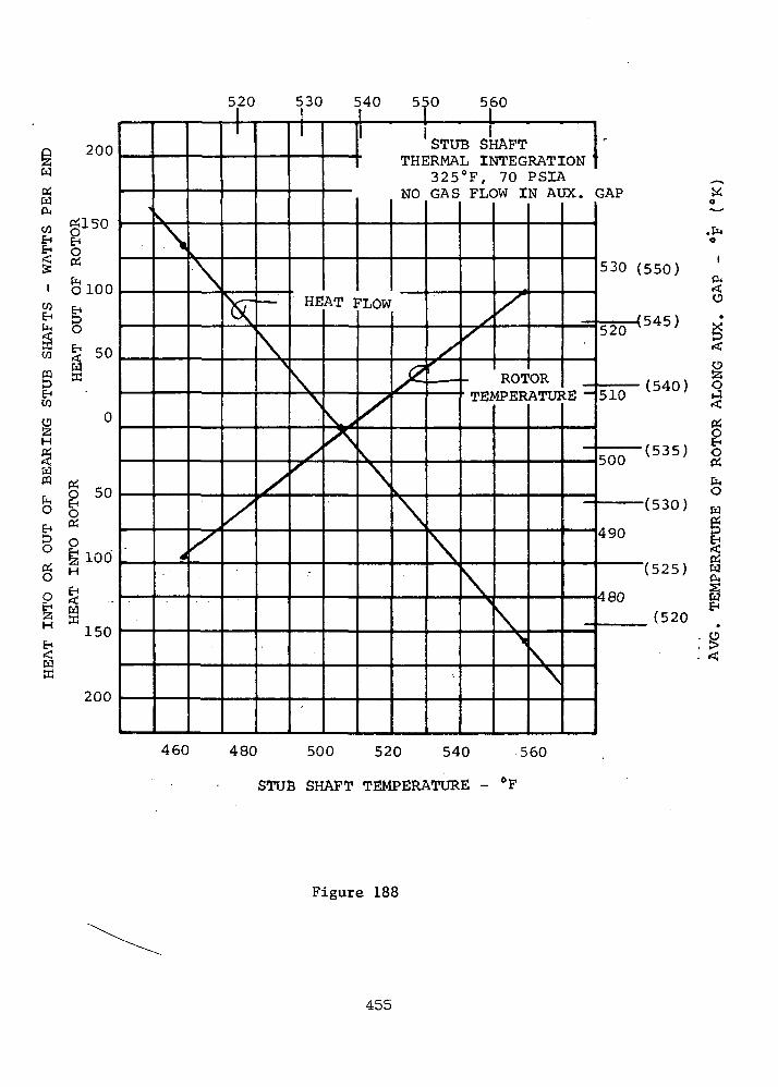
200
w«w
§
0100EH
8
CQ
iH
fQ
EH
8g
». •
a 50
50
100H
EH<Wffi
ffi
150
200
5
^ V
\
4
k
\
X
20 530 540 550 56
V
X
\>
x
HE
\\
/s
AT 1
VA
1
1LOW
X\
\
SO
ISTUB SHAFT I'
THERMAL INTEGRATION J325°F, 70 PSIA
NO GAS FLOW IN AUX. GAP
X-
t.
\
/r
~
\
s/
' TEl
\!>
X
ROT>1PER
\s
ORATUI
\\
:E ~
530 (550)
— — (545)520 V ;
510 (j40)
500 ( b 3 b )
(530)
490
(525)
480(520
460 480 500 520 540 560
STUB SHAFT TEMPERATURE - °F
O
O
w
wcu
Figure 188
455
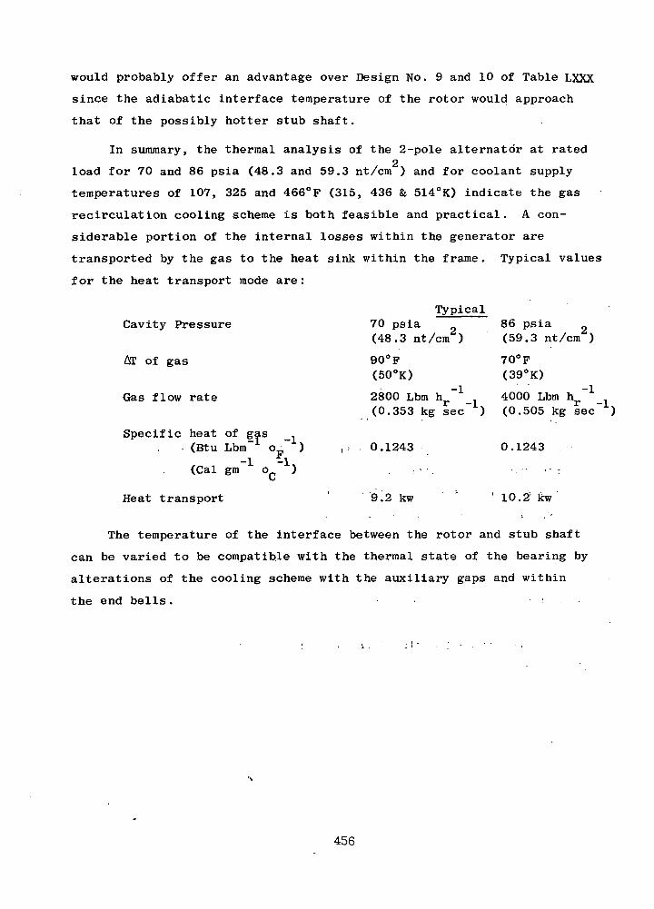
would probably offer an advantage over Design No. 9 and 10 of Table LXXX
since the adiabatic interface temperature of the rotor would approach
that of the possibly hotter stub shaft.
In summary, the thermal analysis of the 2-pole alternator at rated2
load for 70 and 86 psia (48.3 and 59.3 nt/cm ) and for coolant supply
temperatures of 107, 325 and 466°F (315, 436 & 514°K) indicate the gas
recirculation cooling scheme is both feasible and practical. A con-
siderable portion of the internal losses within the generator are
transported by the gas to the heat sink within the frame. Typical values
for the heat transport mode are:
TypicalCavity Pressure
AT of gas
Gas flow rate
Specific heat of gas ,(Btu Lbm"1 o_~ )
(Cal gm o )
Heat transport
70 psia(48.3 nt/cm )
90°F(50°K)
2800 Lbm h ~1
86 psia(59.3 nt/cm )
-1,
70°F(39°K)
4000 Lbm h.-1
-1,(0.353 kg sec ) (0.505 kg sec )
0.1243 0.1243
9.2 kw 10.2 kw
The temperature of the interface between the rotor and stub shaft
can be varied to be compatible with the thermal state of the bearing by
alterations of the cooling scheme with the auxiliary gaps and within
the end bells.
456
Rotor Stress and Bonding
2The maximum stress intensity (92,500 psi, 63,800 nt/cm will occur
around the central hole in the 8.0 inch (20.4 cm) cylinder at 20% over-
speed. Tensile properties of the rotor materials are:Tensile
Material Hardness Temperature 0.2% Yield Strength Strength
SAE 4340 RC32 700°F 110,000 psi 130,000 psi(643°K) (76,000 nt/cm ) (89,700 nt/cm )
Inconel 718 RC38 700°F 125,000 psi 150,000 psi(643°K) (86,300 nt/cm ) (103,400 nt/cm )
A comparison of the maximum stress and the stress at design speed
(24,000 RPM) with the tensile properties of the materials gives:
stress @ 24,000 RPM~
Y. S. of SAE 4340 ~ 110,000 ~ *
oyerspeed stress _ 92,500 _ „T.S7~oT~SAE~4340 ~ 130,000 h
% creep strain at bore in 5 years < 0.01%.
The strength of the joint between the SAE 4340 and alloy 718 has
approached the ultimate tensile strength of the parent materials in past
developments. If this characteristic continues when the 4340 is strengthened
for the specific requirements of this application, the joints will have
adequate strength. The time-temperature-pressure cycle for bonding in an
autoclave have been developed for bonding rotors with lesser strength
requirements. This cycle will have to be modified to produce the strength
required for this application. Experiments are necessary to determine
whether the SAE 4340 can be strengthened during the bonding cycle or
during a he at -treatment cycle after bonding of the materials. Thus,
positive conclusions cannot be made relative to the integrity of the
rotors until these experiments have been performed.
A separate and complete discussion of the bonding of the rotor is
presented in Appendix A.
457
Mass Unbalance
The rotor detail, including significant cross-sections to illustrate
the non-symetric distribution of magnetic and non-magnetic steels, and a
plot of the mass unbalance are shown in Figure 164. The .density of the
non-magnetic steel (Inconel 718) is 5% greater than the density of the
magnetic steel (AISI 4340). This density difference results in the
center of mass of sections between the small end of the conical section
and the (axial) center of the shaft being shifted toward the predominantly
non-magnetic side of the shaft center line. Because the pattern shown
for the left end of the rotor is reversed.on the right end, a couple
will exist. The magnitude of the mass unblance was calculated for sections
AA and BB on Figure 164, and then plotted, with the points of zero un-
balance, to determine the unbalance (per unit axial length). This plot
(shown on Figure 164) was integrated to determine a resultant unbalance of
0.75 inch-pounds (0.864 kg-cm) with a moment arm of 2'.01 inches (5.li cm)
from the shaft center for each end of the shaft.
This mass unbalance, which is.inherent.in the,two-pole.rotor design,
can be balanced by means of holes or weights at the' rotor planes at:;the
outboard ends of the auxiliary gaps. Using holes, several 0.5 inch (1.27
cm) diameter holes are required at each plane. These would be located in
line with the center of the non-magnetic steel at the corresponding end of
the rotor, and would remove about 0.1 pounds (0.0045 kg) of magnetic iron.
To prevent a reduction! of the1auxiliary gap magnetic flux path, and "a•- > • / • - - i • i , ' • • - * \ • - .
resultant decrease in alternator capacity', "these holes would be located at; - - ' • •
a diameter of about 5.875 inches (0.1492 m), with a depth of 0.25 inches
(0.064 cm). These counterbalancing holes would be part of the basic1 '• i ' ' ' ' , " - : • . . : c ' • - . - • ' : /;' = . . . • • > ; i '. : >' ••• <. . ' . • • . .
rotor design and would be drilled prior to final balancing. The same
planes would be available for final balancing purposes after manufacture
of the rotor.
An alternate balancing produce, also in the unbalance plot of
Figure 164, would remove about 0.25 pounds (0.1134 kg) from the non-magnetic
steel at, or near, the conical surfaces. This corresponds to about
0.84 cubic inches (13.8 cubic centimeters) of steel. ' :• •
458
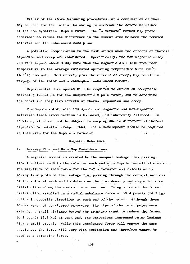
Either of the above balancing procedures, or a combination of them,
may be used for the initial balancing to overcome the severe unbalance
of the non-symetrical 2-pole rotor. The "alternate" method may prove
desirable to reduce the difference in the moment arms between the removed
material and the unbalanced mass plane.
A potential complication to the task arises when the effects of thermal
expansion and creep are considered. Specifically, the non-magnetic alloy
718 will expand about 0.03% more than the magnetic AISI 4340 from room
temperature to the average estimated operating temperature with 466°F
(514°K) coolant. This effect, plus the effects of creep, may result in
warpage of the rotor and a consequent unbalanced moment.
Experimental development will be required to obtain an acceptable
balancing technique for the unsynrnetric 2-pole rotor, and to determine
the short and long term effects of thermal expansion and creep.
The 6-pole rotor, with its symetrical magnetic and non-magnetic
materials (each cross section is balanced), is inherently balanced. In
addition, it should not be subject to warping due to differential thermal
expansion or material creep. Thus, little development should be required
in this area for the 6-pole alternator. > •
Magnetic Unbalance
1. Leakage Flux and Main Gap Considerations
A magnetic moment is created by the unequal le.akage flux passing
from the stack ends to the rotor at each end of a 2-pole Lundell alternator.
The magnitude of this force for the TAC alternator was calculated by
making flux plots of the leakage flux passing through the conical sections
of the rotor at each end to determine the flux density and magnetic force
distribution along the conical rotor section. Integration of the force
distribution resulted in a radial unbalance force of 58.4 pounds (26.5 kg)
acting in opposite directions at each end of the rotor. Although these
forces were not considered excessive, the tips of the rotor poles were
extended a small distance beyond the armature stack to reduce the forces
to 7 pounds (3.2 kg) at each end. The extensions increased rotor leakage
flux a small amount. While this unbalanced force will oppose the mass
unbalance, the force will vary with excitation and therefore cannot be
used as a balancing force.
459 • • •

2. Auxiliary Gap
When the auxiliary gap varies circumferentially, as when the shaft
is eccentric to the end bell, a non-uniform flux density occurs and an
unbalanced magnetic force acts on the shaft. The magnitude of this force
can be estimated by the following method.
The radial gap (g), as a function of angular position, is expressed as:
g = c-e cos 8
where
g = radial gap at 8, inches
c = average radial gap, inches
e = radial eccentricity, inches
8 = angular position on the shaft, 8 = 0 at the position
where g = c-e
The local radial flux density may be expressed as:
3.19 NI . -3 ,, e Qx-lB = x 10 = Bavg (1 cos 8)g c
where2
B = magnetic flux density, kilolines/in
Ni = ampere turns across the gap, amperes2
Bavg = average magnetic flux density, kilolines/in
The force acting upon the shaft in the direction of the radial eccentricity
is given by:
F = -5£-e 72.13
where
F = force acting on the shaft in the direction of eccentricity,e
pounds
R = radius of shaft, inches
L = length of air gap, inches
Evaluation of this definite integral gives the force per unit of
eccentricity:
460

Fe 2"RL n 2 f e2) -1'5
T = f203c BaVg ^ -2c
The average gap (c) around the shaft is large compared with the radial2 2 \
eccentricity (e) of the shaft. Thus, e /c is small compared to unity.
Therefore, the spring constant due to magnetic attraction becomes:
2F _ OArea of gap) Bavge ~ 72.13 X ~c~~
The magnetic spring forces in the auxiliary gap at one end of the 2-pole
alternator at standstill with full load excitation is:
F = IJ.tJLx OSS) _ 4.43 x 10⁴ Lbf/ine ~ 72.13 x .05 ~ (7.75 x 10⁴ nt/cm
DESIGN COMPARISONS
During the Phase I studies, several frequency, speed, and alternator
combinations were screened to establish the relative merits of each from the
standpoint of the alternator and the design impact on the system. As a
result of those studies, a 6-pole 1200 Hz, 24000 rpm Lundell alternator was
recommended. The alternative choice of a 36000 rpm shaft speed or the choice
of an inductor alternator were rejected as impractical as was the choice
of a 4-pole, 800 Hz, 24000 rpm Lundell. The latter was identified as the
most attractive alternator, but the 800 Hz frequency is a very poor system
choice.
For the Phase III studies, emphasis was limited to a 2-pole, 400 Hz,
24000 rpm Lundell alternator since the NASA had determined that the system
requiring the TAG unit could require a significant amount of 400 H.z power.
However, this requirement does not preclude the use of a 1200 Hz alternator
with a frequency converter which, under certain conditions, may be a lighter,
more efficient (and better performing) power source. Because of this,
the potential choice of either a 6-pole, 1200 Hz or a 2-pole, 400 Hz
alternator is still possible, and it is appropriate that the two be compared.
Table LXXXI summarizes the items for comparison. Table LXXXII pre-
sents the comparison data and discussions.
The comparative data on weight and efficiency are probably the most
461
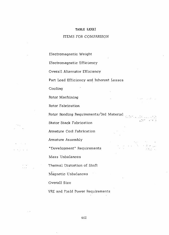
TABLE LXXXI
ITEMS FOR COMPARISON
Electromagnetic Weight
Electromagnetic Efficiency
Overall Alternator Efficiency
Part Load Efficiency and Inherent Losses
Cooling
Rotor Machining
Rotor Fabrication
Rotor Bonding Requirements/3rd Material
Stator Stack Fabrication
Armature Coil Fabrication
Armature Assembly
"Development" Requirements
Mass Unbalances
Thermal Distortion of Shaft
Magnetic Unbalances
Overall Size
VRE and Field Power Requirements
462

TABLE LXXXII
COMPARISON OF 2-POLE AND 6-POLE ALTERNATORS
70 PSIA CAVITY (48.3 nt/cm2) 70 PSIA CAVITY (48.3 nt/cm2)ITEM 6-POLE 2-POLE
ELECTROMAGNETICWEIGHT 279 Ibs 466 Ibs
Further optimization may reduce the 2-pole weight slightly.The rotor for the 2-pole alternator presented is about 35percent heavier than the 6-pole rotor. This difference,however, can be reduced.
ELECTROMAGNETIC 94.2% @ Full Load 92.4% @ Full LoadEFFICIENCY 89.3% @ 1/4 Load 90.9% @ 1/4 Load
Part-load efficiency of the 2-pole is 1.6 points higher.
OVERALL ALTERNATOR 91.0% @ Full Load (approx.) 89.5% @ Full LoadEFFICIENCY 86.3% @ 1/4 Load (approx.) 86.4% @ 1/4 Load
Based on 70 PSIA (48.3 nt/cm2) Based on 70 PSIA (48.3 nt/cm2)cavity and estimate using Ph cavity and Ph III windage cal-III windage calculation methods, culation methods.
PART LOAD EFFI- Based on a comparison of the 90 slot 6-pole design and the 84CIENCY & INHERENT slot 2-pole design, core losses, because of higher frequency,LOSSES are higher in 6-poles; in spite of the larger core volume of
the 2-pole design. Field losses are higher for 2-poles becauseof higher armature reaction mmf and a larger main gap. 2-polearmature winding losses are higher for 2-poles because of therelatively large amount of wire in the end turns. Because of theeffect of the field and armature winding losses, full loadefficiency is higher for the 6-pole design. Quarter loadefficiency, including windage, is essentially the same for the2-pole and 6-pole design.
COOLING Since different conditions and an improved cooling scheme wereCAPABILITIES used on the 2-pole configuration in Phase III, we do ;not have
comparative temperatures between the two for direct tabulation.However, both can be cooled adequately to meet the 300°F (167°K)maximum temperature gradient to the hot spot.
463
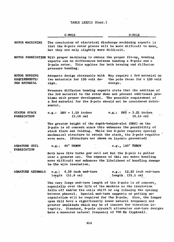
TABLE LXXXII (Cont.)
6-POLE 2-POLE
ROTOR MACHINING The conclusion of electrical discharge machining experts isthat the 6-pole rotor pieces will be more difficult to make,but they are only slightly more difficult.
ROTOR FABRICATION With proper machining to obtain the proper fit-up, bondingexperts see no differences between bonding a 6-pole and a2-pole rotor. This applies for both brazing and diffusionpressure bonding.
ROTOR BONDINGREQUIREMENTS/3RD MATERIAL
Adequate design obtainable withtwo materials for 120 volt de-sign.
STATOR STACKFABRICATION
ARMATURE COILFABRICATION
May require a 3rd material onthe pole faces for a 120 voltdesign.
Pressure diffusion bonding experts state that the addition ofthe 3rd material to the rotor does not present additional pro-blems with proper development. The possible requirement ofa 3rd material for the 2-pole should not be considered detri-mental.
e.g.: DBS = 1.25 inches(3.18 cm)
e.g.: DBS = 3.21 inches(8.15 cm)
The greater height of the depth-behind-slot (DBS) on the2-pole is of concern since this enhances the possibility ofstack flare and folding. V/hile the 6-pole requires specialmechanical structure to retain the stack, the 2-pole requireseven more. (Structure not shown on layouts presented)
e.g. 40° THROW e.g., 120° THROW
Both have five turns per coil set but the 2-pole is pulledover a greater arc. The expanse of this arc makes handlingmore difficult and enhances the likelihood of handling damageto the wire insulation.
ARMATURE ASSEMBLY e.g.'; 4.55 inch end-turnlength (11.6 cm)
e.g.; 12.23 inch end-turn. length . (31.1 cm)
The very large end-turn length of the 2-pole is of concern,especially over the life of the machine as the insulationfalls off and/or the coils shift or sag (closing the spacingbetween phases). Special end-turn supports or potting en-capsulation will be required for the 2-pole. Also, the longerspan will have a significantly lower natural frequency andgreater amplitude which may be of concern for vibration in-tegrity. Standard, 8-pole aircraft alternator end-turn designshave a measured natural frequency of 700 Hz (typical).
464

TABLE LXXXII (Cont.)
6-POLE 2-POLE
"DEVELOPMENT"REQUIREMENTS
Will require special rotor de-velopment, etc. common to the6-pole and 2-pole, but it hasno distinctive developmentrequirements particular to the6-pole alone.
MASS UNBALANCES Symmetrical
According to the three previousitems, will probably requiresome stator fabrication develop-ment on the first unit. Un-balances and nonsymmetricalrotor deformation problems athigh temperatures will requireexperimental development.
Nonsymmetrical from end to endand over the circumference.Requires removal of about acubic inch of Inconel from eachcone section of the rotor.
THERMAL DISTORTIONThermal distortion isOF SHAFT symmetricl
MAGNETIC UN-BALANCES
OVERALL SIZE
VRE AND FIELDPOWER REQUIRE-MENTS
Has unbalance in auxiliary gapand in main gap; no unbalancedmoments due to pole fringingflux.
9.5 inches long X 13.6 inchesdia.
Volumetric space for the fieldcoil is limited and may dictaterestrictions to end bell statormounting structure.
The rotor has a non-symmetri-cal distortion pattern due to2-pole configuration; maycause problems such as warpingof the shaft.
Has unbalance in auxiliary gapand a small moment due to un-symmetrical fringing flux aboutpole ends; no unbalance inmain gap.
12.8 inches long X 17.5 inchesdia. (Non optimized design)
Ample room for field coil andfor changing the end bell con-figuration to accommodate statormounting.
The greater dimensions of the 2-pole adds structural weight tothe unit and increases the bearing span. However, more space isavailable for design innovations as pointed out above.
F.L. field power = 1.16 kW F.L. field power = 3.93 kW
The 2-pole requires a VRE with about twice the rating; however,because the field coil space is crowded on the 6-pole, the am-pere rating of the 6-pole alternator VRE may be 2 to 3 timesgreater; e.g., 80 to 90 amperes typical, to obtain the necessaryampere turns. The number of turns is limited by the minimumpractical wire or strap size which will still yield a designthat is capable of being easily cooled. On the 2-pole, because of
the extra volume available, the necessary ampere turns can beobtained by a greater number of the same size turns.
465

significant; analysis shows there are, with two exceptions, few other
comparative items in the list that significantly influence the choice.
The two exceptions to this might be: (1) the long length of the armature
end-turns on the 2-pole (they are too long for a simple, reliable design),
and (2) the rotor related design problems brought on by the unsymmetrical
configuration of the two poles themselves.
FAILURE MODE, EFFECT AND CRITICALITY STUDY
The FME&CS is carried out for purposes of identifying and cata-
loging the various modes and effects of component failures down to and
including subassembly levels wherever possible. The components and
subassemblies are categorized by a reliability model that consists of:
(1) Rotor,
(2) Stator and stator coolant,
(3) Windings and insulation.
The bearings and seals are not considered as part of the TAG alter-
nator reliability model.
The FME&CS is undertaken at a joint meeting of the engineersimosti ' • . - . ' • > ! . - ;
experienced in the design philosophies. At this meeting, all known
possible failure modes are identified, discussed, and tabulated. The
failure modes identified are correlated according to immediate or long
term effects on the system.
For the study, it is assumed the alternator was in an operating
condition and successful operation constitutes the ability to produce
useful power. The "power system" is defined as the TAG and its ability
to produce power. The effect of the failure on the power system is evaluated
from the standpoint of life, power output., overload', shorts, vibration,
unbalance, overspeed capability, etc. The guiding philosophy in cataloging
the failure modes is "How does the power system respond to the various
failure modes.' The probable causes of the failure are listed to explain
how a particular failure might occur.
The tabulation of the FME&CS is presented in Table LXXXIII. In all,
twenty-six failure modes are catalogued in the table.
466
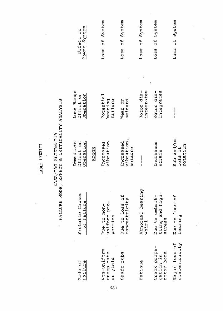
61C CUIO 4JJ
4-1 >U COa)
M-I VI
t3 "%Oa.
6CO
CO
tninO
ecu4-'tn>i
CO
03inO
4-1in
CO
(0tno
eCO4->tn>i
CO
M-I0
tninO.J
eCD4->tn>i
CO
14-1
o05tno
COHCO
(U<J> C CC O Offi -rHOi 4-1 4J
U (tJen 0 vic M-I cuO «w OJ W O
(0•H CJ*4J CC -HCU VI
moa<
CU
cuM-i
vi cuO Vl
VI Nrt) -H<S) <D
te to
I ento cu-H 4J
O CU4J 4-1O C(U -H
I tntn cu
•H 4->
vi tr>0 cu
4-> 4Jo c
OH "^
H
O <E-i U
w
V3
H
O
UUW
. CuCO W<c
w"oo
wa:D
cu c c4-> O O0} -rH
-H 4J 4JT3 U (00) (U )-(
§ M-I a1
<w.aH W O
w cCU 0
e;8o«
tn -H(0 4JQ) n3H MU ^3C-HH >
•0 C0) otn -H cu(X) 4-> HCU (0 3M M N 1CJ ,Q -H 1C-H 0) IH > in 1
CO(UCQ3 CUITJ VlU 3
iHCU -fi.-I (0rQ CUffl,Q M-iO OVl
DJ
II OC Vio ac
£ eno vi cu4-> O -H
0)
QCU
M-IO >i
en -Htn uO-H
4JO C4J 0)
CJCU C3 0Q U
C•H
flCU
Vl-r-l
x:
COcutnfO Ctt> -HVl (0O VlC -PH ID
VlO
N\ CT3 M-I OC O -HITS -P
in torQ W 4-13 0 0tr! rH Vl
I rC
•r-l -H
ISCU C
(00 tn4-i CP en
C cucu -H M3 rH 4J
D -P to
tntno
O C4J -H
Vl0) (03 <DP rQ
•Oo m
Vl CU0 4J
M-i ns T3•H | rH
c cu3 Oi-H1 CU >ic cu0 Vl Vl2! U O
enrQ3Vl
CO
cu3D
•H4JfOCLI
j
(da.oVIa.xUfOVIu
c•H
Co
•r-l
4JrsD-.
CUVlo,Q
Vl04JOVl
0
tnCOoiH
VI0•n(0J5
4-1•HU
•HVl4-)CCUUC0o
467
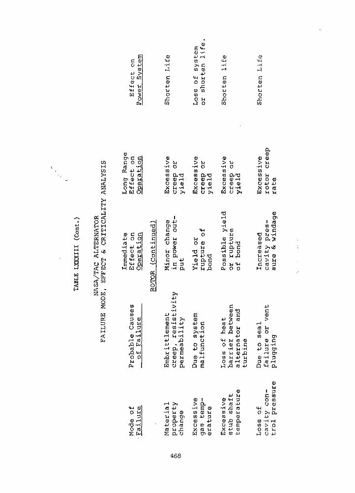
gc ao -P
ui-P >\u
M-i Q)W E04
0)'•H-,-1
CQ)
Of.
0S u-iQ) -r-
4-' •-!0!>l CCO d>
-PM-< VlO O
A:en co(0O viiJ O
CQ)4JVIOf.W
0!•J-i•H
CQ)4JVIO
CO
10H
O UEH H<C EH2 M
W UEH
EHO O<c wEH fa
I"a w
Iwt>M
CM
fl)CJ> CC 0
OS -Pu
tn 0)C 4-iO MH*1 W
o> c•P OfO
• 4-1T3 U0) (1)
f M-4
UH
H H
CO0)CO3IDO
0)rHftIDQ
0J_j
P.
M-lO
(yTU052
GO
4J(0MCD
O
(U£>
•HCOCO0)uw
— J 0)•C tr0) C
CO
•H
4J<tJ^1CDao
3 (0C ,C
•H U4-1C V-lo ou c
— -Hs
K
80a;
cyM3
r— 1•r-4IDtu
mo
4-1c0)e0)
i—4^_J4J•H^1ftgw
rHQ)S-l3
i-H•rH(Cfo
(0•HVlCO
4->n5S
VloCUTI0)0)
O
1.JJ
3O
Vl0)
Oac
•H
4->•H>•H4->CO
-c-1
COQ)
*pt
0)0)^1u
^14->Vl<DaoVl
1-1-0)
-H>1
4J3a
i l
4J-Hi-l•H^Q
ID(1)e0)
0)enC10f.O
0)£>
-HCOto0)oXw
Vl0
ro•H0)
-HJ>^
ea>jtoCQ
OJj
0)3Q
CD
•HCOCO0)uX
VIoa-a0) rH0) (UVl -HCJ >i
14H0
0)
34-> -aa c3 0Vi ,Q
co4Juc3in•H10e
iae a)0) Vl•P 3
4->«.' ID10 VIcn cu
<o>
-Htoto0)uXw
•c1-1OJ
•HS>i
0)iH_Q-HU)to0a,
4J(00)
^4-1O
totoo^
0)^>•HCOU)0)UXH
VIO
O-TJ(U<uVIu
0)VI3.jj
a3VI
VIo
ccu0)*J;4J0)
^Q
VI0)•HVIVIID
4JM-(mw
t_Q
34-1to
r-l0)
•H
^
•ao«
>4H0
T3cID
VlO4JID 0)C CVl -H
4J Vl-1 3ro 4J
(UVl34JIDVlQ)ae4J
0)£>
•HtoCO0)OXw
•o0)COfO0)ViucH
r-4(00)to
O4J
(U3Q
M-4O
toCOOij
a,0)CDVluVlO 0)4J 4JO (0Vl Vl
0)Cn
1 roCQ T3(U CVl -H
?1 t J4-1•H 0)> Vl10 3O CO
4Jq0)£>
Vlo
0">0) CVl -rH
3 O"1
i — 1 O^•H 3ID iH
MH Ou
0)Vi
1 3C COO COU 0)
Vl>i di4J•H rH> Oro ViU 4J
468

C 0)(O -P
tn•P >U CO
4-14-1W
3o E0)
IM -4JO K
>iw toenO M
t-3 O
E0)-Ptfl
U-l•H
C 01a,1 w•P OM rHO,c nco o
ca).PVIo
co
COIQo
a) Q)in -P
•H to!s to
Q)
•r-1
,—I
CQ)-P
Or-
5>
coHCO
0)Cn C Cc o ofO -H
O fOCr> 0) SHC 4-1 Q)
0)
-^-P C<fl 0 01
^H lP C C
O M C
co
(0 MM OQ) -H
0) (UO -P
co0) -P-P fO(0 !H
Q) -HrH VI0) 0)U -PU 0)
M<00)sen oC -P
•H (Q4-1 4J-P 100)
cO T3
0) -p 01
rH S-| C (0
U 4->U O
,QI -H
UgCJ
EHH
OH | "1
0 <EH U< HJ2 EHC^ HW PiEH U
<? t$
U EH< OEH W
< faco H
2; -wQOS.
Wc££3
1-3Hf£
Cn
EH13irfhiO
0) C C- P O O(TJ 'H
•H .p 4->T3 U fO(1) 0) Mg i4_t Q)E 4H OH W O
ou
p^0EH<EHCO
08
PH0EH
EHCO
to0)to3 (!)
U 3rH
>l-HrH fO
rQ fa03rQ 4-10 O
en
01fOCn
C-H.
rH•H
0
0)Ptr>
•H-p(04-1
0-p
(1)pQ
E<D-P0)>101
0)010)M-p01
010)M
Q) P
•H n3W MW 0)QJ £li
U £X 0)
^_l
o0}•o crH -H0 -P01 fO
rHO 3-P E
3(1) U^J OQ ro
4->fO0)
^ ^01 M(U 0)
OT O0•H Mo'O "Mc o
co•H-puc3
r-4
(CE
EQ)
4->01^1(0
01(UJ-l
(U 3> 4J
•H fOW MCO (Ud) QJu £X Q)
W 4-1
Q)M
!-l 3O 01
01•n (uC Mo a^ 4-1O U4-i ro
4-1Q) CP 0Q U
to(UtntoOrH
f^JCfO
0101OrH
4-10
01C to0 O
-H rH
4-1(0 -MA:(0 UQj fjj
0) 4->CO 01
rH
(0u
•HC rH
fO fO»c GU .-i-l0 MS -P
u0 Q)
4-1 rH
Q)0)D J-t
Q 0
(jj50a
4-1o
3)PC7>
• H4JfO
4-1
Ca>0)o0 01
0) rH 4-1> -H
*rH - 4-101 0101 0) X(!) 01 UD !0 fOX 0 -P
W rH 01
E(UP C0) O>l-rH01 -P
U
0 C-P 3
(U rH
3 flJQ E
4H a)O Mp0) rH
•a -HO ro
o0u
4Jc u
-H 3•o
A;(0 CD0) C
rH•H
O 10)
M 'OO
01 O(0 rH
MO
•0
01(00)Mr t
•aap.04Jfn
jjl
Crt!.C
Xa)4JO0
1
CT>C
>H4-1n\^fT3CU(D»«
Q)£fOS-i4-1
£0M
11 f
f^O(0Jj
CO
M/•N
(uOiErd
I— (
O
^fufC4-1r A
(UDCP
•r-l
-U
<Ctl !
Q)>
-H0)Wa)aX
4-1
C(3
»— (
OO
G)MP4-1(0M0)a,E0)
469
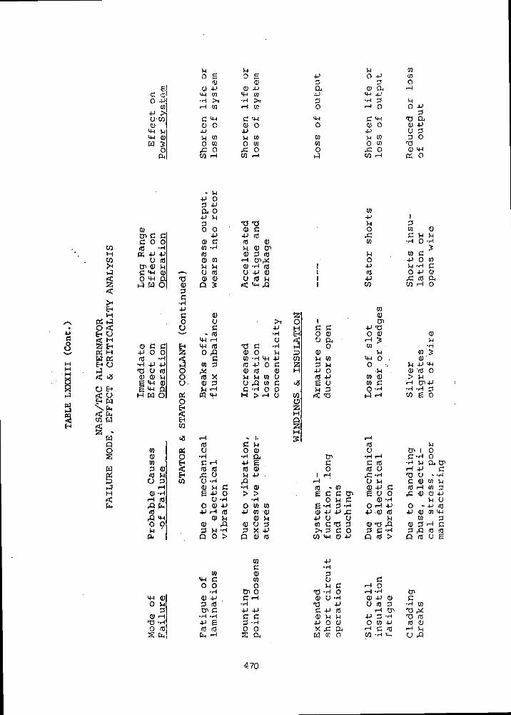
EHH
CU JO <EH U
WEH
U EH< UEH W\fe< faCfl W
Wp
w
H
gC -SO 4J
0!4J >O MQ)m Mm cuw 5
o04
Q)tn c cc o oro -riK 4J 4J
o rotn a) MC 4-1 (D ,-,o m Q tjr3 a o| <u
c•H4JC0
CJ
0) C C EH4J O O Zro -H <c
..H 4J 4J (4•a u ro O0) fl) M O
£ M-) Q.H W O^ 05
OEH
EHW
^j
to #fl) OID EH34) <ro >H EHO 3 W
iH0) -H
rH «fl faro
rQ m0 904
H_l Q)
0 rl
3fl) rH
T3 -Ho roS fa
j_j ^
os o e<1) O
<i) 4-> (U 4Jm 03 m 03•rl >! -H >,
rH 10 rH CO
C M 1 c? M ifl) O <U O
rl en SH toO w O 03,C O ,C OW rH W rH
4-> O3 4Ja. oi J t I
3 -a -ao o <u c4-> 4J ro
<i) c ro Dco -ri M fl) enro Q) 3 rofl) CO rH tn^
rl rl 0) -rl «u ro u 4J a)fl) 0) CJ n) MPS < m f l
Q) aU • >, OC 4J H
• ro -rl £Hm I-H u f£m ro 'C c *ri t-3o fl <D o M p
C ID -H m 4J Wto 3 ro 4-> o c a# cu ro <u Hro X rl rl W O
Q) 3 u fl tn c <Xrl rH C -H O O
CQ m H > rH U W
oaHp§H
rH . I. gro C rl
u o o>•H -H QjC rH 4-> 6ro ro ro fl)rC U H 4->O -H fl0) rl C -Hfl)e 4J o > >
O -H -rl
O fl) 4J o tn in4J rH ro 4J co -fl)
0) rl 0) rl
Q) fl Q) U 33 >H -H 3 X -Pp o > p Q) ro
COc
10 fl)me in0 O O
•H tn o0 4J C rH
3 ro -HCn C 4-> 4J
•rl -H C C
•P g 3 -Hro a o ofa 1-1 s a
i4J O -P3 3a o a4-> m 4-13 -n 3O rH O
m cmO Q) O
4J0) Vi 030) O 03O f. O
»-q W rH
tn4JVl0rCW
J_(
O1 4Ji ro1 4J1 OT
tofl>
i tnc c 4-> -aO fl) O 0)U DJ rH J
O tofl) Mri to mo.3 rl O ;.
4-> O •» .ro 4-> 10 a)e o 10 cH 3 O -rl
< T3 1-5 rH
i-Hrou
tT* 'H r-H
c c roo ro u
1 l-H rC -H
rH U Mro - w a) 4-) ce c c tn g u o
o w e f l ) - Hg -rt 3 -H O rH 4->o 4-1 4J £ 4-> o) ro4J U U rl
en C T3 3 <U T) A>i 3 C O 3 C -Hw m co 4-i p ro >
4->-rl
3u cM C rH 0
IQ -H O rH -rl
0) U -rl 0) 4J 0)•a 4-) u ro 3C 4-> ro I-H Cn0) M M 4J 3 -rl4J O G O TO 4Jx f a rH c row tc o w -ri m
CO03O
i— 1
^4O 4->
3-a a<1) 4JU 33 O
n3D <w
Crf O
130) fl)C rl rl•rl 0 -H
>
ID C•P O CO>H -H C0 4J <U& ro &W rH O
o^1
•Hco 50)
ri 4J ma) Jro o> M
•H -rt 3W g 0
S-Jen i oC -rl O
•rl VI Dj CT>rH 4J CT3 0 r-ri
C 0) 03 Wro I-H en 34: a) cy 4J
r( U
o - -P ro4J fl) en m
03 3fl) 3 rH C
3 fl ro roP ro u E
CnC
•H inT3 ,y•n roro cui — i ^0 fl
470
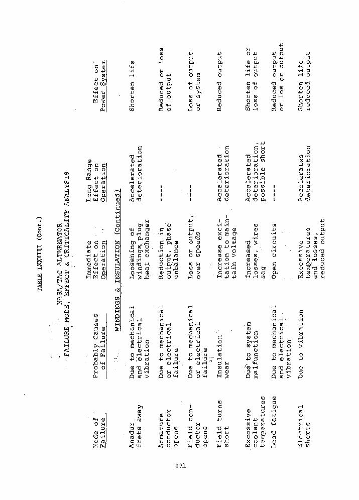
C
c 5o -P
in•p >O COCU
4H M4-1 Q)
(U4-1•H
C<u-pVlow
COCOo
r-H
VIO V
•2t3 aa> -PU 33 O•aa) 4-1PJ O
3a
cu4-1 4JO CO
><CO COCOO Vi
r-4 O
4J
3
3O
CUU3
*OQ)
O!
JjO 4->
3CU O.
4H 4J•rl 3
•H 0
C 4-1CU O•PM COO CO,C OCO rH
4->3
4J a3 -Pa. 3•P O3O S-4
o<U COu o3 rH
'UQ) V4Pi 0
jj- 3
<D DJH ] i i
•H 3rH O
C 'O0 cu4-* UVl 3o -a
,£- GJ
C/} M
/^N.4JCO
^^Mj—iyoi*sij
r4
CO
HCOrH
^
^rf
rHEHH
PH r-l
O <
EH U<C HSi EHPi MW (XEH Orl."
{£ .<*Q f
U EH< OEH K)
C0
CU 0) -Pen c cc o oro -HPi -P -P
CJ rflCn cu viC 4H CUO 4H O
rl W O
4-1 (0ro ViVi 0(U -rH
rH Vl(U CU
rrt
CU!-«»-•
•H•PC. . o
*•*— '
CU C C• P O Orfl -rH
-H 4-> '-P•O U rOCU 0) Vig 4H CUg 4H 0H W O
aoHEH
t— i
CO6;H
U -PU 0)ft, -a
VlCn <U
4-i 3 Cn0 rH C
DJ (0
C co" U .•H Cn XC C cu
.CU -Hw >b -P.O C roO -H CU
111
'
'CUC co
•H roff
c a cu0 U
••-( - C•P -P roO 3 rH
3 CV.ro
0) 3 CPi O'3
1|
11
..4J3a
4-1 CO3 -aO Q)
0)VI DJO CO
W VlCO 0)0 >rl 0
co
•C -rlCU -P4-1 rflrfl viVl 0Q) -rl
i-H Vl<U CUO -PCJ CU< -0
11 C
•r) -rl
CJ rO (UX g CnCU ra
O 4-1CU 4-> rHco Oro C >CU O
. VI -rl CO -P ;rl
C rO rOH 4-1 4-1
C Vl0 0
•a -H ,c0) -P CO4-1 (0rO Vl CUVl O rHCU -rl rP
rH Vl -HCU CU CO
U -P COU <U O^ nzj ex
CO0)Vl•rl
•o >CU03 »rO coCU CUVi coCJ CO CnC O roH rH CO
111
1
CO4J•rl '
3uM•rlCJ
C0)CUo ,
co
CO -riCU 4-1•P rOrO ViVI 0CU -<H
rH VlCU 0)U 4->U O
<c -a
w0) -M CO
cu 3 cu> 4-> CO
- -H rfl coCO Vl,. 0W CU rH
D Q/O E T3X O Cw -P ro
4J3a4J
30
•OQ)CJ3-aQ)V!
EJ
WQO
H
COo§
CO0)CO3 CU(0 VHU 3
rH>l-H•-I ro,Q hrflQ lj_|
O 0i-lcu
Q25H|g
rjif*1^
rflU
'crflpCucugo... .p
<uQ
rHrflCJ
•HVl•P CU OCU -H
rH 4->;cu m
M*O Ac -Hro >
J |
rOO•HC --Irfl rorC CJ
O -rlCU Vle -p
CJo cu-P rH
CUcu3 rl
Q O
cuVl3
rH•rl
ro4H
^rOCJ•rl
c ***•ro ro
rC CJ
0 -HCU Vle -P
o.cuO (U Vl
4-> rH '3
CU i-H(U -rl
3 Vl rflQ 0 4H
£
0•rl-Prfl
"~ r— 1
"" 3 Vlco roC cuH J
.gCU•P CCO O^1'rlCO 4-1
CJ0 C-P 3
4H.Cfl) rH• 3 rop e
,__!roU•HCrfl,CU<ugo•p(!)3O
r-H
roCJ
•HVl•P CU 0CU -HrH -Pcu rfl
Vl•O rQC -Hrfl >
C0•rl4JrflVi
•rl£>
O4-1
0)3Q
4HO M
PCU
T3 -Ho mS
rfl
roVl3 CO
73 -Prfl 0)C Vi< 4H
VlCU 0VI -P3 O4-1 3 COrO t3 Cg C 0)vi o a,
<c u o
icoCJ
VlT3 O COrH 4J CCU CJ 0
•H 3 Oife 'b o
turn
s
TS 4-1rH VlD O•rl ,Cfu CO
S3 OJ0) 3Vi Cn
CU 3 -H> 4-1 4-1
•H .p rt) rOCO C V; 4-1CO (0 0>O rH DJ T!CJ 0 e rsx o a1 o
Cfl O -P J
U•rHvi co4-> -PCJ VIq oy 'co
471
CONCLUSIONS
Pertinent conclusions .associated with the Phase III studies are as
follows:
(1) The likelihood of the high-temperature ANADUR wire insulation eventually
entering the gas circuit as an abrasive dust may preclude the use of
ANADUR in the TAG alternator. A possible high temperature alternative
is a bare wire with mica and alumina in the slots and with the end
turns either (1) uninsulated and physically supported (separated)
or (2) insulated with plasma sprayed alumina. Alternately a ceramic-
eze Insulation could be applied to the wire. This will require
materials development to reduce laboratory techniques to practical
hardware. The other alternative is the organic insulation system.
(2) It appears it is technically feasible to cope with the unbalances and
non-uniform deformations of the 2-pole rotor. However, these introduce
problems which are unique to the unsymmetrical 2-pole configuration.
The severity of these new problems must be clarified by experiments
before one can conclude that the performance of the TAC over its
five- to potential ten-year life will not be plagued with problems
which could have been obviated with a symmetrical 6-pole alternator.
(3) The present 60-slot design having the 8-inch (20.4 cm) rotor OD is
conservative. Future designs such as an optimized version of the
84-slot design will result in a smaller diameter, typically 7.5
inches (19.1 cm). This will also reduce the weight to less than
twice the 6-pole alternator weight.
(4) At part load, the 84-slot 2-pole design equals or exceeds the
6-pole design efficiency.
(5) Reconnectability from 240 to 480 volts is physically possible. In
addition, if corona precludes the use of even 240 volts, it will
be possible to obtain a 120-volt design by substituting a different
stack and winding into the same frame and rotor configuration. The
use of the same rotor is based upon adaptation of a third material
into the pole faces per conclusion (7) below.
(6) Corona considerations limit the minimum cavity pressure to 14 psia2
(9.7 nt/cm ) at 240 volts (possibly half that is absolutely required).
472
2At 480 volts, the limiting pressure is 53 psia (37 nt/cm ). Substi-
tution of an organic insulation for a 107°F (315°K) coolant system
is entirely feasible and would possibly permit the use of output
voltages up to 480 volts depending on the quality of the impregnation.
(7) Addition of a third material to the rotor pole faces apparently does
not increase the complexity of gas pressure bonding the rotor, and
is therefore recommended. Its use also significantly enhances the
likelihood of achieving a 7.5 inch (19.1 cm) rotor OD and of achieving
a single, basic alternator configuration capable of being built with
outputs of either 120, 240, or 480 volts./•
(8) Several cooling configurations can be designed into the alternator to
adequately cool it. Any one of the acceptable configurations can
handle the multitude of different pressures, temperatures, gases
and boundary conditions anticipated. The latter includes relatively
widely divergent rotor stub shaft boundary conditions.
473
APPENDIX A
ROTOR FABRICATION
The rotor design was reviewed to determine if design requirements could
be satisfied in an Inconel 718-4340 Lundell rotor fabricated by hot iso-
static pressure welding (high temperature gas pressure diffusion bonding).
Analysis shows that this technique will be suitable for this application
with minimum development. Feasibility of this approach is currently being
demonstrated at the Westinghouse Astronuclear Laboratory under Contract
NAS 3-11837, "Development of a Gas Pressure Bonded Four-Pole Alternator
Rotor." Current results in this program have indicated joint strengths
of 55,000 psi are readily achieved using non-optimized welding schedules.
Actual joint strengths of 136,003 psi (bending) have been achieved. Welding
schedules for the 81,400 psi joint strength at 700°F required for 20%
overspeed appear entirely realistic.
Similarly, 92,500 psi yield strength at 700°F is achievable in bothr • *» ' • '
base metals since the metallurgical heat treatment and welding thermal•J i' *
cycles are compatible. Strength will be achieved in the 718 by selecting
welding temperatures and times compatible with solution annealing and/or
aging temperatures. The 4340 strength will then be developed, as the assembly
cools in the autoclave, through transformation of the austenitic structure
to a mixture of martensite, ferrite and bainite. With controlled autoclave
cooling, this structure has given a hardness of R 30. Slightly higher
cooling rates can provide higher hardness.
In addition, this process for fabrication of the rotor can be utilized
to attach pole inserts of improved magnetic properties to reduce pole face
losses. Typically, these would be a mild steel such as AISI 1010. Rotor• -^ ' . . ' ' J ' " ' i
fabrication would still be accomplished in one operation by welding the
718, 4340, and 1010 in one autoclave run.
Metallurgical Considerations
Satisfactory joints between 718 and 434D have been obtained by
holding for four hours at 1650°F and 30,003 psi. These joints, in fact,
appear to be overdeveloped and it is anticipated that shorter times at
temperature or lower temperatures will give higher strength joints.
474
The ideal bonding temperature from the standpoint of metallurgical
structure will be in the range of 1325°F to 1400°F since this is the first
aging temperature of 718 and will be above the Ae3 temperature of 4340.
If this temperature range proves suitable for rotor fabrication by hot
isostatic pressure welding, then the 718 can be aged to the required
strength during rotor welding. Similarly, this temperature will austenitize
the 4340 permitting transformation on cooling to achieve the desired
strength level. Interestingly, the deep hardening characteristics of
4340 are sufficient to achieve R 30 at a controlled furnace cooling ratec
of 240°F/hour. Since this rate can be increased, even higher strengths
may be realized. In this process 718 would not have to be double aged.
The second aging treatment at 1200°F would result in a higher strength of
718 than desired while causing simultaneous transformation of the 4340
to an undesirable lav strength spheroidized carbide structure.
The hot isostatic pressure welding process provides increased flexibility
if alternate approaches are required to develop adequate joint strength
simultaneous with the required base metal structure. An as example, joining
could be accomplished by holding for a short time at 1750°F. This provides
solution annealing of the 718. The 718 can then be strengthened by aging
at 1350°F while strengthening of the 4340 is again achieved upon cooling to
room temperature at a controlled rate. In this approach, however, the
aging reaction in 718 will be less effective as a result of slow cooling
from the solution annealing temperature (400°F/minute is usually specified).
This problem is typical of large section sizes in 718 and would require
special definition should a higher bonding temperature be required.
Thermal Strain
The ability of a fabricated rotor to withstand the thermal strains
associated with the austenite transformationis not entirely resolved
at this time. Current results appear encouraging in this respect and a
full clarification will be available with the conclusions of Contract
NAS 3-11837. The primary concern is that the joint strength must be
sufficient to permit accommodation of the expansion of 4340 due to austenite
transformation during cooldown of the rotor assembly. A net strain across
the interface as high as 1.4% may have to be accommodated. Accommodation
will occur by straining of the 4340 since it is the weaker of the two
475
alloys. It should be emphasized that this problem is common to all the
alternate rotor fabrication techniques, all of which require heating above
the Ae3 temperature during rotor fabrication.
As cooldown from the rotor joining temperature progresses, straining
will increase as the austenite transformation proceeds. At the higher
temperatures, above 900°F, the transformation strain will be accommodated
at relatively low stress by creep of the 4340. At this point, the 4343
is weakest both because of high temperature and because the transformation
product contributes little strength. As the temperature decreases further,
and transformation continues, the 4340 strength will eventually increase
to such an extent that thermal stresses of the order of the yield strength
are required for accommodation of the thermal strain (by plastic deforma-
tion). Typically, locked in residual stressed will be near the final
yield strength of the 4340. These stresses will probably be highest
precisely at the joint interface. Further, straining can be considerably
magnified in the vicinity of joint defects.
Although this problem is not fully defined at this time, hot isostatic
pressure welding has two distinct advantages individually or in combination
over other assembly processes. These are: First, the strain is more readily
accommodated by high temperature transformation achieved by cooling at a
minimum rate consistent with final strength requirements; and second,
compressive loading can be maintained during cooling in an autoclave. In
the practice of metal forming compressive loading is frequently beneficial
in minimizing failures during deformation.
Rotor Fabrication Development
As described above, two primary objectives must be satisfied by the
rotor fabrication process:
0 A metallurgical structure of satisfactory strength must be
developed in both alloys,
o Stresses associated with the austenite transformation strain
must be carried by the bimetal joint to permit accommodation
of the strain by plastic deformation, primarily in the 4340
steel.
These objectives are common to all the potential processes and seem
most amenable to accommodation in the hot isostatic pressure welding process.
476

A minimum developmental program will be required since assembly
parameters will be deduced from current work in this area. Existing
autoclave facilities will accommodate this rotor. An initial proof run
will be required to confirm fabrication parameters both in terms of auto-
clave performance, joint integrity, and joint strength. Sample specimens
joined in this run should be recycled in a conventional furnace to the
austenitizing (joining) temperature and then cooled at various (increasing)
rates to ascertain the criticality of cooling rates on joint integrity.
This is necessary to assure that "minimum risk" selection in cooling rate
is made for subsequent rotor fabrication runs. Additionally, two rotor
runs would be recommended. Both runs would include qualification assemblies
deemed suitable for destructive test and hence confirmation of the bonding
run. The first rotor would be subjected to performance tests. Initially,
there would be overspeed spin tests. However, additional tests which
subject joint areas to higher stresses in particular may be desirable. Thermal
stresses imposed on the spin test by heating the outside of the rotor would
be one approach. Multiple cycling may then be desirable and finally
destructive testing of the rotor itself would prove extremely valuable.
The second rotor would then be proof tested using procedures evolved from
evaluating the first rotor. The second rotor would then be committed to
hardware.
477
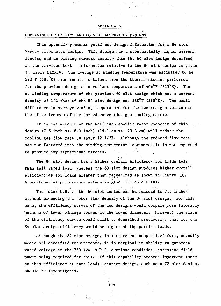
•APPENDIX B
COMPARISON OF 84 SLOT AND 60 SLOT ALTERNATOR DESIGNS
This appendix presents pertinent design information for a 84 slot,
2-pole alternator design. This design has a substantially higher current
loading and ac winding current density than the 60 slot design described
in the previous text. Information relative to the 84 slot design is given
in Table LXXXIV. The average ac winding temperature was estimated to be
590 F (583 K) from results obtained from the thermal studies performed
for the previous design at a coolant temperature of 466 F (315 K). The
ac winding temperature of the previous 60 slot design which has a current
density of 1/2 that of the 84 slot design was 568°F (568°K). The small
difference in average winding temperature for the two designs points out
the effectiveness of the forced convection gas cooling scheme.
It is estimated that the half inch smaller rotor diameter of this
design (7.5 inch vs. 8.0 inch) (19.1 cm vs. 20.3 cm) will reduce the
cooling gas flow rate by about 12 1/2%. Although the reduced flow rate
was not factored into the winding temperature estimate, it is not expected
to produce any significant effects. . ' .
The 84 slot design has a higher overall efficiency for loads less
than full rated load, whereas the 60 slot design produces higher overall
efficiencies for loads greater than rated load as shown in Figure 189.
A breakdown of performance values is given in,Table LXXXIV.
The rotor O.D. of the 60 slot design can be reduced to 7.5 inches
without exceeding the rotor flux density of the 84 slot design. For this
case, the efficiency curves of the two designs would compare more favorably
because of lower windage losses'at.the lower diameter. However, the shape
of the efficiency curves would still be described previously, that is, the
84 slot design efficiency would be higher at the partial loads.
Although the 84 slot design, in its.present unoptimized form, actually
meets all specified requirements, it is marginal in ability to generate
rated voltage at the 320 KVA .9 P.F. overload condition, excessive field
power being required for this. If this capability becomes important (more
so than efficiency at part load), another design, such as a 72 slot design,
should be investigated.
478

' . .TABLE LXXXIVDESIGN SUMMARY
- • - - - ' : . TAG ALTERNATOR84 SLOT DESIGN, 2-POLE
' COOLAi.T i'E;.lPERATUR-; 466°F (315°K)'
RATING: 214 kVA at'0.75 P.F. Lagging
VOLTAGE:. 240/416 reconnectable. to 480/832 .
SPEED: 24000rpm -
FREQUENCY: 400 Hz • -''
DIMENSIONS: INCHES (cm) ' -Rotor O.D. . " : - . • , . 7.50 (19.1)Rotor LENGTH 12.78 (32.4)STACK LENGTH (OVERALL) ' - ' - • : 3.58 (9.1)STACK O.D. . . . t . . 15.16 (38.5)
ELECTROMAGNETIC WEIGHTS: LBS. .(kg)ARMATURE ' ' ' • ' 17;0 (7.7)FIELD ' : . . . , . , . . . . - ; - 43.0 (19.5)FRAME 172.9 (78.5STACKS ' ••'•'- : • > . . . " . . . . . 98.0, - -' . (44.5)ROTOR . ., . 135.4 (61.5)
' TOTAL'; " " , : . . . • • - • • ! - , . . .. • 466'.3 ' (212. 1
MATERIALS:ac.CpNpUCTQRS . , . , = - . 321 SST CLAD SILVERFIELD" CONDUCTORS ' " '" "CUBE COPPER ALLOYA-RMATURE LAMINATIONS ; - . .0.004 INCH .(Or. 102 mm) THICK HIPERCO 27FRAME, ... HIPERCO 27ROTOR MAGNETIC ": SAE 4340-(§> Rc33 ' . -..-ROTOR NON-MAGNETIC INCONEL 718 @ Rc38INSULATION
ac. WINDING.. . .ANADUR'SLOT LINER' ALUMINA ' '"""
- :^ SLOT ,SEPERATOR „.. . SYNTHETIC MICA . , ..-,...FIELD"WINDING SYNTHETIC MICA
WINDING DETAILS:NUMBER OF SLOTS 84
••'CONDUCTORS .PER." SLOT...:. Iv . i. r.-.j. • . 1 . '- M, . . ->v.i. .. •• 2: . ., ;j -,,SERIES TURNS PER PHASE (240 V L-N) 14PARALLEL PATHS (240 V L-N) " • .' . -.-- ; 2
PARALLEL STRANDS 2PHASE BELTS " 60°
• PITCH . . . , 4 3BARE CONDUCTOR DIMENSIONS, INCHES Vo'81 X .144
479
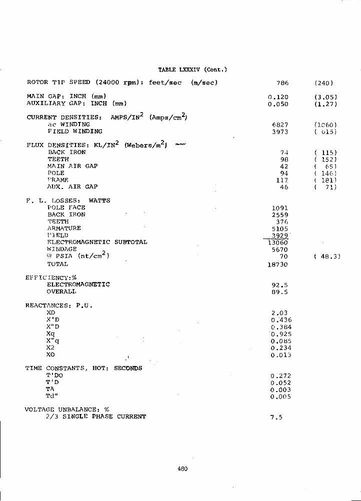
TABLE LXXXIV (Cont.)
ROTOR TIP SPEED (24000 rptn) : feet/sec (m/sec)
MAIN GAP: INCH (mm)AUXILIARY GAP: INCH (mm)
CURRENT DENSITIES: AMPS/IN2 (Amps/cm2;ac WINDINGFIELD WINDING
FLUX DENSITIES: KL/IN2 (Webers/m2jlBACK IRONTEETHMAIN AIR GAPPOLEFRAMEAUX. AIR GAP
F. L. LOSSES: WATTSPOLE FACEBACK IRONTEETHARMATUREFIELDELECTROMAGNETIC SUBTOTALWINDAGE® PSIA (nt/cm )TOTAL
EFFICIENCY:^ELECTROMAGNETICOVERALL
REACTANCES: P.U.XDX'DX"DXqX"q :X2X° .'
TIME CONSTANTS, HOT: SECONDST'DOT'DTATd"
VOLTAGE UNBALANCE: %2/3 SINGLE PHASE CURRENT
786
0.1200.050
68273973
74984294
11746
10912559376
5105392913060567070
18730
92.589.5
2.030.4360.3840.9250.0850.2340.013
0.2720.0520.0030.005
7.5
(240)
(3.05)(1.27)
(1060)( 615)
115)152)
65)146;181)71)
( 48.3)
480
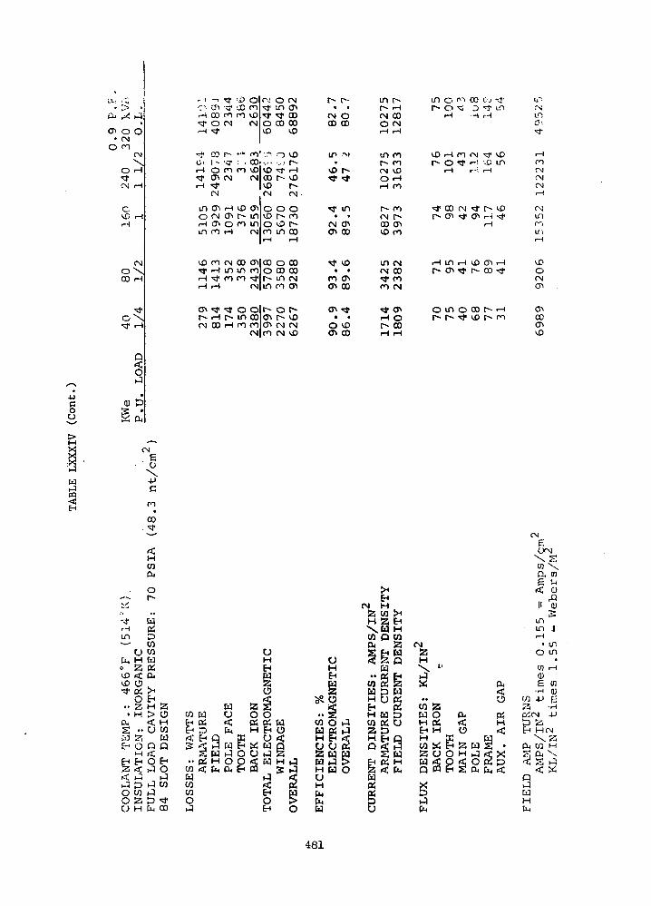
Cu >-)
ou
cn o O• CNO CO
CN
O rH
CN rH
O
rH
O'00
oX
,-• -1O vJlrH CO•xT O
rH <d-
f 03Ci 1 -rH Ort CTlnH *
CN
m enO fNrH (Tlm co
*T <i>•>f 00ro rofN
_ ^
•<7 -. .ro rofN
rH VDcn r^o rorH
OrovDfN
CM
* J"
0VD
CO1 :..-!COvOfN
cnininfN
•..••vOCOvOfN
OVQ0rorH
0in^J*CO
0• „ •
*sf
r-
0r .V.Q
in
fNcnCO00vO
VOr-~rH
VOf^
CN
Oror>-00rH
r^•
fN00
ir•
VD<9ji
J.•
fNcn
r>•
oCO
.-M
f^
^J"
m•cnCO
inc^fNOrH
m
CNorH
r-CNCO
r^rH
00CNi-H
COrovDrH
ro
f)(«x
cnro
in o f1"1 co c.j rj-r^ o ^ D -^r tn
rH -H rH
VDrHCOCN ^ VDr^ o *3* r-i ^o in
rH r-l rH
^* oo <N i* r * v£)r** cn ^* cn i — t **$*
rH
U~-
rsIT!0-.
•*rH
rofNCNCN
•-<
CMin(*~)ITii-H
CN COi m m roro co
i CN
cn * * o or-- rH r-- m coCN 00 rH CO CO
CN
CO O 00O CO 00r- m CNm ro cn
o r*1* vocn CN fNro CN vD
Tj* vO
ro cnon co
O VDcn co
in «NfN CO*d* roro CN
OCO
in rH VO CT> rHcn * r*~ co f
o m o co r- <-HP* r TJ< VD r ro
vDO(Non
COcnvD
CN6U-PC
co•
CO
•*rH
in
ufa H
vD <vD O"3* 0^
-§• H
•£ ••w aE- O
HEH EHa <^ iJ
O COo aO H
Y
PR
ES
SU
RE
: 7
0
PS
L
H a> 0< HO CO
UQ Q<0 EHJ O
h-3JCO
1 *fa 00
co wEH PSE-1 D< EHg rf
.. psCO <cqCOCO0
wrj
9 ffiM EH
W iJ OH O Ofa ft EH
GN
ETIC
a siO 0CS ttjH EH
x Z0 hPg«
fjgQ
EH
MO<
Sr^
S
o
t)HEH
S? P
CO O rJW PS rJH EH <Co o c2a u uta in1 >H H OuH
fa
ES
: A
MP
S/IN
UR
RE
NT
DE
NS
ITY
EN
T
DE
NS
ITY
H fj OHEH 2H Da SCO PS Ua sH H QQ < Mg W
a < fa
gpu
fNaHX "
co aw oH PSEH HHCO «a o§s1fa
go8
oft OS< Hi
a w s •H A rf X«5 o « t>S ft fa <
w X
< 0)
II ^
• in 11rH
• IT.
o m
U) rH
0)e 01-H 0)
13 *rH
DifN 4->
ti aEH HCN
ft CO H
< a^HQ
WHfa
481

,.
ELECTROMAGNETIC < -i
23 .50 .75 1.0 1.25 1 .5
PER UNIT LOAD (0.75) P.P.
EFFICIENCY TRENDS
Figure 189
482

The efficiency trends established for the two designs provide useful
information regarding available design tradeoffs relative to application
requirements.
483
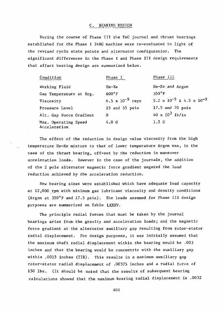
C. BEARING DESIGN
During the course of Phase III the TAG journal and thrust bearings
established for the Phase I 24RG machine were re-evaluated in light of
the revised cycle state points and alternator configuration. The
significant differences in the Phase I and Phase III design requirements
that affect bearing design are summarized below.
Condition Phase I Phase III
Working Fluid He-Xe He-Xe and Argon
Gas Temperature at Brg. 600°F 350°F
Viscosity 6.5 x 10~9 reyn 5.2 x 10~9 & 4.5 x 1(T9
Pressure Level 15 and 55 psia 17.5 and 70 psia
Alt. Gap Force Gradient 0 40 x 103 Ib/in
Max. Operating Speed 4.0 G 1.5 GAcceleration
The effect of the reduction in design value viscosity from the high
temperature He-Xe mixture to that of lower temperature Argon was, in the
case of the thrust bearing, off-set by the reduction in maneuver
acceleration loads. However in the case of the journals, the addition
of the 2 pole alternator magnetic force gradient negated the load
reduction achieved by the acceleration reduction.
New bearing sizes were established which have adequate load capacity
at 12,000 rpm with minimum gas lubricant viscosity and density conditions
(Argon at 350°F and 17.5 psia). The loads assumed for Phase III design
purposes are summarized on Table LXXXV.
The principle radial forces that must be taken by the journal
bearings arise from the gravity and acceleration loads; and the magnetic
force gradient at the alternator auxiliary gap resulting from rotor-stator
radial displacement. For design purposes, it was initially assumed that
the maximum shaft radial displacement within the bearing would be .003
inches and that the bearing would be concentric with the auxiliary gap
within .0015 inches (TIR). This results in a maximum auxiliary gap
rotor-stator radial displacement of .00375 inches and a radial force of
150 Ibs. (It should be noted that the results of subsequent bearing
calculations showed that the maximum bearing radial displacement is .0032
484

TABLE LXXXV
SUMMARY OF BEARING LOADS
F, = 100A
= 40,000 LB/IN x AR
AR = RADIAL DISPLACEMENT OF ROTOR INAUXILIARY MAGNETIC GAP
= .003 INCHES WITH BEARING UNDERMAXIMUM LOAD
PLUS
= .00075 INCHES (.0015 TIR) TOLERANCESTACK-UP BETWEEN ALTERNATOR (£ ANDBEARING £
= .00375 INCHES
40 x 103 x 3.75 x 10"3 = 150 LBS.
TOTAL DESIGN LOAD:
RD (at 12,000 RPM) = -£= 25° LBSi
W
RB (at 24,000 RPM) = 1.5 y1 + F
M = 30° LBS-
R (at 12,000 RPM) = WR + F = 300 LBS.
R_ (at 24,000 RPM) = 1.5 W_ + F = 400 LBS.X K A
485

inches at 12,000 rpm and .002 inches at 24,000 rpm). One G (horizontal
ground operation) at 12,000 rpm and 1.5 G at 24,000 rpm was used as design
values resulting in the 250 and 300 Ib. total bearing loads.
In the axial direction the alternator magnetic forces are negligible
but tolerance to aerodynamic thrust as a result of unbalanced turbine and
compressor wheel pressure distributions must be considered. One hundred
pounds was used for design purposes. Also the same acceleration criteria
as the journals was used for the thrust bearing resulting in design loads
of 300 Ibs. and 400 Ibs. at 12,000 rpm and 24,000 rpm respectively.
JOURNAL BEARINGS
As in Phase I, the journal bearing is a four pad tilting pad on
flexures with a stiffness of 15,000 Ib/in. These flexures accommodate
the shaft centrifugal growth and the radial thermal gradients between
shaft and housing. The significant journal bearing design parameters
are summarized on Table LXXXVI. The pivot radial clearance (.0013 inches)
and the preload (1 - pivot clear./bearing clear.) was set to insure
stable operation at the reference operating condition (24,000 rpm
vertical op'eration). The radial thermal growth (.00104 inch) shown in
Table LXXXVI results from the 80 F At between shaft and housing'determined
in Phase I. As noted above the pad flexures accommodate both the thermal
and centrifugal growths (each of which are of the same magnitude as the
clearance) and, as shown in Phase I, will accommodate large deviations
from the 80°F At without undue bearing performance degradation.
The performance of the journal bearings without changing clearance
or other geometric properties was examined using both He-Xe and Argon
each at 17.5 and 70 psia over a speed range of 6,000 rpm to 36,000 rpm
and a load range of 0 to 300 Ibs. Under no condition was the film
thickness less than .00026 inches (12,000 rpm - 300 Ib. load case).
Furthermore the pad natural frequencies were always greater than 150%
of the operating speed. Thus, no pad resonance problems are anticipated.
The journal bearing minimum film thickness as a function of load at
12,000 rpm and 24,000 rpm for the pressure extremes using both He-Xe and
Argon are shown in Figures 190 and 191- Here it can be seen that the
minimum film thickness at the design load conditions of 250 Ibs. at
12,000 rpm and 300 Ibs. at 24,000 rpm are in no case less than .3 x 10~3 inches.
486
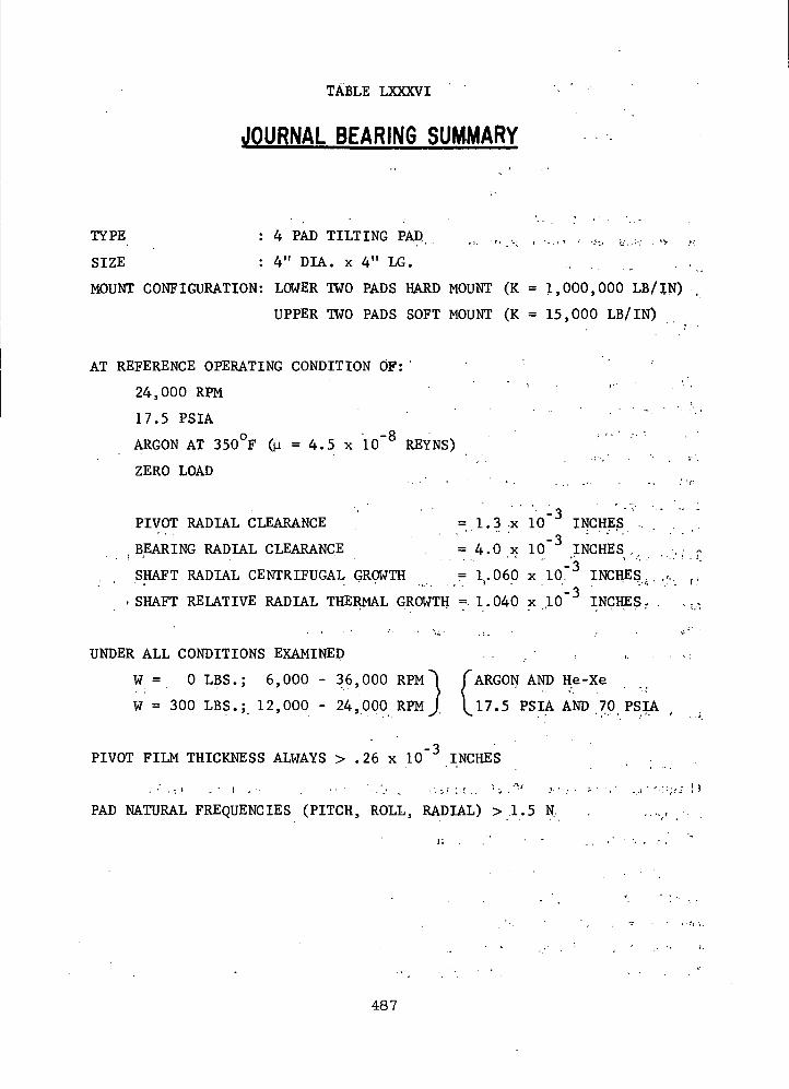
TABLE LXXXVI
JOURNAL BEARING SUMMARY
TYPE : 4 PAD TILTING PAD; ,, „ ,. , .. ., , .,, ..... ,,. „
SIZE : 4" DIA. x 4" LG. .. . . . . . . .
MOUNT CONFIGURATION: LOWER TWO PADS HARD MOUNT (K = 1,000,000 LB/IN) .
UPPER TWO PADS SOFT MOUNT (K = 15,000 LB/IN)
AT REFERENCE OPERATING CONDITION OF: ' "
24,000 RPM ' '
17.5 PSIA
ARGON AT 350°F (|i = 4.5 x 10"8 REYNS)
ZERO LOAD
PIVOT RADIAL CLEARANCE = 1.3 x 10"3 INCHES ,.
.BEARING RADIAL CLEARANCE . = 4.0 x 10 INCHES..,
SHAFT RADIAL CENTRIFUGAL GROWTH = 1.060 x 10"3 INCHES
rSHAFT RELATIVE RADIAL THERMAL GROWTH = 1.040 x 10"3 INCHES-
UNDER A L L CONDITIONS EXAMINED . . . ' , . - , . .
W = 0 LBS.; 6,000 - 36,000 RPM ""I CARGON AND He-Xe
W = 300 LBS.; 12,000 - 24,000 RPM J. \_17.5 PSIA AND 70 PSLA.
PIVOT FILM THICKNESS ALWAYS > .26 x 10"3 INCHES . .
. ' . - . < . : I . - . •• ' •..'.. .. •-:.' :•:.. ! i . :•• .-
PAD NATURAL FREQUENCIES (PITCH, ROLL, RADIAL) > 1.5 N,
487

_cuc
roiO
enCO
H
E
EpE
1 .6
1.2
1.0
.6
JOURNAL BEARING LOAD CAPACITYAT 12,000 RPM
F.:uid
ArgonHe-XeArgonHe-Xe
Viscosity In
Reyns [
-a—©4.5 x 105.2 x
x4.55.2
-9
1(T9
10-910-9
17.517.570.070.0
100 200
A p p l i e d Load - i.bs.
300
Figure 190
488
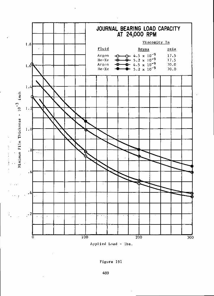
.coc
(0(0
H
Er-H•HDu
E
E•1-1C•H
1 .8
1.6s
\
1.4
1.0
\
JOURNAL BEARING LOAD CAPACITYAT 24,000 RPM
Viscosity In
Fluid
ArgonHe-Xe.ArgunHe-Xe
Reyns
4.5 x 10'9
5.2 x 10'9
4.5 x 10'9
5.2 x 10⁻⁹
psia
17.517.570.070.0
100 200
Applied Load - Ibs.
300
Figure 191
489
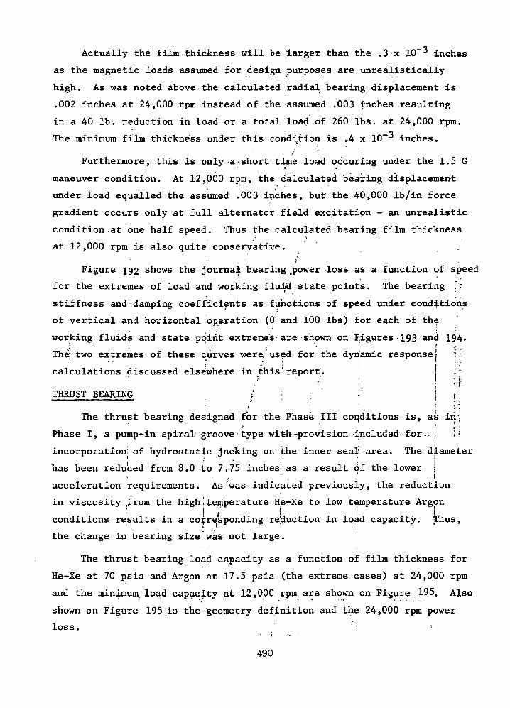
Actually the film thickness will be 'larger than the . 3'-x 10~ inches
as the magnetic loads assumed for design .purposes are unrealistically
high. As was noted above the calculated ;radial bearing displacement is
.002 inches at 24,000 rpm instead of the assumed .003 inches resulting
in a 40 Ib. reduction in load or a total load of 260 Ibs. at 24,000 rpm.
The minimum film thickness under this condition is .4 x 10" inches.
Furthermore, this is only a short time load occuring under the 1.5 G
maneuver condition. At 12,000 rpm, the calculated bearing displacement
under load equalled the assumed .003 inches, but the 40,000 Ib/in force
gradient occurs only at full alternator field excitation - an unrealistic
condition at one half speed. Thus the calculated bearing film thickness
at 12,000 rpm is also quite conservative. .
Figure 192 shows the journal bearing _power loss as a function of speed
for the extremes of load and working fluid state points. The bearing :'".
stiffness and damping coefficients as functions of speed under conditions
of vertical and horizontal operation (0 and 100 Ibs) for each of the
working fluids and state-point extremes• are shown on figures 193 -and 194-" ' '
The.two extremes of these curves were used for the dynamic response!
calculations discussed elsewhere in this'report. j' •'' !
THRUST BEARING / | ; ' \ j
The thrust bearing designed for the Phase III conditions is, as in: f ' J
Phase I, a pump-in spiral groove • type wit-h-provision included-for — i
incorporation of hydrostatic jacking on the inner seal area. The diameter• * I
has been reduced from 8.0 to 7.75 inches as a result of the lower J. ' i
acceleration requirements. As:was indicated previously, the reduction
in viscosity from the high', temperature He-Xe to low temperature Argon• I i \ \ \
conditions results in a corresponding reduction in load capacity. [Thus,
the change in bearing size was not large.
The thrust bearing load capacity as a function of film thickness for
He-Xe at 70 psia and Argon at 17.5 psia (the extreme cases) at 24,000 rpm
and the minimum load capacity at 12,000 rpm are shown on Figure 195. Also
shown on Figure 195 is the geometry definition and the 24,000 rpm power
loss.
490
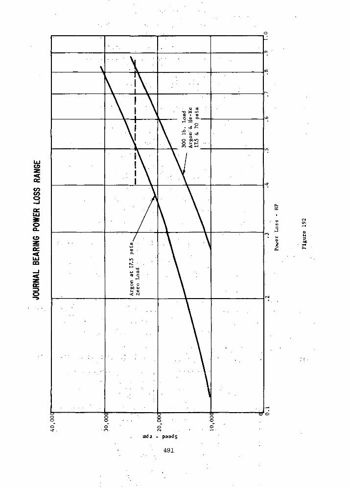
V)COQ
oQ_
CO
CD
_l
OC.
o
OHa:
0)l-l3no
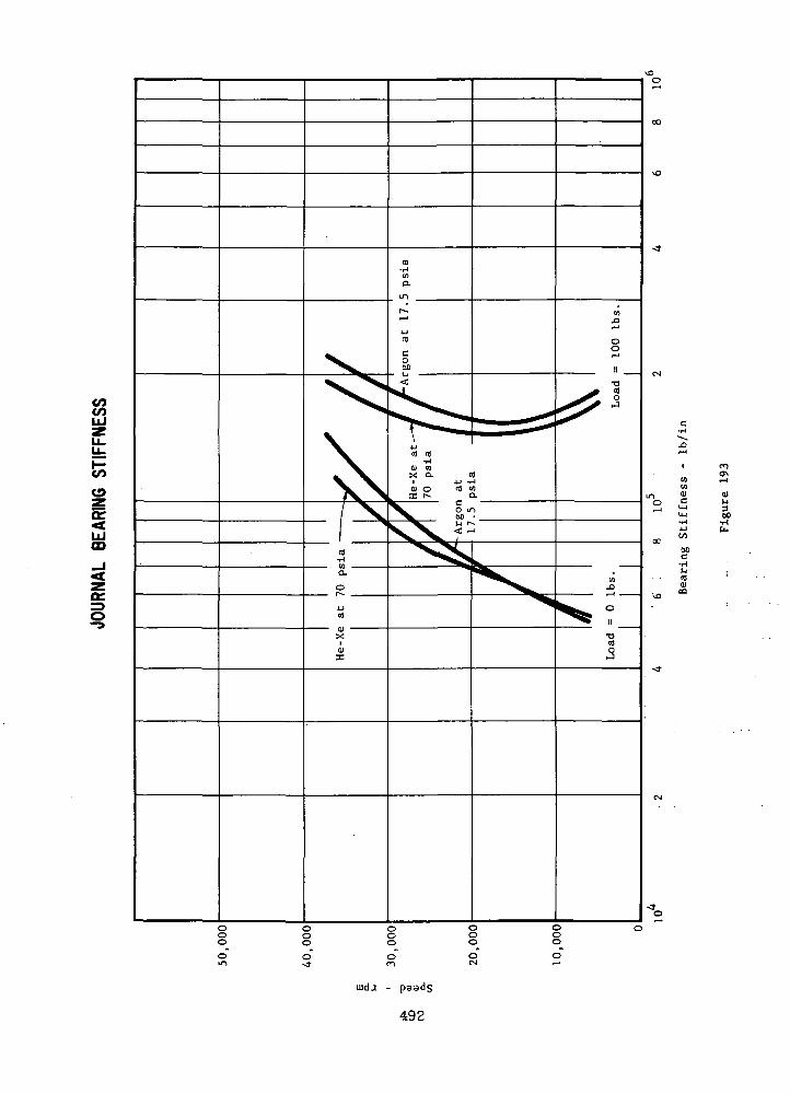
OJ
V)
o2<tUJm
OJ1-13,
ujda -
492
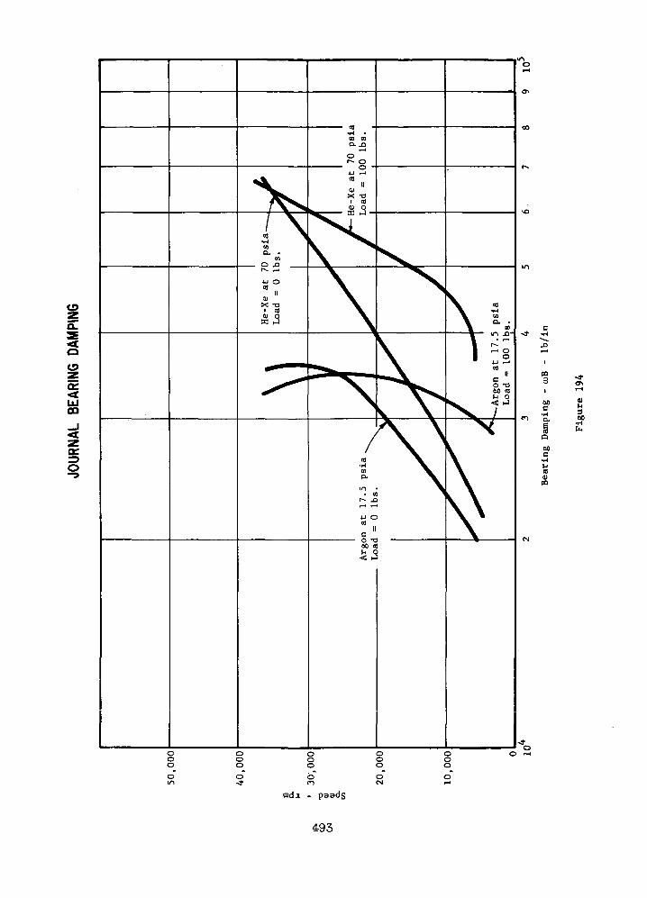
cro
§t>o
uida -
493
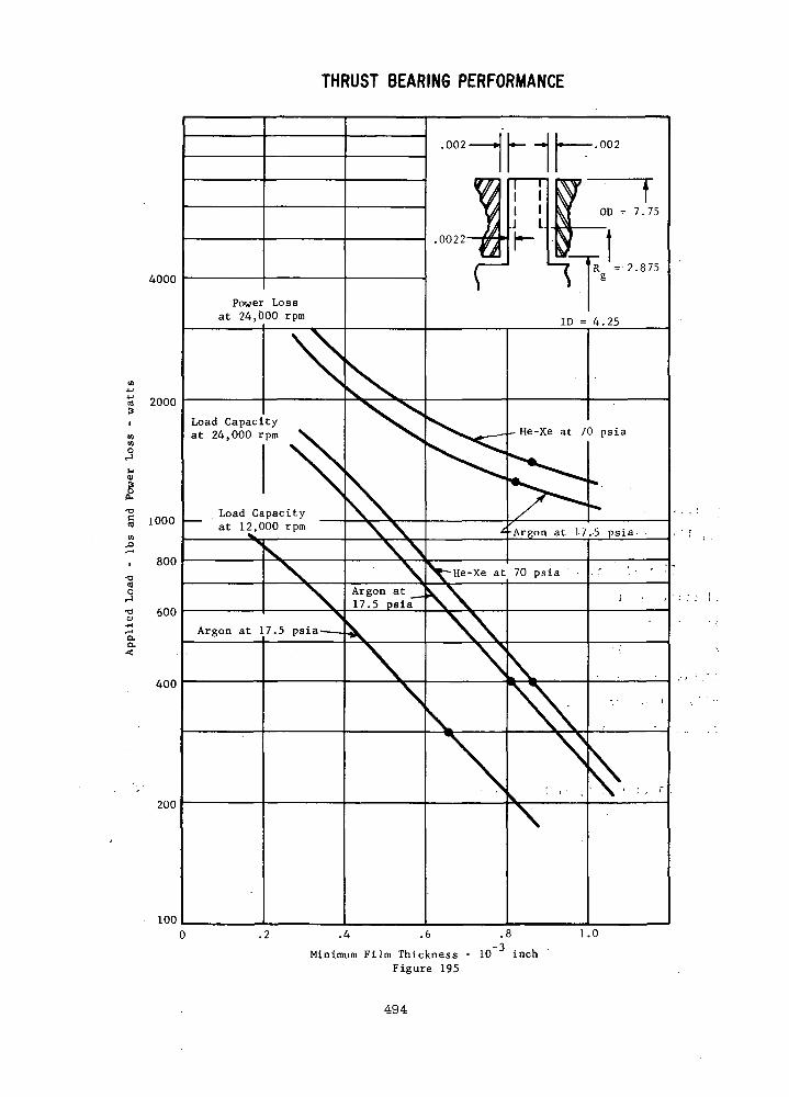
THRUST BEARING PERFORMANCE
4000
2000
•oa
5•o 600
400
1000 —
800
200
100
Power Lossat 24,000 rpm
Load Capacityat 24.000 rpm He-Xe at 70 psia
Load Capacityat 12,000 rpm * -Argon at 17.-5 psia. .
He-Xe at 70 psia
Argon at17.5 psia
Argon at 17.5 psia
1.0
Minimum Fi lm Thickness - 10 inchFigure 195
494
The film thickness under design load conditions (400 Ibs.) at 24,000
rpm is in excess of .8 mils and as can be seen from Figure 195 ,
considerable short time overload capacity is available. For short time
overload conditions, a minimum film thickness of .4 mils should be
readily achievable - limited only by the effect of thermal and mechanical
distortions. At 12,000 rpm the minimum design load (300 Ibs.) film
thickness is .65 mils - somewhat smaller than the 24,000 rpm design-.
However, the power loss is only 1/4 (speed squared effect) thus the
thermal distortions will be negligible and again very small (approaching
.4 mils) film thickness should be available.
The maximum thrust bearing power loss at design conditions is 1400
watts which corresponds to a required cooling rate of 42 watts/in^. The
heat exchanger designed during Phase I was sized for 40 watts/in^ (total
face power equal 1440 watts). As these two heat fluxes are nearly equal
it can be concluded that, with a similar cooling scheme and heat
exchanger geometry, the thermal distortions will be near equal to those
predicted in Phase I. Mechanical distortions should, however, bev
smaller, in magnitude because of the lower design load and smaller diameter.
The effect of thermal distortion on thrust bearing performance was
checked over a range to 150 y inches and the results are shown on
Figure 196. It should be noted that the maximum film distortion cal-
culated in Phase I was somewhat less than 100 y inches. The results on
Figure 196 show a maximum reduction in film thickness of just over .1
mils with practically no change in power loss (or heat flux). Thus,
no thermal -runaway is anticipated and again pushing to smaller film
thickness for overload conditions should prove to be practical.
In summary, the minor design revisions made to the journal and thrust
bearings have made them entirely suitable for the Phase HI design
conditions. Over the range of viscosity for the two different working
fluids and the pressure extremes resulting from power level changes the
bearings maintain adequate film thicknesses for the design load conditions.
The thrust bearing has good margin for overload conditions and the journals
have an inherent margin as a result of the conservative design load
values assumed.
495
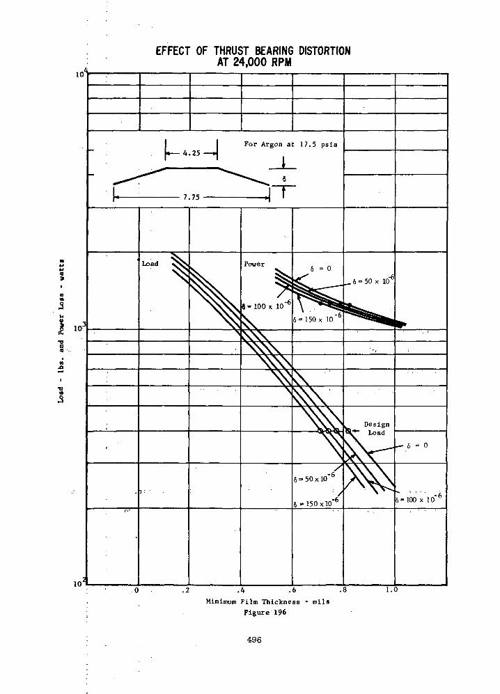
EFFECT OF THRUST BEARING DISTORTIONAT 24,000 RPM
For Argon at 17.5 psia
10'.4 .6 .8
Minimum Film Thickness - milsFigure 196
1.0
496
D. DYNAMIC ANALYSIS
BEARING-ROTOR DYNAMICS
The basic 24RG TAG design was subjected to additional rotor dynamic analysis
during Phase III to establish the effects of the revised Phase III design
conditions on the dynamic response of the TAG rotor. The significant design
differences between Phase I and III affecting the rotor vibrational behavior
and investigated during Phase III were:
Increased size of the two pole alternator
Alternator auxiliary gap magnetic force gradient of 40,000 Ib/in
Bearing dynamic coefficients resulting from size and fluid property
differences.
The configuration of the Phase I and III 24RG TAC's are shown schematically on
Table LXXXVII -along with a comparison of critical speeds. The total rotor
weights are not significantly different, primarily because very early .large '•'
diameter alternator rotor designs were used for the Phase I study which
offsets the effect of the Phase III alternator length increase.
As would be expected the first criticals are not significantly different be-
tween the Phase I and III configurations because of the weight similarity.
The second critical is higher for the Phase III configuration as a result of
increased bearing span and the third critical is reduced primarily because
of increased total length. The third critical is still, however, 49% above
the overspeed condition which is in excess of the minimum 30% margin custom-
arily used for design purposes.
The undamped critical speed map for~-the_Phase III TAG is shown on Figure 197
along with the mode shapes for bearing stiffness equal to 10 Ib/in. The
497

TABLE LXXXVII
PHASE I AND PHASE HI GAS BEARINGTAG WITH RADIAL COMPRESSOR
1 = 4.5HI = 3.62
<3
L
9; • •
>c
Zl
^^1
••
m=?8.65,
" I*I6'.«0.*11=20.15
UIT'T _ IQQ IKw r l - iby IDWTTTT- IQ7 Ih 'n 1 ILL- lali. ID .
1 •
1 = 9.80111=13.13
'.' , .-•-i>
C
!'.
3' •:
• • , .••
<- •
j
• : ;
>. . ' '• '
r - - v -1=4.75
HI= 4;83]
-••?• *• '-'• ~- i*~
- . -i" ••-. 5 '"•• .i CRITICAL SPEEDS AT KBRGJ= 10 >>LB/IN •
i ;i.
FIRST
SECOND :
THIRD"3RD N /28.800
"*. 4 - - . . - .
PHASE I ' '
5900'
7600
49000 "
1.-68
'.">•
'PHASE .III
5800
9000
'43000 ""
1.49
•Tij.tr ji'citc''... :..L~L.-LL '[l.-
! ri ' ' f 1
' i3 I. , j ! i J
498
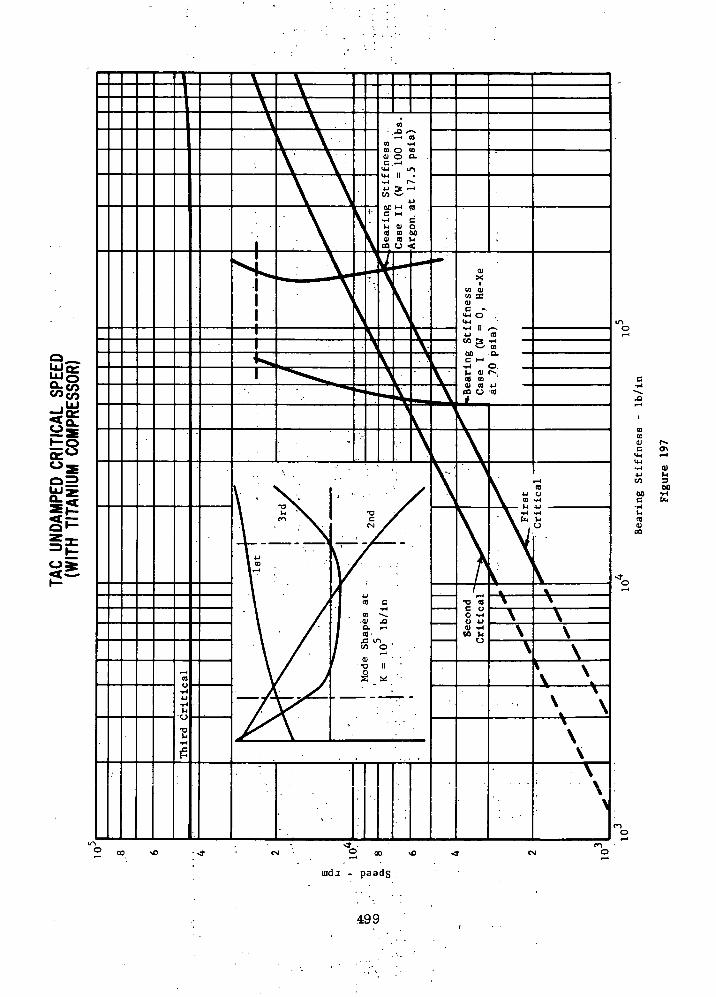
iudj . paadg
.499

first two criticals are relatively rigid and display the typical characteristics
of a symmetrical rotor, i.e. essentially pure translatory and conical first and
second modes. The third displays a significant amount of bending in the alter-
nator stub shafts with one mode very near the bearing. Obviously the third is
to be avoided.
Also shown on Figure 197 are the extreme cases of bearing stiffness over
the range of working fluid choice and state point; and zero bearing load
(vertical operation) and 100 Ibs. bearing load (horizontal ground operation).
These values of bearing stiffness along with the corresponding damping values
are shown in Figure 194 of the journal bearing section were used to calculate
the dynamic response of the rotor discussed below.
The response of the rotor to mechanical unbalance was calculated assuming a
total unbalance equivalent to a 100 M- inch shift of the rotor C.G. with respect
to the (£ defined by the journal surfaces. This unbalance was equally divided
between the turbine and compressor backfaces both in-phase and out-of-phase
with each other. This location of unbalance is a worst case situation as it
accentuates both the criticals closest to the operating speed (the second with
out-of-phase unbalance and the third with in-phase unbalance). The calculations
were made for both of the stiffness vs. speed cases shown on Figure 197 and the
forementioned corresponding damping-speed relationships which cover the extremes
of the assumed cycle and environmental conditions.
The results of the dynamic response calculations are shown on Figures 198 and 199
for bearing stiffness cases I and II respectively. Plotted on each curve is
the bearing amplitude as function of speed and that part of the rotor that has
500
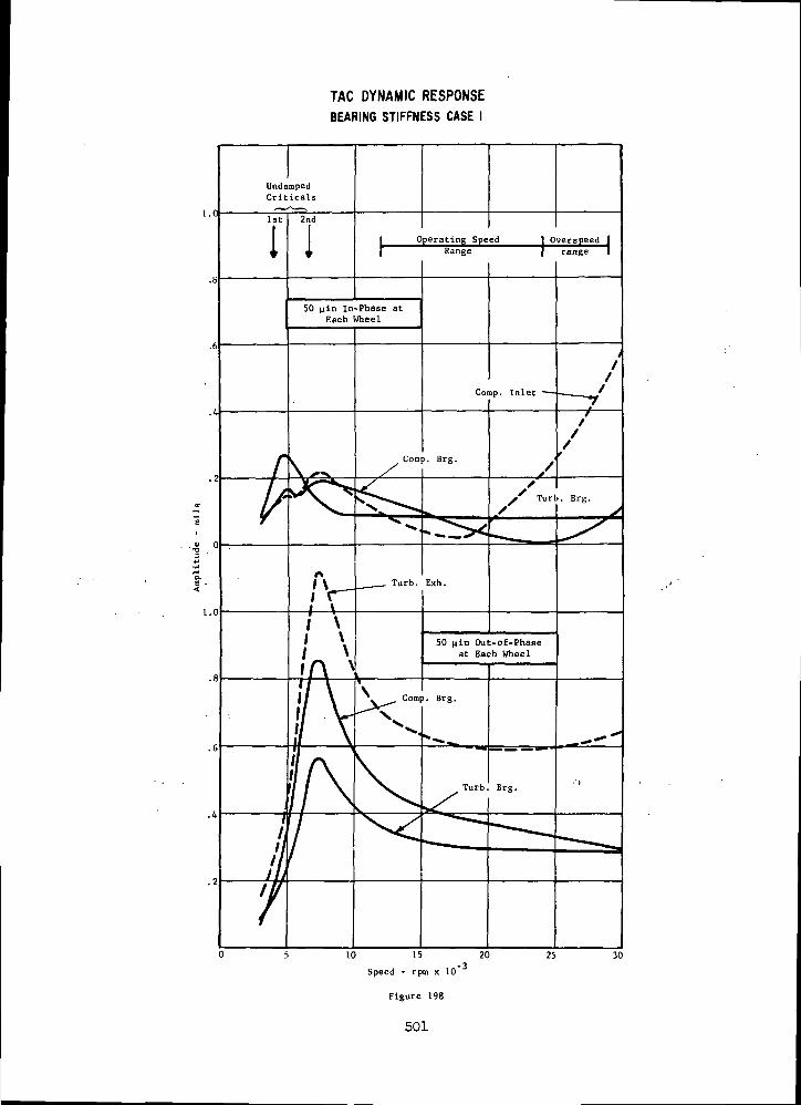
TAC DYNAMIC RESPONSE
BEARING STIFFNESS CASE I
Operating Speed I Overspeed
50 pin In-Phase atEach Wheel
30
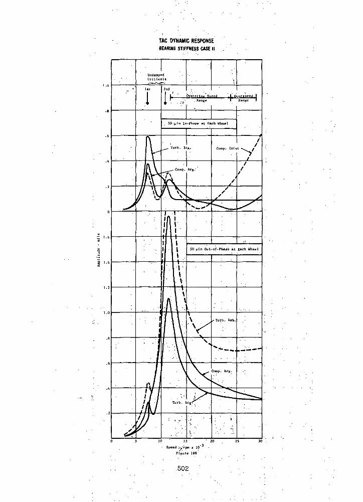
TAC DYNAMIC RESPONSEBEARING STIFFNESS CASE II .
Figure 199
502
maximum amplitude at 24,000 rpm. It should be noted that the part of the rotor
displaying maximum amplitude at 24,000 rpm is not always the same part display-
ing maximum amplitude at resonance.
In both bearing stiffness cases I and II, the predominant resonance mode is as
expected, that is the first critical is predominant and effects of the third
at higher speeds are seen with in-phase unbalance and the second is predomi-
nant with out-of-phase unbalance. For the lower bearing stiffness case I
the resonances (1st and 2nd criticals) are well controlled and display the char-
acteristics of a reasonably well d,amp.ed. system. In the case of high stiffness
corresponding to horizontal operation the criticals are poorly damped and
large in amplitude as a result of the higher critical speed (because of higher
stiffness) and the .poorer damping to critical damping ratio. This poorer
damping ratio results 'from two factors. • ;« '•
v
1. Under highly loaded conditions' the-iratio of bearing stiffness (which
controls critical damping) to. bearing damping inherently increases.
2. Under high bearing stiffness conditions, much of the rotor to housingi ' -V '; '''
relative;motion takes place within.the pad flexure which has, for all
t .practical "purposes,- no damping;-' thus the inherent bearing damping is
less effective. • »-.
I ,. .. „. . .7 -; • • * . . .| :
• * * ' ?The amplitudes of vibration at 24,000 rpm at the bearings for both bearing
stiffness cases with-out-of-phase unbalance are between .3 and .4 mils. The
bearing minimum film thickness with a 100 Ibs. 'applied load is close to .8
mils (see Figure 191). Thus the shaft orbit uses about half the available
bearing clearance which is considered an acceptable upper limit.
503
However at 12,000 r'pm where the amplitudes are greatest (Figure 199, out-of-
phase), the turbine bearing amplitude approaches 1.8 mils as compared to a
100 Ibs. load operating film thickness of only .6 mils (see Figure 190). For
safe start-up and shut-down conditions the orbit at resonance should be
limited to about 75% of the available clearance or about .4 mils at 12,000 rpm.
This simply means that the maximum residual unbalance will have to be limited
to a total of 22 nin. (11 at each plane). This value, equivalent to .070 in-oz,
is well within the capabilities of current balancing state-of-the-art. With
this reduced unbalance, the design speed amplitudes will be correspondingly
reduced, thus greater tolerance to balance degradation with time will be realized.
Also calculated was the response of the rotor assuming, in addition to the bear-
ing case I and II characteristics, a negative force gradient equivalent to
40,000 Ib/in at each alternator auxiliary gap rotor location. The results
of these calculations are shown on Figures 200 and 201 where it can be
seen that the negative force gradient has little significant effect on the
rotor vibrational behavior. The major differences are:
1. The resonant peaks are very slightly shifted to a lower speed.
2. The vibration amplitudes are slightly higher below the first resonance
and slightly attenuated above the first predominant resonance.
These trends are as would be expected as a result of lowering the effective
support stiffness of the rotor. The lower effective stiffness results in
lowered values of critical speed and larger vibration amplitudes above the
first critical for a given driving force. Also, by lowering the effective
support stiffness and maintaining the same absolute value of bearing damping,
504

TAG DYNAMIC RESPONSE (WITH 40,000 LB/IN FORCEGRADIENT AT EACH ALTERNATOR AUXILIARY GAP)
BEARING STIFFNESS CASE I
UndampedCrtticals
1st 2ndOperating Speed
Rangeverspeed.Range
50 uin(In-Phase atEach Wheel
Comp.Inlet
Comp./Brg.
s Turb.Brg.
r\I \ Turb.
Exh.50 uln Out-of-Phase
at Each Wheel
Comp.Brg.
\urb.Brg.
10 15
Speed - rpm x 10
Figure 200
-320 25 30
505
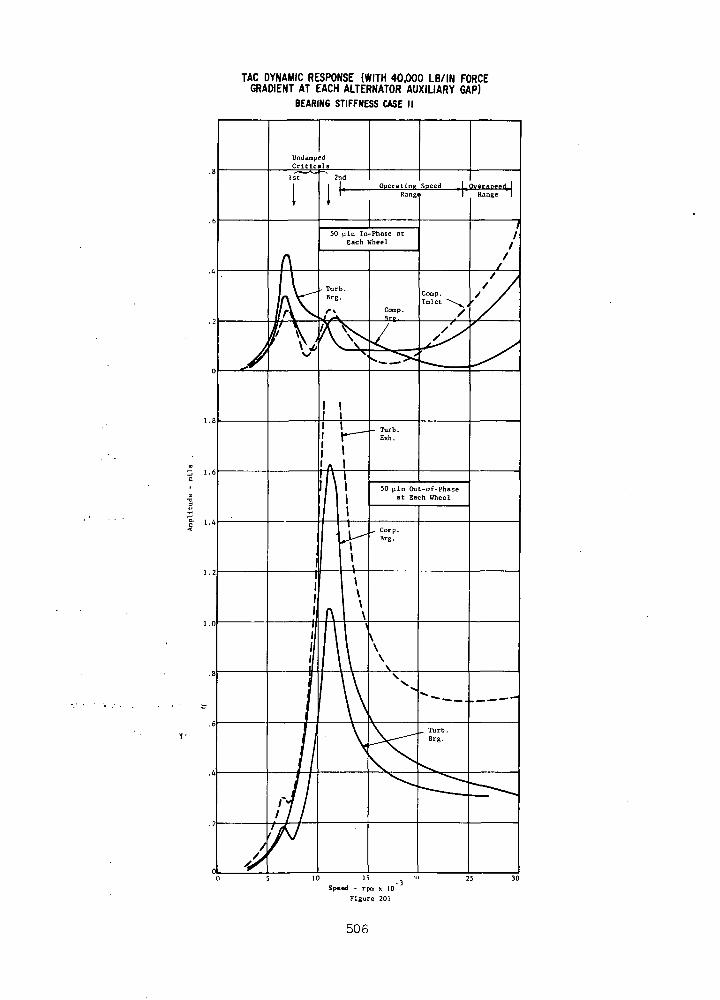
TAC DYNAMIC RESPONSE (WITH 40,000 LB/IN FORCEGRADIENT AT EACH ALTERNATOR AUXILIARY GAP)
BEARING STIFFNESS CASE II
10 15
Speed - rpm x 10
Figure 201
506

the critical damping ratio is increased. This has the effect of attenuating
the critical and amplitudes above the critical.
The amplitudes shown on Figures 200 and 201, as noted above, are not markedly
different from those on Figures 198 and 199, thus the same observation re-
garding unbalance hold when considering the effect of magnetic force gradient.
The effect of substituting a steel compressor wheel for a titanium wheel on
rotor critical speeds and response amplitudes, was also checked. The critical
speeds in Table LXXXVIII reflect the unexpected trends. The difference in
rotor weight is small (steel wheel is approximately 6 Ibs. heavier) thus the
first critical is virtually unaffected. The total difference in weight being
concentrated at one end, however, lowers both the second the third critlcals.
The third critical is 33% above the required overspeed condition. Greater
margin may be desirable and is achievable by a slight increase in compressor
end bearing diameter.
The response to 50 p.in of unbalance out-of-phase at each wheel for bearing case
II (which was the worst amplitude case) was also calculated and is summarized
in Table LXXXIX. The amplitudes of vibration were not significantly differ-
ent between the steel and titanium compressor cases with the major difference
being a slight lowering of the predominant resonance (second critical).
In summary, the third critical speed of the Phase III TAG rotor is acceptably
far removed from the overspeed condition — by a factor of 1.49. The rotor
response calculations did not show any significant effect of the third criti-
cal to 30,000 rpm. The predominant resonance was the second critical speed
507
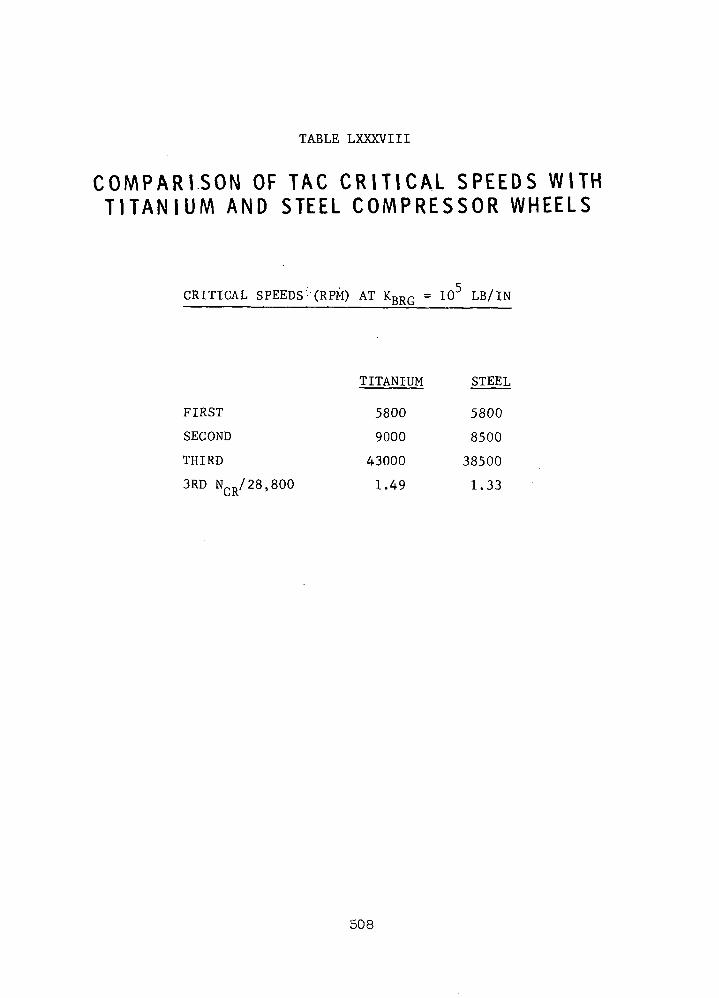
TABLE LXXXVIII
C O M P A R I S O N OF TAG C R I T I C A L S P E E D S WITHT I T A N I U M AND STEEL C O M P R E S S O R WHEELS
CRITICAL SPEEDS (RPM) AT KBRG = 105 LB/IN
TITANIUM STEEL
FIRST 5800 5800
SECOND 9000 8500
THIRD 43000 38500
3RD NCR/28,800 1.49 1.33
508

TABLE LXXXIX
C O M P A R I S O N OF TAG R O T O R - B E A R I N G RESPONSEWITH T I T A N I U M AND STEEL C O M P R E S S O R WHEELS
COMPRESSOR BEARING AMPLITUDES - BEARING CASE II
50 IN OUT-OF-PHASE AT EACH WHEEL
SPEED TITANIUM STEEL(RPM) (MILS) (MILS)
8,000 .35 .37
10,000 .9 1.2
12,000 1.5 1.0
18,000 .51 .41
24,000 .38 .33
30,000 .30 .29
522
509

occurring at about 12,000 rpm. This poorly damped critical can, however,
be well controlled by limiting the total residual unbalance to .070 in-oz.
Furthermore, this residual unbalance results in negligible rotor amplitudes
at design speed.
The 40,000 Ib/in negative force gradient at the alternator magnetic gap
has negligible influence upon the rotor dynamic behavior. Also, the use
of steel instead of titanium for the compressor wheel has little influence
upon the rotor dynamic behavior over the speed range to 30,000 rpm.
510
r E. TAG LJN'IT DESIGN "
Shown, in Figure:-;202 is .the-, drawing -of t'he'Phase'III-TAG.: Because of '•
the decreased inlet temperatures to the compressor and turbine'from the" ' -'•''
values of the Phase I 24RG configuration, the tip,speeds have been .reduced,
in keeping with the same aerodynamic loading. Since the rotative speed
is the same as in Phase I, tip diameters of the compressor and turbine had
to be reduced 9% and 11.5%, respectively. A comparison of design data for
the Phase I arid Phase III 24RG configuration is shown in Table XC. The
requirement for operating the turbine at 1600°F for extended time was
retained, however, in Phase III. The compressor inlet pressure was increased
in Phase III consistent with about the same specific speeds as in Phase I.
In order to have the convenience of using existing 400 Hz equipment with-
out a frequency converter, a Lundell alternator was selected with two
poles. This requires an increase in the diameters of the alternator rotor
and stator about 10% and 28%, respectively. In order to reduce the stress
in the turbine hub, the bore was removed. This necessitated introducing
the cooling at the compressor end of the rotor. This cooling gas is used
to limit the axial temperature gradient along the journals. The removal
of the turbine bore reduced hub stress 33% and, based upon 1600°F operation,
made the stresses in the rotor blades become the critical stresses, with a
unity factor of safety. Due to a change in specified maneuver loads
between Phases I and III, the thrust-bearing outer diameter was reduced
slightly. The liquid cooling of the thrust-bearing stator has the same
configuration as in Phase I.
The radial-inflow turbine has a symmetrically placed inlet scroll
to minimize casing stresses due to internal pressure and thermal gradients.
The exit-diffuser configuration used in Phase I was retained.
Provisions are made for the working gas to be pumped toward the
center of the alternator stack by the conical portions of the alternator
rotor. The gas is later cooled in a heat exchanger and returned to the
alternator stator-rotor gap.
The weights of the Phase I and Phase III 24RG machines are synopsized
in Table XCI. The. Phase III alternator rotor is 38 percent heavier than
that of the Phase I alternator. The Phase III alternator stator is 83
511
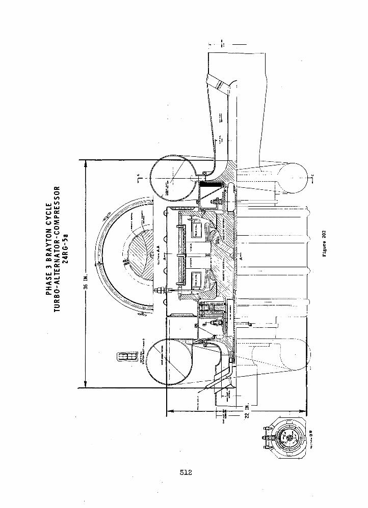
o T
512
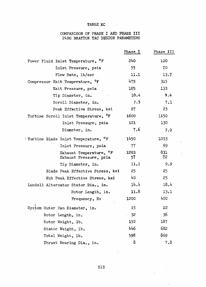
TABLE XC
COMPARISON OF PHASE I AND PHASE III2URG BRAYTON TAG DESIGN PARAMETERS
Phase I Phase III
Power Fluid Inlet Temperature, °F 2UO 120
Inlet Pressure, psia 55 TO
Flow Rate, Ib/sec 11.1 13.7
Compressor Exit Temperature, °F Vf5 315
Exit Pressure, psia . 105 133
Tip Diameter, in. 10.4 9.4
Scroll Diameter, in. 7.5 7.1
Peak Effective Stress, ksi 27 23
Turbine Scroll Inlet Temperature, °F 1600 1150
Inlet Pressure, psia 101 130
Diameter, in. 7.6 7.0
Turbine Blade Inlet Temperature, °F 11*50 1033
Inlet Pressure, psia 77 99
Exhaust Temperature, °F 1203 831Exhaust Pressure, psia 57 72
Tip Diameter, in. 11.1 9.9
Blade Peak Effective Stress, ksi 25 25
Hub Peak Effective Stress, ksi UO 25
Lundell Alternator Stator Dia., in. lU.U iQ.k
Rotor Length, in. 11.8 13.1
Frequency, Hz 1200 UOO£
System Outer Can Diameter, in. 15 22
Rotor Length, in. .32 36
Rotor Weight, Ib. 152 187
Stator Weight, Ib. UU6 682
Total Weight, Ib. 598 869
Thrust Bearing Dia., in. 8 7.8
513
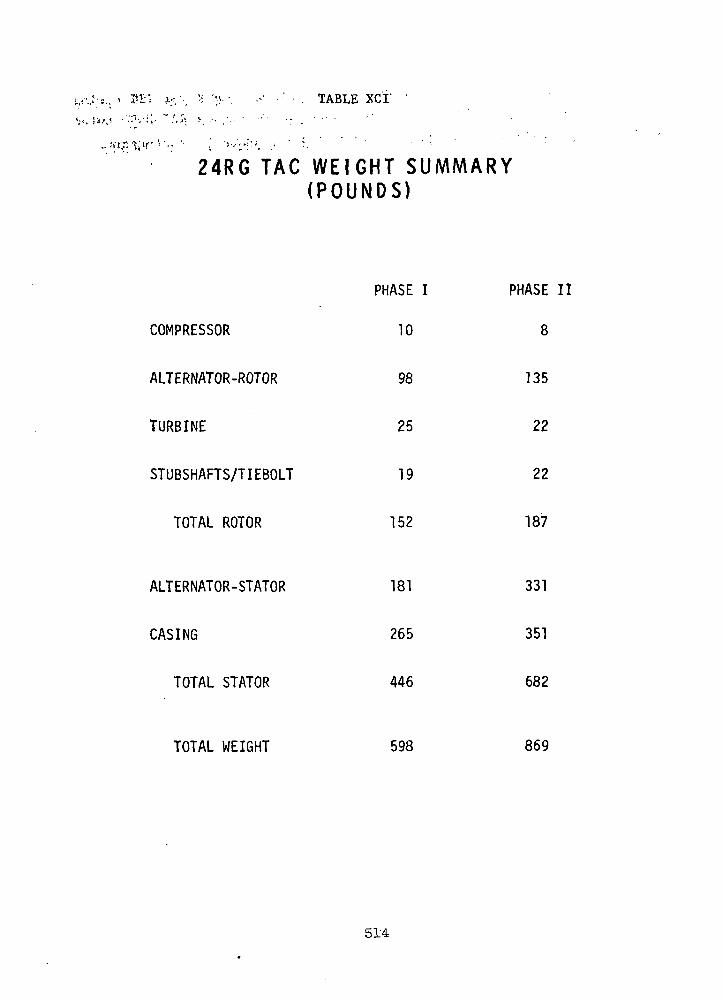
'. TABLE
24RG TAG W E I G H T SUMMARY(POUNDS)
COMPRESSOR
ALTERNATOR-ROTOR
TURBINE
STUBSHAFTS/TIEBOLT
TOTAL ROTOR
ALTERNATOR-STATOR
CASING
TOTAL STATOR
TOTAL WEIGHT 598 869
PHASE I
10
98
25
19
152
181
265
446
PHASE II
8
135
22
22
187
331
351
682
514

percent heavier than that of the Phase I alternator. The Phase .III casing
weighs 32 percent more than the Phase I casing. The Phase III 24RG total
weight is 271 pounds, or 45 percent more than its Phase I counterpart.
515

F. PERFORMANCE ANALYSES
For Phase III the TAG operating conditions were changed as shown in
Table XCII. The temperatures were reduced to the SNAP-8 conditions, and
flow rate and pressure level were increased to achieve 160 KWe output.
The turbine pressure ratio was increased which means that there is less
pressure drop in the heat exchanger and the ducting.
The specific speed of the compressor is 91.5 for Phase III compared
with 88.5 for Phase I. The corresponding specific speeds for the turbine
are 79.1 and 76.7. Because these values are only about 3% different, the
turbomachinery for Phase III was scaled from the 24 RG Phase I designs.
For dynamic similarity of two machines, which have the same pressure ratio2
and polytropic exponent, the value of U /RT should be a constant, where U
is the wheel speed, R is the gas constant and T is the inlet temperature.
An alternate form of this criterion is ND/v^RT where N is rotative speed
and D is the wheel diameter. This relationship was used to scale the
Phase I compressor and turbine diameters to the Phase III conditions.
The scale factors are v/580/700 or 0.91 for the compressor and V/1610/2060
or 0.884 for the turbine. The flow areas of the Phase I designs were
scaled to maintain a constant value of the flow function Wy/T , and theP A
area scale factors were 0.884 for the compressor and 0.853 for the turbine.
A comparison of the dimensions is shown in Table XCIII.
Cycle calculations were made to determine the performance of the
Phase III design for the 6-pole and 2-pole alternators. The effect of the
lower temperatures was to lower the cycle efficiency from 0.284 to 0.257.
Increasing the turbine pressure ratio raised the cycle efficiency to 0.275
as seen for the 6-pole alternator in Table XCIV. Reducing the alternator
efficiency to 0.93 and increasing the windage loss to 5.5 KW for the 2-pole
alternator reduced the cycle efficiency to 0.27.
516
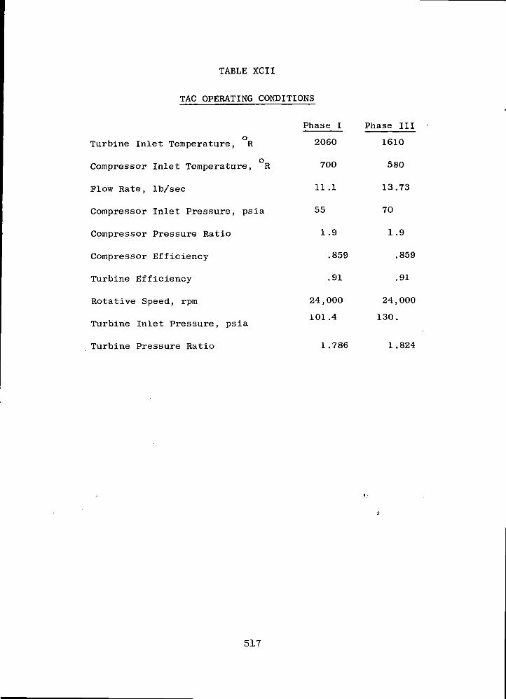
TABLE XCII
TAG OPERATING CONDITIONS
oTurbine Inlet Temperature, R
oCompressor Inlet Temperature, R
Flow Rate, Ib/sec
Compressor Inlet Pressure, psia
Compressor Pressure Ratio
Compressor Efficiency
Turbine Efficiency
Rotative Speed, rpm
Turbine Inlet Pressure, psia
Turbine Pressure Ratio
Phase I
2060
700
11.1
55
1.9
.859
.91
24 , 000
101.4
1.786
Phase III
1610
580
13.73
70
1.9
.859
.91
24,000
130.
1.824
517
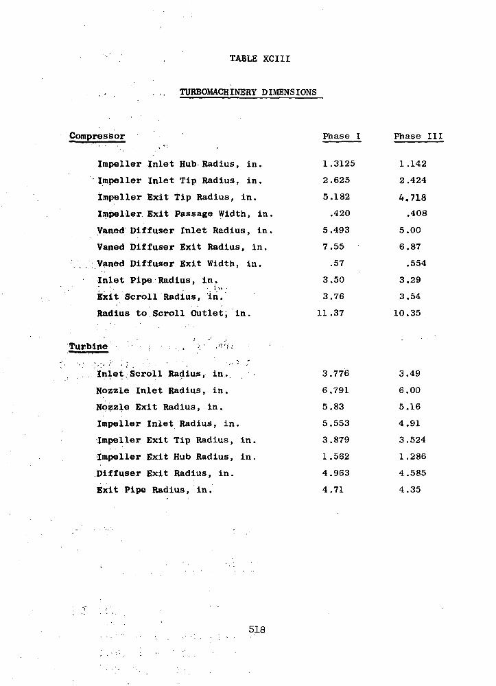
TABLE XCIII
TURBOMACHINERY DIMENSIONS
Compressor
Impeller Inlet Hub Radius, in.
Impeller Inlet Tip Radius, in.
Impeller Exit tip Radius, in.
Impeller Exit Passage Width, in.
Vaned Diffuser Inlet Radius, in.
Vaned Diffuser Exit Radius, in.
... Vaned Diffuser Exit Width, in.
Inlet Pipe Radius, in.' • ' ' i »>, -
Exit Scroll Radius, in.
Radius to Scroll Outlet, in.
'Turbine. • •••"•; • : . , "•: ' ,'•'!- • ' •• . - ' , i «•
. . Inlet. Scroll Radius, in.
Nozzle Inlet Radius, in.
Nozzle Exit Radius, in.
Impeller Inlet Radius, in.
Impeller Exit Tip Radius, in.
Impeller Exit Hub Radius, in.
Diffuser Exit Radius, in.
Exit Pipe Radius, in.
Phase I
1.3125
2.625
5.182
.420
5.493
7.55
.57
3.50
3.76
11.37
3.776
6.791
5.83
5.553
3.879
1.562
4.963
4.71
Phase III
1.142
2.424
4.718
.408
5.00
6.87
.554
3.29
3.54
10.35
3.49
6.00
5.16
4.91
3.524
1.286
4.585
4.35
518

TABLE XCIV.-• •" */ .Jl I
TAG PERFORMANCE COMPARISON
Losses, KW
Leakage, % Flow
Compressor Efficiency
Turbine Pressure Ratio
Turbine Efficiency
Alternator Efficiency
Cycle Efficiency
Flow Rate, Ib/sec
Phase I
6 Pole
7.36
3.23
.859
o I . 786
.91
.942
.284
9.85
Phase IILow Temp
6 Pole !
•7.:36-• i ; . ' • • • • • " •
3.23' *'' ' - ' ' ,.'' f- '-
...859
-K78V
.91
.942
J257'
14.07
Phase^ITf-t
' : ? - - '6 P&le"- ' ••-'<:••#
•K='i --7..'36 -•••-^-"'T--^8, , v - , . , •,.„. r..v. ... ;4 , . . - -
3. "23 ^ '""3-• •' <:! f.si"' . '- '•• ' -•' •'•\\'K
.-..„ -. .....859-. .-, . :-:
: -• '••• "• 1-.824 ' '-:»'>'V.\i
.91' '_" ;; r l"
, . . .-942 v.;. ,. . -," * \ ~ij ' ' f ' . .-"''.'*•, ' '. " *i. .
••• '-'''"i .'275 ''••:'•• fe-^
12.81 13
0; : i-— 1. -. fi »j.
Pole
.61
.23
.859
.824
.91
.93
.27
.06
-, . •-,•-, ** '•'..,... . « n. T,• .-)• :..»•->. • .v'.*•-.-• .•v'i.-.J'.K
519

V. R E F E R E N C E S
1. Rothbart, H. A., Mechanical Design and Systems Handbook, McGraw-HillBook Co., N.Y., 1964, pp. 6-56.
2. Joice, L. J., and La Bane, E. J., "GE 12 Redesigned Compressor Bladeand Vane Laboratory Test," General Electric Company Report No.TM 69AEG1071, September 10, 1969.
3. Kourokevas, G. D., "T-58-8 Stall Checker Kit Vibration Survey,"General Electric Company Report, TM 68AEG1269, 1968.
4. Jennings, B. H., and Rogers, W. L., Gas Turbine Analysis and Practice.McGraw-Hill Book Company, N.Y., 1953, pp. 426-434.
5. Kemp, R. H., Hirschberg, M. H., and Morgan, W. C., "Theoretical andExperimental Analysis of the Reduction of Rotor Blade Vibration inTurbomachinery Through the Use of Modified Stator Vane Spacing,"NACA TN 4373, September 1958.
6. Renner, L. R., Johnston, J. T., and Kline, S. J., "Performance andDesign of Straight Two-Dimensional Diffusers," Thermo-Science Division,Department of Mechanical Engineering, Stanford University, No. P.O.-8,September 1964.
7. Sprenger, H., "Experimental Investigation of Straight and Curved Dif-fusers" (British Translation, May 1962) ASTIA AD 277113.
. i • , ; - \8. Tsyl, E. R., et al., "Overall Performance in Argon of a 6-inch Radial-
Bladed Centrifugal Compressor," NASA TM X-1622, August 1968v
9. Perrone, G. L., Milligan, H. H., "Brayton Cycle 3.2-inch Radial Com-pressor Performance Evaluation," NASA CR-54968, May 1966. >!:
10. Blair, L. W., "Aerodynamic Performance of the GE 2.2 Ib/sec CentrifugalStage Component Tests - B/U 1 to B/U 12," G.E. TM 70AEG1487, April 1970.
11. Balje, 0. E., "A Study on Design Criteria and Matching^of Turbo-machines," ASME 60WA-231, 1960. '
12. Stanitz, J. D., "One Dimensional Flow in Vaneless Dif fusers of •'• *Radial- and Mixed-Flow Centrifugal Compressors, Including' Effects ofFriction, Heat Transfer, and Area Change," NACA TN 2610, January 1952.
13. Goldstein, S., Modern Developments in Fluid Dynamics, Oxford Press(]938). .
14. Faulders-," C.-R.; "Experimental and Theoretical Study'of"'V'ariel'e's Dif-fuser Flow with Supersonic Entry," M.I.T. Gas Turbine Laboratory,'Cambridge, Mass., June 1952.
15. Dean, R. C., Senoo, Y., "Rotating Wakes in Vaneless Diffusers,"ASME Journal of Basic Engineering, September 1960.
16. Brown, W. B., "Friction Coefficients in a Vaneless Diffuser,"NACA TN 1311, May 1947.
17. Eckert, B., Axialkompressoren und Radialkompressoren, Springer-Verlag,Berlin (1953).
520
18. Sovran, G. and Klomp, E. D., "Experimentally Determined OptimumGeometries for Rectilinear Diffusers with Rectangular, Conical, orAnnular Cross Section," Fluid Mechanics of Internal Flow, Elsevier Co.,Amsterdam (1967).
19. Runstadler, P. W. and Dean, R. C., "Straight Channel Diffuser Per-formance at High Inlet Mach Numbers," ASME Trans., September 1969.
20. Rohlik, H. E., "Analytical Determination of Radial Inflow TurbineDesign Geometry for Maximum Efficiency," NASA TN D-4384, February 1968.
21. Steward, W. L., Whitney, W. J., and Wong, R. Y., "A Study of Boundary-Layer Characteristics of Turbomachine Blade Rows and Their Relationto Over-all Blade Loss," J. Basic Eng. Vol. 82, No. 3, September 1960,pp. 588-592.
22. Shepherd, D. G., "Principles of Turbomachinery," MacMillan Co., 1956.
23. Henry, J. R., Wood, C. C., and Wilbur, S. W., "Summary of SubsonicDiffuser Data," NACA RM L56F05, October 1956.
24. Nusbaum, W. J. and Kofskey, M. G., "Cold Performance Evaluation of4.97-inch Radial - Inflow Turbine Designed for Single-Shaft BraytonCycle Space-Power System," NASA TN D-5090, March 1969.
25. Futral, S. M., Jr., and Holeski, D. E., "Experimental Results ofVarying the Blade-Shroud Clearance in a 6.02-inch Radial - InflowTurbine," NASA TN D-5513, January 1970.
26. Nusbaum, W. J. and Wasserbauer, C. A., "Experimental PerformanceEvaluation of a 4.59-inch Radial-Inflow Turbine over a Range ofReynolds Number," NASA TN D-3835, February 1967.
27. Northern Research and Engineering Corporation, "The Design and Per-formance Analysis of Radial-Inflow Turbines," Cambridge, Mass., 1964.
1
28. Eckert, B., "Axial Kompressoren und Radial Kompressoren," Springer-Verlag, Berlin, Germany, 1953.
29. Katsanis, T., "Use of Arbitrary Quasi-Orthogonals for CalculatingFlow Distribution on a Blade-to-Blade Surface in a Turbomachine,"NASA TN D-2809, May 1965.
30. Jamieson, A. W. H., "The Radial Turbine Gas Turbine Principles andPractice," Sir Harold Roxbee Cox, ed., D. Van Nostrand Co., Inc.,1955.
31. Cocanower, A. B., Kline, S. J., and Johnston, J. P., "A UnifiedMethod for Predicting the Performance of Subsonic Diffusers of
. Several Geometries," Stanford University Mechanical Eng. Dept.! Report PD-10, May 1965. " , • ' '
32. Hoerner, S. F., "Aerodynamic Drag," Otterbein Press, Dayton, Ohio,1951.
33. Tysl, E. R., Ball, C. L., Weigel, C., and Heidelberg, L. J., "OverallPerformance in Argon of a 6 Inch Radial-Bladed Centrifugal Compressor,"NASA TM X-1622, August 1968.
34. Nusbaum, W. J., and Kofskey, M. G., "Cold Performance Evaluation of4.97 Inch Radial-Inflow Turbine Designed for Single-Shaft BraytonCycle Space-Power System," NASA TND-5090, March 1969.
521

35. Belt, R. N. , "Silent Electrical Power Generators for Tactical Applica-., ,tions," ;Appendix E, U. S. , Army MERDC, .'Report' No.. 1954, June 1969.
36. Schnetzer, E., "Potassium Turboalternator Preliminary Design Study,1 -Final Report Phase. I,"•. prepared, for-.NASA, Nuclear Systems Programs,
Space Systems, General Electric Co. GESP-296,. 1,96.9.. *
37. Bagwell, D., "TOSS, An IBM 7090 Code for Computing Transient orSteady State Temperature Distributions," Union Carbide Nuclear Co.,Oak Ridge Gaseous Diffusion Plant, AEC R&D Report No. K-1494, 1963.
38. Becker, K. M. and Kaye, J., "Measurements of Diabatic Flow in anAnnulus with an Inner Rotating Cylinder," Trans. ASME, Series C,Vol. 82, 1962, pp. 97-105.
39. Bjorklund, I. S. and Kays, W. M., "Heat Transfer Between ConcentricRotating Cylinders," Trans. ASME, Series C, Vol. 81, 1951, pp. 175-186.
40. Curwen, P. W., "Research and Development of High Performance, Axial-Flow Turbomachinery," NASA CR-801, May 1968.
41. Frost, A., Lund, J., and Curwen, P. W., "High Performance Turbo-alternator and Associated Hardware," NASA CR-1291, March 1969.
42. Cheng, H., Wilson, D., Arwas, E., and Castelli, V., "Research andDevelopment of High Temperature Gas Bearings, I - Analysis andDesign of Three Gas Bearings for High Temperature Operation,"NASA CR-1476, November 1969.
43. Licht, L., and Eshel, A., "Study, Fabrication, and Testing of a FoilBearing Rotor Support System," Ampex Report RR 68-2, NASA CR-1157,November 1968.
44. Peterson, M. B., et al., "Analytical and Experimental Investigationof Gas Bearing, Tilting Pad Pivots," MTI Report 69TR39, NASA CR-72609,September 1969.
45. "Design of Gas Bearings," MTI/RPI Course Notes, Vol. 2, Chapter 6.3 -"Fixed Thrust Bearings" - (First Edition 1967, Second Edition 1968).
46. Murray, S. F., "Research and Development of High Temperature GasBearings, II - Selection and Evaluation of Gas Bearing Materials inArgon at 900°F and 1400°F," NASA CR-1477, December 1969.
47. Wilson, D., and Murray, S. F., "Gas Lubrication Research for 1900°F,Non-Isothermal Operation," Air Force Technical Report AFAPL-TR-67-57,Part III, August 1969.
48. Bamberger, E. N., "Manufacture of Jet Engine Thrust Bearings by Aus-forming - Interim Report No. 9," General Electric Report R69AEG446,January 1, 1970.
49. Bisson, E. E., and Anderson, W. J., Advanced Bearing Technology,NASA SP-38, p. 377, 1964.
50. Anderson, W. J., and Zaretsky, E. V., Machine Design "BearingsReference Issue," June 13, 1968, p. 33.
51. Zaretsky, E. V., Anderson, W. J., and Bamberger, E. N., "Rolling-Element Bearing Life from 400° to 600°F," NASA TN D-5002, January 1969.
52. Cohen, R. and Clausi, J., "Design of Brayton Rotating Unit on Rolling-Element Bearings," PWA-3549, November 1968.
522 '. .- .,'.

53. AFBMA Standards. "Method of Evaluating Load Ratings for Ball Bear-ings," Section 9, Rev. 4, October 1960.
54. Dunn, J. H., "The 1200-HZ Brayton Electrical Research Components,"NASA CR-72564, March 19, 1969.
NASA-Langley, 1971 - 22Coml., Birmingham, Ala. 523

NATIONAL AERONAUTICS AND SPACE ADMISTRATION
WASHINGTON, D.C. 20546
OFFICIAL BUSINESS
PENALTY FOR PRIVATE USE $300FIRST CLASS MAIL
POSTAGE AND FEES PAID
NATIONAL AERONAUTICS AND
SPACE ADMINISTRATION
pocrvt A CTPP . M Undeliverable (Section 15POSTMASTER. postal Manua| > Do Not Rm
"The aeronautical and space activities of the United States shall beconducted so as to contribute . . . to the expansion of human knowl-edge of phenomena in the atmosphere and space. The Administrationshall provide for the widest practicable and appropriate disseminationof information concerning its activities and the results thereof."
— NATIONAL AERONAUTICS AND SPACE ACT OF 1958
NASA SCIENTIFIC AND TECHNICAL PUBLICATIONS
TECHNICAL REPORTS: Scientific andtechnical information considered important,complete, and a lasting contribution to existingknowledge.
TECHNICAL NOTES: Information less broadin scope but nevertheless of importance as acontribution to existing knowledge.
TECHNICAL MEMORANDUMS:Information receiving limited distributionbecause of preliminary data, security classifica-tion, or other reasons.
CONTRACTOR REPORTS: Scientific andtechnical information generated under a NASAcontract or grant and considered an importantcontribution to existing knowledge.
TECHNICAL TRANSLATIONS: Informationpublished in a foreign language consideredto merit NASA distribution in English.
SPECIAL PUBLICATIONS: Informationderived from or of value to NASA activities.Publications include conference proceedings,monographs, data compilations, handbooks,sourcebooks, and special bibliographies.
TECHNOLOGY UTILIZATIONPUBLICATIONS: Information on technologyused by NASA that may be of particularinterest in commercial and other non-aerospaceapplications. Publications include Tech Briefs,Technology Utilization Reports andTechnology Surveys.
Details on the availability of these publications may be obtained from:
SCIENTIFIC AND TECHNICAL INFORMATION OFFICE
NATIONAL AERONAUTICS AND SPACE ADMINISTRATIONWashington, D.C. 20546