
19760008508.pdf - NASA Technical Reports Server
237
-
Upload
khangminh22 -
Category
Documents
-
view
1 -
download
0
Transcript of 19760008508.pdf - NASA Technical Reports Server


=
1
NASA OR-154S66i iil,i•
' 4.vlt__ Suh_lu..... 5.R,portl_(e' " MICROWAVE POWER TRANSMISSION SYSTEM STUDIES December 197S
Volume 1II - Mechanical Systems and Flight Operations (Section 8) 8. Performing0rga_ilition Code
Wl i i
J _ 7. Authw(s! 8. PedocmtngOtgan_tlon Repo,t No.O. E. Maynard, W.C. Brown, A. Edwards, J.T. Haley, G. Melts ERYS-4368
: - J.M. Howell- Raytheon Co. ; A. Nathan - Grumman Aerospace
i, corn,. , , Io.'W_.kUnitNo._,. L Pa_om_n90qmniwtJonName_ Adckm
_.aytheon Company_ Equipn_ent DiVision II.Cont_'_'tor_ No.! $28 Bosto_ Post Road _ 3-17-8_5
. Snd_,/. Massachusetts 017"16 i& Typeof _i.p_,__ P.r_'Cm_ -_ !t
_. 12. Spomm'lql_ _ andAddnm Contractor Report_ National Aerona_cs and Space Admtnietration _.
_, Washington. D.C. 20546 14. Sp_nsorb19AgencyC0de
]" Mr. Rtchkrd M. Schuhi _ NASA Lewis Research Center ._
_ Cleveland0 Ohio 4413SBills I
!' _.. 16. _uact:. ' ' ' - ' ' .... " a.. :! A stt_dy Of microwave power generation, transmission, r_fce.ptton and.control was.conducts d as" past of the NASA Office of Applications' Joint J._wl8 A_esearen _enter/Jet _ropulslon s_aoora_ry
" five-year p_o_ram to demonstrate the feasibility of power transmlsslon.from _eos.ynchr_nAus orbit.;;' "_ Thin vol_z_c (3 of 4} summarizes the efforts ann p_esents recon_rn@naanons assocaa=ea v__ preltmtr_ry design and concept definition for mechanical syste_ms and flight ol>erarJon_. T.echnical*" d_scusslon in the areas of mission ax_alysi8, antenna structural concept, conflKuratlon anatyms,
lu_lembly &n_ packaging .With associated costs are presented..T.echnology is.sue_ _or t_.e control_. system, structural system, thermal system _ assembly IncA.uoan_ cost ann _ 8 role sn i.I_ assembly and maintenance are identified. BacJq[rouna ann aestrea outputs zo_ _uture enor_s are i.:. discussed. :i
i!
.. oato.ar'
!,
" =., =, ....r _ Microwave power transmission; power from Unclassified - Unlimitedt spaces satellite power transmission; phasedi : array power transmission; rectifyln_ antenna
(reetenna).
i
_ it,. Sw_i_ c_. (o(t_ _ _ llu_tv CUm_.tottt_ mini =l. No.of t_ms 22. _'_"Unclassified Unclassified 2_ $3. O0 !
,, . !
! *Fa ssbbytheNationalTechnicalInlm_ation,g_vice,_t_lield. Vi,sinb_1_1 i
,; NA_q-c-iM _. iO-?S)i
00000001-TSA03

L 1 l 1i i I
, . ii
! !
i_
PREFACE
This section was prepared by Grumman Aerospace Corporation
: " for Raytheon as the final report on the Mechanical System and Flight
_" Operations tasks of Preliminary Analysis and Concept Definition. The
_ baseline MPTS assumed for these tasks was derived from the prior
; '" feasibility study (Reference 4). The principal difference between
_ this baseline and the system description that evolved during the Con-
ceptual Design Phase was the increase in weight of the MPTS waveguide|
i\_ to re_lect an increase in wall thickness to 0.5 ann. This increasei;
does not materially effect the study results since the Structure de-
_ sign driver i_ the thermal environment, and the orbital transportat_on-• f
assembly costs are normalized to cost per unit weight.
_ A similar evolution to higher weight took place in the estimate
for the solar photovoltaic power source used as an example for the
complete SPS. The preliminary and final estimates are as follows for
an aluminum-amplitron configuration and 5 GW ground output power:
_" .Prelim_nar 7 Fina_____l
: 106 106Ii Weiqht - kq x Weiqht - kq .x
Solar Array 9.8 11.8
, Transmitting A_tenna 1.7 6.1 (*)
ii.5 17 9
(*} Final Transmitting Antenna Weight - kg x 106
i Power Distribution 0.51
Converters 2.22
Antenna 3.33
6.06
00000001-TSA04

TABLEOFCONTENTS
=' ' ___Q__UME I- EXECUTIVE SUMMAR _
++: +, _Section P._IUL
++" I. Introduction 2
+i :+ 2. DC to RF Conversion 4
:: _+:-' 3. Transmitting Antenna and Phase Front Control 9
'_,+ i _ 4. Mechanical Systems 16_+- !+ 5. Fllghg Operations 27
' '" r 6" Receiving Antenna Z5.+'+! .:-
+;" 7. Systems Analysis and Evaluation 28
i::" 8. Critical Technology 34
:.:: + 9. Critical Technology and Test Program 37+ 10. Recommendations for Additional Studies 42
=_+ _+2 VOLUM__ II 7 Sections I through 7 with Anpendice_ A through G
,I i-+-:, + 7 _+ 1C_tue
':._+,. +_:
++++ '_-+ I. INTRODUCTION, CONCLUSIONS AND RECOMMENDATIONS
,_ 1. I Introduction 1-1_--,"_ :! i"_:_+, +I! 1.2 Conclusions and Recommendations 1-3
_ I.Z.I General I-3
_ 1.2.2 Subsystems and Technology 1-5
+'i 1.2.7.. 1 Environmental Effects - Propagation I-5
t! ! : I. 2. 2.7 DC-RF Converslon 1-5
;:t" l" 2. 7.. 3 Power Interface and-Distributlon (Orbital) I-7__, 1.7.. 2.4 Transmitting Antenna 1-7_:: I.Z. 7.. _ Phase Front Control I- 8
j,! + 1.7.. 7.. 6 Mechanical Systems and Flight Operations 1-9:_" ; 1.7.. 2.7 Receiving Antenna 1-10
i!ii _ : I. 7.. 2.8 Radio Frequency Interference and Allocation I- I I++ • 1.7.. 7.. 9 Risk Assessmerit 1- 17.
" i. 7.. 3 System Analysis and Evaluatlon I- 15
ii
_.._ +
.......... <'0" + + 0_.++::..,++ ° +.-+,+_+,++_., +...... +_'e....... _- , + ., o o ,_ : + +. + o ," - o ^+ + +,+" ,
00000001-TSA05

I j J J J IL
i i (
r
TABLE OF CONTENTS-- Contln_ed
I. 2.4 Technology Development and Te_t Programs I- I%
I. 2.4. 1 Technology D_velopment and Gro_tnd TestProg ram I- 16
I. 2.4. 2 Technology Development and Orbital TestProgram I- 16
i. 2.5 Additional Studies I- 17
|. 3 Report Approach and _rganization I-17
2. ORGANIZATION AND APPI_OACH
Z. i Organization 2- I
, 2.2 Approach 2-3
_ _ 3. ENVIRONMENTAL EFFECTS - PROPAGATION
3. I Introduction 3- I
3.2 Atmospheric Attenuation and Scattering 3-2
5.2. I Molecular Absorption 3-Z
3.2.2 Scattering and Absorption by Hydrometeors 3-4
•" 3. 3 Ionosphere Propagation ,, 3-12
3.3. 1 Ambient Refraction 3- 12I i
3. 3.2 Scintillations Due to Ambient Fluctuations andi Self- Focusing Instabilities 3- I $
_ !_ 3, 4 lonospher_c Modification By High Power Irradiation 3-19/
: 3. 5 Faraday Rotation Effects 3-21
:' 3.5. 1 Introduction 3-21
_ 3. _. 2 Diurnal and Seasonal Changes J-Z1it
i 3.3.3 Midlatltude Geomagnetic Storms 3-22
_ 3.6 ConcluSions and Recommendations 3-Z4
i _ 4. DC-RF CONVERSION
4. 1 Amplitron 4- 1|
4. I. 1 RF CircUit 4-2
4. I. 2 Pyrolytic Graphite Radiator 4-4
4. I. 3 Magnetic Circuit 4-4
• 4. I. 4 ControlHng the Output of Amplitrons 4-5
4.1.3 Weight 4-3
iii
00000001-TSA06

i I I I. I
! TABLE OF CONTENTS-- Confirmed
4.1.6 Cost 4-7
4. I.7 Noise and Harmonics 4-7
4. I.8 Parameters Versus Frequency 4-9
4. 1.9 Parameters Versus Power Level 4-15
4. Z Klystron 4-16
4. Z. I Periodic Permanent Magnetic Focusing 4-17
4. Z.Z Circuit Efficiency 4-Z0
4. Z. 3 Klystron Efficiency With Solenoidal Focusing 4-Z5
4. Z. 4 Heat Dissipation and Beam Collection 4-27
4. Z. 5 Variations of Supply Voltages 4-34
4. Z. 6 Noise, Gain and Harmonic Characteristics 4-37!
4. Z. 7 Tube Designs 4-40
4. 2.8 Tube Lifetime 4-43
4.2.9 Weight and Cost 4-43
4. 2.10 Conclusions 4-46
4. 3 System Considerations 4-48
4. 3. 1 Amplitron Gain and Efficiency 4-48
4. 3.2 Cascaded Vs Parallel Configurations 4-50
4.3. 3 Cascaded Amplitron Gain 4-56
4.3.4 Amplifier Noise 4-56
4.3.5 Klystron Power Level 4-61
4.3. 6 Converter Fitter Requirements 4-64
4.4 Conclusions and Recommendations 4-69
5. POWER SOURCE INTERFACE AND DISTRIBUTION
5.1 Power Source Characteristics 5-1
5.2 Power Source-Converter Inter_ace 5-3
5. _ Power Distribution Flow Paths 5-6
. 5.4 Magnetic Interaction 5- 12
5 3 DC to RF Converter Protection 5-15
: 5.6 Power Distribution System 5- 19
5.7 Power Distribution Cost and Weight _-_3 _
: 5.8 Power Budget 5-Z4 .
-:: 5, 9 Conclusions and Recommendations 5-24 :
ivt
i::' " L
00000001-TSA07
!
_.AB LE O F_C ONTENT S ," Continued
6. TRANSMITTING ANTENNA
6. I Aperture Ill'tmination and Size 6-I
6.2 Array Types 6- 10
.... :-" 6. 3 Subarray Types 6-16
: 6.4 Subarraf Dimensions 6- lb
_:: i 6.5 Subarray Layout 6-Z0
: L 6. 6 Tolerance and Attenuation 6-_6
i=. 6.6. I Frequency Tolerance 6-Z6
6.6.2 Waveguide Dimensional Tolerances 6-27
: 6.6. 3 Waveguide Attenuation 6-28
. 6.7 Mechanical Design and Analysis 6-Z9
6. 7. I Thermal Analysis and ConflgL, ration 6-29
:- 6. 7. 2. Materials 6-38
! 6. 7. 3 Transportation, Assembly and Packaging 6-43
;_: 6. 8 Attitude Control and Alignment 6-4_
_!: 6.9 Conclusions and Recommendations 6-49
7. PHASE FRONT CONTROL
_ 7. I Adapti Phase Front Control 7-4_!" :: 7.2 Command Pha_ Front Control 7- 10
i _i: " 7. Z. I Phase Estimation 7-10
..... 7.2.2 Bit Wiggle 7-14
,:: _" 7.3 Conclusions and Recommendations 7- 14
7' APPENDIX A - RADIO WAVE DIFFRACTION BY RANDOM_ IONOSPHERIC IRREGULARITIES
}i," A. I Introduction A- l
):_i} A. 2. Model for Electron Density Irregularities A-2
-.; A. 3 Phase Fluctuations and Their Spatial Correlation at thei_i.. Diffracting Screen A-3
_':". A. 4 Phase and Amplitude Flucttiations and Their Spatial and'_" Temporal Correlation Functions on an Observational Plane A-4
t' ,
_"
[', ,
: 6 vL
00000001-TSAO8

TABLE OF CONTENTS -- Continued
APPENDIX B - SELF-FOCUSING PLASMA INSTAB.LITIES B- I
APPENDIX C - OHMIC HEATING OF THE D-REGION C-I
APPENDIX D - CAVITY CIRCUIT CALCULATIONS
D. I input Impedance D-1
D. 2 Input Power and Gain at Saturation D-Z
D. 3 Intermediate- and c%utput-Gap Voltages D-3 ,
D. 4 Cavity Tunings D-3
D. 5 Output Cavity and Circuit Efficiency D-4
APPENDIX E - OUTPUT POWER OF THE SOLENOID-F()CUSEDKLYSTRON E- 1 :'
APPENDIX F - KLYSTRON THERMAL CONTROL SYSTEM
F, I Heat Conduction F-1
F. 2_ Temperature, Area and Weight of Radiators F,.Z
F. Z. I Collector F-3
F. Z. Z Collector Reflector and Heat Shield F-4
F. 2.3 Body Radiator F-4?
F. Z. 4 Body Reflector and Heat Shield F-5
F. 3 %%'eiMhtof Heat Pipes F-5
' APPENDIX G - CONFINED-FLO_' FOCUSING OF A RELATIVISTICBEAM G- 1
VOLUME III- MECHANICAL SYSTEMS AND FLIGHT OPERATIONS (Section 8)
I. INTRODUCTION I- 1
Z. S UMMAR Y
2. I Task | - Preliminary Design Z-I
Z. I. I Control Analysis Z-I
2. _. Z Thermal/Structural Analysis Z-1
Z. I. 3 Design Options and Groundrules for Task ZConcept Definition Z- 5 _
vi
.._ . oo., ,.., , ...... • . ._ ., _,._,,._,_........ ., . _ . . . _:_L ...... _a:._, .............. _,,-.,.,.__ _ 4_.:=_ °'_ "*"1_..... " _" '
00000001-TSA09

! i L i I ! Ii'
!,
" : TABLE OF CONTENTS "" Gontinued
: 2.2 Task 2 - Concept Definition 2-9
2. Z. I Mission Analymis 2-9
_- Z. 2.2 Antenna Structural Definition 2-o
2.2, 3 Configuration Analysis 2- 14
Z. 2.4 As,lembly 2-21
: _ 2.2.5 Cost 2-312.3 Recommendations 2- 33
.:_ 3. TECHI_CAL DISCUSSION
i:_;. 3. I Mission Analysis 3. I- I:. 3. I. I SSPS Configuration and Flight Mode Descriptions 3. I-I
" 3. I. Z Transportation System Performance 3. I-I
i 3. 1.3 Altitude Selection 3.1-8
" _ 3. 1 4 SEPS (Ion Engine) Sizing 3. I-14
3, 2 Antenna Structural Concept 3.2- 1,!
..... :: _. 2. I General Arrangement 3.2- 1
_: 3. Z. _. Rotary Joint 3.2- I
! . : _ 3.2.3 Primary/Secondary Antenna Structure 3.2- 15•., IL
*" 3.Z.4 Structure/Waveguide Interface 3.2- 15
, 3.2.5 Antenna Weight and Mass Properties 3.2- 18!i
: 3.3 Configuration Analysis 3.3- I
_' _ 3.3. I Control Analysis 3.3-I:i 3.3-9
_) 3.3. 2 Thermal Evaluation
::." 3.3.3 Str_tctural Analysis 3.3-41i 3.4-1
"_: ' 3.4 Assembly and Packagi_g
3.4. I Detail Parts 3.4-I
?' _ 3.4. p- Structaral Assembly 3.4-9
_ 3. _; Cost 3.5. I
_: 3.5. I Task I - Preliminary DeQlg. Results 3.5-1
=:::'7 3.5.2 Task 2 - Concept Definition Results 3.5-5
°_ 3. S.3 MPTS Structural Costs 3.5- 19
i! _• vii 1
O0000001-TSAIO

i I I I I I I
_ABLE O_F cemENTS -. Continued
_pa_4. TECHNOLOGY ISSUES
4. | Control System 4-l
4. I.I Evaluation of Alternate Power Transfer andDrive Devices 4- 1
4. 1.2 Detailed Control System Analysis 4-2
4. 2 Structural System 4-3
4. Z. I Composite Structures and Assembly Techniques 4-3
4. Z. 2 Tension Brace Antenna Feasibility Assessment 4-4
4. 2.3 Local Crippling Stress Evaluation 4-4
4. 2.4 Design Environments 4-5
4. 2.5 Optimum Antenna Structures 4-5
4.2.6 Finite Element Model Development 4-6
4. 2.? Composite Waveguide 4-6
4.3 Thermal System 4- 7
4. 3.1 Maxim_n Temperature 4-7
.... 4.3.2 Transient Analysis 4-8
4.4 Assembly 4-9
4.4. 1 Assembly Cost 4-9
4.4. 2 Man's Role in Assembly and Maintenance 4- I0
5. REFERENCES 5- I
VOLUME IV -Sections 9 thro_ilh 14 with Appendices H through K
9. RECEIVING ANTENNA
9. I Microwave Rectifier Technology 9-I
9. g Antenna Approaches 9-9
9.3, Topology of Rectenna Circuits 9-14
9.4 Assembly and Construction 9-21
9.5 ROM Cost Estimates 9-21
9. b Power Interface Estimates 9-Z5
9.6. 1 Inverter System 9"30
9.6.2 Power Distribution Costs 9-30
9.6.3 System Cost 9-31
9.7 Conclusions and Recommendations 9- 31
v_ii
00000001-TSA11

TABLE OF CONTENTS -. Continue_
I0. FREQUENCY INTERFERENCE AND ALLOCATIOI': I0-I
I0. I Noise Considerations I0-3
I0. I. I Amplltron 10-3
i 10. 1.2 K!ystron 10-4
I0. I. 3 Interference Limits and Evaluation 10-6
i 10.2 Harmonic Considerations 10-6
I0. 3 Conclusions and Recommendations I0-12
1 I. RISK ASSESSMENT
11. I Technology Risk Rating and Ranking 1 I-I
i I I. 2 Technology Assessment Conclusions and Recommendations l I- 16
12. SYSTEM ANALYSIS AND EVALUATION 12-1
::,i 12. 1 System Geometry 12-I
12.2 Parametric Studies 12-3
IZ. 2. I System Relationships 12-3
_- 12.2.2 Efficiency. Weight and Cost 12-8
: IZ. 2. 3 Converter Packing 12-12
_ _ 12. 2. 4 Capital Cost Vs Power and Frequency Results 12-13
12.2.5 Ground Power Density and Power Level Selection 12- 19
i IZ. 2.6 Frequency Selectioft 1Z-2Z
12.2.7 Characteristics of 5 GW and I0 GW Systems IZ-2Z
12.2. 8 Energy Cost 12-36
12.3 Final System Estimates IZ-41
: 12.3. I Cost and Weight 12-41
12. 3.2 Efficiency Budget 12-43
12.3.3 Capital Cost and Sizing Analyses 12-45
: 12.4 COnclusions and Recommendations 12-45
i 13. CRITICAL TECHNOLOGY AND GROUND TEST PROGRAM
13. I General Objectives | 3- l
13.2 Detailed Ground Test Objectives 13-2
• 13.3 Implementation - Ground Test 13-3
13.3. 1 Summary 13-3
; ix
_r
00000C)-01-TSA12

TABLE C)F CONT]_NTS "" C0_tinued
13.3.2 Phase I 13-5
13.3.3 Phase II 13-5
13.3.4 Phase III 13-9
• 13.3.5 Alternate Phase I Converter Implementation 13-II
13.4 Critical Technology Development 13- 14
13.4. I AmpUtron 13- 14
13.4. 2 Klystron 13-14
13.4. 3 Phase Control 13-14
13. S Schedule and Cost 13-15
13. 6 Conclusions and Recommendations 13- 17
14. CRITICAL TECHNOLOGY AND ORBITAL TEST PROGRAM
14. I Orbital Test Objectives 14-1
14. 2 Implementation 14- 3
14. 2.1 Geos&tellite (Mission I) 14-4
14. 2.2 Shuttle Sorti,_s (Missions 2 through II} 14-4
14.2.3 Orbital Test Facility 14-23
z . 14. 3 Cost and Schedule 14-25_ 14. 4 Conclusions and Recommendations 14-30
" ": APPENDIX H " ESTIMATED ANNUAL OPER_.TIONS AND
i MAINTENAI'_CE COST (5 GW System) q-I
"" APPENDIX I - ANNUAL OPERATIONS AND MAINTENANCECOST (I0 GW System) I- I
APPENDIX J - sYSTEM ANALYSIS EXAMPLES
• J. i Introductory Analysis of Initial Operational System With"_ Minimum Size Transmitting Antenna J-I
J. 2 Analysis of the Final Operational System and Their Goals J-I0
J. 3 Analy3is of the Initial Operational System Based On theFinal System Configuration J-21
J. 4 Weight and Cost Analysis for the Initial and FinalOperational Systems J- 25
J. 5 Energy Cost J-27
X
-j
00000001-TSA13

i, I 1 ', I I I iI
: ,
--i
" I
TABLE OF coNTENTS "'LContln.__4.
;, aP241_
APPENDIX K - DETAILS OF GROUND AND ORBITAL TEST PROGRAM
K. 1 Introduction K- 1
':. K. Z Objectives Implemontatio_, Equipment and Characteristics K- 1
,_. K. 3 Implementation of Objectives HI, H2, DI and DZ UsingLow Earth Orb!.t Sortie Missiuns K-3
• K. 4 Defining an MPTS Orbital Test Facility Program K-13
.- K. 4. I Assumptions K- 13
:: K. 4. Z Sizing the Phased Array Antennas K- 14
I
; Q " : , .
! ./
4_
i
5
i.M
O0000001-TSA14

....1 ]........l!
!
• t
ILLUSTRATIONS
Figure Page i
1-1 Preliminary Design Option Matrix ........ .... .... ..... 1-3
1-2 Task 1 - Preliminary Design Study Logic, Mechanical Systems !And Flight Operations 1-3• • • Q • q_ 4 • • • • • • • • • • • • • • O • • O 0 • • • •
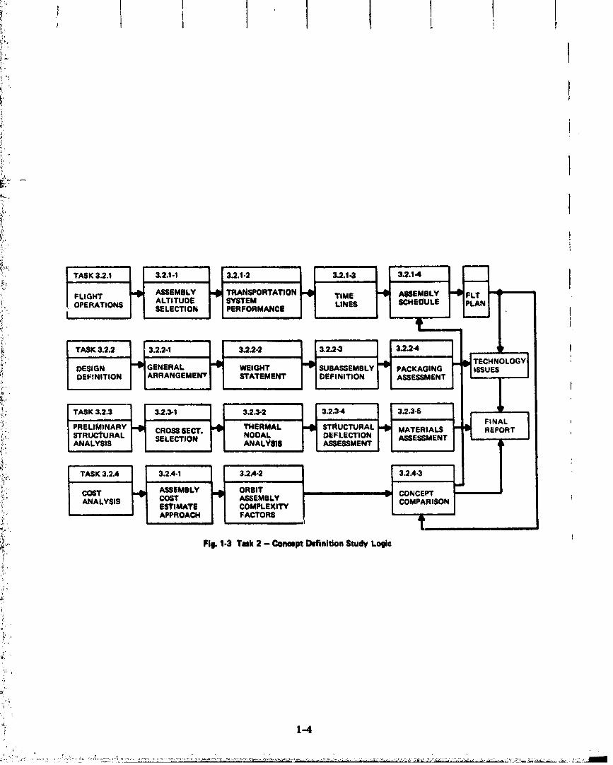
1-3 Task 2 - Concept Definition Study Logic ............. ,.., 1-4 iIj
2-1 Control System AequirementS. .................. . .._.. 2-2
2-2 Control System Requirements ........ . ............... 2-2
=_ 2-3 Mechantc_tl System Options Recommended for Task 2 StUdy ..... 2-4
2-4 Antenna Geometry Tradeoff ... ...................... 2-6 ]
_:_: 2-5 Power Level Limitations Due to Material Thermal Properties .. 2-6 '
2-6 Temperature Difference BetWeen Structural Member LocatedDifferent Dis(_mees Above the A_A_nna Surface ............. 2-7 ,!
2 7 Task 2 BaSeline Design Guidelines 2 8e,m 4, e 4b o • • • • • • • • • • • • • • • •
• 2-..8 LeVel 1 Assembly Functional Flow 2 10 il.... ,. • • • • • 4D • • o • o q_ • • • • • • • • •
l2-9 Baseline SSPS 2 10• 0 4J • • • • • q, • • • • • • • t, • o • e, o • gb o • • • • • • • • • •
Mission Options }-;: 2-10 .... ,......... ........... . ........ 2-11,j
2-11 SSPS Orbital Decay Due to Aerodynamic Drag .............. 2-12
" 2-12 Antenna Struotural Arrangemeat 2-13 i_/
,, • • 4b 4b e, o o • • • ¢ • $ $ • • • • • • • •
2-13 Rotary Joint 2-15_.._ 0 e e o 4_ • • $ • • • 9 • 0 • O • t e • • _ • e • o O • • e 4_ v • • • o !
_ 2-14 S*_ructure/Waveguide Interf_e.. ...................... 2-16
2 15 Structural Joints 2 17 ;
: 2-16 Comparison of Maximum Termperature and Thermal Gradients.. 2-18 •
_ 2-17 Temperature Difference Between Beam Cap Members Located _}
,f• Different Distances Above Antenna Surface ............... 2-20 I
: 2-18 Waste Heat Flux at Center Of Antenna as Function of IScale Factor .......... ...... .................... 2-20 ,,
2-19 Cross-Seotion Design .... .. .............. . ......... 2-22 ' :
: 2-20 Range of Thermally _duced Deflections and LOcal Slope ...... 2-23 .;• :i
: 2-21 Structural Detail Parts Assembly Options .... ....... . .... 2-24 .
2 22 Detail Part AsSembly S_nmary 2 24 '
2 23 MPTS Antenna Structural Assembly 2 26 '_i " - :_ 2-24 Assembly Operations Analysis Approach 2 27
-_ii 2 25 Summary of Assembly Options 2 28• • • o *o • • _ 6 • 6 _ o_ • • • • • • • t 4 t • _ _'i
!i _ 2-26 Transportation and Assembly Elements ................. 2-29 _
.,. xii_i_
00000001-TSB01
j 'i
t" _. ]
i'' Ii :: ILLUSTRATIONS (continued)
-,- Flgur_ PageL._:: ....
_:..... ,;• 2-2V Transportation and Assembly System Fleet and Support-,i_ Equipment Characteristics and Cost Su_ .. ......... .. 2-30_: .....: 2-28 Traffic and Fleet Size Summary 2-32
_ 2-29 Assembly Cost Comparison ......................... 2-32me-
_, : tural CompariI i 2-30 Antenna Struc Cost son .. ................. 2-34--,: i _ 2-31 Recommendations for Task 3 Study .................... 2-34ILK/'
ffi I SSPS Baseline Configuration 3 1 2=__"' 3.1- • ................ • ........ -
.............................1 3. I- Mission ons ........................... ...... 3.1-4
_._!_;. 3.1-4 Shuttle Payload Capability -Dtte East Launch from KSC ....... 3.1-6
_i _ w 3.1-5 Shuttle Payload Capability - Due East Launch from KSC... .... 3.1-6
..... CxTogeni Deploy_i 3.1-6 e Tug Performance ......... 3 -7
m 3.1-7 Cryogenic Tug Configuration ................... . ..... 3.1-7
_¢__.. t, Propttlsi (100 lroula_)_ ( 3.1-8 IO_ OnAltitude vs Time From n mlc -Ef " No Plane Change ....... . ........................... 3. 1-9
i i 3.1-9 SSPS Orbit ................................. 3.1-11
i Decay-" 3.1-10 SSPS Orbit Decay C_terlstles ..................... 3.1-12
3.1-11 SSPS Orbit Decay Charactm'isties .......... . .... . ..... 3.1-12
i i Reqni mpensato Air Drag
t 3.1-12 Force red to Co for ........ . ..... 3.1-13
3.1-13 Ion Propulsion System Sizing Factors . ....... . .......... 3.1-15
_l_.. s 3.1-14 Optimum Specific _ptt_e ..... , ...................... 3.1-17
: 3 1 15 Maximized Payload Ratio 3 1 1'/-_' • " • @ @ o • o @ ,iD 4) q) e. 4 o • o • _, • • • 6 O. e e • O • •
' I A_ange_., _ 3.2-1 MPTS Antenna Struo_ merit .................. 3.2-3-_ 8tru tural Arrange ent•_,, 3.2-2 MPTS Antenna o m ................... 3.2-4
-:_ li 3 2 3 Gear System 3 2 5T?', • " * • * • • o • • o 4 o • • • • • • o e * • o * * • # • • • • e e # _v @ •
• "_:.. 3. 2-4 Typical Motor Options ........... . ....... , ...... ... 3.2-_/
i_'_ _ 3 2-5 Rotary DriVe Concept 3 2 8- ( • t • (, • • • • v @ • • 4) _ • • @ • • • • • • • • _ 4, • • • @ • "
J i3 2 6 Antenna Rotary Joint 3 2 9
_" • _i' 3, 2-? Power Transfer Device Selection Considerations . .... , ..... 3.2-11• 3 2-8 Brush/Slip Ring Concept 3 2 11
_ 3.2-{) Operating Temperatures (°C) of Candidate Brushes..,... .... 3.2-12
°_ i i 3.2-10 Voltag_ Drop for Candidate Brushes (For Single Contacts) 3.2-12
' 3.2-II Friction and Wear Properties of Oils (Four-Ball Test)... ..... 3.2-14
!::/ " xiii "
,. • ,, t;, ' ,:
00000001-TSB02

I
IILLUSTRATIONS (aontinued)
3.2-12 Friction and Wear Properties of Greases (Four-Ball Test)..... 3.2-14r
3. 2-13 _truetural Members.., .... .... ........... ......... 3.2-16t
3.2-14 Waveguide/Strueture Interface, Single Point Support ..... .... 3.2-17 _13.2-15 Waveguide/_c_e Interf_e, Three Point Support ..... .... 3.2-17
3.2-16 Antenna Structure Weight Summary (Graphite/Ep@Xy) iTriangular Hat ...... . ........ . ....... . ............. 3, 2-19 I
3.2-17 Antenna Weight Comparison (Aluminum vs Composites |Tubulse Section) .. .... . ............... . .......... 3.2-20
;!
3.2-18 Antenna Weight Comparison (Aluminum vs Composites
Triangular Hat SeCtion) ............................ 3.2-20 Ij3.2-19 Structure Weight vs Antenna Dimension .................. 3.2-22
3.2-20 SSPS MiCrowave Antenna Mass Properties ................ 3.2-23!
3 2-21 Antenna Structure Weight 3 2-24 I3.2-22 Primary Structure (Uppet- Caps)... .................... 3.2-26
3 2-23 Primary Structure (PostS) 3 2-27 I$ • @ • • • • • • e, • • . . • . v • @ • • • • • • . • . •
I
3 2-24 Primary Structure (Lower Caps) 3 2-28• @ . . . • . . • • . . ..4 • • • • • • • • •
3.2-25 Primary StructureIntegrationItems ................... 3.2-28
3.2-26 SecondaryStructure..................... :......... 3.2-29o
3 2-27 Secondary Structure Integration Items 3 2-29• • • • • • • • • • • • • • • • • • • • •
.I3.2-28 Elevation Joint Support ............................. 3.2-30
3.2-29 Elevation Yoke . ............................. .... 3.2-31
3 2-30 Azimuth Yoke Support 3 2-32• 4 • • $ . • • • ." • • • • * • • • • • • • • • • • • • • • •
3 2-31 AzimuthYoke 3 2-33• • • . • . • • • @ • • • * • • • • • • • • • • @ • • • @ • • * @ • • •
32-32 _lechani_msandSupport' 3 2-34• • • • • • • • • • • • • • • • 4 • $ $ • • • • • • • • • •
3.2-33 Rotary Joint Drive (Mechanical vs Linear Induction Motor) ,.... 3.2-34
• Torque Environment 3 3 23 3-1 System -• • • • . • • • • • • • • • • • 41 4J • • • • • • • • •
3.3-2 Microwave Antenna Mechanical Pointing System ........... . 3.3-3
3.3-3 SSPS Bendtflg Mode Data.. ..... . ........... . .... .... 3.3-5
3, 3-4 Sei_vomechanism Environment . ....................... 3.3-6
3 3 5 Slip Ring Friction Tot, 3 3 8• " J • • 6 • $ 4O . O • • • $ • • • • • . • 4 • • • • , • • " I3.3-6 Control System Requirements .... . .... . ....... . ....... 3.3-8
3.3-7 Preli/_flnary DesiKn Control System ....... ... .......... 3.3-10
3.3-8 Antenna SuppOrt Structure...... ............. . ....... 3.3-11
3.3-9 Gaussian Radiative Heat Flux From Antenna Surface ......... 3.3-13
xiv
00000001-TSB03

• ILLU_3tATIONS (eontimled)
3.3-10 Maximum Structural Temperature vs Transmitted Power ..... . 3.3-14
_ Sy_: 3, 3-11 Microwave Power Transmission stem Struetune , ......... 3, 3-16
.... 3 3-12 Beam Cap Element Geometries 3 3-17• • • • • • • • • • • • • • b • • • • • • • • • •
3.3-13 Typical Thermal Model for Structural Member...... ...... . 3.3-I_
_ 3, 3-14 Maximum Tube Temperature as a Function of Antenna SurfaceTemperature with Tube Inner Wall Emissivity as a Parameter ,. 3, 3-19
; 3, 3-18 Ma_mum Temperature Difference Across a Tubular Structural: Member as a Function of Antenna Surface Temperature With
Tube Inner Wall Emissivity as a Parameter ... ........ 3.3-21
i 3. $-16 Thermally Induced Stresses and Minimum Wall-to-RadiuSRatios for Tubes ....... ..... ..................... 3.3-21
3. 3-17 Comparison of Temperature l_roflles in High-Hat Section for
I = 0 9 and 0 1 3 3-23: inside ............................ " " " " "
3.3-18 Temperature Distribution W_thin.Triangular Shapedi Structttral Member 3 3 9.4i J O 4) • • • • _" • • q) • • qbe oe • coos • e q) e o • 05 O o • an
3.3-19 MaxLmum TemperahJre and Tempet_ature Difference inTriangular Member ............................... 3.3-26
_ i' i 3.3-20 Comparison of Maximum Temperature for Different BeamCap Element Geometries ........ ... • ...... ......... 3.3-28
3.3-21 Comparison of Maximum Temperature Difference forVarious Geometries 3 3-28: • 4 • • e • • • • • e • • • • • o • • • • • • • • • • • • • • •
3.3-22 Temperature Distribution in a Beam Cap Member Located1 Meter Above Antenna Surface ........ . ............... 3.3-29
3, 3-23 Temperature Distribution in a Beam Cap Member Located1 Meter Above Antenna Surfaeee ....................... 3.3-30
i ! 3, 3-24 Temperature Difference Between Beam Cap Members Located• Diff_t-ent Distan Above Antenna Surface 3ces ................ 3, -33
r
3, 3-25 Temperature Difference Between Beam Cap Members Located_ ; Different Distances Above Antenna Surface ................ 3.3-33
3 3-26 Column Temperatures 3 3-36• • • $ • • Q e • _ • e • • • • • Q • • • • • • • • • o • • •
i 3.3-27 _'aste Heat Flux at Center of Antenna as Function of.... Scale Factor 3 3 36
_ 3.3-28 Waste H_:_t Profile for Various Values of Scale Factor ........ 3.3-37li
I 3.3-29 Maximum Tempcratures as a Function of Scale Factor.... .... 3.3-39
3.3-30 Thermal Performance of MI_TS With and Withotit Heat Pipes ,.. 3.3-40
_ 3.3-31 Alternate Structural Arrangements .............. . .... .. 3.3-42
3. 3-32 Weight Relationship for Different L/D (Length Tube/Diameters) . 3.3-43
_ XV
0000000 -TSB04
1 i i! "
i '" Ii -
! I:. ILLUSTRATIONS (continued) ,
i i_: Figure Page
,- 3.3-33 Strength of CireuI_ Tubes for Various Axial Comp__eslonLodds as Function of Wall Thickness and Diameter .......... 3.3-45
_ 3. 3-34 Strength of Circular Tubes for Various Axial Compressioni Loads as Function of Wall Thickness .... ...... . ........ 3.3-45 .
:- 3.3-35 Tri-Beaz_ Cap Cross-Sections (Graphite/Epoxy) .... . ....... 3.3-46 i
Design Loads 3 3 47 I• 3 3-36 .... ... ....... o ..... • ............... -
i, 3.3-37 Deflections - l_'ellmlnnry Ass6ssment ................... 3.3-47
'_, 3.3-38 Typical Antenna Deflections Duo to Thermal Gradients..... ... 3.3-49 ;ii / 3.3-39 Typical Slopes of Structure Due to Thermal Gradients .......... 3.3-49
!i 3.3-40 'rEgg Crate" _condar-. StructUre Deflection Slopes 1,_ (108 Meter Section) 3 3-50 I_.,; • @ @ • • • @ • • • • • • • • • @4*0 • O o @ @ • • e @ • • @
. .,_,
3.3-41 Estimated Graphite CompOsite Properties ................. 3.3-52'_,L. I
i_!: 3.3--42 Thermal Stabil/ty of Various Adhesives at 533°K ............ 3, 3-52 J:i_" 3.3-43 Cost and ProcessLug Characteristics of Various Types
[ !_ of Adhesives 3 3-54T,* @ o . • • . e . . • . ° • . . • . . • • • • o @ o _. • o • • o o • _4. • •
..... 3.3-44 Comparison of MaterLal Properties ................... 3.3-54i //*'
!:_" mbly optl!i, 3.4-1 Structure Detail PaiLs Ass• ons ................. 3, 4-2
_ 3.4-2 Characteristics of Articulated Lattice Beam ............... 3, 4-3,
r:_i 3. 4-3 Tri-Beam Layout Using Tabular and Solid Element Caps ...... 3.4-4
'_ 3.4-4 Allowable Column Load vs Diameter .................... 3.4-6i
_ 3 4-5 Shuttle Compatibility Packaging 3 4-6
_i 3.4-6 Infltght Detail Parts Assembly.... .................... 3.4-?b-_
_" 3.4-? Support Equipment ReqUirements f_ r Inflight Assembly of_._,
--_!, Tri-Beams .. ......... ,. .... . ................... 3 4-8.... 3 4 8 Auto In-Orbit Manufacture (Aluminum) 3 4 8; -', • " • • • . • • • . • • • • • • t • • • . --.'
_L 3"4--9 Level 2 Functional Flow: Assemble MPTS ... ............. 3B4--10
"_r 3.4-10 Level a .._'_m_lonal Flow: Assemble Rotary Joints (3 Sheets) .... 3.4-11i'
_-_*_* 3.4-11 Level 3 FunctiOnal Flow: Assemble Rotary Joint to Antenna:",,. Interface Structure , .............................. 3.4-14
_ 3. 4-12 Level 3 Functional Flow: Assemble Prlmary/Secondary.... Structure 3 4-14
i :_ 3.4-i3 Level 4 Functional Flow: AssembJe Lower Cap; Prima/'yi, ' Structure .... ......... . ........................ 3.4-16
_ bly/_'L 3.4-14 Assem Tlmeline and Consumables Requirement .......... 3.4-17
°' i_ Manipulator Perle mpl it)'_-_: 3.4- rmance Co ex Factor . . ............ 3.4-19
:-:_" xvi
___'_,_,i, i,i. .i_/__............................................................. 7_....._..............._/_....................................................
00000004-TSB05

i i I: 1/ l l
i ILLUSTRATIONS (continued)
t Figure Page3.4-16 Manipula_r Module Assembly Operations Summary... ....... 3.4-19
3.4-17 Level 4 Functional Flow: Assemble Lower Cap; PrimaryStructure ...................................... 3.4-21
3. 4-18 Detailed Task Sequence and Performance Times for Two-ManSkylab 3 Twin-Pole Sunshade EVA Deployment ............. 3.4-22
3 4-19 EVA Assembly Operations Summary 3 4-22• • • • O • • • • • • • • • • • • • • • • •
3 4-20 Free-Flying Teleoperator Concept 3 4-24$ • • • • e • • • • • • • • • • • • 4 • • • •
t 3.4-21 Low Altitude Assembly Support Equipment Weight andCost Estimates ......................... . ........ 3.4-24
3. 4-22 High Altitude Assembly, Typical Six-Man Support Space Station.. 3.4-27
3.4-23 High Altitude Assembly, Typical 12-Man Support Space Station .. 3.4-27
3 4-24 Manlaod TranSport Module 3 4-28
3.5-1 Task 1 -- l_reliminary MPTS Design Data Sheet, RectangularGrid ........ . ................................. 3• 5-3
3.5-2 Task 1 - Preliminary MPTS Design Data Sheet, Radial Spoke ... 3.5--4
3.5-3 Transportation and Assembly Cost Comparison Cases ........ 3.5-6
3.5-4 SSPS Weights ................................... 3.5-6
3.5-5 Traffic Model Assessment, Flight Plan I ...... .. ........ 3.5-8
3.5-6 Traffic Model Assessment, Flight Plan 3 ................ 3.5-9
3 5-V Level 1 Functional Flow: Assembly 3 5-9
3.5-8 Traffic Model and Flight Size Assessment, Flight Plan 2 ...... 3.5-11
3.5-9 Traffic Analysis Summary ........................ , . . 3.5-1.3
3.4-10 Transportation and Assembly Cost, Flight Plan 1 ........... 3.5-13
3.5-11 Transportation and Assembly Cost, Flight Plan 9 ........... 3.5-14
3.5-12 Transportat/on and Assembly Cost, Flight Plan 3 ........... 3.5-15
! 3.5-13 Transportation and Assembly System Fleet and SupportEquipment CharacterLstics and Cost Summary .......... ... 3.5-16
3, 5-14 Waveguide Weight and Packaging Density .............. ... 3.5-18
3.5-15 Traffic Requiremcnts as a Function of Waveguide Weight andPackaging Density . .......... . ................. . . . 3.5-20
3.5-16 Transportation and Assembly Cost Sensiti_'lty to WaveguidePackaging Density 3 5 20• • • • 6 _ • • • o • • o • • • • • • • • 4 • • • e • • • • 4 • • "
3.5-17 Materials and Processing Costs ....................... 3.5-22
3. 5-18 Mi_TS Strtlctural Cost Estimate Assumptions ...... ........ 3.5-24
3 5-19 MI_S Structural Concept Comparison 3 5-24• • t 6 • • • • • • • • • • • • • • • e
:. xvii
00000001-TSB06

L!ST OF N_ON-STANDARD TERMS
AFCRL %Jr Force Cambridge Research Laboratory
ATC Air Traffic Control
! _ ATS Applications Technology Satellite
CFA Crossed Field Amplifier
CPU Central Processor Unit
GaAs GalLium Ar menide
: HLLV Heavy Lift Launch Vehicle
" Met Meteorological
MPTS Microwave Power Transmission System
- - MW Microwave
N.F. noise factor
PPM periodic permanent magnet
: ROM Rough Order of Magnitude
: SCR Silicon Cont_olled Rectifier
SEPS Solar Electric Propulsion StageLq.
_ Sm-Co(SMCO) Samarium Cobalt
SPS Satellite Power System
SSPS Satellite Solar Power Station
TDRS Tracking and Data Relay Satellite
:.- TEC Total Electron Content
00000001-TSB07

E _
_o I Section ii
_ INTRODUCTIONi .' i
i"" i
_ - The objective of the Grumman study effort is to provide refined inputs for mechanical
i .,:.. systems, structure and thermal control for Raytheon's overall h,ve_ttgatton of the Micro-
:,i_." wave Power Transmission System (MPTS), This system will be used to transmit, receiVe
/',' and control large amounts of power from space. Grummants efforts identified structural
r_;;I design options, the drtw_r parameters for both weight and cost, and established require-I i:, ' merits for the structural and flight operations systema.
_;i' An orbiting electric power station has several major elements: the power source or
i;_:_ converter, the electrical power distribution system and the microwave generator/
i _.. transmitting antenna. An antenna can be hypothesized that would be independent of the
|;i! power source except for the mechanical control system interface. The purpose of Task 1,m',,-
../'_... Prel/mlnary Design, was to evaluate this mechanical interface. To achieve the depth|;:.,_i,, needed to gain an understanding of accuracy and stability, a power source and spacecraft
_.._.; had to be selected. Because more data on physical characteristics were available on the
i Satellite Solar Power Station (SSPS), this power source/spacecraft wa_ used in the pre-
ltmiaary assessment.
Selection of the antenna structure required evaluation of 1) basic antenna geometry,
_.,._. 2) the impact Of MW conversion thermal waste on structural material selection and feasible
'_i*_-"- structural flatness, and 3} the mode of transportation and assembly. A broad matrix of_!i antenna geometries, structural m_terials and transportation modes have been evaluated.
i_! Figure 1-1 summarizes this matrix of design options considered during the Task 1
-_'_' Prellmlnary Design Phase.
_i I The three materials, aluminum, graphite/epoxy and Kevlar polyimide, were selected
! on the basis that they represent a broad range of strength, weight, cost and thez real•_i,' characteristics. Aluminum represents a low cost, high .'eight option that wo_d thermally
_, limit the power level selected for the system. Graphite/epo._, represents a msterlal _th
_i_ excellent thermal expansion characteristics, high strength and low weight. Kevlar polyimlde_! would be low weight at modest cost with a resin that could withstand a high temperature
environment.
/
00000001-TSB08

i I i i
b
The fOur transportation modes selected for Task 1 represent thOnear term Space
Transportation System capabilities. A Transtage was seleeted, both in an expendable and i
reusable version, _s ]_eing most representative o_ the performance of the Interim Upper
Stage (IUS). A Full Capability Cryo Tug was used to represent the STEJperformance
capability in the 1984 time frame. The fourth option, Shuttle/Low Altitude Assen_1,1y, was
int_'oduced into the matrix to determine the impact of assembly altitude on overall system
selection. I
Antenna geometry options include a rectangular grid and a radial spoke sLructural
: layout. Both these structural arrangements are acceptable in terms of available layouts I
for the power distribution system. Antenna diameters between 0. T to 1.4 km were in-
cluded in the desigTl matrix after gaytheon's preliminary results indicated theft optimum 1
system performance would fall within these bounds.
The Task I study logic for control analysis and thermal structural analysis and cost
parametrics are outlined in Fig. 1-2. The output of the three principal tasks are recom-
mendations for a limited number of control system, structural and flight operations options
for detailed concept definition in Task 2.
The limited number of design optiOus recommended in Task 1 were ev_uated in
greater detail in Task 2, Concept Definition, using the study logic shown in l_ig. 1-3. In-
formation generated during Concept Definition will permit Raytheon to carry out technical
and economic evaluation leading to selection of a sinsle configuration to be the basis f_r
ground demonstration test.
• Flight plans were generated for assembly of the SSPS at a low altitude which is within
the performance range of the Shuttle with integral OMS, and at an altitude above the Van
Allen belts. Traffic rates and fleet size requirements were established for a one and two
year assembly period. Packaging densities of SSPS components were considered in
establishing the method of assembly using manipulative devices, maneuvering units, and
EVA. Assumptions concerning degree of human skills are outlined as well as the potential
capability of support ancillary equipment. Sensitivity analysis of vartot.s levels of ground
prefabrication compared to corresponding levels of orbital assembly was performed todetermine the most cost effective approach to structural assembly.
1-2
ooooooolLTSE og-.....

+ ,
, L ..,
MATERIAL8 DIAMETER (Kin|
, _ TRANSPORTATION GRAPHITE/ KEV.. STRUCTURAL 0.? 1+0 1.4MODE ALUMINUM EPOXY POLYiMIDE ARRANGEMENT,, _,.
,.. I 8HUT'[LEI I _ '"
• . L ..... HEGTA_IGULAR
' lvl_l' J ....: . HX SHUTTLE/ GRID
i ; '+ CRYOTUB
NN'+i ' LOW ORBIT
RADIAL SPOKEi i" I. ,....
? ' qi " STUDY CONCEPTS *'VALUATED
:_ Fill. 1-1 Preliminary Design Option Matrix
/'
< .': I CONTROL ENVIRON. ,'mOINT_NG PRELIMINARY" ,ANALYSIS MENT Ai:r°.,RACY I- _-] DESIGN
/ LL_
A ALTERNATE
' " _ iSmUCmRALI -IoEsi°N:T -IEVALU"TION
,. L. AL S S j ARRANGEMENT ] • _ , ....
): : --| DEFLECTION
r _ f 1 _ P"---'--'_ -- "......
' ---_ i t.-mE I Iw_IGNtI I-_---
L. J I J I I ..... J I ; . CONC_PTSFO.!"_ ' ' I '------" I '----- T,SX_CONCt_T
" ,i I _m,INIt,O_
+; i t , ,j ,.CONT.O_+:. _mml.,_.,'PAGm]8 TRA. ] F _....,.,c.,.,.,+ I,.,,..1 PORTATIO_ _ THANSPOnl" I FLT OPS
+ + oPm;)o.,Qu_ _o,,,oNsI t '
_'."- } . FIg. i-2 Talk 1 Preiiminl_y Design Study Logic, Mli:hlnl_l Syslenneand Flight Olml_ltlom
,i
._, ._ "... 1-3 ;. •...... ., + ....... + L + _ _++":.: + ,++ . ' +_ ,_ + ::
;:- +
oooooool-TsBlo
iI
t,
,i
'it !
- m m_oNFLIGHT TIME ASSEMBLY_ ALTITUDE SYSTEM LINES SCHEDULE
OPERATIONS SELECTION PERFORMANCE I'¢ i
TASK3.2.2 3.2.2-1 3.2.2-2 3.2.2-3 3.2.24
I__ TECHNOLOGY i_! DESIGN1--'1GENERAL!"1 WaIOHT SUBASSEMSLYPACKAG,N_ISSUES_ DEF,NITIONI iARRAN"EMEmlI U,_TEMEm DEF,N,TION,.SESSMENT I
._: TASK3.2.3 3.2,3-1 3.2.3-2 3.2.3-4 3.2.3-5
_i, PRELIMINARY THERMAL. STRUCTURAL FINAL_;'{t; STRUCTURAL CROSSI_'. ASSESSMENTMATERIALSREPORTSELECTION NODAL DEFLECTION;_; ANALYSIS ANAL._818 ASSESSMENT
_ TASK3.2.4 3.2.4-1 3.2.4-2 3.2.4-3£ p,
", COST ASSEMBLY ORBIT CONCEPTii_' ANALYSIS COST ASSEMBLY COMPARISON IESTIMATE COMPLEXITY
:_ APPROACH FACTORE t_,,,-' i t t tt#" t
_i_, Fill. 1-3 Tank2 - ConoeptDefinition Study Logic
,{,
i'
_'_i 1--4
00000001-TSB11
Antoana general arrungeme_s, interface dz;awlnp and weight statements are in-.
•*_ _ J In this document for use durtnK the remainder of the MPTS studies. Detail thermal
and struchural evaluations have bcon performed to determine the limitations the structure
tmpose on electronic layout and phane front control concepts. Mechanical ol_lons to a
' fully electronic control systemhave bean identified and are shown to desens!tlze the
tolerance on structural assembly accuracy and impact of thermal deflections over a wide
i: range of sun-to-spacecraft geometrieS.
¢b.
• !
1-5
" O0000001-TSB12

SUMMARY
2.1 TASK 1 - PRELIMINARY DESIGN
2.1.1 Control Analysis
Qualitative estimates of requirements and desf.,_ options for sanctum mechanical
steering indicates that pointing accuracy of better t,mn i arc-rain can Im achieved. The
mechanical system, ff integrated with the electronics microwave beam phase front control,
could improve overall system efficiency with minimal impact on system weight and cost.
Figure 2-1 summarizes the design environment for mechanic_l steering. The antenna
- gravity gradient torques are a major externally induced disturbance. Other factors, such
as torque caused by solar oressure, or electromagnetic forces, are small. The most! .
significant torque is the friction torque at the rotary Joint. This torque varies as a function
of system power level and power transfer techniclue. Base motions of the SSPS are caused! I
.:" by normal limit cycle operations and by solar array bending dynamics.
i- Figure 2-2 is a composite of SyStem accuracy and torque requirements as a function_ of mechazdcal control system frequency. An azimuth accuracy of 40 arc-sec can be
achieved with a control system frequency of 1 rad/sec. This control frequency would re-
'/" quire I, 020, 000 N- m (750, 000 ft-lb) peak control torque (meaSured on load side of the
gear train). This control system frequency is well above the first structural frequency of
: the SSPS and antenna. Peak horsepower requirements at 1 rad/sec is 0.18 and 1.75 hp
in azimuth (East-West rotation) and eleVation (North-South rot._tion), respectively.
A review of top level methods for implementing mechanical steering favors a motor-
-. , gearing mechanical system as opposed to a reaction Jet system. I3ecause control system
• frequencies are well above the first structural bending frequencies, no instabilities are
" foreseen. A mechanical system could be configured against wear by providing sufficient
i: redundancy. The reaction Jet approach, in which Jets are mounted to the antenna, would be
advantageous because the antenna structure could be more readily isolated from spacecraft
:, dynamics than a mechanical system using gear trains. The shortcomings of the jet system,
however, include:
>'_',_ "_:' 2-I
O000000]-TSB] 3

i I 1 I '; 1 t !
J . ,e
• ANTENNA TOROUE6 AZIMUTH ELEVATION
- GRAVITY GRADIENT -* N,m (FT.LB) 1800 (1330) 2:_0 (1082)- FRICTION DUE TO ROLLERS " N.m (FT-LB) i30O ((3108) 1150 (792l- FRICTION DUE TO SLIP RINGS --N.m (FT-LB| 1,020,008 (750,000) N/A
• , |
• BASEMOTION
- SSPSLIMIT CYCLE '1 '1u POSITION ~ DEG 9.3.94, ±2 1n RA1 _ " I:IEGI_EC 9x10"l 2x10"S
; u ACA_ELERATIOI_I_ DEG/SEC2
- ANTISYMMETRIC BENDING MOOE
o POSITION " RAD .0627 .0827r, RATE ~ RAD/SEC 4.80x10 "6 4JI6x10r-6-_ ACCELERATION " RADISEC2 8.Tlix 10"8 8'08x104l
.: . . 4
_:_ Fli_ 2-1 Control SystemRequirements
i 1ARC MIN LIMIT
J _ _ AZIMUTH
POINTING 1
,, _ ACCURACY "- RAD ATI____
1X10"4 ELEV
_i, | I I I i t 1 I t •: '.. 0.1 0.2 0.3 0.4 6.6 0JI 1.0 2.0 3.0 4.0 5.6i ,L
i "; CONTROL SYSTEM FRO "- RAD/SEC
s: • CONTROL PEAK TOROUEifi - AZ _ CONSTANT WITH CONT'L FREO = 1,020,000 N.m
•=_ - EL _ CONSTANi"WITH CONT'L FRECI= 2780 N,_
i " ' • PEAK OPERATING HP- AZ -_CONST.ANTWITH COHT'L FREQ : .18 HP
Ld :_ - EL _-CONSTANT WITH CONT°L FREO : 1.75 HP
L' ,,
i =.,:'" Ft_ 2-2 ControlSystemRequirements
_ _ " 2-2
O000000]-TSB]4

* L I I I I*! I ]
I
O RequtremenLfor propellant resupp!y
I • Co_amination of wavegulde functions.
Figure 2-$ lists mechanical system options conaldered-in Task 1 alzd ldentifle_ con-
figurations recommended for Task 2 Concept DefinitiOn. Also included in Fig. 2-_ ate
"° .recommended technology studies which could provide a more optimum design, l_ower
__ clutches or rotary transformers are power transfer advanced space techniques that could
:_ _. lead to a reduction in interface friction, and increased life. Spur gears are recommended :
/ for the gear train, but a direct drive motor system would eliminate gears and may be easier
' : _. tO implement, provided sufficient accuracy could he achieved. Individual rollers are recom-
* mended as baseline because of ease of implementation. Ball hearings offer an advantage in
terms of lower friction torques and should be considered as an alternate. DC brush torque
}_ motors are recommended; however, linear induction motors may show advantages in terms
_ of life and inherent capability to isolate the spacecraft dynamics from the antenna dynamics.
2.1.2 Thermal/_;ruc_u'_/_l.ystS
-!:' * A thermal/structural analysis has been carried out to determine deformations to be.,'" • o
:.:" used in establishment of requirements for phase front control, and to determine cost and
'- : weight factors for overall system selection.
=i. .. " 2.1.2.1 Preliminary Design Options
-_' _ , Figure 2-4 iS a weight comparison of principal structural design layouts. The rec- d
,, tal_,_lar grid approach was fomxl W be lighter than the radial spoke arrangement. Two
:_ -, compression member designs were considered; a singular tube, 100 m long, and a
!/, -,- triangular girder with thin walled circular tubes at the apex with cress tubes and dt_onal
-_! wire bracing. The triangular girder approach was found to be significantly lighter than the
_:: singular tube.
..,:_..,., Assessment of structural deflections included analysis of load, thermal and assembly_: tolerance induced deformations. The assembly tolerances were found to be the largest _
._.ii:.. source of deformation ._.tth a worst case tip deflection of 0. 17 degree. Deflections due to
: thermal bending can be kept below 1 arc-rain ff thermal gradients between the upper and
_ lower primary structural caps can be controlled to less than 4°K. Deflections due to loads
_ .... _vere found to be insignificant.
=_i_'" '" i
_v
_:, 2-3
_o_,:,,_...,.._.:_:...:_,.=_._.._.......................... 211..-__iiii.L.=i...__2 .....=-........"'i.::i_..__: -:::.:.......- - ...:._.a
00000001-TSC01

;L,. i
• ": + ,|I
' ! "! I
I-' I .o. ,i
-'! +. ]
|-_,' ' ' }
* BAaLmE I_ECHNOLOGY . •._:_ AZ EL _IIJDIE8 RECOMMENDED L
-: ( •._, + 41POWERTRA!_FEIt .i Y." Jl ;.
+;, - _lPmGAND.RUm _/ 1/ :t_ ';,_ -- FLEX HARNESS + -" J, .... '._. POWERCLUTCH " '_, - ROTARY TRANtFORMER , ,
4_
._.-'_.... ROLLING CONTACT .I. _i_,;. • GEARS ' i
,_+., - SPURGEARS :-- WORM GEARS
| -t - HARMONIC DRIVE GEARS._: - HELICAL GEARS
F_I- - CHAINDRIVE -- -_
_:'" • BEARINGS i:!!: _i - +
_;;-'_ -- BALL,BEARINGS- -_ ¥
-j.+++° - ROLLER BEARINGS q .I-__ ,, - INDIVIDUAL ROLLERS
ili:_ 4 MOTORSI
+ii_! - DC BRUSHTYPE TOROUS +__/_+;:. - oc.RU_LE.'ro.oUE _ -i/ I/'_;+""'., - INDUCTION_* - AC SYNCHRONOUS ++
_!! - Ac'roRouEt_:r" Fill' 24 _tod 8yndm OptionsRlootnmendedfdr Task 2 Study ,,
_r k
00000001-TSC02

i I 1 I i Iii1
_, _ 2.1.2.2 Thermal_'a/uatlon
_: ! I Prelimimiry thermal analysis Of-the MPT8 centered about dtudies that would indicate:t i"
i _ the sensitivity of temperattl_ level and thermal g_adient on antenna size, power level,
iil microwave eonverter.mle_!.on, and distribution.
2.1.2.2. l Temperate Level .- Struchiral temperature levels, material am£antenna size
il combine to place lhnitations on the powec that can be transmitted by the antenna. Figure 2-6i. shows the limit power level for antenna diameters between 0.7 and 1.4 kin. Aluminum,
i _1 epoxy and polyimide are shown as represen_tive materials. Aluminum and graphite/epoxyi] lose their _rel_h characteristics at approximately 450°K. This limits system power
levels for 1 km diameter _ to 17 gw wiUt a 90_ efficient mierowitve converter _nd to
!_ 4 gw with a 70¢_efficient converter. Limit power levels can be significantly increasedwith the u._e of polyimide composite materials.
i!! 9..1.9.. 2.9. Thermal Gradient - FigUre 2-6 preSents the thermal gradients between primlystructural caps for distances of 40 and 90 meters. The trend indicates that to limit tip i
! _i_j deflections to less than 1 arc-rain, the average distance between caps should be somewhat • _iless than 40 meters. This w_d keep temperature gradients belo_ 4°C. The worst
i case thermal gradients occur when the antenna microwave surface shades the Structure-- from the sun. i
,: 2.1.3 I)esign Options and Groundmles for Task 9 Concept Definition
Task 1 resulted in recommendations that a freqUency of 2.45 GH_ be selected and•: ,
i _ fotlr conflsurations of alerted waveguide transmitting arrays be studied in Task 9.. These :!
• " " configurations involve combinations of amplitrons with aluminum Structure and array,
i i ampLttrenswith graphite composite Structure and array, end a klystron with the same two!-- materials.
I
_ Task I alSo showed that a 5 gw ground output power level would be a reasonable! i_" choice for ali Task 9. study vehicles. An antenna diameter of 1 km was selected based on
.... I the relative inse_iti_dty of this parameter to overall system cost and performance.
i!.,i_ i Figure 2-7 sUmmarizes the guidelines for Task 9. study.
r
i' I
t
.r
O000000q -TRC!.N2

!. SINGULAR TRIANGULAR ]!-_+ TUBE GIRDER i
_+ Fig.24 AntennaGeOmetryTrndloff
i D - 1.4KM D-1A D-I.0 I),1.4 D,I.0 D-O.?: El B
I_ (ALUMINUM) _ (EPOXY) (POLYIMIDEI2O
0"1.0 D_0.7 !
LIMIT TRANSMITTEDPOWER,,,GW lo
0,0.7-/
s I
0
7014
I CONVERSION O- DIAMETEREFF. I
_ FI_ 2.§ PeeWLeedUmildom Dueto MotedllTlmm_ PrOlmmi_
+
: + ..... J +-+"++- ._ ++ ,.. +..:.:.+:+.:+:+ :."+++-:+.+ _++:b:!:+,..-. :---++:++. ....... . ............................
.... .. :_.:,+m.++-+:+,v.+.m+,,+t.++,_.t._:-_..,-t_+++++;_;,Z.+_. _
00000001-TSC0_

:i -20TEMPERATURE OF MEMBER TEMPERATURE OF MEMBERLOCATED 50 METERS LOCATED t00 METERS/ .
_' ABOVE ANTENNA MINUS ABOVE ANTENNA MINUSTEMPERATURE OF MEMBER TEMPERATURE OF MEMBERAT 10METERS AT 10 METERS
!
• POWERTRANSMITTED - 10 GW
! • CONVERTER EFFICIENCY - 90%
_ _ FiQ.2-6 TemperatureDifferenceBetweenStructuralMember LocatedDifferent OistimcesabovetheAntennaS.rfxe
r,3, ,
,, ,, , J
................,:.o,'..:.:_...,._.._......, _. .....-_c'_.-_;"_:_/,.";_/_-:;•"_:.."'-".._:_.. •.......;.:.............. • . i_•
00000001-TS005

.i r i i
FUNDAMENTAL PARAMETERSL I |J ii
DESIGN POWER8OURCE SOLAR PHOTOVOLTAICFREQUENCY 2,4_ GHz
GROUND OUTPUT POWER(t0 § GWUSEFUL LIFE 30 YRTRANSMITTING ARRAY:
TYPE SLOT'rED ARRAYSTRUCTURE RECTANGULAR GRID - GIRDERMATERIAL (1) ALUMINUM
(2) GRAPNITE EPOXY
PHASEFRONT CONTROL (1) COMMAND(2) COMMAND PLU_ ADAPTIVE
DC-RF CONVERTER (I) AMPLITRON(2) KLY_'rRON
HEAT TRANSFER CONDUCTION-RADIATION(NO HEAT PIPE)
RECEIVI._IGANTENNA RECTENNA
TRANSPORTATION-ASSEMBLY (I) SHUTTLE OREITENCRYO TUG/SEPS- HIGH ALTITUDE ASSEMBLY ]
(2) SHUTTLE OREITER/SEF_,;-LOW )ALI"ITUDE ASSEMBLY J
, ,m .. . m : i i
PROVISIONAL PARAMETERS
TRANSMITTING ARRAY:DIAMETER 1 KM
ILLUMINATION EXP [-2_10(rio)2]RADIATED POWER 6.45 GW leSUBARRAY SIZE lSM X 18M T
AMPLITRON OUTPUT POWER 6KW
AMPLITRON EFFICIENCY 85_
KLYmON OUTPUT POWI_R 6KW
KLYSTRON EFFICIENCY 75%
PEAK GROUND POWERDENSITY 23 mwlcm2
RECTENNA SIZE 10km X 13 km iiii i i
Fiik 2-7 Tlak 2 Bweline Deign Guldellnet
t
2-8
00000001-TSC06

, I I I J I I
: . . 2.2 TASK 2 - CONCEPT DEFINITION!.
_i 2.2.1 Miseion Analysis
:_ The mission atudysis effort objective was to define flight scenarios for subsequent
14 assessment of transportation system performance requirements. Figure 2-8 is s top level
functional flow of the SSPS assembly sequence. Two flight plans for assembly and transport
to geosynchronous orbit were developed:
• • Low altitude assembly and transport to _eosy_hronous ustl_ solar electric
t propulsion (SEP)
i • Assembly Just above Van Allen belts and transpoz_ to geosynchronous using SEP.
_ A baseline SSPS, Fig. 2-9 was assumed for mission analysis and subsequent esti-
mates of traffic models and fleet sizes. Performance capabilities of the transportation
system are summarized in Fig. 2-10. Shuttle performance of 6fi, 000 Ib (29, 400 Kg) can.
be expected up to an altitude of 190 n mi. The Cryo Tug, used in the flight plan with
assembly at 7000 n mi, has a payload capability of 36, 800 Ib (16, 700 Kg) in a Tug recover-
able mode.
SEP size and pe_ormance data for the two flight modes are presented in Fig. 2-10.
A SEP system efficiency of 0.7 and a specific weight of 15 Ib/kw (6.8 Kg/kw) was assumed
in the stage sizing. The 0.7 efficiency is equaled or exceeded by today*s technology.
- Overall system specific weight is consistent with projected solar cell weights for the SSPS
.-.'. itself. Specific weight of the power conditioning and subsystems is based on a projected
": four fold improvement in technology (using todayts technology would result in an overall
system specific weight of 65 lb/kw = 29.5 Kg/kw).•,
A 190 n mi assembly site would require continuous orbit keeping propulsion to com-
: ponsate £t,r air drag. Figure 2-11 indicates that uncorrected air drag effects would result
: in assembly entry after one to 16 months depeuding upon configuration M/CdA. The spread
. in M/CdA (0.175 to 1.75) is indicative of the ssPS configuration with solar blankets
deployed and retracted. A 16-1b thrust (70 ne_on) SEP stage would be required for the
orbit keeping function, A propellant expenditure of 44 Klb (20, 000 Kg) is projected.
2.2.2 Antenna Struchwal Definition
The MPTS antenna is 1 km in diameter by 40 meters deep, Fig. 2-i2. The antenna
;. is assembled in two rectangular grid structural layers. The primary structure is built-up
in 108 x 108 x 35 meter bays using triangular girder compression members 18 meters long

t I ! 1
r iii
ASSEMIILE., STATIONKEEF/
ElI AlllTUO|
CONTROL IMOOULE
k 1 ," H,o'H*'H""0" 1_). CREW ASSEMBLE AIISF.MSLE ASSEMllLEI -ITO | 7 &
• ?:..
',) .
,' * SSPS: - SATELLITESOLARPOWERSTATION I:_, _ H MPI_: - MICROWAVEPOWERTRANSMISSIONSYSTEM
! "_ UPS: - SOLARELECTRONICPROPULSIONSYSTEM!!
, Fig.2-8 LevelI AssemblyFunctionalFlow I
;..,};._, COIIITiNUOUSSUPPORT
i--._,_ " 4----- 4.96Km 1r :;: 11
Ij_)- 11Y-;_0 ,,
,_ II WEIGHT-*: ii U lmi _., KgX106 LBX106_,_*. li SOLAR'ARRAY ' ' 0.8 21'.61
:_:_i:!;i " MW ANTENNA 1.66 3.65
_ i';'" 1 Km CONTROL CONSUMABLES_ 12_ (1 YR) 0.02 0.04• ,_
._--" TOTAL 11.48 25.3Q
_. CELL|LANK£TSA MIRRORS& SUPPORT
STRUCTURE
¢'
Fig. _-9 h_line SSP$
" 2-I0
00000001-TS008

]
i
MiniON PLANS
, 1 -- LOW EARTH ORBIT AMY
" SH__E _,,___ •TRANSPORTATIONpERFORMANCEsHuTTLESYSTEM
- MAX PAYLOAD = 65 KLB (29.4 x 10³ Kg)- MAX ALT" 1_ N M
__ii - INCLINATION = 28.5°
, • CRYO TUG
ISP = 456.6 SEC,. 0.898P/L (190 TO 7000 N M) = 36,800 LB (16,670 Kg)
• SEPS
1190N M TO GEOSYNCH)
":, 2 - HIGH ALTITUDE AUY P/L = 25.3 MLii 111.46 x 10⁶ Kg)
WFULL = 3.56 MLB 11.61 x 10⁶ Kg): WPROD" 1.78 MLB 1.81 x 10⁶ Kg)
SHU THRUST = 454 LB (2019N1
__Atl 17000 N M TO GEOSYNCH)
ALLENBELT P/L" 25.3 MLB t11.46 x 106 Kg)." lSp : 4625 SEC
0MS_IilpS_ AMY , WFULL = 2.63 MLB (1.2 x 10⁶ Kg)
- _ W_ROPO1.67--LBC,1,106_W* THRUST-4ooLB11,,N)
.. ; _s AL
!t
i:lg.2-10 MissionOptions
*!
i 2-ii
s i
00000001-TSC09

I
I_ I
<,.
i-
'i I
i: "
_. WCOA-1.7s I
,° 271iL WCoA-.17S 2711:
-_,. ALT.3i_ .am m m
:_: 7tl 7S2 0 4 II 12 10 20 34 II 4 I 12 1B 20 24
_; lilOllTeS MoIrrHsw,
• 16 LIDOF CONTINUOUS FORCE NEEDED TO MAINTAIN 190 N MI ORBIT
::_:_. • 96 PERCENTILE ATMOSPHERE REDUCE ORBIT LIFE BY "" 1/2_...
::, • HEAVIER _ CAPABIUTY TO 265 N MI DE_IRAi_LE :
t
'h/
*
_' 2-12, .j
O0000001-TSCIO

i I L 1 t
|
I KMOlA.
t
I• TEMP. OK 450 560• MODULUS OF ELASTICITY, Psi S X 106 I S X 106
• DENSITY, LB/IN 3 0.101 I 0.055
• THICKNESS RANGE, IN. 0.015 TO 0_IK_? I 0.020 TO 0.055• WEmHT L._e (loS_ Le .os) xJ
SUBARRAY PRI STRUCT 300 _'7 94; SUBARRAY SEC _'RUCT 103 47 68 30
ANT. SUPPORTSTRUCT 233 168 157 71YOKE & MECHANISMS 14_ 68 122 68COATINGS 46 21 49 22
; AMPUTRON SUPPORTCONTOUR CONTROL ACTUATORS 268 122 268 122AMPLITRON ATTACH STRUCT 61 23 36 16
ammmmb _ e amwmm 1minis
! TOTAL 1147 522 g04 411:
F|_ 2.12 AntennaStructuralArranlpment
,!
! 2-13
O0000001-TSC11

} I I
and 3 meters deep. The _eonc_w structure Is used as support points for the waveguide
subarrays _ Ii_built up ,us 18 x 18 x § meter beys. The total antenna structure/mechanical
system weight is 622 x 103 Kg using aluminum and 411 x 103 Kg using graphite/epoxy
: (or polyimfde).
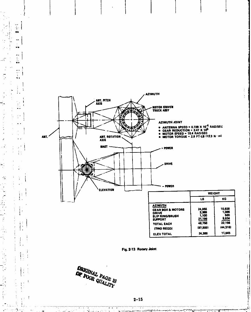
The antenna-to-spacecraft interface uses a 360 ° rotary JoU_ for antenna motion per-
pendicular _o the orbit plane (azimuth Joint) and a limited motion rotary joint, • 10 degp
for North-South poidflng (elevation Joint), Fig. 2-13. Two slip ring asSemblies (one for
plus power and one for power return) are uSed for power transfer across the azimuth
rotary Joint and flex cable Is used across the elevation Joint. Both the azimuth and
elevation Joint drive aUemblies utilize a geared raft about the diameter of the support
structure and four DC brushless motor driven roller assemblies.
The structure to wavegUtde interface uses three gimballed screw Jack assemblies
(Fig. 2-14) to provide a mechanical tuning system for alignment Ofthe wavegutdes after
construction. Up to 40. 5 em of linear motion can be used to correct thermally induced
antenna Up deflections and can also be used to correct a maximum expected 4 arc-rain
subarray miseltgnment.
Figure 2-15 is a typical conceptual desiglt of a mechanical locking mechanism for I
structural Joint_. The girder interconnect f'tting is similar to a docki_ drogue which
utilizes a spring-loadedball lock for fastening with the tri-beam end fitting, t
2.2.3 Configuration Analysis
2.2.3. I Thermal Analysis t
A refined thermal analysis of the antenna conceptual deslgn concentrated efforts on
the following:
; • Selection of the tri-beam element longeton cross Section to minimize maximum
temperature and thermal gradients
• Identifying the limit waste heat at the center of the antenna as a function of
structural vertical member material
• Defl_lng range of thermal gradients between primary and secondary structural
caps as a function of sin1 position relative to the antenna.
Figure 2-16 presents the maximum temperatures and thermal gradient across three
candidate structural cross sections: ttzbtflar, rect_vular hat, and triangular hat. The
_be is the worst from a thermal standpoint. The use of aluminum tubing near the center
2-14
O0000001-TSC12
i 1 I. 1 t
i .. 1:_I,I ,_
i....[" :
..!
- i i
" - ""_---_'_ • GEAR REOUCTION" 2.47 X 10°.*, ....... ._"'._'K[/_/ • MOTOR SPEED- 18.4 RAD/SEC
" ' " • MOTOR TORQUE = 2.8 FT-LB (1:_.3N' m)
i. . f .... I ,,,
_ i _ / EL.A.. _ _" ,_ : | WEIGHT
L_..... "LB' KG,i
': : AZIMUTHm
GEARBOX IllMOTORS 24,068 10.938-': " DRIVE 2,389 1,08tl
/ SLiP RING/BRUSH 1.100 500
( EUm_RT 2'u.._ui! TOVALEAC. 4e,Tso -.,w_
..... _ nwoReom (sT.som c44._'m_!,
-:; , , i ELEVTOTAL 24.300 1t.04S
i Fig. 2-13 Rotary Joint
|
_ , :i:: ' 2-15
; ; . ,, . , , "_
O0000001-TSCl3

i ."
E .,,
,_," M£C_OSMTnAV_L 1: ,, 6 EXTENSION ld IN. (40.5 (:M)_"-_' b ROTATION ,4 ARCMINUTES
"_ ,_ A0.0a;ImeuT
i---:??', ,_motPAoa_L I/. _,, ,r gma
_--_,'_i" ! / AITVINA $|COUOARYmUCTUR|
_** _-"_ _.,,-.-MOTOR-G(AR-IOX,SCR_/,lACKASSY(31)
e:_,,
._ SHAFT _0 9.1 II WAVIOOlO|ASSYWORM :L$ 1.7.OTO. l.o .
:_ GEARBOX& GIMSAt,. _ 3.0-_': _ THEIIUIA OLATIOllFITTilIBm._:,I 1_ , "L._,.... WAV|GUIOCu'_rfluc_REIIITiEFIFAC(_,_---_.,: l POINTSUPPORT
_--,,,' Fig. 2-14 8trua_mOWeve_tcieInterface_-_,_'
! • ,,
i ,,:" 2-16
00000001-TSC14


i I I I I I I Ii

i I t i I I Lim
I of the antenna will not be possible with this geometry. The rectangular high hat designis
" i not alz attractive structural geometry but does offer an improved temperature picture.
I The hat design has the lowest maximum temperature level and minimum.triangular
gradient of the concepts considered. Aluminum construotton Of the tri-beam horizontal
I members can be considered with this cross section.The temperature profiles along the horizontal structural tri-beam caps were evaluated
' I for_varAouS orbitaLpoSitions during the e_uinoxes and solstices. _ Figure 2-17 presents th_
expected variation in.thermal gradievts between primary and secondary structural caps
;: T : The average primary structure thermaLgradient is approximately 5°K at the center of
the antenna. The expected variation in this gradient is ± 1° K. The thern_l gradients be-
tween secondary structural caps are small, 1/2 ° ± 1/4°K, and do not pre_ent a significant
thermally induced deflection environment.
-" The vertical columns of the structure have the same view of the antenna surface and
_ space, and conSequently cannot be readily configured with coatings, insulation or geometry
selection to minimize peak temperatures of the material. FAgure 2-18 presents the maxi-
. mum waste heat flux that will be experienced by the vertical columns for microwave
;! converter efficiency of 85% and 90%. Eighty-seven percent of the waste heat generated by
_ the converters is assumed radiated toward the structure. The parameter p is a scalingm w
factor for the shape of the Gaussiau distritaltion of microwave converters on the antenna
i surface. Limitations as to the taper of this distribution must be imposed depending upon
" "" the structural material selected. A near uniform distribution (I. 5 to I) must be used ifi'
t _ the structure is aluminum or graphite/epoxy (70% converter efficiency). Selection of_ '. graphite/polyimide would be compatible with a desirable 10:1 taper for th._ converter
. 0 : Gauseian distribution.
2.2.3.2 Structural Analysis
• i The Task 2 stru_,t,_ral analysis objective was to refine the design of the structural
members and io perform a detailed assessment of thermally induced deflections. The
._' followingsun'.marizes these assessments:
• Th,h principal applied load for structure design is that induced by inertial response
_ _ of the ctmtrol system during bi'eakaway from the 1.0 x 10⁶ N. m slip-ring torque.!
This torque equates to a 10O lb {440N) end load on the upper and lower members.
J
! 2-19
00000001-TSD03

• UCROWAVECONVE# R_ACIN6: L_N *EXP((R/p)2)14
• ANTENNADIAMETERI Ken I
12_ _e WASTEHEATT0WAR0STRUCTURE=87._/ \
WASTE
_'_ ,_ \ _ .,c.o..vfco.v.T.I _ MAXF0R __.._ EFFICIENCY, ,o,
2_ " IS_6
O| * i. _ , I, I i ,1 I i400 NO _ 7_ _ _ 1_ 11_
_ALE FACTORp,METERS
Fig.2-18 WasteHeatFluxlit C4mttrof Ant_mnim Functionof ScaleFiL'tor !
00000001-TSD04

_ • T_e optimized graphite/epoxy triangular hat loageron design is shown in Fig. 2-19r,
-_,:-" i: _ for a 450°K environment. The 20 mll thick material is compoSed of ten layers of
_)i" : _; J 2-raft graphite fibers.
_ , _,_, • The range of thermally induced deflections and local slope are presented in
_ for an aluminum structure. The slope variations from a mean or average deformity,, is well within limits for graphite/epoxy. Assessment of secondary structure
',_ , .,. deformation Shows that the worst deflections occur at the tips of the antenna, with_' '_ maximum deflections not to exceed 10.5 mm over any one 18 x 18m subarray.
_'_ 2.2.4.1 Detail Parts Assembly
_" Sensitivity analysis of various levels of ground prefabrication compared to corre-
ct:' _ sponding levels of orbital assembly was performed to determine the most cost effective_;_,
:_. _. approach to antenna structural assembly. Figure 2-21 outlines the three approaches which
_i_i'_ _,-.. span the po/_slble options for detail part fabrication. Case I assumes manufacture of_: articulated lattice tri-beams on the ground. These designs can be compressed to 1/30 of
_,i'_: its deployed length for convenient packaging in the Orbiter. Case II assumes that the
}; ground fabricates the longerons and intercostal elements of the trt-beam and that assembly
__,_ of the beam is performed in a space station. Case HI assumes ground personnel prepares
_}i!i fiat Stock with appropriate coatings for installation into an automatic manufacturing module
_" _i I in space._ Figure 2-22 summarizes the pertinent characteristics of these, approacheS. Although
_ the articulated lattice beam is an efficient packaging arrangement, the packaging density in
_,, the Orbiter is extremely poor. As much as 440 Shuttle flights would be required for delivery
. I i of the 470 Klb (213 x 103 Kg) antenna structure. Transport of beam elements provides ant improved packaging density, depending upon the cross-section selected. The number of
-'iil; crew members, however, required to fabricate the finished beam in space in a reasonable
-_i,i time would require deployment of as many as 24 12-man space stations. In-orbit auto-
,?, matlc malZlfacture _f the structural members appear to provide the clearest road to a low
_;_ cost detail parts assembly method.
r ,
.!
00000001-TSD05

Ie
I
DESIGN CONDITIONS __ I• t.4so°K // _,\\ I• _.o,OA_-_._o. // \\ .,'°'• SUm)FiTEVERY3M ]/- _ I.TSieL
.... I ,_:_ ,.I (11r)- ---!
I
/ \ _._______
FIg.2.19 (:mll4eotion Ded_ .
OP.IGINALPAG_IS'_ _OR QuALrrr
2-22
00000001-TSD06

i I I i, i 1 1 t
40 - 16 f
' • S.456WTRANSMITTEDPOWER ALUMINUM
1 36 12
" 20- 8
,1 cs,I
" . .; 10 - 4
, - GR-EP
., 0_- 01 0 4 8 12 Is 20i! SEMI-SPAN.IN. X 10.3
I i , I I a J
100 200 300 400 500[-,
•_ SEMiSPAN,METERSi
(8) Typical Antenna Deflection Due to TherMal Gradients (40 Meter Beam Depth)
:: '.
! ,.
" ALUM|NUM
3
' _ SLOPE.!- , ARCMiN
[_. 2: _ GR-EP
,, ! " MAXALLOW.
IL 4 8 12 16 20
' i ANT, SEMI.SPAN,IN. X 10.3
, 100 200 300 400
i ': SEMI.SPAN,METERS
• " (b) Typical Slopesof _meture Oueto _ Gradients
. r
_ Fig,_l.3ORamp of ThermdJy Jndoood DefleotJom end Lo_l Slope
: t 3-33
,. ,...... o_o o.,_,._:_.,_,_2,L:_:._ ' _
00000001-TSD07

' I I
, :-%
if* TRAMPOAT
-i,* EARTH _ ONOIIIIIT....,!, IrA
: AmmmL| PAOKAOE,_'.}; ARTICUUTED IN ORBITER DEPLOY 1' LAI"IICEBEAMS BEAM IN-*_ ONanouoao OmTe,
2,, d_
B'I
' PACKAOE i;FABRICATEBEAM
_'" " ELEMEETS0111 III ORBITER_ Mf4BIIBLEINTOTill. ,,: 6ROUND
i".: BEAM At I'ACE
......'.-. STA1101i !!
':" nn , _) q_JilJk AUTO }
_ii___:- CASEn. I _ _ _ _ MANUFACTURE
_' ,RE FAil _KAG _ 011ORBIT_'_," PA E_' FLATSTOCK::, ONDROUHO IN ORBITER
_)"' r
!,i, • co.OmON CASE._! cASE._.22 __._._S I•' -- GROUND ASSEMBLEARTICULATED FORM LOMGtERONS PRE-PROCES$
v- :. BEAMS & CROSSMEMBERS FLAT STOCK
, - IN-ORBIT DEPLOY ASSEMBLE MANUFACTURE
-i:_ • PACKAGINGDENSITY 0.1 LB/FT3 0.9 TO 7ISLB/FT3 100 Li_F13• (-SHUTTLE CAPACITY) (6.1 LB/FT$} (6.1 LS/FT3) (6.1 LB/FT3) I
I• NUMBERSHUTTLE 440 8 TO 49 8•1. ,"_, FLT$ TO DELIVER•, ANTENNA STI_UCTURE t
• 8UI_q)RT EQUIPMENT DEPLOYMENTCANNISTEr4 24 SPACESTATIONS 8 MFG MODULES,
_:, nl_coa_noto fi" ) ,0R..UCTURt
; i_z.= o_. pmAm_v UummuV
00000001-TSD08

4
.... 2.2.4. _ Structursl A_sembly
_ Analysis concentrated on the most frequently used operation in the antenna structttre
"_ assembly, namely, the time and motion assessment of joining beams. Assembly costs are
.:. generally a strong function of the quantity and complexity of the assembly operation. In
. the estimate, for example, of aircraft structural assembly, the major cost driver is the
: number of parts and the type fastener used. In the antenna structure and waveguide inter-
_ ' face design, simple mechanical locking mechanisms similar in concept to a docking probe/
drogue was utilized when possible. Since most of the assembly will involve this type of
,! : operation, detail evaluations were performed on this beam assembly procedure,
' Figure 2-23 outlines the antenna structure assembly flow. Assembly st_Lrts with
installation of the rotary Joint using the solar array central mast as the pOint of dep_e.
The rotary Joint to antemm interface follows, using the elevation rotary Joint structure as
i an assembly base. Assembly of the primary and secondary structure is performed working!: !
; radially from the center of the an_nna. Installation of waveguides and electronics follow.
• ; : The alternate approaches evaluated include use of:
• Maaued manipulator modules
• Remote controlled m_mipuiator modules
i • "EVA with assist from remote cont_lled logistics modules.
The operations analysis approach is summarized in Fig. 2-24. The functional steps in
the operation for the three options were identified and a time line analysis performed to
determine the range of potential assembly rates. Estimates of consumables consumption
, of the free-flying modules were also made. Past Grumman simulation data, which relates
! complexity of manipulator operations in a static environment to operations in a dynamic
environment, was used in estimating both manned and remote controlled manipulatol' per-
_ formance. Skylab 3 data on the human performance in assembling the twin pole sunshade
was i sed to estimate EVA assembly rates.
_ Figure 2-25 summarizes results of the operations studies. The following con-
clusions were drawn from this data:
i __ • Remote controlled manipulator assembly offers the most cost effective approach
_ • EVA _ssembly with remote controlled logistics vehicles could be cost competitive
ff assembly times in excess of two years is acceptable and Space Station costs for
a 50-man crew can be shown to be reasonable
2-25
00000001-TSD09

- ........ If! t!
";/" I
I

t
• i i i
..... _ME, MINUTES CONSI, IktABLES, LB
: ,,,MINIMUM MAXIMtJM PR(_PELLANT EC8EVENT AT T '_'t T mN MAX MIN MAX
4.,1.3.1ACOUIRELOWERCAPFROM 3.0 3.0 10.S 10.5 0.3S 1.20 Ai STORAGE
4.3.3.2 TRANSPORT TO AUY 6.0 9.0 S.0 16.5 4.72 4.72
; JOINT
• 4.3.3.3 DEPLOY ASTROMAST 2,0 11.0 2.0 18.5 0.24 0.24
1.17 2.3
4.3.3.4 MANEUVER TO ASSY 0.5 11,5 0.5 19.0 3.0 3.0 I JDISTANCE
4.3.3.5 ATTACH HOLD ARM 3.0 14.5 10.5 29.5 0,36 1.20
4.3.3.5 ALIGN MEMBER WITH 3.0 17.5 10.5 40.0ATTACH JOINT
! 4.3.3.7 BERTHBEAM MEMBER WITH 1.0 18,5
; • EVALUATE STRUCTURAL ASSY OFi JOINTS AS MOST FREQUENT
OPERATION
• IDENTIFY FUNCTIONAL STEF_
• i • PERFORM TIME LINE ANALYSIS USING
" - PAST GRUMMAN MANIPULATORElM DATA
! - SKYLAg 3 TWIN POLE ASSY(
, _ _ PERFORMANCE
"" , F_I.2.Z4AmmblyOl:mtomAndvslsA_
!
T"
! i _
i _" 2-27

STRUCTURAL ASSEMBLY METHOD I': I i T
EVA WITH RE.MANNED REMOTE MOTE -_ON-MANIPU- MANIPU. TROLLEDLATOR LATOR LOGISTICS 1MODULE MODULE VEHICLE
l i i u ii .
e FREE FLYER CHARACTERISTICS I- WeT 1395 Ka 136 K0 136 KO- ISP.SEC 3O0 300 300- CONSUMABLESRATE (Ko/K41
STRUCTURES) 1.7 0.1S 0.0S t-- # OF SHUTTLE RESUPPLY
FLTS FOR ANTENNA 8TRUCT. 12 1 1de i IlL ,i
• ASSY RAI'E i
-- MAX (KI_TRUCTIHR) 13 13 25_. - mN(KeSTRUCT/HR) 7 7 lS
i i i iq
• NO. IN-ORBIT PERSONNEL AT MAX RATE I
- 1 YR ASSY 182 6 95:. - 2 YR ASSY 91 _ 48
i i i
• KEY ISSUE SAFETY TV SAFETYCOMMUNI-
.._ CATIONS' ' LL_'I Ill - I
t
Fig,2-2158ummwy of AuemMy Options
2-28
0000000'1-TSD'12

• , I_ . I i
' • Manned manipulator modules are not c6st effective because of the high propellant
'_ consumption,S#t_
2.2.4.3 Support Equipment RequirementsI
_- :'? Preliminary definition of support system teqtiirements have been established for the
• -- low altittide and high altitude assembly sites using data generated during NASA studies of
_ space st_tlons, research applications modules and remote tel•operator vehicles.
•' _" FigUre 2-26 summari_es the transportation sad assembly approach used as a strawman
!',_ In establishing support equipment requirements. The following lists the major equipments
_" :_. over and above the basic transportation systems required in support of asSembly at the two
_i.','.-.. -- candidate assembly sites:
. ,- Low Altitude 1190 N Mi) High Altitude (7000 N MII
': _ • Remote controlled manlpulators • Remote controlled manipulators@
• Slntttle crew accommodations • Manufacturing mod_es
- Crew support module • Space statlo_
. :_ _.. - CommuniCations module • Crew transport module
-" ;- _ • Manufacturing modules • TDRS.
-, : _ii • TDI_
i
, _Y 1 TRANSPORT TRANSPORT DETAILED ASSY CREW TRANSPORT COMM: ORBIT SYSTEM CREW FARTS METHOD ACCOM TO,; (MATERIALS) GEOSYNCH
_:... ' LOW ORBIT
_" : :!i -_ 28.5°190(qM • SHUTTLE • SHUTTLE • AUTOMATICIN_ORBIT• MANIPu.REMOTE• SHUTTLE_6MIEN • SEPS • TDRS_*' I._:: (MFR LATOR - 30 DAYS
,:; . MODULE)
_". _" HIGH ORBIT • _;;HUTTLE • SHUTTLE • AUTOMATIC • REMOTE • SPACI_ * SEPS • TDRS+.,_ i!' - 7000 N M • FULL CAP. • FULL CAP. IN_3FiBIT MANIPU. STATION
"_ - 28.8 ° TUG TUG (MFR. LATOR_ - (LMEN• CREW MODULE) - 1800AYS
---i: i : TRANSPORTMODULE
'F r _ ._ Fi_ 2-26 Trantportitlon and Assembly Elements
' Figure 2-27 summarizes tl_e weight and cost factors assumed in the overall cost
', i assessment of the SSPS assembly operation. To achieve consistency of data, the $/Kg
_" non-recurring and recurring cost estimate for the Space Station has been applied to the
_" cost of all support equtpmeflt.
._ 2-29
................... +++'+,.... " ' • ..+ .... ,, ..o...... H ...:+, ,. :.. .... \\,o o o _,o+ . ._ n ,, o.o +..,o^ oo ",_ "° ° _oO'="._.,o./o_... +,_
O0000001-TSD1 g

RSCU.q,NELEMENT PERFORMANCE WEIGHT COST/FLT RECURRING UNIT _OURCE
i i | i| i • . i
t, SHUTTLE 65K TO 190 N M NIA $10.5M NIA $180M GAC gHUTTLE100 FLT LIFE STUDY
i:.,, CRYO TUG 38.8 K LE TO IWJRNOUT- $ 1.0M N/A 812M MDACTUG STUDY7600 N M 2680 Kt
_ 100 FLT LIFI_ FULL"24,000 Kti
FREE-FLYING 6 YR LIFI_ 183 K0 TBD _6.95M 81.24M M_FC-PAYLOADTELE OPERATOR OESCRIPTION
VOL II
i'.. RAM SUPPORT 30 I_AY MISSION 5000 K9 $ 1.0M 9218M $44)M WT DATA[;. MODULE 5 YR LIFE - NAS0-27539,- COSTDATA
_i - NAS9-H63RAM-C(_M 30 DAY MISSION 8740 Kg $ 1.0M g283M ISgM WT DAi"AMODULE 5 YR LIFE - HAS8-27539
CO_ITDATA• * - NAsg-9953
MANUFACTURE 5 YR LIFE 9100 K9 TIN) 9288M N2.EM mAG_ MODULE
8EPS 1 YR TRIP TIME FROM (9(_N M - $16.7M _ $400M GAC i_PTNO._.... 1.18 X 10" Iql ASP583-R.IFROM ?00 NM,, $ 9.0M TBD $400M
-:_*_, .msx lo6Kg_ _" ' SPACESTATION 5 YR LiFE 76,700 KO TED $2097.6M _tQ?.8M NAS9,0953
:: 6 MAN_ (2 MAN E YR LIFE 10_400 K9 TBD i2309.9M $'_).iM
• CREW NAS9.25051[ ,_ !. TRANSFER 100 FLT LIFE 10,300 K9 TED _ $71,2M
:: MODULE (4)
TDRS NIA 2038 K| N/A $210M $30.50M HU()H$ REPORT.... amooe.3s14_'L,' ," • '..... '
' Fig. 2-27 Transportation md AssemMy System Fleet and Support F.quipment Cha_cs and Cost Summary (1974 8'el'2' ' '
":[ J_
,,,,/, _rtJ_
_--_,:',• 2"30
4
O0000001-TSD14

) t I i I I 1
:12.2.6 Cost
= ...'" ], The Task 2 Coacepfltal.Design objective was to refine the cost estimates established i
during preliminary design. Cost eStimates of transportation and assembly were increased i] in scope to inolude the entire SSPS and associated support equipments. A more refined
• assessment of the ante_a Structural cost was llerformed on the rectangular grid 1 kin i
• _ _. structural arra_ement using aluminum, graphite/epoxy and g_ap.h_Lpolyimlde, i
"" The following summarize the findings of these assessments:
• Low altitude assembly is significantly lower in cost than assembly above the
"" Van Allen belts (5V5 $/Kg vs 1550 $/Kg)
. .. _ • The major cost driver is Shuttle per flight costs !
! .:.:; -" • Recurring unit costs for Shuttles, Tugs, Space Stations, and other support equip-_-S merits represents I/6th of the total assembly costs :
_=_. __ • Aluminum IS 4 to 5% lower in coSt than composites.i:t'
:-" - o Figure 2-28 summarizes the traffic and fleet size requirements for three flight plans.
._ The total numbers of Shuttle flights required to assemble the entire SSPS tncltldes flights
=!-_.. ,_, _ for deployment of support equipments, transportation of personnel for monitoring the
;_"-; assembly operation and delivery of the consumables for the remote controlled manipulator
i ,'.:.i modules'. Flight Plan 1 and 3 assume one and two year assembly periods at the low altitudei !i,:-=_. site, while Flight Plan 2 assumes a one year assembly time at the high altitude site. A
'! "" significant difference exists in terms of total Shuttle flights needed for assembly at the high
_. _° altitude site, primarily due to the added requirement to transport Tugs to and from orbit.
_!;. _" ' The difference in total Shuttle flights required by Flight Plan 3 is not significantly different
12.. '_ from Plan I, but the average number of flights per day is within reason (I. 37 vs 0.7 per day)
::'_.' particularly when considering the non-optimum launch opportunities available with a
;!):. ;. i 190 n ml assembly altitude. Because of the orbital geometries, launches of as much as two
= ,_i to four Shuttles in one 15 minute launch window may be required with Flight Plan I. The
:!_' two year low altitude assembly plan is recommended ba_ed on the low number of Shuttle
_. flights and reasonable launch rate.
_;. ' Figure 2-29 presents a cost comparison of the three flight plans. The low altitude,
;,. two year assembly period is the lowest cost option (1301 $/kw). This cost could be reduced
-'--_ ! with increase in STS performance by a factor of two ff a heavy lift, deploy only launcher
-'_i: with a payload capability of 120, 000 lb (54,400 Kg) were developed from existing Shuttle
i :: 2-3i
00000001-TSE01

00000001-TSE02

! I i t 1I
components. An additional reduction could be achieved with development of the Fly-Back
Booster. It is conceivable that a cost as low as 000 $/kw could be achieved.An aluminum _ntenna stmzcture is 4 to 5% lower in cost than a graphite/epoxy or
-*" graphite/polyimide structure (Fig. 2-30). This asSumes that the basic structural elements
:'-" can be made of the Standard 5 mfl fibers. Although the cost of composites are slightly
_. higher than alumiaumt tevhnical factors such as thermat properties, could be the in-I'
.,_ fluencing factors in final Selection.
_" 2..3 RECOMMENDATIONS
_ The concepts and design oittions recommended for Task 3 study are listed in Fig. 2-31.
I/ Also included are concepts that show sufficient promise for further technology study.i!
"" Because of the greater cost associated with high altitUde aSSembly, the transportation
' _" mode selection can be narrowed down-to use of the Shuttle at a low altitUde assembly site.
_:__ i Advanced transportatioll system with increased payload (heavy llft vehicle) and development
: of the Fly-Back Booster could further reduce transportation and assembly costs, and
. should be given greater study emphasis.
: _ The rectangular grid structural arrangement should be retained. No technology
_ _ issues arose during Concept Defiaition that would suggest a different approach. The light
weight add standardized construction of the rectangular grid structure makes this approach
,i .i the best of the options studied.
Materials selection cannot be clearly made at this time. Aluminum offers the lowest
cost option with the least technology risk. The graphite composites _re attractive in terms
of thermal expansion properties and the potential to retain stiffness characteristics at high
! i temperatUre (polyimides). Basic materials technology testing of composites is recommended
to determine the outgassing and ultraviolet tolerance of these materials at the expected+ .
, system operating temperatures.
The assembly of structure using remote controlled manipulators was found to be
potentially the lowest cost approach. This assembly technique u'ould minimize the man-in-tt
space role and wot/ld therefore minimize the need for expensive life support equipments.
t T_e use of EVA in the assembly _unction showed the potential for increased production rates
' relative to remote controlled assembly. Ho_vever, the cost of large support Space Stations
may preclude selection of this approach. Study of man's rolc in assembly of large struc-
ture is recommended for investigation outside of the MPTS study.

T
"" 101 61tAPHITF./EPOX¥ ORAPBITE/PO_YIWOE I
| WT-4,X_Xo WT-4.xlr'xlo_ r-i I'12.itI IlZmL I I FmEI_LALUmUM. I iF'n" ..JI/ _'mx'xt I-I I ,..L ! i I
,L I"1 !mL! I I FIBERI I I *
C_T°| I! 'will !!i
"fU' LIAImY I
• t
2_- |2 MATERIALS _ B_J
N TRANSPORT _ _J
- O PREFAB
ANTENNASTRUCTURALOPtiONS I
Fla.2-3OAncwmSuumrdCatI
TASK 3 TECHNOLOGY
STUD.__._Y STUDYTRANSPORTATION MODE
• SHUTTLE/EXPENDABLE TRANSTAGE• SHUTTLE/REUSABLE TRANSTAGE• SHUTTLEICRYO TUG .I I• SHUTTLE/LOW ORBIT ASSY .............................._ .!
".- e ADVANCED TRANSPORT SYSTEM_; ......................................... . ..
STRUCTURAL ARRANGEMENT /• RECTANGULAR GRID ................................... ._• RADIAL SPOKE
MATERIAL /• ALUMtNUM. .............................................
• GRAPHITE/EI_OXY _ _,_• GRAPHiTE/POLYIMIDE• KEVLARIPOLYIMIDE ............ ..............................................
ASSEMBLY
J MANNED MANIPULATOR /d REMOTE CONTROLLED MANIPULATOR ................. ._ .I• EVA ..........................................................................
DETAILED PARTS ASSEMBLY #
• ORD FAB OF DEPLOYABLE STRUCTURE ....................................... _/V MAkNED IN4)RBIT FAB ./• AUTO SPACEFABRICATION ..............................
Fig.2-31 Re¢o_ for Tuk 3 Study
2m34 ,.
00000001-TSF04

rr 1 t I I I/i '/ Pt
I
_, •, ' The method of fabricating detail parts of _he assembly Is strongly driven by the
' _. volume limitations of the transportation system. With the Shuttle volume characteristics,
•. _ . i space fabrication of the low density componentS, such as structure, is recommended. If
• _ volume capabilities of the launch system were Increased, ground prefabrication of deploy-
_i: : i ,' able elements may b(_come a more attractive option.
, I !
_!.
ii!a
•!i, i:
i.
_,,: _-.
t. ,
i: , 1
-_?. !
-.;',.." ,_ 2-35
00000001-TSE05
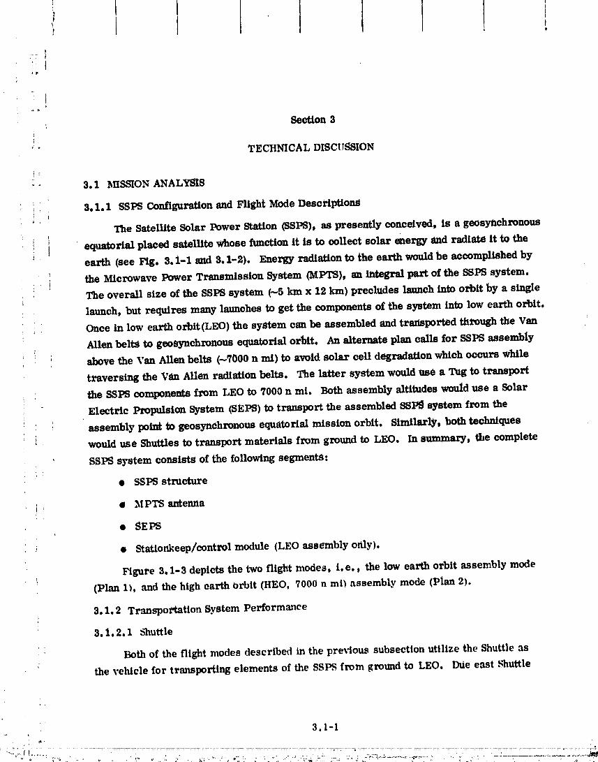
Section 3
'" TECHNICAL DISCUSSION
- • 3.1 MISSION ANALYSIS
i_ :_ 3. i. I SSPS Configuration and Flight Mode DescriptionS
The Satellite Solar Power Station (SSPS), as presently conceived, is a geosynchrollotts
i equatorial placed satellite whose function it is to collect solar energy and radiate it to the
earth (see Fig. 3. i-1 _ 3. I-2). Energy radiation to the earth would be accomplished by
the Microwave Power Transmission System (MPTS), an _ part of the SSPS system.
The overall size of the SSPS system (--5 km x 12 kin) precludes Immch into orbit by a single
launch, but requires many launches to get the components of the system into low earth orbit.
Once in low earth orblt(LEO) the system can be assembled and transported through the Van
Allen beltS to geoSynchronous equatorial orbit. An alternate plan calls for SSPS assembly
i above the Van Allen belts (--7000 n mI) to avoid solar cell degradation which occurs while
traversing the Van Allen radiation belts. The latter system would ttse a Tug to transport
the SSPS components from LEO to 7000 n mi. Both assembly altitudes would use a Solar
Electric Propulsion System (SEPS) to transport the assembled SSI_ system from the
assembly point iv geosynchronous equatorial mission orbit. Similarly, both techniques
would use Shuttles to transport materials from ground to LEO. In summary, the complete
SSI_ system consists of the following segments:
• SSPS structure
g _[PTS antenna
• $EPS
• StaUonkeep/control module (LEO assembly only).
Figure 3,1-3 depicts the two flight modes, i.e. _ the low earth orbit assembly mode
(Plan 1), and the high earth brbit (HEO, 7000 n mi) assembly mode (Plan 2).
3.1.2 Transpol-tation System Performance
3.1.2.1 Shuttle
Both of the flight modes described in the pre_'lous subsection utilize the Shuttle as
the vehicle for transporting elements of the SSPS from ground to LEO. IXie cast Shuttle
3.1-1
00000001-TSE06

r
3.1-2
" • ') o _ :," " v, _, b ,
00000001-T£FN7

_/!- "
!:: , . Man:_ _ . kg tbmx 106
:. SolarArray 0.80 21.61_ :, " Blankets 6.11 13.47_. i Concentrators 0.93 2.05i_, Non-Conductive Structure 1.73 3.81
_ : Busses,Switches 0.23 0.51Mast & Rotary Joint 0.57 1.26
i,: _ " MW Antenna 1.66 3.85
Fief PhaseWaveguide 0.02 0.04SlottedWaveouides 0.68 1.50Subarray Electronics and Detectors 0.03 0.07
"" Element Sta_s and Cont. Data Bus 0.02 0.04
SWitching and Power 0.06 0.13
MW Generators & Cooling 0.63 1.39,- DCBusses 0.20 0.44
Struc_re incl. Rotary Joints 0.23 0.51
.!: .., Installatianal Facilities 0.02 0.04_, " Con*-*ll System incl. 1 year supply of Propellant 0.02 0.04
_ ?
i_ _ Total System 11.48 25.30_ ....
_' Centersof Gravity
Xarm= 0.1 km
Y.Z arms = ± 0.026 km 185 ftl (Variation is due to the rotation of the MW Antenna)
ii!:i : Moments of Inertia.
I:: _ Ixx = 14.24 x 10⁶ kgkm 2 ( 10.48 x 10TMslug ft 21
!:, ' lyy = 123 x 106 kgkm2 ( 90.528 x 10TMslug ft 2)
_.;.- izz = 137 x 106kgkm2 1100.83x 10TMslugft2)
!',
: Fig.3.1.2 UPS MassProperties
3.;-3
00000001-TSEO8

SSPACESHUTTLE
TU_It_I_)LCE_EwNT ,,_ BELTpRc)P TI
PROPELLED TOSYNCHRONOUS ALTITUDE i
" ARRAY DEPLOYED "--_7 '_"
PLAN I PLAN II .1
_- Fill.3.1-3 MhatonOptions :
• ,. 3.1-4
00000001-TSE09

1 I I ,j l Ii .' / t
'* i l
F
p=, ,_.L_, ,
, launches from Kelmedy Space Center ffeLSc) result lfl placement o! the max/mum payload of
_ 65000 It) Into lOw earth ol'bit at 28.5 deg inclination. Figure 3.1-4 presents the Shuttle pay-
i load capability as a function of circular orbit altitude for situations req/dring a rendezvousby the Shuttle. As illustrated, 190 n ml is the maximum altitude that the Shuttle can deploy
_:. the maximum payload of 65000 lb. Shuttle performance degrades near linearly and rapidly
_. _vo 190 n _1 to 290 n ml, where no payload can be placed Into orbit. Shuttle performanceh
i ;'- in this region cmt be increased with the addition of Orbit Maneuvering System (OMS) propel-i-
i*, . lant in the Shuttle*s payload bay; the obvious disad_e of doing thl,, is the loss of payload
i: ' bay volume. Figure 3.1-5 presents similar performance lnformafl( _ _or eases not involving
i-"' an ultimate rendezvous Shnt_e. Maximum ps.vload can be deployed l, _'._0n mi _inoe no OM8.'/,
_, propellant has been budgeted for rendezvous. .
Since deployment of segments of the SSPS wfl! reclulr,q theiz" being placed in close
._:: proximity to previously orbited segments, the rendezvous performance curve was used
•:_ to determine Shuttle capabilities.
_:' i 3.1.2.2 "Tug
,_" _ The Space Tug is an integral part of Flight Plan 2 opt.rations since it wl]l be used to
,:_: _. transport, to 7000 n mi, the material delivered to LEO by the Shuttle. The Tug used-!!"
. ' - throughout this m alysis (see Ref 1) uses cryogenic propellant, is reusable and has the
_, ' following characteristics.
_:'_ • Propellant weight: 50177 lb (22730 Kg)
-_} i ' • Burnout weight: 5755 Ib (260'/Kg)?/: : )
"-i,. • Specific impulse (Isp): 456.5 sec,
_: ' A typical Tug scenario starts with pick-up of a payload from a 190 n ml O _ular olhlt,
then delivering the payload to a _000 n ml circular orbit, mid returning to th,. _shuttle in the
2_: ! origin, 1 190 n ml orbit. Figure 3.1-6 presents the Tug deploy capability while performing,_ such a scenario. The perforlnw'ce _,_ listed as a function of the de1' ¢ the Tug must expend
: :;: , . to get the payload to its point of destination. This cutbeund d_!,a-V can be related to
'*- _ = the deployment altitude. The delta-V ,oquired to return .*.( t_tg to Shuttle has been assumed
_;" to be equal to that ol the outbound leg of th_ lcurfleV,i j_il,.. L
_::, Figure 3.1-7 shows the Tug colx[lguration a_l _-,mmarlzes its payload capability for
_i/"'_" "i'i three operation modes. The first, is for the aforemenUont i payload deploy scenario! it.._ sliows (as does Fig. 3.1-61 that the Tug can deploy 36800 lb t.. _,:70 Kg) to 7000 n ml. The
ii ,. ')_i '!: - _ 3.1-5
L ............... , ........ , , ,
i o _ '_ q, ,,,;.. ,. :o _. • , _'. -. ,, , % o v if,. u . "_" ;"O
O0000001-TSEIO

I
3.1-6 i
oi,_ _ " " " ' " _ .... " .................. ' _" .............. " .......
00000001-TSE11

'+ i
.J
• Isp_4_6.G8EC18 • PROPELLANT WT ." 50.177 LB (22.730 Kg)" • BURNOUT WT = 6755 LB (;')607 K8)
+:_ _ _, • RECOVERABLE TUG
:i '" 1,2_ ,_ _olo ,:RO.10oN.JTO_000N3 =
° ! I_O 2 6 '%
_ _o _4- I
' _" _ - PAYLOAOTO_000'_.,_. I_ , 0 - 0 "' I I I I i I I l l I ..... I I I I I I I l l_l'l I•. : -..',00 50o tODD 50oo _0,000 50,000
TUG PAYLOAD, LB
' : Fig.3.1-6 CryogenicTugDeployPerformanCe
i
i ! I
I: ii '+ _ I t TOTAL WEIGHT. LB (Kg) 55.9...- 17_337)
_ I I PROPELLANT WEIGHT. LB (KB) 50.177 ( ..v))
i+ i ! ; | DRY WEIGHT. LB (KQ) _7_ (2_.,.
" : l "V "v" j S_SCIF,CIMPULSE.SEC ,++.5: \ /
++ I -'Ii. . _'J_" "" . II I PAYLOAD PERFORMANCE TO 7000 N MI
i r_" , [ • RETRIEVE.:.EIKB) 19.000 1,)++ i"_'?'!"'_,,"7"-"_,'-p-T ,._1 • ROUN"rr+.()._9(Kg) 1=o500(_)_.. _...
: Fig.3.1-7 Cryogent_1"u9Conflgumtlon .
_: 3.1-7• W, I .'
° .: +" ; , _ ..° ++...+:',_+ +. °. ,- .. +..... _.,:.. ,,_+. °...,+,,+ °++.+...+ + .+°.., . ,.... +0.+ _ , .:+-,°_++.._;+.+ .+_,...... :+ +....+.: :++ ..+-"°__.+.++ ..... - .." "+"+ *._'_ _ + + .. , • + - +, o ..... .,,+ _ +. ., -++..+, ,. ,, -+ + ".+.' ..' - • _. ;, ": .,, -."_+,l_m•_ +_ ..... _ +_+.+-'_. .
0000000 +I-TBE +I

I [ L ! II
"% 1
second mode, payload retrieval, has a payload capability of 19000 lb (8607 Kg). The final
mode involves deploying and retrieving a payload of equal weight to an orbit (roundtrip),
and Fig. 3.1-7 lists 12600 11o(6662 K6) as the capability.
R. 1.2. $ Solar E]_ectric Propulsion System (SEPS)}
IOn propulsion system performance for both Plan 1, which calls for SSPS delivery
,. from LEO to geosynchronous equatorial orbit, and Plan 2 which requires a similar I
delivery from 7000 n tnl is dependent on SEPS thrust and SSPS weight. Figure 3.1-8
presents SEI_ in-plane performance for a transfer from a 190 n mi circular orbit to geo-
" synchronous orbit (at 28.5 °) for various thrust-to-weight ratios. The figure shows that
approximately one year is required to reach mission orbit with the lowest thrttst-to-weight
ratio being considered: this traversal spends 120 days in the Van Allen radiation region, a 1
: period during which exposed solar cell elfectiveness will be degraded by approximately 40%.
This degradation will be accounted for when sizing the solar array which provides power for !
-_ the ion propulsion system.
3. i. 3 Altitude Selection
L::,. The issue of altitude selection is tied to both the Shuttle payload/altitude capability and ": air drag effects. The trades involved with selecting a LEO assembly altitude (Plan I),
or a high earth orbit assembly altitude (Plan 2) are centered around the consequences
•"* of supplying a Tug fleet for Plan 2 or an Orbit Keep/Altitude Control Module (OKfACM) I
- for assembly in LEO. Ultimately, the selection becomes one of cost and mission complexity.
=.. This subsection reports the effects of air drag on the SSPS in LEO, and wiU discuss the
: sizing of an OK/ACM system required to maintain the SSPS at the selected altitude.
Investigation of air drag effects on a satellite is dependent on the value of the satellites
ballist/c coefficient (M/CdA). Throughout this analysis, two values of M/CdA have been
.i:. i_vestigated, 0.175 and I. 75. These values were selected by assuming a total weight of
25 Mlbs, a Cd value of 2, and an order of magnitude difference in the area into the wind (A).
The ballistic coefficient value of 0.175 assumes that the SSPS solar cells are covering the
_ structtlre (as they would be in actual use) and that the SSPS has its edge into the wind. The
ballistic coefficient value of 1.75 assumes that the solar cells are stored in a rolled window
.. shade fashion, and the effective area is 10% of the nominal area. A one degree peak-to--peak !
oscillation about the center of the SSPS is also assumed. Since orientation of the SSPS edge
perpendicular to the orbital velocity vector (edge into wind) follows a sinusoidal pattern, a
mean area into the wind was computed. The computation considered the centrold of the
._ )
i'
, 3. I-8 _!
M M _
00000001-TSE13

'1
GEOSYNCHi_ONOUS400- I
I
., 1.67x lO.5
" VAN ALLEN BELT300 - I
40 DAYS i
o I 1,_ I I ,,, t0 4 S 12 'iS _0
' _ i ALTITUDe-, N MI X 1000
; i Fill.3.1-8 IonPropul_onAltitude_sTinmfrom(100N MiCircuWsr'-- Nol'laneChJnp_ °
i
tl '.|J. o
__ . ._ 3.1"9 .,
O0000001-TSE]4

|Imtt-oycle slnusold, and resulted in redue_ the effective area by 60% ove_ that of holding
a fixed-ogset..tato _he_.wlnd.
Fig_r.e 3. I-9 illustrates the effect of ai_ drag on SSPS altitude over a 24 month period,
The ballistic coefficient of _).IT5 represents the SSPS with solar cell fully deployed. A
nominal dynamic (Jaechla) mld-lS't9 atmosphere and a 95 percentile atmosphere were
" separately assumed. Considering the 95 percentile atmosphere and an initial altitude that
". Shuttle Can reach wlth gS000 11)(29445 Kg) payload, the SSPS re-_ters (assumed to be 75
" n rot) after only one month .in orbit. The nominal atmoSphet'e assumption merely adds ,_n-
__:" other month to the SSPS orbit life and indicates that an o_htLkeep module must be added toi
_-_ the SSPS if assembly is to be performed at 190 n mi. The figure shows that SSPSts with
i 4 initial orbits of 250, 300, and 400 n mi will not re-enter within a year trader nominal
i-:-";., atmospheric conditions.
: Figures 3. I-I0 and 3.1-11 illustrate the wide variation in orbit lifetime which exists;7
__. for vehicles with the two dL_ferent ballistic coefficient values mentioned earlier. Figurei- ,'
!i- 3. I-I0 presents orbit decay characteristics for_he SSPS at an initial 190 a mi altitude.
:i: Orbit lifetimes which differ by almost an order of magnitude result when the SSPS solari_!! cells are fully deployed _/CdA=0.175) as compared to the case where they are stored in!":_ rolls. Storage of the cells then shows two advantages; first, air drag is reduced and
-i _! secondly, solar cell degradation is reduced daring Van AUen belt transit. Figure $.1-ii
I=:- shows similar information for an initial altitude of 250 n mi, and illustrates the distinct
i [ advantages of assembly at higher altitudes. The question of atmospheric density at 250 n mii !_: becomes academic if a balllstie coefficient of approximately I. 75 can be assured. For these
;' cases SSPS assembly could extend several years without even having to consider the addition
_ of an orbit-keeping module to the SSPS. Unfortunately, Shuttle payload capability (on
_!i integral OMS) to 250 n mi is less than half of what it is to 190 n mi (see Fig. 3. i-4). If the
!ill present shuttle is basellned as the SSPS launch vehicle, then fleet size and Shuttle trafficconsiderations dictate that 190 n mi be selected as the assembly altitude. The selection
_resupposes that an orblt-keeping module, which uses a reasonable amount of propellant
o_'er the assembly period (1 or 2 years), can be sized to maintain the 190 n mi altitude.
The or_it-k_eping module h.'- to supply a force equal in magnitude (and opposite in
direction) to the air drag force. Figure 3,1-12 presents the forces required to compensate
for air drag in low earth orbits. A constant force of 1i Ib u_uld maintain the SSPS at 190
n mi during the assembly period. The fact that the struc_re buildup will be progressive
over the assembly period has been ignored, Rather, the consem'atlve assumption which h._q
3.1-10
00000001-TSF01
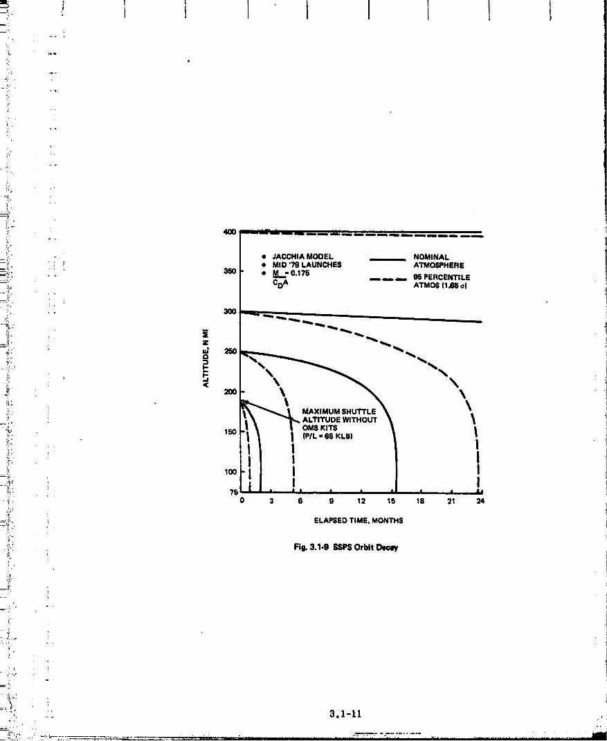
'11 .
q,
•_i,
.'_;
• :i." - - • JACCHIA MODEL NOMINAL_!L " '; f • MID "/9 LAUNCHES ATMOSPHERE_.:_. _: ' 350 • M -0.17E
.... _ m,.,,_-- 95 PERCENTILE
=_;i: CDA ATMO6 (1.65 o)
...... . ],.'/ ,
3OO
%L..
__ 150
u
il_H
:_ _:; ELAPSED TIME, MONTH8
:[i":i"2
_'_.!. FI_ 3,1,9 SSPSOrbit I:)e_aW
;ii!=_: " i
__-.L '
l- !
i 1I' I
i
"_ ' i ]
" -."_;., i
.... 3,1-11 ,.
/
00000001-TSF02

l t I
• JACCHIA MODEL NOMINAL ATMOSPHERE• MID _ LAUNCH
_', _ .... 86 PERCENTILE ATMOSPHERE
" 2SO ............_ L _"' ...........
",, _ ...... T,a'--
z A
' ! 1I
,_:' 75 * * * I I I l l I
'_: 0 3 6 9 t2 15 18 21 24
_i:', ELAPSEDTIME, MONTHS
..... Fig. 3.1-11 _ Orbit Decay Characteristics.f.
h'.
;t 3.i-12
" ii_J_ : .._,_........ _.. .._..-'_-"."_'...... ; ..... "_._ "...... " _ " -...... _...... -: ............" - • , :'_"
00000001-TSFO3
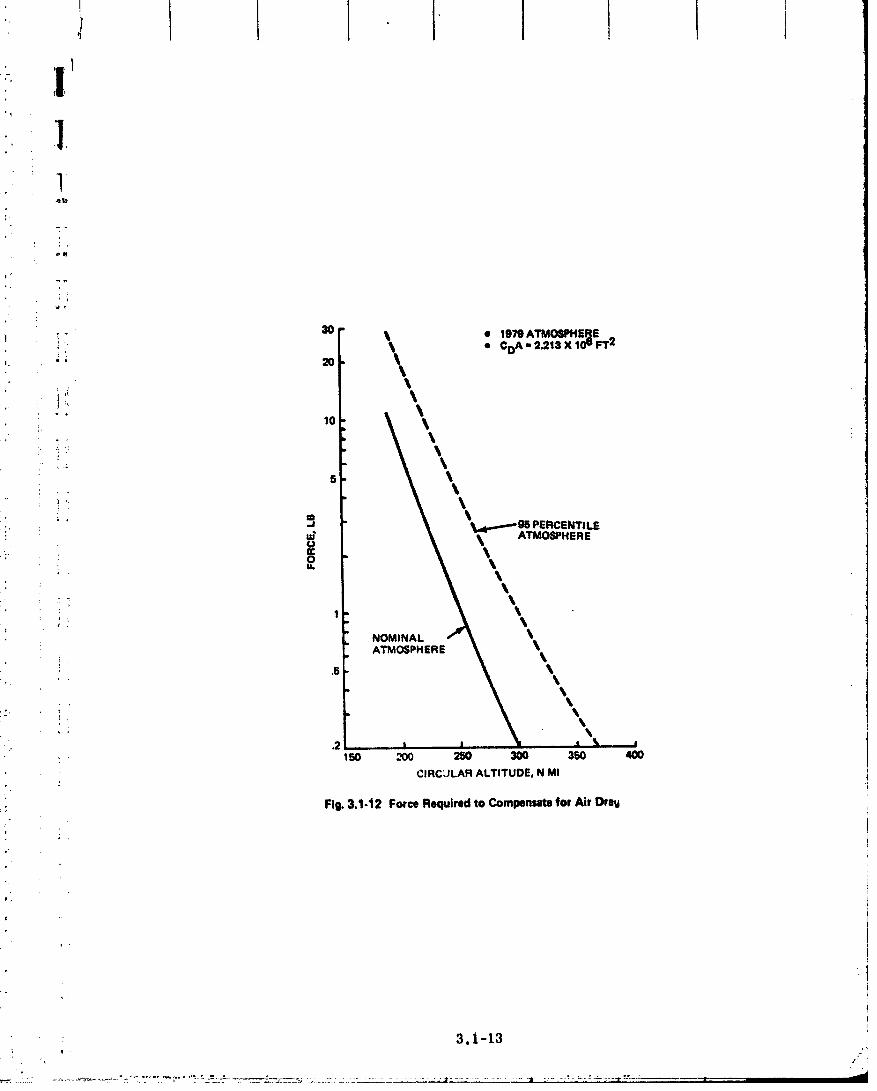
,
,e II
3O
! !- _ • 1979 ATMOSPHEFIE• CDA - 2._13 X 106 FT 2
s
.' _J PERCENTILE
:_ _ _ AT"OSPNERE
NOMINALATMOSPHERE
_- ;
.2 I I _ '
150 _ 250 300 350 400
i CIRC;JLAR ALTITUDE, N MI
.ir: Fig.3.1-12 ForceRequiredto Compensatefor Air l)rew
i
: 3.1-13
C)C)C)C)C)C)C)_-TSFC)4

' I Lt:. |
, .: been made is that the entire structure exists at the beginning of the orbit decay analysis :
time frame. An orbit-keeping mOdule has been. sized to maintain the SSI_ at 190 n miL
• altitude. It represents a small version of _e ion propulsion system proposed to
; transport the SSPS to geosynehronous orbltt and as such, has been sized using thet
: procedure discussed in SUb_ection 3. I. 4..l
_. Power from the statlonkeeplng module ion engine is derived from solar phototm im-
p'. pinging on solar cells. As the SSPS circles the earth in the 190 n ml assembly orbit, it
will be in the earth's shadow approximately 40% of the time. Since the power source for the
: stationkeeping module will be inoperative during the shadow traverse, the force from the
engine will drop off and the &.ql_ orbit will deo_ slightly. To compensate for this effect,
..... the thrust required from the staflonkeeping module has been increased from 11 to 16 lb.
_:. Characteristics of the stationkeeping module, which waS sized to keep the SSPS at 190 n mi
_: altitude under nominal air drag conditionS, are as follows:
-_ • Thrust 161b (71.2N),:"..
....._ • Propellant 44 Klb/yr (19.9 x 10³ Kg/yr)
=_ e Total Module Weight 89 Klb 140. 3 x 10³ Kg)
_, 3.1.4 SEPS {Ion Engine) Sizing
_' 3.i.4.I SizingProcedure_.
_s The factors affecting ion system size and a sizing procedure flow logic are depicted in
_ Fig. 3. I. 13. Maximizing payload ratio (_,B) is the fundamental goal in sizing the ion pro-- ,_q:, J:2=2!? pulslon. Unlike chemical propulsion, this is not achieved with ma._mum specific impulse ,
=_'. must be traded=_ {Isp1. The reduced propellantweight requirement with associatedhigh Isp_• against the increase in weight of the power supply required to achieve it. The factors
_,_ affecting that trade are:
=_._:i e System overall efficiency, ffi 17U.rlp
_i: - 17U = propellant utilization efficiency = particles ionized per total particles_.
=. - _ p = power efficiency = power in the thrust-producing ion Jet per unit of power
i, at the source
,_. • Specific mass of the propulsion system, a = weight of all propulslor, system
hardware per unit of source electric power (lbm/kw_
°_" • Propulsion time, t
o, • Mission AV.
3.1-14
00000001-TSF05

i,
_ " ' "1 PAYLOAD WEIGHT
"'_'* MISSION • REQUIRED AV
_' DEFINITION • TRIP TIMEi_ • PROPULSION SYSTEM. ' ' HARDWARE &
H.x,.,z.oi:'. SPECIFIC PAYLOAD • TOTAL THRUST_.r IMPULSE FRACTION REQUIRED
'_ • OVERALL • TOTAL POWERSYSTEM RI_QUIRED
i._, .. TECHNOLOGY EFFICIENCY (q)'/_!.t. S'rATUS • SP_C,F,CP._*_SS
: , OF PROPULSION'7,'.. / SYSTEM (a)
iJACCEL_R, "ING
! PROPELLANT VOLTAGESELECTION REQUIRED
'_• THRUSTER
_ - TV #ST PER, DESIGN
GEOMETRY T:4RUSTER,_i till' Fig. 3.'-13 Ion PropulsionSystem_zine Factors
i.
li,0"
ri!. .r
3.1-15_-,'.'.. .._,,_:, , ;
00000001-TSF06

For a given value of sizing parameter r3t/a and mission AV, there exists an optimum
Isp which maximizes the non-prepulsive payload ratio. Figures 3.1-14 and 3.1-15 show,respectively, the optimum specific impulse snd cot't.eSpondittg maxi_.ized payload fraction
as a function of ut/a*. Once the optimum Isp and maximized payload fraction are estab-lished, many of the important propulsion system characteristics can be determined. The
propulsion system weights, total thrust requirement, and total source power requirement
can be calculated, as shown below, on the basis of a given non-propulsive payload weight
(MR):
• Payload + propu_ion system weight, MofMR/AR (3. I-I)
• Propulsion system weight, including propell_nt, Mps = Mo-M R (3.1-2)
: M _" e-dV/I_'-g) 'e Propellant weight, Mp = Mo - Mburnout = o(A- _,p (3.1-3)
• Total thrust required, F = (Mp/t sec per yr) Isp (3.1-4)
• Source power --requitement' P = F Isp g/2r/x conversionfactor to KW (7-_) (3.1-5)
3.1.4.2 SEPS Sized For GeosynchronouS Delivery From 190 N Mi
Following the sizing procedures outlined in Subsection 3.1.4.1, the characteristics
of a representative ion propulsion system for the SSPS delivery mission can be determined.
The mission parameters assumed are:
• Delta-V = 16,000 fps (5000 raps)
• Trip time, t = 365 days
• Non-propulsive payload weight, MR = 26 x 106 Ibm (11.8 x 10⁶ Kg).
The assumed mission delta-V corresponds to an ascension to geosynchronous orbit by
continuous thrusting from an initial orbit altitude of approximately 190 n mi. A representa-
tive trip time of one year was selected to improve the rlt/a sizing parameter while keeping
within the bounds of thruster system capability for continuous propulsion. Durations of
apProximately 8000 and 3500 hr have been demonstrated in ground and space tests,
respectively. A three-year continuous-propulsion capability c_n readily be projected, at
this time, for the SSPS time frame.
• Governing equations for Fig. 3.1-14 L'_d3.1-15 are derived in Ref _20).

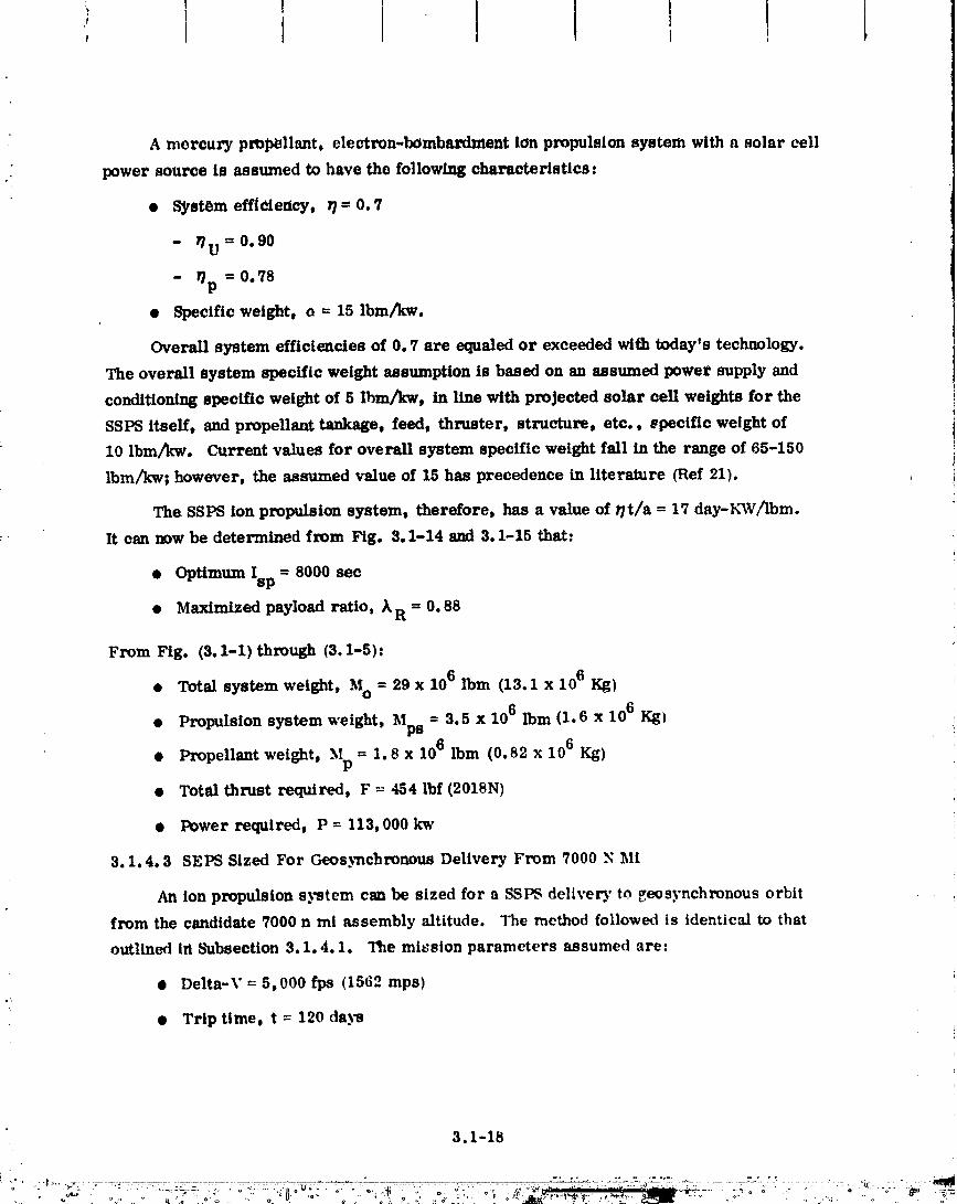
A mercury prop_llant, electron-bombardment ion propulsion system with a solar cell
._ power source is assumed to have the following characteristics:
• System efficiency, _ = 0. "/
- V/U = 0.90
- _p = 0.78
• Specific weight, o = 15 Ibm/kw.
Overall system efficiencles of 0.7 are equaled or exceeded with todayts technology.
The overall system specific weight assumption is based on an assumed power supply and
conditioning specific weight of 5 lhm/kw, in llne with projected solar cell weights for the
SSPS itself, and propellant tankage, feed, thruster, structure, etc., specific weight of
10 Ibm/_w. Current values for overall system specific weight fall in the range of 65-150
Ibm/_w; however, the assumed value of 15 has precedence in literature (Ref 21).
The SSPS ion propulsion system, therefore, has a value of r/t/a = 17 day-K_V_bm.
It can now be determined from Fig. 3.1-14 and 3.1-15 that..
• Optimum Isp = 8000 sec
• Maximized payload ratio, XR = 0.88
From Fig. (3. 1-1) through (3.1-5):
• Total system weight, Mo = 29 x 106 Ibm (13.1 x 10⁶ Kg)
• Propulsion system weight, Mps = 3.5 x 10⁶ Ibm (1.6 x 10⁶ Kg)
= 1.8 x 10⁶ Ibm (0.82 x 10⁶ Kg)• Propellant weight, Mp
• Total thrust required, F = 454 lbf (2018N)
• Power required, P = 113, 000 kw
3.1.4. 3 SEPS Sized For Geos)_chronous Delivery From 7000 Y Mi
An ion propulsion system can be sized for a SSPS delivery to geosynchronous orbit
from the candidate 7000 n mi assembly altitude. The method followed is identical to that
outlined in Subsection 3.1.4.1. The mission parameters assumed are:
• Delta-V = 5,000 fps (1562 raps)
• Trip time, t = 120 days
3.1-18
+ ++ ° °o °° ++ .... > + ++++o+ + .....jk_+ ++++_+;W+ _ + + + +°+ ° ++_=
0000000I T$1=O+

..... • Non-Propulsive payload weight, MR = 26 x 106 Ibm (11.78 x 10⁶ Kg)
:_., • Syste_ efficiency, r}= 0.7
. • Specific weight, _ = 15 Ibm/KW (6.78 Kg/KW)
The resulUng SEI_ had the following ehar_cterlstics:
,!-
_:, • OptimUm Isp = 402_ sec
:_ • Maximized payload ratio, _'R = 0.96
• Total system weight, MO = 27 x 106 Ibm (12.2 x ][06 Kg)9-= _,
_,_, • Propulsion system weight, Mp8 = 1.2 M Ibm (0.54 x 10⁶ Kg)
_: _,, 10 6_i'_'" i._ • Propellant weight, Mp = 0.9 M Ibm (0.4 x Kg)
_ . • Total thrust required, F = 400 lbf (1178N)r
} • PoWer required, P = 43, 000 KW
} ';.i
i
-r'
ii•i
,?
i,
! J 3.1-19r ,. ,"
" O0000001_TSFIO °

3.2 ANTENNA STRUCTURAL CONCEPT
3.2.1 General Arrangement
" The MPTS antenna is 1 km (3280 ft) in diameter by 40 meters (131.2 ft) deep. The
antenna is assembled in two rectangular grid structural layers, Fig. 3.2-1. The primary
, _ structure is built up in 108 x 108 x 35 meter bays using triangular girder compression
members 18 meters long and 3 meters wide. The secondary structure 18 x 18 _: 5 meter bays
(Section B-B, Fig. 3.2-1) are used as support points for the waveguide subarrays. Dimen-
sions of the secondary structure will vary with selection of the optimum subarray size. (The
18 x 18 meter size is typical). A mechanical screw Jack system (Detail C, Fig. 3.2-1) is
used as the interface with the subarrays and provides the flexibility of mechanically aligning
_ the waveguides in orientation and position. This feature desensitizes the configuration re-
quirements on assembly tolerances and thermal deflection accuracies.
The antenna-to-spacecraft interface (Detail D, Fig. 3.2-2), uses a 360 _ rotary joint
(azimuth) about the spacecraft (SSPS) central mast and a limited motion (_8 ° ) rotary joint
for North-South steering (elevation). The azimuth rotary joint uses two slip-rings and brush
assemblies for power transfer (Section F-F, Fig. 3.2-2). One routes plus current, the other
_ negative. The azimuth drive assembly utilizes a geared rail support structure (Section E-E,i Fig. 3. 2-2) and motor driven 4-wheel truck roller assembly. The elevation drive utilizes
, flexible cable for power transfer _ad a geared rail drive system similar to the mechanism
used for azimuth contrtA.
3.2.2 Rotary Joint
A recommended approach for concept definition consisting of rollers and tracks ha
tentatively been made. Power is transferred across the azimuth interface by silver a_l_
brushes and slip rings, and across the elevation drive by flexible cable. The orif" ,alien
drive is by DC torque motor with spur gear drive.
Des gn of the antenna mechanical interface requires selection of the _earing, bearings,
motor, power transfer device and lubrication. Reference 8, eontaihir tesign details and
analysis for a space station solar array t_tatlng joint, has bc,,_ u,_ ! as a source of pertinent
design data. Applicable data from both Ref 7 az t _ has be _(I _,ated in this report for
convenience.
3.2.2.1 Gears
.. The choice of gears to meet the 1 are-min pointing aecur,t_ ,'equirement and 30-year
life is a major issue in control system design. Depending upon thc • ,_,,t of the gear ratio,
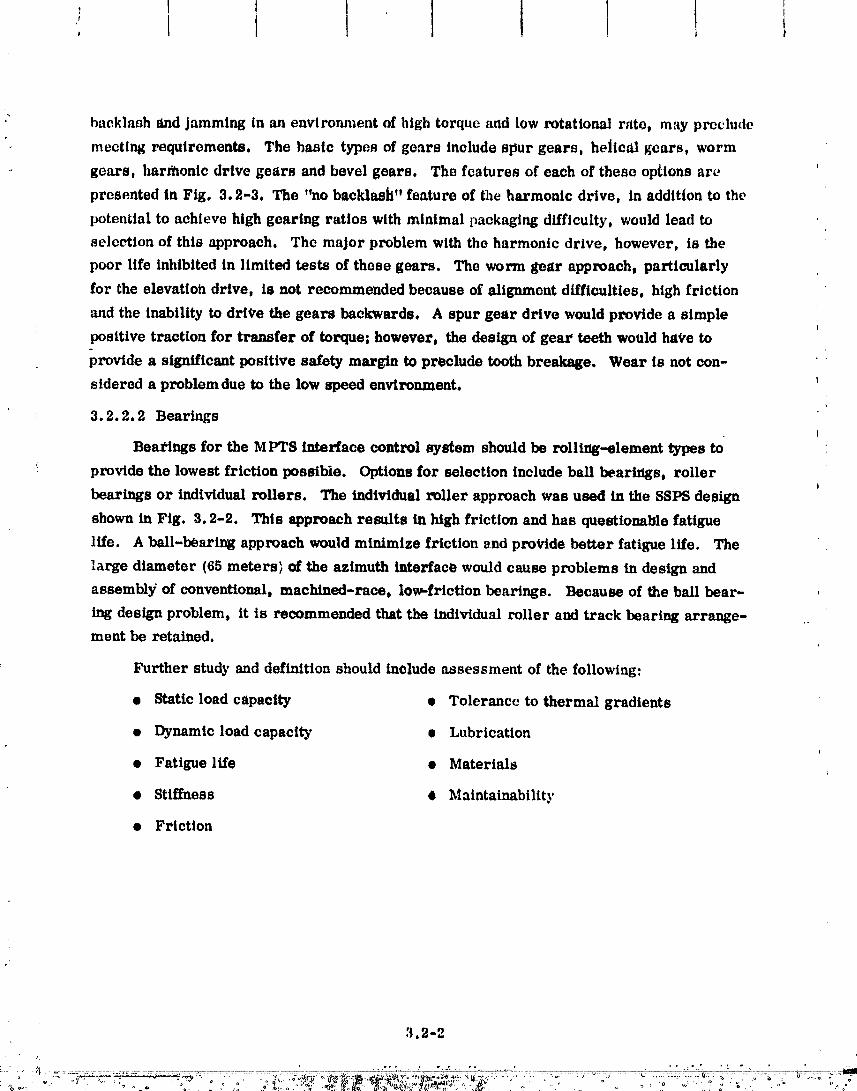
•" backlash _md jamming in an environment of high torque and low rotational rate, may preclude
meeting requirements. The basic types of gears include spur gears, he|lcal gears, worm
gears, harfllonlc drive gears and bevel gears. The features of each of these options ar_
presented In Fig. 3.2-3, The "no backlash" feature of the harmonic drive, in addition to the
potential to achieve high gearing ratios with minimal packaging difficulty, would lead to
selection of this approach. The major problem with the harmonic drive, however, is the
poor life inhibited in limited tests of these gears. The worm _ear approach, particularly
for the elevattoh drive, is not recommended because of alignment difficulties, high friction
and the inability to drt_,e the gears backwards. A spur gear drive would provide a simple
positive traction for transfer of torque; however, the design of gear teeth would hat'e to
provide a significant positive safety margin to preclude tooth breakage. Wear is not con-
sidered a problemdue to the low speed environment.
3.2.2.2 Bearings
Bea_'lngs for the MPTS interface control system should be rolling-element types to
provide the lowest friction possible. Options for selection include ball bearings, roller
bearings or individual rollers. The individual roller approach was used in the SSPS design
shown in Fig. 3.2-2. This approach results in high friction and has questionable fatigue
life. A ball-bearing approach would minimize friction _nd pro_.ide better fatigue life. The
large diameter (65 meters> of the azimuth interface would cause problems in design and
assembly of conventional, machined-race, low,-friction bearings. Because of the ball bear-
ing design problem, it is recommended that the individual roller and track bearing arrange- .
merit be retained.
Further study and definition should include assessment of the following:
• Static load capacity • Tolerance to thermal gradients
• Dynamic load capacitT • Lubrication
• Fatigue life • Materials
• Stiffness O _iaintainability
• Friction
,'_.2-2
0000000-T$ 2

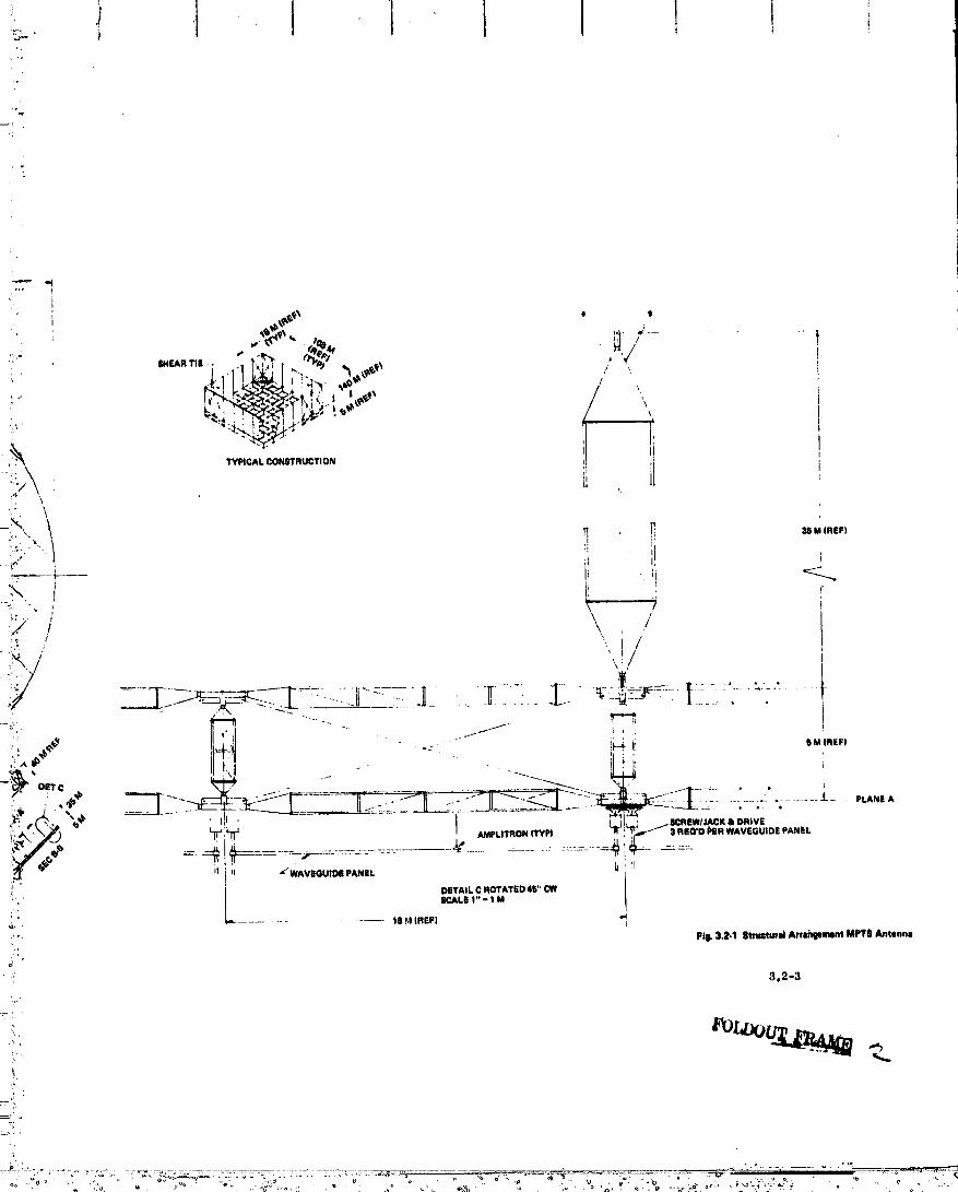
/
, TYPICALCONSTRUCTION
\._' t
N ] ., ""
_/" / /"
, I//
H U "_'WAVEGUIDEPANEL _ 'I
DETAILCROTATED41_*'CWi_, SCALE1" - I M
,,.L.............. %B,_!(REF) -4
Fig.3._-1 Stru_utd Arr_ment MFT$Antennm
#
3.2-3
:'7- _it, [
...."-___.'Tf"'i_°':':--'_":__..._--;;_:::'..-:._.._-_:_.-;-:.__:-.':._-._.:._-?_::_--_........o _ .......... .-J_'----.,_..
O0000001-TSF14
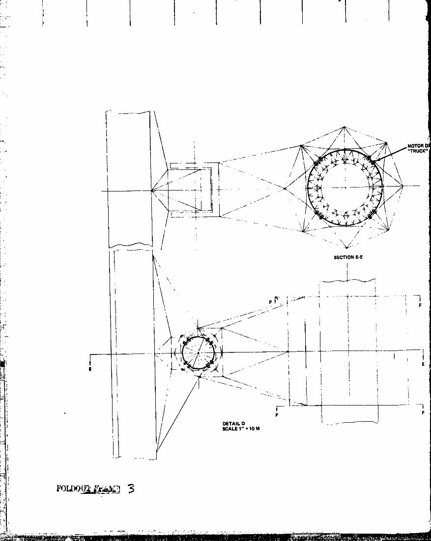
00000001-TSG01

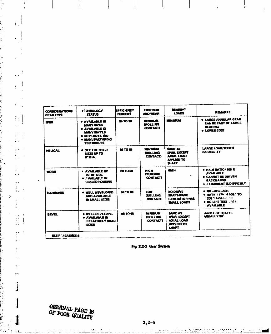
I
!
t
i,
, ooma.om mOLO V ma.,cv
i2,, _ SlUR • AVAU.ABLE IN mTOm MINIMUM MINIMUM • LARGE ANNULAR GEARMANY SIZES (ROLLING CAN BE PART OF LARGE!,
• AVAILABLE |M CONTACT) BEARING"' MANY I_T_ • LOWER
:,. • I,rll_ SIZES TIW;, _ . • MANUFACrUItlNG,:, _ TECHNIQUESi_,: ...........
i' HELICAL • OFF THE SHELF 95TO N ImNUlIUM SAME AS LARGE LOAD/TOOTH_:' _ SIZES UP TO (ItOUJNG SlqJlt. EX(:EFr C_ABILITY
-_ f DIA. CONTACll AXIAL LOAD
_.. APPLIED TO_' SltAFT
• AVA_ILABLE UP f_TO 80 HIGH HIGH • HIGH RATIO (I_I)! *- TO 10'* DIA. (Rim AVAILABLE;i.. • ,_,VAII.ABLE IN I[X)NTAC'_ • CANNOT BE DRIVEN_', -" '.',EALED_ BACKWARDS
_':" ,i' _ • _ UGNMENT I$OIFFICULTkr _
• WELLbEVE_ IN)TON LOW NODRIVE • NO _J_C_LASH_'- ',_ ANO AVAILABLE (ROLLING SHAFT41VAVE • RATK _t-_ "410Q1TO
- " IN SMALL Sl_l_ CONTACT) GENERATOR HAS 200:.1 AVAt L/ "I.E
:.. ! SMALL LOADS • NO UFE TES1 .. _,1, AVAILABLE
., , BEVEL • WIELLII)E'V'EL(_F.I[, _STO_B MINIMU_I SAMEAS Aa_GLEOF_HPFTS• AVAILABLE IN (ROLLIIM; SPUR. EXCEPT " Uil;UALLY
_ .i RELA_LY SiMAL[ CONTACT) AXIAL LOAD
SIZES [ _'PUED TOSe_kFT
i' gEE IR'.FERaik_ |
'i" 1
'[,.
" "_..................'"-""'-:_:-- - _....---_:...................:....-.....;.":::.:....-:..J::.:-,.":A,'.'.'.:":;Z?:__.i_.'..-'_:::!._-;:."'.:::!.":.:_._,\__::-.....'.'.j_J.
00000001-TSGO:3

I I 1, I Ii I 1
3.2.2.3 Motors
The following summarizes the motor requirements for the MPTS ._wchanical system
interface:
Motor Azimuth ElevationCharacteristics Drive Drive
• Torque (peak) 1.02 x 10⁶ N. m 2.83 x 10³ N. m
• Horsepower 0.18 1.8
• Time Constant Less than 0. I see
Figure 3.2-4 is a list of typical motor types that are considerations for the serve
system design.
Control dynamics computations indicate that less than 134 watts power drain is
required to drive the antenna in azimuth; however, startup inertia and response _) control t
the effect of base dynamics will require a high Starting torque motor. A UC motor iS well
suited to this application. The long life requirements (30 years) favors the brushless DC
torque motor, though these devices are slightly" heavier and less efficient than brush motors.
Figure 3.2-5 presents a conceptual design for the rotary drive mechanism. The total weighto
for motors, gears, idler wheels and drive wheels is 12,024 Kg.
An attractive option to the motor-gear system would _ the use of linear step motors
mounted around the periphery of the drive assembly support..'I_nese devices have an
excellent thrust-to-Weight ratio (10:1) and would eliminate the wear'problems associated with
gears. Figure 3.2-6 is a conceptual layout and weight estimate of a three-phase Variable
reluctance linear motor system. A significant weight reduction relative to the motor gear
approach is indicated. The attractiveness of thi_ _pproach in terms of reliability, simplicity
and low weight strongly suggest that technology efforts be initiated to determine the feasibility
of application to the MPTS rotary Joint drive mechanism.
3.2.2.4 Power Transfer Devices
Figure 3.2-7 summarizes power transfer options and the major considerations in
selection. Consideration of all factors leads to a tentative selection of slip rings for the
azimuth drive and flex cables for t,_p elevation drive.
3.2.2.5 Slip Rings and Brushes
A possible configuration woulo _mploy two coin silver slip f'ings around the mast
mounted near the roller ttaeks for gap tolerance stablli_-. Self-lubricating brushes would
3.2-6
00000001-TSG04

! "Pi .... 'i , , 1 i
,°11! - 'i .k,c __-.-...g
i.- ._-, I'- I_
' iii| , , ." "..
!"+' I Ig i II IIi "' illll -.--
i"?:
,-_" -"-_-" I_ _ -1 "_i_,; _ I
; i Ii|!!i " "" '+'"
':- ,+:a i !i' ++++'4 1+: _og_+,,+._i+: . . .... ,, ....;_ }_ii"li _ i l $ <",=: + 1,ti , II lt_ ,
=t'_. _.,+__ .,;.,- .
_'_ + .' ............................. __ __+_ ______..++_+.++.+...._ .+___. _+__+ ....................... _.+ +++ _.r_L++. ++____ ........ __ +_.__..__ ............ _: .__++_ _.+............ :++__ _++' *
00000001-TSG05

; l L
.2.,
i_; ° '
!
,'/, MOTOR DRIVEN ;_;_ GEAR
,_. I CABLE/SEGMENTED GE_J_RACK
it:
:i
_I!:: AZIMUTH DRIVE CHARACTERISTICS
ANTENNASeEED = 0.728X10⁴ RAD/SECGEAR REDUCTION = 2,47 X 10⁵
:; IDLER WHEEL MOTOR SPEED = 18.4 RADISECMOTOR TORQUE - 2.8 FT/LB
(3,8 N m)WT, GEAR BOX & MOTORS= 24°066 LB
(10938 Kg)"FIXED" STRUCTURE WT, DRIVE TRUCK & CABLE - 2389 LB
(1086 Kg)
Fig. 3.2-5 Rotsry Drive Conoept
_. :i r
,'_t:: 3.2-8
0000000]-TSG06

t
• : DIRECTION OIlAMINATION
; WEIGHT
LB Kg ,1
' i!
- +- LIM 2214 Or ]
ARMATURE _ 432 I ,_
2_,* _ I 1116
,1c .1
' Fig. 3.2.6 Antenna Rotary Jo, nt (Frictionllm Linelf Motor COncept| t1I
• • , . ,. ...... -
'_ ...." " + " +_?'_'.........._......................._...................................i_..........................................._..........i___+_++_ _-_"+-_+_+_-__ _+"__"__+' _=_+_+_ill,'
00000001 -TSG07

• !
.: , I I : 0
Z
be spring loaded and made of silver/niobium dlselvnide carrying from 7.75 x 10⁴ to 15.5 x
10't amp/m 2 (50 to 100 a _ p/in. 2). Brush pressure would be from 27,550 to 68,940 N/m 2
_ (4 to I0 psi). Brush speed is low, so no arcing problems are anticipated. Brush height would
be designed for the life of the SSPS at very small penalty, or life/rellabillty goals could be
• met by an unloaded set of standby brushes to be actuated by command when wearout of the
initial set was imminent. Life predictions for such designs have been estimaLed to be
i possible for over 100 years. The m_ln problem is providing for oil vapor lubrication to
supplement the NbSe2 solid lubricant. Oil vapor lube extends the life of brushes, but re-quires some form of reservoir and labyrinth seal to minimize vapor loss. Mass estimate
b -*_
has yet to be made, but the specific weight will probably be small relative to structure,
:- bearings, and buses.
• ti: Figure 3.2-8 is a schematic of the slip ring and brush design concept for the azimuth
- rotary joint. The total weight of brushes and slip rin_s is estimated at 1100 ]b (504 F_).
i '- Slip rings and brushes possess a well-developed technology and have unlimited rota-
i:_ tional freedom in one axis. Their performance is not degraded by stopptng, starting or
' reversing. SUp rings have high reliability over long operating periods. SUp rings, however, t
are relatively heavy and because of their large size would present problems in assembly.
!_- The major consideration to overall system design is the high thermal inputs to the structur..,!
i_.. interface due to I2R losses at the brush slip ring interface. Figure 3.2-9 and 3.2-10 sum-i__. marize the operating temperatures and voltage drop for some candidate brushes and slip ring
_:_ combinations. Considering a system power level of 5 GW and a voltage level of 20 KV, there
will be approximately 20, 000 amperes per bus bar. To achieve a medium current density of_-
7.75 amperes per square meter requires 3, 23 square meters of brush/slip ring contact_:
: _ area. According to Fig. 3.2-10, the voltage drop across the brush/sUp ring interface will
i _ be approximately 0.2 volt which will generate 40 KW of waste heat at each interface. To:"
ensure reasonable operating temperatures f_r the brushes, methods for efficiently "dumping"
_ii" this waste heat should be considered.
_. 3, 2.2.6 Liquid Metal Slip Rings_,_,
No information on successful a'.- lication of this concept has been uncovered to date.
The state-of-the-art is such as to leave most questions unanswered, so development risk
_. is considered high, Reference 8 gave no technical information relativ_ to liquid slip rings
but did not list them with BKF as origin. SKF had tried to use a mercury" liquid metal slip
: ring for instrumentation noise suppression on a 2.1,000 r_m bearing research prvgram hut
had dropped development in favor of a silver/silver graphite solid brush system.
_: 3.2-10: T _'.
00000001-TSG08

SIZE & LONG LIllE POWER COST & TECHNOLOGYDEVICE W(IGHI & MAINT CONSUMPTION fiCHEDULf STATUS LUBRICAIION
SLIP RING INT(RMEDIATF POSSIBLE INTERMEDIATE 12R, SFCOND STATEOF THIbART DRY LIJBE tNCORPOOVERCOME BRUSH RAT(O IN flRUSHfSFRICTION
P_IiIIER CLUTCH INTERMEDIATE POSSI6LE. :INTERMEDIATE 12R THIRD CONCEPT STAG[ NO LIJB_ ON CONTACTSCOM- HAV_ TO RESET MOTOR PARTS NEEDPONENTS MI_[;ELLANEOUS
REPLA(._ LUBRICATIONABLE.
• FLEX CABLE LOWEST POSSIBLE LOWEST 12R. FIRST STATE<)F-THE.ART INDIVIDUAL STRANDS(LOWEST) LUBRICATED WITHIN
SHEATHj _ . ..... i . = : m ,J ,, _ -
ROTARY HIGHEST FDSSIBLE. HIGHEST L(_;SES DEPENDENT ON INDUSTRIAL UNITS OFF NON(TRANSFORMER (DUE TO INVERTER) SIZE AND THE SHELF. PACE
EFFICIENCY. UNITS NEED DEV, ,, .,
ROLLING CONTACT INTERMEDIATE FATIGUE INTERMEDIATE I2R, FOURTH WORKING MODELS CONDUCTIVE DRY LUBEPROBLEMS, OVERCOME BEAR. BUT NEED
ING FRICTION. DEVELOPMENT.
;El: REFERENCE 8
: Fig. 3.2"7 POWW Transfer I)_ice Selection Comider_t_nlt!

F'
J.
/
- .-
L.:
" v,_,C KOTE LUBED MoS,,tLUOED NbSo2LUBED LVE.IGRAP"m SiLV./COm. mLVE.
COPPER SLIP RINGS
. SLIDING4 PSi 88; 73.74 -
,. 10.12 PSi 8041 -
;. 13.16 PSi 504i0
STATIC
- 4 PSi 1'6 - 1
: 8PSI 54 -10-12 PSI 75-78 -13.10 PSI 50,.61 -
' r 81LVER SLiP RINGlJ
i SLIDINGE
i ". 4 PSI 72-_1JJ 100-102 49-56 61-638 PSi 3S-M S1_1 - -
" STATIC
4 PSi 58-62 82418 4449 50,-51
8 PSI 32-46 3947 -
i- Fig.3.2-9 Operating_lemperltum(°C)of CandidateBrushedi
i .os. iN, 2 i'- " LUS_O ILUeEOi-." 8RUSHES VAC KOTE LUOED SILVER/GRAPHITE SILVER/ iSILVlE.____R i
Ii ' 50 A/IN.2 100 ARN2 50 A/IN2 JliOA_IN 2i -. , COPPER SLiP RINGS' .. SLIDING FOR: "- 200 HR - 6r_ Hl_
.: 4 PSI 0,2S 0.18
.," 8 PSi 0.18 0 17
:. 10.16 PSi 0.22 -_ b_rATlC FOR: "- 375 HR, 4 PSi 0.14
__,_, S PSi G14. 1_1sPSi o.17__ _ SLipruNGs ........................... t- ........
' SLIDING FOR; - 200 HR - .._',_0ItR __ .200o.14.._R'-._.;_0 H.__
'" 4 PSi 0.2S 0.34 009 0008 m 0.4_0 0.23 -
'-",' STATIC FOR' " 315 HR - 311_HR _ 1__....HR_ - 37.___HB - .37.b._H_R4 PSi 0.20 027 025 0 073 _ 0.066
": 8 PSI 0.19 0.21 0.20
' Fi_ 3.2-10 VoltageDropfor CandidateBrushes(forSingleContacts)
[ !"_i 3.2-12
O0000001-TSGIO

° , , I I i ' 1°_:" 0 i i l , i
. i_,"
-_i:i_,, Liquid sodium has potential as a slip ring Liquid because of good conductivity, wottlpg
_.* mid viscosity characteristics. Theoretically, such a dc_cc would carry eurrent with low..;'.!3?/,
_?' power loss and low torque drag. Thv main problem is foreseen as development of a long lifo,
....,._:- low friction seal to keep the liquid contained. Such a seal would bc _onsltive to temperature
i,i change, contamination, and corrosion. It might prove difficult to lubricate trod on-line
7:: maintenance or seal replacement could prove complicated.• p;,;
:,/, Because o_ high development risk, lack of destgm information, constraints on structural
_,,_ configuration, and lower life/reliability rating than conventional slip rings, liquid metal slip
_' rings are not recommended for baseline development but should be considered as a potentialA:?) teehnologs" study.;; '¢.,'
-;!_;l:_ 3.2.2.7 Power Clutch and Flexibl_ Cable
:!- A power clutch holds two contacts fixed together while they move through part of a
. ;I_, revolution, and then the contacts break apart and reset to an initial position, and the cycle'_ll
£'_S repeats. The re 'lattve motion is allowed for by a flexible cable. For SSPS application, two::,i' sets of contacts would be required so one could carry the load while the other reset. The-"".:i;l"
Ji! advantage is a lower contact resistance and lower wear rate than with brushes and slip rings,
-._o_. but the greater mechanical complexity and redundant mechanism required would probably
_212:111!i* trend toward high _.rweight and lower reliability.•-_'_* 3.2.2.8 Rotary Tx _sformer
--_/" A rotary transformer could be designed to operate at high efficiency w,,_hr,, wear-=d'i_' .
-" (no contact_, but the high efficiency would require heavv core material and a close t,,h,rance
gap. Since SSPS is a DC system, an additional pertalty would have to be added for Dt C-DC
_ power conversion. Rotary transformers do provide low friction and should be c,,._ldol .,,1as
a potential tecimology study.
3.2.2. t qolling ContactJ:
A rolling contact device transferring power through either .-t' s or bearings is ineffi-
cient as an electrical conduction pafl_ because contact area,_ .'c ,ssonttally lines or points
unless there is deformation - in which ca:-_,_'_,_,tal fati,_,," _,..-;'nes a problem. It i_ notL:
recommended,
_._; 3.2.2.10 Lubrication
' grease .-1. (hasedon_-i_l Lubricant options include o11, and solids. Fi_ '_,.2-11 and 3." '_
. data from Ref ._ summarize test data on various condidatc ot1_ ,-',_ :rreasc, The 30-year life
..,,.,. 3.2-13
O0000001-TSG11

IT.UZ_;P_LIm_LOAD I0 KG (INITIAl. HERTZ 8TREm t 210,000 PSi)SPEED 600 RIM (45 FT/MIN SLIDINGIDURATION 90 MINU_EWBALLS 52100 gTEEL
'-' "M_. reEF. OF FRICTION WEAR 8CAR DIA., _ J
moc ;o°c leo*c as"c ;o°c '[oo°c0.4010.01119 0.0_1 0.096 0.470 0.483
VAC KOTE liETROLEUM 0.0_4 0.432t
VAC KOTE ESTER 0.Q85 0.1088 0.093 0,280 0.276 (1273
oo114 o:41 0.228 o424I VAC KOTE ETHER 0.122 0.118 0.113 i 420"/
' KRVrOX lU AS 0.1t3.__2" _ 0.0m" 0.Ul _ i'
i xeMzlm 0.____ 0.0..__ o.__o7_ _ o.1_ 0.1_.Urn, VERSILUBE F-60 0.096" ERRATIC" 0.080___.._" 0.491 0.445 0.488/
o.o, 0.o,__.22 0.207
[..olsv _101NOT
[SEE REFF,RENCE 8 ......
Fig. 3.2-1t Friction and Wear ProPerties of Oils (Four-Ball Test)
I TEST CONDITIONS:':_'-_OAD ..... 10 KG |INITIAL HERTZ STRESS " 210.000 PSi)
SPEED 600 RiM 145 FT/MIN SLiDiNG)DURATION 90 MINUTESBALLS 52100 STEEL
I MIN. COEF.OF F_R.ICTION WEAR SCAR DIA.. MM.CANDIDAIEGREASE 28C 70C L 100"C 380C L .a-.--| ?0C i .... 1--0OC-------
! 0.O', '--0.0e3..... o__m............. 0--_,'-9- " |-0_-_---- I 0::3_- .....VAC KOTE ESTER BASE: /--
VAC KOTE PETRO. BASE 0.080 0.073 0.071 0.416 ! 0.494 ! 052_,
DUPONT PL-631 01Z0** ,3106 0.100 0.413 I_0298 _* 0 256
KRY'TOX 240AC 0 106"" 0 110"" 0120 0.517 ! 0.424 ! 0.368
SUPERMIL M125 0.089Q, 0.063"_ ! 0.077 _" 0384 0445 0328*
(00 MINi (00 MINt
VERSILUBE G.300 0 174|. 0,093:" "022:" 0504" 0 456 0 _aO"
113 MIN) 115 MIN) IZERO MIN_ _13 MIN_ (15 MIN_ (ZER_MIN'......... ,b .......... .L ......... .t.. ._. .......
• FA!LED AT 11ME INDICATED DUE TO HIGH f RIC't ION, ,, 0 221i* NOIS'."aLIDING
Fid. 3.2-12 Friction and Wear I_owties of Ormtm (Fout-Bal! Tegt)
91tmn4AL m
3.2-14
00000001-TSG12

i
; I i, I ! ! i
If: re_pdt'ement is the mo_t slgufflcarlt consideration, with little or no data to _upport a Belt;ellen.
Vac Kotc lubricants have proven highly rc|lahle la OSo and other sprtc_er_ft slip ring. gear
1. and motor applications. Greases have the same btmie characteristlef_ as the oils with
appropriate thlckerltng ageuts added. Greases should he used only where leakage is too high
to retain an oil. Solids would have application for slip ring and motor h,'u_h(,s.
3.2.3 Primary/Secondary Antenna Structure
The basic strueturb consists of 20 major beams perpendicular to each other to form
a grid of squares 108 meters on each side. The secondary structure located within those grids
form a denser grid of squares 18 meters on each side. The major beam "upper" caps are
girder/columns consisting of three longitudinal members equidistant apart. At appropriate _,_intervals, cross bracing and tension wires are added to balance the shear loads. The
"lower" cap of the primary structure is ldentiaal to the secondary structure which is a beam
consisting of girder/columns five meters apart. These are of similar construction to the
primary members but scaled down. All beams arc given shear capability by virtue of wire/
cables connected in the manner of a drag truss. Horizontal shear capability is obtained in
a like manner by attaching cables at the upper beamcaps across the 108 meter bays. See
Fig. 3.2-i3 for a typicM 108 meter bay structural arrangement.
3.2.4 StrUcture/Wa 'egutde Interlace
Two methods of attaching the wavcguide assembly to the secondary st_cture have been
identified:
i The Single Point PicLup (Fig. 3.2-14) consists of a two-axis motor driven g_ _hal
located at each ls meter intersection. Lugs on this unit attach to composite
_i. structural members wi,lch _upport the waveguide assembly and effectively Irz'_"_'_,
any conductive heat transf, r. The glmbal provides means of varying the ,rating
attitude of the waveguide assembly to account for structural/thermal deformations
t, tFe str_etut'e.
• The Three Point Support (Fig. _.?-15_ requires three tuotr,r ,,. _'en screw .lacks at
each 18 meter intersection. EaC, one l_ mortared or .t .,vt, ,L_ts gtmbal which, when
coupled to the screw jack action, pro,'ld,,_: rot _ttct _ a_,d translational adjustment.
Conductive heat transfer is minimized b_ , t:, of composite fittings to it_terface
with the screw jacks.
3.2-15, ', ,
00000001-TSG13

o ; i

! I I, f
/1".
il!'l_ ,
i;i_ : _ ANTENNA SECONOARY STRUCTURE
2- -
/!
COMPOSITESTRUTS
• ih ; WAVEGUIDE ASE¥
i ! Fig. 3.9-14 Wavegutde/Stmcture Interface, gingle Point Support)
i WT ESTIACTUATOR (ALUM): • REQUIREMENt3
o_. , . • EXT_,NStON16 IN. (40.6 CM),, • ROTATION 4"4ARC MINUTES SHAFT 20.0 9.06; - WORM 3.8 1.72
MOTOR 5.0 3..i ] THERMAL ISOL 1.6 0.72
_o'_ GEAR BOX & GIMBAL 6.6 2.98
;"' i ' 44.0 19.93'I '
_, ANTENNA gECONC_ARY_TRUCTURE
...... r _: __ r_GIMBAL
!
_;" i--_---4 _,, MOTOR GEAR BOX-SCREWJACK ASSY (3)
_ WAVEGUIDE A_
THERMAL ISOLATION FI'I"hNi_
J Fig. 3.2-15 W_egutde/$tructure InterfaCe. Three Point SUPlzort
_ _ 3.2-17
00000002

I
3.2.5 Antenna Weight and Mass Properties
Weight of the structural installation for the SSPS microwave sxgenna evolved fromi
considerations and analysis of the effect of weight on antenna size, materials and coatings, j
• type of construction, manufactUring tolerances, deployment and space assembly, carrier !: I J
system iiateg1'aflon, SSPS life requirements in space environment, and thermal design re- i
quirements. The assumptions, weight drivers, weight trades and the resulting deta/1 weight l
estimate for the antenna structure is included in the following discussion of study results.
3.2.6. X Antenna Structure Weight
Weight of the antenna structure itemized in Fig. $. 2-16 is 410920 kg (904032 lb). The
assumptionsmadeto estimate weigl_are: i
• Antenna diameter: 1 Kin _
• Material: Graphite/epoxy with thc.rmal coatings (weight of graphite/polyimtde is
mUne as for graphite/epoxy)
• Pt.imary b_ructure: Rectangular grid beams at 108 meter intervals. The structure •
' is built up from Structural beams 18 meters long, each of which is constructed from
thre_ longitUdinal members 18 meters long braced at 3 meter intervals. The height
: of the primary structure is 35 meters
• The s_condary structure is built up from 18 meter beams braced at three meter
intervals. The secondary structure height is 5 meters and for. :s the grid for I "
antenna eloctrenle equipment support and spans across the primary structure !
spacing Of 108 meters.
: • Weigh_ penalties for the power distribution bus are not included. 1
2 Alternate Materials and Structural Shape Study ' ]3. 2. 5.
Weight study result_ consi_tering two types of structural shapes (tubula_ and triangular t
hat sections) and two materials (2024 T-6 Aluminum and graphite/epoxy) show that graphite/ ' i
epoxy is 41_ lighter than aluminum for a tubular section and 219_ lighter for the triangular i
hat section. The triangular hat section iS 40_ heavier than the tubular section (in graphite/
epoxy) (Fig. 3.2-17 and 3.2-18). J
3.2.5.3 Weight Parnmetrics and Drivers
• • Load_._._s- The priniai.y antenna loads are introduced into the antenna by the control
actuators which must overcome the slip ring force. Gravity gradient, atmospheric,
and magnetic forces are small when compared to the actuator force.
3.2o18
'" "-_":" ":....._.....:" _, "_"- _.--_--"_ ....._/::.'-_.:',-..........."'"; ":':_.." " "'."_.- ..;.._.._:,j__._._..._','_,_o.-.-_G-_+-'_..'-.:-,.c_:_:.-:--:_'--L._.."" " = ....._._..'_._ _,._'.'.:";:!' _ ......,.. ._:.o_.,.,:.o_ .. '........
00000002-T,.SA03

I
, i
'i
ITEM LIB KG• Jw
_T 1 SUBARRAY PRIMARY STRUCTURE 206_7_ 94,034- : . ,, _i_
_. ,, 2 SUBAflflAY SECONDARY STRUCTURE 65°452 29°7493 ELEVATION JOINT SUPPORT 100082 4_82
4 ELEVATION YOKE 42,241 19,200 [tf
• ,_ 5 AZIMUTH JOINT SUPPORT 8_61 4_)69 i
6 AZIMUTH YOKE 950(_13 43,470 :_;_ .. 7 ELEVATION MECHANISMS 97,500 44,318
' 8 AZIMUTH MECHANISMS& AI"rACH. 24,300 11,045 i
....r _ O AMPI qTRON SUPPORT & ACTUATORS 304,000 138°131 t
_,/', 10 COA |NGS 49°000 22,272
TOTAL ANTENNA STRUCTURE 904,032 410_20
-_i_-• _ ! ! Fi_k3.2-16 AntennaStructureWeightSummary(Graphite/EpoxyTriengulerHat)
? *
.,: 3.2-19
00000002-TSA04
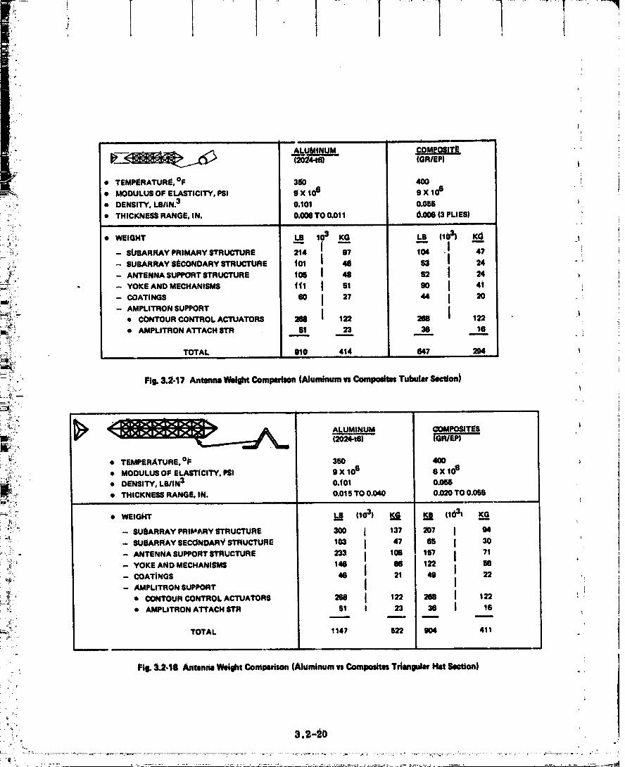
I
| ill
(2324-t6) (GRIEP)
• TEMPERATURlt, OF 3_0 400• MODULUS OF ELASTICITY, PSI 0 X 106 9 X 10⁶
': • DENSITY, LBIIN.3 0.101 0.055 )-6 i"
• THICIrJqF,SS RANGE, IN. 0.000TO 0.011 0.006 13PLIES) :^
_ _:" • WEIGHT LB 103 KG L8 11031 KG I
_' -" II I i: :;:;,: - SUBARRAY PRIMARY STRUCTURE 214 97 104 • 47 ?"_:!; - SUSARFLAYSI_CONDARYSTRUCTURE t01 46 53 I 24 "
:_'_; - ANTENNA SUPPORTSTRUCTURE t05 I 48 52 _ 24
,,:i - - YOKE AND MECHANISMS ttl I 51 90 I 4i i
- COAT,_S " I 27 ,4 I 2o ,.__,_,_.-- - AMPLITRON SUPPORT I_, • CONTOUR CONTROL ACTUA_ _ 122 288 122 "
'_.,:.m"; • AMPLITRON A'rrACH 8TR , 51 23 , 36 16 :• .m_
"_il TOTAL 910 414 647 294 l
:_ '" Fi_ 3.2-17 Antmn| W*IIIM Comlmllo, (Aluminum n Composites Tul:ml,r ,_,tion)
:..._"_,':i" ALUMII_IUM (_OMPOSI'rF.8
,. ! ,_ • TEMPER._TURE, o_= 350 400
i _:i/:. , MCOULUSOFELAS_CITY,m SX_0s eX_06
_/ • DENSITY, LBIIN3 0.101 0.058• THICKNE55 RANGE, IN. 0.015 TO 0.040 0.020 TO 0.065
_-_;!:r: • WEIGHT LB (1031 K._G KE 1103t K_G
:i:!': - SU_RFL_YPR_'_RYmUCTURE 3O0 I _37 _07 I 64__. -- SUBARRAY SECONDAR_ STRUCTURE 103 I 4? 65 I 30
_..:_.-_ _ - ANTENNA SUPPORT_rRUCTURE 233 _ 108 15"/ I 71
; .o0. -- YOKE AND MECHANISMS 146 (16 122 Io_;, - COATINGS 46 I 21 49 22 ,
: _: -- AMPLITRON SUPPORT _ i: __ * CONTOUR CONTROL ACTUATORS 268 I 122 268 I 122 L ,,
; _i • AMPLITRON ATTACH STR 51 t 23 38 I 16
'!_. TOTAL 114? [Q2 904 411 , •
Fil. 3.2-18 Ant, nna Weight Comparison (Aluminum t'sComlmsttes T_ngular H_ _,tton)
r
oi
_. 3.=-90
00000002-TSA05

L.........1......rll........I° I
! I_r,
t
• Materials - Materials considered for further analysis during the study were
an_lized aluminim and graphite composites. The latter appears to be a promising
_ ehoide for the antenna structure due to its lower thermal expansion arid high
sUffness/densit_ ratio.
• Eler_ent Member Shape - '[wo structural shapes were considered in the weight
analysts, namely thin walled tube and a triangular hat section. The triangular hat
sectiorl, although heavier than the tube, has considerably smaller thermal gradientst
across the section and is therefore a more deSirable section.
i: • T_ of ConStruction - T_ o methods of structural arrangement have been compared
on a weight basis; reetangul_ grid and a radial grid. The results showed that the
: rectangular grid has a 25% weight advantage over the radial design.
• Manufacturln_ Toler-'mees - The wall thickness tolerances on standard commercially•
/ available tubes are ±10%. A + 10%tolerance on tube weight would increase the"antenna structured weight by 13,600 Kg (30000 Ib).i
r
:_ • Antenna and Antenna Ba_ Size - During Task i of this study, slntenna Sizing relation-
shlp_ were established to aid in selectillg major antenna dimensions. Figure 3.2-19
i shows the result o_ these studies using early configurations. The trends are valid' : for the final reported configuration weight.
I
• Antenna Mass Properties - Figure 3.2-20 gives the weight, center of gravity, andmoments of inertia of the SSPS antenna. The moments about the antenna center of
i grav/t_, and about the azimuth yoke pivot are given for a total SSPS antenna weight
' of 1.67 x 10⁶ kg.
_ _ • 3.2.5.4 Antenna Structural Weight Derivation
, The antenna structural weights were derived using the results of preliminary load,
: _ thermal, and stress analyses together with "Structural Arrangement for the MPTS Antenna"
(DWG No. MPTS-001). Individual members were sized using a weight Ol_tim/zation technique
" which equates the Euler column buckling stress to the local buckling stress and the applied
_ stress. The sections resulting from this analysis wiU be optimum for giveh material
-- properties, section shape loading requirements and end fixity requirements. Figure 3.2-21
.. summarizes the weight, dimensions and quantities of the elements and beams which make up
. the structure of the _PS antenna. Incltlded are weight estiniates of the antenna azimuth and
I"!:: I 3.2"21 ,..•...
00000002-TSA06


i I.........I ......i ..........i.........-) I"_:' t
_t{_ .
; L:' ,':,.,w:
,.
' t
: o '&t,
i-_:!i'" a PIVOT , .I Z
3!2:: !. _ -|
=_:T';'" X
1. MASSPROPERTIESABOUTANTENNAC.G.! ,, •
: :__., i wEmt,:n" s.a xIos1.8 (l.s"/xlos Ke)" .: -- - 466FT 1142ME'IERS):.. yX__,, .. 0 101
: _:.,,. ,_ i" - o 1o1,.-_°* ', _ IXXICG) 126'/66x 106SLUG-FT2 1170487x 10° Kg_..)
:°:_:: _"' Ivv.(CSl Se_13xI_ " " (m x'm_ K_t_.)' o._. I_zlCa) s63_x losSLUO " 189920x 106 K_)
. ; 2, MASSPROPERTI_ESABOUTPIVOT
• __. . WEmGHT 3.68x 10⁶LB 11.67x 10⁶ Kg)
_., ._ ,, 466FT 1142METERS).. _i - o (o)- 101
" _" °win x_ s_.u_.__':i I ill(PIVOT) - 1170487x 108 Kill-, , ' iyy (PIVOT) - 91109x 106 " " 11:_697x 100 K-9__}
, _ " IzzIPIVOT) - 91189x 106 " " 1123697x 106 KO4Az)
, *_ ,;._ F_S._.30SSPSm.:mWm.n.Mm_? .
o . " tl
.!
•: t
,. ;_ : 3.2-23
OOOOOO02-TSAO8


, l:.t_3.
.... ' elevation Joint meehaniems. Figure 3.2-22 through 3.2-32 give the detail sizes and as_ump-
_,_:..,.. ] tions made for each item in Fig. 3.2-21.'. An lnvesflgatiozi was made to consider the use of a Linear Induction Motor (L_) for
_:_-': I the rotary J_tnt.actuation in lieu of a motorized gear drive. Figure 3.2-33 compat_es the./._ weight of the motorized gear drive with a large (4000 lb)LIM u_ed on the TACRV (Grummrmo;'
_ , contract to the Department of TransportaUon) and a multiple step motor concept. The.... antenna requirements ot low speed and high torque make the m,fltiple step motor a contender
,-_: as the #rive for the antenna.
_ ., "9 -.. ,'¢
t
• _'-_,.,m
' ):!/. -,
,!i ,. ._, •
,-2-" ., a. "
,¢
. ._ .: ,
kl ,s,
.. 3.2-25
00000002-TSA10

, I I l 1
i
L,
,:L i
i ,
i
NUMBER/ TOTAL
LENGTH. M HEIGHT. CM t. MM BEAM WEI(_HTLB KG
A. LONGITUDINALS 18 3.89 0.508 3 13.0 8.9
B. LATERALS 3 3.89 0.508 15 10_ 43
C. WIRES 4.2 0.31 - 24 1.7 0_
D. FITTINGS &ATTACHMENTS ?JS 3.5
TOTAL UNIT BEAM WEIGHT 33.1 15.1i
TOTAL NUMBER REQD/ANTENNA
CI RCUMFER ENCE 174TRANSVI_RSE 792
ASSUMPTIONS: PCAP 3110 LBoMODULUS OF ELASTICITY 6 X 10⁶ PSIL - 118 INCHES/ELEMENT. GRAPHITI_-EPOXY
Fi_ 3.2-22 Primry Structure(UPlxrq_llx)
i i 3226
00000002-TSA11

I "i 1 I "l
•_* _A' t,ONGITUDINAL8 _ ], _ 1 _ 8, LATERAL8
NUMBER/ TOTAL WEIGHTLENGTH, M HEIGHT, CM t. MM POST LB I_G
i,, |
A. LONGITUDINAL_ 38 6.71 0.762 3 66.3 119.7
" ._ Bo LATERALS 3 6.71 0,162 15 27,g 12.7
; C. WIRES 8.5 0.31 - 24 3.9 1.8
'_ D. FII"rlNG8 &AI"tACHMENTS 29.2 13.3
i . ,L
TOTAL BEAM WEII_HT 126.3 57.5]_ • m ,i
NUMBER RFr_D/ANTENNA
_, _ CIRCUMFERENCE - 174TRANSVERSE - ([84
ASSUMPTIONS: PPOST" 750 LB. MOOULU$ OF ELASTICITY 6 X 10⁶ PSI_ L - 230 INCHES/ELEMENT, GRAPHITE/EPOXY
FI0.3.2.23 Prim Structure(Posts]
!.
"* .1_ 3.2-2'7
00000002-TSA] 2

r .
MEMBER.L
NUMBER/ TOTAL WEIGHTLENGTH, M DIA_CM t. MM --6EAM LB Kg
A. LONGITUDINAL8 18 :_ 0.:_06 3 3.22 1.8
B. LATERALS 0.9 _ 0.20_ 1E 0.83 0.4 t
C. WIRES 3.1 031 - 24 1.8 0.8
D. FII"rlNG8 & lATTACHMENTS 1.66 0.7
..... TOTAL WEIGHT 7.40 3A
NUMBER REQDIANTENNA 1
AgSUMPTION$: PCAP" 30 LB, MODULUS OF E_ICITY 6 X 10⁶ PSIL - 118 INCHES, GRAPHITE/EPOXY
_-i _ • SAME AS SECONDARY UPPERSTI_UCTUREAND SECONDARY LOWER STRUCTURE.-- t
" Fig.3.2-24 Priltwry81n_'tum(Lmm' Capee)
_i.....
_i_. e
C
.. TOTALNUMBER/ WEIGHT
ITEM LENGTH, M DIA, CM ANTENNALS Kg
ii
A. UPltERSHEAR TIES 183.0 0.4 62 530 241
B. VERTICAL SHEAFITIES _.4 0.31 M 1310 _5
(:. LOWER SHEAR TIE| 26.0 0.31 2240 1900 864
ii_'' O. F II"IriNGS.PRIMARY 3Q41 21,800 9910
:_:, Fie.:L2-2Sl_maySm_.N IMqrn_.l_ml
00000002-TSA13

.,,'
.,i_i
:., ,4
• UPPERAND LOWERCAI_
ii SAME AEPRIMARY _TRUCTURE LOWER CAPS
' :_ • POSTS .-
__ ......... I TOT,,L:'_" :" " WEIGHT, ._ NUMBER/ i.
._:i. LENGTH, M DtA, CM t, MM BEAM , ,j LB, KG
":"::, ,, ,. 1. LCNGITUOINAL e.0 2.38 0.203 3 I 0.81 2.37
.... :_" 2. TRANSVERSE 0.g 2.36 0.203 9 I 0.50 0.22_ 3. WIRES 1.4 0.31 - 12 ,'I,.30 0.1d;
• _iil, 4. FITTING8 & '.
:. A'rrACHM TE I 0.48,- _- ; TOI"AL BEAMWEIGHT '
CAPS POS'r_
_:, _ NUMBER REQD/ANTENNA ' ' " ,_/ANTENNA• _ CIRCUMFERENCE 174 CIRCUMFERENCE 174';., " " TRANSVERSE 4717 TRANSVERSE 2/ ?7
!. _ .... Fig. 3.2-28 Secondary Sl,ru_re
_-:_,:.. . .
• ;_"_:"" B
• _..,
' _ NUMBER. TOTAL WEIGHT_" ,_ ITEM LENGT;,4.M OIA, CM .. ANTENNA LB KG
• =
; A. LOWER SHEAR TIES 25 0 31 2,')40 t930 d77
• = B. VERTICAL SHEAR TIES 18.7 0 31 4881 3160 1436
C. FITTINGS-SECONDARY 3019 18.000 8182.;' L.......
; , Fig. 3.2-27 _ndary Structure Integration Items
:--:
=- • . : 3.2-29
00000002-TSA14

-,.%•
.L .
iw
t
4
Z
i.i • UmSEn L I
', !
:" ELEMENT MEMBER NUMBER] MEMBER TOTAL WEIGHTMEMBER HEIGHT, CM T,'MM LENGTH, L, M ANTENNA WEIGH1",LB LB KG ;
j A e_ 1.2_ 88.7 8 I_1 4032 ls38
i };" B a._ 1_ _ e We 4_ 21_ :
_i (: _27 1_ :87 4 217 m8 304j FITTINGS 38 380 172
_'_i"' TOTAL PEl_tANTENNA 10,082 4582,,_,_., n n n ill n_
_ ASSUMPTIONS.
i .. ' Pmmdmr ,, 4000 LB,MODULUS OF ELASTICITY 6 X 10⁶ PSI,PINNEO END,[ ,i ":_/' 118"IELEMENT - GRAPHITE EPOXY ...! ................
'- : FIe. 3.2-28 ElevationJoint Support
[ "
| "i '
t
.£
O0000002-TSB01

i t I I,,,r-
b
i
i i
_i_it • ELEMENT HEIGHT 6.27 CM_ :. "" • ELEMEI_rTHICKNESS 1._ MM
(! _ i. • ELEMENtSPACING 3 M_:", ; * • BEAM WIDTH 3 M• • BEAM UNITWEIGHT 3.44 KgiMETER
"' • TOTAL MEMBER LENGTH 4876 MitrER84_ mk _
:, "° • ..,------.WEIGHT --LB K9_ - MEMOeRS ._mOi 1_7a
T " -- B_AIM FII"rlNGS 1500 682
_.. - MISC ATTACH. 3840 1745
_ - TOTAL YOKE 42241 19200
_i ' ii i i . ,, i i
_ "_" ASSUMPTIONS:
':" _. P member - 6000 LBoMODULUS OF E_LASTICITY 6 X 10⁶ PSi PINNED END COLUMN:._', _ L : 118o INCHE_/ELI_MENT, GRAPHITE.EPOXY
_ : Fig.3.2-29 ElevationYoke.t ,
t
B.
, !
'; _ " 3.2"31 t
o', o,, .f_ , ,....%
0
O0000002-T'SB02
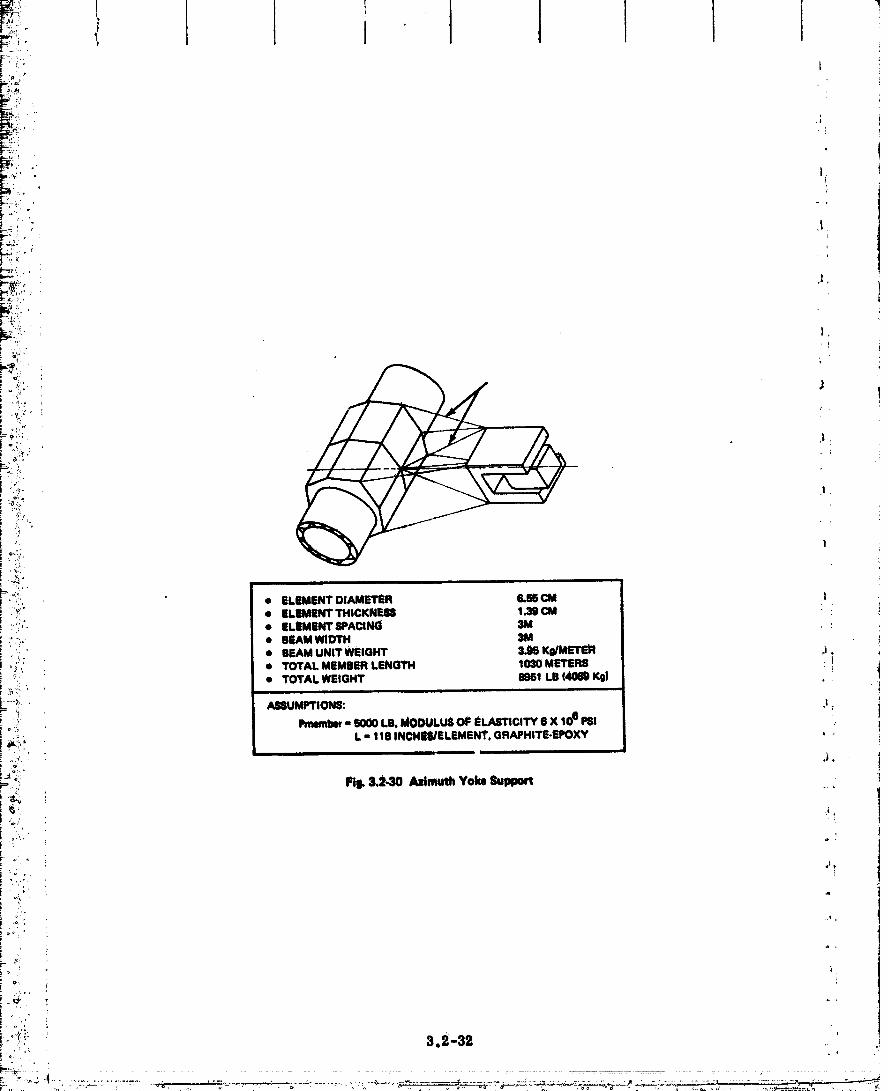
_il, .i_ l
i'
r-
r--,'-;'.".;p; :: , ,
g; i._i ,l
I
'-, ,/.c. |'oi/. "
J,
_:_!:, • EI.EMENTDI_METSR IS.SECM• ;, • EI.EMENT THICKNIF.88 1.3_ CM
:"_:/'. • ELEMENT 8PACING 3M
,,';:;,. • BEAMWIDTH 31Vl_' rf I BEAM UNIT WEIGHT 3.96 K0/METE_ ?/: ; )
_, • TOTAL MEMBER LENGTH 1030 METERS i'L_ • TOTAl. WEIGHT 8951 LB (Am K_ .
__.._: _
±-_.... ASSUMPTIONS: ,l.
' Pmemlw- 6000LB.MODUI.USOFSLASl"ICOTYiSX10"PSI :o _%
l, ,, 118 INCNEII3ELEMEN_. GRAPHITE-EPOXY •
: .."; FtI_3.2-30 AzimuthYokeSupport
.,,_"_,." ! ,_
.°, ;
F i
O0000002-TSB03

1i
:' " I ' • ELEMENT DIAMETER 6,_!; • ELEMENT THICKNESS 1.39 MM
• ELEMENT SPACING 3M. • BEAM WIDTH 3M
'I * BEAM UNIT WEIGHT 3.95 Ks/METER;_ • TOTAL MEMBER LENGTH g_32 METERS
i -- BEAIV_FITTINGS 1500 682 :, t,
_ -- ATTACHMENTS 8694 3952• m *mmmmmml
i 1'_ it i TOTAL YOKE 95833 43410
ASSUMPTIONS: Pmeml_r = 6000 LIB, MODULUS OF ELASTICITY 6 X 10⁶ PSI,_ PINNED END COLUMN L = 118 INCHES/ELEMENT, :
_ GRAPHITE/EPOXY
:__ Fig.3.2-31 Azimuttt Yoke
!. i4 -, 4
!,(_'eo
, i _..' ,_, 3,2-33
O0000002-TSB04

I
AZIMUTH ROTARY JOIN'I"
•; • ANTENNA SPEED 0.728 X 10.4 RAD/SEC 1• GEAR REDUCTION 2.47 X t06 i
., • MOTOR SPEED 18.4 RAD/SEC _ ,
• MOTOR TORQUE 2.8 FT-L8 (THEORETICAL.NEGLECTINGFRICTION .t r
: • WI_OHT I..0 I_ _-- GEAR BOX & MOTORS _ 10638- DRIVE 2389 1008 I.
ILl:. - BRUSHES 1100 BOO
; ,: TOTAL EACH 48750 22158 ].
_I" (TWOREQD, (97500, (44316)
_!; ELEVATION JOINT, }.
• TOTAL WEiGHT - 12.150X2REG- 24.300LB . ,.I11,046 I_
!
_" MECHANICAL (MOTOR/GEARS) LINEAR INDUCTION MOTOR
-_:.' I_,NEAR 8i'EP TACRV
' GEARBOX 24085 LIM 2214 4000 J tj,:
, :- [-i_ DRIVE 2389 , ARMATUR_: 432- 1000 •
.'--_;! BRUSHES t_00 BRUSHES 1100 1100 :i
;:.o w,,,I,o_ _ _,,I,ORT S000 eO00
:: ), ,. EACH 36541 EACH 11746 12100
i: _*:"': 2 REOD (2) 23492 (2124200 "
±i • CONDITIONING 4000 1220e
: ._. TOTAL L8 13862 TOTAL LB 21492 :i6408: , K9 1332161 lg (1_001 1161001i%;,: ,,: ,
: Ftl_ 3.2,33 Rotary Joint Drive (Mechanical vo Ltni_ Induction Motor)
_' ,
! -L, "
=_ 3.2-34
O0000002-TSB05

" 3. $ CONFIGURATION ANALYSIS !
3. 3.1 Cont_.._yais
The vharaeteri_tlcs of a phased array Microwave Power Transmission System ellml-
_. hates the need for mechanical fine pointing of the antenna. Sibnlal phasing compensates for
_. misallgnment and distortions in antenna surface up to 1/16 of a wavelength with minimal loss i
in transmission efficiency. An overall antenna misalignment error of ± I are-rain can be
tolerated by the subarrays. The purpose of this subtask is to define the environment and
load requirementB for the design of the antem2a pointing system servomechanisms, deff_e
:_ the best accuracy that esiz be achieved with this system and identify the likely design
'" approach.
3. 3. I. 1 Spacecraf_ TorqUe Environment
Figure 3.3-1 summarizes the torque environment for the baseline SSPS system
_ (Ref. 2). Torque calculations are based on the Oonflguraflon data presented in Fig. 3.1-24
and the foHOwin_ additional groundrules:
_i • Baseline orbit - equatorial geosyncbronotm
• BaSeline attitude - long axis (X-axis) perpendicular to orbit plane, the solar array
_I normal (Z-axis) parallel to the projection of the sun vector onto the orbit plane.
: The exteraal disturbance torques are induced by aerodynamic, solar pressure_ magne-
i_ ,_ tic end gravity gradients. Gravity gradient torque predominates the induced torque enViron-
me_t by several orders of magnitude mid will be the only _ourco of external torque used to
_i define mechanical system requirements.
Control system torque levels are limited by SSPS structural bending. A force level of
i__ 2980N (667-ib) used for orbit keeping and applied at the comers of the solar array, was
found in Ref. 3 to be the maximum force at which structural deflections can be limited to
_!_ ± I deg. This force, however, induces symmetric bending and does not affevt antenna
"" motion. A 44.5N (10 Ib) ooupled jet firing is used for attitude control and induces anti-
symmetric bending modes which do impact control _ystem design.
:: " 3. $. 1.1.1 Antenna Motion Relative To Spacecraft - Figure 3.3-2 shows a typical system
that pro_qdes rotation in azimuth and elevation. The azimuth rotary Joirit is located at the
mast interface between the antenna assembly and the solar arrays. Azimuth motion is pro-
'_ "" vided by variable speed motor drives located _t this interface. An actuator f0_ elevation
i _- control could utilize proportional linear control (worm gears and linkage} arid would be
_ located at an offset distance from the main antenna-to-mast rotary Joint.
, 3.3-1
00000002-T$80

J I I
: {
i i| _J
8OURCE TORQUE ,_Ti) COMMENTJ i in IL •
AERODYNAMIC N/A At analtitudeof 19,333 fl rot, the atmospheric_ densityisequtvalmttomeplasmaprotonden_W: i
- 3.4 x 10.24 kgm m3 1
(3.0x i0.22_ug/ft3) _Theresultin0forceontheSSPSis:
x1# Nm(sx 104 ib) l
"" Tile relatively low magn_/cla and IllW|tlng torquecan be ignoredm afactor indesign_f medlenlcal
:; interface(Ref. 1). i
SOLAR Tx = 136 nswton-metar Total SolarCollectionarm = 49 x 108m2i (100 ft-lb) _olar PreaumConstant= 48 x 10_i nmvlonlm_" )
. Ty - 6550 neww_ Separationof Cp from og- 25m (Rlf. I)(4t00 ft-lb)
., T, = (_0
" MAGNETIC N/A Adjacent
Early unit magnetic field in the system has ;i. oppos;tepoJar/tyvv_tha net magnetictorque
of approximately zero. (fief. 1)i i
GRAVITY TV - 3100 rmwl_nm/de9 The systentX axisis perpendicularto the orbit ideviatio(1 plane resulting in zero nominal torque about y
_ (23,000 ft-lb/deg_ and z axis. Small limit cycle motions (_10) (_ause
. Tz = 27100 newton m/deg destabilizingsprin9torques. The y andz axisdeviation rotate through 360 ° per orbit and produce
(10,O(X)ft-lb/deg) torqueswith the max valueshownwheny andxaxesare at 45° to the verti¢J. The periodof this
TXmax ,, 12.1 x 10⁴newton.m disturbenceistwiceaUay. (Ref. I)(8.97 x 10 ft-lbl
CONTROL Tx - 6.754 x 10⁵ Impulsivejet form limitedto 667 Ib to limitnewton.meter S_oSstructuraldeflectionsto less1ban-+1°. '
, (4.979 x 105 ft-lb) (Ref. 1)
Ty - 7.8 x 10⁶ Max torquesassumecoupledflringL" neWton.meter _ '
(5.78 x 106 ft.lb)
Tz - 7.9x10⁶• hewton-meter
(s.7ex 1# h-lbI
Fig. 3.3-1 SystemToNlue Enltronment
3.3-2
.....................................C)O-OffooO2_TSB-07
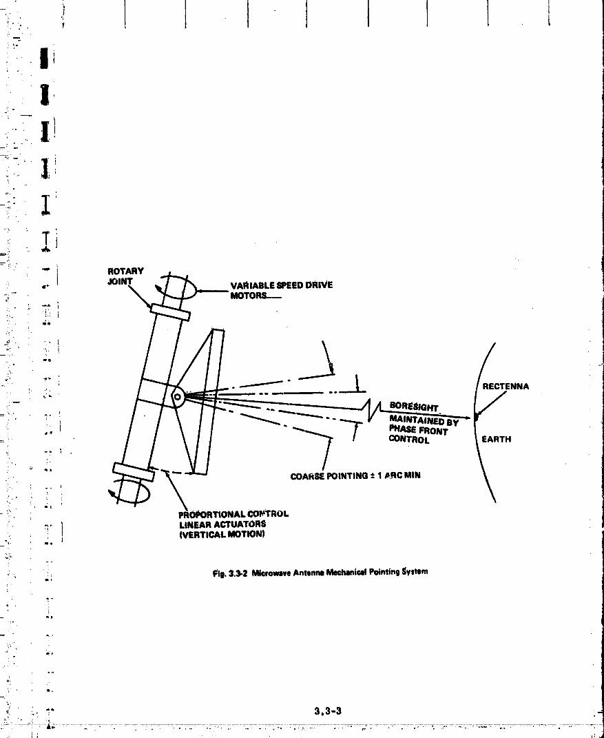
_lb
mqtROTARY
•_: JOINT"" VARIABLESPEEDDRIVE
;i ' MOTORS--._
....... RECTENNA
/ ' _ PHA$E FRONTCONTROL EARTH
COAliSE POINTING ± 1 _RC MIN.. %
• iQ_
_i_/
_" ) LINEAR ACTUATORS] (VERTICALMOTION)ma
*: ' _. Fig. 3.3-2 Microwave Antenna Meehamicat Pointing System
'2
q ,
Z
'_'_ "' " 3.3-3
00000002-TSB08

The eleman_s defining required motion of the _tenna relative to the spltcccraft include
the nominal motion between the stm-oriented SSPS and the earth pointing antenna, the normalt
SSPS cOntrol system limit cycle, and the bendi/_ motion of the SSPS mast at the antenna I
interface. The 0nee-a-day 360° rotation of the sntenna reiaflve to the long axis of the solar
pointing spacecraft is required to maintain boresight poiJ_ug to the rectenna. Additional IIautemta motion in azimuth and elevation is t'equired h) compensate for normal _1 ° space-
craft limit cycling. The modal characteristics of _he SSPS affecting the antenna elcvati0n 1
drive is shown in Fig. 3.3-3. The normalized modal displacements, _, and the normalized I
modal slopes, o, corresponding to each mode, _ identified at the ends of the axis where
the control actuators ___dsensors for the SSPS are located (data presented in Ref 4)° Also
included is the anti-symmetric moc_e shape used to determine movement at the antenna !
interface driven by a coupled firing of the 44.5N SSPS attitude controllers. Maximum [4
antenna motion due to bending will be approximately 0.15 ° st afrequency of 0.018 rad/sec.
FigUre 3. 3-4 summarizes the system angular motion requirements for design of j
|
a
mechanical Interfaces between the spacecraft and antenna. Control error signals will beI
sinusoidal with a frequency equal to that of the SSPS control system limit cycle. Anti- t
symmetric bending motion is superimposed on the basic control motion. The minimum
azimuth antenna rate is equal to orbital rate, while minimum rate in elevation fs zero.
Maximunt azimuth rates occur Just prior to SSPS Jet firing and are induced by gr_tvity
gradient torques. Maximum acesierations occur at Jet firings in azimuth and at peak energy
points in the anti-symmetric bending oscillation in elev_en, i
3.3.1.1.2 Antenna Disturbance Torques - The rotary Joint configuration shown in Fig. 3.2-2 _
: consists of four equally spaced rollers attached to the solar array mast (Ref 5). The rollers
slide on a track incorporated on the rotating mast. There are two sets of ro|lers at each
rotary Joint. Each set of bearings transmits bending moments through the mast segments
by normal loads in each set of rollers. The critical mast bending moments result frOmt
loads induced by spacecraft gravity gTsdient correction torques. These torques produce a
3600N. m bending moment which results in rolling friction torque Of i077N, m in each set of
rollers. (The Teflon coated ro|lers have a Coefficient of friction against rolling of 0.05. )
The slip ring brushes also induce fr/ctional torques. Contact presgdres between the "
brushes a6d rotary Joint ri_ will vary betwee_ 27,550,_/m 2 and 68,940,'_/m 2 (4 and 10 psi)
for Optimum power transfer. At an assumed _system voltage of 20 KV and a brush current
rate of 7.75 x 10⁴ A/m 9-(50 A/[n2), _. 45m 2 (104 in2) of brush area Is required to transfer
10 GW of power. The total normal forc_ is 4.45 x 10SN (1051b) at a 0oeffieient of friction
3.3.-4

+ ' ] I I I I I+', _ |° .b I t!,,4, '2
'i_i i
' |.J
f .
i i'. [
:
" _LJ
:'_..... t\-_, :,, .AtM'TEN_A/ / .:. ,.._, I100I.B xl +_L _yd[(IO0LII;
�!'_ " mrs'/ \ I I_'-_-- /" END
V I+ .-"P?;
; +."i.'• .".". ANTfNNALOCATION
: y
_-+'" _-_ i
i•."" ' 1 NORMALIZED DATA AT SIPS TiPSi iMODE 1ST SYMM IST ANTI.SYMM 2ND SYMM 2ND ANTI-SYMMi+++ ' +
:i-c-..... 1FRe_ENCY Ii:_., _;. _RAD/_EC" 0.0076 0.0178 ._1 0.(_i 4 0.025 ;:: .... 1"-i " !GENERALIZED : i_ Imm.m.uo+ _mm76.I Immm. , ,ram. _ 1,oo,e.
+.C I i
,i :i :i' ;STRUCTURAL I!!, ; ' DAMPING 0,0 0.0 0.0 0.0i o i
.4 ............... ?,
i-;".. • RIGHT END[ _ , "i
-.' '.. ' DISPLACEMENYO +1.0 �$T�h�-0.7t3_0.180 b_- i..- ...... .t+- *
b
! RIGHT ENI_I-,',:: ; NORMALIZED '.
_i'. ' _ t SLOPE (RADIFTI ; +0,864_103 ' +0,18xl0 "3 1.191x_0 3 _0.353x10"3
e
- ANTISYMMETRIC DI_LECTIOi_AT ANTENI_A QIMBAL MOUNT
"_ "' ' " FREQUENCY _ ,0178 RADfSEC
_" '' I 8 = "-.0027RM)SLOPE _ " "-4.E7_+10'5 RAD,_SEC
_,. O.P _'- -o_._o+ ,,_ _ec_:'+.,,'. +. O,e_,
_L: ","
" Fii. 3.3-3 ISPS BvndingModeData
i + +
i . + .. a.a-_ +
........':,+'+,_i+:-:.+. . " -_ ....... ._." ........... s-c +_:......... ::..........+++......... ,............................................................
00000002-TSB10

! I tI I !
i
i_ ]
I
*" AZIMUTH ELEVATIONPARAMETER 8EFIVO 8ERVO COMMENT
i ii
CONTROL A(t) = Wet* K 8m2wet E(t) = KI Sin_et _oe = ORBITAL RATE
_, VARIABLE _ K2Sl_omt _m "ANTI4_dMETRIC MODEFREQ- _18 RAD/SEC
K1 • ATTITUDE DEAD BAND• il °
_ _ - AKn-mrrmc BE_DINDMOVESLOPE- ±.ommRAO_ K Sin2wetSIMULATESCONTROLMOTION WiTH A PERIOD t_: EQUALTO THAT OF GRAVITY GRADIENT TORQUE.
i;* _ PAINRATE .728 X 10.4 RAD/I_EC 0,O ORBITAL RATE
_ MAX RATE .m X t0"1RA_/K-C 3_ X 10.2 RAOm|t: MAX. RATE BUILI_UP DUE TO GRAVITY GRADIENT t
! ' SLEW-RATE .728X 104 RAD/SEC G.O ORBITAL RATE
MAX ACCEL. 1.5 X 10.7 RAD/E_ 8.06 X 10.8 RAO/SEC2 CONTROLTORQUEIN AZIMUTH; ENDING MODE ,!* _ RESPONSEIN ELEVATIONi!_ :' POSITION
_: ACCURACY. 1 MIN 1 MIN
I_ Fig. 3.34 fdmm_itm Environment
_,
_.

t I ! It
I c¢ 0.1 and a m_t diameter of meters, I. 02 x m (75 x ft-lb) torque106N. 104d0 of is Included
by the nllp rings. Figure z. _.1_shows tht, torque Vart,_on with power leVbl.
Antenna gravity gradient torques on the rotary Joli_ts arc calculated using the equations
shown in Fig. 3. 3-6. The disturbance torque is approximately 354N. m/dog (260 ft-lb/deg)
1 offset between the antenna bo_'esight and the local vertical. The noml_lal antenna azltnUth
angle is offset 2.6 ° as a result of locatizig the spacecraft at the stable node point, 123° West
"_ longttttde, and the reetenna at 104 ° West longitude. An additional 3. fib offset results from
"" eccentricity drift caused by solar pressure on the solar arrays. The elevation angle offset
-" is 6.5 ° touted by locating the spacecraft off the equator and the rectcnna at 40° North
,, latK'ude.
"- The next highest disturbance _n the antenna serve system results from electromagnetic
_ " ' radiation forces. An estimate of the force created by the electromagnetic energy radiation
from the antenna has been computed (Ref 6) assuming a total power lnpttt of 1010 watts and
, a frequency of 3 GHz. The force is Calculated by replacing the electromagnetic fields at the
aperture of the slot array by equivalent current sources and computing the forces on the
_ image currents which replace the aperture ground plane. The result_ predict an electro-L
n_gnetic force pressure Of 2. 3 x 10-_N/m _ l_ormal to t:he antenna and a corresponding totali ., _, force of 18N. ,_
Although the electromagnetic forces do not place a significant design requirement on
_ the antenna control system, the constarlt force in the r'tdial dii'ection does require the SSPS: ;
to contindally perform orbital corrections. An acceleration along the radial direction does
i not slgtflflcantly modify the energy of the orbit. The orbit will develop an eccentricity but
the orbit period will remain almost constant. The force of 18 Newtons will cause a r_,lial
:, _ perturbation of
"' _:txR = 1.852 km 0..00 n ml) _
_ by the 80th day. (This same acceleration along the velocity vector would change the semi-"" major axle by (120 n ml) In the same time. ) The propellant: requirement to make an altitude
_ correction of 1.0 n ml for an SSPS of 106 slugs and an ISP - 8000 seconds is,
_, W _ 6.7 kg (15 Ib)p
i _ "llals would be equivalent to a yearly propeil_nt requirement of,
_! Wp = 30.8 Kg _68 lb)
.,, 3. & 1.2 Pointing _ Control
• . Qualitative and limited quantitative data has been generated for defining mechanical,:
_, steering of the transndtting antenna. This data will be used in an overall assessment of• !
3.3-7 i
00000002--I-$B 2

° I ! Ii 0
i
I
i .' ,. ..
00NTACTPlIIIIIUIlll- II_ tCURRENT R&Tl - 80 A/in:
1
D,
J
6• . l
o
i
1J 1 I ! .I, I I | J-
:_ 100 2OO 3O0 400 6OO 6OO 7O0 mO 9O0
• tOROUE REQI) TO OVERCOME SLIP RiNG FRICTIONIx _000FToLB)
• I .i l, 1200
- IX 1000 NEWTON METtRS)
i _ FiI_ 3.3-5 Slip Ring Friotic_nTorque
i-r'' ! ,F. T "T G 4. FedSiN_)
_-!_ _ _T' To-_=,?.z-lx_SIN:_ _,- _.,X,0"_
i. : IM'I£RE
" To - GRAVITY GRADIENT TORQUE
Is FI - RAD|AL FORCE DUE TO DIFFERENCEZ- AXiS tN B/C AND ANTENNA ORBIT MOTION
Ftg, 334 Cont_ System RequlnmenU
i , 3.:)-8
...."..... -............... _ ................................................... 0 "00 - -- '"- '"'-0 O002-TSB13.......

Il I
. . .
f
i_' microwave beam phaao front ront_,'ol. The reaulta of thia effort indleato that n,_.chavdotL!
i : steering of the _t,_na to aecuraclea bot*nr than 1 are-rain _:o readily achieved withouti " atfoBts_tlal Increase in control system torque or horsepower rcqtllrc_ncnts.
/, Figaro 3.3-7 summarizes e_ntrol system design used In preliminary assessment.
: .. The initial response of the motor drive will be to relieve torque loads on the antenn8 Induced
by spacecraft (SSPS) disturban_s. These spaccot_.ft disturbances include grav!ty gradients,[ /i !
• : _mdlng modes, al_d normal satellite limit cycling with a time constant of 12 hours.:t
_ _/ Spaceersit bondl'ngmodes couple through _e rotary Joint and are of the form:
e =^ s cos%t.i_ This motion is coupl_i _ the antenna through rotary Joint friction in l_._thelevation and
azimuth. Antennamotion of the form
, O = Asin ¢_stf
t due to spacecraft bending dynamics which is coupled into the antenna only in elevation. This
_, occurs beOmase the antenna system uses only a 2-axis g_mbal system. This coupled inertiid
i lodldintothe mM;elmais relatively small.
" The gravity gradient disturbance hss been neglected in this study becsnse it is orders
_: of magnihtde less than the coupling disturbance and frittion torque. The 1° satellite limit
_ '' oyole Is also neglected wlth the rationa][e that the 12--hour period Is sufficiently long to
i" ass_ume that steady state conditions exist.
_, _he preliminary system design Is modeled as a motor directly driving the antenna
b,; through a shaft. C_aring dynamiOs and selection can be made with detail analysis at a later
_) i date, A study of control torque requlrememts and power requirements indicate that they are._/ insensitive to variations of control frequency within the range studied. The sygtem size
: _ requiremmts to achieve 1 arc-rain are:i
.... : _ : ' AZ : 1"02 X 106 N.m torque;
_ ,_ ' 0.18 hp
, El: 2830 N.m torque;
-,, 1.8 hp
'_ _ 3. 3. 2 Thermal _vaiuatlon
l_ "_ .... DUring Task 1, the analyses were centered about studies of the sensitivity of temvcr-
_ atUre level and temperature gradient within the antenna sup:-orting structure (Fig. 3. 3-_) to
_'o!. "_" parameters such as a_itenna size, powei-.transmitted, efficiency of microwave converter,
r'_i.. ]. thermal radiation properties of structure, anti spae_.ng of structural elements._N
_.,, . 3.3-9
O0000002-TSB14

I_aU_ne RAil
'%
OOMPENSATIONI
ITOROUm ++Lomc I ---l-xF' e..- ITF
(MOTOR
eAC eA !
(RATEGYItO)
POSITION 8ENSOR
NOTE: KFF ,, l_oC
I
I - ANTENNA INERTIA (SLUG 6 F121 t
KFF - FRICTION COMPENSATION GAIN ($EC)
_". TFF - FRICTION TORGUE MAGNITUDE (FT.LB) .+
Wc - CONTROL IWb'I;EM BANDPAt_ F.REOUENCY.IRADISEC) l
TM ,, MOTOR TIME CONSTANT (SEC)
• EISA ,, I[;TRUCTURAL DISPLACEMENT AFFECTII_G ANTENNA POSITION• (RADIAmM
- StRUCtURALRAteAtFECTmm_m_mm FORCESIRAO/SEC+eA - AmT_NNAmSITION(ram)_A ,, ANTENNA VELOCITY (RAD/EEC)
e A - ANTENNA ACCELERATION (RAD/SEC 2)
T ,, TOTAL ANTENNA tORQUE (FT-LBI
TF " FRICTION TORQUE (FT.Llll
TM • MOTOR TORQUE IFT-Llil I
Fig.3.3-7 PrdtmlMryDeliln ControlSystem '+
_. 3.3-i0, _ ..... , _ _ " -- . +k '74 r I" "y ++" =+ +m "= " = ,
D
.. -....... ....+.. _:-+_~,+_]-+_ (+_ .. , ,.+ _.+.+ _ _ .+.............. +,+ -;; .... . • +...... +++.. ..... . :
'.. j. , , ..... • .+ .
O0000002-TSC01


=_.i
_; _ For propose of selecting cmadidate materials for the support structure, the maximum
_i:. expected temperature must be determined. Should the suI_port 8tmotum be used as an
_"_' electrical distrib_ system from the solar arrays to the microwave converters, temper-
_/, "-: ' ahtre level will also be required to estabUsh the eleotrio_ reslstanoe Of the oonduotors.
_,,_,,_. Reference II states that the m1_zut power trausmlsslon distribution will be Gaussian
_ r " _ cross-section. With the present method of rejecting heat from the nflcrowave converters,
_._!:2._ ! the radiant heat flux to the antenna support structure will also have a Gausslan distribution. _,
. '_ Figure 3.3-9 gives such a distribution for a 1 km diameter sntenna trsnsmitti_ 10 GWwith ...... a microwave converter efflole_oy of 90_. J
_i;,:i The maximum structttral,temperature will ooour In the member that Is closest to the
_i:ii_! center of the antenna where the radiant flux is maximum. Temperature magnitude will.'_:'-,_., : depend on the %/e ratio r." the element, the geometric shape of the eleme_,.Jo a minor_/ extent the t_stmce of the element from the antenna surface _or distsnoes up to _ meters )
_i_i ' the var/ation Is less than 5°K) and, to a major extent, the ms4p_ude of the radiant fltix.8_.. '
.+_... the center of the sntema. This last factor depends on mloxcwave converter efficlency_"<,. |
;_: .spacing and power trsnsmfited.
_:_:" Flgttre3. 3-10 shows nmxinmm structural temperatures as a function of transmitted
L:_,,. power for three antenna diameters and two microwave converter eff_olencies. The three
_-'_" basic trends are. (1) inoreub_ the transmitted Ix)we_'.inom_es the maximum struotursl
-_, temperature, (2) increasing the efficiency of the mic_wave power converter decreases the
_./_._):;_i'/ maximum structural temperature, and (3) increasing the diametbr of the antenna decreases
=_
__,o After completion of Task 1, Raytheon selected the followi_ values for the antenna
-_ parameters (Ref 13):_%.; i
"? • Antennadiameter li_n
:_., • Radiated pOWer 6.45 GW
_:_.. e Amplltro_ OUtputpower 6kw
_,i_i _ • Amplitron efficiency 85% ._
: i i • Kiystron outi_: power 6kw
! : • Klystron efficiency 75c_> ."
"_ • Illumination exp (-2. SOlr/a) 21
i /', !
i", " 3.3"
00000002-TSC03
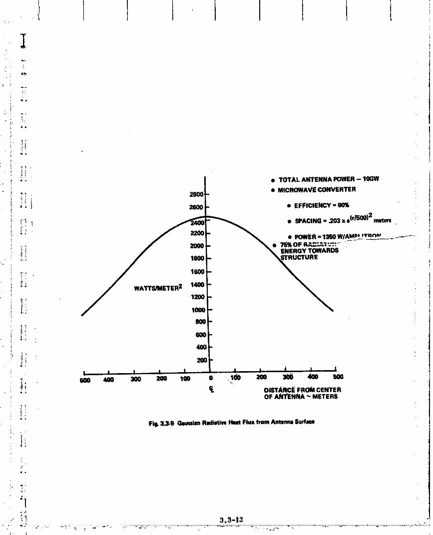
:!
_ Je
f_
_' _li
i • TOTAL ANTENNAPOWER- 10GW_: _ _, • MICROWAVECONVERTERi " 2800-i._ _ _t' 2600 - • EFFICIENCY- 90%
i _--; _ • SPACING- 203 x e1r/'500)2meters ::), 400
! • eOWEA-,13S0WlAe_'.eT'=n" .... ---..... - _ • 7S'X,OF-R,e,.._._';.-:':_..--. .
i' _ljI "_. E.NERGYTOWARDS '
.:-: 1600
1 '
i
i i J i ,i I I J, I , i I
' i _; 600 400 300 200 10o o ". Id0 200 zOO 40o soO• i "-; _. DISTANCI:FROMCENTER
OFANTENNA-,-METERS
JiC: Fig.3.3-9 GamsianRadiativeHeatflux fromAntennaSu_imt
J:
:i
i,
"!
, i
00000002-TSC04

i I ] I I I I i
I
I
i
I_ - / / tKMDIA
; • MAX. T NOT /
::; _ KNOW FOR / _ _ )_, 600 VACUUM CONDITIONS /
: _ // .I / n-90%'_" _ / _ " _ 0.7 KM DIA
.... /_- J
i MAX. T FOR POLYIMIDE& SILICONE RESIN REINFORCED PLA_I'ICS" -_
" soo. ./ / __ _" q-m_' '_ I / _ _ '°_'- _IKMDIA .
-:. : _ 450 -_MA"X/T'-FOR--'AL"_I GR"_EP......._ _ .....
400 I-I / /_ _ ._"- / _ OF WASTE HEATTOWARD6 STR_UCTURE.- ": II//_YOF STRUCTURAL It_EI_B-ER
MICROWAVE CONVERTER SPACING £ " .2' meW.-, ._rdl, i m I I I I I 1 I I I I i I I I 1 I I I i
' _ 0 1 2 3 4 5 6 7 8 9 10 11 i2 13 14 15 16 17 18 19 20
i TRANSMITTED POWER ", GW
._ ; Sill.3.3.10Mutmuti_stmstw_T6rUermre. Trilnsmltl_l
., T
00000002-TSC05

i 1
i
]If;: L = Lmin exp ((r/466)2)
; A_zanalysis by Raytheon revealed that 87.5% of the waste heat generated in the micro-
_ wave converter tubes would be radiated towards the antenna support structure, with the
_ r_ 12.5% belllg rsdlated out of the opposite side of the mztenzia su,-face towdtrd earth.
:/- " Thermal analyses of the following key problems were perfozlned using the above values
,: for the MPTS parameters. Geometry of beam cap elements, temperature difference between
:_ beam caps, column temperatures, and effect of microwave converter spacing on the waste
' heat profile With its attendazlt effect on beam and column temperatUres.//•
>:" This study involved determining the maximum temperature dnd the temperatureP_ a •
;: difference Within structural members having tubular,hlgh-hatand triangular erase-sections
}/ _ (Fig. 3.3-11 and 9.3-12). MaximUm temperature is important from the materials selection
and Strength standpoint, while temperitture gradient is important becmme of the induced
/ thermal stresses. The structural members considered in this study are those that make up
i: , _, the beam cap and are in a plane parallel to the antenna surface (Fig. 3. 3-II). (Members in
:_ a perpelzdicular plane were _nsldered separatc|y. ) They ai_ heated by radiation from the
f .. . _ hot antenna surface below it. For this study the ante,,ma surf.ace at the center was taken to
have an. effective temperature of 600OK which Is approximately the situation when the antenna
is 1. 0 km in diameter and trmmmitttng 6.45 GW With a microwave converter efficiency of
- 9'6%
_ : The temperature analyses were performed by subdividing the particular geometry into
;,.: nodes (betweem 8 and II, depending on the shape) and determining the radiation couplings
il between the/,odes themselves and between the nodes and the autenna surface as well as deep
space (Fig. 3. 3-13). The computer programs CONFAC (CONfiguratiOn FACtor) and AF1
_:: _ (script F) were ttsed to determine the 50 or 8o Significant radiation couplings. Conduction
: ' _ effects were neglected, which Is a conservative approach, pending material and thickness
_' selections. Once the mathematical mc tel of a geometry was established the computer
• : program SSTAI (Steady-State Thermal _nalysls 11was run to evaluate temperatures. The
results of the investigation are discusse _-t.
_: _h3.2. 2 Ttt_ular Cross-Se_tion
-: : Figure 3. _-. ,-esents the maximum _ml_erature that a structural member with s
: tubular ca_ss-section will experience as a function of the effective antenna surface
._:; 3.3-15
V/
0k_ _
00000002-TSC06

,r CONTROL TORQUE (

J
• - j ;:
!' 1_'
' i
•_, SAMCA."! " _ ' I _ ELEMENT
i ,- TUllE
i.%. " : i_.... i, Hi(;. IHAT
i- * . | '
i
_"_ I|
i.o i!_: , . . I"_tlANGLE
I Fig, 3.3-12 BUm Cap Element Geometti_
,i
I
3.3-17
,' !
00000002-TSC08

OEEPPACE I
!:
Jl
SOLAFIJl
LOAD|
NODE- I '
FOR OTHER NODES)
J
3.3-18
............. 00-0-00-O02-TSC09--

* T 1̧ 1 1.......f ....0 i I I
t I.k
t
1
NOTE
• THINWALLEDTUBEASSUMED: (I.E., NO CONDUCTION)
" • RESULT(I ARE INDEPENDENT_)F TUBE DIAMETER
i • SUNLOADTAKENA8 ;[EROTOMAXIMIZE AT ACR088 TUBE
?00 DEEP 8PACE r ,, 0.1'" :: I (NO SUN-LOAD)
. : eOUTE R ,,.It ,,_ elNNE R " 0.4BLASTED)
TMAX INNER 1.0ANTENNA 1' PAINT)
,/i/11/1111
_ eO0o
/ FLAT PLA_.e
ANTENNA T .
" MAX WORKING TEMP FORALUMINUM & GRIEP
,., EFFECTIVE ANTENNA TEMP. OR
Flg. 3.3-14 Maximum Tube Temperature asa Function 04Antenhl SurfaceTemperaturewithTube Inner WldlEmissivityin • Plmmelmr
._ :,.,_ 3.3-z9
"ii'• ••'/_LJ
O0000002-TSCIO

i! ' I I a !ib
If!_'I temperature. The tube outer surfaee was taken to have an emissivity O. 9 (e. g.
Of whi_,e
paint). Three valuet, 0.1, 0.4 and 1.0, were used for the emissivity of the ln_r wall, and
[; as ezpeeted, the higher the cralestvtty Of-the inner wall, the lower the maximu_ temperature.This Is due to the Increased thermal communication between the hot bottom and the cool top
i!i afforded by the higher inner wall emissivity. Figure 3. 3-15 shows the temperatut'e differ-!i_ ence between the bottom and top ¢d the tube for the three interior emissivities. These
I tempet_tture differences Induce bending stresses within the tubes. To sustain these induced
Ii stresses, the tube wall must have a minlnmm thickness. Based on Fig. Oof Ref 2_, Flg.
_: 3. 3-16 was generated. It Is apparent fzom this figure that llltresses Induced In alumhtum1
il are considerable and that the required tube wall thickness would have to be an older of i:i. magnitude greater than that required for a graphite/epoxy tube. Furthermore, _e need to i
i_.. paint the Inside Oi aluminum tubes black is obvious, otherwise the required tube wall thick-'" hess will lead to an exeesslvely heavy beam. For example, a tube diameter of 9. I meter
.... requires a minimum tube wall thickness of I mm (0.039 inch) to sustain the Induced bending
_:: stress associated with a temperature difference of 2_ ° K. Painting the inside surface black
will reduce the required thickness to 0.45 mm (9.017 inch), a greater thau 50_ reduction in;, r
:ii weight. An alternate approach to painti_ the inside of the tubes black is to mmlufacture
i_ii,, the tubes with holes in the walls. This _ pi_ove even more effective than the black t)aint
. .... in reducing the maxilnum temperature sad temperature gradient.
' ' A review of Fig. 8. 8-14 shows that neither aluminum nor graphite/epoxy ca_ be used
. in a tubular geometry in locations where the effective surface temperature Is greater than
._: 500°K because the maximu_l working temperature of these materials will be exceeded,
_- insular the bottom half of the tube with layerS of _[uminized Kapton will lower the
temperature sufficiently sO that they can be used, Note, however, that the temperature
gradle- will not be siglflflcantly reduced. Thls Is apparent from Fig. 3. 3-15 which shows
.... the temperature difference to be a weak function of effective antenna temperature. (Inelulat-
:_ lng the bottom half of the tube ca_ be viewed as reducing the effective antenna t_mperature)._.., Wrapping the entire tube with insulation will result in smaller temperature gradients but
' higher temperatures,
" In conclusion, a tube Is considered a poor geometr3" for a structural member that is
,: parallel to the antenna surface due to the high temperature and gi'adl-.nt that will exist
:': within the tube.
_.?.
:":. 3.3-20
00000002-TSC11

i I I 1 l
DEEPIIFAOE(NOBUN)
_ _AT, eOt,rl.llR - .9
_ OlNNER.• 0;1(Xf.:Xd'RSCD)
-- rllll_
t
_'_-
; ' _ rlNNER "0.4
" 4 _ (AL-BANOBLASTED)
. elNNE R " 1.0100 (BLACK PAINT)
o I , , I , _ iSOt) 000 700
EFFECTIVE ANTENNA TEMP. OK
Fill. 3.3-16 llbximum Tempemur, Diffemno, Ac_ss • TubuldrSuuetmll Memberas_ Functionof Antenna8urfue Temllm'Em_with Tube InnerWdl Endssidtyis • Parameter
! . ALUMINUM GRAPHITE/EPOXY
i ii r i i _ . ii iiii
: INDUCED MIN TUBE INDUCED MIN TUBE
**T, OK BENDI NO WALL TO BEND| NG WALL TO8TRE88. FLAOIUS SI"IRFJ8 RADIUS
:. (elNNE_ WALL) him 2 (KS) RATIO him2 (KSit F_ATIO
i i q ii i i
100°g t03 X 106 him 2 0,0085 14 X 106 n/m 2 0.0009/. (e _, 1.0} (18 KSl) (2 KSI)
u i i i i ii m
23S°K _ X t08 _m2 0.02o 31 x 1o°./m 2 o.o02s: (f "0.41 (M KSII (4.5 K_II
i wl i H i i , H,,i , i i i
400°K 414 X 106 film 2 0.034 50 X 106 him 2 0,0041_- 0Jr leoKSI| (?.3KS,
.,!: FiS_3.3-16 Tllm'mdlv inducedStressesimciMinimumWoll.to-RedimRltios f_ Tubes
_" 3.3-21 1
00000002-TSC12

+ I I I
$.8.2.$ High-HatSeotlon
The hightemperatureandgradient_withlnthe_)e geometryare causedbasicallyby
the bottom segineat of the tube not being able to radiate directly to deep space and the top
segment not receiving radiant enersy directly from the antenna surface. A 'qligh-hat"
geometw does not have this disadvantage. Instead each segment has some view of both theantenna surface lind deep space; albeit the fractional view of each varies from segment to
ji segment.
Figure 3. S-17 shows the temperature dlstt_utlon in a high-hat section thr.t Is dlmen-+ 1
sl0ned L x 6L x 4L. Two canes are shown: One where both sides Of the member are painted ,
,white, and the other cane where the side towards the antesma surface hea a low emissivity
coating (_t= 0. l) or, if alumlmm_ were used, the side towards the antenna surface Is left t
untreated.
A solar load-of 1856 wattslmeter 2 wan applied to the right side of the hlgh-hat to obtain l
the maximum temperature gradient. The following conclesions can be drawn from Fig.
i +: $. 3-17: 1. .+. !
+ 'i +-The high-hat section runs cooler thin the tubular croan-seetion
• Temperature gradients are smaller in the high-hat than in the tube
• Both sides of the high-hnt should be painted white as this reduces the maximum I_temperabJre difference from 196°K to 76°K
• Alum/num or graphite/epoxy cannot be used without some insulation between the
member and the antenna surface. ,.
$.S.2.4 Triangular Cross-Se_ton
The next geometry considered was that of a triangle. In this geometry each segment
_:. of the tris_le ban a good view of cold space. Fliers 8. 3-1B shows the t6mperature dltstri- t
• butien within such a member with and without a solar load. Of great slgnlflc(_nce here is
! '.. the low mtudmum temperature of 4S9°K (330° F) which permits altlminum or _raphite/epox'y
to be used. This geometry can be easily matmfaetured with one side of the aluminum sheet
_- left untreated and the other side pointed white or given an e.lzac flnldh. Graphite/epoxy
would have the top painted white and the side facing the antenna would be aIuminutn f0Ll
bonded into the epoxy.
The maximum temperature differences In the triang_lar s_aped member are seen to
be 73°K with a side ++oiat-10ad and 56°K without a solar load. The two side tabs are rurtnlng "+
3.3-22
=_,,,.-+,]_:.:+i ,, : .....:.......:.........................................,........ .........................+...................................................................... ...... +................ - "+,".-,'+ 7+' ++._++_+-+.:..+ +..:..+_,_;:._" • '++c+_.• • • .+++ .+ +.._. .... +++,,_ +++ ..+.._ +: " • . - • . .+ .
-. - + ......... .. o-' ..+,. -+..+ ._,,',',',',',',',',',_)........... ". _+:+,.++ _..2.+.,':,_'.:_:. ...:..+?;.'+.++ "_'_,.":_..,.7+,+.._.+V _ _'_,"++_+_ _+.'+-++Z+'_'_+"-_++'-'_'-'77+._:'+;+_'+++_:_'_,_++*+_;: )<" _ ':.._o:'m_ "...... . -.. - x ,>-+-+_+_ .......
O0000002-TSC13

4P4
Q .
1 " "--'--O "_ 0"--'---
.... 601 (510) (S21I ¢ |12 "
" SUNLOAD
-- 4L ---
m
IlL515 (SOS) (SSd) 520
' 1356 W/M2
510 i (438) (4"/1) 516
• " (428),..
/ 4171 _ - ND ( = 0.1
' i, / L'°'I
.i
iii i i
i f"//r "/' "//'///' ANTENNA SURFACE / ,/'_r 7'/; / /r / I
6t_°K°
i Fig. 3,3,17 Comperison of Temperature Profiles in High-Hat Section for t.ltlsidql= 0,9 vs 0,1
i
3.3-23
'" " " " : " .... _-',_'.... - ....... LL -'. " _ ^--" ............. t,, -- ,_ " .
00000002-TSC14

i 1 1 I 1.........' tfl
p
i!
i
!' _ L,
e-O_ J;
t_i! aSI e "0.3 4130K ....
(WHITE FAINT*) (413) (431) _ _..I:
i L -,. _
NO SOLAR
LOAD L,
422°K 8OLAR LOAD II_ (422) (4.191 1356W/M2 -,
_'" (408) e "b.1 (4281 ;
t (ALUMINUM ....._ ,. 386°K AS RECD)
il; .2BL
"//i/////i////;/./'/////2"///.:" j" _'''''" j","' so0OI(
i i *FOR ALZAK FINISH. WITH e "035, TEMPERATURES WILL BE APPROXIMATELY :,,' 20°K HIGHER .
• CONDUCTION EFFECTS WILL REDUCE THE TEMPERATURE GRADIENT
_; Fi_ 3.3-18 Teml_ure DistributionwithinTriangulw ShapedStructuralMimer
21,j,
li _ :3.3-24_' i
;_
_ t
00000002-TSD01

t i
cooler than the triangle-proper. Increasing the emissivity of the tabs on the side facin_ the
antenna surface results in higher tab te_npera_ras. Therefore, it is possible to reduce the
temperature gradient within the member _y proper seleCtion of the emissivity of the tabs.
Although applying a coating to the tabs will increase manufacturing costs, the smaller
" temp_ r_ture gradient will permit a thinne_:, and hence lighter, structural member to be "_
_ used. The net effeCt may be a reduction in the total system cost.
• " FigUre 3. 3-19 presents the maximum temperature and temperature difference that
_" Figure 3.3-19 exists In triangular members. The results are shown with and without a
-_ side solar load for two different size tabs with various emissivity values on the tabs. The
J/, emissivity value that minimi_.es the temperature difference Is in the neighlx)rhood of 0.2,
which can be achieved by applying an anodized coating 0.1 microns in thickness (Fief 23).
i! i The maximum temperatar_ difference is reduced to 30°K with solar load and 12°K withoutsolar load.
i. Figure 3. 3-19 alSo shows that there is no thermal advantage to the larger tabs. How-
; ever, opening the triangle beyond the 60 ° angle considered In the study will reduce both the
_. _ maximum temperature and the temperature difference within the member. In th6 lim_,
opening the triangle completely to a fiat plate produces the lowest possible temperature,
i 837°K (147°F), for white paint on the top (_ = 0,9) and unfinished aluminum(_ = 0.i)on the
bottom. This is, of course, at the complete expense of the member streI_th. No doubt
i there is im optimum angle.i, I
The following concluSions can be drawn from this study o_ candidate beam geometries:
! ! • Tube geometry is the worst from a thermal standpoint. ._e highest temperatures_
:' and largest temperature differences are achieved with th;,s geometry. The use of
aluminum or graphite/epoxy tubing near the center of the antenna will not be
possible without the uSe of some insulation between the tubing and the antenna
i surface.-- (The insulation should not encapsulate the tubing. )
• The high-hst section is not an attractive g_ometry although the temperature picture
: i is somewhat better than the tubular geometry. The tube with its greater rigidity is
preferred over the high-hat.
i • The triangttlar section is the best geometr3' of tl',ose studied. |t has the lowest
temperature and the smallest temperatui'e differences. It can be easily manufac-
" tured add made of aluminum. _ether it is economically Justifiable to anodize the),
- bottom of the side tabs remains to be investigated.
3.3-25
00000002-TSD02

::: ! t 1 ! I I I lL:'
I
- i
::.... i L
5 '_ _ -
:":':. C I!/
:_", EMISSIVITY TMA x • _TMA l , IKMAXO OK_TMA x , ._ J_i '-_. ON8OTTOM OK OK--'- i oFTASS i%1:! ........ ,_
_.'. _ NO SUN 422 58 420 61 "__'_': I
_:_, NO SUNI 422 12 422 16 : ;
_:. o.3 1! NOsun ,m 23 ,m 21 _,, ._
I_;: 0.4 . '!.... NO _"11JN 458 44 NC NC
v SUN <"_; - <- 439 73 NC NC : _:
!
• i _lm,:
+" 440 30 439 :<1 I,.-: SUN
-.!. Q.4 _1- ..
-:k- SUN 4-4_ 461 51 NC NC• i m ....
_i' ,,,c-NorcoMPu'rso __-_:" ' 41 $
'_ Fig.3.3-19 MaximumTemperatureendTemperatureDifferenceinTriangularMember
_-. OP._INAL PAGE IS
_: " i: 3.3-26
00000002-TSD03

i
i: Figure 3. 8-20 and 3. _-21 summanize the results of-the study and show clearly the?,
;',,' thermaJly superior p_rformanee of the trlanggla_ geometry, both from the stlmdpoint ofq 'i, _v r
: lower maximum temperature and smaller temperature difference.
_*, 3. 3. 2.5 Temperature Profile
- _,, TemperatUre profiles along the beam cap elements were calculated for the MI_FS in
_* v_l_s orbital positions during the equinoxes and solstices, Orbital variations in the
i_ i i:: teml_ratttre profiles are caused by the varying angle, normal to the structure made with
if*:.: i the sun vector, as a result of the autenna being earth oriented. The "North-South" and_ =_ "Eas_-West" beam caps have been assumed to be oriented at 45° to the sun line to minimize
i_ _ differential solar inputs. The temperature p -t_iles change during the year as a result of .
iii:_: ._ __,: the soltar load on the structure varying with the _mnges in Earth-Sun distance and the inclin-
e: -, aflon of the solar v_ctor to the orbital plane.!i
i_ _ _ Figure 3.3-22 shows three temperature profiles for a beam cad member located one ':
;_ -- meter above the antenna surface. Two profiles are for the extremes of the full sun condl-
!:_ _, tion, that is, when the structure is located at the sub-solar point of the orbit during theiq" !
"_ eqttlnoxes and the summer solstice. It is observed that the yearly variatio_ in th_ tempera-
! ture profile of a beam cap element ts only a few degrees. This i_ cOntrasted with the orbital
_ vari_tion which is much greater. Figure 3. 3-22 shows that as the structure near the center
_ of the antelma goes around an orbit its temperature will change approximately 50°K. Near
}, the perimeter of the structure, where the sun's load represent_ a greater fraction of the
:'_' "" total heat load on the structure, the temperature of the beam elements shifts roughly 150°K
!'_ _" as the MlyrS moves around an orbit. This swing in temperature may be significant wheni' ,!
[ii "_ one considers that there will be over 10,000 such cycles during the 30-year life of the
_: -_ MPTS.
_' " '' The temperature swing near the structure perimeter is reduced when a n_ore nearlyii;;' _ uniform microwave converter spacing is used. The temperature profiles shown in Fig.
-,' 3.3-22 are those associated with a scale factor p = 466 meters* which produces a 10 to 1_
;_ . power ratio from the center to the antenna tip. %Vitha scale factor of p= 557 meters the
); J.. power ratio is reduced tO 5 to 1 and, as Fig. 3.3-23 shows, the temperature shift near the
!_ perimeter is reduced from its previous x'alue of 150 _ to 120_K. The swing near the center,
; however, has increased from S0 ° to 60 ° K.7
,! ;. *Microwave Converter Spacing = Lml n x Exp ((r/p _"1
3.3-27
00000002-TSD04

i t ! I L
e00 - eOU.rER. ii
7I
°_" S00 .1_ ." MAX TEMP _OR AL 0.1 ' /0.1 '_...... ,_..,__
(3SooF) _._..I_. _ ,_• _ - cT.b_m °'2 t
i; ..I i
GEOMETRY .i iFig. 3.3-20 C_m_, of MaximumTen'qnm_ for _ Beam_ ElementGeomo_m i
: elNNS R
: " eOUT'ER ',.,0.9 .
?
"" _ .t4
"; 100 -
1.0
0.2
0.0
GEOMETRY
Fig. 3._-21 Co_ of IdeximumTempmtwe OiffeNmcefor VariousGeometries
3.3-28
...... .,. ......... _... , ...,_ ............. ,_,,. _.,._ • ,. -,- _ =_. ....-_.*,,. .-._- . . ._- -. -;_:_,_ -_ ,_ _ _.,.: , - , , _., .=, _.,- -
00000002-TSD05

I
;, 3.3-29 •
• -- + +_+..+..,_+.=-::+++++. .<,...... :-_.:+++'.t++..L+.+_-+,;_:+__+'++- L)±+++; ++:_ . . . + ++ +_+:_ + " - !,..
+ .... ',*"+ .... . + ,.. ' .;+.; , + ..... , ++_, + ., .:,+<:,,,o.., _+'T+""?-" + +.,+o ++ ,. ,-,"_,.,+....+.:+..°..... o;_ +,,.,,.+__++.+_.__+_' +.... + .... ", ' - oo + ' +_z" ;'.,./,_ +,:+'+_
00000002-TBD06

MAX WORKING TEMF f:OR AIM I3SO°F) I, & GRAPHITE/EPOXY
_0 Io _ I _ammmB qmmmD 9mmmlD_mlmD Imlmm _mmm llml eel mile
• MICROWAVE CONVERTER EFFICll`_NCY - 7b'%
• SCALE FACTOR p - 857 METERS |
• IM:,_n=RRAllO- S:i
4O0 mucllJRS ATSUB-SOLARPOINTOF JORBIT: EQUINOX
SUMMERsoUmcE
mUCrURE SHAOOWEDBY ANTENNA SURFACE
: 300- |
e-0J)
%-0.4 '%- 0.42ooGEOMETRYOF BEAMCAPELEMENt
, I I I ,, J ,,!
o too 2Oo 300 4O0 rm0
RADIAl. DISTANCE f:ROM CENTER OF ANTENNA, METERS
AboveA.temuSurfaa
3.3-30.i
00000002-TSD07

!. _! t 1.4-'
Another significant item shown in Fig. 3. 3-23 is that the maxltnum temperature has
"_ been reduced from the 440OK shown in Fig. $. 3-22 to 425eK. This is an important reduction
-" In temperature a_ it provides some margin for an aluminum or graphite/epoxy structure,
(The maximum recommended service temperature for these materl_s is 450OK. )
3. 3. 2.6 Ten_perature Difference Between Beam Cap Elements
The temperature gradients within the antenna support structure will pose the most
: severe design condition for maintaining structural flatness. The severlfy of the prOblem is
" ' indicated by Ref 12 which states that to limit antenna tip deflections to less than 1 are-rain,• I
• ; the t_ ._ ,rshtre difference between the upper and lower caps must be less than 30K. Some
" • of the temperature gradients and their causes that can exist within the strU_ are glven
: _ next.ii
" A temperature gradient through the cross section of a sta_ard mem1_er will exist
_ tending to give the member a banana shape. Such a gradient is caused by non-unlform heat-
: : ing around the surface of a member. The magnitude of the gradient depends on the material,
_ ; surface radiation properties and geometry of the element. Figure 3. 3-21 shows the trian- i
' _ i gular shaped geometry to have the smallest temperllture difference ( 20°K versus 400°K
for the tubular geometry with low inner wall emissivity).
_ However, a much more significant temperature difference that can exist within the
stru_ is between corresponding elements on the upper and lower caps. The cause of
: il ' _ the temperature differenc_ is the different views that the two corresponding elements will
have of the radiating antenna surface, with the element furthest away effectively receiving
i raditntt energy frOm a larger portion of the antenna surface below it. For example, 90_: of
the radiation flux that impinges on a strue_tral element located a distance d above the
antenna surface comes from within an imaginary disc of radius 3d on the surface below it.
" Because the surface has a Gaussian rather than a uniform distribution, the further element
ii _ will receive a different amount of energy than the closer element. The amount o_ radiant
energy received by the further element may be more or less than that received by the closer
element depending on the location of the elements with respect to the center of the antenna.
_ : : Near the center, the further element will receive less enerlD', while near the edge it will
receive more. The exact amount of energy received by an element and its resulting.
', temperature were calculated using a computer program that was developed to account for
" the Gausslau waste heat distribution on the ,qntenna surface.
As a result of this t_e of temperature difference, the elements on the lower cap will
expand more than those on the upper cap and the antenna will tend to "dish." Naturally If a
,o_
3-3-31
/
00000002-TSD08

constent tempet'_re difference existed between upper and l_wer caps, the structure could
_: be built frith membe_ pt'estresscd such that when the temperature differ'enos was applied
41- the Emtenna would straightenout and become fiat. However its the MPTS travels aromtd an !:: orbit the tem__mtttr,e_dtfferenee between beam oape will vary.
An analysis was performed to assess the temperature difference between beam caps,
_.., both on a dally and yearly basis. Figure 3. 3.-24 presents results of the analysis and shows
o: several things. The first Is that the greater the separation distance between elements, the
i greater the temperature difference between them. There Is virtually no temperature dlf-
i_ ference between element_ located 6 meters and 1 meter above the antenna sttrface, except
ii,: near the perimeter where the difference Is approximately 3OK. The difference in temper--
i:_ ature between elements at 41 meters and 1 meter varys from about 5°K near the center to t
_"-"_:._ nearly zero and then over 14°K at the perimeter. (Note that calculations for temperatures !
• did not include the effects of partial shading that will occur during parts of an orbit and lead
i" to an asymmetrical temperature profile about the center of the antenna. ) 1
Another item of importance shown in Flg. 3, 3-24 Is that the orbital variation in the4"
_:.i: temperature difference between the 41 and 1 meter locations is for the most part less than
i:.' 2°K; and this is true any time of the year. The orbital variation tn the temperature differ-
_ ence between the 6 and 1 meter locations is insignificant - it is lost in the thtclmess of the
=_. line. It is now apparent that the orbital re.elationS In temperature difference are not large I
:, and therefore by properly rigging the structure the thermally induced deflections can be i
_"" nulled out on an orbital average basis. The additional time varying deflections may prove
negligible, especially ff organic matrices are used, ff not It may be possible to electron-
_- lcally cOmpenSate for them by "phasing" the microwave converters several times a day.
....::: It Is instructive to consider the temperature differences that are produced by a more
_ uniform waste heat distribution. Figure 3. 8-25 shows the situation for the scale factor
_il P = 557 meters which yields a po_ver ratio of 5 to 1 in comp&rison with the 10 to 1 of
_ Figure 3. ,?-24. A comparison of the two figures shows that the more nearly uniform the
-_"_: dlstributlou, the smaller the temperature difference between beam caps. This is a ....
o: second advantage to having a large scale factor; the first advantage of yielding a lower
:,_ maximum temperature was mentioned earlier'.
3. 3.2.7 Column Temperatures;/
_* Temperature predictions for the columns or vertical members tying the beam caps
together as well as the antenna surface to the beams are shown In Fig. 3.3-26. (Columns
:-_ not shown will have temperatures intermediate to the center and perimeter column _
_! 3.3-32_;: "
00000002-TSD09

Ir T....' I i
.°
J
-, 8 • MICROWAVE CONVERTER EFFICIENCY" 1_ ,
• SCALE FACTORp = 466 METERS
• POWERRATIO = 10:1 i
RADIAL DISTANCE FROM CENTER OF ANTENNA, METERS
--I IOD 200 300 400 :'i ] o_TEMP' 0
. ] t!
' I -4 _i:' i
• SECONOARYSTRUi_TURE '
_. PRIMARY ,
4 ORBITAL STRUCTURE (T6 METER - T1 METER)
_ VARIATION TEMP OF MEMBER
_ _ I (ANY SEASON) LOCATED41 METERSj !_ ; -12 ABOVE ANT. MINUS i2 -' ' TEMP OFMEMBER :!
AT 1 METER i
ii, -16 1T41- T1)
Fit. 3.3-_4 Tempetatur4 Difference between Beam Cap Members Located DifferentDistances Above Antenna Surface:- l
i !
• MICROWAVE CONVERTEI_ EFFICIENCY = ?5% !" i
,} " 8 • SCALE (=ACTORp - 55? METIERS_.°• !• POWERRATIO _ 5:1
',}i [, 4 i
IRADIAL DISTANCE FROM CENTER OF ANTENNA, METERS J
.i o ,, I I I I .
SECONDARY
,_):. -8 " STRUCTURE
.-_. -12 - I
I
i -16 1
! _ Fig. 3.3.25 T_ ature Difference Between OealmCap Members Located Different Oistonces
• .!'_. _. _ntenn| Surface i
r _
'_, .. 3.3-33 ' ""
00000002-TSD] 0
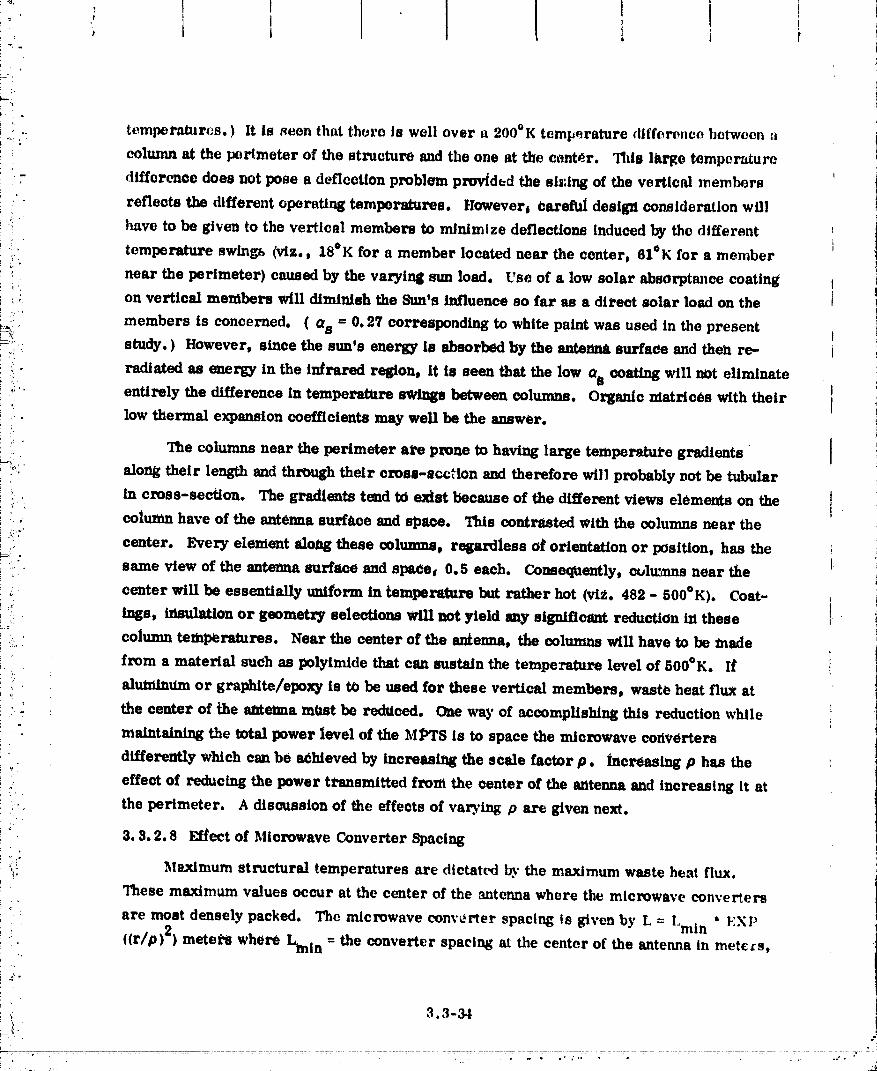
.. tempel'aturcs. ) It Is seen that there fB well over a 200°K temperature difference between a
column at the perimeter of the structure and the one at the cent_.r. This lttrge temperature
- difference does not pose a deflection problem provided the sis:ing of the vertical members
reflects the different operating temperatures. Howevert careful design consideration will
;.... have to be given to the verticsl members to minimize deflections induced by the different
: temperature swings (vtz., 18°K for a member located near the center, 61°K for a member
near the perimeter) caused by the varying sun load. Use of a low solar absorptance coatingt'_ on vertical members will diminish the 8umts influence so far as a dit.ect solar load on ther.
: members is concerned. ( a s = 0.2V corresponding to white paint was used in the present I_;':" study. ) However, since the sun's energy is absorbed by the antenna surface and then re- ij!
ili radiated as energy in the infrared region , it is seen that the low a s coating will not eliminate
_" entirely the difference in temperature _ between columns. Organic matrices with their [low thermal expansion coefficients may well be the answer.
" " The columns near the perimeter ate prone to having large temperetut-e gradients "
'._., along their length and through their eross-eccHon and therefore will probably vet be tubular
_.. in cross-section. The gradients tend tO exist because of the different views elements on the_ _
, column have of the antenna surf_tce and space. This contrasted with the columns near the
i:ir center. Every element along these columns_ regardless of orientation or position, has the !
_ : same view of the antenna surface and spaee_ 0.5 each. ConseqUently, ctAumns near the t
: center will be essentially uniform in temperature but rather hot (vi_.. 482 - 500°K). Coat-
": tugs, inmflaflon or geometry selections will not yield any signiflcsnt reduction in these
;.. column temperatures. Near the center of the antenna, the columns will have to be made
from a material such as polyimlde that can sustain the temperature level of 500°K. If
aluminttm or graphlte/epoxy is tO be used for these vertical members, waste heat flux at
/: _ the center of the antenna mOst be redttced. One way of accomplishing this reduction while
maintaining the total power level of the MPTS is to space the microwave coriverters
dliferently which can be a_hleved by increasing the scale factor p. increasing p has the
effect of reducing the power transmitted fronl the center of the antenna and increasing it at
i_ the perimeter. A discussion of the effects of var_'ing p are given next.
3. 3.2.8 Effect of Microwave Converter Spacing
_i! Maximum structural temperatures are dictat_i by the maximum waste heat flux.
: These maximum values occur at the center of the antenna where the microwave converters
_ ': are most densely packed. The microwave converter spacing is given by L _- Lmi n * _:XP
_. ((r/p) 2) meters where Ltnin = the converter spacing at the center of the antenna in meters,
_ 3.3-34
' "...... 00000002-TSD11

+ ' 1 l I I--m!
t' I '
I,-i <
I+_,. j r -- distance from antenna ccnLei' in meters, and p = scale factor In meters, it follows that72 !; ,
: the waste heat flux radl/_ted towards the structure at the center Of the mltenna is given by:
"" 9.,F + [1 .,r/) * P , watt.__._s
- ' ,: max, ,r',7*/ Ix- ExP('(ro/pl"lJ m 2J
1,: , w_re- F = fraction of waste heat radiated toward the structure, the remainder being
_' radiated toward eurth
_. + r_ = efficiency of microwave converter
+, _ P = power trammltted by antenna watts
..if.[" _ p : scale faoWr, meters
..i_.' r0 = radius of autanna, meters
, It is Interesting to observe that for a given power transmission the maximum waste
._ . + heat flux is independent of Lml_. This can be attributed to the fact that increasing Lmln• i _. _i requires increasing the power level per converter. The end result being that the waste
_' heat per unit area remains constant (assdming conJtant converter efficiency).
_," Figure 3. _b.27 presents the waste heat flux at the center of the antenna as a function
+. o_ th0 scale factor p. Two curves are shown: one for a microwave converter efficiency of
_'. _ i 85% and the other for an efficiency of 70_ which is now considered representative of the
_." "+ klyst:on performance rather thaa 75%. For values up to about 600 meters, p exhibits a
-_.:, _: strong lnflUmlee on the maximum waste heat flux. The maximum flux values that can be
_, , -, tolerated by three candidate mltterlals are shown as _00, 8600, and 8100 w/m 2 for--_
.. .. : aluminum, graphite/epoxy and polylmide composites, respectively. These v_lues establish,,,+ i+:,.,o. _. minimum values for the scale IIaetor p, I.e., they Impose a coi_stralnt on the shape of the
, Gatmslan distribution. For example, consldetdng an efficiency of 70_ and an aluminum
_ structure, Fig. 3. 3-2"/shows that the mien)waVe converters will have to be spaced aecord-
ing to 0 £ 1100 meters, which produces a fairly fiat Gausslan dlstr/bution, nearly a uniform
+' :' dlstrlbuflon. Figure 3. 3-28 shows the waste heat profile across the antenna sdrlacc for
:' threi_ ValUes of p. It clearly llltmttates the effect that 0 has on the v:___teheat profl|e|
smaller values of 0 producibg profiles with greater waste heat Concentrations at the center
and lower waste heat concentrations at the perimeter, which in turn leads to greater
differences in coltmm and bea_ temperatures between th_ center and the perimeter.
.. 3.3-35
• "i. !
00000002-TSD12

I289°K (60°F) FULL BUN t
228°K (-60°FI NOSUN
I
600°K (440°F) FULL SUN
482°K(4Oe°F)NOSUN
Fig. 3.3-:_6 Column Temperatures
16
\ • mCR0WAVEC0N.mRPAC,ND"LMIN'EX"_P)2) ]14 _ • ANTENNA DIAMETER- 1 Km
lk
li
12 VWASTE HEATTOWARDSTRUCTURE"17.B% " ] I
10 " k IMAX FOR _,
WASTE POt_lMm..___%_
HEAT 8,-LUX. IKW/M:_ !,
6 ' MICROWAVE CONVERTER
MAX FOR _._ EFFICIENCY
4 ALUMINUMGR/EI s _0% fi
2 ss_ T
0400 SbO BOO 700 eo0 900 1000 11(J0
SCALE FACTOR., METERS
'Filk 3.3-2? Waste Haiti Flux It Center of Antenna lUlFunction of the Stole Fl_tOr
3.3-36'- ,j
00000002-TSD13

!i
'_'" 8
7
• CONVERTF.REFFICIENCY - 70%i
, : 6 • POWERTr4ANSMIUlON - 6.45 GW
POWI_R RATIO: CENTER TO TiPI
_, 10:1
; _ 2.9:13u. 4 1.5:1
SCALE FACTOR
3 p - 1100 METERS4
t!,. - 690 METERS
•: 2
,. I . -466METERS
! "' 1
., o I I I I ,I, 0 100 20O 300 4OO 6OO
, RADIAL DISTANCE FROM CEN'rER OF ANTENNA. METERSi
. " • Fig. 3.3-28 Waste Heat Profile for Vadom Valuta of the Scale FaRtor
i '
t
I 3.3-37 :';., ,,
4 _
_"_'__"_"!_:_'_;_ _....... ................................... _ ' "............................. " " " _. -.'. .*.i._
00000002-TSD14

_!_' 'i_e effect of p on the m_xlmum structural temperatures Is shown in Fig. 3.3-29 for
two offieiencles, 70 and 85_, and two types of members, vertical and horizontal. Figure
-_' 3.3-29 relrdorce_ what was mentioned early that a vertical member or column will run
hotter than a horizontal beam at the center of the antenna. But more to the relevancy of p
.:_ is the trend shown of decreasing temperature with increasing P. It Is obvious that the
-,_i_ choice of p may well impose a cmu_traint on material selection. It is recognized that p will
*':. influence the microwave transmission efficiency and the total power that can be handled by
_ the MPTS. It should now be obvious that p has a strong effect on structural temperatures
_!ii and material selection which must be accounted for in any studies to optimize the power
_ received on Earth. I
_!:: Before closing this section It should be noted that there are other ways of reducing
_,: the maximum structural temperature than by increasing p! some of the methods are:
:_: • Alter the microwave converter radiator design so that more of the waste heat
_i!: is rejected in the transmission direction of the microwaves (toWard Earth) and=_i_i less is radiated towards the antenna support structure. In th_ present study,
-=_ 87.5_ of the microwave converter waste heat is being radiated towards the
_!_ structure and 12.5% toward Earth.o_°_ • Employ heat pipes to smooth out the heat rejection profile so as to produce a
_:,.,, nearly uniform profile across the _lurfaoe of the antenna (see Fig. 3. 3-30)..
_:* • Design tb_ microwave converter radiator surfaces to be geometrically and
.:_: spectrally selective so as to reduce the amount of solar energy that is absorbed
i:! and to alter the distribution of radiant flux emanating from the antenna to a more
! nearlytmlform one.
i.: • Use special coatings on the structural members. For the present study white
_: paint (Os/( = 0. $) was used on the side of members facing space and an aluminum
finish ( _ = 0.1 and ( = 0.2, lightly anodized) for the side facing the antenna
surface. Coatings _uch as silver teflon (as/_ = 0. I) and gold ( ( = 0.05),_(- respectively could be substituted for the white paint and aluminum.
:/
:"_._ It mvst be noted that most coatings degrade as a result of exposure to ultraviolet,
_,:" radiation and particulate radiation emanating from galactic sources and the Van Allen belt,
!:: The 30-year MPTS design life demands that serious consideration be given to establishing
_" the extent of degradation. At the present time there is a dearth of data for ultraviolet
_- exposures greater than 104 sun-hours; the MPTS will have an exposure of approximately_:_"
-_'; ' 2.6 X 10⁵ sun-hOurs.
OOOOOO02-TSEO'I


8
i _ • 6.45 GW
I • ,KM
EAT PIPES )
WITH
_', I 2 i
!W/O HEAT PIPES
0
0 loo 2Oo 30o 4o0 wo IDISTANCE FROM CI_NTER, METERS
°_ T .(W,,m'S.eArFt.UX.4 ,'
o 100 2oo 30o 400 6o0
2 DISTANCE FROM CENTER. METERS I
o_ oTEMPERATURE OF
'-2 • MEMBER LOCATEO41 M_TERS ABOVEANTENNA MINUS
-4 TEMPERATURE OFMEMBER AT 6 METERS
-6
Fig. 3.3-30 Tlte_md Performan_ of MPTS With end Without Heat Pipes
" 3.3-40
ooooooo2-TSEo3

l
,- ! :
.+
ti ' 3.3.3 Structural Analysis
•' The following is a summary assessment of preliminary structural design options:
®
• Structural arrangements of the antenna primary structure leads to selection
based on light weight of a rectangular grid beam arrangement, which is 15%
to 30% lighter than either a triangular or radial arrangement.
+ • Primary structural member evaluation considering columns of 5, 25 and 100
meter lengths concludes that primary structure caps should be built up as
!' triangulargirders.18 meter longgirdersmade up of3 meter bayshas been
),.... selected for cap members.
i _i: _ • A determination was made that inertially induced deflections are insignificant,+_'+ but thermal gradients n,uSt be kept low, in the order 2° to 4°C between the
i _ upper and lower caps of the primary structure.
........ • Composites offer attractive features in terms of weight savings and thermal
'_' propertles.
/_ • Other factors for future study are the integration of power lines and structure./,
" 3.3.3.1 Antenna Structural Design Arrangementsf,
_,. Three structural arrangements were considered as candidates for the baseline design
_i,' _ (seeFig.3.3-31).
• RectangularGridBeams - Primary beams atrightanglestoeachother
' • Triangular Grid Beams - Primary beams arranged in such a manner as to
_. produce geodetic structure
• Radial spoke beams - Primary beams emanating from a central core andextending to the periphery as spokes in a bicycle wheel.
>,
: : The inertial loads applied to the antenna arc relatively low, thel'efore the total structural
;E: i weight is a direct function of total beam length. Assuming eqt,al lengths of unsupported
• . beams in each case, the total beam length for the three arrangements were generated. 1/,." The ratio of their respective total lengths are shown in Fig. 3.3-32. The respective total
lengths are approximately 15,760 meters for the rectangular grid, 23,300 meters for the 1• ,)
_" triangular and 21,330 meters for the radial. Figure 3.3-32 was generated to demonstrate
..... weight relationships using an L/D (length of member/alia, of member) of 20 to 100. In each
"=:7 " case aluminum with a thictmess of 0.02 in. (0.05 cm) and a height betaveen caps of 40 meters
! was assumed.
3.3-41ii ,'f'
00000002-TSI=0,4

" ' l I 1 I I I i_ .:L/L
,. I
'2 _;i! I*2 _e,_,.
....'i, RECTANGULARGRIDBEAMS
:-,,,,4; j.,iJ;
_-,_i?_ SEoLECTED-,:_,: _ ASSUMPTIONS: 1::_:,_' CONCEPT
,:_; DEFINITION • ALL INDIVIDUAL
--"__ TRIANGULARGRIDBEAMS BEAMSSAMELENGTH
:_," @
< " • WEIGHTA DIRECT= ?.: _ FUNCTIONOFTOTAL....:i.' BEAMLENIITH
@4' _,
o_ RADIAL "SPOKE"BEAM8
-.e"_g"
°;2_ I i*_:. 1 2
"" TOTALBEAMLENGTH
y'_,i
::? Fill.3.3-31 AlternateIltrucluralArrangements
/ r,
2 ',",, :.
X'
00000002-TSE05

]
11
.... TRIANGULAR CONFIG
RE_rANGULA._ \\
° \ _ t-.O2INC.
" .. _
_RADIAL CONFIGi I
S00 1000
WEIGHT _- K LBi i I I
• _ 0 1000 2_00
WEIGHT ~ KgX 10.3
Fig. 3.3-32 Weilht Rele_lomhtpfor Different UD (Length TubolDienwten)
3.3-43P
O0000002-TSE06
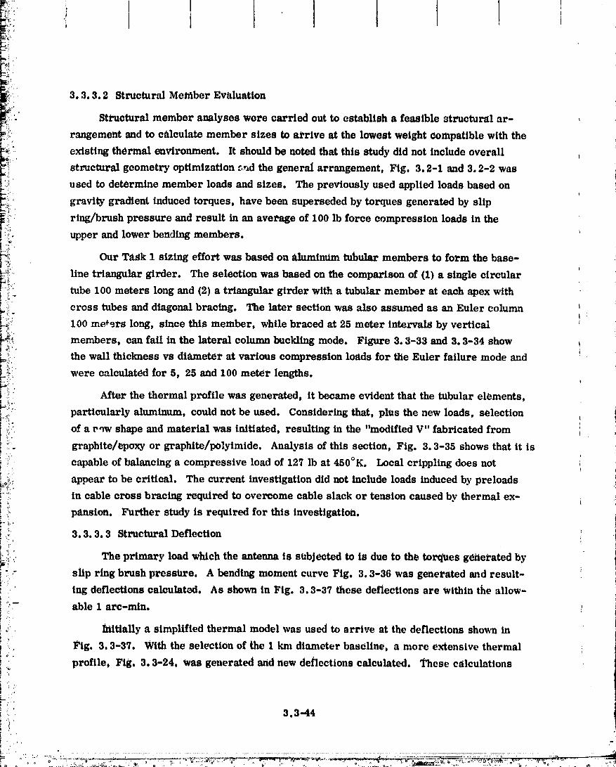
! 3.3.3.2 Structural Met_ber Evaluation
:." Structural member analyses were carried out to establish a feasible sts_uctural ar-_': rangement and to c_tleulate member sizes to at'rive at the lowest weight compatible with the
_i _:_ existing thermal environment. It should be uoted that this study did not include overallstructural geometry optimization r,ud the general arrangement, Fig. 3.2-1 and 3.2-2 was
I':_ used to determine member loads and sizes, The previously used applied loads based on
ki: gravity gradient induced torques, have been superseded by torques generated by slip_:l
l:ii: ring/brush pressure and result in an average of I00 lb force compression loads in theiii_; _i upper and lower bending members.
l_ii Our Ta_k I sizing effort was based on aluminUm tubular members to form the base-i
_!°ii:" line triangular girder. The selection was based on the comparison of (1) a single circular_;_ tube 100 meters long and (2) a triangular girder with a tubular member at each apex with
_._!_ cross tubes and diagonal bracing. The later section was also assumed as an Euler column
L_;:_, 100 meters long, since this member, while braced at 25 meter intervals by vertical :
_?_" members, can fail in the lateral column buckling mode. Figure 3. 3-33 and 3.3-34 show
the wall thicknessvs diameter atvarious compression loadsfor the Euler failuremode and
_:.._: were calculated _or 5, 25 and 100 meter lengths.
Pii::.. After the thermal profile was generated, it became evident that the tubular elements,
!i'_° particularlyaluminum, couldnot be used. Consideringthat,plus thenew loads, selection_-_
i)}.;:, of a v_w shape and material was initiated, resulting in the "modified V" fabricated from 4
_.i graphite/epoxy or graphlte/polytmide. Analysis of this section, Fig. 3.3-35 shows that it is!
!... capable of balancing a compressive load of 127 lb at 450°K. Local crippling does not iI
_ii;_ appear to be critical. The current investigation did not include loads induced by preloads-_.!-t:; in cable cross bracing required to overcome cable slack or tension caused by thermal ex-
_, panslon. Further study is required for this investigation.'.-t
i: 3.3.3.3 Structural Deflection _i _ i
_ " The primary loadwhich the antennais subjectedto is due tothe torques gei_ei'atedby
".- slip ring brush pressure. A bending moment curve Fig. 3.3-36 was generated and result-L
... ing deflections calculated. As sho_n in Fig, 3, 3-37 these deflections are Within the allow-
_-_,_- able 1 arc-rain, t
:i
_ initially a simplified thernml model was used to arrive at the deflections sho_ in
Fig. 3.3-37. With the selection of the 1 km diameter baseline, a more extensive thermal
. profile, Fig, 3.3-24, was generated and new deflections calculated. These c_lculattons
i ;
L_ j;"
3.3-44
/- l
O0000002-TSE07

_f
:'" L - 200 INCHES ("-E;M)L .' 1000 INCHU (*"2SM)
E- 107 PsiAXIAL
'_" LOAD .20tLB _30 LB mm 101.8"20LB .30LB
-lO I.B _.... % _ _ EULER .6_ .3 _ __ FAILURE
\\\-i : _ 133.44N) .4
*'_ ASSUMEDMIN _ _ _ .3: GAGE "_ "_ (-133.44N)
i "",.4. 1--4448N1 1-88.96N1LOCAL CRIPPLING (-44.48N) .1 -
.. FAILURE MODE
" I I I I 0 _I I I I0 _ .6 1.0 1.4 lJ 2.0 3.0 4.0
DIAMETER; D " INCHES DIAMETER; D "_INCHES| i l I ' ! | li 'I ! I I I
.i 2cm 3cm 4cm 5cm 6 8 10 12cm
LOCAL CRIPPLING SHOWN AS iNDEPENDENT OF- _ D SINCE LOW VALUE OF C IS USED IN BUCKLING!_
: RELATION F = CE tl r C = .06WAS USED TO ACCOUNT FOR INITIAL IMPERFECTIONS
Fig. 3.3-33 Strengthof CircularTubesfor VariousAxial Coml_ession•_ Loadsas Functionof Wall Thickneu and Diameter
L = 4000 INCHES (_100 M)_ E = 107 PSI
,: -30LB. " 1.2 .-20LB _
_ 1.0 _ _ EULER FAILURE
' _ LOAD -" o9
,_ '_ .8m_ .7
. _ o6
, _ .4, .3
.2 (--44.48N1 (-4BB.96N) (-1_L44N)
.f
14 15 16 17 18 19 20 21 22 23 24 25 26
DIAMETER. D. CM
,., Fig.3.3-34 StNnglit of Citmlm Tubesfor VariousAxial CompressionLoadsm FunctionOfWdi'Thir.knm
" 3.3.454e
O0000002-TSE08

i "- 1
i " "" i
i
r._7" DESIGNCONDITIONS
-;"" • T : 4500K // " % /
" • ENDLOAD" 440NEWTON // % jU I ii • SUPPORTEVERY3M .... I/,_ _ _l,_e 1.711ii. .
!_::_ COil,osirE # N I l
. !i
:.- I ,_ (llr'l__::,- F ,
,+ I 4,I
:" I i
b-, . ii I.r / \ , .....'" .A. .A.
.L.,.,. lili. 3.3.38 Td llm Cip Ciim4iiiltonl (Grllldti/Epozyl ,-
i.
i± '
3.3-46
O0000002-TSE09

I Ii i tt
: / ULTIMATE BENblNG MOMENT
'i 10 r FOR ,75 KM, 1o0KM, 1.5 KM,DIAMETERS
.:; 1.5 KM FACTOR OF
T
: .5 KM
-S
NEWTON.METERS X 103
-10
Fi9. 3.3-36 Design Loads
| /°"/; _L 6T
,,=,., ,,.o.,:s,/ //
( 1.27M1 50_
(.0008M) 20x 10 .4 7 KM DIA
(.0003M) 10x 10 .4 _--"'_
1.0 1.5 2.0 O 10 29 30
(5.S6_'K) (11.12°K) 116.7°K)DIAMETER (KM)
._. .._TIFo)
" ' A. LOAD INDUCED B+ THERMALLY INDUCED
i Filk 3.3-3_ Deflections - Prelimimuy Assessmentv. ,'
+ 3.3-4'/ •
.... 'i _ .... . , ,_:::+:..::,-_ . .+:.:_,+ "'.'.'+'.Lt':.-_;'-_.+,x-+.._"-+'-+'---:+._ _,....... "-'"_'+ ,+r'_ "" _';,L...,,.--_._ :, -- ._-._,. _" ,................... O0000002-TSE 10

! l t 1 ! •[ i t !
wore performed with the uac of an in-house "3-dimensional frame" computer program.
The rcsultl_lg deflections curve told slopes are showa in Fig. 3.3-38 and _. 3-39 for the
primary structure.
To evaluate the effects of secondary structural deflection on th6 ovez_li deflection, a
section of structure farthese from the antenna center was chosen for examination. This
particular area was chosen because (I) it is the area that the primary structure experiences
its largest deflection and (2) the temperature gradients are highest. Figure 3.3-40 reflects
the defleetiecs and slopes calculated for the secondary structure, and as c_tn be seen, the
magnitudes will contribute very little to the overall deflections.
Note that Fig. 3.3-38 and 3.3-39 show the deflections and slopes ealeulat_ for t
temperature deviations that occur during different seasonal and orbital positions. The
*. mean A T curves represent the location and angle that the respective waveguide arrays would I
be assembled to the secondary structure. The wavegulde assemblies within approximately L
the 16,000 in. (406 M) radius can be preset or '_imed" once and left alone. ThoSe located I
beyond this radius must be adjustable in flight by use of screw Jacks or similar devices.
Further elimination of adjustable devices can be achieved by Judicious design procedures
to reduce defleetion_ at the antenna periphery. Close manufacturing tolerances will have
to be augmented by an adjustment or '_.ming" technique in order to minimize bu/lt-in
waviness and deflections. A study of tolerances, both manufacturing and assembly would
determine the extent and type of adjustment that would be necessary. A typical girder 18 I
meters long has the following tolerances:
Length ± 2 in. (50.8ram)Couplinq fitting ±. 28 in. (6.38 ram) (mechanical or weldment)
Stra/ghtness ± 1/2 in. (12.7 nun) bR_9 ± 2.076 in. (62.73 ram)
The RSS over a 1000-meter length of 40 beam element is:
d= N_ n where oN=
The worst ease angle of ettrvatm.e is defined by:
= (,f'12+d12_(x- _)Gwhere H = 35 meters
H
f/2 : 500 meters
612 =. 10s40:. os_.752
= 0. 003 radlans or 0. 1723°
3.3-48
O0000002-TS E11
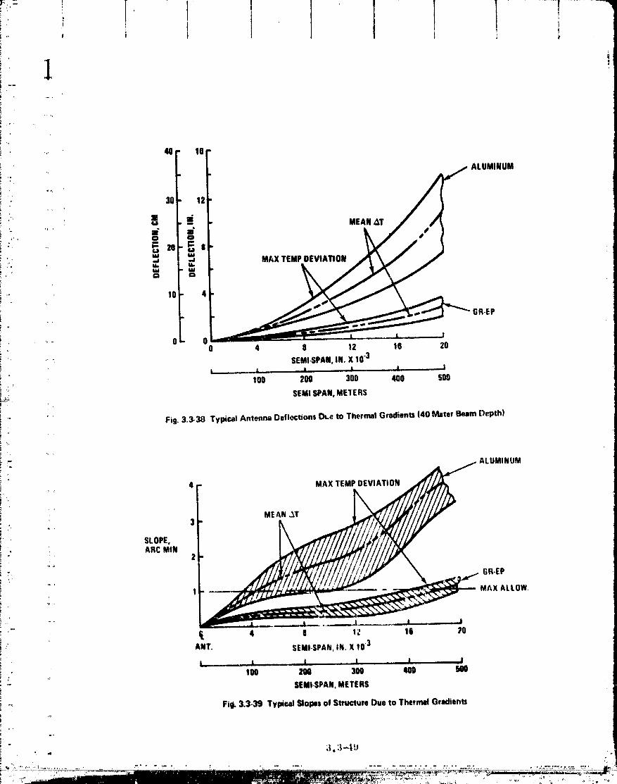
'' " "i
" 40,I, 16,. ALUMINUM
30" 12
[ : .... Z0 " e
Z
!'" 10- 4
-. GR-EP
"" O- 00 4 8 12 16 20
'- _ SEMI-SPAN,IN. X 10.3! , • i J. A I
.; _ 100 200 300 400 500_; SEMI SPAN,METERSi
i '" Fig. 3.3-38 Typical Antenna Deflections [h.e to Thermal Gradients 140 Meter Beam Depth)
i , ALUMINUM! •i 4 r" MAX TEMP DEVIATION
r •
i MEAN _T
! SLOPE,I - . ARC MINo
7
: _., GR.EP
1 ..... _ _MAX ALLOW
i,.,, ,....
._ t_ ,, I .... • _1 .I J
] l_ 4 O lZ 16 20
i" ANT. SEMI-SPAN.IN, X 103
l _ l J I _1', ,_ 100 2N 300 400 500
SEMI.SPAN, METERS
"_ Fill, 3,3.39 Typical Slopes of Struc_re Due to Thermal Gradients
O0000002-TSE12

? -
;' 3.3-50'I
,J ,
O0000002-TS E13

I I I Ii _ 1 i i; i I , !
• II,
Aa the limit of curvature mu_t be held to 1 Itre--mln eL, 0.016_i _, _ fu_'tl_ee m_nly_ti_;is
required to dotornllne prohahillty of this woeBt case occurring.
•, 3, 3.3.4 Materials
: Three materials have been considered for the antcana structurv: aluminum,
.... graphite/epoxy and polyimide composites. Each material has its advaatagca and disadvant-
ages. Aluminum offers low material cost and established processing, manufacturing and
, assembly techniques but suffers from relatively high coefficient of thermal expansion.
Graphite/epoxy, an organic composite that Grumman is developing extensive experience
with, exhibits the attPactlve properties d a low coefficient of thermal expansion and a highstrength-to-weight ratio. On the debit side, the material cost of graphite/epoxy runs 25 to
200 times that of aluminum. Also on the debit side is the relatively low maximum redom-
mended service temperature for graphite/epoxy (conservative designers limit graphite/epoxy
to 450°K, i.e., 350°F, the same as aluminum). Based on the tempcrahzre predictions of
Subsection 3.3.2, the uSe of either aluminum or"graphite/epoXy for the columns near the
center of the antemta is precluded (see Fig. 3.3-26); the use tt:?these materials for the beam
cap elements near the center is marginally satisfactory.
Polyimlde composites such as graphito/polyimide or !_evlar/polyimtde offer_ relief to
the temper_re problem as they have maximum recommended service temperatures in the
range 530 to 645°K (500 to 700°F). In addition to the higher allowsble temperattlre,
graphite/polyimlde offers the same main advantages of a graphite/epoxy matrix, namely
high strength-to-weight ratio and low coefficient of thermal expansion. Figure 3.3-41
shows these properties for various graphite composite systems. Little data ezlsts for the
strength characteristics of epoxy and polytmide composites at elevated temperatures.
However, Fig. 3.3-42 sheds light on the performance of these materials when used as
adhesives. The superiority of polyimide over epoxy at 5330K (500° F) is obvious. But
concern exists as to what the performance of polyimide will be after 30 years (2.6 x 10⁵ hrs)
of operation at 533°K. Figure 3.3-42 shows that after 4 x 10⁴ hours (4.6 years) the lap
shear strength is otlly 65% of its value after 10 hours. Suitable tests and extrapolation
procedures are required to resolve this concern.
On the debit side, the material and pt_)cessing costs for polyimid_s arc considerable
in comparison with epoxy. Futhermore, as Fig. 3.3-43 shows, polylmidcs have a high
volatile content. More than likely the pelyimtdes will be processed in space and, therefore,
a suitable bleeder system must be provided to prevent contamitt,_!n_ Items such as micro-
wave converters and parts that have been thermally coated.
3.3-51
O0000002-TS E14

|5
.. JJ L j, ..... _ _ __Q .L._ | I 1
3 pLY PROPERTIESFIBER
I+ENSILE TEfISlLE 114ERMAL COEF 10_ m/m/°K MAX|_: GRAI_HIT_& lAYOUT RESIN THICKNEU DENglTY ATRENGTH MODULUS TEMP,li:_'_ ' COMPOSITE (3-PLY) (ram) (Kg/m3) (10an/m21 (109n/m) LONG. TRANSVERS_.I OK
i T30015208
(EPOXY) (0 tr60) T 5208 0.17 1600 345-415 48-76 0.36.0.63 1.1.4.5 450
ii HT_/710 SKYBONOt
_' (POLYIMIDE) 10• 601T 710 0.17 (11 1550 278-310 48.69 0.31t.0.63 1.1-4.5 500
HT-S/710 _;KYBONO
(POLYIMIDE) 10,45) T 110 0.1711)-" 1660 345.415 6_83 0.36,0.90 1.24.6 645 _V;:
_: , AS!3501(EPOXY) 10• 60) 13501 0.17 1520 2"/5-310 584_ 0.364).83 1.14.8 450
_iI +":; =+ HH-SI3801+' (EPOXY) 10,601 3501 0.17 111 1745 19S-240 83-103 0.184).40 0.7-1.8 450
S: NOTE: AT PRESENT NO SOURCE IS AVAILABLE FOR THIN PLY GR/PI, OR H_I. THESE ESTIMATES ARE BASED ON
;_., UMITED DATA AVAJLASLE ON COMPOSITELAE_iNATESSUCH AS (0t_ E0)s OF CONVENTIONAL THICKNESS..- • e,mmmm.im_i,m.mm
_!_ Fig. _L_41 Edlmated GrephhJ _ Pro_rtk_ +
27.6 I_!_, (41 0 HIGH TEMPERATURE EPOXY ';
,. El POLYIMIOI_ ..
i .rrAL-= STEEL_.+. _._.,:..+.. "" 131
_.
:r
oL 1_ ,,,-" AGING AT 633°1 1500°FI. HOURS
Fti_ 3L3-42 Thermal Sta_ltty Of Vedous Adhmvel it 533°K
O0000002-TSF01

ii: r I
%:,,
i,il With any of the composites, the question of outgassing naturally arises. Tests run ati_: , Glmmmafl on graphite/epoxy laminates showed ess,mtially no outgassing when the specimens
were exposed to high vacuum at room temperature for 72 hours. Tests at elevated temper-
_,.... atures need to be run. Polyimides, not being free Of volattles as are epoxys, may present
: _. an outgassing problem. The vapors given off by a polytmide composite, structure may
il inhibit proper operation of the microwave converters. Tests are required to establis_ the
, vapor pressul'e characteristics of candidate composites at elevated ter_peraturee_ and then,
ff necessary, suitable coatings to minimize the outgassing must be found.:% .- f
i!i _. Up to this point, any reference to temperature has always been along the lines of high
i. temperature. The MlYrS, however, will experience cold temperatures around the time of
_. _ the two equinoxes each year. The structure will cool down to temperatures in the neighbor-!_:, '° hood of 75°K (-325°F). This cold temperature will not present any problem to aluminum
:;_ .... which has been used to virtually 0°K. How the composites hold up is an unknown. Tests to
_ _" establish their cold temperature performance and their response to temperature cycling
ii _ (from 75 to say are required.600°K)
k_
'-;_:.... Structural members manufactuned from composite materials will have a white thermal
_ contrOl paint applied to the side of the member that faces space while the opposite side
_:' _ which faces the hot antenna surface will have an aluminum foil bonded into it to proVide a
_i.i: .-. good heat reflector. Thus, the composite materials will not be directly subjected to ultra- ,__. _, violet radiation. However, tests to estab_sh the ultraviolet degradation that the white paint
i-: and aluminum foil will undergo during the 30-year MI_rS life are required.
_. Figure 3.3-44 summarizes pertinent properties of the three m_ertals: aluminum,
1! graphite/epoxy and graphite/polylmide. At the risk of over simplification, the material to
'_- use for the antenna support structure should have the best available strength-to-weight ratio
_; and be capable of operating at 600_K for 30 years. This statement can be made becan_e
i,: material and processing costs should play a secondary role in material selection since
i/ transportation costs dominate the overall cost picture. Furtheremore, it can be assUmed
_ ": that any tendancy towards outgassing or ultraviolet degradation ,_,ill be aptly prevented by _Iii.... application of Suitable coatings. A low thermal expansion cocfflclent is deslrable but should°,t'/:_,_" never' play a dominant role in the material selection process since a mechanical adjustment
..... device will most likely be utilized to remove manufacturing tolerances. This same device,
:,- properly controlled can remove deflections caused by differential thermal expansions.=i'
_ . In conclusion, the polyimtde matrices have m,ch to offer but appropriate test data for_; a 30-year life ar_ required on their low and high temperature perforn_ncc as well as their
i" ,., vapor pressure characteristic°.
i I" ; 3.3-53 !
O0000002-TSF02

i i i i
_._'_;: ADHESIVE TYPE CURE TEMP.•°K VOLATI LES MATERIAL COST PROCESSING COST •
?lil, I EPOXY 4500 NON E LOW LOW
_:_' 530 -- 645 ° 10 -- 16% HIGH VERY HIGH--_-?ii ' POL YBENZIMIDAZOLE
POLYIMIDE 530 - 646 ° 10 - I§% HIGH VERY HIGH
_'¢. Fig. 3.3-43 Cost and Prm:e_nti Chef'of Various TYim of Adhwt,es
_;:' GRAPHITE/ GRAPHITE/
_.'_'_ PROPERTY ALUMINUM EPOXY POLYIMIDE
k APPROXIMATE STRENGTH
! TO WEIGHT* (103 M) 23 28 28TENSILE STRENGTH106 N/M 2 241.600 195.415 275-415
___ i ' (Kg/M3) 2570-2960 15002000 ' 1500.2000
COEFFICIENT OF THERMAL
_:, EXPANSION___ (10 .6 MIM PER OK) 23.4 0.1-0.7 0.3-1.0
" " 'i_',i!:_' MAXIMUM RECOMMENDED• _'" SERVICE TEMPERATURE
...._ (OK) 450 450 530.645
_-"....";:='.' MOO. OF ELAST.
..... ,. 10gN/M 2 73 48,105 48-83
. __.. SPECIFIC HEAT(jlkg.OK) 920-962 870-1000 -
_;).' THERMAL CONDUCTIVITY•_!,:, WI(M.OK) 117-234 0.24,5 5-10
:: i. r ....• _ _ REQUIRED THERMAL ANODIZED E.G. ALZAC_.,_,.:_:": COATING - 8PACE SIDE OR WHITE PAINT WHITE PAINT WHITE P_INT
i o":": REQUIRED THERMAL NONE ALUMINUM FOIL ALUMINUM FOIL :COATING-ANTENNA SIDE BONDED IN BONDED IN
|
0_, *TITANIUM AND ITS ALLOYS HAVE A STRENGTH TO WEIGHT RATIO OF 36
_,'_ .,_, Fig. 3.3-44 Complttlon of Material PTopettJ_
L_. "'
.....;!L ................................................................................................................................................................................
OOOOOO02-TSFO3

I i !t 1
"_ 3,3.3.5 Other F_tctors
_ At this time no attempt has been made to integrate poWex' transmission lines and
" _ structural elements. The large current flow in this network requires large conductors and
_ it is possible, perhaps necessary, to utilize the structure as an integral pal.t of the power
.,,, system. For example, ff we assume a Gauselan distribution, the mean distance from the i
, center would be approximated by d = 1. "/7¢, where 3 ¢ = xltdius of the antenna. Assuming a
, total power of fi gigawatts and 1600 areas of equal power, it follows that the power from each
area ffi6 x 109 watts/1600 = 3.1 x 10⁶ watts. The current at 20 KV, to each of these areas
.. would be I = P/E = 3.1 x 10⁶/2 x 104 = 156 amp. The mean conductor length is (1.77'/)
(500/$)=195M (640 ft) long. Neglecting temperature, a No. 2 size eopper conductor
(AN-J-C-48) or an equivalent No. 0 aluminum conductor can carry that load. The weight
;". _" of the aluminum conductor is -_. I/ft and results in a totsl weight of (. i) (640) (1600) =
_ 102,400 Ib (9.25,280 kg). Weights of this raagnitude should be integrated into the basic
,,, structure.
¢
: !
i
J
'1 3.3-55
'i-._:" " ": " --:_ " " = : " " ' " ...... .
O0000002-TSF04

" I 1 1 J, !
i?: -_.4.1 Detag Parts
.Z:: A study of packaging structural members/elements was initiated to determine the
_ _. optimum arrangement within Shuttle constraints, and to determine the sensitivity of various
_! levels of ground prefabrication compared to corresponding levels of orbital assembly.
_." ' ' The options selected for evaluation, shown in Fig. 3.4-1, span the potential split up of
_._.. fabrication methods between ground based and space based operations. These cases are
: as foHow_:
_i',: • Case I - Aneemble collapsible beam members on earth which will provide theF
__ii' , . most efficient Shuttle packing density and deploy when in space':'. • Case H - Prefabricate structural elements of trt-beams and manually assemble
::_' in space_i!ii';:
,'!_" • Case HI - Prefabricate fiat stock on ground with required thermal coatings and
aUtc assemble in space.
Assembly of structural members on the ground requires that these members be
::_ • stowed in a folded or compressed manner to achieve as high a density as possible. Efficient=-!,: - ,
--._._ Shuttle utilization requires a cargo density of at least 6 lb/ft 3. A survey of existing
- _' stowable structural members (astromast, articulated lattice) suggest that an order of
_::.: magnitude less is the best that can be achieved. Figure 3.4-2 was generated for typicalv
i_,: articulated lattice girder members and, as can be seen, the densities are in the order of
_'! 0.01 to 0.02 lb/ft 3. This represents a Shuttle load factor of 1% and it is obvious that even
-?i. with improved design techniques, the net gain would still fall far short of the desired goal.
=_.,.." .. The attractive facet of this approach is that most of the subassembly work is done on the
=:'," ground, not at the orbital site. If advanced launch systems were not as volume restricted
::!: as the Shuttle, this approach could become the preferred choice.
=_!i Detailcomponent fabricationon the ground and assembly atthe orbitalsiteoffersoppor-._" tuolty for a much more efficient packaging density. The first step in this approach is to sub-
:!, stitute very thin solid elements for the "Baseline" approach of thin walled tubes (Fig. 3.4-3).
ii'. This imrnediately achieves a packaging densl_, far in excess of the minimum 6 lb per cubic
_i foot, but as the followir_ example shows, also results in a weight increase. To balance a
100 Ib load in a thin walled, 2.5 in. diameter graphite/epoxy tube, supported at sLx meter
:" intervals, the wall thickness would be 0. 0075 in. The resulting weight is 0.039 lb/ft. ByY
,,...
'.:.. .: ,,.., 3.4-1
OOOOOO02-TSF05


I
1
n
-" LR _
_: DIAMETER-MEMBER, IN. 2 3 4 5 6.....
ALLOWANCE FOR CABLES & FITTINGS, IN. 1 1.5 2 2.5 3
A E - BAY LENGTH EXTENDED, FT 4,9 4.9 9.85 9.85 9.85
AR - BAY LENGTH RETRACTED, IN. 5 7.8 10 12.5 15
NO. OF BAYS (RETRACTED IN 60 FT) 144 96 72 57.5 48
• i LE - EXTENDED LENGTH. FT ?00 470 710 570 475
ESTIMATED WT OF FITTINGS, LB (.2) 86 (.3) 86 {.4) 86 (.5) 1_6 (.6) 86
, ESTIMATED STRUCTURE. WT, L9:" (0.0075 GRAPHITE EPOXY) 22 22 44 44 44
NO. OF BIROERS THAT CAN BEPACKAGED IN SHUTTLE BAY ? 7 1 1 1
.
TOTAL WT PACKAGED IN SHUTTLE, LB / ?56 756 130 130 130
IPACKh_GING DENSITY IN SHUTTLE, ILBIFT" 0.071 0.071 I O012 0.012 O012
.............. L
* Fig. 3.4-2 CharlcteriltiCS o| Articulated Lattice Beam
3. _-3
O0000002-TSF07


L t, l
...... substituting three solid elements, arbitrarily adding supports evvry 12 inches to b, lance
: 33 lb egch, the weight is 0.0429 lb/ft (0.0143 x 3) Fig. 3,4-4. Assumlhg the 12 in, sup-
.,,, ports add an additional 50% weight penalty, the total weight would be 0. 0643 1b/ft.
. Figure 3.4-5 shows the limitations of both structural elements with respect to the Shuttle
__ cargo bay, and it is clear that further optimization can result in less weight penalty while
yielding an efficient packaging density.
: ,,. This assembly concept would require the largest work force in orbit of any of the
options considered. When the cost of the required Space Station, crew rotation and
_ materials and life support logistics is factored into the equation, this approach does not
appear desirable. Figure 3.4-6 summarizes an estimate of the rate of assembly of a
: typical structural trt-beam in which the caps and intercostal members have been shipped
" in an efficient Shuttle packaging arrangement to a Space Station. Skylab 3 data on the rate
: of assembly of the twin pole sunshade was used to establish the degree of human skills in
space environment. In the Skylab 3 mission, a single man assembled two 55 ft poles in
5 ft sections in 137 minutes. This represents an assembly rate of 6.2 rain/operation. A
:" typical MI_rS 18 meter structural member would require 78 operations. Assuming a 90%
learning curv_ improvement in skills relative to Skylab performance, a 2.5 rain/operation
could be considered plausible. At this rate 5.7 lb/m-hr rate of assembly could be
achieved. Twenty-four 12-man Space Stations would be required to support the assembly
crew at 5.7 lb/m-hr. A total of 470 kJb of MPTS antenna structure could be fabricated
using a crew of 275 in the allotted 2-month period. This high manpower requirement with
associated Space Station support equipment tends to eliminate this approach as a _able
detailed assembly approach (Fig. 3.4-7).
Complete fabrication and assembly in orbit can achieve 100% Shuttle lend factor by
.,-, transportation of raw materials to the fabrication/assembly site. This concept requires a
free flying "factory". It is not unreasonable to assume that one could be designed and built
:. with little technical risk. Figure 3.4-8 shows a concept for in-orbit fabrication and
assembly of a typical girder. Considering the factors involved, that is, volume limitations
of the Shuttle and the desire to minimize on-orbit personnel, this :_pproach appears to be
the most promising. An operations analysis of this process has tentatively established a
rate of assembly of 420 lb/hr for the MPTS structur._t elements. At this rate, eight manu-
facturing modules would be required to meet assembly time tables.
• i 3.4-5
OOOOOO02-TSFO9

a35
t
• ,02_
l. .0204[
ql[ m _ i
i_,' 33[ $*;", - " -- .010[
I
_>7 0.1 _165 0_ 0.1
! _.. DIAMETER, INCHES
i-%,'..F _*", llll. 14-4 AIl_villile COlumn Load is Dtimetel (Sidld Gitt Epoxy E - 13 x l(I 6 PSi, 12 *° Long).
.i=#i ',) •
" .. _ i
4,
L4_ • 0.165" OIA SOLID ELEME.;. i , L II
,L_ +.
>;;, J
I /
pOOR PACKAGINGDENSITY l_iOODPACKAGING DENSITYVOLUME LIMITED CAPACtl_ OF WEIGHT LIMITED TO 66.000 LB4000 TUBES.9300 LB APPROX 16.(i(_10ELEMENTS
REQUIRE THREE TIMES ASMANY ELEMENTSAS TUBESTOBUILD UP EQUAL AMOUNT OF
I " . STRUCTURE
i Ill. 3.4-§ _ C_)mpltibiWlty I_icllutlingii %.
i l II
O0000002-TSF'I 0

121 ASSEMeLYRATE
t' _ S i, _KYLAB3..
m S ,90_ LEARNING CURVE
_/ - " ASSY MODULE 160"X 14'1 ¢
HATCH _ 2
._--J t i,,[ t I TL_
TYPICAL TRIBEAM 100 300 500 700 900
: -- WEIGHT = 21.4 LB (AL. ALLOY} NO. OF OPERATIONS
'_' -- NOOF OPERATIONS '=78 _ / 2.5 MtN/OPERATION
• TIMELINE (ONE BEAMASSY)
, TASK TIM..._E
1, SET UPEQUIPMENT/MATERIALS 15MIN2. ASSEMBLEBEAM 195 MIN3. RETURN TO SPACESTATION
;- OPEN HATCH & REMOVE BEAM• FROM ASSEMBLYMODULE 1E MIN
TOTAL TIME 225 MIN
BEAM ASSEMBLYRATE = 0.095 LB/MIN,, 5.7 LB/M-HR q26 Kg/M-HRI
Fill. 3.4-6 Infllght Detail Pare A_embly
.., ,_. ,_,4-7 j
O0000002-TS F11

7(:100 4000 • ANTENNA STRUCTURAL WT - 470 KLd ALUMINUM
• A881GhED A_EMBLY TIME - 1.9 MONTHS
8000 • 8T_IUCTURAL DETAIL PART MANPOWER- 82,600 M-HR8(24) 12_IAN
• NO. OF PERSONNEL= 280 SPACESTATION8
_oo 300o
_3000 _ (WT INFORMATION: 8EE NAS9"91)83
(J
_. 1111111-
12 MAN SPACESTATION
o I I I I I I0 80 100 lEO 200 250 300'
NO. OF CREWMAN
Ftlk 3.4"7 Support Equipment Requtmmml_ for In-Flight Auem_y of Tri Beams
STACKSOFEDGE STRIP
CROPPINGHEADS FEED DRUMS
CROSSSTRIP FEED DRUM
GUIDE ROLLERS
HARVESTING ARMS• WELDING HEADS
/
WELD CURRENTCONDITIONERSEQUENCERFOR:• FEED• CROP• WELD
TYPICAL BEAM POWERSUPPLY
t" WIDE
:, FII. 3.4-8AutoIn-OrbltIdlnufxtum(Aluminum)
- 3.4 -8
O0000002-TSF12

i i ! ,
l
3.4.2 Structural Assembly
A preliminary assembly sequence for the MPTS antenna follows, This assembly flow
Is based on the rectangular grid general arrangement, (see Fig. 3.2-1). Major functional
blocks are Identified in the order In which they arc assembled.
A top level operations analysis is presented for the following structure assembly
methods:4 ..
• Using manned free flying manipulator modules
, • Using remote controlled free flying manipulator modules
• EVA using remote colltrolled logistics modules.
The analysis has led to the following indicators:
_" • Assembly using remote controlled manipulator modules offers th_ most cost
effectiVe approach
: • EVA assembly with remote controlled logistics modules could be cost competitive
: • Manned manipulator assembly tends not to be effective because of the high pro-
pellant consumption of the free flyers.
3.4. 2.1 MPTS Assembly Functional Flow
3.4.2.1.1 Level 2 Assembl_, Flow - Figure 3.4-9 is a breakdown of the assembly steps
for the MPTS antenna structure. Assembly starts with installation of the rotary Joint using
., .. theSSPS centralmast as a pointofdeparture.The rotary.Jointtoantennainterfacestruc-
tureassemblyfollowsusingtheelevationrotaryjointstructureas an assemblybase.
ASsembly oftheprimaryand secondarystructureIsperformedworkingradiallyfrom the
centeroftheantenna.Installationofthewaveguidesand electronicsfollows.
_ 3.4.2.1.2 Level 3 Assembly Flow - Figures 3.4-10 through 3.4-12 are more detailed
definition of sequences for assembly of the rotary Joints, interface structure, and antenna
:_: primary and secondary structure. Assembly of the rota_, joints appears to represent the" most complex assembly operation due to the number of unique installations (gears, flo._
_ harnesses, etc. ). Assembly of the antenn:_ lt_lf along _,.ith wnvcguidcs and electronics,
is a repetitive operation and should not pose difficult problems.
="!" 3.,I-_J
O0000002-TSF] 3

I_ I 1.." i ! II i i
!
i, :,
f'.
i.o,, ,,.,., ,F.. ,, "H "'LY JOI ASSEMELE_' ASSEMBLE _OTAR INSTALl. INSTALLASSEMBLE PRIMARY & 5.0
ROTARY TO ANTENNA i-MPT_ ....... ECONDARY $UBARRAY ELECTRONICS- I I I JOINTS I l INTEHFAGI_ l I _',;, ,,,',-,,RE I I i" I II I L_Ruc_RsI I ....... !I
4.2 iNTERFACE 4.3 PRIMARY & ,SECONDARY
$1"RUCTURE _ STRUCTURE
_.-.i_'' . ._4_ $UBARRAYo_
_:. 4,5 ELECTRONICS
?
Ft_ _L4-9 Lml 2 Functional Flow : Ammble MPTS
_,_, 3.4-10
........,.......................................-#........ ......._,,._,, ,. ,., __............o,..- .,_ ...............-...............-_--__
O0000002-TSF14

I t I 1: t ! iI t 1 1t 1 I
I
J!:
,.,i _,.,.,i ! ,.,._i / +.,.3"F,t,.,.,i i ,.,++,• I | ASSEMBLE ASSEMBLE ASSEMBLE ASSEMBLE I I A_EMBLE I
ASSEMBLE I _ [ AZIMUTH I _IAZ ROLLER ILl AZ SLIP L_JAZ SLIP L.ROTARY I--,_ROLLER I_ITRUCKS & _ AZROLLER RINGPLATE | WIRINGSUPPORTII
,o,,,,, , ,...cK. 1 I°"'v'"°'°"l ! "_' "; '!Ii I['RIVE<_EAR l IsT"ucTuRE(:'
1
ASSEMBLE I I ASSEMBLE l I ' ' ASSEMBLEAZ TO EL ASSEMBLESLiP RING (2) I I AZ SLiP RING I . ! SET BRUSH INSTALL _ JOINT ELEVATION
TO ROLLER I=,,_ BRUSHES & !"_ PRESSURE _-_ELECTRONICS _- _. INTERFACE I I MATE TO SIC I I INTERFACE BRACE':" . STRUCTURE J I BUS SYSTEM I | STRUCTURE
ii i
ASSEMBLE I _ I ASSEMBLE ASSEMBLE |_1 INSTALL AZ INSTALL I [ INSTALLELTRUCKS _ ELTRACK EL JOINT l-._ll TOELJOINT EL JOINT 1..._ EL JOINT
&GEAR SUPPORT FLEX 1 i ELECTRONIC STRAIN STRUCTURE 1 / BUS SYSTEM& MOTORS ]i HARNESS..
Fig. 3.4-10 Level 3 Functional Flow: Astemble Rotary Jointl (Sheet 1 of 3)
-v. qU_
3.4-11
00000002-TSG01

I
4.11 4.12 4.16 4.10 & 4.17ASSEMELE ASSEMBLE 4.13 4.14 ASSEMBLE A_EMELE SLIP RINGAZ ROLLER AZ ROLLER ASSEMBLE ASSEMBLE AZ SLIP TO ROLLER INTERFACE LTRACK & TRUCKS & AZ AZ SLIP RING 8"_'RUCTURE& AUEM SLIPDRIVE DRIVE ROLLER RING SUPPORT RING BRUSHES& MATE TOGEAR MOTOR BRACE PLATE STRUCTURE 8/C BUSSYSTEM
TRACK i
• SLIP RING
Fig. 3.4.10 Lnet 3 Functlond Flow: Assemble Rotary Joints (Sh_t 2 of 3)
3.4-12
J
00000002-TSG02

I
p ,
).,
):.,
'; ,- _ _ 4.1.10 4.1.13 4.1.14
, : ASSEMBLE AZ 4.1.11 4.1.12 ASSEMBLE ASSEMBLE.__ TO EL JOINT ASSEMBLE ASSEMBLE EL TRACK & EL JOINT
_"-' INTERFACE STRUCTURE ELEVATION BRACE EL TRUCKS & MOTORS GEAR TRAIN SUPPORT STRUCTURE
t,
.
(.
I(
!-' Fi9. 3.4-10 Level 3 Functional Flow: Alsembte Rotary Joints (Sheet 3 of 31
i'
% •
, r
..... 3.4-I_ .,
00000002-TSG03

t I _ i1 1 t I I !
'14,__ ] J4.=._ I 14.2.2__ I 14.", JI ASSEMnLEJ I I I ASSl_mLEi I J ,J ROTARY JOINT J .J A_MB'LE I I mlMARY J .I J..._ IN,fALL
I,_ STrUCTUrEI,.,-,el r 4.3I TOANTENNA •_ 6"rRUCTURAL i I UP_RCAP I I ALIGN j -j EU8I INTE.FACE ! I FINGERS I I bETWEEN I I SYSTEMiST"ucTuREJ [ J L FINOEM I I J J
I
|
Fi_ 3.4-11 level 3 Functional Row: Assemble Rotary Joint to Antenna Interface Structure
I
I
ASSEMBLE ASSEMBLE j J ASSEMBLE ASSEMBLE ASSEMBLEPRIMARY & UPPER J _ J VERTICAL LOWER CAP ALIGN OU'I_ER _,.SECONDARY CAPS _ MEMBERS PRIMARY PRIMARY MEMBERSOF 1STRUCTURE PRIMARY J [ PRIMARY STRUCTURE SECONDARY
STRUCTURE J [ STRUCTURE STRUCTURE STRUCTURE /NOTE: FUNCTIONAL FLOW FOR TYPICAL 108 X 108 mSTRUC_RAL BAY _
J J ASSEMBLE ALIGN I I INSTALLASSEMBLE _ SUBARRAY SECONDARY _ RP_)I_WER INSTALLSECONDARY _ MECHANICAL ,..u_, INSULATION 4.4
... UPPE"-R SUBARRAY
VERTICAL _, MECHANICALMEMBERS SYSTEM
ONDARY STRUCTURE
--SECONOARYST.UCTURELOWERCA "PRIMARY
Fi_ 3.4-12-I,.e_1 3 Functiond Flow: _iemilJe-I_mm-_-_;i]nu_-ture
3,4-14
___._.._..__..___,.:__.___.._.______.._._..__ ....._ ,_...... . ...._........... ..........._ ..... --__-....... _....... Z_____
00000002-TSG04

I"_ 3.4.2.1.3 Assembly Using Manipulator Modules - Figure _. 4-13 1_ :_ repr¢:_,;,t;itive pl_,n
for asBembling beams fol the primary/secondary structure of the antenna. This operation
I is selected for detailed analysis because it represents the most frequently used oper,tlon
in the buildup of structure. Manhour requirements to perform this operation rcprv_cnt_r 40 to 50% of the assembly cost of the antenna. Statistical data on aircraft assembly indicates
that structural assembly accounts for 20% of the total cost to produce.
The assembly sequence presented tn Fig. 3.4-13 assumes the use of a free flying
manipulator module which could be manned or remotely controlled from the ground.
•Astromast beams are assumed stored in a logistics area in the retracted condition. The
astremast storage area Is also representative of the location of an auto beam m_nufacturing
- unit. The assembly Joint is assumed to be a mechanical locking device similar to a docking
_ drogue.
" The objectives of the operations analysis are as follows:
• Establish a rough order of magnitude range of time required to assemble thestructure
• Establish a level of complexity between performing assembly from the ground and
manually in orbit
• Establish typical consumables requicements for ancillary equipments used in
assembly.
Figure 3.4-14 summarizes the maximum and minimum time required to acquire a
beam from storage, tram_port to the assembly area, join _he beam to the structure am!
return to the storage area. A minimum time of 23.5 minutes and a maximum time of _t_
minutes has been e_ablished assuming a manipulator design similar to the Shuttlc RMS.
" The minimum time represents the potential of a mav.ipulator to perform the re_,uired tasks
assuming perfect accuracy and totally static conditions. The maximum time was established
_ utilizing the parametric data in Ref 24 which relates the ratio of performing a basic task in
... a static environment to the time required to perform the task in a _'namic environment.
,, The parameters considered in establlshin_ complexly, factor_. ':,'c,lude:
• Control system frequency of the manipulator and target
• Attitude limit cycle amplitude of the target
0 The distance between the target attachment point and the target cg
O The position and velocl_' accuracy during stationkeeping
0 Manipulator time delay.
3.,|- 15
.'-y~. '_.
_%:.r'_ '_-_.': ' _H.,_:-_-_. :'==_-.;-':.::-_-_-:_'_". =__:'-_=,--=-_-_:--.-._,_',-_,_,- _......_'_ - I.... ' _±" '__ ._:_2..T_.'.. o ' "__._--..'_, .... _--_,_7_-_ • . I
O0000002-TSG05

El' ,
, H H H ",'_: 4.3.3 4.3.3.1 4.3.3.2 4.3.3.3 J _ 4.3.3.4
/ ii
,, ' ASSEMBLE ACCIUIRE TRANSPORT DEPLOY _ MANEUVER ,•_ LOWERCAP LOWER CAP ASTROMABT _ r I TO ASSEMBLY_' TO ASSEMBLY
_i " PRIMARY MEMBER FROM COMPRESSION I I DISTANCE--:" ", STRUCTURE STORAGE JOINT MEMBER
" L" : Li*,t, •
Lt H H H ,,_*: 4.3.3.6 4.3.3.6 -4.33J 4.3.3.8
_;_,:_,=,,_, ATTACH ALIGN BERTH BEAM TRANSFER I
_,}: Ht)LD ARM MEMBER WITH MEMBER WITH TO STORAGE;"":_:_: TO RIGID2,_ STRUCTURE JOINT JOINT AREA
i _xt _°''*'°" NI_'_:"" '_ J _ _ MECHANICAL}i:!:. \ I - _ 4_.3_ 4.3._.7 I _ I LATCH ,
_i: I TRANSFER TO _
_':- _ "1i" FREE FLYER_k 4.3.:1.4MANEUVER TO _ _ (MANNEO OR REMOTE
•.'.OISTANCE.._S_" | CONTROLLEO_
_ <_"\±/.' ""'_'_°?";';°I_"? o.,..o,,.A.._...
_, Fig. 3.4-13 Level 4 Functional Flow: Manipulator Module Assembly of Lower Cap; Primary Structure
i,
'1;._
. -t,,_ 3.4-i6
" 00000002-TSG06

.t
. °
I
; TIME, MIN. CONSUMABLES, LB. EVENT MINIMUM MAXIMUM PROPELLANT ECS
Ill ill •
AT T AT T MIN MAX MIN MAX
4.3.3.1 ACQUIRE LOWERCAPFROM STORAGE 3.0 3.0 10.5 10.5 0.36 1.20 _ i
4.3.3.2 TRANSPORT TO ASSEMBLYJOINT 6.0 9.0 6.0 16.5 4.72 4._2
4.3.3.3 DEPLOYASTROMAST 2.0 11.0 2.0 18.5 0.24 0.241.17 2.3
4.3.3.4 MANEUVER TO ASSEMBLY DISTANCE 0.6 11.5 0.5 1_.0 3.0 2.0
4.3.3.5 " ATTACH HOLD ARM 3.0 14.5 10.5 .')9.5 0.36 1.20
4.3.3.6 ALIGN MEMBER WITH ATTACH JOINT 3.0 17.5 10.5 40.0 0.36 120i]
4.3.3.7 BERTH BEAM MEMBER WITH JOINT 1.0 18.5 1.0 41.0 0.12 0.12 I L
4.3.3.5 TRANSI_ERTO STORAGE AREA 5.0 23.5 5.0 46.0 4.72 4.72 I' 'ii i -
TOTAL LB 13.88 16.40 1.17 23
TOTALK9 3 J 053 J 1(',4
Fig. 3.4-14 Assembly Tifmline and Consumal_es Requirement
OmAL PAGEI8t)Fl,(X QU-I'Y
3.,1-17
O0000002-TSGO?

Time delay effects ea_ be used to establish the penalty for performing assembly remotely
!::'. from the ground. The range of time delays considered lit Fief 24 was between _re and two
seconds. If it is asmmted that a maimed manipulator will perform with time delay near
z_ro and remote controlled manipulators will perform with time delays near two seconds,
little difference in total time to perform the assembly tasks can be identified.
Figure 3.4-15 presents the variation in complexity factor (time in dynamic environment/
time in static environment) for variations in target limit cycle deadbmtd¢ manipulator
_. characteristic frequency and the distance between the target cg and manipulator attach
point for a system with a two second time delay. A similar plot for a system with zero
!:_ time delay shows little variation in complexity factor for target limit cycle amplitudes ofL
less than 1° and low manipulator characteristic frequeT,cies.
Manned free flyer module propellant consumption will vary between 14 and 16 lb _3.3
to 7.2 Kg) for the minimum and maximum time case, respectively. This quantity per trip
includes limit cycle control and translational propellants. These estimates assume az
! 3000 113(1359 Kg) vehicle with inertia and Jet geometries similar to the Luw.ar Module (LM)
ascent stage at docking. The ECS consumables required for life support will be approxi-
• mately 0.2 to 0.3 lb (0.1 Kg) per trip. This estimate i_ based o_ the LM configured for one
mail.
An unmnnnad manipulator module could be configured at 400 lb (181 Kg). This lower|
: weight reduces propellant consumption to reasonable levels, 1.8 to 2.1 lb (0.9 Kg) per trip.
_ The order of magnitude difference *'_ propellant consumption for the unmanned, relative to
i • a manned free flyer, is a strong factor in favor of remote controlled assembly approaches.i
!; Figure 3.4-16 presents assembly cost factors which utilize the operations time line
analysis results. The overall structure can be assembled at a rate of 13 to 26 lb/m-hr
(6 to 12 Kg/m-hr). This range of cost was established by determining the number of Joints
in a t}_tca] 105m x 108m primary/secondary structural bay (394) and the time to :_scmble,
established in Fig. 3.4-14, for each Joint. The rate in ublts of lb/m-hr is established by
i dividing the weight of a typical structur_ _ bay by the total time. These assembly rates are
: in line with that assumed during Task 1, 11 lb/m-hr. This is the rate at which steel worker_
can cozistruct a major building on the ground assuming aluminum girders.
3.4.2.1.4 Assembly Using EVA Operations - Little or no data exist concerning large _cale
EVA assembly operations from which an extrapolation of task and time estimates can be
! made. This was determined after a survey of the literature and conversations with NASA
_ personnel. However, actual EVA performance on Skylab equaled or exceeded expect._tton_
i •
' 3.4-18
00000002-TSG08

2 _EC TIME DELAY
ASS'UMSSWORST
AI"rACH FT. L)IST - 75 FT. CASETARGET TO6 - MANIPULATOR FREQ.
RATIO _'_---'" 1.0
/ WM
: _: TDYN _ _ T " TARGETTSTATIC 4 M -- MANIPULATOR .....
' 2
_'* I I I i I I I I I I I I i I i l
1.0 5.
_M MANIPULATOR CHAR FREQ, RAO/SEC
Ft_ 3.4-15 Manipulator Performance Complexity Factm
i_ • ASSUMPTIONSFOR TYPICAL 108 X 108m ANTENNA BAY:MATERIAL - ALUMINUMWEIGHT - 3951 LBNO. OF JOINTS .- 394
i" FREE FLYERWEIGHT - 3000 LB
Isp - 300 SEC
Eli. • ASSEMBLY ROM UNIT MODEL RELATIONSHIPS_;0 ASSEMBLY TIME = 13 LBIM-HR (MINI,_. 26 LBIM-HR (BEST|
i
_il FREE FLYER PRr)PELLANT = 1 5 LBILB OF STRUCTURE_':! EC$ REQMT 0.;_LBILB OF STRUCTUREg_ ,....
i;e Fig. 3.4-16 Manipulator Module Assembly Opetelmns Summary
i!:i:
ol
Y
•I'.L,
00000002-TSG09

1 I l 1, i i
or simulation results of the same performance in neutra_ buov;mcy proccdurcs/pr_*lci_'m'y
development operations. It can tm expected that, gtvonproper restraints and life slJpl_rt
systems, man can lmrform as well in space as he does on earth. It is felt that a degree: of
confidence can be achieved by relating MPTS structural assembly time estimates to that
of the Twin-Pole Sunshade assembly using EVA techniques on 8k-ylab 3.
1.'t_,q_re3.4-1"/shows the MPTS structural assembly pl..tn utilizing EVA opc_rations in
conjunction with a remote controlled logistics module for transport of beam sections from
stor_Lge to the assembly area. A two-man operation in assumed. A work platform wt_h
the appropriate foot and hand restraints is uttltzed. 'rht_ first crew test (Operaticn 4.3.2. f,)
iS to move the work platform to th_ next assembly point. The logistics module delivers
t]_'eo beams which are temi_orartly lashed to the work platform. The crew preassembles
the three beams and tension wires to form the str_mtural quad at the work platform. The
ceew unfolds the beams (total beam weight = 65 lb) (29.4 Ks) orients the unfolded section
for mating to the structure
Figure 3.4-18 is a task description of Skylab 3 Twin-lW)le Sunshade deployment. The
relatedoperationsused to definethe time requiredt. assemble the MPTS structurearc 'iI
s_ps 2, 4, and 5 which are similar to establishing the work station at the new assembly
point, prefabrication of the delivered beams and deployment and Tasting7 of the s tr_,.¢.tt,r:tl
i:_ o_ad. A learning advantage has been assumed in establishing the time estim;_.c:_ sh_r,_'_ in
Fig. 3.4-17.
I'igurc :3.4-19 summarizes the rate of assembly, rate of free fly¢_r prnT.,d t..mt ex_:-
diture and the required Space Station ,.;upport requArcment to house the nee.led crew st_:¢,
for MFTS stluctural assembly in approximately two months The as_'_m,bl_ r:_t,: _, the,
case was not constrained by crew performance but rather by p_rformanc'e o! the free fiver.
This could in fact have v:fltdi_" in that even in earth const_dction of large ,;truc:t_rc,
the supply of materials to the irmaeotate assembly Ix_int ie_,often the time con_r._ining
clement. A Space _ation at a projected wetgh, of 5o0, 00_ !b would be required to ,qtlp|:_rt
the 30-man crew necessary to assemble the 470 klb of antenna structure.
The assembly rate using EVA operations tends to be twice that using feint.., con-
t_x)lled manipulator ol_ratlons. This agrees with intuition even though the operations
. analysis presented here. is based on very. limt_d data. Because of the potential increase in
assembly rate using EVA operations, wbich could offset the cost of the Space Station, this
approach should be retained as a potential option nee<ling further technolo_" stu_-
3.4-20
00000002-TSG10

_ * ! ' t i t !
oilil j7'
• ',1
.... i 1
.... "_"r
" 4.3.3
,_,",. A_:EMBLELOWERCAP
" PRIMARY
.... i_: 81"RUCTURE EVA OPERATION() . _,
4, 19TO 31.5 MINI 16TO 9 MINI 12TO 11MINI 10.5TO 11.5 MIN
'_i_ _" 4.3.3.1 4.3.3.2 4.3.3.3 4.3.3.4=-_;,::_ .
, MANIPULATOR DEPLOY3 (6 TO 9 MINI°'_. ACQUIRE 3 _ TRANSPOHT '_ ci_'TROMAST _ MANEUVER TO ._ 4.3.3.1
/: LOWER CAP TO ASSEMBLY ASBYWORKi. MEMBER FROM JOINT COMPRESSION
....• :'" STORAGE MEMBER) ErATION,%;, .
--t _|"_','r
': i ?
' ;.:',- 15-10MINI 15-10MINI I 11-2MINI (5-1oMINI..../ _ • ._,
_* 4.=.3.6 4.3.3.7 4.3.3.8 4.3.3.9 :i
--:':*'_!_" 2 MEN MOVE WORK SECURE-, • CONNECT2...... _ DI,c;;CONNECT "_ STATION TO ._ DELIVERED _ (ENDJOINTS ""
, i}:;' A_EMBLY NEXT ASSEMBLYCOMPRESSION
i, WORKSTATIO_ POINT MEMBERSTO & TENSION WIRE ti_,.,. TEMPORARY PT TO FORM QUAD I
• WORK _'_"_ PLATFORM
• /: !i
........ L * _11
,6;_:;. 12"4MINI 12-4MINI 13.6MINI 14-8MINI i ]
:} 4.3.3.10 4.3.3.11 4.3.3.12 4.3.3 13 *!_'
,*,:, UNFOLD _ UNFOLDED _ JOIN'TO ,,_ SECURE '_ 4.3,3.6= _.r CONNECTED SECTION ASSEMBLED TENSION WIldE _]
_i: SECTIONS FOR FINAL STRUCTURE 81ALIGN:, ASSEMBLY
2:"!, i
_¢" i
;_'i' FiB. 3,4_17 Lelld 4 Functional Flow: EVA Assemble Lower Cap; Pnm_, Structure _
." ,I. ,1-21
00000002-TSG11

I
--_ _, ACTUAL ITS11MA1I_1")_:;. TIME WITH TtM_ WITHOU1
_.i; 'I'ASK IDF_CFtlPTION DETAtLG PRO.BLEM5 PH(J_LEM5
r_} (MINUTES) IMINU]ES}_:' _ 1. SETUP OF SAIL EQUIPMENT IN 1HE COLLFCT POLES,RODS, SAIL, blASEPLA-fE"*".'* FIXED AIRLOCK SHROUD AREA CLOTHES LINES, ETC. 25 25
2. SETUP rIUAL HAND RAIL WORK STATIQN INSTALL FOOT RESTRAINTS 18 IB- _-. INSTALL BASEPLATE
INSTALL SAIL BAG
3. ASSEMBLETWO 55 FT POLES& INSTALL CONNECT S FOOT SECTION, ETC. 137 45
-_*:..... IN BASEPLATE NOTE: UNACCOUNTED FOR CONDITIONS_',* RESULTED IN ASSEMBLYPROBLEMS
6.' _ 4. REMOVAL OF SAIL OUT OF BAG & STRETCH SAIL TO ITS 22 FOOT x 24 FOOT 25 15-':;; ':= DEPLOYMENT FULLY EXTENDED LENGTH
_' NOTE: UNACCOUNTED FOR CONOIT,ONSRESULTED IN DEPLOYMENT PROBLEMSo,
% 5. INSTALL CLIPS ON CLOTHESLINE & FIRST STEP IN SECURING SAIL B 9_': PUSHSAIL POLESAGAINST WORKSHOP
-_,. 6. nE:'_.OYMENT OF REEFING LINES LASTSTEP IN FLATTENING SAIL AGAINST 16 16_.._,. WORKSHOPS
_i.'.!:" 7. CLEAN.taP RETRIEVE CONTAINERS& RESTRAINTS E B
,=_,*/,.' 238 t38
.:l." 13HR058 MIN.) (2 HR., 16 MIN.)
_,_;_ *DATA SUPPLIEDBY R. KAIN TELEPHONLeCONVERSATION AND AS DERIVED. FROMACTUAL SKYLAS 3 MISSION EVE_NTSTIMELINE
_:.
•m:_=_._ Fi_ 3.¢t8 Deiailed Trek Sequence lind Performance Times for Two-Man _kyleb 3 Twln-Pole Sunshade EVA Deployment"
_* " • AS_UMISTIONSFOR TYPICAL t_lXtSm SUBARRAY BAY
WEIGHT - 65.1 LB
FREE FLYER
_, WEIGHT - 300 LBIsp - 3o0SEC
• ASSEMBLY ROM U._IITMODEL RELATIONSHIPS
..-i',, ASSEMBLYTIME - 27 LB/MHR (LONGEST)50 LB/M-HR (FASTEST)
"ii_'. FREE.FLYER PROPELLANT = 0.071 LSILB STRUCTURE
..,;. • SUPPORT_.QUIPMENTREQUIREMENT FOR A_EMBLY OF MPTSSTRUCTURE
_'o-_" WEIGHT = 470 KLB_ ASSIGNED ASSEMBLYTIME _ 2.9 MONTHS
_.: ASSY MANPOWERREQD - 9,400 MAN-Hf't
_(_. NO OF PERSONNEL ,_30
._ ;_ Fill.3.4.19 EVA A_semblyOl_r_tmmSummary
00000002-TSG12

! w l t !I i L _+
]
3.4.2, 2 On-Orbit Support System lh_quiromonts
Prelimln/xry definition of _upport system requirements have bct_n established for the,.
low aJtitude and high altitude aBsembly sites using data generated during the studios of
8pace Stations, research application module++ and remote tcleoporator vehicles (ltcf 25
through 28). The major support equipment requirements arc summarized for the nltcrnntc
assembly sites as follows:
Low Altitude (190 N Mi/
• Remote controlled manipulators
• Shuttle crew accommodations
- Crew support module
- Communications module
• Manufacturing modules
High Altitude (7000 N Mi)!,
• Remote controlled manipulators
• Manufacturing mddule
• Space station
' • Crew tranSportatiOn module.
3.4.2.2.1 Remote Controlled Manipulator- Module - The RMM is a free-flying teleoperated
vehicle which serves to extend and enhance the natural sensory, manipulative, locomotive
and cognitive capsbilities of a man from a remote location. Figure 3.4-20 is a sketch ,+,f
the Free-Flying Teleoperator (FFTO), identified in the preliminary Payload Descriptions+
Level B Data package for potential Shuttle sortie payloads (Payload No. I_%-04-,_). The
: FFTO weighs 183 Kg dry. and has 33 Kt_of hydrazine for propulsive maneuvers. Although
more detailed definition of a remote controlled manipulator system for use in assembly of
: the MPTS Is required, the functional capabilities of the FFTO is mzffidently clo_,e to what
is needed to use it as a strawman in overall system assessment of the assembly oi_:xmticn.
3.4.2.2.2 Crow S.pport Module - A ItAM ,%pport .Module (RSM) is tired in the study its
bcifig representative of the support t,_luipmc.t nccc:_:_:_rv to house the c.re_v fc_r monitoring
the assembly operation. The IISM is a pres,_urized vehicle which will :lc¢'.m_mottate up to
four additional crcwmt:n over the number transported in the Orbiter. Fik,_re _..1-21 is :-_
./,

SUPPORTMODULE (4 MENI COM MO_ULE
SUPPORTMODUP.E COM MODULE6 WEIGHT • 10,887 L8 • WEIGHT= 19.230
• COST111}70_I _) CO_T (1971_)- NON RECURRING - _l I_4M NON RECURRING " 1_26M
!_ . - RECURRING • ILI2Nt/I.'NIT - RECURRING - M)MJUNIIL *
__. Fllk 3.4-21 Low Altil_h AuemblV _,l_IX_t Equipment Wllght _ Cca_ l_timat_
!*C,_. Or l_OltQU_,I_ ._.4-:_,,!'.,;
00000002-TSG14

; sketch of the RSM configured (s_e Ref 26) in the Orbiter for support of the MPTS assembly
mission. 'Phe interior arrangement is based on a longitudinal floor arrangement between
...... the end bulkheads. Interior secondary structure includes four overhead sleep compart-
ments0 sto_'age voltune, air ducting, and utilities runs. Sufficient l_om exists in the main
:.... pi_tform of the interior for mounting controls and displays consoles for monitoring
: assombly operations. Consumables and other life support items necessary for a 30-day
( +_ i mtsf, ion are considered an integral part of the module.
_t 3. 4. 2. 2. 3 Communications Module - A communications module, Fig. 3.4-21, is used as a:_ center to transmit television data via TDR$ to the grotmd and to receive cOmmAnd data!+
from ground controllers for operation of the "remote manipttlato_-s. A potential need for aS
il+ much as 190 simultaneous TV pictures would be required. The communications module
_ would receive TV signals from the manipulator modules via omnLantennas and condition
t/ the signals for Ku-band transmisSion.
i A total bandwidth of 5700 MHz would be requirod for black and white pictures (no data• compaction) !_assembly is performed in one year. The planned TDRS has a bandwidth of
_: only 225 MHz which can simultaneously support '/RMMts.
_ + Se,_eral observations for remote operations can be identified:i. i
_+ _ • A dedicated high bandwidth communications satellite system is needed similar
to TDPB
'/ • Slow scan TV (1MHz) could be used ff it can be shown that the RMM's can
Ii adequately be controlled with this quality picture. Only 25 RMM's could be
serviced at one time with the current TDRS concept
! • -A high degree of operations coordination is needed ff TV operations are to be
limite_ to 25 at a time - this assumes TV is used for only close-in assembly tasks
_ • If assembly time were increased from 1 to 4 years, 45 manipulstor modules would
• be needed with 7 in a "IV operations mode at a time "_ndhence would be more
_ ; compatible with a dedicated TDRS system (three satellites).
_" The weightestimates shown inFig. 3.4-21 are based on an 18-flSortieRAM
!" _ (,r_ef 26) with 1310 lb of antenna and cot_mtmicatiofl equipment added. The 1310 lb is the• - estimated weight for the dual Shuttle communications _'stem.t,+
_, ,, It is recomme_idcd that two _edicated TDRS (3 satellites each) be utilized in a supporti role.
3.4-25 ,"
00000003

3.4.2. :_.4 ManUfacturing Module - The mlmufac_tqng module processes fiat stock into
basis structural element tri-beams. FigUre 3.4-8 shows the application of these modules
for manufacture of beams using aluminum. Th_ basle operations for aluminum beam mdnu-
facture include roll forming the fiat strip stock into the required longeron and intercostal
elements of the beam. Feed and cropping mechanisms ensure proper member lengths.
; Spot welding is used to Join longerons and intercostals. Harvt,sting arms and associated
mechanisms are used to assemble the end fittings. I
Beam _actttre us ,i_g graphite/elz3Z3r could utilize rolled strips of partially cured
/" composite materials. A series of hot and cold roller_ would be used tO finalize the setting _i
process. Bondizg de,ices are used to Join elements. , :),
A.prelimtnary operations analysis of the manMacttwing steps indicate that beams can :i
roughly be mmmfacttueed at the rate of 420 lb/hr. The weight estimate shown in Fig. $. 4-8 _"
uses the RAM free flying payload modttle for the basic sracecreft and a 100_ wrap around.. )"
"._ faOtor to. acccamt.fo_ maz_act_ing equipment& _p_ioantly more study iS required to ....
define the module concept for a more realistic estimate. )
'!" 3.4.2.2.5 ,.,S_ace Sh_ion - FI_g_'e 3.4-22 is a scI_ematlc of a basic slx-man Space S_aflon _
needed to support assembly operations at a '1000 n mi altitude site. Information presented i
in Hcf 25 Was used.to establtsh_weight and cost estimates. To achieve consistency of data, _,
the $/Ib noa-reeu.relag ond recurring cost estimates for the Space Station esfabtfshed in I
!:._ Ref 28 has been applied to the cost of all support equipment (RMM, RAM, Support Modules, oi;,,' etc. ). Figure 3.4-23 iS the weight and cost esttmate8 for a 12-man support Space Station,
and has beet[ used-to establish the-weight a_d cost trends a_ a function of number of crew
members. _
3.4. 2.2. e crew Tm_ Module - Reference 21 waJ) used to establ_ a strawman for
the crew tmnspor_module, F_. 8=4-24. Theconceptualdeslgn of this mod_te can be used
to transport et'Jws tmtween (lie _nittle azittthe support Space 8hltion at '/000 n.ml using the
Space Tug as a i)t_o_a stege. It also I_ the Oper.dfloflal capability for servicing the "'
manufacturlltg modtdes and rmhoie manipttlator modules. '
r(
." 3.4-264
,.._.-:................................ ....... .il..i......'iiii......................'........'............_.i_-_<_':00000003-TSA03
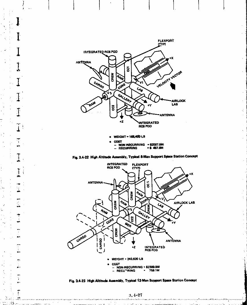
, ,i..... I t ] i 1 ], ] [i._._ .]
FLEXPORt
It.] ,
_1_ "_ 'ANTENNA
_, +Z _INTEGRATED
,L ! ncspod,_ • WEIGI4T" 11_4(10 LB
_ • COST•_'e. -- NON RECURRING "1_097_
- RECURI_ING "$ 487.8M
T Fi_ 3.4-22 High Altitude Assembly,Typlm164tian SupportSlmceStationConcept
,NTEGRATED FLEXPOFrr
" .TI F_S POD (TYPI,i_ +X
,._ '. ANTE
ia. ":i
.!
I Z INTEGRATED ... t._ ) RCSeOD
_ • WEIGHT - 243.620 LB
• COST•" - NON.RECURRING - S230Q.gM
,. - RECU'_RING - 759,1M
_,., Fig. 3.4-23 High Altitude Assembly,Typical t2-Mlm SupportSpaceStolon Conmpt
0000000g-TSA04

= O_omAt_PA_ mor PooaqU_
00000003-TSA05

':' ,.. 3.5 COST
_; °_ This subsection contains cost paramctries for mechanical systems and flight operations.!f,
_' _ Flight operations cost estimate_ are made for the entire SSPS including the recurring costs
:iL for suppport equipment. Mechanical System costs are estimated for the MPTS antenna and
_.., ,. include the following cost elements:
'_..... • Primary and Secondary structure
- Materials L,
_,_,_ - Manufactm'Ing
• Materials transportation
• Assembly.
_ .. 3.5.1 Task 1 - Preliminary Design Results
• _ The fallowing Summarizes the significant otKputs of this initial activity:
• The perfornmnee of the Interim Upper Stage (Transtage) is insufficient to transport
.... assemhly crews to the prime aSsembly site above the Van Allen belt
ri}!_'" _, • A_embly at low altitude results in _ significant reduction in total structttr_ system
_'_i _ ' cost relative to assembly at the prime site
_: , i • Kevlar/polyimtde is the low cost material for assembly at 7000 n ml altitude
• Aluminim structures would result in lowest cost structure for low altitude assembly
i : G A 1.4 krn diameter aluminum antenna is four times the cost of a 0.7 _ diameter!.
" antenna,}
The top level alternate concepts assessed during Task 1 are summarized in Fig. 1-1.
FOur translmrtation modes, three structural materials, two structural arrangements and
three antenna diameters wcre Included in the preliminary matrix of options. The four
transportation modes included:
.. @ Shuttle/Expendable Transt_gc (1980 IOC}
.,- • Shuttle/Reusable Transtage {1980 IOC)
"' _ Stluttle/Cryo Tug (1984 IOC}
:_ • Shuttle/Low Orbit Assembly (1980),!
" " 3,5-1

The materials considered in this initial assessment Included: .
• Ahtm_um (AI_ coating)I
: • G_l)h/te/epoxy (white paint coating) J
, • Kevlax potyimide (white paint coating) 1
The two structural arrangements evaluated were th0 "rect_ng_ar grid" and "radial Iispike" designs divenssed in Reference 16. Antenna diametera of 1.4, 1.0 and 0. Jkm wer_ '
assessed.
Figure 3.5-1 and 3.5-2 summarize the Task I preliminary estimates of weights and
costs for the "rectangular grid" and "radial spike" design options. Figttre 3.5-I shows
weight and cost variations for antenna diameters between 0. 7 and 1.4 km aad for aluminum,
. graphite/epoxy and K_vlar/polyimide. Figure 3.5-2 shows the radial spike design for a: I km diameter antenna using the same three materials. Only two of the four flight modes
(e. g., Cryo Tug, Mode HI and Shuttle/low orbit assembly, Mode IV) are presented. The
performance of the Transtage 1US was found to be insufficient to deliver assembly crews to
a site of 7000 n m_ altitude. Assembly at low alUtude shows a significant cost benefit over !assembly at 7000 n mi. On the average, a 40 to _07o decrease in costs can be achieved with i
the lower altitude assembly site. i
i!_. Kevlar/polylmlde is potentially the low cost material for assembly at 7000 n mtaltitude. This cost advantage over aluminum or graphite/epoxy will be greater ff it can be
shown that the thermal variatioa of polytmide would be sufficient to withstand the expected
i environment without coatings. Aluminum is the low cost material for low altitude assembly,
with Kevlar polyimide the second choice. Aluminum structure will be approximately 25% ....
less costly than graphite/epoxy and 20% less than Ke_,lar for the low altl'_tde ease.
The rectangular grkt (I kin) antenna was selected for concept definition during Task 2.
Aluminum 4rodgraphite/epoxy or polyimide wi_ selected for more in-depth asSassmeut.
Further evaluation of the assembly altitude selection _vas recommended to determine the
impact on cost:
• Support Equipments
• SEPS transportation costs
"e Asse .bly costs of the entire SSPS,
"- 3.5-2
00000003-TSA07


I
"" 3.5.2 Tnsk 2 - Concept DefinitiOn Results
T The Task 2 findingsare summarizedas follows: I. • Low altitude assembly (190 nntl) is s/gnlfi0antly lower in cost than assembly above
_-° the Va_Allen belt.
. • The maJo_ cost driver, is the Shuttle operations cost. The most p_yoff ior reduction
of overall assembly and transportation costs would be the reduction of the per flt_ht
" STS costs by lnt_luetng the Fly-Back Booster and/or heavy lift vehicle.
i • Recurring unit costs for Shuttles, Tugs, Space _ttions, etc. r_presents 1/6 of the=i
total costs for assembly.
" :i • Aluminum iS tim low Cost material for the _. Composites increase Cost
:, 4to5%.
• { 3.5.2. I Transportation and Assembly
The assembly and transportation system elements assumed for the low altitvde and
_ high altitude assen_bly site Task 2 cost estimates are presented in Fig. 3.5-3. The low
_. altitude assembly site uses the Shuttle for tran_o_atton of materials and consumables. The
!.: Shuttle, augmented by support modules in thepayload bay, are used for crew aceommoda-
tions. Detailed parts are fabricated in orbit using automated manufacturing modules.
-_ _ AsSembly is performed using remote controlled manipulators. Solar Eleetric Propulsion
__ is used for transport of the assembled SSPS to the geosynehronous orbital position. The
_ high altitude site requires the a4diUon of the Full Capability Tug for transport of materials, : {
_}, . and must be augmented by a crew transport module for rotation of assembly crewS. A six-man space station is assumed re_i_d for Crew accommodations at the high altitude site.
3.5.2.2 Fleet Size and Traffic Assessment
.. " Both fleet size calculations and the asSesSment of vehicle traffic are directly affected
by the total weight that is transported to orbit, the assembly altitude, and the assembly time
in orbit. This subsection presents the effect that these elements h_ve on traffic rate and
. fleet si_e for three representative flight plans. All three flight plans considered In,-orbit
_ manufacture Of all SSPS structural components by manufacturing modules. The three
flight plans _tre:
d Flight Plan 1 - One year _s_embly at 190 n mt
.... • Flight Plan 2 .- One year assembly at 7000 n mi
.... • Flight Plan 3 - _vo year assembly at 190 n mi.
! Figure 3.6-4 summarizes the SSI_ component weights for the three flight plans listed above.
•_ _ 3.5-5
_:;___.... '" ...... - ............ '-_-'_-_......._J"-- _-__--"-_-..................... 00000003-TSA 10

.... }
.... I
_., _i_,:_!_
3.
_ TRANSPORT DETAIL TRANSPORT_-_;'; ASSEMBLY MODE TRANSPORT CREWACgOM - PARTS A_iEMIILY TO
_,. ALTITUDE (MATERIALli) CREW8 MODATIONIt ABltEMBLY METHOD GEO8YNCH
_" ' LOWORBIT
'_i; e- 1_0 N MI • A_lrlg • REMOTEIN-i:ii_BIT MANIPULATOR
_'_/_ • :tB.5°INCL • SHUTTLE • S?IUI"rLE • 81.1UTTLE MANUFACTURE • 8EPS
- 30 DAYS
_-"_ '", ', HIGH ORBIT
_ii • 7000NMI • SHUTrLE • SHUTTLE • PACE • AUTOMATIC • REMOTE el SEPS
_,_'"i" IrlrATION IN-ORBIT MANIPULATOR
TRANSPORT
MODULE
_: Fil_3.64 TnmpomUo. md AmmbiyCostCo,.pL.i_mCam
i,i
FLIGHT PLANi
1 2 3 ,-_
"' 8TAT. KEE_?MOD.STRUCTURE KLB (103 Kil) 45.0 (20.4) NOT REED 45.0 (20.4|
STAT. KEEP CONSUMASLE$ KLB (103 KIl) 44.0 (19.90 NOT REQD 88.0 (39.9|
SSPSSTRUCI1JRE Mill(108KII) 21._ (9.S) ;_.1 (9,6) 2_.1 _9.6|
MPllIANTENNA MLB(10SKII) 4.12 (i.9) 4.12 (t.9) 4.12 (1.9|
" IIEI_ETRUCTURE (t) MLOIiOSKIll 1.'/7 (0.8) 0.32 (0.14) 1.06 (_48)
SEllSCONSUMAOL_.S(1| MLe (106 k0) 1.18 (0.8I 0.90 (().4fl 1.6"7 (0.76)ii i!
TOTAL MLS ML8 (106 Kil) ! 20.86 (13.1) ;_6.44 (11.97) 27.98 (12.67)
_ Fi9. 3.6-4 SiPS Weiihll
3°5-6
00000003-TSA11

, I I i
"" Tim assumFttons u_od fez fleet sizing are divided into three group8 a8 follows:
,.,!. I_u_'Ueand _ _rformnnce
• 65K lb Shuttle capability to 190 n ml orLlt
•. • 36.8K Tag payload capability from 190 to 7000 n miil-
_i • 25 Shuttle flts/yr for each Shuttle vehicle
,_ .... • 23 Tug flts/yr for each Tug vehicle
i_• _ Each manufaetari_ module processes 420 lb/hr
_: , • Manufacturing modules operate 24 hr/day
,:_ • Remote manipulator modules (RMM) assembles at 26 lb/man-hour
{. '.... e One ground controller for each RMM
;': • Each ground controller works 1_5 mhr/month_. 'i
.. • RMM's are used three shlfts/day
_ _ • RMM's require 5% consumables for each i Ib movedII'
_ Crew Requirements
._, 7000 N Mt site
,:_. i • Six men needed in 7000 n mi orbit for 1 yrif',
i e Crew change every 180 days at high altitude site' .i 190 N Mi siteii
i • Shuttle crew quarters
- • SL_men
I 30-day missions
Figure 3.5-5 and 3.5-6 present a detailed breakdm_._ by assembly phase
'! (see Fig. 3, 5-71 of the number of Shuttles used during each phase of assembly for Flight"' Plan 1 (1 year assembly 190 n ml), and Flight Plan 3 12 year assembly at 190 rt _11. AlsO
_.. listed are the approximate assembly times based on the material delivery and manufacturing
_ -, assumptions. Both of these flight plans h_ve a_sumed that a separate solar array is avail-
..:.. able to power the SEPS during the trip to geosynchronous orbit An investigation of the
?
00000003-TSA12
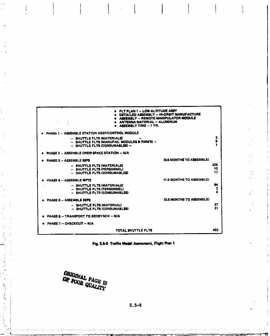
+k I I 1 1 +' t i + !
i iiiii
• FLT PLAN 1 - LOW ALTITUDE A88Y• DETAILED ASSEMBLY- IN.ORBIT MANUFACTURE• ASSEMBLY - REMOTE MANIPULATOR MODULE
i • ANTENNA MATERIAL - ALUMINUM• ASSEMBLYTIME - 1 YR.
• PHASt:1 - ASSEMBLESTATION KEEPICONllqOL MODULE
- SHUTTLE FLI"S(MATERIALE_ - 2- SHUTTLE FL'r8 (MANUFAC. MODULE8 & RMM'Sl - 9"- SHUTTLE FLTS (CONSUMABLES) - 1
• PHASE2 - ASSEMBLECREWSPACESTATION - N/A
• PHASE3 - ASSEMBLESSP$ (9.6 MONTH_ TO ASSEMBLE)
- SHUTTLE FLTS (MAT_RIALSI 326- SHUTTLE FLTS (PERSONNEL) 10- SHUTTLE FLI_ (CONSUMABLES) 17
• PHASE4 - ASSEMBLEMP'I_ (1.9 MONTHS TO ASSEMBLE) ++
- SHU'rTLE FLTlS(MATERIALS) 64- 8HUT'rLE FLTS (PERSONNEL) 2- SHUTTLE i_LTS(CONSUMABLES) 4
• PHASE 6 - ASSEMBLE$EPS (0.5 MONTHS TO ASSEMBLE)
- SHUTTLE lILTS (MATERIAL) 2?- SHUTTLE FLT9 (CONSUMABLES} 31
e PHASE6 - TRANSPORT TO GEOSYNCH - N/A
• PHASE? - CHECKOUT - N/A
TOTAL EHUT'rLE FLTS 492ii , i
t
-_ Fill. 3.6-6 Tmffto Model Anmment. Might Plan 1
++++ +"_ QIT,,,U.,+_-.
+'
+ 3.5-B
+
O0000003-TSA13

l i .... i ii. ...................... i . .
• FLT PLAN :i _ LOW ALTITUDE AShY• DETA;LED ASSEMBLY -- IN.ORBiT MANUFACTURE• ASSEMBLY_ REMOTE MANII_ULATOR MODULE
-" • ANTENNA MATERIAL - ALUMINUM• A_IIEMBLY TIME - 2 YR.
4 PHAIIE 1 - AE8EMBLEErN KEEPICONI_0L MODULE
- SHUTTLE FLT8 (MATER|AL61 _ 2i _' - SHUI"I'LE FLT8 IMI_R. MODULES & RMM'S) - §: - SHUTTLE FLlli (CONSUMABLE8) •
i ! • PHASE2 ASSEMBLECRSWS,"ACE_rATION - N/A
_; • PHASE3 - _UEMSLE 8SPS (19.2 MONTHS TO ASSEMBLE)
- SHUITLE FLT8 (MATERIALS| 325' . - SHUTTLE FLllll (PERSONNEL) 20
'-;, - SHUTTLE FLT8 (CONSUMABLES) 1?
ii, • PHASE4 - ASSEMBLEMPTS (3.S MONTHS 10 ASS; _)LE)' : • ' - SHUTTLE FLTS (MATERIALS| (..
_. - SHUTTLE FLTS (PEF_,)NNEL)- SHUTTLE FLI_ (CON:_UMABLES)
• PHASE5 - ASSEMBLESEPS I0.S lla_ ,'.JAS_._ J:.
_. J - SHUTTLE FLTS (MATERIALS) 2?_'. - SFIUT_LE FLTS (CONSUMABLF_) 31
_'ii • PHASE6 - TRANSPORT TO GEOSYNCH - NIA
• PHASI=? CHECKOUT - NIA
_. /'OT/_L SHUTTLE FLTS . 501
i
Fig. 3.5-6 Traffic Model Assessment, Flight Plen 3
_!, .....,. i 1.0
' nimLe_;;}., STATIONKEEP,'
ATTITUDE•B:,_,,/o , CONTROL
_i!_ , MOOULE
i !- I l. i i iol_' ' TRANSPORT CHECKOUT
L ANEMBLE ASSEMBLE
MPTS"" I I .,,s... TO• GEOSYNCH ACTIVAI"E
i_o_ . . ,!.
: . _ SSPS: - SATELLITE SOLAR_OWER STATIONMPTS: - ICROWAVE POWERTRANSMISSION SYSTEM
_• S|PS: - SOLAR ELECTRONiC PROPULSIONSYSTEMi.
.....: ,,.- Fil_ 3.5-7 Level I FuectioMI Flow: A_mmbly
+.: .... ,, 3.5-',t :.
:t!:,-_' ;-. -,t _.............. ' '" ............ • •
00000003-TSA14

"., feasibil@y of-using the BSPBfor.this l_u_ and reconflgurlng tt once in Seosynchroneus
orbit, proved to be ext_ vmely costly beoaum of _b additional hardwa_ required to sup..
port recoMtguration. Manned Space EP.ationLln _osynchronotts oabit would be necessary to
support the recoM/sueation crew| this would impose a requirement for a Tug fleet and
/. additional Shuffle flights to effect deplo_lnent of hardware, consumables, personnel, an_
: Tugs. Secondly, a delay in the start of SSPS operation would be required. A separate
SEt'S array avoids the reconflguration Step and results in lower total program cost and a _
SSPS which becomes operational earJ*er.
o Results of the fleet size analyses show that 24 Shuttles are required for the one yeer
assembly plan (Flight Plan 1) and 15 Shuttlesare needed to support the two year assembly
plan (Flight Plan 3). In both cases, two crew support modtfles are required to support the
six-man crew. Eight manufacturing modules and 182 manipulator modules are needed for
Flight Plan 1 and halt,'that number for Flight Plan 2. '
Figure 3.5-8 presents the detailed Shuttle/Tug flight requirements necessary to sup-
i:i" port Flight Plan 2, t.e., one year assembly at 7000 n mi. Since atmospheric drag is not
a consideration at 7000 n mi, the stationkeeping module has b_m eliminated. The figure
shows that the Shuttle is required to make approximately 1300 flights in a year. The
dramatic use over the LEO assembly requirement of approximately 500 Shuttle flights can
: _ be explained by the fact that additional flights are required (at less than 100% load factor,
= i.e., 65000 Ib payload) to get Tugs into orbit. The result is that 59 Shuttles and 37 Tugs i
=_ are needed to support Flight Plan 3.
_ i 3.5.2.3 Launch Opportunity Sensitiv/ty to Traffic Rate ' :
_ The Shuttle h/m _m ETR launch opportunity every 23.5 hours to a 190 n mi 28.5
' inclined orbit assembly site. A glance at the total number of Shuttle launches required for
_ either Of th_ one year assemblies (see Fig. 3.5-9) indicates that fl_om one to four Shuttle
launches per day are required ff orbit phasing is neglected. Worst case phasing conditions
can exist on some Of these days; this only serves to aggrevate the launch/day _ltuatlon. "
This _ihlation arises from the fact that under worst case phasing conditions, it is optimum
_. to delay launch a day, and spend 16 hours phasing with the assembly area at 190 n mi. The
_/_ alternative is to launch on the first opportunity, spend 40 hours phasing, and arrive at the
_ assembly point at the same time as a vehicle that delayed launch for 1 day. Obviously, it
is more advantageous to delay launch for the day and wait 6n the ground for better relative
_ launch site/assembly point phasing to exist. This waiting would mean that the ETR launch
.__ ra' _ would double on some days during the year alld that from 2 to 8 vehicles would have to,i
00000003-TSB01

r
• FLI"_LAI_2- mGNAL_TrtmeAm' rro0oNMI!,_. • IN.OR8rI: MANUFACTURE AT 7000 NML
• . R_MOTE MANfPULATOR ASBEMILY!'* '_" •, I YEAR MANUFACTURE & ASSEMBLY
_ • ANTENNA _ - ALL'._M!___Lm
.,. • F_-IASE1 -- EQUIPMENT DGPI.OYMENI_
:!i...... SHUTTLE FI:II_ TO LOW EARTH ORBIT (MFR. MOD) 8_._"' ":,i. ; -- SHUTTLE FII_ TO LOW EARTH ORBIT (RMM'8} i "L., .-. - 8HLYI'TLEFLTS J=_FI1"1.1(3DEPLOl_MENT .. 10_-_' -- TUG FLT_ 10
.:_.. . :, • _.2_.,CI_WBPACESTATIONOEPLOYMENI" .
iii:( : :_, -- SHUTTLE FLTS TO LOW _ ORBIT (SPACESTATION) 8#_' -- SHUTTLE FLTS FOP.TUG DEPLOYMENT 8_,' - TUQFLTS B
_ 4 PHASE3 - SSP$MANUFACTURE.
•i. -- SHUI"rLE FITS TO LOW EARTH ORBIT (MATERIAL) 325!:-'. _ _, -- SHUT'tl.I_ FLTS FEIRTUG DEPLOYMEN3: 5/4
:! i -- "GJGFL'I:S 874
_!.." i "" • t:_S 4 - MPT_ MANUFACTURE
_:' -- SHUTTLE.FLTS TO LOW EARTH ORBIT (MATERIAL) 64i_" _: - SHuI"rLE I_L_:_FOR.TUG DEPLOYMENT 112_;, - TUG FLTS t12_.. ,_.::!_ • PHASES oBEPSMANUFACTURE. .._' " ] _"' -- SHUTTLE FL"IS TO LOW EARTH ORBIT (MATERIAL) 50
i j !,:' d _ _ -- SHUTTLE FL_ FOR TUG DEPLOYMENT 88- I_JG FLTS 88
.; _ PHASE6 - TRANSPORT TO GEOSYNCH
:_i - SHUTTLE FLTSTO LOW EARTH ORBIT ($1_PSPROPELLANT) 14i"_: ' ' " '_ - SHUI"TLE FLTS FOR TUG DEPLOYMENT 2S :_ i .... TUG FLTS 25L '
_:,' - " - SHUI"rLE FLTS TO LOW EARTH ORl_lT (RMM CONSOMABLE$) 21'_ - SHUTTLE FLTS FOR TUG DEPLOYMENT 36 :;',. _. - TUG FLTS 36
,_: - SHUTTLE FLTSTO LOW EARTH ORBIT (CREW+ RSM) 2- SHUTTLE FLTS FOF_TUG DEPLOYMENT. 2 :, -- TUG FLTS "---- 2
':_"' : _ " TOTAL SHUTTLE FLTS 1348;:i.: ' *_i TOTAL TUG FLTS 8':5
e.,
._. " Fi_. 3.5,8 Tr_ifftc Mm_ lind I_ieet 8L_eAss/mment, Flight I_n 2 .....
00000003-TSB02

i_, I i
i!"!_,. w
.: lsaunel_:l..._t_d_, the...laun_h v,,_edow._ -- 15 mlsmte_,)_ .cur_,en_..launeh...olwrating
:o It Is Intere_ to note that, lt an aeemmbly alti_ 255 n.ml wera ehojlen, proper
i_iili_ p.hasie_ with th_ assembly point v_Lexlst on _ bl_Is and the _u_tmh ovexd_v from
one. day to _he next woll/d be avoided.__
3,_. 2.4 Fleet Slze/Tmffie Recom_oas
LI
_: Figure 3.5-9 presenls a summary of_the fleet slz_/treffl_ requLeementa_ot the thre_ ..........
if" flight plans. Based on stn/ctly fleet _0 consideration a_:_o year aese_0.bLy at LEO lit
_i; recomme_led._Yrom_a_launc_ opportunity _ of view, a 255 n _ti asse_bly____de isrecommended.Thiall/de alsooffersobtt decayas.
i;!/ 3. 5.2.4. 1 Concept Cost Comparison - Co_pflattons were prepared for"_ following
if! three cases:-iii_ • F,31ght Plan I - Low alei_de assembly, one yee_r assembly _ (Fig, 3. 5-Z0)
_i e___light_Plan 2- Hlgh altitude asSemb_y._one y_ anembly peeiOd (Fig. 3. 5-][1)
i!f" • Flight Plan-3 - LoW ai_itUde assembly, two yea_ assembly ize_iod 0Tig. 3. 5-1L2_. ,
i_ The recurring and nonrecurring cost estimates for suppor_ equiptnefits assum_ t_t_ts ..,
i!if concept comparison are outlined in Fig. 3. §..15.- Previous cost dsht on 8pace Station
i/!. (NAS 9-§955) were updated to 19'/4 dollars end a9pliOd as a unit cost fae_r ($/Kg) to Space istattOn_ Shuttle Support modules, remote maniptdators and auto malmfacturtng modules. _
_H Weight estimates were taken from Ref. 25 attd 26 for the Modula_ Sp_e Station arid Shuttle _
ii: Support Modules, respectively. COst estimate_ for Shuttle were taken_reni Grmnman :.'! Please A study results w]flle Tug estimates were based on recent Tug System Studies. The _
_i: cost o_ SEPS and the control modules were asstuned at $1M/lb o_ thrust6 Ref. 29. Ali
:;. equipments used in the cost comparison were amortized over the assbmbly of five SSPS.
Ftgtt_e 3.5 "0 throt/gli 3.5-12 summarizb tile tr__ion and assembly costs for .
:; the three flight plans cited.above. An assembly cost of 1323/kw (5 GW system) c_u be",U : i
_: achieved at a low altitude site with a one year a_sembly time (Flight Plan 1, Fig. 3.5-10).
_!f/: These costs can be reduced slightly, $150_ _w, ff the assembly time 18 increased to two
i i_ years. (Flight Plan 3. Fig. 3.5-12). Assembly at high altl_ude would cost 350/I_, (Flight
_' Plan 2, Fig. 3.5-11_, an unacceptable cost level, ff space based power generation is to be
;' competitive with ground generated power.
_
_.:-_. 3.5-12
_:-_ . ._
O0000003ITSB03

E 'I! .... I
l"• !
'" ,.co Lot FLT FL f'LA LT;'LAN3-. '_: - ASSEMBLY ALT. ' Ib0 NM 7000 I_JP_ 190 N M
:i, - ASSEM,B_Y TIME 1 YR 1 YR 2 YR• , DETAILP.AKT_ AUTO IN-ORBiT.-- A_dl'OI N,ORBI1' AUT'O IN-ORBil'
.- ASSEMBLY RI_MO1]L _ ___REMQ.TE ITEMOi"E
•,- - _LIs _. _18 sol_ - TUG - 85S -
_7 - AVG _HUTTLE FLT_DAY 1.37 3._ 0.7"'- _ !_ - A_GTUGFL_ -- 234 -
.. ILFLI[E_$tZE
' _,_ - _TTLE _4 Se iS'_i - I_uIUFACI_e I_DULD 8 8 4
._ -- _TGR MODULES le2 17e 91- CRm _ I_U_.S 2 -
' _* -TUa - _ -J_! -- SFA_E t_rATiON - 1 -
- CMEWT_,_mT M_r,JLS - 2 .... -
(: Bl. &_9 1_ A,r,_d,t.t__i.mry! ,
; RECURRINGNON- FLEET AMORTIZgO NO. NO. OPS
; ; I : ELEMEI_r RECURRING, _ SIZE OVER 5 88P8, $M FLTS PERSONNEl. COST,L:, "
• SHUTTLE N/A 24 _ 492 -- 5°1_
• MooO_ 2_r 2 Is 12 - 12_._ FUUatOM
, M(_DULE 283- 2 2_.6 i2- - 12
, W_UFACnJ_S-iobuLd 2m 8 _6o - - 12
_' ;_ FRI_E-FLYMIIG' t TELEOISERJ_TOR 5.iV6 182 45.2 - 546 21.?
ooW._OL, :. MOl_Jl`e TED 1 3.2 - - ! .4
,, TORE 230 6 00 - - 9
..... SEPS TED I 400 1 - 15.7
iF n
CTAL ,,.-',,,,, jJ
• TOTAL CO_(T |RECUR �OPS|,. &e.Te!.?M _
• ! ,,. • _IKW " $1352/KW!
- * "_UME$ $1M/MONTH OVER 1 YR PERIOD FOR FLT O1_ SUPPOftT i
• ,. Fi_ 3.15,1F0Tv_ao_ahJ_ an_ AJmomMyCoa__ Plan I _
t
. . _ _._• . ,- .
O0000003-TSB04

i _.
1
Ii
_:" NoN. FLSET AMO._ZED NO. .o. ms$--;. ,.
5_ RECURRING. SM SIZE OVER § _IPS, tM FLT8 PERSONNEL COST,Mil
"_: SHUTTLE N/A- .. _ 2,120 1348 - 14,154
i_i_,--;, TUG N/A Sl 89 8SS - IlSS '-
, . ,,.
_:_;'-'_** PACE 8_ATION
i- CREW
! _,.*'° MANUFACTURE_! _ MODULE 288 8 100 - -- 12
.; FREE'FLYING_, _ TELEOPERATOR 8315 178 43.6 - 828 20.9
L_:, CONTSlOL_ MODULE Till) 1 3.2 - - 1.4
_o_ TDFtS 230 8 60 - - 9
_ SEPS T.Sb 1 70 - - 9.0i or i ,i
• : " 8UEiTOTALS 2_"7..3 t S,(:_.:l
e- TOTAL (I:tECURRtNG + O1-_ - ilT,l_t2.SM" !/' 4 COSTIL_ $?mlUi (I r_ I_IKgl:__. _ • cOEi'/KW - 13537/kW
'. "_88Uli_E8 I1M/_ONTH OVER 1 YR PEFIIODFOR FLT OPSSUPPORT
' Fql. l.E, ti_ 1;nimlmiliiton _ Anem_4y _ Flight Iq_ 2
_:; .... 3.5-14
_ ..i,__.-'_ ................... ............................... ...._............. _, _,
00000003-TSB05
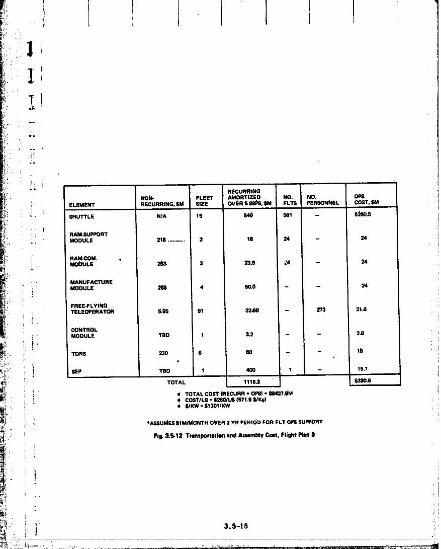
i
i: t iH:/.' i
RECURRINGNON- FLEET AMORTIZED NO. NO. OPS
_ : ELEMENt RECURRING, $M SiZE OVi_R 5 SSI_, _ FLT8 PERSONNEL COST, iM'! , i i ii ii
_." SHUTTLE N/A 15 540 501 -- 5_._I0.5
): 1•, RAM SUPPORT
_. MODULE 218 ........ 2 16 24 - 24
,; RAM.COM. .
• - MANUFACTURE
2 , MODULE 288 4 50.0 - - 24_ ._.
FREE-FLYING_;': _ TELEOPERATOR 5.95 91 22.60 - 2'/3 21.6 !
T.
CONTROL
MODULE TQD 1 3.2 - - 2.8
' o
,:_' , _ _SEP TEID 1 400 1 - 15.7
! TOTAL i 115.3 53g0.8
: :: _ TOTAL COST IRECURR + OPS) ,',,tii8427._J
_' !. _ ii COST/LB - S260/LB 1571.9 $/Kg|
i! %4_SUME5 $1 MII_ONTH OVER 2 YR PERIleD FOR FLT OPS SUPPORT
i_£' Fill. 3.5-12 Ttlnsportation and AnatoMy Colt, Fliilht Plan 3i,1
,1' [
., 3.5-i5 ::
O0000003-TSB06

J
i
|
' 'R"CURRI"":mu "NON-ELEMENT PERFORMANCE tI$1GHT COST/FLT UECUWRING UNIT SOURCE
SHUTTLE • 66K TO 190 N M N/A $/0.5M N/A $180M GAC SHUTTLE100 FLT LIFE STUDY _
CRYO TUG 36,8 K LB TO BURN OUT = $ 1.0M N/A $12M . MDAC TUG STUDY7000 N M 2630 K9100 I;LT LIFE FUbl_"
FREE-FLYING 5 YR LiFE 183 K9 TI_ _. $5.foM $1.24M Mfi;FC-PAYLOADTELE OPERATOR DESCRIPTIO_I _-_
VOL.. RAM SUPPORT 30 DAY MISSION 5000 K9 $1.(gi4 _IBM $40151 WT DATA|
MODULE S YR LIFE - NAS8.27539COST DATA- NA_9.9953
RAIM.COM 30 DAY MISSION 8760 1(9 $ 1.0M $283M S59M IWT DATAMODULE 5 #R LIFE ' - NAS 8-27539
- COST DATA- NA_ 9-9953
MANUFACTURE 5 YR LIFE 0t00 K9 _ _ $62.§M SWAGMODULE
SEllS 1 YR TRIP TIME FROM lg_ N M - $t5.1_A TBD $400M GAC RPT Nk).1.11t X 10u K0 ASP 583-9-8FROM 700 N M" $ 9.0M TBD M00M
.m x losKaPACE STATION 8 YR LIFE ?6.700 K6 TBO 1_007._ j48?.SM NAS 9-9953SM_12 MAN 5 YR LIFE 10_0100 K9 1tD _.91tA $75'_.Ila
. C_tEW NAS9-25051. TRAY_ISPER 100 FLT LIFE 10,35_ K9 701) $33_ 1_7_.2_
JOOULE (4)TDR$ N/A _8 _ NiA l_'J(l_M _ HUGHS REPORT
30096.3514,Hi i
• _ enJc_ su_ (lWdtrE)
3.s-le ,
O0000003-TSB07

i,I
p.. ! ";' STS operations cost. is the, major cost driver. Ove_80_ of the cost for assembly are
i..;,' -_ ' related to 5TS pen-flight lauach costs. These costs can be significantly reduced by lntro-
i _'" duclug the Fly-Back Boosters. Datll gena=ated during the.Slmttle Phase A studies Indicatedi-
that launch costs could L_ _duced by a factor of two or three with a Fly-Back Booster. A: ,
• _ hea_y lift _ehtcle, which utilizes the current Shuttle system e_erual tanks, SSME. and solidF _;'- _.i
roc_ could-be utfltzed in a deployonly flight mode and Increase throw weight performance
_,,_ to $120_)00 It) pen flight without increasing launch costs. Launch cost of $25 to _0/lb
..... could be achie_,ed with these S'l_.m_fficattons.
Recurring costs for. support equipments were found not to be as significant a cost1!:: :.i!.!, ,, driver as was expected. The unit costs to pttrchase the Space Stations, additional Shuttles,
_%_'_" i! i manuf_lcturing modules, etC. represent only 1/6 the cost to assemble _ach SSI_.
i:':" The development cost of Space S_attons, Shuttle payload bay support modules and
-' :i _ free flying teleol_rators can be shared or.fully absorbed by I)rograms which are mor_ near
[.__.,.. term than SSI_. The function of the. manufactttting moduleil and SEPS, may be so uniqueL--_..- _ to SSI_S that these elements may have to be accounted as part of the SSPS developmen_F_?::" !ll ......'-"! " " COstS
i._ii! " 3.5.2.4.2 SensitivityTo ShuttlePackaging Densit_ - A xevlew of packaging factorsfor _|
elements.of the SSPS has showtt that most components and/or subassemblL_s can utilize
[-i!I ; the full payload performance capability of the Shuttle. The exception ts perhaps the antenna
[ :. v_aveguides. Structural Subassemblies, can be packages as fiat stock and {abrtcated in
space with relatively simple auto mannfacturlng modules. Solar cell blankets can be rolled
,=;. i into tightly packages bundles for transport. Electrtc_ wiring and equipments can also be
• _ densely packaged. The wavegutdes, however, may require fabrication on earth where the
_=. _ tightdlmebslontdtolerancesnecessary for efficientmicrowave performance c_n be closely
_-_ cohtz_lled.
i,'- _, The design of close tolerance hinges and lockIng mechanisms as an Integral part of• .. the wa_gulde subarray offers a packaging approach with reasonable densities. Figure
_:!' ° 3.5-14 Is a parametric pret_entatton of total waveguide weight and p_ck,_gln_ density aS a
_: function of w_veg_lde wall thickness. The final selection of thickness wfl| be determined
" " :, by analysis of the operational thermal requirements of the waveguldes. An Increase In
i :. i thickness will Increase conductivity of heat from the hot surface wher(_ the microwave con-
i _ ; version electronics are mounted to tile cooler slotted face of the Subarray. _is thermal
_"_' _ transfer is required to minimize the thermal gradients between the surfaces thereby
Pi"<'. r_lnlm|ztng thermal dll_rtion. The packaging approach sho_ In Fig. 3. _-14 utilizes the!b L
v_
00000003-TSB08

!:
!,
s.S-ls
;.,_..1211. .............. •....................................... ' •.............................., _:_.....
O0000003-TSB09

'" ,,J i t i
, !
t
hinges miming the 18 meter length of the wwzeguide as a means of.rolling the _rray into as
tight a bundle as possible, without affecting the dimensional cheraCteL'isflcs of individual
i waveguides within the subarray (similar-packnglng approach as usecLto stow snow fence)."" After delivery of the subarrays to orbit, lockt- • mechanism on the face opposite the hinge
lines are utilized to securely deploy the subarray to within the required flatnmm.
Figure 3.5-15 relates total wavegtfide sy_m weight to packing density _nd number ofi __-_"!_ ": Shuttle flights. The flight plans presented ear|ler in this section, assumed infiight fabrica-
"" tion of these units. A total.of 25 flights was required to transport the 3.95 Kg of 10 mil
-_ aluminum stock for inflight manufacture. The number of flights increases to 140 if the
_ waveguides are fabricated on the ground and t_anoported in the packaging arrangement
; _. show_ in Fig. 3.5-14. The number of required flight_ remain constant up to a waveguide
!. i ;_ wall thickness of 50 raft. Above this material thickness, the Shuttle perform_tnce limita-
i_ tlon¢ become the driving factor for establishing quantity of flights.
_ Trafisportation costs increase 20°/ofrom the baseline rate of 1301 $/kw to 1550 $/kw
:r_. if space fabrication is not used for the wave_ide. This 20% increase holds up to a wave-
_:_ ! _ guide wall thickness of.50 mil.. At a thickness of 100 mil, the increase in cost.is 50%.
Figure 3.5-16 summarizes the cos_ deltags as a function of w_vegulde wall thickness.
3.5.3 MI_S Structural Costs4 •
:. The c_st elements for mech_mical systems 'and flight operations have been broken
_. , down into the following subdivisions:
_:. _ _ • Primary and secondary structure
"-" Materialsi ': "
_:_; :il. - Manufactux_g_ _' ' • Materials transportation
?
__i:- :. • -Assembly.
i .: _ Cost parametrics for the structure are in 1974 dollars and include the cost of
"_"" _.. materials and thermal coatings. The manufacturing processing costs for prelaunch forming
_' of beam elements and applicatl0n of thermaJ coating_ are included_ Cost relationships are-/
; in the form 0f $/Kg._a
?i,'
O0000003-TSBIO

----_NOAMPLITRON)
_1LWF'r 3 A 0.061iiI.WALLTHICKNF.88(NO.AMPLtTROI_
O 0,I0 IN, WAt.L THICKNE88.(NO AMPL|TRON)

• t
:-_:.... " Materials Translmortatlon costs a_o evaluated for a low altitude assembly dit_
._:_i/ .. only, _lm h_ altl_de option was decided because of-the nolz-competitlve costs (see_Yt/ [..,_/.: .. , Subse0tlon 3.5.21. The OOB_.of trlmsportla& assembly crews and in-flight pro_emsln__
_?_,:.... , modules are not included under this cost element.
.... ',. Assembly costs for the structural materials (1.e., alumtnum and graphite composites)
• options considered wore assumed the same. The results of the assembly cost comparison
:.oi. (Subsection $.5,2) were used to e_abllsh a proportionate cost fox suppert equipmentS,
: _: SEP. tragasportation cost, etc. based on antanna weight =elattve to the entire SSPS. The
,. assembly cost of stt_cture varies with the mzmber of-Joints or pieces of material that
.._.. must be assembled and is independent of the prol_rties or weight of the material.
_ _! 3.5.3.1 Materials and Manufacturing Costs
_ _'!// The microwaVe power transmission section of the orbiting solar energy collector can
-_':.:: be designed from advanced composite material or aluminum to meet three criteria. These
_o_/," .axe Is) 30--year-life, (b) low or zero thermztl expansion.and (c) operating temperature
_ _" rang_ between 460°K and 480°K. This stru_xue_ era, be designed as thl_walX tubes, 3-6
:_,_'_: inches th diameter, 18m 180 it) or less in length, or as thin (0. 0101 slats which roll up to
_o.i';'_ _thelix 4. 6m 115 ft) in diameh_r.
_4_ A summary of material and processing costs are given in Fig. $. 5-1_ for severn.__,: csndldates. _zhnal control coating costs are included.
....:i_ii/./i_" Material costs were obtained durin_ fbe week of August 19, 1974 from Grumman :,__:;/. / '. puarehsst_ agents, who are 1_ dlrecl, contact with vendors and who used most recent put- _
_i: chase orde:s and quotes as their basis. These costs are listed in Fig. _. 5-1, as "p,senti material cOst'*, and would be the price paid.today for a lat'ge quantity order. The only ex-
_s__!_!!_ • _ _ cepflon I_ 2-mll-thlck graplflte/epoxy 3-1rich-wide tape whose price would drop from_r_'q_'_'' 726 _ 15330 pet Ib) (which is the Small batch co_) to less than 210 $/KK 15100 pet. lb)
_, !. , for la/_ volume oi.ders; a firm price could not be obtalded from the vendors.
_ .... Mini_hUin prices ahown in Fig. 3.5-I'_ are generally the same as present prices or
_'_"__ . are based on recent prices (e.g. 236 $/1_ (5107/1b) for boron/epoxy in Janu_-_ 1974).
_I projected near term lower costs (e. g. 44 _/Kg (_20/lb) for graphite/epoxy} or different
_-_'_'_ " forms of tl_ material (e.g., Kevlar prices, aluminum alloy types).
'_ ;:
O0000003-TSB12

' iI
i °"
| '
_g _g _g
!'!. i! "i:
O0000003-TSB13

I •
_: _ " Maximum prices anticipate a 20-25% ltglation_y raise during tl,e 1974-1975 time-
- span for most of the materials listed in Fig. 3. _-17 except _or the Kcvlar ma._imum pri_e
_. which is a more expensive form of this pat*ticular n,zh_rial. Kovlar prices may drop In
t_,e near future as usngc of this mi_fl-made fiber increases.
.... Procedsing costs wore based on a recent J_udy for the VFAX aizplane design in
_i which an analysis considered metal and composite designs. These costs are based on the
;; current $14-$i6 per hour manufacturing rate. They reflect a 75-80% learn/ng curve,
with maximum cost taken at Ship NO. 1 and minimum cost at Ship No. 190. It is undetstc
_ _: that 150 ships may not be built, but that within each ship there exists sufficient repetitive
_ structure such that mass preduct!-.m of identical items will tend to lower unit cost as mor(
" _ and more items are built./ " i '
_/._". For further in-depth reference the reader is directed to Ref 17.
i 3.5.3.2 Transportation and Assemblyw,,
_ Figure 3. S-18 summarizes the cost relationships used in comparing MPTS strdCtur
_. _ options. The cost of materials transportation assumes the Shuttle can deliver 29.4 x 10³
_'__ (65 K/lb) to 190 n mi at a _ost of $10.5M per flight. In the four month period allocated to_..: ,i the _tssembly Of the ante_la, eight flights _vere needed for tranS_x)ttation of consumables
• and personnel (see Subsection 3.5.2). It is assumed that the type of material used in the
construction ofthe antenn_ does not _tffect this requirement. The cost of eqhipments for
mlpport of asSembly and the cost of SEPS transportation to geosynchronous Was allc_cated
._ _ in proportion to the baseline antenna weight to solar array weight ratio used in the traffic
: mod_l assessment and was assumed irdependent of strUctural material.
_i" _ Figure 3.5-_9 shows that aluminum is the low cost material for the antenna str_ctu
' The three gr_phit,._/composite options evaluated are:
_:" il • Graphite/epoxy - 5 mfl material
-. • Graphite/epoxy- 2 rail material=: ,: 'o
• Graphite/polyimide - 2 rail material.
The increased cost of the graphite composite materials and prelaunch proeessihg
_ , _ relative to aluminum is greater than the transportation cost _av/ngs achieved _vith the
:_/" lighter material. These composite eost estimates are _ased on projected costs of grapht
_ material in c_antities of a fm_'thousand pounds. Ve_id0r contacts have indicated, howeve
_ that large _plantity orders (millions of pounds) may significantly reduc_ these costs.
_._... ._ 3.5-23
° .....-:i'L......_• _::_.,,_. _ .-.
O0000003-TSB'I4
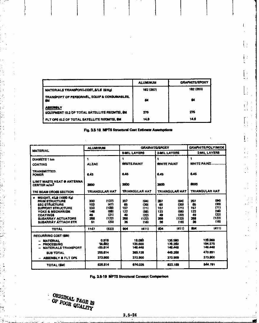
' 1'l
It
L_
t- J
ALUItgNU?,9 GRAPHIZE/EPOXY
ii i !
MATERIALSTRANS#OFLT-COSl",S/Lm(S/re) i62 (ssT) le2 (_sz)
11_ANd4_rOFPERSONNt!L,S(_JIl_a CON:_JkL4BLF-S.m 64 d4
• : Assmy i _EQUIPMENT (0.2 OF TO_AL SATELLrrE REQMI_._ 275 278
FLT OPg (0_ OF TOTAL SATELLITE RE(]Mll)o SM 14.9 i4.9 I_i !
i FI_ 3_18 MP13Strum.ratCon E_mm Anu_ptiom
:: MATERIAL ALUMINUM, GRAEHITEJEPO_Y GRAPHITE/POLYIM!DE __ 6-MIL LAYER8 2-MIL LAYERS _.MIL LAYk_S ,i II I i I ul'l iii i "fu" ii I_ i i
OtAM£rS_km 1 1 1 1COATING ALZAC WH_TF.P.AINT WHITE PAINT WHITE PAIN:T-_ :
TRANSMITTED.POWER 6.45 6.45 6.45 6.45
; LIMIT WASTE HEAY" • ANTENNA[- CENTER wire2 3600 56b0 3600 8000
i TRI BEAM CRO_S SECTION TRIANGULAR HAT I:RfANGULAR HAT TRIANGULAR HAT TRIANGULAR HAT
• WEIGHT. Kt,6 (1000 Kg)PRIM STRUCTURE 300 (137) 201 (94) 207 (94) 207 (94) ; i_.$EC STnU_TURE 103 (47) 68 (30) 68 (30) 65 (30)SUISP_RT SI_RUCTURE 233 (106) 157 (71) 157 (71) 157 (7t)YOKE & MECHANISM 146 (66) 122 (56) 122 (56) 122 (6iJ)COATINGS 46 (21) 49 (22) 46 (22) 49 (22)_I.leARRAY ACTUATORS 268 (122) 268 (122) 288 (122) 288 (122)
_-_ SUEARRAY ATTACH STR 61 (23) 36 (t6) 36 (16) 36 (16)i
" "_ TOTAL 1147 (§22) 904 (4tt) g_04 (4il) g04 (411)
_-'i_ RECUFiI_ING C06T (Mit} -
- MATERIAL 0.918 18.08_ 120.560 12_Nt8: - PROCESSING _;8J_82 135.600 176_k) 194_75
,., -- MATERIALS TRANSPORT 185,81_ 146.448 146.448 146.448SUB TOTAL 266.6i4 300.128 449.288 4_0_9t
- ASSEMBLY & FLT OPS 373.91)0 373.900 3?3300 373,900II mm
: TOTAL (_M) 629_14 614_28 823.188 844,791
Fi_ 3.6.19 MPTSStmctundConapt Co_
00000003-T$00"1

I_
i
::_•" i Section 4 .
:, TECHNOLOGY.ISSUESz
• ii This Seetioa includes an initial listing of MPTS technology t_sues. This listing ldentt_
-_!_ ties areas in technology where more work needs to be done and suggests approaches for ac.
2: _" complishing these tasks. No attempt has been made at this time to categorize or combine
_ these technology programs.91' _ p
-_• 4. i CON'£ROL SYSTEM
i!_,.i 4.1.1 E_th_.tion of Alteraato Power Transfer and Drive I_viCes%. •:_:' _, Slip rings and flex harnesses are power transfer deVices most Commonly used in
-_ _,, spacecraft. However, these systems, principally the slip ring approach, require many
_ _ mechanical interfaces. Potential reliability advantages can be envisioned With the use of
, _; rotz.ry tr_-_formers for l_wer tra_fer and direct drive, linear induction motors for drive
_ power. Potentialpayoffs in reduced maintenance or logistic requirements and lower friction__-,: , •
---_ _ JUstify further study of these devices for the MPTS.
_ 4. I. I. I Background
_*':!'_i .__: Slip rings and flex harnesses are the only fllght-demonstrated methods of power•'_ transfer across rotating joints. Because of the project scale of the MPTS, in si_e torrent
: _ carrying capacity, and mission duration, it is deemed critical to further evaluate roth.ry
._, transformerS and linear induction drive devices.
'::" _ These devices are relatively new applications for a space environment. A rotary
! transformer and linear induction motor drive combination has many advantages including no
• i: wear or wear products, no arcing, negligible friction, no viscous drag from liquid contact,
" and energy transfer relatively unaffected by the presence of oil, water, or other contaml-
....ii, :__ nants. Furtherdesignandexperimentalwork isrequiredtodeterminethepraetlbilityof•_, -* sucha devicetotheMPTS.
_. 4.I.i.2 DesiredOutput
# Conceptual design to determine feasibility, weight and cost of rotary
_" transformer/linear induction motor
e Outline of scaled do_ prototTpe test program which will lead to developmentof full Scale model.
_ _ 4-1
I
00000003-TSC02

4.1.2 _ C___tro__1_ysten_ Anal_s.ts I
The preLt___!._ anal_oal study perfo_med.__t of t_s contmct,lnohtded an
assessment of_p_bable l_intlng accuracy, cont1_Ltorque requh'ements, honsepower require-
meats and-coatroI system bandpass frequency. These results were obta/ned using simplified i
systemmodels so that the most significant factors could be studied. These simplifications _ 1
may result in not identifying key dynamics problems associated with spaceera_ to antenna
structural, dynamics and non-ltnearlfles in the meehsnical elements of the control system, tJ.
4..1.2.1 Background i
,_ A more _th study which, conSiders non-linesrities and structural dynamics would
modify and complicate the control system design. The first step in a refined Stttdy Would be ]_the development of an sccurate se_ of Structural modes of vibration fon all frequencies up f
:i through that of the contl_l system bandpaSs froq_ncy. This ts_required to understand j-system.stability and performance in a realistic mann_
These bending modes couple into antennamotions through friction effects in the bear- iings dnd gear _rdtus, and by physically perte_ing the antenna through motion cross-coupling I
S,
into its two-axis gimbal system. The preliminary study documented here _____ th_e__e
effects; however, a much more detailed investigation is required.
The torque drive-gear chain system has within it the factors of flexibility, friction,
backlash, and h.vsteresis. These were briefly considered in the preliminary study. They _
were neglected in the p_eliminary analysis, but they must be considered in more detail
Disturbatlce forces which must be considered in further analysis efforts are. due to ',..
angular momentum cross-coupling, gravity gradient, magnetic field interaction, and solar
il pressure. Preliminary study indicated that these might be initially neglected because of the
dominating influence of friction forces and structural mode oscillations, which were con-
_!_" sidered.
:!: It is possible that detailed study efforts will Show that many of these aforementioned!_: factors are critical effects on control design and performance. It may also be found that iti,}:il is not possible to calculate or estimate some of these factors with sufficient accuracy to
I_:_i provide the necessary control performance accuracy. In that case a type of "adaptive",:_'_' control design may be required where a special estimator logic (Kalman Filter) can update
_;. the knowledge of these f_tctors and adjust the control system gains appropriately.
00000003-TSC03

I ] I 111 J
• ' 'IHtm
t __ __.Deiail_ eonK'ol system deat_
. i, e. In-de_ stabtI_ analydis
! '.]'2 e_Pninttng aC_y Sensitivity to eOnflgtWatlon uncezq_tinties• {"
_ t .Full S-dimensional m_th-mndel Simulation demonstration.:i
_ 4.2 STRTTr._r_AL SYSTEM
_: I 4..2..l__on_posite St_cW.res. sail Assembly Techniqu_s
Th_ attractive combinaflo_ O_strength and miass ptOpertiea peculiar to adv_tnced-cOm-
__' posites makes thes_ materials strong candidates fo_ the antenna stru_htre_ High.strength,IF
stiffness, and low thermal expansion ale desirable propertieS. The initial studies of the
_ _ :, _ MTI_S shows these materials to be cost competitive.
4, 2. I. I Background
. _ i: Up_to this time mt/_h o_ the mechanical propezfles data for advanced composites have ,
-*i:: .... been established foe short-duration aire_aft and spacecraft mission. _he _tehim struc-
" " i i_ tural, designs would.employ composites in.much thinner gauges than has been norm_tlly used.
"" Development of mechanical I_roperties in th_ sections (5 mil rahge) must be _ed.!,
_ _ Durability of orga_e matrix materials i_ oz_bttmust be reliably pl_licted based on sound} Ii '
- - test dat_._ These verification tests for long-duration life times (30 years) must be initiated
7 • : as soon as possible,_r
_• :_-_ Methods of.assembly aud manufacture in Space must be evaluated to determine overall
,_ :_, feasibility of composites to MTPS application. Creep _tigue from tllermal cycling in a
.._i! Space environment should be a long,term advanced, study for"these m_t_t.ials._ Bonding
methods used to Join members in a space environment needs definition.
_ 4.2.I.2 DesiredOutput
# Sufficientdatato_upportdesignofMTPS structureusingthinmembers ina:!!• geosynchronousaltitudeenvlromuentfora 30-yearperiod.Thisdatashould
;_ _ determine materials strength degradation due to fatigue, radiation, temperature
_. and outgassing
i _ Methods for manufacture in space, Low cost methods of transportin_ raw
._ materials to a space-based f_ctory and st_bsequent automatic mamdac_.-'re of
basic struc_r_.l elements
_ 4* Methods of Joinln_ and bonding basle structural elements into large _:.-:c.ture.
:_ 4-3
........ ?- -_- - _ i i - _ "" "± III ii ............ T_/' ,_r, Ilill ...... ' .... |
00000003-T$C04

" 4...2.-_ T_ton.Brace.Amtenna Feasibtlity Assessment
Background
The Tension BnaCe o_cept may offer weight._tnd cost d_,'antqds over a built-_tlp
section ___ach. The fiat ar.ra_' is relatively, insensitive totout,of-plane therniaLdistox_-
' tions since the-braces maintain a l_sttive _rce on the fiat a_ty tension wiz'es. The bl'ace
. • and flat az.ray wires, can serve as both structural members a_ conducting elements.
" In order to assess the concept feasibility structuzal art'augemeut, cteawln_s must be. j• dr_twn, stantctunal members need to be sized, the eomblned.effects of thermal cycling,
-__/ long teJ:m...o_ep on wires, Joints .and braces, need to be ev_, and the feasibility of
_-_"/_ using Stt'ucture for.power teansmission needs definition. In addition, methods of assembly
=!,: to produce a fiat pre-tevmioned_trtay in Space needs to be evaluated along with alterlmte
- materials and relative costs.
_._ 4.2.2.2 D_Sired OUtput
_i_. • Preliminary drawings of conflguratioft options and Selection of one of the following:
_i - Squ_e sz_z.ay
-_" - Triangular array
-i: - Round array
•,., ¢ Selection o_ _r, triangtdar or radial grid for the fiat array
'_ii'. • RecOmmendation of the number oil.braces per assembly, brace size and wire size •
__!_. • Material options
__ • Method of assembly in space....;//
_ • Long term sti'ength/the_tnal and creep effects on wines and l_,_.*_tces -
=_/ • Structural weight/cost analysis comparing three tension bl.ace options with
-:_i built-up section sPl_roach.;/.
4.2.3 Local Crippling Stress Evaluation
_" A study is required for the prediction of loc_ compression crippling failure modes of
very thin (0.1 - 0.15 ram) structural sections for various materials. The sttidy should in-
_ elude tubular as well as other structural sh&peS such as hat sections, channels angles,
sections of circleS, etc. Of prime interest in the evaluation are the effects of initial Ira-
._ perfectionS induced in the fabrication process.
00000003-TSC05

L 1 II 1
t__ .....
"' 4.2...3.. 1 Bdekgrotmd
_ Some test data has been generetted in the_low thickness ranges and.ar_ summaz_lzed
i_._he NASA Etandbook of Stt'uctu_al Stability. HoWever, the thickness does not extend in-
_i _ the ranges expected for the antenna structur._; in addition, various rn_atet'ials should be_i _" evaluated such as the. graphite/epoxy. Kevlar 49/epoxy, etc.
._ 4.2.,,3-.,.2-. Desired Output4,
Local instability design curves as function of-parameter_ such as section geometry,
i _ initial imperfections, materials properties, applied axial compression load end tempe_'ature-
• " load time histories.
_ 4.2.4 Design Envi_0nmetlts
i o A study of all the structural design environments induced or. the antenna during launch
.i I into low and synchronous orbit i_ necessary. This study siiould establish the desiga condi-
tions induced duri_ fabrication and assembly in space, with consideration being given to the
: 30-year life requirement,
4.2.4.1 Background
i No data is available on the design environments for larr;_ structures of the type to be "i_.', = I
used on the antenna. Of particular interest (and related to the fabrication process) are the
__ : environments induced in assembly, opera_.ion _ld refurbishment during the 30-y_ar life.
4.2.4.2 Desired Output .,!
1 i Structural design environments including acoustic shock, acceleration, vibration, I
temperature, meteoroid, etc. : in addition the above arc affected and influenced b3" the
30-year lifo operation.
: 4.2. _ Optimum .Antenna Structured
The cost of the MPTS iS strongly dominated by the mass of the antenna support
_'.... i _ structure. Significant cost savings will be offered by. _ optimum structural arrangement_ for the environmental conditions and stiffness requirements. A study that takes into
consideration the following factors should be performed:
_ • Geometry
:!il ii • DeSign environments including effects of meteoroids
_:, • Life requirement (fracture, creep, fatigue creep buckling, etc.
iii '_," ,
00000003-TSC06

4
• biatm:i_s appjloattons
• Stiffness-retirements
s_.Eeasibili_ of fabet_n and.assembly
Consideration to be riven-to various configurations of structural elements and shapes.
4.2.5.1 Background
Non_ available on large space structures of this type.
4.2. 5.2 Desired Output
Design.data and typical _t_tur_l d_siml arrm_emenbs wlfleh win Satisfy the expected
requirements.
4.2.6 Ptntte Element Model Development.
Finite element models of selected structural arrangements.are needed-to evaluate
the antenna structural responses to ther.maLand dynamic loads These models would
ensure that a particular design configuration would satisfy the deflection ILmit..'Aons and
pointing accuracy reql_irerhents. As par[ of this S_dy to dewHop finite ele_.e_t models,
consideratio_ could be given to developing a memben loading system by int redstng Or
relaxing cable loads based on a defleetlo_ sensing system in codJtmction with _ o_-bo_ii'd
computer and cable loading/unloading drive system._ The objective of.this system is to
cori'eet any large induced deflections which may occur in the 30-year life due to load and
thermal dlstorti0_s as well as ct'eep.
_-_ 4.2.6.1 Background
None available.
4..2.A..2__Destred Output
F-easibllity of _'pical design conceptS to meet requirements.
4.2.7 Composite Waveguide
The MPTS waveguide will experience extremes in thermal environment and may
require tight dimensional and electrical stability throtighout these extremes. Composites
offer the pOtonttal to meet these requirements at lo_v _veight and high strength.
4.2.7.1 Background
The Air Force Materials Laboratory at Wright-Pattersoh Air Force B_se (Ref |7
and 19_ has completed studies on manufacturing methods for dimensionally stable #ompositc
4-6
00000003-T$C07

!qr
i_, mtct'0wave oomt_bnen_. Coml_nents Were made of graphite/epoxy and _-aL_ easet: were---
_ found to meet.crt_zria of temperature stability, reproducibility and _eaSonable L,os! These
components Were tested for mechanical aud.electrAc_ pJ_flpe_les in a te_Lperature range
• between U7 to.39._°K (-250 to _).
Appli0atton to the MPTS would reqtttre cost-effective manufacture of composite
i_/ components in sigrdflcahtly larger" letq_dls, and tested il_ a much harsher environment:
_:_ 50 to 600°K (-370 1:o620°F). Manufacturing techniques for interfacing microwave con-
_ version devices such as _nplttrons and klystrens are required. _,iaterials other than_o
i-:" i: graphite could lead to a mere cost-effective total system. One such material is Kevlar.
_ _ This ms_tl has a tendency to degrade in the presence of UV rs.diation and coating methods
_i_. !_ to preclude this degradation would be required.
_:: 4.2.7.2 Desired Output
:_ : , • Manufacturing methods for long length cemposite material
_ a.. Material tests at the temperature extremes
! __ • Radiation characteristic testing
!_'! !_ • Manufacture _osts
: _ • Extent of UV degradation
_.. -i: _i. _ Suitable protective coatiugs.
4.3 THERbLAL SYSTEM
tii _ 4.3.1 _laximum Temperaturei For a given microwave convert_r efficiency and antenna diameter, the power tr_.ns-
_i. _ missiort capability of the MPTS is limited by the maximum permissible structural te:n-perature. Potential payoffs for greater power transmission and wider selection of
_ _ structural materials to choose from warrant studies for reducing the maximum t,_mpera-
tul*e experienced by the structure.
4. 3.1.1 Background
The Gauss!an _'vaste beat distribution of the MPTS causes peak tcmj_c_ature_ in the
center of the antenna support structure th:it ai*e 2O0_K hotter than the tempera_r,;._ nt th_
• edges. If one material is to be used efficiently throughout the structure, all of the
<, _ ,_tr_rt_re _hould b_ near the mnxlmum working tcm_,r_ture nf the mat_,,.t_l. _- ._._
! maximize the transmission capability of the MPTS. Studies are required to eva'.a_e
/. 4-7_ " ,._
_:_:-_.:._:_- _ :•:i _ -_-i ii_i_=._.:-_ =_._i___._i_ . __ _ _ _i•_• ._:_ _ .i :/_-_-i:.-_ :•_::-•:__•:_:_i i: i•:: _-:__:!::._:::/i::_:_,-_._:i _ i,/_ L•_ _i_ ,_
00000003-TSC08

varLotm techziiques for smcot_ng_oUt the Gaussi_/n waste heaLd/strR_::-va. (An iml_rtant
byp_eoduct of-_ls auloothhig_WtU be smgllen temperature d/ffe_ences ":,e_weer_structhral-
members.-) Techuiques for smoothhtg_t_e distribution t_t. shoidd._:._vestigated are:
(1) the use of geometntcally and spectraUy selective rsdtatc_, (2) hc_t pLpes to t_auspoL'__
heat away from.the center add- (3) through the selection-oL_._constant p in the microwave
converter, spacing e_ation ]. ffii rain, eXp (r/p) $. It is reOognized that this constant wilL_
affect the microwave transm/ssion-efficiency and the-total power that can be ha.ndled by
the MPTS.. A study that includes the effect on atructural temperatures is required to
establish the p. value that results in the maximz_ power _eceived on Earth.
As part of this study to increase the power _mission-c_ty of the MI_.TS and
increase the choice of struchtcal materials, it is recommended that the effect of coatings
on reducing the maximum structural temperature be investigated. Sele_tive use of coatings
wiU also offe]: minimization of temp.er_at_re dfffere.nces between structural members.
4.3.1.2 Desired Outt_ts
• Conceptu_ desist of geometrically and spect_ally selective z_liator__along with
their _t_tendaut _ _wer-leveL increments
• Performance requirements, installation considerations, and redundancy aspects
of heat pipe designs along with their predicted power level increments. Due to
the high _lperatures t300 - 500OK) the heat pipe designs will involve new
developments
• Selection criteria for the spacing constant p that provides maximum power
• received on the ground for a givenantemut si_e and maximum structural
: temperainre
Candidatecoatingsfot__e structuralmembers with theirattendarltpower level
increments. Considerationfor minimizing temperature differencesbet_'een
elements by selectivelycoatingthe members shouldbe part _fthisstudy. The
degradationperformance ofthe coatlng_must be examined _t_as to ensure the
30-year design lifeof the MPTS. A testprogram for obtaL_.'_the necessary
degradationdata shouldbe outlinedas part ofthisktudy.
4.3.2 TransientAnalysis
: The greatest uncert_tinty in th_ stress levels that the structut_ --,,:tubers _'lll
the v:triousstructuralmembers. To ensure thlatthe lightestposslb.ds:ructureisused
]
4-S
/
00000003-TSC09

! ] this uncertainty must be eliiuinated, i.e., a detailed _udy of the transient thermal per-
formaace of the structure must be performed.
] 4. 3.2. I Background
I Twice each ye_x the MPTS will be shadowed from the Sun by the Earth. While in the,i Earth's shadow there will be no waste heat. The only sotlrce of-heat to the MPTS will be
5-6 w/m 2 ft_om the Earth's infrared emission and albedo. The structure will drop to
i", .... -- appl'oximately '/5°K (-385°F) during the "/2 minute occult period. Stresses will be induced
" _. as a result of compOnents with low thermal inertia cooling and shrinking more rapidly than
_, the t_eavter" ones. The counterpart of this p_reblem with the MPTS coming out of the
- shade and into the sunlight will also have to be investigated since the members will be
: .. ' stressed differentty in the two situations. Identification and modelling of the criticalmh
-" sup_rt struc_re elements will be _quired. A thermal model of the antenna waveguide/
radiator surface will be necessary to provide the thermal inputs to the strttcture as the
"" entire MPTS moves in and out of the Earth's shadow.
-: o 4. 3.2.2 Desired Ou_ut
_ Transient temperature responses of critical structural members during cool-down
_ am_heat-up as the MPTS goes in and out of Earthts shadow
"' _ The stresses induced in the structural members as a result of differential
contractions]expansions caused by the different temperature responses.
' 4.4 ASSEMBLY
o. 4.4. I Assembly Cost
":- The greates_ uncertainty in _stablishing accurate cost estimates for the ,_IPTS is the
-, estimate of assembly cost. In the development _f assembly cost estimates, th_ amount of
-. resources (manpower, f_cilities and materials) required to produce the end product must
::i ,;, be known. Manpower-.costs are of two types: recurring and non-recurring. Recurring is
.. the effort associated with the fabrication, assembly, integration and test of flight hardware.
Non-recurring cost is the effort :tssoctated with manufactut'tng and tc_ting lJrototypc or
_ test hnrdware, This effort also includes the cost of tooling a_id pecu|lar sul_port equipment.
4.4.1.1 Backgrout_d
. Three basic methods of developing manufacturing cost estimates are used: grass;/
.. roots, analogou_ and parametric, Grass roots estimates are b,_ed on h_tld_n_ _ from
=i _ detailed estimates and require goed deflriition of tht_parts to be fabricated, the methods
c
...... T;:_it'_ ...... iilillll [ I"II l" "i [
C}C}C}C}C}C}C}:3--I-$C'I C)

to be used and-rite eqtttpme_t reqtttred. Analogous estimatos use eomputsons wtChpast
p_.. This method requires histori_J-cost data and the exet.oise of Judgment to
_. determine a repr_sentatiw program for comparison and adJustrfwnt foi" vawinKoom-p|exity factors. Parametric estimates use mathematical formulas based on siLmti_cant
_, variablos related to physical or performance chlrao_rlstics of the systom.
Since there is no historical data based for spjee antennas, a combination of grass
_ roots an_analog0us teclmiques is required to develop cost esUmates. A baseline-desi_
is z_equlred Which is sufftolently detailed to determine the cost d_iv_t's-and major.cost
_'_ elements. These can then be related to cost data on fabrication, assembly, and erection
_"_"i:_"i',. for large ahzmtnum structures or ground based antennas.4.4,L.2 Desii'ed Outpu_
'i_i_i.. • Baseline ctestgn to determine:! - Eleme_ fabrication method
_ii - Joint design
- _ssembly snd erection--s
__ and delivery techniques
Alignment procedtnres
- Tooling and equipment requirements
i_,__ - Facilityrequirements
., • Anatysis of cost data for erection of representative aluminum structures
• Preliminary plah for manufacture on earth
• Analysts of sp_ee assembly techniques
• Analysis st utronant c_pabllities to parlor.in assembly tasks
• .Analysis of special equipment requirements.
4.4.2 Man's Hole in Assembly and Maintenance
The Apollo and Skylab programs demonstrated manta capability to wor. successfully
in zero gravity. Future work in sphee will require teams of men to assemble enormous
Structures across vaelt areas Over _veeks or months. The jobs that marl _im and must do _
:. in the transport, assembly, positioning and maintenance of the MPTS need to be identified.
_ii The equipment needed for these Jobs and the design of the MPTS to aid Job conduct strnne:ly
Influences the operational concepts selected.
4-10
• -. ...... L'_..,._h . h- -' " ................ - II I In II i " " II m -- _411 - " _ _:L_
00000003-T$C'1 "1

i 1 I
Iql 4,4.2.1 und
The assembly of the MPTS involves these human factor and safety concerns:
Lt[e sup_rt equipment
I • Mobility andrestraint Jnethods/devioeJ
• Special tools and aids
_ ,b Stability and structural-integrity of space structure when "m_tnhandled"
" • Work_ite volume, power, attitude control, etc., requirements
°° • Manipulator _es: electrieai, mechanical and procedural
• Envir_nmental protection requirements for solar flames, miorometeorites
and microwave radiation
• Safety in mating large structures and installing/checking out high voltage/
high amperage equipment.
i _, Maintenance of the MPTS requires answers to these questions before design concepts
_ ace.firmed:
_ • Should the system ever h_ve a plamied shutdown? For what reason and for
how long?
_, • Wili maintenance by men be done from the microwave radiating side of the
antenna? From the heat rejection side of the assembly?
• What materials or devices can be tailored to protect men and/or equipment
from microwave radiating h_ards, but still provide _isual information on
i m_tivity progress ?
_ • Are equipment requirements for MPTS assembly operations compatible with
equipment requirements for maintenance? Should they be compatible ?
,i 4.4.2.2 Desired Outputs
0 Remote c,ntrol activity descriptions
• Crew roles ._nd Job descriptionsI
0 Crew equipment requirements
e Crew safety constraints
• Work site requirements
• Maintemmee philosophy
b Simulation requirements.
'i 4-11
00000003-T$C'I2

I I i i.('r I
]:
_-" Section 5
CONCLUSIONS AND RECOMMENDATIONS
.... 5. I CONCLUSIONS
"_ The _ollowlng summarizes significant conclusions for the _chan-
ical systems and flight operations.
a. Rectangular gli_ structural arrangement with tri-
angular has section is recommended for basic members of the trans-
mitting antenna structure.
-; b. Aluminum, graphite epoxy, and graphite polymide
i. ' are recommended candidate _aterials.
c. Aluminu_n materials result in the probable lowest
: cost and development risk program with thermal limits being their most
critical area.
.. d. Composites are attractive for low thermal dis-
.. tortion and high temperature operation (polymide), but ultra-violet
compatibility, and outgaBslng leading to rf generator contamination
: need investigation.
.' " e. Assuming the Shuttle as the transportation sys-
• "_ tem, low altitude assembly is recommended The associated transpor-i
• tatlon and assembly cost for $10.5M/launch is estimated to be near
.! 600 $/kg.
f. AdvanCed transportation system needed for low cost
,J. _f large payloads to earth orbit at reXatlvely low launch _ackaging
densities for the payload. Low cost advanced transportation system
i required to transport assembled or partlally assemb1_d STStems from
IOW eaEth orbit to geosynchronous equatorlai orbit.7
.I
, 5-1
00000003-TSCI3

m
g. O_bital assembly r0_IEes remote controlled
manipulators.
h. Ma._Imum on orbit manutaaturlng and assembly will
be neCesSary when using the Shuttle transportation or other options
_.• with small volume capacity requiring high launch packaging densities
'_ to achieve payload performance.
7 5 .2 RECOP_.NDATIONS
i Technology issue8 for mechanical systems are listed and dis-!_ cussed in Section 4 of Section 8 (Mechanlcal Systems and Flight
i_ OperationS} . This listing identifies areas in technology where more
week needs to be done and suggests approaches for accomplishing these
tasks. The following simplified list is incorporated here as recom-
'' mendations for further de_ailed investigation.
a. Evaluate alternate power transfer and drive
!__ devices for the rotary joint.
_ b. Conduct detailed control system analysis.
_ c. Conduct detailed investigations of composite
structures and assembly techniques.
_, d. Investigate tension-brace concepts and compareL
_ them with the built-up section approach.
i ! e. Evaluate the loaal crippling stress characteris-tics of the basic thin material el_ents o_ the structure.
f. Establish the design environments for launch
into low earth orbit, transfer to syhchronous orbit as well as those
associated with fabrication and assembly.
i_ 5-2
i: _ " . ,
00000003-T$C 4

•. Section 6
REFERENCES ._.
1. GAC Memo ASP-611-M-1018; SSPS Baseline Mass Properties;16 Nov 1972
!., 2. GAC Memo ASP-611-M-1004; Sensitivity o£ Attitude Control Propellant Require-
ments to SSPS Deviation Angle Limits; 21 Aug 1972
: 3. GAC Memo ASP-,_ll-M-1011; Forces Resulting From the Electromagnetic Radiation
_ of Energy From the SSPS Antenna; 1972
_. 4. Lewis Research Center - NASA CR-2_,57; Feasibility Study of a Satellite Solar Power
Station; Feb 1974
_ 5. GAC Memo ASP-611-M-1005; SSPS Rotary Jo'-_t Friction TOrque Characteristics;
• . .. 1972 I
° - 6. GAC Memo ASP--611-M-1011;" Forces Resulting From the Electromagnetic Radiation
of Energy From the SSPS Antenna; 1972
7. GAC Memo ASP-611-M-31; SSPS Rotating Joint - Pre:!minary Study l>rogr_ss Report; :
20 April 1972
" " 8. LMSC - A981486; Space Station Solar Array Technology Evaluation; Dec 1970
i:- 9. GAC Memo ASP-611-M-1008; Review and Update Baseline Configuration; 25 Aug 1972
10. E.i. DuPont, A-87903; Properties and Characteristics of "Kevlar" 49, Yarn and
• CompoSites
11. GAC Memo MPTSS-74-003; Orientatioll Meeting With Ra,_heon on Microwave Power
Transmisslor[ System Study; 6 Aug 1974 I
12. GAC Memo MPTSS-74-004; August Progress Report - Microwave Power TransmisSion
Systems Study; 8 Aug 1974
13. GAC Memo MPTSS-74-011; October Progress Report - Microwave Power Trans-
mission Studies: 3 October 1974
14. GAC Memo ASP-611-M-1003: SSPS Microwave Antenna Deflections DUe to
" Te_D_rnt_lre; .ql .Tuly 1.972
15. GAC 3temo ASP-611-M-I000; SSPS Microwave Antenna Temperatures; 27 July i972
__ 6 _ 1
i
00000003-TSD0"I

i t 1#
16..-GAC Memo _SS-74-O07_Subtask 3_t., 2-1, Pz.eliminary Structural Destgn Opttens;
26 Aug 1974
17. AFML-TR-74-7.0, LTN Project-No. 461-2; Manufacturing Methods for Dimensionally
Stable composite Microwave Components; May 1974
18. IBM No. 74W-00033; Space Tug Autonomy Anatysis Study; 18 Jan 1974
" 19. AFIVIL-TR-71-_06,Vol II,Advanced Composite Material Study for Millimeter Wave-
:..... length Antennas; 0ct.1971
20. G. Hosh, _t. and Httsom, G., "AchieVement of Synchronous Orbit Using Electronic ......
L)r0pulsion," AIAA Paper 69-275; Ma_h, 1969
i// 21. Mickelsen, W. R., _rFuture Trends in Electric Propulsion," AIAA Paper 66-595;
_. June, 1966
. 22. GAC Memo MPTSS-74-013; Summary Data - Structural Analysis Microwave l>oWerZ ' ,
i_: "/_ransmission System; 4 October 1974! 'f-
i 23. SAE.Aerospace Handbook - Part 4C *_pacecraft Thermal Balance", p. 615
: _. 24. AS1_-946-5-6i, '_Jtudy of Requirements for Assembly and Docking of Spacecraft in
_-,., Earth Orbit," NAS8-27_60; March 1972
_=_ 25. MSC-02464; SIY_0-546-1 '_huttle-Launehed Modular Space Station, Vohune 1,
i_i_ Concept Definition," NAS9-9953; January 1971
i" 26. GDCA-.DDA72-006, "Research and Applications Module (RAM) Phase B Study,"
_:_ NAS8-27539; May 1972
i "_ 27. XM-TN-160, "Experiment Module Concepts Study," NAS8-25051; May 1970
_ 28. MSFC Doc., "PrelimtnaD" NASA Payload Descriptions, t, July 1974
_ 29. ASP 583-1t-8, _atellite Solar Power Station," November 1971
i,'
! .,,
_, j,,
_:• 6-2
..................... 00000003-TSD02