19790015316.pdf - NASA Technical Reports Server
316
General Disclaimer One or more of the Following Statements may affect this Document This document has been reproduced from the best copy furnished by the organizational source. It is being released in the interest of making available as much information as possible. This document may contain data, which exceeds the sheet parameters. It was furnished in this condition by the organizational source and is the best copy available. This document may contain tone-on-tone or color graphs, charts and/or pictures, which have been reproduced in black and white. This document is paginated as submitted by the original source. Portions of this document are not fully legible due to the historical nature of some of the material. However, it is the best reproduction available from the original submission. Produced by the NASA Center for Aerospace Information (CASI)
-
Upload
khangminh22 -
Category
Documents
-
view
1 -
download
0
Transcript of 19790015316.pdf - NASA Technical Reports Server
General Disclaimer
One or more of the Following Statements may affect this Document
This document has been reproduced from the best copy furnished by the
organizational source. It is being released in the interest of making available as
much information as possible.
This document may contain data, which exceeds the sheet parameters. It was
furnished in this condition by the organizational source and is the best copy
available.
This document may contain tone-on-tone or color graphs, charts and/or pictures,
which have been reproduced in black and white.
This document is paginated as submitted by the original source.
Portions of this document are not fully legible due to the historical nature of some
of the material. However, it is the best reproduction available from the original
submission.
Produced by the NASA Center for Aerospace Information (CASI)

NAS8-32475DPD558DR MA-04
x
Ah 1979
SSD 79-0010-2-2
Satellite Power Systems (SPS)Concept Definition Study
FINAL REPORT (EXHIBIT C)VOLUME II
SYSTEM ENGINEERINGPART 2
(COST AND PROGRAMMAT'CS - APPENDIXES)
01% Rockwell InternationalSatellite Systems DivisionSpace Systems Group12214 Lik—nnrl AnulevardDowney. CA 90241
;i
SS D 79-0010-2-2
4 y
5Satel l ite Power Systems (SPS
Concept Def y n^t^on Study :aI' FINAL REPORT (EXHIBIT C),
VOLUME IIa
SYST EM ENGINEERINGPART 2 'I
(COST AND PROGRAMMATICS - APPENDIXES)
CONTRACT NAS8-32475 fiDPD 558 MA-04- ^I
IMarch 1979
Apyruved
Submit d by
G. HANLEY C.H. GUTTMAN` Program Malta r SPS Study Team Manager, NASA/MSFC
rPrepared for: n
K National Aeronautics and Space AdministrationGeorge C. Marshall Space Flight Center ^r }
Marshall Space Flight CenterAlabama 35812
FVi
N!11>;,, ^'bRockwell International a °^ ;^^
Satellite Systems Division w'^^ r r `tSpace Systems Group, `' tlll12214 Lakewood Boulevard -Y,Downey. CA 90241. .. e
E

ga"mfq.- b ,^'R"'^"". , .. ,. _ ..K—,h .,yK,+,-rmFar+Fc :.
^'GM1
. 1111
Satellite Systems Division„ Rockwell1
fSpace Systems Group Intemationat
i
f.
FOREWORD k k
Volume II, System Engineering, is presented in two parts. Part 1 encom-passes SPS system engineering aspects. Part 2 consists of a volume on SPScost and programmatics; an appendix is included in Part 2 to cover the SPSWBS and cost estimates. Volume II of the SPS Concept Definition Study finalreport is submitted by Rockwell International through the Satellite SystemsDivision. All work was completed in response to NASA/MSFC Contract NAS8-32475,•Exhibit C, dated March 28, 1978.
The SPS final report will provide the NASA with additional information onthe selection- . of a viable SPS concept, and will furnish a basis for subsequent-
G technology az_:oancement and verification activities. Other volumes of the .finalreport are listed as follows:
Volume Title
T Executive Summary
III Experimentation/Verification Element Definition
IV Transportation Analyses
V_ Special-Emphasis Studies
VI In-Depth Element Investigations ”.
VII Systems/Subsystems Requirements Data Book}
The SPS- Program Manager, G. M.. _Hanley, may be contacted on any of thetechnical or management aspects of this report. He can be reached at213/594-3911, Seal Beach, California.
s
i
•_ SSD 79-0010-2-2
u.

^^^'.^.
x.. ;`^^^• ^^.a .. __ ._ M.A.-. _. .._.. _._. __........,v...^_^..-«.: _.... .. _ ..- ._. -.c-.-=..e--_..--.-,^-,....
o-"
Satellite Systems Division RockwellSpecs Systems Group Ittteffl8t101181
dLAi'a^► ^'^ ^ •^G .ppG.EN
A4 4
ACKNOWLEDGEMENTS
Since the publication of earlier Rockwell SPS cost, economic, andprogrammatic documentation—dating back to 1976—a continuing effort has been -maintained to incorporate the latest program developments, expand the RockwellSPS cost model; conduct comparative cost/economic analyses; prepare integratedschedules or networks; and define SPS program plaLts and resource requirements.
k
The results of this work represent a professional contribution on the part ofmany individuals, where most of them have been with the SPS contract activityand supplementing company-sponsored efforts since the start of our effort. Itis this contribution that requires acknowledgement.
The overall study activity was alsosupported by other business/industrialorganizations and technical membersof the SPS program team and their manage-ment, making it possible to reach the desired conclusions with the minimum ofeffort.
The Rockwell SPS program development team that contributed to the search,analyses, and results of this study are: fi
J • Dr. L. R. Blue Cost/Risk Programming• W. Cooper Cost Analysis a?
D. E. Lundin SPS Schedules/NetworksA. D. Kazanowski Resource Analysis
The overall SPS program development activity on SPS costs, schedules,program planning, resource analysis, and computer programming was completedunder the direction of F. W. Von Flue.
The help and support of personnel from NASA/MSFC and the SPS ProgramPlanning Office is also acknowledged.
r Engineering Cost Group
- W. S. Rutledge
-- J. W. Hamaker- D. T. Taylor
• Program Plans and Requirements Group
- W. A. Fergusonr
- H. K. Turner
SSD 79-0010-2-2
^f^Eeo- i`:.^."_.z.?.x^,^.^, <: _ .: ,.,ow.-i^.YC..a,tt^^?.-..^".+r.5ua4 .`.z^^»^: ^.o..,:., ^ ,. .,.m.,^.,,,,^,.«: *...,.,, .r_. .r,. _r.^. •,r. _.., .. ..-:r ... ,.4 .: ,- .. ...- ._ ..... .nk ...

L'
t" Satellite Systems Division0DRockwell aSpace Systems Group International
A
APPENDIX A
SATELLITE POWER SYSTEM WORK BREAKDOWNF STRUCTURE DICTIONARY
=r
SOLAR PHOTOVOLTAIC GaA]ASj CONCENTRATION RATIO (CR) - 2THREE-TROUGH COPLANAREND-MOUNTED ANTENNA
bfti is ,-. !.'.
Y
r J
A- i
SSD 79-0010-2-2
_.. - m--^— -
Y^.aCa'.^<__«Yl «.. ..xPr'.kS^..«_:. .U'S:.Y...i:..ftl...a.3.sik...Y•...-'++.tv .. ..n ...... .... e.. ... ....... .. ..... ,. .a...^..- .... 1,. « ^i-., .. v ,.. _.s.^.

. fir', a'IR , L L°°'°' y"'. +1 ... - .. _ r.K.rm-•_ efitl M.`l^,aiApo,
^. _r •ir. .::=•ice,+ I -. ^ ._.. r,. .. .. .......-,- — ^ ^^._.^....w......ta_vJK.r..^_^.._»-.. y. rs+.+..,.. .•.wa........... i*^,.
RockwellSatellite Systems DivislonOil% ISpace Systems Group ntemetlonal
t
w
's
APPENDIX A 2.
' SATELLITE POWER SYSTEM WORK BREAKDOWNSTRUCTURE DICTIONARY
a
INTRODUCTION
Generally a work breakdown structure (WBS) is thought to be a product-oriented family tree composed of all the hardware, software, services, andother tasks necessary to define the program. It offers visual display, relatesproject elements, and defines the work to be accomplished. The WBS is then atool for facilitating communications and understanding a complex program by'dividing this program into less complex, more manageable subdivisions orelements. It is most desirable that the WBS provide a uniform basis for manage-ment and control; cost estimating, budgeting and reporting; scheduling activities,organizational structuring, specification tree generation, weight allocation andcontrol, procurement and contracting activities, and serve as a tool for programevaluation. Therefore, the WBS developed and defined herein is primarily
' tailored to the unique cost, economic, and programmatic requirements of thesSatellite Power System (SPS). It is designed to allow a standard and logical
E format for estimating SPS project cost, while at the same time permitting cost r 1.:
and economic comparisons of SPS to alternate and competitive candidates forproducing power.
WBS MATRIX
1 The total WBS matrix shown in Figure A-1 is a three-dimensional-structure "`4that shows the interrelationship of (1) the hardware and activities dimension,
s (2) the accounts and phases dimension, and (3) the elements of cost dimension.This latter dimension is not further developed at this time, but is provided toshow the overall expansion capability built into the WBS matrix. This dimension,will become more important in later years when the SPS program approaches a
c4, Phase C/D start and is defined to the extent that the elements of cost can beplanned and estimated with realism.
There is, of course, the fourth dimension of time which cannot be graph-ically shown but must be considered also. Each entry on the other threedimensions varies with time, and it is necessary to know these cost values byyear for budget planning and approval, and to establish cost streams for dis-
tcounting purposes.
While a multiple-dimensional approach may at first appear unduly complex,it actually provides benefits that far outweigh any such concern. This structuralinterrelationship provides the capability to view and analyze the SPS from a num-ber of different financial and management aspects. Costs may be summed by hardwaregroupings, phases, functions, etc. The WBS may be used in a number of three-
_ dimensional, two-dimensional, or single-listing format applications.
A-1
' SD i9-0010-2-2
r

f,
'I•
NZ
Vii . rSatellite Systems Division Aft Rockwell
Space Systems Group International^: t
yy, _ i
/1 10.0
`^ tia•A ^, tPv"S Ml»A IMiN0 _SYST_fM la 4, ^^ ^t"aaY aJ `p+a^ +^
tcot Uf;t%1 111o9A1 00
2 1700. 1A00%A S n Y R { 1
0►t11AT10 7.,... ...4`^
,C
t
Ol1MSYS76N 'tt
Nt t
SYS1ltl_
c. rgO011AM ^^:,- /IIOOMAM
ACIX7UMlt i
Figure A^1. 1 Satellite Power System Work Breakdown Structure

ACCOUNTS AND PHASES DIMENSION
'The accounts and phases dimension differs somewhat from the typical break-
rd3oi }
out for government aerospace programs in that it has been developed to alsoaccommodate the financial involvement of the private sector, hence, the inclu-sion of the breakout of financial divisions or "accounts." Distinctions have
_ been made between capital expenditures, which are recoverable by annual depre-ciation charges and are not deductible as expenses, and operation and mainten-
ance charges against income, which are deductible as expenses in the yearincurred.
To accomplish this objective, four financial accounts have been established.Design, development, test, and evaluation (DDT&E) includes the one-time costsassociated with the development of components, subsystems, and systems requiredfor the SPS project. Initial capital investment includes the costs associatedwith initial procurement and emplacement of the SPS plant and equipment.Replacement capital investment includes the costs associated with capitalasset replacements over the operating.life of the SPS (e.g., subsystem spareparts, overhauls, etc.). Operations and maintenance (0&M) includes the costsof expendables (e.g., propellants for the propulsion subsystem thrusters), minormaintenance, repair crews, etc. The interrelationship of the financial accountsto the normal aerospace program phases of DDT&E, investment, and operations arealso shown in this dimension of the WBS matrix to permit traceability to these
' more commonly recognized therms.
HARDWARE AND ACTIVITIES WBS DIMENSION
"LL
t
The hardware and activities WBS dimension contains hardware elements ofthe satellite system and ground system subdivided into subsystems and assemblies.
k Inherent within this dimension is the capability for further subdivision to lowerlevels of detail limited only by the realism of the requirements.
Required'support hardware, possibly developed under the sponsorship of otherprograms, is also displayed here for completeness and includes such items asspace construction and support equipment and transportation vehicles. Some orall of these support elements may be developed for multiple project applications. #A determination will be made later as to how much, if any, of the developmentcosts of these support elements should be charged against the SPS program.
Each of the elements of support hardware is broken out only at a summarylevel within the SPS WBS. However, they each have their own detailed WBS whichcould be displayed in depth under the SPS WBS if required.
$, Finally, the hardware and activities ,WBS dimension also includes thenecessary activities of management, integration, operations, etc., required toaccomplish the overall SPS missions.-
A-3
'4_
SSD 79-0010-2-2a

Satellite Systems Division 0D
RockwellSpace Systems Group International
DICTIONARY ORGANIZATION
J,The SPS dictionary is divided into:
(1) A graphic display of the three-dimensional WBS matrix(Figure A-1)
(2) The definitions of terms of the accounts and phasesdimension (pages A-5 A-6)and
4
(3) The definitions of terms of the WBS hardware and activitiesdimension (pages A-7 through A-16)
A systematic numerical coding system coordinates the rows of the hardware andactivities dimension to the columns of the accounts and phases dimension suchthat all matrix locations are identifiable by WBS number.
Since each matrix position corresponds to one particular row of the hard-ware and activities dimension and also to one particular column of the accountsand phases dimension, a complete definition of any matrix position is constructedby combining the definitions from the two applicable dimensions. That is, toavoid repetition, definitions are provided only once for each hardware and activ-ities dimension row and only once for each accounts and phases dimension column,and a complete definition for any matrix position is a combination of these twodefinitions.
A-4
C. SSD 79-0010-2-2

t
Satellite Systems Division„ RockwellSpace Systems Group 1 International
A
DEFINITIONS OF ACCOUNTS AND PHASES
1100--DESIGN, DEVELOPMENT, TEST, AND EVALUATION (DDT&E)
The DDT&E account/phase consists of the one-time costs associated with`designing, developing, testing, and evaluating the components, subsystems, andsystems required for the SPS project. It includes the development engineering,testing, and support necessary to translate a performance specification into adesign. It encompasses the preparation of detailed drawings for system hardwarefabrication, system integration, and (depending on the system, subsystem, orcomponent) structural, environmental, and other required tests. It includes allground tests, sortie tests, subscale and full-scale SPS tests, and all hardwarefabrication required for such tests. Also included are the analysis of data andwhatever redesign and retest activities are necessary to meet specifications.
- It also includes ground support equipment, special test equipment, and otherprogram-peculiar costs not associated with repetitive production. All SPS
' related support systems such as transportation, space construction base, andr assembly/support equipment necessary to accomplish the DDT&E phase are included
at present for completeness. It may later be determined that some of thesesupport systems will exist with or without SPS; therefore, they may not be f
chargeable to the SPS project.
1200—•INITIAL CAPITAL INVESTMENT
The initial capital investment account is a summation of those plant andequipment expenditures made for the initial procurement and installation of each
a full-scale SPS. That is, this account collects the production, assembly, instal-lation, transportation, test, etc,, costs of each individual satellite and groundstation that is associated with, and necessary to, bringing the power plant on-line (in government aerospace terminology, this corresponds to costs in theinvestment phase). Examples of costs collected in this account are the procure-ment cost and launch cost of the satellite system itself, the procurement costof the ground system (including installation), and all other necessary costs toachieve this end such as those attributable to space stations, launch vehiclefleets, etc. Also included is pro rata share of such functional costs asprogram management, SE&I, etc., related to the foregoing systems. Only costsincurred after the end of the DDT&E phase and prior to the initial operational`capability (IOC) of each SPS are collected in thisb:account
1300—REPLACEMENT CAPITAL INVESTMENT
The replacement capital investment account is a summation of those plantand equipment expenditures made for capital asset replacement and major over-hauls that are expected to last more than one year and result in an improvementto the operating system. Examples of costs collected in this account are thecosts of spares, their installation and associated launch costs or groundtransportation costs, permanent improvements in the system such as rotary joint
' replacement, installation of improved design satellite control equipment, etc.,
A-5
SSD 79-0010-2-2
x

i
Satellite Systems Division Rockwell1
r'
- Space Systems Group Intematlonal
< as well as pro rata shares of functional costs. These expenditures begin atthe IOC and continue over the life of each SPS.
1400—OPERATIONS AND MAINTENANCE (0&M).
All ,
The 0&M account is a summation of those expenditures incurred in the day-to-day operations beginning with the IOC and continuing over the life of eachSPS. Examples of costs collected in this account are wages of operations andmaintenance personnel, minor repairs and adjustments to systems to maintain anordinarily efficient operating condition, expendables and consumables, _launchcosts for transfer of on-orbit personnel and resupply of expendables and con-.sumables, etc. j
at
f
e
r
iA-6
SSD 79-0010-2-2
• r-. y .' ..._. ur, _ ...- s ....:<.va.._...^......^.a..sr.-. w^......r..,.a..,GU,. ....ur.w^, ...,v.....« n .«...-..r-.... i.uu^..a._^. s.... n ..-1s.. .s.. ^... ..m, ....n._..,z•.., -u.. w:^s.i.ia...-... ^_ ...e n„r . id...... ,t....+,a
DEFINI
1.0 SATELLITE POWER SYE
The program includerequired for the design,ations, and maintenanceand ground receiving stdsuch as space construct!
1.1 SATELLITE
This element inclucorbit (GEO) for the coltand transmission of elec
1.1.1 ENERGY CONVERSIOb
This element inclucennuprt the Golar energ-,
WZ
yt
Satellite Systems Divisionoi% RockwellSpace Systems Group International''
r^
;ONS OF HARDWARE AND ACTIVITIES
k
,,M PROGRAM
all the elements of hardware, software, and activitiesievelopment, production, assembly, transportation, oper`the SPS program systems. Included are the satellite
Lon systems, as well as the necessary support systemsi and support and transportation.
the hardware andsoftware located in geosynchronous:tion of solar energy, conversion to electrical energy,.ical energy in microwave form to earth.
i the components required to collect solar energy,-o electrical enerQv_ condition the electrical enerev_
1.1.1.1 STRUCTURE
This element includes all necessary members to support the concentrators,solar blankets, and other energy conversion subsystem hardware. It includesstructural beams, beam couplers, cables, tensioning devices, and secondarystructures which are required as an interface between the primary structure and
r the mounting attach points of components, assemblies, and subsystems,
1.1.1.2 CONCENTRATORS
This element concentrates the solar energy onto the solar blanket toincrease the energy density on the conversion device. It includes the reflec-tive material and any integral attach points required for mounting. Excludedare tools and support equipment required for deployment and tensioning.
1.1.1.3 SOLAR BLANKET
This element converts solar energy to electrical energy and provides power;- to the power distribution and conditioning buses. _It includes the photovoltaic
conversion cells, coverplates, substrate, electrical interconnects, and anyintegral attach points required for mounting. Excluded are tools and supportequipment required for deployment and tensioning.
1.1.1.4 POWER DISTRIBUTION AND CONDITIONING
This element in-ludes the power conductors, switch gear, and conditioningequipment and slip rivggs required to transfer power from the solar blanket tothe interface subsyste4 power distribution elements. Also included are electri-cal cables and harnesses required to distribute power to equipment located on
A-7
SSD 79-0010-2-2
^ :,4

,,,. As
It
t Satellite .Systems Division RockwellSpace Systems Group International
Fq.v
the energy conversion structure, plus batteries or storage medium for informa-tion system and attitude control. Excluded are data buses which are includedin the information management and control subsystem (WBS No. 1.1.3).
1.1.1.5 THERMAL CONTROL
This element includes any component used to modify the temperature of theenergy conversion subsystem components. It includes col'dplates, heat transfer,'.and radiator devices, as well as insulation, thermal control coatings, andfinishes. Excluded are paints or finishes applied to components during theirmanufacturing sequence.
1.1.1.6 MAINTENANCE Yl
This element provides for is-place repair or replacement of components, andincludes work stations, tracks, `access ways, and in situ repair equipment.
'e. 1.1.2 POWER TRANSMISSION
This elemet receives do electrical power from the interface subsystem,conditions the power, converts it to microwave energy, and radiates theenergy to the ground receiving station. Included are power distributions fromthe interface subsystem, dc-to-RF. conversion devices, control and monitoringequipment, and antenna radiating elements.
1.1.2.1 STRUCTURE
- This element includes all members necessary to support the transmittersubarrays and other power transmission subsystem hardware. It includes struct-ural beams, beam couplers,, cables, tensioning devices, and secondary structures.
i
i. 1.1.2.2 TRANSMITTER SUBARRAYS
This element includes all the hardware required for generation, distribu-tion, phase control, and radiation of microwave energy. This includes the
F: subarra structure, wave guides, power amplifiers, phase control electronicsy g P s
and power harnesses. Also included are thermal control devices and finishesT: that are manufactured as an integral part of the subarray.
W , 1.1.2.3 POWER DISTRIBUTION AND CONDITIONING
This element includes the power conductors, switch gear, and conditioningequipment required to transfer power from the interface subsystem to the sub-array wiring harnesses and to any other power-consuming/storage equipment
sk located on the power transmission structure, such as butteries.
1.1.2.4 THERMAL CONTROL
This element includes any component used to modify the temperature ofpower transmission subsystem components. It includes coldplates, heat transferand radiator devices, as well as insulation, thermal control coatings, andfinishes. Excluded are paints and finishes applied to components during their
A-8
SSD 79-0010-2-2

Satellite Systems DivisionSpace Systems Group
manufacturing sequence and thermal control devices that areof another component.
1.1.2.5 CONTROL
This element provides the reference phase for all subaing circuits. This includes the reference oscillator signafrequency conversion equipment plus components that commonl
1.1.2.6 MAINTENANCE
This element provides for in-place repair or replacemeincludes work stations, tracks, access ways, and in situ re
1.1.3 INFORMATION MANAGEMENT AND CONTROL
This element includes those components that process inthe satellite. This includes sensing, signal conditioning,
r tations, formulation and signal routing.
Oil%Rockwell'Intemattonal
.,,;r ;
n integral part
i GSM
ay phase conjugat- .'"s
distribution andserve all subarrays.
of components andit equipment. i
,rmation on boardormatting, compu-
1.1.4 ATTiTUDL UUNTKUL RAD JlAT1,U1vl^LLr-LAU
This element includes the components required to orient and maintain the f
satellite's position and attitude in GEO. Included are sensors, reactionwheels, chemical and electric propulsion hardware, and propellants. t
1.1.5 COMMUNICATIONS
This element includes the hardware to transmit and receive intelligenceamong ,the various SPS elements. This includes communication of both data andvoice between the SPS and the control center, as well as among the various cargoand personnel vehicles._ Excluded is intravehicular and intrasatellite communi-cations.
.y1.1.6 INTERFACE (ENERGY CONVERSION/POWER TRANSMISSION)
This element provides the movable interface between the energy conversionsubsystem and the power transmission subsystem. A 360 rotary joint and anantenna elevation mechanism are required to maintain proper alignment of the
A
transmitter with the ground receiving station. Included are structure, mechan-isms, power distribution, thermal control, and maintenance hardware.
1.1.6.1 STRUCTURE i
This element includes all members necessary to provide a mechanical inter-face between the primary structures of the energy conversion subsystem and the
s_
power 'transmission subsystem. It includes beams, beam couplers, cables, tension-ing devices, and secondary structures._ Excluded are elements of the drive,assembly which are included in mechanisms (WBS No. 1.1.6.2).
,v
A-9
SSD 79-0010-2-2
,
f"

Satellite Systems Division RockwellSpace systems Group op Interna tiona l
--^^ 1.1..6.2 MECHANISMS
This element includes the components required to rotate and elevate the
fpower transmission subsystem. Included are the drive ring, bearings, geardrives and drive motors. 1
` 1.1.6.3 POITR DISTRIBUTION
This element provides for the transfer of electrical powerthrough theinterface. It includes slip rings, brush assemblies, feeders, and insulation.
1.1.6.4 THERMAL CONTROL M s
This element includes any component used to modify the temperature ofinterface subsystem components. It includes coldplates, heat transfer andradiator devices, as well as insulation, thermal control coatings, and finishes.
G - Excluded are paints or finishes applied to components during their manufacturingsequence.
1.1.6.5 MAINTENANCE
This element provides for in-place repair or replacement of components andincludes work stations, tracks, access ways, and in situ repair equipment.
1.1.7 SYSTEMS TEST
t:
_ J This element includes the hardware, :software, and activities required for\." ground-based systems tests including qualification tests and other development
tests involving two n*_- more subsystems or assemblies. It includes the produc-tion, assembly, integration, and checkout of satellite system hardware into a
t full or partial system test article. It also includes the design, development,and manufacture of special test equipment, test fixtures, and test facilitiesthat are not included in other elements such as ground support faciliteis.Also included are the planning, documentation, and actual test operations.
t 1.1.8 GROUND SUPPORT EQUIPMENT (GSE)
This element includes all ground-based hardware required in support ofhandling, servicing, test, and checkout of the satellite subsystems. It also
includes special hardware required for simulations and training.a!
:. 1.1.9 PRECURSOR TEST ARTICLE
The precursor pilot plan test article and operations are included in this '-
element. It represents a test vehicle that consists of an energy conversion,interface, and power transmission segment.
1.2 SPACE CONSTRUCTION AND SUPPORT
This element includes all hardware and activities required to assemble,check out, operate, and maintain the satellite system. Included are spacestations, construction facilities, support facilities and equipment, and
-^ manpower operations.
A-10
SSD 79-0010-2-2
'..- "^^M •Yv:.... ._
J.a rv.n _>.. . v ai.... ., .x ....,.. ^. -... ... i ._ . , _r x ., r.. • , rY Z °:.
. .., yu .a.d5.+^ ^ _.. __ .
t.-,. +:ice .^w.,.[ay.. F ^:xIF,4:31rrk .N.it a .._ Kiillr' ..vxe .. .. _ s_ r.

'^'+h. 5+11^ • '[ t T# w?.x,Fa.
R
_' .QW_' < .^4.•Try4yft x`.4°^.1 ^r
'e'
'
Satellite Systems Division0DRockwellSpace Systems Group International
1.2.1 CONSTRUCTION FACILITIES
This element includes the facilities, equipment, and operations requiredto 'assemble and check out the satellite system'. Included are crew life supportfacilities, the central control facility, fabrication and assembly facilities,
,.` cargo depots, and operations.
1.2,1.1 WORK SUPPORT FACILITIES
This element includes the facilities and equipment required for satelliteassembly and checkout. Included are beam fabricators, manipulators, assembly
S'
z
it
4
r, r
- alc L. 1ic 1GL:L1° 1L1°CU 1C1d LCU LU U CW 5UPPOEL,
1.2.1.2 CREW SUPPORT FACILITIES
This element includes the facilities and equipment required for the lifesupport and well-being of the crew members. Included are living quarters,center control facilities, recreation facilities, and health facilities of the
` satellite construction base,
1.2.1.3 OPERATIONS
This element includes the planning, development, and conduct of operations € ,1at the construction facility. It includes both the direct and support personneland the expendable maintenance supplies required for satellite assembly andacheckout.
1.2.2 LOGISTICS SUPPORT FACILITIES
This element includes the hardware, software, and operations required in-low earth orbit (LEO) to support the construction and operations and maintenanceof the satellite system. Included are crew life support facilities,, cargo and
< x;
propellant depots, and vehicle servicing facilities necessary for the receiving,storage, and transfer of cargo and personnel destined for a construction base
is or operational satellite located in GEO.r^
^1.2.2.1 WORK SUPPORT FACILITIES n
This element includes the facilities and equipment required to providelogistics support in LEO. Included are heavy-lift launch vehicle (HLLV) and
r orbital transfer vehicle (OTV) docking stations,, _payload handling equipment,and cargo and propellant storage depots. Excluded are facilities related tocrew support.
1.2,2.2 CREW SUPPORT FACILITIES
This element includes the facilities and equipment required for the lifesupport and well-being of the crew members. Included are living quarters, -recreation facilities, and health facilities of the LEO Base.
R.1
A-11
SSD 79-001.0-2-2

i -,.*^ ^, a, ^ s:^xF"L•^"' FnY+a',yy.KY ,,,.^y-vg,.ry y,.f,;.-q",.y,:xly{
Y
_Satellite Systems Division Rockwell
Space Systems Group Internationalxgg
1.2.2.3 OPERATIONS
This element includes the planning, development, and conduct of operationsat the logistics support facility. It includes both the direct and support per-sonnel and the expendable maintenance supplies required for logistics support.
z,1.2.3 O&M SUPPORT FACILITIES
This element includes the facilities, equipment, and operations requiredin GEO to support the operations and maintenance of the satellite system.Included are the on-orbit monitor and control facility and the life supportfacilities and equipment required to provide comfortable, safe living quartersfor the resident crew members. t,
1.2.3.1 WORK SUPPORT FACILITIES
This element includes the facilities and equipment required for operationand maintenance of the satellite system. Included are satellite monitor andcontrol stations and any centralized repair'facilities not included undermaintenance (WBS Numbers 1.1.1.6, 1.1.2.6, and 1.1.6.5).-
'- 1.2.3.2 CREW SUPPORT FACILITIES
This element includes the facilities and equipment required for the lifesupport and well-being of the crew members. Included are living quarters,
4 recreation facilities, and health facilities. }
1.2.3.3 OPERATIONS
This element includes the planning, development, and conduct of operations- at the 0&M support facility. It includes both the direct and support personnel
and the expendable maintenance supplies required in GEO for satellite operationsand maintenance.
1.3 TRANSPORTATION
This element includes all space transportation required to support thesatellite system assembly and operation; and the ground support facilities toprovide a launch, recovery, propellant, logistics, and operational capability.Included are the launch to LEO and the orbit-to-orbit transfer of all hardware,materials, and personnel required during the construction and lifetime opera-tion of the satellite system.
1.3.1 'HEAVY-LIFT LAUNCH VEHICLE (HLLV)
This element includes the HLLV vehicles and operations required to supportthe satellite system assembly and operation. Included is the launch to LEO ofall space construction and support equipment, satellite system hardware, OTV's,propellants, and other consumables required throughout the satellite lifetime.
1.3.1.1 HLLV VEHICLE
This element includes the vehicle fleet procurement required to supportthe SPS project.
A-12'I
SSD 79-0010-2-2

"^^,T',^^^^;.„^.-,._..:
^
.
} T,f;,dx
:a
ly:'
Satellite Systems Division RockwellSpace Systems Group 1 International
q'
.1 1.3.1.2 HLLV OPERATIONSa
This element includes the necessary vehicle operations (user charge perflight including payload integration) required to support the SPS projects
1.3.2 CARGO ORBITAL TRANSFER VEHICLE (COTV)
, This element includes the COTV vehicles and operations required to supportthe satellite system assembly and operation. Included is the LEO-to-GEO transferof space construction and support equipment, satellite system hardware, spares,and propellants required throughout the satellite lifetime. a
I 1.3.2.1 COTV VEHICLES
This element includes the vehicle fleet procurement required to supports the SPS project.
1.3.2.2 COTV OPERATIONS
This element includes the necessary vehicle operations (user charge perflight including payload integration) required to support the SPS project.
1.3.3 PERSONNEL LAUNCH VEHICLE (PLV)
This element includes the PLV and cargo vehicles of the growth Shuttle'and operations required to support the satellitesystem assembly and operation.Included is the launch to LEO and return of all personnel and priority cargorequired throughout the satellite construction period and operational lifetime.
1.3.3.1 PLV VEHICLES
This element includes the vehicle fleet procurement required to supportthe SPS project. Included are the vehicles for personnel transfer from earth
_ to LEO and for cargo transfer as needed to support elements of the precursor M'
' phase of program development.
n 1.3.3.2 PLV OPERATIONS
This element includes the necessary vehicle operations (user charge perflight including payload integration) required to support the SPS project. -
1.3.4 PERSONNEL ORBITAL TRANSFER VEHICLE (POTV)
= This element includes the POTV vehicles and operations required to supportthe satellite system assembly and operation. Included is the LEO to GEO andreturn transfer of all personnel and priority cargo required throughout thesatellite construction and operational periods.
1.3.4.1 POTV VEHICLES
This element includes the vehicle fleet procurement required to supportk the SPS project..
A-13
^^. SSD 79-0010-2-2

Pie- .. ..
^ •..- . fir.
Satellite Systems Division„Rockwell1
#Space Systems Group Intemational
..
1.3.4.2 POTV OPERATIONSfi
f This element includes the necessary vehicle operations (user charge per >rflight including payload integration) required.to support the SPS project.
Y1.3.5 PERSONNEL MODULE (PM)
This element includes the PM units and operations required to support thesatellite system assembly and operation. Included is the LEO to GEO and returntransfer of all personnel and critical hardware items required throughout thesatellite construction and operational periods.- The PM provides a crew habitatduring the orbit-to-orbit transfers of personnel.
1.3.5.1 PM VEHICLES
This element includes the PM unit procurement required to support the SPSproject.
1.3.5.2 PM OPERATIONS
This element includes the necessary operations (user charge per flight- including payload integration) required to support the SPS project.
1.3.6 INTRA-ORBITAL TRANSFER VEHICLE (IOTV),
This element includes the IOTV vehicles and operations required to supportthe satellite system assembly and operation. Included is the intra-orbittransfer of cargo between the HLLV, COTV, construction facility, logistics sup-port facility, and operational satellites.
1. 1.3.6.1 IOTV VEHICLES
This element includes the necessary vehicle fleet procurement required tosupport the SPS project.
k 1.3.6.2 IOTV OPERATIONS
This element includes the necessary ehicle operationsy p (recurring refurbish> ment and propellant costs) required to support the SPS project.
_
143.7 GROUND SUPPORT FACILITIES
This element includes all land, buildings, roads, shops, etc., required tosupport the cargo handling, launching, recovering, refurbishment, and operationsof the space transportation system.
1.3.7.1 LAUNCH FACILITIES
This element includes the design and construction of the actual launchfacility and its associated equipment. Included are land, buildings, and equip-ment requiredto support the various crews. It also includes the required
I control centers and administrative facilities.
A-14
•k :- SSD 79-0010-2-23:

Satellite Systems Division0D RockwellSpace Systems Group Intematlonal
1.3.7.2 RECOVERY FACILITIES
r This element covers the design, construction, and equipping of the actualrecovery facilities.
rdr'
1. 3.7.3 FUEL FACILITIES
This element includes fuel production facilities, storage and handlingfacilities, transportation, and delivery and safety facilities for both thefuel and the oxidizer. Also included are the facilities for fuels used in thevarious orbital transfer facilities.
'a
1.3.7.4 LOGISTICS SUPPORT
This element includes the land, buildings, and handling equipment for thereceiving, inspection, and storage and packaging ofall payloads to be launchedexcept for fuels and oxidizers.
1.3.7.5 OPERATIONSwl
This element includes the planning, development, and conduct of operationsat the ground support facilities. It includes both the direct and support per-sonnel and the expendable maintenance supplies required for the ground supportfacilities operation and maintenance.
1.4 GROUND RECEIVING STATION
This element includes the land, facilities, and equipment that comprise the_ ground subsystems utilized to receive the radiated microwave power beam and toe provide the power at the required voltage and type of current for entry into the
national power grid. Also included are the equipment and facilities necessary'to provide operational control over the satellite.
1.4.1 SITE AND FACILITIES
This element encompasses the site and facilities for the ground receivingstation system which includes the rectenna, grid interface, and satellite con-
.k trol subsystems. Included are the land, site preparation, roads, fences,utilities, lightning protection, buildings, and maintenance equipment requiredto house and support the other ground station subsystems.
^C
1.4.2 RECTENNA SUPPORT STRUCTURE
This element includes the hardware, materials (steel and concrete), andassembly operations necessary to erect the physical support for the rectennaarray elements of WBS No. 1.4.3.
1.4.3 POWER COLLECTION ~'
This element includes the antenna array elements associated with the actual~. reception and rectification of the microwave radiation. These elements are in
series and parallel as required to deliver the required output voltage and
. A-15
SSD'79-0010-2-2
Satellite Systems Division,^, Rockwell_ Space Systems Group International
iis
1 current. Also included are those components that accept the do power from thearray elements and route, control, convert, and switch this power for deliveryto power conversion stations of the grid interface.
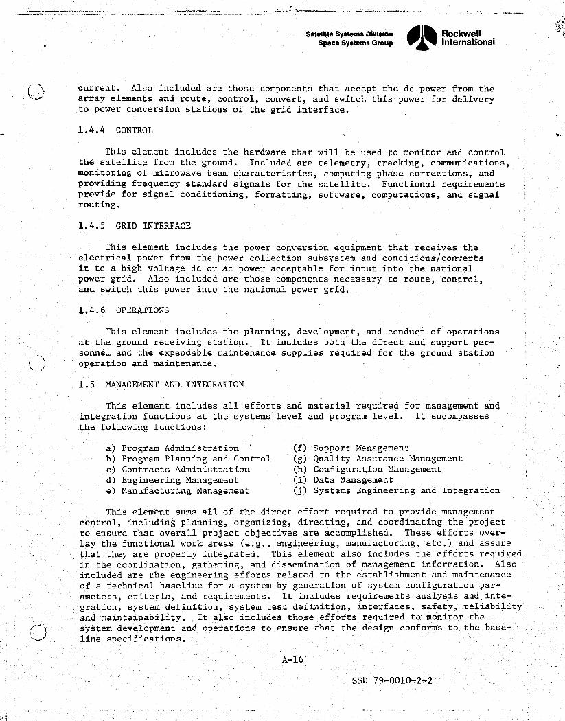
1.4.4 CONTROL
This element includes the hardware that will be used to monitor and controlthe satellite from the ground. Included are telemetry, tracking, communications,
` monitoring of microwave beam characteristics, computing phase corrections, andproviding frequency standard signals for the satellite. Functional requirementsprovide for signal conditioning, formatting, software, computations, and signalrouting.
1.4.5 GRID INTERFACE s
r. This element includes the power conversion_ equipment that receives theelectrical power from the power collection subsystem and conditions/convertsit to a high voltage do or ac power acceptable for input into the nationalpower grid. Also included are those components necessary to route, control,and switch this power into the national power grid.`
1.4.6 OPERATIONS
This element includes the planning, development, and conduct of operationsat the ground receiving station. It includes both the direct and support per-sonnel and the expendable maintenance supplies required for the ground stationoperation and maintenance.
1.5 MANAGEMENT AND INTEGRATION
x` This element includes all efforts and material required for management andintegration functions at the systems level and program level. It encompassesthe following functions: -
a) Program Administration (f) Support Managementb) Program Planning and Control (g) Quality Assurance Managementc) Contracts Administration (h) Configuration Managementd) Engineering Management (i) Data Managemente) Manufacturing Management (j) Systems Engineering and Integration
This element sums all of the direct effort required to provide managementcontrol, including planning, organizing, directing, and coordinating the projectto ensure that overall project objectives are accomplished. These efforts over-lay the functional work areas (e.g., engineering, manufacturing, etc.) „ and assure
- that they are properly integrated. This element also includes the efforts requiredin the coordination, gathering, and dissemination of management information. Alsoincluded are the engineering efforts related to the establishment and maintenanceof a technical baseline for a system by generation of system configuration par-ameters, criteria, and requirements. It includes requirements analysis and inte-gration, system definition, system test definition, interfaces, safety, ,reliability.and maintainability. It also includes those efforts required to monitor thesystem development and operations to ensure that the design conforms to the base-line specifications.
A-16
SSD'79-0010-2-2

J
Satellite Systems Division „RockwellSpace Systems Group Intemetional
F
G
j
APPENDIX B .<
SATELLITE POWER SYSTEMCOST ESTIMATING. RELATIONSHIPS (CERS)
K
1J SOLAR PHOTOVOLTAIC GaAIA S
CONCENTRATION RATIO (CR) — 2THREE—TROUGH COPLANAREND—MOUNTED ANTENNA
CONFIGURATION
,j
e
,r,
SSD 79-0010-2-2
^x9e^.x^i”' C `' i - -...^.,r._L^—b.,'.4.'l^F.^,kM' ... c,. _._: ,.rr..,st:'Y3P#x .a•..v.5.. .:..y,, '. y.' w^.e. Ry ,. •, 3p+m... ,YF^fmflG _..4^'anc.^^.ra^c4te, ^.. }

^^n':^`•`^ ^i^°".°"'. _.. .. _. , . r .. ^;..... .-+txpys. a,.>.^s^,•4'^•.-x:n.*'*:r^c-••uear.^' ' ,
f ^^
_ Satellite systems Division 0D
RockwellSpace Systems Group Intemational
0
APPENDIX B sSATELLITE POWER SYSTEM
`' ( COST ESTIMATING RELATIONSHIPS (CERS)
B.0 INTRODUCTION
This appendix contains the cost analyses and a description of cost elementsthat comprise the SPS program. Each item is presented in accordance with thework breakdown structure of Appendix A and is responsive to the Rockwell refer-
4. ence configuration defined under Exhibit C of NAS8-32475 -- a 3-trough planararray with an end mounted tension web antenna (Figure B-1).
k,
4 ^P
1^ , ` r ls^
4f
^nluii_
^x -. L ^^ L i - .133./6/ Rl v] _ \
a. u 639.222'
I300—_650 660 1700
30-0 01A (REP
650 450
L
;r` \•/SO_^I . /60--r -sso —+— a0o 660^\...^.
}
Figure B-1. SPS Reference ConfigurationF
Subsequent sections of this appendix describe the definitions and groundrules used during the cost analysis; the methodology followed in developingestimates and the computer program; plus a detailed discussion of each'subsystem, assembly, or component used in.the analysis. These descriptions in-clude design input parameters, cost estimates, scaling exponents/factors, andsupporting computer,program cost model equations for each of the WBS items.
B-1
SSD 79-0010-2-2
^r

.W. W7.1F .rr.'°t'
^'GGrli'j i'NV=
Satellite Systems Division,^, Rockwell- Space Systems Group International ,.
-: 'l
{k
B.1 COSTING GROUND RULES AND GUIDELINES
The following major ground rules and.assumptions were used in the perform-ance of this study:
1. The SPS WBS of Appendix A was used as the structure of programp
hardware, activities and accounts.r
2. Key dates of program planning:
1980 - 1985 Ground Based Exploratory Research Activities:1981 - 1987 Key Technology Program Activities1990 Decision Point for SPS Commercialization
(Phase C/D)2000 IOC of First SPS
3. Costs, are reported at WBS level in terms of:
(a) Development cost and TFU (theoretical first unit).
(b) Initial capital investment average cost per satellite(Satellites TFU and No. 2 through No. 60).
(c) Replacement capital investment (RCI) cost and operationsand maintenance (0&M) cost per satellite per year.
4. Cost estimates are projected in 1977 dollars and maximum use wasmade of past SPS studies and other associated data as appropriate.
5. SPS build rate will be two nominal 5 GW SPS systems per year for30 years to provide a total capacity of 300 GWs by 2030.
6. Overall'SPS lifetime will be 30 years with minimum maintenanceand no salvage value or disposition costs. T
7. Complete construction and assembly will occur at GEO synchronousorbit.
r 8.- Calculations based on 0% launch losses.
aG"
9. Program management and SE&2 (management and integration) are costedat 5% of all other level 2 costs.
JO. 25% mass contingency is costed as a 15% cost contingency on items 1.1,`1.2, and 1.3 of the SPS WBS.
B.2 COSTING METHODOLOGY
The approach followed in developing cost estimates for the SPS Programwas based on the maximum use of contract and company sponsored work. The basicRockwell - NASA/MSFC computer cost model was expanded considerably to incorpor-ate the requirements of a revised WBS structure (Appendix A). The data base
SSD 79-0010=2-2

Ssteilite Systems Division Rockwell y< .',Space Systems Group
01% International's
of existing and proved CERs was expanded }y grass roots analysis and specificengineering estimates on the flight vehicles and ground receiving station to
x
provide cost projections based on industrial/consultant experience and onsimilar contract effort such as those of the Rockwell Space Shuttle,and SpaceStation programs. Costing of some WBS elements utilized previously developeddata with slight modification to incorporate reference systems specifications.
There are a series of equations that were used to deal with the four basictypes of cost accounts and phases of the program -- DDT&E, initial capital in-vestment, replacement capital investment,.and operations and maintenance.
The DDT&E equation (CD) estimates the cost of the design, development,and test/evaluation of WBS line items for the satellite, space constructionand support, transportation, and ground receiving station, plus management -and integration support. Management and integration are costed as a separateline item at 5% of all other level two costs of the WBS. Because of the grossnature of the level of information/definition on systems test and GSE (groundsupport, equipment), the cost of system.test hardware,and system test operations,has been assumed to be one-half of the satellite system first-unit costs. A10% factor of satellite DDT&E is used for GSE.
The appropriate inputs for the DDT&E CERs are the applicable total systemmass, area, or power. A development factor is provided in the equation (DF)to adjust the cost to reflect only that portion of the total system mass, areaor power considered necessary for development of the complete system where it t'
y"t- is not required to develop the total mass, area or power. The CD cost equation` also allows for the application of a complexity factor (CF) to adjust the cost
results when it is determined that the item being estimated is either more or
t:less complex than the CER base data.
The initial capital investment (ICI) cost equations estimate the initialcapital investment cost of hardware items as a function of their mass, area orpower. The ICI cost equation is expressed in four different forms -= CLRM,-CTFU, CTB, and CIPS. The CLRM (cost of lowest repeating module) equationrequires'that the input correspond to the mass, area or power of the lowestrepeating module (M). This is necessary because of the physical scale of the3
_SPS and the production quantities required for many of the hardware elements.It is not reasonable to estimate the SPS initial capital investment cost as ahistorical function of the entire SPS mass, area or power. Instead, it is
R desirable to.cost the number of repeating modules required per satellite toestablish the satellite theoretical.first-unit: cost (TFU), and to input thesatellite TFU cost into a progress (learning) function for the quantity ofsatellites required to calculate the average unit cost (CTB - cost to build).This calculation involves two steps in..the cost equations. The first step(CLRM) is simply the portion of the equation which estimates the theoreticalfirst repeating module-cost as discussed above. The second step (CTFU) hasthe progress function incorporated into the equation for the quantity of re-peat modules required for the first satellite. It automatically takes into
< account the progress over production quantities required when calculating the >cost to build an average unit over the total option quantity. This CTB cal-culation is then the basis of CIPS, where the number of units to construct a
F' satellite option are divided by the option quantity and then multiplied by the
B-3
.^ SSD 79-0010,2,2
^,. ......^.+.-s•+-..o-++wtnjn^.+-Yt^m—x.ati^.,n.r^am+nt•.cy ..t^..,.,..,t..... _.....e.--+.n.^^rrtwrr:.i._tt-v -
-^". x.ant u.tli^n F. ' . ., -.. ^ ^

. Satellite Systems Division, RockwellSpace Systems Group 1 International
CTB. In some ICI cost equations, such as those of SPS_ transportation, thespace vehicle has a service life that is greater than that needed to construct t,a single satellite. The CIPS equation provides the cost model with a neededprogram flexibility.
At the current level of SPS definition, it was difficult to decide just,what is a repeating module. It is often impossible to know with any certaintyjust what portion of the total mass is appropriate to run through the equationas a module. It is just as difficult to identify how many distinct types ordesigns of modules will be required for any subsystem or assembly. In suchcases, the study simply assumed a module mass (or area or power) based on <'engineering best judgment.
Replacement capital investment (CRCI) CERs simply provide for the multi-.plication of the annual spares fraction (F,) of each system by that system'scost to build in order to arrive at an RCI cost per satellite per year.
. Operations and maintenance costs (CO&M) are estimated in terms of 0'&M 1cost per satellite per year. 0&M costs include those expenditures incurred`in day-to-day operations beginning with SPS initial operating capability (IOC)and continuing over the life of each satellite. They consist of wages ofoperations and maintenance personnel, minor repairs and adjustments to systemsto maintain an ordinarily efficient operating condition, expendables and con-sumables, launch costs for delivery and transfer of on-orbit personnel andcargo resupply of expendables and consumables, etc.
k The cost methodology seeks to account for five separate effects whichinfluence SPS cost. These are scaling, specification requirements, complexity,the degree of automation, and production progress. Scaling refers to the re-lationship in cost between items varying in size, but similar in type. Econ-omies of scale usually assure that such a relationship will not be strictly
u: linear, but rather as size increases, cost.per unit of size will decrease.The slope of this relationship is reflected by the equation exponent whichresults from the regression analysis of the data used to develop the costestimating relationship.
Specification requirements have been accounted for by normalizing the CERdata base to manned spacecraft specification levels using factors from the RCAPrice Model lFrom that model, an average cost factor to adjust MILSPEC to4tmanned spacecraft is around 1.75 for DDT&E and 1.6 for production cost. Underthe assumption that some relaxation of Apollo-type specifications can be madefor the SPS, a factor of 1.5 was assumed for both DDT&E and production cost.Furthermore, it was assumed that a factor of 3.0 would adjust commercialspecifications to SPS requirements. Therefore, military or commercial costdata used in the CERs were adjusted upward by factors of 1.5 and 3.0, respec-tively.
. The cost equations allow a complexity factor input to adjust the cost., result when it is determined that the item being estimated is either more or
less complex than the listed CER data base.
1Equipment Specification Cost Effect Study, Phase II Final Report, Nov. 30,' - 1976, by RCA Government Systems Division
B-4
SSD 79-00102-2

R ^'
Satellite Systems Division
Oil%
RockwellSpace Systems Group Intematlonal
E
The degree of automation is accounted for in certain cost equationsthrough an.adjustment to the CER coefficient by the tooling factors, given in
' Table B-1. The effect of tooling is dependent upon the annual production rate.Higher production rates allow harder tooling and, thus, effect cost reductions. aThe tooling factors are used only on those CERs which are based on historicalaerospace programs with limited annual production rates. Tooling factors arenot used on those CERs which are based on data already reflecting automatedproduction techniques (e.g., the commercial electronics data for the microwaveantenna CER).
Table B-1. SPS Tooling Factors
AVERAGE ANNUAL TOOLING PROGRESSPRODUCTION RATE FACTOR FRACTION
(AAPR) (TF) 0)
1-2 1-0 0.803-5 6.9 0.806-9 0.8 0.80
10-19 0.7 0.8520-39 0.6 0.854o-69 0.5 0.85.70-109 0.4 0.85
1107159 0.3 0.90160-219 0.2 0.90220-999 (AAPR)-*.35 0.90
1000-9999 (AAPR)-o•35 0.9510.000 (AAPR)-0.35 0.98
The decreasing cost effects of progress due to production process improve-ments or direct labor learning are accounted for through standard progressfunctions. Many SPS components will be mass produced in a capital intensivemanner and will experience little labor learning. Other SPS hardware items,however, Will be produced at very low annual rates, much in the labor-intensivemanner of historical spacecraft programs, and therefore would experience learn-ing. (Tec.hnical;ly distinguishable from learning, but still predictable withthe same form of exponential function, are the effects of-production processimprovement. In this model, when progress functions are used, they are meantto account for both of these effects.) A constant relationship has been assum-ed between the progress fraction and the annual production rate as given inTable B-1.
As required by the costing ground rules and assumptions, all CERs are interms of 1977 dollars. The study.did assume 1990 technology and 1990 supply/demand conditions which, in some cases, resulted in differential (non-general)price inflation or deflation between 1977 and 1990 being included in the CERs.Specifically, it was assumed that composite raw material prices and someelectronic component prices will decrease relative to general prices whilealuminum coil stock prices will increase relative to general prices. Sucheffects are allowed for by the CERs, but only to the extent that the expectedprice changes differ from expected general price changes. The CERs affectedare the antenna structure CER, the power source structure CER, and the micro-wave antenna CER.
Definitions of "S''PS cost model terms and equation abbreviations are present-
1 ed in Table B-2.
B-5
SSD 79-0010-2-2

Satel lite Systems Division , M RockwellSpace Systems Group 1 International 'd
Table B-2. Definitions of SPS Cost Model Elements
3
Jj
{
FF
s'
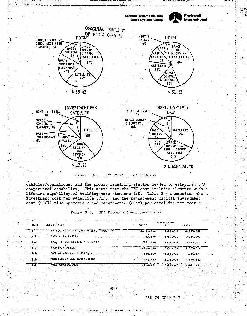
' B.3 SPS PROGRAM COST BREAKDOWNS
An overall cost relationship for the SPS , program is shown in Figure B-2.Principal areas of SPS costing are represented to indicate the emphasis onexpenditures as the program moves from one phase to the next.
x Subsequent tables summarize the cost data used in developing Figure B-2.They reflect SPS-related development cost DDT&E (CD) data through the first
f-- 5-GW satellite (TFU). Table B-3 includes space.constructionfauppert,, transportation-
B-6
SSD 79-0010-2-2
..' K{ . .. _. ... .. .. . ... uY.e.v... ,... R,a`'ar._. re rn . v..1Lw. ._.ld..Yl a.^ v._..J.. Y ... ...n._.......... .^.. eY .v.._._ ... t.. n. _L _. ._.. ... .._.
Satellite Systems Division , ® RockwellSpace Systems Group 1 International
WGIIlIAL I"AG7 I^'r
E; OF Pooh, 0k. tDDT&E
MGMT.6 DD &EMGMT.6 INTEG. INTEG.GRND. RECEIVING 4%STATION, ,5Z MASS
SPACEGRS
SPACE
t :ONTTRANSP.
7$TRANSP.
12$%
6 GRND. MASS 6 GROUNDFACILITIES CONTING. FACILITIES
l^'a 1,. SPAZE37$
12 %44$
CONITRUCT.SATELLITE
&,SUPPORT16%
c 22%PACE
SATELLITECONSTR.
>. 24%6 SUPPORT
17%
E 33.4B $ 51.1B
INVESTMENT PER REPL. CAPITAL/a; MGMT.4$ INTEG. SATELLITE
MGMT.4$ INTEG. O&Mli
SPACE SPACE CONSTR. 6
CONSTR. 6 b SUPPORT.
SUPPORT, 8% 10%SATELLITE MASS SATELLITE
MASS39$
CONTING. 32%CONTINGENCY TRANSP. 1
9% b FACIL. GRSACE
14$'GRND. 12$' TRANSPORTA-
RECEIV-TION 6 GROUND :. .
1NGSTATION
FACILITIES31$`26$
.$ 13, 9B $ 0,65B/SAT/YR `.
Figure B-2. SPS Cost RelationshipsF
vehicles/operations, and the ground receiving station needed to establish SPSoperational capability. This means that the TFU cost includes elements with alifetime capability of building more than one SPS. Table B-4 summarizes theinvestment cost per satellite (CIPS) and the replacement capital investment
F
cost (CRCI) plus operations and maintenance (CO&M) per satellite p:^r year.
41 Table B-3. SPS Program Development Cost
UEVELUPMENT' MBS Y OESCRIPTIUN DOTtE TFU TOTAL
{ 1 SATELLIIL PO4ER SYSTEM ISPS) PROGRAM 3b•:1.7e2 51103.2•.2 94505.000
:Ir 1.1 SAT6LLITt SYSTEM - _^ -_^-7933,570 7950.922 15884.492
` 1.2 SPACE CUNSTRUCTIUN L !AjPPORT - 7331.160 8602.523 15933.703
- ---------•----1,3 TRANSPURTA/IJN ----------- -- --1246B.316 22b66.199 3533 .016
'y -1.4
6kOJNO FECcIV1NG STATION _ _ 115.699 30219.727 3734.427
1. MANAGEMENT AND INTEGRATION 1392.4b3 2151:918 3S4+.392
1.6Y^ MASS CUNT INWO CY 4160.031 5V12. 94S 1:072.977'r
`et
y
3
B-7
SSD`79-0010-2-2
.: f
Satellite Systems Division„ RockwellSpace Systems Group 1 International 4 4a
.
( rte
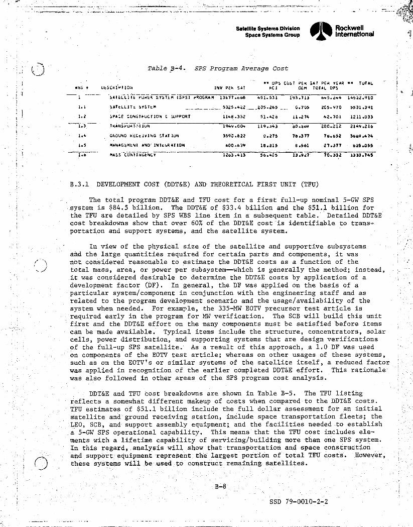
Table B-4. SPS Program Average Cost
*• OPS CUST PEK SAt PER YEAR •• TUTAL # ?MbS + UESCkIPTION 114V PEk SAT K I OEM TUTAL UPS
' i ^LIIESAIELrudCR SYSTEM (SPS) rROGRAM 13b77.0 " 451.531 193.713 6r5.244 14522.910
' 1.1 SATtLLITc SYSTtM _. 1325.422_ _ _Z05.265 _-_, 0.705 265.970 5531.391
a1.2 SPACE CUNSTkUCTION L SUPPORT 1148.332 51.426 11.274 62.701 1211.033
1.3 TKANSrUkT•^IIUN 194Y.00r 119.j43 tl0.bo9 ZOC.212 2149.216k
1.4 GROUNO ktCCIVING STAIIUN 3590.622 0.275 78.377 76.652 3669.474
1.5 MANAGkMENI AND'1..41t(.RAT1ON 600.674 18.815 8.561 27.377 026.055 K' 1
! 1.6--- MISS CURII-.4GcNCY -' 120.413 56.405 13.927 70.332 1333.745 ?
B.3.1 DEVELOPMENT COST (DDT&E) AND THEORETICAL FIRST UNIT (TFU)
The total program DDT&E and TFU cost for a first full-up nominal 5-GW SPSsystem is $84.5 billion. The DDT&E of $33.4 billion and the $51.1 billion forthe TFU are detailed by SPS WBS line item in a subsequent table. Detailed DDT&Ecost breakdowns show that over 60% of the DDT&E cost is identifiable to trans-portation and support systems, and the satellite system.
In view of the physical size of the satellite and supportive subsystemsand the large quantities required for certain parts and components, it wasnot considered reasonable to estimate the DDT&E costs as a function of thetotal mass, area, or power per subsystem-which is generally the method; instead,it was considered desirable to determine the DDT&E costs by application of a
_development factor (DF). In general, the DF was applied on the basis of a_s,
particular system/component in conjunction with the engineering staff and asrelated to the program development scenario and the usage/availability of the
. system when needed. For example, the 335-MW EOTV precursor test article isT _ required early in the program for MW verification. The SCB will build this unit
first and the DDT&E effort on the many components must be satisfied before itemscan be made available. Typical items include the structure, concentrators, solarcells, power distribution, and supporting systems that are design verifications
w of the full-up SPS satellite. As a result of this approach, a 1.0 DF was usedon components of the EOTV test article; whereas on other usages of these systems,such as on the EOTV's or similar systems of the satellite itself, a reduced factorwas applied in recognition of the earlier completed DDT&E effort. This rationalewas also followed in other areas of the SPS program cost analysis.
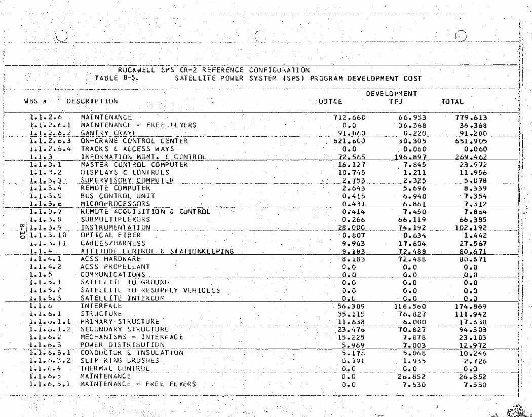
DDT&E and TFU cost breakdowns are shown in Table B-5. The TFU listingreflects a somewhat different makeup of costs when compared to the DDT&E costs.TFU estimates of $51.1 billion include the full dollar assessment for an initialsatellite and ground receiving station, include space transportation fleets; theLEO, SCB, and supportassembly equipment; and the facilities needed to establisha S-GW SPS operational capability. This means that the TFU cost includes ele-ments with a lifetime capability of servicing/building more than one SPS system.In this regard, analysis will show; that transportation and space constructionand support equipment represent the largest portion of total TFU costs. However,these systems will be used toconstruct remaining satellites.
'
'
B-8
SSD 79-0010-2-2

.ery +ff^wa ,r^z t '1'x: ^^.-e;.. N,r,^t^n•,.i,.Y.±tsr: H.r es^n a. _^c`;c^:iR-- s - ., ... ^ .mfi.,-. - ^.
f
j . Y
^ { ROCKWELL SPS Ck-^ REF ._- RE C -r N E CONF-IGURATIUN'B-5.-TABLE SATELLITE POWER SYSTEM (SPS) PROGRAM DEVELOPMENT COST'
- DEVELOPMENTWBS 4 UESCRIPTION DDTCE TFU TOTAL
1 SATELLITE POWER SYSTEM (SPS) PROGRAM 33401.762 51103.242 84505.0001.1 SATELLITE SYSTEM 7933.510 7950.922 15884.492t
^- 1.1..:1. . ..._._LNE^RGY_.CUi^fV`RSI,N1.1.1.1 STRUCTURE 71.066 104.608 175.674
PRIMARY STRUCTURE 47.821 35.100 82.921 jf ^ ,d 1._1.1.1.2 SECONDAKY STRUGTUkE 23 245 699503_ 92,753* N 1.1.1.2 CONCENTRATORS 0.0 759637 75.637
1.1.1.3 SOLAR BLANKETS 0.0 1651.832 1651.8321.1.1.4 POWER - TST_... f: _C OND,TI . IONG O ^'^ 46-.999___.___ 12.6.986_._.- 173.984_1.1.1.4.1 SWITCH GLAR CONVERTLRS 3.582 89.123
------92.704
1.1. 1.4.2 CONDUCTORS C INSULATION O 6.234 9.468 15.7021.1. 1.4.3 SLIP RINGS O 7.392 27.626 35.0181.1.1.4.4 BATTERIES 5.001 0.338 5.339
p 1.1.1.4.5 BATTERY PD&C 24.790 0.430 25.2201. 1.,1.5 THERMALCONTROL. . vT^ c,710 1. 1. b MAINTENANCE' 0.0 48.921 48.921101.1.6.1 MAINTENANCE - FREE FLYERS -C =? 0.0 29.299 29.299
i - 1.1.1..6.2 MANNED MANIPULATOR 0.0 19.243 1Q.:.203kT 1.1.1.6.3 TRACKS & ACCESS W A YS 0.0 0.420 0.420
1. 1.2 POWER TRANSMISSION 883.144 3816.522 46999664F 1.1.2.1 STRUCTURE 26.007 49 w9 -- _Z
a
1. 1.2.1.1 PRIMARY STRUCTURE 7.301 3.350 10.651 bE.' 1.1.2.1.2 SECONDARY STRUCTUKE 18.705 45.999 64.704
1 . 1.2.2 TR A NSMITTER SUBARkAYS - KLYSTRONS 102.576 2702.309 2804.8851.1.2.2.1 KLYSTKON UDT6E 102.516 0.0 102.576 t
E 1.1.2.2.2 KLYSTRON ICI, R, OEM 0.0 2702.309 2702.309 i.1.12.3_ _ POWtR GIST. E CONDITI CNING .. _. _-. _ _ ----.._.: :._^..._ 12 _ 7g9.8UQ 782.193 t.
1.1.2.3.1 SWITCH GEAR E CONVEkTLRS _-7.132 ; --_--_ _ 752.336 --
---759.468
_
1.1.2.3.2 CONDUCTORS C INSULATION 5.262 5.348 1.0.6101. 1.2. 3.3 BATTER I LS 0.0 12.115 12.1 -15 s1.1.2.4 THERMAL CUNTROL - INSULATION 29.136 208.002 237.198
' 1.1.2.5 CONTROL - PHASE REFERENCE 0.373 20.050 20.4231.1.2.5.1 REFERENCE F-itEQUEVCY GE_NERAIOR_---_ _.___ __ __ :___. _^. _ :.____- __ ^_•1Q.0___ ^Q,.100-- -- 0..200 _f
V 1,.1.2.5.2 DIST. SYSTEM, COAXIAL CABLE 0.203-___
12.I8d.______ - .___.___
12_383
F1
A
ROCKWELL SPS CR-2 REFERENCE CONFIGURATION^1TABLE B-5. SATELLITE POWER SYSTEM ( SPS) PROGRAM DEVELOPMENT COST p
N DEVELOPMENTWBS ti DESCRIPTION -DDTLE TFU TOTAL ra
^° ? 1.1.2.6 MAINTENANCE 712.660 66.953 779.613 x1.1.2.6.1 MAINTENANCE - FREE FLYERS 0.0 36.368 36.3681.1.2.b..2-- GANTRY _CRANE --•- - -__-. ' 91.0 6 0 ,.^0.120__
a; 1.1.2.6.3 ON-CRAVE CONTROL CENTER 621.600 30.305 651.9052.6.41.1. TRACKS C ACCESS WAYS 0.0 0.0600. 060
-1.1.3 INFORMATION MGMT. L CONTROL 72.565 196,897 269.4621.1.3.11.1.3.2
MASTER CONTROL COMPUTERDISPLAYS L CONTROLS
16.12710.745
7.8451.211
23.97211.956
_.1.3.3i SUPERVISORY COMPUTR?_--__--- _E __--- - -: _.__. ___ _ ---2^ 75 s _ -- _ ---2.325 5_.07F3 €1.1.3.4 REMOTE COMPUTER 2.643 5.696 8.339.1.3.5 BUS CONTROL UNIT 0.415 6.940 7.354:
1.1.3.6 r+ MICROPROCESSORS 0.431 6.881 7.312
1.1.3.7 REMOTE ACQUISITION L CONTROL 0.414 7.450 7.864SUBMULTIPLEXORS 0.266 66.119 66.385 E;
1.1 . 3.9 _I NSTKUMEN 'fATIU.V __, -- 28.000 X74.-192H ; 1. 1.3.10 OPTICAL FIBER 0.807 0. b34 1.442
9
i.i.3.11 CABLES/HARNESS 9.963 17.604 27.567X1.1.4 ATTITUDt^CGN ROL C STAT`10NKEEPTNG 8.183 72.488. 80.6711.1.4.1 ACSS HARDWARE 8.183 72.488 80.671 kij r.
L
1.1.4.2 ACSS PkOPELLANT 0.0 0.0 0.0^1.1._5 COMMUNICATIONS_ _._ . __... - 0.0--.:_ - ---^._ 0.0 -- - - -0.0- -> `.. _1.1.5.1 SAT EL LITE TOTGROUV U 0.0 0.0 0.-01.1.5.2 SATELLITE TO RESUPNLY VEHICLES 0.0 0.0 0.01.1.5.3 SA T E LL I T E INTERCOM 0.6 0.0
€! 1.1.6 INTERFACE - 56.309 118. 5.60 174.869 i
1.1.6.1 STRUCTUkE 35.115 76.827 111.9421. 1. o. 1.1 NRIMARY STRUCTURE
-11.638 :__.6.0.00.
1.1.6.1.2 SECONDARY STRUCTURE 23.476 70.827 94.3031.1.6.2 MECHANISMS - INTERFACE 15.225 7.878 23.1031.1.0.3 POWER DISTRiburIDN 5 .969 7.003 12.972
^.{ 1.1.6.3.1 CONDUCTOK L INSULATIUN 5.178 5.068 10.2461 1.1.6.3.2 SLIP RING 13kUSHtS 0. 191 1.935 2.726 €
1.1.6.4 THERMAL CONTROL _ _ _. _ _ . _ _ _ _.:. _ - _ -0. C . _ _- - 0.0 - - _ 0-.0-- -^1.1.6.5 MAINTENANCE 0.0 26.852 26.852 €
a , MATNTENANCt - FREE FL YERS 0.0 7.530 7.530 i

ROCKWELL SPS CR-2 REFERENCE CONFIGURATION-5. SATELLITE POWERTABLE B SYSTEM (SPS) PROGRAM'DEVELOPMENT COST
DEVELOPMENTWBS,'# DESCRIPTION DDTGE TFU TOTAL
mr--tr,
1.1.6. 5-2 MANNED MANIPULATOR 0.0 19*203 19.2031. 6. 5.3 TRACKS & ACCESS WAYS 0 . 00 0.120 0.120
1.1.7 SYSTEMS TEST 5325.422 0.0 5325'.422--------
01.7.1 SYSTEM GROUND TEST HARDWARE 2662.711 0.0 2662.7111.1.7.2 SYSTEM GROUND TEST OPERATIONS 2662.711 0.0 2662*7111.1.8 GROUND SUPPORT EQUIPMENT 721.234 0.0 721,2341 1.9 COTV - PRECURSOR 748.653 1738.474 2487.1271.1.9.1 COTV PRECURs,OR VEHICLE 748.653 1737.844 2486.4971.1.9.1.1 PRIMARY STRUCTURE - E.Co 239.863 1.544 91.4081.1.9.1.2 SECONDARY STRUCTURE - E.C. 0 21.178 533.576 554.754 It
II 1.9o1.3 CONCENTRATOR - E.C. 0 3:^;v
r- 7, 869 2*817 10.686 :1 .1.5.1.4 SOLAR BLANKET -E.C. 47oG41 60.300 107.341l.i.9ol.5 SWITCHGEAR & COINVLKIERS -E.C. c 3.497 1.725 5.2221 * 1.9.1o6 CONDUCTOkS C. INSULATIGN E.L. 7.048 1.431 8o4781,1,9.1.7 ACS HARDWARE - E.L. 12.190 620.634 632.8231.1 * 9 * 1.8 SLIPRlNGS - PRECURSOR 54.565 30.980 85.546I.1o9.1o9 PRIMARY STRUCTURE - INTERFACE 152.844 6.000 158.844
1.9.1.10 SECONDARY STRUCTURE INTERFACE 15.155 4.047 19.202101.9.1.11 MECHANISMS - INTERFACE 78.868 221.647 300.5141.1o9.1.12 CONDUCTORS L INSULATION 3.993 -0. -211 4.2041.1. 9 .1. 13 SLIPRING BRUSHES PRECURSOR 2.529 2.268 4.797 __.I o1.9.1.14 PRIMARY S TRUCTURE POWER TRANS 20,936 0.250 21.186
1. 1. 9.1..15 SECONDARY STRUCTURE - POWER TRANS 17.041 2.546 19.58711o9.1o16 TRANSMITTER KAYS- KLYSTRONS---S UBAR ICI 0.0 141.497 141.4971.1. 9. 1. 17 SWITCHGEAR & CONVERT1 KS P.To PRECURSOR 6.756 47.520 54.2761o1.9o1.18 CONDUCTORS & INSULATION P.T. PRECURSOR 4.147 0. 240 4.3871.1.9.1.19 bAITERIES P.T. PRECURSOR 27. 1(1 6 11 501 . 38.607I.I.V.1.20 THERMAL CONTROL INSULATION PRECURSOR 26.539 45.996 72.5351.1.9.1.21 REFERENCE FREQUENCY GENERATOR
PRECURSOR 0.500 0.100 0.600
1. 1.9.1. 22 DIST. SYSTEM, COAXIAL CABLE C;o258 0.517 0.775DEVICE S 0.022 Co500 Go522
1. lo -v. 1. 24 TRAN S MITTER SUBARKAYS - KLYSrRONS DDT&E 148o707 0.0 148o707COTV PRECUKSUR OPEKATIONS 0.0 0.630 D 063SPACE CUNSTRA'i IOty L SUPNORT 7331.180 8602.523 15933.703
1-2-1 CON STRUCT FACIL111E5 3653.249 6575.176 10228.422
2

y .-,. !,,,yp m^,!+.=t..+e srna*,.. r nr :,..-, a...- _ r-rrr. G -;,:.r- - ... :t..e T _ .. F a_' :+". •r. ^..'
t,
a^
ax
•
a`
r
f'
t
' ROCKWELL SPS CR-2 REFERENCE= CONFIGURATION ;' !TABLE B-S._: SATELLITE POWER SYSTEM (St?S) PRGGRAM UEVEL(7PMENT COST ^.
DEVELOPMENT ►a WIaS .4 DESCRIPTION
_DDTEE TFU TOTAL r
1.2.1.1 WORK SUPPORT FACI LI1I ES 3092.417 3956.069 7048.484 r4 1.2.1.1.1 BEAM MACHINE 2.000 83.150 85.150
s 1.2.1.1.2 . BEAM MACHI NE CA SSET_TES____--
Q. b00------ 6._------.31.5:_...__ __ _ _- .7 . .115r,•3`
U1.2.1.1.3 CABL^t ATTACHMENT MACHINE 4.300 28.228 32.528 -'
.^ 1.2.1.1. 4 REMOTE MANIPULATOR 60880 60.390 67.270
w ~J_
1.2.1.1.5 BLANKET DISPENSER MACHINE 4, 000 26.154 309154
r' 1.2. 1. 1.b SOLAR BLANKETCASSETTES J.$QO 9.076 9.676k ; 1.2: 1.1.'r REFLECTOR DISPENSER MACHINE 6.000 4,.651 109651
1.2.1.1.13 REFLEC .T .0R_ CASSETTES -- _. __ :_____----- 1.000_..--- 2;. -721 _ _..3.7211.2.1.1.9
- -- --CAB LE/CATENARY DISPENSER MACHINES 2.200
_ -22.786 24.986
1.2.1. 1.10 ANTENNA PANEL INS * EQ P •C. 80.000 200.272 2.80.272[-
1 . 22.. 1.1.11 GA N I R Y/CRANES 13.600 15.034 9$. 6 34.1.2.1.1.12 CARGO STORAGE CD EPUTSi 12.000 7.559 19.5591.2.1.1.13 FAB FIXTURE 2165.128 82.445 2247.573
w4- 1.2.1.1.14 AIRLOCK DOCKING MODULE (ADM) _ _^^-' 0.0__^^^ 242.302 _ _-242-.3021.2.1.1.15 BASE MGMT. MODULE (6MM) 0.0 1213.870 1213.870
N ; 1.2.1. 1. lb POWER MODULE (PM) 0.0 1075.459 1075.459M 1.2.1. 1. 17
"-PRESSU KIZEU STORAGE MODULE (PSM) 793.710 805.657 1599.367
1. 2. 1.2 CREW SUPPORT FACI L1 •tI ES-SCB 560.832 2590.290 3151.122 jAIRLOCK DOCKING MODULE-ADM 31.152 73.413 104.565 +i
102.1.1.2 CREW HABITABILITY „ MODULE-CHM^ -__ X0._0_. 1634.456 16349455_..___._'i 1.2.1.2.3 CONSUMABLES LOGISTICS MODULE-CLM 0.0 604.675 604.675
1.2. 1.2.4 SHIELDING 34:3.200 21.160 364.3601.2.1.2.5 CREW SUPPORT MODULL-CSM 166.480 2:56.587 443.067N 1.2.1.3 OPERATIONS 0.0 28.819 28.8191.2.1.3.1 OPERATIONS, CONSTkUCTION CREW 0.0 19.781 19.761 i1.2.1.3.2 ORBITAL OPEtRATIONS,CUNST. PROV. 0.0 9.,-'36 9.638.__1.2.2 LOGISTICS SUPPORT FACILITIES-LEO 3677.434
_917.151 4595.082
10 2. 2. 1 WURK SUNPOKI FACILITIES 2814.992 586.187 3401.179ai
a
1.2.2.1.1 BASE M611T. MODULE-BMM 2 464 .993 3 10 .81 4 277 5.bO6POW Lk t^tOGULt-PM 350.000 275.373 625.373
1.2.2.2 CREW SU[J PUwr FACILITI-ES 86Z'.942 328.782 1191.7241.2.2.2.1 CREW HABITABILITY MGDOLE-CHM .__ 262.275 101.928 364_.2061.2.2.2.2 CONSUMAbLES LOGISTICS MODULE 265.000
_70.095 335.095
1.2.2.2.3 CREW SUPPORI MODULE/EVA 335,664 156.759 492.423-
k
w.. •- t r :. K., `!' -.".. S.t •n e.! ... :. in •. 1 .Saflt4l ..._A .v _ WX.L?.

tf:} ,. .^A"^ew°^p$'f!^Y'+.^y^,. d" ^are9.a; ^T`",N+'t*^;,^*' ,Y'` 9^'v.D .'.ors _ '*'.ef*+a,• ^^^+F. Yx.p
e^
_} z c
RUCKWELL 5PS CR-2 REFERENCE CONFIGURATIONTABLE.'_.B-5._. SATELLITE POWER SYSTEM (SPS) PROGRAM DEVELOPMENT COST x'
DEVELOPMENTwbs # DESCRIPTION DUTBE TFU TOTAL
1.2. [. OPERATIONS 0.0 2.182 2.182 ;'1.2.2.3.1 LEO OPERATIONS CREW 0.0 1.498 1.4981.2.2.3.2 LEO CREW PROVISIONS 0.0 0.684 0.684------_._'1.2.3 BEM SUPPORT FACILITIES - SATELLITE 0.0 1110.198 1110.198
' i.2.3.1 WOR; SUPPORT FACILITIES 0.0 763.578 763.578 tt 102.3.1.1 AIRLOCK DOCKING MODULE-ADM 0.0 44.520 44.520
v1.2.3.1.2 BASE MGMT MODULE-BMM 0. 0 310.814 310 814•F°. L,,2.3.1.3 PRESSURIZED STORAVE MCDULE-PSM 0.0 408.244 408.L44
1.2_03.2 -_SUPPORT---FACTLITI__. CREW - -L-S.__.--------------.-:- _ _._.__-______ _..0 03!+_3 ..85► 31.2.3.2.1 AIRLOCK DOCKING MODULE-ADM 00 0.0 15.111 15.111
.j''. 1.293.-2s2 CREW HABITABILITY MODULE-CHM '^ ^: 0.0 101.928 101.928
' 1.2 .3.2. 3 C ONSUMAB LES LOGISTICS MODULE- C LM 0.0 7Q.095 70.0 9 51.2.3.2.4 CREW SUPPORT MODULE=/EVA ,s 0.0 156.759 156.759
(. 1.2.3.3 OPERATIONS 00 2.727 2.7271.2.3.3.1 SATELLITE _.__CREW_OPERATIONS _ -- :^ ^ 0 .0 i. 872-_ _ ' 1.2.3.3.2 SATELLITE CREW PROV iS IONS D G^ 0.0 0.855 0.855 K
^'r 13 TRANSPORTATION 12468.816 22866.199 35335.016 S,
kSPS-HEAVY LIFT LAUNCH VEHICLE(HLLVi-nt n36G0.000 9530.432 1bI3y.492' 1.3.1.1 SPS-HLLV FLEET 8600.000 8950.176 17550.176
1.3.1.2' SPS-HLLV OPERATIONS 0.0 580.320 580.320 j
1.3.2 CARGO OKBITAL TRANSFE t^ VEHICLE( COTV 1 _ .: _-_ ^__.;: 31.818 _----3.625.720 _ ..---3657 -.538 _.__.___1.3.2.1 COTV VLHICLtS 31.bI8 3621.310 3653.1281.3.2.1.1 PRIMARY STKUCTt1RE 3.930 9.267 13.1971.3.2.1.2 SECONDARY STRUCTURE: 4.582 2478.750 2483.332 i1.3.2.1.3 CONCENTRATOR 1.685 15.818 17.503
< 1.3.2.1.4 SOLAR BLANKET 7.664 338.117 345.781K 1.3.2.1.5 SWITCHGEAR AND CONVERTERS -- - ---- -._ __.._^ :_ _^ _ _._ 2.054 8. 760_ - _-_.-10.814____,-_
- 1.3.2.1.6 CONDUCTORS AND INSULATION 2.205 8.584 10.7891.-3. 2.1.7 ACS HARDWARE 9.697 762.015 771.712 ,1.3.2.1.8 INFO. MGMT. AND CON TR OL 0.0 0.0 0.0
1.3.2.2 COrV OPERATIUNS 0.0 4.410 4.410{1.3. PERSONNEL LAUNCH VLHICLE(PLV) 1549.000 6251.230 7800.230
PLV_-FLL,ET.STS--- 1549..000 _..._. 3908.082 - -5457.,082 -- ---1.3.3.1.1 STS-PL ORBITER 0.0 1682.531 1682.5311.3.3.1. STS-PLV LXTERNAL TANK 0. 606.205 606.205
r a4.'. r

r. , 1 7.^:'^^rs ",^+^,'n v.-^^w*±^ , * Fa .,t:..t''r^°>-^ ;^ ^.acs ;wr^ _ :*mac;^°
I ^h
ROCKWELL SPS LR-2- REFERENCE CONFIGURATIONTABLE_ B-5. SATELLITE POWER SYSTEM (SPS) PROGRAM DEVELOPMENT COST
DEVELOPMENT iWES N DESCRIPTION DUTEE TFU TOTAL k
1.3.3.1.3 STS-PLV Llw. ROCKET BOOSTER 1304.000 873.985 2177.985' 1.3.3.1.4 STS CARGO CARRIER AND EM 245.000 745.362 990.362 a
1.3.3.2 PLV C STS-HLLV OPERATIONS _ « 0.0 2343.150 _ 2343.150: 1.3.3.2.1 PLV OPERATI'ON5 0.0 12.14.400 1214.400
1.3.3 -.Z.2 STS HLLV CARGO OPERATIONS 0.0 1128.750 11289750 ^ r1. 3. PERSONNEL ORBITAL TRANS VEHICLE 350.000 56.282 406.282 f
1.3.4.1 POTV-FL EE'T 350.000 54.764 404.764a 1.3.4.2 POTV-OPERATIONS 0.0 1.518 1.518
1. 3 .5 .:_. _:_: P E RSONN E L MODULE(_ PM)_w-:_^ _ __. .__:_`_ -- 118.000 _ _ 201.910 _ 319.910__., 1.3.5.1 PM FLEET 118.000 198.610 316.6101.3.5.2 PM OPERATIONS 0.0 3.300 3.3001. 3.6 1NTRAORBITAL TRANSFER VEHICLE(IOTV) 100.000 5.567 105.5671.3.6.1 IOTV FLEET 100.000 5.476 105.4761.3.6.2 IOTV OPERA71UN5 0.0 01091 0.091 §
^ 1.,3. - --GROUND SUPPORT - FACILITIES __-- - --- _ 172,0._000 3195.000 _._._ -. 4915.000.__.__0.0 '' N 1.3.7.1 LAUNCH FACILITIES O.G Q.0
r;t 1.3.792 RECOVERY FACILITIES 0.0 0.0 0.01.3.7.3 FUEL FACILITIES 0.0 00-0 0.01.3.7.4 LOGISTICS SUPPORT 0.0 0.0 0.01.3.7.5 OPERATIONS 0.0 0.0 000 4
1.4 GROUND RECEIVING SEAT ION __. _. _.__ _'.__. 1.15.699--_-_-___361.8.727_ _ ___..3734.427__._1.4.1 S1TE AND FACILITIES 1.000 195.197 196.1971.4.1.1 LAND AND PREPARATION 0.0 105.341 105.3411.4. 1. 1.1 BLAND _ ^_ 0.0 35,000 35.0001.4.1.1.2 LAND PREPARATION 0.0 70.341 70.3411.4.1.2 ROADS AND FENCES 0.0 74.180 74.1801.4.1.2.1 RAILS AND KUADS_ _ _ _ ,.:. _. - W 0.0 :73.710. _ _ _.:_7.3.710_. g1.4.1.2.2 FENCING 0.0 0.470 0.4701.4.1.3 UTILITIES O.o 0.200 0.2001.4.1.4 bUILDINGS 0.0 11.4 7_7_ - 1 1_.477 _ I__.1.4.
1.4, i
-STC^{2AGE I-M- AINTtNANCE 0.0 1.300 1.3001.4.1. ,4.2 CUNV. STA. & MONII'OR/CONTROL FAC. 0.0 10.177 10.1771.4. 1. 5 MAINT ENANC t EQPT. ---- O.t,O 4.000 4.000
t 1.4. 1.6 LIGHTNING PROTECT WI N 0.G 0.0_
0.01.4.1.7 SITE E FACILIIIES UDTCE 1.000 0.0 1.000

^,^,M
^! dl
ROCKWELL SPS CR-2 REFERENCE CONFIGURATIONTABLE' 5.; SATELLITE POWER SYSTEM (SPS) PRUGRAM DEVELOPMENT COST t ;.
If
DEVELOPMENT_}
WBS it DESCRIPTION DDTLE TFU TOTAL'
1.4.2 RECTENNA SUPPORT SI RUCTURE 2.000 1849.629 1851.6291.4.2.1 STEEL PANEL FAB. L INSTALLATION 0.0 1696.508 1696.5031.4. 2. 1.1 HAT SECTIONS A-
E_
- - 1.4.2.1.2.
WIDE FLANGES 0.0 295.173 295.1731.4.2.1.3 TUBE BRACES L H ARDWARE 0.0 431.346 431.346 =.
f4 _ 1.14.'. 1.4_ A SSE MBL Y L' INSTAL LA TION_- - _ 0.0 610.762 6 1Qs762tt 1.4.2.2 TRENCHING L CONCRETE INSTALLATION 0.0 153.121 153.121
1.4.2.2.1 FOOTING LONCRETE L RE-BAR 0.0 70.821 70.8211.4.2.2.2 MACHINGERY L EOUI PM_LNT __` - - ^_^--_0. 0 --- _-_,--22_.360 22.360_1.4.2.2.3 CON ST RU CTIuN OP ER AIIONS 0.0 59.940 59.9401.4.2.3 SUPPORT STRUCTURE DDTLE 2.400 0.0 2.000 t1 .4.3 POWER COLLECTION_ - 3.000 1353.211 1356.211 K1.4.3.1 ANTENNA ARRAY ELEMENT S 0 .0 1127.331 1127.331
r 1.4.3.2 POWER DISTRIBUTION SYSTEM ^ ^- 0.0 69 .660 69.6601.4. 3 .3, _.. __. _INSTALL^4TIUN_L CHECKOUT -- - _:___ ^0.0-, --156• 220
., 1.4. 3.4 POWER COLLEC ZION-DDTL E . 3.000 0.0 3.000^. r 1.4.4 CONTROL 100000 75.000 85.000
- 1 . 4 .4. 1 Y CO N TR OL CENTER EQU IPMENT C O.C1 15 .000 _ 5 .0003 1.4.4o2 CONTROL ELECTRONICS 0.0 60. 000 60.400
1.4.4.3 CONTROL UDTLE_ 10.000 000 10.000.I
_- 1.4.5 GRID INT^RFAC __. _._._ _ INC yy.;.6^9` __-.._145.690 _.....245.389------_..__';..' 1.4.5.1 ELECTRICAL EQUIPMENT 0.0 145.690 1.45.690
1.4.5.2 GRID INTERFACE-DUTLE 5+9.699 0.0 99.699' 1.4.6 OP ERATIONS 0.0 0.0 010
1.4.6.1 OPER. E MAINT. PERSONNEL 000 000 0.01.4.6.2 MAINT. MATERIAL 000 0.0 0.01 • % MANAGEMENT AND IfVTEGRATION ._----- _1392.463_ _215 . 1.918_ 3544._3.?^2__-1.6
-- -- . _.__.._MASS CONi1NGENCY 4160.031 5912.945
-•- _ .10072.977
__.__-_._c

. x
x
L^ -fr
Satellite Systems Division„ RockwellSpace Systems Group 1 Intemational
y
B.3.2 INVESTMENT AND OPERATIONSY .
Detailed investment and RCI/O&M cost data are shown in Table B-6. Invest-ment costs were developed at two levels:
(1) Initial capital investment (ICI), which is the cost of pro-duction, assembly, installation, transportation, and testsof each individual satellite produced, and the ground sta-tion system and associated effort necessary to bring the
r power satellite on line to a 5-GW operational capability.
"h(2) Replacement capital investment (RCI), which are those
” expenditures relating to capital asset replacement and major.maintenance overhauls/spares that are expected to last formore than one year or result in an improvement to the oper-
4ating system.
Costs for the transportation fleet needed to construct the satellites areincluded in the ICI; whereas, the fleet required for 0&M of the satellite overthe 30 years is included in the 0&M cost. Replacement capital investment isincluded in the RCI column.
Investment per satellite is equivalent to the average unit cost of thetotal SPS requirement*•-TFU plus satellites and supporting program elements for fthe 60-SPS option. Total average ICI cost is projectedat $13.9 billion.
^l Annual.SPS estimates are placed at $0.45 billion for RCI and $0.20 billion for0&M.
r
s:E
K
Iliz
B-16
SSD 79-0010-2-2
F

ROCKWELL SPSS CR-2 REFERENCE CONFIGURATIONT'A b L L B-6. , SATELLITE POWER SYSTEM ISMS) PROGRAM AVERAGE COST
*4 OPS COST PER SAT PER YEAR TOTALWBS DESCRIPTION 11AV PER SAT RL1 O&M TOTAL OPS
I SATELLITE POWER SYSIEM (SPS) PROGRAM 13877 * 668 451.531 193.713 645.2.44 14522*9101.1 SATELLITE SYSTEM 5325.422 205.265 0.705 205.970 5531.391
ENERGY CONVERSION 1851.6221.1.1.1 STRUCTURE 96.-169 0.194 0.0 0.194 96*983
PRIMARY STRUCTURE 35.100 0.070 0.0 0.070 35.1701.1.1.1.2 SECONDARY STRUCTUkL. 61.689 0.123 010 0. 123 61
1.'1.1.2 CONCENTRATORS 67.183 0.134 0.0 0.134 67*3181.1.1.3 SOLAR BLANKETS 00 1556.692 3.113 0.0 3.113 1559*13051.1.1.4 POWER DIST. & CONDITIONG -n :0 91.948 0.169- 0.010 0.179 92.127
SWITCH GEAK F, CONVERT LRS -a- 66.093 4.0 0.0 0.0 66.0931.1.1.4.2 CONDUCTORS L INSULA I o"- I LN Z 9.468 0.0 0.0 0.0 9.4681.1.1.4.3 SIP RINGS 15.825 0.158 0.0 0.158 15,9631.1.1.4.4 BATTERIES 0.238 0.008 0.010 0.0.18 0.2561.1<.1. li . 5 BATTEkY PD&C 0.324 "0.003 0.0 0.003 0.3271.1.1.5 THERMAL CONTROL rn 0.0 0.0 ----o Ro-1.1.1.6 MAINTENANCE 39.010 0.890 0.0 0.890 39.8991.1.1.6.1 MAINTENANCE - FREE FLYERS 23.392 0.585 0.0 0.585 23.977
MANNED MANIPULATOR 15.198 0.304 0.0 0.304 15.5021.1.1.6.3 TRACKS & ACCESS WAYS 0.420 0.001 0.0 0.001 0.4211.1.2 POWER TRANSMISSION 3153.938 197.438 0.485 197,923 3351.8611.1.2.1 STRUCTURE 44.175 0.08$ _. 0.0 0.088 44.263
._1.1.2.1.1 PRIMARY STRUCTURE 3.350
- '0.007
--0.0 0.007 3.357
r. 1.1.2.1.2 SECONDARY sT R uCTURE 40.325 0.032 0.0 0.082 40.9061 1.2.2 T I:k KLYSTRONSTRANSMIT S UB AR, RA YS 2322.8G4 154.854 0.0 154*854 2477.658
KLYSTRON DDI & E 0.o O.G 0.0 0.01.1.2.2.2 KLYSTRON ICI, R lOLM 2322.804 154.854 0.0 154.654 2477.6581.1.2.3 POWER DIST• & COND11ILNING 526 .406 34.454 0.475 34.929 561.3341.1.2.3.1 SWITCH GEAR & CONVEKTERS 512 .556 34.171 0.0 34.171 546.7261.1.2.3.2 CONDUCTORS & INSULATION 5.348 0.0 0.0 0.0 5.3481.1.2.3.3 BATIEKILS 3.502 0.283 0.475 0.758 9*2611.1.2.4 THERMAL CUNIROL - INSULATION 184.657 1.847 0.0 1.847 166.5041.1.2.5 CONTROL PHAS E- REI-ERENCE 20J .050 0.262 0.010 0.272 20,3221.1.2.5.1 REFERENCE FREQUENCY GLNEKATOR 0 . i ru o 0.003 0.010 0.013 0.1131.1 . 2. 5. 2 DISI. SYSTEliv COAXIAL CABLE 12.160 -0.0 0.0 0.0 12*1801 .1.2.5. 1 DIST. SYSTEM, UEVlCF-S 7.770 0.259 0.0 0.259 8.029
5yt
^L A

^ Ts'y}^,v^3NkF• i^T"4P, . " • lMy,9vf'-7xS15'4::? .^%lY"t .{T y. .. a ,r .. .,Y.C°c:'i1i°y 'v'3r+.st{^'a 3 -., t • "5,^ ,. - . ...
k
RUCKWEL`L SPS CR-2 REFERENCE CONFIGUKATIONTABLE- B=6. SATELLITE POWER SYSTEM (SPS)- PROGRAM AVERAGE COST
0PS COST PER SAT PER YEAR ** TOTALWb"o DESCRIPTION INV PER SAT RCI O&M TOTAL OPS
'1.1.2.6 MAINTENANCE 55.846 5.933 0.0 5.933 61.7791.1.2.6.1 MAINTENANCE - 'FREE FLYERS 18.%fi4 0.576 0.0 0.576 29.360
1.1 2. 2 GANTRY CRANE __.. __ 0-.220_ ____,_- _Q• coo^ -_-- G .,O 0 4041____. ___0:220.2. 6. DN -CRANE CONTetOL CEIVT ER 26.182 5.356 0.0 5.356 32.139 j
1.1.2.6.4 TRACKS C ACCESS WAYS 0..060 0.000 0.0 0.000 0.0601.1.3_- INFORMATION M GfMT. 8 CONTROL 163.189 1.632 1,632164. .$21,
X 1.1.3.1 MASTER CONTROL COMPUT LR 2.659 0.027 0.0 0.027 2.6851.1.3.2 D ISP LAYS C CONTROLS 0.453 0.005 000 0.005 0.4581.1.3.3 SUPERVISORY COMPUTER _ :..^ __.._^._0.96y..- --- 0.0100.0 .___. 0.010 . 0.9791.1.3.4 REMOTE CuMPUTER 2.238 -0.022 0.0 0.022 2.260101.,305 BUS CONTRAIL UNIT 5.128 0.051 0:.0 0.051 5.1791.1.3.6 MICROPROCESSORS 5.085 0.051 0.0 0.051 5.1361.1.3.7 R,EMOT'E ACQUISITION L CUNTROL - 5.505 0.055 0.0 0.055 5.5601.1.3.8 SUBMULTIPLEXORS 58.682 0.587 0.0 0.587 59.2681.1.3.9 INSTRUMENTATION . -__- ::. 65.84g ---__ . -.0_658. 0_.0 _- _ - _..0._658 _. _ _66.5041.1.3.10 OPTICAL FIBER 0.578 0.006 0.0 0.006 0.584
00 1.1.3.11 C ABLES /HARNESS 16.047 0.160 0:0 0.160 16.207I. I. AT
TI TUD E CONTROL L ST AT10'NKEEPING 5 3.7 46 0.537 0.132 0.669 54.4 1 6_
1.1.4.1 ACSS HARDWARE 53.746 0.537_
0.047 0.584 54.3301.1.4.2 ACSS PROPELLANT 0.0 0-.0 0.085 0.085 0.0851. 1. 170 COMMUNICATIUN_S _.:_ _ .. 0.0 0.0 .-._ _ _0 . 0_.__.. 0.-0_- _..0.0.-
1.1.5.1-- _
SATELLITE TO GROUND 0.0. 0.0 0.0 0.0 000 j
1.1.5.2 SATELLI'lE fO RESUPPLY VEHICLES 0.0 O.Q 0.0 0.0 0.01.1.5.3 SATELLITE INTERCOM 0.0 Cr.C_ 0.0 0.0 0.01.1:.6____-
_ -INTERFtiCE 102.929 1.157 0.078 1.235 104.1631.1.6.1 STRUCTURL 68.840 0.138 0.0 0.138 68.998 a1.1.6.1.1 PkIMAKY S'lKUCTJkE 6.000 0.Di.2 0.0 0.012 6.012
i
101.6.1.2 SECONDARY STRUCTUkk 62.8.60 0.126 0.0 0.126 62.9861.1.6.2 MECHANISMS - INTEkFAC c 5.61(-1 0.058 0.078 0.136 5.9581._1. a.3 POWER D1 STKIdUT1.DN 6.510 0.014 0.0 0.014 6.524_
^'l.l. o. .1 - CC1!VDUCTUk " 1NSULA"I ION -^ -- -' 5.068 0.0 0.0 0.0 5.0681.1.6.3.2 SLIP RING BRUSHES 1.442 0.014 0.0 0.014 1.4561.1.b.4 THERMAL CONTROL 0.0 U C► 0.0 0.0 0.01.1. t,.5 MAINTENANCE --
_.21.738 0.946 u.0 0.946 22.684
1.1.6.5.1 MAINTLNANCE - FR`EL FLYERS 6.420 0.642 0.0 0.642 7.062

a
i
' ROCKWELL SPS CK-2 REFERENCE CONFIGURATION'TABLE B-6. SATELLITE POWER SYSTEM (SPS) Pkl]i;kAM AVERAGE COST
4*-
OP5 COST PER SAT PER YEAR ** TOTAL.WBS # DESCRIPTION INV PER SAT RCI O&M TOTAL UPS
1..1.6.5.2 MANNED MANIPULATOR 15.198 0.304 0.0 0.304 15.5021.1.6.5.3 TRACKS C ACCESS WAYS 0.<120 0.000 0.0 0.000 0.1201.1.7 SYSTEMS TES i 0.0 0.0 0.0 0.0 0.01.1.7.1 SYSTEM GROUND TEST HARDWARE 0.0 0.0 0.0 0.0 0.01.1.7.2 SYSTEM GROUND TES1 ^,t`ERAT ION S 0.0 0.0 0.0 000 0.0I. I. GROUND SUPPORT EQUIPMENT p Z 0.0 0.0 0.0 0.0 0.01.1.91.1.9. 1
COTV - PRECURSORCOTV PRECURSOR VEMICL E
O r 0.00.0
0.00.0
C1.00.0
_0.0
0.00.0
0.01.1.9.1.1 PRIMARY STRUCTURE - E.C. '^ _ _- _ _1.1.9`.1.2 SECONDARY STRUCTURE - E.C. 0.0 0.0 0.0 0.0 0.01. 1.9.1.3 CONCENTRATOR - E. C. ... 0.0 0.0 0.0 0.0 0.0
` 1.1.9. 1. 4 SOLAR BLANKET -E.C. 0.0 0.0 0.0 0.0 010SWITCHGEAK to CONVERTERS -E.C. 0.0 0.0 0.0 0.0 0.0
r 1.1.9.1.6 CONDUCTORS E INSULATION - E.C. 0.0 0.0 0.0 0.0 0.0t7i 1.1.9.1.7 ACS HARDWARE - E.C. 0.0 0.0 0.0 0.0 0.0r1.1.9.1.ES SLLF'RINGS - F'RECURJOR 0.0 0.0 U.0 0.0 0.0 I;
1.1.9.1.9 PRIMARY STRUCTURE - INTERFACE 0.G 0.0 0.0 0.0 0.01. i. y . 1.1C SECONDARY STRUCTURE - INTERFACE 0.0 0.0 0.0 0.0 0.0 =-
MECHANISMS - INTERFACE 0-.G 0.0 0.0 -0.0 0.01.1.9.1.12 CONDUCTORS V. INSULATIUN 010 0.0 0.0 0.0 0.01.1.9.1.13 SLIPRING BRUSHES - vRECURSOR 0.0 0.0 0.0 0.0 0001.1.9.1.14 PRIMARY SIKUCTURE - PO ,4ER TRANS 0.0 0.0 0 .0 0.0 0001.1.9.1.15 SECONDARY STRUCTURE - POWER TRANS 0.0 0.0 0.01 0.0 0.01.1. 3. 1 .16 1RA NSMI TTER SUBARKAYS - KLYSTRONS 1C 0.0 0.0 0.0 000 0.01.1.9.1.17 SWI7CHGLAIt L CONVERTERS - P.T. PRECU 0.0 0.0 0.0 0.0 000
CONDUCTORS C INSULATION - N.T. PRECU 0.0 0.0 0.0 0.0 000 F1.1.9.1.19 13ATIEKIES - P.`I . Pk ECUkSUR _ _ - - 0.0_._._. _ 0.0 - - G•U 0.0 - --- 0.1.1.9.1.2E THERMAL CONTROL - INSULAT ION - PRECU 0.0 0.0 0.0 0.0 0.0i1.1.9.1.21 REFERENCE FREQUL•NLY bENERATOR - PREC 0.co 0.0 0.0 0.0 0.01.1.'v. 1.22 DIST. SYSTEM, COAXIAL CABLE 0.0 0.0 Cl .0 0.0 0.01.1.9.1.23 DIST. SYSI EM DEVI LLS 0.4 0.0 0.0
,0.0 0.0
^r 1.1.9.1.24 TRANSMITTER SUB AK RAYS - KLYSTRONS Dig 0.0 0.0 0,0 0.0 0.0F(; 1.1.9.2 CUTV PRLCUk SUR UP ERAC TUNS 0.0 0.0 0.0 0.0 _ ... . 0•0__.. sr; 1.2 SPACE- CCNSTRUCT10N C SUPPC;R'f 1148.332 51.423 11.274 62.701- 1211.033
1.2.1 CuwSTKUCf lu,i FACT LITI LS 11.3.606 19.081 11.274 30.355 153.961
PF
a,

^T`i 3'fd:, _'T"9, ..^r. i9!{I^d _S.'Cmr rY ",F^S.;";nw...s'T"mr 2^F?ri'k." Ri.0 fn:w is+i g'-9inY `S"3 1: x_(t ... ... i..;.,ey}^ ^^{^ F l '
ROCKWELL :,PS Cif-2 REFERENCE CONFIGURATION ti;TAbLE'B-6.; SATELLITE POWER SYSTEM (SPS) PROGRAM AVERAGE COST ?
l OPS COST PER SAT PER YEAR ** TOTALpF${t
WBS 4 DESCRIPTION INV PER SAT RCI OEM TOTAL OPS
1.2.1.1 WORK SUPPORT FACILITIES 66.G25 13.784 11.274 25.057 91.0831.2.1.1.1 BEAM MACHINE 1.386 0.0 0.594 0.594 1.9801.2.1.1.2 BEAM MACHINE CASSETTES 01.097 0.000 0.090 0.091 001881.2.1.1.3 CA6LE AT i ACHMENT MACHINE 0.470 0.0 0.144 0.144 0.6141.2.1.1.4 REMOTE MANIPULATOR 0.987 0.036 1.925 1.961 2.9481.2.1.1.5 BLANKET DISPENSER MACHINE "0.436 0.0 0.180 0.180 0.6161.2.1.1.6 SOLAR BLANKr-T CAS SE TI ES 0.273 0.000 0.115 0.116 0.3891.2. 1.1.7 REFLECTOR DISPENSER MACHINE 0.078 0.0 0.048 09048 0.1261:2 -.1. 1.0 REFLECTOR CASSETTES 0.042 0.001 0.054 0.055 0.0971.2.1.1.9 CAB LEAATENARY DISPENSER MACHINES 0 .380 0.0 0.168 0.168 0.5481.2.1.1.10 ANTENNA PANEL INS. EQl-T. 3.338 0.0 6.755 6.755 10.093
GANTRY/CRANES 1.417 0.0 0.600 0.600 2.017i-^^1.2. 1. 1.12 CARGO STUkAGE DEPUT S 0.126 0.0 0.600 0.600 0.726
1.2.1.1.13 FAB FIXTURE 1 .3 74 0.0 0.0 0.0 1.3741.2. 1.1.14 AIRLOCK DOCKING MODULE _(_ADM) _.._^..___;, 4.03a_ _.-- - - 0_.285 _- 0.0 4_.3231.2. 1. 1.15 BASE MGMT. MODULE (EMS,) 20.23.1 6.064 0.0 6.069 26.300
v,' 1.2. 1. i.16 POWER MlluULE (PM) 17.924 5.377 0.0 5.377 23.3021.2.1.1.17 PRESSURIZED STORAGE MODULE (PSM) 13.428 2.014 0.0 2.014 15.442_1.2.1.2 CREW SUPPORT fACI LITI ES-SC8 43.171 5.297 0.0 5.297 48.4691.2.1.2.1 AIRLOCK DOCKING MODULE-ADM 1.224 0.294 0.0 0.294 1.517 1.2.1.2.2 CREW HAbITAt3ILITY MODULE-CHM ______-. -- ---- - --27_. 2 41 - 1.923. 0.0 __. :. 1.923 -29.1641.2. 1.2.3 CONSUMAbLES LOG !S'i ICS MODULE-CLM 10.078 1.344 0.0 1.344 11.422
i 1.2.1.2.4 SHIELDING 0.353 0.026 0.0 0.026 0.379j 1.2. 1. 2. CREW SUPPORT MODU LL-C SM 4.276 1.711 0.0 1.711 5.967
1.2.1.3 OFIERATIUNS 14.410 10.0 0.0 0.0 14.4101.2. 1.3.1 OPERATIONS, CONSTRUCTION CREW 9.890 0.0 0.0 0.0 90890
ar1.2. 1.3._-1.2.2
ORBITAL UAL= kAi tUfV^,CUNST. PROV.LOGISTICS SUHeOR7 FAC ILI(IES-LEON
------ T 4.51916.340
0..e18."299
_0.0 _0.0
0..0. _18.299
4.519_----34.640 llk
1.2.2.1 WORK SUPPORT FACLLITILS 9.770 11.724 0.0 11.724 21.494`.` 1.2.2.1.1 LASE MGMT. MODULE-b MM 5.1 3 0 6 .216 0.0 6.216 11.397 1
1.2.2.1.2 POWER MUUULE-PM 4.590 5.507 0.0 5.507 10.097d 1.2.2.2 CkEW SUPVURI FACI L11I L-S 5.460 6.576 0.0 6,576 12.0551.2.2.2.1 CREW HAb1TAbILIIY tUUULE-CHM -1.699 2.039- 0_.0 2.039 3.7,37_1.2.2.2.2
_-_ _CONSUMMA uftES LOGISTICS MODULE
_ _ _1.168 1.402
- _0.0 1.402 2.570
1.2.z.2.3 CREW SUPPUKT MUDULE/EVA 2.613 3.135 0.0 3.135 5.748
s
w

..P. ' : _,a'.i`.timKR`;{(^'k?^y*'fisR':'ore :^",';i'.f" .. , s& . : .., _ V v^.^ `:'.Tf.,-... T.y,^-..5, +T'n `i"'4°, r - ^wV•^ k!fg .. a ,-.'^=m :.-nFN'+l r•^'v^'•'.`T. ^l^rrr.7+c^
..Y .G
F $ ,
ROCKWELL SNS CR-2 REFERENCE CONFIGURATIONTABLE B-6: SATELLITE POWER SYSTEM (SPS) PROGRAM AVERAGE COST
OPS COST PER SAT PER YEAR * TOTALWbS # CESCRIPTION INV PER SAT RCI O&M TOTAL UPS
. '. 1.2.2.3 OPERATIONS 1.091 0.0 0.0 0.0 16091LEO OPE RAT IONS CREW 0.749 0.0 0.0 0.0 0.749
1. 2 . 2. 3. 2 LEO CREW PROVISIONS 0.342 0.0 0.0 0-0^--- 0.342_1.2. 3T
-_--OEM SUPPORT FACILITIES - SATELLITE 1003 .386 14.047 0.0 14. 047 1022.433
¢;n 1.2.3.1 WORK SUPPORT FACILITIES 692.183 7.778 0.0 7.778 699.9601.2.3.1.1 AIRLOCK DOCKING MODULE-ADM 40:056 0.267 0.0 0.267 40.3231.2.3.1.2 BASE MGMT MODULE-8MM 283.322 5.666 0.0 5.666 288.9891.2.3.1.3 PRESSURIZED STORAGE MODULE-PSM 368.805 1.844 0.0 1.844 370.6491.2.3.2 -1.2.3.2.1
CREW SUPN!1kT- _FACI LI 7I .S_----------_.___ AIRLOCK DOCKING MODULE-ADM
313 . 4766+•13.774
27.__._.0.275
-_ U.• Q_ .__ _ - --0.0
.__ b. 27 .0 -0.275
-----319.74514.049
+ 1.2.3.2.2 CREW HABITABILITY MODULE-CHM 92.913 1.858 0.0 1.858 94.7711.2.3.2.3 CONSUMABLES LOGISTICS MODULE-CLM 63.695 -1.278 010 1.276 65.173 a1.2.392.4 CREW SUPVORF MODULE/EVA 142.694 2.858 0.0 2.858 145.7511.2.3.3. OPERATIONS 2.727 0.0 0.0 0.0 2.727
td SATELLITE OPERATIONS CKEW 1.872 0.0 _ 0.0 _ 0.0 1.872 _ C1.2.3.3.2 SATELLITE CREW P^R^OVISIONS 0.355 0.0 0.0 0.0 0.855
e; 1.3 TRANSPORTATION 1949°.004 119.343 80.869 200.212 2149.2161.3.1 SPS-HEAVY LIFT LAUNCH VEHICLE(HLL:V) 1256.406 99.642 39.372 139.014 1395.420 t,
, 1.3.1.1 SPS-HLLV FLEET 767.020 99.642 24.256 123.898 89099171.3.1.2 SPS-HLLV OPERATIONS 469.367 0.0 15.i16 15.116 504.502
' 1.3.2 CARGO ORBITAL TRANSFEk VEHICLE( COT_V_) 213.343 1._957--_-,--- 6.371 _8.328 _ 218._671--- ---_1.3.2.1
-COTV VEHICLES 2045.681 1.957 6.233 3.190 213.871
1.3.2.1.1 PRIMARY STRUCTUhE 0.566 0.005 0.017 0.023 0.5891.3.2.1.2 SECONDARY STKUCTUKE 142.934 1.364 4.331 5.696 148.6301.3.2,.1.3 CON CE NTRAIUk 0.414 0.009 0.028 0.036 0.951 D
' 1.3.2.1.4 BLANKET, 20i077 0.192 C.6C8 0.800 20.1.3.2.1.5 SWITCHGEAR AND CONVERTER S 10.r65-----_- - 0.001_ _ 0 014_ -------- .0._V16 481•_-____.
t ,; 1.3.2.1.6_---
CONDUCTORS AND INSULATION r 0.525 0.002 0.016 0.017 0.5421.3.2.1.7 ACS HARDWAKE 40.199 0.384 1.218 1.602 41.8011 . 3.2.1 . 8 INFO. M GM I. AN D_CLINTRUL
i0.0 0.0 0.0 0.0 0.0 a'
Ai 1.3.2..2 - --^- n 0- CdTV - 61- ERATIONS 4.662 0.0 0.135 0.139 4.801{
1 .3.3m
PLRSONNLL LAUN' - H VLHI CLE( P LV) 423.752 12.995 32.927 45.922 469.6741.3.3.11.3.3.1. 1
S -fS-PLV FLEET __:_ __. '^ (aSTS-PLV ORb if R 100 .340
12.9955.797
^14 0478 .2 50
27.04214.047
Z15.474114.387
1
1.3.3.1.2 STS-PLV EXTE; j- tAL 'TANK 41.674 :0.0 3.330 3.330 45.010 ap
1
K ^n

wa .^.k1
i4.^
f^
ROCKWELL SPS Cry-2 REFERENCE CONFIGURATIONTABLE B-6.1 SATELLITE POWER SYSTEM (SPS) PROGRAM AVERAGE COST
UPS COST PER SAT PER YEAR * TOTALWbs 4 DESCRIPTION INV PER SAT RCI O&M TOTAL OPS r.
1.3.3.1.] STS-PLV LIO. ROCKET 6u0STER 33.991 7.196 2.466 9.664 43.6551.3.3.1.4 STS CARGO CA RRIER AND EM 12.423 ' O.0 000 0.0 12.4231 _PLV 0 ST5 MLLV 1P ER AT IONS -_--- T^_135 . 3.19 _ _0 0 .-__--___ .6 --6G_ _ __._.._1-b:_$._$0. _ _-_;._2. - -,20:0_a. 3 .3. 3. 11.3.3.2.1 PLV OPERATIONS 216.507 0.0 18.880 18.880 235.3871.3. 3.2.2 STS NLLV CARGO Oi' ERAi` IONS18.813 0.0 0.0 0.0 18.8131.1.4 PERSONNEL ORBITAL TRANS VEHICLE 2.4b8 0.736 0.254 00990 3,478
_ 1.3.4.1 POTV-FLEET 1.802 0.736 O.lb5 0.921 2.7231.3.4.2 POTV-OPERATIONS 0-.686 0.0 0.069 0.069 0.7551.3.5 _ PERSONNEL . MODULE(PM) -_ _._' __.. 1.294 -- - '0..199 _ 0.126 - ._.:0.324_.
t 1.3.5.1 PM FLEET 0.746 0.199 0.075 0.273 1.019r` 1.3.5.2 PM OPERATIONS 0.548 0.0 0.051 0.051 0.599
_ 1.3.6 INTRAORBITAL TRANSFER VEHICLE(IOTV) 1.471 0.265 0.045 0,31.0 1,7801.3.6.1 1DTV FLEET 1.389 0.265 0.042 0.307 1.6971.3.6.2 IOTV OPERATIONS 0.081 0.0 0.002 0.002 0.084
r.? 1.3.7 GROUND - SUPPORT _FA Cl LI_ TIES _-_..._ _ 53 .1`50 _-_3.550 1-75 _-- -- 5, 325 _ 58 :55 _to 1.3.7.1 LAUNCH FACILITIES 0.0 0.0 000 000 0.0N 1.3.7.2 RECOVERY FACILITIES E5 0.0 0.(} 0.0 0.0 0.0
1.3.7.3 FUEL FACILITIES_ 0.0 0.0_ 0.0 0.0 0.^__1.3.7.4LOGISTICS SUPPORT 0.0 G.0 0.0 0.0 0.0
r . 1.3. 7.5 OPERATIONS 0.0 0.0 0.0 0.0 0.01.4 GROUND RECEIVING STATION _. :_ _ _ 3590 .822_ __-- --- _0..2-75 -__ .778.3_l7_ 78.652
SITE AND FACILITIES 1ts8.934 0.200 0.0 0.200 189.1341.4. 1. 1 LAND AND PRLPAKAT IOtV 9%.11:9 0.0 0.0 0.0 99.1191.4.1.1. 1 LAND 35.000 0.0 0.0 0.0. 35..0001.4. 1.1.2 LAND PREPARATION 04.119 0.0 0.0 0.0 64.1191.4. 1.2 ROADS AND FENCES 74.138 0.0 0.0 0.0 74.138y a1.4.1.2.1 R :^^'n O ^G 0^0AILS AND ROADS __.::. - 73 .71U.. --._ '_._. _. - ...._ . . 73.710-- -
` } 1.4.1.2.2 FENCING 0.428 0.0 0.0 0.0 '0.428__-_+1.4.1,.3 UTILITIES 0.200 0.0 0.0 0.0 0.2001.4.1.4_ BUILDINGS_ - ^ 11.417_ 0 .0^ 0 .0 0 . 0 11.477
~_ 1.4.1.4.1 STORAGE rMAINTENANLE 1.300 0.0 0.0 0.0 1.3001.4.1.4.2 CUNV. STA. 1; MONITOk/CONTk0L FAC. 10.177 0.0 0.0 0.0 10.177
w. 1.4. 1.5 MAINZ ENANCc EQP1._ _: 4.000 0.2001_. -.0.0--- --- _ 0.200 4.2001.4.1.6 LIGHTNING PROTECT ION J.O 0..0 000 0.0 0.01.4.1.7 SITE L FACILITIES UUT&E- 0.0 0.0 0.0 Li.O 0.0

ROCKWELL SPS CR-2 REFERENCE CONFIGURATION- TABLE B-6t SATELLITE POWER SYSTEM (SPS) PROGRAM AVERAGE COST y.
4* OPS COST PER SAT PER YEAR * TOTALWBS # DESCRIPTION INV PL SAT RCI OEM TOTAL OPS
3 1.4.2 RECTENNA SUPPORT' STRUCTURE 1827.999 0.075 0.447 0.522 1828.521" 1.4.2.1 STEEL PANEL FAB. C INSTALLATION 1696.493 0.0 0.0 0.0 1696.493'. 1.4.2.1.1 HAT SECTIONS -- __.._- _.359.2 24_ ---- .t?--0_-----0:0------ 9 22.4.
1.4.2.1.2----- ---'
WIDE FLANGES 295.170 0.0 0.0 0.0 295.170I.4. 2. I.3 TUBE BkACES E HARDWARE 431.343 0.0 0.0 0.0 431.343
.J
1.4.2.1.4 ASSE14BLY C INSTALLAIION 610.756 0.0 0.0 0.0 610.7561.4.2.2 TRE14CHING L CONCRETL INSTALLATION ii^1.566 0.075 0.447 0.522 132.0271.4.2.2.1 FOO1 I NG CONCRETE L RE-BAR - 70.820 0.0 0.0 O. Q 70.8201.4.,2.2.2 MACHI'NGERY EQUIPMENT,& 0.745-^: 0.0750_.447_.._ - - 0.522 _ 1x267_1.4.2.2.3 COVSTKUCTIU+V OPERA] - 10NS 59.940 O.Q 0.0 0.0 59.9401.4. 2.3 SUPPORT STRUCTURE DDT LE 0.0 0.0 000 0.0 0.01.4.3 POWER GOLLECTION 1353.200 0.0 0.0 0.0 13-531.4.3.1
_ANTENNA ARRAY ELEMENTS 1127.321 0.0 0.0 0.0 1127.321
1.4.3.2 POWER DISTRiBUf ION SYSTEM O p 69.659 0.0 000 0.0 69.659{ w 1. 4.3. 3 INSTALLATION & CHECKOUT :0 156. 220 -.-0.0 0.00.3-
1.^. 3.4 PIWER COLLECTION-UUTL E ®^^-----
-- 0.0 0.0 0.0 0.0 0.0^.1.4.4 CONTROL O 75.600 0.0 000 0.0 750000 L,x1. 4.4. 1 CONTROL CL`-NTE K E QU IPMENT FM ENT r 15V 00 0.0 0.0 410_ _ _ _ _ .5.0 00 (',_
` 1.4.4.2 CONTROL ELECTRONICSbC
60.000 0.0 0.0 0.0 60.0001.4.4.3 CONTROL UDTLE 0.0 0.0 0.0 0.0 0001.4.5 GRID I NT ER F AC t -- - __ _.__ _. m _.__ -__ 145 .690 ----- ___ -- 0.00 01.4. 5. 1 ELECTRICAL EQUIPMENT 145.690 0.0 0.0 010 145.6901.4.5.2 GRID INTLRFACE-DUILE -0.0 0.0 0.0 0.0 0.01.4. 6 O P E RA TIONS 0.0 0.0 77.930 77.930 779930
'- 1.4.6.1 OPER. L MAINT. P'L-FSONNEL 4'.0 0.G 64.800 64.800 64.800i 1.4:6.2 MAINT. MATEKIAL 0.0 0.cl 13.130 13.130 13.130 4,t 1.5 MANAGEitiitNT AND 1NIE6KATI0N _. _--« _ . 600._679 __ - ..18.81 .5 _ _8,.561_t. 27.377 628_.055__.__
1.6 MASS CONTINGENCY 1263.413 56-.405 13.927 70.332 1333.745
.d

} Y 'N, »x•' ^'T ..,^,r ..r ._?Mj; ...wf "s+s't'e';P,^* ' , y^S64€.^.'.'^^^;yw,m.^r,-.vrc.+M+r` M a^'9''E7!`^n
♦ .y
a , Satellite Systems Division Rockwell1
x
Space systems Group International
1.0 SATELLITE POWER SYSTEM (SPS) PROGRAM
4
The program elements described in this section include all.the elementsF. of hardware, software, and activities required for the design, development,
production, assembly, transportation, operations and maintenance of the Satel-lite Power Systems Program. Included are the satellite and ground receivingstation systems as well as the necessary support systems such as space con-struction and assembly equipment, plus transportation.
Cost estimates are presented for DDT&E, Theoretical First Unit (TFU),,
t'. investment per satellite, replacement capital investment, and operations/maintenance for SPS program elements in the following categories:
s Satellite
• Space Construction and Support- xf
•'Transportation
• Ground Receiving Station
• Management and Integration
Mass Contingency
S I G -PAGE -BLANK 'NOT ,F
raa^ r I I G `fie ^ :. t:• ^..f^S *-4 ^ b.' i''? ^..i5.0.
t.. },
ORIGINAL PAGE IOF POOR QUALITY
g rzYf
B-25
SSD 79-0010-2-2

} '=•t2^- ..rar-w^.aFsp:^r"T^^ra.•^Y^w^„rs.-,ar^zts.a
Satellite Systems Division Rockwell ^xSpace Systems Group „ International r ;;,'
-^ 1.1 SATELLITE
I ,
jd
Elements of the satellite costed in this section include the hardware andsoftware located in geosynchronous orbit for the collection of solar energy,its conversion to electrical energy, and the transmission of this electricalenergy in microwave form to earth.
The satellite concept is of a planar array using GaAlAs photovoltaic cellswith a solar reflector (concentrator) to provide a concentration ratio of 2.0 -
" suns. The concept consists of 3 main bays with 10 subsections in each of the
,. main bays and is 16,000 meters long by 3900 meters wide with an end mounted
j: antenna adding another 1750 meters to the length (Figure 1.1-1). The totaldry weight of the satellite is 26.416x10 6 kg (Table 1.1-1). It has a primary
1 structure of composites, GaAlAs solar cells, and a microwave antenna using the,klystron power module as a source for the generation of MW energy.
jsow"-, f-/^^: A51
^^ .ii\boon FEZ 3 2, 1 '` 2''. `bc^ ^•
1300M I
1275M SOLAR ARRAY DESIGN FACTORS
SOLAR INPUT 1319.5 WATTS/M2i ENERGY ONTO CELL (CR=1.83) 2414.7
REFLECTOR OPS TEMP 113C77M 438.5
DESIGN FACTOR (.89) 390.27SOLAR CELL SEASONAL FACTOR (.968) 377.78BLANKET ° DEGRAD FACTOR (.96) 362.67
SG FACTOR(.997) 361.58MARGIN (.9751 352.6
I 600M SOLAR ARRAY POWER OUTPUT = 352.6 W/M2 X 27.0 (IA M2^:. 650MA ry = 9.52 GW
Figure 1.1-1. Solar Array Dimensions .
.lThe satellite has been divided into a-numb er of main elements that are
included in the following items as described in the SPS WBS of Appendix A.
1.1.1 Energy Conversion
1.1.2 Power-Transmission
1,1.3 Information Management and Control
B-26
SSD 79-0010-2-2 -

SUBSYSTEM CO-PLANAR (3 TROUGH)
COLLECTOR ARRAY
STRUCTURE AND MECHANISMS 1.260PRIMARY STRUCTURE .702SECONDARY STRUCTURE .353MECHANISM .200
ATTITUDE CONTROL (0.116)POWER SOURCE (7.855)SOLAR PANELS 6.818SOLAR REFLECTORS 1.037
POWER DISTRIBUTION AND CONTROL (2.603)POWER CONDITIONING EQUIPMENT (.193)POWER DISTRIBUTION (2.410)CONDUCTORS AND INSULATION (2.367)SLIP RINGS .043
INFORMATION • MANAGEMENT s CONTROL (.050)DATA PROCESSING .021INSTRUMENTATION .029
TOTAL ARRAY DRY 11.884
ANTENNA SECTION
STRUCTURE & MECHANISM (0.977)PRIMARY STRUCTURE .120SECONDARY STRUCTURE .599ANTENNA .067MECHANISM .191
THERMAL CONTROL 1.408KLYSTRON COOLING .851INSULATION .557RADIATOR -
MICROWAVE POWER (7.012)KLYSTRONS 4.250ATT. SEN. ELECTRONICS 8 PHASE CONTROL .142WAVEGUIDES 2.620
POWER DISTRIBUTION & CONTROL (4.505)POWER CONDITIONING EQUIPMENT 1.901POWER DISTRIBUTION (2.604)CONDUCTOR 6 INSULATION (2.587)SLIP RING BRUSHES .017
INFORMATION MANAGEMENT E CONTROL (.630)DATA PROCESSING .380INSTRUMENTATION .250
TOTAL ANTENNA SECTION 14.532
TOTAL SPS DRY 36.416
E
_ ^f..;y^,,^ y^P'y....: .. .. ^... ^.,,. ^.:e ^•Y„F ,L.xF ^,^•^Y.'y"`a %^:iV`PA i3I.,^. t
w
_Satellite Systems Division
Space Systems Group,il%
RockwellIntemetionel
R ,
s,
1.1.4 Attitude Control and Stationkeeping;•r'
1.1.5 Communications 3^4:
,..1.1.6 Interface -
1.1.7 Systems Test
1-.1.8'.
Ground Support Equipment
1.1.9 Precursor Test Article;s
i
Table 1.1-1. Solar Photovoltaic Power Conversion R^MAL, mtp Ern'
Mass Statement - -10 6 kg End-Mounted Antenna OF POOR^-
h
J
a
fN
SSD 79-0010-2-2
B-27

S ^^
^. Et'ir f4j
^^ 3
ty
Satellite Systems DivisionV%RockwellSpace Systems Group International
l 1.1.1 ENERGY CONVERSION_r
This element includes the components required to collect solar energy,7
convert the solar energy to electrical energy, condition the electrical energy, ^^•,and transport it to the interface subsystem (WBS No. 1.1.6).
The satellite structure, solar cells/blankets, concentrators, and powerdistribution/conditioning subsystems areincluded in this element plus thenecessary maintenance requirements to support operations.-
i
.W
w^
B-28
SSD 79-0010-2-2

^ Fir: SPcaI `' r'v} „ ^.
..^^.. .. -?K•^°^ =:-u,'w^+?...^. ^^ =a+..•,-, . F.;• ' q^ ,^mot:#.'. ^`
F
r'
'Satellite Systems Division Rockwell
Space Systems Group „International1 1
4s x) 1.1.1.1 STRUCTURE
This element includes all necessary members to support the concentrators,solar blankets, and other energy conversion subsystem hardware. It includes y
structural beams, beam couplers, cables, tensioning devices, and secondarystructures which are required as an interface between the primary structureand the mounting attach points of components, assemblies, and 'subsystems.
1.1.1.1.1 Primary Structure -
the primary SPS structure assemblies are made up, basically, of tribeamgirders, tension cables, and joints. The fabrication and assembly of thesestructures are accomplished on orbit by beam machines and supporting auxiliaryequipment. These structural elements are made of a graphite fiber reinforced
,.' composite that must individually withstand the forces, torques, and dynamicsimposed by the construction process. Once built into an assembly level, the
w` structure must have sufficient strength and stiffness to withstand the forcesof the environment (gravity-gradient torques), the attitude control system(forces and frequencies), and the operational equipment (rotary jointsk micro-wave.induced thermal environment).
The SPS requirement for low thermal distortion, under high thermal stress,dictates the need for a material with a very low coefficient of expansion. Themost likely candidate, ,at this time, is a graphite composite material.
The energy conversion structure D&D CER was developed using graphite com-.posite data obtained from NASA's Redstar Data Base. Tooling cost was excludedunder the assumption that this cost would, be incurred in the development of =orbital fabrication equipment. The following data points were used:;
. Space Telescope Shell• ATS-F Truss- HERO Optical Bench k
;. • Shuttle Payload Bay Doors
The primary structure ICI is the cost of raw materials only since the,costs associated with fabrication and assembly are charged against orbitalassembly and support equipment.. The structure ICI cost equation is based onraw composite material stock (prepregnated graphite) cost. These material
F costs are based on vendor quotes obtained from Hercules, Fiberrite and UnionCarbide.
Range of Data
D&D: 30.0 to 2000.0 kg
iICI: Unlimited
16.1.1.1.2 Secondary Structure: Y '
The secondary structure consists of the passive interface attachmentbetween the primary structure and operational subsystems. The structuralmembers are made of aluminum with the ability to articulate, rotate, or other-
' wise support/allow motion between the primary structure and other subsystems elements.a:.
B-29r
SSD 79-0010-2-2
b
^^.^71 T 77 77,._.,

t ^^
Satellite Systems Division , RockwellSpace Systems Group 1 Intemational
t
This element includes all structure, consisting of mounting brackets,1 clamps and installation structure required as an interface and mounting attach 4
points of components, assemblies, and subsystems. It also includes any struc-ture required between two or more components or assemblies.
A
,.. Development of the secondary structure CER for DDT&E was based on costdata contained in the MSFC Redstar Data Base. Data from a variety of launch
s1K
vehicle and unmanned satellite programs were available and the applicable datapoints are listed below: z
• S-IVB Interstage• S-IC Forward Skirt f• X-IC Intertank• Solar Telescope Housing Assembly (ASM)• Common Mount Assembly ASM)• Telescope Gimbal Assembly (ASM)• Common Mount Actuators (ASM)• Telescope Gimbal Actuators (ASM)• Array Platform Elevation Pointing Actuator'(ASM)• UV Gimbal Mount Actuators (ASM)•' W Instrument Mount Assembly (ASM)• Solar Array and Boom Structure (ATS-F)• Squib Interface Unit (ATS-F)• Interstage (Centaur)- Nose Shroud ( Centaur)• Fixed AirlockShroud(Skylab)
'..r .- • Payload Shroud (Skylab) -• Pallet Segment (Spacelab) -`• OSO-1
. ATS-F• S-II
The ICI production cost CER was based upon an Engineering_ Cost estimate.
Range of Data:
DDT&E: 6.0 to 15,000.0 kgICI: 6.0 to 15,000.0, kg
-Input parameters TO are in kilograms of mass.
' 1.1.1.1.3 Cost Estimates
Table 1.1.1.1.1 and 1.1.1.1.2 cover cost estimates associated with theprimary and secondary structures.
B-30
SSD 79-0010-2-2

t
ICY?
r'
g:.
s;
d.
f7
ROCKWELL SPS CR-2 REFERENCE CONFIGURATIONTABLE 1.1.1.1.1 PRIMARY STRUCTURE
4
INPUT PARAMETERS INPUT COEFFICIENTS
T= 702000.000 TF= 1.000000 CDCER= 0.023000M= 11700.0000 06M= 0.0 CDEXP= 0.800000
CF= 1.000000 Z1= 1.000000 CICER= 0.000050PHI= 1.000000 Z2= 60.000000 CCEXP= 1.000000
R= 0.002000 Z3= 60.000000 —^DF= 0.020000 Z4= 60.000000 Z5= 0.0
CALCULATED VALUES KG SUM TO 1.1.1.1 $,MILLIONS
CD=COCER X tT X OF)XX(CDEXP) X CF- 47.821
CLRM=CICER X (M)XX(CIE_XP) X CF X TF 0.585
tr, #RM =T / M 60.000 tiwFA E =1.0 + LOG(PHI) / LOG(2.0) 1.000
CTFU=(CLRM / E)X((#RM X Z1+.5)XX(E) -0.5XX(E)1 35.100}
CTB =((CLRM/E)XI(#RM X Z3 + 0.5)XX(E) — 0.5XX(E)l ) / Z3 35.100 F
E CI PS=CTB*Z4/Z1
CRCI =CTB X R 0.070
CCEM = OEM OR CTB*Z5/Z2/ENYR 0.0
-- COMMENTS
P
_

r^a
. 0-Y
6
1
ROCKWELL SPS CR-2 REFERENCE CONFIGURATION` TABLE 1•.1.1.1.2 SECONDARY STRUCTURE
INPUT PARAMETERS INPUT COEFFICIENTS
—T= 358000.000 TF= 0.007300 CDCER.= 0.156000M= 5.000000 OS,M= 0.0 COEXP= 0.511000
CF= 1.000000 Z1= .1.000000 CICER= 0.101000 aPH 1.= 0.980000 Z2= 60.000000 CIEXP= 0.355000
R= 0.002000 Z3= 60.000000OF= 0.050000 Z4= 60.000000 Z5= 0.0
CALCULATED VALUES KG SUM TO 1.1.1.1 $,MILLIONSr
CD=COCER X (T X DF)XX(CDEXP) X CF ^ LL _ T 23.245
CLRM=CICER X (M)XX(CIEXP) X CF X TF 0.001
#R M =T / M 71600.000
E =1.0 + LOG( PHI) / LOG(2.0) 0.971
bd CTFU= (CLRM 0 E)X((#RM X Z1+.5)XX(E) — 0.5XX(E)/ 69.508 a..w
CTB =l(CLRM/E)X((#RM X Z3 + 0.5)XX(E) —0.5XX(E)l 1 / Z3 61.689
r=1 CIPS=CTB*Z4%Z2—
x} CRCI =CTB X R 0.123
r>

.i ... ^d.•9r' '*yE , A",i^^^.+ss.*..
:
^1'+ •9.vmw+uazw..^• ^ia:.x.c. _ ` :.s...,
rSatellite Systems Division„ Rockwell
1Space Systems Group International
F
1.1.1.2. CONCENTRATORS
This element concentrates the solar energy onto the solar blanket to in-crease the energy density on the conversion device. It includes the reflective
„... material and any integral attach points required for mounting. Excluded aretools and support equipment required for deployment and tensioning.
Concentrator membranes are used to reflect the sun onto the solar cellsurfaces and obtain a nominal concentration ratio of 2. The concentrator ismade of (0.5-mil) aluminized Kapton. The memurane has a mass of 0.018 kg/m2and is mounted on the structure using attachments and tensioning devices.Excluded are tools and support equipment required for deployment.'
The DDT&E CER (CD) is based on thin sheet aluminum vendor data. The ICICER for concentrators is based on Rockwell data for Type H Kapton material withan aluminized coating. As concentrator thickness decreases, cost per unit areadecreases due to the diminished material requirements. However, at around25 microns (1 mil), the cost reductions are cancelled by the increased difficul-ty of processing thin materials and the overall cost per unit area begins torise. Rockwell data from Dupont indicates that the current cost of 0.5 milconcentrator for the SPS would be about $4.73 per square meter. At increased
- demand and increased yields, cost could potentially reach $1.61 per squaremeter. However, the most likely value, and the value on which the concentratorICI CER is based, was quoted at $2.58 per square meter. For the purposes ofthe CER this was rounded to $3.00 per square meter to include sensors and mount- ^.ing attachments and scaled at a slope of 0.95 to reflect anticipated largearray economies.
Range of Data
E DDT&E: 100 M2- 100,000 M2ICI: Unlimited
Input parameters T&M are in square meters, see Table 1.1.1.2.
r.
i
-
4 B-33
SSD 79-0010-2-2
a^^'s".•.t^NB:vMm.taK.^" '+^.,, s;_-_w .. ._ ._.,, _ .ya.v,^^.xatr.fire„3sie.^rra•"..^^,rfi...r_Y^^Cs^. .., s^c.^:.:moo. , ...^-.....,_....".v..^s._. u..,. .t. .._.,,_. ° .W., r.._... _._ ,__..._ ,. ^,ti. _._ ^ .-.4 -^.. _ ... .,._r-.°_.^:'.^

+15a1H^;'PTA,-s^ai^.`„`'nav^^-^F.2a4'^'^'s'Y*"^y^^RT+'^ ^^y `•4 .':i. °';''3°i ,X.?'P`-7'Sr 'R^T..:sn ....- X - .. _, N .. ^._.. .reM:yw^_ .s!°,,:i!^r
' ROCKWELL SP'S CR-2 REFERENCE CONFIGURATIONTABLE 1.1.1.2_
CONCENTRATORS
1 INPUT PARAMETERS_
INPUTT Y
T= 54000000.0 TF= 1.000000 COCER= 0.0M= 450000.000 OBM= 0.0 COE'XP= 0.0
— CF= 1.000000 Z1= 1.000000 CICER= 0.000003` PHI= 0.980000 Z2=_ 60. 0000_00 CI EXP= 0.950000
10.002000R= Z3= —^ 60.000000DF= 1.000000 Z4= 60.000000 Z5= 0.0
CALCULATED VALUES SQ M SUM TO 1.1.1 S, MILL IONS
. ` ---- _'CD=CDCER X --(TX.
DF)XX(CDEXP) X CF k^ . 0.0
CLRM=CICER X (M)XX(CIEXP) X CF X TF 0.704
#RM ='T ! M 120.000
E =1.0 + LOG(PHI) ! LOG(2.0) 0.971F
w CTFU=(CLRM ! E)X((#RM X Z.1+.5)XX(E) — 0.5XX(E)! 75.637k,
CTB =((CLRM/E)X((#RM X Z3 + 0.5)XX(E) —0.5XX(E)) )./ Z3 67.184
67.183I
CRCI =CTB X R 0.134 is
' COCM = OEM OR CTB*Z5/Z2 / ENYR 0.0
COMMENTS
!q_r
-
a
t ^'_.
V^,^yr,

P
S"Ilte Syster` Space Syst
1.1.1.3 SOLAR BLANKET
This element converts solar energy to electricato the power distribution and conditioning buses. Iconversion cells, cover-plates, substrate, electricaintegral attach points required for mounting. Excluequipment required for deployment and tensioning.
Gallium aluminum arsenide (GaA1As) cells have bsists of GaAs junction with a GaAIAs window, substralectors, and an anti-reflective coating. The solarKapton membrane upon which the cells are fastened wiadhesive. Also included in the blanket are the inteattachments/tensioning devices, and sensors.
Historical cost data on solar arrays from previ
y
Division 0D Rockwellis Group Intemetional
r, 1
energy and provides power,8
includes the photovoltaic. x4
interconnects, and anyad are,tools and support
an selected. The cell Ion-a, adhesive, current col-Lanket consists of ai a thermo-setting FEP:onnects, thermal coating,
is satellite programs were
CER. However, due to the rapidly changing technology, historical data is notapplicable for use in-estimating the SPS solar blanket production cost. TheDepartment of Energy (DOE) has initiated the U.S. Photovoltaic ConversionProgram. Two main objectives of _this program are to develop by 1990 the tech-nological and-industrial capability to produce silicon solar arrays at a priceof less than $500 per peak KWe and to establish by 2000 the viability of evenlower-cost ($100 to $300 per KWe) and /or more efficient alternatives utilizingnovel materials and devices. Since it is generally believed throughout thephotovoltaic industry that low cost. solar arrays are achievable and dependent:on the demand for high production rates and since some progress toward meetingthe DOE goal has already been made, it was decided to base the SPS solar array
Fcost estimates on projected costs rather than historical costs.
The CD CER was based on solar array historical cost data from the follow-ing programs...
,- Skylab (OWS)Skylab (ATM)tFRUSAr.SEPS (Est.)
`rThe cost of array structure and mechanisms was not included so that the
data would be compatible with the SPS concept of on-orbit structure fabrica-
s tion and assembly. Although there is a large difference in size between the above arrays and the SPS array, the SPS arraywill consist of a large numberof smaller units. The development fraction (DF) was utilized to normalize
- the CD cost to reflect cost of only that portion of the total solar array arearequired to develop the power system.
The initial capital investment CER (CI) cost estimate for material andproduction processing was based upon information contained in the Arthur D.-Little report of March 1978 as prepared under Contract NAS9-15294 with NASA/
" X JSC. The materials cost of $33/M 2 and a fabrication cost of $34/M2 total$67/M2 for a gallium arsenide solar cell array. This assessment is consistentwith work 'completed under Rockwell company sponsored activity based on 1977prices and assuming 1990 technology.
B-35
SSD 7'9-0010 -2-2

_ Satellite Systems Division„Rockwell
1
1 5
0 }Space Systems Group International
s,a
'Range of Data: - f
DDT&E: 10-300 square metersICI: Unlimited a
Cost estimates are shown in Table 1.1.1.3.
t
'^ r
f
E
B--36
SSD 79-0010-2-2

-
c
ROCKWELL SPS CR-2 REFERENCE CONFIGURATIONTABLE 1.1.1.3 SOLAR BLANKETS
INPUT PARAMETERS$ INPUT COEFFICIENTS
T= 27000000.0 TF= 1.000000 COCER= 0.0M= 18750.0000 OEM= 0.0 CGEXP= 0.0
CF= 1.000000 Z1= 1.000000 CICER= 0.000067PHI= 0.990000 Z2= 60.000000 CI EXP= 1..000000
R= 0.002000 Z3=DF= 1.000000 Z4= 60.000000 Z5= 0.0
CALCULATED VALUES SQ M SUM TO 1.1.1 $•MILLIONS
CD=CDCER X (T X DF)XX(CDEXP) X CF 0.0
CLRM=CICER X (M)XX(CIEXP) X CF X TF 1.256
#RM =T / M 1440.000
E =1.0 + LOG( PHI) ! LOG(2..0) 0.986
CTFU=(CLRM / El X((#RM X Z1+.5)XX(E) -0.5XX(E)) 1651.832U.)
=
CTB =((CLRM/E)X((#RM X Z3 + 0.5)XX(E) -0.5XXIE)) ) / Z3 1556.693
- ---C I P S.= CT B* Z4 ^. Z 2 -`- - --- ------- `^_ _ --9 ----__1556. 69 2
CRCI =CTB X R 3.113
CCEM _ O&M OR CTB*Z5/Z2/ENYR 0.0 i

'
Satellite Systems Division0DRockwellSpace Systems Group Intematlonal
^xt ?s-
a
1.1.1.4 POWER DISTRIBUTION AND CONDITIONING (PD&C)
This element includes the various power feeders, switching and condition-ing equipments necessary to. deliver power at the required voltage and powerlevels throughout the satellite. An energy storage system is included, as apower source, to supply minimum power to the various subsystems during eclipseperiods. Data buses are not a part of this element as they are included inthe information management and control subsystem (WBS No. 1,1.3).
The PD&C system receives power from the solar photovoltaic power genera-tion system and provides for the power conditioning and switching required todeliver the power, through its distribution network, to the satellite power'transmission system. Electrical power is transferred from the solar arraydistribution network through a rotary joint, utilizing slip rings and brushes, j
to the microwave antenna distribution and conditioning system for the deliveryof power at the required levels. The life expectancy of the PD&C is 30 ,yearswith the exception of the energy storage system (batteries), which is project-ed to have a life expectancy of 15 years.
1.1.1.4.1 Switches and Con_ver.ters .. /
Switches will be used to perform various functions and will be monitoredand controlled through the IMCS. Switchgears will.
• Isolate solar array blankets for maintenance work_ r
Provide voltage regulation of solar array output by selectiveswitching of isolation switchgears
• Control voltage and currents through the IMCS system for shortcircuit protection
• Prevention of large line transients'
. Systematic start-up and shut-down of array during eclipse periods
• Control various loads
The primary switches will be of the Penning cross-field tube design. FunctionsP=' controlled by these switches will be monitored by the IMCS to determine their
status and establish the opening or closing position as required. Basically,the switches are held in a closed state during the operational mode. During
` start-up and shut-down operations, switches will be monitored by the IMCS, andwhen certain voltage levels are reached,.a command signal will open or closeswitches as needed.
The power converter and conditioners convert the existing bus voltages tothe subsystem voltage required for the various subsystem loads.- The outputtolerances will be based on the using subsystem interface requirements. Thepower converters are utilized in the,GEO mode of operation.
B-38
uSSD 79-0010-2-2

i3rv/A._
vL_.-k"._^"^.^'"' "....X.^^. -. ^.,"^ __ ...... -ea% ^v_vry A^=^ ... a^,.. _ .,..>.^+r+•.,...®....r.. .n .. _ _.,...^..
{
i^
J;
Satellite Systems Division01, RockwellSpace Systems Group International
1 1.1.1.4.2 Conductors and Insulation._
Main feeders are generally sized to minimize the combined mass of itselfand the solar array mass, considering power requirements, efficiency, and thevariation in resistivity with operating temperature. The power distribution A01
' system utilizes flat aluminum (6101/T6) feeders where feasible, and roundconductors for those subsystems where flat conductors are not feasible.
t, The CD CER was based on historical cost data obtained from the RedstarData Base on the following satellite programs.
• DSCS-II ATS-AATS-F ATS'-E
• OSO-I HERO• ATS-B
The ICI CER was. based on preprocessed aluminum material cost data and theuse of 6101/T6 aluminum. Differential aluminum inflation between currentprices and expected mid 1986 prices was included. Cost data was obtainedfrom the following manufacturers:
Reynolds MetalsAlcoa AluminumAmchem Products, Inc.
• The Yoder Company
Range of Data:
DDT&E: 20 to 150 kilogramsICI: Unlimited
,
1.1.1.4.3 Slip Rings
The slip ring portion of the rotary joint is included in the PD&C of the
t Energy Conversion segment. The slip rings consist of an aluminum core withcoin silver cladding on each slip ring. The core cross section is 33.7 cm2.
4 The slip ring diameter is .3 km with a length of .94 km. Each slip ring weighs10,715 kg with a total weight of 42,860 kg for the required 4 slip rings.
The cost data for the.slip.rings cost data are based upon large groundcommercial and military slip rings. Since all but one of the base data sliprings were designed for ground.application, it was decided that these datashould not be.used as a basis,for estimating DDT&E costs. It was determined 5
` that thedata shoiild.be used only as a basis for estimating ICI productioncosts and then only after applying complexity and specification upratingfactors. The following factors were applied:
Complexity Factor x 3Specification Uprating Factor x 3
Total x 9
B-39
p$SD 79-0010-2-2

Satellite Systems Division, RockwellSpace Systems Group 1 International f_ ;
The ICI . production cost CER was based on data provided by the followingmanufacturers.
Manufacturer Application
Poly-Scientific High energyPoly-Scientific RadarElectro-Tec Navy destroyer propeller system
e Electro-Tec Satellite solar arrayI.E.C. Navy shipboard hoist
= Due to the relatively low production rate of 1 to 5 units per year, the .?tooling factor is assumed to be 1.0.
The DDT&E. cost was estimated with a CER developed for secondary structurewhich consisted-of space qualified hardware of approximately the same complexity.See the discussion of the secondary structure CER.
Range of Data.
1.1.1.4.4 Batteries
Batteries will be utilized during ecliptic periods to provide minimumenergy required by the energy conversion subsystems. The batteries will be ofa sodium chloride design, having a density of at least 200 watt hours/kg.
The DDT&E and the ICI CER's were developed using battery data from themanned/unmanned spacecraft list below:
a' APOLLO Lunar Module ATS-F.APOLLO Lunar Rover HAWKEYE
• ATS-E OSO-I
Range of Data:
G; DDT&E: 1.0 to 180.0 kgICI: 1.0 to 180.0 kg
r' 1.1.1.4.3 Battery PD&C
This element provides the mechanism for the charging of the satellitec batteries and the distribution and regulation of power to and from theF` batteries. Included are the battery chargers, power regulators, power con-
ditioning and power conditioning, equipment which directly interface with thebattery subsystem.
a, The DDT&E and the ICI CER's were developed using data from the mannedX
and unmanned spacecraft below:
• APOLLO Lunar Module GEMINI.• APOLLO Lunar Rover • HAWKEYE
B-40
..SSD 79-0010-2-2
fin- ^_ . ... .. .. ...t.... d.+we>:•4 h4s^s •1.t6tf.^WY,..et•^...,..iL 4s..z nom'. .- _s ,.,.... ., ,.,...,.^ v ,_ ._ .. _
s Satellite Systems Division Rockwell1
{F, Space Systems Group International 93
• ATS-E •_OSO-Y• ATS-F T..
,...,.,. Range of Data' ^
DDT.&E: 2.0 to 68.0 k gICI: 2.0 to 68.0 kg
1.1.1.4.6 PD&C Cost Estimates
Cost calculations developed from the CER's discussed in the precedingparagraphs are presented in the following tables: "I
Table Description
1.1.1.4.1 Switch Gear and Converters
` 1.1.1.4.2 Conductors and Insulation
1.1.1.4.3 Slip Ringsy
1.1.1.4.4 Batteries
` 1.1.1.4.5 Battery PD&C
t,
n
B-41
SSD 79-0010-2-2

r•• 7
Asilz,t d
r
ti
a
ROCKWELL SPS CR-2 REFERENCE CONFIGURAfiIONTABLE 1.1.1.4.1 SWITCH GEAR S CONVERTERS
1
INPUT PARAMETERS_
INPUT -COEFFICIENTSt
T= 187000.000 TF= 1.000000 CDCER= 0.158000x- M= 3117.00000 OEM= 0.0 CDEXP= 0.297000
CF= 1.500000 Z1= 1.000000 CICER= 0.000400s . ' PHI= 0.95 0000 Z2= 6 0 .000000 CI E XP = 1.. 000000
k R= _ 0.0 Z3= 60.000000DF= 0.050000 Z4= 60.000000 Z5= 0.0
CALCULATED VALUES KG SUN TO 1.1.1.4 E, M ILL IONS
CD=CUCER X IT X DF)XX(CDEXP) X CF 3.582
CLRM=CICER X (M)XX(CIEXP) X CF X TF 1.870
#RM =T l M 59.994
N E = 1 .0 + L OG (PH'I) / LOG(2.0) _ 0 .926
hCTFU=(CLRM / E)X((#RM X Z1+.5)XX(E) -0.5XX(E)1 89.123
CTB =((CLRM /E)X(I #RM X Z3 + 0.5)XX(E) -0.5XXtEl1 ) / Z3 66.093
CIPS=CTB*Z4/Z2 66.093
CRCI =CTB X R 0.0
a1CCEM = O&M OR CTB*Z5/Z2/ENYR 0.0
COMMENTS M
i
gym, 7 #'

ROCKWELL SPS CR-2 REFERENCE CONFIGURATIONTABLE 1.1.1.4.2 CONDUCTORS E INSULATION
--thfiiOT COEFFICIENTS
T= 2367000.00 TF= 1.000000 CD.CER= 0.158000M= 19725.0000 OEM= 0*0 CDEXP= 0.297000
CF= 14000000 Z1= 1.000000 CICER= 0.000004PHI= 1.000000 Z2= 60.000000 CIEXP= 1.000000
0.0 Z3= 60e000000DF= 0.100000 Z4= 60.000000 Z5= 0.0
CALCULATED VALUES KG SUN TO 1.1.1.4 St MILLIONS
CD=CDCER X (T X DF)XX(CDEXP) X CF 6.234
CLl •M=CTCER X (M)XX(CIEXP) X CF X TF 0.079
#RM =T M 120,000
E =1.0 + LOG(PHI) LOG(2.0) 1.000
CTFU=(CLRM E)X((#RM X Z1+.5)XX(E) — 0.5XX(E)1 9.468
CTB =((CLRM/E)X((#RM X Z3 0.5)XX(E) — 0.5XX(E)1 I Z3 9.468
CRCI =CTB X R 0*0
CCEM O&M OR CTB*Z5/Z2/ENYR 0.0

27.626
15.825
15.825
IY..""1;^`^'!+73d•Tj',"'7Yst,: l{ A`°.7w'='^.3""r^s++x=. 41 i . .; •.. .T'.°. .A'i iy. "';1_F._ zRi'{i ._;,M., t _ ,.. _ .. : r-
♦ - - -.
vf
r
t Ii
ROCKWELL SPS CR-2 REFERENCE CONFIGURATIONTABLE 1.1.1.4.3 SLIP RINGS x
INPUT PARAMETERS --^^I'NPUT COEFFICIENTS
T= 43000.0000 TF= 1.000000 000ER= 0.156000" M= 10750.0000 OEM= 0.0 COEXP= 0.511000
` CF= 1..500000 Z1= 1.000000 CICER= 0.000764PHI= _0.900000 Z2= 60.000000 CI EXP= 0.950000
R= A0.010000 Z3= 60.000000 ---_
` OF= 0.020000 Z4= 60.000000 Z5= 0.0
CALCULATED VALUES KG SUM TO 1.1.1.4 SvMILLIONS
CD=000ER X (T X OF)XX(CDEXP) X CF 7.392
CLRM=CICER X (M)XX(CIEXP) X CF X TF 7.745
I' #RM =T / M 4.,000
E 1.0 +-=_ LOG(PHI) / LOG(2.0) 0.848
CTFU=(CLRM / E)X((#RM X Z1+.5)XX(E) -0. 5XX(E)f
CTB ((CLRM/E)X((#RM X Z3 + 0.5)XX(E) -0.5XX(EJJ ) / Z3
CIPS=CTB*Z4/Z2 ^-- --
CRC =CTB X R 0.158
„ .
CCEM O&M OR CTB*Z5/Z2/ENYR 0.0
-- COMMENTS
ES
,'

^YImNwVFt_M-yM1• y- , .. R•X?^i'yf^°^^`^9 --.^y+'. •'4? '. .....,` j.XeP...r^+.-^S .. _ :+y r. v .3AT - .. w ^
f r
ri .• t Y
ROCKWELL SPS CR-2 REFERENCE CONFIGURATION 4• TABLE 1.1.1.4.4 BATTERIES
' INPUT PARAMETERS INPUT COEFFICIENTS t,
T= —4000.00000 TF= 0.075600 COCER= 0.037000
M= 50.000000 OEM= 0.010000 CDEXP= 0.734000 yia: CF= 1.000000 Z1= 1.000000 CICER= 0.028000
PHI= 0.950000 Z2= 60.000000 CIEXP= 0.241000R= 0.033333 Z3= 120.000000
, DF= 0.200000 Z4= 60.000000 Z5= 0.0 4
1}f
CALCULATED VALUES KG SUM TO 1.1.1.4 Sv MILL IONS
CD CDCER X^(T X DFIXX(CDEXP) X CF -----___-____.— 5.001 .---,_------_-----_^___ _; .
CLRM =CICER X (M) XX (C IEXP) X CF X TF 0.005
ova^, #RM =T / M 80.000
L" E --1.0 + LOG(PHI) / LOG(2.0) 0.926
CTFU=(CLRM / E)X(I#RM X Z1+.5)XX(E) -0.5XX(E)1 0.338
k
r•CTB /E)X((#RM X Z3 + 0.5)XX(E) — 0.5XX(E))=((CLRM ) / Z3 0.238
0.238
CRCI =CTB X R 0.008
CCCM O&M OR CTB*Z5/Z2/ENYR 0.010
COMMENTS. —___• — _-- .— ^______.^— __ _,__„
4
x

a
ROCKWELL SPS CR-2 REFERENCE CONFIGURATION a
" TABLE 1.1.1.4.5 BATTERY P08C
INPUT PARAMETERS ----- ---^^--~'—- INPUT''COEFF1CiENTS —^
# T= 2000.00000 TF= 0.043000 CDC'ER= 0.053000 aE M= 250.000000 OCM= 0.0 CDEXP= 0.890000
CF=> 1.000000 Z1= 1.000000 CICER= 0.012000a PHI= 0.950000 Z2= 60.000000 CIEX'P= 0.859000q R= 0.010000 Z3= 60.000000
. DF= 0.500000 Z4= 60.000000 Z5= 0.0 x
CALCULATED VALUES KG SUM TO 1.1.1.4 $,MILLIONS
Iu
CD=CDCER X (T X OF)XX(CDEXP) X CF 24.790
f, CLRM=CICER X (M)XX(CIEXP) X CF X TF 0.059 ?
E . 1 #RM =T / M 8.000
' rn E =1.0 + LOG(PHI) / LOG( 2_. 0) 0.926
CTFU=(CLRM / E)X((#RM X Z1+.5)"XX(E) —0.5XX(E)1 0.430
a CTB =((CLRM/E)X((#RM X Z3 + 0.5)XX(E) —0.5XX(E)) ) / Z3 0.324`^ x
C I P S = CT B* Z 4 / Z 2 - 0..3 24
CRCI = CTB X R 0.003
" COE M = O&M OR CTB*Z5/Z2/ENYR 0.0
F as

Satellite Systems Division„ Rockwell1 International` Space Systems Group
1.1.1.5 THERMAL CONTROL
rThis element includes any component used to modify the temperature of the
energy conversion subsystem components. It includes cold. plates, heat trans- x qa_. fer and radiator devices as well as insulation, thermal control coatings and
finishes. Excluded are paints or finishes applied to components during theirmanufacturing sequence.
F
r ', >1
a
1_
” B-47
t: SSD 79-0010-2-2
^;^?_ ..^,^.^:i.•.....x....^. a. ,,, ^:. o= .. :^:^3.i:Cr.orvx+k:Yr•^v^^MS..rt.a*im. ^'r^::`_^"^._^g%e t, wt.^,e^b :o,.._wn , .,n .,.......^vi.o-_^^.e;:^.. ._. ,. iw .^_^ •,s. .. _.. _-r _^. ..trirz ^^.. ... _. .. _a,^:. ,....v...

WBS NO.MAINTENANCE ITEM
DESCRIPTION1.1.1.6
ENERGY CONVERSION
1.1.1.6.1 "Free-Flyers" or Barge for 0.8 VehicleCargo and Personnel Utilization(Common Use Item)
1.1.1.6.2 Manned Manipulator Module 1 Vehicle
1.1.1.6.3 Tracks and Access Ways 84,000 kg
c
-
Satellite Systems DivisionSpace Systems Group
Rockwell1 IntemationalF j
1.1.1.6 MAINTENANCE t
This element provides for in-place repair or replacement of components;and includes work stations, tracks, access ways, and in situ repair equipment.
The maintenance requirements of this element are related to the energyconversion section of the satellite covering the main structure, concentrators,solar blankets, and power.distribution/conditioning. Some of the items ofmaintenance equipment will be commonly used on the satellite power transmissionand interface segments.. In these cases, the costs have been apportioned to the i.related WBS element. Maintenance requirements are listed in Table 1.1.1.6 andcosts are presented in Tables 1.1.1.6.1, 1.1.1.6.2 and 1.1.1.6.3.
Table 1.1.1.6 Maintenance Requirements

1 61,
ROCKWELL SPS CR-2 REFERENCE CONFIGURATIONTABLE 1.1.1.6.1 MAINTENANCE — FREE FLYERS
2tINPUT PARAMETERS ~^ INPUT COEFFICIENTS
T= 5000.00000 - TF= 1.000000 CDCER= 0.0M= 5000.00000 OEM= 0.0 CDEXP= 0.0
CF= 1.250000 Z1= 0.800000 CICER= 0.005798PHI= 0.950000 Z2= -60.000000 CIEXP= 1.000000
R= 0.020000 Z3= 48.0000000F= 1.000000 Z4= 48.000000 Z5= 0.0
` CALCULATED VALUES KG SUM TO 1.1.:1.6 $,MILLIONS
CD=CDCE'R X (T -X OF)XX(CDEXP) X CF _ _ 000
CLRM=CICER X (M)XX(CIEXP) X CF X TF 36.238
#RM =T / M 1.000
tO E =1.0 + LOG (PHI) 1 LOG(2. 0) 0.926
., CTFU=(CLRM 1 E)X((#RM X Z1+.5)XX(E) —0.5XX(Ell 29.299
4
CTB =(>(CLRM/E)X((#RM X Z3 + 0.5)XX(E) -0.5XX(Ell ) / Z3 29.240
_—C I P S= CT. B* Z 4 %Z 2 -. _^—_ _— ------- — — — - — —23.392sr.1 CRCI .=CTB X R 0.5855. CO&M = OEM OR CTB*Z5/Z2/ENYR 0.0
COMMENTS -- ---- _--- --_.___—__.
^
.j
l'
04.

i
- .-<.- rte- ., x - nm t
e
1
ROCKWELL'SPS CR-2 REFERENCE CONFIGURATIONTABLE 1.1.1.6.2 MANNED MANIPULATOR
INPUT PARAMETERS INPUT COEFFICIENTS-
T= 3000.OMJO TF= 1.000000 COCER= 0.0M= 3000.00000 OEM= 0.0 COEXP= 0.0
CF= 1.100000 Z1= 1.000000 CICER= 0.005798 j' PH I= 0 .950000 Z 2= 60.000_00 _0 CIE X P= 1 .000000
R=T!_
0.020000 Z3= 60.000000DF= 10000000 Z4= 60.000000 Z5= 0.0
CALCULATED VALUES KG SUM TO 1.1.1.6 $,MILLIONS
` CO=000ER X (T X DF)XX(CDEXP) X CF 000
CLRM=CICER X (M)XX(CIEXP) X CF X TF 19.133
#RM =T / M 1.000o _E =1.0 + LOG( PHI) / LOG(2.0) 0.926
CTFU=(CLRM / E)X((#RM X Z1+.5)XX(E) -0.5XX(E)%
19.203
CTS =((CLRM/E)X(( #RM X Z3 + 0.5)XX(E) 0.5XX(E1J ) / Z3" 15,198
CT PS =CT8*Z4/Z2 15.1.98-_

``o*-?."H` e-;'.+r+c,°,r.'^'g1^,'c„M -...:.:a.F.^P ^n.:..;5" v :. a.°" .S ...•,.^,?F.-.. ¢.- .T`. -+.sn>la - 4 ... ...^.rme^f^.......pS'p n, ^°" .y:..y.A.;1 !^L
i
$ez, ROCKWELL SPS CR-2 REFERENCE CONFIGURATIONTABLE 1.1.1.6.3 TRACKS E ACCESS WAYS -.
-- INPUT PARAMETERS INPUT COEFFICIENTS--
T= 84000.0000 TF= 1.000000 CDCER= 0.0 i^ M= 84000.0000 06M= 0.0 CDEXP= 0.0
CF= 1.000000 Zt= 1.000000 CICER= 0.000005PHI= 1.000000 Z2= 60.000000 CIEXP= 1.000000_
R= 0.002000 Z3= 60.000000 — ---DF= 0.200000 Z4= 60.000000 Z5= 0.0
CALCULATED VALUES KG SUM TO 1.1.1.6 $,MILLIONS
CD=CDCER X (T X DF)XX(COEXP) X CF 0.0
1' CLRM=CICER X (M)XX(CIEXP) X CF X TF 0.420
#RM =T / M 1.000r ^
E = 1.0 + L OG(P HI ) / LOG(2. O) 1.000
CTFU=(CLRM / EiX((#RM X Z1+.5)XX(E) —0.5XX(E)1 0.420
CTB =((CLRM/E)X((#RM X Z3 + 0.5)XX(E) —0.5XX(EJ!' ) / Z3 0.420
s;
F;CRCI =CTB X R
COSM OEM OR CTB*Z5/Z2/ENYR
COMMENTS
0.420
0.001^ k 7
0.0
A
..^ t1a
q ^
#
• r
3
'

Satellite Systems Division Rockwell
Space Systems Group International
1.1.2 MW POWER TRANSMISSION
This element receives do electrical power from the interface subsystem,conditions the power, converts it to microwave energy and radiates the energy Y' Alto the ground receiving station. Included are power distribution from theinterface subsystem, do to RF conversion devices, control and monitoringequipment, and antenna radiating elements.
Costs in this section include those of the antenna structure and sub-arrays with their klystrons; the power distribution and conditioning system;thermal control; phase reference system; and maintenance requirements. TheMW antenna system is illustrated in Figure 1.1-2 and illustrates the basicconfiguration, including overall dimensions of the selected antenna structureconcept.
MECHANICALMODULE (777 READ)
30,82 1,2 KM SUMMING BUS(2 PLACES)
SUBARRAY 10.2 34,92 j : ^r ,^ ^,^• + / GIMBAL
11 .64
POWER MODULE'(10 TYPESI ~'^
SECONDARYr 2.33 FEEDERS (34 PLACES)
F Figure 1.1-2. Microwave Transmission SystemSatellite Antenna
The smallest antenna building block is the power module, which varies insize from the one illustrated (which is used at. the center portion of the
antenna) to 3.40 by 5.82 meters at the periphery of the antennae Ten dif-ferent power module sizes are used to comprise the antenna element. Eachpower module has a klystron located in its center. The power modules arearranged into subarrays measuring 10.2 by 11.64 meters. Each subarray hasits own phase control electronics. Nine subarrays are connected to form amechanical module-30.82 by 34.92 meters.
a-B-52
SSD 79-0010-2-2

Satellite Systems Division „Rockwell1Space Systems Group International
1.1.2.1 STRUCTURE
This element includes all members necessary to support the transmitter:., subarrays and other power transmission subsystem hardware. It includes
structural beams, beam couplers, cables, tensioning devices, and secondarystructures.
.1. L L.1.1: rrlIuary JLrucLUre -
This element includes the basic supporting framework of the microwaveantenna power transmission system up to the interface connection. The anten-na primary structure has three main components - a tension web made from com-posite wires or tapes; a catenary cable that transfers the web tension to theverticies; and the octogonal compression frame. The antenna frame provides a
t: structural support but does not include the wave guides or radio frequencyassemblies associated with the microwave subsystem.
This element is limited to primary load carrying structure and does notinclude other secondary structure such as equipment mounts, platforms, andspace equipment supports.
The SPS requirement for low thermal distortion, under high thermal stress,dictates the need for a material with a very low coefficient of expansion. Themost likely candidate, at this time, is a graphite composite material.
The antenna structure D&D CER was developed using graphite composite dataobtained from NASA's Redstar Data Base. Tooling cost was excluded under theassumption that this cost would be incurred in the development of orbitalfabrication equipment. The following data points were used:
• Space Telescope ShellATS-F Truss
• HEAO Optical Bench• Shuttle Payload Bay Doors
The antenna structure ICI is the cost of raw materials only since thecosts associated with fabrication and assembly are charged against orbitalassembly and support equipment. The antenna structure ICI cost equation isbased on raw composite material stock (prepregnated graphite) cost. These
r
material costs are based on vendor quotes obtained from Hercules, Fiberriteand Union Carbide.
Range of Data:
D&D: 30,0 to 2000.0 kgICI: Unlimited
1.1.2.1.2 Secondary Structure
` The secondary structure consists of the passive interface attachmentbetween, the primary structure and operational subsystems. The structuralmembers are made of aluminum with the ability to articulate, rotate, or
B-53
SSD '79-0010- 2-2
r ,,
,
e
SatelilbSystems Division„RockwellSpace Systems Group 1 international a.J
CFotherwise support/allow motion between the primary structure and other subsys-` r' tem elements. ,
' This element includes all structure, consisting of mounting brackets,clamps and installation structure required as an interface and mounting attach'+
^- + points of components, assemblies, and subsystems. It also includes any struc-ture required between two or more components or assemblies.
Development of the secondary structure CER for DDT&E was based on costcontained in the MSFC Redstar Data Base. Data from a variety of launch vehicleand unmanned sate-lite programs were available and the applicable data pointsare listed below:
• S-IVB Interstage • Solar Array and Boom Structure(ATS-F)
• S-IC Forward Skirt
• S-IC Intertank• Squib Interface Unit (ATS-F)
Interstage' (Centaur)• Solar Telescope Housing Assembly
F (ASM) . Nose-Shroud (Centaur)i
Common Mount Assembly (ASM) • Fixed Airlock Shroud (Skylab)I
Telescope Gimbal Assembly (ASM) Payload Shroud (Skylab)
• Common Mount Actuators (ASM) Pallet Segment (Spacelab)iTelescope Gimbal Actuators (ASM) • OSO-1
,
f'jj
w
Array Platform Elevation Pointing • ATS-F
I Actuator (ASM) • S-II• UV Gimbal Mount Actuators (ASM)
• UV Instrument Mount Assembly (ASM)
The ICI production cost CER was based upon an Engineering Cost estimate.
Range of Data:
DDT&E: 6.0 to 15,000.0 kgICI: 6.0 to 15,000.0 kg
t-_ 1.1.2.1.3 Cost Estimates
i- Input parameters TO are in kilogramsi;
of mass, see Tables 1.1.2.1.1 and1.1.2.1.2. -
B-54
SSD 79-0010-2-2
i=

jROCKWELL SPS CR -2 'REFERENCE CONFIGURATION
TABLE 1-.1.2.1.1 PRIMARY STRUCTURE
PARAMETERSINPUTv
i INPUT COEFFICIENTS
T= 67000.0000 TF= 1.000000 CDCER= 0.023000M= 8375.00000 06M= 0.0 COEXP= 0.800000
-CF= 1.000000 Z1= 1.000000 CICER= 0.000050PHI= 10000000 Z2= 60.000000 CIEXP= 1.000 0_0_ 0
R= 0.002000 Z3= 60.000000DF= 0.020000 Z4= 60.000000 Z5= 0.0
CALCULATED VALUES KG SUM TO 1.1.2. SvMILLIO > 4
CD =000ER X (T 'X DF)XX(CDE XP) X CF
7.301 --
CLRM=CICER X (M)XX(C.IEXP) X CF X TF 0.419
4! #RM =T / M 8.000
E =1.0 + LOG (PHI) J LOG(2.0) 1.000
' CTFU=(CLRM / E)X((#RM X Z1+.5)XX(E) - 0.5XX(E)) 3.350
CTB =((CLRM/E)X((#RM X Z3 + 0.5)XX(E) -0.5XX(E!) i / Z3 3.350
.GIPS=CTB Z4/Z2
3.350
CRCI =CTB X R 0.007
CCEM = ,06M OR CT B*Z5/Z2'/ENYR 0.0 t
COMMENTS
1
ix
5

.te•,z+•.^s'.,t.m,,^ ^^.,'xst^rrr.^?°2"'w^^^;." :4'^- ' •` -C-c '^ rr,, a.^. ,-.t
ty
,#.,, .. ,. .. _y xA
4 :, F0.a a'1
f
,. f
Fez
ROCKWELL SPS CR-2 REFERENCE CONFIGURAT IONTABLE 1.1.2.1.2 SECONDARY STRUCTURE
INPUT PARAMETERS ----^ --`— ---INPUT COEFFICIENTS—
T= 234000.000 TF= 0.007300 CDCER= 0.156000: M= 5.000000 OSM= 0.0 CDEXP= 0.511000
CF= 1.000000 Z1= 1.000000 CICER= 0.101000 i
PHI= 0.980000 Z2= 60.000000 CIEXP= 0.355000(1;
R= 0.002000 Z3— 60.000000DF=0.050000 Z4= 60.000000 Z5= 0.0
CALCULATED VALUES KG SUM TO 1.1.2.1 SiMILLIONS
CD=000ER X (T X OF)XX(CDEXP) X CF 18.705
CLRM=CICER X IM)XX(CIEXP) X CF X TF — 0.001
c^ #RM =T / M 46800.000° E =1.0 + LOG( PHI) / `LOG(2.0) 0.971
CTFU=(CLRM / E)X((#P.M X Z1t.5)XX(E) -0 5XXIE)1 45.999
KCT8 =((CLRM/E)X(( #RM X Z3 + 0.5)XX(E) —0.5XX(EI) ) f Z3 40.8.25
_.____GIPS =CTB*Z4 40.825
CRCI =CTB X R 0.082 ry
CG'EM 06M OR CTB*Z5/Z2/ENYR 0.0
COMMENTS
a ^^_

r _. ,.,^ . r^^
^ r
Satellite Systems Division „ RockwellSpace Systems Group 1 International
1.1.2.2 TRANSMITTER SUBARRAY/KLYSTRONS xn .
r This element includes all the hardware required for generation, distribu-tion, phase control and radiation of:microwave energy. This includes the sub- ^44array structure, wave guides, power amplifiers, control devices,.and'power.harnesses. Also included are thermal control devices and finishes that are
E manufactured as an integral part of the subarray.
RF generators convert the direct current (dc) electric power to RF micro-wave power. Klystrons are used in this system as the high power RF transmit-.ting devices. Wave guides receive.the RF power from the generator and radiateit to the.ground-based rectenna.
Historical data for some twenty phased array radars ranging over a periodof the last twenty years were extracted from the Redstar Data Base and/orobtained from various contractors. The data were analyzed, normalized and thecasts-.,were adjusted to reflect 1977 dollars. In addition, for all costs
' utilized, the facility receiver subsystem hardware, data subsystem costs andbasic facility/housing costs were removed.
The application of phased array radar costs to- the development costestimates of the microwave antenna was pertinent since the design and develop-..ment of these physically large ground installations was conducted in much thesame manner that is being utilized for the SPS. The ground arras* radiatingelements were assembled in subarray panels, complete with the radiating ele-ments, wave guide, and cabling. The subarrays " were then mounted into the
F facility framework, subarray cabling, and plumbing connection completed atsystem level and confidence testing conducted. The same general assemblyphilosophy is expected to be followed for the microwave antenna, the differ-ence being that the microwave antenna will be totally assembled in the spaceenvironment.
y The D&D CER was based on data from four DOD classified projects-identifi-ed only as Projects 21, 22, 23, and 24 as well as the Cobra Dane, AN/SPS-48and SAM-D (PATRIOT) radar systems.
E
A different approach was taken to develop the TFU CERs. After reviewingk
the various radar systems' cost, _it was determined that not enough insightwas afforded into the components; therefore, a "grass-roots" approach wasundertaken.
b
For purposes of developinga " rass-roots" estimate for the TFU, a seg-ment of the antenna measuring 2.4 m was assumed to be the Lowest ReplaceableUnit (LRU). In addition, to arrive at an "average" LRU, it was necessary toevenly distribute all components over the antenna. Enclosed tables list thecomponents and their estimated cost for both the klystron and amplitron con-figurations. The required components were determined through analysis.Letters and telephone calls were directed to hardware manufacturers request-
I ing technical data and cost quotes for the specified components. Where mul-tiple quotes were obtained, the average cost was used. In some instances,estimates had to be relied upon. It was further assumed that the componentsare the same in each configuration with only the power tubes changing with theexception of the klystron configuration where the IRF amplifier is different.
B-57
SSD 79-0010-2-2
^E^^^r.?..^f.^"rie$^aL324it^.2N^.v •':» _ • 'i^ , .^-_ter _ _, u_::u3'SaS.1.cxso..,_..vN¢d :ti t..f1 ,101.. 'Y^eM .'MU+d^M...rL LL:a,1^..^.._ u. _ w..i «.c. .,..,^...... ^. .s. ..... x. .... a.__ .. ... c. .. .... i_ _ ..... . ^. ._ .,. t_ ..^3
.r .
J..
_Satellite Systems Division Rockwall
Space Systems Group International
< Data contained in the Redstar Data Base were utilized to develop integra-tion factors which were added to the vendor quotes. To account for the costassociated with voltage measurement instrumentation for the microwave antenna,a 20% instrument factor was also applied to the vendor quotes. The individual 9
cost estimates, developed for each type of power tube, were utilized to developCERs based on the area of one LRU. For the purpose of developing these CERs,three different LRU sizes were assumed - 2.4 m 2, 24 m2 , and 240 m 2 . it is
•' necessary for the user to determine the size and number of LRUs required forany given antenna configuration. It is also necessary for the user to considerany learning that may occur.
Range of Data:
D&D: 1000 to 100,000 kilowattsICI: Unlimited
Table 1.1.,2.2.1 expresses the DDT&E cost estimate [CD=.067(PT)1.517(CF)]to facilitate the use of antenna power in kilowatts as the input factor.
` Table 1.1.2.2.2 shows the CI,LRU=.00327 (ALRU)'-"' where.A is in square meters:.A complexity factor of 1..25 is used to compensate for the klystron kilowattpower rating as used in the data base.
f
B-58
I" SSD 79--0010-2--2
F,.^'r"Y_°v'. s.'L a..ro^ex %%w...': . .. 'k :; ... ,.x . .... .r:*.fi..: a-.sy.4:Jtin,. :.^'vnu'rt`.^.erLr..af..G.e•'^ ^.di+4 . 7..'Shri. ,.J.ti..6,m 'w .. } i:'. 1.

T".
ROCKWELL SPS CR-2 REFERENCE CONFIGURATIONTABLE 1.1.2.2.1 KLYSTRON DDT&E
INPUT PARAMETERS INPUT COEFFICIENTS
T= 6790000.00 TF= 1.000000 CDCER- 0.205000M= 6790000.00 OEM= 0.0 CDEXP= 0.507000
CF= 1.250000 Zt= 1.000000 CICER= 0.0PHI=0.980000 Z2= 60.000000 CTEXP= 0.0
R= 0.0 Z3= 180.000000OF= 0.020000 Z4= 60.000000 Z5= 0.0
CALCULATED VALUES KW SUM TO 1.1.2.2 $,MILLIONS
CD=CDCER X (T X DF)XX(CDEXP) X CF 102.576
CLRM=CICER X (M)XX(CIEXP) X CF X TF 0.0
#RM =T M 1.000
UnE 1.0 + LOG (PHI) LOG( 2.0) 0.971
CTFU=(CLRM E)X((#RM X Z1+.5)XX(E1 -0.5XX(E)) 0.0
CTB =((CLRM/E)X((#RM X Z3 0.5)XX(E) -0.5XX(E)l I./ Z3 0.0
0.0
CRCI =CTB X R 0.0
CCtM OEM OR CT13*Z5/Z2/ENYR 0-.0
COMMENTS

u^ .";, N x] 3 ,..-;z +xis'
S
ROCKWELL SPS CR-2 REFERENCE CONFIGURATIONTABLE 1.1.2.2.2 KLYSTRON ICI, R• OEM
INPUT PARAMETERS INPUT COEFFICIENTS
T= .830808.000 TF= 1.000000 COCER= 0.0M= 118.800003 06M= 0.0 COEXP= 0.0
CF= 1.250000 Z1= 1.000000 CICER= 0.003270PHI= 0.980000 Z2= 60.00_00_00 CIEXP= 1.000000Y_R=
0.066667 Z3=-^-- 1.80.00000.0 ^ ^•^ __.___ _____..__-.^_^___._. _____w
t DF= 0.020000 Z4= 60.000000 Z5= 0.0
:r CALCULATED VALUES SQ M SUM TO 1.1.2.2 $,MILLIONS^y ,F
CD=CDCER X (T X DF)XX(CDEXP) X CF 0.0`
' CLRM = CICER X (M)XX ( CIEXP) X CF X TF 0.486
6993.332 i
F`- o E =1.0 + LOG( PHI) / LOG(2.0)
CTFU=(CLRM / E)X((#RM X Zl+.5)XX(E) -0.5XX(E)!
CTO I(CLRM/E)X((#RM X Z3 0.5)XX(E) -0.5XX(EJJ 1 / Z3
i - CIPS=CTB Z4/Z2
CRCI =CTB X R
CQEM OEM OR CTB*Z5 /Z2/ENYR
--_-"CCIMM'ENTS
0.971 __ ___._-
2702.309
2322.804
_-2322.804
154.854
0.0

l ,. ^,;. .. ^il:.. ..m ^af^ _ tY""ti^"..'4^^!^(."3"^'H'•-2^^ YY .+.^..^°WY
r,
..... .-^........®..^^...^_c.z. tea. .. ...... .xvnxr.+ss .._:..
t.^SM
]^ S
Satellite Systems Division Rockwell,1Spaae Systems Group International
{
> 1.1.2.3 POWER DISTRIBUTION AND CONDITIONING (PD&C)
This element includes the various power feeders, switching, and condition-M'_. ing equipment s necessary to deliver power at the required voltage and power f;
levels for the power transmission section (antenna portion) of the satellite.F- An energy storage system is included to supply power to keep the power trans-
mission system at a ready state and for housekeeping requirements duringeclipse periods. Data buses are not a part of this element as they are includ-ed in the information management and control subsystem (WBS No. 1.1.3).
The PD&C system receives power from the interface (Energy Conversion/Power Transmission) system and provides for the power conditioning and switch-ing required to deliver the power, through the distribution network, to themicrowave energy conversion units. On the rotating member, power is conductedthrough switch gears to do/dc converters which output the six primary voltagesrequired by the Klystrons., Each voltage is conducted to a summing bus throughswitch gears and power feeders and.on through switch gear at the mechanical
- modules for use at the subarrays to provide power at the 135,864 Klystrons.
Batteries and battery conditioning equipment are included also to providethe stored energy to power the heater requirements which keep the Klystronsat a ready mode during the eclipse periods. The batteries will also providepower for the necessary housekeeping activities, i.e., stationkeeping, IMCS,TT&C, etc., during this period.
1.1.2.3.1 Switches and Power-Conditioning.-
Switches will be used to perform operational functions as monitoredthrough the IMCS. Switch gears will:
• Isolate converters, main feeders, secondary feeders, mechanicalmodules, subarrays and Klystrons for maintenance work
• Provide split bus power feed to offer redundancy to some modulesin event of failure of a converter or summing bus
Control power through the IMCS for:
short circuit protections • systematic start-up and shut-downs to prevent surges
during eclipse periods• control various loads
The basic switches will be of the Penning cross-field tube design andmonitored and controlled by the IMCS. The IMCS will will determine theirstatus and functionally connect them to the proper feeder and summing busas conditions may direct.
The power converter . and conditioners convert the existing bus voltagesto the subsystem voltage required for the various subsystem loads. The outputtolerances will be based on using subsystem interface requirements. The powerconverters are utilized in the GEO mode of operation.
B-61SSA 79-0010-2-2
q'" •"A_^,^.., _ .vrs.*m. --, ?N 6TPM7S"+i^FwCM^t'^"a^ r ,

1Satellite Systems Division, Rockwell1 ~Space Systems Group International
cJ 1.1.2.3.2 Conductors and Insulation
The summing buses, main feeders and secondary feeders are generally sizedto minimize the combined mass of itself and the satellite mass, considering thepower requirements, efficiency, and variation in resistivity with temperature.The PD&C utilized aluminum (6101-T6) conductors.
1.1.2.3.3 Batteries
Batteries.will be utilized during the ecliptic periods to provide minimumenergy to keep the Klystrons warmed to a ready state and as necessary duringthe required housekeeping tasks. The batteries will be a sodium chloride typehaving the capability of providing 200 watt hours/kg.
The battery PD&C costing is included in the earlier sections of 1.1.2.3.2and 1.1.2.3.1. This element consists of the mechanisms for the charging ofbatteries and the distribution and regulation of power to and from the battery.This function will be monitored and controlled by the 1MCS. Included are thebattery chargers, power regulators, diodes, power regulators, and power con-ditioning equipment that directly interfaces with the battery system.
I
i1.1.2.3.4 PD&C Cost Estimates.
I The CER's used in this section are the same as those described in jlSection 1.1.1.4. The following tables itemize the design/cost parametersand identify the cost estimates in each area.
Table Description
1.1.2.3.1 Switch Gear and Converters
1.1.2.3.2 Conductors and Insulation

^^Ie'4rv71"",+jK`€dMt'kTf'$C3tRdJG' aY ,ft. =•,Y.' 'rY,ue...,.s wYSau. ^ryi .m , ..:: M. rr+q.. .:
C'
a!!
.. ,n^.:. _T-
tt
4 Y
tx
a
ROCKWELL SPS CR-2 REFERENCE CONFIGURATIONTABLE 1.1.2.3.1 SWITCH GEAR & CONVERTERS
INPUT PARAMETERS INPUT COEFFICIENTS
T= 1901000.00 TF'= 1.000000 COCER= 0.158000M= 2447.00000 OEM= 0.0 CDEXP= 0.297000
CF= 1.500000 Z1= 1.000000 CICER= 0.000400r PH:I=' 0.950000 Z2= 60.000000 CIEXP= 1.0 0000 0
R= 0.066667 Z3= 180.000000 ----DF= 0.050000 74= 60.000000 Z5= 0.0
CALCULATED VALUES KG SUM TO 1.1.2.3 S,MILLIONS
u CD=CDCER X (T X 0F)XX(COEXP) X CF 7.132
CLRM = CICER X (M)XX ( C IEXP) X CF X TF 1.468
#RM =T / M 776.870
wE _1.0 + LOG(PHI) / LOG(2.0) 0. 926
_ CTFU=(CLRM / E)X((#RM X Z1+.5)XX(E) -0.5XX(E)1 752.336
.! CTB =((CLRM/E)X((#RM X Z3 + 0.5)XX(E) -0.5XX(Eli ) / Z3 512.556
CIPS=CTB*Z4/Z2^___^ _.__...___---_------ --
512.556
` CRCI =CTB X R. p 34.171
COCM = OEM OR CTB*Z5/Z2/ENYR 0.0 '._._____-
COMMENTS

^{.^.^-''".a.`.^`. ._^^.., ^o^:^-r-r.^^,r'a .—^^a„-*--^t.••.a'a, }, r tiyrr.°iy^e; ::^ _. ^F
,.. n.. _ ..
f
IA
ROCKWELL SPS CR'-2 REFERENCE CONFIGURATION
TABLE 1.1..2.3.2 CONDUCTORS E INSULATION
INPUT PARAMETERS INPUT COEFFICIENTS
T= 1337000.00 TF= 1.000000 COCER= 0.158000
aM= 1720.00000 O&M=
CF= 1.000000 ZI,_=0.01.000000
CDEXP=CICER=
0.2970000.000004
►V,
T— PHI= 1.000000 Z2=- -R_ - ---- J0.0 Z.3=
60.00_0000_ 60.000000
CI EXP= 1.000000
h DF= 0.100000 Z4= 60.000000 Z5= 0.0
CALCULATED VALUES KG SUM TO 1.1.2.3 E o MILLIONS ,
CO=CDCER_X (T X OF)XX(CDEXP) X CF 5.262
CLRM=CICER X (M)XX(CIEXP) X CF X TF 0.007
' bo #RM =T / M 777.32.5rn-:,
E =t.0 + LOG( PHI) / LOG(2.0) ^^. - 1.000—
F
rTFU=(CLRM 1 E)X((#RM X Z1+.5)XX(E) —0.5XX(EJJ - 5.348
CTB'=((CLRM/E)X((#RM X Z3—+ 0.5)XX(E) —0.5XX(E!) ) / Z3 5.348
CI PS= CTB*Z4/Z2 5.348 ,t
CRCI =CTB X R 0.0G ,3
CCEM • = O&M OR CTB*Z5/Z2/ENYR 0.0
- ^_---CfIMMENTSt ^:
(
t' 3
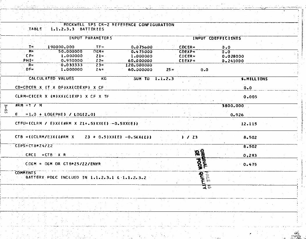
.^"!R'{ ^"`.-.: N*a'F•«av*R.K':, *Y. _;:" F ^'m,".r'* .C?,7^,'K ^l"a "..y ^` .. _ r ,. ^' ... -.'aeThL"'^.. .-w+ 'Ya
r
ROCKWELL SPS CR-2 REFERENCE CONFIGURATIONTABLE 1.1.2.3.3 BATTERIES r
INPUT PARAMETERS ---- — INPUT COEFFICIENTS
T= 190000.000 TF= 0.075600 CDCER= 0.0M= 50.000000 OCM= 0.475000 CDEXP= 0.0
CF= 1.000000 Z1= 1.000000 CICER= 0.028000PHI= 0.950000 Z2= 60.000000 CIEXP= 0.241000x . R= 0.033333 Z3= 120.0000001
^y DF= 1.000000 Z4= 60.000000 Z5= 0.0
4,! CALCULATED VALUES KG SUM TO 1.1.2.3 $,MILLIONS
CO=CDCFR- X (T X DF)XX(CDEXP) X CF 0.0
--CLRM=CICER X (M)XX(CIEXP) X CF X TF 0.005
Goi #RM =T > M 3800.000
E =1.0 + LOG( PHI) / LOG(2.0) 0.926
CTFU=(CLRM / E)X((#RM X Z1+.5)XX(E) — 0.5XX(Elf 12.115
8
CTB =l(CLRM/E)Xl(#RM X Z3 + 0.5)XXIEf —0.5XX(Eff f / Z3 8.502
CIPS=CTB*Z4/Z2 8.502
CRCI =CTB X R 0.283
COEM OEM OR CTB*Z5/Z2/ENYR 0.475^. COMMENTS_..^____.___—.____.___---____^._____
BATTERY POEC INCLUED IN 1.1.2.3.1 E 1.1. 2. 3.2
rl
v
-
......

a' 'may"...-
ury
^•h
a, a
Sato ite Systems DivisionRockwellSpace Systems Group I Intematlonal
(J1.1.2.4 THERMAL CONTROL
This element includes any component used to modify the temperature ofpower transmission subsystem components. It includes cold plates, heattransfer and radiator devices as well as insulation, thermal control coatings gand finishes. Excluded are paints and finishes applied to components during
' - during their manufacturing sequence.and thermal control devices that are anintegral part of another component.
The multi-layer insulation panels are required for the back surface ofthe resonant cavity radiators to restrict waste heat leaks which could in-crease temperatures of electronics to unacceptable levels. This insulationis coated externally with low absorptivity/emissivity materials to limit theabsorbed solar flux to which the surface is exposed during part of the orbit.
The-insulation CER's are based upon secondary structure CER's where thesecondary structure CER's were considered comparable to the requirements ofinsulation in its application on the antenna.
Table 1.1.2.4 presents cost estimates for thermal control,
f
k
K"_
Lam++
`.
ar.
B-66
SSD 79-0010-2-2
x` r'`

51i^i'.{i",i^,`me+m??'.'*i3^N+?a£:?7Rr_'^r°`^gi '7^'T.n" '^vry:x'S ,,. :.-.s.r•ro,-,.,- „z, ..,.^ - _ a ^m n`Rs .a^:m>`_ .,a,.y.. .-. r -...
x i
a{: ROCKWELL SPS CR-2 REFERENCE CONFIGURATION"tTABLE 1.1.2.4 THERMAL CONTROL — INSULATION
INPUT PARAMETERS — INPUT COEFFICIENTS f Y
T= 557000.000 TF= 0.012400 CDCER= 0.156000` M= 4.000000 OEM= 0.0 CDEXP= 0.511000
CF= 1.000000 Z1= 1.000000 CICER= 0.101000PH I= 0.980000 Z 2_= 60.000000 CIE XP = 0.3 550 00TR= 0.010000 Z3= 60.000000
' DF= 0.050000 Z4= 60.000000 Z5= 0.0
CALCULATED VALUES KG SUM TO 1.1.2 39MILLIONS
CU=C DCE R X_(T X DF )XX( CD EXP) X CF
;. CLRM=CICER X (M)XX(CIEXPI X CF X TF 0.002
`td 139250.000s` #RM =T / M
E — = 1. 0 + LOG (PHI) / LOG ( 2.0) ^^__•_^—
0 .9 7 13 ,--
? t' LT FU=(CLRM / E)X((#RM X Z1+.5)XX(E) -0.5XX(E)) 208.062 w.:
CTB =((CLRM/E)X((#RM X Z3 + 0.5)XX(E) —0.5XX(E11 I / Z3 184.657
_CIPS=CTB*Z4/Z2
_ — -- -- — --184.657
CRCI =CTB X 1.847
^' ! COEM = OEM OR CTB*Z5/Z2/ENYR 0.0
C
-
t Ai
S
L
a s
s
a
f
4r.,4 N
i

WBSNO'.
ITEM/DESCRIPTION
QUANTITYPER SATELLITE
1.1.2.5.1 REFERENCE FREQUENCY GENERATOR l SET (777 POWERAMPLIFIERS, 1 -4REGULATORS)
1.1.2.5.2 COAX CABLE 777 SETS
1.1.2.5.3 DEVICES FOR USE ON FREQUENCY 777 SETSDISTRIBUTION SYSTEM
^ '-1+-., Z^.r ,
'•..iK^ .mi 'a"'.R"'1 +Q .ym,^-6 M . .'f ..rT.y..t i eaR.'9)Zf!!.
'. Satellite Systems Division„ RockwellSpace Systems Group 1 Intemational f'”
n
1.1.2.5 CONTROL-PHASE REFERENCEIJ
This element provides the reference phase for all-subarray phase con-jugating circuits and includes the reference oscillator signal distribution,and frequency conversion equipment. It covers components/equipment thatcommonly serve all subarrays. y`
x
The transmitted signal is formed from the pilot beam by means of theretroelectronics where one circuit is required per subarray. A servo systemis needed to transfer the required reference phase from a central point to amechanical module, where it is distributed to the nine subarrays. The mainitems included in this subsystem are shown in Table 1.1.2.5.
Table 1.1.2.5 Control-Phase Reference

S .^5
..`YwfC"'p'7?'4'+os'i . fi'h P,yw,+'rs k1`•`'b :^ ... '^ .. „.,.,.i-. ,. , A 'TW, ..: il'n^^A^iF 2l!A^mi'.nASm?ie l;'%
F •r
{., ROCKWELL SPS CR-2 REFERENCE CONFIGURATIONTABLE 1.1.2.5.1 REFERENCE FREQUENCY GENERATOR
INPUT PARAMETERS INPUT COEFFICIENTS
T= 1.000000 TF= 1.000000 CDCER= 0.500000 i- M= 1.000000 OCM= 0.010000 CDEXP= 1.000000
CF= 1.000000 Z1= 1.000000 CDCER= 0.100000PH,I= 1.000000 Z2= 60.000000 CTEXP= _1.000000
R= 0.033333 TZ3= 120.000000' OF= 0.200000 Z4= 60.000000 Z5= 0.0
' - CALCULATED VALUES - SET SUM TO 1.1. 2.5 S,MILLIONS C
' x CO=CDCER X (T X OF)XX(CDEXP) X CF _.0.1003:, 4
CLRM=CDCER X (M)XX(CIEXP) X CF X TF 0.100
pd #RM =T / M 1.000
E = 1.0 + LOG(PH I) / LOG(2.01 1.000^-_------- ^ it
" CTFU=(CLRM / E)X((#RM X Z1+.5)XX(E) -0.5XX(E)I 0.100 f
^ ' k
CTB =((CLRM/E)X((#RM X Z3 + 0.5)XX(E) -0.5XX(E) ► ' ) / Z3 0.100
CIPS=CTB*Z4/Z2 0.100
CRCI =CTB X R 0.003
' COEM = OEM OR CTB*Z5/Z2/ENYR 0.010r
y
4
a
r
_ 1 4-- . - ". s ...ass .. . , v -,. •. .. .. .-, `t • S '. .:.. .. .: . .. v ....r. W a _.
Fu.'.4-.a.Y n a f.tvK ^! . .. - t ss c

i ir—^ a^^r'-r.°a^'*^7,.!r"A°^.` ' `t '.^ - f ' -rfit ,r°. s 17'
n
i
ROCKWELL SPS CR-2 REFERENCE CONFIGURATION:.TABLE 1..1.2.5.2 DIST. SYSTEM, COAXIAL CABLE
INPUT PARAMETERS -- ~ - INPUT COEFFICIENTS
T= 203000.000 TF= 1.000000 CDCER= 0.000005M= 261.000000 OEM= 0.0 COEXP= 1.000000
CF= 1.000000 Z1= 1.000000 CI`CER= 0.000060PHI= 1.000000 Z2= 60.000000 CIEXP= 1.000000 --
R= 0.0 Z3= 60.000000 -DF= 0.200000 Z4= 60.000000 Z5= 0.0 h
a
CALCULATED VALUES M SUM TO 1.1.2.5 St MILLIONS
CD=CDCER X (T X DF)XX(CDEXP) X -CF 0.203
E CLRM=CICER X (M)XX(CIEXP) X CF X TF 0.016
#RM =T / M 777.778tdio E = 1.0 + LOG( PHI) ! LOG("2.'0) 1.000
CTFU=(CLRM / E)X((#RM X Z1+.5)XX(E) -0.5XX(E)) 12.180 Y}dapM
CTB =((CLRM/E)X((#RM X Z3 + 0.5)XX(E) -0.5XX(E)J ) / Z3 12.180
GIPS=CTB*Z4/Z2 12.180~.
¢ CRCI =CTB X R 0,0
-CCEM = OEM OR CTB*Z5/Z2/ENYR 000
^.. :.-s._r..«..n. a ^ a. • r_.. - ..... ... .
w
-..
i

Y ^^, qs ^;:-^ ^;+.a't.'^^,ox.:r°a.-'•r •^,^k,K _ r „'^';er^±y"r^` , ^'rr ac qr , *^.,...:. „^. ..: .. .. _. .. s
Y,.
ROCKWELL SPS CR-2 REFERENCE CONFIGURATIONTABLE 1.1.2.5.3 DIST. SYSTEM, DEVICES
I ^^INPUT PARAMETERS INPUT COEFFICIENTS
T= 1554.00000 TF= 1.000000 CDCER= 0.000225M= 2.000000 OEM= 0.0 CDEXP= 1.000000 f
-. CF= 1.000000 Z1= 1.000000 CICER= 0.005000PHI= 1.000000 Z2= 60.000000 CIEXP= 1.000000
R= 0.033333 Z3= 120.000000. OF= 0.200000 Z4= 60.000000 Z5= 0.0
. R
CALCULATED VALUES KG SUM TO 1.1.2.5 $.MILLIONSz
CD=000ER X (T X OF) XX( CDE XP) X CF 0.070
CLRM=CICER X (M) XX(C IEXP) X CF X TF 0.010 !'
td #R M =T / M 777.000
s ~' E =1.0 + LOG( P HI) / LOG12.0) 1.000
a CTFU=(CLRM / E')X((#RM X Z1+.5)XX(E) —0.5XX(E)) 7.770
CTB =((CLRM/E)X_((#RM X Z3 + 0.5)XX(E) — 0.5XX1 E)) ) / Z3 7.770
7.770T^
k ;' CRCI =CTB X R 0.259 {
COEM = O&M OR CTB*Z5/Z2/ENYR 0.0
•
s. _ •LSihb ... ., x.Mx ry. R a u
V }
r y^^^yF•^

WBSNO.
MAINTENANCE ITEMDESCRIPTION
1.1.2.6 POWERTRANSMISSION
1.1.2.6.1 "FREE-FLYERS" OR BARGE FOR 1 VEHICLE UTILIZATIONCARGO AND PERSONNEL (COMMONUSE ITEM)
1.1.2.6.2 GANTRY CRANE AT ANTENNA SET
1.1.2.6.3 ON-CRANE CONTROL CENTER, SETHOISTS, EQUIPMENT TEST GEAR,ROBOTICALS
1.1.2.6.4 TRACKS AND ACCESSWAYS 12000 kg
x
Satellite systems Division Rockwell
Space systems Group International
1.1.2.6 MAINTENANCE
This element provides for in-place repair or replacement of componentsand includes work stations, tracks, access ways,, and insitu repair equipment.
Maintenance requirements of this element are related to the power trans-mission (antenna) section of the satellite covering the structures; subarrays(Klystrons); power distribution/conditioning and energy storage; thermalcontrol, and control elements. Some of the maintenance equipment are multi-purpose and are therefore costed against the applicable maintenance items onan apportioned basis.
Maintenance requirements for this element are presented in Table 1.1.2.6and cost estimates are projected in Tables 1.1.2.6.1, 1.1.2.6.2, 1.1.2.6.3,and 1.1.2.6.4.
eTable 1.1.2.6 Maintenance Requirements
.3
1
x
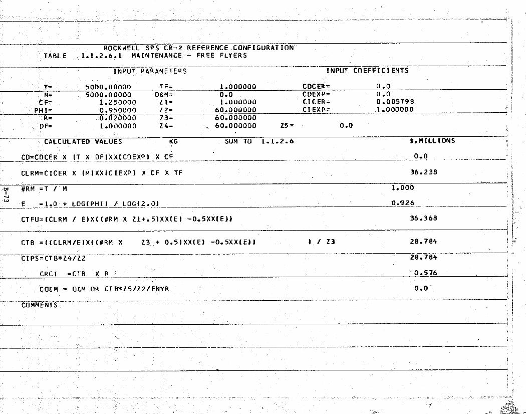
28.784
28.:784---_^_^
0.576 - --
Y
-i
1.000
0 .426 -
36.368
e
r
.^E
k Z .
ROCKWELL SPS CR-2 REFERENCE CONFIGURATION.TABLE 1.1.2.6.1 MAINTENANCE FREE FLYERS T
INPUT PARAMETERS INPUT COfFFiCIENTS
T= 5000.00000 TF= 1.000000 CDCER= 0.0M= 5000.00000 OEM= 0.0 COEXP= 0.0
CF= 1.250000 Z1= 1.000000 CDCER= 0.005798PHI= 0.950000 Z2= 60.0UU000 CIEXP= 1.000000
` R 0.020000 Z3= 60.000000E ; DF= 1.0 00 000 Z4= 60.000000 Z5= 0.0
CALCUL ATED VALUES KG SUM TO 1.1.2.6 $, M ILL IONS— 4
CO=CDCER X (T X DF)XX(CDEXP) X CF - 0.0
j CLRM=CICER X (M)XXICIEXP) X CF X Tf 36.238
Vw
- ------ ---- -- -R^
CTFU=(CLRM / E)X((#RM X Z1+.5)XX(E) 0.5XX(El):^ r
-1CTB =((CLRM/E)X((#RM X
Z3_+ 0.5)XX(E) -0.5XX(E)) ) / Z3
{ CIPS=CTB*Z4/Z2
^i CRC =CTB X R
#RM =T / M
E =1.0 + LOG(PHI) / LOGI2.0)

;r
t
ROCKWELL SPS CR = 2 REFERENCE CONFIGURATIONTABLE 1.1.2.6.2 GANTRY CRANE
— _
INPUT PARAMETERS INPUT COEFFICIENTS
° T= 40000.0000 TF= 1.000000 CDCER= 0.234000M= 40000.0000 OEM= 0.0 CDEXP= 0.653000u CF= 1.100000 Z1= 1.000000 CI'CER= 0.000005
PHI= 1.000000 Z2= 60.000000 CIEXP= 1.000000R= 0.002000 Z3= 60.000000
DF= 0.200000 Z4= 60.000000 Z5= 0.07
5 CALCULATED VALUES KG SUM TO 1 °.1.2.6 Ss MILLIONS
° CD=CDCER X (T X DF)XX(CDEXP) X-CF 91.060 €
CLRM=CICER X (M)XX(CIEXP) X CF X TF 0.220
#RM =T / M 1.000
E = 1.0 + LOG(PHI) ! LOG(2.0) 1.000
CTFU=(CLRM l E)X((#RM X Z1t.5)XX(E) —0.5XX(E)1 0.220
CTB =((CLRM/E)X((#RM X Z3 + 0.5)XX(E) — 0.5XX(E1) ) / Z3 0.220x
CIFS—CTB*Z4lZ2 - - 0.220
r . CRCI =CTB X R 0.000
I° COEM CEM OR . CTB*Z5/Z2/ENYR 0.0
COMMENTS— 7
^ R

itr--
a
'" '". : ' °T' 7r;axiT %: 5 •"; ;". ;i'^
t
k ^
ROCKWELL SPS CR -2 REFERENCE CONFIGURATION t ;'-I TABLE 1.1.2,6.3 ON—CRANE CONTROL CENTER Ji
INPUT PARAMETERS INPUT COEFFICIENTS
T= 50000.0000 TF= 1.000000 CDCER= 0.012432M= 50000.0000 OSM= 0.0 CDEXP= 1.000000
CF= 1.000000 Z1= 0.100000 CICER= 0.005798t . PHI= 0.950000 Z2= 60.000000 CIEXP= 1.000000s R= 0.020000 Z3= ^i 6.000000 1,
OF= 1.000000 Z4= 6.000000 Z5= 0.0
CALCULATED VALUES KG SUM TO 1.1.2.6 $,MILLIONS
CD=CDCER X (T X DFIXX(CDEXP) X CF 621.600
C'LRM=CICER X (M)XX(C IEXP) X CF X TF 289.900 `r-ti
z ^, #RM =T M 1.000]f
(3
"' E =1.0 + LOG(PHI) / LOG(-2.01 0.926
CTFU=(CLRM / ElX((#RM X Z1+.5)XX(E) 0.5XX(E)) 30.305
CTB =((CLRM/E)X((#RM X Z3 + 0.5)XX(E) -0.5XX(El)fi CIPS=C
TB*Z4/Z2i_«^_______________.`..____^,______F :-..
" CRCI =CTB X R7 ..
. CCEM = OEM OR CTB*Z5/Z2/ENYR
1 / Z3 267.824
26.782
5.356
0..0tb
o ^ ^i

Y ...--.•r ..mat^. 7 f,77 'T ",77 rnt g ..^;?, ^'r.•y: 1,. _ "m"`R 'y -
4 S •-.v=-^'+ . .. --. r _ ., _..
. .. •'r8i; .
^1
^j Nry{
Si
#ROCKWELL SPS CR-2 REFERENCE_CONFIGURATION
TABLE 1.1..2.6.4 TRACKS E ACCESS WAYS
'k,
-- INPUT PARAMETERS INPUT COEFFICIENTS
T= 12000.0000 TF= 1.0000UU CDCER= 0.0a M= 12000.0000 OEM= 0.0 CDEXP= 0.0
CF= 1.000000 Z1 = 1.000000 CICER= 0.000005y PH_I=1.000000 Z2=—__ _ 60.0000_00 -CI EX P= 1.000000 _ i
R-- 0.402000 Z3—^ 60.000000DF= 1.000000 Z4= 60.000000 Z5= 0.0
CALCULATED- VALUES KG SUM TO 1.1,2.6 $, MILLIONSa
CO=CDCER X (T X DF)XX(CDEXP) X , CF 0.0i
CLRM=CICER X ( M )XX(C IEXP) X CF X TF 0.060f
#RM =T / M 1.000
E =1.0 / LOG( 2.0)-+ —LOG(PHI) _ 1.000
4. CTFU=(CLRM / E)X((#RM X Z1+.5)XX(E â —0.5XX(E)l 0.06G
CT0 =((CLRM/E)X(( #RM X Z3 + 0.5)XX(E) — 0.5XX(E)) J./ Z3 0.060
CIPS=CTB*Z4/Z2 0.060
CRC I = CT B X R 0.000
C CC M = OEM OR CT B*Z5 /Z 2 /ENYR 0.0 t'
# COMM ENT Sa
i
i.:
1
1

^f ,..roux- - .... ^f• _ ^. •.e»-^:r,+jr -*^ &:.•,^',••^•.,^,.,.,.-,7, .
Satellite Systems Division„Rockwell1Space Systems Group Intemational
f:
! 1.1.3 INFORMATION MANAGEMENT AND CONTROL
This element includes those components that process information onboard z.the satellite. This includes sensing, signal conditioning, formatting, com-puta.tions, and signal routing.
b The information management and control subsystem (IMCS) provides theinterconnecting elements between and within all the various satellites andground-based operational subsystems. The IMCS also provides operationalcontrol of both the satellite and ground systems as well as providing allsubsystem processing support for all but very special functions.
c
The satellite IMCS consists of the on-board processing equipment [centralprocessing units (CPU) and memories], the inter- and intra-subsystem data net-work (data buses), the man-machine interfaces (display/control), and inter-system communication links, including RF, but excepting those specificallyprovided for the control and transfer of primary power, and all elementsprovided to accommodate activities related to system security, safety, or any'other operation necessary to the continuing operation of the SP3.
Because of the early stage of program analysis, only those requirementsimposed upon the IMCS by a limited number of satellite operations have beenidentified. The identified requirements generally are limited to thoseassociated with the immediate operations of an active satellite. Auxiliaryfunctions such as ground/space communications, display/control, safety, secur-ity, etc., will be added when data become available.
The usage and application of IMCS items is identified in Table 1.1-3 and
P
provides direct association with the subsystem functions.
Table 1.1-3. Usage/Application Matrix per Satellite
INSTRUMENTATION DATA ACQUISITION DATA PROCESSING CONTROL
cez ^ o z ^coz
d J F 4 J 2 4 QH ^- i- > J -g0
-J ►-
NQQ2 O ^
aa2 H ^^.
{{{^^^d
4^d W a !- 2 G:
ELEMENT z z ttt^^^ s ur z u^ z c^ z WBS
DESCRIPTION N a u°O W cc °- L u°UJ
C L3 a c°^ °uVi NO.
MASTER CONTROL COMPUTER X X X X
DISPLAYS CONTROL X X X X X 1.1.3.2
SUPERVISORY COMPUTER X X X 1.1,3.3
REMOTE COMPUTER X X X 1.1.3.4
BUS CONTROL UNIT X X X X X 1.1.3.5
MICROPROCESSORS X X X 1.1.3.6
REMOTE ACQ. s CONTROL X X X X X X 1.1.3.7
SUB-MULTIPLEXER X X X X X
INSTRUMENTATION X % 1.1.3.9
`FIBER OPTICS X 1.1.3.10
CABLES b-HARNESSES X X X X X X X X X X 1.1.3.11
p'
`. B-77n SSD 79-0010-2-2
7•ay":^^_4..n :."5,.a ^z• ... ...- .. _, ...^'tita^r4'a,M^7, .Gird.s'9F"^:. ?^'x_:]}..aR 2rzw..S” .. ca .. s s .. y. r , r+ ruxv

_ er. a .x
Satellite Systems Division RockwellIntemational n- Space Systems Group
5
These items have been separated into general hardware groups for costingpurposes.
COMPUTERS
Historical cost data were obtained for computers from the Redstar Data` Base system and are listed below: j
- Gemini-3 • Viking Zander• Minuteman - MOL• Skylab HEAO
A 50% integration factor was included in the DDT&E CER's to allow forsubsystem level costs.
Range of Data: {{I
r DDT&E and ICI: 1.8 to 75.7 kilograms
' ELECTRONIC COMPONENTS
The electronic components associated with Avionics include the Submulti-plexors, Remote Acquisition Units, Microprocessors, Bus Control Units andinstrumentation.
-. Development of an electronic components CER was based on the selected;:'components of the ATS-F and OSO-8 spacecraft. These 19 electronic components,.are listed below:
ATS-F OSO-8
Aux. Digital Sun Sensors Solar Power• SupplyMonopulse Unit Power SupplyWide Band Data Unit Control Decoder/Demodulator.C Band Data Unit Remote DecoderS/L Band Transmitter PCM DecoderVHF Receiver Format GeneratorCommand.Decoder Wheel ClockData Acq. & Control Unit Sail ClockData Switching Unit S Band Transmitter
VHF Transmitter
Range of Data;
. DDT&E and ICI: 1.1 to 19.6 kilograms
a DATA BUS
This element consists of both copper wire and fiber optics. Historicalcost data were obtained from the Redstar Data Base to produce the data bus
--^ DDT&E CER. Commercial prices were used for the data bus ICI CER.
B-78
SSD 79-0010-2-2
,a

t <W
'wiLL'..• _ ^;,, ^K^`^'^R'^Ar4"T• ;S•4Y^f'I1^ ^.v.,avY^w •5%^.'ew':I++ae^mayima Y'
.. ^—""'.r `Y^s^..^...._.._^....vwu.. as^ _....-.,•.-^—^++.>...srmaramfzs..wu+^er . -.. >_..., _ ..
y -t_a.a:u.e xna xri:.u....a.r:.tw.:^..^z..S^r;Y..u.3+rvMUa^'naWr:a. Z.#.(.+..a.uS.::.°." ` _.. . "C ., _. •^^.. .._ .i....alu-usa, f: +vswv::...^..::., _...i3 S.... s..-......, w-..t n+ ..^^..- .. 4A^`
Satellite Systems DivisionO, Rockwellx•
Space Systems Group International
x'
.' Production cost information obtained from private industry for 'off-the-'. shelf" fiber optics and copper wire are listed below:
_. FIBER OPTICS: Y,;i;
Manufacturer Type Characteristics Cost per Meterk
ITT Electro-Optical GG-02 Single Fiber (1-10 km)Products Division 50 m Dia.. $3.25
GS-02 Single Fiber $2.5050 m Dia.
Valtec Fiberoptics MG-05 Single' Fiber $2.50'{ Division 65 m Dia.
Galileo Electro- - Single Fiber $1.58F; Optics Corporation 88 m Dia.
Average cost per meter $2.40
One industry spokesman estimates that the . cost of optical fibers wouldlikely decrease to 40% by 1980. This study assumes a $2.40 per meter averageprice reduced by 40% . to,$1.44 per meter.
COPPER WIRE:
Manufacturer Characteristics Cost per Meter
Dearborn Wire & Cable 22 gage stranded $0.807f.
fsilver plateStandard Wire & Cable 22 gage stranded - $0.705
r silver plate =.f'
Karen, Inc. 22 gage, 2 conductor -'$0.807silver plate
` Mil-Spec Wire & Cable 22 gage, 19-30 $0..610 ti.Corporation stranded
Average cost per meter $0.732
:. Instrumentation input parameters T&M are in kilograms.
Cost estimates for the items of Table 1.1-3 are presented in Tables 1.1.3.1p through 1.1.3.11 inclusive.
B-79 t
,.- SSD 79-0010-2-2

i.^^^`?"'^^'m;°^A'[^.;!^'ia^±r^^' ^p+^n^^,r,,^ ar,;^5r.;^ C.r.^'+,^-° ,fit. ,^^,;^..,y^r..s^'n '^ w^ .. ^2 zy.^n .. ' y .-^ ..^..n,.,,,^' _ '^'"-r•^.nrm}"^
n^
i
ROCKWELL SPS CR-2 REFERENCE CONFIGURATION ra
' TABLE 1.1.3.1 MASTER CONTROL CCMPUTER
INPUT PARAMETERS -- INPUT COEFFICIENTS
T`= 1000.00000 TF= 0.900000 CDCER= 0.633000M= 500.000000 OSM= 0.0 CDEXP= 0.521000
FVj CF= 1.000000 Z1= 1.000000 CICER= 0.172000
` PHI= 0.800000 Z2= 60.000000 CIEXP= 0.535000R= 0. 01.0000 Z3= 60.000000
$4. DF= 0.500000 Z4= 60.000000 Z5= 0.0
CALCULATED'' VALUES KG SUM TO 1.1.3 EMILLIONS
CD=CDCER X (T X OF)XX(CD EXP)^X CF 16.127
t CLRM=CICER X (M)XX(CIEXP) X CF X Tf 4.302
#RM = T / M 2.000tz
E = 1.0 + LO G(PHI) / LOG(2.0) 0.678
CTFU=(CLRM / E)X((#RM X Z1+.5)XX(E) -0.5XX(E)1 7.845
CTB =((CLRM/E)X((#RM X Z3 + 0.5)XX(E) -0.5X1481 ) / Z3 2.659
--- CIPS=C,TB*Z4/Z2 ______. 2.659 !1
CRCI =CTB X R 0.027 {—
CCE-M _ OEM OR CTB*Z5/Z2/ENYR 0.0 t.
COMM E(VT S
t

;
T
ROCKWELL, SPS CR-2 REFERENCE CONFIGURATION rf TABLE 1.1.3.2 DISPLAYS 6 CONTROLS
- INPUT PARAMETERS - - INPUT COEFFICIENTS
T= 200.000000 TF= 0.900000 CDCER= 0.102000M= 200.000000 0&M= 0.0 CDEXP= 0.879000 g
CF= 1.000000 Z1= 1.000000 CICER= 0.069000PHI= 0.800000 Z2= 60.000000 CIEXP= 0.557000
-R= 0.010000 Z3= 60.000000DF= 1.000000 Z4= 60.000000 Z5= 0.0
CALCULATED VALUES KG SUM TO 1.1.3 SsMILLIUNS
i LD=CDCER X (T X OF)XX(CDEXP) X CF 10.745
CLRM = CICER X (M)XX(C IEXP) X CF X TF 1.188
#RM = T / M 1.000e
E = 1.0 + LOG(PHI) / LOG(2.0) 0.678
CTFU=(CLRM / E)X((#RM X Z1+.5)XX(E) —0.5XX.(E)) 1.211
CTB =((CLRM/E)X((#RM X Z3 + 0.5)XX(E) —0.5XX(E)) ) / Z3 0.453
` CI PS=CTB^FZ4lZ2 --- -- -- ------ 0.453j
CRC I =CTB X R 0.005
k' COEM'= 0&M OR CTB*Z5/Z2/ENYR 0.0
COMMENTS
J
,^^ t = s
y
ii
i

77toROCKWELL SPS CR- 2 REFERENCE CONFIGURATION {
i TABLE 1.1.3.3 SUPERVISORY COMPUTER
' INPUT PARAMETERS INPUT COEFFICIENT'Sr
`. T= 84.000000 TF= 0.700000 CDCER= 0.633000M= 14.000000 OSM= -0.0 CDEXP= 0.521000 t
CF= 1.000000 Z1= 1.000000 CILER= 0.172000 :+PHI= 0<.850000 Z2= 60.000000 CIEXP= 0.535000
R= 0.010000 Z3= 60.000000DF= 0.200000 Z4= 60.000000 Z5= 0.0
CALCULATED VALUES KG SUM TO 1.1.3 St MILLIONS r•
1 CD=CDCER X (T X DF)XX(CDEXP') X CF 2.753
iCLRM=CICER X (M)XX(CIEXPJ X CF X TF 0.494
,; F m #RM = T / M 6.000co
E - =1.0 + LOG(PH I'1 / LOG (2'. 0) 0.766
CTFU=(CLRM / E)X((#RM X Z1+.5)XX(E) — 0.5XX(E)! 2.325 4
CTB =t(CtRM/E)X((#RM 'X Z3 + 0.5)XX(E) —0.5XX(E)'! 1 / Z3 0..969
CIPS=CTB*Z4%Z'2--- ^0.969f
CRCI =CTB X R 0.010
C06M = OEM OR CTB*Z5/Z2/ENYR 0.0 l
.Y
------ --"---- .._. .. .=. <, . . .. '. `. _ L°'... ._ •_. '. ,,,.,-:. _
f•4^v
.x. La's"".

z
vt,i^,, ^, ^: U
ROCKWELL SPS CR-2 REFERENCE CONFIGURATIONTABLE 1.1.3.4 REMOTE COMPUTER
COEFF—ICIfNTS^Y—INPUT PARAMETERS -- - INPUT
T= 518.000000 TF= 0.400000 CDCER= 0.633000M= 14.000000 OEM= 0.0 CDEXP= 0.521000
CF= 1.000000 ZY= 1.000000 CICER= 0.172000PHI= 0.850000 Z2= 60.000000 CIEXP= 0.535000
R= 00010000 Z3= 60.000000 —DF= 0.030000 Z4= 60.000000 Z5= 0.0
CALCULATED VALUES KG SUM TO 1.1.3 3, MILL IONS
CO=CDCER"X (T X OF)XX(CDEXP) X CF 2. 64 3
CLRM=CICER X (M)XX(CIEXP) X CF X TF 0.282 4w #RM =T / M 37.000o
'( u' E = 1.0 + LOG(PHI) / LOG(2. 0) 0.766
i ' CTFU=iCLRM / E)X((#RM X Z1+.5)XX(E) -0.5XX(E)1 5.696
CTB =((CLRM/E)X((#'RM X Z3 + 0.5)XX{E) — 0.5XX(E)l ) / Z3 2.238
,.E;
CIPS=CTB*Z4/Z2 2.238
CRCI =CTB X R 0.022
1COEM _ 06M OR CTB*Z5/Z2/ENYR 0.0
E. --—k COMMENTS .—_------ -
v
yt
r X14`'
• - ^ - - - `a<- - .._. .. _e3Lds'k—_ ,. emu..,_.>^'. ,_.._ :°.'•. `'"; ir_^s
l

v!s'^a;#}c. p
1 ^(
i
ROCKWELL SPS CR-2 REFERENCE CONFIGURATION ?,TABLE 1.1.3.5 BUS CONTROL UNIT :$3s
—^4V— --- —INPUT PARAMETERS —INPUT COEFFICIENTS
T= 4110.00000 TF= 0.076000 CDCER= 0.102000 1M= 5.000000 OEM= 0.0 CDEXP= 0.879000 ia CF= 1.000000 Z1= 1.000000 CICER= 0.069000{ PHI= 0.95 0_000 Z2= 60.000000 CIEX_P = 0.55700 0R= 0.010000 Z3= 60.000000
DF= 0.001200 Z4= 60.000000 Z5= 0.0
' CALCULATED VALUES KG SUM TO 1.1.3 S•MILLIONS !!
CD=CDCER X (T 'X DF)XX(CDEXP) X CF ^4__ 0.415>
CLRM=CIC E R X (M'IXX(CIEXPI X CF X TF 0.013
#RM- =T / M 822.000}l7
co
E =1.0 + LOG( PH I) / LOG(2 . 0) 0 .926
r'{ CTFU=(CLRM / E)X((#RM X Z1+.5)XX(E) —0 5XX(Ell 6.940
'i CTB =((CLRM/E)X((#RM X Z3 + 0.5)XX(E) —0.5XX(El) l / Z3 5.128r ^^w _C IP:S=CTB*Z4/ Z2 5.128
CRCI =CTB X R 0.051 -
^ •iCOEM = OEM OR CTB*Z5/Z2/ENYR 0.0 i{
.
ta.. COMMENTS
_._ ______:._r... _ .^__ _ - _. _ _ _.__ . __ _,— __..-_.____.,_—
-
.__.._._ _...______ _ .:__._ _..__ --.. _^—_ .^ _...__^___...__._v^• .^__^_r.. ___.__—
it
-n

F -,r- y ^ .a. ;.., ^. .. .Pn. YMO,MC[ $_b';^, az 'k.!' ._nl[iclf+ "7V i-T M+'lva _.. {`
r,'sTs^^^ 1 -.. . . .,,i• .^ :•14p1°• f•,. _•x'Y!"daT£.vnrlF
'.^.SI`
f
ROCKWELL SP S CR-2 REFERENCE CONFIGURATION
`
! '`
4TABLE 1.1.3.6 MICROPROCESSORS
PARAMETERS --- -_— —INPUT -INPUT COEffICIENTS
T= 3960.00000 TF= 0.078000 CDCER= 0.102000M= 5.000000 OEM= 0.0- CDEXP= 0.879000
CF= 1.000000 Z1= 1.000000 CICER= 0.069000PHI= 0.950000 Z2= 60.000000 CDEXP= 0.5570_00
A R= 0010000 Z3= 60.000000DF-= 0.001300 Z4= 60.000000 Z5= 0.0
j CALCULATED VALUES KG SUM TO 1.1.3 S,MILLIONS
{ - CD=CDCER X UT X DF)XX(CDEXP)! X CF ^. 0.431 ' J
CIRM=CICER X (M)XX(CIEXP) X CF X TF 0.013
#RM = T ,0 M 792.000
)'. i00E = 1.0 + LOG(PHI) / LOG(2.0) 0.926
° CTFU=(CLRM / E )X((#RM X Z1+.5)XX(E) -0.5XX(E)) 6.881
CTB =((CLRM/E)X((#RM X Z3 + 0 . 5)XX(E) — 0.5XX ( E)) ) / Z3 5.085
a?' CLPS=CTB*Z4/Z2 5.085F'
CRCI =CTB X R 0.051 #
COCM = OEM OR CTB *Z'5/Z2/ENYR'_ 0.0------ —CQ M M E NT S,
:1P
w
ks
v

PP+, `'.'q?J° , 79°N''T^w?tmF S, Its."'.^Zf'TS,?"3SXT.'^^"rrt'°"A`q^=^^.^+
. r .iR..,^ x rb^"'.'
.. _
iROCKWELL-SPS CR-2 REFERENCE CONFIGURATION rs
TABLE 1.1.3.7 REMOTE ACQUISITION E CONTROL
INPUT 'PARAMETERS' INPUT COEFFICIENTS
T= 4925.00000 TF= 0.069000 CDCER'= 0.102000 i
M= 5.000000 OEM= 0.0 CDEXP= 01879000CF= 1.000000 Z1= 1.000000 CICER= 0.069000PHI= 0.950000 Z2= 60.000000 CIEXP= 0.557000
— R= 0.010000 Z3= 60.000000 {DF= 0.001000 Z4= 60.000000 Z5= 0.0
tj CALCULATED VALUES KG SUM TO 1.1.3 $ * MILLIONS #
` CD CDCER X (T X DF)XX(CDEXP) X CF 0.414
CLRM=CICER X ( M )XX(C IEXP) X CF X TF 0.012€ai
' #RM =T / M 985.000td
a E =1.0 + LOG( PHI) / LOG(2.0) 0.926
CTFU=(CLRM / E)X((#RM X Z1f.5)XX(IE) —0.5XX(E)1 7.450
CT8 =((CLRM/E)X((#RM X Z3- + 0.5)XX(E) —0.5XX(EIJ ) ! Z3 5.505b"
CIPS=CTB*Z4/Z2 5.505
CRCI =CTB X R 0.055 '.
COEM _ OEM OR CTB*Z5/Z2/ENYR 0.0------.. _.__' i1
COMMENTS
s
n
Y
g i ^ rJz"

rd
i
jr
ROCKWELL SPS CR-2 REFERENCE CONFIGURATIONTABLE 1.1.3.8 SUBMULTIPLEXORS
st
INPUT PARAMETERS INPUT COEFFICIENTS
T'= 9`3000.0000 TF= 0.022000 CDCER= 0.102000M= 3.000000 OEM= 0.0 CDEXP= 0.879000r:t CF= 1.000000 Z'1= 1.000000 CIC.ER= 0.069000
PHI= 0.980000 Z2= 60.000000 CIEXP= 0.557000
^qA ^
r '`s1
R 00010000 Z3= 60.000000 --^
DF 0.000032 Z4= 60.000000 Z5= 0.0
CALCULATED VALUES KG SUM TO 1.1.3 t, MILL IONS
CO=CDCER X (T X DF) XX(CDEXP) X CF -- ^ 0.266t x
CLRM-CICER X ( M)XX(CIEXP) X CF X TF 0.003
g ! ^, #R M =T / M 31000.000 —t j oo
E = 1.0 + LOG(PHI) / LOG( 2. 0) 0 .971r^ -- — --- --- ---s
CT FU=(GERM E)X(( #RM X Z1+.5)XX(E) -:0.5XX(Ell 66.119
F CTB =((CLRM/E)X((#RM X Z3 + 0.5)XX(E) —0.5XX(Ell ) / Z3 58.682
CIPS=CTB*Z4/Z2i
58.682
F CRCI =CTB X R 0.587
CO&M O&M OR CTB*Z5/Z2/'ENYR 0.0
`, x
j
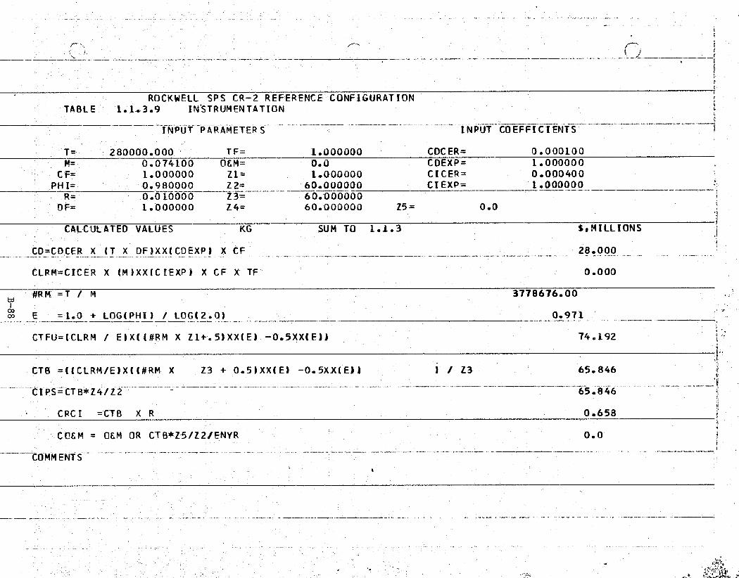
ti
ROCKWELL SPS CR-2 REFERENCE CONFIGURATIONTABLE 1.1..3.9 IN'S'TRUMENTATION
?AIOIIT DADAMCTCDC - iAl
5
^ a
rn G G ^r r i Gnirc— t
T= 280000.000 TF= 1.000000 CDCER= 0.000100M= 0.074100 OEM= 0.0 CDEXP= 1.000000
CP= 1.000000 Z1'= 1.000000 CICER= 0.000400
PHI= 0.980000 Z 2= 60.000000 CI EXP= 1.000000R= 0.010000 Z3=^
—60.'000000 f
DF= 1.000000 Z4= 60.000000 Z5= 0.0
CALCULATED VALUES KG SUM TO 1. 1.3 $,(MILLIONS
CD'=CDCER X (T X DF)XX(CDEXPI X CF 28.000
CLRM=CICER X (M)XX(CIEXP) X CF X TF 0.000
#R M =T / M 3778676.00io E = 1.0 + LOG(PHI) / LOG(2.0) 0.971 `.
CTFU=(CLRM / E1X((#RM X Z1+.5)XX(E) — 0.5XX(E)) 74.192 °=
^. CTB =((CLRM/E)X(I#RM X Z3 + 0.51XX(EI —0.5XX(E)l 1 / Z3 65.846
CIPS=CT8*Z4/Z2 65.846
CRC I =CTB X R 0.658 1^i
( *COEM OEM OR CTBZ5/Z2/'ENYR 0.0
i
kIre^
^-n Iy 1^}7 r-^

ROCKWELL'SPS -CR-2 REFERENCE CONFIGURATION Y`TABLE 1.1.3.10 OPTICAL FIBER
t INPUT PARAMETERS — INPUT COEFFICIENTS — f-
T= 62.000000 TF= 1.000000 CDCER= 0.237000M== 62..00000000 O&M= 0.0 CDEXP=- 0.297000
CF= 1.000000 Z1= 1.000000 CICER= 0.010219PH[=' 0.980000 Z2= 60.000000 CI`EXP= 1.000000R_ . . _ —
0.010000 — Z3 = 60.000000DF= 1.000000 Z4= 60.000000 Z5= 0.0
CALCULATED 'VALUES KG SUM TO 1.1.3 $,MILLIONS
CD=CDCER X (T X DF)XX(CDEXP) X CF 0.807
CLRM=CICER X (M)XX(CIEXP) X CF X TF 0.634
#RM =T / M 1.000e
' E = 1.0 + LOG(PH[) / LOG(2.0) 0.971 Ft
CTFU = (CLRM / E)X((#RM X Z1+.5)XX(E) —0.5XX(E1) 0.634
CTB =(!(CLRM/E)X(1#RM X Z3 + 0.5)XX(E)— —0.5XX(E)1 ) / Z3 0.578
s CIP^S=CTB*Z4/Z2 -0.578r
$; CRCI =CTB X R — 0.006
CO&M = O&M OR CTB*Z5/Z2/ENYR. 0.0
COMMENTS
e
M
a1 y.,a.


..r -. ^': ♦
Rif,: Y ;. 1
'.
,._ .nmatsY::" ..; asnraew'^ , -_ nta - - a ... _k
f r+^.1s^
-°-'
Satellit* Systems Division1P, RockwellSpace Systems Group International i
^' a
1.1.4 ATTITUDE CONTROL AND STATIONKEEPING 3
This element includes the components required to orient and maintain thesatellite's position and attitude in geosynchronous orbit. Included are sen-sors, reaction wheels chemical and electric propulsion hardware and propel- -lants.
The baseline ACSS features an argon ion bombardment thruster RCS whosecharacteristics are:
• Thrusters located in 4 modules at each corner of the satellitei
• Each module has 16 thrusters
• Cryogenic propellant storage-electric refrigeration with heat lossmakeup
• Hemispherical plume characteristics
• Serviceable in place
The system operates on an average of 36 thrusters. A total of 64 thrustersare included to provide the required redundancy. The redundancy was based onan annual maintenance/servicing interval, 5000 hour thruster grid lifetime and5-year thruster MTBF. Sixteen thrusters are located on the lower portion ofeach corner of the spacecraft. Each thruster is gimbaled individually tofacilitate thruster servicing, to permit operation of adjacent thrusters dur-ing servicing, and to provide the redundancy. The thrusters nominally providea force approximately in the direction of the sun to counter the solar pressure
E; force (stationkeeping) which is the dominant thruster requirement. The thrust-ers are gimbaled through small angles (as illustrated) and differentiallythrottled to provide the remaining forces and torques for attitude control and ;astationkeeping.
Sensors that make up the attitude reference determination system include:
. CDD Sun Sensor (1/System)
• CCD Star Sensors (2/Systems)
Electrostatic . or laser gyros (3/System)
• Dedicated mini processor
The attitude reference determination system features Charge Coupled DeviceY.
FR (CCD), star and sun sensors as well as electrostatic or laser gyros and dedicat-ed microprocessors. Seven attitude reference determination units are locatedat various locations on the satellite in order to sense thermal and dynamicbody bending, and to desensitize the system to these disturbances. The controlalgorithms will feature statistical estimators for determining principal axis.orientation, body bending stage observers or estimators, and a quasi-linearpropulsion thrust command policy to provide precise control and minimizestructural bending excitation.'
B-91
SSD 79-0010-2-2
•

r Satellite Systems Division Rockwell
Space Systems Group International11
{ The mass properties of the ACSS are summarized in Table 1.1-4. Thissummary includes the mass of individual elements and propellant weight onan annual basis.
Table 1.1-4. ACSS Mass Summary
MASSITEM (x 10+3 KG)
-ATTITUDE REFERENCE DETERMINATION SYSTEMS (7) 0.32
THRUSTERS—INCLUDING SUPPORT STRUCTURE,64 ® 120 KGITHRUST EER 7.68
THRUSTER GIMBALS AND MOUNTING 3.98
TANKS, LINES, REFRIGERATION 15.07
POWER PROCESSING EQUIPMENT S& 95
TOTAL (DRY) 116.00
ARGON PROPELLANT— ANNUAL REQUIREMENT 85.39
TOTAL (WITH PROPELLANT) 201.39
9y '
a
Historical cost data were obtained from NASA's Redstar Data Base. His-torical data relative to electrical propulsion is limited, consequently, study !z
_ data have been utilized where necessary. Ion bombardment thrusters are Argonpropellants with a low thrust but a significantly higher specific impulse,thus reducing propellant resupply cost.
€. Development of the propulsion subsystem CER's was based on the spacecraftprograms listed below:
SEPS (Boeing) Study ATS-F (Ion Experiment) y
SEPS (Rockwell) Study Rockwell SPS Study- SERT-II SERT-C Study
Range of Data:
, DDT&E and ICI: 18.0 to 107,500.0 kg
Input parameters T&M are in kilograms.
Tables 1.1.4.1 and 1.1.4.2 contain the costs for this element.,
w.
B-92
SSD 79-0010-2-2

1 , '.y^ r ri:*,":a.: *C'Nt ..fit'"" . rr rn-s+: • t ^;rr^^ -
,,
C . ;.
1
ROCKWELL SPS CR-2 REFERENCE CONFIGURATIONj TABLE 1.1.4.1 - ACSS HARDWARE
—
Y
INPUT PARAMETERS- I NPUT COEFF ICIENTSa
T= 116000.000 TF= 0.105900 COCER= 1.122.000M= 1812.00000 O&M= 0.046620 COEXP= 0.190000
' CF= 1.000000 Z1= 1.000000 CICER= 0.057000PHI= 0.950000 Z2= 60.000000 CI EXP= 0 .729000
R= 0.010000-! -- Z3= 60.000000DF= 0.300000 Z4= - 60.000000 Z5= 0.0
CALCULATED VALUES _ KG SUM TO 1.1.4 S, MILL IONS
CD=CDCER X (T X DF)XX(CDEXP)-X CF 8.183
CLRM=CICER X (M)XX(CIEXP) X CF X TF 1.432 -5
-- #RM =T. / M 64.018tdi` w E =1.0 + LOG!'PHI) / ;LOG(2.'0) 0.926
CTFU=(GLRM / E)X((#RM X_ Z1+.5)XX(E) — 0.5XX(El1 72.488
I -
CTB =((CLRM/E)X((#RM X Z3 + 0.5)XX(E),- 0.5XXIEJ) ) / Z3 53.746F
CI"PS'=CTB*Z4/Z2 53.746
CRCI =CTB X R 0.537
CC&M = OEM OR CTB*Z5/Z2/ENYR 0.047
COMMENTS
y
_

yi f 7—^
tn '-
fry L.. i
t
{
ROCKWFLL SPS CR-2 REFERENCE CONFIGURATIONTABLE 1.1.4.2 ACSS PROPELLANT
{
- INPUT PARAMETERS INPUT COEFFICIENTS
T= 1.000000 TF= 1.000000 CDCER= 0.0M= 1.000000 OEM= 0.085390 CDEXP= 0.0
CF= 1.000000 Z1'= 1.000000 CICER= 0.0PHI= 1.000000 Z2= 60.000000 CI EXP = 0.0
R= 0.0 Z3- 60.000000., OF= 1.000000 Z4- 60.000000 Z5= 0.0
CALCULATED VALUES SUM TO 1.1.4 SOILLIONS
CD=CDCER X (T X DF)XX(CDEXP) X CF 0.0
E CLRM---CICER X (M) XX(C IEXP) X CF 'X TF 0.0 _
y
NRM =T / "M 1.000


fi',ter
r
_ w r`ji,
Satellite Systems Division„ RockwellSpace systems Group International
1.1.6 INTERFACE (ENERGY CONVERSION/POWER TRANSMISSION)}
This element provides the movable interface between the energy conversion }subsystem and the power transmission subsystem. A 360° rotary joint and an p
antenna elevation mechanism are required to maintain proper alignment of thetransmitter with the ground receiving station. Included are structure,mechanisms, power distribution, and maintenance hardware.
The interface is utilized to 1) transfer energy from the slip ring to theantenna via transmission brushes, and 2) act as the structural support memberbetween the main satellite and the antenna.. The elements of this movableinterface (Figure 1.1-6) are described in the following subsections.
”
GFigure 1.1-6. Energy ConversionlPower
Transmission Interface
B-96
SSD 79-0010-2-2

..ky,
Y satellite systems Division Rockwell-a
space systems Group International
1.1.6.1 STRUCTUREr
This element includes all members necessary to provide a mechanical inter-face between the primary structures of the energy conversion subsystem and the ypower transmission subsystem. It includes beams, beam couplers, cables,'tensioning devices, and secondary structures. Excluded are elements of thedrive assembly which are included in mechanisms (WBS No. 1.1.6.2).
1.1.6.1.1 Primary Structure
The basic supporting structure of the movable interface is included in~this element. It is the primary load carrying structure and does not includethe secondary structure that is required to support transmission buses orequipment.
The SPS requirement for low thermal distortion, under high thermal stress,dictates the need for a material with a very low coefficient of expansion.The most likely candidate, at this time, is a graphite composite material.
X
The interface primary structure D&D CER was developed using graphite com-posite data obtained from NASA's Redstar Data Base. Tooling cost was excludedunder the assumption that this cost would be incurred in the development oforbital fabrication equipment. The following data points were used:
Space Telescope Shell• ATS-F Truss
_ HEAO Optical Bench• Shuttle Payload Bay Doors.
k The interface structure ICI is the cost of raw materials only since thecosts associated with fabrication and assembly are charged against orbitalassembly and support equipment. The structure ICI cost equation is based onraw composite material stock (prepregnated graphite) cost. These materialcosts .are based on vendor quotes obtained from Hercules, Fiberrit, and Union.Carbide,
Range of Data:
D&D: 30.0 to 2000.0 kgICI: Unlimited
1.1.6.1.2 Secondary Structure.,
The secondary structure consists of the passive interface attachmentbetween the primary structure and operational subsystems. The structuralmembers are made of aluminum with the ability to articulate, rotate, or other-wise support/allow motion between the primary structure and other subsystemelements.
This element includes all structure, consisting of mounting brackets,clamps and installation structure required as an 'interface and mounting attach
is
Y
B-97
SSD 79-0010-2-2
w..,.=„_.

:^" 4wA3 a.i ^{^. ,rye 4..`
F-
a
-
x..-: !?.^ac{ie^Y—,x' A'''...'Wma.iL.w N V
-^+
K 4 4
n >ra
r;Satellite Systems Division„Rockwell
Space Systems Group 1 International
• points of components, assemblies, and subsystems. It also includes anystructure required between two or more components or assemblies.
Development of the secondary. structure CER for DDT&E was based on costz
data contained in the MSFC Redstar Data Base. Data from a variety of launchvehicle and unmanned satellite programs were available and the applicabledata points are listed below: -
• S-IVB Interstage Solar Array and Boom Structure(ATS-F)
• S-IC Forward Skirt d
• S-IC Intertank • Squib Interface Unit (ATS•-F)
- • Solar Telescope Housing Assembly • Interstage (Centaur)
(ASM) • Nose Shroud (Centaur)
• Common Mount Assembly (ASM) Fixed Airlock Shroud (Skylab)
Telescope Gimbal Assembly (ASM) Payload Shroud (Skylab)
•- Common Mount Actuators (ASM) Pallet Segment (Spacelab)
• Telescope Gimbal Actuators (ASM) • OSO-1
• Array Platform Elevation Pointing • ATS-FActuator (ASM)
:.
S-IIs UV Gimbal Mount Actuators (ASM)
a
• UV. Instrument Mount Assembly (ASM)
sThe ICI production cost CER was based upon an Engineering Cost estimate.
Range of Data:
DDT&E: 6.0 to 15,000.0 kgICI: 6.0 to 15,000.0 kg
Input parameters T&M are in kilograms of mass.
1.1.6.1.3 Cost Estimatest
Primary and secondary structure costs arepresented in Table 1.1.6.1.1” and 1.1.6.1.2 respectively.
B-98
,,SSD 79-0010-2-2

aansn :?^;;9"kt¢'rif!Pr'ag^aw';^pe^N'^Mnlpu+a•^k"' ar,! ,°^^^mni.?F M1^nq:a'a'^,; .ID. x
1t
__ . _ ,.
y . _ ....
j.
4ROCKWELL-SPS CR-2^REFERENCE CONFIGURATION
TABL E 1.1.6.1.1 PRIMARY STRUCTURE
r INPUT PARAMETERS INPUT COEFFICIENTS
' T= 120000.00 0'TF = 1.000000 CDCER= 0.0230 00M= - 20000.0000 0&M= 0.0 CDEXP= 0.800000 j
CF= 1.000000 Zi= 1.000000 CICER= 0.000050PNI- 1.000000 Z2=' 60.000000 CDEXP= 1.000000_. _ _ --
R= 0.002000Z'3=
60.000000DF= 0.020000 Z4= 60.000000 Z5= 0.0
CALCULATED VALUES KG SUM TO 1.1.6.1 $,MILLIONS
CD=CDCER X (T X DF)XX(CDEXP) X CF 11.638
CLRM=CTCER X (M)XX(CIEXP) X CF X TF 1.000
-#RM =T / M
- -- --6.000
^E =1.0 '+ LOG(PHI) / LOG(2.0) 1.000
5
CTFU=(CLRM / E)X((#RM X Z1+.5)XX(E) -0.5XX(E)1 6.000
CTB =((LLRM/E)X((#RM X Z3-+ 0.5)XX(E) -0.5XX(E)-) 1 / Z3 6.000
' CIPS=CT3*Z4/Z2 6.000
t CRC I = CTB X R 0 .012
E CC&M _ OEM OR CTB*Z5/Z2/ENYR 0.0F' a
.COMMENTS
i'
y
x
rrI
e

Y9PrEfY^^'1P'T#"`^ K9vh4FAY'^o- -°.?i'n'q.'.+niPy"`„..:^°"'RCC^iiq`?".tro-^s .s.T3 ^(,.>'<..'a'P. 7 aa!i„'rL, : ?'aY^" S'T`.R
{ 3
yq r_;'Vf"+»^+r-.° _ _. • ..''`Y^^Y^^
4r
A
r ^
-
y
Y
t1
ROCKWELL SPS CR-2 REFERENCE CONFIGURATIONTABLE 1.1.6.1.2 SECONDARY STRUCTURE
i
INPUT PARAMETERS —INPUT COEFFICIENTS -
T= 365000.000 TF- 0.007300 CDC ER= 0.156000., M= .0 000 O&M= 0.0 CDEXP= 0.511000
CF= 1.000000 Z1= 1.000000 CICER= 0.101000PHI= 0.980000 Z2= 60.000000 CIEXP= 3.355000 E
R= 0.002000 --' - Z3= 60.000000'. DF= 0.050000 Z4= 60.000000 Z5= 0.0
CALCULATED VALUES^ KG SUM TO 1.1 .6.1 $,MILLIONS
Y CD=CDCER X (T X DF)XX(CDEXP) X CF 23.476
CLRM=CICER X (M)XX(CIEXP) X CF X TF 0.001^s s'F a;, tri
#RM =T_:/__M 73000.000_-
°o E =1.0 + LOG(PHI) / LOG12.0) 0.971
CTFU = (CLRM / E)X((*RM X Z1+.5')XX'(E) —0.5XX(E)) 70.827
CTB =((CLRM/E)X((-RM X Z3 + 0.5)XX(E) —0.5XXIE1)# 1 / Z3 62.860
LIPS=CTB*Z4/Z2 62.860J
CR CI =C T B X R 0.126 k
sCOEM = OEM OR CTB*Z5/Z2/ENYR 0.0 fi ”
COMMENTS
w..y-.

LY.
Satellite Systems Division„RockwellSpace Systems Group International r
4.
r 1.1.6.2 MECHANISMS
This element includes the components required to rotate and elevate theL
power transmission subsystem. Included are the drive ring, bearings, gearr drives, and drive motors.'
The structural mechanisms consist of active structural subassemblies thatarticulate, rotate, or otherwise cause or allow motion between the primarystructure and other subsystem elements or between subsystem elements them-selves.
The ICI production cost CER was based on data provided by the followingmanufacturers
Manufacturer Application
Poly-Scientific High energy
Poly-Scientific Radar
Electro-Tec Navy destroyer propeller systemi
Electro-Tec Satellite solar array
I.E.C. Navy shipboard hoist
Due to the difference in complexity and the specification requirementsdifferences between ground and space qualified equipment, the following factors .were applied.
Complexity Factor x 3
Specification Uprating Factor x 3Total x 9
Range of Data:
DDT&E: 6.0 to 15,000.0 kgICI: 6.0 to 15,000.0 kg
Input parameters T&M are in kilograms of mass, see Table1.1.6.2.
r
^n
'.
I
la ;L.
. B-101
SSD`79-0010-2-2
a •

H
i.r,
ROC`'aWELL SPS CR-2 REFERENCE_ CONFIGURATIONTABLE 1.1.6.2 MECHANISMS - INTERFACE
INPUT PARAMETERS INPUT COEFFICIENTS
T= 391000.000 TF= 0.054900 CDCER= 0.156000M= 391.00000 OEM= 0.078000 CDEXP= 0.511000
Y CF='' 1.000000 Z1= 1.000000 CICER= 0.000764PHI= 0.950000 Z2= 60.000000 CIEXP= 0.950000
R= 0.010000 Z3= 60.000000DF= 0.020000 Z4= 60.000000 Z5= 0.0
CALCULATED VALUES KG SUM TO 1.1.6 S,MILLIONS
CD=000ER X (T X DF)XX(CDEXP) X CF 15.225
CLRM=CICER X (M)XX(CIE'XP) X CF X TF 0.012
a„ trj#RM = T / M 1000.000
E =1.0 + LOG(PHI) 3 LOG(2.0) 0.926
CTFU=(CLRM / E)X((#RM X Z1+.5)XX(E)-- 05XX(E)) 7.878
CTB =((CLRM/E)X((#RM X Z3 + 0.5)XX(E) -0.5XX(E)) ) / Z3 5.821
pLIPS=CTB*Z4/Z2
_5.821
CRC I =CTB X R ^.0.058^_ _ - -COEM = OEM OR CTB*Z5/Z2/ENYR 0.078
COMMENTS
u

,4
Satellite Systems Division ^^, RockwellSpace Systems Group International
s
1.1.6.3 POWER DISTRIBUTION
T Us element transmits the electrical power from the rotary joint to themicrowave power transmission system. The PD&C system consists of power riserswhich are coupled to the pickup shoebrushes on the rotary joint and routed onthe antenna support yolk (interface) to the isolation switches on the antennaproper. There are two sets of slip rings. One positive and one negative, atthe rotary joint. Sixteen brushes are needed per slip ring. The life expect-ancy of the PD&C is 30 years with calculated replacements of the slip ring.
1.1.6.3.1 Conductors and Insulation.
The power risers are sized to minimize the mass of itself and the satel-lite mass, considering power requirements, efficiency and variation, in resis-tivity with operating temperature. The power risers are made of multipleround aluminum (6101-T6) conductors with 1 mm kapton insulation.
1.1.6.3.2 Pickup Shoe Brushes.
The pickup shoe brush portion of the rotary joint is included in the powerdistribution of the interface segment. Sixty-four pickup shoe brush assembliesare required per satellite. The brush material is 75% MoS2 and 25% MotTa witha contact surface area per brush of 863 cm 2 . The shoe dimension is 2.72 m x12.7 am x-19 am with a total weight of 11341 kg for 64 pickup shoe brushes.
1.1.6.3.3 Power Distribution. Cost-Estimates-
The CER presented in section 1.1.1.4.2 was used for the conductors andinsulation. An extension of this CER was used for the brushes of section1.1.6.3.2. The cost estimates for interface power distribution are presentedin Tables 1.1.6.3.1 and 1.1.6.3.2.
4
f
h
r
B-103
S5D 79-0010-2-2

w
r
ROCKWELL SPS_CR-2 REFERENCE CONFIGURATIONTABLE 1.1.6.3.1 CONDUCTOR E INSULATION
INPUT PARAMETERS INPUT 'COEFFICIENTS
T= 1267000.00 TF= 1.000000 CDCER= 0.158000M= 39594.0000 Q.&M= 0.0 CDEXP= 0.297000
CF= 1.000000 Z1= 1.000000 CICER= 0.000004 j
PHI=1.000000 Z2= 60.000000 CIEXP= 1.000000R_ 0.0 _^.---__ Z3_: 60.000000
DF= 0.100000 Z4= 60.000000 Z5= 0.0
CALCULATED VALUES KG SUM TO 1.1.6.3 5•MILLIONS
"CD=CDCFR X (T X DF)XX(CDEXP) X CF 5.178 1
CLRM=CICER X (M)XX(CIEXP) X CF X TF ( 0.158
#R-M = T % M-. _
32.000 r° E =1.0 + LOG(PHI) / LOG(2.0) 1.000
CTFU=(CLRM / E)X((#RM X Z1+.5)XX(E) -0.5X`X(E)l 5.068
CTB =((CLRM/E)Xt(#RM X Z3 t 0.5)XX(E) -0.5XX(E)) ) / Z3 - 5.068
r,C[PS = CTB*Z4/Z2 5..06.8
CRCI = CTB X R_
0.0
itCCEM _ O&M OR CT$*Z5/Z2/ENYR 0.0
COMMENTS
a
ex h
t-

t l^ttty^',C'°!M^'"lF°7`ifiia'91a' IP?:°;.vmi "7+;xP^r.,'1"°S'^^arr!r:!'. a1. 5'. .,A`.2_Agi>• -„°4.5:.^5.:» 1p.rc. - :. ^ _ .. _. '•';,^' - '',
ry
E
^r ROCKWELL SPS CR-2 REFERENCE CONFIGURATIONTABLE 1.1.6.3.2 SLIP RING BRUSHES
INPUT PARAMETERS - INPUT COEFFICIENTS
T= 11341.0000 TF= 1.000000 CDCER= 0.158000_M= 531.000000
_O&M= 0.0 CDEXP= 0.297000
CF= 1.000000 Z1= 1.000000 CICER= 0.000200PHI= 0.950000 Z2= 60.000000 CIEXP= _ w^1.000000_..__._. R____
_0.010000 Z3= 60.000000Df= 0.020000 Z4- 60.000000 Z5= 0.0
S
t ,
CALCULATED VALUES KG SUM TO 1.1.6.3 $,MILLIONS
CD=CDCER X (T X DF)XX(CDEXP) X CF 0.791
CLRM=CICER X (M)XX(CIEXP) X CF X TF 0.106
#R M =T / M 21.358
E = 1.0 + LOG( PHI l / LOG(2. O) 0.926
{ CTFU=(CLRM / E)X((#RM X Zi+.5)XX(E) -0.5XX(E)) 1.935
CTB =("(CLRM/E)X((#RM X Z3 + 0.5)XX(E) -0.5XX(E)) ) ! Z;3- 1.442
LIPS=CTB#Z4/Z2---
1.442
CRCI =CTB X R 0. 014
COEM = 'OEM OR CTB*Z5/Z2/ENYR 0.0
COMMENTS
E'
°t
x
•
.. x . ._.. n.. .n. a e. ... . .._. .. . ....
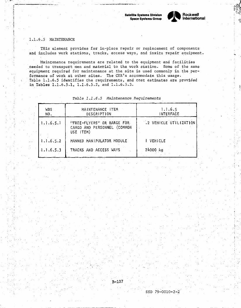
WBSNO.
MAINTENANCE ITEM
DESCRIPTION
1.1.6.5INTERFACE
1.1.6.5.1 "FREE-FLYERS" OR BARGE FOR .2 VEHICLE UTILIZATION
CARGO AND PERSONNEL (COMMON
USE ITEM)
1.1.6.5.2 MANNED MANIPULATOR MODULE 1 VEHICLE
1.1.6.5.3 TRACKS AND ACCESS WAYS 24000 kg
THis element provides for in-place repair or replacement of componentsand includes work stations, tracks, access ways, and insitu repair equipment.
Maintenance requirements are related to the equipment and facilitiesd d 1 t th k 4 S f hnee ed to transport men an mater o e wor station. ome o t e same
equipment required for maintenance at the site is used commonly in the per-formance of work at other sites. The CER's accommodate this usage.Table 1.1.6.5 identifies the requirements, and cost estimates are providedin Tables 1,1.6.5.1,-1.1.6.5.2, and 1.1.6.5.3.
Satellite systems Division Rockwell
Space systems croup InternationalS
Table 1.1.6.5 Maintenance Requirementsyl

^`+ Fi, .,.;5" :, -. - . ..#^?R"'..,,':Nr$45„ik ..3.^ y^^:-T.''"'•"-+.s" •}rc- .r;.*fir _..9...n... . .. -:i m-}1{!pt's+p. _ rniY^+.!n..Yi5°`^
x
}
T,.
7,
tROCKWELL SPS`CR-2 REFERENCE CONFIGURATION
TABLE 1.1.6.5.1 MAINTENANCE = FREE FLYERS
INPUT PARAMETERS INPUT COEFFICIENTS
T= 5000.00000 TF= 1.000000 CDCER= 0.0M= 5000.00000 OCM= 0.0 CDEXP= 0.0
CF= 1.250000 Z1= 0.100000 CICER= 0.005798PHI= 0.950000 Z2= 60..000000 CIEXP= 1.000000
R= 0.020000 Z3= 12.000000DF= 1.000000 Z4= 12.000000 Z5= 0.0
CALCULATED VALUES KG SUM TO 1.1.6.5 $,MI'LLIONSI
CD=CDCER X (T X-DF)XX(CDEXP) X CF 0.0
CLRM=CICER X (M)XX(C IEXP) X CF X TF 36.238
-- #RM =T / M 1.000
00 E = 1.0 + LOG(PHI) / LOG(2.0) 0.926y
CTFU=(CLRM / E)X((#RM X Z1+.5)XX(`E)'- 0.5XX{EJJ 7.530
}}CTB =((CLRM/E)X((#R'M X Z3 + 0.5)XX(E) -0.5XX(E1) ) / Z3 32.098
^ji
CI PS= CTB*Z4/Z2 - 6.420I^
CRCI =CT B X R 0.642}
COEM = O&M OR CTB*Z5/Z2/ENYR 0.0`
COMMENTS -
,^ .:.. _ ... . .;. ,.. :-.': ^ , -_:•.: . . . ., .. ---
--'"-- ^ ac+k^ ..._ a *^aa;,:r ,...mod' :.+ ,, ., _ n .^_^:^ .,.,, ..., ^

PF It
. '3 xv =: rr ^ . m {*+"gM•yam
I
ROCKWELL'SPS CR-2 REFERENCE CONFIGURATIONTABLE 1.1.6.5.2 MANNED MANIPULATOR ` :}
' INPUT PARAMETERS_-
INPUT COEFFICIENTS
T= 3000.00000 TF= 1.000000 CDCER= 0.0N= 3000.00000 OEM= 0.0 CDEXP= 0.0 r
_CF= 1.100000 Z1= 1._000000 CICER= 0.005798PH`I= 0.950000 Z2= 60_.000000 CIEXP= 1.000000
R= 0.020000 7.3= 60.000000E14, DF= 1 .:000000 Z4= 6.0.000000 Z5=.. 0..0
r ,
CALCULATED VALUES KG SUM TO 1.1.6.5 S,MILt10NS
CD=CDCER X (T X DF)XX(CDEXP) X CF 0.0_
CLRM=CIC:ER X (M)XXIC IEXP) X CF X TF 19.133
` #RM' =T / M 1.000
E = 1.0 + LOG( PHI) / LOG(2. 0) --.-_^^0.926
CTFU=(CLRM / E)X((#RM X Z1+.5)XX(E) -0.5XX(E))-` 19.203
CTB =((CLRM/E)X((#RM X Z3 + 0.5)XX(E) -0.5XX(EJ) ) / Z3 15.198
CIPS=CTB*Z4/Z2 15.198
Fi CRCI =CTB X R 0 .304
;;. CCEM OEM OR CTB*Z5/Z2/ENNR 0.0
COMMENTS
N' _._,_ ._._ - - - - mss►._ ._ -.___ _-. - —^ ^C
- ITIp
`s
,
>
_<•e

^Ne^l 'Ftm , °,"•.it "'"°9^'yf-y* `rf"Fn ,.F"fRv^; )?±Trt; ['t'+ar,A^iF^" y'U' r f"" ^?';T:7m*FV*'"°' f" 7' ni. ;vrt' r-r.+2rvn cs4f•_°- _
1. f A . ':
`` tt
.. a - ,.. -f
l
}
,
ROCKWELL SPS CR-2 REFERENCE CONFIGURATIONTABLE — 1.1.6.5.3 TRACKS & ACCESS WAYS
<a
INPUT PARAMETERS INPUT COEFFICIENTS
T= 24000.0000 TF= 1.0000J0 CDCER= 0.0_ M= - 24000.0000 O&M= 0.0 CDEXP= 0.0CF= 1.000000 Z1= 1.000000 CICER= 0.000005
PHI= 1.000000 Z2= 60.000000 CIEXP= 1.000000R= 0.002000 Z3= 60.000000
s1
OF= 1.000000 Z4= 60.000000 Z5= 0.0 p.
' -CALCULATED .VALUES KG SUM TO 1.1.6.5 —S,,MILLIONS
' CD=CDCER X IT X DF)XX(CDEXP) X CF 0.0 t
`f
CLRM=CICER X (M)XX(C IEXP) X CF X TF 0.120
to #RM =T 1.000 — —
, F C E =1.0 + LOG(PHT) / LOGI'2.0) 1.000
CTFU=(CLRM / E)X((#RM X Zl+.5)XX(E) -0.5XX(E)) 0.120
CTB =((CLRM/E)X((#RM X Z3 + 0.5)XX(E) —0.5XX(E)) ) / Z3' 0.120
' CIPS=CTB*Z4/Z2 0.120
t < CRCI _=CTB X R 0.000____ .
CO&M _ O&M OR CTB*Z5/Z2/ENYR 0.0
COMMENTS
' .,. " '1w ,_^-^ aC.a,.sa w ' W;wn.t^ . .. y+t ara ... < Yu^.rt .au- wtr.

w-
Satellite Systems Division RockwellSpace Systems Group top intematlohai ro
1.1.7 SYSTEMS TEST
3
This element includes the hardware, software, and activities required forground-based systems test including qualification tests and other developmenttests involving two or more subsystems or assemblies. It includes the produc-tion, assembly, integration, and checkout of satellite system hardware into afull or partial system test article. It also includes the design, development,and manufacture of special test equipment, test fixtures, and test facilitiesthat are not included in other elements such as ground support facilities.Also included are the planning, documentation, and actual test operations.
Tables 1.1.7.1 and 1.1.7.2 document DDT&E cost estimates respectively forhardware and operations based on individual calculations equal to 50% of the
E:
satellite ICI.
tnp
i 41L
YY
of - '•: -R
A
B-111Y
SSD 79-0010-2-2

. .. -7^ jY.4a.rvs t,.-,.,,^,z.w*ten=,:Fb'C,`*^ ^nr^' ,, _ _ ^ y
f
,.i } .std'
ROCKWELL SPS CR-2 REFERENCE' CONFIGURATIONTABLE 1.1.7.1 SYSTEM GROUND 'TEST HARDWARE
INPUT PARAMETERS INPUT COEFFICIENTS
T= 0.0 TF= 1.000000 CDCER= 0.0M= 0.0` 0 0.0 CDEXP=
_0.0—_
`t C F= 0.0 Z1= 1.000000 CI CFR= 0.0PHI= 1.000000 Z2= 60.000000 CLEXP= 0.0 _- .__-- __- _ - - . -- ------_. .- ---___.
R= 0.0 Z3- 60.000Li00 _ _. _ _ _---- -___ _ ..-
;DF= 1.000000 Z4= 60.000000 Z5= 0.0
CALCULATED VALUES SET SUM TO 1.1.7 S,MILLIONS
CD=CDCER X (T X OFIXX(CDEXP) X CF 2662.711
CLRM=CICER X (M)XX(CIEXP) X CF X TF 0.0
!#RM =T I M 0.0 T
E = 1.0 + LOG(PHI) ! LOG(2.0) 0.0a;
,t CTFU=(CLRM / E)X((#RM X Z1+.5)XX(E) —0.5XX(E)! 0.0
e' t CTB =((CLRM/E)X((#RM X Z3 + 0.5)XX(E) —0.5XX(E)) I l Z3 0.0
- - _CIPS=CTB*Z4/Z2 0.0
R =CT=CTB X R
COCM =' OEM OR CTS*Z5/Z2/ENYR 0.0 aw
COMMENTSOCT:E = 50% OF SATELLITE ICI
.... _ _ .a
=; 4 v a ^. .^ .msµ

`3:r a., .c^^aw Pm c re "^ " e :y. r=rz;rs
x ^ 1
z
i
1 s
ROCKWELL SPS CR-2 REFERENCE CONFIGURATION J j4.s TABL E 1.1.7.2 SYSTEM GROUND TEST OPERATIONS'
INPUT PARAMETERS -- - ^} — —^ l- -- INPUT COEFFICIENTS
T= 0.0 TF= 1.000000 CDCER= 0.0
{M= 0.0 _ OEM= 0.0 CDEXP= 0.0f CF= 0.0 7-1'= 1.000000 CICER= 0.0
PHI= 1.000000 Z2 60.000000 CDEXP= 0.0R= 0.0 Z3= 60.000000DF= 1.000000 Z4= 60.000000 Z5= 0.0
CALCULATED VALUES SET SUM TO 1.1.7 $,MILLIONS
xt CD=CDCER X (T X DF)XX(COEXP) X CF 2662.711
CLRM=CICER X (M)XX(CIEXP) X CF X TF 0.0#RM =— / M 0.0
` N E = 1.0 + LOG(PHI) 2 LOG(.0) 0.0- w- - - _. _ _..
CTFU=(CLRM / E)X((#RM X Z1+.5)XX(E) — 0.5XX{E)1, 0.0'_~v,
CTB =((CLRM/E)X((#RM X Z3 + 0.5)XX(E) —0.5XX(Ed) ) / Z3 0.0
f - Cl PS=CTB*Z4/12 0.0._
CR CI_ = C T B X R^ i_ 0.0
CGEM = OEM OR CTB*Z5/Z2/ENYR 0.0F
i_
'COMMENTS
IDTEE TEST OPS = 50% OF SATELLITE ICI
."s
z

µms'
A
Satellite Systems Division,
e
Rockwell1Space Systems Group International{
t 1.1.8 GROUND SUPPORT EQUIPMENT (GSE)
J
This element includes all ground-based hardware required in support ofhandling, servicing, test, and checkout of the satellite subsystems. It alsoincludes special hardware required for simulations and training.
Costs for design, development, manufacture, acceptance, qualification,and maintenance of the GSE equipment are included. It is recognized thatvarious equipments can serve multipurposes. For example, a developmentalmockup may later serve as a training aid after it has served its originalpurposes. In these instances, the acquisition cost is charged to the originalor first purpose use, and subsequent usage will incur only the recurring opera-tions and maintenance costs.
GSE costs from several launch vehicle, manned spacecraft and unmannedsatellites were analyzed to determine their applicability to SPS GSE require-ments. From these data, a percentage factor was developed which was used toestimate SPS ground support equipment costs.` This factor is expressed by theequation CD = 0.10 (C); where C = DDT&E cost of the satellite system. SeeTable 1.1.8.
f-P;
v
t
r
- B-114
SSD 79-0010-2-2

CTB =((CLRM/E)X((#RM X Z3 + 0.5)XX(E) —0.5XX(E)l ) / Z3
CIPS=CTB*Z4/Z2a,fr., CRCI =CTB X R:
CCEM = O&M OR CTB*Z5/Z2/ENYR
COMMENTSDDT&E GSE = 10% OF SATELLITE DDTEE ABOVE
-ROCKWELL SPS^CR-2 REFERENCE CONFIGURATIONTABLE 1.1.8 GROUND SUPPORT EOUI'PMENT i
x Y=r„
INPUT PARAMETERS INPUT COEFFICIENTS
T= 0.0 TF= 1.000000 COCFR= _0.0M= 0.0 OEM= 0.0 CDEXP= D.0-
CF= 0.0 Z1= 1.000000 CICER= 0.0PHI= 1.000000 Z2= 60.000000 CIEXP= 0.0
R= 0.0 Z3= 60.00OJ00DF`= 1.000000 Z4= 60.000000 Z5= 0.0
x. CALCULATED VALUES SET SUM TO 1.1 $,MILLIONS -^
z CD=CDCER X (T X DF)XX(CDEXP) X CF 721.234
k CLRM=CICER X (M)XX(LIEXP) X CF X TF 0.0
` td #RM = T / M 0.0 u^j N lip
` E =1.0 + LOG(PHI) / LOG(2.01
s-. CTFU=(CLRM / E)X((#RM X Z1+.5)XX(E) — 0.5XX(E)) 0.0

Y^ R k
Satellite Systems Division Rockwell
r Nay
Space Systems Group International
>5
1.1.9 PRECURSOR TEST ARTICLEs
The 335 MW pilot plant precursor test article and operations is includedin this element. It represents the technology verification space system com-bining the energy conversion, interface, and power transmission segments ofthe SPS satellite. The configuration will be constructed by the satelliteconstruction base where the sequence is to build the slip ring/rotary jointhousing structure followed by the interface hub and yoke base plus the 1stbay of the solar array. Slip rings are installed and the solar concerterportion is completed as the yoke (interface) arms are fabricated. The antennaconstruction and maintenance platform is attached to provide facilities forthe antenna fabrication and installation of required power modules. The com--.pleted EOTV/Demo unit is illustrated in Figure 1.1.9.
^—SCB
^
l
..a
_... ._^
..................
Figure 1_.1.9 EOTV Precursor Test Article Y
1 ,
B-116
SSD 79-0010-2-2
..

is
's
t
Satellite Systems Division, , RockwellSpace Systems Group International
1r1.V...L. cwl y rRECURSOR VEHICLE
This element covers the vehicle procurement required to support theintegrated test and demonstration program.
The energy conversion segment of the vehicle consists of primary andsecondary structure, concentrators, solar blankets, switchgear and converters,conductors/insulation, attitude control and information management subsystems.The interface segment includes the primary and secondary structure, mechanisms,conductors/insulation and slip ring brushes.
The precursor power transmission segment will be representative of thefull-up satellite antenna to the extent of using identically available com-ponents for the required power levels of the test article. It will includestructures, transmitter subarrays, power distribution and conditioning, bat-teries, insulation, and phase control elements.
CER's used in this section are the same as those used in the particularelements _:?f earlier satellite sections. DDT&E is, however, a main cost itemin these categories as the systems/subsystems will require substantialdevelopment activities, whereas the other satellite systems/subsystems willcapitalize from this development work.
Cosh estimates for the precursor test article are presented in ther! following tables: i..
Tables SegmentI
1.1.9.1.1 thru 1.1.9.1.8 Energy Conversion
} 1.1.9.1,.9 thru 1.1.9.1.13 Interface
1.1.9.1.14 thru 1.1.9.1.24 Power Transmission
B-117
SSD 79-0010-2-2

r '^^deiR"F ^St`:'`'^-^'7t^`'^i^fflws'^,+K ,'P'.,`ky.gC^'?$ '^7n",?^vY"rY mew-*".'.hvrim ^r `r-;^d, x, -P.y 'f'* ., f^yrppBi-^±3ts^1lR"t^"'.•.*c»
k -.
1ROCKWELL SPS CR-2 REFERENCE CONFIGURATION
TABLE 1.1.9.1.1 PRIMARY STRUCTURE — E.C.
Y,{ INPUT-PARAMETERS INPUT COEFFICIENTS
f..T= 30890.0000 TF= 1.000000 CDCER= 0.023000
i M= 2059.00000 OEM= 0.0 CDEXP= 01800000j CF= 1.000000 Z1= 1.000000 CICER= 0_.000050{ PHI= 1.000000 Z2= 60.000000 CIEXP_= 1.000000
R= 0.0 Z3= 0.0OF= 1.000000 Z4= 60.000000 I5= 0.0
CALCULATED VALUES KG SUM TO 1.1.9.1 _ S•MILLIONS# sv
CD= CDCER—X '(T X OF)XXICDEXP) X CF 89.863
C'LRM=CICER X (M)XX(CIEXP) X CF X TF 0.103
bd #RM =T / M 15.002
co E =1.0 + LOG(PHI) / LOG(2.0) _ :__._,1.000
CT FU= (CLRM / E)X((#RM X Z1+.5)XX(E) — 0.5XX(EI) 1.544
CTB =((CLRM/E)X((#RM X Z3 + 0.5)XX(E) —0.5XX(E)) ) / Z3 0.0
e CiPS=CTB*Z4/Z2 0.0 r
C RC I =CTB X R 0.0-
f CLIEM = OEM OR CTB*Z5/Z2/ENYR 0.0
COMMENTS4
J
9
_
•..... .. . - a. r,.., .. 4 ..: ,. ".4.... !. > } .. ^ .^i . ... .... *J:.}r s.% ^C , . i \^z..... . .. ..v w ,. L^ ...,t . .

_
L
t{
~SPS CR-2 REFERENCE CONFIGURATION
TABLE 1 1.g ROCKWELL
.1.2 SECONDARY STRUCTURE — E.C.
= INPUT PARAMETERS INPUT COEFFICIENTS
T= 14918.0000 TF= 1.000000 COCER=' 0.156000— —M= 5.000000 OEM— 0.0 —CDEXP= 0. 511000
CF= 1.000000 Z1= 1.000000 CI CER= 0.101000PHI= 1.000000 Z2= 60.000000 CDEXP— 0.355000s g ---— — _R= 0.0 Z3= 0.0
DF= 1.000000 Z4= 60.000000 Z5= 0.0
CALCULATED VALUES KG SUM TO 1.1.9.1 39MILLIfONS
CD CDCER X (T X DF)XX(CDEXP) X CF 21.178
CLRM=CICER X (M)XX'(CIEXP) X CF X TF — 0.179
5 #RM =T / M 2983.600
E =1.0 + LOG( PHI) / LOG(2.0) 1.000
CTFU=(CLPM / E)X(—(#RM X Z1+.5)XX(E) —0.5XX(E)) 533.576 -
CTB =((CLRM/E)X((#RM X Z3 + 0.5)XX(E) — 0.5XX(E)) ) / Z3 0.0
K C'IPS=CTB*Z4/Z2____- .---._..
0.0
e= CRCI =CTB X R 0,0
CLCM _ OEM OR CTB*Z5/Z2/ENYR 0.0i
COMMENTS
ry^..
S
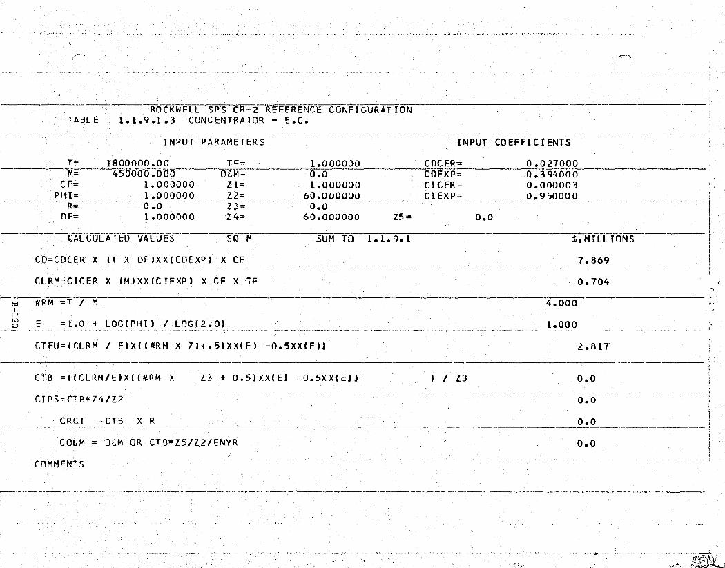
} .t ^ T^!s^'gp^.F'°rix^+P .^., „`^ ; T'4'',y^' ava+n^4Fnn?K v^' ie , — s •ni°.: '"'^" -u. r'P x ..nT F", s* , _ .. 3-
A+`•,Gv:F
^^1.^?
{ ...
ir
t
' -ROCKWELL SPS CR-2 REFERENCE CONFIGURATION -s., TABLE 1.1.9.1.3 CONCENTRATOR — E.C.
' - INPUT PARAMETERS INPUT COEFFICIENTS -
.,, T= 1800000.00 TF= _ 1.000000 CDCER=' 0.027000M- 450000.000 OEM=— 0.0 CDEXP= 0.394000
CF= 1.000000 Z1= 1.000000 CICER= 0.000003PHI= 1.000000 Z2— 60.000000 CDEXP= 0.950000
0.0 Z3= 0.0DF_ 1.000000 Z4= 60.000000 Z5= 0.0
_CALCULATED VALUES SO M SUM TO 1.1.9.1 $,MILLIONSi
CD=CDCER X (T X DF)XX(CDEXP) X CF 7.869
{FF{, - CLRM=CI.CER X (M) XX (C IEXP ) X CF X TF - 0.704
#RM =T / M 4.000
.__o E = 1.0 + LOG(PHI) / LOG(2.0) 1.000
CTFU=(CLRM / E)X((#RM X Z1+.5)XX(E) —0 5XX(E)) 2.817
CTB =((CLRM/E)X((#RM X Z3 + 0.5)XX(E) —0.5XX(E)) ) / Z3 0.0
CI PS=CTB*Z4/Z2 0.0
;. CRC I = CTB X R 0.0 *3CO&M = O&M OR CTB*Z5/Z2/ENYR 0.0
COMMENTSF.
yr }:y-

ROCKWELL SPS CR-2 'REFERENCE CONFIGURATIONTABLE 1.1.9.1.4 SOLAR BLANKET -E.C.
5
__ -INPUT PARAMETERS INPUT COEFFICIENTS_._
T= 900000.000 TF= 1.000000 CDCER= 0.16140_0M = 18750.0000 06.M;= +0.0 CDEXP= 0.394000
CF= 1.000000 Z1= 1.000000 CICER= 0.000067 rPHI= 1.000000 Z2= 60.000000 CIEXP= 1.000000
R- 4.0Z3=_ ._.,
0.0DF= 2.000000 Z4= 60.000000 Z5=- 0.0
CALCULATED VALUE S KG SUM TO .1.1.9.1 t.MILLIONS
CO=CDCER X LT X DF)XX(CDEXP) X CF 47.041
CLRM=CICER X'(M)XX(CIEXP) X CF X TF 1.256
td #RM =T / M0
tom.
E = 1.0 + LOG( PHI / LOG( 2'.0) 1.000
CTFU=(CLR.M / E)X((#RM X Z1+.5)XX(E) -0.5XX(El) 60.300
CT$ =((CLRM/E)X(( #RM X Z3 + 0.5)XX(E) 0.5XX(E)) I / Z3
0.0
^j GIPS=CTB*Z4/Z2 0.0 :.
C`RC I CT B_ X R -^= _-__ 010
CCEM = O&M OR CTB*Z5/Z2/ENYR 0.0
COMMENTS7
3
W
> w
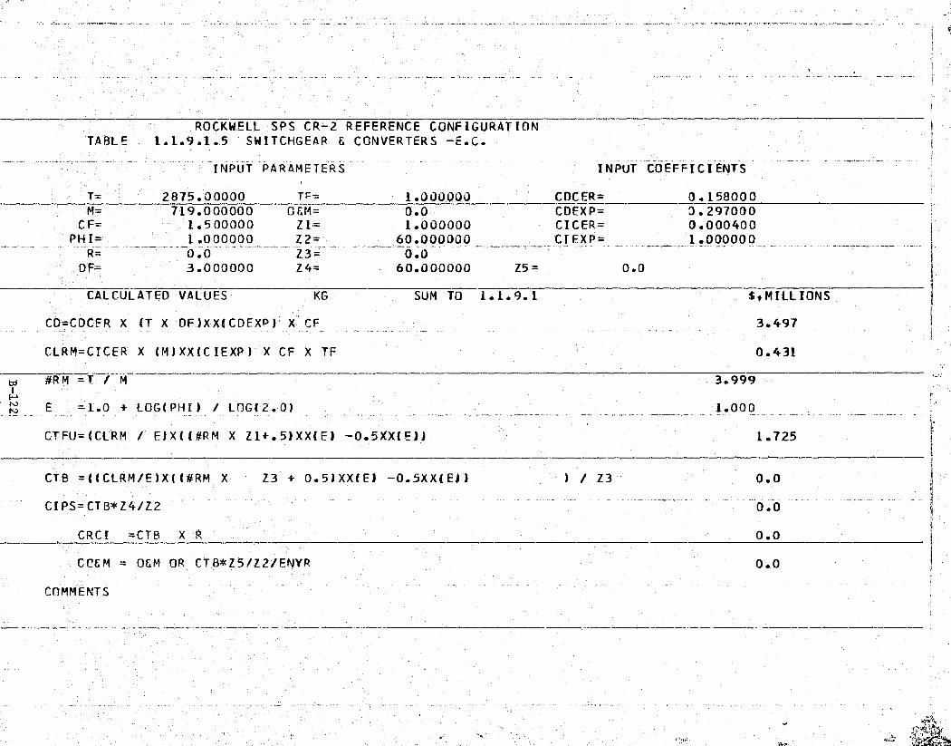
e
j
C r
r
ROCKWELL,SPS CR-2 REFERENCE CONFIGURATIONTABLE 1.1.9.1.5 SWITCHGEAR E CONVERTERS -E.C.
INPUT PARAMETERS INPUT COEFFICIENTS
T=2875.00000 _T_F= 1.000000 CDCER= 0.158000M= 719.000000 OEM= 0.0 CDEXP= 0.297000
[CF= 1.500000 Z1= 1.000000 CDCER= 0.000400
—--' PHI= 1.000000 Z2= 60.000000 CIEXP= 1.000000R= 0.0 Z3= 0.0DF= 3.000000 Z4= 60.000000 t5= 0.0
CALCULATED VALUES KG SUM TO 1.1.9.1 E,MILLIONS
;:' CO=CDCFR X (T X DF_)XX(CDEXP) X CF 3.497^` k
CLRM=CDCER X (M) XX (C IEXP) X CF X TF 0.431
#R M =T / M 3.999i
E =1.0 + LOG( PHI) / LOG(2. 0) 1.0003,,
,x CT FU=(CIRM' 1 E)Xi (#RM X Z1+ 5)XX(E) — 0.5XX(El) 1.725f;
CTB =((CLRM/E)X((#RM X Z3 + 0.5)XX(E) —0.5XX(E)) ) /'Z3 0.0'FGF
CIPS=CTB*Z4/Z2 0.0el
., CRCI = C TB X R 0.0_
CC'EM = OEM OR CTB*Z5/Z2/ENYR
_ --
0.02
< F COMMENTS
',
_irk
v^:
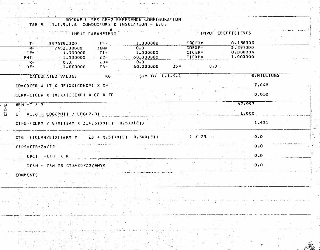
7 ml
-
-k
ROCKWELL SPS CR-2^REFERENCE CONFIGURATIONTABLE- 1.1.9.1.6 CONDUCTORS & INSULATION - E.C.
-INPUT PARAMETERS INPUT COEFFICIENTSj
( T= 357675.0 00 TF= 1.0JOJoO COCER= 0.15800_0M= 7452.00000 O&M= 0.0 CDEXP= 0.297000
CF= 1.000000 Z1= 1.000000 CICER= 0.000004PHI=-1.000000 Z2= 60.000000 CIEXP= 1.000000R- 0.0 Z3= 0.0
DF= 1.000000 Z4= 60.000000 Z5= 0.0
CALCULATED VAUUES v KG SUM TO 1.1.9.1 $,MILLIONS
CD=CDCER-X (T X OF)XX(CDEXP) X CF 7.048
CLRM=CICER X (M)XX(CIEXP) X CF X TF 0.030
WA 47.997
w E = 1.0 + LOG(PHI) / LOG(20) 1.000
CTFU=(CLRM / E)X((#RM X Z1+.5)XXl E1 -0.5XX(E)) 1.431
CTB =((CLRM/E)X[ (#RM X Z3 0.5)XX(E-) -0.5XX(EJ) ) / Z3- 0.0 !'.
`I GIPS=CTB*Z4/Z2-- -" - 0.0
CRCI =CTB X RYerr
0. 0
CCU &M = O&M OR CTB*Z5/Z2/ENYR 0.0
COMMENTS
J ,

^ " ^:. = '" £` s ew ,{r.e ;";a; ^r- ..'' °_. ,'?r K:?<<=+;+q• .: z z. + - ^^;r..,,, .. i . ' v^ —17w7, .w w.;
qA} ..:
4
i
ROCKWELL SPS CR-2 REFFRENCE CONFIGURATIONTABLE 1.1.9.1.7 ACS HARDWARE — E.C.
INPUT PARAMETERS INPUT COEFFICIENTS
T= 283557.000 TF= 0.300000 CDCER= 1.122000M= 1970.00000 OEM= 0.0, CDEXP= 0.190000
C F= 1.000000 Z 1= 1,.000000 CI CER= 0.057000PHI= 1.000000 Z2= 60.000000 CIEXP= 0.729000
R= 0.0 Z3= 0.0DF= 1.000000 Z4= 60.000000 Z5= 0.0
CALCULATED VALUES EKG SUM TO 1.1.9.1 SIMILLIONS
CD=CDCER X (T X DF)XX(CDEXP) X CF 12.190
CLRM=CICER X (M)XX(CIEXP) X CF X TF 4.312r:
#RM =T / M 143.938
E =1.0 + LOG (PHI) / LOG(2. 0) 1.000f'
" CTFU=(CLRM 1 E)X((#RM X 21+.5)XX(E) -0.5XX(E`)) 620.634
CTB =((LLRM</'E)X((#RM X Z3 + 0.5)XX(E) —0.5XX(E)) l / Z3 0.0
cLIPS=CTB*Z4/Z2
:.. _0.0 u
CRCI =CTB X R 0.0
P C06M = OSM OR CTB*Z5/Z2/ENYR 0.0 ,
COMMENTS

2ycr?*
„R."^R°.4q-nInj+°4rnY+rc#'7^"e' 3P('g'l'"'+em m.-. s ^H;?cY,'°° .'!"+y;^.`r'"e rd' F..^ - .. -.
t^^^i•yes
ROCKWELL SPS CR-2 REFERENCE CONFIGURATIONTABLE 1.1.9.1.8 SL IPR INGS — PRECURSOR`
INPUT PARAMETERS- -.__
INPUT COEFFICIENTS-t,
T= 43000._000.0 TF= 1.000000 CDCER= 0.156000M= 10750.0000 0&M=
_0.0 CDEXP= 0.511000
CF= 1.500000 Z1= 1.000000 CICER= 0.000764PHI= 1.000000 Z2= 60.000000 CIEXP= 0.950000
R= 0.0 Z3= 0.0
r;DF= 1.000000 Z4= 60.000000 Z5= 0.0
F CALCULATED VALUES KG SUM TO 1.1.9.1 StMILLIONS
CD=CDCER X (T X DF)XX(CDEXP) X CF 54.565
CLRM=CICER X (M)XX(CIEXP) X CF X TF 7.745
#RM =T / M 4.000
Ln E = 1.0 + LOG( PHI) / LOG( 2.0) 1.000
CTFU=(CLRM / E)X((#RM X Z1+.5)XX(E) --0.5XX(E11 30.980 ,^
CTB =((CLRM/E)X(( #RM X Z3 + 0.5)XX(E) —0.5XX(E-)) 1 / Z3 0.0
CIPS=CTB*Z4/Z2 0.0
CRC_I =CTB X R 0.0
CC&M _ 0&M OR CTB*Z5/ZZ/ENYR 0.0
.---.:._.._COMMENTS ..

,.rzr. a w A--,-•: .-r ,.. .,fie rf ...-o a
f$v-.,{,.m°^^iC'S}:n#"a"si ^.•.'„iS; m^Se'}T^:^r?da µNT: . -aSr'h!f'a'?..^ `v?M^„- T•9 f' %""i S'Fy. .. .. Y _ _
k
.' ~ROCKWFLL SPS CR-2 REFERENCE CONFIGURATION 1TABLE 1.1.9.1.9 PRIMARY STRUCTURE - INTERFACE
' INPUT PARAMETERS INPUT COEFFICIENTS f
_ `T=120000.000 TF= 1.000000 CDCER= 0.023000M= 200.00000.0 O&M= 0.0 CDEXP= 0.800000
CF= 1.000000 Z1= 1.000000 CICER= 0.000050.. PHI= 1.000000 Z2= 60.000000 CDEXP= 1.000000
R= 0.0 Z3= 0.0DF= 0.-500000 Z4= 60.000000 Z5= 0.0
EKGCALCULATED VALUES SUM TO 1.1.9.1 $,MILLIONS
CD=CDCER X (T X DF)XX(CDEXP) X CF 152.844
CLRM=CDCER X (M)XX(C IEXP) X CF X TF 0.010
,`. rn E =1.0 + LOG(PHI) / LOG(2.0) 1.000
CTFU=(CLRM / E)X((#RM X Z1+.5)XX(E) -0.5XX('E)) 6.000
CTB =((CLRM/E)X((#RM X Z3 + 0.5)XX(E) -0.5XX(E)) ) / Z3 0.0{_
CIPS-CTB*Z4/Z2 _0.0
CRCI =CTB X R 0.0
° CC&M = O&M OR CTB*Z5/Z2/ENYR 0.0 i
' -COMMENTS
}' _r
;^! t
e .. R. a t^'1 . •^
i- - .^ -.. ,."h ..: \ - ^ _ _ .. .^^NY `.,.s. ..„.. .. ^ .^hd...t .1s ....., Sa r^r. _,.. kv ^ •.:a ..s.s ,i._. -.

_
ROCKWELL SPS CR-2 REFERENCE CONFIGURATIONTABLE 1.1.9.1.10 SECONDARY STRUCTURE - INTERFACE
r
INPUT PARAMETERS — INPUT C13EFFICIENTS1
T= 15500.000 0 TF= 0.007300 CDC ER= 0. 156000M= 5.000000 OEM= 0.0 CDEXP= 0.511000
CF= 1.000000 Z1= 1.000000 CICER= 0.101000PHI- 1.`000000Z2= 60.000000 CIEXP= 0.355000
R= 0.0_Z
3= - 0.0DF= 0.500000 Z4= 60.000000 Z5= 0.0 a
CALCULATED VALUES KG SUM TO 1.1.9.1 S.MILLIONS
CO=CDCER X (T X DF)XX(CDEXP) X CF 15.155
CLRM=CICER "X (M)XX(CIEXP) X CF X TF 0.001
3100.0 00
., —E = 1.0 _-+ LOG( PHI) / LOG(2.0) - _ .: :.._ _ 1.000 {
CTFU=(CLRM / E)X(( #RM X Z1+.5)XX(E) —0.5'X.X(E)) 4.047
CTB',=((CLRM/E)X((#RM X Z3 + 0.5)XX(E) —0.5XX(E)) ) / Z3 0.0
CI PS= CTB*Z4/Z2 0.0
CRCI =CTB X R 0.0
. COSM' = OEM OR CTB*Z5/Z2/ENYR 0.0
COMMENTS-.--
k
- ..,,,,,.. - ,,,rho . :..,x .âc .'sx ^.c a r a.. ,....:a.,,.'t,S
..

"' 1 e','a°^"^^`. sue, -'e. ^„.!a,_: ^`+m :+;!rtn yn ;r ';}^Ai. ^-.z ;,,' ..f;-.'^.,^,^-grer _ _ :^^,n^ _•....r. _. _ _ ..,ems ,_. T" f,-
t
^r
e
ti.
ROCKWELL SPS LR-2 REFERENCE CONFIGURATION' TABLE 1.1.9.1.11 MECHANISMS - INTERFACE
F -INPUT PARAMETERS INPUT COEFFICIENTS
T= 391000.000 TF= 1.000000 CDCER= 0.156000_N= 391.000000 OEM= 0.0 CDEXP= 0.511000
rCF= 1.000000 Z1= 1.000000 CICER= 0.000764
' PHI= 1.000000 Z2= 60.000000 CIEXP= 0.950000R= 0.0 Z3= 0.0
DF 0.500000 Z4= 60.000000 Z5= 0.0
CALCULATED VALUES KG SUM TO 1.1.9.1 S,MIfLIONS
CD=CDCER X (T X DF)XX(CDEXP) X CE 78.868t
CLRM=CICER X (M)XX(C'IEXP) X CF X TF 0.222
#R m = t M 1000.000
w E =1.0 + LOG(PHI) / _LOG(2.0) 1.000
CTFU= (CLRM / E)X(( #RM X Z1+.5)XX(E) -0.5XX(E)) 221.647
:C CTB =((CLRM/E)X((#RM X Z3 0.5)XX(E) -0.5XX(E)) l / Z3
- CIPS =CTB*Z4/Z2 0.0
CRCI =CTB X R 0.0
CC&M _ O&M OR CTB*Z5/Z2/ENYR 0.0
COMMENTS
{1'

,> r
grti^ nl"vw^RY«+^'RF^'"'•°t ^^ .-n•.,^-,f,,. ..,r-z: ^t^r^+?* =Tf'-°,^-.y^-^ x - ..
rc^^ fL1
I
l i -t
, i _
i
u
- ROCKWELL SPS CR-2 REFERENCE CONFIGURATIONTABLE 1.1.9.1.12 CONDUCTORS E INSULATION
INPUT PARAMETERS INPUT COEFFICIENTS
T= 52 790.0000 TF= 1. 000000 C DC ER= 0 . 15900 0M= 1650.00000 OEM= 0.0 CDEXP= 0.297000
CF= 1.000000 Z1= 1.000000 CICER= 0.000004PHI= 1.000000 Z2= 60.000000 CIEXP= 1.000000
R= 0.0 Z3= 0.0DF=- 1.000000 Z4= 60.000000 Z5= 0.0
CALCULATED VALUES Y KG SUM TO 1.1.9.1 StMILLIONS
CD=CDCER X (T X DF)XX(CDEXP) X CF 3.993
CLRM=CICER X (M)XX(CIEXP) X CF X TF 0.007
#RM =T / Mi 31.994
a E' = 1.0 + LOG( PHI) / LOG( 2.01 1.000
CTFU= (CLRM / E)X((#RM X Z1+.5)XX(E) -0.5XX(E)1 0.211
CTB = (_(CLRM/E)X(d#RM X Z3 + 0.5)XX(E) -0.5XX(E)) ) / Z3 0.0
CIPS =CTB*Z4/Z2 _0.0
' CRCI =CTB X R 0.0
CCBM O&M OR CTB*Z5/Z2/ENYR 0.0
COMMENTS
_ -f
e,
n 1
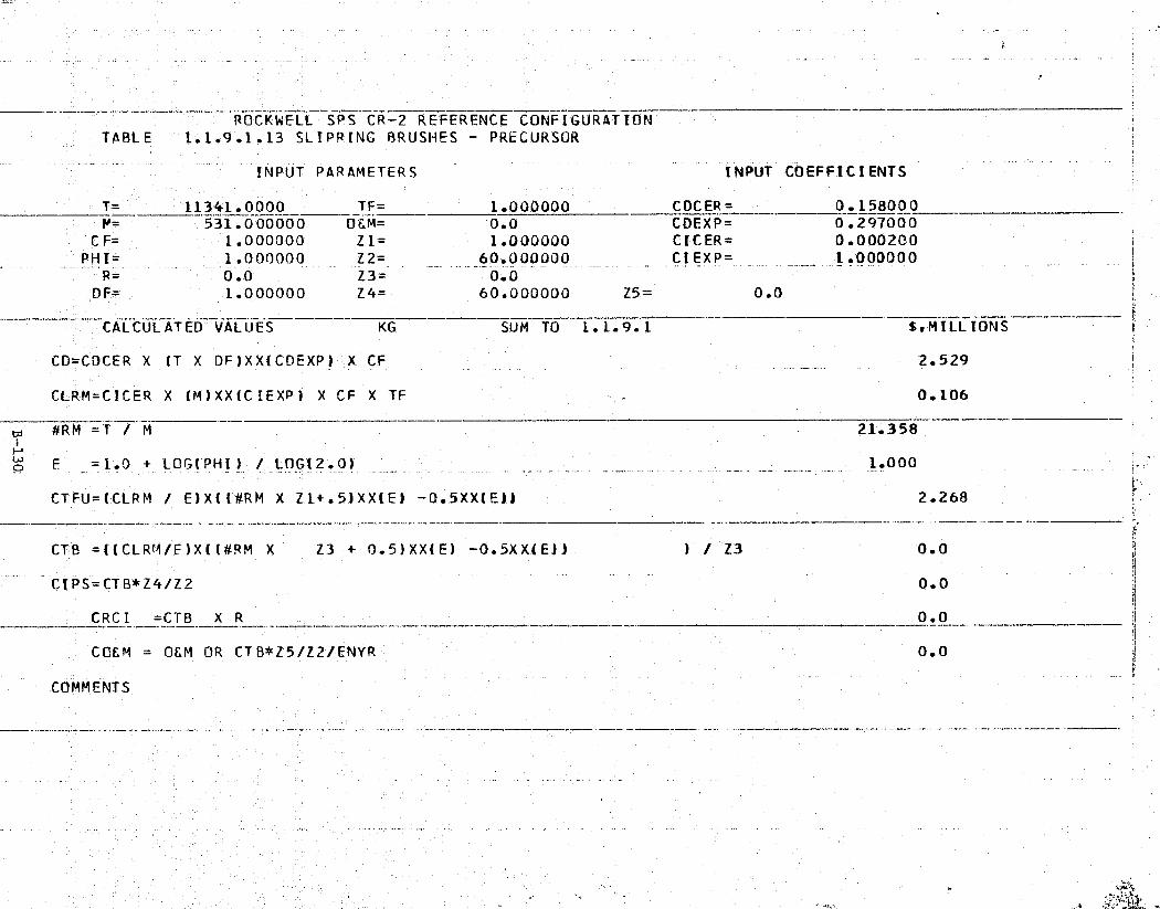
.. r'i'.R { `y...!yR'h.:^"'^'ri'rvi:it k ^'I,h^'t :'Y `..-„T,e+-1 .i ^i^"'rf't:t° _,^:•f ,rte .^4:.-a ,. -..;`-?P€',' { .. {n +ZynWC^' ^_Y.T LTIr.Yn-'%p
s - Tk.j
ROCKWELL SPS CR-2 REFERENCE CONFIGURATION - k
TABLE- 1.1.9.1.13 SL I PR ING BRUSHES - PRECURSOR `4
INPUT PARAMETERS INPUT COEF FTC TENTS
t T= 11341.0000_ __TF= 1.000000 CDCER= 0.158000N= 531.000000 OLM= 0.0 CDEXP=' 0.297000
CF= 1.000000 Z1= 1.000000 CICER= 0.000200PHI= 1.000000 Z2= 60.000000 =...____ ..CIEXP _1.000000
R= -0.0 Z3= --0.0I DF= 1.000000 Z4= 60.000000 Z5= 0.0 F
CALCULATED VALUES ^^^ KG -^ SUM TO 1.1.9.1 1,MILLIONS
CD=CDCER X (T X DF)XX(CDEXP) X CF _: _ _ 2.529p!'
CLRM=CICER X (M)XX(CIEXP) X CF X TF 0.106
w #RM^=T / M - -_^ 21.358
^ Y
o E =1-.0 + LOG(PHI )' / LOG(2.0) 1.000_..__ .:-_ . ..
CTFU=(CLRM / E)X((#RM X Z1+.5)XX(E) -0.5XX(E)1 2.268
,. CTB =((CLRM/E)X((#RM X Z3 + 0.5)XX(E) -0.5XX(E)) ) / Z3 0.0
CI'PS=CTB*Z4/Z2_
0.0
.° CRCI =CTB X R 0.0 I
CO&M = O&M OR CTB*Z5/Z2/ENYR - 0.0
COMMENTS{]
jIi.
.I'A
V
a44

p_Eyvy sS»:. qu gr.(° r.e.x ygSR'N.'. -m,...o. -'4..fe^;; ,ww+r °`^Ff -.R. e,^ -3'4
ROCKWELL SPS CR-2 REFERENCE CONFIGURATIONTABLE 1.1.9.1.14 PRIMARY STRUCTURE - POWER TRANS i
INPUT PARAMETERS INPUT COEFFICIENTS, i .a
T= 5000.00000— TF= 1.000000 CDCER= _0.023000___M= 1250.00000 0&M=^
0.0 COEXP= 0.800000CF=, 1.000000 Z1= 1.000000 CIC'ER= 0.000050
PHI= 1.000000 Z2= 60.OU0000 CIEXP= 1.000000R = 0.0
—Z3= 0.0
4 OF= 1.000000 Z4= 60.000000 Z5= 0.0
CALCULATED VALUES _
KG SUM TO 1.1.9.1 —^^,MILLi'ONS
CO=CDCER X (T X DF)XX(CDEXP) X CF 20.9362
'. CLRM=CICER X (M)XX(C IEXP) X CF X TF 0.063 ;c
iF4 E =1.0 + LOG(PHI) / LOG(2.0) 1.000
I' CTFU=(CLRM ! E)X((#RM X Z1+.5)XX(E) — 0.5XX(E)) 0.250
CTB =((CLRM/E)X((#RM X Z3 '+ 0.5)XX(E) —0..5XX(E)) ) / Z3 0.0
'CIPS=CTB*Z4/Z2 0.0
CAR C I = CT B X R 0.0
_CC&M = 0&M" OR CTB*Z5/Z2-/ENYR 0.0.
COMMENTS
J
.t 'rQy41 S

Rp^+•ri*.-r^"^y. vi!',at41'!!Yr i+6F*-»If,/'°'%tr^"'1 +a""q" IJrNr,..+'.xt a1T .^.'x""y^T'"_"^w._
a
S
k,
ROCKWELL SPS'CR-2 REFERENCE CONFIGURATIONTABLE', 1-.1.9.1.15 SECONDARY STRUCTURE — POWER TRANS
INPUT PARAMETERS INPUT COEFFICIENTS
T= 9750.00000 TF= 0.007300 CDCER= 0.156000{ M= 5.000000 O M= 0.0 CDEXP= 0.511000
CF= 1.000000 Z1= 1.000000 CICER= 0.101000PH 1= 1.000000 Z2= 60.000000 CI EXP= 0.355000
0.0 Z3-z- 00DF= 1.000000 Z4= 60.000000 Z5= 0.0
CALCULATED VALUES KG SUM TO 1.1.9.1 5. MILL IONS
CD=CDCER X IT X DF)XX(CDEXP) X- CF 17.041z
C.LRM=CICER X (M)XX4CIEXP) X CF X TF 0.001
ci #RM =T :/ M' 1950.000
N E =1.0 + LOG(PIAI) / LOG(2.0) 1.000
CTFU=(CLRM / E)X'((#RM X. Z1+.5)XX(E) -0.5XX(E)') 2.546k
"r
CTB =((CLRM/E)X(I #RM X Z3 + 0.5)XX(E) — 0.5XX(E)) ) / Z3 0.0
y
i
CIPS=CTB*Z4/Z2 0.0
CRCI =CTB X R 0.0
COEM _ OEM OR CTB*Z5/Z2/ENYR 0.0
COMMENTS

^».,,. a
A
•r
w
ROCKWFLL SPS CR-2 REFERENCE CONFIGURATIONTABLE _ 1.1.9.1.16 TRANSMITTER. SUBARRAYS - KLYSTRONS ICI
INPUT PARAMETERS INPUT COEFFICIENTS
T=- 34617.0000 TF= 1.000070 CDCER= 0.0 ?M= 118.800003 OEM= 0.0 CDEXP= 0.0
CF= 1.250000 Z1= 1.000000 CICER= 0.003270PHI= 1.000000 Z2= 60.000000 CTEXP= 1.000000
R= 0.0 Z3= 0.0DF= 1.000000 Z4= 60.000000 Z5= 0.0
CALCULATED VALUES SQ M SUM TO 1.1.9.1 E`,MILLIONS ^a
CD=CDCER X (T X DF)XX(CDEXP) X CF 0.0
vt^:k CLRM=CICER X (M) XX (CIEXP) X CF X TF 0.486
#RM =T / M 29.1.389ww E =10 + LOG(PHI) / LOG(2.0) 1.000
P5
'^K CTFU=(CLRM ! E)X( (#RM X Z1+.5)XX(E) -0.5XX(E)) 141.497
° CTB =((CLRM/E)X((#RM X Z3 + 0.5)XX(E) -0.5XX(E)) ^Z3) / 0.0 r
CIPS=CTB'*Z4/Z2 _._0.0
4 CRC I_ =CTB X R 0 .0
CCS,M = OEM OR CTB*Z5/Z2/ENYR 0.0
" 1111
COMMENTS
r
- , ''e,{w
^„` ^ 4r'" t 1.1 .li
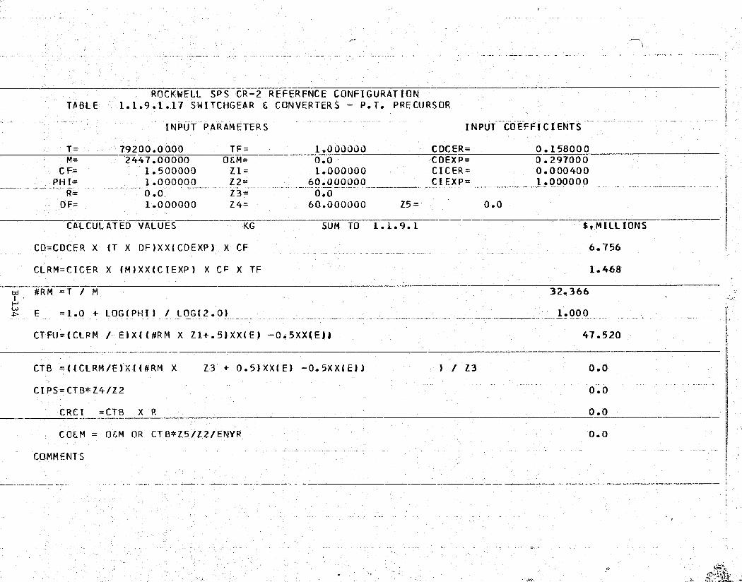
5y 1t `'^
ax
' ROCKWELL SPS CR-2 REFERENCE CONFIGURATIONTABLE 1.1.9.1.17 SWITCHGEAR E CONVERTERS - P.T. PRECORSOR
i. INPUT PARAMETERS INPUT COEFFICIENT$
T= 792 00.0000 T_F = 1.000000 CDCER.= 0.158000M= 2447.00000 OEM= 0.0 CDEXP= 0.297000
CF= 1.500000 Z1= 1.000000 CICER= 0,000400 rPHI= 1.000000 Z2= 60.000000 CIEXP= 1.000000
R= 00 Z3= 0.0DF= 1.000000 Z4= 60.000000 Z5= 0.0
CALCULATED VALUES KG SUM TO 1.1.9.1 $,MILLION'S
Y, CD=CDCER X (T X DF)XX(CDEXP) X CF 6.756
CLRM=CICER X (M)XX(CIEXP) X CF X TF 1.468
( w #RM =T / M 32.366
E =1.0 + LOG(PHI) / LOG(2.0) 1.000
CTFU=(CLRM / E)X((#RM X Z1+.5)XX(E) -0.5XX(E)) 47.520t
`. CTB =((CLRM/E)'X((#RM X Z3 + 0.5)XX(E) -0.5XX(E)) ) / Z3 0.0
CIPS='CTB*Z4/Z2-
0.0-
CRCI =CTB X
-
0.0T
CCEM =A06M OR CTB*Z5/Z2/ENYR 0.0
COMMENTS_
t
ey
r
A
Of
,
3
a... .. . iov. ._ ... .-s ^., _. ..l .. . .. ..i i'....G . w - ,L. .^ •wAa..E iYt ..,a A ,sa .... Y... v ,.ev^.i
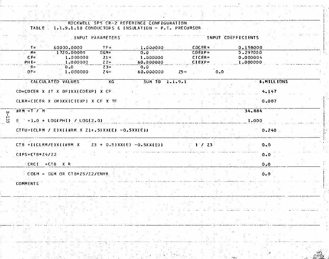
'-3^"!?4^y„iM .E.'Y„.-.w'*e°^"Cg i.'+,a'2csA?"_ _ £a i'X R' - ^' - _ .. » w t _ .-.. •:y;yay.r,. .—a.x 9!F
d^
S
yk
ROCKWELL ~CRSPS-2 REFERENCE CONFIGURATIONTABLE 1.1.9.1.18 CONDUCTORS & INSULATION — P.T. PRECURSOR.
INPUT PARAMETERS INPUT COEFFICIENTS'
T= 60000.0000 TF= 1.-0OU000 CDCFR= 0.1_5_8000-- M= 1720.00000 O&M= 0.0 CDEXP= 3.297000
{ CF= 1.000000 Z1= 1.000000 CICER= 0.000004PHI= _1.000000 Z2= 60.000000 CIEXP= 1.000000
R= 0.0 Z3= 0.0
:- DF= 1.000000 Z4= 60.000000 Z5= 0.0
-i'- CALCULATED VALUES ^ KG SUM TO 1.1.9.1 StMILLIONS
CD=CDCER X (T DF)XX(CDEXP) X CF_X 4.147
CLRM=CICER X (M )XX (C IEXP) X CF X TF 0.007
j'. td #R M =T / M + 34.884
E-- =1.0 + LOG(PHII / LOG(2.0) 1.000.'
d. . CTFU=(CLRM / E)X1(#RM X Z1+.5)XX(E) —0.5XX(E)) 0.240 a
,. CTB =((CLRM /E)X((#RM X Z3 + 0.5)XX(E) —0.5XX(E)) V/ Z3 0.0
CIPS=£TB*Z43 Z2 0.0
CRCI =CTB X R 0 . 0
CC&M = 0&M OR CTB*Z5/Z2/ENYR 0.0
A(
COMMENTSF
r
{
'
w

:' '1'f"9Pt,F _.t F _'%?."p:°TR^.'Tt;°fi'^'ir " l,v...ax'I-'.E t ^.y per. ^r}•c T - ... ._ .. - + ^. , .. ,. .,
K r
t
ROCKWELL SPS CR-2 REFERENCE CONFIGURATION` TABLE 1.1.9.1.19 BATTERIES — P.T. PRECURSOR
INPUT PARAMETERS INPUT COEFFICIENTS
T— 800_0.00_000 TF= 1.000000 CDCER= 0.037000M= 50.000000 OEM= 0.0 CDEXP= 0.734000 —
CF= 1.000000 Z1= 1.000000 CICER= 0.028000PHI= 1.000000 Z2= 60.000000 CIEXP= 0.241000
R.= 0.0 Z3= 0.0DF= 1.000000 Z4= 60.000000 Z5- 0.0
CALCULATED VALUES KG SUM TO 1.1.9.1 $,MILLIONS
CD=000ER X (T X DF)XX(COEXP) X CF 27.106 c
CLRM=CICER X (M)XX(CIEXP) X CF X TF 0.072
#RM_=T / M 160.000 —^ 1i
'— —° E =1.0 + LOG (PHI) / LOG(2-0) _ __. ... -;_.:.__...-. --_ ^ _ - __-1.000
a` CTFU=(CLRM / E)X(`(#RM X Z1+.5)XX(E)'- 0.5XX(E)) 11.501
CTB =((CLRM/E)X((#RM X Z3 + 0.5)XX(F) —0.5XX(E.)) ) / Z3 0.0 a'
,i:I
CIPS=CTB*Z4/Z2 0.0
CRC =CTB X R
COEM = O&M OR CTB*Z5/Z2/ENYR_ 0.0 r
COMMENTS
;1 w
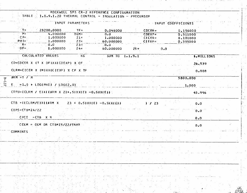
CF'r^?.2F'PF1-fea"!f'.!.-..'n"Xyq. •pp...±F 'T'q/o°.P'x .J.. 7'r"_3 ^R=S°°^ 5 'T'S 'h .. ^. f. -rol y.. T.. .... `llTAa
t
- ROCKWELL -SPS CR-2 REFERFNCE CONFIGURATIONTABLE 1.1.9.1.20 THERMAL CONTROL - INSULATION - PRECURSOR
INPUT PARAMETERS INPUT COEFFICIENTS
' T= 23200. 0000 TF= 0.048000 CDCE R = 0.15 600_0_N= 4.000000 O&M= 0.0 CDEXP= 0.511000
CF= 1.000000 Z1= 1.000000 CICER= 0.101000PHI= 1.000000 Z2= 60.000000 CI EXP= 0.355000
DF= 1.000000 Z4= 60.000000 Z5= 0.0_
CALCULATED VALUES KG SUM TO 1.1.9.1 $,MILLIONS
` CD=CDCER X (T X DF)XX(CDEXP) X CF 26.539
, CLRM=CICER X (M)XX(CIEXP) X CF X TF 0:008
5800.000
E = 1.0 + LOG(PHI) / LOG( 2.0) 1.000
CTFU=(CLRM / E)X((#RM X Z1+.5)XX(E) -0.5XX(E)1 45.996
CTB =((CLRM/E)X((#RM X Z3 + 0.5)XX(E) -0.5XX(E)) ) / Z3 0.0_ CIPS=CTB*Z4/Z2 0 ..0
CRCI =CTB X R 0.0
CCEM = OEM OR CTB' Z5/Z2/ENYR 0.0
COMMENTS
,r
., . ... - .. _ .. . .. i... •.. _ .. "'=";• .. r. .. ,. .. YFS -Qt

^T.
}
ROCKWELL SPS CR-2 -REFERENCE CONFIGURATIONTABLE 1.1..9.1.21 REFERENCE FREQUENCY GENERATOR -' PRECURSOR
INPUT PARAMETERS INPUT COEFFICIENTS
T= 1.000000 TF= 1.000000 CDCER= 0.500000^f M= 1.000000 OEM= 0.0 CDEXP= 1.000000
CF= 1.000000 Z1= 1.000000 CICER- 0.100000PHI= 1.000000 Z2= 60.00UOOO CIEXP= 1.000000
R- 0.0 Z3=T 0.0DF= 1.000000 Z4= 60.000000 Z5= 0.0
CALCULATED VALUES SET SUM TO 1.1 .9.1 SiMILL'IONS
CO=CDCER X (T X DF)XX(CDEXP) X CF 0.500
f CLRM=CICER X (M)XX(CIEXP) X CF X TF 0.100
,€ #RM = T M 1.000
., w E =1.0 + LOG(PHI) / LOG(2.0) _ _ 1.000f
g` ` CTFU=(CLRM / E)X(I#RM X Z1+.5)XX(E)" 0.5XX(E) 1 0.100

A Y5R°^"!`'? "`"P4:?!"?R!"f`f"i .^Yr^ tr'7vrm ri ' .c l.'r.w.Te °aP:. -_ i I7# ;^r.' -g+, -t _ ,_.. - _. A a ..si < .aw.
;. ROCKWELL SPS CIR 2 REFERENCE CONFIGURATION aTABLE 1.1.9..1.22 DIST. SYSTEM, COAXIAL CABLE {
INPUT PARAMETERS INPUT COEFFICIENTS
T= 8613.00000 TF= 1.000000 CDCER= 0.0000_30t; M= 26,1.000000 O&M= 0.0 COEXP= 1.000000
CF= 1.000000 Z1= 1.000000 CICER= 0.000060PHI= 1.000000 Z2= 60.000000 CIEXP= 1.000000
` R= 0 .0 Z 3 = 0.0DF= 1.000000 Z4= 60.000000 25= 0.0 -
—CALCULATED VALUES M SUM TO 1.1.9.1 S,MILLIONS
CD=CDCER X (T X DF)XX(CDEXP) X CF 0.258
CLRM=CICER X (M)XX(CIEXP) X CF X TF 0.016
#RM =T / M 33.000 a
_E =1.0 + LOG(PHI) / L.OG(2.0) 1.000_h
CTFU=(CLRM / E)X((#RM X Z1+.5)XX(E) -0.5XX(E1) 0.517
CTB =((CLRM/E)X((#RM X Z3 + 0.5)XX(E) —0.5XX(E)1 ) / Z3 0.0
CIPS=CTB*Z4/Z2 _0.0
F,.CRCI =CTB X R 0 .0
CC&M = OEM OR CTB*Z5/Z2 `/ENYR 0.0 a
COMMENTS
k
a
r
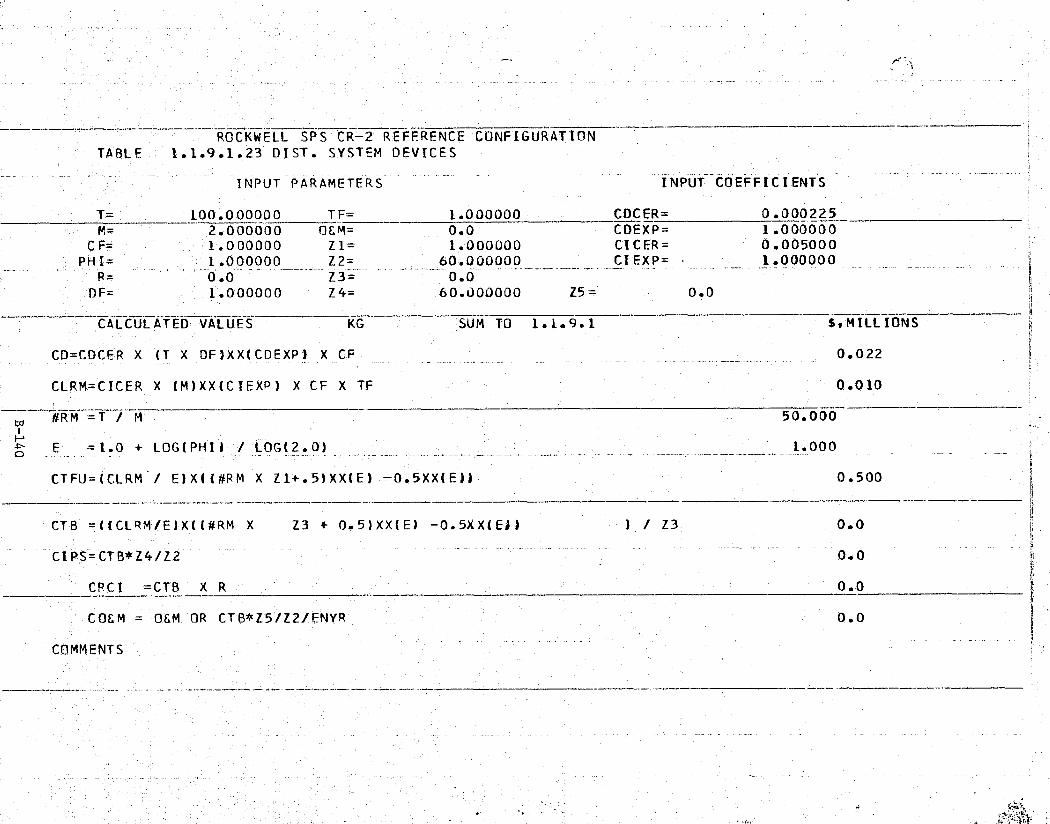
ROCKWELL SPS CR-2 REFERENCE CONFIGURATIONTABLE 1.1.9.1.23 DIST. SYSTEM DEVICES
' INPUT PARAMETERS INPUT COEFFICIENTS
T= 100.000000 TF= 1.000000 CDCER= 0.000225M= --- 2.000000 OEM= v 0.0 CDEXP= 1.000000
CF= 1.000000 Z1= 1.000000 CICER= 0.005000PHI= 1.000000 Z2= 60.000OOU _ CIEXP= 1.000000
- --- Z3 -=- - - - - ___- ., _
r, DF= 1.000000 Z4= 60.000000 Z5= 0.0,
CALCULATED VALUES KG SUM TO 1.1.9.1 $,MILLIONS
tCD=CDCER X (T X OF)XX(CDEXP! X CF 0.022 €
^Y( CLRM=CICER X (M)XX(CIEXP) X CF X TF 0.010
#RM =T / M 50.000
E =1.0 + LOG(PHI) / LOG(2.0) 1.000
CTFU=(CLRM / E)X((#RM X Z1+.5)XX(E) -0.5XX(E)! 0.500
CTB =((CLRM/E)X((#RM X Z3 + 0.5)XX(E) -0.5XX(Ef) ) / Z3 0.01^
_ .. _..CI PS=CTB*Z4/Z2, 0.0 .<
;. CPC I = CTB X R 0.0
COEM' = OEM OR CTB*Z'5/Z2/ENYR 0.0
" COMMENTS
a

b1 s x 4 . ^^c'•^.^,*c!^?.n-^rp ^ ^-r'.'^^ `. ry ^' ^-^' r-..,Ae'.x•-, ,^;.,., _ ,. ,.,;eY,. _ _ N .:,,,yr,.,z,... _ .. z
I^^
ROCKWELL SPS CR- 22^REFERENCE CONFIGURATIONkTABLE 1.1.9.1.24 TRANSMITTER SUBARRAYS — KLYSTRONS DDTEE
INPUT PARAMETERS —INPUT COEFFICIENTS
T= 282_500.00_0 TF= 1.000000 CDCER= 0.20_5000y— M= 282500.000 OEM= 0.0 — CDEXP= 0.507000
CF= 1.250000 Z1= 1.000000 CDCER= 0.0PHI= 1.000000 Z2= 60.000000 CIEXP= 0.0
R= 0.0 Z3= 0.0DF= 1.000000 Z4= 60.000000 Z5= 0.0
CALCULATED VALUES KW SUM TO 1.1.9.1 f,MILL[ONS
CD=CDCER X (T X DF)XX(CDEXP) X CF 148.707
CLRM=CDCER X (M)XX(CIEXP) X CF X TF 0.0
#RM =T 1 M 1.000i
E =1.0 + L0GiPHI) / L0G(2.0) 1.000
CTFU=(CLRM / E)X((#RM X Z1+.5)XX(E) -0.5XX(Ell 0.0
CTB =((CLRM/E)X((#RM X Z3 + 0.5)XX(E) —0.5XX(E)) ) / Z3 0.0
CIPS=CTB*Z4/Z2 0.0
CRCI =CTB X R 0.0
COEM = 06M OR CTB*Z5/Z2/ENYR 0.0 s
:. COMMENTS
t
r
4
i

Satellite Systems Division RockwellI1Space Systems Group International
ttr, 1.1.9.2 EOTV PRECURSOR OPERATIONS
This element includes the necessary vehicle operations (user chargeper flight including payload integration) required to support the precursortest activity.
Cost estimates are presented in Table 1.1.9.2.
t
if
a
B-142I
a_.

k 4^}?°^ " "YRf'.`.^^Y,`L°rh^1.^'•'a?M i^^^Y^;',k4.`.^i1'_°?"R7„`'...`^i r'Rf ,R , y,r47miw .yrg..+. .._"9 i v
1^'t,
.. r ,. -
T
4iq^
_.ROCKWELL.• S 0 R—CR=2 REFERENCE. CONFIGURATION - -TABLE 1.1.9.2 COTV PRECURSOR OPERATIONS
INPUT PARAMETERS INPUT COEFFICIENTS a ,
T= 1.00_0000 TF= 1.000000 CDLER= 0.0M-^ 1.000000 OEM= 0.0 CDEXP= O.G
CF= 1.000000 Z1= 1.000000 CILER= 0.630000- PHI= 1.000000 — Z2= 60.000000— — CIEXP.= 1.000000-
R= 0.0 Z3= 0,.0rT DF=- 1.000000 Z4= 60.000000 Z5= 0.0
CALCULATED VALUES FLIGHT SUM TO 1.1.9 SiMILLIONS
CD=CDCER X (T X DF)XX(CDEXP)'X CF 0.0
` CLRM=CICER X (M)XX(CIEXP) X CF X TF 0.630
1.000
_._ w E =1.0 + LOG( PHI) / LOG(2. 0) _ 1.000
CTFU-(CLRM / E)X((#RM X Z1+.5)XX(E) —0.5'XX(E)l 0.630
r.
tCTB =((CLRM/E)X((#RM X Z3 + 0.5)XX(E) —0.5XX(E)) ) / Z3 0..0
CIPS=CTB*Z4/Z2 0.0 11'
CRCI _=CTB X R — -- -- — ----- 0.0 — ---r
CQCM = OEM OR CTB*Z5/Z2/ENYR 0.0 z,
COMMENTS
F
.. rr'

^,,:.If,
aIs
Satellite Systems Division „Rockwell iSpace Systems Group 1 International 's
1.2 SPACE CONSTRUCTION AND SUPPORT
This element includes all hardware and activities required to assemble,checkout, operate, and maintain the satellite system. Included are spacestations, construction facilities, support facilities and equipment, andmanpower operations.
The Rockwell reference configuration is used as a baseline for the devel-opment of a satellite construction scenario and construction systems/equipment.Precursor operations incident to the establishment of orbital support facilitieswere identified and the satellite construction sequences and procedures weredeveloped.
The overall scenario leading to establishment of satellite constructionsupport facilities and to satellite construction is shown in Figure 1.2-1.Initial operations entail use of the growth shuttle and the shuttle derivedHLLV for transporting men and material to LEO for the precursor phase of theprogram. Subsequently, during the 30 year satellite construction phase, thesps HLLV will become the primary transportation element for delivering con-struction mass to LEO and the shuttle HLLV will be used for personnel transferto LEO.
6
a
Y
SATELLITEGEQ CONSTRUCTION.'
n
PTOV EOTV
SCa
TRANSITTO GEO
\L ^`' —4
FLE EOTV` q^`i^ONST, IOTV OPERATIONS
CON57.
t \FIXTURE !.^ }^
SCB
INITIAL LEO BASE
ORBITERDELIVEREDET
Figure 1.2-1. Overall Satellite Construction Scenario
The initial step in satellite precursor operations is establishment of aLEO base as shown in the lower left of the figure
.
. Crew and power modules aretransported to LEO by shuttle derivatives and assembled. When thebase isfully operational, shuttle external tanks are delivered and mated to form
B-144
SSD 79-0010-2-2

Satellite Systems DivisionSpace Systems Group
r
gv
7
a^
construction fixtures for the Satellite Construction Base (SCB) construction.The figure shows a completed SCB. Since the more economical SPS HLLV will notbe available during this phase of the program, and since overall plans specifyan EOTV test article, it is possible that only the center section of the SCB
;. would be constructed initially. This trough would be used to fabricate thepilot plant EOTV test article with an end-mounted antenna.. After proof ofconcept, the remainder of the SCB would be completed along with sufficientEOTVs to support initial satellite construction operations. The SCB will thenbe transferred to GEO, using one or more EOTVs for propulsion and attitudecontrol. Upon reaching GEO, satellite construction would commence, with thelogistics support as shown at the right of the figure.
The energy conversion segment of the satellite structure is constructedby the integrated SCB in a single pass. Satellite longerons of a length suf-ficient to connect the triangular frames of the slip ring support structureare fabricated, followed by construction of the slip ring interface structure,and the first satellite structure frame. The SCB then proceeds to fabricate/install the remainder of the satellite structure and solar converter. Con-struction of the slip rings, and yoke (interface) takes place concurrentlyusing free flying fabrication facilities to support this building process(Figure 1.2-2).
\ \ -
f/ ^ \ f.^ r ^1r ^\v ^r.
Figure 1.2-2. Antenna Supporting Structure Assembly Sequence
This section addresses the facilities/equipment, and operations requiredto support SPS work, crew, and operational requirements during the SPS program,Section 1.2.1 deals with the construction facilities; and Section 1.2.2 dealswith the work and crew requirements at LEO. Section 1.2.3 covers the require-ments in GEO to support operations and maintenance of the satellite.
B-145
SSD 79-0010-2-2

Satellite systems Division Rockwell
Space systems Group International
1.2.1 CONSTRUCTION FACILITIES
This element includes the facilities, equipment, and operations requiredto assemble and checkout the satellite system. Included are crew life supportfacilities, the central control facility, fabrication and assembly facilities,cargo depots, and operations.
ki'• ^ a
ss
'liI^iJ
The satellites are constructed in GEO, each satellite being constructedat its designated longitudinal location. The SCB supports construction oftwo satellites per year during the program and serves as headquarters foroperations and activities necessary to construct such items as the satellite,antenna interface, antenna, and EOTV. The SCB is constructed of compositesand consists of the fabrication fixture, construction equipment, and basesupport facilities.
The construction fixture is in the form of three troughs, correspondingto the satellite configuration, which permits simultaneous construction ofall troughs. Additional structural members are located in the middle troughand are used as support for the rotary joint/antenna structure. Figure 1.2=-3illustrates the construction base and shows the location of work and crewfacilities.
The SCB fabrication fixture assembly and support equipment, and the crew/''work 'modules on the base are itemized in Table 1.2.1. SCB modules used to
` support the crew/work activities are of various internal configurations toaccommodate specific functional requirements. All modules are of the samediameter and most are of the same length, their dimensions and mass being in
;. compliance with space transportation system constraints. The modules arelocated on the fab fixture along with the assembly and support equipment.
Y` The Airlock Docking Module (ADM) is used to join the other base modulesto provide docking accommodations for other elements such as crew transportmodules, consumables logistics modules (CL1 and intra-base logistics vehicles,
,. and for transfer of personnel and equipment between different pressure environ-ments. The Crew Habitability Module (CHM) provides stateroom and personalhygiene facilities, and support systems for 24 to 30 crew members. The Base
^., Management Module (BMM) houses the operational communications and controlsystems for the base. Power Modules (PM) are photovoltaic power systems
i4 (collectors, converters, conditioners, and storage) which support all basepower requirements. Pressurized Storage Modules (PSM) provide an area forstorage and workshop accommodations. Shielding"(SHD) is provided in selectedmodules to protect against solar flare radiation. The Crew Support Module (SM)provides the -alley, recreational and medical facilities and support subsystems.
- Work support, crew, and operational requirements are discussed in the followingparagraphs.
1.2.1.1 WORK SUPPORT FACILITIES - SCB
k This element includes work facilities and equipment required for satelliteassembly and checkout. Included are beam fabricators,
jigs, installation and deployment equipment, and cargo storage depots. Exclud-
R
ed are the facilitiesrelated to crew support.
B-146
SSD 79-0010-2-2
^^.r:.» ^-*^rcro.e.,.d.^^.^....®....,.,...,,..m.. ... •_-..--o-,.,...m.- .,are.,w.,r ....ate .., ,.^.-3 L-x..,,... ,.. s: ..,.^„ ,.. ,. w ,,. K... ,., .. .. . ..

I
LL 11J 1L1J 1 1 L- LJI I 1 1
^
..
A u
11 I,
1, B ^^ u
nn n
71
ISbd
16 If 21 ,1
xit
n n n > no n-
_co
a ,^ B 77 ji ^ :, ^ A ,
An EQUIPMENT & LOCATION DESCRIPTIONS
A N
it
d _'
®
L
_ ^^_
OTHRU 11 LONGITUDINALTRIBEAM FABRICATION PODSA
a v
Fo
^. _ \ 12 THRU 27 CROSSBEAM FABRICATION PODS c °a9
'rp~o
1
28 THRU 33 REFLECTOR DISPENSING AREASi;
• tIv
- n.Oil
P-rsi_
34 THRU 36 SOLAR BLANKET DISPENSING AREAS
1 .< (19 37 CENTRAL HABITAT-LANDING & WAREHOUSINGVIEW A-A
_VIEW B•B cD 038 THRU 39 AUX HAB/COMPLEX BLANKET FACILITIES m
Figure 1.2--3. Satellite Construction Base (SCB) to
'( 1
• a
^,tom-
,ter^'^t
^.,

TFIR W11-1-
Satellite Systems Division Rockwell
Space Systems Group 1 International>ti
tTable 1.2.1 Total Space Construction and
Support Equipment Requirements P
SPACECONSTRUCTION
BASEWORK CREW
SYSTEM SUPPORT SUPPORTDESCRIPTION ABBREVIATION FACILITIES FACILITIES
BASE MODULES:
AIRLOCK DOCKING MODULE ADM 17 5CREW HABITABILITY MODULE CHM 17CONSUMABLES LOGISTICS MODULE CLM 9BASE MANAGEMENT MODULE BMM 4CREW SUPPORT MODULE/EVA CSM/EVAPOWER MODULE PM 4PRESSURIZED STORAGE MODULE PSM 4SHIELDING SHD 8CREW SUPPORT MODULE CSM 3
CREW REQUIREMENTS 317 AVG.504 'PEAK
ASSEMBLY AND SUPPORT EQUIPMENT:
BEAM MACHINES 198BEAM MACHINE-CASSETTES 3618CABLE ATTACHMENT MACHINES 72REMOTE MANIPULATOR 110SOLAR BLANKET DISPENSER MACHINE 72SOLAR BLANKET CASSETTES 5760REFLECTOR DISPENSER MACHINES 6REFLECTOR CASSETTES 360
-CABLE/CATENARY DISPENSERS 84ANTENNA PANEL INSTALL. EQUIP. IGANTRY/CRANES 12CARGO STORAGE DEPOT 4
SCB FAB FIXTURE 1
;
-i
s
SCB modules used mainly in the support of construction operations includea total of 17 ADMs, 4 Brls, 4 PMs, and 4 PSMs. The CERs used for these moduleswere based on Rockwell Space Station studies.
All SPS unique fabrication/orbital construction assembly and supportN' equipment is included in this section (reference Table 1.2.1). Included are4 tt}e tribeam fabricators, cable attachment machines, solar blanket/concentrator
dispensing machines, and antenna panel installation equipment. Each oftheserequirements were analyzed for equipment usage, replacement factors, 0&M, andprojected costs based on engineering estimates of design characteristics. Theitems of assembly and support equipment and base modules remain on the SCB asit transfers from one construction site to another. Cost estimates for theseitems are presented in Tables 1.2.1.1.1 through 1.2.1.1.17.
1.2.1.2 CREW SUPPORT FACILITIES - SCB
This element includes the facilities and equipment required for the life-support and well-being of the crew members. Included are living quarters,central control facilities, recreation facilities, and health facilities of
,- the satellite construction base.
B-148
^zSSD 79-0010-2-2

Satellite Systems Division RockwellSpace Systems Group „International1 4
r
r
4
Crew support facilities include 5 ADMs, 17 CHMs, 9 CLMs, 8 SLDs, and3 CSMs. Detail cost sheets on these components are identified in Tables -1..2.1.2.1 through 1.2.1,2.5.
FT`e 1.2.1.3 OPERATIONS
This element includes the planning, development, and conduct of opera-tions at the construction facility. It includes both the direct and supportpersonnel-and the expendable maintenance supplies for satellite assembly andcheckout. f
This element has been divided into the subelements of operations (Table1.2.1.3.1) and consumables (Table 1.2.1.3.2) where an average crew of 317persons is required to man the SCB over the normal six month fabricationperiod. A crew rotation is scheduled for every three months. -Consumablesfor the SCB are calculated at 3.6 kg/person/day.
r
t
a
B-149
"' SSD 79-0010-2-2

,-..ate^ ..,.;P?'"'gf"'gym 7'• : ,t .
t
ROCKWELL. SPS. ,CR-2 REFERENCE CONFIGURATIONTABLE 1.2. 1.1..1 BEAM MACHINE
--INPUT PARAMETERS INPUT COEFFICIENTS
T= 1.000000TF= 1.000000 CD C ER= 2 .000 000M= 1.000000 0.594000 CDEXP= •1.000000
CF= 1.000000 Z1= 198.000000 CICER= 0.700000PHI=0.920000 Z2= 60.000000 CIEXP= 1.000000s
5R= .. _ .
0.0 --_ _ _
Z3= 198.000000OF= 1.000000 Z4= 198.000000 Z5= 0.0
CALCULATED VALUES SUM TO 1.2.1.1 S,MILLIONS
CD=CDCER X (T X DF)XX(CDEXP) X CF 2.000
'.I CLRM=CICER X (M)XX(CIEXP) X CF X T 0.700a
#RM =T / H 1.000n ^ ^
o E =1.0 + LOG(PHI`) / LOG(2.0) 0.880 r
k'it
CTFU=(CLRM' / E)X((#RM X Z1+.5)XX(E) —0.5XX(E)) 83.150
CTB =((CLRM /E)X((#RM X Z3 + 0.5)XX(E) —0.5XX(E)! ) / Z3 0.420
r' CIPS=CTB*Z4/Z2 1.386
,t' CRCI —CTB X R 0.0
COEM = O&M OR CTB*Z5/Z2/ENYR 0.594 t
e COMMENTSr^
: L AJ Aaik
Ni

^
i +^^4.0'' t ps"w!4°""„"a..,'t"y',^""exF`^. . ,__,^' "'^^T =)•. -*^;4'• ., >d. .u+ sr:a - .. q -.. 1 ,.-,.Je^,yioy '. ..^,. c_^'fi.^*,y,.a:Y,Yi»^a
¢ 11
y I`C[7
ROCKWELL "SPS CR-2 REFERENCE CONFIGURATIONTABLE 1.2.1.1.2 BEAM MACHINE CASSETTES
INPUT PARAMETERS INPUT COEFFICIENTS
T= 1.000000 TF= 1.000000 CD_C_ER= 0._80_000 0_1.000000 0&M= 0.090450 - CDEXP= 1.000000 ir CF= 1.000000 Z1= 1206.00000 CICER-- 0.008200
PHI= 0.,950000 Z2= 60.000000 CDEXP= 1.000000R= 0.066667
__..Z3 = 3618.00000 T -- - --- --
DF= 1.000000 Z4= 1206.00000 Z5= 0.0
CALCULATED VALU E S ----^^- SUM TO 1.2.1.1 $. M ILL IONS
CD=CDCER X (T X 0F)XX(CDEXP) X CF 0.800
r CLRM=CICER X (M)XX(CIEXP) X CF X TF 0.008
#RM =T / M 1.000wLn E =1.0 + LOG( PHI) / LOG( 2.0) 0.926
CTFU=(CLRM / E)X((#RM X Z1+.5)XX(E) -0.5XX(E)1 6.315
CTB =((CLRM/E)X((#RM X Z3 + 05)XX(E) -0.5XX(E)) ) I Z3 0.005
CIPS=CTB*Z4/Z2 0.097
CRC =CTB X RI 0..000
I CCEM O&M OR CTB*Z5/Z2/ENYR 00090
COMMENTS
I.
^ rr^.

' Y` i is ._ , fi'!li*e} C. :_.^w+'TC..:Y' }s , M _ . -
r-
4
ROCKWELL SPS CR-2 REFERENCE CONFIGURATIONTABLE 1.2-1-1.3 CABLE ATTACHMENT MACHINE
INPUT PARAMETERS INPUT COEFFICIENTS
T= 1.000000TF= _1.000000 CDCER= 4.300000--M= 1.000000 O&M= 0.144000 COEXP== 1.000000
CF- 1.000000 Z1= 72.000000 CICER= 0.500000PHI= 0.950000 Z2= 60.000000 CIEXP= 1.000000
R= 0.0 Z3= —72.000000
DF= 1.000000 Z4= 72.000000 Z5= 0.0
z CALCULATED VALUE"_—_
SUM TO 1.2.1.1 ^` S, MILL IONS
CO=CDCER X (T X DF)XX(CDEXP) X CF 4.300e
CLRM=CICER X (M)XXICIEXP) X CF X TF 0.500
#R M =T I Pit —1.000
K N,
N E = 1.0 + LOG(PHI) /-LOG(2.0) 0.926 '=
CTFU=(CLRM I E)Xl(#RM X Z1+.5)XX(E) — 0.5XX(E)) 28.228 t,
CT'B =((CLRM/E)X(( #RM X Z3 + 0.5)XX(E) —0.5XX(E)) ) / Z3 0.392^ _= CIPS=CTB*Z4/Z_2 0.470 a
' CRC I=CTB X R 0.0
COEM O&M OR CTB*Z5/Z2/ENYR 0.144 g 3t;
COMMENTS
n
f_
all
a' 1

771
Y^>nxrrri}#'"fP. 't,'x^4i "Sq`".r[tN°Yt`.r'!,°;+.93wif^"^^w.,s`Rh ,.^'f:7%'`t :.:.YT^.,'+"^'^T'M!;'.^': ♦^. TKi+ J •/n=e ♦. ... _ _ y _
ROCKWELL SPS CR-2 REFERENCE CONFIGURATION _ *-„ TABLE 1.2.1.1.4 REMOTE MANIPULATOR
' INPUT PARAMETERS INPUT COEFFICIENTS
T"= 1. 000000 T F= 1.000000 CIC ER= 6. 8 80000_M= 1.000000 REM= 1.925000 CDEXP= _ __ ^1.000000 --^
CF= 1.000000 Z1= 55.000000 CICER= 1.200000k; PHI= 0.980000 Z2= 60.000000 CTEXP= 1.000000_--
R= 0.033333 Z3=-
110.000000DF= 1.000000 Z4= 55.000000 Z5= 0.0
CALCULATFD VALUES —^ ^'! SUM T0^1.2.Z.1 $,MILLIONS
z CD=CDCER X (T X DF)XX(CDEXP) X CF 6.880
CLRM=CICER X (M)XX(CIEXP) X CF X TF 1.200
td #R M __T...^ — M_._,.^_ - ---
1.000
w E = 1.0 + LOG( PHI 3 LOG(2.0) 0.971.,.:
- CTFU=(CLRM / E)X((#RM X Zl+.5)XX(E) -0.5XX(E1) 60.390
CTB =((CLRM/E)X((#RM X Z3 + 0.5)XX(E) —0.5XX(E)) ) / Z3 1.077
F' CIPS=CTB#Z4/Z2 0.987
CRC I = CTB X R 0.036
COEM = OEM OR CTB*Z5/Z2/ENYR 1.925
COMMENTS
r
i
♦ . . ..1 ._: .."°, .':J.Cr
u^eGF . ..... ..+G.....yK.Ii _. `kr ..Y ...- iv ^.-., ,_w-....r._ .

k ,,,. ^^*,^-:x5`^+zn*'^vtsrw. ,„F:a«t`;m.m^,{""'$•^'x":".,s z.;.i' ^n': `f°^,""l9"^"m°"^,'^.- .,.:..a^ m ,. ..,.^ ^.. fg - _ „"-'M'^i'y^.,..,.,.a^i^a.,i=^izc'^cq
1
ROCKWELL ^SPS^CR-2 REFERENCE CONFIGURATION -^^—^^^^TABLE 1.2.1`.1.5 BLANKET DISPENSER MACHINE
r; INPUT PARAMETERS INPUT COEFFICIENTS
! T= 1.000000 TF= 1.000000 CDCER=_ _ _M= — 1.000000 O&M=^ 0.380000 —CDEXP=
_4.00_00001.000000
CF= 1.000000 Z1= 72.000000 CICER= 0.400000PH t= 0.980000 Z2= 60.00000U CI EXP= 1.000000
— R= 0.0Z3=
72.000000DF= 1.000000 Z4= 72.000000 Z5= 0.0
CALCULATED VALUES— SUM TO 1.2.1.1 $•MILLIONS
CD=CDCER X (T X DF)XX(CDEXP) X CF 4.000
CLRM=CICER X (M)XX(CIEXP) X CF X TF 0.400
#RM =T / M — -- 1.000r _Ln E =1.0 + LOG(PHI) / LOG(2.0) 0.971 1'..t
` CTFU=(CLRM / E)X((#RM X Z2+.5)XX(E) —0.5XX(E)1 26.154
CTB =((CLRM/E)X((#RM X Z3 + 0.5)XX(E) —0.5XX(E)) ) / Z3 0.3.63
CIPS=CTB*Z4/Z2 0.436
CRCI =CTB X R 0.0 l
CO&M = O&M OR CTB*Z5'/Z2/ENYR 0.180
COMMENTS
n

„u: ^:.Ft^;c'"-Vf,'.a't`xF . R;;`°:'.",^!^.`°.rC.>"• ^n •;zfT . ^ G :°4.. _... .. , • t -.•
t
^*t
s
ROCKWELL SPS CR-2 REFERENCE CONFIGURATION --yTABLE 1.2.1.1.6 SOLAR BLANKET CASSETTES
INPUT PARAMETERS INPUT COEFFICIENTSi
T= 1.000000 TF= 1.000000 CDCER= 0.900000IJ
M- 1.000000 OEM= 0.115200 COEXP= 1.000000CF= 1.000000 Z1= 1440.00000 CI.CER= 0.010000
PHI= 0.950000Z2= 60.000000 CI EXP= 1.000000f - -- -- R_ .- -- 0.066667..
Z3- .
°5760.00000-OF= 1.000000 Z4= 2880.00000 Z5= 0.0
s" CALCULATED VALUES SUN) TO 1.2.1.1 $,MIL*LIONS
CD=CDCER X (T X DF)XX(CDEXP • ) X CF 0.800
f : CLRM=CICEFR X (M)XX(CIEXP) X CF X TF 0.010
Fs ai #R M = T M^ 1.000r
^y. Ln E =1.0 + LOGI PH;I) / LOG( 2.0) 0.926I a ..:G
CTFU=(CLRM / E)X((#RM X Z1+.5)XX(E) —0.5XX(E).! 9.076 .
-r
CTB =((CLRM/E)X((#RM X Z3 + 0.5)XXtE) —0..5XXIEJ) ! / Z3 0.006
CIPS=CTB*Z4/Z2 0.273
CRCI =CTB X R 0.000
COCM O&M OR CTB*Z5/Z2/F_NYR 0.115
_._ COMMENTS
, O... .. h ., .. ..

rti
ROCKWELL SPS'CR-2 REFERENCE CGNFLGURATIONTABLE 1.2.1.1.7 REFLECTOR DISPENSER MACHINE
f INPUT PARAMETERS INPUT COEFFICIENTS
T= _1.000000 TF= 1.000000 CDCER= 6.00_000_0_M= 1.000000 OEM= 0.048000 CDEXP= 1.000000
CF= 1.000000 Z1= 6.000000 CICER= 0.800000PHI= 0.980000 Z2= 60.000000 CIEXP= 1.000000
0.0 -- 6.000000DF= 1.000000 Z4= 6.000000 Z5= 0.0
CALCULATED VALUES T SUN TO 1.2.1.1 $,'MILL IONS
CD=CDCFR X (T X OF)XX(CDEXP) X-CF 6 000
CLRM=CICER X (M)XX(CIEXP) X CF X TF 0.8001
#RM =T / M 1.000
rn E =1.0 + LOG (PHI) / LOG(2 .0) 0.971
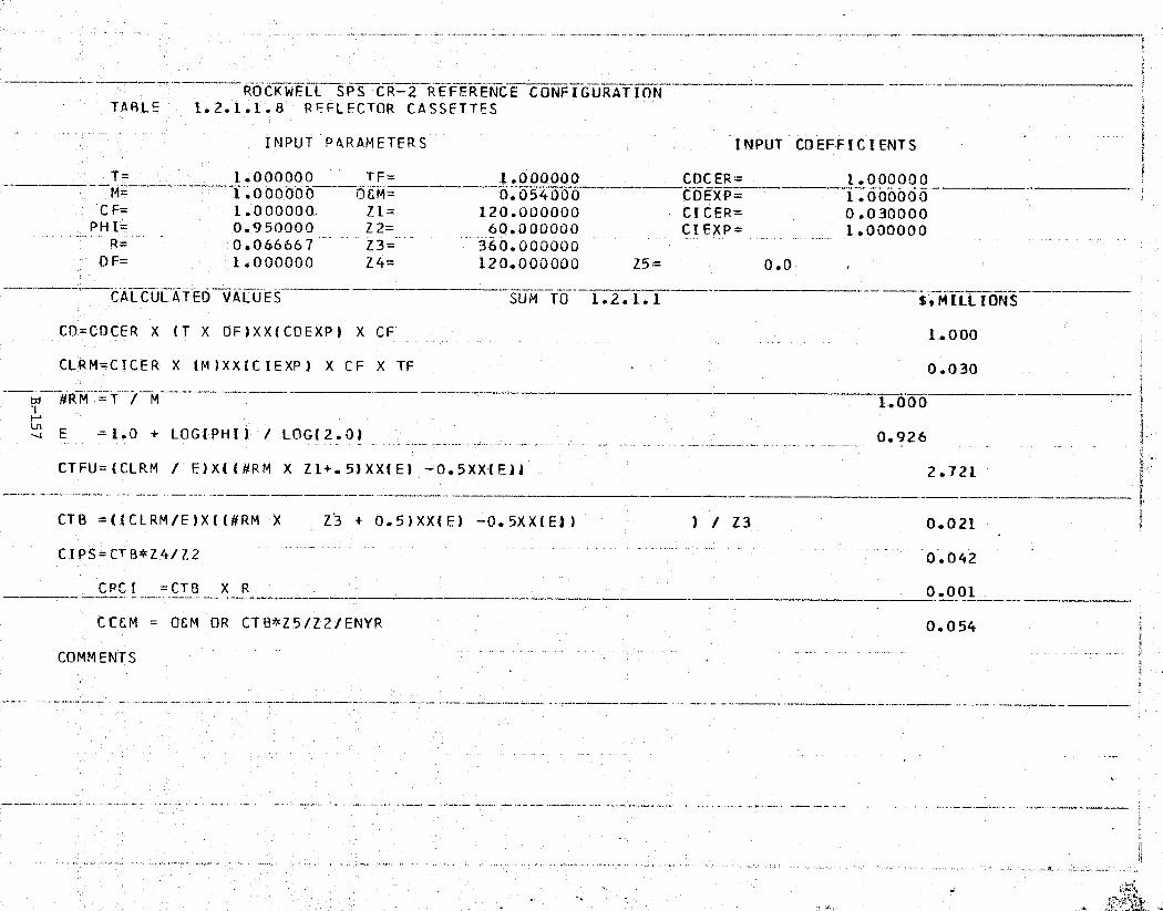
iY 'l T .R.'.,g;:'iM'r"`s`;'^"e!A'.°-^*".,: ;;.. ,-'^`,' .rn,^ X3x: =+nr,.^;`.",^.... } •a.-mss ,r, .F'.o'^r'^.,
ru^
.... .. ^'.' ,x^ _ " ,. .,,• .. ..... cT ''h^'" y'°'
e'^
V,
^t.
-- -ROCKWELLL SPS CR-2 —REFERENCE CONFIGURATIONTABLE 1.2.1.1.8 REFLECTOR CASSETTES $ J.
INPUT PARAMETERS INPUT COEFFICIENTSc
T— 1.000000 TF =—
1.000000 CDCER= 1 .000000 siVIM— __^, •.— T 1.000000 OEM= 0.054000 CDEXP= 1.000000
4.' CF= 1.00000.0. ZL= 120.000000 CICER= 0.030000PHI= 0.950000 Z2= 60.000000 CIEXP= 1.000000_ R = 0.066667 Z3=._ 360.000000
DF= 1.000000 Z4= 120.000000 Z5= 0.0rk.
, CALCULATED VALUES— —.
-SUM TO 1. 2.1..T f,MLLIIONS
CD=CDCER X (T X DF)XX(COEXP) X CF 1.000
CLRM=CICER X (M )XXIC IEXP) X CF X TF 0.030
t^ #RM_ =—T_^M.t - 1.000
¢:. v E' = 1.0 + LOG(PHI) / LOG(20) 0.926
CTFU=(CLRM / E)X(C#RM X Z1+.5)XX(E) -0.5XX(EIJ 2.721k:
CTB =((CLRM/E)X((#RM X Z3 + 0.5)XX(E) —0.5XX(E)) ) / Z3 0.021ri
CIPS=CTB*Z4/Z2 0.042
CRCI =CTB X R 0 .001
= O&M OR CTB*Z5/Z2/ENYR_CCCM 0.054
a COMMENTS
,.., z

r{
ROCKWELL 'SPS^CR-2 P^REFERENCE CONFIGURATIONTABLE 1.2.1.1.9 CABLE/CATENARY DISPENSER MACHINES f
INPUT PARAMETERS INPUT COEFFICIENTS
T=1.000000 TF= 1.000000 CDCER= 2.200000_.__.M_ ___4___..--1..00000
.0 OGM_0.168000
_CDEXP=
_1.000000
CF= 1.000000 Z1= 84.000000 CLCER= 0.300000PHI= 0.980000 Z2= 60.000000 CIEXP= 1.000000 !
R= 0.0 l Z3= 84.000000DF= 1.000000 Z4= 84.000000 Z5= 0.0
CALCULATED VALUES SUM TO 1.2. 1.1 $, M ILL IONS
CD=CDCER X (T X DF)XX(CDEXPI X CF 2.200
CLR.M=CICER X (M)XX(CIEXP) X CF X TF 0.300
# R M =T / M 1.0 00
'00 E =1.0 + LOG(PHI) / LOG(2.0) 0.971
CTFU=(CLRM l E)X((#RM X Z1+.5)XX(E) -0.5XX(E)) 22.7864
r CTB =((CLRM/E)X((#RM X Z3 + 0.5)XX(E) — 0.5XX(E)) ) / Z3 0.271^.
_ y
CIPc=(TB*Z4'/Z2 0.380
CRCI =CTB X R 0.0
CC&M = 0&M OR CTB*Z5/Z21ENYR 0.168
COMMENTS

I ru
ROCKWELL SPS CR-2 REFERENCE CONFIGURATIONTABLE 1.2.1.1.10 ANTENNA PANEL INS. EQPT.
INPUT PARAMETERS INPUT COEFFICIENTS
T= 1.000000 TF= 1.000000 CDCER= 600.000000M= 1.000000 O&M= 6.755000 CDEXP= 1.000000
C F= 1.000000 Zl= 1.000000 CICER= 200.000000
PHI= 0.980000 Z2= 60.UOOOOO CIEXP= 1.000000R= 0.0 Z3= 1.000000
DF= 0.133333 Z4= 1.000000 Z5= 0.0
CALCULATED VALUES SET SvMILLIONSSUM TO 1.2.1.1
CD=CDCER X (T X DF)XX(CDEXP) X CF 80.000
k , IRCLRM=CICER X (M)XX(ClEXP) X CF X TF 200.000
itt,L
1.000
- E - =1.0 + LOGiPHI, ) - / LOG .(2.0), ^0.971
CTFU=(CLPM E)X((#RM X Zl+.5)XX(E) -0.5XX(E)) 200.272
CTB =((CLRM/E)X(I#RM X Z3 0.5)XX(E) -0.5XX(EJJ Z3 200.272
CIPS=CTB*Z4/Z2 3.338
CRC I =CTB X R 0.0
COEM OEM OR CTB*Z5/Z2/ENYR 6.755
COMMENTS
zx-

qRV 'f G {p/ X 5jS b#F e g k .. a . [°:r „s^,a' m ro f? . # °nn r Rs
~^ - "ROCKWELL SPS CR-- 2 REFERFNCE CONFIGURATIONTABLE 1.2.1.1 .11 GANTRY/CRANES
INPUT PARAMETERS INPUT COEFFICIENTS
T-1.000000 TF 1.000.00_0 CDCER= 17.000000M_..u,_ __.. ^_.1..000000_ Y -OEM=_ —0.6 70000^^--CDEXP= 1.000000
CF= 1.000000 Zl= 12.000000 CICER= 8.000000PHI= 0.950000 Z2= 60.000U00 CIEXP= 1.000000
R=_ ...
--0.0 _.
_ Z3= 12.000000DF= 0.800000 Z4= 12.000000 Z5= 0.0
,: CALCULATED VALUES -^ SUM T0^1.2.1.1 -^^ —-^S,MILLIONS
CD=CDCFR X (i X DF)XX(CDEXP) X CF 13.600
CLRM=CICER X (M)XX(CICXP) X CF X TF 8.000
^^ #RM =T / M- - - ^__.^_ _
1.000
^` o E =1.0 + LOG(PHI) / LOG(2.0) 0.926
CTFU (CLRM / E)X((#RM X Z1+.5)XX(E) -0.5XX(E)1 85.034 4
h.
CTB =((CLRM/E)X((#RM X Z3 + 0.5)XX(E) -0.5XX(E)D ) / Z3 7.086
CIPS=CTB*Z4/Z2_
1.4.17
CRCI -CTB X R 0.0r
eLCEM = OEM OR CTB*Z5/Z2/ENYR. 0.600 s
COMMENTS
a'
^^.,uh ._ . ._ ^Gn.exK.^......:. i>: w.i.....a.. ^ ,uc . ,.ss•..•.'',I^^s^^. ..0 , - .. - x .^
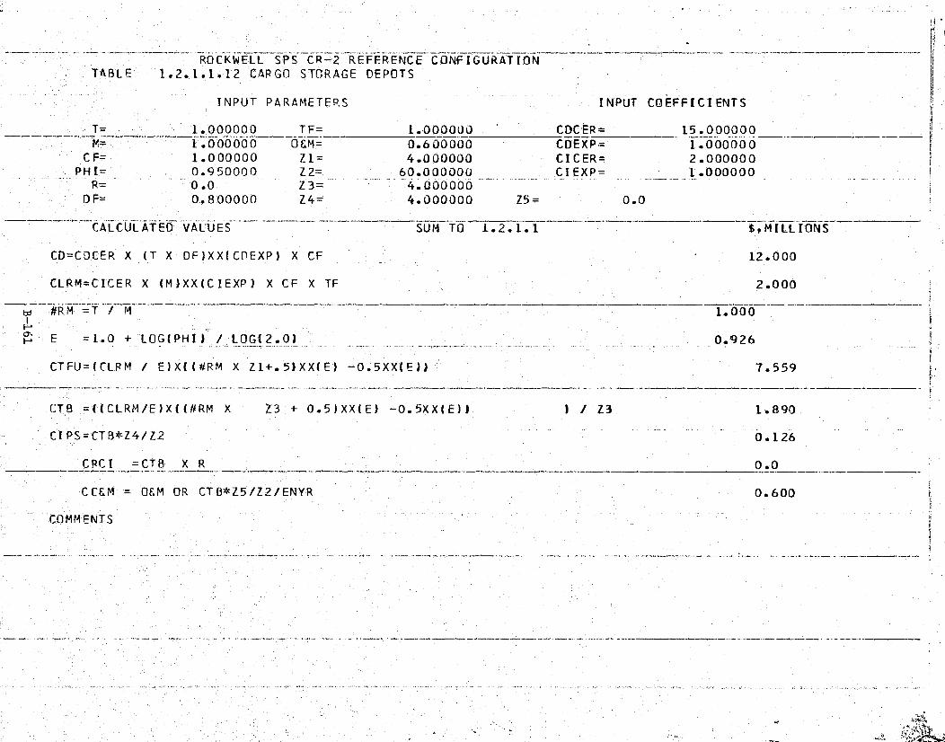
ii sFaRrx ^',^!ir""at;•?^s^,:.'""°`¢.sF nn"i "a:^ .^,^^!4 „.^r; w- r cT, rr aFR • ^ S +e. e s, c,:,:, n.-T +Fi
. .. '..^,. «c..... _ .. , r _ ... - _
l^
r'
+ ^- --__T RQCKWELL SP-S- CR-2 REFERENCE CONFIGURATIONTABLE 1.2.1.1.12 CARGO STORAGE DEPOTS
TNPUT PARAMETERS INPUT COEFFIC`
T= 1.00000 0 TF= 1.000000 CDCER= 15.1s N= 1.0`00000 OEM= 0.600000 CDEXP= l.t
f'^^ryryEEY
Y
i
PHI= 0.950000 Z2= 60.000OOU CDEXP= 1.000000 -R= 0.0 Z3= 4.Qt)0000
D'F= 0.800000 Z4= 4.000000 Z5= 0.0
" CALCULATED l► ALUES SUN TO ---^- __-^-- ^ ^S1.2.1.1 :MILLIONS
CD=CDCER X (T X DF)XX(CDEXP) X CF 12.000
CLRM=CICER X (M)XX(CIEXP) X CF X TF 2.000#R.MrT .. / M...__---__ ^.
1.00 0
;` N E =1.0 + LOG( PHI) / LOG(2.0) _ - - 0.92.6
CTFU=(CLRM / E)X((#P,M X Z1+.5)XX(E) —0.5XX(E)1 7.559•
CTB =((CLRM/E)X((#RM X Z3'+ 0.5)XX(E) —0.5XX(E)1 ) / Z3 1.890
TIPS=CTB*Z4/Z2 0.126
CPCT = CTB X R
CC&M = OEM OR CTB*Z5/Z2/ENYR 0.600 k;'
COMMENTS
,
S
ny
,
..-ti.. a ' fig ,} , ^6r,4LY.^S kSf ... iV^.r. ,wvw•...
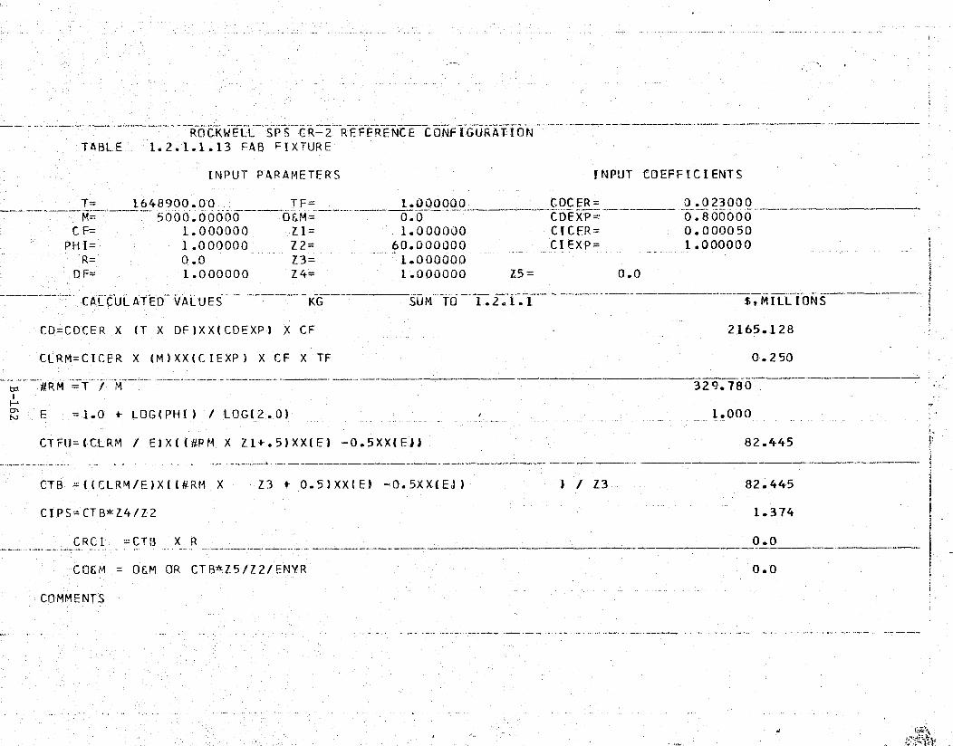
. - r. _ 3 ^. "";,n ' r ` ^"-.,^ncv,•»t^.: ^..G r ;. ^^y^wFF.•ar^y,^
p
R
ROCKWELL `:SPS CR-2 REFERENCE CONFIGURATION} TABLE 1.2.1.1.13 FAB FIXTURE
`z INPUT PARAMETERS INPUT COEFFICIENTS
T= 1648900.00 TF= 1.000000 0.023000M= 5000.-00000 OF.M= 0.0
_CDEXP=
_0.800000
' CF= 1.000000 Z1= 1.000000 CICER= 0.000050PHI= 1.000000 Z2= 60.000000 C.1 EXP. = 1.000000
R= 0.0 Z3= 1.000000 eDF= 1.000000 Z4= 1.000000 Z5= 0.0
CALCULATED VALUESKG _SUM TO 1.2.1.1 $,MILLIONS {
CD=CDCER X (T X DF)XX(CDEXP) X CF 2165.128
CLRM=CDCER X (M)XX(CIEXP) X CF X TF 0.250
td #RM =T / M 329.780i
,; N E =1.0 + LOG(PHI) / LOG(2.0) 1.000
• CTFt)=(CLRM 1 E)X((#PM X Z1+.5)XX(E) —0.5XX(EJJ 82.445 q _«..n.._ .
"
_ ......... . ....:. .... ... .....-...._. .. ^.:.._,_..._.._...._...-..^_......__-..-._...i...._-T_^.__...._._-
CTB =((CLRM/E)X((#RM X Z3 + 0.5)XX(E)
.-..-^.__.^_-,_._,^._ _^..^._^^^.._.
—0.5XX(EJ)
:.nom-.^.. _.._._._..n_._^^..-....
) /—Z3
--^ ._^.
82.445 555p y
CI PS= CTB*Z4/Z2 1.374
CRCI =CTB X R 0. 0
CCEM = OEM OR CTB*Z5/Z2/ENYR 0.0^ a
COMMENTS
A.y;
ys
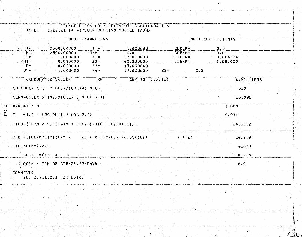
rnnY °imTriy..'•:^IyPw.K4°^F_'T)5f' _.,y "°I:": x v.. -1?:yh+^+"<-a•`>. :'C." .Rf. "4Y• -.ki
_ _ 9 -. .1.f`"
f
IN
___.^ -•POCKWELL—SPS CR-2..-_REFERFNCE'CONFIGURATION
.._.^.__—.__ter......_— ..__...._..—... _.^_ _.-..._,_.__.
TABLE 1.2.1.1.14 AIRLOCK DOCKING MODULE (ADMD fi.
INPUT PARAMFTERS INPUT COEFFICIENTS j
T= 2500.000100 TF= 1.000000 !CDCER= 0.0--- M____. ... —.-- 2500.00000 0£M= 0.0 CDEXP= 0.0CF= 1.000000 Z1= 17.000000 CICER= 0.006036
PHI= 0.980000 Z2= 60,000000 CIEXP= 1.000000R= 0.020000 Z3= —17.000000
DF= 1.000000 Z4= 17.000000 Z5= 0.0
CALCULATED VALUES T^ KG $, M ILL IONSSUM TO 1.2.1.1
CD=CDCER X (T X DF)XX(CDEXP) X CF 0.0
I CLRM=CICER X (M)XX(CIEXP) X CF X TF 15.090
#R'M = T / M — 1.000
w E =1.0 + LOG(PHI) / LOG(2.0) 0.971
CTFU=(CLRM / E)X((#RM X Z1+.5)XX(E) -0.-5XX(E))— 242.302
CTB =((CLRM/E)X((#RM X Z3 + 0.5)XX(E) -0.5XX(E)) ) / Z3 14.253S
' CIPS=CTB*Z4/Z2 4.038
CRCL =CTB X R 0.285
CCEM = OEM OR CTB*Z5/Z2/ENYR 0.0
COMMENTS5 ,.
S EE 1.2.1.2.1 FOR DDTEEi
aEf
1fi
F,i
,^f
}—.. ,. _ _ ... . . , , .. .._ _. . -4".- - _ .z^ _ _ is.aese '^' `.._ _ ^ '^^ tea.. _.K ^r _.:• es. ,.. ._ - a ..^ .._.. ..._.. v...

c Y ^, _ - ^ AF>,+r^irr^{x'ww`^L' !^'E•,q^X"_TA?F_N!§i'Y°TTM"y^s`^;^"'1u^a '.^}c^','. {,., . l. Y
ne;y a'4v^'.'.::... _
f
__.___ _ ...._ __ _... ...,....... . ..- ..:... _.._.... .._.,.—«_..... .._.. «_.. ...^.__-...... ter._. «...-__..r .. .... ..........
ROCKWELL SPS CR-2......__.....-_T-...__^ ___,....^.+_.___..._..^_.. ... __^._.._...__
REFERENCE CONFIGURATION_-.•....^.. ^_^__.. _--•._._._._....^_...._.r..^....-,.. .._.._ .«--_..._.^.__.-..-»......-__^..^.....^u.^.^.._ -._ 1
TABLE 1.2.1.1.15 BASE MGMT. MODULE (BMM)'
INPUT PARAMETERS INPUT COEFFICIENTS i
T = 27000.0000 TF= 1.0000J0 COCER= 0.0M=— 27000.0000 OEM= 0.0 CDEXP= 0.0
CF= 1.000000 Z1= 4.000000 CICER= 0.011496PHI= 0.960000 Z2= 60.000OU0 CIEXP= 1.000000 E
R= 0.020000 Z3= 4.000000_
DF= 1.000000 Z4= 4.000000 Z5= 0.0 a
CALCULATED VALUES KG SUM TO 1.2.1.1 S,MILLIONS E,
CD=CDCFR X (T X DF)XX(CDEXP) X CF 0.0
X ('M)XX(CIEXP) X CF X TF 310.392F"
1.000
4- E =1.0 + LOGI PNI') / LOG(2.0) 0.971 i
CTFU=(CLRM f E)X((€#RM X Z1+.5)XX(E) — 0.5XX(E)) 1213.870E
CTB =((CLRM/E)Xi(kRM X Z3 + 0.5)XX(E) — 0.5XX(E)) ) / Z3 _303.467
rbCIPS=CTB*Z4/Z2 20.231
:a CRCI =CTB X R 6.069
CCEM OEM OR CT8*Z5/Z2/ENYR 0.0 iCOMMENTS
SEE 1.2.2.1.1 FOR DDTEF
n..^t1 w
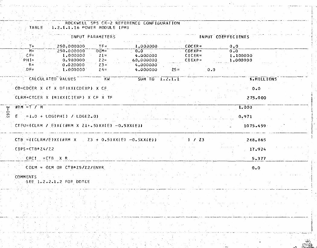
'f{.2 -w+°-'."y^.'.t±'"w,; ^?`. 'F'j^+-; n+rvmr eM`ca-t ;Fs.X'+<--^ p,•x;v°Y"'^ '?g"^. n-r rzr a=7 r; 'T'{° .. » — - c ..
A
~ ROCKWELL SPS CR-2 REFERENCE CONFIGURATIONTABLE 1.2.1.1.16 POWER MODULE (PM)
INPUT PARAMETERS INPUT COEFFICIENTS
T= TF_250.000000 1 .00000 0 CDC FR — 0.0
a_ _CDFXP= _0.0
CF= 1.000000 Z1= 4.000000 CTCER= 1.100000PHI= 0.980000 Z2= 60.000000 CIE:XP= 1.400000
R_- 0.020000 Z3= 4.000000^c DF= 1.000000 Z4= 4.000000 Z5= 0.0
—r' CALCULATED VALUESKW,__ SUM TO 1.2.1.1 $9MTLLIONS
: d¢} CD=CDCER X (T X DF)XX(CDEXP) X CF 0.0
4, . CLRM=CICER X (M)XX(CIEXP) X CF X TF 275.000
^ w #RM =T ! M — -- ._.._.1.00.0._.—_.^_
NE —= 1.0 + LOG(PH I) / LOG(2.0) 0.971
CT FU=(CLRM / E) X{ (#ARM X Z1+. 5) XX( E) —0.5'XX(E )) 1075.459r..,s
t=', CTB =((CLRM/E)X((#RM X Z3 + 0.5)XX(E) —0.5XXlE"))' ) / 23 268.865
CIPS=CTB*Z4/Z2 17.924
CRCI =CTB X R 5.377
CLEM" = OEM OR CTB*Z5/Z2/ENYR 0.0
COMMENTSi SEE 1.2.2.1.2 FOR DDT6E
ra
,3
F'

h t I^
P6
w 111
3
ROCKWELL 'SPS TCR-2 REFERENCE CONFIGURATION1
TABLE 1.2.1..1.17 PRESSURI`ZFD STORAGE MODULE (PSM);.<
INPUT PARAMETERS INPUT COEFFICIENTSK
T 15000.0000 TF= 1.000000 CDCER= 0_.052914_ ----^^...'^,_ _--__.Y_.15000.00000&M_0.0
.—'CDEXP= 1.0.00000
CF= 1.000000 Z1= 4.000000 CICER= 0.013734PHI= 0.980000 —Z2= 60 UOU000 CIEXP= 1.000000
DF= 10.000000 Z4_ 4.000000 Z5= 0.0
CALCULATED VALUES -KG SUM TO —1.21 .1.1 $.MILLIONS
CO=CDCER X (T X DF)XX(CDEXP) X CF 793.710
CLP.M=CT 'CER X (M)XX(CIEXP) X CF X TF 206.010
#RM =T / M 1.000NON
E =1 0 + LOG(PHI) / LOG(2."0) 0.971
cCTFU=(CLRM / E)X((#RM X Z1+.5)XX(E) —0.5XX(E1)-- 805.657 9
CTB =((CLRM/E)X((#RM X Z3 + 0.5)XX(E) —0.5XX(_Ef l ) ! Z3 201.414
CI'PS=CTB*Z4/Z2 13.428z ^
CRC I =CTB X R 2.014
CO&M = O&M OR CTB*Z5/Z2/ENYR 0.0
COMMENTS
"say _YLfI5RrN .. vv, \ ,n..-... k. _.: w. _ w, #viAb

_ ^ Y ::r^^-''-._*,'m€+ e°.n^',s -e+,,,.,.r^^^t^°"..+f•'°kT^'"="^?`;t",h'^rsry.+Y"^.%^ r^±cx"+^R r*.s;...,^s^y} °t„ y T...;^s i ^.mr '^ "° : • :.
7uu
e
t.
tA
ROCKWELL SPS—CR-2 R EFERENCE CONFIGURATIONTABLE 1.2.1.2.1 AIRLOCK DOCKING MODULE—ADM
' INPUT PARAMETERS INPUT COEFFICIENTS xk
T= 2500.0_000_0 TF= 1.000000 _CDCER= 0.012461M= 2500.00000 OEM= 0.0 CDEXP= 1.000000
'. CF= 1.000030 Z1= 5.000000 CICER= 0.006036PHI= 0.980000 Z2= 60.000000 CIEXP= 1.000000
R= 0.020000 Z3— 5.000000DF= 1.000000 Z4= 5.000000 Z5= 0.0
CALCULATED VALUES KG $,MILLIONSSUM TO 1.2.1.2
CD=CDCER X (T X DF)XX(CDEXP) X CF 31.152
CLRM=CICER X (M')XX(CIEXP) X CF X TF 15.090
R M .___T —I _M__1.000
E =1.0 + LOG(PHI) / LOG(2.0) — 0.971
CTFU=(CLRM / E)X((#RM X Z1+. 5)XX(E) — 0.5XX(E)) 73.413
CTB =((CLRM/E)X((#RM X Z3 + - 0.5)XX(E) — 0.5XX(E)) ) / Z3 14.683
CIPS=CTB*Z4/Z2 1.224
_CRC i =CTB X R __._ ..^_ _. ^— 0_,_294y_ _
CCCM = OEM OR CTB*Z5/Z2/ENYR 0.0ati
COMMENTS
S
fa
E J
y
"•}ate' _ - — .^._ _ .... _ _ a. }}..ii ^0
•+^C^h^+ y4 ... .... .... .^v.-.'i .b...} .. v. A+r ,ir., .. r_. vD• y ' _II.. .__. .va. ,_. r....
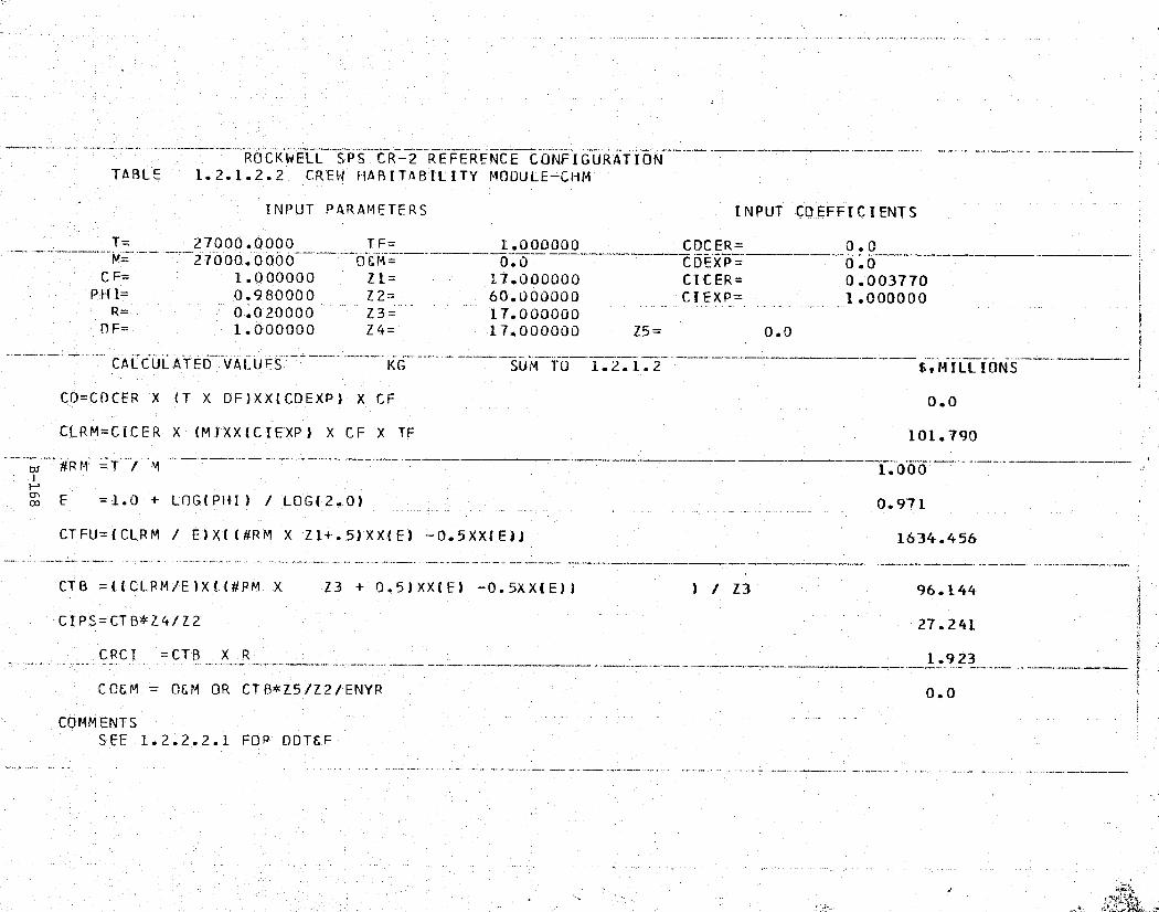
n.. `T... rf':H.-eH7"M ,^XrT.rS"i°'^1', '
u tiC`
ROCKWELL SPS CR-2 REFERENCE CONFIGURATION; a TABLE 1.2.1.2.2 CREW HABITABIL ITY MODULE-CHM
INPUT PARAMETERS INPUT COEFFICIENTS
T= 27000.0000 TF= 1.000000 CDCER 0.027000.0000 O&M= 0.0 CDEXP- 0.0
CF= 1.000000 Z1= 17.000000 CICER= 0.003770PHI= 0.980000 Z2= 60.000000 CTEXP= 1.000000
' R= 0.020000 Z3=:000000
17.000000DF= 1Z4= 17.000000 Z5= 0.0
CALCULATED T VALUES KG SUM TO 1.2.1.2 S,MILLIONS
CD=CDCER X (T X DF)XX(CDEXP) X CF 0.0
E CLRM=CC"ER X '(M)XX(CIEXP) X CF X TF 101.790_. — 1.000.—
r;.:; E =1.0 + LOG( PHI) / LOG(2.0) _ 0.971
CTFU=(CLRM / E) X.((#RM X Z1+.5)'XX,(E) -0.5XX('E11 1634.456
CTB =(ICLRM/E)X((#RM,_X Z3 + 0.5)XX(E) -0.5XX(E)I ) / Z3 96.144
CI PS=CTB Z I Z2 27.241
CRCI = CTB X R 1.923
^
C'CEM = OEM OR CTB*Z5/Z2/ENYR 0.0^
tz
t' COMMENTS
:., SEE 1.2.2,.2.1 FOR DDTEF
"
5
'
w.
r ,
w ♦ .. +:e^i{.e ._ ., -... '^t[:t:,ave s't- .,_. ew .... . ..... a ." .. ,.t

-,w
" .. -.... _. .: _ ... _..: ...+....
r
,.. ..,_.. ,,. ... ..: <..-. .emu_.. ... .,... .... t
k
t
---^ -
-__.r.>
-^CONFIGURATION. REFERENCEROCKWELL S UM- CR-2TABLE 1.2.1.2.3 CONSUMABLES LOGISTICS MODULE-CLM
INPUT PARAMETERS INPUT COEFFICIENTS
T= 5000.00000 TF= .1.000000 CDCER=' _Q. O jM= 5000.00000 it&M= 0.0 CDEXP= 0.0
CF= 1.000000" Z1= 9.000000 CICER= 0.014000PHI= 0.980000 Z2= 60.000000 C.EXP= 1.000000
R= 0.020000 Z3= 9.000000DF= 1.000000 Z4= 9.000000 Z5= 0.0
$,MILLIONSCALCULATED--VALUES KG SUM TO 1.2.1.2
CD=CDCER X (T X DF)XX(CDEXP) X CF 0.0
CLRM=CICER X (M) XX (C IEXP) X CF X TF 70.000
# R M =T / M --- -- 1.000
F = 1.0 + LOG(PHI) / LOG(2.0) 0.971
CTFU= (CLRM / E)X((#R.M X Z1+.5)XX(E) -0.5XX(E))' 604.675 F
CTB-=((CLRM/E)Xf(#RM X Z3 + 0.5)XX(E) -0.5XX(E)) ) / Z3 67.186
CIPS=CTB Z4/Z2 10.078
CRCI =CTB X R 1.344
CP&M = O&M OR CTB*Z5/Z2/FNYR - 0.0 3
COMMENTSSEE 1.2.2.2.2 FOR DDT&E 4
f
r -,.

'•zria'?!{4'.!.vV'ux^ro•+. R.°}..r."^^+' it '3'+ .a'41 .. .n.e ^...'fR"elm,.."r'°n^'?.+rii,-t%..
^Id^^F'S9^h
ROCKWELL SPS CR-2 REFERENCE CONFIGURAT IONTABLE 1.2.1.2.4 SHIELDING
INPUT PARAMETERS INPUT COEFFICIENTS
s T= 11000.0000 TF= 1.000000 CDCER= 0.156000M= 11000.0000 O&M= 0.0 CDEXP= 1.000000
CF= 1.000000 Z1= 8.000000 CICER= 0.101000PHI= 0.980000 Z2= 60.000000 CI EXP= 0.355000
R= 0.010000 Z3= 8.000000DF= 0.200000 Z4= 8.000000 Z5= 0.0
m CALCULATED VALUES KG SUM TO 1.2.1.2 StMILLIONS
CD=CDCER X (T X DF)XX(CDEXP) X_CF 343.200
CLRM=CICER X (M)XX(CIEXP) X CF X TF 2.748
td #RM =T / M 1.000F,
o E =1.0 + LOG(PHI) / LOG(2.0) 0.971
i CTFU=(CLRM / E)X((#RM X Z1+.5)XX(E) — 0.5XX(E'I) 21.160
CTB =((CLRM/E)X((#RM X Z3 + 0.5)XX(E) —0.5XXIE)) ) / Z3 2.645t^E CI PS = CTB*Z4/Z2 0.353 Na
CRCI = CTB X R,
0.026
CC&M = O&M OR CTB*Z5/Z2/ENYR 0.0
COMMENTS
mP'-... ... ..*
'u+. 4(Yf ' t om ^.l

^j?.{^,° 'P°YR: ." g5*, !SlY :M'RIF,°3 :q°,r,,+PP*` rift 4.., 'n W.:'_.i!.isPaa=eA'-n°1"Crf'e... .ni _ . , c t y '^' ... =:;Y+F; d. '.'."k'R°..f'yE RAF
^
_ROCKWELL SPS Ck-2 REFERENCE CONFIGURATION
TABLE 1.2.1.2.5 CREW SUPPORT MODULE-CSM t
INPUT PARAMETERS INPUT COEFFICIENTS1
is
T= 15000.0000 TF= 1.000000 CDCER= 0.012432. TM_ —15000.0000 ---O&M=
_0.0 CDEXP= 1.000000
CF= 1.000000 Z1= 3.000000 CICER= 0.005798PHI= 0.980000 Z2= 60.000000 CIEXP= 1.000000
R- - 0.020000----Z3 ___. _
3.000000DF= 1.000000 Z4= 3.000000 Z5= 0.0
CALCULATED VALUES KG SUM TO 1.2.1.2 $,MILLIONS
CD=CDCER X (T X DF)XX(CDEXP) X CF 186.480
CLRM=CICER X (M)XX(CIEXP) X CF X TF 86.970
bi #R M =T / M 1.000r s
E = 1.0 + LOG( PHI) / LOG(2. 0) 0.971
CTFU=(CLRM / E)X(I#RM X Z1+.5)XX(E) —0.5XX(E)i 256.587aa .
CTB =((CLRM /F)X((#RM X Z3 + 0.5)XX(E) — 0.5XX(E)) ) / Z3 85.529
CIPS=CTB*Z4/Z2 - _
4.276
C.RC I =CTB X R 1.711
CCEM _ O&M OR CTB*Z5/Z2/ENYR 0.0
COMMENTS
,3s
y
t
J

Satellite Systems RockwellSpace Systems Group International
(THIS PAGE INTENTIONALLY LEFT BLANK)
Kt

ROCKWELL SPS CR-2 REFERENCE CONFIGURA-TIONTAWS 1.2.1.3.1 OPERATIONS, CONSTRUCTION CREW
INPUT PARAMETERS INPUT COEFFICIENTS
T= - 317.000000 TF= 1.000000 CDCER= 0.0M = 317.000000 06h1= 0.0 CDEXP= 0.0
CF= 1.000000 Z1= 1.000000 CICER= 0.062400PHI = 1.000000 Z2= 60..000000 CI EXP = 1.000000
R= 0.0 Z3=._
31.000000DE= 1.000000 Z4= 30.000000 Z5= 0.0
}Py
- i
u
CALCULATED VALUES _-MEN --^- SUM TO 1.2.1.3
$9MILLIONS
CD=CDCFR'X (T X DF)XX(CDEXP) X CF 0.0
CLRM=CICER X (M)XX(CIEXP) X CF X TF 19.7£1
#RM =T / M 1.000'
w E =1.0 + LOG(PHI) / LOG(2.0) 1.000
CTFU=(CLRM / E)X('(#RM X Z1}..5)XX(E) -0.5XX(E)) 19.781
CTB ((CLRM/E)X((#RM X Z3 + 0.5)XX(E) - 0.5XX(EJ) ) / Z3 19.781
CIPS=CTB*Z4/Z2
9.890
{ CPCI =CTS X R 0.0
COEM = O&M OR CTB*Z5/Z2/ENYR 0.0
COMMENT'S
x

^uF.{,^im•apttr{r^v,^'^^4^:? z,xR=T^!r.. "'-"^Tf"'y,. s°st ?t:z
x
^---_'• ROCKWELL SPS ^CR2 2REFER.ENCElCONFIGUkATION2.L.3.2 ORBLTnL OPERATiONS,CONST. PROV.
INPUT PARAMETERS INPUT COEFFICIENTS
T'= 410832.000 TF= 1.000000 CDCER 0.0M 410832.000 OEM= 0.0 COEXP 0.0
CF= 1.000000 Zl= 1.000000 CICER= 0.000022
s' PHI= 1..000'000 Z2= 60.000000 CIEXP= 1.000000R= 0.0 - Z3= 31.000000DF 1.000000 Z4= 30.000000 Z5= 0.0
^^^^ CALCULATED' VALUEST-- KG 4i SUM TO 1.2. 1.3 _^ $•MILLIONS
I CO=CDCER X (T X DF)XX(CDEXP) X CF 0.0
CLRM=CICER':' (M)XX(CIEXP) X CF X TF 9.038
t t # R M =T ^_. _
1.0 00r.
k E 1.0 + LOG(PHI) / LOG(2.0) 1.000 ff`
CTFU=-(CLRM / E)X((#RM X Z1+.5)XX('E) -0.5XX(E)) 9.038
CTB =((CLRM/E)X((#RM X Z3 + 0.5)XX(E) 0.5XX(E1_) ! ! Z3 9.038'
CIPS=C'TB*Z4/Z2 4.519
—CRCI CTB X R 0.0m
COEM OEM OR CTB*Z5/Z2/ENYR 0,0
COMMENTS
Hi
(
_
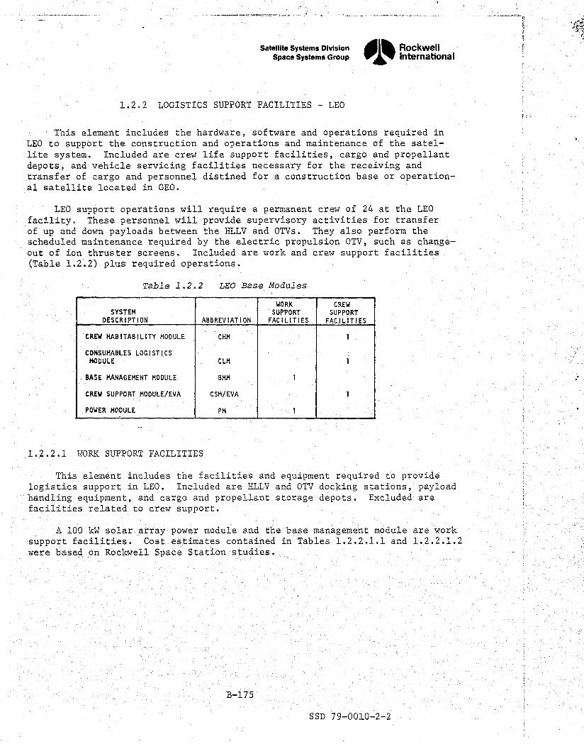
SYSTEMDESCRIPTION ABBREVIATION
WORKSUPPORTFACILITIES
CREWSUPPORTFACILITIES
CREW HABITABILITY MODULE CHM I
CONSUMABLES LOGISTICSMODULE CLM
BASE MANAGEMENT MODULE 8MM
CREW SUPPORT MODULE/EVA CSM/EVA I
POWER MODULE PM
Satellite Systems DivisionSpace Systems Group„
RockwellInternational
1.2.2 LOGISTICS SUPPORT FACILITIES LEO
This element includes the hardware, software and operations required inLEO to support the construction and operations and maintenance of the satel-lite system. Included are crew life support facilities, cargo and propellantdepots, and vehicle servicin g facilities necessary for the receiving andtransfer of cargo and personnel distined for a construction base or operation-al satellite located in GEO.
LEO support operations will 'require a permanent crew of 24 at the LEOfacility. These personnel will provide supervisory activities for transferof up and down payloads between the HLLV and OTVs. They also perform thescheduled maintenance required by the electric propulsion OTV, such as change-out of ion thruster screens. Included are work and crew support facilities(Table 1.2.2) plus required operations.
Table 1.2.2 LEO Base Modules
1.2.2.1 WORK SUPPORT FACILITIES
This element includes the facilities and equipment required to providelogistics support in LEO. Included are HLLV and OTV dockin g stations, payloadhandling equipment, and cargo and propellant storage depots. Excluded arefacilities related to crew support.
A 100 W solar array power module and the base mana gement module are worksupport facilities. Cost estimates contained in Tables 1.2.2.1.1 and 1.2.2.1.2were based on Rockwell Space Station studies.
B-175
SSD 79-0010-2-2

•
t'
• ^
kid
ROCKWELL SPS CR-2 REFERENCE CONFIGURATIONTABLE 1.2.2.1.1 BASE MGMT. MODULE-BMM
INPUT PARAMETERS INPUT COEFFICIENTS
• _ T= _ 27000.0000 TF= _ _ 1.000000 _ CDCER= 0.09129b___.______M= - 2700b0.000^ OEM=- -^ 0.0 CDEXP= - 1 .000000 -
' CF= 1.000000 Zl= 1.000000 CICER= 0.011496PHI= _ 0.980000 Z2 60.00000c^ CIEXP= _ 1.000000
r R= 0.020000 Z3 _. 1.000000
i DF= 1.000000 Z4= 1.000000 Z5= 0.0
CALCULATED VALUES KG SUM TO 1.2.2.1 E,MLLLIONS
i` CD=CDCER;X (T X DF)XX(CDEXP) X CF 2464.993
CLRM=CICER X (M)XX(CIEXP) X CF X TF 310.392
1.000:i to
F =1.0 + LOG(PHI) / LOG(2.0) 0.971
3CTFU=(CLRM / E)X((#RM X Z1+.5)XX(E) —0.5XX(E)) 310.814
f
i CTB =((CL RM/E)X((#RM X Z3 + 0.5)XX(E) -0.5XX(E.1) 7 / Z3 310.814
CIPS=CTB*Z4/Z2 5.180
CRCI =CTB X R 6.216
CC&M OEM OR CTB*Z5/Z2/ENY'R 0.0
_COMMENTS 4
Fr
_£

- et±?"g '.aw^°Fa•nr';;+R»grrtm .; `^'s -r+..yr,-an:^cw:r°:.+,*••aj747 ..r ;-c..-•
e`
ROCKWELL SPS CR-2 RE—FER'ENCE CONFIGURATIONTABLE 1.2.2.1.2 ROWER MODULE—PM
^t
INPUT PARAMETERS INPUT COEFFICIENTS
T=, 250.000000 TF= 1.004000 CDCER= 1.400000M= 250.000000' OEM= 0.0 CDEXP= 1.000000
CF= 1.000000 Z1= 1.000000 CICER= 1.100000PHI = 0.980000 Z2= 60.000000 CIEXP= 1.000000 `.yR_ 0.020000 Z3= 1.000000
a DF= 1.000000 Z4= 1.000000 Z5= 0:0
~CALCULATED VALUES KW SUM TO 1.2.2.1 $9MILLIONS"
CD=CDCER X (T X DF)XX(CDEXP) X CF 350.000
CLRM= CICER_X (M)XX(CIEXP) X CF X TF 275.000
1.000
E = 1.0 .+,. LOG'.(PHI)'/ LOGI2.0) 0.971
CT FU= tCLRM / E!X((#RM X Z1+.5)XX(E) -0.5XX(E1) 275.373Fr
---+^' CTB J=((CLRM/E)X((#RM X Z3 ± 0.5)XX(E) -0.5XX(E)) ) / Z3 275.373
E' CIPS=CTB*Z4/Z2 4.590
y _CRCI =CTB X R— — - -- 5.50 7--__
CCEM = OEM OR CTB*15/Z2/ENYR 0.0
COMMENTS
a
k )
a
yj ..'.' r •• . .. ....-.. •'. a—•w., .. 4• . `.. . e <CKi^i...5. . u _E.. ^F h'•nx v.0 ^T ...n. ^.t k. ti .. ... .L -.. ^ _c .. sx^v. _^ __Y

Satellite Systems Division Rockwell
Space Systems Group International1-:
1.2.2.2 CREW SUPPORT FACILITIES
This element includes the facilities and equipment required for the life M
support and well-being of the crew members. Included are living quarters,recreation facilities, and health facilities at LEO.
The crew habitability module and crew support module/EVA are the samebasic configuration as for those on the SCB. However, the crew supportmodule has an airlock and EVA preparation area. A consumables logisticsmodule is the third element of crew support facilities. ._
CERs,used for crew support facilities were based upon Rockwell Space ^?Station studies. See Tables 1.2.2.2.1, 1.2.2.2.2, and 1.2.2.2.3.
:
z,i . t
a`
B-178
SSD 79-0010-2-2

ROCKWELL SPS CR.-2 REFERENCE CONFIGURATION
Et TABLE 1.2.2.2.1 CREW HABITABILITY MODULE — CHM i
INPUT PARAMETERS INPUT COEFFICIENTS I
T= 27000.0000 TF 1.000000 CD_C_ER= 0.009714
M= 27000.0000 OEM=^.^__ ^Y 0 ,0 _
CDEXP=— 1.000000 i§? CF= ; 1.000000 Z1= 1.000000 CICER 0.003770
PHI= 0.980000 Z2 60.000000 CIEXP= 1.000000R_ 0.0.20000 Z3_ — 1.000000DF= 1.000000 Z4 1.000000 Z5= 0.0`y !
ULCUL ATED VA!_UES KG 1.2.2.2 f, M ILL IONS
f` CD=CD CER X (T X DF )X X(CDEXP) X CF 262.278t
CLRM=CICER X (M)XX(CIEXP) X CF X TF 101.790
1.000ti #R M =T / M
E =1.0 + LOG(PHI) / LOG(2_.0) 0.971 1
CTFU=(CLRM / E)X((#RM X Z1+.5)XX(E) -0.5XX(E))' _ 101.928
Fi CTB ((CLRM/E)X((HRM X Z3 + 0.5)XX(E) -0.5XX(E)) ) / Z3 101.928
s# GIPS=CTB*Z4/Z2 1.699
C"RCI =CTB X R 2.039
CORM = OEM OR CT B*Z5/Z2/ENYR 0.0
COMMENTS
1f
C,
r '
Aa
- ;r _. , - _ ,^i.L _.. s\,,,..._. _ _.., , . - .,, ..^. rte` ►.'.
:.c^^

„
^; I
ROCKWELL SPS CR-2 REFERENCE CONFIGURATIONTABLE 1.2.2.2.2 CONSUMABLES LOGISTICS MODULE
:f INPUT PARAMFTERS INPUT COEFFICIENTSt
T= 5000.00000 TF— ^,1.00000 CDC FR 0.053000^_M- 5000.00000 06M= 0.0 CDEXP= 1.000000
t CF'= 1.000000 Z1= 1.0.00000 CICER= 0.014000PHI = 0.980000 Z2= 60.000000 CIEXP= 1.000000
R'= 0.020000 Z3= 1.000000E` DF= 1.0.00000 Z4= 1.000000 Z5= 0.0
^—CALCULATED VALUES KG SUM TO L.L.2.2 $•MILL-IONS
6i CD=CDCER X (T X DF)XX(CDEXP) X CF 265.000
CLRM=CICER'X (M)XX(CTEXP) X CF X TF 70.000
E.' ai #RM =T / Mi
1.000
E =1.0 +ELOG(PHI) / L'OG(2.0) _ ^. _ _._ 0.971
CTFU=(CLRM / E)X((#RM X Z1+.5)XX(E) -0.5XX(EJ) 70.095
f; CT =((CLR MI/E)X((#RM X Z3 + 0.5)XX(E) -0.5XX(E)) ) / Z3 70.095
CIPS=CTB*Z4/Z2 1.168
'.! CRCI =CTB X R-
1.402
COSM OEM OR CTB*Z5/Z2/E'NYR 0.0
+ COMMENTS
_

ROCKWELL SPS CR-2 REFERENCE CONFIGURATIONTABLE 1.2.2.2.3 CREW SUPPORT MODULE/EVA
INPUT PARAMETERS INPUT COEFFICIENTS
T= 27000.0000 TF= 1.000000 COCER= 0.012432M= 27000.0000 OEM=' 0.0 CDEXP= 1.000000
CF= 1.000000 Z1= 1.000000 CICER= 0.005798PHI- 0.980000 Z2= 60.000000 CIE'XP= 1.000000
R- 0.020000 Z3= 1.000000DF= 1.000000 Z4= 1.000000 Z5= 0.0
CALCULATED VALUES' — KG SUM TO 1.2.2.2 ^SrMILLIONS
CD=CDCER X (T X DF)XX(CDEXP) X CF 335.664
CLRM=C,ICER 'X (M)XX(CIEXP) X CF X TF 156.546^r
Rf#RM^= T / M w 1.000
f .
z E = 1.0 + LOG(PH I) / LOG( 2. 0) 0.971
j CTFU=(—CLRM / E)X((#RM X Z1+.5)XXIE) -0.5XX(E)) 156.759
CTB =((CLRM/E)X((#RM X Z3 + 0.5)XX(E) —0.5XX(E)1 ) / Z3 156.759 s
k°I—CIPS=CTB*Z4/Z2 _. 2.613
CRCI =CTB X R 3.135
CCEM '= OEM OR CTB*Z5/Z2/ENYR 0.0
COMMENTS
r^a
'r±
.;
OR

,. ^,. „t,^,,.^, -r--,man•^^'C4,'.73.^`%".m"."n,*„Xc::f•*"^'^r.
¢^ay
., .._.. .,, _.. ._..,.+..-•^^o^+mex^.R..-....- ., ., .,-^...m..^ Fay_.._.... ,^.ss- .....:...._...ra._ ^. __.._N... ^
Satellite systems DivisionI RockwellSpace systems Group
il%International
y
1.2.2.3 OPERATIONS G^
This element includes the planning, development, and conduct of operationsat the logistics support facility. It includes both the direct and supportpersonnel and the expendable maintenance supplies required for logistics sup-port.
G
An average of 24 crew members are required at the LEO Base to supportorbital operations. Engineering estimates were made of the operations andconsumable requirements at LEO. See Tables 1.2.2.3.1 and 1.2.2.3.2,
e
1
,s
c
tit
##, y
V
B-182
V. SSD 79-0010-2-2

F,k. .: ..,
:rlFn°^`a5P"r7n^a^e m'r'X"A^ 3^:g1Y"?`S.. F'r' ;i»_k ra4•j^'$ > rSZs'l }TFx'.
.. _ ...
r a
.. _.- ^-. ,..__._^.
^
.. ,. ..t. ._..__. ___ .^_^_.,r ._.._..-^._ r .............. .....
^,^.
r....n
p.
ROCKWELL SPS -CR-2 REFERENCE CONFIGURATION
TABLE 1.2.2.3.1 LEO OPERATIONS CREW
' INPUT PARAMETERS INPUT COEFFICIENTS ?^
T=24.000000 TF = 1.0 0 0000 CDCER= 0.0_____M= 24.000000 OSM= 0.0 - CDEXP= - 0.0--_-- w ;
CF=- 1.000000 Zl= 1.000000 CICER= 0.062400PHI= 1.000000 Z2'= 60.000000 CIEXP= 1.000000
R= 0.0 Z3= 31.000000DF= 1.000000 Z4= 30.000000 Z5= 0.0
i
- CALCULATED VALUES MEN SUM TO 1.2.2.3 $,MILLIONS
CO=CDCER X (T X DF)XX(CDEXP) X CF 0.0
CLPM=CICER X (M)XX(CIEXP) X CF X TF 1.498
1.000iHw F 1.0 + LOG( PHI / LOG(2.0) 1.000
CTFU=(CLRM / E)X((#RM X Z1+.5)XX(E) -0.5XX(E)1 1.498
CTB =((CLRM/E)X((#RM X Z3 + 0.5)XX(E) -0.5XX(E)1 ) / Z3 1.498
CI PS = CTB Z4/Z2 _ 0.749ii
CRC I =CTB X R 0.0
C'C&M =-O&M OR CTB*Z5/Z2/ENYR 0.0_
COMMENTS
t
w

}ic'."lrr`°igar+`filyrr"°?-.i^M1°''.B,R^, ^ji.r^.^..•c+pp•,^ft^.9^ ^Y` !L , h -. .. r - ^'R'e'VF,. .i .. _
4
ROCKWELL SPS CR-2 REFERENCE CONFIGURATIONTABLE 1.2.2.3.2 LEO'_ CREW PROVISIONS
INPUT PARAMETERS INPUT COEFFICIENTS
T= 31104.0000 TF= 1.000000 COCER= 0.0N= 3110`4.0000 06M= X0.0 CDEXP= 0.0
CF= 1.000000 Z1= 1.000000 CICER= 0.000022PHI= 1.000000 Z2= 60.000000 CIEXP= 1.000000
R_ -0.0 Z3— 31.000000
DF= 1.000000 Z4= 30.000000 Z5= 0.0
CALCULATED VALUES KG SUM TO 1.2.2.3 $v MILLIONS'
CD=CDCER X (T X OF)XX(CDEXP) X CF 0.0 j
CLRM=CICER X (M)XX(CIEXP) X CF 'X TF 0.684
_td #RM _T / M 1.000
E =1.0 + LOG(PHI) / LOG(2.'0) 1.000
CTFU=(CLRM / E)X((#RM X Z1+.5)XX(E) -0.5XX(E))' 0.684i
i{ CTB =((CLRM/E)X((#RM X Z3—+-0.5)XX(E) 0.5XXlE)) )'/ Z3 0.684 f
CIPS=CTB*Z4/Z2_
0.342
7
CRCI =CTB X R 0.0 iCOEM = OEM OR CTB*Z5/Z2/ENYR" 0.0
COMMENTS
I

Satellite Systems DivisionRockwell
oi%Space Systems G ►oup Intemational
1.2.3 SATELLITE 0&M SUPPORT FACILITIES
This element includes the facilities, equipment, and operations requiredin GEO to support the operations and maintenance of the satellite system.Included are the on-orbit monitor and control facility and the life supportfacilities and equipment required to provide confortable safe living quartersfor the resident crew members.
A permanent satellite operations and maintenance base is installed oneach satellite at a location near the antenna to provide best access to all << asystems of the satellite. The base has facilities for both the crew and for y
storage of maintenance material, and installation/repair equipment. Table1.2.3 identifies the supporting facilities.
Table 1.2.3 Satellite 001 Base
}
K
SYSTEMDESCRIPTION ABBREVIATION
WORKSUPPORTFACILITIES
CREWSUPPORT
FACILITIES
AIRLOCK DOCKING MODULE ADM 3 1
CREW HABITABILITY MODULE CHM 1
CONSUMABLES LOGISTICS MODULE CLM I
BASE MANAGEMENT MODULE BMM I
CREW SUPPORT MODULEAVA CSM/EVA 1
PRESSURIZED STORAGE MODULE PSM 2
1.2.3.1 WORK SUPPORT FACILITIES
a.
This element includes the facilities and equipment required for operationand maintenance of the satellite system. Included are satellite monitor andcontrol stations and any centralized repair facilities not included undermaintenance. J
The ADM is required at four places for the integration of other modulesh comprising the satellite 0&M base. Three of these modules are to be used
primarily for work support operations. The satellite BMM incorporates amonitoring and fault isolation capability for the SPS satellite subsystems }as well as the controls required for alternate operational modes and functionalisolation of selected subsystems for maintenance. The cost estimates of these >modules and the PSM are shown in Tables 1.2.3.1.1, 1.2.3.1.2 and 1.2.3.1.3.The CERs are based on Rockwell Space Station studies.'
F,
"
B-185
SSD 79-0010-2-2
r
a^

1+,"^ `+M-vo.
a
'
-_.-r___._.,•..^..rrr...__.>3..r _._. nom_.._ sue_..__.:». .. _ ._n _... —....r--.._:.._^....._. .<_^ -_.. _.«....._._^_:.. ...._.......,^_. _..._- _. _.._._,.._.v_..n._ _<_, ....-... ...n-..._....... ,._-.... ..__:..rr.__-_.. _._. ^... ... ^...,.:.._. . _ r ...»-....,..-._.
ROCKWELL SPS CR-2 REFERENCE CONFIGURATIONTABLE 1.2.3.1.1 AIRLOCK DOCKING MODULE'-ADM
T= 2500.00000" TF= 1.000000 CDC ER=--. 0.0M= 2500.00000 O&M= 0.0 CDEX 0.0
CF= 1.000000 Z1= 3.000000 CICER= 0.006036PHI= 0.980000 Z2= 60.00000 CIEXP= 1.000000
R= 0.020000 Z3= 180.000000DF= 1.000000 Z4= 180.000000 Z5= 0.0
CALCULATED VALUES KG SUM TO 1.2.3.1 $,MILLIONS
CD=CDCER -X (T X DF)XX(CDEXP) X CF 0.0
C"LRM=CICER X (M)XX(CIEXP',) X CF X TF 15.090
#R M =T / M 1.000
o E =1.0 + LOG (PH I ? / LOG( 2.0) 0.971
CT'FU = (CLRM / E)X((#RM X Z1+.5)XX(E') -0.5X'X(E-)! 44.520
CT'B =(`(CLRM/E)X((#RM X Z3'+ 0.5)XX(E) -0.5XX(E)) ) / Z3 13.352 >+
CIPS--CTB*Z4/Z2 40.056
CRCI =CT'B X R4
0.267
COEM = O&M OR CTB*Z5/Z2/FNYR 0.0
COMMENTSSEF 1.2.1.2.1 FOR DDTCE
i
the
+y}y^
+4

ry(qv
}
JoiRt '^'Y.M1!Y":^n75F, `PIe?ryp.5*,y*'k7".-°.e,^rY..:C '} y'm1MS'F°'9MR'Z"'°4 a:"'r _J°/Y `-'R- . , _
_
ROCKWELL SPS CR-2 REFE=RENCE CONFIGURATIONTABLE 1.2.3.1.2 BASE MGMT MODULE—BMM
INPUT PARAMETERS INPUT COEFFICIENTS)
y ,
T= 27000.0000 TF= 1 .00u0jo C DCER=, 0_.0 e_.^-. -_ 0- 0-,_ -.,,
M= 27- -0 "00.. 0000 OEM=--0:0
-- --CDEXP= 0.0^
^_ ..
CF= 1.000000 Z1= 1.000000 CICER= 0.011496PHI= 0.980000 Z2= 60.000000 CIEXP= 1.000000
R= 0.020000 Z3= - - 60.000000DF= 1.000000 Z4= 60.0.00000 Z5= 0.0
CALCULATED VALUES - -KG SUM TO 1..2.3.1 $,MILLIONS
CD=CDCER X (T X DF)XX(CDEXP) X CF 0.0
CLRM=CICER X (M)XX(CIEXP) X CF X TF 310.392
t #RM =T /Mi 1.000
°^ E =1.0 + LOG(PHI ): / LOG(2.0) 0.971
CTFU=(CLRM / E)_X((#RM X Z1+.5)XX(E) -0.5'XX(E)) 310.814
CTB =((CLRM/F)X((#RM X Z3 + 0.5)XX(E) — 0.5XX(El) ) / Z3 283.323
CIPS = CTB*Z4/Z2 283.322
CRCI =CTB X R 5.666
C Q6 M = OEM OR CT B* Z 5 /Z 2/ ENYR 0.0
COMMENTSSEE 1.2.2.1.1 FOR DDTEE

^^`^'•Y $' ^°}.N„?'}r 9p'f,1!5F:^r'A^'nY t,:i`. 35.x•: ^*'. v: .L^`^(^.i};: t7a'TT'Y?L, r:. L _._.
^ r
«7q
F
f
f
ROCKWELL SPS C »P -2 REFERENCE CONFIGURATIONTABLE 1.2.3.1.3 PRESSURIZED STORAGE MODULE-PSM {
f
INPUT PARAMETERS INPUT COEFFICIENTS
T= 15000.0000 TF= 1.000000 COCER= 0.0M= 15000.0000 OEM= 0.0 ~^COEXP= 0.0
` CF= 1.000000 Z1='- 2.000000 CICER= 0.013734PHI= 0.980000 Z2= 60.000000 CIEXP= 1.000000
R= 0.010000 Z3= 120.000000DF= 1.000000 Z4= 120.000000 Z5= 0.0 b
..--..mo
D Vw_-•_AL- •_-CALCULATEUES iKG i`SUM TO 1.2.3.1 ^rMILLIONS
CD=CDCER X (T X OF)XX(COEXP) X CF 0.0
CLRM=C'ICER X (M'XX(CIEXP) X CF X TF 206.010
#RM -T / H 1.000
m E =1.0 + LOG (PHI / LOG( 2.'0) 0.971
CTFU=(CLRM / E)X(-(#RM X Z1+.5)XX(E) -0.5XX(E)) 408.244
CTB ((CLRM/E)X((#RM X Z3 0.5)XX(E) 0.5XX(E)) } / Z3 184.403
CIPS = CTB*Z4/Z2 368.805i
CRCI =CTB X Ry i
CCEM _ OEM OR CTB*Z5/Z2/ENYR 0.0
COMMENT'SSEE 1.2.1.1.17 FOR DDT£E

rte.-^^---:^^^.z.^^,a...,._..,v.^ ,,. _ .^.^,r.va._ _ • ^ ._..,.. _. .._._......^^. ^^ ^^^
Satellite Systems Division , RockwellI` Space Systems Group, International
1.2.3.2 CREW SUPPORT FACILITIES
This element includes the facilities and equipment required for the life
Si support and well-being of the crew members. Included are living quarters,
{recreation facilities, and health facilities.
The combination crew support and EVA module (CSM/EVA) has the same inter-nal function as for the SCB, but occupies only half of the module. The otherhalf is an integrated multi-crew member EVA preparation area and airlock`
?;station.
The ADM, CIDI, CLM and CSM/EVA modules are costed in Tables 1.2.3.2.1,1.2.3.2.2, 1.2.3.2.3, and 1.2.3.2.4. The estimates, are based on Rockwell's
1
{_ iSpace Station studies. ,j
}
a.:. .
rppn
;.
,
5 ,
' L [
i
L
Y
F
8-189
L
YSSD 79 -0010-2-2

ROCKWELL SPS CR-2 REFERENCE CONFIGURATIONTABLE t.2.3.2.1 AIRLOCK DOCKING MODULE—ADM
INPUT PARAMETERS INPUT COEFFICIENTS
T= 2500.00000 TF= 1.000000 CDCFR= 0.0M= 2500.00000 OF.M= 0.0 CDEXP= 0.0
C F= 1.000000 Zl= 1.000000 CICER= 0.006036PHI= 0.980000 Z2= 60.000000 CTEXP= 1.000000
P= 0.02oboo Z3= 6o 000000DF= 1.000000 Z4= 60:000000 Z5= 0.0
CALCULATED VALUES KG SUM TO 1.2.3.2 $,MILLIONS
CD=CDCER X (T X DFJXX(CDEXP) X CF 0.0
CLRM=CICER X (M)XX(CIEXP) X CF X TF 15.090
bi #RM =T M 1.000
koE =1.0 + LOG(PHI) LOG(2.0) 0.971
CTFU=(CLRM / E)X((#RM X Zl+.5)XX(E) —0.5XX(E)) 15.111
CTB =((CLRM/E)X(I#RM X Z3 0.5)XX(E) —0.5XX(El) Z3 13.774
CIPS=CTB*Z4/Z2 13.774
CRCI =CTB X P 0.275
CC&M O&M OR CTB*Z5/Z2/FNYR 0.0
COMMENTSFOR DDT&E

t
3
A
y "
---"ROCKWELL SPS CR-2 - REFERENCE CONFIGURATIONTABLE 1.2.3.2.2 CREW HABITABILITY'M'ODULE=CHM z
INPUT PARAMETERS INPUT COEFFICIENTS
T= 27000.0000 TF= 1-.0000J0 CDCER= 0.0 HI{y(
M= 27000.0000~ OEM= 0.0 CDEXP= 0.0CF= 1.000000 Z1= 1.000000 CICER= 0.003770
PHI= 0.980000Z2= 60.000000 CIEXP= 1.000000R= 0.020000
__..Z3= 60.000000
DF= 1.000000 Z4= 60.000000 Z5= 0.0
CALCULATED VALUFS KG SUM TO 1.2.3.2 S9MILLIONS
CD=CDCER X (T X DF)XX(CDEXP) X CF 0.0
CL'RM = CICER X (M)XX(C IEXP) X CF X TF 101.790
#RM =T / M 1.000'tdiE =1.0 + LOG(PHI ), / LOG(2.0) 0.971
CTFO=(CLRM' / E)X(( #RM X Z1+.5)XX(E') —0.5XX(E)) 101.928 4
CTB =((CLRM/F)X((#RM X Z3 + 0.5)XX(E) —0.5XX(El) 1 ! Z3 92.913 '.
CI Os= CTB*Z4/Z2 92.913
CRCI =CTB X R 1.858r.
CC&M = O&M OR CTB*Z5/Z2/FNYR 0.0 i
COMMENTS^. SEE 1.2.2.2.1 FOR DDT&E
t
C.
ufit,.;•
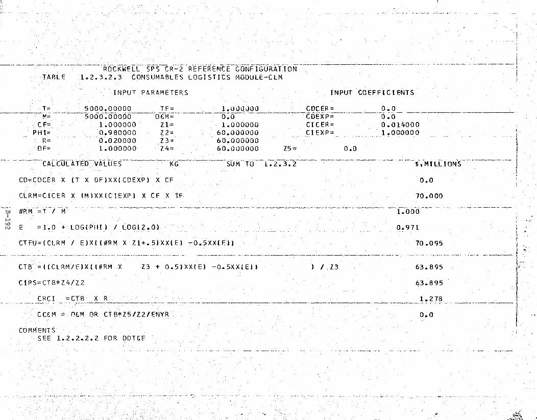
1
ROCKWELL S.PS CR-2 REFERENCE CONFIGURAT yION !TABLE 1.2.3.2.3 CONSUMABLES LOGISTICS MODULE—CLM
t
INPUT PARAMETERS INPUT COEFFICIENTS
T_ 5000400000TF=
1'.00OJOO CDCER= 0.0M= 5000A0000 OLM= 00 CDEXP= 0.0
CF= 1..000000 Z1= 1.000000 CICER= 0.014000PHI= 0.980000 Z2= 60.UOOOOU
—CI EXP= 1.000000
R= 0.020000 Z3= 60.000000DF= 1.000000 Z4= 60.000000 Z5= 0.0
.__..____...^..__.—CALCUL%t1TFD VALUES?~ KG ._: ^SUM TTt3^1.2.3.2 $-.MLLLIONS---___
CD=CDCER X (T X OF)XXICDEXP)—X CF 0.01
CLRM = CICER X (M)XX (C IEXP) X CF X Tf 70.000
rr^ #RM =T / M _ 1.000
E =1.0 + LOG(PHI) / LOG( 2.0) 0.971
CTFU=(CLRM / E)X((#RM X Zl+.'5)XX(E) —0.5XX(E)) 70.095
CTB =((CLRM/E)X((#RM X Z3 + 0.5)XX(E) —0.5XX(E)f ) / Z3 63.895 -*
CIPS= CTB*Z4/Z2 63.895
CRCI =CTB X R 1.278
CCEM = OEM OR CTB*Z5/Z2/ENYR 0.0 -
COMMENTSSEE 1.2.2.2.2 FOR DDTEE
— y
}
aw

,ex: .:s: u+ 'N'.3" .ate, , .w?;e``a!srtcx!zrrr ;c aa,.:.?"r;,x,;,Y'P';.. 7F
c
E
ROCKWELL SPS CR-2 REFERENCE CONFIGURATIONAA
TABLE_ 1.2.3.2.4 CREW SUPPORT MODULE/EVA
INPUT PARAMETERS INPUT COEFFICIENTS{
T= 27000.0000 TF 1.000000 CDCER= 0.0M= 27000.0000 C1EM= 0.0^ CDEXP= 0.0 r
CF= 1.000000 Z1= 1.000000 CICER= 0.005798'PHI= 0.980000 Z2= 60.000000 CIEXP= 1.000000
R= 0.02.0000 Z3= _ 60,000000DF= 1.000000 Z4= 60.000000 Z5= 0.0--CALCULATED VALUES EKG $9 MI L IONSSUM TO 1.2.3.2
CD=CDCER X (T X DF)XX(CDEXP); X CF 0.0
CLRM=CICER X (M)XX(C'IEXP) X CF X TF 156.546
tdi #RM =T / M 1.000N
' w E = 1.0 + LOG(PHI) / LOG(2.0) 0.971
CTFU=(CLRM / E)X((#RM X Z1+.5)XX(E) —0.5XX(E)) 156.759
CTB =((CLRM/E)X'((#RM X' Z3 + 0.5)XX(E) —0.5XX(E)) ) / Z3 142.894
CIPS=CTB*Z4/Z2 142.894E
f
„CRC I' =CTB X R 2.858
a
CC&M _ O&M OR CTB*Z5/Z2/ENYR 0.0'
" COMMENTSS EF 1.2.2.2.3 FOR DDTEE
:: F
c.

Satellite Systems Division Rockwell
Space Systems Group International
a
1.2.3.3 OPERATIONS
This element includes the planning, development, and conduct of operationsat the 0&M support facility. It includes both the direct and support personneland the expendable maintenance supplies required in GEO for satellite operations }and maintenance.
The satellite operations base crew is manned by 30 persons on a continuousbasis throughout the year. This crew and supporting provisions are costed inTables 1.2,3.3.1 and 1.2.3.3.2 based on engineering estimates.
Al.
t,
N
0.'I
B-194
SSD 79-0010-2-2
w

ROCKWELL SPS CR-2 REFERENCE CONFIGURATIONTABLE 1.2.3.3.1 S4TELLITE OPERATIONS CREW
INPUT PARAMETERS INPUT COEFFICIENTS
V^ T= TF=_ _30.000000 ^ 1.000000 CDC_ER= 0.0^M= 30.000000 OEM= 0.0 CDEXP= 0.0CF= 1.000000 L1= 1.000000 CICER= 0.062400
PHI = 1.000000 Z2= 60.000000 CIEXP= 1.000000R= 0.0 Z3= 60.000000
DF= 1.000000 Z4= 60.000000 Z5= 0.0
CALCULATED VALUES MEN SUM TO 1.2.3.3 E,MILLIONS
CD=CDCER X (T X DF )XX(CDEXP) X CF 0.0
CLRM=CIC'ER X (M) XX(C IEXP) X CF X TF 1.872
tz #RM = T / M 1.000iN I:U E =1.0 + LOG(PHI) / LOG(2.0) 1.000
CTFU = (CORM / E)X((#RM X Zl+.5)XX(E) —0.5XX(E)) 1.872
T
CTB ===((CLRM/E)X((4RM X Z_3 + 0.5)XX(E) —0.5XX(E)1 ) / Z3 1.872
LIPS=CTB*Z4/Z2 1.872
CRCI =CTB X R 0.0
CCEM = OEM OR CTB*Z5/Z2/ENYR 0.0E
,. COMMENTS»
,_
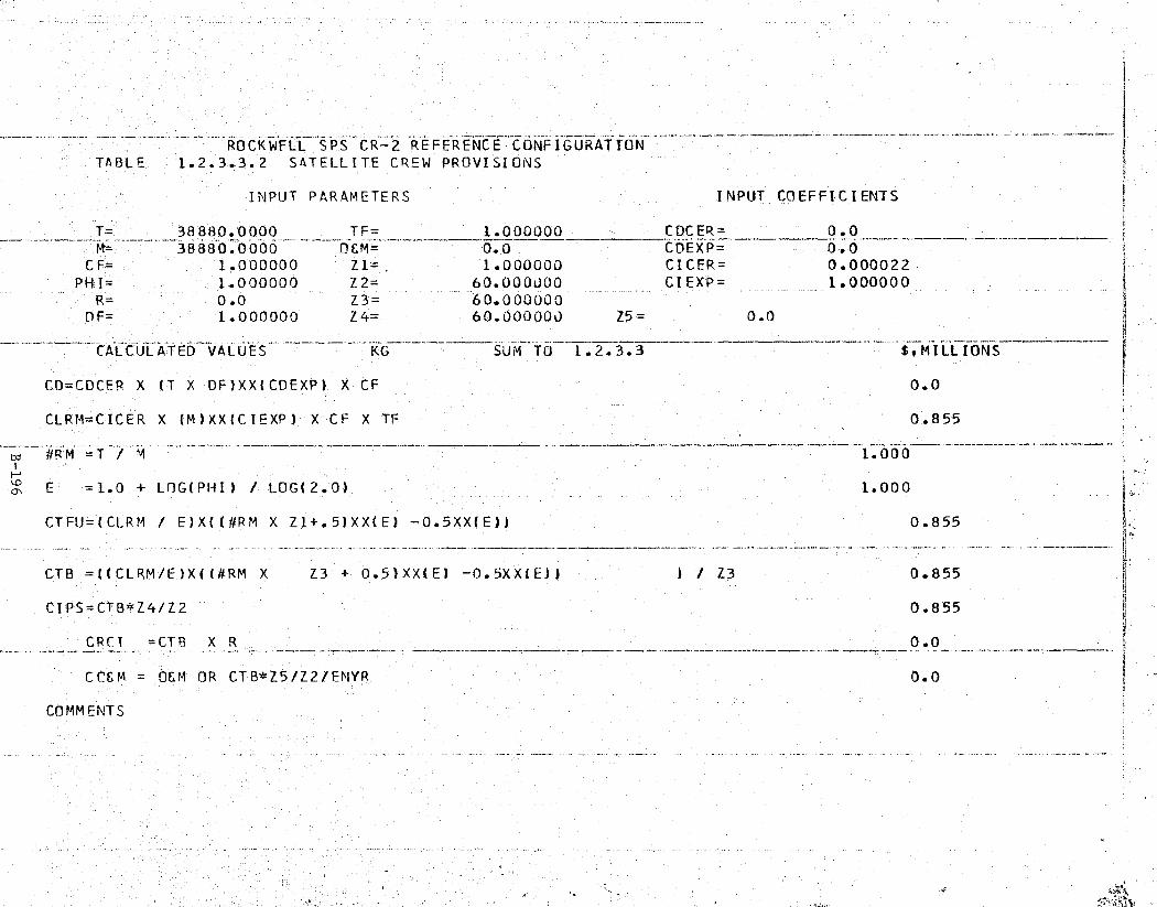
t , rte..
ROCKWELL SPS CR-2 REFERENCE CONFIGURATIONTABLE — 1.2.3.3.2 SATELLITE CREW PROVISIOiNS
INPUT PARAMETERS INPUT COEFFICIENTS
T= 38880.0000— TF= 1.000000 CDCER= 0.0M= 38880.0000 OEM= 0.0 CDEXP= 0.0 {
CF= 1.000000 Z1= , 1.000000 CICER= 0.000022' PHI= 1.000000 Z2= 60.000000 CIEXP= 1.000000
R= 0.0 —Z3 = 60.000000
DF = 1.000000 Z4= 60.000000 Z5= 0.0 w
CALCULATED VALUES KG SUM TO 1.2.3.3 $•MILLIONS
CD=CDCER X (T X DF)XX'(CDEXP) X CF 0.0
CLRM=CICER X (M)XX(CIEXP) X CF X TF 0.855
i1.000
' E -1.0 + LOG(PHI) / LOG(2.0)_
1.000 <'!r 4
CTFU=(`CLRM / E)X((#RM X Z1+.5)XX(E) —0.5XX(E)) 0.855d ^
CTB =((CLRM/E)X((#RM X Z3 + 0.5)XX(E) — 0.5XX(E)) ) / Z3 0.855
CIPS=CTB*Z4/Z2 0.855
CRCI =CTB X R 0.0
CCEM OEM OR CTB*Z5/Z2/FNYR 0.0 szb
COMMENTS
;L
' 3

k ry!•^-^ ?±t ^'ieT0M`vim...."':.",.
^ 4, -
s
Satellite
Space Systems,
Group Q% International11.3 TRANSPORTATION
r.
This element of the costing includes all space transportation required to ysupport the satellite system assembly and operation. Included are transporta-tion requirements supporting the precursor activity, launch to LEO, orbit-to-orbit transfer of all hardware, materials, and personnel, and intra-orbitmovement of cargo during the construction and lifetime operation of thesatellite system.
The overall scenario for SPS space transportation systems consists ofseven major elements -- Space Shuttle derivatives for personnel (PLV) and pre-cursor cargo (STS-HLLV); SPS heavy lift launch vehicle (HLLV); electric orbittransfer vehicle (EOTV); intra-orbit transfer vehicle (IOTV); personnel orbittransfer vehicle (POTV); personnel module, (PM); and orbital/ground supportfacilities. Transportation requirements and concepts for SPS vary as afunction of program phase. During the verification planning period (19811987), the baseline Shuttle is used to conduct sortie missions. Later `,n theverification program "growth" Shuttle is used to deliver personnel and cargoto LEO, The Shuttle derived HLLV is also employed early in the program forLEO fabrication of the space construction base plussupport in building theprecursor satellite (EOTV) test model. Figure 1.3-1 illustrates early programsystems and identifies the SPS VTO/HL HLLV that will be needed for the fabrica-tion of flight EOTVs and the mass-to-orbit requirements of satellite construc-tion.
' LEO STAGING EOTV TO GEO
BASE -
HLLV
^M POWIOTVE, MATING
i,
HLLV
STS
'r ;\
l
Figure 1.3-1. SPS Transportation System - LEO OperationsOperational Program
B-197
".
SSD 79-0010-2-2

t!^YSi r„;,.". ,^'' 'nr.^P y.,. .. ...... ,..-...—.. .._ _. fir.: ...
_ - nf•.!'A'°T"'._)Y'T^'i'._^R'^',.'^,e..Tfi .^i'..
• » +y Ins.
i
rt
4
° r,.. riy
►. Satellite Systems Division0, Rockv.,allSystems Group International ;:SrSpace
n
~ Geosynchronous orbit is the eventual destination of SPS construction a
materials/equipment, personnel, and supplies. The crews will be transported'zfrom earth to' LEO by the growth Shuttle containing the personnel module (PM)where the PM will then be carried to GEO by the POTV. Cargo will be delivered Yto LEO by the SPS VTO/HL-HLLV configuration, transferred to the EOTV by IOTV's,transported to GEO by the EOTV, and off-loaded by IOTV's. Additional detailon the individual vehicles is presented in later subsections.
Mass-to-orbit requirements for construction, propellant, and operations/maintenance activities were-established in accordance with the mission profileand build schedule of two SPS satellites per year with a first unit (TFU) bythe end of year 2000. These calculations were based on a round trip vehiclelife as shown in Table 1.3-1.
Table 1.3-1. Vehicle Life with Maintenance
VEHICLE R.T. FLIGHTS PER VEHICLE
STS GROWTH VEHICLE FOR PLV/CARGO 100' SPS-VTO/HL HEAVY LIFT LAUNCH VEHICLE 300
EOTV-CARGO (ELECTRIC) ORBIT TRANSFER VEH..
20POTV-PERSONNEL ORBIT TRANSFER VEHICLE 100IOTV-INTRO-ORBIT TRANSFER VEHICLE 200
Table 1.3-2 shows the vehicle fleet and vehicle flight requirements tobuild the first SPS satellite, LEO construction base, and the EOTV testvehicle. These calculations were based on the mass-to-LEO and GEO for person-nel, materials, and supplies identified to each of the transportation modes.Precursor activities can be completed by utilizing (1) the two existing TFU
z personnel modules_(P1kIs); and (2) an additional PLV over the two needed for theF' TFU. Two Shuttle launch vehicle sets will be combined with a cargo container/
engine module to transport materials to LEO for the precursor activity. ,TFUvehicle requirements are based on mission timelines, turnaround schedules, andflight profiles.
k Table 1.3-3 tabulates the total program transportation requirements andthe number of flights per vehicle as needed to construct the satellites and to provide ,operations and maintenance after IOC. These calculations are thebasis for developing overall fleet requirements for a 60-unit SPS program,but do not include the precursor effort identified in Table 1.3-2 nor theadditional vehicles needed forattrition/spares or overhaul (replacementcapital investment).
IE;
^J
B-198i
SSD 79-0010-2-2

MASS x 106 KG VEHICLE FLIGHTS
PLV HLLV POTV EOTV IOTV
LEO GEOLEO GEO
SATELLITECONSTRUCTION 2197.8 2197.8 1340 9682 1220 425,1 9682 9682OPERATIONS & MAINTENANCE 1803.0 1803.0 3694 7943 3660 348.7 7943 7943
CREW CONSUMABLESCONSTRUCTION 31.5 28.7 - 139 - 5.6 139 126_OPERATIONS'& MAINTENANCE 86.8 86.0 - 382 - 16.6 382 379
POTV PROPELLANTSCONSTRUCTION 82.7 41.4 - 364 - 8.0 364 T82OPERATIONS & MAINTENANCE 267.8 133.8 - 1180 - 25.9 '-1180 589
EOTV CONSTRUCTIONCONSTRUCTION 28.2 24.2 - 124 - 4.7 124 107OPERATIONS & MAINTENANCE 22.2 19.0 - 98 - 3.7 98 84
EOTV PROPELLANTSCONSTRUCTION 340.3 2.0 - 1499 - 0.4 1499 9OPERATIONS & MAINTENANCE 304.0 - - 1339 - - 1339
IOTV PROPELLANTS•CONSTRUCTION 7.2 3.3 - 32 - 0.6 32 15OPERATIONS & MAINTENANCE 6.6 3,0 - 29 - 1 0.6 29 13
SUMMARYCONSTRUCTION 2687.7 2297.4 1340 11,840 1220 4.14 11,840 1Q121OPERATIONS & MAINTENANCE 2490.4 2044.8 3694 10,971 3660 396 10971 9,008
TOTAL 5178.1 4342.2 5034 22,811 4880 840 22,811 19,129- VEHICLE FLEET
CONSTRUCTION - - - 14 39 12 22 110OPERATIONS & MA'INTENANCE - - 37 37 37 20
TOTAL - - 1 51 76 -49 42 210
• ._._._..,._..._.... -;,.-...,-.-....«,-mot ' _•. b' f
^t^ Mai
Satellite Systems Division RockwellH Space Systems Group ,1, International .upsr0^.'^QDit Q
k
Table 1.3-2. TFU Transportation Requirements
MASS x 106 KG VEHICLE FLIGHTS
PLV HLLV PON EOTV IOTV
LEO GEO LEO GEO
37.12 31.12 45 163,5 45 6,5 164 164SATELLITE CONST, MAINT. 8
PACKAGING
CREW CONSUMABLES 8 PKG, 0.98 0,94 - 4.3 0,2 4 4
POTV PROPELLANTS 8 PKG. 2.91 1.46 - 12.8 03 13 6
EOTV CONST:, MAINT, 8 PKG, 7,20 - 15 31,7 - - 32 -
EOTV PROPELLANTS 8 PKG, 4.79 - - 21.1 - - 21 -
IOTV PROPELLANTS & PKG, 113 0,06 - 0,6 - - 1 -
5 174
TOTAL 1 53,131 39.58 60 234.0 45 7,0 409
TFU FLEET VEHICLE REQUIREMENTS 2 5 4 6 4
GROWTH SHUTTLE VEHICLE70PERATIONS
REQUIREMENTS FOR PRECURSOR ACTIVITIES
(LEO BASE. SPACE CONSTRUCTION BASE, AND
72 FLIGHTS
1 VEHICLE
129 FLIGHTS
2 VEHICLES
EOTV TEST VEHICLE - EOTV'S) PERSONNEL (PLV) LARGO CARRIER/ENGINEMODULE AND LAUNCHVEHICLE
t
:ir7
I
Table 1.3-3. Total Program Transportation _ f'Requirements
j
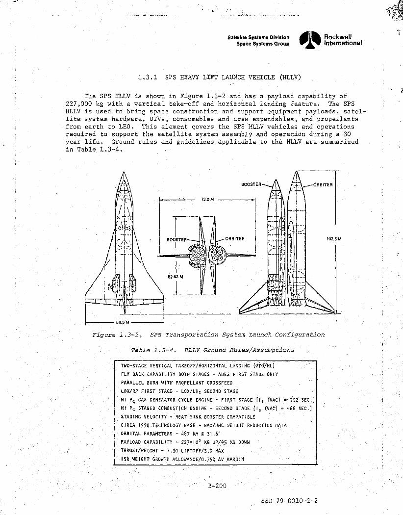
..:.-,.rx^v._x__^.sr a.sx.e.urn F s' xL. 't µ.ms. 1f
Satellite Systems Division Rockwell
Space Systems Group 1 International k
t1.3.1 SPS HEAVY LIFT LAUNCH VEHICLE (HLLV)
The SPS HLLV is shown in Figure 1.3-2 and has a payload capability of 4
'
227,000 kg with a vertical take-off and horizontal landing feature. The SPSHLLV is used to bring space construction and support equipment payloads, satel-lite system hardware, OTVs, consumables and crew expendables, and propellantsfrom earth to LEO. This element covers the SPS HLLV vehicles and operationsrequired to support the satellite system assembly and operation during a 30year life. Ground rules and guidelines applicable to the HLLV are summarized jl
in Table 1.3-4.
I
BOOSTER ORBITER
+-rl — 72.0 M
T ._ORBITER 102.5 MBOOSTER 1
62.63 Mr
56.0 M
r' Figure 1.3-2. SPS Transportation System Launch Configuration
€ Table 1.3-4. HLLV Ground Rulesl ssumptionss,
B-200

'7.
Satellite Systems Division Rockwell„International
^t tSpace Systems Group 1 ^ s^
bRiGNAL i^ ► ^:
OF. POOR QUALITY
1.3.1.1 SPS HLLV FLEET #
A total of 76 HLLV vehicles are required to handle the mass flow require-ments throughout the 60 year SPS program. Thirty-nine vehicles are requiredfor the construction of60 satellites and 37 vehicles are needed for operationand maintenance during the 30 year satellite lifetime.
Data used in projecting estimates for the HLLV and supporting flight costs` were fa-toned from the NASA/JSC contract NAS9-15196. Specific changes were
made to`consider the reference HLLV design configuration; vehicle complexity afactors ` -- engines, ablative shield, propellant valves, and system/subsystemdesign; plus the greater mass of the Orbiter/booster as compared with currentexperience and Rockwell Space Shuttle contract work.
HLLV capital asset replacements, major overhaul requirements, spares pro-visioning, and system lifetimes were projected as being equivalent to twovehicle replacements for each of the SPS fleet vehicles. These calculationsare reflected as an annual cost per satellite over the 30 year period.
-; The DDT&E cost estimate was developed from 'a`careful evaluation of the` NAS9-15196 data base and a comparative factoring'of these data as compared
with data directly applicable to the Space Shuttle program.
See Table 1.3.1.1 for the SPS HLLV cost computer program tabulation.
r,
B-201
SSD 79-0010-2-2

tiff;;S.._^_ _^..-_ _..._-_ ._.-....._ __^.,__ ..._._- . _.. ._.... __. .V._.__ _ _....-._.. .. ._...__.. ..-.^:_ _,.._.._., ._-__' . _.-:..... _... ...._._
ROCKWELL SPS CR-2 REFERENCE CONFIGURATION__ _ _^.«__» _ •-.--._...-__._._...__........-...........-... _.. _...._-:. ...._-.,.._......,.-_«.._... .......___.».._.._.......,.._:.
TABLE 1.3.1.1 SPS-HLLV FLEET
INPUT PARAMETERS INPUT COEFFICIENTS
j T= 1.000000_ TF= 1.000000 CDCER- 8600.00000- M _ -- -- - - - -1.000000 OFM= 0.0 CDEXP= 1 .000000s ' CF= 1.000000 Z1= 5.000000 CDCER= 2000.00000
PHI'= 0.920000 Z2= 60.000000 CIEXP= 1.000000g'! R= 0.084440 Z3= 228.ODOOJO
DF= 1.000000 Z4= 39.000000 Z5= 1 37.000000
` __ _SEfi -CALCULATED VALUES_____ SUM TO 1.3.1 $,MILLIONS-
' CD=CDCER X (T X DF)XX(CDEXP) X CF 8600-.000
CLRM = CDCER X (M) XX (C IEXP) X CF X TF 2000.000. td #RM^-T- _M 1...000
k E =1.0 + LOG(PHI )' / LOG(2.0) 0.880
r° CTFU=`(CLRM / E)X((#RM X Zi+.5)XX(E) -0.5XX(E1) 8950.176 $
` CTB =((CLRM/E)X((#RM X Z3 + 0.5)XX(E) °-0.5XXdE)) ) / Z3 1180.031
t ' LIPS=CTBt Z4/Z2 767.020
CRCI =CTB X R 99.$42
r_DSM = n&m OR CTB*Z5/Z2/ENYR 24.2.56
COMMENTS_
s.
r.
Satellite Systems Division „RockwellSpace Systems Group 1 International
1.3.1.2 SPS HLLV OPERATIONS
This element includes the necessary vehicle operations (user charge perflight including payload integration) required to support the SPS program,?The HLLV has a lifetime capability of 300 flights.
There are a total of 22.811 round trip flights required to support the60 year program where approximately 227,000 kg is delivered per flight. Theseare grouped into a total of 11840 flights for construction and 10,971 flightsfor operations and maintenance. The TFU requires a total of 234 flights tocarry the necessary mass to orbit. On the average of 60, satellites, approx-
A
imately 197 flights are needed for satellite construction and 6 flights are A
required for annual operations and maintenance per satellite.
The projected cost per HLLV flight is based on contract data (referenceNAS9-15196) that was factored and revised to arrive at a propellant, payloadintegration, and supporting operational cost by evaluation against suchthings as propellant costs versus HLLV requirements. See Table 1.3.1.2.
A
rn
P
B-203
SSD 79-0010- 2-2

Cx i
4
a
ROCKWELL. ySPS CR-2 REFERENCE CONFIGURATIONTABLE " 1.3.1.2 SPS-HLLV OPERATIONS
INPUT PARAMETERS INPUT COEFFICIENTS
T= 1.000000 TF= 1.0000J0 CDCER= 0.0
E; M= 1.000000 0 M= 0.0 CDEXP= — 0.0CF= 1.000000 Z1= 234.00000 CICER= 2.480000
PNI=1.000000 Z2= 60.000000 CIp:XP= 1.000000P= 0.0 Z3= 22811.0000
DF= 1.000000 Z4= 11840.0000 Z5= 10971.0000
____-~FLIGHTCALCULATEQ^VALUFS SUM TO 1.3.1 $•MILLIONS
CD=CDCER X (T X DF)X"X(CDEXP) X CF 0.0
CLRM=C'ICER X (M)XX(C IEXP) X CF X TF 2.480
td #RM =T' / M 1.000
I,'NO
E =1.0 + LOG(PHI) / LOG(2.0) 1.000
CTFU=('CLRM / E) X((J#RM X Zi+. 5) XX(E) —0.5XX(E1) 580.320
CTB =((CLRM/E)X((#RM X ?3 + 0.5)XX(E) —0.5XXIE)) ) / Z3 2.480
CIPS=CTB=Z,4/Z2 489.387
CRCI' =CTB X R 0.0i
CLCM 0&M OR CTB*Z5/Z2/ENYR 15-.116 s
' COMMENTSF
1
^..._ ... .. ,^. Ydw aft ^:.:.r 'hs. 'w.... .d.^,. ,..a..
..iCfCxx=-._ . . ..u.v_.,..
^. .. - - > _. .• ^^;?' _ — . — .
—

tt
7
Satellite Systems Division Rockwell s
Space Systems Group InternationalOil% {
ORIGINAL PAGE 151.3.2 CARGO ORBITAL TRANSFER VEHICLE (COTVbF POOR QUALITY
r= ;
_.
This element includes the COTV vehicle and operations required to supportthe satellite system assembly and operation. Included is the LEO-to-GEOtransfer of space construction and support equipment, satellite system hard-ware, spares, and propellants required throughout the satellite lifetime.
The Rockwell cargo orbital transfer vehicle is a high specific impulseconfiguration that is possible with electric propulsion. The concept isshown in Figure 1.3-3 and has a payload capability of 5.17X10 6 kc, (equivalentto 23 HLLV payloads) with a 6 month round trip time per flight, a''7
COTV fleet procurement andoperations are detailed in sections 1.3.2.1and 1.3.2.2, respectively.
EOTV DRY WT. - 106 KGEOTV WET WT. - 1.67 X 10⁴ KGPAYLOAD WT. - 5.17 X 10⁶ KG 1300M
t700M I^.
F
•
562.9M ^^ T
INCLUDES
r0 0 0 0 0 0 2096 SPARES
f 0 0 0 0 0 4I' o OON
00:1
100M 0 O^.r O 0 0
O00 I
Figure 1.3-3. EOTV Reference.Configuration
j
B-205
SSD 79=0010-2-2
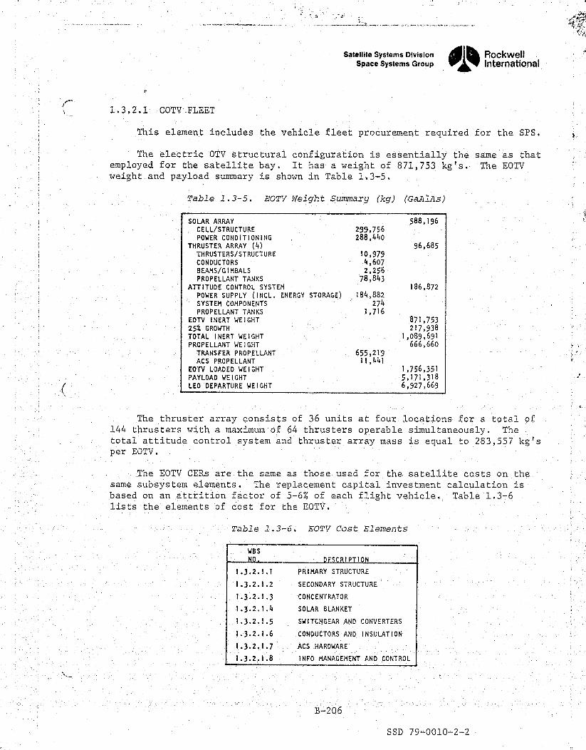
E
W34
Satellite systems Division ®® Rockwell `1Space systems Group International a
1.3.2.1 COTV:FLEET
This element includes the vehicle fleet procurement required for the SPS.
The electric OTV structural configuration is essentially the same as thatemployed for the satellite bay. It has a weight of 871,753 kg's. The EOTV
r._ weight and payload summary is shown in Table 1.3-5.
Table 1.3-5. EOTV Weight Summaxy (kg) (GaA1As)
y
f
E The thruster array consists of 36 units at four locations for a total of144 _thrusters with a maximum of 64 thrusters operable simultaneously. Thetotal attitude control system and thruster array mass is equal to 283,557 kg'sper EOTV., 9
F The EOTV CERs are the same as those used for the satellite costs on thesame subsystem elements. The replacement capital investment calculation is
R
based on an attrition factor of 5-6% of each`flioht vehicle: Table 1.3-0lists the elements of cost for the EOTV.
Table 1.3-6. EOTV Cost Elements

ROCKWELL SPS CR-2 REFERENCE CONF-I6URATTON Pht
t
^.
TABLE 1.3.2.1.1 PRIMAPY STRUCTUREr
INPUT PARAMETFRS INPUT COEFFICIENTS —
T= TF=_30890.0000 — _- 1.000000 CDCER=-- -0.023000M=M= 2059.D0000 OEM— 0.q CDEXP= 0.800000
CF= 1.000000 Z1= 6.000000 CICER= 0.000050PHI= 1.000000 Z2= 60.000000 CIEXP= 1.000000 x.
R= 0.003500 Z3= 44.0000000 00DF= 0.020000 Z4= 22.000000 Z5= 20.000000
CALCULATED VALUES KG SUM TO 1.3.2.1 $•MILLIONS -'
CD=CDCER X (T X DF)XX(CDEXP) X CF 3.930
CLP.M=CTCER X (M)XX(CIEXP) X CF X TF 0.103
td itRM = T —/ M 15.002
' E =1.0 + LOG( PHI) / LOG(2.0) 1.000
CTFU=(CLRM / E)X(( #RM X Z1+.5)XX(E) — 0.5XX(E)1 9.267
CTB =((,CLRM/E)X((#RM X Z3 + 0.5)XX(E) —0.5XX(—EJJ ) / Z3 1.544
CI PS=CTB*Z4/Z2 0.566
CPCI =CTB X R 0.005_,
COfM = O&M OR CTB*Z5/Z2/ =NYR 0.017
' COMMENTS
t
)
rs

}}V'1m
'*."a ., _•^ -'Fry'y"1?.',m ,yf^!`r'f•.a .a> .r:^,n^r ".t^"^:a r
y.
a I
ROCKWELL SPS CR-2 REFERENCE CONFIGURATIONTABLE 1.3.2.1.2 SECONDARY STRUCTURE
t
F ' INPUT PAPAMETERS INPUT COEFFICIENTSa
T= 14918.0000 TF= 1.000000 COCER= 0.156000E M= 5.000000 OEM= 0.0_ CDEXP= 0.511000
CF= 1.000000 Zl= 6.000000 CICER= 0.101000PHI- 0.980000 Z2= 60.00000 CIEXP= 0.355000
R= 0.003500 Z3= 44.000000DF= 0.050000 Z4= 22.000000 Z5= 20.000000
CALCULATED VALUES'-___-__ KG^_.__..._
SUM TO 1.3.2.y 1 $,MILLIONS
CD=CDC.ER X (T X DF)XX(CCEXP) X CF 4.582f
' CLRM=DICE R X (M)XX(CIEXP) X CF X TF 0.179
#RM =T / M 2983.600
CD00 E =1.0 + LOG( PHI) / LOG(2.0) 0.971 Ir•
CTFU=(CLPM / E)X((#RM X Z1+.5)XX(E) -0.5XX(E)1 2478.750µ
CTB =((CLRM/E)X((##RM'X -Z3 + 0.5)XXIE) "-0.5XX(E)f ) / Z3 389.820i.
CTPS=CTB*Z4/Z2 142.934
_.. ;:.. µCRCI =CTB X R - _._. ._ _ _.._ . _ _ ..._.^ ......-. 1.364
e- CCCM = OEM OR CTB*Z5/Z2/FNYR= 4.331
COMMENTS

l1
ROCKWELL 'SPS CR-2 REFERENCE CONFIGURATIONTABL E 1.3.2.1.3 CONC FNT^,ZTOR
INPUT PARAMETERS INPUT COEFFICIENTS
T= 1800000.00 TF= 1.000000 CDCER= 0.027000M= 450000.000" OEM= 0.0 ---___.CDEXP= 0.394000 -'
CF= 1.000000 Z1= 6.,000000 CICER= 0.000003PHI= 0.980000 Z2= 60.000ODU CIEXP= 0.950000
€ R= 0.003500 Z3= 44.000000
fDF= 0.020000 Z4= 22.000000 Z5= 20.000000-
fALCULATED, - VALUES ----SQ M -^^ — SUi^i — TU 1.3.2.1 - ',MILLIONS,
C'D=CDCER X (T X DF)XX(CDEXP) X CF 1.685
' CLRM=CICER X (M)XX(CIEXP) X CF X TF 0.704 k
_t - FIRM =T /" M 4.000-^ _f
E =1.0 + LOG(PHI) / LOG(2.0) 0.971
C'TFl1=(CLPM / E)X((#R.M X Z1+.5)XX(E) —0.5XX(E)1 15.818
CTB =((CLRM/E)X((#RM X Z3 + 0.5)XX(E) —0.5XXtE)) ) / Z3 2.494
CIPS=CTB*Z4/Z2_
0.914
CRCI =CTB X R 0.009Y.
COEM =' O&M OR CTB*Z5/Z2/ENYR 0.028
'COMMENTS
! t
'a
ashY,-
. _ ,.. ^;. • s1' l ".' ... ,.1 ce"^jC4< .ii. . ^ii3..+hY ^ . w 4., . h...^_

fT-",;;.^q+wr=eqg_:,rrecn,,xt^t2; X'"x'i," . ";as'^ e r f.x3v -: t, .
..,T
^ ..
1 ;i
iROCKWELL_SPS CR-2 REFERENCE CONFIGURATION
TABLE 1.3.2.1.4 SOLAR BLANKET
INPUT PARAMETERS INPUT COEFFICIENTS
T= 900000.000 TF=^ 1.U00000 CDCER= 0.161400•^
_. _ _M= 18750.0000 0&M= 0.0 CDEXP= 3.394000
CF= 1.000000 Z1= 6.000000 CICER= 0.000067PHI= 0.990000 Z2= 60.0000U0 CIEXP= 1.000000
rt R= 0.003500 Z3= 44.000000DF= 0.020000 Z4= 22.000000 Z5= 20.000000
CALCULATED ^VALUES J- ^ SQ+ M _^
- sum To ^ 1.3.2.1 y v--^^ 1- $,MILL IONS
CD=CDCER X (-T X DF)XX(CDEXP) X CF 7.664
gCLRM=CICER X (M)XX(CIEXP) X CF X TF 1.256
toi #RM =T ! M-
48.000- -
No E =1.0 + LOG( PHI) ! LOG(2.0) 0.986
CTFU=(CLRM / E)X((#RM X Z1+.5)XX(E) -0.5XX(F1) 338.117
CTB =((CLRM/E)X((#RM X Z3 + 0.5)XX(E) -0.5XX(E)) ) / Z3 54.757
L IPS=CTB*Z4/Z2 20.077
CRCI =CTB X R 0.192
CC&M = O&M OR CTB*25/Z2/FNYR 0.608
COMM FLATSNASA/ADL NAS 9-15294 MARCH 1978
E7/SQ MMTLS X33/SQ M_& PROCESSING $34/S0 M.
t

h, a re• ten» -__
j{
• -tl
f^'TABLE
ROCKWELL SPS CR-2REFERENCE1-SWITCHGEAR.3.2.1.5
CONFIGURATIONAND CONVERTERS
INPUT PARAMETFRS INPUT COEFFICIENTS
T"= 2875.00000 TF= 1.000000 CDCER= 0.158000_M--^Yi ^719.0000^0 DEM=^ 0.0 CDEXP= 0.297000CF= 1.500000_ Z1= 6.000000 CICER= 0.000400
PHI= 0.950000 Z2= 60.000000 CIEXP= 1.000000R= 0.001111 Z3= 44.000000
DF= 0.500000 Z4= 22.000000 Z5= 20.000000
CALCULATED VALUES KG SUM TO 1.3.2.1 $,MILLIONS
CD=CDCER"X (T X DF)XX(CDEXP) X CF 2.054
CLRM=CICE'R. X (M)XX(CIEXP) X CF X TF 0.431
#RM =T / M 3.999
E =1.0 + LOG(PHI) / LOG(2.0) 0.926
CTFU=(CLRM / E)X((#RM.X Z1+.5)XX(E) -0.5XX(E)) 8.760
d CTB =((CLRM /E)X((#RM X Z3 + 0.5)XX(E) —0.5XX(E)) ) / Z3 1.268
CIPS=CTB*Z4 /Z2 0.465
C'RCI =CTB X R: 0.001
CC&M = O&M OR CTB*Z5/Z2/ENYR 0.014
COMMENTS
i
a

qs..
` a
- - .. .. q
'ROCKWELL SPS CR-2 REFERFNCEY CONFIGURATIONTABLE 1.3.2.1.6 CONDUCTORS AND INSULATION
INPUT PARAMETERS INPUT COEFFICIENTS
T='357675.000 TF= 1.000000 CDCER= 0.158000'_M--.,-_... -7452.00000 0&M= 0.0 CDEXP= 0.297000
CF- 1.000000 Z1= 6.000000 CICER= 0.000904PHI= 1.000000 Z2- 60.000000 CIEXP= 1.000000_
R= 0.001111 Z3= 44.000000 yDF= 0.020000 Z4= 22..000000 Z5= 20.000000
CALCULATED VALUES KG SUM TO 1.3.2.1 $,MILLIONS
CD = CDCER X (T X DF)XX(CDEXP) X CF 2.205
CLRM=CICFR X (M)XX(CIEXP) X CF X TF 0.030
#R"M =T / Ma_ 47.997i
N E = 1.0 + LOG (PHI) / LOG (2.0) 1.000
CTFU-(CLRM`/ E)X((#RM X Z1+.5)XX(E) -0.5XX(E)) 8.584 .
CTB =((CLRM/E)X((#RM X Z3 + 0.5)XX(E) -0.5XX(E)1 ) / Z3 1.431 r
Cl PS=CTB*Z4/Z2 0.525
f P'CI =CTB X R 0.002
CO&P4 -= 0&M OR CTB*Z5/Z2/ENYR. 0.016
COMMENTS
)

INPUT PARAMETERS INPUT COEFFICIENTS- -' ^
n TF=-_'
122000______- ' 1970~00000 OCM= O°U ' CDEXp= 146000
F= '. I,000080 Zl= 6°008000 ClCER= 8°057000
PHI=` ~ ^ 0~958000 / Z2= _ _60.800000 _ CIEXP= O °^29000 _ __ __^ R= .0~083500
_Z3= 44.000000
^ DF= 0~300000 Z4= 22.008000 Z5= 20.000000
l^
CALCULATED VALUES KG SUM TO 1.3.2.1
$'MILLIOM8
9°697
1.348
0.926
CTFU~(CLRM / E)X((#RM X Il+.5)XX(E) —0.5XX(E))' 762.015
CIPS=CTB*Z4/Z2 40.199
^^^

ROCKWELL SPS CR-2 REFERENCE CONFIGURATIONTABLE 1..3.2.1.8 INFO. MGMT. AND CONTROL
INPUT PARAMETERS INPUT' COEFFICIENTS'
T= 0.0 TF= 1.000000 CDf.ER= 0.0M^ 0.0 O&M= 0.0 CDEXP= 0.0
CF= 0.0 Z1= 6.000000 C ICER= 0.0PHI= 1.000000Z2= 60.000000 CIEXP= 0.0
R= 0.0_..
Z3 = 60.000000DF= 1.000000 Z4= 60.000000 Z5= 0.0
CALCULATED VALUES -^ g ---SUM TO 1.3.2.1 E. MILL IONS
CD=CDCER X IT X DF)XX(CDEXP)—X CF 0.0
CLRM=CICER X (M)XX(CIEXP) X CF X TF 0.0
rNE =1.0 + LOG(PHI) I LO`G(2.0) 0.0
CTF11=fCI R l FIX((IfRM X 71 +_51XXIFI — 0.5XXIFIJ 0.0
a
ia
^, 4 ", °'yam° "a ."° y'ue ne v a .a . f a v 3 h; a s s w`+
>
r i
^ z1
`f
t iSti
z Y

`Ir 7r^{Nait - _.
` Satellite Systems Division Adlbk RockwellSpace Systems Group International
1.3,2.2 COTV OPERATIONS i
Necessary vehicle operations (user charge per flight including payload'integration) is included in this element.
The flight life of the EOTV is estimated at 20 round trips from LEO toGEO. Four hundred forty-four flights are required for the construction of60 satellites and an additional 396 flights will maintain the operationalsatellites for the 30 year period. Seven flights are required to build thefirst satellite.
The calculations used in this cost estimate are presented in Table 1.3.2.2.
j
:4
k
f '
^ F
u
i'
:
x
B-215
N`SSD 79-0010-2 -2

all
r
ROCKWELL SPS CR-2 REFERENCE ,CONFIGURATION YTABLE 1.3.2.2 COTV, OPERATIONS :?
INPU T PARAMETERS INPUT 'COEFFICIENTS
T= 1.000000 TF= 1.000000 COCER= 0.0M'= 1.000000 OEM= 0.0 COEXP= 0.0
CF= 1.000000 Z1= 7.000000 CICER= 0.630000PHI= 1.000000 Z2= 60.000000 CIFXP= 1.000000
R- 0,.0 —Z3= 840.000000
DF_= 1.000000 Z4= 444.000000 Z5= 396.000000
CALCULATED VALUES FLIGHT V^ SUM TO 1.3.2 $,MILLIONS
CD=CDCER X (T X DF)XX(CDEXP) X CF_ 0.0 i
CLRM = CICER X (M)XX(CIEXP7 X CF X TF 0.630
#RM =T l^^^I --i 1.000
-- rn E =1.0 + LOG( PHI) / LOG(2 •.O') 1.000 # s'
CTFU = (CLRM / F)X((#RM X Z1+.5)XX(E) —0.5XX(E)) 4.410
CTB =((CLRM /E)X'(( #RM X Z3 + 0.5)XX(E) -0.5XX(E)) ) / Z3 0.630
CIPS = CTB*Z4/Z2 4.662-
CRCI =CTB X R_ 0.0
CCEM = OEM OR CTB*Z5/Z2 /ENYR 0.139
COMMENTS
- fti

CCi
\^v JCi v^ \O^Z^ O
Z-1
VEHICLEI ITEM ^4°0"^ J ^^ y Qv4,r hQ v^ -4^ Qo4° °^ c,
DESCRIPTION Q a^ ^` he moo= ,fieQ
V H t RE UIR 'v NTS
SHUTTLE ORBITER(STANDARD VERSION) (1) (3) 15 37 26 73 1 EASHUTTLE CARGOCARRIER &MODULE 2 1 3 1 EAEXTERNAL TANK (201) (60) 1541 3694 5235 1 EA 1 EALIQUID ROCKET
BOOSTER (6) (10) 34 74 216 324 2 EA 2 EA
FLIGHT RE UIREMENTS
PERSONNEL LAUNCHVEHICLE (PLV) (72) (60) 1412 3694 5106
CARGO CARRIER
LAUNCH VEH. MODULE 129 129
° Precursor & TFU requirements included in satellite construction quantity.
n
f.
r Satellite Systems Division ®hk RockwellSpace Systems Group International
t.n
(s
1.3.3 PERSONNEL LAUNCH VEHICLE (PLV)
rc,
_ This element includes the space shuttle growth vehicles and operations a.„ required to supportthe satellite system assembly and operation. Included is
the launch to LEO and return of all personnel and priority cargo requiredthroughout the satellite construction period and operational lifetime.
In addition to the earth-to-LEO transfer of personnel during satelliteconstruction and operational periods, the space shuttle growth vehicle will1) accommodate the transfer of personnel and 2) with the cargo/engine moduleadaptation, will transfer the cargo/material needed for precursor activities 'qdealing with the LEO Base, Space Construction Base, and the initial EOTV-335mW precursor test article. Shuttle goowth vehicle and flight requirementsfor the SPS Grogram are identified in Table 1.3.3.
AL PDAGE Q^Table 1.3.3. Shuttle Growth Vehicle and OF
POOR QUALITYFlight Requirements

x3 s
R
Satellite Systems Division RockwellAi S
Space Systems Group International
s1.3.3.1 PLV FLEET
This element includes the vehicle fleet procurement required to supportthe SPS program. Included are the vehicles for ,personnel transfer from earthto LEO and for cargo as needed to support the precursor phase of SPS program .
development.
The PLV consists of a standard Shuttle Orbiter, an external tank, andtwo liquid rocket boosters. The cargo vehicle configuration is achieved byreplacing the orbiter with a cargo carrier and engine module. The externaltank and liquid rocket booster (Figure 1.3.3) are common systems used on theShuttle derived personnel and cargo vehicles. The integral, SSME-35 poweredconcept requires four engines with a thrust-to-weight ratio at lift-off of1.335, which is adequate for both nominal and abort trajectories.
BOOSTER (EACH): i
GROSS WT 871K LBPROP. YT 715K LBINERT WT 156K LB
^aSSME-35:
F 459K'LB (S.L.) (EACH)
LAUNCH CONFIGURATION ISp 406 SEC (S.L.)
PAYLOAD • 100K LB GLOW 3.670; LB• 35:1 f,
MR • 6:1
156 FT
20.0 FT DIA'
--•
[[ssue^ ^j
^:
LH Z TANK L02 TANK -- t1W VJ
(102K LB) `. (613K LB)"•"'
`,^1 .L 1
LANDING ROCKETS` LANDING ROCKETSSSME•35
RCS FLOTATION STOWAGE 4 REQO
PARACHUTE STOWAGE ENGINE COYER
(OPEN)
' Figure 1.3.3. PLV Configuration
Cost estimates were developed from work produced under the RockwellShuttle Growth Study Contract NIAS8-32015 of May, 1977. DDT&E, Shuttle Orbiter,external tank, liquid rocket booster, the engine module costs, and projectionson operational requirements were' identified by comparative evaluation with theShuttle growth data base. Mangy different concepts for reducing Shuttle opera-tions costs were examined in the study, but overall cost characteristicsclearly reflected the choice of propulsion which lead to the SSME-35 poweredLRB as a considered alternative.
;.; Elements of the STS PLV and cargo fleet were individually analyzed on thebasis of systems per vehicle, vehicle life, asset rep lacement and operationalaspects, A PLV orbiter 30 year replacement factor of 0.5 equivalent vehicles
' B-218
k : SSD 79-0010-2-2
y.

"^ '''^ C 4 ^°`^•aee--.•. _ _ fir►. t: .:,M; TX'$`P!^X'OS`ii T_ ^. *F+tfG
area^.u^tcil—un
t
{ Jr
E Satellite Systems Division
v lk Rockwell
Space Systems Group International
s
was used for each orbiter in the fleet. The external tank is an expended
a
k item after each flight and the LRBs are to be replaced on the basis of twoboosters for each one in the fleet. An attrition/spares factof of 0.5equivalent vehicles is also used for the cargo/engine module.'
` DDT&E and system cost estimates are identified in the following tables:F h
Table No. Item
1.3.3.1.1 STS-PLV Orbiter r
1.3.3.1.2 STS-PLV External Tank
1.3.3.1.3 STS-PLV Liquid Rocket Booster
^, a 1.3.3.1.4 STS-Cargo Carrier and Engine Module
r 'i
ri.
x
t
7
B-219
SSD 79-0010-2-2r
^.^ ...._^. :.. . ' , •.:_ -.... , vim;= . _ -• : .,_. __'`:. :; ^.^s^

^^^R^?!F'dFT•'"1R°,'^Ftt"L' . 'T''.4c"Y"^Rm^twxr^Ye'.""`'^(.'%S`.""'. .R 3;1 ."9:: .^yd •M"°SCr°.". d •.
- - ^
_
,
jF.•_.awe..,
ROCKWFLL SPS CR-2 REFERENCE—CONFIGURATION—TABLE 1.3.3.1.1 STS— PLV ORBITER
E
INPUT PARAMETERS INPUT COEFFICIENTS
T= 1.000000 TF= 1.000000 CDCER= 0.0+ M— 1,000000 OEht=.^_.._.._....^ -.— 0.0_........___- CDEXP=. 0.0
CF= 1.000000 Z1= 3.000000 CICER= 600.000000PHI= 0.920000 Z2= 60.000000 CI EXP= 1.000000 a
R= 0.014444 Z3= 78.000000DF= 1.000000 Z4= 15.000000 Z5= 37.000000
CALCULATED VALUES SET SUM TO 1.3.3.1 $,MILLIONS
CD=CDCER X (T X DF)XX'(CDEXP) X CF 0.0
CLRM = CICER X (M)XX(CIEXP) X CF 'X TF 600.000
!tr, #RM =T 1 M 1.000 a
o E =1.0 + LOG(PHI) / LOG(2.0) 0.880
CTFU=(CLRM / E)X((#RM X Zl+.5)XX(F) -0.5XX(E)1 1682.531 l
CTB =((CLRM/E)X((#RM X Z3'+'0.'5)XX(E) —0.5Y,X(E0l ) / Z3 401.360i
CIPS=CTB*Z4/Z2—
100.340
CRCI = CTB X R 5.797
CO& M = O&M OR CT8*Z5 /Z2/FNYR 8.250
COMMENTS
_.. ^.d
. ...^. .. _.. ., , y.. w .,.
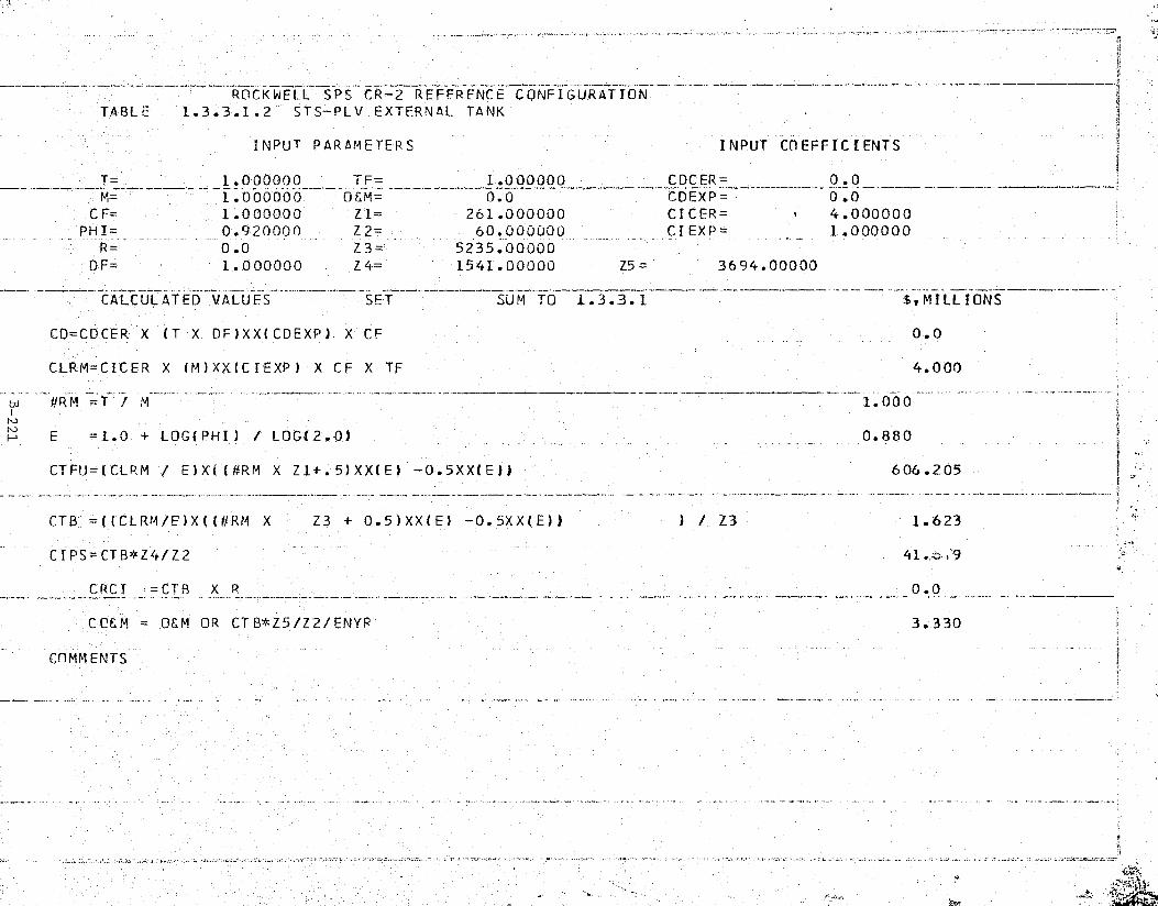
ROCKWELL SPS CR-2 REFERENCE CONFIGURATION ^) a
TABLE 1.3.3.1.2 STS-PLV EXTERNAL TANK
INPUT PARAMETERS INPUT M EFFICIENTS
T= _ 1.000000 TF= 1.000000 CDCER= 0.0M,= 1.000000 O&M= 0.0 CDEXP= 0.0
CF= 1.000000 Z'1= 261.000000 CICER= 4.000000PHI= 0.920000 Z2= 60.000000 CIEXP= 1.000000R_ 0.0 7_3= 5235.00000
DF= 1.000000 _Z4= 1541.00000 Z5= 3694.00000
CALCULATED VALUES SET =,MILLIONSSUM TO 1.3.3.1
CD=CDCER X (T X DF)X_X(CDEXP) X CF 0.0
CLRM=CICER X (M)XX(CIEXP) X CF X TF 4.000
td #RM =T / M 1.000- <,
N E =1.0 + _LOG(PHI) / LOG(2.0) 0.-880
CTFU=(C,LRM / E)X'i (#RM X Z1+.5)XX(E) —0.5XX(E)) 606.205
CTB =((CLRM/E)X((#RM X Z3 + 0.5)XX(E) —0.5XX(E)) ) / Z3 1.623
C I PS-CTB Z4/ Z2 _ 41.,,E :29a
CRCT =CTB X R 0.0
C CEM _ O&M OR CT B*Z5/Z2/ ENYR' 3.330
CnMM ENTS
's.
}

I
ROCKWELL SPS CR-2 'REFERFNCE CONFIGURATION'r A 131 r- 1 -1 -:) - 1 -1 c r c- ni ti 1 r n:. n nr' V Cr un nr TG'O
iz.
INPUT PARAMETERS INPUT COEFFICIENTS
T= 1.000000 TF= 1.000000 CDCER= 1304.00000M= 1.000000 (1FM= 0.0 CDEXP= 1.000000
CF= 1.000000 Z1= 5.000000 CICER= 195.300003'. PHI= 0.920000 Z2= 60.000000 CTEXP= 1.000000
R= 0.060000 Z3= 162.000000DF= 1.000000 Z4= 17.000000 Z5= 37.000000
CALCULATED VALUES S'ET SUhi TO 1.3.3.1 $,MILLIONS
C'D=CDCER X (T X DF)'XX(CDEXP) X CF 1304.000
' CLRM=CICER X (M)XX(CIEXP') X CF X TF 195.300
td 1.000
N E =1.0 + LOG(PHI)-/ LOG(2.0) 0.880
' CTFU=((-LRM / E)X((#RM X-Z1+.5)XX(E) -0.5XX(E)) 873.985 sW
CTB =((CLRM/E)X((#RM X Z3'+ 0.5)XX(E) —0.5XX(E)) ) / Z3 119.967
CIPS = CTB*Z4/Z2 33.991
--2
CRCI =CTB X R 7.198
CO&M = OEM OR CTB*Z5/Z2/ENYR 2.466
COMMENTS_ x
'a
t^
gj+'1
c^. 3 . '. '.5^2J1:'.. _.. v ._. ^:\aafvl».r:<^... ... y tift rsN-: . ,.. ... i.. uc t . sv .......t -.

..
C
tsrS i., ^R' ..7+_'.fw'^'.xFTe'sw. ,"M°t^2a.±*'"° s; r+*.^"r .. ,"??:3'a ^"s,. rN,:.^.. ,..;.•f`r? P9`w ePa^F .r,: jejr °T ^N "r^Y vF T T' ' ,..w•-a+x".i— _ — a.y..,r +, a7""a `r.,`...z7 }
:pp
ROCKWELL S.PS CR-2 REFERENCE CONFIGURATION-^TABLE 1.3.3.1.4 STS CARGO CARRIER AND EM
INPUT PARAMETERS INPUT COEFFICIENTS
T= 1.000000 TF= 1.000000 CDCER 245.000000OO--- —` CDEXP= 1.000000_
kCF= 1.000000 Z1= 3.000000 CDCER= 265.800049
PHI= 0.920000 Z2= 60.000000 CIFXP= 1.000000R= 0.0 23= 3.000000
DF= 1.000000 Z4= 3.000000 Z5=— 0.0
Y CALCULATED VALUFS----___._--$^--
$,MILLIONSSUM TO 1.3.3.1
CD=CDCER X- (T X DF)XX(COEXP) X CF 245.000
'- CLRM=CICER X (M)XX(CIEXP) X CF X TF 265.800
td #R M =T / M 1.000
io F = 1.0 + LOG( PHI) / LOG(2.0) __ 0.880
CTFU = (CLRM / E)X((#RM X Z1+.5)XX(E) — 0.5XX(E)) 745.362
CTB =((CLRM/E)X((#RM X Z3 + 0.5)XX:(E) -0.5XXIE)) )_/ Z3 248.454
CIPS = CTB*Z4/Z2 12.423
CRCI —CTB X R 0.0
CGEM 06M OR CTB*Z5/Z2/ENYR 0.0 iy
COMMENTSE
3
_
S
yi

Satellite Systems Division Rockwell>$
Space Systems Group International
1.3.3.2 PLV OPERATIONS .
This element includes the necessary vehicle operations (user charge per v„flight including payload integration) required to support the SPS program.
gA total of 5,235 flights are required of the Shuttle derived personnel
and cargo vehicle 1,412 for construction, 3,694 for operations, and 129for the precursor program. The 1,412 PLV flights for construction include72 for the precursor effort and 60 for the TFU satellite.
1Cost estimates per flight were projected after an engineering analysis
of the operational costs and vehicle elements identified in the RockwellShuttle Growth Study (NAS8-32015). Tables 1.3.3.2.1 and 1.3.3.2.2 coveroperational cost estimates,
i
i
t ;x ,
nn
B-224_
^- SSD 79-0010-2-2
t, - a: ^ - ^3.^^'_'.¢..asa,.e.ayse;rcaz+.ts^s..__^__^,.^^.^..^^_^aas!-^^c^•wr mr^.::^_^,..,—.—.

^{5,^2%k''.S T.±^`a'R"iy m . .v n Far,^E,"'';',';^°"'^nY^;xC.'.r^ r^,:Kd., m,—G^*."`x°nvic7 a,, r,t- a •-_: '.^ , - -. -„",v: , . ..
-ROCKWELL SPS CR-2 REFERENCE CONFIGURATION
TABLE 1.3.3.2.1 PLV 'OPE'RATIONS
INPUT PARAMETERS INPUT COEFFICIENTS
T= _-_ 1.00J000_, TF= 1.p000000 CDCER= 0.0M=
-.._1.000000
.0&h1= 0.0 CDEXP= 0.0
CF= 1.000000 Z1= 132.000000 CDCER= 9.200000PHI= 1.000000 Z2= 60.100000 CIEXP= 1.000000
R= 0.0 Z3 5106.00000(1F 1.000000 Z4 1412.00000 Z5= 3694.00000
CALCULATED VALUES FLIGHT SUM TO 1.3.3.2 ~- -
CD=CDCER X (T X DF)XX(CDEXP)'X CF
CLRM=CDCER X (M)XX(CIEXP) X CF X TF
_ -$,MILLIONS
0.0
9.200
#RM_=T / M -- --- -- 1.000---._^-_iN
L.nE =1.0 + LOG(PHI) / LOG(2.0) 1.000
CTFU=(CLRM / E)X((#RM X Z1+.5)XX(E) 0.5XX(E)) 12.14.400
CTB =((CL,RM/E)X((#RM X Z3 + 0.5)XX(E) -0.5XXiE)) ) / Z3 9.200
CIPS=CTB*Z4/Z2 216.507
CRC =CTB X R 0.0
CC&M OEM OR CTB*Z5/Z2/ENYR 18.880
COMMENTS_

ROCKWELL SPS CR-2 REFERENCE CONFIGURATION
e
TABLE 1.3.3.2.2 STS HLLV CARGO OPERATIONS
INPUT PARAMFTERS INPUT COEFFICIENTSa a
1.000000 TF= 1.000000 CDCER= 0.0a
M= 1.000000 OEM= 0.0 CDEXP=__...__
0.0tj CF= 1.000000 Z1= 129.000000 CDCER= 8.7500007 PHI= 1.000000 Z2= b0-.000000 CI EXP= 1.000000 t
R= 0.0 7_3= 129..000000' DF= 1.000000 Z4= 129.000000 Z5= 0.0
C
CALCULATED VALUES $ SUM TO 1.3.3.2 $,MILLIONS
CD=CDCER X (T X DF)XX(CDEXP) X CF 0.0
CLRM=CICFR X (M)XX(CIEXP) X CF X TF 8.750
€ #R M =*T M 1.000r ^No, E =1.0 +' LOG(PHI) / LOG(2.0) _ 1.000.•
CTFU=(CLPM / E)X((#RM X Zi+'.5)XX(E) —0.5XX(E)1 1128.750
CTB =((CLRM/E)X((#RM X Z3 + 0.5)XX(E) — 0.5XX(EJ) ) / Z3 8.750
CIPS = CTB*Z4/Z2 18.813
R = T8 X RC CI C 0 .0
COEM _- OEM OR CTB*Z5/Z2/FNYR 0.0
ECOMMENTS
's
r` ,,dRr -.. r ...,..

^, rte- nti
i'
Kral-
Satellite Systems Division Rockwell
Space Systems Group ® International11.3.4 PERSONNEL ORBITAL TRANSFER VEHICLE (POTV) j
This element includes the POW vehicles and operations required tosupport the satellite system assembly and operation. Included is the LEOto-GEO and return of all personnel and priority cargo required throughoutthe satellite construction and operational periods.
All of the POTV options evaluated utilize a single stage propulsiveelement that is fueled in LEO and refueled in CEO for the return flight.The reference configuration is illustrated in Figure 1.3.4 where the POTV(a propulsive stage) is capable of transporting a 60-man personnel module(PM) of 18,000 kg. The vehicle is costed in section 1.3.4.1 and POTVoperations are covered in section 1.3.4-2.
® 1 2 ASE
ENGINES4.5 M _. _
7(1.^ r u'rt"`i Zi .. f1 rtr""-rytr M ^-n
PERSONNEL MODULE POTV
r

iI
A ^
Satellite Systems DivIsion RockwellSpace Systems Group International
tY
1.3.4.1 POTV FLEETr;
The vehicle fleet procurement required to support the SPS program isincluded in this element. The POTV is a single stage OTV of 36,000 kg withrefueling at GEO for the return to LEO. Propellants are carried from LEOto GEO by the EOTV. The SPS HLLV carries the construction, crew expendables,and POTV propellants to LEO. The Shuttle Orbiter carries the crew in a per-sonnel module (PM) to LEO for transfer to the POTV.
The singlestage OTV configuration selected_is a scaled version of thoseconcepts resented in the BAC FSTSA NAS9-24323 contract and engineering
p
analyses presented in'Exhibits A/B of the Rockwell contract NAS8- 32475. DDT&Eestimates considered fewer engines, a significant difference in mass, and thedegree of development required for the engines. Engineering analyses ofavailable vehicle estimates projected a POW cost based on the design andcomplexity of the vehicle.
POW cost estimates are presented in Table 1,.3.4.1 for a total fleet of196 vehicles with: l) 12 for personnel involved in satellite construction,2) 37 for SPS operational activities, and 3) an attrition factor of 3 equival-ent vehicles to keep the fleet fully operational.
t:
I
tIn
B-228 -
SSD 79-0010-2-2

-- -2ROCKWELL SP S CR.REFERENCE CONFIGURATIONTABLE 1 . 3.4.1 POTV,—FLEET
INPUT PARAMFTERS INPUT COEFFICIENTS>j
T= 1.000000 TF 1.000000 CDCER= 350.0_00000 {M=^ _
1.001000 QEM=_
0.0 C.DEXP= 1.000000CF= 1.000000 Z1=- 4.000000 CICER= 15.000000 aPHI= 0.920000 Z2= 60.<000000 CIEXP= 1.000000
R— - 0.081667 Z3= 196.000000DF= 1.000000 Z4- 12.00.0000 Z5= 37.000000
YCALCUL ATED VAtUFS SETS y E,MILLIONSSUM TO i.3.4
CD=CDCER.X'(T X DF)XX(CDEXP) X 'CF 350.000
CLRM=CICER X (M)XX(CIEXP) ,X CF X TF 15.000
1.000N
E =1.0 + LOG(PHI) / LOG(2.0) 0.880
CTFU = (CLRM / E)X((#RM X Z1+.5)XX(E) -0.5XX(E))- 54.764
CTB =((CLRM/E)X,(('IRM X Z3,+ 0.5)XX(F.) — 0.5XX(E)) ) / Z3 9.010
CIPS = CTB*Z4/Z2 1.502
CRCI CTB X R - 0.736 F
!- -
CO&M = 0&M OR CTB*Z5/Z2/ENYRi
OD 90.185 I'
COMMENTS
a
i
w V
.
¢iti ^! {'^S^^
` ^,A,. ^ ^ tea. • ^ .. +.1trx[Y fit, -.^ tk.,mt _...-4fA.Y

^-;u"g^nyst^'4^,k^^'.^r:^ - ^ `,..rx.;..-°caw•°*cre^aa+,°+csr^t;..^^§^'^^rr`:a.s.^v:-+^.wr
^
f
I' Satellite Systems Division ® Rockwell6
! Space Systems Group International
1.3.4.2 POTV OPERATIONS
This element includes the necessary vehicle operations (user charge per 3^_._. flight including payload integration) required to support the SPS program i
with required personnel.
The primary operational cost of the POTV is the cost of fuel. A totalof 4,880 flights were costed on this basis where 1,220 flights were for
I satellite construction; 3,660 for operations and maintenance; and 45 of the j` 1,220 needed to support TFU activities. Table 1.3.4.2 presents the results rt
C
!
of this 'analysis.
it
F
FI^:
C.
r
1.
'
rz ,,
h
h
.C:
F: B-230
S5D 79-0010-2-2
- _

,.r F « , .. n v am a FYa
^'.C3`. , amir+^*a^tts'..^rt°,< ems';° - ,_-D'.i^"`"^'-""'.r _ , _. - -, ., -s
^^.,^,^
,a
441
«
ROCKWELL SPS CR-2-REFERENCE CONFIGURATION A
TABLE 1.3.4.2 POTV-GPERATIONS
INPUT PARAMETERS INPUT 'COEFFICIENTS
T= 1.000000 TF= 1.000000 CDCER= 0.0M= 1.000000 O&M= 0.0 CDEXP= 0.0
CF= 1.000000 Z1-= 45.000000 CICER= 0.033742PHI= 1.000000 60.000000 CIEXP= 1.000000
R= 0.0 Z3= 4880.00000DF= 1.000000 Z4=- 1220.00000 Z5=- 3660.00000
CALCULATED VALUES $ SUM TO. 1.3.4 $,MILLIONS
CD=CDCER X (T X DF)XX(CDEXP) X CF 0.0
CLRM=CICER X (M)XX(CIEXP) X CF X TF 0.034
iw E = 1.0 + LOG(PHI)'/ LOG(2.0) 1.000
CTFU=(CLRM / E)X((#RM X Z1+.5)XX(E) -0.5XX(EJ) 1.518
CTB =((CLRM/E)X((#RM X Z3 + 0.5)XX(E) -0.5XX(E)) ) / Z3 0.034
CIPS=CTB*'Z4/Z2-_
-0.686
CRCI =C-T B X R 0. 0 y
CC&M = O&M OR CTB*Z5/Z2'/ENYR 0.064
COMMENTS ji " k
w; * ^_ Q•+i'... .. .. . . .., .. `^^'!' < ,. a v i _ .. +ciV.•-^vw„a^, - .. <... ^< .» ,v ^l'..uvjfl.a,i"... F,Y ^.s .a^ .r.LLti

3
Satellite Systems Division ® Rockwell1- Space Systems Group InternationalSrix}
;_1.3.5 PERSONNELMODULE (Phi)
This element includes the PM units and operations required to support the ' ¢^satellite system assembly and operation. Included in the earth-to-LEO-to-GEOand return transfer of all personnel and critical hardware items requiredthroughout the satellite construction and operational periods. The PM provid-es a crew habitat during the orbit-to-orbit transfers of personnel as well asduring the trip from earth. An illustration of the PM was shown in Figure1.3.4. It has a 60-man capacity and is approximately 17 m long by 4.5 m indiameter. The Shuttle is used for the earth-to-LEO transfer and the POTV Y•,,X
:. handles the round -tri P movement from LEO-GEO-LEO.
B-232
SSD 79-0010-2-2y_-

"` ^:^Yt'Cr^'1 _ ^',.,:"":s^ s ` rN:t` ' ,'^:"...^.x• "z!•'^S+'^?i^'?a;' i!a^.'s^^!°`..^..•°•,^_,...-..wr ry
. .t k.
+Tsk:
1.
Satellite Systems Division Rockwell dSpace Systems Group International
x'
ii
1.3.5.1. PM FLEET
Procurement of the PM as required to support the SPS program is coveredin this element. The PM is operated by a pilot and co-pilot and contains themajor systems of life support, communication, seating, and support facilities.
R A total of 4 PMs are needed to support the program and 2 equivalent PMs areconsidered sufficient to provide spares and major overhaul components duringthe program. Four vehicles will be required to build the satellite TFU andearly program supporting elements such as the LEO Base and SCB.
Engineering cost projections were based on Rockwell company-fundedstudies of 1976 where DDT&E, a pair of 68 passenger modules, and the orbitermodification kits were costed from internal design specifications. PM fleetprocurement costs are presented in Table 1.3.5.1.
4
Q
a:
B-233;'
". SSD 79-0010-2-2

:.:.^ _ .. ,.-... .s .. ..moo,,. .. ^..,. ^-^.'.,- ^ ^.,n,,6,rµ„z- • 1^
{ ` S
'y
. -....a a _.-...
°s4
it
ROCKWELL SPS C R— 2 REFERENCE - CONFIGURATION
TABLE 1.3.5.1 PM FLEET
INPUT PARAMETERS INPUT COEFFICIENTS
T= 1.000000 Tr= .1.000000 CDCER= 118.000000M= ^1.0000d0
_0£'M-__ 0.0 CDEXP= 1.000000
CF= 1.000000 Z1= 4.000000 CICER= 54.399994PHI= 0.920000 Z2= 60.000000 CIEXP= 1.000000
R= 0.004444 Z3= 12.000000DF= 1'.000000 Z4= i.000000 Z5= 3.000000
ICALCULATED $,MILLIONSVALUES^ - SET — ^ SUM TO 1.3.5
CO=CQCER X (T X OF)XX(CDEXP) X ` IF 118.000
CLRM = CICER X (M)XX(CIEXP) X CF X TF 54.400
4R M =T / M 1.000tdiw E = 1.0 + LOG(PHI) LOG(2.0) 0.880
f CTFU=(CLRM / E)'X([!IRM X Z1+.5)XX(E) 0.5XXIE)) 198.610
t
fCTB =((CLRM/E)X((#RM X Z3 + 0.5)XX(E') -0.5XXIEl) ) / Z3 44.737
CI PS= CTB*Z4/Z2 0.746
CRCI =CTB X R 0.194
CC&M = 0£M OR CTB*Z5/Z2/EN` .R 0.075
COMMENTS
i

^9rVrr'•.. tee. q: /..X..i.^JG ^
°.
n ,
~Rarer-xn.'.-^+unw..u..^.......a..m>n...++. ..:... _ .,.;.............w.x..a.,us r.. . .,.....I+iyr+ L/ {9^... ... .. . *
1{ {
Satellite systems Division, RockwellSpace systems Group il% International
a#
}
ri 1.3.5.2 PM OPERATIONS
This element includes the necessary operations (user charge per flight rincluding payload integration) required to support the SPS program.
A PM crew (pilot and co-pilot) will command the module during earth-to-LEO trips on the Shuttle and complete the procedures of leaving the Shuttleand making the POTV hook-up for transfer to GEO. The crew will monitorpassenger off-loading/transfer to and from the LEO Base, SCB, or satellite jjO&M Base. Two man-days are calculated per trip which includes a rest periodat GEO and a day f after the tr ip. An average of 4 993 round trip_fli flights3' P • S ^ gare projected from earth to GEO and back. A total of 132 flights are neededfor the precursor and TFU programs. The engineering estimates of PM opera-tions a:.; presented in Figure 1.3..5.2.
` I
•
f:
4
B-235
i~ SSD 79-0010-2-2
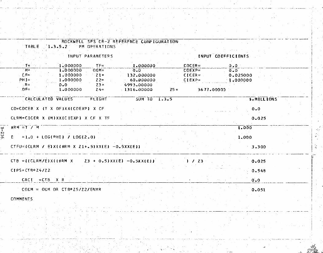
Tyr5 ^ `'
ty
ROCKWELL SPS CR-2 REFERFNCE CUNFIGURATION'TABLE 1.3.5.2 PM OPERATIONS
INPUT PARAMETERS INPUT COEFFICIENTS-
T= 1.000000 TF= 1.000000 CDCER= 0.0M=1.-000000 b04_=_- - 0.0 CDEXP= 0.0
CF= 1.000000 "Z1= 132.000000 CICER= 0.025000PHI= 1.000000 Z2= 60.000000 CIEXP= 1.000000
R,= - 000 -Z3_ 4993.00000DF= 1.000000 Z4= 1316.00000 Z5= 3677.00000
CALCULATED VALUES FLIGHT St MILLIONS -^ —SUM TO 1.3.5
CD=CDCER' X ('T X DF)XX(CDEXP) X CF 0.-0 f
CLRM=CICER X (M)XX(CIEXP) X CF X TF 0.025
,- bd - #RM <=T / M -- — - _—.— -... •.__.---- 1.0.00
Nrn E =1.0 + LOG(PHI) / LOG(2.0) 1.000
CTFU=(CLRM / E)X((#RM_X Z1+.5)XX(E) -0.5XX(E)) 3.300
CTB =((CLRM/E)X((#RM X Z3 + 0.5)XX(E) -0.5XX(E))' ) / Z3 0.025
CIPS=CTB*Z4/Z2 - -. <0.548 '.
CRCI =CTB X R 0.0 t
COEM = O&M OR CTB*Z5/Z2/ENYR 0.051 t;
COMMENTS
.. .... _..., III
E s . e _y t t `
qll
s
fi 3
u fi
Satellite Systems DivisionQ%RockwellSpace Systems Group International
`i
1.3.6 INTRA-ORBITAL TRANSFER VEHICLE (IOTV)
This element includes the IOTV vehicles and operations required tosupport .the satellite system assembly and operation. Included is the intra-
J

SUBSYSTEM WEIGHT (kg)
ENGINE (1 ASE) 245PROPELLANT TANKS 15STRUCTURE AND LINES 15DOCKING RING 100ATTITUDE CONTROL 50OTHER 100SUBTOTAL 525GROWTH (10%) 53TOTAL INERT 57
PROPELLANT 00TOTAL LOADED 878
{ Ef,S^^r ^;:^^ A•
.r'. . x ^ '^^^+.,_ . 'efF"f3^^ '! ^.:..:'ytw'^ `rh::'.4'JP'Y
Satellite Systems Division RockwellOi%
Space Systems Group international
1.3.6.1 IOTV FLEET1
g;.r
This element includes the necessary vehicle fleet procurement required e.;
to support the SPS program. The IOTV has been synthesized in terms ofapplication and concept only. IOTV elements considered here are powered byv.a chemical (LOX/LH2 ) propulsion system. At least three distinct applicationshave been identified; (1) the need to transfer cargo from the HLLV to theEOTV in LEO and from the EOTV to the SPS construction 'base in GEO; (2) theneed to move materials about the SPS construction base; and (3) the probableneed to move men or materials between operational SPSs. Clearly the POTV,used for transfer of personnel from LEO to GEO and return, is too large tosatisfy all intra-orbit requirements. A "free-flyer" tLeoperator conceptwould appear to be a logical solution to the problem. A propulsive elementwas synthesized to satisfy the cargo transfer application from HLLV-EOTV-SPSbase in order to quantify potential on-orbit propellant requirements. Pertin-ent IOTV parameters are summarized in Table 1.3.6.
Table 1.3.6. IOTV Design Parameters
A total of 840 IOTVs are needed to maintain intra-orbit cargo/operationst
flow during the program. One hundred ten vehicles will accomplish the con-struction phase and 100 vehicles are needed for satellite 0&M. An attrition/spares fleet of equivalent vehicles was projected on the ratio of 3 units foreach of the operational vehicles.
Cost estimates for the IOTV are engineering assessments based on POTVdesigns and similarities such as those of the common advanced space engine(ASE). Table 1.3.6.1 displays the applicable cost data.
M-
u -
B-238
T SSD 79-0010-2-2

7{'["", ^'w'^7""C 7'.';'1 AC''bq^^.z, ,z. a¢ t[S"7e t ,M..F"PrFF ':ri ... ,r .s — .. .w..
„i
h
ROCKWELL SPS CR-2 REFERENCE CONFIGURATIONTABLE 1.3.6.1 IOTV FLEET
{
INPUT PARAMETERS INPUT COEFFICIENTS
T= 1.000000 T_F=_ 1.000000 CDCER 100.000000_
1.000000 06M= - 0.0_
CDEXP= 1.000000 -CF= 1.000000 Z1 4.000000 CICER= 1.500000
PHI 0.920000 Z2= 60.000000 CIEXP= 1.000000R _ _ -.___ _- 0.350000 _
Z3-_ _
_ 840.000000 __-
DF 1.000000 Z4= 110.000000 Z5= 100.000000
CALCULATED—
VALUES SET SUM TO 1. 3. - - -- E,MIiUf dNS
CD=CDCER X (T X DF)XX(CDEXP) X CF 100.000
CLPM=CICER X (M)XX(CIEXP) X CF X TF 1.500
#RM =T / M - -1.000
E =1.0 + LOG(PHI) / LOG(2.0) 0.880
CTFU=(CLRM / E)X((#RM X Z1+.5)XX(E) -0.5XX(E)l 5.476
CTB =((CLRM/E)X((#RM X Z3 + 0.5)XX(E) -0.5XX(E)) ) / Z3 0.758
CIPS=CTB*Z4/Z2 1.3'89
CRCI =CTB X R 0.265
CCEM OEM OR CTB*Z5/Z2/ENYR 0.042
COMMENTS -
_a
y
r
R ,yr
3^

r^".'"^"
a
i
Satellite Systems Division , RockwellSpacespace systems croup International t
f
y
^- 1.3.6.2 IOTV OPERATIONS ,, 3
This element includes the necessary vehicle operations and propellantcosts required to support the SPS program. It includes the on-orbit opera-tional cost of transferring cargo at LEO and GEO.
A total of 41,940 IOTV flights are planned for LEO and GEO constructionand operations/maintenance requirements of the program. The 22,811 flightsneeded for construction and the 19,979 for operations and maintenance are con-sidered as equal missions for the purpose of costing. The propellant require-ments were averaged and calculated at 1977 dollars of $0.07/kg for L0 2 and$3.27/kg for LH2 . A 40% mark-up was added per flight for other operationaland maintenance charges. See Table 1.3:6.2.
.i
i
.r
rill
5
r:
B-240
S.SD 79-0010-2-2
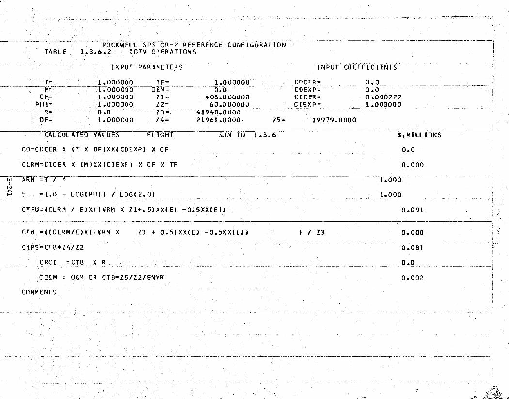
ti!'ti,."Yw„y,^.p-`FJ•.,"T°"r'^"a°}'.w ,.'^,C'a°.! y.'lrt" _ ..:t'ra*wP'°T"^.CT! ,C i, '''T.:.;x. re r^ :ro:^[rm:n..^ _
` i.- _.
,
[
- _ .. r /6;
r
ROCKWELL SPS CR-2 REFERENCE CONFIGURATIONTABLE 1.3.6.2 IOTV OPERATIONS i
INPUT PARAMETERS INPUT COEFFICIENTS
IT= 1. 000 000 TF= 1.000000 CDC ER= 0.0
^ 1
1.000000 OEM= _ — 0.0 CDEXP= 0.0CF= 1.000000 Z1= 408.000000 CICER= 0.000222
PHI= 1.000000 Z2= 60.000000 CIEXP= 1.0000000.0 ` Z3—_41940.0000
DF= 1.000000 Z4= 21961.0000 Z5= 19979.0000
11AL ULAfr VALUES FLIGHT SUM TO 1.3.6 $,MILLIONS
CD=CDCER X (T X DF)XX(CDEXP) X CF 0.0
CLRM =CI.CER X (M)X.X(C IEXP) X CF X TF 0.000
t
I
d #RM -T / M 1.000NN E = 1.0 + LOG(PHI) / LOG(2.0) 1.000
q
CTFU=(CLRM / E)X((#RM X Z1+.5)XX(E) —0.5XX(E)) 0.091
CTB =((CLR'M/E)X((#R.M X Z3 + 0.5)XX(E) —0.5XX(E)1 1 / Z3 0.000
C'IPS=CTB*Z4/Z2_
0.081I
CRCI =CTB X R 0.0
CC'EM OEM OR CTB*Z5/Z2/ENYR 0.002 sa
COMMENTS
Kt.

-. __. .... _..s .. ea.:.w:._.r.ar._.r.....`«.....-... .._.-.._ .. ,. »....,._......+ni.v.r3..+-. ..: m.ra.. ., s: .. »..-n «. . a....^ .,.. yi^1'
t
y Y,Nr;
Satellite Systems Division„ RockwellSpace Systems Group 1 InternationalF
E. 1.3.7 GROUND SUPPORT FACILITIES yt y
-- This element includes all land, buildings, roads, shops, etc., requiredto support the cargo handling, launching, recovering, refurbishment, andoperations of the space transportation system.
1.3.7.1 LAUNCH FACILITIES
This element includes the design and construction of the actual launchfacility and its associated equipment. Included are land, buildings, and
' equipment required to support the various crews. It also includes the re-quired control centers and administrative facilities.
1.3.7.2 RECOVERY FACILITIES
This element covers the design, construction,.and equipping of the actualI
recovery facilities. 1
1.3.7.3 FUEL FACILITIESI
This element includes fuel production facilities, storage and handlingfacilities, transportation, and delivery and safety facilities for both thefuel and the oxidizer. Also included are the facilities for fuels used inthe various orbital transfer facilities)
1.3.7.4 LOGISTICS SUPPORT
This element includes the land, buildings, and handling equipment for thereceiving, inspection, and storage and packaging of all payloads to be launch-ed except for fuels and oxidizers.
t
1.3.7.5 OPERATIONS
This element includes the planning, development, and conduct of opera-`,.
tions at the ground support facilities. It includes both the direct and support personnel and the expendable maintenance supplies required for the groundsupport facilities operation and maintenance.
A cost estimate for ground support facilities is projected in Table 1.3.7based on the Boeing final report, NAS9-14710, dated September 1977, Volume 4,'Cost Estimates. It is judged that there is little difference in the cost offacilities_ in this report as compared with those projected for the tratisporta-
r; tion and operations requirements of this study.r
W
B-242
SSD 79-0010-2-2
L

p
r ,
RliLKWrLL SPS L-K-21ABLL- 1.-3.'/ GRUi1Nb -'iJPI uRT
RL''FERENCE CUNFIGURAlIGfVFACILITIES
INPUT r'ARAML-TcKS INPUT COLFFICItNT^
GT=1 . ("tf^:7t.?, I F= 1. f)000 OO CDCEK= 1120. CGOOO h
ri= 1.c1c,4 CJ L,. hi- 1. l75 C, 0 GDEXP= 0.0C F= 1. C; .G 1. 00 Crvt)0 CICER= 3195.00000
NH1= I.Ci_,0CL;;G Lt= 5u.G00000 CI EXil 0.0` f = t).U'1I11 Z3= 1.0 C.0
D = i C,0 " Z4=i
100CCC00 Z,t^= 0.0
CALCULAI t0 VALUtS SU.1 rU 1.3 !^yMILL10N5
C.u=Cr)C-r: 4 (T X [)F)XX(CL)EXP) X Cr 1720.000
CLRM= ClL l"--K X (N)XX(Llt:XP) X CF X TF 3195.00L
td 6' r0l =7 / ti 1.000
w L =1.0 + LOG( PHI) % LUG(2.C) 1.000
f L I FU= (CLt^f1 / t)X(( NKll X LI+.^) )A (E) :3195. 000
i I = ({CLKiY/L IX(( g KM X Z t i. -)XX (L) — ).5XX (E) ! 1 / L' 3195.;'00
C 1 PS= L1 L,M[4/Lc^
53.250
C hL I = CT 6 X F; 55_3. _,._..
CUz;M = UC,r1 LN Cl L3 4'Z^,JL2/F...NYk 1.775
C u "i; 1i E NT S e 3
2^
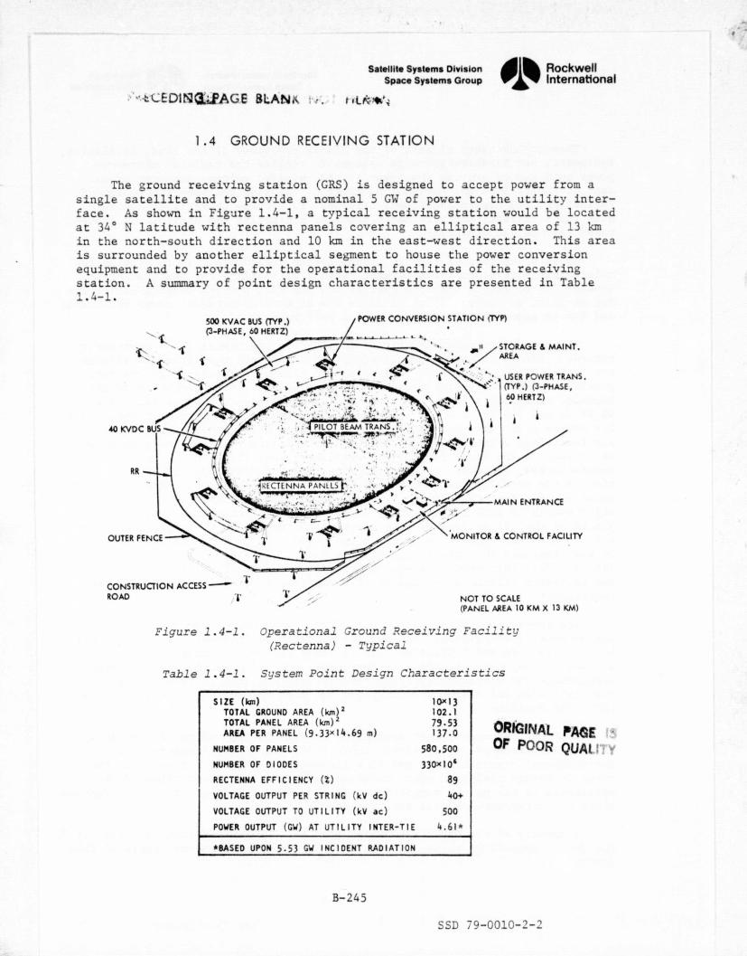
S^
Satellite Systems Division„ Rockwell
Space Systems Group International, ,UDi^:3=.PAGE ELAN& t tk•*'^
1.4 GROUND RECEIVING STATION
The ground receiving station (GRS) is designed to accept power from asingle satellite and to provide a nominal 5 GW of power to the utility inter-face. As shown in Figure 1.4-1, a typical receiving station would be locatedat 34° N latitude with rectenna panels covering an elliptical area of 13 kmin the north-south direction and 10 km in the east-west direction. This areais surrounded by another elliptical segment to house the power conversionequipment and to provide for the operational facilities of the receivingstation. A summary of point design characteristics are presented in Table1.4-1.
500 KVAC BUS (TYP.) POWER CONVERSION STATION (TYP)
(3-PHASE, 60 HERTZ)
it STORAGE & MAINT.`t
AREA
/^ -..^,^_ ^
►
, ^^-
f r' ^ Yvt ° `' ( USER POWER TRANS.(TYP.) (3-PHASE,
60 HERTZ)
40 KVDC BUS J PILOT BEAM TRANS^r
RR
BLCTLNNA PANELSr
MAIN ENTRANCE'.,^L L
_yam ^•, yr.
\OUTER FENCE
.f
MONITOR S CONTROL FACILITY^ •^^ Y `
T
CONSTRUCTION ACCESSROAD "T 1 NOT TO SCALE
(PANEL AREA 10 KM X 13 KM)
Figure 1.4-1. Operational Ground Receiving Facility(Rectenna) - Typical
Table 1.4-1. Sc;stem Point Design Characteristics
SIZE ( Ian) 1 Ox 13TOTAL GROUND AREA (km) 2 102.1TOTAL PANEL AREA (km) 2 79.53AREA PER PANEL (9.33 x 14.69 m) 137.0
NUMBER OF PANELS 580,500
NUMBER OF DIODES 330x10`
RECTENNA EFFICIENCY ($) 89
VOLTAGE OUTPUT PER STRING (kV dc) 40+
VOLTAGE OUTPUT TO UTILITY (kV ac) 500
POWER OUTPUT (GW) AT UTILITY INTER-TIE 4.61+
*BASED UPON 5.53 GW INCIDENT RADIATION
ORIGINAL PAGE 15OF PC-OR QUAHTY
^ 1
B-245
SSD 79-0010-2-2

Satellite Systems Division ^^bk RockwellSpace Systems Group International
This ground based element of the SPS is comprised of the land, facilities,equipment, and hardware/software systems to receive the radiated microwavepower beam and to provide the power at the required voltage and type of cur-
`
rent for entry into the national power grid. It also includes the equipment,facilities, and hardware/software necessary to provide operational controlover the satellite; and a reliable means of monitoring and controlling groundbased systems and equipment.
Major objectives of the SPS ground system design are: (1) to provide lowmaintenance subsystems and equipment capable of handling the designed powerlevels; (2) to assure that the overall station will provide dependable servicefor at least 30 years; (3) to minimize the size of operational crews and costs;and (4) to economically optimize system performance.
There are nine major activities involved in the overall GRS constructionprocess. After the survey and clearing, utilities and supporting facilitiesare installed while the site is leveled and graded. Trenching and concretepouring precede the installation of rectenna panels, after which electricalhook-up, converter stations, and monitoring facilities are installed. The40 kV do and 500 kV ac buses are then interconnected and procedures take placefor system checkout. Cost effective utilization of equipment and personnelwas identified after the development and integration of detail phasing schedul-es on each of the first four ground stations. Contacts with A&E, equipmentmanufacturers, concrete, and construction firms provided additional informa-tion on the duration and sequence of operations based on their experience withprograms of this type. Figure 1.4-2 is an integrated summary schedule ofmajor events in constructing the ground receiving station where emphasis isplaced on the utilization of construction equipments and their transfer fromsite to site as required to maintain the build rate of two stations per year.It was concluded that the equipment from Site 1 would be available for use onSite 3. This information on equipment/manpower utilization, site sequencing,and equipment lifetimes is used in this analysis to establish total resourcerequirements for the program.
{r
t
,
The ground receiving station was divided into several main elements forthe purpose of associating cost and programmatic definitions. These elementsinclude (1) site and facilities, (2) rectenna support structure, (3) powergollection, (4) control, (5) grid interface, and (6) operations. SPS designdefinitions and specification requirements were analyzed to provide realisticcost estimates and resource definitions for each element as explained in thefollowing sections.
Internal resources, cost estimating relationships, and prior cost analys-es were supplemented by: 1) direct contact with business, industry, andinstitutional organizations, and 2) a literature search of various publica-tions to obtain realistic cost estimates and operational definitions directlyapplicable to the unique requirements of the GRS. A list of principal organiza-tions and literature sources are presented in Table 1.4-2.
A summary of the costs associated with the GRS is presented in Table 1.4-3.The detail supporting these costs is presented in the subsequent pages of thissection.
B-246
SSD 79-0010-2-2

Nd
v -ev on^ to
^ m
3 3
woN_
C O10 z
I
r Q0
7 ^c^0 =
m
Ca
Niv
11W MY ITN- T — -- Hq am a!bl am
SITE SU1V1Y (L UTILITIES PLAN &RDAItl S E 1 SIIf l_JS1iJ LIT! 1
CONS11IL1C110N r ACNTIn INSTALLATION 311! I Slif ] Sn(l .." JACCESS, MAIM., WU10Aa COP4IRUC110N r Slit 1 SR! 3 r—^^(—^ C_ SRIOPERATIONS
t0^1►M^j1^►^OCWLM al s ►rt 1 —1 - - - - - Int fEouIPMt N11 tRANIrn ^lOUMrAl Ni kSwsPeR ptTe A
- - -uw31,4 13 4 O AalNO 0""VION3I_MOR7ii - SRt 7 ^- - -^O - 0111/M(M^11ANS1.1 1 1
- - - -`fOUltMlfykIMNS/fR ortE Y
CEMENT ^
10U11. •1ACIi NT l^ T tOUI ►MEMO TRANS ► !1 SITE (p(fYMl M^ ItANS!!1M(^CURt M!!/f tffUP —'COMINIIOUS 1110,K041040 L FOUNDATIONN CEMENTPOURING OP A11004 f(^JYMIM-MUCl1REMt M_ PLANTr 1 f(IUUIPMtMJlRANL9 I !C]UYMlNT1;RANS/[R ary l ySETUP - -
• SEIU^ -+
10U1M1fM rACIL. tM%mil tOUIPMEN"TiRLIr^ sne I - - Site :tWl► M!M IRANSrtR J - — fOUlPA1lM IRAN3f[^
PER FRAME •"COLLIC101 FAME EMASSY, INSIAllA1 KON 1 AU GNMIM 0111 -
!02(m'-4-N^-OWMIN I S^ 1I - -- - SITE 1 -MIONS l EOUYM[M IRANSr(R^ IWI►MlM TlAN11(1, (Srtl,
Slif 7(il10UND WI(> INf1AllAlION, COLlfCTORPANEL WIRING A CHECKOUT OPERATIONS
SITE ] SRt 1
CONVERSION 3TAIION IPOI04LAIPON \ O ^'SIP[ 1 311E ]
CHECKOUT OPtRAI IONS -l^L SITE /
G)10 KVAC • 100 KVAC I IS INSTALLATION N
It
CHECKOUT OPERAIIONI J y SIit3—^ S11 CA-=^r (- Srt(I ^^E ]MONI1041110 11 COM1101 CeMER rAC tln V Snt ]
CCONSTRUCTION
Dt*s [ s11t 1 snt ^ 1MONIf011NG COMtOL IS UTILITY IMfRPACtEOl11PMtM INSIALLATION A CHECKOUT Le ! ] srtc +O/IRAIK)NS
SYSTEM MIOWION IS 1131 OPERATIONS - flit 1 __ SRI! 1 fp(^
eEaONo /CW{/g OAIION •Or/ Lemr KNt LAA
ns Ina r LfJ
Figure .1.4-2. Rectenna Construction SequenceSummary Schedule
U)
b^D
1v0N0IJ
1N
C►

WBSNO. DDTSE TFU ICI
RCl/08M
1.4.1 SITE AND FACILITIES 1.0 195.2 . 188.9 °2
1.4.2 RECTENNA SUPPORT STRUCTURE 2.0 1849.6 1828. .5
1.4.3 POWER COLLECTION 3.0 1353.2 1353.2 -
1.4.4 CONTROL 10.0 75.0 75.0 -
1.4.5 GRID INTERFACE 99.7 145.7 145.7 -
1.4.6 OPERATIONS - - - 77.9
Satellite Systems Division ® ® RockwellSpace Systems Group ® International
Table 1.4-2. Organizations and Literature SourcesSupporting GRS Definition
ORGANIZATION PURPOSE
• AMERICAN BRIDGE - A DIVISION OF TO DEVELOP STEEL REQUIREMENTS, COSTSU.S. STEEL AND OPERATIONS DEFINITION FOR PRO-
CUREMENT AND INSTALLATION OFRECTENNA SUPPORT STRUCTURE
• RIVERSIDE CEMENT - •A DIVISION OF , PROVIDE CONSULTATION ON CEMENT/CONCRETEAMERICAN CEMENT CORPORATION; SPECIFICATIONS, OPERATIONAL METHODS,AND C. S. JOHNSON, CO. PROCESSING/HANDLING EQUIPMENT, AND
CONCRETE PLANT
° TOWNSEND E BOTT UM, INC., DISCUSS SITE PREPARATION, CONSTRUCTIONCONSTRUCTION MANAGER, OPERATIONS/SEQUENCING, PLUS ACTIVATIONTEN MW SOLAR PLANT - REQUIREMENTSBARSTOW, CA.
° SOUTHERN CALIFORNIA EDISON TO DISCUSS DC/AC POWER DISTRIBUTION ANDCONVERSION REQUIREMENTS, AND OBTAINCOST ESTIMATES ON INSTALLATION OFLINES/TOWERS
° MODERN ALLOYS, INC.; AND TO DISCUSS USE AND APPLICATION OFMILLER FORMLESS CO. EQUIPMENT/CREW FOR CONTINUOUS CONCRETE
POUR OF RECTENNA SUPPORT STRUCTUREFOOTINGS
• CATERPILLAR; INTERNATIONAL OBTAIN PRICES ON EARTH MOVING, GRADINGHARVESTER; AND JETCO, INC. AND TRENCHING EQUIPMENT
L117RATURE SOURCES
• THE RICHARDSON RAPID SYSTEM CONSTRUCTION LABOR AND OPERATIONS
1978-1979 EDITION PRICES
• ENGINEERING NEWS RECORD - 1977 CEMENT, AGGREGATE AND LABOR PRICESA WEEKLY McGRAW-HILLPUBLICATION
• NATIONAL CONSTRUCTION ESTIMATING CONSTRUCTION OPERATIONSGUIDE (NCE)
Table 1.4-3. GRS Cost Summary ($ Millions)
B-248
SSD 79-0010-2 -2

4
yr%
Kt
Satellite Systems Division„ Rockwell Aa
Space Systems Group 1 International
1.4.1 SITE AND FACILITIESt
The ground receiving station is located on a site of 35,000 acres where Y?ic+,•
over 25,000 acres of a central ellipse, or 72% of the total acreage, is usedfor rectenna panels. The area surrounding the inner ellipse is allocated formaintenance/control facilities, access roads, converter stations, and the rowsof towers that support the 40 kW do and 500 kV ac cables. The GRS perimeteris fenced for security reasons.
The sequence of construction operations begins with site identification,environmental impact studies, zoning/permits, surveys, utility/road installa-tion, and supporting facilities. After reference coordinates are established,the site is cleared, leveled, and followed with precise grading for panel
r'
foundations, 'fabrication facilities, installation and GRS site completion.This includes concrete mixing plants, rectenna panel fabrication factories,
a
crew accommodations, warehousing, and support facilities as shown in Figure1.4-3 The GRS DDT&E effort will be a valuable asset to all GRS sites byproviding designs, analyses, and procurement specifications for commonly usedbuildings and facilities.
•
PANEL FACTORY LIVING & CREW AREAGIN AL
G^qq ,
EQUIPMENT MAINTENANCE BLDG ^^
QUALITYMATERIAL ^^®RSTORAGE/DISTRIBUTION YARD CONSTRUCTION SUPPORT
BASE NO. IMAINTENANCE ROADTO BASE NO. 1 COORDINATE 8 GRADE
l , REFERENCE MATRIX
' CONCRETE PLANT f
ACCESS . • • LIVING & CREW AREA
< ROAD DIRECTION OF SITE.. < /DEVELOPMENT 3
F". r.. ?a PANEL INSTALLATIONCONSTRUCTIONSUPPORT BASENO. 2
CONCRETE PLANT ^^ EQUIPMENTMAINTENANCE BLDG
PANEL FACTORY
MATERIAL STORAGE/DISTRIBUTION YARD
POWER TO CFO ?CONSTRUCTION BASES 90 MAINTENANCE ROAD TO BASE NO. 2"
F
,
Figure 1.4-3. Support Facilities
Clearing and leveling operations will occur at a number of locations' within the panel farm perimeter. These operations consist of tree removal (if
required), grading, and leveling the terrain to acceptable slope angles, andremoving excess dirt. _Sixteen areas of the ellipse would be cleared and leveled simultaneously. Bulldozers will make the initial cut, scrapers will grade
` to more precise requirements, and an estimate was made of one crew of 13 men
B-249
r.SSD 79-0010-2-2
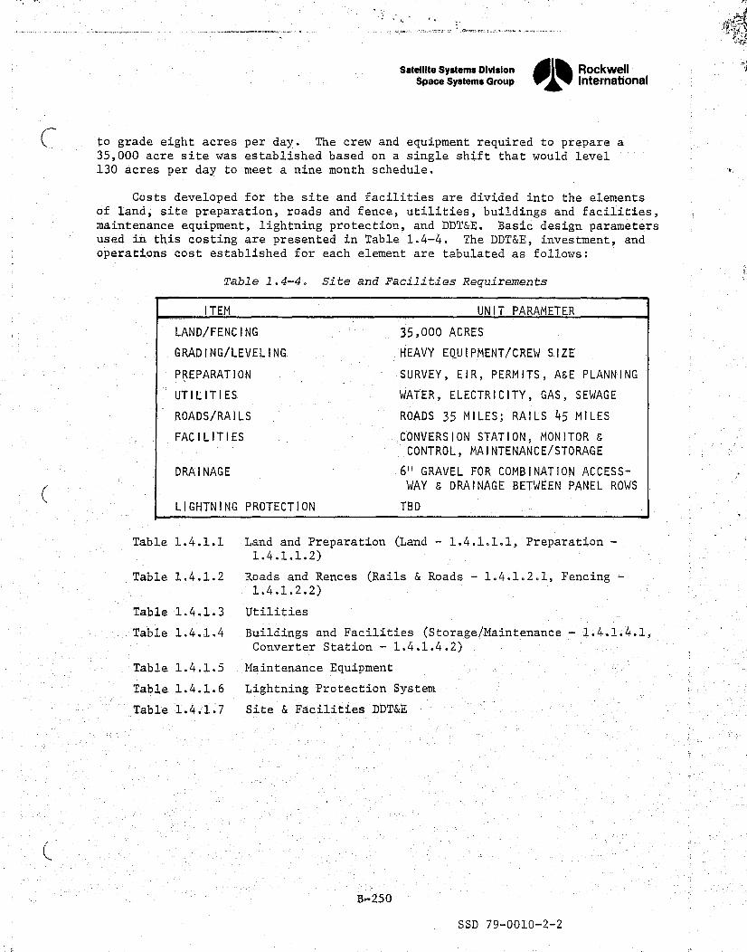
,..
is k
^fy
Satellite systems Division Rockwell
Space Systems Group 1 Internationals
to grade eight acres per day. The crew and equipment required to prepare a35,000 acre site was established based on a single shift that would level130 acres per day to meet a nine month schedule.
Costs developed for the site and facilities are divided into the elementsof land, site preparation, roads and fence, utilities, buildings and facilities,maintenance equipment, lightning protection, and DDT&E. Basic design parametersused in this costing are presented in Table 1.4-4. The DDT&E, investment, andoperations cost established for each element are tabulated as follows:
Table 1.4-4. Site and Facilities Requirements
Table 1.4.1.1 Land and Preparation (Land - 1.4.1.1.1, Preparation -1.4.1.1.2)
Table 1.4.1.2 Roads and Rences (Rails & Roads - 1.4.1.2.1, Fencing -_1.4.1.2.2)
Table 1.4.1.3 Utilities
Table 1.4.1.4 Buildings and Facilities (Storage/Maintenance - 1,4.1.4.1," - Converter Station - 1.4.1.4.2)
Table 1.4.1.5 Maintenance Equipment
Table 1.4.1.6 Lightning Protection System
Table 1.4.1.7 Site & Facilities DDT&E
B-250
t SSD 79-0010-2-2

Fkv'S^ST t'^i ^ _.:.... ,...: .} . . . .1:. .. 3.-v.:n- _ .. ^ .. 1s"'•"/fS^£. YSPi.!LP3{a"*"17t'-^^
• i•
'(ROCKWELL SPS CR-2 REFERENCE CONFIGURATIONTABLE 1.4.1.1.1 LAND
- - — -INPUT PARAMETERS INPUT COEFFICIENTS +
T= 35000.0000 TF= 1.000000 CDCER= 0.0 ^k
M= 35000.0000 OEM= 0.0 CDEXP= 0.0 --CF= 1.000000 Z1= 1.000000 C'ICER= 0.001000
PHI = 1.000000 Z2- - 60.000000 ---------- -- CI EXP- _1.000000 —_ R= 00 Z3= 60.000000DF= 1.000000 Z4= 60.000000 Z5= 0.0 .-
CALCUL—Af VALUES ACRES SUM TO 1.4.1.1 $,MILLIONS
CD=CDCER X (T X DF)XX(CDEXP) X CF 0.0
CLRM=CICER X (M)XX(CIEXP) X CF X TF 35.000
td #R M =T / Si 1.000
t Ln
F =1.0 + LOG('PH I) / LOG(2.0) _ _ _. --- — ._ _ 1.000
CTFU=(CLRM / E)X((#RM X Z1+.5)XX(E) — 0.5XX(E)) 35.000
CTB =((CLRM/E)X((#RM X Z3 +.0.5)XX(E) —0.5XX(E)) ) / Z3 35.000s :`
'•
CIPS=CTB*Z4/Z2 35.000
CRC =C TBT'B X RI -- ---_^.^-- ---- —_ ® h,t 0. 0 _. ------
CQEM = OEM OR CTB*Z5/Z2/ENYR 0.0A ti •
_. ^_a
COMMENTS^a
7
h.
#^
i
Ca.,
t

xw:ti.
"aiµµ
t ,
A
4
ROCKWELL SPS CR-2 REFERENCE CONFIGURATION'
TABLE 1.4.1.1.2 LAND PREPARATION
INPUT PARAMETERS INPUT COEFFICIENTS
T= 35000.0000 TF= 1.000000 CDCER=_ 0.0M= 35Q00.0000 OEM= 0.0 CDEXP= 0.0
CF= 1.000000 Z1= 1.000000 CICER= 0.002007PHI=0.980000 Z2= 60.000000 CIEXP= 1.000000.__ _ --..-.• Z3= -0 0_ -- - _.__-
-60_ _. .__ 000000--_ ---- -.-----____ V
DF= 1.000000 Z4= 60.000000 Z5= 0.0
CALCULATED VALUES ACRES SUM TO 1.4.1.1 $,MILLIONS
CD'=COCER'X (T X DF)XX(CDEXP) X CF 0.0
F -..CLRM=CTCER X (M)XX(CIEXP) X CF X TF 70.245
td # R M T/ M 1.000NLn' E = 1.0 + LOG( PHA) / LOG(2.0) 0.971
CTFU=('CLRM / E)X((#PM X Z1+.5)XX(E) — 0.5XX(E)) 70.341 ++
CTB =((CLRM/E)X((#RM X Z3 + 0.5)XX(E) —0.5XX(E)1 ) / Z3 64.119
CIPS=CTB*Z4/Z2 64.119
CRCI =CTB X R 0.0
COGM _ OEM OR CTB*Z5/Z2/ENYR 0.0
CQMMENTS
^ i
Ni

",'.Ar.'r?`[ Ft. i : rr i„v-,.:"Y ti ., _^.' r 3 cr, . ^M* 3r^a rF k^ c?!F aer ;4
'^",.'R+':"°' - +
^ k\3
,.,” _...^: T, ,K.4,., *^
-s
F ROCKWELL SPS CR-2 REFERENCE CONFIGURATIONTABLE 1.4.1.2.1 RAILS AND ROADS
w ,. r
INPUT PARAMETERS INPUT COEFFICIENTS q ^.
T= 1.000000 TF= 1.000000 CDCER= _ 0.0 __,^ Y _M= 1.000000 OEM= 0.0 CDEXP= 0.0
CF- 1.000000 Zi= 1.000000 CICER= 73.710007PHI=1.000000 Z2= 60.000000 CIEXP= 1.000000
R= 0.0 Z3= 60.000000t DF= 1.000000 Z4= 60.000000 Z5= 0.0
CALCULATED VALUES SET SUM TO 1.4.1.2 S,MILLIONS
CD=CDCER X (T X DF)XX(CDEXP) X CF
CLPM=CICER X (M)XX(CIEXP) X CF X TF 73.710
= T 1.000^ N 4
W E = 1.0 + LOG(PHI) / LOG(2.0) 1.000
CTFU-(CLRM / E)X((#RM X Z1+.5)XX(E) 0.5XX(Ell 73.710
CTB =((CLRM/E)X((#RM X Z3 + 0.5)XX(E) —0.5XX(E:)) 1 / Z3 73.710
^,.. CI PS=CTBIZ4/Z2 73.710
^CRC_I =CTB X R 0.0_
COCM' = OEM VOR CTB*Z5/Z2/ENYR 0p 0.0
COMMENTS 'O
f m£ cp,
3
,t
tnr.
.,. ,_ r .. _. - r„_. . . ,: , _. _r_ sx9nhi< `. e. ,...: :. ^,7a:,r r"ie -^ v ,... ..: t-_. ^_. "., .. -.. a• ^^ .

^°l*".'9}m` T 'fa b 'R 'tr.:.... +.... .°'"•l,,f',`^^ Y'z.:'?fr — . te' - .. ^ _s`
^^
i3 i
C:
ROCKWELL SPS CR-2 REFERENCE CONFIGURATIONTABLE 1.4.1.2.2 FENCING Y
INPUT PARAMETERS INPUT COEFFICIENTS
T= 42671.0000 TF= 1.000000 C"DCER= 0.042671.0000 OEM= 0.0 CDEXP= 0.0 ^~
CF= 1.000000 Z1= 1.000000 CICER= 0.000011PHI= 0.980000 Z2= 60.000000 CIEXP= 1.000000
R= 0.0 Z3= 60.000000DF= 1.000000 Z4= 60.000000 Z5= 0.0
CALCULATED VALUES Ma
SUM TO 1.4.1.2 $,MILLIONS^
CD=CDCER X (T X DF)XX(CDEXP) X CF 0.0
CLRM=CICER X (M)XX(CIEXP) X CF X TF 0.469
#R M = T / MN
1 In l4-j E 1.0 + LOG(PHI) / LOG(2.0)
CTFU=(CLRM / E)X((#RM X Z1+.5)XX(E) —0.5XX(E))
1.000
------ _.. _ D.971
0.470u
f

^.wf"-•aC.^Y.'4M"I".: :AP°f± ,M s-R+j ,^, F"r'•l_W_ •n'°^:?.,n • . n . `% ... L.:` . 'f : i ^ryf. _. .. - 4 'Tw...s,•-y.fy4pp. ^.^a...:^,T'W:,TAd..;ypA ^.o^
Fnil'
l.dA'.. .r
SPSROCKWELL CR-2 - _-__^_^
yREFERENCE CONFIGURATION ,TABLE 1.4.1.3 UTILITIES }^^
INPUT PARAMETERS INPUT COEFFICIENTS
T= 1.000000 TF=T
1.000000_ CDCER= 0.0M= 1.000000 06M= 0. 0 COEXP= 0.0
CF= -1.000000 Z1= 1.000000 CICER= 0.200000PHI= 1.000000 Z2= 6Q.000000 C1EXP= 1.000000
R= 0.0 Z3= 60.000000DF= 1.000000 Z4=
—60.000000 Z5= 0.0
CALCULATED VALUES SET SUM TO 1.4.1 $,MILLIONS
CD=CDCER X (T X DF)XX(CDEXP) X CF 0.0
CLRM=CICER X (M)XX(CIEXP) X CF X TF 0.200—
#RM =T/_
1.000N^ E =1.0 + LOG( PHI / LOG(2.0) 1.000
CTFU=(CLRM / E)X((#RM X Z1+.5)XX(E) -0.5XX(E71 0.200
CTB =((CLRM/E)X((#RM X Z3 + 0.5)XX(E) —0.5XX(E)b )^/"3 0.200
^^ r
CIPS*Z4/Z2=CTB ,^0.200
CRCI =CTB X R
COEM = OEM OR CTB*Z5/Z2/ENYR 0.0
COMMENTS
t 4
4
t a . `a

:^ .r.,.•.+_"gmav •sx_,.. ,SF'q_-....z,F;•'vw` a -.T _ _ _. oil `',
ROCKWELL SPS CR-2 REFERENCE CONFIGURATIONTABLE 1.4.1.4.1 STCRAGE,MAINTENANCE *,
INPUT PARAMETERS INPUT COEFFICIENTS
T=1.0 00000 T F = 1.000000 CDCER= 0.0N= 1.000000 O&M= 0.0 CDEXP= 0.0
CF= 1.000000 Z1= 1.000000 CICER= 1.300000PHI = 1.000000 Z2= 60.000000 CIEXP= 1.000000_. -R _ - . _. _ _ 0,,.0
Z3= 60.000000DF= 1.000000 Z4= 60.000000 Z5= 0.0
CALCULATED VALUES SUM TO 1.4.1.4 f, MILL IONS
CD=CDCER X (T X DF)XX(CDEXP) X CF 0.0
CLRM=CICER X (M)XX(CIEXP) X CF X TF 1.300
'1.000Nlli°' E =1.0 + LOG(PHI) / LOG( 2.01 1.000
CTFU=(CLRM / E)X((#RM X Z1+.5)XX(E) -0.5XX(E)J- 1.-300 +.
CTB =((CLRM /E)X((#RM X Z3 + 0.51XX(E) -0.5XX(El) ) / Z3 1.300
CI PS=CTB*Z4/Z2 1.300
- CRCI =CTB X R 0.0
COEM = OEM OR CTB*Z5/Z2/ENYR 0.0`
COMMENTS
y
a
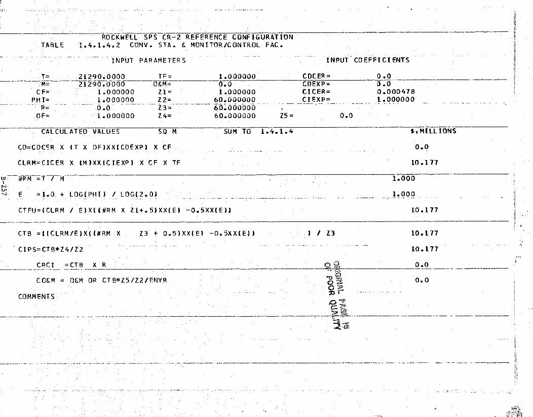
Poll
ROCKWELL SPS CR-2 REFERENCE CONFIGURATIONTABLE 1.4.1.4.2 CONV. STA. MONITOR/CONTROL FAC.
INPUT PARAMETERS INPUT COEFFICIENTS
T= 21290.0000 TF— I.UOOOOO CDCER= 0.0M= 21290.0000 0.0 CDEXP= 3.0
CF= 1.000000 Z -1 = 1.000000 CICER= 0.000478PHI= 1.000000 Z2= 60.U0U000 CIEXP= 1.000000
0.0 Z3= 60.000000OF= 1.000000 Z4= 60.00UOOO Z5= 0.0
CALCULATED VALUES so M SUM TO 1.4.1.4 $9MILLIONS
CD=CDCER X (T X DFJXXICDEXP) X CF 0.0
CLRM=CICER X (M)XX(CIEXP) X CF X TF 10.177
-WRM =T / M 1.000Ln
E =1.0 + LOG(PHI) LOG(2.0) 1.000
CTFU=(CLRM E)X((#RM X Zl+.5)XX(E) -0.5XX(E)l 10.177
CTB =((CLRM/E)X((#RM X Z3 0.5)XX(E) -0.5XX(E)) Z3 10.177
CIPS=CTB*Z4/Z* 2 10. 177
CRCI =CTB X R 0.0

t
a ,^ .+t
i
^ I
- -^^ROCKWELL SPS CR-2 REFERENCE CONFIGURATIONTABLE 1.4.1.5 MAINTENANCE EQPT.
4f
INPUT PARAMETERS INPUT COEFFICIENTS
T= 1.000000 TF= 1.000000 -CDCER= 0.0^M=_ 1.000000 0£M= 0.0 CDEXP= 0.0CF= 1.000000 Z1= 1.000000 CICER= 4.000000
PHI=. 1.000000 Z2= 60.000000 CIEXP= 1.000000R=
- 0 0.50000 Z3T 60.000000DF= 1.000000 74= 60.000000 Z5= 0.0
--- . CALCULATED VALUES $ SUM TO 1. 1 b.MILLIONS
CD=CDCER. X (T X DF)XX(CDEXPI X CF 0.0
CLRM= CICER X (M)XX(CIEXP) X CF X TF 4.000
i #RM = T / M—___
1.000Ln°° E = 1.0 + LOG(PHI) / LOG(2.0) 1.000
CTFU= (CLRM >'E)X((#RM X Z1+.5)XX(E) -0.5XX(E)) 4.000
- -
CTB =((CLRM/E)X((#RM X Z3 + 0.5)XXIE) -0.5XX(E)) ) / Z3 4.000f
CIPS=CTB*Z4/Z2
_
4.000
x
CPCI =CTB X R 0.200
COEM _ OEM OR CTB*Z5/Z2/ENYR 0.0
COMMENTS
.air }

0.0
0.0
0.0
0.0
,.•
;y.w^s°Pry**q' .`3gt"tr"r°iSIR rYn. _.^;v .v+ara?^H;TCfR+^ ... .^ .'n-.rsy "; ^°
^^."*°nif:.
l< ...yt•tr ye^"rwtT"SC^^'-.,,^,T'.F•j^£
^1 ... .. y
.. .... .... . . .. . . _ _-- » - _ _
f
^t
R6CKWELL SPS CR-2 REFERENCE CONFIGURATIONTABLE 1.4.1.6 LIGHTNING PROTECTION
INPUT PARAMETERS INPUT COEFFICIENTS
T= 0.0 TF= 1.000000 CDCER= 0.0M= 0.0 OEM= 0.0 CDEXP= 0.0 a
CF= 0.0 Z1= 1.000000 CICER= 0.0PHI= 1.000000 Z2= 60.000000 CIEXP= 0.0
R= 0.0 Z3= 60.00000 0DF= 1.000000 Z4= 60.000000 Z5= 0.0
CALCULATED VALUES S SUM TO 1.4.1 - S,MILLIONS
CD=CDCER X (T X OF)XX(CDEXP) X CF 0.0
CLRM=CICER X (MIXX(CIEXP) X CF X TF 0.0
#RM =T / M 0.0Ln< E =t.0 + LOG(PHI) / LOG(2.0) 0.0
CTFU=(CLRM / E)X((#RM X Z1+.5)XX(E) -0.5X'X(E1) 0.0
CT8.=((CLRM/E)X((#RM X Z3 + 0.5)XX(E) -0.5XX(E1) ) / Z3_
CII'S=CTB*Z4/Z2
CRC[ =CT B X R
CCEM = OEM OR CTB*Z5/Z2/ENYR
COMMENTS
G)_
O
' 0 ^00C ^` to
i

4
r
v
ROCKWELL SPS CR-2 REFERENCE CONFIGURATIONa
k
TABLE 1.4.1.7 SITE 6 FACILITIES DDT&E
INPUT- PARAMETERS_ __.__ _ .-- .-_ _._ _.._-- ,
- INPUT COEFFICIENTS
T= 1.000000 TF= 1.000000 CDCER= 1.000000-M=
-- - 1.000000 OEM= 0.0 CDEXP= 1.000000CF= 1.000000 Z1= 1.000000 CICER= 0.0
PHI=1.000000 Z2= 6_0.000_000 CIEXP= 0.0R= 0.0 Z3= 60.000000 --- ti
1)F= 1.000000 Z4= 60.000000 Z5= 0.0
CALCULATED VALUES $ SUM TO 1.4! 1 St MILL IONS
CO=CDCER X (T X DF)XX(CDEXP) X CF 1.000
CLRM=CICER X (M)XX(CIEXP) X CF X TF 0.0
td ._ #R MA= T / M 1.000 iNIOff; ?of E = 1.0 + LOG t PH I) / LOG(2. O1 _m .,_ ..-_ . __. _..-.'_:- _ -^^ _.^ 1.000
CTFU=(CLR'M ! E)X((#RM X Z1+.5)XX(E)' —0.5XX(E) 0.0
CTB =((CLRM/E)X((#RM X Z3 + 0.5)XX(E) —0.5XX(E)) ) / Z3 0.0
CIPS = CTB*Z4/Z2 d 0.0
CRCI =CTB X R 0.0 a
COEM = O&M OR CTB*Z5/12 /ENYR 0.0f
_COMMENTS
s
, a
ct ,{
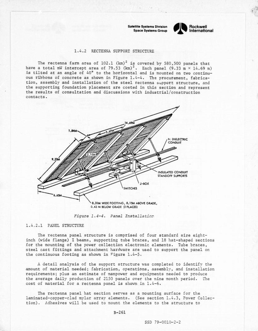
ECTRIC)IT
INDUIT'PORTS
Satellite Systems Division Rockwell
Space Systems Group International
1.4.2 RECTENNA SUPPORT STRUCTURE
The rectenna farm area of 102.1 (km )2 is covered by 580,500 panels thathave a total mW intercept area of 79.53 (km) 2 . Each panel (9.33 m x 14.69 m)is tilted at an angle of 40° to the horizontal and is mounted on two continu-ous ribbons of concrete as shown in Figure 1.4-4. The procurement, fabrica-tion, assembly and installation of the steel rectenna support structure, andthe supporting foundation placement are costed in this section and representthe results of consultation and discussions with industrial/constructioncontacts.
0.43 M BELOW GRADE (2 PLACES)
Figure 1.4-4. Panel Irstallator
1.4.2.1 PANEL STRUCTURE
The rectenna panel structure is comprised of four standard size eight-inch (wide flange) I beams, supporting tube braces, and 18 hat-shaped sectionsfor the mounting of the power collection electronic elements. Tube braces,steel caEt fittings and attachment hardware are used to support the panel onthe continuous footing as shown in F igure 1.4-5.
A detail analysis of the support structure was completed to identif y theamount of material needed; fabrication, operations, assembly, and installationrequirements; plus an estimate of manpower and equipments needed to producethe average daily production of 2150 panels over the nine month period. Thecost of material for a rectenna panel is shorn in 1.4-6.
The rectenna panel hat section serves as a mounting surface for thelaminated-copper-clad mylar array elements. (See section 1.4.3, Power Collec-tion). Adhesives will be used to mount the elements to the structure to
B-261
SSD 79-0010-2-2
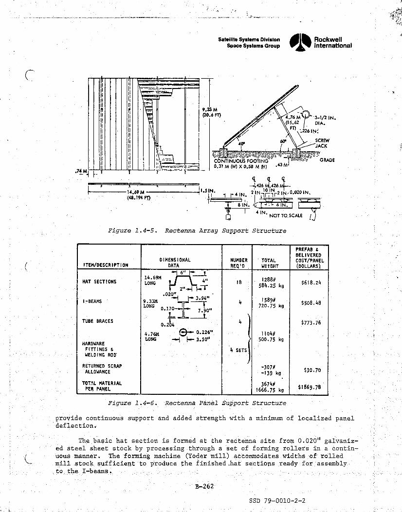
Satellite Systems Division„RockwellSpace Systems Group 1 International
t
I
r II II9.33 M
i^ II(30.6 Fn / / ' 4.76 # ' 3-1/2 IN.II
II(15.62 DIA.
\226 IN;'
60' SCREW 9II II T 40' y JACK f
I II i ^ 1^y ^: : c<p^ ^^^9:?iJ^)q %Ir:il^^l^li°^fi ^. /,^\`_d ;GRADECONTINUOUS FOOTING
II ii ^1yi ., .,^ ^,, i 0.31 M (W) X 0.58 M (H) .43 M
_ f,.74 M4 t4
—+426 tA.426 M^—I 1.51N. 10 INk 14,69M I 1 r41N. 21N -lf 1 -2 1N,0.020IN.
(48.194 FT), T
8IN. l ^: 6IN.
^— 4IN. NOT TO, SCALE
Figure 1.4-5. Rectenna Array Support Structure
ITEM/DESCRIPTIONDIMENSIONAL
DATANUMBERREQ'D
TOTALWEIGHT
PREFAB 6DELIVEREDCOST/PANEL(DOLLARS)
HAT SECTIONS14.69#LONG 18
584825kg$618.24.
2.^T
i-BEAMS 9.33M
.020 3.94” '
LONG^ ^.
41589#
720.75 kg$508.48
0.1 70L^ ^.«o
TUBE BRACES ^ 4 $773.760.204
4.76M 0.226" 1104#LONG y{ I+- 3.50" 500.75 kg
HARDWAREFITTINGS 6 4 SETSWELDING ROD'
RETURNED SCRAP -307#$30.70ALLOWANCE -139 kg
TOTAL MATERIAL3674#
PER PANEL 1666.75 kg$1869.78
Figure 1.4--6. Rectenna Panel Support Structure
rprovide continuous support and added strength with a minimum of localized paneldeflection.
The basic hat section is formed at the rectenna site from 0.020" galvaniz-ed;steel sheet stock by processing through a set of forming rollers in a contin-uous manner. The forming machine (Yoder mill.) accommodates widths of rolledmill stock sufficient to produce the finished .hat sections ready for assemblyto the 'I beams.
B-,262
SSD 79-0010-2-2
e

- -ar.K...+,-awn+- - -.....,_.:.-awwawrn.w-F' .. ,.0 s - r:< .. - - - . - . r ^ xY^wy
Satellite Systems Division I, RockwellSpace Systems Group 1 International
A^ ,f
#c!Ix>
is
Four standard wide-flange 8-inch galvanized steel I-beams are required inlengths of 9.33 m for each rectenna panel. This material will be delivered tothe site in precut lengths for hole punching and,the addition of brackets/machined castings for the support braces and panel mounting.
x
Four 3.5" diameter tube braces of galvanized steel are cut to a length of4.76 m and preassembled to the fittings/hardware. Anchors, brackets, clips,hangers, etc., are fabricated or cast of carbon steel material and galvanizedprior to machining at the site. All these items are scheduled to combine withthe hat sections and I-beams at a centralized facility for assembly. A con-cept for such a facility is shown in Figure 1.4-7. The factory has multiple'assembly lines where each line has a materials feed section, steel assemblyfacilities, electron ics assembly and checkout section. It was assumed thatone line using automated procedures could assemble and checkout a panel in40 minutes. On this basis, seventy-two assembly lines operating 20 hours perday, seven days a week are required to produce 580,500 panels in the allocated270 days. Eight additional requirements are summarized in the lower left ofthe figure.
After the panels have been checked; they are placed on an overhead convey-ing system and transported to loading stalls, where they are assembled into9-panel magazines and loaded on specially designed trucks for delivery to thepbint of installation.
Specialized equipment is required to deliver the panels from the factoryto the installation point and to install them because of their large dimensions.After consultation with industrial sources on large equipment handling, a con-cept for a specialized machine was developed (Figure 1.4-8). The front andrear wheel pairs are each steerable as a unit and have provisions for heightadjustment The panels are transferred in magazines and lifted by means offixtures mounted in vertical rails. They can be translated laterally andlongitudinally for final positioning before attachment to the footings.
1.4.2.2 TRENCHING AND CONCRETE FOOTINGS
A trade-off which considered eight individual footings versuscontinuousfootings was made. A maximum wind force of 90 m/hr was assumed. It was deter-mined that the amount of concrete required for either approach was essentiallythe same, but that the continuous footing concept was easier to instal]_ andrequired fewer operations and less capital equipment.
Each panel is secured to the footings at eight locations by fixtureswhich are imbedded in the concrete during the pouring operation. Mounting =<.attachments which provide for longitudinal and lateral adjustment are securedto the fittings. Screw jacks on each of the rear attach points provide forpanel adjustment and alignment.
The footings of continuous concrete are 0.43 meters deep, 0.31 meterswide, and project 0.15 :peters above ground level. Two footings are excavatedsimultaneously by trenchers which feed the removed dirt into a truck. Approx-imately - 17X10 meters of trenches must be excavated. To accomplish this,38 trenchers are required, each trencher excavating 90 meters per hour.
B-2634
SSD 79-0010-2-2
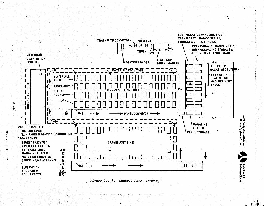
Fm
CtSo=
s ^g^^*tr}.,..c±*;rrs^rz+y-^.+.`""."'`Th.^,.M1^ -.^.e^ s, ;rfi•.;*`. ^z>. ^T;Mr ^ ^•, -wa, -'r mss., .^„- _*^:^^.q^y.^-Fr,;-,:^ja*•ar^,i^a
y
r tFULL MAGAZINE HANDLING LINE
TRACK WITH CONVEYORTRANSFER TO LOADING STALLS,
VIEW A-A STORAGE & TRUCK LOADINGEMPTY MAGAZINE HANDLING LINE
TRUCK ^ 7 TRUCK UNLOADING, STORAGE&
MATERIALS RETURN TO MAGAZINE LOADER
DISTRIBUTION 1 4 PRECISION 1CENTER MAGAZINE LOADER TRUCK LOADERS A
MATERIALS CONVEYOR — _ _ — ~ MAGAZINE OELTRUCK
4 EA LOADINGMATERIALS_ Q Q (, n (^ n Q S1 ^I (-T Q j1 (1 a• _] [=] STALLS FORf FEED(^ LJ u ^I j-J u f (-^_LJ Q MAG. DELIVERY
oJ PANEL ASSY-- ] p Q 0 p n n n n n F] p 0 Q Q U %m TRUCK
ELECT. 18 x 4 PANEL ASSY LINES, HOOKUP---^^ Q^ 0 Q Q U U U U U Ll 0 0 0 0 °1 000000 0 Do 0*0 000 0 00 0
O^
I I 16M ^°r—► - PANEL CONVEYOR — No F7771 L= N
_^_---------- --- --------^ A o..L MAGAZINEPRODUCTION RATE: f
^ t^1-1^^ LOADER
108 PANELS/HR ® ® I ' t I PANEL STORAGE
d 12.9-PANEL MAGAZINE LOADINGS/HR /0 3CREW REGMTS:
Ur
r M.3 MEN AT ASSY STA 18 PANEL ASSY LINES °c o
o° 2 MEN AT ELECT. STA ^I 1- r5 x 72 ASSY LINES 360 L - _^ IJMAGAZINE LOADERS 12
i^ MATL'S DISTRIBUTION 18 ^^ U 13 .J V L^ e1 LJ LJ LJ 1J U L. Li Jr' SERVICING/MAINTENANCE 36
`. 426 ^^ --► --^SUPERVISION 42SHIFT CREW 4f£
" a 4'SHIFT CREWS _1872
,Figure 1.4-7. Central Panel Factory
I
m
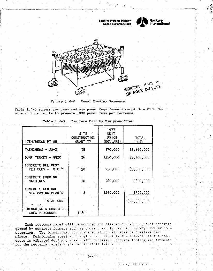
ITEM/DESCRIPTION
SITECONSTRUCTIONQUANTITY
1977UNIT
PRICE(.DOLLARS}.
TOTAL
COST
TRENCHERS - JW-2 38 $70,000 $2,660,000
DUMP TRUCKS - 992C 26 $350,000 $9,100,000
CONCRETE DELIVERYVERICLES - 10 C,Y. 190 $50,000 $9,500,000
CONCRETE FORMINGMACHINES 10 $60,000 $600,000
CONCRETE CENTRALMIX PAVING PLANTS 2 $250?000 $500,000
TOTAL COST $22,360,000
TRENCHING & CONCRETECREW PERSONNEL 1480
Satellite Systems Division Rockwell`r Space Systems Group
0j% Intematlonal
fr•;
a
o . Y qtr, POOH
Figure 1.4-8. Panel Loading Sequence
-Table 1.4-5 summarizes crew and equipment requirements compatible with thenine month schedule to prepare 1088 panel rows per rectenna.
Table 1.4-5. Concrete Footing Equipment/Crew
Each rectenna panel will be mounted and aligned on 6.8 cu yds of concrete
placed by concrete formers such as those commonly used in freeway divider con-struction. The formers extrude a shaped ribbon at rates of 6 meters per
r minute. Reinforcing steel and panel attach fittings are inserted as the 'con-crete is vibrated during the extrusion process. Concrete footing requirements
r for the rectenna panels are shown in Table 1_.4-6.
B-265
SSD 79-0010-2-2
t

7
i^
Satellite Systems Division Rockwellk Space Systems Group OD International
's p{
Table 1.4-6. Concrete Footing Requirements
ITEM/DESCRI.PTION
1977 $WLL PRICEDELIVERED)
INGREDIENTSFOR
6.8 CU.YDS.
MATERIAL COSTDELIVERED
(1977 DOLLARS)
CEMENT (5 SACK) $42/TON 3196# $67.12(94# SACK)
SAND $4.51 /TON 9520# $21.47
ROCK 1" -11" $4.39/TON 12444# $27 .31
WATER - 2040# !d
REINFORCING $0.10/LB 64# $6.44STEEL - #4
TOTAL/PANEL 27264# $122 .34
DELIVERED 1977 MILL PRICES PER ENGINEERING NEWS RECORD (ENRI -McGRAW HILL, AN INDUSTRY PUBLICATION
n'
1.4.2.3 COST ESTIMATES
DDT&E, investment, construction/installation, and operations costs ofr. the rectenna supportPP structures (less electronic elements ) and the concrete
footings are identified in the following tables:
Table 1.4.2..1.1 Hat Sections
Table 1.4.2.1.2 Wide Flanges
I' Table 1.4.2.1.3 Tube Braces & Hardwares
Table 1.4.2.1.4 Assembly & Installation
Table 1.4.2.2.1 Footing Concrete & Rebar
r` Table 1.4.2.2.2 Machinery & Equipment
Table 1.4.2.2.3 Construction Operations
Table 1.4.2.3 Support Structure DDT&E
w
e:<
B-266
h" SSD 79-0010-2-2

ROCKWELL SPS CR-2 REFERENCE CONFIGURATION z? #TABLE 1,.4.2.1.1 HAT SFC TION S z__ . INPUT PARAMETERS
INPUT COEFFICIENTS
f4T= 580500.0 00 T F= 1.000000 CDCER= 0.0
i M= 1.000000 OEM= 0.0 COEXP= 0.0CF= 1.000000 Z1= 1.000000 t10ER= 0.000619
PHI = 1.000000 Z2= 60.000000 CIEXP= 1.000000R_0.0
_ _______ _.__ Z3=60.000000
OF= 1.000000 Z4= 60.000000 Z5= 0.0
CALCULATED_VALUFS PANEL SUM TO 1.4.2.1 S,MILLIONS
CD=CD{ER X (T X OF)XX(CDEXP) X CF 0.0
CLRM= CICER X (M)XX(CIEXPI X CF X TF 0.001
#RM =T / M 580500.000i E
E =1.0 + LOG( PHI) / LOG(2.0) 1.000
CTFU=(CLRM / E)X((#RM X Z1+.5)XX(E) -0.5XX(E)) 359.228 f
CTB =((CLRM/E)X((#RM X Z3 + 0.5)XX(E) -0.5XX(E)) ) / Z3 359.224 $
CIPS=CTB*Z4/Z2___ 359.224
R CI = CTB X R 0.0
4 CCEM = OEM OR CTB*Z5/Z2/ENYR 0.000COMMENTS .,
EACH PANEL USES 18 HAT SECTIONS TOTALING 584.25 KG (1288LBS):. WITH COST ESTIMATF(USS) OF

0.0
7
.A
ROCKWELL SPSY CR-2 REFERENCE CONFIGURATION
TABLE 1.4.2.1.2 WIDE FLANGES j
INPUT PARAMETERS INPUT COEFFICIENTS
T= 580500.000 TF= 1.000000 C D CER= 0.0M= 1.000000 OEM= 0.0 CDEXP= 0.0
_J
CF= 1.000000 Z1= 1.000000 CICER= 0.000506PHI= 1.000000 Z2= 60..000000 CIEXP= 1.000000
R= 0.0 Z3= 60.000000DF= 1.000000 7.4= 60.000000 Z5= 0.0
CALCULATED VALUES -PANEL SUM TO 1.4.2.1 fr—MILtiONS
CD=CDCER X (T X DF)XX(CDEXP)'X CF 0.0 j
CLRM=CICER X (M)XX(CIEXP) X CF X TF 0.001
#RM =T / M 580500.000 -—
Nco E =1.0 ± LOG(PHI) / LOG(2.0) 1.000
CTFU=(CLRM / E)XI(#RM X Z1+.5)XXIE) -0.5XX(E)) 295.173
,
I CTB =((CLRM/E)X((#RM X Z3 + 0.5)XX(E) -0.5XX(E11 ) / Z3 295.170
CIPS=CTB*Z4/Z2-
- - 295.170
CRCI =CTB X R 0.0
c .a

1
ROCKWELL SPS CR-2 REFERENCE CONFIGURATIONTABLE 1.4.2.1.3 TUBE BRACES HARDWARE
INPUT PARAMETERS INPUT COEFFICIENTS}
T= 580500.000 TF= 1.000000 CDC'ER= 0.0M= 1.000000 06M= 0.0 CDEXP= 0.0
CF= 1.000000 Z1= 1.000000 CICER= 0.000743PHI= 1.000000 Z2= 60.000000 CIEXP= 1.000000
R'= 0.0 Z3= 60.000000DF= 1.000000 Z4= 60.000000 Z5= 0.0
PCALCULATED VALUES PANEL SUM TO 1.4.2.1 $.MILLIONS
CD=CDCER X (T X DF)XX(CDEXP) X CF 0.0
CLRM=CICER X (M)XX(CIEXP) X CF X TF 0.001
#RM"=T / M 580500.000i' N
-,=1..0_+, LOG(PHI)..:/ LOG(2.0) 1.000
CT FU=(GERM / E)X((#RM X Z1+.5)XX(E) —0.5XX(E)) — 431.346
CTB =((CLRM/E)X((#RM X Z3 + 0.5)XX(E) —0.5XX(E)) ) / Z3 431.343 X
i ..CI"PS=CTB*Z4/Z2 431.343
CRCI _CTB X R `v'y 0.0____^^
C.t'B.M = OEM OR CTB*Z5./Z2/'ENYR _ ° 0.0 G
jr
COMMENTSINCLUDES 4 TUBE BRACES 4.76M LONG,°FRONT E REAR CLEVIS FITTINGSoCAST MOUNTINGS t WELD ROD•AND PROVIDES FOR OVERALL SCRAP ALLOWANCES.
4
ri
sa
i I
-
:ji
9
`, Y ^

ROCKWELL SPS CR-2 REFERENCE CONFIGURATIONTABLE 1.4._2.1.4 ASSEMBLY E INSTALLATION
INPUT PARAMETERS INPUT COEFFICIENTS
T=580500.000_ TF= 1.U00000 CDCER= 0.0 _i1_
M'='1.000000 OEM= --- 0.0 — LDEXP= 0.0CF= 1.000000 Z1= 1.000000 CICER= 0.001052
PHI= 1.000000 Z2= 60..000000 CI EXP= 1.000000 ---- R= - 0.0 Z3= 60.000000
_
f"f
DF= 1.000000 74= 60.000000 Z5= 0.0_CALCULATED VALUES PANEL SUM TO 1.4.2.1 $•MILLIONS
CD=CDCER X (T X DF)XX(CDEXP) X CF 0.0p
,., CLRM=CICER X (M')XX(CIEXP) X CF X TF 0.001
#RM-=T/ M._. ---- – -- - 580500.000—
iNo E =1.3 + LOG(PHI) / LOG(2.0) 1.000
CT FU= (CLRM 1 E)X((#RM X Z1+.5)XX(E) --0.5XX(E11 610.762
CTB =((CLRM/E)X((#RM X Z3 + 0.5)XX(E) -0.5XX(E)) ) / Z3 610.757r'
CIPS=CTB*Z4/Z2 610.756
CRCI =CTB X R 0.0 t
CO&M OEM OR CTB*Z5/Z2/ENYR. 0.0
COMMENTS
ri"t i
y.. yr' ^.oarl

Y
ROCKWELL SPS CR -2 REFERENCE CONFIGURATIONTABLE 1.4.2.2.1 FOOTING CONCRETE 6 RE—GAR
It
INPUT PARAMETERS INPUT COEFFICIENTS
T= 580500.000 TF= 1.0OJJ00 CDCER= 0.0M= 1.000000 OEM= 0.0 CDEXP= 0.0
CF= 1.000000 Z1= 1.000000 C'ICER= 0.000122PHI= 1.000000 Z2= 60.000000 CIEXP= 1.000000__ .. R_:__.
0.0 Z3= 60.000000DF= 1.000000 Z4= 60.000000 Z5= 0.0
CALCULATED VALUES PANEL SUM TO 1.4.2.2 S,MILLIONS
CD=CDCER X (T X DF)XX(CDEXP) X CF 0.0
CLRM=CICER X (M)XX(C IEXP) X CF X TF 0.000
to #RM =T / M 580500.000N
E = 1.0 + LOG(PHL) / LOG(2.0) 1.000
CTFU=(CLRM ! E)X((#RM X Z1+.5)XX(E) —0.5XX(E)) 70.821
CTB =((CLRM/E)X((#RM X Z3 + 0.5)XX(E) —0.5XX(E)) ) / l_3 70.820
CIPS= CT9#Z4/Z2
70.820
CRCI =CTS X R 0.0

.-^^'?`PRi^'+n "f. F i ''6?W-'^"a'AP`Y•.c'%'7F:i^`5'^' kT°1'i.3-we.,;r•-^•3R•iWRN^'y^'+?a..ar.ya ., n•• :'nY, ! - -. ._.. ^ ..
.
R
ROCKWELL SPS CR-2 REFERENCE CONFIGURATIONTABLE 1.4.2.2.2 MACHINGERY C EQUIPMENT
- INPUT PARAMETERS - INPUT COEFFICIENTS_
T= 1.000000 TF= 1.000000 CDCER= 0.0M= 1.000000 OSM= 0.447200 CDEXP= —0.0
CF= 1.000000 Zl= 1.000000 CICER= 22.360001! -PHI= 1.000000 Z2= _ 60.000000 CIFXP= 1.000000
R=— — 0.003333 — Z3= 8.000000DF= 1.000000 Z4= 2.000000 Z5= 0.0
n CALCULATED VALUES SET SUM TO 1.4.2.2 $t MILL IONS
r CD=CDCER X (T X DF)XX(CD'EXP) X CF 0.0 -
CLRM=CDCER X (M)XXfCIEXP) X CF X TF 22.360
ba #R'M =T / M 1.000
N E = 1.0 + LOG( PHI) / LOGl2.01 1.000x
CT'FU=(CLRM I E)X((#RM X Z1+.5)XX(E) — 0.5XX(E)) 22.360
b
CTB =((CLRM/E)X((#RM X Z3 + 0.5)XX(E) -0.5XX(E)) ) l Z3 22.360
CIPS=CTB*Z4/Z2_._ -_ 0.745
C R.0 I Y =CTB ,X R_ 0.0 75
CC&M _ O&M OR CTB*Z5/Z2/ENYR 0.447
COMMENTS
Y
t
i[Vol
_
^

'}StI'f"".br T "^^°',°.PTR, :r!'r..^ a+.i^+^F«P°; 4's*^ ^..hTiva. 'Ind; 2 "5-.-.' ...',9.*•'rnfT' 'ttT'^.:. .,'T .R,r mt,"` y,N° 1 . 5^
..
ROCKWELL SPS CR-2'REFERENCE CONFIGURATIONTABLE 1.4.2.2.3 CONSTRUCTION OPERATIONS
INPUT PARAMETERS INPUT COEFFICIENTS i
T= 399600.000 TF= 1.000000 CDCER.= 0.0N= 399600.000 OBM= 0.0 CDEXP= 0.0
CF= 1.000000 Z1= 1.000000 CICER= 0.000150PHI= 1.000000 Z2= 60.0 00000 CIEXP= 1.000000
:' R= 0.0 Z3= 60.000000DF= 1.000000 Z4= 60.000000 Z5= 0.0
CALCULATED VALUES MANDAYS SUM TO 1.4.2.2 StMILLIONS
:i CD=C'DCER X (T X DFIXX(CDEXP) X CF 0.0
CLRM=CICER X (M)XX(CIEXP) X CF X TF 59.9404 9 ^Ms F .
'rY
#RM =T / M 1.000 qqaaqq
I: w F =1.0 + LOG(PHI) / LOGI2.01 1.000
CTFU=(CLRM / E)X((#RM X Z1+.5)XX(E) —0.5XX(E)1 59.940
ii CTB =((CLRM/E)X((#RM X Z3 + 0.5)XX(E) —0.5XX(E)) ) / Z3 59.940
4 n CIPS=CTB*Z4/Z.2 59.940 ^f.
CRCI = CTB X R 0.0
CC&M OEM OR CTB*Z5/Z2/ENYR 0.0
COMMENTS
k
.. -.. .. -try
^n'^1^^^^M_ .;:w^n• .. .y+ r
ti'I , ^^da . i.w . ^M-ab3s.C^'..'^^'.x. ._ _ K y._

l^r.«:fi y.*»^r.R^lvwa+.rra+..o;*r,•:.,^vs s.'•T-m".,-'•±mgast,.. ?. ,X" :e3 .f °c. .r ..w'r .. .. .-r '^.eaw."agar;.•;-y;.,s-r.,.r^K+,_!
,$
,a
o
ROCKWELL SPS CR-2 REFERENCE CONFIGURATION4^^—` TABLE 1.4.2.3 SUPPORT STRUCTURE ODTEE
,a_ INPUT PARAMETERS INPUT COEFFICIENTS
T= 1.000000 TF= 1.000000 COC ER= 2 .0000 00- M= 1.000000 OEM= 0.0 CDEXP= 0.300000CF= 1.000000 Z1= 1.000000 'CICER= 0.0
' PHI= 1.000000 Z2= 60.000000 CIEXP= :_. 0..0R= 0.0 Z3= 60.000000" t DF= 1.000000 Z4= 60.000000 Z5= 0.0
CALCULATED VALUES SET SUM TO 1.4.2 $,MILLIONS
Pl i CD=CDCER X (T X DF)XX(COEXP) X CF 2.000
CLRM=CIC.ER X (M)XX(CIEXP) X CF X TF 0.0
#RM =T / M! 1.000N —
.. E = 1.0 + LOG (PHI) / LOG ( 2 .01 1.000
CTFU=(CLRM / E)X((#RM X Z1+.5)XX(E) —0.5XX(E1J 0.0
CTB =((CLRM/E—)X(( #RM X Z3 + 0.5)XX(E) —0.5XX(E)1 ) / Z3 0.0
x CIPS=CTB*Z4/Z2 0.0—
CR CI =CTB X R 0.0
CCEM = O&M OR CTB*Z5/Z2/ENYR 0.0 Kk
4
COMMENTS
x^
Ye
.
_a'+ are: a
y
ai

1
yy
Satellite Systems Division Rockwell1space Systems Group International } r
i 1.4.3 POWER COLLECTION j
This element of the GRS includes the rectenna array elements associatedwith the actual reception and rectification of the microwave radiation. Theseelements are in series and parallel as required to deliver the line outputvoltage and current. Also included are those components that accept the dopower from the array elements and route, control, convert, and switch thispower for delivery to the power conversion stations of the grid interface.
The rectifier assembly consists of a GaAs diode and input/output filters.The_ outputs of the rectifier circuit are series connected to output 40+ kV(Figure 1.4-9): The regulation assembly accepts the voltage from the seriesconnected rectenna diodes and adjusts the voltage output to the power distribu-tion feeders to a value consistent with positive current flow. The rectennaarray elements are 0.735 x9.33 m in size and 20 elements are combined per panelwith diode circuitry equivalent to the mW density pattern. A total of 735diodes or diode equivalents are required per average panel with a rectenna itotal. of 330x10 6 diodes as shown in Figure 1.4-10.
.500TO USER KV4C
y
% DOUBLE BOXES BUSES /`^EA SECTORIM. CUBES
40,000 VDC BUSSES ISOLATION 4X4X4MSWITCHES
' STRING - 3 EA/SECTOR CONVERTER 400 MW s!MOTOR MOTSWITCHES
16 MW SCNES 4X4X4M
STATION 500 KVAC(TYPICALWCf;
N---r
I i
^-1
t t^_,i ^
-.,,_w
OF 12 SITES)
t 1 I tt i
°.'It I
t Zt yZ l W
t d l lai w
G_ i- i I IIt
tt jt 1068 ROWS
t
{ IFEEDER POWER (INPUT TO
1-h: j i
II t!
t it
40,MD VDC BUSSES)
)r i i : i ll 11 RANGE 12.1 - 16 MW AT^-r-:- (300 -400A)14.8 MW AS MANY FEEDERS
1 .AS REQUIRED TO
MASS IN QUADRANT (FEEDERS ONLY) 50,000 KG (200,000 KG FOR ENTIRE FARM) APPROACH^16 MW
1.
Figure 1.4-9. Rectenna Schematic Block Diagram- Preliminary
The electronic array element of the antenna is a multilayered copper/dielectric, sandwich panel material. - Resource/mass projections are identified
. in Table 1.4- 7. These calculations were based.on the array cross section andpanel requirements shown in Figure 1.4-11. Costs were determined from
B-275
SSD 79-0010-2-2
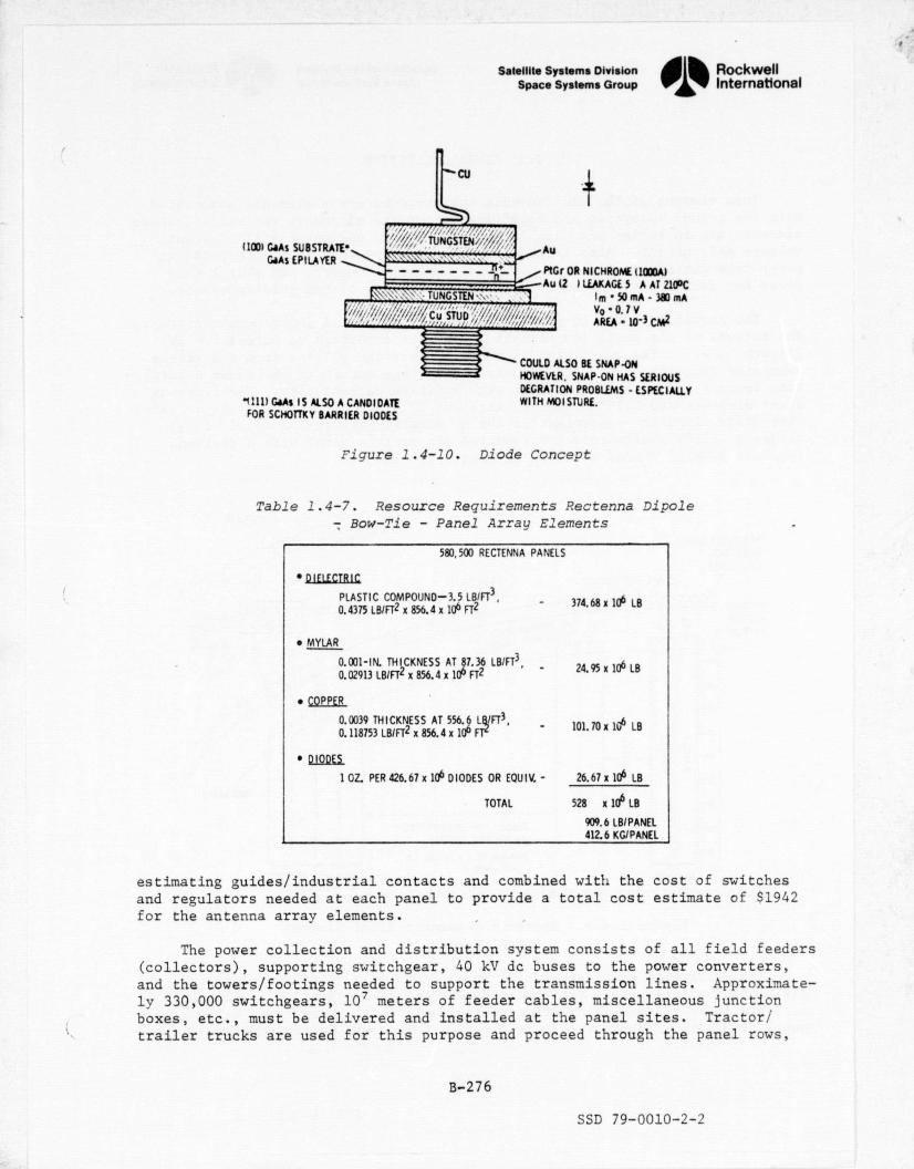
- S7
Satellite Systems Division ,^^ RockwellSpace Systems Group International
CU
IIODI GaAs SUBSTRATE• TUNGSMN '
AuGaAs EPILAYER
PIG OR NI CHROME IIODDAIAu 11 1 LEAKAGE. 5 A AT 210DC
Im-50MA• 380 MA
Cu STUD,,
"1111 GaAs IS ALSO A CANDIDATEFOR SCHOTTKY BARRIER DIODES
Vo-0.7VAREA - 10- 3 CM2
COULD ALSO BE SNAP-0NHOWEVER. SNAP-ON HAS SERIOUSDEGRATION PROBLEMS • ESPECIALLYWITH MOISTURE.
Figure 1.4-10. Diode Concept
Table 1.4-7. Resource Requirements P.ectenna DipoleBow-Tie - Panel Array Elements
580,500 RECTENNA PANELS
• DIELECTRIC
PLASTIC COMPOUND-3.5 LB/FT 3, 374.68 x 10⁶ LB0.4375 LBIFT2 x 856.4 x 106 FT2
• MYLAR
0.001-IN. THICKNESS AT 87.36 LBIFT3,24.95 x 106 LB
0.02913 L Ell FT2 x 856.4 x 106 F12
• COPPER
0.0039 THICKNESS AT 556.6 L IFT3,101.70x 14 LB
0.118753 LBIFT2 x 856.4 x 106 Fl
• DIOQES.
1 OZ PER 426.67 x 10⁶ DIODES OR EQUIV. - 26.67 x 10⁶ LB
TOTAL 528 x 106 LB
909.6 LBI PANEL412.6 KG/PANEL
estimating guides/industrial contacts and combined with the cost of switchesand regulators needed at each panel to provide a total cost estimate of $1942for the antenna array elements.
The power collection and distribution system consists of all field feeders(collectors), supporting switchgear, 40 kV do buses to the power converters,and the towers/footings needed to support the transmission lines. Approximate-ly 330,000 switchgears, 10' meters of feeder cables, miscellaneous junctionboxes, etc., must be delivered and installed at the panel sites. Tractor/trailer trucks are used for this purpose and proceed through the panel rows,
B-276
SSD 79-0010-2-2

Satellite Systems DivisionSpace Systems Group 01% Ino
International
ORIGINAL PAGE is
OF pVOR Quhak urface
T` Cu Clad1.5 in. Mylar
13.8 cml1l
Ir Dielectric
n•^u ^u^^ouc AKKAT
• 20 ARRAY ELEMENTS/ PANEL
• 1475 FT2 1137 M21 PER PANEL
• 1990 TECHNOLOGY
• 1977 PRICES
• TOTAL PANEL AREA • 9.33 M x 14.69 M x 580,500 PANELS 79.56 x 10⁶ M2130.61 FT x 48.19 FT x 580,500 PANELS 856.4 x 10⁶ FT2)
• DIELECTRIC 0.4375 LB/FT2 x 856.4 x 106 FT2 (0 $0.8721LB $326.72 x 10⁶
• MYLARI SURFACE 4 LAYERS x 856.4 x 10 6 FT2 @ $0.10 FT2 $342.56 x 10⁶
• COPPER IPROCES$ED/BONDED)
65% COVERAGE x 856.4 x 10⁶ FT2 4 $0.151FT2 $ 83.50 x 10⁶
• DIODESIEQUIVALENTSIWIRE
426.67 x 10⁶ DIODES @ $0.10 EA. $ 42.67 x 10⁶
• BONDING 6 SURFACES x 856.4x 10⁶ FT2 (_@ $0.02621FT2- $134.63 x 10⁶
Figure 1.4-11. Rectenna Dipole - Bow-Tie -Pane1 Array Elements
delivering material at each panel. Additional trucks with reels playout thefeeders, which then are installed in conduits and spliced to panel connectionsby the electrical installation crew. Contacts with a utility company indicatea requirement of 8 manhours to hookup one panel. On this basis, the manpowerand equipment projections were established for a 20 hour 7 day week.
Equipment for electrical hookup and checkout of completed panels was cal-culated on the basis of acquisition cost prorated over the service life andutilization period at a particular site. Total crew requirements of 4196personnel and the schedule period were the basis of calculating man-day re-quirements of 755,280. The amortized cost of equipment and labor were combin-ed for the total cost factor.
DDT&E power collection costs are associated with the design and verifica-tion of bow-tie electronic panels/bonding processes, connectors, and largeswitchgear to optimize the voltage/current ratios and element/wiring configura-tion. Cost estimates are provided in the following areas:
Table 1.4.3.1 Antenna Array Elements
Table 1.4.3.2 Power Distribution Svstem
Table 1.4.3.3 Installation and Checkout
Table 1.4.3.4 Power Collection DDT&E
B-277
SSD 79-0010-2-2

n ^P r per. x`ar^^
t `
r
ROCKWELL SPS CR-2 REFERENCE CONFIGURATIONTABLE 1.4.3.1 ANTENNA ARRAY ELEMENTS
y ' INPUT PARAMETERS INPUT 'COEFFICIENTS }
T= 580500.000 TF= 1.000000 COCER= 0.0M=1.000000 0&M= 0.0 COEXP= 0.0
CF= 1.000000 Z1= 1.000000 CICFR= 0.001942FPHI= 1.000000 Z2= 60.000000 CI EXP= 1 .000000^v
R 0.0 Z3= 60.000000 –DF= 1.000000 Z4= 60.000000 Z5= 0.0sCALCULATED VALUES PANEL SUM TO 1.4.3 $,MILLIONS
CD=CDCER X (T X DF)XX(CDEXP) X CF 0.0
CLRM=CICER X (M)XX(CIEXP) X CF X TF 0.002
a, #RM =–T / M 580500.000y _ s'r_oo. E =1.0 + LOG(PHI) LOG(2.0) ;_--__- - - -- - - - _ 1.000------ - _ - -
CTFU=(CLRM / E)X((#RM X Z1+.5)XX(E) -0.5XX(EIJ 1127.331 ?^
CTS =((CLRM/E)X((#RM X Z3-+ 0.5)XX(E) —0.5XX(E)) ) / Z3 1127.322
CIPS=CTB*Z4/Z2 1127.321
CR'CI =CTB X R
CC&M = O&M OR CTB*Z5/Z2/ENYR 0.0
COMMENTS
_

_ T . _VP
^'^i^ ^ i. i^?!^R,^y{ry1jx^E°'t'n`^? ;MI`'?#a {Pw,^m^mR'y'a T t?x.q n+^.S^."RP58"?a.\7".^1, '''# f!rT' ^'. ^!':fl.^
• ,
ROCKWELL SPS CR-2 REFERENCE CONFIGURATIONTABLE 1.4.3.2 POWER DISTRIBUTION SYSTEM ^
s
INPUT PARAMETERS INPUT COEFFICIENTS_
T= 580500.000 TF= 1.000000' CDCER= 0.0M= 1.000000 OEM= 0.0 COEXP= 0.0
CF= 1.000000 Z1= 1.000000 CICER= 0.000120PHI=1.000000 Z2= 60.0000OU CIEXP= 1.000000
R=0.0 Z3= 60.000000DF= 1.000000 Z4= 60.000000 Z5= 0.0
CALCULATED VALUES PANEL SUM TO 1.4.3 SvMILLIONS
CD=CDCER X (T X DF)XX(CDEXP) X CF 0.0
CLRM=CICER X (M)XX(C IEXP) X CF X TF 0.000
#RM =T / M 5805000000
E =1.0 + LOG(PHI) / LOG(2.0) 1.000
CTFU=(CLRM / E)X((#RM X Z1+.5)XX(E) -0.5XX(E))O
69.660
G^CTB =((CLRM/E)X((#RM X Z3 + 0.5)XX(E) -0.5XX(E)! ) / Z3 p Z 69.659_ fir.
-CIPS=CTB*Z4/Z2 69.655
CRCI =CTB X '—R
A 0.0 E
COGM _ OEM OR CTB*Z5/Z2/FNYR °e 0.0 {
1 _ .

^{iMeWfm . t',,F Tx°M'i'YT^R'¢"Y;^f#?^..'R[F:'Sf'v.^k"Y`fih"a+'s°^P""T'p." . i RP'S ., .._. emy{a'%Si!u. ^r*;i ^!' .nT;R" *.i'T "`rW '^'S..>"„ _ ... _ ^ .., . YV•:. i^: s?E
k_
4
_ROCKWELL SPS CR-2 REFERENCE CONFIGURATION I
TABLE 1.4.3.3 INSTALLATION E "CHECKOUT
INPUT PARAMETERS INPUT COEFFICIENTS
T= 781100 .00_0_ TF= 1.000000 CDCER= 0.0K= 4340.00000 OEM= 0.0 CDEXP= 0.0
CF= 1.000000 Z1= 1.000000 C[CER= 0.000200PHI= 1.000000 Z2= 60.000000 CIEXP= 1.000000
R= 0.0 Z3= 60.000000DF= 1.000000 Z4= 60.000000 Z5= 0.0
CALCULATED VALUES MANDAYS SUM TO 1.4.3 S,'MILLIONS
CD=CDCER X (T X DFIXX(CDEX'P) X CF 0.0
CLRM=CDCER X (M)XX(CIEXP) X CF X TF 0.868
- #RM =T 1 M 179.977
o E =1.0 + LOG(PHI) / LOG(20) 1.000i'.
CTFU=(CLRM / E)X((#RM X Z1+.5)XX(E) -0.5XX(E)l 156.220'
CTB =((CLRM/E)X((#RM X Z3 + 0.5)XX (E) -0.5XX(E))' I j Z3 156.220
CIPS=CTB*Z4/Z2 156.220
CRCI =CTB X R 0.0#,
CQEM = OEM OR CTB*Z5/Z2/ENYR 0.0 1COMMENTS
, a
a

caP..rcF wn-,e,^.+C'^':?kF"».*..^! ^F+S° i'c ,en"T^+z,*ar E"`#"d4!*•r .r^ A s -r^-3sr_..w t --` °1hP. 3f F^rsr: r; _ Y:` -N+r`R'...^ - .., ,. ^q .xr?'. .s 'lam^
yROCKWELL SPS CR-2 REFERENCE CONFIGURATIONTABLE 1.4.3.4 POWER COLLECTION-DDT&&
{
INPUT PARAMETERS INPUT COEFFICIENTS
T= 1.000000 TF= 1.000000V
CDCER=_
3.000000M= 1.000000 O&M= 0.0 CDEXP= 0.300000
CF= 1.000000 Z1= 1.000000 CICER= 0.0PHI= 1.000000 Z2= 60.000000 CIEXP= 0.0
' R= 0.0 Z3= 60.000000.;' DF= 1.000000 Z4= 60.000000 Z5= 0.0
CALCULATED VALUES SET SUM TO 104.3 O d L•MILLIONS
CD=CDCER X (T X DF)XX(CDEXP) X CF -_ 3.000_ __.._ _- _. _ }
m re- ECLRM=CICER X (M)XX(CIEXP) X CF X TF _0.0
r #RM =T / M 1.000
E =1.0 LOG{PHI) / LOG(2.0) ^_ --+ - ---- --- -.^,. 1.000._ _._ _F'
CTFU= (CL'RM / E)X((#RM X Z1+.51XX(E) -0.5XX(E1) 0.0
= CTB =((CLRM/E)X((#RM X Z3 +'0.5)XX(E) -0.5XX(E)1 ) / Z3 0.0
LIPS=CTB*Z4/Z2 0.0
CRC I =CT3 X R 0.0 3
CCEM = 06M OR CTB*Z5/Z2/ENYR' 0.0
1` s COMMENTS
w
1
a
,
tX
a
d
w
J
g:e

Satellite Systems Division , RockwellSpace systems Group 1 International
'x'i
1.4.4 CONTROL `sx
The telemetry, tracking, communications, monitoring of microwave beamcharacteristics, computing phase corrections, and the equipment needed to
•rt provide frequency standard signals for the satellite are included in this- section. This hardware will be used to monitor and control the satellitefrom the ground.
The following monitor and control functions are performed:{
1. Tracking, using ground-based radars to monitor the orbital stabilityof the satellite. y
2. Beam monitoring and control, using ground equipment for adaptive orcommand control of the satellite microwave beam.
3. Data management, using equipment required to analyze signals and datafrom the satellite and ground-based systems to compute control signalsand corrective data to maintain safe and optimum performance. =;
4. Communications, using equipment required to maintain communications. between the ground station and the SPS satellite. Included are the
communications with the crew, and telemetry nd command equipmentY ,.not included in the beam monitoring and control assembly.i
At this time, the cost effort is divided into the three categories ofcontrol center equipment, beam control electronics, and DDT&E. Two sets offull-up IBM 370, or equivalents, a complete display center, and a manned controlroom are envisioned as basic elements of the control center. Beam controlelectronics would consist of control sensors and dual frequency transmitters.The overall DDT&E and hardware costs were projected by engineering. The exact-ing requirement of this rectenna operation will require further study in future
` contract activity to define the technical and performance standards. It shouldalso be noted that system and operational requirements are needed to defineadequate software/programming considerations.
r,. Cost estimates are presented as follows:
Table 1.4.4..1 Control Center Equipmentw
Table 1.4.4.2 Control Electronics
Table 1.4.4.3 Control DDT&E
a
B-282
SSD 79-0010-2-2

' ROCKWELL SPS CR-2 REFERENCE CONFIGURATI -ON nTABLE 1..4.4.'1 CONTROL CENTER EQUIPMENT
ii
INPUT PARAMETERS -INPUT COEFFICIENTS €
G' T= 1.000000 TF=- 1.000.000 CDCrR= 0.0 izM= 1.000000 OEM= 0.0 `CDEXP= 0.0^CF= 1.000000 Z 1= 1.000000 CI CER= 15.000000 1
~PHI= 1.000000 Z2= 60.000000 CIEXP= 1.000000
R= 0.0 Z3= 60.000000DF`= 1.000000 Z4= 60.000000 Z5= 0.0 r
^iCALCULLAATED_' VALUES SET SUM TO 1.4.4 -.b., MILL IONS
CD=CDCER X (T X DF)XX(CDEXP) X CF 0.0
R CLRM=CICER X (M)XX-(C IEXP) X CF X TF 15.000
#RM =T / M 1.000r
` co^ E =1.0 +_LOG(-PHI) / LOG(2.0)
CTFU=(CLRM / E)X((#RM X Z1+.5)XX(E) -0.5XX(E)) 15.000•u
CTB =('(CLRM/E)X((#RM X Z3 + 0.5)XX(E) -0.5XX(E)) ) / Z3 15.000
CIPS=CTB*Z4/Z2 15.00000.n M.,
I CRC =CTB X RII _ 0.0-
i' CCEM = 06M OR CTB*Z5/Z2/ENYR r 0.0
COMMENTS
' Rr
k `.
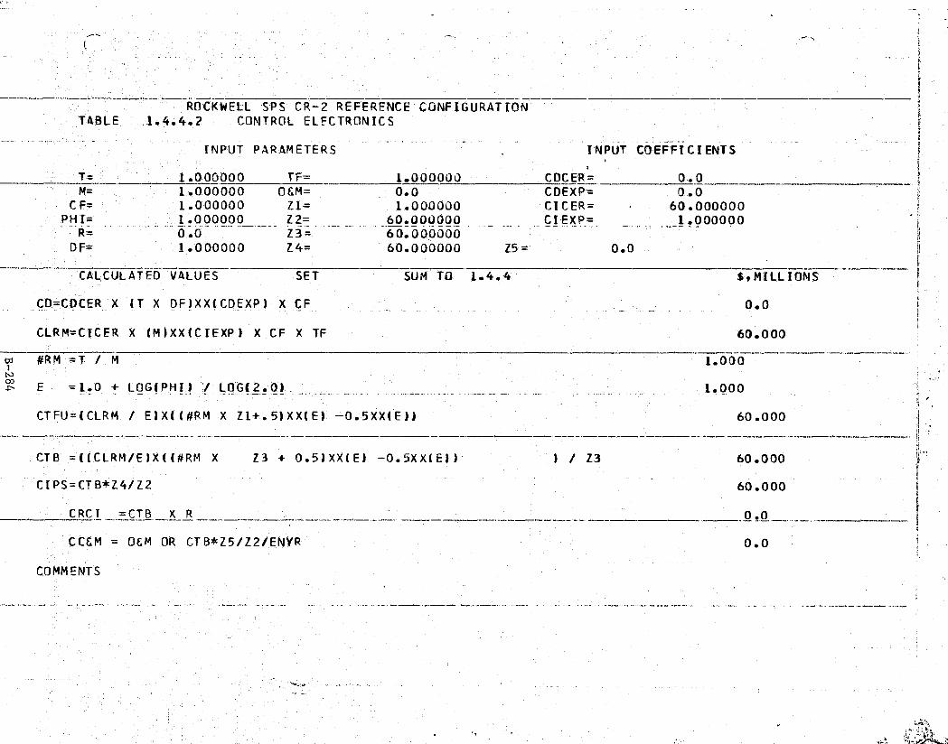
w.wT.9•'OC"•n .a..,w=xcyy'sVS'R.ep,s.TPkF, }w...' 4 ...,. .-±v,T.«wa.`F% y"S "PM - /.nYf .
i 1
._-
ROCKWELL SPS CR = 2 REFERENCE CONFIGURATIONTABLE 1.4.4.2 CONTROL ELECTRONICS
INPUT PARAMETERS INPUT COEFFICIENTS
T=.1.000000 TF= 1.000000 CDCER= 0.0M= 1.000000 0&M= 0.0 COEXP= 0.0 ^^
CF= 1.000000 Z1= 1.000000 CICER= 60.000000PHI= 1.000000 Z2=60.000000- CIEXP= 1.000000 1R_- - -
0.0 Z3_ 60.000000DF= 1.000000 Z4= 60.000000 Z5= 0.0 r'
CALCULATED VALUES SET SUM TO 1.4.4 E,M:ILL1-0MS
CD=CDCER X (T X DF)XX(CDEXP) X CF 0.0
i1 CLRM=CICER X '(M)XX(CIEXP) X CF X TF 60.000
ca #R'M =T / M
coE =1.0 + LOG(PHI) '/ LOG(2.0) - _ _ . — _ 1.000 y
CTFU=(CLRM / E1X((#RM-X Z1+.5)XX(E)' -0.5XX(E)1 60.0007 .
CTB = (,(CLRM/E)X((#RM X Z3 + 0.5)XX(E) —0.5XX(E)) 1 / Z3 60.000rt...
CIPS=CTB*Z4/Z2 60.000
CRC I =CTB X R
CC&M = 0&M OR CTB*Z5/Z2/ENYR 0.0F
Ii COMMENTS
;; M
r^

rncgBnSxf. +vk'*,x;x•• lF'XT'iF'. FRfM•rsf ^.fi..ec.. . :., e F ,, F t^.... ^
l _ • r,?';K`•y_.'iR'N'Y^yVnTySF:g.
vj 1
ROCKWELL SPS CR-2 REFERENCE CONFIGURATION it
TABLE 1.4.4.3 CONTROL DDTEFsi P
INPUT PARAMETERS INPUT COEFFICIENTSy -s
T= 1.000000 TF= L.00JUOV CDCER= 10.000000 __' aM- 1.000000 0.0 COEXP= 1.000000CF= 1.000000 Z_1= 1.000000 CICER=_, 0.0
PHI= 1.000000 Z2= 60.000000 CiEXP= 0.0R,= 6.0 Z3= 60.000000
OF= 1.000000 Z4= 60.000000 Z5= 0.0
CALCULATED VALUES SETJ
SUM TO 1.4.4 S,MILLIONS
CD=CDCER X (T X DF)XX(CDEXP) X CF 10.000
CLRM=CICER X (M)XX(CIEXP) X CF X TF 0.0
#RM T / Ma
1.000Nt E = 1.0 + LOG( PHI) / LOG(2.0) 1.000
CTFU=(CLRM / E)X(l#RM X Z 1+.5)XX(E) —0.5XX(E)) ^ O 0.0 r
CTB =((CLRM/E)X((#RM X Z3 + 0.5)XX(E) — 0.5XX(E1) ) / Z3 Sy s,. 0.0 '.
CIPS=CTB*Z4/Z2 .a 0.0
CRCI =CTB X R 0.0;.
COEM OEM OR CTB*Z5'/Z2/ENYR 0.0
COMMENT'S
,t,
F
t.^
;. . .n
r

ITEM DESCRIPTION SPECIFICATIONGRS
QUANTITYPROJECTEDUNIT COST
TOTAL(1977$)
CONVERTER-STATIONS 400 mW - 12 EA. $10x106 $12Ox106500 kV acor kV do
ISOLATION SWITCH- 4x4x4 m 24 EA $400,000 EA $0.96x10⁶
GEAR
FILTER YARDS 12 $100,000 EA $1.2x10⁶
INTERCONNECT TOWERS 500 kV ac 90 EA $12.741x10⁶
& FOUNDATION TOWERS
INTERCONNECT 12 $901000/MI $10.789xIO6TRANSMISSION CABLE LINES
i
TOTAL/GRS $145.69x10⁶
w
a
Satellite Systems DivisionSpace Systems Group
1.4.5 GRID INTERFACE
01% RockwellInternatmat ional
This element includes the power conversion equipment that receiveselectrical power from the power collection system and conditions/converts itto a high voltage do or ac power acceptable for input into the national powergrid.
The converter stations accept 40 kV do power and output 500 kV ac or dc.The concept utilizes a solid-state inversion/step-up concept typified by anexisting do - ac conversion station located in Sylmar, California. Although +specific design details of this system await clarification in a future studyeffort, an analysis and cost estimate was prepared as shown in Table 1.4-8.The CER for DDT&E were derived from cost estimates in the "Technical StudyReport on Pacific Northwest-Southwest do inter-tie," prepared by the BonnevillePower Administration in February, 1976. This DDT&E estimate was based on sixcost quotations which Bonneville received on _a 1.44 GW and a 2.20 inter-tie,The total cost for the 1.44 GW terminal ($156.7
.9 was allocated as 30% DDT&E-
and 70% ICI.. This judgment was based on the assumption that most of thefacility will be a standard design.
Table 1.4-8. Grid Interface (WBS 1.4.5)x

y
A
ROCKWELL SPS CR-2 REFERENCE CONFIGURATION. 1 i;TABLE 1.4.5.1 ELECTRICAL EQUIPMENT i
1{
INPUT PARAMETERS INPUT COEFFICIENTS
T= 1.000000 TF= _.1.000000 _---`.- CDCER 0__0__M= 1.000000 OEM= 0.0 CDEXP= 0.0
CF=` 1.000000 Z1= 1.000000 CICER= 145.690002PHI= 1.000000 Z2= _ _60.000000 CI EXP =. 1.000000
R= 0.0 Z3= 60.000000DF= 1.000000 Z4= 60.000000 Z5= 0.0
CALCULATED VALUES SET SUM TO 1.4.5 $,MILLIONS
CO=CDCFR X (T X OF)XX(CDEXP) X CF _ _ _ 0.•0
CLRM=CT'CER X (M)XX(C IEXP) X CF X TF 145.690
ARM =T / M 1.000Nco E =1.0 + LOG(PHI) / LOG(2.0) _ 1.000
CTFU=(CLRM / E)X((#RM X Z1+.5)XX(E) — 0.5XX(E)i 145.690
CTB =((CLRM/E)X((#RM X Z3 + 0.5)XX(E) -0.5XX(E)) ) / Z3 145.690^r
CIPS=CTB*Z4/Z2 145.690i
CRCI =CTB X R 0.0
CO&M = OEM OR CTB*Z5/Z2/ENYR 'n 0.0s
COMMENTS
f^

a
a ROCKWELL SPS CR-2 REFERFNCE CONFIGURATION_TABLE> 1.4.5.2 GRID I'NTEPFAC£-DDTEE
INPUT PARAMETERS INPUT COEFFICIENTS
T= 5.000000 TF- : 1.00JOU_0 _. _ CDCER= . ._ 37.714996
M=5.000000 OEM= _ 0.0 CDEXP= - 0.604000
CF= 1.000000 ZL= 1.000000 C'ICER= 0.0PHI=" 1.000000 Z2= 60.000000 CI EXP= 0.0
R= 0.0 Z3= 60.000000
fDF= 1.000000 Z4= 60.000000 Z5= 0.0
_
CALCULATED VALUES GW SUM TO --1 -4 $,MILLIONS
CD=CDCFR X (T X DF)XX(CDEXP) X CF 99.699
CLRM=CICFR X (M)XX(C TEXP) X Cr- X TF 0.0
#RM =T / M 1.0004
00 E" =1 0 + LOGiPHI) / LOG(2.0) 1.000 i
CTFU=(CLRM / E)X((#RM X Zl+.5)XX(E) — 0.5XX(E)) 0.0
z
CTB =((CLRM/F)X'((#RM X Z3 + 0.5)XX(E) —0.5XX(E)) ) / Z3 0.0
CIPS = CTB*Z4/Z2 0.0
CRCI =CTB X R _.._. 0.0
Cfl&M = OEM OR CTB*Z5/Z.2/FNYR 0.0
COMMENTS tr _
ff^.^ at,. ,y M. 6:
,.y
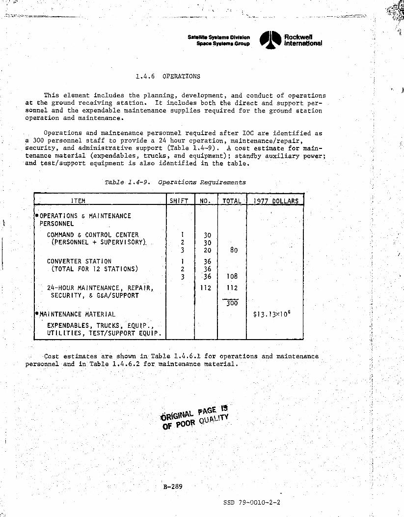
a , s 6
1
Satellite systems Division Rockwell
Space systems Group Intemationals.
1.4.6 OPERATIONS
This element includes the planning, development, and conduct of operations A^._. at the ground receiving station. It includes both the direct and support per-
sonnel and the expendable maintenance supplies required for the ground stationoperation and maintenance.
Operations and maintenance personnel required after IOC are identified asa 300 personnel staff to provide a 24 hour cperation, maintenance/repair,security, and administrative support (Table 1.4-9). A cost estimate for main-tenance material (expendables, trucks, and equipment); standby auxiliary power; ?and test/support equipment is also identified in the table.
Table 1.4-9. Operations Requirements
ITEM SHIFT NO. TOTAL 1977 DOLLARS
*OPERATIONS & MAINTENANCEPERSONNEL
COMMAND & CONTROL CENTER 1 30(PERSONNEL + SUPERVISORY), 2 30
3 20 80
CONVERTER STATION 1 36(TOTAL FOR 12 STATIONS) 2 36
3 36 108
24-HOUR MAINTENANCE, REPAIR, 112 112SECURITY, & G&A/SUPPORT
300
*MAINTENANCE MATERIAL $13.13x 10⁶
EXPENDABLES, TRUCKS, EQUIP.,UTIL[TIES, TEST/SUPPORT EQUIP.

t .7f t
i P•^g
ROCKWELL SPS CR-2 REFERENCE CONFIGURATIONTABLE 1.4.6.1 OPER. E MAINT. PERSONNEL
INPUT PARAMETERS INPUT COEFFICIENTS
T=300.000000 TF=..__ _._._. _ ._W 1.00oujo__- _- .. CDCER=_ : ^_ -- 0-' 0-M_.300.000000 OEM= 64.800003 COEXP= __ _0.0
CF= 1.000000 Z1= 1.000000 CICER= 0.0PHI= 1.000000 Z2= 60.OU0000 _ CIFXP= 0.0
R= 0.0 Z3= 60.000000DF= 1.000000 Z4= 60.000000 Z5= 0.0
CALCULATED VALUES MAN-DAY'S_ SUM TO 1.4.6 E,MILLIONS
CD=CDCER X (T X DF)XX(CDEXP)— X CF 0.0-g
1,
CLRM=CTCER X (M)XX(C'IEXP) X CF X TF 0.0
rd #RM =T: % M. 1.000io
EE _ =1.0 + LOG(PHI) LOG(2. 0)_- 1.000 .
CTFU=(CLRM / E)X((#RM X Zl+.5)XX(E) -0.5XX(E)) 0.0 ..±
CTB =((CLRM/E)X((#RM X Z3 + 0.5)XX(E) -0.5XX(E)) ) / Z3 0.0
CIPS=CTB*Z4/Z2 0.0n
CRCI =CTB X R 0.0
COGM = OEM OR CTB*Z5/Z2/ENYR 64.800 r4
COMMENTS360 DAYS/YR 3 SHTFTS/DAY 300 MANDAYS/SHIFT *'3200/MANDAY
F

sq
ROCKWELL SPS CR-2 REFERENCE CONFIGURATION if tTABLE - 1.4.6.2 MA INT. MATERIAL
INPUT PARAMETERS INPUT- COEFFICIENTS
T= =_ ,._.^__. ..x.._. 1.0 00000 --TF-- 1.000000 -M= 1.000000 OEM= 13.130000 CDEXP= 0.0
CF= 1.000000 Z1= 1.000000 CICER= 0.0PHI= 1.000000 Z2= 60.000000 - CI.EXP= 0..0 __._ i
R= 0.0 Z3= 60.000000DF= 1.000000 Z4= 60.000000 Z5= 0.0
CALCULATED VALUES SET SUM TO L.4.6 SMILI CONS
CD=CDCER X (T -X OF)XX(CDEXP) X CF 0.0
CLRM=CICER X (M)XX(CIEXP) X CF X TF 0.0 `.
#R.M =T / M 1.004N
E =1.0 + LOG(PHI) / LOG(2.0) _ 1.000
CTFU =CLRM / E)X((#RM X Z1+.5)XX(E) -0.5XX(E)1 0.0
CTB =((CLRM/E)X((#RM X Z3 + 0.5)XXIE) -0.5XX(Ell ) / Z3 0.0 j..
CIPS = CTB*Z4/Z2 0.0
CR'CI =CTBX R Q,Q..^^__^
COEM = O&M OR CTB*Z5/Z2/ENYR 13.130
COMMENTS
r,
r ^^
vx
IV^. -; '.7s
4^s.M._`.
4r ' 2{ »^
uurr,,(( a .. w ..:^iVd3Rnn.2 ^:. .« 1. S Au`_^ ^ti;
^

..... e •1, TT^s-'+w_mT'^er-:-vcc—l^.m^+c e. -._ ws...r.++arr as r.^aw.:<,—.....a.s.+«.cw..:.. rK.-.e ^...., .i ..»..._.. ..... .-......... .x...... .r..^ tee. . .. ..... ... ... _11{
a Py' 4
Satellite Systems Division RockwellSpace Systems Group International
1.5 MANAGEMENT AND INTEGRATION
This element includes all efforts and material required for management 3'+and integration functions at the systems level and program level. It encom-passes the following functions:
1. Program Administration
2. Program Planning and Control
3. Contracts Administration
4. Engineering Management
5. Manufacturing Management
6. Support Management
7. Quality Assurance Management
'. 8. Configuration Management9. Data Management
>. 10. Systems Engineering and Integration.
This element sums all of the direct effort required to provide management rcontrol including planning, organizing, directing, and coordinating the project 2to ensure that overall project objectives are accomplished. These efforts
l^ overlay the functional work areas (e.g., engineering, manufacturing, etc.) and` assure that they are properly integrated. This element also includes the =.
efforts required in the coordination, gathering, and dissemination of manage-ment information. Also included are the engineering efforts related to the .'establishment and maintenance of a technical baseline for a system by genera-tion of system configuration parameters, criteria, and requirements. It in-cludes requirements analysis and integration, system definition, system testIdefinition, interfaces, safety, reliability, and maintainability. It alsoincludes those efforts required to monitor the system development and opera-tions to ensure that the design conforms to the baseline specifications.
The management and integration function for DDT&E, TFU MCI, RCI and 0&Mare estimated at a cost equal to 5% of the corresponding total dollar estimatesfor WBS elements 1.1 through 1,.4 within each area. Table 1.5 presents thistabulation.
B-292
SSD 79-0010-2-2
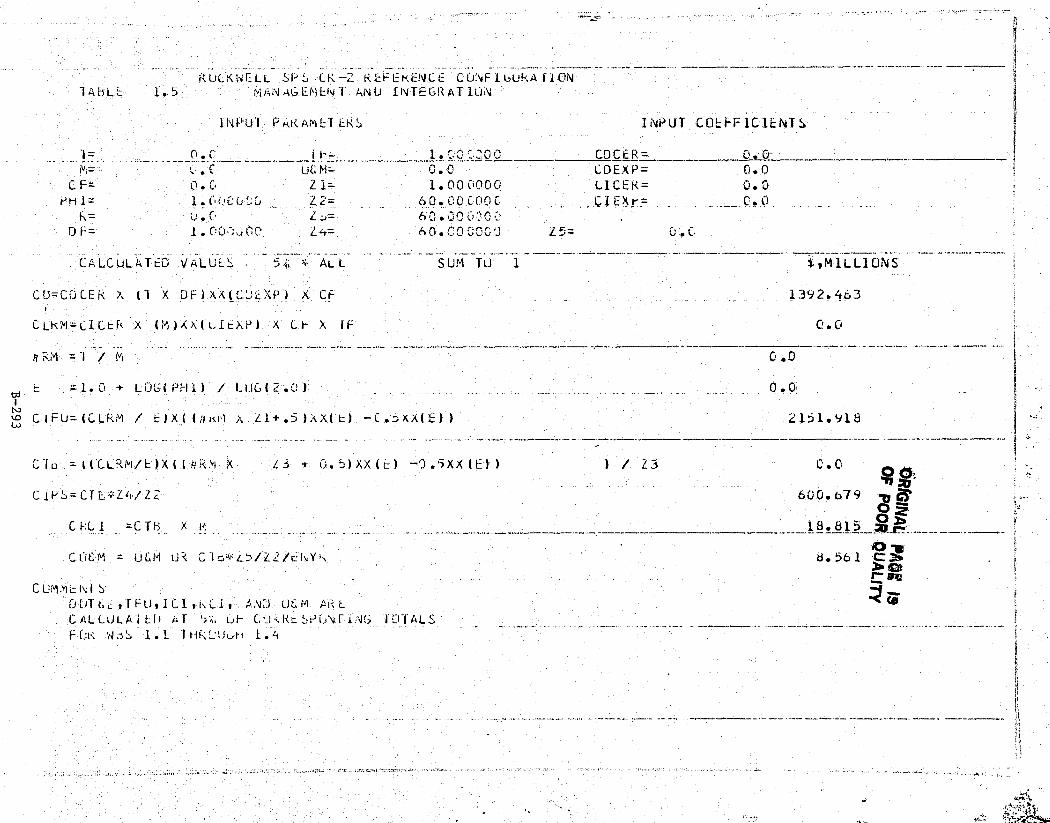
i a^.r^—""""{s^- `;"KK`.?'kRCe;3n'^^7^rr,R:„r°^.:.w' ^. dr. .^.FKS,*.fv ^*w_ _
71.
_ ^ —.. ,,,,,,yyy
1
Tray.... .. ..... .,. ., .. ..... ': . ,.-
5 1
P\UCKWF--LL SP CK- ...-._. _ter_.__
REFEKENCE CONFI bUkA I'lOiV
..... ^. ___.. _,._._ ^_ •.W
IABLt 1.5 m, AN AGENI EN kVU INTEGRATION{
liVul PARiumLT EKS INPUT CLi- F1CIENIS
i= . C4 `: 0 V CD CER = o.uI= . i UF. M= ';. G COEX P= 0.0
C F= ' 0. G 2 1= 1. 0 0 0000. L CEK= 0.0PH 1= 1.5vi(1 Zt`= 60.00 C-0 CI EX Y= C. 1.5r
Dt= = 1.00"r;:,tr,, ^4= 60."00,v^J Z_— 0.0
CALCULATED VALULS AL L SUM" TO 1::
*vMILLIU NS
CU=CC;C`i R «(l X JF)Xit(C'cCt') X C1=_ _ X 1392.463
CLKtil_ LILLR X (iM)X,\(t,IEXP) X' Ct- X 1F C,. C+
I
=1.0 + LVC(PHI) ! LI ul2. ;1 0.0'bj
NC 1 FU=(CLRM ! t) X{ (,IKi •1 .: Z1+.5 )hXl'L- 1 — 1 .DAX/E)) 2151.91
Lo
1s.
Cfu = (ICLR(°I /E ► X(ItjR^i X ZS * 6 51 )XX(E1 -- 1).ixx E 1 1 / Z3
CiPS = CTL- Z'r/Z 600.679 O ZC PL l =c T h x K - ..__, _.^^r:^_ -----18.815 ° -
Ct1t^M = ULM U CIG^^^S/Z t/ N.Y. 8.561 C:r^
Cumm 1^T IS
UUT6 ,TFU 1C1,i.0-I, ANi.) U A1-1LCALLULA l t}) AT ' a, Li L° k `yi'i,tif•i'U'i ''CII ALS :t
FGr; JaS 1.1 T 1.^+
k
ii
i
'(c+ yx.
t
-

. i. iwi> ^^t± . a rsi.^h^`33*^'s. ^--"°"+aqt'^ ASS'
,
f2
E Satellite Systems Division Q, RockwellSpace Systems Group Intemationel
i
1.6 MASS CONTINGENCY
A cost contingency has been added to the SPS Program to provide for
t potential growth due to increased weight as a result of design/developmentactivities that would affect the procurement of systems during any phase ofthe program. This allowance is costed as a 15% bottom line contingency tothe DDT&E, TFU, ICI, RCI and 0&M elements of the program. Table 1.6 reflectsthe total amounts in each of these areas based on the totals of items 1.1, 1..2,and 1.3.
v
,' b
:. p B-294
SSD 79-0010-2-2
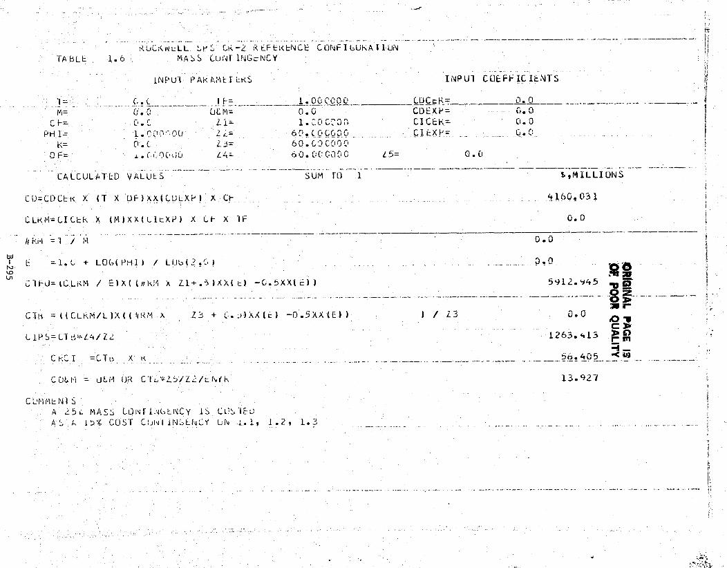
KUCKwLLL ,K5 Cat —[: REFEKENCE CCjNFIC;UKAI'lUV :'TA bLL 1. o MASS LUi4T INGcNCY r.
1NF'ul P AKA ;1tl EKS IEvPUI COEFFICIENTS i
1= c . C I F = 1 . ,ou C a t 00 LiJC_K= tom• n —M= c.. -0 UL M=
_C1. G CDEX1'= G. Cl
C F= c , r L 1 = 0 C.; .^„ Cl CF-K= C,.PHI= r:Mr'.0U Lc— 6f;.i:C,G G ^^, ._.. ClExp= _ C,.%G_
tOF="jL, Lam= 613.E.,CG11c^0 L5= O.0
CALCULATED VALULS SUM TO 1 b^MLLLIONS
CU=CDLEK X (T X OF1XX(i,U XF) x CF_
CLkNi=CICLk X (M)XX(CItXi') X LF X IF 0.0
kri = 1 / (-1 xI3 . t7
N E =1. L + LOCH( PHI) / LOU- I2.C-) _ _ 0.0—
t: 'lFcJ= ICLKM / E)X ll,'4 X L'-1+. ;i )XX( E) —C,.5XX( i_)) 5912.v45 ^p „_0 a..
C,Tli =((CLR.M. L):Xll4 M X Z3 + :1. Ax e. -0.5XXlC1) ) / 13 O. 0+O 7
'.
( rL4/IRS= (,T L^^^-_
1263. 413 _r m
C =CTn X ^c __ _. _. __. _ _._.--- _ ._..._ 5 4015 '4'^
L- 0L — uLM OR C1"L,^`5/Z^/t(^Yk 13. y2
A E5 M S, c,0 r GEN, CY IS c:CIE-U`; L 1 t)% !.US r C.tjIV l IN ;LN("Y UN 1. I, 1 . 2 1. 3 _
' 1
{d ^
f
i