rl- 13 - NASA Technical Reports Server
485
rl- 13 NASA COMPENDIUM OF SATELLITE COMMUNICATIONS PROGRAMS (NASA-CR-1328 79 ) NASA COMPENDIUH OF N74-11971 SATELLITE COHMUNICATIONS PROGRAMS (Computer Sciences Corp.) -*8 p HC $26.25 Fo CSCL 17B Unclas G3/07 23016 Prepared for NATIONAL AERONAUTICS AND SPACE ADMINISTRATION GODDARD SPACE FLIGHT CENTER Greenbelt, Maryland 20771 Contract No. NAS5-21522 AUGUST 1971 . L 9t CS C*UU COMPUER SCENCESCORPOATIO
-
Upload
khangminh22 -
Category
Documents
-
view
1 -
download
0
Transcript of rl- 13 - NASA Technical Reports Server

rl- 13NASA COMPENDIUM OF SATELLITE
COMMUNICATIONS PROGRAMS
(NASA-CR-132879 ) NASA COMPENDIUH OF N74-11971
SATELLITE COHMUNICATIONS PROGRAMS
(Computer Sciences Corp.) -*8 p HC$26.25 Fo CSCL 17B Unclas
G3/07 23016
Prepared for
NATIONAL AERONAUTICS AND SPACE ADMINISTRATION
GODDARD SPACE FLIGHT CENTER
Greenbelt, Maryland 20771
Contract No. NAS5-21522
AUGUST 1971
. L 9t
CS C*UU
COMPUER SCENCESCORPOATIO

NASA COMPENDIUM OF SATELLITE
COMMUNICATIONS PROGRAMS
Prepared for
NATIONAL AERONAUTICS AND SPACE ADMINISTRATION
GODDARD SPACE FLIGHT CENTER
Greenbelt, Maryland 20771
Contract No. NAS5-21522
AUGUST 1971
COMPUTER SCIENCES CORPORATION
6565 Arlington Boulevard
Falls Church, Virginia 22046
Major Offices and Facilities Throughout the World

PRECEDING PAGE BLANK NOT FILMED
PREFACE
During the decade of the 1960s a new industry, satellite communications, was
born as one of the products of the space program conducted by the United States of
America. As of mid-1971, this new industry has evolved to the point where it serves
a major portion of the world's population. The most dramatic illustration of this
service is real-time television coverage of major international events, allowing
millions to literally be "on-the-spot" to view such activities as the Olympic games
and official state visits of world political and religious leaders.
Numerous programs have contributed toward the evolution of satellite communi-
cations over the past 10 years and much has been written about them. The primary
objectives of this compendium are to summarize the major contributions of each
program and to compile an extensive bibliography of the publicly available writings
on them. The compendium has been assembled under the sponsorship of the Goddard
Space Flight Center of the National Aeronautics and Space Administration.
iii

PRECEDING PAGE BLANIK NOT FILMED
TABLE OF CONTENTS
Section 1 - Introduction ............................ ....... 1-1
1.1 Scope ............................................. .. 1-1
1.2 Overview of Programs .................. ............ 1-3
1.3 Evolution of Technology ................... ........... 1-10
Section 2 - Scope ........................................ 2-1
2.1 Program Description .................. ............. 2-1
2.2 System Description................................ 2-22.3 Spacecraft...................................... 2-4
2.4 Ground Terminals ................................ 2-6Cited References ..................... ............ 2-10
Section 3 - Echo ........................................ 3-1
3.2 System Description ................... ............. 3-43.3 Spacecraft ..................................... 3-10
3.4 Ground Terminals ................................ 3-13
3.5 Experiments .................................... 3-17
3.6 Operational Results ............................... 3-20Cited References ................................. 3-22Related References ................................ 3-25
Section 4 - Courier ...................................... 4-1
4.1 Program Description .............................. 4-14.2 System Description ................... .............. 4-24.3 Spacecraft ..................................... 4-44.4 Ground Terminals ................................ 4-64.5 Experiments .................................... 4-94.6 Operational Results ............................... 4-10
Cited References ................................. 4-13Related References ................... .............. 4-14
Section 5 - West Ford ..................................... 5-1
5.1 Program Description .............................. 5-15.2 System Description ................... ............. 5-4
v

TABLE OF CONTENTS (Continued)
5.3 Spacecraft............................................. 5-55.4 Ground Stations ..... .... ............. .. ........... 5-85.5 Experiments ......... ........................ 5-85.6 Operational Results ............................ 5-14
References ...................... ............. 5-15
Section 6 , Telstar. ............. ............. .. .......... 6-1
6.1 Program Description ......... ...... .... ... ....... 6-16.2 System Description ................... .......... 6-36.3 Spacecraft ............................ ..... ......... 6-56.4 Ground Terminals ........ ....... ................ .. 6-86.5 Experiments ... .... ...... .. .............. 6-106.6 Operational Results .............................. 6-13
Cited References .................................. 6-15
Section 7 - Relay ........................................ 7-1
7.1 Program Description ............................ 7-17.2 System Description .............................. 7-27.3 Spacecraft .................................. 7-57.4 Earth Stations ................................ 7-77.5 Experiments ................................. 7-97.6 Operational Results ............................. 7-11
Appendix 7-A - The Relay Microwave Antenna ...................... 7-13
Related References .............................. 7-15
Section 8 - Syncom ......................................................... 8-1
8.1 Program Description ............... ..... ........ 8-18.2 System Description .................... .... ....... 8-38.3 Spacecraft .................................. . 8-78.4 Ground Terminals .............................. 8-98.5 Experiments ... ................ .............. 8-98.6 Operational Results ............................... 8-12
Cited References ................................ 8-15Related References ............................ . 8-17
vi

TABLE OF CONTENTS (Continued)
Section 9 - Lincoln Experimental Satellites ........................ 9-1
9.1 Introduction .................................... 9-1
9.2 X-Band Satellites ................... ..... ....... .. 9-2
9.2.1 General Description .................. ........... .. 9-2
9.2.2 System Description ............................ .. 9-7
9.2.3 Spacecraft................................... .. 9-10
9.2.4 Ground Terminals ............................... 9-13
9.2.5 Experiments ................................... 9-15
9.2.6 Operational Results ........ ......................... 9-18
9.3 UHF Satellites .................. ...... ........... 9-18
9.3.1 General Description .............................. 9-18
9.3.2 System Description .............................. 9-25
9.3.3 Spacecraft ........................ ..... ....... .. 9-31
9.3.4 Ground Terminals ............................... 9-34
9.3.5 Experim ents ................................... 9-35
9.3.6 Operational Results ........................ .... 9-47
Cited References ......... .................. ........ ....... 9-49
Related References ................................. 9-54
Section 10 - Intelsat ........ ................. .... ............ .. 10-1
10.1 Program Description ............................. 10-1
10.2 System Description ....................... ....... 10-9
10.3 Spacecraft ........ .......... .......... .... ... 10-18
10.4 Ground Terminals ................................ 10-26
10.5 Experiments ........ .................. .... ............ 10-34
10.6 Operational Results ............................. 10-38
Related References ............................... 10-44
Section 11 - Molniya-1 ...................................... 11-1
11.1 Introduction ............................. ........ 11-1
11.2 Spacecraft ........................... .... .... 11-2
11.3 Ground Terminals ............................... 11-8
11.4 Experiments .............................. ....... 11-9
11.5 Operations ..................................... 11-9
Related References ............................... 11-13
vii

TABLE OF CONTENTS (Continued)
Section 12 - Initial Defense Communications Satellite Program .......... 12-1
12.1 General Description .................. ............. 12-112.2 System Description ................................ 12-512.3 Spacecraft ............................ ............ 12-1112.4 Ground Terminals ................................ 12-1412.5 Experiments .......... ................ ........... 12-1412.6 Operational Results ............................... 12-14
Cited References ................................ 12-25Related References ................... ....... ..... 12-26
Section 13 - Applications Technology Satellite ..................... 13-1
13.1 Introduction ............................................ 13-113.2 Spin Stabilized Satellites ........................... .. 13-213.2.1 General Description ........ ............. .... ........ 13-213.2.2 System Description .................. ............... . 13-613.2.3 Spacecraft .......... ........................ .... 13-1113.2.4 Ground Terminals ......... ....................... 13-1113.2.5 Experiments ................................. ... 13-1813.2.6 Operational Results ................................ 13-2813.2. 7 Major Contributions to Satellite Communications ............ 13-2913.3 Gravity Gradient Stabilized Satellites ..................... 13-3013.3.1 General Description .......................................... 13-3013.3.2 System Description ............... .... ............ 13-3413.3.3 Soacecraft ....................................... 13-4013.3.4 Ground Terminals ..................... .... ........ 13-4513.3.5 Experiments ..... ................................ 13-4513.3.6 Operational Results ........ ................................... 13-5213.4 Large Aperture Antenna Spacecraft (ATS-Faud G) ........... 13-5513.4.1 General Description ................................ 13-5513.4.2 The ATS-F Spacecraft .............. ............... 13.5513.4.3 Ground Terminals ................................ 13.6813.4.4 Experiment .......... .............................. 13-7013.4.5 Operational Results ........ ................. ...... 13-83
Cited References ................................. 13-84Related References ....................... ..... ............ .. 13-88
Section 14 - Tacsat....................................... 14-1
14.1 Program Description .............................. 14-114.2 System Description ................................ 14-2
viii

TABLE OF CONTENTS (Continued)
14.3 Spacecraft ....................................... 14-6
14.4 Earth Terminals .................................. 14-11
14.5 Experim ents ..................................... 14-11
14.6 Operational Results ....... ............ ..... ........ 14-20
Cited References .......... . ....... .. ............... 14-22
Related References ........ ..... .............. . . .. . 14-23
Section 15 - Skynet ........... ......... ...... .. ................ 15-1
15.1 Program Description ( 1 ) ........................ 15-1
15.2 System Description.................... ................. 15-5
15.3 Skynet Spacecraft .............................. ....... 15-11
15.4 Ground Terminals ......... .... ......... ............ 15-15
15.4.1 Type I & II Earth Terminals ................................ 15-15
15.4.2 Type III & IV Earth Terminals .......................... 15-17
15.4.3 Type V Shipborne Terminal .......................... .. 15-20
15.5 Experiments Description ....... ............. ......... 15-2215.6 Operational Results .............. ....... ..... .......... 15-22
Ci ed References ...... ..... ... .. ..... ... ....... 15-23Related References .................................. 15-24
Section 16 - Nato Satellite System ........ ........ ..... .......... 16-1
16.1 Program Description ............................... 16-116.2 System Description............ ..... ..... ......... 16-516.3 Nato Spacecraft .......... .... .................... . 16-1116.4 Nato Satellite Ground Terminals ...... ............. ..... 16-1116.5 Experiments Description ............................ . 16-1316.6 Operational Results ......... ........ ..... ........... 16-16
Cited References ................................... 16-17
Section 17 - Phase II Defense Satellite Communications System .......... 17-1
17.1 Program Description ................. .... ...... ..... 17-117.2 System Description ....... .. .. ................. ... 17-317.3 Spacecraft ...... ........................ ..... ...... 17-517.4 Ground Terminals ... .................. ................. . 17-10
17.4.1 Modified IDCSP Terminals ....... ........... ........... . . 17-1017.4.1.1 AN/FSC-9 Terminals ..... ....... ..... ..... ......... .. 17-1017.4.1.2 AN/MSC-46 Terminals ...... ....... .... ............. . 17-1217.4.1.3 AN/TSC-54 Terminals ........ .......................... 17-1217.4.2 New Terminal Developments .... ............. .. ............ 17-1317.4.2.1 HT/MT Terminals ........ .... ...................... ... 17-13
ix

TABLE OF CONTENTS (Continued)
17.4.2.2 LT Terminals ....... ...... ............. ................. 17-1417.5 Experiments .... ..... ........................... .... ..... 17-1417.6 Operational Results .... ........................... 17-14
Related References .................................. 17-15
Section 18 - Telesat ............ ..... ..................... 18-1
18.1 Introduction.......................... ............ 18-118.2 Spacecraft Description .............................. 18-218.3 Earth Terminals For Telesat ................. ......... 18-418.4 Experiments ......... ...... .................. ... . 18-618-5 Operational Results ................. ...... .... ........ 18-7
Related References ................................. 18-8
x

LIST OF ILLUSTRATIONS
Figure
1-1 Historical Summary of Program Activities as of Mid-1971 ......... 1-4
2-1 SCORE Satellite Interconnection Diagram ....................... 2-32-2 SCORE Ground Station Interconnection Diagram ................... 2-63-1 General Features of the Echo II Experiment ..................... 3-63-2 Circuit Configuration, Echo II Communications Experiments ......... 3-83-3 Block Diagram of the Holmdel Facilities ..................... 3-153-4 NRL Space Communications Facility, Stump Neck, Maryland. .......... 3-164-1 Satellite Electrical Subsystems ............................. 4-64-2 Ground Terminal Block Diagram ........................... 4-85-1 Block Diagram of Propagation Experiment Reciever .................. 5-65-2 Block Diagram of Communications Receiver .... ............... 5-65-3 In-Plane and Out-of-Plane Belt Demensions vs Time .............. 5-115-4 (a) Bistatic Belt Mapping, (b) Constant Density Contours (1-dB Increments
215 Days after Election, (c) Contours of Constant Density 209 Days afterEjection ........................................... 5-12
6-1 Satellite Repeater ..................................... 6-66-2 Major Subsystems of the Andover Terminal .................... 6-87-1 Relay Satellite Transponder Fonfiguration ..................... 7-58-1 Syncom Earth Coverage ................................. 8-58-2 Satellite Communications Subsystem ......................... 8-79-1 Simplified Terminal (without Frequency Hopping) ................ 9-99-2 LES X-Band Transponder ............................... 9-129-3 LET System .................. ....................... 9-139-4 LES-6 Earth Visibility as a Function of Antenna Elevation Angle ..... 9-269-5 TATS Functional Block Diagram .............................. 9-309-6 LES-5 Transponder Block Diagram .......................... 9-339-7 ECI UHF Terminal Block Diagram , ................. ...... 9-369-8 Project East 3/4-Ton Terminal Block Diagram ................... 9-3710-1 Block Diagram of Early Bird Repeater ......................... 10-2010-2 Communications System Block Diagram for Intelsat II ............ 10-2110-3 Block Diagram of Intelsat I Communications System ............. 10-2410-4 Communications Subsystem of Intelsat IV Satellites ............... 10-2710-5 Components of the Intelsat IV Satellites ................. ..... .. 10-2910-6 Early History of Intelsat System Usage .......... ........... 10-4010-7 Cumulative Outage Performance for Early Bird. .................. 10-4010-8 Intelsat Traffic Growth Projection (1965-1980) .................. 10-4311-1 The Molniya-1 Communications Satellite (Cutaway View)........... 11-411-2 Molniya-1 Communications Repeater ......................... 11-712-1 Basic Block Diagram of Typical User Link ....................... 12-6
xi

LIST OF ILLUSTRATIONS (Continued)
Figure
12-1 Basic Block Diagram of Typical User Link ...................... 12-612-2 Satellite Availability ................................... 12-1012-3 IDCSP Satellite Functional Block Diagram ....................... 12-1512-4 AN/FSC-9 Simplified Functional Diagram ...................... 12-1912-5 AB/MSC-46 Simplified Functional Diagram ..................... 12-2012-6 AN/TSC-54 Simplified Functional Diagram ...................... 12-2113-1 ATS 1 and 3 Earth Coverage................................ 13-713-2 Frequency Translator Functional Block Diagram .................. 13-1413-3 Multiple Access Functional Block Diagram ....................... 13-1413-4 Camera Mode Functional Block Diagram ....................... 13-1413-5 VHF Transponder Block Diagram ............................. 13-1513-6 Major Subsystems of a NASA ATS Terminal ..................... 13-1713-7 System Configuration for Millimeter Wave Tests .................. 13-3513-8 System Block Diagram for L-Band Tests ....................... 13-3613-9 ATS-5 Earth Coverage ................................... 13-3713-10 ATS-5 L-Band Repeater Block Diagram .......................... 13-4313-11 The NASA Rosman, North Carolina Millimeter Wave Station.......... 13-4713-12 L-Band System Earth Station Block Diagram ..................... 13-4813-13 Composite Feed Assembly (Plan View) ........................... 13-5613-14 Transponder Signal Interfaces .............................. 13-5813-15 Communications Subsystem Block Diagram........................ 13-5913-16 Frequency Synthesizer Block Diagram .......................... 13-6613-17 Millimeter Wave Equipment Package ........................... 13-6713-18 Transponder Block Diagram ................................. 13-6913-19 Rosman Ground Station Block Diagram ................... ...... 13-7213-20 ATS-F and G Mobile Terminal System Block Diagram .. . ..... .. . 13-7313-21 ATS-Communications Landlines ............................. 13-7414-1 Ground Terminal RF Channel Frequency Plan.................... 14-514-2 Typical Frequency Allocation Chart .................. ......... 14-514-3 Communications Repeater Block Diagram ....................... 14-914-4 Block Diagram of TACSAT UHF Ground Terminal .............. . . 14-1214-5 Block Diagram of TACSAT SHF Ground Terminal .................. 14-1315-1 SKYNET SSMA Links ..................................... 15-715-2 FM/FDMA Links (2-MHz Channel) ............................ 15-915-3 Communications Transponder .................. ........... ... 15-1315-4 Type I and Type II Simplified Block Diagram ..................... 15-1815-5 Type III and Type IV Simplified Block Diagram .................... 15-1915-6 Shipborne Terminal ............................. ....... .. 15-2116-1 NATO SATCOM Phase Interconnectivity ......................... 16-716-2 NATO Ground Terminal Simplified Block Diagram ................ 16-15
xii

LIST OF ILLUSTRATIONS (Continued)
Figure
17-1 Phase II DSCS Communications Transponder. .................. 17-717-2 Phase l DSCS Frequency Plan ............................ 17-918-1 Communication Repeater Schematic................... ....... 18-3
xiii

PRECEDING PAGE BLANK NOT FILMED
LIST OF TABLES
Table
1-1 Summary of Program Scope and Status as of Mid-1971 .......... 1-6
1-2 Summary of Major Contributions .......................... 1-21
2-1 Participating Spacecraft .............................. 2-1
2-2 Frequencies Employed in Project SCORE ................... 2-4
2-3 Signal Processing Employed in Project SCORE ............... 2-4
2-4 Satellite Characteristics ............................. 2-5
2-5 Earth Terminal Characteristics .......................... 2-7
3-1 Echo Program Objectives ............................. 3-1
3-2 Participating Satellites ............................... 3-2
3-3 Participating Terminals .............................. 3-5
3-4 Echo I Operating Frequencies ................... ...... 3-9
3-5 Echo II Operating Frequencies .......................... 3-9
3-6 Signal Processing for Echo I ........................... 3-10
3-7 Characteristics of Major Project Echo Ground Terminals ........ 3-14
3-8 Communications Experiments .......................... 3-18
4-1 Participating Spacecraft ............................. 4-1
4-2 Participating Earth Terminals .......................... 4-2
4-3 Courier Frequencies (MHz) ............................ 4-3
4-4 Signal Processing Employed ........................... 4-4
4-5 Satellite Characteristics ................... .......... 4-5
4-6 Characteristics of Earth Terminals ....................... 4-7
4-7 Summary of Program Experiments ....................... 4-9
4-8 Communications Performance Experiments ................. 4-11
5-1 Project West Ford Frequencies ......................... 5-5
5-2 Earth Terminal Characteristics ......................... 5-9
5-3 West Ford Dipole Belt: Channel Characterization ............. 5-13
6-1 Telstar Program Objectives ............................. 6-1
6-2 Participating Spacecraft ................. ......... 6-2
6-3 Participating Earth Terminals ............................. 6-3
6-4 Telstar Frequencies Employed (MHz) ................. .... 6-4
6-5 Signal Processing Employed .......................... 6-5
6-6 Telstar I and II Characteristics ......................... 6-7
6-7 Characteristics of Major Earth Terminals ................... 6-9
6-8 Summary of Program Activities ......................... 6-11
6-9 Telstar I and II Communication Demonstrations .............. 6-12
6-10 Telstar I and II Communication Experiments. ................ 6-14
7-1 Participating Spacecraft ................. ......... 7-2
7-2 Primary Earth Terminals Participating in the Relay Program..... 7-3
7-3 Project Relay Frequencies (MHz) ......................... 7-4
xv

LIST OF TABLES (Cont'd)
Table
7-4 Satellite Characteristics. ............... . . . . . . . . . . . . . 7-67-5 Earth Terminal Characteristics ........ . . . . . . . . . . . ...... 7-87-6 Major Relay Communication Experiments ................... .7-108-1 Participating Spacecraft .............................. 8-28-2 Participating Earth Terminals .......................... 8-38-3 Syncom Frequencies (MHz) ............................ 8-68-4 Signal Processing Employed .......................... . 8-68-5 Satellite Characteristics ............ . . . . . . . . . . . ....... 8-88-6 Characteristics of Major Earth Terminals ........ .......... 8-108-7 Summary of Program Experiments ....................... 8-118-8 Communications Performance Experiments ......... . . . . .... . 8-138-9 Communications Technical Characteristics Measurement ....... 8-149-1 X-Band Experiment Objectives .......................... 9-29-2 X-Band Spacecraft............ ...................... 9-49-3 Participating Earth Terminals .. .......................... 9-69-4 X-Band LES Operating Frequencies (MHz) ........ . . . . . 9-79-5 Signal Processing for LET Operation with LES-4 .,............ 9-99-6 Satellite Characteristics ...... ........................ 9-119-7 Characteristics of LET-1 Ground Terminal ........... . ...... 9-149-8 Summary of X-Band LES Experiments..................... 9-169-9 Satellite System Performance Experiments ................ . . 9-199-10 UHF LES Experiment Objectives .................... .... 9-209-11 UHF Spacecraft....... .............................. 9-219-12 UHF LES Operating Frequencies (MHz) ..................... 9-279-13 Signal Processing Using Frequency Diversity ................ 9-289-14 Signal Processing Using TATS .... ...................... 9-299-15 Satellite Characteristics................................ 9-329-16 Characteristics of Major UHF LES Terminals ................ 9-389-17 Summary of UHF LES Experiments ........................ 9-399-18 Noise and Interference to UHF Tactical Satellite Communications .. 9-449-19 UHF Propagation Link Losses ............................ 9-459-20 Tactical Modem Performance .......... . . . .... . . . . 9-4610-1 Intelsat I (Early Bird) Spacecraft ........... . . . . . . . . . . 10-310-2 Intelsat II Spacecraft ...... .......................... 10-510-3 Intelsat III Spacecraft ................................ 10-610-4 Intelsat I Participating Earth Terminals .. .... ........... 10-910-5 Intelsat II Participating Earth Terminals ................... 10-1010-6 Intelsat III Participating Earth Terminals .................. 10-1210-7 Ground Complex Additions by End 1972 .......... .............. 10-13
xvi

LIST OF TABLES (Cont'd)
Table
10-8 Intelsat Frequency Assignments ......................... 10-14
10-9 Early Bird Communication Characteristics .......... . ...... 10-20
10-10 INTELSAT II Characteristics .......................... 10-22
10-11 INTELSAT III Characteristics ................. ...... . 10-25
10-12 INTELSAT IV Characteristics .......................... 10-28
10-13 Characteristics of Typical Early Bird Earth Terminals ......... 10-31
10-14 Characteristics of Typical Second Generation Earth Terminals .... 10-32
10-15 Characteristics of Typical Third Generation Earth Terminals ..... 10-33
11-1 Molniya-1 Communications Satellites ................... .. 11-311-2 Molniya-1 Spacecraft Description ........................ 11-511-3 Earth Terminal Characteristics ......................... 11-10
11-4 Orbita Ground Stations ............................... 11-12
12-1 IDCSP .................... .................. ... *.... 12-2
12-2 IDCSP Spacecraft ................................... 12-312-3 Participating Terminals .............................. 12-412-4 IDCSP Duplex Channel Capacity and Performance (Dual Two
Satellite Access) .................................. 12-12
12-5 IDCSP Access Frequencies ............................ 12-13
12-6 IDCSP Satellite Characteristics ......................... 12-16
12-7 Characteristics of IDCSP Ground Terminals ................. 12-17
12-8 Summary of Program ................................ 12-2213-1 Experiment Categories ............................... 13-3
13-2 Spin Stabilized Spacecraft ............................. 13-413-3 Participating Earth Terminals ........................... . 13-513-4 SHF Communications Frequencies (MHz) ................... 13-813-5 VHF (MHz) ............ ....... .................... 13-813-6 TT&C (MHz) ...................................... 13-813-7 SHF Signal Processing for SHF Multiple Access Mode .......... 13-913-8 Signal Processing for SHF Frequency Translation Mode ......... 13-1013-9 Signal Processing for VHF Repeater ...................... 13-1013-10 ATS-1 .......................................... 13-1213-11 ATS-3 ... . ........ .............................. 13-1313-12 NASA ATS ...................................... . 13-1613-13 Summary of ATS 1 and 3 Experiments ..................... 13-1913-14 SSB-FDMA/PM ............................. 13-2213-15 TV System Design Characteristics ................. ... . . 13-2413-16 Freqeuncy Translation TV System Experiments .............. 13-2413-17 NASA Baseline VHF Tests ............................ 13-2613-18 Experiment Categories ............................... 13-30
xvii

LIST OF TABLES (Cont'd)
Table
13-19 Gravity Gradient Spacecraft ........................... 13-3113-20 Millimeter and L-Band Terminals. .............. . .. ... 13-3213-21 Millimeter Wave and L-Band Frequencies (GHz) . . . . . . 13-3813-22 Signal Processing for L-L Satellite Channel ............... 13-4013-23 ATS-2 and 4 Characteristics .......................... 13-4113-24 ATS-5 Characteristics ............................. 13-4213-25 Characteristics of Millimeter Wave and L-Band Ground
Terminals .................. .......... ... ..... 13-4613-26 Summary of ATS-2, 4 and 5 Experiments ............... . 13-4913-27 Preliminary Results Millimeter Wave Experiment ............ 13-5113-28 L-Band Experiments ................................ 13-5313-29 Communications Subsystem Characteristics ................ 13-6013-30 C-Band Performance ............... ............... 13-6113-31 S-Band Performance ............................ 13-6213-32 L-Band Performance ........................... ... ... 13-6313-33 VHF and UHF Performance .......................... 13-6413-34 Characteristics-Millimeter Wave Experiment Terminals ....... 13-7114-1 TACSATCOM Objectives ............................. 14-114-2 Participating Spacecraft .............. ...... .... ..... 14-214-3 Participating Terminals ............................ 14-314-4 TACSAT Frequencies (MHz) .......................... 14-414-5 Signal Processing for UHF Modes .................. ... 14-614-6 Signal Processing for SHF Modes ....................... 14-714-7 TACSAT Characteristics ................ ........... 14-814-8 Characteristics of UHF Earth Terminals ... .............. 14-1414-9 Characteristics of SHF Earth Terminals .................. 14-1514-10 Technical Experiment Results ......................... 14-1715-1 Participating Spacecraft .......... ........... 15-315-2 Participating Earth Terminals ................. s. .. 15-415-3 Skynet Frequencies ............................. 15-515-4 Power Budget for Typical SSMA Links. ............... . 15-815-5 FM Demodulator Performance........................ 15-1015-6 SKYNET I Satellite Characteristics . . . . ............ ..... 15-1215-7 Characteristics of Skynet Earth Terminals ................. 15-1616-1 Participating Spacecraft .......................... .... .. 16-316-2 Participating Earth Terminals........................ 16-416-3 NATO SATCOM Phase II Frequencies .................... 16-616-4 FM Demodulator Performance ............................ 16-916-5 Power Budgets for Typical NATO FM Performance at the Worst
Geographic Position ....... ... ............. .... . 16-10
xviii

LIST OF TABLES (Cont'd)
Table
16-6 NATO Satellite Characteristics ................ ..... 16-12
16-7 Characteristics of NATO Earth Terminals ............... 16-14
17-1 Phase II DSCS .7..................... ........ * 17-2
17-2 New Phase II DSCS ................................. 17-2
17-3 Phase II Satellite Characteristics ......................... 17-6
17-4 Characteristics of New DSCS Ground Terminals .......... .. 17-11
18-1 Telesat Characteristics ............................ 18-5
xix

SECTION 1 - INTRODUCTION
1.1 SCOPE AND ORGANIZATION
This document presents a comprehensive review of worldwide satellite communi-
cation programs that range in time from the inception of satellite communications to
mid-1971. Particular emphasis is placed on program results, including experiments
conducted, communications system operational performance, and technology employed.
The background for understanding these results is established through brief summaries
of the program organization, system configuration, and satellite and ground terminal
characteristics. Major consideration is given to the communications system aspects
of each program, but general spacecraft technology and other experiments conducted
as part of the same program are, for the most part, at least mentioned summarily.
Each program review attempts to be thorough and objective to the maximum extent
possible from publicly available literature. In some cases, such literature was
not adequate to allow complete reporting to the level of descriptive detail desired.
This is particularly true for programs involving foreign, international, or military
sponsorship. Program difficulties encountered are viewed as positive contributions
towards advancing the state-of-the-art in satellite communications and are presented
in that light.
The project reviews presented include all significant past programs in which
satellites having some operational capability were successfully launched into orbit and
all active programs, as of mid-1971, wherein development and procurement of the
necessary space hardware had been approved. Some of the programs described span
a considerable period of time and an evolutionary development of several configura-
tions of ground and space assets. In most such cases, separate discussions of thedifferent segments of the program, each segment of which may encompass several
spacecraft, are provided. The approach to program segmentation has, in all cases,been guided by the results-oriented objective of this document. The organizational
grouping this provides may not in all cases coincide exactly with the chronological
1-1

sequence of events or the official program organization based on administrative con-
siderations and initially expected results.
The document is organized and formatted to provide the user with easy access to
needed information. It features a chronological ordering of program descriptions,
brief concise summaries of each program, including extensive use of tabular presen-
tations, adherence to a consistent format from description to description, and exten-
sive bibliographies of cited and related references from which the reader can do more
detailed research on a particular aspect of a program. The consistent format provides
consideration of the same items of information in the same order on each program and
extends this philosophy from the defining and ordering of major subtopics to the de-
fining and ordering of the tables employed. The bibliographies are incorporated
directly following the particular program to which they are pertinent and are composed,
in general, of references readily available within the public domain.
The basic format for each description encompasses the following major sub-
topics: (1) Program Description, (2) System Description, (3) Spacecraft, (4) Ground
Terminals, (5) Experiments, and (6) Operational Results. In a few instances, the
nature and extent of available information dictated that the "Program" and "System
Description" subtopics be replaced by a "General Description" or "Introduction"
subtopic. In such cases, information of the type normally included in the first two
subtopics is distributed over the introductory, spacecraft, and ground terminal sub-
topics.
Information, typically, included within each major subtopic is as follows:
* Program Description - Project origin and objectives; spacecraft launch
dates, orbital data, and status; extent to which program objectives were
accomplished; participating ground terminals; sponsoring organizations;
and significant results advancing the state-of-the-art in satellite communi-
cations.
1-2

* System Description - Ground terminal linking, extent of spacecraft visi-
bilities, operating frequencies, signal processing including modulation and
multiple access, system control, and calculated link performance.
* Spacecraft - Major characteristics of antennas and communications re-
peaters; general satellite features including stabilization, prime power,
size and weight; and communications repeater block diagram. Major on-
board experiments not directly communications-related are listed but not
described in detail.
* Ground Terminals - Major characteristics of antennas, receive system,
transmitter, tracking system and physical installation; block diagram of
principal subsystems; and any unique aspects.
* Experiments - Definition of major types of experiments, summary of pri-
mary experimental results, and descriptions of significant demonstrations
and public relations highlights.
* Operational Results - Summary of operational traffic handled, plus opera-
tional performance and reliability of the satellites and ground terminals.
1.2 OVERVIEW OF PROGRAMS
Major events, in each of the programs reviewed in this document, are summa-
rized as a function of time in Figure 1-1. The programs illustrated encompass all
significant satellite communication activities involving orbiting hardware since the
launching of the Score satellite, with the possible exception of Project Oscar.
Several active repeater satellites, nicknamed "Oscar, " have been launched, starting
as far back as late 1961 by the U. S. Air Force, to provide amateur radio communi-
cations satellites for use by "Ham radio" operators throughout the world. Some of
these satellites were very short-lived and they, by intent, did not push the state-of-
the-art in satellite communications.
1-3
PROGRAM 1968 B 1960 1961 192 1963 194 1965 1088 1887 10 B 169 1970
SCORE
ECHODI)
COURIER
WEST FORD _ _
TELSTAR(2)
RELAY(3
)
SYNCOM-UNCOLN EXPERIMENTAL SATELLITE (5)
INTELSAT(B) ---MOLNIYA
(8)
IDCSP (SCS PHASE 1)APPLICATIONS TECHNOLOGY SATELLITE(
1
TACSAT
SKYNET
NATO
DSCS PHASE II
TELESAT
LEGEND: I [ SATELLITE PROCUREMENT IN PROGRESS. FIRST LAUNCHING HAS NOT OCCURRED.FIRST LAUNCH UNSUCCESSFUL.
OPERATING SPACECRAFT IN ORBIT. SPACE SEGMENT BEING ACTIVELY EMPLOYED TO MEET PRIMARY PROGRAM OBJECTIVES.. SPACECRAFT IN ORBIT HAVING SOME OPERATING CAPABILITY. SPACE SEGMENT, IF USED, IS MEETING REDEFINED OR SECONDARY OBJECTIVES.
NOTES: (1) TWO SPACECRAFT OF DIFFERENT STRUCTURAL DESIGN EVALUATED AT SEPARATE TIMES. SAME TYPE EXPERIMENTS CONDUCTED IN BOTH CASES.(2) TWO VERY SIMILAR SPACECRAFT EVALUATED AT SEPARATE TIMES USING SIMILAR TESTS. FIRST SATELLITE FAILED PRIOR TO SECOND LAUNCHING.(3) TWO VERY SIMILAR SPACECRAFT EVALUATED AT SEPARATE TIMES USING SIMILAR TESTS(4) SPACECRAFT TURNED OVER TO DOD IN EARLY 1965 AND HANDLED OPERATIONAL TRAFFIC UNTIL ABOUT 1969.(5) SPACECRAFT OPERATING AT SHF FREQUENCIES EVALUATED DURING FIRST PERIOD OF ACTIVITY AND UHF SATELLITES DURING SECOND.(6) FOUR GENERATIONS OF SPACECRAFT EVOLVED DURING THE OPERATIONAL PERIOD SHOWN.(7) SPIN STABILIZED SPACECRAFT EVALUATED DURING FIRST PERIOD OF ACTIVITY AND EXPERIMENTS ON SPACECRAFT DESIGNED FOR GRAVITY GRADIENTSTABILIZATION CONDUCTED DURING SECOND.(8) HISTORY OF SATELLITE FAILURES AND RESULTANT PERIObS WHEN SYSTEM WAS INOPERATIVE ARE UNCERTAIN.
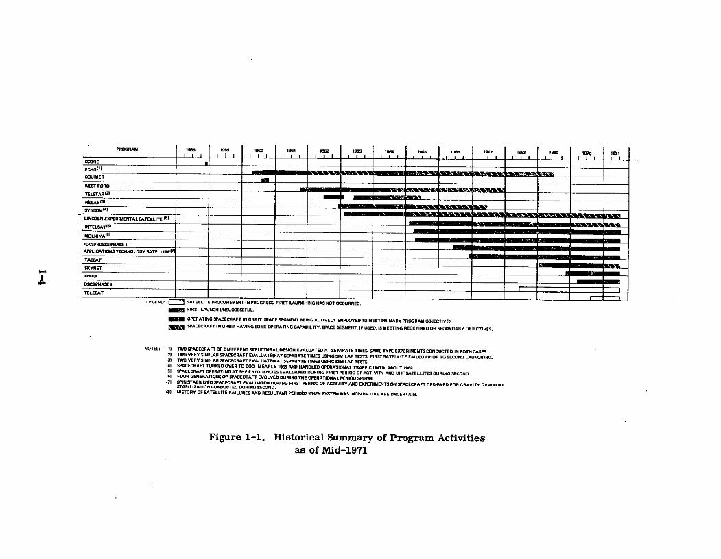
Figure 1-1. Historical Summary of Program Activitiesas of Mid-1971
The figure dramatically displays the very short duration of the Score and Courier
programs conducted during the early history of satellite communications. These pro-
grams represented the initial attempts to employ active satellites for communications.
During this early era, the Echo and West Ford programs also displayed the long life
times attainable through employing passive satellites to establish a communications
system. However, the Telstar, Relay, and Syncom programs soon proved that highly
reliable active satellites were feasible and, in view of the higher system capacities
provided, all subsequent programs have followed their lead. Some modest interest in
passive satellite technology has been retained by the National Aeronautics and Space
Administration (NASA) but no technology developments or future satellite launchings
are presently planned.
The technology demonstrated in the Telstar, Relay and Syncom programs led,
in a relatively short time, to the development of operational systems. Subsequent
programs providing these systems have included Intelsat, Initial Defense Communi-
cations Satellite Program (IDCSP), Skynet, and the North Atlantic Treaty Organization
(NATO) program. Additionally, the Defense Satellite Communications System (DSCS)
Phase II and Telesat programs have satellite procurements underway that should lead
to operational systems by mid-1972 and early 1973, respectively. Satellite experi-
mentation has been continued by the Lincoln Experimental Satellite (LES), Applications
Technology Satellite (ATS), and Tacsatcom programs.
A more detailed summary of the programs reviewed in this document is provided
in Table 1-1. The table includes an indication of individual program sponsorship and
mission. These have been powerful factors dictating the lines along which programs
evolved. Accordingly, the programs can be grouped into U. S. military, purely
scientific, international commercial, foreign military, and domestic commercial
categories.
The U. S. military programs have involved a considerable amount of scientific
investigation of their own but it has, for the most part, been channeled towards the
specific goals of developing strategic and tactical military communications systems.
1-5

Table 1-1. Summary of Program Scope and Statusas of Mid-1971
SatelitesProgram Lunched Sponsor Mission Status
aoor One active store DOD/Army Experimentation Communications failed due to battery failure after
and forward 12 days In orbit. Orbit decayed after 35 days.
Iho Three passive NASA Experimentation Two satellites succsafully employed. Experimentcompleted by early 1965. Orbit of last satellitedecayed in 1969.
Co.lrlvr Two active store DOD/Army Experimentation One satellite sucessfully supplied communications
and forward for 1'( days. Command receiver failure causedsatellite to become inactive.
Wast Pord Two dispensers DOD/Air Force Experimentation One dispenser successfully dispersed dipoles inof dipole needles passive reflecting belt. Major experiments com-
pleted in first year in orbit. Estimated that orbitof last dipoles decayed by early 1968.
T.1star Two active AT&T Experimentation Both satellites successfully employed. Lastsatellite turned off in 1967. Experimentationessentially completed by early 1965.
Relay Two active NASA Experimentation Both satellites successfully employed. Lastsatellite failed in 1967. Experimentation essentiallycompleted by early 1965.
Syncom Three active NASA Experimentation Two satellites attained synchronous orbit and success-fully supplied communications. Both satellites stillactive with no stationkeeping capability. Experimen-tation completed by early 1965. Extensively used forDOD operatlinal traffic from 1965 through 1969. Nclonger employed.
Three active DOD/Air Force Experimentation Two X-Band satellites successfully employed. Lastoperating at X-Band satellite became unusable when its orbit decayed In& three active 1968. X-Band experiments were completed by earlyoperating at UHF 1967. All three UHF satellites successfully employed.all in 5 launches Last satellite remains usable. UHF experiments were
essentially complete by early 1970. Plans exist fortwo additional spacecraft to be launched by late 1974.
Tntelsat One Intelsat I, Intelsat Commercial One Intelsat I successfully employed. Satellitefour Intelsat IIs, International retired from service in early 1969, reactivated ineight Intelsat IIIs, Communications mid 1969, and finally retired in late 1969. Three& one Intelsat IV. Intelsat IIs successfully employed. All three retainAll active operating some operational capability and have been placed inBt C-Iand. reserve. Five Intelsat IIls successfully employed.
One has been placed in reserve, one is operationalover Indian Ocean, one is operational over PacificOcean, and two are operational over the AtlanticOcean. One Intelsat IV has been successfullyplaced into operation over the Atlantic Ocean. Plan.exist for additional Intelsat IVs and an Intelsat Vseries of satellites.
Molniya Eighteen active Soviet Civilian and Orbits of five satellites have decayed. Exact statusGovernment military communi- of remaining spacecraft uncertain but at least four
cations internal are thought to be active. Plans exist for a secondto USSR series of Molniya spacecraft (Molniya II) operating
at C-Band but employing the same highly ellipticalorbit as Molniya I. Plans also exist for 7-Bandspacecraft to be deployed into geostationary orbits.
IDCSP (DSCS Thirty-four DOD/DCA Experimentation Twenty-six IDCSP satellites successfully employed.Phase I) IDCSP, One GGTS 1, and strategic Twenty-one remain usable. Experimentation for most
One DoDGE, & one military part terminated six months after first launch of 7 andDATS 1 all in 5 communications IDCSP satellites and system declared operational.launches for U.S. Automatic satellite turn-offs to start in 1972 and
be completed by mid 1974. GGTS land DODGE were em-ployed for a time to evaluate gravity gradientstabilization. DATS 1 provided data on electronicallydespun phased array antennas.
ATS Two spin NASA Technical & User Two spin stabilized satellites successfully employed.stabilized, and Experimentation Both remain usable. Communications experimentsthree gravity essentially completed by early 1969. One satellitegradient designed for gravity gradient stabilization success-stabilized fully employed. It remains usable. Most experiments
that appear likely to be conducted completed by early1971. Development of two satellites providing 30-footparabolic antennas underway. Launches expected in1973 and 1975.
Tscsat One active DOD/Air Force Preoperational One satellite successfully employed. It remainsExperimentation active with periods of l3coning and degraded EIRP.
Major experiments essentially completed by early 1971.Plans exist for follow-on military tactical system.
Skynet Two lctive British Military One satellite successfully employed and remains active.Goverrnment Communications Second serIes of satellites (Skynet IT) being procured
for U.K. and first launching expected in late 1972.
NATO Two active NATO Military Two satellites successfully employed to form NATOCommunications Phase II system and both remain active. Plans existfor NATO for a Phase III system.
DSCS Phase II None DOD/DCA Strategic military Six satellites being procured. First launch of twocommunications for satellites planned for late 1971.U.S.
Tlenat None Csnadian Commercial Three satellites being procured. First to le lsun,-no dGovornment Domestic communi- in last quarter of 1972. Second to be launced about
ications for Canada four months later as in-orbit spare.
1-6

The evolution of the strategic systems began with the Score and Courier, experimen-
tal store-and-forward satellites. It was continued almost 6 years later with the first
IDCSP launching. In the interim period, the military attempted to develop three axis-
stabilized satellites for launch into synchronous orbits (i. e., Project Advent), developed
the system concepts, and designed the space segment for a medium altitude random
polar orbit system, and extensively considered the possibility of employing Intelsat
for service. Project Advent was terminated in 1962 when the launch vehicle and
stabilization technology required proved to be beyond the state-of-the-art at that time.
The medium altitude development was suspended when the potential economies of
Intelsat service emerged. The latter was dropped for a number of reasons with the
principal factor being the military requirement for a high degree of independent sys-
tem control. The IDCSP concept effected some of the desired system economies by
injecting a reduced number of the previously designed medium altitude satellites into
random near synchronous orbits, using independently programmed and funded Titan
IIIC developmental launches. Between the termination of Project Advent and the first
IDCSP launching, the military gained operational satellite communications experience
by supplying the ground complex and conducting the communication experiments on
NASA's Project Syncom. Operational strategic military systems will be advanced a
step further when the first two DSCS Phase II satellites are launched in late 1971.
Developing tactical systems did not become a formally announced goal of the
U. S. military until 1965 when the Tacsatcom program was established. The experi-
mental UHF satellites of the LES program and the Tacsat satellite followed in direct
response to that goal. However, some of the major system concepts, and in particu-
lar the modulation concepts evaluated in these experiments, began to evolve in the
West Ford program and the SHF portion of the LES program. The latter two evalua-
tions also contributed data of general scientific interest and information applicable to
the development of strategic military systems but in a larger sense they represented
the beginning of tactical military system experimentation.
1-7

NASA has been responsible for the purely scientific programs conducted to date.
These programs have investigated technology applicable in all types of satellite
communications systems. NASA became active in satellite communications at a very
early date through the Echo passive satellite program. As the general interest in
active satellites intensified in the early 1960s, the Relay and Syncom programs came
into being to investigate these types of satellites in medium and synchronous altitude
orbits, respectively. Towards the mid-1960s the questions on the type of satellite and
orbit to employ had been resolved and approaches to realizing high gain satellite
antennas, spacecraft stabilization, and multiple access became the vital issues. An
Advanced Syncom program was initially conceived by NASA to study these problems.
However, this soon evolved into the ATS program, which added a multitude of other
space experiments to those designed to advance communications technology.
The programs oriented toward realizing a system capable of supporting inter-
national commercial communications include Telstar and Intelsat. Telstar was an
experimental program that contributed to general scientific knowledge. However, it
was initiated by the American Telephone and Telegraph (AT&T) Company primarily to
demonstrate the feasibility of employing active satellites for commercial communi-
cations. Before the program was completed, AT&T was legislated out of international
commercial satellite ownership by the Communications Satellite Act of 1962, creating
the Communications Satellite Corporation (Comsat). This was followed in 1964 by
international interim agreements establishing Intelsat and including Comsat as the
U. S. representative in this consortium of international partners. The Intelsat program
was initiated immediately based on technology developed in NASA's Project Syncom.
Foreign programs producing systems whose primary objective has been military
communications include Molniya, Skynet, and NATO. The experimental beginnings
upon which the Russian Molniya program was based are not publicly known. These
spacecraft began to be placed in orbit in the mid-1960s and an operational system was
soon established to provide military and some civilian communications. This system
has been maintained since that time through replacement launches of similar, if not
1-8

identical, spacecraft. The Skynet and NATO programs evolved in the late 1960s and
early 1970s from technology developed in the U. S. military's IDCSP program. Skynet
provides military communications for the United Kingdom (U. K.) and NATO does the
same for the NATO countries.
Systems designed strictly to provide internal domestic communications for a
particular country are still in their infancy. The first such system is expected to be
provided by Canada's Telesat program by early 1973.
Looking into the future, a number of potential new programs and continuations
of old programs can be discerned which are not extensively reviewed in this document.
Plans exist for two additional LES experimental satellites, and it is expected that a
follow-on U.S. military tactical satellite program will evolve soon. The LES experi-
ments are still classified and the exact nature and extent of the tactical program have
yet to be defined. A Cooperative Applications Satellite (CAS-C), also known as a
Communications Technology Satellite (CTS), sponsored jointly by Canada's Department
of Communications (DOC) and NASA, should soon start to attract public attention.
CAS-C will be jointly developed by Canada and NASA and integrated in Canada. Space-
craft launch is expected by early 1975. The U. S. and Canada will conduct experiments
on a time-shared basis. Intelsat has plans for an Intelsat V series of spacecraft to
advance their international commercial system into its fifth generation of hardware.
The technology upon which these satellites will be based may be developed by a proto-
type or experimental satellite flown before the operational satellites are launched in
the late 1970s. Some competition for future Intelsat systems is likely to emerge in
the form of a Soviet Stationar program. The U. S. S. R. has been granted allocations
by the International Telecommunications Union (ITU) for a geostationary satellite
system operating at C-Band. In the area of foreign military programs, the U.S.S.R.
plans a Molniya II series of spacecraft; the U. K. is developing Skynet II satellites;
and NATO is designing a Phase III system to replace the existing Phase II system.
Molniya II will employ the same highly elliptical orbit as Molniya I but operate at
C-Band. Skynet II will be similar in design to Skynet I but will have considerably
1-9

higher EIRP. NATO Phase III is still in the early planning stages. Two new domestic
commercial satellite systems should also begin to emerge soon. Development of a
U. S. System will proceed as soon as the Federal Communications Commission (FCC)
approves one or more of the numerous filings it has received. Additionally, experi-
mental Franco-German Symphonie and Italian Sirio programs are underway that will
provide much of the basis for the intra-European system being developed by the European
Space Research Organization (ESRO). Launches of experimental Symphonie and Sirio
spacecraft should occur by late 1973 or early 1974. Finally, a completely new use for
satellite communications technology has recently become apparent. This is in the
area of air and marine traffic management.
1.3 EVOLUTION OF TECHNOLOGY
The low altitude Score satellite employed simple off-the-shelf VHF hardware to
dramatize the potential of satellite communications by broadcasting a prerecorded
Christmas message from President Eisenhower in 1958. From this beginning, the
interest in satellite communications began to mount in the early 1960s.
Major initial areas of concern centered upon the type of satellite to select,
type of orbit to employ, frequencies to utilize, and the development of ground terminal
technology compatible with satellite communications. The basic satellite question was
whether active or passive satellites should be employed. Either store and forward or
real time active satellite repeaters were feasible. Passive reflector systems could
be composed of a relatively small number of large single point reflecting structures
or belts of multiple dispersed reflective elements. To resolve the orbit selection
issue, low, medium and synchronous altitudes had to be considered, as did orbit in-
clination and degree of ellipticity. Frequencies appropriate for consideration were
determined to be in the band from 1 to 10 GHz. Ground terminal technology of parti-
cular interest included low noise receive systems, demodulator thresholds allowing
detection down to low values of signal-to-noise ratio, accurate satellite tracking so
that high gain antennas could be employed, and high reliability operational performance.
1-10

Outside of these areas the programs of the early 1960s, including Echo, Courier,
West Ford, Telstar, and Relay, employed similar technology that was well within the
state-of-the-art at that time. Briefly, the active satellites provided almost omni-
directional antennas with essentially zero gain, low transmitter output power, no
stabilization or spin stabilization relative to the sun, and solar cell arrays encircling
the outside of the spacecraft to generate prime power. The ground terminals supplied
large parabolic reflector or horn antennas, high power klystron or TWT transmitters,
and fixed installations. Modulation was conventional analog frequency modulation and
multiple access was by frequency division when employed. The active satellites were,
in general, expected to support no more than two simultaneous accesses. Communi-
cation services handled included analog voice, TTY, low resolution facsimile, and
television.
By late 1963, with the aid of data from these initial programs, the questions of
type satellite, frequency band, and ground terminal technology had been resolved.
Relay and Telstar had proven that reliable active real time repeaters were feasible and
they had become the preferred choice. These repeaters were of the double conversion
type with either hard limiting or AGC to ensure a constant input to the output power
amplifier operating near saturation. Active repeaters were preferred over the passive
systems of Echo or West Ford due to the higher system communication capacities
afforded. Real time repeaters were the choice over the store and forward system of
Courier because they resulted in simpler more reliable repeaters, and launch vehicle
technology had progressed to the point that reasonably sized satellites could be in-
jected into orbits high enough to provide wide areas and relatively lengthy periods of
mutual ground terminal visibility.
Satellite communication frequencies had been reserved at 4 and 6 GHz for
commercial operations and at 7 and 8 GHz for government operations. The former
were the frequencies demonstrated in the Telstar program while the latter were
employed on West Ford.
1-11

Basic ground terminal technology had been developed on the Echo program in-
cluding: Cooled maser and uncooled parametric amplifier low noise receive systems;
FM feedback demodulators for threshold extension; and accurate tracking using pro-
grammed inputs, manual steering from optical settings or radar autotracking. This
technology was upgraded on Project Telstar to display reliabilities compatible with
commercial operations and precision autotracking of beacon or communications signals
radiated from active satellites. By late 1963, cooled parametric amplifier low noise
receive systems had also begun to appear in Projects Telstar and Relay.
In 1963 and 1964, the orbit question was finally, for the most part, resolved by
the results of the Syncom program, in favor of geostationary orbits. This completed
the early experimental phase of satellite communications wherein the fundamental
system concepts that have continued to apply were established.
Syncom demonstrated launch vehicle and satellite positioning and stabilization
technologies to precisely inject spacecraft into synchronous equatorial orbits, to
position in longitude and to maintain a satellite's longitudinal position (i. e., station-
keep). It further gave a preliminary indication that the long propagation time delay
(i. e., 260 ms one way) and the associated echo problems that it introduces into 2-wire
terrestrial telephone facilities were surmountable and, therefore, posed no drawbacks
to this approach to satellite communications. With synchronous technology proven, the
facts that only three or four satellites were required to provide a system giving world-
wide earth coverage between +750 of latitude, that earth terminal tracking requirements
were significantly relaxed though not entirely eliminated, and that the problem of hand-
over from one moving satellite to another no longer existed, made geostationary orbits
the preferred choice for point-to-point communication via satellite.
Syncom further refined the state-of-the-art by providing advancements in satel-
lite stabilization techniques and antennas. Syncom was spin-stabilized, as were
Telstar and Relay, but in this case the spin axis was aligned at a 900 angle to the
orbital plane and precisely maintained in this orientation by H2 0 2 gas jets. This
allowed antennas providing pancake-shaped beams only slightly wider than required
1-12

to cover the earth from synchronous altitude (i. e., 17i) to be employed. These
antennas provided gains of about 6 dB.
With the feasibility of satellite communications demonstrated and the basic
system concepts defined, interest turned in the mid-1960s to implementing operational
systems, further refinements of spacecraft and ground terminal technologies, and
developing advanced modulation and multiple-access techniques, including those
designed specifically for handling digital communications traffic. In 1965 and into
late 1966, the Intelsat and Molniya programs provided the beginnings of what was
later to develop into extensive operational systems. During this same period, the
X-Band portion of the LES program began to investigate technology refinements and
advanced techniques.
In early 1965, Intelsat I (Early Bird) was launched into a geostationary orbit
with the spacecraft located over the Atlantic Ocean and after a short checkout period
introduced the first continuous commercial communications services provided by
satellite. Early Bird employed satellite technology developed in Project Syncom to
provide communications between terminals that were, for the most part, upgraded
and modified versions of installations developed during Projects Telstar and Relay.
Early Bird provided a duplex high capacity trunk between the United States and Europe.
Its main technological contribution was to demonstrate, finally and conclusively,
through extensive subjective user evaluations, that time delay and echo are not serious
problems in synchronous satellite communications.
Shortly after the Early Bird launch, the first of the Molniya satellites, developed
by the U. S. S. R., began to appear in orbit. These spacecraft employed orbits uniquely
suited to provide service to regions lying entirely in the Earth's northern hemisphere.
The orbits selected are highly elliptical, with 12-hour periods and apogees occurring
over the northern hemisphere. These satellites provided the Soviet Union with a
long-haul, cross-continent, Moscow-to-Vladivostok communications trunk. Major
spacecraft technological innovations included flywheel stabilization, fully sun-
oriented solar panels, and antennas that tracked the earth independent of the main body
of the satellite.
1-13

The X-Band LES Satellites of this period investigated despun satellite antennas,
automatic on-board spacecraft attitude control, fully solid state transponders opera-
ting at X-Band, and ground terminal digital equipment providing random multiple
access. Antenna despinning was of interest as a means of obtaining high gain earth
coverage pencil beams on spin-stabilized spacecraft. The X-Band LES satellites pro-
vided an initial indication of the feasibility of despinning by switching between elements
of a multi-element array encircling the spacecraft spin axis. However, since these
satellites were not at synchronous altitudes, the full gain potential of the technique was
not demonstrated. Autonomous on-board attitude control to reduce ground control
requirements was initially demonstrated on a satellite stabilized relative to the sun.
Accurate on-board control of earth-oriented satellites remained to be proven. Solid-
state X-Band transponders were shown to be feasible, but their low efficiencies and
power outputs made them relatively unattractive as compared to the TWT output
amplifiers being employed on operational systems. Frequency hopping of the center
frequency of an MFSK channel was demonstrated to be a satisfactory approach to ran-
dom multiple access among users handling digital traffic. Frequency hopping was first
considered on Project West Ford and was of interest as a means to combat Jamming
in military systems, resist radio frequency interference, and allow common occupancy
of the same frequency/time spectrum by users having low duty cycle random require-
ments for service. Error correcting sequential decoding of convolutionally encoded
messages was also shown to be a powerful means for improving performance in digital
systems operating at low signal-to-noise ratios.
By mid-1966, the initial interests of the mid-1960s in operational systems and
advanced technology and techniques were supplemented by an interest in new applica-
tions. Up to this time, satellite communications had been looked upon, principally,as just another means of providing the kind of communication services commonly
available in the military and commercial long-haul telecommunications networks
(i. e., analog voice, TTY, low resolution facsimile, and television). It now began to
be apparent that powers and bandwidths were available to support wideband digital
1-14

traffic such as might be produced by high resolution facsimile and computer-to-
computer applications. Additionally, the high satellite EIRP made available by
advanced TWTs and earth coverage pencil beams made it possible to provide communi-
cations and position location for small aircraft, shipborne, remote data platform, and
mobile land terminals. Between mid-1966 and late 1968, the Intelsat and Molniya
operational systems continued to evolve, and the military IDCSP system was placed
into operation. During this same period, a significant portion of the UHF LES testing
was conducted, and the ATS program was initiated to investigate new technology,
techniques, and applications.
In early 1967, the first successful launching of a second generation of Intelsat
spacecraft was accomplished. By late 1967, three Intelsat IIs had been successfully
launched, and commercial communications service was being provided over both the
Atlantic and Pacific Oceans. The advent of reliable tunnel diode amplifiers to serve
as relatively low-noise, high-gain satellite input preamplifiers allowed single RF
conversion transponders to be provided on these satellites. Allowable satellite weight
and prime power in combination with new high performance earth terminals permitted
these transponders to be designed for linear input/output power transfer characteris-
tics. These wideband satellites and an expanded ground complex resulted in extensive
satellite multiple access in an operational system for the first time. Conventional
FM-FDMA was employed, and system control techniques were developed to provide a
high reliability operational system.
Concurrent with these Intelsat activities, continued launches of the Molniya I
spacecraft maintained an operational Russian system. With the addition of new ground
terminals, service in this system was considerably expanded in 1967 when the U.S.S.R.
inaugurated a space television distribution system, allowing people in Siberia, the Far
East, and the Far North to view broadcasts from Moscow.
In late 1966, the first group of 7 IDCSP satellites were successfully injected
into near synchronous orbits, using a single launch vehicle, and by mid-1968 three
more successful launches had established a system including more than 20 satellites.
1-15

This military system began to meet emergency operational requirements in December,
1966, and by mid-1967 it was declared completely operational. In this system of
multiple, near synchronous satellites, outage periods due to no spacecraft being visible
and during satellite handovers were overcome by scheduling around these events. The
type of system realized was the result of economic considerations dictating that a space
segment, initially designed and developed before synchronous technology was proven
feasible, be implemented. The system employed conventional modulation and multiple-
access techniques, except for high data rate (1Mbps) MFSK modems for facsimile
transmission and an operational pseudonoise antijam capability.
Extensive evaluations of approaches to realizing high gain, pencil beam, earth
coverage antennas were conducted during this period. Techniques for realizing despun
antennas on spin-stabilized spacecraft were exhaustively considered, and gravity
gradient stabilization, such that rigidly mounted spacecraft antennas were continuously
pointed towards the earth, was seriously investigated for the first time.
Electronically despun phased arrays were flown on a synchronous ATS satellite
in late 1966, and on a near synchronous test spacecraft launched as part of the IDCSP
program in mid-1967. These tests demonstrated that this type of antenna system was
feasible, and gains of up to 14 dB were realized. Electronic switching as a means to
realize a despun antenna was given further consideration in the synchronous UHF LES
satellite launched in late 1968. The feasibility of this approach was again demonstrated,
and a gain of about 10 dB realized. However, questions on the optimum approach to
antenna despinning were laid to rest when an ATS spacecraft launched in late 1967
demonstrated the feasibility of mechanically despun antennas. By late 1968, it was
apparent that the latter approach provided reliable performance and antenna gains of
about 16 dB. Additionally, weight and prime power consumption were competitive
with or superior to that realized by other approaches.
Gravity gradient stabilization was of interest because of the potentially high
reliabilities available from such a passive system. Launches of medium and syn-
chronous altitude ATS spacecraft, designed for this type of stabilization, were attempted
1-16

in early 1967 and late 1968, respectively. Additionally, special near synchronous test
satellites, included as part of the IDCSP program, were launched in mid-1966 and
mid-1967. The ATS evaluations could not be conducted due to launch vehicle failures.
The IDCSP tests demonstrated a limited degree of success in initially establishing
and maintaining gravity gradient stabilization, but numerous unexplained difficulties
were encountered. As a result, by late 1968, the jury was still out on gravity
gradient stabilization, but the initial findings were not favorable.
The mid-1966 to late 1968 time period also saw considerable experimentation,
at VHF and the lower UHF frequencies, with providing communications to small mobile
or remote terminals or both. The existence of extensive conventional small terminal
facilities was the primary driving force behind the initial interest in this frequency
band. A preliminary evaluation of propagation characteristics had been carried out
with the aid of a simple UHF beacon radiating satellite launched as part of the LES
program in late 1965. Additionally, a few simple demonstrations had been conducted,
using the telemetry and command system on a Syncom satellite.
More extensive experiments were made possible with the inclusion of a VHF
transponder on the first spin-stabilized ATS spacecraft launched in late 1966. These
experiments were extended further when a UHF LES satellite was launched in mid-
1967, and the second spin-stabilized ATS spacecraft, also including a VHF transponder,
was launched in late 1967. The emphasis in the LES experiments was on developing
a tactical military capability, while the interest in ATS was in demonstrating position
location and communications for application to commercial and private aircraft and
ships and to remote data platforms. The experiments performed considerably
advanced the state of knowledge of propagation and noise at these frequencies while
proving that such systems were feasible. In the LES program, the first experimental
tactical terminals designed for specific military applications began to emerge.
During this period, the spin-stabilized ATS satellites also demonstrated the
feasibility of a signal-processing satellite repeater that provided multiple access
through frequency-division multiplexing of independent single sideband uplink signals
1-17

and down converting the composite received signal for phase modulation of a single
radiated carrier. This system was of interest because it supplied frequency spectrum
conservation on the uplink and efficient utilization of available spacecraft power on the
downlink. Additionally, a UHF LES satellite displayed that an autonomous control
system could accurately maintain a spin-stabilized spacecraft's spin axis at a 900
orientation relative to the orbital plane.
Between late 1968 and early 1971, the areas of concern that existed in the years
spanning the mid and late 1960s had to be further expanded to include consideration of
higher frequencies for providing the same types of services. Interest began to develop
in employing L-Band frequencies (i. e., a higher portion of the UHF band) for aircraft
and maritime position location and communications in the private and commercial
sectors. These frequencies are attractive because of the wider bandwidths and more
accurate position location afforded. Further, millimeter wave frequencies started to
be considered for commercial telecommunication services. The wider bandwidths
available and visions of overuse of the allocated C-Band spectrum were the driving
forces behind this interest. During this period, the operational Intelsat system con-
tinued to evolve, the Molniya and IDCSP systems continued to supply satisfactory
operational service, the Skynet and NATO military systems initiated operational
service, the exploration of tactical military communications was continued by the LES
program and supplemented by a Tacsat satellite, and the ATS program conducted
initial evaluations of L-Band and millimeter wave communications.
In late 1968, Intelsat began to establish a third generation satellite system. By
early 1970, five successful launches had been completed, and a truly worldwide system
providing service over the Atlantic, Pacific, and Indian Oceans had been completed.
These satellites took advantage of the technology developed in the ATS program by
employing mechanically despun antennas. The transponders were again linear, single
conversion repeaters and FM-FDMA was the main mode of operation. However,
experimentation was conducted on a PCM-PSK-TDMA system designed for 12- to 120-
channel links and PCM-PSK-FDMA, SPADE, designed for links ranging from fractional
requirements to 12 and 24 channels. Both systems were-a demonstrated to be feasible.
1-18
The TDMA development extended and confirmed earlier TDMA demonstrations con-
ducted as part of the ATS program.
Between late 1968 and early 1971, two new operational systems came into being.
A Skynet satellite was placed into a geostationary orbit providing visibility from Europe
and much of Africa, in late 1969, and an operational military system for the United
Kingdom was established. The satellite was based on technology developed in the
IDCSP program but pseudonoise PSK was used to provide multiple access in the first
all-digital operational system. NATO satellites were launched into geostationary
orbits in early 1970 and early 1971. They were positioned over the Atlantic to provide
operational service for the North Atlantic Treaty Organization countries and employed
conventional technology developed in the IDCSP and Skynet programs.
On the LES program, testing of the UHF satellite launched in late 1968 con-
tinued. In addition to displaying the switched antenna, this satellite demonstrated the
feasibility of high-efficiency, solid-state UHF transmitters operating directly from the
unregulated primary power source, autonomous satellite stationkeeping and station-
changing, and reliable pulsed plasma microthrusters. The demonstrated autonomous
stationkeeping capability, together with the previously displayed autonomous attitude
control system, provided the potential for significantly reducing future ground tracking
and command requirements. The spacecraft microthrusters were of interest as a
means towards attaining highly precise attitude control and stationkeeping systems.
Microthrusters were first considered in the ATS program as a means of providing
stationkeeping and stationchanging on gravity gradient stabilized satellites where the
attitude correction torques were quite low.
In early 1969, a Tacsat spacecraft was placed into a geostationary orbit and
used along with the latest LES satellite to further demonstrate and develop a tactical
military satellite communications capability. Tacsat included both UHF and SHF
transponders, an input/output switching capability, and an ability to vary transponder
bandwidth that afforded multiple commandable modes of operation, including cross-
band configurations. By early 1971, prototype operational tactical terminals, at both
1-19

UHF and SHF, had been demonstrated for aircraft, ship or land mobile use. In addi-
tion, operational frequency-hopping MFSK modems had been displayed. This approach
was selected over pseudonoise PSK due to shorter acquisition times in a random-access
environment, relaxed synchronization requirements, and a greater resistance to the
multipath likely to occur in many tactical situations (e. g., as for aircraft communi-
cation at elevation angles below 20").
In late 1969, the final ATS spacecraft designed for gravity gradient stabilization
was launched. The launch vehicle performed properly but control of the satellite was
lost during an initial spin stabilized period before location on-station in a geostationary
orbit. As a result, the spacecraft was left spinning about a longitudinal axis such that
it could not be despun and the gravity gradient booms deployed. By early 1971, this
final failure to demonstrate reliable gravity gradient stabilization at synchronous
altitude, along with the successful development of despun antennas, had caused interest
in this technique to wane. In spite of the improper stabilization, L-Band and milli-
meter wave experiments included on this satellite were performed, and valuable data
was obtained that will contribute towards opening these frequencies for future use.
The millimeter wave frequencies evaluated were at 15. 3 and 31. 65 GHz.
Finally, in early 1971, Intelsat successfully launched the first of what will be a
fourth generation Intelsat space system. This satellite features earth coverage and
fixed narrow coverage antennas on a mechanically despun platform. Additionally, it
provides 12 transponders of moderate bandwidth such that separate types of services
can be provided in separate channels (e. g., television distribution in one channel, high
capacity telephone trunks in another, and low duty cycle individual voice links in still
another). Major contributions of the satellite communication programs completed or
in progress as of mid-1971 are summarized in Table 1-2.
Looking into the immediate future, it can be seen that two new programs,
Telesat and DSCS Phase II, are on the horizon, as is a third basic configuration of ATS
spacecraft. Gazing even deeper into the years ahead, the CTS and US domestic satel-
lite (Domsat) programs are among the emerging satellite communications activities.
1-20

Table 1-2. Summary of Major Contributions
Program Primary Results
Svorv, (1) Demonstrated feasibility of employing active orbiting satellites to relay messages over intercontinen-tal distances.
Echo (1) Displayed feasibility of erecting and maintaining large lightweight structures adequate to serve as
passive reflectors in apace. (2) Verified that conventional microwave theories for determining path
lose could be applied to satell te links. (3) . Fostered development of ground terminal technologyIncluding low noise receiver preamplifiers, FMFB receivers, accurate tracking techniques and terminal
operating procedures.
Courier 1 Displayed feasibility of high capacity high rate digital store & forward satellite Syates.Demonstrated difficulty of attaining lifetime & reliability need for operational systems.
West Ford (1) Showed that X-Band dipoles can be dispersed into a paasive reflecting belt, (2) Diaplayed that belt
is predictably affected by solar radiation pressure & does not interfere with radio astronomy.
(3) Demonstrated that communications are feasible and multipath time delay & frequency smear are predictable.
Telstar (1) Demonstrated performance and reliability, adequate for commercial operations, can be attained wWitactive satellites. (2) Verified that multipath fading was not significant for operation at 4-6 OGHand elevation angles above few degrees. (3) Displayed accurate and reliable acquisition and auto-
tracking of active satellites.
Relay (1) N-on-P solar cells shown to be more resistant to radiation then P-on-N cells. (2) Displayed thatdew point criteria and leakage tests should be included in power transistor apecifications. (3)Indicated that relatively complex command signals are necessary to avoid spurious responsaes.
Syncom (1) Demonstrated feasibility of placing & accurately poaitioning satellites in synchronoua orbit. (2)
Provided first, in orbit, demonatration that time delay and echo are not serious problems in
synchronous satellite communicationa.
LES (1) Displayed feasibility of all solid state X-Band satellite transponsers even though power out &efficiency were relatively low. (2) Demonstrated feasibility of X-Band & UHF electronicallyswitched deapun antennas. (3) Advanced state of knowledge of UHF propagation & noise including
RFI. (4) Displayed workable dxperimental tactical ground terminals. (5) Demonstrated feasibilityof high efficiency UHF satellite transmitters operating from unregulated solar array power supply
(6) Accurate autonomous spin axis attitude control was exhibited. (7) Performance potential of
sequential decoding as applied to satellite links was displayed. (8) Frequency hopping was. hownto provide satisfactory random access & resistance to multipath & RFP. (9) Demonstrated feasibility
of autonomous stationkeeping and station changing.
Intelsat (1) Demonstrated that time delay & echo are not serious problems in commercial communlcationsthrough synchronous satellites. (2) Displayed single conversion linear satellite repeaters.
(3) Employed first aatellite antennas having beamwidths considerably narrower than required for
earth coverage. (4) Developed techniques for control b operation of a high reliability operationalsystem. (5) Developed and demonstrated PCM-PSK-TDMA trunking systems. (6) Developed PCM-PSK-PDMA
single voice channel system (i.e., SPADE).
Molnye (1) Demonstrated feasibility of operational system in northern hemisphere using 12 hour highly ellipticalorbits. (2) Displayed electric motor driven, flywheel stabilized spacecraft with earth tracking
antennas & capability of orienting solar panels towards sun.
IDCSP (DSCS Phase I) (1) Demonstrated operational system composed of large number of simple random orbit satellitea can beestablished & maintained. (2) Displayed feasibility of wide band high data rate (1Mbpa ) satellitetransmissions of high resolution imagery. (3) Demonstrated a limited degree of success in initiallyestablishing & maintaining gravity gradient stabilization but encounted numeroua unexplaineddifficulties. (4) Displayed operational jam resistant pauedonoise modems.
ATS (1) Demonstrated feasibility & potential of electronic despinning using phased arrays. (2) Displayedfeasibility & attractiveness of mechanically despun antennas. (3) Showed that single-sidebandfrequency division multiplexing on uplink & phase modulation by the composite received aignal ondownlink is practical means of multiple access. (4) Demonstrated feasibility of VHF satellitecommunications among small mobile terminals. (5) Provided date on millimeter wave propagation.
6) GOave initial indication of potential L-Bend holds for aircraft and maritime communications(7) Displayed the difficulties that can be encountered in attempting to deploy & initially stabilize
gravity gradient stabilized satellites.
Taenat (1) Demonstrated operational UHF and SHP mobile earth terminals. (2! Displayed feasibility of channel-ized satellite repeater capable of switched input/output connect i . (3) Provided gyrostatsatellite stabilization. (4) Demonstrated operational frequency hopping modem.
Skynet (1) Provided first operational all digital satellite system using spread spectrum multiple access.
NATO (1) Employed conventional M-FDMA technology to minimise system risk.
1-21

These programs will continue to advance spacecraft and ground terminal technology,
investigate new applications for satellite communications technology, and evaluate the
potential for opening new frequency bands for utilization. The Telesat program will
provide Canada with a commercial domestic satellite communications system. The
ground complex will include small simple terminals for unattended remote operation
in far northern and arctic locations, as well as more conventional terminals. The
DSCS Phase II will provide the U. S. military with an operational second generation
system to replace the IDCSP. The satellites will demonstrate accurately steerable
narrow coverage antennas.
The new ATS spacecraft will include a 30-foot diameter parabolic antenna,
highly accurate 3-axis stabilization using gas jets and error signals derived from a
monopulse receive tracking system, and input/output switching among multiple trans-
ponders receiving and transmitting in different frequency bands. The first of these
satellites will investigate the feasibility of employing a synchronous communications
satellite as a relay for tracking other satellites and transferring digital signals between
them and a ground station, of aircraft position location and air-to-ground communi-
cations using a synchronous satellite, and of supplying FM TV reception to small UHF
ground terminals with the benefit of a 30-foot satellite antenna. Additionally, this
spacecraft will investigate uplink RFI at 6 GHz, millimeter wave propagation at 20 and
30 GHz, and signal attenuation at 13 and 18 GHz caused by atmospheric hydrometeors.
The CTS satellite will include a super-efficiency power transmitting tube, pro-
viding a 200-watt minimum output at 12 GHz, unfurlable solar power arrays of approxi-
mately 1.5-kilowatt initial capability, liquid metal slip rings, and electric propulsion
for accurate stationkeeping and stabilization using flexible appendages. High power
RF transmitters at frequencies above 10 GHz and prime power sources of kilowatt size
or greater represent technology that will be needed for educational and community TV
satellite broadcast systems, interplanetary space probes, and large earth-orbiting
platforms. The liquid metal slip ring experiment should demonstrate a means of
alleviating many of the problems characteristic of transferring high power across
1-22

rotating interfaces. Electric propulsion provides the potential for reducing one of the
constraints on narrowing the spacing between satellites in synchronous orbit. Exces-
sive drift and instability could result in major interference problems and degraded
communication capabilities. In addition to the advanced technology experiments, CTS
will provide the vehicle for investigating numerous user applications. These may
include educational TV, biomedical networks, law enforcement networks, and service
for the handicapped applications.
The U. S. Domsat program provides the potential for supplying point-to-point
trunk and multipoint message telephony; telegraphic and wideband data; and network,
educational, and community antenna television services that complement and improve
the services presently provided by terrestrial facilities. Eight applicants filed for
permits from the Federal Communications Commission (FCC) to construct U.S. domestic
satellite systems by the March 15, 1971 filing deadline. The Commission's invitation
to file covered systems "for multiple or specialized common carrier services, for
lease to other common carriers, for private use, joint cooperative use, or any com-
bination of such services. " The applications filed propose widely varying types and
levels of service for a diverse group of potential users. The FCC has a goal of ruling
on applications by mid-1972.
A whole new industry was brought into being in the 1960s built on technology
demonstrated by experimental satellites such as Relay, Telstar, and Syncom. Simi-
larly, rapid growth of existing capabilities and initiation of new space communications
applications, such as high rate information transfer, data collection, educational
broadcast, and traffic management, are sure to occur during the 70s, based on the
results of experiments described in this document.
1-23

SECTION 2 - SCORE
2.1 PROGRAM DESCRIPTION
The objective of Project SCORE (Signal Communication by Orbiting Relay
Equipment) was to place in orbit an 80-foot Atlas missile and to use this as a plat-
form for a communication system capable of spanning intercontinental distances.
The ultimate goal was to demonstrate the feasibility of such a system and to explore
some of the technical and operational problems that would attend a military satellite
communication system. The communications portion of the project was assigned to
the U.S. Army Signal Research and Development Laboratory, Fort Monmouth,
New Jersey, late in July 1958. SCORE was successfully launched by the Air Force
on December 18, 1958, thus becoming the first communications satellite. The
orbital parameters are given in Table 2-1.
Table 2-1. Participating Spacecraft
Satellite SCORE
Manufacturer/Sponsor U. S. Army, ARPA
Launch Date December 18, 1958
Launch Vehicle Atlas 10-B
Apogee (mi.) 928
Perigee (mi.) 115
S Inclin. (deg.) 30
Period (min.) 101
Status Expected Life of Orbit:20 Days; Actual life oforbit: 35 days, Communi-cations failed December 301958, due to battery failure
2-1

This first satellite communications system functioned for approximately 12
days, achieving its desired goals - to demonstrate the feasibility of an orbital relay
that could span intercontinental distances. Among the achievements attained during
the experiment were:
1. The first successful relay of teletype signals through an orbiting station.
2. The first successful delayed repeater communication from earth to
satellite to another point on earth at a later time.
3. The first successful multichannel teletype transmission by a delayed
repeater.
2.2 SYSTEM DESCRIPTION
Two complete communications packages were installed in what are normally
the guidance pods on the sides of the Atlas missile. Ground equipment installed
in army vans with associated support vehicles was located at Fort MacArthur,
California; Fort Huachuca, Arizona; Fort Sam Houston, Texas; and Fort Stewart,
Georgia. All ground stations were linked by both telephone and HF radio to the
system control center at the Signal Corps Laboratory in Fort Monmouth, New Jersey.
The design of the system was based on providing two modes of operation - as
a delayed repeater and as a real time active repeater. In the delayed repeater mode,
the satellite would record information transmitted to it upon reception of a suitable
command signal from a ground station. Upon reception of a different command signal,
the satellite would transmit the previously stored information back to the originating
ground station. The second mode of operation, that of a real time repeater, was
obtained by the use of yet another command signal which activated the satellite as a
radio relay repeater station with the recording mechanism bypassed. The capacity
of the system was one voice channel or seven 60-wpm teletype channels, frequency
division multiplexed.
2-2

The satellite receiver was an FM "paging" receiver - the type often used by
doctors and salesmen to receive telephone calls when away from their offices. A
commercial transistor model was modified extensively through the addition of an
RF stage using selected transistors to increase its sensitivity. A vacuum tube
transmitter from an FM handie-talkie was repackaged and modified through the
addition of a high power (8 watts) output stage. A continuous loop magnetic tape
recorder developed at the Signal Corps Laboratory was used as the message
storing device. Seventy-five feet of magnetic tape was used to provide 4 minutes
of audio recording. The control unit responded to command signals from the
ground and activated the receiver, the transmitter, or the magnetic tape recorder.
Three modes of operation were commanded - record, playback, and real time.
Since the satellite was expected to orbit for only 20 days, a non-rechargeable high
capacity zinc-silver oxide battery was employed rather than heavier and more
costly solar and nickel cadmium cells.
The Atlas missile itself was used as the antenna and was excited by slots
located in the two pod covers. The resulting radiation pattern was similar to a
long wire doublet with associated nulls.
Spacecraft characteristics for the SCORE satellite are displayed in Table 2-4.
A system diagram of the satellite is shown in Figure 2-1.
MTRRECORDER
Figure 2-1. SCORE Satellite Interconnection Diagram
2-3

VHF frequencies were used to minimize the effects of cosmic noise and
ionospheric propagation while still permitting the use of sensitive, transistorized
receiving equipment in the satellite. The operating frequencies employed in Project
SCORE are given in Table 2-2. The IF bandwidth chosen was as narrow as possible
consistent with frequency stability, Doppler shift, maximum audio frequency, and
carrier frequency deviation.
Table 2-2. Frequencies Employed in Project SCORE
Uplink Downlink Beacon
150 mHz 132 mHz 108 mHz
Narrowband FM was selected as the modulation technique with a deviation
ratio limited to 1. 0 at 5 kHz. Additional data on the modulation technique is shown
in Table 2-3.
Table 2-3. Signal Processing Employed in Project SCORE
Single Access One Voice Channel or Seven 60-wpm teletype
RF Modulation Narrowband FM, Deviation = ±5 kHz
Demod. Performance 10 dB
(FM Threshold)
Link Margin (Up/Down) 39/19 dB*
*At a slant range of 1000 miles.
2.3 SPACECRAFT
The 142-1b payload consisted of two complete repeater terminals installed
in what are normally the guidance pods on the sides of the Atlas missile. Each
package contained a receiver, transmitter, magnetic tape recorder, control unit,
beacon transmitter, dc to dc converter, and battery. Communications character-
istics of the satellite are summarized in Table 2-4.
2-4

Table 2-4. Satellite Characteristics
Type Slot Antenna
Number Two receiving, two transmitting
Xmit. Beamwidth No Data
Gain -1 dB
Frequency Band VHF
Type Store-and-forward/real-time repeater
Bandwidth 40 kHz
Number Two
Type Front End Transistor
Front End Gain No Data
System Noise Fig. 10 dB
Type Vacuum Tube
Gain No Data
Power Out 8 Watts
EIRP 8 dBW*
Type None
Capability None
Sa Primary Zinc-silver oxide battery
Supplement None
4
Comm. Power Needs 53 Watts
Size Mounted on Atlas Missile of dimensionsof 85 ft. long by 10 ft. diameter
Weight 142 lbs.
*Derived value based on available data.
2-5

2.4 GROUND TERMINALS
Each of the communication ground terminals noted in Paragraph 2.2 included
two transmitters and receivers for communication, each capable of operating on
two frequencies; two beacon receivers for tracking and temperature recording; and
two control units. The equipment configuration is shown schematically in Figure 2-2;
it was housed in a 35-foot semitrailer.
ANTENNAPEDESTAL I
ANTENNAFILTER
ANTENNA BEACONCONTROL RECE RECORDER
T-R COMM. TELETYPE TELETYPERELAY RECEIVER TERMINAL PRINTER
MICROPHONE RECORDER
VHFTRANS- CONTROL TELETYPEI ITELETYPEMITTER UNIT TRANSMIT TRANS-
TERMINAL DIST.
Figure 2-2. SCORE Ground Station Interconnection Diagram
The VHF communications receivers and transmitters in the ground station were
commercial FM equipment adapted for use in the SCORE Project. For monitoring
the satellite's tracking beacons, receiving equipment was provided which enabled
reception of the tracking frequency near 108 MHz. In all but the California station,
the ground antenna was positioned by an operator maximizing the 108-MHz signal
reception with the antenna positioning controls. At the California station, the azimuth
control was slaved to the alidade of an experimental direction-finding equipment while
the elevation control was manually varied. The communication characteristics of the
ground stations are tabulated in Table 2-5.
2.5 EXPERIMENTS
On the first orbit, attempts were made by the California ground station to
interrogate the communication package designated No. 1. An excellent carrier was
2-6
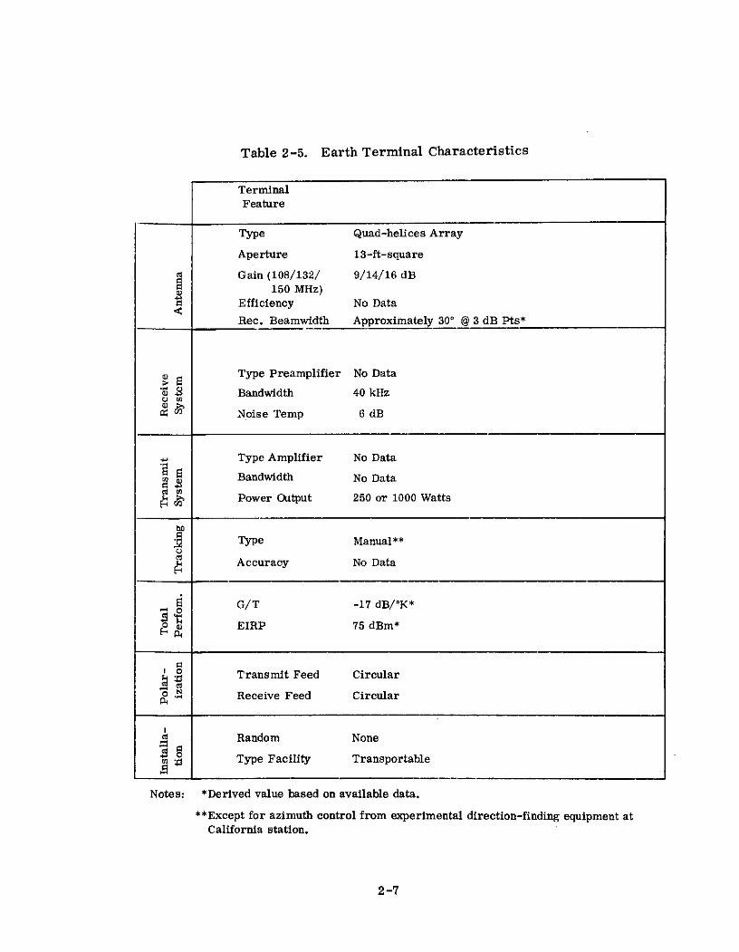
Table 2-5. Earth Terminal Characteristics
TerminalFeature
Type Quad-helices Array
Aperture 13-ft-square
Gain (108/132/ 9/14/16 dB150 MHz)
a Efficiency No Data
Rec. Beamwidth Approximately 300 @ 3 dB Pts*
Type Preamplifier No Data
$ Bandwidth 40 kHz
Noise Temp 6 dB
Type Amplifier No Data
Bandwidth No Data
C Power Output 250 or 1000 Watts
Type Manual**
Accuracy No Data
G/T -17 dB/OK*
0) EIRP 75 dBm*
o Transmit Feed Circular
0Receive Feed Circular
Random None
Type Facility Transportable
Notes: *Derived value based on available data.
**Except for azimuth control from experimental direction-finding equipment atCalifornia station.
2-7

received from the communication transmitter, but no modulation. Since no other
orbit that day was close enough to the ground station, no further attempts were
made to interrogate the communication equipment. On the following day, package
No. 2 was interrogated by a temporary site established at Cape Canaveral (now
Cape Kennedy) for prelaunch checkout. It responded and the ground crew received
the following prerecorded message from President Eisenhower:
This is the President of the United States speaking. Through the marvelof scientific advance, my voice is coming to you from a satellite circlingin outer space. My message is a simple one. Through this unique means,I convey to you and to all mankind America's wish for peace on earth andgood will towards men everywhere.
On each of the subsequent days, each function for which the equipment was
designed was tested and successfully demonstrated. Among the experiments per-
formed were the following:
1. Initially, transmission of President Eisenhower's prerecorded voice
message followed by one channel of teletype code.
2. Direct relay of California's communication site identification in voice,
followed by the President's message in teletype code. The Texas site
received these signals with two short fades and the Arizona and Georgia
sites received portions of the transmission.
3. While clearing the tape recorder, California transmitted in voice to the
satellite for storage. Texas interrogated the satellite, and both Texas
and Georgia received the voice loud and clear. Then Georgia reinter-
rogated the satellite and received the message again.
The above tests were performed in other variations using voice and one channel
of teletype until the fortieth pass, when the Georgia site sent seven simultaneous
multiplexed teletype messages in a single transmission to the satellite for storage.
The satellite was then interrogated and good teletypewriter copy was received.
2-8

In summary, the communications package was interrogated 78 times, loaded
with new material 28 times, and operated as a real time relay for a total of 117
deliberate operations. Until battery exhaustion on December 30, 1958, the satellite
demonstrated conclusively the practical operation of a satellite radio relay system
capable of spanning intercontinental distances.
2.6 OPERATIONAL RESULTS
Since Project SCORE was an experimental program, no operational traffic was
passed. Further, the operational reliabilities of the satellite and ground terminals
were generally good and in agreement with prelaunch expectations. This performance
reflected the exclusive usage of state-of-the-art hardware that characterized this
system's implementation.
2-9

RELATED REFERENCES
1. S. P. Brown and G. F. Senn, "Project SCORE," Proc. IRE, Vol. 48, No. 4,pp. 624-630, April, 1960, AD 241674.
2. M. I. Davis and G. N. Krassner, "SCORE - First Communications Satellite, "Astronautics, May, 1959, AD 221 328.
3. S. P. Brown, "Project SCORE: Signal Communication by Orbiting RelayEquipment, " IRE Trans. on Military Electronics, Vol. MIL-4, Nos. 2-3,pp. 193-194, April-July, 1960.
4. H. K. Ziegler, "The Signal Corps at the Space Frontier," IRE Trans. onMilitary Electronics, Vol. MIL-4, No. 4, pp. 404, October, 1960.
5. G. V. Kedrowsky, "Project SCORE - The First Satellite CommunicationSystem," Aerospace Engineering, October, 1960.
6. M. I. Davis, et. al., "The ATLAS-SCORE Communication System," Proc.3rd National Convention on Military Electronics, pp. 401-406, 1959, AD221 324.
7. S. P. Brown, et. al., "Project SCORE," U.S. Army Research and DevelopmentLaboratory, Fort Monmouth, New Jersey; April 15, 1959.
2-10

SECTION 3 - ECHO
3.1 PROGRAM DESCRIPTION
R&D efforts that led to the Echo satellites descended from an IGY program that
the National Aeronautics and Space Administration, NASA, had inherited from its
predecessor organization, the National Advisory Committee for Aeronautics. The IGY
balloon satellite had been conceived and designed primarily for air density experiments.
NASA took charge of this activity and reformulated it as Project Echo in late 1958.
Major objectives for the Echo program were as indicated in Table 3-1.(1)(2)
Table 3-1. Echo Program Objectives
Number Description
1 To evaluate the communications capability available
from large spherical passive satellite reflectors.
2 To study the feasibility of erecting and maintaining
large lightweight structures in the space environ-
ment.
3 To gather data on solar pressure and the outer limits
of the earth's atmosphere as well as evaluating their
effects on satellite orbits.
Of three attempts to orbit passive reflecting balloons during this program, two
of these efforts were successful. The launches and satellite status are reviewed in
Table 3-2. (1)(3)(4)
Prior to the initial Echo launch, extensive ground, vacuum chamber, and space
ballistic tests were conducted. (1)(2)(5) The ground tests employed prototype spheres
to confirm sphericity and structural integrity of basic balloon design. The vacuum
chamber tests evaluated balloon release from its containing canister, unfolding, and
inflation during free fall at NASA's Langley Research Center. The balloon deployment
system was refined and space-qualified during four launches into a ballistic trajectory
by modified Sargent rockets from NASA's Wallops Island, Virginia, launch site. These
launches were code-named Shotput I through IV. The first launch on 28 October 1959
3-1

resulted in the sphere rupturing into a thousand pieces. After two more tests on
16 January 1960 and 27 February 1960 and changing the folding pattern, inflation
system, and prelaunch payload conditioning cycle, a successful vertical test was
conducted on 4 January 1960.
Table 3-2. Participating Satellites
Satellite Echo A-10 Echo I Echo IIManufacturer & Sponsor G. T. Schieldahl( 1 ) & NASA
Launch Date 5/13/60 8/12/60 1/25/64Launch Vehicle Delta(2 ) Thor-Agena B
Apogee (mi.) No 1051 816
Perigee (mi.) Orbit 941 642Data Inclination Attained 47.20 81. 50
Period (min.) 118.2 108.8
Satellite lost Orbit decayed Orbit decayedStatus due to second 5/24/68 resulting 6/7/69 resulting
stage attitude in satellite in satellitecontrol malfunction destruction destruction
Notes: (1) Balloon manufacturer. Beacons on Echo I and II supplied byRadio Corporation of America.
(2) Thor-Delta with the Delta being the improved second andthird stages of Vanguard.
(3) At initial injection. Solar pressure and atmospheric dragsubstantially altered parameters
Subsequent to the failure of the initial launch, a fifth Shotput test was conducted
on 31 May 1960 to qualify the sphere with radio tracking beacons attached. These
beacons were left off the payload during the initial orbital launch attempt, since they
had not been previously qualified by a vertical test. Following these activities,
Echo I was successfully launched from Cape Kennedy, Florida, into a near circular
low altitude inclined orbit. It was an immediate resounding success, being large and
reflective enough to be seen against the nighttime sky with the naked eye. During its
lifetime, valuable information was contributed towards meeting all the program
objectives listed in Table 3-1. In particular, the feasibility of passive satellite
communications was demonstrated.
3-2

The one drawback of the Echo I balloon was that it was not rigid enough to remain
smooth and spherical under the deforming forces of atmospheric drag and solar
pressure after its pressurizing gas leaked out. (1)(2)(6) Its shape deteriorated signi-
ficantly within a few weeks after launch. In recognition of this, efforts were inititated
in late 1960 to develop a second generation Echo balloon that was rigid enough to
withstand the deforming forces.
Once again, static ground tests, vacuum chamber drop tests, and vertical space
tests were conducted. The first two groups of tests were again conducted in the
dirigible hanger at Weeksville, North Carolina, and at Langley Research Center,
respectively. The two vertical launch tests occurred 15 January 1962 and 18 July 1962,
employing a Thor rocket from Cape Kennedy. TV and movie cameras mounted in the
Thor followed and photographed the payload from ejection through reentry. In the
first test, the balloon blew up due to excessive inflation pressure. During the second
test, a different balloon inflatant resulted in successful balloon deployment, but
pressurization was not great enough to provide a good reflecting surface.
As a result of the suborbital tests, it was concluded that a thorough evaluation
of inflation characteristics was necessary by means of full-scale balloon statics ground
tests. These were conducted in the dirigible hanger at the Naval Air Station,
Lakehurst, New Jersey. Following further refinement of the pressurization system
during these tests, Echo II was successfully launched from the Western Test Range
(i. e., Vandenberg Air Force Base, California) into a near polar low altitude orbit.
Immediately after the first pass, it was determined that internal pressurization
reached no more than 1000 psi as compared to the 5000-6000 psi expected, and the
balloon was rotating about an inertial axis with a spin period of about 100 seconds. (7)
These occurrences produced forces within the satellite shell that caused the surface
to wrinkle somewhat. As a result, unexpectedly high scintillations of the reflected
RF signals were encountered. In spite of this, the balloon remained an effective
passive communications reflector and demonstrated that a lightweight spherical
balloon could maintain its shape and surface characteristics, even after the loss of
3-3
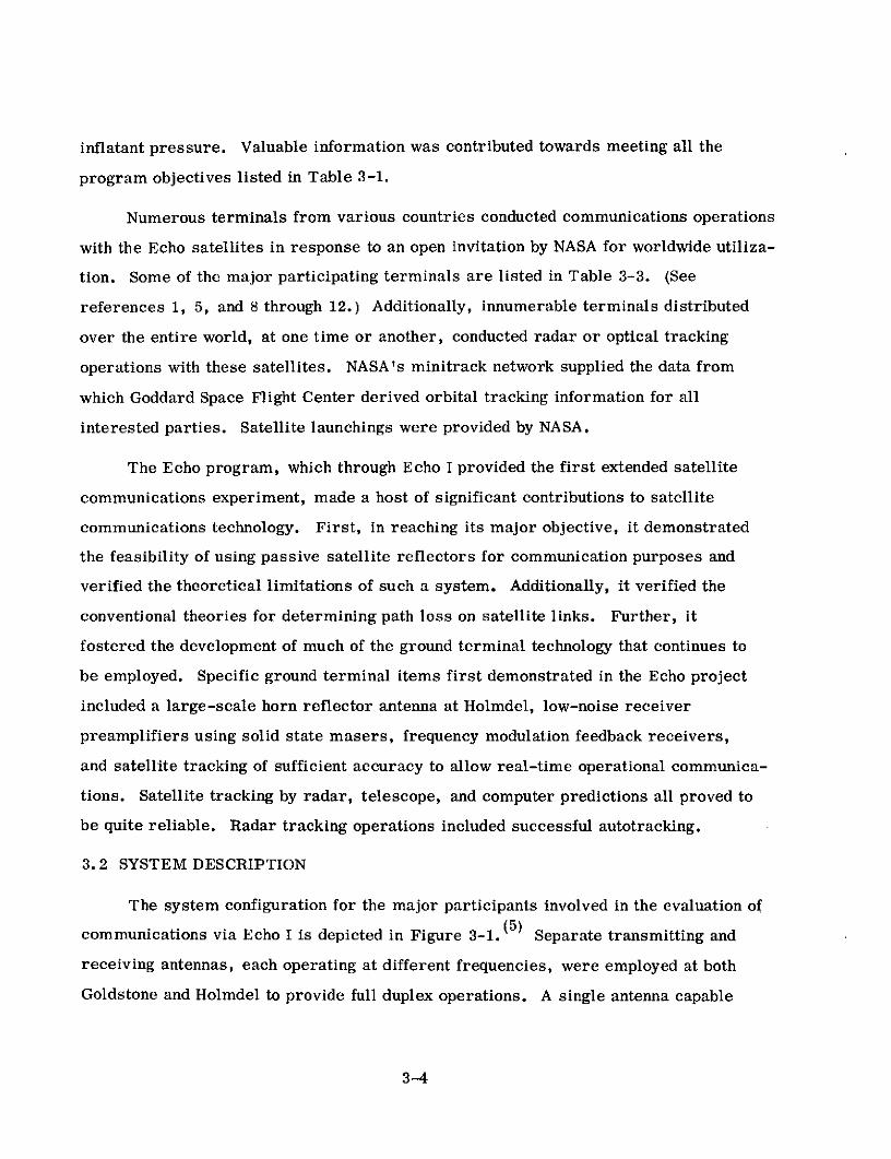
inflatant pressure. Valuable information was contributed towards meeting all the
program objectives listed in Table 3-1.
Numerous terminals from various countries conducted communications operations
with the Echo satellites in response to an open invitation by NASA for worldwide utiliza-
tion. Some of the major participating terminals are listed in Table 3-3. (See
references 1, 5, and 8 through 12.) Additionally, innumerable terminals distributed
over the entire world, at one time or another, conducted radar or optical tracking
operations with these satellites. NASA's minitrack network supplied the data from
which Goddard Space Flight Center derived orbital tracking information for all
interested parties. Satellite launchings were provided by NASA.
The Echo program, which through Echo I provided the first extended satellite
communications experiment, made a host of significant contributions to satellite
communications technology. First, in reaching its major objective, it demonstrated
the feasibility of using passive satellite reflectors for communication purposes and
verified the theoretical limitations of such a system. Additionally, it verified the
conventional theories for determining path loss on satellite links. Further, it
fostered the development of much of the ground terminal technology that continues to
be employed. Specific ground terminal items first demonstrated in the Echo project
included a large-scale horn reflector antenna at Holmdel, low-noise receiver
preamplifiers using solid state masers, frequency modulation feedback receivers,
and satellite tracking of sufficient accuracy to allow real-time operational communica-
tions. Satellite tracking by radar, telescope, and computer predictions all proved to
be quite reliable. Radar tracking operations included successful autotracking.
3.2 SYSTEM DESCRIPTION
The system configuration for the major participants involved in the evaluation of
communications via Echo I is depicted in Figure 3-1. (5) Separate transmitting and
receiving antennas, each operating at different frequencies, were employed at both
Goldstone and Holmdel to provide full duplex operations. A single antenna capable
3-4

Table 3-3. Participating Terminals
ANTENNA SATELLITE
LOCATION SPONSOR DIAMETER (ft) EMPLOYED
Goldstone, California Jet Propulsion Laboratory 8. 5 (2 dishes) Echo I
Holmdel, New Jersey Bell Telephone Laboratories 60 & 20 Echo I
Stump Neck, Maryland Naval Research Laboratories 60 Echo I & II
Paris, France Centre Nationale d'Etudes 30 Echo Ides Telecommunications
Jodrell Bank, England University of Manchester 250 Echo I & II
Schenectady, New York General Electric Labora- 28 Echo Itories
Cedar Rapids, Iowa Collins Radio Corporation 28 Echo I
Dallas, Texas Collins Radio Corporation 60 & 28 Echo I & II
Columbus, Ohio Ohio State University 30 (4 dishes)* Echo II
Gorky, Russia Zimenki Observatory 49 Echo II
Trinidad United States Air Force 84 Echo II
Rome, New York United States Air Force 33 Echo II
tOperated as phased array
of alternate transmit or receive operation at the same frequency was utilized at Stump
Neck. The Goldstone terminal employed a third frequency and its separate transmit
and receive antennas to provide a radar tracking capability. (13) Ordinarily, both
Holmdel and Stump Neck received from Goldstone during the first part of a satellite
pass. After the balloon set for Goldstone, Stump Neck then transmitted to Holmdel.
On a few passes, both Goldstone and Stump Neck simultaneously transmitted to
Holmdel, using circular polarizations of opposite sense and slightly different transmit
frequencies. Echo I provided periods of mutual visibility up to about 15 minutes for
Holmdel and Goldstone and 25 minutes for Holmdel and Stump Neck.
3-5

1w 147 ~ ECHO I
MILES
I'
I \ \- 7 \ \ N
9~11
5 60* DISH
- \ N ODS
RECEIVER / RECEIVER TRA SM TTE
SNRL
STUMPNECK,SM MD. 20' x 20'
HORN10 KW PINTINGTRANSM ITTER GO L LGL
DABTLBTL
JPL NJJGOLDSTONE,
CAL.
GODDARD SPACE FLIGHT CENTERWASHINGTON, D.C.
MINITRACK NETWORK
Figure 3-1. General Features of the Echo I Experiment

For the Echo II communication experiments, the system configuration for the
principal participants was as illustrated in Figure 3-2. (10) The configuration was
such as to provide half duplex communications as the primary mode of operation.
Normally, Dallas transmitted while Stump Neck or Columbus or both received.
Dallas could transmit on either of two frequencies and Stump Neck could receive either
of these frequencies. However, Columbus received on only one of the Dallas trans-
mit frequencies.
The Dallas site included a second transmit antenna used in radar tracking
operations to a receiver operating off the communications transmitting antenna. Radar
tracking was performed at a separate frequency from the communication frequencies,
and Stump Neck included a receive capability at that frequency. Stump Neck also
included a communications transmit capability for use in special cases. East Coast
to West Coast mutual visibilities were increased over those for Echo I by the higher
orbital inclination of Echo II.
Frequencies employed for communications and radar tracking operations with
the Echo satellites spanned a wide range extending from VHF to S-band. This was a
result of performance as a function of frequency, being, in general, unaffected by these
passive reflectors. Strictly speaking, fading, due to scattering from the wrinkled
skin of these reflectors, did become more of a problem at the higher frequencies.
Operating frequencies for the major participants involved in experiments with Echo I
and II are summarized in Tables 3-4 and 3-5, (5)(10) respectively. The two GHz
frequencies were chosen because they were available for allocation by the Federal
Communications Commission and because they were the correct frequencies for
future satellite and deep space communications activities. The 960-MHz frequency
was chosen because equipment on this frequency existed at Goldstone from an earlier
program.
3-7

ECHO 2
///
// ///'
/ o
/N /.
4- 30
28' ANTENNAS 60' ANTENNA60' ANTENNA OSU
COLUMBUS OHIO NRLARAPAHO STATION STUMPNECK MO.
DALLAS TEXAS
Figure 3-2. Circuit Configuration, Echo II Communications Experiments

Table 3-4. Echo I Operating Frequencies
Goldstone to Holmdel . . Goldcstone t. ,Holmdel to Stump Neck toor Stump Neck Goldstone Goldstone Holmdel
2390 MHz 2388 MHz 960 MHz 2390:MHz
Table 3-5. Echo II Operating Frequencies
Dallas to Dallas t o Dallas toStump Neck; Columbus Dallas
2260 MHz or . 2260 MHz 2190 Mhz2380 MHz
The basic signal processing techniques employed for the Echo I tests are
summarized in Table 3-6.(5)(14)(15) There were no multiple-access restrictions
except the normal requiremenits for signal orthogonality, since the satellite was
simply a passive reflector. -Therefore, any of the commonly conceived multiple-
access techniques (e. g., time, frequency, and code-division multiple access) could
have been employed. Frequency division was used because of its ready compatibility
with common existing earth terminal technology. For a perfectly spherical reflector
with a smooth skin, there are likewise no satellite-imposed restrictions on the RF
modulation technique employed., However, for a deformed reflector with a wrinkled
skin, both fading and limitations on the coherent bandwidth are imposed. Frequency
modulation (FM) is normally effective in the face of fading as long as the coherent
bandwidth of the channel isn't exceeded. Large margins are required for an opera-
tional system of this sort.
Margins, for a perfectly reflecting sphere, must account for variations in range,
atmospheric and ionospheric attenuation and noise, antenna tracking and polarization
losses, and ground terminal performance. For an imperfect sphere such as Echo I,
margins must be further increased to account for signal fading due to scattering off
the balloon surface and changes in the instantaneous reflective cross sectional area.
3-9

Signal processing techniques were basically the same for Echo II as for Echo I.
Performance was improved somewhat primarily due to an average reflective cross
sectional area that was 3 dB larger, slightly shorter ranges to the satellite, and the
fact that the balloon shape did not deteriorate as a function of time. Additionally,
both frequency and space diversity were tried as means of combating coherent fading.
Table 3-6. Signal Processing for Echo I
Multiple Access FDMA for an Unlimited Number of Users
RF Modulation FM, (1) single sideband, narrow-bandphase modulation, and conventionalamplitude modification.
Ground Demodulator FMFB receivers employed giving thresholdPerformance at about 13 dB C/N in 6-kHz bandwidths. (2)
Holmdel Receive Carrier- 34. 2 dB for Goldstone transmit, satelliteto-Noise midway between terminals, and 6-kHz
noise bandwidth.
Holmdel Receive Margin About 21 dB.( 3 )
Notes: (1) Frequency modulation was normally used.
(2) In normal 60-MHz RF bandwidth, threshold occurs at 3-dB C/N.
(3) High margin allows successful operation in spite of significant signalfluctuations. Also allows good quality communications employingmodulation techniques with considerably less processing gain than FM.
3.3 SPACECRAFT
Echo I was a hollow sphere constructed from gores of 0.0005-inch thick Mylar
with the external surfaces coated with vapor-deposited aluminum to provide efficient
radio-wave reflectivity.(1) In this design, long cigar-shaped pieces are cut out of
sheet material and joined together with "butt" seams. Where the "gores" come
together at the two poles of the structure, a reinforcing "pole cap" was used. The
sphere was designed to have a 100-foot diameter when inflated and weighed approxi-
mately 135 pounds. (3)
3-10

Before launch, the satellite was evacuated and accordion-pleat folded for pack-
ing in the spherical launch container. The launch container, measuring 26 inches in
diameter, was also evacuated to a rather low vacuum prior to launch.
When the container was placed in orbit, it was explosively separated at its
equator and the satellite was initially inflated by the small amount of residual air
entrapped within its interior. (16) Inflation was completed and the shape of the inflated
satellite was temporarily maintained by the small gas pressure created by sublimating
solids (i. e., 20 pounds of anthraquinone and 10 pounds of benzoic acid) contained
within the satellite. (2) These inflatants could produce a skin stress of about 150 psi
in Echo I and the pressurized life of the satellite was approximately 14 days.
Initial tracking of the satellite was greatly aided by two radio beacon transmitters
attached to the sphere's external surface. Each of the two assemblies, located
diametrically opposite on the equator of the satellite, include one transmitter, its
associated antenna, a group of solar cells and one-half of the satellite's storage-
batteries.(16) Each of the continuous wave transmitters was designed to provide
about 10.5 milliwatts of power at a frequency of 107.94 MHz. Crystals were chosen
to provide a frequency separation of 500 to 1000 Hz between the two transmitted signals.
The quarter-wave monopole antenna for each beacon transmitter was erected normal
to the satellite surface. The radiation pattern provided was somewhat similar to
that of a monopole antenna above an infinite plane.
In Echo II, the basic type of gore construction developed in Echo I was retained. (1)
It was made up of 106 gores with each gore measuring 4 x 215 feet. (2) The gores
were butt-jointed together, using 1-inch wide tapes made of the same material as the
gores. The gores terminated at the polar areas of the sphere where 54-inch diameter
pole caps were attached, using a 1-inch overlapping joint. The material used was a
3-layer sandwich of .00020-inch sheets of aluminum on each side of a .00036-inch
mylar polyester film. The total skin thickness was . 00075 inch, which was only 50
percent greater than that of Echo I but it produced a rigidity about 100 times greater.
This construction resulted in an inflated sphere measuring 135 feet in diameter and
weighing 550 pounds.
3-11

The structure was folded and packed inside a launch canister having an elliptical
vertical cross section and a circular horizontal cross section as mounted for launching. (6)
The canister had a 30-inch vertical diameter and a 44-inch horizontal diameter. The
container, as well as the satellite, was evacuated to prevent excessively rapid
inflation by expansion of residual air inside. The canister was separated in orbit in
the same manner as for Echo I and residual air again provided the initial inflation.
However, continued inflation and full pressurization were accomplished in a much more
controlled manner. In this system, the inflatant, now pyrozole, was sealed in numer-
ous small packets that were attached to the inside surface of the satellite. (1) The
packets were sealed with an adhesive wax that melted just below the equilibrium
temperature of the sphere in orbit. The bags, therefore, were not opened to start
sublimation and the buildup to higher pressurization until the sun's energy elevated
the temperature of the satellite. This occurred long after initial inflation and the
danger of rupture due to dynamic loads had passed.
Initial pressurization was designed to be higher than for Echo I. The theory
behind the use of the three-layer laminated material and this higher pressurization
was that the different moduli of elasticity of mylar and aluminum would result in the
aluminum stretching in a nonelastic fashion while the mylar sheet was still within its
elastic limit.(1) Thus, after the pressurization escaped, the mylar would tend to
return to its original dimensions, placing the aluminum cemented to it under a com-
pressive load. This results in a material that behaves like a prestressed beam and
is quite rigid.
Echo II also supported two radio telemetry beacons mounted diametrically
opposite one another at the sphere's equator. These beacons served as a tracking
aid as well as a means of telemetering data on satellite temperature and pressure.
The pressure monitoring capability extended from a minimum of 10- 5 mm to a
maximum of 0.5 mm of mercury. (17) The temperature measurements extended from
minus 120' to plus 1600 C. The beacon system included two battery packs, four solar
cell panels, and interconnecting cables to give a total weight of approximately 6
3-12

pounds. The carrier frequencies were at 136. 020 and 136. 170 MHz, and each carrier
was amplitude-modulated with three sinusoidal subcarriers bearing the telemetry
information. The antenna, supplied with each transmitter, was a quarter-wave
monopole made of spring wire. Upon satellite inflation, the antenna erected to a
position normal to the surface of the satellite. The effective radiated power of each
transmitter was greater than 34 milliwatts under continuous operation. The beacons
were designed to operate for 1 year, at which time a mercury cell cutoff circuit
terminated radiations.
3.4 GROUND TERMINALS
Characteristics of three of the terminals listed in Table 3-3 as participants in
Project Echo are provided in Table 3-7.(5)(10)(18)(19)(20) Holmdel and Goldstone
were the two major experimenters involved in Echo I testing, while the Stump Neck
terminal participated in Echo I tests and was a principal evaluator of communications
via Echo II. Major subsystems of the Holmdel and Stump Neck terminals are depicted
in Figures 3-3(5) and 3-4(1 0 ) , respectively.
The configuration of each of these three terminals reflects the considerable
concern that existed over the feasibility of accurately acquiring and tracking the
passive Echo spacecraft. None of the terminals relied on the satellite beacon for
tracking. Beacon tracking was performed by the NASA Minitrack network, and the data
contributed towards the generation of program track information by Goddard Space
Flight Center. Radar techniques were employed by the communications terminals to
give an active tracking capability. However, optical tracking was the preferred
method of tracking when the satellite was visible (i. e., at night).
Circular polarization was employed to eliminate the need for polarization
tracking. The direction of rotation (i. e., left- or right-hand circular) was selected
at each transmit and corresponding receive antenna to account for the direction
reversal that occurs upon reflection from the spacecraft.
3-13

Table 3-7. Characteristics of Major Project Echo Ground Terminals
Terminal
TERMINAL FEATURE Holmdel Goldstone Stump Neck
Type Parabolic Transmit & Separate Parabolic Single Parabolic
Horn Receive Transmit & Receive Reflector
Aperture Size 60 ft. Diameter Xmit 85 ft. Diameter Xmit 60 ft. Diameter
& 20x20 ft. Receive & 85 ft. Diameter Rec.
Receive 43.3 dB @2390 MHz 45.5 dB @ 960 MHz 49.7 @ 23e4 MHz
Gain Transmit 43.1 dB@ 960 MHz 52.5 dB @ 2390 MHz
Receive 72%(1) 52%(1) 44(%(1)Efficiency Transmit 60%(1) 42%(1) (4)
Beamwidth Receive 1.2o@3 dB Pts. 0.9 @ 3 dB Pts. 0.5@3 dB Pts.Transmit 1.2* @ 3 dB P t s . 0. 33 @ 3 dB Pts. ------- (4)
Type Preamplifier Maser Uncooler Parametric Traveling Wave Amplifier
Amplifier
Bandwidth 7 MHz( 2 ) 5 MHz( 2 ) 200 MHz RF( 3 )
Noise Temperature 450 K @7.5* El. 3000 K 5500 K
Type Amplifier Klystron Klystron Klystron(4 )
Bandwidth 1.5 MHz No Data No Data
> Amp. Power Out 10 KW 10 KW 10 KW
Program track, optical Program track, optical Program track or
Type track, manually con- track, or monopulse optical track
trolled radar track radar autotrack
Program track ±0.2* Program track 1 0.150 Program track 0. 4'
Accuracy Optical track ±0. 05" Optical track 10. 1 Optical 1 0.30
Radar track 40. 1 Radar track 10. 030 forreceive & 10.1* xmit.
o G/T 26.5 dB/K(1) 20.5 dB/K ° 22 dB/*K
o EIRP 112.5 dBM(1 ) 122.5 dBM ___---(4)
s. Transmit Feed Left Hand Circular Right Hand Circular --- (4)
Receive Feed Left Hand Circular Right Hand Circular Circular
a Radome None None None
Type Facility Fixed Fixed Fixed
Notes: (1)Derived value based on data available
(2)Front end bandwidth. Predetection demodulator bandwidth was 6 kHz
(3)Predetection demodulator bandwidth was 50 kHz
(4)Terminal did not normally transmit
3-14

10 KW TRANSMITTER MODULATION
18' DISH
60'ISHPOSITION COMMANDS
CAMERA
POSITION COMMANDS
DISPLAY
RADARRECEIVER
18' DISH
BORESIGHT COUNTER-CAMERA CLOCKWISE
POLARIZATION RECEIVER
RECORDERS:20' x 20' AUDIO ANDHORN CARRIER
CLOCKWISE JPOLARIZATION
DRIVEPOSITION COMMANDS
CLOCK
GODDARD TAPE DIGITAL TO COMMANDS SELECTOR
SPACE FLIGHT ANALOG C AND ANGULARCENTER CONVERTER OFFSETS
OPTICS POSITION COMMANDS
Figure 3-3. Block Diagram of the Holmdel Facilities
3-15
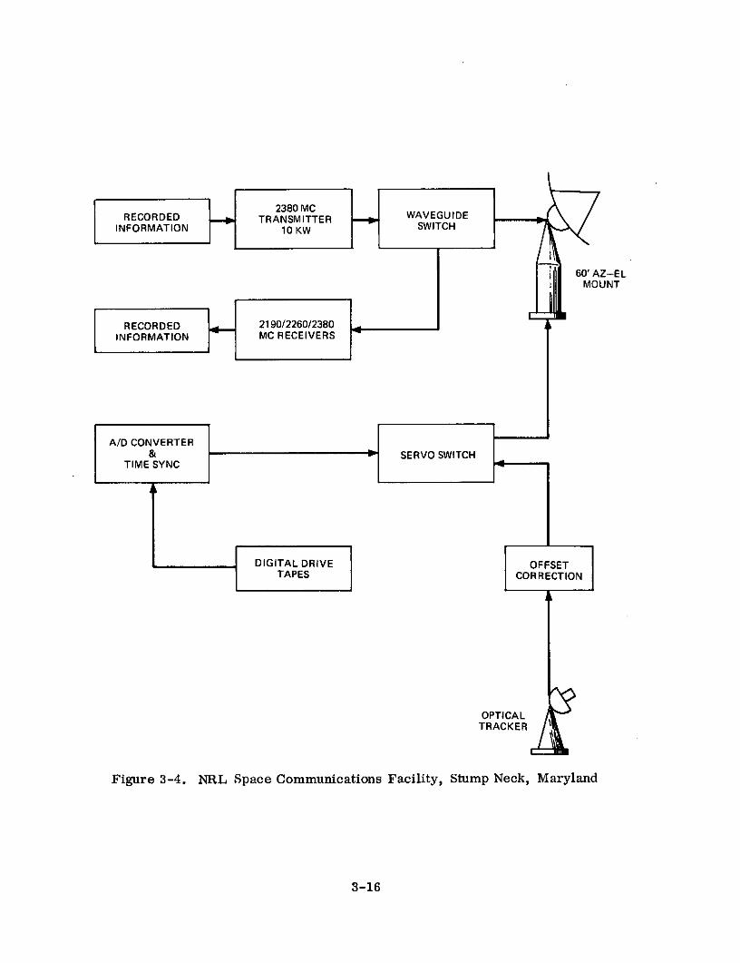
RECORDED 0 TRSMITER W A V E G U ID E
INFORMATION 1T10 KW SWITCH
S60' AZ-ELMOUNT
RECORDED 2190/2260/2380INFORMATION MC RECEIVERS
A/D CONVERTER& SERVO SWITCH
TIME SYNC
DIGITAL DRIVE OFFSETTAPES CORRECTION
OPTICALTRACKER.
Figure 3-4. NRL Space Communications Facility, Stump Neck, Maryland
3-16
3.5 EXPERIMENTS
The premier objective of the Echo program was to evaluate the feasibility of
employing satellite reflectors for global communications, and most of the planned
experiments were directed towards that end. The second objective listed in Table 3-1
was accomplished through preflight statics tests, ballistic space tests, the TV system
on the booster that monitored the deployment of Echo II, optical observations of both
spheres over a period of time, and monitoring of reflected received signal levels
over a period of time. Received signal level data was obtained in the planned communi-
cations tests as well as in independent radar tracking operations. References 21
through 24 provide examples of the type of information analyses completed to verify
that large lightweight structures of the Echo type can be successfully deployed and
maintained in orbit.
Accurate tracking of the Echo balloons was maintained throughout their lifetime.
This gave the basis for accomplishing the third objective in Table 3-1, as well as
allowing the balloons to serve as accurate position location measurement references
for remote geographic points. References 25 through 28 are examples of the types
of analyses and conclusions that have been made possible by the extensive data on the
Echo orbits.
The major communications tests performed on Project Echo and a summary of
their results are given in Table 3-8.(5)(8)(10)(22)(29)(30) Items 1 through 4 in the
table were tests or analyses employed extensively on both Echo I and II, while the
remaining listed tests were conducted mainly with Echo II alone. Results of the first
three items, as well as optical data, indicated that Echo I was relatively smooth and
spherical during its pressurized lifetime but developed wrinkles and flat areas during
the first month in orbit, which tended to become more extensive and severe as time
passed. Similar data indicated that Echo II developed a wrinkled skin very quickly
after deployment and maintained its shape as a function of time.
3-17
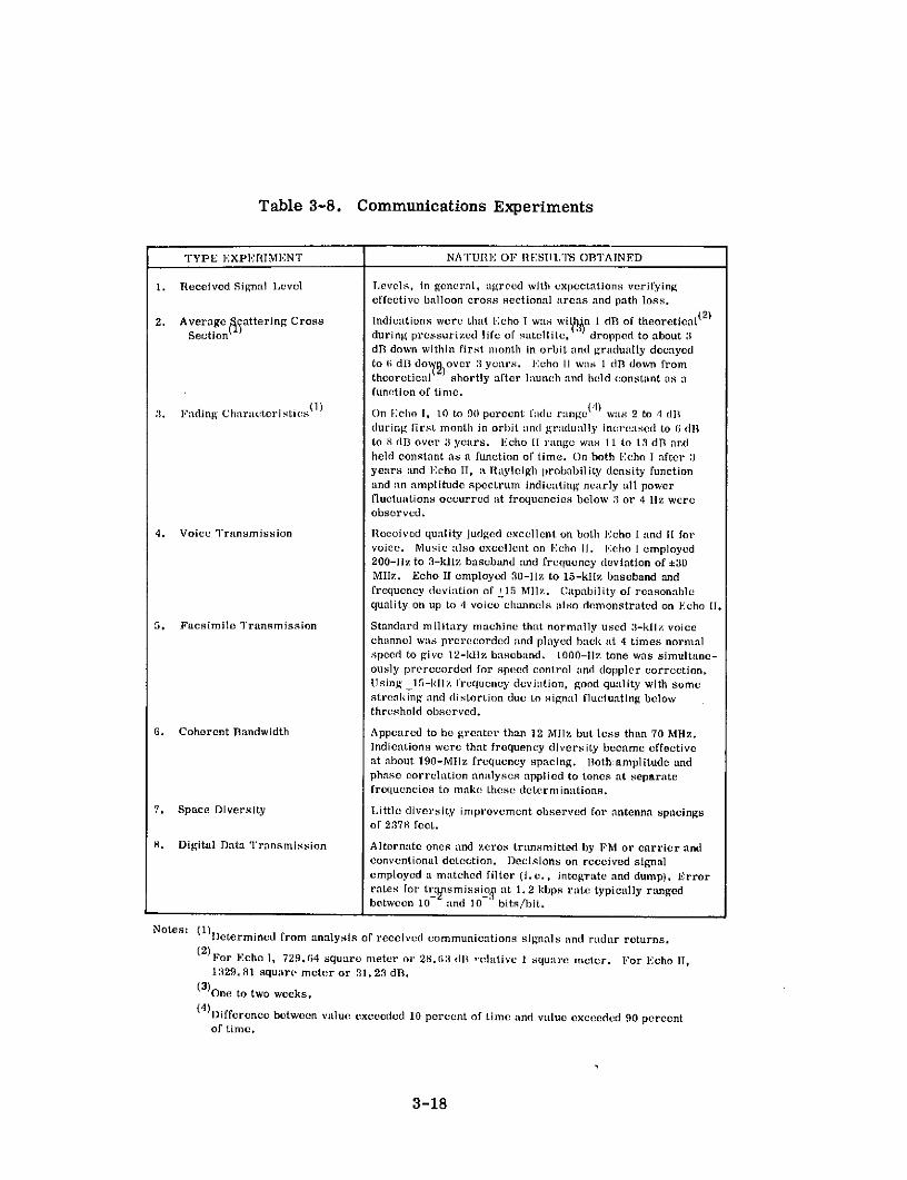
Table 3-8. Communications Experiments
TYPE EXPERIMEN'r NATURE OF RESULTS OBTAINED
1. Received Signal Level Levels, in general, agreed with expectations verifyingeffective balloon cross sectional areas and path loss.
2. Average battering Cross Indications were that Echo I was witln 1 dB of theoretical(2 )
Section during pressurized life of satellite, dropped to about 3dB down within first month in orbit and gradually decayedto 6( dBl dow )over 3 years. Echo 11 was 1 dB down fromtheoretical shortly after launch and held constant as afunction of time.
:1. Fading Characteristics ( 1 ) On Echo 1, 10 to 90 percent fadle range (l )
was 2 to 4 dlduring first month in orbit and gradually increased to (i dBlto 8 dB over 3 years. Echo II range was 11 to 13 dB andheld constant as a function of time. On both Echo I after :1years and Echo II, a Rayleigh probability density functionand an amplitude spectrum indicating nearly all powerfluctuations occurred at frequencies below :13 or 4 Hz wereobserved.
4. Voice Transmission Received quality judged excellent on both Echo I and II forvoice. Music also excellent on Echo II. Echo I employed200-11z to 3-kllz bascband and frequency deviation of :30MlIz. Echo II employed 30-11z to 15-klIz baseband andfrequency deviation of 115 Mllz. Capability of reasonablequality on up to 4 voice channels also demonstrated on Echo II.
5. Facsimile Transmission Standard military machine that normally used 3-kIlz voicechannel was prerecorded and played back at 4 times normalspeed to give 12-kllz baseband. 1000-liz tone was simultane-ously prerecorded for speed control and doppler correction.Using 115-kllz frequency deviation, good quality with somestreaking and distortion due to signal fluctuating belowthreshold observed.
6. Coherent Bandwidth Appeared to be greater than 12 Mllz but less than 70 Mllz.Indications were that frequency diversity became effectiveat about 190-MHlz frequency spacing. Both amplitude andphase correlation analyses applied to tones at separatefrequencies to make these determinations.
7. Space Diversity Little diversity improvement observed for antenna spacingsof 2378 feet.
8. Digital Data Transmission Alternate ones and zeros transmitted by FM or carrier andconventional detection. Decisions on received signalemployed a matched filter (i.e., integrate and dump). Errorrates for tr.Ynsmissio. at 1.2 kbps rate typically rangedbetween 10 and 10 bits/bit.
Notes: (1)Determined from analysis of received communications signals and radar returns.(2)For Echo 1, 729.(64 square meter or 28.63(1 d 'elative 1 square meter. For Echo II,
1329.81 square meter or 31.23 dB.
(3)One to two weeks.
(4)Difference between value exceeded 10 percent of time and value exceeded 90 percentof time.
3-18

In addition to the experiments listed in the table, several tests of perhaps some-
what lesser importance were conducted employing primarily Echo 1. Voice trans-
mission evaluations were extended by utilizing single-sideband, narrow-band phase,
and amplitude-modulation techniques for comparison with frequency modulation. (5)
The performance did not equal that with FM, indicating that the coherent bandwidth of
the channel had not been exceeded in the tests; therefore, conventional theories for
comparing modulation techniques applied. Measured doppler shift was compared with
theory and found to be in good agreement. Performance of FM with feedback receivers
was evaluated and found to agree well with previous laboratory measurements and
theory. Performance of the ground terminal tracking systems was closely watched.
All performed well, and the potential of automatic tracking was demonstrated. In
addition, a television signal was transmitted and limited quality reception obtained,
using facilities developed for Project West Ford.(31)
Numerous notable demonstrations were also conducted. (5)(30) Most of these
occurred during the early days of Echo I and tended to dramatize the potential of
this type of communications. Included were a tape-recorded voice message by
President Eisenhower during the first satellite pass on August 12, 1960; prerecorded
2-way messages by President Eisenhower and Senator L. B. Johnson on August 13,
1960; and the first 2-way live voice transfer between Mr. W. C. Jakes of Bell
Telephone Laboratories and Mr. P. Tardani of Jet Propulsion Labs also on August 13,
1960.
Finally, Echo II provided a first in international communications, when Russia
agreed to participate in a cooperative experiment with NASA and to supply NASA with
tracking data during the early orbits after launch. (11)(32)(33) The tests were con-
ducted in accordance with the Bilateral Space Agreement between the USSR (Academy
of Sciences) and the USA (NASA) reached at Geneva on June 8, 1962. The tracking
data consisted of photographs and optical observations that helped to determine that
the balloon had been successfully deployed and to establish initial orbital parameters.
3-19

The communications experiments were performed between the Jodrell Bank
Radio Observatory of the University of Manchester, England, operating on NASA's
behalf and the Zimenki Observatory of the Gorki State University northeast of Moscow.
The Jodrell Bank facility provided a 250-foot diameter steerable antenna and a 1-kW
transmitter to radiate signals at a frequency of 164.2 MHz. The Zimenki facility
received both this signal and the 136-MHz satellite beacon, using a 49-foot diameter
antenna. Transmissions included unmodulated carrier, 400-Hz tone modulation,
Morse telegraphy, teletype, telephone and facsimile.
Theoretical link calculations showed that performance could only be marginal,
but the results obtained were even poorer than expected. This was attributed to
inaccurate pointing of the antenna at the transmitting site, refractive and reflective
effects on the signal at the low elevation angles and wide beamwidths used, and
polarization mismatches between the transmitting and receiving antennas. In spite
of this, 34 experiments were conducted between 21 February and 8 March 1964, and
the international cooperation displayed made the entire operation a significant
diplomatic success.
3.6 OPERATIONAL RESULTS
Project Echo was an experimental program; therefore no operational traffic
was carried. Operation of the experimental ground stations was entirely satisfactory
as expected. The only difficulty of any significance was caused by occasional errors
in the prepass tracking predictions. These errors were of sufficient magnitude to
make ground terminal program tracking unsatisfactory. They were a result of the
manner in which the orbits of the large lightweight Echo structures were being
perturbed from pass-to-pass by solar pressure and atmospheric drag. The tracking
difficulties encountered could have been overcome by obtaining more extensive track-
ing data and updating computed orbital elements more often.
No unexpected operational difficulties of importance were encountered with
the Echo I balloon. At the end of a week of operation, a malfunction occurred in the
3-20

beacon battery supply such that the beacons transmitted only when a solar cell pack was
illuminated by the sun. However, the beacons were not designed for a long lifetime,
since their primary mission was to assist the tracking operations during the early
orbits of the satellite so that accurate initial orbital elements could be generated.
This mission was fulfilled.
The only anomalous operation that developed during operations with Echo II was
scintillation of the reflected received signal due to wrinkling of the satellite skin. This
was caused by the unexpected satellite spin that developed during the first orbit after
launch and lower than expected initial inflation pressure. The exact cause of these
unusual occurrences was not determined. The beacons on this spacecraft operated
for 1 year as planned.
3-21

CITED REFERENCES
1. L. Jaffee, "Communications in Space, " Holt, Rinehart and Winston Inc., New York,
New York, 1966.
2. J. R. Burke, "Passive Satellite Development and Technology, " Astronautics and
Aerospace Engineering, Vol. 1, No. 8, September, 1963.
3. "Summary Log of Space Launches 1957-69, " TRW Space Log, Vol. 9, No. 4,
Winter 1969-1970.
4. "Echo, " STL Space Log, Vol. 3, No. 3, September, 1963.
5. W. C. Jakes, Jr., "Participation of Bell Telephone Laboratories in Project Echo
and Experimental Results, " The Bell System Technical Journal, Vol. XL, No. 4,
July, 1961.
6. H. L. Eaker, "Project Echo Objectives and Implementation, " WESCON/65, Western
Electronic Show and Convention, San Francisco, California, August 24-27, 1965.
7. A. Kampinsky and R. K. Ritt, "Experimental and Theoretical Evaluation of a
Passive Communications Satellite (Echo II), " NASA TN D-3154, NASA, Washington,
D.C., May, 1966.
8. L. Jaffee, "Project Echo Results, " Astronautics, May, 1961.
9. A. L. Hedrich, "Communications Satellite Technology, " Proceedings of the Fourth
National Conference on the Peaceful Uses of Space, Boston, Massachusetts, April
29-May 1, 1964.
10. "Echo II Experimental Program Final Report, " Collins Radio Company,523-0556818-001D3N, July 15, 1965.
11. H. L. Eaker, and W. C. Nyberg, "Analysis of US-USSR Communications Experi-
ments Conducted between Jodrell Bank Observatory (UK) and Zimenki Observatory
(USSR) via the Echo II Satellite, NASA TMX-55343, Goddard Space Flight Center,January, 1965.
12. "Experimental Passive-Satellite Communications Link, Appendix I, Descriptive
Handbook, Volume I, " RADC:-TN-60-281B, Philco Research Division, November
29, 1960.
13. R. Stevens and W. K. Victor, , "The Goldstone Station Communications and Track-
ing System for Project Echo, " NASA Contract No. NASw-6, Technical Report No.
32-59, Jet Propulsion Laboratory, December 1, 1960, AD251-505.
3-22
14. C. L. Ruthroff, and W. C. Jakes, Jr., "System Calculations, " The Bell System
Technical Journal, Vol. XL, No. 4, July, 1961.
15. C. L. Ruthroff, "FM Demodulators with Negative Feedback, " The Bell System
Technical Journal, Vol. XL, No. 4, July, 1961.
16. J. G. McCubbin, and H. B. Goldberg, "Beacon Transmitters and Power Supply
for Echo I, " RCA Review, March 1961.
17. N. L. Martin, and H. S. Horiuchi, "The Application of a Beacon Telemetry System
for Measuring Orbital Performance of the Echo II Satellite, " WESCON/65, Western
Electric Show and Convention, San Francisco, California, August 24-27, 1965.
18. W. C. Nyberg, R. L. Kaiser, and W. E. Leavitt, "Experiments to Determine
Communication Capability of the Echo II Satellite, " Publications of Goddard Space
Flight Center 1964, Volume II, Space Technology.
19. J. P. Schafer, and R. H. Brandt, "960-me, 10 kW Transmitter, " The Bell System
Technical Journal, Vol. XL, No. 4, July, 1961.
20. E. A. Ohm, "Receiving System, " The Bell System Technical Journal, Vol. XL,
No. 4, July, 1961.
21. "Photometric Measurements of Surface Characteristics of Echo I Satellite, " Final
Report Contract No. NAS 1-3114, Goodyear Aerospace Corporation, GER 11648,
June 19, 1964.
22. "Final Report for Effective Radio Cross-Section Analysis from Experimental MeasurE
ments, Echo I, 21 June 1965-28 April 1967, " Contract No. NAS 5-9648, Collins Radit
Company, Cedar Rapids, Iowa.
23. R. F. Julian, and D. P. Hynek, "Cross-Section Measurements of the Echo II
Satellite by the Milestone L-band Radar, " Group Report 1964-16, Massachusetts
Institute of Technology, Lincoln Laboratory, April 7, 1964.
24. J. Yagelowich, "Echo II Television System, " WESCON/65, Western Electric Show
and Convention, San Francisco, California, August 24-27, 1965.
25. R. Bryant, "A Comparison of Theory and Observation of the Echo I Satellite, "
Journal of Geophysical Research, Volume 66, No. 9, September, 1961.
26. R. Jastrow, and R. Bryant "Variations in the Orbit of the Echo Satellite, " Journal
of Geophysical Research, Volume 65, No. 10, October, 1960.
3-23

27. J. Meens, "On the Orbital Eccentricity of the Balloon Satellites, " Journal of BritishAstronomical Association, February, 1966.
28. G. E. Cook, and D. W. Scott, "The Semi-Annual Variation in Air Density at aHeight of 1100 km from 1964 to 1967, " Planetary and Space Sciences, Volume 17,Pergamon Press, 1969.
29. W. C. Nyberg, "Results of Communications Experiments Conducted with the EchoII Satellite, " WESCON/65, Western Electric Show and Convention, San Francisco,California, August 24-27, 1965.
30. W. K. Victor, and R. Stevens "The Role of the Jet Propulsion Laboratory in.Project Echo, " NASA Contract No. NASw-6, Jet Propulsion Laboratory TechnicalRelease No. 34-141, October 14, 1960.
31. D. H. Hamilton, Jr., H. H. Hoover, Jr., R. V. Locke, Jr., D. C. MacLellan,W. E. Morrow, Jr., B. E. Nichols, T. F. Rogers, and P. Waldron, "Trans-continental Satellite Television Transmission, " Proceedings IRE, June, 1962.
32. R. C. Behn, "Communications Satellites, " in Handbook of Soviet Space ScienceResearch, Wukelic, G. E., editor, Gordon & Breach.
33. "Significant Achievements in Space Communications and Navigation 1958-1964, "NASA SP-93, NASAWashingtAn, D.C., 1966.
3-24

RELATED REFERENCES
1. A. B. Crawford, D. C. Hogg, and L. E. Hunt. "A Horn-Reflector Antenna for
Space Communications, " The Bell System Technical Journal, Vol. XL, No. 4,
July, 1961.
2. R. W. DeGrasse, J. J. Kostelnick, and H. E. D. Scovil, "The Dual Channel
2390-me Traveling Wave Maser, " The Bell System Technical Journal, Vol. XL,
No. 4, July, 1961.
3. L. U. Kibler, "Standby Receiver System, " The Bell System Technical Journal,
Vol. XL, No. 4, July, 1961.
4. O. E. DeLange, "Satellite-Tracking Radar, " The Bell System Technical Journal,
Vol. XL, No. 4, July, 1961.
5. M. Venohara, and H. Seidel, "961-me Lower-Sideband Vp-Converter for Satellite
Tracking Radar, " The Bell System Technical Journal, Vol. XL, No. 4, July, 1961.
6. R. Klahn, J. A. Norton, and J. A. Githens, "Antenna Steering System," The
Bell System Technical Journal, Vol. XL, No. 4, July, 1961.
7. K. L. Warthman, "Boresight Cameras, " The Bell System Technical Journal,Vol. XL, No. 4, July, 1961.
8. W. C. Jakes, Jr. "Project Echo, " Bell Laboratories Record, Vol. 39, No. 9,September, 1961.
9. D. P. Hynek, "Radar Cross-Section Observations of the Echo I Communications
Satellite," Lincoln Laboratory, Massachusetts Institute of Technology, AD 274065.
10. H. Mark, and S. Ostrach, "The Inflated Satellite-Characteristics in Sunlight and
Darkness," Aerospace Engineering, April, 1961.
11. H. L. Eaker, "Results of Communication Experiment Conducted with Echo II
Satellite," Conference Record, First IEEE Annual Communications Convention,"
Boulder, Colorado, June 7-9, 1965.
12. J. P. Talentino "Full Scale Ground Tests of Echo II Prototype Spheres, "
WESCON/65, Western Electric Show and Convention, San Francisco, California,August 24-27, 1965.
13. H. L. Eaker, "Summary and Over-All Results of the Echo Project, " WESCON/65,Western Electric Show and Convention, San Francisco, California, August 24-27,1965.
3-25

14. H. S. Horiuchi, "Telemetry Instrumentation of the Echo II Passive Communi-cations Satellite," Publications of Goddard Space Flight Center, 1964, Vol. II,Space Technology.
15. S. L. Zolnay, and J. W. Eberle, "Some Characteristics of Echo ReflectedSignals," Record of the 1965 International Space Electronics Symposium, November2-4, Miami Beack, Florida.
16. J. W. Eberle, "High Gain Antenna Array Facilities at the Ohio State University,"Air Force Contract AF 30(602)-2166, AD 270839, September 22, 1961.
17. J. W. Eberle, and S. L. Zolnay, "Signal-to-Noise Ratio Improvement in anAdaptively Phased Array," Conference Record, First IEEE Annual CommunicationsConvention, Boulder, Colorado, June 7-9, 1965.
18. "A Technicue for Achieving Very High Antenna Gain, " Rome Air DevelopmentCenter Technical Report No. RADC-TR-65-108, June, 1965.
19. H. Bahiman, "Postlaunch Structurel Analysis of Echo II Satellite," NASA TND-3170, NASA, Washington, D. C., February, 1966.
20. S. H. Genatt, "Stereo Photography of the Echo II Balloons Number 9, 11, and 13,"Publications of Goddard Space Flight Center, 1964, Vol. II, Space Technology.
21. L. Jaffe, "NASA Communications Satellite Program," Proceedings of the SecondNational Conference on the Peaceful Uses of Space, Seattle, Washington, May 8-10,1962.
3-26
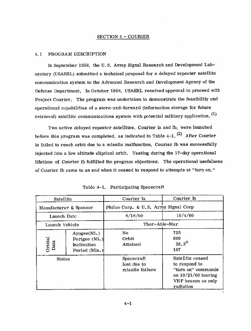
SECTION 4 - COURIER
4.1 PROGRAM DESCRIPTION
In September 1958, the U. S. Army Signal Research and Development Lab-
oratory (USASRL) submitted a technical proposal for a delayed repeater satellite
communication system to the Advanced Research and Development Agency of the
Defense Department. In October 1958, USASRL received approval to proceed with
Project Courier. The program was undertaken to demonstrate the feasibility and
operational capabilities of a store-and-forward (information storage for future
retrieval) satellite communications system with potential military application. (1)
Two active delayed repeater satellites, Courier Ia and Ib, were launched
before this program was completed, as indicated in Table 4-1. (2) After Courier
Ia failed to reach orbit due to a missile malfunction, Courier Ib was successfully
injected into a low altitude eliptical orbit. Testing during the 17-day operational
lifetime of Courier Ib fulfilled the program objectives. The operational usefulness
of Courier Ib came to an end when it ceased to respond to attempts at "turn on."
Table 4-1. Participating Spacecraft
Satellite Courier Ia Courier Ib
Manufacturer & Sponsor Philco Corp. & U. S. Army Signal Corp
Launch Date 8/18/60 10/4/60
Launch Vehicle Thor-Able-Star
Apogee(Mi.) No 755C Perigee (Mi.) Orbit 600
d Inclination Attained 28. 3
1 Period (Min.) 107
Status Spacecraft Satellite ceasedlost due to to respond tomissile failure "turn on" commands
on 10/21/60 leavingVHF beacon as onlyradiation
4-1

The two earth terminals employed in Project Courier are listed in Table 4-2. (3)
Satellite launchings were supplied by the U.S. Air Force.
Table 4-2. Participating Earth Terminals
Antenna DateLocation Sponsor Diameter (Ft.) Installed
Fort Monmouth, New Jersey USASRDL 28 1960
Camp Salinas, Puerto Rico USASRDL 28 1960
The major contribution of Project Courier to satellite communications
technology was to demonstrate the technical feasibility of a delayed repeater high
capacity digital satellite communications system. However, the satellite's early
failure clearly demonstrated the need for additional care and effort in designing
and testing components and systems intended for operational satellite applications.
4.2 SYSTEM DESCRIPTION
Tests were conducted with Courier Ib on a loop-back or push-to-talk basis
by the two terminals indicated in Table 4-2. Both real time and store-and-forward
operation was possible. During store-and-forward operation, an earth terminal
could load traffic into the spacecraft's tape recorders at the same time it received
previously stored messages from the satellite.
The altitude and inclination of the satellite orbit made an average of five
workable orbits at the Fort Monmouth station and an average of seven at the Puerto
Rico station possible out of approximately 14 orbits per day. (3) The satellite was
in view of the ground station during each orbit for a maximum of 19 minutes at
Fort Monmouth and 22 minutes at Puerto Rico. (2) Mutual visibilities as long as
15 minutes were available.
4-2

Operating frequencies for the Courier satellites were as indicated in
Table 4-3. (2) The UHF communications frequencies were chosen for the wide band-
width and simplicity of equipment design provided in addition to the noise and
propagation advantages at these frequencies. (4)
Table 4-3. Courier Frequencies (MHz)
Communications TT&C
Uplink Downlink Command Telemetry
1750 1800 to 1900* 135 108**
* Two transmitters, modulated with same information and operating about
20 MHz apart, utilized for frequency diversity.** Separate acquisition beacon, disabled upon satellite "turn on, " operated at
same frequency.
The basic signal processing techniques utilized on Project Courier were as
indicated in Table 4-4. (2) (5) The modulated uplink signal was detected in the
satellite. The detected baseband was recorded in the satellite or retransmitted
in real time. During transmission over the downlink, the detected signal modulated
the satellite transmitter's radiated carrier. The uplink performance was, in
general, superior to the downlink performance indicated in the table. Margins had
to be adequate to account for variations in range, rain losses, satellite antenna
gain as the aspect angle to the ground terminal changed, and other link parameters
that varied to a smaller extent.
4-3

Table 4-4. Signal Processing Employed
Multiple Access None
RF Modulation FM*
Ground Demodulator Estimated** threshold at about 10 dB C/N
Performance
Ground Terminal 16 dB for maximum range*** and 100 kHz
Receive Carrier-to- noise bandwidth
Noise
Ground Receive Margin 6 dB at maximum range
* Employed on both the up and down link
** Estimate based on fact that conventional discriminators were employed
*** 3300 statute miles
4.3 SPACECRAFT
Spacecraft characteristics for the Courier satellites are displayed in
Table 4-5. (2) (3) (6) A block diagram depicting the basic electrical configuration
of the satellite is shown in Figure 4-1. (3) The considerable redundancy incorporated
reflected the concern over spacecraft reliability that existed at that time. The
design expectation was for a 1 year in orbit lifetime. A special acquisition
transmitter, separate from the telemetry transmitter, was supplied. While in
the acquistion mode, the two VHF receivers were alternately activated to "listen"
for ground terminal signals, on a part-time basis. The cycling of the receivers
was such that an active receiver was listening only about 10 percent of the time.
4-4

Table 4-5. Satellite Characteristics
Type UHF - Pair of slotted fin VHF - 4 whip turnstile
antennas located 1800 apart for TT&Con satellite equatorialband.*
Number One OneBeamwidth Essentially Omnidir- Essentially Omnidirectional
Sectional
Gain 0 dB 0 dB
Frequency Band UHFType Demodulating/remodulating with capability for real
time or delayed operation. **3 dB BW 550 kHzNumber One with considerable built in redundancy
Type Front End Four receivers, each with a down conversion mixer- first stage. Discriminator outputs of receivers
combined in baseband combiner.
SQ Front End Gain 100 dB IF following down conversion mixer in each receiver.
Sys. Noise Fig. 14 dBType 2 planar triodes, each modulated with the detected
uplink signal and operating 20 MHz apart to supply
frequency diversity. Redundant pair of transmittersavailable at ground command.
Gain No data availablePower Out 33 dBm
EIRP-UHF Ant. 29 dBm***
g Type Spin with no active correction capability
cn Capability Unoriented relative to earth. Initially approximatelyW N 90 spin axis aspect to sun.P Primary Solar array with 65 watts average output. ****
M Supplement 2 nickel cadmium batteries - about 12 amp. hr.
_ , capacity per battery****P Comm. Power Needs Approximately 200 watts
Q Size Spherical with 52 in. diameterWeight 500 lbs.
* Two receivers and a redundant transmitter connected to each slotted fin.
Transmitters on one fin operate at different frequency from those on other.
All receivers at same frequency.** 1 analog and 4 digital tape recorders allow delayed operation.*** Transmitter to antenna losses are 4 dB including a diplexer and hybrid.**** At launch.
4-5

When one of the receivers detected a ground terminal signal, it came on in full-time
operation and the remaining satellite systems could be activated on command.
Aperture i MMcrowave Microwave co sdiplexer receiver t basebond fCommand _unction
Microwave I plus standby combiner decoder
antennas
Aperture 2 icrowave Microwavediplexer receiver 2
2 plus standby D Real 1 2 3 4 5Data timestoragedevices
Datastorage
Microwave devices
tronmitter 1plus standby
dtrngrrttFer 2
VHFVHF antenna M rreceiver plus standby
VHF Acquisitiondiplexer transmitter
plu s standbyTelemetry Telemetry
transmitter ---- -- generator Iplus soandbyJ plus standby
i i!converter Power to equipment
Figure 4-1. Satellite Electrical Subsystems
4.4 GROUND TERMINALS
The ground terminals employed at Fort Monmouth and Camp Salinas were
essentially identical. Major characteristics of these terminals are displayed in
Table 4-6. (1) (2) (3) Major subsystems are illustrated in the block diagram of
Figure 4-2. (3)
4-6

Table 4-6. Characteristics of Earth Terminals
Type Parabolic Reflector
Aperture Size 28 Ft. Diameter
Receive Gain 41 dB
Efficiency 50%*
Rec. Beamwidth 1.35 at 3 dB pts.
Type Four receivers each with uncooled parametric
c Preamplifier amplifier front end. Two receivers operate in
linear polarization diversity at each satellite
transmit frequency. **Bandwidth 500 kHz***
4 Noise Temp. 640 0 K
S Type Amplifier Klystrona, Bandwidth 4 MHz****
u Amp. Pwr. Out 1 kW
Type Conical Scan Auto track
. Accuracy 0. 50 at maximum slewing rate of 15 0 /second
G/T 13 dB/oK*
c EIRP 99 dBm*
Transmit Feed Circular
om Receive Feed Linear Diversity Receptiont
-a Radome None
a Type Facility Fixed because of antenna installationt t
* Derived value based on data available.
** Receivers operating on same frequency combined at RF.
Composite signals at separate receive frequencies combined at
baseband.
*** 100 and 200-kHz bandwidths also selectable.
**** RF bandwidth. Effective bandwidth of signal from modulator
was a maximum of about 200 kHz.
t Crossed dipoles at 450 to horizontal and vertical employed.
t t Terminal included antenna, 3 semitrailers, and a maintenance
van plus power generators.
4-7

As the figure indicates, the system was primarily designed to handle teletype
traffic since digital messages are normally more compatible with store-and-forward
operation than analog messages. The terminals included a record and playback
speed changing capability in their data storage system such that stored teletype
messages could be transferred to and from the satellite at a 55-kbps rate.
MPUNHEDPAPER APERECORDER MICROCROWAVE
ANTENNA
AND PLAYBACKS COMBINEH FREQUENCY VVERSITYCLOCK NRECEiVERS
AGC TRACKING SIGNAL FOR ANTENNA
MATR CODER VHF TRANSMITTER DUPLEXER VHF
4 -8
OTHER S1GNATSA
ACKNOWLEDGE- REFERENCEDATA
MENT TAPERECORDER TRACKING DATA
TELEMETERING VMFOUICK LOOK DE-MODULATING POLARIZ ATIONRECORDER ANDDE- DIVERSITY
AND DISPLAY MULTIPLEXING RECEIVERS
AGC SIGNAL. OUTPUT
Figure 4-2. Ground Terminal Block Diagram
4-8

The choice of circular polarization for the transmit feed resulted in a 3-dB
uplink polarization loss since the satellite antenna's transmit and receive
polarization was linear. This loss was avoided on the downlink without resorting
to a polarization tracking system by employing crossed dipoles and dual receivers
at each downlink frequency to give polarization diversity reception.
4.5 EXPERIMENTS
Experiments conducted on Project Courier can be grouped into the three
major categories listed and defined in Table 4-7. (2) Each of these groups of tests
contributed to accomplishing the program objectives.
Table 4-7. Summary of Program Experiments
Type Description1. Communications Evaluate link parameters and communications
Performance traffic handling capabilities of a delayedrepeater satellite.
2. Satellite Performance Determine capability and reliability of varioussubsystems of complex signal processingrepeater.
3. Jamming Resistance Measure satellite and communications per-formance under interference conditions onVHF or UHF uplinks to satellite.
The spacecraft performance tests monitored items such as satellite tape
recorder operation, temperature, spin axis attitude, spin rate, solar power supply,
and command system performance. (2) During the short operational lifetime of
Courier Ib the satellite performance was (in general) good and in agreement with
expectations. Spin rate was observed to decay at the rate of about 1 rpm per
month. Performance exceptions involved the tape recorders and command system.
One of the five tape recorders became stuck at an endstop and further recording or
4-9

playback was impossible. Command system malfunctions resulted in an operational
effectivity of only about 95 to 97 percent. Malfunctions included failure to respond
to commands, improper command acknowledgements, response to improper access
codes, and in one case improper execution of the command sent.
Jamming resistance tests involved CW interference to the VHF link and both
CW and pulse interference with the UHF message link. (2) The system was found
to be readily susceptible to jamming of either the UHF or VHF links, as might
be expected since no antijamming features were incorporated. UHF link signal-to-
jamming ratios of 5 to 7 dB had to be maintained to preserve system operation in
the presence of CW jamming. With pulse jamming, the signal-to-jamming ratio
required appeared to be somewhat higher.
The communications performance tests described in Table 4-7 are defined
in Table 4-8. (2) The table also includes primary results obtained. A precise
evaluation of link parameters was not obtained, since spin axis attitude could be
determined only from surface temperature sensors and received signal level, and
spin rate was determined from the received signal level alone. As a result, highly
accurate real time satellite antenna gain data was not available. In both the record
and playback modes, delayed repeater operation required 5-second lags before
initiating signal transfers to allow tape recorders to reach operational speed. In
addition to the tests listed in Table 4-8, Courier Ib was employed in radar range
measurement experiments. (7) These experiments contributed the development of
techniques for employing ranging data to develop satellite tracking information.
4.6 OPERATIONAL RESULTS
Project Courier was an experimental program; therefore, no operational
traffic was carried. Satellite operational results during the 17-day lifetime of
Courier Ib were described in the discussion of experiments (Paragraph 4. 5).
Ground terminal tracking reliability and accuracy were quite good. Communications
equipment performance and reliability was easily adequate for the limited duration
4-10

Table 4-8. Communications Performance Experiments
Type Experiment Nature of Results Obtained
1. Received Signal VHF and UHF uplink and downlink levels, in general,Level appeared to agree with expectations with level variations
for most part due to Faraday rotation, satellite spinand changes in spin axis aspect to earth. *
2. Teletype Delayed repeater and real time performance was thesame. Average corrected error rate* was3. 33 x 10- 4 bits per bit.
3. Voice Delayed repeater and real time performance appearedthe same. Single channel voice subjectively evaluatedto be of commercial quality. Estimated that four ormore multiplexed voice could have reasonably beenaccommodated.
4. Facsimile Real time performance subjectively evaluated asexcellent. Some synchronization difficulties encounteredin delayed repeater operation due inadequate speedstability of tape recorders. ***
* Exact real time effects of spin rate and spin axis aspect were difficult toascertain since satellite did not incorporate sensors for their measurement.However, fades did not correlate with atmospheric disturbances that affectmore conventional types of long distance radio propagation such as HF.
** Nulls in pattern from two-element satellite antenna caused error burststwice per satellite spin cycle due to signal level dropping below threshold.Corrected error counts eliminated these bursts from consideration.
*** Synchronization difficulties could be overcome by multiplexing a separatesynchronization signal with facsimile signal. However, this resulted innoticeable intermodulation.
4-11

experiment conducted. However, reliabilities of the klystron power amplifiers and
low noise parametric amplifier receiver front ends employed were not adequate for
an operational system.
The major operational difficulty encountered with the Courier system occurred
on October 21, 1960, when the satellite ceased to respond to ground terminal
"turn on" commands. This left the satellite in an acquisition mode with the UHF
communications system and telemetry transmitter deactivated, and only the VHF
beacon transmitter remained active. The exact cause of failure was never determined.
Erratic command system in-orbit performance on Courier Ib and subsequent life
testing of a duplicate satellite model pointed toward a failure of command system
circuitry. The circuitry for cycling the VHF acquisition receivers "on" and "off"
(i. e., battery saver circuit) was hypothesized as the most likely point of failure. (2)
4-12

CITED REFERENCES
1. P. W. Siglin and G. Senn, "Courier Communication Satellite, " Journal IEE,August, 1961
2. T. P. Mottley, W. P. Teetsel and P. W. Siglin, "Project Courier Final Report,"AD224091, U. S. Army Signal Research and Development Laboratory, FortMonmouth, New Jersey, July 24, 1961
3. P. W. Siglin and G. Senn, "The Courier Satellite, " in CommunicationsSatellites, Carter, L. J., Editor, Academic Press Inc., New York, N.Y.,1962
4. G. F. Senn and P. W. Siglin "Courier Satellite Communications System, "IRE Transactions on Military Electronics, October, 1960
5. J. E. Bartow, T. P. Mottley and W. P. Teetsel, "The Courier CommunicationsSatellite System, " in Telecommunications Satellites, K. W. Gatland, Editor,Prentice-Hall Inc., Englewood Cliffs, New Jersey, 1964
6. Philco Corporation, "Courier Satellite Final Report, " WDL-TR1339,AD403881, prepared for U. S. Army Signal Supply Agency, Fort Monmouth,New Jersey, January 31, 1963
7. M. Easterling, "A Skin Tracking Radar Experiment Involving the CourierSatellite, " IRE Transactions on Space Electronics and Telemetry, June 1962
4-13

RELATED REFERENCES
1. "Army Courier Tests Space Communications," Aviation Week, Vol. 73,No. 15, October 10, 1960
2. E. Imboldi and D. Hershberg, "Courier Satellite Communications System,"in Advances in the Astronautical Sciences, Vol. III, Plenum Press Inc.,New York, N.Y., 1963
3. Y. Nakata and R. Nemugaki, "Some Results of Radio Observation ofCourier Ib, " Proceedings 4th International Space Science Symposium,Warsaw, Poland, June 4-10, 1963
4. M. L. Ingalsbe, "The Courier Satellite Microwave Antennas, " Philco,Western Development Laboratories Technical Report 1248, 1959
5. "Significant Achievements in Space Communications and Navigation,1958-1964, " NASA SP-93, National Aeronautics and Space Administration,Washington, D.C., 1966
6. "Active Communications Satellite Experiments, " Report 207-1, CCIRDocuments of the XIth Plenary Assembly, Oslo, 1966, Vol. 4, Part 2,International Telecommunications Union, Geneva, 1967
7. "How Courier Satellite's Ground System Works," Electronics, Vol. 33,July 22, 1960
8. "Courier Satellite for Global Communications, " Electrical Engineer,Vol. 79, November, 1960
9. J. M. Rosenberg, J. T. Nawrocki, and H.A. Kelley, "The CourierCommunications Satellite Electrical Design," IRE International ConventionRecord, Vol. 8, March, 1961
10. R. C. Titsworth et. al., "Ranging Experiments," JPL ResearchSummary No. 36-11, Aug. -Sept., 1961
11. J. P. Buffington and S. L. Wiig,"The Courier Recorder-Reproducers, IREInternational Convention Record, Vol. 5, March, 1961
4-14

SECTION 5 - WEST FORD
5. 1 PROGRAM DESCRIPTION
Project West Ford (earlier, Project Needles) was a scientific and technical
investigation, sponsored and supported by the U. S. Air Force, into the feasibility of
using an orbital array of dipoles as passive reflectors in a global communication
system. The communications concept investigated under Project West Ford could,
in principle, provide the following:
1. Immediately accessible, continuous, worldwide communication coverage
linking widely separated transmitting and receiving terminals without
intermediate relay stations.
2. High dependability by virtue of very low vulnerability to disruption by
natural or manmade influences.
3. Capability of resisting electronic jamming and compatibility with techniques
for providing cryptographic security.
4. Reliability and ease of maintenance and repair, since the space subsystem
is passive and the active electronic equipment is on earth, and since relay
stations in remote and possibly politically unstable locations are not
required.
5. Ability to carry simultaneously a large number of circuits between
transmitters and receivers located in widely separated geographical
regions.
6. Relative ease of operation, since ground antennas are not required to
track the satellite relay medium at high rates over large angles.
7. Relative economy of establishment, since only two successful rocket
launches could establish the entire satellite portion of a system to provide
the performance indicated.
5-1

The principal advantage of the West Ford concept is its great inherent resistance
to any damage (natural or other) that could significantly reduce its capability, so
worldwide communications could be maintained under any foreseeable circumstances.
The question of possible interference to radio astronomy, optical astronomy,
and space travel was under discussion from the outset of Project West Ford.
Because of this concern, an ad hoc committee of the National Academy of Sciences
was established which subsequently recommended that the project be declassified
and disclosed to the scientific community at large. Opposition to the West Ford
project was especially concerned with leaving material that might prove to be consider-
ably harmful in the above-mentioned respects dispersed in space.
Late in September 1961, a special panel of the President's Science Advisory
Committee concluded that "the United States can proceed with the West Ford commun-
ications experiment without danger to science. " As a result, a satellite carrying the
West Ford dipole dispenser package was launched on October 21, 1961. The attempt
failed because of a mechanical malfunction in the dispenser. The dipoles did not
disperse: fragments of the package were observed in orbit by a VHF radar but they
could serve no useful communications function.
A year and a half elapsed before a second attempt was made on May 10, 1963.
The dipole dispenser was carried into orbit as a piggyback payload on a large parent
satellite, and the parent satellite was placed in an approximately polar orbit of about
3700-km altitude. The inclination and altitude were selected to ensure that the dipole
belt lifetime would be limited by solar radiation pressure. A radio command signal
was employed to release the dipole dispenser. However, due to a 30-minute ejection
delay imposed by the mission of the parent vehicle, the dipole dispenser was heated
unevenly by the sun. This caused imperfect dispensing which resulted in somewhat
less than half the dipoles being dispensed individually. Nevertheless, a sufficient
number of dipoles were successfully dispensed into orbit to allow experimental
investigation.
5-2

The subsequent West Ford space experiment demonstrated that the orbiting
dipole technique can provide reliable radio communication over large distances.
More specifically, this program demonstrated that:
1. Large quantities of fine microwave dipoles can be fabricated, compactly
packaged, launched into orbit about the earth, and dispensed.
2. Large quantities of fine dipoles can be made to form a compact belt
around the earth of predictable dimensions and within a predictable time
period.
3. The orbital perturbations caused by solar radiation pressure and the
earth's gravitational field are essentially as predicted by theories developed
at Lincoln Laboratory. The spreading of a dipole belt similar to that
deployed, over 7 months' time, is no more than about 200 km ina radial
direction from the earth and about 60 km in a direction normal to the
orbit plane.
4. Solar radiation pressure will limit the lifetime of a dipole belt similar to that
deployed to about 3 to 5 years.
5 Propagation effects of the dipole scatter medium are as predicted: a
multipath time delay spread of about 100 microseconds and a doppler
frequency smear of 1 to 2 kHz were observed several months after
dispensing.
6. The various modulation-demodulation techniques operate with a dipole
belt at close to their predicted performance; communication rates of
several tens of thousands of bits per second were achieved soon after
dispensing.
7. The interference of a dipole belt similar to that deployed, with radio
astronomy measurements, is negligible as might be theoretically predicted.
5-3
5.2 SYSTEM DESCRIPTION
The major experiments performed using the dipole belt were conducted with
sites in Massachusetts and California operating as monostatic radars, as a bistatic
west-to-east radar, and for west-to-east communications. The eastern site was
more heavily instrumented as a receiving station and the western site more as a
transmitting station. Propagation measurements and communications experiments
including high-speed data, teletype, and voice were performed. Belt-scattering
cross-section and dimension measurements were made by both monostatic and
bistatic radar experiments. The results of these experiments are discussed in
Paragraph 5. 5.
The choice of frequency range for Project West Ford was a compromise among
many factors. In the upper UHF and SHF region, atmospheric noise is negligible.
Galactic noise is not of great concern at frequencies above about 1000 MHz, nor is
the influence of the ionosphere, in either a quiet or disturbed state. At frequencies
of some 3000 MHz and higher, the noise contributed by atmospheric attenuation is
noticeable in sensitive receivers, and precipitation-induced attenuation begins to be
important along long slant paths at frequencies above 6000 MHz.
The use of lower frequencies will yield higher values of radiowave cross-section
per unit mass for a given dipole thickness; at very low frequencies, however, the
dipole thickness must be increased to preserve its shape and the greater mass would
increase any possible spacecraft collision hazard. In addition, there are greater
numbers of more powerful radio equipments operating at the lower frequencies.
Signals scattered from a low frequency belt by these powerful equipments may cause
interference.
Consideration of these factors led to the choice of a band of frequencies near
8000 MHz for a test of the orbital scatter technique. The operating frequencies
employed in Project West Ford are given in Table 5-1.
5-4

Table 5-1. Project West Ford Frequencies
Millstone Camp Parks
Radar Communications Radar Communications
TransmitFrequency 7750 7750 8350 8350
(MHz)
ReceiveFrequency 7750 8350 8350 7750
(MHz)
The experimental program for determining the properties of the dipole belt as
a communications medium had two major goals. The first of these was the measure-
ment of the propagation characteristics of the belt in sufficient detail to permit the
design of possible future communications systems. The second goal was the achieve-
ment of digital data transmission at high rates consistent with the density of the dipoles
in orbit. The fact that these two goals were to be achieved at the same point in time
required the use of two receivers.
The receiver employed for measuring the propagation characteristics of the
dipole belt was essentially of the RAKE-type and is shown in the block diagram of
Figure 5-1. The tap unit (tapped delay line) outputs are used to form real-time
displays of multipath envelope and doppler spectra and to derive error signals for
frequency and delay tracking and for gain control. The communication receiver is
essentially of the correlation type using quadrature, full wave, square law detection.
The block diagram for this receiver is shown in Figure 5-2.
5.3 SPACECRAFT
Early in May 1963 a package containing 4. 8 x 10⁸ copper dipoles, each
0. 00178 cm in diameter and 1. 78 cm in length, was placed into a nearly circular,
nearly polar orbit at a mean altitude of 3650 km. A radio command signal from the
ground initiated the release of the dipoles from the package. At first the dipoles
formed a rather compact cloud which, due to differential linear velocity increments
imparted to each dipole, gradually spread around the orbit. After several months,
5-5

IF APLIF AIER LIFIER
60-Me AND MIXERS
IF OUTPUT TOINP
AND PAIR BUFFER MAGNETIC
'EFe BUFFERT
CONTROL L D YSTEM
CONTROL CONTTRACKING OL I-M
S CLOCK
Figure 5-2. Block Diagram of Communications Receiver
5-65-6

the dipole distribution assumed an approximately toroidal configuration with a circum-
ference of 63, 000 km and cross-section that varied along the orbit, with a mean
width of about 15 km and a mean depth (in the orbital plane) of about 30 km. In this
condition each dipole was separated from its nearest neighbor by an average distance
of about 400 m. This tenuous distribution of orbital dipoles is known as the Project
West Ford Dipole Belt.
The above description of the dipole belt suggests that it may be considered as
a large number of approximately coorbital passive satellite reflectors. Each passive
reflector spacecraft takes the form of a short-circuited dipole half-wave resonant at
a frequency of 8000 MHz. The half-wave dipole was selected as the elemental reflect-
or because it achieves a large gain in scattering cross-section per unit mass (due to
resonance effects). In addition, the scattering from a large number of randomly
oriented dipoles is essentially nondirectional. Other passive reflectors which also
achieve large gain per unit mass are available (e. g., a flat circular plate), but most
are extremely directional, a severe limitation for use in a system of worldwide coverage
As a consequence of the concern that the dipole belt might result in interference
to other scientific endeavors, limiting the lifetime of the belt became an important
goal of the West Ford program. As a result of extensive studies on the orbital
properties of the dipole belt, it was determined that the major influence on the perigee
height would be solar radiation pressure. The effect of the solar radiation pressure
would be to drive down the perigee height until the orbit pierced the dense portions
of the earth's atmosphere where air drag would exert an additional force to drive
down the perigee height still further until the orbit intersected the earth's surface.
From an extrapolation of the time behavior of the physical cross-section of the
actual belt, it was concluded that 25 percent of the individually orbiting dipoles would
cease to orbit after about 2-1/2 years, 50 percent after 3 years, and 100 percent after
5 years. Thus it was expected that the orbits of all separated dipoles would decay
by early 1968.
5-7

5.4 GROUND STATIONS
Two ground stations were constructed, one in Massachusetts (at Millstone Hill
in West Ford) and one in California (at Camp Parks in Pleasanton) to use the dipole
belt and to measure its characteristics. The ground stations can transmit and
receive CW X-band communications signals simultaneously. In addition, each station
can be changed within minutes to a radar capable of tracking and measuring the
characteristics of the dipole belt and other satellites. The characteristics of the
ground stations are presented in Table 5-2.
5.5 EXPERIMENTS
Two broad investigative programs were established for determining the
feasibility of using the orbital dipole belt as a medium for global communications.
The first was a measurements program for estimating the belt orbit parameters
over an extended period of time, studying dispersion of the belt with time, deter-
mining the variation of dipole density along the orbit with time, and estimating the
total number of dipoles. The second program, determining the properties of the
dipole belt as a communications medium, had two major goals: the first was the
measurement of the propagation characteristics of the belt; the second goal was
the achievement of digital data transmission at high rates consistent with the density
of the dipoles in orbit.
Physical measurements of the dipole belt were obtained by three distinct
approaches. The first approach involved monostatic pulse radar operations to
measure range, angles, and scattering cross-section. The second approach
involved direct measurement of path loss for bistatic CW transmissions from one
side to the other via belt scattering. The third approach involved inference concern-
ing belt dimensions which may be made from bistatic measurements of doppler spread.
5-8
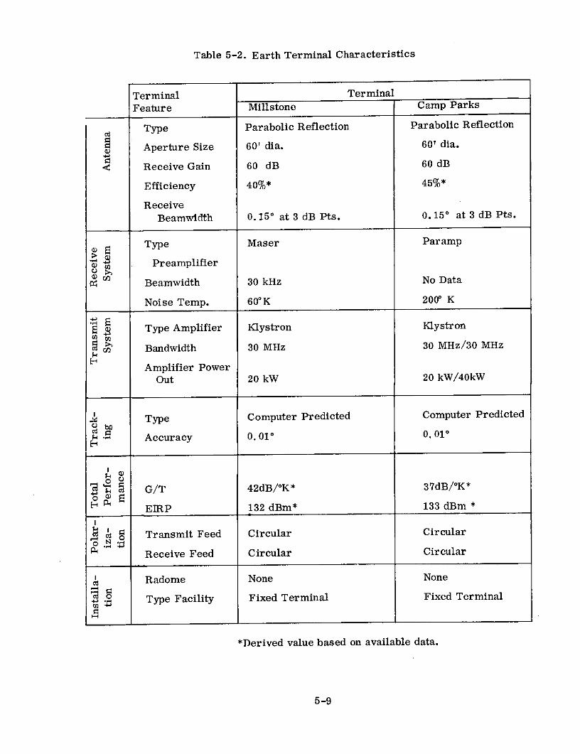
Table 5-2. Earth Terminal Characteristics
Terminal Terminal
Feature Millstone Camp Parks
Type Parabolic Reflection Parabolic Reflection
Aperture Size 60' dia. 60' dia.
- Receive Gain 60 dB 60 dB
Efficiency 40%* 45%*
ReceiveBeamwidth 0.150 at 3 dB Pts. 0.150 at 3 dB Pts.
Type Maser Paramp
"$ Preamplifier
M Beamwidth 30 kHz No Data
Noise Temp. 60 0 K 200" K
Type Amplifier Klystron Klystron
Bandwidth 30 MHz 30 MHz/30 MHz
Amplifier Power
Out 20 kW 20 kW/40kW
WType Computer Predicted Computer Predicted
Accuracy 0.010 0.010
SG/T 42dB/OK* 37dB/°K*
EIRP 132 dBm* 133 dBm*
Transmit Feed Circular Circular
Receive Feed Circular Circular
Radome None None
Type Facility Fixed Terminal Fixed Terminal
*Derived value based on available data.
5-9

Measurements of the orbit parameters verified the important predictions about
orbital vehavior, as, for example, the smoothing of the distribution of the dipoles around
the orbit from the initial high-peaked cluster at the dispenser. In measuring orbital
parameters, rms deviations normal to the orbital plane averaging 7.5 km and rms
deviations in geocentric radius averaging 9.5 km were observed. The average nodal
period during the first 720 revolutions (the first 80 days of belt life) was found to be
166.455 minutes. From this nodal period the average semimajor axis during this
interval was computed to be 1.57 earth radii.
All three physical measurement approaches were employed in determining belt
dimensions. Typical results of these measurements are summarized in Figure 5-3.
In this figure, perigee and semi-latus-rectum points are marked and each point on the
chart indicates the data sources, the 3-dB in-plane dimension and, except for the
inferences from doppler measurements, the 3-dB out-of-plane dimension. Experimental
estimates of the number of dipoles in orbit indicated that between 16 and 39 percent of
the ejected dipoles were properly dispensed. It also appeared that occasionally more
than one center of density developed, so that two closely spaced dipole belts were
present. This situation is depicted in Figure 5-4.
Measurement of the propagation characteristics of the belt was one of the goals
of the second experimental program. The dipole belt provided a channel in which sig-
nals were communicated from one point to another by scattering from a large number
of dipoles in a volume of space defined by the intersection of two antenna beam patterns
with the belt. Each dipole behaves like an independent scatterer, and consequently
the received signal at any given time is the sum of the signals scattered by a large
number of dipoles. The fact that the dipole scatters are not concentrated at a single
point influences the performance of the system in detail. Specification of the received
signal-to-noise ratio is not sufficient to characterize a spread channel such as the
orbital dipole belt. The minimum additional information that is required to give an
adequate description of the communications performance is knowledge of two
parameters - multipath spread (L) and doppler spread (B) - which are measures of
5-10

80 ---- INSUFFICIENT DATA
DAYSAFTER
60 - EJECTION
40
W 40 -
0
20 25
132
-80 -60 -40 -20 0 20 40 60 80TIME FROM MAXIMUM DENSITY (min)
A 8.0 A-120 -I'A A
I1.I*A A I
t n _ 376-80- 13.7 11.7 12.4 A u
14.8 14.6
-40 42.6 B- 40 1
CC C 95
0 _____ 16.3
3 2230 4 256 82
B
80- 222 Bo- --------------- 37 172 B--
40 km OUT-OF-PLANE 322 + "
120- 40 km IN-PLANE 22.6 25.2
0 40 80 120 160 200 240DAYS AFTER EJECTION
Figure 5-3. In-Plane and Out-of-Plane Belt Demensions vs Time.A = Monostatic Radar Data. B = Bistatic Radiometric Data. C =Inference from Bistatic Doppler Data. u-w = Angle from Perigee.
5-11
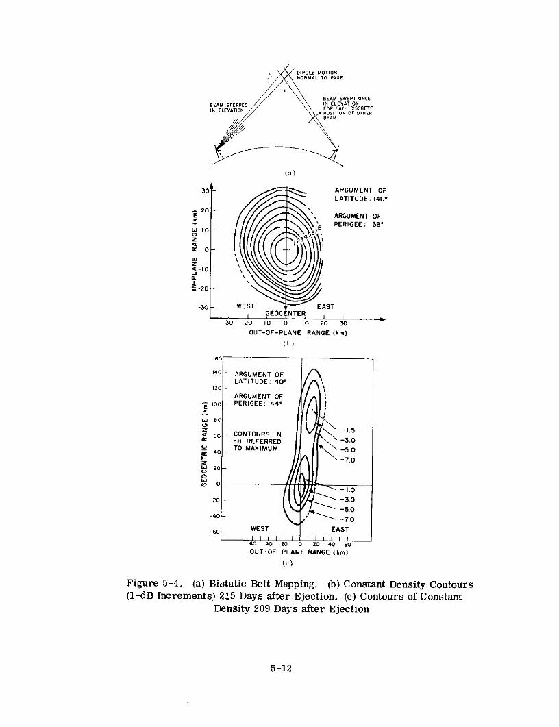
DIPOLE MOTIONNORMAL TO PAGE
BEAM SWEPT ONCEBEAM STEPPED IN ELEVATIONIN ELEVATION FOR EACH DISCRETE
POSITION OF OTHERBEAM
30- ARGUMENT OFLATITUDE: 140*
S20 •E 2 ARGUMENT OF
L PERIGEE: 38'w 10 8
Z 23 1
wz-Ja.
t -20 -
-30 WEST EASTI I GEOC NTER I I30 20 10 0 10 20 30
OUT-OF-PLANE RANGE (km)(h)
160
140 ARGUMENT OFLATITUDE: 40*
120 -
ARGUMENT OF100oo PERIGEE: 44*
w 800
Z -I.5< 60 - CONTOURS IN
dB REFERRED -3.0TO MAXIMUM -5.04400 2 0 0
F- -7.0Dw 20-o
-1.0
-20 - -3.0
-5.0
-60 WEST EAST
60 40 20 0 20 40 60OUT-OF-PLANE RANGE (km)
Figure 5-4. (a) Bistatic Belt Mapping. (b) Constant Density Contours(l-dB Increments) 215 Days after Ejection. (c) Contours of Constant
Density 209 Days after Ejection
5-12

the channel spreading in the time and frequency domains, respectively. If the time
and frequency behavior of a dispersive medium is sufficiently well- behaved, the two
parameters B and L are an adequate description for the purpose of signal design.
A more complete description of the dipole belt is furnished by the so-called scattering
function of the medium. This is a function cr of the two variables, time ' and
frequency f , and designates the scattering cross-section of the medium at propaga-
tion delay T and doppler shift f . The scattering function of a dispersive channel,
together with the spectrum of the additive noise component, constitutes a model of the
channel that is sufficiently detailed to allow synthesis of optimum signals and detect-
ions and to permit comparative performance of signaling schemes.
The multipath and doppler spreads and path losses as measured by these
techniques are summarized in Table 5-3. The strongest overall conclusion of the
propagation experiment is that the scattering function is generally well-behaved.
Table 5-3. West Ford Dipole Belt: Channel Characterization
Date of Doppler t Path Loss Angle re
Experiment* Spread B B X L (dB) Perigee
(eps) (deg)
May 20 630 .031 203 138
May 29 680 .034 207 115
June 19 1600 .080 209 100
July 12 1800 .090 212 82
Sept. 24 2300 .11 215 77
Nov. 13 1200 .060 221 69
Nov 8 960 .048 221 27
Dec. 5 1070 .054 222 2
*Date of ejection,tL = 50 sec (3-db width)
5-13

The second objective in the study of the dipole belt as a communications medium
was the achievement of actual communication in the absence of detailed knowledge of
the scattering function. Thus, the purposes of the communications experiment were
the transmission of digital data, the measurement of the performance of the system,
and the comparison of these results with theory. The basic communications technique
employed was binary frequency shift keying (FSK) with quadrature, full-wave, square-
law detection as indicated in Paragraph 5.2. In order to cope with intersymbol inter-
ference due to the dispersive nature of the channel, successive transmissions used
different frequency pairs and were detected in separate receivers operating in parallel.
Two message sources were available to the transmitter: a fixed word repetition and a
standard 60-wpm teletype. In addition, a digitized PCM system was constructed to pro-
vide voice communication in the early stages of the experiment.
On May 14 and 15, speech was transmitted using the PCM system. The received
speech was intelligible and its general quality varied as the PR/No ratio fluctuated
about a mean of about 53 dB. Between May 14 and June 18, eight communications
experiments were performed. This covered the period of time from shortly
after initial dispensing to roughly closure time. During all the experiments, therefore,
the belt was incomplete and in each run that portion of the belt spanning the central
densest spot was employed. The experimental results were generally in fairly good
agreement with the theory. For the most part, the theory overbounded the actual error
probability at most by a factor of 2. In summary, the performance of the data comm-
unications system was found to be in substantial agreement with a theory which
assumed the use of an optimum receiver. This is consistent with the above result
that the scattering function was adequately described by the two parameters B and L,
since the signals were designed under that assumption.
5.6 OPERATIONAL RESULTS
No operational traffic was carried by this experimental system. The operation-
al reliability of the space subsystem was quite high due to its passive nature.
Finally, the operational performance of the earth terminals employed in the experi-
ments was good, as expected.
5-14

References
1. C. F. J. Overhage and W. H. Radford, "The Lincoln Laboratory West Ford
Program - An Historical Perspective, " Proc. IEEE, Vol. 52, No. 5,pp. 452-454 (May, 1964).
2. J. W. Findlay, "West Ford and the Scientists, " Proc. IEEE, Vol. 52,
pp. 455-460 (May, 1964).
3. W. E. Morrow, Jr. and T. F. Rogers, "The West Ford Experiment - An
Introduction to this Issue," Proc. IEEE, Vol. 52, No. 5, pp. 461-468 (May, 1964).
4. I. I. Shapiro et. al., "Orbital Properties of the West Ford Dipole Belt," Proc. IEEE,
Vol. 52, No. 5, pp. 469-518 (May, 1964).
5. F. E. Heart et. al., "Measured Physical Characteristics of the West Ford Belt,"Proc. IEEE, Vol. 52, No. 5, pp. 519-533 (May, 1964).
6. C. L. Mack, Jr. and B. Reiffen, "RF Characteristics of Thin Dipoles, " Proc. IEEE,
Vol. 52, No. 5, pp. 533-542 (May, 1964).
7. I. L. Lebow et. al., "The West Ford Belt as a Communications Medium, " Proc.
IEEE, Vol. 52, No. 5, pp. 543-563 (May, 1964).
8. D. C. MacLellan et. al., "Effects of the West Ford Belt on Astronomical Observa-
tions," Proc. IEEE, Vol. 52, No. 5, pp. 564-570 (May, 1964)
9. P. Waldron et. al., "The West Ford Payload, " Proc. IEEE, Vol. 52, No. 5,pp. 571-576 (May, 1964).
10. B. E. Nichols and D. Karp, "West Ford Radar and Microwave Equipment, " Proc.
IEEE, Vol. 52, No. 5, pp. 576-588 (May, 1964).
11. B. F. LaPage et. al., "West Ford Antenna and Feed System, " Proc. IEEE, Vol. 52,
No. 5, pp. 589-598 (May, 1964).
12. F. E. Heart and A. A. Mathiasen, "The Antenna Pointing System for West Ford, "Proc. IEEE, Vol. 52, No. 5, pp. 599-606 (May, 1964)
13. "Significant Achievements in Space Communications and Navigation 1958-1964, "NASA SP-93, National Aeronautics and Space Administration, Washington, D. C.,1966.
14. "Review of the West Ford Communications Experiment, " IG Bulletin No. 86,August, 1964, Transactions American Geophysical Union, September, 1964.
15. "DOD-NASA Review of Communications Satellite Technology", Burke, J. R. andKaiser, J., IDA/HQ 63-1870, Institute for Defense Analyses, Washington, D. C.September, 1963.
16. "Project West Ford - A Feasibility Study of Orbital Scatter Communication,"Massachusetts Institute of Technology, Lincoln Laboratory, Lexington, Massachusetts,March 27, 1964.
5-15

17. "Report on the Optical and Radio Astronomical Effects of the Project West Ford
Experiments, " National Academy of Sciences National Research Council,
Space Science Board, February 7, 1964.
18. "WestFord Dipole Belt: Optical Detection at Palomar, " Sandage, A., andKowal, C., Science, Vol. 141, No. 3583.
19. "West Ford Dipole Belt: Photometric Observations," Tifft, W. G., Sinton, W. M.,and Priser, J. B., Science, Vol. 141, No. 3583, 1963.
20. "Optical Effects of the 1963 Project West Ford Experiment", Liller, W., Science
Vol. 143, No. 3605, January 31, 1964.
21. "The Case for the Needles Experiment," Purcell, E. N., New Scientist, Vol. 13,No. 272, February 1, 1962.
22. Statement of Radford, W. H., Dinneen, G. P.. Morrow. Jr.. W. E.. andRichmond, A. S., of Massachusetts Institute of Technology, in Hearing on SatelliteCommunications before a Subcommittee of the Committee on Government Operations,House of Representatives, Eighty-eighth Congress, Second Session, April 7, 1964.
23. "Satellite Communications (Military-Civil Roles and Relationships), Report by theMilitary Operations Subcommittee of the Committee on Government Operations,October, 1964.
24. "Satellite Communications: Six Years of Achievement 1958 through 1964", Jaffe, L.,NASA, Washington, D. C., March 1, 1965.
25. "Orbital Scatter Communications," Morrow, Jr., W. E., MS-105, paper presentedat URSI Meeting, London, September, 1960.
26. "Communications by Orbiting Dipoles, " Morrow, Jr., W. E., MS-346, paperpresented at URSI Meeting, Paris, France, September 1961.
27. "Technical Problems Associated with Communications Satellites, " Stanford ResearchInstitute, Final Report on NASR-49(08), Part C - Interference to Optical Astronomyfrom Earth Satellites, October, 1963.
28. "West Ford Point Selection Program," Prinan, J. D., Lincoln Lab, MassachusettsInstitute of Technology, Lexington, Massachusetts, Report No. 21G0025, December 21,1960, AD 432-786.
29. "Revision of West Ford TTY Checking Program, " Prinan, J. D., MIT Report No.21G-0022, Supp. 1, AFESD TDR 62-122, August 2, 1962, AD 283-778.
30. "Optical Brightness of the West Ford Experiment," Liller, W., Nature, Vol. 200,October 26, 1963, A64-10907.
31. "The West Ford Antenna Feed System, " Niro, L., MIT Technical Report No. 259,AFESD TDR 62-111, March 5, 1962, AD 282-311.
5-16

SECTION 6 - TELSTAR
6.1 PROGRAM DESCRIPTION
The Telstar program was conceived by Bell Telephone Laboratories for the
primary purpose of demonstrating the feasibility of employing orbiting satellites
for commercial communication purposes. Specifc objectives were as indicated in
Table 6-1. (1)(2)(3)
Table 6-1. Telstar Program Objectives
Number Description
1 Demonstrate broadband transmission through communication
satellites.
2 Test operational communications satellite reliabilities.
3 Obtain operational experience with satellite ground terminals.
4 Increase knowledge of satellite tracking techniques.
5 Provide scientific measurements of radiation in space.
Two active spacecraft, Telstar I and Telstar II, were successfully launched
into medium altitude elliptical orbits during the course of the program as indicated
by Table 6-2. (1)(2) Numerous communication demonstrations and detailed
experiments were successfully conducted with Telstar I during its 7-month lifetime
and considerable data on radiation in the inner Van Allen belt obtained. Before
Telstar I finally failed from higher than expected radiation (which had resulted from
the high altitude nuclear tests), an initial malfunction of the command circuit was
successfully diagnosed from the ground and the satellite was commanded back "on."
This ground diagnosis represented a first in satellite communications. Program
6-1

objectives were for the most part met in the Telstar I experiments. Telstar II,
launched after the failure of Telstar I, extended the previous experiments and
demonstrations.
Table 6-2. Participating Spacecraft
Satellite Telstar I Telstar II
Manufacturer & Sponsor Bell Labs and AT&T
Launch Date 7/10/62 5/7/63
Launch Vehicle Delta
Apogee (Mi.) 3514 6713
Perigee (Mi.) 592 604
' Inclination 44. 80 42. 70
Period (Min.) 158 225
Status Failed 2/63 due to Transmittedradiation damage to untilcommand decoders. 6/65
Major earth terminals participating in the program are shown in
Table 6-3. (1) (2) (4-7) Satellite launchings and the collection of tracking and telemetry
data through a worldwide network of Minitrack stations were provided by the National
Aeronautics and Space Administration (NASA).
Probably the most important contribution of Project Telstar, to satellite
communications technology, was to publicize, through numerous television
demonstrations, that orbiting satellites were feasible for use in commercial
communication systems. From a purely technical viewpoint, one of the most
important achievements was to confirm (in basic agreement with Echo I experience)
that standard transmission parameters could be employed to predict performance with
no concern about multipath fading for frequencies approaching 4 to 6 GHz and
6-2

ground antenna elevation angles greater than a few degrees. A second technical
achievement of major importance was to demonstrate further that acquiring and
tracking a moving satellite was not an overly demanding assignment for a narrow-
beam communications antenna equipped with an autotrack system.
Table 6-3. Participating Earth Terminals
Antenna Diam- Date ofLocation Sponsor eter (Ft.) Installation
1. Andover, Maine AT&T 67.7 1962
2. Holmdel, N. J. AT&T 20 ft. x 20 ft. 1962
3. Pleumeur Bodou, French Nat'l. Center 67. 7 1962France for Telecommunications
Studies (CNET)
4. Goonhilly Downs, British General Post 85 1962England Office
5. Fucino, Italy Telespazio 30 1962
6. Raisting, Deutsch Bundespost 30/82 1963/1964Germany
*Existing terminal with receiver modified for use with Telstar. Terminal employeda pyramidal horn reflector.
6.2 SYSTEM DESCRIPTION
The Andover terminal was the principal terminal involved in the experiments
performed, with many of them being conducted on a loop-back basis. Major
demonstrations were performed over a link between Andover and terminals in
Europe or at Holmdel.
The satellite orbits, described in Table 6-2, were in agreement with plans
to provide the maximum realizable visibility per day and per pass while employing
6-3
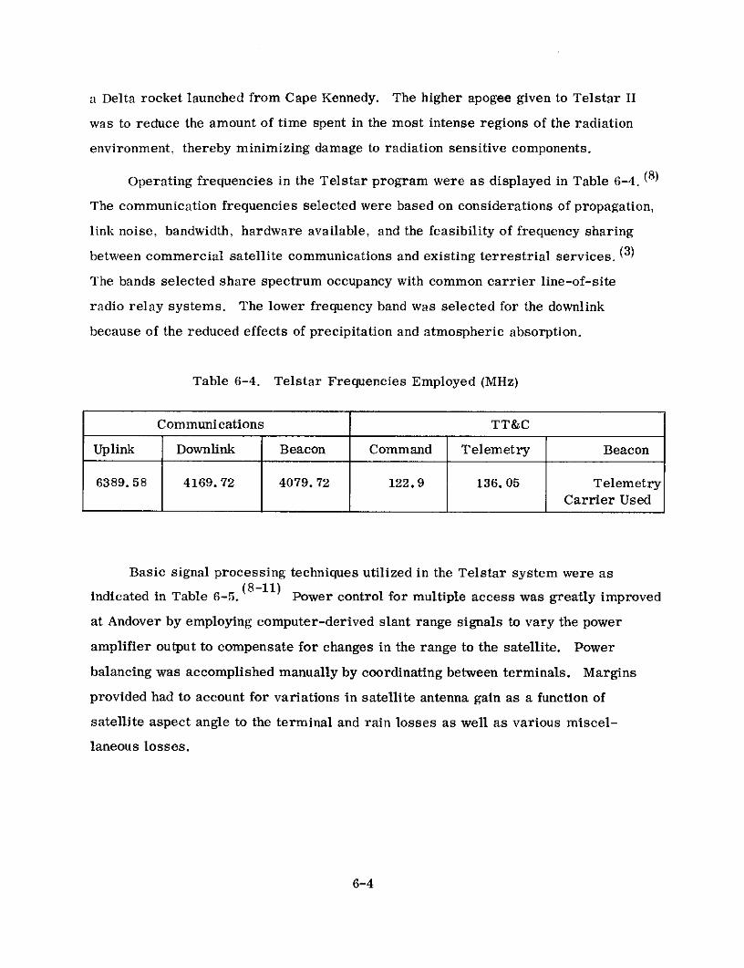
a Delta rocket launched from Cape Kennedy. The higher apogee given to Telstar II
was to reduce the amount of time spent in the most intense regions of the radiation
environment, thereby minimizing damage to radiation sensitive components.
Operating frequencies in the Telstar program were as displayed in Table 6-4. (8)
The communication frequencies selected were based on considerations of propagation,
link noise, bandwidth, hardware available, and the feasibility of frequency sharing
between commercial satellite communications and existing terrestrial services. (3)
The bands selected share spectrum occupancy with common carrier line-of-site
radio relay systems. The lower frequency band was selected for the downlink
because of the reduced effects of precipitation and atmospheric absorption.
Table 6-4. Telstar Frequencies Employed (MHz)
Communications TT&C
Uplink Downlink Beacon Command Telemetry Beacon
6389. 58 4169. 72 4079. 72 122.9 136. 05 TelemetryCarrier Used
Basic signal processing techniques utilized in the Telstar system were as
indicated in Table 6-5. (8-11) Power control for multiple access was greatly improved
at Andover by employing computer-derived slant range signals to vary the power
amplifier output to compensate for changes in the range to the satellite. Power
balancing was accomplished manually by coordinating between terminals. Margins
provided had to account for variations in satellite antenna gain as a function of
satellite aspect angle to the terminal and rain losses as well as various miscel-
laneous losses.
6-4

Table 6-5. Signal Processing Employed
Multiple Access Frequency division for up to two carriers to support duplex
operation
RF Modulation FM
Demodulator Conventional Discriminator - Threshold at about 10 dB C/N
Performance FMFB Receiver - Threshold at about 5 dB C/N
Andover Receive 13. 6 dB * for maximum slant range, ** 7.50 antenna
Carrier-to-Noise elevation angle, 1 satellite access, and 25-MHz noise
(C/N) bandwidth
Andover Receiver Conventional Discriminator - 3. 6 dB
Margin FMFB Receiver - 8.6 dB
*Includes 0. 4-dB radome loss.
**Approximately 5, 700 mi.
6.3 SPACECRAFT
Satellite characteristics for Telstar I and II are displayed in Table 6-6. (12-15)
The communications repeater in both satellites was as illustrated in Figure 6-1. The
basic repeater design reflects the desire to employ established technology to ensure
reliability. Most of the repeater is in broad principle similar to equipment used
earlier in land-based microwave systems. Storage batteries and a capability to
command equipment "on" and "off'' allowed utilizing a solar array too small to meet
real-time power demands but within weight limitations. Spin stabilizing relative to
the sun reduced temperature equalization and solar array illumination problems.
However, it made the selection of an essentially omnidirectional antenna necessary.
6-5

fr ft6389.58MC 4169.72 MC
NOTE: CIRCLED NUMBERS SHOWPOWER LEVELS IN DBM fo
4079.73MC
AGC MONRTOR 4t CIE
r------- ------ fo D
DC I
AMPLIFIER I TRAVELING-PRE- WAVE
AMPLIFIER AMPLIFIER TUBE
DOWN VARO- UP T COMBINING - SEPARATIONCONVERTER 5SER CONVERTER FILTER FILTER
38-DBGAINE I rF AMPLIFIER
6299.58 MC 90.00 P25MC
FILTER
BEAT IOSCILLATOR 4079.73MC LIMITER oMODULATOR 4079.73 MC4079.73 MC
3DBCOUPLER
2219.85MC
Figure 6-1. Satellite Repeater
6-6

Table 6-6. Telstar I and II Characteristics
C Band with separate multi- VHF quadrafiler
Type port xmit. & rec. girding S/C Helix for TT&Cequator
Number One One
About 1200 centered on S/C Essentially Omni-Beamwidth equator* directional
Gain 0 dB 0 dB
Frequency Band C Band
Type IF translating with AGC of IF stage
Bandwidth 50 MHz at 1-dB points
Number One
P Type Front End Down Conversion Mixer
. Front End Gain 7-dB conversion loss into 87 dB ** IF
Sys. Noise Fig. Overall - 12.5 dB. 20 MHz centered on carrier -
16.5 + 2 dB
Type Single 6-watt TWT
Gain 37. 5 dB as operated
Power Out 3. 5 watt as operated
EIRP - C Band Ant. 33 dBm for 1 carrier
Type Spin with magnetic torquing coil
Capability Unoriented relative to earth
U) Normal 90' spin axis aspect to sun
$ Primary Solar array with 14 watts*** average output
Supplement**** Nickel cadmium batteries giving about 35 watts
6 Comm. Power Needs 19 watts maximum including beacon
8 Size Spherical with 34. 5 in. diameter
Weight 175 lbs
* Pattern reasonably uniform with smooth dropoff to 6 dB
down over + 60 ° from spacecraft (S/C) equator. Deep nulls
beyond this.** Nominal gain varied by AGC.
*** At launch.
•*** Furnishes power during peak loads and eclipses.
6-7
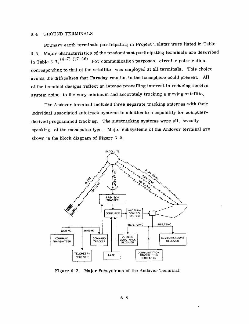
6.4 GROUND TERMINALS
Primary earth terminals participating in Project Telstar were listed in Table
6-3. Major characteristics of the predominant participating terminals are described
in Table 6-7. (4-7) (17-26) For communication purposes, circular polarization,
corresponding to that of the satellite, was employed at all terminals. This choice
avoids the difficulties that Faraday rotation in the ionosphere could present. All
of the terminal designs reflect an intense prevailing interest in reducing receive
system noise to the very minimum and accurately tracking a moving satellite.
The Andover terminal included three separate tracking antennas with their
individual associated autotrack systems in addition to a capability for computer-
derived programmed tracking. The autotracking systems were all, broadly
speaking, of the monopulse type. Major subsystems of the Andover terminal are
shown in the block diagram of Figure 6-2.
SATELLITE
6 -
4079.73MC 416972 MC
TRANSMITTER TRACKER RC RECEVER
COMPUTER CONTROL
TEL E M E T R Y COMMUNICATION
RECE TRANSMITTER
Figure 6-2. Major Subsystems of the Andover Terminal
6-8

Table 6-7. Characteristics of Major Earth Terminals
TERMINAL
TERMINALFEATURE ANDOVER* HOLMDEL GOONHILLY DOWNS
Type Conical Horn Reflector Pyramidal Horn Reflector Parabolic Reflector
< Aperture Size 67.7 ft. Dia. 20 ft. x 20 ft. 85-ft. Dia.Z ---- - -------- ---------------------- -- -- --Receive Gain 58 dB 48 dB 55.6 dB
z Efficiency 70 - 75% 70 - 75% Approx. 30%
Rec. Beamwidth 0.230 @ 3 dB Pts. 0.780 @ 3 dB Pts. 0.20 @ 3 dB Pts.
w 2 Type Preamplifier Traveling Wave Ruby Maser Maser Traveling Wave Maser---- ---------.- - - - - - - - - - -
I- Bandwidth 25 MHz @ 3 dB Pts. 20 MHz @ 1 dB Pts. 25 MHz @ 3dB Pts.Lu - - ---------------------------- ---------- ----------
c- n Noise Temp. 32 0 K * * @ 900 El. 170 K @ 900 El. 55 0 K @ 900 El.
2 Type Amplifier Traveling Wave Tube Traveling Wave Tube
cn Bandwidth 32 MHz @ 1 dB Pts. No Transmissions Employed 100 MHz @ 3 dB Pts.
cc Amp. Pwr. Out 2 kW 5 kW
0 Type Autotrack by Command Predicted Look Angles plus Programming Trackingz Tracker, Precision Tracker, Manual Correction of Errors
or Vernier Tracker by Detected on Separate 18-ft.< Separate Antenna. Dish Tracker.r---- - -- -- ------------------------------ - -- -- -- -
I- Accuracy Command Track ±10 As good as ±0.050 can be Approximately 0.10Precision Track +.010 obtained.Vernier Track ±.0050
u
Z G/T 40.7 dB/oK 36 dB/oK 38 dB/oK------------------ ---- -- -- ----- -- -- -----------------
0OI- u EIRP 123 dBm None Approx. 123 dBm
a-
0Transmit Feed Circular Circular Circular
N
Receive Feed Circular Circular CircularO
2 Radome 210-ft. Diameter None NoneSPressurized to
-J 0.175 Ib/in. 2
- -~-- -- -- -- -- -- -- -- -- -- -- -------- - -- -- -- -
Type Facility Fixed Terminal Fixed Terminal Fixed Terminal
*The terminal at Pleumeur Bodou has essentially the same characteristics.**The noise temperature at a 7.50 elevation angle is about 50 0 K.
6-9

The Holmdel terminal, originally built for Project Echo, included a glint
telescope to determine the orientation of the satellite's spin axis and the spin rate.
Determinations were made by observing the flashes of sunlight reflected from the
three mirrors mounted on the satellite's surface.
6.5 EXPERIMENTS
The experiments conducted on the Telstar project can be grouped into four
major categories as displayed and defined in Table 6-8. The radiation experiments,
described in the table, contributed considerable data towards characterizing the
particles within the inner and outer Van Allen belts. Additionally, valuable
knowledge of the effects of radiation upon solid-state devices (i. e., upon solar cells
and transistors) was gained. The most spectacular radiation experiment result,
however, was the discovery, from the data on Telstar I, that high altitude nuclear
testing dramatically intensified the radiation environment in the Van Allen
belts. (2)(27)
The space experiments, defined in Table 6-8, monitored such items as
attitude of the spacecraft spin axis in inertial space, spin rate, temperatures at
the spacecraft surface and of critical internal components, satellite RF power
levels, and variations in spacecraft circuitry and components. Changes in spin
axis attitude, due to the residual magnetic moment of the spacecraft, were
recorded. Spin rate decay, resulting from eddy currents generated in the satellite
as it rotates in the earth's magnetic field, was observed. The decay was greater
on Telstar I because of its lower orbit. Skin temperatures varied between about
-150F and 40 0F.
6-10

Table 6-8. Summary of Program Activities
Type ProgramActivity Objective Nature of Activity
Satisfied
1. Radiation 5 Measure electron and proton spectrums**Experiments and spatial distributions as a function of
time. Evaluate radiation damage to solidstate devices as a function of shielding.
2. Space 2 Measure spacecraft performance underExperiments launch and space stresses.
3. Communication 1 Display broadband transmissions byDemonstrations satellite comparable to conventional
commercial transmissions.
4. Communication 1 Evaluate technical performance of broad-Experiments band satellite communications.
* Program objectives are numbered and defined in Table 6-1.** Radiation spectrums characterize the number of particles per unit volume
as a function of particle energy level.
Internal temperatures varied between about 60°F and 80 0F. The radiated RF
power was observed to remain constant as a function of time. The only significant
changes observed in circuitry or components were a degradation of solar cell output
and the failure of several transistors within the command decoder of Telstar I.
Both of these changes were a result of the radiation encountered.
The communication demonstrations, mentioned in Table 6-8, included a
variety of tests whose descriptions and results are indicated in Table 6-9. (29)(30)
More than 400 demonstrations were conducted in the Telstar program. (31)
6-11

Table 6-9. Telstar I and II Communication Demonstrations
Type Demonstration Nature of Results Obtained
1. One-way monochrome Highly successful. Some loss of picture definitionTV due to baseband bandwidth limitations* in ground
terminals. At maximum range, weighted signal-to-noise somewhat less than for normal BellSystem commercial service. Transients fromcamera switching at originating studios causednoise bursts in received signals.
2. One-way color TV** With no audio transmitted"* and spacecraft atshort to moderate ranges, high quality pictureswere obtained.
3. Two-way monochrome Audio signals transmitted in both directions withTV definite reduction in quality. Picture quality
about 20 dB**** poorer than for one-way trans-missions.
4. One-way 600 telephone Amount of noise in poorest telephone channelchannels about 6 dB more t than for CCIR commercial
grade circuits.
5. Two-way 12-channel Poorest channel typically had noise performancetelephony about equal to that for 600 telephone channel
transmissions. Crosstalk between carriers wasno problem.
6. High- and low-speed Data rates from those for 60-wpm teletypewriterdata including facsimile signals to 875 kbps were tried. Test results
satisfactory to excellent compared to resultsobtainable on a 4000-mile microwave radio relaysystem. Changes in absolute time delay causedsome timing problems for high-speed data andfacsimile. Doppler shift caused some distortionin low-speed data signals.
Notes: * Filtered to about 2 MHz to allow audio signal to frequencymodulate a 4.5-MHz aural subcarrier.
** A color program demonstration with audio was conducted inearly January 1963 in which the audio modulation was insertedduring the time interval reserved for horizontal blanking.
*** No baseband filter employed.**** About 16 dB of degradation due to reducing peak frequency
deviations from 7 MHz to 1 MHz. Remaining degradation fromreduced satellite transmitter power per carrier.
t When satellite is at maximum range.
6-12

The communication experiments, noted in Table 6-8, are defined in detail
in Table 6-10. (29)(30)(8) This table includes the general results obtained. In
considering received carrier power fading measurements, note that the horizons
at Andover and Goonhilly are at about 20 and 0. 5° in elevation, respectively. Most
of the impairments to signal transmission were determined to be caused by the
ground terminals. In addition to the tests mentioned in Table 6-10, a time syn-
chronization test was conducted. (29) Precision atomic clocks in the USA and UK
were compared by transmitting pulses simultaneously in both directions. The
accuracy of the method was believed to be about 20 pss and a difference in clock
time of 2 milliseconds was found.
6.6 OPERATIONAL RESULTS
No operational traffic was handled during this program due to its experimental
nature. However, the operational performance of the system, as the various
experiments were conducted, was of considerable interest as indicated by Program
Objectives 3 and 4 listed in Table 6-1. Operational performance of the two
satellites was as discussed in the description of program experiments in Paragraph
6. 5. The ground complex operations displayed that satellite communications ground
terminals of satisfactory reliability to provide continuous commercial service were
feasible. The performance demonstration included showing a capability for
dependable satellite acquisitions and accurately tracking moving satellites.
Satellite tracking turned out to be less difficult than expected and special purpose
tracking antennas were determined not necessary. Perhaps the most spectacular
ground operational result was produced by the malfunction of the command circuit on
Telstar I on November 24, 1962. (32) Subsequent ground diagnosis and attempts to
revive the spacecraft resulted in its being successfully commanded "on" again on
January 3, 1963. This was a first in satellite communications. The ability to
devise revised command signals to bypass radiation damaged transistors in the
command decoder were instrumental in the successful results obtained.
6-13

Table 6-10. Telstar I and II Communication Experiments
Type Experiment Nature of Results Obtained
1. Received Carrier Power Measured values, in general, agreed with pre-dicted values when range and spin axis aspectangle of satellite are taken into account. Varia-tions in received power clearly showed satelliterotation, changes in aspect angle and changes inrange. No noticeable multipath fading observedat Andover for elevation angles above about 40or at Goonhilly for elevation angles above about3.
2. Frequency Baseband response essentially flat up to 5 MHz
Responses when conventional FM receiver was used. ForFMFB receiver response flat up to 3 MHz. Allof response limitations appeared to be due toground terminal equipment employed.
3. Noise Baseband noise performance, for various signalsemployed, defined in Table 6-9. Measurementsfor impulse noise indicated only random thermalnoise present. Satellite repeater noise spectrumon Telstar I observed to display considerablepeaking around communications carrier fre-quency. This gives effective noise figure over20 MHz of about 16.5 dB ±2 dB.
4. Amplitude and Phase Measurements of envelope delay, differentialDistortion gain and phase, and intermodulation noise taken.
Performance measured for television and 600-channel telephony indicate objectives* for thesemeasurements met. Additionally, no audio tovideo crossmodulation interference observedand video to audio crossmodulation not signifi-cant.
5. Doppler Shift Measured and calculated curves of Doppler shiftagreed within 1 kHz over period of about 45 mins.
6. Absolute Delay Measured and calculated delay agreed withinabout 20 psec.
* Objective for intermodulation noise is maximum 36 dBrn total at 0-dB trans-mission level divided among various sources. Delay distortion objectivecorresponds to a differential phase of 4. 2, which is within 5° requirement forN. T. S. C. color television.
6-14

CITED REFERENCES
1. "Significant Achievements in Space Communications and Navigation,
1958-1964, " NASA SP-93, National Aeronautics and Space Administration,
Washington, D. C., 1966.
2. Staff of Bell Telephone Laboratories, "Project Telstar, " in Telecommuni-
cations Satellites, K. W. Gatland, Editor, Prentice-Hall Inc., Englewood
Cliffs, New Jersey, 1964.
3. I. Welber, "Telstar, " Astronautics and Aerospace Engineering, September.
1963.
4. W. J. Bray, "Prospects for Europe: The United Kingdom Ground Station
and the Telstar and Relay Tests and Demonstrations, " in Telecommunications
Satellites, K. W. Gatland, Editor, Prentice-Hall Inc., Englewood Cliffs,
New Jersey, 1964.
5. Capt. C. F. Booth, "Project Telstar, " Journal IEE, April, 1963.
6. W. C. Jakes, Jr., "Participation of the Holmdel Station in the Telstar
Project, " NASA SP-32, Vol. 2, National Aeronautics and Space Administration,
Goddard Space Flight Center (NASA/GSFC), June, 1963.
7. "Project Telstar - Fucino Earth Station Operational Analysis, " NASA SP-32,
Vol. 4, NASA/GSFC, December, 1965.
8. D. F. Hoth, E. F. O'Neill, and I. Welber, "The Telstar Satellite System, "
NASA SP-32, Vol. 1, NASA/GSFC, June, 1963.
9. A. J. Giger, S. Pardee, and P. R. Wickliffe, "The Ground Transmitter
and Receiver," NASA SP-32, Vol. 1, NASA/GSFC, June, 1963.
10. S. B. Bennett, and L. C. Thomas, "The Telstar Communications Satellite
Experiment Plan, " IEEE Transactions on Communications and Electronics,January, 1964.
11. A. J. Giger, and J. G. Chaffee, "The FM Demodulator with Negative
Feedback, " NASA SP-32, Vol. 1, NASA/GSFC, June, 1963.
12. R. H. Shennum, and P. T. Haury, "A General Description of the Telstar
Spacecraft, " NASA SP-32, Vol. 1, NASA/GSFC, June, 1963.
6-15

13. H. J. Maunsell and J. W. Stafford, "Telstar Design and Construction andEarly Results of the Scientific Space Experiments, " IEEE Transactions onCommunications and Electronics, January, 1964.
14. D. C. Bomberger, D. Feldman, D. E. Trucksess, S. J. Brolin andP. W. Ussery, "The Spacecraft Power Supply System, " NASA SP-32,Vol. 1, NASA/GSFC, June, 1963.
15. C. G. Davis, P. T. Hutchison, F. J. Witt and H. 'J. Maunsell, "TheSpacecraft Communications Repeater, " NASA SP-32, Vol. 1, NASA/GSFC, June, 1963.
16. M. G. Bodmer, J. P. Laico, E. G. Olsen, and A. T. Ross, "The SatelliteTraveling - Wave Tube, " NASA SP-32, Vol. 3, NASA/GSFC, June, 1963.
17. A. J. Giger, S. Pardee, Jr., and P. R. Wickliffe, Jr., "The GroundTransmitter and Receiver, " NASA SP-32, Vol. 1, NASA/GSFC, June, 1963.
18. J. N. Hines, Li Tingye and R. H. Turrin, "The Electrical Characteristicsof the Conical Horn-Reflector Antenna, " NASA SP-32, Vol. 2, NASA/GSFC,June. 1963.
19. J. A. Githens, H. P. Kelly, J. C. Lozier and A. A. Lundstrom, "AntennaPointing System: Organization and Performance, " NASA SP-32, Vol. 2,NASA/GSFC, June, 1963.
20. J. S. Cook and R. Lowell, "The Autotrack System, " NASA SP-32, Vol. 2,NASA/GSFC, June, 1963.
21. J. V. Anders, E. F. Higgins, Jr., J. L. Murray and F. J. Schaefer, Jr.,"The Precision Tracker, " NASA SP-32, Vol. 2, NASA/GSFC, June 1963.
22. W. J. Bray and F. J. D. Taylor, "The Post Office Satellite CommunicationsSystem Ground Station at Goonhilly, Cornwall, " NASA SP-32, Vol. 4, NASA/GSFC, December, 1965.
23. C. N. Kington, "The Goonhilly 85-ft. Steerable Dish Aerial, " NASA SP-32,Vol. 4, NASA/GSFC, December, 1965.
24. J. C. Walling and F. W. Smith, "The Traveling Wave Maser Amplifier inthe Goonhilly Radio Station, " NASA SP-32, Vol. 4, NASA/GSFC, December,1965.
6-16

25. M. O. Bryant, A. Thomas and P. W. Wells, "A High Power Travelling
Wave Tube for Satellite Communications, " NASA SP-32, Vol. 4, NASA/GSFC,
December, 1965.
26. W. J. Bray, F. J. D. Taylor and R. W. White, "Results of Tests at Goon-
hilly Using Experimental Communications Satellites Telstar I and Telstar II,"
NASA SP-32, Vol. 4, NASA/GSFC, December, 1965.
27. W. L. Brown, J. D. Gabbe and W. Rosenzweig, "Results of the Telstar
Radiation Experiments, " NASA SP-32, Vol. 2, NASA/GSFC, June, 1963.
28. P. T. Hutchison and R. A. Swift, "Results of the Telstar Satellite Space
Experiments, " NASA SP-32, Vol. 2, NASA/GSFC, June, 1963.
29. R. W. Hatch, S. B. Bennett and J. P. Kinzer, "Results of the Telstar
System Communications Tests," NASA SP-32, Vol. 2, NASA/GSFC, June,
1963.
30. Bell Telephone Laboratories, "Communications and Radiation Experiments
with Telstar II, " NASA SP-32, Vol. 4, NASA/GSFC, December, 1965.
31. "Active Communications Satellite Experiments, " Report 207-1, CCIR
Documents of the XIth Plenary Assembly, Oslo, 1966, Vol. 4, Part 2,
International Telecommunications Union, Geneva, 1967.
32. J. S. Mayo, H. Mann, F. J. Witt, D. S. Peck, H. K. Gummel and W. L.
Brown, "The Command System Malfunction of the Telstar Satellite," NASA
SP-32, Vol. 2, NASA/GSFC, June, 1963.
6-17

SECTION 7 - RELAY
7.1 PROGRAM DESCRIPTION
The Relay Program was conceived and implemented under the auspices of NASA/
Goddard Space Flight Center (GSFC), beginning in 1960. The objectives of the
program were:
1. To demonstrate the feasibility of relaying wideband communication signals
between ground stations via satellite relays in low altitude orbits
2. To evaluate spacecraft performance and to test the life of communication
satellite system components in the orbital environment, and
3. To measure the amount of radiation encountered, its effect on solar cells
and diodes, and the effectiveness of various amounts of shielding.
The spacecraft for this program were designed and manufactured by Astro-
Electronics Division of the Radio Corporation of America, based on system engi-
neering studies by Thompson-Ramo-Wooldridge Systems Group. The Relay program
was directed by NASA (GSFC).
Two active satellites, Relay I and Relay II, were successfully launched into
medium altitude elliptical orbits. Relay I was launched on December 13, 1'962, and
Relay II on January 21, 1964. The orbital parameters for both spacecraft are shown
in Table 7-1. Relay I and II were basically of the same design, although certain
modifications were introduced into Relay II based on operating experiences with
Relay I. These modifications included the use of n-on-p instead of p-on-n solar cells
and changes in the wideband repeater high-power regulator circuitry.
The primary earth terminals participating in the Relay Program are listed in
Table 7-2. Tracking and telemetry data were provided by the NASA worldwide
network of Minitrack stations.
7-1

Table 7-1. Participating Spacecraft
Satellite Relay I Relay I
Manufacturer & Sponsor Radio Corporation of America/NASA
Launch Date 12/13/62 1/21/64
Launch Vehicle Thor-Delta Thor-Delta
Apogee (mi.) 4612 4606
* Perigee (mi.) 819 1298
O Inclination 47. 5* 46.30
Period (min.) 185 195
Last Useful Operation of Last Useful Operation ofStatus Transponder: Transponder:
2/10/65 6/9/67
Perhaps the most significant contributions to space communications from the
Relay Program were due to the observed malfunctions of the spacecraft. Major
difficulties included the power regulator failure on Relay I and a satellite command
receiver susceptibility to spurious signals. As a result of the power regulator
failure, it was recognized /that dew point criteria and leakage tests had to be included
in all future power transistor procurement specifications and that equipment should
be tested throughout the temperature range, rather than at specific maximum, mini-
mum, and typical values. The command receives spurious responses resulted in a
recommendation that more complex command signals be designed for all future
spacecraft.
7.2 SYSTEM DESCRIPTION
The Relay system consisted of the orbiting satellite, the complex of partici-
pating ground and test stations, the Operations Center, and GSFC supporting activ-
ities. The satellite itself was basically a microwave repeater which received
frequency modulated communication signals on 1725 MHz for translation to 4170 MHz
7-2

Table 7-2. Primary Earth Terminals Participating in the Relay Program
Date of AntennaLocation Sponsor Installation Diameter (ft.)
Andover (Maine) AT&T 1962 67.7
Nutley (N.J.) IT&T 1963 40.
Goonhilly Downs(England) General Post Office 1962 85.
Fucino (Italy) Telespazio 1962/1965 30./44.
Rio de Janeiro Radio International(Brazil) de Brazil 1963 30.
Raisting (Ger.) Deutsche Bundespost 1963/1964 30./85.
Ibaraki (Japan) Kokusai Denshin Denwa Co. 1963 65.
Kashima (Japan) Radio Research Laboratories 100.
Pleumeur Bodou Centre National d'Etudes(France) des Telecommunications (CNET) 1962 67.7
Rao (Sweden) Scandinavian Committee forSatellite Telecommunications (STSK) 1966 85.
Griiion (Spain) Compania Telofonica Nacionalde Espana 1964 85.
Mojave (Calif.) NASA 1960 40.

and retransmission. In the translating process the modulation index was tripled to
compensate for the bandwidth limitations of the earth terminal klystron transmitters.
The repeater transmitted one-way television signals, when operated in the wideband
mode, and 12 simultaneous two-way telephone conversations when operated in the
narrow-band mode. In addition to a redundant wideband communication system, the
spacecraft had a radiation experiment package, electrical power system, command
and telemetry system, and supporting structure. Satellite operating frequencies are
given in Table 7-3. The characteristics of the spacecraft and the ground stations
are described in Sections 7. 3 and 7.4, respectively.
Table 7-3. Project Relay Frequencies (MHz)
Communications TT&C
Xmit. Mode Uplink Downlink Beacon Command Telemetry
Wideband 1725.0+ 7.0 4169. 7+ 11. 5
1723.3+ 0.5 4164.7+ 1.51726. 7+ 0. 5 4174. 7+ 1.5
The orbital parameters for both Relay I and II are described in Table 7-1. The
orbit was selected to meet the following requirements:
1. To maximize satellite mutual visibility above a 5-degree horizon between
U. S. and Europe. A minimum of 100 minutes per day during the first 30
days was the achieved design objective
2. To provide acceptable mutual visibility times for the test stations and
smaller ground stations
3. To traverse a radiation environment suitable for evaluation by the on-board
radiation experiments
4. To minimize the simultaneous occurrence of mutual visibility times and
eclipses
7-4

5. The sun look angle was to lie between 90 + 15 degrees for the first 30 days
in orbit with a maximum deviation of + 31 degrees for a year's orbit
6. The launch trajectory was to be consistent with the range safety require-
ments at the Atlantic Missile Range.
Relay II was launched into a slightly higher orbit because of improved launch
vehicle performance.
7.3 SPACECRAFT
Except as noted, the Relay I and Relay II spacecraft exhibited no essential
differences. The principal characteristics of the spacecraft are presented in Table
7-4. Two completely independent microwave transponders were provided for
increased reliability; their configuration is shown in Figure 7-1. Two modes of
operation were available with the transponder. The wideband mode was utilized for
one-way wideband communications such as television or 300 channels of telephony.
The narrowband mode was utilized for two-way communications such as 12-channel
two-way telephony. In the narrow-band mode, two ground stations could commu-
nicate with each other, one transmitting on 1723. 33 MHz, the other transmitting on
1726.67 MHz. The spacecraft 'transponder converted these frequencies to 4165 MHz
and 4175 MHz, respectively. As noted previously, the modulation index was tripled
to compensate for the bandwidth limitations imposed by the earth terminal klystron
transmitters.fo= 68.33 Mc
LOAALA LIMITER TRIPLER
OSCILLATOR TWO-WAY TEiEPHONE OSCILLATOR
1 725. AMBIF E ANLIMITER TRIPLER TWT 2 Mc- B1723.333 M. AMPLIFIER I FILTER 4164.72 M N1726.667 Mc .67 Mc 4174.72 M
L f,= 71.67 M- TELEVISIONAGC fo= 70.0 Mc
TRIPLER BEACON
TRANSPONDER NO. 2 SAME AS ABOVE
Figure 7-1 - Relay Satellite Transponder Configuration
7-5

Table 7-4. Satellite Characteristics
Type L,C-Band slotted wave- VHF 4 Monopole Array forguide, separate trans- TT&C
Smit and receive
Number One OneSBeamwidth 75* in any place thru the spin axis Essentially Omnidirectional
Gain -1 dB (transmit and receive) Approximately -idBPolarization Circular: RHP (receive), LHP (transmit) Linear in plane parallel toFrequency Band L,C-Band spin axls
Type IF Translating
Bandwidth 34 MHz @-l dB Points (Wideband Mode); 2 MHz @-3 dB Points (Narrow-S Number Two (Including one spare) band Mode)
4 Type Front End Down Conversion Crystal Mixera Front End Gain 6 dB Conversion Loss into IF followed by a limiter
System Noise Overall: 13 dBFigure
Type Single 11 watt TWT
Gain 36 dBPower Out 10 watt
A EIRP - Microwave 9dBW*
SP Type Spin with Magnetic Torquing Coil, 160 RPM-4j Capability Unoriented relative to Earth, nominal 900 spin axis aspect to sun
w W P Primary Solar Array with 61 watts average output.o Supplement Nickel Cadmium Batteries, each cell having about 3-ampereP4 %U hour capacity.
) Comm Power Needs 87 watts
U Size Basically Cylindrical, 30" diameter, 52" heightWeight 175 lbs.
*Derived value based on antenna gain and transmitter output power.

The microwave antennas were circularly polarized biconical horns with nominally
omnidirectional patterns about the spin axis to prevent amplitude modulation. Vertical
coverage (in the plans iof the spin axis) extended from 40 to 115 degrees (-1 dB points).
In addition, this particular antenna system provided decoupling between the two trans-
mitters and receiver of the spacecraft without any switches, thereby reducing losses
and increasing reliability. Further details on the microwave antenna can be found in
Appendix 7-A.
The VHF antenna consisted of 4 monopoles extending out from the bottom
mounting ring face of the spacecraft. For command reception the antenna elements
were fed in phase to produce a dipole-like pattern; while for telemetry and tracking
transmission they were fed pairwise in phase quadrature to produce a circularly
polarized wave in the plane perpendicular to the spin axis. In any planes parallel to
the spin axis the wave was linearly polarized.
All spacecraft power was generated by solar cells. Storage batteries charged
by the solar cells were used to supply the peak power necessary for repeater opera-
tion. On Relay I the solar cells were boron-doped silicon cells, p-on-n, gridded and
covered with 60-mil thick fused sheets. To decrease solar cell degradation due to
radiation, n-on-p cells were used on the solar array of Relay II.
In addition to the communications repeaters, and other subsystems needed to
support the principal mission of Relay, the spacecraft carried a group of components
to obtain data on particle radiation in space. These consisted of six radiation detec-
tors and a collection of isolated solar cells and semiconductor diodes. The latter
were accumulated on a "radiation-damage-effects" panel.
7.4 EARTH STATIONS
Some of the major earth stations participating in Project Relay are described in
Table 7-5 in terms of their basic characteristics. In the Relay system, the stations
at Nutley and Mojave were designated as Test Stations and, as such, had prime
responsibility to command the satellite and monitor telemetry. Other stations par-
ticipating in the program under agreements with NASA were designated as Ground
7-7

Table 7-5. Earth Terminal Characteristics
Terminal TERMINALFeature Andover Nutley/Mojave Fucino No. 1 Raisting No. 2
Type Conical Horn Refl. Parabolic Refl.. Parabolic Refl. Parabolic Refl.Aperture Dia. 67.7' 40' 30' 85'Receive Gain 58 dB 49.1 dB 48.7 dB 57.5 dBRec. Beamwidth
(3 dB) 0.230 0.450 0.550 0.200Efficiency 70-75% 30%* 45%* 45%*
4 Type0 ) Preamplifier TW Ruby Maser Uncooled Paramp Cooled Paramp T.W. Maser") E Bandwidth 25 MHz 25 MHz 25 MHzo >1 Noise Temp. 320K/Zenith 360 0 K 220*K/Zenith 25 MHK/7.54) 54
0K/7.50 elev.
-
0 Amplifier Type Klystron Klystronr. Bandwidth No Data No Data TWT25 MHz TWT2MHzscn Power Output 10 kW 10 kW25MHz 25MHzE, 2 kW
Type Autotrack by Programmed Programmed Track- Computer TrackingCommand Tracker, Tracking, ing, plus Mono- Monopulse
-4 Precision (Beacon Monopulse pulseTracker, or Com-municator Antenna
P Accuracy Command Tr. + 1* Prog.Tr.+ 0.10 No Data Computer TrackingPrecision Tr. + 0.010+ 0.020 Monopulse+ 0.10 q0nopulse + 0.0030Comm. Ant. + .005-
-o G/T 4ldB/oK* 23.5dB/oK* 25.3 dB/oK* 40 dB/OK*
o EIRP 120 dBm* 111 dBm* 104 dBm* L12 dBm*
"1 Transmit Feed Circular Circular Circular Circular
o m Receive Feed Circular Circular Circular Circular4N
160' Diametero Rubberized Dacron. Radome 210' Diameter, None None(a Rubberized Dacron None-4H Type Facility Fixed Terminal Transportable Fixed Terminal
" Fixed Terminal
*Derived value based on data available.
7-8

Stations. It should be noted that although the Nutley Test Station employed the same
communications antenna, they were separate operations.
The Communications Satellite Operations Center was established to handle
experimental scheduling, daily operations planning, and data processing. This
center also provided a centralized command post to exercise control over the satel-
lite. Supporting activities included telemetry data processing, orbital prediction,
and satellite tracking information.
7.5 EXPERIMENTS
Each of the participating stations was asked to submit a detailed experiment
plan concerning those tests in which that particular station would participate. The
communications experiments were divided into three classifications: wideband per-
formance experiments, narrowband performance experiments, and system demon-
stration experiments. System performance experiments - wideband and narrowband -
were intended as objective tests to obtain quantitative and statistical data on the
electrical parameters of the system by analyzing the response to carefully controlled
executions. The various major types of experiments prepared for the Relay program
are outlined in Table 7-6. Details of the experiments were given in the Relay Com-
munications Experiment Plan (RI-0521A). This plan gave the general purpose and
description of the individual experiments, and the test procedures for each of the
stations.
In order to make the most effective use of the entire Relay system, which
included the complex of participating earth stations as well as the satellite, it was
necessary to schedule the communications experiments with some care. Experiment
schedules were initially planned over a 1-month period. It was found useful early
in the program to assign operational days during each week to designated stations,
with the days assigned arbitrarily. Examination of orbital data would then indicate
which passes on each day were usable for the station designated for that day.
For detailed experimental results the reader is referred to the bibliography.
General conclusions were as follows:
7-9

Table 7-6. Major Relay Communication Experiments
I. Wideband Performance Experiments
A. Received Carrier Power
B. Insertion Gain Stability
C. Noise Measurements: Continuous random, impulsive, periodic,baseband, ground terminal IF, and satellite noise
D. Linear Distortion: Field-time, line-time, and short-timedistortion plus amplitude-frequency and phase-frequendy char-acteristic at both baseband and RF.
E. Nonlinear Distortion: Differential gain, envelope delay, syn-chronization nonlinearity, audio distortion, and intermodulationnoise
F. Interference
G. Special Transmission Tests: Doppler shift, absolute delay, andtracking accuracy
H. Television Test Patterns: Monochrome and color.
H. Narrowband Performance Experiments
A. Received Carrier Power
B. Insertion Gain Stability
C. Noise Measurements: Continuous random, impulsive, periodicand satellite noise
D. Linear Distortion: Amplitude-frequency and phase-frequencyat baseband
E. Nonlinear Distortion: Envelope delay, intermodulation noise,and intelligible crosstalk
F. Interference
G. Special Transmission Tests: Doppler shift, absolute delay,tracking, clock pulse synchronization, and multiple loop.
III. System Demonstration Experiments
A. Television: Monochrome, color, and narrowband
B. Telephony: One-way and two-way
C. Digital Data Transmission: High and medium rate
D. Program Material: Music
E. Satellite vs. Conventional Communications Comparison: Teletype,facsimile, and high-rate teletype
F. Multiple Satellite Tests.
7-10

1. Television - No appreciable degradation of the signal could be attributed
to the satellite except for the expected noticeable increase in noise. The
received pictures at Pleumeur Bodou were always of excellent quality and
were often transmitted over the European network. At Goonhilly Downs good
quality of the satellite video channel was obtained; multipath and echo
signals were imperceptible. Further, doppler frequency shifts are
observed to have no effect on the quality of the received monochrome
video signal.
2. Telephony - Links were always excellent with respect to the contact
established and noise in the telephone channels.
3. Facsimile - Some deformation (skew) caused by the variation in propagation
time during the transmission could be seen. For photographs lacking in
fine detail the effect was tolerable; for newspaper pages or drawings the
effect could be sufficiently large to be troublesome.
4. Radiation Experiment - The n-on-p solar cells were shown to be more
resistant to radiation than p-on-n cells. Some mapping of the electron
and proton fields in the Relay orbit was also accomplished.
7.6 OPERATIONAL RESULTS
The objectives of the Relay program were entirely experimental in nature;
therefore, no operational traffic was handled. The program was extraordinarily
successful with malfunctions in either the satellites or ground complex being infre-
quent. However, it was not entirely free of operational difficulties. Most trouble-
some was an inability to turn off one of the high power regulators and its associated
wideband repeater on Relay I. Analysis indicated that excessive reverse leakage
current in the high power regulator series pass transistors prevented the regulator
from being shut off. The cause of this excessive reverse leakage current was appar-
ently moisture precipitating on the active surface of the transistor as the junction
temperature passed through the transistor's dew point temperature. After about 12
7-11

months operation the problem seemed to disappear, perhaps due to the evaporation
of the condensation into the vacuum of space. In addition, spurious responses by the
spacecraft were observed rather frequently by noting the satellite equipment being
turned on and off in the absence of ground commands.
7-12

APPENDIX 7-A. THE RELAY MICROWAVE ANTENNA
The microwave antenna requirement for the Relay spacecraft included:
1. 1Omnidirectional pattern about the spin-axis
2. Coverage from near 35" to 120* in zenith angle as measured from the
spin axis
3. Circular Polarization
4. Sufficient decoupling between the two Relay transmitters to prevent the
inactive one from loading the active one
5. Sufficient decoupling between transmitters and receiver.
These requirements were met in a unique slotted waveguide antenna designed by
O. M. Woodward of RCA. The transmitting portion of the antenna was comprised of
five parts: the mode transducer, the coaxial wavequide transmission line, the quarter-
wave plate, the inclined-slot exciters, and the radial waveguide. The mode transducer
consists of two de-coupled input ports near the base of the antenna. With this the input
coaxial TEM mode line can feed the coaxial TE11-mode waveguide transmission line.
The two input ports were oriented at right angles so that the TE11 modes excited in the
coaxial waveguide would be orthogonal. In addition, the transmitter ports were one
guide wavelength apart to reduce direct cross-coupling between them. To provide still
further isolation, a quarter-wave plate consisting of two longitudinal metal ridges
attached on opposite sides of the coaxial waveguide inner conductor was employed to
convert the linearly polarized waves from the separate input ports to circularly
polarized waves of opposite rotational sense. The radiator itself consisted of eight
slots inclined at an angle of 550 and equally spaced about the outer conductor. Because
the radial and tangential components of the field radiated by these slots were observed
to be inphase, a radial waveguide, constructed from two parallel metal discs, was
employed to obtain the quadrature phasing required for circularly polarized radiation.
The phase velocity of the axial component was unaffected by these discs. The phase
7-13
velocity of the tangential component, however, was a function of the spacing. Hence,
by proper choice of spacing and diameter, a differential phase-shift of 90* between
these two components was obtained, to produce circular polarization of the plane normal
to the spin axis.
The receiving portion of the antenna consisted of three parts: the transmission
line, the inclined radiating slots, and the radial waveguide. Only a single port antenna
was needed for reception as the two receivers were joined in parallel. The receiving
antenna was mounted above the transmitting antenna and connected to the receiving
port by a coaxial transmission line residing interior to the coaxial line of the trans-
mitting antenna. The receiving radial waveguide acts similarly to that of the trans-
mitter in causing a 900 phase shift between the orthogonal, axial and tangential,
electric-field components. The slots are oppositely inclined to those of the transmitter,
resulting in opposite sense, circular polarization.
7-14

RE LATED REFERENCES
1. B. N. Abramson and M. A. Brady, "The Relay Communications Satellite
System," Proceedings IEE International Conference on Satellite Communica-
tions, November, 1962.
2. J. C. Blair, "Spurious Signals in Satellite Command Systems," IEEE Trans.
on Electromagnetic Compatibility, Vol. EMC-7, No. 3, pp. 249-262,
September 1965.
3. H. Carl, "Satellite Communication Ground Station in Germany, " Electrical
Communication, Vol. 39, No. 1, pg, 123, 1964.
4. J. J. Dougherty, "Present and Future Communications Satellite Programs of
NASA," Proc. 8th International Convention on Military Electronics,
Washington, D.C., September 14-16, 1964.
5. J. C. Fonseca and C. H. Moreira, "Rio de Janeiro Satellite Communications
Terminal Operation with Relay I, " Globecom VI Digest, 1962.
6. J. C. Fonseca and C. H. Moreira, "Transportable Satellite-Communication
Ground Station in Brazil, "Electrical Communication, Vol. 39, No. 1,
pp. 124-128, 1964.
7. L. Jaffe, "The Current NASA Communications Satellite Program,"
Proceedings 13th International Astronautical Congress, Vol. 2, Varna,
Bulgaria, September, 1962.
8. L. Jaffe, "Communications Satellites," Mechanical Engineering Vol. 84,
No. 12, pp. 34-41, December, 1962.
9. R. J. Mackey, "Communications Satellite Program, " American Rocket Society
17th Annual Meeting and Space Flight Exposition, Los Angeles, November
13-18, 1962.
10. W. Markowitz et al, "Clock Synchronization via Relay II Satellite," IEEE
Trans. on Instrumentation and Measurement, Vol. IM-15, No. 4, pp. 177-184
December, 1966.
11. S. Metzger, "Project Relay," American Rocket Society 17th Annual Meeting
and Space Flight Exposition, Los Angeles, November 13-18, 1962.
12. E. F. O'Neill, "Space Communications Systems - Results and Problems,"
Progress in Radio Science, Vol. VIII, Space Radio Science, New York,
Elsevier, 1965.
7-15

13. R. H. Pickard, 'Relay I Spacecraft Performance, " Proceedings 5th InternationalSymposium on Space Technology and Science, Tokyo, September 2-7, 1963.
14. W. A. Schreiner, 'The Communications Satellite Relay, "14th InternationalAstronautical Congress, Paris, September 1963.
15. P. R. Wakefield et al, "The Traveling Wave Tube for the Project Relay Commu-nications Satellite," Proceedings National Telemetering Conference, Vol. 2,New York, May 1962.
16. R. E. Warren and J. R. Burke, "Project Relay," British Communications andElectronics, Vol. 9, No. 9, pp. 582-583, August 1962.
17. R. M. Wilmotte, "NASA's Relay Spacecraft, " Aerospace Engineering, Vol. 21,No. 8, pp. 62-63, August, 1962.
18. H. L. Wuerffel and R. P. Dunphy, "The Relay Communications Satellite - Factvs. Theory, "Trans. American Society for Quality Control, 18th Annual Con-vention, Buffalo, N. Y., May 4-6, 1964.
19. M. L. Wuerffel and R. P. Dunphy, "The Relay Communications Satellite - AStudy in the Achievement of High Reliability, " Industrial Quality Control, Vol. 22,January, 1966.
20. "Development of the Relay Communications Satellite, " Interavia, Vol. 17,pp. 758-759, June, 1962.
21. "Active Communications Satellite Experiments," CCIR Documents of the XIthPlenary Assembly, Vol. 4, Part 2, Report 207-1, Geneva: International Tele-communications Union, 1967.
22. "Navigation Experiment Utilizing Relay II Satellite, "National Aeronautics andSpace Administration, Report NASA-CR-429, 1966.
23. "Significant Achievements in Space Communications and Navigation 1958-1964, "National Aeronautics and Space Administration Report NASA SP-93, 1966.
24. "Report on Clock Pulse Synchronization Experiment Via Relay II Satellite,"Journal Radio Research Laboratories, Vol. 12, September 1965.
25. W. J. Bray, "Prospects for Europe: The United Kingdom Ground Station andthe Telstar and Relay Tests and Demonstrations," Telecommunications Satel-lites, K. W. Gatland, ed., Englewood Cliffs, New Jersey: Prentice-Hall1964.
7-16

26. P. Cherecwich, "Project Relay Communications Satellite: First Design Details,"
Electronics, Vol. 35, No. 40, pp. 46-48, October 5, 1962.
27. B. Cooper and R. McClure, "Space-Research Ground Station, " Electrical Com-
munication, Vol. 39, No. 1, pp. 25-36, 1964.
28. J. E. Drucker, 'Transportable-Station Operation with Telstar and Relay Satel-
lites," Electrical Communication, Vol. 39, No. 1, pp. 113-122, 1964.
29. J. D. Riesling, 'The NASA Relay I Experimental Communication Satellite,"RCA Review, Vol. 25, No. 2, pp. 232-261, June, 1964.
30. S. Metzger and R. Pickard, "Relay," Astronautics and Aerospace Engineering,
Vol. 1, No. 8, pp. 64-67, September, 1963.
31. L. Pollack et al, "Medium Capacity Space-Communication Terminal, "Electrical Communication, Vol. 39, No. 1, pp. 37-48, 1964.
32. R. C. Waddel, "Radiation Damage to Solar Cells on Relay I and Relay II,"
IEEE Trans. on Nuclear Science, Vol. NS-11, No. 5, pp. 60-68, November, 1964.
33. R. M. Wilmotte, "The Spacecraft of the Relay Project," Telecommunications
Satellites, K. W. Gatland, ed., Englewood Cliffs, N.J., Prentice-Hall, 1964.
34. "Final Report on the Relay Program, " National Aeronautics and Space Admin-
istration Report, NASA SP-76, 1965.
35. "Relay Program: Final Report," National Aeronautics and Space Administra-
tion Report, NASA SP-151, 1968.
7-17

SECTION 8 - SYNCOM
8.1 PROGRAM DESCRIPTION
A spin-stabilized synchronous communications satellite was first proposed by
Hughes Aircraft Company in the autumn of 1959. (1) Project Syncom was initiated
as a joint NASA/DOD development in August, 1961. The major objectives of this
program were to develop the capability of launching satellites into earth synchronous
orbits and to demonstrate the utility of this type of orbit for satellite communications. (2)
Three spacecraft were launched during the course of completing Project Syncom,
as indicated in Table 8-1. (4) (5) (6) Syncom I went totally silent during the firing
of its apogee motor in an attempt to complete injection into a synchronous inclined
orbit. Subsequent optical sitings revealed that the desired orbit was attained to
partially satisfy the program objectives. Syncom II was successfully launched into
a synchronous inclined orbit and initially positioned over Brazil at 550 W. longitude.
It was later moved to a final location over the Indian Ocean. Numerous experiments
and demonstrations were conducted to satisfy all program objectives. Subsequent
to the initial successful operations with Syncom II, the Thrust Augmented Delta
rocket became available, making possible further improvements in the synchronous
orbit injection technology. This launch vehicle allowed Syncom III to be successfully
placed into a synchronous equatorial orbit (i. e., a geostationary orbit). The
satellite was positioned over the Pacific International Date Line and additional
communications measurements and demonstrations were conducted. With all of
the Syncom programs' experimental objectives attained, Syncoms II and III were
turned over to DOD in early 1965 to provide an operational communications capability
serving the Far East, Pacific Ocean and Western United States. This continued
until the first worldwide military satellite communications system became operational
and was able to assume the communications load (see Section 12).
The principal earth terminals involved in the program were 'supplied by the U. S.
Department of Defense and are indicated in Table 8-2. (3) (4) (6-11) Satellite
8-1

Table 8-1. Participating Spacecraft
Satellite Syncom I Syncom II Syncom III
Manufacturer & Sponsor Hughes Aircraft & NASA
Launch Date 2/14/63 7/26/63 8/19/64
Launch Vehicle Delta Thrust Augmented Data
Orbital Data*
Apogee (Mi.) 22,978 22,760 22,590Perigee (Mi.) 21,205 22,072 21,578
Inclination 33.50 33.10 0.310
Period (Min.) 1,426.6 1,454 1,423
Status Spacecraft became inactive during Spacecraft active. Stationkeeping Spacecraft active. Stationkeepingapogee motor firing to attain syn- capability exhausted. Left at about capability exhausted. Left driftingchronous orbit. 770 E. longitude." West. Circles earth in about 18
months.
NOTES: *At initial injection. Attitude control and stationkeeping produced changes."Stable equalibrium point in earth's gravitational field.

Table 8-2. Participating Earth Terminals
Antenna DateLocationDiameter (Ft.) Installed
Ft. Dix, N.J. * U.S. Army 60 1962
Camp Roberts, Calif. * U.S. Army 60 1962
Lakehurst, N.J. ** U.S. Army 30 1962
Greenbelt, Maryland ** U.S. Army 30 1963
Republic of Viet Nam *** U.S. Army 30 1964
Thailand **** U.S. Army 15 1964
Asmara **** U.S. Army 15 1964
Kingsport t U.S. Navy 30 1962
USS Canberrat U.S. Navy 6 1965
USS Midwayt U.S. Navy 6 1965
Kashima, Japantt Japan's Radio 32.8 1964Research Lab
Point Mugu, Calif.ttt U.S. Navy 85 1964
* Fixed AN/FSC-9 terminals.
** Transportable AN/MSC-44 terminals later relocated to Hawaii andPhilippines.
*** Transportable AN/MSC-45 terminal.
**** Transportable MK-IV terminals.
tU. S. Navy ships.
ttTransmitting terminal only.
tttReceiving terminal only.
8-3

launchings were provided by the National Aeronautics and Space Administration (NASA).
The NASA Worldwide Minitrack network collected tracking and telemetry data. Selected
newly procured tracking, telemetry, and command (TT&C) terminals were also pro-
vided by NASA. One of the most important of these was located on the Kingsport.
The great contribution of Project Syncom to satellite communications technology
was to display the feasibility of placing satellites into synchronous equatorial orbits and
maintaining precision stationkeeping and attitude control. The synchronous equatorialorbit significantly reduced the ground terminal tracking requirements and made it
possible to establish an essentially worldwide communications system with as few asthree or four satellites. The only earth areas without satellite visibility in such asystem are the regions immediately around the North and South Poles. The high
altitude of the synchronous orbit and the capability to precisely maintain the satellite's
spin axis at a 900 attitude relative to the orbital plane made it possible to employ
antennas providing pancake-shaped radiation patterns of significantly higher gain thanthe previous essentially omnidirectional satellite antennas. Finally, the communi-
cations experiments verified the link propagation parameters and provided the firstindication that round trip time delay and return echo due to two-wire user terminationsare not insurmountable obstacles to the use of synchronous satellites in commercial
communications applications.
8.2 SYSTEM DESCRIPTION
Initial tests performed while Syncom II was stationed over Brazil involved the
Fort Dix, Camp Roberts, Lakehurst, and Kingsport terminals. After the satellite was
repositioned over the Indian Ocean, tests were conducted employing principally theAsmara, Philippines, and Thailand terminals. Tests involving Syncom I includedthe Camp Roberts, Hawaii, Viet Nam, Kingsport, USS Canberra, USS Midway,Kashima, and Point Mugu terminals, among others. Practically all transmissionsover either satellite were conducted on a loop-back basis or over a single link betweentwo terminals. Both half and full duplex links were established.
Typical earth coverages supplied by the synchronous orbits of Syncoms II and Mare illustrated in Figure 8-1. (9) The significantly smaller area of 24-hour earth
8-4

coverage provided by Syncom II is due to its inclined orbit resulting in a daily figure
eight earth trace of the subsatellite point.
'2HR COVERAGE
'24 HR COVERAGE
- -24 HR COVE RAGE
330 INCLINATION
o - - -E Q UATOR --
4''
C 3- - - - SYNCOM 2
ground complex under development at that time for the Armys Project Advent.
Upon termination of this synchronous satellite project, the Fort Dix, Camp Roberts,
-- -- - -IJ -
90 120 150 ISO 150 120 90 60 30 0 30 60 90
Figure 8-1. Syncom Earth Coverage
Operating frequencies for the Syncom satellites were as indicated in Table
8-3in Table 8-4. (3) (4) The communications frequencies were selected to be compatible with the
ground complex under development at that time for the Army's Project Advent. (7)
Upon termination of this synchronous satellite project, the Fort Dix, Camp Roberts,
and Kingsport terminals required only relatively minor modifications to become
part of the Syncom program.
Basic signal processing techniques used in the Syncom program were as indicated
in Table 8-4. (3) (4) Power balancing for duplex operation was accomplished manually
by coordinating between terminals via leased conventional circuits. Margins for
duplex operation were quite narrow but had to account only for rain losses, inaccurate
8-5
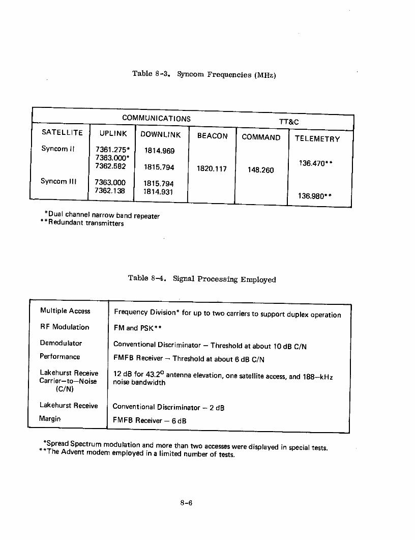
Table 8-3. Syncom Frequencies (MHz)
COMMUNICATIONS TT&CSATELLITE UPLINK DOWNLINK BEACON COMMAND TELEMETRY
Syncom II 7361.275* 1814.9697363.000* 136.470*7362.582 1815.794 1820.117 148.260
Syncom III 7363.000 1815.7947362.138 1814.931 136.980**
*Dual channel narrow band repeaterS* Redundant transmitters
Table 8-4. Signal Processing Employed
Multiple Access Frequency Division* for up to two carriers to support duplex operation
RF Modulation FM and PSK**
Demodulator Conventional Discriminator - Threshold at about 10 dB C/NPerformance FMFB Receiver - Threshold at about 6 dB C/NLakehurst Receive 12 dB for 43.20 antenna elevation, one satellite access, and 188-kHzCarrier-to-Noise noise bandwidth
(C/N)
Lakehurst Receive Conventional Discriminator - 2 dBMargin FMFB Receiver - 6 dB
*Spread Spectrum modulation and more than two accesses were displayed in special tests.*The Advent modem employed in a limited number of tests.
8-6

power balancing, and various miscellaneous variations in link parameters of lesser
magnitude.
8.3 SPACECRAFT
Spacecraft characteristics for the Syncom satellites are displayed in
Table 8-5. (3) (4) (5) (13) All three satellites contained identical apogee motors for
final orbit circularization. The basic configuration for the communications subsystem
on the Syncom satellites is displayed in Figure 8-2. (4) Each receive channel consists
of a mixer, a local oscillator, an IF amplifier, a limiter amplifier, and a mixer
connected through a hybrid to the redundant TWTs.
TO TELEMETRY
IF RECEIVER TRANSMITTERNO. I NO. I
LOCAL |ANTENNA DUAL ANTENNA
MIXER OSCILLATOR ERECTOR COL SLOTNOF NO. SLO
MIXTO TEMETY
A. COMMUNICATION SUBSYSTEM
Figure 8-2. Satellite Communications Subsystem
Syncom H differed from Syncom I only in nitrogen tank mounting and internal
operating pressure, the wiring harness, and the addition of a standby battery to pro-
vide 40 minutes of telemetry should the main power supply fail. These changes re-
sulted from the conclusion that a high-pressure nitrogen tank failure caused the loss
of Syncom I.
Based on Syncom II experience, several modifications were also made to Syncom
III. N-on-P solar cells with 12-mil fuzed silica covers replaced the more radiation
sensitive P-on-N solar cells with their 6-mil glass covers. A redundant hydrogen
peroxide (H2 0 2 ) system replaced the high pressure nitrogen (N2 ) system. The stand-
by battery and apogee motor timer were deleted. Two temperature sensors were
8-7

Table 8-5. Satellite Characteristics
SATELLITE SYNCOM I & II SYNCOM III
Type UHF Xmit. - collinear array of slot VHF-4 whip turnstile for TT&CU) dipoles SHF Racv. - slot dipolez Number One One Essentially the same as for Syncom I & II
Beamwidth Pancake beam about 250 wide at Essentially OmnidirectionalZ 3-dB pts. for Xmit.
Gain Xmit. - 6 dB 0dBRacy. - 2 dB
Frequency Band SHF Racv. and UHF Xmit.
Type IF Translation Hard Limiting Same as for Syncom I & II
3dB BW 5 MHz 0.5 MHz* 4.5 MHz 13 MHz or 50,kHz"Number Redundant Xponders of different BW selectable on ground command
Receiver
Type Front End Down Conversion MixerS Front End Gain 90 dB IF following down converter
SSys. Noise Fig. 10 dBwt Essentially the same as for Syncom I & II
Transmitter
Type Redundant TWTs*"Gain 33dBPower Out 2 watt (nominal)
EIRP - UHF Ant. 6dBW
Stabilization
Type Spin with H202 and N2 reaction control*"* Spin with H202 reaction control."
X: Capability Spin axis could be maneuvered to within 10 of normal to orbital plane.Power Source
u. Primary Solar Array - 29 watt output at launch-J< Supplement 2 Nickel Cadmium Batteries - about 0.8 amp. hr. per battery at launch
Comm. Power Needs About 15 watt Essentially the same as for Syncom I & II
o Size Cylindrical - 15.5 in. high & 28 in. diameter
Weight 78.8 Ibs. initially in orbit 73.8 Ibs. initially in orbit
*Bandwidth for each of two channels provided for more convenient full duplex narrowband operation."Either wideband or narrowband mode can be selected.
*Either TWT can operate with either transponder. Interlocks prohibit parallel operation.****Gas jets provide both attitude corrections and stationkeeping.
8-8

added. The transponder containing two 0. 5-MHz bandwidth IF sections was replaced
by a 10-MHz bandwidth channel for television tests with a 50-kHz option for small
station testing.
8.4 GROUND TERMINALS
Among the participating earth terminals listed in Table 8-2, the AN/FSC-9, the
AN/MSC-44, and the Kingsport terminals were the principal stations involved in the
early testing on both Syncoms II and III. Characteristics of these terminals are
presented in Table 8-6. (3) (6) (9) (11) (14) (15) Major subsystems of the ground
facilities placed aboard the Kingsport are shown in Figure 8-3. (3) The AN/FSC-9
and AN/MSC-44 terminal installations did not, in general, include the TT&C antenna
and system.
The transmit and receive polarizations available at the AN/MSC-44 and Kingsport
terminals were compatible with those of the Syncom sattellites. In contrast, the
receive polarization of the AN/FSC-9 terminals was such that a 3-dB polarization
loss was suffered. By choosing circular polarization, however, it was no longer
necessary to track variations in the linear polarization received from the satellite.
The AN/FSC-9 and AN/MSC-44 terminals employed two axis (i.e., azimuth and
elevation) tracking and control of the antenna. The Kingsport terminal was provided
with a three-axis antenna, however, to ensure a capability for near zenith operation
from the rolling and pitching ship.
8.5 EXPERIMENTS
Experiments conducted on project Syncom are grouped in five major categories
and defined in Table 8-7. Synchronous orbit injection was successfully completed on
Syncoms I, II and III. In the latter case, a synchronous equatorial orbit was realized.
Spacecraft stationkeeping and attitude control were successfully maintained on
Syncoms II and III. In the process of stationkeeping, considerable data on the triaxial
nature of the earth and the drift of synchronous satellites was generated. (16) (17) (18)
8-9

Table 8-6. Characteristics of Major Earth Terminals
TERMINALTERMINALFEATURE AN/FSC-9 AN/MSC-44 KINGSPORT
Type Parabolic Reflector Parabolic Reflector Parabolic ReflectorZ Aperture Size 60 Ft. Diameter 30 Ft. Diameter 30 Ft. DiameterwJ Receive Gain 48 dB 42 dB 40 dB
z Efficiency 50% 50%* 35%*< Rec. Beamwidth 0.650 at 3 dB Pts.* 1.30 at 3 dB Pts. 1.60 at 3 dB Pts.*
u 2 Type Preamplifier Temperature Controlled Temperature Controlled Temperature Controlled-?_ Parametric Amplifier Parametric Amplifier Parametric Amplifier0o Bandwidth 100kHz* 100 kHz** 100 kHz*x Lo Noise Temp. 2300 K at 7.50 El. 2000 K at 7.50 El. 200*K at 7.50 El.
i Type Amplifier Klystron Klystron KlystronZ Bandwidth 100 kHz*** 100 kHz*** 100 kHz***< Amp. Pwr. Out 20 kW**** 20 kW * 20 kW"
I-
s Type Conical Scan Autotrack Conical Scan Autotrack Spiral Scan Autotrack5 Accuracy ± 0.024 ± 0.050 +0.050
<: G/T 24.4 dB/K * 19 dB/OK* 17 dB/OK*L EIRP 128 dBm*,**** 123.4 dBm*,**** 125.3 dBm*,..
r C Transmit Feed Circular Circular Circular- Receive Feed Circular Linear Circular or Linear
N (Interchangeable)
J0 Radome None None 53 Ft. DiameterPressurized
z j Type Facility Fixed Terminal Transportablet Ship
*Derived value based on data available*IF bandwidth variable to 10 and 40 kHz. RF bandwidth is 10 MHz at 3-dB pts.
***Radiated signal bandwidth. RF bandwidth is 15 MHz at 3-dB pts."***Peak possible. Operationally the practical limit is 3 dB less.
tlncluded eight vans, all air-transportable in C124 and C133 aircraft. Total weight about 65,000 Ibs.
8-10

TABLE 8-7. SUMMARY OF PROGRAM EXPERIMENTS
Type Activity Nature of Activity
1. Synchronous Orbit Injection Demonstrate launch and synchronous orbitinjection of spin stabilized satellite.
2. Stationkeeping and Attitude Demonstrate precision control of spinControl axis attitude and central longitude of earth
subsatellite point.
3. Communications Demonstra- Display feasibility of synchronous satellitetions communications to live audiences.
4. Communications Perform- Measure overall communications per-ance formance of synchronous satellite system.
5. Communications Technical Measure detailed link and communicationsCharacteristics parameters in synchronous satellite system.
Thousands of successful special tests and demonstrations were performed over
the Syncom satellites. These include numerous demonstrations of teletype, telephony,
and facsimile. Special demonstrations displayed vocoder operation, multiple access
using spread spectrum, real time relaying of satellite telemetry, transmission of
oceanographic data, continuous 24-hour auto-tracking, 28 hours of continuous com-
munications with the Kingsport while underway at sea, and direct teletype communica-
tions with an aircraft in flight. The latter employed the VHF command receiver and
telemetry transmitter on Syncom III. (19)
Special occurrences among the demonstrations included President J. F. Kennedy
speaking from the White House to the Prime Minister of Nigeria;-President Kennedy's
address to the United Nations; conversations between participants in the 1963 Extraor-
dinary Administrative Radio Conference of the ITU in Geneva, Switzerland, and mem-
bers of the U.N. in New York; and international TV coverage of the Olympics from
Japan in October, 1964. The demonstrations also displayed that satellite time delay
and echo could be overcome. However, to accomplish the latter it was found necessary
to maintain incoming conventional phone line levels at -15 dBm or above with the
8-11

equipment employed. The time delay presented few psychological problems even with
unexpectant speakers.
The communications performance experiments described in Table 8-7 are de-
fined and their basic results presented in Table 8-8. (3) (4) (15) (19) Results indicated
are for half duplex operation. The Syncom II television transmissions involved a wide-
band FM modulator at Fort Dix. At the receive end, the Bell Telephone Laboratory's
Andover terminal was outfitted with a maser preamplifier operating at the Syncom
frequencies. The Syncom III Japan to California television test was the 1964 TV cover-
age of the Olympics. Television p-p signal to weighted rms noise ratios would be
about 8 dB better than the unweighted values indicated in the table. This means signals
were quite viewable but not of high quality.
The communications technical characteristic measurements noted in Table 8-7
are described in Table 8-9. (3) (4) In addition to the tests mentioned, the frequency
response of the 50-kHz transponder on Syncom III was measured. It displayed an 87-kHz bandwidth at the 3-dB points. Further, measurements of the Faraday rotation ofthe 137-MHz telemetry signal from Syncom III provided considerable data on the
electron content of the ionosphere. (20) (21)
8.6 OPERATIONAL RESULTS
The communications system operations on Project Syncom displayed that highly
reliable synchornous satellite communications systems were feasible. During the
initial experimental period of the program, operational responsibility for the Syncom
satellites rested with NASA while DOD operated and maintained the ground communi-cations terminals. In early 1965, DOD added the satellites to its operational responsi-bilities and employed them to provide operational military communications for theFar East, Pacific Ocean area, and Western United States. During all of the time theSyncom satellites were actively employed, no significant operational difficulties wereencountered. Minor difficulties included a slight gas leak, a buildup of H2 0 2 pressure,and one receiver occasionally going into oscillation upon turn on under high space-craft temperature conditions. Ground terminal operation and tracking was, in general,routine.
8-12

Table 8-8. Communications Performance Experiments
TYPE EXPERIMENT NATURE OF RESULTS OBTAINED
1. Telephony Single channel S+N/N of 35 dB readily attained with maximum FM deviation" ratioemployed. Multichannel"* operation demonstrated on Syncom III at reduction in perchannel performance.
2. Data Transmission Using vestigial sideband modems operating into 4--kHz baseband input to normal FMterminal equipment, 3-kbps rates at low error rates*"" were possible. Using PSK RFmodulation, data rates as high as 50 kbps were possible.
3. Teletype For single channel operation into 4-kHz baseband input to normal FM terminal equip-ment, error rates of 0.1% were readily attained. For 1 of 16 channels into 4-kHz base-band, error rates less than 1% were attained.
4. Facsimile Operating into standard FM terminal equipment, overall picture quality numericallyrated at 7 on a 0 to 10 scale was commonly obtained. Factors degrading quality includedbandwidth limitations,t phase delay distortion,t and satellite spin rate modulation.
5. Television Fort Dix to Andover through Syncom II realized 26-dB p-p signal to rms noise ratio.ttKashima to Point Mugu through Syncom III realized 34-dB p-p signal to rms noiseratio.ttt
6. Direct Aircraft TTY Pan American scheduled aircraft to Camp Roberts through Syncom III VHF commandreceiver and telemetry transmitter realized under proper conditions, up to 60-wpmTTY.tttt
NOTES: *Signal was 1-kHz tone; 35 dB provided better than 99% sentence intelligibility.**Maximum was 10; lower ratios were also selectable.
***Four channel AN/TCC-3 multiplex employed on Syncom III.""On order of 10
- 5 bits/bit.tGround terminal equipment imposed limitations.
ttVideo baseband bandwidth -2.5 MHz, p-p FM frequency deviation -4.5 MHz, preemphasis -14 dB, andaudio signal transmitted separately.
tttVideo baseband bandwidth -2.5 MHz, p-p FM frequency deviation -7 MHz, preemphasis -14 dB, syncpulses removed and regenerated at receiver, and audio handled separately.
ttttAircraft had vertically and horizontally polarized Yagi antennas. Roberts used TT&C Yagi antenna.
8-13

Table 8-9. Communications Technical Characteristics Measurement
TECHNICAL CHARACTERISTICS NATURE OF RESULTS OBTAINED
1. Spacecraft Transfer Function Beacon receives total output power for no communications signal present.Communications input must be varied over several dB to completely sup-press beacon and capture TWT.
2. Ground Terminal UHF/SHF Beam Alignment Determined from point of maximum suppression of beacon signal. Goodalignment found.
3. Received Carrier Power at Ground Measured values, in general, agreed with predicted values. For antennaelevation angles above 7.50, no selective fading due to multipath existed.
4. Received Signal Level at Satellite Agreed well with predicted values.
5. Frequency Response For 4-kHz channel, baseband response exceeded the requirements of MILSTD 188B for a 6000-n.mi. reference circuit.*
6. Envelope Delay For 4-kHz channel, baseband response exceeded the requirements of MI LSTD 188B for a 6000-n.mi. reference circuit.*
7. Spacecraft Antenna Pattern Performed with satellite spin axis in plane of orbit. Pattern shapes agreedwell with prelaunch measurements and indicated about 1.50 error in meas-ured satellite orientation parameters.
8. Intermodulation Not performed on Syncom II. Nearly all measured degradation was due toAN/TCC-3 and FM modulation/demodulation.
9. Spacecraft Oscillator Frequency Measured frequency agreed with prelaunch measurements.
*Ground terminal equipment imposed limitations.
8-14

CITED REFERENCES
1. D. D. Williams and R. W. Cole, "Syncom, " in Telecommunications Satellites,K. W. Gatland, Editor, Prentice-Hall, Inc., Englewood Cliffs, New Jersey,1964.
2. L. Jaffe, "Communications in Space, " Holt, Rinehart and Winston, Inc., NewYork, New York, 1966.
3. Syncom Projects Office, Goddard Space Flight Center (GSFC), "SyncomEngineering Report, " Volume I, NASA TR R-233, Washington, D. C., March,1966.
4. Syncom Projects Office, GSFC, "Syncom Engineering Report, " Volume II,NASA TR-R-252, NASA, Washington, D. C., April, 1967.
5. Hughes Aircraft Company, "Hughes Communications Satellites - OperationalSummary, " Hughes SSD 60011R, February, 1966.
6. "Active Communications Satellite Experiments, " Report 207-1, CCIR Docu-ments of the XIth Plenary Assembly, Volume 4, Part 2, International Tele-communications Union, Oslo, 1966.
7. "Satellite Communications (Military-Civil Roles and Relationships), " Reportby the Military Operations Subcommittee of the Committee on GovernmentOperations, October, 1964.
8. J. W. Johnston, "Status of Military Satellite Communications Research andDevelopment, " IEEE Transactions on Military Electronics, Volume MIL-9,April, 1965.
9. W. H. Edwards and J. S. Smith, "Experience of the Defense CommunicationsAgency in Operating Pilot Satellite Communications," in CommunicationsSatellite Systems Technology, edited by Richard B. Marsten, Academic Press,New York, 1966.
10. M. D. Van Orden and E. N. Marsh, "Navy Achievements in SatelliteCommunications, " AIAA Communications Satellite Systems Conference,AIAA Paper No. 66-270, Washington, D. C., May 2-4, 1966.
11. W. T. Tobias, R. G. Keyes, and T. R. Gleason, "Communications Operationswith Syncom II, "IEEE International Convention Record, Volume 12, Part 6,New York, March 23-24, 1964.
8-15

12. "Syncom to Have Cousin, " Electronics, Volume 36, February 15, 1963.
13. R. M. Bentley and A. T. Owens, "Syncom Satellite Program, " Journal of
Spacecraft and Rockets, Volume 1, No. 4, July-August, 1964.
14. D. J. Woodward and J. F. DeBold, "Kingsport Experience with the Syncoms, "Astronautics and Aeronautics, Volume 3, No. 3, March 1965.
15. V. F. Henry and M. E. McDonald, "Television Tests with the Syncom II
Synchronous Communications Satellite, " NASA TN D-2911, National Aero-nautics and Space Administration, Washington, D. C., July 1965.
16. R. E. Balsam and B. M. Anzel, "Determination of the Pacific EquilibriumPoint for a Stationary Orbit, " Journal of Spacecraft and Rockets, Vol. 4,No. 10, October 1967.
17. C. A. Wayner, "Determination of the Triaxiality of the Earth from Observationsof the Drift of the Syncom II Satellite, " Goddard Space Flight Center, X621-64-90, April 1964.
18. W. A. Heiskanen, "Is the Earth a Triaxial Ellipsoid?, " Journal of GeophysicalResearch, Volume 67, 1962.
19. F. C. White, "For a Pilot over the Ocean a Satellite Link to Home, " Elec-tronics, Volume 39, No. 9, May 2, 1966.
20. J. E. Titheridge, "Continuous Records of the Total Electron Content of theIonosphere, " Journal of Atmospheric and Terrestrial Physics, Volume 28,December 1966.
21. Y. Nakata, "Variation in Ionospheric Electron Content Measured by RadioWaves from Syncom III, " Radio Science, Volume 1, October 1966.
8-16

RELATED REFERENCES
1. P. S. Dupont, "Syncom Electrical Power System, " Journal of Spacecraft andRockets, Volume 3, April 1966.
2. N. W. Feldman and G. P. Tripp, "Design of the Voice Portion of the SyncomGround Station, " IEEE International Convention Record, Volume 12, Pt. 6,New York, March 23-26, 1964.
3. D. D. Williams, "Control of the Syncom Communication System, " Proceedingsof the Joint American Astronautical Society and Aerospace Electrical SocietyMeeting, Los Angeles, California, May 25-27, 1965.
4. _oB. Miller,.,"'Synotm II to Us'~1iltiple Access Devices,. Aviation Week and SpaceTechnology, Volume 78, June 10, 1963.
5. B. Miller, "First Syncom to Test Synchronous Orbit Feasibility, " AviationWeek and Space Technology, Volume 77, August 20, 1962.
6. F. P. Alder, "Syncom, " International Astronautical Federation, 14th Inter-national Astronautical Congress, Paris, France, September 1963.
7. E. J. Althaus and J. C. Meyer, "Syncom Reliability," 11lth National Symposiumon Reliability and Quality Control, Miami Beach, Florida, January 12-14, 1965.
8. R. M. Bently, "Design and Development of the Syncom Communications Satellite,Conference of Civilian and Military Uses of Aerospace, New York, January 12-14, 1965.
9. C. G. Murphy, "A Syncom Satellite Program, " AIAA Summer Meeting, AIAAPaper No. 63-264, Los Angeles, California, June 17-20, 1963.
10. R. R. Allan, "On the Drift of Syncom 2 and the Value of J 2'" Planetary andSpace Science, Volume 12, April 1964.
11. G. Silverman, J. W. Lockett, and J. C. Cittadino, "Results of Syncom Com-munications Experiments, " IEEE International Convention Record, Volume 12,Pt. 6, March 23-26, 1964.
12. J. W. Johnston, "Army Participation in Project Syncom, " Proceedings ArmyDepartment Army Scientific Conference, Volume 1, 1964.
13. W. M. Pulford, VHF Ground-Satellite-Aircraft Relay Using Syncom III,"IEEE 12th Annual East Coast Conference on Aerospace and NavigationalElectronics, Baltimore, Maryland, October 27-29, 1965.
8-17

14. "USNS Kingsport-Satellite Communications Ship, " AIAA Annual Meeting, AIAAPaper No. 64-417, June 30, 1964.
15. "First Synchronous Satellite Goes Up in 1962," Electronics, Volume 34,October 27, 1961.
16. "Syncom II, " Wireless World, Volume'69, October, 1963.
17. "Syncom II Is Stellar in First Role: Launched into Synchronous Orbit forCommunications Test, " ISA Journal, Volume 10, September 1963.
18. P. E. Norsell, "Syncom, " Astronautics and Aerospace Engineering, Volume 1,No. 8, September 1963.
8-18

SECTION 9 - LINCOLN EXPERIMENTAL SATELLITES
9.1 INTRODUCTION
From its inception, the Lincoln Laboratory of the Massachusetts Institute of
Technology has had an interest in long-range military communications systems.
Early work was with ionospheric and tropospheric scatter systems. The scatter
concept was extended, under U. S. Air Force sponsorship, to the West Ford Program.
Upon successfully concluding Project West Ford, the Laboratory's program aims
were recast, in 1963, towards developing active communications satellite techniques. (1)
This program, also under Air Force sponsorship, has made use of the original West
Ford ground terminals as well as small mobile ground terminals to communicate
through a series of Laboratory-developed satellites designated the Lincoln Experi-
mental Satellites (LES).
Lincoln Laboratory's active communications satellite program has been con-
cerned with the development and testing of new spacecraft and ground terminal tech-
niques having application to military command and control. (2) The objective of the
spacecraft techniques investigations has centered on obtaining the maximum satellite
effective radiated power for a given satellite mass. In agreement with this objective,
research has been conducted on improved spacecraft power-generation systems, high
efficiency spacecraft transmitters, high-gain spacecraft antennas, and spacecraft
attitude stabilization and stationkeeping systems. The surface terminal techniques
investigation has focused on developing methods of more effectively utilizing a
given radio signal strength generated by a communications satellite. Areas of
interest have included the development of efficient modulation-demodulation systems,
random multiple access techniques having no stringent synchronization and control
requirements, source signal encoding techniques that reduce required user data rates,
low noise receiving systems, and simple antenna systems suitable for small terminals.
9-1

In the first phase of the program, particular attention was given to X-band fre-
quencies in the vicinity of the microwave bands allocated for military communications.
This emphasis was a natural extension of the X-band capabilities developed during
the Project West Ford experiment. (3) In the second phase of the program, attention
has been focused on frequencies in the 225 to 400 MHz UHF communications band.
This band is used for a wide variety of United States government communications ser-
vices.
To date, six satellites, LES-1 through -6, have been launched as part of this
program and employed in experiments. LES-7 was conceived as a high ERP, three
axis stabilized, 300 to 500 pound satellite using a lens antenna and a 19 horn feed
cluster to provide a composite beam whose shape could be carried by ground command
to fit the earth coverage requirements of a particular link. This satellite would have
operated at X-band but funding considerations plus a greater interest in experiments
at the UHF frequencies resulted in its cancellation. Presently, plans exist for a
LES-8 and LES-9 to be launched by late 1974 but these experiments are still in the
concept formulation stage.
9.2 X-BAND SATELLITES
9. 2. 1 General Description
Specific objectives of the satellites and earth terminals included in this portion
of the LES program are listed inTable 9-1.
Table 9-1. X-Band Experiment Objectives
Number Description
1 Investigate X-Band Satellite Communications Performance
2 Display Operation of Solid-State X-Band Transponders
3 Investigate Despun Antennas
4 Evaluate Autonomous Satellite Attitude Control
5 Study Space Radiation Environment
6 Demonstrate Efficient Error Correcting Coding-Decoding Techniques
7 Investigate Minimum Data Rates for Voice Signal Transmission
8 Study Multiple Access Techniques with no Stringent SynchronizationRequirements
9-2

Three X-band satellites have been launched during the LES program as indicated
in Table 9-2 (4) (5). LES-1 was correctly injected, by its launch vehicle, into an
inclined medium altitude circular orbit. However, a design flaw in the satellite's
ordnance circuity prevented ignition and separation of the rocket motor supplied for
final orbit injection. This left the combination in the medium altitude circular orbit
instead of a 1500 by 8000 nautical mile inclined elliptical orbit as planned. At separa-
tion from the launch vehicle, the satellite-rocket motor combination was spun up about
the axis of least inertia to 180 rpm. When the rocket motor failed to separate, spin
axis conversion immediately started to occur. Before it was completed, a few initial
communications tests were conducted. The X-band repeater and antenna switching
system functioned properly but the tumbling mode that was assumed destroyed LES-1's
usefulness.
LES-2 was successfully launched along with the Lincoln Calibration Sphere
(LCS)-1 later in 1965. This satellite was almost identical to LES-1. With the
benefit of a revision of the satellite's ordnance circuitry, it was placed into the type of
orbit that had been planned for LES-1. Numerous communications experiments were
conducted with this satellite and all objectives listed in Table 9-1, with the exception of
Item 5, were accomplished. The satellite contained no experiment measuring the
space radiation environment.
LES-4 was launched along with LES-3, Oscar 4, and OV2-3 as a secondary
payload aboard the third flight test of the Titan IIIC. LES-3 was a UHF Lincoln
Experimental Satellite operating as a radio signal generator. Oscar 4 was an amateur
radio communications satellite for use by "Hams" throughout the world. OV2-3 was
a scientific satellite to gather data on solar and geomagnetic activity by measuring
changes in cosmic ray and trapped particle fluxes. The objective was to place LES-3
and LES-4 into near synchronous (i.e., 18, 200 nautical mile), circular orbits having
a 0* inclination. After a near perfect injection into parking and transfer orbits, the
Titan III C third stage failed to ignite and LES-3 and LES-4 were ejected into highly
elliptical inclined orbits.
9-3

Table 9-2. X-Band Spacecraft
Satellite LES - 1 LES - 2 LES- 4
Manufacturer & Sponsor Lincoln Laboratories & U. S. Air Force
Launch Date 2/11/65 5/6/65 12/21/65
Launch Vehicle Titan III A Titan III C
Apogee (mi.) 1744 9384 20,890
- Perigee (mi.) 1726 1757 124
Inclination 32. 20 31. 40 26.6
Period (min.) 145.7 315.2 589.6
In orbit, solar array In orbit but Transmission ceased indegraded, and tumbling was shut down October 1968. Orbit sub-
Status with satellite rocket automatically sequently decayed andmotor still attached. by its internal satellite was destroyed.
clock in 1967.
elliptical orbit.
NOTE: (1) At initial injection. Parameters of LES-4 were altered by atmosphericdrag due to the low perigee.
9-4

LES-4's initial spin axis orientation was such that solar panel illumination pro-
vided telemetry power only. By late 1965, a residual magnetic moment along the spin
axis had precessed the spin vector until the sun was only 470 below the satellite
equator. This provided sufficient solar power to allow operation of all systems. As
a result of the unplanned orbit, one of the two onboard antenna switching control
systems and the magnetic spin axis orientation system could not be operated. However,
one of the two antenna switching control systems did operate properly and all of the
objectives listed in Table 9-1, with the exception of Item 4, were for the most part
successfully accomplished.
The principal satellite communications terminals participating in experiments
with the X-Band LES satellites are listed in Table 9-3(6) (7). The terminal at Camp
Parks and one of the terminals at Millstone Hill were the facilities originally developed
for Project West Ford. Lincoln Experimental Terminal-1 (LET-1) was a transportable
ground terminal housed in two vehicles capable of being towed as trailers. One vehicle
contained the antenna and RF equipments. The second vehicle continued the signal
conditioning and processing equipment necessary for signal generation, modulation
and up conversation to IF. The LET-1 terminal was located adjacent to the Lincoln
Laboratory's Facilities in Lexington. The other two LET terminals consisted of a
LET-1 type signal processing van utilized with existing antennas and RF equipment.
LET-2 employed the 60-foot West Ford antenna and X-band RF equipment at Millstone
Hill. LET-3 employed the 30-foot antenna and X-band RF equipment of the Army's
transportable Mark 1A terminal.
The LET-3/Mark 1A combination was initially deployed to Camp Roberts,
California for LES tests. After a few months it was moved to Ft. Monmouth, New
Jersey for a limited number of LES experiments and subsequent modification for tests
with the IDCSP satellites.
9-5

Table 9-3. Participating Earth Terminals
Location Sponsor Antenna DateDiameter (Ft) Installed
Camp Parks, California U. S. Air Force 60 1961
Millstone Hill, Mass. U. S. Air Force 60 1961(West Ford)
Lexington, Mass. (LET-1) U. S. Air Force 15 1965
Millstone Hill, Mass.(LET-2) U.S. Air Force 60 1965
Camp Roberts, California(LET-3) U. S. Army Satellite 30 1966
CommunicationsAgency
Tracking and VHF telemetry data was obtained primarily by the Camp Parks
and Millstone Hill (West Ford) terminals. The satellite launchings were provided by
the U. S. Air Force.
The X-Band LES program was responsible for a number of significant contri-
butions to satellite communications technology. It proved the feasibility of building
solid state X-band transponders for operation in a communications satellite. A useful
communications capability was supplied even though satellite dc to RF power conver-
sion efficiency and RF power output were relatively low. The feasibility and perfor-
mance capabilities of electronically switched despun antennas were demonstrated. A
workable automatic magnetic spin axis torquing system for attitude correction was
exhibited. The performance potential available through the application of convolution
encoding and sequential decoding to satellite links was displayed. Frequency hopping
was shown to be a satisfactory means of multiple access having no stringent synchroni-
zation requirements and giving considerable protection against interfering signals.
Finally, the capabilities of both pitch-excited and voice-excited vocoders, when used
over a satellite link, were demonstrated. The former handled speakers at the
9-6

satellite ground terminal while the latter allowed remote speakers, connected through
the normal switched telephone network, to use low rate digital satellite voice circuits.
9. 2. 2 System Description
The West Ford terminals contained conventional analog voice signal processing
and frequency modulation equipment while the newly developed LET terminals were
equipped for digital signal processing. As a result, the three LET terminals inter-
operated independent of the West Ford terminals. Individual terminal loop back tests
plus half and full duplex two-terminal operations were conducted. Extensive multiple
access tests were not performed due to the limited number of participating terminals
having compatible modulation and signal processing systems. However, the LET ter-
minal approach to modulation made multiple access a real possibility even for operation
with hard limiting satellites.
Operating frequencies for the X-band Lincoln Experimental Satellites are shown
in Table 9-4 ( 8 ). By choosing the X-band frequencies for communications experiments,
it was possible to make use of ground terminal facilities previously developed for
Project West Ford. More important, however, it afforded the opportunity in accordance
with the program objectives, to conduct tests and develop experimental hardware
operating at frequencies internationally allocated for military satellite communications.
Table 9-4. X-Band LES Operating Frequencies (MHz)
Communications Telemetry*
Up Link Downlink Beacon
8350 7750 7740 237
*VHF tracking was also performed on this signal. A command system was
not employed.
The two West Ford terminals used conventional FM for their RF modulation
and frequency division multiple access when full duplex operations were conducted.
Signal processing and link performance for LET operations with LES are summarized
9-7
in Table 9-5(7) (9) (10) . The signal structure except for the frequency hopping feature
is sketched in Figure 9-1 ( 9 )
In the LET system, the elementary channel symbol used was a sinusoidal pulse
200 As in duration on one of 16 frequencies. The received pulse was detected by a bank
of 16 matched filters. This modulation-demodulation system was preceded by a con-
volutional encoder and followed by a sequential decoder. Information rates of approxi-
mately 200 bps, 5 kbps, and 10 kbps were achieved.
At the 5-kbps rate, an information bit was fed to the encoder every 200 ps. The
encoder generated three parity check bits based on the 60 preceding information bits.
These four bits were employed to select one of 16 channel frequencies every 200 As.
At the receiver the match filter outputs were sampled every 200 ps and ordered accord-
ing to magnitude. The seven samples of largest magnitude were fed to the sequential
decoder which recovered the original information bits.
Analogous operation occurred at the 10 kbps rate. In this case, one parity check
bit was generated for each input information bit and two information and two check bits
were used to select 1 of 16 channel frequencies. At the 200 bps rate, 24 successive
200 As pulses carried the same information while the 25th pulse was a synchronization
pulse. At the receiver, the matched filter outputs were integrated over 24 successive
pulses before ordering the samples and decoding.
This signalling system guaranteed accurate transmission at low values of Eb/N o .
To convert this into multiple-access, or anti-interference operation, the block of 16
channel frequencies employed in any 200 ps symbol interval was, itself, pseudorandomly
hopped over the 20 MHz bandwidth of the terminal and satellite RF systems. Since the
frequency hopping occurred only every 200 As, the signal acquisition and ynchronization
requirements were modest as compared to a pseudonoise spectrum spreading system.
Acquisition was achieved automatically using time and frequency predictions obtained
from a station clock and the satellite ephemeris. The desired synchronization was
achieved by transmission of a synchronizing pulse (i. e., a 200-A s pulse that is frequency
hopped but carries no information) every 5 ms. A tracking loop integrated over many of
these pulses in sequency to achieve the desired timing and frequency accuracies of 5 As
and 625-Hz, respectively.
9-8

Table 9-5. Signal Processing for LET Operation with LES-4
Multiple Access Code Division through pseudorandom frequency hoppingof channel center frequency
RF Modulation MFSK employing 16 channel frequencies
Ground Demodulator E, (1) of 6 dB required (2 ) corresponding to 43 dB/HzPerformance No signal-to-noise density ratio for a 4. 8-kbps
voice channel
LET-1 Receive Carrier- 58 dB/Hz based on operation at vnchronous altitude,to-Noise Density 2 watt satellite EIRP, & 100 0K (' receive system
noise temperature.
Margin Required for 5 dBLink Degradation
Margin Available for 10 dB corresponding to 10 potential users of the sameMultiple Access type
Notes: (1) Energy per bit to noise density ratio
(2) Gives probability of error of 10-3 when matched filter detection andsequential decoding of convolution encoded signal is employed.
(3) Represents LET receiver thermal noise alone. For code divisionmultiple access when almost entire satellite output represents inter-ference, receive system noise temperature was raised a maximum of12. 70K.
INFORMATIONNPUT CONVOLUTIONAL 1 OF 16 RFR ENCODER FREQUENCY SELECTOR TRANSMITTER
18 IT/200 Is 4 BITS/200ps 200-ps PULSE ON
2BIT/200 "1 1 OF 16 FREQUENCIESTRANSMITTER
RF 16-CHANNEL SEQUENTIAL OUTPUTRECEIVER DATA RECEIVER I DECODER
200-us PULSE ON "ORDERED LIST" I BIT/ 200I OF 16 FREQUENCIES ONCE EVERY 200 ps
PLUS NOISE 2.BT/200
RECEIVER
Figure 9-1. Simplified Terminal (without Frequency Hopping)
9-9

The three alternate information rates provided corresponded, in order of
ascending rate, to transmission of two 100-wpm teletype channels, a pitch-excited
vocoder output (4. 8 kbps) plus the two teletype channels, or a voice-excited vocoder
output (9. 6 kbps) plus two teletype channels, respectively. The two vocoder systems
were provided in one unit capable of two modes of operation. Both modes provided
a high degree of intelligibility and speaker recognizability. In the pitch-excited
mode, a high fidelity input was required as provided by the high quality microphone
at the LET terminal. When operated at the higher data rate, the vocoder was used
in the voice-excited mode, allowing the use of a degraded input, including a "phone
patch" connection to the commercial telephone plant.
9.2. 3 Spacecraft
Characteristics of the communications-related subsystems of the LES-1, 2 & 4
spacecraft are given in Table 9-6(1) (8) (11). The LES-1 and 2 satellites were nearly
identical in all respects and the transponder, aboard all three spacecraft, was
basically the same. A simplified block diagram of the transponder is shown in
Figure 9-2. A 60-MHz IF was employed which made double up conversion necessary
to avoid the need for narrow sideband separation filters at the 7. 8-GHz output
frequency.
LES-1 and 2 were designed to operate with their spin axis normal to the earth-
sun line. As a result, the spacecraft orientation relative to the earth varied making
a broad range of coverage by the satellite antenna pattern necessary. This was
solved through the 8-element switched array of antenna elements arranged in two
rings. The two 4-element rings girded the upper and lower hemispheres of the
satellite, respectively. Sensors operating at the wavelengths of visible light served
as inputs to the logic system determining spacecraft spin rate and earth direction.
The logic controlled antenna switching. A 2-throw switch selected the ring to be
activated while a 4-throw switch performed the despinning within an individual
ring. The automatic magnetic torquing system employed solar cells on the upper
9-10

Table 9-6. Satellite Characteristics
SATELLITE LES 1 AND 2 LES 4
Type X-Band - Switched array of UHF Telem. - Four 1/8-wavelength X-Band Xmit. - Switched single UHF Telem. - Circumferential8 horn elements* in 2 rings monopoles ring array of 8 horn elements. gap between X-Band xmit. andabout spin axis X-Band Rec. - Biconical horn. receive antennas.
2 Number One One One Onez
Xmit. Beamwidth (3dB) Pencil Beam a minimum of Omnidirectional Pencil Beam 230 wide at minimum Toroidal pattern of greater than
< about 600 wide including dimension earth coverage width.switched beam pointing errors.
Gain Xmit. - 3.1 dB 0 dB Xmit. - 10.6 dB 1.4 dB in equatorial plane ofRec. - 3.7 dB Rec. - 4.4 dB satellite
Frequency Band X-band X-band
Type IF translation hard limiting IF translation hard limiting
Bandwidth (1 dB) 20 MHz 20 MHz
Number One One
Receiver
u Type front end Down conversion mixer Down conversion mixer
< Front end gain No Data No Data
System Noise Figure 16 dB 9dB
Transmitter
Type Up converter output radiated Up converter output radiated
Gain No Data No Data
Power out 115 mW 230 mW
EIRP -7 dBW 3 dBW
Stabilization
Type Spin with autonomous magnetic torquing of spin axis Spin with autonomous magnetic torquing of spin axis
( Capability LES-2 settled to 120 ± 70 from perpendicularity to satellite-sun line Torquing inoperable due to unplanned orbit
Power Source
< Primary Silicon solar cell array providing at least 27 watts at launch Silicon solar cell array providing at least 40 watts at launchu Supplement None None
Comm. Pwr. Needs No Data No Data
W Size Polyhedron 24 in. wide between opposite square faces 10-sided cylinder approximately 25 in. high and 31 in. across
Weight 69 Ibs. for LES-1 and 82 lbs. for LES-2 116 Ibs.
*Each horn was terminated in a diverging lens.
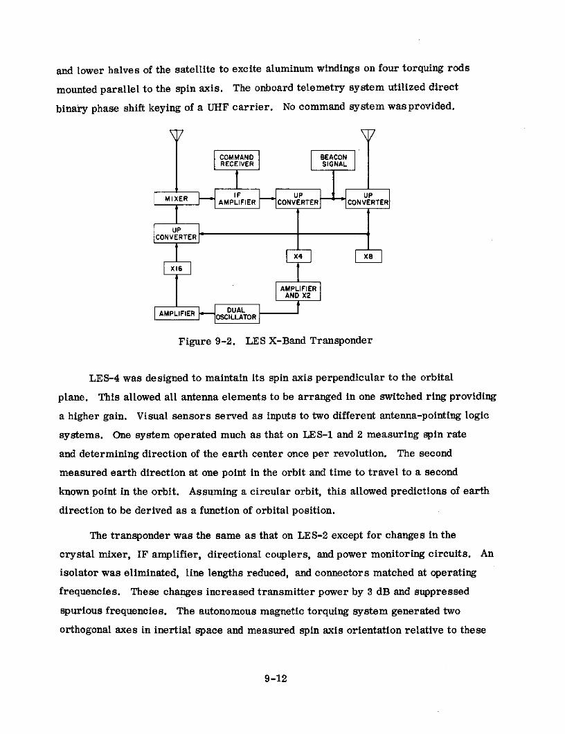
and lower halves of the satellite to excite aluminum windings on four torquing rods
mounted parallel to the spin axis. The onboard telemetry system utilized direct
binary phase shift keying of a UHF carrier. No command system was provided.
COMMAND BEACONRECEIVER SIGNAL
AMPLIFIER CONVERTER CONVERTER
CONVERTER
X4 8X16
AMPLIFIERAND X2
AMPLIFIER ODUALOSCILLATOR
Figure 9-2. LES X-Band Transponder
LES-4 was designed to maintain its spin axis perpendicular to the orbital
plane. This allowed all antenna elements to be arranged in one switched ring providing
a higher gain. Visual sensors served as inputs to two different antenna-pointing logic
systems. One system operated much as that on LES-1 and 2 measuring spin rate
and determining direction of the earth center once per revolution. The second
measured earth direction at one point in the orbit and time to travel to a second
known point in the orbit. Assuming a circular orbit, this allowed predictions of earth
direction to be derived as a function of orbital position.
The transponder was the same as that on LES-2 except for changes in the
crystal mixer, IF amplifier, directional couplers, and power monitoring circuits. An
isolator was eliminated, line lengths reduced, and connectors matched at operating
frequencies. These changes increased transmitter power by 3 dB and suppressed
spurious frequencies. The autonomous magnetic torquing system generated two
orthogonal axes in inertial space and measured spin axis orientation relative to these
9-12

axes once per orbit at points, 900 apart, where the satellite orbit intersected these
fixed axes. LES-4 also included a radiation experiment to measure spatial and
temporal variations of the energy spectrum of trapped electrons. The spectrum was
measured in five energy ranges from 130 keV to 4 MeV.
9.2.4 Ground Terminals
Among the terminals listed in Table 9-3, the Lincoln Experimental Terminals
were the major stations involved in experiments with the X-band Lincoln Experimental
Satellites. LET-1 and LET-2 performed most of these tests. The characteristics
of LE T-1 are summarized in Table 9-7(9) (12). Characteristics of the existing
Millstone Hill antenna and RF equipment employed in LET-2 were discussed in the
description of Project West Ford ground stations in Section 5.4. A block diagram
of the LET-1 system is shown in Figure 9-3(9 )
RANGE TRANSMITTERI SEQUENCE
TIME GENERATOR
DOPPLER FREQUENCYCONTROL
X-BANDCARRIER 15-ft
ANTENNAFREQUENCY-
HOPPING TRANSMITTERSYNTHESIZER
VOCODER
CODER PARAMETRIC
cc DECODER AMPLIFIER
U 16-CHANNELRECEIVERS AMPLIFIER
X-BAND
TELETYPE FREQUENCY- FREQUENCY-
HOPPING HOPPINGSYNTHESIZER SYNTHESIZER SERVO
RINGE RECEIVERS SEQUENCE SYNC
TIME GENERATOR RECEIVER
DOPPLER FREQUENCY * SEARCH
POINTING AND SYNC
INSTRUCTIONS
Figure 9-3. LET System
9-13

Table 9-7. Characteristics of LET-1 Ground Terminal
Type Cassegrain
Aperture Size 15 ft. diameter
Receive Gain 48 dB
S Efficiency 50 percent
Rec. Beamwidth 0.58° at 3 dB pts.
o Type Preamplifier cooled parametric amplifier
'~ Bandwidth 20 MHz
P Noise Temperature 1000 K at 900 elev. in clear weather
. Type Amplifier Klystron
Bandwidth 20 MHz
E Amp. Pwr. Out 10 kW
i Type computer-aided monopulse autotrack
- Accuracy no data
o 4 G/T 28 dB/K *
F E IRP 118 dBm *
d Transmit Feed right hand circular
.• . Receive Feed left hand circular
d Radome none
S. Type Facility transportable in two trailers **
Notes: * A derived value based on data available.
** An electronics vehicle and an antenna vehicle.
As has been indicated, LET-1 was contained in two vehicles. The electronics
vehicle was a modified low-bed commercial van which contained the signal processing
equipment, a communications and antenna control console, a prime power generator
and its fuel, an air conditioner, and storage for the antenna panels. The second
9-14

trailer, called the antenna vehicle, contained the transmitter and its heat exchanger,
a refrigerated parametric-amplifier receiver, low-level microwave equipment, the
antenna backup structure, feeds, and servo-mechanism equipment. The use of cir-
cularly polarized antenna feeds made the terminal compatible with the circular polari-
zation employed by the X-band antennas on LES-1, -2, and -4.
In addition to its signal processing, the LET system included another novel
innovation. It incorporated a small general purpose digital computer (UNIVAC 1218)
as an integral part of the communications terminal. The computer system was
assigned four major tasks. It derived pointing angle inputs to the antenna servo system.
This computation also produced range and Doppler estimates for use in time and
frequency synchronization. The computer generated displays for terminal operators
and provided flexible operating controls. Further, it handled vocoder and teletype
message traffic multiplexing/demultiplexing.
9.2.5 Experiments
Experiments conducted during the X-band portion of the LES program may be
grouped into six major categories as indicated in Table 9-8(1) (4) (9) The automatic
magnetic torquing experiment was a success on LES-2 where, after several months,
the spin axis settled into an average 120 position away from perpendicular to the
satellite-sun line. The spin axis oscillated +7' about this position with a period of
135 days ( 1 ) . Automatic magnetic torquing of the spin axis could not be accomplished
on LES-1 and -4, however, due to the tumbling mode assumed and improper orbit
respectively.
The space radiation experiment was conducted on LES-4 exclusively. With the
highly elliptical orbit attained, LES-4 supplied extensive data on the energy spectrum
of trapped electrons in five energy ranges from 130 keV to 4 MeV and at altitudes
from 100 to 18, 200 nautical miles (1). Five solid state detectors were employed.
A sixth detector was continually exposed to a source of known intensity and served
as a calibration sensor such that the degradation of the five detectors due to the
space radiation environment could be determined. Three of the five detectors were
9-15

shielded silicon cells while the other two were CdTe thin film cells. Results on
the CdTe cells, as constructed, indicated they could not satisfactorily withstand a
space environment (1 3). Earth albedo measurements were also made as an additional
experiment on the earth environment (14 ) (15)
Table 9-8. Summary of X-Band LES Experiments
Program
Experiment Objective Nature of ActivitySatisfied*
1. LET Terminal & Signal 6,7&8 Evaluate performance of antenna, RFProcessing components, & signal processing system.
2. Satellite X-Band 1 & 2 Demonstrate feasibility of solid stateTransponder satellite transponders for operation at
X-Band
3. System Performance 1, 2, 6, 7&8 Measure LES/LET capability when operatedas a communication system
4. Despun Antenna 3 Study antenna switching as a method ofantenna despinning in spin stabilized satellites
5. Space Radiation Environ- 5 Determine temporal and spatial character-ment istics of near earth space radiation
6. Automatic Magnetic 4 Evaluate feasibility of magnetic torquingTorquing of Spin Axis for automatic attitude alignment of spin
stabilized satellites.
*Program objectives are numbered and defined in Table 9-1.
The despun antenna experiment was carried on all three X-band satellites. On
LES-1, the switched antenna functioned as expected during most of the first 10
orbital revolutions until conversion to the 60-rpm tumbling mode was completed (1 6 )
On LES-2 operation was satisfactory and in agreement with expectations. The use
9-16

of conventional optics at visible wavelengths in conjunction with logic initially designed
for IR sensors resulted in some anomalous operation (1 ). Near satellite sunrise and
sunset, the logic tended to lock on the sun rather than the earth. Moreover, the logic
tended to point antennas toward the middle of the illuminated crescent rather than at
the middle of the earth. These difficulties were not crucial as the ground sites
operated with daylight at both transmitter and receiver. On LES-4 the antenna system
which measured earth direction during every satellite rotation also operated essentially
correct. Operation occasionally broke up for typically tens of minutes in a 8-hour
pass due to a defective circuit (14 ). The second switching logic system on LES-4
could not operate properly at all since the satellite was not in a circular orbit.
Measurements on the LET system included evaluations of the performance of
RF equipment, antenna system, and signal processing system. In the two former
areas, transmitter output power, receiver noise temperature, system bandwidth,(17)
and antenna autotrack capability were particular parameters of interest (7 These
measurements demonstrated performance in agreement with specified values. Per-
formance of the signal processing system was demonstrated in "back-to-back"
testing. Both the voice-excited vocoder mode using remote speakers connected to the
terminal through the commercial switched telephone network and the pitch-excited
vocoder mode using local speakers displayed satisfactory operation. In both modes,
familiar speakers could easily be detected. The frequency hopping, MFSK, and
convolution encoder-sequential decoder combined signal processing system displayed(18)
a threshold in close agreement with the 6 dB E b/N expected . Theory and-DO
practice were in almost perfect agreement when 0. 3 dB of loss due to non-ideal
matched filters and another 0. 3 dB of loss due to non-ideal pulsed signals (i.e.,
the switching time of the frequency synthesizer was 2-4 ps) were taken into considera-
tion. The one-way delay induced by the sequential decoder was about 200 s 7)
The satellite X-band transponder received considerable operational evaluation
on LES-2 and LES-4. Satellite EIRP, receiver noise figure, bandwidth, frequency
stability, and beacon performance were all monitored and found to be the same as
9-17

measured during prelaunch checkouts (1 9 ) . LES-I's transponder was operated for a
short time until the satellite assumed its tumbling mode and the transponder performed
as expected(16)
The satellite system performance tests and their results are summarized in
Table 9-9(9) (11) (16) (19) (20). These tests were conducted with LES-2 and LES-4.
Specific results mentioned in the table are for operation with LES-2.
9. 2. 6 Operational Results
Since these were experimental satellites, no operational traffic was carried.
The general performance of all spacecraft was good and in agreement with expecta-
tions. The solar array output on LES-1 had degraded significantly by September of
1965 due to the satellite being left in a circular orbit within the Van Allen Belt (1 9 )
With LES-2 being in an elliptical orbit having an apogee out of the area of severe
Van Allen Belt radiation, its solar array did not show significant degradation until
mid 1966(6). Even then the difficulties were not severe enough to impair transponder
or telemetry operation.
The Lincoln Experimental Terminals provided generally reliable performance.
One significant initial difficulty was due to the installation of the general purpose
computer. Its inclusion resulted in certain equipment malfunctions being difficult to
localize because "everything was so connected. ,(9) When this became clear, special
troubleshooting programs and techniques were designed. With these techniques,
the computer became an asset since it could test all interconnecting equipment.
9.3 UHF SATELLITES
9. 3.1 General Description
On October 2, 1965 a Deputy Secretary of Defense memorandum titled "Tactical
Satellite Communications Research and Development" inagurated the U. S. military's
TACSATCOM experimental program. This memorandum instructed the military
departments to initiate studies in R&D to hasten the use of satellite repeaters for
tactical communications. Experiments with the UHF Lincoln Experimental Satellites
9-18

Table 9-9. Satellite System Performance Experiments
TYPE EXPERIMENT NATURE OF RESULTS OBTAINED
1) FM Voice & Music Monostatic plus half and full duplex bistatic testsconducted by Camp Parks and Millstone Hill (West Ford).Quality was excellent.
2) Vocoded Voice & LET-1 conducted tests. Transmitter power necessary
TTY (Full duplex) to attain receiver threshold measured as function ofsatellite range. Measured values generally agreed*with calculated theoretical values. **
3) Vocoded Voice & TTY LET-1 & LET-2 conducted tests. LET-2 transmitter
(Full duplex) adjusted 8 dB below that of LET-1. Measured performanceagreed well with theoretical performance based on pro-jected up and down link parameters, hard limited satellitetransfer function, and theoretical receiver threshold. **
4) Interference Sensitivity With either interfering tone or wide-band noise, no inter-ference to normal transmissions detected until inter-fering signal substantially exceeded communicationssignal on satellite up link. Communications failed onlywhen interference forced the communications downlinksignal to drop below receiver threshold.
5) Frequency Spread vs. Spreading from frequency hopping varied over 2. 5, 5, 10,Processing Threshold and 20 MHz. No change in signal processing threshold
occurred except at the 20 MHz rate. At this rate, band-pass limitations of the satellite and terminals caused somedegradation.
6) Vocoder Performance For operation above threshold, both vocoded modesdisplayed essentially the same performance as found inLET "back-to-back" tests.
7) Vulnerability to Intelligent Performance compared to pseudonoise for a broad class
Hostile Jamming of jammers. Results classified.
Notes: * Deviations caused by: satellite power varying with temperature, age and inexact aiming ofsatellite antennas; terminal receive noise temperature varying with weather conditions and
antenna elevation angle; path loss varying with weather conditions, satellite range, and antenna
elevation angle; terminal calibration changing with age; and satellite and terminal bandpass
not being entirely flat.
** Theoretical threshold occurs at a received power to noise density ratio (P /No) of 43 dB based
on an Eb/No of 6 dB and a 4. 8 Kbps vocoder data rate. This compares to a Pr No of 52 dB
required to obtain comparable quality on a single FM voice channel.
9-19

(LES) constituted the initial phases of this program. The program was continued by
the successful launching of TACSAT I in early 1969 (see Section 14). Specific objectives
of the satellites and earth terminals included in the LES portion of the TACSATCOM
program are listed in Table 9-10(21).
Table 9-10. UHF LES Experiment Objectives
Number Description
1 Develop and demonstrate space hardware operating in the miliaryUHF frequency bands
2 Develop and demonstrate mobile tactical terminals operating at the
military UHF frequencies
3 Investigate propagation characteristics of UHF satellite links
4 Determine the extent of RF interference to a UHF tactical satellite
communications system
5 Study electronic switching in despun antennas
6 Evaluate high efficiency RF transmitters
7 Demonstrate automatic onboard satellite attitude control
8 Display automatic onboard satellite stationkeeping
9 Study the space radiation environment
Three UHF Lincoln Experimental Satellites were launched as part of the
TACSATCOM program as indicated in Table 9-11(22) (23) (24) (25). LES-3 was
launched along with LES-4, Oscar 4, and OV2-3 as indicated in the "General
Description" of the X-band LES (see Section 9.2.1). When the improper injection
into a highly elliptical inclined orbit occurred, LES-3 was left spinning at 140(14)
RPM with its spin axis inclined about 15* to the orbital plane ( 14 ) This was in
contrast with the planned perpendicular orientation. Despite the unplanned orienta-
tion, LES-3 operated as designed and, in accordance with its sole mission objective,
provided the signals necessary to carry out UHF propagation measurements. Atmos-
pheric drag, resulting from the low perigee of this satellite's highly elliptical orbit,
eventually caused the orbit to decay but not before all desired testing had been
successfully completed.
9-20

Table 9-11. UHF Spacecraft
Satellite LES-3 LES-5 LES-6
Manufacturer & Sponsor Lincoln Laboratories and U. S. Air Force
Launch Date 12/21/1965 7/1/1967 9/26/1968
Launch Vehicle Titan m C
Apogee (mi) 20,890 20,894 22,236
1 Perigee (mi) 124 20,692 22,119
Inclination 26.60 7.20 30
o Period (min.) 589.6 1,319 1,431.2
Formal spacecraft In orbit but a failure In orbit and activeobservations terminated in the final power with output power
Status in late summer 1967. amplifier driver reduced due to solarOrbit decayed 4/6/68 stage caused radia- array degradation.and satellite was des- tions to cease in Stationed at approxi-troyed. late May 1970. mately 400 West
longitude.
NOTES: *At initial injection. Atmospheric drag, solar pressure, and attitude andstationkeeping maneuvers are among causes of parameter changes.

LES-5 along with its companion satellites, IDCSP 16 through 18, DATS 1 and
DODGE, constituted the payloads successfully launched by Titan III-C Vehicle No. 14(21) (26)
into planned near-synchronous, near-equatorial orbits 2 1 (26). The three essentially
identical IDCSP satellites, DATS 1 and DODGE were all part of the Initial Defense
Communication Satellite Program (see Section 12). IDCSP 16-18 augmented two
earlier successful launches of seven and eight IDCSP satellites respectively and
completed the first U. S. global experimental military communication satellite system.
DATS 1 was electrically identical to the IDCSP satellites but employed an experi-
mental electronically despun antenna. DODGE was intended to study a number of
advanced gravity-gradient stabilization techniques at near-synchronous attitudes
and to take color TV pictures.
LES-5 and the ground complex employed with it provided experiments aimed at
meeting all of the objectives listed in Table 9-10 with the exception of Items 5, 6
and 8(21) . The satellite was utilized, during its 3-year (approximate) active lifetime,
by tactical terminals of all the U. S. armed services and NATO forces. In general,
the experiments conducted allowed all of the intended objectives to be accomplished.
These successes were attained in spite of a number of minor spacecraft failures.
Difficulties included predictable daily periods of abnormally high rate receiver timing
signals to the command system and Radio Frequency Interference (RFI) Experiment,
predictable yearly periods of reduced receiver sensitivity, failure of one of four
sun sensors providing inputs to the automatic attitude control system, and a 1. 7 kHz
frequency shift in one of two transponder local oscillators resulting in a correspond-
ing change in frequency translation.
LES-6, OV2-5, OV5-2, and OV5-4 were successfully launched into planned
orbits by Titan III-C Vehicle No. 5(21) (27) The launch vehicle's Transtage left
LES-6 in an essentially synchronous equatorial orbit. The satellite's onboard cold
ammonia thruster system was used for final adjustment into a stationary orbit with(28)
the spacecraft positioned at about 86* West longitude ( 2 8 ) . OV2-5 and OV5-2 were
launched to collect data on the space radiation environment while OV5-4 provided
9-22

an experiment on heat transfer in a liquid under zero-g conditions. LES-6 and the
ground terminals operating with it provided experiments aimed at meeting all of the
objectives listed in Table 9-10.
Shortly after orbital injection it was observed that the satellite was spinning
about an axis offset about 2. 2 from the axis of symmetry of the cylinder (i.e.,
nutating). Additionally one solar panel, lying in the plane defined by the actual
spin axis and the axis of symmetry, was providing a severly reduced power output (2 9 )
The exact cause of these seemingly related difficulties was not determined. It was
hypothesized that the satellite unbalance and resultant spin axis offset was produced
by about 1. 1 pounds of weight added to the outside surface of the cylinder. One
theory suggested that an object was caught on a dipole antenna and was shadowing the
solar panel. The net effect was to make the automatic attitude control system unusable
and produce a spin rate modulation of the solar array de power output that resulted
in a similar modulation of the RF power output.
A further difficulty was encountered about a week after launch when a relay
flip flop failed in the Earth Position register of one of the satellite's two antenna
switching logic systems (2 9 ) . However, the second switching logic system remained
in good working order and was able to successfully handle antenna switching except
during periods of darkness of the subsatellite point. The satellite was allowed to
drift from its initial position to about 93W longitude and was maintained at this
location by the automatic stationkeeping system for several months. During these
initial months in orbit, the satellite was employed by tactical terminals of all of
the U. S. armed services in tri-service tests and all of the objectives listed in
Table 9-10, with the exception of Item 7, were successfully accomplished.
On July 23, 1969 a program was initiated to move LES-6 further eastward to
about 40"W longitude so that the NATO countries of Europe could view the spacecraft (3 0 )
The satellite arrived at its new station in the beginning of December 1969(31). It
has been maintained at approximately this location until the present and continues to
be employed by the NATO countries and the U. S. armed services.
9-23

The major satellite communications ground station involved in testing with all
three UHF Lincoln Experimental Satellites was the Lincoln Laboratory's terminal
located on the roof of Building B at the Laboratory in Lexington, Massachussetts (2 9 ) (3 2 )
This terminal employed a 30-foot parabolic antenna and initially came into being
in 1965. It was subsequently upgraded in performance capabilities. Lincoln Labs
supplemented this terminal in late 1966 with a small truck-based UHF terminal
employing a 12-dB gain helix antenna (6 ) . This terminal was designated LET-4 as
it was preceded by three transportable SHF Lincoln Experimental terminals (see
Section 9.2.1). LET-4 was a major participant in LES-5 and LES-6 testing.
In addition to these terminals, a host of mobile terminals built by the three
major U. S. armed services used the satellites. These included fixed wing aircraft,
helicopter, surface ship, submarine, van, small truck, jeep, and manually carried
terminals ( 33 ) (3 4 ) ( 3 5 ) (3 6 ) . The latter included small terminals that can be carried by
one man and larger terminals carried by a team of men.
Fixed wing aircraft outfitted with these terminals included B-52s, C-135s, and
P-3s. Many of the aircraft tests used airplanes based at Wright Patterson Air Force
Base in Ohio. Helicopters provided with terminals included the UH-1F and UH-1D
aircraft. Surface ship terminals involved in tests included the USS Providence, USS
Guadalcanal, USS Threadfin, USS Picuda, USS Pocono, USCGC Glacier, and USS
Leahy. Submarine terminals participating in tests included the USS Tullibee and USS
Thornback. Army tests of vehicular and manually transported terminals were
conducted at Fort Monmouth, New Jersey and Fort Clayton, Panama Canal Zone among
other places. Various fixed or semi-fixed stations making some use of LES-5 and LES-6
were located at Rome, New York; St. Petersburg, Florida; San Diego, California;
New London, Connecticut; Patuzent River, Maryland and St. Inigoes, Maryland.
Spacecraft telemetry was obtained by Lincoln Laboratory facilities at Camp
Parks, California; Millstone Hill, Massachusetts; and Lexington, Massachusetts.
Additional locations receiving special installations of telemetry equipment included
9-24

Cape Kennedy, Florida and Guam Island. The main command station was Lexington,
Massachusetts. Spacecraft launchings were provided by the U. S. Air Force.
The UHF LE S program resulted in numerous advancements in technology
available to support the design of satellite communications systems. It significantly
advanced the state of knowledge of UHF propagation and the UHF noise environment
including RF interference. In particular, the studies characterized propagation and
noise pertinent to systems involving small mobile aircraft, ship, vehicular and
manpack terminals. Workable experimental tactical communications terminals,
including antennas and modems, were developed and demonstrated. The feasibility
of high efficiency UHF satellite transmitters operating directly from an unregulated
solar array power supply was displayed accurate autonomous attitude control of
spin-stabilized near-synchronous satellites was exhibited. The feasibility of autonomous
stationkeeping and station changing was demonstrated. These two automatic control
concepts could ultimately greatly simplify the need for ground control operations
and ground tracking requirements. This may become important as the number of
satellites in orbit increases and the separation between them decreases. In addition,
an electronically switched despun antenna system successfully operating at UHF
frequencies was displayed.
9.3.2 System Description
Numerous linking arrangements were devised among the many terminals
participating in tests. The tests included individual terminal loop back, two terminal
hald duplex, full duplex, and multiple access tests. Many of these tests centered
upon the Lexington terminal. The orbit of the LES-5 spacecraft supplied 5 days
of visibility at Lexington out of the 11 required for its slight west-to-east drift to
produce one revolution of movement relative to a given spot on the surface of the
earth(2 3 ) . The earth visibility supplied by LES-6 in its initial stationary location
is shown in Figure 9-4(33)
9-25

90
I 1 80
77
.10
50
) -- o
OE ' OE\ 1 1 I I
bl .I I - \ • \I Hf ~,- 9 Y 8
30
7000 2010
T h0
90E 80 150W 12O101 (i~W~ l2W 6OW 3 O dllW0WI I I 30~ 60EW15OW
11 20
I \ N .Z 1 140
30C) E50
00
100 I I 60
0070
go
-- 90
Figure 9-4. LES-6 Earth Visibility as a Function of Antenna Elevation Angle.

Operating frequencies for the three UHF Lincoln Experimental Satellites
are shown in Table 9-12(14)(21)(33). The choice of the UHF frequency band for these
studies was governed principally by the antenna problem and the spectrum alloca-
tions that were available for military use. In the very constrained physical environ-
ment of a small mobile terminal, and in particular in the environment of an
aircraft, it is highly desirable to use simple antennas which do not require accurate
pointing. Given this requirement, a relatively low frequency is attractive since
the receiving cross section of a dipole antenna is proportional to the square of the
wavelength(33) . The limitations on the lower end of the spectrum are governed by
noise background and spectrum availability
Table 9-12. UHF LES Operating Frequencies (MHz)
CommunicationsSatellite Telemetry
Uplink Downlink BeaconLES-3 -- -- 232.9 No data
255-280 ( 1 )
LES-5 255.1(2) 228.2 228.43 236.75
290-315 ( 1)LES-6 302.7 ( 2 ) 249.1 254.14 236.75
302.7 (2)
Notes: (1) Frequency band over which RFI measurements were made.Command receiver operated off RFI receiver.
(2) Center frequency of communications transponder.
The major approaches to signal processing centered upon a triple frequency-
time diversity technique conceived by Aerospace Corporation and developed by
Electronic Communication Inc., and the frequency hopped Tactical Transmission
System (TATS) developed by Lincoln Labs. Conventional analog FM and frequency
division multiple access were also occasionally employed. Signal processing and
link performance when the frequency diversity technique was employed on a channel
perturbed by Gaussian additive noise are summarized in Table 9-13
The triple diversity modem handled 60 or 100 word per minute teletype using an
asynchronous baudot code. Incoming teletype messages were reclocked to obtain a
uniform bit stream which could be split into three chips per bit. The three chips
9-27

were sequentially transmitted on three different frequencies. There was a constant
frequency separation between the three "Mark" and three "Space" frequencies. The
data demodulator used a phased lock loop to derive ship timing such that the proper
pair of matched filters were sampled at the proper time. The total energy present in
the three mark channels was compared with the total energy present in the three
space channels for each bit time to decide if a "Mark" or "Space" had been sent.
This system was designed specifically for aircraft and with its 100-kHz bandwidth
provided good resistance to multipath fading down to an elevation angle of about 4 to
the satellite for an airplane flying at about 30, 000 feet. The triple diversity also
provided protection against RFI.
Table 9-13. Signal Processing Using Frequency Diversity
Multiple Access Frequency Division but frequency-time diversity provides
some resistance to interference from other users in same
frequency band.
RF Modulation FSK
Ground Demodulator E/No2 of 12 dB required 3 ) corresponding to 31 dB/Hz
Performance signal-to-noise density ratio for 75 bps TTY channel
C-135 Receive 44 dB based on operation with LES-5 at maximum range and
Carrier-to-Noise utilization of blade aircraft antenna with 1-kW transmitter (4)
Density and receiver having 4.5 dB noise figure
Link Margin 13 dB
NOTES: (1) Each bit divided into three chips. Each ohip transmitted successively
at separate frequency.(2) Energy per bit-to-noise density ratio
(3) Gives probability of error less than 10-3 based on matched filter
detection and integration over outputs of each of three filters
representing '"Mark" and "Space" respectively.(4) Spacecraft transponder operated at 100-kHz bandwidth and marginally
saturated by uplink signal.
9-28

Signal processing and link performance when the TATS modem was employed
on a channel perturbed by Gaussian additive noise are summarized in Table
9-14(33)(37)(38). A functional block diagram of a TATS modem is given in Figure
9-5(37). This modem was specifically designed for the military tactical communica-
tions environment and continued to be used in extensive testing on TACSAT I (see
Section 14.5). It was designed to allow a high level of random multiple access with
a minimum of acquisition and synchronization difficulties, provide a high degree of
resistance to RFI, and supply good performance in the face of multipath fading. As
designed, it provided little resistance to jamming.
Table 9-14. Signal Processing Using TATS
Multiple Access Code Division through frequency hopping of channel centerfrequency
TATS Demodulator Eb/No ( 1 ) of 11 dB required(2) corresponding to 45 dB/HzPerformance signal-to-noise density ratio for a 2. 4 kbps vocoded voice
channelC-135 Receive 55 dB based on operation with LES-6 at maximum range anq
Carrier-to-Noise utilization of blade aircraft antenna with 1 kW transmitterDensity and receiver having 4. 5-dB noise figure.
Link Margin 10 dB
Notes: (1) Energy per bit-to-noise density ratio(2) Gives probability of error less than 10 - 3 based on matched filter
detection and Reed-Solomon coding of data(3) Spacecraft transponder operated at 500-kHz bandwidth and marginally
saturated by uplink signal.
The basic signaling waveform was a T second sine wave pulse on one of eightcfrequencies spaced at 1/T -Hz increments. Six bits of information corresponding
to sixty-four possible states of the input word were coded into a sequence of seven such
pulses using the (7, 2) octal Reed-Solomon code (3 7 ) . An additional fixed frequency
pulse started each seven pulse code word to aid in time and frequency synchronization.
Therefore, the time to transmit each code word was 8 T seconds. Since each codec
9-29

each word contained six bits of information, the data rate was 0. 75/T bits-per-
second. At the two data rates handled by the modem (i.e., 75 or 2400 bits/sec),
T was 10 msec. or 312. 5 ps, respectively.
DATA MFSK FREQUENCY MODEM
IN COMMANDS SYNTHESIZER OUTPUT
FREOUENCY-HOPPINGCOMMANDS
PATTERN HOPPING-RNSELECT GENERATOR
(o) TRANSMITTER
MODEM DE-HOPPED DAECOR OUT
ODEM MIXER DECODER OUTINPUT SIGNAL
FREOUENCY HOPPING- SYNCHRONIZATION
SYNTHESIZER GENERAR
PATTERN SELECT
(b) RECEIVER
Figure 9-5. TATS Functional Block Diagram
At the receiver, the amplitude of the envelope out of each of eight matched
filters was sampled and quantized to one of 16 levels at the end of each T -secc
pulse interval(37). Seven sets of these measurements, corresponding to one code
word, were used to generate 64 numbers related to the likelihood that each of the
64 possible code words was the one actually being received. The maximum likelihood
6-bit information word was outputed each 8 T seconds.c
Bandspreading was accomplished by generating a new base or carrier fre-
quency in each pulse interval to which the frequency selected in that interval by
the input code word was added (3 7 ) . The carrier hopping pattern consisted of a
repetitive sequence of seven frequencies chosen from a larger set of possible
carrier frequencies. Since the modulation frame contained 8 pulses or chips, the
9-30
carrier frequency for each chip position within the modulation frame was cycled
through the carrier hopping pattern. This guaranteed frequency diversity in the
sync measurement in the presence of selective fading.
The hopping patterns were selected such that each pattern used the whole trans-
mitted bandwidth (i. e., 500 kHz or 10 MHz as selected) and the number of pattern
overlaps between members of the selected set were small for all possible time
shifts. The first property provided the diversity necessary to combat frequency
selective fading due to multipath and RFI. The second property minimized the
possibility of decoder error due to channel cross-talk.
9.3.3 Spacecraft
Characteristics of the communications related subsystems of the LES-5 and
6 spacecraft are given in Table 9-15. See References 21, 32, and 39 through 42. A
block diagram of the transponder on LES-5 is shown in Figure 9-6 (3 9 ) The LES-6
transponder was basically the same as that shown for LES-5. Transponder fre-
quencies, powers and bandwidths were different. Additionally, the beacon trans-
mitter served as the third input to the antenna triplexer instead of the telemetry trans-
mitter. The latter employed a separate antenna for signal radiations.
The characteristics of LES-3 are not summarized in Table 9-15 since it did
not contain a communications repeater. LES-3 was built to provide an orbiting UHF
beacon to be used for propagation measurements. It radiated 28.5 watts biphase
modulated by a 15-bit pseudorandom sequence clocked at a rate of 100 kHz (11)(14)
Such a signal permitted detailed measurements of the multipath and fading character-
istics of the propagation medium.
LES-3 was constructed utilizing the frame, power system, and power amplifiers
designed for LES-1 and 2 and was similar in appearance to these satellites (1 ) (1 9 )
The most apparent difference was a lack of optical sensors and X-band antennas on
the triangular faces and the presence of a UHF monopole antenna projecting from the
top and bottom rectangular surfaces of the spin stabilized satellite. These surfaces
9-31

Table 9-15. Satellite Characteristics
Satellite LES-5 LES-6
Type UHF-Array of 16 axial cavity backed UllF-Switched array of Telem-Monopoleslots in 2 rings and 8 full-wave deploy- 16 axial cavity backed stub extended from
able dipoles in 1 ring. (1) Triplexer slots and 16 axial one end along lineallowed communication xmit and half-wave extended of spin axis.
a receive plus telem. to use same antenna dipoles. (1) Both slots
system and extended dipolesin 2 rings of 8 elementseach.
Number One One One
Xmit Beamwidth Torroidal pattern about 370 wide Pencil beam 34o x 47" Omnidirectional
(3 dB)
Gain Xmit - 2.5 dBl; RIec - 2.2 dB Xmit - 10 d11; lice - 10 11B 0 (dB
Frequency Band UIiF Ul F
Type IF translation hard limiting IF translation hard limiting
Bandwidth (3 dB) 100 or 300 KIlz switchable on ground 100 or 500 Kllz switchable on ground commandcommand
Number One One
Type Front End lDown Conversion Mixer lDown Conversion Mixer
Front End Gain No data No data
% System Noise_ Figure 3.6 dB 3.6 dB
Type Four hybrid summed transister amplifiers Eight hybrid summed transistor amplifiers in
in final stage final stage
Gain About 25 dB for transmitter power About 10 dl for final stage and 60 dB for total
Samplifier chain xmit chain
Power Out 42 watts 122 watt at launch
EIRP 17 dBW 29 dBW at launch
Type Spin with autonomous magnetic attitude Spin with autonomous magnetic or gas thruster
control system attitude control system plus autonomous station-
0 keeping using cold ammonia gas or pulsed plasmaVthrusters
1 Capability Spin axis was kept within 2. 6 of orbit Automatic attitu de control inoperable because of
normal spin axis misalignment. (2) stationkeeping dis-played capability of keeping satellite within about
-2 of desired longitude.
Q Primary Silicon solar cell array providing 13l(6 Silicon solar cell array providing 220 watts at
watts at launch launch
Supplement None None
Communication Power Approximately 70 watts Approximately 180 wattsNeeds
Size Cylindrical approximately 66 inches in Cylindrical approximately 66 inches in length
length and 48 inches in diameter and 48 inches in diameter
Weight 225 lbs 36(i lbs
Notes: (1) Elements in 2-ring arrays employed in collincar pairs made up of one element from
each ring. Slot arrays driven in phase quadrature with extended dipole arrays. This
in combination with the orthogonal polarization of the two types of arrays produced a
circularly polarized antenna system.
(2) System was designced to attain an accuracy of 0(). 1(i using gas thruster system.
9-32

RF'INSTRMENT SPACECRAFT BEACON-SIGNALAND OMNIDIRECTIONAL TRANSMITTER
COMMAND RECEIVER ANTENNA (228.43 MHz)
BROADBAND FILTER TRANSPONDER/ANTENNA POWERAND RF AMPLIFIER INTERFACE CIRCUITRY AMPLIFIOWER (PA)
(255 TO 280 MHz) (TRIPLEXER)
NARROWBAND FILTER TELEMETRY - SIGNAL NARROWBAND
AND RF AMPLIFIER TRANSMITTER RF FILTER
(o = 2 5 5
.1 M H z )
(236.75 MHz) (fo =
228.2 MHz)
LINEAR IF AMPLIFIER,NARROWBAND FILTER,MIXER AND LIMITER MIXER
(fo = 32.6 MHz.
BW 1 = 100MHz,
8W2 = 300 kHz)
LOCALOSCILLATOR ALTERNATE LOCALOSCILLATOR
1222.5 MHz) COMMAND DETECTOR (195.6 MHz)
Figure 9-6. LES-5 Transponder Block Diagram
carried no solar cells. The antenna system produced a toroidal pattern with a
measured gain of 4-1/4 dB in the direction perpendicular to the spin axis. The
spacecraft weighed approximately 32 pounds.
LES-5 provided, in addition to the features indicated in Table 9-15, a solar
cell degradation experiment, an RF interference experiment, and experimental
switching logic for antenna despinning although no actual antenna switching was
performed (2 1 ) . The solar cell experiment included measurements on two 10-ohm cm.
silicon cells with 30-mil. cover slides, one 10-ohm cm. silicon cell with 6-mil.
cover slide, and two CdS thin film cells (1 3 ) . The satellite RFI receiver had a 120-
kHz noise bandwidth and was designed to tune from 283 MHz to 253 MHz in 256 steps
of approximately 120 kHz each, dwelling at each step for 2.56 seconds 4 3 . The
time for a complete frequency scan was approximately 11 minutes. In the fixed
9-33

frequency modes, the RFI instrument also functioned as the command receiver for
the spacecraft. The onboard experimental switching logic was included to obtain
data for the design of the despun antenna system flown on LES-6.
LES-6 provided, in addition to the features indicated in Table 9-15, a solar
cell degradation experiment, space radiation environment measurements, an
earth albedo experiment, an RF interference experiment, precision spin period
measurements, and a communications transmitter making highly efficient use of
available dc power (2 1 ) . The solar cell experiment studied radiation effects pertinent
to solar power arrays made from the standard silicon cells normally used and effects
on experimental cells of various types. The latter included lithium-doped cells
made from silicon grown by crucible, float zone and Lopex techniques; cells made
from silicon grown by the dendretic support process; cells manufactured by ion
implant techniques; CdS thin film cells, and Cd Te thin film cells (4 4 ) . The space
radiation experiment was designed to measure the trapped electron spectrum over the
range of 275 keV to 3 MeV (2 1 )(45). The earth albedo experiment measured the
reflected optical spectrum from the earth in 6 spectral bands from 0. 41 microns to
1.00 microns (2 1 ) . The RFI experiment was very similar to that on LES-5 except(43)
it measured interference in the band from 290 to 315 MHz ( . Precision spin
period measurements were a by-product of a special clock rate generator included
on LES-6 as part of the automatic stationkeeping system. The high efficiency trans-
mitter operated directly from the solar bus. The power amplifier load line was
adjusted to be coincident with the locus of maximum power points as the output from
the solar array varied with sun illumination and satellite life 2 1 ). There was no
dc-dc converter losses in order to obtain proper regulated voltages and no unutilized
power for solar array radiation degradation margins.
9.3.4 Ground Terminals
The major station involved in UHF LES testing was Lincoln Laboratory's
Lexington terminal. Early military terminals involved in the program were the
Electronic Communication, Inc., (ECI) terminals employed by the Air Force (3 3 )
9-34

and Navy and the Project East vehicular earth terminals (3 5 ) developed by the Army.
The ECI terminal was an experimental, off-the-shelf, single channel, low data rate,
teletype communication system that employed the triple frequency diversity ECI
modem. The U. S. Navy version of this terminal was nicknamed a LODUS terminal.
The U. S. Air Force version was designated the UHF terminal (ECI 591). The U. S.
Army's Project East equipments included two jeep, two 3/4-ton truck, and one
26-foot van terminal. They were assembled from off-the-shelf commercial and
military equipment and employed conventional frequency modulation for voice and
teletype communications. Block diagrams of typical Air Force ECI and Army 3/4-
ton truck terminals are shown in Figures 9-7 and 9-8 respectively.
With the experience gained from operating these early terminals, the U. S.
Armed Services went on to develop terminals specially designed for operation in
a tactical military communications environment. These terminals employed the TATS
modem, developed by Lincoln Laboratories and produced by Sylvania Electronics
Products Inc., as a major mode of communications. They are described in the dis-
cussion of ground terminals employed with TACSAT I (see Section 14.4). Character-
istics of the Lexington fixed terminal and a typical C-135 aircraft ECI terminal are
delineated in Table 9-16(6) (33)(34)(36)(39). The linear polarization of the blade
aircraft antenna resulted in a 3-dB link polarization loss since all of the UHF
Lincoln Experimental Satellites had circularly polarized antennas. The crossed
dipole and crossed slot aircraft antennas were circularly polarized.
9. 3. 5 Experiments
A multitude of small mobile terminals were available for test operations
and innumerable measurements, demonstrations, and tests of a wide variety were
conducted over the UHF Lincoln Experimental Satellites. Demonstrations even
included support of Apollo 9's splashdown by LES-6. Major categories of significant
experiments were as indicated in Table 9-17(21)(33)
9-35

ANTENNA
DIPLEXER
S250 MHz
FREQUENCY
TRANSLATOR
TEST SETS300 MHz
BAND PASS 1 KILOWATT
FILTER
TRANSMITTER
PREAMPL
TELETYPE
SYSTEM
DOWN UPCONVERTER ACONVERTER
70 MHz ECI 70 MHzMODEM
0 dbm
Figure 9-7. ECI UHF Terminal Block Diagram
9-36

TEST TRANSLATORAND PARAMP
RCVRr i1 NO. 1
FDM 2 CH DATAD/C DEMUX MODEM
PREAMP RCVR
ANT I NO. 2
I I CONTROL
S- DIPLEXER CONVERTER &! I MONITOR
PANEL TELETYPEWRITER
TH-22
POWER FDM 2 CH F-316POE D/C XMTRAMP MUX FILTERS
Figure 9-8. Project East 3/4-Ton Terminal Block Diagram
a;
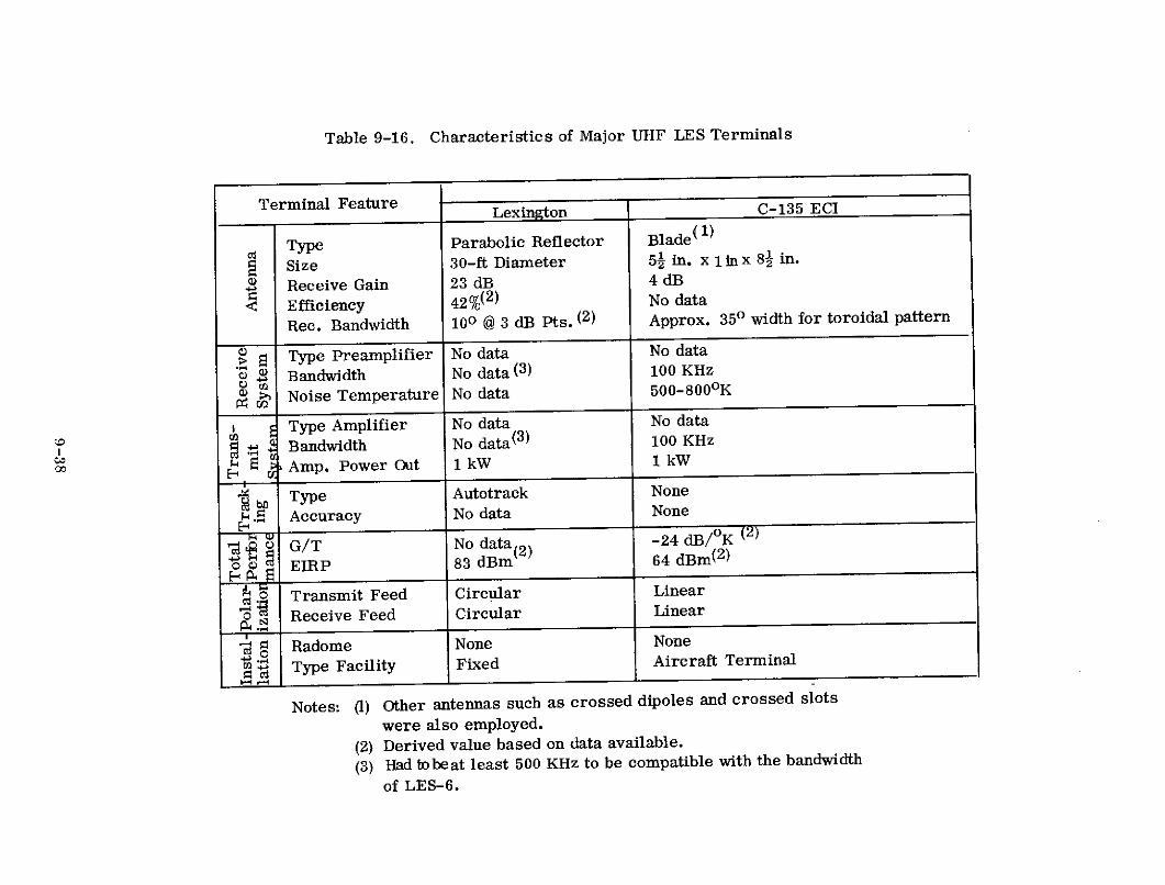
Table 9-16. Characteristics of Major UHF LES Terminals
Terminal Feature Lexington C-135 ECI
C Type Parabolic Reflector Blade(1)
Size 30-ft Diameter 51 in. x 1inx 8- in.
Receive Gain 23 dB 4 dB
Efficiency 42%(2) No data
Rec. Bandwidth 100 @ 3 dB Pts. (2) Approx. 350 width for toroidal pattern
> Type Preamplifier No data No data
Bandwidth No data (3) 100 KHz
S Noise Temperature No data 500-8000 K
Type Amplifier No data No data
- Bandwidth No data(3 ) 100 KHz
00 2 Amp. Power Out 1 kW 1 kW
bL Type Autotrack None
- . Accuracy No data None
S G/T No data(2) -24 dB/K (2)
0 EIRP 83 dBm( 64 dBm(2 )
o Transmit Feed Circular Linear
.4 Receive Feed Circular Linear
Radome None None
' Type Facility Fixed Aircraft Terminal
Notes: (1) Other antennas such as crossed dipoles and crossed slots
were also employed.
(2) Derived value based on data available.
(3) Had iobeat least 500 KHz to be compatible with the bandwidth
of LES-6.

Table 9-17. Summary of UHF LES Experiments
Program
Experiment Objective Nature of ActivitySatisfied*
1. Aircraft Antennas 2 Evaluate antennas for use on airplane and
helicopter satellite communications terminals.
2. Satellite Multiple Access 1, 2&3 Determine system limits and constrainingfactors for multiple access using tacticalterminals.
3. Tactical Modems 2 Measure performance of different tactical
terminal modulation/demodulation techniques.
4. Propagation Link Losses 3 Evaluate factors producing variations from
link attenuation determined by conventional
free space spreading and antenna gain consider-
ations
5. System Noise and 3&4 Measure receive system noise temperatures
Interference and RF interference to tactical satellitecommunications systemrs.
6. Satellite UHF Transponder 1 Determine performance of solid statesatellite repeaters operating at UHF.
7. Solar Cell Degradation 9 Study the effect of the space radiation environ-
ment on various experimental solar cells.
8. Earth Albedo 9 Define the spectrum of electromagnetic energyat optical frequencies as reflected by the
earth and viewed by a synchronous satellite.
9. Space Radiation 9 Measure temporal and spatial characteristics
Environment of near earth, space radiation.
10. Automatic Stationkeeping 8 Evaluate the feasibility of autonomous onboardcontrol employing either cold ammonia gas orpulsed plasma thrusters.
11. Automatic Attitude Control 7 Determine the feasibility of autonomous onboard control employing either magnetictorquing or cold ammonia gas thrusters.
12. High Efficiency RF Trans- 6 Demonstrate the feasibility of satellite trans-
mitters mitters operating directly from a solar arrayprimary power system.
13. Despun Antenna 5 Study use of switching in conjunction withmulti-element arrays as a means of realizing
a despun antenna on a spin stabilized satellite.
*Program objectives are numbered and defined in Table 9-10.
9-39

The despun antenna, indicated in the table, was flown on LES-6 and consisted
of an array of 8 elements with each element composed of a pair of collinear axial
extended dipoles in combination with a pair of collinear axial slots(21) . Two elements
were excited at a time and all combinations of successive elements were sequentially
activated as the satellite rotated. Each combination was excited in either of two-
phase relationships to produce two beam positions per pair of elements and a total
of 16 switched overlapping beams in the array. Post launch measurements of
antenna gain indicated it was in the region of 8.5 to 9 dB, which agreed with pre-
launch measurements. Pattern ripple due to beam switching was +0. 5 dB
Two antenna-switching logic systems were included on LES-6 which could be
operated independently or in a combined mode (2 1 ). As on LES-4, one system
measured the direction to the earth at one point in the orbit and predicted the orbital
position of the satellite as a function of time while the second system determined
earth direction during every revolution of the spinning satellite. In the combined
mode, the earth direction measuring system was employed during the hours of local
daylight at the subsatellite point and the orbit storage system was used during the
hours of local darkness. All modes of operation worked well for the first week in
orbit (29) . Subsequently a relay flip-flop failed in the Earth Position register of the
orbit storage system causing inaccurate pointing in both that mode and the mixed
mode. The earth direction measuring system continued to work as expected. As
on LES-4, however, pointing became inaccurate between local sunset and sunrise
as the satellite's optical sensors lost track of the exact location of the earth.
Proper operation of LES-6's high efficiency RF transmitter from a varying
dc power source was verified immediately after launch when it was discovered that
one solar panel was not delivering the expected power. This failure produced a
spin variation of about 1 volt in the solar bus voltage which resulted in about a 0. 5-
dB spin variation in transmitted power (2 9 ) . This variation was superimposed on the
ripple due to beam switching. The transmitter has continued to perform properly
as solar array output has varied with the season of the year and satellite lifetime in
orbit.
9-40

Automatic attitude control systems were included on both LES-5 and LES-6.
Their principal of operation was basically the same. They measured latitude, of the
satellite-earth line, relative to the satellite's equatorial plane at points 900 apart in
the orbit, providing a good view of both the sunlit earth and the sun (2 1 )( 4 6) . By
positioning the measurements 900 apart, X and Y axes of correction were established.
In making a limited number of measurements it was assumed that the satellite
attitude did not change greatly between measuring points. Proper orbital measurements
points were determined by the coincidence of pulses from specially positioned earth
and sun sensors. Knowledge of the satellite spin rate, as determined from sun sensor
measurements, and X and Y axis errors allowed corrections to be triggered at the
appropriate points during every satellite rotation.
The LES-5 attitude control system employed only magnetic torquing for
corrections and operated correctly in spite of the failure of one of its four sun
sensors. The effect of the failure was to reduce the rate of attitude correction but(21)
not its overall accuracy . The system demonstrated a capability of keeping the
spin axis within 2.60 of normal to the orbital plane (4 6 ) . The LES-6 system provided
either magnetic or cold ammonia gas thruster corrective torquing and was designed
to maintain attitude within 0.160 when the gas thruster system was employed (2 1 )
The LES-6 system could not be operated when the satellite spin axis was found
(immediately after launch) to be offset 2. 2* from the axis of symmetry of the cylinder.
The automatic stationkeeping system on LES-6 used an accurate onboard
clock to provide an indication of the time at which the satellite should arrive at a
given point in its orbit (2 1 )(28) . The time of actual arrival, as determined by the
clock and the coincidence of sun and earth sensor observations, was compared with
the desired time to generate longitude position errors to be corrected by firing
thrusters as appropriate. Thrusters firings were activated at satellite orbital
points separated by 1800 in order to ensure that orbit eccentricity remained constant.
Either cold ammonia gas thrusters or pulsed plasma electric microthrusters, using
solid Teflon as the propellant, could be employed for corrections.
9-41

Both thruster systems displayed proper and reliable operation although some
intermittency of the pulsed plasma thrusters was observed after they had fired for
several thousand hours (4 7 ). Further, the system displayed a capability of maintaining
the spacecraft within about 20 of a desired reference longitude.
The earth albedo and space radiation environment experiments were carried on
LES-6 alone. Both experiments have returned considerable data that has been useful
in characterizing the space environment. In the case of the radiation experiment,
this was accomplished in spite of interference produced when the communication(48)
antennas situated closest to the experiment were energized . Data taken during
periods of interference were unusable. However, there were times defined by a set
of earth and sun angles during which valid data could be obtained.
Solar cell experiments on LES-5 and LES-6 returned valuable data that has
contributed towards the design of spacecraft solar arrays. LES-5 silicon cells
showed an initial 4 percent degradation and an 8 percent yearly degradation. The
CdS cells displayed a 5 percent initial degradation and a 20 percent yearly degrada-
tion( 1 3 ) . LES-6 experiments revealed, among other things, that low energy proton
damage effects at the unshielded edges and contact bars of cells do occur in syn-
chronous orbit and are significant and that lithium doped P-N cells fair quite poorly
with an initial year's degradation as high as 42 percent (4 4 )
The UHF transponders carried on LES-5 and LES-6, in general, performed
well. Measurements taken included received communications signal level, local
oscillator frequency stability and transponder frequency translation, bandwidth,
receiver sensitivity, transponder total and differential time delay, transponder
transfer characteristics, and beacon performance. The receiver on LES-5 showed
a 17-dB seasonal decrease in sensitivity which was attributed to an open circuit in
the first RF amplifier that was produced as the average temperature of the satellite
decreased(2 1 ) . The satellite temperature cycle was such that the sensitivity dropped
in March and recovered in November of each year. In addition, one of the trans-
ponder local oscillators exhibited a sudden 1700-Hz shift in frequency in December
9-42

1968. This produced a comparable change in translation frequency. It was
hypothesized from ground testing on similar hardware that a capacitor in the LO
experienced an abrupt change in value. LES-6 has performed almost exactly as
predicted throughout its lifetime except for the output variations due to the spin
modulation on the dc power supply. None of the difficulties reviewed significantly
handicapped the communications test program.
Results of UHF noise and interference measurements are given in Table
9-18 (3 3 )(3 5 ) (4 3 . As indicated by the table, receiver composite noise temperature
measurements were taken on vehicular, shipborne, and airborne terminals while uplink
UHF interference levels at a synchronous satellite were measured on LES-5 and LES-
6. LES-5's RFI receiver experienced a timing problem which was hypothesized to
be due to cross coupling from one of the onboard logic systems that operated on earth-
sun inputs. These inputs disappeared around local midnight at the subsatellite
point as did the RFI receiver timing problem. As a result, all of the LES-5 RFI
data was centered about local midnight. LES-6's data gave a 24-hour distribution of
interference but since the satellite was stationary the information obtained was
primarily applicable to the North and South American continents alone. In addition
to the measurements indicated in Table 9-18, tests of interference generated by the
UHF tactical satellite communications terminals were conducted showing that
potential conflicts do exist if adequate distances and frequency separations are not
maintained.
Propagation link losses experienced by a UHF tactical satellite communications
system as determined from experiments on LES-3, -5, -6 are summarized in
Table 9-19 (see References 33 through 35 and 49). In addition to the factors indicated
in the table, structural blockage during maneuvers was found to be an occasional
problem in aircraft and shipboard terminals.
Performance of the three major types of modems evaluated in the tactical
satellite communications environment is summarized in Table 9-20 (3 3 ) (3 4 ) In all
cases, the table indicates performance on a channel perturbed by additive white
Gaussian noise alone.
9-43

Table 9-18. Noise and Interference to UHF Tactical Satellite Communications
Test Nature of Results
1. Vehicular Terminal Receive System Noise Receiver noise temperatures varied between 3600K and 5300K. Contribu-
Temperature tions by environment were as low as 3000 K and occasionally an order of
magnitude higher. Total system noise temperatures ranged between
about 7000K and 3,7000 K. RFI was an occasional problem. Both
AN/TRC-24 and AN/ARC-27 terminals were sources of interference.
2. Shipborne Terminal Receive System Noise Total receive system noise temperatures varied between about 600 K
Temperature and 2000 0K. RFI was not a serious problem but was occasionally
encountered. Shipboard radars such as the AN/SPQ-5A, AN/SPS-29,
and AN/SPS-43; communications terminals such as the AN/GRC-27,
portable electric generators and are welders could produce interference.
3. Airborne Terminal Receive System Noise Total receive system noise temperature including RFI was about 10000 K
Temperature over water and lightly populated areas, about 20000K over fairly heavily
populated land areas, and about 10, 000 K at low altitudes directly over
industrialized towns. Specific high power UHF ground communications
transmitters and the Time Division Data Link (TDDL) transmitters
located around the perimeter of the U. S. caused interference problems.
4. Uplink Interference to Synchronous Satellites Measured on LES-5 and LES-6. * Largest signals come from TDDL
sites in the air-defense system. Many other signals also detected.
There was no piling-up of signals from many small common-channel
transmitters. Some portions of the bands scanned showed little activity.
*Surface EIRPs as low as 50 to 100 watts detected on LES-5. LES-6 responded to EIRPs of 10 to 25 watts.

Table 9-19. UHF Propagation Link Losses
Parameter Nature of Results
1. Surface Terminal Antenna Aircraft antenna gain may vary from +9 to -15 dB
Gain over a hemisphere with elevation angle to satellite a
major factor determining average gain. Surface
vehicular or manpack terminal patterns affected
by any metal object within 10 meters.
2. Power Imbalance Can be significant problem for multiple mobile termi-nals accessing a hard limiting satellite since individualterminal uplink power levels showed about a -t2 dBvariation. Ability of individual terminal to effectentire system decreased dramatically as number oftotal accesses became large (i.e., about 10).
3. Intermodulation In general, was not a significant problem. In case
of FM voice signal and frequency hopping signal,however, intermodulation added a noticeableamount of noise to FM signal.
4. Atmospheric Absorption Attenuation due to atmospheric moisture mayvary between 0.5 to 1.5 dB dependent upon the
atmospheric path traversed by the signal.Locally heavy precipitation can add severalmore dB of loss.
5. Multipath Fading Encountered by aircraft. Two ray model for
the most part valid in predicting results. Cir-
cularly polarized signals provide degree of
protection since multipath fading on horizontallyand vertically polarized components is relatively
independent. Fading occurs primarily for eleva-
tion angles between 0 & 200, Over water and icecyclic fades vary between 1 & 10 dB with 5 dB
being most common. Over land cyclic fadesdecrease to 2 to 3 dB with occasional random
fades of 5 to 10 dB. Flights over mountains dis-
play no multipath.
6. Polarization Losses Can be up to 3 dB for operation with circularlypolarized satellite. Circularly polarized aircraft
antenna losses will, in general, vary with elevation
angle to satellite.
7. Fast Fading Occurred at rate 100 times faster than predictable
by 2-ray multipath no del. Both enhancement andfading occurred. Was frequency selective. Ocurred
only over water at look angles greater than 250
when operating within 300 of equator. Did notappear cyclic.
8. Scintillation Limited data indicated low probability of occurrence
for operation above 10o elevation angle in Temperate
Zone (+200 to + 650 latitude), Can cause fades up to20 dB. Polar Zone scintillation also observed.
9. Tropical Foliage 4 to 6 dB of loss encountered by vehicular and man-
pack terminals. Changing moisture content causes
variations.
10. Auroral Activity Limited data indicated little or no effect.
9-45

Gaussian noise alone. The TATS performance is about 2. 5 dB at 2. 4 kbps and 4. 5
dB at 75 bps above theoretical. This performance was for production model modems
optimized for the 2. 4-kbps data rate. Lincoln Laboratory prototype TATS modems
achieved much nearer to theoretical performance at both data rates. Production
TATS modems also displayed poor operational reliability. The triple diversity
modem displayed a significant degree of protection against multipath and RFI as did
the TATS modem. The TATS modem also supplied an in-band multiple access
capability.
Multiple access tests were successfully conducted employing narrowband FM
voice, triple diversity teletype, TATS 2400 bps, and TATS teletype separately and
in mixed modes ( 33 ) . Up to 17 TATS 2400 bps accesses through LES-6 into a C-135
aircraft terminal were demonstrated to be feasible (5 0 ) . However, TATS, as designed
with its short period frequency hopping pattern (i. e., it repeats every 7 symbols)
suffered from considerable interference due to related address codes. With even as
few as two common frequencies between two hopping patterns the cross correlation
was sufficiently high to make false acquisitions so prevalent that acquiring the proper
signal was almost impossible. Therefore, the hopping patterns present in a multiple
access environment had to be severly constrained. These restrictions, in some
cases, limited the number of premissible users below that theoretically indicated
by consideration of available power and bandwidth alone.
Table 9-20. Tactical Modem Performance
Modem Nature of Results
1. TATS Eb/N of 11. 5 dB and 13. 5 dB required for 10-4
probaility of error at 2.4 Kbps and 75 bps datarates respectively. At these levels of Eb/Nacquisition failure rates were less than 10- .
2. Triple Diversity Eb/N of 12 dB required for probability of error
less tan 10 - 3 at 75 bps data rate. No acquisition
problem existed.
3. FM Voice Narrowband FM gave acceptable quality at
Pr/No=50 dB which corresponded to E /N o ofabout 15 dB for data transmissions over this
channel. No acquisition problem existed.
9-46

Numerous tests were conducted in attempts to develop aircraft antenna systems
providing constant gain and polarization losses over an entire hemisphere. Fixed
wing aircraft experiments included evaluations of crossed slot, crossed dipole, and
blade antennas (3 3 ) . The crossed slot antenna supplied relatively good hemispherical
coverage with antenna gain for the circularly polarized antenna varying between -1
dB and +5 dB. The crossed dipole and blade antennas provided complementary
patterns with the former displaying good gain at elevation angles above 30* to 400
while the latter supplied its peak gain at elevation angles below 300 to 400. The
crossed dipole supplied circularly polarized signals and the blade linearly polarized
signals. The complementary patterns indicated that these two antennas should be
employed in a combined system having a switching capability for selecting the
appropriate antenna.
Helicopter antenna tests included evaluations of crossed dipole and blade
antennas individually and in various combinations mounted above and below the
rotor ( 3 6 ) . As in the case of the fixed wing aircraft tests, results indicated that a
crossed dipole and blade antenna should be employed in combination. Locating it
above the rotor avoided rotor blade modulation caused primarily by blockage of the
antenna aperature.
9. 3. 6 Operational Results
These were operational spacecraft; therefore, no operational traffic was
carried. The experimental tactical ground terminals operated essentially as
expected. One difficulty was that production models of the TATS modem displayed
poor reliability. The satellites also operated, generally, as expected in spite of a
number of minor difficulties, most of which were described in the discussion of
"Experiments" in Section 9. 3. 5.
Problems previously discussed on LES-5 included the sun sensor failure
affecting the automatic attitude control system, the high rate timing signal to the RFI
and command receiver, the 17-dB degradation in communications receiver sensitivity,
and the sudden shift in transponder frequency translation. Additional LES-5
9-47

difficulties included intermodulation between the telemetry and commuincations
transmitters, an open circuit in one series-connected string on a solar panel,
and higher than expected first year degradation of the solar array (i. e., about 22%).
The intermodulation was a result of the two signals using the same antenna and was
generated in spring finger contacts used at the edges of the slot antenna cavities
behind the solar panels. This problem disappeared after the satellite had been in
orbit a few months. The solar array power difficulties did not interfere with LES-5
te sting.
Problems previously discussed on LES-6 included spinning about an axis 2. 20
offset from the axis of symmetry of the cylinder, one solar panel delivering a low
power output, a flip flop failure in an Earth Position register of the antenna switching
logic, and interference to the radiation environment experiment by radiating
communications antenna elements. Additional LES-6 difficulties included intermodu-
lation between the beacon and communications transmitters and the shutter, covering
the radiation experiment, operating intermittently. The former was the same problem
as experienced on LES-5 and it too disappeared after a brief time of in-orbit opera-
tion. The latter was caused by variations in the dc power level and the lack of a
power regulator on this spacecraft.
9-48

CITED REFERENCES
1. H. Sherman, D. C. MacLellan, R. N. Lerner, and P. Waldron, "The
Lincoln Experimental Satellite Program (LES-1, 2, 3, 4) a Progress
Report, " AIAA 1st Communications Satellite Systems Conference, Wash-
ington, D.C., May 2-4, 1966.
2. W. E. Morrow, Jr., "The Lincoln Experimental Communications Satellite
and Terminal Program, " AIAA 2nd Communications Satellite Systems Con-
ference, San Francisco, California, April 8-10, 1969.
3. "LES - An Advance in Space Communications, " Signal, February, 1969.
4. H. Sherman, D. C. MacLellan, R. N. Lerner, and P. Waldron, "Lincoln
Experimental Satellite Program (LES - 1, 2, 3, 4), Journal of Spacecraft
and Rockets, Vol. 4, No. 11, September, 1967.
5. TRW Space Log, Vol. 5, No. 4, Winter 1965-1966.
6. "Quarterly Technical Summary, Space Communications, " Division 6,
Lincoln Laboratory, Massachusetts Institute of Technology, September
15, 1966, DDC AD 802 943.
7. I. L. Lebow, "Communications via Several Satellites Using the Lincoln
Experimental Terminal, " AIAA 1st Communications Satellite Systems
Conference, Washington, D. C., May 2-4, 1966.
8. D. C. Mac Lellan, H. Sherman, and P. Waldron, "The Lincoln Experi-
mental Satellite (LES)", Group Report 1964-65, Lincoln Laboratory,Massachusetts Institute of Technology, October 14, 1964.
9. J. W. Craig, W. R. Crowther, P. R. Drouilhet, Jr., J. N. Harris,F. E. Heart, B. H. Hutchinson, I. L. Lebow, P. G. McHugh, B. E.
Nichols, P. Rosen, S. B. Russell, J. Tierney, "The Lincoln Experi-
mental Terminal, " TR-431, Lincoln Laboratory, Massachusetts
Institute of Technology, March 21, 1967, DDC AD 661 577.
10. P. R. Drouilhet, Jr., "The Lincoln Experimental Terminal Signal
Processing System, " Conference Record, First IEEE Annual Communi-
cations Convention, Boulder, Colorado, June 7-9, 1965.
11. "Quarterly Technical Summary, Space Communications, " Division 6,Lincoln Laboratory, Massachusetts Institute of Technology, December 15,
1965, DDC AD 477 580.
9-49

CITED REFERENCES (Continued)
12. P. Rosen, and R. V. Wood, "The Lincoln Experimental Terminal, " Con-
ference Record, First IEEE Annual Communications Convention, Boulder,
Colorado, June 7-9, 1965.
13. F. W. Sarles, Jr., and L. P. Cox, "Solar Cell Degradation Experiments
on LES-4 and -5, " ESD-TR-70-162, Lincoln Laboratory, Massachusetts
Institute of Technology, Lexington, Massachusetts, DDC AD 708 603.
14. "Quarterly Technical Summary, Space Communication, " Division 6,
Lincoln Laboratory, Massachusetts Institute of Technology, June 15, 1966,
DDC AD 480 755.
15. "Quarterly Technical Summary, Space Communications, " Division 6,
Lincoln Laboratory, Massachusetts Institute of Technology, June 15,
1966, DDC AD 486 272.
16. "Quarterly Technical Summary, Space Communications, " Division 6,Lincoln Laboratory, Massachusetts Institute of Technology, March 15,1965, DDC AD 461 528.
17. P. Rosen, and B. E. Nichols, "Results of Experiments with the Lincoln
Experimental Terminal (LET) Using a Variety of Channel Types, " NEREM
Record 1965, November 3, 1965.
18. K. L. Jordon, Jr., "The Performance of Sequential Decoding in Conjunction
with Efficient Modulation, " IEEE Transactions on Communications Tech-
nology, Vol. COM-14, No. 3, June, 1966.
19. "Quarterly Technical Summary, Space Communications, " Division 6,Lincoln Laboratory, Massachusetts Institute of Technology, September
15, 1965, DDC AD 473 102.
20. "Quarterly Technical Summary, Space Communications, " Division 6,Lincoln Laboratory, Massachusetts Institute of Technology, June 15, 1965,DDC AD 468 636.
21. D. C. MacLellan, H. A. MacDonald, P. Waldron, and H. Sherman,"Lincoln Experimental Satellites 5 and 6, " AIAA 3rd Communications
Satellite Systems Conference, Los Angeles, California, April 6-8, 1970
DDC-AD707475.
22. TRW Space Log, Vol. 9, No. 4, Winter 1969-1970.
9-50

CITED REFERENCES (Continued)
23. "Quarterly Technical Summary, Space Communications, " Division 6,Lincoln Laboratory, Massachusetts Institute of Technology, September 15,1967, DDC AD 820 967.
24. "Quarterly Technical Summary, Space Communications, " Division 6,Lincoln Laboratory, Massachusetts of Technology, June 15, 1970, DDCAD 874 643.
25. "Quarterly Technical Summary, Space Communications, " Division 6,Lincoln Laboratory, Massachusetts Institure of Technology, September 15,1970, DDC AD 876 711.
26. "Initial Defense Communication Satellite Program, " TRW Space Log., Vol.
7, No. 4, Winter 1967-68.
27. TRW Space Log, Vol. 8, No. 4, Winter 1968-69.
28. A. Braga-Illa, "Preliminary Report on the Orbital Operation of the Automatic
Stationkeeping System of LES-6", AIAA Guidance, Control and Flight Mechanics
Conference, Princeton, New Jersey, August 18-20, 1969.
29. "Quarterly Technical Summary, Space Communications, " Division 6,Lincoln Laboratory, Massachusetts Institute of Technology, December 15,1968, DDC AD 846 887.
30. "Quarterly Technical Summary, Space Communications, " Division 6, Lincoln
Laboratory, Massachusetts Institute of Technology, September 15, 1969,DDC AD 861 186.
31. "Quarterly Technical Summary, Space Communications, " Division 6, Lincoln
Laboratory, Massachusetts Institute of Technology, December 15, 1969, DDCAD 866 132.
32. "Quarterly Technical Summary, Space Communications, " Division 6, Lincoln
Laboratory, Massachusetts Institute of Technology, March 15, 1968, DDCAD 831 081.
33. A. L. Johnson, and M. A. Miller, "Three Years of Airborne Communica-tions Testing via Satellite Relay, " Air Force Avionics Laboratory, AirForce Systems Command, Wright-Patterson Air Force Base, Ohio, DDCAD 880 276.
34. J. J. Foshee, G. E. LaVean, A. Johnson, and R. M. Goode, "Multipathand Propagation Experiment Utilizing VHF/UHF Satellite CommunicationsSystem, " AIAA 2nd Communications Satellite System Conference, SanFrancisco, California, April 8-10, 1968.
9-51

CITED REFERENCES (Continued)
35. S. M. Segner, "Performance of the Project East Vehicular Earth Terminals
with the LES-5 UHF Satellite Communications Repeater, " AIAA 2nd Communi-
cations Satellite Systems Conference, San Francisco, California, April 8-10,1968.
36. T. J. Yake, and J. W. Uhrig, "Helicopter Communications via UHF Satellite
Relays, " Air Force Avionics Laboratory, Air Force Systems Command,
Wright-Patterson Air Force Base, Ohio DDC AD 873 786.
37. P. R. Drouilhet, Jr., and S. L. Bernstein, "TATS-A Bandspread Modula-
tion Demodulation System for Multiple Access Tactical Satellite Communication,"Lincoln Laboratory, Massachusetts Institue of Technology, MS-2604, August
14, 1969.
38. "Quarterly Technical Summary, Space Communications, " Divison 6, Lincoln
Laboratory, Massachusetts Institute of Technology, March 15, 1970.
39. W. W. Ward, and B. E. Nichols, "Lincoln Experimental Satellite - 5 (LES-5)
Transponder Performance in Orbit, " Massachusetts Institute of Technology,Lincoln Laboratory, TN 1968-18, November 1, 1968, DDC AD 686 421.
40. R. E. Dolbee, "Design Procedure and Measured Performance of the LES-6
UHF Transmitter, " Massachusetts Institute of Technology, Lincoln Laboratory,TN 1968-20, July 19, 1968.
41. R. N. Assaly, M. E. Devane, B. F. La Page, M. L. Rosenthal, A. Sotiropoulos,"LES-6 Antenna System, " Massachusetts Institute of Technology, Lincoln
Laboratory, TR 465, March 10, 1969.
42. M. E. Devane, D. J. Frediani, B. F. La Page, M. L. Rosenthal,A. Sotiropoulos, "Antenna System for LES-5, " Massachusetts Institute of
Technology, Lincoln Laboratory, TR 451, July 18, 1968.
43. W. W. Ward, R. L. Sicotte, K. H. Hurlbut, and C. J. Zamites, Jr.,"The Results of the LES-5 and LES-6 RFI Experiments, " Massachusetts
Institute of Technology, Lincoln Laboratory, TN 1970-3, February 6, 1970,DDC AD 703 738.
44. F. W. Sarles, Jr., "Preliminary Results from the LES-6 Solar Cell
Experiment, " Massachusetts Institute of Technology, Lincoln Laboratory, DDC
DDC AD 707 483.
9-52
CITED REFERENCES (Continued)
45. "Quarterly Technical Summary, Space Communications, " Division 6,Lincoln Laboratory, Massachusetts Institute of Technology, September 15,
1968, DDC AD 843 053.
46. W. L. Black, B. Howland, and E. A. Vrablik, "An Electronic Attitude
Control System for a Synchronous Satellite, " Journal of Spacecraft and
Rockets, Vol. No. 7, July, 1969.
47. R. Vondra, K. Thomassen, and A. Solbes, "A Pulsed Electric Thruster
for Satellite Control, " Proceedings of the IEEE, Vol. 59, No. 2, February
1971.
48. "Quarterly Technical Summary, Space Communications, " Division 6, Lincoln
Laboratory, Massachusetts Institute of Technology, June 15, 1969, DDC AD
856 179.
49. J. Aarons, H. E. Whitney, and R. S. Allen, "Scintillation Observation of
Synchronous Satellites, " Air Force Cambridge Research Laboratories,L. G. Hanscom Field, Bedored, Massachusetts, AFCRL - 69 - 0011,January, 1969.
50. S. L. Bernstein, and R. L. Nickelson, "Preliminary Results of Multiple Access
Experiments with TATS and LES-6, " Massachusetts Institute of Technology,Lincoln Laboratory, TN 1969-50, September 29, 1969.
9-53

RELATED REFERENCES
1. "Quarterly Technical Summary, Space Communications," Division 6, Lincoln
Laboratory, Massachusetts Institute of Technology, December 15, 1966, DDC
AD 806 010.
2. J. B. Rankin, "X-Band Transmitting Antenna for LES-4, " TR-415, Lincoln
Laboratory, Massachusetts Institute of Technology, April 28, 1966.
3. M. L. Rosenthal, "X-Band Receiving Antenna for LES-4, " TR-410, Lincoln
Laboratory, Massachusetts Institute of Technology, December 22, 1965.
4. R. N. Assaly, J. B. Rankin, and L. J. Ricardi, "Switched-Beam Antenna
System for LES-1 and LES-2," TR-409, Lincoln Laboratory, Massachusetts
Institute of Technology, December 16, 1965.
5. W. E. Morrow, Jr., "An Overview of Satellite Communications Both Past
and in the Future, " Proceedings XVI International Astronautical Congress,
Vol. 4, Meterorological & Communications Satellites, Athens, Greece, 1965.
6. W. B. Smith, and I. I. Shapiro, "Observations of Hysteresis Damping in
a Spinning Satellite, " Journal of Spacecraft and Rockets, Vol. 5, No. 3,
March, 1968.
7. M. E. Devane, and M. L. Rosenthal, "Telemetry Antenna for Lincoln Experi-
mental Satellites LES-1 and LES-2," TR-394, Lincoln Laboratory, Massachus-
etts Institute of Technology, June 22, 1965.
8. P. Rosen, R. V. Wood, Jr., and B. E. Nichols, "Lincoln Experimental Terminal,"
TN 1966-30, Lincoln Laboratory, Massachusetts Institute of Technology, May
11, 1966.
9. J. Tierney, and J. N. Harris, "The Lincoln Experimental Terminal Channel
Vocoder (LET-VOC)," First IEEE Annual Communications Convention, Boulder,
Colorado, June 7-9, 1965.
10. N. L. Daggett, "Lincoln Experimental Terminal Timing and Frequency Control,"
TN 1966-33, Lincoln Laboratory, Massachusetts Institute of Technology,
August 4, 1966.
11. I. L. Lebow, and P. G. McHugh, "A Sequential Decoding Technique and Its
Realization in the Lincoln Experimental Terminal, " IEEE Transactions on
Communications Technology, Vol. COM-15, No. 4, August, 1967.
9-54

12. "Quarterly Technical Summary, Space Communications," Division 6, Lincoln
Laboratory, Massachusetts Institute of Technology, December 15, 1967, DDC
AD 826 016.
13. "Quarterly Technical Summary, Space Communications," Division 6, Lincoln
Laboratory, Massachusetts Institute of Technology, June 15, 1967, DDC AD
838 299.
14. "Quarterly Technical Summary, Space Communications, " Division 6, Lincoln
Laboratory, Massachusetts Institute of Technology, March 15, 1969, DDC AD
851 886.
15. "Space Electronics, " Electronics, Vol. 40, No. 11, May 29, 1967.
16. "More of LES," Electronics, September 30, 1968.
17. "Experimental Communication Satellite LES-6, " Telecommunication Journal,
Vol. 35-XI, 1968.
18. P. R. Drouilhet, Jr., and S. L. Bernstein, "TATS- A Bandspread Modulation-
Demodulation System for Multiple Access Tactical Satellite Communication,"
EASCON '69 Record.
19. E. M. DeLacy, and W. T. Higgins, "Description and Operational Summary of
the SHF and UHF Satellite Terminal Facilities, " MITRE Corporation, Bedford,
Massachusetts, MTR 1898, September 1970.
20. T. S. Seay, and A. H. Huntoon, "A LES-5 Beacon Receiver, " Lincoln
Laboratory, Massachusetts Institute of Technology, TN 1969-29,
May 1, 1969.
21. J. H. Helfrich, "LESTR-2 Telementry Ground System, " Lincoln Laboratory,
Massachusetts Institute of Technology, TN 1968-19, June 17, 1968.
22. A. Braga-Illa, "Automatic Satellite Stationkeeping, " Journal of Spacecraft and
Rockets, Vol. 6, No. 4, April, 1969.
23. A. Braga-Illa, "Orbit Determination from the Satellite, " Journal of Spacecraft
and Rockets, Vol. 6, No. 3, March, 1969.
24. A. Braga-Illa, "Automatic Orbit Control of the Lincoln Experimental Satellite
LES-6, " Lincoln Laboratory, Massachusetts Institute of Technology, TR 469,
July 10, 1969.
9-55

25. W. J. Guman, and D. M. Nathanson, "Pulsed Plasma Microthruster Propulsion
System for Synchronous Orbit Satellite, " Journal of Spacecraft and Rockets, Vol.
7, No. 4, April 1970.
26. A. Sotiropoulous, "LES-5 Triplexer, " Lincoln Laboratory, Massachusetts
Institute of Technology, TR 438, August 31, 1967.
27. J. B. Rankin, "Commutating Feed for Circular Array Antenna and its Applicationof the LES, " Lincoln Laboratory, Massachusetts Institute of Technology, TN1965-19, May 24, 1965.
9-56

SECTION 10 - INTELSAT
10. 1 PROGRAM DESCRIPTION
The International Telecommunications Satellite Consortium (Intelsat) is a
partnership initially established between 14 member nations in 1964 for the purpose
of providing global commercial telecommunications via satellite. Since that time,
the organization has expanded to include 79 member nations (as of May 1971), and new
applications for membership continue to be received. The interim agreements estab-
lishing the organization in 1964 provided for two management organs. An Interim
Committee on Satellite Communications (ICSC), made up of member nations, served
as a policy board, and the U. S. Communications Satellite Corporation (Comsat) was
responsible for system operation and technical management. In this arrangement,
Comsat was also the U. S. representative on the ICSC and under voting weighted
according to system ownership was the predominant voice in establishing initial Intelsat
policies.
During negotiations initiated in 1969 and concluded on May 20, 1970, the interim
agreements were superseded by permanent definitive international arrangements that
will become effective in about 1978. The reorganization required by the new agreements
will be phased over a 6-year period. This period will begin when all member nations
have ratified the new agreements. The earliest possible date for total ratification is
April 20, 1972.
During the 6-year phase-over period, a Board of Governors, composed of 20 to
25 members voting according to ownership percentage, will replace the ICSC. No single
member will control more than one-half the votes on this board. The Board of Governors
will receive top level political guidance from an Assembly of Parties, consisting of
representatives of all member states, which meets at least once every 2 years. The
Board will be guided on system operational matters by a Meeting of Signatories, consisting
of the telecommunications representatives of all member states. At the start of the
6-year phase-over period, the Board will appoint a Secretary General to handle adminis-
trative and financial management of the system. Additionally, the Board will negotiate
10-1

a 6-year contract with Comsat to provide system operational and technical management.
At the end of the 6-year period, a Director General will be appointed to assume the
executive responsibilities of Intelsat. He will take over administrative, financial,
operational, and technical management of the system. The Director General will be
responsible to the Board of Governors, but the exact makeup of the Director's office
has yet to be determined.
From the time it was established in 1964 to the present, Intelsat has produced
four generations of satellite and ground systems. Development of the initial satellite,
nicknamed Early Bird and later designated Intelsat I, was initiated by Comsat in
November 1963. Just a year earlier, in August 1962, the U. S. Congress had passed
the Communications Satellite Act, which authorized the creation of a private corporation
(Comsat) to instigate the development of a global commercial communications satellite
system. At the time when Early Bird's development began, the Syncom II satellite
had just completed demonstrating that reliable communications could be provided
through lightweight synchronous satellites. As a result, the Syncom satellite design
formed the basis for the Early Bird spacecraft. Early Bird was launched in early 1965,
as indicated in Table 10-1, and by April 22, 1965, had successfully achieved synchroni-
zation into the desired geostationary orbit with the satellite located over the Atlantic
Ocean. After a period of satellite performance testing, system parameter evaluation
using the operating ground stations, terrestrial and satellite circuit lineup, and public
demonstrations, commercial operation was initiated on June 28, 1965. The satellite
successfully provided commercial communications service between the United States
and Europe until it was retired in early 1969. It was reactivated for a brief period later
in 1969 when temporary difficulties were encountered with the antenna system of a third
generation Intelsat satellite.
The second generation of Intelsat spacecraft was designated Intelsat II. Even when
the Intelsat I system was under development, it was realized that many of the inherent
advantages of space communications could not be exploited. Specifically, its antenna
characteristics were such as to embrace only the northeastern part of North America
10-2

Table 10-1. Intelsat I (Early Bird) Spacecraft
Launch Date April 6, 1965
Manufacturer/Sponsor Hughes/Comsat
Launch Vehicle Thrust Augmented Delta
Apogee (Mi) 22,733
S Perigee (Mi) 21,748
Period (Min.) 1436.4
Inclination 0.1 °
Status: June 28, 1965 - Operational
Jan. 20, 1969 - Retired Reserve
June 29, 1969 - Reactivated
Aug. 21, 1969 - Retired (Pre-sently located at 121 0 Wlongitude)
*Parameters at initial orbit injection. Attitude control and stationkeepingmaneuvers produced changes.
10-3

and the western part of Europe, and it did not allow for simultaneous intercommunication
among numerous earth stations. By late 1965, it was recognized that the constraints
imposed by these deficiencies would be incompatible with a NASA requirement for
multichannel communications in late 1966 among its tracking stations at Carnarvon,
Australia, Ascension Island, Canary Island, tracking ships in the Atlantic, Pacific,
and Indian Oceans, and the Manned Space Flight Center in Houston, Texas. In the past,
these circuits had been carried by HF radio, but for manned space flights, improved
communications were desired. Consequently, in the fall of 1965 the development for
Intelsat II had begun with the primary goal of satisfying the NASA requirements; excess
capacity was to be used for other commercial traffic. Because of the urgency to satisfy
the NASA requirement, the Intelsat II design evolved directly from that of Intelsat I.
Four Intelsat II satellites were produced and launched as indicated in Table 10-2.
The first launch occurred in October 1966; but when the satellite's apogee motor mal-
functioned, the spacecraft was left in a highly elliptical inclined orbit, making it unusable
for full-time commerical operations. Subsequent launches in January and September
1967 successfully placed two satellites into operational service over the Pacific Ocean.
A March 1967 launch successfully supplemented the Intelsat I satellite in operation over
the Atlantic Ocean. With these three satellites in place, commercial service was
available over both the Atlantic and Pacific Oceans. The Intelsat II satellites continued
to meet international commercial communications requirements successfully until third
generation replacement satellites allowed them to be retired to the active reserve.
The development of Intelsat III was initiated in 1964 with a design study and
followed 2 years later with the award of a contract for the design, development,
and fabrication of the necessary spacecraft. Eight Intelsat III satellites were launched
between September 1968 and July 1970 as indicated in Table 10-3. Launch failures in
September 1968, July 1969, and July 1970 made three of these satellites unusable.
A successful launch in December 1968 placed a spacecraft in service over the Atlantic.
Some difficulties were encountered when this satellite's mechanically despun antenna
started sticking in mid-1969. This occurrence made necessary the aforementioned
10-4

Table 10-2. Intelsat II Spacecraft
Satellite F-1 F-2 F-3 F-4
Manufac/Sponsor - Hughes/Intelsat a
Launch Date 26 October 1966 11 January 1967 22 March 1967 22 September 1967
Launch Vehicle ThrustImproved Delta
Apogee (Mi) 23,014 22,257 22,254 22,245
. Perigee (Mi) 2,088 22,244 22,246 22,220
. Inclination 17.2 1.30 20 0.90
Period (Min) 730. 1 1436. 1 1436. 1 1429. 5
Status: Failed to achieve Placed in Placed in Placed in servicesynchronous orbit service over service over over Pacific atdue to malfunction Pacific at 1720 Atlantic at 1760 East. Nowof apogee motor. East. Now in 60 West. Nov at 1710 West.Employed commer- reserve at 1250 in reserve atcially in December West. 130 West.1966 and January1967.
*Parameters at initial orbit injection. Attitude control and stationkeeping maneuvers produced changes.

Table 10-3. Intelsat III Spacecraft
Satellite: INTELSAT III (F-1) (F-2) (F-3) (F-4) (F-5) (F-6) (F-7) (F-8)Manufacturer/Sponsor TRW/COMSAT TRW/COMSAT TRW/COMSAT TRW/COMSAT TRW/COMSAT TRW/COMSAT TRW/COMSAT TRW/COMSATLaunch Date Sept. 18, 1968 Dec. 18, 1968 Feb. 5, 1969 May 21, 1969 July 25, 1969 January 14, 1970 April 22, 1970 July 3, 1970Launch Vehicle Long-Tank Delta Long-Tank Delta Long-Tank Thrust Long-Tank Thrust Long-Tank Thrust Long-Tank Delta Long Tank Delta Long Tank Delta
Augmented Delta Augmented Delta Augmented Delta
Apogee (mi) 22, 257 22, 235 22, 166 3355
Perigee (mi) No Orbit 22, 244 22, 215 21,889 167
Inclination (deg.) Achieved 0.71 1.29 0.50 30.3 No Data No Data No Data
Period (min.) 1436 1436 1436 146.7
Status: Failed to Orbit; Placed over the Placed over the Placed in service Unusable because Placed over the Placed over the Failed to achievepitch rate system Atlantic at 300 W Pacific at 174
0E and over the Pacific at 3rd Stage mal- Atlantic at 240 W. Atlantic at 190 W. synchronous orbitpitchand began service on began service on 1740E as a replace- function placed and began service and began service due to a malfunction
malfunction forced December 24, 1968. February 16, 1969. ment for (F-3) and into incorrect on Feb. 1, 1970. on May 8, 1970. during apogeeCeased operation Repositioned over began service on Orbit. Subsequently motor firing.payload destruct June 29, 1969. Indian Ocean at 62.50 May 31, 1969. decayed.Resumed operation after losing 6 dB ofAug. 1, 1969. Now transponder gain dueat 48
0W. Placed in to a malfunction in one
retired reserve stage of the tunnelFeb. 1, 1970. diode amplifier, and
began service thereJuly 1, 1969.
PaPc-S at in'_t'a crb't etcor -. A'ti:e ctfrl

reactivation of Early Bird. The antenna problem was resolved by August 1, 1969,
and commercial operations were resumed until a subsequent January 1970 Intelsat III
launch allowed the satellite to be placed in the retired reserve. In April 1970 another
successful Intelsat III launch supplemented the operational capability available over
the Atlantic.
An Intelsat III satellite was first placed into operation over the Pacific in February
1969. This satellite was supplemented by a second spacecraft in May 1969. When the
first Pacific Intelsat III lost 6 dB of transponder gain due to an RF receive amplifier
malfunction, it was relocated over the Indian Ocean where the traffic requirements were
lighter. As a result, four Intelsat III satellites were, as of May 1971, providing global
commercial service over the Atlantic, Pacific, and Indian Oceans.
Development of the fourth generation of Intelsat spacecraft, Intelsat IV, began in
the latter portion of the 1960s. These satellites, manufactured by Hughes Aircraft
Corporation, have been designed to provide a substantially greater capability to meet the
increased global communication needs of the 1970s. The first, in an expected series of
eight satellites, was successfully launched by an Atlas Centaur rocket into a geostationary
orbit on January 25, 1971. It was positioned over the Atlantic at 24. 50W longitude.
Subsequent Intelsat IVs will be launched for service over the Atlantic, Pacific, and
Indian Oceans with an additional two satellites as spares in orbit. Each satellite will
have a life expectancy of about 7 years.
As of Mid-1971, Intelsat had already commenced planning for an Intelsat V series
of spacecraft. The first launch of an operational satellite is being projected for the
1977-78 period. It may be preceded by an experimental or prototype model. The
precise approach to satellite development has yet to be formulated.
Because the Intelsat program has been a commercial venture, the number of
major innovations in equipment and techniques employed has been limited. The intent
has been to minimize the risk of spacecraft failure and the exceptional reliability record
amassed by the system testifies to the success of this policy. Nevertheless, the
Intelsat program has made significant contributions to satellite communications.
10-7

Numerous subjective tests with Intelsat I demonstrated conclusively that the
round trip time delay and echo due to two-wire user terminations were not insurmountable
obstacles to the utilization of synchronous satellites for commercial communications.
This was in confirmation of preliminary indications obtained on Project SYNCOM.
The Intelsat II spacecraft demonstrated that tunnel diode amplifiers of operational
reliability were available for use as RF receive preamplifiers. Utilizing these relatively
low-noise, high-gain preamplifiers allowed direct RF to RF conversion in a single stage
to be employed. Sufficient spacecraft power and high performance earth terminals
allowed these transponders to be designed for linear input/output power transfer
characteristics. Additionally, Intelsat II and an expanded ground complex demonstrated
the feasibility of extensive multiple accessing of a single satellite transponder by a group
of operational ground terminals.
When the wideband Intelsat III satellites were placed into operation, it was necessary
to introduce a third generation of earth stations to the system in order to take full advan-
tage of the expanded capabilities of the space subsystem. These terminals employed
newly developed 500-MHz bandwidth cooled parametric amplifiers, as well as 500-MHz
bandwidth high power traveling-wave tube transmitters, capable of over 6 kW of multi-
carrier power.
The more recent Intelsat IV spacecraft have contributed to satellite communications
technology by demonstrating fixed narrow beamwidth (i. e., 4. 50) antennas mounted on a
mechanically despun platform and a highly channelized satellite repeater (i. e., 12 inde-
pendent transponders). The narrow-beam antennas provide coverage to a fixed, relatively
restricted area of the earth but the high antenna gain available significantly increases
satellite EIRP. The large number of transponders, each having a 36-MHz bandwidth,
allows users with substantially different communication requirements to operate
independently of each other in separate satellite channels (e. g. , television distribution in
one channel, high-capacity telephone trunks in another, and low-duty cycle individual
voicelinks in still another). Additionally, a fully variable, demand-access, satellite
system will be demonstrated for the first time during the period when the Intelsat IV
satellites are being placed into operational service. Comsat has developed a
10-8

single -carrier-per-voice channel PCM-PSK-FDMA demand-access system nicknamed
SPADE that will be employed.
10.2 SYSTEM DESCRIPTION
Transatlantic communications via Early Bird were nominally effected through
the Andover, Maine, earth station and one of four European earth stations. A Canadian
station at Mill Village, Nova Scotia, also served as the North American terminal
about 1 day per week after late 1966. In addition, it carried Early Bird traffic during
the Intelsat II launches to release the Andover station for launch support operations.
Three of the European stations, located at Goonhilly Downs (England), Pleumeur
Bodou (France), and Raisting (Germany), served alternately in the roles of operating
station and standby. They were interconnected by microwave links and submarine
cables that permitted all European traffic to be carried by any one of the stations.
The fourth smaller participating European terminal, located at Fucino (Italy), acted
as a terminal for weekend traffic. It was linked to the other three terminals via
Frankfurt, Germany. The terminals participating in Early Bird operations are
summarized in Table 10-4.
10-4. Intelsat I Participating Earth Terminals
Ant. Date of
Location Owner Dia. Install-(ft. ) ation
Andover (Maine) Comsat 67.7 1965
Mill Village (Nova Scotia) Canadian Overseas Telecom 8. 5 1966Corp (COTC)
Goonhilly Downs (England) General Post Office 85. 0 1965
Pleumeur Bodou (France) Centre National d'Etudes des 67.7 1965Telecommunications (CNET)
Raisting (Germany) Deutsche Bundespost 82 1964
Fucino (Italy) Telespazio 44 1965
10-9

The development of Intelsat II with a bandwidth several times that of Early
Bird was accompanied by second generation earth station designs such as those for
the Brewster Flats, Washington, and Paumalu, Hawaii, installations. A listing of
terminals, in addition to those indicated in Table 10-4, participating in operations
with Intelsat II satellites, as of April 1968, are listed in Table 10-5. Intelsat II
satellites located over both the Atlantic and Pacific Oceans provided multiple-access
communications among appropriate groups of these terminals. The wide variety of
station antenna sizes stems largely from the fact that many of the smaller ones were
required on very short notice to provide communications support for NASA's Apollo
program. Many of the smaller aperture stations have now been replaced by ones of
higher sensitivity. Their existence did, however, provide experience in working
with a variety of stations with a wide range of sensitivities.
Table 10-5. Intelsat II Participating Earth Terminals
ANTENNA DATELOCATION DIAMETER (FT.) INSTALLED
FUCINO (ITALY) 90 1967
BUITRAGO (SPAIN) 85 1968
ORAND CANARY ISLAND (SPAIN) 42 1967
ASCENSION ISLAND 42 1967
BREWSTER FLATS (WASHINGTON) 85 1966
PAUMALU (HAWAII) (NO. 1) 85 1966
PAUMALU (HAWAII) (NO. 2) 42 1968
CARNAROON (AUSTRALIA) 42 1967
TAMAY (PHILIPPINES) 42 1968
SI RACHA (THAILAND) 42 1968
MOREE (AUSTRALIA) 92 1968
IBARAKI (JAPAN) 72 1968
NASA TRACKING SHIPS (3) 30 1967
10-10
System planning for the Intelsat III satellite was completed in 1967, and a
third generation of earth stations was designed to provide full operating capability
with these spacecraft. Of paramount importance to the Intelsat III satellite design
was the use of two transponders covering nearly the entire 500-MHz band assigned
to communications satellite service. The new earth station designs made this
entire band available for use so that carrier frequencies could be assigned without
regard for narrow-band equipment. This flexibility guaranteed the success of multi-
destination FM-FDM to provide complete satellite multiple access to all earth
stations in the network. A complete list of terminals participating in operations with
Intelsat III satellites, as of January 1971, is provided in Table 10-6. Multiple access
communications nets have been formed among appropriate groups of these terminals
to operate with Intelsat satellites located over the Atlantic, Pacific, and Indian Oceans.
Fourth generation earth terminals are presently being constructed to operate
with the new Intelsat IV satellites. These terminals provide a large number of
carriers to take advantage of the multiplicity of satellite transponders that have
become available. As a result, the requirements for linearity in common RF trans-
mitting and receiving elements within these ground terminals have been substan-
tially increased. Additions to the ground complex defined in Table 10-6 that should
be operational by the end of 1972 are listed in Table 10-7. Intelsat IV satellites will
in the near future assume responsibility for space segment operations over the
Atlantic, Pacific, and Indian Oceans. These satellites and new signal processing
techniques will allow both fixed assignment and fully variable demand assignment
approaches to multiple access to be implemented among appropriate groups of user
terminals.
Operating frequencies for the four types of Intelsat spacecraft are defined
in Table 10-8. The bands of utilization indicated depict the fact that the Intelsat I,II, and III spacecraft contained two, one and two independent repeaters, respectively.
In the case of Intelsat IV, the bandwidth shown spans the total operating frequency
10-11

Table 10-6. Intelsat III Participating Earth Terminals
ANTENNA DIAMETERLOCATION (FT.) DATE INSTALLED
1) Balcarce, Argentina No. 1 No Data September, 19692) Ascension Island, United Kingdom 42 April, 19673) Moree, Australia 90 May, 19684) Carnarvon, Australia 97 October, 19695) Ceduna, Australia No Data December, 19696) Ras Abu-Jarjur, Bahrain 90 July, 19697) Tangua, Brazil 98 February, 1969
8) Mill Village, Canada No. 1 85 October, 1969 (Last Mod)9) Mill Village, Canada No. 2 90 January, 1969
10) Longovilo, Chile 97 July, 196811) Taipei, Republic of China 100 December, 196912) Choconta, Colombia 97 March, 197013) Pleumeur-Bodou, France No. 1 67.7 June, 1965 (Last Mod)
14) Pleumeur-Bodou, France No. 2 97 November, 196915) Raisting, Germany No. 1 82 June, 1965
16) Raisting, Germany No. 2 No Data October, 196917) Thermopylae, Greece 100 April, 197018) Hong Kong, United Kingdom No. 1 90 September, 196919) Djatiluhur, Indonesia 97 September, 196920) Asadabad, Iran 97 October, 196921) Fucino, Italy No. 1 90 August, 1967 (Last Mod)
22) Fucino, Italy No. 2 97 July, 197023) Ibaraki, Japan No. 2 90 March, 1968 (Replaced Ibaraki 1)24) Yamaguchi, Japan 90 July, 1969 (Last Mod)
25) Mt. Margaret, Kenya No Data August, 197026) Kum San, Republic of Korea 97 April, 197027) Umm Al-Aish, Kuwait No. 1 97 October, 196928) Arbaniyeh, Lebanon 97 September, 196929) Kuantan, Malaysia No Data March, 197030) Tulancingo, Mexico 105 January, 196931) Sehouls, Morocco No Data December, 196932) Utive, Panama 98 September, 196833) Lurin, Peru 100 July, 196934) Tanay, Philippines No. 1 97 April, 196835) Buitrago, Spain No. 1 85 January, 196836) Buitrago, Spain No. 2 98 April, 197037) Grand Canary Island, Spain Twin 42 ft. April, 196738) Sri Racha, Thailand No. 1 97 April, 196839) Sri Racha, Thailand No. 2 97 April, 197040) Goonhilly Downs, United Kingdom No. 1 85 July, 1969 (Last Mod)41) Goonhilly Downs, United Kingdom No. 2 No Data November, 196842) Andover, Maine 67.7 June, 196543) Brewster, Washington 97 December, 196644) Paumalu, Hawaii No. 1 97 December, 196645) Paumalu, Hawaii No. 2 97 December, 196846) Etam, West Virginia 97 October, 196847) Cayey, Puerto Rico 97 January, 196948) Jamesburg, California 97 December, 196849) Pulantant, Guam 98 November, 196950) Bartlett, Alaska 98 July, 197051) Camatagua, Venezuela 98 November, 1970
10-12

Table 10-7. Ground Complex Additions by End 1972
Antenna Dia.Location Antenna Dia. Date Installed
(ft)
1) Barbados, United Kingdom No Data 1972
1) Yaounde, Cameroon No Data October, 19713) Vancouver Island, Lake Cowichan, Canada No Data 19724) Kinshasa, Democratic Republic of Congo No Data June, 19715) Sululta, Ethiopia No Data 19726) Martinique, France No Data 19717) Libreville, Republic Gabon No Data 19728) Raisting, Germany No. 3 No Data 19729) Hong Kong, United Kingdom No. 2 No Data 1971
10) Arvi, India No Data 197111) Emek Haela, Israel No Data May, 197212) Fucino, Italy No. 3 No Data 197213) Abidjan, Ivory Coast No Data August, 197114) Prospect Pen, Jamaica No Data 197115) Ibaraki, Japan No. 3 No Data 197116) Baqa, Jordan No Data 197117) Umm Al-Aish, Kuwait No. 2 No Data 197218) Warkworth, New Zealand 97 May, 197119) Lanlate, Nigeria No. 1 No Data 197120) Lanlate, Nigeria No. 2 No Data 197221) Chittagong Hill Tracts, East Pakistan No Data 197122) Karachi, West Pakistan No Data 197123) Tanay, Philippines No. 2 No Data 197124) Dahban-Jeddah, Saudi Arabia No Data 1972
25) Riyadh, Saudi Arabia No Data 197226) Dakar, Senegal No Data 197127) Sentosa, Singapore No Data August, 197128) Aguimes, Spain 97 April, 197129) Tanum, Sweden No Data October, 1971
30) Matura Point, Trinidad No Data May, 197131) Ankara, Turkey No Data 197232) Goonhilly, United Kingdom No Data 197233) Vung Tan, Republic of Viet Nam No Data 197234) Lusaka, Zambia No Data 197235) Tegucigalpa, Honduras No Data April, 1971
36) Balcarce, Argentina No. 2 No Data August, 1971
10-13

Table 10-8. Intelsat Frequency Assignments
COMMUNICATIONS TT&C
SPACECRAFT Uplink Downlink Command Telemetry Beacon
Intelsat I (Early Bird) 6288-6314 MHz 4068-4094 MHz 6289 MHz 4104 MHz 136, 4104 MHz
6377-6403 MHz 4148-4174 MHz 6402 MHz 4138 MHz 137, 4138 M Hz
Intelsat II 6282-6408 MHz 4057-4183 MHz No Data 136 MHz 136 MHz
(*)Intelsat III 5930-6155 MHz 3705-3930 MHz 6175 MHz 3933-3967 3933-3967
6195-6420 MHz 3970-4195 MHz
(**) (**)Intelsat IV 5930-6420 MHz 3705-4195 MHz 6175 MHz 3950 MHz 3950 MHz
(*) Telemetry used to phase modulate beacon
(**) Divided into 12 channels each 36 MHz wide.

range of 12 independent repeaters. Downlink center frequencies for each of the 12
repeaters are: 3725, 3765, 3805, 3845, 3885, 3925, 3975, 4015, 4055, 4095, 4135,
and 4175 MHz, respectively. Uplink frequencies for each repeater are 2225 MHz
above the indicated downlink frequency. The frequencies employed were selected
to be compatible with the frequency bands reserved for commercial satellite commu-
nications use on a shared basis in 1963. These frequencies were set aside in
response to recommendations originated by AT&T during the Telestar program.
With the extensive ground complex and comparatively limited number of
spacecraft involved in the Intelsat program, satellite multiple-access techniques
and RF modulation employed have been of vital importance to the system. Intelsat I
incorporated a multiple-access capability, in a sense, by virtue of its sharing a
single TWT between two independent frequency-translating transponders. Since each
of these transponders was hardlimiting in nature, the number of carriers accessing
each was limited to one. For this reason, the mode of communication was point-to-
point, and only one duplex link between the United States and Europe was provided.
Conventional voice-channel multiplex equipment similar to that employed in the Bell
System and frequency modulation of the radiated carriers were employed. This
system configuration, in conjunction with the ground terminals available, provided
Intelsat I with a 240-duplex voice-channel capacity.
The Intelsat II system was designed to provide for frequency-division multiple-
access (FDMA) of the satellite by a number of earth terminals. Theoretical studies
had shown that for multiple large index FM carriers accessing the transponder:
(1) the satellite should be designed for a quasi-linear operation, (2) the maximum
power input should be limited to 1.5 to 2. 0 dB less than the producing transponder
saturation, and (3) the level and distribution of the carriers should be such that the
intermodulation products are approximately of constant level over the entire trans-
mission band. To ensure compliance with these criteria, carrier control stations
were established at Paumalu, Hawaii, and Andover, Maine, whereby the Atlantic
and Pacific Intelsat II systems could be monitored, each from a single point. In
10-15
early operations with Intelsat II satellites, FM carriers centered at specified fre-
quencies were preassigned to individual links between two points, thereby retaining
the point-to-point mode of operation employed on Intelsat I. However, multiple
point-to-point links were established through the Intelsat II transponders. The
system configuration described, together with the second generation ground complex,
produced a 240-duplex voice-channel capacity for each Intelsat II satellite.
It was recognized, by the time the Intelsat III satellites started to be put into
service, that the satellite capacity could be increased and the system complexity
reduced by switching to a point-to-multipoint mode of multiple-access operation.
This was implemented by designing each terminal to transmit one preassigned
multidestination FM carrier containing channels intended for all users to which it
was linked. Baseband channels were preallocated to a particular user as part of a
given network plan and were stripped off at each respective receiving site. The
Intelsat III satellite transponders were again designed for quasi-linear operation,
and the same type of carrier control concept as utilized for the Intelsat II system
was employed. The described mode of system operation has allowed the third
generation earth terminals to realize a 1200-duplex voice-channel system capacity
when operating through an Intelsat III satellite. Alternately, the satellite can provide
four television channels.
The Intelsat III approach to modulation, multiple access, and system control
will continue to be employed as the new Intelsat IV satellites are introduced to the
system. However, it will be supplemented, at an early date, by a fully variable
demand-access system called SPADE, which will operate in a separate transponder
of the Intelsat IV satellite. The term SPADE is derived from Single-channel-per-
carrier, Pulse -code-modulation, multiple-Access Demand-assignment Equipment.
The SPADE system will feature PCM encoding of individual voice channels for
quadriphase PSK modulation of a carrier. It includes the ability to deactivate carrier
transmission to the satellite during periods of talker inactivity and a decentralized
control concept allowing self-assignment of available satellite channels. The SPADE
10-16

system has been assigned to transponder 10 of Intelsat IV satellites. This particu-
lar transponder does not have access to the spot beam antennas. SPADE will be
compatible with standard manual or automatic international signaling and switching
systems. User applications, where the satellite channel requirements vary widely
over the period of a day, will find SPADE quite attractive. Each of the Intelsat IV
transponders will, in conjunction with the earth coverage satellite antennas and the
fourth generation ground complex, provide about 500 full duplex voice channels when
FDMA-FM is employed, 800 full duplex voice channels when SPADE is used, or 1
FM color television channel, including the TV audio.
10-17

10.3 SPACECRAFT
The Early Bird satellite was very similar to the Syncom III spacecraft. Early
Bird's microwave repeater consisted of two independent nonlinear, hard-limiting,
frequency translating transponders. Both transponders shared a single TWT output
power amplifier. A second TWT was carried on-board the spacecraft for redundancy;
however, only one of the tubes was on at a time. A block diagram of the Early Bird
repeater is provided in Figure 10-1. The satellite was spin-stabilized for attitude
control and the elimination of temperature extremes. The pancake-shaped antenna
pattern was squinted to provide high gain coverage of the northern hemisphere alone.
Spacecraft design lifetime was only 18 months. However, Early Bird operated
successfully for more than 3 years until it was retired from service. Communi-
cations characteristics of this satellite are provided in Table 10-9.
The Intelsat II satellite design evolved directly from that of Early Bird. Among
the most significant changes were the adoption of a single redundant wideband linear
amplifier and an antenna beam that covered both the northern and southern hemis-
pheres. The transponder bandwidth was 125 MHz compared with the two repeaters of
25-MHz bandwidth, each used in Early Bird. A block diagram of the Intelsat II
satellite's communications system is shown in Figure 10-2. To maintain the 240-
circuit capacity of Early Bird, in spite of the wider antenna beamwidth, Intelsat II
employed multiple traveling-wave tubes operating in parallel. Four tubes were
included in anticipation that three would be required to meet the EIRP requirements,
leaving one tube as a spare. However, the antenna and power efficiencies achieved
were such that a 2-tube configuration was adequate. The additional power required
by Intelsat II was provided by using a larger solar cell array. In contrast to
Early Bird, Intelsat H was designed to support communication through the eclipse
periods occasionally experienced in the synchronous orbit. The communication
characteristics of Intelsat H are shown in Table 10-10.
10-18

EARLY BIRD
(FREQUENCIES INX3 HYBRID I X2 PARENTHESIS ARE
FOR REPEATER 2)
128fmo
fmo = FREQUENCY MASTER OSCILLATOR
f IF = FREQUENCY INTERMEDIATE FREQUENCY X32
X4
2 Im384fmo t fmo 256fmo
MASTER 16.4855 mcOSCILLATOR (16.2219 mc)
Sfmo
TM X5ENCODER (X5)
5fmo (3fmo)
-- 1 BEACON
DECODER I AMPHASIEMODULATOR
-__ - -BEACON
TO TRAVELING-
FROM 0 FILTER MIXER INTERMEDIE LIMITER HMVEL FILTER WAVE AMPLIFIER
ANTENNA FREQUENCY IXER AND ANTENNA
FREQUENCY f IF FREQUENCY
RECEIVE TRANSMIT
SIGNAL SIGNAL SIGNAL BEACON
6389.97 mc 59.54 mc 4160.75 mc 4137.86 mc(6301.02 mc) (71.81 mc) (4081 mc) (4104.14 mc)
Figure 10-1. Block Diagram of Early Bird Repeater

Table 10-9. Early Bird Communication Characteristics
Type XMTR-Skirted 6-element Collinear Slot Dipoles
RCVR - Collinear 3-element Cloverleaf Array
Number 1 - XMTRZ 1- RCVR
z Beamwidth XMTR - 110 with beam center squinted 70 intonorthern hemisphere
RCVR - 400
Gain XMTR - 9 dB; RCVR - 4 dB
Polarization Linear in plane perpendicular to spin axis
Frequency Band C-Band
Type Hard-limiting, double conversion repeater
Bandwidth 25 MHz - each repeater @ 0.5-dB points
Number Two repeaters sharing a common TWT XMTR
W Type Front End Down Conversion Mixer
> Front End Gain No Data
Sys. Noise Figure Overall - 10 dB
Type 6-watt TWT and identical spare
Gain No Data
Power Out 4. 3 watts as operated
EIRP 10. 2 dBW @ beam edge/14 dBW maximum
SType Spin (152 rpm) with H2 0 2 jet attitude & spin rate control
SCapability No Data
w Primary 46. 5 watts from 6000 n-on-p solar cells *
S Supplement 1. 5 amp-hr. from two 21-cell nickel-cadmium batteries**
Comm. Power Needs 26. 8 watts
Size Cylindrical: diameter = 28. 4"; height = 23. 2"
Weight 149 lbs at injection, 89-79 lbs after apogee fire
* Capability at launch** Furnishes power during launch. Eclipse operation not possible.
10-20

CRYSTAL CRYSTAL
OSCI LATOR OSCILLATOR
MULTIPLIER MU15MHzX2 MULTIPLIER
X2
MASTERMULTIPLIER OSCILLATOR
X8 124 MHz MULTIPLIERMULTIPLIER X18
X2
MULTIPLIERX3 1 PHASE ENCODER
RECEIVE MULTIPLIERSANTENNA 1 X9
1 ON-OFF TRANSMITCOMMAND MIXERANTENNA
DISCRIMINATOR
2225 MHz
TUNNEL-SDIODE -- DIRECTIONALj MIXER FILTER DRIVER TWT DIRECTIONAL
AMPLIFIER COUPLER COUPLER
RECEIVEANTENNA 2 O
RECEIVER 2 m
Figure 10-2. Communications System Block Diagram for Intelsat II

Table 10-10. INTELSAT II Characteristics
Type Transmit: Multiple Element Biconical Horn
Number One Transmit and 2 Receive
Beamwidth Transmit: +6o (centered at equator)Receive: Essentially omnidirectional
Gain (4 GHIz) 8 dB
Frequency Band C-Band
Type Linear Single RF translation
B.W. ( dB) 126 MHz
Number 2 (1 redundant spare)
Type Front End Tunnel Diode Amplifier
9 Front End Gain No Data
Sys. Noise Figure 6 dB
Type 4 TWT's
Gain No Data
Power Out Nominal 10.8 dBW (7.8 dBW/TWT)
EIRP (at beam edge) 15 dBW (after back-off for multicarrieroperation)
Type Spin with H202 jet attitude control
Capability No Data
Primary 85 watts from 1?, 756 n-on-p solar cells *
Supplement 9. 0 amp/hour from two nickel cadmiumbatteries **
Comm. Power Needs No Data
Size Cylindrical: Height = 26. 5", Diameter = 56"
Weight 190 lbs after apogee fire
* Capability at launch
** Initial capability available for eclipse operation
10-22

Because the communications subsystem of the Intelsat III satellites provided
for two independent transponders, these spacecraft more closely resemble Intelsat I
than Intelsat II. The most significant difference between the Intelsat I and Intelsat III
transponders is that whereas the former was a hard-limiting, nonlinear, double-
conversion repeater, the latter is a linear single-conversion repeater. This is in
agreement with the Intelsat II design. Each Intelsat III transponder has a bandwidth
of 225 MHz. Together the two transponders cover most of the 500-MHz bandwidth
allocated to the communication satellite service in the 4-GHz and 6-GHz bands.
The initial satellites in the Intelsat III series employed single tunnel-diode amplifiers
in the receiver. However, after satellite F-3 lost 6 dB of transponder gain due to a
malfunction in one stage of the tunnel-diode amplifier, all subsequent spacecraft
were provided with redundant receive amplifiers to enhance the overall subsystem
reliability. A block diagram of the satellite communications subsystem is provided
in Figure 10-3. Communications characteristics of the satellite are summarized
in Table 10-11.
A further important distinction between Intelsat I and Intelsat III appears in
the communication antennas. The antennas of Intelsat I were symmetrical about
the spin axis to maintain constant antenna gain. Intelsat III employs a mechanically
despun antenna. This mechanically despun antenna is the most important innova-
tion in this series of satellites, and perhaps the most critical. Special lubricants
are used for the bearings, which are exposed to the hard vacuum of space and a
wide temperature range. Because Intelsat III has no VHF telemetering and tele-
command equipment (these functions are handled at C-band), an additional antenna
at 6 GHz with substantially omnidirectional properties has been provided to receive
telecommand signals for the initial setting up in orbit. The expected lifetime of
the satellite is 5 years.
The Intelsat I through III satellite designs produced communications systems
that were power limited, even though a high performance ground complex was
provided. This situation began to change with the development of the Intelsat IV
10-23

TELE:El:.Y]_* TELEMETRYCDOER I NPUIPTS
RADIO-FREQUENCY TRAVELING-WAVE-TUBE-AMPLIFIER POWER SUPPLY
BANDO A: 5930 to 6155 megahertz OSCILLATOR
S------ 3705 to 3930
TUNNEL. HYBRID LOWLEVEL RLTER HIGH-LEVEL megahertz0... 1 NETWORK MIXER TRAVELIN- COUPLERTRAVELING-AMPLIFIER WAVE TUBE WAVE TUBE
CIRCULATOR
...... TUNNEL- TRANSPONDER I
AMPLIFIER COMMAND COMMANDOMNIDIRECTIOAL DECODER OUTPUTSANTENNA INPUT COMMAND
// - - - -(TNNEL-DIODEAMPLIFIER SELECT)
TORECEIVE TRANSMIT OESPUNDIPLEXER 0PLEXER ATN
COMMAND
r AMPLIFIER SELE CT )
COMMAND COMMANDPOESPUN ANTENNA D T DECODER OUTPUTSINPUT INELU
AMPLIFIER TRANSPONDER 11O FLIIERCIRCULATOR
TUNNEL LOW-LEVEL HIGH-LEVELTNEL. HYBRID MIXER TRAVELING- TRAVEUG-AMPLIFIER NETWORK WAVE TUBE COUPLER WAVE TUBE 3970 to 4195
megahertzBEACON SIGNAL
BAND B: 6195 to 6420 megahertzRADIO-FREQUENCY TRAVELING WAVE-TUBE-AMPLIFIER POWER SUPPLYOSCILLATOR
TELE E-JRY q- TELEMETRYCODER I PiUS
Figure 10-3. Block Diagram of Intelsat III Communications System

Table 10-11. INTELSAT III Characteristics
Type Conical Horn with flat plate
reflector, mechanically despun
Number 1
Beamwidth (4/6 Gllz) 24/14. 50
Gain (4/6 GIIz) 16/21 dB
Frequency Band C-Band
Type Two independent linear singleconversion repeaters
B.W. (3 dB) 225 MHz each transponderimbehr Two
Type Front End Two stage tunnel diode amplifier
Front End Gain 31 dB
c Sys. Noise Figure 7 dB
S Type WTGain 73 dB
Power Out 12 Watts
EIRP(beam edge) 22 dBW per transponder
Type Spin
Capability No Data
Primary 10, 720 solar cell array - 161 watts
41 Supplement 1 rechargeable 20 cell nickel-cadmiun
batcery
Comm. Power Needs 99 watts
Size Cylindrical 55.4" diameter, 41"height without antenna
Weight (at liftoff) 632 lbs
(in orbit) 322 lbs
Polarization: Transmit - RHC
Receive - LIIC
10-25

spacecraft. When the spot beams of this satellite are employed with high perfor-
mance ground terminals, a bandwidth limited system results. The Intelsat IV
satellites' communications subsystem consists of global receive and both global and
spot beam transmit antennas connected to a 12-channel repeater that provides high
power amplification for each channel individually. Each of these 12 channels has
a bandwidth approaching 40 MHz, thereby providing capacity for about 500 com-
munications circuits. The satellite has the capability, using the EC antenna, for
relaying 6000 half duplex telephone calls, or 12 color television programs, or
any equivalent combination of such transmissions. The communication system
of Intelsat IV is depicted in the block diagram of Figure 10-4. Communications
characteristics of the satellite are summarized in Table 10-12.
The spot beam transmit antennas represent the most significant departure
from the previous satellite designs of the Intelsat series. Two of these antennas,
each a parabolic disc of 50 inch diameter, are mounted on the despun control
mast of the satellite. The entire RF portion of the spacecraft is despun. Pointing
of the spot beams is prefixed on the ground. These high gain antennas with beam-
widths of about 4 degrees, can be used to provide spot coverage in Europe and
North and South America, or they can be employed to provide intracontinental
coverage within specific countries. The basic physical configuration of the
Intelsat IV spacecraft is depicted in Figure 10-5.
10.4 GROUND TERMINALS
The Intelsat ground complex that provided communications through the Early
Bird ,atellite consisted to a large extent of modified versions of terminals initially
constructed to participate in Telstar and Relay program experiments (see Sections 6
and 7). The participating terminals were listed in Table 10-4. The Andover earth
station, originally built for Telstar, was modified during the period July 1964
through March 1965. The Goonhilly Downs earth station, also an original Telstar
terminal, was withdrawn from service in September 1964 for modification to work
10-26

EASTSPOTBEAM
6GH- 4GHP E ZER -- IEVEL 4.5o
4GHz
T SABBNSSWITCHABLE TwT GLOBA
...HYBRID 42BEAM
TG SY UEVEL SWITCH
STAND-BY RECEVERP
4
4 5.
BEAM
Figure 10-4. Communications Subsystem of Intelsat IV Satellites

Table 10-12. INTELSAT IV Characteristics
Type Global Receive, Global Transmit: conicalhorn with flat plate reflection. Spot Beam:50"parabolic reflectoT *. Omnidirectionalcommand receive antenna and omni-directional telemetry transmit.
Number 2 of each of the above communications antennasXmit. Beamwidth (global/spot beam) 17/4. 5
< Xmit. Gain (global/spot) 20. 5/31.7 dBPolarization Circular
Frequency Band C-band
Type Linear or limiting** single RF conversion repeater
B. W. (-1 dB) 36 MHz
Number 12
Type Front End Tunnel Diode Amplifier1 Front End Gain 13. 8 dB
Q Sys. Noise Figure 8.2 dB
Type
" Gain 58 dB
S Power Out 8 dBW per transponder
EIRP***(global/spot beam) 22. 5/34. 2 dBW per transponder at beamedge
Spin with hydrazine jet attitude & orbital ****
0 Type control. Stationkeeping to +0.25* North-South andCapability +0. 12' East-West. Attitude control to +0. 18.
> Primary 42, 240 solar cells - 750 watts at launchSupplement Nickel-cadmium batteries
rj
Comm. Power needs No Data
Size Cylindrical: 7'9" diameter, 17'4" height overall,9'3" solar drum alone
S Weight (at liftoff) 3094 lbs(in orbit) 1544 lbs
Notes: * Beam pointing adjusted prior to launch. Pointing cannot be changed by groundcommand.
** Selectable by ground command*** Measured in anechoic chamber
**** Both north/south and east/west stationkeeping provided.
10-28

TELEMETRY & COMMAND ANTENNAS ANTENNA MAST STRUCTURE
EARTH COVERAGE TRANSMITNUTATION DAMPER & RECEIVE ANTENNAS
OUTPUT MULTIPLEXERS SPOT-BEAM COMMUNICATION ANTENNAS
FORWARD SUN SHIELD TELEMETRY HORN
TWT POWER SUPPLY CONVERTERS . AVE GUIDE
BEARING AND POWER-TRANSFER ASSEMBLY TELEMETRY & COMMAND REPEATER ELECTRONICS
POSITIONING AND ORIENTATION ELECTRONIC EQUIPMENT COMPARTMENT
PROPELLANT TANKS (4)ELECTRICAL POWER CONTROL ELECTRONICS (2)
SOLENOID & SQUIB DRIVERS- / BATTERY PACK
0
tCO RADIAL JET SUN SENSOR
EARTH SENSOR SOLAR ARRAY
DESPIN CONTROL ELECTRONICS SPIN-UP JET
APOGEE MOTOR AFT THERMAL BARRIER
AXIAL JETS BOOSTER ADAPTER
Figure 10-5. Components of the Intelsat IV Satellites

with Early Bird. Prior to modification, the performance of Goonhilly was about
3 dB down as compared to Andover and PleumeurBodou. The modification improved
the terminal's performance by reducing profile inaccuracies of the reflector, reducing
aperture blocking from the feed support structure, and reducing feeder losses.
Characteristics of the Andover, Goonhilly, and Raisting earth terminals, as con-
figured for operation with Early Bird, were as indicated in Table 10-13.
Second generation earth terminals were developed to take advantage of the
wider bandwidths of the Intelsat II satellites. These earth stations employed more
advanced equipment than had previously been available, including solid-state designs,
masers of wider bandwidth, Cassegrain feed antenna systems, and dual carrier
receiving chains. A technical summary of three typical second generation earth
stations that participated in operations with Intelsat II satellites is given in Table 10-14.
The original Intelsat I terminals were also used to operate in the Intelsat II system.
These terminals were not significantly modified from their Early Bird configurations.
In building the third generation stations for operation with Intelsat III, new
500-MHz bandwidth cooled parametric amplifiers were developed, as well as
500-MHz bandwidth high power traveling-wave tube transmitters capable of over
6 kW of multicarrier power. Antenna sizes become relatively standardized at
97 feet diameter, partly to compensate for the somewhat higher noise temperatures
resulting from the wideband feed systems, and partly to obtain a small performance
margin for the terrestrial stations. The characteristics for two third generation
earth stations, Paumalu (Hawaii) and Fucino (Italy), are presented in Table 10-15.
With both global and spot beam transponders, Intelsat IV will allow earth
stations to operate with a large number of carriers. This will result in inter-
modulation distortion becoming an increasingly important consideration in earth
station performance. The higher capacities associated with Intelsat IV require
existing earth stations to verify a greater linear deviation capability, evaluate
their threshold extension demodulator performance at the larger capacities,
10-30

Table 10-13. Characteristics of Typical Early Bird Earth Terminals
Terminal Terminal
Feature - Andover * Goonhilly Downs Raisting
Conical Horn Parabolic ParabolicType Reflector Reflector Reflector
Aperture Dia. 67. 7 ft 85 ft 82 ft
Receive Gain 58 dB 58.5 dB 58.4 dB
Efficiency 70 - 75 % 55 - 60%** 55 - 60%**
Rec. Beamwidth
(3 dB) 0. 230 0. 20 0.20
Type Traveling Wave Traveling Wave
•g Preamplifier Ruby Maser Ruby Maser Maser
09 Bandwidth 25 MHz @ 3 dB Pts. 25 MHz @ 3 dB Pts. 20 MHZ @ 3 dB Pts.
Noise Temp. 50 0 K @ 7.50 Elev. 50 0 K @ 7.50 Elev. 50 0 K @ 7.60 Elev.
S Type Amplifier TWT TWT TWT
Bandwidth 30 MHz 30 MHz 30 MHz
Power Output 3 kW 3 kW 2 kW
Type Monopulse Programmed
Autotrack Tracking
Accuracy + .010 No Data + .010
4 G/T 41 dB/oK** 41. 5 dB/oK** 41. 5 dB/K **
EIRP 125 dBm** 124 dBm** 123.5 dBm**
. Transmit Feed No Data No Data No Data
Receive Feed No Data No Data No Data
. 210' Diameter 154' DiameterM Radome Rubberized Dacron None Rubberized Dacron
Type Facility Fixed Terminal Fixed Terminal Fixed Terminal
Notes: * The terminal at Pleumeur Bodou had essentially the same characteristics
** Derived value based on data available.
10-31

Table 10-14. Characteristics of Typical Second Generation EarthTerminals
TerminalTerminal Buitrago, Brewster Flats, NASA Ship****
Spain Washington
Type Cassegrain Cassegrain Cassegrain
Cd Aperture Dia. 85 ft 85 ft 30 ft
Receive Gain 58.4 dB 58.4 dB 47.8 dB
Efficiency 60%* 60% * 41%*
Rec. Beamwidth 0. 20* 0.2 o* 0. 50 *
Type Cooled Parametric Cooled Parametric
. Preamplifier Amplifier Maser Amplifier
Bandwidth No Data 30 MHz (-1 dB) 110 MHz(-3 dB)
Noise Temp. 58 0 K @ 100 Elev. 50 0 K @ 100 Elev. 135 0 K @ 7.50 Elev.
3 Type Amplifier Klystron Klystron Klystron
S Bandwidth 60 MHz (-1 dB) 30 MHz (-1 dB) 70 MHz (-3 dB)
a Power Output 10 kW 10 kW 10 kW
b. Type Autotrack Autotrack Monopulse Autotrack
Accuracy No Data No Data + 0.06°
' G/T 40. 8 dB/K * 41.4 dB/oK * 26 dB/oK
S EIRP 130 dBm * 130 dBm * 122 dBm maximum
STransmit Feed No Data No Data Linear **
0 Receive Feed No Data No Data Linear**
Radome None None Inflatable
53 ft diameter***
Type Facility Fixed Terminal Fixed Terminal Shipboard
Notes: * Derived value based on data available.
** Modified to circular for Intelsat III operations. Transmit-LHC and Receive-RHC.
*** Not employed operationally.**** Three of these terminals existed on board the Redstone, Vanguard, and Mercury,
respectively.
10-32

Table 10-15. Characteristics of Typical Third Generation Earth Terminals
Terminal TermialFeature Paumalu, Oahu Fucino, Italy
Type Cassegrain Cassegrain
Cd Aperture Diamctcr 97 ft 90 ft
Receive Gain 60 dB* 59.9 ldB
Efficicncy 60% ** 70%*
Rec. Beamwidth 0. 16 * 0. 170
a Type Preamplifier Hlelium Cooled Paramps. lclium Cooled Paramps.
6 U2 Bandwidth 500 MIlz 500 MlHz
e Noise Temp. 50 K @d 7. 5 Elcv. 40 K 06 7. 5 Elev.
Type Amplifier TWT TW
Bandwidth 500 Mllz 500 Mhz
Power Output 6 kW ; kW
Type Autotrack and Manual Autotrack, Program Track,and Manual
Accuracy No Data Autotrack -0. 020
i G/T 43 d(B/K* 4:1. 5 dB/o*
P EIRP 129 dBm* 129 dBm *
r Transmit Feed No Data Linear or Circular
.0 Receive Feed No )ata. Linear or Circular
a Radome None None
4 Type Facility Fixed Terminal Fixed Terminal
Notes: * Derived value based on data available.** Assumed value based on performance typically realized for this type antenna.
10-33

augment existing group delay equalization to the larger bandwidths associated with
higher capacities, and replace certain traffic bearing and monitoring filters whose
bandwidths are related to channel capacity.
Fourth generation earth stations have already been constructed at Talkeetna,
Alaska, and Pulantat, Guam. At this writing, the publically available literature
describing the performance of fourth generation Intelsat terminals appears to be
quite limited. In general, they are required to provide a receive gain of at least
57 dB and a receive G/T of 40.7 dB/eK. Both the transmit and receive chains will,
as a goal, provide a 500-MHz RF bandwidth. Terminal transmitting feeds will be
left-hand circularly polarized and receive feeds right-hand circularly polarized.
Each terminal will, as a minimum, contain both an autotrack and manual tracking
capability.
10.5 EXPERIMENTS
Since the major objective of the Intelsat program has been to establish an
operational international commercial satellite communications system, the number
of experiments and the instances of utilizing innovative equipment types have been
somewhat limited. In spite of this, a number of experimental activities of major
significance have taken place and indications are that this type of activity will
accelerate in the future.
An example of past activities is the Early Bird tests to evaluate the sub-
jective effects of long transmission delay on telephone subscribers and techniques
for reducing echo caused by two wire user terminations to acceptable levels.
Although the feasibility of synchronous satellite communications had been success-
fully demonstrated in the Syncom program, conclusive results in the two areas
indicated had not been obtained. Furthermore, prior to Early Bird, the opera-
tional experience required for a reliable commercial system was not available.
The successful operation of Early Bird (Intelsat I), for more than 3 years,
demonstrated public acceptance of space communications. In so doing, it proved
10-34

conclusively that, for single synchronous earth satellite repeaters, transmission
delay and echo were not serious problems in the realization of an operational
commercial system. Earth station experience gained at Andover, Goonhilly Downs,
Pleumeur Bodou, and Fucino demonstrated that efficient reliable communications
could be maintained and heralded the introduction of multistation operations.
Another area of major experimental interest to Intelsat has been modulation
techniques for multiple access of a single satellite transponder. An important
inherent advantage of communications via satellite is that a large number of widely
separated earth stations can communicate with each other simultaneously through
the same satellite. Through multiple access, the potential exists to greatly increase
system flexibility and to reduce the size and equipment complexity of the space
subsystem. As a result, techniques for multiple access have received a great deal
of attention for both military and commercial applications.
At the time of Early Bird, frequency modulation and frequency-division
multiple-access (FDMA) were the common approaches to RF modulation and multiple
access. Both were favored because of their compatibility with existing hardware.
It was also desirable at that time, due to limitations on realizable satellite power
and weight in orbit, to operate spacecraft repeaters as hard limiting transponders.
This approach to repeater design provided maximum efficiency in converting pri-
mary dc power into radiated RF power. However, the nonlinear transfer function
of hard limiting transponders results in intermodulation among the various
independent carriers existing in an FDMA system and thereby limits the potential
system capacity somewhat.
A means of avoiding the nonlinear repeater problem is to operate with only
one carrier through the satellite transponder at any one time. This can be accom-
plished by having the earth stations transmit their information in bursts rather than
continuously as in FDMA, and by synchronizing these bursts so that they enter
the transponder in a nonoverlapping sequence. Such a system is called time-division
10-35

multiple-access (TDMA). Intelsat's interest in TDMA started in the early stages
of commercial satellite communications in 1964, and in 1965 work was initiated
on the MATE program. This 3-terminal system operated at 6 Mbps and had a pre-
assigned capacity of 72 channels. The field testing of MATE, the first TDMA sys-
tem to be so tested, was conducted via Intelsat I in August 1966. The tests clearly
demonstrated the feasibility of TDMA and indicated that burst synchronization
to accuracies in the low nanosecond region could be achieved if such accuracy were
required.
Both the initial FDMA and TDMA systems employed fixed preassigned alloca-
tions of satellite transponder time, frequency, and power. Unfortunately, the pre-
assigned approaches to multiple access, while providing excellent quality and ser-
vice, have a poor working flexibility and use satellite spectrum and power inefficiently
by providing a poor "fill factor." Fill factor can be viewed as the relationship of the
total voice channel capacity of a satellite transponder to the average number of
such channels actively employed during the busy period. When fixed assignments
are made, there are numerous instances where channels stand inactive. Recog-
nizing the need for more efficient systems, Intelsat began to consider demand
access approaches to multiple utilization of the same satellite transponder. In
demand access, the general concept is to assign nonoverlapping allocations of
satellite power and time-frequency spectrum to users, in real time, as their
demand for service occurs. Both TDMA and FDMA systems providing demand-
access service are theoretically feasible.
An FDMA demand-access system given extensive consideration by Intelsat has
become commonly known as the SPADE system. SPADE has been designed for
links ranging from fractional requirements to 12 and 24 channels and is a PCM-
PSK-FDMA system. The development of SPADE was begun in 1964. The term
SPADE is derived from Single-channel-per-carrier, Pulse-code-modulation,
multiple-Access, _Demand-assignment Equipment. The salient features of the SPADE
10-36

system include digital PCM encoding of voice on a single channel per carrier, the
ability to transmit to the satellite only during talker activity, quadriphase PSK
modulation, system self-assignment of channels, and operation with standard manual
or automatic international signaling and switching systems. The ability to deactivate
earth terminal transmissions during periods of talker inactivity tends to compensate
for having to operate satellite transponders in a backed-off mode such that linear
transfer functions are provided. The system is compatible with the Intelsat II, III,
and IV satellites. It was tested between Andover, Maine, and Cayey, Puerto Rico,
over Intelsat II; and later between Etam, West Virginia, and Goonhilly Downs,
Cornwall, over Intelsat III. The SPADE system is now considered operational and has
been assigned to transponder 10 of Intelsat IV. This particular transponder does
not have access to the satellite's spot beam antennas.
Following the MATE system success, Intelsat started planning for the next
generation of TDMA systems, with emphasis on extending the state-of-the-art in
all technological areas relating to TDMA. The resulting experimental system,
called MAT-1, is a PCM-PSK-TDMA system for 12 to 24 channel links. It is
based upon a 50-Mbps transmission rate that yields over 700 8-bit PCM channels
in a 10-station network configuration. A unique feature of this system is its
orientation toward demand assignment.
The Kokusai Denshin Denwa (KDD) Research Laboratory has developed a
50-Mbps TDMA system, called TTT, which has time-assigned traffic blocks,
including a block devoted to an experimental pulse-code modulation, time-
assignment speech interpolation (PCM-TASI) design. The MAT-1 and the TTT systems
are compatible; field tests of these terminals were conducted in July 1970, over
Intelsat II (F-4) among stations in Hawaii, Japan, Australia.
Another technique being actively developed is that of placing a time-division
switching capability on-board the satellite itself. This technique will become par-
ticularly attractive as satellites providing multiple spot beams come into use. In
this technique, known as Satellite-Switched Multiple Access (SSMA), all stations'
10-37

transmissions are frame-synchronized by destination as they enter their respective
satellite receivers. Following amplification and, perhaps, down conversion, these
signals enter the satellite distribution subsystem that acts as a time-division switch.
In this switch, all the traffic intended for a particular destination is sequentially
directed toward the output amplifier and antenna for that destination. The receiving
system demodulates a single carrier, and the frame synchronization is now source-
oriented rather than destination-oriented.
Still another area of major concern to the Intelsat program has been link pro-
pagation. Considerable detailed data on satellite link propagation characteristics
at the 4- and 6-GHz frequencies has been obtained. This includes items such as
atmospheric absorption as a function of weather conditions; scintillation and fara-
day rotation as functions of time, geographic location, and sunspot activity; and
multipath as a function of antenna elevation angle. As the geostationary orbit has
tended to fill up with satellites operating at 4 and 6 GHz, Intelsat has become
interested in link propagation characteristics for spacecraft communications systems
operating at frequencies above 10 GHz. This interest is evidenced in the Comsat
propagation experiment to be conducted at 13 and 18 GHz by NASA's ATS-F
satellite. This experiment is designed to gather data on satellite signal attenuation
at 13 and 18 GHz caused by atmospheric hydrometeors at ground stations located
in representative climatological areas. The data obtained from this experiment
will provide the basis for establishing minimum power margins needed for opera-
tion at 13 and 18 GHz.
10.6 OPERATIONAL RESULTS
Since the Intelsat program has produced a commercial communications
system, the system's operational results obtained during each of the four genera-
tions of the space subsystem are of considerable interest. Early Bird was launched
on April 6, 1965, and by April 22 it was sufficiently synchronized for the commence-
ment of communications testing. Two groups of tests were conducted concomitantly:
the Performance Test Plan to determine how well the spacecraft performance in
10-38

orbit met contract specifications, and the Experimental Test Plan to determine
system parameters when the spacecraft is used with the operating ground stations.
The Performance Test Plan was completed in four days and included measurement
of the spacecraft's effective radiated power (ERP), receiving sensitivity, trans-
ponder gain and frequency response, noise power ratios (NPR), intelligible cross-
talk, antenna patterns, polarization, and insensitivity of the command system to
interference. The only notable failing of the Performance Test Plan was that the
specification for intelligible crosstalk of -45 dB could not be met with TWT No. 1.
For this reason, TWT No. 2 was used for all commercial operations.
The Experimental Plan tests were conducted for 18 hours per day for a week.
System characteristics with a variety of loading conditions were measured for all
stations. It was determined that the 240 circuit capacity could be realized by the
four high-capacity stations and that a 6-dB margin existed in fair weather. It
was also determined that the antenna gain and receiving sensitivity for the four
large stations were similar to within 1 dB.
Tests on system characteristics for monochrome TV were performed until
all stations reached agreement on the optimum operating parameters.
Three weeks after launch, the spacecraft and the earth stations were properly
tested, and the space segment of the system was ready for use. The terrestrial
network operators then began circuit lineup. For the 120-channel multiplex system
to be used for the first commercial service, it was necessary to allow 4 weeks
for adjustments at a circuit level both in the U. S. and in the four countries in
Europe. These tests were completed on schedule, and the system was ready for
operation in June.
After a series of successful demonstrations with telephone circuits and television
service, commercial operation was initiated on June 28, 1965. Figure 10-6 sum-
marizes commercial usage for telephone and television traffic through November 1967.
The satellite contribution to out-of-service time was zero in the Early Bird system.
10-39

NO. OFCHANNELS
TV HOURS
140 EARLY BIRD
130
25120
110 INTELSAT IIS PACIFICOCEAN
20 100
90
so80
1570
INTELSAT II60 ATLANTIC OCEAN
10 50
40
30
20
10
JF MAMJ JASONDJ FMAMJ J A S O N D
1966 1967
Figure 10-6. Early History of Intelsat System Usage
3.0
2C
1.5 - Total system
1.0Earth stations
Interconnects
I A I . 1 I. II I.J J ASO ND J F M AM J J A S O ND J
1965 1966 1967
Figure 10-7. Cumulative Outage Performance for Early Bird
10-40

All loss of service was attributable to the seven major earth segment elements --
the five earth stations and the U. S. and European interconnects. The reliability
history of this service through early 1967 is shown in Figure 10-7 in terms of
cumulative percentage outage time. Early Bird was placed in retired reserve
on January 20, 1969, after Intelsat m achieved operational status. It was re-
activated for a brief period between June 1969 and August 1969 when temporary
difficulties were encountered with the despun antenna of an Intelsat III satellite.
The operational lifetime of 3-1/2 years far exceeded the design lifetime of 1-1/2
years for this exceptionally successful satellite program.
The first Intelsat II satellite (F-1) was launched in October 1966. Although
it failed to achieve stationary orbit, the successful functioning of the communica-
tions subsystem permitted an 8-hour-per-day voice service to be established between
the earth stations in Hawaii and Brewster Flat. The highly elliptical, inclined
orbit realized reduced the commercial utility of the F-1 satellite to negligible
proportions, but the experience with its functioning subsystem proved to be invalu-
able in preparing for operations with its successors. Live television between Hawaii
and the U.S. mainland was inaugurated via (F-1) on November 18, 1967.
Intelsat II (F-2) and (F-4) were employed for service in the Pacific area.
During the time when the (F-4) satellite was undergoing final positioning maneuvers,
its longitude was allowed to approach closely that of (F-2) for the purpose of making
intersystem interference measurements. At Paumalu, the 85-foot antenna was
operating with (F-2) while the 42-foot antenna was available for experimental work
with (F-4). Experiments and measurements of interference were made as the
satellites approached to within 0.5" of each other. It was concluded from these
interference measurements that the Intelsat II system can be safely operated with
a minimum of 1. 6 of longitude separation between satellites. Both of these satel-
lites and (F-3), which supplemented Early Bird in the Atlantic area by providing
wide area service, have operated satisfactorily providing commercial communica-
10-41

tions service. Multiple-access service was successfully initiated with the Intelsat II
(F-2) satellite on January 27, 1969.
The first Intelsat m satellite (F-1) was launched in September 1968, but no
orbit was achieved. This was followed by the launch of Intelsat III (F-2) on December
18, 1968. This satellite began operational service over the Atlantic on December 24,
1968. It operated satisfactorily until June of 1969, at which time sticking of the
mechanically despin antenna was encountered. This was determined to be due to a
thermal gradient problem across the bearings of the despin motor. By August of
1969, the satellite was back in operational service. It continued to be employed
until February 1, 1970, when Intelsat III (F-6) assumed the operational load over
the Atlantic Ocean and (F-2) was retired from service. Intelsat III (F-3) was launched
into orbit over the Pacific on February 5, 1969. It was placed into operational
service on February 16, 1969, and continued to be employed in the Pacific location
for about 6 months. F-3 was then repositioned over the Indian Ocean after losing
about 6 dB of transponder gain due to a malfunction in one stage of the receiver
tunnel diode amplifier. The reduced channel loading associated with operations at
the Indian Ocean location permitted the satellite to continue in a useful capacity.
Intelsat III (F-4) replaced (F-3) in handling the Pacific Ocean operational traffic.
Intelsat III (F-7) was successfully placed into service over the Atlantic on May 8,
1970, to supplement (F-6). As of mid-1971 Intelsat III (F-3), (F-4), (F-6), and (F-7) and
the associated ground complex continue to perform essentially as expected.
The first Intelsat IV satellite (F-2) was successfully launched into orbit over
the Atlantic Ocean on January 25, 1971. Communications tests began on February 7,
and on March 26 earth station antennas in 14 countries, then operating with the
Intelsat III (F-6) satellite, began a simulataneous mass pointover to assume operational
service through the Intelsat IV (F-2) satellite. Fabrication of follow-on satellites
in the IV series continues on schedule. As of mid-1971, future Intelsat IV launches
were tentatively planned as follows:
10-42

Pacific Third Quarter 1971
Second Atlantic Fourth Quarter 1971
Pacific spare Second Quarter 1972
Atlantic spare Last Half 1972
Indian Ocean 1973
Operational traffic projections for the composite Intelsat system are shown
in Figure 10-8. The figures from 1971 onward reflect the minimum projected yearly
growth rate of 15%. Figures show voice channels or half duplex circuits.
VOICE CHANNELS(Or Half- Circuits)
40,000 -
30,000 ------ ------- - ------
20,000
10,000 ---
0 . I t I I , _ . L ._ ._ I .1965 66 67 68 69 70 71 72 73 74 75 76 77 78 79 80
Figure 10-8. Intelsat Traffic Growth Projection (1965-1980)
10-43

RELATED REFERENCES
1. J. F. Arnaud, "Progress of INTELSAT," 1968 IEEE Int'l. Conf. on Comm.,Convention Record, pp. 634-638, June 1968.
2. R. E. G. Back and D. J. Withers, "The Development of the INTELSAT Global
Satellite Communication System, Part 1 - The Early Years and the INTELSAT
III Satellites," Post Office Electrical Engineers Journal, Vol. 62, No. 4,pp. 207-212, January 1970.
3. J. M. Barstow, "Satellite Communications Systems," Microwave Journal, pp.
100-105, November 1966.
4. R. M. Bentley, "Early Bird," Astronautics and Aeronautics, Vol. 3, No. 3,pp. 26-29, March 1965.
5. R. M. Bentley, "Early Bird Experimental Results," Proceedings XVI'th Int'l.Astronautical Congress, Vol. 4, Meteorological and Communications Satellites,Athens, Greece, 1965.
6. E. R. Cacciamani, Jr., "The SPADE Concept Applied to a Network of Large andSmall Earth Stations," AIAA Paper No. 70-420, April 1970.
7. D. Chakraborty, "INTELSAT IV Satellite System (Voice) Channel CapacityVersus Earth-Station Performance," IEEE Trans. Comm. Tech., Vol. COM-19,No. 3, pp. 355-362, June 1971.
8. P. F. Checcacci, et al, "A Comparison of Scintillations at Two Middle LatitudeObservations," Proc. Seventh Int'l. Space Science Symposium, Vienna, Austria,10-18 May, 1966, pp. 1345-1353.
9. F. Donnelly, et al, "Design of a Mechanically Despun Antenna and its ControlSubsystem for a Spin-Stabilized Synchronous Satellite," AIAA Paper No. 68-433,April 1968.
10. S. H. Durrani, "A Multifunctional Satellite for the Late 1970's, " WESCON Tech-nical Papers, Vol. 14, Paper 13.4, 1970.
11. M. Feigen, et al, "The INTELSAT III Satellite," 1968 IEEE Int'l. Conf. onComm., Convention Record, pp. 639-645, June 1968.
12. O. G. Gabbard, "Design of a Satellite Time-Division Multiple-Access BurstSynchronizer," IEEE Trans. Comm. Tech., Vol. COM-16, No. 4, pp. 589-596,August, 1968.
10-44

RELATED REFERENCES (Cont'd)
13. H. Haberle and E. Herter, "A Proposal for the Interworking of Preassignment
Satellite and Terrestrial Systems with Demand-Assignment Satellite Systems in
Interregional Telecommunication Networks," IEEE Trans. Comm. Tech., Vol.
COM-19, No. 2, pp. 205-210, April 1971.
14. R. Y. Huang and P. Hooten, "Communication Satellite Processing Repeaters,"
Proc. IEEE, Vol. 59, No. 2, pp. 238-251, February 1971.
15. A. Kampinsky, "Evolution of a Spacecraft Antenna System," Proc. 4'th Aero-
space Mechanisms Symposium (JPL), pp. 13-18, January 1970.
16. J. R. Koster, "Ionospheric Studies Using the Tracking Beacon on the "EarlyBird" Synchronous Satellite," Annales des Geophysique, Vol. 22, No. 7-8,pp. 435-439, July-September 1966.
17. E. J. Martin and W. S. McKee, "Commercial Satellite Communications Experi-
ence," Spectrum, Vol. 4, No. 7, pp. 63-69, July 1967.
18. S. Metzger, "The Commercial Communications Satellite System: 1963-1968,"Astronautics and Aeronautics, Vol. 6, No. 4, pp. 42-51, April 1968.
19. H. Michishita, et al, "TTT System Experiments via INTELSAT III," presentedat the 1971 Int'l. Conf. on Comm., June 14-16, Montreal, Canada.
20. A. T. Owens, "The Early Bird Program," WESCON Convention Record, Vol. 9,paper 19. 3, August 1965.
21. J. B. Potts, "Commercial Communication Satellite Earth Stations - Past,Present, and Future," AIAA Paper No. 70-421, April 1970.
22. J. B. Potts and H. Prescott, "Earth Station Transitions Within the INTELSATSystem," presented at the 1970 IEEE Int'l. Conf. on Comm. Conf. Paper70-CP-343-COM, June 1970.
23. H. Prescott, "Earth Stations for the Global Satellite Communications System,"1968 IEEE Int'l. Cony. Digest, p. 208, March 1968.
24. W. L. Pritchard and J. G. Puente, "The Advantages of Demand Assignment forInternational Satellite Communication Systems," Telecommunications, Vol. 5,No. 3, pp. 27-33, March 1971.
10-45

RELATED REFERENCES (Cont'd)
25. J. G. Puente, "A PCM-FDMA Demand Assigned Satellite Multiple AccessExperiment," Telecommunication J., Vol. 36, No. 4, pp. 158-170, April 1969.
26. J. G. Puente and A. M. Werth, "Demand-Assigned Service for the.INTELSATGlobal Network, " IEEE Spectrum, Vol. No. 1, pp. 59-69, January 1971.
27. J. G. Puente, et al, "Multiple-Access Techniques for Commercial Satellites,"Proc. IEEE, Vol. 59, No. 2, pp. 218-229, February 1971.
28. W. G. Schmidt, "An Efficient TDMA System for Use by Emerging Nations withthe INTELSAT IV Satellite," EASCON '68 Record, pp. 21-27, September 1968.
29. W. Schrempp and T. Sekimoto, "Unique Word Detection in Digital Burst Com-munications," IEEE Trans. Comm. Tech., Vol. COM-16, No. 4, pp. 597-605,August 1968.
30. T. Sekimoto and J. G. Puente, "A Satellite Time-Division Multiple-AccessExperiment," IEEE Trans. Comm. Tech., Vol. COM-16, No. 4, pp. 581-588,August 1968.
31. S. W. Spaulding, "Practical Space Applications," in Advances in the Astro-nautical Sciences, L. L. Kovanan (ed.), Vol. 21, pp. 189-198.
32. R. Stamminger, "Transmission System Planning for INTELSAT III," AIAAPaper No. 68-448, April 1968.
33. F. J. D. Taylor, "INTELSAT II in Systems -- The Results of Practical Experi-ence, " AIAA Paper No. 68-427, April 1968.
34. J. H. W. Unger, "Random Tropospheric Angle Errors in Microwave Observa-tions of the Early Bird Satellite," Bell System Technical Journal, Vol. 45, No.9, pp. 1439-1474, November 1966.
35. M. J. Votaw, "The Early Bird Project, " Proceedings XVI'th Int'l. AstronauticalCongress, Vol. 4, Meteorological and Communications Satellites, Athens,Greece, 1965.
36. M. J. Votaw, "The Early Bird Project," IEEE Trans. Comm. Tech. Vol.COM-14, No. 4, pp. 507-511, August 1966.
37. A. M. Werth, "Multiple Access and Demand-Assignment Techniques," AIAAPaper No. 70-463, April 1970.
10-46

RELATED REFERENCES (Cont'd)
38. A. M. Werth, "SPADE: A PCM FDMA Demand Assignment System for SatelliteCommunications," 1970 IEEE Int'l. Conf. on Communications, paper 70-CP-423-COM, June 1970.
39. H. E. Whitney, et al, "Studies of the Latitudinal Variations of Irregularities byMeans of Synchronous and 1000 km Satellites," Proc. Seventh Int'l. SpaceScience Symposium, Vienna, Austria, 10-18 May 1966, pp. 1358-1369, 1966.
40. "Communications Satellites, " Space World, Vol. G-12-84, pp. 24-29, December1970.
41. "INTELSAT III," Electrical Communication (special issue) Vol. 45, No. 4, pp.278-378, 1970.
42. "INTELSAT IV - Newest Series of Commercial Communications Satellites,"Signal, pp. 43-45, April 1971.
43. "INTELSAT IV - European Participation," Radio and Electronic Engr., Vol. 41,No. 2, pp. 94-95, February 1971.
44. "INTELSAT IV," Space, Vol. H-4-88, pp. 5-9, April 1971.
45. F. E. Donnelly, Jr., et al, "The Design of the Mechanically Despun Antenna forthe INTELSAT III Communications Satellite," IEEE Trans. Antennas and Propa-gation, Vol. AP-17, No. 4, pp. 407-415, July 1969.
46. S. B. Bennett and I. Dostis, "The INTELSAT IV Transponder," IEEE 1971 Inter-national Conference on Communications, Conference Record, pp. 35-7 to 35-12,June 1971.
47. N. K. M. Chitre, "INTELSAT IV Communications System Simulation," IEEE1971 International Conference on Communications, Conference Record, pp. 35-24to 35-29, June 1971.
48. R. R. Colino, "The Present and Future Organizational Structure of INTELSAT,"IEEE 1971 International Conference on Communications, Conference Record, pp.35-1 to 35-6, June 1971.
49. M. L. Rosenbluth, "Network Operation with Communications Satellites, " IEEE1971 International Conference on Communications, Conference Record, pp.35-18 to 35-23, June 1971.
10-47
RELATED EXPERIENCE (Cont'd)
50. "Growing, Reorganized INTELSAT Ponders New Satellite Series," AviationWeek & Space Technology, Vol. 95, No. 8, August 23, 1971.
51. "Multiple Access Techniques Add Flexibility," Aviation Week & SpaceTechnology, Vol. 95, No. 8, August 23, 1971.
10-48

SECTION 11 - MOLNIYA-1
11.1 INTRODUCTION
For the Soviet Union, which occupies about one-sixth of the earth's surface,
an efficient system of space communications is a vital necessity. The country covers
nearly 6000 miles from east to west and over 2500 miles from north to south, and is
crossed by 11 time zones; in addition, there are tremendously varied climatic
conditions and vast areas of rugged terrain. For the United States, geostationary
orbits over the earth in the equatorial plane have been favored because they permit
communications 24 hours per day. For the Soviet Union, whose territory extends
up to 80°N latitude, however, such an orbit is not ideal. It does not ensure commun-
ications at earth station elevation angles greater than 7. 50 for all areas that lie
above 70°N latitude. The Soviet Union's communication satellites system, using the
Molniya-1 spacecraft, circumvents this difficulty by employing the highly eccentric
elliptical orbits described below.
The orbit chosen for Molniya-1 satellites is interesting for two reasons.
First, it is highly elliptical, with an apogee of 40, 000 km in the northern hemisphere
and perigee of 500 km in the southern hemisphere, with a period of revolution of
nearly 12 hours. Thus the two daily orbital apogees for any given satellite occur over
earth longitudes 1800 apart. Second, the angle of inclination of 650 means that the
useful period, during one of the two daily orbits of a spacecraft, when the satellite
can be employed for radio communication between distant points in the USSR, is
between 8 and 10 hours. If three Molniya-1 communication satellites are
launched at regular intervals into identical elliptical orbits whose planes are shifted
relative to one another by 1200, they will form a system that ensures 24 hours per
day communications for the entire USSR. It should be noted that this orbit also
affords the possibility of continuous communication between the European USSR and
North and Central America, thereby establishing communications between most
parts of the northern hemisphere where between 75 and 80 percent of the earth's
11-1

population resides. The orbital characteristics of the Molniya-1 satellites launched
as of mid-1971 are shown in Table 11-1.
It should be further noted that an additional important advantage accrues to
the Soviet Union with the selection of an elliptical orbit. For a launch vehicle of
given thrust operating from the appropriate Soviet launch site, two or three times
the weight can be placed into the selected elliptical orbit as into an equatorial
synchronous one. This fact helps explain the uncommonly large weight of about
2000 pounds associated with the Molniya-1 spacecraft when compared to the more
modest weights of the United States' geostationary spacecraft.
In addition to its unique orbit, the Molniya program has been responsible for
a number of other innovations in satellite communications technology. Major
advances provided by the Molniya-1 satellites included a demonstration of an opera-
tional system using flywheel stabilization, solar panels that were continually main-
tained in a 900 aspect relative to the sun line by proper positioning of the body of
the spacecraft, and parabolic antennas that tracked the earth independent of the
main body of the satellite. This program also produced the first system supplying
a regular space television distribution service to a large number of receiving
terminals of wide geographic dispersion.
11.2 SPACECRAFT
The Molniya-1 spacecraft is shown in Figure 11-1; its principal communica-
tion parameters are summarized in Table 11-2. In form, the spacecraft is cylin-
drical with conical ends having a diameter and height of about 5 and 10 feet, respec-
tively. Its more apparent features include the six solar cell panels and the two
parabolic communication antennas (one in reserve). Within the hermetically sealed
body are the primary transponder (along with the complete spares), an electronic
computer for equipment control, a gyrostabilizer, chemical batteries, and various
electronic equipment. The fact that the spacecraft is gyro, and not spin-stabilized,
required the inclusion of equipment for internal temperature regulation; this is
11-2

Table 11-1. Molniya-1 Communications Satellites
Orbital Parameters
Period of OrbitalApogee Perigee Revolution Inclination*
Satellite Launch Date (km) (km) Hr. Min. (Deg.) Status
Molniya-1 A April 23. 1965 39. 381 497 11:48 65 In orbit
Molniya-1 B Oct. 13, 1965 40. 000 501 11:59 65 March 17. 1967
Molniya-1 C April 25. 1966 39. 500 499 11:50 64, 5 In orbit
.Molniya-1 D Oct. 20. 1966 39.700 485 11:53 64.9 Sept. 11. 1968*
Molniya-1 E May 25. 1967 39. 810 460 11:55 64. S In orbit
Molniva-1 F Oct. 3. 1967 39, 600 465 11:52 65 March 4. 1969"
Molniya-1 G Oct. 22. 1967 39.740 456 11:54 64.7 Dec. 31. 1969-*
Molniya-1 H April 21. 1968 39.700 460 11:53 6.5 In orbit
Molniya-1 J July 5. 1968 39.770 470 11:55 65 May 15. 19.71 "
Molniya-1 K Oct. 5. 1968 39. 600 490 11:52 65 In orbit
Molniya-1 L April 11. 1969 39. 700 470 11:53 65 In orbit
Molniya-1 1M .July 22. 1969 39. 500 520 11:51 64.9 In orbit
Molniya-1 N Feb. 19. 1970 39. 175 487 11:43 65.3 In orbit
Molniya-1 P June 26. 1970 39. 527 846 11:58 6.5.4 In orbit
Molniya-1 R Sept. 29. 1970 39. 300 480 11:46 65. 5 In orbit
Molniya-1 S Nov. 27. 1970 39. 729 626 11:58 65.4 In orbit
Molniya-1 T Dec. 25. 1970 39. 600 480 11:52 65 In orbit
Molniya-1 U July 28. 1971 39. 300 470 11:45 65.4 In orbit
*Original parameters supplied by Novosti.**Date of orbit decay.

:::: :I:::::::::' ':::::::' '11::i~111'' : i:::::::-: :::-: :ii_:iiljilii iiii~i~ll
... ... ....
:i:,l~sil~jl~lliii~iiii ilili'ij i~ll:.lli;;iiLili:liijiijljllll
Fil':ili llilii iiiiiiiiiiiiilililji i
:: ::::::I::i::::::::::::::::::
!iii ~ ~ ~ ........... .............
ii~~iii~iiii..... .... .... liil~ii! iiiii'i..... ... I:I tiii~iliii~itiliii:.isil:.i:: :
1-body; 2 -equipment rack; 3 -heat regulating system rack; 4 -heatregulating system radiators; 5 - solar cell panels; 6 - communicationsantenna; 7 - antenna drive; 8 - flywheel gyro; 9 - optical solar orientation
sensors; 10 -optical earth orientation sensors; 11 - pressurized air con-tainers-, 12 -correcting engine; 13 - radiometer; 14 - vacuum shield insul-
ation.
Figure 11-1. The Molniya-1 Communications Satellite (Cutaway View)
1i-4

Table 11-2. MolniyaI Spacecraft Description
Type Parabolic Reflector (3' dia.)
Number 2 (including one reserve)
Beamwidth (-3dB) 22*
Gain 16-18 dB
Polarization Circular
Frequency Band 800-1000 MHz, **
Type Nonlinear frequency translating
Bandwidth No Data
Number 1 + 2 reserve
Type Front End Silicon diode mixer
Front End Gain No Data
Sys. Noise Figure 9-10 dB
Type 2-Stage TWT
Gain 60 dB
Power Out 40 W for TV or 14 watts per channelfor duplex multichannel telephony
EIRP 30 dBW*
V Type Gyro
Capability No Data
5 5 Primary Silicon Solar Cells, 500-700 watts output
P4 o Supplement Battery
Comm. Power Needs No Data
Size Cylindrical: height - 10'; diameter - 5'
Weight 2200 lbs.
*Derived value based on antenna gain and transmitter output power.**Some Molniya-1 satellites operated in the 3400- to 4100-MHz band possibly as
a checkout for prototype Molniya-II downlink equipment.
11-5

accomplished by means of a radiator-condenser (in a cylindrical configuration about
the spacecraft body) and a heat panel (in the form of a flat ring).
When the spacecraft attains its final orbit and has separated from the last
stage of the launch vehicle, the solar cell panels, originally folded along the body
of the satellite, are automatically extended. The orientation system is switched on,
the satellite's tumbling motion is arrested by gas-jets, and the body of the satellite,
together with the solar cell panels, is oriented toward the sun to maximize the power
for the solar cell system. During the entire orbital trajectory, the spacecraft
attitude is maintained by a gyro-stabilizer driven by an electric motor so that the
solar panels remain directed toward the sun.
After sun acquisition, one of the on-board antennas is directed towards the
earth by highly sensitive earth sensors. The earth is acquired, and this antenna
continues to track the earth during the entire period of communication. Should it
become necessary to switch to the standby antenna, all that is required is to rotate
the body of the satellite 1800 about its longitudinal axis, using the gas-jet stabilizers.
A block diagram of the transponder "Alpha" used in the Molniya-1 spacecraft
is shown in Figure 11-2. The principal communication parameters are summarized
in Table 11-2. Both signal reception and transmission are accomplished with the
same parabolic spacecraft antenna; isolation filters are used to separate these
signals. The signals received from earth stations operating at two different frequen-
cies are further separated by an input duplexer. After intermediate frequency con-
vension in a silicon diode mixer, the signals are amplified and then amplitude-
limited. After passing through a parametric-diode up-converter and output duplexer,
the signals are amplified in a two-stage TWT amplifier. The first TWT operates in
a linear mode, while the second TWT operates in a saturated mode. A ferrite
isolator is employed between TWTs for matching. For duplex telephony, the power
output is 14 watts per channel. For television, the output power is the maximum
available of 40 watts. Design lifetime of the later Molniya-1 spacecraft was about 2
years as compared to 1 year for initial versions.
11-6

REPEATER N1
I
TWT FI TWT
LONL LON2
0-- N2 REPEATER N2
N3 REPEATER N3
PTRS
01 02
D = DUPLEXERESS = EARTH STATION SIMULATORFI - FERRITE ISOLATORIF I NTERMEDIATE FREQUENCY AMPLIFIERL LIMITERLO = LOCAL OSCILLATORM = MONITOR EQUIPMENTPT = PROGRAMMED TIMERRS = REPEATER SWITCHING0 = FILTER
TWT = TRAVELING WAVE TUBE POWER AMPLIFIER
Figure 11-2. Molniya-1 Communications Repeater

11.3 GROUND TERMINALS
The ground terminal antennas (transmitting and receiving) are 50-foot diameter
paraboloids with Cassegrain feeds. They are mounted on rotating units permitting
a tracking accuracy of a few angular minutes; tracking is either preprogrammed
or self-tracking. To decrease losses in the feeder waveguide equipment, buildings
are constructed in direct proximity to the rotating units. The parametric amplifiers
of the receiver, along with the receiver duplexer and directional coupler, have been
installed in an antenna cabin behind the primary reflector. For the output of the
parametric amplifier, the received IF signal is fed to the receiving equipment located
in the building. The high frequency power output from the transmitter building is
delivered to the antenna feed along a waveguide through the rotating junction.
The transmitting unit consists of an exciter, frequency modulator, power
amplifier and supply, monitor, and heat exchanger. The transmitter itself is a
5-kW multicavity klystron. The video bandwidth available for the television mode is
5 MHz. For more efficient transmission of television and telephone signals, there
are standard preselection systems. High transmitter carrier frequency stability
is achieved by utilizing a quartz master oscillator in the exciter with subsequent
multiplication and mixing with the FM modulator signal.
The receiving equipment consists of operating and monitoring receivers.
Each consists of a remote parametric amplifier with IF preamplification, IF
amplifiers, limiters and demodulators for the television and telephone modes, and
supply sources. Moreover, a receiver monitor, video monitor, and received. signal
level recorder are included as part of the receiving units. The parametric amplifi-
ers of the receivers are two-stage regenerative amplifier-converters. In the
Molniya-1 system, the two-stage parametric amplifiers operate at both normal and
liquid nitrogen temperatures. The noise temperature of the uncooled paramp is
150" K, and of the cooled is 80* K. The cooled paramp is installed ahead of an
isolating filter. The frequency passband is sufficient for quality transmission of
black and white or color television. For transmission of group spectra, frequency
11-8

feedback reduces the passband to 1. 5-2. 0 MHz. Further details of the ground
terminals are provided in Table 11-3.
11.4 EXPERIMENTS
Since the Molniya program has produced an operational satellite communications
system, it might be expected that there has been little emphasis on experimentation.
Further, what experiments have been conducted are not well documented in the open
literature available to the Western World. It might be conjectured that, when the
first Molniya-1 spacecraft began to appear in orbit, both the highly elliptical orbit
employed and the three-axis stabilized satellite, with its sun-oriented solar panels
and tracking antennas, were considered experimental in nature. Obviously, these
experiments worked out well, since the operational system continued to incorporate
the aforementioned features. Additionally, it is known that the Molniya satellites
have been employed to provide measurements of the earth's environment. The
orbital paths of these satellites carry them through the earth's radiation belts
several times each day, and studies are being made not only of the radiation belts
but also of the effects they have on spacecraft equipment, especially solar cells.
11.5 OPERATIONS
The Molniya-1 system was designed for relaying wideband transmission of
either duplex multichannel telephone communications (including telegraph and
facsimile) or television (black and white or color). Initially, operations were of a
point-to-point nature between Moscow and Vladivostok to provide regular telephone
and telegraph exchange between the center of the country and the Far East to transmit
Central Television programs to viewers in the Maritime territory. The first TV
transmission via a Molniya-1 satellite was made on 25 April 1965, just 2 days after
the launching of the first vehicle. Under a Franco-Soviet research program, color
television broadcasts have been successfully transmitted between Moscow and Paris
since December 1967, using Molniya-1 in conjunction with the Secam III system.
This research program followed a previously successful Moscow-Paris
11-9

Table 11-3. Earth Terminal Characteristics
Terminal Terminal
Features Moscow/Vladivostok Orbita
Type Parabolic ParabolicCassegrain
Aperture Size 50' diameter 40' diameterReceive Gain 52 dB* 50 dB*
(3.4 GHz)4 Efficiency 60%** 55%**
Receive Beamwidth(3.4 GHz) 0.4** 0. 50*
Type Two-:stage regen- Two-stage paramp.Preamplifier erative Parametric (Cooled to -196 0K)
Q Amp. (Cooled)4 Bandwidth No data No data
Noise Temp. 2300K 2000K
M Type Amplifier Klystron None normally> Bandwidth 5 MHz Provided
S Power Out 5 kW Provided
S Type Self-tracking or Programmed .trackingProgrammed or self-trackingTracking
Accuracy No data 08' of arc
p G/T 28.4 dB/°K* 27 dB/OK*
" EIRP 130 dBM* None*
N•r Transmit Feed No Data None
S Receive Feed No Data No data
c Radome No Data None
- Type Facility Fixed Fixed
*Derived value based on data available.** Assumed value based on common performance for this type antenna.
11-10

demonstration. The results of this early demonstration were reported in documents
of the 1966 URSI (CCIR) Meeting in Oslo, Norway.
Recently, experimental transmissions of newspaper pages, along with televis-
ion transmissions, have been carried out via Molniya-1. Newspaper pages from
Pravda in Moscow successfully transmitted to Khabarovsk (near Vladivostok) have
shown that the imprint of such pages is satisfactory. However, the rapid changes in
propagation path length on the ascent and descent of the elliptical orbit does result
in some peculiarities, such as an apparent bending in the received newspaper type
page. As of mid-1971, equipment was being added to Orbita stations that will
further expand their telecommunications capability by permitting the relaying of
computer data.
In 1967 the USSR inaugurated a space television distribution system, using
Molniya-1 satellites, allowing people in Siberia, the Far East, and the Far North
to see broadcasts from Moscow. As of mid-1971, the number of ground stations
in this network was about 40. A few of the known receiving site locations are
tabulated in Table 11-4. The Orbita stations have achieved an extremely high level
of reliability of not less than 99. 7 percent. A notable event during 1969 was the
building by Soviet engineers of an Orbita receiving station in Ulan-Bator, Mongolia.
This terminal began operation on February 2, 1970. A station has also been pro-
posed for Havana, Cuba. Recently, a second generation of ground terminals,
Orbita 2, have been described and have begun to be set up.
In addition to the communication functions served by the Molniya-1 satellites,
certain spacecraft in the series have been fitted with television cameras and have
successfully transmitted detailed photographs of the earth's cloud cover from
altitudes ranging between 30, 000 and 40, 000 km. These pictures are especially
important in determining meteorological conditions in conjunction with "Meteor"
class weather satellites that photograph the earth's cloud cover from near circular
625-km orbits.
11-11

Molniya-1 satellites have also participated in the Soviet manned space program
by relaying communications between surface ships in direct contact with Soyuz
-6, -7, and -8 and a central control site within the Soviet Union.
Table 11-4. Orbita Ground Stations
Alma-Ata Kemerovo NovosibirskArkhangel'sk Khabarovsk PetropavloskAshkabad Komsomolsk-on-Amur (Kamchatka)Bratsk Krasnoyarsk SurgutChita Magadan SyktyvkarFrunze Murmansk Ulan-UdeIrkutsk Noril'sk Vladivostok
Djezkazgan GremikhaYakutsk Abakan Anadyr (or Bilibino)Yuzhno-Sakhalinsk Dzhezkazgan OkaDudinka Gur'yev OuraiSalekhard Kyzyl Sovetskaya GavanZayarsk Zeia Nebit DagBlagoveshchensk Moscow
11-12

RELATED REFERENCES
1. I. Bogachev, et al, "Long-Range, Multi-channel, Space... (Communications),"[in Russian], Aviatsiya i Kosmonautika, No. 5, pp. 10-14, May 1967; No. 6.pp. 65-69, June 1967; pd No.- 7, pp. 17-20, 1968.
2. A.D. Fortushenko, "The Soviet Communication Satellite Molniya 1," Tele-communications Journal, Vol. 32, No. 10, pp. 422-424, October 1965.
3. M. R. Kaplanov, "The Molniya 1 Communications Satellite," United NationsConference on the Exploration and Peaceful Uses of Outer Space, Vienna,Austria, 14-27 August 1968, Paper 68-95771.
4. K.L. Plunmmer, "Soviet Communications Satellites," Spaceflight, Vol. 12,pp. 322-324, 1970.
5. K. L. Plummer, "A Soviet Year in Space," Spaceflight, Vol. 12, pp. 193-196,1970.
6. R. R. Allan, "The Operation of Molniya Communications Satellite," RoyalAircraft Establishment Tech. Rept. 69266, November 1969, AD 702 006.
7. "Molniya Decay Validates RAE Technique, " Aviation Week & Space Technology,pp. 91 & 93, December 9, 1968.
8. "USSR to Orbit Three New Communications Satellites..." Electronics, Vol. 44,No. 9, p. 97, April 26, 1971.
9. "Orbita - Communications Through Space, " Pravda, October 29, 1967.
10. Yu Dmitriyev, "'Orbita' Space System," Trud, AD 679 497.
11. Yu Koginov, "Pros and Cons of 'Orbita' Television Satellite System Discussed,"Pravda, AD 707 311.
12. L. Ya. Kantor, "Orbita Television Distribution System, " Proceedings of theFourth Colloquium on Microwave Communication, Budapest, Hungary, April21-24, 1970, pp. 1-6.
13. R. C. Behn, "Communications Satellites," Handbook of Soviet Space-ScienceResearch, Chapter 15, G.E. Wukelic (ed.), New York, Gordon and Breach,1969.
14. Documents of the URSI (CCIR) Meeting, Oslo, 1966, Document IV-307.
11-13

15. S. N. Verov (C. H. Bepol), "Measurement of Solar Protons on Molniya-1 May 25,1967," [in Russian] Geomagnetism and Aeronomy, Vol. 9, No. 6, pp. 968-971,1969.
11-14

SECTION 12 - INITIAL DEFENSE COMMUNICATIONSSATELLITE PROGRAM
12.1 GENERAL DESCRIPTION
The Initial Defense Communications Satellite Program (IDCSP), as finally
implemented, was an outgrowth of Army participation in NASA's Project Syncom
and an initial system concept calling for medium altitude polar satellite orbits. By
participating in the Syncom Program, the Army gained a nucleus of ground terminals
and operating experience applicable in the IDCSP. (1) The satellites resulting from
the initial medium altitude system concept were simple state-of-the-art spacecraft.
Subsequent to their design, the Titan IIIC became available as a launch vehicle. (2)(3)
It became apparent that considerable cost savings could be realized by the employ-
ment of separately scheduled and funded Titan IIIC developmental launches to boost
a reduced number of previously designed satellites into near-synchronous equatorial
orbits. In June 1966 the first seven IDCSP satellites were successfully orbited by a
Titan IIIC booster.
The objectives of the IDCSP are listed in Table 12-1. (4)(5) The space subsys-
tem consisting of 26 near-synchronous, random equatorial orbit satellites was placed
into orbit in four separate launches (see Table 12-2). (6)(7)(8) The period immediately
after the first launch was used for system testing between deployed terminals. In
particular, a two-channel duplex link capability between two AN/MSC-46 terminals
was demonstrated. In December 1968 emergency operational links were established
between Hawaii-Republic of Viet Nam (RVN) and Philippines-RVN. In July 1967 the
entire Pacific network was placed in initial operational status and integration of
IDCSP into the DCS was begun. Although designed as an R&D system the IDCSP
almost immediately became an operational system; however, some R&D was con-
tinued in other portions of the system.
12-1

Table 12-1. IDCSP
Number Description
1 Conduct system research, development, testing and evaluation
to determine operational compatibility and utility of the Initial
Defense Communication Satellite System (IDCSS) to meet user
requirements.
2 Establish a research and development communications satellite sys-
tem in being, designed for the most part to be directly convertible
and expandable to an operation system traough integratim and compati-
.bility with the DCS; thereby capable of providing service to
specified users of the National Communications System.
3 Provide an emergency capability for supplementing the Defense
Communications System (DCS) and improving its assurance of
provision of the minimal essential survival communications for the
National Military Command and Control purposes.
Of the 26 satellites launched, 21 were still operational as of 29 June, 1971.
The 100-l41b satellites are spin-stabilized, solar-powered, and they carry no batteries.
They drift randomly (depending upon exact altitude) from West to East at approximately
300 per day so that a single satellite stays within view of a particular ground terminal
for about 4-1/2 days. Originally designed for a mean-time-to-failure (MTTF) of 1.5
years (with a goal of 3 years) experience has shown that figure exceeded by a wide
margin. As late as the first quarter of 1968 projected MTTF was 4.5 years.(9)
12-2

Table 12-2. IDCSP Spacecraft
Satellite IDCSP
Manufacturer and Sponsor Philco-Ford, DOD/DCA/SAMSO
Launch Vehicle Titan IIIC
Launch Date June 16, 1966 August 26, 1966 January 18, 1967 July 1, 1967 June 13, 1968
Number Launched 7 IDCSP + 3 IDCSP +GGTS 1 8 IDCSP 8 IDCSP 8 IDCSP
DATS 1DODGE,LES 5
! Initial Orbit Data
Period (Min) 1334.2-1344. 0 Launch '1330 - 1343 1309.8-1319 1269 - 1350.6
Perigee (St. Mi) 20, 913-20, 949 Failed 20, 835-20, 935 20, 509-20,692 19, 121-20,976
Apogee (St. Mi) 21,051-21,350 21,031-21,275 20,846-20,894 21,027-21,401
Incl. (Deg.) 0. 0-0. 2, Most 0.0 - 0.1 7.2 0.10.1
*Status 1 IDCSP Failed 1 IDCSP Failed 1 IDCSP Failed June 1971May, 1969. March 1968, and several others have
DA TS 1 Failed a history of intermittentMay 1970, anc performance.
LES 5 CeasedRadiationMay 1970.
*Status as of 29 June 1971: 21 IDCSP satellites operational.
NOTE: IDCSP satellite transmitters are scheduled to turn off automatically6 years from date of launch.

In addition to the IDCSP satellites four experimental satellites have been put
into orbit in four successful IDCSP launches. These satellites are also listed in
Table 12-2.
The ground subsystem consists of three different terminal types (see Table 12-3).
Two large fixed AN/FSC-9 terminals, which were converted from the ADVENT pro-
gram for use with IDCSP, are located in CONUS at Ft. Dix, New Jersey, and Camp
Roberts, California. Twelve large transportable AN/MSC-46 terminals are deployed
throughout the world, and two are used for training. This terminal was developed for
IDCSP, primarily for entry into the Defense Communications System (DCS). There
are 13 highly transportable AN/TSC-54 terminals, some deployed and some on standby
for use in case of contingency. All terminals transmit in the 7.9- 8.4-GHz band, and
receive in the 7.25- 7.75-GHz band. A fourth terminal, the AN/SSC-3, a small ship-
board terminal, was developed but never became operational. It would have served
for Navy ship-to-ship and ship-to-shore communications.
Table 12-3. Participating Terminals
Terminal Type Manufacturer and Sponsor Antenna Diameter Power
(ft) (kW)
Modified by Radiation, Inc/
AN/FSC-9 Army-SATCOM 60 20
AN/MSC-46 Hughes Aircraft/Army-SATCOM 40 10
AN/TSC-54 Radiation, Inc. /Army-SATCOM Four-dish array,18 ft. effective 5
AN/SSC-3 Hughes Aircraft/Navy-NAVE LEX 6 5.
IDCSP has demonstrated the establishment of an operational worldwide military
satellite communication network which provides a wide range of services. Included
in these services are the transmission of wideband data from RVN to Washington and
protected pseudonoise modulation. In establishing the network a number of other
12-4

technological capabilities have been demonstrated. The Titan IIIC was shown to be
capable of transporting and deploying one to eight satellites to near-synchronous
altitude. The deployment process itself was a demonstration of the capability to
perform a fairly complex operation. It consisted of the deployment of eight separate
satellites at timed intervals and with slightly differing initial velocities. Finally,
through the DODGE satellite, experience was gained with gravity gradient stabilization.
A capability to detumble the satellite was demonstrated, but the gravity gradient sta-
bilization system was unable to achieve or to maintain damping to a degree satisfactory
for communication satellites.
12.2 SYSTEM DESCRIPTION
The Defense Satellite Communications System (DSCS) is one part of the total
Defense Communications System (DCS), which is a worldwide complex of long haul,
point-to-point communications facilities. These facilities include transmission via
conventional VLF through HF radio, land and submarine cable, microwave relay,
and tropospheric scatter. IDCSP augments and (where required due to physical or
technical limitations) replaces these conventional communication methods. The
IDCSP provides near-synchronous communication satellites to relay voice and
digital communications between fixed and mobile users. It consists of four subsys-
tems: earth station, launch and deployment, space, and control.
A satellite link is formed by an earth station at each end of the link and one
satellite. Figure 12-1 shows one-half of a typical user-to-user link. The exact
configuration of the earth station/user interface varies depending on the situation.
For example, it is possible for the user (especially tactical or contingency users)
to be connected directly to the Link Terminal. However, in normal DCS use, the
user interfaces with the Technical Control Facility (TCF) as shown in Figure 12-1.
The earth station subsystem includes all the elements necessary to establish satellite
communication channels which serve DCS stations or directly connected users.
12-5

SATELLITE
USER
TERMINAL
INTERCONNECTHTO LINK TERMINAL FACILITY
OTHER LINK ORTERMINAL (ICF)
AN/MSC-46 TECHNICAL J USERSCONTROLFACILITY
~I -EARTH STATION SUBSYSTEM
Figure 12-1. Basic Block Diagram of Typical User Link

There are three types of terminals used in the IDCSP. Two AN/FSC-9 terminals
are located at Camp Roberts, California, and Fort Dix, New Jersey. They are fixed
installations, each equipped with a 60-foot diameter antenna. The AN/MSC-46 link
terminals, deployed at high traffic density nodes, are transportable facilities with 40-
foot diameter antennas. They are primarily intended for use as DCS trunk terminals.
The highly transportable AN/TSC-54 link terminals are used for extension of the DCS
into contingency areas for tributary-type links to outlying activities and as Navy
shore stations. Local conditions dictate the type of transmission facility used as an
interconnect link. Interconnect links in CONUS consist of leased commercial facilities,
and those overseas are government-owned and operated radio relay or cable facilities.
The launch and deployment subsystem includes: the Titan IIIC launch vehicles,
satellite dispensers and support facilities to implement and support the launch
operations, satellite injection into orbit, the ensuing telemetry readout, and tracking
and ephemeris determinations. Launch phase technical support was provided by the
Air Force Satellite Control Facility (SCF). Since the completion of the launches the
SCF has provided orbital tracking data and telemetry monitoring to determine satel-
lite health. This information is forwarded to the Satellite Communication Control
Facility (SCCF) to be used in system control.
The space subsystem is composed of 26 satellites launched into random
equitorial orbits at a near synchronous altitude of approximately 18,200 nautical
miles. At this altitude the satellites, as viewed from the earth, drift from West
to East at about 300 of longitude per day. A varying distribution of satellites
encircling the earth results, since each satellite is released from the dispenser at
a slightly different orbital velocity. The differential velocities are chosen in such
a way as to reduce "bunching,' of satellites, thus enhancing satellite availability.
This type of space subsystem configuration minimizes the effect of any individual
satellite's failure. In addition, since no satellite stationkeeping is necessary, the
potential for an enemy gaining control of the satellite and disrupting communications
is reduced.
12-7

The purpose of the control subsystem is to achieve an orderly allocation of
system assets among various users in accordance with validated user requirements.
The basic elements of the control subsystem are the Satellite Communications Control
Facility (SCCF), the Area Communications Control Function (ACCF), and the Earth
Station Control Function (ESCF). The SCCF is the focal point of the control subsystem
and is collocated with the DCA Operations Center (DCAOC) in Arlington, Virginia.
The primary mission of the SCCF is the preparation and distribution of long term
schedules (60 days prepared every 30 days), short term (up to 30-day duration), and
emergency satellite/link terminal schedules in accordance with validated user
requirements.
To a large extent the circuits provided by the IDCSP appear similar to con-
ventional trunks. Careful engineering of the earth station and DCS station inter-
face make it possible to replace a standard common user trunk with a satellite link
(of equal channel capacity) involving a minimum of special consideration and realign-
ment of equipment on the part of the user or operator. However, certain system
characteristics of the satellite channel can introduce unfamiliar problems. These
are propagation delay, handover, and doppler shift. Propagation delay ranges from
about 200 ms to 260 ms. Experience has shown that this amount of delay is not
bothersome on typical analog voice circuits and has little effect on the quality of
data transmission. The occurrence of outage due to handovers (the transfer from
one satellite to another) are normally predictable in advance; with proper scheduling
and coordination their effects can be minimized. The handover time design objective
is 2 minutes. The maximum doppler shift, 0.21 parts per million, occurs when
the satellite is rising or setting with respect to a given link terminal. In general,
these shifts are sufficiently small to have no noticeable effects on data transmitted
via IDCSP.
To establish communications between two terminals it is necessary that a
satellite be mutually visible to the terminals. The SCCF is able to provide satellite
scheduling data for all links for a 60-day interval. Satellite availability predictions
12-8
based on probabilistic analyses for various links are shown in Figure 12-2 as a
function of the total number of orbiting satellites. The availability for the Hawaii-
Republic of Viet Nam (RVN) link is shown both for at least one satellite and for at
least two satellites. Two satellites would be required when the channel require-
ments exceed the capability of one satellite. Thus, with a system composed of 15
satellites, the availability of at least one satellite for the Hawaii-RVN link is 89 per-
cent and the availability of at least two satellites is 64 percent. Since there is no
orbital control to permit repositioning of the satellites, random gaps occasionally
occur and are a major cause of satellites being unavailable. In addition, satellites
may become temporarily unusable due to conjunctions with other satellites (resulting
in multipath) or with the sun or moon (resulting in 'an increase in system noise
temperature). Since the satellites have no batteries they do not operate during
eclipse (while in the earth's shadow).
Four forms of modulation are used in IDCSP. They are frequency division
multiplex-frequency modulation (FDM-FM), pseudonoise (PN), differential phase shift
keying (DPSK), multiple frequency shift keying (MFSK). All link terminals utilize
FDM-FM and PN. The AN/TSC-54 link terminals also utilize DPSK and the AN/MSC-
46 terminals are capable of operating with MFSK. PN modulation yields a degree of
antijam protection to the system.
The FDM baseband consists of nominal 4-kHz channels, or frequency shift
keyed (FSK) teletype channels, or combinations of both. The AN/FSC-9 and AN/
MSC-46 link terminals were modified to accommodate up to 12 voice channels.
The link terminal equipment is also capable of accepting up to five individual TTY
channels at direct current and frequency shift keying them into one of the voice
channels. It is not anticipated that this latter capability will be used for normal
DCS service. It is usually more efficient (a greater number of circuits per VF
channel) to multiplex the TTY channels at the DCS facility. This capability could
be used, however, for direct access from a user to the satellite link terminal if
necessary.
12-9

26 -
24
22
20
W AVAILABILITY OF AT LEAST
w. 16 / TWSATELLITES
2 AT LEAST 0
~-L -
z ONE SATELLITES10Tv
4 _- 0000
0 10 20 30 40 50 60 70 75 80 85 90 92 94 95 96 97. 98 99
AVAILABILITY - %
Figure 12-2. Satellite Availability

The baseband configuration of the AN/TSC-54 terminal is compatible with the
baseband of the larger terminals; interoperability in the FDM-FM mode is assured.
The AN/TSC-54 has no voice frequency multiplex equipment but is equipped with
voice frequency telegraph keyers and converters and can provide one voice frequency
channel and two out of band TTY.
Certain AN/TSC-54 link terminals are capable of differentially biphase modulating
the carrier with serial binary data streams of up to 2400 bps with a design objective of
50 kbps. A teletype time division multiplex (TDM) unit accepts up to 16 75-bps
teletype inputs and converts them into a binary stream suitable for DPSK modulation.
Table 12-4 indicates the capacity experienced, in practice, on particular links
as a function of terminal type on each end of the link. These figures are for duplex
accesses (2-carrier access), the maximum operational satellite loading used in
IDCSP. The satellite frequency plan, optimized to yield minimum intermodulation
interference, is indicated in Table 12-5.
12.3 SPACECRAFT
The IDCSP satellites are double frequency conversion, hard limiting repeaters
that are placed into near-synchronous equatorial orbit at an altitude of approximately
18,200 nautical miles. At this altitude the satellites drift from west to east (relative
to the earth) at about 30* per day. The satellites are spin stabilized at approximately
150 rpm (by two nitrogen nozzles) to maintain the spin axis within ±5° of normal to
the earth's equatorial plane. These satellites are not equipped with batteries and
have a transmitter EIRP of 37 dBm minimum.
The satellites are launched up to eight at a time by a Titan IIIC launch vehicle
equipped with a satellite dispenser and using the standard Titan fairing. Each satel-
lite is released from the dispenser with slightly different initial orbit velocity (approxi-
mately 35 ft/s differential). This differential initial velocity causes a relatively
random orbital distribution of the satellites, which minimizes satellite conjunctions.
Signatures are provided by having each satellite in a payload operate at its own
unique telemetry frequency in the neighborhood of 400 MHz.
12-11

Table 12-4. IDCSP Duplex Channel Capacity and Performance (Dual Two Satellite Access)
FDM/FM MODE DPSK MODE
No. of Global No. of TacticalLink Terminal Quality Quality Data Rate Probability ofConfiguration Channels Channels (bps) Error (Pe)
AN/FSC-9To 2 5
AN/FSC-9
AN/FSC-9To 2 5
AN/MSC-46
AN/FSC-9To 0 1
AN/TSC-54*
Improved AN/MSC-46To 5 11
Improved AN/MSC-46
AN/MSC-46To 2 5
AN/MSC-46
AN/MSC-46*To 0 1
AN/TSC-54
AN/TSC-54To 0 1 2400 10- 5
AN/TSC-54
*Power Control is utilized to equalize received C/kT

Table 12-5. IDCSP Access Frequencies
Satellite RF Frequency (MHz)Access
Channel Downlink (Transmit) Uplink (Receive)
1 7,267.0250 7,985.7450
2 7,271.7125 7,990.4325
3 7,277.9625 7,966.6825
4 7,285.7550 8.004.4950
12-13

The repeater, shown in simplified block diagram form in Figure 12-3, is all
solid state except for the TWT transmitter. Amplification and limiting of the signal
take place at intermediate frequencies. The mixing frequencies are derived from a
basic oscillator and multiplier chains. The output of the IF amplifier/limiter is then
summed with the beacon signal, up converted, and fed through the traveling wave
tube amplifier and out to the transmitting antenna. A redundant TWT amplifier can
be switched on in case the first TWT fails. This switch-over is accomplished auto-
matically and can occur only once. There is also included an automatic power shut-
off circuit which activates 6 years after launch.
The transmitting and receiving antennas are separate. They are biconical horns
with a toroidal pattern, omnidirectional in azimuth and earth-coverage (280) in the
other plane. Major communications-related characteristics of the satellites are
summarized in Table 12-6.
12.4 GROUND TERMINALS
The characteristics of the three terminal types used in the IDCSP are shown
in Table 12-7; and block diagrams are shown in Figures 12-4 through 12-6.
12.5 EXPERIMENTS
The primary objective of the Initial Defense Communications Satellite Program
(IDCSP) was to support developments in military satellite communications and provide
a limited operational capability. The experiments and development testing that have
been performed through mid-1971 are summarized in Table 12-8.
12.6 OPERATIONAL RESULTS
The IDCSP has become an operational long-haul satellite communications
system. A single satellite is capable of supporting two duplex voice links, each link
carrying five voice channels, but operationally, only one duplex link per satellite is
allowed to ensure adequate link margins. The system has provided a wideband (450
kbps, 900 kbps under optimum conditions) operational capability for facsimile service
12-14

RCV XMIT
FILTER CONVERTER LIMITER M CONVERTER AMPLIFIER
SOLAR
ARRAY BEACON
REDUNDANCY
- CONTROLt'3
U I
POWER FREQUENCYCONTROL CONVERTER GENERATOR
UNIT
6-YEARRADIATION TELEMETRY
TERMINATION SYSTEM
DEVICE
Figure 12-3. IDCSP Satellite Functional Block Diagram

Table 12-6. IDCSP Satellite Characteristics
Type Dual biconical - toroidal pattern
Number Two - RHCP receive, LHCP transmit
Beamwidth Earth coverage, 360" x 280
Gain 5 dB in plane normal to the spin axis,3 dB minimum in all directions within +140 of the plane
Frequency Band SHF - 7. 3 GHZ transmit, 8. 0 GHz receive
Type Hard-limiting, double frequency conversion
3 dB BW 26 MIHz
Number One
Type Front End Down conversion mixer
• Front End Gain No DataU
SSystem Noise Figure 10 dB
Type TWT
n Gain No Data
SPower Out 3 watt
EIRP 37 dBm minimum
. Type Spin at approximately 150 rpm
Capability +50 spin axis attitude
a Primary 8000 n-on-p solar cells provide 40 watts at launch
0 Supplement None
Comm. Power Needs No Data
Size 36" diameter by 32" high
Weight 102 lb. or less
Frequency .400 MHz
SIRP 18 dBm minimum in all directions within + 450 of a planeEIRPnormal to the spin axis
Frequency . 7.3 GHz
U EIRP 24.5 dBm minimum
12-16

Table 12-7. Characteristics of IDCSP Ground Terminals
Terminals
Terminal Features AN/FSC-9 AN/MSC-46 AN/TSC-54 AN/SSC-3
Type cassegrain Cassegrain 4 Cassegrain Dish Array Cassegrain
ci Aperture Size 60 ft. Diameter 40 ft. Diameter 18 ft. Diameter Effective 6 ft DiameterReceive Gain 58. 5 dB* 57. 5* 50. 5 41. 5*Efficiency 30%c 55% 55% 60
Receive Beamwidth 0.160 0.240 0.520 1.50
Type Preamplifier Cooled Parametric Cooled Parametric Uncooled Parametric Temperature Stabilized
Amplifier Amplifier Amplifier Parametric Amplifier
V ~ Bandwidth 50 MHz (3dB points) 40 MHz (1 dB points) 40 MHz (1 dB points) 40 MHz (3 dB points)
Noise Temperature 2000 K (spec.) 2040 K @ 7.50 El 2830 K @ 7.50 El 250 0 K @ 7.50 El
@ 7. 50 El
Type Amplifier Klystron Klystron Klystron Klystron
Q Bandwidth 50 MHz (3dB points) 40 Hz (1 dB points) 10 MHz (1 dB points) 40 MHz (3 dB points)
S Amp. Power Out 10w to 20 kW 100 w to 10 kW 5 kW max. 5w to 5 kW
.6 Type Autotrack Autotrack Autotrack Autotrack
@ Accuracy No Data No Data No Data No Data
*Derived value based on data available

Table 12-7. Characteristics of IDCSP Ground Terminals (contd)
Terminals
Terminal Features AN/FSC-9 AN/MSC-46 AN/TSC-54 AN/SSC-3
G/T 34.7 dB/K 34. 0 dB @ 200 El 25.3 dB/oK 16. 4 dB/ K
EIRP 101.2 dBw 98 dBw 87.9dBw 78.7 dBw
a Transmit Feed RHCP RHCP RHCP RHCPS0 Receive Feed LHCP LHCP LHCP LHCP
0Radome None Yes None Yes
Type Facility Fixed Terminal Transportable Highly Transportable Shipboard TerminalTerminal Terminal
*Derived value based on data available

DE- PATCH DUPLEXERMODULATOR PANEL RECEIVER COUPLER COMPARATOR
+ A AAZ AEL
TONE SCANIDENTIFI- TRACKING REFERENCE SCANNERCATION RECEIVER GENERATORCOUNTER
SERVOSYSTEM
Figure 12-4. AN/FSC-9 Simplified Functional Diagram

DE-
MODULATOR
TRACK A AZ DIPLEXERRECEIVER RECEIVER 4 COMPARATOR
AEL
SERVO ANTENNA
CONTROL DRIVE
Figure 12-5. AN/MSC-46 Simplified Functional Diagram

FOUR DISHDIVIDER 10DUPLEXERS 10POLARIZERS ARRAY
IIN 10MODULATOR TRANSMITTER TEE'S g (4) J4) ANTENNA
MULTIPLEXER
DE- CMODULATOR RECEIVER
AEL AZ
SANTENNAPOSITIONING , SCANNERCIRCUITRY
IFigure 12-6. AN/TSC-54 Simplified Functional Diagram
igure 12-6. AN/TSC-54 Simplified Functional Diagram

Table 12-8. Summary of Program
Type Experiment Nature of Results Obtained
1. Multiple Launch Successful launch and injection into near synchronous equatorial orbit ofup to 8 satellites from one Titan IIIC launch vehicle.
2. Voice Transmission Duplex links carrying up to twelve 4 kHz voice channels at Defense CommunicationSystem tactical quality.
3. Wideband Data Transmission Simplex links to 1 Mbps using Multiple Frequency Shift Keying for the transmissionof high resolution imagery.Duplex links using Phase Shift Keying for the transmission of high data ratedigitized voice traffic, providing secure, high quality voice communications.
4. Communications to Mobile Terminals Duplex data links to ships (AN/SSC-3) and aircraft, (Wright PattersonExperimental Terminal), 75 bps to 2400 bps, ship to shore and air to ground.
5. Interference and Jamming With a pseudonoise spread spectrum modulator/demodulator it was demonstratedthat duplex communications could be maintained with inband uplink interference/jammer power very much larger than the uplink signal power. Operational testsdemonstrated that the Defense Satellite Communication System would be effectiveunder severe uplink jamming conditions.
6. Timing Transfer Using pseudonoise spread spectrum modulator/demodulators it was demonstratedthat timing synchronization could be achieved at satellite earth stations, tobetter than one microsecond, on a world wide basis.
7. Low Elevation Propagation Measurements were made of propagation medium effects on wide bandwidths(20 MHz), at 7.3 GHz over satellite to ground paths down to zero degreeselevation. Differential fading results were obtained that could not be explainedin terms of any reasonable two component ray propagation model.
8. Electronic Despun Antenna The Despun Antenna Test Satellite (DATS) demonstrated the practicality of anelectronically despun phased array antenna on a spin stabilized satellite toproduce a continuously earth-direction beam. Successful tests were completedat low data rates (narrow bandwidth tracking loops), showing the effects ofdespinning on the communication signals.

Table 12-8. Summary of Program Experiments (Contd)
Type Experiment Nature of Results Obtained
9. Gravity Gradient Stabilization - DODGE ( 1 0 ) Successfully detumbled satellite from an initial 0.6 RPM tumble rate.
(Department of Defense Gravity Experiment) However, oscillations in pitch, roll, and yawl varied widely and only oncein 17 satellite passes during 1967 were the oscillations damped to the levelpredicted by theory and required for a communication satellite. Also a numberof times the satellite has resumed tumbling and has had to be restabilized.Causes have not been determined for all these tumbling occurrences.

over a two-satellite hop link from RVN to Washington, D. C. In addition, the system
has provided emergency communications when conventional systems have failed. For
example, during the Middle East crisis in May and June 1967, HF radio suffered
frequent outages and the West Germany - Ethiopia link provided a primary tracking
facility. In September 1967 the Hawaii-RVN link carried five of the highest priority
military voice channels for a 10-day period while the commercial Trans Pac sub-
marine cable was broken east of the Philippines. Another submarine cable failure
between Thailand and RVN in October 1967 was temporarily covered by the IDCSP.
Since the first satellite launch in June 1966, the satellites have performed
better than expected. The major cause of failure has been the failure to turn on
again after coming out of eclipse, and in some cases such failed satellites have
turned on after subsequent eclipses. The next most frequent problem has been
failure of the automatic TWT switching system resulting in switched TWTs before
they have actually failed. As of mid-1971 valid TWT switching had been experienced
on three satellites as a result of failures. However, switching had also occurred on
three other satellites for no known reason.
The major failure experienced with the ground terminals was with the mainte-
nance of the cryogenic cooling system in the AN/MSC-46 terminals. These were to
be field-maintainable, but had to be returned to the manufacturer for maintenance.
The problem was subsequently fixed by modification. Another problem area was an
oversensitive tracking system due to its design to track polar orbiting satellites.
A modification narrowing the tracking bandwidth solved this problem. For the
AN/MSC-46 terminals the MTTF experienced was about 75 hours. For AN/TSC-54
terminals it was about 300 hours.
12-24

CITED REFERENCES
1. J. W. Johnston, Status of Military Satellite Communications Research and
Development, IEEE Transactions on Military Electronics, April 1965, Vol.
MIL-9, No. 2.
2. F. D. Boyle, The Defense Communications Satellite Program, Signal, June
1965, Vol. 19, No. 10.
3. H. B. Kucheman, Jr., W. L. Pritchard, and V. W. Wall, The Initial Defense
Communications Satellite Program, AIAA Paper No. 66-267, AIAA Communi-
cations Satellite Systems Conference, Washington, D. C., May 2-4, 1966.
4. J. J. Cohen, The Initial Defense Communications Satellite Program, NEREM
Record, 1965.
5. J. J. Cohen, World-Wide Military Communication Satellite System Concept,Annals of the New York Academy of Sciences, Nov. 22, 1965, Vol. 134.
6. TRW Space Log, Winter 1969-70, Vol. 9, No. 4.
7. DCA Report Number R-242405-4-2, Updated Communication Satellite
Characteristics Matrix, May 31, 1971.
8. IDCSP Status Report for June, 1971.
9. W. T. Olsson, The Defense Satellite Communications System - A Progress
Report, AIAA Paper No. 68-426, AIAA 2nd Communications Satellite Systems
Conference, San Francisco, California, April 8-10, 1968.
10. F. F. Mobley, Gravity-Gradient Stabilization Results From the DODGE
Satellite, AIAA Paper No. 68-460, AIAA 2nd Communications Satellite
Conference, April 8-10, 1968.
12-25

RELATED REFERENCES
1. J. A. Buegler, R. S. Davies, and D. T. Magill, "Digital Techniques inMilitary Communication Satellite Systems," AIAA 3rd Communications SatelliteSystems Conference, Los Angeles, California, April 6-8, 1970.
2. D. L. LaBanca, G. R. Ash, and J. J. Spilker, "Computer-to-ComputerSatellite Communications," Electronic and Aerospace Systems, EASCON "70"Convention Record, Washington, D. C., October 26-28, 1970.
3. G. M. Hatch, "Communications Subsystem Design Trends for the DefenseSatellite Communications Program," IEEE Transactions on Aerospace andElectronic Systems, Vol. AES-5, No. 5, September, 1969.
4. W. L. Pritchard, "The Initial Defense Communications Satellite, " MicrowaveJournal, Vol. 9, November, 1966, A67-13926.
5. J. J. Cohen, "Military Services' Satellites Will Ring the Earth, " Electronics,Vol. 39, No. 9, May 2, 1966, A66-28362.
6. J. F. Mason, "Army Lays the Groundwork for Satellite Communications,",,Electronics, Vol. 38, May 31, 1965.
7. J. W. O'Neill, "Military Communications and Navigation Satellites," TRWSpace Log. Vol. 9, Summer-Fall, 1969.
8. Y. W. Wall, "Military Communication Satellites," Astronautics and Aeronautics,Vol. 6, April, 1968, A68-24886.
9. D. G. Dwyre, "The IDCSP Satellite-Concept and Performance," AIAA PaperNo. 70-492, AIAA 3rd Communications Satellite Systems Conference, LosAngeles, California, April 6-8, 1970, A70-25449.
10. R. C. Barthle, "Current Status of the Initial Defense Communications SatelliteProgram, " AIAA Paper No. 66-269, AIAA 1st Communications Satellite Sys-tems Conference, Washington, D. C., May 2-4, 1966, A66-24742.
11. R. S. Davies, "A Description of Communications Satellites Developed for theDepartment of Defense, " AIAA Unmanned Spacecraft Meeting, Los Angeles,California, March 1-4, 1965, A65-19510.
12. V. W. Wall, "Military Communications Satellites," AIAA Paper No. 65-323,AIAA 2nd Annual Meeting, San Francisco, California, July 26-29, 1965,A66-15170.
12-26

13. W. Beecher, "Military Communications Satellites," Astronautics and Aero-nautics, Vol. 4, No. 5, May, 1966.
14. L. G. Fischer, "Military Satellite Control," Astronautics and AerospaceEngineering, Vol. 1, September, 1963, A63-21540.
15. J. J. Dorsey, "Defense Communications Satellite Program, " Astronautics andAerospace Engineering, Vol. 1, September, 1963, A63-21539.
16. W. L. Pritchard and N. MacGregor, "Design Differences Between Military andCommercial Communications Satellites," December, 1964, ContractAF04(695)-469, DDC AD453999.
17. W. H. Edwards, and J. S. Smith, "Experience of the Defense CommunicationsAgency (DCA) in Operating Pilot Satellite Communications," AIAA 1st Communi-cations Satellite Systems Conference, Washington,. D. C., May 2-4, 1966,Paper 66-269, A66-24741.
18. M. D. Van Orden, "Navy Achievements in Satellite Communications, " AIAA1st Communications Satellite Systems Conference, Washington, D. C., May 2-4,1966, Paper 66-270, A66-24743.
19. V. W. Wall, "Military Communications Satellite Development," Armed ForcesCommunications and Electronics Association, 21st Annual Convention andExhibition, Washington, D. C., May 23-25, 1967, Paper, Signal, Vol. 21,July, 1967, A67-34612.
20. "Quarterly Review and Analysis of IDCSP Test Program," Defense Communi-cations Agency, Report No. R-254301-1-2, March 19, 1968.
21. "DSCP Test Directorate Meeting No. 9, Defense Communications Agency, "Report No. R-254301-3-2, November 27, 1968.
22. "DSCP Test Directorate Meeting No. 10, Defense Communications Agency,"Report No. R-254301-6-2, July 9, 1969.
23. B. Kovit, "The New Comsats," Space/Aeronautics, October, 1964.
24. "Eight Department of Defense Comsats Orbited," Technology Week, Vol. 20,January 23, 1967.
25. J. Rhea, "Initial Defense Communications Satellite Program Network Completed;Department of Defense Eyes Advanced Comsats," Aerospace Technology, Vol. 21,July 17, 1967.
12-27

26. R. Pay, "Eight More Initial Defense Communications Satellites Readied forLaunch," Technology Week, Vol. 20, January 9, 1967.
27. "Eight Satellites to Augment the Initial Defense Communications SatelliteSystem," Electronics, Vol. 40, December 25, 1967.
28. H. Scharla-Nielsen and W. Endlicher, "Design of a Satellite Terminal forContingency Deployment," AIAA Paper No. 68-439, AIAA 2nd CommunicationsSatellite Systems Conference, San Francisco, California, April 8-10, 1968.
29. E. T. Bobak, E. I. Roberts, and P. C. McLellan, "Techniques for EnsuringHigh Reliance Through Acceptance Testing on IDCSP Satellite, " EASCON '68Record, Electronics and Aerospace Systems Convention, Washington, D. C.,September 9-11, 1968.
30. D. M. Howared, "A Torsion Wire Damping System for the DODGE Satellite,"Aerospace Mechanisms, Vol. 1, Part A, G. G. Herzl, Editor, LockheedMissiles and Space Company, 1970.
31. "Initial Defense Communications Satellite Program," TRW Space Log, Summer1967, Vol. 17, No. 2.
32. E. Langer, COMSAT II: Commercial System to Avoid Tie with DefenseDepartment; Company Now Faces Other Problems, Science, November 6,1964, Vol. 146, No. 3645.
33. Report by the Military Operations Subcommittee of the Committee on Govern-ment Operations, Satellite Communications (Military - Civil Roles and Relation-ships), October, 1964.
34. A Study of Propagation Medium Effects on Wide Bandwidths over Satellite toGround Propagation Paths, February, 1971, Air Force Avionics Laboratory,Technical Report AFAL-TR-71-57, Wright Patterson Air Force Base, Ohio.
12-28

SECTION 13 - APPLICATIONS TECHNOLOGY SATELLITE
13. 1 INTRODUCTION
The history of this wide ranging program can be traced back to late 1962 when
the National Aeronautics and Space Administration (NASA) initiated design studies for
what was then known as the Advanced Syncom. (1) This was a proposed second gener-
ation synchronous communications satellite for continuation of the experimentation
started in the highly successful Project Syncom. In 1964, the program concept was
broadened to include experiments pertinent to meteorology, navigation, and general
spacecraft technology. The multidimensioned project thus formed was called the
Applications Technology Satellite (ATS) program. By consolidating multiple experi-
ments into a single program, NASA realized significant cost reductions and structured
a program that was directly responsive to the responsibilities assigned NASA under
the Space Act of 1958 and the Satellite Act of 1962.
The ATS program, as initially conceived and approved by Congress, was a
multiyear project involving five unique satellites launched into space to conduct some
20 major experiments and a number of related data-gathering studies. Major objec-
tives of the five flights were to: (1) investigate technology common to a number of
space applications; (2) investigate technology for the synchronous orbit; (3) develop
spacecraft stabilization techniques; and (4) develop experiments for several satellite
applications.
The underlying design philosophy, in developing these satellites, was to provide
a large and adaptable volume for mounting the various experiment payloads while
employing basic satellite configurations appropriate for either spin or gravity-
gradient stabilization. Two satellites were designed in the spin stabilized configu-
ration and three were gravity gradient stabilized. Two subconfigurations existed
for the gravity gradient stabilized satellites. The first of the three satellites
employing this stabilization technique was designed for a medium altitude circular
13-1

orbit where no stationkeeping was necessary. The two subsequent spacecraft were
configured for operation in synchronous equatorial orbits.
Each of the five satellites contained a separate !complement of experiments
with a relatively low level of experiment repetition from spacecraft to spacecraft. (2)
The exception to the latter was the C-Band communications experiments. All five
satellites included identical C-Band repeaters for conducting these experiments.
As development and launching of the initial five satellites proceeded, and NASA
began to look towards the future, the main thrust of the ATS program objectives
became more exclusively communications oriented. NASA's ATS research effort is
now directed towards advanced techniques for bringing satellite communications to
an ever-increasing number of small, perhaps mobile, users having multiple access
to the satellite system; toward broadcast satellite applications, both radio and tele-
vision; toward more efficient techniques of frequency utilization through investigation
of millimeter wavelengths; and toward satellite aids to lunar, planetary, and inter-
planetary communications.
NASA has proposed and has received approval to develop two additional ATS
satellites. These spacecraft will have a higher in-orbit weight and greater available
primary power. They will employ three-axis stabilization to provide greater stabili-
zation accuracy. Additionally, the spacecraft will feature large (i. e., 30-foot
diameter) space-erectable antennas producing high antenna directives.
13.2 SPIN STABILIZED SATELLITES
13. 2. 1 General Description
The experiments carried on the spin stabilized Applications Technology Satel-
lites can be grouped into seven major categories. These categories are listed and
defined in Table 13-1. (3)(4) Primary objectives of the SHF (C-Band) communications
experiments were to: (1) evaluate a multiple access system having a 1200-channel
capacity in voice, teletype, data, and facsimile modes of operation; (2) evaluate
13-2

wideband transmission techniques;(3) investigate polarization and transmission
phenomena; and (4) provide a communications transmission capability in support of
other applications technology satellite experiments. Major VHF communications
objectives were to demonstrate the feasibility of continuous air-to-ground and ship-
to-shore voice communications through a satellite. The satellite VHF transponder
also provided the opportunity to: (1) evaluate the feasibility of a meteorological
network in which data from small unmanned stations are collected at a central station
for dissemination to all interested stations within the satellite coverage area; (2)
investigate the feasibility of VHF navigation systems using satellites; and (3) study
the practicality of disseminating time via a VHF satellite.
Figure 13-1. Experiment Categories
Number Description
1 VHF & SHF Radio Commnications and Propagation
2 Meteorological Concepts, Applications and Techniques
3 Navigation and Position Location Techniques
4 Despun Antenna Systems
5 Measurements of the Earth Environment
6 Technology Applicable to Spacecraft Stabilization andStationkeeping
7 Miscellaneous Aspects of Spacecraft Design
Two active repeater satellites employing spin stabilization, ATS-1 and ATS-3,
were launched during the ATS program as indicated in Table 13-2. (3)(4) ATS-1
(i. e., ATS-B prior to launch) was successfully launched into a geostationary orbit
and positioned over the Pacific Ocean where it has remained. Its initial program
of communications related experiments, including radio communications, propagation,
and the electronically despun antenna, were all successfully completed and the space-
craft at this writing is being employed for further experimentation. Concurrently,
the remaining scientific experiments were also completed and were successful. (5)
13-3
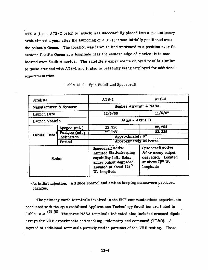
ATS-3 (t. e., ATS-C prior to launch) was successfully placed into a geostattonary
orbit almost a year after the launching of ATS-1; it was initially positioned over
the Atlantic Ocean. The location was later shifted westward to a position over the
eastern Pacific Ocean at a longitude near the eastern edge of Mexico; it is now
located over South America. The satellite's experiments enjoyed results similar
to those attained with ATS-1 and it also is presently being employed for additional
experimentation.
Table 13-2. Spin Stabilized Spacecraft
Satellite ATS-1 ATS-3
Manufacturer & Sponsor Hughes Aircraft & NASA
Launch Date 12/6/66 - 11/5/67
Launch Vehicle Atlas - Agena D
Apogee (mi.) 22,920 22, 254
SPerigee (i.) 22,277 22,228Orbital Data Inclination Approximately 0
Period Approximately 24 hours
Spacecraft active Spacecraft active
Limited Stationkeeping Solar array output
Status capability left. Solar degraded. Located
array output degraded. at about 700 W.Located at about 1490 longitudeW. longitude
*At initial injection. Attitude control and station keeping maneuvers produced
changes.
The primary earth terminals involved in the SHF communications experiments
conducted with the spin stabilized Applications Technology Satellites are listed in
Table 13-3. (5) (6) The three NASA terminals indicated also included crossed dipole
arrays for VHF experiments and tracking, telemetry and command (TT&C). A
myriad of additional terminals participated in portions of the VHF testing. These
13-4

included fixed and semi-fixed earth terminals, aircraft terminals, shipborne stations,
ocean buoy data platforms, and various fixed and mobile land-based data platforms
providing information on earth resources. Terminal locations were widely scattered
over portions of the world having visibility of ATS-1 and ATS-3. Entities, in addition
to NASA, providing VHF terminals included the Environmental Science Services
Administration (ESSA) of the U. S. Department of Commerce, the Federal Aviation
Administration, Office of Naval Research, Aeronautical Radio Incorporated (ARINC),
Hughes Aircraft, various major commercial airlines, and a number of foreign
countries. Satellite launchings were provided by NASA.
Table 13-3. Participating Earth Terminals
AntennaLocation Sponsor Diameter Date
(ft.) Installed
Rosman, North Carolina NASA 85 1965/66*
Mojave, California NASA 40 1965/66*
Cooby Creek, Australia NASA 40 1965*
Kashima, Japan Radio Research Laboratories 98. 5 1967*Ministry of Posts and Tele-communications, Japan
*Date of ATS-related installation alone.
Specific refinements to the state-of-the-art, contributed by the ATS-1 and 3
test programs, were innumerable. There were four contributions of major impor-
tance in satellite communication; two of these were in the area of despun antenna
technology. ATS-1 demonstrated the feasibility and potential of electronic-despinning
using phased arrays while ATS-3 displayed the feasibility and attractiveness of
mechanically-despun antennas. The SHF multiple access experiments showed the
possibility of the practical implementation of a system employing single-sideband
frequency division multiplexing on the uplink and phase modulation by the composite
13-5

received signal on the downlink. Additionally, the feasibility of VHF communications
through a synchronous satellite by small mobile earth terminals was demonstrated.
13. 2. 2 System Description
The SHF tests with ATS-1 involved all of the terminals listed in Table 13-3.
Loop back, half duplex, full duplex, and three terminal multiple access test configu-
rations were all employed. For the ATS-3 tests only Rosman and Mojave terminals
had satellite visibility. Tests were therefore performed on a loop back, half duplex,
and full duplex basis. VHF tests were conducted in all of these configurations from
loop back through full duplex linking. Satellite transponder non-linearity, plus power
and bandwidth limitations, tended to limit multiple access capabilities. The NASA-
furnished terminals provided two functions in the VHF tests. They conducted base-
line evaluations of the satellite VHF transponder and theVHF propagation link to
serve as a reference for testing with mobile and remote data terminals. The NASA
terminals also participated in the latter tests as central land bases. Typical earth
coverages supplied by the geostationary satellites, ATS-1 and ATS-3, are shown in
Figure 13-1.
Operating frequencies for the spin stabilized Applications Technology Satellites
are shown in Tables 13-4, 5, and 6. (5) The 6- and 4-GHz frequencies were selected
to be compatible with the international allocations for commercial satellite communi-
cations. The VHF frequencies were selected for a communications experiment
because of compatibility with existing frequencies employed for spacecraft TT&C
and conventional hardware that could readily be supplied for small mobile terminals
(e. g., aircraft terminals).
13-6
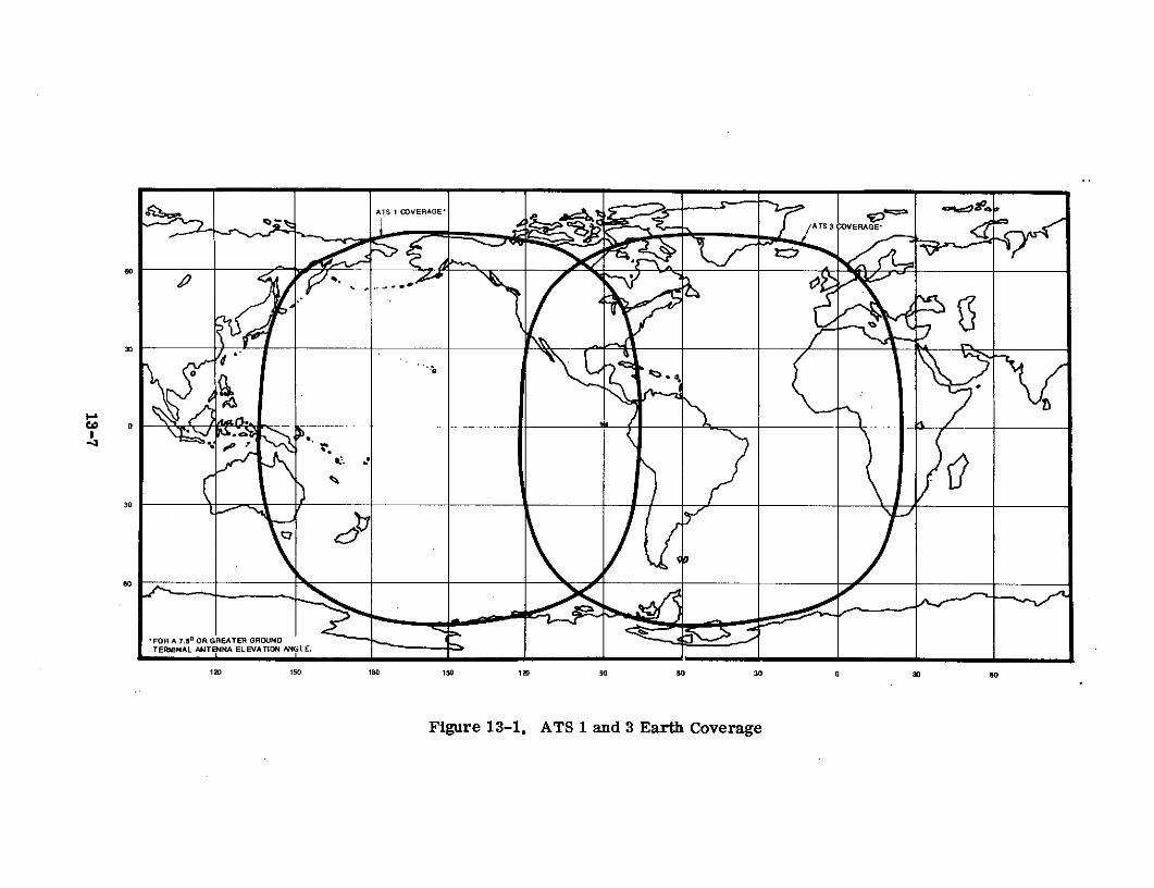
Figure 13-1. ATS 1 and 3 Earth Coverage
d9-
ca 0 Aft -. ~ IXl~
Figure 13-1. ATS 1 and 3 Earth Coverage
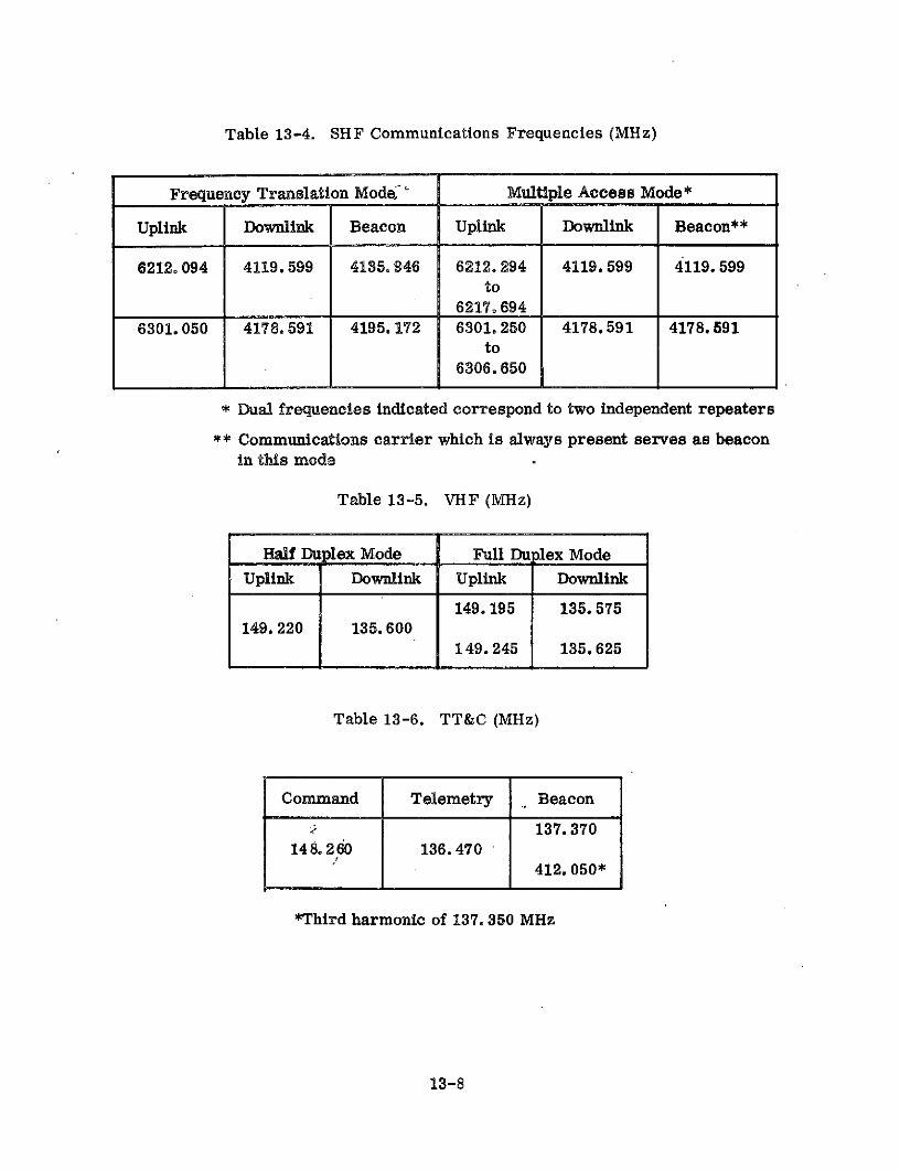
Table 13-4. SHF Communications Frequencies (MHz)
Frequency Translation Mode " Multiple Access Mode*
Uplink Downlink Beacon Uplink Downlink Beacon**
6212.094 4119. 599 4135. 946 6212.294 4119. 599 4119. 599to
6217.6946301.050 4178.591 4195.172 6301.250 4178.591 4178.591
to6306. 650
* Dual frequencies indicated correspond to two independent repeaters
** Communications carrier which is always present serves as beaconin this mode
Table 13-5. VHF (MHz)
Half Duplex Mode Full Du lex Mode
Uplink Downlink Uplink Downlink
149.195 135.575149.220 135. 600
149. 245 135.625
Table 13-6. TT&C (MHz)
Command Telemetry Beacon
137.37014 8. 2 60 136.470
412. 050*
*Third harmonic of 137. 350 MHz
13-8

Basic signal processing techniques employed with the spin stabilized Appli-
cations Technology Satellites, when operated in the SHF multiple access mode,
were as described in Table 13-7. (7) When in this mode (i. e., SSB-FDMA/PM) the
spacecraft is a signal processing repeater. Single side band (SSB) signals from
individual terminals are frequency division multiplexed on the uplink. The individual
signals are combined in the spacecraft and down-converted to provide a composite
baseband that phase modulates the transmitted carrier. The downlink signal is
detected by a discriminator in the ground terminal receiver and demultiplexed to
derive the desired individual message. In this system, uplink noise becomes a
more significant factor in determining total performance but requirements for
frequency spectrum and uplink power control are reduced. The use of SSB modu-
lation on the uplink tended to restrict the traffic handled to conventional 4-kHz voice.
Table 13-7. SHF Signal Processing for SHF Multiple Access Mode
Multiple Aooess/RFMuodulati s/Fn SSB on uplink and PM on downlink
Ground Demodulator .Threshold estimated at 10O-dB C/N basedPerformance upon employing conventional discriminators
Rosman Receive Carrier- 16.7 dB employing 2 TWTs on ATS-1 andto-Noise a 12-MHz IF bandwidth
Rosman Receive Margin 6.7 dB
A second SHF communications mode, available on ground command, configures
the spacecraft repeater as a standard frequency translation transponder. Signal
processing employed for operation in this mode is depicted in Table 13-8. Both
television and multichannel voice traffic were commonly handled with the spacecraft
configured in this manner.
13-9

Table 13-8. Signal Processing for SHF Frequency Translation Mode
Multiple Access Frequency Division* for a limited number of users.
RF Modulation FM *
Ground Demodulator Threshold estimated at 10-dB C/N based uponPerformance employing conventional discriminators.
Rosman Receive 14.4 dB employing 2 TWTs on ATS-1 and aCarrier-to-Noise 35-MHz IF bandwidth
Rosman Receive Margin 4.4 dB
Time division and code division (i.e., spread spectrum)multiple access were employed in special tests.
** Binary phase shift keying and quadraphase shift keyingwere employed in time division and spread spectrummultiple access tests.
For operations involving the VHF satellite repeater, the basic signal processing
techniques employed were as indicated in Table 13-9. (8) A single duplex voice channel
was typical of the traffic handled by this frequency translation repeater.
Table 13-9. Signal Processing for VHF Repeater
Multiple Access Frequency division for a limited number of users.
RF Modulation FM
Ground Demodulator Threshold estimated at 10-dB C/N based uponPerformance employing conventional discriminators
Ground Terminal* 20. 1 dB with ATS-1 and a 100-kHz IF bandwidthReceive Carrier-to-Noise
Ground Terminal* 10 dBReceive Margin
*For common type of VHF ATS terminal deployed at the three NASA ATSterminal sites.
13-10

13.2.3 Spacecraft
Characteristics of the communications related subsystems of ATS-1 and 3 are
described in Tables 13-10 and 13-11,(3)(4)(9)(1 0 ) respectively. With the exception
of the high power TWTs on one transponder of ATS-3, the SHF transponders aboard
the two spacecraft were virtually identical. Functional diagrams depicting each of the
three possible modes of the transponder (i. e., frequency translation, multiple access,
and onboard camera) are given in Figures 13-2, 13-3, and 13-4. The VHF trans-
ponder on each spacecraft is illustrated in Figure 13-5. As indicated by the figure,
the VHF transponder on ATS-3 differed from that on ATS-1 in that a capability
existed to cross strap the VHF receiver to the transmitter of one of the SHF trans-
ponders. In this mode of operation, selectable by ground command, the SHF
transponder was operated in the camera mode and the received VHF signal was
down-converted to serve as the input to the SHF transponder's voltage controlled
oscillator.
13. 2. 4 Ground Terminals
Two of the three NASA ATS terminals, Rosman and Mojave, are large multi-
functional installations supporting numerous other NASA programs. Characteristics
of the ATS related facilities at all three locations are summarized in Table 13-12.
(See References 5 through 8 and 11. ) Major subsystems of the NASA ATS terminals
are depicted in the functional block diagram of Figure 13-6. (6)
Equipment and its characteristics are quite similar at all three sites with the
major difference being in the size of the SHF antennas. The linear polarized SHF
feeds employed at all three sites were compatible with the satellite's transmit and
receive polarization. This polarization selection made polarization tracking
necessary. For VHF communications, the T&C antenna was normally configured
for circular polarization. With the linear polarization employed on the satellite,
this resulted in 3-dB uplink and downlink polarization losses.
13-11

Table 13-10. ATS-1
Type SHF xmit. -16 element VHF Comm-8 VHF TT&C-8electronically despun element electron- whip turnstilephased array. ically despunSHF Rec. -collinear phased array.array
Number One One One
< Beamwidth (3dB) Pencil beam a max- Pencil beam Essentially omni-imum of about 210 about 600 wide. directionalwide for xmit.
Gain Xmit-14 dB Xmit-9 dB 0 dBRec-7.8 dB Rec-8 dB
Frequency Band SHF VHF
Type Triple Mode supplying: (a) soft limiting IF translationIF translation; (b) modulation conversion hard limitingfor multiple access; (c) wideband trans-mission of onboard data
3 dB BW (a) IF translation-25 MHz; (b) modulation 100 K Hzconversion-5. 45 MHz uplink & 25 MHzdonwlink; (c) Onboard data xmit-25 MHz
Number 2 independent repeaters ne
Type Front End Tunnel diode amplifier into down conver- Down conversionsion mixer mixer
Front End Gain No data No data
6.2 dB 4. 0 dBFigure
Type Two TWTs 8 solid state_amplifiers
Gain No data No data
; Power out 4 watt per TWT or 8 watt total 5 watt per amplifieror 40 watt total
EIRP 22 dBW with 2 TWTs 23 dBW for 1 carrier
Type Spin with redundant H2 0 2 reaction control systems and nitrogen.._ jets for spinup.
Capability Spin axis attitude errors of about 0. 20 attained
S Primary N-on-P solar array with 175 watt output at launch
S: Supplement 2 nickel cadmium batteries with 6 amp-hr per battery capacity' at launch
( Comm. Power Needs Each SHF transponder-35 watts, VHF transponder-90 watts, and
electronically despun antenna-8watts
Size Cylindrical-57 inches high and 56 inches in diameter
Weight 775 lbs initially in orbit
* Mode for each SHF transponder independently selectable by ground command.
**. Can be operated individually or in parallel.
13-12

Table 13-11. ATS-3
Type SHF-mechanically VHF Comm.-8 VHF TT&C-8
despun cylindrical element elec- whip turnstile
parabolic collimator tronically despunilluminated by col phased arraylinear xmit and recv.
M line feeds. *
Number One One One
Beamwidth (3 dB) Pencil beam about Pencil beam Essentially omni-
200 wide about 600 wide directional
Gain Xmit-16 dB Xmit-10 dB 0 dB
Recv-17.5 dB Recv-8 dB
Frequency Band SHF VHF
Type Triple mode ** supplying: (a) soft limiting IF translation
IF translation; (b) modulation conversion soft limiting
for multiple access; (c) wideband trans-mission of onboard data
3 dB-dW (a) IF translation-25 MHz; (b) modulation 100 KHz
conversion-5.45 MHz uplink and 25 MHz
downlink; (c) Onboard data xmit-25 MHz
Number 2 independent repeaters one
Type Front End Tunnel diode amplifier into down conversion Down conversion
conversion mixer mixer
Front End Gain No data No data
System Noise 6.2dB 3.5dBFigure
Type Two TWTs*** 8 solid state
amplifiers
Gain No data No data
Power Out Xponder 1-4 watt/TWT or 8 watt total 6. 3 watt per
Xponder 2-12 watt/TWT or 24 watt total amplifier or50 watt total
EIRP Xponder 1-24.5 dBW with 2 TW'rs 25. 8 dBW for
Xponder 2-29.3 dBW with 2 TWTs 1 carrier
Type Spin with H2 02 or hyrazine reaction control systems and
nitrogen jets for spinup.
Capability Spin axis attitude errors of about 0. 20 attained
s Primary N-on-P solar array with 175 watt output at launch
' Supplement 2 nickel cadmium batteries with 6 amp/hr per battery
capacity at launch
Comm. Power Needs SHF Xponder 1-35 watts, SHF Xponder 2-90 watt, VHF
SXponder-100 watts, and mechanically despun antenna-
a 15 watt
Size Cylindrical - 71 inches high and 58 inches in diameter
Weight 805 lbs initially in orbit.
* Fail safe mode can be initiated by blowing parabolic reflector off antenna
to get pancake pattern and about 7 dB gain.
** Mode for each SHF transponder independently selectable by ground command.
*** Can be operated individually or in parallel.
S*** One 12 watt TWT failed to function making 26.'5 dBW maximum EIRP
available.
13-13
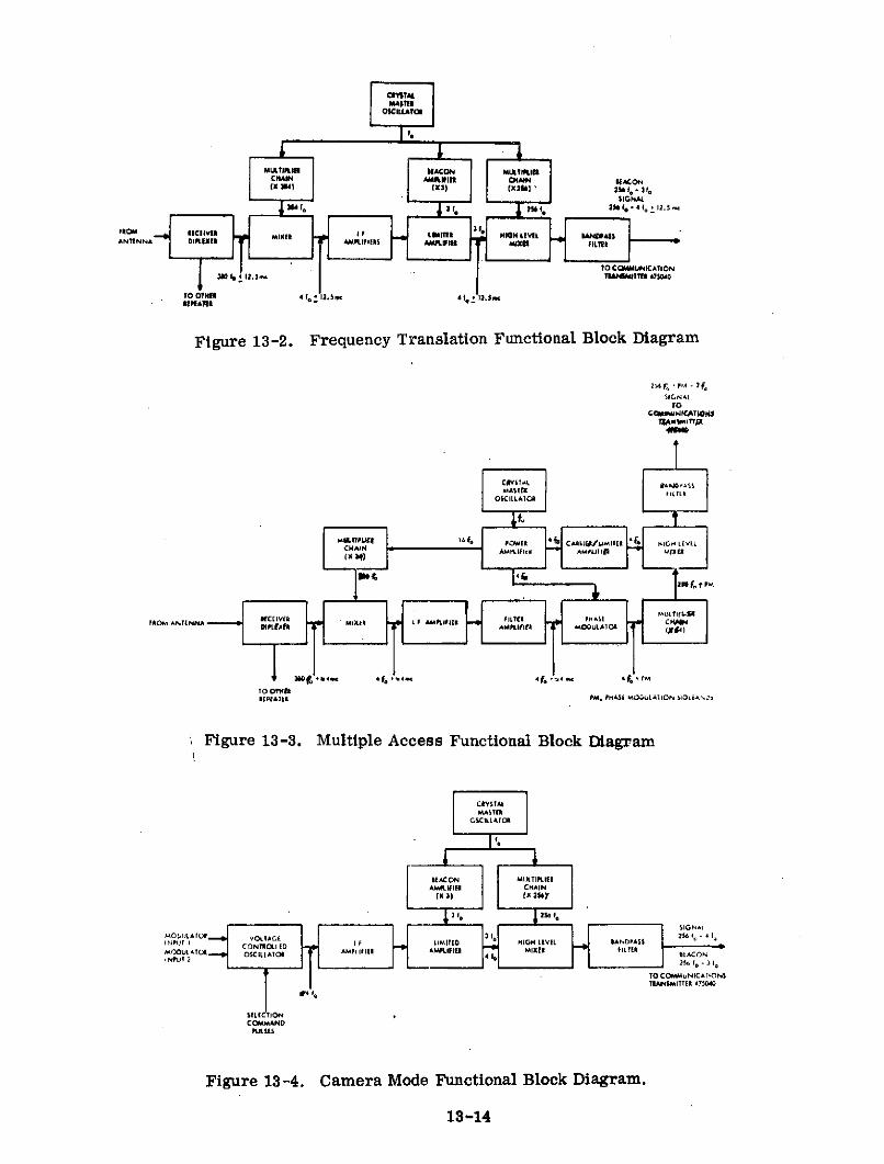
ANTENNA DI II AMPLIIIAS IX LFILet i. i
L BEACONTO CMMUNICATI ON
OM 11111S Mo
LIE AMLFI 0- 12.H m
Figure 13-2. Frequency Translation Functional Block Diagram
2T6 f, PIA -3L'SIGN.AL
104igure 13-3. M lple Access Functinl Blo gra
C MY6IAI I'l -SS
O$CILLAII
F40MVANTENNA MIXER I I AMPLIFlia PHASI CI
360 4 ,f.-,.4- ,f+. .,,e 4f P, M10 OTHE
RPIlt PM, PMASE MO&ULAIION $DLiANlD
Figure 13-3. Multiple Access Functional Block Diagram
DEACON MULTIPLIERAMPLIFIER CHAIN
(x 3) (x 2sY
236 f.
SIGNAtINPL I NT. OLIED IF LIMITED NIGH LtVEL BANDPAS$
M O DULAC O l TO D AM PIFlEt AMFI l M iEr FIL ot
TO COMMUNICATIONSTRANSMITTER 475040
F4 1o
(Ll TIONCOMMAND
PULSES
Figure 13-4. Camera Mode Functional Block Diagram.
13-14

IPLR #3 FILTER FILTERH 100-kdz 7 13 .6 mz
ANTENA ELEMENT # DEECTOR
DIPLELR #- RECEIVER #2
-25 db
CROSS STRAP CCVERTER-13 db (ATS-3 ONLY)
Figure 1:1300 z TOLP FILTER MICROWAVE
WAVEFORM VCOCo GENERATOR ... .
A 1 135.3 MHzCen
L.O.
(ATS-3 ONLT)
-4 db TRANSXITTER #1
IAASESHrFT TO DIPLEME #1
HTgRID CLASS CL assanx (AB2)
Figure 13-5. VHF Transponder Block Diagram.

Table 13-12. NASA ATS
TerminalTerminal Feature erminal Feature Rosman (SIIF) Mojave (SIIF) Cooby Creek (SIIF) All 3 Terminals (VHF)
Type Cassegrain Cassegrain Cassegrain Cross Dipole Array(4)
Aperture Size 85 ft. D)iameter 40 ft. Diameter 40 ft. I)lameter About 15 ft x 15 ft
Receive Gain 58.4 di 51 d(11 51.5 dB 22 dBl
< Efficiency 50(% 48% 54% 65%
Receive Beanmwidth .2o * (a 3 (dB Pts. .4(1) ()
3 dB Pts .4o * dl3 dB Pts. 13
Type Preamplifier Cooled Parametric Cooled Parametric Cooled Parametric No data
> E Amplifier Amplifier Amplifier
Bandwidth 30 MHz 30 Mllz :30 Mlz 11 Mz *
Noise Temperature 750
k @ 7. 5oEl. 750 k 0 7. 50 El. 75
0k ft 7. 5 El. 1230
0k
Type Amplifier Klystron Klystron Klystron No data
E Bandwidth 25 MlHz 25 MHz 25 Milz No data
1 Amp. Power (Xt 1 KW in SSB modes 1 KW in SSB m:)de 1 KW in SSB mode 2.5 KW& 2W in FT & 2 KWin FT & 2 KWin FT
mode *" mode *
mode **
Tlype Monopulse auto- Monopulse auto- Monopulse auto- Monontlse auto-track on X-Y mount track on X-Y mount track on Az-El track * on X-Y
mount mountAccuracy +0.030 in winds up 0.04 in winds up -0.040 in winds up 10.50
to 20 mph to 20 mph to 20 mph
G/T 39.6 dB 32.2 dB :32.7 dB -8.9 dB
0 EIRP 122.1 dBM 116.5 dBM 116 dBM 76 dBM
, Transmit Feed Linear Linear Linear Circular or linear
*Receive Feed Linear Linear Linear Circular or linear
Radome None None None None
Type Facility Fixed Terminal Fixed Terminal Transportable oobFixed exceptat,I_ .Cooby Creek
Derived value based on data available.
SSB and FM power amplifiers use same model klystron which is capable of up to 10-KW average output.
13 air-transportable vans in addition to SilF and T&C antenna existed at Cooby Creek.
" Separate Yagi transmit and receive antennas of same type integrally mounted i.)n same base.
Selectable bandwidths of 10 KHz, 30 KlIz, 100 KHlz, 300 KHz, 1 Mhz, and 3 Mllz are available.
Manual positioning used at Cooby Creek.
N n-rotatable in the linear configuration.
13-16

6
ANTENNACOMMAND CONTROLSYSTEM SYSTEM
ANTENNA FMCONTROL TRANSMITTERSYSTEM
SSBTRANSMITTER
TRACKING TELEMETRYRECEIVER RECEIVER*
RANGE &TRACKING RANGE FMRECEIVING RATE RECEIVER
EQUIPMENT
POLARIZATION PMTRACKING PMRECEIVERRECEIVER
*EQUIPMENT IS RECONFIGURED FOR VHF COMMUNICATIONS TRANSMISSION & RECEPTION
Figure 13-6. Major Subsystems of a NASA ATS Terminal.

13.2.5 Experiments
Experiments conducted as part of the spin stabilized ATS program are listed
in Table 13-13. (3)(4)(5) The table shows the seven major experiment categories,
listed in Table 13-1, into which the individual experiments can be grouped. In the
case of the satellite VHF transponder experiments, some overlap between categories
existed. These transponders supported selected meteorology and navigation experi-
ments in addition to the communications and propagation experiments.
Specifically, in the WEFAX experiment, the satellite VHF transponder relayed
Environmental Science Services Administration (ESSA) weather data (including ATS
SSCC photographs) in facsimile format from Suitland, Maryland to Automatic Picture
Transmission (APT) stations in the U. S., Japan, and Australia. (12) As part of
OPLE, the spacecraft VHF repeater relayed interrogations and responses between
the OPLE Control Center (OCC) and small remote platforms which were sometimes
in motion. Responses included data from local sensors and OMEGA navigation
system VLF tones received at the remote platforms and up converted to VHF. (13)
Various other navigation and postion location experiments employed the spacecraft
VHF transponder for ranging measurements.
The meteorological experiments, defined in Table 13-13, produced a vast
number of high quality pictures from the spacecraft camera systems and demonstrated
the feasibility of weather facsimile through the satellite's VHF repeater. The space-
craft stabilization experiments have displayed that nutation sensing and damping,
for nutation angles between 0. 0010 and 5. 00, can be satisfactorily accomplished
and that hydrazine thrusters are feasible; the resistojet stabilization experiment
was not as successful. The entire ammonia fuel load was depleted on ATS-1
(probably by a leak at a pressure transducer port) and particle contamination
resulted in abnormal valve operation and thrusting performance on ATS-3. (5)
Considerable data was obtained on the navigation and satellite technology experiments
with the result that all major objectives have for the most part been met. Additionally,
13-18

Table 13-13. Summary of ATS 1 and 3 Experiments
Experiment Spacecraft Category of Activity
1. Microwave Communications 1 & 3 Communications and propagation evaluation
2. VHF Communications 1 & 3 Communications and propagation evaluation
3. Phased Array Antenna 1 Comparison despun antenna technology
4. Mechanically Despun Antenna 3 Comparison despun antenna technology
5. Spin Scan Cloud Cover (SSCC) Camera 1 & 3 Meteorology concept consideration
6. WE FAX 1 & 3 Meteorology concept consideration
7. Image Dissector Camera System 3 Meteorology concept consideration
8. Nutation Sensor 1 & 3 Spacecraft stabilization investigation
9. Resisto-jet 1 & 3 Spacecraft stabilization investigation
10. Hydrazine Rocket System 3 Spacecraft stabilization investigation
11. Omega Position Location Experiment (OPLE) 3 Navigation techniques study
12. Self-Contained Navigation System 3 Navigation techniques study
13. Reflectometer 3 Satellite technology evaluation
14. Apogee Motor Plume 3 Satellite technology evaluation
15. Supra thermal Ion Detector 1 Earth environment measurements
16. Magnetometer 1 Earth environment measurements
17. Omnidirectional Electron-Proton Detector 1 Earth environment measurements
18. Multielement Particle Telescope 1 Earth environment measurements
19. Solar Cell Radiation Damage 1 Earth environment measurements
20. Thermal Coatings 1 Earth environment measurements
21. Electron Magnetic Deflection Spectrometer 1 Earth environment measurements

the environmental measurements experiments have been providing valuable informa-
tion that is adding to the pool of knowledge on the space environment in the vicinity of
the earth.
The phased array antenna, employed on ATS-1, consisted of 16 antennas
arranged around a circle of one wavelength radius with each antenna composed of
four collinear dipoles. Phasing of the radiated output was accomplished using
eight ferrite phase shifters. Each phase shifter provided two equal amplitude out-
puts whose phase was varied in an opposite sense by inputs from the Phased Antenna
Control Electronics, PACE. The two phase shifter outputs were connected to two
diametrically opposite antennas. The PACE derived phase shifter control signals
from satellite spin rate inputs and orbital position. This antenna system realized a
measured in-orbit gain of about 12. 5 dB with a beamwidth of approximately 220
due to the array. Beamwidth due to the stack of dipoles was determined, prior to
launch, to be about 170. The PACE system demonstrated reliable performance and
accurate pointing of the radiated beam. The total drive power requirement of the
phase shifters was about 2 watts.
The mechanically despun antenna, employed on ATS-3, consisted of a rotating
cylindrical parabolic collimator illuminated by a two element collinear array feed.
Each array element was a full wave dipole. The parabolic collimator was rotated in
opposition to the direction of spacecraft spin by a 128-step synchronous stepping
motor and encoder controlled by the Mechanical Antenna Control Electronics, MACE.
The MACE system was essentially identical to the PACE system employed on ATS-1.
The measured in-orbit gain of this antenna was about 17 dB with a beamwidth of
approximately 200. The PACE system displayed a capability of pointing the antenna
beam towards the earth within about ±0. 7 degrees. Antenna system reliability was,
in general, quite good. During the satellite's first year in orbit, several malfunctions
of the despinning mechanism were observed due to stalling of the stepping motor.
No thermal effects could be related to this anomaly. It was hypothesized that a
failure of the electric damper circuit associated with the stepping motor Regulator
13-20

No. 2 was responsible for the abnormal behavior. A switchover to backup electronics
eliminated these malfunctions.
Prime objectives of the microwave communications experiments were defined
in Paragraph 13.2. 1. The final objective, providing support to other onboard experi-
ments, was readily accomplished through numerous transmissions of wideband data
from other satellite experiments. The spacecraft television cameras were the chief
beneficiaries of this mode of operation.
Multiple access experiments of primary interest and their basic results are
described in Table 13-14. (7)(14) Additionally, measurements of system noise power
ratio and multiplex channel linearity, envelope delay, harmonic distortion, and
frequency response were carried out with satisfactory results. The experiments
indicated that CCIR and CCITT standards on communications transmission
can be met with this type of system. Frequency control and a high level of inherent
frequency stability are necessary to eliminate mutual interference on the uplink and
to allow accurate demodulation to baseband of the SSB signal containing no reference
carrier. Automatic level control is necessary to assure a proper balance of modu-
lation indexes for all signals accessing the satellite's PM transmitter. Adequate
short term frequency stability was found to be the most difficult requirement to meet
but numerous special tests at NASA ground terminals indicated that much can be done
to reduce instabilities. As expected, the higher receive antenna gain and EIRP of
the ATS-3 satellite afforded greater performance capabilities than experienced with
ATS-1.
Experiments employing the spacecrafts' wideband frequency translation
repeater measured frequency division multiplex and television system performance.
The frequency division multiplex tests were conducted employing a simulated loading
of up to 1200 one-way voice channels at Rosman and up to 240 one-way channels at
Mojave and Cooby Creek. Measurements of RF signal power and propagation
losses; baseband frequency response and envelope delay; system noise power ratio;
and multiplex channel frequency stability, level stability, S/N ratio, data error
13-21
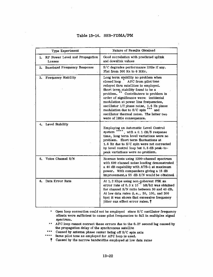
Table 13-14. SSB-FDMA/PM
Type Experiment Nature of Results Obtained
1. RF Power Level and Propagation Good correlation with predicted uplinkLosses and downlink values
2. Baseband Frequency Response S/C degrades performance little if any.Flat from 300 Hz to 6 MHz.
3. Frequency Stability Long term stability no problem whenclosed loop AFC from pilot tonerelayed thru satellites is employed.Short terra.stability found to be aproblem. ** Contributers to problem inorder of significance were: incidentalmodulation at power line frequencies,oscillator 1/f phase noise, 1. 6 Hz phasemodulation due to S/C spin *** andoscillator thermal noise. The latter twowere of little consequence.
4. Level StabilityEmploying an Automatic Level Controlsystem ****, with a 0. 1 dB/S responsetime, long term level variations were noproblem. Short term fluctuations at1. 6 Hz due to S/C spin were not correctedby level control loop but 0. 5 dB peak-to-peak variations were no problem.
5. Voice Channel S/N Rosman tests using 1200-channel spectrumwith 600 channel noise loading demonstrateda 40 dB capability with ATS-1 at maximumpower. With companders giving a 15 dBimprovement,a 55 dB S/N would be obtained
6. Data Error Rate At 1. 2 Kbps using non-qoherent FSK anerror rate of 6.3 x 10 bit/bit was obtainedfor channel S/N ratio between 30 and 40 dB.At low data rates (i. e., 50, 100, and 300bps) it was shown that excessive frequencyjitter can effect error rates. t
* Open loop correction could not be employed since S/C oscillator frequencyoffsets were sufficient to cause pilot frequencies to fall in multiplex signalspectrum.
** AFC loop cannot correct these errors due to the 0.27 second lag caused bythe propagation delay of the synchronous satellite
*** Caused by antenna phase center being off S/C spin axis**** Same pilot tone as employed for AFC loop is used.
t Caused by the narrow bandwidths employed at low data rates
13-22

rate, linearity, envelope delay, harmonic distortion and frequency response were
taken. (7)(14) Performance was compared with standards given by the CCIR and
EIA recommendation TR-141 and found to be, in general, compatible with the high
quality expected for long haul telephony. With 1200-channel loading, compandors
would be required to meet S/N ratio requirements. Frequency instabilities were,
in this case, almost entirely due to differential doppler but were not significant.
An AFC loop was not required.
For the television tests, major system design characteristics were as indicated
in Table 13-15. (7)(14) Monochrome TV test terminals were installed at all three
ATS earth stations and color test facilities were available at Rosman. Experiments
conducted and their basic results are described in Table 13-16. In addition to these
tests, numerous demonstrations have been conducted and events of interest televised.
Included were the "Our World" demonstration in June 1967, the address by Japanese
Prime Minister Sato during his Australian visit in October 1967, and coverage of the
Olympics in Mexico City in 1968.
Investigations of transmission phenomena included measurements of spacecraft
spin modulation, transmit and receive antenna patterns, and repeater saturation
characteristics plus ground terminal G/T, antenna pointing accuracy, and transmit
and receive antenna patterns. Results were in general agreement with previous
independent measurements and theoretical expectations. Investigations of polari-
zation phenomena included evaluations of SHF Faraday rotation as projected from
VHF measurements and the effect of satellite antenna beam position on observed
polarization at the ground. The latter determined that the ATS-1 polarization angles
(polang) changes about 0. 110 per degree change in satellite beam position while the
ATS-3 polang is constant to approximately ±40 from peak of beam.
Additionally, numerous special tests were performed by NASA ground terminal
engineers and the Japanese and Australian governments. The Japanese tests
employed the Kashima ground terminal and repeated many of the SSB-FDMA/PM
13-23

Table 13-15. TV System Design Characteristics
Parameter Value
1. RF Carrier Deviations
a. By video signal + 10 MHz peakb. By audio subcarrier + 1 MHz peak for 6 MHz subcarrier, + 0.715
MHz peak for 4. 5 MHz subcarrier, or + 1. 3MHz peak for 7. 5 MHz subcarrier.
2. Audio Subcarrier Frequencies 6. 0 MHz (4. 5 or 7. 5 MHz optional)
3. Subcarrier Deviation by Audio + 200 KHz peak
4. Video Section Bandwidth 30 Hz to 4. 5 MHz (3. 5 MHz optional)
5. Audio Section Bandwidth 30 Hz to 13 KHz
Table 13-16. Frequency Translation TV System Experiments
Type Experiment Nature of .Results Obtained
1. Continuous Random Noise 51 dB peak-to-peak signal to weighted rms noisemeasured at Rosman with peak power on ATS-3.CCIR standards require 56 dB for 99% of time.
2. Periodic Noise (Power S/N of 43 dB with all significant components belowsupply hum) 1 KHz obtained to exceed CCIR recommendations
by 8 dB.
3. Crosstalk An initial audio-to-video problem caused by couplingin a common baseband equipment power supply waseliminated to reduce crosstalk level to 75 dB downor more.
4. Linear Waveform Distortion Frequency response, short time wave form distortionline-time and field-time waveform distortion, andenvelope delay evaluated. CCIR recommendationsfor international TV circuit met and those for systemM (Canada and USA) partially met.
5. Non-Linear Waveform Differential gain and color vector error (equivalent ofDistortion differential phase) evaluated. CCIR recommendations
for international TV circuit met but those for systemM were not met.
6. Insertion Gain Variations Found to be negligible.
13-24

and frequency translation mode tests performed by the NASA ATS terminals. Major
differences were a greater emphasis on digital traffic handling capabilities and an
investigation of the feasibility of time division multiple access employing frequency
translation repeaters. The latter culminated in the demonstration of practical 4-
phase and 2-phase systems operating at 13 Mbps and 27 Mbps,respectively. (15)
Australian experiments employing the NASA Cooby Creek ground terminal, evaluated
digital transmission over satellite voice circuits, (16) telephone signaling systems
compatible with satellites, (17) and computer-to-computer communications at bit
rates up to 2. 4 kbps. (18) The feasibility of operational systems was demonstrated
in all cases.
Major objectives of experiments performed using the VHF repeaters of the
two satellites were defined in Paragraph 13. 2. 1. However, prior to conducting the
indicated investigations, a series of ground-to-satellite-to-ground tests were
conducted employing the VHF facilities of the NASA ATS earth terminals to provide
baseline data. These tests and their primary results are described in Table 13-17. (19)
Aircraft to ground communications through the satellite has been successfully
demonstrated on a number of occasions by commercial air flights over both the
Atlantic and Pacific. (5)(20) A number of airlines in the United States plus such
foreign carriers as Qantas, Japan Airlines, and BOAC have participated in these
tests. Briefly, the aircraft terminals have consisted of a frequency modulation
transceiver capable of radiating up to 500 W, data acquisition equipment, and
specially designed circularly polarized antenna installations.
Ground-satellite-aircraft tests have demonstrated the feasibility of realizing
a high operational reliability in such links. Multipath fading, scintillation, and air-
craft antenna anomalies (i. e., variations in gain as function of aspect angle to satel-
lite and polarization ellipticity) have been primary causes of signal fading. High
solar and magnetic field activity affected propagation but did not present unmanage-
able problems. Precipitation static discharges raised normal 1100 0K antenna
temperatures to 70, 0000K. To achieve acceptable communications during these
13-25

Table 13-17. NASA Baseline VHF Tests
Type Test Nature of Results Obtained
1. Receive Signal Level Good correlation with theory. Diurnal trendindicated showing peak signal level reached inevening hours following sunset. Daily variationis as much as 6 dB.
2. Carrier to Noise Versus Downlink limited region or maximum C/NUplink ETRP reached at a ground transmitted EIRP of about
40 dBW. Maximum measured C/N on ATS-1was 17 dB and on ATS-3 was 20 dB.
3. Signal to Noise, Carrier Predicted and measured S/N and C/N displayedto Noise & Data Error good agreement. Data error rate at 1. 2 KbpsRate showed that local RFI was a predominant factor.
4. Satellite Transponder On ATS-1, 2 equal accessing carriers couldPassband Frequency differ in transmitted power by as much as 9 dBResponse due to gain variations across passband plus
compression. On ATS-3, maximum differencewas 4 dB.
5. Satellite Transponder On ATS-1, 6 dB of small carrier compressionCompression displayed for 10 dB small carrier to large carrier
input ratio. No significant compression measuredon ATS-3.
6. Carrier Intermodulation ATS-1 closely followed theoretical hard limiterperformance. Sum of 3rd and 5th harmonics onATS-1 was 8 dB down. On ATS-3 the sum was17 dB down.
7. Interference Effects Various levels and frequency separations forAM and FM interference evaluated as a functionof measured voice channel articulation index (AI)***of desired signal. Results inconclusive dueto difficulties in interpreting mechanized measure-ments of AI.
* Improvement over ATS-1 primarily due to lack of compression innear linear transponder.
** Two input carriers employed.
*** FM employed on desired signal.
13-26

disturbances, antenna noise temperatures must be limited to a maximum value of
70000K. Aircraft receiving from the satellite experienced interference when operating
within line-of-sight of aircraft or ground stations transmitting co-channel in the con-
ventional environment.
Aircraft-satellite-ground links have, generally, displayed a lower reliability
than the links in the opposite direction. A major cause has been insufficient radiated
power from the aircraft and uplink interference caused by conventional VHF communi-
cations systems within the satellite's area of earth coverage. The factors producing
variations in link performance are, in general, the same as for the ground-satellite-
aircraft link. It has been recommended that an operational system employ circularly
polarized satellite antennas and linearly polarized aircraft antennas to minimize
antenna caused performance variations.
Maritime radio communications via geostationary satellite has been demon-
strated to be feasible in a number of ship-to-shore and ship-to-ship communications
tests. (5) Participating ships have included the Coast Guard cutters Glacier and
Klamath, the S. S. Santa Lucia, (21) and the German ships Gauss and Meteor.
Successful experiments have been conducted with ships operating in the Pacific,
the Arctic, the Antarctic and the Atlantic Oceans. Indications were that S/N ratios
of about 40 dB could conveniently be attained on a voice channel and data error
rates on the order of 10- 3 and 10 - 4 bits/bit realized at 600 bps transmission rates.
Short term fade depths in the order of 12 dB were observed in some tests.
Data dissemination in a meteorological network was displayed in the WEFAX
experiment. Data collection from small unmanned stations was demonstrated as
part of OPLE. Additionally, special hydrological(22) and ocean buoy experiments ( 2 3 )
have shown successfully that satellites can be employed for remote station interrogation
and data transfer. Signal fading was observed to be a significant factor to be con-
sidered in designing operational systems.
13-27

VHF ranging experiments have displayed the feasibility of employing satellites
operating at these frequencies for navigational purposes. Tests indicated that
position fixing accuracies within ±1 n, mi. were attainable.(24) The satellite's
VHF transponder has also been used in time dissemination experiments conducted
by ESSA and the National Bureau of Standards. Accuracies of better than 10 micro-
seconds have been demonstrated. (25)
The VHF transponders on ATS-1 and 3 have, additionally, been employed in
various special tests and demonstrations. These include communications support
for selected Apollo landings and tests of: aircraft to aircraft communications when
the two aircraft are operating near opposite poles of the earth, (26) chirp modulation
as a means of overcoming multipath effects and doppler shifts, (27) educational and
public radio transmissions in Alaska, and VHF propagation phenomena. The latter
include measurements of multipath, scintillation, and Faraday rotation effects.
Each satellite's telemetry beacon and the Third Harmonic Generator (i. e., third
harmonic of telemetry beacon) on ATS-3 have also been employed for such measure-
ments. These measurements, in addition to supplying direct propagation information,
have been useful in studies to determine the temporal makeup of the earth's ionosphere.
13. 2. 6 Operational Results
Since ATS-1 and 3 were experimental satellites, no operational traffic was
carried. The operational performance of the NASA ATS ground terminals was
good. In general, it was also shown that operational mobile VHF terminals were
feasible. However, in specific cases of hastily assembled experimental VHF
facilities, operational difficulties including insufficient transmitter power, antenna
anomalies, and poor equipment reliability were encountered.
The operational performance of the two spin stabilized satellites was basically
quite good. Specific minor difficulties encountered on ATS-1 included a gradual
decay of radiated power when both SHF transponders and all four TWTs were
energized and occasional SSCC picture streaking. The former was determined
13-28

to be a temperature problem and operation with three TWTs was found to be sustain-
able. The latter occurred during periods when the spacecraft load exceeded solar
array output to the extent that the batteries were depleted resulting in an abnormally
low battery voltage.
Operational difficulties on ATS-3 included the failure of one 12-watt TWT to
operate, a spurious SHF emission at 4201 MHz when operating in the FT mode,
spacecraft response to commands intended for ATS-1, and a malfunction of the
mechanically despun antenna (MDA). The spurious SHF emission was conjectured
to be due to thermal effects, occuring during eclipse, creating an electrical or
mechanical/electrical path to allow sustained passage of sufficient electrical energy
to activate the VCO employed in the SSB-FDMA/PM mode. Responses to ATS-1
commands were determined to be due to the address assignments made and not due
to equipment abnormalities. As a result, the address assignments for ATS-4 and 5
were changed. The despun antenna malfunction was verified to be produced by
stalling of the MDA motor as discussed in Paragraph 13.2.5.
13-29

13.3 GRAVITY GRADIENT STABILIZED SATELLITES
13. 3. 1 General Description
The experiments carried on the Application Technology Satellites that featured
evaluations of gravity gradient stabilization can be grouped into six major categories.
These categories are listed and defined in Table 13-18.(28), (29), (30) The objectives
of the SHF C-Band experiments were the same as indicated in the "General Descrip-
tion" of the spin stabilized ATS (see Section 13.2.1). The objectives of the L-Band
experiments were to demonstrate the feasibility of air-to-ground communications at
these frequencies and to investigate propagation effects. The objective of the milli-
meter wave experiment was to investigate propagation at 15 and 32 GHz.
Three active repeater satellites (i. e., ATS-2, ATS-4, and ATS-5) were launched
during the ATS program for the express major purpose of evaluating gravity gradient
stabilization. The status of these spacecraft is reviewed in Table 13-19.
Table 13-18. Experiment Categories
Number Description
1 Gravity Gradient Stabilization at Medium and Synchronous Altitude
2 C-Band, L-Band, and Millimeter Wave Radio Communications andPropagation
3 Meteorological Experiments
4 Measurements of the Earth Environment
5 Technology Applicable to Spacecraft Stabilization and Stationkeeping
6 Miscellaneous Spacecraft Technology
ATS-2 (i. e., ATS-A prior to launch) failed to reach its intended 6000 nautical
mile circular orbit when the second stage of the launch vehicle failed to restart leaving
the spacecraft in a highly elliptical orbit having a relatively low perigee. This pre-
cluded proper testing of the gravity gradient control system although the stabilization
booms were successfully deployed. Limited data was obtained on most of the
13-30

remaining spacecraft experiments including data on the C-Band communications,
meteorological, and environment measurements experiment.
Table 13-19. Gravity Gradient Spacecraft
Satellite AT S-2 ATS-4 AT S-5
Manufacturer & Sponsor Hughes Aircraft & NASA
Launch Date 4/5/67 8/10/68 8/12/69
Launch Vehicle Atlas-Agena D Atlas-Centaur
Apogee (mi.) 6947 480 22,277
Orbital Perigee (mi.) 115 135 22,196Data* Inclination 28. 40 290 2. 60
Period (min.) 218. 9 94. 5 1436
Satellite was Orbit decayed Satellite spin-shut down 10/17/68 result- ning around10/23/67. ing in satellite longitudinalOrbit destruction axis but in syn-
STAT USdecayed 9/2/69 chronous orbitresulting in located at aboutspacecraft 1050W. longi-destruction tude.
*At initial injection. Altitude control and station-keeping maneuvers producedchanges.
ATS-4 (i. e., ATS-D prior to launch) fell short of its intended synchronous orbit
when the Centaur failed to re-ignite for a second burn leaving the spacecraft in a low
altitude parking orbit with the Centaur still attached. Shortly after second burn failure,
the ATS-4-Centaur conglomerate went into a tumble about a traverse axis. Subsequent
maneuvers by the spacecraft attitude control systems were unable to completely correct
this condition. As a result the gravity gradient system could not be tested and little
information was obtained on the other satellite experiments although all subsystems
appeared to be operating properly. Among the operations accomplished was a partial
deployment of the stabilizing booms, boom scissoring and successful firing of the ion
engines.
13-31

Table 13-20. Millimeter Wave and L-Band Terminals
Antenna Frequency BandDiameter
Location Sponsor (FT)
Bedford, Massachusetts* Air Force Cambridge Research Labs 28 Millimeter Wave
Cambridge, Massachusetts* Department of Transportation 10 Millimeter Wave(2 Dishes)
Ottawa, Canada Prime Site* Canadian Communications Research 30 Millimeter WaveSecondary Site* Center 8
Rome, New York* Rome Air Development Center 15 Millimeter Wave
Hlolmdel, New Jersey* Bell Telephone Laboratories 20 Millimeter Wave
Lakehurst, New Jersey* U.S. Army Satellite Communications 30 Millimeter WaveAgency
Greenbelt, Sit NASA, Goddard Space Flight Center 15 Millimeter WaveMaryland Transmit Site 10
Waldorf, Maryland* Naval Research Labs 60 Millimeter Wave
Columbus, Ohio*** Fixed Site* Ohio State University 30 Millimeter WaveMobile Site* 15
Rosman, North Carolina NASA,Goddard 15 Millimeter Wave
Boulder, Colorado* ESSA Wave Propagation Lab 10 Millimeter Wave
Boulder, Colorado* Westinghouse Georesearch 12 Millimeter Wave
Orlando, Florida* Martin Marietta Corp. 12 Millimeter Wave
San Diego, California* *** Naval Electronics Laboratory 60 Millimeter WaveCenter
Austin, Texas* *** University of Texas 10 Millimeter Wave2 Dishes)
Rosman, North Carolina** NASA, Goddard 15 L Band
Mojave, California** NASA, Goddard 15 L Band
S.S. Manhattan** **** NASA, Goddard 3 L Band
*Receiver only
**Transmit/Receive installation
***Active participants in NASA/GSFC Millimeter Wave Experiment.
Remaining Millimeter Wave stations are independent experimenters
****Experimental icebreaking oil tanker
13-32

ATS-5 (i. e., ATS-E prior to launch) was successfully placed into the planned syn-
chronous orbit but was left spinning about the spacecraft's longitudinal axis. Spin
stabilization about this axis was the planned method of satellite control during the
transfer orbit, apogee motor firing, and maneuvers to position the spacecraft on
station. However, greater than expected nutation during this phase produced loss of
spacecraft control and ultimately resulted in the present spin about the proper axis
but in a direction opposite (i. e., counterclockwise) to that needed for the planned
operation of the two-stage yo-yo despin mechanism. Consequently, a scheduled
investigation of gravity gradient stabilization was again left unaccomplished. Modi-
fications to earth terminal equipment, however, have allowed many of the remaining
experiments aboard this satellite to be partially successful. In particular, objectives
have been partially attained with regard to the millimeter wave, L-Band, and environ-
mental measurements experiments.
The primary earth terminals involved in the few C-Band communications opera-
tions conducted included the terminals employed for the testing on ATS-1 and ATS-3
(see Table 13-3) with the addition of the terminal at Ahmedabad, India. The latter
became operational in 1967 and conducted tests and demonstrations with ATS-2. The
major terminals participating in the L-Band and millimeter wave tests on ATS-5 are
defined in Table 3-20. (31, 32, 33) All of these terminals became operational in 1969
and 1970. Tracking, telemetry, and command (TT&C) was provided by separate
installations included in the NASA ATS facilities located respectively at Rosman,
North Carolina; Cooby Creek, Australia; and Mojave, California. In addition, some
telemetry and tracking was provided by terminals at Johannesburg, South Africa;
Tananarive, Madagascar; and Kauai, Hawaii. Satellite launchings were provided by
NASA.
The launch difficulties on ATS-2 and 4 precluded any significant contributions to
satellite communications by the experiments on board these spacecraft. However,
ATS-5 did make several contributions, first, its millimeter wave experiment has
provided valuable data that will contribute towards opening this band for satellite
13-33

communications; secondly, its L-Band experiment has given a preliminary indication
of the potential that these frequencies hold for aircraft and maritime control, com-
munications, and navigation; and third, this satellite displayed the potential difficul-
ties involved in injecting a gravity gradient stabilized satellite into a synchronous
orbit and deploying it to a desired station.
13.3.2 System Description
The SHF (i.e. C-Band) tests conducted were done primarily on a loop back or
half duplex basis. The system configuration for the millimeter wave tests was as
shown in Figure 13-7. The figure indicates, uplink propagation measurements were
performed in the satellite and telemetered to the ground. Downlink measurements
are performed on the ground. A system block diagram of the initially planned L-Band
communications test configuration is shown in Figure 13-8. Signals are sent from
the ground stations to the satellite at C-Band. These signals are combined in the
satellite and retransmitted to the aircraft at L-Band. The ground stations monitor
the L-Band transmissions from the satellite for frequency control and ground-to-
satellite range measurements. Aircraft transmissions arrive at the satellite at
L-Band where they are combined and transferred to C-Band for transmission to the
ground stations. An L-Band ground station transmit capability is also provided to
allow full testing of the satellite from the ground. The earth coverage supplied by
ATS-5 for the millimeter wave and L-band tests is shown in Figure 13-9.
SHF, C-Band, operating frequencies on the gravity gradient stabilized space-
craft were the same as on ATS 1 & 3 (see Table 13-4).
The same is true of the TT&C frequencies (see Table 13-6). The millimeter
wave and L-Band operating frequencies are shown in Table 13-21.(31, 32) The indi-
cated millimeter wave frequencies are of interest in that they are located at the first
two windows in the frequency spectrum above 10 GHz where water vapor and oxygen
absorption are low. Millimeter wave propagation, in general, is of interest in that
it offers a possible means of reducing overcrowding in the lower bands. Additionally,
it offers extremely wideband capabilities, high gain-small aperture antenna
13-34

ATS V SPACECRAFT
3165 GHz SIGNALRECEIVER PROCESSOR
STATUS153 GHz
MODULATOR 153 GHz TELEETRY CO ANDTRANSMITTER CWI TRANSMITTER SUBSYSTEMS SUBSYSTEMSL i
K BANDUPLINK
KuBANDDOWNLINK
O I-- ------ NASA MMW STATION ROSMAN. N.C. PARTICIPATING STATIONS I NASA ATS STATIONI CFREUENCY
FREQUENCY 153GHz TELEMETRY COMMANDFEED RECEIVER METEOROLOGICAL RECEIVER TRANSMITTER
SDATASIGNAL MAGNETICPROCESSOR RECORDERS
IRECORDING32.65 GHz 153 GHz METEOROLOGICAL SYI STEMS
TRANSMITTER RECEIVER DATA ----- -
I ODULATOR SIGNAL RECORDING r-PROCESSOR SYSTEMS GODDARD SPACE FLIGHT CENTER - - -
- -- -REDUCTION APPLICATIONS
SEXPERIMENTS ATSOCCANALYSIS BRANCH
Figure 13-7. System Configuration for Millimeter Wave Tests

L BANDYUCROOU LBAND? AIRCRAFT
SATELLITE
8C%C%
GRO GR ENE
ROJAVEGTERRESTIAL LINW
Figure 19-8. System Block Diagram for L-Band Tests

120 150 180 150 120 90 60 30 0 30 60
60 6030 L 30
GREATER GROUND TERMINALANTENNA ELEVATION ANGLE
120 150 180 150 120 90 60 30 0 30 60
Figure 13-9. ATS-5 Earth Coverage

characteristics, and reduced size and weight of components. The L-Band frequencies
are of interest for aircraft control, navigation, and communications. The VHF fre-
quencies are also commonly considered for this purpose since they are compatible
with existing equipment. L-Band offers the potential of more accurate satellite
ranging and wider bandwidths for multiple access communications and control.
Table 13-21. Millimeter Wave and L-Band Frequencies (GHz)
Millimeter Wave L-Band
Uplink Downlink Uplink Downlink
31.65 15.3 1.65 1.55
The basic signal processing techniques employed for C-Band tests were the
same as used in ATS-1 and ATS-3 tests (see Tables 13-7 and 13-8). The millimeter
wave experiment provided two complete and independent propagation measurement
links. Similar signal processing techniques were employed on each link. It basi-
cally consisted of modulating a carrier with a single tone such that a carrier and
first order upper and lower sidebands all of equal level are produced. This was
accomplished by a varactor phase modulator in the satellite and a varactor frequency
upconverter, which was capable of AM, FM, or PM modulation, in the ground trans-
mitter. For the uplink, sidebands could be set at + 1. 0, + 10, or + 50 MHz from the
31. 65 GHz carrier. For the downlink, settings of + 0. 1, + 1. 0, + 10 or + 50 MHz
from the 15. 3 GHz carrier were possible (34) Receivers employed down conversion
mixing, filtering, envelope detectors, and phase detectors to derive measurements
of carrier, upper sideband, and lower sideband amplitude plus relative sideband
phase.
The L-Band signal processing employed was dependent upon the modes selected
for satellite operation. Four modes were commonly employed as follows:
13-38

1. Narrowband L-L (FM/FM)
Spacecraft receives at L-Band and retransmits at L-Band (frequency
translation).
2. Cross Strap L-C & C-L
a. L-C Cross-strap (SSB/FM)
Spacecraft receives at L-Band (SSB), translates to video (500 to 600 kHz)
and uses the video signal to modulate (FM) the spacecraft C-Band VCO;
the output of which is then translated to C-Band and retransmitted.
b. C-L Cross-strap (FM/FM)
Spacecraft receives at C-Band, frequency translates to L-Band, and
retransmits (Frequency translation).
3. L-L (SSB/FM)
Spacecraft receives at L-Band (SSB) translates to video (500 to 600 kHz) and
uses the video signal to modulate (FM) the Spacecraft L-Band VCO; the out-
put of which is then translated to L-Band for transmission to the earth
station.
4. Wideband Data Mode (FM downlink only)
Video signals from onboard-spacecraft equipment modulates (FM) the satel-
lite L-Band VCO the output of which is upconverted to L-Band for transmis-
sion to earth. A fifth possible mode was identical to narrowband L-L
(FM/FM) except a wide bandwidth was supplied.
Link performance for modes involving the C-Band downlink and a high
uplink S/N was essentially as defined in Tables 13-7 and 13-8. Typical
link performance for modes involving the L-Band downlink and a high uplink
S/N was as described in Table 13-22 for a narrowband L-L FM/FM link.
The frequency translation modes were not designed primarily for multiple
13-39

access. The planned multiple access modes of operation employed the L-L
SSB/FM and the L-C SSB/FM satellite transponder configurations.
Table 13-22. Signal Processing for L-L Satellite Channel
Multiple Access FDMA for limited number of accesses
RF Modulation FM
Ground Demodulator Threshold estimated at 6 dB C/N basedPerformance upon employing FMFB receivers
Rosman Receive 9 dB employing 2 TWTs, 2.2 MHzCarrier-to-Noise IF bandwidth, and 1 satellite access
Rosman Receive Margin 3 dB
13.3.3 Spacecraft
Characteristics of the communications-related subsystems of ATS-2 and ATS-4
are described in Table 13-23.(10, 28, 29) Block diagrams of the three possible
modes of the SHF transponders were shown in Figures 13-2, 3 and 4. The Table
displays some of the major system design differences in synchronous-altitude and
medium-altitude gravity gradient stabilized communications satellites. These include,
for the latter, low antenna gains for earth coverage beams; no need for an onboard
apogee motor and spin stabilization prior to positioning "on station;" and no need for
stationkeeping during gravity gradient stabilization "on station."
Characteristics of most of the communications-related subsystems on ATS-5
are shown in Table 13-24.(10, 30, 32, 34) A functional diagram depicting the L-Band
transponder, and its various selectable modes, is given in Figure 13-10. (32) With
the exception of the antenna system, the characteristics of the onboard millimeter
wave equipment are not described in the Table since this equipment does not include
a millimeter wave communications transponder. Its primary purpose was simply to
make propagation measurements.
13-40

Table 13-23. ATS-2 and 4 Characteristics
Satellite ATS-2 ATS-4
Type SHF-Horns used TT&C-8 SHF-Planar TT&C-for both xmit whip array used for Essentiallyand receive turnstile both xmit and the same
)receive as for
Number One One One ATS-2a Beamwidth (3 dB) 45° pencil Essen- 23- pencil
beam xmit and tially beam xmit andreceive omnidirec- receive
tional
Gain 10.5 dB xmit 0 dB 16.5 dB xmitlna reeive _nd reiceive ad-rcIve
Frequency Band SHF (C-Band) SIIF (C-Band
Type Essentially the same Essentially the same
3 dB BW as for the repeaters as for the repeatersNumber on ATS-1 ( :ue lablle on ATS-1 (See Table
, I Type Front End 1--1 ) 1-1.0)S - Front End Gain
- a Q k System NoiseCd o,D I N Figure
C- Type:: C 4- Gain
E, Power OutEIRP 18 dBW with 2 TWT's 211 dBW with 2 TWT's
Type Gravity gradient with no (;) Spin iliti:ally* witistationkeeping capability nitrogen jets for spin-
-o0 up and Ivydrazin.r( gas-P jet reaction control.
Gravity gradient "onstation" with micro-thruster station-
a)< e to l u n*
Capability No data due to launch No data due to launchfailure failure
Primary N-on-P solar array withr 140 watts at launch Essentially the same
H Supplement Two nak .l ":ulIum battr- as for ATS-2S w t Li (1 !:p-"ii'. /b tt i
0 0P , cap .ti al.t launch
w Comm. Power Needs Each SHF transponder - 350 watts and gravity gradient
- 35 watts
Size Cylindrical - 72 incheshigh and 56 inches indiameter
Weight 815 ib I.rlitially in orbi L i)ll lb initilly inorbit
*llrwrnr the transfer orblt and until the ;pacocrafIt i p)o:;it,i n,('don :;tatlon
' .*Wiu I lming n:ol d jets al.o avallale for :;,tl, l I, nveri':; cl 11
;tJ,ali i Lizat on occurn at 1800 from dcni. t ;tt l lb
13-41

Table 13-24. ATS-5 Characteristics
Type L Band - 12 Helix Millimeter Wave - SHF (C Band) - TT&C -planar array used Conical horns used Essentially the Essentiallyfor both xmit and for both xmit and same as for the same asreceive receive ATS-4 (See Table for ATS-2
Number One One 13-23) (See Table
Beamwidth 3 240 pencil beam 200 pencil beam 13-23)Sfor xmit xmit and receive
Gain Xmit. - 14 dB Xmit. - 19 dBRec. - 15 dB Rec. - 19 dB
Frequency Band L-Band* SHF CC Band)Type Multiple mode** supplying: (a) narrowband IF trans-
lation?"* (b) wideband IF translation*** (c) modula- Essentially thetion conversion for multiple access (d) wideband same as for onetrasmission of onboard data (e) C-L band**** and of the repeat-L-C' band cross-strap ers on ATS-1
3 dB BW (a) narrowband translation-2.5 MHz (b) wideband trans- (See Table 13-2)lation-25 MHz (c) modulation conversion-100 KHz uplinkand 25 MHz downlink (d) onboard data xmit-25 MHz (e)cross strap-25 MHz for C-L and 100 KHz uplink into25 MHz downlink for L-C
SNumber OneType Front End Tunnel diode amplifier into down conversion mixer
S Front End Gain No data,t, System Noise Figure 8.5 dB
S Type Two TWT'sttGain No data
g Power Out 12 watt per TWT or 24 watt total
EIRP 2.4 dBW with 2 TWT's 24 dBW with 2 TWv
Type Spin initiallyttt with nitrogen jets for spinup and hydrazine gas jeti reaction control. Gravity gradient "on station" with microthruster
.9 0H stationkeeping.
4 O NCapability Excessive nutation with apogee motor attached during spin stabilized phase.SNo gravity gradient data obtained.
Primary N-on-P solar array with 175 watts at launch.
Supplement 2 nickel cadmium batteries with 6 amp. hr/battery capacity at launch.Comm. Power Needs C band xponder-35 watt, L band xponder-90 watt, gravity gradient-35 watt,
C and millimeter wave experiment - wattSize Cylindrical - 72 inches high and 60 inches in diameterWeight 94 lbs. initially in orbit
Notes: * Transponder is an adaption of one of C band transponders appearing on previousApplications Technology Satellites
** Modes are independently selectable by ground command*** Soft limiter*** Wideband IF translation
t Modulation conversion for multiple access (i.e., SSB-FDMA/FM)tt Can be operated inividually or in parallel
ttt During the transfer orbit and until the spacecraft is positioned on stationSubliming solid jets also available for satellite inversion if stabilizationoccurs at 180 from desired attitude
13-42
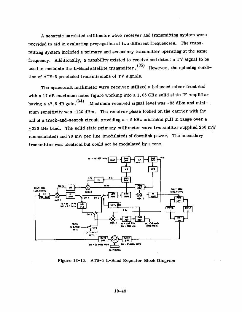
A separate unrelated millimeter wave receiver and transmitting system were
provided to aid in evaluating propagation at two different frequencies. The trans-
mitting system included a primary and secondary transmitter operating at the same
frequency. Additionally, a capability existed to receive and detect a TV signal to be
used to modulate the L-Band satellite transmitter. (35) However, the spinning condi-
tion of ATS-5 precluded transmissions of TV signals.
The spacecraft millimeter wave receiver utilized a balanced mixer front end
with a 17 dB maximum noise figure working into a 1. 05 GHz solid state IF amplifier
having a 47.5 dB gain.(3 4 ) Maximum received signal level was -85 dBm and mini-
mum sensitivity was -120 dBm. The receiver phase locked on the carrier with the
aid of a track-and-search circuit providing a + 5 kHz minimum pull in range over a
+ 320 kHz band. The solid state primary millimeter wave transmitter supplied 250 mW
(unmodulated) and 70 mW per line (modulated) of downlink power. The secondary
transmitter was identical but could not be modulated by a tone.
fo W 16.837 MH "a
X3 X24
10 9610 pwRRCVE SIG: OPF ON XMIT SIGt
1651.0 MH MIX 2 ISD.0 Mx
S W 2 -5 M F L T Y 2I X 3T W T A T W T A
SW 3
FROM M(X 4 S kHb TO CIAND
C-1AND aw = 10Dm n VCO
TO C-BANDRPTR
1W - 25 MH MIN W 25 M MIN
NTENNA
Figure 13-10. ATS-5 L-Band Repeater Block Diagram
13-43

In addition to the communications related subsystems, ATS-2 provided (28).
a) two 1-inch 800-line advanced vidicon cameras, one narrow-angle and one wide-
angle, and a tape recorder as a meteorological experiment; b) two 525-line TV
cameras measuring boom thermal-bending characteristics plus a power control
unit, solar aspect sensor, and two IR earth sensors to support the gravity gradient
experiment; c) an environmental measurements package including omnidirectional
proton-electron counters, electron magnetic deflection spectrometer, multi-element
particle telescope, VLF whistler mode detector, cosmic radio noise receiver, solar
cell radiation damage array, thermal coating samples, and electric field experiment;
and d) a DOD albedo experiment.
In addition to the communications-related subsystems, ATS-4 provided (29)
a) hydrazine gas jets plus passive and active nutation control systems for spacecraft
stabilization and stationkeeping during the period of spin stabilization; b) a two-
stage yo-yo despin mechanism; c) resisto jet and cesium ion microthrusters for
stationkeeping during gravity gradient stabilization; d) a TV camera monitoring
booms plus solar aspect and IR earth sensors to support the gravity gradient
experiment; e) an image orthicon day-night camera as a meteorological experiment;
and f) a magnetometer sensor measuring spacecraft charge as an environmental
measurements experiment.
In addition to the communications-related subsystems, ATS-5 provided (30)
a) essentially the same equipment as listed in items a) through d) for ATS-4; b) an
environmental measurements package including a tridirectional particle detector
measuring protons with energies between 30 and 250 keV and electrons between 30
and 300 keV, a unidirectional particle experiment to study auroral particle fluxes,
a bidirectional particle experiment to map electrons and protons on constant lines of
force and determine properties of acceleration within the magnetosphere, an
omnidirectional particle experiment measuring electrons in 12 discrete energy
ranges and the flux of solar cosmic rays, a radiometer measuring solar radio
13-44

bursts between 50 kHz and 4 MHz, and an electric field measurements experiment;
and c) other experiments in spacecraft technology including a magnetic damper, a
solar cell voltage monitor, heat pipes for solar panel thermal equalization, a third
harmonic generator similar to that on ATS-3, a solar cell damage experiment and
a magnetometer experiment.
13.3. 4 Ground Terminals
Major NASA terminals supporting SHF, C-Band, operations were the same as
employed on ATS-1 and 3. These terminals were described in Table 13-2. Terminals
participating in millimeter wave and L-Band experiments were defined in Table
13-20. The millimeter wave installation at NASA's Rosman, North Carolina facility
and the L-band installation at Mojave, California are typical of the earth terminals
employed for these two respective groups of experiments. Major characteristics
of typical millimeter wave and L-Band terminals are described in Table 13-25. (32),
(34) Terminal block diagrams are provided in Figures 13-12 (3 1 ) and 13-13. (32)
The millimeter wave terminal block diagram displays the interest that existed
in finding meteorological measurement techniques which could be useful in predicting
propagation losses at these frequencies. The L-Band terminal was configured such
as to allow operation in the satellite L- to C-Band cross strapping mode. The linear
polarization employed at the millimeter wave terminal and the circularly-polarized
feeds of the L-Band terminal were compatible with the spacecraft polarizations
making link losses due to this source small.
13.3.5 Experiments
Experiments that were planned for ATS-2, 4, and 5 are summarized in
Table 13-26. (28), (29), (30) The Table also indicates the six major experiment
categories, listed in Table 13-18, into which the individual experiments can be
grouped.
Some data was obtained on most of the experiments onboard ATS-2. The
data, generally, was of limited value, however, since a launch vehicle failure left
13-45

Table 13-25. Characteristics of Millimeter Wave and L-Band Ground Terminals
Table 13-25. Characteristics of Millimeter Wave and L-Band Ground Terminals
Terminal
Rosman (Millimeter Mojave (L Band)Terminal Feature Wave)
Type Cassegrain Cassegrain
Aperture Size 15 ft. Diameter 15 ft. Diameter
Antenna Recelve Gain 54dB 35.5 dB
Efficiency 45%* 65%*
Receive Beamwidth .30(1) @ 3 dB Pts. .30(1) @ 3 dB Pts.
Type Preamplifier Tunnel Diode Uncooled ParametricAmplifier
ReceiveSystem Bandwidth 600 Ml!z** P 3 dR Pt:;. No Data***
Noise Temperature 10000 K 340 0 K
Type Amplifier TWT Klystrom
Transmit Bandwidth 450 MHz** 3 dl P'ts. 7 MHz @ 3 dB Pts.System
Amp. Power Out 1KW**** 1KW
Type Conical Scan Autotrack Slaved to 40ft. C Band& Program-Autotrack Antenna Autotrack
Tracking
Accuracy No Data No Data
Total Per- G/T 22 dB/oK 9.2 dB/OK
formance EIRP 116 dBM 93.6 dBM
Transmit Feed Linear CircularPolari-zation Receive Feed Linear Circular
Rosman (Millimeter Mojave (L Band)Terminal Feature Wave)
Instal- Radome None None
lation Type Facility Transportable Transportable
NOTE: * Derived Value Based on Data Available
•* RF Bandwidth
•** 25 MHz Required to Receive Wideband Data from Satellite
**** Normally Operated at 10 to 100 Watts
Transmitter is Linear to About 200 Watts for Use in Multiple AccessMode
Conical Scan Could Not be Used Due to the Spin Condition of ATS-5
13-46

15 FT DIA
AUTO/PROGRAM TRACKANTENNA SYSTEM
VERTICALON -BEAM SCAN
DUAL DUAL16 GHz 35 GHZ 15 GHz 15 GHzFEQUENCY RADIOMER WEATHER WEATHERFEENCD RADIOMETER RADARRAIOETER CAMERA
STRIP INTERVAL RAINCHART INTEGRATOR15 3 GHz 31 65 GHz RECORDER TIMER GAUGE#2
RECEIVER XMITTER
RECEIVER 30SIGNAL I STATUS CHANNEL
PROCESSOR FM I XMITTER SCANNER
STATUS
STATION14 STATUS
SCHANNEL FMto ANALOG
MAGNETIC FM AMBIENT
RECORDER FM 36 TEMPERATURE
CHANNELTDM/FM
COM DEW CELLMUTATOR TEMPERATURE
STRIP CHART RECORDERS NASA RAINBCD
(16 CHANNELS GAUGE10
WINDDIRECTION CLOUD
SPACECRAFT RECEIVER INTERVAL COVERTM DATA FROM TIMER COVAMER
ATS BUILDING AMBIENTPRESSURE
WEATHER
CLASS
Figure 13-11. The NASA Rosman, North Carolina Millimeter Wave Station

L-BAND 1650 MII TRANSIT1550 MHD RECEIVE
P.A. DUPEXER PARAMP
I RF TEST L-BANDI.P.A. L LOOP & DOWN
RCVR CONVERTERCALIBRATION
70 MHz IF
L BANDUP CONVERTER
70 Haz IF
UP CONVTER C R DS IA
BASEBAND IN ABAND T
MULTII MULTIPIEXSWD RECEIVE
EQUIPMIDIT EQUIRIENT
INPT OUTPUT
C-BAND 6212 Mas TRANSMIT6119 MHz RECEIVE
I.P.A P.A. DUPLEXER TDA
TEST IDOPL.. . J
Figure 13-12. L-Band System Earth Station Block Diagram
13-48

Table 13-26. Summary of ATS-2, 4 and 5 Experiments
Space-Experiment craft Category of Activity
1. Microwave (C-band) Communications 2, 4 & 5 Communications and propagation evaluation2. Millimeter Wave Propagation 5 " " " "
3. L Band Communications 5 " " " "
4. Gravity Gradient Stabilization 2, 4 & 5 Gravity gradient stabilization investigation5. Advanced Vidicon Camera 2 Meteorology concept consideration6. Image Orthicon Camera System 4 " " "
7. Subliming Solid Engine 2, 4 & 5 Study stabilization & stationkeeping technology8. Resistojet 4 & 5 " " " " "
9. Ion Engine 4 & 5 " " " " "
10. Albedo 2 Miscellaneous spacecraft technology consideration11. Magnetic Damper 5 " " " "
12. Voltage Monitor 5 I " " "
13. Heat Pipe 5 " " " "
14. Solar Cell Damage 5 " " " "
15. Third Harmonic Generator 5 " " " "
16. Magnetometer 4 & 517. Omidirectional High-Energy Earth environment measurements
Particle Detector 2 & 518. Cosmic Radio Noise Receiver 2 & 5 " " "
19. Electric Field Measurements 2 & 520. Electron Magnetic Deflection
Spectrometer 2 " " "21. Multi-element Particle Telescope 2 " " "22. VLF Whistler Mode Detector 223. Solar Cell Radiation Damage Array 2 " " "24. Thermal Coating Samples 2 " " "25. Tridirectional Medium Energy
Particle Detector 5 " " "26. Bidirectional Low Energy Particle
Detector 5 " " "27. Unidirectional Low Energy
Particle Detector 5 " " "

the spacecraft tumbling in a highly elliptical orbit. The stabilization booms were
successfully deployed but the tumbling nature of the satellite resulted in the loss of
one boom and in another being broken. Operation of the C-Band transponders was
demonstrated including transmissions by the earth terminal at Ahmedabad, India.
ATS-4 produced even less in the way of successful results than ATS-2. Among the
accomplishments were partial deployment and scissoring of the stabilization booms
plus successful firing of the ion engines.
Some of the experiments on board ATS-5 were also lost when the spacecraft
was left spinning rather than gravity gradient stabilized. In particular, it was not
possible to obtain data from the gravity gradient, resistojet, ion engine, solar cell
voltage monitor, heat pipe solar panel temperature equalization, cosmic radio noise,
or from the electric field measurements experiments. If the booms could be deployed
the latter two could be successfully completed. Noteworthy successes have been
obtained from the earth environment measurements, L-Band and millimeter wave
experiments. The latter two were obtained through ground terminal modifications
to accommodate the periodic nature of the received signal, caused by the spacecraft
spin.
For the millimeter wave experiment, the spacecraft spin rate (i. e., 76 rpm)
resulted in a received signal pulse having a 26 ms time duration between 1 dB down
(36)points, that occurred every 789 ms. Ground complex modifications to accommodate
this type of received signal included exclusive employment of program tracking rather
than autotracking, installing a manual override to prevent the receiver phase lock
loop from going into a search mode during deep fades of the peak signal, tripling
the data sampling rate to 108 samples-per-second (i. e., one every 9.2 ms) and
selecting the maximum valued sample as the only valid data point during any given
second. Detrimental effects of the spacecraft spin have included loss of the milli-
meter wave to L-band TV transmission capability, a loss of fade measurement range
which in itself was not of major significance, a serious degradation of the differential
sideband phase measurement capability due to spin-induced doppler effect and
13-50

settling time of the quadrature phase detectors, and loss of the ability to detect short
term signal fades occuring at rates greater than about 0. 5 Hz. The detrimental
effects of spacecraft spin plus a 9 dB drop in primary transmitter outputs, occurring
about 3 months after satellite launch, also made it impossible to obtain coherence
bandwidth measurements at 15.3 GHz.
Data was obtained on the statistics of long term fades, correlation between
various attenuation prediction techniques and actual measured attenuation, effects
of site diversity at 15. 3 GHz, and coherent bandwidth at 31. 65 GHz. Preliminary(31), (34), (36)
results are tabulated in Table 13-27.
Table 13-27. Preliminary Results Millimeter Wave Experiment
Type Experiment Nature of Results Obtained
1) Attenuation at 15. 3 GHz 1 to 3 dB in light rains or dense fog,3 to 7 dB in continuous rains (5 to50 mm/hr) and number of fadesexceeding 12 dB in heavy thunder-storms.
2) Evaluation attenuation Excellent results using radiometerprediction techniques measurements* of sky temperature.
Fair results employing radar back-scatter readings at millimeter wavefrequency. Better results at lowerfrequencies. Poor results using raingage measurements of rainfall rate.Results improved with more gagesover greater area.
3) Effects site diversity Durations of 6 to 10 dB fades reducedat 15.3 GHz by approximately two orders of
magnitude using simple diversitysystem with 4 km ground separationbetween terminals.
4) Coherent bandwidth at Measured relative amplitude variations31. 65 GHz of sidebands have been within ±2 dB of
carrier for sidebands at +1. ±10, and±50 MHz.
*Operating at same frequency as propagation link.
13-51
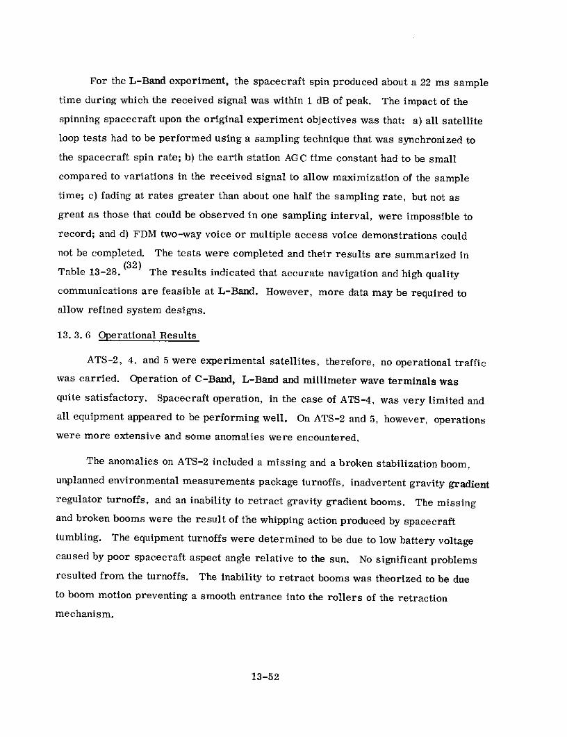
For the L-Band experiment, the spacecraft spin produced about a 22 ms sample
time during which the received signal was within 1 dB of peak. The impact of the
spinning spacecraft upon the original experiment objectives was that: a) all satellite
loop tests had to be performed using a sampling technique that was synchronized to
the spacecraft spin rate; b) the earth station AGC time constant had to be small
compared to variations in the received signal to allow maximization of the sample
time; c) fading at rates greater than about one half the sampling rate, but not as
great as those that could be observed in one sampling interval, were impossible to
record; and d) FDM two-way voice or multiple access voice demonstrations could
not be completed. The tests were completed and their results are summarized in(32)
Table 13-28. The results indicated that accurate navigation and high quality
communications are feasible at L-Band. However, more data may be required to
allow refined system designs.
13. 3. 6 Operational Results
ATS-2, 4, and 5 were experimental satellites, therefore, no operational traffic
was carried. Operation of C-Band, L-Band and millimeter wave terminals was
quite satisfactory. Spacecraft operation, in the case of ATS-4, was very limited and
all equipment appeared to be performing well. On ATS-2 and 5, however, operations
were more extensive and some anomalies were encountered.
The anomalies on ATS-2 included a missing and a broken stabilization boom,
unplanned environmental measurements package turnoffs, inadvertent gravity gradient
regulator turnoffs, and an inability to retract gravity gradient booms. The missing
and broken booms were the result of the whipping action produced by spacecraft
tumbling. The equipment turnoffs were determined to be due to low battery voltage
caused by poor spacecraft aspect angle relative to the sun. No significant problems
resulted from the turnoffs. The inability to retract booms was theorized to be due
to boom motion preventing a smooth entrance into the rollers of the retraction
mechanism.
13-52

Table 13-28. L-Band Experiments
Type Experiment Nature of Results Obtained
1) Spacecraft Antenna Half-power beamwidth 240 for transmit and 280 for receivePatterns
2) L Band Propagation Diurnal variations due to ionosphere were less than ±0.3 dB basedon four 24 hour test sequences. Observed short term fading andscintillation effects were less than ±0.3 dB on both uplink anddownlink
3) Spacecraft Oscillator Spacecraft VCO offset from nominal decreased from about -245 KHz atFrequency Offset turn on to about -180 KHz 200 minutes later. Spacecraft master
oscillator caused offset in earth station baseband signal of about4 KHz at turn on and stabilized to about 500 Hz 15 hours later
4) Spacecraft Intermodula- At normal power output levels intermodulation products are approxi-tion Distortion (SSB/FM) mately 26 dB below either of two test tones
5) Spacecraft Transponder The initial point where a 2 dB increase in input power causes onlyCompression (FM/FM) a 1 dB increase in satellite output occurs at an earth station
transmit power of 39.6 dBm6) Spacecraft SSB/FM Modu- Response of the SSB/FM L-band modulator to a tone received at
lator Linearity several RF levels was linear up to a modulation index of 12 radiansrms
7) Spacecraft Frequency In narrow band FM/FM, a 2 MHz 3 dB BW measured. In SSB/FM mode,Response half power BW was 115 KHz
8) Doppler Due to Spacecraft At 20 dB down points on spacecraft antenna pattern,varies fromSpin +12 Hz at a maximum to -46 Hz minimum
9) Multiplex Channel S/N Signal to thermal noise ratio was measured to be 36 dB* at earth(SSB/FM) station transmitter power output of 50 dBm. S/N decreased linearly
with decrease in SSB transmitter power10) Spin Modulation Com- By modulating uplink power in synchronism with spacecraft spin and
pensation Test such as to compensate for variations in satellite receive antennapattern, usable uplink window was increased from 52 ms to 100 ms
* At Mojave terminal.

The only significant operational difficulties encountered on ATS-5 have involved(35), (36)
the primary and backup millimeter wave transmitters. The main transmitter
functioned perfectly during the first 3 months in orbit. On November 22, 1969,
however, the output power was down 6 dB at turn-on. This condition continued until
December 17 when a further 3 dB loss was recorded. Transmitter power has
remained stable at this level to the present writing. The dc input power has shown
no change from pre-launch level during this entire time. Further the 30. 6 GHz
local oscillator power has shown no significant change. This indicates that the loss
is occurring in the solid state multiplier chain above the L-Band portion where the
receiver local oscillator power is coupled out. The exact location and cause of the
failure has not been determined.
The backup millimeter wave transmitter showed normal power characteristics
from launch until October 22, 1969. The transmitter output power was then observed
to decrease over time periods as short as 2-1/2 hours and as long as 9 hours to a
level between 3 and 4 dB below normal output at which time the output abruptly
dropped to zero. A period of nonoperation has always restored the transmitter to
normal output. A loss in dc input power that correlates with the loss of RF output
power has been recorded. It has been evident that the thermal sensitivity of the
transmitter is responsible for the power loss.
13-54

13.4 LARGE APERTURE ANTENNA SPACECRAFT (ATS-F and G)
13. 4. 1 General Description
NASA's Applications Technology Satellites (ATS) F and G are for demonstrating
the use of a synchronous orbit spacecraft as a relay station for several communications
experiments. They will provide accurate three-axis attitude control using inertia
wheels and/or gas jets as control actuators. The communications subsystems of
these spacecraft include a parabolic reflector antenna of 30-foot diameter, a composite
multifrequency antenna feed assembly, a multiple frequency transponder, and two
separate major propagation experiments. A primary objective of these spacecraft is
the demonstration of the 30-foot space deployable antenna. This antenna, in conjunc-
tion with'the remainder of the communication system, provides a highly effective
radiated power making possible the utilization of small inexpensive receiving terminals
for such uses as relay links with spacecraft, ships, aircraft, and low-cost ground
stations. Experiments employing terminals of this type have been designed for use
with the ATS-F spacecraft and are described in a later section. Because no experi-
ments have been approved for ATS-G as of mid-1971, the following discussion considers
only the ATS-F program.
13.4.2 The ATS-F Spacecraft
The composite feed assembly shown in Figure 13-13 is used in conjunction with
the reflector to provide efficient antenna performance over a broad range of frequencies
and a wide variety of beam shapes, sizes, and functions. Although individual feed
elements are used for each frequency band to permit optimum performance, a great
deal of commonality exists among the radiating elements. To satisfy polarization,
weight, and size requirements, cavity-backed cross-dipole elements are used for S, L,
and UHF feeds. These elements offer simple and reliable radiators capable of operat-
ing at the frequencies, bandwidths, and polarizations defined by the experiments. With
the exception of VHF radiators, the feed! layout enables placement of all radiating
elements in the parabola's focal plane, and minimizes interaction between neighboring
feeds.
13-55
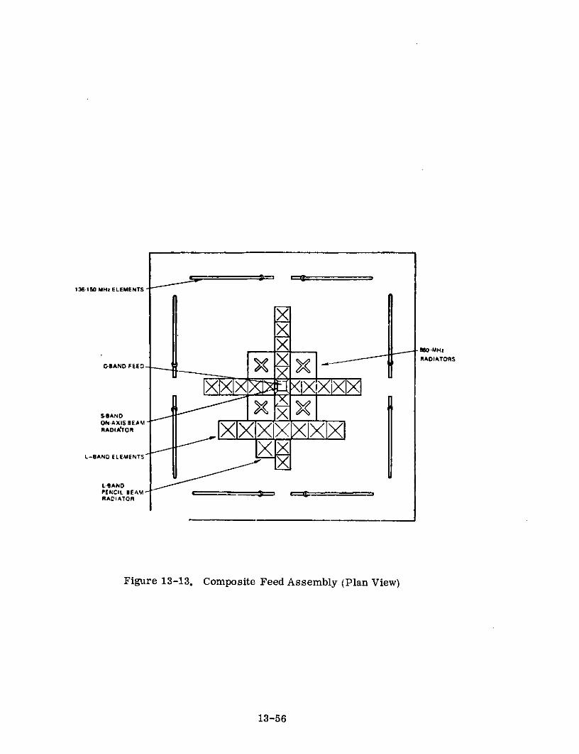
136-150 MHz ELEMENTS
-80 -MHz
-BAND FEED - X RADIATORS
SBAND
NADIA'TOM
L-SAND ELEMENTS
L-IIANDPENCIL BEAMRACIATOR
Figure 13-13. Composite Feed Assembly (Plan View)
13-56

Signal interfaces for the multiple frequency transponder are illustrated in
Figure 13-14 ( 3 7) Its configuration is shown in the communication subsystem block
diagram of Figure 13-15( 3 7 ) The transponder consists of the receiver assembly, IF
amplifier assembly, synthesizors, and transmitters. Its characteristics are
summarized in Tables 13-29, 30, 31, 32, and 33!37) The receiver assembly design
follows proven technology with appropriate redundancies to increase reliability. More
interesting is the IF amplifier assembly, consisting of an IF input switch matrix,
three identical 150-MHz IF amplifiers, and an IF output switch matrix. To achieve
high reliability with maximum flexibility, IF switching is provided to interconnect the
various circuits. The input switch matrix allows any down-converter to be connected
to any IF amplifier. As many as three IF channels can be accommodated simultaneously.
The output switch matrix allows any IF amplifier to be connected to any up-converter.
Further, the wideband data unit can be connected to any up-converter.
The IF amplifier is a cascade type with high gain wide-bandwidth stages so that
the frequency response is determined by the bandpass filter. The nominal bandwidth
of the filter is 40 MHz and this fixes the maximum bandwidth of the amplifier. The
signal can be further filtered, on command, to a 12-MHz bandwidth.
Within the output processor, the signal can be amplitude limited before reaching
the output, or the signal can be detected in a single sideband detector. The baseband
output from the detector is used to phase-modulate an internally generated carrier.
This converts the multiple-carrier frequency division multiplex (FDM) information at
the input to phase-modulated information at the output.
The AGC loop has three basic modes of operation that optimize performance for
the particular experiments. For the wideband experiment, a predetection AGC loop
is used that detects the total received signal (signal plus noise) and varies the gain to
keep the output power constant. For the PLACE experiment post detection, AGC is
used with a 1-MHz bandwidth. The output signal from the IF amplifier is fed to the
frequency synthesizer.
13-57

TO ATTITUDE MM WAVECONTROL S/S EXP TO LASER
EXP
INPUT RF MONOPULSE WIDEBAND BEACON OUTPUTSIGNALS DETECTOR DETECTOR RFSIGNALS
T&DREITV CBAND RECEIVE IF TRANSMITTERPLACE SIGNALS ASSEMBLY ASSEMBLY ASSEMBLY C A T&DREMONOPULSE I C-BAND ITVLASER EXP ' SIGNALS PLACEMMWAVE EXP LASER
RADIOMETER
-BANT&DRE S PREAMPLIFIER. MIXERS BEACONT&DRE I SIGNALS SWITCHINGMONOPULSE ONOPMATRICES POWER
MODULATORS. AMPLIFIERSL-BAND MIXERS
PLACE SIGNALS S-BAND T&DREPLACE T&DRE
L-BAND3 PLACE
MONOPULSE ITV
TO T&C zS/S z WIDEBAND
C) DATA
B UNIT
-Jiu
FREQUENCY
c
Figure 13-14. Transponder Signal Interfaces

TRANSECHORN
SWITCH ROM WTA r RECEIVER IF AMPLIFIER ASSEMBLY TRANSMITTER
7 - - - - - - - - - - - -- - - - - - - - - -- - -- - -I
FIC F ~ DOWN I I
EEC CON TWI TO FEE
HORN I Ex
C A1 A S SWITCH LT1 TRI CO t ON U TWTA r 0 . J
ND OA S ISaTPE$.C8R BAND
I T & C FUNCTONS I
MONO IL.. TT
PULSE I I - VE N BAND
DATo
A ODU D N u A T
r.,N
LATOT EOTE DRIVER
PECI PREEAM 1
T COUO P II
DOWN IF 03 CO HE ITCH DET SBA*ND
N PREAMP C IDE VERTE FEEDSHANDOVERTESBND
A Y- - o U oSE IL n DRIVE PA
;El -;; ttttttt tttttttitt o oooze,
T O M U PI R ,..zPREAM.
LDE TECTOR T IONS
-TC TDRIVER -"T
LOP NOPULSE TO TAC
I :1oIIIo T
CON WITC CPLR LBA*ND
vWFAT IDIS NTHESIZER SYNTHESIZER TOTLM
&BAD x AT DATA L BANDXE
0MO MOUNIT NO I PA
L igure TX DRIVER CHF DAIDEBAD CON AMP
LATOR DATAUDATALSERTIR FILTE
UoD
UNIT O 2L
iure 1 ComuicO SuITH Bo T
9'j; LIP DRIVER UHFPCON OPLSVERTER AMP TOnC
.. I AT f ff f ff f ft - -'TO _O (-) L A- 0 R
SY THSIERSWTC F MO OPULSE O CU DETECTOR T A
DIPLITC & DRIVERE
V.F A*NT Z' PLSE SYNT..S.IER SINI.ES.IE 6 DRIVER
ISO ML Iz MODU MONO I(NO. I NO 2 No 2 TO TLMLATOR PULSE
#AD FITEI TO MODUL AORSLTOR
V _j -RIICUULDIICOMANDCONV R ONVER DSTR DISTA
ANEWITNOIIT O I N S NN M I NOFEEDII RYOII
Figure 13-15. Communications Subsystem Block Diagram

Table 13-29. Communications Subsystem Characteristics
RECEIVER TRANSMITTER
NOMINAL ANTENNA PEAK MIN G T GfT TRANSMITTER MIN. ERP ERPMOI)EL USER FREQUENCY BANDWIDTH POLARIZATION FIELDOFVIEW ANTENNA OVER FOV (PEAK) OUTPUT POWER OVER FOV (PEAK)
(MHz) (MHz) (DEGREES) GAIN (dB) (dBK) (dBK) (WATTS) (dBW) (dBW)
30-FOOT C-BAND RECEIVE LASER 6350 40 LINEAR 0.4 49.0 10.5 13.5MMW 6150 12MONOPULSE 5950
0-FOOT C-BANDTRANSMIT LASER 3750 40 LINEAR 0.6 46.0 21.0 SIS (I) 54.s (I)
MMWTENNA TEST 47.2(2) 5O.2 (2)ANTENNA TEST 4150
HORN C-BAND RECEIVE T&DRE ITV 6350 40 LINEAR 20 16.5 -20 (lTPLACEMMW 6150 12LASER ATS-R 5950
HORN C-BAND TRANSMIT T&DRE BEACONPLACE 3950 40MMW LASER 3750 LINEAR >20 16.6 21.0 25.0(I) 28.0(I)RADIOMETER 4150 20.7 (5) 23. (2)RFI 3450 500 LINEAR >20 16.7 20.0
30-FOOT C-BAND RECEIVE RFI 6150 500 HORIZONTAL 0.4 48.5 NA NA NA NA NAVERTICALRCP
30-FOOT S-BAND RECEIVESCAN TADRE 2250 40 RCP 13.2(3) 40.5,
30-FOOT S-BANDTRANSMIT ON AXIS TADRE ow00 12 RCP 39.5 - - 200 - 50.5
3-FOOT S-BANDTRANSMIT SCAN TADRE 1800 12 RCP 132(3) 9.o - - 200 48
34-FOOT S-BAND RECEIVEON AXIS TADRE -22500 2 RCP 40.5 - 9.5
40
30-FOOT L-BAND PENCILBEAM RECEIVE PLACE 1650 12 RCP I 385 2.5 5.5 - -
30-FOOT L-BAND PENCILSEAM TRANSMIT PLACE isso 12 RCP IS 38. - 40.0 49.0 SI
3IFOOT L-BAND FANBEAM RECEIVE PLACE 1650 12 RCP I 7 . 31 .5 -5.0 -2
30-FOOT L-BAND FANBEAM TRANSMIT PLACE Is50 12 RCP 1 7.5 31.5 - - 400 42.0 45
30-FOOTUNF TRANSMIT ITV 850 40 RCP 3.0 33.0 - 800 48.0 SI
304 OOT VHF RECEIVE MONOPULSE ISO 6 LINEAR .>I5 17- -20 -1 -*
30-FOOT VHF RECEIVE COMMAND I48.26 .03 LINEAR >1S I -20 .1I__ I 154.2
3-FOOT VHF TRANSMIT TELEMETRY 136.23 2 LINEAR >15 17 2.0 17 20EME
1~37.11
(I) SINGLE CARRIER OPERATION (2) DUAL CARRIER OPERATION (3) THIS IS A 13.2 DEGREE PLANE INCLUDING THE Z AXIS
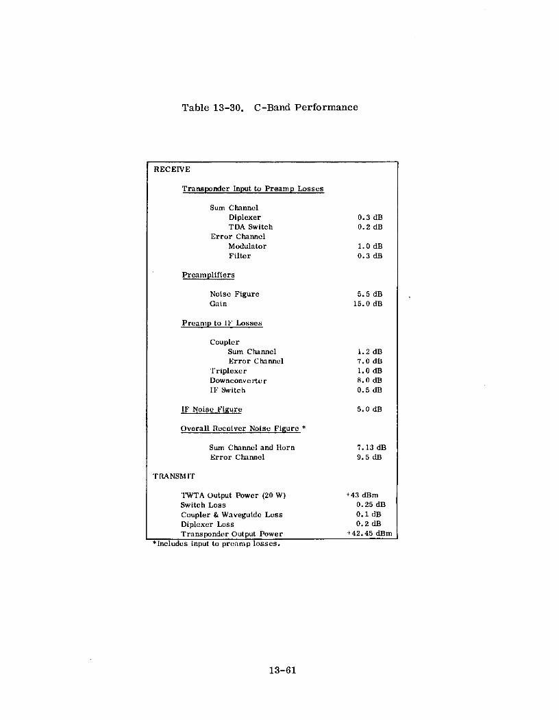
Table 13-30. C-Band Performance
RECEIVE
Transponder Input to Preamp Losses
Sum ChannelDiplexer 0.3 dBTDA Switch 0.2 dB
Error Channel
Modulator 1.0 dBFilter 0.3 dB
Preamplifiers
Noise Figure 5.5 dBGain 15.0 dB
Preamp to 11 Losses
CouplerSum Channel 1.2 dBError Channel 7.0 dB
Triplexer 1.0 dBDownconverter 8.0 dBIF Switch 0.5 dB
IF Noise Figure 5.0 dB
Overall Receiver Noise Figure *
Sum Channel and Horn 7.13 dBError Channel 9.5 dB
T RANSMIT
'IWTA Output Power (20 W) +43 dBmSwitch Loss 0.25 dB
Coupler & Waveguide Loss 0.1 dB
Diplexer Loss 0.2 dBTransponder Output Power +42.45 dBm
*Includes input to preamp losses.
13-61

Table 13-31. S-Band Performance
RECEIVE
Transponder Input to Preamp Losses
Sum ChannelFilter 0.15 dBPreamp Switch 0.2 dB
Error ChannelModulator 1.0 dBFilter 0. 15 dB
Preamplifiers
Noise Figure 3.7 dBGain 34.0 dB
Preamp to IF Losses
CouplerSum Channel 1.2 dBError Channel 7.0 dB
Downconverter 7.0 dBIF Switch 0.5 dB
IF Noise Figure 5.0 dB
Overall Receiver Noise Figure *
Sum Channel & Cross Array 4. 10 dBError Channel 4.93 dB
TRANSMIT
Power Amplifier Output Power (21 W) +43.2 dBSwitch Loss 0.2 dBCable Losses 0.2 dBTransponder Output Power +42.8 dBm
*Includes input to preamp losses.
13-62

Table 13-32. L-Band Performance
RECEIVE
Transponder Inhput to Preamp Losses
Diplexer 1.1 dB
Preamplifier
Noise 4.4 dB
Gain 25.0 dB
Preamp to IF Losses
Filter 0. I1 dB
Downconverter 7.0 dB
IF Switch 0.5 dB
IF Noise Figure 5.0 dB
Overall Receiver Noise Figure* 5.57 dB
'TRA NSM IT
Power Amplifier Output Power (40 W) +46 dBm
L-Band TX/RCV Diplexer Loss 0.2 dB
Cable Losses 0.2 dB
Transponder Output Power +45.6 dBm
*lncludes input to preamp losses.
13-63

Table 13-33. VHF and UHF Performance
VIIF I ICEIVE (150 MHlz)
T'ransponder input Losses
Sum ChannelT&C diplexer 1.0 dB
T&C hybrid 3.0 dB
Coupler 1.0 dB
Error ChannelModulator 1.0 dB
Filter 0.2 dB
Coupler 7.0 dB
Both channels filter 1.0 dB
Line Switch 0.5 dB
IF Switch 0.5 dB
IF Noise Figure 5.0 dB
Overall Receiver Noise Figure*
Sum Channel 12.0 dB
Error Channel 15.2 dB
UIF TRANSMIT (860 Mlllz)
Power Amplifier Output Power (80 W) +49 dBm
Filter Loss 0.2 dB
Cable Loss 0.2 dB
Trransponder Output Power 1-48.6 dBm
*lncludes input to preamp losses.
13-64

The synthesizer uses direct synthesis from a single frequency standard. A
simplified block diagram of the synthesizer is shown in Figure 13-16. The figure
shows the signal flow for the coherent repeater operation mode at L-Band. When it
is desired to have the synthesizer operate independently of the received frequency, a
highly accurate reference oscillator is substituted in place of the IF signal in the
phase detector and the synthesizer locks to the reference oscillator. Redundancy is
achieved by using two synthesizers.
Solid state power amplifiers are used for all but the C-Band transmitter. The
C-Band transmitter consists of three traveling-wave tube amplifiers. Command logic
circuitry is used to initiate switching and TWTA selection to effect either a single
power output (10 W) from any one of the three TWTAs, or a combined power output of
20 W from any two of them. The third TWTA performs as a redundant unit capable of
being employed in either of the 10- or 20-W power output modes. The UHF, L-Band,
and S-Band power amplifier are all transistorized. There is no downlink communica-
tions capability available at VHF.
Separate equipment, consisting of an RF Oscillator-Multiplier unit and a 20/30
GHz Modulator-Amplifier unit is also provided onboard the spacecraft for the Milli-
meter Wave Experiment (MWE) described in Section 13.4.4. This equipment can be
used either to generate two CW signals at 20 and 30 GHz, or to synthesize two
coherent multitone spectra each consisting of a carrier and four tones on each side
spaced at 180-MHz intervals and centered at 20 or 30 GHz. In addition, the 6 GHz
uplink signals received by the basic ATS-F multifrequency transponder can be cross-
strapped at IF to the MWE equipment to provide modulated downlink signals at 20 and
30 GHz. A block diagram of the MWE equipment package is shown in Figure 13-17.
In the CW or cross-strapped modes the output signal powers at 20 and 30 GHz are
limited to 2 watts each; for the coherent multi-tone spectrum the output power is 17. 8
dBm per tone. The MWE will employ both horn antennas and the main parabolic
reflector antenna. The beam peak gains for the 20 and 30 GHz horns will be 27. 6 dB
and the parabolic antenna gains will be 37. 0 and 39. 0 dB, respectively, for the 20 and
30 GHz signals.
13-65

~ 3800 MHI
C-BAND CBNINPUT FROM 100 0ANTENNA
L-BANDOUTPUT SA-BND -BAND IF CBNTO -,-POWER XR AMPLI- MXR1
R VCOMz MR MIXz
ANTENNA AMP FIER
OR40 1w 6200 MHz
-MMHz
X2 X9 3 600 MHz
........ .....X 2 20 1800MHz
4000 MHz
X19- 3800 MHz
PHASEFigure 13-16. Frequency Synthesizer Block DiagramHz
13X3 X5 X46
TECTOR VC0 MHz MHz MHz 60 ~
6000 MHz
-2 -2 25 MHz 1500 MHz
L10MkX3 X11 1650 MHz
Figure 13-16. Frequency Synthesizer Block Diagram
13-66

5 MHz 20 GMaster2 UP- Hybrid TWTA* - HornOsteillator Multiplier Converter Hybrid TTAntenna
120 20/30 GHzSu0 10 GHz , TTA Diplexer Paraboli c
I MultF TWTA Antenna
*TravelingWave Tube X3 r 30 G H z
Amplifier r Hybrid - TWTA* HornMultiplier Converter
L __J Antenna
Figure 13-17. Millimeter Wave Equipment Package
13-67

A separate and independent single frequency conversion transponder is also
being included on-board the ATS-F spacecraft for the COMSAT Propagation Experi-
ment (CPE). Separate channels are provided at 13. 19 - 13. 20 GHz and 17. 79 - 17. 80
GHz with full redundancy in each channel. A signal received in either of these bands
will be translated to 4.15 GHz and amplified in a three-stage tunnel diode amplifier.
The outputs from the two channels will then be filtered, combined in a hybrid network,
and the combined signal delivered to two independent power amplifiers, each consist-
ing of a three-stage tunnel diode amplifier in cascade with a traveling wave tube
amplifier. A block diagram of the CPE transponder, which uses less than 14 watts
of spacecraft power, is shown in Figure 13-18.
The per carrier output of the transponder at 4 GHz will be -36 dBw for the 18
GHz diversity experiment carriers, and -29 dBw for the 18 GHz and -37 dBw for the
13 GHz dual frequency terminal carriers. The on-axis gain of the receiving antenna
will be 28. 6 dB and 25. 8 dB above isotropic at 18 and 13 GHz, respectively. At 18
GHz the antenna beamwidth will be 4' by 8. 5' . The on-axis gain of the transmitting
horn antenna will be 17 dB above isotropic at 4 GHz; the corresponding high-power
beamwidth will be 200.
13.4. 3 Ground Terminals
Four NASA ATS ground terminals will provide the main support for operations
conducted on the ATS-F and ATS-G spacecraft. All four stations will provide C, S,
and L-Band frequency modulated (FM) transmitters and C, S, and L-Band FM receivers.
Operations for which they will be responsible include spacecraft command and control,
collection of range and range-rate data for orbit determination, recording polarization
data for spacecraft attitude determination, and performance of technological and
scientific experiments. One station will be located at Rosman, North Carolina, and
two will be located at Mojave, California. One of the latter is a Transportable
Ground Station (TGS). After the launch of ATS-F, the TGS will be moved overseas.
The C-Band portions of each of these terminals, and the L-Band installation at Mojave,
13-68

18 GHzCRYSTAL FREQUENCY
OSC. & TRANSLATORMULTIPLIER
14 GHz
3-S T A G E 4 GHz
MIXER TUNNELASSY DIODE
AMP Twr a18G Gz 3-STAGE SWER,A D SUPPLY
REDUNDANT18-GHz
FREQUENCYTRANSLATOR
FROM BI I PFANTENNA ------------ 1 O-MHz TO
13 GHz ANTENNA
DIPLEXER RTIEC FREQUENC 3d
TRANSLSTOT R
MULTIPLIER TRNLTRHBI
9 GHz u BPF o 4 GHz10- MHz
13 GHz MIXER 3-STAGE 4 GHzASSY TDA
3- DAGE TWTA, TDA
REDUNDANT13-GHz
FREQUENCYTRANSLATOR
Figure 13-18. Transponder Block Diagram
13-69

will be modified versions of the facilities employed in previous ATS experiments. The
fourth terminal is a mobile station that will allow the experimenters' equipment to be
remotely located. In addition, it"will serve as a backup to the TGS and will contain
UHF equipment to support the 860 MHz-downlink for the ITV experiment. The three
stations, Rosman, Mojave, and the TGS will have nearly identical communications and
telemetry and command equipment. The major difference is in the antenna systems.
A separate transportable millimeter wave terminal for the Millimeter Wave Experiment
will be located adjacent to the ATS facilities at Rosman. Major characteristics of these
terminals are summarized in Table 13-34. (37) A block diagram of the communica-
tions facilities at Rosman and in the mobile terminal are shown in Figures 13-19 and
(37)13-20, respectively.
The instructional television experiment will be conducted by the Indian Govern-
ment in cooperation with NASA. Three Indian stations, located at Ahmedabad,
Bombay, and Delhi will originate TV programs for relay through ATS-F. These
signals will be received by small inexpensive terminals scattered throughout India.
All spacecraft maneuvers and experiments will be controlled by direction from
the ATS Operations Control Center (ATSOCC) at Goddard Space Flight Center (GSFC)
at Greenbelt, Maryland. All test data obtained will be forwarded from the ground
stations to GSFC for processing, evaluation, and distribution to experimenters.
Ground complex circuits for effecting this control and distribution of data are illus-
trated in Figure 13-21. ( 3 7 )
13.4.4 Experiment
The primary objective of ATS-F and G is to demonstrate the feasibility of a
30-foot diameter deployable spacecraft antenna with good RF performance up to
6 GHz. (38) In addition, the spacecraft is to provide an earth synchronous oriented
platform stabilized along three axes for advanced technology and scientific experi-
ments. In the field of communications, six very important technological experiments
will be performed. These are:
13-70

Table 13-34. Characteristics - Millimeter Wave Experiment Terminals
STATION
ITEM DESCRIPTION ROSMAN MOJAVE IRANSP HIAIE MOBILE TERMINAL
C BAND
Typ. Parkxallc RoEflctor wilh STADAN Patubh Hf:l wilh Css In P-I.il1ll Rr9liA.r wilh
P6im Focu Fo-1 and ATS CaIss.pain FamIl Prmu F:ul. Fuld
C Bald Food
Diametofr B If 401 21 1
Polar xi ollA Lilllll
Mor XY A II PRTruivo FIIn
I. :3.1 I,, 41 C ;1iI
T.an.m.I Fn1. b.025 to fi,425 61/
G/T 13.7 GHI) (Zu ilh)I 36.4 111 31.!, 3H 32.0,111 24.111 d (C jll
Glin Rciv (3.7 Gft 56.0 dB 49., dH 50 O, dH 44. 111
G i Trsml 15.9GHlI B61.0dR 53.0d1 53bdR 41.)dB
Roiv Sysnm Nlisn 6 K 63"K 100 K
Tnlip. (ZnnIItht ) B125K IIrl:otoid
S AND L BAND
Type PI RMlI lil: R icl wlth Plllne :oc:s F -In
POIalasit11i Cu ulal
Mount A7 I1 IRTcniv Fru,. S RII(: 2.0b I, 2.1 GHI
Tlll it FIr, S Hillll: 7. 1 i 2: (3GH
I Bi 1: 1.62 1, I.I (; I
G/T: L Bll c l(Zl ilh) 10.6dB
S GIT: S Ba-d (Zelnilh) 12 .1 11
Guinl
S- Band RCV 3:5.7 I
Z S Billrd XMT 3L B,,J XMT .. 3,11R
R.olvl, Sy,, m N)II
Tanlrullna ( Zlllillll
L B lll 2 I"K
S -ll 230'K
Tyl., PIillil:
R10DIIc:DIIOI wilh
Pllmo Follls F ?dt
Diiarnto, 71 t
PIlari llt ion C ll
Molll Polhlt
RF iv,, FrI. 8:6 HD MM1
G/T IZnith) 5, R M,1H
Gain Ru iWv 31.1 111
Rleiv- Systlr Noisu 450"K
Temp. (ZlBiMh)
MMW EXPRMNT
Tyl, Pridxlic
Oiilmlmter 1I it
Fu-fs OI ll F InelV: y
I ininu
MInIIII AZ EL
R.,c iv. Only Frencrly 20 lrl 30 G(HI
"G/T: 20 GH, 70.0 IB
30 GH, 7915 ,B
30 GH" 58dB
Ronivll SV,.tm Nloie 20 GH 630 'K
Tempm r llllll (ZIth) 30 GH. 710 "K
C BAND
Niso Tmp IH'K
RF Bar.twidth 500 MH,
IF Bandwidth I, t 50 MH,
S AND L BAND
Noisl Tmp 100 "K
RF Balldwidlh Up 11 50 MH,
IF Bandwidth tiI in 50 MH,
C-BAND
Max. Powm Oulltpt kW kW
RF B-rllwillth 50 Mll
S AND L BAND
Mex. Po~wr Outp t S 1H llll: 100 W (CWI I IRlnll: 1 kW ((:W)
RF RBandwidlh S Rolli: 60 MH, I RlHal 10 MHI
"Mininllm at Ilnk urloss otlluorwlsn notntn
"'Thu exisling 15 If L Bomi anto l aIt Mqave ih eilll mIrilill lo il:lll S Hllr lllllllity
13-71

AUTOTRACKRECEIVE
C-BANDRECEIVE
DEMOD
ROSMAN 116MD -0 EXPERI-85-FT C-BAND MENTS
ANTENNA TRANSMIT
DEMOD
BASE-IF BAND
PATCHING PATCHING
EXPERI-MENTS
S/L-BAND CETECRECEIVE MOD
MOD
15-FTANTENNA S/L-BAND
TRANSMIT
R&RRSREMOTE If RR
CON EL FREQUENCYCONTROLAND TIMING
POWER
Figure 13-19. Rosman Ground Station Block Diagram

21- FOOT C-BANDRECEIVER RCIEBASEBAND
S UHF OUTPUTS
RECEIVER
ANTENNAREMOTECONTROL IF AMPLIFIERS,
ANTENNA RECIVER DEMODULATORS.MODULATOR.AND
EOUALIZERS
TEST TRANSLATORNOISE SOURCES
AND PERFORMANCEMONITOR
C-BANDTRANSMITTER
S-BANDINPUT
TRANMITER
POWER FREOENCY MAINTENANCESUBSYSTEM AND TIMING VAN
Figure 13-20. ATS-F and G Mobile Terminal System Block Diagram
13-73

ROSMAN II MOJAVE TRANSPORTABLEGROUND STATION
Rosman, N. Carolina Goldstone Dry Lake, AbroadCalifornia
5 lines to 2 lines to 21 line to
local exchange local exchang (local exchange
I 1 FDX (2 T-30 to T+3I1 FDX 12 T-30 to T+30 days) I 1 FDX
IL ----------- GODDARD SPACEI L-FLIGHT CENTER
I 1FDX I AHMEDABADI -, -INDIA
1FDX I 1 line to
I local exchange
MOBILE TERMINAL
Remote SiteVaried
SCAMA
100WPMTTY
-.-.-. 5 MHz VIDEO (Tentative)
1 MHz VIDEO (Tentative)(Shared with other Projects)
Figure 13-21. ATS Communications Landlines
13-74

" Tracking and Data Relay Experiment (T&DRE)
" Position Location and Aircraft Communications Experiment (PLACE)
0 Instructional Television (ITV) Experiment
* Millimeter Wave Communications and Propagation Experiment (MWE)
0 13 and 18 GHz Propagation Experiment
0 Radio Frequency Interference (RFI) Experiment
Other related experiments include Television Relay Using Small Terminals (TRUST),
Very High Resolution Radiometer, Spacecraft Attitude Precision Pointing and Slewing
Adaptive Control Experiment, Cesium Bombardment Ion Enginer, Laser Retro-
reflector, Educational Television, Radio Beacon, and Environmental Measurements.
13.4.4. 1 Tracking and Data Relay Experiment ( 39 )
The tracking and data relay experiment (T&DRE) will employ the ATS space-
craft to relay command, tracking, and telemetry data between ground stations and the
low orbiting satellite NIMBUS-E. The systems concept associated with this experi-
ment makes it possible to view the low orbiting spacecraft from an earth-synchronous
satellite for durations nearly six times greater than are presently possible from a
single ground station. Two such synchronous satellites could provide almost continuous
coverage and would eliminate the need for tape recorders to store data on the low-
orbiting spacecraft. The objectives of the experiment are, (1) to determine the extent
to which the orbit of an earth-orbiting satellite can be established from another orbit-
ing spacecraft, and (2) to develop the technology and demonstrate the feasibility of a
data relay system.
To accomplish the first objective, four-way range and range-rate (R&RR) data
will be obtained on the NIMBUS and relayed to the control ground station. The R&RR
system uses a series of tones to modulate an RF carrier, the modulated carrier is
transmitted from the ground station to ATS-F, then down to NIMBUS, up to ATS-F,
13-75

and then back down to the ground station. The phase delay and doppler shift of the
returning signal yields the total four-way range and cumulative range rate over the
signal path from which the orbit of NIMBUS can be determined. The transmission
link between the ATS spacecraft and the ground is at C-Band; between the ATS and
NIMBUS spacecraft S-Band signals are employed.
T&DRE design objectives for uncertainties in raw tracking data are 4. 0 meters
in range and 0. 6 centimeters/s in range rate. Based on the availability of long-are
tracking data, studies have shown that it should be possible to determine the NIMBUS
orbit to within 50 meters in a total elapsed time of several hours. This constitutes
a substantial improvement over ground-based tracking systems which typically require
days and weeks of data processing to determine orbits which at best are known only
to within hundreds of meters. Verification of these theoretical studies is considered
the major scientific and application goal of the T&DRE.
To accomplish the second objective, that of developing the technology and
demonstrating the feasibility of a data relay system, data from NIMBUS will be
relayed via ATS-F. The data transmission capacity of the NIMBUS to ATS-F link is
determined by the power of the transmitter and antenna gain available on the NIMBUS
spacecraft; this capacity is more than sufficient to provide highly reliable trans-
missions of normal 4 kbps data from NIMBUS to the ground via ATS-F. To perform
a more meaningful evaluation of T&DRE return link performance, test data will be
transmitted at rates of 50, 100, 200 and 400 kbps. Signal detection at the ATS
ground station will be done using a high-performance carrier tracking phase demodu-
lator which will track the residual carrier component of the transmitted signal under
all system doppler conditions.
13.4.4.2 Position Location & Aircraft Communications Equipment ( 3 9 )
The Position Location & Aircraft Communications Experiment (PLACE) will
obtain engineering data and provide practical experience to apply in developing an
improved air traffic control system using a satellite operating in the aeronautical
13-76

L-Band. PLACE is designed to promote both improved methods for aircraft position
location and two-way communications between the ground and many aircraft. There
are two primary objectives:
* To prove the feasibility of synchronous satellite relay of multichannel
two-way voice and digital data communications between participating
aircraft and their ground control centers
* To investigate the feasibility and to evaluate the absolute and relative
accuracy of position location techniques using a single satellite.
To accomplish the first objective the ground control facilities transmit, to the
satellite, voice and data signals at C-Band. The ATS-F satellite receiver phase
locks to these incoming signals which are then coherently converted to L-Band at 1500
MHz. These signals are transmitted to the aircraft transponder which phase locks to
the L-Band signal. All stations are thus coherent with each other. Communication
with a specific aircraft is accomplished by modulating that baseband channel assigned
to that aircraft, the aircraft transceiver receives the composite signal but only
demodulates its assigned channel within the baseband. Information from the aircraft
is transmitted in the band from 1650 MHz to 1652 MHz. ATS-F receives this spectrum
and, after preamplification, down-converts it to baseband in the IF amplifier. This
baseband signal is used to phase-modulate a carrier which is transmitted back to the
ground control facilities at C-Band. The ground station receives the carrier and
recovers the aircraft's subcarrier signal.
To accomplish the second objective, unique surveillance and ranging tones will
be used to modulate the carrier from the master control simultaneously with the voice
and data signals. In ATS-F this signal is processed the same as the voice and data
signals. All aircraft will transpond these tones, on a time-shared basis, back to
ATS-F where they are relayed to the ground station for processing in real time to
determine the location of each aircraft.
13-77
The inflight performance experiments will be conducted as a combined effort of
Goddard Space Flight Center and the Federal Aviation Administration, and possibly
other experimenters. The experiments will include actual aircraft flights to deter-
mine the effects of multipath, the ionosphere, noise environment, and geographic
location on both the L-Band communication and position location links.
13.4.4.3 Instructional Television Experiment ( 3 9 )
In the Instructional Television (ITV) Experiment, a television signal is relayed
from the ground through the ATS-F spacecraft to small inexpensive earth terminals.
Its purpose is to advance the state-of-the-art in space communications by combining
the proven technology of satellite relay of wideband FM signals with the new tech-
nology of the ATS-F spacecraft's large aperture parabolic reflector in the geostation-
ary orbit. The experiment will be conducted by the Government of India in cooperation
with NASA. The Indian government will develop, provide, and maintain the ground
receiver segment of the ITV experiment; and develop and use program materials that
will carry out the instructional objectives of the experiment. Three different uplink
stations at Ahmedabad, Bombay, and Delhi will be used during the experimental
period. In isolated villages, standard TV receivers will be augmented with 10-foot
diameter antennas for direct reception of the 860-MHz satellite radiated signal. In
urban areas, the signal will be received with 15-foot diameter antennas and then
rebroadcast from standard television transmitting stations.
The primary objective of the ITV experiment is to demonstrate the transmission
of CCIR quality television signals to small inexpensive ground UHF receiving terminals.
A secondary objective is to observe the effects of ionospheric dispersion on system
performance as a function of electron density distribution, ground station location, and
other system variables and to compare the observations with theoretical predictions.
13. 4. 4. 4 Radio Frequency Interference Experiment ( 4 0 )
The Radio Frequency Interference Experiment is designed to measure and
evaluate the amount of mutual interference between communication satellite and
13-78

terrestrial microwave relay systems at the shared common carrier frequency bands of
4 and 6 GHz. Although mutual interference can occur in two distinct modes, satellite-
to-terrestrial or down-link mode and terrestrial-to-satellite or uplink mode, only the
up-link interference mode at 6 GHz is presently being considered for the ATS-F
experiment plan. The technical objectives of the up-link interference tests and
measurements are:
* To determine the integrated interference power from all 6 GHz
terrestrial sources sharing the common carrier band within the
r-f field of view of the ATS-F satellite
" To establish practical G/T limits for satellites sharing the 6 GHz
common carrier band
* To determine the geographical and frequency distribution of 6 GHz
terrestrial sources sharing the common carrier band
* To establish the protection ratio of wanted-to-unwanted carrier
power (C/X) required at the satellite receiver.
The RFI measurements will be performed using standard noise-power-ratio
(NPR) tests with the earth terminal configured in a back-to-back loop through the
satellite. The reference NPR measurements will be made using the earth coverage
(low gain) antenna of the satellite with the main beam of the high gain (30-foot)
antenna pointed to a quiet spot on the earth. In order to relate the interference levels
to the wanted-to-unwanted signal ratios (C/X), the system carrier-to-noise and base-
band signal-to-noise ratios will also be measured. The main beam of the high gain
antenna will then be pointed toward a high density population area such as the north-
eastern coastal region of the United States and the measurement technique repeated.
This set of measurements now contains both the simulated desired signals (and basic
noise) plus the real (unwanted) noise signals from all earth sources within the field of
view of both satellite antennas. These unwanted noise signals, sharing the same
common carrier frequency as the simulated system, can now be determined by
13-79

remeasuring the system NPR, carrier-to-noise, and baseband signal-to-noise ratios.
The measurements will be repeated to determine the interference noise levels as a
function of source latitude, frequency, and time.
13.4. 4.5 Millimeter Wave Communications and Propagation Experiment
The purpose of the Millimeter Wave Communications and Propagation Experi-
ment (MWE) is to provide additional information about the millimeter wave propagation
characteristics of the earth's atmosphere so that this portion of the electromagnetic
spectrum can be utilized effectively for communications and scientific purposes. The
propagation effects of interest in Space-Earth Millimeter Wave links include atmos-
pheric attenuation (absorption and scattering), refraction, dispersion, and noise
considerations. Associated with these effects is the propagation medium bandwidth
limitation, as related to very wideband communications and data transmission systems.
The objectives of the MWE are to:
* Provide propagation characteristics of Space-Earth Links at 20 and
30 GHz under defined meteorological conditions
0 Provide engineering data on Space-Earth Communications Links
operating at 20 and 30 GHz under various meteorological conditions
and modulation techniques
0 Establish a model for the prediction of millimeter wave propagation
effects.
To achieve these objectives the data obtained from the experiment will be
analyzed using three general areas of investigation identified as Propagation Data
Analysis, Communications Link Analysis, and Channel Correlation Analysis. The
Propagation Data Analysis includes accumulation and cumulative comparison of the
received signal effects versus such meteorological data as rainfall rate, weather
radar return, radiometer temperature, and speed and direction, temperature,
barometric pressure and refractive index. The Communications Link Analysis will
13-80

permit a direct comparison to be made between such measures of link performance as
carrier-to-noise ratio and bit error rate and the link parameters of modulation index,
transmission rate, and carrier frequency. The Channel Correlation Analysis will
study the channel characterization by two-dimensional correlation measurements to
provide a measure of such important channel parameters as coherence bandwidth,
delay spread, fading bandwidth, and coherence time.
To accomplish the objectives of the MWE, probing signals will be transmitted
from the ATS-F satellite at 20 and 30 GHz to a number of earth terminals in three
modes of operation: a multi-tone mode consisting of a coherently-related carrier and
four tones on each side, all spaced at 180-MHz intervals; a carrier wave (CW) only
mode at the frequencies of 20 and 30 GHz; and a communications mode designed to
repeat the ATS-F 6 GHz uplink modulation by means of an IF cross-strap to the basic
ATS-F communications transponder. As presently planned, the prime communica-
tion and propagation experiment station will be at Rosman, North Carolina, and will
employ a 15-foot diameter parabolic antenna. Other sites located in the Washington,
D. C., area including COMSAT, the Naval Research Laboratory (NRL), and one fixed
and one transportable site being established for the NASA Radio Interference Propaga-
tion Program (RIPP) will participate and perform diversity testing. It is further
expected that the Ohio State University's (OSU) multi-site capability developed under
the ATS-F program will be utilized by RIPP for acquisition of additional diversity
data. Experimental data will be recorded over a period of 6 months to provide
information on seasonal and diurnal variations in propagation conditions at these
frequencies.
13. 4. 4. 6 The 13 and 18 GHz Propagation Experiment
The 13 and 18 GHz Propagation Experiment is designed to gather data on satel-
lite signal attenuation at these frequencies caused by atmospheric hydrometeors at
ground stations located in representative climatological areas. The data from this
experiment will permit determination of minimum power margins needed in spacecraft
13-81

communications systems operating at frequencies above 10 GHz. The technical objec-
tives of the experiment are:
* To obtain the statistical distribution of signal attenuation at 13 and
18 GHz for widely varying climatic and geographical earth station
locations
* To obtain, at 18 GHz, joint distributions of attenuation magnitude
and duration as a function of earth station separation, climatology,
and season
To determine the feasibility of employing spot beam techniques at
frequencies of 13 GHz or lower to overcome localized fading.
To accomplish these objectives 15 participating earth stations will be established
throughout the eastern half of the U. S. and separated from each other by at least
160 km. Each of these stations will be capable of transmitting, to the ATS-F, two
frequencies near 13. 2 and 17. 8 GHz. In addition, diversity operations will be estab-
lished at three of these dual frequency terminals by locating in the vicinity of each
three single frequency terminals transmitting near 17. 8 GHz. The separation between
the diversity terminals will be less than 40 km. The specific site locations for the
transmitting earth terminals have not been selected as of mid 1971. The ATS-F
transponder will receive these signals from the earth terminals, translate them to the
4 GHz band, and retransmit them to a single receiving terminal. The receiving
terminal will receive the signals at 4 GHz, separate out the individual carriers,
envelope detect them, and record the power of each carrier on magnetic tape. The
duration of the experiment will be sufficiently long to permit a statistical comparison
between the measured attenuations and the general meteorological parameters that are
routinely collected by the weather bureau, such as rainfall rate, number of thunder-
storm days, and total precipitation.
13-82

13.4. 5 Operational Results
Since these are experimental satellites no operational traffic will be carried.
Further, since the ATS-F launch (as of mid-1971) is not anticipated until about 1973
no operational experience has been accumulated on the satellites or on the planned
ground complex.
13-83
CITED REFERENCES
1. "Government Use of Satellite Communications, " Forty-Third Report by the
Committee on Government. Operations, House Report Number 2318, October
19, 1966.
2. L. Jaffee, in a statement at Hearings before a Subcommittee of the Committee on
Government Operations, House of Representatives, Eighty-Ninth Congress,
Second Session, September 6, 1966.
3. "Applications Technology Satellite," TRW Space Log, Vol. 6, No. 4, Winter
1966-67.
4. "Applications Technology Satellite," TRW Space Log, Vol. 7, No. 4, Winter
1967-68.
5. Draft Revision of Report 207-1, CCIR Doc. IV/69-E, Period 1966-69, June 18,1968.
6. Space Tracking and Data Acquisition Network Manual, X-530-69-109, National
Aeronautics and Space Administration (NASA), Goddard Space Flight Center,Greenbelt, Maryland, August 1969.
7. "Super-High-Frequency (SHF) Communications System Performance on ATS,"
Volume 1 - System Summary, NASA-TM-X-65304, NASA, Goddard Space
Flight Center, Greenbelt, Maryland.
8. "ATS-1 VHF Communications Experiment Final Report, May 1967-December
1969, " FAA-RD-70-12, National Aviation Facilities Experimental Center,Atlantic City, New Jersey.
9. J, P. Corrigan, "The ATS VHF Experiment for Aircraft Communications,"Canaveral Council of Technical Societies, Fourth Space Congress on the
Challenge of the 1970's, Cocoa Beach, Florida, April 3-6, 1967.
10. R. H. Pickard, "The Applications Technology Satellite, " in Meteorological and
Communications Satellites, International Astronautical Federation, Sixteenth
International Astronautical Congress, Athens, Greece, September 13-18, 1966,
Proceedings, Vol. 4.
11. T. Keating, "X/Y Angle and Polarization Angle Tracking of the ATS-B Space-
craft Using the Rosman 85-foot Antenna No. 2 and Mojave 40-foot Antenna, "NASA-TM-X-55716, NASA, Goddard Space Flight Center, Greenbelt, Maryland.
13-84

12. S. Wishna, "WEFAX - Weather Data Relay Communications Experiment, "
EASCON '68 Record, Electronics and Aerospace Systems Convention, Washing-
ton, D.C., September 9-11, 1968.
13. Computer Sciences Corporation, "OPLE Experiment Summary, " Contract No.
NAS5-11672, Report No. 4031-19, Goddard Space Flight Center, Greenbelt,Maryland, February 1971.
14. "Super-High-Frequency (SHF) Communications System Performance on ATS.Volume 2 - Data and Analysis, "NASA-TM-X-65341, NASA, Goddard SpaceFlight Center, Greenbelt, Maryland.
15. Y. Suguri, H. Doi, and E. Metzger, "A TDMA/PCM Experiment on Applications
Technology Satellites, " Conference Record IEEE International Conference on
Communications, Boulder, Colorado, June 9-11, 1969.
16. R. I. Davidson, "Data Transmission over Combined Terrestrial and Satellite
Circuits (ATS Test Plan APO-1), " Goddard Space Flight Center, Greenbelt,Maryland, January 1968.
17. G. L. Crew, "Telephone Signaling over a Satellite Link (ATS Test PlanAPO-2), " Goddard Space Flight Center, Greenbelt, Maryland, January 1968.
18. I. T. Hawryszkiewycz, "Computer to Computer Communications Using aSatellite Link (ATS Test Plan APO-3), " Goddard Space Flight Center, Greenbelt,Maryland, May 1968.
19. R. L. Baldridge, and L. K. Harman, "Multiple Channel VHF Satellite TestResults on ATS-1 and ATS-3, " IEEE International Conference on Communications,Proceedings, Volume 2, San Francisco, California, June 8-10, 1970.
20. W. W. Buchanan, "Aeronautical Satellite Communications - A Progress Review,"Radio Technical Commission for Aeronautics, Annual Assembly Meeting,Washington, D. C. September 25-26, 1968.
21. Westinghouse Electric Corporation, "Final Report, Maritime Mobile SatelliteCommunications Tests Performed on S. S. Santa Lucia, " U. S. Department ofCommerce Maritime Administration, Washington, D. C.
22. T. W. Davis, A. F. Flanders, and F. V. Kohl, "Hydrologic CommunicationsExperiment on the Applications Technology Satellite (ATS-1), "Sixth InternationalSymposium on Remote Sensing of Environment, Ann Arbor, Michigan, October13-16, 1969, Proceedings, Volume 1.
13-85
23. J. W. Coste, and D. K. Hall, "An Experiment with VHF Satellite and HF-SSBCommunications for Data Collection from Ocean Data Stations, " NTC 70, IEEENational Telemetry Conference, Los Angeles, California, April 27-30, 1970.
24. General Electric Company, "Periodic Progress Report for ATS Ranging andPosition Fixing Experiments (1 May 1970-31 July 1970), " Contract No. NAS5-11634, Goddard Space Flight Center, Greenbelt, Maryland.
25. L. E. Gatterer, J. L. Jesperson, S. G. Kama, and P. F. MacDoran, "SatelliteVHF Transponder Time Synchronization, " IEEE Proceedings, Vol. 56.
26. M. M. Garcia, and C. F. Sundstrom, "Airborne Satellite CommunicationsDuring Aurora 1 Studies, Final Report, " EGG-1183-524, Edgerton Germeshausenand Grier, Inc., Bedford, Massachusetts.
27. "Report on Tests of Chirp Modulation Data Transmission from Ground (Mobile)to Aircraft via Satellite ATS-3, " Royal Aircraft Establishment, Farnborough,Hants., England, February 17, 1969.
28. "Applications Technology Satellite," TRW Space Log, Summer 1967, Vol. 7,No. 2.
29. "Applications Technology Satellite, " TRW Space Log, Winter 1968-69, Vol. 8,No. 4.
30. "Applications Technology Satellite Program, " TRW Space Log, Winter 1969-70,Vol. 9, No. 4.
31. "Millimeter Wave Propagation Experiments Utilizing the ATS-5 Satellite, "NASA X-751-70-428, Goddard Space Flight Center, Greenbelt, Maryland,November 1970.
32. F. J. Kissel, "L-Band Performance Characteristics of the ATS-5 Spacecraft, "IEEE International Conference on Communications, San Francisco, California,June 8-10, 1970.
33. O. J. Hanas, and R, N. Waetjen, "Navigation and Communication Experimentat L-Band on Board S. S. Manhattan Using ATS-5 Satellite, " EASCON '70.
34. L. J. Ippolito, "Millimeter Wave Propagation Measurements from the Applica-tions Technology Satellite (ATS-5), " IEEE Transactions on Antennas andPropagation, Vol. AP-18, No. 4, July, 1970.
13-86
35. C. N. Vammen, and F. L. McCormick, "ATS-5 Millimeter Wave Propagation
Experiment, " IEEE Transactions on Aerospace and Electronic Systems, Vol.
AES-6, No. 6, November, 1970.
36. L. J. Ippolito, "ATS-5 Millimeter Wave Experiment Data Report, Oct. -Dec.
1969, " NASA X-733-70-123, Goddard Space Flight Center, Greenbelt, Maryland,
March 1970.
37. "The ATS-F and -G Data Book, " Goddard Space Flight Center, Greenbelt,
Maryland, October 1971.
38. A. B. Sabelhaus, "Applications Technology" Satellite -F and -G Communications
Subsystem, " Proc. IEEE, Vol. 59, No. 2, pp. 1206-1212, February 1971.
39. Joseph P. Corrigan, "Applications Technology Satellites -F and -G Communica-
tions Experiments, " to be published.
40. V. F. Henry and J. J. Kelleher, "Radio Frequency Interference Experiment
Design for the Applications Technology Satellite, " IEEE 1968 EASCON Conven-
tion Record, pp. 514 - 520 (September 1968).
13-87

RELATED REFERENCES
1. W. Gocbd, and K. W. Schrick, "Position Experiments Using Distance Measurementsof Satellite ATS-3, " Institute of Navigation, Journal, Vol. 23.
2. J. Aarons, "The High-Latitude F-Region Irregularity Structure During the October30 - November 4, 1968 Magnetic Storm," Radio Science, Vol. 5.
3. J. A. Klobuchar, M. Mendillo and M. D. Papagiannis, "Ionospheric Storms atMidlatitudes, " Radio Science, Vol. 5.
4. A. V. Rosa, and M. J. Davis, "Possible Detection of Atmospheric Gravity WavesGenerated by the Solar Eclipse," Nature, Vol. 226.
5. O. G. Almeida, A. V. Rosa, "Observations of Ionospheric Electron Content Duringthe March 7, 1970 Solar Eclipse, "Nature, Vol. 226.
6. S. J. Andrzejewski, "Frequency Stability Characteristics and Stabilization Tech-niques in an SSB-FDMA/PhM Multiple Access System, " AIAA Third Communica-tions Satellite Systems Conference, Los Angeles, California, April 6-8, 1970.
7. R. E. Anderson, "Experimental Evaluation of VHF for Position Fixing by Satellite, "AIAA Third Communications Satellite Systems Conference, Los Angeles, California,April 6-8, 1970.
8. F. F. Enge, "Applications of Omega Position Location Experiment to Mass Trans-portation, " Navigation, Vol. 16.
9. G. K. Kuegler, and R. Martel, "Short Term Frequency Stability Measurements of theApplications Technology Satellite No. 1 Multiple Access Communications System, "IEEE International Conference on Communications, Boulder, Colorado, June 9-11,1969, Conference Record.
10. L. Blaisdell, O. Mahr, and R. Rubin, "ATS Mechanically Despun CommunicationsSatellite Antenna, " IEEE Transactions on Antennas and Propagation, Vol. AP-17.
11. L. F. Deerkoski, "A Performance Evaluation of a Two-Element Large ApertureAntenna Array, " NTC 69, IEEE National Telemetering Conference, Washington,D. C., April 22-24, 1969.
12. H. D. Webb, "Solar Flares and Magnetic Storm of May 21-28, 1967, " Journal ofGeophysical Research, Vol. 74.
,13-88

13. H. R. Erhardt, and B. T. Subbotin, "Application of Electronically Phased Antennas
for Spin Stabilized Satellites," in Signal Processing Arrays, Proceedings of the
Twelfth Symposium, Duesseldorf, West Germany, July 7-13, 1966.
14. O. Mahr, "The Automatic Antenna Position Control System for the ATS Synchronous
Orbit Spin Stabilized Satellite," in Application Satellites, International Astronautical
Federation, International Astronautical Congress, 17th, Madrid, Spain, October
9-15, 1966.
15. Y. Ishizawa, M. Kajikawa, T. Nakajima, and T. Takahashi, "Electrical Performanc,
of the 30m Cassegrain Antenna at the Kashima Earth Station, " Radio Research
Laboratories, Journal, Vol. 15.
16. G. E. Dehm, and R. W. Donaldson, "Automatic Real Time Data Acquisition and
Processing for ATS Communications Experiments, " IEEE Transactions on
Aerospace and Electronic Systems, Supplement, Vol. AES-2, November 1966.
17. B. Spratt, "A Split Personality VHF COM System, "IEEE Region III Convention,Atlanta, Georgia, April 11-13, 1966.
18. "Applications Technology Satellite, Volumes 1 through 6, Technical Data Report,"NASA-TM-X-61130, NASA, Goddard Space Flight Center, Greenbelt, Maryland.
19. R. A. Lohnes, D. N. Matteo, and E. R. Grimshaw, "Unique Mechanism Features
of ATS Stabilization Boom Packages", in Aerospace Mechanisms, Vol. 1, Part A,G. G. Herzl, Editor, Lockheed Missiles and Space Company, 1970.
20. E. J. Buerger, "Development of a Passive Damper for a Gravity-Gradient Stabilized
Spacecraft, " in Aerospace Mechanisms, Vol. 1, Part A, G. G. Herzl, Editor,Lockheed Missiles and Space Company, 1970.
21. R. E. Hunter, R. O. Bartlett, R. M. Worlock, and E. L. James, "Cesium ContactIon Microthruster Experiment Aboard Applications Technology Satellite (ATS) IV, "Journal of Spacecraft and Rockets, Vol. 6, No. 9, September, 1969.
22. J. P. Dallas, "Despinning the ATS Satellite," in Aerospace Mechanisms, Vol. 1,Part A, G. G. Herzl, Editor, Lockheed Missiles and Space Company, 1970.
23. L. H. Grasshoff, "An Onboard Closed-Loop Nutation Control System for a Spin-Stabilized Spacecraft, " Journal of Spacecraft and Rockets, Vol. 5, No. 5, May, 1968.
24. D. H. Westwood, D. L. Kratzer, and M. E. Illikainen, "L-Band Receiver andModulator for the ATS-5/S. S. Manhattan Experiment, " EASCON '70.
13-89

25. A. Bulge, J. Levatich, and E. Robertson, "Propagation Experiments Above 10 GHzfor Application to Communications Satellite Systems, " AIAA 3rd CommunicationsSatellite Systems Conference, AIAA Paper No. 70-500, Los Angeles, California,April 6-8, 1970.
26. E. Marriott, "Grivity-Gradient Satellites of the ATS Program, " in Global WeatherPrediction - The Coming Revolution, Edited by G. Lusignan, and J. Kiely, Holt,Rinehart and Winston, Inc., New York, New York.
27. J. J. Davis, E. James, P. Ramirez, O. Wood, and R. Worlock, "An AdvancedContact Ion Microthruster System, " Journal of Spacecraft and Rockets, Vol. 6,P. 424-429.
28. R. A. Callens, T. K. Pugmire, R. Shaw, "Ammonia Resistojet StationkeepingSubsystem Aboard Applications Technology Satellite (ATS) IV," American Instituteof Aeronautics and Astronautics, 7th Electric Propulsion Conference, Williamsburg,Virginia, March 3-5, 1969.
29. R. P. Routt, and J. D. Shepard, "A Subliming Solid Reaction Control System,"International Astronautical Federation, 19th Congress, New York, New York,October 13-19, 1968.
30. E. M. Mazur, "Attitude Control System for the Gravity Gradient Stabilized Appli-cations Technology Satellite," in AIAA/JACC Guidance and Control Conference,Seattle, Washington, August 15-17, 1966.
31. B. S. Shephard, C. R. Shively, and D. W. Zehner, "Gravity Gradient BoomStabilization System for the Applications Technology Satellite (ATS-E), " Vol. 1,Final Report, NASA-CR-109580, Westinghouse Electric Corp, Baltimore,Maryland.
32. "Millimeter-Wavelength Propagation Studies Semiannual Status Report," NASA -CR-110649, Ohio State University, Columbus, Ohio.
33. F. Kissel, "L-Band Performance Characteristics of the ATS-5 Spacecraft, "NASA-TM-X-63828-REV X-731-70-51, NASA, Goddard Space Flight Center,Greenbelt, Maryland.
34. "ATS-E Press Kit, " NASA NEWS RELEASE-69-114, NASA, Washington, D. C.
35. "Project ATS-A, " NASA NEWS RELEASE-67-71, NASA, Washington, D. C. ,March 1967.
36. W. K. Allen, "PLACE Experiment Description, " NASA Technical MemorandumX-63289, November 1967.
13-90

37. R. R. Carman & B. Rottmayer, "A 30-Ft. Diameter Antenna for the ATS-F andG Synchronous Satellite, " Proc. 4th Aerospace Mechanisms Symposium (JPL),pp. 143-147, Jan. 1970.
38. T. Dillon, et al, "One Millipound Cesium Ion Thruster System, " AIAA Paper No.70-1149, April 1970.
39. M. Fashano and R. J. Rechter, "Use of a Data Relay Satellite System with ATS, "IEEE 1968 EASCON Convention Record, pp. 501-513, September 1968.
40. T. L. Felsentreger, et al, "Geodetic Earth Orbiting Satellite GEOS-C, ApplicationsTechnology Satellite ATS-F Tracking Experiment, " NASA Technical MemorandumX-63872.
41. H. L. Gerwin, "GSFC Phase A Analytical Report for ATS-F and G, " NASATechnical Memorandum X-55837, February 1967.
42. I. L. Goldberg, "A Very High Resolution Radiometric Experiment for ATS-Fand G, " NASA Technical Memorandum X-63112, January 1968.
43. P. J. Heffernan, "TRUST, " Goddard Space Flight Center, Greenbelt, Md., GSFCDoc. X-733-68-163, May 1968.
44. J. Heffernan, "Instructional Television for Underdeveloped Countries, Using theATS-F & G Satellite, " IEEE 1968 EASCON Convention Record, pp. 617-618,September 1968.
45. V. J. Jakstys and H. Ward, "Composite ATS-F & G Satellite Antenna Feed, " IEEE1971 International Conference on Communications, pp. 28-16 to 28-21, June 1971.
46. C. R. Laughlin, R. C. Hollenbaugh, E. Hirschmann, and W. K. Allen, "PositionLocation and Aircraft Communication Equipment (PLACE), " Goddard Space FlightCenter, Greenbelt, Md., GSFC Doc. X-731-67-159, April 1967.
47. C. R. Laughlin, et al, "PLACE Experiment Description, " GSFC Document X-733-67-577, Goddard Space Flight Center, Greenbelt, Md., November 1967.
48. C. R. Laughlin and P. J. Heffernan, "ATS-F & G Data Relay Experiment, "Goddard Space Flight Center, Greenbelt, Md. , GSFC Doc. X-733-68-190, May 1968.
49. J. H. McElroy, et al, "10. 6-Micrometer Laser Communication System Experi-ment for ATS-F and ATS-G, " Proceedings International Telemetering Conference,Washington, D.C., September 15-17, 1969.
13-91

50. R. H. Pickard and P. J. Herfernan, "The ATS-F/NIMBUS-E Tracking and DataRelay Experiment, " GSFC Document X-751-70-361, Goddard Space Flight Center,Greenbelt, Maryland, October 1970.
51. R. H. Pickard, et al, "The S-Band Telemetry, Tracking, and Command Experiment,Proceedings International Telemetering Conference, Washington, D. C. , September15-17, 1969.
52. V. Sarabhai, "Television for Development, " presented at the Society for Int.Development Conf. , Delhi, India, November 14-17, 1969.
53. R. F. Schmidt, "Computed Radiation Patterns of a Thermally Distorted 30-FootATS-F and G Parabolic Reflector Antenna, " NASA Technical Memorandum X-63401,November 1968.
54. R. A. Stampfl and A. E. Jones, "Tracking and Data Relay Satellites, " IEEE Trans-actions on Aerospace and Electronic Systems, " Vol. AES-6, No. 3, pp. 276-289,May 1970.
55. "GSFC Phase A Analytic Report for ATS-F&G, " Goddard Space Flight Center,Greenbelt, Md., Doc. X-730-67-118, Feb. 1967.
56. P. J. Heffernan and R. H. Pickard, "The ATS-F/Numbus-E Tracking and DataRelay Experiment, " AIAA Paper No. 70-1306.
13-92

SECTION 14 - TACSAT
14.1 PROGRAM DESCRIPTION
The Air Force has the long-range objective to provide combat forces with
satellite communications between mobile tactical terminals.! ) A series of prior
successful satellite developments and experiments in the Lincoln Experimental
Satellite Program (see Section 9) led to a contract in January 1967 for the develop-
ment of a prototype version of an operational satellite, the Tactical Communications
Satellite (TACSAT).
Specific objectives of the Tactical Satellite Communications (TACSATCOM)
program are listed in Table 14-1!2)(3)(4)
Table 14-1. TACSATCOM Objectives
Number Description
1 Develop, test, and experiment with space andsurface hardware in UHF and SHF bands.
2 Develop, demonstrate, and evaluate operationalconcepts for use with many mobile tactical ter-minals. These include problems of multipleaccess and power control.
3 Provide UHF voice link between the Apollospacecraft and recovery aircraft, ships, andground stations.
The active repeater satellite was launched into a geostationary orbit (see
Table 14-2) and positioned over the United States where it has undergone a successful
testing program that is continuing. TACSAT also performed very well in support of
Apollo recovery operations. The experiment involved a number of mobile terminals,
specifically developed for this program, that can be divided into UHF and SHF types
and subdivided by platform type. These are listed in Table 14-3!5)(6) In addition,
various other existing terminals were used for the TACSATCOM experiments.
14-1

Table 14-2. Participating Spacecraft
Satellite TACSAT
Manufacturer and Hughes Aircraft and AF Space andSponsor Missile Systems Organization
Launch Date 9 February 1969
Launch Vehicle Titan IIIC
Apogee (mi) 22,397Orbital Perigee (mi) 22,331
Data(*) Inclination 0.60Period Approx. 24 hrs.
Status Spacecraft Active
*At initial injection. Attitude control and stationkeepingproduce changes.
The design of TACSAT represented some major advances in spacecraft tech-
nology. It is a prototype for new high power communication satellites as well as a
test vehicle for tactical communications. Features include use of the gyrostat
stabilization principle to allow more flexibility in spacecraft design, complexity
of repeater design, development of a new 20-watt SHF TWT, and development of
load-bearing solar panels. The design of families of UHF and SHF earth terminals
based on extensive commonality of equipment represented another advancement.
The feasibility of UHF and SHF communications through a synchronous satellite by
small mobile earth terminals was demonstrated. Use of the tactical transmission
system (TATS) frequency-hopping modem for multiple access and overcoming multi-
path interference was also demonstrated and the attendant problem areas investigated.
14.2 SYSTEM DESCRIPTION
The UHF and SHF tests were conducted on a half and full duplex basis. The
TACSAT spacecraft is designed to operate in a variety of modes to accommodate the
planned tests with terminals of different capabilities. Functionally, the communi-
cations subsystem consists of a UHF frequency translating repeater and a SHF
14-2

Table 14-3. Participating Terminals
FrequencyType Sponsor Band Antenna
AN/TSC-80 US Army SatellityShelter Terminal Comm. Agency SHF 4-ft diameter parabola
(USASCA)
AN/MSC-54Vehicular Terminal USASCA SHF 3-ft diameter parabola
AN/TSC-79Teampack USASCA SHF 3-ft diameter parabola
AN/TRR-30Alert Receiver USASCA SHF 1-ft diameter parabola
AN/ASC-14 2.75-ft diameter
Airborne Terminal USASCA SHF Cassegrain
AN/ARC-146 AF Electronics Sys-Airborne Terminal tems Div. (AFESD) UHF Blade; crossed dipole
Large ship - 4-elementarray crossed dipole
AN/WSC-1 (V) Small ship - singleShipboard Terminal AFESD UHF element crossed dipole
Submarine - dipole;Helix
AN/TRC-157Shelter Terminal AFESD UHF Short backfire
AN/MSC-58Vehicular Terminal AFESD UHF Short backfire
AN/TRC-156Teampack AFESD UHF Short backfire
AN/TRR-32Alert Receiver AFESD UHF Monopole
14-3
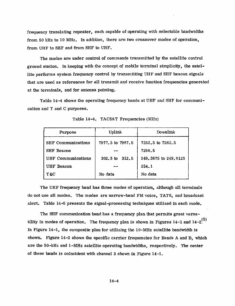
frequency translating repeater, each capable of operating with selectable bandwidths
from 50 kHz to 10 MHz. In addition, there are two crossover modes of operation,
from UHF to SHF and from SHF to UHF.
The modes are under control of commands transmitted by the satellite control
ground station. In keeping with the concept of mobile terminal simplicity, the satel-
lite performs system frequency control by transmitting UHF and SHF beacon signals
that are used as references for all transmit and receive function frequencies generated
at the terminals, and for antenna pointing.
Table 14-4 shows the operating frequency bands at UHF and SHF for communi-
cation and T and C purposes.
Table 14-4. TACSAT Frequencies (MHz)
Purpose Uplink Downlink
SHF Communications 7977.5 to 7987.5 7252.5 to 7262.5
SHF Beacon -- 7298.5
UHF Communications 302. 5 to 312.5 249. 3875 to 249. 8125
UHF Beacon -- 254.1
T &C No data No data
The UHF frequency band has three modes of operation, although all terminals
do not use all modes. The modes are narrow-band FM voice, TATS, and broadcast
alert. Table 14-5 presents the signal-processing techniques utilized in each mode.
The SHF communication band has a frequency plan that permits great versa-
tility in modes of operation. The frequency plan is shown in Figures 14-1 and 14-2! 5 )
In Figure 14-1, the composite plan for utilizing the 10-MHz satellite bandwidth is
shown. Figure 14-2 shows the specific carrier frequencies for Bands A and B, which
are the 50-kHz and 1-MHz satellite operating bandwidths, respectively. The center
of these bands is coincident with channel 3 shown in Figure 14-1.
14-4
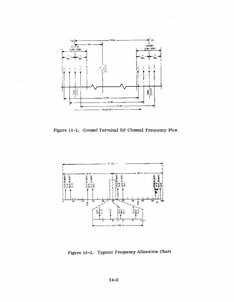
I I MH M------ -- UO
R1 (1 IV[ I RANSMII
10 MI; BAND 10 MH1 BAND
MH MMI
4_ _-•- Rf QUI NCY
I II I IQ NI I
ti I 1 I
I l l
5 H S : HANDA ki
Figure 14-2. Typical Frequency Allocation Chart
14-514-5

Table 14-5. Signal Processing for UHF Modes
Narrow-band BroadcastMode FM Voice TATS Alert
Multiple Access FDMA - 11 channels See Section 9.3 Only one warn-available ing transmis-
sion at any onetime.
RF Modulation FM MFSK and fre- FSKquency hopping
Ground Demodula- Threshold estimated Threshold is 8 dB Threshold esti-tor Performance at 10-dB C/N based for PE = 1x10- 3 mated at 10-dB
upon employing con- C/N based uponventional discrimi- employing con-nators ventional disc.
Ground Terminal* 29.3 dB** 24.1 dB*** 21.7 dB**Receive Carrier- 16.7 dB 11.5 dBto-Noise
Ground Receive 19.3 dB 16.1 dB 11.7 dBMargin* 6.7 dB 3.5 dB
*Higher value is for strongest UHF terminal pair and lower value is for weakestUHF terminal pair. All results for single access.
**Based on 15-kHz IF bandwidth.
***Based on 50-kHz detection bandwidth for high data rate TATS mode.
The SHF frequency band has four modes of operation, although all terminals
do not use all modes. The modes are frequency modulation for voice or data, TATS,
DPSK, and broadcast alert. Table 14-6 presents the signal-processing techniques
utilized in each mode.
14.3 SPACECRAFT
Characteristics of the communications-related subsystem of TACSAT are
described in Table 14-7. A block diagram of the communications repeater is shown
in Figure 14-3. There are eight ground commandable modes corresponding to the
14-6
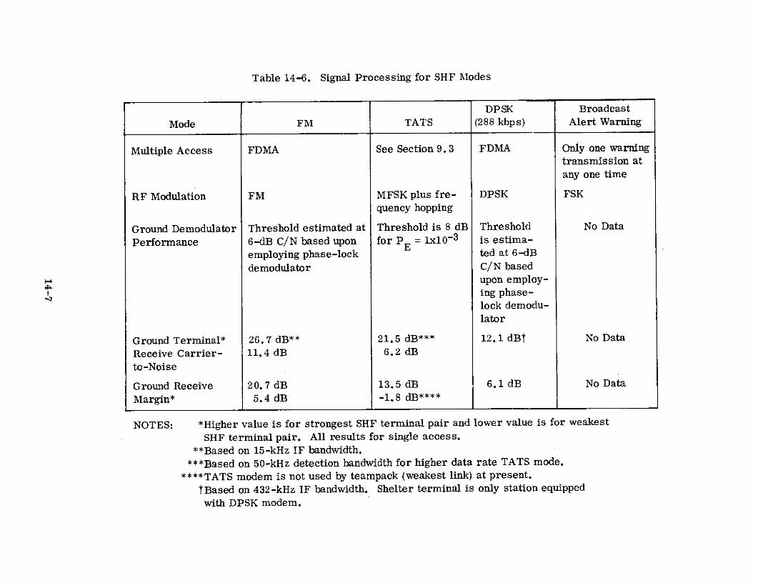
Table 14-6. Signal Processing for SHF Modes
DPSK Broadcast
Mode FM TATS (288 kbps) Alert Warning
Multiple Access FDMA See Section 9.3 FDMA Only one warningtransmission atany one time
RF Modulation FM MFSK plus fre- DPSK FSKquency hopping
Ground Demodulator Threshold estimated at Threshold is 8 dB Threshold No Data
Performance 6-dB C/N based upon for PE = 1x10⁻³ is estima-
employing phase-lock ted at 6-dB
demodulator C/N basedupon employ-ing phase-lock demodu-lator
Ground Terminal* 26. 7 dB** 21.5 dB*** 12.1 dBt No Data
Receive Carrier- 11.4 dB 6.2 dB
to-Noise
Ground Receive 20.7 dB 13.5 dB 6.1 dB No Data
Margin* 5.4 dB -1.8 dB****
NOTES: *Higher value is for strongest SHF terminal pair and lower value is for weakest
SHF terminal pair. All results for single access.**Based on 15-kHz IF bandwidth.
***Based on 50-kHz detection bandwidth for higher data rate TATS mode.
****TATS modem is not used by teampack (weakest link) at present.
tBased on 432-kHz IF bandwidth. Shelter terminal is only station equippedwith DPSK modem.

Table 14-7. TACSAT Characteristics
'Iype Ull '-iiv, element SIlf'- !;paratie fin Loaded horns T & C- 1iicon.ical lornhl ical array for trans for transmi I and rice ivyemit anld rceivc
Numllber OCiin (Oni Olne
IBeamwidth Earth covctrage (190). Earth coverage (190). Recei v, Approximately 100a l('ce(iive and ransmi t and t ransmit patttrn s not
patterns not identical identical and not symmetrical.and not symmetrical.
;ain peak -17.58B11 peak -19. 3d No dataIleceive minimul over ieceive minimum over coverage
coverage area area -15. 2d1-12.79d11
peak -17.12d11 p-Iak -18.41iiTralhnsmit mini lmum over Tr;l;mit iminimum over covcrlgq
cocvcrci( area area -15. 2di11-14. 67di,
l"requoncy lBand UllF SllF (X-BAND)
''ype Hard limitiinqg IF trans- lard limiting IF tranliation.lation. Adjustable Adjustable bandwidthi and cross-baillldwidth adll crossovIr ovir to Uill re,peti(r by commandL.ltco S110 rcpealter by :corm-mand.
Idli IcW Straiclht through modes- Straiqht. through mrod-,l;- 50kllz,50kllz, 100kllz and 1Mliz anid I0MIIz;crossove modch425klz ;crosssovvr modes 425kilz425klz and 10MlIz
Numbor One with some 01n with soc~c rcdunllancyredundancy
Type Front End Transistor preamplifior Tunnel diode amplifior intoSinto downc conversion down conversion mixer
Smixer
w lFront Enl Gain No data No data
System Noise 3.7111 6.9d11Figure
Type 16 paral.lel transistor 3 TWTs - Any 2 sumied icn aIampl i I irs with summi nq output TWT swi ch.
ii of .lly cnumbcr possibl
4j G iI No data No data
Power out Carr icr powir ( 16 power Carrier ipower (2 TWTs) -14. 6bdiWampl if iets) -23.611IW
Beacon powcr (16 pocwlr BIcacon power (2 'WT's) -0.2dBlWamplifie.rs) -8.0dBlW
hII RP Carrier -40.7dBiW Carrier -33.0dlBW
lBcaclon -25. IdlW Ieacon -18.61lBW
'Typo Gyrostat. - consists of spinning cylinder containinq solar cells and a despun platforncontaininl communications equipmont. iciarin s and slip rings usld [betwi(en the 2 sic
=-
m tions. Nitrogen spinlup system, hydTrogenq pccroxidt, reaction jcts a.111id iutatioll damp e rN are usid.
Capabi Ii ty Overall pointing capability is approximat.ely 0.1 dchgree rms. llowever, intUrnittentMc cnutiation of about 1 degree occurs. l, s bcn illvestigated and conflirlmed theoretically
a and can corrected on fut.ure spacecraft.
0 Primary Lolar array with 980 watts output
,o Supplemcnt Ilattury capacity-over 20 ampere-hours
rUComm. Power Necd:; No data
Si ze Cylinder 25 feoot long and 9 feet in diamotcr
Wciql.t About 1600 lbs. in orbit
14-8

BAND PASS 50 H50.HzFILTER FILTER UHF
FILTER
FILTEREPC TO UHF
B AANTENNA
UHF
S UPP 4 UHF425 kHz CONVERTER DIPLEXFRFILTER
UHF
RECEIVER
WB 10 MHz BEACON- -I0- ----- ,-1 IMAGF
10 MHz .
FILTER FILTER
10
FILTER
SHF
RECEIVER
FILTER
LO IF PROCESSOR AMPLIFIERSN
LO W IF LO Lo
B - B IA N T E N N ALO SHF TWT 2 SHF
REFERENCE GENERATOR BCN RF OUTPUT ILTER MONITORDRIVER S ICH
TWT 3
Figure 14-3. Communications Repeater Block Diagram
14-9

four filter bandwidths at each frequency band. Two of the modes represent cross-
coupled operation between the UHF and SHF repeaters.
TACSAT is the first U.S. spacecraft stabilized with gyrostat technology!4 )
This means that the satellite does not have to be spun about its maximum moment of
inertia and thus frees the designer of onboard equipment from the moment of inertia
design constraints.
The spacecraft consists of a large spinning cylinder within which is mounted a
cone-shaped structure. A bearing assembly attached to the cone structure supports,
on its housing, a despun platform containing antennas and communications and telem-
etry equipment. The spinning section contains solar cells, batteries, auxiliary
telemetry, tracking, and command equipment, despin control electronics, the hydrogen
peroxide propulsion system, and the nitrogen spinup system. A pendulum liquid damper
is used for nutation damping.
The intent of the program was to provide experimental hardware for testing
tactical satellite communications and, therefore, to be conservative in the spacecraft
development approach. Space-proven technology was used wherever possible. How-
ever, the satellite requirements could not be met without some major advances in
spacecraft technology. These included: use of the gyrostat stabilizing concept;
intricacy of the. repeater design; use of beryllium within the structure; development
of a new 20-watt TWT; and development of load-bearing solar panels.
Biphase digital modulation beacon signals are associated with each of the
repeaters. The modulating signal is a pseudorandom binary bit stream that may be
used at the ground stations for synchronization or timing functions. In addition, the
beacon frequency is used as a reference frequency for all tactical ground terminals.
The satellite UHF receiver processes the received RF signal, which varies in
level from -150 to -105 dBW. The signal is split into two channels, one for narrow-
band and the other for wideband operation.
14-10

The wideband channel is downconverted to a band around 92.5 MHz, hard-limited
and cross-coupled to the SHF transmitter. The narrow-band channel is downconverted
to a band around 16.6 MHz, hard-limited and then coupled to the various filters. A
ground commandable mode selection switch routes the desired channel output to the
UHF transmitter.
The SHF received signal level varies from -150 to -85 dBW. The signal is
downconverted to a band around 92.5 MHz. This signal is split into two paths, one
of which is amplified in the 10-MHz channel and limited. The signal in the other
path is downconverted to a band around 16.6 MHz for the SHF narrow-band channel
modes. A ground commandable mode selection switch routes the desired channel
output to the SHF transmitter.
14.4 EARTH TERMINALS
Two families of tactical terminals were developed for use in the two TACSAT
frequency bands as listed in Table 14-3. Each family employed considerable com-
monality of equipment with terminal-specific equipment mainly in the categories of
antenna, preamplifier, transmitter, and number and types of modems. Figures
14-4 and 14-5 show block diagrams of the UHF and SHF terminals, with all the
possible modes of operation in each frequency band included.
As discussed previously, the satellite beacons at UHF and SHF were used as
frequency references for all ground terminals. In the UHF receivers, the ground
terminal reference oscillator was compared to the beacon and adjusted manually
once a week. In the SHF receivers, a phase-lock loop was used to keep the ground
terminal frequency standard locked to the beacon frequency. Major characteristics
of the terminals are shown in Tables 14-8 and 14-9.
14.5 EXPERIMENTS
The experiments performed can be grouped under two general types: technical
and operational. The technical experiments investigated satellite and ground terminal
14-11

FDN
FUP F BEACON
TESTTRANSLATOR
DIPLEXER
LOW NOISE TATS 70 MHzS RCVR MODEM TRANSMITTER
TTY VOCODER
HEADSET FM DET FM MOD MIKE
ALERT ALERTCODEDETECTOR GENERATOR
BEACON FREQUENCY REFERENCE F R E
QUENCY
DETECTOR COMPARATOR OSCILLATOR SYNTHESIZER
FREQUENCY
SYNTHESIZER
Figure 14-4. Block Diagram of TACSAT UHF Ground Terminal
14-12
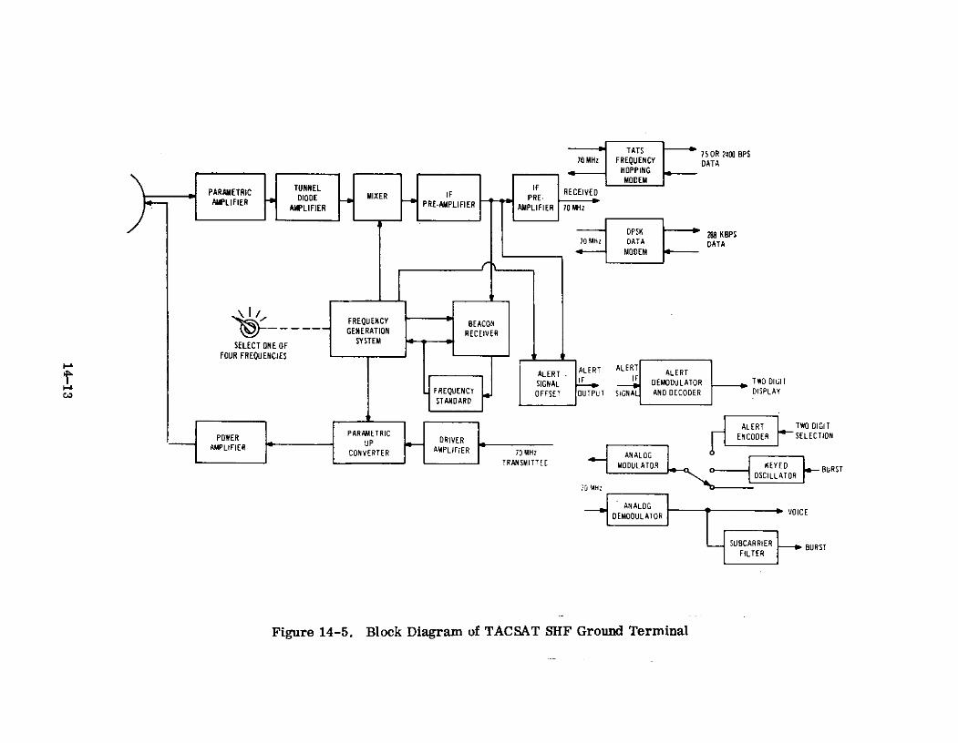
TATS 75 OR 2400 BPS70 MHz FREQUENCY DATA
HOPPINGMODEM
PARAMETRIC TUNNEL IF RECEIVEDLFER DIODE FMIXER IF PRE-,ER AMPLIFIER PRE-AMPLIFIER AMPLIFIER 70 MHz
DPSK 288 KBPS70 MHz DATA DATA
MODEM
SELECT ONE OF SYSTEM
FOUR FREQUENCIES
SALERT. ALERT ALERT ALERTSIGNAL DEMODULATOR TWO DIGIT
coFREQUENCY OFFSET OUTPUT SIGNAL AND DECODER DISPLAYSTANDARD
ALERT TWO DIGITPOWER PARAMETRIC ENCODER SELECTION
AMPLIIER UP DRIVERAMPLIFIER CONVERTER AMPLIFIER 10 MHz ANALOG - O D TTRANSMITTECE MODULATOR OSCI OR EYED BURST
ANALOG
DEMODULATOR VICE
SUBCARRIER BURSTFILTER
Figure 14-5. Block Diagram of TACSAT SHF Ground Terminal

Table 14-8. Characteristics of UHF Earth Terminals
Terminal Feature Terminal
AN/ARC-146 AN/WSC-1(V) AN/TRC-157 AN/MSC-48 AN/TRC-156 AN/TRR-32
Type Blade for low Large ship antenna Short backfire. Short backfirel Short backfire Monopole
elevation angles -four element balun-fed cross- balun-fed crossed balun-fed crossed
up to 300;crossed
- crossed dipole ed sleeve dipole sleeve dipoles sleeve dipoles
dipole for higher array over a with front re- with front reflec with front reflec.
elevation angles ground plane.amal flector and. rear tor and roar tor and rear
ship antennal ground-plane re- ground-plane re- ground-plane re-
S single element flector flector flector
- crossed dipoleover a groundplane
Aperture Size Blade-contained Large ship-ground Ground plane- 84 Ground plane Ground plane 11 in. long
in structural plane square 55- in. by 84 in. similar to similar to
members 5-1/6 in. 1/4 in. on a aide AN/TRC-157 AN/TRC-157
by 13/16 in, by small ship-ground
8-5/8 in.; cross- plane circular 38ed dipole-contain- in. diametered in structuralmember 12-15/16in. by 15-31/32in. by 8-5/16 in.
Blade-nominal OdB Large ship-12dB 13.5dB 13.5dB 8.5dB minimum 2 dB
Receive GainCrossed-dipole- Small ship-7dB6dB at aenith
Efficiency No data No data No data No data No data No data
Receive Beamwidth No data No data 400 minimum 400 minimum Similar to No dataAN/MSC-157, and-58
Type Preamplifier Transistor( 1 )
Tranitor( Traneistor(1 )
Transistor(1) Transistor(1) Transistor(1)
SRF-240 to 260Mlz RF-240 to 260MHz RF-240 to 260Mllz RF-240 to 260Mlz RF-240 to 260 MHz
Bandwidth IF- 250kiz either IF- 250kHz either IF- 250kiz IF- 25Okz either IF- 250kHz either 4kHz
side of RF chan- side of RF chan- either side of side of RF chan- side of RF chan-
nel center fre- nel center fre- RF channel cmn- nel center fr- nl cnter fro-
. quency quency tar frequency quency quency
(0.5dB pts.) (0.5dB pts.) t0.5dB p (0.5dB pts.) (0.5dB pts.)
Noise Temperature 6300K 900oK (2) 530OK 53
0fK 6000K les Lhan 4400K
Type Amplifier No data No data NO data No data No data
RP-300 to 315MHz RF-300 to 315MHzI RF-300 to 315MHz RF-300 to 315Mitz RF-300 to 315M1z
Bandwidth IF- amplitude re- IF- amplitude re- IF- amplitude re- IF- amplitude re- IF- amplitude re- No transmit
Ssponse within sponse within sponse within sponse within sponse within capability
*5MHz of band can- +5MN1 of band tSMHz of band l5MHz of band con- '5MHz of band
tar frequency: center frequency: center frequency: ter frequency: center frequency
1 to 10 watts - 1 to 10 watts - 1 to 10 watts - 1 to 10 watts - is l.0dB
12.0dB, 10 to 100 2.0dB, 10 to 10000 l 2dB, 10 to 100
watts -watts - 0..5dB, watts - 0.5dB, watts - 0.5dB, watta - t0.dl
100 to 1000 watts 100 to 1000 watts 100 to 1000 watts
- :0.SdB - '0.8dB - 10.9dB
Ap. Power Out Continuously ad- Continuously ad- Continuously ad- Continuously ad- o output levels
Justable 1 watt justable from 1 justable from I justable from 1 selectable -2
to 1000 watts watt to 1000 watt to 1000 watt to 100 watts watts and 20 watts
watts watts
Type None None-manual posi- None-manual posi- None-manual poai- None-manual posi- None-manual posi-
tioning aided by tioning aided by tioning aided by tioning aided by tioning
Ssignal strength signal strength signal strength signal strength
meter (4) 5 (6) meter meter meter
Scuracyo data on poi- No data n poi- No data on posi- No data on poi- No data on
Applicable tioning accuracy tioning accuracy tioning aceuracy tioning accuracy positioningaccuracy
S/T(7 )
Blade:- 28dB/o K Large ship: -13.8dB/oK -13.8dB/o K
-15.8dB/oK No data
S-17. 5dB/oK
Crossed dipole: Small ship:-22dB/oK -22.5dB/o
K
EIRP Blade: 30 to 60 Large ship: 42 to 43.5 to 73.5dam 43.5 to 63.dBm 15dBm and 25dBm No transmit
dBm 72dBm capability
Crossed dipole: Small ship: 37 to
936 to 66dBm 67dBm
StCransmit Feed Blade - linear Circular Circular Circular Circular Linear
a Fand Crossed dipole-SNc.civ. Feed circular
Radome Yes None None lbne None None
Type Facility Birpla Nhifphnrne Transportable Mnhilo-jeo Transportable- Transportable-
c mounted by truck or mounted two or three men one manaircraft
Notes: (1) Estimated from data available.
(2) Nominal value. Ranged up to 20000K on some ships.
(3) Antennas switched depending on elevation angle.
(4) After positioning, antenna is slaved to ship's gyro-system to follow movement in azimuth plane
(5) On some large ships a dual antenna system, one forward and one aft of the ship's superstructure
is used. The antennas are automatically switched to provide an unobscursd satellite view.
(6) Submarine used UHF SATCOM antenna system employing a helix antenna (4 to 5dB gain) for high
elevation angles and a dipole antenna (2dB gain) for low elevation angles.
(7) Derived value based on data available.
14-14

Table 14-9. Characteristics of SHF Earth Terminals
Terminal Feature Terminal
AN/ASC-14 AN/TSC-80 AN/MSC-57 AN/TSC-79 AN/TRR-30
Type Cassegrain ' Parabolic Parabolic Parabolic Parabolic
m Aperture Size 33 inch diameter 48 inch diameter 36 inch diameter 36 inch diameter 12 inch diameter
a Receive Gain 33.1dB 36.5dB 33.5dB 33.5dB 23.8dB
SEfficiency 52%(1) 1 54%(1) 54%(1) 48%(1) 46%(1)
Receive Beamwidth 3.50 @ 3dB pts. 2.40 @ 3dB pts. 3.40 @ 3dB pts. 3.40 @ 3dB pts. 10.30 @ 3dB pts.
Type Preamplifier Uncooled parametric Uncooled parametric Uncooled parametric Tunnel diode Tunnel diode
amplifier followed amplifier followed amplifier followed amplifier amplifierby tunnel diode by tunnel diode by tunnel diode
amplifier amplifier amplifier
") Bandwidth 10MHz 10MHz 10MHz 10MHz 10MHz
ao(2) (2) -325K (2)920Noise Temperature -325
0K 230 - 315K 3259200K 896 - 915K
Type Amplifier No data Klystron Travelling wave Travelling waveStube tube
Bandwidth 10MHz 10MHz 10MHz 10MHz No transmitEcapability
Amp. Power Out 1400 watts Adjustable frommaximum (3) 1.5 watts to 80 to 100 watts Selectable 3
0 450 or 500 watts maximum watts or 10 watts
Type Modified conical None-manual posi- None-manual posi- i None-manual posi- No datascan plus gyros to tioning aided by tioning aided by tioning aided by
c remove attitude signal strength signal strength signal strength
changes meter meter meter
w Accuracy No data Setting accuracy Setting accuracy Setting accuracyof better than of better than of better than±0.50 ±0.50 i ±0.50
(2) (1) (2) (1) (2) (5.8dB/o)l1
0 G/T (2)to 8dB/K() 12.9 to l.5dB/o) 2)to 8.
4dB/oK (2)to 3.9dB/o -5.7 to -5.dB/oK
m EIRP 95.6dBm(1)maximum Adjustable from (1)o 69.3dBm ty 94.0 or 83.5 to 84.5dBm Selectable 69.3dBm No transmit
94.5dBm(l' maximum or 74.5dBm(1) capability
0 Transmit Feed Circular Circular Circular Circular Circular
~ Receive Feed Circular Circular Circular Circular CircularON
0 Radome Yes None None None None
5 Type Facility Airborne Transportable by Transportable by Transportable by Transportable bytruck or aircraft small vehicle and two or three men one man
a I accessory trailerfor prime power
csupply
Notes: (1) Derived value based on data available.(2) No data on lower limit.(3) At power amplifier flange.

performance characteristics and system performance characteristics with the various
modems employed singly and under multiple-access conditions. The operational ex-
periments evaluated TACSATCOM performance during armed force operational ex-
ercises. In addition, there were various special tests employing TACSAT.
It was originally intended that technical experiments be performed before
operational experiments but late equipment delivery necessitated that the two types
be performed concurrently in some cases. Table 14-10 presents the major technical
experiments together with the salient results obtained.
The operational experiments, conducted by the Navy, are termed a Fleet
Operational Investigation (FOI) and are intended to investigate tactical concepts,
operating procedures, and techniques. These overlapped, to some degree, technical
experiments but were intended to determine effects of operationally imposed factors.
The following categories of operational experiments were established:
1. Multiple-access capability
2. Operational techniques and procedures
3. Environmental influences on operational characteristics
4. Special purpose operational applications.
The specific experiments were of three types: teletype, voice, and
simultaneous voice and teletype.
Successful communications were maintained during typical maneuvers such as
helicopter operations from a ship, destroyer maneuvers, aircraft launch and recovery
operations aboard a carrier, and orbit of a C-130 aircraft. The FM voice mode was
of high quality and very reliable. Secure digitized voice was more cumbersome and
less reliable and intelligible than FM voice. However, it provides a high level of
security. Secure teletype communication was excellent, provided synchronization
was achieved. The probability of achieving synchronization was not as high as
14-16

Table 14-10. Technical Experiment Results
Experiment Type Experiment Configuration Nature Of Results Obtained
1. Limits Of Satellite Coverage Area UHF and SIIF shelter terminals in Mary- At UHF no degredation above 10 degreeland. UHF and SHF teampack terminals elevation angle. At lower angles signal
in various Pacific Island locations. deteriorated but data was obtained to
Used FM voice channel employing special at least 4 degrees. At SHF no rep-
data modem rsuntatlvce data Is available.
2. Parameters of TACSAT Operating Using CW transmission to measure All test results agreed closely with
Modes parameters. theoretically predicted values or
Modes I parameters, equipment specifications.
3. Terminal Antennas Ground, ship, submarine and aircraft Ground, ship and submarine antennas
mounted antennas were tested, performed well. Data was obtained onperformance of various antenna designsfor fixed wing aircraft and helicopters.
4. Terminal Characteristics Standard tests were used to determine Basically the terminals performed with-
the characteristics in nominal limits and met most of theelectrical and mechanical requirements.
Shipboard UHF terminals had consider-
ably higher noise temperatures (up to2000
0K) than other UHF terminals (below
1000K).
5. FM Voice Modem Single satellite access voice link at Both the UIIF and SHF FM voice links
UHF and at SIF performed satisfactorily and had suf-ficient system margin.
6. Single TATs Modem With Ground Single transmitting modem configuration Under stable conditions modem perfor-
Terminals using every UHF, SIIF and cross-strap mance via satellite is within ldB (as
mode capable of supporting TATs modem. determined by Eb/Novs. error rate) of
back-to-back performance. Interferenceappears to be unavoidable in 10MHz band-width UHF uplink and is present in 500
kHz UHF band at times. Variations alongthe radio-wave propagation path also
contribute to variations of several dB.
7. Single TATs Modem With Aircraft Single transmitting modem configuration In general, the tests demonstrated the
Terminal using UHF from ground transmitter to capability of the TATs modem to operate
aircraft terminal. A ground receive satisfactorily with a aircraft communica
terminal used to provide a reference tion system including its multipathdata base environment. About 3dB maximum fade,
with a period of about 3.5 seconds,observed at elevation angle to thesatellite less than five degrees. Whenusing blade antenna modem lost lock dur-
ing 360-degree turns and with aircraftheading directly away from sub-satellite
point. Using reference data baseantenna system gain vs. elevation anglewas calculated for the two onboardantennas.
8. Multiple TATs Modem Up to five transmitting modems are com- Unexpectedly poor performance was notedbined, and transmitted. The test was during several of the runs using the
performed using the satellite and in a satellite relay. No results are report-
back-to-back setup. ed for tests using the satellite. Back-to-back tests which eliminate on-orbitsignal fluctuation, intermodulation,and possibly interference were perfor-med. They gave information on limita-tions in use of address codes to pre-vent false acquisition and maintainadequate link margin.
9.DPSK Modem (288kbpa) 6-channel PCM communications using TD- The 1-MHz satellite bandwidth was used
660 and the 288-kbps modem. SHF shelt- with carriers spaced 500kiHz apart.
er terminal-to-SHF shelter terminal This resulted in spectrum overlap and
full duplex. test results showed that the presentsystem will not support 6-channel PCM.
14-17

desired, due to a slight incompatibility between the TATS modem and the cryptographic
equipment. The teletype mode was considered the most useful because of the large
number of simultaneous accesses and security.
Complete random access to the satellite repeater is complicated by the necessity
to control the uplink power of the users. Joint Service Monitor/Control experiments
were performed to determine tradeoffs involved between a system that is too costly
or unreliable (no control) and a system that operationally is too restrictive in use
(complete control). The experiments were conducted using the TACSAT UHF mode.
The primary control concept allowed complete random access for all 75-bps TTY,
TATS users and for all alert message users subject only to EIRP restrictions. All
other communications modes had to obtain prior approval from the real-time monitor/
control agency before accessing the satellite. A schedule of priority in user com-
munication modes was set up, and each service was allocated a portion of the satellite
EIRP for nonrandom access communication modes. For power control, all UHF ter-
minals were allowed one of two radiated power magnitudes, depending on the receiving
and transmitting antenna gains. Experimental results were obtained that will be useful
in the design of an operational system.
The development of different modulation and multiple-access techniques led to
an investigation of the capability and compatibility of simultaneous use of different
techniques. One experiment involved simultaneous use of TATS and FM/FDM with
the TACSAT 500-kHz bandwidth UHF mode. Only certain TATS codes were used
such that the TATS signal energy did not fall in a selected portion (81.6 kHz wide)
of the repeater bandwidth. This allowed use of FM channels one through seven.
Twelve low data rate TATS at 18 dBW per access, two high data rate TATS at 29 dBW
per access, and three FM accesses at 31 dBW per access were used. Results showed
a C/kT of 59 dB for the FM accesses and a test tone plus noise-to-noise ratio of 26 dB.
Members of the Avionics Laboratory of the ECOM conducted digital data trans-
mission tests with TACSAT, using the TATS modem and the UHF-equipped helicopter.
14-18

The purpose was to determine the effects of the helicopter environment on the capa-
bility of the TACSAT system to relay digital data that could be extrapolated to simulate
air traffic control data.
The power level was varied in steps and the digital error rates recorded. Air-
craft engines and rotor and aircraft heading all affected the error rate vs. power
level. However, the results showed that with sufficiently high transmitted power
levels no errors occurred.
A series of tests using the USS Independence and NELC successfully demon-
strated the feasibility of establishing automatic digital data links between remotely
located participants.
The technical feasibility of transferring real-time ASW operational display
data to and from a computer-equipped P-3 aircraft and a ground-based computer
terminal was demonstrated. The experiment was performed at UHF, and the modu-
lation was 2400-bps FSK because the TATS modems wereunavailable.
A 2-way UHF-TDM communication mode used for air traffic control and
carrier landing operated successfully through the TACSAT repeater.
Vocoder voice word intelligibility experiments using the TATS modem werec
conducted using TACSAT. The word intelligibility vs. - values reached a maximumo
of 80 percent in some tests and 90 percent using other terminals.
Experiments were performed to determine degree of improved traffic flow in
a star net using automatic control. Functions, such as addressing of members and
assignment of channels, were performed by a computer installed at the net control
station in Bedford, Massachusetts. Automatic Net Control units were installed at
ground-based terminals and Eastern Test Range C-135 aircraft.
Although the experiments were considered preliminary and additional work
remains, the results showed that automatic polling significantly improved traffic
flow in star nets.
14-19

Experiments with terminals located in Panama were performed to determine the
effect of tropical environment, particularly attentuation due to foliage, on UHF and SHF
communications. The average attenuation at UHF in foliage was about 8 dB. At SHF no
signal acquisition was obtained in the foliage. There were equipment problems directly
related to temperature and humidity.
14.6 OPERATIONAL RESULTS
One of the objectives of the TACSATCOM program was the support of Apollo
missions. TACSAT was used to support Apollo missions 10 through 13 in the
following capacities.
1. Command and control of the Apollo Range Instrumentation Aircraft while
enroute and at their staging bases.
2. Astronaut voice relay from the spacecraft to Mission Control Center in
Houston during orbit, translunar injection burn, and recovery operations.
3. Following the aircraft transporting the lunar samples to Houston.
4. Recovery ship-to-shore communications 7 .
High-power UHF ground-based transceivers were used and the aircraft and
ships were equipped with TACSAT terminals. Communications during all operational
phases were outstanding.
In addition, the TACSAT SHF communication band was used to provide satellite
relay of live television coverage of the moon landing from the continental United
States to Alaska. A modified army SHF terminal in Anchorage, Alaska, was used
for this purpose.
From launch to June 1970 (latest date data is available), all major satellite
subsystems performed well with two exceptions; a nutation anomaly and a drop in
UHF ERP. It was found that the nutation angle, instead of decaying after separation,
maintained a fairly steady level of about 1 degree. The nutation disappeared even-
tually but has since reappeared at intervals. A study indicated that certain rotor
14-20

destabilizing forces are much larger than anticipated. These can be decreased by
minor changes in the design of future spacecraft. The nutation angle is not large
enough to affect communication system performance.
The UHF ERP dropped after several months from 38.4 dBW to 35.4 dBW +2 dB
with erratic variation about the mean. In addition, the transmitting antenna pattern
changed significantly. Laboratory tests have demonstrated that all the phenomena
observed could be caused by a short circuit to the ground plane or an open circuit on
the first turn of any of the four outer helix antennas.
In addition, there have been three component failures, none of which has
affected system operation; one of the four earth sensors is behaving erratically, one
of the redundant decoders of the TT and C subsystem has produced extraneous out-
puts at times, and one SHF TWT has suffered a reduced power level, probably due
to helix current changes caused by temperature sensitivity.
The UHF terminals developed for the TACSATCOM program were considered
as advanced development models, while the SHF terminals were considered as
feasibility models. Basically, the terminals met most of the electrical and mechan-
ical requirements. The UHF equipment was fairly reliable, but the reliability of the
SHF terminals and the TATS modem designed for TACSATCOM use were not as high
as desired.
14-21

CITED REFERENCES
1. Statement of Maj. Gen. Otto J. Glasser in hearings before a Subcommittee of
the Committee on Government Operations, House of Representatives, 89th
Congress, 2nd Session, August 18, 1966.
2. Lt. Gen. W. O'Neill, "Military Communication and Navigation Satellites,"TRW Space Log, Vol. 9, No. 2, Summer/Fall, 1969.
3. TRW Space Log, pg. 70, Vol. 9, No. 2, Summer/Fall, 1969.
4. R.D. Brandes, "The Tactical Communications Satellite," IEEE Transactions
on Aerospace and Electronic Systems, Vol. AES-6, No. 4, July 1970.
5. R. S. Lawton, and V. C. Chewey, "A Family of SHF Tactical Satellite Communi-
cation Ground Terminals, " IEEE Transactions on Aerospace and ElectronicSystems, Vol. AES-6, No. 2, March 1970.
6. "Tactical Satellite Communication Systems, " Product Description, CollinsRadio Company, Cedar Rapids, Iowa.
7. H. L. Heibeck, "NELC UHF Tactical Satellite Communications Terminal forApollo 9, 10, and 11 Recovery Missions," Naval Electronics LaboratoryCenter, NELC-TD-83, 21 July 1970.
14-22

RELATED REFERENCES
1. H. E. Weber, "Aircraft to Satellite SHF Communications, " Microwave Journal,
Vol. 12, No. 10, October 1969.
2. W. J. Russell, "Analysis and Simulation of the Despin Control System for a
Military Communications Satellite," Aerospace Corporation, Report No. TOR-
0200 (4113)-3, AD 862080, 16 December 1968.
3. R. J. Karl, et al, "A Study of Network Control Techniques for TACSAT, " HRB
Singer Inc., RADC-TR-70-174, Vol. 1, AD 876621, September 1970.
4. T. J. Yake, and J. W. Uhrig, "Helicopter Communications via UHF Satellite
Relays," Air Force Avionics Laboratory, WPAFB, Technical Report AFAL-
TR-70-152, July 1970.
5. D. L. LaBanca, et al, "Computer-to-Computer Satellite Communication,"
EASCON '70 Convention Record, October 26-28, 1970.
6. J. Y. Hayase, and G. J. Goubeaud, "Computer Controlled Time Division
Multiple Access (TDMA) Control System and Link Performance," EASCON
'70 Convention Record, October 26-28, 1970.
7. E.J. Andrews, "UHF Terminals for TACSATCOM, " Telecommunications,
Vol. 5, No. 4, April 1971.
14-23

SECTION 15 - SKYNET
15.1 PROGRAM DESCRIPTION ( 1 )
In 1962, the first tentative studies were started to determine the feasibility
of a satellite system to meet the United Kingdom's military needs. During 1963 and
1964 subsequent studies proceeded toward a goal of choosing an optimum system.
Meanwhile, the U. S. was planning the deployment of its Interim Defense Satellite
Communication System (IDSCS). The U.S. intended to devote the first year of IDSCS
to testing, and the U. K. was invited to participate in the test phase.
The U. K. program to participate in the IDSCS testing consisted of building
five earth stations and work began on these stations in 1965. Three, with 40-foot dishes,
were designed by Marconi to have an operational capability within the SKYNET program.
The fourth was designed and developed by the Admiralty Surface Weapons Establish-
ment. This terminal was entirely experimental to test and confirm the basic
design requirements for shipborne terminals. The fifth station - a mobile land
terminal - was built by the Signals Research and Development Establishment. This
terminal was also an experimental tool.
The first Marconi station was completed in the middle of 1966, and the other
four stations were all working and participating in testing before the end of that year.
During the testing a large number of R&D tests - typically, measurements of
propagation conditions, path loss, earth station performance, and experiments on
advanced modulation techniques - were accomplished to aid in the design of the
SKYNET System.
In 1966 a Memorandum of Understanding was signed between the U.K. and
the U.S. whereby the U.S. would build and launch two satellites required by the
SKYNET Program. Philco-Ford was to build the satellites and the USAF
Space and Missile System Organization (SAMSO), with technical support from the
Aerospace Corporation, was to act as the procurement agent for the U.K.
15-1

Two satellites were to be launched in 1969-70, with one satellite acting as
a backup for the other to provide a 5-year system capability. SKYNET I "A"
was successfully launched into synchronous orbit in November 1969. SKYNET
I "B" was launched in August 1970 and was a total loss when it failed to reach
synchronous orbit. It was generally believed that the apogee kick motor used
to circularize the orbit exploded. Table 15-1)(2)(3) summarizes launch and status
information on the SKYNET satellites.
The U.K. has initiated procurement of additional higher power satellites
from Marconi, U.K., which is working under license to Philco-Ford, U.S.
The U. K. anticipates launching the first of the SKYNET II series in the summer
or fall of 1972. SKYNET II will be similar in design to SKYNET I but will have
considerably higher EIRP (20-watt TWT vs 3. 0-watt TWT).
The operational requirements dictated the use of nine earth stations, five
of which were to be stationary and four mobile. The stationary stations are in the
U. K., Cyprus, Bahrain, Gan and Singapore. Although the stations are considered
stationary, all stations with the exception of the U. K. station have been designed so
that they can be moved if necessary. Two of the mobile stations are fitted in ships -
the assault headquarters ships HMS Fearless and HMS Intrepid. The last two
stations are mobile stations ashore. These two terminals are to be held in strategic
reserve and deployed for contingency operations. Table 15-2 (2)(4 through 9) is a
summary of the terminals participating in the SKYNET Program.
The operational aims are to provide long distance strategic point-to-point
digital communications and to meet selected tactical communication needs with the
mobile terminals.
The central requirement of the system is for multiple access. It was deemed
essential that any stationary terminal be able to communicate with any other, subject
to the limitation of satellite effective radiated power and the amount of terminal
equipment available for the link in question. In a real sense the central requirement
goes beyond multiple access and includes an element of random access.
15-2
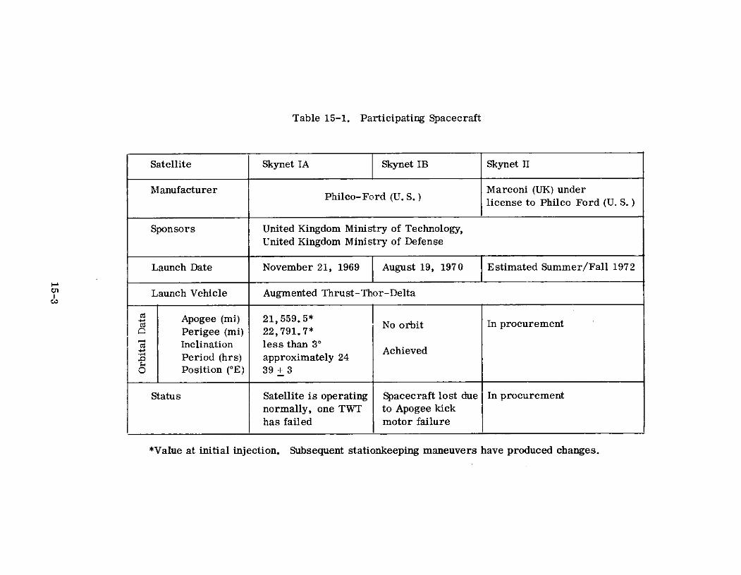
Table 15-1. Participating Spacecraft
Satellite Skynet IA Skynet IB Skynet II
Manufacturer Marconi (UK) underlicense to Philco Ford (U. S.)
Sponsors United Kingdom Ministry of Technology,United Kingdom Ministry of Defense
Launch Date November 21, 1969 j August 19, 1970 Estimated Summer/Fall 1972
Launch Vehicle Augmented Thrust-Thor-Delta
d Apogee (mi) 21, 559. 5*P) No orbit In procurementPerigee (mi) 22,791.7*Inclination less than 3'
3 Achieved.-0 Period (hrs) approximately 240 Position (°E) 39 + 3
Status Satellite is operating Spacecraft lost due In procurement
normally, one TWT to Apogee kick
has failed motor failure
*Value at initial injection. Subsequent stationkeeping maneuvers have produced changes.

Table 15-2. Participating Earth Terminals
Ant. DateLocation Diam. (ft.) Utilization Type Installed Manufacturer Comment
UK (Oakhanger) 40 Static-operational I 1969 Marconi Ltd Main stationtraffic
Cyprus 40 " II 1966 Marconi Ltd
Singapore 40 " II 1966 Marconi Ltd
Bahrain 21 " III 1969 GEC-AEI Air TransportableElectronics
Gan 21 " III 1969 LtdLtd
Contingency 21 Contingency IV 1969 Helicopter
Contingency 21 " IV 1969 Transportable
HMS Fearless 6 Shipborne V 1970 Plessey Radar
HMS Intrepid 6 " V 1970 Ltd
Christchurch 40 Testing -- 1966 Marconi Ltd
Oakhanger 60 Telemetry, Command -- 1969 Radiation Inc. Same designand Control as USAF sat-
ellite trackingstation

Since this has been an operational system, its contributions to satellite
communications technology have, by intent, been constrained. Nevertheless, it has
been the first satellite communications system to provide an all-digital mode of
operation. This was accomplished by employing spread spectrum multiple access
for users of the 20-MHz channel of SKYNET. In implementing the system, opera-
tional spread spectrum modems and time-division multiplex equipment were
developed and tested to meet specific SKYNET requirements.
15.2 SYSTEM DESCRIPTION
Based on the two sets of requirements for communications within the SKYNET
System: (1) long distance strategic point-to-point digital communications, and
(2) selected tactical communications with mobiles, it was decided that two
independent satellite bands would be required (20 MHz and 2 MHz). Table
15-3(2)(3) gives the frequencies of the two bands.
Table 15-3. Skynet Frequencies
2-MHz Channel 20-MHz Channel(MHz) (MHz) Beacon (MHz)
Uplink 7976. 02 to 7978. 02 7985. 12 to 8005. 12 ------
Downlink 7257. 3 to 7259.3 7266. 4 to 7286.4 7299. 5
The satellite, with two independent bands, allowed tailoring of the modulation
and multiple access to satisfy all system requirements. Other specified features
of the system include providing reliability of communications under various
conditions of weather, loading and interference, and providing flexibility in terms of
interconnections and traffic carried.
The various requirements of SKYNET communications led to a choice of
terminals of varying capacities. In addition, the satellite antenna pattern was
15-5

designed broadly enough for coverage from the United Kingdom in the West to
Singapore in the Far East. The U. K. 's other areas of interest fall between these
two extremes.
Traffic requirements were in the form of telegraphy, speech, and medium
speed data circuits. It was decided that the strategic system would be designed
specifically for digital signals at medium speed rates meeting the form of 75 x 2n
bits/second and would use the 20-MHz channel. Once the digital philosophy was adopted,
a telegraph time division multiplex capable of assembling an assortment of syn-
chronous and nonsynchronous telegraph signals of differing data rates into a single
synchronous data stream was developed.
For the 20-MHz channel, SSMA was chosen over FDMA. This choice allowed
frequency planning to be eliminated since SSMA transmissions could be superimposed
to any desired degree, subject only to the normal capacity limit of the system.
Additional advantages of this choice were (1) SSMA signals are virtually immune to
intermodulation effects except for the small loss of useful power (approximately, 1 dB)
due to the radiation of intermodulation, and (2) inherent jamming protection is
provided. Figure 15-1(2)(10) indicates the SSMA links established among the fixed
terminals operated in the 20-MHz channel. Table 15-4(2) summarizes the typical
link performance in the 20-MHz band.
In the more difficult mobile terminal case, it was decided to use FDMA with
FM as the basic modulation in the 2-MHz satellite band. In addition, the 2-MHz channel
is used to provide engineering teletype orderwire facilities between fixed stations.
Figure 15-2(2) indicates the FM links to be established in the 2-MHz band. Link-
power limitations dictate that the mobile and shipborne terminals communicate only
with a 40-foot station. Table 15-5(5)(6)(9) gives the FM performance characteristics
of the demodulators used by the mobile and shipborne terminals.
Since reliability of communications is of paramount importance, adequate link
margins were allowed in all cases for unpredictable losses due to weather, mis-
alignments and equipment degradation. Estimates of 2 dB for excess path
15-6

GANBAHRAIN
21'21'
UK
42'
NOTE: ALL STATIONS CAPABLE OF COMMUNICATIONWITH ONE ANOTHER
Figure 15-1. SKYNET SSMA Links

Table 15-4. Power Budget for Typical SSMA Links
(1) Received power at satellite (dBm) -72.8
74 (2) Receiver noise level for a 2750 noise temperature(dBm/Hz) -165.2
(3) Signal/noise ratio at receiver (dB) in 20-MHzbandwidth 19.4
(1) Received power (dBm) -99.2
(2) SSMA noise density (dBm/Hz) -169.2
(3) Thermal noise density (2500K) (dBm/Hz) -174. 6
(4) Total noise density (dBm/Hz) -168. 1
(5) Signal/noise power density (dB/Hz) 68. 9
(6) Required signal/noise power density (dBm/Hz) usingo DPSK modulation with 2400-bps channel for errorSrate of 1 in 1000 42.0
(7) Intermodulation loss (dB) 1. 0
(8) Margin (dB) 8.0
(9) Residue (dB) 5 - (6 + 7 +8) 17.9
This indicates that 62 digital streams of 2400 bps canbe accommodated.
15-8

SATELLITE
UK, C, B. G, S USE NARROWBAND UK 2-MHz 2FOR FM/FDMA TELETYPE ORDER- CHANNEL S2 M1, M2 ONLY COMMUNICATEWIRE OR TO COMMUNICATE WITH TO A 40 FOOT TERMINALS1. S2 M1 M2 TO A 40 FOOT TERMINAL
C S1
B M 2
G M
UK 40' TERMINAL AT OAKHANGER M1 & M2 = 21' CONTINGENCY TERMINALSB 21' TERMINAL AT BAHARAIN S t = 6' SHIPBORNE TERMINALG = 21'TERMINAL AT GAN S2 = 6' SHIPBORNE TERMINALS = 40' TERMINAL AT SINGAPORE
Figure 15-2. FM/FDMA Links (2-MHz Channel)

Table 15-5. FM Demodulator Performance
Threshold of
Maximum Peak Threshold of Phase-Lock
Baseband Frequency Equivalent Carrier Conventional Loop Used in
Frequency Deviation Carrier BW Discriminator SKYNET System
(kHz) (kHz) BW (kHz) (dB/Hz) C/No (dB/Hz) (dB/Hz)
4 16 42 52 50.7
4 7.5 23 43.6 53.6 52.1
13 34 45.3 55.3 53.3
15-10

attenuation and 110 0 K for excess noise are used for earth stations in the U. K. and
Singapore that are served by a suitably disposed geostationary satellite. (11)
Losses are likely to be somewhat greater in the case of an earth station with a
radome because of the attenuation of a water film on the surface. Reductions in
signal/noise ratio of up to 6 dB have been observed with a radome under conditions
of very heavy rain. Margins must be allowed for both "up" and "down" links if a
local rain squall is not to upset the power balance of the entire system. Total
margin required was 7 to 8 dB.
Control, as exercised in the SKYNET System, is of three different types:
control of the spacecraft, the earth station complex, and the traffic. Accurate
control of the spacecraft is essential to successful operation of the communication
system. It is necessary to maintain spacecraft position and attitude by on-board control
systems and to switch spare repeater subsystems if malfunctions occur. The
control is exercised at Oakhanger by the Telemetry and Command Station on the
basis of computations performed at Royal Aircraft Establishment Farnborough.
Engineering control of the communication system is exercised from the
Master Engineering Control Centre (MECC) collocated with the Type I earth station
at Oakhanger. The status of each earth station in the system is displayed and instruc-
tions on power levels, frequencies, and operating modes to be used as well as positional
information relating to the spacecraft, are broadcast over engineering orderwire cir-
cuits from this station.
Traffic control takes place at speech and telegraph facility control centers which
are remote from the earth stations and connected to them by telephone lines.
15.3 SKYNET SPACECRAFT
Spacecraft characteristics for the SKYNET satellites are displayed in Table
15-6!2)(3) A simplified block diagram depicting the communications configuration
of the satellite is shown in Figure 15-3. (3)
15-11

Table 15-6. SKYNET I Satellite Characteristics
Type X-Band mechanically despun UHF array for TT&C with redundant UHF transponders andcommand/telemetry processinglll elquipmentll
Z Number One Two
Z Beamwidth 19" Essentially omni-directional
Gain (dB) 18.5 0.7
Frequency Band X-Band
Type Hard-limiting dual channel
1 dB Bandwidth 20-MHi and 2-MH/ channels
Receiver
Type Front End Down-conversion mixer into linear amplifier"
Front End Gain No Data
Noise Figure 2750"K (10.2 dB)I-u
W Transmittera-
Type Redundlant TWT
Gain No Dala
Power Output (dIBm) 31.0
EIRP (IdBm) peak of beam 49.5 (in each channel)
Stabili/ation
Type Spin 90 rlrl 5 years
Capability (stationkeepilln) 3" for 5 years
W Power Source
Primary Cylimhlical array of silicon solar cells, capable of providing 97 watts of prime power throughoutW 5 years of orbit life
< Supplement Two redlundant 16-cell iickel cadmium bIitteries for operation during eclipse (6 AH per cell)
W Communication Power Needs (watts) 64
Site (inches) 54 diameter 60 high
Weight (ibs.) Launch 535. on orbit 280
*Dynamic range (a) 20-MHz channel 90 to -45 dBm
(b) 2-MH? channel 100 to -45 dBBm
15-12

TRANEDUER
RF I
E7975 TO C25 TONE
GEN = 30PULSE HP
KI VULTER 71H Vz
NNOMINAL EP PER CAN 44 6
Fiure 15-3. Communications Trans onderCO 5
Figure 15-3.IF mucL ain Transn X1

The Communications Subsystem (shown in Figure 15-3) receives, translates in
frequency, amplifies, and retransmits X-band signals. Two channels, 20- and
2-MHz bandwidth (1 dB), are provided. The total output power is divided equally
between the two channels. Figure 15-3 indicates the single thread path. The
complete equipment redundancy and cross-strapping which is employed to achieve
reliability is not shown. Selection of either set of communications equipment,
operating with either traveling wave tube amplifier, is accomplished by ground
command.
The received signal is: (1) isolated by polarization diversity in the orthomode
transducer, (2) downconverted to IF, (3) split into separate channels for amplif i-
cation and hard-limiting, (4) recombined and up-converted to output frequency,
(5) amplified to output power in the TWT, and (6) introduced into the communications
antenna through the orthomode transducer. A signature tone timing signal is
frequency modulated on the beacon carrier and introduced into the communication
band in the channel summer.
The communications antenna consists of the RF assembly and the motor
drive assembly (MDA). RF energy is circularly polarized, collimated into a plane
wavefront and focused upon the flat plate reflector. The beam axis, reflected
through 900 angle, is continuously directed toward the subsatellite point by the
despun motion of the radiating aperture. A rotary choke joint at the lower end of
the MDA housing permits efficient transfer of energy between the spacecraft fixed
and despun waveguide sections. A hydrazine reaction control subsystem provides
for attitude control and stationkeeping and, in addition, would allow the relocation of
the SKYNET satellite to a more optimum location if system requirements change.
Three redundant antenna pointing control systems, earth horizon sensors,
sun angle sensors, and a backup earth to satellite command link, are provided. A
UHF subsystem, also redundant, is provided for telemetry tracking and command
services (TT&C).
15-14
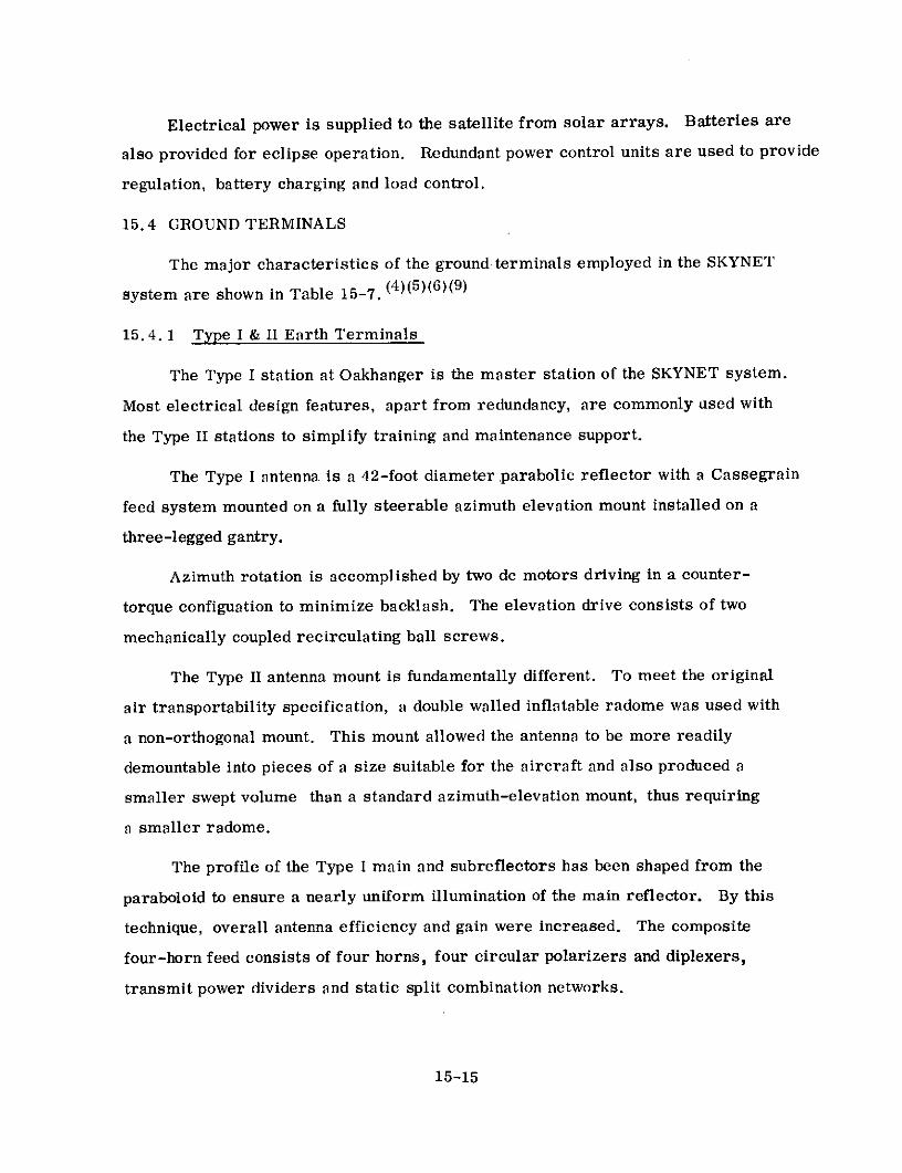
Electrical power is supplied to the satellite from solar arrays. Batteries are
also provided for eclipse operation. Redundant power control units are used to provide
regulation, battery charging and load control.
15.4 GROUND TERMINALS
The major characteristics of the ground terminals employed in the SKYNET
system are shown in Table 15-7. (4)(5)(6)(9)
15. 4. 1 Type I & II Earth Terminals
The Type I station at Oakhanger is the master station of the SKYNET system.
Most electrical design features, apart from redundancy, are commonly used with
the Type II stations to simplify training and maintenance support.
The Type I antenna is a 42-foot diameter ,parabolic reflector with a Cassegrain
feed system mounted on a fully steerable azimuth elevation mount installed on a
three-legged gantry.
Azimuth rotation is accomplished by two dc motors driving in a counter-
torque configuation to minimize backlash. The elevation drive consists of two
mechanically coupled recirculating ball screws.
The Type II antenna mount is fundamentally different. To meet the original
air transportability specification, a double walled inflatable radome was used with
a non-orthogonal mount. This mount allowed the antenna to be more readily
demountable into pieces of a size suitable for the aircraft and also produced a
smaller swept volume than a standard azimuth-elevation mount, thus requiring
a smaller radome.
The profile of the Type I main and subreflectors has been shaped from the
paraboloid to ensure a nearly uniform illumination of the main reflector. By this
technique, overall antenna efficiency and gain were increased. The composite
four-horn feed consists of four horns, four circular polarizers and diplexers,
transmit power dividers and static split combination networks.
15-15

Table 15-7. Characteristics of Skynet Earth Terminals
TERMINAL TYPE I II III IV V
Type Cassegrain Cassegrain Cassegrain Cassegrain Cassegrain(paraboloid reflector) (paraboloid reflector) (shaped surface) (shaped surface) (paraboloid reflector)
Mount Az. Elev. non orthogonal Az. Elev. Az. Elev. three -axis
z Aperture Size (ft) 42 40 21 21 6
l Receive gain (dB) 56'" 56 52 52 40.5
Efficiency (%) 54' 50' 73 73 63"
Receive Beanmwidth (0) 0.23' 0.24' 0.4 0.4 1.6"
Type Preamplifier Two stage uncooled Two stage uncooled Two stage liquid Two - stage liquid Ambient temperatureparametric parametric nitrogen cooletd nitrogen cooled parametric
parametric parametric
_ Gain (d8) 30 30 30 30 20
S1I dB Bandwidth (MHz) 50 50 50 50 50
Tuning Capability (MHz) 500 500 500 500 500
Noise Temperature (OK) 120 120 50 50 220
2 Type Amplifier Klystron Klystron Klystron Klystron Klystron
z m Bandwidth (MHz) 50 50 50 No Data No Data
Sin Amp Power Output (kW) 20 20 5 5 5
U Type (monopulse) Automatic Automatic Automatic Automatic Automatic
:- Accuracy (30) 0.05 0.05 0.09 0.09 0.15
d Long Term (1 yr) 111107
11104
11lO7
1n107
No Data
z Short Term (1 s) 1n1109 1n109
ln109
1n109
i.s
Sys. Noise Temp. OK 250 230 120 120 .300< U-H- G/T 32.0' 32.4" 31.2""' 31.2"'" 15.7"
EIRP(dBW) 100" 100' 90" 90* 78"
E o Transmit Feed Right Hand Circular Right Hand Circular Right Hand Circular Right Hand Circular Right Hand Circular
. < Receive Feed Left Hand Circular Left Hand Circular Left Hand Circular Lelt Hand Circular Left Hand Circular
IZ Raduome Yes Yes No No No
Type Facility Fixed Fixed but movable Fixed but air Mobile Helicopter ShiphorneZ4 transportable transportable
Calculated from other measured parameters
" Actual gain is 57 dB. 1 dB is lost in cable runs that allow maintenance iand repair on paramps while station is stilloperating. This was (lone to accomplish high reliability.
" " G/T of 28.8 dB when parametric anmplifier is run at anlbient temperalture.
15-16

The Type I and II station receiving systems are similar except that in the
Type I station it is duplicated, with a remotely controlled waveguide changeover
switch in the signal path. A simplified diagram of the essentials of the communi-
cations chain is shown in Figure 15-4. (4)
The low noise receiver is preceded by a "waffle-iron" type low pass filter
giving 93 dB of protection against the transmitter signal spaced only 500 MHz away.
The duplicated transmitter subsystem is designed to provide accurate control
of power output from 100 W to 20 kW, with control of power sharing between the
fm and SS paths. Channel combining is performed at shf to avoid the risk of fm and
spread spectrum intermodulation that could arise with a common upconverter
stage.
The operational requirements of frequency flexibility and high stability are
met by deriving the local oscillator signals from frequency synthesizers in the
100- to 150-MHz band locked to a high stability (1 part in 1010) Master Oscillator at
1 MHz.
The Type I and Type II stations have a duplicated Master Oscillator and one
spare synthesizer (as a compromise between full redundancy and economy) for
the three operational LO sources (receive, SS, and fm transmit).
15. 4. 2 Type III and IV Earth Terminals
The SKYNET Type III and IV earth terminals have 21-foot diameter antennas.
Both types of stations are identical, but the Type IV is helicopter transportable,
where the Type III is only air transportable by standard aircraft. The simplified
block diagram of the signal paths in the Type III and IV earth terminals are shown
in Figure 15-5. (5)(6) A five-horn static split system is used for tracking and all
the microwave equipment is mounted on the back of the antenna disk. The antenna
mount is a simple two-axis elevation/azimuth system.
The received signals pass through a diplexer and a band-stop filter to reject
transmitted frequencies, and then into a two-stage liquid nitrogen-cooled parametric
15-17

SINSS MODULATORS SS BASEBAND
XMITDRIVEXMIT UNIT OUT
SS DEMODULATORS EQUIPMENT
INFM MODULATORS FM BASEBAND
DRIVECOMBINER XMIT UNIT
FM DEMODULATORS EQUIPMENT OUT
FS
BEACON TRACKINGRF TDA'S DOWN- RE
FILTERS CONVERTER RECEIVER
SERVOMOTORS
Figure 15-4. Type I and Type II Simplified Block Diagram

FILTERMODULATION ANDFILERHPA MIXER BASEBAND .9 INEQUIPMENT
MOUNTING DIPLEXER FILTER PARAMETRIC MIXER IF DEMODULATION AND UTPREAMP -- BASEBAND
EOUIPMENT
TRACKINGRECEIVER ANTENNA &RRAE NR
SERVO CONTROL
SERVOPOWER
AMPLIFIER
Figure 15-5. Type III and Type IV Simplified Block Diagram

amplifier. Subsequently, they pass to a mixer/IF preamp combination and then to
an IF amplifier where the FDM and spread spectrum signals are separated.
The combined uplink IF signal is fed into the transmitter unit. There it is
converted to the final frequency, amplified in an intermediate power amplifier,
followed by a higher power, liquid-cooled, five-cavity klystron (VA925E).
Frequency control is the same as in the Type I and II terminals.
t5. 4. 3 Type V Shipborne Terminal
Figure 15-6 ( 9 ) illustrates the essentials for the Type V terminal.
Information signals to be transmitted by the terminal are passed through
the baseband equipment to the exciter, which produces a low-power microwave
carrier modulated by the baseband signal. The microwave signal is amplified to
a level of a few kilowatts and fed to the waveguide system and the antenna.
The waveguide system contains the necessary filter and diplexers for separating
received from transmitted signals. It also contains a monopulse comparator for
deriving angular misalignment signals which are fed to the tracking receiver.
Received communications signals are first amplified in a low-noise preamplifier.
After down-conversion to a suitable intermediate frequency and filtering to select
the wanted carriers, they are then demodulated in the receivers. The latter feed
the baseband equipment with outputs to the user equipment (telephone, telegraph,
etc.).
Stabilization of the antenna beam is by reference to the gyro assembly, which
provides an inertial reference pointing angle. Any misalignment of the beam with
respect to this reference is sensed by the gyro pickoffs, and corrections are applied
by power servo and drive motors. The inertial reference point angle is updated
by signals derived from the tracking receiver so that the beam always points at the
satellite. Manual pointing data for initially acquiring the satellite may also be
fed to the gyro assembly.
15-20
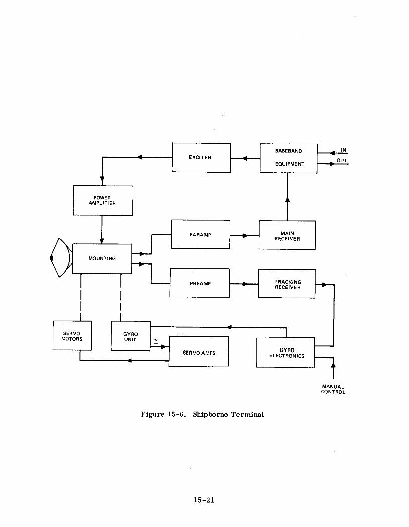
POWERAMPLIFIER
PARAMP MAINI RECEIVER
PREAMP TRACKINGRECEIVER
MANUALCONTROL
Figure 15-6. Shipborne Terminal
15-21
For a terminal located on a ship, due to pitching and rolling motions, a two-
axis mount is inadequate for tracking the satellite through regions requiring high
mount velocities and accelerations. Therefore, a three-axis mount was employed.
15.5 EXPERIMENTS DESCRIPTION
Since this is an operational system, few experiments have been conducted.
The repeater performance, which is crucial to the performance of the entire system,
has been measured in orbit by means of the special earth station test facility at
SRDE (Christchurch, U. K.). To date no significant change from the performance
measured by Philco-Ford in the laboratory before launch has been observed.
15.6 OPERATIONAL RESULTS
The SKYNET system was designed in a conservative manner and the satellite
and ground terminals developed met their specifications. As a result, the operational
performance has been within the limits that were anticipated. The only spacecraft
malfunction of significance was the failure of 1 TWT after a year of in-orbit
operation.
15-22

C ITE D RE FERENCES
(1) F. C. Padfield, "The Origin of SKYNET," Record of SKYNET Colloquium,London, England, 1970.
(2) J. H. Bagley, "Specification of the SKYNET Communications System,"Record of SKYNET Colloquium, London, England, 1970.
(3) Douglas G. Duyre, "The SKYNET Satellite," Record of SKYNET Colloquium,London, England, 1970.
(4) C.B. Wooster, "SKYNET Type I & II Ground Stations," Record of SKYNETColloquium, London, England, 1970.
(5) G. Padley and W. P. Robins, "SKYNET Type III & IV Ground Stations" -Technical Description, Record of SKYNET Colloquium, London, England, 1970.
(6) A.I. Naylon and R. J. Jones, "Measured Performance of SKYNET Type III & IVStations, " Record of SKYNET Colloquium, London, England, 1970.
(7) E. H. Thomas, "SRDE Satellite Communications Test Terminal," Record ofSKYNET Colloquium, London, England, 1970.
(8) G. Sinkewlz, "Telemetry & Command Station," Record of SKYNET Colloquium,London, England, 1970.
(9) G. Harries and K. Milne, "The Design of Shipborne Satellite Terminals,"Record of SKYNET Colloquium, London, England, 1970.
(10) J. W. Cunning, "SKYNET Traffic Systems, " Record of SKYNET Colloquium,London, England, 1970.
(11) D.A. Hannaferd, "Meteorology Factors in Space Communications Systems,"IEE International Conference on Satellite Communication, Nov. 1962.
15-23

RELATED REFERENCES
(1) J. W. O'Neill, "Military Communications and Navigation Satellites,"TRW Space Log, Vol. 9, No. 2, Summer-Fall, 1969.
(2) "SKYNET, The British Defense Satellite Communication System,"Radio & Electronics Engineer, Vol. 37, April 1964.
15-24

SECTION 16 - NATO SATELLITE SYSTEM
16.1 PROGRAM DESCRIPTION
In 1963/65 the first tentative studies were started to determine the feasibility of
a satellite system to satisfy NATO communication needs. After the signing of the
Memorandum of Understanding between the U.K. and the United States in 1966 for the
SKYNET satellites, the United States proposed that NATO utilize the satellite tech-
nology developed for SKYNET in order to have a viable synchronous satellite communi-
cation system built and deployed by 1971. In 1967, a Memorandum of Understanding
was signed between the United States and NATO, whereby the U. S. would build and
launch two SKYNET-type satellites. Philco Ford was to build the satellites. The
USAF Space and Missile System Organization (SAMSO), with technical support from the
Aerospace Corporation, was to act as the procurement agent for NATO.
Further system engineering studies indicated that two rather minor changes in
the SKYNET-type satellite would provide a more optimum system for NATO. The
first modification was to change the equal power division between the 20-MHz and
2-MHz channels to a 6-to-1 ratio, respectively. The second change was to shift the
antenna aiming point from the subsatellite point on the earth to between 400 and 450 N
latitude, since all NATO earth terminals were to be located north of the Equator.
This yielded a more optimum power spread for NATO coverage over the Northern
Hemisphere.
In addition, NATO decided to participate in the IDCSP test program. This early
part of the project was called NATO SATCOM Phase I. NATO initially leased and
finally purchased two 15-foot diameter "MASCOT" satellite ground terminals built by
Philco Ford. These terminals were used in test operations with IDCSP satellites to
train personnel for the coming of the advanced system (NATO SATCOM Phase II).
The second Phase of the program included launching the two modified SKYNET-
type satellites and building a satellite ground system. Phase III of the NATO program
is post-1975 and is presently in the early planning stages.
16-1

For NATO SATCOM Phase II, the two satellites were to be launched in 1969/1970,
with one satellite acting as a backup to provide a 5-year system capability. NATO I
was successfully launched into synchronous orbit in March 1970. The launch of NATO
II was delayed until 1971 due to the apogee motor failure that occurred during the
launch of SKYNET I "B. " NATO II was successfully launched into synchronous orbit
in February 1971. Table 16-1(1) (2) summarizes launch and status information on
the NATO satellites.
The operational requirements dictated the utilization of 12 stationary earth
terminals. The 12 stations are located near the capital cities of the 12 following
countries: Belgium (Ll), Germany (L2), United States (L3), UK (L4), Norway (L5),
Turkey (L6), Italy (L7), Canada (M2), Netherlands (M3), Denmark (M4), Greece (M5),
and Portugal (M6). Although the stations are stationary, they can be disassembled
and relocated to a prepared site. Table 16-2(1) is a summary of the participating
earth terminals of the NATO SATCOM Phase II systems.
Originally, two types of ground stations were planned, one employing an antenna
42 feet in diameter, which was designated a large (L#) capacity terminal and one with
a 21-foot antenna designated a Medium (M#) capacity terminal. However, system
engineering studies indicated that if the satellite power was divided in a more optimum
way (6-to-1 power split versus equal power split), it would be more realistic to use
only one type of ground terminal. The change to all identical ground terminals (42 feet
in diameter) provided much more flexibility and reduced the total logistic problem.
The definitions of large and medium capacity terminals remained.
The operational objective of the NATO SATCOM Phase II has been to provide
highly available voice and telegraph communication circuits between the NATO
countries and the military and political headquarters. The central requirement of the
system is for multiple access. It was deemed essential that the number of circuits
should be fixed and the quality of the circuits should be constantly monitored and
controlled.
16-2

Table 16-1. Participating Spacecraft
Satellite NATO I NATO II
Manufacturer Philco Ford (USA)
Sponsors North Atlantic Treaty Organization (NATO),Brussels, Belgium
Supreme Headquarters, Allied Powers Europe (SHAPE),Casteau, Belgium
Launch Date 3/20/70 2/3/71
Launch Vehicle Augmented-Thrust-Thrust Delta
Apogee (mi) 22, 619 23, 024
Perigee (mi) 21,420 21,432
S Inclination Less than 30 Less than 30
Period (hrs) Approximately 24 Approximately 24
O Position (OW) 18 ± 3 ** 26 ~ 3 **
Status Satellite is operating Satellite is operatingnormally, one TWT, has normally.
* At initial orbital injection. Attitude control and station-keeping maneuvers changeorbital parameters.
** Positions were chosen so that at the extremities (i. e., 15"W and 29°W) the minimum
elevation angle from any NATO ground terminal would be greater than 100.
16-3

Table 16-2. Participating Earth Terminals
Ant. Date
Location Description Dia. Utilization Installed Manufacturer
Belgium** L1 Operationaland primarysystem control
Germany** L2 Operational trafficand backup systemcontrol
United States L3 Standard ElectricLorenz* (Germany)Prime contractor:
Norway L5 led a consortiumof companies
Turkey L6 42' 1970/ from the NATOItaly L7 1971 Countries to build
Operational trafficCanadaground terminals,
modulation, multi-Netherlands M3 plex, control, andDenmark M4 interconnect
facilities.Greece M5
Portugal M6
Hague, 1968/ SHAPE TechnicalNetherlands 1969 Center
*SEL is a subsidiary of International Telephone and Telegraph Corp.**Main station interconnect by LOS microwave.
16-4

The NATO SATCOM Phase II was built entirely from existing technology in order
to minimize system risk. This approach to design has produced a successful operational
system. Its consequence is that no major contributions toward advancing the state-of-
the-art in satellite communications have been made.
16.2 SYSTEM DESCRIPTION
System studies based on the requirements for communications within the NATO
System indicated that the optimum choice for multiple access would be FDMA, since
no random access was required. It was further determined that the seven large
capacity terminals would operate in the 20-MHz band, each transmitting a single
multidestination 24-voice channel FM access, and that the five medium capacity
terminals would operate in the narrow-band (2-MHz) channel, each transmitting a
single multidestination, 3-channel FM access. All stations, both large and medium
capacity, receive and demodulate a number of carriers dependent on the individual
station connectivity requirement. Table 16-3 gives the frequencies of the two satellite
channels. Figure 16-1(1) indicates the connectivity of the NATO SATCOM Phase II
system.
Since the satellite transponder is hard-limiting, frequency planning to control
intermodulation and accurate power control are required. The frequency planning
was accomplished via computer analysis and verified by measurements on a simulator.
The three most important overall criteria that were used in designing the system
were:
1. Performance
2. Availability
3. Proven techniques
The single most dominant requirement was to provide a system that would mini-
mize the probability that a given communication circuit might become unavailable.
This was achieved by a combination of realistic performance estimates for equipment,
16-5

Table 16-3. NATO SATCOM Phase H Frequencies
2-MHz Channel (MHz) 20-MHz Channel (MHz) Beacon (MHz)
Uplink 7976. 02 to 7978. 02 7985. 12 to 8005. 12 --
Downlink 7257. 3 to 7259. 3 7266. 4 to 7286. 4 7299.5

NORWAYS- GERMANY L5
L2
REDUNDANTSYSTEM CONTROL
ITALY
CANADAM2
PRIMARY HOLLANDSYSTEM CONTROLM3
L1 M4
GREECE
M5
PORTUGAL
M6
Figure 16-1. NATO SATCOM Phase Interconnectivity
16-7

inherently reliable units, redundancy, and rapid fault diagnosis and repair. In
addition, performance margin was provided to protect the system against environ-
mental extremes.
In view of the need to achieve a highly reliable system, great emphasis was
placed on the importance of using techniques and equipment that had already been
proven. Traffic requirements are in the form of telegraphy, speech, and low-speed
digital circuits that can be carried on a voice channel.
A second stage of the NATO SATCOM program is being considered. In Stage 2,
a limited number of stations may be equipped with spread spectrum equipment. Pro-
vision for the introduction of spread spectrum modulation equipment in the satellite
ground terminals was incorporated in the original design of the stations.
Table 16-4 ( 1 ) gives the FM performance characteristics of the demodulators
used in the system. The number of modes that are provided allow the system to
change capacity and configuration as long-term requirements vary.
Table 16-5(1) gives a typical downlink power budget for the NATO System for
conditions that should exist 99 percent of the time at the worst geographic station.
Margins at all other stations are 0. 1 to 2. 7 dB higher than those shown in the table.
Since reliability of communications is of paramount importance, margins were
allowed for unpredictable losses due to weather, power control, misalignments and
equipment degradation.
As for the SKYNET system, control of the NATO SATCOM Phase II system is
provided in a number of different forms, viz, of the spacecraft, the earth terminal
complex, and the traffic. Spacecraft control is exercised by the USAF Satellite
Control Facility, Sunnyvale, Calfiornia, through its worldwide network of satellite
monitoring facilities.
Control of the distribution of satellite output power is exercised from the Pri-
mary Control Center (PCC) collocated with the Belgium earth station or from the
Secondary Control Center (SCC) collocated with the German earth station. The method
16-8
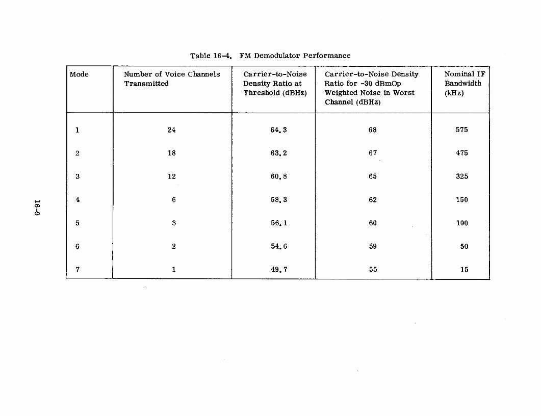
Table 16-4. FM Demodulator Performance
Mode Number of Voice Channels Carrier-to-Noise Carrier-to-Noise Density Nominal IFTransmitted Density Ratio at Ratio for -30 dBmOp Bandwidth
Threshold (dBHz) Weighted Noise in Worst (kHz)Channel (dBHz)
1 24 64.3 68 575
2 18 63.2 67 475
3 12 60.8 65 325
4 6 58.3 62 150
5 3 56.1 60 100
6 2 54.6 59 50
7 1 49.7 55 15
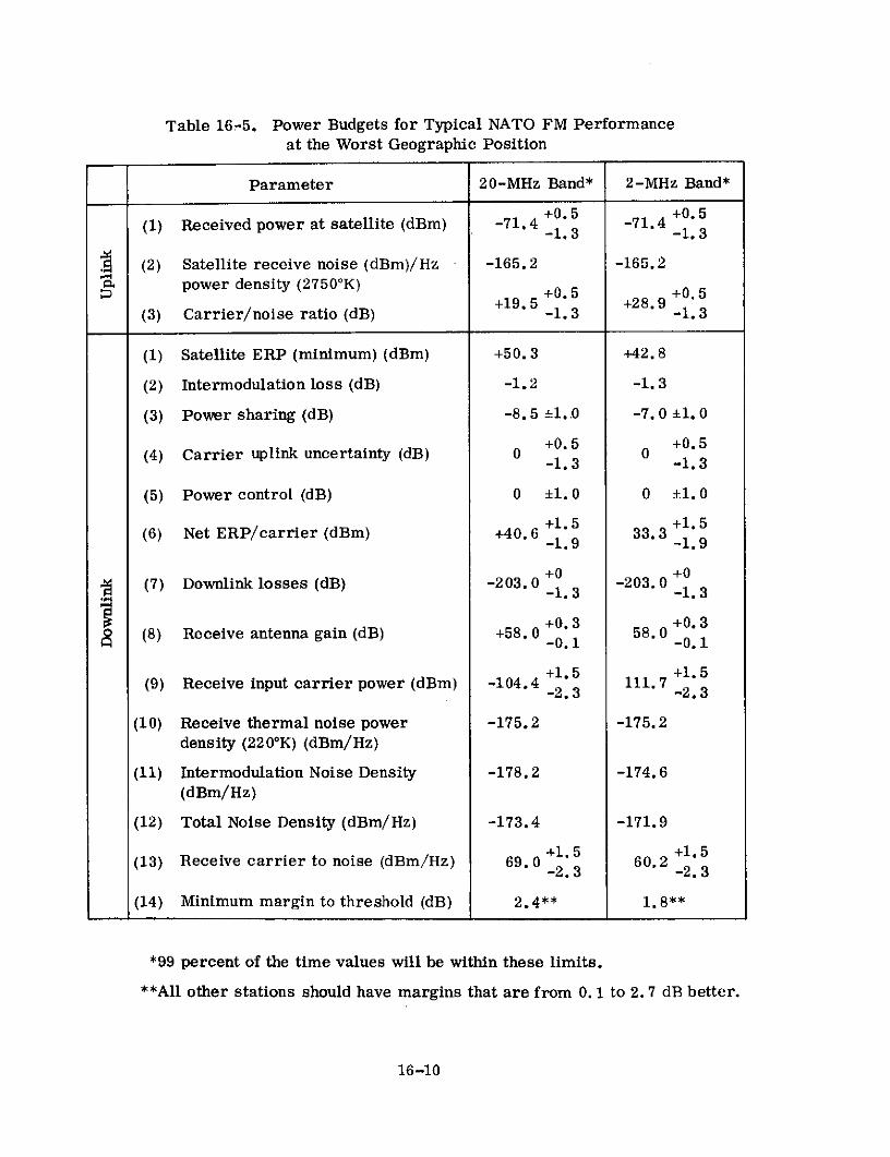
Table 16-5. Power Budgets for Typical NATO FM Performanceat the Worst Geographic Position
Parameter 20-MHz Band* 2-MHz Band*
+0.5 +0.5(1) Received power at satellite (dBm) -71.4 -71.4
-1.3 -1.3
(2) Satellite receive noise (dBm)/Hz -165.2 -165.2power density (27500K)
+0.5 +0.5+19.5 +28.9
(3) Carrier/noise ratio (dB) -1.3 -1.3
(1) Satellite ERP (minimum) (dBm) +50.3 +42.8
(2) Intermodulation loss (dB) -1.2 -1.3
(3) Power sharing (dB) -8.5 ±1..0 -7.0 ±1. 0
+0.5 +0.5(4) Carrier uplink uncertainty (dB) 0 0-1.3 -1.3
(5) Power control (dB) 0 ±1.0 0 ±1. 0
+1.5 +1.5(6) Net ERP/carrier (dBm) +40.6 1.33. 31.
-1.9 -1.9
+0 +0(7) Downlink losses (dB) -203.0 -203. 0
-1. 3 -1. 3
+0.3 +0.3(8) Receive antenna gain (dB) +58.0 58.0 -0.1
+1.5 +1.5(9) Receive input carrier power (dBm) -104.4 111.7
-2.3 -2.3
(10) Receive thermal noise power -175.2 -175.2density (220 0K) (dBm/Hz)
(11) Intermodulation Noise Density -178.2 -174.6(dBm/Hz)
(12) Total Noise Density (dBm/Hz) -173.4 -171.9
+1.5 +1.5(13) Receive carrier to noise (dBm/Hz) 69.0 60.2
-2.3 -2.3
(14) Minimum margin to threshold (dB) 2.4** 1. 8**
*99 percent of the time values will be within these limits.
**All other stations should have margins that are from 0. 1 to 2. 7 dB better.
16-10

of power control utilized is manual. Manual control is dependent upon the judgment
of the controller to react properly to a given set of circumstances within a highly
ordered set of procedures. The controller provides the intangible asset of making
critical decisions under highly unexpected circumstances. Methods were chosen and
equipment provided to allow the controller a wide latitude of choice.
Equipment has been provided for the continuous monitoring and measuring of
system performance. The information from each system terminal is forwarded
continuously to the system controller by means of an automatic data reporting network.
Both system control stations, at Belgium and Germany, receive and process the same
information independently. The two control stations are interconnected via a land
data link so that the system can be controlled from either, using the equipment pro-
vided at the other station. In effect, there is a total redundancy in the control system.
Each control center is provided with computation and display equipment for the analysis
and display of the incoming data. A TTY orderwire network via the satellite has
been provided to allow the controller to forward specific control instructions to any
station.
Traffic control takes place at speech and telegraph facility control centers that
are remote from the earth stations.
16. 3 NATO SPACECRAFT
Spacecraft characteristics for the NATO satellites are displayed in Table 16-6 ( 1 )
The simplified block diagram depicting the communications configuration of the
satellite is the same as shown in Figure 15-3 for the SKYNET satellite. The space-
craft functioning and subsystems are identical to those described in Paragraph 15. 3
for SKYNET.
16.4 NATO SATELLITE GROUND TERMINALS
The NATO SATCOM Phase II System utilizes 12 identical ground terminals. The
ground terminals at Belgium (L1) and Germany (L2) are the master stations of the
16-11

Table 16-6. NATO Satellite Characteristics
Type X-Band mechanically despun with lens UHF array for TT&C with redundant UHFto aim center of beam at 420 -450 N. transponders and command/telemetry
processing equipment
Z Number One Two
Beamwidth No Data Available Essentially omnidirectional
Gain (dB) 17.5 -0.7
Frequency Band X-Band
Type Hard-Limiting dual channel
1 dB Bandwidth 20 MHz and 2 MHz channels
, Receiver
W Type Front End Down conversion mixer into linear amplifier*
L Front End Gain No Dataa-w Noise Figure 27500 K (10.2 dB)
Transmitter
Type Redundant TWT
Gain No Data
Power Output (dBm) 33.0 (20 MHz) 24.5 (2 MHz channel)
EIRP (dBm) peak of beam 50.5 (20 MHz channel) 42.0 (2 MHz channel)
Stabilization
Type spin 90 rpm - 5 years
Capability (stationkeeping) 130 for 5 years
w Power Source
F Primary Cylindrical array of silicon solar cells, capable of providing 97 watts of prime power,< throughout 5 years of orbit lifeu. Supplement Two redundant 16 cell nickel cadmium batteries for operation during eclipse (6 AH<, per cell)
I Communication power needs (watts) 64
Size (inches) 54 diameter 60 high
Weight (Ibs.) Launch 535. In orbit 280
*Dynamic range (a) 20 MHz channel - 90 to -45 dBm(b) 2 MHz channel - 100 to -45 dBm
16-12

network. Table 16-7 ( 1 ) summarizes the performance of the NATO ground terminals.
The antenna is a 42-foot diameter Cassegrain with a reflector shaped to provide high
efficiency. It is mounted on a fully steerable azimuth/elevation mount.
The basic IF interface is 70 MHz (both transmit and receive). A simplified
diagram of the essentials of the communications chain is shown in Figure 16-2(1)
The entire transmit and receive chain components are redundant.
The parametric amplifier, which is designed to have a low noise figure, uses a
varactor diode that is operated at its parallel resonance frequency. The output signal
from the parametric amplifier is then fed to the microwave receiver. Down-conversion
to 70 MHz is accomplished by standard heterodyning techniques.
The transmitter subsystem is designed to provide accurate power control
(±0. 5 dB) from 100 W to 5 kW. In addition, a summing amplifier is provided (390 MHz)
to potentially combine up to eight separate uplink signals. Signal power is first
increased by the use of an intermediate power amplifier, which is a TWT. The TWT
output directly feeds the high power kylstron, which is a Varian Type VA-925F cooled
by distilled water. The most important features of the transmit chain are frequency
stability and setability. Stringent frequency and power control are required to main-
tain satellite output power balance.
The operational requirements of frequency flexibility and high stability are met
by a derived local oscillator supplied from frequency synthesizers locked to a high
stability (1 part in 1011) master oscillator.
16.5 EXPERIMENTS DESCRIPTION
The repeater performance, which is crucial to the performance of the system,
has been measured in orbit by means of the special earth station test facilities at
SRDE (Christchurch U.K.) and the SHAPE Technical Center (STC), the Hague. To
date no significant change from the performance measured by Philco Ford in the
laboratory prior to launch has been observed.
16-13

Table 16-7. Characteristics of NATO Earth Terminals
Type Cassegrain Shaped Surface
Mount AZ -ELEV
z Aperture Size (It) 42
Z Receive gain (dB) 58
Efficiency (%) 75
Receive Beamwidth (0) 0.23'
Type Preamplifier Varactor diode
Gain (dB) No Data
U-I IB8 Bandwidth (MHz) 50
w Tuning Capability (MHz) 500
c Noise Temperature (OK) 90 - 100
- 2 Type Amplifier KLYSTRONI B' Bandwidth (MHz) 50
m Amp Power Output (kW) 5 6
z Type (monopulse) AutomaticI)
< Accuracy (3J) 0.025'"
C f long term (1 yr) 1 in 109
Ui-
o short term (1 sec.) 1 in 1011
Sys. Noise Temp. OK 210
' G/T 34.8'
EIRP (dBW) 94"
2
Transmit Feed rittlit hand circular
Receive Feed left hand circularC-
SRadorne Yes"'-j
_ Type Facility Fixed.."
SCalculated from otlher rneasured parameters' This can degrade to 0.05 per channel if manual track is requiredS'All except L2 Germany
""Can Ise relocated to prepared site
16-14

EQUIPMENT ROOM AZIMUTH CABIN
IST UP 2ND UP,5T UP CONVDRUER &CONVERTER CONVERTER & HIGH POWERMODULATORS COVR &INTERMEDIATE ERSUMMING INTERMEDIATE 1 AMPLIFIER
POWERAMPLIFIERS AMPERERAMPLIFIER
I
DUPL-EXER
FREQUENCY TEST LOOPGENERATION I TRANSLATOR
COMPARATOR
IF COMMUNICATIONS PARAMPDEMODULATORS DISTRIBUTION DOWN GROUP
AMPLIFIERS CONVERTER
ELEVATIONSERVO TRACKING TRACKING CABIN
DRIVE & DOWNCONTROL CONVERTERSA
MOUNT
PEDESTAL
Figure 16-2. NATO Ground Terminal Simplified Block Diagram

16.6 OPERATIONAL RESULTS
As of May 1971, measurement of the operational performance of the NATO
Phase II system has not been accomplished. The only spacecraft malfunction of
significance has been the failure of one TWT after 6 to 8 months of orbit operation.
16-16

CITED REFERENCES
(1) "In House NATO SATCOM Communication System Documentation," ComputerSciences Corporation, Falls Church, Virginia.
(2) "Military Communications and Navigation Satellites," J. W. O'Neill, TRWSpace Log, Vol. 9, No. 2, Summary Fall 1969.
16-17

SECTION 17 - PHASE II DEFENSE SATELLITE COMMUNICATIONS SYSTEM
17.1 PROGRAM DESCRIPTION
In June 1968 the Department of Defense announced its decision to acquire six
satellites and additional earth terminals as the second phase of the Defense Satellite
Communications System (DSCS). The first phase (the IDCSP) had successfully com-
pleted its research and development objectives and since late 1967 had been providing
a restricted operational capability.
The objective of the second phase, or Phase II, of the DSCS is to establish an
operational military satellite communications system which will provide substantial
increases in performance together with a wider variety of services for users. When
completely operational the Phase II DSCS will be a part of the Defense Communications
System (DCS) and will function as both a long haul strategic trunking system and a
system capable of supporting military contingency operations. In addition, the sys-
tem will be capable of supporting service to small tactical users, if needed.
Two of the six satellites procured under this program are, as of mid-1971,
scheduled to be launched aboard a Titan IIIC booster into synchronous orbit in late
1971, and should become operational in early 1972. Definite dates for the follow-on
launches have not been scheduled, but will be made on an as-required basis for
replenishment and to establish additional in-orbit operational satellites. Table 17-1
summarizes launch and status information on the Phase II DSCS satellites.
The earth terminals presently being used with the IDCSP (see Section 12. 1) will
be modified and upgraded for operational use with the Phase II DSCS. In addition, a
limited quantity of new terminals will be procured and deployed to fulfill the opera-
tional requirements. A summary of the present IDCSP terminals is presented in
Table 12-3. Table 17-2 presents a summary of the new terminals which will partici-
pate in the Phase II DSCS.
17-1

Table 17-1. Phase II DSCS
Satellite Phase II DSCS
Manufacturer & TRW/U. S. Air ForceSponsor
Launch Date - Dual satellite launch - Dec. '71
- No decision on additional launch dates
Launch Vehicle Titan IIIC
Apogee (Mi.)
t- Perigee (Mi.) In procurement (planned for synchronous0 Inclination orbit) as of mid-1971
Period (Min.)
Status In procurement as of mid-1971
Table 17-2. New Phase II DSCS
Antenna DateType Diameter Utilization Sponsor Available
HT 60 ft High density traffic USASCA* Mid-' 73
MT 20 ft Low density traffice USASCA* Mid-' 73
LT 8 ft Contingency & special Not awarded Not awardeduser support as of mid-'71 as of mid-'71
*United States Army Satellite Communications Agency
17-2

The military satellite communication system that has been designed will satisfy
the varied and changing user requirements over the next 5 years. The system will
evolve from an analog system (almost total) into a digital system (almost total) during
this period. Additionally, the initial groundwork will be laid for moving into a time
division multiple access (TDMA) system. The satellites developed will provide
steerable narrow coverage antennas which will greatly enhance the flexibility and oper-
ational capability of the system. Ground assets developed primarily for the Phase II
DSCS will include militarized pulse-code modulation (PCM) and time division multiplex
(TDM) equipments, error correcting coders/decoders, high data rate phase shift keyed
(PSK) modems, and new highly-reliable ground terminals.
17.2 SYSTEM DESCRIPTION
The first Phase II satellites are scheduled to be launched in late 1971 and the
system will be implemented in three distinct periods, each providing different communi-
cations capabilities. In the first period (denoted as Stage la), Phase II will operate in
the frequency division multiple access (FDMA) and code division multiple access
(CDMA) mode and will provide a point-to-point operational capability by mid-1972 after
completing essential on-orbit satellite tests. In the second period (denoted as Stage
Ib), Phase II will operate in the FDMA mode to provide a multipoint network satellite
communications capability and the CDMA mode to provide point-to-point protected
(i. e., jam-resistant) communications for vital traffic. During the final period, the
Phase II system will employ time division multiple access (TDMA) and CDMA to pro-
vide a total network capability. The latter state will be denoted as Stage 2.
In Stage la, the point-to-point terminal linking arrangement results in an oper-
ational system similar to that of IDCSP. However, in this case, many links will be
handled simultaneously by each satellite. During this initial stage of the Phase II
DSCS only the upgraded IDCSP terminals will be included in the system. The traffic
will range from one analog voice channel between AN/TSC-54 terminals to 12 analog
voice channels between AN/MSC-46 terminals. A few selected links will provide a
wideband digital traffic capability to support such requirements as wideband digital
17-3
data and digitized voice signals. These digital links will be time-shared with FM voice
circuits. The baseband and modulation equipment (i.e., FM modems, multiplex,
digital modems, etc.) will be those which are presently in use in the IDCSP.
A protected traffic capability (i. e., circuits resistant to RF jamming) will be
provided during Stage la on a terminal-to-terminal basis using existing CDMA (spread
spectrum) equipment. These links will be dedicated lines between selected users and
will pass designated vital traffic only. Communications control of the system during
Stage la will consist of scheduling with system coordination and discipline maintained
by a controller. One controller will be established for each satellite.
Initially, it is intended to launch two satellites. Three to four satellites may be
needed to supply a complete global capability providing connectivity among the geo-
graphical locations dictated by military requirements. However, a decision on placing
more than two satellites in orbit has been deferred to a later date.
A limited number of AN/TSC-54 terminals will be equipped to provide a con-
tingency capability in Stage la. These terminals will be self-contained in that they
will be provided with FM modems, multiplex, and ancillary equipment to handle 12
voice channels. The FM modems will be capable of modulating an RF carrier with up
to 72 voice channels delivered to the terminal in a baseband form from a separate
technical control facility. Operation of contingency terminals during this stage will be
via the satellite narrow beam antennas.
Stage lb will utilize multiple receive and transmit carriers at selected locations
(nodes) to support links in a multipoint network operating via a single satellite. Traffic
will range from 12 voice channels on the AN/MSC-46 pairs to three voice channels
between the AN/MSC-46 and AN/TSC-54 terminals. Initially, a few links will be used
to provide wideband digital traffic between selected areas in support of imagery data
and digitized voice requirements as in Stage la. As the time division multiplex
(TDM) and pulse code modulation (PCM) equipments become available, the system will
phase from an almost all-analog system into a hybrid (part analog, part digital) and
17-4

finally into an all-digital system. Access to the satellite in Stage lb will be FDMA.
During this stage the new MT and HT terminals will become available and will be
integrated into the system. Control of the DSCS in Stage lb will continue to be on a
schedule and discipline basis as described for Stage la.
AN/TSC-54 terminals will be available for contingency operation as described
for Stage la. In Stage lb a larger number of AN/TSC-54 terminals will have been
modified for contingency operation through the satellite narrow beam. They will be
provided with URC spread spectrum equipment to achieve electronic survivability
(i. e., an anti-jam capability). Note that operation with the satellite narrow coverage
antennas, in itself, provides jammer rejection when the beam can be placed so as not
to include the jammer.
In Stage 2, the system will operate using time division multiple access (TDMA).
All links will be established on a time base (rather than frequency) allowing each
terminal to function as a multiple link, or nodal, terminal. A full complement of
modified IDCSP and newly-procured terminals will be available for use during this
stage.
Protected traffic will continue to be provided using spread spectrum equipment.
However, the modems employed will be of an advanced model specifically designed to
meet the Stage 2 system requirements.
17.3 SPACECRAFT
The spacecraft characteristics for the Phase II DSCS satellites are displayed in
Table 17-3. A block diagram depicting the communications transponder is shown in
Figure 17-1.
The communication subsystem consists of a multiple channel repeater with the
channels crosslinked, receive and transmit EC antennas, and two NC antennas each
capable of receiving and transmitting simultaneously. Each NC antenna will be capa-
ble of being independently steered.
17-5

Table 17-3. Phase II Satellite Characteristics
X -BAND MECHANICALLY X -BAND MECHANICALLY S-BAND BICONICAL HORNTYPE DESPUN HORN DESPUN PARABOLIC REFLECTOR FOR TT&C
Number 1 1 1
Z Beamwidth Pencil Beam - 18" Pencil Beam - nominal 2.5" Toroidal 32" wide
w (Earth Coverage)i
Gain (dB) Xmit. - 16.8 (Edge) Xmit. - 33 (Edge) 3 (Peak)
Configuration EC-EC' EC-NC* NC-NC' NC-EC*
Type Single conversion with each of 4 channels operating in a linear, quasi-linear, or hard-limiting mode asselected by ground commands
Bandwidth (1 dB) 125 MHz 50 MHz 185 MH' 50 MHz
Number One One One One
Receiver
Typo Front End Tunnel Diode common to EC-EC & EC-NC Tunnel Diode common to NC-NC & NC-EC channels.channels
Front End Gain No Data No Data
System Noise Figure 8.3 dB 12.8 dB
Transmitter
Type TWT common to EC-EC & TWT common to EC-NC && EC-NC channels NC-NC channels
This channel shares a transmitterGain No Data No Data with EC-EC channel
Power Out 20 Watts 20 Watts
EIRP 28 40 (Each of 2 antennas)43 (1 antenna)"
Stabilization
Type Spin stabilized - nominal 50 RPM with hydrazine thrusters for stationkeeping and attitude corrections
Capability Pointing accuracy of despun platform 10.14". That of NC antenna 10.2'. East-West stationkeeping to within t3"w uof designated subsatellite point for 5 years
c-Power Source
Primary Right cylindrical array of solar cells, capable of providing 520 watts at launch and 357 watts after 5 years
W Supplement Three nickel cadmium batteries
Communication Power Needs 235 watts
Size (feet) diameter - 9; height 13
Weight (Ib) 1100
'Denotes uplink and downlink antennas that channel interconnects."'With 2 NC antennas employed TWT output power is split. With 1 antenna full power goes to that antenna.
17-6

NTENN. "BEACON 2
DSCIPLEx~E EC TTRNkIT F
TER POER MTE ixER
I I
ILTER IXER S M
PLIIER AMP IFIER L LEVEL HIGH -EVEL
7 AT T*;
...... .I I
M..
FREIENCY ECi
NARROWBEAM ENERTOR
NARNaIDO BEA
ANTEYA
Figure 17-1. Phase I DSCS Communcations Transponder
DIPLEXER
I
ANTENNAIXE
Figure 7-1. Pase H DCS Com unicatins Trasponde

The uplink frequency transmitted by a DSCS earth terminal determines which of
the four signal channels will be used. This assumes that an earth terminal planning to
use either the NC-NC or NC-EC channels is within the geographical area covered by
one of the NC antenna patterns. Satellite receive frequencies are in the 7900-8400
frequency band. These input frequencies are translated in frequency, amplified, and
retransmitted in the 7250 to 7750 MHz band. A simplified frequency plan is presented
in Figure 17-2 which relates the various channel modes together with their related
frequency translations and satellite antennas. Both the EC-EC and NC-EC channels
share the output power of a 20-watt TWT amplifier using the earth coverage antenna.
Likewise, the NC-NC and EC-NC channels are combined and transmitted via a second
20-watt TWT amplifier using either one or both of the narrow coverage antennas. The
bandwidths of each channel are presented in Figure 17-2 and represent 410 MHz of
usable bandwidth.
All active components within the communications subsystem are redundant.
Selection of any active component, together with the narrow coverage antenna switching,
is accomplished by ground command. In order to achieve maximum in-orbit usage of
the Phase II satellite, all onboard systems have been sized to provide a minimum 5-
year operational lifetime. Each channel within the satellite can be commanded to
operate in either a linear, a quasi-linear or a hard-limiting mode.
All transmitting antennas will be left-hand, circularly polarized, while the
receiving antennas will be right-hand, circularly polarized. The two narrow coverage
antennas will be capable of being independently steered through +100 in each of two
orthogonal directions, whereas the earth coverage antennas (transmit and receive
horns) will provide coverage to approximately 1/3 of the earth's surface.
The launch profile of the launch vehicle will be chosen so that, with use of the
satellite's orbital control subsystem and telemetry and command subsystem, the
longitude of each satellite's subsatellite point can be accurately selected. In the same
manner, the satellite's orbital control subsystem and the telemetry and command
subsystem will be capable of repositioning the satellite once during the operational
17-8

t 500 MHz 'IEXCLUSIVE BAND
EC-NB EC-EC NB-EC NB-NB
UPLINK
EXCLUSIVE BAND
N EC-EC NB-EC NB-NB EC-NB
DOWNLINK 0 7H E
7 7 7 7 7 7 7 7 72 2 3 4 4 4 6 7 7
BEACONS: 7250.1 5 7 7 0 5 9 7 0 57675.1 0 5 5 0 0 0 5 0 0
k 500 M Hz EN
Figure 17-2. Phase II DSCS Frequency Plan
17-9
life to any other equatorial point at a rate of at least 150 per day. Over the operational
life of the satellite, the East-West excursions of the satellite will be maintained to
within +3" of the designated subsatellite point. The inclination of the satellite orbital
plane with respect to the equatorial plane will not exceed +30 over the operational life.
Electrical power is supplied to the satellite from solar arrays. In addition,
batteries are provided for eclipse operation.
17.4 GROUND TERMINALS
The two major classes of ground terminals to be employed in the Phase II DSCS
include modified Phase I, IDCSP, terminals and new terminals presently under
development. The major characteristics of the IDCSP ground terminals are presented
in the description of Phase I DSCS ground terminals (see Table 17-4). Modifications
being made to these terminals, their background, and major characteristics of the
new terminals are as follows:
17.4.1 Modified IDCSP Terminals
17.4.1.1 AN/FSC-9 Terminals
The AN/FSC-9 is a large fixed terminal employing a 60-ft. antenna. There are
two of these terminals, one at Fort Dix, New Jersey, and one at Camp Roberts, Cali-
fornia. The AN/FSC-9 terminals were originally designed and procured under the
Advent Program. Initially they operated with the SYNCOM satellites, but they were
later modified for operation in the military satellite communications band and used
with the IDCSP Phase I satellites. These two terminals were rehabilitated and upgraded,during 1970-71, by STRATCOM under contract to the Philco-Ford Corporation. These
modifications ensure compatibility with the Phase II, Stage la DSCS. Further modi-
fications to at least one of the AN/FSC-9 terminals are planned in order to provide
a multiple transmit and receive carrier capability, a 500-MHz receive bandwidth and
a 100-MHz transmit bandwidth. These modifications will allow the terminal to function
as a Stage lb DSCS nodal terminal.
17-10

Table 17-4. Characteristics of New DSCS Ground Terminals
TERMINAL TERMINALS
FEATURES HT MT
Type Nominally Parabolic 4 Cassegrain dish array
< Aperture Size 60 ft. Dia. 20 ft. Dia. (effective)2
w Receive Gain 60 dB* 50 dB*Z< Efficiency No Data No Data
Receive Beamwidth 0.160 @ 3 dB pts.* 0.50 @ 3 dB pts.*
Type Preamplifier Cryogenically cooled Uncooled
u-- Bandwidth 500 MHz 500 MHzLU>-- W Noise Temperature No Data No Data
Type Amplifier 2 - LPA (Low Power Amplifier) 1 - LPA1 - HPA (High Power Amplifier) 1 - HPA
Sw Bandwidth LPA - 500 MHz LPA - 500 MHz
HPA - 170 MHz HPA - 170 MHz
Amp. Power Out LPA - 3kW LPA - 3 kWHPA - 8kW HPA - 8kW
Z
e Type Automatic Automatic
X Accuracy No Data No Data
< G/T (dB/K) 39 2700
c EIRP (dBm) 127 117
< Transmit Feed RHCP RHCPN
n Receive Feed LHCP LHCPOQ.
20
Radome None None-J- Type Facility Fixed Transportable
Z
*Derived values for typical antennas of the size indicated
17-11

17.4.1.2 AN/MSC-46 Terminals
The AN/MSC-46 is a relocatable terminal consisting of three vans and a trans-
portable 40-ft. antenna and pedestal. The entire terminal including the antenna and
pedestal is air transportable. The existing 14 AN/MSC-46 terminals were designed,
developed, and placed in operation during the 1963-67 period. The total weight of the
AN/MSC-46, in a transport configuration including the diesel generators, is approxi-
mately 125,000 pounds. The AN/MSC-46 terminal was designed to be capable of being
assembled in 18 hours by a crew of 8 men. In practice, the time required for instal-
lation and checkout prior to achieving operational readiness has been considerably
longer than 18 hours.
Present planning calls for crystal oscillator modifications to all 14 AN/MSC-46
terminals prior to Stage lb. Up to seven of these terminals will be provided with a
multiple transmit and receive carrier capability, a 500- MHz receive bandwidth and a
100-MHz transmit bandwidth in order to allow them to function as Stage lb DSCS nodal
terminals.
17.4.1.3 AN/TSC-54 Terminals
The AN/TSC-54 was designed as a highly transportable terminal which could be
transported in a single military aircraft of the C-130 type. The total weight of the
existing AN/TSC-54 terminal type, including spare parts, a single prime power unit,
and fuel sufficient for 72 hours of operation, is approximately 25, 000 pounds. The 13
AN/TSC-54 terminals were designed, developed, and placed in operation during the
1965-68 period.
The AN/TSC-54 terminals will be modified and equipped to fulfill two missions
during Stage 1. They will be equipped to handle up to 12 voice channels for DSCS
trunking, using the earth coverage satellite repeater channel. Additionally, with the
necessary modifications, they will be used as contingency terminals utilizing the
satellite narrow beam channel. These contingency terminals will include 12 channels
of self-contained multiplex equipment but will be able to handle a baseband consisting
of up to 72 voice channels.
17-12

The modifications and equipment additions to the AN/TSC-54s will more than
double the weight and volume of these terminals. The latest weight estimates for the
AN/TSC-54 contingency terminal complex in a transport configuration is 68, 000 pounds.
17.4.2 New Terminal Developments
17.4.2.1 HT/MT Terminals
A contract was awarded in June 1970 for the design, development, and testing of
one prototype HT and MT terminal, respectively. Final acceptance testing of the two
prototype terminals should be completed by mid-1972. Major characteristics of each
terminal are given in Table 17-4. The emphasis in the HT/MT designs was in the
following areas:
* High availability obtained by the use of extensive redundancy and sophisti-
cated fault location and automatic switchover circuitry
* Multiple transmit and receive carrier capability including a high level of
immunity to the intermodulation products resulting from multiple carrier
operation
* Wide bandwidths, linear phase and amplitude characteristics, flexible fre-
quency control, and dual IF interface frequencies of 700 MHz and 70 MHz
in order to ensure compatibility with the variety of modems anticipated
during the 15-year design life of the HT/MT terminals.
The HT and MT terminals are nearly identical except for the antenna subsystems.
The HT will use a 60-ft. antenna which can be erected and subsequently removed from
a permanent foundation. The MT terminal design employs the previously developed
AN/TSC-54 18-ft. cloverleaf type antenna. It is anticipated that in any production
versions of the MT that might be procured, the 18-ft. cloverleaf antenna will be re-
placed by a parabolic dish antenna approximately 35 ft. in diameter in order to increase
the communications capacity of this terminal.
17-13

The total weights of the development models of the HT and MT terminals are
estimated at 400,000 and 100,000 pounds respectively, including the maintenance and
service vans and the prime power units. The weight of the production version of the
MT would, of course, increase should it incorporate the larger antenna design.
17.4.2.2 LT Terminals
The Light Transportable (LT) terminal is presently in the definition stage; a
contract award is not anticipated before 1973. Further information is unavailable at
this time.
17.5 EXPERIMENTS
The Phase II DSCS will be an operational system; no experiments are presently
planned. A wide range of tests are scheduled for both checkout and evaluation of
performance.
17.6 OPERATIONAL RESULTS
Satellites have not been launched as of mid-1971.
17-14

RELATED REFERENCES
1. W. T. Olsson, "The Defense Satellite Communications Systems - A ProgressReport," American Institute of Aeronautics and Astronautics, Second Communi-
cations Satellite Systems Conference, San Francisco, California, April 8-10,1968.
2. R. G. Backes, "Potential Future Roles of Satellite Communications in Supportof National Security," American Institute of Aeronautics and Astronautics,Second Communications Satellite Systems Conference, San Francisco, California,April 8-10, 1968.
3. A. N. Feineman, "Fulfilling Requirements with Military Communications Satel-
lites, " American Institute of Aeronautics and Astronautics, Seventh Annual
Meeting and Technical Display, Houston, Texas, October 19-22, 1970.
4. "Optimization of User and Earth Station Interfaces with DSCS," Philco-Ford
Corp., Western Development Labs., Palo Alto, California, WDL-TR-DA2190,October 1970, DDC-AD-876883.
5. "Optimization of User and Earth Station Interfaces with DSCS," Philco-Ford
Corp., Space and Reentry Systems Division, Palo Alto, California, SRS-TR-DA2172, April 1970, DDC-AD-871974.
6. M. P. Talbot, Jr., and R. A. Culpon, "A Preliminary Comparison of the Anti-Jam Characteristics of Several Radio Repeaters: A Digital Simulation," Mitre
Corp., Bedford, Massachusetts, MTR-1772, May 1970, DDC-AD-871455.
7. "Optimization of User and Earth Station Interfaces with DSCS, Task 8 OverallEarth Complex Integration," Philco-Ford Corp., Space and Reentry SystemsDivision, Palo Alto, California, SRS-TR-DA2160, January 1970, DDC-AD-866676.
8. "High Speed Sequential Decoder Study," Codex Corp., Watertown, Massachu-setts, April 1968, DDC-AD-865788.
9. "Optimization of User and Earth Station Interfaces with DSCS, Task 2 FaultLocation and Interference Measurement," Philco-Ford Corp., Space and Re-entry Systems Division, Palo Alto, California, SRS-TR-DA2045, April 1969,DDC-AD-861317.
17-15

10. "Optimization of User and Earth Station Interfaces with DSCS, Task 7 A/DConversion and Digital Baseband Multiplexing," Philco-Ford Corp., Space andReentry Systems Division, Palo Alto, California, SRS-TR-DA2046, April 1969,DDC-AD-861221.
11. B. T. Birkett, "The 'Dielguide' Antenna versus the Standard Antenna of theAN/SSC-3 SATCOM Terminal," Naval Electronics Laboratory Center, SanDiego, California, NELC-1579, August 1968, DDC-AD-845750L.
12. W. D. De Hart, "Defense Satellite Communication System - Phase II, " Electronicand Aerospace Systems EASCON "70" Convention Record, Washington, D. C.,October 26-28, 1970.
13. J. Husted, A. Walker, and G. Goubeaud, "A Time-Division Multiple-AccessSystem for the Defense Satellite Communications System," Electronic andAerospace Systems EASCON "70" Convention Record, Washington, D. C.,October 26-28, 1970.
14. J. A. Buegler, D. T. Magill, and R. Lee, "TDMA Experimental Hardware forMilitary Communications Satellite System," Electronic and Aerospace SystemsEASCON "70" Convention Record, Washington, D. C., October 26-28, 1970.
15. J. A. Buegler, R. S. Davies, and D. T. Magill, "Digital Techniques in MilitaryCommunication Satellite Systems, " American Institute of Aeronautics and Astro-nautics, Third Communications Satellite Systems Conference, Los Angeles,California, April 6-8, 1970, AIAA Paper No. 70-495.
16. R. K. Townley, and R. C. Davis, "TDM/TDMA Synchronization," Electronicand Aerospace Systems EASCON "70" Convention Record, Washington, D. C.,October 26-28, 1970
17. G. M. Hatch, "Communications Subsystem Design Trends for the Defense Satel-lite Communications Program," IEEE Transactions on Aerospace and Elec-tronic Systems, Vol. AES-5, No. 5, September 1969.
18. J. W. O'Neill, "Military Communications and Navigation Satellites," TRWSpace Log, Vol. 9, No. 2, Summer-Fall 1969.
17-16

19. D. E. Kendall, "Integration and Testing of the Defense Satellite CommunicationsSystem Phase II Satellite, " American Institute of Aeronautics and Astronautics,Third Communications Satellite Systems Conference, Los Angeles, California,April 6-8, 1970, AIAA Paper No. 70-447.
20. A. T. Finney, "A Phase II Satellite for the Defense Satellite CommunicationsSystem," American Institute of Aeronautics and Astronautics, Third Communi-cations Satellite Systems Conference, Los Angeles, California, April 6-8,1970, AIAA Paper No. 70-493.
21. "Government Use of Satellite Communications," Forty Third Report by theCommittee on Government Operations, House Report No. 2318, October 19,1966.
22. P. J. Klass, "New DOD SATCOMs Nearing Launch, " Aviation Week and SpaceTechnology, January 11, 1971.
23. R. M. Langelier, D. Quagliato, and J. Quigley, "Characterization and Codingof DCSP Satellite Communications Channels," Electronics and Aerospace Sys-tems EASCON "68" Convention Record, September 9-11, 1968.
24. R. Y. Huang, and P. Hooten, "Communications Satellite Processing Repeaters,"Proceedings of the IEEE, Vol. 59, No. 2, February 1971.
17-17

SECTION 18 - TELESAT
18.1 INTRODUCTION
Telesat Canada was established on September 1, 1969 by an Act of the Canadian
Parliament to provide domestic communications service in Canada by satellite.
It is a corporate instrument to own and operate on a commercially profitable basis
the domestic satellite communications system of Canada as a mixed government,
commercial common carrier, and public business venture. Before the establishment
of Telesat Canada, some advanced technical planning had been carried out by the
Prime Minister's Task Force on Satellites, a project group set up by the Canadian
government and headed by Dr. J. H. Chapman. The group concluded that a
geostationary satellite system would be the most economical way to satisfy Canada's
composite needs for Arctic communication service, remote television service, and
additidfl heavy route television and message traffic service along the U. S. /
Canadian border.
Design work was initiated in 1969 on a satellite capable of being launched by
the thrust-augmented Thor-Delta series of NASA launch vehicles. The spacecraft
was to provide six RF channels, each capable of transmitting one color TV signal
or the equivalent in message traffic. Early in 1970, however, Telesat received a
proposal from the Hughes Aircraft Company for a spacecraft design also capable
of being launched by thrust-augmented Thor-Delta series, but which provides
exactly twice the communications capacity of the previous design. Telesat is
now proceeding on the basis of this new design and expects the satellite to be launched
in the last quarter of 1972. The initial system will use two satellites in orbit, the
second acting as an in-orbit spare. A third satellite will be available for launching
either to replace a failed satellite or to accommodate system growth. The second
satellite will be launched about 4 months after the first launch.
The major contribution of this system to satellite communications technology
is that it will be the first operational domestic satellite system, and as such is the
18-1

forerunner of future domestic systems. Additionally, it will develop and demonstrate
earth terminals suitable for unattended operation under climatic conditions, including
those existing in Arctic regions.
18.2 SPACECRAFT DESCRIPTION
The Canadian domestic satellite, officially named "Anik" (the Eskimo word
for brother), is an all microwave, fixed gain, 12-channel transponder where each
channel is essentially an independent amplifier with a bandwidth of 36 MHz. The
transponder configuration is shown schematically in Figure 18-1. It receives
signals sent from ground stations in the 5925-to 6425-MHz band and down-converts
these to 3700 MHz to 4000 MHz for retransmission to other stations. The only
active equipment common to all communications channels is a wideband receiver
which establishes the system noise temperature, translates the 6-GHz carriers to
4 GHz, and amplifies the 4-GHz carriers to an intermediate power level before
channelization. Separation of the FDM-FDMA channels is accomplished by two
multiplexers for the even and odd number channels, each of which consists of a
bank of six circulator-coupled waveguide filters. A 37 percent efficiency TWT
amplifier with a saturated output power of 5 watts is provided in each channel for
final power amplification. After power amplification, the channels are summed by
two low loss multiplexers, again odd and even, each of which consists of a bank of
six waveguide filters. The receiver and driver portions of the repeater are redundant,
with a switch at the input selecting the chain for processing inputs. Two spare
channels are available since the satellite is sized for 10-channel operation at the
end of the 7-year mission life.
The mechanically despun communications antenna consists of a 5-foot diameter
parabolic reflector and its associated feeds. Antenna despin control is exercised
either by ground command or by an on-board pilot signal processor tracking on a
ground generated pilot signal. The lightweight reflector is fabricated from a honey-
comb sandwich and the reflecting surface is covered with a metal mesh. The latter
makes the antenna transparent, thereby reducing what otherwise would be the
18-2

INPUT OUTPUT
MULTIPLEXERS MULI IPLEXERS TM1
TRANSMITTERS
F1 TWT F1
RECEIVER TRASMITTER DRIVERS F33 TWT F3
F5 TWT 5
2225 MHz
LOCAL
OSCILLATOR F7 TWT F7
TRANSMITRECEIVE6GH4 H F9 -TWTO ( CHANNEL ROTARY
TUNNEL DOWN TUNNEL JOI N
DIODE CONVERTER DIODE DTW
AMPLIFIER AMPLIFIER
F11 TWT F11
INPUTSWITCH HYBRID
F2 TWT F2 r6GH 4GH
TUNNEL DOWN TUNNEL DTWTDIODE CONVERTER DIODE
AMPLIFIER AMPLIFIER F4 TWT F4
22 MHz F6 TWT 16LOCAL
OSCILLATOR
F8 TWT FS
F10 TWT F10
F12 TWT F12
TM2
Figure 18-1. Communication Repeater Schematic
18-3

significant disturbance of the satellite by solar pressure. The feed assembly consists
of a two-horn feed on one polarization for the transmit function, and a three-horn
feed plus a planar subreflector for the receive and track functions. The horizontal
arrangement of the horns assures that the antenna pattern, roughly 30 x 80, is
wider in that direction than in the perpendicular one. The beam pattern is pointed
toward Canada, about 7. 60 off the equator. The omnidirectional toroidal beam
telemetry and command antennas used during the transfer orbit phase of satellite
injection on station are mounted on top the parabolic reflector antenna.
Economies in system design have been realized through several steps taken
to lessen the satellite's weight and hence its cost in orbit. These steps include
satellite attitude determination on the ground rather than by on-board spacecraft
hardware, extensive use of thin-walled invar filter waveguides, and affixing the
squared solar cells to panels attached to the outer cylindrical body of the spacecraft
with rubber cement rather than epoxy.
The design provides for 10-channel operation during sun eclipse periods when
the system must be powered by an on-board battery system. During normal sun-
light operation only 10 channels would be in operation, with the remaining two
channels used for standby operation. The spacecraft is designed for a useful
lifetime of about 7 years. Spacecraft characteristics are summarized in Table 18-1.
18.3 EARTH TERMINALS FOR TELESAT
In the Introduction three distinct service requirements were noted for the
Telesat system: arctic communication service, remote television, and heavy route
communications along the U. S. /Canadian border. The equipment complements
required to realize circuits of acceptable quality and reliability for each of these
services differ considerably, so several earth station configurations have been
proposed. The present plans call for two heavy route stations capable of passing
all forms of transmission to and from the satellite. The master station, which will
also contain the telemetry, tracking and command installation, is planned for Allan
18-4

Table 18-1. Telesat Characteristics
Type Dual Mode with shaped beam, Parabolicreflector of 5 foot diameter, plus bicone
cd for telemetry and a cloverleaf for commandduring the launch and transfer orbit phase.
Number OneBeamwidth 3' x 80 to give coverage of CanadaGain 27 dB over coverage area*
Frequency Band C band: 5925 - 6425 MHz (RCV)3700 - 4200 MHz (XMT)
Type Non-linear single conversionB.W. (3dB) 36 MHz per channelNumber 12 RF channels including 2 on standby
P Type Front End Tunnel Diode Amplifier> Front End Gain No DataC ; Sys. Noise Fig. Approximately 9 dB*
SType TWTGain No Data
X Power Out 5 W
EIRP 33 to 34 dBW within coverage area perchannel
G/T -7dB/oK
Type Spin with hydrazine jet stationkeeping andattitude control.
Z Capability Stationkeeping to within ±0. 10 of 00 orbitinclination and proper longitude.
k Primary 20, 448 solar cell array providing 300 wattspower at launch and 230 watts at end of 7
0 years.SSupplement Two 28 volt nickel-cadmium batteries
Comm. Power Needs 220 wattsSize Total Height = 11.4 ft.; cylinder 75 inch
diameterWeight 200 lbs. in transfer orbit, 630 lbs. after
firing of apogee motor
*Value derived from other data available.
18-5

Park, about 70 miles northwest of Toronto. The other heavy route station is
planned for Lake Cowichan, 40 miles north of Victoria, British Columbia. They
will use 97-foot antennas with uncooled parametric amplifiers to give a minimum
G/T of 37 dB/oK.
Five regional network-quality television (NTV) earth stations will be established
near Edmonton (Alberta), Regina (Saskatchewan), Winnipeg (Manitoba), Halifax
(Nova Scotia) and St. Johns (Newfoundland). These network television stations will
be used to receive CBC programs for further distribution by conventional terrestrial
means. Approximately 25 remote television (RTV) stations are planned for isolated
communities in the northern parts of Canada not served at present by terrestrial
microwave facilities. These receive-only stations will be located as close as
practicable to the TV rebroadcasting stations they serve. The minimum G/T for
the NTV and RTV earth stations will be 28 and 26 dB/oK, respectively. Both
the NTV and RTV stations will be capable of unattended operation.
The proposed earth station complement also calls for two northern tele-
communications (NTC) earth stations for arctic service. The primary purpose of
the NTC stations is to establish two-way communications between the northern
localities and the Allan Park main station as well as to receive TV programs for
rebroadcasting to the local communities. The stations will be designed for unmanned
operation and will be suitable for operation in severe arctic conditions. The first
two stations of this type will be located at Frobisher Bay and Resolute Bay in the
Canadian Arctic.
At the time of the writing little technical data regarding the proposed earth
station configurations of the Telesat have been published. All the available data has
been included in the text above.
18.4 EXPERIMENTS
Since the objective of the Telesat program is to establish an operational
domestic communications system, few experiments are planned. Testing will, for
18-6

the most part, consist of satellite in-orbit checkouts and initial evaluations of
system performance.
18.5 OPERATIONAL RESULTS
As of mid-1971, the satellites have not been launched. When the system is
established, each channel of a satellite will be capable of accommodating a color
television program or as many as 960 multiplexed voice channels frequency
modulated onto a single carrier. When multiple carriers are employed in an FDMA
mode of operation, the voice channel capacities of a single satellite channel will be
diminished.
18-7

RELATED REFERENCES
1. J. Almond and R. M. Lester, "Communications Capability of the Canadian
Domestic Satellite System, " Proceedings IEEE 1971 International ConferenCe
on Communications, pp. 11-1 to 11-7, (June, 1971).
2. J. Almond and P. M. M. Norman, "The Initial Design of the Canadian Domestic
Satellite Communication System, " AIAA Paper No. 70-429, (April, 1970).
3. J. H. Chapman, "Canadian Domestic Satellite Communications Policy, "AIAA Paper No. 70-428, (April, 1970).
4. J. H. Chapman, "The Domestic Satellite Communications System of Canada,"Proceedings of the National Electronics Conference, Chicago, pp. 992-993,(December, 1970).
5. J.A. Collins, "Considerations for a Canadian Domestic System, " AIAA
Paper No. 68-413, (April, 1968).
6. L. B. Dunn, "Telephony to Remote Communities in Canada via Satellite, "Proceedings IEEE 1971 Int'l. Conf. on Comm., pp. 11-20 to 11-25,(June, 1971).
7. L. E. Harrison, "Canadian Domestic Satellite (Telesat): A General Description, "Proceedings IEEE 1971 Int'l. Conf. on Comm., pp. 11-8 to 11-13 (June, 1971).
8. R. M. Lester, "Constraints on a Canadian Communications Satellite System, "Canadian Electronics Engineering, Vol. 13, No. 2, pp. 34-37, (February, 1969)and No. 3, pp. 56-62 (March, 1969).
9. R. G. Lyons, "Effects of Non-linear Gain and AM/PM Conversion in FDMACommunication Through a Satellite Repeater, " Proceedings IEEE 1971 Int'l.Conf. on Comm., pp. 11-26 to 11-31, (June, 1971).
10. P. M. M. Norman and D. E. Weese, "Thin Route Satellite Communications forNorthern Canada, " Proceedings IEEE 1971 Int'l. Conf. on Communications,pp. 11-14 to 11-19 (June, 1971).
11. "Canadian Satellite Design Reduces Weight, " Aviation Week & SpaceTechnology, Vol. 95, No. 10, September 6, 1971
18-8