19920006246.pdf - NASA Technical Reports Server
426
NASA TECHNICAL MEMORANDUM 1041.28 NASA-TM-104128 19920006246 It GLOBAL CHANGE TECHNOLOGY ARCHITECTURE TRADE STUDY L. Bernard Garrett, Warren D. Hypes, and Robert L. Wright (Editors) September 1991 ! '_ H,.i()i N/B National Aeronauticsand _ . ... ) -_, SpaceAdministration :: ' ''" '' '" LangleyResearchCenter Hampton,Virginia23665-5225 ...... :':L: ';,':'_ ;-,.:. _-", ..... ;'::'LZ,': !.,., h,...l_,
-
Upload
khangminh22 -
Category
Documents
-
view
1 -
download
0
Transcript of 19920006246.pdf - NASA Technical Reports Server
NASA TECHNICAL MEMORANDUM 1041.28 NASA-TM-10412819920006246
It
GLOBAL CHANGE TECHNOLOGYARCHITECTURE TRADE STUDY
L. Bernard Garrett, Warren D. Hypes,and Robert L. Wright (Editors)
September 1991
!
'_ H,.i()i
N/BNationalAeronauticsand _ . ... ) -_,SpaceAdministration :: ' ' ' " ' ' '"
LangleyResearchCenterHampton,Virginia23665-5225 ......
:':L: ';,':'_;-,.:. _-", ..... ;'::'LZ,': !.,., h,...l_,

Ib
GLOBAL CHANGE TECHNOLOGYARCHITECTURE TRADE STUDY
L. Bernard GarrettNASA Langley Research Center
Warren D. HypesThe Bionetics Corporation
and
Robert L. WrightNASA Langley Research Center
(Editors)
September 1991Q

TABLE OF CONTENTS
TABLE OF CONTENTS iii
EXECUTIVE SUMMARY . . 1L. Bernard Garrett and Warren D. Hypes
SCIENCE REQUIREMENTS FOR A GLOBAL CHANGE TECHNOLOGYARCHITECTURE TRADE STUDY 73John T. Suttles, Edwin F. Harrison, Gary G. Gibson,
and Thomas G. Campbell
SATELLITE ORBIT CONSIDERATIONS FOR A GLOBAL CHANGETECHNOLOGY ARCHITECTURAL TRADE STUDY 91Edwin F. Harrison, Gary G. Gibson, John T. Suttles, J_nes J'. Buglia,
and Israel Taback
SELECTION OF REPRESENTATIVE INSTRUMENTS FOR A GLOBALCHANGE TECHNOLOGY ARCHITECTURAL TRADE STUDY 109Warren D. Hypes, Lloyd S. Keafer, Rogard Ross, Heather R. Knight,
Anthony Jalink, and Cheryl L. Allen
MICROWAVE SENSING TECHNOLOGY ISSUES RELATED TO A GLOBALCHANGE TECHNOLOGY ARCHITECTURE TRADE STUDY. 181Thomas G. Campbell, Jim Shiue, Denis Connolly, and Ken Woo
SUNSYNCHRONOUS LOW EARTH ORBIT SPACECRAFT CONCEPTS ANDTECHNOLOGY REQUIREMENTS FOR GLOBAL CHANGEMONITORING 187L. Bernard Garrett, Ansel J. Butterfield, "Israel _?abackl Paul darn,
and Donald R. Burrowbridge, Jr.
HOOP COLUMN SOIL MOISTURE SPACECRAFT IN LOW EARTH ORBITFOR GLOBAL CHANGE MONITORING. 271Melvin J. Ferebee, Jr.
GEOSTATIONARY ORBIT EARTH SCIENCE PLATFORM CONCEPTSFOR GLOBAL CHANGE MONITORING 281Jeffery T. Farmer, Thomas G. Campbell, William T. Davis,
Paul A. Garn, Charles B. King, and Cheryl C. Jackson
OPTIONS IN THE GLOBAL CHANGE FLEET ARCHITECTURE PROVIDEDBY THE PRESENCE OF AN EOS-A AND -B 293
• Warren D. Hypes and Rogard T. Ross
INFORMATION DATA SYSTEMS FOR A GLOBAL CHANGE TECHNOLOGYINITIATIVE ARCHITECTURE TRADE STUDY. 309
, Nicholas D. Murray
iii
APPENDIXES
APPENDIX A - GLOBAL CHANGE TECHNOLOGY INITIATIVEARCHITECTURE TRADE STUDY PLAN 341 •
APPENDIX B - PHYSICAL AND PERFORMANCE CHARACTERISTICSOF INSTRUMENT SELECTED FOR GLOBAL CHANGE MONITORING 351Cheryl L. Allen
APPENDIX C - PLOTS OF GROUND COVERAGE ACHIEVABLEBY GLOBAL CHANGE MONITORING INSTRUMENTSAND SPACECRAFT. 381Heather R. Knight and Lynda Foe'rnsler "
iv

t
EXECUTIVE SUMMARY
L. Bernard GarrettNASA Langley Research Center
Warren D. HypesThe Bionetics Corporation

ABSTRA(7I"
Systems concepts were developed and technologyassessments conducted for science
instrument combinations and spacecraftarchitectureoptions to measure long-term globalclimate
changes on Earth. An extensive series of atmospheric;land, ocean, and ice; and Earth and solar
radiation measurements, to be accumulatedover decades,were defined requirements for the study.
* The need for full global coverage with repeateddaily samplings, augmentedby nearcontinuous
regional intensive coverage measurements, led to orbit selections at both Sun synchronous low-
Earth orbit (LEO) and geostationary Earth orbit (GEO) locations. For global studies, temporal
requirements were to sample every 1 to 12 hours for atmospheric and radiation parameters and one
day or more for most Earth surface measurements. Spatialresolution needs varied from 1 km for
land and ocean surface parameters to 50 km for some atmosphericparameters.
Twenty-seven instrument concepts were selected, with multiple units on duplicate
spacecraft, to meet the measurement requirements. The instruments were selected from surveys
of existing instruments or developed as new concepts during the study. New concepts include a
large soil moisture radiometer and an atmosphericpressure LIDAR in LEO. New GEO
instruments included a high-resolutionmicrowave radiometer for precipitationmeasurementsand
several new high-resolution, increased-sensitivityinstruments normally associated with LEO
missions to meet temporal sampling requirements of less than 3 hours. The latter approach was '_
necessary to keep the total number of spacecraftwithin practical limits.
Several combinations of spacecraftand the large space platform architectureoptions were
assessed including Delta-launchedsmall LEO spacecraftof the upgradedmultimissionmodular
variety and Titan IV-launched large LEO platforms that are new designswith high-performance,
high-capacity spacecraftbuses. All architecturesalso includeda Titan IV-launchedLEO soilt
moisture radiometer spacecraft and severalGEO platforms with optional launch and deployment or
on-orbit assembly possibilities, Individual technologydevelopment needs in science
instrumentation, spacecraft subsystems, and information and data systems were identified.
3
INTRODUCTION
Extensive study efforts have beencompleted to define and propose Earth science missions
that arebest conducted throughutilizationof spacecraftplatforms. The science relates to a broad °
range of deep space and Earth-relatedmissions. The focus for this study is the Earth-related
systems in the Mission to PlanetEarth (MPE) Program and the enabling Global Change
Technology (GCT) program.
The need for the Earth science missions and their applicabilityto global change studies are
well described in the NASA Advisory Council, Earth Sciences Committee Reports of 1986 (ref. 1)
and 1988 (ref. 2). The reports provide a list of variables and parameters that must be measured
periodically or continuously in order to monitor and quantify global conditions and changes. A
second series of documents, the NASA Office of Space Sciences and Applications Strategic Plans
of 1988 and 1989 (refs. 3, 4) also discuss Earth-related sciences and, in addition, describe a
conceptual set of spacecraft and space platforms that will support the missions. The key platforms
are the two Polar Orbiting Platforms, the Earth-Observing Systems A and B (Eos-A and Eos-B).
As stated in the 1988 Strategic Plan, "---theEarth-Observing System will place a suite of
instruments in low-Earth orbit to make comprehensiveobservations of Earth's atmosphere,
oceans, land surfaces, and biota--- for at least 15 years, the mission will study the global-scale
processes that shape and influence the Earth as a system." The U.S. provided Eos will be
complemented by other scientificplatformsprovided by internationalpartners to achieve global
coverage of the planet. The first series of the U.S. Eos spacecraft are scheduled for launch by
Titan IV vehicles in the mid-to-late 1990s,with subsequent launches of similar instruments
planned on 5-year cycles. A second major spacecraft system featuring a geostationaryorbit has
been defined and is being proposed for approximately the same time period as the Eos platforms.
Th usNASA has major LEO and GEO systems proposed for application to MPE and GCT
programs in the immediate future. I
The need for global change science studies will extend well beyond theseearly major
systems, but the mix of advanced science instruments, spacecraft, and mission orbits for the later
science studies has not been defined. The definitionof thesefuture systems are critically needed toa_
provide a road map for long lead technology development programs of NASA and other agencies.
For example, measurements requiring the highest resolution and sensitivitiesare currently planned
_' for low-Earth orbits. If near continuous coverage is also required, then a large numberof
instruments and spacecraft are needed. An alternative is to develop advanced sensors capable of
providing equivalent resolutions and measurement accuracies from geostationaryorbits, thereby
reducing the spacecraft fleet to more affordable numbers_
In 1989the NASA Office of Aeronautics, Explorationsand Technology conducted a series
of workshops in preparation for a new Global Change Technology Initiative (GCT) on the major
technologies for a comprehensive set of MPE spacecraft, including upgrade/replacementplatforms
for Eos (ref. 5). These workshops developed an extensive set of sensor, spacecraft/platform, and
information system technology needs and development plans. The study concluded that systems
_ studies and analyses were needed to continually refine the scope of the technology effort and to
ensure continued relevance to evolving requirements for the Mission to Planet Earth instruments.
Similar issues were reported by the Space System and Technology Committee's Ad Hoc Review
Team on Planet Earth Technologies (ref. 6) in which they stated "One fundamental issue pervaded
the review team's discussion of the Mission to Planet Earth and GCT's support of it: lack of a
coherent architecture. The committee felt hampered in their ability to assess OAST's GCT plans
because of insufficient mission and system planning and analysis....Considerationssuch as orbital
configuration and constellation (including altitude and numberof spacecraft),refurbishment
capabilities, and piatfomasand instrument lifetimeswill significantlyimpact not only technology
selection but also development and deployment costs."
This report describesan architecture trade study conducted at Langley Research Center to
develop a representative mix of advanced science instrumentation,spacecraft, and mission orbits to
5

assist in the technology selection processes. The analyses concentratedon the highest priority
classes of global change measurements which are the global climate changes (ref. 7). With
sufficient lead time and resources to develop advanced sensors and science instruments, °
opportunities will exist to significantlyimprove our predictive capabilitiesto project the impactsof
natural- or human-inducedactivities on global climate changes.,ID
The study is divided into five major areas:
(1) Definition and synthesisof science requirements.
(2) Selection of representativescience instrumentsand instrumentcomplements with1
limited conceptual design.
(3) Selection of mission orbits.
(4) Development of spacecraftand platform architecturalmix.
(5) Technology assessments.
The overall study process is shown in figure 1. Issues addressed in the tradeoffs included
assessments of the economics of scale of largeplatforms with multiple instruments relative to
smaller spacecraft; the influences of current and possible future launch vehicles on payload sizes
and on-orbit assembly decisions; and the respective roles of low-Earth versus geostationaryEarth
orbiting systems. The time frame for implementation is the first decade of the twenty-firstcentury.
6
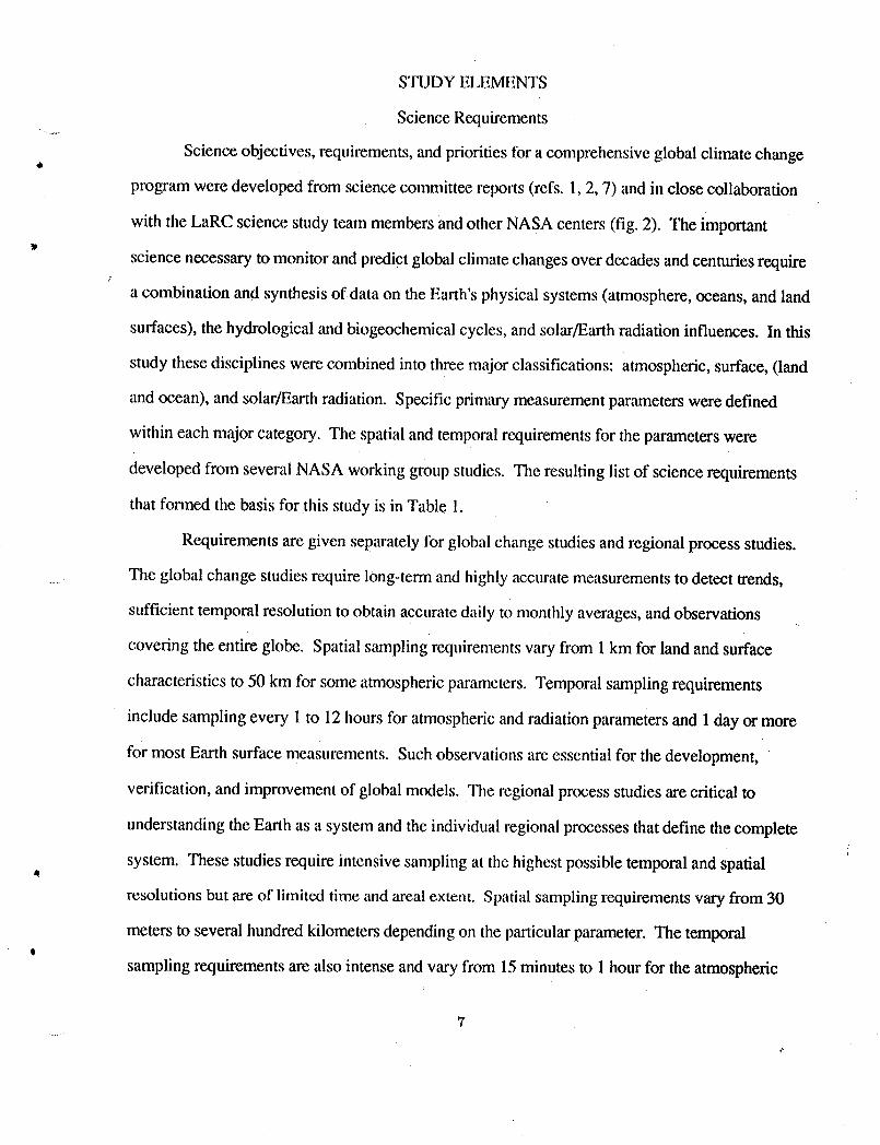
STUDYELEMENTS
Science Requirements
Science objectives, requirements,and priorities for a comprehensiveglobal climate change6
program were developed from science committee reports (refs. 1,2, 7) and in close collaboration
with the LaRC science study team members and other NASA centers (fig. 2). The important
science necessary to monitor and predict global climate changesover decades and centuries require
a combination and synthesis of data on the Earth's physical systems (atmosphere, oceans, and land
surfaces), the hydrological and biogeochemicalcycles, and solar/Earthradiation influences. In this
study these disciplines were combined into three major classifications: atmospheric, surface, (land
and ocean), and solar/Earth radiation. Specific primary measurementparameters were defined
within each major category. The spatial and temporal requirements for the parameters were
developed from several NASA working group studies. The resulting list of science requirements
that formed the basis for this study is in Table 1.
Requirements are given separately for global change studies and regional process studies.
..... The global change studies require long-term and highly accuratemeasurements to detect trends,
sufficient temporal resolution to obtain accuratedaily to monthly averages,and observations
covering the entire globe. Spatial sampling requirementsvary from 1 km for land and surface
characteristics to 50 km for some atmosphericparameters. Temporal sampling requirements
include sampling every 1to 12hours for atmospheric and radiationparameters and 1 day or more
for most Earth surface measurements. Such observations are essential for the development,
verification, and improvement of global models. The regional process studies are critical to
understanding theEarth as a system and the individual regional processes that define thecomplete
system. These studies require intensive sampling at the highest possible temporal and spatial
resolutions but are of limited time and areal extent. Spatial samplingrequirementsvary from 30
meters to several hundred kilometersdepending on the particularparameter. The temporalt
sampling requirements are also intense and vary from 15minutes to 1 hour for the atmospheric
7
€.

A Missi°noptions Insirument.I ! f S/C and
groupings I platform options
Science I
requirements i i Trade offs_ Candidate _1instrument !
Sensor technology Subsystem technology Mission & S/C= assess ments assessments arch itecture
assessments
, LaRC Management Reviews and Documentation ,I I
- 7"KOAST OSSA
Figure l. GCT ARCHITECTURE TRADE STUDY PROCESS.
- (t ° . _ ,, ° .

Developedby: Tim Suttles, Edwin Harrison,Gary Gibson,Tom Campbell,BruceKendall, and colleagues
Sources: Science CommitteeReports, NASA,and other GovernmentAgencyScientistsincluding Earth System SciencesCommitteeReport, January 1989;Committeeon Earth Sciences-FederalCoordinatingCouncil on Science,Engineering,and Technology;LaRC and GSFC scientists.
ScienceObjectives: Monitoringand predictingglobal climate changesoverdecadesand centuries in the following categories:
• Physicalsystems (atmosphere,oceans, land surfaces)JA
_" • Biogeochemicalcycles• Water cycle• S01ar/EarthRadiation influences
ScienceData: • Globalclimate change long-termsurveys• Intensiveregional climate processesstudies
Science Categories: • Atmosphere• Surface (land, ocean)• Solar and Earth radiation
Figure2 - GCTArchitectureStudy Science RequirementsLBG-MP7
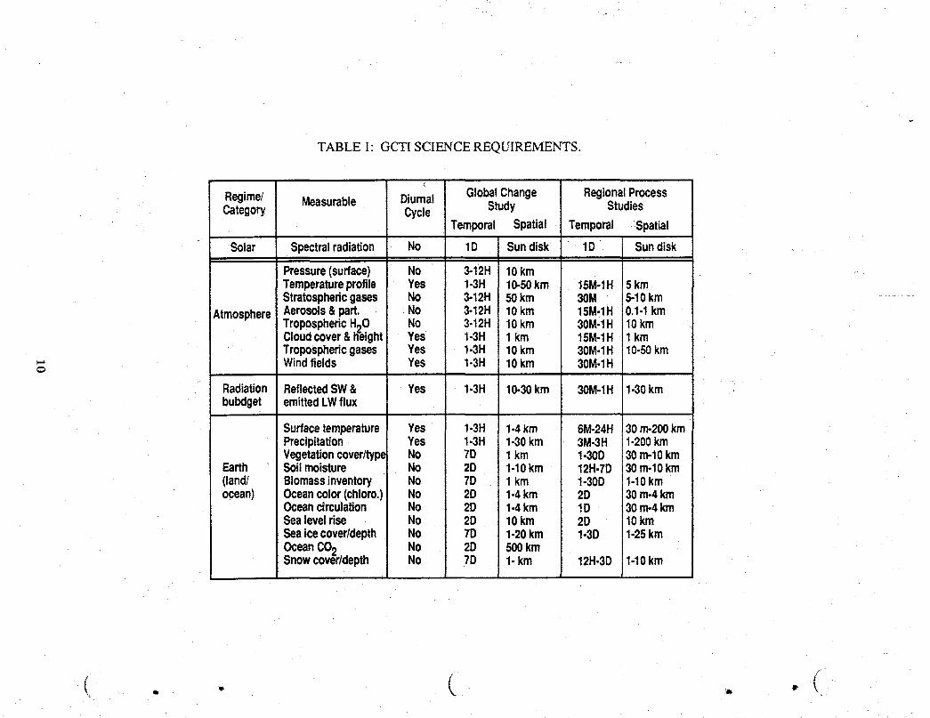
TABLE 1: GCTI SCIENCE REQUIREMENTS.
(
Regime/ Measurable Diurnal GlobalChange RegionalProcessCategory Cycle Study Studies
Temporal Spatial Temporal -Spatial
Solar Spectralradiation No 1D Sundisk 1D Sundisk
Pressure(surface) No 3-12H 10kmTemperatureprofile Yes 1-3H 10-50km 15M,1H 5 kmStratosphericgases No 3-12H 50km 30M 5-10km ............
AtmosphereAerosols& part. • No 3-12H 10km 15M-1H 0.1-1kmTroposphericHgO No 3-12H 10km 30M-1H 10kmCioudcover&h-eight Yes 1-3H 1 km 15M-1H 1 kmTroposphericgases Yes 1-3H 10km 30M-1H 10-50kmWindfields Yes 1-3H 10km 30M-1H
Radiation ReflectedSW& Yes 1-3H 10-30km 30M-1H 1-30kmbubdget emittedLWflux
Surfacetemperature Yes 1-3H 1-4km 6M-24H 30m-200kmPrecipitation Yes 1-3H 1-30km 3M-3H 1-200kmVegetationcover/type No 7D 1 km 1-30D 30m-lOkm
Earth Soilmoisture No 2D 1-10km 12H-7D 30rrvlOkm(land/ Biomassinventory No 7D 1 km 1-30D 1-10kmocean) Oceancolor(chloro.) No 2D 1-4km 2D 30m-4km
Oceancirculation No 2D 1-4km 1D 30m-4kmSealevelrise No 2D 10km 2D 10kmSeaicecover/depth No 7D 1-20km 1-3D 1-25kmOceanCO2 No 2D 500kmSnowcov_ir/depth No 7D 1-km 12H-3D 1-10km
. - C . .(
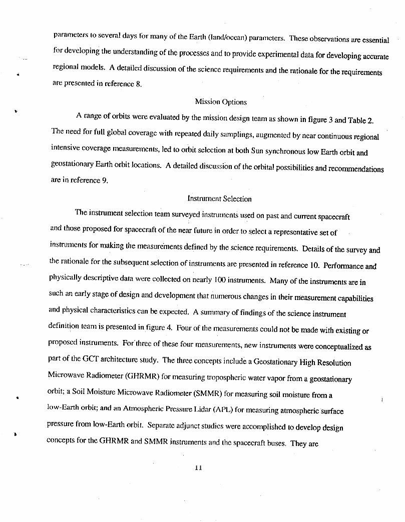
parameters to several days for many of theEarth (hind/ocean)parameters. These observations are essential
for developing the understandingof the processes and to provideexperimentaldata for developing accurate
regional models. A detailed discussion of the science requirementsand the rationale for therequirements
are presented in reference 8.
MissionOptions
_' A range of orbits were evaluated by the mission design team as shown in figure 3 and Table 2.
The need for full global coverage with repeated daily samplings, augmentedby near continuousregional
intensive coverage measurements, led to orbit selection at both Sun synchronous low Earth orbit and
geostationaryEarth orbit locations. A detailed discussionof the orbital possibilities and recommendations
are in reference 9.
Instrument Selection
The instrument selection team surveyed instruments used on past and current spacecraft
and those proposed for spacecraftof the near future in order to select a representative set of
instruments for making the measurementsdefined by the science requirements. Details of the survey and
the rationale for the subsexluentselectionof instruments are presented in reference 10. Performance and
physically descriptive data were collected on nearly 1(X)instruments. Many of the instruments are in
such an early stage of design and developmentthat numerous changes in their measurementcapabilities
and physical characteristics can be expected. A summary of findings of the science instrument
definition team is presented in figure 4. Four of the measurementscould not be made with existing or
proposed instruments. For'three of these four measurements,new instruments were conceptualized as
part of the GCT architecture study. The three concepts include a Geostationary High Resolution
Microwave Radiometer (GHRMR) for measuring tropospheric water vapor from a geostationary
orbit; a Soil Moisture Microwave Radiometer(SMMR) for measuring soil moisture from a i4
low-Earth orbit; and an Atmospheric Pressure Lidar (APL) for measuring atmosphericsurface
pressure from low-Earth orbit. Separate adjunct studies were accomplished to develop design
concepts for the GHRMR and SMMR instruments and the spacecraft buses. They are
11

Developedby: Ed Harrison,Gary Gibson,Tim Suttles,IsraelTaback,Jim Buglia,and HeatherKnight _ _
Principalmissiondesign driverswere the temporalcoverageand resolutionrequirementsfor:
• Global ClimateChangeStudies - 3- to 12-hourtemporalcoverage• RegionalClimateProcessStudies- minutesto I hourtemporalresolution
Orbitsanalyzedincluded:• Mid-Inclined(i = 28.5 - 57°, h = 400 - 600km)• Polar/SunSynchronous(i = 97.8 - 99.5°, h = 600 -1000 km)• EquatorialLowAltitude(i = 0, h = 1300- 5200 km)• EquatorialIntermediateAltitude(i = 0, h = 5300- 20,000 km)• Geosynchronous(i = 0°, h = 36,000km)
Orbitsselected:
• Sun synchronous(4 platformsto provide3-hourglobalcoveragewithequallyspacedequatorialcrossingtimes, h --800km)
• Geosynchronous(1 or 2 moveablein latitudeto provideminutes to1 hourcoverage)
• Mid-Inclined(SpaceStationFreedominstruments)
Figure 3 - GCTArchitecture StudyMissionDesignOptions
LBG-MP 8
tr

Table 2. COMPARISON OF SATELLITE ORBITS
Orbit Advantages Disadvantages CommentsMID:INCLINED - Pressure thru all local hoursi = 28.5-57° - High resolution - No high latitudeh 400 - 600 km - Maximize payload with coverage
shuttle launch (i=28.5°)- Compatible with space station
- Global coveragePolar/Sun-synch - Same local time coveragei = 97.8-99.5° - High resolution Limited temporal - 4 satellites willh = 600 - 1000 km - Compatible with NOAA coverage from provide 3-hour,
operational satellites 1 satellite global coverage
L- Equatorial (i = 0°) - Very limitedlow altitude Moderate temporal geographicalh = 1300 - 5200 km coverage (2 - 4 hours) coverage
- Limited temporal and moderate - No high latitudeEquatorial (i = 0°) geographical coverage coverage 5 satellites requiredintermediate altitude - Higher resolution or smaller - Not compatible with to cover all hoursh = 5300 - 20000 km optics/propulsion requirements NOAA operational in the tropics and
than GEO, but greater than satellites for mid-latitudesfor low orbits correlative or
auxiliary data
- Very high temporal coverageExcellent for climate 5 satellites required
Geosynchronous process case studies - Limited geographical to cover tropicsi = 0° over a selected region coverage and mid-latitudesh = 36000 km - Compatible with operational
satellites for auxiliary data
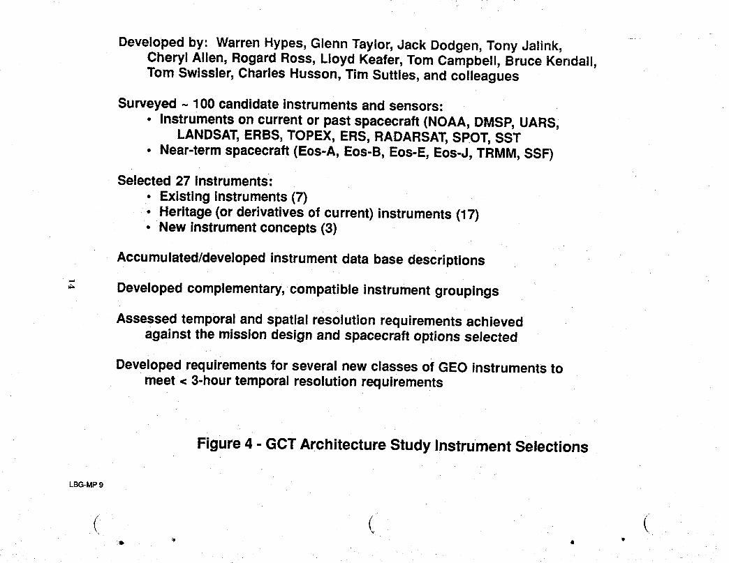
Developedby: WarrenHypes,GlennTaylor,Jack Dodgen,Tony Jalink,Cheryl Allen, RogardRoss, LloydKeafer,TomCampbell,BruceKendall,Tom Swissler,CharlesHusson,Tim Suttles,and colleagues
Surveyed~ 100candidateinstrumentsand sensors:• Instrumentson currentor past spacecraft(NOAA,DMSP,UARS,
LANDSAT,ERBS,TOPEX,ERS,RADARSAT,SPOT,SST• Near-termspacecraft(Eos-A, Eos-B,Eos-E,Eos-J,TRMM,SSF)
Selected27 instruments:• Existinginstruments(7)• Heritage(or derivativesof current)instruments(17)• New instrumentconcepts(3)
Accumulated/developedinstrumentdata base descriptions
Developedcomplementary,compatibleinstrumentgroupings
Assessed temporal and spatial resolution requirements achievedagainst the mission design and spacecraft options selected
Developed requirements for several new classes of GEO instruments tomeet < 3-hour temporal resolution requirements
Figure 4 - GCT Architecture Study Instrument Selections
LBG-MP 9
detailed in references 11 and 12and outlines of the concepts are shown on figures 5 and 6. A
,_ general concept for the APL was also developed, but a detailed design concept was not produced.
An outline of the concept is shown on figure 7. Currently there is no instrument concept for the
fourth measurement, ocean/atmosphereCO2 exchange, from either a GEO or LEO spacecraft.
The initial selection of instrumentswas made based on an instrument'sability to make the
required measurement at the specified spatialresolution. The temporal requirements for the
measurements were also a factor driving instrument selection towards instrumentsthat can operate
from geostationary orbit for measurementswith temporal requirements of 1hour or less. The only
practical way of meeting this temporal requirement is to place an instrument in a stare, sweep, or
scan mode in geostationary orbit. Some of the measurements with short temporal requirements,
however, cannot be accomplished from GEO with existing or near-term instruments. The
technology needs for new classes of GEO instruments were developed within this study; however,
they were not carried forward into the mission options and spacecraft/platformarchitecturestudies
because the current technology base will not support their inclusion. Thus, some of the short
temporal requirements were accommodated in LEO using multiple spacecraftto shorten the time
between measurements. Variousoptions for the number of GCT spacecraft,orbit inclination, orbit
altitudes, etc. are discussed in reference 5.
The instruments selectedare listedin Table 3. Design and performance informationon the
selected instruments are in reference 10. The three instruments for which new concepts were
developed are indicated in the table. During instrument selection, three changes were made in the
written formatof the science requirements to correlate science requirementswith instrument
availability. The measurable "stratospheregases" was separated into "ozone" and "other gases"
/, since ozone can be measured from a geostationaryspacecraft with current conceptual instruments
while the other gases cannot. "Wind fields" was separated into "Stratospheric"and
o "Tropospheric"because the measuring instruments for the two types of winds are entirely different
and, again, one may be inferred from a geostationaryorbit measurement while the other cannot.
15

Title: Geostationary High ResolutionMicrowaveRadiometer (GHRMR)
Measurement: TroposphericWater Vapor,Precipitation
Contact: TomCampbell, Jeff FarmerLARC LARC
InstrumentType: Microwave RadiometerDimensions: 15mX 15m X 30mMass: 2525 kgAverage Operational Power: 370 watts
= DataRate: 90kbpsSpectral / Frequency Range: 18 - 220 GHzNo. of Channels / Frequencies:Viewing Field: Earth DiscScanning Characteristics: Mechanical mirror with electronic phased array scanningResolution (Horizontal / Vertical): 10 - 120 km /Swath Width:Satellite Application: None (new concept)Technology Status: Conceptual design, GCTI spacecraft, no formal study
Figure 5. Conceptual geostationary microwave radiometer for water vapor and percepitation.
...... ( ( ................ cJ_ ........... i_. ....................... • _ \

SoilTitle: Moil,are MicrowaveRadiometer (SMMR)
Measurement: Soil Moisture
Contact: TomCampbell, Melvin FerebeeLARC LARC
Instrument Type: Microwave RadiometerDimensions: 118mX 118mX 100m
Mass: 4000kgAverageOperational Power: 500 wattsData Rate: lkbps
: " Spectral / FrequencyRange: 1.4 GHzNo. of Channels / Frequencies: 1 FrequencyViewing Field: Nadir (+/-18.5° crosstrack)
: Scanning Characteristics: PushbroomResolution(Horizontal / Vertical): 12 km /SwathWidth: 535 km
SatelliteApplication: None(newconcept)TechnologyStatus:Heritage- AirborneLowFreq.MicrowaveInstr.for Soil Moisture,
Sea SurfaceTemp.,andSalinity/ AircraftCurrent - ConceptualDesign, GCTI Spacecraft,
No formal study
_gure 6. Conceptual microwaveradiometer for measuring soi! moisture....... - ............. _- v = IUI III_,O.OU!!!!g',_U!! !!!U!bLUIE.
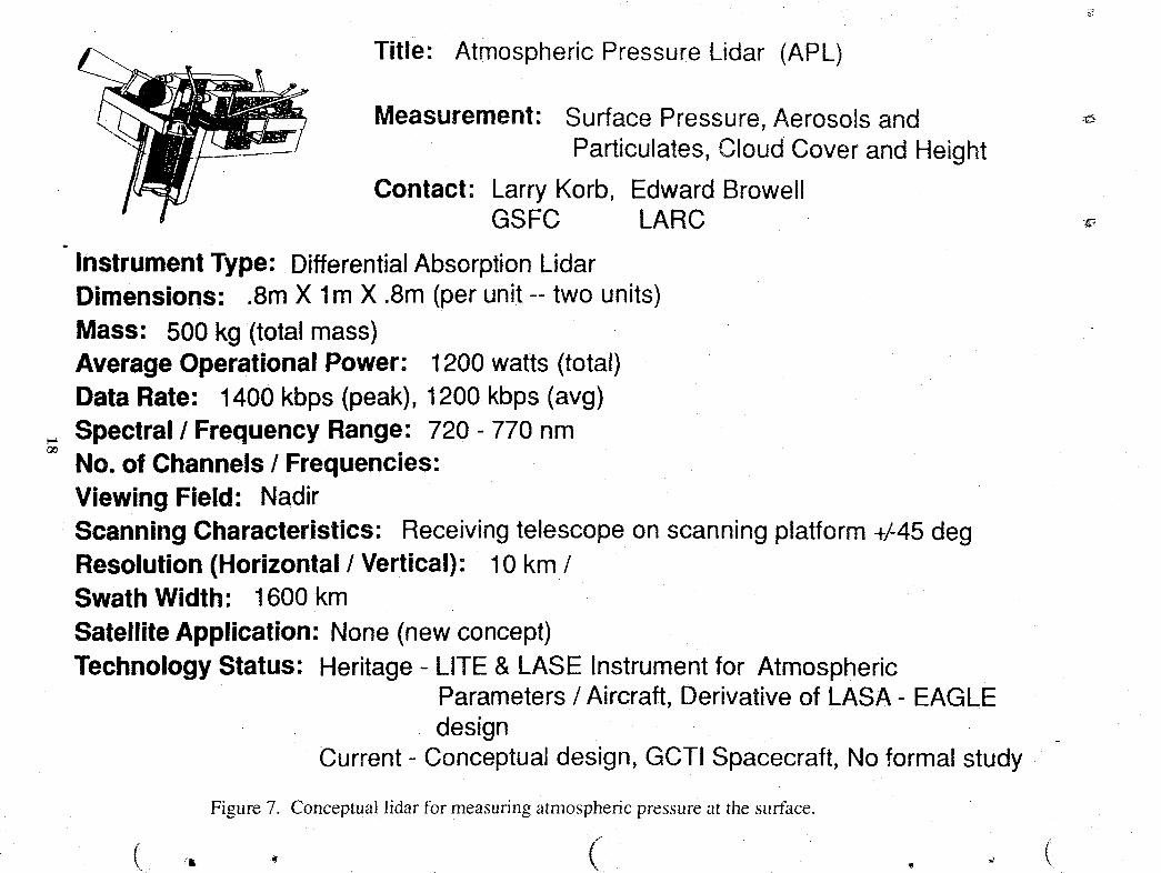
Title: Atmospheric Pressure Lidar (APL)
Measurement: Surface Pressure, Aerosols and _.Particulates, Cloud Cover and Height
Contact: Larry Korb, Edward BrowellGSFC LARC -_
Instrument Type: DifferentialAbsorption LidarDimensions- .8m X lm X .8m (per unit -- two units)
Mass: 500 kg (total mass)Average Operational Power: 1200 watts (total)Data Rate: 1400 kbps (peak), 1200 kbps (avg)
_. Spectral / Frequency Range: 720 - 770 nmNo. of Channels / Frequencies:Viewing Field: NadirScanning Characteristics: Receivingtelescopeonscanningplatform+/-45degResolution (Horizontal/Vertical): 10 km /Swath Width: 1600 km
Satellite Application: None (newconcept)Technology Status: Heritage- LITE & LASE Instrumentfor Atmospheric
Parameters/ Aircraft, Derivativeof LASA- EAGLEdesign
Current- Conceptualdesign, GCTI Spacecraft, No formalstudy
Figure 7. Conceptual lidar for measuring atmospheric pressure at the surface.
- (( ,. • , o t
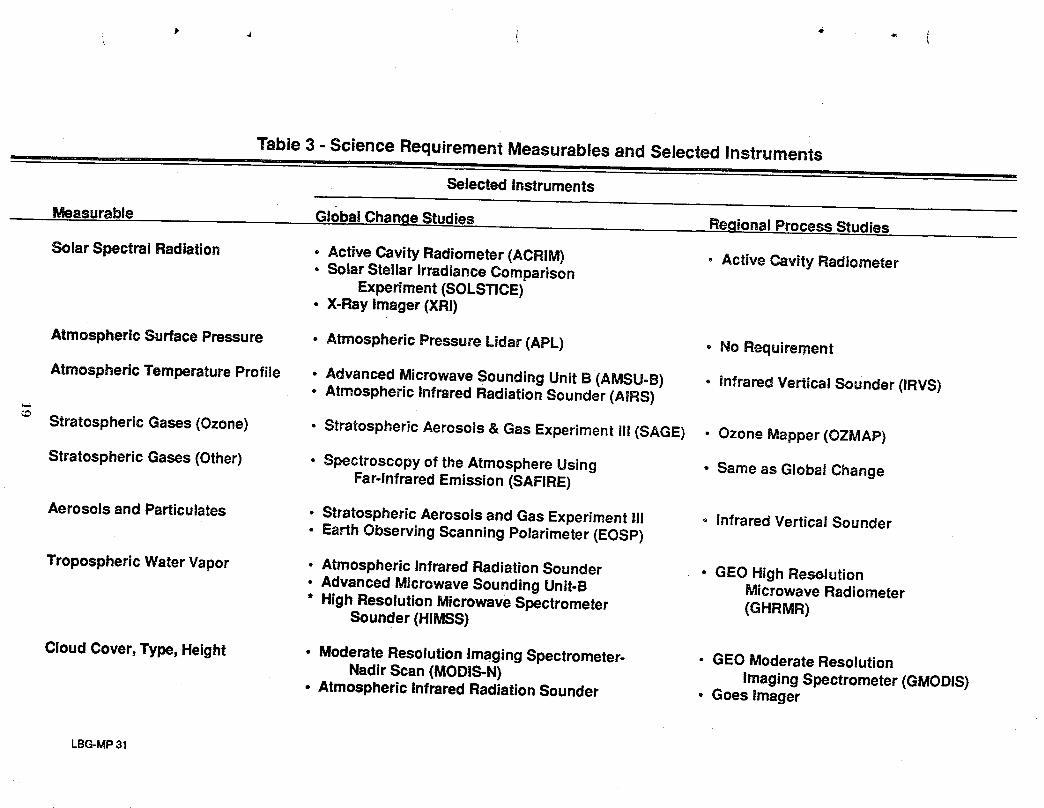
Table 3 - Science Requirement Measurables and Selected Instrumentsii i i i
Selected Instruments
Measurable Global ChangeStudies RegionalProcessStudies
SolarSpectralRadiation • ActiveCavityRadiometer(ACRIM) • ActiveCavity Radiometer• So|arSteltarIrradianceComparison
Experiment(SOLSTICE)• X-Rayimager(XRi)
AtmosphericSurfacePressure • AtmosphericPressureLidar(APL) o No Requirement
AtmosphericTemperatureProfile • AdvancedMicrowaveSoundingUnitB (AMSU-B) , InfraredVerticalSounder(IRVS)• AtmosphericInfraredRadiationSounder(AIRS)
StratosphericGases(Ozone) • StratosphericAerosols& GasExperimentili (SAGE) • OzoneMapper(OZMAP)
StratosphericGases(Other) • Spectroscopyof theAtmosphereUsing • Sameas GlobalChangeFar-InfraredEmission(SAFIRE)
AerosolsandParticulates ° StratosphericAerosolsandGasExperimentIU . InfraredVerticalSounder• EarthObservingScanningPolarimeter(EOSP)
TroposphericWaterVapor • AtmosphericInfraredRadiationSounder • GEOHighResolution• AdvancedMicrowaveSoundingUnit-B MicrowaveRadiometer• HighResolutionMicrowaveSpectrometer (GHRMR)
Sounder(HIMSS)
CloudCover,Type,Height • ModerateResolutionImagingSpectrometer- • GEOModerateResolutionNadirScan(MODIS-N) ImagingSpectrometer(GMODIS)
• AtmosphericInfraredRadiationSounder • GoesImager
LBG-MP31

Table3 - Continued
Selected Instruments
Measurable Global Change Studies Regional Process Studies6.
Tropospheric Gases • TroposphericEmissionsSpectrometer(TES) • Same as GlobalChange• TroposphericRadiometerfor Atmospheric
Chemistryand EnvironmentalResearch(TRACER)
Wind Fields-Stratospheric • StratosphericWind InfraredLimbSounder (SWIRLS) • Same as Global Change
Wind Fields-Tropospheric • GOESImager • Same as GlobalChange
ReflectedShortWaveand • Cloud and Earth RadiantEnergySystem (CERES) • GeostationaryEarth RadiationEmitted LongWaveFlux Sensor(GERS)
Surface Temperature • ModerateResolutionImagingSpectrometer- NadirScan • GOES imager
Precipitation • High ResolutionMicrowaveSpectrometerSounder • GEO High ResolutionMicrowaveRadiometer(GHRMR)
Vegetation CoverType • Moderate ResolutionImagingSpectrometer-NadirScan ° High ResolutionImagingSpectrometer(HIRIS)
Soil Moisture • Soil MoistureMicrowaveRadiometer(SMMR) • Same as Global Change
Biomass Inventory • ModerateResolutionImagingSpectrometer-NadirScan • High ResolutionImagingSpectrometer
Ocean Color • Moderate ResolutionImagingSpectrometer-TiltScan • ModerateResolutionImaging(MODIS-T) Spectrometer.TiltScan
• High ResolutionImagingSpectrometer
LBG-MP 32
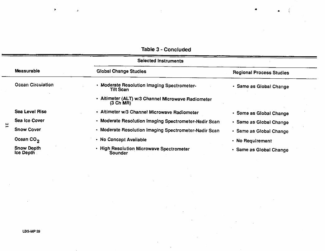
Table 3 - Concluded
Selected Instruments
Measurable Global Change Studies Regional Process Studies
OceanCirculation • ModerateResolutionImagingSpectrometer- • SameasGlobalChangeTiltScan
• Altimeter(ALT)w/3 ChannelMicrowaveRadiometer(3Ch MR)
SeaLevelRise • Altimeterw/3ChannelMicrowaveRadiometer • Sameas GlobalChange
Sea iceCover • ModerateResolutionImagingSpectrometer-NadirScan • Sameas GlobalChange
SnowCover • ModerateResolutionImagingSpectrometer-NadirScan ° SameasGlobalChange
OceanCO2 • No ConceptAvailable • NoRequirement
SnowDepth ° HighResolutionMicrowaveSpectrometer ° Sameas GlobalChangeIceDepth. Sounder
LBG-MP33
Tl!.e"cover" and "depth" measurements for the "sea ice" and "snow"measurables were broken out
as separate measurements since instrumentsapplicable to measuringcover are entirely different
than those for measuring depth.
InstrumentComplements "
The definition of GCT spacecraft represents an orderedapproach to the accommodationof
scientific measurement and instrumentrequirements. Accommodationof the temporalscience
requirements effectively establishes theonboard instrument inventory for a particular spacecraft.
Instrument operating requirements such as power, mass, spatial resolution, and data rates establish
the performance specifications for the spacecraft subsystems. Instrument viewing requirements,
together with heat rejection radiator considerations, establish the onboard positioning and layout
within each of the spacecraft.
The first selection of instrumentsfor manifestingaboard specific spacecraft is to separate
those for LEO application from those for GEO application. The low-Earthorbits for all the
spacecraft are assumed to be Sun synchronous, thus allowing observations at any point on the
Earth at 12-hourintervals. Accordingly, one spacecraft satisfies the 12hour and longer temporal .._..
measurement requirement and also meets the upper limit of a 3- to 12-hourrequirement. Four
spacecraft in complementary orbits (45 degrees apart) satisfy the upper limit for a 1- to 3-hour
requirement.
The only practical way to accommodate the 1 hour or less temporal coverage objective is to
place instruments in geostationaryorbit; however, some of the instruments do not have the spatial
resolution and sensitivities for the geostationaryaltitude. Instruments for temporal measurements
of I hour and less, that currently have or in the near future can be expected to have geostationary
capability, were manifested onboard a geostationaryspacecraft. Those that are not near-term
candidates for geostationaryapplication were manifestedon LEO spacecraftwith a 3-hour temporal "
cycle. Early in the study it was concluded that measurementsmore frequent than the 3 hours
22
provided by four sunsynchronous I,EO spacecraftcannot realisticallybe provided because of the
excessive number of spacecraft required.
Thus, the spacecraft instrument complementsand the composition of the spacecraft fleet,IP
were determined based on the ground rule that the temporalmeasurement requirementsof less than
three hours would be met by geostationary systemsif currently projected instrument technologies
developments occurred. If not, the LEO spacecraft would accommodate instruments for 3 hours
and longer repeat coverage periods. Table 4 presents two options for the LEO spacecraft fleet,
with designations of A through E assigned for the individual spacecraft. Note on the table that
spacecraft E of the small spacecraftconstellation includes instruments for the less than 1-hour
temporal measurements. Although grouped according to this temporal requirement, as previously
stated, measurements from LEO could not be accommodatedat less than the 3-hour frequency
without a prohibitive number of spacecraftand instruments.
Seven of the instruments listed in Table 3 are proposed for use on geostationary spacecraft.
Of the seven instruments proposed, six can be placed on a single spacecraftbut the seventh, the
.... new concept GHRMR microwave instrument,requires a dedicated spacecraftdue to the large size
antennae and unique configurationof microwave instruments. The instrument complements of the
two geostationary spacecraft are listed in Table 5 as Option G2, spacecraft A&B. This assumes
packaging and launch by existing Titan IV vehicles and a Centaur upper stage.
Separate options for packaging and deployment for an on-orbit assembly of the entire seven
geostationary instruments on a single platform was also examined. This option, designated G1 in
Tables 4 and 5, is possible with Shuttle or Titan IV launches and with on orbit assembly at Space
Station Freedom. Alternatively, if a Shuttle C, Block 1 with its large 7.6 m-diameter shroud is
developed, the entire complement of seven instruments mightbe packaged and launched as a
single, complete platform with automated deployment occurring on orbit.
23
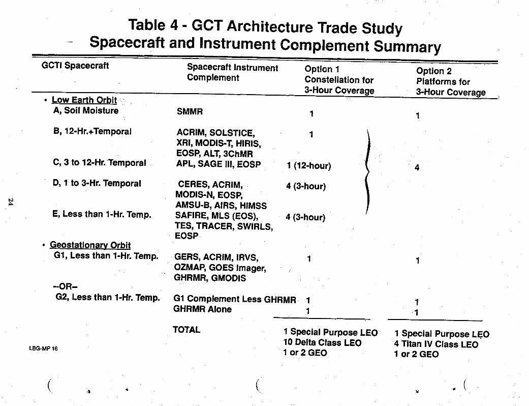
Table 4- GCT Architecture Trade StudySpacecraft and Instrument Complement Summary
i ii
GCTI Spacecraft Spacecraft Instrument Option 1 Option 2 -Complement Constellation for Platforms for
3-Hour Coverage 3-Hour Coverage• Low Earth Orbit
A, Soil Moisture SMMR 1 1
B, 12-Hr.+Temporal ACRIM, SOLSTICE, 1XRI, MODIS-T,HIRIS,EOSP,ALT,3ChMR
C, 3 to 12-Hr.Temporal APL, SAGE Iil, EOSP 1 (12-hour) 4
D, 1 to 3-Hr. Temporal CERES,ACRIM, 4 (3-hour)MODIS-N, EOSP,AMSU-B, AIRS, HIMSS
E, Less than 1-Hr.Temp. SAFIRE, MLS (EOS), 4 (3-hour)TES, TRACER, SWIRLS,EOSP
• GeostationaryOrbit
G1, Less than 1-Hr.Temp. GERS,ACRIM, IRVS, 1 1OZMAP, GOES Imager,GHRMR, GMODIS
-OR-
G2, Lessthan 1-Hr.Temp. G1 Complement Less GHRMR 1 1GHRMR Alone 1 1
TOTAL 1 Special Purpose LEO 1 Special Purpose LEO10 Delta Class LEO 4 Titan IV Class LEO
LBG-MP16 1 or 2 GEO 1 or 2 GEO
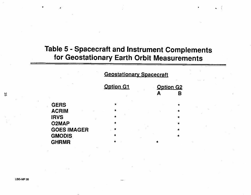
Table5 - Spacecraftand InstrumentComplementsfor Geostationary Earth Orbit Measurements
nl
Geostationary Spacecraft
Option G1 Option G2A B
€;x
GERS * *ACRIM * *IRVS * *O2MAP * *GOES IMAGER * *GMODIS * *GHRMR * *
LBG-MP30 ....
The combination of the one or two GEO spacecraftand the two options of theLEO
spacecraftproduce the fin,'dfleet architecture listed in Table 6. Note that two major options are _._,_
suggested. Option 1features ten Delta Class LEO spacecraftwhile Option 2 features four large
Titan IV Class LEO spacecraft. Under both options, the special purpose soil moisture microwave
spacecraft (LEO SpacecraftA) and the one or two GEO spacecraftare required. The GEO
spacecraft are assumed to be moveable in latitude to monitorregional areasof high scientific
importance.
SpacecraftConfigurations
The spacecraft and platform concept developmentteam surveyed existing and proposed
spacecraftand contacted several NASAcenters and aerospace industry sources in developing the
spacecraftarchitecture options outlined on figure 8. Severalcombinationsof spacearchitecture
options were assessed which included small Delta launched LEO spacecraftand large Titan IV
launched LEO platforms. All architecturesincluded a Titan IV launched soil moistureradiometer
for LEO operations and one or two geostationaryplatforms with several launch, deployment and/or
on-orbit assembly options. Instrument allocations and spacecraft/platformdesigns are discussed "-""
below.
The configurations of the GCT spacecraftvary from modification of existing modularized
spacecraft to entirely new conceptual designs. The new designs are related to the three special
purpose spacecraft: the LEO SpacecraftA and the two GEO Spacecraftoptions.
The modified modular spacecraftused extensively to provide the spacecraftoperating
subsystems for the remainder of theGCT fleet is the MultimissionModular Spacecraft (MMS)
developed by the NASA Goddard Space Flight Center. The modified MMS and its application to
the GCT fleet are detailed in reference 13. For the GCT application,the communicationand dam
handling module would be replaced with the new NASAData Link Module, theAttitude Control
System would incorporateadvances developed for the TOPEX spacecraft, and the power and ',
propulsion modules would incorporate recent advances that evolved from Space Station Freedom
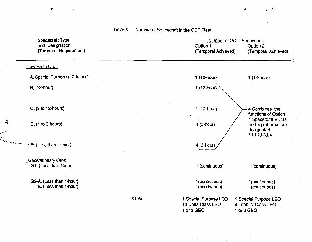
Table6 - Numberof Spacecraftin theGCTFleet
SpacecraftType Numberof GCTISpacecraftand Designation Option1 Option2(TemporalRequirement) (TemporalAchieved) (TemporalAchieved)
A,SpecialPurpose(12-hour+) 1 (12-hour) 1 (12-hour)
B, (12-hour) 1 (12-hour)
C, (3 to 12-hours) 1 (12-hour) 4 Combines thefunctions,of Option1 Spacecraft B,C,D,
.4 , D, (1 to 3-hours) 4 (3-hour) and E platforms are•jJ
j designated_._ L1,L2,L3,L4
_-__ ......... E;,-(Lessthan 1-hour) 4 (3-hour)
GeostationarvOrbitG1, (Lessthan1hour) 1 (continuous) 1(continuous)
G2-A,(Lessthan1-hour) 1(continuous) 1(continuous)B,(Lessthan1-hour) 1(continuous) 1(continuous)
TOTAL 1 SpecialPurposeLEO 1 Special Purpose LEO10 Delta Class LEO 4 Titan IV Class LEO1 or 2 GEO 1 or 2 GEO
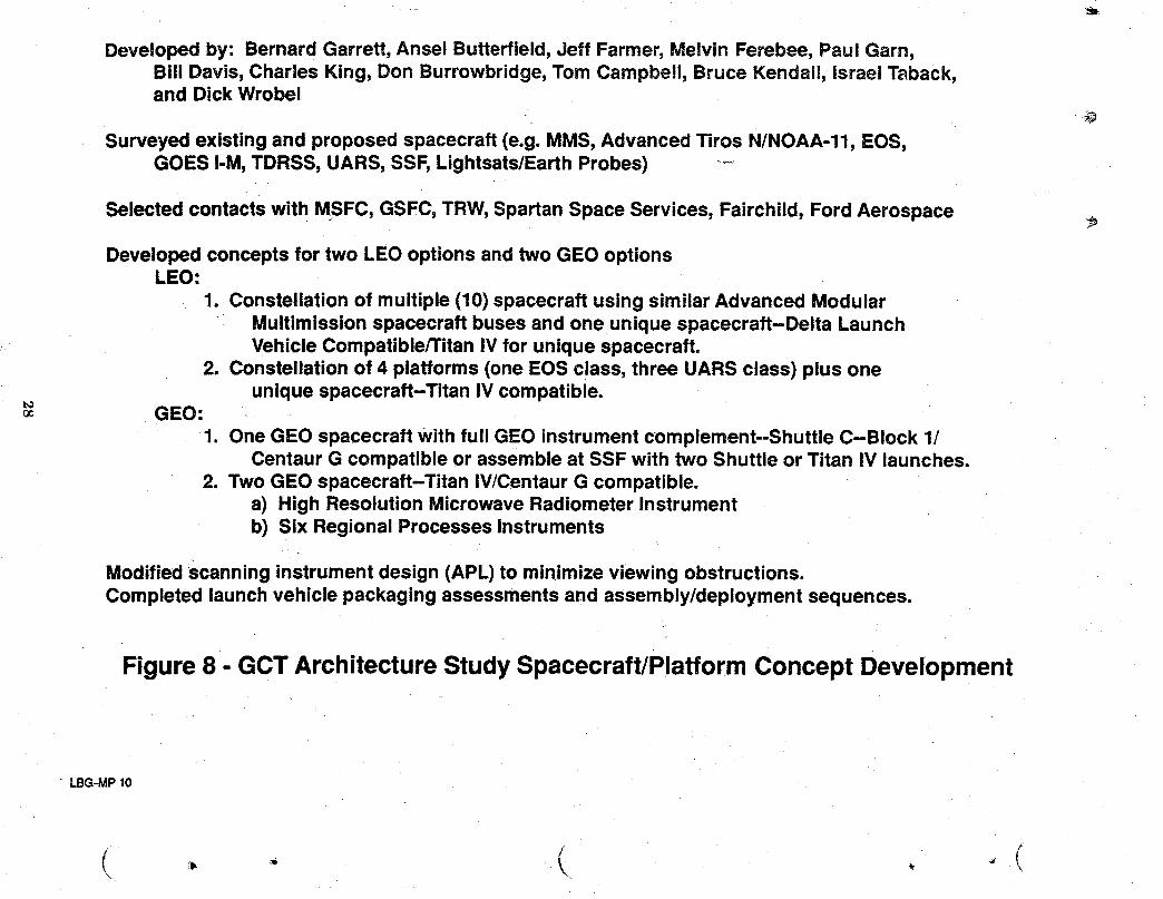
Developed by: Bernard Garrett, Ansel Butterfield,Jeff Farmer, Melvin Ferebee, Paul Garn,Bill Davis, Charles King, Don Burrowbridge,Tom Campbell, Bruce Kendall, Israel Taback,and Dick Wrobel
Surveyed existing and proposed spacecraft (e.g. MMS, Advanced Tiros N/NOAA-11, EOS,GOES I-M,TDRSS, UARS, SSF,Lightsats/EarthProbes) ---
Selected contacts with MSFC, GSFC, TRW,Spartan Space Services, Fairchild, Ford Aerospace -_
Developed conceptsfor two LEO options and two GEO optionsLEO:
1. Constellationof multiple (10) spacecraft using similar Advanced ModularMultimission spacecraft buses and one unique spacecraft-Delta LaunchVehicle Compatible/TitanIV for unique spacecraft.
2. Constellationof 4 platforms (one EOS class, three UARS class) plus oneunique spacecraft-Titan IV compatible.
GEO:1. OneGEO spacecraft with full GEO instrumentcomplement--Shuttle C-Block 1/
Centaur G compatible or assembleat SSF with two Shuttle or Titan IV launches.2. Two GEO spacecraft-Titan IV/Centaur G compatible.
a) High Resolution Microwave Radiometer Instrumentb) Six Regional Processes Instruments
Modifiedscanning instrument design (APL) tominimize viewing obstructions.Completed launchvehicle packaging assessmentsand assembly/deploymentsequences.
Figure 8 - GCTArchitectureStudySpacecraft/PlatformConcept Development
LBG-MP10
C\ •
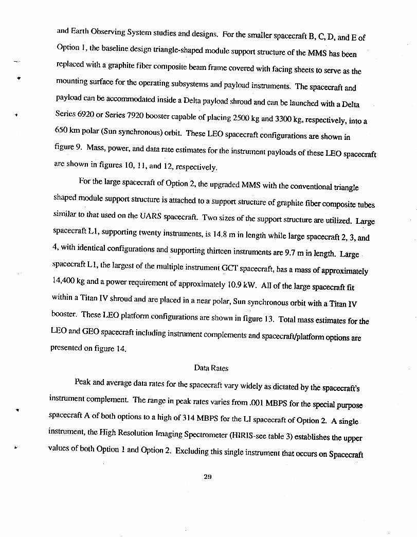
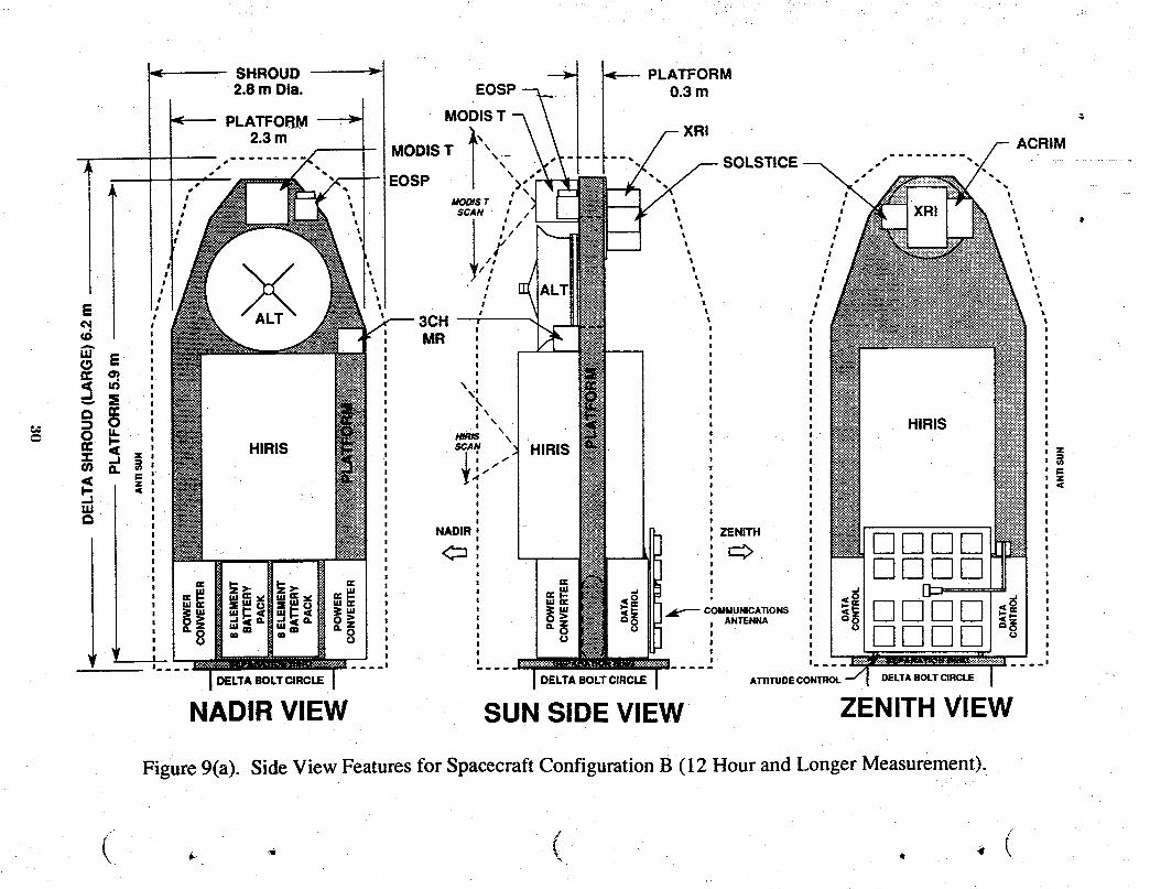
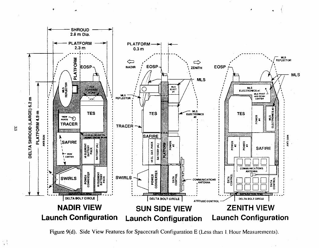
and Earth Observing System studies and designs. For the smaller spacecraft B, C, D, and E of
Option 1,the baseline design triangle-shapedmodule support structureof the MMS has been
.... replaced with a graphite fiber composite beam frame covered with facing sheets to serve as the
_' mounting surface for the operating subsystemsand payload instruments. The spacecraft and
payload can be accommodated inside a Delta payload shroudand can be launched with a Delta
Series 6920 or Series 7920 booster capable of placing 2500 kg and 3300 kg, respectively, into a
650 km polar (Sun synchronous) orbit. These LEO spacecraftconfigurations are shown in
figure 9, Mass, power, and data rate estimates for the instrument payloadsof these LEO spacecraft
are shown in figures 10, 11, and 12, respectively.
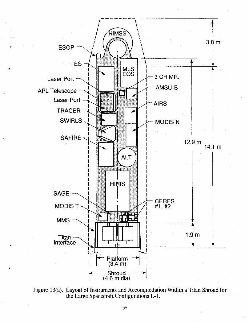
For the large spacecraft of Option 2, the upgraded MMS with the conventional triangle
shaped module support structure is attached to a support structure of graphite fiber composite tubes
similar to that used on the UARS spacecraft. Two sizes of the support structure are utilized. Large
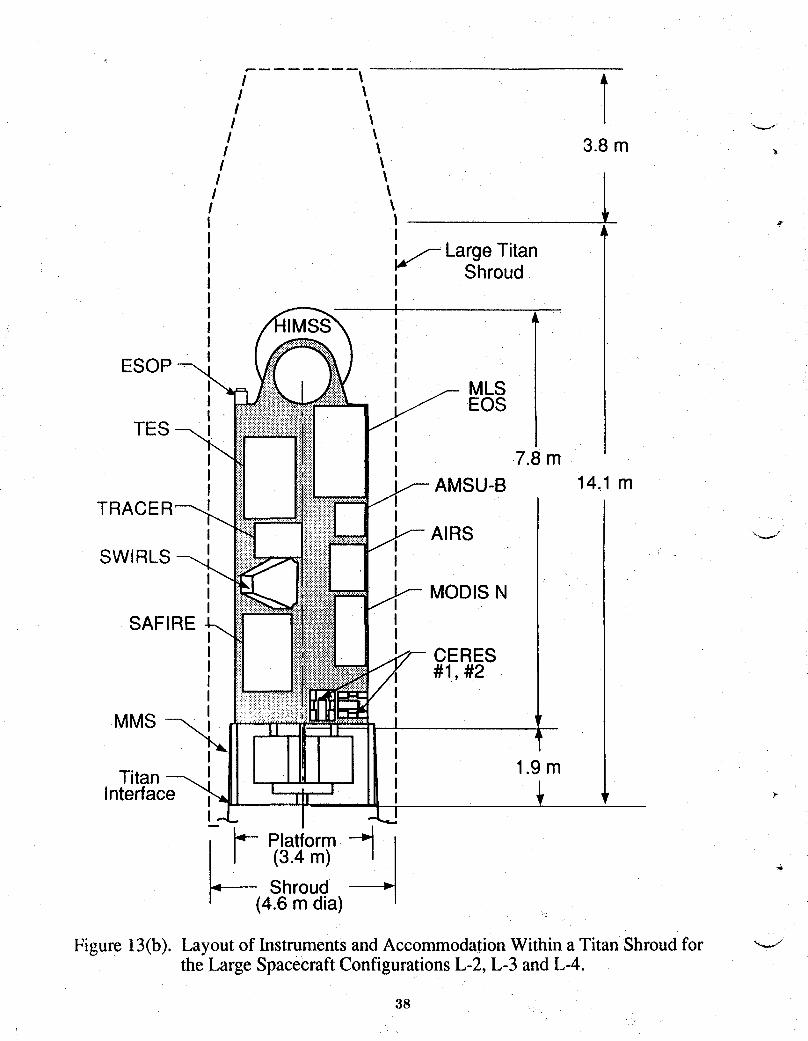
spacecraft L1, supporting twenty instruments, is 14.8 m in length while large spacecraft 2, 3, and
4, with identical configurations and supporting thirteen instruments are 9.7 m in length. Large
spacecraft L1, the largest of the multiple instrument GCT spacecraft, has a mass of approximately
14,400kg and a power requirement of approximately 10.9 kW. All of the large spacecraftfit
within a Titan IV shroud and are placed in a near polar, Sun synchronousorbit with a Titan IV
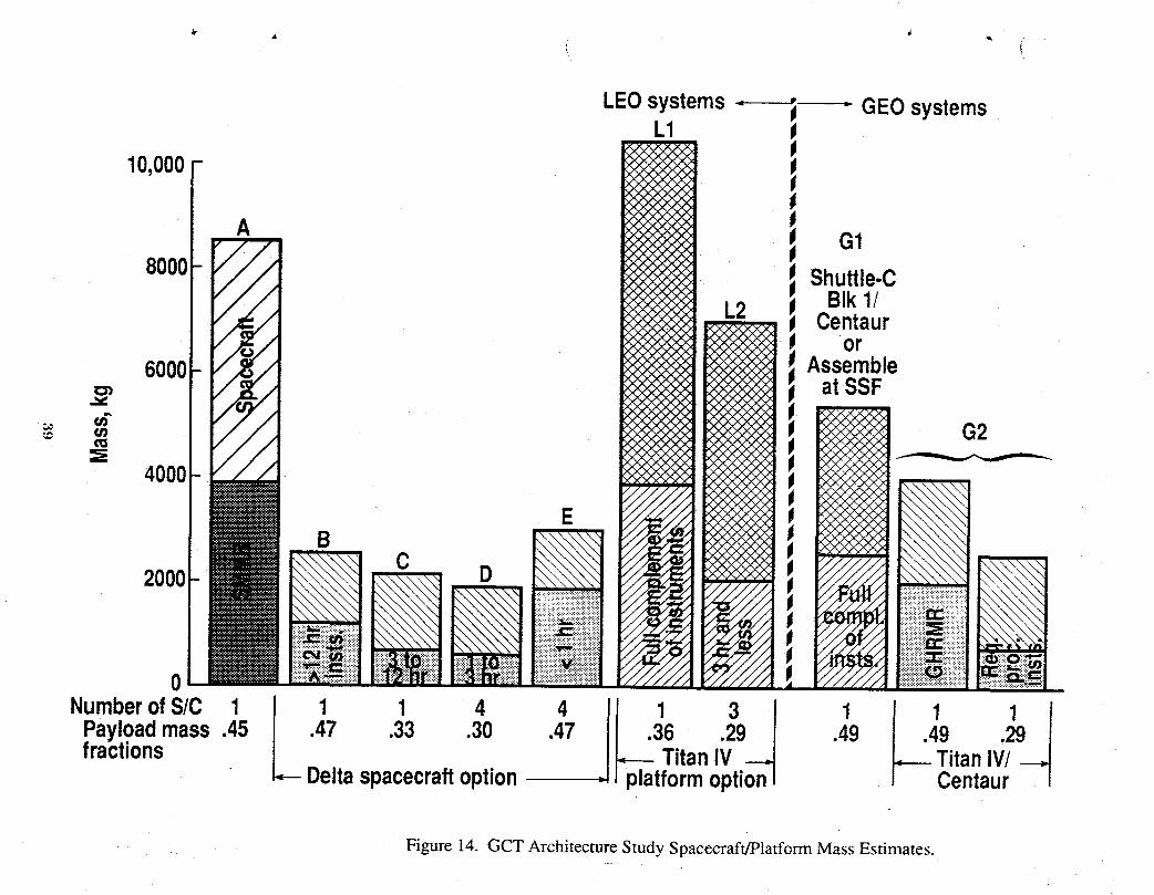
booster. These LEO platform configurations are shown in figure 13. Total mass estimates for the
LEO and GEO spacecraft including instrument complementsand spacecraft/platformoptions are
presented on figure 14.
Data Rates
Peak and average data rates for the spacecraftvary widely as dictated by the spacecraft's
instrument complement. The range in peak rates varies from .001 MBPS for the special purpose
4 spacecraft A of both options to a high of 314 MBPS for the LI spacecraft of Option 2. A single
instrument, the High Resolution Imaging Spectrometer (HIRIS-see table 3) establishes the upper
_, values of both Option 1 and Option 2. Excluding this single instrumentthat occurs on Spacecraft
29
< SHROUD _ --->- <---PLATFORM2.8 m Dia. 0.3 m
PLATFOBM _ MODIS T --
,, XRI
2.3 m MODIS T _ /- ACRIM
•, SOLSTICE _ ........ji. EOSP \ ""a_,% .__S T
SCAN
is
!
1#
/ 3CH :_2 ', MR ,
_E : :_. : :
,(_ i'- ' N/R/$ ,,<. = : SCA. =
,,-I, ,I NADIR ZENITHI
, _ c:_I!!!I!! _ COMMUNICATIONSI i ANTENNAI II I
_ ,I I _1
)ELTA BOLT CIRCLE DELTABOLTCIRCLE ATnTUDE CONTROL DELTA BOLT CIRCLE
NADIR VIEW SUN SIDE VIEW ZENITHVIEW
Figure 9(a). Side View Features for Spacecraft Configuration B (12 Hour and Longer Measurement).
( ( ,(

< SHROUD >2.4 m Dia.
.4--- PLATFORM _ PLATFORM .<--2.2 m 0.3 m
p % / ' '_'%, S' %/ \ I _ / \
! \ I \ I \I \ I \ I \
I \ I \ / \
l \ I \ I \I \ NADIR I \ ZENITH I \
I \ I \ I \I \ I \ I \
\ I \ I \I \ I \
I \ I \APL I I APL I
I SAGE IIE ,
O4 I
,,..,. I
< E 03
Z I
CO m !"-_ 0 !
!" POWER#30 < / \ /
,..I \\ I I \ I"I" a,, BATTERY, BA17"ERY(4L)03
I--...IU.I
COMMUNICATIONS
I ANTENNA ANTENNA
I! t |
, I I! _j
DELTABOLTCIRCLE OELTABOLTCIRCLE DELTABOLTCIRCLE
NADIRVIEW SUN SIDE VIEW ZENITH VIEWLaunch Configuration Launch Configuration Launch Configuration
......... Figure 9(b). Side View Features for Spacecraft Configuration C (3 to 12 Hour Measurements).
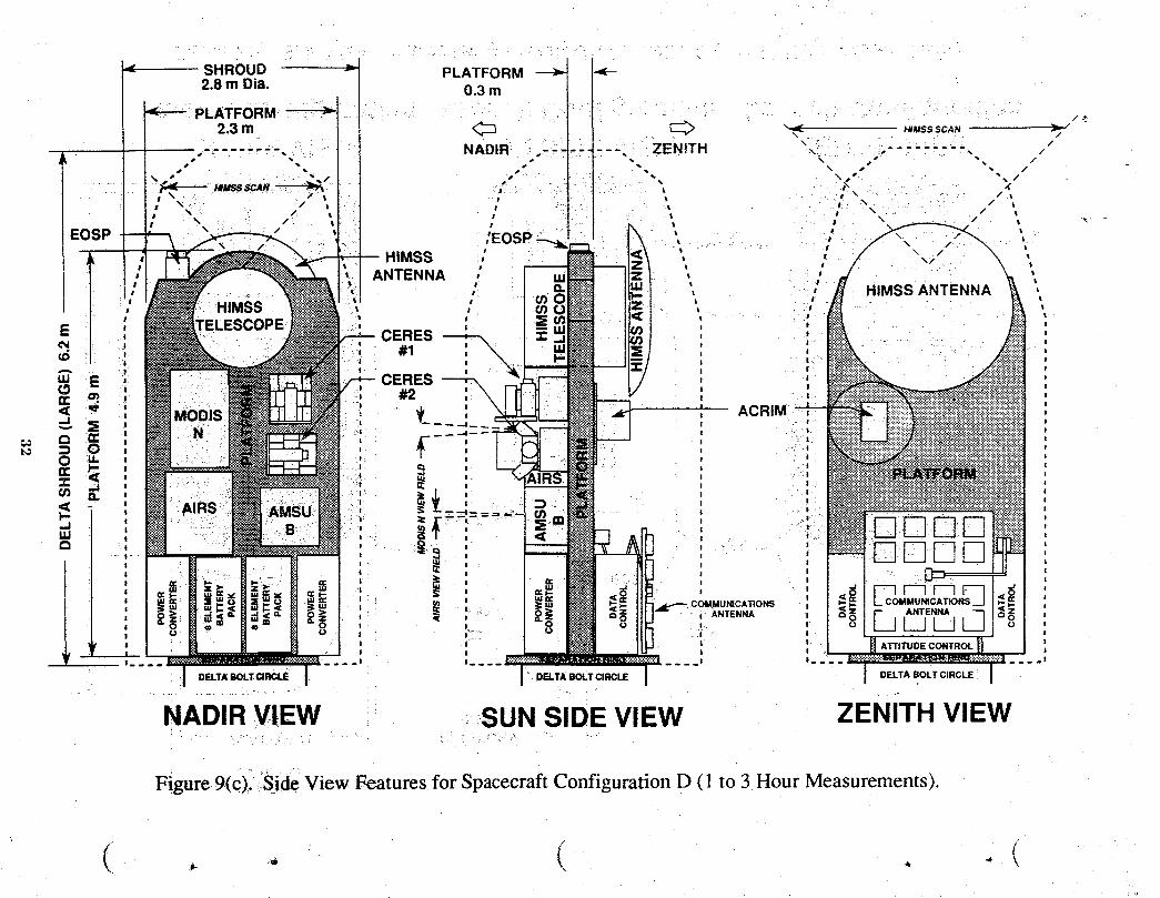
Figure 9(c).iSide View Features for Spacecraft Configuration D (l to 3 Hour Measurements).
( ( ,x
SWIRLS COMMU_CAT_.SnANTENNAiii
I_ .| I I ....... I
DELTA BOLT CIRCLE DELTA BOLT CIRCLE DELTA BOLT CIRCLEATTITUDE CONTROL
NADIR VIEW SUN SIDE VIEW ZENITH VIEW
Launch Configuration Launch Configuration Launch Configuration
Figure 9(d). Side View Features for Spacecraft Configuration E (Less than 1 Hour Measurements).
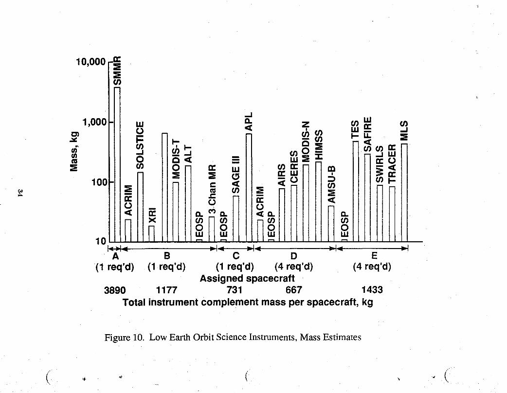
10,000_n-
,,ooo += __._
o o .__ _ _ioo _ +:_
_0 .. o o o oi_ _ i _,qll J.,,.- i _ir,
A B C D E(1 req'd) (1 req'd) (1 req'd) (4 req'd) (4 req'd)
Assignedspacecraft3890 1177 731 667 1433
Total instrumentcomplementmassper spacecraft,kg
Figure 10. Low Earth Orbit Science Instruments, Mass Estimates
.. • (
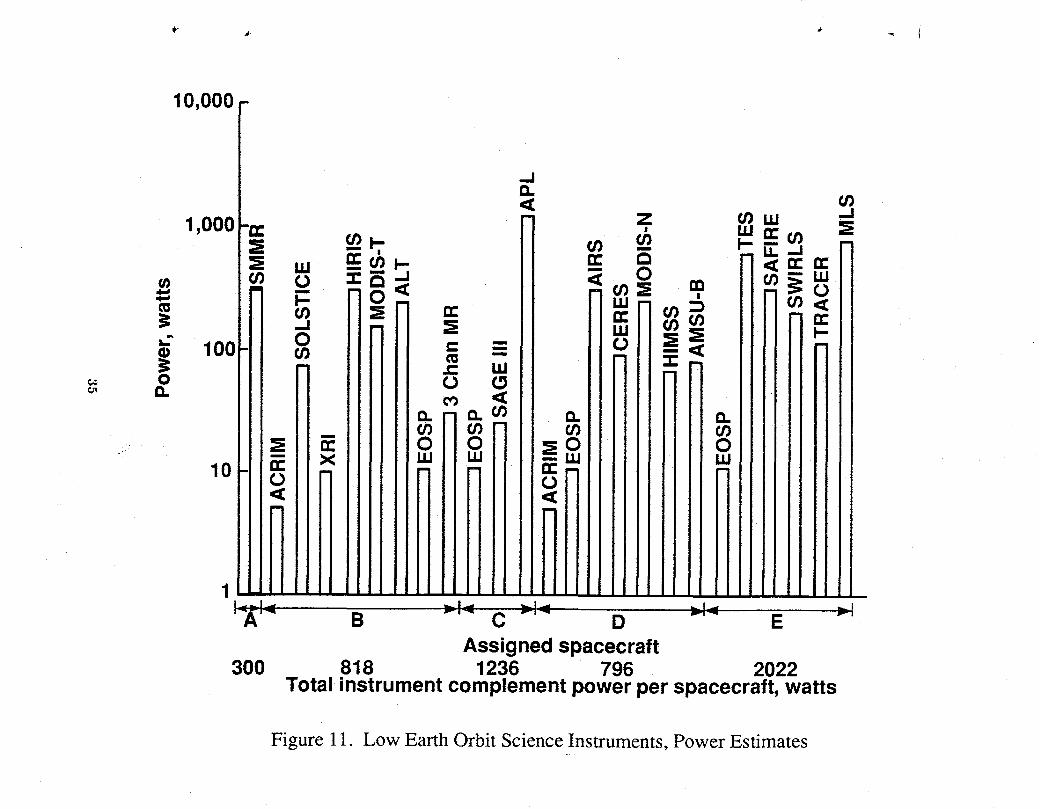
Figure 11. Low Earth Orbit Science Instruments, Power Estimates

1000 -_- Ave. = Clear bar-r Peak = Shaded & clear bar
100 _-, !
10 _ _ u_
01 = l
€_ ,,.I
O.Ol oO_i
o.ool i
0.0001'-._- B -'- C"- D -'- E -'
Assigned spacecraftAvg..001 10 1.3 11.1 10.4Peak .001 289 1.5 13.1 10.4
Total instrument data rate per spacecraft,Mbps
Figure 12. Low Earth Orbit Science Instruments, Data Rate Estimates
' ' lI \I \I \
.... / \t \ 3.8 m
' ESOP --_ t \
' tTES t \\_' I MLS I
I EOS ILaser Port _! 3 CH MR.
II_ AMSU-BAPL Telescope I
Laser Port I ...........................................IAIRS
I _ ITRACER ,'_ I
SWIRLS I===. MODIS NI ,_I
SAFIRE -,.. 12.9 m-- 14.1 m
ALT
SAGE HIllS
' i _1_ CERES
MODIS T #1, #2
II I
MMS _ I"_ .....i1 ' I| II I t
, ' 1.9 mTitan --_ _ _ _,
Interface "_ il, ,
Y
[_ _ /
"P- Platform ___- /_ (3.4 m)Shroud(4.6 m dia)
Figure13(a). Layoutof Instrumentsand AccommodationWithina TitanShroudforthe LargeSpacecraftConfigurationsL-I.
37
; ' TI \I \/ \I \/ _ 3.8 m ,I \
' ' 1\| oI
_ LargeTitanShroud
ESOP -_MLS
i EOSITES --_ I
i _ 7.8 mI II AMSU-B 14.1 m
TR II AIRS .,,.....-
SWIRLS--- I II
I MODIS NI
SAFIRE _ iICERES#1, #2
II
MMS-_, ,_ ti 1.9mTitan I
Interface I _, '_I
i _--Platform(3.4 m) --_Shroud
J (4.6 m dia)
Figure 13(b). Layout of Instruments and Accommodation Within a Titan Shroud for "--.JtheLargeSpacecraftConfigurationsL-2, L-3 andL-4.
38
LEOsystems, j " GEOsystemsL1
_°'°°°I _ 1
Ifi , o18000 _ Shuttle-C
L2 _ BIk1/Centaur
0_-1 _ = orAssemble600 _ atSSF
40001-!
- 0 n== C D
2000 _ _ _ 1
NumberofS/C 1 ) p___6tran/3onl 1 19 !
Payloadmass.45 .417 .33 ._0 .4 .49 .2fractions .--- TitanIV/--.4
Deltaspacecraftoption Centaur J
• Figure 14. GCT Architecture Study Spacecraft/Platform Mass Estimates.
B of the small spacecraftoption and spacecraftL1 of the largespacecraftoption, the maximumdata
rate for both Option 1 and Option 2 is the 45.8 MBPS that occurs with the geostationary spacecraft
G1. Thus, the nominal range for the majority of the spacecraft is .001 to 45.8 MBPS with the
peak value 0f289 to 314 MBPS occurring on only one spacecraft in each option due to a single
instrument. A detailed discussion of instrument data rates and a concept for data management is _7
presented in reference 14.
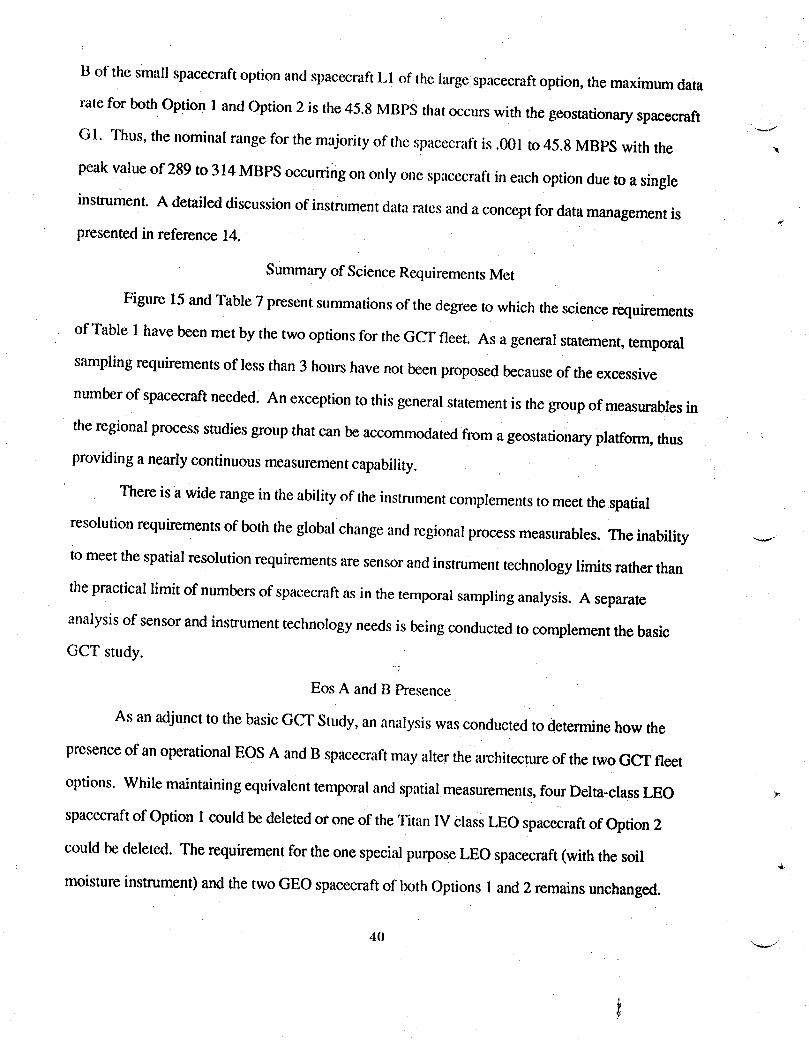
Summary of Science RequirementsMet
Figure 15 and Table 7 present summationsof the degree to which the science requirements
of Table 1 have been met by the two options for theGCT fleet. As a general statement, temporal
sampling requirements of less than 3 hours have not been proposed because of theexcessive
number of spacecraftneeded. An exception to this general statement is the group of measurables in
the regional process studies group that can be accommodatedfrom a geostationary platform, thus
providing a nearly continuous measurementcapability.
There is a wide range in the abilityof the instrument complementsto meet the spatial
resolution requirements of both the global change and regional process measurables. The inability
to meet the spatial resolution requirementsare sensor and instrument technology limits rather than
the practical limit of numbers of spacecraft as in the temporal samplinganalysis. A separate
analysis of sensor and instrument technology needs is being conducted to complement the basic
GCT study.
Eos A and B Presence
As an adjunct to the basic GCT Study, an analysis was conducted to determine how the
presence of an operational EOS A and B spacecraftmay alter the architectureof the two GCT fleet
options. While maintaining equivalent temporaland spatial measurements, four Delta-class LEO ,,
spacecraftof Option 1could be deleted or one of the Titan IV class LEO spacecraftof Option 2
could be deleted. The requirement for the one special purpose LEO spacecraft (with the soil
moisture instrument) and the two GEO spacecraft of both Options 1and 2 remains unchanged.
4(1
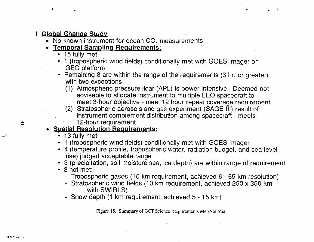
! Global Change Study• No known instrument for ocean CO2measurements• Temporal Sampling Requirements:
• 15 fully met• 1 (tropospheric wind fields) conditionally met with GOES imager on
GEO platform• Remaining 8 are within the range of the requirements (3 hr. or greater)
with two exceptions:(1) Atmospheric pressure lidar (APL) is power intensive. Deemed not
advisable to allocate instrument to multiple LEO spacecraft to' meet 3-hour objective - meet 12 hour repeat coverage requirement
(2) Stratospheric aerosols and gas experiment (SAGE Iil) result ofinstrument complement distribution among spacecraft- meets12-hour requirement
• Spatial Resolution Requirements:• 13 fully met• 1 (tropospheric wind fields) conditionally met with GOES Imager• 4 (temperature profile, tropospheric water, radiation budget, and sea level
rise) judged acceptable range• 3 (precipitation, soil moisture sea, ice depth) are within range of requirement° 3 not met:
- Tropospheric gases (10 km requirement, achieved 6 - 65 km resolution)- Stratospheric wind fields (10 km requirement, achieved 250 x 350 km
with SWIRLS)- Snow depth (1 km requirement, achieved 5 - 15 km)
Figure 15. Summary of GCT Science Requirements Met/Not Met
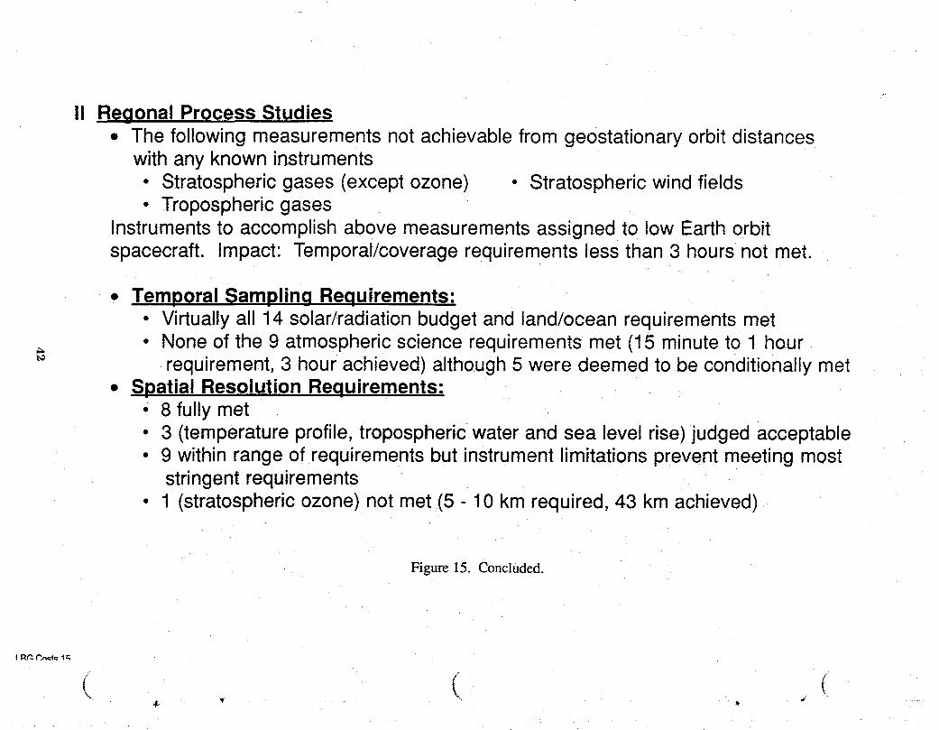
II Reqonal Process Studies• The following measurements not achievable from geostationary orbit distances
with any known instruments• Stratospheric gases (except ozone) • Stratospheric wind fields• Tropospheric gases
Instruments to accomplish above measurements assigned to low Earth orbitspacecraft. Impact: Temporal/coverage requirements less than 3 hours not met.
• Temporal Samplinq Requirements:• Virtuallyall 14 solar/radiationbudgetand land/ocean requirementsmet
,. * None of the 9 atmospheric science requirements met (15 minute to 1 hourrequirement, 3 hour achieved) although 5 were deemed to be conditionally met
• Spatial Resolution Requirements:• 8 fully met• 3 (temperature profile, tropospheric water and sea level rise) judged acceptable• 9 within range of requirements but instrument limitations prevent meeting most
stringent requirements• 1 (stratospheric ozone) not met(5 - 10 km required, 43 km achieved)
Figure 15. Concluded.
- & _
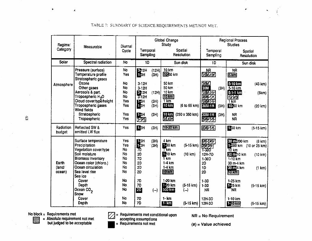
TABLE 7: SUMMARY OF SCIENCE REQUIREMENTS MET/NOT MET.
GlobalChange RegionalProcessRegime/ Measurable Diurnal Study StudiesCategory Cycle Temporal Spatial Temporal Spatial
Sampling Resolution Sampling Resolution
Solar Spectralradiation No 1D Sundisk 1D Sundisk
Pressure(surface) No [_2H (12H) 10km NR NRTemperatureprofile Yes lull-- (3H) _ km I_Stratosphericgases
(3H; 5-10km
AtmosphereOzone No 3-12H 50km (43kin)Othergases No 3-12H 50km
Aerosols&part. No (12H) 10km (5kin)TroposphericH_OCloudcover/type/height Yes D3H (3H) 1km 1kmTroposphericgases Yes D3H (3H) (6to65km) (3H)!1_50 km (20kin)Windfields
'_ TroposphericStrat°sphericYesYeS_1_ (3H) _ (250x350km) _ (3H) NRNR
RadiationReflectedSW& Yes Q3H (3H) _:_ii] _ D30 km (5-15km)budget emittedLWflux
Surfacetemperature Yes _[_H (3H) 4kin-1-kin _ _k20_mkm (Skin)iPrecipitation Yes H (3H) B30km (5-15kin) (10or25kin)Vegetationcover/type No 10kmSoilmoisture No 2D _10 km (10km) 12H-TD !_10 km (10kin)Biomassinventory No 7D 1km 1-30D 1-10km
Earth Oceancolor(chloro.) No 2D 1-4km 2D 30m-4km(land/ Oceancirculation No 2D 1.4km 1D Ik'_l_4km (1kin)ocean) Sealevelrise No 2D 2D
SeaiceCover No 7D 1-20km 1-3D 1-25kmDepth No 7D li_km (5-15kin) 1-3D 1_25km (5-15kin)
OceanCO2 No W (--) _ (-) NR --NRSnow
Cover No 7D 1-km 12H-3D 1-10kmDepth No 7D (5-15km) 12H-3D _ (5-15km)|I 1_31
Noblock-- Requirementsmet _ = Requirementsmetconditionalupon NR= No Requirement= Absolulerequirementnotmet acceptingassumptions
butjudgedtobeacceptable l = Requirementsnotmet (#) = Value achieved
: A summary of the GCT fleet architecturewith and withoutan operationalEos A and B is presented
in Table 8. A more detailed presentation of the adjunct study is presented in referenee 15.
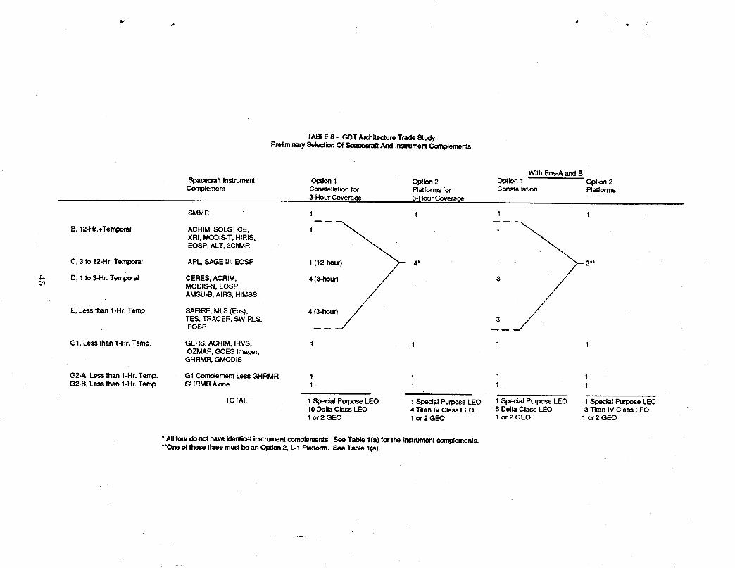
TABLE8- GCTArchitectureTradeStudyPreliminarySelectionOfSl_aCecraftAndInstrua_ntComplements
With Eos-A and BSpacecraft Instrument Option I Option 2 Option 1 Option 2
Cor_nt Constellationfor Platformsfor Constellation Platforms
3-Hour Coverage 3-Hour Coverage
SMMR 1 1 1 1
B, 12-Hr.+Temporal ACRIM, SOLSTICE, 1XRI, MODIS-T, HIRIS,EOSP, ALT, 3ChMR
C, 3 to 12-Hr. Temporal APL, SAGE lit, EOSP 1 (12-hour) 4" 3*"
_ D, 1 to 3-Hr. Tent>oral CERES,MoDIS.N,ACRIM,EoSP, 4 (3-hour) _ 3
/AMSU--B,AIRS, HIMSS
E, Less than 1-Hr. Temp. SAFIRE, MLS (Eos), 4 (3-hour) 7TES, TRACER, SWIRLS, _/EOSP
G1, Less than 1-Hr. Temp. GERS, ACRIM, IRVS, 1 1 1 1OZMAP, GOES Imager,GHRMR, GMODIS
G2-A ,Less than 1-Hr. Temp. G1 Complement Less GHRMR 1 1 1 1G2-B, Less than 1-Hr. Temp. GHRMR Alone 1 1 1 1
TOTAL 1 Special Purpose LEO 1 Special PurposeLEO 1 Special Purpose LEO 1 Special Purpose LEO10 Delta Class LEO 4 "l'danIV Class LEO 6 Delta Class LEO 3 Tdan IV Class LEO1 or 2 GEO 1 or 2 GEO 1 or 2 GEO 1 or 2 GEO
• All four donothaveidenticalinstrumentcomplements.SeeTable l(a) forthe instrumentcomplements."*Oneof thesethreemustbe anOption2, I.-1 Platform.SeeTablel(a).
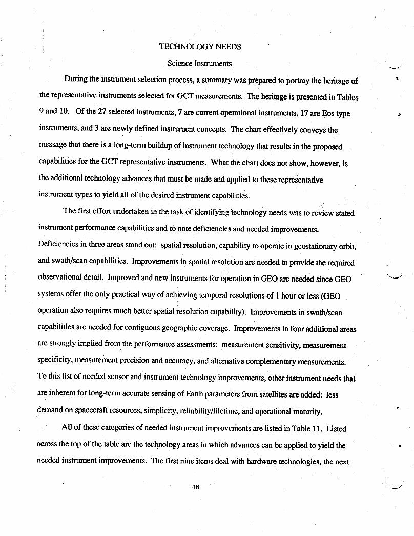
TECHNOLOGYNEEDS
Science Instruments
During the instrument selectionprocess,a summarywas prepared to portray the heritage of "
the representative instruments selectedfor GCT measurements. The heritage is presented in Tables
9 and 10. Of the 27 selected instruments, 7 arecurrentoperational instruments,17 areEos type
instruments, and 3 are newly defined instrumentconcepts. The charteffectively conveys the
message thatthere is a long-termbuildupof instrumenttechnology thatresultsin the proposed
capabilities for the GCT representative instruments. What the chart does not show, however, is
the additional technologyadvances that mustbe made and applied to these representative
instrument types to yield all of the desired instrumentcapabilities.
The f'trsteffortundertakenin the taskof identifyingtechnology needs was to reviewstated
instrument performance capabilities and to notedeficiencies and needed improvements.
Deficiencies in three areasstand out: spatialresolution,capability to operate in geostationaryorbit,
and swath/scan capabilities. Improvements in spatialresolutionare needed to providethe required
observational detail. Improved and new instrumentsfor operation in GEO are needed since GEO "-"/
systems offer the only practical way of achieving temporal resolutionsof 1 hour or less (GEO
operation also requires much better spatial resolution capability). Improvementsin swath/scan
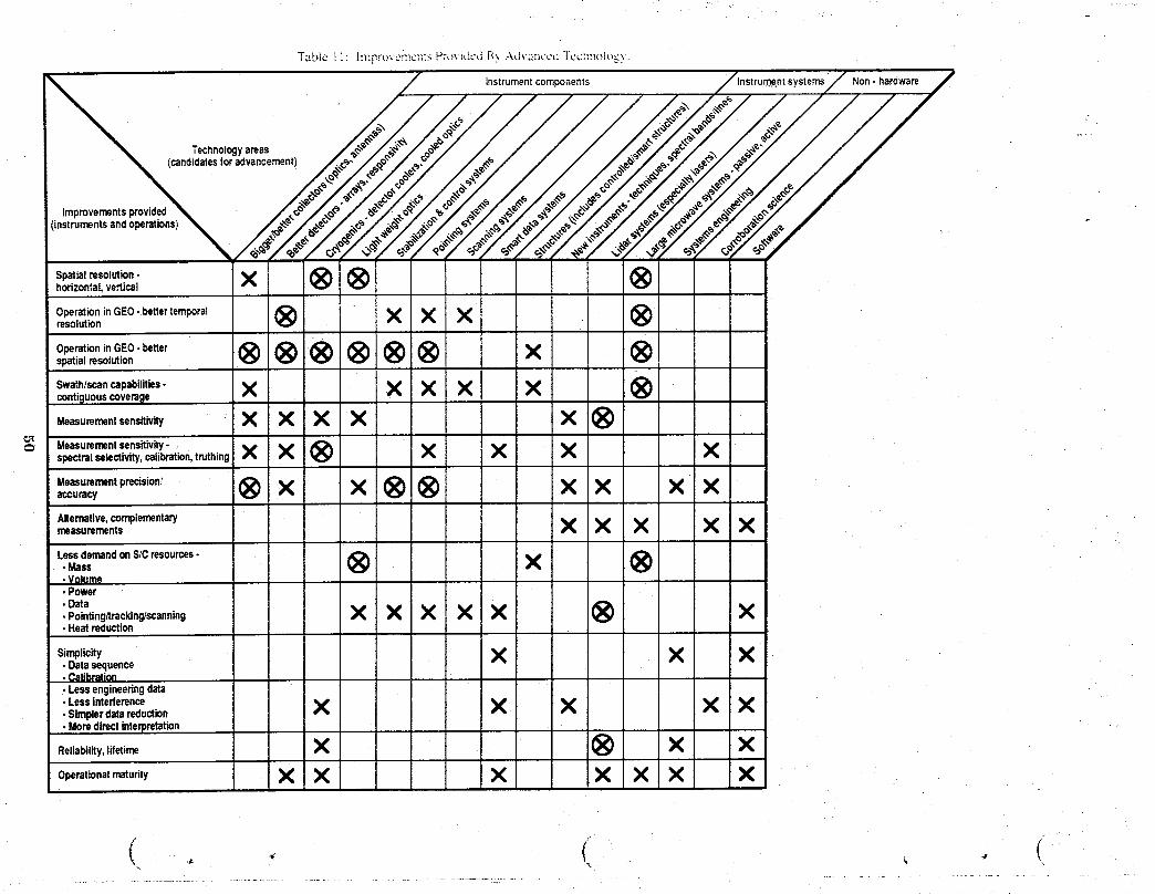
capabilities are needed for contiguous geographiccoverage. Improvementsin four additional areas
are stronglyimplied from the performance assessments: measurement sensitivity,measurement
specificity, measurement precision and accuracy, and alternativecomplementarymeasurements.
To this list of needed sensor and instrument technology improvements,other instrument needs that
are inherent for long-term accurate sensing of Earth parameters from satellitesare added: less
demand on spacecraft resources, simplicity,reliability/lifetime,and operationalmaturity. _"
All of these categoriesof needed instrumentimprovements are listed in Table 11. Listed
across the top of the table are the technology areas in which advances can be applied to yield the
needed instrument improvements. The first nine items deal with hardware technologies, the next
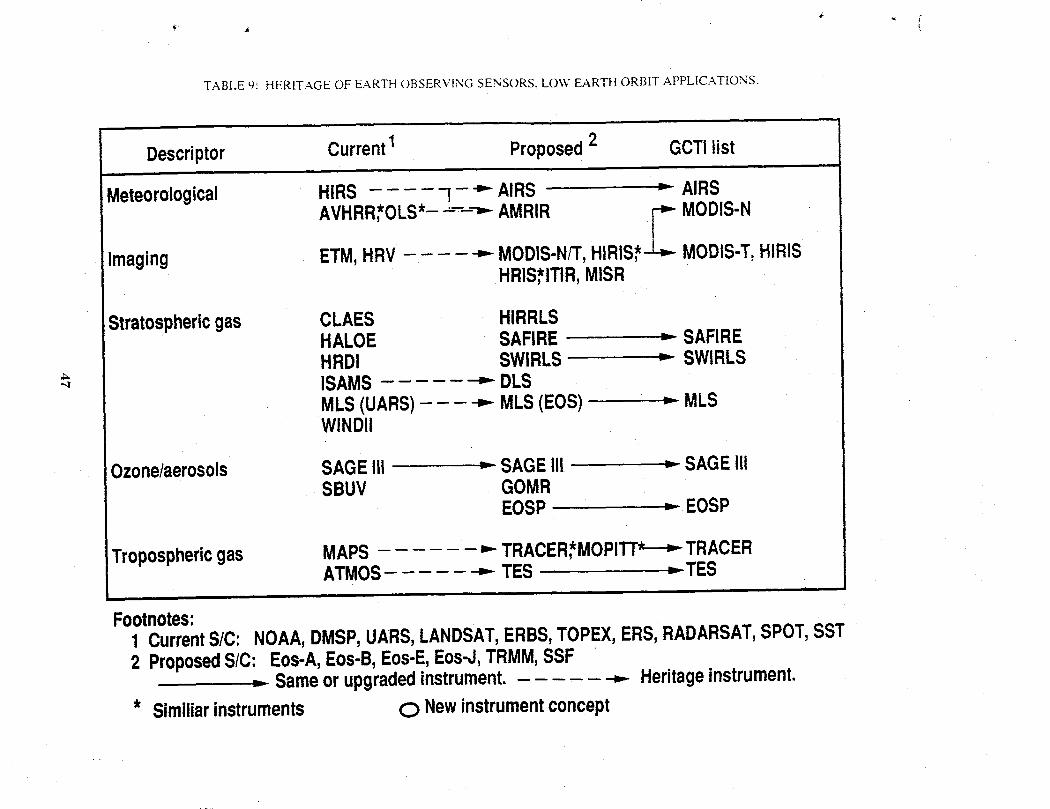
TABLE 9: HERITAGE OF EARTH OBSERVING SENSORS, L(.)\V EARTH ORBIT APPLICATIONS.
Descriptor Current1 Proposed2 GCTIlist
Meteorological HIRS l -'" AIRS = AIRS
AVHRR,*OLS*--'---=-AMRIR _-- MODIS-N
Imaging ETM,HRV _ MODIS-N/T,HIRIS,*-_ MODIS-T,HIRISHRIS,*ITIR,MISR
Stratosphericgas CLAES HIRRLSHALOE SAFIRE -_ SAFIREHRD! SWIRLS = SWIRLS
"-, ISAMS _ DLSMLS(UARS) _ MLS(EOS) = MLSWlNDII
Ozone/aerosols SAGEIII = SAGEIii = SAGE111SBUV GOMR
EOSP = EOSP
Troposphericgas MAPS _ TRACER*MOPI_ TRACERATMOS _ TES = TES
i i
Footnotes:1 CurrentS/C: NOAA,DMSP,UARS,LANDSAT,ERBS,TOPEX,ERS,RADARSAT,SPOT,SST2 ProposedSIC: Eos-A,Eos-B,Eos-E,Eos-J,TRMM,SSF
= Sameorupgradedinstrument. _ Heritageinstrument.* Similiarinstruments O Newinstrumentconcept

TABLE _):_CONCLUDED).
3
Descriptor CurrentI Proposed2 GCTIlist
Microwave AMSU,SSM-T, = AMSU = AMSU(B)Radiometer ATSR
SSMI _ HIMSS,AMSR* = HIMSS
MIMR,*AMIR,*ESMR@
Activesystems ALT(+3CMR) =--ALT = ALT(+3CMR)- AMI,*SAR* .= AMI,*SAR*
RSCAT _ SCANSCAT_- ATLIDO_
LAWSGLRSLASAEagle _ _PL_
Solar ACRIM =-ACRIM = ACRIMSOLSTICE - SOLSTICE _ SOLSTICEPEM ENAC,POEMSSUSIM
XRI = XRI
Radiationbudget ERBE ,..-CERES -= CERES
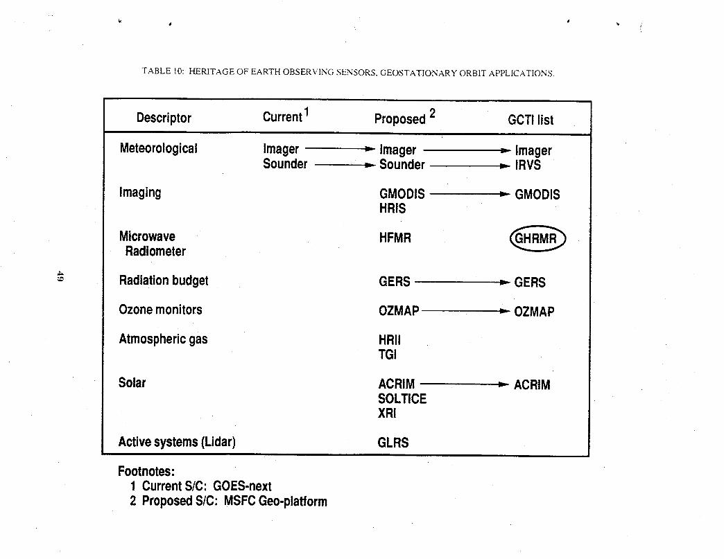
TABLE 10: HERITAGEOF EARTHOBSERVING SENSORS,GEOSTATIONARY ORBIT APPLICATIONS.
Descriptor Current1 Proposed2 GCTIlist
Meteorological Imager = Imager ,- ImagerSounder .= Sounder = IRVS
Imaging GMODIS = GMODISHRIS
Microwave HFMR _Radiometer
Radiationbudget GERS =--GERS
Ozonemonitors OZMAP = OZMAP
Atmosphericgas HRiiTGI
Solar ACRIM = ACRtMSOLTICEXRI
Activesystems(Lidar) GLRS
Footnotes:1 CurrentS/C:GOES-next2 ProposedS/C:MSFCGeo-plafform
T_lbie i i: h_:_rovcmc_stsP:o',idcd _.\ .-\d\4iiccd Tcc!/_lolo_>.
Instrumentcomponents systems Non- hardware
Technologyareas(candidatesforadvancement)
Improvementsprovidedinstrumentsandoperations)
Spatialresolution• X _ _ ®horizontal,vertical
OperationinGEO-bettertemporat @ X X X @resolution
OperationinGEO- better=,=_,=_n @®®@@@ x ®Swathlscancapabilities- X X X X X @conti_lUOUScovetable
Me=umment.nsitiv_ X X X X X @
Measurementsensitivity. 'spectralselectivity,calibration,truthing X X @ X X X X
.oo.._.o,_,.,oo,®x x®® xx xxaccuracy
Alternative,complementarymeasurements X X X X X
LessdemandonSICresources-... ® x ®• Volume• Power• Data• Pointing,tracking/scanning X X X X X @ X• Heatreduction
simp,_,y X X X• Datasequence• Calibration• Lessengineeringdata
• Lessinterlerence X X X X X• Simplerdatareduction• Moredirectinterpretation I
Reliability,lifetime X @ X X
Operationalmetudty X X X X X X X

three deal with the complete instrument system, and the last three deal with non-hardware
technology A need for a particular technologyto providea particular instrument improvementis
designated by x. Strong needs are designated by an _. This matrix represents an initial attempt atat
scoping the technology needs for GCT instruments.
By necessity the technology needs for the three new instrument conceptsselected for GCT
had to be addressed. The selectionof the Geostationary High Resolution Microwave Radiometer
(GHRMR) and the Soil Moisture Microwave Radiometer(SMMR) forced a look at the
technologies involved in large aperture multi-frequencymicrowave passive systems (see column
12 of the needs chart). Jeffery Farmer et al. (ref. 11)in defining the GHRMR anticipated
technology advances in the areas of large antennas, structures,controls, and microwave signal
detection in order to develop a space flight instrument system with adequate sensitivity and spatial
resolution when operating in geostationary orbit. Melvin Ferebee et al., (ref. 12) in defining a
concept for the SMMR, primarily addressed the largecollector (including structuresand controls)
technologies in order to obtain adequatespatial resolution at the low microwave frequency required
for sensing moisture in various soils to usable depths in the order of 12 cm or more.
The third new GCT instrument is a concept for the measurement of surfacepressure. The
instrument has been titled Atmosphere Pressure Lidar (APL). The selectionof APL forced a look
at lidar system technology needs (see column 1 of the needchart). The measurementprinciple is
based on the experimental work of Korb et al. (ref. 16)at the NASA Goddard Space Flight Center.
The Earth Observing Syslem Volume 1ld, LASA documentdescribes the principle as it could be
employed in a Lidar Atmospheric Sounder and Altimeter instrumentas follows: "The surface
pressure experiment is a two-wavelengthDIAL measurement utilizingthe backscatteredenergy
from the Earth's surface or from low-lying clouds. A pressure-sensitive measurement is obtained
by locating one wavelength in a temperature insensitiveabsorption trough region. A trough region
is the region of minimum absorption between two strongly absorbing lines in the oxygen A-band
near 0.76 }.tm,or 13,150 cm-1. The absorption in the trough is proportional to the square of the
51
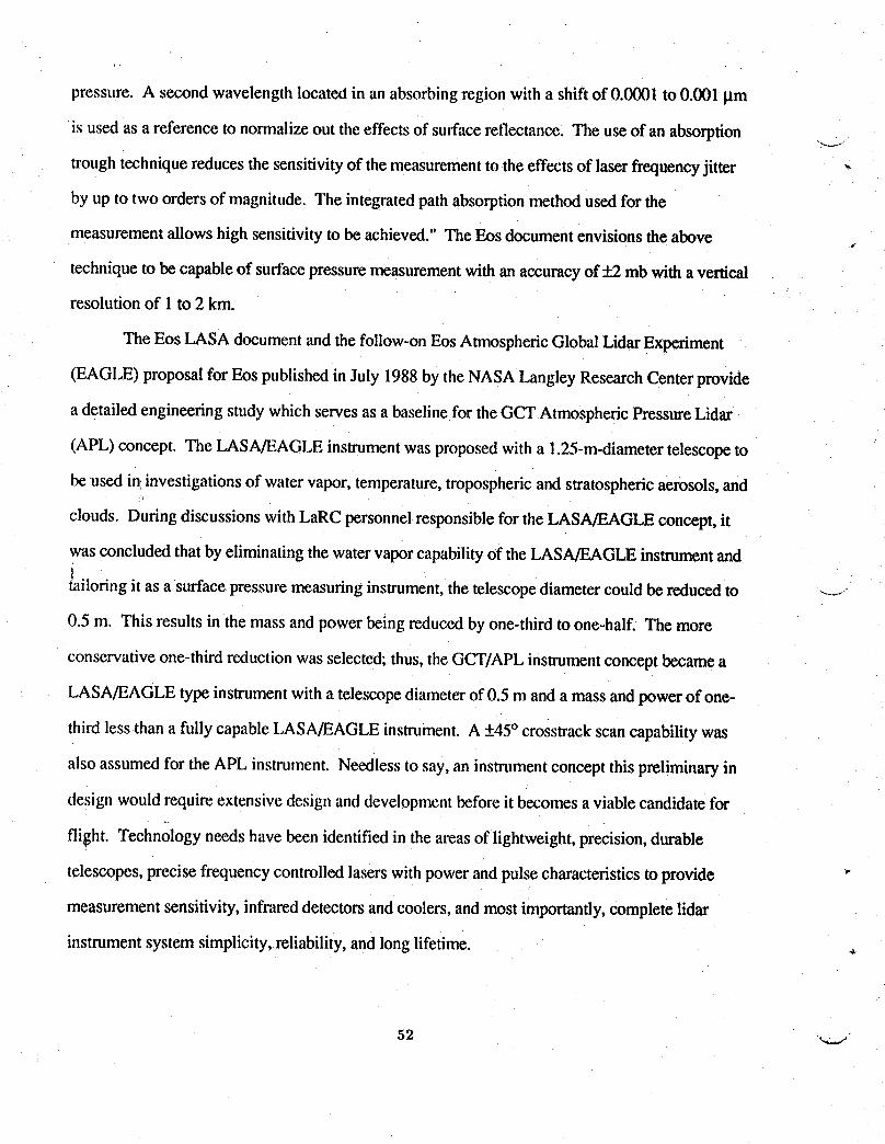
pressure. A second wavelength located in an absorbing regionwith a shift of 0.0001 to 0.001 l.tm
is used as a reference to normalize out the effects of surfacereflectance. The use of an absorption
trough technique reduces the sensitivityof the measurementto the effects of laser frequencyjitter '-
by up to two orders of magnitude. The integrated path absorptionmethod used for the
measurement allows high sensitivity to be achieved." The Eos document envisions the above
technique to be capable of surface pressure measurement with an accuracyof_'_ mb with a vertical
resolution of 1to 2 km.
The Eos LASA document and the follow-,onEos Atmospheric Global Lidar Experiment
(EAGLE) proposal for Eos published in July 1988 by the NASA Langley Research Center provide
a detailed engineering studywhich serves as a baseline for the GCT AtmosphericPressure Lidar
(APL) concept. The LASA/EAGLE instrument was proposed with a 1.25-m-diametertelescope to
be used in investigations of water vapor, temperature, troposphericand stratosphericaerosols, and
clouds. Duringdiscussions with LaRC personnel responsible for the LASA/EAGLE concept, it
wasconcluded that by eliminating the water vapor capability of theLASA/EAGLE instrumentand
Itailoringit as a surfacepressure measuringinstrument, the telescopediameter could be reduced to ---..-.
0.5 m. This results in the mass and power being reduced by one-third to one-half. The more
conservative one-third reduction was selected;thus, the GCT/APL instrumentconcept became a
LASA/EAGLE type instrumentwith a telescopediameter of 0.5 m and a mass and power of one-
third less than a fullycapable LASA/EAGLE instrument. A +45° crosstraekscan capability was
also assumed for the APL instrument. Needless to say, an instrument concept this preliminary in
design would require extensive design and development before it becomes a viable candidate for
flight. Technology needs have been identified in the areas of lightweight,precision, durable
telescopes, precise frequency controlled lasers with power and pulse characteristics to provide
measurement sensitivity, infrared detectors and coolers, and most importantly, complete lidar
instrument system simplicity, reliability, and long lifetime.

The need for the three new GCT instrument concepts and the general technology needs
matrix presented in Table 11illustrate the need for an extensive instrument development program.
The detailing of the elements of this program is a major follow-on task. This task is to be4'
undertaken separately by appropriate instrument specialists at the Langley ResearchCenter. To
conclude this section of this report, therefore, we have only their introductory narrative which
addresses the general technical areas of detectors, cryogenic coolers, lightweight optics, and lasers.
Detectors
The majority of Eos proposalsreflects significant instrument performance benefits obtained
through the use of arrayed detectors, as compared with single element detectors or a few point
detectors, as were used in the 1980s. Dectector arrays for the mid-infrared wavelengths from 2 to
20 I.tmhaverecently become availablethat exhibit greatlyincreased capability whilebeing virtually
identic',din size and mass to previouslyavailable designs. This improvement is reflected in better
experiment radiometric sensitivity and spectral or spatial resolution. Currently, arrayed mid-
infrared (up to 10 l.tm)detectors in line arrays on the order of a hundred detectors and area arrays
..... of up to 64 by 64 elements are available. In the next decade these detectors should become more
available with their capability size, and cost further improved. Active, remote sensors such as
lidars would benefit from the development of improvedAvalanche Photo Dectectors or other solid
state detectors capable of photon noise limited performance in the 0.7 to 2.0 I.tmrange. This is just
longward of the wavelength range where multiplier-photo tubes can operate. This improved
performance would benefit the very important water vapor, pressure, and temperature profile
measurement made with iidar instruments. Earth budget remote sensing experiments from GEO
with temporal sampling capability of fraction of hours would be enabled through the development
., of cryogenically cooled active cavity receiver detectors. Thesedetectors have been shown in the
laboratory to be capable of nano-watt sensitivity.
5"_
i/
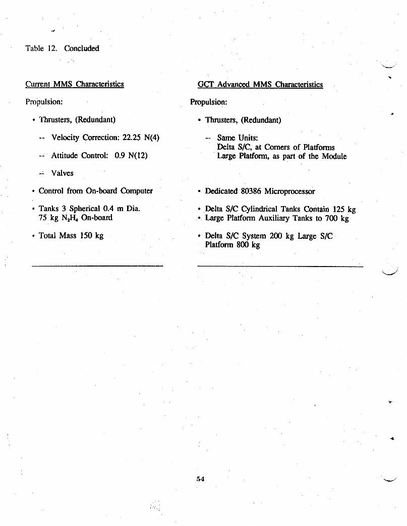
Table 12. Concluded
CurrentMMS Characteristics GCT Advanced MMS Characteristics
Propulsion: Propulsion:
• Thrusters, (Redundant) • Thrusters, (Redundant)
-- Velocity Correction: 22.25 N(4) -- Same Units:Delta S/C, at Comers of Platforms
-- Attitude Control: 0.9 N(12) Large Platform, as part of the Module
-- Valves
• Control from On-board Computer • Dedicated 80386 Microprocessor
• Tanks 3 Spherical 0.4 m Dia. ° Delta SIC Cylindrical Tanks Contain 125 kg75 kg N2I-hOn-board ° Large Platform Auxiliary Tanks to 700 kg
• Total Mass 150 kg ° Delta S/C System 200 kg Large S/CPlatform 800 kg

Cryogenic Coolers
..... Remote sensor measurements can be widened in scope and substantially improved with
high capability, efficient cryo-coolers with operational life times of 5 years. Coolers are needed for
several types of applications:
(1) Cold Optics: Remote sensors looking Earth-ward from space view a scene that is at
approximately 250 K. Optimum instrument performancefor this level of scene photon flux
requires the instrument optics to operate at intermediatelycold temperaturesof approximately150 K.
(2) Detector Coolers: A great numberof applicationsrequire detectors operating at liquid nitrogen
temperature. An energy efficient, reliable 5-year life cryo-cooler delivering 1 W at 80 K is needed.
The cooler should impart a negligiblemechanicalvibration level to the alignment sensitive
instrument focal plane assembly.
(3) High Capability Coolers: The sensitivity of detectors ranging in spectral frequency over the
entire mid-infrared spectrum would be much improved if a cryo-cooler capable of a 1W load at
20 K were available. For far-infrared (20 to 500 microns) experiments efficient long-life cryostats
are needed. Present technology provides hybrid coolers that use a liquid helium dewar with coldi
shields held at intermediate, progressivelycolder (30, 80, and 150 K) temperatures.
LightweightOptic,s
Space based lidar instruments must use receiver telescopes on theorder of 1 m in diameter
to attain the desired sensitivity. Far-infrared and other remote sensing instruments also use large
diameter optics to maintain small diffractioneffects as compared with spatial resolution; however,
the need for large optics contrasts with the need for low instrument mass for efficient launch in
,, space. The development of lightweightoptical systems can thus contribute greatly to reducing
latmchcosts while maintaining performance. Present technology is on the verge of producing
diffraction limited optical elements with a mass of 20 kg/m2for optical element diameters of up to
1 m. Several technologies capable of this low density are presently being pursued:
55
(1) Silicon-Carbidemirrors where the materialis vapor deposited on a carbon mandrel,
(2) chemically milledAluminum mirrors where lightningholes arechemicallymachinedinto the
mirror blank, and (3) Fritted Glass where two thin glass face-plate blanks are spaced by a set of
thin-wall glass tubes fused in between. These techniques need to become more available to be cost
effective. To reach the full potential of mass savings, it is imperative that the optics support j_
structure, i.e,, the telescope structure,also be light weight while element de-space and tilts are
controlled to the needed tolerances by a meteringsystem.
Lasers
To perform adequately, atmosphericparticle and gas lidars and differential absorptionlidars
(DIAL) require non-tunable (albeit multi-spectral)and tunable laser outputs respectivelyof at least
one and preferably two Joules per pulse at pulse repetition rates of 10 Hz or more. Qualified lasers
of this output level have not been flown in space. LaRC's LITE project will use a 1.5-Joule-per-
pulse class, three color (1.064, 0.532, 0.352 l.tm)laser for atmospheric constituent and wind
sensing. For the post year-2000 time period,lasers will need to use diode pumping to increase
their efficiency and reduce laser power requirements. The laser power consumption, and the waste "-_.J
heat they generate that needs to be rejected to spacewith bulky radiators, can be reduced from the
several thousand watts required for flashlamp pumped systems to the order of a few hundred watts
! with diode pumps.
Spacecraft and Subsystems
The study identified spacecraft and subsystem areas where technology advances will enable
i or enhance the systems. Some of the technology improvementsare already in work and were
incorporated into the spacecraft and platform designs. There are other elements where good,
reliable engineering designs and system integrationare sufficient using current technology. "_
Technology developments and demonstrations are mandatory for the large antenna
structures. If we are to provide the required sizes and surface accuraciesto meet the resolution
requirements, then these antenna must be packaged for htunchand either deployed or assembled
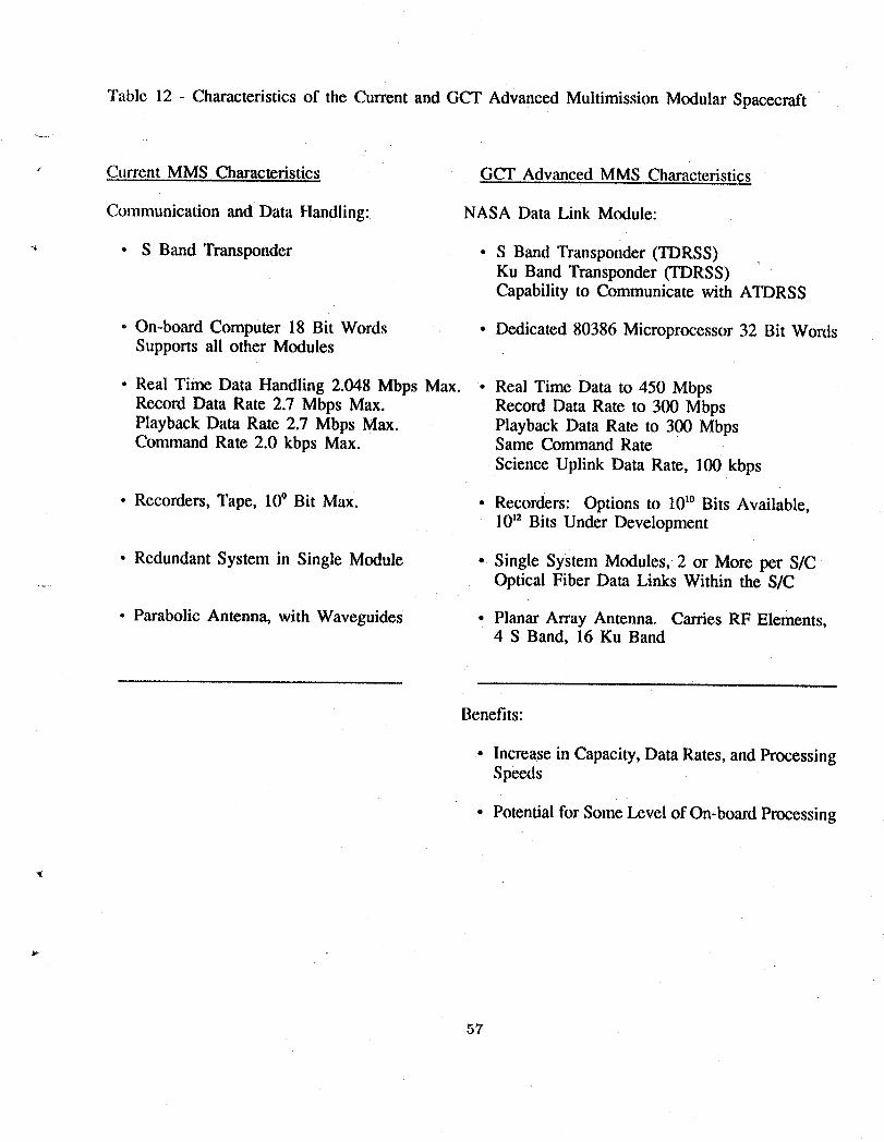
Table 12 - Characteristics of the Current and GCT Advanced Multimission Modular Spacecraft
x Current MMS Characteristics GCT Advanced MMS Characteristics
Communication and Data Handling: NASA Data Link Module:
-' • S Band Transponder • S Band Transponder (TDRSS)Ku Band Transponder (TDRSS)Capability to Communicate with ATDRSS
° On-board Computer 18 Bit Words • Dedicated 80386 Microprocessor 32 Bit WordsSupports all other Modules
• Real Time Data Handling 2.048 Mbps Max. * Real Time Data to 450 MbpsRecord Data Rate 2.7 Mbps Max. Record Data Rate to 300 MbpsPlayback Data Rate 2.7 Mbps Max. Playback Data Rate to 300 MbpsCommand Rate 2.0 kbps Max. Same Command Rate
Science Uplink Data Rate, 100 kbps
• Recorders, Tape, 109Bit Max. • Recorders: Options to 101°Bits Available,|0 t2 Bits Under Development
• RedundantSystem in Single Module • Single System Modules,2 or More per S/C...... Optical Fiber Data Links Within the S/C
• Parabolic Antenna, with Waveguides • Planar Array Antenna. Carries RF Elements,4 S Band, 16 Ku Band
Benefits:
• Increasein Capacity,DataRates,and ProcessingSpeeds
• Potential for Some Level of On-board Processing
57
on-orbit tOexacting tolerances. Although there is limited technology development work ongoing
on the assembly of precision reflectors, there are currently no technology programs with significant _._._
funding within NASA to develop the on-orbit deployable hardware and verify reliability. The
balance between mechanical or electronically steering of the beams has not been established. To
the extent that mechanical steering is required to point the antenna there, this could be a source of _.
significant onboard disturbances which must be isolated and/or predictably controlled by the
spacecraft. Advanced, thermally stable materials or predictably controlled structures are also
needed to maintain surface accuracies and antenna dish and feed alignments.
Design of the spacecraft recognized NASA-published technology and were guided by
active efforts within Goddard Space Flight Center to uprate the Multi-Mission Modular Spacecraft
(MMS) subsystems. Table 12 sumarizes the capabilities for each of the MM3 modules to show
current performance, planned upgrades, and any particular adaptations proposed for GCT
spacecraft applications. The modular design of spacecraft is the preferred approach in this study
which affords maximum flexibility in tailoring the individual spacecraft to meet the particular
instrument complement and mission requirements. On-orbit serviceability was not incorporated "-""
into the designs because of inaccessibility of the orbits by the STS and no firm NASA plans for
robotic servicing in polar or geostationary orbits. Specific subsystem development needs are
addressed below.
Communications and onbo_u'ddata handling requirements established a critical need for
significant advances. Data and information technologies are addressed separately; however, the
implications to spacecraft onbom'd elements imply operations that utilize imbedded high-speed
microprocessors with internal communications and data transferred through fiber optic links. Data
transmission rates exceed the Tracking and Data Relay Satellite System (TDRSS) down-link "_
capabilities and would require the Advanced TDRSS. Onboard data rates estimate established the
need for high speed optical disc recorders with storage capacities ranging up to 1012bits. _,
58
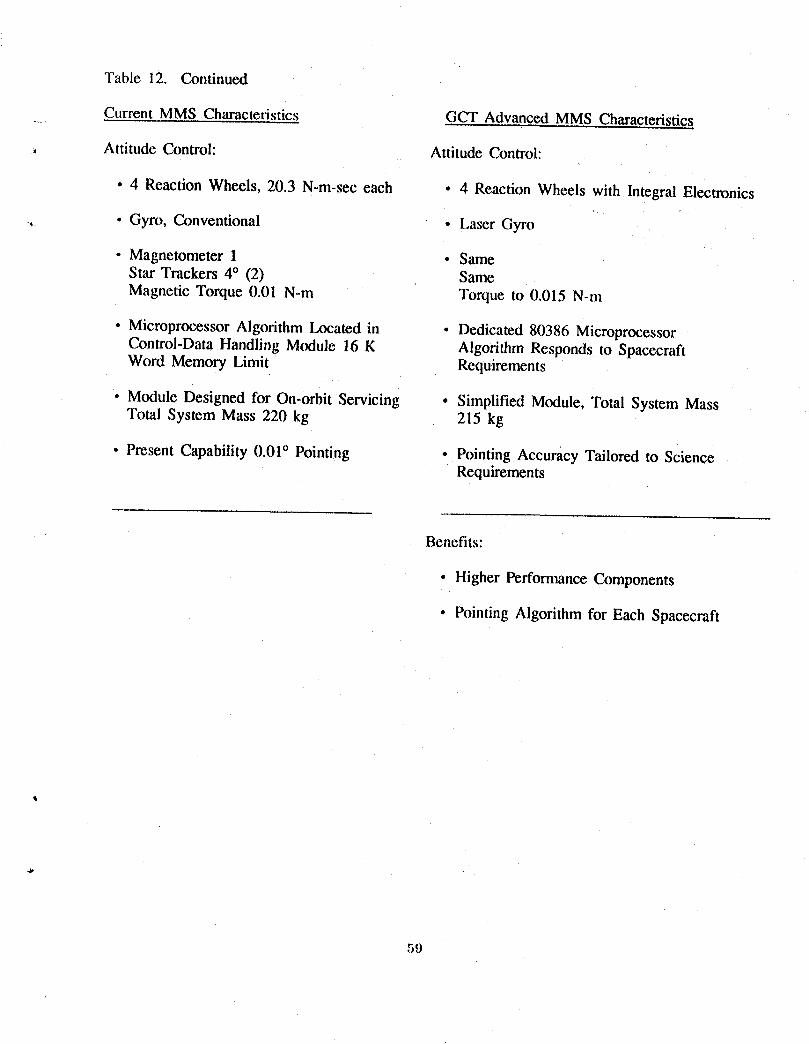
Table 12. Continued
Current MMS Characteristics GCT Advanced MMS Characteristics
, Attitude Control: Attitude Control:
• 4 Reaction Wheels, 20.3 N-m-sec each • 4 Reaction Wheels with Integral Electronics
,_ • Gyro, Conventional • Laser Gyro
• Magnetometer 1 • SameStar Trackers 4° (2) SameMagnetic Torque 0.01 N-m Torque to 0.015 N-m
• Microprocessor Algodthm Located in • Dedicated 80386 MicroprocessorControl-Data Handling Module 16 K Algorithm Responds to SpacecraftWord Memory Limit Requirements
• Module Designed for On-orbit Servicing • Simplified Module, Total System MassTotal System Mass 220 kg 215 kg
• Present Capability 0.01° Pointing • Pointing Accuracy Tailored to ScienceRequirements
Benefits:
• Higher Performance Components
• PointingAlgorithmfor Each Spacecraft
59
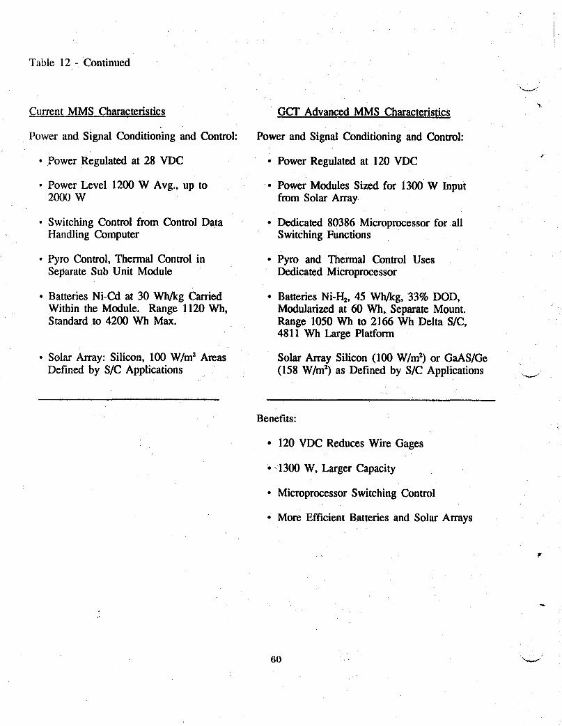
Table 12 - Continued
Current MMS Characteristics GCT Advanced MMS Characteristics
Power and Signal Conditioning and Control: Power and Signal Conditioning and Control:
• Power Regulated at 28 VDC • Power Regulated at 120 VDC
• Power Level 1200 W Avg., up to • Power Modules Sized for 1300 W Input2000 W from Solar Array
• Switching Control from Control Data • Dedicated 80386 Microprocessor for allHandling Computer Switching Functions
• Pyro Control, Thermal Control in • Pyro and Thermal Control UsesSeparate Sub Unit Module Dedicated Microprocessor
• Batteries Ni-Cd at 30 Wh/kg Carded • Batteries Ni-H2, 45 Wh/kg, 33% DOD,Within the Module. Range 1120 Wh, Modularized at 60 Wh, Separate Mount.Standard to 4200 Wh Max. Range 1050 Wh to 2166 Wh Delta S/C,
4811 Wh Large Platform
• Solar Array: Silicon, 100 W/m2 Areas Solar Array Silicon (100 W/m2) or GaAS/GeDefined by S/C Applications (158 W/m2) as Defined by SIC Applications .._1
Benefits:
• 120 VDC Reduces Wire Gages
• _1300 W, Larger Capacity
• Microprocessor Switching Control
• More Efficient Batteries and Solar Arrays
The attitude control and pointing stabilityrequirements for spacecraftin LEO appear within
the capabilities planned in an uprating of the present MMS module for use on the TOPEX and
UARS spacecraft. The larger Titan platform would use planned Eos spacecraftcontrol systems.1+
Instrumentresolution requirements tbr operation in GEO result in pointing accuracy limits that
generate need for active isolation techniques. Pointing accuracyrequirements for GCT instruments
in GEO are shown in figure 16, proposed technologies for accomplishmentare identified in figure
17in comparison with present listed capabilities. A design goal of the study was to control the
GEO spacecraft to a pointing accuracy of 5 x 10-:_degreesand utilizedynamicallyisolated scan
platforms with advanced star trackers for the fine pointingsystems. The spacecraftoperating in
GEO underscore the need for :_dynamic activecontrol system thatcan maintain the instrument
pointing within the accuracy limits while accommodating the structuralresponses associated with
onboard effects such as antenna scanning, stationkeeping,and thermal cycling.
GCT instrumentation tends to exhibit heavy powerdemands and thereby emphasize the
need for low mass elements with improved power handlingcapabilities. A minimum performance
........ equal to that identified for GaAs/Gecell end-of-life at 158W/m2 and 45 W/kg is needed.
Candidatecell systemsmeeting their requirementare under developmentand their availability
would be incorporated into any GCT configurationas a means to reduce the area of the solar array.
The instruments which require the most power also operate continuously and, therefore, require an
energy storage capability for complete orbit operation. A fullydeveloped Ni-H2 battery unit
operating at 45 W hr/kg with a 33 percent depth of discharge is needed for a GCT type mission.
An additional need is the development of a dedicated microprocessorfor Overallload management
with a power output regulated at the higher 120volts d.c. Further, the control and regulator
, elements need modularizationat power levels that allow the use of multiple units in responding to
the design requirements for individual spacecraft. Forexample, modularizationat 1300 watts
would accommodate power demands from 1 to 6 kW within the range of 5 units.41+
61
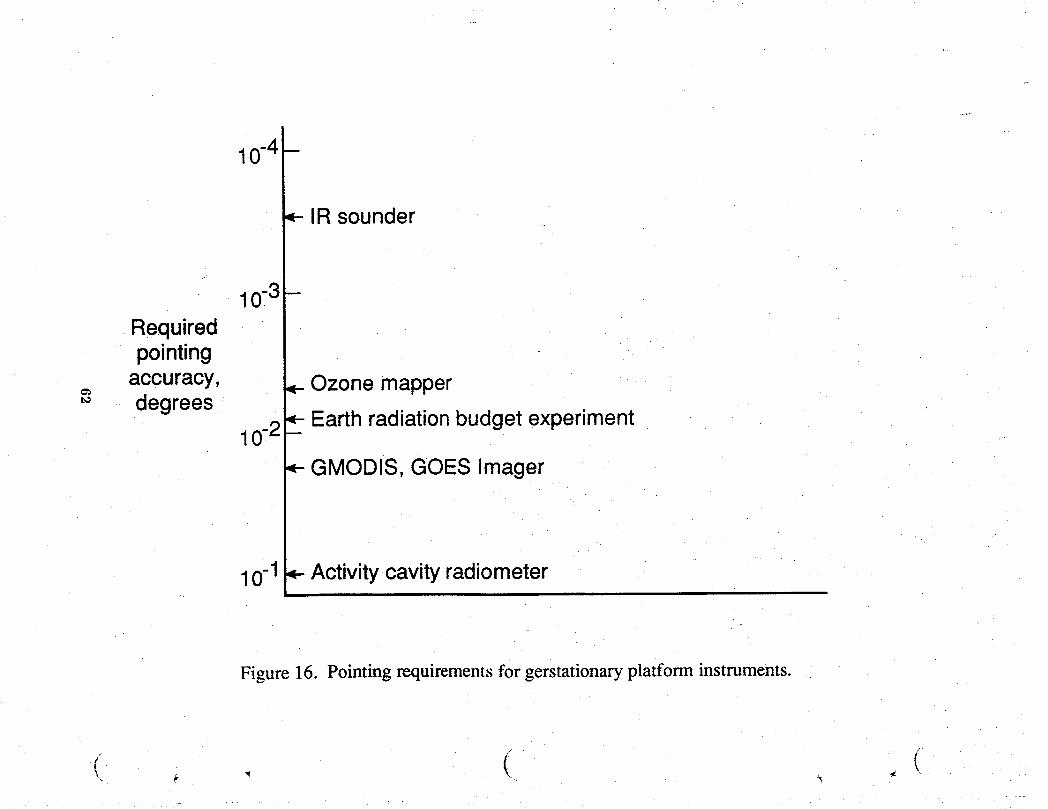
_-IR sounder
10-3 -
Requiredpointing
accuracy, Ozone mapper'_ degrees
_- Earth radiation budget experiment10-2 -
GMODIS, GOES Imager
10-1 _ Activity-cavity radiometer
Figure 16. Pointing requirements for gerstationary platform instruments.
• (( _ , ( .
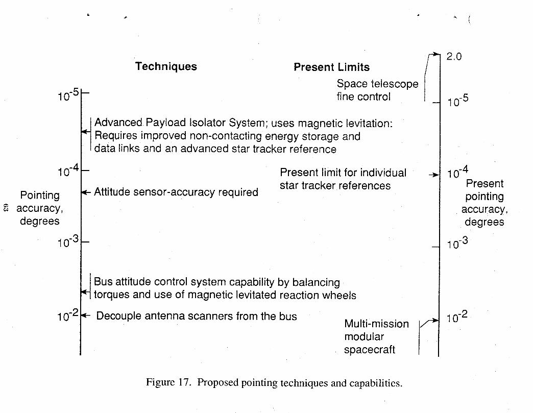
I
Techniques Present Limits /-_ 2.0
Space telescope
10-5 - fine control - 10-5
Advanced.Payload Isolator System; uses magnetic levitation:Requires improved non-contacting energy storage anddata links and an advanced star tracker reference
10-4 - Present limit for individual _ 10-4star tracker references Present
Pointing _- Attitude sensor-accuracy required pointingaccuracy, accuracy,degrees degrees
10-3- _ 10-3
Bus attitude control system capability by balancingtorques and use of magnetic levitated reaction wheels
10-2 _- Decouple antenna scanners from the bus Multi-mission / _ 10-2
modular [spacecraft
Figure 17. Proposed pointing techniques and capabilities.
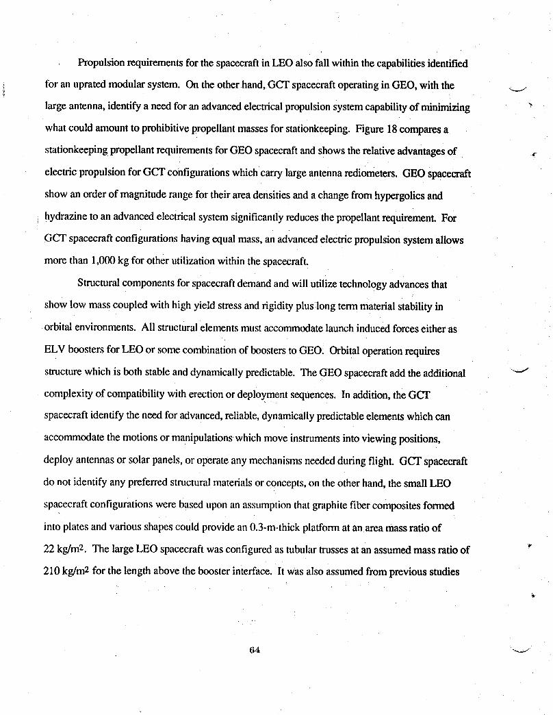
Propulsion requirements for the spacecraftin LEO also fall within the capabilities identified
for an uprated modular system. On the other hand, GCT spacecraftoperating in GEO, with the .._i.
large antenna, identify a need foran advanced electricalpropulsion system capability of minimizing
what could amount to prohibitivepropellantmasses for stationkeeping. Figure 18comparesa
stationkeeping propellant requirements for GEO spacecraftand shows therelative advantagesof ,
electric propulsion for GCT configurations which carry large antenna rediometers. GEO spacecraft
show an order of magnitude range for their area densities and a change from hypergolicsand
hydrazine to an advanced electrical system significantlyreduces the propellant requirement. For
GCT spacecraftconfigurations having equal mass, an advanced electric propulsion system allows
more than 1,000kg for other utilizationwithin the spacecraft.
Structural components for spacecraftdemand and willutilize technology advances that
show low mass coupled with high yield stressand rigidity plus long term material stability in
orbital environments. All structural elementsmust accommodate launchinduced forceseither as
ELV boosters for LEO or some combination of boosters to GEO. Orbital operation requires
structure which is both stable anddynamically predictable. The GEO spacecraftadd the additional '"-'i
complexity of compatibility with erection or deploymentsequences. In addition, the GCT
spacecraft identify the need for advanced,reliable, dynamicallypredictableelements which can
accommodate the motionsor manipulations which move instrumentsinto viewing positions,
deploy antennas or solar panels, or operate any mechanisms needed during flight. GCT spacecraft
do not identify any preferred structural materials or concepts, on the other hand, the small LEO
spacecraft configurations were based upon an assumptionthat graphite fiber composites formed
into plates and various shapes could provide an 0.3-m-thick platform at an area mass ratio of
22 kg/mL The large LEO spacecraft was configured as tubular trussesat an assumed mass ratio of "
210 kg/m2 for the length above the booster interface. It was also assumed from previous studies
(Z) PMR dia. of 7.5 and 15 mX PMR dia. of 7.5 and 40 m
Reference spacecraft mass (BOL)--,_I Area-to-mass
2500- ratio m2/kg0.55
I ------ 0.05
Present technology _(2000- Isp = 2,940 N-sec/kg(300sec)
,,oo-g Propellantmass, kg (
1000 -- Advanced electricIsp = 24,500 N-sec/kg
(2,500 sec)
500 -
0 2000 4000 6000 8000 10000
Total spacecraft mass (BOL) kg
Figure 18. Comparison of stationkeeping propellant requirements for 10 year life in GEO.
that a combination of materials with a low thermalcoefficientof expansion approaching
10-7m/m-°K and thermal shieldingor blanketingwas necessary to maintaindimensionalstabilityof
the spacecraft and large antenna. .,z
The process of assembly integration and testingof a spacecraft is a recognized time
consuming sequence and the global change requirementsfor multiple spacecraftidentify a,F
development need in this area. Specifically the subsystem modules aredesigned for ease of
integration in that information flows through fiberoptical links and imbedded microprocessors
control internal operations. Spacecraft integrationthen focuses upon software and, thereby, can
take advantage of a test bed concept developed at the LaRCfor applicationto aircraftcontrol
systems. The GCT identifies the need for an integrationtest facility that will supportdevelopmentI
of operating interface software by working with spacecraftelements at any stage of def'mitionfrom
an algorithm simulation to flight-readyhardware. The degree of simulationneeds to include
accommodations of dynamic effects as they are anticipatedduringflight. In such a context, the
GCT identifies the need for predefined structural elementswhich can be combined to form the
spacecraftand show the predicted structuraldynamic responsesaccommodated in the integrated \_.._
test bed.
The study has underscored the needs for innovative techniques which will permit the rapid
implementation of a spacecraft to loft a group of instruments. The need emphasizesmodularization
for both operating and structural elements while allowing synergy betweenelements. As an
example, power conversion and regulation modulesgenerally will need to dissipate heat by
radiation. A module that utilized metal matrix compositesas the heat sink radiator could make
theseelements as the side plates of spacecraftplatform. The metal would accept launch loads
during boost and operate as a coldplate during theremainder of the flight. In summary,!
modularizationof components is both a requirement and a well accepted means to deliver
flexibility. The recent developmentof fiber optics for informationtransfereliminates electrically ,.
introduced disturbances. Imbedding of microprocessors transfers integration into software
66
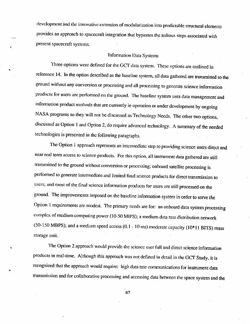
development and the innovativeexlension of modularizationinto predictablestructuralelements
provides an approach to spacecraft integration that bypasses the tedious steps associated with
present spacecraft systems,
lnfomaationData Systems
Three options were defined for the GCT data system. These options are outlined in
reference 14. In the option described as the baseline system, all data gathered are transmittedto the
ground without any conversion or processing and all processing to generate science information
products for users are performed on the ground. The baseline system uses data management and
information product methods that are currently in operationor under development by ongoing
NASA programs so they will not be discussed as Technology Needs. The other two options,
discussed as Option i and Option 2, do require advanced technology. A summary of the needed
technologies is presented in the followingparagraphs.
The Option Iap proachrepresentsan intermediatestep to providingscience users direct and
near real term access to science products. For this option,all instrument data gathered are still
transmitted to the ground without conversionor processing;onboard satellite processing is
performed to generate intermediateand limited final science products for direct transmissionto
users; and most of the final science informationproducts for users are still processed on the
ground. The improvements imposed on the baseline informationsystem in order to serve the
Option 1 requirements are modest. The primary needs are for: an onboard data system processing
complex of medium computing power (10-50 MIPS);a medium data rate distribution network
(50-150 MBPS); and a mediunl speed access (0.! - 10 ms) moderatecapacity (10" 11BITS) mass
storage unit.
The Option 2 approach would provide the science user full and direct scienceinformation
products in real-time. Although this approach was not defined in detail in the GCT Study, it is
recognized that the approach would require: high data rate communications for instrument data.g,,
transmission and for collaborative processing and accessing data between the space system and the
67

ground system; high performance processing/computingboth on the spacecraft and on the ground;
and high capacity and fast access mass data storageon the spacecraft and on the ground. To meet
theserequirements, technology advances are needed in the disciplinesof global data ",
communication and processing architectures,optical communications,optical networking
(> 500 I_IlPScapability), optical disk recorders (10,12 - 10"13bits capacity, 0.01 - 1MS access), __
high performance computing (> 100 Giga flops), and wide area optical networking.
Additional details on the InformationData Systemsoptions and the technology needs that
accompany the options are contained in reference 14.
! CONCLUDING REMARKS
The GCT ArchitectureTrade Study has attempted to define a viable approachto a mixed
fleet of spacecraft and remote sensors that can, with reasonable advances in technology,
satisfactorilymeet a set of science requirements focused on detecting and quantifying global
changes that may occur with the Earth's physical systems that affect climate, i.e., atmosphere,
oceans, and hind surfaces. The global changes of interest in this study are those that occur over
time scalesof decades to centuries. It is recognized that there are global changes that occur on "---J
much longer time scales, but they are more appropriately evaluated by in-situ sensor systems.
Measurements required for detecting and quantifying global changesare of two classes:
related to regional scale processes and those related to global scale processes. The process class by
itself is not a driver in the selectionof instruments or their distribution on spacecraft;however, the
spatial and temporal measurement requirements related to the process class are drivers of the
overall system architectureboth at the individualinstrument/spacecraftleveland at thecombined
fleet level. In general, the spati_dresolution requirementsdrive the selectionof sensors and
instrumentsand the assignment to LEO or GEO application while the temporal resolution
requirements drive the distribution of instrumentson the spacecraft, the orbit inclinations of the
spacecraft, and the number of similar or identical spacecraft.
It is important to note that no reasonable architecturecan meet all of the science
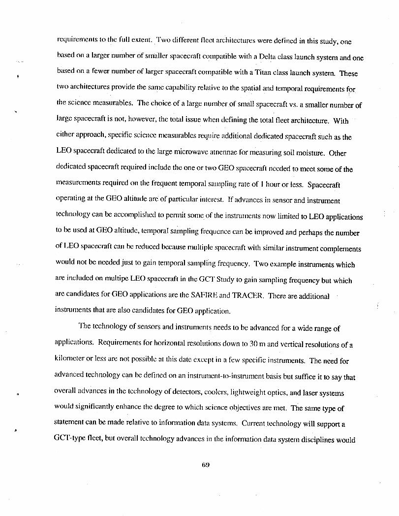
requirements to the full extent. Two different fleet architectureswere defined in this study, one
based on a larger numberof smaller spacecraftcompatible with a Delta class launch system and one
based on a fewer numberof larger spacecraftcompatible with a Titan class launch system. These
two architectures provide the same capabilityrelative to the spatial and temporal requirements for
the science measurables. The choice of a large numberof small spacecraftvs. a smaller number of
large spacecraft is not, however, the total issue when defining the total fleet architecture. With
either approach, specific science measurablesrequire additional dedicated spacecraft such as the
LEO spacecraftdedicated to the large microwave amennaefor measuring soil moisture. Other
dedicated spacecraft required include the one or two GEO spacecraftneeded to meet some of the
measurements required on the frequent temporal sampling rate of I hour or less. Spacecraft
operating at the GEO altitude are of particularinterest. If advances in sensor and instrument
technology can be accomplishedto permit some of the instrumentsnow limitedto LEO applications
to be used at GEO altitude, temporal sampling ffequencecan be improved and perhaps the number
of LEO spacecraftcan be reduced because multiple spacecraftwith similar instrumentcomplements
.... would not be neededjust to gain temporal sampling frequency. Two example instruments which
are included on multipe LEO spacecraft in the GCT Study to gain samplingfrequency but which
are candidates for GEO applications are the SAF1REand']'RACER. There are additional
instruments that are also candidates for GEO application.
The technology of sensors and instruments needs to be advanced for a wide range of
applications. Requirements for horizontal resolutionsdown to 30 m and vertical resolutionsof a
kilometer or less are not possible at this date except in a few specific instruments. The need for
advanced technology can be defined on an instnm_ent-to-instrumentbasis but suffice it to say that
overall advances in the technology of detectors, coolers, lightweightoptics, and laser systems
would significantly enhance the degree to which science objectivesare met. The same type of
statement can be made relative to informationdata systems. Current technology will supporta
GCT-type fleet, but overall technology advances in the informationdata system disciplines would
69

support a much-enhanced data management network. The spacecraft technology advances that
would return the greatest dividendsare those related to up-rating many of the subsystemson .._...-
current or proposed versions of the modular spacecraftbuses, such as the NASA Multimission
Modular Spacecraft (MMS). A spacecraft technologywhich, if advanced, would provide the
science community newcapabilities for Earth sciences studies is the one related to the design, i
packaging, and deployment of the large frame-typestructuresassociated with the rnierowave
instruments. The basic microwave technology is at hand, but the ability to apply it to the
development of the large antennas and support spacecraftrequired for a GCT-type fleet has not
been demonstrated.
Perhaps the most significant contributionof the GCT Architecture Trade Study is to!
' identify some of the technology needs that will pace the extent to which global change science can
be supported during the next two or three decades. The basic study can now serve as a baseline
from which an)appropriate technologydevelopment programcan be framed.

References
1. NASA Advisory Council, Earth Science Committee Report of 1986.
2. Report of the Earth System Sciences Committee, NASAAdvisory Council, "Earth System
Science, A Closer View (A Program for Global Change)," January 1988.
3. NASA Officeof Space Sciences and Applications StrategicPlan of 1988.
" 4. NASA Office of Space Sciences and Applications StrategicPlan of 1989.
5. NASA Office of Aeronautics, Exploration,and Technology "GlobalChange Technology
Initiative. Technical Overview," May 31, 1990.
6. Report of the Ad Hoc ReviewTeam on Planet Earth Technologiesof the Space Systems and
Technology Advisory Committee "Technologyfor the Missionto Planet Earth," 1989.
7. Committee on Earth Sciences,Federal Coordinating Councilon Science, Engineering, and
Technology, 1989.
8. Suttles, J. T.; Harrison, E. F.; Gibson, G. G.; and Campbell, T. G.: Science Requirements
for a Global Change Technology Initiative ArchitectureTrade Study. White Paper Report.
Undated.
9. Harrison, E. F.; Gibson, G. G.; Suttles, J. T.; Buglia, J. J.; and Taback, I.: Satellite Orbit
Considerations for Mission to Planet Earth. White Paper Report.
10. Hypes, W. D.; Keafer, L. S.; Ross, R. T.; Jalink, A., Jr.; Allen, C. L.; and Knight, H. R.:
Representative Instruments for the Global Change Technology InitiativeArchitectureTrade
Study. White Paper Report, January 1990.
11.Farmer, J. T.; Campbell, T. J.; Davis, W. T.; Garn, P. A.; King, C. B.; and Jackson, C. C.."
Conceptual Design of a Geostationary Earth Science Platform. March 1990.
12. Ferebee, M. J., Jr.: Hoop Column Soil Moisture Spacecraft in Low Earth Orbit. March 1990.
13. Butterfield, A. J.; Garn, P. A.; and Burrowbridge, D. R.: GCT Multi-instrument.Spacecraft in ,
Sun Synchronous Low Earth Orbits. April 1990./,
•' 71
14. Murray, N. D.: Information Data Systems for a Global Change Technology Initiative
Architecture Trade Study. June 1990.
15. Hypes, W. D. and Ross, R. T.: The Impact of an Eos-A and B on the Architectural Mix of the
GCT Spacecraft Fleet. White Paper Report, January 1990.
16. Korb, C. L.; Weng, C. Y.: Differential Absorption Lidar Techniques for Measeurernent of the
Atmospheric Profile. Applied Opitcs. 22, 3759, 1983.
72
SCIENCE REQUIREMENTS FORA GLOBAL CHANGE TECHNOLOGY INITIATIVE
, ARCHITECTURE TRADE STUDY
John T. Suttles and Edwin F. HarrisonNASA Langley Research Center
Gary G. GibsonLockheed Engineering and Sciences Company
Thomas G. CampbellNASA Langley Research Center

,,p
SCIENCE REQUIREMENTS FOR A GLOBAL CHANGE TECHNOLOGYINITIATIVE ARCHITECTURE TRADE STUDY
by
John T. Suttles*, Edwin F. Harrison*,
Gary G. Gibson "l',and Thomas G. Campbell1:
SUMMARY
Science requirements for a Global Change Technology Initiative (GCTI)Architecture Trade Study have been established by reviewing and synthesizingresults from recent studies. A scientific rationale was adopted and used to identify
a comprehensive set of measurables and their priorities. Spatial and temporalrequirements for a number of measurement parameters were evaluated based onresults from several working group studies. Science requirements have beendefined using these study results in conjunction with the guidelines forinvestigating global changes over a time scale of decades to centuries.Requirements are given separately for global studies and regional process studies.For global studies, temporal requirements are for sampling every 1 to 12 hours foratmospheric and radiation parameters and 1 day or more for most Earth surfacemeasurements. Therefore, the atmospheric measurables provide the most criticaldrivers for temporal sampling. Spatial sampling requirements vary from 1 km forland and ocean surface characteristics to 50 km for some atmospheric parameters.Thus, the land and ocean surface parameters have the more significant spatialvariations and provide the most challenging spatial sampling requirements.
INTRODUCTION
Global observations of the physical parameters required to detect and
quantify changes in global climate, composition of the atmosphere, surfaceproperties, and the biosphere can only be accomplished using sophisticatedinstruments on orbiting spacecraft. Defining such a mission is a formidable taskinvolving several essential elements. First, the overall goals of the effort must bedefined and the associated science requirements established. Next, goals and
*Atmospheric Sciences Division, NASA Langley Research Center,Hampton, VA 23665-5225
lLockheed Engineering and Sciences Company, Hampton, VA 23666) :_Guidance and Control Division, NASA Langley Research Center,
Hampton, VA 23665-5225
75
requirements must be prioritized according to scientific importance, feasibility,cost, and risk factors. Then, mission analysis, sensor selection, and spacecraftdesign can proceed as appropriate. Results of these studies are used in a re-examination of mission priorities by the Science Requirements Definition Team. ,.
The purpose of this paper is to adopt a science rationale and identify theassociated measurables, priorities, and measurement requirements for the GlobalChange Technology Initiative (GCTI) Architecture Trade Study.
SCIENTIFIC RATIONALE, MEASURABLES, AND PRIORITIES
The Earth System Sciences Committee (ESSC) report (ref. 1)made a numberof recommendations concerning the most critical needs in a program toinvestigate global change. The committee confirmed the need for sustained, long-term measurements over the globe. These measurements would be used toestablish a fundamental description of the Earth and its history, to conduct focusedresearch and process studies, and to develop and apply Earth system models.Because of the interdisciplinary nature of the problems and the very large datarequirements, the committee strongly recommended that an information system
be a major segment of the program.
In their report, the ESSC gave some important guidelines for establishing ascience rationale, the associated measurements, and the measurement priorities.These guidelines are given in table 1. An essential part of any scientific program isthe use of observational data with conceptual and numerical models. Models arecurrently being developed to describe global change on two distinct time scales:thousands to millions of years, and decades to centuries. Processes on both timescales are important; however, those operating on the scale of decades to centuriesare particularly relevant to the concerns and planning of human societies. Forexample, processes on the time scale of decades to centuries include those relatedto ozone depletion, greenhouse warming (due to carbon dioxide and other tracegases), deforestation, and desertification. Therefore, the current study focuses onmeasuring parameters of the physical systems (e.g., atmosphere, oceans, and landsurfaces), the biogeochemical cycles, and the hydrological cycle for global changestudies covering decades to centuries. For the most part, science problems on thelonger time scale of thousands to millions of years are not as urgent for globalchange studies, can be addressed with measurements that only need repeatingevery few years, or are appropriate for in situ observations. In this work,observational requirements are primarily for remote sensing from satellites. Inevaluating the observational requirements, it must be recognized that somestudies give needs in terms of instantaneous measurements while others give ,needs in terms of the final data products. Finally, the ESSC indicated the need fortwo basic types of studies: global studies or surveys, and case studies involvingregional processes.
76
Table 2 shows the measurables and ESSC priorities for Earth science studieson the time scale of decades to centuries. The measurables are broken down into
categories relating to the atmosphere, the Earth land and ocean surfaces, and theenergy components of the solar and Earth radiation. While this list ofmeasurables is widely accepted, the priorities are subject to debate. For example,the priority framework of the U. S. Global Change Research Program shown intable 3 (from ref. 5, a report by the Federal Coordinating Council on Science,Engineering, and Technology (FCCSET)), gives all the measurables in table 2 as
_o high priority, but places much higher relative importance on clouds and watervapor than does the ESSC. At a recent meeting, the Investigator Working Groupof the Earth Observing System (EOS) found substantial agreement with thepriorities in table 3, but voiced the need for a relative measure of importance togive proper perspective to the separation between the highest and lowestpriorities.
It seems prudent at this point to examine some parameters that are excludedby adopting the rationale stated above. To this end, the measurables for the timescale of thousands to millions of years are shown in table 4. Several items on thislist warrant comment. Although given low priority by the FCCSET, twomeasurables were given the highest priority by the ESSC: seismic properties(including plate motions and deformations), and gravity and geoid. The seismicproperties are presently being measured to high accuracy by in situ techniquessupplemented by precise position information from the Global Positioning System(GPS). Some monitoring improvements can be achieved by the Geodynamic LaserRanging System (GLRS). The gravity measurable is pertinent to this study,particularly as it relates to satellite position determination for analysis of altimetrymeasurements. This is an indirect requirement, and the GPS can provide theneeded information. Therefore, based on the low priority for the adopted sciencerationale and the existing capabilities for these two measurables, we feel justifiedin not including these parameters. Also included on the list in table 4 is thelightning measurable, even though it was not included in the ESSC sciencediscussions. Lightning has been included in several measurement system studies,however, so it was included for completeness. With regard to lightning, we havenot found any specific scientific requirement for this measurement, and, therefore,it is not included in our study.
INITIAt, MEASUREMENT REQUIREMENTS
Numerous scientific groups have undertaken to establish spatial andtemporal requirements for Earth science measurements. Results of the mostrelevant studies are given in table 5 for temporal requirements and in table 6 forspatial requirements. The Science and Mission Requirements Working Group forthe Earth Observing System (EOS) defined scientific requirements for a widevariety of measurements of atmospheric, radiative, and Earth surface parameters
77

(ref. 2). A study by a group from JPL(ref. 3) encompassed a larger number ofmeasurables and tended to confirm the EOSrequirements for many parameters,but generally called for higher temporal resolutions for most atmosphericmeasurements. The Langley Research Center has also conducted a comprehensive ,,study which focused on identifying the technology needs for a global changescience program (ref. 4). Scientificrequirements establishedby a group affiliatedwith the geosynchronous Earth observing system (unpublished report, EarthScience Geostationary Platform Science Steering Group) established temporalrequirements from a few minutes to about 3 hours, and less severe spatialsampling requirements than identified by other studies.
These studies generally tended to establish measurement criteria whichmirrored the capabilities of the satellite system that the study group was affiliatedwith. For example, the EOS group set temporal requirements from 12 hours toseveral days. The single Sun-synchronous EOS satellite meets these requirements.The JPL group generally set measurement criteria consistent with the capabilitiesof a two-satellite system. The geosynchronous Earth observing system groupfocused on process studies which resulted in requirements which could only bemet by a system which sampled almost continuously.
SCIENCE GUIDELINES AND MEASUREMENT REQUIREMENTS
In order to make sense of the widely divergent sets of initial measurementrequirements, it is necessary to view them within the guidelines of the ESSCscience rationale. First, it must be recognized that for some studies andmeasurables, instantaneous measurement requirements are given, while in othercases, requirements are given for final data products. Second, requirements arefrequently intermixed for two distinct types of studies: (1)Global Change Studies;and (2) Regional Process Studies. Finally, it should be noted that it may not bepossible to meet all measurement requirements with satellite observations alone,and systems involving combinations of in situ, aircraft, balloon, and satellitetechniques may be necessary.
The Global Change Studies require long-term and highly accuratemeasurements to detect trends, sufficient temporal resolution to obtain accuratedaily to monthly averages, and observations covering the entire globe (see table 7).Such observations are essential for the development, verification, andimprovement of global models. The spatial and temporal resolutions formeasurements and for data products are based on estimates of the variability ofparameters involved and on the data product resolutions needed by modelers.The best guidelines for observational requirements are global climate modelcharacteristics.
78
Based on current climate model characteristics, the spatial resolution fordata products must be 100-250 kin (horizontal) and have a vertical resolutionequivalent to 9-17 pressure levels. Resolution requirements for instantaneousmeasurements should, therefore, be in the range of 10-25 kin.
The best estimates of temporal resolution for data products range from lessthan 1 day to 1 month. For adequate temporal sampling, some variables such ascloud cover and associated radiation parameters require measurements across the
_ entire diurnal cycle to avoid aliasing daily and longer-term variations. Otherphysical properties change at a much slower rate. Some examples are sea icedistribution and land surface properties.
Regional Process Studies are crucial to understanding the Earth as a systemand to evolving improved models. These studies require the highest possibletemporal and spatial resolutions, but are of limited time and space extent. Theyinvolve satellite, aircraft, and ground-based measurements used together in anintensive field study. Some of the important existing regional climate processstudies are listed in table 8 for the Physical Climate System and for theBiogeochemical Cycles. These are the programs that must be continued andexpanded upon in order to adequately understand regional processes and developaccurate models.
FINAL SCIENCE REQUIREMENTS
The requirements recommended for the GCTI Architecture Trade Study areshown in table 9. The requirements are given separately for Global ChangeStudies and Regional Process Studies. Tile requirements are to be interpreted asinstantaneous measurement requirements, and the appropriate data products aregiven as a footnote. Parameters for which measurements over the diurnal cycleare critical are so noted. Where a range of values is given, the lower value is anideal to provide an objective while the upper value is an adequate level orminimum requirement.
For Global Change Studies, temporal requirements are for sampling every 1to 12 hours for atmospheric and radiation parameters and 1 day or more for mostEarth surface measurements. For temporal variations, the most rapidly changing
parameters are those related to the Earth's atmosphere. For this reason, these,, measurables provide the most critical drivers for temporal sampling. Spatial
sampling requirements vary from 1 km for land and ocean surface characteristicsto 90 km for atmospheric parameters. Thus, the land and ocean surfaceparameters have the more significant spatial variations and provide the mostchallenging spatial sampling requirements.
79
Regional Process Studies require temporal sampling of minutes to days andspatial sampling from 30 meters to several hundred kilometers, depending on theparticular parameter. The only feasible satellite methods for meeting the veryhigh temporal resolutions shown (i.e., minutes) would involve instruments on ageostationary platform and operating in a staring mode. On the other hand, thevery high spatial resolutions required would probably dictate measurements fromlow Earth orbit. Thus, a mixed fleet of satellites appearsnecessary for providinginformation for the regional process studies. Data products for the regional studiesare highly variable and depend on the particularprocess being investigated.Therefore, no data product resolutions have been given.
REFERENCES
1. Earth System Sciences Committee (F. Bretherton, Chairman): Program forGlobal Change, Earth System Science --- A Closer View. Report of the EarthSystem Sciences Committee, NASA Advisory Council. National Aeronauticsand Space Administration, Washington, DC, January 1988.
2. EOS Science and Mission Requirements Working Group (Dixon M. Butler,Chairman): Earth Observing System Science and Mission RequirementsWorking Group Report, Volume I. NASA TM-86129, August, 1984.
3. Global Change Technology Initiative Working Group: Report on the FirstGlobal Change Technology Workshop. Jet Propulsion Lab, Pasadena, CA, 1989.
4. Rowell, L. F. and T. J. Swissler: Advanced Technology Needs for a GlobalChange Science Program: Perspective of the Langley Research Center. NASATM-4196, 1991.
5. Committee on Earth Sciences:Our Changing Planet: The FY 1990ResearchPlan. A Report by the Committee on EarthSciences of the FederalCoordinating Council on Science, Engineering, and Technology; The U. S.Global Change Research Program, July 1989.
80

TABLE 1. GUIDELINES FOR SCIENCE REQUIREMENTS
• CONCEPTUAL AND NUMERICAL MODELS
THOUSANDS TO MILLIONS OF YEARS - EARLY EARTH, CORE AND MANTLE,
PLATE-TECTONICS, AND SOLAR-DRIVEN
DECADES TO CENTURIES - PHYSICAL SYSTEMS (ATMOSPHERE, OCEANS,
LAND SURFACES), BIOGEOCHEMICAL CYCLES, WATER CYCLE
• OBSERVATIONAL REQUIREMENTS
REMOTE SENSING VS. IN SITU OBSERVATIONS
INSTANTANEOUS MEASUREMENTS VS. ANALYZED DATA PRODUCTS
• SCIENTIFIC STUDIES
GLOBAL VARIABLES (SURVEYS)
PROCESSES (CASE STUDIES)
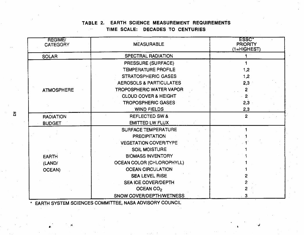
TABLE 2. EARTH SCIENCE MEASUREMENT REQUIREMENTSTIME SCALE: DECADES TO CENTURIES
REGIME! ESSC*CATEGORY MEASURABLE PRIORITY
(1=HIGHEST)SOLAR SPECTRALRADIATION 1
PRESSURE (SURFACE) 1TEMPERATUREPROFILE 1,2STRATOSPHERICGASES 1,2
AEROSOLS& PARTICULATES 2,3
ATMOSPHERE TROPOSPHERICWATERVAPOR .. . 2CLOUDCOVER& HEIGHT .2
TROPOSPHERICGASES 2,3WIND FIELDS 2,3
o_
RADIATION REFLECTEDSW& 2BUDGET EMI3-FEDLW FLUX
SURFACETEMPERATURE 1PRECIPITATION 1
VEGETATIONCOVER/TYPE 1SOILMOISTURE 1
EARTH BIOMASSINVENTORY 1
(LAND/ OCEANCOLOR(CHLOROPHYLL) 1OCEAN) OCEANCIRCULATION 1
SEA LEVELRISE 2SEA ICECOVER/DEPTH 2
OCEANCO2 2SNOWCOVER/DEPTH/WETNESS 3
EARTHSYSTEMSCIENCESCOMMITTEE,NASAADVISORYCOUNCIL

TABLE 3. U.S. GLOBAL CHANGERESEARCH PROGRAM PRIORITY FRAMEWORK
SCIENCE PRIORITIES
Climateand Biogeochemical EcologicalSystems EarthSystem Human SolidEarth SolarDTnamics and Dynamics Histor Interactions Processes Influences
Role of Clouds Bio/Atrn/Ocean Long-Term Paleoclimate Data Base Coastal Erosion EUV/UVOcean Circulation Fluxes of Trace Measurements Paleoecology Development Volcanic Monitoringand Heat Flux Species of Structure/ Atmospheric Models Linking: Processes ar Energ
Land!Atm/Ocean Atm Processing Function Composition Population Permafrost and CouplingWater & Energy of Trace Response to Ocean Circula- Growth and Marine Gas Irradiance
_o Fluxes Surface/Deep Climate and tion and Distribution Hydrates (Measure/0._" Coupled Climate Water Other Stresses Composition Energy Ocean/Seafloor Model)
System & Biog Interactions Ocean Demands Heat andZQuantitative Terrestrial between Productivity Changes in Energy Fluxes Record
,,,< Links Biosphere Physical and Sea Level Land Use Surficial Proxy Measure-_: Ocean/Atm/ Nutrient and Biological Change Industrial Processes mentsand_z Cryosphere Carbon Cycling Processes Paleohydrology Production Crustal Motions Long-Term
Interactions Terrestrial Inputs Models of and Sea Level Data Baseto Marine Interactions,Ecosystems Feedbacks, and
ResponsesProductivity/ResourceModels
q
INCREASING PRIORITY
SOURCE:COMMITTEEON EARTHSCIENCES
FEDERALCOORDINATINGCOUNCILONSCIENCE,ENGINEERING,ANDTECHNOLOGY
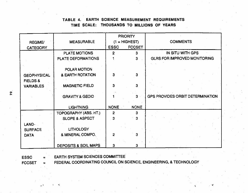
TABLE 4. EARTH SCIENCE MEASUREMENT REQUIREMENTSTIME SCALE: THOUSANDS TO MILLIONS OF YEARS
PRIORITY
REGIME/ MEASURABLE (1 = HIGHEST) COMMENTS
CATEGORY ESSC FCCSETPLATEMOTIONS 2 3 IN SITU WITH GPS -
PLATE DEFORMATIONS 1 3 GLRS FORIMPROVEDMONITORING
POLARMOTION
GEOPHYSICAL & EARTHROTATION 3 3FIELDS&VARIABLES MAGNETICFIELD 3 3
(_ ,.
' GRAVITY& GEOID 1 3 GPS PROVIDESORBITDETERMINATION
LIGHTNING NONE NONE
TOPOGRAPHY(ABS.HT.) 2 3SLOPE&ASPECT 3 3
LAND-
SURFACE LITHOLOGYDATA & MINERALCOMPO. 2 3
DEPOSITS& SOIL MAPS 3 3
ESSC = EARTHSYSTEMSCIENCESCOMMI1-FEEFCCSET = FEDERALCOORDINATINGCOUNCILON SCIENCE,ENGINEERING,& TECHNOLOGY
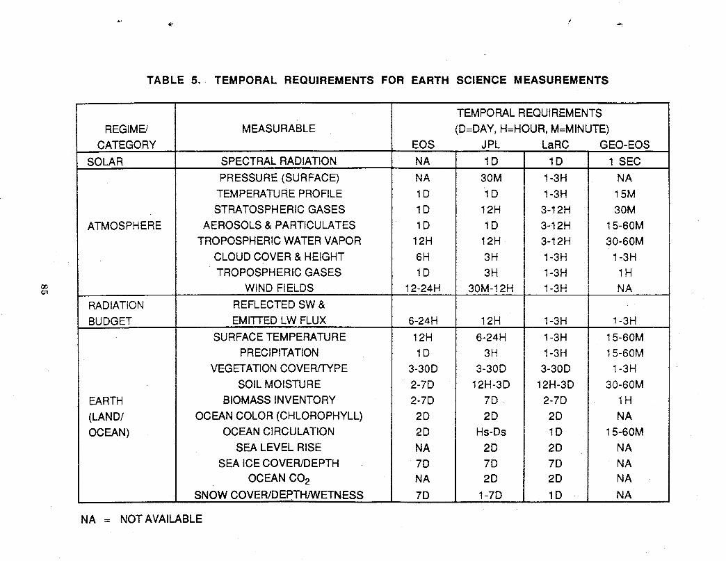
TABLE 5. TEMPORAL REQUIREMENTS FOR EARTH SCIENCE MEASUREMENTS
TEMPORALREQUIREMENTS
REGIME/ MEASURABLE (D=DAY,H=HOUR,M=MINUTE)CATEGORY EOS JPL LaRC GEO-EOS
SOLAR SPECTRALRADIATION NA 1D 1D 1 SEC
PRESSURE(SURFACE) NA 30M 1-3H NATEMPERATUREPROFILE 1D 1D 1-3H ! 5MSTRATOSPHERICGASES 1D 12H 3-12H 30M
ATMOSPHERE AEROSOLS& PARTICULATES 1D 1D 3-12H 15-60MTROPOSPHERICWATERVAPOR 12H 12H 3-12H 30-60M
CLOUDCOVER& HEIGHT 6H 3H 1-3H 1-3H
TROPOSPHERICGASES ! D 3H 1-3H 1H_ WIND FIELDS !2-24H 30M-12H 1-3H NA
RADIATION REFLECTEDSW&BUDGET EMITTEDLW FLUX 6-24H ! 2H 1-3H 1-3H
SURFACETEMPERATURE 12H 6-24H 1-3H 15-60MPRECIPITATION 1D 3H 1-3H 15-60M
VEGETATIONCOVER/TYPE 3-30D 3-30D 3-30D 1-3HSOILMOISTURE 2-7D 12H-3D 12H-3D 30-60M
EARTH BIOMASSINVENTORY 2-7D 7D 2-7D 1H
(LAND/ OCEANCOLOR(CHLOROPHYLL) 2D 2D 2D NAOCEAN) OCEANCIRCULATION 2D Hs-Ds 1D 15-60M
SEA LEVELRISE NA 2D 2D NASEA ICE COVER/DEPTH 7D 7D 7D NA
OCEANCO2 NA 2D 2D NASNOWCOVER/DEPTH/WETNESS 7D 1-7D 1D NA
NA = NOTAVAILABLE
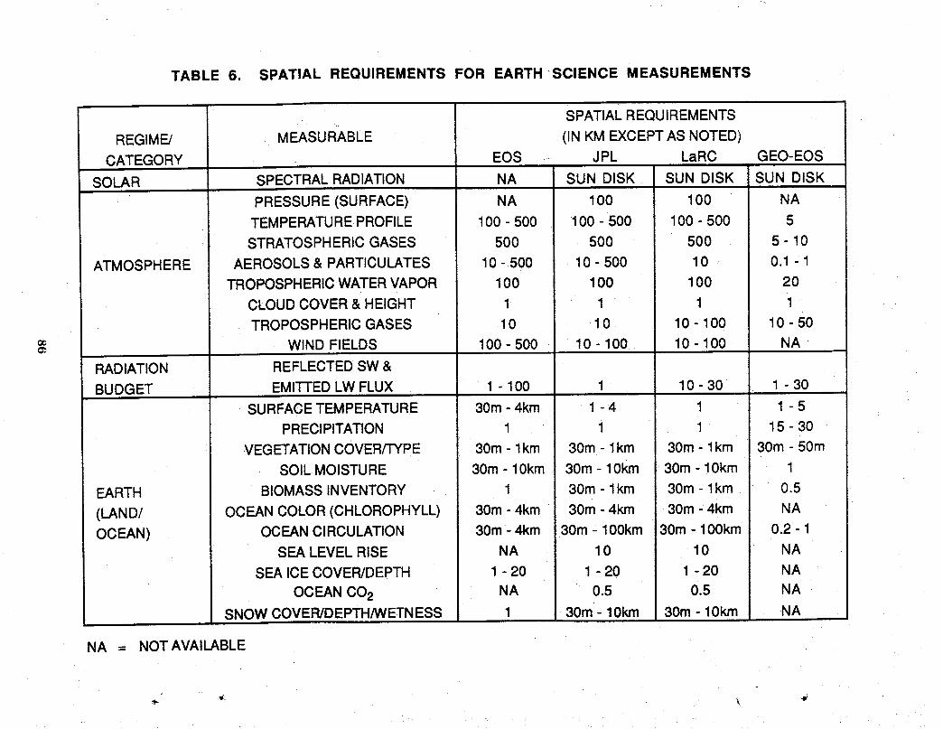
TABLE 6. SPATIAL REQUIREMENTS FOR EARTH SCIENCE MEASUREMENTS
SPATIALREQUIREMENTS ,-
REGIME/ MEASURABLE (IN KM EXCEPTAS NOTED)CATEGORY _ EOS .... JPL LaRC GEO-EOS
SOLAR SPECTRALRADIATION NA SUN DISK SUN DISK SUN DISK
PRESSURE(SURFACE) NA 100 100 NATEMPERATUREPROFILE 100 - 500 100 - 500 100 - 500 5
.- STRATOSPHERICGASES 500 500 500 5 - 10
ATMOSPHERE AEROSOLS& PARTICULATES 10 - 500 10 - 500 10 0.1 1TROPOSPHERICWATERVAPOR 100 100 100 20
CLOUDCOVER& HEIGHT 1 1 1 1TROPOSPHERICGASES 10 10 10 - 100 10 - 50
WIND FIELDS 100 - 500 10 - 100 10 - 100 NA
RADIATION REFLECTED•SW&BUDGET EMI]-FEDLW FLUX 1 - 100 1 10 - 30 1 - 30
SURFACETEMPERATURE 30m- 4km 1 - 4 1 1 - 5PRECIPITATION ' 1 1 1 15 - 30
VEGETATIONCOVER/TYPE 30m- lkm 30m - I km 30m- 1km 30m - 50mSOILMOISTURE 30m - 10km 30m - 10km 30m - 10kin 1
EARTH BIOMASSINVENTORY 1 30m - 1km 30m- 1km 0.5
(LAND! OCEANCOLOR(CHLOROPHYLL) 30m- 4km 30m - 4km 30m_4km NAOCEAN) OCEANCIRCULATION 30m 4km 30m 100km 30m -100km 0.2- 1
SEA LEVELRISE NA 10 10 NA
SEA ICECOVER/DEPTH 1 - 20 1 - 20 1 - 20 NA
OCEANCO2 NA " 0.5 0.5 NASNOWCOVER/DEPTH/WETNESS 1 30m - 10kin 30m - 10kin NA
NA = NOTAVAILABLE
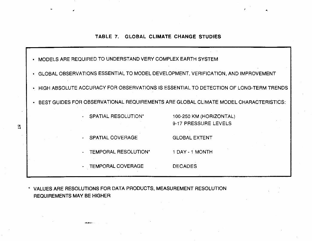
TABLE 7. GLOBAL CLIMATE CHANGE STUDIES
• MODELS ARE REQUIRED TO UNDERSTAND VERY COMPLEX EARTH SYSTEM
• GLOBAL OBSERVATIONS ESSENTIAL TO MODEL DEVELOPMENT, VERIFICATION, AND IMPROVEMENT
• HIGH ABSOLUTE ACCURACY FOR OBSERVATIONS IS ESSENTIAL TO DETECTION OF LONG-TERM TRENDS
• BEST GUIDES FOR OBSERVATIONAL REQUIREMENTS ARE GLOBAL CLIMATE MODEL CHARACTERISTICS:
SPATIAL RESOLUTION* 100-250 KM (HORIZONTAL)
9-17 PRESSURE LEVELS"4
- SPATIAL COVERAGE GLOBAL EXTENT
TEMPORAL RESOLUTION* 1 DAY- 1 MONTH
TEMPORAL COVERAGE DECADES
* VALUES ARE RESOLUTIONS FOR DATA PRODUCTS, MEASUREMENT RESOLUTION
REQUIREMENTSMAY BE HIGHER
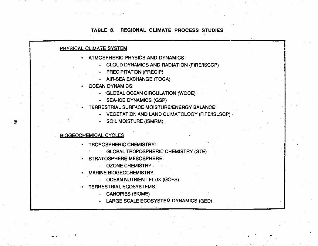
TABLE 8. REGIONAL CLIMATE PROCESS STUDIES
PHY_£1CALCLIMATE SYSTEM
• ATMOSPHERIC PHYSICSAND DYNAMICS:
CLOUD DYNAMICSAND RADIATION (FIRE/ISCCP)PRECIPITATION(PREClP)
AIR-SEA EXCHANGE(TOGA)• OCEAN DYNAMICS:
GLOBALOCEANCIRCULATION (WOCE)- SEA-ICE DYNAMICS (GSP)
• TERRESTRIALSURFACEMOISTURE/ENERGYBALANCE:
VEGETATIONAND LAND CLIMATOLOGY(FIFE/ISLSCP)
'_ SOIL MOISTURE(ISMRM)oe
BIOGEOCHEMICAL CYCLES
• TROPOSPHERICCHEMISTRY:
GLOBALTROPOSPHERICCHEMISTRY (GTE)• STRATOSPHERE-MESOSPHERE:
OZONE CHEMISTRY• MARINEBIOGEOCHEMISTRY:
OCEAN NUTRIENTFLUX (GOFS)• TERRESTRIAL ECOSYSTEMS:
CANOPIES (BIOME)LARGESCALEECOSYSTEM DYNAMICS (GED)
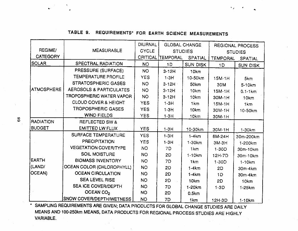
TABLE 9. REQUIREMENTS* FOR EARTH SCIENCE MEASUREMENTS
DIURNAL GLOBAL CHANGE REGIONAL PROCESS
REGIME/ MEASURABLE CYCLE STUDIES STUDIES
CATEGORY CRITICAL TEMPORAL SPATIAL TEMPORAL SPATIAL
SOLAR SPECTRAL RADIATION NO 1D SUN DISK 1D SUN DISK
PRESSURE (SURFACE) NO 3-12H 10kmTEMPERATURE PROFILE YES 1-3H 10-50km 15M-1H 5km
STRATOSPHERIC GASES NO 3-12H 50km 30M 5-10km
ATMOSPHERE AEROSOLS & PARTICULATES NO 3-12H 10km 15M-1H 0.1-1kin
TROPOSPHERIC WATER VAPOR NO 3-12H 10km 30M-1H 10km
CLOUD COVER & HEIGHT YES 1-3H I km 15M-1H 1km
TROPOSPHERIC GASES YES 1-3H 10km 30M-1H 10-50kin
WIND FIELDS YES 1-3H 10km 30M-1H
RADIATION REFLECTED SW &
BUDGET EMITTED LW FLUX YES 1-3H 10-30km 30M-1H 1-30km
SURFACE TEMPERATURE YES 1-3H 1-4km 6M-24H 30m-200km
PRECIPITATION YES 1-3H 1-30km 3M-3H 1-200km
VEGETATION COVER!TYPE NO 7D 1km 1-30D 30m-10km
SOIL MOISTURE NO 2D 1-10kin 12H-7D 30m-10km
EARTH BIOMASS INVENTORY NO 7D 1km 1-30D 1-10km
(LAND/ OCEAN COLOR (CHLOROPHYLL) NO 2D 1-4km 2D 30m-4km
OCEAN) OCEAN CIRCULATION NO 2D 1-4km 1D 30m-4kmSEA LEVEL RISE NO 2D 10km 2D 10km
SEA ICE COVER/DEPTH NO 7D 1-20km 1-3D 1-25km
OCEAN CO2 NO 2D 0.5km
SNOW COVER/DEPTH/WETNESS NO 7D 1km 12H-3 D 1-10km
SAMPUNG REQUIREMENTS ARE GIVEN; DATA PRODUCTS FOR GLOBAL CHANGE STUDIES ARE DAILY
MEANS AND 101_250kmMEANS, DATA PRODUCTS FOR REGIONAL PROCESS STUDIES ARE HIGHLY
VARIABLE.

SATELLITE ORBIT CONSIDERATIONS FOR MISSION TO PLANET EARTH
Edwin F. HarrisonNASA Langley Research Center
Gary G. GibsonLockheed Engineering and Sciences Company
John T. SuttlesNASA Langley Research Center
James J. BugliaFlight Mechanics and Control, Inc.
Israel TabackThe Bionetics Corporation

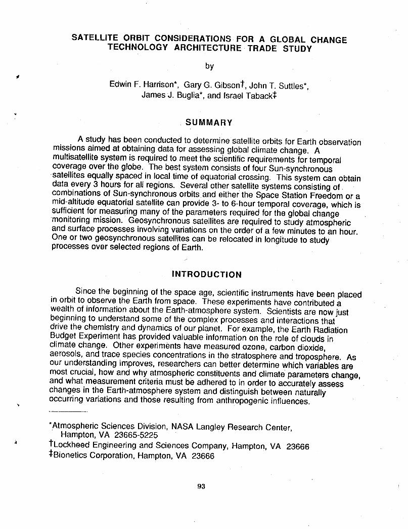
SATELLITE ORBIT CONSIDERATIONS-FOR A GLOBAL CHANGETECHNOLOGY ARCHITECTURE TRADE STUDY
by
* Edwin F. Harrison*, Gary G. Gibson1, John T. Suttles*,James J. Buglia*, and Israel Taback:l:
SUMMARY
A study has been conducted to determine satellite orbits for Earth observationmissions aimed at obtaining data for assessing global climate change. Amultisatellite system is required to meet the scientific requirements for temporalcoverage over the globe. The best system consists of four Sun-synchronous.satellites equally spaced in local time of equatorial crossing. This system can obtaindata every 3 hours for all regions. Several other satellite systems consisting ofcombinations of Sun-synchronous orbits and either the Space Station Freedom or amid-altitude equatorial satellite can provide 3- to 6-hour temporal coverage, which issufficient for measuring many of the parameters required for the global changemonitoring mission. Geosynchronous satellites are required to study atmosphericand surface processes involving variations on the order of a few minutes to an hour.One or two geosynchronous satellites can be relocated in longitude to studyprocesses over selected regions of Earth.
INTRODUCTION
Since the beginning of the space age, scientific instruments have been placedin orbit to observe the Earth from space. These experiments have contributed awealth of information about the Earth-atmosphere system. Scientists are now justbeginning to understand some of the complex processes and interactions thatdrive the chemistry and dynamics of our planet. For example, the Earth RadiationBudget Experiment has provided valuable information on the role of clouds inclimate change. Other experiments have measured ozone, carbon dioxide,aerosols, and trace species concentrations in the stratosphere and troposphere. Asour understanding improves, researchers can better determine which variables aremost crucial, how and why atmospheric constituents and climate parameters change,and what measurement criteria must be adhered to in order to accurately assesschanges in the Earth-atmosphere system and distinguish between naturallyoccurring variations and those resulting from anthropogenic influences.
*Atmospheric Sciences Division, NASA Langley Research Center,Hampton, VA 23665-5225
1Lockheed Engineering and Sciences Company, Hampton, VA 23666:l:Bionetics Corporation, Hampton, VA 23666
93
It is not practicalto expectthat satelliteand groundstationscan continuouslymeasureall the environmentalparametersover the globe. Sucha measurementsystemwould not only requirean unacceptablylargenumberof orbitingplatforms,but would also yielda prohibitivelylargevolumeof data for processing. A more _,reasonableapproachto observationsfor assessingglobalchangeis to establishrealisticprioritiesfor measurementparameters,estimatethe requiredsamplingfrequency,and thendefinethe bestsatellitesystemfor obtainingthesemeasurements.Thegoalof the presentstudyis to definethecharacteristicsof thesatelliteorbits whichwill meetthe sciencerequirements.
SCIENCE REQUIREMENTS
Suttleset al. (1991)conducteda studyto establishspatialand temporalrequirementsfor Earthsciencemeasurements.Theyexaminedthe findingsofnumerousscientificworkinggroupsand compiledcriteriafor a wide varietyofmeasurementsof atmospheric,radiative,and Earthsurfaceparameters.
The science requirements for global change and regional process studies aresummarized in table 1 which was taken from Suttles et aL (1991). For global changestudies, the temporal requirements are generally for coverage every 1 to 3 hours foratmospheric, radiation budget, and climate-related parameters. Most land andocean surface measurements are needed on time scales of a day or more. For eachmeasurable, an assessment of the criticality of obtaining data over the diurnal cycleis given. For example, tropospheric parameters generally tend to change rapidlyduring a day while most stratospheric gas concentrations vary over longer timescales. The spatial resolution requirement for global change studies normallyranges from 1 to 10 km. These spatial and temporal resolutions are for the sensormeasurements. Data products for global change studies are daily means and 100-to 250-km means. Measurement priorities for each variable are discussed in Suttleset al. (1991).
For regional process studies, the required temporal resolution is 15 to 60minutes. The spatial resolution ranges from a few meters to 10 km. Frequent, highspatial resolution observations are necessary in order to understand and modelphysical processes in atmospheric physics and dynamics, ocean dynamics, andbiogeochemical cycles in the Earth-atmosphere system. Data product requirementsfor regional process studies are highly variable.
ORBITAL CONSIDERATIONS "/
The requirement for global monitoringdictates the need for a system whichcan view regions over the entire planet. Also, the instruments must have sufficientspatial resolution capability to meet scientific requirements for measurements. Insome cases, this consideration might tend to limit orbital altitude. However, in thisanalysis, temporal sampling requirements are the primary drivers in selecting asystem of satellites for monitoring global change.
94
The science requirements for temporal resolution in table 1 can besummarized as (1) global climate change studies require 3- to 12-hour resolution,and (2) regional climate process studies require 15 minutes to 1-hour resolution.High temporal resolution coverage can be obtained in several ways:
- Multiple Sun-synchronous satellites- Sun-synchronous plus mid-inclined satellites- Low- and mid-altitude equatorial satellites- Single or multiple geosynchronous satellites.
Computer simulations of satellite orbital dynamics and sensor techniqueswere developed to determine time and space coverage capabilities from the variousorbits. First-order orbital perturbations were included to take into account Earth'snonsymmetrical gravitational field and the motion of the Earth with respect to the Sun(Brooks, 1977). This model is sufficient for preflight mission planning and analysis.
Sun-synchronous orbits
Currently, there are two Sun-synchronous (SS) satellites proposed for theEarth Observing System (EOS). The two satellites are planned for identical orbits at705-km altitude and an equatorial crossing local time of 13:30 on the ascendingnode. The relatively low orbit altitude ensures high spatial resolution formeasurements. The first of these spacecraft (EOS A) will be launched in 1997 andthe second (EOS B) in 1999.
Ground tracks for 2 days for the EOS A or B satellite are shown in figure 1. Forthis orbit, a crosstrack scanner can provide global coverage each day with viewingzenith angles less than 70°. As shown in figure 1, ground tracks for day 2 fallapproximately midway between the ground tracks on day 1. This ensures thatregions will be covered at both high and low viewing zenith angles.
Latitude-local time coverage for the EOS A or B satellite is shown in figure 2.The temporal coverage repeats for each orbit for the life of the mission. A single SSsatellite views a region twice each day, once on the ascending node and again onthe descending node. Thus, at the Equator, the measurements are spaced 12 hoursapart in local time. Additional temporal coverage can be provided with SS satellitesproposed by the European Space Agency (1997 launch) and the Japanese (1998launch). These two spacecraft, designated as the European Polar Orbiting Platform(EPOP) and the Japanese Polar Orbiting Platform (JPOP), are at about 824-kmaltitude and have a descending node equatorial crossing local time near 10:30. Theaddition of the EPOP or JPOP will provide a temporal coverage resolution of 3 to 9hours for each region. With ideal spacing in equatorial crossing time, three SSsatellites can provide 4-hour coverage capability, and four SS spacecraft (see figure3) can cover each region of the globe every 3 hours.
-_ The advantages of Sun-synchronous orbits are (1) global coverage, (2) highspatial resolution, (3) repeatable local time coverage, and (4) compatibility withNOAA operational satellites for auxiliary data.
95
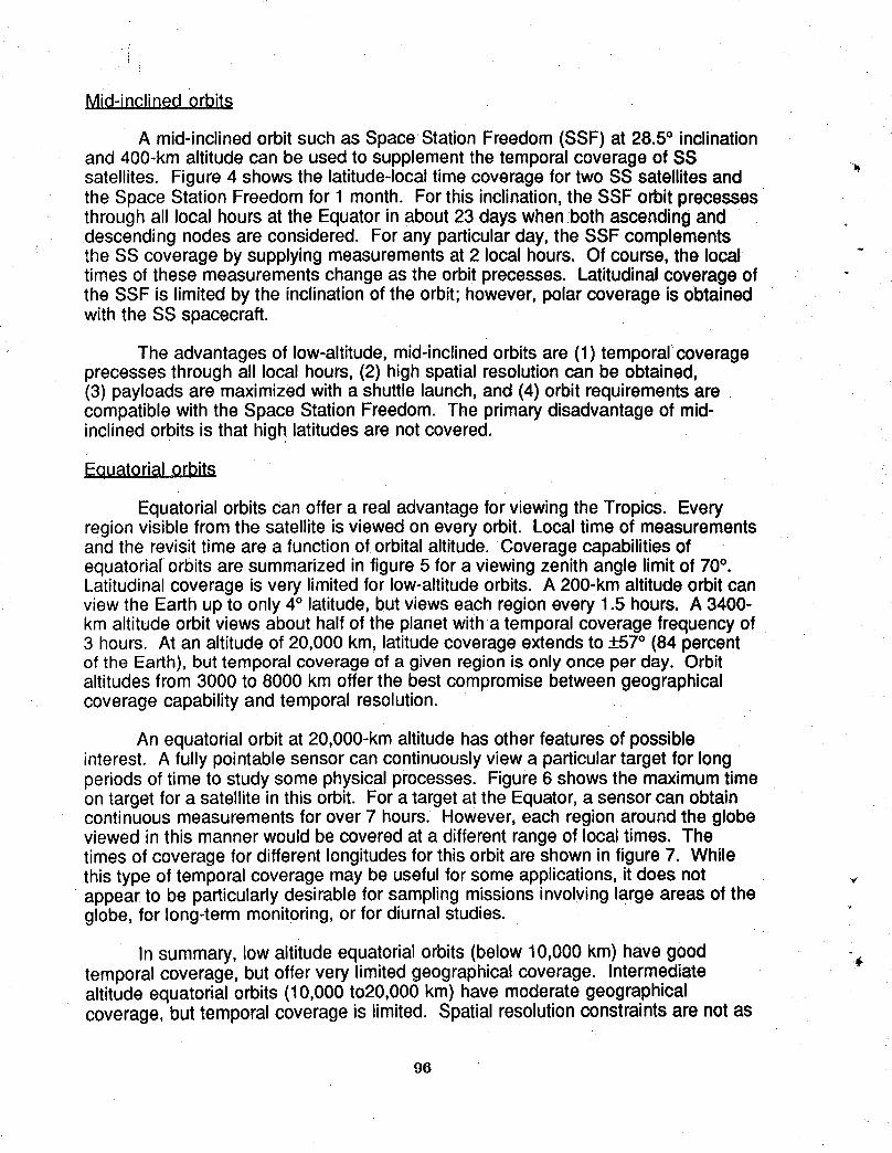
Mid-inclined orbits
A mid-inclined orbit such as Space Station Freedom (SSF) at 28.5° inclinationand 400-km altitude can be used to supplement the temporal coverage of SSsatellites. Figure 4 shows the latitude-local time coverage for two SS satellites andthe Space Station Freedom for 1 month. For this inclination, the SSF orbit precessesthrough all local hours at the Equator in about 23 days when both ascending anddescending nodes are considered. For any particular day, the SSF complementsthe SS coverage by supplying measurements at 2 local hours. Of course, the localtimes of these measurements change as the orbit precesses. Latitudinal coverage ofthe SSF is limited by the inclination of the orbit; however, polar coverage is obtainedwith the SS spacecraft.
The advantages of low-altitude, mid-inclined orbits are (1) temporal coverageprecesses through all local hours, (2) high spatial resolution can be obtained,(3) payloads are maximized with a shuttle launch, and (4) orbit requirements arecompatible with the Space Station Freedom. The primary disadvantage of mid-inclined orbits is that high latitudes are not covered.
Eeuatorial orbits
Equatorial orbits can offer a real advantage for viewing the Tropics. Everyregion visible from the satellite is viewed on every orbit. Local time of measurementsand the revisit time are a function of orbital altitude. Coverage capabilities ofequatoriaf'orbits are summarized in figure 5 for a viewing zenith angle limit of 70°.Latitudinal coverage is very limited for low-altitude orbits. A 200-km altitude orbit canview the Earth up to only 4° latitude, but views each region every 1.5 hours. A 3400-km altitude orbit views about half of the planet witha temporal coverage frequency of3 hours. At an altitude of 20,000 km, latitude coverage extends to +57° (84 percentof the Earth), but temporal coverage of a given region is only once per day. Orbitaltitudes from 3000 to 8000 km offer the best compromise between geographicalcoverage capability and temporal resolution.
An equatorial orbit at 20,000-km altitude has other features of possibleinterest. A fully pointable sensor can continuously view a particular target for longperiods of time to study some physical processes. Figure 6 shows the maximum timeon target for a satellite in this orbit. For a target at the Equator, a sensor can obtaincontinuous measurements for over 7 hours. However, each region around the globeviewed in this manner would be covered at a different range of local times. Thetimes of coverage for different longitudes for this orbit are shown in figure 7. Whilethis type of temporal coverage may be useful for some applications, it does not vappear to be particularly desirable for sampling missions involving large areas of theglobe, for long-term monitoring, or for diurnal studies.
In summary, low altitude equatorial orbits (below 10,000 km) have good -_temporal coverage, but offer very limited geographical coverage. Intermediatealtitude equatorial orbits (10,000 to20,000 km) have moderate geographicalcoverage, but temporal coverage is limited. Spatial resolution constraints are not as
96
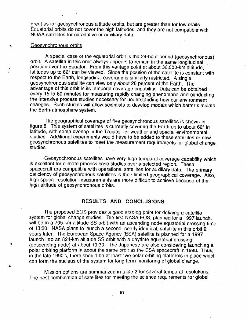
great as for geosynchronous altitude orbits, but are greater than for low orbits.Equatorial orbits do not cover the high latitudes, and they are not compatible withNOAA satellites for correlative or auxiliary data.
,, Geosynchronous orbits
A special case of the equatorial orbit is the 24-hour period (geosynchronous)orbit. A satellite in this orbit always appears to remain in the same longitudinalposition over the Equator. From this vantage point at about 36,000-km altitude,latitudes up to 62° can be viewed. Since the position of the satellite is constant withrespect to the Earth, longitudinal coverage is similarly restricted. A singlegeosynchronous satellite can view only about 26 percent of the Earth. Theadvantage of this orbit is its temporal coverage capability. Data can be obtainedevery 15 to 60 minutes for measuring rapidly changing phenomena and conductingthe intensive process studies necessary for understanding how our environmentchanges. Such studies will allow scientists to develop models which better simulatethe Earth-atmosphere system.
The geographical coverage of five geosynchronous satellites is shown infigure 8. This system of satellites is currently covering the Earth up to about 62° inlatitude, with some overlap in the Tropics, for weather and special environmentalstudies. Additional experiments would have to be added to these satellites or newgeosynchronous satellites to meet the measurement requirements for global changestudies.
Geosynchronous satellites have very high temporal coverage capability whichis excellent for climate process case studies over a selected region. Thesespacecraft are compatible with operational satellites for auxiliary data. The primarydeficiency of geosynchronous satellites is their limited geographical coverage. Also,high spatial resolution measurements are more difficult to achieve because of thehigh altitude of geosynchronous orbits.
RESULTS AND CONCLUSIONS
The proposed EOS provides a good starting point for defining a satellitesystem for global change studies. The first NASA EOS, planned for a 1997 launch,will be in a 705-km altitude SS orbit with an ascending node equatorial crossing timeof 13:30. NASA plans to launch a second, nearly identical, satellite in this orbit 2years later. The European Space Agency (ESA) satellite is planned for a 1997launch into an 824-km altitude SS orbit with a daytime equatorial crossing(descending node) at about 10:30. The Japanese are also considering launching apolar orbiting platform in about the same orbit as the ESA spacecraft in 1998. Thus,in the late 1990's, there should be at least two polar orbiting platforms in place whichcan form the nucleus of the system for long-term monitoring of global change.
Mission options are summarized in table 2 for several temporal resolutions.The best combination of satellites for meeting the science requirements for global
97
coverage and a 3-hour temporal resolution for diurnal coverage is to add twoadditional SS satellites with appropriate equatorial crossing times to the EOS andESA (or Japanese) polar orbiting platforms. Another attractive option is adding oneadditional SS spacecraft and the SSF to the EOS and ESA (or Japanese) satellites.This combination provides temporal coverage of 3 to 4 hours and concentrates thecoverage of one satellite (SSF) in the Tropics. The three SS satellites will providegood polar coverage. Diurnal sampling is not required for many of the parameters tobe measured. Consequently, some instruments would only need to be flown on oneSS spacecraft. Table 2 also identifies several three-satellite orbit combinations withtemporal sampling capability from 4 to 6 hours.
Regional studies of physical processes require much higher temporalresolutions than can be obtained from the satellite systems designed for globalchange monitoring applications. One or two geosynchronous satellites are neededto provide this capability. These satellites should be movable in longitude so thatthey can be repositioned around the globe as required tOstudy particular regions.
REFERENCES
1. Brooks, David R.: An introduction to orbit dynamics and its application to satellite-based Earth monitoring missions. NASA RP-1009, November 1977.
2. Suttles, John T., Edwin F. Harrison, Gary G. Gibson, and Thomas G. Campbell:Science requirements for a global change technology architecture trade study.NASA TM-104082, May 1991.
98

TABLE 1. REQUIREMENTS* FOR EARTH SCIENCE MEASUREMENTS
DIURNAL GLOBAL CHANGE REGIONAL PROCESS
REGIME/ MEASURABLE CYCLE STUDIES STUDIES
CATEGORY CRITICAL TEMPORAL SPATIAL TEMPORAL SPATIAL
SOLAR SPECTRAL RADIATION NO 1D SUN DISK 1D SUN DISK
PRESSURE (SURFACE) NO 3-12H 10km
TEMPERATUREPROFILE YES 1-3H 10-50km 15M-1H 5km
STRATOSPHERIC GASES NO 3-12H 50km 30M 5-10kmATMOSPHERE AEROSOLS & PARTICULATES NO 3-12H 10km 15M-1H 0.1-1km
TROPOSPHERICWATER VAPOR NO 3-12H 10km 30M-1H 10km
CLOUD COVER & HEIGHT YES 1-3H lkm 15M-1H l km
TROPOSPHERIC GASES YES 1-3H 10km 30M-1H 10-50kin
WIND FIELDS YES 1-3H 10km 30M-1H
RADIATION REFLECTED SW &
_ BUDGET EMITTED LW FLUX YES 1-3H 10-30km 30M-1H 1-30km
SURFACE TEMPERATURE YES 1-3H 1-4km 6M-24H 30m-200km
PRECIPITATION YES 1-3H 1-30km 3M-3H 1-200km
VEGETATIONCOVER/TYPE NO 7D lkm 1-30D 30m-10kmSOIL MOISTURE NO 2D 1-10km 12H-7D 30m-10km
EARTH BIOMASS INVENTORY NO 7D lkm !-30D !-10km
(LAND/ OCEAN COLOR (CHLOROPHYLL) NO 2D 1-4km 2D 30m-4km
OCEAN) OCEAN CIRCULATION NO 2D 1-4km 1D 30m-4kmSEA LEVEL RISE NO 2D 10km 2D 10km
SEA ICE COVER/DEPTH NO 7D 1-20km 1-3D 1-25km
OCEAN CO2 NO 2D 0.5km
SNOW COVER/DEPTH/WETNESS NO 7D 1km 12H-3D 1-10km
* SAMPLING REQUIREMENTSARE GIVEN; DATA PRODUCTS FOR GLOBAL CHANGE STUDIES ARE DAILY
MEANS AND 100-250km MEANS, DATA PRODUCTS FOR REGIONAL PROCESS STUDIES ARE HIGHLYVARIABLE.
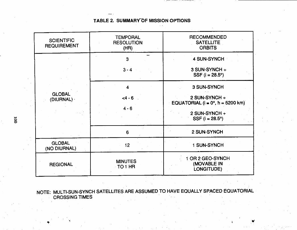
TABLE 2. SUMMARY-OF MISSION OPTIONS
TEMPORAL RECOMMENDEDSCIENTIFIC RESOLUTION SATELLITE
REQUIREMENT (HR) ORBITS
3 4 SUN-SYNCH
3 - 4 3 SUN-SYNCH +SSF (i= 28.5°)
4 3 SUN-SYNCH
GLOBAL ' '(DIURNAL) - <4 - 6 2 SUN-SYNCH +
EQUATORIAL (i -- 0°, h = 5200 km)i 4-6
.... 2 SUN-SYNCH +"= SSF (i = 28.5°)
6 2 SUN_-SYNCH
GLOBAL 12 1 SUN-SYNCH(NO DIURNAL)
MINUTES 1 OR 2 GEO-SYNCHREGIONAL TO 1 HR (MOVABLE IN
LONGITUDE)
NOTE: MULTI-SUN-SYNCH SATELLITES ARE ASSUMED TO HAVE EQUALLY SPACED EQUATORIALCROSSING TIMES
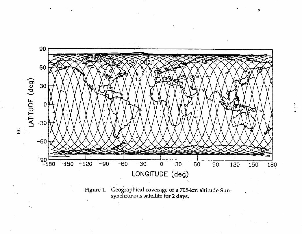
9O
6O
=9q- 80 -150 -t20 -90 -60 -30 0 30 60 90 120 150 180
LONGITUDE (decj)-.
Figure 1. Geographical coverage of a 705-kin altitude Sun-synchronous satellite for 2 days.
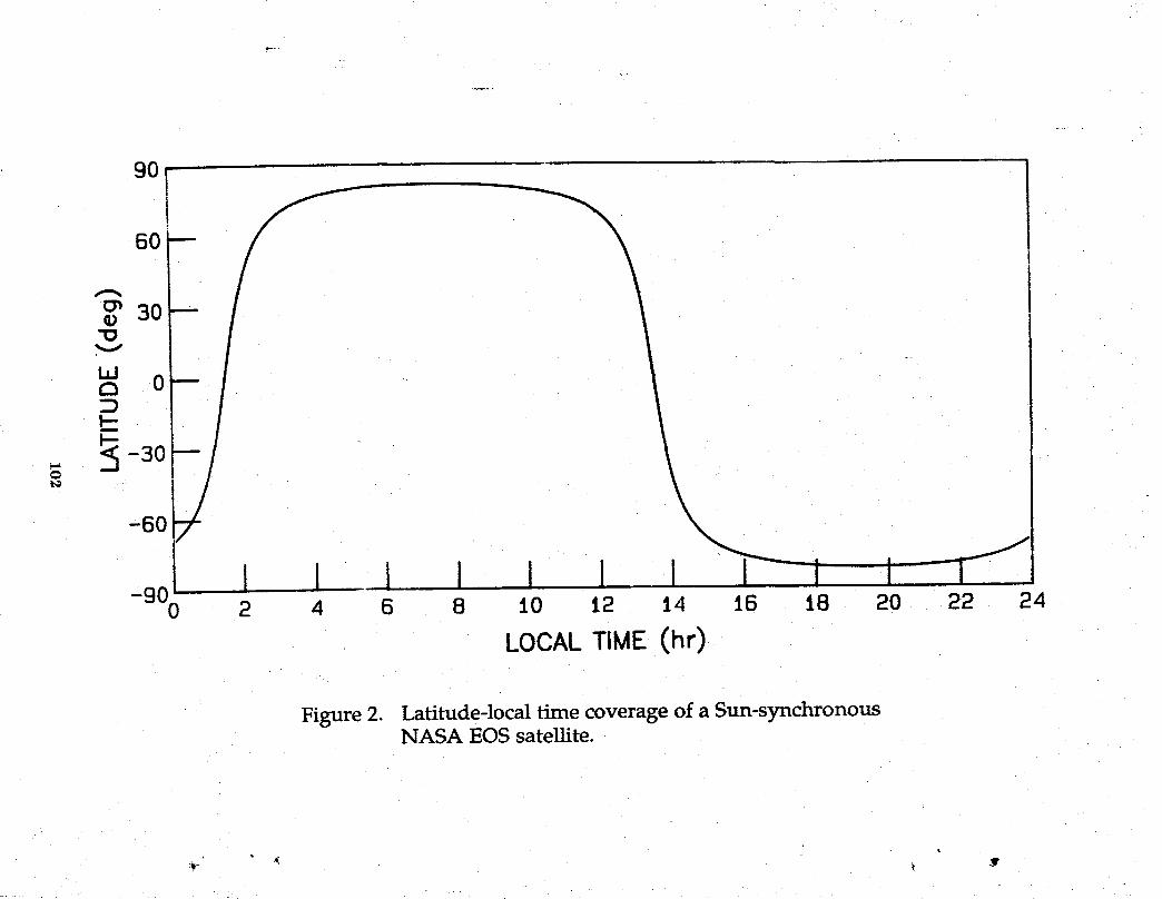
90
60
30
O 0:D
I--
_: :S-30-60
i i I i i-900 2 4 6 8 I0 12 14 16 18 20 22 __4
LOCALTIME (hr)
Figure 2. Latitude-local time coverage of a Sun-synchronousNASA EOS satellite.
i
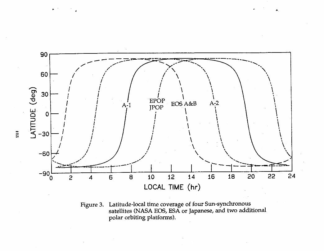
9O
_f _. f" "y. _. _ -,
/ I / \ \ \ ',,•._ / ! / i \ \ \ \._3o-- / ! / i \ \ \ ;- I I EPOP " \v ! , A-1 "POP EOS A&B A_2 \
I / / ', i t !N o- J
-60 ./ ./ \X X.-,. _../ _ t'- _ .-_,....._. -,,,.._.._1"--'--- -T=---1-----"I I I ! I----1--:-T--'P ---=---
-900 2 4 6 8 t0 12 14 J.6 18 20 22 24
LOCAL TIME (hr)
Figure 3. Latitude-local time coverage of four Sun-synchronoussatellites (NASA EOS, ESA or Japanese, and two additionalpolar orbiting platforms).
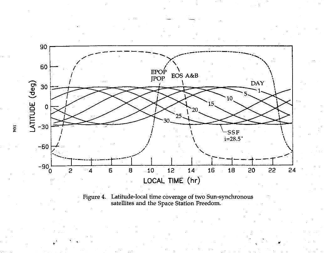
9O
f _ _ _ _ _ "°'''_'" "'_",_.,,,_**
f
\60 -- I EPO_ \ \
1 1 JPOP EOS A&B ,1 / i \ DAY \
.g _o _....5..._
v I0_'..,.. 10I_ i_ " - " _ "_°_ _ _'_'_
2 2si_ _._ /-3o. -_.i•._ -_°F-i -- ! \ _ss_ _,
/ / \ i=28.5 ° \
-50 --/- / k \/
--I...........r--, ,kL - ----900 2 4 6 8 _.0 1 16 1!4
LOCALTIME (hr)
Figure 4. Latitude-local time coverage of two Sun-synchronoussatellites and the Space Station Freedom.
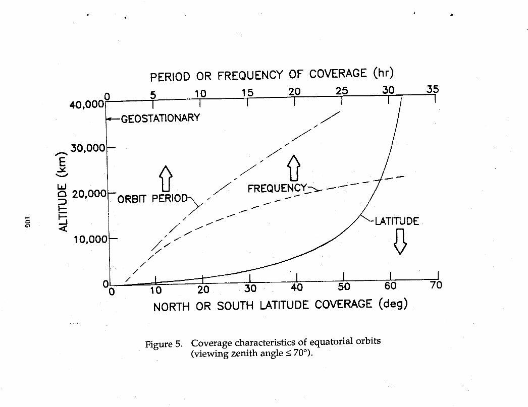
PERIOD OR FREQUENCY OF COVERAGE (hr)
0 5 10 15 20 25 30 3540.0001 l I i l i I/ I
_--GEOSTATIONARY . . .__' _o,ooo
onnool- U :, / FREQUENCY--._.--------- 7-
_ ._._----+. /'7-- /-,_,.-,-,-,-uo+-.'°'°°°F ..+
• /
0 10 20 30 . 40 50 60
NORTH OR SOUTH LATITUDE COVERAGE (deg)
Figure 5. Coverage characteristics of equatorial orbits(viewing zenith angle < 70°).
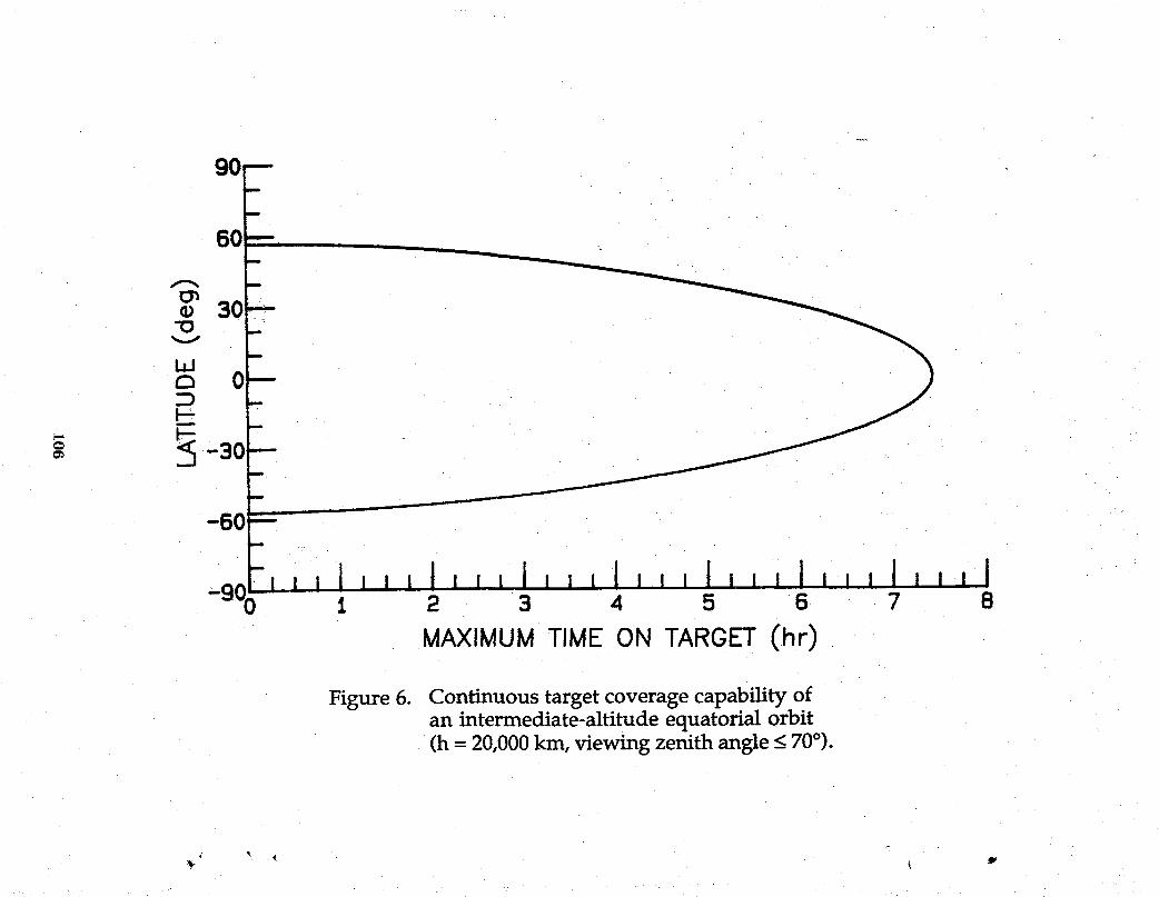
90--
60
60
--1
1 2 3 4 5 6 7 8
MAXIMUMTIME ON TARGET(.hr)
Figure 6. Continuous target coverage capability ofan intermediate-altitude equatorial orbit(h = 20,000kin, viewing zenith angle < 70°).
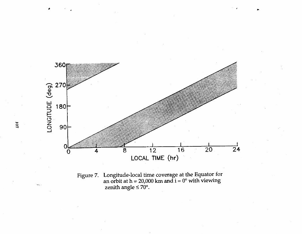
360
I I I I0 4 8 12 16 20 24
LOCAL TIME (hr)
Figure 7. Longitude-local time coverage at the Equator foran orbit at h = 20,000 km and i = 0° with viewing
.... zenith angle < 70°.
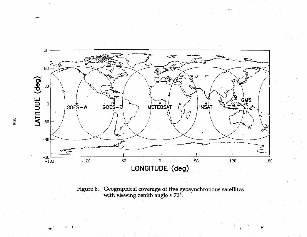
50
6O
i,I _./ GMSa 0:::) GOES-W GOES-I METEOSATk INSAT
\\\ /// /i/t \\ i/ . \__o _- - -><--_o I I I I • I-180 -120 -60 0 60 120 80
LONGITUDE(deg)
Figure 8. Geographical coverage of five geosynchronous satelliteswith viewing zenith angle < 70°.
SELECTION OF REPRESENTATIVE INSTRUMENTSFOR A GLOBAL CHANGE TECHNOLOGY
.. ARCHITECTURE TRADE STUDY
Warren D. Hypes and Lloyd KeaferThe Bionetics Company
Rogard Ross and Heather R. KnightJoint Institute for Advancement of Flight Sciences
Anthony Jalink and Cheryl L. AllenNASA Langley Research Center
4

INTRODUCTION
..... This report documents a portion of effort conducted within the Global Change Technology
4 Initiative (GCTI) Architectural Trade Study. The purpose of the GCTI Trade Study is to
develop and evaluate architectural mixes of spacecraft and sensor (instrument) groupings at
. LEO, GEO, and intermediate orbits to meet the science needs of global change studies. The
Trade Study Plan entilted, Global Change Technology Initiative Architecture Trade Study
Plan dated April, 1989 specifies a study divided into nine tasks. Task 1 of the Study was
to develop a set of science requirements that specified the measurements to be made and
the spatial resolution and temporal frequency at which they should be made. This task
was completed, and a set of science requirements have been established. The completion
of Task 1 permitted the GCTI Study to move into the Task 2 effort. Task 2 is entitled
Sensor Requirements and Constraints but more appropriately it would be entitled Instrument
Selection and Complementary Packaging. Due to the scope of the total GCTI Study
and the unavoidable overlap between Tasks, the completion of Task 2 required interfacing
...... with Task 3, Mission Design Options; Task 4, Spacecraft and Platform Development and
Options; Task 6, Spacecraft and Sensor Performance Assessments; and Task 9, Technology
Assessment. The approach to and the results of the Task 2 effort and its interfaces with the
other Tasks are the subject of this paper.
OBJECTIVES
The objectives of Task 2 of the GCTI Architecture Trade Study are to select representative
sets of instruments for making the science measurements specified in Task 1 and to identify
instruments that, when flowntogether, form special complementary package formeasurement
purposes. The list of representative instruments and their complementary relationships
provide a payload manifest defined in terms of mass, power, size, viewing angles, data rates__t
etc. which can be used to focus spacecraft trade studies and the definition of a candidate
GCTI fleet.
11]

SCIENCE REQUIREMENTS
The rationale for and the definition of science requirementsestablished duringthe Task 1
effort has been presented by Suttles, et al. (1989). Table I taken from the Suttles t
document summarizes the requirements in tabular form. Values are presented for two types
of measurements, global change study and regional process studies. The global change
study requirementsrelate to measurements that are essential to the detection of long-term
trends on a global scale. These measurements often provide the basic experimental data
for the development and verification of large geographical area environmental models. The
regional process studies relate to measurements that are essential to short-term, intensive
field experiments on a local or regional scale. In general, they requirehigher resolutions on
a more frequent temporal schedule than those of the global change studies.
Both spatial and temporal requirements are specified. The spatial values represent the
required horizontal resolution measuring capability of the instrument and the temporal
values represent the required measurement frequency. Although the science requirements
do not specify values for vertical resolution, the instruments selection team and the science _-_
requirements team agreed that for measurables where vertical distribution is important, the
data would be enhanced if measurements were made at nine to seventeen levels in the total
depth of the atmosphere and at least two or three levels in the troposphere. These guidelines
were used in the instrument selection process.
CANDIDATE INSTRUMENTS
In order to select a representative set of instruments for making the scientific measure-
ments, a survey was made of instruments used on past and current spacecraft and those
proposed for spacecraft of the near future. Data describing candidate instruments were
collected from a variety of sources including NASA Technology Models and NASA Instru-
ment Handbooks. A number of documents on the Upper AtmosphereResearch Satellite and "
the Earth Observation System proved valuable. Reports on the progress of the geostation-
ary platforms under study at NASA Marshall were closely examined. Used as guidelines .,_._.
112
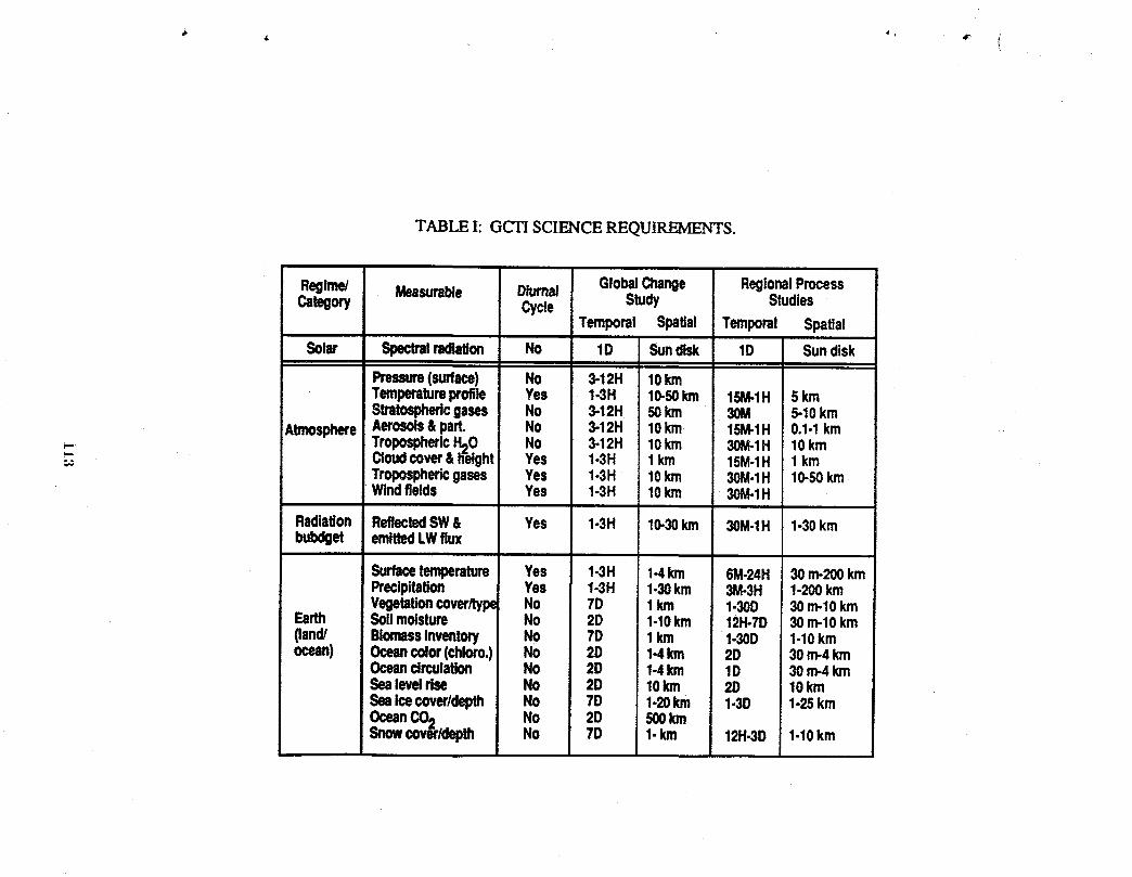
TABLE I: GCTI SCIENCE REQUIREMENTS.
Regime/ Measurable Diurnal GlobalChange RegionalProcessCategory Cycle Study Studies
Temporal Spatial Temporal Spatial
Solar Spectralradiation No 1D Sundisk 1D Sundisk
Pressure(surface) No 3.12H 10kmTemperatureprofile Yes 1-3H 10-50km 15M-1H 5 kmStratosphericgases No 3.12H 50km 30M 5-10km
AtmosphereAerosols&part. No 3.12H 10km 15M.1H 0.1-Ikm_ Tropospheric.H20 No 3-12H 10km 30M.1H 10km
Cloudcover&h-eight Yes 1-3H 1km 15M.1H 1kmTroposphericgases Yes 1-3H 10km 30M.1H 10-50kmWindfields Yes 1-3H 10km 30M-1H
RadiaUon ReflectedSW& Yes 1-3H 10-30km 30M.1H 1-30kmbulxIget emittedLWflux
Surfacetemperature Yes 1-3H 1-4km 6M-24H 30m-200kmPreclpitalion Yes 1-3H 1-30km 3M-3H 1.200kmVegetationcover/type No 7D 1km 1-30D 30m-lOkm
Earth Soilmoisture No 2D 1-10km 12H-7D 30m-lOkm(land/ BiomassInventory No 7D 1km 1.30D 1-10kmocean) Oceancolor(chloro.) NO 2D 1-4Ion 2D 30m-4km
Oceancirculation No 2D 1.4km 1D 30m-4kmSealevelrise No 2D 10Ion 2D 10kmSeaicecoverldepth No 7D 1-20km 1-3D 1-25kmOceanCO2 No 2D 500kmSnowcov_rldepth No 7D 1-km 12H.3D 1-10km
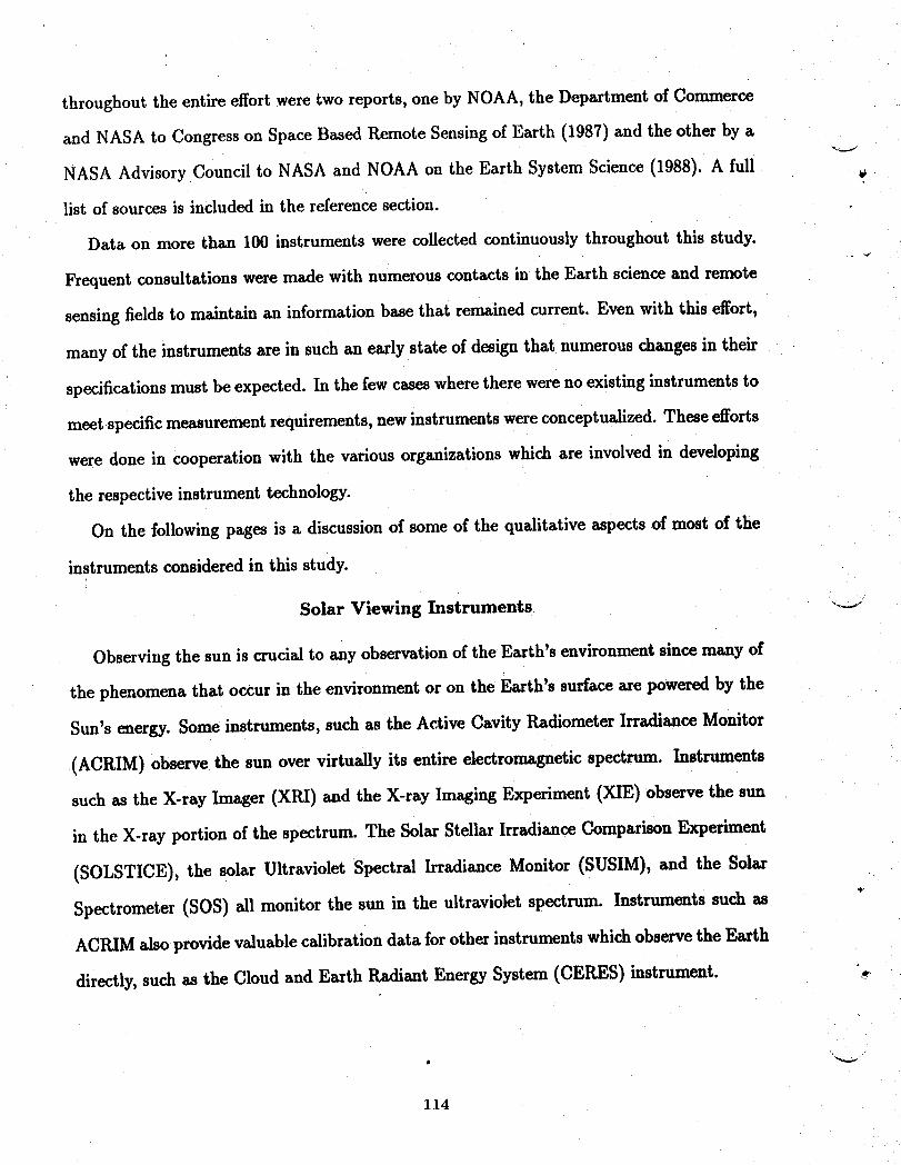
throughout the entire effortwere two reports, one by NOAA, the Department of Commerce
and NASA to Congress on Space Based Remote Sensing of Earth (1987) and the other by a
NASA Advisory Council to NASA and NOAA on the Earth System Science (1988). A full
list of sources is included in the reference section.
Data on more than 100 instruments were collected continuously throughout this study.
Frequent consultations were made with numerous contacts in the Earth science and remote
sensing fields to maintain an information base that remained current. Even with this effort,
many of the instruments are in such an early state of design that numerous changes in their
specifications must be expected. In the few cases where there were no existing instruments to
meet specific measurement requirements, newinstruments were conceptualized. These efforts
were done in cooperation with the various organizations which are involved in developing
the respective instrument technology.
On the following pages is a discussion of some of the qualitative aspects of most of the
instruments considered in this study.
Solar Viewing Instruments "'_
Observing the sun is crucial to any observation of the Earth's environment since many of
the phenomena that occur in the environment or on the Earth's surface are powered by the
Sun's energy. Some instruments, such as the Active Cavity Radiometer Irradiance Monitor
(ACRIM) observe the sun over virtually its entire electromagnetic spectrum. Instruments
such as the X-ray Imager (XRI) and the X-ray Imaging Experiment (XIE) observe the sun
in the X-ray portion of the spectrum. The Solar Stellar Irradiance Comparison Experiment
(SOLSTICE), the solar Ultraviolet Spectral Irradiance Monitor (SUSIM), and the Solar
Spectrometer (SOS) all monitor the sun in the ultraviolet spectrum. Instruments such as
ACItIM also provide valuable calibration data for other instruments which observe the Earth
directly, such as the Cloud and Earth Radiant Energy System (CERES) instrument. _
114
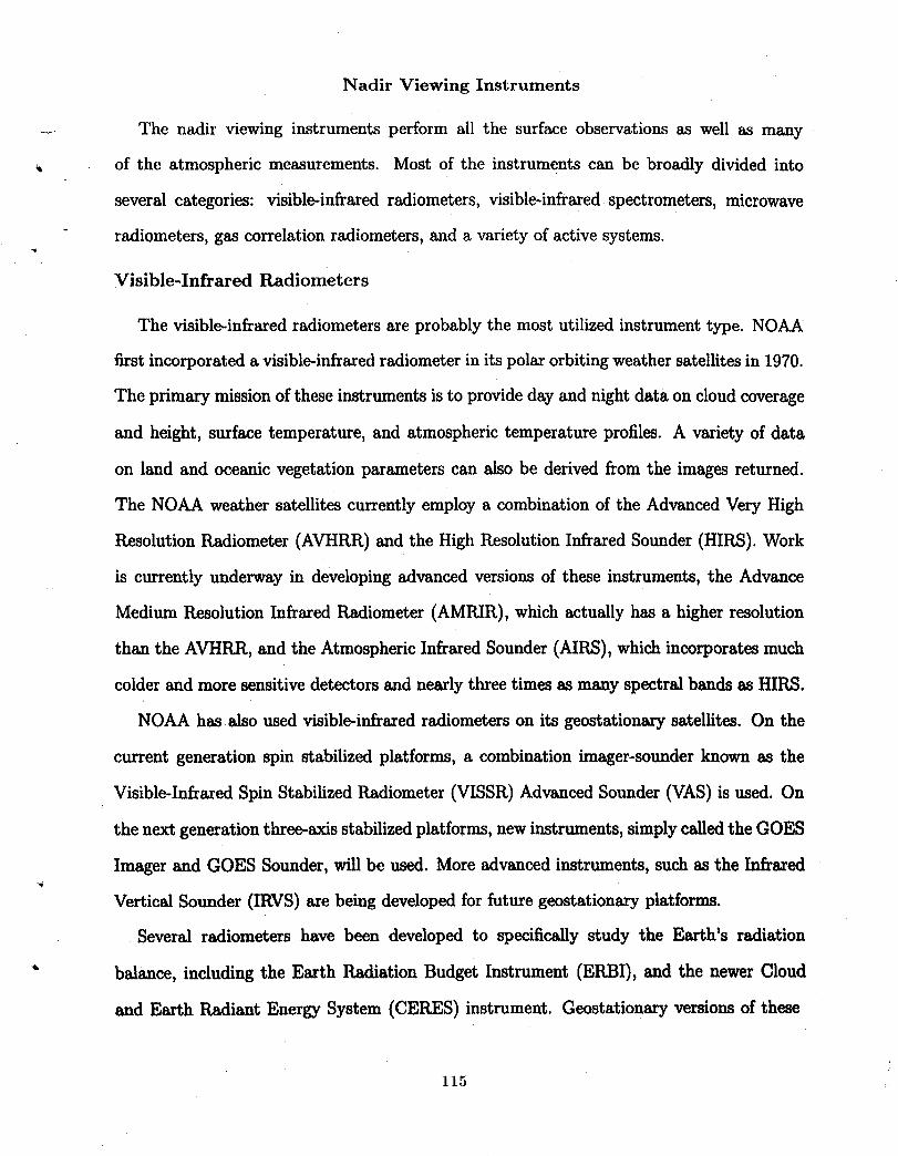
Nadir Viewing Instruments
..... The nadir viewing instruments perform all the surface observations as well as many ,
of the atmospheric measurements. Most of the instruments can be broadly divided into
several categories: visible-infrared radiometers, visible-infrared spectrometers, microwave
radiometers, gas correlationradiometers, and a variety of active systems.
Visible-Infrared Radiometers
The visible-infrared radiometers are probablythe most utilized instrument type. NOAA
first incorporateda visible-infrared radiometerin its polar orbiting weather satellites in 1070.
The primary mission of these instruments is to provide day and night data on cloud coverage
and height, surface temperature, and atmospheric temperature profiles. A variety of data
on land and oceanic vegetation parameters can also be derived from the images returned.
The NOAA weather satellites currently employ a combination of the Advanced Very High
Resolution Radiometer (AVHRR) and the High Resolution Infrared Sounder (HIRS). Work
is currently underway in developing advanced versions of these instruments, the Advance
Medium Resolution Infrared Radiometer (AMRIR), which actually has a higher resolution
than the AVHRR, and the Atmospheric Infrared Sounder (MRS), which incorporatesmuch
colder and more sensitive detectors and nearly three times as many spectral bands as HIRS.
NOAA has also used visible-infrared radiometers on its geostationary satellites. On the
current generation spin stabilized platforms, a combination imager-sounder known as the
Visible-Infrared Spin Stabilized Radiometer (VISSR) Advanced Sounder (VAS) is used. On
the next generation three-axis stabilizedplatforms, new instruments, simply called the GOES
Imager and GOES Sounder, will be used. More advanced instruments, such as the Infrared,€
Vertical Sounder (IRVS) are being developed for future geostationary platforms.
Several radiometers have been developed to specifically study the Earth's radiation
" balance, including the Earth Radiation Budget Instrument (ERBI), and the newer Cloud
and Earth Radiant Energy System (CERES) instrument. Geostationary versions of these
115
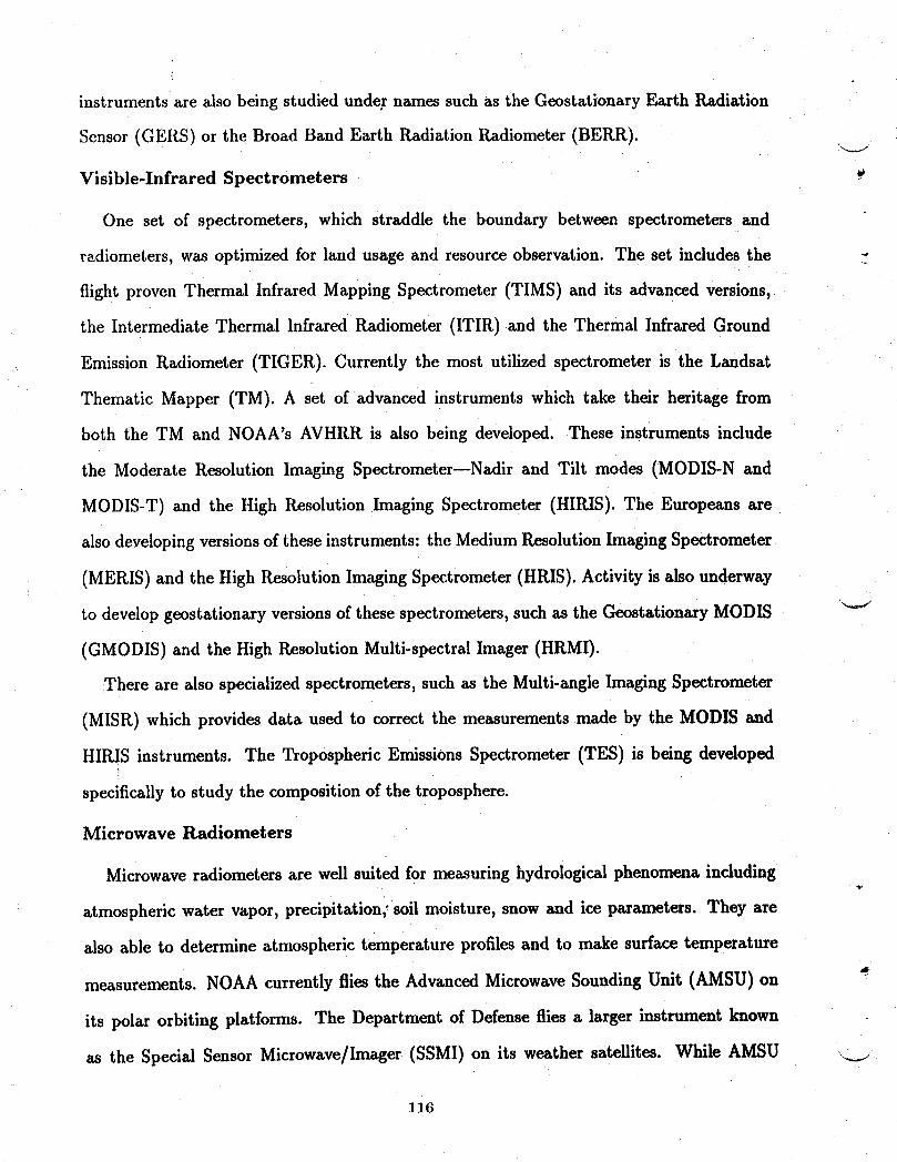
instruments are also being studied under names such as the Geostationary Earth Radiation
Sensor (GERS) or the Broad Band Earth Radiation Radiometer (BERR).
Visible-Infrared Spectrometers
One set of spectrometers, which straddle the boundary between spectrometers and
radiometers, was optimized for land usage and resource observation. The set includes the
flight proven Thermal Infrared Mapping Spectrometer (TIMS) and its advanced versions,
the Intermediate Thermal Infrared Radiometer (ITIR) and the Thermal Infrared Ground
Emission Radiometer (TIGER). Currently the most utilized spectrometer is the Landsat
Thematic Mapper (TM). A set of advanced instruments which take their heritage from
both the TM and NOAA's AVHRR is also being developed. These instruments include
the Moderate Resolution lmaging Spectrometer--Nadir and Tilt modes (MODIS-N and
MODIS-T) and the High Resolution Imaging Spectrometer (HIRIS). The Europeans are
also developing versions of these instruments: the Medium Resolution Imaging Spectrometer
(MERIS) and the High Resolution Imaging Spectrometer (HRIS). Activity is also underway
to develop geostationary versions of these spectrometers, such as the Geostationary MODIS _
(GMODIS) and the High Resolution Multi-spectral Imager (HRMI).
There are also specialized spectrometers, such as the Multi-angle Imaging Spectrometer
(MISR) which provides data used to correct the measurements made by the MODIS and
HIRIS instruments. The Tropospheric Emissions Spectrometer (TES) is being developed
specifically to study the composition of the troposphere.
Microwave Radiometers
Microwave radiometers are well suited for measuring hydrological phenomena including
atmospheric water vapor, precipitation; soil moisture, snow and ice parameters. They are
also able to determine atmospheric temperature profiles and to make surface temperature
measurements. NOAA currently flies the Advanced Microwave Sounding Unit (AMSU) on
its polar orbiting platforms. The Department of Defense flies a larger instrument known
as the Special Sensor Microwave/imager (SSMI) on its weather satellites. While AMSU _.._
116
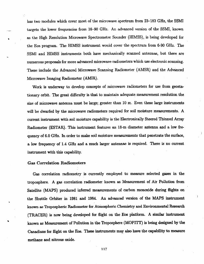
has two modules which cover most of the microwave spectrum from 23-183 GHz, the SSMI
........ targets the lower frequencies from 18-90 GHz. An advanced version of the SSMI, known
as the High Resolution Microwave Spectrometer Sounder (HIMSS), is being developed for
the Eos program. The HIMSS instrument would cover the spectrum from 6-90 GHz. The
SSMI and HIMSS instruments both have mechanically scanned antennas, but there are
numerous proposals for more advanced microwave radiometers which use electronic scanning.
These include the Advanced Microwave Scanning Radiometer (AMSR) and the Advanced
Microwave Imaging Radiometer (AMIR).
Work is underway to develop concepts of microwave radiometers for use from geosta_
tionary orbit. The great difficulty is that to maintain adequate measurement resolution the
size of microwave antenna must be large; greater than 10 m. Even these large instruments
will be dwarfed by the microwave radiometers required for soil moisture measurements. A
current instrument with soil moisture capability is the Electronically Steered Thinned Array
Radiometer (ESTAR). This instrument features an 18-m diameter antenna and a low fre-
quency of 6.0 GHz. In order to make soil moisture measurements that penetrate the surface,
a low frequency of 1.4 GHz and a much larger antennae is required. There is no current
instrument with this capability.
Gas Correlation Radiometers
Gas correlation radiometry is currently employed to measure selected gases in the
troposphere. A gas correlation radiometer known as Measurement of Air Pollution from
Satellite (MAPS) produced inferred measurements of carbon monoxide during flights on
the Shuttle Orbiter in 1981 and 1984. An advanced version of the MAPS instrument
known as Tropospheric Radiometer for Atmospheric Chemistry and EnvironmentalResearch
(TRACER) is now being developed for flight on the Eos platform. A similar instrument%
known as Measurement of Pollution in the Troposphere (MOPITT) is being designed by the
Canadians for flight on the Eos. These instruments may also have the capability to measure
methane and nitrous oxide.
117
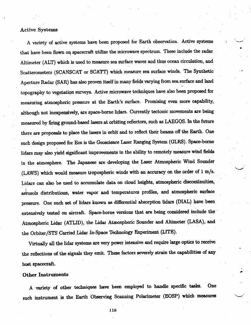
Active Systems
A variety of active systems have been proposed for Earth observation. Active systems
that have been flown on spacecraft utilize the microwavespectrum. These include the radar
Altimeter (ALT) which is used to measure sea surface waves and thus ocean circulation, and
Scatterometers (SCANSCAT or SCATT) which measure sea surface winds. The Synthetic
Aperture Radar (SAR) has also proven itself in many fields varyingfrom sea surface and lando_
topography to vegetation surveys. Active microwave techniques have also been proposed for
measuring atmospheric pressure at the Earth's surface. Promising even more capability,
although not inexpensively, are space-borne lidars. Currentlytectonic movements are being
measured by firing ground-based lasers at orbiting reflectors,such as LAEGOS. In the future
there are proposals to place the lasers in orbit and to reflect their beams off the Earth. One
such design proposed for Eos is the GeoscienceLaser Ranging System (GLRS). Space-borne
lidars may also yield significant improvements in the ability to remotely measure wind fields
in the atmosphere. The Japanese are developing the Laser Atmospheric Wind Sounder
(LAWS) which would measure tropospheric winds with an accuracy on the order of 1 m/s.
Lidars can also be used to accumulate data on cloud heights, atmospheric discontinuities,
a_rosols distributions, water vapor and temperatures profiles, and atmospheric surface
pressure. One such set of lidars known as differential absorption lidars (DIAL) have been
extensively tested on aircraft. Space-borne versions that are being considered include the
Atmospheric Lidar (ATLID), the Lidar Atmospheric Sounder and Altimeter (LASA), and
the Orbiter/STS CarriedLidar In-Space Technology Experiment (LITE).
Virtually all the lidar systems arevery powerintensive and requirelarge optics to receive
the reflections of the signals they emit. These factors severely strain the capabilities of any
host spacecraft.
Other Instruments
A variety of other techniques have been employed to handle specific tasks. One
such iustmment is the Earth Observing Scanning Polarimeter (EOSP) which measures _-J
118
polarization of upwelling energy from the Earth and thus provides atmospheric connections
___ for a number of spectrometers such as the MODIS, HIRIS, and TES. The EOSP also provides
information on cloud properties and aerosol distributions.
Limb Viewing Instruments
Limb viewing instruments are a special class of instruments that view the Earth's upper
atmosphere at or near the apparent upper edge of the atmosphere when viewed laterally from
the spacecraft. Measurements axe based on transmission and absorbance of the sun's energy
as it passes through the atmosphere path (sun in occultation behind the atmosphere) or upon
the spectra of thermal energy emitted by the constituents of the atmosphere. Limb viewers
are, therefore, especially adaptable to spectral analysis of atmospheric gases. Because of the
viewing geometry of limb viewers, the strongest signal results at a point along the viewing
path where the path is tangent to the Earth's surface so that vertical scanning provides
a profile of the vertical distribution of the emiting gases in the stratosphere and upper _
troposphere. The measurement is obtained many kilometers from the subsateUite location
of the viewing instrument, thus lower measurement altitude is a function of cloud height.
The measurement techniques can again be divided into a number of categories: visible-
infrared radiometers, gas correlation radiometers, visible-inkared spectrometers, visible-
infrared interferometers, grating spectrometers, microwave radiometers, and a number of
sensors operating in the ultraviolet spectral region.
Visible-Infrared Radiometers
A pair of infrared radiometers proposed for the Eos program are the High Resolution
Research Limb Sounder (HIRRLS) and the Dynamic Limb Sounder (DLS). Both instruments
measure several gases including ozone, water vapor, methane and nitrogen dioxide in the
* spectral region from 6 to 8/zm.
Gas Correlation Radiometers
The Upper Atmosphere Research Satellite (UARS) will carry two gas correlation
119

radiometers. The Improved Stratospheric and Mesospheric Sounder (ISAMS) and the Halo-
gen Occultation Experiment (HALOE). Together the two instruments cover the spectrum ,._.'"
from 2 to 17 _m although the HALOE instrument is only operational at sunrise and sun- *
set. The Stratospheric Wind Infrared Limb Sounder (SWIRLS) is being developed for the
Eos program. This instrument employs new gas correlation techniques to measure upper
atmospheric wind fields and temperature profiles as well as several gas species.
Visible-Infrared Spectrometer
The Cryogenic Limb Array Etalon Spectrometer (CLAES) was developed for UARS to
be an extremely versatile instrument capable of measuring a wide range of gas species,
Unfortunately this instrument also dominates half of the satellite's payload allowance. The
Spectroscopy of the Atmosphere Using Far Infrared Emission (SAFIR.E) instrument is being
developed for the Eos program. This instrument will also be able to measure a wide variety
of gases using a combination of far-infrared spectrometry and mid-infrared radiometry.
Visible-Infrared Interferometers
A great deal of information about the atmospheric conditions can be determined using
intefferometer techniques. The UARS mission carried two intefferometers, a Fabry-Perot
intefferometer named the High Resolution Doppler Imager (HRDI) and a Michelson inter-
ferometer called the Wind Imaging Intefferometer (WINDII). Both instruments are useful
for measuring upper atmosphere wind fields and temperature profiles.
t Grating Spectrometers
The Stratospheric Aerosol and Gas Experiment (SAGE) III is an instrument with a long
heritage dating back to NIMBUS-7 launched in 1978. This instrumentmeasures ozone, water
vapor, nitrogen dioxide and aerosols. Measurements are made by observing the sun as it
passes through the atmosphere at sunrise and sunset. The light entering the instrument is
diffracted by a grating, thus the name grating spectrometer. _--_
120
Microwave l_diometers
...... The Microwave Limb Sounder (MLS) was first developed for the UARS mission. It makes
measurements in three channels with a total spectral range of 63 to 205 GHz. The improved
instrument planned for the Eos era will expand the coverage to five channels covering the
_ spectral range of 117 to 637 GHz.
Ultraviolet Sensors
Sensors employing the ultraviolet spectral region are used primarily to measure ozone.
The SAGE III instrument extends to the ultraviolet region. Current NOAA polar orbiting
satellites carry the Solar Backscatter Ultraviolet Spectrometer (SBUV), and a Global Ozone
Monitoring Radiometer (GOMR) is planned for the Eos era. There are plans to place similar
instruments in geostationary orbit. These instruments are currently being referred to as the
Geostationary Total Ozone Monitoring System (GEO-TOMS) or simply, the Ozone Mapper
(OZMAP).
INSTRUMENT SELECTION
It is important to reiterate early in this instrument selection discussion that the objective
of the Task 2 effort was to select a representative set of instruments that could be used
to conceptualize individual GCTI spacecraft and various options for the fleet architecture.
The Task 2 effort was not intended as an in-depth, detailed engineering trade-off study
of competitive instruments. Where instrument or instrument concepts existed for making
required measurements, the written literature describing the instrument was accepted as
factual. Where instruments or concepts did not exist, new concepts were generated except
_ for one measurement. There is no instrument or concept available for measuring the
ocean-atmosphere CO2 exchange (Ocean CO2-Table I). New instrument concepts developed
during this study include a Soil Moisture Microwave Radiometer (SMMR) for measuring soil
moisture, an Atmospheric Pressure Lidar (APL) for measuring surface atmosphericpressure,
and a Geostationary High Resolution Microwave Radiometer (GHRMR) for measuring
tropospheric water vapor and precipitation from geostationary orbit. These new instrument
121
concepts are included on the proposed instrument lists that follow and are discussed in more
detail in the TECHNOLOGY NEEDS section of this report. ,..._
- Rationale
When first viewing the science requirements on Table I, it becomes readily apparent
that both the spatial resolution and temporal sampling requirements willimpact instrument
selection. One would expect that spatial resolution would have a major impact but the first
impact comes from the temporal requirement. Note on Table I that ten of Regional Process
Studies temporal requirements are in the minutes-hours range and eight of the ten are in
the minutes--1 hour range. Without an unreasonable number of spacecraft in LEO, there
in no way to achieve repeating temporal sampling of 1-hour or less except by the use of a
positionable geostationary spacecraft. Thus, instruments for ten of the measurables need
to be capable of operation from GEO while attempting to come reasonably close to the
spatial resolution requirement. Of the ten measurables, two of them, stratospheric gases and
tropospheric gases cannot be measured from the GEO altitude (with the possible exception
of stratospheric ozone which can be measured from GEO). Instruments for these measurables
are relagated to LEO spacecraft. In addition, wind field measurements are complementary
to the atmospheric gases measurements so they are assigned to the same host spacecraft as
the atmospheric gases instruments. Six of the Regional Process measurable plus one element
of a seventh measurable remain as candidates for GEO instruments. Thus, the first level
instrument selection step related to the temporal sampling requirements establishes the need
for instruments that operate at both LEO and GEO altitudes.
In addition to the temporal sampling requirement that, in effect, becomes the first level_tv
instrument selection criteria, seven other criteria had some effect on instrument selection.
They are listed in Table II and are discussed in the paragraphs that follow.
Instrument Signal Source
With remote sensing instruments, data on the desired measurable are not obtained
directly, but are inferred from measured electromagnetic radiation usually in the optical "'_"
122
and microwave spectral regions. Often the measurable can be sensed in more than one
...... spectral band and by more than one technique. Furthermore, sometimes the measurable
is inferred from some other quantity or characteristic, e.g., winds from cloud motions,
vegetation type and ocean chlorophyll from surface color, aerosols and particles from light
. scattering. Therefore, an important piece of information in instrument selection is what
is actually being sensed and what is its relation to the desired measurable over the range
of conditions experienced during the whole observation period. Often the relationship has
been established empirically via in situ 'truth" measurements, and the limitations of the
"truthing" must be understood.
The source of the signal may be the instrument itself in the case of a radar or lidar. More
often for global change measurables, natural signals such as reflected/scattered sunlight or
surface and atmospheric infrared and microwave emissions provide the signal. Often source
signals are weak and must be selected from a noisy background or interfering radiation. Two
impacts on GCTI instrument selection are:
(1) Measurables where the diurnal cycle is critical must be sensed by an active sensor or
by sensing emitted radiation, i.e., the signal cannot depend on solar radiation.
(2) Auxiliary instruments may be requiredto assess and correct for interference such as
clouds, polarization and microwaveradiation.
123
:
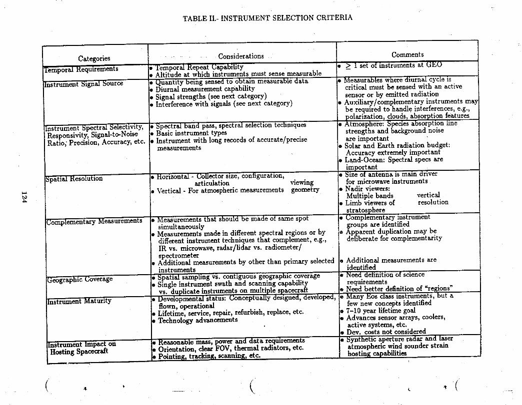
TABLE II.- INSTRUMENT SELECTION CRITERIA
In
Categories i ........... Considerations CommentsTemporal Requirements '* Temporal Repeat Capability • > 1 set of instruments a_ GEO
• Altitu(le at which instruments must sense measurableInstrument Signal Source • (_uantity being sensed to obtain measurable data • Measurables where diurnal cycle is
mDiurnal measurement capability critical must be sensed with an active• Signal strengths (see next category) sensor or by emitted radiation• Interference with signals (see next category) . Auxiliary/complementary instruments may
be required to handle interferences, e.g.,olarization, clouds, absorvtion features
Instrument _pectral Selectivity, • Spectral band pass, spectral selection techniques • _tmosphere." Species absor'ption lineResponsivity, Signal-to-Noise • Basic instrument types strengths and background noise
Ratio; Precision, Accuracy, etc..• Instrument with long records of accurate/precise are importantmeasurements • Solar and Earth radiation budget:Accuracy extremely important
• Land-Ocean: Spectral specs areimportant
Spatial Resolution • Horizontal - GoUectorsize, configuration, • Size of antenna is main driverarticulation viewing for microwave instruments
• Vertical - For atmospheric measurements geometry • Nadir viewers:_. Multiple bands vertical
• Limb viewers of resolution
• stratosphereComplemeniary Measurements Measurements that should be made of same spot • Complementary instrumentsimultaneously groups are identified
• Measurements made in different spectral regions or by , Apparent duplication may bedifferent instrument techniques that complement, e.g., deliberate for complementarityIR vs. microwave, rsdar/lidax vs. radiometer/spectrometer
• Additional measurements by other than primary selected • Additional measurements areinstruments identified
GeographicCoverage l• Spatial sampling vs. contiguous geographic coverage • Need definition of sciencet• Single instrument swath and scanning capability requirements
vs. duplicate instruments, on multiple spacecraft. * Need better definition of "regions"Instrument Maturity • Developmental status: Gonceptually designed, developed, • Many Eos class instruments, but a
flown, operational few new concepts identified• Lifetime, service, repair, refurbish, replace, etc. • 7-10 year lifetime goal• Technology advancements s Advances sensorarrays, coolers,
active systems, etc.• Dev. costs not considered
lmtrttment Impact on , Reax_nable mass, power and data. requirements • Synthetic aperture radar and laserHosting Spacecraft • Orientation, clear FOV, thermal radiators, etc. atmospheric wind sounder strain
• Pointing_ tracking, scanning_ etc. .. hosting capabilities
Instrument Spectral Selectivity, Responsivity, and Accuracy
The most important characteristics of remote sensing instruments for GGTI measurables
are the spectral region of operation and the applicability of that spectral region to the
particular measurement. Sensing of atmospheric and land/ocean measurables is especially
dependent on selecting specific spectral lines or bands. Responsivity and signal-to-noise,
although separately defined characteristics dependent on a number of other instrument
features, are often also strongly dependent on spectral selectivity. The names of basic
instrument types usually make some reference to spectral band and/or selection technique,
e.g., infrared spectrometer, Fabry-Perot interferometer, gas correlation radiometer, grating
spectrometer, etc. Two other important instrument characteristics, especially for solar and
Earth radiation budget measurables, are precision and accuracy. Selection of instruments
with the right spectral resolution, radiometric sensitivity, and other characteristics for
a particular measurable entails assessment of the general capabilities of the types of
instruments, the design and tradeoffs of specific embodiments, and the historical record of
measurements made in the space environment by identical or similar instruments. Although
for an actual mission such assessments require extended comparative analysis, the selection
for each GCTI measurable of an appropriate instrument type and a representative or example
instrument was based on published documents and the judgment of personnel with remote
sensing experience.
Spatial Resolution
The spatial resolution values given for the Science Requirements listed on Table I are for
horizontal resolution and are generally interpreted as the maximum allowable dimension of
a single measurement '_ootprint."
Vertical resolution for atmospheric measurables was considered during instrument se-
lection; however, since the science requirements were presented only in terms of horizon-
tal spatial resolution, an instruments horizontal resolution capability dominated the selec-
tion procedure. This approach could, and did, become the primary selection criteria. An
125

exampleistheselectionoftheGOES ImagerforTroposphericWindsratherthanthespecific
wind measuring LAWS instrument. The science requirement for the measurable tropospheric _.__
windsisahorizontalresolutionofI0kin.WiththeGOES Imagerinstrument,tropospheric _
windscanbe inferredfromthemotionofcloudsatastatedhorizontalresolutionof8 km.
Itsverticalresolution,however,islimitedtospecificaltitudeswherecloudsexist.Frequently
thisresultsindataattwoorthreelevels.The statedhorizontalresolutionfortheLAWS
instrumentisapproximately100kin.ThustheLAWS instrumentmissesthesciencere-
quirementby a factoroften.Itsstatedverticalresolution,however,isanimpressive1 km
with an accuracy of 1 m/s. If vertical resolution was .thedominant selection criteria, LAWS
would be the instrument of choice. In this particular instrument selection case, the Regional
Process Studies temporal requirement of 30 min-1 H for tropospheric winds also strongly
suggested the selection of the Geostationary GOES instrument. The instrument design im-
pacts of the spatial resolution requirements are primarily on the signal collector ("optics")
size, configuration including viewing geometry, and articulation. For examples: (1) The size
oftheantennaisthemain designdriverforthelongwavelengthmicrowaveinstruments, _'/
(2)Limb viewingisthemostpracticalapproachforgoodverticalspatialresolutioninthe
uppertroposphereandinthestratosphere.Fortheverticalresolutionoftheatmosphereby
nadirviewinginstrumentsanadditionalconsiderationistheselectionofdifferentlyweighted
spectralchannelsforemissionsensingortheuseofan activesensorsuchasa lidarora
radar.Notethatdesigninginstrumentsforhorizontalspatialresolutionisnotgenerallylim-
itedbythe'Lphysics,"butbypracticalengineeringconstraintsandtradeoffs.Therefore,ifa
particularinstrumenttypeisthechoiceforotherreasons,designchangestomeetthespatial
resolution requirements are often possible. *
Complementary Measurements
Often a particular scientific investigation requires simuitaneons spatial and temporal data
on several measurables. In addition, data on an individual measurableacquired by different
measurementtechniquesorindifferentspectralbandsishelpfulinscientificinterpretation _-J
126
of the measurement results. Although not specifically stated as science requirements,
considerations of complementary measurement needs are instrument selection criteria. In
response to these needs, the instruments selected for the individual measurables weregrouped
into nine complementary packages. All instruments within a single package are to be flown
together on a single spacecraft. The complementary packages are as follows:
Spectral radiation Spectral radiation/radiation budget (LEO)Meteorology Spectral radiation/radiation budget (GEO)Stratospheric gases/wind fields High resolution spectrometryAerosols (GCS) OceanTropospheric gases
Many other complementary packages could be defined; e.g., a biomass burning package of
instruments to measure tropospheric gases and winds, surface temperature and biomass
inventory, but with diminishing returns regarding GCTI instrument selection.
For completeness, measurements from several selected instruments require supplementary
data to be obtained simultaneously from auxiliary instruments. These data are used to
correct or calibrate the primary data. For example, a polarimeter (EOSP) instrument has
been chosen to correct for polarization of signal sources when used in conjunction with some
of the selected spectrometers.
Geographic Coverage
Implied in the science requirements is the concept that geographic coverage should
be contiguous or spatial sampling should be sufficiently dense to discern the geographic
variations. The instrument characteristics of interest to this criteria category are the overall
field-of-view or swath and the off-track scanning capability. The usable overall field-of-view
may be limited by viewing angle, i.e., the physics of the remote sensing observations. For
example, high latitude coverage from a geostationary spacecraft at the equator is limited
by the slant angle of observation. Similarly, in low Earth orbit instruments with large
"pushbroom" swaths or with large off-track scans may be limited by the allowable slant angle
of observation of the desired measurables. On the other hand, swath and scanning capabilities
of the instruments are often limited by their optical designs or scanner mechanisms and
127
necessary improvements in particular types are not usually limited by the physics, but by
engineering and design tradeoffs.
Instrument Maturity
The timeframe of the missions envisioned in the GCTI architecture study is far enough
in the future to allow instrument candidates ranging from those that have flown in space on
an operational basis to those that have only recently been conceptually designed. Mature
or nearly mature instruments or concepts have been favored to maximize the probability of
adequate instrument lifetime. Completely new concepts were selected only for measurables
where there were no satisfactory candidates, however,there appears to be sufficient time to
develol_the new instrument technology and to incorporate it into new instrument concepts.
Instrument Impacts on the Hosting Spacecraft
The final category of instrument selection criteria deals with those instrument charac-
teristics which impact the hosting spacecraft. Table II lists about ten such characteristics
which were evaluated in the selection process. Two characteristics, mass and power, are _-_/
included in the final instrument lists since they have a large impact on spacecraft selection
and design.
Lists of Selected Instruments
Once a set of measurables was established and a set of candidate instruments and
instrument concepts for making the measurements was identified, the selection process
could begin. Candidate instruments and concepts are listed in Table III according to the
measurable to which they relate. The selected instrument or concept identified and key
reasonsfor its selection are included. The reasons for selection are extensions of the selection
rationale previously discussed. At this point, instrumentselection was complete; however, to
be of maximum practical value, the selection needed to be grouped into lists of instruments
making measurements at the same temporal frequency. In an earlier discussion in this paper
it was established that the temporal sampling requirement of <__1hour requires the GCTI -__._
128

TABLE III.- CANDIDATE AND SELECTED INSTRUMENTS
CandidateMeasurable(TypeStudy) Instruments Selected Reasons
SolarSpectralRadiation(GCS) ACRIM ACRIM • Measures total spectral irradiance,
complements the Earth RadiationSOLSTICE Budget instrumentXRI • Continuity with UARS and EOSSUSIM • Doesn't strain host spacecraftSOS
SOLSTICE • Complements ACRIM in specificXRI spectral regions
SOLSTICE---Ultraviolet irradianceXRI--X-ray and energy input
by charged particles• Small impact on spacecraft to
add these two instrumentsb=*
_ (RPS) Same as GCS ACRIM Same as GCSAmospheric Surface Pressure
(GCS) None APL • New instrument concept basedon successful technique (aircraftexperiments) and conceptual designof a similar type instrument (LASA-EAGLE)
(RPS) : No RequirementAtmospheric Temperature
Profile AMSU-B AMSU-B oProven technology(GCS) AIRS ,Good spatial resolution
HIRS ,All weather capabilityHIMSSAMRIR AIRS •Very good spatial resolutionSWIRLS eVery good spectral resolution in
thermal IR (gives goodvertical resolution)
oDay/night capability
(RPS) IRVS _ IRVS •NextgenerationIR SounderGMODIS forGEOGOES SounderVAS

TABLE III.- CONTINUED ---
CandidateMeasurable {Twe Studv_ Instruments Selected Reasons
Stratospheric Gases (Ozone)(GCS) SAGE III SAGE Ill *A flight proveninstrument for ozoneSAFIRE .Measurement technique based on
MLS sol_ occultation. Thus supplementsCLAES SAFIRE (Spectrometer) and MLSHALOE (microwave) instruments selectedATMOS for other stratospheric gases
but sL_omeasuringozone
(RPS) OZMAP OZMAP ,Only candidate for ozone measurementfrom GEO*GEO measurement needed to meet
temporal requirementStratospheric Gases (Other)
(GCS) SAGE Ill SAFIRE ,Measures key stratospheric gasesSAFIRE .Combines multi-channel FourierMLS spectrometer with multi-channelCLAES broad hand radiometerHALOE sLIMS and HALOE heritage (broad band)ATMOS radiometerHIRRLS ATMOS heritage (Fourierspectrometer)SWIRLSDLSD MLS .Spedfic for species related toHRI ozone depletionTOMS .Measurements by microwave---complementsSBUV other techniques of SAGEGOMR and SAFIREISAMSLIMS
(RPS) Sam_ as GCS S_me as GCS .Same as GCS

f
\ 4,
TABLE IlL- CONTINUED
Candidateh_e.asurable{Twe Study) Instruments _el_cted Reasons
Aerosolsand Particulates(GCS) SAGE III SAGE III *Proven instrument
HIRRLS .Limb viewer measuringultravioletMISR scatteringEOSP .Good supplement to ozone measuring
instruments
EOSP .A nadir viewer measuring polarization.Provides a supplementary correction
measurement (polarization) forother prime instruments
.Complements SAGE III
(RPS) IRVS IRVS ,OnlyviablecandidatefromGEOwithreasonablehorizontalresolutionand _ood vertical resolution
TroposphericWater Vapor(GCS) AIRS AIRS oTnfraredspectralbandsprovide
AMSU-A goodverticalresolutionAMSU-B ,In_..aredmeasurementcomplementsHIMSS microwavemeasurementsAMSRSWMR AMSU-B erasspecificfrequencies(highAMIR frequency)forwatervaporSSM/I ,ProveninstrumentHIRS ,WideswathLASAATLID HIMSS ",Hasspecificfrequencies(lowAVHRR frequencies) for water vaporMODIS-N ,Wide swathMODIS-T .Proven instrument (SSM/I heritage)
.Lighter weight than electronicallyscanningmicrowaveradiometer
(RPS) None acceptable GHRMR .New concept developedforgeostationary sensingbasedon applying advanced butfeasiblemicrowave technology
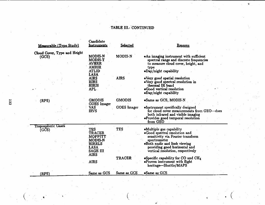
TABLEIII.-CONTINUED
CandidateMeasurable fTvve Study) Instruments Selected Reasons
Cloud Cover, Type and Height(GCS) MODIS-N MODIS-N *An imaging instrumentwith sufllcient
MODIS-T spectral range and discrete frequenciesAVHRR to measure cloud cover, height, andAMRIR typeATLID eDay/night capabilityLASAAIRS AIRS eVery good spatial resolutionHIRS eVery good spectral resolution inHIRIS thermal IR band
•- APL *Good vertical resolution -"• Day/night capability
(RPS) GMODIS GMODIS eSame as GCS, MODIS-NGOES ImagerVAS GOES Imager .Instrument specifically designedIRVS for cloud covermeasurements from GEO--does
both infrared and visible imaging• Provides good temporal resolution
from GEOTropospheric Gases
(GCS) TES TES eMultiple gas capabilityTRACER eGood spectral resolution andMOPPITT sensitivity via FouriertransformMODIS-N . spectrometerHIRRLS .Both nadir and limb viewingLASA providing good horizontal andSAGE III vertical resolution, respectivelyAIRS
TRACER eSpecific capability for CO and CH4AIRS .Proven instrument with flight
heritage--Shuttle/MAPS
(RPS) Same as GCS Same as GCS *Same as GCS
(- iI (
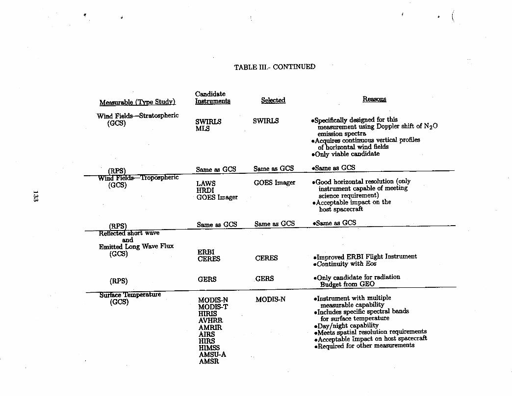
k
TABLE III.- CONTINUED
CandidateMeasurable(.TypeStudy) Instrumen_ Selected Reasons
Wind Fields--Stratospheric(GCS) SWIRLS SWIRLS ,Specifically designedfor this
MLS measurementusing Dopplershift of N20emissionspectra
eAcquires continuousvertical profilesof horizontalwind fields
oOnly viable candidate
w_RPS) Sameas GCS Sameas GCS ,Same as GCSd Fields---Tropospheric
(GCS) LAWS GOES Imager -Good horizontal resolution(onlyHRDI instrumentcapableofmeetingGOES Imager science requirement)
.Acceptable impact on thehost spacecraft
(RPS) Same as GCS Same as GCS -Same as GCSReflectedshort wave
andEmitted Long WaveFlux
(GCS) ERBICERES CERES *Improved ERBI Flight Instrument
oContinuitywith Eos
(RPS) GERS GERS eOnly candidate for radiationBudget from GEO
Surface Temperature(GCS) MODIS-N MODIS-N ,Instrument with multiple
MODIS-T measurablecapabilityHIRIS .Includes specificspectralbandsAVHRR for surfacetemperatureAMRIR sDay/night capabilityAIRS eMeets spatial resolutionrequirementsHIRS eAcceptableImpact on host spacecraftHIMSS eRequiredfor other measurementsAMSU-AAMSR
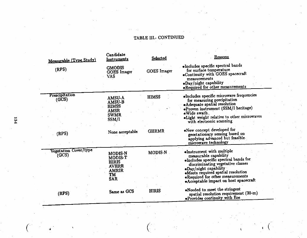
TABLE Ill.-CONTINUED
Candidate
MeasurablefTvveStud_ _ _ Reasons
(RPS) GMODIS .IncludesspecificspectralbandsGOES Imager GOES Imager forsurfacetemperatureVAS eContinuitywithGOES spacecraft
measurements.Day/night capability,Requiredforothermeasurements
_n HIMSS elndudes specific microwave frequenciesAMSU-AAMSU-B formeasuringprecipitationHIMSS oAdequatespatialresolutionAMSR eProveninstrument(SSM/Iheritage)SWMR eWideswath,SSM/I eLight weight relative,to other microwaves. with electronic scanning
(RPS) Noneacceptable GHRMR eNew conceptdevelopedforgeostationary sensing based onapplying aclvanced but [easmLemicrowave technology
e MODIS-N eInstrumentwithmultipleMODIS-NMODIS-T measurablecapabilityHIRIS sIndudesspecificspectralbandsforAVHRR discriminatingvegetativeclassesAMRIR .Day/night capability
eMeets required spatial resolutionTM sRequiredforothermeasurementsSAR .Acceptableimpactonhostspacecraft
(RPS) Same as GCS HIRIS oNeeded to.meet the stringentspatial resolution requirement (30-m).Providescontinm'tywithEos
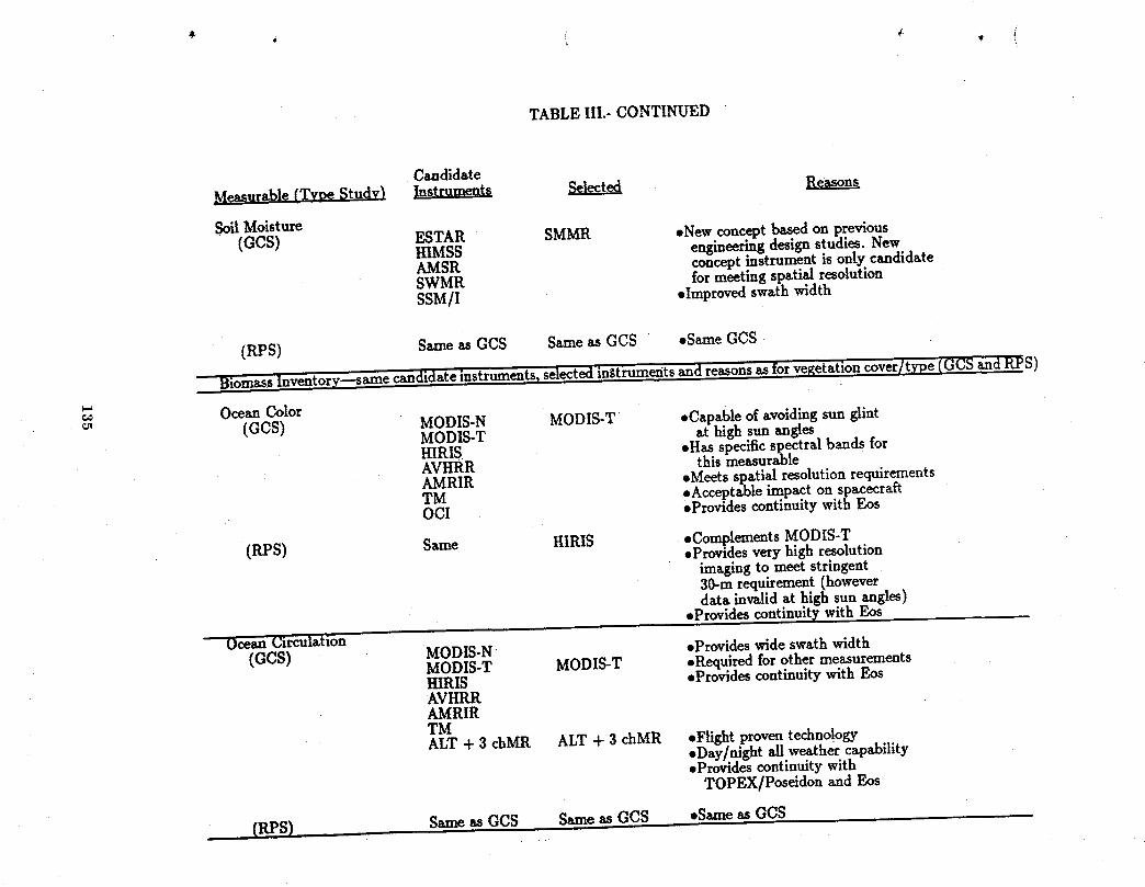
TABLE III.- CONTINUED
CandidateMeasurable(Type Study) Instruments Selected ReasonsSoil Moisture
(GCS) ESTAR SMMR .NewconceptbasedonpreviousHIMSS engineeringdesignstudies.NewAMSR conceptinstrumentisonlycandidateSWMR formeetingspatialresolutionSSM/I .Improvedswathwidth
(RPS) Same asGCS Same asGCS ,Same GCS
BiomassInventory---saznecandidateinstruments_selectedin_tiumentsandreasonsasforvegetationcover/type(GCS andRFS)
OceanColor(GCS) MODIS-N MODIS-T ,Capableofavoidingsunglint
MODIS-T athighsunanglesHIRIS .Has specific spectralbandsforAVHRR thismeasurableAMRIR ,MeetsspatialresolutionrequirementsTM ,Acceptableimpacton spacecraftOCI ,ProvidescontinuitywithEos
(RPS) Same HIRIS ,ComplementsMODIS-T,Providesveryhighresolutionimagingtomeetstringent30-mrequirement(howeverdata invalidathigh sunangles)
,ProvidescontinuitywithEosOceanClrculatlon
(GCS) MODIS-N ,ProvideswideswathwidthMODIS-T MODIS-T ,RequiredforothermeasurementsH.IRIS ,ProvidescontinuitywithEosAVHRRAMRIRTMALT + 3 chMR ALT + 3 chMR .Flight proven technology
.Day/night all weather capability
.Provides continuity withTOPEX/Peseidon and Eos
(RPS) SameasGCS SameasGCS .SameasGCS
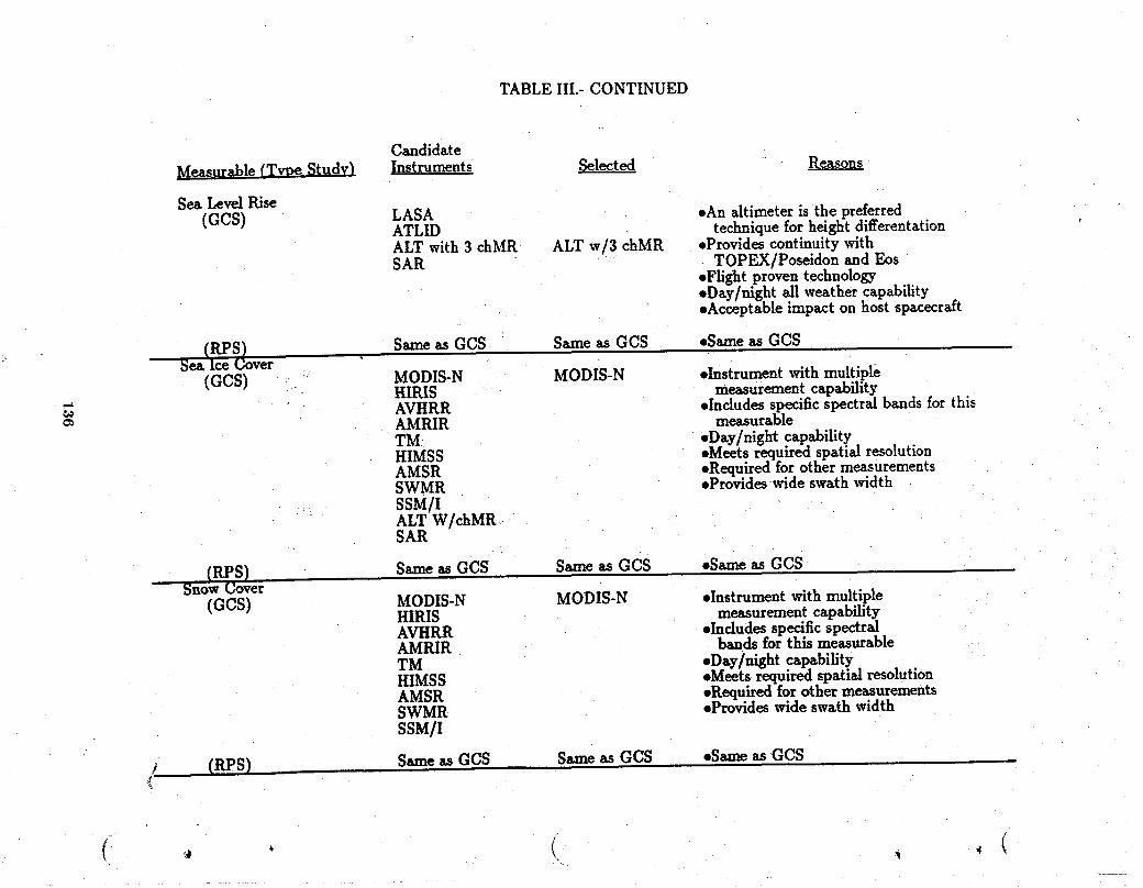
TABLE III.-CONTINUED
Candidate
Measurable(Type Study) Instruments Selected Reasons
SeaLevelRise(GCS) LASA sAn altimeteristhepreferredATLID techniqueforheightdifferentation
ALT with3chMR ALT w/3 chMR ,ProvidescontinuitywithSAR TOPEX/Poseidonand Eos
,FlightproventechnologyeDay/night all weather capabilityeAcceptable impact on host spacecraft
S-me asGCS S-measGCS ,SameasGCS..SeaIceCover
(GCS) MODIS-N MODIS-N ,Instrumentwithmultiple• I-[IRIS measurementcapability" AVHRR ,Indudesspecificspectralbandsforthis
AMRIR measurableTM: ,Day/nightcapabilityHIMSS ,,MeetsrequiredspatialresolutionAMSR ,RequiredforothermeasurementsSWMR eProvideswideswathwidth
-_ SSM/IALT W/chMRSAIl.
(RPS) S_,'-_asGCS S_-,easGCS ,S=neasGCSSnow Cover
(GCS) MODIS-N MODIS-N ,InstrumentwithmultipleHIRIS measurementcapabilityAVHRR ,Includes specific spectralAMRIR bandsforthis measurableTM eDay/nightcapabilityHIMSS .Meets required spatial resolutionAMSR ,RequiredforothermeasurementsSWMR ,ProvideswideswathwidthSSM/I
/ (RPS) S._-.easGCS S_,,_asGCS .S_m_asGCS
( • ( , , (
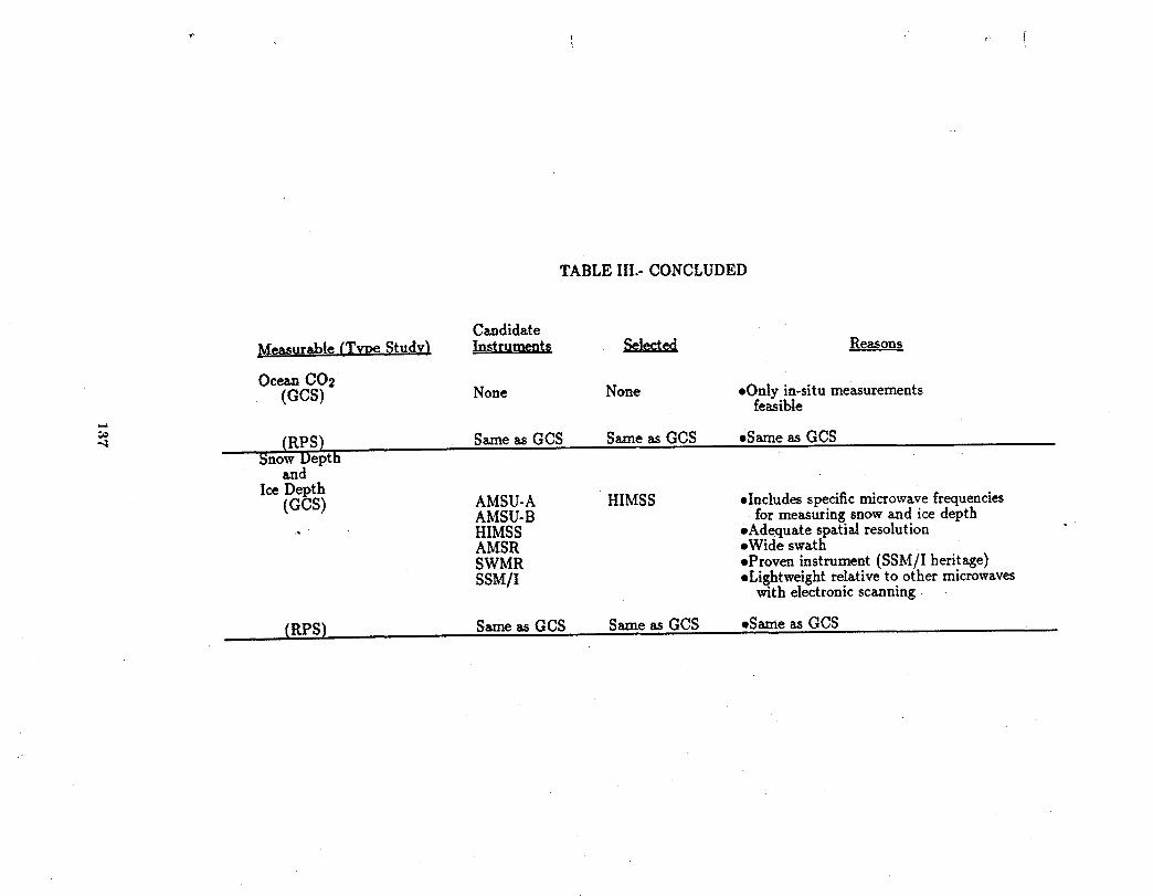
TABLE III.-CONCLUDED
CandidateMeasurabh (Twe Studv} Instruments _
Ocean COs(GCS) None None *Only in-situ measurements
feasible_=_€,€
(RPS) SameasGCS SameasGCS .SameasGCSSnowDepth
andIceDepth
(GCS) AMSU-A HIMSS .IncludesspecificmicrowavefrequenciesAMSU-B for measuring snow and ice depth
•" " HIMSS .Adequate spatial resolutionAMSR *Wide swathSWMR eProven instrument (SSM/I heritage)SSM/I *Lightweight relative to other microwaves
with electronic scanning
(.RPS) SameasGO* SameasGCS -SameasGO*
fleet include at least one geostationaxy spacecraft. This consideration did affect the selection
of instruments for select measurables. The remaining temporal requirements do not affect
instrument selection but they, along with instrument complementarity considerations, do ,_
affect the number of spacecraft and the grouping of instruments on the spacecraft. Two
quotations from the Task 3 report (Harrison, et al., 1989) provide a perspective:
"A multisatellite system is required to meet the scientific requirements
for temporal coverage over the globe. The best system consists of four sun-
synchronous satellites equally spaced in local .timeof equatorial crossing. This
system can obtain data every 3-hours for all regions."
and
"Somemeasurement parameters requireobservations every 12-hourswhich
can be achieved with a single sun-synchronoussatellite."
138
This perspective prompts the groupings of measurables by temporal requirements for both
Global Change and Regional Process Studies. Six groupings were chosen and are presented
as blocked-off temporal requirements in Table IV. With instruments selected to make the
" measurables and the measurables assembled into groups of similar temporal requirements,
the instrument lists to be subsequently used in spacecraft design were prepared. The six
. instrument lists are presented in Tables V-X. Note on the instrument lists that more than
one measurable is identified with most of the individual instruments. There was a primary
instrument selected for each measurable and the measurable is labelled with a (P) where
listed along with the instrument that is prime for its measurement. Some instruments are
prime for more than one measurement, therefore, there may be two or more measurables
with (P) labels associated with a single instrument. Most instruments can make additional
measurements other than those for which it may be prime. They are shown in the Tables as
additional (A) measurements. Note that the instrument lists also include the mass and power
characteristics of the instruments plus a designation of its complementary status with other
instruments. Additional physical and performance characteristics of instruments selected are
..... presented in Appendix A.
Low-Earth Orbit Instrument Lists
Beginning with the Global Change Study, the measurables needing the most frequent
sampling are those with a 1-3H temporal requirement. They are presented on Table IV as
group 1 and the corresponding instrument list is presented in Table V as Instrument List
No. 1.
139

TABLE IV: GCTI SCIENCE REQUIREMENTS GROUPING.
Regime/ Measurable Diurnal GlobalChange RegionalProcessCategory • Cycle Study Studies
Temporal Spatial Temporal Spatial
Solar Spectralradiation No 1D Sundisk 1D Sundisk
Pressure(surface) No _ 3-12. 10km _
Temperatureprofile Yes _ 10-50km 5kmStratosphericgases No 3-12H 50km .5-10km
AtmosphereAerosols&part. No 3-12H 10km _ 0.1-1kmTroposphericH20 No b3-12H 10kin (_ 30M-1H10kin
• CIoudcovar&_ght Yes 1-3"-'H"1km 15M-1H11kmTr0posphedcgases Yes 1-3H 10km 30M-I"----'H"!10-50kmWi_flelds Yes (_ 1-3H 10km (_ 30M,1H
Radiation ReflectedSW& Yes 1-3H 10-30km 30M-1H1-30kmbulxIget emittedLWflux (_
Surfacetemperature Yes 1.3H 1-4km _M-24H30m-200kmPrecipitation Yes 1-3H 1-30km 3M-3H 1-200kmVegetationcover_pe No _ 1km _ 30m-10km
Earth Soilmoisture No 2D 1.10km 12H.7D 30m-10km(land/ Biomassinventory No 7D I km 1-30D 1-10km_,ean) Oceancolor(chloro.) No 2D 1-4km 2D 30m-4km
Oceancirculation No (_ 2D 1-4km (_ 1D 30m-4kmSealevelrise No 2D 10km 2D 10kmSeaicecovar/depth No 7D 1-20km 1-3D 1-25kmOceanCO2 No 2D 500kmSnowcov_rldepth No 7D . 1-Ion 12H-$D.1.10km

TABLE V.INSTRUMENT LISTI:
GLOBAL CHANGE STUDIES,1-3HOUR TEMPORAL, LOW-EARTH ORBIT SPACECRAFT (GCS,1-3I-I,LEO)
Measurable Mass Power Complementary(P)-Primarv:(A)-Additiowl InstrumentTvpe_" RepresentativeInstrumell(-LkgL_
(P CloudCover_€Type SurfaceImagingVis/ MODIS-N 200 250 a(P SurfaceTemperature InfraredSpectrometer ModerateResolutionImaging
IAA SeaIce_ Snow Cover Spectrometer-Na_iirScanVegetationCover(A BiomassInventory(A OceanColor(A OceanCirculation
(P)TemperatureProfile AtmosphericInfrared AIRS 80 300 a"(P)CloudHeight Sounder AtmosphericInfrared(A)TroposphericWaterVapor RadiationSounder
(P)TemperatureProfile AtmosphericMicrowave AMSU-B 40 80(A)TroposphericWater Vapor Sounder AdvancedMicrowave
a
SoundingUnit-B
(P) Precipitation MicrowaveSpectrometer HIMSS 222 66 a(P) TemperatureProfile Sounder HighResolutionMicrowave
"(A) TroposphericWaterVapor SpectrometerSounder(A) SurfaceTemperature(A)SeaIce& SnowDepth
(P) TroposphericGases: CO, CH4TroposphericGasCorrdationTRACER 80 120 bIR Radiometer TroposphericRadiometerfor
AtmosphericChemistryandEnvironmentalResearch
(P)TroposphericGases:03,H20, TroposphericInfrared TES 491 600 bNO2, N20, HNO3, CIspecies Spectrometer TroposphericEmissions
Spectrometer
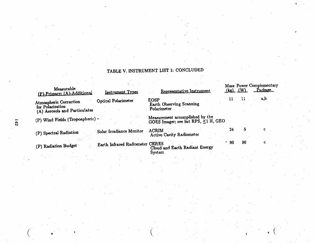
TABLE V.INSTRUMENT LISTh CONCLUDED
Measurable MassPowerComplementary(p).Primarv:(A)-Additional InstrumentTvves RepresentativeInstrument _ _ Package
AtmosphericCorrection OpticalPolazimeter EOSP 11 11 a,bforPolarization EarthObservingScanning(A)Aerosolsandparticulates Polarimeter
(P)Wind Fields(Tropospheric)- Measurementaccomplishedbythe_" GOES Imager;seelistRPS,_<1H,GEO
(P)SpectralRadiation SolarIrradianceMonitor ACRIM 24 5 cActiveCavityRadiometer
(P)RadiationBudget EarthInfraredl_diometerCERES " 90 90 cCloudandEarthRadiantEnergySystem
(

€
TABLEVI.- INSTRUMENT LIST 2:GLOBALCHANGE STUDIES, 3-12 HOUR TEMPORAL, LOW-EARTH ORBIT SPACECRAFT (GCS, 3-12 H, LEO)
Measurable Mass Power Complementary_P)-Primarv:(A_-Additional _ RepresentativeIns,_rume_t _ _ Package
(P) SurfacePressure Differential Absorption APL* 660 1200(A) Aerosolsand Particulates Lidar Atmospheric Pressure(A) CloudCoverand Height Lidar
(P) StratosphericGases Limb ScanningInfrared SAFIRE 304 304 d03, H20, H202, NO2, Spectrometer/Radiometer Spectroscopyof theHNO3, N20_, CH4, HF, HBr, Atmosphere Using Far-InfraredHCI, HOCI Emission
(P) StratosphericGages: Us, MicrowaveLimb MLS 450 790 dH20, H202, CIO Sounder MicrowaveLimb
Sounder
(P)WindFields(Stratospheric)GasCorrel_tionIR SWIRLS 90 197 d(A) Temperature Profile Wind Sounder . Str'..t_s_--ho-_-_Wind
InfrardLi'_Sounder
(P)StratosphericGases:03, SolarOccultationGratingSAGE Ill 60 25 hNO2' H20 Spectrometer .Stratospheric Aerosols and(P)AerosolsandParticulates GasExperiment
(P)AerosolsandParticulatesPolarimeter EOSP 11 11 hEarthObservingScanningPolarimeter
The followinginstruments also t
appear on other listsand offeroptions for exclusionfrom/ordistribution amongspacecraR
Tropospheric Water Vapor Infrared Sounder AIRS (See list GCS, 1-3 H, LEO) 80 300 aTemperatureProfile Atmospheric Infrared
( CloudHeight Radiation Sounder
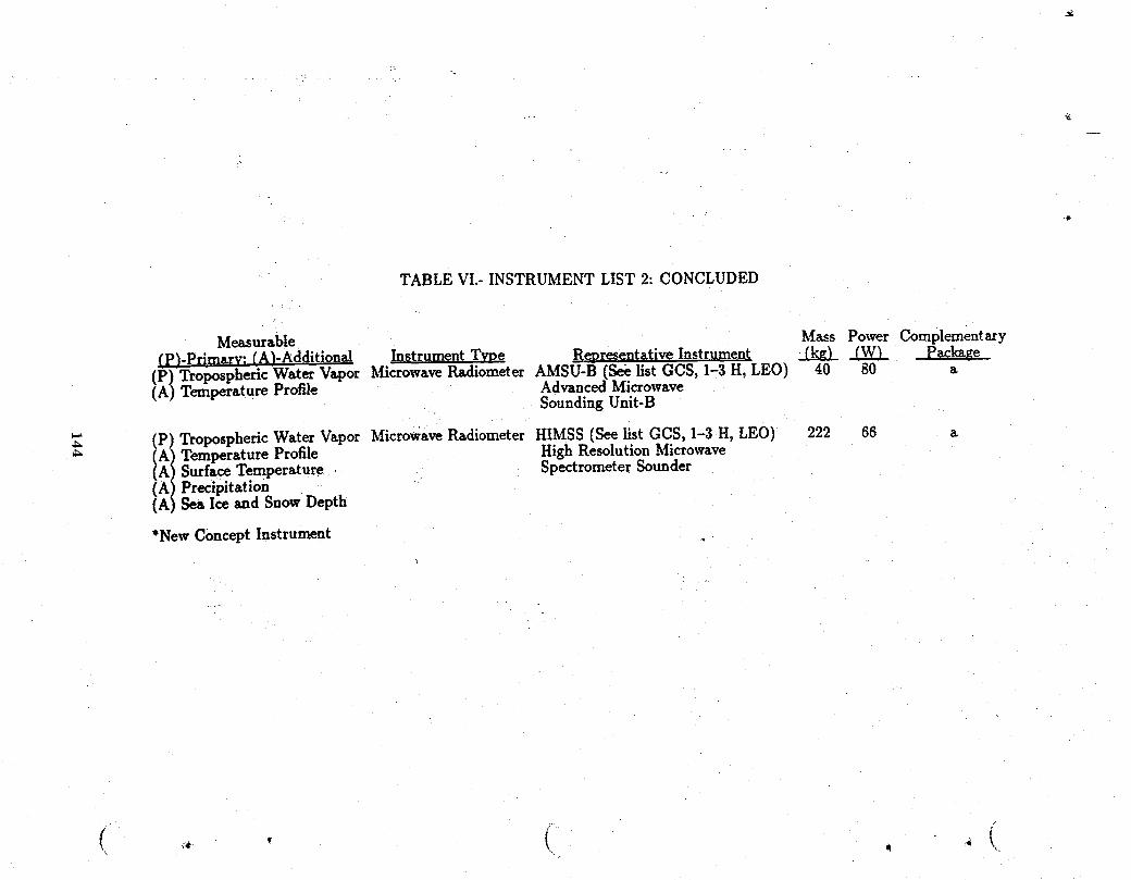
TABLE VI.-INSTRUMENT LIST2:CONCLUDED
Measurable Mass Power ComplementaryfP)-Primarv: fA)-Additional Instrument Twe Representative Instrument _ _ , Package(p)TroposphericWaterVapor MicrowaveRadiometerAMSU-B (SeelistGCS, I-3H,LEO) 40 80 a(A) Temperature Profile Advanced MicrowaveSoundingUnit-B
(p) TroposphericWater Vapor MicrowaveRadiometerHIMSS (See listGCS, I-3H,LEO) 222 66 a
_" (A1TemperatureProfile HighResolutionMicrowave(A SurfaceTemperature SpectrometerSounder
(AIPrecipitation(A SeaIceandSnowDepth
*New ConceptInstrumentt
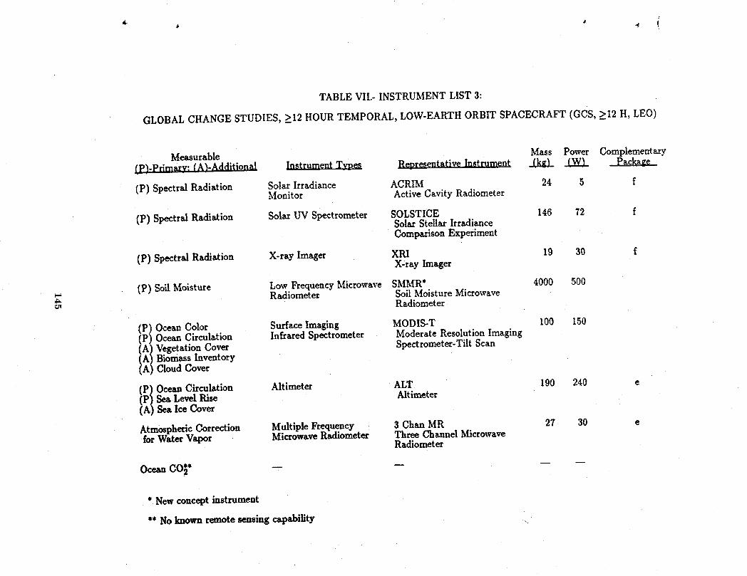
TABLE VII.-INSTRUMENT LIST3:
GLOBAL CHANGE STUDIES,>__12HOUR TEMPORAL, LOW-EARTH ORBIT SPACECRAFT (GCS,>_12H,LEO)
Measurable Mass Power Complementary(PJ-Primarv:(At-Additional InstrumentTypes RepresentativeInstrument .Lkg,L _
(p)SpectralRadiation SolarIrradiance ACRIM 24 5 fMonitor ActiveCavityRadiometer
(P)SpectralRadiation SolarUV Spectrometer SOLSTICE 146 72 fSolarStellarIrradianceComparisonExperiment
(p)SpectralRadiation X-rayImager XRI 19 30 fX-rayImager
(P)SoilMoisture Low FrequencyMicrowave SMMR* 4000 500Radiometer Soil Moisture Microwave
Radiometer
ii / OceanColor SurfaceImaging MODIS-T 100 150OceanCirculation InfraredSpectrometer ModerateResolutionImaging
VegetationCover Spectrometer-TiltScan(A BiomassInventory(A CloudCover
A1 OceanCirculation Altimeter ALT 190 240 eIP Sea Level Rise Altimeter( Sea Ice Cover
3 ChanMR 27 30 eAtmosphericCorrection MultipleFrequencyfor WaterVapor MicrowaveRadiometer ThreeChannelMicrowaveRadiometer
OceasCOt* -- --
* New concept instrument
** No known remote sensing capability
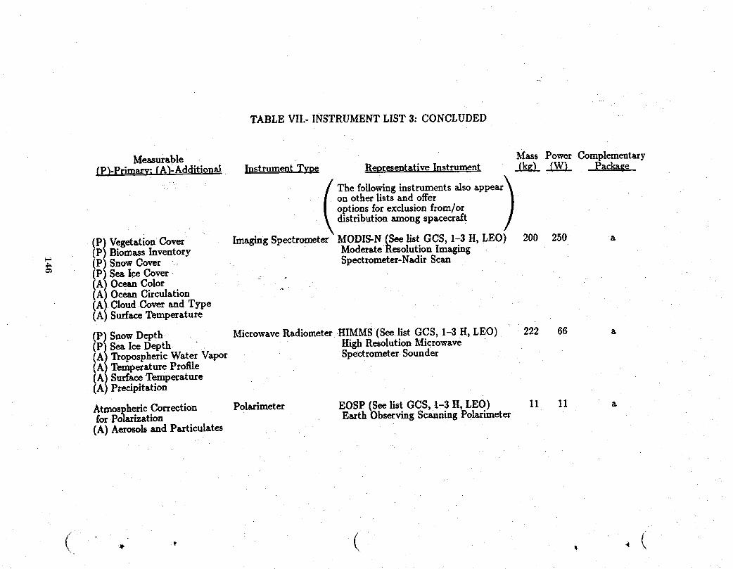
TABLEVII.- INSTRUMENTLIST 3: CONCLUDED
Measurable Mass Power ComplementaryfP)-Primarv: fA_-Additiona!_ Instrument T. Representative Instrument _ _ Paclmge
! The followinginstruments als° appear!
on other lists and offeroptions for exclusion from/ordistribution among spacecraft
(P Vegetation Cover Imaging Spectrometer MODIS-N (See list GCS, 1-3 H, LEO) 200 250 a(P Biomass Inventory Moderate Resolution Imaging(P Snow Cover Spectrometer-Nadir Scan(P Sea Ice Cover _.(AOcean ColorfA OceanCirculationiA' Cloud Cover and Type(A SudaceTemperature
Microwave Radiometer HIMMS (See list GCS, 1-3 H, LEO) 222 65 a
i/Snow Depth
IP Sea Ice Depth High Resolution Microwavem
(A Tropospheric-WaterVapor Spectrometer Sounder(A TemperatureProfile(A SudaceTemperature( Predpitation
Atmospheric Correction Polarimeter EOSP (See list GCS, I-3 H, LEO) 11 11 afor Polarization Earth Observing Scanning Polarimeter(A) Aerosols and Particulates
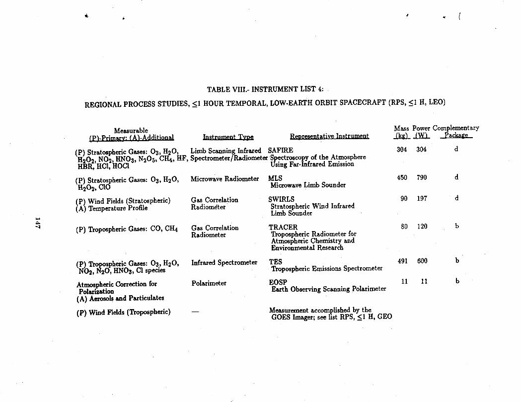
TABLE VIII.-INSTRUMENT LIST4:
REGIONAL PROCESS STUDIES,__IHOUR TEMPORAL, LOW-EARTH ORBIT SPACECRAFT (RPS,_<IH,LEO)
Measurable Mass Power Complementary
(p)-Primary:(A)-Additional _ RegresentativeInstrument _ _ Package
(P) Stratospheric Gases: 03, H20, Limb Scanning Infrared SAFIRE 304 304 dH202, NO2, HNO3, N205,CH4, HF, Spectrometer/RadiometerSpectroscopyoftheAtmosphereHBR, HCI,HOCI UsingFar-lnfraredEmission
(P)StratosphericGases:03,H20, MicrowaveRadiometer MLS 450 790 dH202, CIO MicrowaveLimb Sounder
Gas Correlation SWIRLS 90 197 d(P)Wind Fields(Stratospheric)(A)TemperatureProfile Radiometer StratosphericWind InfraredLimb Sounder
q (P)TroposphericGases:CO, CH4 Gas Correlation TRACER 80 120 bRadiometer TroposphericRadiometerfor
AtmosphericChemistryandEnvironmentalResearch
(p)TroposphericGases:03,H20, InfraredSpectrometer TES 491 600 bNO2, N20, HNO3, Cl species TroposphericEmissionsSpectrometer
AtmosphericCorrectionfor Polarimeter EOSP 11 11 bPolarization EarthObservingScanningPolarimeter(A)Aerosolsand Particulates
(P)Wind Fields(Tropospheric) -- Measurementaccomplishedby theGOES Imager;seelistRPS, __IH, GEO
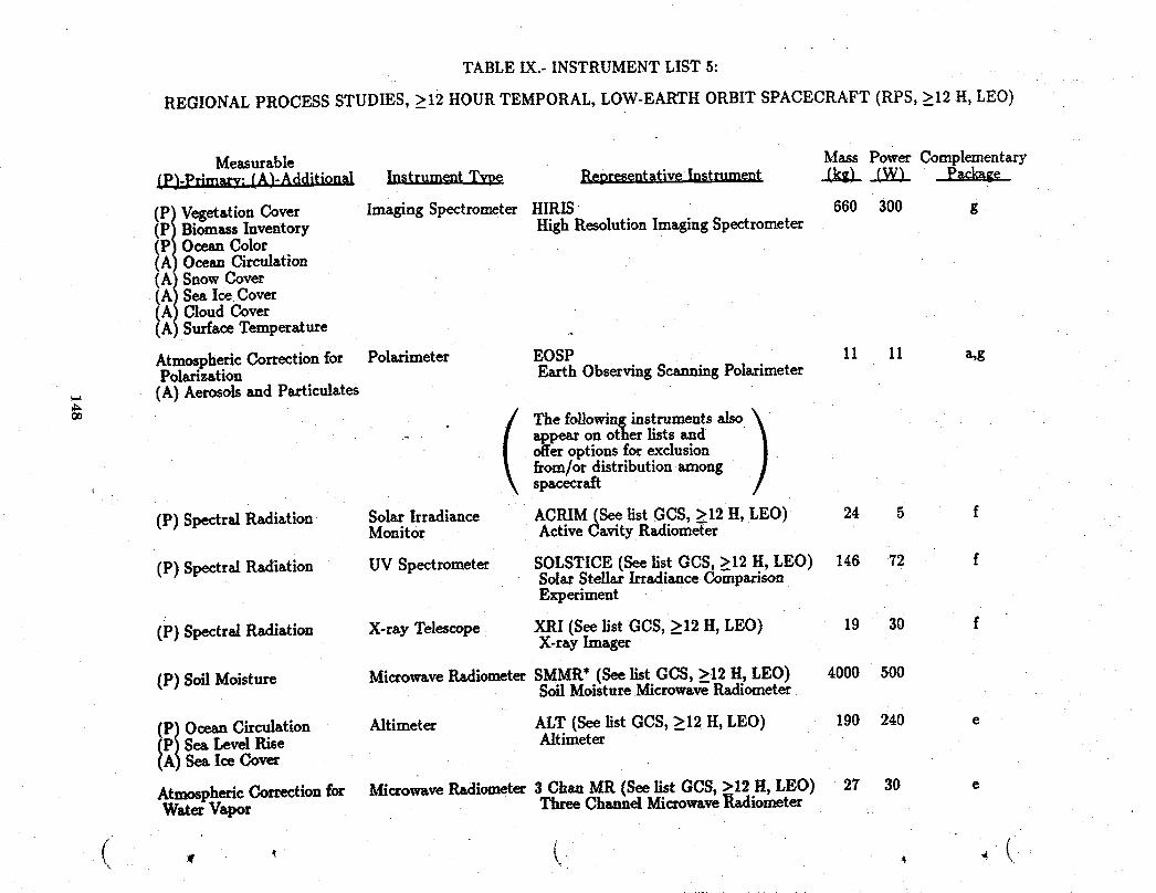
TABLE IX.-INSTRUMENT LIST5:
REGIONAL PROCESS STUDIES,_>12HOUR TEMPORAL, LOW-EARTH ORBIT SPACECRAFT (RPS,_>12H,LEO)
Measurable Mass Power Complementary(P)-Prlmary: (A)-Additional II1gLLgI_gL.T..g_ Representative Instrument _kiLL _
(P Vegetation Cover Imaging Spectrometer HIRIS 660 300 g(P Biomass Inventory High Resolution Imaging Spectrometer
IF Ocean ColorOcean Circulation(A SnowCover(A Sea Ice Cover(A Cloud Cover(A Surface Temperature
Atmospheric Correction for Polarimeter EOSP 11 11 a,gPolarization Earth Observing Scanning Polarimeter
_., (A) Aerosols and Particulates
00 Q The following instruments also )
_ appear on otherlists andofferoptionsforexclusionf_om/ordistribution.a_mongspacecraft
(P) Spectral Radistion Solar Irradiance ACRIM(See list GCS, >12 H, LEO) 24 5 fMonitor Active Cavity RadiomeTer
(P) Spectral Radiation UV Spectrometer SOLSTICE (See list GCS, >12 H, LEO) 146 72 fSolar Stellar Irradiance C_o_aparisonExperiment
(P) SpectralRadiation X-rayTelescope XRI(SeelistGCS,_>12H,LEO) 19 30 fX-rayImnger
(P)SoilMoisture MicrowaveRadiometerSMMR*(Seelist GCS,>_12H, LEO) 4000 500SoilMoistureMicrowaveRadiometer
_ '_Ocean Circulation Altimeter ALT (See list GCS, >_12H, LEO) 190240 eSea Level Rise AltimeterSea Ice Cover
Atmospheric Correction for _._crowave Radiometer 3 Chan MR (See list GCS, >12 H, LEO) 27 30 eW_ter Vapor Three Channd Microwave_adiometer
/
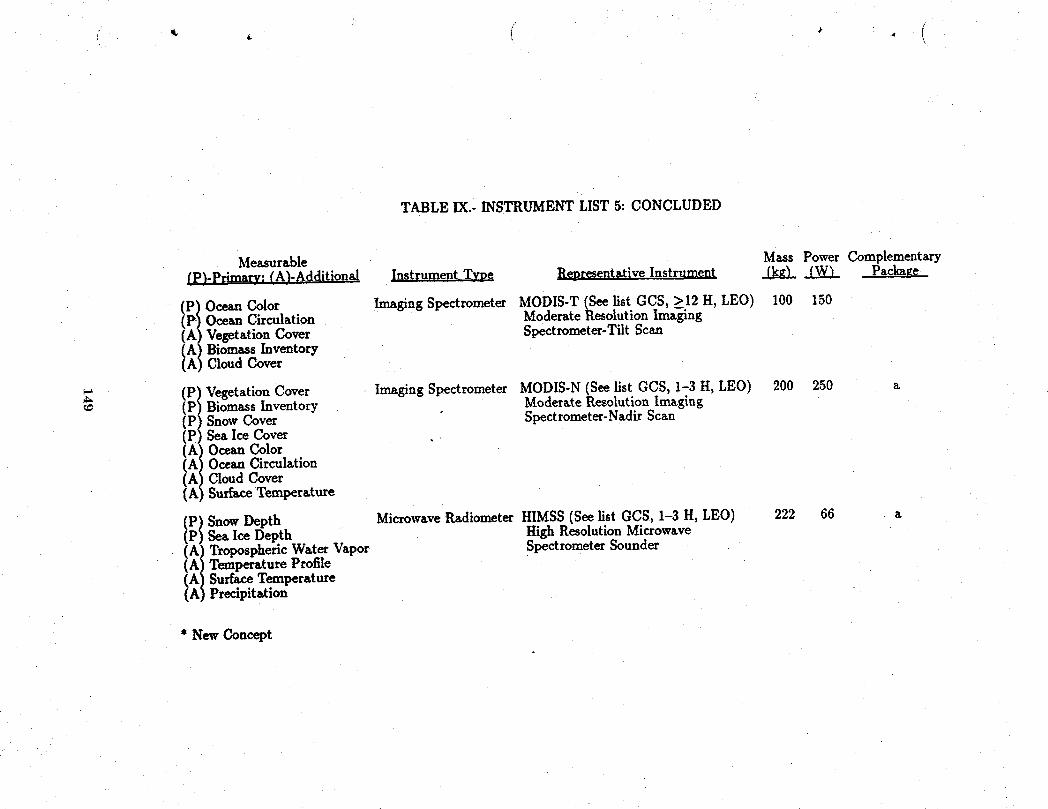
TABLE IX.- INSTRUMENTLIST 5: CONCLUDED
Measurable Mass Power Complementary(PJ-Pr;maw:fA)-Additional n.I._gLgm_nL._ RepresentativeInstrument _ _ Packaegg_
Imaging Spectrometer MODIS-T (See list GCS, _>12H, LEO) 100 150(P/Ocean Color(P Ocean Circulation ModerateResolution Imaging(A) Vegetation Cover Spectrometer-Tilt Scan
(AI Biomass Inventory(A CloudCover
(P! VegetationCover Imaging Spectrometer MODIS-N(See list GCS, 1-3 H, LEO) 200 250 a(P Biomass Inventory ModerateResolution Imaging
(PI SnowCover Spectrometer-NadirScan(P Sea Ice Cover
(AIOceanColor
(A Ocean Circulation(A Cloud Cover(A SurfaceTemperature
MicrowaveRa_iiometerHIMSS(See list GCS, 1-3 H, LEO) 222 66 a(PISnowDepth(P Sea Ice Depth HighResolutionMicrowave(A) TroposphericWaterVapor SpectrometerSounder
(A! TemperatureProfile(A SurfaceTemperature(A Precipitation
* New Concept
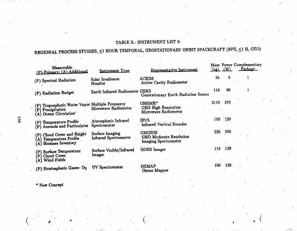
TABLE X.- INSTRUMENT LIST 6:
REGIONAL PROCESS STUDIES, _<I HOUR TEMPORAL, GEOSTATIONARY ORBIT SPACECRAFT (RPS, _<I H, GEO)
Measurable Mass Power Complementary(p)-Pr;rmu'v; (A3-Additional Instrument Twe Representative Instrument _ .J..W.)_
(P) Spectral Radiation Solar Irradiance ACRIM 24 5 iMonitor Active Cavity Ra_liometer
(P) Radiation Budget Earth Infrared Ra_iiometerGERS 110 90 iGeostationaxy Earth RsAiation Sensor
(_ TroposphericWater Vapor Multiple Frequency GHRMR* 3110 370
' (PA/Precipitation MicrowaveR_liometer GEO High Resolution( Ocean Circulation" Microwave RadiometerT_ 150 150
= (P/ Temperature Profile Atmospheric Infrared IRVS(pj Aerosols and particulates Spectrometer Infrared Vertical Sounder
(P) Cloud Coverand Height Surface Imaging GMODIS 230 250
(A/ Temperature Profile Infrared Spectrometer GEO Moderate Resolution(Ap Biomass Inventory Imaging Spectrometer
(_ Surface Temperature Surface Visible/Infrared GOES Imager 118 130Cloud Cover ImagerWind Fields
(p) Stratospheric Gases: 03 UV Spectrometer OZMAP 100 130Ozone Mapper
* New Concept
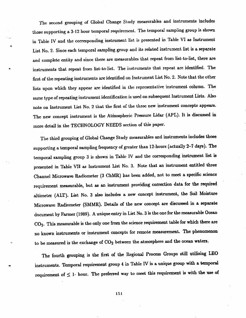
The second grouping of Global Change Study measurables and instruments includes
those supporting a 3-12 hour temporal requirement. The temporal sampling group is shown
in Table IV and the corresponding instrument list is presented in Table VI as Instrument
List No. 2. Since each temporal sampling group and its related instrument llst is a separate
and complete entity and since there are measurables that repeat from list-to-list, there are
* instruments that repeat from list-to-list. The instruments that repeat are identified. The
first of the repeating instruments axe identified on Instrument List No. 2. Note that the other
lists upon which they appear are identified in the representative instrument column. The
same type of repeating instrument identification is used on subsequent Instrument Lists. Also
note on Instrument List No. 2 that the first of the three new instrument concepts appears.
The new concept instrument is the Atinospheric Pressure Lidar (APL). It is discussed in
more detail in the TECHNOLOGY NEEDS section of this paper.
The third grouping of Global Change Study measurables and instruments includes those
supporting a temporal sampling frequency of greater than 12-hours (actually 2-7 days). The
temporal sampling group 3 is shown in Table IV and the corresponding instrument list is
presented in Table VII as Instrument List No. 3. Note that an instrument entitled three
Channel Microwave IL_diometer (3 ChMR) has been added, not to meet a specific science
requirement measurable, but as an instrument providing correction data for the required
altimeter (ALT). List No. 3 also includes a new concept instrument, the Soil Moisture
Microwave Radiometer (SMMR). Details of the new concept are discussed in a separate
document by Farmer (1989). A unique entry in List No. 3 is the one for the measurable Ocean
CO2. This measurable is the only one from the science requirement table for which there are
no known instruments or instrument concepts for remote measurement. The phenomenon
_" to be measured is the exchange of CO2 between the atmosphere and the ocean waters.
The fourth grouping is the first of the Regional Process Groups still utilizing LEO
_- instruments. Temporal requirement group 4 in Table IV is a unique group with a temporal
requirement of _ 1- hour. The preferred way to meet this requirement is with the use of
151.
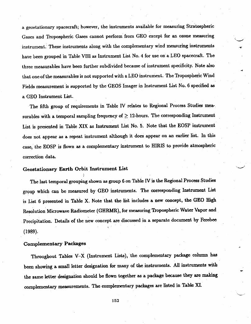
a geostationary spacecraft;however, the instruments available for measuring Stratospheric
Gases and Tropospheric Gases cannot perform from GEO except for an ozone measuring
instrument. These instruments along with the complementary wind measuring instruments
have been grouped in Table VIII as InstrumentList No. 4 for use on a LEO spacecraft. The
three measurables have been further subdivided because of instrument specificity. Note also
that one of the measurables is not supportedwith a LEO instrument. The TroposphericWind
Fields measurement is supported by the GEOS Imager in Instrument List No. 6 specified as
a GEO Instrument List.
The fifth group of requirements in Table IV relates to Regional Process Studies mea-
surables with a temporal sampling frequency of _ 12-hours. The corresponding Instrument
List is presented in Table XIX as Instrument List No. 5. Note that the EOSP instrument
does not appear as a repeat instrument although it does appear on an earlier list. In this
case, the EOSP is flown as a complementary instrument to HIRIS to provide atmospheric
correctiondata.
Geostationary Earth Orbit Instrument List _-J
The last temporal groupingshown as group 6 on Table IV is the Regional Process Studies
group which can be measured by GEO instruments. The corresponding Instrument List
is List 6 presented in Table X. Note that the list includes a new concept, the GEO High
Resolution MicrowaveRadiometer (GHRMR), for measuring Tropospheric Water Vapor and
Precipitation. Details of the new concept are discussed in a separate document by Ferebee
(1989).
Complementary Packages
Throughout Tables V-X (Instrument Lists), the complementary package column has
been showing a small letter designation for many of the instruments. All instruments with
the same letter designation should be flown together as a package because they are making
complementary measurements. The complementary packages are listed in Table XI.
152
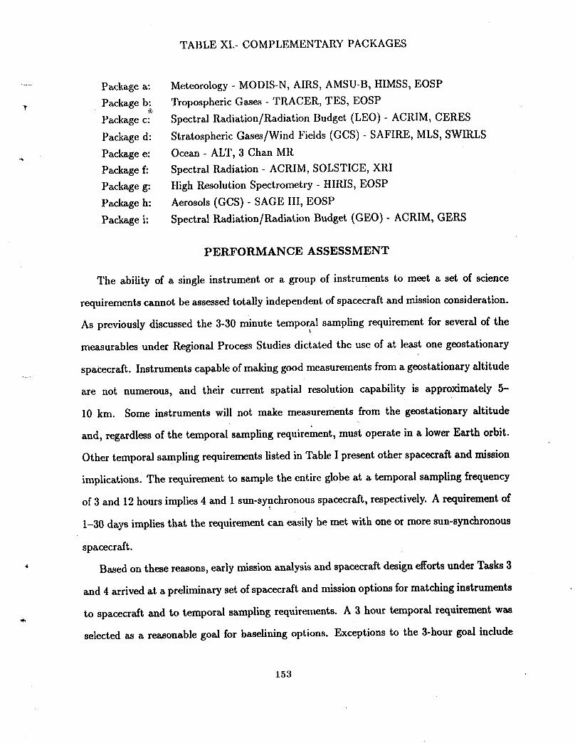
TABLE XI.- COMPLEMENTARY PACKAGES
....... Package a: Meteorology - MODIS-N, AIRS, AMSU-B, HIMSS, EOSP
_. Package b: Tropospheric Gases - TRACER, TES, EOSP
Package c: Spectral Radiation/Radiation Budget (LEO) - ACRIM, CERES
Package d: Stratospheric Gases/Wind Fields (GCS) - SAFIRE, MLS, SWIRLS
__ Package e: Ocean - ALT, 3 Chan MR
Package f: Spectral Radiation - ACRIM, SOLSTICE, XRI
Package g: High Resolution Spectrometry - HIRIS, EOSP
Package h: Aerosols (GCS) - SAGE III, EOSP
Package i: Spectral Radiation/Radiation Budget (GEO) - ACRIM, GERS
PERFORMANCE ASSESSMENT
The ability of a single instrument or a group of instruments to meet a set of science
requirements cannot be assessed totally independent of spacecraft and mission consideration.
As previously discussed the 3-30 minute temporal sampling requirement for several of the
measurables under Regional Process Studies dictated the use of at least one geostationary
spacecraft. Instruments capable of making good measurements from a geostationary altitude
are not numerous, and their current spatial resolution capability is approximately 5-
10 kin. Some instruments will not make measurements from the geostationary altitude
and, regardless of the temporal sampling requirement, must operate in a lower Earth orbit.
Other temporal sampling requirements listed in Table I present other spacecraft and mission
implications. The requirement to sample the entire globe at a temporal sampling frequency
of 3 and 12 hours implies 4 and 1 sun-synchronous spacecraft, respectively. A requirement of
1-30 days implies that the requirement can easily be met with one or more sun-synchronous
spacecraft.
" Based on these reasons, early mission analysis and spacecraft design efforts under Tasks 3
and 4 arrived at a preliminary set of spacecraft and mission options for matching instruments
to spacecraft and to temporal sampling requirements. A 3 hour temporal requirement was
selected as a reasonable goal for baselining options. Exceptions to the 3-hour goal include
1.53
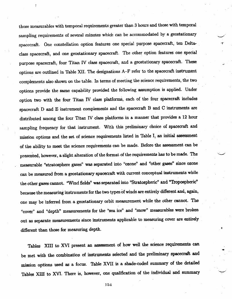
those measurables with temporal requirements greater than 3 hours and those with temporal
sampling requirements of several minutes which can be accommodated by a geostationary _.i
spacecraft. One constellation option features one special purpose spacecraft, ten Delta- _
class spacecraft, and one geostationary spacecraft. The other option features one special
purpose spacecraft, four Titan IV class spacecraft, and a geostationary spacecraft. These
options are outlined in Table XII. The designations A-F refer to the spacecraft instrument
complements also shown on the table. In terms of meeting the science requirements, the two
options provide the same capability provided the following assumption is applied. Under
option two with the four Titan IV class platforms, each of the four spacecraft includes
spacecraft D and E instrument complements and the spacecraft B and C instruments are
distributed among the four Titan IV class platforms in a manner that provides a 12 hour
sampling frequency for that instrument. With this preliminary choice of spacecraft and
mission options and the set of science requirements listed in Table I, an initial assessment
of the ability to meet the science requirements can be made. Before the assessment can be
presented, however, a slight alteration of the format of the requirementshas to be made. The _.i
measurable "stratosphere gases" was separated into "ozone" and "other gases" since ozone
can be measured from a geostationary spacecraft with current conceptual instruments while
the other gases cannot. '"Wind fields" was separated into "Stratospheric" and '_lYopospheric"
because the measuring instruments for the two types of winds are entirely differentand, again,
one may be inferred from a geostationary orbit measurement while the other cannot. The
"cover" and "depth" measurements for the "sea ice" and "snow" measurables were broken
out as separate measurements since instruments applicable to measuring cover are entirely
different than those for measuring depth. *
Tables XIII to XVI present an assessment of how well the science requirements can
be met with the combination of instruments selected and the preliminary spacecraft and
mission options used as a focus. Table XVII is a shade-coded summary of the detailed
TablesXIIItoXVI.Thereis,however,onequalificationoftheindividualand summary _-J
154
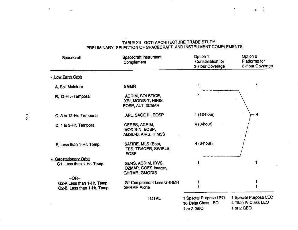
TABLEXll GCTIARCHITECTURETRADESTUDYPRELIMINARYSELECTIONOFSPACECRAFTANDINSTRUMENTCOMPLEMENTS
Spacecraft SpacecraftInstrument Option1 Option2Complement Constellationfor Platformsfor
3-HourCoverage 3-HourCoverage
A, SoilMoisture SMMR 1 1
B, 12-Hr.+Temporal ACRIM,SOLSTICE, 1XRI, MODIS-T,HIRIS,EOSP,ALT,3ChMR
C, 3 to 12,Hr.Temporal APL,SAGE I!1,EOSP 1 (12.hour) 4
D, 1 to3-Hr. Temporal CERES,ACRIM, 4 (3-hour)MODIS-N,EOSP,AMSU-B,AIRS, HIMSS
E, Lessthan 1-Hr.Temp. SAFIRE,MLS(Eos), 4 (3-hour)TES, TRACER,SWIRLS,EOSP __
• _eostationaryOrbitG1, Lessthan 1-Hr.Temp. GERS,ACRIM, IRVS, 1 1
OZMAP,GOES Imager,GHRMR,GMODIS
-OR--G2-A,Lessthan 1-Hr.Temp. G1ComplementLessGHRMR 1 1G2-B, Lessthan1-Hr.Temp. GHRMRAlone 1 1
TOTAL 1 SpecialPurposeLEO 1 SpecialPurposeLEO10 DeltaClass LEO 4 Titan IV Class LEO1 or 2 GEO 1 or2 GEO
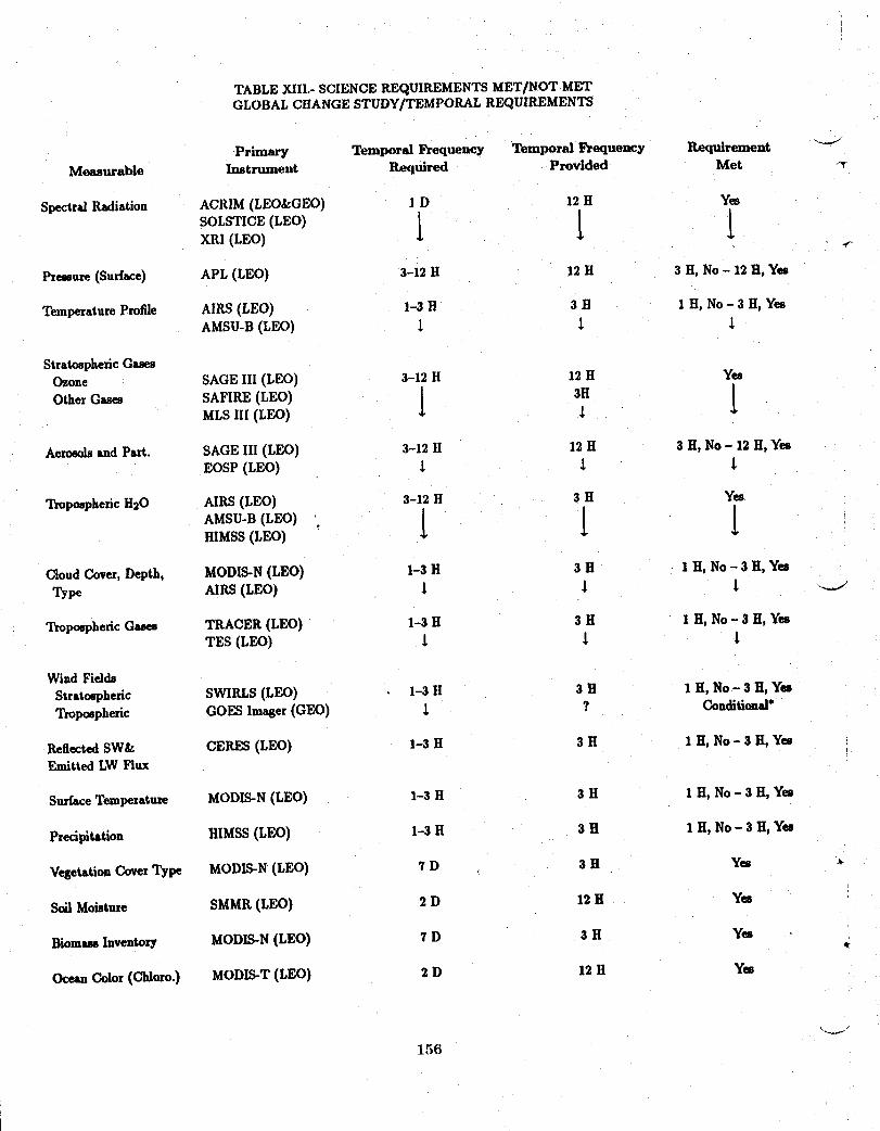
TABLE XIII.- SCIENCE REQUIREMENTS MET/NOT METGLOBAL CHANGE STUDY/TEMPORAL REQUIREMENTS
Primary Temporal Frequency Temporal _requency Requirement _"_Measurable Instrument Required Provided Met
Spectral Radiation ACRIM (LEO_GEO) 1 D 12 H Yes
SOLSTICE(LEO) 1 t lXRI (LEO) ._
Prepare (Surface) APL (LEO) 3-12 H 12 H 3 H, No - 12 H, Yes
Temperature Profile AIRS (LEO) 1-3 H 3 H 1 H, No - 3 H, YesAMSU-B (LEO) t l
StratosphericGMesOzone SAGEIII (LEO) 3-12 H 12 H Yes
Other G-- SAFIRE(LEO) l 3HMLS III (LEO)
AeroeolsandPart. SAGEIII (LEO) 3-12 H 12 H 3 H, No - 12 H, YesEOSP (LEO) 1 _ _,
Tropo6phericH20 AIRS(LEO) 3-12 H 3 H Yes
HIMSS(LEO)
Cloud Cover,Depth, MODIS-N(LEO) 1-3 H 3 H 1 H, No - 3 H, YesType AIRS(LEO) t l t _
Tropo_heric Gues TRACER(LEO) 1-3 H 3 H I H, No- 3 H, YesTES (LEO) I t
Wind FiddsStratospheric SWIRLS(LEO) 1-3 H 3 H 1 H, No - 3 H, YesTrol_pheric GOESImager(GEO) 1 ? Conditional*
Reflected SW& CERES(LEO) 1-3 H 3 H 1 H, No - 3 H, YesEmittedLWFlux
SurfaceTemperature MODIS-N(LEO) 1-3 H 3 H 1 H, No - 3 H, Yes
Precipitation HIMSS(LEO) 1-3 H 3 H 1 H, No - 3 H, Yes
VegetationCoverType MODIS-N(LEO) 7 D , 3 H Yes
Soil Moisture SMMR(LEO) 2 D 12 H Yes
BiomessInventory MODIS-N(LEO) "tD 3 H Yes €/
OceanColor(cldoro.) MODIS-T(LEO) 2 D 12 H Yes
156
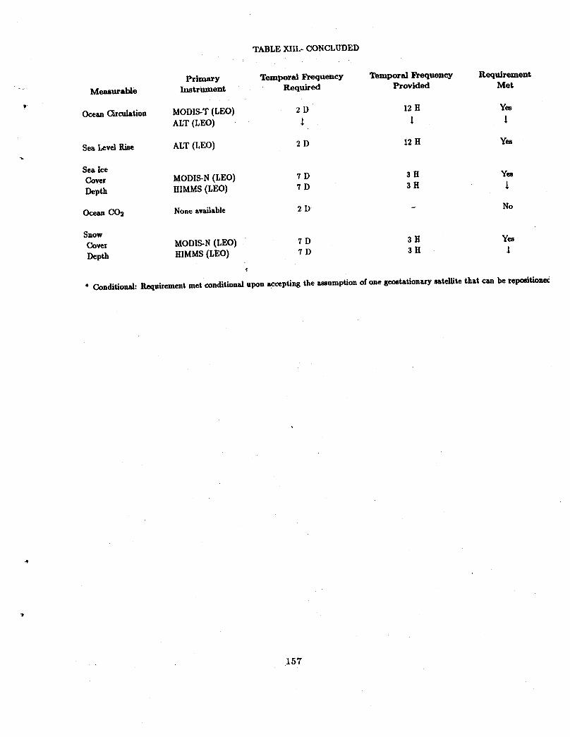
TABLE XIIL- CONCLUDED
Primary Temporal Frequency Temporal Frequency Requirement
.... Measurable Instrument Required Provided Met
Ocean Circulation MODIS-T (LEO) 2 D 12 H YesALT (LEO) 1 1
Sea Levd Rise ALT (LEO) 2 D 12H Yes
Sea IceCover MODIS-N (LEO) 7 D 3 H Yes
Depth HIMMS (LEO) 7 D 3 H
Ocean CO2 None available 2 D - No
Snow
Cover MODIS-N (LEO) 7 D 3 H Yes
Depth HIMMS(LEO) 7 D 3 H 1
* Conditional: Requirementmet conditional upon accepting the assumption of one geostationary satellite that can be repositionec
, !57
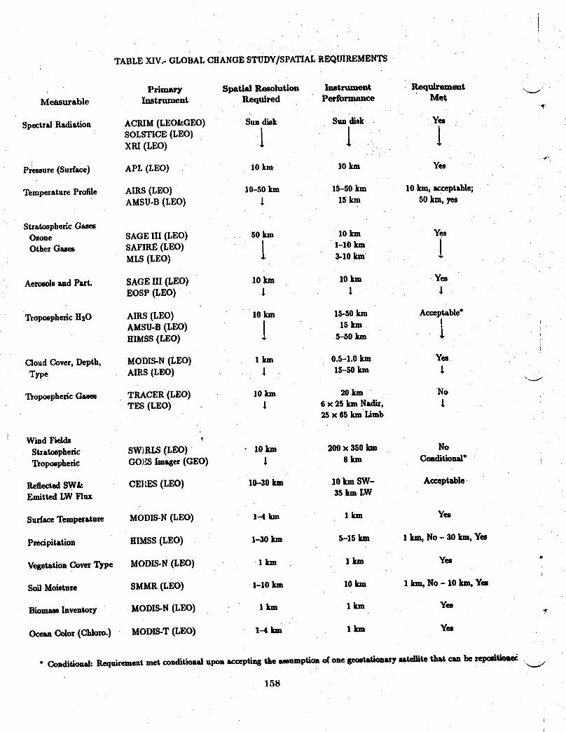
TABLEXIV.-GLOBALCHANGESTUDY/SPATIALREQUIREMENTS
Primary Spatial Resolution Instrument Requirement .___
Measurable Instrument Required Performance Met
Spectral Radiation ACIUM (LEO_GEO) Sun disk Sun disk Yes
SOLSTICE(LEO) I I IXRI (LEO)
Pressure (Surface) APL (LEO) l0 km I0 kin Yes
Temperature Profile AIRS (LEO) 10-50 km 15-50 km I0 kin, acceptable;AMSU-B (LEO) _ 15 kln 50 kin, yes
Stratospheric GasesOzone SAGE III (LEO) 50 kin I0 km YesOther Gases SAFIRE (LEO) | I-I0 ]an I
MLS (LEO) I 3-10 km4.
Aerosols and Part. SAGE Ill (LEO) 10 km I0 km YesEOSP (LEO) t i
Tropospheric H20 AIRS (LEO) I0 km 15-50 km Acceptable*
AMSU-B (LEO) 1 15km [HIMSS (LEO) 5-50 km
Cloud Cover, Depth, MODIS-N (LEO) I km 0.5-1.0 ]an Yes
Type AIRS (LEO) l 15-50 km
Tropospheric Gases TRACER (LEO) I0 km 20 km NoTES (LEO) i 6 x 25 km Nadir,
25 x 65 km Limb
Wind Fields
Stratospheric SW]RLS (LEO) l0 km 200 x 350 km No
Tropospheric GO}_ Imnger (GEO) i 8 km Conditiomd"
Reflected SW& CEI_S (LEO) 10-30 kin 10 km SW- AcceptableEmitted LW Flux 35 km LW
Surface Temperature MODIS-N (LEO) 1-4 km I kln Yes
Precipitation HIMSS (LEO) 1-30 km 5-15 lun I kin, No - 30 kin, Yes
Vegetation Cover Type MODIS-N (LEO) I km ] fun Yes _"
Soil Moisture SMMR (LEO) I-I0 km I0 km I kin, No - I0 kin, Yes
Biomaes Inventory MODIS-N (LEO) I km I km Yes •
Ocean Color (Cldozo.) MODIS-T (LEO) 1-4 km I kln Yes
" Conditional:Requirementmetconditionalupon acceptingthe amumptionof one geostationarysatellite tlutt can be s_ImSitioa_
158
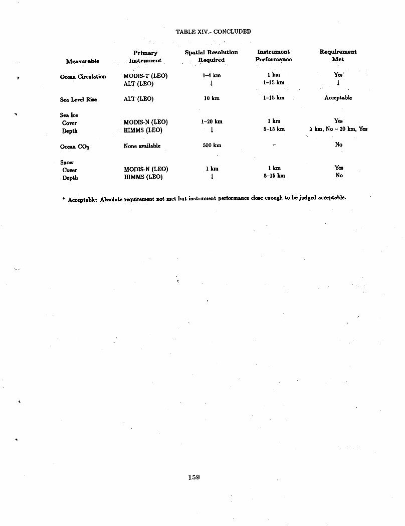
TABLE XIV.- CONCLUDED
Primary Spatial Resolution Instrument Requirement.... Measurable Instrument Required Performance Met
_, Ocean Circulation MODIS-T (LEO) 1-4 km 1 km YesALT (LEO) _ 1-15 km
Sea Level Rise ALT (LEO) 10 km 1-15 km Acceptable
_" Sea Ice
Cover MODIS-N (LEO) 1-20 km 1 km Yes
Depth HIMMS (LEO) _ 5-15 km 1 kin, No - 20 kin, Yes
Oceu COs None available 500 km - No
Snow
Cover MODIS-N (LEO) 1 km 1 km Yes
Depth HIMMS(LEO) 1 5-15 km No
* Acceptable: Absolute requirementnot met but instrument performanceclose enough to bejudged acceptable_
159

TABLEXV.- REGIONALPROCESSSTUDIES/TEMPORALREQUIREMENTS
Primary Temporal Frequency Temporal Frequency R_quirem@nt -__jMeasurable Instrument Required Provided Met
SpectralRadiation ACRIM(LEO&GEO) 1 D 12H Yes
SOLSTICE(LEO) 1 1 1XRI(LEO)
Pressure(Surface) - No Req. - -
TemperatureProfile IRVS(GEO) 15 M-I H FullDisk-1H Conditional
StratosphericGasesOzone OZMAP(GEO) 30 M ? ConditionalOtherGases SAFIRE (LEO) I 3 H No
MLS (LEO) _ I
Aer_ols and Part. IRVS(GEO) 15M-I H Full Disk-1H Conditional
TroposphericH20 GHRMR(GEO) 30 M-I H ? Conditional
CloudCover,Depth, GMODIS(GEO) 15 M-I H ? ConditionalType GOESImager
Tropo6phericGases TRACER(LEO) 30 M-I H 3 H NoTES (LEO) L _
Wind Fields _-'JStrstospheric SWIRLS(LEO) 30 M-I H 3 H NoTropospheric GOESImager(GEO) _ FullEarth-25M Conditional
1000x 1000km- 40 S
ReflectedSW& GERS(GEO) 30 M-I H FullDisk-I to 3 H ConditionalEmitted LWFlux
SurfaceTemperature GOESImager(GEO) 6 M-24 H FullEarth-25M Conditional1000× 1000km-40S
Precipitation GHItMR(GEO) 3 M-3 H ? Conditional
VegetationCoverType MODIS-N(LEO) 1-30D 3 H YesHIRIS(LEO) ! 12H l
i
Soil Moisture SMMR(LEO) 12 H-?D 12 H Yes
BiomassInventory MODIS-N(LEO) 1-30D 3 H YesHIRIS(LEO) _ I
OceanColor(Chloro.) (HIRIS)(LEO) 2 D 12 H Yes
160

Table XV.- CONCLUDED
Primary Temporal Frequency Temporal Frequency Requirement..... Measurable Instrument Required Provided Met
Ocean Circulation MODIS-T (LEO) 1 D 12 H YesALT (LEO) I 1
Sea Level Rise ALT (LEO) 2 D 12 H Yes
Sea IceCover MODIS-N (LEO) I-3 D 3 H Yes
Depth HIMMS (LEO) 1 1
OceanC02 - No Req. - -
Snow
Cover MODIS-N (LEO) 12 H-3 D 3 H YesDepth HIMMS (LEO) I _
* Conditional: Requirementmet conditional upon accepting the assumption of one geostationarysatellite that can be rel_dtione_
161
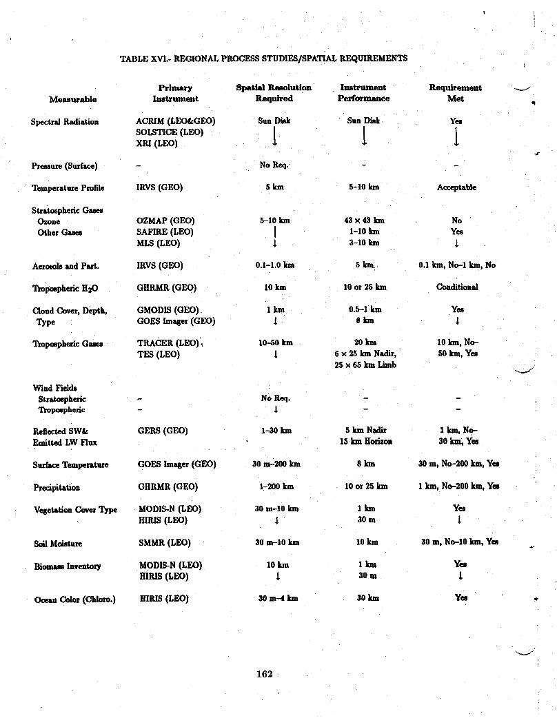
!I
TABLE XVI.- REGIONAL PROCESS STUDIES/SPATIAL REQUIREMENTS
Primary Spatial Resolution Instrument RequirementMeasurable Instrument Required Performance Met ,q
Spectra/Radiation ACRIM (LEO&GEO) Sun Disk Sun Disk Yes
SOLSTICE(LEO) 1 tXRI (LEO)
Pressure (Surface) - No Req. - -
Temperature Pmfde IRVS (GEO) 5 km 5-10 km Acceptable
Stratospheric GasesOzone OZMAP (GEO) 5-10 km 43 x 43 inn No
Other Gases SAFIRE (LEO) [ 1-10 inn YesMLS (LEO) _ 3-10 lun
AemmM and Part. IRVS (GEO) 0.1-1.0 Inn 5 km 0.1 kin, No-1 kin, No
Ttopmpheric H_O GHRMR (GEO) 10 km 10 or 25 km Conditional
Cloud Cover, Depth, GMODIS (GEO) 1 km 0.5-1 km YesType GOES Imeger (GEO) _ 0 Inn
Tmpmphexic Gases TRACER (LEO) ,. 10-50 km 20 km 10 Inn, No-TES (LEO) ! 6 x 25 km Nadir, 50 km, Yes
25 x 65 km Limb -,_/
Wind Fields
Stratospheric - No Req. - -Tmpmpherlc - _ -
Reflected SW& GERS (GEO) 1-30 km 5 km Nadir 1 kin, No-Emitted LW Flux 15 km Horizon 30 km, Yes
Surface Temperature GOES lmager (GEO) 30 m-200 km 8 kln 30 m, No-200 kin, Yes
Precipitation GHRMR (GEO) 1-200 km 10 or 25 km 1 km, No-200 kin, Yes
Vegetation Cover Type MODIS-N (LEO) 30 m-10 km 1 inn YesHIRIS (LEO) l 30 m
Soil Mmsture SMMR (LEO) 30 m-10 km 10 km 30 m, No-10 kin, Yes _.
Biomass Inventory MODIS-N (LEO) 10 km 1 Inn YesHIRIS (LEO) t 30 m ]
Ocean Color (Chloro.) HIRIS (LEO) 30 m-4 km 30 km Yes _,
162
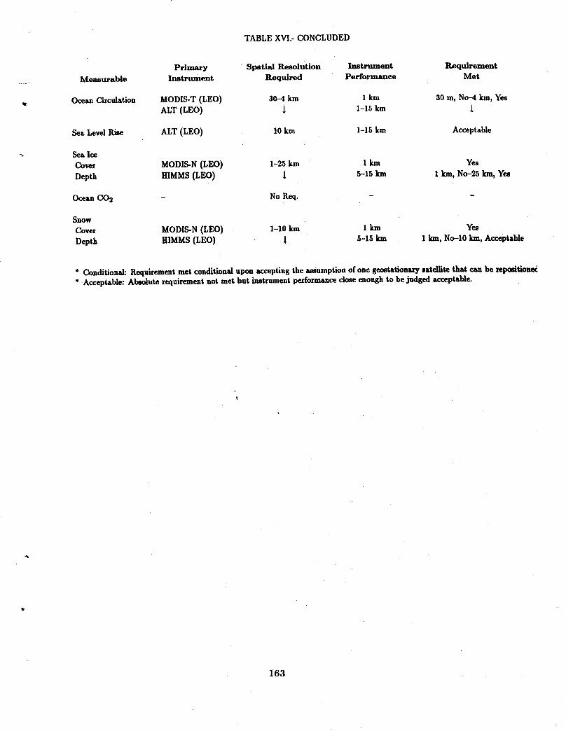
TABLE X_.-CONCLUDED
Primary Spatial Resolution Instrument RequirementMeasurable Instrument Required Performance Met
Ocean Circulation MODIS-T (LEO) 30-4 km 1 km 30 m, No-4 km, YesALT (LEO) 1 1-15 km
Sea LevelRise ALT (LEO) 10 km 1-15 km Acceptable
SeaIceCover MODIS-N(LEO) 1-25 km 1km YesDepth HIMMS(LEO) 1 5-15 km 1 kin,No-25km,Yes
OceanCO2 - NoReq. - -
Snow
Cover MODIS-N(LEO) 1-10 km 1 km Yes
Depth HIMMS(LEO) _ 5-15 km 1 km, No-10 kin, Acceptable
" Conditions]: Requirement met conditional upon accepting the assumption of one gec_tationxrysxtel]ite that cu be repositione_" Acceptable: Absolute requirementnot met but instrument performanceclose enough to be judged acceptable.
163
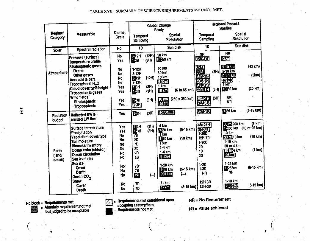
TABLE XVII: SUMMARY OF SCIENCE REQUIREMENTS MET/NOT MET.
GlobalChange RegionalProcess
Regime/ Measurable Diurnal Study StudiesCategory Cycle Temporal Spatial Temporal Spatial
Sampling Resolution Sampling Resolution
"Solar Spectralradiation _1o 10 Sundisk 10 Sundisk
Pr.sure(s....). No .R_Temperatureprofile Yes (3H) km _Stratosphericgases
Othergases No 3-12H 50km (3HIAerosols&part. No _I12H (12H)! 10km (Skin)TroposphericH20 No 2HCloudcoverltyp_/height Yes [IJI3H (3H) 1kin 1kinTroposphericgases Yes (3H) (6to65kin) (3H) _ km (20kin)Windfields
Stratospheric Yes _ (3H) _1_ (250x350km) _ (3H), NRTropospheric Yes i NRi
Radiation ReflectedS-W& Yes B3H (3H) _ _ _30km (5.15km)budget emittedLWflux • __
J
Surface temperatur, Yes _ H (3H) 4Am,km _ 10_m _)0km (Skin)
Precipitation Yes H 13H) []J30km (5-15kin) km (10or25kin)VegetaUoncover/type NoSoilmoisture No 20 l_10 km (10km) 12H-70 _?J[_10km (10km)Biornassinventory No 70 1km 1-300 1-10km
Earth Oceancolor(chloro.) No 20 I-4 km 20 30rn-4km(land/ Oceancirculation No 2D 1-4km 10 (I kin)ocean) Sealevelrise No 2D _ 2D
SeaiceCover No 7D 1-20km 1-30 1-25km
Depth No _ _]_ (5.15kin)1-30 i][25Rkm (5.15kin)OceanCO2 No (-) (-.) NRSnowCover No 70 I- km 12H-30 1-10kmDepth No 70 (5.15km) 121-1-30 (5-15km)iD_T_
m
Noblock= Requirementsmet _ = Requirementsmetconditionalupon NR = No Requirement= Absoiuierequirementnotmet acceptingassumptions
butjuclgedtobeacceptable _ = Requirementsnot met (#) = Value achieved
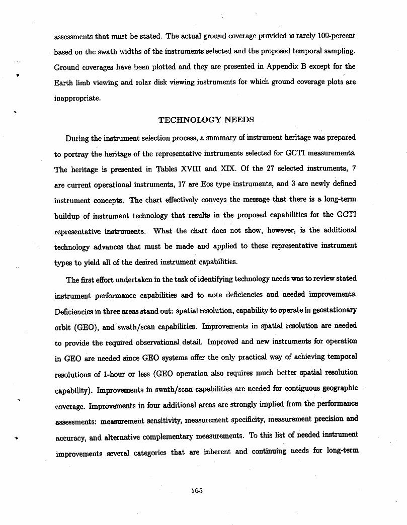
assessmentsthatmustbestated.The actualgroundcoverageprovidedisrarely100-percent
basedon theswathwidthsoftheinstrumentsselectedand theproposedtemporalsampling.
Ground coverageshavebeenplottedand theyarepresentedinAppendixB exceptforthew
Earthlimbviewingand solardiskviewinginstrumentsforwhichgroundcoverageplotsare
inappropriate.
TECHNOLOGY NEEDS
Duringtheinstrumentselectionprocess,a summaryofinstrumentheritagewasprepared
toportraytheheritageoftherepresentativeinstrumentsselectedforGCTI measurements.
The heritageispresentedinTablesXVIII and XIX. Of the 27 selectedinstruments,7
arecurrentoperationalinstruments,17areEos typeinstruments,and 3 arenewlydefined
instrumentconcepts.The charteffectivelyconveysthemessagethatthereisa long-term
buildupofinstrumenttechnologythatresultsintheproposedcapabilitiesfortheGCTI
representativeinstruments.What the chartdoesnot show,however,isthe additional
technologyadvancesthatmust be made and appliedto theserepresentativeinstrument
• typestoyieldallofthedesiredinstrumentcapabilities.
The firsteffortundertakeninthetaskofidentifyingtechnologyneedswastoreviewstated
instrumentperformancecapabilitiesand to notedeficienciesand neededimprovements.
Deficienciesinthreeareasstandout:spatialresolution,capabilitytooperateingeostationary
orbit(GEO),and swath/scancapabilities.Improvementsinspatialresolutionareneeded
toprovidetherequiredobservationaldetail.Improvedand new instrumentsforoperation
inGEO areneededsinceGEO systemsoffertheonlypracticalway ofachievingtemporal
resolutionsof1-houror less(GEO operationalsorequiresmuch betterspatialresolution
capability).Improvementsinswath/scancapabilitiesareneededforcontiguousgeographic
coverage.Improvementsinfouradditionalareasarestronglyimpliedfromtheperformance
assessments:measurementsensitivity,measurementspecificity,measurementprecisionand
accuracy, and alternative complementary measurements. To this list of needed instrument
improvements several categories that are inherent and continuing needs for long-term
165
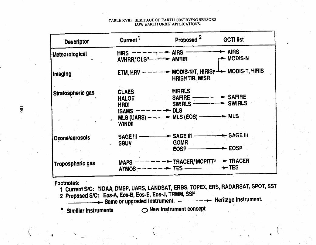
TABLE XVIII: HERITAGE OF EARTH OBSERVING SENSORSLOW EARTH ORBIT APPLICATIONS.
i
Descriptor Current1 Proposed2 GCTIlist
Meteorological HIRS I - "" AIRS > AIRS
_ AVHRR,*OLS*--'--",--AMRIR £ MODIS-NImaging ETM,HRV ,,- MODIS-N/T,HIRIS* MODIS-T,
HIRISHRIS*ITIR,MISR
Stratosphericgas CLAES HIRRLSHALOE SAFIRE = SAFIRE
_. HRDI SWIRLS _ SWIRLSISAMS _ DLSMLS(UARS) ,-- MLS(EOS) _- MLSWlNDil
Ozone/aerosols SAGE!!1 _ SAGEI!1 = SAGEIIISBUV GOMR
EOSP _ EOSP
Troposphericgas MAPS ,,.-TRACER*MOPITr*---,--TRACERATMOS _ TES _ TES
Footnotes:
_ urrentS/C: NOAA,DMSP,UARS,LANDSAT,ERBS,TOPEX,ERS,RADARSAT,SPOT,SSTProposedS/C: Eos-A,Eos-B,Eos-E,Eos-J,TRMM,SSFSameorupgradedinstrument.- .... --,- Heritageinstrument.
* SimillarInstruments C) NewInstrumentconcept
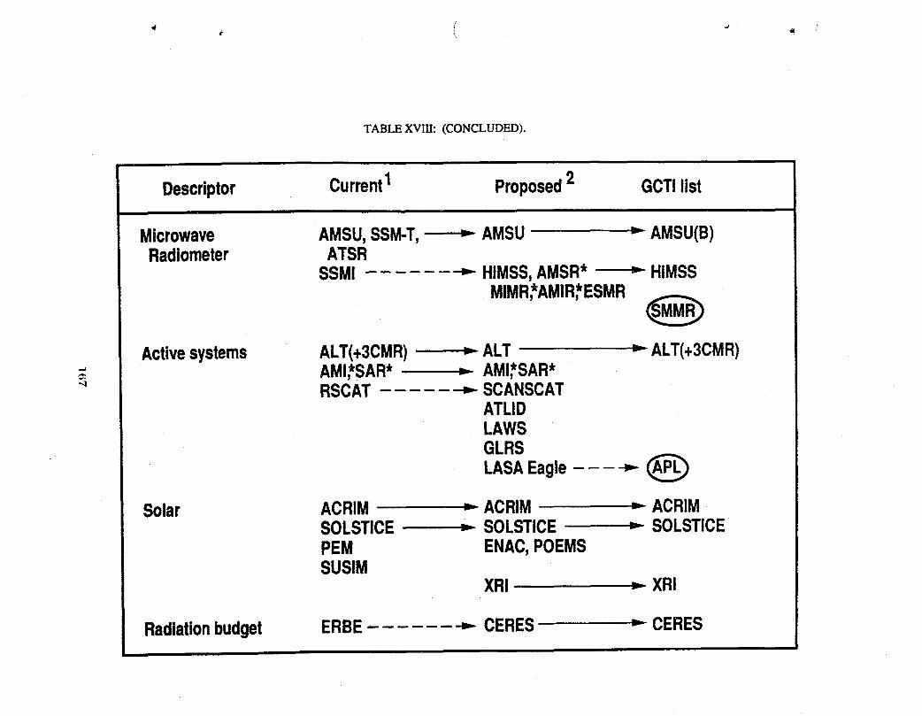
TABLE XVIII: (CONCLUDED).
Descriptor Current1 Proposed2 GCTilist
Microwave AMSU,SSM-T, = AMSU > AMSU(B)Radiometer ATSR
SSM! _ HIMSS,AMSR* > HIMSS
MIMR,*AMIR,*ESMR_)
Activesystems ALT(+3CMR) -_ALT > ALT(+3CMR)AMI,*SAR* "- AMI,*SAR*
" RSCAT _ SCANSCATATLIDLAWSGLRS
LASAEagle _
Solar ACRIM = ACRIM = ACRIMSOLSTICE .= SOLSTICE = SOLSTICEPEM ENAC,POEMSSUSIM
XRI > XRI
Radiationbudget ERBE _- CERES = CERES

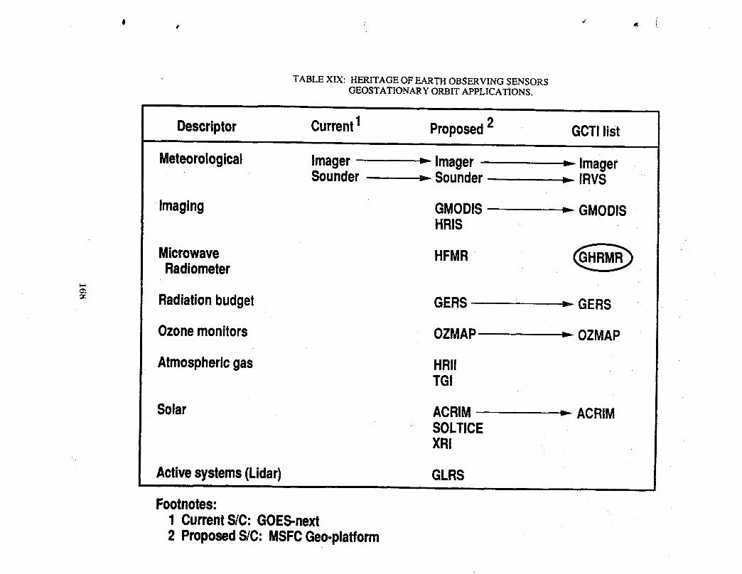
TABLE XIX: HERITAGE OF EARTH OBSERVING SENSORSGEOSTATIONARY ORBIT APPLICATIONS.
i
Descriptor Current1 Proposed2 GCTIlist
Meteorological lmager _ lmager _ ImagerSounder _ Sounder = IRVS
Imaging GMODIS _ GMODISHRIS
Microwave HFMRRadiometer
Radiationbudget GERS _ GERS
Ozonemonitors OZMAP _ OZMAP
Atmosphericgas HRI!TGI
Solar ACRIM _ ACRIMSOLTICEXR!
Activesystems(Lidar) GLRSi |
Footnotes:1 CurrentS/C:GOES-next2 ProposedS/C:MSFCGeo-platform
accurate sensing of Earth parameters fi'om satellites are added: less demand on spacecraft
resources, simplicity, reliability/lifetime, and operational maturity.
All of these categories of needed instrument improvementsare listed in Table XX. Listed
across the top of the table are the technology areas in which advances can be applied to yield
the needed instrument improvements. The first nine items deal with hardware technologies_
the next three deal with the complete instrument system, and the last three deal with
non-hardware technologies. A need for a particular technology to provide a particular
instrument improvement is designated by x. Strong needs are designated by an ®. This
matrix represents an initial attempt at scoping the technology needs for GCTI instruments.
169 -_,..j

TABLE XX: IMPROVEMENTS PROVIDED BY ADVANCED TECHNOLOGY.
Instrument€omponents NQ_- h_-@sm_
(candidatesfol
_venwnts p_v_ded(Irmmmems_ openelons)
!_ga_l, _n.,llcal ,.
Oper_toninGEO•_tler__. i®® @ ® ®® x @s._..._.,,. X X X X X @co_m_
-_ k...._.n,,_,y X X X X I X (8)i
Memummentsensiflv_•._.=.,._.._,-,,_.,_.,,_h,.oX X t8) X X X XMeasumme_precision!_._ ®x x®® x x x x
i
Allernatlw,complementary.,-..,.,,-._ X X X X XLessdemandonS/Cresources•._ ® x ®•Volume•Power
i
•o_ IX X X X X (g) X•Polnting_eklnWseannlng•Hellnlductkln
•w_,y X X X.Om_nce•_B#_.BUon•Less_i_ dm•LessInterl_•s_k,,,,,-_u_. X X X X X•Uore€ll__eq._,tatlo.
Reliability,lifetime X @ X X
o_..,m_ X X X X X X X
By necessity the technology needs for the three new instrument concepts selected for
GCTI had to be addressed. The selection of the Geostationary High Resolution Microwave
Radiometer (GHRMR) and the Soil MoistureMicrowaveRadiometer (SMMP_)forced a look ,_
at the technologies involved in large aperture multi-frequency microwave passive systems
(see column 12 of the needs chart). Jeffrey Farmer et al. (Farmer, 1989) in defining the
GHRMR anticipated technology advances in the areas of large antennas, structures, controls,
and microwave signal detection in order to develop a space flight instrument system with
adequate sensitivity and spatial resolution when operating in geostationary orbit. Melvin
Ferebee et al., (Ferebee, 1989) in defining a concept for the SMMR, primarily addressed the
large collector (including structures and controls) technologies in order to obtain adequate
spatial resolution at the low microwave frequency required for sensing moisture in various
soils to usable depths in the order of 12cm or more.
The third new GCTI instrument is a concept for the measurement of surface pressure.
The instrument has been titled Atmosphere Pressure Lidar (APL). The selection d APL
forced a look at lidar system technology needs (see column 1 of the need chart). The
measurement principle is based on the experimental workof Korb et al. (Korb, et al., 1983)
at the NASA Goddard Space Flight Center. The Earth Observing System Volume 11(1,
LASA document describes the principle as it could be employed in a Lidar Atmospheric
Sounder and Altimeter instrument as follows: "The surface pressure experiment is a two-
wavelength DIAL measurement (Korb and Werg, 1983) utilizing the backscattered energy
from the Earth's surface or from low-lying clouds. A pressure-sensitive measurement is
obtained by locating one wavelength in a temperature insensitive absorption trough region.
A trough region is the region of minimum absorption between two strongly absorbing lines
in the oxygen A-band near 0.76 pm, or 13,150 cm-1. The absorption in the trough is
proportionalto the squareof the pressure.A secondwavelengthlocatedin an absorbing
regionwitha shiftof0.0001to 0.001/_mis usedas a referencetonormalizeouttheeffectsof surfacereflectance.The useof an absorptiontroughtechniquereducesthe sensitivityof
171

the measurement to the effects of laser frequency jitter by up to two orders of magnitude.
The integrated path absorption method used for the measurement allows high sensitivity
_- to be achieved." The Eos document envisions the above technique to be capable of surface
m pressure measurement with an accuracy of 4-2 mb with a vertical resolution of 1 to 2 km.
The Eos LASA document and the follow-on Eos Atmospheric Global Lidar Experiment
(EAGLE) proposal for Eos published in July, 1988 by the NASA Langley Research Center
provide a detailed engineering study which serves as a baseline for the GCTI Atmospheric
Pressure Lidar (APL) concept. The LASA/EAGLE instrument was proposed with a 1.25 m-
diameter telescope to be used in investigations of water vapor, temperature, tropospheric and
stratospheric aerosols, and clouds. During discussions with LaRC personnel responsible for
the LASA/EAGLE concept, it was concluded that by eliminating the water vapor capability
of the LASA/EAGLE instrument and tailoring it as a surface pressure measuring instrument,
the telescope diameter could be reduced to 0.5 m. This results in the mass and power being
reduced by one-third to one-half. The more conservative one-third reduction was selected;
thus, the GCTI/APL instrument concept became a LASA/EAGLE type instrument with
.... a telescope diameter of 0.5 m and a mass and power of one-third less than a fully capable
LASA/EAGLE instrument. A 4-45° crosstrack scan capability was also assumed for the APL
instrument. Needless to say, an instrument concept this preliminary in design would require
extensive design and development before it becomes a viable candidate for flight. Technology
needs have been identified in the areas of lightweight, precision, durable telescopes, precise
frequency controlled lasers with power and pulse characteristics to provide measurement
sensitivity, infrared detectors and coolers, and most importantly, complete lidar instrument
system simplicity, reliability, and long lifetime.
172

The need for the three new GCTI instrument concepts and the general technology needs
matrix presented in Table XX illustrate the need for an extensive instrument development
program. The detailing of the elements of this program is a major follow-on task. This
task is to be undertaken separately by appropriate instrument specialists at the Langley
Research Center. To conclude this section of this report, therefore, we have only their
introductory narrative which addresses the general technical areas of detectors, cryogenic
coolers, lightweight optics, and lasers.
Detectors
The majority of Eos proposals reflectsignificant instrumentperformance benefits obtained
through the use of arrayed detectors, as compared with single element detectors or'_afew
point detectors, as wereused in the 1980's. Detector arrays for the mid-infraredwavelengths
from 2 to 20pro have recently become available that exhibit greatly increased capability while
being virtually identical in size and mass to previously available designs. This improvement
is reflected in better experiment radiometric sensitivity and spectral or spatial resolution.
Currently, arrayed mid-infrared (up to 10#m) detectors in line arrays on the order of a _-_
hundred detectors and area arrays of up to 64 by 64 elements are available. In the next
decade these detectors should become more available with their capability size, and cost
further improved. Active, remote sensors such as lidars would benefit from the development
of improved Avalanche Photo Detectors or other solid state detectors capable of photon noise
limited performance in the 0.7 to 2.0pm range. This is just longward of the wavelength range
where multiplier-photo tubes can operate. This improved performance would benefit the
very important water vapor, pressure,and temperature profilemeasurement made with lidar
instruments. Earth budget remote sensing experiments from GEO- synchronousorbit with °
temporal sampling capability of fraction of hours would be enabled through the development
of cryogenically cooled active cavity receiver detectors. These detectors have been shown in _
the laboratory to be capable of nano-watt sensitivity.
173 _-'_
Cryogenic Coolers
Remote sensor measurements can be widened in scope and substantially improved with
high capability, efficient cryo-coolers with operational life times of 5-years. Coolers areJ
needed for several types of applications:
, (1) Cold Optics: Remote sensors looking Earth-ward from space view a scene that is at
approximately 250 K. Optimum instrument performance for this level of scene photon
flux requires the instrument optics to operate at intermediately cold temperatures of
approximately 150 K.
(2) Detector Coolers: A great number of applications require detectors operating at liquid
nitrogen temperature. An energy efficient, reliable 5-year life cryo-cooler delivering 1 W
at 80 K is needed. The cooler should impart a negligible mechanical vibration level to the
alignment sensitive instrument focal plane assembly.
(3) High Capability Coolers: The sensitivity of detectors ranging in spectral frequency over
v the entire mid-infrared spectrum would be much improved if a cryo-cooler capable of a
1W loadat 20 K wereavailable.Forfar-infrared(20 to 500micron)experimentsefficient
long-lifecryostatsare needed. Presenttechnologyprovideshybridcoolersthat use a
liquidheliumdewarwithcoldshieldsheldat intermediate,progressivelycolder(30,80,
and 150K) temperatures.
LightweightOptics
Spacebased lidar instrumentsmust use receivertelescopeson the orderof onemeter in
diametertoattainthe desiredsensitivity.Far-infraredandotherremotesensinginstruments
also use large diameter optics to maintain small diffraction effects as compared with spatial
resolution; however, the need for large optics contrasts with the need for low instrument
mass for efficient launch into space. The development of lightweight optical systems can
thus contribute greatly to reducing launch costs while maintaining performance. Present
174
"technology is on the verge of producing diffractionlimited optical elements with a mass of
20 kg/m 2 for optical element diameters of up to on the order 1 m. Several technologies
capable of this low density are presently being pursued:
(1) Silicon-Carbide mirrorswhere the material is vapor deposited on a carbon mandrel
(2) ChemicallyminedAluminummirrorswherelargelightningholesarechemicallymachined
intothe mirrorblank
(3) FrittedGlasswheretwothinglassface-plateblanksarespacedby a setofthin-wallglass
tubes fused in between. These techniquesneedto becomemore availableto be cost
effective.To reachthe full potentialof mass savings,it is imperativethat the optics
supportstructure,i.e., the telescopestructurealsobe lightweightedwhileelementde-
spaceand tilts arecontrolledto the neededtolerancesbya meteringsystem.
Lasers
Toperformadequatelyatmosphericparticleand gas lidarsand differentialabsorption
lidars(DIAL)requirenon-tunable(albeitmulti-spectral)and tunablelaseroutputsrespec-
tivelyof at leastoneandpreferablytwoJoulesperpulseat pulserepetitionratesof 10 Hz
or more.Qualifiedlasersof this output levelhavenot beenflownin space. LagC'sLITE
projectwilluse a 1.5-Joule-per-pulseclass,threecolor(1.064,0.532,0.352pm)laserfor
flighton the spaceshuttlein the mid-1990's.Researchis progressingtowardlaboratory
demonstrationof a tunable(0.6-1pro)Ti:Sapphirelaserof at least 1 Joule/pulseat 10 Hz
by mid-1990.Duringthis timeperiod2-prolaserresearchwillproduceeye-safelasersfor
atmosphericconstituentand windsensing.Forthe post year-2000timeperiodlaserswillq_
needto use diodepumpingto increasetheirefficiencyandreducelaserpowerrequirements.
Thelaserpowerconsumption,and the wasteheat they generatethat needsto be rejected
to spacewithbulkyradiators,canbe reducedfromthe severalthousandwattsrequiredfor
flashlamppumpedsystemsto the orderof a fewhundredwattswithdiodepumps.
175
References
(This list of references is not suitable for use in a formal publication; however it......... is presented to document the sources of information used to accomplish the
, Task 2 effort).
1. NASA Space Systems Techn01ogv Model, Vol. 1-Model, NASA TM-88174;CN 153751, June 1985.
2. NASA Space Systems Technology_ Model, Vol. 3-Data Base, NASA TM-88176;CN 153751, June 1985.
3. Jane's Spaceflight Directory 1987-1988.
4. Report of the Earth System Science Committee, NASA Advisory Council,NASA Headquarters, January 1988.
5. Earth Observing System 1989 Reference Handbook, NASA Goddard SpaceFlight Center, March 1989.
6. 1989 Long-Range Program plan, NASA Headquarters, 1989.
7. Geostationarv Platform Study, Contract Extensio..n.,Final Report, LockheedMissile & Space Co., NAS 8-36103, Mod No. 13, DR-9, November 1988.
8. C.J. Scolese, L.C. Scholz, 'Eos Mission Design Utilizing the Space Station..... Platforms', AIAA 89-0252, 27th Aerospace Sciences Meeting, January 9-12,
1989.
9. GCTI Meeting Notes, NASA Langley Research Center, May 31, 1989.
10, Sensor Requirements, Memo from C. Husson, NASA Langley ResearchCenter, June 19, 1989.
11. Geostationa_ Platform Bus Study, Vol. 11, Final Report, NAS 8-36104, WDL-TRl1066, September 1987.
12. Eos "All Hands" Science Team Package, March 1989.
13. TRACER - A Multiple Level Carbon Monoxide Correlation Radiometer, EosProposal, 1988.
14. Space Based Remote Sensing of the Earth, A Report to Congress, NOAA, USDept. of Commerce, NASA, September 1987.
- 15. D. Pidgeon, "Subsystem Design Study For an Earth Science GeostationaryPlatform", Master's Thesis, JIAFS/GWU/NASA, July 1989.
176
16. A. Schnapf, "TIROS Meteorological Satellites", Monitoring Earth's Ocean,Land, and Atmosphere from Space - Sensors, Systems and Applications,Progress in Aeronautics and Astronautics, Vol. 97, American Institute ofAeronautics and Astronautics, New York, 1985.
4
17. GE-Eos Instrument Interface Meeting, B. Budd, M. DiJoseph, August 1, 1989.
18. Earth Science Geostationarv Platform Technoloav, NASA Langley ResearchCenter, NASA Conference Publication 3040, September 21-22, 1988. 4
19. Handbook of Sensor Technical Characteristics, S. Tanner, Systematics GeneralCorporation, NASA Reference Publication 1087, 1982.
20. Research and TechnoloaT 1988, NASA Goddard Space Flight Center,CN-151-695, 1988.
21. Earth Science Ge,ostationary Platforms, Phase A Instrument Studies -Meeting 1, NASA Marshall Space Flight Center, March 29, 1989.
22. UARS Project Data. Bo.o.k,General Electric Astro-Space Division, April, 1987.
23. Geostationarv platform Study, Midterm Review., Lockheed Missile and SpaceCompany, Ford Aerospace Corporation, Computer Science Corporation,NAS 8-36103, LMSC-F333054, July, 1989.
24. GOES I-M Operational Satellite Post-Conference Summary_ Report, NOAA, _._.US Dept. of Commerce, May 1989.
25. The Observing System for the Wea.ther Watch of the 1990's - GOES IJK/LM,Ford Aerospace Corporation.
26. "Microwave Remote Sensing Systems for Global Change", Briefing Document,T.G. Campbell, August 1989.
27. "Earth Observing System" Poster, Hughes Santa Barbara Research Center,May 1989
28. C0n.cept Definition for .Spa.c..eStation Technoloa3/Development Experiments -Experiments Definitio.n, Research Triangle Institute, NAS 1-17639,
TDMX 2264, RTI/3042/07-01F, August 1985.
29. A Design Study for the use of a Multiple Aperture Deployable Antenna forSoil Moisture Remote Sensin¢ Satellite Applications, Foldes Inc.,NAS 1-17209, CR-178154, August 1986.
_r
30. Large Space Systems Technology, NASA Langley Research Center,NASA Conference Publication 2035, January 17-19, 1978.
177
31. Ea__le - Eos Atmospheric Global Lidar Experiment, Proposal for Eos, Vol. 1Technical and Management, NASA Langley Research Center, July 15, 1988,
.... 32. "GEO Instrument Data Base", Vernon Keller, NASA Marshall Space Flight, Center, October 17, 1989.
33. LASA - Lidar Atmospheric Sounder and Altimeter, Earth Observing System -Instrument Panel Report, Vol. 2d., NASA, 1987.
34. Earth Observing System, Science and Mission Requirements, Working Group_, Vol. 1, NASA Goddard Space Flight Center, TM-86129, August1984.
35. Tropospheric Passive Remote Sensing, NASA Langley Research Center, NASAConference Publication 2237, July 20-23, 1981.
36. Technology for the Mission to Planet Earth, Report of the Adhoc ReviewTeam, Prepared by TRW Space & Technology Group Publications, 1989.
37. Characteristics of a Multireflector Antenna for High Resolution Radiometerwith Large Angle Scan, Foldes Inc., NAS 1-17209, May 3, 1989.
38. Preliminary Ranking of Various Multireflector Antennas for 6-31 GHz BandRadiometers, Foldes Inc., NAS 1-17209, June 2, 1989.
39. Support Trusses for Large Precision Segmented Reflectors: Preliminary..... Design and Analysis, Timothy Collins, W.B. Fichter, NASA Langley Research
Center, TM-101560, March 1989.
40. Earth Observing System Background Information Package (BIP) -Announcement of Opportunity, Part 5, OSSA-1-88, January 19, 1988.
41. S. Ride, Leadership and America's Future in Space, A Report to theAdministrator, August 1987.
42. C. Covault, "Mission to Planet Earth", Aviatio.n Week and Space Technology,March 13, 1989, pp. 34-50.
43. G.I. Johnston, W.R. Hudson, "Technologies for Monitoring Global Change",MAA 89-0254, 27th Aerospace Sciences Meeting, January 9-12, 1989.
44. J.T. Suttles, E.F. Harrison, G.G. Gibson, and T.G. Campbell, "Global ChangeTechnology Initiative Architecture Trade Study: Task 1 ScienceRequirements Identification", Unpublished White Paper, NASA LangleyResearch Center, August 1989.
- 45. E.F. Harrison, G.G. Gibson, J.T. Suttles, I. Taback, and J. Buglia, "SatelliteOrbit Considerations for Earth Observation Missions", Unpublished WhitePaper, NASA Langley Research Center, August 1989.
178

46. C.L Korb and C.Y. Weng, "Differential Absorption Lidar Techniques ForMeasurement of the Atmospheric Pressure Profile", Applied Optics, 22, 3759, o_.._1983.
47. J.T. Farmer, T.G. Campbell, W.T. Davis, P.A. Garn, C.B. King andC.C.Jackson, "ConceptualDesign of a Geostationary Earth Science Platform",Unpublished White Paper, NASA Langley Research Center, March 1990.
48. M.J. Ferebee, "Hoop Column Soil Moisture Spacecraft in Low Earth Orbit",Unpublished White Paper, NASA Langley Research Center, March 1990.
179

I'

MICROWAVE SENSING TECHNOLOGY ISSUESRELATED TO A GLOBAL CHANGE TECHNOLOGY
ARCHITECTURE TRADE STUDY
Thomas G. CampbellNASA Langley Research Center
Jim ShiueNASA Goddard Space Flight Center
Denis ConnollyNASA Lewis Research Center
Ken WooJet Propulsion Laboratory

:i
,L
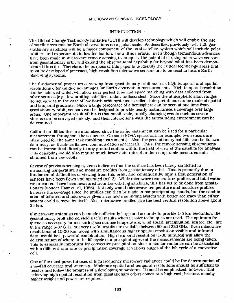
MICROWAVE SENSING TECHNOIXkGY
INTRODUCTION
The Global Change Technology Initiative {GCTI)will develop technology which will enable the use'_ of satellite systems for Earth observations on a global scale. As described previously [ref. 1,21,geo-
stationary satellites will be a major componenl of the total satellite, system which will include polarorbiters and experiments in low inclination, low altitude orbits. Even though tremendous advanceshave been made in mk:rowave remote sensing teclmiques, the potential of using microwave sensorsfrom geostationary orbit will extend the observational capability far beyond what has been demon-strated thus far. Therefore, the purpose of this paper Is io identify the critical technology areas thatmust be developed if precision, high-resolution microwave sensors are to be used in future Earthobserving systems.
The fundamental properties of viewing from geostatlonary orbit such as high temporal and spatialresolutions offer unique advantages lor Earth observation measurements. High temporal resolutioncan be achieved which will allow near perfect tlrne and space rnatching with data collected fromother sources (e.g., low orbiting satellites, radar, radiosondesl. Since the atmospheric slant rangesdo not vary as in the case of low Earth orbit systems, excellent interpretations can be made of spatialand temporal gradienls. Since a large percentage of a hemisphere can be seen at one time fromgeostationary orbit, sensors can be designed to provide nearly instantaneous coverage over largeareas. One important result of this is that small-scale, rapidly changing events such as severestorms can be surveyed quickly, and their interactions with the surrounding environment can bedetermined.
Calibration difficulties are minimized since the same instrument can be used for a particularmeasurement throughouI the sequence. On some NOAAspacecraft, for example, two sensors areoften:used for the same task (profiling instruments]. Also. the geostatlonary satellite can be its owndata relay, as It acts as ll.s own communication spacecraft. Thus, the remote sensing observationscan be transmitted directly to any ground station within the field of view of the satellite for analysis.This capability would also require much lower data rates than for comparable measurements
_-- obtained from low orbits.
Review of previous sensing systems Indicates thai the surface has been barely scratched Inmeasuring temperature and moisture profiles frorn geostatlonary orbit. This Is primarily due tofundamental difficulties of viewing from this orbit, and consequently, only a first generation ofsensors have been flown and operated (ref. 3). While microwave temperature profiles and total watervapor content have been measured from low-orbiting satellites, this has yet to be done from geosta-tionary Wonder Haar et. al, 1986). Not only would microwave temperature and moisture profilesIncrease the coverage since the profiles can then be made in nonprectpitating clouds, but the combin-at Ion of Infrared and microwave gives a complete sounding system with better accuracy than eithersystem could achieve by Itself. Also, microwave profiles give the best vertical resolution above about25 kin.
If microwave antennas can be made sufficiently large and accurate to provide 1-5 km resolution, thegeostationary orbit should yield useful results when passive techniques are used. The optimum fre-quencies necessary for measuring sea surface lemperature, wind speed, precipitation, sea ice, etc., arein the range 6-37 GHz, but very useful results are available between 90 and 220 GHz. Even microwave
- resolutions of 10-30 kin, along with simultaneous higher spatial resolution visible and infrareddata, would be a powerful combinalion. High temporal resolution (1-30 minutes] will allow thedetermination of where in the life cycle of a precipitating event the measurements are being taken.This is especially Important for convective precipitation since a similar radiance can be associatedwlth a different rain rate or preclpllation coverage at various stages of the life cycle of a convective
• cell.
One of the most powerful uses of high frequency microwave radiances could be the determination ofsnowfall coverage and intensity. Moderate spatial and temporal resolutions should be sufficient toresolve and follow the progress of a developing snowstorm. It must be emphasized, however, thatachieving high spatial resolution from geostationary orbits comes at a high cost, because usuallyhigher weight and power are required.
183

SCOPE OF RESEARCH AND "I_CHNOLOGY
The identification of the critical microwave remote sensing technology areas which would enableadvanced geostationary systems was achieved by first developing the work breakdown structure(WBS}for the related technology disciplines. This WBS area is a subset of the Observational ThrustSection of the GCTI WBS program plan. Three major WBS elements were identified for the micro- "wave sensor technology area which are: (1) large space antenna technology (which includes filledand unfilled aperture techniques), (2) passive microwave sensor (radiometer) technology, and(3} active microwave sensor (radar) technology. Specific research and technology development taskswere identified and prtorltized for each of the WBS technology areas listed above. The prioriUzationwas based on the selection of those technology areas believed to be critically needed if the feasibilityof new microwave sensors is to be demonstrated in a time to affect the design and development of thefinal satellite system. The objectives, science implications, and the technical issues associated withthis technology program will now be discussed.
OBJECTIVES
The objectives for this research program are to enable the development of significantly lighter andless power-consuming, high resolution microwave sensors which will operate at frequencies from1-200 GHz. These systems will use large aperture antenna systems (both reflector and phased arrays)capable of wide scan angle, high polarization purity, and utilize sidelobe suppression techniques asrequired. Essentially, the success of this technology program will enable high-resolution micro-wave radiometers from geostationary orbit, lightweight and more efficient radar systems from lowEarth orbit, and eliminate mechanical scanning methods to the fullest extent possible--a mainsource of platform instability in large space systems.
SCIENCE IMPLICATIONS OF THIS TECHNOLOGY PROGRAM
The development of advanced radiometer and radar technology will provide measurements of theEarth's hydrological cycle, including precipitation, clouds, water vapor, snow cover, soil moisture, _-Jice type and thickness, air temperature profile, sea surface temperature, and sea surface wind speed.Also, this work is significant in that large and higher frequency antennas will be developed whichwill enable measurements with higher resolution and sensitivity. These characteristics willimprove spatial imaging, provide more accurate information on cloud column height and evolution,rain and precipitation, surface temperature (ocean and land), ocean and wind patterns, biomassinventory, and snow and ice formations. These measurements, in turn, will provide much neededinformation on the greenhouse warming effect, air pollution and acid deposition, and land surfaceclimatology.
TECHNICAL ISSUES
The key technical issues in the microwave sensor technology area were identified by representativesfrom the NASA Centers, JPL, and by reviewing the results of the Earth Science GeostaUonaryPlatform Technology Workshop (ref. 1) which was conducted at the Langley Research Center inSeptember 1988. The critical task areas for each of the WBS elements are listed below:
(I) Large Space Antenna Technology
o Precision membrane reflector antenna technology (<40 GHz)o Distributed, phased array antenna technology (<40 GHz)o Precision, solid reflector anlenna technology (40-220 GHz) -,° Rapid scanning techniques for large reflector antennaso Optically-controlled Beam Forming Network [BFN} technology° Distributed phased array antenna technology {40-220 GHz)
Specific task descriptions on each of these technology areas were developed and provided as inputs to _..jthe GCTI planning activity.
184

(2) Pas_sive Microwave Sensing Technology
° Electronic scanning radiometer technology Ifllled aperture)o Quasi-optical millimeter wavelength component technologyo Synthetic aperture radiometer technology luiamledaperturel
. Specific task descriptions on each of these technology areas were developed and provided as inputs tolhe GCTI plannlng activity.
(3) Active Microwave Sensing Technology
o MMIC componenttechnology for 1-90 GHZ radar applicationso High power, non-MMIC, high frequency radar systems componentso Pulse modulator technology for sidelobe suppression techniques
Specific task descriptions on each of these technology areas were developed and provided as inputs tothe GCTI planning actlvlly.
Su turn ary
Advanced microwave sensing technologies are critically needed if the science objectives of theGlobal Change Technology Initiative are to be met. The development of microwave sensing technol-ogy by NASA has been sporadic during the past 5-10 years, especially in the area of advanced sensordevelopment. For example, tile Push Broom Microwave Radiometer (PBMRI, developed by Langleyfor soll moisture measuremerlts in 1985, was the last microwave sensor supported by OAET for anOSSA application. Therefore, the GCTI provides a new opportunity for a renewed effort by NASA toaddress a much needed technology--the development of advanced microwave remote sensing systemsfor LEO and GEO applications.
185
REFERENCES
I. Campbell, Thomas G.; and Wright, Robert L.: Earth Science GeostaUonary Platform Technology.Technology Workshop Proceedings conducled at I_angley Research Center, Hampton, Virginia,September 21-22, 1988.
2. Shenk, William E.; Hall, Forest; and Esaias, Wayne: Earth Observations from GeosynchronousSatellites. Paper presented at GOES I-M Operational Satellite Conference, April 3-6, 1989.
3. Shenk, William E.; Vonder Haar, Thomas H.; and Smith, William L.: An Evaluation ofObservations from Satellite for the Study and Prediction of Mesoseale Events and CycloneEvents. American Meteorological Society, Vol. 68, No. 1, January 1987. _
186
SUNSYNCHRONOUS LOW EARTH ORBITSPACECRAFT CONCEPTS AND TECHNOLOGY REQUIREMENTS
FOR GLOBAL CHANGE MONITORING
L. Bernard GarrettNASA Langley Research Center
Ansel J. Butterfield, Israel Taback and Paul A. GarnThe Bionetics Corporation
Donald R. Burrowbridge, Jr.Spartan Space Services

ip
1.0 INTRODUCTION, SCOPE AND CONTENTS
r
The GCTI listing of instruments for operation in low Earth, sunsynchronous
orbits shown in Table 1-1 contains 21 entries, of which 20 are carried aboard
multi-instxtmlent spacecraft. This list identifies the temporal requirements for
repetition of measurements and also includes groups of instruments that make
complementing measurements. Definitions for individual spacecraft follows the
temporal and grouping requirements to establish constellations which will provide
the measurement data. The definitions of constellations for multi-instrumentspacecraft show two alternatives:
1. A constellation of 10 spacecraft, each compatible with launch by aDelta booster; or,
2. A constellation of 4 spacecraft, each requiring a Titan booster.
Operating subsystems for the individual spacecraft can utilize modular
concepts that are adaptations based upon current plans for improving theperformance of the NASA-GSFC Multimission Modular units.
The descriptions of the spacecraft and constellations begin with a
compilation of instrument-related requirements that define the principal system
performance parameters and operating capabilities. Spacecraft operating
subsystem capabilities are then compared with the existing Multimission Modular
elements to identify the improvements required or adaptations. The descriptionsof the individual spacecraft first address the smaller Delta booster units and then
the larger Titan booster units. A comparison of features leads to a summary of
results and identification of the technology advances required for the GCTI_. spacecraft.
189
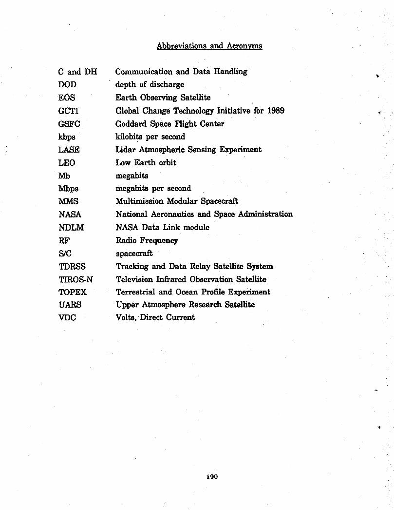
Abbreviations and Acronyms
C and DH Communicationand DataHandlingDOD depthofdischarge
EOS EarthObservingSatellite
GCTI Global Change Technology Initiative for 1989
GSFC Goddard Space Flight Center
kbps kilobits per second
LASE Lidar Atmospheric Sensing ExperimentLEO Low Earth orbit
Mb megabits
Mbps megabits per second
MMS Multimission Modular Spacecraft
NASA National Aeronautics and Space Administration
NDLM NASA DataLinkmodule
RF Radio Frequency
S/C spacecraft
TDRSS Trackingand DataRelaySatelliteSystem
TIROS-N TelevisionInfraredObservationSatellite
TOPEX Terrestrial and Ocean Profile Experiment
UARS Upper Atmosphere Research SatelliteVDC Volts, Direct Current
190
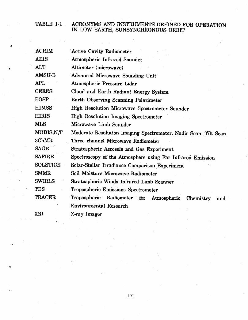
TABLE 1-1 ACRONYMS AND INSTRUMENTS DEFINED FOR OPERATIONIN LOW EARTH, SUNSYNCHRONOUS ORBIT
ACRIM Active Cavity Radiometer
AIRS Atmospheric Infrared Sounder
ALT Altimeter (microwave)
AMSU-B Advanced Microwave Sounding Unit
APL Atmospheric Pressure Lidar
CERES Cloud and Earth Radiant Energy System
EOSP Earth Observing Scanning Polarimeter
HIMSS High Resolution Microwave Spectrometer Sounder
HIRIS High Resolution Imaging Spectrometer
MLS Microwave Limb Sounder
MODIS,N,T Moderate Resolution Imaging Spectrometer, Nadir Scan, Tilt Scan
3ChMR Three channel Microwave Radiometer
SAGE Stratospheric Aerosols and Gas Experiment
SAFIRE Spectroscopy of the Atmosphere using Far Infrared Emission
SOLSTICE Solar-Stellar Irradiance Comparison Experiment
SMMR Soil Moisture Microwave Radiometer
SWIRLS . Stratospheric Winds Infrared Limb Scanner
TES Tropospheric Emissions Spectrometer
TRACER Tropospheric Radiometer for Atmospheric Chemistry andEnvironmental Research
XRI X-ray Imager
L91
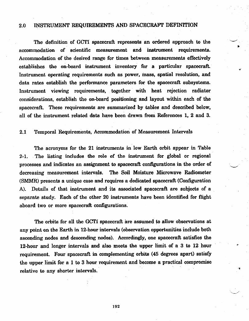
2.0 INSTRUMENT REQUIREMENTS AND SPACECRAFTDEFINITION
The definition of GCTI spacecraft represents an ordered approach to the "-t
accommodation of scientific measurement and instrument requirements.
Accommodation of the desired range for times between measurements effectively
establishes the on-board instrument inventory for a particular spacecraft.
Instrument operating requirements such as power, mass, spatial resolution, and
data rates establish the performance parameters for the spacecraft subsystems.
Instrument viewing requirements, together with heat rejection radiator
considerations, establish the on-board positioning and layout within each of the
spacecraft. These requirements are summarized by tables and described below,
all of the instrument related data have been drawn from References 1, 2 and 3.
2.1 Temporal Requirements, Accommodation of Measurement Intervals
The acronyms for the 21 instruments in low Earth orbit appear in Table
2-1. The listing includes the role of the instrument for global or regional
processes and indicates an assignment to spacecraft configurations in the order of ___
decreasing measurement intervals. The Soil Moisture Microwave Radiometer
(SMMR)presents a unique case and requires a dedicated spacecraft (Configuration
A). Details of that instrument and its associated spacecraft are subjects of a
separate study. Each of the other 20 instruments have been identified for flight
aboard two or more spacecraft configurations.
The orbits for all the GCTI spacecraft are assumed to allow observations at
any point on the Earth in 12-hourintervals (observation opportunities include both
ascending nodes and descending nodes). Accordingly, one spacecraft satisfies the
12-hour and longer intervals and also meets the upper limit of a 3 to 12 hour _
requirement. Four spacecraft in complementing orbits (45 degrees apart) satisfy
the upper limit for a 1 to 3 hour requirement and become a practical compromise
relative to any shorter intervals. _
192
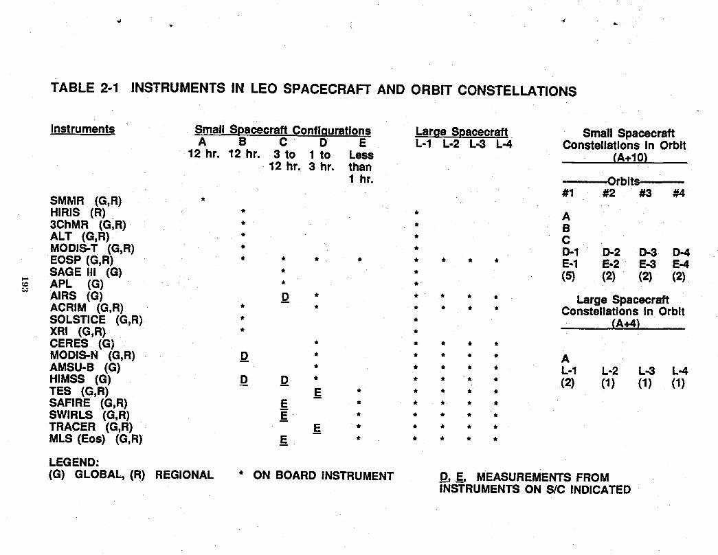
TABLE 2-1 INSTRUMENTSIN LEO SPACECRAFTAND ORBIT CONSTELLATIONS
Instruments Small Spacecraft Configurations Large Spacecraft Small SpacecraftA B C D E -1 -2 -3 -4 Constellationsin Orbit
3t to
(2) (1) (1) (1)ED_44
12,hr. 12 hr. o 1 Less (A+10)
12 hr. hr. than1 hr. Orbit¢
SMMR (G,R) #1 #2 #3 #4
HIRIS (R) * A3ChMR (G,R) *ALT (G,R) * CMODIS-T (G,R) * D-1 D-2 D-3EOSP (G,R) * * * E-1 E-2 E-3SAGE III (G) * (5) (2) (2) (2)APL (G) *AIRS (G) D Large SpacecraftACRIM (G,R) * Constellationsin OrbitSOLSTICE (G,R) * (A+4)XRI (G,R) *CERES (G) *MODIS-N (G,R) D * AAMSU-B (G) * L-1 L-2 L-3 L-4HIMSS (G) D D *TES (G,R) E *SAFIRE (G,R) E * *SWIRLS (G,R) E * *TRACER (G,R) E * * * * *MLS (Eos) (G,R) E * * * * *
LEGEND:(G) GLOBAL,,(R) REGIONAL * ON BOARD INSTRUMENT D, E_, MEASUREMENTSFROM
INSTRUMENTSON S/C INDICATED
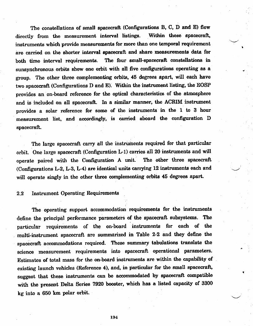
The constellations of small spacecraft (Configurations B, C, D and E) flow
directly from the measurement interval listings. Within these spacecraft,
instruments which provide measurements for more than one temporal requirement _J
are carried on the shorter interval spacecraft and share measurements data for
both time interval requirements. The four small-spacecraft constellations in
sunsynchronous orbits show one orbit with all five configurations operating as a
group. The other three complementing orbits, 45 degrees apart, will each have
two spacecraft (Configurations D and E). Within the instrument listing, the EOSP
provides an on-board reference for the optical characteristics of the atmosphere
and is included on all spacecraft. In a similar manner, the ACRIM instrument
provides a solar reference for some of the instruments in the 1 to 3 hourmeasurement list, and accordingly, is carried aboard the configuration D
spacecraft.
The large spacecraft carry all the instruments required for that particular
orbit. One large spacecraft (Configuration L-l) carries all 20 instruments and will
operate paired with the Configuration A unit. The other three spacecraft
(Configurations L-2, L-3, L-4) are identical units carrying 12 instruments each and ___
will operate singly in the other three complementing orbits 45 degrees apart.
2.2 Instrument Operating Requirements
The operating support accommodation requirements for the instruments
define the principal performance parameters of the spacecraft subsystems. The
particular requirements of the on-board instruments for each of the
multi-instrument spacecraft are summarized in Table 2-2 and they define the
spacecraft accommodations required. These summary tabulations translate thescience measurement requirements into spacecraft operational parameters.
Estimates of total mass for the on-board instruments are within the capability of
existing launch vehicles (Reference 4), and, in particular for the small spacecraft,
suggest that these instruments can be accommodated by spacecraft compatible
with the present Delta Series 7920 booster, which has a listed capacity of 3300
kg into a 650 km polar orbit.
194
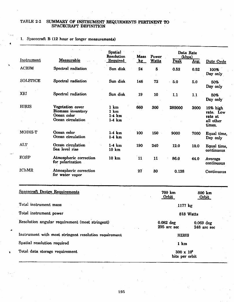
TABLE 2-2 SUMMARY OF INSTRUMENT REQUIRMENTS PERTINENT TOSPACECRAFT DEFINITION
I SpacecraftB (12hourorlongermeasurements)
Spatial Data RateResolution Mass Power (kbos)
Instrument Measurable Required kg Watts Peak Avg. Duty Cycle
ACRIM Spectral radiation Sun disk 24 5 0.52 0.52 100%Day only
SOLSTICE Spectral radiation Sun disk 146 72 5.0 5.0 50%Day only
XRI Spectral radiation Sun disk 19 10 1.1 1.1 50%Day only
HIRIS Vegetation cover 1 km 660 300 280000 3000 15%highBiomass inventory 1 km rate. LowOcean color 1-4 km rate atOcean circulation 1-4 km all other
times.
MODIS-T Ocean color 1-4 km 100 150 9000 7000 Equal time,Ocean circulation 1-4 km Day only
ALT Ocean circulation 1-4 km 190 240 12.0 10.0 Equal time,Sea levelrise 10km continuous
EOSP Atmosphericcorrection 10km 11 11 86.0 44.0 Averageforpolarization continuous
3ChMR Atmosphericcorrection 27 30 0.128 Continuousforwatervapor
Spacecratl Design Requirements 700 km 800 kmOrbit Orbit
Total instrument mass 1177 kg
Total instrument power 818 Watts
Resolution angular requirement (most stringent) 0.082 deg 0.069 deg295 arc sec 248 arc sec
Instrument with most stringent resolution requirement HIRIS
Spatial resolution required 1 km
Total data storage requirement 300 x 10obits per orbit
195
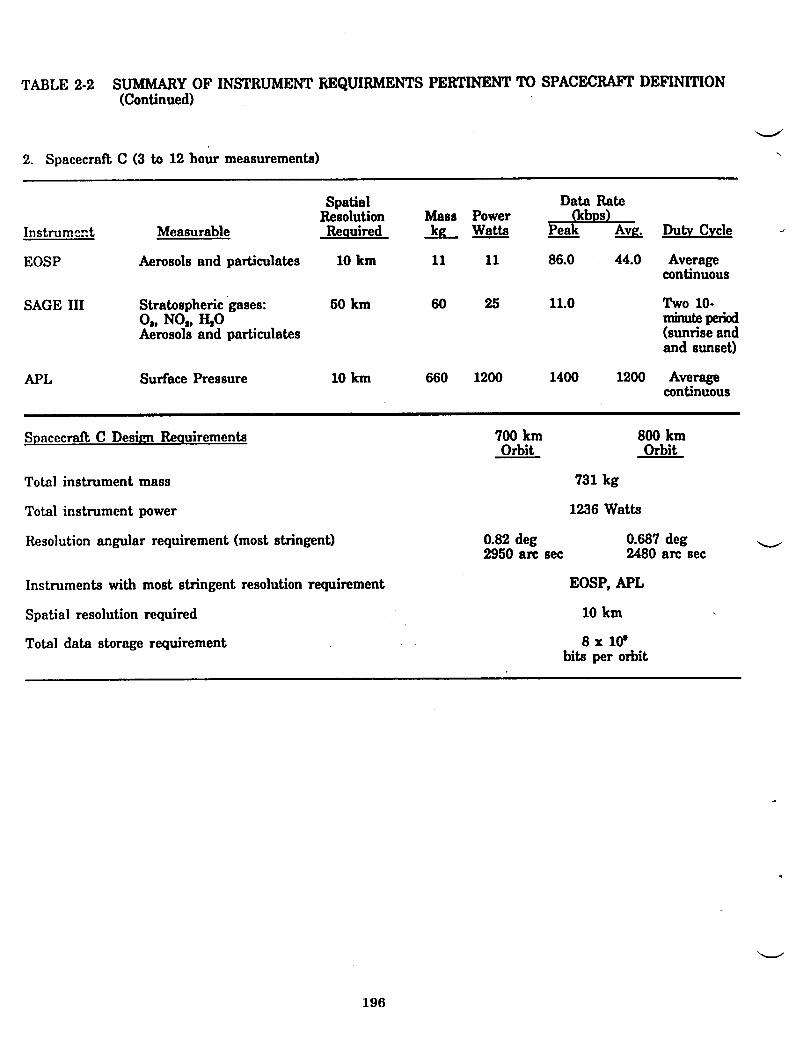
TABLE 2-2 SUMMARYOF INSTRUMENT REQUIRMENTS PERTINENT TO SPACECRAFTDEFINITION(Continued)
2. Spacecraft C (3 to 12 hour measurements)
Spatial Data RateResolution Mass Power _kbps)
Instrument Measurable Required k_ Watts Peak Avg. DutyCycle
EOSP Aerosolsand particulates 10km 11 11 86.0 44.0 Averagecontinuous
SAGE III Stratosphericgases: 50 km 60 25 11.0 Two 10-Oa,NOI,_0 minuteAerosols and particulates (sunrise and
and sunset)
APL SurfacePressure 10km 660 1200 1400 1200 Averagecontinuous
Spacecrat_ C Design Requirements 700 km 800 kmOrbit Orbit
Total instrument mass 731 kg
Total instrument power 1236 Watts
Resolution angular requirement (most stringent) 0.82 deg 0.687 deg ._2950 arc sec 2480 arc sec
Instruments with most stringent resolution requirement EOSP, APL
Spatial resolution required 10 km
Totaldatastoragerequirement . 8 x l(fbitsperorbit
196

TABLE 2-2 SUMMARY OF INSTRUMENT REQUIRMENTS PERTINENT TOSPACECRAFT DEFINITION (Continued)
3. Spacecraft D (1-3 hour measurements)4
Spatial Data RateResolution Mass Power (kbvs)
Instrument Measurable Required k_ Watts Peak _ Dut.vCycle
ACRIM Spectralradiation Sun disk 24 5 0.52 0.52 100%Day only
EOSP Atmosphericcorrection 10km 11 11 86.0 44.0 Continuousforpolarization
AIRS Temperature Profile 10-50 km 80 300 3000 1000 AverageTropospheric Water Vapor 10 km ContinuousCloud Height 1 km
Aver.ageCERES Radiation Budget 10-30 km 90 90 4.0 4.0 Continuous
MODIS-N Vegetation Cover 1 km 200 250 10000 100%(day)
Biomass Inventory 1 kmSea Ice and Snow Cover 1-20 kmCloud Cover and Type 1 km 2500 100%
(night)Surface Temperature 4 km
HIMSS _ Tropospheric Water Vapor 10 km 222 66 27.0 ContinuousTemperature Profile 10-50 kmPrecipitation 1-15 kmSea Ice and Snow Depth 1-20 km
AMSU-B Temperature Profile 10-50 km 40 80 4.4 ContinuousTropospheric Water Vapor 10 km
..... iiill i i i i i
Spacecraft D Design Requirements 700 km 800 kmOrbit Orbit
Total instrument mass 667 kg
Total instrument power 802 Watts
Resolution angular requirement (most stringent) 0.082 deg 0.069 deg295 arc see 248 arc see
Instruments with most stringent resolution requirement AIRS, MODIS-N
Spatial resolution required 1 km
oj Total data storage requirement 64.1 x l(fbits per orbit
197
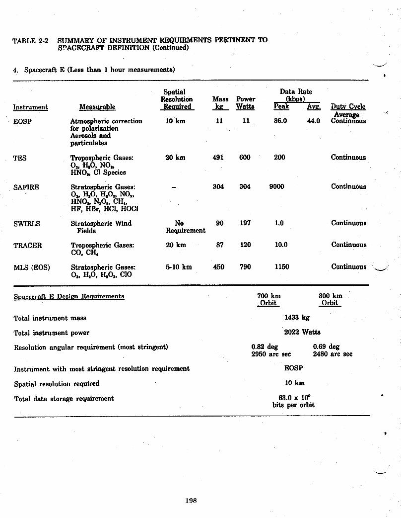
TABLE 2-2 SUMMARYOF INSTRUMENT REQIJIRMENTSPERTINENTTOSPACECRAFTDEFINITION (Continued)
4. Spacecraft E (Less than 1 hour measurements) _'_"
Spatial Data RateResolution Mass Power (kbps)
Instrument Measurable Required k_ Watts. Peak Avg. Duty CycleAverage
EOSP Atmospheric correction 10 km 11 11 86.0 44.0 Continuousfor polarizationAerosols andparticulates
TES Tropospheric Gases: 20 km 491 600 200 Continuous08, HiO, NO,,HNOa, C! Species
SAFIRE Stratospheric Gases: -- 304 304 9000 ContinuousOs, H20, HiOg,NO_,HNOa, NmOa,CH,,HF, HBr, HCI, HOCI
SWIRLS Stratospheric Wind No 90 197 1.0 ContinuousFields Requirement
TRACER Tropospheric Gases: 20 km 87 120 10.0 ContinuousCO, CH4
MLS (EOS) Stratospheric Gases: 5-10 km 450 790 1150 Continuous _._Oa, H20, H_O_,C]O
Spacecraft E Design Requirements 700 km 800 kmOrbit Orbit
Total instrument mass 1433 kg
Total instrument power 2022 Watts
Resolution angular requirement (most stringent) 0.82 deg 0.69 deg2950 arc sec 2480 arc sec
Instrument with most stringent resolution requirement EOSP
Spatial resolution required 10 km
Total data storage requirement 63.0 x 109bits per orbit
198

TABLE 2-2 SUMMARY OF INSTRUMENT REQUIRMENTS PERTINENT TOSPACECRAFT DEFINITION (Concluded,_
5. LargeSpacecraR,L-IInstrumentsCarried:All20 ListedAbove
Spacecraft L1 Design Requirements 700 km 800 kmOrbit Orbit
Total instrument mass 3951 kg
Total instrument power 4840 Watts
Resolution angular requirement (most stringent) 0.082 deg 0.069 deg295 arc sec 248 arc sec
Instruments with most stringent resolution requirement HIRIS, AIRS, MODIS-N
Spatial resolution required 1 km
Total data storage requirement 414.00 x I(Pbits per orbit
ii iiiii i ii
6. Large Spacecrait, L-2, L-3, I_4Instruments Carried:
ACRIM, AIRS, AMSU-B, CERES, EOSP, HIMSS, MODIS-N
Instrument requirements are listed in Table Section 3 (Spacecraft D) above.
MLS (EOS), SAFIRE, SWIRLS, TES, TRACER
Instrument requirements are listed in Table Section 4 (Spacecraft E) above.
i
Spacecraft L-2, L-3, L4 Design Requirements 700 km 800 kmOrbit. Orbit.
Total instrument mass 2089 kg
Total instrument power 2813 Watts
Resolution angular requirement (most stringent) 0.082 deg 0.069 deg295 arc sec 248 arc sec
Instruments with most stringent resolution requirement AIRS, MODIS-N
Spatial resolution required 1 km
Total data storage requirement 110.62 x 10°bits per orbit
199

The power needed to operate the instruments provides the principal
requirement that defines the electrical generation and storage elements. The
Instrument resolution becomes the principal requirement for attitude control or
pointing stability. Both of these requirements show some interaction with the
altitude of the orbit. A final definition of the orbits for the GCTI spacecraft will
• represent an optimized balance between ground coverage (or swath) traded against
number of orbits per day. In anticipation of such a trade, these evaluations
considered operations at both 700 km and 800 km in order to accommodate the
critical conditions for each orbital case. Operation at 800 km imposes the limiting
condition for pointing accuracy and attitude stability. The 1 km spatial resolution
requirement shows an 0.069 degree angular intercept from an orbit at 800 km.
Pointing accuracies and platform stabilities need controls to achieve about one
order of magnitude less to assure adequate resolution. On the other hand,
operation at 700 km altitude provides the criteria for electrical power generation.
At the lower altitude, eclipse accounts for a larger portion of the orbit period and
reduces the time available for battery charging which in turn results in a larger
solar array.
Within each of the spacecraft configurations, the on-board instruments
establish the principal requirements for data handling rates and data storage.
The data handling rates vary throughout the course of an orbit, and Table 2-3
summarizes the data rates and data storage for the 20 instruments on board the
multi-instrument spacecraft. The table shows the orbital variations in data rates
and estimates the storage requirements for an orbit with 60 minutes of
illumination and 40 minutes in eclipse. A summing of data rates and storage
estimates for the on-board instruments establishes the requirements for each
spacecraft; Table 2-4 summarizes these res,dts. The totals for data storage
include a generous arbitrary increment of 600 Mb per orbit for spacecraft-
generated data to cover operating parameters, timing, and positioning dataassociated with each orbit. The data storage requirements may extend beyond one
orbit; therefore, the on-board data storage unit has been increased by one order
of magnitude. J
200
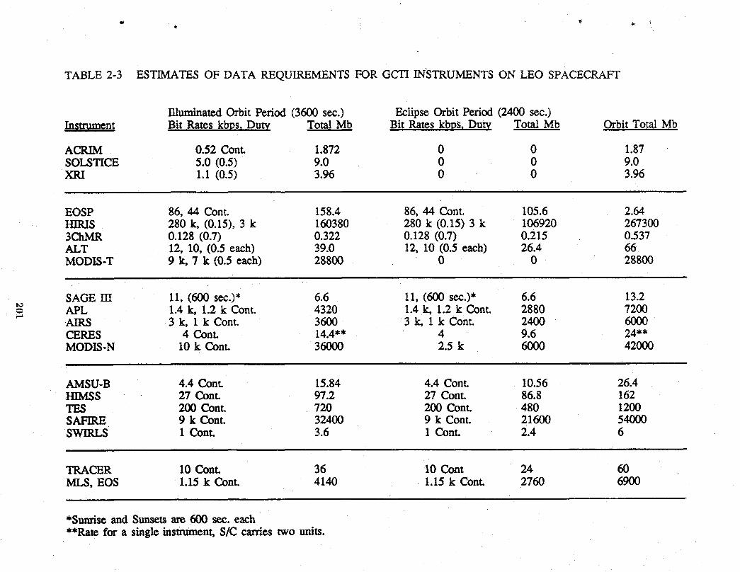
4_
TABLE 2-3 ESTIMATESOF DATA REQUIREMENTSFOR GCTI INSTRUMENTSON LEO SPACECRAFT
IlluminatedOrbitPeriod(3600sec.) EclipseOrbitPeriod(2400sec.)Instrument Bit Rateskbps,Duty TotalMb Bit Rateskbps,Duty TotalMb OrbitTotalMb
ACRIM 0.52 Cont. 1.872 0 0 1.87SOLSTICE 5.0 (0.5) 9.0 0 0 9.0XRI 1.1 (0.5) 3.96 0 0 3.96
EOSP 86, 44 Cont. 158.4 86, 44 Cont. 105.6 2.64HIRIS 280 k, (0.15), 3 k 160380 280 k (0.15) 3 k 106920 2673003ChMR 0.128 (0.7) 0.322 0.128 (0.7) 0.215 0.537ALT 12,10,(0.5each) 39.0 12,10(0.5each) 26.4 66MODIS-T 9 k, 7 k (0.5 each) 28800 0 0 28800
SAGE HI 11, (600 sec.)* 6.6 11, (600 sec.)* 6.6 13.2t_= APL 1.4k,1.2k Cont. 4320 1.4k,1.2k Cont. 2880 7200
AIRS 3 k,Ik Cont. 3600 3k,Ik Cont. 2400 6000CERES 4 Cont. 14.4"* 4 9.6 24**MODIS-N 10 k Cont. 36000 2.5 k 6000 42000
AMSU-B 4.4 Cont. 15.84 4.4 Cont. 10.56 26.4HIMSS 27 Cont. 97.2 27 Cont. 86.8 162TES 200 Cont. 720 200 Cont. 480 1200SAFIRE 9 k Cont. 32400 9 k Cont. 21600 54000SWIRLS 1 Cont. 3.6 1 Cont. 2.4 6
TRACER 10 Cont. 36 10 Cont 24 60MLS, EOS 1.15 k Cont. 4140 1.15 k Cont. 2760 6900
*Sunrise and Sunsetsare 600 see. each**Ratefor a single instrtmaent,S/C carries two units.
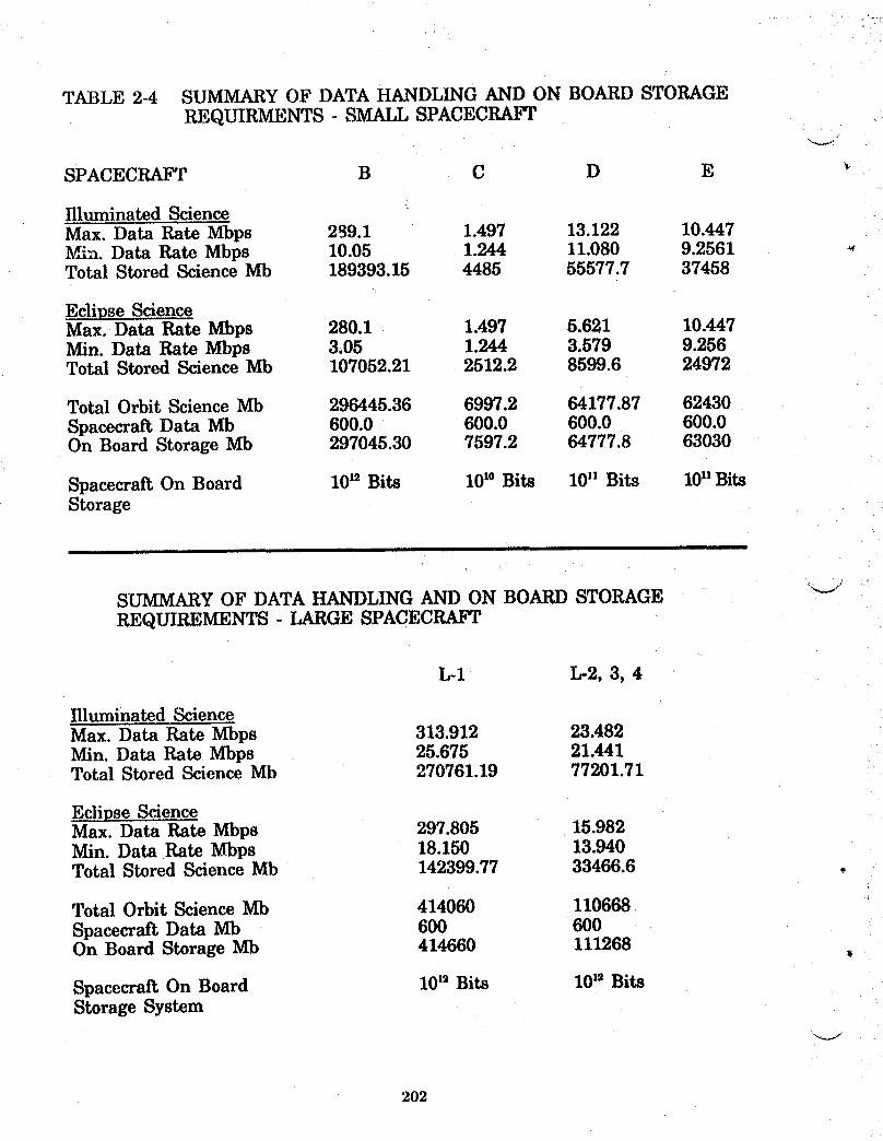
TABLE 2-4 SUMMARY OF DATA HANDLING AND ON BOARD STORAGEREQUIRMENTS - SMALL SPACECRAFT
SPACECRAFT B C D E
Illuminated ScienceMax. Data Rate Mbps 299.1 1.497 13.122 10.447lVfin. Data Rate Mbps 10.05 1.244 11.080 9.2561Total Stored Science Mb 189393.15 4485 55577.7 37458
Eclipse ScienceMax. Data Rate Mbps 280.1 1.497 5.621 10.447Min. Data Rate Mbps 3.05 1.244 3.579 9.256Total Stored Science Mb 107052.21 2512.2 8599.6 24972
Total Orbit Science Mb 296445.36 6997.2 64177.87 62430Spacecraft Data Mb 600.0 600.0 600.0 600.0On Board Storage Mb 297045.30 7597.2 64777.8 63030
Spacecraft On Board 10_2Bits 10_°Bits 10_ Bits I0n BitsStorage
SUMMARY OF DATA HANDLING AND ON BOARD STORAGE "JREQUIREMENTS - LARGE SPACECRAFT
L-1 L-2, 3, 4
Illuminated ScienceMax. Data Rate Mbps 313.912 23.482Min. Data Rate Mbps 25.675 21.441Total Stored Science Mb 270761.19 77201.71
Eclipse ScienceMax. Data Rate Mbps 297.805 15.982Min. Data Rate Mbps 18.150 13.940Total Stored Science Mb 142399.77 33466.6 .
Total Orbit Science Mb 414060 110668Spacecraft Data Mb 600 600On Board Storage Mb 414660 111268 •
Spacecraft On Board 10is Bits 10Is BitsStorage System
202

2.3 Instrument Mounting and Accommodation
In addition to the mass and power, the accommodations of the instruments
on board a spacecraft must address the physical dimensions of the package with
critical attention to both the viewing requirements for measurements and the
space radiator requirements for those instruments which carry cooled detectors.
The combination of viewing for data and radiant heat rejection effectively
determines the layout of instruments aboard any spacecraft configuration.
Accommodation requirements for each group of instruments are summarized in
Table 2-5 in terms of mass, power, dimensions, viewing, and heat rejection
requirements. These data summarize the pertinent information gathered and
refined during the process of instrument selection.
These combinations of requirements for spacecraft accommodations
represents the finalized product of an iterative process and also continued an
initial concept of either small, Delta-booster compatible spacecraft or large, Titan-
booster compatible spacecraft. In addition, the finalized summary of spacecraft
operating subsystems continued to show compatibility for accommodation by a
modularized approach, and the existing Multimission Modular units provided the
basis for comparison.
2O3
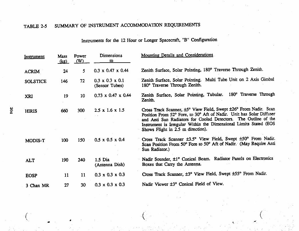
TABLE 2-5 SUMMARYOF INSTRUMENTACCOMMODATIONREQUIREMENTS
Instruments for the 12 Hour or Longer Space,'aft, "B" Configuration
Instrument Mass Power Dimensions MountingDetails and Considerationsrice) OV) m
ACRIM 24 5 0.3 x 0.47 x 0.44 Zenith Surface, Solar Pointing, 180° Traverse Through Zenith.
SOLSTICE 146 72 0.3 x 0.3 x 0.1 Zenith Surface, Solar Pointing. Multi Tube Unit on 2 Axis Gimbal(Sensor Tubes) 180° Traverse Through Zenith.
XRI 19 10 0.73 x 0.47 x 0.44 Zenith Surface, Solar Pointing, Tubular. 180° Traverse ThroughZenith.
= HIRIS 660 300 2.5 x 1.6x 1.5 CrossTrackScanner,:!:5° ViewField,Swept_+.26° FromNadir. ScanPosition From 52° Fore, to 30° Aft of Nadir. Unit has Solar Diffuserand Anti Sun Radiators for Cooled Detectors. The Outline of theInsu'ument is Irregular Within the Dimensional Limits Stated (EOSShows Flight in 2.5 m direction).
MODIS-T I00 150 0.5 x 0.5 x 0.4 Cross Track Scanner :]:3.5° View Field, Swept +_.50° From Nadir.Scan Position From 50° Fore to 50° Aft of Nadir. (May Requi_ AntiSun Radiator.)
ALT 190 240 1.5 Dia Nadir Sounder, +1° Conical Beam. Radiator Panels on Electronics(Antenna Dish) Boxes that Carry the Antenna.
EOSP 11 11 0.3 x 0.3 x 0.3 Cross Track Scanner, _+3° View Field, Swept :k.55° From Nadir.
3 Chan MR 27 30 0.3 x 0.3 x 0.3 Nadir Viewer +3° ConicalField of View.
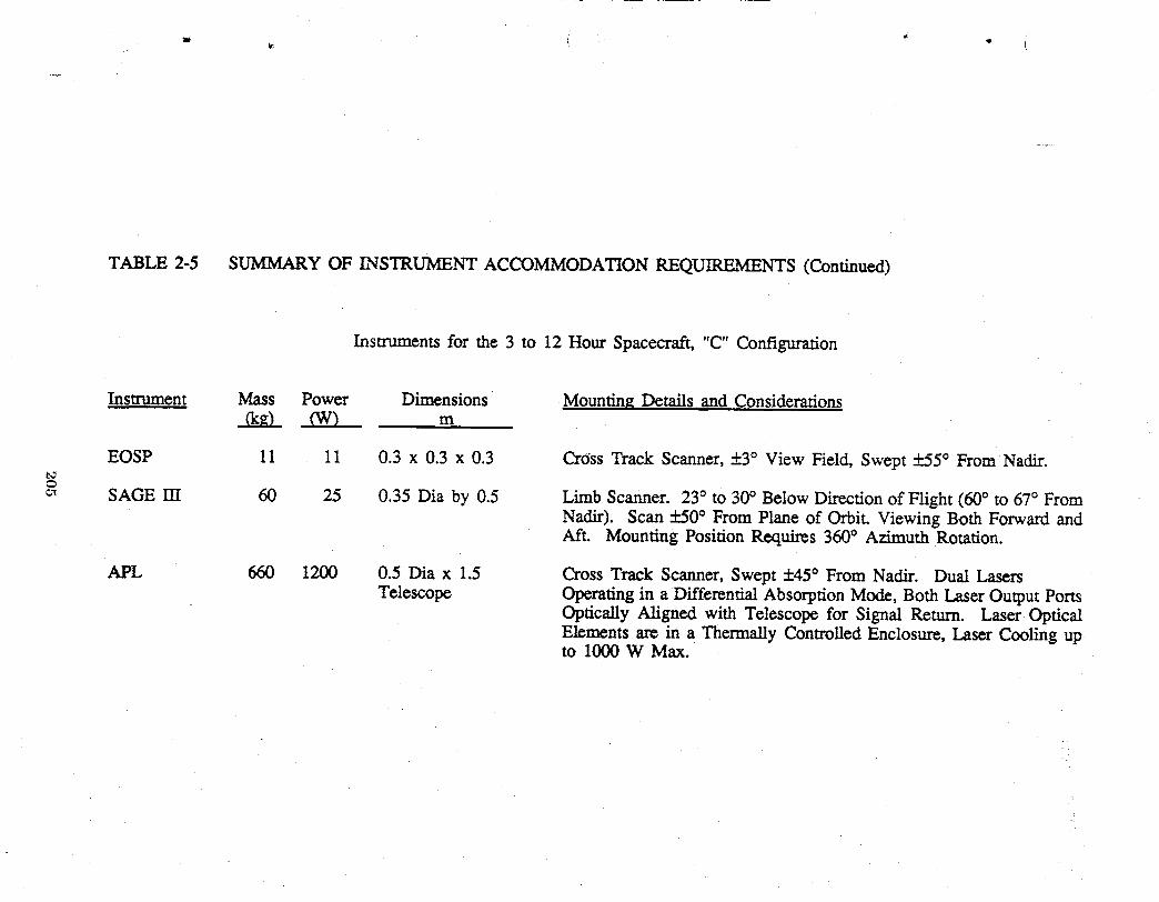
TABLE 2-5 SUMMARY OF INSTRUMENT ACCOMMODATION REQUIREMENTS (Continued)
Instruments for the 3 to 12 Hour Spacecraft, "C" Configuration
Instrument Mass Power Dimensions Mounting Details and Considerationsm
EOSP 11 11 0.3 x 0.3 x 0.3 Cross Track Scanner, 5:3° View Field, Swept +_.55° From Nadir.
_ SAGE rrl 60 25 0.35 Dia by 0.5 Limb Scanner. 23° to 30° Below Direction of Flight (60° to 67° FromNadir). Scan 5:50° From Plane of Orbit. Viewing Both Forward andAft. Mounting Position Requires 360° Azimuth Rotation.
APL 660 1200 0.5 Dia x 1.5 Cross Track Scanner, Swept +45° From Nadir. Dual LasersTelescope Operating in a Differential Absorption Mode, Both Laser Output Ports
Optically Aligned with Telescope for Signal Return. Laser OpticalElements are in a Thermally Controlled Enclosure, Laser Cooling upto 1000 W Max.

TABLE 2-5 SUMMARY OF INSTRUMENT ACCOMMODATIONREQUIREMENTS(Continued)
InstrumentsfortheI to3 HourSpacecraft,'_D"Configuration
Instrument Mass Power Dimensions Mounting Details and Considerations..Qm)- Cvv) m
ACRIM 24 5 0.3 x 0.47 x 0.44 Zenith Surface, Solar Pointing, 180° Traverse Through Zenith.
EOSP 11 11 0.3 x 0.3 x 0.3 Cross Track Scanner,+3° View Field, Swept :P.55° From Nadir.
AIRS 80 300 1.0 x 0.8 x 0.5 Cross Track Scanner, :V.2° View Field, Swept :V.50° From Nadir.Requires a Space Radiator,Anti Sun Side.
b_
= CERES 90 90 0.6 x 0.5 x 0.7 Wide Angle Scanner. Cross Track Swept From +100° (Above(Each of 2 Units) Spacecrafi Plane Sun Side) to -73° Anti Sun Side. Scan Positioned
Fore and Aft up to +73° From Nadir.
MODIS-N 200 250 1.2 x 0.7 x 0.5 Cross Track Scanner, +4° View Field, Swept :1:50From Nadir. SolarDiffuser, Space Radiator Anti Sun Side.
HIMSS 222 66 1.2 Dia x 1.2 Coni_d Forward Scan at 53° From Nadir Swept +45° FromBarrel Plane of Orbit. Barrel Rotates at 30 rpm.
2 m Dia Antenna
AMSU-B 40 80 0.7 x 0.7 x 0.5 Cross Track Scanner, +1° View Field, Swept :_.50° From Nadir.
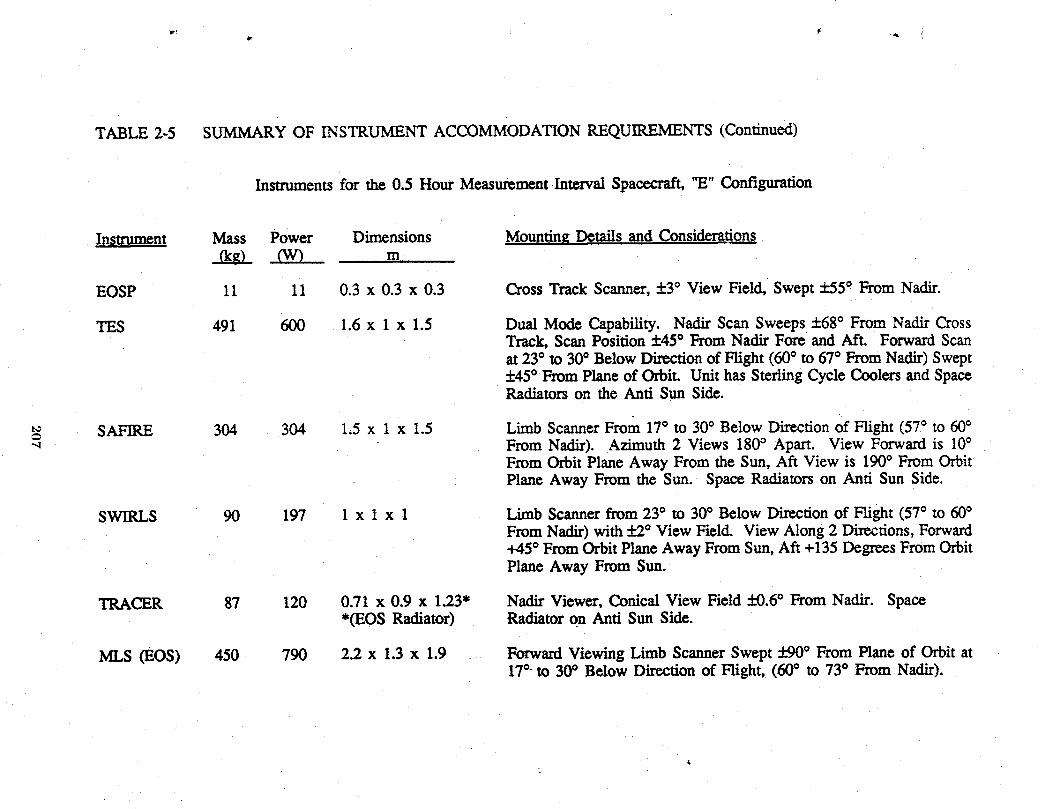
TABLE 2-5 SUMMARY OF INSTRUMENT ACCOMMODATION REQUIREMENTS (Continued)
Instrumentsfor the 0.5 Hour MeasurementIntervalSpacecraft,"E" Configuration
Instrument Mass Power Dimensions MountingDetailsandConsiderations_0gL 6V) m
EOSP !1 11 0.3 x 0.3 x 0.3 CrossTrackScanner,:!:3° ViewField,Swept+_55° FromNadir.
TES 491 600 1.6 x 1 x 1.5 Dual Mode Capability. Nadir Scan Sweeps +68° From Nadir CrossTrack, Scan Position ±45° From Nadir Fore and Aft. Forward Scanat 23* to 30° Below Direction of Flight (60° to 67° From Nadir) Swept+45° From Plane of Orbit. Unit has Sterling Cycle Coolers and SpaceRadiators on the Anti Sun Side.
t_ SAFIRE 304 304 1.5 x 1 x 1.5 Limb ScannerFrom 17° to 30° Below Direction of Flight (57° to 600From Nadir). Azimuth 2 Views 180° Apart. View Forward is 10°From Orbit Plane Away From the Sun, Aft View is 190° From OrbitPlane Away From the Sun. Space Radiators on Anti Sun Side.
SWIRLS 90 197 1 x 1 x 1 LimbScannerfrom23° to 30° Below Directionof Flight (57° to 60°FromNadir)with :[:2° View Field. View Along2 Directions,Forward+45° FromOrbitPlaneAway FromSun,Aft +135DegreesFromOrbitPlane Away From Sun.
TRACER 87 120 0.71 x 0.9 x 1.23" Nadir Viewer,Conical View Field ±0.6° From Nadir. Space*(EOSRadiator) Radiatoron Anti Sun Side.
MLS (EOS) 450 790 2.2 x 1.3 x 1.9 ForwardViewingLimb ScannerSwept 590° FromPlane of Orbit at17°-to 30° Below Directionof Fright, (60° to 73° FromNadir).
3.0 SPACECRAFT OPERATING SUBSYSTEMS
The concepts for modularization of spacecraft operating subsystems have
been developed and successfully flown in the form of the GSFC Multimission
Modular Spacecraft (MMS). GCTI spacecraft operating subsystems utilize the
same approach to modularization and incorporate new or additional components
that respond to GCTI requirements. The MMS consists of three major electrical
subsystem assemblies, a mounting structure and a propulsion module; Reference
5 summarizes the pertinent performance capabilities of the assembly. Modules
within the MMS are currently being uprated and adapted to advanced flight
projects; and for these units, the module interfaces remain unchanged such that
commonality for change-out can be assured. Adaptation to GCTI spacecraft does
not require such an interchangability, therefore, improved MMS units in simplified
packages become the GCTI modules; Figure 3-1 shows the MMS modules and
summarizes the changes or modifications proposed. The numbers of spacecraft
defined for operation in sunsynchronous LEO would justify the modificationsdescribed below. An estimate for the status of present MMS modification is also
included. _'_,
3.1 Communication and Data Handling Module (C and DH)
The communication and data handling subsystem has received a major
uprating; the replacement assembly is the NASA Data Link Module (NDLM,
Reference 6). Modifications expand the initial capabilities for data rates, storage
capacities, and transmission links to include Kband for TDRSS, which in turn
changes the antennas, The differences between the original MMS unit and the
NDLM assumed for GCTI appear summarized inTable 3-1. Improvements
proposed allow matching the capabilities of the module to the particular
requirements of a spacecraft; the principal adaptation element becomes the
algorithm within a dedicated microprocessor. NDLM units have capabilities that
accommodate any of the instrument combinations identified. The configuration
and layout of components within the NDLM are shown in Figure 3-2 and appear
as redundant systems packaged for change-out on orbit. Since GCTI spacecraft
208

ACSMODULE• NewComponents• DigitalOperation TRANSITION
ADAPTER(LargeS/COnly)
MODULE SUPPORTSTRUCTURE COMMUNICATION
(Large,S/C Only) AND__ is- DATA HANDLING .
• Use NASA Data Link,POWER MODULE Components
• Digital Operation • Redundant Modules• Regulator and Half Size
Switch Functions• Half Size Module
(Batteries NI-H2in Separate Module) SC & CU
4T, • Part of Power
PROPULSIONMODULE (PM-1)Retain for Large S/C, Separate
Mount Small S/C, DigitalControl
Figure 3-1 Components and Elements of the Multimission Modular Spacecraftand Principal Adaptations to GCTI ApplicaUon.
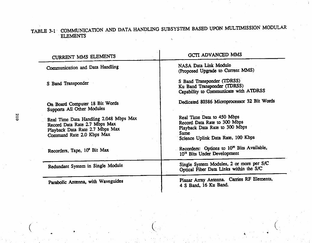
TABLE 3-1 COMMUNICATION AND DATA HANDLING SUBSYSTEM BASED UtK)N MULTIMISSION MODULARELEMENTS
CURRENT MMS ELEMENTS GCTI ADVANCED MMSq i i
Communication and Data Handling NASA Data Link Module(ProposedUpgrade to Curr_ntMMS)
S Band Transponder S Band Transponder(TDRSS)Ku Band Transponder(TDRSS)Capability to Communica_ with ATDRSS
On Board Computer 18 Bit Words Dedicated 80386 Microprocessor 32 Bit WordsSupportsAll OtherModules
t_b-s
Real Time Data Handling 2.048 Mbps Max Real Time Data to 450 MbpsRecord Data Rate 2.?Mbps Max Record Data Rate to 300 MbpsPlayback Data Rate 2.7 Mbps Max Playback Data Rate to 300 MbpsCommand Rate 2.0 Kbps Max Same
Science Uplink Data Ra_, I00 Kbps
Recorders,Tape, 109 Bit Max Recorders: Options to 10_°Bits Available,10'_ Bits Under Development
i
RedundantSystem in Single Module Single System Modules, 2 or more per S/COptical Fiber Data Links within the S/C
• i.
ParaboficAntenna, with Waveguidcs Planar Array Antenna. CarriesRF Elements,4 S Band, 16 Ku Band.
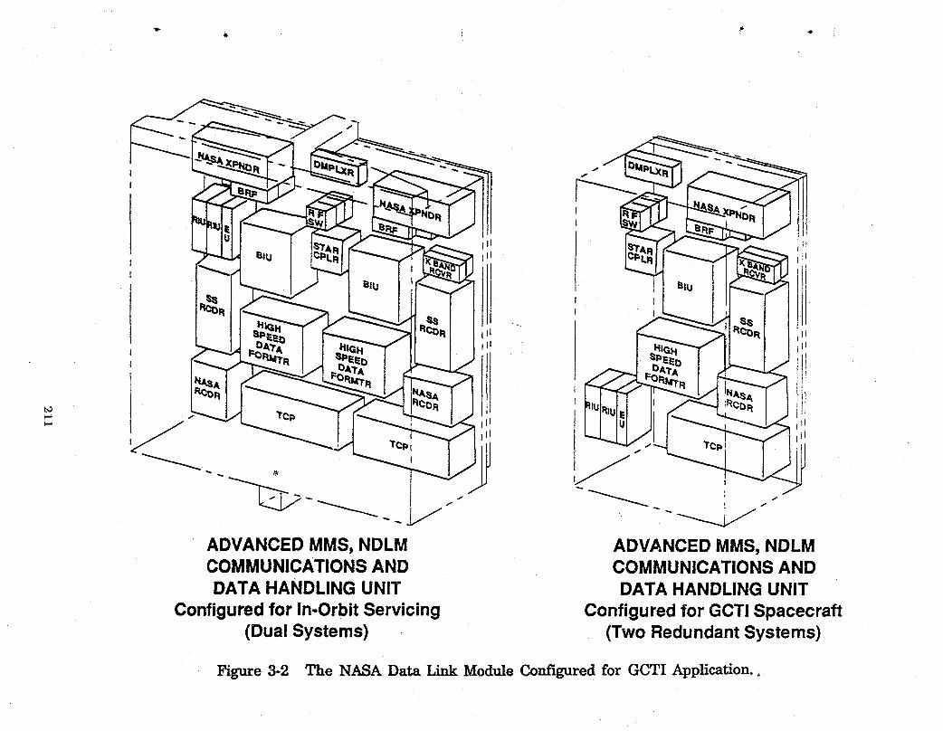
! tij L +i;
ADVANCEDMMS,NDLM ADVANCEDMMS,NDLMCOMMUNICATIONSAND COMMUNICATIONSANDDATA HANDLINGUNIT DATA HANDLINGUNIT
Configuredfor In-OrbitServicing Configuredfor GCTI Spacecraft(DualSystems) (TwoRedundantSystems)
Figure 3-2 The NASA Data Link Module Configured for GCTI Application.,

in sunsynchronous orbits do not require change-out capability, NDLM units will
be carried as two separately packaged subsystems each configured for conventional
bolt-on mountings. Estimates of masses for elements within the NDLM show
some potential for an overall reduction; however for this study, the C and DH
system mass will be assumed identical to that for an existing MMS module plus
mass estimates based upon the wide-band TDRSS link communication elements
used in Landsat D (Reference 7).
3.2 Attitude Control Module
Uprating for the attitude control module is summarized in Table 3-2 and
effectively incorporates improvements to components within the system. The
principal change in operation appears in the use of a dedicated microprocessor
which eliminates a previous dependence upon a central computer in the C and DH
module. Internally, the module co-locates sensors, such as gyros and star trackers,
the microprocessor and active control elements such as momentum wheels, in a
manner that achieves more rapid and more precise system response to
disturbances. Existing units offer stabilization to 0.01 degree (36 arc sec.) which _._/"
would nominally accommodate a resolution requirement of about 0.1 degree. The
most stringent instrument resolution requirement listed in Table 2.2 is 0.069
degree (248 arc sea) and appears compatible with the capabilities of improved
o components and a dedicated microprocessor. Elimination of on-orbit change-outcapability does not change module dimensions but does permit a simpler and less
massive module package.
3.3 Electrical Power System
The uprating features for the electrical power system are summarized in .
Table 3.3. A change from a 28 VDC to a 120 VDC distribution follows both
Space Station Freedom and EOS conventions. Within GCTI spacecraft, a
dedicated microprocessor in the power conversion module accommodates the
instruments and performs all spacecraft power switching functions including those
for heaters and pyros. A separate submodule element of the MMS is not retained
212
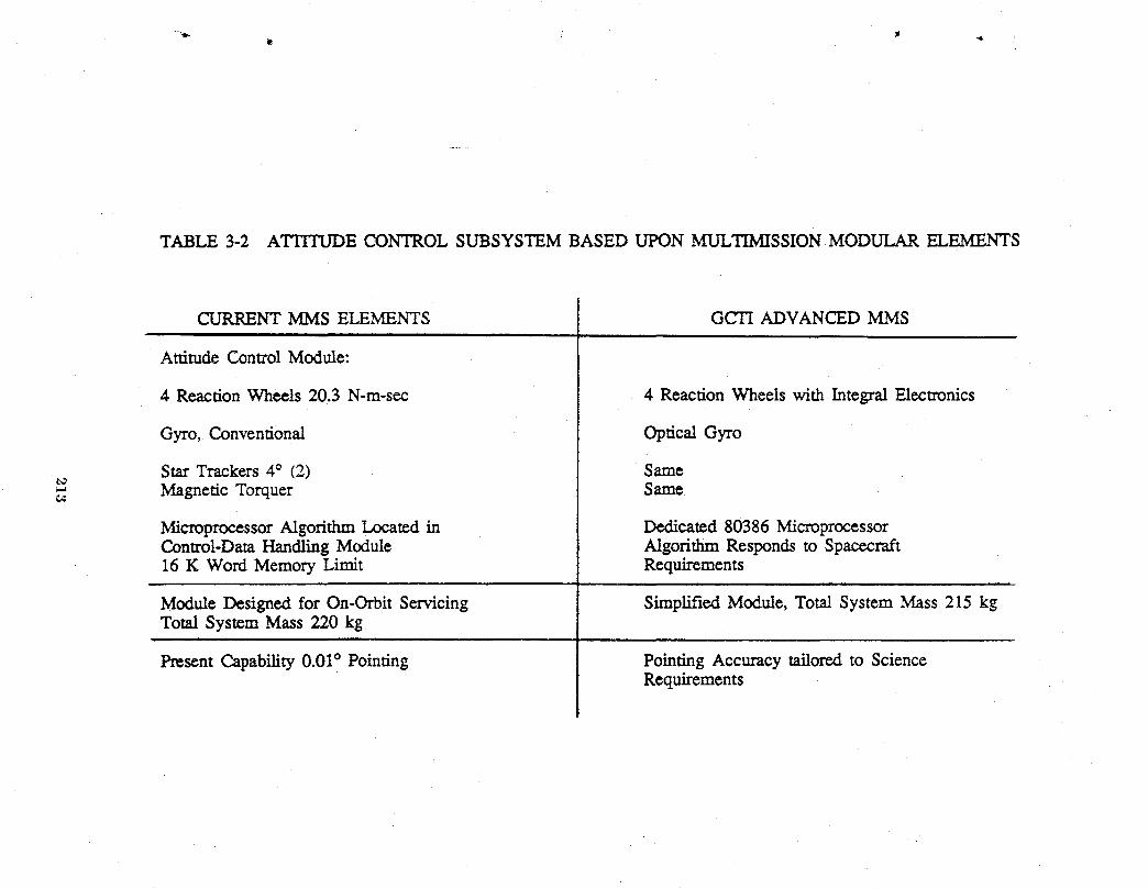
TABLE 3-2 ATITFUDE CONTROL SUBSYSTEM BASED UPON MULTIMISSION MODULAR ELEMENTS
CURRENT MMS ELEMENTS GCTI ADVANCED MMS
Attitude Control Module:
4 Reaction Wheels 20.3 N-m-sec 4 Reaction Wheels with Integral Electronics
Gyro, Conventional Optical Gyro
Star Trackers 4° (2) Samet_
_" Magnetic Torquer Same
Microprocessor Algorithm Located in Dedicated 80386 MicroprocessorControl-Dam Handling Module Algorithm Responds to Spacecraft16 K Word Memory Limit Requirements
Module Designed for On-Orbit Servicing Simplified Module, Tota! System Mass 215 kgTotal System Mass 220 kg
Present Capability0.01° Pointing Pointing Accuracy tailored to ScienceRequirements

TABLE 3-3 ELECTRICALPOWER SUBSYSTEM BASED UPON MULTIMISSIONMODULAR ELEMENTS
CURRENT MMS ELEMENTS GCTI ADVANCED MMS|
Pow_ and Signal Conditioning and Control Unit Power Module Contents
Pow_ Rcgnl_on at 28 VDC Power Regulated at 120 VDC
Pow_ I_vel 1200 W Avg. up to 2000 W Power Modules Sized for 1300 W Input FromPeak Solar Array
t_
Switching ControlFrom Control Data Dedicated 80386 Micropressor for allHandling Computer Switching Functions
Pyro Conrail, Thermal Control in Pyro and Thermal Control Uses DedicatedSeparate Sub Unit Module Microprocessor
Batteries Ni-Cd at 30 W-h/kg CarriedWithin Batteries Ni-H2, 45 W-h/kg, 33% IX)D, Modularizedthe Module, Range 1120 W-h, Standard at 60 W-h, Separate Mount. Range 1050 W-h toto 4200 W-h Max 4811 W-h
Solar Array: Silicon, 100 W/m= Solar Array Silicon (100 W/m2) or GaAs/GeAre,as Defined by S/C Applications (158 W/m2) as Defined by S/C Applications

for GCTI. Each of the power conversion modules is sized to accommodate and
distribute up to 1300 W as input from the solar array. For GCTI spacecraft,
modules have masses of 95 kg each in a package half the size of the present MMS
• units. Storage batteries for the GCTI spacecrait are separately mounted Ni-H_
units in modules of 60 W-h each. These batteries anticipate a development to
the point where they can deliver 45 W-h/kg at complete discharge and operate
with a 33 percent depth of discharge during each orbit (Reference 8).
Power requirements for each of the spacecraft configurations define
appropriate solar arrays. Present technology utilizes silicon cells which have an
end-of-life capability of about 100 W/m s and deliver 29 W/kg from a typical array
installation. These capabilities are compatible with modest power requirements;
however, the power requirements for some of the GCTI spacecraft indicate a need
for more efficient solar cells to ease area requirements for the arrays. Therefore,
GCTI assumes availability of GaAs/Ge solar cells in arrays that have end-of-life
capabilities of 158 W/ms and deliver 45 W/kg (References 8 and 9).
3.4 Propulsion
The existing MMS propulsion module utilizes a direct blow-down catalytic-
burn hydrazine system which the GCTI spacecraft also use with the same
thrusters, valves and valve controllers. A dedicated microprocessor provides the
control requirements particular to a spacecraft; Table 3-4 summarizes the
pertinent features. The principal differences appear in the integration into the
spacecraft and the amount of propellant aboard the spacecraft. Small spacecraft
integrate the propulsion system into the structure and carry the propellant in
cylindrical tanks; large spacecraft retain the present MMS module with extra
., 1 propellant carried in auxiliary spherical tanks.
3.5 Assessments of Status for MMS Subsystem Improvements
The improvements or changes as described above have been recognized and
addressed in development efforts that range from near complete to that of a
215
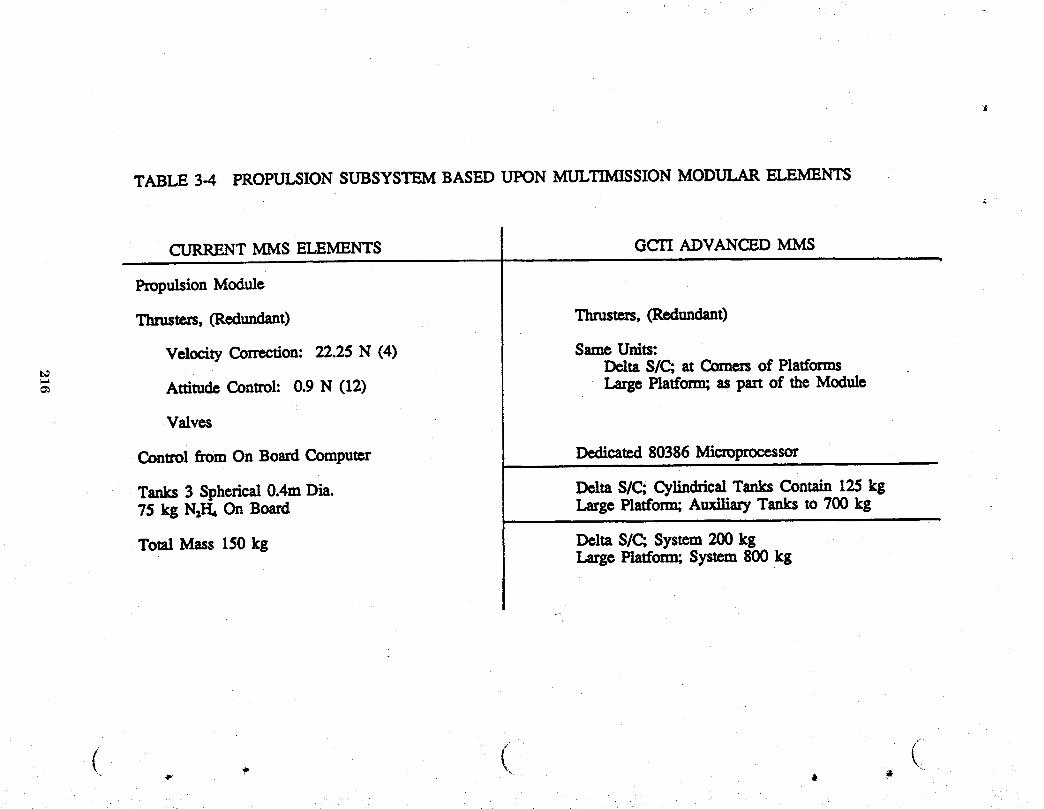
TABLE 3-4 PROPULSION SUBSYSTEM BASED UPON MULTIMISSION MODULAR ELEMENTS
CURRENT MMS ELEMENTS GCTI ADVANCED MMS
Propulsion Module
Thrust,_,(Rodundam) Thrusters,(R_unden0
Velocity Correction: 22.2S N (4) Same Units:Delta S/C; at Comers of Platforms
Attitude Control: 0.9 N (12) Large Platform; as part of the Module
Valves
Control f_m On Board Computer Dedica_I 80386 Microprocessor
Tanks 3 Spherical0.4m Dia. Delta S/C; Cylindrical Tanks Contain 125 kg75 kg N21-1_On Board LargePlatform;AuxiliaryTanksto700kg i
TotalMass 150kg DeltaS/C;System200kgLarge Platform;System800kg
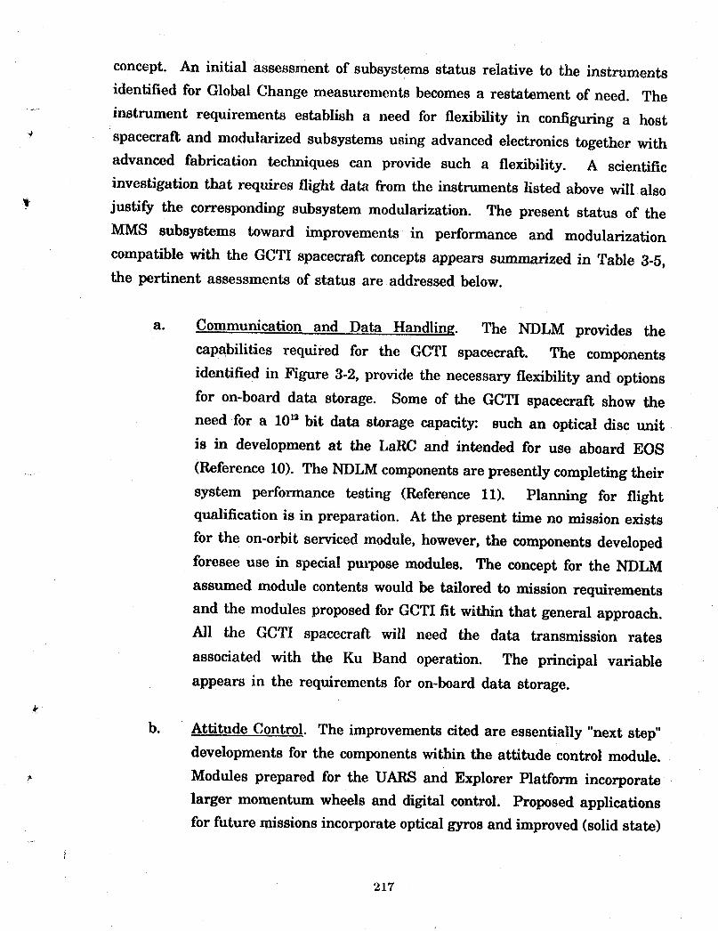
concept. An initial assessment of subsystems status relative to the instruments
identified for Global Change measurements becomes a restatement of need. The
....... instrument requirements establish a need for flexibility in configuring a host
spacecraft and modularized subsystems using advanced electronics together with
advanced fabrication techniques can provide such a flexibility. A scientific
investigation that requires flight data from the instruments listed above will also
justify the corresponding subsystem modularization. The present status of the
MMS subsystems toward improvements in performance and modularization
compatible with the GCTI spacecraft concepts appears summarized in Table 3-5,
the pertinent assessments of status are addressed below.
a. Communication and Data Handling. The NDLM provides the
capabilities required for the GCTI spacecraft. The components
identified in Figure 3-2, provide the necessary flexibility and options
for on-board data storage. Some of the GCTI spacecraft show the
need for a 10_2bit data storage capacit3r, such an optical disc unit
is in development at the LaRC and intended for use aboard EOS
(Reference 10). The NDLM components are presently completing their
system performance testing (Reference 11). Planning for flight
qualification is in preparation. At the present time no mission exists
for the on-orbit serviced module, however, the components developed
foresee use in special propose modules. The concept for the NDLM
assumed module contents would be tailored to mission requirements
and the modules proposed for GCTI fit within that general approach.
All the GCTI spacecraft will need the data transmission rates
associated with the Ku Band operation. The principal variable
appears in the requirements for on-board data storage.
b. Attitude Control. The improvements cited are essentially "next step"
developments for the components within the attitude control module.
Modules prepared for the UARS and Explorer Platform incorporate
larger momentum wheels and digital control. Proposed applications
for future missions incorporate optical gyros and improved (solid state)
217
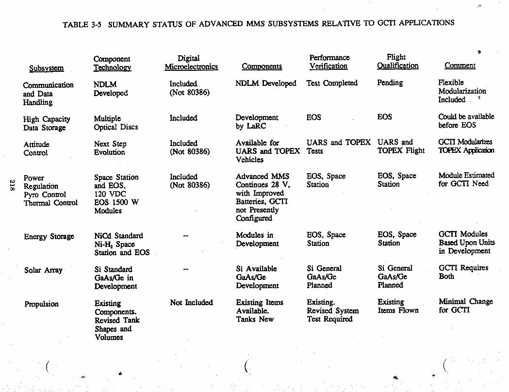
TABLE 3-5 SUMMARY STATUS OF ADVANCED MMS SUBSYSTEMS RELATIVE TO GCTI APPLICATIONS
@
Component Digital Performance HightSubsystem Technology Microelectronics ,Components V,rification Qualification Comment
Communication NDLM Included NDLM Developed TestCompleted Pending Hexibleand Dam Developed (Not 80386) ModularizationHandling Included _"
HighCapacity Multiple Included Development EOS EOS Couldbe availableDam Storage Optical Discs by LaRC before EOS
Ammdc Next Step Included Available for UARS and TOPEX UARS and _ Modu]afiz_Control Evolution (Not 80386) UARS and TOPEX Tests TOPEX Flight TOPEX
Vehicles
Power Space Station Included Advanced MMS EOS, Space EOS, Space ModuleEstimatedRegulation and EOS, (Not 80386) Continues 28 V, Station Station for _ Ne_Pyro Control 120 VDC with ImprovedThermal Control EOS 1500W Batteries, GCTI
Modules not PresentlyConfigured
Energy Storage NiCd Standard -- Modules in EOS, Space EOS, Space GCTI ModulesNi-I-I=Space Dvvelopment Station Station Based Upon UnitsStation and EOS in Development
Solar Array Si Standard -- Si Available Si General Si General GCTI RequiresGaAs/Gc in GaAs/Ge GaAs/Ge GaAs/Ge BothDevelopment Development Planned Planned
Propulsion Existing Not Included Existing Items Existing. Existing Minimal ChangeComponents. Available. Revised System Items Flown for GCTIRevised Tank Tanks New Test RequiredShapes andVolumes
( . (
star trackers to achieve pointing accuracies of 0.0003 degrees (1 arc
sec). An application of improved momentum wheels with an optical
tyro and digital electronics operation is being configured for the
TOPEX spacecraft and packaged by the spacecraft builder. The GCTI
module retains the present module dimensions to house improved
momentum wheels, optical gyros and existing star trackers plus a
dedicated microprocessor for control.
c. Electrical Power. Improvements to the existing MMS power module
support the application to UARS which accommodates a 1600 W
average power level. Additional improvements proposed would utilize
uprated Ni-Cd batteries or incorporate Ni-H2 units. The module
configuration and operating voltage would not change. Spacecraft
components have standardized on 28 VDC, and integration testing
benefits from co-location of the power converter-regulators and the
batteries. GCTI modules make a significant departure principally for
thermal and mounting flexibility considerations. They contain
......... converter-regulators and a microprocessor for switching controls in a
module half the size of present units. Operation at 120 VDC assumes
availability of EOS or Space Station Freedom technology.
Modularization of power regulation at 1300 W and Ni-H2 batteries at
60 W-h represents a best-fit estimate based upon available data.
d. Propulsion. The changes to the propulsion system are considered
available. The principal difference appears as the adaptation of the
valves, sensors and control elements to the particular digital interface
associated with the 80386 microprocessor. Cylindrical tanks of the
• dimensions required for the small spacecraft are considered available
technology. Large spherical tanks are also considered available
technology.
In summary, the subsystem definitions for the GCTI spacecraft recognized
that the present MMS units would complete their flight assignments with the
219
UARS and the Explorer Platform, however, the need for advanced modularization
concepts would continue. The NDLM presented a comprehensive advanced
configuration and was utilized accordingly. The attitude control system needed for _-_
the TOPEX spacecraft was considered the model for future modularization and
therefore utilized. Space Station Freedom and EOS addressed electrical power
system advances in voltages, modularization and energy storage that offered a
basis for a GCTI module, and finally, changes in driver electronics, tank shapes
and fluid lines uprate the MMS propulsion module to a GCTI application. A
decision to fly a group of GCTI defined instruments on other than their present
host spacecraft such as UARS, EOS or TIROS-N would turn the GCTI concepts
into requirements for subsystem modules.
220
4.0 SMALL SPACECRAI_ CONFIGURATIONS
The small spacecraft concepts utilized the published capabilities of the
current Delta series boosters and the availability of larger volume shrouds as the
baseline envelopes for spacecraft configurations; launch capabilities listed are:
_t
Delta 6920 - 2500 kg to a 650 km polar orbit
Delta 7920 - 3300 kg to a 650 km polar orbit
The principal dimensions for the Delta shrouds are shown in Figure 4-1; in
flight, the shroud separates as a clam-shell and thereby makes all the internal
volume available to a spacecraft. In the descriptions which follow, spacecraft
Configuration B is the baseline concept with the other three as adaptations to fit
particular requirements. The descriptions first summarize the configuration and
then address the pertinent features such as structural accommodations, electrical,
and subsystem accommodations and operating accommodations.
4.1 Small Spacecraft, 12 Hour or Longer Measurement Interval, Configuration B
The features of the B configuration spacecraft are summarized in Table 4-1;
I the layout and concepts for accommodation are shown in Figures 4-2, and 4-3.
This spacecraft accommodates the instruments, their viewing requirements and
heat rejection requirements all within the dimensions of a large Delta shroud and
shows total mass well within the launch capability of a Delta 7920. Definition
of the Sun side for GCTI spacecraft arbitrarily assumes a flight direction away
from the booster separation plane and operation with a morning sun during a
descending node.
Structure and On Board Accommodation
The principal structural elements for all of the small spacecraft consist of
a graphite fiber composite platform and an aluminum separation ring that adapts
the thrust face of the Delta booster to the base of the platform. The structural
221
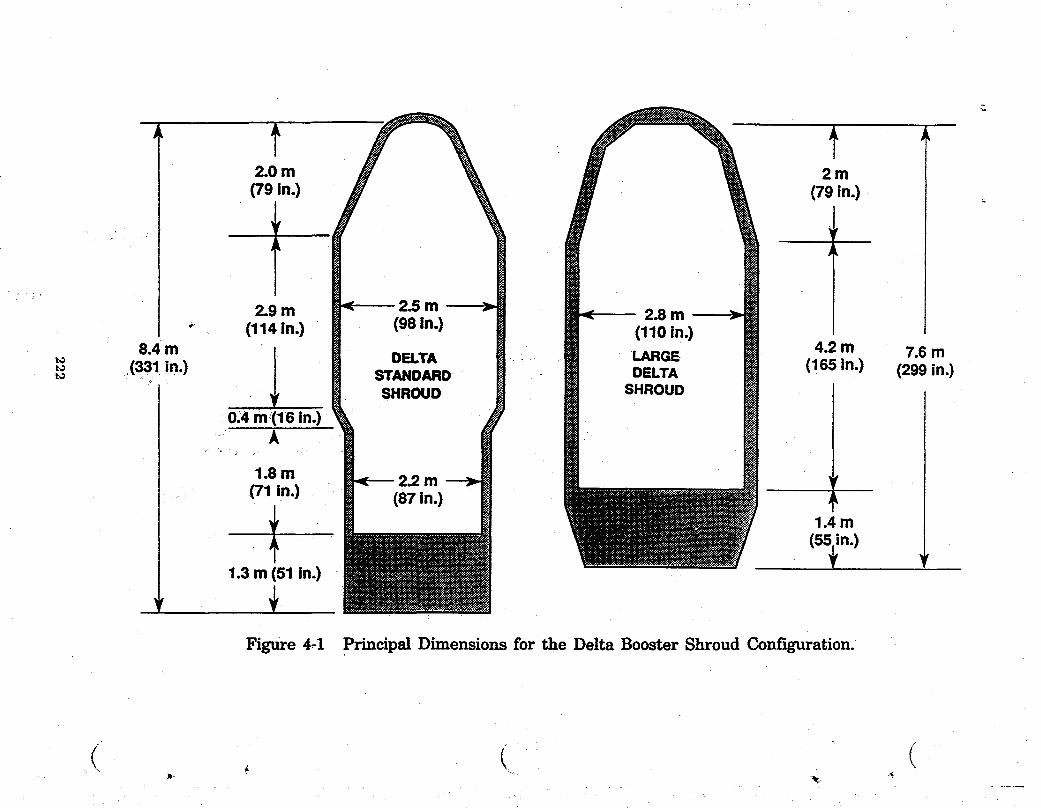
2.0m 2m
(79in.) (79 in.)
2.9 m < 2.5 m 2.8 m" (114 in.) (98 in.) (110 in.)
8.4 m / 4.2 mDELTA LARGE 7.6 m
_ (331 in.) _ STANDARD DELTA (165 in.) (299 in.)SHROUD SHROUD
0.4 m(16 in.)A
1.8 rn 2.2 m _f
(71 in.) jI 1.4 m(55n.)1.3 m (51 in.)
Figure 4.1 Principal Dimensions for the Delta Booster Shroud Configuration.
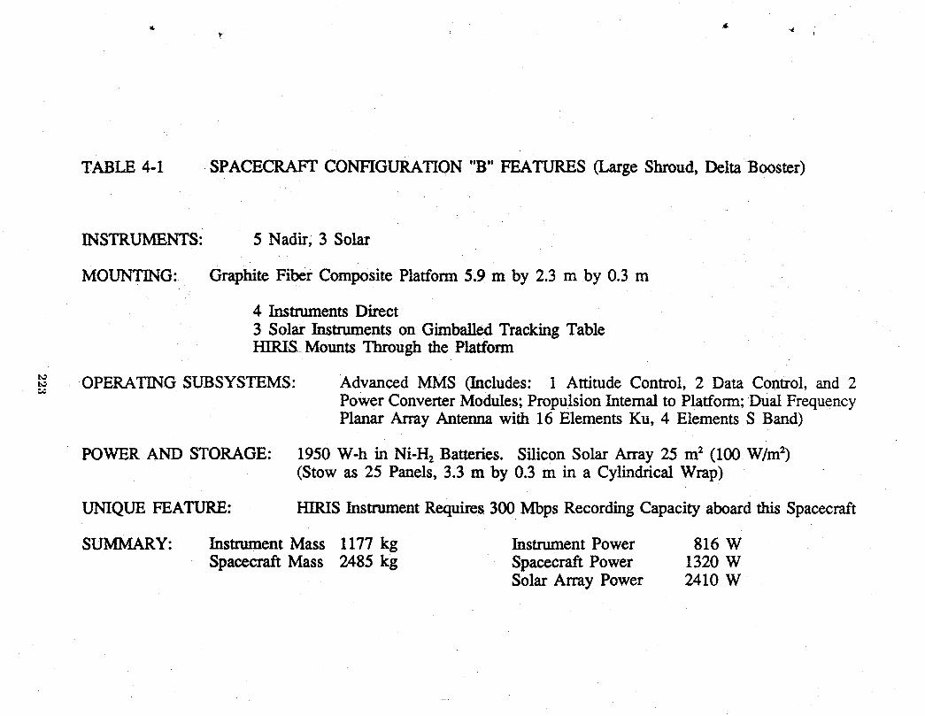
TABLE 4-1 SPACECRAFT CONFIGURATION "B" FEATURES (Large Shroud, Delta Booster)
INSTRUMENTS: 5 Nadir, 3 Solar
MOUNTING: Graphite Fiber Composite Platform 5.9 m by 2.3 m by 0.3 m
4 Instruments Direct3 Solar Instruments on Gimballed Tracking TableHIRIS Mounts Through the Platform
t-_
OPERATING SUBSYSTEMS: Advanced MMS (Includes: 1 Attitude Control, 2 Data Control, and 2Power Converter Modules; Propulsion Internal to Platform; Dual FrequencyPlanar Array Antenna with 16 Elements Ku, 4 Elements S Band)
POWER AND STORAGE: 1950 W-h in Ni-H2Batteries. Silicon Solar Array 25 m2 (100 W/ms)(Stow as 25 Panels, 3.3 m by 0.3 m in a Cylindrical Wrap)
UNIQUEFEATURE: HIRIS InstrumentRequires300 Mbps RecordingCapacity aboardthis Spacecraft
SUMMARY: Immanent Mass 1177 kg Instrument Power 816 WSpacecraftMass 2485 kg SpacecraftPower 1320 W
Solar Array Power 2410 W
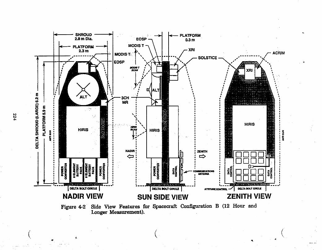
SHROUD ' . _, PLATFORM2.8m Dla. EOSP 0.3m
MODiS T
MODIS-_T_i ..., ..... ACR!M_, SOLSTICE ." "EOSP "'
MOO_T
, ; ',f
E _' ; '
_ MR ,
,,,r
s _
_ Z I ,"
I
II
DELTA BOLTCIRCLE ATnTU_ DELTABOLT
NADIR VIEW SUN SIDE VIEW ZENITH VIEW
Figure 4-2 Side View Features for Spacecraft Configuration B (12 Hour andLonger Measurement).
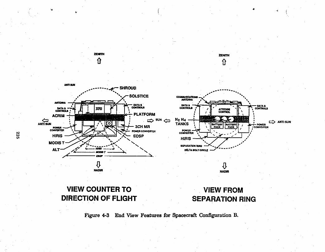
qlW |
ZEIm'H ZENITH
0
ANt1Stm
o'". oo....... _ SHROUDss €_IUPi_L52_I -_s S _
DATA& _ " ,,- - "• _ _IL DATA&
_T_, _ _;I "1" A_._ "11' T',€omi_ul : - PLATFORM e t .# ,t €olrmoL rl /"
' _11 IIl_ 'ACRIM : _ SUN<:_ N_,H- ' _ l_-_J_r-- :C:a ' : ....... ,_Jn .-- _-_TANKS _ I _ 'l'*"_ll,_-_-II, , .k,-4--,,o_"_ A.'nsuN
._ucnsuN L-- 3CH MR _,..L \ I _ I PA_ _1, ! i 'c°_=m_€o.vBv= \ mwr_co_u_r_ powr_ "1 '- ." I," I ; "t_
t_ HIRIS _,_=,J " " " -" "
._ EOSP HIRIS _'_/'. ,'"r ,..... °." • ,% SF.PARA"rloNRING..... """DELTAiI_.T ORCLE
g g
VIEW COUNTERTO VIEW FROMDIRECTIONOF FLIGHT SEPARATION RING
Figure 4-3 End View Features for Spacecraft Configuration B.

concept adopted for the platform utilizes a gridwork of beams covered by sheets
to form the mounting surfaces. GCTI platform design is an extension of a concept
developed to provide an equipment mounting deck for the Lidar Atmospheric
Sensing Experiment (LASE, Reference 12); Figure 4-4 shows the layout for the
beams. The LASE deck also acts as an optical bench which carries about 325 kg
of h_strumentation that includes dual frequency-controllable lasers and an 0.6 m
dia by 0.9 m telescope. A platform for a GCTI spacecraft will have the major
loading condition occur during launch. Therefore the beams which form the
internal bracing must transfer forces from the separation ring into the mounting
points for the instruments and subsystem components. A graphite composite
structure constructed as contiguous hollow square beams with 0.3 m sides and 3
mm walls shows a mass of 22 kg/m2, and this value is assumed for all the small
spacecraft platforms.
Accommodation of the instruments is considered straightforward. Four ofthe Nadir directed instruments are considered "bolt-ons". The trio of solar
reference instruments mounts on a gimballed platform that allows tracking the
sun throughout the illuminated portion of the orbit. The location indicated is
somewhat arbitrarY with the actual location determined by the orbit selected for
flight. The HIRIS instrument requires particular accommodation. Available
definitions of th_ exterior shape and mountings provide only envelope dimensions
and an indication of trunions as the pivot elements in the scanning system. In
addition, the unit has a space radiator. The accommodations provided accept the
envelope dimensions and will accommodate trunions for scanning in either or both
of the directions as indicated. A platform can be configured to apply launch
acceleration forces to the instrument at any point or combination of points around
the periphery of the opening in the platform. Arrangement of the other
instrumentation, as shown, minimizes t_e bending moments applied to theplatform during launch accelerations.
Electrical and Subsystem Accommodations *
Spacecraft operating subsystem modules mount on the platform just forward
226

EQUIPMENT MOUNTING DECK - BASIC
,f "I r" ..........
III
i L J ._ _•_ -_r • -_ 34.0 °°ri J
!_. LJ ..... ..I ..... _
Figure 4-4 Graphite Fiber Composite Beam Structure for the LASE.
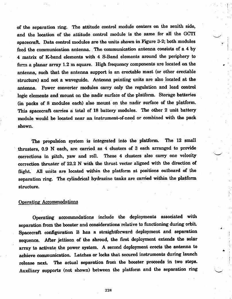
of the separation ring. The attitude control module centers on the zenith side,and the location of the attitude control module is the same for all the GCTI
spacecraft. Data control modules are the units shown in Figure 3-2; both modulesfeed the communication antenna. The communication antenna consists of a 4 by
4 matrix of K-band elements with 4 S-Band elements around the periphery to
form a planar array 1.2 m square. High frequency components are located on the
antenna, such that the antenna support is an erectable mast (or other erectable
structure) and not a waveguide. Antenna pointing units are also located at the
antenna. Power converter modules carry only the regulation and load control
logic elements and mount on the nadir surface of the platform. Storage batteries
(in packs of 8 modules each) also mount on the nadir surface of the platform.
This spacecraft carries a total of 18 battery modules. The other 2 unit batterymodule would be located near an instrument-of-need or combined with the pack
shown.
The propulsion system is integrated into the platform. The 12 small
thrusters, 0.9 N each, are carried as 4 clusters of 3 each arranged to provide
corrections in pitch, yaw and roll. These 4 clusters also carry one velocitycorrection thruster of 22.2 N with the thrust vector aligned with the direction of
flight. All units are located within the platform at positions outboard of the
separation ring. The cylindrical hydrazine tanks are carried within the platformstructure.
Operating Accommodations
Operating accommodations include the deployments associated with
separation from the booster and considerations relative to functioning during orbit.
Spacecrai_ configuration B has a straightforward deployment and separation
sequence. After jettison of the shroud, the first deployment extends the solar
array to activate the power system. A second deployment erects the antenna toachieve communication. Latches or locks that secured instruments during launch
release next. The actual separation from the booster proceeds in two steps.
Auxiliarysupports(notshown)betweenthe platformand the separationring _..
228
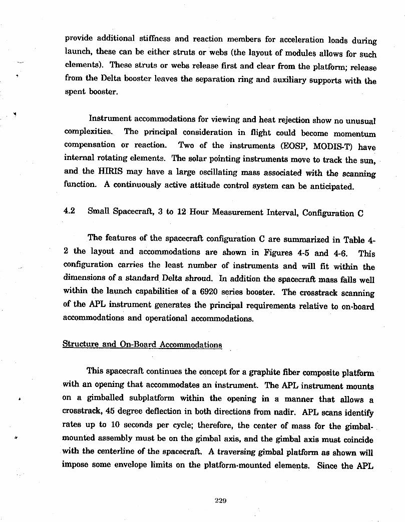
provide additional stiffness and reaction members for acceleration loads during
launch, these can be either struts or webs (the layout of modules allows for such
- elements). These struts or webs release first and clear from the platform; release
" from the Delta booster leaves the separation ring and auxiliary supports with thespent booster.
Instrument accommodations for viewing and heat rejection show no unusual
complexities. The principal consideration in flight could become momentum
compensation or reaction. Two of the instruments (EOSP, MODIS-T) have
internal rotating elements. The solar pointing instruments move to track the sun,
and the HIRIS may have a large oscillating mass associated with the scanning
function. A continuously active attitude control system can be anticipated.
4.2 Small Spacecraft, 3 to 12 Hour Measurement Interval, Configuration C
The features of the spacecraft configuration C are summarized in Table 4-
2 the layout and accommodations are shown in Figures 4-5 and 4-6. This
configuration carries the least number of instruments and will fit within the
dimensions of a standard Delta shroud. In addition the spacecraft mass falls well
within the launch capabilities of a 6920 series booster. The crosstrack scanningof the APL instrument generates the principal requirements relative to on-boardaccommodations and operational accommodations.
Structure and On-Board Accommodations
This spacecraft continues the concept for a graphite fiber composite platform
with an opening that accommodates an instrument. The APL instrument mounts
. on a gimballed subplatform within the opening in a manner that allows a
crosstrack, 45 degree deflection in both directions from nadir. APL scans identify
rates up to 10 seconds per cycle; therefore, the center of mass for the gimbal-mounted assembly must be on the gimbal axis, and the gimbal axis must coincide
with the centerline of the spacecraft. A traversing gimbal platform as shown will
impose some envelope limits on the platform-mounted elements. Since the APL
229
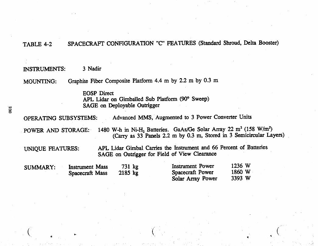
TABLE 4-2 SPACECRAFT CONFIGURATION"C" FEATURES (StandardShroud, Delta Booster)
INSTRUMENTS: 3 Nadir
MOUNTING: GraphiteFiber Composite Platform 4.4 m by 2.2 m by 0.3 m
EOSP DirectAPL Lidar on Gimballed Sub Platform (90° Sweep)SAGE on Deployable Outrigger
OPERATING SUBSYSTEMS: Advanced MMS, Augmented to 3 Power ConverterUnits
POWER AND STORAGE: 1480 W-h in Ni-H2Batteries. GaAs/GeSolar Array 22 m2 (158 W/mr)(Carry as 33 Panels 2.2 m by 0.3 m, Stored in 3 SemicircularLayers)
UNIQUE FEATURES: APL Lidar Gimbal Carries the Instrument and 66 Percent of BatteriesSAGE on Outrigger for Field of View Clearance
SUMMARY: InstrumentMass 731 kg InstrumentPower 1236 WSpacecraft Mass 2185 kg SpacecraftPower 1860 W
Solar Array Power 3393 W
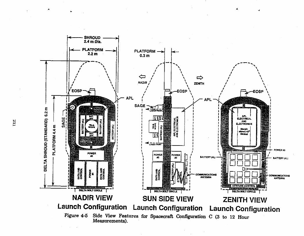
< SHROUD >2.4 m Dla. ....
PLATFORM _ PLATFORM2.2 m 0.3 m
s % / \ / \/ \ / \ I \
I \ / _ / \/ _, i \ / \I \, \ <:= / \ => , ,
I \ \ / \/ \ ZENITH I \
/ \ NADIR ! \ I \I \ / \ I \
I \ / \ IEOSP / \ / \
I \ I \t ! APL
APL iSAGE J
!
4 s
__. ,,O i
I Irr .j i I '_ I"if" _ _"_'F.RY I BATTERY(4L)
,,,...II.Ua
_ __ -com_uN_cA'nom
! '• !i
DELTABOLTCiRClE DELTABOLTCIRCLE DELTABOLTCIRCLE
NADIR VIEW SUN SIDE VIEW ZENITH VIEW
Launch Configuration Launch Configuration Launch ConfigurationFigure 4-5 Side View Features for Spacecraft Configuration C (3 to 12 Hour
Measurements).

"°'t C_TROL
SUN_ , ._ _ ..... I" EOSP EOSP _ SUN
"=SAGE _ _""_"f / SAGE
DATA AND --_ DATA ANDCONTROL €ONTROL /" CONTROL
IzOWERm "" .... _ CROSS1'1_K
NADIR
VIEW COUNTER ViEW COUNTERTO DIRECTIONOF FLIGHT TO DIRECTIONOF FLIGHT
Launch Configuration Flight Configuration
Figure 4-6 End View and Flight Configuration for Spacecraft C.
instrument presently is in an early stage of configuration definition, envelope
considerations for a host spacecrait can be accommodated. The fore and ai_ fields
of view for the SAGE III instrument must be free from intrusion by the scanning
motion of the APL. Therefore, the SAGE III mounts on a deployable outrigger
beam that places the instrument in line with the APL scan plane but outboard
_ at a distance sufficient for unobstructed viewing of the sunrise and sunset events
associated with the measurement sequences.
A potential alternate configuration would use the on-board attitude control
subsystem to provide the roll cycling or positioning for the APL. The entire
platform and APL would move as a unit and thereby relieve some of the envelope
constraints for the APL electrical components. Such an operation would incur the
expense of adding additional gimbal mountings for the antenna, solar array and
the SAGE instrument.
Electrical and Subsystem Accommodations
The locations of the electrical operating modules adjust to accommodate the
smaller diameter of the standard Delta shroud. Power requirements for the APL
result in a solar array that necessitates three power conversion modules with the
third unit mounted just forward of the attitude control module on the zenith
surface of the platform. Continuous operation of the APL justifies placing 16 of
the 28 battery units on the platform and accepting the need for additional
momentum compensation. Power requirements for this relatively small spacecrai_
also justify the use of GaAa/Ge solar cells principally as a means to reduce the
array area.
Operating Accommodation
Operating accommodations also relate to the APL. The deployment sequence
for shroud release, solar array deployment and antenna erection are the same as
for the configuration B. The sequence then executes the extension of the SAGE
III before release of the platform and energizing the APL. Separation from the
233
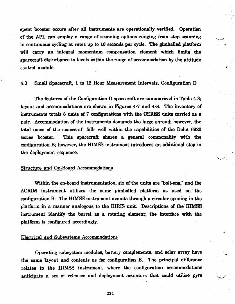
spent booster occurs after all instruments are operationally verified. Operation
of the APL can employ a range of scanning options ranging from step scanning ___to continuous cycling at rates up to 10 seconds per cycle. The gimballed platform
will carry an integral momentum compensation element which limits the
spacecraft disturbance to levels within the range of accommodation by the attitudecontrol module.
4.3 Small Spacecraft, 1 to 12 Hour Measurement Intervals, Configuration D
The features of the Configuration D spacecraft are summarized in Table 4-3;
layout and accommodations are shown in Figures 4-7 and 4-8. The inventory of
instruments totals 8 units of 7 configurations with the CERES units carried as a
pair. Accommodation of the instruments demands the large shroud; however, the
total mass of the spacecraft falls well within the capabilities of the Delta 6920
series booster. This spacecraft shares a general commonality with the
configuration B; however, the HIMSS instrument introduces an additional step in
the deployment sequence.
Structure and On-Board Accommodations
Within the on-board instrumentation, six of the units are '_olt-ons," and the
ACRIM instrument utilizes the same gimballed platform as used on the
configuration B. The HIMSS instrument mounts through a circular opening in the
platform in a manner analogous to the HIRIS unit. Descriptions of the HIMSS
instrument identify the barrel as a rotating element; the interface with the
platform is configured accordingly.
Electrical and Subsystems Accommodations
Operating subsystem modules, battery complements, and solar array have
the same layout and contents as for configuration B. The principal difference
relates to the HIMSS instrument, where the configuration accommodations
anticipate a set of releases and deployment actuators that could utilize pyro __j
234
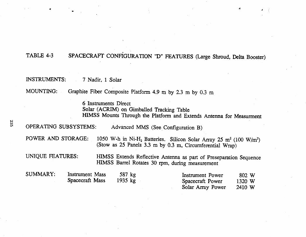
TABLE 4-3 SPACECRAFT CONFIGURATION "D" FEATURES (Large Shroud, Delta Booster)
INSTRUMENTS: 7 Nadir, 1 Solar
MOUNTING: Graphite Fiber Composite Platform 4.9 m by 2.3 m by 0.3 m
6 Instruments DirectSolar (ACRIM) on GirnbaUed Tracking TableHIMSS Mounts Through the Platform and Extends Antenna for Measurment
t_1.€
OPERATING SUBSYSTEMS: Advanced MMS (See Configuration B)
POWER AND STORAGE: 1050 W-h in Ni-H2 Batteries. Silicon Solar Array 25 m2 (100 W/m2)(Stow as 25 Panels 3.3 m by 0.3 m, Circumferenti!l Wrap)
UNIQUE FEATURES: HIMSS Extends Reflective Antenna as part of Preseparation SequenceHIMSS Barrel Rotates 30 rpm, during measurement
SUMMARY: Instrument Mass 587 kg Instrument Power 802 WSpacecraft Mass 1935 kg Spacecraft Power 1320 W
Solar Army Power 2410 W
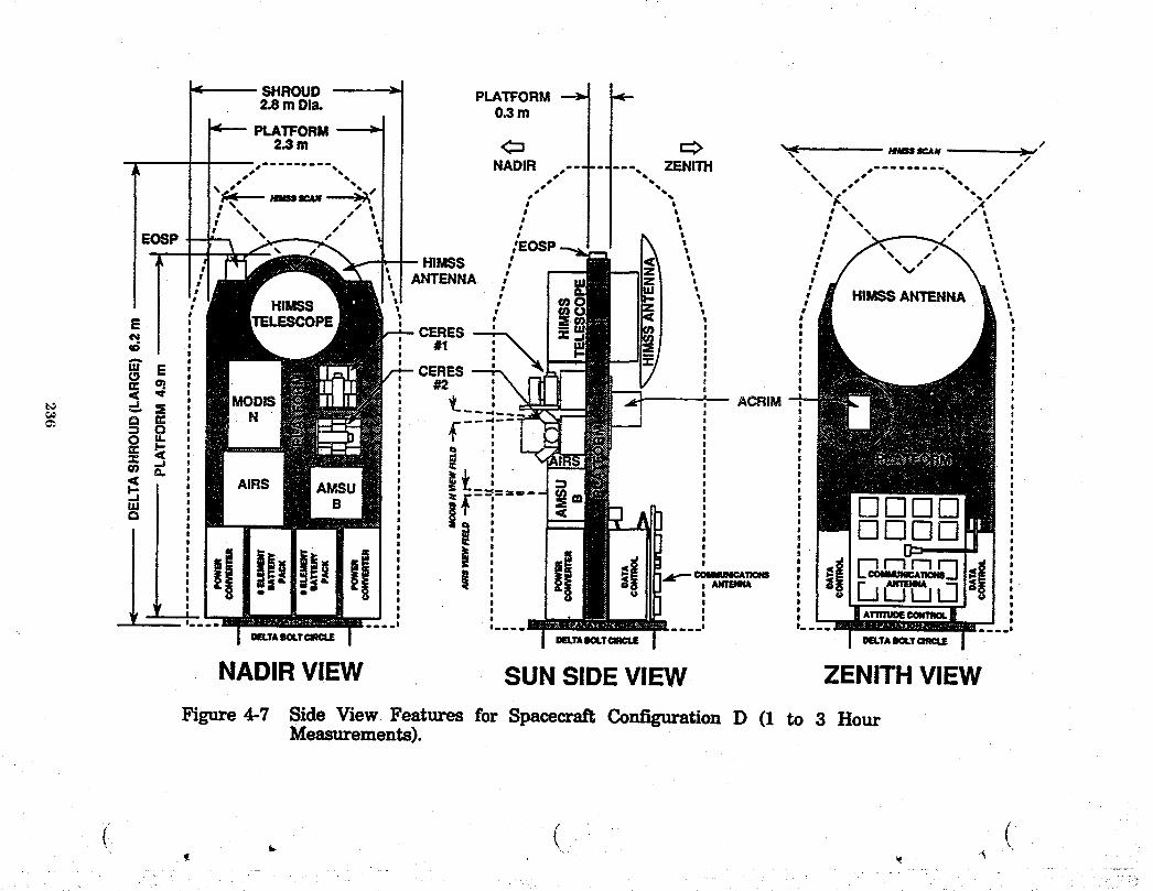
i ( (
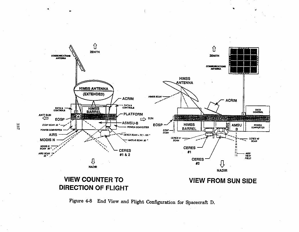
VIEW COUNTERTO VIEW FROMSUN SIDEDIRECTIONOF FLIGHT
Figure4-8 End View and FlightConfigurationfor SpacecraftD.
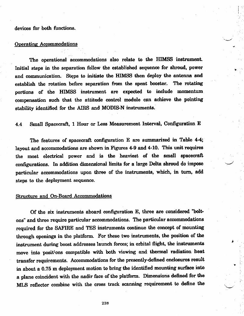
devices for both functions.
Operating Accommodations
The operational accommodations also relate to the HIMSS instrument.
Initial steps in the separation follow the established sequence for shroud, power
and communication. St_ps to initiate the HIMSS then deploy the antenna and
establish the rotation before separation from the spent booster. The rotating
portions of the HIMSS instrument are expected to include momentum
compensation such that the attitude control module can achieve the pointing
stability identified for the AIRS and MODIS-N instruments.
4.4 Small Spacecraft, 1 Hour or Less Measurement Interval, Configuration E
The features of spacecraft configuration E are summarized in Table 4-4;
layout and accommodations are shown in Figures 4-9 and 4-10. This unit requires
the most electrical power and is the heaviest of the small spacecrai_
configurations. In addition dimensional limits for a large Delta shroud do impose _-J
particular accommodations upon three of the instruments, which, in turn, add
steps to the deployment sequence.
Structure and On-Board Accommodations
Of the six instruments aboard configuration E, three are considered "bolt-
ons" and three require particular accommodations. The particular accommodations
required for the SAFIRE and TES instruments continue the concept of mounting
through openings in the platform. For these two instruments, the position of the
instrument during boost addresses launch forces; in orbital flight, the instruments *
move into posit;ons compatible with both viewing and thermal radiation heat
transfer requirements. Accommodationsfor the presently-defined enclosures result
in about a 0.75 m deployment motion to bring the identified mounting surface into
a plane coincident with the nadir face of the platform. Dimensions defined for theMLS reflector combine with the cross track scanning requirement to define the
238
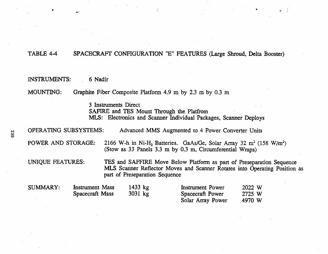
TABLE 4-4 SPACECRAFT CONFIGURATION "E" FEATURES (Large Shroud, Delta Booster)
INSTRUMENTS: 6 Nadir
MOUNTING: Graphite Fiber Composite Platform 4.9 m by 2.3 m by 0.3 m
3 Instruments DirectSAFIRE and TES Mount Through the PlatfromMLS: Electronics and Scanner Individual Packages, Scanner Deploys
OPERATING SUBSYSTEMS" Advanced MMS Augmented to 4 Power Converter Units
POWER AND STORAGE: 2166 W-h in Ni-H2 Batteries. GaAs/Ge, Solar Array 32 m2 (158 W/m2)(Stow as 33 Panels 3.3 m by 0.3 m, Circumferential Wraps)
UNIQUE FEATURES: TES and SAFFIRE Move Below Platform as part of Preseparation SequenceMLS Scanner Reflector Moves and Scanner Rotates into Operating Position aspart of Preseparation Sequence
SUMMARY: Instrument Mass 1433 kg Instrument Power 2022 WSpacecraft Mass 3031 kg Spacecraft Power 2725 W
Solar Array Power 4970 W
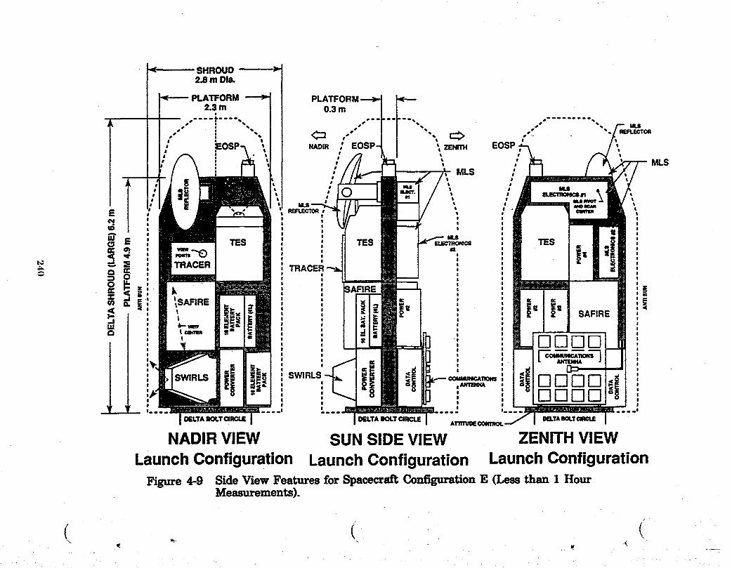
SHROUD2,8 m Dla.
PLATFORM2.3m 0.3m
t
N_Dm , EOSP _ ZENrm EOSP" MLS
" MLS
m_croRI
!
E TES m_mo_s TES#2
_ :S TRACERTRACER
' it- Jo .= _' : = |= sAFI_E
d L,,,,,,, \m !' ' L DDDD n
I !
i=iiI, ==I= I I l_=_I= =I== l
DELTABOLTCIRCLE DELTABOLTCIRCLE DB.TABOLTATllI1JOE CONTROL
NADIRVIEW SUNSIDEVIEW ZENITHVIEWLaunch Configuration Launch Configuration Launch Configuration
Figure 4-9 Side View Features for Spacecrsi_ Configuration E (Less than 1 HourMeasurements).
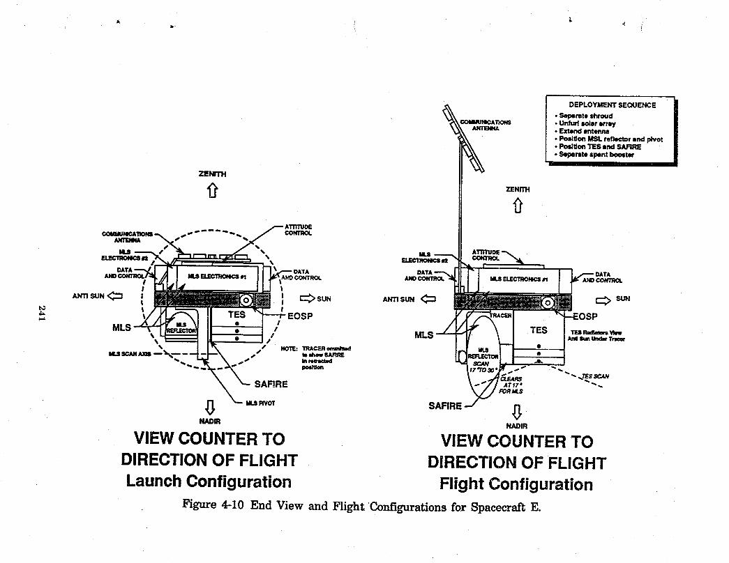
__ DEPLOYMENTSEQUENCE
• Seperatoshroud
_;_om • Unfurlsolararray• Extend Ilntenrm• Posl_onMSLreflectorend pivotoPositionTESand SARRE• Seperatespentbooster
ZENITH
ZENITH
.- .,. ,,. _ ATnTUDE€OMMUI4¢AIIONS _ .. _- " _ -,..q, % _ CONTROL
S %
"-1 ._Jr""-" DATA
, b mmm : =:>sun A_s_ <::= =:>su.t_ __-J !
iii TESRml_rs __ ImlSunLkx_Tr_sr
_.. CLEARS """- ..TE$SCAN
$AFIRE LTIZ" ""..FORJ4.S
NADIR NADIR
VIEWCOUNTERTO VIEW COUNTERTODIRECTIONOF FLIGHT DIRECTION OF FLIGHT
Launch Configuration Flight ConfigurationFigure4-10 End View and FlightConfigurationsforSpacecraftE.
location of the pivot axes for the moving elements within the MI_ instrument.
The reflector will move from a launch-compatible position into the flight
configuration as part of the deployment sequence. Electronics for the MLS mount
on the zenith face of the platform and can accept modularized elements in a
multi-unit configuration.
Electrical and Subsystem Accommodations
The six instruments together have the highest power demand of the small
spacecrai_ series which leads to a solar array requirement that results in four
power converter modules and a 36-element battery installation. GaAs/Ge solar
cells are needed to minimize the area of the array and launch mass. Scanning
elements of the MLS instrument are expected to include momentum
compensations; however, the attitude control system can anticipate a continuous
action in response to residual disturbances. Requirements for platform pointing
and stability are associated with the EOSP 10 km resolution and appear as within
the momentum capabilities of a single attitude control module, i_)
Operating Accommodations
The principal steps in the deployment sequence for the configuration E
appear outlined in Figure 4-10. The MLS is the first to move into a flight
operating configuration. Motions of the TES and SAFIRE instruments involve
controlled translations accomplished in a straightforward sequence. Scanners
within the TES instrument appear to involve small optical elements and do not
introduce any significant disturbances into the system. MLS operations include
large elements moving about two axes and anticipate momentum compensations4
to cancel the dynamic interactions such that an active attitude control system can
maintain the required stability.
242
5.0 LARGE SPACECRAFT CONFIGURATION
.... The large spacecraft configurations address the same temporal requirements
as the small spacecraft by placing all the instruments required for a particular
orbit aboard a single spacecraft. The large spacecraft constellation alternative,
therefore, consists of a dedicated "Configuration A" unit plus four multi-
instrument units, of which three are identical. Large spacecraft all require Titan
boosters and use the long Titan shroud. Figure 5-1 shows the dimensions of the
shroud and the clearance dimensions needed for the proposed spacecraft support
structure. Large Titan-launched spacecraft have been proposed that can utilize
the present multimission modular elements to provide the spacecraft operating
subsystems. Figure 5-2 shows this concept in flight configuration, and Figure 5-
3 shows how the load carrying structure will fit into a large Titan shroud.
5.1 Large Spacecraft, 20 On-Board Instruments, Configuration L-1
The features of the spacecraft are summarized in Table 5-1; the layout and
...... accommodations of instrumentation are shown in Figures 5-4 and 5-5. This
configuration carries all of the instruments listed for low Earth orbit except the
Soil Moisture Measurement Radiometer (SMMR). The 20 on-board instruments
amount to 21 units, since the CERES instrument is duplicated in the same
manner as for the small spacecraft (Configuration D).
Structural and On-Board Accommodations
The support structure for the large spacecraft utilizes a truss assembly of
graphite fiber composite tubes similar to that used on the UARS spacecraft
, (Reference 13). Estimates of mass as a function of truss length based on UARS
data yields a value of 210 kg/m. This value allows for localized tailoring of the
support structure to accommodate the specific needs of particular instruments.
• For truss structures in the length range 10 m to 14 m, the value is considered
somewhat conservative.
243
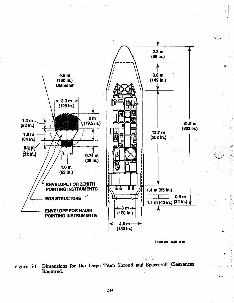
2.3 m(89 in.)
4.6 m 3.8 m(180In.) (149In.)Diameter f
(128in.),
2m1.3m -_ 179.5In.) 21.9m(52In.)
(882in.)12.7m1.6 m
(64 In.) ' (502in.)S
I-0.'74m _, ;(29 in.)
1.6m(63 in.) i
ENVELOPEFORZENITH ', ,
POINTINGINSTRUMENTS 1.4m (55 In.)
EOSSTRUCTURE .... t-- 0.6 m1.1m (43 in.)(24 in.),
ENVELOPEFORNADIR / m APOINTINGINSTRUMENTS (120in.)!_ 4.6m----_1180in.)
11-29-89 AJB #18
*)
Figure 5-1 Dimensions for the Large Titan Shroud and Spacecraft ClearancesRequired.
244

POWERMODULES
t,_
ATTITUDE MMSCONTROL
Figure 5-2 Concept for a Large Spacecraft Utilizing the Multimission ModularSpacecraft for Operating Subsystems.

LAUNCHVEHICLE . ADDmONALMMSADAPTOR MODULES
TITANIVFAIRING
I
VOLUME AVAILABLEMMS STOWED HIGH INSTRUMENT TRUSS FOR INSTRUMENT AND
GNN ANTENNA STRUCTURE SOLAR ARRAY
Figure 5-3 Large Spacecraft Structure Within the Long Titan ShroucL
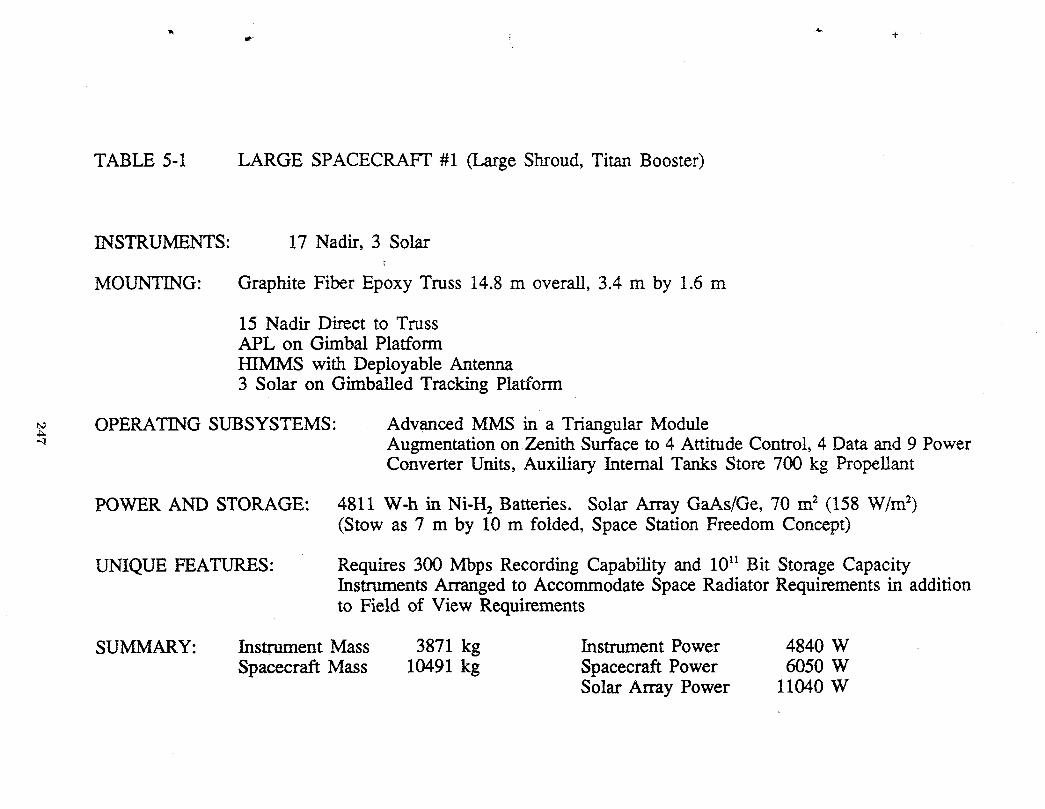
TABLE 5-1 LARGE SPACECRAFT #1 (Large Shroud, Titan Booster)
INSTRUMENTS: 17 Nadir, 3 Solar
MOUNTING: Graphite Fiber Epoxy Truss 14.8 m overall, 3.4 m by 1.6 m
15 Nadir Direct to TrussAPL on Gimbal PlatformHIMMS with Deployable Antenna3 Solar on Gimballed Tracking Platform
OPERATING SUBSYSTEMS: Advanced MMS in a Triangular Module-" Augmentation on Zenith Surface to 4 Attitude Control_4 Data and 9 Power
Converter Units, Auxiliary Internal Tanks Store 700 kg Propellant
POWER AND STORAGE: 4811 W-h in Ni-H2 Batteries. Solar Array GaAs/Ge, 70 m2 (158 W/m2)(Stow as 7 m by 10 m folded, Space Station Freedom Concept)
UNIQUE FEATURES" Requires 300 Mbps Recording Capability and 1011Bit Storage CapacityInstruments Arranged to Accommodate Space Radiator Requirements in additionto Field of View Requirements
SUMMARY: Instrument Mass 3871 kg Instrument Power 4840 WSpacecraft Mass 10491 kg Spacecraft Power 6050 W
Solar Array Power 11040 W

r TI 1I t .
I tI t
I tti I 3.8 m
I tESOP I I
tt
I _ __I t
I t _'TESI
I III 3CH MR.
LASERPORT
APL * *I !I
LASER PORT I AIRSII I
!TRACER ,I
I MODIS NSWIRLSIIII
SAFIRE 12.9m 14.1m
. HIRIS
SAGE
MODIST CERESi , #1,#2I I V
MMS _ I!, 1.9 m
TITAN
INTERFACE _ , , _f _fi i=.. .j j
- PLATFORM--_13.4m)
•4,---- SHROUD(4.6 m Dia.) ,
Figure 5-4 Layout of Instruments and AccommodationsWithin a Titan Shroud forthe Large Spacecraft Configuration L-1.
248
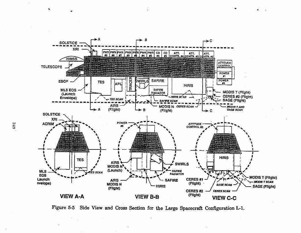
BSOLSTICE
XRI
TELESCOPE
ESOP
MLS EOS MODIS T (Flight)(Launch CERES #2 (FI}ght)
Envelope) SAGE (Flight)
==""A=_R'S"" MODIS N CERESSCmV _. JaootsT_tOA (Flight) B (Flight) C SAGESCAN
SOLSTICEXRI I
ACRIM POWER ' _ ATTn'UDI _ _ %_i_ _15 _ % CONTROL _2
I % 4' % S %
I 11 ! I I
| ! | |I I I I I I HIRIS I| I 'k I _ I II # AIRS I' " .oo,s.\ SWRLS". E - •
MLS , _rEs SCAN (Launch) -_ RJU_U_TOR _
LaunchEOS_ _ ="" | AIRS SAFIRE CERES #1 --/ ',1,=,, ,, . < MODIS T (Flight)
_," _. MODtSTSC4Nnvelope) MODIS N HIRIS (Right) - SAOESCAN-- _--- SAGE (Fllght)
(Flight) CERES #2 OZRESSC_---/
VIEW A-A VIEW B-B (Right) VIEW C-C
Figure 5-5 Side View and Cross Section for the Large Spacecraft Configuration L-1.

Instrument accommodations follow the requirements defined in terms of both
viewing and heat rejection by space radiators and are the same as to the small
spacecraft. Solar-sensing instruments mount on the same gimballed table used
for the small spacecraft (Configurations B and D) and it is located at the forward
end of the zenith surface. The other instruments are arranged to accommodate
their particular viewing requirements. Truss structure allows some flexibility,
since instruments can extend into the truss envelope and both the APL and HIRIS b
instruments take advantage of that flexibility. Space radiation requirements for
the AIRS and MODIS-N instruments require mounting on a deployable
substructure. (Figure 5-5 illustrates the concept.) The deployable mount carries
the instruments against the truss during launch; during orbital flight operation,
the instruments are positioned to allow space radiators to view in the anti-sun
direction below the envelopes of the instruments mounted on the anti-sun side of
the truss. A similar deployable substructure carries the MODIS-T, SAGE and
CERES units. For these instruments, the deploying mount accommodates the
viewing requirements.
Electrical and Subsystem Accommodations
Masses, power demands, data rates, and data recording capacities require
multiple subsystem modules for their accommodations. The capacity of the
attitude control momentum wheels has been estimated at 3000 kg for a
dynamically active spacecraft; additional modules are added proportionately. Data
handling requirements are potentially within the capabilities of the NDLM;
however, the need for flexibility in data accommodation leads to an on-board
duplication of the small spacecraft system. Modularization of power conversion
modules on the basis of a 1300 W solar array input establishes the number of
units carried. Mounting of subsystem modules for the large spacecraft includes
an assembly like an existing MMS with the auxiliary units mounted along the
zenith surface of the truss structure; Figure 5-5 shows the accommodations for the
subsystem modules. Energy storage requirements (4811 W-h) equate to 80 batteryelements which would be assembled into the 8 element modules as used for the
small spacecraft (Configurations B and D). These 10 battery modules then mount
25O
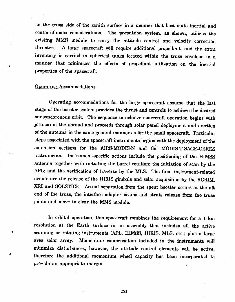
on the truss side of the zenith surface in a manner that best suits inertial and
center-of-mass considerations. The propulsion system, as shown, utilizes the
existing MMS module to carry the attitude control and velocity correction
thrusters. A large spacecraft will require additional propellant, and the extra
inventory is carried in spherical tanks located within the truss envelope in a
manner that minimizes the effects of propellant utilization on the inertial4
properties of the spacecraft.
Operating Accommodations
Operating accommodations for the large spacecraft assume that the last
stage of the booster system provides the thrust and controls to achieve the desired
sunsynchronous orbit. The sequence to achieve spacecraft operation begins with
jettison of the shroud and proceeds through solar panel deployment and erection
of the antenna in the same general manner as for the small spacecraft. Particular
steps associated with the spacecrat_ instruments begins with the deployment of the
extension sections for the AIRS-MODIS-N and the MODIS-T-SAGE-CERES
instruments. Instrument-specific actions include the positioning of the HIMSS
antenna together with initiating the barrel rotation; the initiation of scan by the
APL; and the verification of traverse by the MLS. The final instrument-related
events are the release of the H1RIS gimbals and solar acquisition by the ACRIM,
XRI and SoI_qTICE. Actual separation from the spent booster occurs at the aft
end of the truss, the interface adapter beams and struts release from the truss
joints and move to clear the MMS module.
In orbital operation, this spacecraft combines the requirement for a 1 km
resolution at the Earth surface in an assembly that includes all the active
' scanning or rotating instruments (APL, HIMSS, HIRIS, MLS, etc.) plus a large
area solar array. Momentum compensation included in the instruments will
minimize disturbances; however, the attitude control elements will be active,
' therefore the additional momentum wheel capacity has been incorporated to
provide an appropriate margin.
251

5.2 Large Spacecrail, 12 On-BoardInstruments, Configurations It2, L-3 and LA
The features of these spacecraft are summarized in Table 5-2; the layout _Jand accommodations of instruments are shown in Figures 5-6 and 5-7. This
configuration carries the same instruments as the combination of Configurations
D and E from the small spacecraft series. These large spacecraft will operate in
_ree complementing orbits, thereby satisfying a 3-hour measurement interval forthe instruments identified.
Structural and On-Board Accommodations
These three large spacecraft are identical units formed by truncating the
support structure defined for Configuration L-1. The layout of the instruments
also retains the mounting accommodations defined for the larger unit.
Requirements for viewing and space radiators continue for the AIRS, MODIS-Nand CERES units and, the deployable mounts are retained on this spacecraft.
Truncation reduces both the length of the platform and the mass delivered to
orbit; however, the envelope dimensions and masses require a Titan-series booster
for delivery to orbit. _"_
Electrical and Subsystem Requirement
The reduced scope of instrumentation decreases the subsystem support
requirements. Attitude control modules are reduced by one unit relative to the
larger spacecraft to assure adequate margin for momentum control. A doubled
communication system has been retained for commonality with the larger
spacecraft and power control modules relate to the solar array power. The
propulsion capability retains the same configuration.
Overating Accommodations
Operating accommodations follow the same steps as outlined for the larger,
Configuration L-l, spacecraft. The steps for shrouds, solar array, antennas and
252
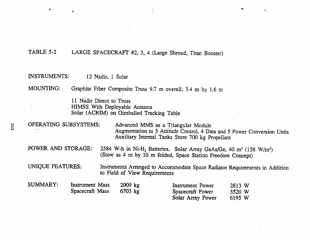
TABLE 5-2 LARGE SPACECRAFT #2, 3, 4 (Large Shroud, Titan Booster)
INSTRUMENTS: 12 Nadir, 1 Solar
MOUNTING: Graphite Fiber Composite Truss 9.7 m overall, 3.4 m by 1.6 m
11 Nadir Direct to TrussHIMSS With Deployable AntennaSolar (ACRIM) on Gimballed Tracking Table
_,_ OPERATING SUBSYSTEMS: Advanced MMS as a Triangular Module....:_ Augmentation to 3 Attitude Control, 4 Data and 5 Power Conversion Units
Auxiliary Internal Tanks Store 700 kg Propellant
POWER AND STORAGE: 2584 W-h in Ni-H2 Batteries. Solar Army GaAs/Ge, 40 m2 (158 W/m2)(Stow as 4 m by 10 m folded, Space Station Freedom Concept)
UNIQUE FEATURES: Instruments Arranged to Accommodate Space Radiator Requirements in Additionto Field of View Requirements
SUMMARY: Instrument Mass 2009 kg Instrument Power 2813 WSpacecraft Mass 6703 kg Spacecraft Power 3520 W
Solar Array Power 6195 W
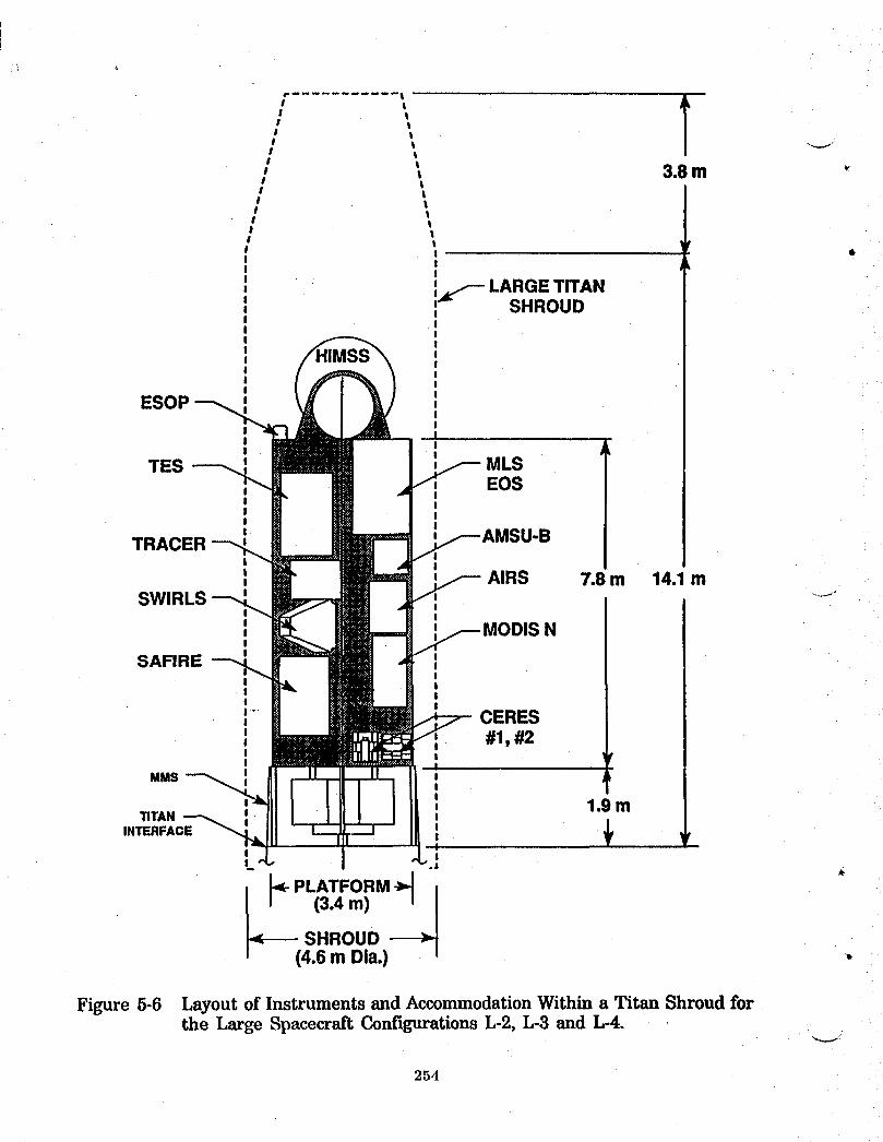
t
lttI
tt 3.8mt
_f--LARGET_ANSHROUD
ESOPIII
TES MLS, EOS
I II II II II
TRACERI I
AIRS 7.8 m 14.1mI
SWIRLSI I' _ISNII
SAFIRE , II
I tI II I"" CERES,' , #1, #2I II I
MMS I llt 1
, 1.9 mTITAN o
, ,INTERFACE II
I II_ .]
13.4m)
.<---- SHROUD --->.(4.6m Dla.)
Figure5-6 LayoutofInstrumentsand AccommodationWithina TitanShroudforthe LargeSpacecraftConfigurationsL-2,L-3 and L-4.
254
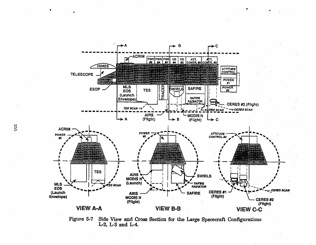
mmmmmmmlmmmmmmmmm mmlmmmmlmmmmmmmmmmmmmmmmmmm mmlllmmmmmmmmmm
TELESCOPE
instrument deployments are identical. Actions to initiate the dynamic instruments
are the same for HIMSS and MLS which then followed by the ACRIM acquisition
of the solar disc as precursor to separation from the spent booster. HIMSS and
MLS operation during an orbit will require a continuous momentum correction.The momentum margin provided by three attitude control modules will assure the
1 km resolution of the Earth surface for the AIRS and MODIS-N instruments.
256
6.0 COMPARISONS AND ASSESSMENTS OF SPACECRAFT ALTERNATIVES
The comparisons of the spacecraft alternatives address the numbers of_r
spacecraft, the boosters required and the masses delivered to orbit. Assessments
of the spacecraft address operational considerations such as flexibility and
replacement. Both of the alternate spacecraft constellations include the large
antenna radiometer unit intended for measurement of soil moisture, therefore,
comparisons and assessments need consider only the 10 unit small spacecraft
configurations and the 4-unit, large spacecraft configurations. The pertinent
considerations first address numbers of units and masses delivered to orbit as
comparisons of equipment requirements and then address the operational features.
Operational considerations identify the inherent advantages and disadvantages
for each of the alternatives while recognizing that an advantage offered by one
alternative could be the disadvantage associated with the other alternative.
6.1 Comparison of Masses and Quantities
The summaries of masses and quantities of equipment delivered to orbit
appear in Tables 6-1 and 6-2. Overall comparisons of spacecraft assembled and
boosters expended stand as 10 small or 4 large which becomes the basis for
comparing total masses and quantities of spacecraft equipment delivered into orbit.
The total mass for the 10 small spacecraft shows a slight advantage relative
to the total mass for the large spacecraft. A comparison of contributing elements
summarized in Table 6-2 indicates the principal differences. Numbers of
instruments and total mass of instruments delivered to orbit are essentially equal;
the difference is the 6 additional EOSP units and the one extra ACRIM unit
required for the small spacecraft. The principal difference appears in structure,
* and this difference relates to the accommodation of loads during launch
acceleration. The small spacecraft utilize short, stiff platforms and carry
instruments in a manner that minimizes bending reactions. During launch they
' act as axial-compression loaded, deep-webbed beams with the loads effectively
applied within the dimensions of the web. The structures for the large spacecraft
257
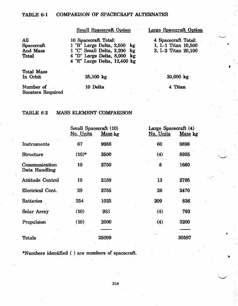
TABLE 6-1 COMPARISONOF SPACECRAFTALTERNATES
Small S_aceeraft O_tion Large Spacecraft Option
All 10 Spacecraft Total: 4 Spacecraft Total:Spacecraft 1 "B" Large Delta, 2,500 kg 1, L-1 Titan 10,500And Mass 1 "C°'Small Delta, 2,200 kg 3, L-2 Titan 20,100Total 4 "D" Large Delta, 8,000 kg
4 "E" Large Delta, 12,400 kgd
Total MassIn Orbit 25,100 kg 30,600 kg
Number of 10 Delta 4 TitanBoosters Required
TABLE 6-2 MASS ELEMENT COMPARISON
Small Spacecraft (10) Large Spacecraft (4)No. Units Mass kg No. Units Mass kg
Instruments 67 9988 60 9898
Structure (10)* 3500 (4) 8925
Communication 10 2750 8 1680Data Handling
Attitude Control 10 2150 13 2795
Electrical Cont. 29 2755 26 2470
Batteries 254 1025 209 836
Solar Array (10) 931 (4) 793
Propulsion (10) 2000 (4) 3200
Totals 25099 30597
*Numbers identified ( ) are numbers of spacecraft.
258
are two to three times the length and about two times the width of the smaller
spacecraft. In addition, the shroud limitations identified in Figures 5-1 and 5-5
requires mounting all the nadir facing instruments in a manner that introduces
unbalanced bending moments during launch. The truss structure defined for the
large spacecraft follows present technology and assumes that the launch forces and
their effects on the asymmetric support structure can be accommodated within
the mass limits identified.
The electrically operating subsystems show some mass advantages that favor
the large spacecraft systems, these represent economies of scale associated with
modularization. The attitude control appears as the exception, and stems from
modularization based upon mass (3000 kg). The propulsion system also has a
larger mass requirement for each of the spacecraft. These values are considered
estimates based upon relative masses and relative cross section areas.
•In assessing the differences between the masses delivered to orbit, the
instruments and subsystems are either equal or show some advantage associated
with scale. The significant differences appear in propellant requirements and
structure, and these estimates carry the largest degree of uncertainty. A more
comprehensive analysis for each area could reduce the differences. Sincethe total
difference between the estimates is less than 20 percent, the comparisons of massdo not show major differences between the two alternatives.
6.2 Assessments of Small Spacecraft
The temporal requirements associated with the GCTI measurements
establish the need for multiple, identical spacecraft and the small spacecraft
alternative turns that requirement into an advantage at the expense of some
additional complexity in the operation of ground controls. Specific anticipated
advantages and disadvantages are summarized as follows.sl
259
Anticipated Advantages
1. Modularization. The multi spacecraft requirements generated by the
GCTI mission necessitate modularization of the spacecraft operating
subsystems. The small spacecraft configurations can make an
effective utilization of the modularization. Concepts generated for
the study provideredundancy in the data handling and communication
links and a capacity to effectively tailor power control elements to the
power demands of the spacecratL These capabilities are advantageous
to the GCTI spacecraft configurations since they require relatively
large amounts of power, the smallest solar array defined generates
2410 W, which is about two times that used for the present
operational NOAA units (TIROS-N).
2. Integration of Instruments. The small spacecraft configurations carry
fewer instruments and thereby reduce the interface and integration
requirements associated with a spacecratL The grouping of
instruments also eases some of the constraints within the operation
of the spacecraft. Such an effect shows for the cases of configurations
C and E where the attitude control requirements rela_ to a 10 km
surface resolution as comparedto configurations B and D which must
respond to a 1 km surface resolution requirement. GCTI spacecraft
will use dedicated microprocessorscommunicating by optical fibers as
the principal means for operating control and exchange of data such
that software accomplishes most of the integration. Grouping
instruments with similar needs for spacecraft support functions also
eases the integration of instruments into a spacecraft system, a
feature provided by the small spacecraft option.
3. Fabrication and Assembly. The combination of standardized modules,
a standard adapter ring and a platform fabricated from conventional
structural elements (eg. channels, angles, sheets) eases the processes
of fabrication and assembly. The platforms and solar arrays are the
260
only unique elements within a small spacecraft configuration, and
these are essentially modularized at the sub element level.
4. Configuration Flexibility. The four configurations defined for the
GCTI spacecraft show the inherent flexibility of the design approach.
These concepts provide the capability to configure a spacecraft to fit
a need. These spacecraft can respond to the availability of an
instrument in a manner that provides the earliest opportunity for the
return of measurement data. Small spacecrai_ can supplement larger
systems to extend the range of measurements needed to evaluate an
effect of interest. Finally, small spacecraft are readily duplicated such
that additional units can be placed in complementing orbits or a
critical instrument can be replaced in orbit by flying a small unit
companion to another spacecraft.
Recognized Disadvantages
• 1. Multiple Spacecraft Operation. The small spacecraft configurations
have two or more units in each of 4 sunsynchronous orbits. The
ground control systems will need the capability to handle up to 11
spacecraft with as many as 5 moving in a closely spaced group.
2. Implementing Organization. The implementation of the small
spacecraft will require a dedicated organization capable of addressing
and controlling four spacecraft configurations in which data fi,om one
spacecraft complements measurements from a companion unit.
Effective implementation of the small spacecraft alternates will require
design, fabricating, assembly and test teams that can respond to the
integration and interaction requirements. In such a context, the small
spacecraft series differs from previous scientific probes which have
tended to be independently configured and independently operated.
261
6.3 Assessments of the Large Spacocraft
The large spacecraft alternatives appear as the conventional approach to a
multi-instrument, dedicated-mission spacecraft. The required instruments are .
placed in orbit aboard the least number of spacecraft. Corresponding advantages
and disadvantages are summarized as follows.8
Advantages
1. System Commonality. The large spacecraft series makes a direct
approach to the integration of instruments and yields two spacecraft
configurations in which the smaller unit is a derivative of the larger.
These spacecraft offer the economy of scale in the use of the operating
subsystem modules which support both alternates. A selection of one
size spacecraft to provide the design approach would allow some
adjustment in the increments for modularization of power, mass, data
rates, etc. The larger spacecraft have the capability to utilize
commonality up to the practical limits.+
2. Operational Commonality. The ground control operation for these
spacecraft would follow the presently established procedures that
address near-identical units in complementing orbits such as the
NOAA-TIROS-Nseries. The quantity of data return presents its own
complexity which is independent of spacecraft configuration.
Disadvantages
1. Design and Operating Constraints. The operating subsystems and
structure for the large spacecraft must accommodate the combined
requirements of narrow earth measurement resolutions and highest
data rates. Large spacecraft result in the most inherently flexible
structure while demanding pointing accuracies and attitude controls
to operate within the closest tolerances.
262
2. Measurement Opportunity. The instrument (or instruments) which
incur the longest development and delivery cycle will effectively
establish the earliest time for data availability from any of the
" instruments. In addition the large spacecraft limit recoveries from
on-board instrument anomalies to just the actions associated with an
operational work-around.
6.4 Assessment Summary
The assessments of the two configuration alternatives do not define a
preferred approach. In contrast they identify a potential means for implementing
the science measurements in a manner that allows feedback from ongoing
measurements to assist or refine follow-on investigations.
The instruments identified for the GCTI measurements show a range in
development status that extends from preliminary design to flight ready. A
number of the GCTI instruments are presently identified for flight aboard
spacecraft presently moving through their design and fabrication phases. The
small spacecraft concepts offer the capacity to augment the data from existing
spacecraft by placing selected instruments in companion orbits. In a similar
manner small spacecraft can operationally evaluate refined or improved versions
of presently operational instruments. At some time later, the flight-proven,
effective instruments can be placed aboard a large platform and operated for an
extended period of time. Small units can then provide special support or specially
focused measuremen_ in response to need. This concept for a combined,
integrated approach to spacecraft appears well suited to a scientific program that
assesses changes occurring in the time frame of decades-to-a-century.
263
7.0 ASSESSMENTS OF SPACECRAFT AND SUBSYSTEM TECHNOLOGYREQUIREMENTS
The assessments of spacecraft-related technology requirements immediately "-J
show the need for accommodating large quantities of data with a particular
emphasis on transmission links. The total data transmission requirements forGCTI include the additional contributions from the Soil Moisture Radiometer
4t
Spacecraft and spacecraft in geosynchronous orbit. These combined requirements
are recognized and addressed separately. In addition, the technology associated
with accommodating high data rates within spacecraft are also addressed as part
of the data transmission system and appear in the spacecrai_ definitions as part
of the dedicated microprocessor utilization. In context, therefore, assessments of
the spacecraft related technologies or technical considerations are addressed below
in terms of the operating subsystems and structure beginning with communication
and data handling.
7.1 Communication and Data Handling
The data storage requirements identify the need for recorders with a 10'_ ..__t
bit capacity. Summaries of spacecraft operating requirements (Tables 2-2 and 2-.4)
show data rates which can generate more than 1011bits during the course of an
orbit. Estimates of storage requirements do not address intervals between data
transmissions or any requirements for assured data that results in redundancy of
recording. A number of data storage systems have been identified as candidates
for achieving capacities up to 101_-bits (Reference 6) and techniques approaching
10H bit storage are considered within the capabilities of present spacecraft
subsystems. Requirement for spacecraft on-board compatibility in terms of power
demand and physical size combine to establish the level of achievement necessary
forGCTI application.The LaRC isdevelopinga modularizedunitbasedupon
a 0.36 m diameter opticaldiscwhich appearsas a candidateof promise
(Reference 10).
The balance of the components within the communications and data
264
handling system are addressed in the development efforts associated with the
.__.. NDLM (Reference 6) and would be available for GCTI subsystem modules.
7.2 Attitude Control
The requirements for attitude control subsystem operations appear within
the capabilities of the planned improvements for the present MMS units or the
Hubble Space Telescope reaction wheels. Stability requirements for a 1 km
surface resolution limit approximate those listed for the present MMS units
(knowledge to 0.01 degree). Improvements in response to momentum control plus
the improvements in accuracy associated with the an optical gyro are expected to
provide the necessary control capability. In addition, any improvements in the
sensitivity of the star tracker, a larger magnetic torquer and the use of a
dedicated microprocessor should combine to provide the combinations of position
knowledge, attitude reference, and overall computational cycle times that will
assure the required precision through the orbital measurement sequences.
.... 7.3 Electrical Power Generation and Distribution
The electrical power generation and control subsystem shows three areas
which require the achievement of present development goals:
a. Solar Array Conversion Efficiencies. The power demands for the
GCTI instruments require a minimum performance equal to that
identified for GaAs/Ge end-of-life at 158 W/m2 and 45 W/kg. These
values equate to about a 12 percent energy conversion efficiency,
Candidate cell systems exist which have conversion efficiencies
extending past the 20 percent level, (Reference 8) and availability of
these alternates would be incorporated into any GCTI configuration
as a means to reduce the area of the solar array.
b. Energy Storage. The instruments which require the most power also
....... operate continuously and therefore require an energy storage
265
capability that equates to a fully developed Ni-H2 system at 45 W-
hr/kg operating with a 33 percent depth of discharge. A limited
number of GCTI compatible alternate storage systems exist (Reference
8), such that the Ni-I_ system may represent the realistically
available option; the GCTI study underscores the need for continued
development.
c. Power Regulation Efficiency. The modularization of power control and
regulation at 120 VDC and 1300 W input assumes operation at
efficiencies that have less than a 60 W total power loss within the
module. Performance at these levels is considered achievable,
(Reference 8) and becomes necessary to allow the freedom of
placement as indicated in the concepts shown. The present MMS unit
with the internally mounted Ni-Cd batteries has a mounting
constraint such that direct sun light must not fall on the thermal
control louvers.
7.4 Propulsion_._j"
The GCTI spacecraft will utilize the presently defined MMS system modified
to operate with dedicated microprocessor controls and modified tankage for storing
the propellant. The performance achievable by a monopropellant hydrazine system
offers the best alternate compatible with the GCTI mission and spacecraft
configurations (Reference 8). Relocation of thrusters and the addition of auxiliary
tanks are considered available technology.
The principal function of the propulsion system will be reboost velocity
correction using the large thrusters; vernier thrusters operate to reestablish the
nadir facing orientation. Reboost requirements have not been specifically defined;
individual spacecraft appear relatively small and dense, with correspondingly small
drag effect predictions. On the other hand, the relatively large area solar arrays
do increase the potential for drag effects, therefore, an increased propellant
capacity has been included for each of the spacecraft configurations.
266

7.5 Structure
The GCTI spacecraft utilize a refinement of existing structural concepts asfollows:
€ a. Small Spacecraft Platforms. Structure is based upon the development
of graphite fiber reenforced composites to achieve a specific mass of
22 kg/m 2 while subjected to the launch accelerations of a Delta
booster. The technology identified would extend present approaches
based upon structural shapes to permit modularizing a platform to
accommodate the instruments and supporting electronics modules
during both launch accelerations and orbital operation.
b. Large Suacecrat_ Trusses. The truss structure assumes development
to the point of 210 kg/m over the working length above the booster
interface with the capability to accept asymmetric dynamic loadings
during a Titan launch. Worst case instrument asymmetry could
impose a loading of up to 300 kg/m at 0.5 m offset distributed over
the nadir facing portion of the truss.
7.6 Assembly Integration and Test
The GCTI spacecraft identify developmental requirements and particular
improvements related to these elements of the implementation sequence.
a. Integration Test Bed. The concepts for operational integration
utilizing dedicated microprocessors moves much of the system
" complexity into software. A test bed using linked microprocessors,
instrument simulators, and operating subsystem modules would allow
the operational integration to proceed in concert with the fabrication
d of the spacecraft. The test bed would follow the concepts utilized for
the present LaRC Air Lab such that the electrical operating portions
of flight equipment could be operationally verified before assembly into
267
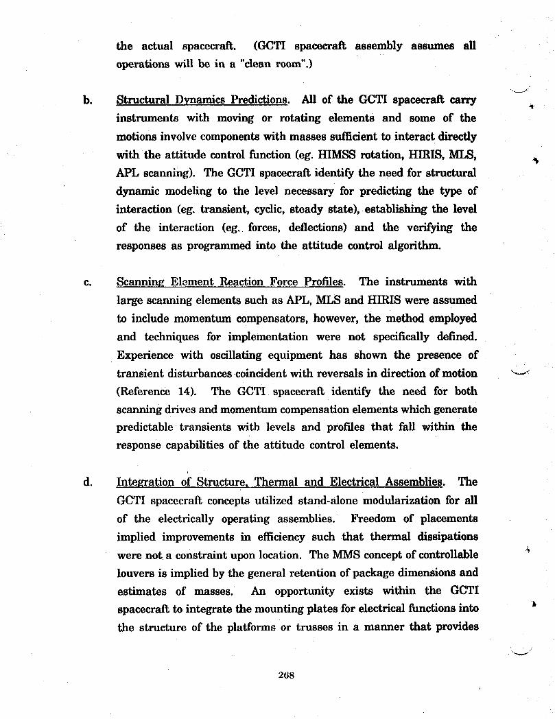
the actualspacecraft.(GCTI spacecraftassembly assumes all
operationswillbe in a "cleanroom".)
b. StructuralDynamics Predictions.Allofthe GCTI spacecraRcarry
instrumentswith moving or rotatingelementsand some of the
motionsinvolvecomponentswithmassessufficienttointeractdirectly
with the attitude control function (eg. HIMSS rotation, HIRIS, MI_,APL scanning). The GCTI spacecraft identify the need for structural
dynamic modeling to the level necessary for predicting the type of
interaction (eg. transient, cyclic, steady state), establishing the level
of the interaction (eg. forces, deflections) and the verifying the
responses as programmed into the attitude control algorithm.
c. Scanning Element Reaction Force Profiles. The instruments with
large scanning elements such as APL, MLS and HIRIS were assumed
to include momentum compensators, however, the method employed
and techniques for implementation were not specifically defined.
Experience with oscillating equipment has shown the presence of
transient disturbances coincident with reversals in direction of motion "--I
(Reference 14). The GCTI spacecraft identify the need for both
scanning drives and momentum compensation elements which generate
predictable transients with levels and profiles that fall within the
response capabilities of the attitude control elements.
d. In_grationof Structure,Thermal and ElectricalAssemblies.The
GCTI spacecraftconceptsutilizedstand-alonemodularizationforall
of the electricallyoperatingassemblies.Freedom of placements
impliedimprovementsin efficiencysuch that thermaldissipations
were not a constraint upon location. The MMS concept of controllable #
louvers is implied by the general retention of package dimensions and
estimates of masses. An opportunity exists within the GCTI
spacecraft to integrate the mounting plates for electrical functions into J
the structure of the platforms or trusses in a manner that provides
268
both structural stiffening and thermal radiation. The small spacecraft
configurations B and D offer a potential example. The power control
modules could be mounted upon an aluminum-based metal matrix
composite plate element that formed the anti-sun side of the platform.
During launch the structural elements would carry the thrust loads,
during operation the same elements would provide a space radiator
_ for heat dissipation.
7.7 Implications of Technology Assessments
The study to define spacecraft configurations to implement the modeling of
global changes has generally reenforced the rationales for continuing the present
areas of subsystem and component development. On-board data storage
requirements for GCTI instruments would arise from any scenario addressing the
combination of measurements identified by similar science requirements. The need
for flexibility in the ,configuration of spacecraft exists and underscores the need for
uprating the performance of circuitry and improving the modularization. Presently
defined, large, research-oriented spacecraft show configurations intended to support
a number of investigations within a roster of on-board instruments. Global
Change Initiative requirements identify the need for measurements in addition to
those provided by existing spacecraft and thereby establishes a need for rapid
response in configurating a spacecraft. The structural, assembly, integration and
test related developments cited above specifically address features of a technology
infrastructure capable of making a rapid spacecraft response to a set of scientific
requirements that can be defined in terms of specific flight instruments.
269
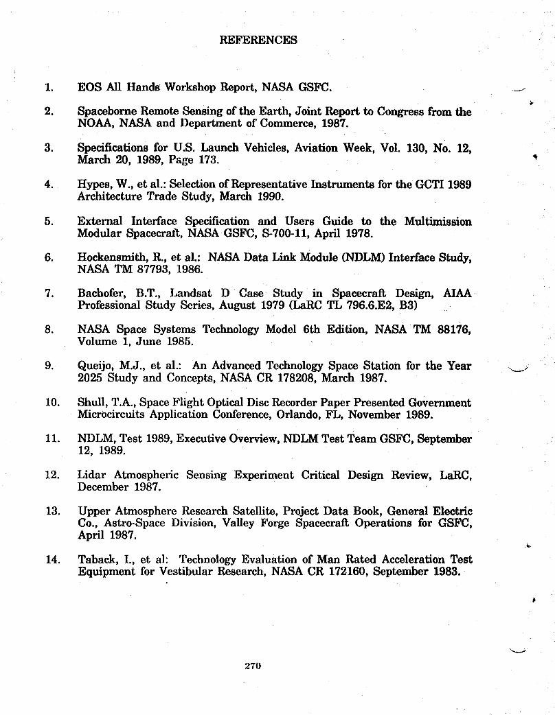
REFERENCES
I. EOS AllHands Workshop Report,NASA GSFC. ._i4r
2. SpaceborneRemote SensingoftheEarth,JointReporttoCongressfrom theNOAA, NASA and DepartmentofCommerce, 1987.
3. SpecificationsforU.S.Launch Vehicles,AviationWeek, Vol.130,No. 12,March 20, 1989, Page 173.
4. Hypes, W., et al.: Selection of Representative Instruments for the GCTI 1989Architecture Trade Study, March 1990.
5. External InterfaceSpecificationand Users Guide to the MultimissionModular Spacecraft,NASA GSFC, S-700-11,April1978.
6. Hockensmith,R.,etal.:NASA Data LinkModule (NDLM) InterfaceStudy,NASA TM 87793,1986.
7. Bachofer, B.T., Landsat D Case Study in Spacecrait Design, AIAAProfessional Study Series, August 1979 (LaRC TL 796.6.E2, B3)
8. NASA Space Systems Technology Model 6th Edition, NASA TM 88176,Volume 1, June 1985.
9. Queijo, M.J., et al.: An Advanced Technology Space Station for the Year _._._2025 Study and Concepts, NASA CR 178208, March 1987.
10. Shull, T.A., Space Flight Optical Disc Recorder Paper Presented GovernmentMicrocircuits Application Conference, Orlando, FL, November 1989.
11. NDLM, Test 1989, Executive Overview, NDLM Test Team GSFC, September12, 1989.
12. Lidar AtmosphericSensingExperimentCriticalDesign Review, LaRC,December 1987.
13. Upper Atmosphere Research Satellite, Project Data Book, General ElectricCo., Astro-Space Division, Valley Forge Spacecraft Operations for GSFC,April 1987.
14. Taback, I., et al: Technology Evaluation of Man Rated Acceleration TestEquipment for Vestibular Research, NASA CR 172160, September 1983.
'v
270

HOOP COLUMN SOIL MOISTURE SPACECRAFT IN LOW EARTH ORBITFOR GLOBAL CHANGE MONITORING
Melvin J. Ferebee, Jr.NASA Langley Research Center

4-
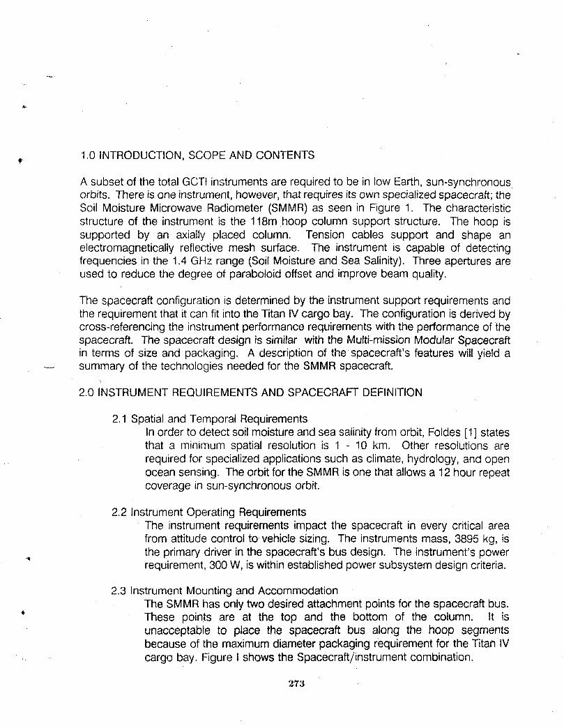
1.0 INTRODUCTION, SCOPEAND CONTENTSt"
A subset of the total GCTt instruments are required to be in low Earth, sun-synchronousorbits. There is one instrument, however, that requires its own specializedspacecraft; theSoil Moisture Microwave Radiometer (SMMR) as seen in Figure 1. The characteristicstructure of the instrument is the 118m hoop column support structure. The hoop issupported by an axially placed column. Tension cables support and shape anelectromagnetically reflective mesh surface. The instrument is capable of detectingfrequencies in the 1.4 GHz range (Soil Moisture and Sea Salinity). Three apertures areused to reduce the degree of paraboloid offset and improve beam quality.
The spacecraft configuration is determined by the instrument support requirements andthe requirement that it can fit into the Titan IVcargo bay. The configuration is derived bycross-referencing the instrument performance requirements with the performance of thespacecraft. The spacecraft design is similar with the Multi-mission Modular Spacecraftin terms of size and packaging. A description of the spacecraft's features will yield a
.-- summary of the technologies needed for the SMMR spacecraft.
2.0 INSTRUMENTREQUIREMENTSAND SPACECRAFTDEFINITION
2.1 Spatial and Temporal RequirementsIn order to detect soil moisture and sea salinity from orbit, Foldes [1] statesthat a minimum spatial resolution is 1 - 10 km. Other resolutions arerequired for specialized applications such as climate, hydrology, and openocean sensing. The orbit for the SMMR is one that allows a 12hour repeatcoverage in sun-synchronous orbit.
2.2 Instrument Operating RequirementsThe instrument requirements impact the spacecraft in every critical areafrom attitude control to vehicle sizing. The instruments mass, 3895 kg, isthe primary driver in the spacecraft's bus design. The instrument's power11
requirement, 300 W, is within established power subsystem design criteria.
2.3 Instrument Mounting and AccommodationThe SMMRhas only two desired attachment points for the spacecraft bus.These points are at the top and the bottom of the column. It isunacceptable to place the spacecraft bus along the hoop segmentsbecause of the maximum diameter packaging requirement for the Titan IV
- cargo bay. Figure I shows the Spacecraft/instrument combination.
273
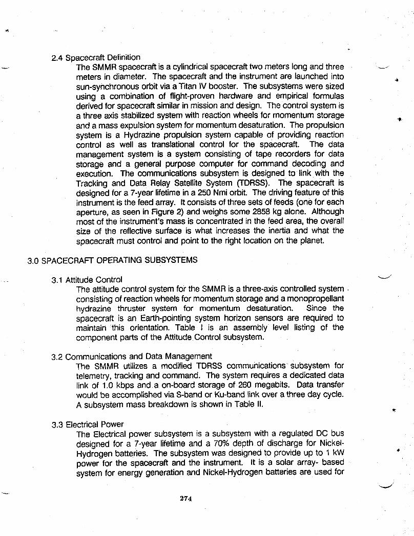
2.4 Spacecraft DefinitionThe SMMRspacecraft is a cylindrical spacecraft two meters long and three ---meters in diameter. The spacecraft and the instrument are launched into _,sun-synchronous orbit via a Titan IV booster. The subsystems were sizedusing a combination of flight-proven hardware and empirical formulasderived for spacecraft similar in mission and design. The control system isa three axis stabilized system with reaction wheels for momentum storageand a mass expulsion system for momentum desaturation. The propulsionsystem is a Hydrazine propulsion system capable of providing reactioncontrol as well as translational control for the spacecraft. The datamanagement system is a system consisting of tape recorders for datastorage and a general purpose computer for command decoding andexecution. The communications subsystem is designed to link with theTracking and Data Relay Satellite System (TDRSS). The spacecraft isdesigned for a 7-year lifetime in a 250 Nmi orbit. The driving feature of thisinstrument is the feed array. It consists of three sets of feeds (one for eachaperture, as seen in Figure 2) and weighs some 2858 kg alone. Althoughmost of the instrument's mass is concentrated in the feed area, the overallsize of the reflective surface is what increases the inertia and what thespacecraft must control and point to the right location on the planet.
3.0 SPACECRAFTOPERATINGSUBSYSTEMS
3.1 Attitude Control "-JThe attitude control system for the SMMRis a three-axis controlled system •consisting of reaction wheels for momentum storage and a monopropellanthydrazine thruster system for momentum desaturation. Since thespacecraft is an Earth-pointing system horizon sensors are required tomaintain :this orientation. Table l is an assembly level listing of thecomponent parts of the Attitude Control subsystem.
3.2 Communications and Data ManagementThe SMMR utilizes a modified TDRSS communications subsystem fortelemetry, tracking and command. The system requires a dedicated datalink of 1.0 kbps and a on-board storage of 260 megabits. Data transferwould be accomplished via S-band or Ku-band link over a three day cycle.A subsystem mass breakdown is shown in Table I1.
3.3 Electrical PowerThe Electrical power subsystem is a subsystem with a regulated DC busdesigned for a 7-year lifetime and a 70% depth of discharge for Nickel-Hydrogen batteries. The subsystem was designed to provide up to 1 kWpower for the spacecraft and the instrument. It is a solar array- basedsystem for energy generation and Nickel-Hydrogen batteries are used for
274

energy storage. The solar arrays are separated from the spacecraft busand placed at the top of the column in order to prevent shadowing of thearrays by the reflective mesh. Electrical cabling will then need to beprovided to the power handling systems on the spacecraft bus. Table Illshows a breakdown of the component parts of the electrical powersubsystem.
3.4 PropulsionThe Propulsion subsystem, as alluded to in the Attitude control subsystemdescription, is a monopropellant Hydrazine subsystem consisting of sixreaction control jets and two translational thrusters. Of all the subsystemson the spacecraft, this one is the only distributed subsystem. In thisparticular case, the attitude control thrusters are placed on the top andbottom of the column as well as on the hoop in order to utilize the largemoment arms afforded by the reflective mesh structure. Therefore, thereis a requirement to allow fuel lines and control lines to run from thespacecraft bus to the remote thrusters. A subsystem mass breakdown isshown JnTable IV.
4.0 SPACECRAFT PACKAGING
The tri-aperture SMMRis designed to fit into the Titan IVcargo bay. Foldes presents twomeans of meeting this requirement. The hoop is segmented and designed to fold
...... .... accordion-style around a telescoping column. This method of folding the reflectivesurface is employed in both packaging methods. The more challenging problem ispackaging the feed array structure to meet the Titan's cargo bay envelope. Again. Foldesdiscusses two ways of folding the feed structure, the end package and the wrap package.The end package requires that the feed structure be foldes and housed in a "box" placedat the end of the telescoping column. The wrap package indicates that the feed structureis wrapped around the reflective surface package (the stowed hoop and column).Because of the spacecraft's position on the instrument structure (at the end of thecolumn. The end package method is eliminated. Thus, the packing scheme utilized isthe wrap package for the feed structure, the hoop iscollapsed onto a telescoping columnand the spacecraft is attached to the end of the column. This is shown in Figure 3. Asseen in the figure, the spacecraft/instrument system does fit within the Titan's payloadbay.
* 5.0 Spacecraft Mass Summary
The total spacecraft mass summary is shown in Table V. The overall mass of thespacecraft/instrument system is 5827 kg. These estimates are based on actual flight
"_ hardware mass valuesand empirical relationships relatingcapabilitiesmasses of previousspacecraft in this class and.their associated subsystems to the predicted performanceand mass of future spacecraft. This mass is well within the Titan's payload carrying
27,5
capabilities. The propellantis sized for a 7-year lifetimeand includespropellantforattitudecontrol and stationkeeping.Thestructureandthe thermalcontrol valueswere _-_estimatedusing the empiricalrelationshipsdescribedabove. .
6.0 SpacecraftTechnologyRequirements
Thetechnologiesusedto sizethe spacecraftbus and its supportingsubsystemsare basedon currentflight-readyand flight-provenhardware[2]. The improvementsintechnology in the various subsystem disciplines could only help to increase theperformanceof the spacecraft. The instrumentutilizesstate-of-the-artmaterialsin itsreflectivemeshandsupportstructures. Improvementscan berealizedinthe feedarraysand its electronicsin order to drivethe weightdownto a more reasonablelevel. ThereJsneedto further study deploymentmethodologiesfor the reflectivemesh structure inorderto understandthe dynamicsassociatedwith the unfurlingof sucha largestructurewith distributedutility lines.
BIBLIOGRAPHY,
1. Foldes, Peter. A Design Study For the Use of a Multiple Aperture DeployableAntenna for Soil Moisture RemoteSensingSatelliteApplications, NASAContractor Report178154, August, 1986.
2. Aerospace Corporation. Systems Cost/Performance Analysis Final Report.Aerospace Report No. ATR-75(7363),March, 1975. "J
276
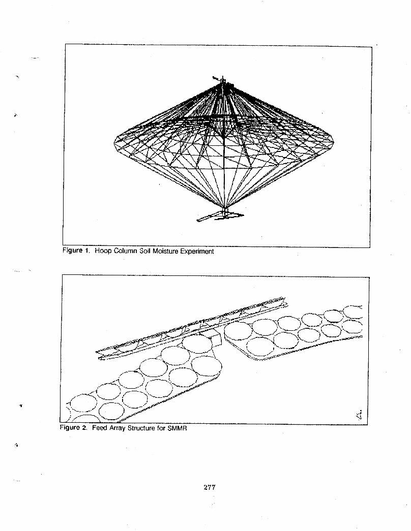
Figure 1. Hoop Column Soil Moisture Experiment
277

_r
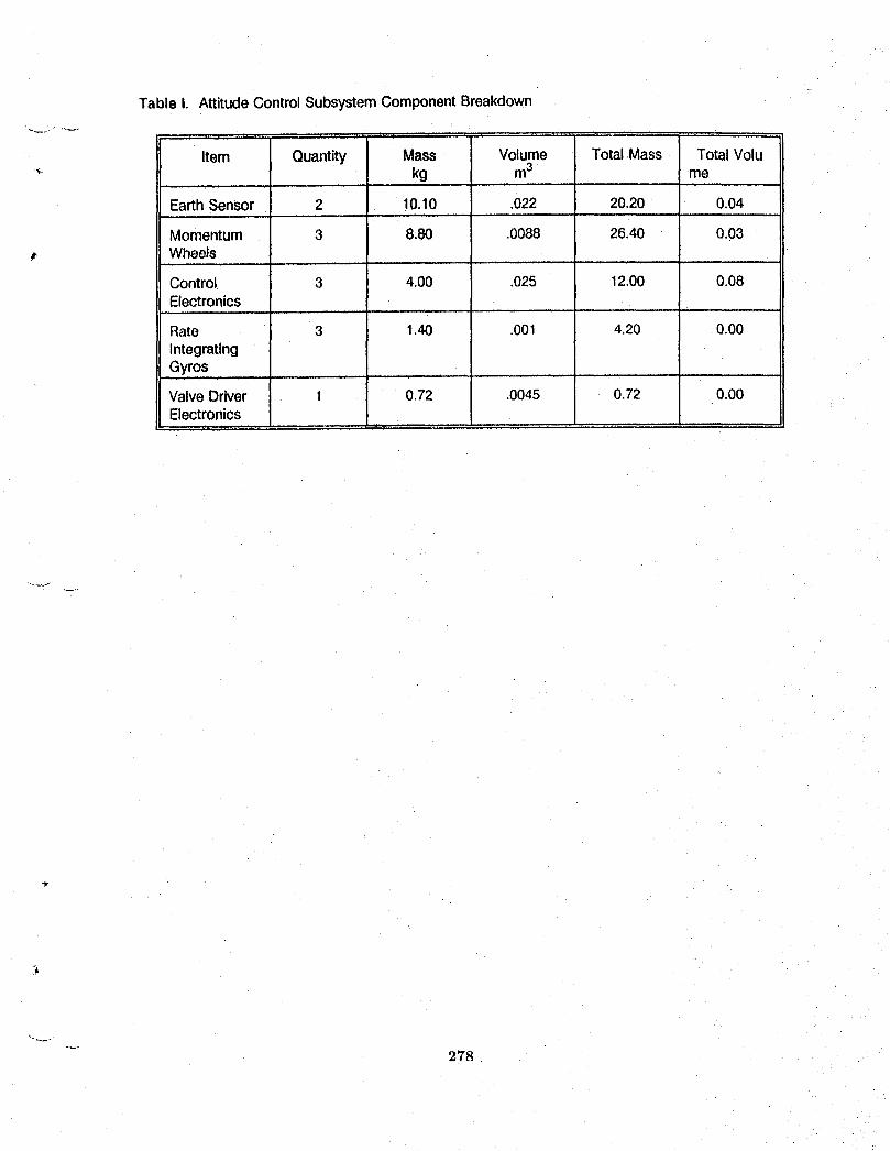
Table I. AttitudeControlSubsystemComponentBreakdown
Item Quantity Mass Volume Total.Mass TotalVolukg m3 me
Earth Sensor 2 10.10 .022 20.20 0.04
Momentum 3 8.80 .0088 26.40 0.03Wheels
Control 3 4.00 .025 12.00 0.08Electronics
Rate 3 1.40 .001 4.20 0.00
Integrating
-Gyros ............. I 'Valve Driver 1 0.72 .0045 0.72 0.00Electronics
278
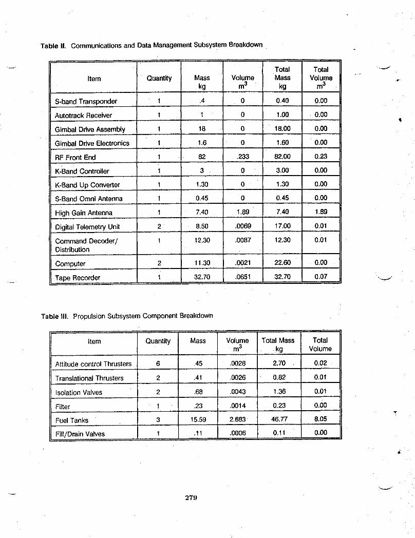
Table I1. Communicationsand Data ManagementSubsystemBreakdown
, , • ,, ,,
-- Total Total
Item Quantity Mass Volume Mass Volume ,.kg m3 kg m3
, , , , ,, , ...... , .,
S-bandTransponder 1 .4 0 0.40 0.00
AutotrackReceiver 1 1 0 1.00 0.00
GlmbalDriveAssembly 1 18 0 18.00 0.00
GimbalDriveElectronics 1 1.6 0 1.60 0.00
RF Front End 1 i 82 .233 82.00 0.23, ,. ,,,,
K-BandController 1 3 0 3.00 0.00
K-BandUp Converter 1 1.30 0 1.30 0.00
S-BandOmni Antenna 1 0.45 0 0.45 0.00
High GainAntenna 1 7.40 1.89 7.40 1.89
DigitalTelemetryUnit 2 8.50 .0069 17.00 0.01
CommandDecoder/ 1 12.30 .0087 12.30 0.01Distribution
I Computer 2 1130 .0021 22.60 0.00
Tape Recorder 1 32.70 .0651 32.70 0.07 ..._i
Table III. PropulsionSubsystemComponentBreakdown
Item Quantity Mass Volume Total Mass Totalm3 kg Volume
, , ,,, ,
Attitude control Thrusters 6 .45 .0028 2.70 0.02
Translational Thrusters 2 .41 .0026 0.82 0.01
Isolation Valves 2 .68 .0043 1.36 0.01
Filter 1 .23 .0014 0.23 0.00,w
Fuel Tanks 3 15.59 2.683 46.77 8.05
Fill/Drain Valves 1 .11 .0006 O.11 0.00
,€
279
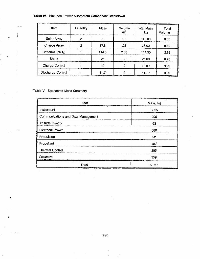
Table IV. Electrical Power Subsystem Component Breakdown
, ., , . ... .,,
...... Item Quantity Mass Volume Total Mass Totalm3 kg Volume
"_ Solar Array 2 70 1.5 140.00 3.00
Charge Array 2 17.5 .25 35.00 0.50
Batteries (NiH2) 1 114.3 2.86 114.30 2.86
Shunt 1 25 .2 25.00 0.20
Charge Control 1 10 .2 10.00 0.20
Discharge Control 1 41.7 .2 41.70 0.20
Table V. Spacecraft Mass Summary
Item ' Mass, kg
Instrument 3895
Communications and Data Management 200
Attitude Control 63
...... •. Electrical Power 366
Propulsion 52
Propellant 487, , , .,,
Thermal Control• 205
Structure 559
Total 5,827, ,, , , , , ,
280

_im,-
GEOSTATIONARY ORBIT EARTH SCIENCE PLATFORMCONCEPTS FOR GLOBAL CHANGE MONITORING
,y-
Jeffery T. Farmer, Thomas G. Campbell and William T, DavisNASA Langley Research Center
Paul A. Garn and Charles B. KingThe Bionetics Corporation
Cheryl C. JacksonFlight Mechanics and Control, Inc.


1.0 Introduction and ScopeFunctionality of a geostationary spacecraft to support Earth science regional
process research has been identified in reference 1. Most regional process studies, require high spatial and temporal resolution. These high temporal resolutions are on
the order of 30 minutes and may be achievablewith instruments positioned in ageostationary orbit. Reference 1 has identified a compliment of typical existing or nearterm instruments to take advantage of this altitude. This paper lists this set of
, instruments, discusses the requirements these instruments impose on a spacecraft,then presents a brief description of the geostationary spacecraft concepts whichsupport these instruments.
2.0 Instruments and RequirementsThefollowing instruments were identified in reference 1 as representative of the
types of Earth science instruments which could be employed on a geosynchronousspacecraft for regional process studies. The name of each instrument is given alongwith its measurable and proposed spatial resolution (temporal resolutions were allapproximately 30 minutes) as well as its mass and power requirements in Table I.
Table I. Instrument List
Name Measurable Spatial Mass PowerResolution kg W
km
•.. ACRIM solar radiation sun disk 24 5
GERS Earth radiation 40 110 90
GOESI surface temperatures, 1-8 118 130wind speed
IRVS air temperatures, 5-10 150 150trace gases
OZMAP ozone levels 43 100 130
GMODIS clouds,biomass 0.5 230 50
GHRMR-a ... H20 profiles 10 2417 370
GHRMR-b H_O profiles 25 1947 296" where the full names of the instruments are:
ACRIM - Active Cavity RadiometerGERS -Geostationary Earth Radiation SensorGOES - GOES ImagerIRVS - Infrared Vertical SounderOZMAP - Ozone MapperGMODIS - Geostationary Moderate Resolution Imaging SpectrometerGHRMR - Geostationary High Resolution Microwave Radiometer
283
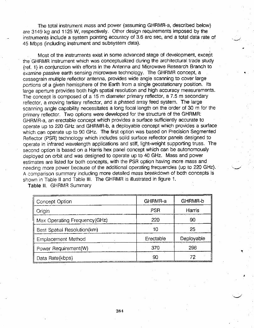
The total instrument mass and power (assuming GHRMR-a,described below)are 3149 kg and 1125 W, respectively. Other design requirements imposed by the
- instruments include a system pointing accuracy of 3.6 arc sec, and a total data rate of __.i45 Mbps (including instrument and subsystem data).
w
Most of the instruments exist in some advanced stage of development, exceptthe GHRMR instrument which was conceptualized during the architectural trade study(ref. 1) in conjunction with efforts in the Antenna and Microwave Research Branch toexamine passive earth sensing microwave technology. The GHRMR concept, a *cassegrain multiple reflector antenna, provides wide angle scanning to cover largeportions of a given hemisphere of the Earth from a single geostationary position. Itslarge aperture provides both high spatial resolution and high accuracy measurements.The concept is composed of a 15 m diameter primary reflector, a 7.5 m secondaryreflector, a moving tertiary reflector, and a phased array feed system. The largescanning angle capability necessitates a long focal length on the order of 30 m for theprimary reflector. Two options were developed for the structure of the GHRMR:GHRMR-a, an erectable concept which provides a surface sufficiently accurate tooperate up to 220 GHz and GHRMR-b, a deployable concept which provides a surfacewhich can operate up to 90 GHz. The first option was based on Precision SegmentedReflector (PSR)technology which includes solid surface reflector panels designed tooperate in infrared wavelength applications and stiff, light-weight supporting truss. Thesecond option is based on a Harris hex panel concept which can be autonomouslydeployed on orbit and was designed to operate up to 40 GHz. Mass and powerestimates are listed for both concepts, with the PSR option having more mass andneeding more power because of the additional operating frequencies (up to 220 GHz). ..._.,..A comparison summary including more detailed mass breakdown of both concepts isshown in Table II and Table II1. The GHRMR is illustrated in figure 1.
Table II. GHRMR Summary
Concept Option GHRMR-a GHRMR-b
Origin PSR HarrisI
Max Operating Frequency(GHz) 220 90
Best Spatial Resolution(km) 10 25
Emplacement Method Erectable Deployable
Power Requirement(W) 370 296 .,,_.
Data Rate(kbps) 90 72
284
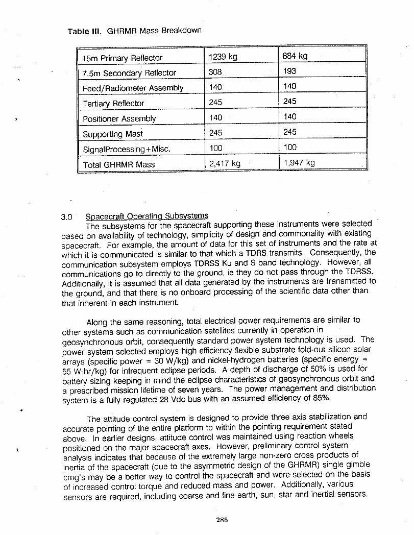
Table III. GHRMR Mass Breakdown
,. , r ........
15m Primary Reflector 1239 kg 884 kg
7.5m Secondary Reflector 308 193
Feed/Radiometer Assembly 140 140
Tertiary Reflector 245 245
- Positioner Assembly 140 140
Supporting Mast 245 245
SignalProcessing+Misc. 100 100
Total GHRMR Mass 2,417 kg 1,947 kg
3.0 Spaceoraft Operating SubsystemsThe subsystems for the spacecraft supporting these instruments were selected
based on availability of technology, simplicity of design and commonality with existingspacecraft. For example, the amount of data for this set of instruments and the rate atwhich it is communicated is similar to that which a TDRS transmits. Consequently, thecommunication subsystem employs TDRSSKu and S band technology. However, allcommunications go to directly to the ground, ie they do not pass through the TDRSS.Additionally, it is assumed that all data generated by the instruments are transmitted tothe ground, and that there is no onboard processing of the scientific data other thanthat inherent in each instrument.
Along the same reasoning, total electrical power requirements are similar toother systems such as communication satellitescurrently in operation ingeosynchronous orbit, consequently standard power system technology is used. Thepower system selected employs high efficiency flexible substrate fold-out silicon solararrays (specific power = 30 W/kg) and nickel-hydrogen batteries (specific energy =55 W-hr/kg) for infrequent eclipse periods. A depth of discharge of 50°,/ois used forbattery sizing keeping in mind the eclipse characteristics of geosynchronous orbit anda prescribed mission lifetime of seven years. The power management and distributionsystem is a fully regulated 28 Vdc bus with an assumed efficiency of 85%.
The attitude control system is designed to provide three axis stabilization andaccurate pointing of the entire platform to within the pointing requirement statedabove. In earlier designs, attitude control was maintained using reaction wheels
,_ positioned on the major spacecraft axes. However, preliminary control systemanalysis indicates that because of the extremely large non-zero cross products ofinertia of the spacecraft (due to the asymmetric design of the GHRMR) single gimblecmg's may be a better way to control the spacecraft and were selected on the basisof increased control torque and reduced mass and power. Additionally, varioussensors are required, including coarse and fine earth, sun, star and inertial sensors.
285
The propulsion system serves to desaturate the reaction wheels or cmg's andto provide station keeping and station repositioning (changing of longitude) which is
.... mandated by the requirement to cover different regions of the Earth. Electrothermal .-_..monopropellant hydrazine (isp=230 sec) was used as the fuel. The system iscomposed of the three tanks of hydrazine and three of nitrogen (pressurant), anassortment of thrusters including eight 2.2 N thrusters for station keeping and orbitrepositioning and four 0.44 N thrusters for cmg desaturation plus the necessary fluidlines and control electronics.
It
The spacecraft structure is dominated by that which supports the GHRMR. Thelarge diameter reflectors are composed of solid precision surface panels supported bygraphite composite tetrahedral trusses for the PSRoption and other types offramework for the Harris option. The reflectors and feed array are separated by adeployable pac truss concept also made of graphite composites. Preliminarystructural analysis attests to the integrity of the structures. These trusses are alsoassumed to be sufficientlythermally insulated to reduce excessive thermal distortions.Finally,the structure supporting the spacecraft bus and the other instruments iscomposed of graphite/aluminum honeycomb and integrated Iouvered radiators on acomposite frame. This combination provides sufficient structural support and thermaltransport and rejection capability.
4.0 Spacecraft ConfigurationsThe GHRMR strongly influences the configuration of the spacecraft in that its
large size and offset parabolic design as well as its viewing requirements greatly limitthe placement of the other instruments and the spacecraft bus. Additionally, its large ..__..size also drives the attitude control system which then influences the power system aswell as other subsystems. Also, complex assembly of the GHRMR may drive theconfiguration. To address these effects of the GHRMR,two alternative types ofconfigurations were conceptualized. The first configuration (called GEO1) is a singlespacecraft supporting all instruments including the GHRMR. The second configuration(called GEO2) is a pair of deployable spacecraft: one supporting only the GHRMR(G1) and the other (G2) supporting all remaining instruments. The two configurationswere examined to identify any advantages in mass, power, launch volume, andcomplexity and to surface any other imPortant issues.
A comparison of total spacecraft mass and power can be made by examiningTable IVwhich shows mass and power estimates for two GEO1designs (eachsupports a different GHRMR option) and one GEO2 design supporting the HarrisGHRMR and the remaining instruments separately on a pair of spacecraft, G1 and G2. ,_These estimates are broken up into payload mass and power and spacecraft busmass. Note that the payload to spacecraft mass fraction for the spacecraft carryingthe GHRMR are more favorable than that of spacecraft G2, whose mass fraction iscloser to historical trends. The high mass fraction is a result of the large mass of ,GHRMR instrument (concentrated primarily in the structural components) compared tothe relativelysmall requirements it places on the spacecraft subsystems.
286
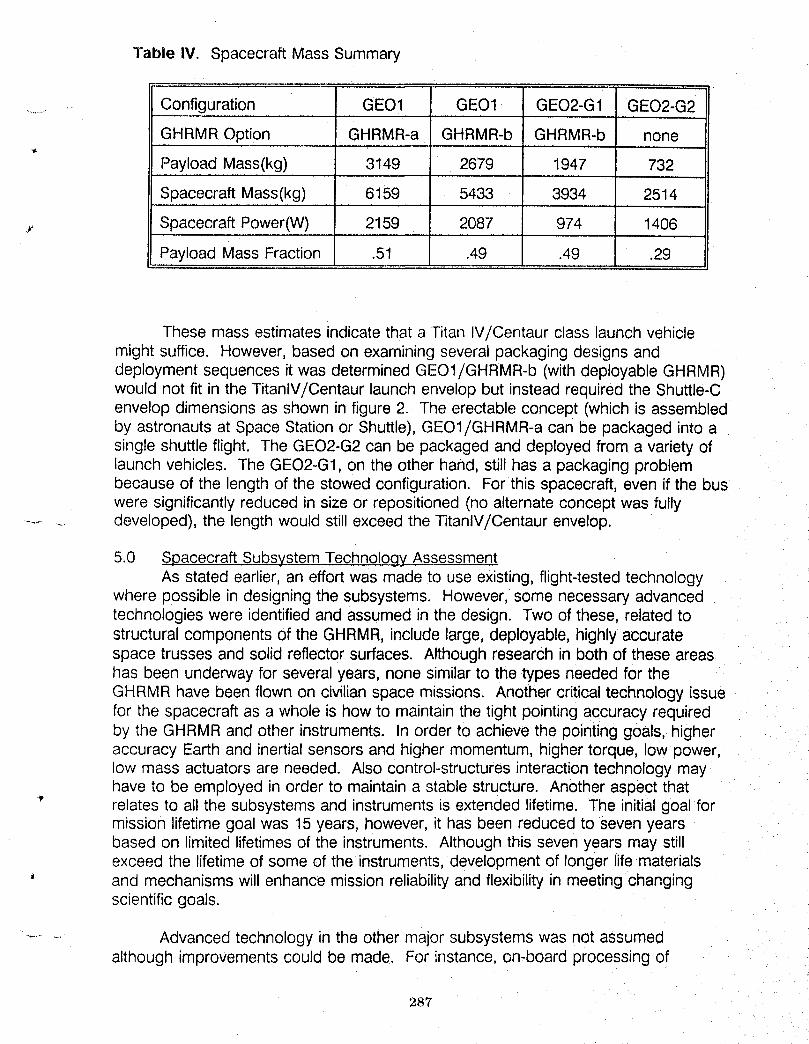
]'able IV. Spacecraft Mass Summary
....... Configuration GEO1 GEO1 GEO2-G1 GEO2-G2
GHRMR Option GHRMR-a GHRMR-b GHRMR-b none..... , ........ ,, ,,
Payload Mass(kg) 3149 2679 1947 732
Spacecraft Mass(kg) 6159 5433 3934 2514
, Spacecraft Power(W) 2159 2087 974 1406
Payload Mass Fraction .51 .49 .49 .29
These mass estimates indicate that a Titan IV!Centaur class launch vehiclemight suffice. However, based on examining several packaging designs anddeployment sequences it was determined GEO1/GHRMR-b (with deployable GHRMR)would not fit in the TitanlV/Centaur launch envelop but instead required the Shuttle-Cenvelop dimensions as shown in figure 2. The erectable concept (which is assembledby astronauts at Space Station or Shuttle), GEO1/GHRMR-a can be packaged into asingle shuttle flight. The GEO2-G2can be packaged and deployed from a variety oflaunch vehicles. The GEO2-G1,on the other hand, still has a packaging problembecause of the length of the stowed configuration. For this spacecraft, even if the buswere significantly reduced in size or repositioned (no alternate concept was fully
....... developed), the length would still exceed the TitanlV/Centaur envelop.
5.0 Spacecraft SubsystemTechnology AssessmentAs stated earlier, an effort was made to use existing, flight-tested technology
where possible in designing the subsystems. However, some necessary advancedtechnologies were identified and assumed in the design. Two of these, related tostructural components of the GHRMR, include large, deployable, highly accuratespace trusses and solid reflector surfaces. Although research in both of these areashas been underway for several years, none similar to the types needed for theGHRMR have been flown on civilian space missions. Another critical technology issuefor the spacecraft as a whole is how to maintain the tight pointing accuracy requiredby the GHRMR and other instruments. In order to achieve the pointing goals, higheraccuracy Earth and inertial sensors and higher momentum, higher torque, low power,low mass actuators are needed. Also control-structures interaction technology mayhave to be employed in order to maintain a stable structure. Another aspect that
" relates to all the subsystems and instruments is extended lifetime. The initial goal formission lifetime goal was 15 years, however, it has been reduced to seven yearsbased on limited lifetimes of the instruments. Although this seven years may stillexceed the lifetime of some of the instruments, development of longer life materials
' and mechanisms will enhance mission reliability and flexibility in meeting changingscientific goals.
........ Advanced technology in the other major subsystems was not assumedalthough improvements could be made. For instance, on-board processing of
287
scientific data will help to reduce communication needs and improve calibration and synchronization of data from the various instruments providing better overall - measurements. lmproverrients in solar cell technology and battery lifetime and energy
d
density and utilization of higher voltages could reduce weight and increase reliability. Finally, higher specific impulse fuels or application of ion propulsion would help reduce C
the mass of propellant and tankage needed on orbit and development of an orbit transfer vehicle would provide an alternative means to achieve to geostationary altitude which might alleviate packaging problems and launch vehicle constraints.
'4
BIBLIOGRAPHY
Hypes, et. al. Selection of Representative Instruments for the Global Change Technology Initiative Architecture Trade Study, January, 1990.
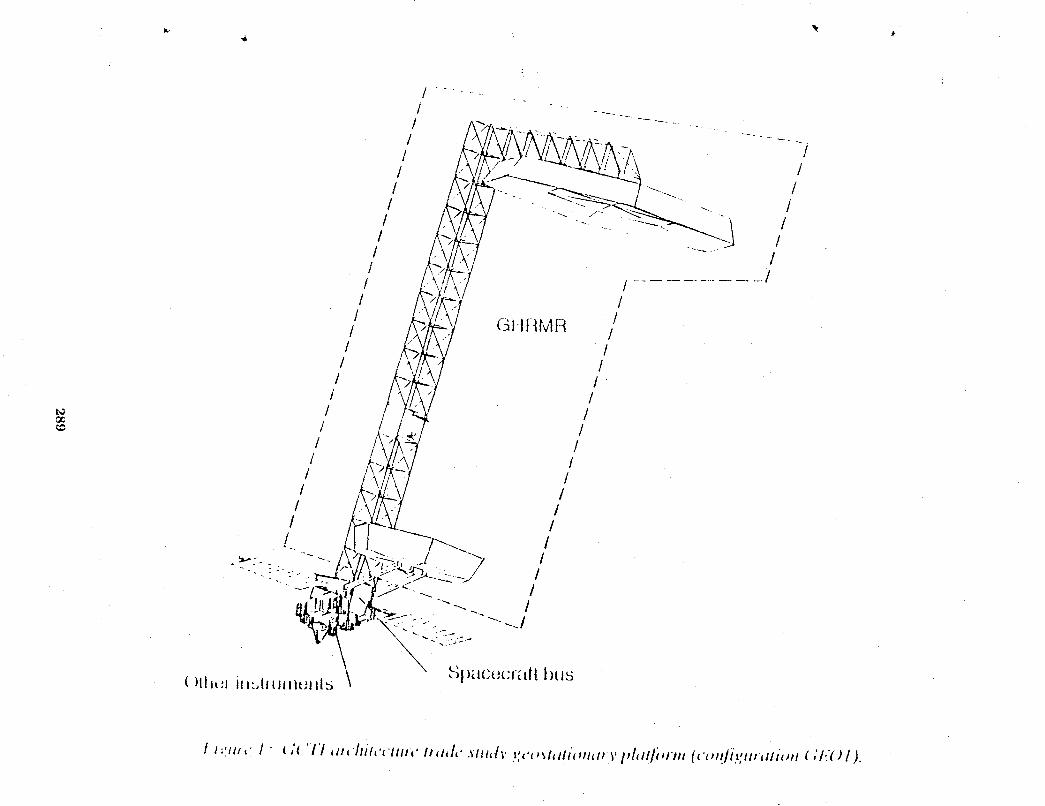
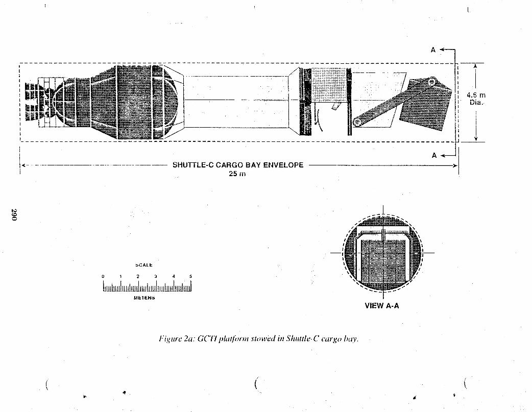
t_
!
_CALI.. I I\ +,
0 1 2 3 4 5
l_lHh_HIt_l_LHhi_,t_hHilJtidmtll=dMETEH_
VIEWA-A
t.'i,_,re 2a: GC77 i_lat/'orm stowed in Shuttle-C cargo bay.
( (
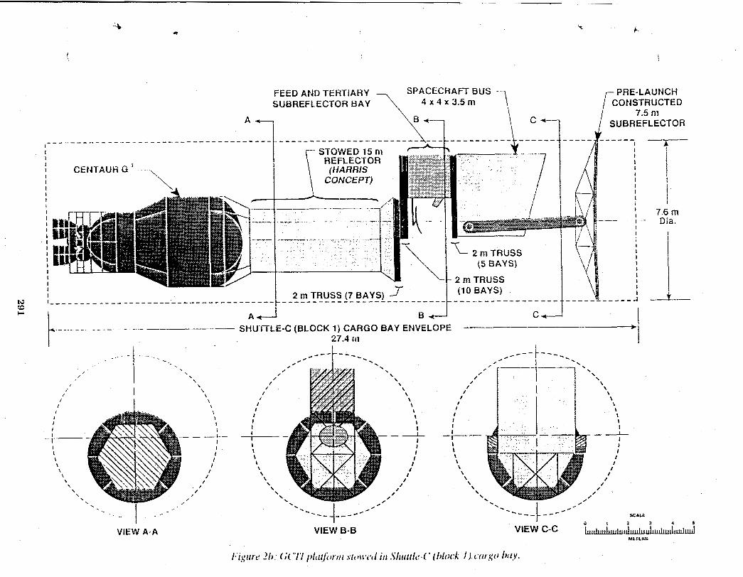
FEED AND TERTIARY SPACECRATT BUS PRE-LAUNCH SUBREFLECTOR BAY
7.5 nl SUBREFLECTOR
I 1 REFLECTOR
1 I I I
I I i i - - - - - - - - - - - - - - - - - - - - - - - - - - - - - - - - - - - - -
_ _ _ _ . _ _ - ______- SHUTTLE-C (BLOCK 1) CARGO BAY ENVELOPE - -
27.4 III
7.6 m Dia.
- 1 . . VlEW A-A
i VlEW 8-8
I
VlEW C-C


OPTIONS IN THE GLOBAL CHANGE FLEET ARCHITECTUREPROVII)ED BY THE PRESENCE OF AN Eos-A AND -B
Warren D. HypesThe Bionetics Corporation
Rogard T. RossJoint Institute for Advancement of Flight Services

i •
INTRODUCTION
The baseline architecture of the GCTI fleet was established by selecting and designing
spacecraft and instruments to meet the science requirements developed under the Task 1 effort.
While attempting to meet the temporal sampling portion of the science requirements, no
consideration was given to the presence of the prolx)sed Earth Observing System (Eos) SpacecraftvP
that would be making m_myof the same measurements with many of the same instruments. After
establishing the GCT! baseline independent of the Eos Spacecraft, however, it is now prudent to
examine the impact of the presence of the Eos Spacecraft on the GCTI fleet. A small scope, GCTI
Study supplement was accomplished to assess the impact. The content and results of the
supplementary study are the subject of this white paper.
OBJECTIVE
The objectiveof this study is to determinethe impactof consideringan operationalEosA
and B upon the two options of the proposedGCTI fleet.
ASSUMPTIONS
The followingassumptionsapply to the study:
1. Eos-A and Eos-B are operational. Both are in the same sun-synchronousorbit at an
attitudeof 705 km with a crossing timeof 1330hours. The instrumentcomplementsare those
presentedon the Santa BarbaraResearchCenterchart#90527dated May 1989and titled, Earth
ObservingSystem (Eos).
,, 2. TheGCTI Spacecraftand instrumentcomplementsare those selectedduring the GCTI
ArchitecturalTradeStudy. They arereproducedin Table 1.
295
3. The GCq'I science requirements, including the spatial _esolutions and temporal sampling
frequencics, arc aplfiicablc.
ANALYSIS
The instrument complement for tile Eos-A spacecraft is presented in "Fable2. The Table
also includes instruments on G(TI'I spacecraft B, C, D, and E that are the same instruments as
those on Eos-A. The instrument complement for dm Eos-B spacecraft is presented in Table 3. The
table also includes instruments on GCTI spacecraft B and E that are the same instruments as those
on Eos-B. Table 4 lists the G(SI'I instruments that are not included on either the Eos-A or Eos-B
spacecraft. These compm'ative instrument lists provide the baseline for the following analysis.
Two of tile G(?'I'! spacecraft, or the specific use of the sp;icccrafl. _lv'csignificantly differenl
from the Eos spacecraft to the extent that the pres_:.'nceor absence of the Eos spacecraft have little
impact on the GCTI fleet. G(_'I spacecraft A is a special purpose spacecraft dedicated to a single
Soil Moisture Microwave Radiometer (SMMR) instrument. Eos does not include a comparable
instrument. The GCTI Architecture must, therefore, h_cludespacecraft A with the SMMR "-J
instrument. GCq"I spacecraft G1 or G2 arc Geostationary spacecraft with specific Geo
instruments. Eos concepts do not include comparable instruments, therefore, the GCTI
Architecture must include spacecraft G 1 on tile two part G2.
296
With the alx)ve spacecraft and instruments excluded from this G_.FI Study supplement
(they must be included in the G(_'I Architecture regardlessof the presence or absence of Eos), the
" isstie now becomes the relationship between the two Eos spacecraft and GCTI spacecraft B, C, D,
and E of Option 1 or GCTI spacecraft Li, 112,L3, and L,tof Option 2 along with their respective
) instrument complements.
GCTI Option 1Constellationfor 3-HourCoverage:
SinceGCTI and Eos spacecraftare in similar polar, sun-synchronousorbits instruments
that are the sameon GCTI and Eos spacecraftcan make comparablemeasurements. In thesecases
thereis no reason to duplicatethe Eosinstrumentson GCTI spacecraftexcept where neededto
meet the GCTI temporalsciencerequirements.TheGCTI architecturerequiresone spacecraftB.
Eos-Aincludes all of the GCTI spacecraftB instrumentsexcept ACRIM,SOLSTICE,XRI, and
3chMR. The ACRIM instrumenton spacecraftB fulfillstheGCTI sciencerequirementto measure
spectralradiation(total solar irradiance- fulldisk)with a temporalrequirementof 1-Day.
SpacecraftD, however,includesan ACRIMinstrumentas a complementto the CERESRadiation
Budget instrumentand this ACRIMcan make therequiredmeasurements.TheACRIM instrument
on spacecraftB can be deleted. The SOLSTICEand XRI instrumentson spacecraftB are not
requiredby GCTI sciencerequirements. Theywere includedto makea complementary
measurement(solar UV irradiance- fulldisk) to the total irradianceof the ACRIMinstrument. The
Eos programplaces the ACRIMand SOLSTICEon a spacestationattachedpayloadsince the solar
viewingmodeeliminatedthe Earthorbit track and the temporalsamplingfrequencyas prime
. considerations. There is no reason why thisarrangementwould not sufficefor meeting theGCTI
sciencerequirements. The XRIcan also be added to theatachedpayload. Theremaining
spacecraftB instrumentto be accountedfor is the 3 ch MR. Again,this instrumentwas added as a
297

supplement, it assists in thecalihrationof the ALT instrument&ita. There is an ALl"on Eos-A
and, althoughnot knownfor certainty,it is likely to includea 3 ch MRor elseother instrumentsin
the Eos-A complementprovide the neededdata. It is assumedwith confidencethatthe,It
arrangementthatEos-A has for theALT instrumentis adequate. In summary,with Eos-A and B
present,GCTI spacecraftB can be eliminatedalthoughit requiresa reasonableredistributionof
ACRIM, SOLSTICE, XRI, and 3 Ch MR.
The GCTI spacecraftC is configuredto meet the3 to 12-hourtemporalmeasurablesof the
GCTI science requirements. It includesonly threeinstruments(APL,SAGE llI, EOSP), two of
which are included on Eos-A. Only the new conceptatmospherepressurelidar (APL) is not
includedon an Eos platform. Thus,GCTI spacecraftC could be eliminatedif some way of
accommodatingthe APLinstrumentis found. This potentialaccommodationhasnot been worked
in detail,but theGCTI spacecraftdesign personnelstatethat it is a possibilitythat one SpacecraftD
couldbe reconfiguredto includeAPLalthoughthereconfigurationwouldbe extensiveinscope.
The GCTI SpacecraftD is configuredto meetthe 1to 3-hourtemporalmeasurementsof the
GCTI sciencerequirements. Duringthe basicGCTI architecturestudy,it wasconcludedthat the 1- "--J
hour temporalrequirementplacedexcessivedemandson the GCTIfleet and thatthe 3-hour
temporal requirementwas reasonable. Withpolar, sun-synchronousspacecraftsuch as Eos-A and
B and GCTI spacecraftB, C, D, and E, a 3-hour temporalcycle can be met with four spacecraft.
The Eos-Aspacecraftincludesallof the instrumentson GCTIspacecraftD with theexceptionof
the ACRIM instrument;thus, exceptfor ACRIM,Eos-Awill replaceone of the GCTI spacecraft
D's. With three remainingGCTI spacecraftD's with an ACRIMinstrumentand the possibilityof
ACRIM and SOLSTICEalso flyingon thespace stationattachedpayloads,the loss of one ACRIMj,
is not consideredto be a major problem. In summary,the Eos-Aspacecraftwill replaceone of the
GCTI spacecraftD's leaving threeof theD's. Three of thefour spacecraftwill include an ACRIM.
298
The GCTI spacecraft E is configured to meet the stratosphericand tropospheric gases and
wind measurements of the GCTI science requirements except, as previously stated, only a 3-hour
temporal coverage for both Regional Process and Global Change Studies was used to drive the
recommended architecture. "['heEos-A and Eos-B spacecraft include all of the instruments on
_, GCTI spacecraft E. Therefore, the Eos spacecraft will replace one of the GCTI spacecraft E's
leaving the requirement of three GCTI spacecraft E's to meet the 3-hour temporal target.
The Eos-A and B spacecraft do not include any of the instruments on the GCTI spacecraft
G1 or G2. In addition, the orbits are not comparable since the Eos spacecraft are planned for LEO
operations while the GCT! spacecraft G's are planned for Geostationary operation. Thus, either
the G1 or G2 selection for the GCTI architectural fleet will be needed regardless of the presence or
absence of the Eos spacecraft.
GCTI Option 2 - Platformsfor 3-HourCoverage:
As presentedon Table 1thereare someelementsof theGCTI Option2 architecturethat are
the sameas in theOption 1architecture. As in Option 1,Option2 includesthe GC'rl spacecraftA
dedicatedto the SMRR instrumentin LEO. Option2 'alsoincludesthesamegeostationary
spacecraftthat are in theOption 1architecture. As in Option1, thepresenceor absenceof the Eos
spacecraftdoes not impacteither theLEO SpacecraftAor theGEO spacecraftG1/G2elementsof
Option 2. They continueto be neededto fulfillthe sciencerequirementsof theGCTI study. The
remainingGCTI spacecraft- B, C, D, and E - and their instrumentcomplementsvary significantly
between Options 1and 2.
In Option2 the instrumentcomplementsof GCTI spacecraftB, C, D, and E are assembled
onto four large platforms,threeof whichare configuredto achieve the target 3-hourtemporal
coverage, and the fourth (L1)configuredto meet a 12-hourtemporalcoverageas well as the 3-hr
299
coverage. The combined instrument complements of Eos-A and B include all of the instruments
on GCTI spacecraft B, C, D, and E except for ACRIM, SOLSTICE, 3chMR, and APL. With the
exception of the four instruments, the impact of Eos-A and B on the GCTI architecture would be "-J
that one of the three GCTI Titan IV launched platforms I-.2,I-,3,or I-,4could be eliminated but L1
must remain. The remaining GCT! platforms and tile combined Eos A and B could then be time
sequenced to provide the required temporal coverage.
It is now important to consider the impact of the four GCTI instruments missing from the
combined Eos-A and B complements. One scenario is to leave the four platforms, three GCTI
platforms and the two spacecraft Eos platform, with their current instrument complements. The
loss of one of the I-,2,1,3,or 1,4ACRIM instruments results in one of the 3-hour CERES
measurements not having the ACRIM suplxm data. The absence of the SOLSTICE from Eos will
not have an impact since SOLSTICE is a support instrument to ACRIM for the solar speclral
radiation measurement required once a day. The GCTI Lx large spacecraft with an ACRIM and
SOLSTICE meets the requirement. The same analysis is applicable to the absence of the 3 Ch MR.
It is a support instrument for the ALT instrumentrequired once]12-hours and can be met by the ....-J
GCTI I.,1spacecraft. The APL instrument makes the surface pressue measurement on a 12-hour
cycle. Again, the GCTI Lx spacecraft meets this requirement. Thus, the only effect of the four
instruments missing from the Eos spacecraft is that the ACRIM support data for one of the four
CERES instruments will be missing. In a second scenario, if the ACRIM and SOLSTICE
instruments axe placed on the space station attached platforms as described in the Option 1
discussion and the ACRIM measurement can suffice for supporting the CERES on Eos, there is no
impact on temporal sampling of four GCTI instruments missing from the combined Eos A and B
complements.
• -,o,.
300
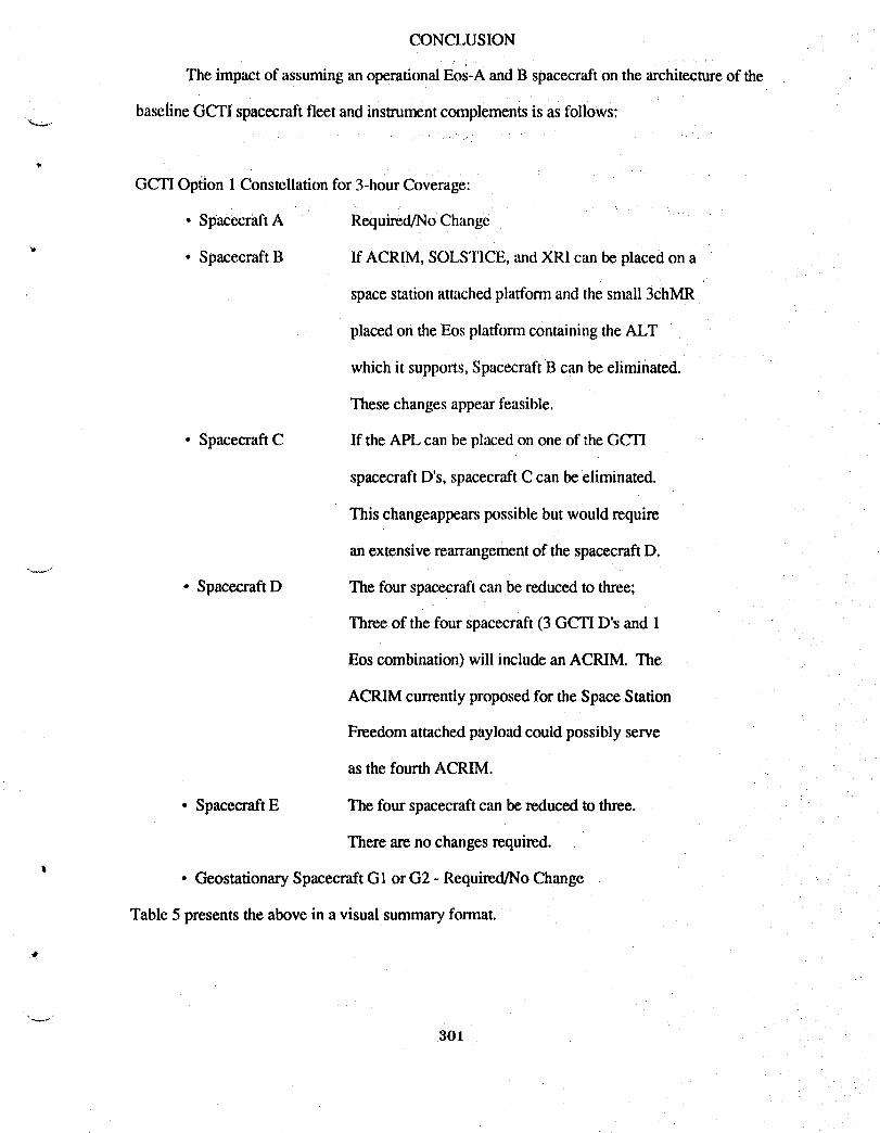
CONCLUSION
The impactof assuminganoperationalEos-Aand B spacecrafton the architectureof the
baselineGCTI spacecraftfleet and instrumentcomplementsis as follows:
GCTI Option 1Constellationfor 3-hourCoverage:
• SpacecraftA Required/NoChange
• SpacecraftB If ACRIM, SOLSTICE,and XRI can be placedon a
spacestationattachedplatformand thesmall 3chMR
placedon theEos platformcontainingtheALT
which it supports,SpacecraftB can be eliminated.
Thesechangesappearfeasible.
• SpacecraftC If the APLcan be placed on one of the GCTI
spacecraftD's, spacecraftC can beeliminated.
This changeappearspossiblebut would require
an extensiverearrangementof the spacecraftD,
• SpacecraftD The fourspacecraftcan be reducedto three;
Threeof the four spacecraft(3 GCTID's and 1
Eos combination)will includean ACRIM. The
ACRIMcurrentlyproposedfor the SpaceStation
Freedomattachedpayloadcouldpossiblyserve
as the fourth ACRIM.
• SpacecraftE The fourspacecraftcan be reduced to three.
Thereare no changesrequired.
• GeostationarySpacecraftG1 or G2 - Required/NoChange
Table 5 presentsthe above in a visual summaryformat.
301
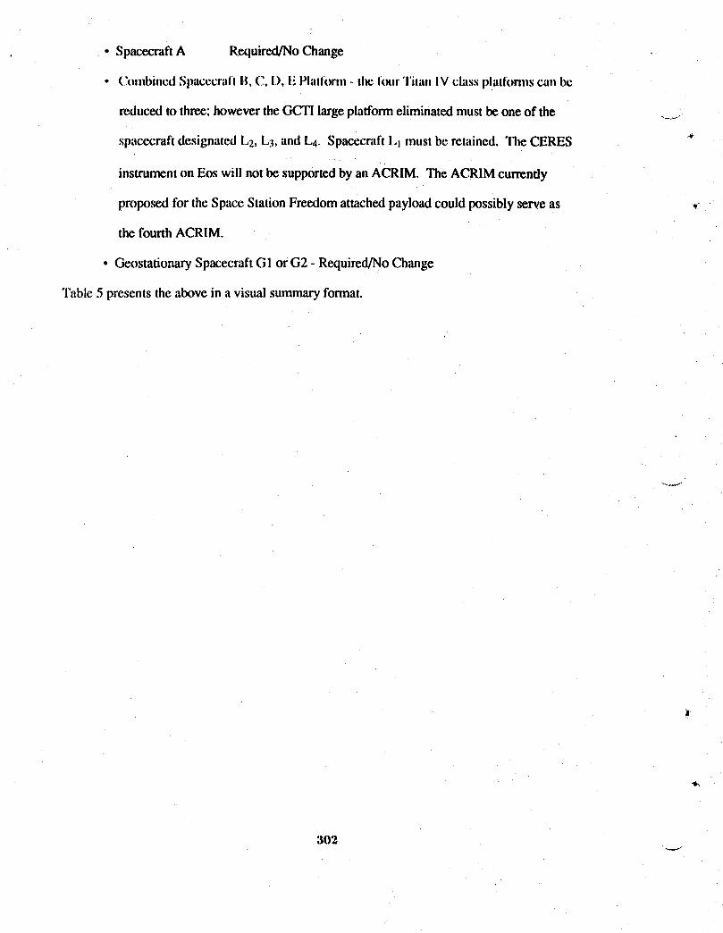
• SpacecraftA Required/NoChange
• C(m)binedSl)acccraflB,C.,I), F,Platforn)-.theIour"l'ilanIV(:lagsplalk)nns(;awlbe
reducedto three; howevertheGCTIlargeplatformeliminatedmustbe one of the ....
spacecraftdesignated 1.2, L3, and !-,4.Spacecraft1,1must be retained. Tile CERES *
instrumenton Eos will notbe supportedby an ACRIM. The ACRIMcurrently
proposedfor the SpaceStationFreedomattachedpayloadcouldpossiblyserve as _
the fourth ACRIM.
• GeostafionarySpacecraftGI or G2 - Required/NoChange
Table 5 presentsthe above in a visualsummaryformat.
302

TABLE 1.(a) - INSTRUMENTCOMPLEMENTSFORTHE FOUROPTION 2 PLATFORMS
Opl;ion2 Platforms
instrument8 L-1. L-2 L-3 L-4.
HIRIS *3 ChMR *ALT *MODIS-T *EOSP * * * *SAGE III *APL *AIRS * * * *
_, ACRIM * * * *SOLSTICE *XRI *CERES * * * *MODIS-N * * * *AMSU-B * * * *HIMSS * * * *TES * * * *SAFIRE * * * *SWIRLS * * * *TRACER * * * *MLS * * * *
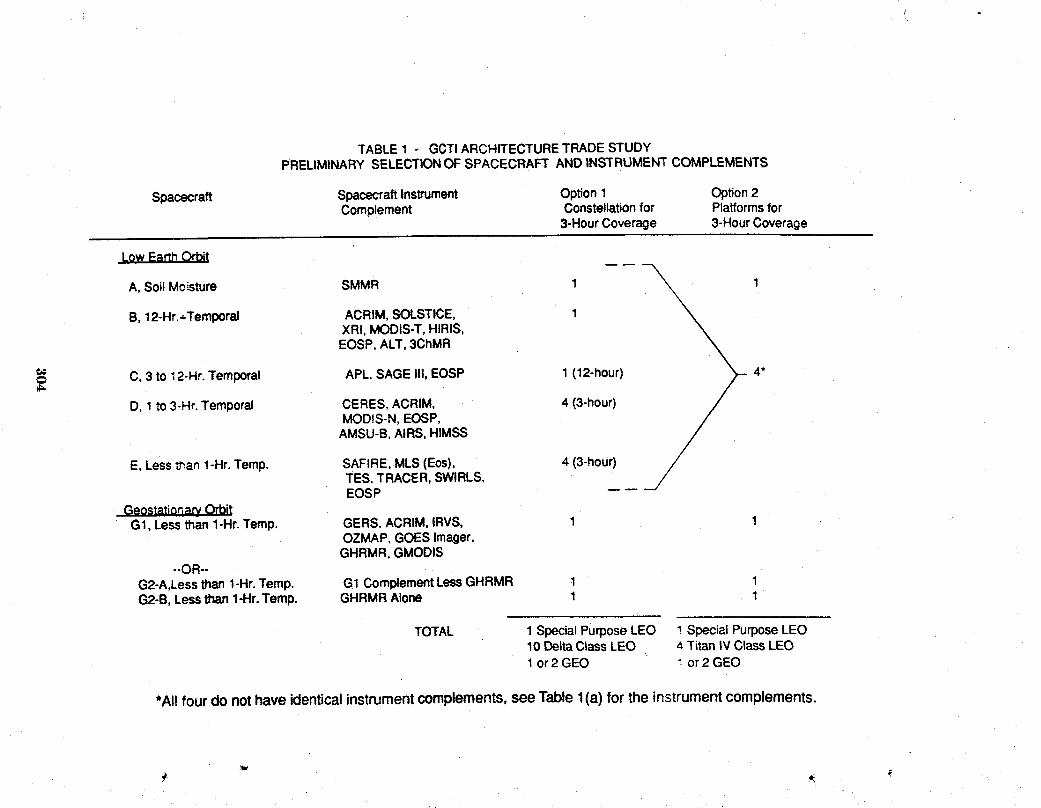
TABLE1 - GCTIARCHITECTURETRADESTUDYPRELIMINARYSELECTIONOFSPACECRAFTANDINSTRUMENTCOMPLEMENTS
Spacecraft SpacecraftInstrument Option1 Option2Complement Constellationfor Platformsfor
3-HourCoverage 3-HourCoverage
I
A, Soi!Mo_ture SMMR 1 _X\ 1
B, 12-Hr.+Temporal ACRIM,SOLSTICE, 1 '_XRI, MODIS-T,HIRIS,EOSP,ALT,3ChMR
C, 3 to 12-Hr.Temporal APL.SAGEIII,EOSP 1 (12-hour) 4"
/D, 1 to 3-Hr.Temporal CERES.ACRIM, 4 (3-hour)MODtS-N,EOSP,
AMSU-B,AIRS,HIMSS
/E, LessSan 1-Hr.Temp. SAFIRE,MLS(Eos), 4 (3-hour) /
TES, TRACER,SWIRLS, /EOSP --- -/
GeostationarvOrbitG1, Lessthan1-Hr.Temp. GERS,ACRIM,IRVS, 1 1
OZMAP,GOESImager,GHRMR,GMODIS
--OR-G2-A,Lessthan1-Hr.Temp. G1 ComplementLessGHRMR 1 1G2-B,Lessthan1-Hr.Temp. GHRMRAlone 1 1
TOTAL 1 SpecialPurposeLEO 1 SpecialPurposeLEO10 DeltaC_assLEO 4 Titan IV ClassLEO1 or2 GEO _ or 2 GEO
*Allfourdonothaveidenticalinstrumentcomplements,seeTablel(a) fortheinstrumentcomplements.
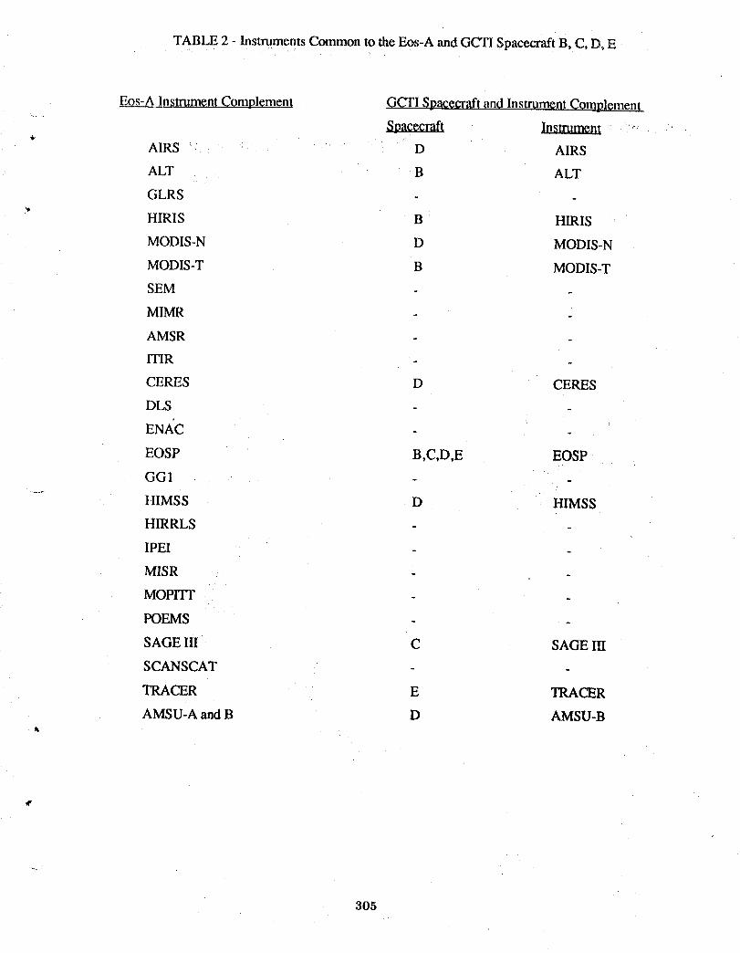
TABLE 2 - Instruments Common to the Eos-A and GCTI Spacecraft B, C, DoE
Eos-A Instrument Complement GCTI Spacecraft and Instrument Complement
Spacecraft Instrume0l,ik
AIRS D AIRS
ALT B ALT
GLRS
HIRIS B HIRIS
MODIS-N D MODIS-N
MODIS-T B MODIS-T
SEM
MIMR
AMSR
ITIR
CERES D CERES
DLS
ENACEOSP B,C,D,E EOSP
GG1
HIMSS D HIMSS
HIRRLS
IPEI
MISR
MoPrIT
POEMS
SAGE III C SAGE III
SCANSCAT
TRACER E TRACER
AMSU-A and B D AMSU-B
305

TABLE 3 - INSTRUMENTS COMMON TO THE Eos-B AND GC'TISPACECRAFT B AND E
Eos-BInstrumentComplement GCTI SpacecraftandInstrumentComplement
Spacecraft. Instrument
SAR
SEM
GGI
GOS
IPEI
LIS
MLS E
SAFIRE E SAFIRE
SWIRLS E SWIRLS
TES E TES
XIE B XRI
306

TABLE 4 - GCTI INSTRUMENTS NOT ON AN Eos SPACECRAFT
GCH LEO Spacecraft Instrument
B, D ACRIM
B SOLSTICE
B 3 Ch MR
C APL
A SMMR
GCTI GEO SPACECRAFT
G1 GERS
ACRIM
IRVS
OZMAP
GOES Imager
GHRMR
GMODIS
OR
G2-A G1 Complement
G2-B GHRMR
307
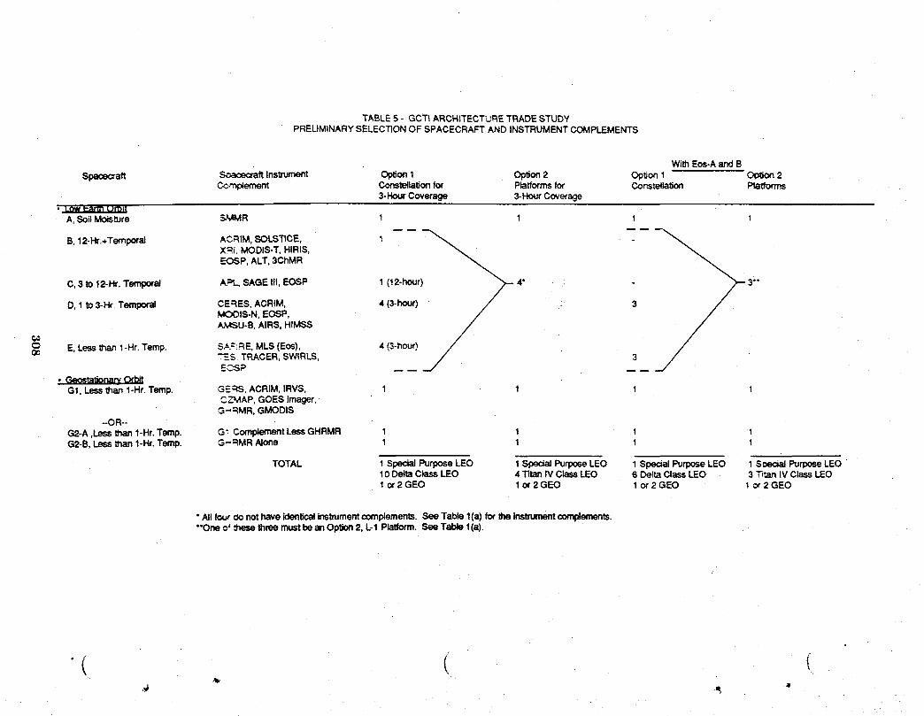
TABLE5 - GCT! ARCHITECTL_RETRADESTUDYPRELIMINARYSELECTIONOF SPACECRAFTAND INSTRUMENTCOMPLEMENTS
WithEos-AandBSpacecraft _aft Instrument Option1 Option2 Opbon 1 Op_on2
Co.,-nplement Constellationfor Platformsfor Constellation Ptatforms3-HourCoverage 3-HourCoverage
• L_ e_annom_A,SoilMoisture S._MR 1 1 1 1
X.=.='.MODIS-T,HIRIS,EOSP, ALT,3ChMR
C,3 to 12-I-k.Temporal A.=_ SAGE III,EOSP 1 (!2-hour 4" 3""
D, 1to 3-Hr.Temporal CE=_ES,ACRIM, 4 (3-hour) / : 3
MOOIS-N,EOSP, / /'//
A_SU-B, AIRS, HIMSS /
E, Lesst_han1-Hr.Temp. S_F;_E, MLS(Eos), 4 (3-hour) / /"=-S TRACER,SWIRLS, // 3 /
G1, Less_an 1-Hr.Temp. G-_-:>,S,ACRIM, IRVS, 1 1 1 1CZMAP, GOES Imager,G- _MR, GMODIS
-OR--G2oA,Less_'k3n1-Hr.Temp. G: ComplementLessGHRMR 1 1 1 IG2-B,Less_ 1-Hr.Temp. G-_MR Alone 1 1 1 1
TOTAL 1 SpecialPurposeLEO 1 SpecialPurposeLEO 1 SpecialPurposeLEO 1 SpecialPurposeLEO10DeltaClassLEO 4 _tan IV ClassLEO 6 DeltaClassLEO 3 T'_tanIV ClassLEO1 or2 GEO 1 or 2GEO 1 or 2 GEO 1 or 2GEO
• All fc_, oo nothaveidenticalinstrumentcomplements.See Table1(a) for the insVumentcomplements."'Oneo. _ three mustbeanOption2, L-1Platform.See Table l(a).
INFORMATION DATA SYSTEMS FOR A GLOBAL CHANGE TECHNOLOGY INITIATIVEARCHITECTURE TRADE STUDY
Nicholas D. MurrayNASA Langley Research Center

INFORMATION DATA SYSTEMS FOR A GLOBAL CHANGE TECHNOLOGY INITIATIVEARCHITECTURE TRADE STU1)Y
NicholasD.Murray
lnfomaationSystemsDivision
NASALangleyResearchCenter
_, Hampton,Virginia
INTRODUC'I'ION
The Global Change Technology lniti_(tive (G(YI'I) was established to develop technology whichwill enable use of satellite systems for Earth observations on a global scale, enable use of the
observations to predictively model Earth's changes, and provide scientists, government, business,
and industry with quick access to the resulting intbmaation. At.NASA Langley Research Center, a
GCTI Architecture Trade Study was undertaken to develop and evaluate the architectural
implications to meet the requirements of the global change studies and the eventual implementation
of a global change system. The output of the trade study are recommended technologies for the
Global Change Technology Initiative. This paper documents that portion of the study concernedwith the information data system.
The informationdata systemfor an earth globalchangemodelingsystemcanbe very extensiveand
can be beyondaffordabilityin todays' cost terms. Therefore,,'mincrementalapproachto gainingasystem is most likely and thi:;study developed an options approach to levels of capabilityversusneeded technologies. The primary drivers of the requirements for the informationdata system
evaluation were the necded science products, the science measurements[1], the spacecraftorbits121, the instrument configurations [31, and the spacecraft configurations and. their attendant
architectures 1141.The science products requirements were not studied here; however, someconsiderationof the product needs were includedin the evaluationresults. The informationdatasystem technologyitems were identifiedfrom the viewpointof the desirable overall informationsystem characteristics.
REQUIREMENTS
The recommended satellite fleets are detailed by Table 1 [4,51. The spacecraft instrumentconfigurationsare given as A,B,C,D,Efor the lowearth orbit (LEO)constellation,and as A, L1 =B+C+D+E and L2 = D+E for platforms. The options given were with and without the earth
'_ observing satellites(EOS)A and B, For the options with the EOSA and B, the constellationandplatfc_rmfleets havea reduced numberof satellites. Workingin conjunctionwith theLEO satellites
311
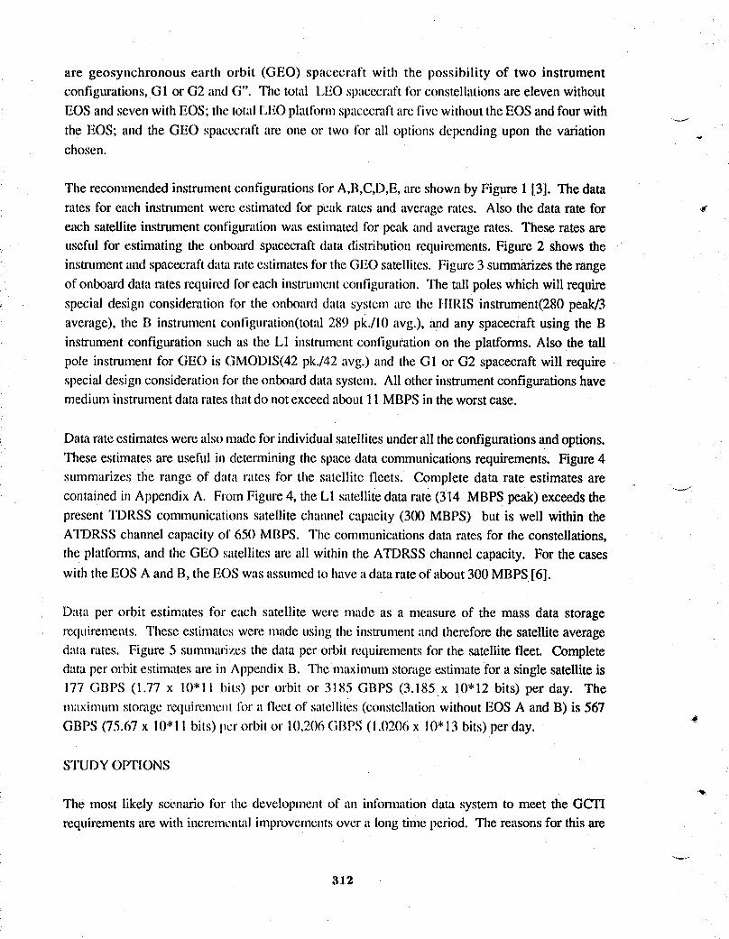
are geosynchronous earth orbit (GEO) spacecraft with the possibility of two instrumentconfigurations,GI or G2 and G". The total LEO spacecraftfor constellationsare eleven withoutEOSand seven with EOS; the total LEOplatformspacecraftare five withouttheEOS andfour with
the EOS; and the GEO spacecraftare one or two tbr all options depending upon the variation _,chosen.
The recommendedinstrumentconfigurationsfor A,B,C,D,E,are shown by Figure 1 [3]. The datarates for each instrument were estimated for peak rates and average rates. Also the data rate for _¢each satellite instrument configurationwas estimat_ for peak and average rates. These rates areuseful for estimating the onboard spacecraftdata distribution requirements.Figure 2 shows the
instrumentand spacecraftdata rateestimatesfor theGEO satellites. Figure 3 summarizestherangeof onboarddata rates requiredfor each instrumentconfiguration.The tall poles which will requirespecial design consideration for the onboard data system are the HIRIS instrument(280 peak/3average), the B instrument configuration(total289 pk./10 avg.), and any spacecraft using the Binstrument configurationsuch as the L1 instrumentconfigurationon the platforms. Also the tallpole instrument for GEO is GMODIS(42 pk./42 avg.) and the GI or G2 spacecraft will requirespecialdesignconsiderationfor theonboarddata system. All other instrumentconfigurationshavemedium instrumentdatarates thatdo not exceedabout 11MBPSin the worstcase.
Data rate estimateswere also madefor individualsatellitesunderall theconfigurationsand options.These estimatesare usefid in determiningthe spacedata communicationsrequirements. Figure4summarizes the range of data rates for the satellite fleets. Complete data rate estimates are
containedin AppendixA. From Figure4, the LI satellitedata rate (314 MBPSpeak)exceeds thepresent TDRSS communications satellite chatmel capacity (300 MBPS) but is well within theATDRSSchannel capacity of 650 MBPS. The communicationsdata rates for the constellations,the platfomls, and the GEO satellitesare all within the ATDRSSchannel capacity. For the cases
with theEOS A and B, theEOS wasassumedto havea data rate of about 300 MBPS[6].
Data per orbit estimates for each satellite were made as a measure of the mass data storagerequirements. These estimateswere made using the instrumentand thereforethe satelliteaveragedata rates. Figure 5 summarizesthe data per orbit requirementsfor the satellite fleet. Completedata per orbit estimatesare in AppendixB. The maximumstorageestimatefor a single satelliteis177 GBPS (1.77 x 10"11 bits) per orbit or 3185 GBPS (3.185 x 10"12 bits) per day. Themaximumstoragerequireme_tfi_ra fleet of satellites(constellationwithout EOS A and B) is 567GBPS (75.67 x 10*11 bits) per orbit or 10,206GBPS (!.02(16x 10' 13bits) per day.
STUDYOPTIONS
The most likely scenario for the developmentof an inlbmaationdata system to meet the GCTIrequirementsare with incrementalimprovementsover a long time period. The reasonsfor this are
312
two Iold: a full capability inlormation data system will be very expensive and the cost is better
borne increnlentally; and a fidl capability information data system will be very extensive with adegree of collaborative ptocessing between diverse elements that is unprecedented - the incremental
approach provides the ()pportunity to learn and gain confidence for each step of improved
_' capability before deciding on the next (and larger) step. For these reasons, an options approachwith increasing information system capabilities was chosen tbr tile study.
The study considered three options for the inlk)nnation data system:
1) A baseline system that represents the data measurements and information product methods that
are currently in operation. For this method, all data gathered is transmitted to ground without anyconversion or processing and all processing to generate science intbrmation products for users areperformed on the ground.
2) An option 1system that representsan intermediatestep to providing science usersdirect and
near realtime access to science products. For this system, all instrument data gathered is still
transmitted to the ground without conversion or processing; onboard satellite processing isperformed to generate intermediateand limited final science products for direct transmissionto
users; and most of the final science intk_rmationproducts for users are still processed on theground.
3) An option 2 system that would provide the science user full and direct science informationproducts in realtime. This approachwill requirecombined and collaborativeonboard satelliteand
ground processing and quickly accessible data archiving. The study of this option was tooextensive for the GCTI ArchitectureTrade Study and is incomplete. However,initial results willbe discussed.
BASELINE RESULTS
The informationdata system (Figure 6) wouldconsist of the followingitems: a data distributionnetwork; network interl'accs (NI); embedded data processors (EDP); data processors in a
processing complex; mass data storage; time and fl'equency;and communicationsand tracking.The instrument configtmttions are variable depending upon the configurations A,B,C,D,E,L,G.
The onboardprocessing €:omplexis wu'iabledcpcndingupon the onboard processingrequired bythe options of baseline, option 1, and option 2. The communications and tracking subsystemcommunicatesdata to a groundcomputingcornplex througha TDRSSor ATDRSScommunicationsatellite via a ground network.
" The issue for the onboard system raised by the requirementsis how to efficientlyhandle the fewinstrumentswith highdata rates,which are the HIRIS for LEO and theGMODIS for GEO. These
313
data rates can be handled by high rate cables sep:lratclyfronl the data distributionnetwork. Withthis approach (Figure 7), a high data rate insu'unmnt ia,ould have separate cables to the dataprocessingsubsystem,to the massdata storagest,bsystem,and to thecommunicationand tracking -_-.subsystena. Allother datarate requirementswouldbe handledby thedata distributionnetworkatamedium data rate of about !1 MBIS. The proccssing complex needs are minimal under the
baseline option. Two tape recorders are adequate to handle the onboard storage needs on a perorbit basis. The space data communicationratescau be handlcdby today's TDRSS or the plannedcommunicationssatellites. The ground data system is adeqt,ate but very slow in serving science *informationrequests.
With the high data rate cable techniqt,e, all the needed data management system (DMS) componentsare under adwmced deveiopnmnt by NASA progranas--Polar Orbiting Platform, Multimission
Modular Elements, Space Station l-:reedom, and EOS Data InR_rmation System. The DMS
component capabilities being developed tire: I(X)MBPS data distribution network; 10 to 12 MBPS
connections to instruments and subsystems; 1 to 4 MIPS embedded data processors; 4 to 8 MIPS
data processors; and 10"1 I bits tape recorders.
OIrFION1 REQUIREMENTS
With some new technologyDMS component additions,tile baselineonboard system could begin
to process data and provkle science informationproducts in near realtime. Some of the potentialrealtime science information products are listed in Table 2 171. A significant number of
applications have been identified that need onboard processing as well as realtime datatransmission. The time response range of these applications are: continuous, such as forchlorophylland temperature maps; rapid response to emergencyevents, such as large storms andetu'thquakes;and selectivefor surfaceareas, such as sea/ice interfaceand supportfor local remote
sensing experiments. Also needed are continuous searchof instrument data for warning signs,such as volcanicgasesand surl_methermalevents. For this option, the instrumentdata would stillbe transmitted to ground and archived,but someof thereallimeearth sciencesdata needsas scienceproducts could be st,plflied to the science users directly on request either through the'IT)RSS!ATI)RSSgroundnclwo,k or by direct broadcastto local receivingstations.
The iml)rovementsiml)osedon tile baseline intbrulation system in order to serve the option 1requirementstire modest.The p,'imaryneeds are for: an onlx)arddata system processingcomplexof medium computingpower(10-50 MIPS); a lnediunadata ratedata distributionnetwork(50-150MBPS); and a medium speed access (0.1-10 MS) mc×leratecapacity (10"11 BITS) mass storageunit.
'W
31.4
OPTION 2 REQUIREMENTS
The option 2 requirements are extensive and l)robably unprecedented. Although the study resultsare incomplete, it can be recognized that there are needs for: high data rate communications not
-, only tbr instrtnnent data transmission but also for collaborative processing and accessing data
between the space system and the ground system; high performance prcx:essing/computing both
on the spacecraft and on the ground; and high capacity and fast access mass data storage on the
spacecraft and on the grot,nd. An immediate need is to determine a global approach to the
+ collaborative processing/computing and data commtmications.
CANDIDATE TECH NOI.OGIES
Since the baseline option can be formed with existing and/or developmental components, nocandidate technologies are rcqt, ired for the baseline. Recommended technologies were derived for
options 1 and 2 as listed by Table 3. Each technology need is identified with the information data
system element. The option 1 technologies coincide with some of the option 2 technologies but the
required capabilities for the option 2 technologies are greater. The recommended technologydescriptions follow and am identifiable with the analysis results.
TITLE: Global Data Communication and Processing Architeciures
DESCRIPTION:In order to servescience userswith informationproductsin near realtime,anextensive collaborativeprocessing system will need to be established. The steps tOthis type ofunprecedented system are to understand the needs of the science community, to formulaterequirements through analytical methods, and to establish architectural structures for the
informationsystem. This candidate technology would perform all three of these functionsand
would cover satellite systems, space data communications systems, and ground systems. Key•areas that rexluirefurther research,definitionand trade stt,dies include global system architectures
that meet the science needs; st,bsystemarchitecturesthat are optimizedfor local or regional tasks;control system architecturesthat enable efficient operations;and intelligentsystem approachestofaultcontainmentand management.
TITLE: Optical Commt,nicatkms
+ DESCRIPTION: Collaborative processing to serve science users will require high capacitycommunicationlinks. These high capacity communicationlinks will be required between polarorbiting LEO spacecraft,GEO observationplatforms,and ground systems. It is essential that thecommunicationsystem selectedhave thecapabilityto grow and to evolve to handle sensorswhich
,,,- can be expectedin the future. The unprecedentedhigh bandwidthrequirementscan best be servedby opticalcommunicationsin spacerather than by limitedRF spectrum. Optical communications
315

permits high performance systems to be implenlented using very small antennas which is a majoradwmtage in space.
TITLE: Optical Networking
DESCRIPTION:The requirements of tile onboard data distribution networks will become
increasingly demanding for high data rates in support of onboard processing and combined
collaborative processing between the satellite system and the ground system. At these rates, .,,
optical media is the most efficient and the technology of choice. The need is to develop networksthat _u'emore and mote optical to the point of developing all oplical networks. Research and
development is needed in higher level protocols, high performance and fault tolerant network
topologies, and optical nodes and devices. The performance levels required are approximately:
Option 1- 50-150 MBPSeffectivetransmissionr,'ltes
Option 2 - >500 MBPSeffectivetransmissionrates
TITLE: Parallel Processing/! ligh Pcrfornmncc I_rc_:cssing
DESCRIVI'ION:Inorder to serve science users effectively,there is a need for eventual onboard
processing. The technologymost likely to lead to the performancelevels for the immediate timeperiod is parallel processing. Many inexpensive commercial parallel processing systems are .....beginning to become awfilableand this effort would look to build on these efforts to produceparallel processingat 10-50 MIPS capability for option 1 application. Exploitationof the supercomputer technologyis requiredto attain the perfi)rmancelevels for high perfommnceprocessingwhich is the choice for option 2.
Option I - 10-50 MIPS capability
Option 2 - > 500 MIPS capability
Tl'l'l Ji,:Optical Disk l/t'Ci)l'dt'r
DES(]I_II)TION:Scrvinl• scit;l|t.'e ilSOrsdirecily wilh science i_roducts also requires onboard data
storage and fast data access. The lilOSl pronlising recording technology with this combination of °requirements is the optical disk. For quick turn arouild of ground processed science products,
quick access mass data storage is also required. The collaborative processing of Option 2 willextend these needs even more.
Oplion I - 10' I I bits capacity. 0.1-10 MS :lccess
o
31,6
Option 2 - 10"12-10"13 bits capacity, 0.01-1 MS access
TITlrE: High Pertbnnance Cornputing
DESCRIPTION: The concept of providing science users with quick access science products, with
realtime global event data, and with interactive science processing requires high performance
ground computing at multiple sites. Computational requirements of more than 100 Gigafl0ps have
" been cited as tile need fbr the yem"20(X). To achieve this overall high performance, technology
efforts are required to improve parallel processing concepts, operating systems, processinghardware, interconnection systems, and software programming.
TITLE: Wide Area Networking ( Optical )
DESCRIPTION: Ground based wide area conaputer data communications are required to supportthe advancing scientific investigations, to enable distributed user access to science data and
information products, and to access data archives and supercomlguting resources. The increasing
volume of data and increasing distribution points makes high bandwidth optical networking
technology the choice for the future. Combining optical networking with todays network system
would provide an order of magnitude improvements required for the future. Research and
development is needed m conmmnications controller level interfaces, high speed routers, higherlevel protocols and architectural alternatives.
REFERENCES
1. Suttles, J. T. ; Harrison, E. F. ; Gibson, G. G. ; and Campbell, T. G. • "ScienceRequirementsfor a GlobalChangeTechnologyInitiativeArchitectureTrade Study". Report to the
Global Change Technology Initiative ArchitectureTrade Study WorkingGroup, NASA LangleyResearchCenter. _
2. Harrison, E. 1-7.; Gibson, (J. G. ; Suttles, J. T. • Buglia, J. J. - and Taback, I. : "Satellite Orbit
Considerations For Mission to Planet Earth". Report to the Global Change Technology InitiativeArchitecture Trade Study Working Group, NASA Langley Research Center.
3. Ilypes, W. D. ; Kcafcr, 1_. ; Ross, R. ' Jalink, A. ; Allen, C. L. ; and Knight, H. R. :4
"Represenlative lnstrunlcnts for the Global Change Technology Initiative Architecture Trade
Study". Report to the Global Change Technology Initiative Architecture Trade Study WorkingGroup, NASA Lang4ey Rcsearch Center, January, 1990.
317
4. Anonymous : "GCT! Multi-lnstrument Spacecraft in Sunsynchronous Low Earth Orbits".Report to the Global Change Technology Initiative Architecture Trade Study Working Group,NASA l.angley ResearchCenter,April 6, 1990 ..._.-
5. Hypes, W. D. ; and Ross, R. • "The Impactsof an EOS-A and B on the Architectural Mix ofthe GCTI SpacecraftFleet". Report to theGlobalChangeTechnologyInitiativeArchitectureTradeStudy WorkingGroup, NASA Langley ResearchCenter,January, 1990.
6. Reportof the EOS Data P:mel- EarthObservingSystem Dataand lnfomaationSystem,NASATechnicalMemorandum87777.
7. Reportof the 1SESEarth SciencesWorkshop,Williamsburg,Va., May 1-4, 1989.
"v"
,a
3 18

Table 1- The GCTI Architecture Study Satteltite Fleets
GCT! FLEET W/O EOS A&B GCTI FLEET W/EOS A&B
OPTION 1 OPTION 2 OPTION 1 OPTION 2CONSTELLATION PLATFORMS CONSTELLATION PLATFORMS
1A 1A 1A 1A
1B
1 C 1 LI=B+C+D+E 1 LI=B+C+D+E
4D 3D
4 E 3 L2=D+E 3 E 2 L2=D+E
1G1 1 G1 1G1 1 G1OR OR OR OR
1G2&G" 1G2&G" 1G2&G" 1G2&G"
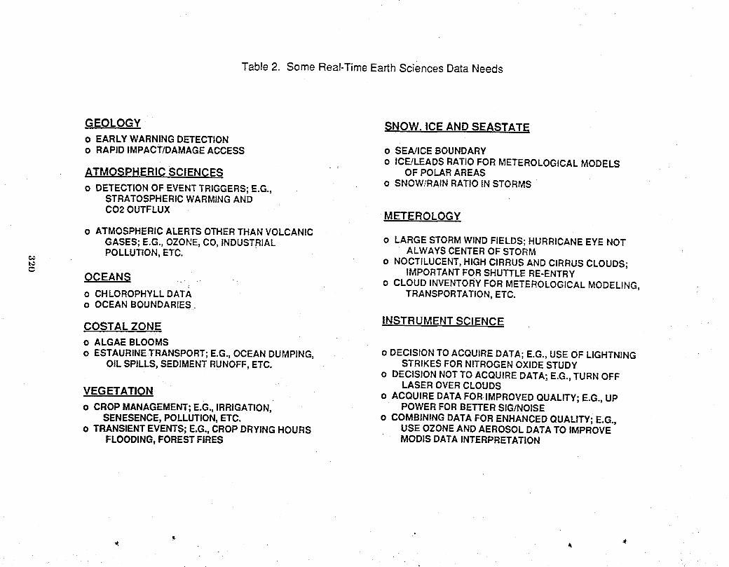
Table 2. Some Real-TimeEarth Sciences DataNeeds
GEOLOGY SNOW. ICE AND SEASTATEo EARLY WARNING DETECTIONo RAPID IMPACTIDAMAGEACCESS o SEA!ICE BOUNDARY
o ICE/LEADS RATIOFOR METEROLOGICALMODELS
ATMOSPHERIC SCIENCES OFPOLARAREASo SNOW/RAIN RATIO IN STORMS
o DETECTIONOF EVENTTRIGGERS; E.G.,STRATOSPHERICWARMINGAND
CO20UTFLUX METEROLOGY
o ATMOSPHERICALERTS OTHERTHAN VOLCANICGASES; E.G., OZONE, CO, INDUSTRIAL o LARGE STORMWIND FIELDS; HURRICANEEYE NOTALWAYS CENTEROF STORMPOLLUTION, ETC. o NOCTILUCENT,HIGH CIRRUS AND CIRRUS CLOUDS;
IMPORTANTFOR SHUTTLE RE-ENTRYOCEANS o CLOUD INVENTORYFOR METEROLOGICALMODELING,
o CHLOROPHYLL DATA TRANSPORTATION,ETC.o OCEAN BOUNDARIES
INSTRUMENT SCIENCECOSTAL ZONE
o ALGAE BLOOMSo ESTAURINETRANSPORT;E.G., OCEAN DUMPING, o DECISION TO ACQUIREDATA; E.G., USE OF LIGHTNING
OILSPILLS, SEDIMENTRUNOFF,ETC. STRIKES FOR NITROGENOXIDE STUDYo DECISION NOTTO ACQUIRE DATA; E.G., TURN OFF
LASER OVER CLOUDSVEGETATION o ACQUIRE DATAFOR IMPROVED QUALITY; E.G., UP
o CROP MANAGEMENT;E.G., IRRIGATION, POWER FORBETTERSIG/NOISESENESENCE,POLLUTION,ETC. o COMBINING DATA FOR ENHANCEDQUALITY; E.G.,
o TRANSIENTEVENTS; E.G.,CROPDRYING HOURS USE OZONEAND AEROSOL DATATO IMPROVEFLOODING,FOREST FIRES MODIS DATAINTERPRETATION
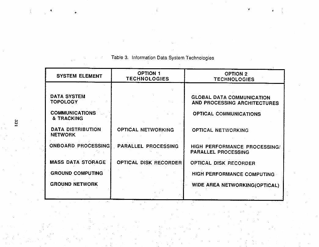
Table 3. InformationData System Technologies
OPTION 1 OPTION 2SYSTEM ELEMENTTECHNOLOGI ES TECHNOLOGIES
DATA SYSTEM GLOBAL DATA COMMUNICATIONTOPOLOGY AND PROCESSING ARCHITECTURES
COMMUNICATIONS OPTICAL COMMUNICATIONS& TRACKING
t._
DATA DISTRIBUTION OPTICAL NETWORKING OPTICAL NETWORKINGNETWORK
ONBOARD PROCESSING PARALLEL PROCESSING HIGH PERFORMANCE PROCESSING/PARALLEL PROCESSING
MASS DATA STORAGE OPTICAL DISK RECORDER OPTICAL DISK RECORDER
GROUND COMPUTING HIGH PERFORMANCE COMPUTING
GROUND NETWORK WIDEAREA NETWORKING(OPTICAL)
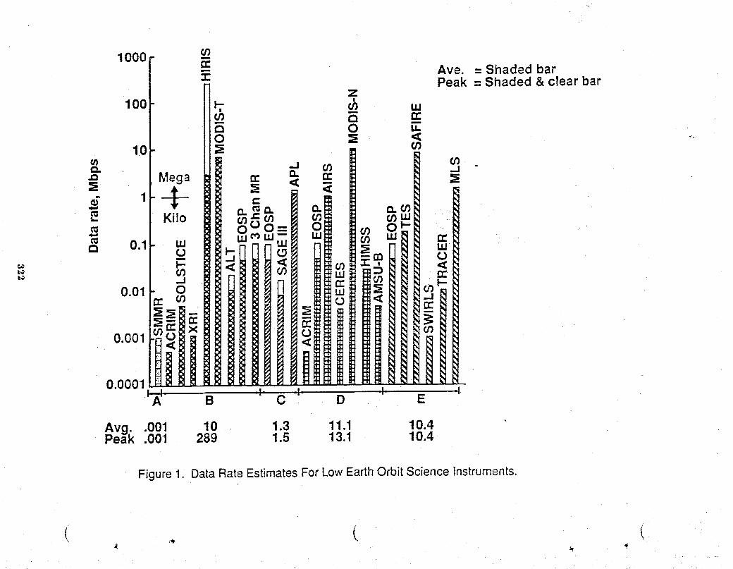
0.0001,..v. ,I' _I' ,I, "I'A' B C D E
Avg..001 10 1.3 11.1 10.4Peak .001 289 1.5 13.1 10.4
Figure 1. DataRate EstimatesFor Low EarthOrbit Science Instruments.
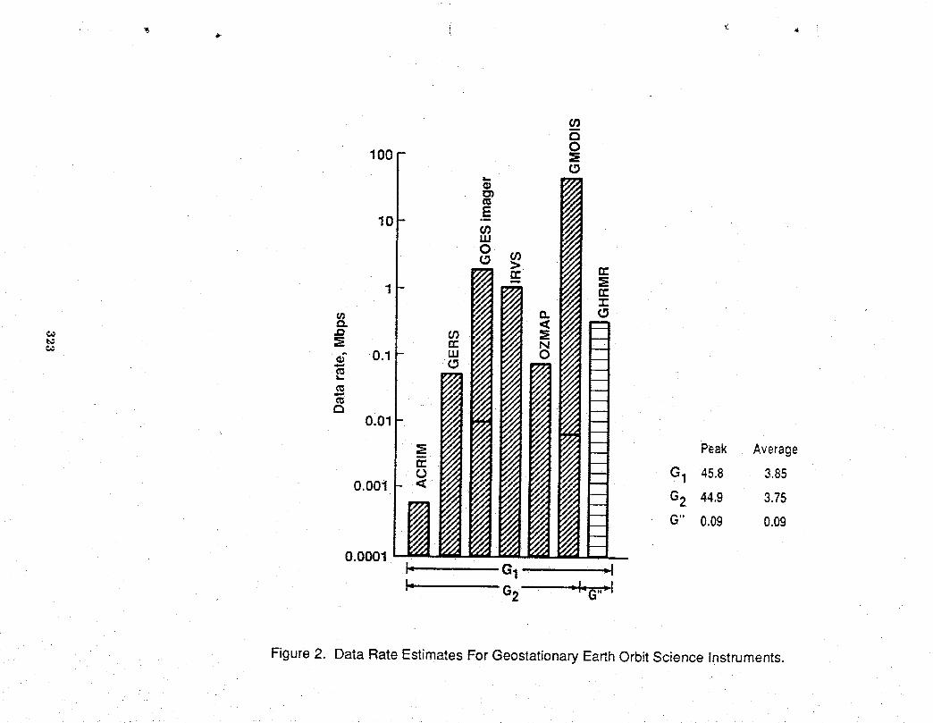
Figure 2. Data Rate Estimates For Geostationary EarthOrbit Science Instruments.

Figure3: The Range of PeakData RatesFor The GCTI InstrumentConfigurations
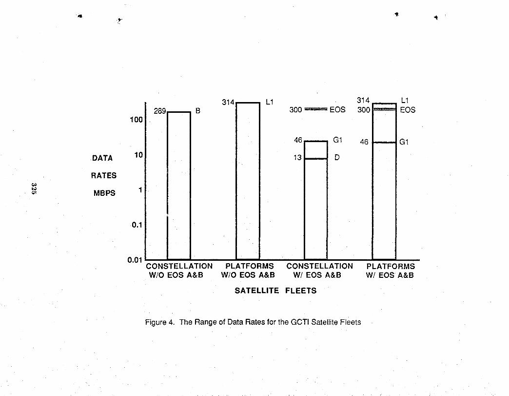
314 L1 314 L1B 300 _ EOS 300 _ EOS
100 :
• 46 G1 46 G1
DATA 10 13 D
RATES
1MBPS
0.1
0.01CONSTELLATION PLATFORMS CONSTELLATION PLATFORMSW/O EOS A&B W/O EOS A&B W/ EOS A&B W! EOS A&B
SATELLITE FLEETS
Figure 4. The Rangeof DataRates for the GCTI Satellite Fleets
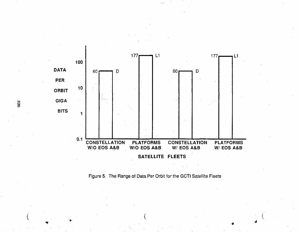
177 -- L1 177 L1100
DATA 60 D 60 _ D
PER ii
ORBIT 10 • iI
GIGA :
i
BITS1 ;
i 11
0.1CONSTELLATION PLATFORMS CONSTELLATION PLATFORMSW/O EOS A&B W/O EOS A&B W/ EOS A&B W/EOS A&B
SATELLITE FLEETS
Figure5. The Rangeof DataPer Orbit for the GCTISatellite Fleets
i ._ ( i

\
(__ POWER ! EDP _ dEDP IINSTRUMENT ! INSTRUMENTDA CONFIGURATIONS
PROPULSION DP A EDP INSTRUMENT A, B, C, D, E, L, GDI
s /
@-I Io!@ d I IGN&C E P R SC MANAGEI EDP & CONTROLBUTI
STORAGE N D FREQUENCY
E _T
COMM W DATA ONBOARD& O PROCESSORS
RTRACKING K PROCESSING
COMPLEX
D COMPUTING_ PROCESSORS J
Figure6. The GCT! InformationData System
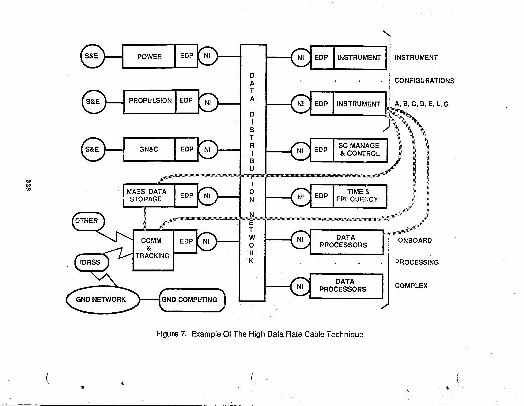
POWER INSTRUMENT INSTRUMENT
CONFIGURATIONS
PROPULSION INSTRUMENT A, B, C, D, E, L, G
GN&C SC MANAGE& CONTROL
t_
o_ MASS DATA TIME & ii_
STORAGE FREQUEt-,ICY .j ii_• it
COMM DATA ONBOARD& PROCESSORS
TRACKINGPROCESSING
@_N ) DATA
PROCESSORS COMPLEX
D COMPUTING
Figure 7. ExampleOf The High Data RateCable Technique

APPENDIX A
DATA RATE ESTIMATES FOR THE GCTI FLEET
329

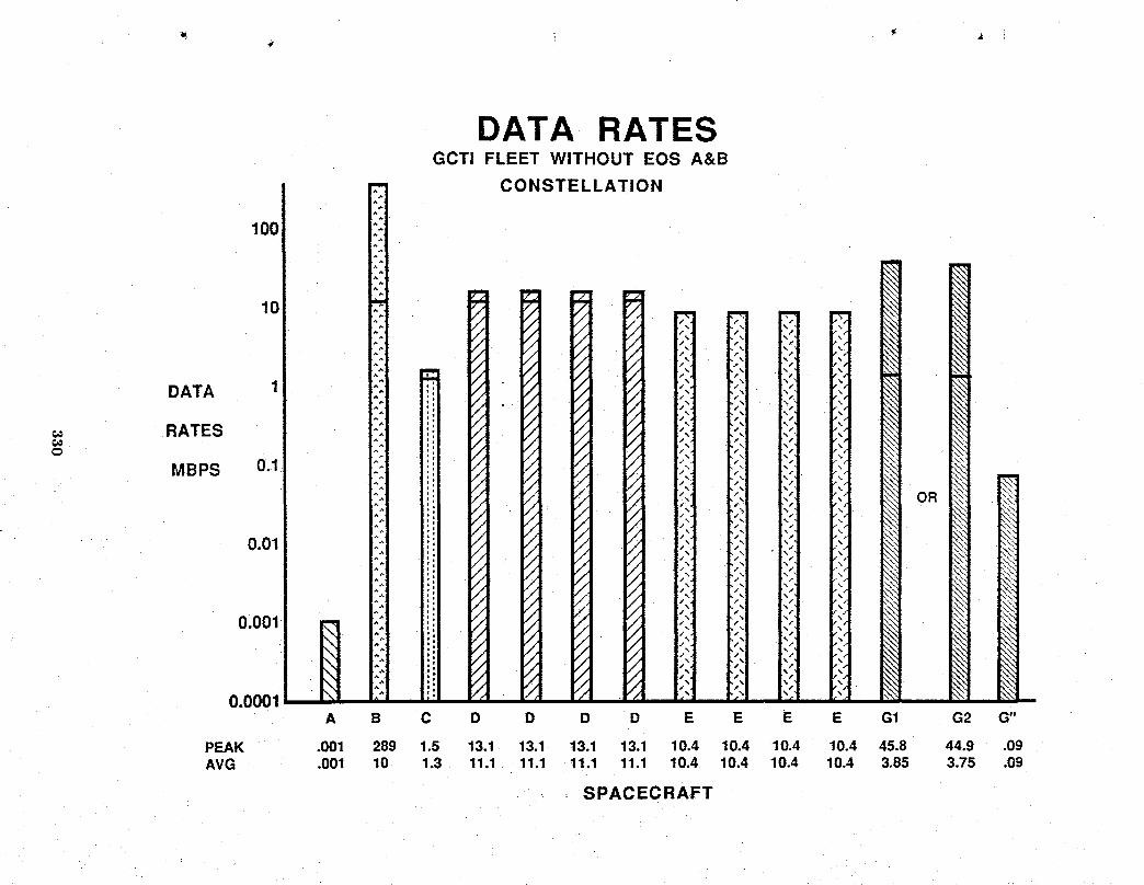
DATA RATES GCTl FLEET WITHOUT EOS A&B
CONSTELLATION
DATA
RATES
MBPS
PEAK .001 289 1.5 13.1 13.1 13.1 13.1 10.4 10.4 10.4 10.4 45.8 44.9 .09 AVG .001 10 1.3 11.1 11.1 11.1 11.1 10.4 10.4 10.4 10.4 3.85 3.75 .09
SPACECRAFT

DATA RATESGCTI FLEET WITHOUT EOS A&B
PLATFORMS
1000
100
DATA 1
RATES€€,m
MBPS 0.1
OR
0.01
0.001
0.0001 - _ -A L1 L2 L2 L2 G1 G2 G"
PEAK .001 314 23.5 23.5 23.5 45.8 44.9 .09AVG .001 32.8 21.5 21.5 21.5 3.85 3.75 .09
SPACECRAFT
(r _ l

&
DATA RATESGCTi FLEET WiTH EOS A&B
CONSTELLATION
100
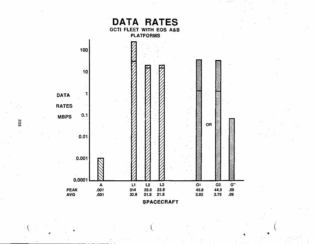
AI)I)ENI)IX B
DATA PER ORBIT ESTIMATES FOR THE GCTI FLEET
334

DATA PER ORBITGCTI FLEET WITHOUT EOS A&B
CONSTELLATION
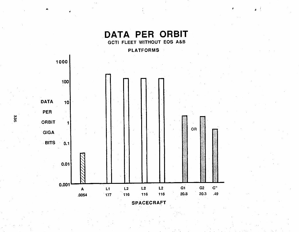
DATA PER ORBITGCTi FLEET WITHOUT EOS A&B
PLATFORMS
1000
im
m m =e=
100=
DATA 10
PER
_" ORBIT 1 _i
GIGA _: OR¢..
BITS 0.1 ,_:
0.01
O.O01A L1 L2 L2 L2 G1 G2 G"
.0054 177 116 116 116 20.8 20.3 .49
SPACECRAFT
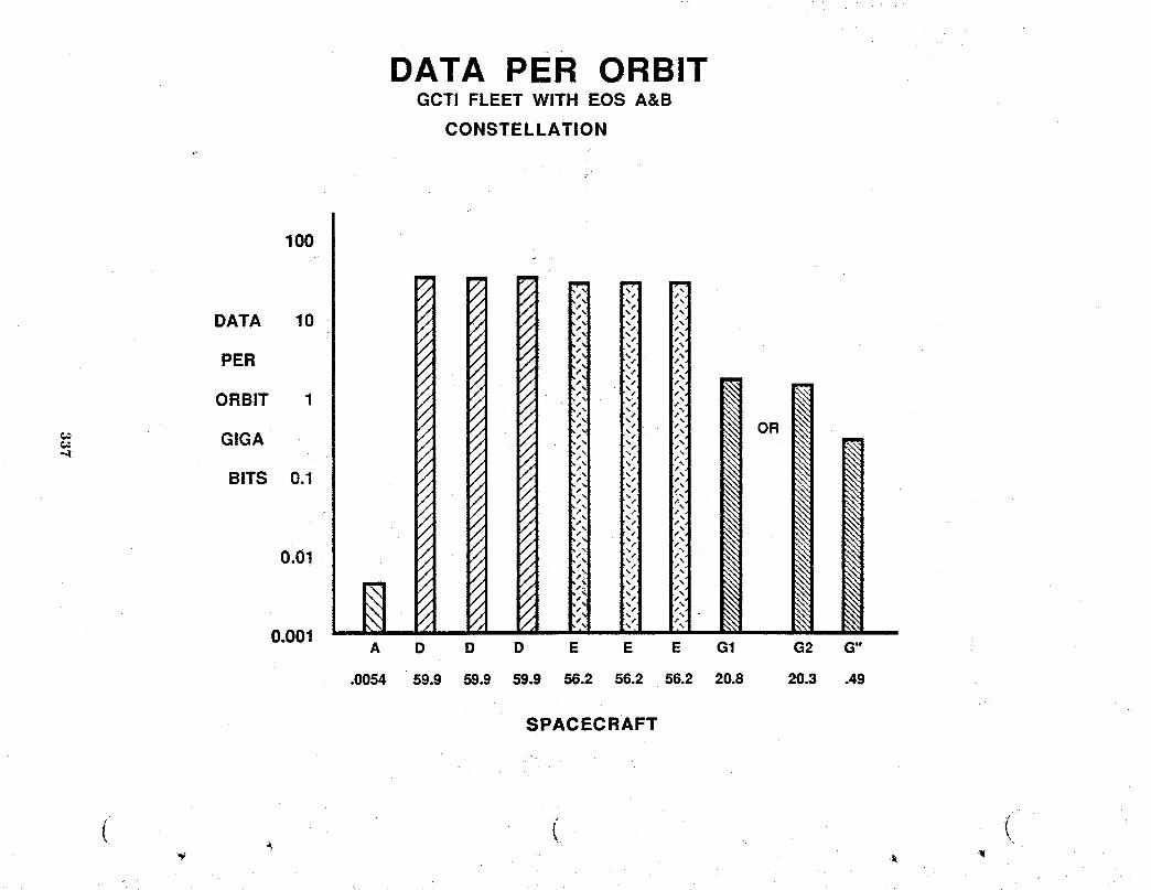
DATA PER ORBITGCTI FLEET WITH EOS A&B
CONSTELLATION
SPACECRAFT
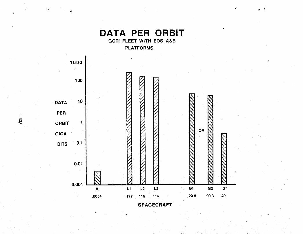
DATA PER ORBITGCTI FLEET WITH EOS A&B
PLATFORMS
1000

,It-

APPENDICES

W

APPENDIX A
GLOBAL CHANGE TECHNOLOGY INITIATIVEARCHITECTURE TRADE STUDY PLAN
Prepared by
Spacecraft Analysis BranchNASA Langley Research Center

2

Approvals
James D. Lawrence, Jr. Dr/Frank AllarioosphericSciencesDivisionChief FlightElectronicsDivisionChief
t11P ,¢u';'""'"• .. i>'/,2#-_-.:"Dr. WillardW../Anderson Mr.H. MiltonHoit '_S;L__'_z-Guidanceand ControlDivisionChief InformationSystemsDivisionChief
sl,l,fMr. JoSephB. Talbot William M.
SpaceStationOfficeManager SpaceSystemsDivisionChief
5 16'_q _,._?Mr.Irving _be! Dr. MichaelF. CardStructtnalDynamicsDivisionChief StructuralMechanicsDivisionChief
,i
l
15r.R_ ;.)€3¢uracaSysterfisE_fneering DivisionChief
343

GLOBAl., C tANGE I l.(J INOI.OGY INITIATIVEARCHITECTURE TRADE STUDY PLAN
Background ,,,_.._
Extensive study efforts have been completed to define and propose Earth science missions
that are best eonduct_ through utilization of spacecraft platfomls. The science relates to a broad
range of deep space and Earth-related missions. The focus for this study is the Earth-related
systems in the Mission to Planet Earth (MPE) Program and the enabling technology program
provided by the Global Change "1echnology Initiative (GCTI).
The need for the Earth science missions ,'rodtheir _pplicability to global change studies are
well described in the NASA Advisory Council, Earth Sciences Committee Report of 1986. The
report provides a list of wlriables and parameters that must be measured periodically or
continuously in order to monitor and quantify global conditions and changes. This list will provide
a baseline departure point for the science requirements definition task of this study. A second
document, the NASA Office of Space Sciences :rodApplications Strategic Plan of 1988 also
discusses Earth-related sciences and, in addition, descriiws a conceptual set of spacecraft platforms
that will support the nfissions. "the key platforms are the two Polar Orbiting Platforms, the Earth-
Observing Systems A and B (Eos-A and Eos-B). As stated in the Strategic Plan, "---the Earth-
Observing System will place a suite of instn_ments in low-Earth orbit to m_e comprehensive
observations of Earth's atmosphere, oceans, land surfaces, and biota--- for at least 15 years, the
mission will study the global-scale processes that shape and influence the Earth as a system."
A second major spacecraft system t_aturing a geostationary orbit has been defined and is
being proposed for approximately the same time period as the Eos platforms. Thus we have one
E( "._major I.,EOand one major G. ) system proposed for application to MPE and GCTI programs in
the immediate filture. The need for global change science studies will extend well beyond these41"
early major systems, but the mix of missions, spacecraft, and sensors for the htter science studies
has not been defined. The purpose of this trade study is to develop and evaluate architectural
1!,
344

mixes of spacecraft and sensor groupings at LEO, GEO, and intermediate orbits to meet the future
science needs. The sizes of the spacecraft platforms and single vs. mini-fleet options will be
...... included in the study."11
Objectives
,_ The overall objective of the trade study is to define the architectural mix of missions,
spacecraft/platforms, and sensors to meet the science requirements of the MPE/GCTI Program
beyond the early Eos and GEO spacecraft missions. Within the overall objective, the study
includes the following specific objectives.
1. Substantiatetheselectedmixof LEO,GEO,or intermediateorbit spacecraft/
platforms.
2. Define the requirednumberand sizeof spacecraftrelated to objective1.
3. Definea genericsen_r complementfor thespacecraft/platforms.
4. Evalnatecurrentspacecraftcapabilitiesto meet themissionrequirements
and developconceptu',ddesignsof spacecraft/platfomlsas required.
5. Identifyadvancedor newtechnologyneededto mostefficientlyaccomplish
the MPE/G(YI'IProgram.
Technical Approach
The approach is to use _1set of technical tasks with definable completion points to focus and
guide the trade study. The tasks are:
Task 1 - Science Requirements Identificationit
The effort under this task will develop a list of science requirements that will focus the
efforts of the subsequent tasks. The task effort is not intended to develop science requirements in
345
great detail but to produce a representative set that can be related to mandatory LEO, GEO, or
intermediate altitudes or that provide options in the selection of candidate missions and spacecraft.
Establishing priorities for tile science requirements for Global Change will also be addressed in the _,
conduct of the study.
Task 2 - SensorRequirementsand Constraints "
Once therepresentativeset of sciencerequirementsand measurementshavebeenidentified,
tile next task is to identifythe appropriategenericsensors. In addition,sensorcompatibilitywill be
evaluatedso that sensorgroupingcan be factoredinto the missionand spacecrafttrades. The
operational characteristicsof thesensors and theconstraintsthey imposeneeddetailedstudy.
Their impacton spacecraftaml missiondesign is great. As a beginning,thefollowingis a list of
sensoroperational characteristicsand constraintsthatneedto be consideredfor eachof thesensors
identified.
Sensor type
Mass/dimensions ,.,_,...t
Power
Sensor duty cycle/power use profile
Antenna sizes and precision requirements
Spatial coverage and resolution required
Temporal coverage required
Viewing mode (nadir, scan, sweep, etc.)
Viewing angles (forward, rear, lateral)
Pointing accuracy (roll, pitch, yaw)
Day/night viewing cycle
Number of inform_uionchannels
846
Operationaltemperaturerequirement
Operationalfrequencyband
..... Thermalcontrol(heat to dissipate,temperaturetoleranceof sensor)¥
Data transmissionrate (kilobits/sec)
Specialcalibrationrequirements
._ Susceptibilityto contamination
In-operationservicingrequirement
PotentialEMI constraints(on the sensoror imposedby the sensor)
Task 3 - MissionDesignOptions
The third task is to integratethesciencerequirementsfrom task 1and thecandidatesensors
and sensorcharacteristicsfrom task 2 intoa set of conceptualmissions. This task willaddressthe
tradesbetweenGEO, LEO, and intermediatealtitudemissions. For missionsother than thoseof
GEO, the tradesmust evaluatealtitudeand orbit inclinationcombinationsthatprovidethe required
spatialcoverage. Another missionvariableto be definedis the numberof spacecraftrequiredto
providethe temporalcoverageor to providethe spatialandtemporalcoverageby a multipleset of
spacecraft. Science rexit,irementsfor repeatand/or specificfrequencyobservationswill also impact
the singlevs. multiple spacecrafttrades.
Task 4 - Spacecraftand PlatformConceptsDevelopmentand Options
This task consistsof surveysand assessmentsof existingspacecraftand the development
of new spacecraft/platformconceptsto support themissionsthatevolve from tasks 1-3. This task
is intendedto generatea representativeset of spacecraftincluding;single-purposespacecraft,
intermediatesystemsfor compatiblesciencesensors,and largeplatformswith a significantnumber
of sensors. RepresentativesystemsincludeExplorerclass, and multimissionspacecraft;several
largespacecraftplatformsincludingconceptslikea free-flyinglargeantennawith dedicated
347
spacecraft bus; and several large platforms. Tile primary design criteria will be the ability of the
spacecraft/platform to provide the necessary resources to the sensors and to meet the performance
requirements for the mission set(s). Also, to be emphasized as design drivers are the issues of _--_
compatibility with projected available launch vehicles and transportation systems, ease of
deployment, potential for in-space assembly, growth potential, and frequency and ease of
servicing. Because of schedule and resource limitations, this task is not expected to lead to a _"
comprehensive, fully optimum space architecture but will produce sufficient data on representative
classes and numbers of spacecraft/platform concepts to provide the Agency with options for future
in-depth studies. Also, broader, more comprehensive studies involving multiple field centers and
Headquarters could be undertaken in the ensuing year.
Task 5 - Subsystem Definitions
This task is a par_dleleffort to task 4 to define the spacecraft/platform subsystems. Major
subsystems that have a pronot, nced effect on the capabilities'of the spacecraft to meet the resource
and performance requirements will be studied. Other subsystems of secondary importance will be
defined as necessary to establish overall spacecraft mass, and performance characteristics will be
developed but to lesser detail. Recommended subsystem modifications to existing spacecraft willbe identified.
Task 6 - Spacecraft and Sensor Perlbrmance Assessments
This task includes simulation and quantification of the on-orbit performance of the
spacecraft, its associated subsystems, and the sensors to meet the science and mission
requirements. Outputs fi'om this task include, but are not limited to, assessments in the areas of
pointing control and stability, vibrational disturbances and need for suppression, power utilization
con flicts, and thermal distortion and control. Results can lead to recommended modifications in
the designs and/or to the identification of technology needs to be incorporated in task 9.
,'148
Task 7- Trade-Off Criteria
A formal task will be conducted to arrive at a set of trade criteria that will result in a set of
candidate systems for enabling the MPE Program. No attempt will be made at this time to preselect
the criteria; however, some application of costs and technology development timelines will be
included in the criteria.
Task 8 - Trade-Off Evaluations
This task blends all the results of tasks 1-7 and results in a set of conceptual missions and
spacecraft that will meet the science objectives of the MPE at minimum cost of resources. The
trade studies will define the architectural mix of spacecraft and sensor groupings for flight at LEO,
GEO, and intermediate orbits. Practical, achievable sizes of the spacecraft in the mix will be
established. An approximate schedule compatible with science needs and realistic availability of
technology will be proposed. Spacecraft subsystems will be defined in sufficient detail to support
the accom plishment of task 9.
Task 9 - Technology Assessment
During the accomplishment of tasks 1-6, study efforts will not be restricted to the ground
rule that conceptual missions, sensors, spacecraft, and subsystems must be based on existing
technology. In fact, the sl,ecified science needs extend well into the 21st century and, thus, dictate
that extended and new technology may be required to support the advanced missions. A
concentrated effort will be made throughout the study to identify and specify these needed
technology advances. The ell'on of task 9 will document these findings for incorporation into the
GCTI program.
J_
349


APPENDIX B
PHYSICAL AND PERFORMANCE CHARACTERISTICS OFINSTRUMENTS SELECTED FOR GLOBAL CHANGE MONITORING
Cheryl L. AllenNASA Langley Research Center

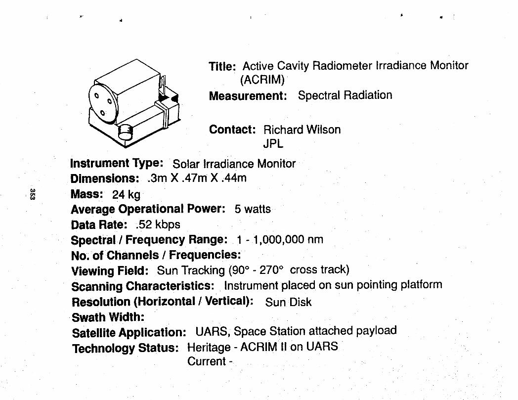
Title: Active Cavity Radiometer IrradianceMonitor(ACRIM)
Measurement: Spectral Radiation
Contact: RichardWilsonJPL
InstrumentType: SolarIrradianceMonitorDimensions: .3m X .47mX .44m
= kg= Mass: 24AverageOperationalPower: 5 wattsDataRate: .52 kbpsSpectral/ FrequencyRange: 1 - 1,000,000nmNo.of Channels/ Frequencies:ViewingField: SunTracking(90° - 270° crosstrack)ScanningCharacteristics: InstrumentplacedonsunpointingplatformResolution(Horizontal/ Vertical).: SunDiskSwathWidth:SatelliteApplication: UARS,SpaceStationattachedpayloadTechnologyStatus: Heritage-ACRIM!1onUARS
Current--
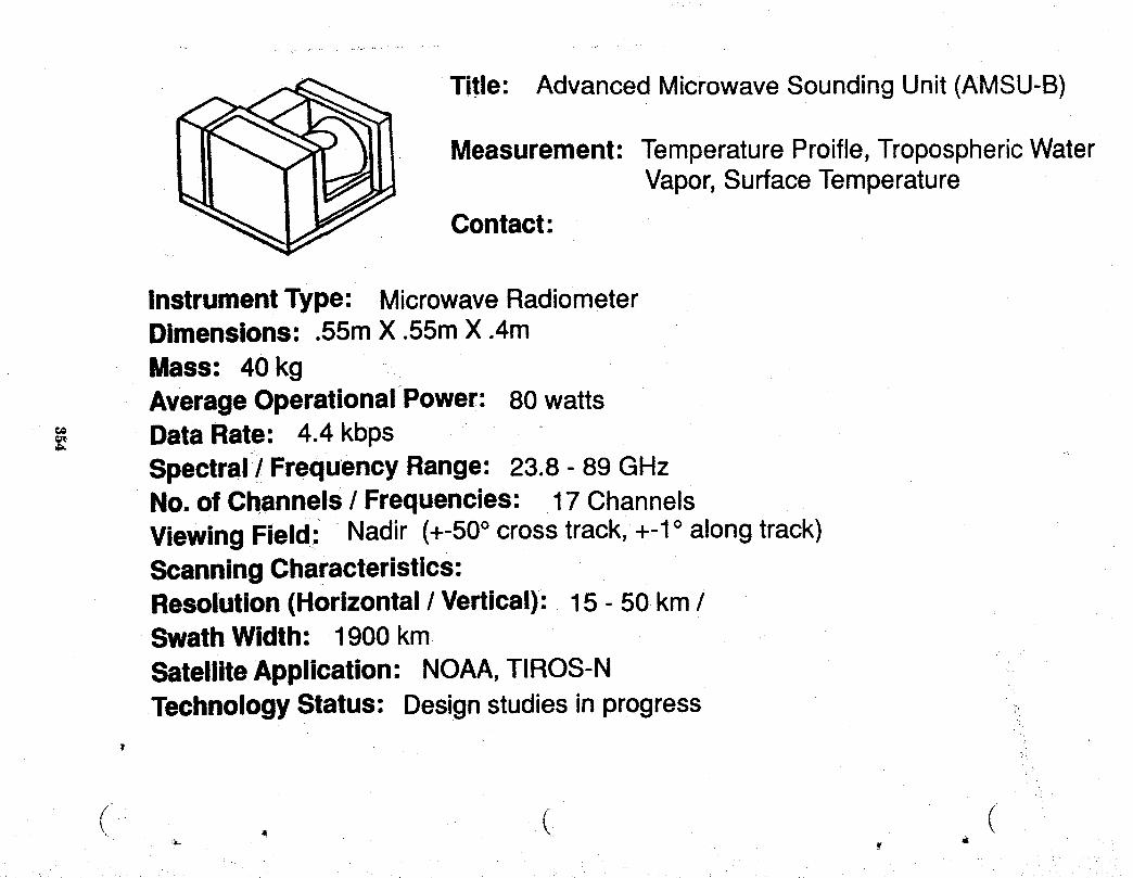
Title: AdvancedMicrowaveSoundingUnit (AMSU-B)
Measurement: TemperatureProifle,TroposphericWaterVapor,SurfaceTemperature
Contact:
Instrument Type: MicrowaveRadiometerDimensions: .55m X .55m X .4mMass: 40 kgAverageOperational Power: 80 watts
" Data Rate: 4.4 kbps€,_-bb.
Spectral / Frequency Range: 23.8 - 89 GHzNo. of Channels / Frequencies: 17 ChannelsViewing Field: Nadir (+-50° crosstrack,+-1° alongtrack)ScanningCharacteristics:Resolution(Horizontal / Vertical): 15 - 50 km /Swath Width: 1900 kmSatelliteApplication: NOAA,TIROS-NTechnologyStatus: Designstudiesin progress
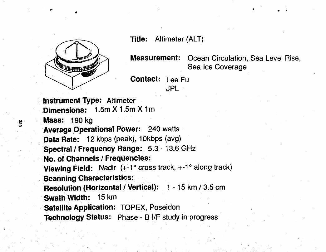
Title: Altimeter (ALT)
Measurement: OceanCirculation,Sea LevelRise,Sea Ice Coverage
Contact: LeeFuJPL
InstrumentType: AltimeterDimensions: 1.5mX 1.5mX lm
== Mass'. 190kgAverageOperationalPower: 240wattsDataRate: 12 kbps(peak),10kbps(avg)Spectral/ FrequencyRange: 5.3 - 13.6GHzNo.of Channels/ Frequencies:ViewingField: Nadir (+-1° crosstrack,+-1° alongtrack)ScanningCharacteristics:Resolution(Horizontal/ Vertical): 1 15km/ 3.5cmSwathWidth: 15kmSatelliteApplication: TOPEX,PoseidonTechnologyStatus: Phase- B I/F studyinprogress
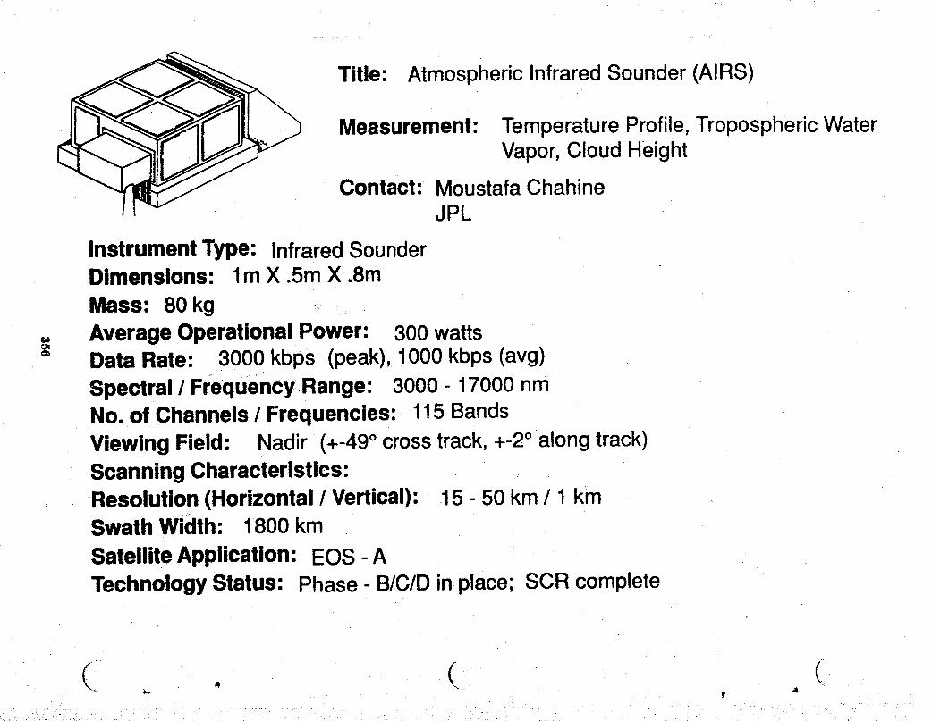
Title: Atmospheric Infrared Sounder (AIRS)
Measurement: TemperatureProfile,Tropospheric WaterVapor,Cloud Height
Contact: MoustafaChahineJPL
InstrumentType: InfraredSounderDimensions: lm X .5mX .8mMass: 80 kg
= AverageOperationalPower: 300wattsDataRate: 3000kbps (peak),1000kbps(avg)Spectral/ Frequency.Range: 3000- 17000nmNo.of Channels/ Frequencies: 115BandsViewingField: Nadir (+-49° crosstrack,+-2° alongtrack)ScanningCharacteristics:Resolution(Horizontal/ Vertical): .15- 50 km/ 1 kmSwathWidth: 1800kmSatelliteApplication: EOS- ATechnologyStatus: Phase- B/C/Dinplace;SCRcomplete
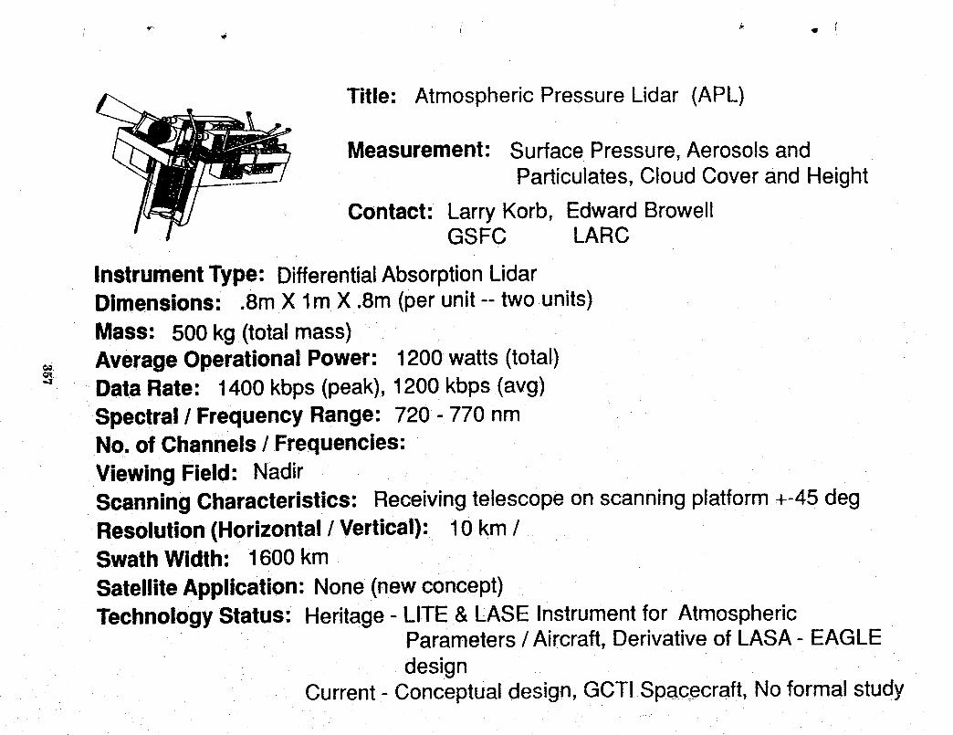
Title: Atmospheric Pressure Lidar (APL)
Measurement: Surface Pressure,AerosolsandParticulates, Cloud Cover and Height
Contact: Larry Korb, Edward BrowellGSFC LARC
InstrumentType: DifferentialAbsorptionLidarDimensions: .Sin X l m X .Sin (perunit -- two units)
Mass: 500 kg (totalmass)_, AverageOperationalPower: 1200 watts(total)€.R
"_ Data Rate: 1400 kbps(peak),1200 kbps(avg)Spectral / Frequency Range: 720 - 770 nmNo. of Channels / Frequencies:Viewing Field: NadirScanningCharacteristics: Receivingtelescopeon scanningplatform+-45 degResolution(Horizontal / Vertical): 10 km /Swath Width: 1600 km
SatelliteApplication: None(newconcept)TechnologyStatus: Heritage- LITE & LASE Instrumentfor Atmospheric
Parameters/ Aircraft,Derivativeof LASA- EAGLEdesign
Current- Conceptual design, GCT! Spacecraft, No formal study
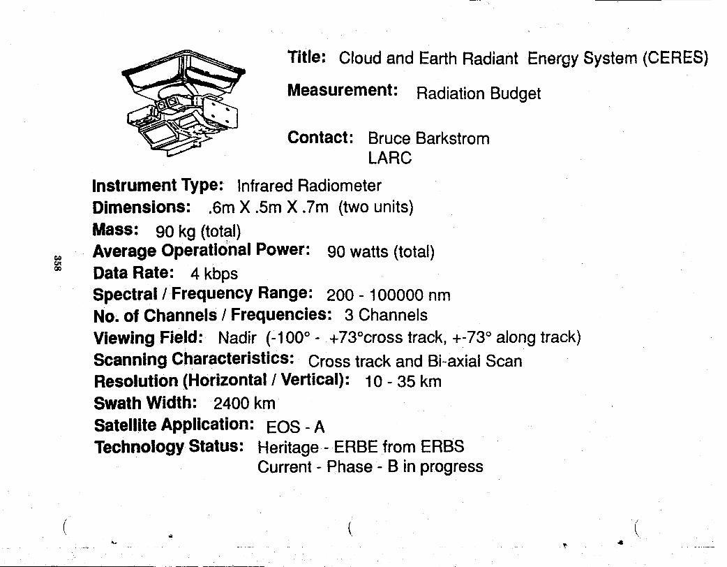
Title: Cloudand EarthRadiant EnergySystem(CERES)
Measurement: RadiationBudget
Contact: Bruce BarkstromLARC
Instrument Type: Infrared RadiometerDimensions: .6m X .Sin X .Tin (twounits)
Mass: 90 kg (total),, Average OperatiOnalPower: 90 watts(total)tax
oo Data Rate: 4 kbpsSpectral/Frequency Range: 200 - 100000 nmNo, of Channels / Frequencies: 3 ChannelsViewing Field: Nadir (-100° - +73°crosstrack,+-73° along track)Scanning Characteristics: Crosstrackand Bi-axialScanResolution(Horizontal/ Vertical): 10 - 35 kmSwath Width: 2400 kmSatelliteApplication: EOS - ATechnologyStatus: Heritage- ERBE from ERBS
Current- Phase- B inprogress
C . € (

Title: Earth Observing Scanning Polarimeter (EOSP)
Measurement: Aerosols and Particulates, Ozone
Contact: Larry TravisGSFC
InstrumentType: PolarimeterDimensions: .3m X .3m X .3m
Mass: 11kg_= AverageOperationalPower: 11watts
DataRate: 86 kbps(peak),44 kbps(avg)Spectral/ FrequencyRange: 410 - 2250 nmNo.of Channels/ Frequencies:ViewingField: Nadir (+-55°crosstrack,+-3° alongtrack)ScanningCharacteristics:Resolution(Horizontal/ Vertical): 10km/SwathWidth: 2280kmSatelliteApplication: EOS-ATechnologyStatus: Phase- Bstartearly1990
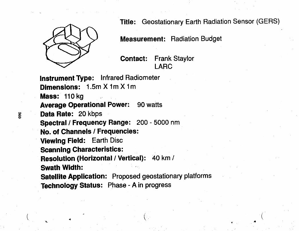
Title: GeostationaryEarth RadiationSensor (GERS)
Measurement: Radiation Budget
Contact: Frank StaylorLARC
InstrumentType: Infrared RadiometerDimensions: 1.5m X lm X lm
Mass: 110kgAverage Operational Power: 90 watts
= Data Rate: 20 kbpsO
Spectral / Frequency Range: 200 - 5000 nmNo. of Channels / Frequencies:Viewing Field: EarthDiscScanning Characteristics:Resolution(Horizontal / Vertical): 40 km /Swath Width:
SatelliteApplication: ProposedgeostationaryplatformsTechnologyStatus: Phase- A inprogress
C , - ( i
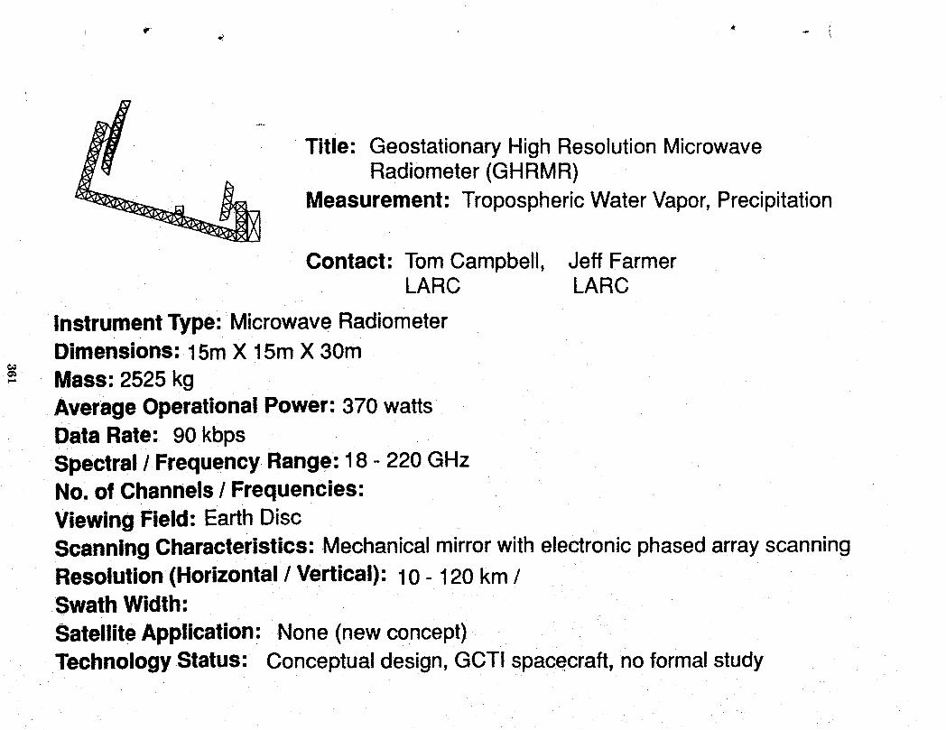
Title: Geostationary High Resolution MicrowaveRadiometer (GHRMR)
Measurement: Tropospheric Water Vapor,Precipitation
Contact: TomCampbell, Jeff FarmerLARC LARC
InstrumentType: MicrowaveRadiometerDimensions: 15m X 15m X 30mMass: 2525 kgAverage OperationalPower: 370 wattsData Rate: 90 kbpsSpectral / Frequency Range: 18 - 220 GHzNo, of Channels/ Frequencies:Viewing Field: EarthDiscScanningCharacteristics: Mechanicalmirrorwithelectronicphasedarray scanningResolution (Horizontal/ Vertical): 10 - 120 km /Swath Width:SatelliteApplication: None (newconcept)TechnologyStatus: Conceptualdesign,GCTI spacecraft,noformalstudy
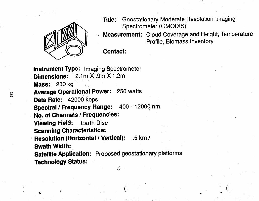
Title: Geostationary Moderate ResolutionImagingSpectrometer (GMODIS)
Measurement: Cloud Coverage and Height,TemperatureProfile, Biomass Inventory
Contact:
InstrumentType: Imaging SpectrometerDimensions: 2.1m X .9m X 1.2mMass: 230 kgAverageOperational Power: 250 watts
t_
Data Rate: 42000 kbpsSpectral / Frequency Range: 400 - 12000 nmNo. of Channels / Frequencies:Viewing Field: EarthDiscScanning Characteristics:Resolution(Horizontal / Vertical): .5 km /Swath Width:SatelliteApplication: ProposedgeostationaryplatformsTechnologyStatus'.
/

Title: GeostationaryOperational EnvironmentalSatellite (GOES) Imager
Measurement: SurfaceTemperature,Cloud Cover,Wind Fields
Contact:
InstrumentType: VIS /IR RadiometerDimensions: 1.5m X lm X lm
¢e
= Mass: 118kg€o
Average Operational Power: 130 wattsData Rate-: 2621 kbps
Spectral / Frequency Range: 700 - 12000 nmNo. of Channels /Frequencies: 5 ChannelsViewing Field: EarthDiscScanningCharacteristics:Resolution(Horizontal / Vertical): 8 km/ 1 kmSwathWidth:SatelliteApplication: GOESTechnologyStatus:
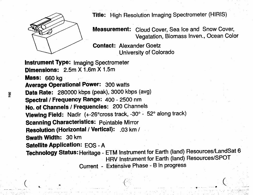
Title: High ResolutionImagingSpectrometer(HIRIS)
Measurement: CloudCover,Sea Iceand SnowCover,Vegatation,BiomassInven.,OceanColor
Contact: AlexanderGoetzUniversityofColorado
InstrumentType: ImagingSpectrometerDimensions: 2.5mX 1.6mX 1.5mMass: 660kgAverageOperationalPower: 300watts
== DataRate: 280000kbps(peak),3000kbps(avg)Spectral/ FrequencyRange: 400- 2500nmNo.of Channels/ Frequencies: 200 ChannelsViewingField: Nadir (+-26°crosstrack,-30° - 52° alongtrack)ScanningCharacteristics:PointableMirrorResolution(Horizontal/ Vertical): .03km/SwathWidth: 30kmSatelliteApplication:EOS- ATechnologyStatus:Heritage- ETMInstrumentforEarth(land)Resources/LandSat6
HRVInstrumentforEarth(land)Resources/SPOTCurrent- ExtensivePhase- Binprogress
. C-- C_.- ._t,........ _t ............ 4 .-=
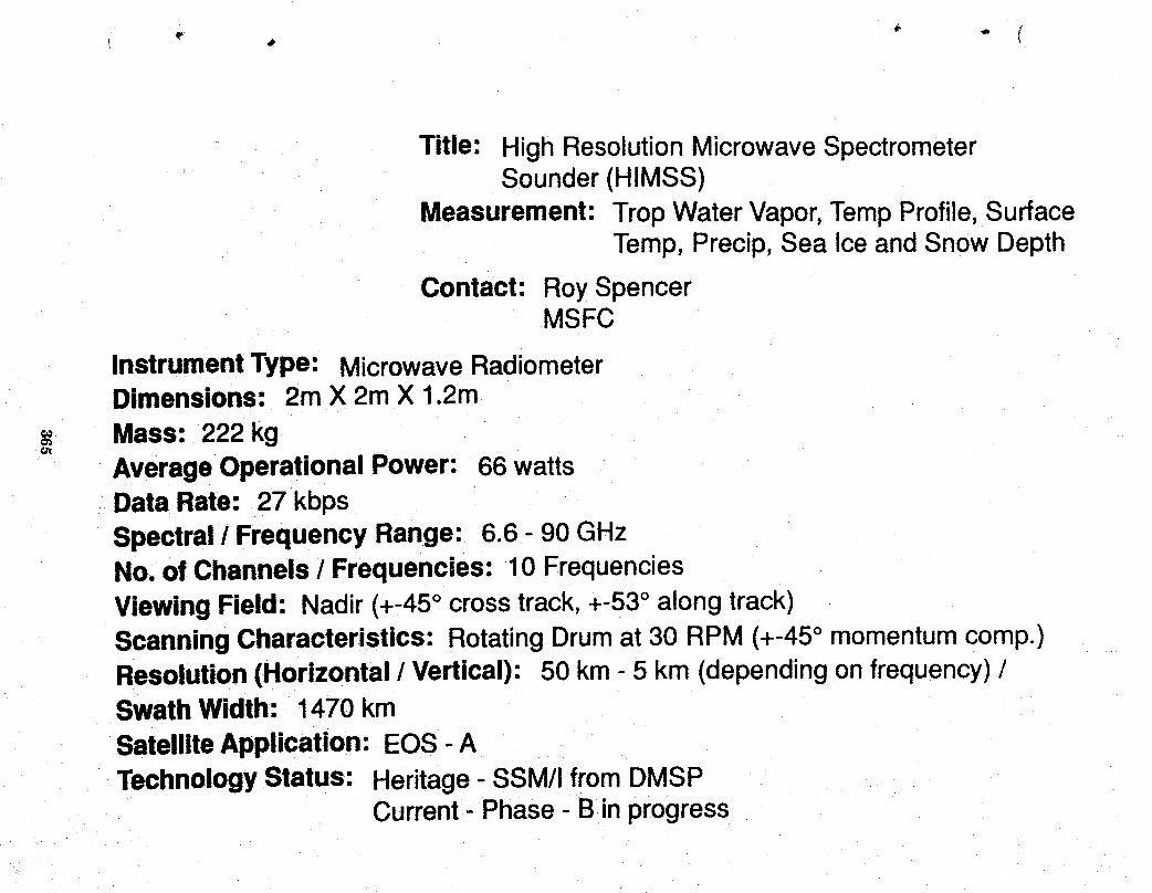
Title: High Resolution MicrowaveSpectrometerSounder (HIMSS)
Measurement: Trop Water Vapor,TempProfile, SurfaceTemp, Precip, Sea Ice and Snow Depth
Contact: Roy SpencerMSFC
Instrument Type: Microwave RadiometerDimensions: 2m X 2m X 1.2m
== Mass: 222kg¢JI
AverageOperational Power: 66 wattsData Rate: 27 kbpsSpectral / Frequency Range: 6.6 - 90 GHzNo. of Channels / Frequencies: 10 FrequenciesViewing Field: Nadir(+-45° crosstrack,+-53° alongtrack)ScanningCharacteristics: RotatingDrumat 30 RPM (+-45° momentumcomp.)Resolution(Horizontal / Vertical): 50 kin- 5 km (dependingonfrequency)/Swath Width: 1470 kmSatelliteApplication: EOS - ATechnologyStatus: Heritage- SSM/I fromDMSP
Current- Phase- B inprogress
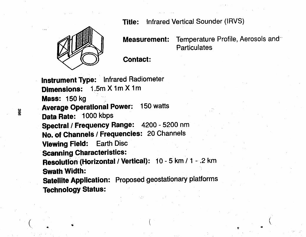
Title: Infrared Vertical Sounder (IRVS)
Measurement: TemperatureProfile,Aerosolsand-Particulates
Contact:
InstrumentType: InfraredRadiometerDimensions: 1.5mX lm X lmMass: 150kg _.
= AverageOperationalPower: 150watts= DataRate: 1000 kbps
Spectral/ FrequencyRange: 4200- 5200nmNo.of Channels/ Frequencies: 20 ChannelsViewingField: EarthDiscScanningCharacteristics:Resolution,(Horizontal/ Vertical): 10- 5 km/ 1 - .2 kmSwathWidth:SatelliteApplication: ProposedgeostationaryplatformsTechnologyStatus:
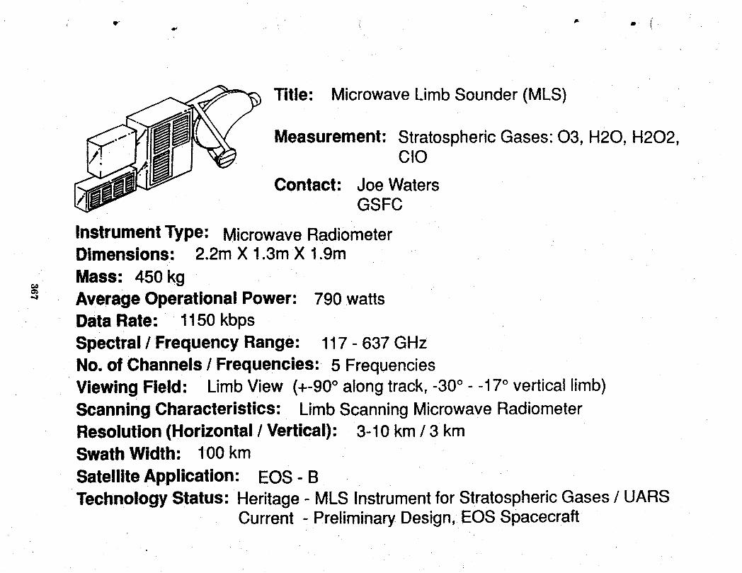
Title: Microwave Limb Sounder (MLS)
Measurement: Stratospheric Gases: 03, H20, H202,CIO
Contact: Joe WatersGSFC
Instrument Type: Microwave RadiometerDimensions: 2.2m X 1.3m X 1.9m
Mass: 450kgAverage Operational Power: 790 wattsData Rate: 1150kbpsSpectral / Frequency Range: 117 - 637 GHzNo. of Channels / Frequencies: 5 FrequenciesViewing Field: LimbView (+-90° alongtrack,-30° - -17° verticallimb)Scanning Characteristics: LimbScanningMicrowaveRadiometerResolution(Horizontal / Vertical): 3-10 km / 3 kmSwath Width: 100 km
Satellite Application: EOS - BTechnologyStatus: Heritage - MLS Instrumentfor StratosphericGases / UARS
Current - PreliminaryDesign, EOS Spacecraft
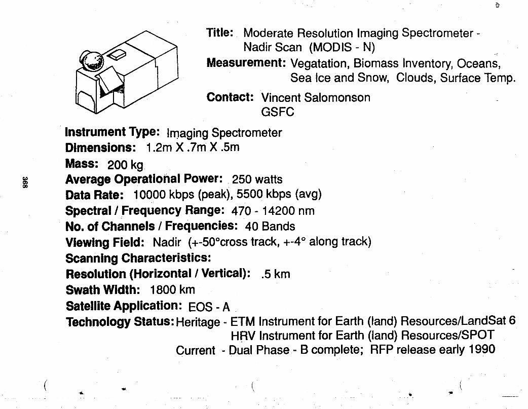
Title: Moderate Resolution ImagingSpectrometer-Nadir Scan (MODIS - N) _
Measurement: Vegatation, Biomass Inventory,Oceans,Sea Ice and Snow, Clouds, Surface Temp.
Contact: Vincent SalomonsonGSFC
InstrumentType: ImagingSpectrometerDimensions: 1.2m X .7mX .Sm
Mass: 200 kg,'_ AverageOperational Power: 250 wattsO¢
Data Rate: 10000 kbps (peak),5500 kbps (avg)Spectral /Frequency Range: 470 - 14200 nmNo, of Channels / Frequencies: 40 BandsViewing Field: Nadir (+-50°crosstrack,+-4° alongtrack)ScanningCharacteristics:Resolution(Horizontal / Vertical): .5 kmSwath Width: 1800 km
SatelliteApplication: EOS - ATechnologyStatus:Heritage- ETM Instrumentfor Earth (land) Resources/LandSat6
HRV Instrumentfor Earth(land)Resources/SPOTCurrent - DualPhase - B complete; RFP releaseearly1990
\
Title: Moderate Resolution ImagingSpectrometer-Tilt Scan (MODIS - T)
Measurement: Cloud Cover,Sea Ice and Snow Cover,Vegatation, Biomass Inven.,Ocean Color
Contact: Vincent Salomonson.GSFC
InstrumentType: Imaging SpectrometerDimensions: .5m X .5m X .4m
,, Mass: 100kgAverage OperationalPower: 150wattsData Rate: 8500 kbps (peak),3500 (avg)Spectral / Frequency Range: 400 - 1040 nmNo. of Channels / Frequencies: 64 ChannelsViewing Field: Nadir (+-50°crosstrack,+-50° alongtrack)Scanning Characteristics: Scan MirrorResolution(Horizontal / Vertical): 1 km /Swath Width: 1800 kmSatellite Application: EOS - ATechnologyStatus: Heritage- ETM Instrumentfor Earth(land)Resources/LandSat6
HRV Instrumentfor Earth(land)Resources/SPOTCurrent - ExtendedPhase - B studycomplete;design in hand

i •
Title: Ozone Mapper (OZMAP)
Measurement: Ozone
Contact'.
InstrumentType: UV SpectrometerDimensions: _,_1m X lm X 1.67mMass: 100kgAverageOperational Power: 130 watts
,, Data Rate: 70 kbpso
Spectral / Frequency Range: 295 - 318 nm, 6000 - 18000 nmNo. of Channels / Frequencies:Viewing Field: EarthDiscScanningCharacteristics:Resolution(Horizontal / Vertical): 43 km/ .6 kmSwath Width:SatelliteApplication: ProposedgeostationaryplatformsTechnologyStatus:
( - I
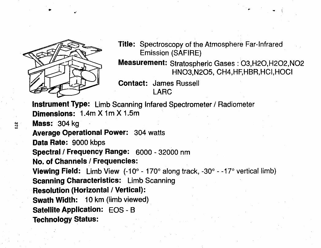
Title: Spectroscopy of the Atmosphere Far-infraredEmission (SAFIRE)
Measurement: Stratospheric Gases : O3,H20,H202,NO2HNO3,N205, CH4,HF,HBR,HCI,HOCI
Contact: James RussellLARC
Instrument Type: Limb Scanning Infared Spectrometer/ RadiometerDimensions: 1.4m X lm X 1.5m
,_ Mass: 304 kg.ql
Average Operational Power: 304 wattsData Rate: 9000 kbpsSpectral / Frequency Range: 6000 - 32000 nmNo. of Channels / Frequencies:Viewing Field: LimbView (-10° - 170° alongtrack, -30° - -17° verticallimb)Scanning Characteristics: LimbScanningResolution(Horizontal / Vertical):Swath Width: 10 km (limbviewed)SatelliteApplication: EOS - BTechnologyStatus:

Title: StratosphericAerosol and Gas Experiment(SAGE III)
Measurement: StratosphericGases: 03, NO2, H20,Aerosols and Particulates
Contact: Patrick McCormickLARC
Instrument Type: Limb Scanning Grating SpectrometerDimensions: .35m X .35m X .Em
Mass: 60 kg,, Average Operational Power: 25 watts
Data Rate: 11 kbps (peak), 8 kbps (avg)Spectral / Frequency Range: 300 - 1500 nmNo. of Channels / Frequencies:Viewing Field: Nadir ( +-180° alongtrack,-30° - -23° verticallimb)Scanning Characteristics: ScanningMirrorResolution(Horizontal / Vertical): / 1 - 2 kmSwath Width:
Satellite Application: EOS - ATechnologyStatus: Heritage- SAGE II on ERBS
Current--.PhaseB/C/D scheduledfor 1990
Title: StratosphericWind InfraredLimb Sounder(SWIRLS)
Measurement: Wind Fields (Stratospheric),TempertureProfile
Contact: Daniel McCleeseJPL
InstrumentType: Gas CorrelationRadiometerDimensions: .52 m3Mass; 90 kgo=
_" AverageOperational Power: 197wattsData Rate" 1 kbpsSpectral / Frequency Range: 7600 - 17200 nmNo. of Channels / Frequencies:Viewing Field: LimbView (45° - 135° alongtrack,-30° - -23° verticallimb)ScanningCharacteristics: ScanMirrorResolution(Horizontal / Vertical): 200 kin/3 kmSwath Width: 200 km (limb)Satellite Application: EOS-BTechnologyStatus: Heritage- PMR instrumentforstratosphericgases/NIMBUS
Current- Preliminarydesign,EOSspacecraft
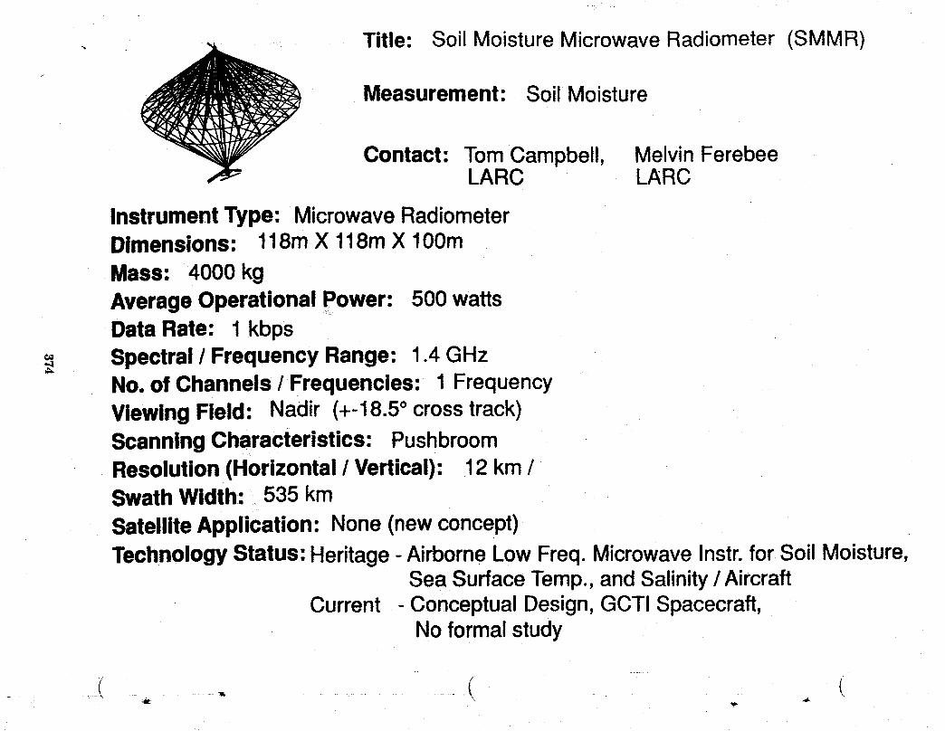
. - Title: Soil Moisture Microwave Radiometer SMMR)/
Measurement: Soil Moisture
Contact: TomCampbell, Melvin FerebeeLARC LARC
InstrumentType: MicrowaveRadiometerDimensions: 118mX 118mX 100mMass: 4000 kgAverageOperational Power: 500 wattsDataRate: 1 kbpsSpectral / Frequency Range: 1.4 GHzNo. of Channels/Frequencies: 1 FrequencyViewing Field: Nadir (+-18.5° crosstrack)ScanningCharacteristics: PushbroomResolution(Horizontal / Vertical): 12 km /SwathWidth: 535 kmSatelliteApplication: None(newconcept)TechnologyStatus: Heritage- AirborneLowFreq.MicrowaveInstr.forSoil Moisture,
Sea SurfaceTemp.,andSalinity/AircraftCurrent - ConceptualDesign,GCTI Spacecraft,
Noformalstudy

Title: Solar Stellar IrradianceComparison Experiment
(SOLSTICE)Measurement: Spectral Radiation
Contact: Gary RottmanUnlverswtyof Colorado
Instrument Type: Ultra-VioletSpectrometerDimensions: .3m X .3m X.lm
Mass: 146kg€o
=_ Average Operational Power: 72 wattsData Rate: 5 kbpsSpectral/Frequency Range: 120 - 500 nmNo. of Channels / Frequencies: 3 ChannelsViewing Field: SunTracking(90° - 270° crosstrack)Scanning Characteristics: InstrumentplacedonsunpointingplatformResolution (Horizontal / Vertical): SunDiskSwath Width:
Satellite Application: UARS,SpaceStationattachedpayloadTechnologyStatus:
Title: Three Channel Microwave Radiometer(3CMR)
Measurement: Ocean Circulation,AtmosphericWaterVapor Correction
Contact:
InstrumentType: MicrowaveRadiometerDimensions: .3m X .3m X .3m
Mass: 27 kgAverageOperational Power: 30 wattsData Rate: .128 kbpsSpectral / Frequency Range:No. of Channels / Frequencies:Viewing Field: Nadir (+-3° crosstrack,+-3° alongtrack)Scanning Characteristics:Resolution (Horizontal / Vertical):Swath Width: 50kin
SatelliteApplication: TOPEX, PoseidonTechnologyStatus:
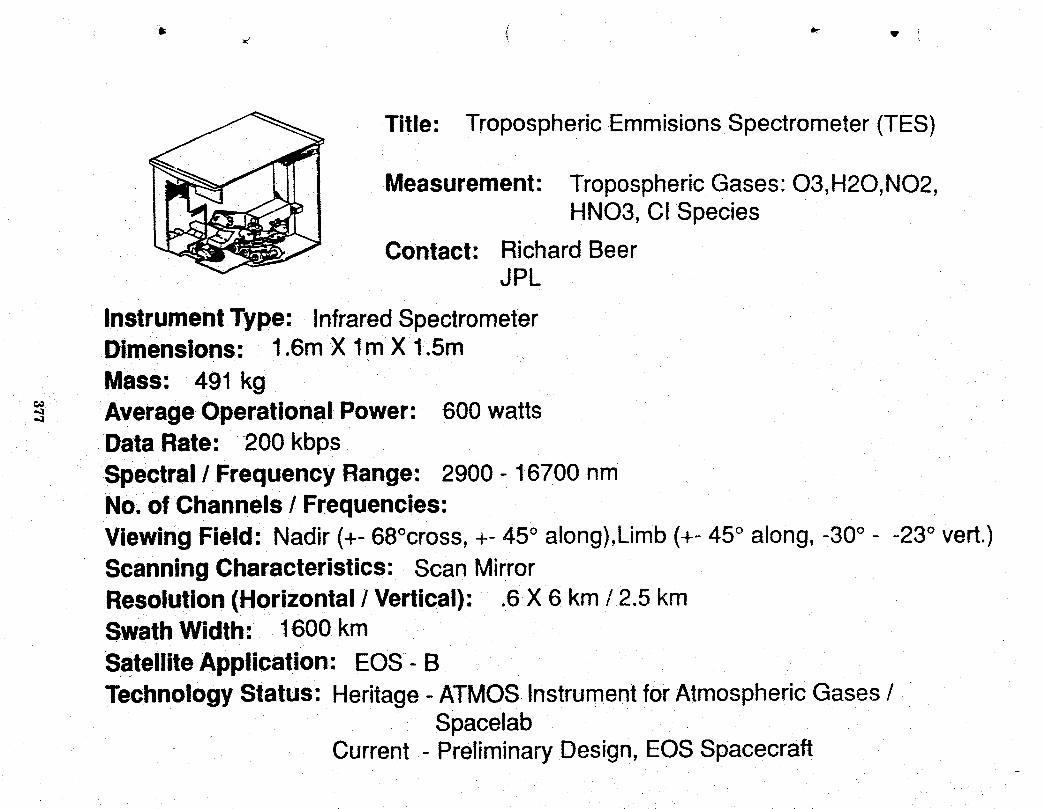
Title: Tropospheric EmmisionsSpectrometer (TES)
Measurement: TroposphericGases: O3,H20,NO2,HNO3, C! Species
Contact; Richard BeerJPL
InstrumentType: InfraredSpectrometerDimensions: 1.6m X l m X 1.5m
Mass: 491 kg.,-_ AverageOperational Power: 600 watts
Data Rate: 200 kbpsSpectral / Frequency Range: 2900 - 16700 nmNo. of Channels / Frequencies:Viewing Field: Nadir(+- 68°cross,+- 45° along),Limb(+- 45° along, -30° - -23° vert.)ScanningCharacteristics: Scan MirrorResolution(Horizontal / Vertical): .6 X 6 km / 2.5 kmSwathWidth: 1600 km
SatelliteApplication: EOS- BTechnologyStatus: Heritage- ATMOS InstrumentforAtmosphericGases /
SpacelabCurrent - Preliminary Design, EOSSpacecraft
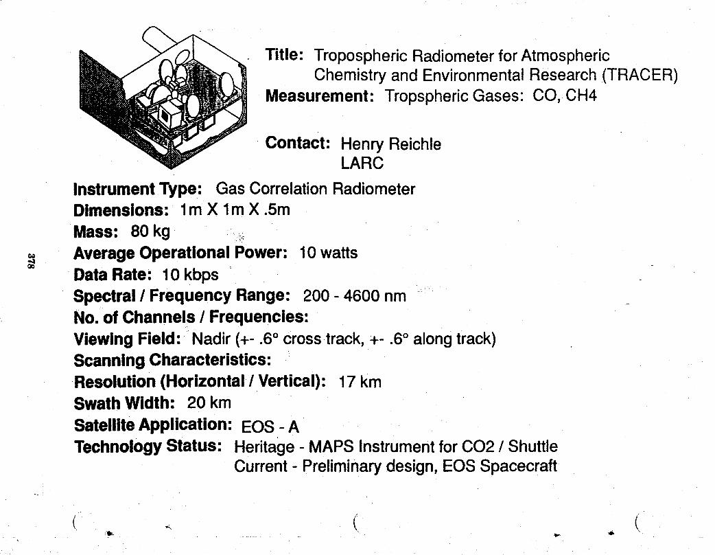
Title: Tropospheric Radiometerfor AtmosphericChemistry and EnvironmentalResearch (TRACER)
Measurement: TropsphericGases: CO, CH4
Contact: Henry ReichleLARC
InstrumentType: Gas CorrelationRadiometerDimensions: lm X lm X .5m
Mass: 80 kg _.AverageOperational Power: 10watts
O¢
Data Rate: 10 kbpsSpectral / Frequency Range: 200 - 4600 nmNo. of Channels / Frequencies:Viewing Field: Nadir(+- .6° crosstrack,+- .6° alongtrack)ScanningCharacteristics:Resolution(Horizontal / Vertical): 17 kmSwath Width: 20 kmSatelliteApplication: EOS - ATechnologyStatus: Heritage- MAPS InstrumentforCO2 / Shuttle
Current- Preliminarydesign,EOS Spacecraft
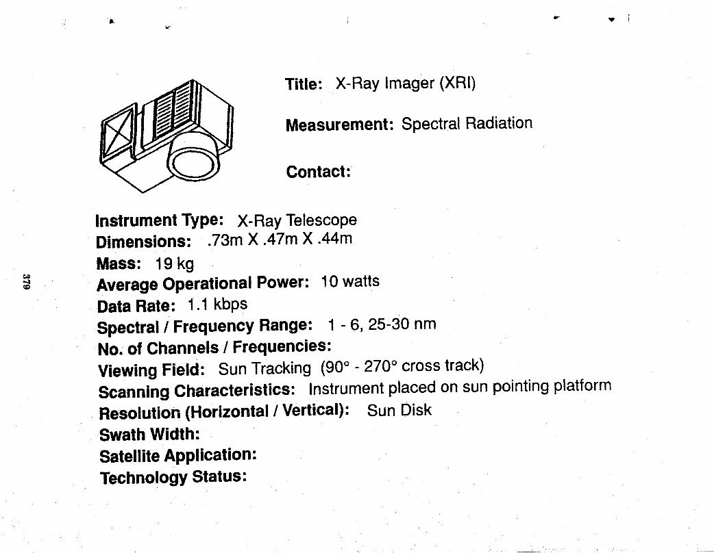
Title: X-Ray lmager (XRI)
Measurement: Spectral Radiation
Contact:
InstrumentType: X-Ray TelescopeDimensions: .73m X .47m X .44m
Mass: 19kg€o
Average Operational Power: 10 wattsDataRate: 1.1 kbps
Spectral/ Frequency Range: 1 - 6, 25-30 nmNo. of Channels / Frequencies:Viewing Field: SunTracking (90° - 270° crosstrack)ScanningCharacteristics: Instrumentplaced on sun pointingplatformResolution(Horizontal / Vertical): Sun DiskSwath Width:SatelliteApplication:TechnologyStatus:

APPENDIX C
PLOTS OF GROUND COVERAGE ACHIEVEABLE BYGLOBAL CHANGE MONITORING INSTRUMENTS AND SPACECRAFT
Heather R. KnightJoint Institute for Advancement of Flight Sciences
Lynda FoernslerUniversity of Auburn

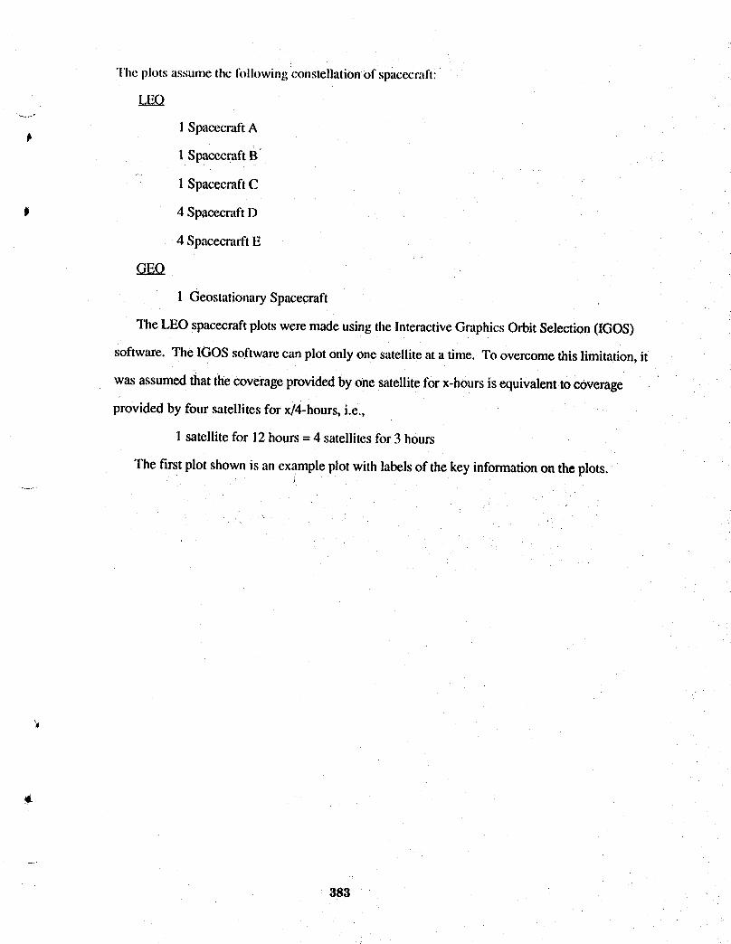
"l'heplots assume the Iollowingconstellationof spacecratt:
V.Lg_Q
I SpacecraftA
1SpacecraftB
1 SpacecraftC
J 4 SpacecraftD
4 SpacecrarftE
GEO
1 GeostationarySpacecraft
The LEO spacecraftplots were madeusing tileInteractiveGraphicsOrbit Selection(IGOS)
software. The IGOS softwarecan plotonly one satelliteat a time. To overcomethis limitation,it
wasassumedthat thecoverageprovidedby one satellitefor x-hoursis equivalentto coverage
provided by four satellitesfor x/4-hours,i.e.,
1 satellitefor 12hours= 4 satellitesfor 3 hours
The first plotshown is an exampleplotwith labelsof the key informationon the plots,
383

SAMPLE PLOT
All satellites are in an 800km circular orbit at an inclination -1of 98.6 degrees (sun-synchronous). Specifics of the instrumentare listed at the top of the page while the time period of the plotand the percentage of the Earth covered during this time periodare listed on the right.
384
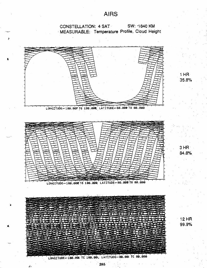
AIRS
CONSTELLATION: 4 SAT SW: ,1840 KM.... MEASURABLE: Temperature Profile, Cloud Height
1HR35.8%
3 HR84.8%
i _ i i I t 1 i i i i, ,1 ! i i i i i i i J i i i i _ i _ i i i i i i t
LONGITUDE=--18g, 8g@TO 188. gg_ LATITUDE,- 8g. ggg TO 8g. 8gO
12 HR99.9%
LONGITUDE.,.-1,88.eOITCzse.ee=, LAT[TUDE.-8e.0O_TC8e.eee
,;, 385

ALT
CONSTELLATION: 1 SAT SW:'15 KMMEASURABLE: Ocean Circulation, Sea Level Rise ....
1D4.7%
LONGITUOE=-I80.000TO 180.00_ LATITUDE,-80.000TO 80.800
2D9.3%
LONGITUDE,-I80.00e TO 180.00_ LATITUD£,-80.000 TO 80.000
Jb
"1
386

i
AMSU
CONSTELLATION: 4 SAT SW_ 1900 KM- MEASURABLE: Temperature Profile
t il t - 1 HR
37.1%
i t , i , _ i _ i i "
LONG[ TUDE=-180, OO&TO 180. 001_ LA [ I TUDE=-80. t_O8TO 80. 000
3 HR86.4%
LONGITUDE--t80.00eT0 t88.00_ LATITUDE,-80.000T0 88.000
12 HR" 99.9%
LONGITUOE,-_80,00e TO 180.00_ LATITUDE,-80,00Q TO 80.000
887
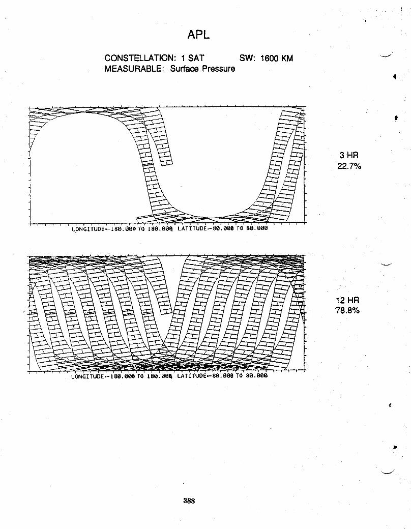
i
APL
CONSTELLATION:1 SAT SW: 1600 KM _-_MEASURABLE: SurfacePressure
4
3 HR22.7%
I i i ; i _ i i ! , _ i l i i i ; i i i i i i i i i i i i , 1 i |
LONG];TUDE=-1.80.0@0 TO 18g. O{_el LAT [ TUDE=- 80. gg0 TO 88. Ogl_
12 HR,. 78.8%
388

t
CERES
........ CONSTELLATION: 4 SAT SW_.2500 KMMEASURABLE: Radiation Budget
/,
t
1 HR51.6%
LONGITUOE,-180.OOOTO 180.000 LATITUDE,-80.000 TO 80.000
LONGITUOE--I80.000 TO 180.000 LATITUOE=-80.000TO 80.000
I
389
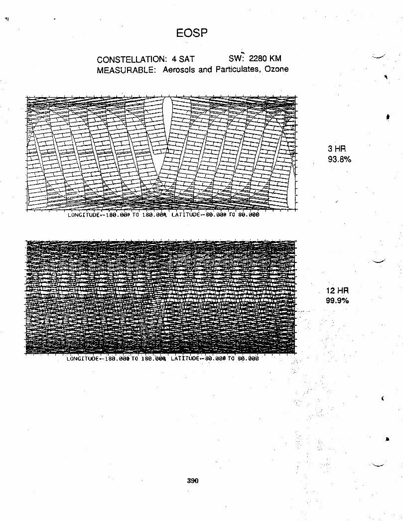
EOSP
CONSTELLATION: 4 SAT SW_:2280 KM "'-_MEASURABLE: Aerosols and Particulates, Ozone
3 HR93.8%
12 HR99.9%
LONGITUOE.-18B.OOe TO 180.00_ LATITUDE,-80.B00 TO 86._60
J
39O

HIMSS
..... CONSTELLATION: 4 SAT SW: "1470 KMMEASURABLE: Precipitation, Temperature Profile,
w Surface Temperature
t
1 HR28.1%
i l i _ _ r i i _ I i i i E l I i I I 1 i i i i i 1
LONGITUDE=-L80.BeeTO 180.00_ LATITUOE=-80.00e TQ 80.000
3 HR71.5%
LONGITUDE,-L80.00QTO 180.0OQ LATITUDE,-80.009 rO 80.888
12 HR99.6%
LONGITUOE--L88.BSeTO t80.08_ LATITUDE,-80.008 TO 8_.008
391 '
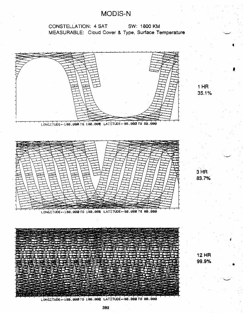
MODIS-N
CONSTELLATION: 4 SAT SW: 1800 KMMEASURABLE: Cloud Cover & Type, Surface Temperature ..-_-.-
,I
1 HR35.1%
LONGITUDE=-I80.00_T(_ 180.00_ LAI'ITUDE.-80.00(_TO 80.000
3 HR83.7%
LONGITUDE=-180. 000 FO 180. 001_ 'LATITUOE,,-80.000 TO 80. 000
12 HR99.9%
J_
LONGITUDE_I80.00_TO 180.00_'LATITUDE_80.00Q T0.80.000
392
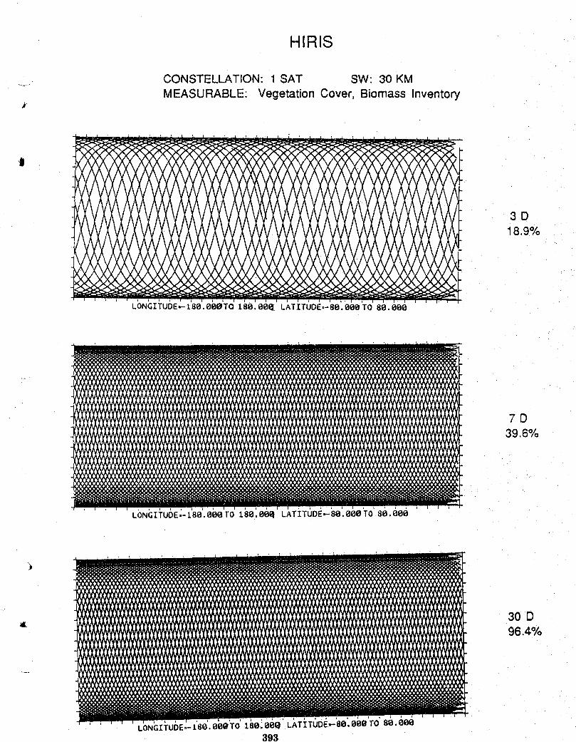
HIRIS
CONSTELLATION: 1 SAT SW: 30 KM
MEASURABLE: Vegetation Cover, Biomass Inventory
t
3D18.9%
i , i J
LONGITUOE,,-180.00eTO 180.00(_. LATITUDE,-80.00e TO 80. 000
7D39.6%
LbN(3I_rU6E ;- 1'80'. eOO TO 180'.O(_ LATi_TODI_,-'SB. 00OT0 80. eee
30 D= 96.4%
LONGITUDE,,-180. 000 TO 180 '.00e' LATI TUDE.-.-80. eee TO Be. ace393
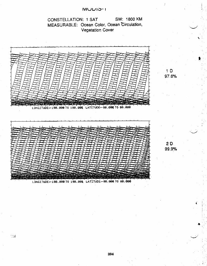
IVILJLJ I_._- I
CONSTELLATION: 1 SAT SW: 1800 KMMEASURABt.E: Ocean Color, Ocean _irculation,
Vegetation Cover
t
1D97.6%
LONGITUOE,-180.eOe TO 180.00_ LATITUDE,-80.00e TO 80.088
2D99.9%
LONGITUDE--Z80,00eTO 180.00_ LATITUDE=-80.008 TO 80.000
394
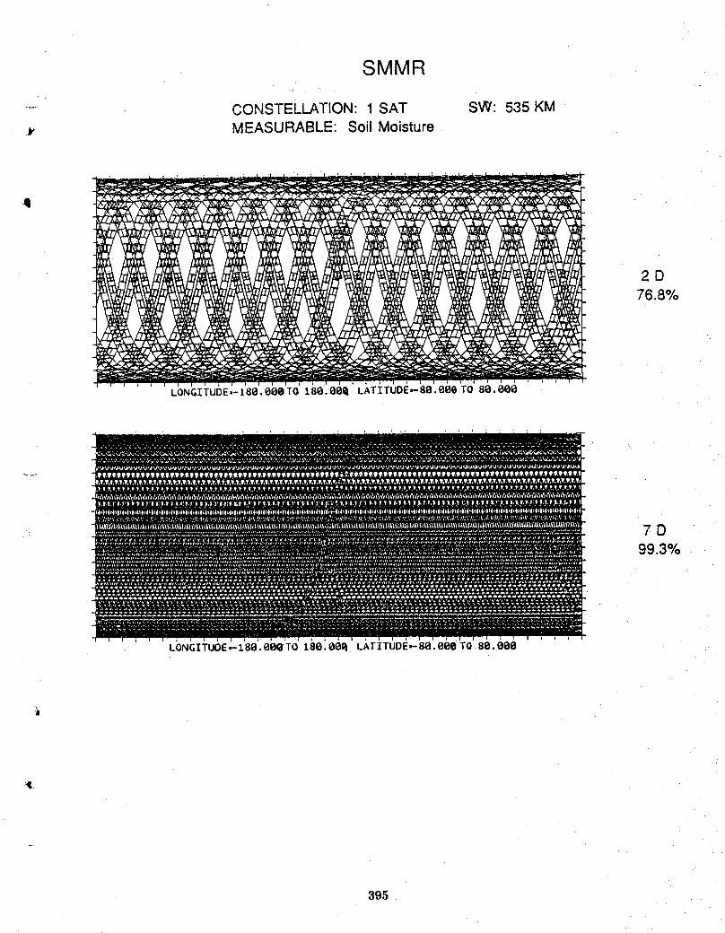
SMMR
...... CONSTELLATION: 1 SAT SW: 535 KM
_. MEASURABLE: Soil Moisture
,q
2D76.8%
LONGITUDE=-I80.000TO 180.00_ LATITUDE_80.000 TO 80.000
LONGITUOE_180.000'TO 180.80_ LATITUDE,-80.000 TO 80.000
4.
395
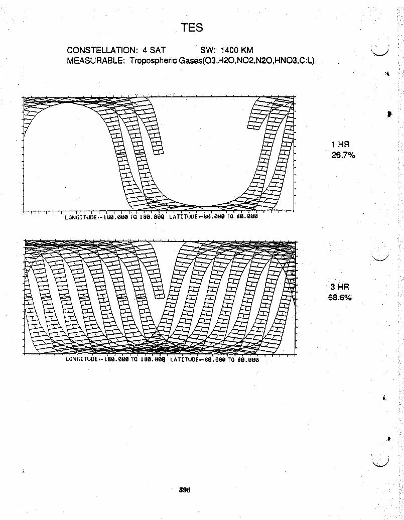
TES
CONSTELLATION: 4 SAT SW: 1400 KM _...jMEASURABLE: Tropospheric Gases(O3,H20,NO2,N20,HNO3,C:L)
1HR26.7%
3 HR68.6%
LON(;[TUDE,-L80.00@ TO 180.00a LATITUDE,-80.00a TO80.000
396
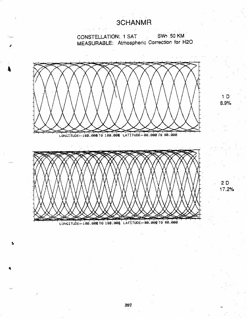
3CHANMR
....... CONSTELLATION:, 1 SAT SW.*50 KM
_. MEASURABLE: Atmospheric Correction for H20
1D8.9%
LONGITUOE,-I80.000T0 188.800 LATITUOE=-80.e00T0 88.000
2D17.2%
.... LONGITUDE_[80.000TO 180.000 LATITUDE=-80;00QT0 80.000
,!
397
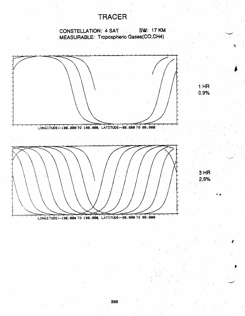
TRACER
CONSTELLATION: 4 SAT SW: 17 KMMEASURABLE:TroposphericGases(CO,CH4)
1 HR0.9%
LONGITUDE,-180.000 TO 180.00_ LATITUDE,-80.000 TO 80.000
3 HR.2.6%
LONGITUDE=-I80.000 TO 180.00_ LATITUDE,-80.000 TO 80.000
J
398
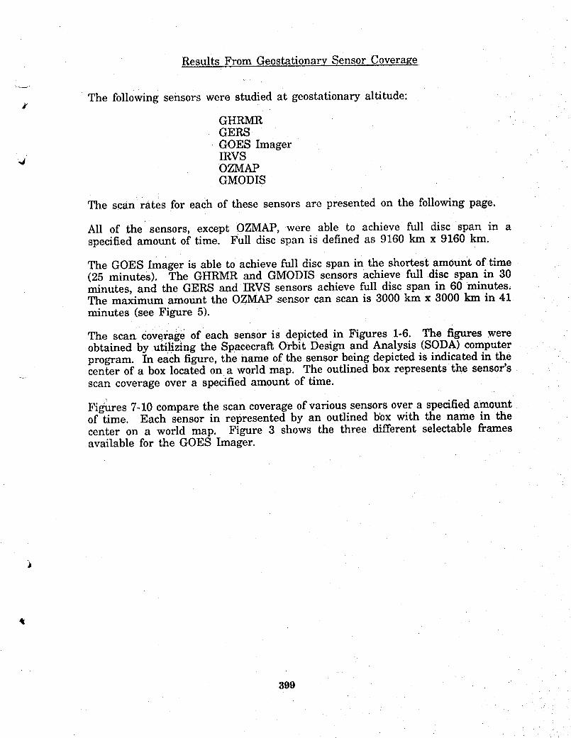
Results From Geostationary Sensor Coverage
The following sensors were studied at geostationary altitude:
GHRMRGERSGOES ImagerIRVS
"# OZMAPGMODIS
The scan rates for each of these sensors are presented on the following page.
All of the sensors, except OZMAP, were able to achieve full disc span in aspecified amount of time. Full disc span is defined as 9160 km x 9160 km.
The GOES Imager is able to achieve full disc span in the shortest amount of time(25 minutes). The GHRMR and GMODIS sensors achieve full disc span in 30minutes, and the GERS and IRVS sensors achieve full disc span in 60 minutes.The maximum amount the OZMAP sensor can scan is 3000 km x 3000 km in 41minutes (see Figure 5).
The scan coverage of each sensor is depicted in Figures 1-6. The figures wereobtained by utilizing the Spacecraft Orbit Design and Analysis (SODA) computerprogram. In each figure, the name of the sensor being depicted is indicated in thecenter of a box located on a world map. The outlined box represents the sensor's
..... scan coverage over a specified amount of time.
Figures 7-10 compare the scan coverage of various sensors over a specified amountof time. Each sensor in represented by an outlined b_x with the name in thecenter on a world map. Figure 3 shows the three different selectable framesavailable for the GOES Imager.
399

Sensor Scan Rate
Geostationary High Resoldtion 9i60x9160 km in 30 rainMicrowave Radiometer (GHRMR)
Geostationary Earth Radiation Full disc span inSensor (GERS) 1 to 3 hours
Geostationary Moderate Resolution Full disc span everyImaging Spectrometer (GMODIS) thirty min
Geostationary Operational Selectable Frame AvailableEnvironmental Satellite (GOES) Full earth in 25 rain,Imager 3000x3000 km in 3.1 vain,
or 1000xl000 kin in 40 sec
Active Cavity Radiometer Not applicable. Faces sun.][rradiance Monitor (ACRIM)
Infrared Vertical Sounder (IRVS) Full earth coverage in1 hr
Ozone Mapper (OZMAP) OZMAP coverage may besimilartoGOES Sounderwhich is3000x3000 kmin 41 minutes
400
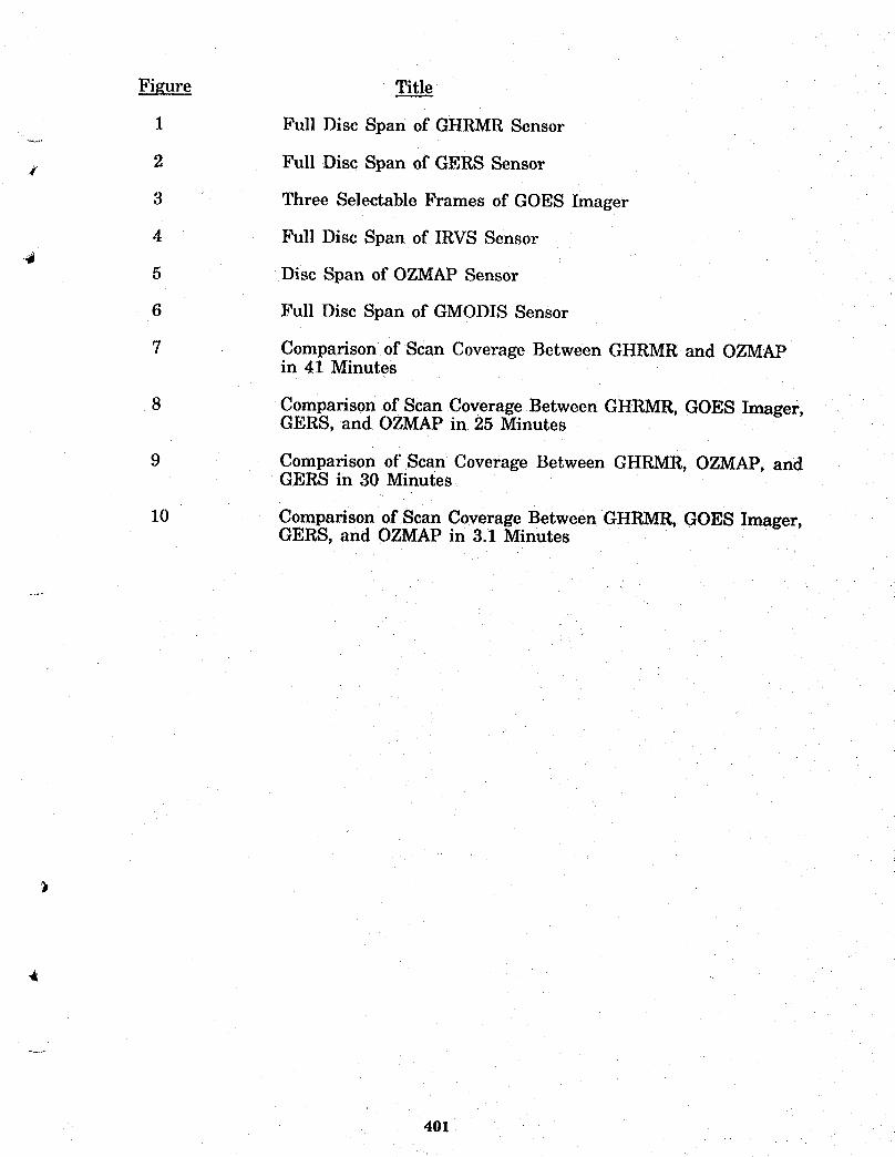
Figure Title
1 Full Disc Span of GHRMR Sensor..... .
2 Full Disc Span of GERS Sensor
3 Three Selectable Frames of GOES Imager
4 Full Disc Span of IRVS Sensor
5 Disc Span of OZMAP Sensor
6 Full Disc Span of GMODIS Sensor
7 Comparison of Scan Coverage Between GHRMR and OZMAPin 41 Minutes
8 Comparison of Scan Coverage Between GHRMR, GOES Imager,GERS, and OZMAP in 25 Minutes
9 Comparison of Scan Coverage Between GHRMR, OZMAP, andGERS in 30 Minutes
10 Comparison of Scan Coverage Between GHRMR, GOES Imager,GERS, and OZMAP in 3.1 Minutes
401
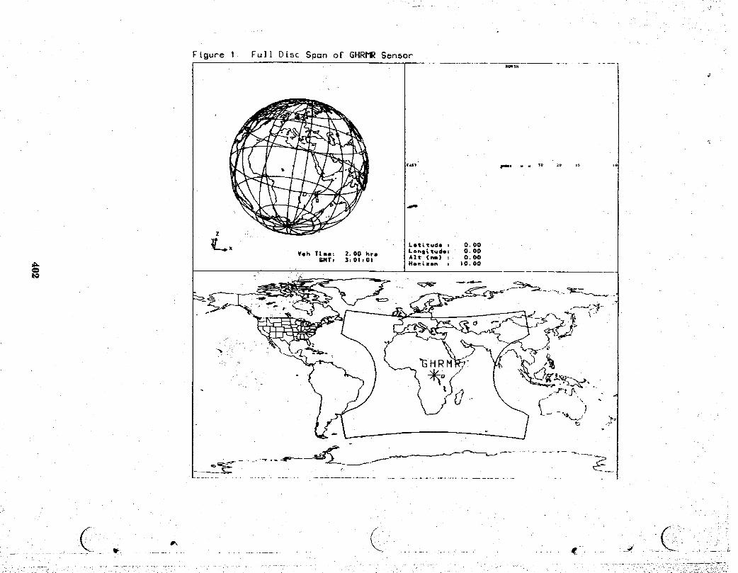
Figure I Full Disc Span of GHRMR Sensork_lM
[_Sl imn • M 3Q ;9 is
dwm
..........., .......... __-........................................................ ;--:.;:_c;_i,_:?_)!__
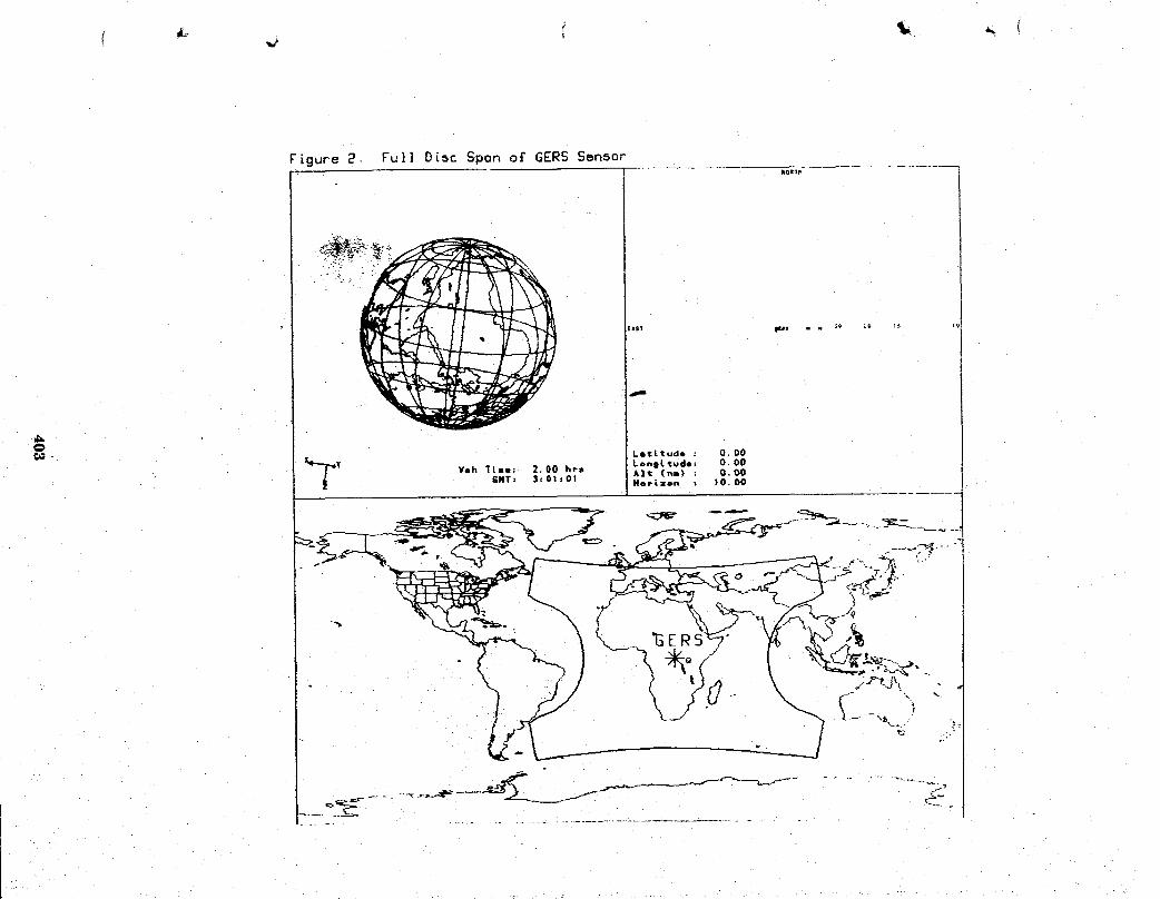
Figure 2 Full Disc Span ot GERS Sensor
t,sl ff.ls . . s_ z9 1_
.... L" "
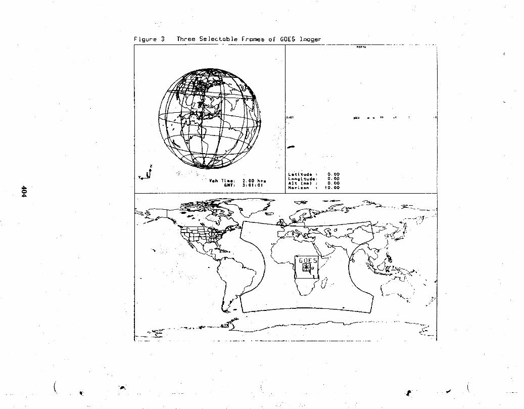
FLgure 3 Three Se]ectab]e Frames of GOES I_g_kOR_
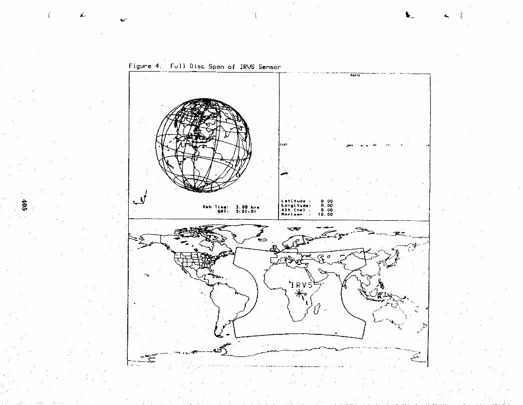
Figure 4. Fu]} Disc Span of ]RUS Sensor
AS! _s _ e sv _-€. i v
zJIL
_;_ v_ T Latitude z 0 O0
'9"--" Yeh ;lml: 2.00 hr8 LonsLt_de; O.OOGNTt 3101101 A]t CnI) : O, OO
H_P_zon : 10.00

Figure S. Disc Spon of OZMI_P Sensor
+Is+ t+,zh P . Z. !++ :.._ +++ :_,;

Figure G. Full Disc Span of GrIODIS SensorNQII_
Z
LetLtudo _ O.00
Y LoBs{rude; 0.00¥¢h T&Re: 2.00 hre Alt (ha) : .O. O0
GNI: 3zOIzOI Horizon : 10.00

Figur_ 7. Co,,_por_on o£ Scan Couer_ge 8_t_en GHRDIP_nd OZtlAP in 41 Minutes
......................

Figure 8 Comparison o£ Scon Coverage Betueen GHRMR,GOES ,Imager, GERS, and OZMAP in 2S Minutes
IOmlm
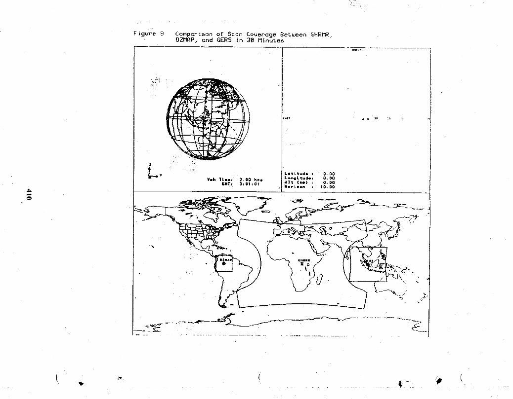
Figure g CompQrlson oE Soon Coverage Between GHR_.OZI_P, ond GERS in 38 Minutes
i;,$I m . $_ ;._ L_, :9

Figure 18 Comparison of Scan Couerage Bergen GHRMR,GOES Imager, GERS, and O_P in 3. I Minute_
kOAIP
Y
)'_ Let_tude : 0,00M,* XYeh Time: 2.00 hrs Longitude+ 0.00
GNTx 3tOllOI A|t (hi) : O. O0HOPLSOh , |0.00
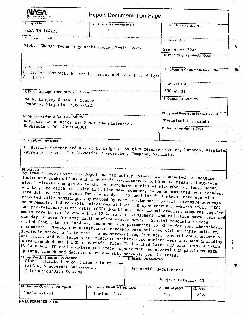
Report Documentation Page
1. Report No. 2. €_over,ment Accession No 3. Recipient's Catalog No.
NASA TM-I04128
4. Title and Subtitle 5. Report Date
Global Change Technology Architecture Trade Study September 19916. PerformingOrganizationCode
................................................................... 8. Performing Organization Report No.
1,. Bernard Carrett, Warren I). ltypes, and Robert L. Wright
(Ed i tot s) 10.WorkUnit No.
....................................................................................................................506-49-319. Performing Organization Name and Address
-{_. Contract or Grant No.
NASA, Langley Research Center
Hampton, Virginia 23665-5225
"_. Typeof ReportandPeriodCovered
"1-2_-Sponsoring Agency Name and Address Technical MemorandumNational Aeronautics and Space Administration
Washington, DC 20546-0001 14. Sponsoring &gency Code
15. Supplementary Notes
L. Bernard Garrett and Robert L. Wright: Langley Research Center, Hampton, Virginia.
Warren D. Hypes: The Bionetics Corporation, Hampton, Virginia.
_. Abstract
Systems concepts were developed and technology assessments conducted for science
instrument combinations and spacecraft archietecture options to measure long-term
global climate changes on Earth. An extensive series of atmospheric; lang, ocean,
and ice; and earth and solar radiation measurements, to be accumulated over decades,
were defined requirements for the study. The need for full global coverage with
repeated daily samilings, augumented by near continuous regional intensive coveragemeasurements, led to orbit selections at both Sun synchronous low-Earth orbit (LEO)
and geostationary Earth orbit (GEO) locations. For global studies, temporal require-
ments were to sample every 1 to 12 hours for atnospheric and radiation parameters and
one day or more for most Earth surface measurements. Spatial resolution needs
varied from 1 km for land and ocean surface parameters to 50 km for some atmospheric
parameters. Twenty seven instrument concepts were selected with multiple units onduplicate spacecraft, to meet_ the measurement requirements. Several combinations of
spacecraft and the large space platform architecture options were assessed including
Delta-launched small LEO spacecraft, Titan IV-launched large LEO platforms, a TitanIV-launched LEO soil moisture radiometer spacecraft and several GEO platforms with
optional launch and deployment or on-orbit assembly possibilities.
17, Key Words(SuggestedbyAuthor(s)) 18. DistributionStatementGlobal Climate Change, Science ]nstrumen- P
tation, Spacecraft Subsystems, Unclassified-UnlimitedIn[ormation/Data Systems
Subject Category 43
l --T21_N°"°f pages I _" Price
19. Security Classif. (of this report) 20_-S_c_tyCi_t_(__is-pageT-"- .........
Unclassified 1 Unclassified I 4L4 AI8, l i
_ASAFORM 16260CT

_jP
t'
4t_