19830013758.pdf - NASA Technical Reports Server
263
General Disclaimer One or more of the Following Statements may affect this Document This document has been reproduced from the best copy furnished by the organizational source. It is being released in the interest of making available as much information as possible. This document may contain data, which exceeds the sheet parameters. It was furnished in this condition by the organizational source and is the best copy available. This document may contain tone-on-tone or color graphs, charts and/or pictures, which have been reproduced in black and white. This document is paginated as submitted by the original source. Portions of this document are not fully legible due to the historical nature of some of the material. However, it is the best reproduction available from the original submission. Produced by the NASA Center for Aerospace Information (CASI)
-
Upload
khangminh22 -
Category
Documents
-
view
2 -
download
0
Transcript of 19830013758.pdf - NASA Technical Reports Server

General Disclaimer
One or more of the Following Statements may affect this Document
This document has been reproduced from the best copy furnished by the
organizational source. It is being released in the interest of making available as
much information as possible.
This document may contain data, which exceeds the sheet parameters. It was
furnished in this condition by the organizational source and is the best copy
available.
This document may contain tone-on-tone or color graphs, charts and/or pictures,
which have been reproduced in black and white.
This document is paginated as submitted by the original source.
Portions of this document are not fully legible due to the historical nature of some
of the material. However, it is the best reproduction available from the original
submission.
Produced by the NASA Center for Aerospace Information (CASI)

r.
DOE/NASA/0254-1NASA CR-168087 7
DEA 101-77CS51040
Stirling Engine Application Study
(NASA-CR- 166087) STIRLING EDIGINE U83-..2029APPLICATION STUDi Final Report (Little(Arthur D.) , Inc.) 261 p HC A 12/11F A01
CSLL 10B UnclasG3/85 09374
March 1983
Prepared forNATIONAL AERONAUTICS AND SPACE ADMINISTRATIONLewis Research CenterUnder Contract DEN 3-254
forU.S. DEPARTMENT OF ENERGYConservation and Renewable EnergyOffice of Energy Systems Research

DOE/NASA/0254-1NASA CR-168087DEA 101-77CS51040
Stirling Engine Application Study
March 1983
Prepared forNATIONAL AERONAUTICS AND SPACE ADMINISTRATIONLewis Research CenterUnder Contract DEN 3-254
forU.S. DEPARTMENT OF ENERGYConservation and renewable EnergyOffice of Energy Systems Research
{
S
I a
f_
ft
Ee
II
I.
I- iI
I
i
M ;'
1t
11 ;
` For sale by the National Technical Information Service, Springfield, Virginia 22161
NASA-C-168 (Rev. 10-75)
ti
U
1. Repo" No. 3. Gonerewnent Accession No. 3. Rae^ieect 'e ^ No.NASA CR-1687
1. Title and Su6titM S. Report Data*arch 1913
STIRLING ENGINE APPLICATIONS STUDY 8. tirfcrmkp OtrNration Os
y
de
^7. Iwthorlel & ^
atlll ^ No.
Williaa P. TeaganDavid R. Cunningham
10. Want Unit No.
9. Performing Organisation Name and Address
Arthur D. Little, Inc.Acorn Park 11. Oontrk! or Grant No.
Cambridge, MA 02140 DEN 3-254
13. Type of fiaport and Period Cograd
12. Sponsoring Agency Nerve and Address Contractor ReportU. S. Department of EnergyConservation and Renewable Energy 14. SPonprk+i ^=Y CodeOffice of Energy Systems Research DOE/NASA10254-1Washington, DC
15. SupplNnentary NobsFinal Report. Prepared under Interagency Agreement DE-AI01-77CS51040. Project Manager,Donald Alger, Transportation Propulsion Division, NASA Lewis Research Center,Cleveland, Ohio 44135.
16. Abstract
This report surveys a range of potential applications for Stirling engines in the powerrange from 0.5 to 5000 hp. Over one hundred such engine applications are grouped into asmall number of classes (10), with the application in each class having a high degree ofcommonality in technical performance and cost requirements. A review of conventionalengines (usually spark ignition or Diesel) was then undertaken to determine the degree to --which commercial engine practice now serves the needs of the application classes and todetermine the degree to which commercial engine practice now serves the needs of theapplication classes and to determine the nature of the competition faced by a new enginesystem. In each application class the Stirling engine was compared to the conventionalengines, assuming that objectives of ongoing Stirling engine development programs aremet. This ranking process indicated that Stirling engines showed potential for use inall application classes except very light duty applications (lawn teowere, etc.). However,this potential is contingent on demonstrating much greater operating life and reliabilitythan has been demonstrated to date by developmental Stirling engine systems. This impliesthat future program initiatives in developing Stirling engine systems should give moreemphasis to life and reliability issues than has been the case in ongoing programs.
ORIGINAL PAGE 19OF POOR QUALITY
17. Kay Vilords 'Suggested by Author(s)) 18. Distribution SbtamentStirling Engines Unclassified - Unlimited
Engine Applications
STAR Category 85DOE Category UC-96
19. Security Classif. (of this report) 20. Security Clmif, (of this page) 21. No. of Pops 22. Price'
Unclassified Unclassified 261

ORMINAL PAGE MOF POOR QUAD
TABLE OF CONTENTS
Pa20 No.
1.0 EXECUTIVE SUMMARY 1-1
2.0 INTRODUCTION 2-1
2.1 Background 2-1
2.2 Purpose and Scope 2-5
2.3 Program Approach 2-6
3.0 SURVEY OF APPLICATIONS 3-1
3.1 Stirling Engine Applications 3-1
3.2 Conventional Engine Applications 3-4
3.3 Results of Surveys and Classification 3-7
of Applications
4.0 CLASSIFICATION OF APPLICATIONS 4-1
5.0 CONVENTIONAL ENGINE MARKETS AND PERFORMANCE 5-1
CHARACTERISTICS
5.1 Current Engine Sales 5-1
5.2 Engine Cost and Performance Characteristics 5-6
5.3 Selection of Representative Engines 5-15
6.0 STATUS OF STIRLING ENGINE SYSTEMS 6-1
6.1 Background 6-1
6.2 Kinematic Engines 6-3
6.3 Free-Piston Engines 6-16
6.4 Operational Issues 6-21
7.0 SELECTION OF A.PrLICATION CLASSES FOR STIRLING ENGINES 7-1
7.1 comparative Engine Characteristics and Ranking 7-1
of Stirling Engine Applications
7.2 Selection of Baseline Stirling Engine Systems 7-21
7.3 Conceptual Designs for Baseline Systems 7-37
iii^ArthwDtUt&,Im

TABLE OF CONTENTS (Continued)
l` 8.0 POSSIBLE EFFECTS OF TECHNOLOGY, ECONOMIC CONDITIONS,
AND REGULATORY CHANGES
^s 8.1 Effects of Advances in Technology
8.2 Effects vt Emission and Noise Standards
8.3 Effects of Fuel Availability and CostE
I 9.0 DISCUSSION OF RESULTS
Paee No.
8-1
8-1
8-5
8-12
9-1
A-1
B-1
C-1
C-1
C-9
C-21
D-1
E-1
APPENDICES:
A. GENERAL STIRLING ENGINE: REFERENCES
B. INDIVIDUALS AND ORGANIZATIONS IN STIRLING ENGINE
TECHNOLOGY INTER:'IEWED FOR THIS PROGRAM
C. CONVENTIONAL ENGINE DATA
1. 1980 GASOLINE ENGINE SALES BY APPLICATION
^.
1980 DI ESEL ENGINE SALES BY APPLICATION
3. MEDIUM AND LOW SPEED DIESEL, GAS TURBINE,
AND RANKINE ENGINE PERFORMANCE AND COST
D. CLUSTER ANALYSIS RESULTS SUMMARY
E. SELECTED FOREIGN APPLICATION OF STIRLING ENGINE

Pta
OF POOR Qumm
LIST OF FIGURES
1.1 RELATIVE RANKING OF STIRLING ENGINE APPLICATIONS
2.1 SCHEMATIC DIAGRAM OF STIRLING ENGINE APPLICATIONSTUDY APPROACH
5.1 1980 UNITED STATES SALES OF GASOLINE ENGINES.1-224 kW
5.2 1980 UNITED STATES SALES OF DIESEL ENGINES.1-298 kW
5.3 TYPICAL FUEL CONSUMPTION OF ENGINES UNDER1500 kW (2000 hp)
5.4 TYPICAL SPECIFIC WEIGHTS OF ENGINES UNDER1500 kW (2000 hp)
5.5 TYPICAL SPECIFIC VOLUME OF ENGINES ITNDER1500 kW (2000 hp)
5.6 TYPICAL. COSTS OF ENGINES UNDER 1500 kW (2000 hp)
6.1 HISTORICAL DEVELOPMENT OF STIRLING TECHNOLOGY
6.2 UNITED STIRLING OF SWEDEN 4-95 (P-40) ENGINE
6.3 PART LOAD ENGINE EFFICIENCY CHARACTERISTICS
7.1 STIRLING AND CONVENTIONAL ENGINE/APPLICATIONASSESSMENT - CURRENT TECHNOLOGY
7.2 EXAMPLE OF SCORING METHODOLOGY - HEATPUMP/TOTAL ENERGY APPLICATION CLASS
7.3 RELATIVE RANKING OF STIRLING ENGINEAPPLICATIONS - CURRENT TECHNOLOGY
7.4 STIRLING AND CONVENTIONAL ENGINE/APPLICATIONASSESSMENT - DEVELOPED TECHNOLOGY
7.5 RELATIVE RANKING OF STIRLING ENGINEAPPLICATIONS - DEVELOPED TECHNOLOGY
7.6 CONVENTIONAL AND STIRLING ENGINE ENERGY BALANCEAND ENERGY RECOVERY POTENTIAL
7.7 APPLICATIONS POTENTIAI.13 SERVED BY A SIMPLERURAL POWER ENGINE
7.8 APPLICATIONS POTENTIALLY SERVED BY ASILENT POWER GENERATOR
Pa2a No.
1-4
2-7
5-3
5-4
5-7
5-8
5-9
5-10
6-2
6-4
6-11
7-2
7-4
7-5
7-7
7-8
7-16
7-24
7-25
hi
/L Arawr a uttk Illtc.

OF POOR QUAWY
LIST OF FIGURES (Cont-inued)
7.9 APPLICATIONS POTENTIALLY SERVED BY ANAUTOMOTIVE /AUTOMOTIVE DERIVED POWER UNIT
7.10 APPLICATION CLASSES SERVED BY A LARGE, HIGHDUTY CYCLE POWER SYSTEM
7.11 1 kW HOT AIR ENGINE SYSTki
7.12 CONCEPTUAL DESIGN OF A SILENT POWER GENERATORUSED IN A SOLAR THERMAL APPLICATION
7.13 3 kW FREE PISTON STIRLING ENGINE (MTI)
7.14 CONCEPTUAL DESIGN OF AN AUTOMOTIVE DERIVED ENGINEIN A COMMERCIAL. MEAT PUMP APPLICATION
7.15 30 kW DERA:GD AUTOMOTIVE ENGINE (MOD-1) FORCOMMERCIAL HEAT PUMP APPLICATION
7.16 CONCEPTUAI• DESIGN OF A LARGE STATIONARYPOWER SYSTEM
Page No
7-26
7-27
7-39
7-42
7-43
7-47
7-49
7-53
vi /^► Arthuu Q Little, Inc.

pt POOR QUALITY
LIST OF TABLES
Page No.
1-10
3-8
4-3
5-2
5-16
6-5
6-8
1.1 PERFORMANCE REQUIREMENTS FOR SELECTED ENGINE DESIGNS
3.1 FOTENTIAL ENGINE APPLICATIONS AND SELECTEDOPERATIONAL ADVANTAGES
4.1 SUMMARY OF APPLICATION CLASS GROUPING
5.1 UNITED STATES ENGINE PRODUCTION: k to 5000 hp, 1978
5.2 CHARACTERISTICS OF REPRESENTATIVE ENGINES FOR EACHAPPLICATION CLASS
6.1 DESIGN PERFORMANCE SPECIFICATIONS OF THE 4-95STIRLING ENGINE.
6.2 SUMMARY OF EMISSION STANDARDS FOR PASSENGERAUTOMOBILES COMPARED WITH STIRLING ENGINEPERFORMANCE
6.3 SUMMARY OF ACCUMULATED OPERATION TIME FOR ASEENGINES AND MEAN OPERATIOG TIME TO FAILURE
7.1 RURAL. POWER SYSTEM REQUIREMENTS
7.2 SILENT POWER SYSTEM REQUIREMENTS
7.3 REQUIREMENTS OF APPLICATIONS SERVED BYAUTOMOTIVE AND AUTOMOTIVE DERIVED POWERSYSTEMS
7.4 LARGE STATIONARY POWER SYSTEM REQUIREMENTS
7.5 COMPARISON OF CONCEPTUAL DESIGN WITH APPLICATIONREQUIREMENTS - RURAL POWER SYSTEM
7.6 PERFORMANCE PROJECTIONS FOR SILENT POWER GENERATORSYSTEM ENGINE (BASED ON MTI DESIGN)
7.7 COMPARISON OF CONCEPTUAL DESIGN PARAMETERS WITHAPPLICATION REQUIREMENTS - SILENT POWER SYSTF24
7.8 PERFORMANCE PROJECTIONS FOR RESD AUTOMOTIVESTIRLING ENGINE
7.9 COMPARISON OF CONCEPTUAL DESIGN PARAMETERS WITHAPPLICATION REQUIREMENTS - AUTOMOTIVE DERIVEDPOWER (HEAT PUMP EXAMPLE)
6-17
7-28
7-29
7-30
7-31
7-40
7-44
7-46
7-50
7-51
Uvi
ORtd ML PA(W 19OW POOR (UALRY LIST OF TABLES (Continued
Pue No.
7.10 COMPARISON OF CONCEPTUAL DESIGN PARAMETERS WITH 7-54APPLICATION REOUTREMENTS - STATIONARY POWER
8.1 PRESENT AND FUTURE FEDERAL PASSENGER 8-7AUTOMOBILE EMISSION STANDARDS
8.2 EMISSION STANDARDS FOR CONTROL, OF AIk POLLUTION 8-8FROM MOBILF. SOURCES
8.3 NOISE RFCVLATIONS PROMULGATED OR PROPOSED 8-11
9.1 SUMMARY - STIF.':JNG ENGINE STATUS AND DEVELOPMENT 9-2NEEDS
i
viii J^ ^lrtlMir D^ I.itik^ inc.

ORDINAL PAGE 13
OF POOR QUALITY
1.0 EXECUTIVE SUMMARY
SCOPE AND APPROACH
This report discusses the results of a program having as an overall objective,
to assess the potential for Stirling engine applications in the 0.5-5000 hp
output range.
The program was divided into two major task areas:
o A Market Survey and Engine Requirements task during which the wide
range of potential engine applications were organized into classes
having similar technical and economic performance requirements.
o A Stirling Engine Application Assessment task during which the
potential for Stirling engines to serve the needs in each of the
application classes identified in Task I was assessed.
The above activities req%tired characterizing the performance levels of
conventional (primarily spark ignition and Diesel internal combustion engines)
engines used to serve different application categories and comparing these with
both the present and projected characteristics of Stirling engines. The
combination of information on application requirements and engine
characteristics was then used to identify those classes of applications where
Stirling engines may have some combination of advantages over alternative
systems. Important technical requirements for Stirling engines to be
successful in these applications were identified in order to help focus future
R&D activities.
The above activities were undertaken by a combination of reviewing gtirling
engine and conventional engine literature, discussions with organizations
developing Stirling engines, and in-house analysis.
ENGINE APPLICATIONS
There are two general types of engine applications that were considered during
[ 0
1-1
/L Armor Ex ut,tk, Inc.

s_
PAGE
the study. Those applications which are now served by corsrcially available
engines, and those applications which are not now served by eosimarcially
available engines for any number of technical and economic reasons.
Total U.S. sales of conventional engines in 1978 was about 26 million units
annually of which 25.6 million (98x) were gasoline, 0.62 million units (22)
were Diesel, and less thgn 3000 units were gas turbine or packaged Rankine
cycle. Of these, over 922 had capacities below 150 hp and the total number
sold annually above 2000 hp was less than 1000. The market for engines in the
higher end of the study range is. therefore, very limited which reduces the
^4} incentive to commit R&D funds to serve this market segment.
} Roughly half of all engines sold are small gasoline engines (under 10 hp) for
light duty applications such as lawn dowers and chain saw driven.
Nearly all these low power applications are served by inexpensive. lightweight
engines and it is doubtful that a Stirling engine could iaeet the needs of this
large application class.
The primary market for engines over 10 hp is for automotive propulsion (452),
with the remaining market share divided among dozens of small market segments
such as heavy duty vehicles, generator sets, and farm equipment. This study
indicated that many of these applications might be served by Stirling engines
if the performance goals of ongoing programs are achieved.
The Stirling engine appears to have a variety of favorable attributes
applicable to a number of applications which, for one reason or another are not
now served by conventional I.C. engines. Such applications include:
• Heat pump and total energy drives.
• Solar power.
• Thermal storage (underwater applications).
• Biomass fueled rural power.
• Space Power (not within the scope of this study).
1-2

o"aaQUMM
Even for th above applications, however, other power systems could be used.
For example, modest improvemenLu in the noise and emission levels of I.C.
engines might sake thew suitable for commercial size gas fired heat pins,
while organic Rankine or Brayton cycle engines could be used in solar thermal
applications.
" It should also be noted that the market potential for all these
non-conventional applications is highly uncertain and, as of now, there is no
significant commercial experience on which to base market projections. For
}example, the market for gas fired heat pumps will depend more on the relative
l pricing of gas and electricity than on the technical merits of the drive
syatema.
In short, developing a Stirling engine for these unconventional applications
involves a high degree of both technical and market risk.
APPLICATION RANKING
Over 100 applications for engines were identified during the literature review.
Individual applications having similar technical performance requirements were
grouped together into 10 application classes. The potential for the Stirling
engine to compete on a technical and cost basis within each class was estimated
using a numerical ranking system. Although the use of a numerical ranking
system contributes to the objectivity of the ranking process, there is still a
great deal of judgement exercised in assigning numerical scores to the various
engine operating parameters.
The ranking process for Stirling engines at their present development status
indicates that they are not competitive in any application class. This is due
to the simple fact that Stirling engines have not demonstrated sufficient
operating reliability or lifetimes to make them viable in any application of
commercial interest.
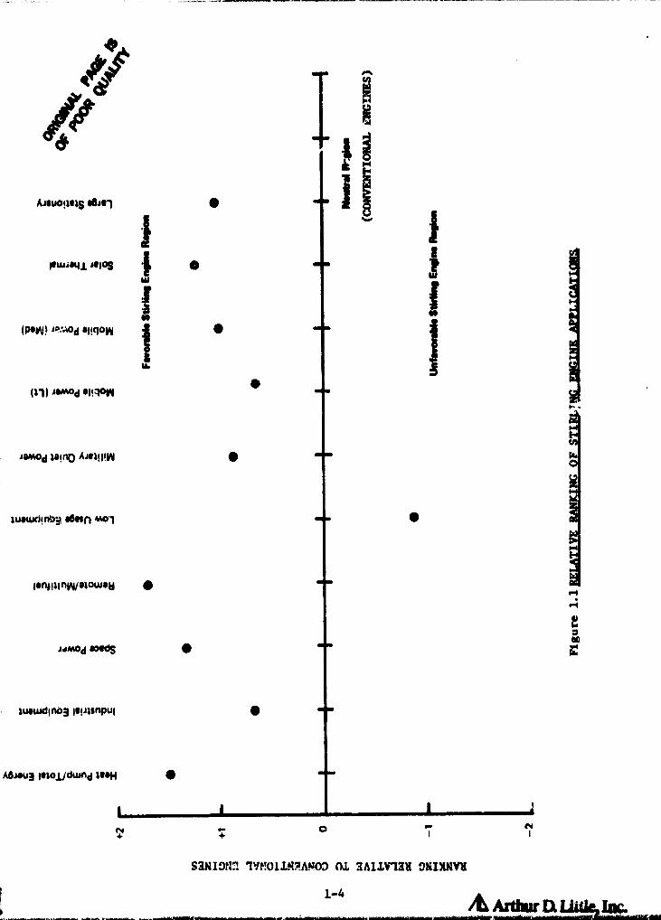
Figure 1.1 shows the ranking of Stirling engines in 10 application classes.
assuming success in ongoing development programs. The key assumptions made ini
E
1-3 /K iArdw its. Lade, Inc, i
4t gr
Amw!mS alliel
10WA41 JOIOS
(poW) Apmod allcion
111) ismod &I!"
is"d Zaino Ajel!l!n
wowdinbii sovin moi
lanpilnw/siouiew
AilmOd IMWS
lelilsnpul
A&MU3 letoliduind 11014
"i9-4
O
iz
N1
UNIDO IMUMMMOD CU 3AIIV"131 DNIXNYH
1-4
A Ardw U

r=
r OF POO
this ranking were that the reliability and life potential of the Stirling
engine were achieved, while still maintaining good efficiency, noise, and
emission characteristics. It was assumed that Stirling engines will be
marginally larger and heavier, and somewhat more costly than their I.C. engine
counterparts, due to basic configurational constraints.
P!The advantages of the Stirling engine over the conventional alternative are
proportional to the distance above the .neutral axis. There are several
application classes including heat pumps/total energy, rural. power, and silent
generators which are particularly well addressed by Stirling engines due to a
combination of their high efficiency, low noise levels, and multi-fuel
capability.
I;The mass market, light duty cycle class of applications (lawn mowers, chain
i- saws, etc.) has a negative rating due to the relatively large size and high
cost of Stirling engines.
Vehicular propulsion applications are seen to have a rather modest positive
ranking, reflecting in part, the success of the continuing development of
current I.C. engine technology in addressing this class of application.
The advantages of vehicular Stirling engines include achieving even lower
emission levels than now called for by Federal. standards; a widely based,
multi-fuel capability; and potentially better fuel mileage than delivered by
current gasoline technology. Due to the critical factor that vehicular
propulsion plays in national energy use and emissions, relatively modest
improvements in ;erformance levels can have significant overall impact on a
national scale. As such, the development of an automotive Stirling engine
would provide the country with additional flexibility in defining emission
standards and fuel use strategies.
STIRLING ENGINE STATUS
The development of Stirling engines has been proceeding for over 40 years at
organiz a tions in Sweden, The Netherlands, and the United States. Most of the
t ` work on Kinematic engines is based on technologies developed over the last 20
1-5 ArtWt Lx iia
;_

OF PON QUALM
years at United Stirling (Sweden) and Philips (The Netherlands). touch of the
activity in the United States in this field is based on a complex series of
joint venture and license agreements with these foreign companies. As a
practical matter, therefore, the number of participants in the Stirling engine
field has been quite limited. This reflects, in part, the desire to maximise
the use of the expertise contained in these organisations when initiating new
programs, thereby increasing the probability of near-term success. However,
this limit .i participation could inhibit the generation of new ideas and the
introduction of new personnel into the field.
PERFORMANCE
Test bed Stirling engines have demonstrated many of their projected advantages,
such as high efficiency (ever 35% achieved), low emissions (well below EPA
automotive limits), low noise, and multi-fuel operation. Configurations have
been developed which can be placed under the hood of a mid-sized automobile and
their weight can probably be consistent with most application requirements.
The primary development issues confronting Stirling enginri now are similar to
those which hove historically been identified as problem areas: unproven
reliability and life, and relatively high manufacturing costs.
Selected teat engines have accumvlated in excess of 5000 hours of operation.
However, this operation has been accompanied by numerous unplanned shutdowns
and replacement of key components. Typical operating periods are in the 50-100
hour range. As the result of the ongoing Stirling engine programs, significant
progress has been made in improving the reliability of test ongines and times
between shutdown have been increasing on the automotive test engines.
Many of the reasons for unplanned system shutdown are related to
instrumentation and auxiliary equipment failures which do not reflect- directly
on engine reliability per ad. However, several problem areas are basic to the
Stirling engine configurations built to date and include:
o Piston seals, which must operate unlubricated while still maintaining
acceptable wear rates.
1-6 /b Arthw Ek u Im

OINONWAL MN 0OF POOR quAuTy
o Reciprocating shaft seals which must both contain high pressure (2000+
psi) working gas and not allow oil into the working volume.
o E'igh temperature (1300°F+) heat transfer systems (heater head, air
preheaters, combustion chamber) resulting in severe thermal stresses
I`
during cyclic operation.
C..
While progress is being made in addressing these and other technical issues asc:
a result of ongoing programs, one must still conclude that these currently are
the major sources of design, life, and reliability difficulties.
COST
There is no commercial practice in Stirling engines to function as benchmark
for cost projections and as a point of comparison with conventional engine
alternatives. The Stirling engine does not require valves or a timed ignition
system, which provides an outward appearance of simplicity when compared to a
conventional I.C. engine. However, they require a complex, high temperature
combustion/heat transfer subsystem, an enlarged radiator, and more complex
auxiliary components and controls. The net result is that most observers
project- that the Stirling engine will have a cost which is 25-100% higher than
for an I.C. engine of similar capacity and end use function. These
observations are supported by preliminary studies done in support of the
automotive program.
It should be noted, however, that a modest cost premium will be acceptable in a
number of applications (heat pumps, total enLrgy, etc.), if the Stirling engine
has superior performance characteristics as compared to alternative systems.
KINEMATIC vs FREE PISTON CONFIGURATIONS
Most of the development efforts to date have been focussed on kinematic
Stirling engines, whereby the engine output is rotary or shaft power. These
configurations ere necessary as a practical matter for vehicular applications
and provide a great deal of flexibility since many forms of commercially
available devices (compressors, pumps, etc.) can be connected to the output
1-7 /L Arth a IL Lit&, hm

OMQINft PAQE ISOF POOR QUALITY
` 4 i
jt_,
shaft. Kinematic engines require, however, the use of shaft seals to contain
the high pressure working gas.
Free piston Stirling engines are a relatively recent development with major
development activities starting in the early 1970'x. They are conceptually
simple and power can be extracted via linear alternators, hydraulic pumps, or
gas compressors without the use of a shaft seal. As a result, the units can be
hermetically sealed. The elimination of the shaft seal makes the free piston
engine particularly interesting for low power applications where the mechanical
losses of the seal can significantly impact engine efficiency. As a result of
eliminating the need for shaft seals and being able to utilize gas gap or
clearance piston seals, free piston Stirling engines show particularly good
potential for achieving long life and high reliability. This is one reason why
their use is being stressed for heat pump and space power applications where
long life is very important. However, to date, free piston engines have not
demonstrated their potential for superior reliability or life to kinematic
engines. This, in part, reflects the relatively modest funding and a short
period of time devoted to free piston engine developments. It is also due to
the fact that free piston engines built to date have two of the problem areas
which have been associated with kinematic engines - piston seals operating in
an unlubricated area and high teriperature heater head-combustor systems.
However, the benefits of eliminating the shaft seal cannot be underestimated
and it appears that the free piston system may be an attractive option,
particularly in those applications where the power can be readily extracted
from the engine, such as in heat pump, space power or natural gas liquifier
systems.
STIRLING ENGINE REQUIREMENTS
In order to illustrate the technical and cost requirements for Stirling engine
systems, preliminary specifications were prepared for four conceptual engine
designs. The four designs were selected to cover a multiplicity of the
favorable application classes identified by the ranking exercise so that the
development risks could be spread among several potential markets. The engine
designs selected were:
1-8

ORIGINAL PAGE IS
OF POOR QUALITY
o A simple, multi-fuel engine for rural power applications.
o A low noise power system for heat pump, electric generator and solar
power applications.
o A mid-size power system for vehicular drive, commercial total energy,
and marine power applications.
Fill o A large, high efficiency, power system for co-generation and shipboard
drives.
The low noise power system and mid-size power system engine designs were
intended to address all favorable applications shown on Figure 1.1, except the
Remote /Multifuel and Large Stationary classes. The simple, Multifuel engine
design is directed toward applications in the Remote /Mult ifuel class, and the
large, high efficiency, power system design is meant to accommodate
applications within the Large Stationary class.
The requirements for each engine design were estimated by comparison V ►ith
performance of likely competitive systems and/or assessing the basic needs of
the applications being served.
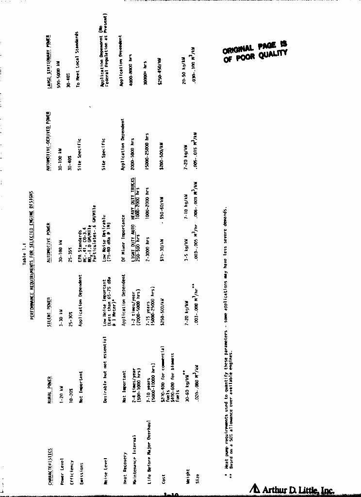
Table 1.1 summarizes the performance requirements used for conceptual design
purposes. As indicated, the vehicular propulsion applications for the mid -size
power plant place far more stringent requirements on low cost than for the
engines serving other applications. For example, a biomass fired rural power
unit could cost in excess of $500/kW and still be competitive with gasoline
fired alternatives. On the other hand, all the non-automotive engines will
require operational life in excess of 5,000 hours and for larger systems, in
excess of 20,000 hours. Stirling engines can meet most of the operational
requirements indicated in Table 1.1 based on demonstrated characteristics.
However, the reliability and life requirements shown are far in excess of those
demonstrated to date, and may pose a difficult challenge to future Stirling
engine development programs.
FOREIGN MARKET
The study summarized in this report emphasizes domestic applications of
1-g /d Ardw D: LJWe, Inc.
WI
^I COI gT
C^^^ ^ + O N ^
^W
1r.r r CO C Qa
Z z{1'Iy =
x
V V ^ ^7f \QQ
\V^1
CL N 1J1 JCS NO N Y
C f a ^ G ONCj M M
r GQ N
= NM1nVf V/
N
u =N N
YnV1^ !-• L L/=
LEO s sOI r ^ "' ^ Y
2^ s1
^M
Or u =g
WCK
WI ^^A r.
=.' O Hi LO
^If L =
HI DMZ a OI O.G
't ^I N =WW f
W A O rC V^ A
qN 9 LY L^^
Ni ^ Jt O
Ni ^IYo ^^
C~ I g 6n 'A Ou ZM I V 1 Z S Iµ^
.O.I.n M m OMpOI O N ^ V ppx q
3t ^.. r- O4A
QI M N O-WSZ^ M
SIW
CI M ry M CD d
W9C C 9 O
y. d u u1nL
W IGy
p ^V1yGy1O L NA L LL L^
W ^ QL
_
Irr+
d 10 L'^ adi
^ N 8 QQL O p iL pppd•4I I sY ?P ^
.V. +A te`
MdN
1O^ C+Y O
1wiO.
z iW M NN
ILI
^ OLA
O O_JNi P1 pQ J^Q+ ^ r-v n^ M n ON
mVd
_'^
N ` Nd9V S
L L V4
^^ A ^ N Ni r° w ♦Y =^t8O Y
Y ^ E 10 ^ ^N I 2.1 ! 10N 1 N O 1J^ N ti ^+
^fO ^O
pRdOb ^ Np p ^ o t If1 111'1 N 7 R 7 O O
.. i' Z Nr n^ MI^N1► ^1
daH
NIrV-rH) _
d ^,
ry ' J d OKI L ^ N
N
Lda
N
t
FNCOArGC
Lya
EA6 NdCN •rte
a o.r y
W rO
C
Q iAa0+ L9 dW ON7 d
U
CyNEE C
6L Ip7
A
C^DV ^
Z
3 Mw-
Ye '-
I_
NOLI ^ C 4 C
v
CI YyJ v^ ^ r =L ^ _^ € -
JI Zn fif H ^L f ''
L
Ad
L La o
99La a d
> p C Oli
aJ CCd ++N
♦dlC d ^+_
J V
al
^ N7 N

OR UM PARE 4OF POOR QUALITY
Stirling engine systems. However, if Stirling engines are aucces-+fully
developed they would have worldwide applicability and there arc efforts
underway in Japan and Curope to develop Stirling engines for a range of
applications to serve their markets. In some cases, a combination of
applications needs, government policies, and energy pricing could make thei
near-term use of Stirling engines more attractive in foreign Rpplications than
tis now the case for domestic applications. Two such examples are illustrated
! in Appendix E. One is for the case of hsaat pump drives in Japan where
1 government policies to even out Iarge seasonal variations in electricity and
gas use provide a strong incentive to accelerate the use of gas fired heat pump
' and total energy systems. Emphasis is being given to using Stirling engine
drives in the residential and light commercial capacity ranges. The other
example cited is the large potential in developing countries for small biomass
fired Stirling engines to satisfy critical needs for irrigation, refrigeration,
and village lighting, as an alternative to high operating cost Diesel
generators or Rrid extensions. In both cases, it is quite likely that foreign
manufacturers will rely heavily on the large U.S. based R&D programs in
developing their systems. Ic is, therefore, important that both government and
corporate strategies relative to the Stirling engine development and
commercialization programs consider this export potential as well as the
domestic markets.
DEVELOPMENT ISSUES
The previous sections indicate that a series of successfully developed Stirling
engine systems would result in substantial differences in Stirling engine
configurations and requirements and, hence, development needs.
A primary focus of both automotive and heat pump Stirling engine programs
(which have received the bulk of R&D funding) has been to demonstrate that
Stirling engines can meet the operational requirements of these two
applications. As a res- • lt of these programs, Stirling engines have been
successful it demonstrating their potential relative to such critical
parameters as efficiency, emissions, multi-fuel capability, low noise
m
1-.l
Arthur Q Litt&, Im

QUALITY
operation, and acceptable size and weight (for automotive applications).
` Although further improvements in these areas is desirable, such improvements
are probably not essential for commercial acceptance in many applications of
widespread interest.
The critical issues which must be addressed by Stirling engine development
programs relate to:
o Operational Life
o Reliability
Cost
Succeso ully addressing these issues would result in an engine having overall
advantages for some applications relative to conventional alternatives and
being attractive for use in several Applications which are not readily served
by existing system options (high temperature solar, nuclear space, etc.).
Of the above issues, that pertaining to operational life is of major concern to
all potential end users. Without acceptable life characteristics, all other
" engine attributes are of no significance at all. The lack of demonstrated,
consistent operational reliability was also noted by several potential end
users as their mnior reason for doubting the credibility of Stirling engines as
a practical power system.
sTo some extent, it appears that the problems associated with attaining
acceptable operational lifetimes has been related to ._he emphasis on developing
j a high performance automotive engine within a short period of time in order to
address national policy goals. This emphasis has resulted in:
o Operating test engines at high speeds (4,000 rpm) required of a compact
engine and emphasizing high heater head temperatures in order to
achieve efficiencies consistent with high gas mileage.
o A relatively limited amount of long-term component development and
testing in order to focus limited resources on developing and testing
complete engine systems.
o An emphasis on R&D activities to support the goal of meeting the very
stringent cost constraints imposed by automotive applications.
1-12 & A1'dw a Uttle, hr..

OM N+IAL PA0 X19
Of POOR -QUM •
It should be noted that other Stirling engine programs (heat pumps) have also
tended to emphasize achieving relatively stringent cost-performance goals
rather than to demonstrate reliability and life. One of the primary challenges
facing the Stirling engine community is, therefore, to demonstrate that
Stirling engines can achieve respectable reliability and life goals using
near-term modifications of these technologies that have been developed over the
past 30 years. If the technology cannot be adapted to demonstrate reasonable
life characteristics in the near-term, the resultant lack of credibility for
the Stirling engine could result in erosion of both public and private sector
support.
There is good reason to believe that more credible life and reliability
characteristics can be achieved with Stirling engines using current technology.
For example, reducing operating speeds may substantially increase the Jife of
piston and shaft seals while reduced heater temperatures and lower heat fluxes
could increase the reliability of heater heads. At the reduced performance
levels, the engines may not be directly suitable for automotive or mass market
heat pump applications. However, their performance may still be of interest
for special markets which can be a starting point for wider use. This is, in
fact, the strategy which appears to be followed by smaller companies using
private sector funds.
Based on the above considerations (i.e., applicability of Stirling technology
to a number of application categories) an integrated Stirling engine
development program should give more emphasis to demonstrating life and
reliability characteristics of widespread commercial interest. Such a program
could include a combination of adapting existing technology to emphasize
increased life and focussing more R&D resources on those critical issues now
limiting life and reliability.
SUMr1ARY OF RESULTS
United States Market
A survey of engine applications within the united States was conducted during
1-13^D.Utdc'Im
oRio^ti
OFR PACE IS
i POO QUALrrV
this study. Over one hundred engine applications were identified and grouped
into the following ten classes, with each class having a high degree of
commonality in technical performance and cost requirements:
o Heat Pump/Total Energy
o Industrial Equipment
I o Space Power
o Remote/Multifuel
o Low Usage Equipment
o Military Quiet Power
o Mobile Power (Light)
o Mobile Power (Medium)
o Solar Thermal
o Large Stationary
Stirling and conventional engines were compared in each application class. the
ranking process gave the following results.
o Stirling engines showed favorable potential for a'.1 applications except
the Low Usage Equipment class (lawn mowers, etc.).
o Favorable Stirling engine application classes, which are currently
served by conventional engines, represent a potential market of about
13 million engines per year.
Stirling engines hold a distinct advantage over conventional engines as
power sources in the Heat Pump/Total Energy, Space Power, Solar
Thermal, and Remote/Multifuel application classes. There is, however,
no present commercial practice on which to base market projections.
S -
Four Stirling engine conceptual designs were defined that could address all of
the nine favorable application classes.
o A simple, multifuel engine ( 1-20 kW).
o A low noise power system ( 3-30 kW).
o A mid-size power system for vehicle drives and stationary power (30-100
W).
o A large, high efficiency power system (500-5000 kW).
1-14Arthur D. ijtde, Inc.
PA" 19SRI ODOR QUALMO
Technology Needs
There remain some development needs that have not been adequately addressed by
ongoing development programs. Achievement of the following goals are necessary
in order to broaden the applicability of the Stirling engine.
E o Demonstrate Stirling engine life, consistent with the needs of each
application class, and show that maintenance requirements can be met.
o Consistently achieve a distinct efficiency advantage over the I.C.
engine in order to provide an incentive for Stirling engine
development.
o Emphasize Stirling engine designs - or modifications of engines of
present development programs - which are consistent with long life, low
maintenance operation. (Example: Stationary engine derived from
automotive engine.)
If life and reliability goals can be demonstrated without a large compromise in
efficiency, or increase in cost, the Stirling engine can be a highly
competitive option for use in all nine favorable application classes.
Foreign Markets
Developing Countries
A biomass sired Stirling engine (Remote /Multifuel application class), using
indigenous fuels, is an attractive power source alternative to Diesels and
photovoltaic systems in developing countries. The value of this potential
foreign Stirling engine market may total nearly 200 million dollars by 1990.
This value corresponds to a power generating capability of 200 MW, or 40,000
5 kW engines.
Japan
Government policies relative to R&D funding, gas pricing, and tax incentives
have been taken by the Japanese government to accelerate the introduction of
gas fired systems - Stirling powered, and others. For this purpose, the
1-15 AL ArftUt' Ex L1t0

u ct^ P^OF
Government has initiated a 6 year. 40 million dollar program. in cooperation
with industry and universities, to develop 3 and 30 kW sized engines to power
the heat pump and total energy systems.
Pursuance of the above policies could create a relatively large Stirling engine
market in Japan, and also put Japan in a very strong competitive position
relative to the development of a similar market in the United States.

1
1[!'^..
OMOINAL PAGE 18OF POOR QUALITY
2.0 INTRODUCTION
2.1 Background
Stirling engines have been under development for over 40 years by organizations
in Sweden, The Netherlands, and the United States. The interast level in the
Stirling engine as a clean, efficient power converter has increased
dramatically in the last 8-10 years as a result of rising world oil prices and
concern for the environment. The total financial resources which have been
devoted to Stirling engine development are estimated to he on the order of $500
million. This can be compared to the estimated engine R&D budget of a major*
United States automobile corporation of $600 million /year. The resources
directed toward Stirling engine development have, therefore, been relatively
modest compared to those for autom%tive internal combustion engines.
Stirling engines have a number of potential advantages which have provided the
incentive for these programs, including:
(a) Multifuel Capability which allows operation with a wide range of fossil
fuels, as well as non-conventional heat inputs, 6uch as solar energy,
biomass, nuclear, and thermnl storage.
(b) High Thermal Ffficicncy which results in more economic operation in those
applications where fuel costs are important.
(c) Low Emission Levels in fuel fired applications as a result of being an
external combustion engine. This advantage is particularly important in
vehicular and in closed environment applications (mines, etc.).
(d) Low Noise and Vibration resulting from the use of mechanically balanced
mechanisms, the lack of valves, relatively low operating speeds, and
continuous combustion.
* Based on 4% of sales devoted to R&D and 25% of R&D going into enginesystems.
-1
AL A rtwr Q

. ws
ONOWAL PAOZ ISOF POOR Q ; : t.*' Tv
(e) High Reliability and Long Life resulting from outwardly simple mechanical
corfigyrations anu relatively few moving parts (no valves, etc.).
(f) Good Part Load and Variable Speed characteristics which are important for
vehicular and some generator applications.
Many of the above advantages have been demonstrated i.n operating hardware. For
example, efficiency levels in excess of 35 percent have been achieved is part
of the automotive program and engines have been operated using nolar, isotope,
and thermal storage heat inputs. However, other attributes, such as high
reliability, have not yet been demonstrated with the consistency required for
commercial systems.
Despite its demonstrated and projected attributes, the stirling engine ties
still not found commercial acceptance. The reasons for this are complex and
several of them are discussed briefly below.
o The primary funding fot Stirling engine developments,
particularly in the United States, has been for automotive
applications:. The low emission levels and high thermal
efficiency (i.e., good gas mileage) potential of the
Stirling engines make them well-suited for this
application. However, the highly developed Internal
Combustion O .C.) engines now used, have themselves been
the subject of continuing development effort over the last
decade and are now, when combined with armller cars,
providing improved mileage and emisei.on chararteristice.
These characteristics are achieved with anginen having a
selling price ($25-30/kW) which probably cannot be achieved
with a Stirling engine - even in mass production
quantities. The projected) performance characteristics of
advanced automotive Stirling engines (192)
indicated,
however, that Stirling engines may have efficiency, fuel
flexibility, and emission advantages over conventional I.C.
engines. These advantages could become increasingly

ORIG ►L PACE IS
OF POOR QUALITY
important in the future depending on cost and availability
of clean automotive fuels. Thus, the goals behind the
development of an automotive Stirling engine are a moving
target.i
n As a practical matter, conventional I.C. engines can
address nany of the applications considered for Stirling3
engines. I.C. engines have the benefit of over 50 years of
extensive development and a firmly established
' sales/maintenance infrastructures throughout the world. As
such, Stirling engines will require significant advantages
over conventional engine options in order to result in a
large market penetration.
o Current technology Stirling engines still have not
demonstrated the life and reliability required to address
the application: for which they are being considered. It
is not certain that Oie technical reasons for the lack of
demonstrated reliability can be successfully addressed for
the mass market applications, while still maintaining the
other required attributes (for example, high efficiency
implies high operating, temperatures which complicate
achieving reliability and cost goals).
o Many engine systems indirectly utilize the production
economies of the automotive and truck markets to maintain
relatively low engine costs in a wide variety of
applications. Fxamples of this include engine driven
pumps, inboard marine engines, and standby
engine/ generators, which often use automotive or truck
engine blocks as the basic buildir., component. Stirling
engines will be at a disadvantage in such applications if
the automotive Stirling engine program is not pursued.
o Applications requiring unconventional heat inputs such as
z ,.solar energy or isotopes can often be addressed by other
extnrnal heat input engines. For example, several studiesl
indicate that Stirling engines combined with high
concentration ratio parabolic dish concex,trators are an
2-3 /L1 AfthW' D. U1de Lw.

t-I
QRIDIg i MBE 0
CW Pow QUMM
attractive solar power option. However, there are several
options being actively pursued for solar power including
photovoltaics, solar driven Rankine engines, and solar
driven Brayton engines. The early stage of development of
these solar power teCtITIOlogies complicates the task of
selecting the system with the best commercial potential
and, therefore, the potential role of Stirling engine3.
The above factors must be addressed when considering the prospects for Stirling
engine commercialization efforts. In particular, the issues are:
• For what combination of applications do Stirling engines show
significant advantages over probable competitive systems?
• What operating characteristics and cost goals must be
achieved for Stirling engines to result in large penetrations
into s ,-ch markets?
• Do the sizes of potential markets for Stirling engines
warrant Research and Development (R&D) effort to develop
appropriate engine systems?
• What critical development needs must be addressed b y ongoing
Stirling engine development programs in order for the engines
to show promisor in making a meaningful penetration into these
markets?
The program described herein has as an overall goal to address the above issues
in order to assist the Department of Energy and NASA Lewis Research Center in
determining which Stirling engine applications are most likely to be
successful. In addition, this report identifies R&D initiatives needed to
accelerate the introduction of Stirling engines in attractive application
areas.
The results of this program will be cne of the inpu+s used by program planners
in DOE and NASA to direct future Stirling engine development programs and
ensure that limited financial resources are utilized as effectively as
possible.
2-4
AL Arthur Q uttip, im

NOMlAL PAGE 0OF POOR QUALITY
2.2 Purpose and Scope
The specific objectives of this study were to:
• Assess the applicability of Stirling engines to a broad range
of applications with capacity requirements of 0.5 to 5,000
hp.
• Identify applications in which the operational advantages of
Stirling engines could be particularly important and might,
therefore, make them competitive with conventional engine
systems.
• Estimate the market potential for those classes of
applications in which Stirling engines show promise of
competitive performance..
• Identify and comment on important technical, regulatory, and
economic trends which might influence the potential market
for Stirling engines.
• Identify technology advancements required to result in
competitive Stirling engine performance levels in those
applications which appear to have the best promise.
This study emphasizes the application of Stirling engines in the United States.
' however, attention is drawn to foreign applications which might significantly
expand the market for specific application classes.
The technical effort required to achieve the program objectives was divided
into the following two tasks.
o Task I: Market Survey and Engine Requirements
Survey and organize engine applications by class (similar power level,
duty cycle, etc.) and characterize the performance levels of conventional
engines which are either now used or could be used in each application
class.
i\
2-5Arthur Q Little, Ira%

Ste
T
t
PRO
or POO
Is
QUAL"*
o Task ll; Stirling lugiuo Application Asseesmeot
Art► vois the ability of a successfully developed Stirling engine to tract the
requi remonto at each of the appl icat ion classes identified in Task Z and
identity the technology advancements required to be competitive.
_'.3Proaram Approach
1.3.1 Taa►k 1
The overall Approach to accompl ish 'lank 1 is inAieated in Figure :.1 The
primary Aettvittvs whi. •h were undertaking during the Task 1 of fort were:
I, %,urvov of Famine A pl ient ions
A mirvev of engine appl icat ions was umirrtA on to idon: i ty both the= range of
ptisniblo onginr- Applirattans anti important rrtl ►► irements (eff iciency. emissions.
e--te.) which must he m; ► t ist ied by rngit ►om Addre entog the Application. This
activit y tnclt►ded aurvovtng both the St 'It IWg engine Itterats ► re And the
literature porto iititilt to u111il Ica t tonm tit convent ional onginO Systems.
Stems :— ldent it it , at loci of Appl icat ion t l; ► ssrs
Applications having. similar technicAl anti tost rayutroments ware then grouped
Into clArssr:; Which are Ilow or could he served by common engine systems.
Pertormmicr pnrAme-tr ► t: that were considerrd in torming these application
c1A ►.e:rsa included titictenev. emissiont•, lite, sir . weight. part load
operation, and noime level.
Stet 3.- jhor,ectrrtsAt ion ot^ C uttyant ional F:n tr t ^»a
Conventional engine pr ► formance. and cost chatectrrtattem ware revietwr.' and
matched Against the reyuirrmeuts of the Application elassrs identified instep
?. C011ve+ntional engine imstams considered in this exorcisir included spArk
E`-h
^► _ AL Arthur v. Little, im

OMGIM PAGE 0OF POOR QUALITY
Survey ofPreviouslyConsidered
StirlingEngine
Applications
Classificationof
Applications
Step 2Survey of
ConventionalEngine
Applications
Step 1 Characterizationof ConventionalEngine Options
Step 3
Selection ofBest Representative
Engines
Step 4
Figure 2.1 TASK I - "MARKET SURVEY" AND ENGINE REQUIREMENTS
2-7
/& Arthur Ia.

a1M0M^ '^ 1'^OW Q' • •
ignition (gasoline) engines, diesel engines, small combustion turbines, and
packaged Rankine cycle engines.
Step 4: Selection of Representative Engine
A representative engine which is either now or could be used to satisfy each of
the application classes was selected and its performance characteristics
summarized. The engine performance characteristics used tended to be for the
better engines in each category so that the nature of the competition which
must be addressed by Stirling engine developments was realistically assessed.
2.3.2 Task II
The overall approach to Task II is indicated in Figure 2.2. This task was
divided into the following major steps.
Step 1: Stirling Engine Characteristics
The present status of Stirling engine technology was reviewed to quantify the
operating characteristics of current developmental engines. also, qualitative
judgements were made as to the probable operating characteristics of engines
which might result from ongoing programs assuming a reasonable deg.ee of
success in current R&D programs.
Step 2: Stirling Engine/Application Class Ranking
The performance characteristics of developed Stirling engine systems were
compared to those of likely competitive power systems (usually I.C. engines per
Task I) for each of the application classes being considered. Numerical
weights were attached to all important performance characteristics to assist in
making the judgements required to quantitatively rank the suitability of
Stirling engines to serve each application class.
2-8

I Review of Stirling EngineCharacteristics
Selection of ApplicationClasses for
Stirling Engine
Step 1 Step 2
Identification of DevelopmentDeeds for Stirling Engines
Step 3
Figure 2.2 TASK II - STIRLING ENGINE APPLICATION ASSESSMENTS
2-9
OFPOW QUAL TY
Step 3: Stirling Engine Performance Requirements
The operational requirements and cost constraints for four Stirling engine
systems which could serve a range of the favorable applications identified in
Step 2 were quantified and conceptual designs were prepared for each of those
engine classes indicating possible overall system configurations.
Step 4: _Identification of System Development Needs
The required performance characteristics of Stirling engines defined in Step 3
were compared with those of present developmental Stirling engines and the
goals of ongoing development programs. This comparison was used to help
identify the nature of additional R&D activities which would help accelerate
the use of Stirling engines in favorable applications.
2-10
Arthur DL Uttle, W.

OF POOR QUAD MV
3.0 SURVEY OF APPLICATIONS
A review of the technical and cost requirements of possible engine applications
was undertaken in order to assist in the process of identifying those applications
where the Stirling engine is most 1iKely to be competitive. The results of
this review were used in Section 4.0 to group applications into categories
having common technical/cost requirements.
0Over the last 20 years, extensive work has been done in the analyses of Stirling
engines to serve a wide range of applications. In fact, Stirling engines have
been considered for almost all major applications now served by conventional
engines. In addition, Stirling engines have been considered for numerous
applications which cannot be readily served by other available engines. Such
applications include parabolic dish solar power systems, nuclear powersd submarines,
small scale biomass fired generators, and small space power systems. In order
that this previous experience be factored into this program, a survey of the
previous and present Stirling engine programs and application studies was
conducted.
Also, in order to ensure that all potential applications of Stirling engines
are considered, a survey of present engine practice was undertaken. In this
way, present applictions for conventional engines were identified and quantified
as to market size and engine characteristics. The results of this survey are
discussed in detail in Section 5.0.
The approach taken in the survey of applications and a summary of its results
follow.i
3.1 Stirling Engine Applications
A review was made of Stirling engine applications which have been considered
by the various groups working in this technology. The primary intent of this
i review was to determine:
o Which applications have received the most attention.
3-1
Att ur Q Uftlo, Inc.

iQRMaNAL rAn 13OF FOW QUA:Ty
o Why Stirling engines were considered to be attractive for these applications.
This activity was undertaken by:
o A review of the Stirling engine literature.
o Interviews with experts in organizations which are now actively engaged
in developing Stirling engines.
3.1.1 Literature Review
Over 200 papers and reports dealing with the application of Stirling engines
were analyzed during the course of this review. These documents covered the
important programs undertaken during the last 30 years, primarily in Europe,
the United States, and Japan. A listing of these Stirling engine references
is given in Appendix A.
The applicationb identified as part of this review process are summarized
later in conjunction with other methods of survey. However, in general, the
following observations can be made based on the results of this survey:
• Over 25% of the literature deals with automotive applications of Stirling
engines. This reflects the fact that most United States funding expended
on Stirling engines over the last 20 years has been for cuch applications.
The primary incentive behind pursuing this application for Stirling
engines has been their potential for low exhaust emissions and good
fuel mileage.
• The other mosi common non-automotive applications considered for Stirling
engines were gas fired heat pumps and solar thermal power units. The
incentive for Stirling engines in heat pumps is their potential for
low noise and vibration levels, high reliability, low emissions and
good efficiency. The high efficiency of the Stirling engine is important
in a solar application that uses a parabolic concentrator because an
increase in conversion efficiency directly correlates to a reduction
of concentrator size and cost.
• Over 100 applications for Stirling engines were addressed in the literature.
However, most of these applications were addressed primarily at the
conceptual level so that only limited technical, cost, or market data
was provided.
3-2 AL Ardw Q Little, im

^R:O WAL PAGE IS``f POOR Q JAWY
o With the exception of the automotive program reports, most of the
literature emphasizes technical issues with relatively little discussion
of economic, institutional, or market isauas.
o Quantitative information provided on technical requirements of applications
(especially reliability, noise levels, emission levels, etc.) was very
limited in most instances.
o With the exception of the United States automotive program, there was
only limited quantitative justification provided to support the selection
1of Stirling engines for the applications as compared to commercially
I: available alternatives or with other developmental engine options
(Brayton cycles, organic Rankine engines, fuel cells, adiabatic Diesel,
r etc.). Specifically, in few cases does the literature attempt to deal
with the effect of improvements in conventional engine technology in
assessing the potential for Stirling engines.
3.1.2 Interviews
( Interviews were conducted with over 20 organizations active in the Stirling
engine field. Organizations contacted include NASA Lewis Research Center,
Department of Energy, Argonne National Laboratories, Mechanical Technologies,
Inc., General Electric, Sunpower, Inc. (a participant in this study), and
Philips. A complete list of contacts is provided in Appendix B, along with a
list of current and past Stirling engine programs.
The purposes of the interviews were to:
• Discuss questions arising from the literature review.
• Obtain their latest views on potentially favorable applications and
technology issues.
A general overview of the results of the interviews is given below. The interviews
were conducted on an informal basis with minimal supporting documentation
being provided. Therefore, the impressions indicated do not represent an
industry concensus but rather provide insights into some of the issues being
faced by the Stirling engine community.
o I.C. engines (Diesel, in particular) are very tough competition in
most applications now served by conventional engines and the improvement
3-3 & Atthm Ut Utdcl Inc.LJ

!N ' OMOINAC PACE IS
QF PM QUALITY
in I.C. engine technology is creating a moving target for development
of competitive Stirling engines.i
t o The most commonly cited favorable application for Stirling engines was
heat pumps - particularly in commercial sizes.
• There appears to be a general feeling that Stirling engines might be a
good option for using low-grade fuels (wood wastes, etc.).
• One contact indicated that, to justify development of a Stirling engine,
a multiplicity of suitable applications will have to be identified.
• Several observers (particularly academic) emphasized the need for more
imaginative R&D programs. However, little information was provided to
indicate what R&D would be :useful or why it would enhance Stirling
engine prospects.
The interviews, in general, supported the results of the literature survey in
identifying the most favorable applications. In particular, no new applications
that were not extensively covered in the literature were identified during the
course of the interviews.
1. Limited discussions were also held with a few organizations which have considered
the use of Stirling engines in the past (military generators, submarine propulsion,
vehicular propulsion), to solicit their views on future prospects. The primary
impression resulting from these discussions was a general concern over the
life and reliability history of the Stirling engine, with both past and present
operating experience cited to support this view.
This issue appears to be important to many of the potential users of Stirling
engine systems in both civilian and military applications and must be successfully
addressed to increase the level of interest in Stirling engine systems.
3.2 Conventional Engine Applications
Most potential applications of Stirling engines are already being addressed by
one or more conventional engines. In this context, conventional engines include
spark ignition (gasoline or gaseous fuel), compression ignition (Diesel or dual
fuel), gas turbine, and small Rankine engines. In order to determine the requirements
3-4
ORSt1NAL Pq^
r OF POOR QU"
of existing engitte applications, their characteristics were reviewed using, in
large part, Arthur D. Little's existing in-house data base. For this study,
the Arthur D. Little u , ta base was supplemented with a literature search and
the use of a market study entitled Engine Data V published by Power Systems
Research, Inc. (Appendix A).
13.2.1 In-House Data Review
The in-house data review consisted of two distinctly separate efforts.
o Extraction of relevant data from Arthur D. Little's data base.
o Discussions with Arthur D. Little staff with extensive experience in
various fields in which engines are utilized.
The Arthur D. Little data base contains information on engine applications in
the areas of:
o Industrial equipment,
j o Marine (pleasure craft and light commercial).
o Agricultural equipment.
o Lawn and garden equipment.
o Compressors (portable).
# o Passenger cars.
o Trucks (light, medium, and heavy duty).
o Welders.
` o Construction equipment.
o Generator sets.
o Mobile refrigeration equipment.
o Light and experimental aircraft.
o Natural gas pipeline engine applications.
o Heat pumps.
Specific data were compiled for each engine application, the categories for
which are listed as follows:
• Power and torque vs speed.
• Engine weight.
• Durability and reliability.
• Serviceability and maintainability.
3-S
A AVfty D- L

i1i
ORIONAL PAG9 0Of POOR QUALM
• Fuel consumption.
• Emisaions.
• Life ( and time between overhauls).
• Size.
• Initial cost, overhead costs.
• Multiple fuel c, .pability / adaptability.
• Number of cylinders.
• Engine configuration ( in-line, vee, opposed, etc.).
• Liquid vs air cooling.
• Bell housi ng and flywheel options.
Much of the in-house data was obtained through person-to-person and/or telephone
interviews of engine or equipment manufacturers in North America, Es_:rope, and
Japan.
^- In performing this work, great care was taker, to insure that the needs of an
1 application were separated from the actual characteristics of engines presently
serving that need. This is because in a majority of applications, the operating
ischaracteristics of the equipment driven by those engines were designed arounc
specific engine performance requirements or capabilities ( speed range, duty
cycles, etc.). Subsequently, engine manufacturers designed new engines to fit
into the existing operating requirements. This is done in order to maximize
the interchangeability of one's engiti.es with those of a competitive make. Only
when a manufacturer has control over both the engine and its equipment application,
as in automotive use, : a: example, are the performance characteristics of engines
optimized to fulfill the needs of a particular end use.
By separating the desired engine characteristics from the current engine characteristics,
the influence of existing engines over application requirements can be removed
where appropriate_. Once this its done, the Stirling engine can be judged (in
Task 2) against the actual needs of an application in terms of engine features,
irstead of competing against attributes of present engines which may or may not
be necessary for any given application.
The existing data base and the experiences of the staff who compiled it was
expanded through a aeries of interviews with Arthur D. Little staff who specialize
3- 6
i
i
Arthm U link, Inc,

ORONAL PAW 18
OF POOR QUALITY
in selected areas where engines are -ised. This effort covered both conventional
ind non-conventional applications of shaft power in the fields of Mining, Agriculture,
and Heavy Industry. Those applications which tend to utilize one or more potential
Stirling engine attributes were sought out. Special attention was give to I.C.
engine driven applications where Stirling engines are likely to have some potential.
In general, mining and agricultural applications appear quite limited due to
! relatively low market volumes.
3.3 Results of Surveys and Classification of Applications
The information obtained during the survey of Stirling and conventional engine
applications identified over 100 possible applications where engines are either
now in use or could be used if engines with the right characteristics were available.
These applications are listed in Table 3.1. The operational advantages expected
from Stirling engines in these applications are also indicated. Specific operational
advantages which are noted are:
o The need for a Multi Fuel Capability, in order to be able to use non-
distillate fuels such as heavy oils, biomass, coal, solar energy, isotopes,
or thermal storage.
o Low Emissions, in order to satisfy environmental regulations or consumer
requirements
o High Efficiency levels in order to reduce operating costs or, in some
cases, such as in solar thermal systems reduce overall system costs.1 '
o Low Noise and Vibration, which can he particularly important in applications
such as residential heat pumps, and pleasure boats.
o Low Maintenance, which is very important for remote applications or high
duty cycle applications.
o Heat Recovery, which is necessary in the operation of heat pump and total
energy systems.
It should be emphasized that attributing one of the above characteristics to a
specific application is often highly judgemental and doing so is intended primarily
to guide the effort of future tasks in identifying applications which might have
common engine requirements.
3-7

ORIGINAL. PAGE iS
TABLE 3.1 OF POOR QUALM
APPLICATIONS AND SELECTED OPERATIONAL ADVANTAGES
X: Denotes a requirement ~J
m4
W►r
APPLICATIONS
Z
Nr.
W
°J
^'
Wr
WU_W
N
.J
d~
m
J
W
Z
°J
Uj
V
`''S
1. ELECTRIC POWER GENERATIONQuiet Electric Power Generation for Army X X X X
Quiet Electric Power Generation forRecreation Vehicles, Mobile Homes, etc. X X X X X X
Remote Electric Power using Solar/BiomassLiquid Fuels X X X
Central Power Station/StationaryApplication X X X X X
Reliable Electric Power For TelephoneSwitching Station X X X X X
Isotope Powered Electric Generator X X X X
Liqhthouse Applications X X. X
Short Duration Underwater Power Plant X X X X X
Municipal Power Generation usingMunicipal & Agricultural Wastes X X X X X
Power Generation from Coal-Derived Fuels,Low Grade Petroleum, etc. X X X X
Signal Buoys, Sonobuoys X X X
Communications Booster Stations X X
Emergency and Standby Electric Power(hospital, industry) X X X X
Portable Generators X X X X X
Peaking Generators X X X
Off-Shore Oil Platform X X X X X
f"L
3-8 & Arthur D Little, Inc.

0 ' F^EOF PON TABLE 3.1 (Continued)
i
a-X: Denotes a requirement ~'Ja
pp
C
W
.^+
APPLICATIONS 2
Zr• )V
W
c
W^
L6WW
0"
Z
$
ZOI--
m
>
g
Z1yd
o
O
Z. HEAT PUMP APPLICATIONS
Heat Pump Drive for Residential/Commercial Application X X X X X X X
Industrial Heat Pumps X X X X X
Advanced Heat Pump Applications (using X x X X
cycles such as Stirling-Stirling)
• MEDICAL APPLICATIONS
Powered Wheelchair X X X X X
Portable Refrigerator for Storing.Biological Samples/Blood, etc. X x X X X
I. REMOTE/THIRD WORLD APPLICATIONS
Ventilating Fans in Remote Areas X x X X X
Cold Storage of Food in Remote Areas X X X X
TV/Radio in Remote AreasFuel: Wood, Hay, Rice Husk, Charcoal,
etc. X x x x
Wood Splitter/Cordwood Saws using
wood fuel X X X
Portable Refrigerators for RecreationVehicles/Yachts X X X x X x X
Rural Well-Water Pumps X x X x
Rural Irrigation Pumps x X x
Back-Pack Power Plant X x x X
3- 9 & Arthur D little, Inc.

i
i
i
r
^141 PAW 0 TABLE 3.1 (Continued)OF pW
X: Denotes a requirement J
4vJW
HAPPLICATIONS
ZoN
W
a
W;«+
La.W
W
Nr
Z
c^m
y
W
W
g
0
Cr.
cg
H
_
Remote Meteorological St ► .ions X X
Microwave Relay Statian X X
5. AGRICULTURE
Tractors X X X
Farm Equipment (self-powered) X X X
Logging Machines X X X
Grain Drying X X X X
Rototillers X X
Forestry X X
6. MINING
Shuttle Cars for Underground Mines X X X X X X
Power Generation in Mines X X X X X X X
Surface Minir; X X X X
Auxiliary Vehicles Inside Mines X X X X X X
7. TRANSPORTATION
Passenger Cars X X X X X X
Trucks X X X X X
Bus X X X X X X
Road Cleaning X X X
3-10

TABLE 3.1 (Continued)
ORIlWM PAGE 1s
OF POOR QUAWY
i
h
...X.
.._,,E`Ilt)ti'S PlYl'tlUll'E`Illotlaii ..I a-.
i z ZI..
17 LAJ
I
C)
J V) " W cr W ;C^
1 La- Syr ar W
1
APPLICATIONS -'
W Z
Mo o o 0 wi J S ^! J J Z
tXTaxi X X X X X
Rail Applications, using coal oriI
conventional fuels (elect. or I ' 1
hydraulic) I X X X IX
Rail Maintenance Equipment ► X X I 1X
Motorcycles I X j X + X X }
Mopeds X X 1 X X
Delivery Trucks X X X ! X I X
Hybrid Electric Vehicles4; X I X X j X ( X X
Small Cars for Shoppers C X X X X ( X
;8. CONSTRUCTION
Quiet Air Compressor
I Tractors
I Scraper Shovel
Saw
Roller
Pile Drive
Front End loader
Paving Breaker
Grader
Mobile Crane
Derrick Crane
Concrete Pump
Concrete Mixer
Contractor Pumps
1
X^( X X
'
1X
1 X j1
X
X iX
Ii X X1
X X Xi
i X i+X
^X ^X !
fX
I
XX I X
IX
X j 'X j
X j X
4X X^
X ^X
X ( X
3-11
/L Arthur a utt* Inc.

ORIGINAL PAGE ISTABLE 3.1 (Continued)
of pOOR QUALITY
-\. (?enotes a roquirement
, Co I W^S = I W O ' ! CrVO 1 ►-, ►r W IJ NW Vt
^-+ti
WV1
j di ^,^F- C^
<..^
Ul
APPLICATIONS _ w " IgWo I
(<
INDUSTRIAL APPLICATIONS j t
Compressors (Portable aid Stationary) i X iX j
Indoor Equipment - Forklift Trucks, I ( 'i
etc, ' XIX I X1 X Xi iWelders X X i X !Mobile Refrigeration Equipment X ^X j X I X X
Undersea Mining X` X X I X X jSubmersibles or Crawlers for off-shore iOil and Gas Industry I X X X I X X X i
Gas Compression/Liquefaction i Xi ^X X
Industrial Trucks (Light, Medium andI IHeavy) X X X j X
Industrial Drives
XiX
I(Natural Gas Pipeline Applications(Compressor) ;X ! X
Gas Gathering XI
Xi X
Industrial Equipment - Outdoors X ^ ^X 1
I
X
Hydraulic Drive in enclosed spaces XI X (X X X j
Industrial Cogeneration X ..X + X
High Temperature Waste Heat Source
for Power Generation X X
Residential/Commercial Total Energy
Pov,er/Feat !curce for Pleasure Boats X X X IX X ,X X
MILITARY APPLICATIONS
Compressor (Portable and Stationary) Xi
X X
ISubmarien/Underwater/Gen. Purpose X. X X X X X
3-12
A Ardwr Dl IJt*-,1M
19.
10.
11

TABLE 3.1 (Continued)
ORMNAL PAGE 13
Of POOR QUAL17Y
x: D notes a requirement
APPLICATIONS
My
d V Vc= W O <• d
Uj-j I W Q
I^
C
i W i W i O i •-+ Cr-
Z
J 3 't 33 -.z .ht0 «-+ 10 0 o W
Marine Generators for Navy X I I X
Marien Prime Movers for Navy X 1
X (
X
Small Research Submarines X X X X
Large Military Submarines X i X X j X ^X X
Unattended Surveillance Devices j X I X X X
Nuclear or Solar power generation for i 1 I ! icommand posts ' X 1 i X l
i X i X X
Military Vehicles (Trucks) X i X X X .
i
.12.i
Military Control and Logistical IVehicles I X
Military Naval Vessels X!
Military Tanks ; X'
RESIDENTIAL APPLICATIONS/CONSUMER
PRODUCTS I
i X
X I X
iX
X
X
X
i
I
13.
I
Lawn and GardenI
t i X i
Snow Blower X 1 iChain Saw , X
Power Tools i X
Compressor for Consumers X i
SOLAR THERMAL APPLICATIONS
Solar Thermal Power (Dish Mounted) X X X Xi
Solar Powered Pumps X X
iSolar Powered Compressors for shopair. etc. X I x i X
t_.i__ ! ' _ __L
3-13 /d Arthur U. Ilt&, Inc.

OR!OINAL PAGE ISTABLE 3.1 (Continued)
OF POOR QUALITY
X: Denotes a requirement ! rJ I
mQ
Q Z
V
I W 1 p
WI
tdZ
! ►- v 1- w
ILW>.
W N U. N i Cie
0-4
L b-»
LLJ
LL. " CO
y►-+ W
APPLICATIONS.o 0 0 o w
J JI J =
14. COOLING
i
Cryoqenic Cooling I ( X X ^
i Residential/Commercial Air Conditioner ; X X X X X
15. SPACE APPLICATIONS I ! I
Radio-Isotopk Powered Space Application X X X X
Solar Powered Space Power System i X X X j X
16. MARINE APPLICATIONS (Commercial)
0
Ocean Vessels
X
X j
X X
Commercial Coastal Vessels
X
X I
X ; X
Commercial Offshore Vessels
X
X
X I X
Commercial Inland Waterways Vessels
X
X
' X i X
I
s
3-14 /rl Ardw U. IJtde, Inc.

For the development of Table 3.1, the applications have been listed under titles
descriptive of their end use. This division is quite arbitrary and was selected
primarily because available information sources tend to group engine applications
t into similar categories. it should be emphasized, however, that there is often a
wide range of engine requirements within any of the above application categories.
For example, Electric power generators range from 3 hp standby generators to
5,OGO lip continuous duty cycle generators for off-shore oil platforms. Similarly,
transportation applications include fractional hp moped engines as well as high
duty cycle 500 hp truck engines. As such, the end use categories are, in some
cases, not particularly useful in identifying applications which have common
engine requirements.
3-15 /L Arthur Q ut&, inc.

ORIMAL PAGE MOF POOR QUALITY
4.0 CLASSIFICATION OF APPLICATIONS
In addition to some duplicate descriptions under different categories, many
of the applications in Table 3.1 have similar cost, performance, and capacity
requirements. For example, the engine requirements for a residential heat
pump and a military generator are similar in almost all respects even though
the end use functions differ greatly. Similarly such diverse conventional
applications as an engine driven water pump for irrigation (in the United
States Southwest) and automobiles have similar capacity and cost constraints,
which often results in their being served by common engines. As a result,
most conventional engines are used to satisfy a number of diverse applications
with attendant development and production economies.
The grouping of such a large number of overlapping and divergent applications
into a small number of classes is a highly judgemental process. After elimination
of duplicates and obviously similar applications, a computer based "Cluster
Analysis" technique was utilized in order to assist in the grouping process.
This technique required assigning numerical weighting to the various application
requirements and then logically grouping applications so as to maximize
common desired characteristics. This Cluster analysis is described in Appendix
D along with the input data used to numerically categorize the individual
applications.
As a result of both the Cluster Analysis and informed judgements, the sixteen
classes of .applications identified in Section 3.0 were reorganized into ten
categories having common requirements.
Information provided for each class of applic,&.ions includes:
• The power requirements of engines commonly utilized for applications
which are now served by conventional engines or which are likely to
be needed for applications not now served by any engine type.
• Estimated aggregate market size. For applications now served by
conventional I.C. engines, the market indicated is the actual sales
of engines usually used in the application class under consideration
(discussed in more detail in Section 5.0). The term NCP (no commercial
4-1
AL Amur D. u^ im

practice) is used where there is no significant commercial use of
any conventional engine on which to base market size.
o The important operational characteristics required of each application
class. Many of these are quantified during
the discussion of conventional engine characteristics (Section 5.0)
and the selection of application classes showing particular promise
for Stirling engines (Section 7.0).
Several of the important characteristics of each application class identified
in Table 4.1 are outlined briefly below.
A. Heat Pump and Total Energy
In a heat pump/total energy application, an engine would need low
emissions, good fuel efficiency, very low noise and vibration, heat
recovery, infrequent maintenance, long life, and good startability.
Not so critical to engine success in this application are low engine
cost and weight, small engine size and good load following.
B. industrial Equipment
Fuel switching capability, low noise and vibration, heat recovery,
low weight and small engine size are not critical in industrial
equipment. However, low emissions, good fuel efficiency, long life,
good startability, low cost and good load following are important in
these applications.
C. Nuclear Power (Space)
In a nuclear (isotope or reactor) space power system, fuel efficiency,
low noise and vibration, long life, startability and load following
are critical parameters. Fuel switching, low emissions, heat recovery
and low engine cost are not important in these applications.
D. Long-Run, Remote, Multi-Fuel Applications
In a rural power system, fuel switching, fuel efficiency, low maintenance,
long life and startability are important characteristics. Low emissions,
low noise and vibration, heat recovery and engine size and weight
are not critical.
E. Low Usage Equipment
In low usage equipment the main factor for success are very low
cost, startability, low engine weight and small size. Other factors
are not critical such as efficiency nr heat recovery.
4-2A ,a►rftr Q I.3ttk, Inc.

ORIGINAL PAGE LSOF POOR QUALM
0zHP400
^I
N
HI
20
s E1
aU
^ HA a
E-4 a
w0x
g
Rog1.6
v 'gc E
^
'g
1111111 llilli
O
z
33^ 3Y^^^33 ^+
Ll $Lh
v3^t72
r0
=
t
y
dpQQ 8 QQ
ONE
sr+ ^Ld111 t0 N
^D
^ N
E'z J
` aa^-^ 5 E
CLE w _
E
d
N'AVMM C
^0Y 1.
^ v 'O Nm
cd W g a° MCuj
W CD N wCL Ew w _w
m U
4-3
/t Arthur DL Little, W.

OMN,4L PAGE 18OF POOR QUA
LP
S
b
^^ J7
U ^ g
^88 §• ^ •- ^ S r ^ c uNyi n ^ c^i ^ ^^pp ri of s^' •' N ^$ ^ ^ Ofd.-rO OfMtO Q
r4
' ,^ ai tV Z
bH
t 3p^
oY 33go.X 3Y w
C t2S ^f R NOOR^ ^ ^ 'ta " W 4N
•- •- 7
N^f N N1u3l,
NIt
O- •^'
V
C
N —
.2Owl
cc w
LFWL
4 c wM M
9 >`£1,14 F5 9 9 x
r' N M^- uj LL! W W k
4-4/L Arttuu Ex Littk, Its.

81888•p
vUlMrn N
8g 8Rvi ev 06qr
3333333
r r r
8
'z 8
C «
1 i
•N
cv
'-i
.Q
roF33 3 33 33x3
ac o N o a o^ o 0 0cri N ^ . !V N
N V
0NsNM ^
C4Hrl8NUl
8e a
m"a
OMINAL PAGE 13
OF POOR QJAUTV
gct
v y
g^ g
1 1 1 1 1
i
a1 1 1 1 1 1
A t^ 4
of ^
« ^. E
F MJ
^' N
4-5 1

cc
5u
9
^ZW Z
OMINAL PAGE 1U
OF POOR QUALITY
M 9 C2 ac 'u
33
aUZ V V
3 Y ^
Q
d ^ r
m
0 E c3^S
Uj
.Y ^ A m Y c^i^ o
A H- x c ap ^, v
^ vg- gAo> ^ 8•"^
s rt+i th
J
4-G
Arthur Q Uttic, im

F. Military
Fuel switching, fuel efficiency, low noise and ^Y ibration, load following
and startability are important, as are small size, low weight, low
maintenance and long life. Low emissions, heat recovery and low
cost are not as critical.
G. Mobile Light Duty
Nearly all factors mentioned previously are important in light mobile
power applications, particularly emissions, cost, and load following.
M. Mobile Heavy Duty
In medium duty mobile power applications, fuel switching and efficiency,
low emissions, long life and good load following are important, but
heat recovery, low engine cost and weight are not as important as
foi- the light duty mobile rower.
1.^y
Solar Thermal and Thermal Storage Power
!. Most solar thermal power units employing Stirling engines assume
that thermal energy storage is incorporated with the solar receiver
in order to reduce problems associated with transient operation.
The Stirling engine would, in fact, be operating from thermal storage.
These seemingly diverse applications are, therefore, grouped together
since they could be served by a common class of engines design to
operate from a high temperature thermal storage media. In these
applications, efficienc y , low maintenance, long life, low cost, and
reliable startabilit y are important. Low emissions don't apply and
fuel switching as well as heat recovery are not critical.
J. Large Multi-Fuel
Large stationary power systems generally operate with a high duty
cycle. The critical characteristics of these systems will be high
thermal efficiency and a multifuel capatility. Both these characteristics
lead to lower fuel operating costs which are a dominant cost factor
with high duty cycle equipment. Other characteristics such as low
size and weight, and good startability are not particularly important.
f /L Arthur Q Little, Inc.

5.0 CONVENTIONAL ENGINE MARKETS AND PERFORMANCE CHARACTERISTICS
Most applications being considered for Stirling engines are presently being
served or could be served by one or more conventional engine system. As a
practical matter, Stirling engines will have to show some combination of technical
andjur economic advantages to displace the conventional engines now utilized.
It is, therefore, important to have an understanding of the market for conventional
engines and the characteristics of engines now used in major market segments
in order to evaluate the prospects for Stirling engines in each application
class. In recognition of the above, this section of the report provides:
o A brief overview of the market for conventional engines.
o A summnary of the salient operating characteristics and cost for widely
used conventional engines.
o The selection and description of a "representative engine" which would
be typical of the competition in each application class.
5.1 Current Engine Sales
Table 5.1 summarizes the United States sales of engines in the power range
from 0.5 to 5000 hp in 1978. The total number of engines sold annually is
about 26 million. Of these about 25.6 million (98%) are spark ignition engines
and about 0.62 million (2%) are Diesel engines. In addition, a small number
of gas fired reciprocating engines (about 1500) and gas turbines (about 1500)
are also sold in this power range.
Figure 5.1 shows a detailed sales breakdown of spark ignition engines in the
1-300 hp range, by rated power output for the year 1980. Approximately 92% of
all such engines have rated outputs below 150 hp. Within this engine class
there are two types of engines which account for nearly 87% of all engines
sold:
o Over 12 million engines with capacities of under 10 hp are sold annually.
These are typically low usage engines used in such widespread applications
as lawn mowers, chain saws, and snow blowers. The major portion of
these engines are provided by either Briggs and Stratton or by Tecumsah.
5-1A& Arffiur Dt

v arv4u
u uu44 u
V4m m .-1P4aJ as a a
0 oco to
Aiv v z Z
m co to ym
O p OOJJI
Ln&M In
Vr"4V
rl riV V w
uCH
M M4c 4cV1 IT I M
mLm .7 u 1
w iw w -r4u
NC4
N M C^ N'"4 N m
ORIGINAL PAGE
OF POOR QUALITY
u
d ^C
0 1+ to
E V
O
001 oc O
^ d N
O R+ VI
O1
I Sri M
lJ ^7O N
Ou N
00 d d N
C+ vri
_
A ^w
a ,^00
0 en
O 0
O u co_ L co
O^ M
H t;0
N z
ti! f r-4
OJ
r-1 z O M
O D d
N 4 ^O
E-4 C O .T
V4 0 co
O L L
f^G rl a r1a 00 d .-+
w I-+zd a
c^ w a
z cd ,^ n
W a L+ nC!1 ^ n
t/1 O O
a d
1 M
Oz
NM N r! 00 n %.O O P-4 r1 NC'4
^` w00 M 0 H O
w w w w co %p
00
co
0^ O^w
Ll n 1 V1w
O nM -4 ,4 0 0 J N %0
r--I N M
CO) n
^CO U9 00 00 ^O
^G N^^O
^ CT tr't ^ 00 u'100
^p
00Ln C7%
N V)M n r-4
r-1 P-1
M M N O NOD ^ O r--I CN 00 ri co M C
w w O n w% %C Ili Nw w N OD C^ ^0%C
00 ^ IT %0 V1 P-4 O 00 '7w w
00 r 4 1.0 MO M ^ M r1 M r.{ J u9 M 0%r♦ Ln O N N N r♦ rt M O N
C4 r♦
umudsw
w°
ur~m07m01OG
E4J
m
a,3 mo a,a Lw^
0J YIU L>•+ mw
U G
Nw+ ~i.1 w
id ^--r LV! 1.a0) ^ Mn L pn^'J 1+07 ^^ GA
W-4cn -W
u a 6
e..Y
W^It tn
o
cc
ITrl N
H
ga
CO I 1 0Q, o,
vu Mco o s
^^ pMAN
a `-4k.o
wo eno
o l 1 0 A
;^oG .^
en 'T ^o 0o d rte. ,°^
F^oen z A V nCN r-
5-2

ORKtM'tAL^^OF POOR
0zde
ltrwo solnv i
099 oS3 Otloi- t v 113 SM311tllcoc no solnv
R tot ovoi-solnv • SUN v31SArN7 -t It ► la SXOnulIlk
swos^ avos-t • ► 1a smonvl99t no solnv
ul no solnv
x
Qs
WE tl91SAYNJ smn'
Woot avoi solry
w► wo solnvIQIQa ^
s
w no solnv I
= 901 1)OOw UMAYND Ss 1180NOlnr
t
NLulol• Nvvls s SOolue-sivowMS
1
°• R ^ ^ i i
9oNvsnoNl N1991vs
5-3
lr ^
Ys
yWz
2
A
/L Arthur Q little, Inc.
o Over 7 million engines are produced annually with rated power outputs
of between 60 and 150 hp for vehict o lar applications. Most of these are
for automotive use. However, a significant number are also used in
such applications as light trucks, and tractors. Over 112 dozen manufacturers
(primarily automotive companies) participate in this market area.
Figure 5.2 shows the detailed sales breakdown of Diesel engines by rated output
in the under 400 hp range. The sales distribution of Diesel engines is seen
to be more evenly distributed than for spark ignition engines. Widespread
applications for Diesels indicated on Figure 5.2 include compressor drives,
farm equipment, and generator sets. However, approximately 60% of Diesel
sales are for automotive and truck propulsion applications.
Within the power range covered by Figures 5.1 and 5.2, the reciprocating internal
combustion engines are similar in design and concept. Many are versions of
automotive engines which achieve their rated power at relatively high crankshaft
r
speeds (over 1,200 rpm) and are commonly referred to as "high speed engines".
High speed engines in the 400-1000 hp range are not a large share of the market.
The number of units sold annually is estimated to be less than 1000 units per
year.
Engines with power outputs in excess of 1000 hp generally are operated at
lower speeds. The lower speeds are usually dictated by large cylinder bores
and longer operating life requirements. The industry classifies these as low
speed (up to 400 rpm) and medium speed engines (400-1200 rpm).
Table 4.1 includes an estimate of engine sales in this range. The total volume
of engines is less than 2000 units pet year. Major uses for these larger
engines are for marine propulsion, locomotives, municipal generating; stations,
and gas pipeline compressor stations.
5-4/L Arthur Q Little, Inc.

a100^: Po00 ;oolt(0
s
f -
,z
F
t,i
VA1wN 1510480 IN fMOnYI R
wilm AVa 1511MOMI1 ^3
AVALMAw1110'Am 151111OnM
IWVLNSNWNra '351w
xOK'OANSMANIO I0081011111
mm AVa IM SUMMA
VLMN 1310'151) to 911-,Ruta no" 151"Of L I
EEAVKtLVI / MOVw 151swonu
0K V1nwY0/ f011wwf1O 151 3MOf1Y1
t/'Aw'f/10'ISO -=m'TMfM
wtn3mlla 3r0LOVr1'0VV11Z11'N 1/10 110 Iw 3MOnYlto Vmw,ws 51Mwwm 151 sMamla
aft71013NI~o Iwl smonn
ttw 1310 ADO IWO 3MORY1
'Oilw'151IN011Y1ta'N'f11O'LBO !V/w a lY//O f51Mww00'fr0AOV111'OV s Y
tY'N 1110 ADO -O51w
wNV10 AYVN'ANI Il'/13YOnYl 'fY0LT'YLYkW1O s3}/Af011Wwf1O 3YOlOVrA'OV 1511VYO
w01MAUNwwf10 3MVY0Nflo - AVVN ' Ito samom01YOL3VIIA ov
!!10 "IN 1511 fYOIOVrl OV Iru nx1Y1I ! t
u11 Ula'L10 frolOVY1 roV'IM naniu
1SS Rollo g011111Y0011101T'Ya'OVNM ON MOLDY
m AVO ODOVOI LY'1YOlOVr1 11IMr 3 "OlOVr1 OVsweL l rf11l/ fYOLNU ow
c++ uw'13w aww[{/1/511An/0 3Y017VY1 9V
aSS/r//O fMMwI 11,111 1 VVI DVla'111010 fY0a0VY/'OV'Irtl nOnW'MVO
taus am
0/K11)11/W fYOLOVu."
Vw awas3a10111w MaLOM/ 1V'MVOom 11111110 SVOLT'111'wV
wasV0 'Ow1w[111111 /11130 fY0S1WY
Ra301VSI01 fWUwa7'Irt3 onvAYYOAOVYI'OVam mWdw MDaawl'*I
YNWONOINIO 30013"1 "'91110OOmm Mf51,f/oM110Vw'M01 0V111'OV'MVO
0NAV 111110 t/OIn1Or0'MOl irYl'MOK/YM00 rR em nsm r swoIN11A'0V"YAY YIN
cl rwS MA lr tlnOfYYA frV0' am, IYUO 3111040"A OV'sumil N'MVO
SLwO NNrYN MM1IM'NIOIOVYI OVSHIP $0111111" 11BOVOI" , V daY WIN f11010VY/ 0V
JIM IIVIIO n10I1M'f113 0110111114f YV"WA !1101011111 ON
3M NINO fYIOI IM 3111'0110,15111 YVNNVAY010VVA 0',
VON NVNO f111a,lM'$In ^01/0'YO10VY1011MOO VLOIAN 11010VY1 N,OYVO w NMV,
111 . 0110511 V10MM YYOMMA 01110YVO l NMV1
s-s SONVINIONA AM $a IVS Arthur D. little, Inc.
Q
hM
W
t
Y.
RF
i
J= A O
u • •

5.2 Engine Cost and Performance Characteristics
There is a wide range of engines now in use with over 50 manufacturers producing,
at least, 670 engine models. However, within broad engine categories (small
low usage, automotive, low speed Diesel, etc.) the technical characteristics
of engine types fall within a relatively narrow band. This fact is reflected
in the highly competitive nature of the engine business where relatively
modest differences in performance or cost can influence sales.
The United States Army has compiled a useful display of the characteristics
of some specific engines used in a range of military applications. Figures
5.3 through 5.6 present their plots of specific fuel consumption (related to
engine efficiency), power to weight ratio, specific volume, and costs for a
wide range of engines under 1500 kW (2000 hp). * These plots include gas
turbines, as well as projections for the adiabatic Diesel under test at Cummins.
They indicate a rather wide range performance between different categories of
engine system. For example, there can be over a two to one difference in any
parameter depending on engine type considered. This further emphasizes the
importance of realistically assessing which types of conventional engines
Stirling engines will have to compete against in each application.
Low Usage Engines:
The most important characteristic of these small, mass produced, spark ignition
engines are their very low cost (<$50/kW ), small size, and low weight. These
are all critical for the types of applications in which these engines are
normally used.
The relatively short life (typically 500-1000 hours) and poor fuel efficiency
(10-15%) of these engines does not strongly detract from their capability tv
function adequately in their most common applications. For example, a useful
life of 500 hours represents over 10 lawn cutting seasons in a typical lawn
mower application.
* Data compiled from a series of unpublished communications and presentationsto Department of Transportation personnel by TARADCOM.
5-6 /d Arthur D Little, Inc.

ccW
F2WVccW9L
ILL
1t
LM
LaIU.
OatOf W
W2
GO Z
O OC a } HLUd O W7 m cc Qy
o iNco
fi g
J4-d H/qi NOI1dwnSNO913nA DIAM dS DIVUS
20
/L Arthur U. Llttk, Inc.

ac
3s
^^^ w a yr
' rdi
ccr r
Q 1^ r m dr v _
{ W2
N ^' Wr im
OY} O r
cc
2 ^W rQ ^•
W 8W -A
^ X gV 9 CO) IL
Od
$y> to p W
N Q n W
r m d OCID
0 O°r° O ^ 3
r f^ r Y
J^OC4 x
w
QpJ^ ^ c$ • aM
$.^ CL
Z •
IN t0 J> M
H 'NOS
CLZ W
~W •^
_ f- Ln c7 U.
O rr = ^^ t> o COr 0NJ n • • M tip
• of > > ^ •Z • J Q• N >J
c F_ , o y •t" ! J 2 ' W O OQ D -"-1
r r'
dHl87 1M 314132
5-8
& Arthur D Little, Inc.

PA" is0 pw QuALM
at i^ w
'tS
^ ma^n
uiO!'7 a
2O0Q
Q O a
I Ic•
^ a^ ^ W
D ^ m
Q VC4 W
S Q yr ^^Q
• m Q
JQ
JJ^^ a X
ao ^ • •
• H OD
N u7•
v m
Z Z O`^^
o M• m J^ "' o y
J N• to • ^Q W
^ ^ ^ ^ ^ ,JJ • a oa
M •^ aMy •W O O LQ V~•
1 1N
dH/£u 3Wn1OA 31AIDUS
5-9
8 ^m
It ;0
Of N^ ^ p8 ^
XCL
Lip
W Wv Q O
O ^
& Arthur Q Little, Inc.

ORIGINAL PAGE
OF POOR Q
C4
~ gC9W
/5^V
W2 l^
rN !V J
WyW_
N
J^^ M' N 0
Qv Z 0 Q
y 'OQ
aJ_ N
ps• ca
Z J U
dHJ/t d 3MOd3SW0H/lSO3
/t Arthur D Little, Inc.

Automotive Engines (Spark Ignition):
As with low usage engines, spark ignition automotive engines have a cost of
$25-30/kW. This low cost reflects both the economics of mass production and
the relatively modest operational life (3000-4000 hours) required of such
engines. The modest life goals, in turn, allow for higher operational speeds
(higher rated outputs) and lighter weight construction.
F
jThe efficiency indicated is in the 25-30% range. This efficiency range is at
the lower end of that expectel from Stirling engines, which would provide the
Stirling engine with a fuel economy advantage.
The emission levels indicated for the automotive engine satisfy present Feder+:
regulations and will continue to do so under proposed low (see Section 6.0).
High Speed Diesels:
This class of engine includes those now used in automotive applications,
which are estimated to cost $25-40/kW. Non-automotive engines have a significantly
higher cost 0150/kW to $300/kW) than their spark ignition counterparts.
Benefits derived from this significantly higher cost include higher efficiency,
in the 30% to 35% range, and longer life, (up to 20;060-30,000 hours). The
higher cost of these engines facilitat:s establishing a competitive position
for Stirling engines in applications which they serve. Recent systems studies
at NASA indicate that the efficiency of a well developed Stirling engine may
be better than Diesels in the high speed range. En addition, Diesel engine
emissions include particulates which are not now covered by regulations. As I
indicated in Section 6.0, there is a great deal of concern about the health
hazards of the particulates, which may result in additional regulations,
thereby enhancing the competitive position of the Stirling engine.
Medium and Low Speed Diesels:
These engines are typically used in applications wh-re long life and high
reliability is required. The resultant robust construction and the low production
quantities lead to engines with relatively high costs in the $200-500/kW
range.
5-11 Arthu IL Little, Im

The fuel efficiency of these engines is generally very high (35-40X) and, in
addition, some engines in this cla ys have a limited multi-fuel capability.
Typically, the same model can be ret up as either a Diesel, gaseous, duel Lr
even tri-fuel engine. Diesels are run on anything from No. 2 Diesel down to
the heavy distillates such as Bunker "C". The more common gaseouR fuel is
natural gas, although all sorts of other combustible gaseous faels such as
sewer gas have been used.
Dual or tri-fuel engines have in the past been typically compression ignition
engines using a liquid fuel injected as in a normal Diesel to ignite a carburetored
(pre-mixed) gaseous fuel. These dual fuel engines get about 10% of their
total energy from the liquid fuel, the remainder from the gaseous fuel. They
ate used where the extra reliability and extended maintenance intervals of a
Diesel are desired, but where it is inconvenient or uneconomical to run the
engine entirely on a liquid fuel. Lately, true dual fuel engines, where the
fuel injectors are replace_ with a spark plug system, are coming into more
widespread use.
These engines are urually relatively heavy and bulky as compared to "high
speed" engine classes. For example, their specific weight is typically in
the 10-30 kg/kW range as compared to spark ignition automotive type engines
with specific weights of 2-4 kg/kW. Consequently, there will be considerable
flexibility in the physical design of Stirling engines (size, weight, layout)
when used in applications now served by low speed internal combustion engines.
A very important feature of engines in this class is their high reliability
as measured by maintenance intervals and useful life. Many engines in this
class have lives in excess of 20,000 hours (time to major overhaul) and will
operate with maintenance intervals of 1,000 hours to 2,000 hours. The exceptional
reliability is in a totally different class than that achieved or needed by
automotive engines and could be one of the more difficult goals to be met by
a new engine development.
5-12& Ardur 11 U—t-&-- L=

The market for gas turbines under 3730 kW (5000 hp) is extremely limited.
The primary reason for this is their relatively high initial cost ($150-
1 300/kW) and poor efficiency (20-25X), when purchased in physically small
sizes and moderate turbine inlet temperatures (i.e., about 17000F). The
hi cost is due to requirements for expensive ( difficult to machine and
join) materials in the combustor and turbine (e.g., Inconel), close tolerances
required, difficult to machine shapes, and fine surface finishes required
for the vanes and blades.
Gas turbine units generally start well after long dormant periods, but take
longer to reach power than reciprocating engines. Problems with compressor
choking :-cinder initial start-up, and thermal inertia hampers the larger
regenerated units. While some units can achieve full power within 30 seconds,
some units require as much as 30 minutes.
The power density of gas turbines is generally a factor of 10-100 better
than the slog speed reciprocating engine against which they compete.
Gas turbines also possess an extremely long life and extended maintenance
intervals. Lives of 60,000 hours plus between overhauls have been quoted, as
have maintenance intervals of 30,000 hours.
Like other types of engines, gas turbines possess a limited multi -fuel capability.
They are, however, more sensitive to the fuel quality, as combustion products
loaded with abrasive particulates can have a detrimental effect upon the
turbine component life. Generally speaking, gas turbines can be set up to
run on the same fuels as the large reciprocating engines.
More details of the multi -fuel capability of conventional internal and external
combustion engines appear in Section 8.0.
t
4
5-13
/^ Arthur D. Little, Inc.

t
f
t
F i' Rankine En¢ines:
One of the attributes of a Stirling engine is its potential to operate using
solid fuels and the capability to utilize non-conventional heat inputs (solar,
nuclear, thermal storage). While Diesel and gasoline engines, and to a
jlesser extent, turbines do not offer this advantage, Rankine engines can use
solid fuel heat sources and hence wider multi-fuel capability is available
in such engines. Therefore, Rankine engines are likely to be in competition
with Stirling engines in many applications of interest. One difference
between a Stirling engine and a Rankine engine may be that efficiencies
attainable in small Rankine systems (less than 100 kW) are generally considerably
lower (at 15-25X) compared to projected efficiencies of 30-40+X for similar
size well developed Stirling systems.
i
At present, Rankine steam power plants ate mostly used by utilities for
generating hundreds of Megawatts of power. However small Rankine systems
(ranging from 10 kW up to 15,000 kW) are increasin p considered for many
applications. The smaller Rankine systems (10 kW up to 5,000 kW) utilize
various heat sources including:
o Solar energy.
o Waste heat from Diesel plants or furnaces.
o Oil and gas (in packaged boilers).
o Geothermal.
Rankine cycle engines require relatively large amounts of heat transfer area
and relatively complex series of expanders, pumps, and controls for their
operation. As such, the limited practice to date has resulted in relatively
high costs in the $1,000-3,000 per kW range. Projections for larger production
quantities are in the $500-1500 range, depending on capacity and operating
temperature.
5-14
Arthu I.IJtd Inc.
5.3 Selection of Representative Engines
Once the application classes were defined (see Section 4.0) the sales leading
engines for that class were determined from data compiled by Power Systems
Research. A summary of this data appears in Appendix C. In many cases, more
than one type (i.e., Diesel, spark ignition, 2-cycle or 4-cycle) made up a
significant portion of the total engine sales within an application class.
When this occurred, the sales leading engine of each type was identified.
Table 5.2 specifies a specific conventional engine which would be typical of
that either used or which could be used in each application class. Engine
capacities were selected to emphasize those applications within each class
with the largest potential markets. Performance and cost information is presented
for each representative engine to provide a benchmark by which to judge Stirling
engines in those applications. Also noted is the production volume of the
representative engine.
As suggested by Table 5.2, there is no single set of technical or cost goals
which must be achieved by Stirling engine systems. For example, automotive
applications set particularly stringent cost requirements on the Stirling
engine (about $25/kW) but only requires 2,000-3,000 hours of operational life,
which allows additional flexibility in the choice of hot section materials and
system design. In contrast, a heat pump application might allow costs 4 to 5
times those of an automobile engine but would require a useful life of over
20,000 hours.
As noted on Table 5.2, there are some application- where there is no present
commercial practice, with conventiona.. engines. These applications include
nuclear/space power and solar power. For these ?Dplication classes the possible
competitive engines were selected as thermo-electrics, Brayton cycle, and
Rankine cycle engines, respectively. This selection reflects the limited
practice to date in these ap p lication areas. Appendix C.3 has additional
information on medium and low speed Diesels, gas turbines, and Rankine cycle
engines.
r
5-15 & AftW r D. lithe, Inc.

I All Ri k it am . R
`^k3i^E
m'
der,f YIP
ma^^
^-!n_
sIn
i.'n
R$l^^tGwAa
edi
AOt ^ 'E
Q Pv
VPO A O P Y1
N
f n f f P P !V h 1P O O
Q►9 R' Meg
O 044
N lb H r N n n h N N K v v W O O O
C'—R,:
o$ 8 8 8
3^6
— w Fz ^
crya^ L
#^
a33's
d3 adL
3t
33Lit
3133 3W 2 < Lg^z
)^v^
ra <^^
r3 ^
nn n Nh 6
W
c e
1
4
^W f X11 y J^
? T ^ ^ h h 1^f1 ^
O Z'
F F
3
ui In o — rei o P
E S
t U n h ell n ^! w s
WM
) N^ x
OWW
I V= f f ,^,.. ^ Zi ^O
^S
^
^ w € a= LR'= N ^ O
p ggO Z Z G p ^ N r^► Eck
F
^;C
CW iE ` S r^b . Ni Yf NP N ^ P af 2 IO 17 m Nn n p _ i I I C=R S
^^^ Fi iti Fi^ F ^^ ^S^^g $ Q
^S
^ ^ o^
8^C^;
4 1^4
eO1^iR
4 i C ^ 0 ^'^ l^4^E Z '
R oP " ry m EoV O n ` '^ g R 2. R
^ R
•^
pp
C C ^ ^Y
Cy yy
L C^
^ _^
^ i ^ ^+
.L d i
!
^`8 ^ x
'^3A 3i S
$ao£^ 3i li ^ z lS 'g
Y'I$M
Wf ;^ m caSor_
s € S^ ^^ a sh
`.^3x ^" ,^ v^ ^ rry i ^^
°fe^^ =
Ea
r,S ^.' c t s s s f 5 fP _ i .Z
°
` a ^^_
b>8 ^ x t
.i Y
.e 6 a' ^r
W ' T E c 6 s ¢ i ^ ^ E^ 4 c CC
c^ '
.e^ ^ ^ ^^
22R a ,c LL a
Ixf W N Y{Ym
-° 5-16
3

6.0 STATUS OF STIRLING ENGINE SYSTEMS
6.1 Background
The closed cycle, regenerative Stirling engine concept was initially developed
by Robert Stirling in 1816. It, the late 1300's and early 1900's several
thousand hot air engine] operating on a simplified version of the Stirling
cycle were manufactured. These relatively heavy and inefficient engines
could operate on coal, charcoal, or wood to produce power for water pumping
and remote applications. Virtually all hot air Stirling engines were eventually
replaced by more efficient and compact steam power systems.
The modern era of Stirling engine development began in the mid 1930's at
Philips in Holland. The initial effort was to develop a low power (0.2 kW)
generator for powering radios in remote areas. Latter developments emphasized
vehicular propulsion systems. Over the ensuing 45 or more years, over 8
major companies have been involved in Stirling engine development programs.
However, as indicated in Figure 6.1, there have been only two primary developers
of kinematic Stirling engines, Philips and United Stirling. All other developments,
including those in the United States, are the result of a complex series of
license and joint venture agreements between the companies involved.
The development of free piston engines is relatively recent and was initially
spurred by the programs of W. Beale at the University of Ohio. Subsequently,
free piston engine activities have been undertaken at Mechanical Technologies,
Inc., General Electric, University of Washington, and ERG. These other activities
are, however, in large part based on earlier work by Beale.
Even though Stirling engines have been under development for over 40 years,
it is estimated that less than 500 Kinematic engines have been built and
fewer than 50 free piston engines have been built. As a practical matter,
there have been very few different basic engine configurations built and
tested. This, in part, reflects the tendency to utilize the few key personnel
and organizations with extensive Stirling engine experience in developing
more advanced engine systems. I` may, however, have the effect of limiting
the flow of new ideas and personnel into the field.
6-1 /L Arthur a Link, Inc.

ORIGINAL PACE iSOF POOR QUALRY
WJ WW Q^^M LL
E_
Q^
C
N JN
C
J
R y
^ Q m
^ O U
t ^, 3
a^ cU m •`
m
«m.Q ^ N C
f-
ibW
n
76
p Oelf N `aj
^ ^ r
6-2
/L Arthur U. little, Inc.
More detailed overviews of the history of Stirling engines can be found in
References 1-4.
The objectives of the following sections are to:
o Provide an overview of the operational characteristics of Stirling
^n
engines tested to date and the extent to which actual performance has
demonstrated the Stirling engine advantages indicated in earlier
sections.
o Identify those factors which are limiting the performance of Stirling
engines as now designed.
o Review steps being taken to rectify identified problem areas.
This information will be used to make judgements on the probable near and
longer term performance levels of Stirling engines and to identify R&D activities
needed to result in competitive Stirling engine configurations.
e6.2 Kinematic Engines
The most extensive recent experience that is well documented with kinematicI
Stirling engines has been achieved with those based on the 4-95 (P-40) engine
designed by United Stirling of Sweden. Various modifications of this engine
have evolved over a period of seven years and it is the basis of the MOD-I
engine, being developed as part of the DOE /NASA Advanced Automotive Stirling
Engine (ASE) Program, sand a solar operated engine, which recently initiated
testing as part of the JPL solar thermal/parabolic dish program. (5 , 6)This
engine, shown in Figure 6.2, is a four -cylinder, double acting configuration
which can produce 40 kW (55 hp) under design conditions (Table 6 . 1). As of
January, 1981, 21 engines of this basic design had been '-jilt and over 13
thousand hours of operation had been accumulated. (7) As indicated later,
however, the accumulated hours of operation have usually entailed numerous
unplanned shutdowns and the reliability of critical subsystems (primarily
seals and heater head) are still in question.
6-3/L1 Arthur D little, Inc.

URIGPIAL rAGE ISOF PAAd N 1 a a.
Figure 5.2 UNITED STIRLING OF SWEDEN 4-95 (P-40) ENGINE

Table 6.1
DESIGN/PERFORMANCE SPECIFICATIONS OF THE 4-95 STIRLING ENGINE
Overall Dimensions 785 x 655 x 580 mm
Dry Weight (including zuxiliaries) 329 kg
Brake Powera at 4000 rpm =40 kW
Brake Thermal Efficiency at =29%2000 rpm
Working Gas Hydrogen
Working Gas Mass <100 g
Number of cylinders 4 (square 4 arrangement)
Displacement 0.38 1
Bore 55 mm
Stroke 40 mm
Drive Dual crank, crankshafts geared to driveshaft
Method of Power Control Mean cycle pressure modulation (15 MPa, max)
Fuel Unleaded regular gasoline or diesel fuel
Range of air-fuel Ratio 15 tc 25
Heater Type Involute Tubular
Number of Tubes 72Number of tubes per quadrant 18
Heater Materials:
Tube Multimet N-155Cylinder and Regenerator Housings Haynes Stellite HS-31
Preheater Type Recuperative
Number of Regenerators/Coolers 2per Engine Cylinder
Regenerator Material 304 Stainless Steel Wire Mesh Gauze
Piston Rod Seal Type Sliding (Pumping Leningrader)
Piston Rod Seal and Piston RULON LD (filled PTFE)Ring Material
a. Mean cycle pressure, 15 MPa; heater temperature, 720°C; cooler temperature, 50°C.b. Including gas in storage bottle.c. Controlled by Bosch K-Jetronic continuous fuel injection system.
SOURCE: Reference 8
6-5
/d Arthur D. Lurie, Inc.

Most of the following commentary on the performance characteristics of kinematic
Stirling engines is based on the 4-95 engine and its more recent derivatives.
However, reference is also made to earlier Philips engines, where this experience
i' helps to illustrate specific Stirling engine characteristics of interest.
Efficiency:
Stirling engine efficiencies of 30% have been consistently demonstrated on
test and demonstration engines for over 15 year.i. (8 , 1) More recent tests
with the MOD-I engine and solar version of the 4-95 have demonstrated efficiency
levels in excess of 35% (including burner and parasitic power losses)(9,10).a
Projections by NASA suggest potential automotive engines for efficiencies in
the low 40% and in the high 40% for certain stationary applications of automotive
derived engines which do not have the losses associated with a combuster
subsystem, i.e., solar nuclear, and thermal storage. The efficiency capabilities
of Stirling engines are, therefore, well-demonstrated, and further improvements
might be expected, as higher temperature heater head materials are developed.
Multi-Fuel Capability:
The MOD-I engine has been operated on most liquid fuels (gasoline, Diesel,
etc.) of near-term interest as a motor fuel. 0 1) Earlier work on Stirling
engine generator sets (GPU-3, developed at G.M.) demonstrated the capability
of Stirling engines to switch between a wide range of liquid fuels used in
military field service.0 ,12) Philips operated a biomass fired engine using
a heat pipe heat transfer system (13) and more recently, Sunpower, Inc. has
operated a simple hot air Stirling engine directly fired by charcoal and rice
husks.(14,15)
The basic multi-fuel capability of a Stirling engine has, therefore, been
extensively demonstrated, particularly when using liquid and gaseous commercial
fuels.
The ability of large, high temperature, high efficiency Stirling engines to
utilize coal has been the subject of several studies funded through the Argonne
National Laboratories. These studies did not identify insurmountable technical
6-0 Ar(hw DL little, IM.

barriers to the operation of the Stirling engine in this fashion. However,
no experimental work has been done to date, in order to resolve the many
serious issues associated with high temperature, high power density coal
fired systems (fouling, corrosion, slagging, etc.).
As a practical matter the ability to burn coal will not influence the desirability
of the Stirling engine in most applications since few power systems of less
than 5000 kW utilize coal, due to the difficulty associated with coal handling
and stack gas clean up.
I.ow Emissions:
One of the major incentives to the development of Stirling engines has been
their potential for low exhaust gas emission operation. Since the combustion
process takes place outside tl.e working volume of the Stirling engine, the
process is more easily controlled and can be carried out with less violent
transients and in a more steady state fashion than it an internal combustionengine. This greatly simplifies control of the air/fuel mixtures and results
in reduced emissions. The MOD-I engine has been extensively tesced over
automotive driving cycles and has resulted in emission levels as summarized
in Table 6.2.(9)
These emission levels are well below those required of present and projected
regulations (Table 6.2) and below those of competitive I.C. engines. Stirling
engines have consistently demonstrated such low emission levels, in a system
with good air/fuel ratio control and adequate combustor design.
Noise and Vibration:
Stirling engines have no valves, can be fully balanced, and use a continuous
combustion process in their operation. As a result, they have low operational
noise levels and minimum vibration. These attributes have been demonstrated
on several engines including the MOD-T and the V160 engine of SPS. Both
these engines demonstrated noise levels of less than 70 DB (a comparable
Diesel can be over 90 DB)(16) and very low mechanical vibration levels. This
characteristic makes the use of such engines in applications requiring low
noise levels (heat pumps, indoor vehicles, etc.) particularly attractive.
L' 6-7 & Arthur D. little, Inc.
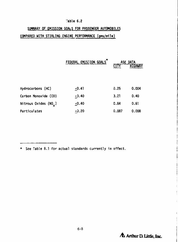
';able 6.2
SUMMARY OF EMISSION GOALS FOR PASSENGER AUTOMOBILES
COMPARED WITH STIRLING ENGINE PERFORMANCE (gms/mile)
*FEDERAL EMISSION GOALS ASE DATA
CITY HIGHWAY
Hydrocarbons (HC) <0.41 0.25 0.004
Carbon Monoxide (CO) <3.40 3.21 0.40
Nitrous Oxides (NO X)<0.40 0.84 0.61
Particulates <0.20 0.087 0.008
* See Table 8.1 for actual standards currently in effect.
6-8
& Arthur D. Utttc, Inc.
0

Startability:
i{
Stirling engines require a number of auxiliaries for starting. In the automotive
application, the engine has two starter motors, one for auxiliaries including
the blower, atomizing air compressor and hydraulic oil pump and another to
operate the starter.
i_
The high energy flux of the combustion chamber/heater head subassembly is the
source of considerable design difficulty. However, this high energy flux
also results in allowing the engine to become operational very quickly from a
cold start. Thus, there is no reason that the Stirling engine would be worse
than Diesel or otto cycle internal combustion engines in terms of time to
start and develop power. Tests on the automotive Stirling engine indicate
the engine will be operational within 15 sec. at 85 0F and 40 sec. at -20OF
which compares well with an automotive Diesel (from 20-60 sec.05)
It appears, therefore, that the Stirling engine startability is comparable to
that of I.C. engines (and probably better than that of Rankine cycle or gas
turbine engines) and is sufficient for all applications of Interest.
Part Load Operation:
In the Stirling engine, power output is proportional to the pressure and the
swept volume of the engine and therefore there are two common methods of
controlling the power output. One is to adjust the volume that is swept and
the other is to adjust the mean pressure of the engine, usually in conjunction
with a change in the rpm. Mist Stirling engines to date are controlled by
adjusting the gas pressure and rpm of the engine. These systems use a compressor
and a storage bottle with check and control valves, in adc"ition to short
circuits to adjust the output of the engine. In most cases, the heater head
temperature is maintained constant by varying the fuel flow to the combustor.
The alternative drive mechanisms mentioned later sections vary the displacement
of the engine with variable stroke drives through the use of swashplates,
6-9& AAtthw Dt Utde, Im.

etc. These systems hold promise to improve the load following characteristics
of the Stirling engine and decrease its complexity, but are nit yet demonstrated
technology in large sizes. Swashplate systems have been used in amall compressors
for a number of years, there is only limited experience in power transmission
of cver approximately 20 hp.
The part load operation of an engine is particularly important for vehicular
propulsion applications. It can also be important in other applications
such as generator sets, as well as utility and solar thermal power generation
b • stems. Figure 6.3 shows curves of the part load power and efficiency of
the MOD-I Stirling engine as a function of speed and pressure. (9) As indicated,
the part load efficiency is excellent. Furthermore, the high efficiency is
ac:.ompanied by very good torque characteristics.
The part load characteristics of Figure 6.3 were accomplished mainly by
changing the working gas pressure to change power at constant operating
- temperatures. Similarly good part load characteristic are expected to occur
!. when acing a variable displacement arrangement to vary outp.at.(17,18)
Syste^r. Size and Weight,
Stirling engines developed to date have usually been somewhat heavier and
larger than conventional engines, particularly in applications utilizing
light duty Internal Combustion engines. This is due, in part, to the fact
that most engines developed thus far have been demonstration type engines.
It would appear that the continuous combustion process described above will
result in smaller engines, since the po;•er is generated smoothly, without
rapid transients in the engine. In addition, high working gas pressures,
high, continuous, heat flux rates, and short stroke, tend to make the size
of the mechanica: portion of a double acting Stirling engine (pistons and
drive train) smaller than for an Internal Combustion engine of similar capacity.
For example, the displacement volume of the automobile Stirling engine is
approximately 30 id (.38 in 3 /hp) vs 100+ id ('1 in 3/hp) for a typical
conventional engine in the same power range nd application class (automotive).
A
6-10 /LiArthw Dt Uffle, im

OWWAL PAGE 18
OF Q ALITY
Mod I Stirling Engine System Data
60
50
40
Ydc 30aCcW
20
10
0L0
MeanWorking
Hydrogen Working Gas Gas720° C Hester Head Temperature Pressure50°C Cooling Water Temperature- Predictions ^00OV 15 MPa
• Repeat Points e
'#0 ' do,.p 13 MPa
do
^10 4400 do ,.o0 11 MPa
I ♦^dov409 MPa
^ A ^NO 7 MPa
/00
cf
dJ* 5 MPa
do
0i do
alp daw
A^.
3 MPa
l
1000 2000 3000 4000 5000
Engine Steed, rpm613441
DURCE: MTJ
Figure 6.3 PART LOAD ENGINE EFFICIENCY CHARACTERISTICS
6-11& Arthm a

1000 2000 3000 4000
Engine Speed, rpm
0LV 5000
rcdCL
0cas
W
c
W
Of .rMjAlL
rA /a
QUAUFf
Mod I Stirling Engine System Data
Hydrogen Working Gas720° C Heater Head Temperature
50 0 C Cooling Water TemperaturePredictionsRepeat Points
Meanr• Working
Gasdo
Pressure•ate.
i ^'•• 15 MPa
^^^^.•` ^`^^^ 9 MPa
5 MPa
J 3 MPa
50
40
30
201
10
Figure 6.3 (Continued) PART LOAD ENGINE EFFICIENCY CHARACTERISTICS
6-12
/& Arthur D little, Inc.

1
However, Stirling engines require a relatively large and complex external
combustion system which is not required by an I . C. engine.
This combustion system includes the blower, heater head heat exchanger, air
preheater system, insulation and associated controls. As suggested by Figure
6.1, the combustion system is a major factor in determining engine size and
weight.
In addition, almost all the waste heat (85X) in a Stirling engine must be
rejected through a radiator (in air cooled systems) as compared to only
about 60% in an I.C. engine. (9) Further, Stirling engine performance is
more sensitive to cooling temperature than the I.C. engine. Thus, radiator
sizes must be correspondingly larger.
The addition of heat pipe systems in connection with the heater head design
is not likely to decrease the volume, since at some point the volume will be
limited by that surface area needed to input the required amount of heat to
operate the engine based on the heat transfer coefficients on the flame side
in the combustor system. The heat pipe might, however, allow a different
configuration which could allow the engine to be designed in such a way to
more effectively utilize the space available. There are a number of drive
configurations which if successful could improve the specific power output
for the Stirling engine. However, at this stage these are still design
programs with no working prototypes on which to base accurate estimates of
engine size.
One of the major fo-:-uss,^-s of the automotive program has been to adapt the 4-
95 designs to result in engines of acceptable size and weight for automotive
applications. This program has been successful in that the MOD-I style
engine* has been installed in the engine compartment of an American Motors
automobile. It should be noted, however, that this engine is still larger
* The MOD-I denigration refers to the first of two engine design steps inthe development of the A,itomorive Stirling Engine (ASE). The MOD-IIwill be the s^coad step, incorporating the lessons learned in the development
of the MOD-I. The Reference Engine System Design (RESD) is a continuouslyupdated paper design ingine, incorporating the latest design modifications,
to reflect the most aavanced ASE technology at that time.
6-13 & Arthur D Little, IfkC.

ORIGINAL PAGE 13OF POOR QUALAY
and heavier than an I.C. engine of similar capability. Basic MOD-I
engine system weight is about 420 10 9) as compared to 330 lb for a 4 cylinderL4 Internal Combustion engine. (20) Including ancilliaries (such as battery,
radiator, exhaust, etc.) it appears a 3000 pound vehicle powered by the MOD
I Stirling engine will be 200-300 pounds heavier than the same vehice powered
by a conventional engine. (20) Later modifications may reduce the weight of
the basic engine, but it is difficult to project a total engine system weight
of less than that of a conventional I.C. engine.
It should be noted that the incremental size a-i-d weight of Stirling engines
relative to conventional engines a ppears to be relatively modest and will
not, in itself, be a major barrier for Stirling engine use in most of the
applications under consideration.
System Cost:
A number of general studies have been performed in an attempt to quantify the
cost of Stirling engine systems when produced in quantities sufficient for
automotive use. They were conducted by both automobile manufacturers, and
independent companies that conventionally do costing an-lysis for the automobile
industry. All studies seem to agree that the automotive Stirling engine would
be 25-100% more expensive than the same size internal combustion engine currently
considered for automotive use, assuming the same production rates and power
outputs.
Therefore, most developers of Stirling engines have assumed that they would be
premium cost engines and that this premium would be justified by their superior
efficiency, emission, multi-fuel, and noise characteristics. The primary
reason for the assumed incremental cost of Stirling engines (as compared to
I.C. engines) is thei.. • requirement for an efficient high temperature combustion/heat
transfer system, larger radiator requirements, and possibly more complex controls.
Unfortunately, there has been relatively limited detailed cost estimation of
Stirling engines. The most up-to-date study was undertaken by Pioneer Engineering
in support of the automotive program. 0 9) This study indicated t:at an RESD
Stirling engine would cost in 1984 roughly $1815 when produced in large numbers
,M
6-14 it Arthur D. Little, Inc.

(300,000) as compared to a cost of $940 for a gasoline internal combustion
engine including emission and catalytic equipment. A major goal of the NASA
ASE Program is engine cost reduction and design improvements (discussed in
Section 9) should narrow this difference. However, some premium for the Stirling
engine is likely to remain for the previously discussed reasons. Other studies
on automotive (21) and stationary power (22) have also assumed a cost differential
for Stirling engines as compared to the most likely alternatives.
It should be noted, however, that in many stationary applications (total energy,
generator sets, et .) the I.C. engines often cost well in excess of $100-200
per kW (4-8 times that of automotive engines). This is due to a need for some
combination of longer life, extensive sound silencing, and emission controls,
which generally lead to more expensive construction and engine derating. Stirling
engines used in these applications may not carry a significant cost premium as
compared to the most likely competition.
Life and Maintenance:
The Stirling engine has good potential for low maintenance. The lubricating;
oil is not in contact at any time with combustion products, therefore eliminating
one of the major maintenance items. There are no valves or complex, precise
injection, or ignition systems to need maintenance. Potential reliability
problems unusual to the Stirling engine include unlubricated piston seals, rod
seals, thi heater head, and the gas compressor systems, in engines that use
that method of power control. Overhaul items include bearings, rings, seals,
and heater heads in the kinematic systems.
For the same reasons outlined above that Stirling engines have good potential
for low maintenance operation, they have good potential for long life. However,
this potential is as yet undemonstrated in kinematic engines. Although free
piston engines have operated continuously for a significant period of time (on
the order of 50r hours), very little long term, total life testing has been
perfcrmed on either design. This is probably due `o the fact that the application
for which the Stirling engine is currently being co, idered most intensively
is the automotive application, which has a relatively short life requirement.
In a nuinbpr of development programs the engine itself is used as a component
6-15 A. Arthur D` little, Inc.
i

development system, therefore failure of any one individual component amongst
many will cause termination of the test but not necessarily from that componei
which is being developed. The main impediment to long life indicated so far
in Stirling engine development programs is heater head design and seal life
for both piston seals and rod seals.
Mest engines built to date have been experimental in nature and, therefore,
life and maintenance data is still quite limited. Although selected individual
engines have bee. operated in excess of 5000 hours, (23) engine operation has
generally been accompanied by numerous shutdowns where various components
(seals, 1-caters, etc.) were changed. Table 6.3 provides information on the
testing experience with the series of 4-95 test engines leading to the MOD-I
designs. As indicated, typical testing times on any given unit are typically
in the tens of hours range.
As indicated above, there are several reasons why more reliable operation has
not been achieved and none, in themselves, appear to be unsolvable using identifiable
technology. A study of automotive-derived Stirling engines for stationary
applications identified desigi modifications that might allow a 50,000 hour
life at reduced power, while still maintaining good engine efficiency. 0 8)
Nevertheless, long-term, reliable operation is one of the few potential attributes
of a Stirling engine which has not yet been satisfactorily demonstrated.
6.3 Free Piston Engines:
The evolution of free piston Stirling engines started with the work of Dr.
vJilliam Beale at the University of Ohio in about 1962. This early work resulted
in small scale prototype engines (fractional %orsepower) which demonstrated
basic operating principles of this form of °_ugine. The Dotential advantages
of this type of engine became more widely recognized in the early 1970's.
This resulted in larger companies taking an interest in its development primarily
for heat pump and solar applications, which were and still are of great interest
to the gas industry and the DOE. As indicated on Figure 6.1, this resulted in
free piston Stirling engine programs being initiated at General Electric and
Mechanical Technology, Inc. (MTI) in the 1972-75 time period based in large
part on Beale's technclogy developments.
6-16 & Arthur D: little, Inc.r.se

Table 6.3
OPERATIO
OPERATION MEAN OPERATING TIME TOENGINE TIME FAILURE (hrs)*
ASE 40-1 (NASA) 238.0 6.43
ASE 40-7 (MTI) 206.0 7.95
ASE 40-8 (Spirit) 292.44 3.75
ASE 40-12 (Concord) 140.4 14.04
ASE 40-4 (USSw) 6134.46 91.56
ASE 58-1 (USSw) 172.06 15.64
* All classes of failures, since initial start of the engine, areincluded in the calculation of mean time to failure. This includes,for example, replacement of components due t residual core particlesin engine due to improper cleaning, burner blower belt failure,cracked spark ;!ug, etc.
SOURCE: NASA/Lewis ASE Program, Reference 24.
6-17 /L Arthur D. little. Inc.

As a practical matter, therefore, free piston Stirling engines have only been
investigated for commercial applications over the last 8 years and total expenditures
have been on the order of $10 million - a very modest amount for a new engine
development program. The status of this technology should be viewed taking
into consideration the limited resources devoted to its development.
Free piston Stirling engines either have demonstrated or could readily demonstrate
many of the major operational advantages which have been verified on kinematic
engines, namely:
o High efficiency,
• Low emissions,
• Low noise and vibration, and
o Multi Fuel Capability
In fact, at low power levels (1-10 kW), free piston Stirling engines may have
a higher efficiency than their kinematic counterparts, since there are no
mechanical shaft seal losses. The lack of a mechanical drive train could well
make the free piston machinery even quieter than kinematic equipment.
The above attributes have been reasonably well demonstrated on equipment tested
at SUNPOWER, General Electric and MTI. However, the cummulative operating
time on free piston engines in a size range of practical interest is still
less than 5000 hours with the longest operation of a single engine being about
500 hours. This longer tizem operation has been accomplished both at SUNPOWER
on a 1 kW electric machine and at G.E. on a 3 kW Stirling/linear compressor
device for integration into a heat pump systems using a conventional vapor
compression cycle.
Clearly, despi . the superficial simplicity of a free piston Stirling engine,
there are still difficulties in transforming this simplicity into mechanically
reliable hardware.
' 6-18/^ Arthur a Little, Inc.

The scope of this chf this chapter do not include the very low power output ( 5 watt)
Stirling engine heart pumps developed at the University of Washington. It
should be noted, however, that this program has demonstrated that a free piston
configuration using a hydraulic output system can achieve very reliable operation
(35,000 hours).(25)
Recent studies indicate that this heart pump technology might be scaled up to
larger sizes of more widespread interesL . (25) The potential advantage of this
configuration could include the elimination of power piston gas bearing or dry
sliding seals and ease of energy extraction from the free piston motion. The
hydraulic arrangement proposed, however, still has not been demonstrated in a
size range of practical interest. Thus it is difficult to make judgements as
to the applicability of this technology at this time.
In Section 6.2, it was indicated that the primary causes of unplanned shutdown
with kinematic test engines were problems with:
• Heater head
• Piston seal
• Shaft seal
• Pressure level control (i.e., power control)
• Miscellaneous parts and instrumentation
Although generally designed to be hermetically sealed to avoid the need for a
shaft seal and contamination problems, free piston Stirling equipment still
require a high temperature heater `read and piston seals for their operation.
As a practical matter, therefore, two of the critical design problem areas in
kinematic engines are also present with free piston equipment.
There is no fundamental difference in the heater head requirements, between
the kinematic and free piston designs. Therefore the comments made earlier
regarding heater head design apply equally here.
As a practical matter, kinematic equipment requires sliding piston seals to
limit the flow of working gas by the pistons. Since these seals must operate
unlubricated, they have been and remain a source of concern in achieving long
term operation.
I^
6-19,L Arthur Q little, Inc.

With free piston equipment, two approaches are being pursued; sliding seals
similar to those used in kinematic equipment and clearance seals. The sliding
seals in free piston equipment are subjected to a similar environment as in
kinematic equipment and, therefore, success in developing long lived seals
would be generally applicable to both kinds of equipment.
Clearance seals are now used in free piston equipment (refrigeration cycles)
developed for aircraft and space use. They have the advantage of resulting in
no contacting surfaces and, therefore, engines using such seals should achieve
long life operation.
The lack of a shaft seal on a free piston engine is a significant reliability
advantage. However, to date this advantage has been somewhat counteracted by
problems in the complexities associated with extracting power from a free
piston machine. With linear alternators, the side forces (perpendicular to
the strike motion) generated by non-perfect geometry and windings, etc. can
create goads that can cause large wear rates in sliding bearings. Clearance
bearings are not quite as affected by this problem, but are correspondingly
more costly and difficult to make, as well as sensitive to operate. The
linear compressor design, as configured in the G.L. heat pump system, adds
another degree of freedom to th control of the system, as well as another
piece of moving equipment.
As a result of the above factors, the reasons for shutdown in free piston
equipment has to a great extent paralleled that of kinematic equipment in:
• Heater heads
• Piston seals (sliding or clearance)
• Mechanical or electric power tranducer failures
• Miscellaneous instrumentation.
Due to the limited amount of operational experience, there is not a statistical
breakdown of these shutdown modes.
/t Arthur D Utde, Inc.

The wajor ongoing free piston engine development programs are shown on Figure
6.1. The programs of SUNPOWER, Inc. (Dr. Beale) are privately funded and
directed at heat pump 8 q PPand as li uification applications. The gas liquification
systems use a Stirling-Stirling cycle so that the power output of the engine
does not have to be converted into electric or mechanical power. Although
this provides some definite design simplicities, the issues associated with
heater head and piston sealing (sliding seals) remain. The primary differences
between the G.E. and MTI systems are in the piston sealing arrangement (G.E.
uses sliding seals and MTI a clearance seal) and in the means of transferring
power to the heat pump cycle. The limited operating experience with any of
the free piston arrangements complicates the task at this time of judging
which technical approaches are most likely to be successful.
6.4 Operational Issues
As indicated in the previous section, Stirling engines have demonstrated most
of the favorable operational characteristics which have been promoted by their
developers over the last 20 years. Even where characterisitcs such as weight,
size, and cost may put Stirling engines at a disadvantage compared to alternative
engines, the differentials may not be so large as to eliminate the Stirling
engine from consideration. However, the life and reliability of Stirling engines
has still not be demonstarated at levels sufficient to justify commercial development.
A review of the operational experience with Stirling engines indicates that the
following factors have contributed to the lack of reliable operation.
High Temperature Operation:
In order to operate at high efficiency, Stirling engines require an efficient,
high, temperature, combustion/heat transfer system.
Typical operating temperatures must be in excess of 1300 0F, and overall combustion
system efficiencies of 85% are normally required which, in turn, imply preheaters
6-21 /d Arthur D Little, Inc.

with an effectiveness in excess of 90%. Heater head designs must be consistent
with both the need to achieve high combustion gas to engine working gas heat
transfer rates and to minimize engine void volumes. These somewhat conflicting
requirements have led to complex heater head designs.
Seals:
There are basically two types of seals used in the kinematic Stirling engine
piston seals, and shaft seals, as described below.
The piston seal generally take the fo.m of a series of piston rings that keep
the working gas from passing the piston rather than going through the cooler,
regenerator, and heater circuit. These rings must operate without lubrication
in a relatively warm part of the engine. Leakage past these seals results in
reduced engine performance and although they don't seal the entire working
pressure of the ergine from the atmosphere, they have been a source of considerable
design difficulty. Typical seal materials used to date have been engineering
plastics such as Teflon, Rulon, etc.
T'L;e shaft seal performs two functions:
o Sealing the high pressure gas (up to 2000 psi and above) inside the
engine, and
o Preventing the lubricating oil contained in the crankcase for the drive
train from entering the engine and fouling the heater head, piston
seals, regenerator, etc.
The two approaches tested most to date are the Roll Sock seal of Philips and
the sliding shaft seal used by United Stirling (the Leningrader pumping seal).
Neither type has reliably demonstrated the length of life required in heat
pump, stationary power generation, or other lung life ,application.
It is important even in the automotive application that the goals for seal life
be reliably achievable since, in present configurations, these seals ire not
easily replaced as in a routine maintenan n e procedure.
6-22
/L Arthur a Little, Inc.

As indicated above, two approaches to piston seals are being developed for free
piston Stirling engines in the size range of this study: sliding and clearance
or gas gap seals.
Seals in free piston engines are not required to seal against the same pressures
as in a double acting kinematic engine, due to fundamental differences in the
configuration of the engines. However, the life requirements are similar as
can be the temperature of operation. Additionally, changes in sliding seal
friction due to seating or wearing-in of the seal can have a more pronounced
affect of the performance of free piston engines than of kinematic engines, due
to its sensitivity to slight changes in phase-angle between pistons.
There are basically two types of clearance seals under investigation: hydrodynamic
and hydrostatic. In the hydrodynamic bearing, gas is drawn into the gap or
clearance by the viscous forces of the gas and the relative motion of the parts.
This type has the advantage of not using any high pressure bleed gas and therefore
having the potential for low leakage losses past the bearing.
However, to result in acceptably low gas leakage rates the gap between the
pistons and cylinders must be on the order of .0001" which implies machining
tolerances of 0.00001". It has not yet been demonstrated that such precision
equipment can be ma-;c consistent with the cost constraints of consumer products.
Test engines using clearance seals have been operated for periods of up to
10,000 hours and preliminary results suggest that the technical performance of
the seals appear co be attractive, if practical cost and thermal distortion
issues can be resolved.(27)
Hydrostatic bearings work by supplying gas under pressure to the bearing surfaces,
whether or not the surfaces are in motion relative to one another. Tolerances
can be at least an order of magnitude less stringent than with the hydrodynamic
seals, but the losses associated with the use of the pressurized gas can become
large, if the clearance gap is excessive. Clearance gaps of 0.001-0.003 in are
currently under rest in free piston Stirling engine systems and, based on initial
test results, appear to be operating satisfactorily-*
* From personal commu- nnic Kions with MTI personnel.
6-23 /e Ardw Ex utde, inc.

Controls:
Present kinematic Stirling engines use variable working gas storage volume,
compressor sensors, and check valves to implement. In parallel with the pressoire
control system, the combustion system operation must be controlled (variable
blower speeds, fuel inputs, etc.) so as to maintain constant temperature operation
at all loads.
These relatively complex control arrangements require the simultaneous operation
of many sensors and components which can often be difficult to achieve for
extend^d periods in test systems.
A variable angle swashplate drive system may provide a simpler, more compact
and reliable method for power control of a kinematic Stirling engine. Power
control is achieved by varying piston stroke. An engine using such a variable
angle swashplate--the Philips Adverco Stirling engine--is currently under test
at Lewis Research Center. Other expected advantages for this power control
method are an improvement in part load efficiency and a faster response to
torque load variations.
6-24
& Arthur IX little, I:ii.

7.1 Comparative Engine Characteristics and Ranking of Stirling Engine
Applications
This section describes the ranking of the Stirling engine application classes
that were outlined in Section 4.0, for two different stages in the development
of Stirling engines; current technology and developed technology.
There are a number of desirable charactristics that an engine would have when
operating in any one application that could be used to describe the operation
of that engine. The following is a list of these characteristics that are
important to a large number of applications. Each of these characteristics
is defined in Section 7.1.3:
• Fuel Flexibility
• Low Emissions
• High Efficiency
• Low Noise and Vibration
• Straightforward Heat Recovery Potential
• Low Maintenance
• Long Life
o Easy Startability
o Low Cost
o Low Weight
o Small Size
o Good Load Following (Control)
7.1.1 Relative Rankine of Stirling Engine Applications - Current Technology
Figure 7.1 summarizes the ranking of the applications identified in Section
4.0 for Stirling engines at their current stage of development. For this
ranking, state-of-the-art engine technology was used as a baseline.
The top row in each category is the weight. This is the importance of that
particular attribute (such as low emissions or low cost) to the application.
i 7-1
/^1 Arthur D. Lttte, Inc.

Total Energy/
meat Puma c
S
IndustrialEquipment c
S
Powered cIsotoot
S
iterrlote, Multi-foal Power c
S
Low Ump cEquipment
5
MilitaryiouistPower
Mobile Power 1(Light Duty)
I
Mobile Power(Medium Duty
WarThermal
Large Stations
Power
7 • a 9 10 a 9 a t 2 6 4 6s
2 ) 6 • a a 7 7 6 N7 9.•471• q S4 36 •D q 56 12 32
7, 7 + 7 2 7 N6 6.763L63 N 43 LI2 LIC L14 9 6a i s
5 t b 5 0 6 7 7 is
t2D
• M +•
2 7 • 7 6 T 7 6 9 42210 a• 3a 35 0 30 49 N a2
• 7 7 9 2 1 7 4 6 N6 I'm0/ 66 t2 N 0 10 T 26 10 25 U
0 0 9 9 0 10 10 0 6 6 a Be 1.06
3 t0 t0 10 2 • 2 >M 6.292
2T 90 00 00 0 12 24 16
6 8 9 10 4 • 6 430 7.414
0 0 72 72 0 0 90 00 0 K 1+ M
9 2 6 S 4 6 7 a • S 5 6 • 015
2 2 3 • 2 a S 7 a a • 7 366 5290ti X. • 10 a ?6 56 N 40 40 42
9 6 S • a 2 1 7 t • • S 3e4 3.27581 12 30 to n t 2 7 6s 24 10 10 30
4 3 ] S 0 S 2 a 10 a 7 S so 2.217
1 ] ^ 4 7 J 7 9 9 • 7 400 6.6674 9 9 20 35 14 Sa 90 2 $
9 a S 8 2 1 7 2 3 ] 5 267 4 !+S35 t• tS 46 0 t0 2 20 2• 21 26
8 3 7 9 1 7 7 9 4 7 7 • 77 .715
6 4 • B ] 6 6 7 6 8 8 7 466 6 1.6N 2 5• 3 s2 N 36 SO
9 J 7 a 8 2 1 7 7 t 5 6429 a.57t
12 21 N 12 a t• 7 63 12 26 36 40
7 9 a e 5 6 5 7 a 7 a • M -.977
• T ) 7 7 6 s 7 • 7 ) a 664 72a 56 36 >d 30 dt N 72
7 ) 2 t 7 4 5 5 6 S 10 6.930L13 7 63 56 72 >d t2 S N 32 35 40 N
7 a 6 7 4 7 s 7 4 4 S a 77 753
:• 4 7 1 ) e a a 7 7 7 9 411 •9262 28 56 64 72
g 7 9 7 2 1 e 2 S 5 6 3.893g6 56 93 2a tt 8 16 20 25 N 453
5 0 9 7 5 9 9 a 6 7 7 1 •0 1.126
5 a a 6 9 7 4 5 S 7 aq 6.2N3a 0 N •0 N 2 2 6 5
7 a a t a 2 5 5 7 413 5.162L30 0 83 66 b t6 9 t6 35 35
• B 9 7 ] 7 9 S t 1 2 8 72 .945
V 4 6 a 5 7 7 9 7 6 5 S a N1 6.69132 N )2 21 e/ 36 4 9 10 d•
l, 7 7 e 617 1 t 7 5 t 4 7 413 5.73672 56 63 S6 to i4 e ] 20 8 6 56
1n
Y740
w
f j 7-2 /Q Arthur D, little, Inc.I

ii
The second row is the assessment of conventional engine technology to that
application, The upper left hand number is the raw score given that engine
and the lower right hand number is the weighted score. The third row is the
assessment of Stirling engine technology to that application. The upper left
hand number is the raw score given that engine and the lower right hand number
is the weighted score.
For both the conventional and Stirling engine technologies the score is based
on the engine that is best suited or is currently being used in that application.
The performance of these engines assumes the "high quality" end of currently
y available technology for conventional engines and they state of current development
} for the Stirling engine,
The column labeled totals includes the sum of the weights ( row 1) and the sum
of the weighted scores, in rows 2 and 3, for conventional engines and Stirling
engine s , respectively, The column labeled Engin e Score is the sum of the
weighted scores divided by the sum of the weights for conventional engines
and Stirling engines in rows 2 and 1, respectively, The column labeled classification
spread is the difference between the Stirling engine score and the conventional
engine score, An example of the scoring methodology is shown in Figure 7,2,
The greater this number, the better the Stirling engine looks relative to a
conventional engine. Figure 7.1 illustrates this rating for each application.
The ranking process requires making numerous judgements as to the relative
performance characteristics of both internal combustion rind St:'_ing engines.
Making these ,judgemonts is complicated by the relatively limited optrational
experience with Stirling engines. The judgements made relative to conventional
engine technologies are consistent with the characteristics listed in Table
5,2 for representative engines in each catogory. This ranking process is
useful in highlighting major issues affecting the potential use of Stirling
engines. However, due to the highly judgemental nature of individual entries
to the ranking process, undue importance should not be attached to modest
numotical difference in total scores.
As indicated, at the current state of development. only space power shows
promise for being a favorable application, This is due, in part, to the fact
/^ Arthur Dl t.ittk

ORIGINAL PAGE ISOF POOR QUALM
I ^atIA8T22IRV49Mlc
WII
=-N^ N I^ tO Q t0 tp f^ f+ tp ^D tp N
W
OWr
aa p QQ ^p II 1!^y CMp CD n n CD t0 M to N N M I NND
( w
^ u I
I
wif
W
m w w w w w r^ f- d mow
w ^ WR w
v^ I
^I Q
OC W
p WIa ^ n
co
CO Ito
ccu
wiT
0 Sjig
LF
i
O r "' ^i
L d y o.Mj cc 5 C C W
O ^p
y ^ W ^ ^cc to c ^' ^ 3 3 ^
y Q p^
W LLuU. 33A-j (j
/^ Arthur D: little, Inc.

oRKiNm PAGE toOF mdww nt l&Lrry
Jannod Aaeuopel$ 96jej
Jeloc
al!goW Ainp wmpaN
al!goW Alnd 146!7
JOMOd 1aoM Ajppo
ivawd!nb3 96esn mo7
Ian;!ilnW alowaa
luawdlnb3 leuisnpu
Ab,8u3 leiol/adld leaf
N+^ ± I I
peajdg uo!leo! ;lsselo
7-5 Arthur U, U TAC.
W_Z
nZWO2J
HNWOt92
Y24(c
O
M
WQti
L)
U.

}
that high precision hydrodynamic piston seals/bearing for space free piston
equipment (for refrigeration) has demonstrated long life in steady state
operation typical of space applications. (27) All other applications are
shown as not favorable due, in large part, to a lack of demonstrated life and
reliability with equipment suitable for terrestrial applications.
7.1.2 Relative Ranking of Stirling Engine Applications - Developed
Technology
Perhaps a more important exercise is the assessement of the potential of
future, more developed Stirling engines that meet reliability and life goals
of the various application classes. However, in the ranking it is still
assumed that Stirling engines do not compare favorably with internal combustion
engines relative to cost, weight, and size due to factors discussed in Section
6.
Figure 7.4 summarizes the ranking process, assuming a more developed Stirling
engine technology. No changes are assumed for conventional engine technology
from Figure 7.1, since the time period for developments in this area are
long, relative to those in the comparatively undeveloped Stirling engine
field.
As summarized in Figure 7.5, there is a rather wide range in the potential
for Stirling engines in the different application classes. For purposes of
this discussion the applications were divided into three categories.
(a) Not Promising
o Low Usage Equipment
Application is not dependant on the attributes of the Stirling engine for
success. Depends heavily on factors such as cost, size, and weight in which
the Stirling engine does not fair well, and has very stiff competition from
conventional engine alternatives.
w y
7-6
A! NAY[ ]a utk ,Las{i.
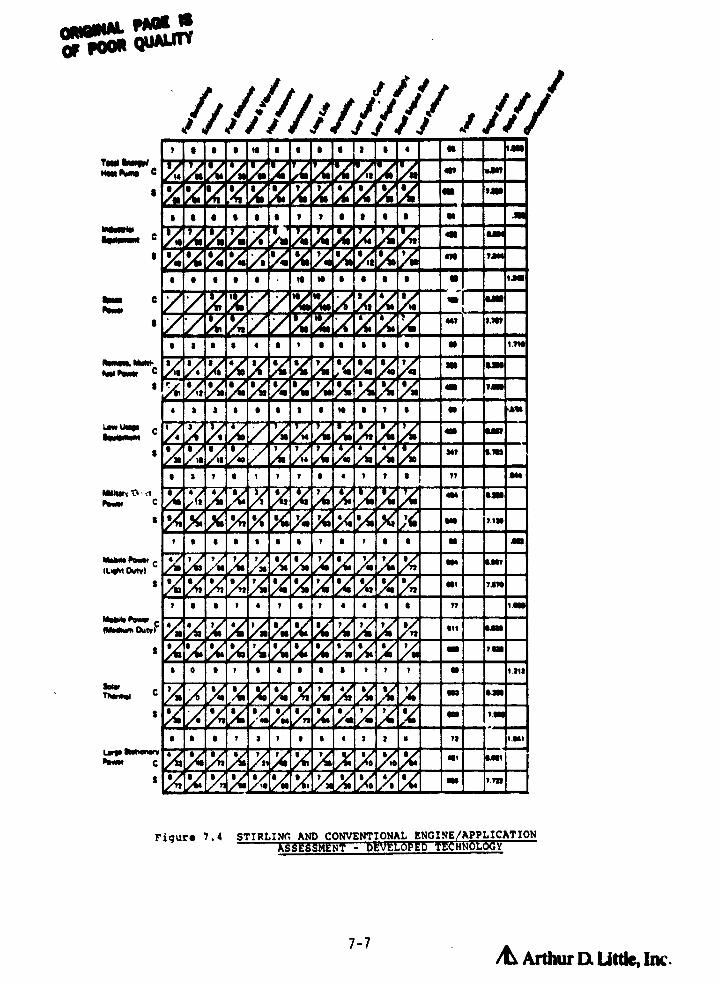
• • • a i • • i ! • • M aM
4p • N
N e! • 0
• • • • • • T • • 0 1"J"•) n r • •t 1!
e • • • • • it to e • • • N tan
• a ^
• •n )aa>s s,
t • • • • • • 7 0 . i •h U r
400
• 3 3 . 0 e 3 0 N • T •'0 1
41%
3•N
). N
's
•. •0
e 7 7 • t 1 1 • . 1 T • » .M•
• • • 7 • 7 ••i am
• • . 700 t TM 7 .10 IAA
• . t • , 7 . ,,1 tal,M 2, r
• . f • 7 . . ) • • • f Nt T.i7•
, • . 1 . 1 • 7 • • i • » 1.
• 1 • t • • 0 7 1 t .71 >1 N t2
•17
• • e . , • • • . • • ) NO ).•N
. 0 • 1 f • • . • t , t N 1.213
• . • 0 t Is • • ts 61 N3 am
• M 7! ••
e • e 1 2 7 • i • 2 3 . it 1.4061
• • • i 7 1 • 7 i . •0 10
rl
!• N t 0 •
pun 0
#no CP•ww
t
tf•tw, MWt1^^,,, 1fa•1f, c
TOW iWO4"m PAW C
•
M101wim C
M
•
Low UUM C•01d/^M11
•
M.*wv t1 :t►t vw C
•IM•MN hw/ CIU,At Ow"I
•
iM&dkm ornlG
•
S"CTheow
•
^,a1N e^.t1.11.11frlwl `'
•
Figure 7,4 STIRLING: AND CONVENTIONAL ENGINE/APPLICATIONASSESSMENT -D LCD-TECHNOLOUY
7-7
& Arthur DL I,it&, Im.
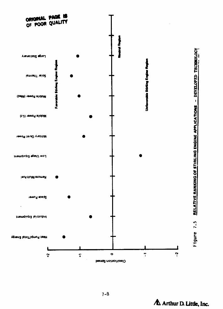
7-8
AL Arthur DL Little, Inc.
AAUOIIRIS WJOI
PWA841 AIOS
IPOW ► amod 44!qow
111 ► JwOd *PqM
jamod joint) AAI!I!n
luowd i nb3 somn mol
ismod S"ds
luouidinb3 lopisnpul
A6iou3 lowl/duind wsH
OWN&Of POOR
+-
PIOXIS U09931PS11113
r=
AH06
ca
ZwJ13z
4as
all.I-U.

W Intermediate
In these applications the potential advantage of Stirling engines, u,:en in
their developed state, appear to be modest as compared to more conventional
alternatives. However, in applications with very large market potentials,
these modest advantages could still have significant total impacts.
o Light Duty hobile
Competition from conventional engine technology (Diesel and Otto cycle engines)
is extremely keen, with both types receiving intensive development effort
from public and private sources. Cost, size, and weight restrictions are
severe, and there is significant infrastructure for conventional engine technology
if already in place. However, the potentially large market and impact of these
engines warrants continued parallel development of the technology.
o Industrial Equipment
There is a relatively small market which is reasonably well served by conventional
alternatives, although positive attributes of 5` 4 r 1;.ng engines are potentially
important in these applications.
o Military Quiet Power
Also a relatively small market with difficult (and expensive and time consuming)
certification procedures (military specs) and control requirements. However,
cost not so critical and advantages of Stirling engines are important in this
application.
(c) Promising
o Heat Pump/Total Energy
Has a large potential market, and few competitive engines. Attributes of
Stirling engine technology are critical in this application and cost, weight,
and size requirements are not as critical.
7-9 /d Arthur Q Link, Inc.
LA- -----

0
o Space Power
Although a small market, in terms of number of units sold, potential attributes
i of free piston Stirling engines are very important, and cost is not an important
factor. Competition is not as well-suited to larger power sizes as Stirling
engine.
o Remote Multifuel
Competition is not currently serving this market adequately "primarily using
inexpensive gasoline engines and small Diesels), since none are multifuel.
Cost, size, and weight constraints are not critical. Market is large particularly
in remote areas of developing countries. There is also potential for significant
domestic market, in remote areas ov in second cr vacation homes away from the
power lines.
o Medium Duty Mobile Power
Although competition is tough, cost, size, and weight constraints are less
than with light duty mobile power and Stirling engine attributes are important
in this operation.
o Solar
Large potential market competition is from Rankine cycle and Brayton engines,
as well as photovoltaics. Stirlinc engine attributes such as efficiency are
important in this application+ although cost and low maintenance are important
constraints.
o Large Stationary Power
Cost, weight, and size constraints not critical. Multifuel capability desirable
as are other Stirling attributes. Market relatively small, and will not
likely justify development of engines specifically for this market.
7-10

7-11
i7.1.3 Definition of Desirable Engine Characteristics
i
The following descriptions are intended to briefly outline each of the engine
characteristics and the rationale behind the score of the conventional engine
system. Stirling engine performance is outlined in detail in the previous
section, and is not repeated below.
Fuel Flexibility:
a Although difficult to quantify, fuel switching capability is desirable in a
} number of applicati-.is . For example, remote or military power generation,
where supplies of one type of fuel might easily be interrupted, but others
might still be available, would clearly benefit from being able to use solid3
- fuels as well as a variety of more conventionai gaseous or liquid fuels.i
Other applications such as solar thermal and low usage equipment (lawn mowers,
chain saws, etc.) place less importance on fuel flexibility than other characteristics,
simply because the end user doesn't see fuel flexibility as an important
constraint to effective operation.
Conventional internal combustion engines, are usually not well suited to the
use of radically different fuels. This is primarily because the combustion/fuel
handling systems must be carefully integrated into the design of the prime
mover part of the engine system. For example, in the light duty mobile
power application (automotive), many engines are designed to use lead free
gasoline. The use of any other fuel (with the possible exception of certain
gaseous fuels) can damage or otherwise make inoperative other parts of the
system, such as carburetor, valve seals, catalytic converters, etc. In the
case of the Diesel engine, the diesel fuel itself provides lubrication to
the fuel injection systems. The use of straight gasoline, which has very
poor lubricating properties in a Diesel engine would result in substantial
damage in a very short period of time. Thus, conventional (I.C.) engines do
not score well in fuel flexibility. Gas turbine and Rankine cycle engines
can be somewhat better, depending on design.
/© Arthur a utt1G, hr.

The Stirling ingir.e, on the other hand, being an external combustion engine,
can have a more independeet combustion/heat transport system. Tests and
desonstration systems built to date have demonstrated the ability to operate
on a wide variety of fuels, including liquid and gaseous fuels as well as
various solid fuels, such as cattle dung, rice husks, wood chips, etc. Thus,
the Stirling engine is rated well in fuel flexibility.
Emissions:
The emissions characteristics of an engine can be an important issue on both
a national/social scale, as in the case of the automotive and heat pump
=
applications, and an individual basis, as in the case of industrial equipment.
The Environmental Protection Agency (EPA) of the United States Government
has mandated a series of emission standards for automobiles sold in the
United States. These standards have had a serious impact on the design of
engines for automotive use. (Similar standards are being considered for
home heating systems.)
For engines used in less open spaces such as mining vehicles or fork lift
trucks, the effects of that particular engine on the operator of the equipment
is of greater importance than the aggregate effect of those engines on society
as a whole.
F^r other applications, such as remote or military power, low usage equipment,
etc., the engines may be small in output, far from populated areas, or used
relatively infrequently, and for these applications emissions is not a crucial
area of consideration for the user.
The difficulty in .achieving a low emission, I.C. engine stems from the fact
that the combustion process takes place within the engine cylinders, under
difficult to control, time and load varying conditions. In an effort to
alleviate the atmospheric pollution problems of many urban areas, conventional
I.C. engine has had conbiderable development in the past 10-12 years, including
after process cleanup (catalytic converters, EGR, etc.), improved air/fuel
F
control, advanced ignition systems, turbocharging, etc. Current technology
I.C. engines, particularly for automotive use, can operate , pith goad exhaust
emission character -tics acd are rated fairly well in those applications. 1
L
3

The Stirling engine with its external combu r.tion system can operate with low
emissions in almost any application, and is rated highly on this characteristic.
Ill
j
Efficiency:
Efficiency is clearly an attribute that is desirable in any application. its
some cases, such as space power and solar thermal, the efficiency of the engine
has a direct impact on the "fuel sa-cce" requirements. For example, a more
efficient engine could requ=ire less solar collector or a smaller nuclear or
isotope heat source as well as a smaller heat rejection system. For larger
stationary power, heat pumps, and light and medium duty mobile power, an efficiency
at le Ant equal to that of conventional engines currently used will be required
to achieve some penetration of the current market for that equipment. In some
applications, fuel efficiency is not as critical a factor, such as in low
usage equipme ►+t, or military quiet power generation, where other :actors such
as weight, cost, or low noise are more impor_ant than the last few percentage
points in efficiency.
As covered in Section 5.0, conventional engine efficiencies range from 10-15%
for single cylinder, low cost Briggs and Stratton type engines, to 18-25% for
gasoline automotive engines as well as gas tubines on up to 30-40% for large.
low speed Diesel engines and Rankine cycles. Conventional engine efficiency is
well-documented, and can be quite high. For this reason, the conventional
engine can be rated reasonably high within any given application class.
As previously mentioned, the Stirling engine can operate veiy efficiently in a
range of sizes and is therefore scored very well, usually incrementally higher
than I.C. engine alternatives.
Noise and Vibration:
i
Although noise and vibration may, in some applications, be tolerable, it is
never desirable. Noise is critical in certain applications such as military
power where quiet operation is necessary to avoid detectior and heat pump
systems where use in residential areas will prohibit the operation of noisy
7-13 A Arthur Dt Little,1M

engine systems. In other applications, vibration is critical; for example,
in space systems, vibration could be potentially damaging to sensitive electronic
components. Similarly, vibration in a solar collector system could hamper
long term performance of the system. Low noise and low vibration levels are
also important in light and medium mobile power applications.
Conventional gasoline internal combustion engines can be made to be quiet and
smooth by design, muffling, special mountings, enclosures, etc. The Diesel,
by nature of the combustion process it utilizes, iG a noisier, more vibration
prone engine. Gas turbines can be very smooth engines but are generally
quite loud unless extensive muffling to the intake and exhaust is performed.
Rankine cycles are also reasonably quiet and smooth.
The Stirling engine has the potential to be quieter still, due to the lack of
valves and continuous combustion process. Therefore it is rated very highly
in this category.
Heat Recovery:
There are two aspects to heat recovery. The positive is that the heat can be
utili ,,ed in an associated or separate application at no detriment to system
operation. The negative (heat rejection) is that this heat must be removed
from the engine for continued operation. This can result in extra components
for the engine as well as efficiency penalties for certain types of engines.
Heat recovery is critical to the economic application of heat pumps and total
energy systems. It can be important in solar thermal applications, large
stationary power, and mobil power application. Heat recovery is of little or
no consequence in space power, industrial equipment, and low usage equipment,
although heat rejections is necessary in all of them. A great many internal
combustion diesel and Otto cycle engines are liquid cooled. For these engines,
heat recovery can take place in three areas: a) the cooling jacket, (b)
exhaust gases, and c) lubrication systems. For gas turbine systems energy
recovery is primarilv from exhaust gases. For air cooled engines, heat is
only available from the exhaust and lubrication systems. For a Rankine cycle
engine, heat is potentially available from a cooling or heat rejection system
1 and the combustion system.
7-14& Arthur Dl Little, Inc.

AFor internal combustion onginee, relatively high temperatures are available
with very little effect on engine performance. However, to recover this
energy requires the addition of an additional heat exchanger in the exhaust
stream. This component can be expensive and must be carefully designed and
t ` installed to avoid degrading system performance. Figure 7.6 illustrates thef
apportionment of heat from the various sources for an internal combustion
engine and a Stirling engine. Some care must be taken in recovering heat
from the exhaust stream to avoid condensing water vapor from the exhaust and
creating a c rrosive environment in various engine components. Conventional
engines are rates moderately for heat recovery.
The Stirling engine is different in that the major source of heat is from the
cooler. A small amount of heat is also available from the combustor after
passing through the air preheater. Thus, it is easier to collect the majority
of reject energy from a Stirling engine, since it comes mostly from the
cooler, which each engine must have. The disadvantage with heat recovery in
the Stirling engine is that since the efficiency is inversely proptional to
the cooling temperature it is desirable to extract heat from the engine at as
low a temperature as possible, thus in some cases reducing the usefulness of
the collected heat. Stirling engines are therefore rated well on heat recovery,
since no additional equipment is needed, and most of the heat can be recovered.
MA:nPonAnro-
Maintenance requirements can be described in terms of level of skill required
to perform that maintenance (such as simple oil change or ignition system
maintenance, on up to overhaul) and the frequency of that maintenance. whether
it be scheduled or unscheduled, due to some form of breakdown. Maintenance
can be important from two standpoints. One is economic, whether the burden
of the expense of doing the maintenance is prohibitive in a certain application.
The second is from a logistics standpoint, i.e., the difficulty of obtaining
maintenance and/or parts. Maintenance is critical in space power applications
from a logistics viewpoint. It is of primary importance in military systems,
from a logistics standpoint and in heat pump applications, stationary power
applications, solar, and medium mobii applications from an economic standpoint.
t Maintenance is not thought to be as critical in light mobil applications,
industrial applications, remote power generation, and low usage equipment.
L

^pAGEi3
Of pOO
1'F
€ 9
t Other5%
Exhaust
Gases10%
WorkOutput
30%
CoolingWater55%
Mod I Stirling Engine
3%
Work
Exhaust OutputGases 22%
30%CoolingWater45%
Conventional Gasoline Engine
Figure 7.6 CONVENTIONAL AND STIRLING ENGINE ENERGY BALANCEAND ENERGY RECOVERY
7-16
Ardw EX Little, Im.

With conventional engine systems maintenance is often inversely proportional
to the cost and often the life of the system. Small engines can need maintenance
every 25 hours,amounting to ail changes, filter changes and ignition systems
tune ups. On the other hand, well designed Diesel and gas turbine engines
can , go thousands of hours before maintenance is required,
Maintenance, as indicated above, varies from inspecting and/or replacing air
and oil filters, adjusting injector and ignition systems, valves. coolant
levels, on up to an overhaul which requires a major disassembly of the engine,
replacement of bearings, piston rings, valves, valve guides, seats, etc.
Conventional engine s are rated well on maintenance, since they can be selected
for the application based on that requirement.
A well developed Stirling engine should be somewhat better on maintenance and
is so rated based on the factors outlined in the previous section
Life:
Thera are two ways -% discussing the life requirements of an engine, One is
in term:: of absolute number of hours and the other is relative to the life
of the piece of equipment in which it is installed. Thus the term long life
can have a different meaning depending on the application. Similarly, life
can be important from a logistic standpoint (difficulty in replacing an
engine) and from an economic standpoint where the cost of replacing the
engine is prohibitively expensive in a given application. Long life in
terms of total number of hours operated is critical in space applications,
solar, large stationary power systems, and heat pumps. Life requirements
are not quite so stringent in applications such as law usage and light mobil
power applications where as long; - ► s the engine lasts the life of the rest of
the equipment it will he satisfnctor y (500-3000 firs).
I:, before overhaul of a conventional Dietzel and Otte cycle internal combustion
engine can be from 1,000 to '1,000 hours. 1000 hours might correspond to a
7-17Arthur Q Uttk, Inc. -^

7-1a
t
single cylinder Briggs and Stratton type engine, and 3,000-5,000 hours for a
gasoline fired internal combustion engine for an automobile. 50,000 hours
might be expected of a recipr:cating Diesel in a long life type application.
Gas turbines and Rankine cycle engines have been known to run for hundreds
of thousands of hours before failure or need for total overhaul. Internal
combustion engine failures are generally due to bearings, valves, or rings.
Gas turbines have similar failure modes in bearings, as well as turbine and
compressor, erosion and degredation. Thus, conventional engines are rated
jquite well in long life category.
Stirling engines have the potential for long life for the same reasons as
they have potential for low maintenance and, therefore are rated very well.
Startability;
Conditions effecting the startability of an engine are the reliability with
which the engine can be started, the ease or difficulty with which it can be
started, and the time to either maintain its own idle power or develop full
power. Startability is important in most applications and critical in a few
such as space and military. In these applications, an engine that won't
start is of very little value.
Most conventional engines need a starter motor of some type to initiate the
cycle to the point where it can carry on its own loads. A typical Otto
cycle engine in an automobile has a 15 second start requirement from when
the key is first turned until the automobile is driven away. Diesel engines
generally take somewhat longer than this to warm up the glow plugs, particularly
in cold weather. Gas turbines can be slower yet, taking significant time
(2-30 minutes) to reach speed to avoid compressor stall and achieve good
temperature stabilization. Rankine cycles tend to be slower yet requiring
time to initialize boilers, condensers, etc.
Conventional engines are rated quite well in startability in most applications.
As indicated in previous sections, Stirling engines should start as well as
conventional engines and are rated about the same.

Engine Cost:
Engine cost can be a main driver in many applications, typically those
with a mass market such as low usage equipment, light duty mobil power
applications, and solar thermal applications. This is mainly based on thefact that the competitive engines such as the Briggs and Stratto and
automotive type engines ace so low in cost. Engine cost is less critical
where other characteristics such as fuel savings or efficiency or reliability
are important such as space applications, military, stationary power, or
total energy heat pump systems.
It must be kept in mind that, as pointed out in previous sections, conventional
engine technology is extremely well-developed. Engines of both small and
medium sizes are produced in very large volumes and present very tough
competition from a cost standpoint. For this reason the conventional
engine is rated very well from a cost standpoint.
The Stirling engine has a number of specialized components peculiar to it
(as discussed in previous sections) and therefore production costs are not
expected to be as low as those for conventional engines. Thus its score
is lower than that of the I.C. engine.
Small Engine Size:
In certain applications, the physical size of the engine will be a constraining
factor. For example, if in light mobile power applications, the engine
will not fit under the hood with all its auxiliary components, battery,
condenser, and other equipment, it will not be acceptable. Small engine
size is usually important but not critical in low usage equipment, military,
quiet power generators, solar thermal applications and space systems.
As indicated, the gas turbine and two stroke engines are the lowest followed
-{ by the Briggs and Stratton type single cylinder low power engines in turn
-i followed by internal combustion engines of gasoline fired and Diesel fired
t
7-19/L Arthur D: Litue, Inc,. __.__

engines on up to low speed Diesel engines and Rankine cycle engines.
The conventional engine is rated moderately on size.
As indicated previously, the Stirling engine will generally tend to be
larger than a similar size conventional engine since the component required
for combustion, preheating, etc. is significantly larger than the air
( handling equipment for the conventional engine, while the remainder of the1.
system will be similar. Hence, the Stirling engine is rated lower than
conventional engines.
Low Engine Weight:
A highpower-to-weight ratio, although desirable in any application, is
truly important in only a few such as low usage equipment, military power,
and solar thermal. In space applications a high power-to-weight ratio fot
the total system (thermal energy source, hest transport subsystem, power
converters, and radiators) is critical.
The very high efficiency of Stirling engines in such applications would
tend to reduce the size and weight of the thermal source and heat rejection
subsystems. This provides some additional flexibility in the design parameters
for the engine itself.
Typical conventional Otto and Diesel cycle engines are generally quite
heavy (10-50 Kg/kW). Such engines are often used in applications where
weight is not a critical factor. Where weight does become important two
stroke and gas turbine cycle engines can have very high power to weight
outputs generally at some sacrifice in efficiency, pollution characteristics,
or perhaps life. Rankine cycle engines generally have poor characteristics
from a weight standpoint and are not generally considered for mobil type
applications.
The Stirling engine is rated lower than the conventional engine alternatives
for the same reasons as described in the preceding paragraphs on engine
size.
7-20 & Arthur U, Little, Inc.

kLoad Following/Control:
In this section load following is defined as the ease with which the engine
can be controlled to follow a given load or demand placed on that engine.1( The following is very important in low and medium power mobil applications,
military applications, industrial power, and stationary power generation.
Other applications such as total energy systems, remote multi-fuel, and
low usage do not demand rapid fluctuations in output from the engine to
perform their functions. As indicated in the section on Emissions, rapid
changes in output demanded of an engine can have significant effects on
the emission characteristics far that engine and therefore, load following
control is connected to the emissions characteristics of an engine.
The conventional internal combustion engine is an excellent load following
device. It is well understood how throttle position, rpm, and manifold
pressure are related and can be controlled almost instantaneously to adjust
the output. The gas turbine can have from fair to good characteristics in
power control, although in some cases it can be expensive. Rankine cycle
engines cften have slow response and in order to avoid poor load following
characteristics require, sophisticated control systems, due to the large
thermal inertia of the boiler and other heat transfer components of the
system. Conventional engines are therefore rated quite well in load following.
The Stirling engine will probably have good load following characteristics,
as described in previous sections. The mass of the heater head and the
movement of gas into and out of the engine (in pressure control systems)
will dictate a response time poorer than that of a conventional I.C. engine.
Variable displacement systems (swashplate, Z drive, etc.) will likely have
response times similar to I.C. engines.
7.2 Selection of Baseline Stirling Engine Systems
As indicated in the previous section, there are 9 classes of applications
which show potential of being served by Stirling engines, assuming engines
are developed which meet the primary goals of present development programs.
7-21
& Arthur Q LJtde, Inc.

In principle, a series of engines could be developed to uniquely serve the
needs of each of these application classes. This would involve the development1.
of several dozen engine systems which is clearly impractical. Equally important,
common engine designs can be developed which with minor modifications can be
used to serve a multiplicity of applications. Developing a small number of
baseline engine systems has the advantage of:
o Resulting in engines which can serve a variety of potential markets,
thereby reducing development risks.
o Allowing for reduced development and manufacturing costs, since a
small number of common engine designs can be produced in large quantities.
o Addressing specialized markets with particularly favorable near-term
potential with engines which can be eventually used in larger market
segments.
It should be noted that the above approach for Stirling engines is not fundamentally
different from that followed with conventional engines. Basically similar
engines are often used to satisfy widely divergent applications. For example,
automotive engines are used for irrigation pumping and, on a limited scale,
for commercial scale gas fired heat pumps (in Europe only, at this time).
Similarly, medium size Diesels (30-100 hp) are used for tractor drives as
well as for generator sets.
The selection of baseline engines to serve the potentially favorable application
classes of Figure 7.5 is a highly judgemental. process. The basic goal of
this process was to identify engine categories which:
• Served a number of potentially favorable applications having common
technical and cost requirements.
• Differed from other engine categories in important characteristics so
as to define a unique engine category.
• Had market potentials spread across several favorable applications,
which merit the associated development costs and risks.
Utilizing the above criteria, engine categories were identified which could
address all the favorable applications of Section 7.1. These engine categories
are:
o Simple Rural Power
7-Z2
/L Arthur D, uwie, Inc.

o Silent Power Generators
o Automotive and Automotive Derived Power Unit
o Large, High Duty Cycle, Stationary Power
The applications comprising each of these engine categories are schematically
illustrated in Figures 7.7 through 7.10 and the technical requirements of an
engine for these applications are shown in Tables 7.1 through 7.4. In most
cases, the requirements of these applications are formulated by assessing
those engines currently in use or in applications where there is no current
market, determining what characteristics would be necessary for that application
to find widespread use. Brief descriptions of each engine category follow.
Simple Rural Power (Multi-Fuel):
Several studies (28) point out the need for simple power systems for use in
rural areas both in the United States and in developing countries. Presently,
rural power needs can be served by various forms of I.C. engines. Where
heavy duty cycles are involved, derated I.C. engines or Diesel engines are
typically used. These engines are, however, relatively unreliable when
used in rural areas with harsh operating conditions and, in some cases,
minimal maintenance. Furthermore, the I.C. engines can only operate on a
limited range of commercial fuels.
An important requirement of a rural Stirling engine power system is that it
can operate on non-commercial fuels often found in such areas, as well as
on liquid and gaseous commercial fuels. These fuels include charcoal, wood
and crop residues (rice husks, etc.).
As indicated schematically in Figure 7.7, such a multi-fuel engine would
have a wide range of applications, including:
o General electric power generation.
• Water pumping.
• Farm equipment.
In the United States, a simple rugged wood fired engine could find a market
segment for rural second hues and camps as well as for use in farms where
crop wastes are generally available. In developing countries they could
I
7-23 Arthur Dt Ut*, Im

cWY
WOWVa
ccWOZ_REco2
t7
aWHF-JIL
OOO3
IL
ILQ
sLi
ac
ccWZWOQW3OILVochVWJW
9
aL
W
ORROu PAGE ISOf Poon gtmuM
tu

OR'QINAL PAGE ISOF POOR QUALITY
IW
3
>le
1
I
Gon
Lpfrti
WZ 2O pF- ZLO WILI Z
WJ
aoz
: OOH 2Z
O-©:
r1 VW3
J
O2
Ir
FJ_
QW
OIL
w
J
Go
-2' /© Arthc DL Little, Im j

W
Q
Om
ohoH
Ht
EQ
WJ
W>
J
QW
m
I-.J Zt3FQOO
IL^ W
ZIL Wv
WZp j OJ ^
<
N^ W }lyeW
V W
Q0
0
QED^DZ Q
ccW
3
d
v22
OvW
HOOF
W
O WZ
O^;
O
W^J
Y =00 w
J^vQ =F
m ^v
o+
arLO1
AL Ardwr a utdow,

ORIOM ma aOf POOR QUALITY
tWZW
ccW
OIL
}
Ji ^ h2J
W
W
WZ
re
WOccJ
E =
yWZWOOV
O
AL Arthur a uttie, Inc.

TABLE 7.1
RURAL POWER SYSTEM REQUI_REMENTS
Power Level
1 - 20/kW
Efficiency
10 - 20%
Emissions
Not Important
Noise Level
Not Important
Heat Recovery
Desirable but not essential
Maintenance Interval
2 - 4 Times/Year(500-1000 Hrs.)
Life Before Ma3or Overhaul
7 - 10 Yrs. (5000 -10,000 Hrs.)
Cost
$200 - 400 -Operated withcommercial fuels
$400 - 600 -Operated withBiomass fuels
Weight
30 - 60 icy/kW*
Size .020 - .080 M3/kg
* Based on a 50% Allowance Over Available Engines.
1-28 Arthur Q Uttk, Inc.

SILENT POWER SYSTEM REQUIREMENTS
Power Level
3 - 30/ kW
Efficiency
25 - 35%
Emissions
Application Dependent
Noise Level
Low Noise Important(Less than 65-75 dBA @ 1Meter)*
Heat Recovery
Application Dependent
Maintenance Interval
1-2 Times/Yr (2,000 -5,000 Hrs.)*
Life Before Major Overhaul
7-15 Yrs.- 15,000 -25,000 Hrs.*
Cost
$250 - $500/kW
Weight
7 - 20 kg/kW
Size .003 - .008 M3/Hr.**
* Heat Pump Requirements Used to Quantify these Parameters - SomeApplications May have Less Severe Demands
** Based on a 501 Allowance Over Available Engines
7-29 /t Arthur Di. US-, im

^ ORIGINAL QUA^^
OF POOR
^ L4J L
t:C ^ O Yb `^j'
\M
W.~ ^ O 1? IA Yn %A L N Ln
In r~
O tt f 10 OI
\ rCl
CD a8VC!
Vd E I >, LnCD
YCD CD m
N N i4J
00 to 00 1Cl 1
N1 1 O 4J .r. O1 ' w O1 Ln O 1 LnO
Q
WO O
Mr-N
S-N dNr y r :V^^ iW O
S M
OrF-W 4J
V) CN dW Nld M tp ^^ YN u O i f d H
i2 M\
>-m
>-N I r 1 N r = O Scr.
H^Of C^
0 39
W W 3 d C O O Y \ C~ Y 4J
bdXO m O N \ cn O
W d 0 3'Q C r r h M N r O YOM Ln +J m to
O tNp M U 00 U 1 1
N W } 1 t 6n l r . Z COCIr O O
rto
C^ ¢ a xi 31n a O O C) 0W O Ln CLu0 to 0r^, a O O In OM 1- W 2 Lf) N W S Z 0. -J O w \
Q ^n Urr WW J >m d F 4!
Q rS r
fU.., ^i4-1
0C
tL O
Z O( Q tp b^ d 3LUZ tL L ^ a Y\fW
} I r 1 •^ rNL°'
g+ M=0
-00E to^
C 2 2 3393 6n
=F~ _u \4AUto
-Cry m O
OY\ \
OO
= O SQ C r r 1A 41 O O O CICS O U") to cf O O •'- t0 1n O M \r M 1i J
N r •r Z AO r 1 M 1 LnM1 1 1 1 4
Q x L-I
3 Lnrn O 1 u') 1 O
0 to aU0 m On +-M N W2Zd Jam-+ Q N N M
r
L iaJ O
L
Crr
r ^ t0.1 L>
V b^N C C NJ Cl • O J cr- CO to 4JL U N GJ +t L t4J W 4J w •I- to r 0 W N
•^ > O a r-C W W Z 2 JO U 3 V1
7-30
/t Arthur D: little, Inc.

Heat Recovery
Maintenance Interval
Life Before Major Overhaul
Cost
Weight
Power Level
Efficiency
Emissions
Noise Level
Size
500 - 5000/kW
30 - 40%
To Meet Local Standards
Application Dependent(No Federal Regulationat Present)
Application Dependent
4,000 - 8,000 Hrs.
30,000 + Hrs.
$250 - 450/kW
Not Critical(20 - 50 kg/kW)
Not Critical(.030 - .100 M3/kW)
-47
TABLE 7.4 ORIGINAL PAN 18OF POOR QUALITY
LARGE STATIONARY POWER SYSTEM REQUIREMENTS
7-31Afthur It Uttle, Inc.

7-32 /L Arthur Q Uttk, Inc,
help provide critical power needs using locally available fuels which would
ensure a strong base of support from governments and multi-lateral financial
institutions (World Bank, etc.),
j; Table 7,1 summarizes the requirements for an engine system to be viable
from technical/economic points of view in this category of applications,
As indicated, only moderately high efficiencies of 10-20% will be required
since conventional engines utilizing fossil fuels typically operate in this
t range. Emission levels are not critical nor is heat recovery, Noise levels,
while not critical, must not be harmful to bystanders or operators.
Maintenance is acceptable 2 to 4 times per -ear, but should be performed
only with basic tools and a minimum of skille,; 'Labor, Lifetime before
major overhaul should be at least 5,000-20,000 hours to be competitive.
Engines currently used range from small gasoline engines requiring frequent
maintenance (25-50 hours) and having relatively short lives (up to 1,500
hours) up to small Diesels with infrequent maintenance (100-500 hours) and
long life (up to 20,000 hours).
Acceptable costs range from $200-400/kW for engines that will be run primarily
on fossil fuels, up to $400-600/kW for engines which are run on biomass,
The difference is attributable to the fuel savings for the biomass operated
system. Neither weight nor size are critical and could be as much as 502
greater than conventional engines,
Silent Power System:
In several of the application classes of Figure 7,4, low noise and vibration
operation is otie of the most important features. These applications are
shown schematically in Figure 7.8 and include:
o Residential/Small Commercial Scale Total Energy/Heat Pump Systems.
o Military Generator Sets.
o Solar Thermal Power.
1.
As a practical matter, therefore, the development of highly reliable, low
noise, engine systems could, in principle, address many of the most highly
ranked Stirling engine applications.
At the present time, these application classes are either not being addressed
at all or are addressed inadequately by existing engines. For example,
I.C. engines have been used in demonstration heat pump systems but have not
been widely accepted in part due to their high noise levels. Similarly,
space thermal power is now generated using thermoelectrics which have very
low efficiency ( 6%) making their use in larger power systems of the future
highly problematic.
The market size for this engine category is difficult to estimate since
many of the application classes it would serve are not now served by conventional
engines. However, for an engine meeting requirements summarized in Section
4.0, the market should be substantial. For example, over 2 million residential
size heating systems are sold annually for both new construction and replacement
markets. Even a modest penetration into such a large market area could
result in a significant sales potential for engine driven heat pump systems.
Table 7.2 summarizes the requirements for an engine system to be successful
in this category of applications. Several studies (29) have indicated a
requirement of a 30+% efficiency in heat pump applications, in order to be
competitive with electric driven systems. Emission levels for fossil fuel
operated systems will be very important in heat pump or total energy applications
:s (less than or equal to a furnace in residential use), but not so critical
in remote or military power use. Low noise will be important in all these
applications, with the possible exception of solar power generation in
remote areas.
Infrequent maintenance is important in all these applications. Maintenance
at 1 to 2 times per year (or 2,000-5,000 hours) is required in most of
these applications, and a life of 7-15 years (15,000-25,000 hours) is required
for economic competitiveness particularly in solar thermal or total energy
L
heat pump applications, at the engine costs outlined below. Clearly, if
engine costs were lower, life would not need to be so long.
Arthur D: Little, Inc.1^.7-33

Acceptable cos s based on competitive systems and application requirements
range from $250-500/kW, for terrestrial applications. Size and weight,
while not critical in heat pump systems (can be up to 50% over conventional
alternatives) is important in space solar and military applications.
Automotive and Automotive Derived Power System:
The largest single category of engines sold today are those developed for
vehicular propulsion. The large majority (95X) of these engines are used
in automobiles and light trucks which clearly represent the major long-
term incentive for the government to support the development of high efficiency,
low emission, Stirling engine systems.
A large number (over 100,000 units/year) of automotive engines are, however,
sold annually in a variety non-automotive applications such as inboard
boat engines, irrigation pumps, and farm equipment.
In addition, automotive engines have been used in demonstration systems
for commercial size heat pumps and total energy systems.
As indicated in previous sections, the life requirements of tl.:, automotive
application are considerably shorter than for most other applications in
this size range. Derating ;.ind possibly design modifications to the basic
automotive engine configurations will likely be needed to address these
longer life applications. 0 8)
As with conventional automotive engines, the automotive Stirling engine
could be adapted to address a range of applications where the Stirling
engine attributes are particularly important. These application classes,
as indicated schematically in Figure 7.9, include
• Heat Pump/Total Energy (commercial sizes)
• Marine Power
• Stationary Power
• Mining Equipment
L7-34 AL - - - --- __ ----- -

The commercial success of an automotive Stirling engine program does not,
therefore, depend solely on the near-term implementation of the automotive
Stirling engine for general purpose vehicular propulsion. The markets
represented by non-automotive application could, in themselves, be substantial.
Thus, an automotive Stirling engine program could lead to viable engine
systems in a number of applications, perhaps before they find success in
the vehicular applications.
Table 7.3 summarizes the requirements for an engine system to be successful
in this category of applications. Engine costs are based on the large
production volumes associated with penetration into the automotive market.
As indicated, an efficiency of 25 to 35% will be required in all these
i
applications because current technology gasoline engines operate at 25%
and Diesel engines at 35%. Emission characteristics will clearly have to
meet EPA standards for the automotive application, perhaps some lesser
i
standards for boat drives, etc., or maybe even more rigorous for commercial
heat pumps /total energy systems. Heat recovery is critical to thermal
applications but not important to boat drives or submersible vehicles.
Maintenance intervals, as shown in Table 7.3, as well as life, cost, weight,
and size are dictated by the characteristics of current technology alternatives,
namely gasoline and Diesel internal combustion engines.
Large, High Duty Cycle Stationary Power
Several studies have indicated the potential applications for a large
stationary Stirling eng:ne rower plant similar to the large low speed
Diesel, gas turbine, or small steam turbine power plant in application
areas. The primary motivation for the development of such an engine is
t
the ability of the Stirling engine to use a variety of fuels such as coal,
refuse, etc., in addition to conventional fossil fuels. Other attributes
include high efficiency, good emission characteristics, and quiet operation.
t ^
7-;35
&EX

As indicated schematically in Figure 7.10, an engine of this type would
find a range of applications including
o Cogeneration
• Pipeline Power
• Utility Power
• Ships and Barges
The development of such an engine would permit the generation of electricity
in close proximity to noise sensitive areas such as apartment or office
buildings, for use in distributed energy systems. The fuel flexibility
would permit the operator to operate on whatever fuel was least expensive
at the time, promising economic incentive to use this type of engine.
The market for this class of application is relatively small, less than
1,500 units sold per year in the above 500 hp size range. While the development
of Stirling engine technology probably isn't justified on the basis of
this application alone, scaling up an engine developed for another application
might be.
Table 7.4 summarizes the requirements for an engine system in order to be
successful in this category of application. Current technology Diesel
engines in this size range are operating at 30-40% efficiency, although
gas turbine and steam cycle can be 20-30X.
Emission levels are highly dependent on the application; for utility power
generation, EPA standards must be adhered to. For ship use, there are not
currently any regulations. The same applies to noise levels. Heat recovery
is clearly important in cogeneration applications, but not in the remaining.
Maintenance is a crucial factor, as is long life. Maintenance intervals
of 4,000 to 8,000 hours have been achieved as have total life times of
30,000+ hours with conventional engines and thus will be required of the
Stirling engine.
s'
L 1-36 & Arthur n Little, Im
E Conventional engines in this size range cost from $250450/kW. Size and
weight are not generally crucial factors and allowances of 50% over
conventional technology, as 'shown in Table 7.4, are probably acceptable.
7.3 Conceptual Designs for Baseline Systemst
1
This section presents conceptual engine designs for each of the four engine
categories identified in the previous section. In these conceptual designs,
the engine system is defined as all those components needed to perform in a
given application including cooling systems and pumps, combustors, batteries,
control systems, and, in some cases, fuel tanks, not just the prime mover or
mechanical part of the system.
For each application class there are a number of Stirling engine configurations
which could be selected as the baseline design. For example, either free
piston or kinematic Stirling engines could, in principal, be used in all application
classes. In this section, the baseline engine design selections are consistent
with the emphasis of current programs. For example, most current efforts
directed toward silent power systems (heat pump applications, etc.) assume the
use of free piston equipment. On the other hand, automotive derived engines
would, of necessity, be based on kinematic engines which can be interfaced
with automotive power trains.
Simple Rural Power:
As indicated in the previous section, the performance requirements (efficiency,
etc.) of the simple rural power systems are not particularly stringent. On
the other hand, such systems must have a rugged simple construction consistent
with operation and maintenance in harsh environments.
The basic system configuration selected for this application class is a modern
version of a hot air engine. Such engines cannot achieve the efficiency or
power density capabilities of Stirling engines using high pressure helium or
tt
7-37AL A►rthw a i ittk, hic.

# hydrogen working fluids. However, they have several potential advantages
which are important for this application class.
o Using 1-2 atmospheres of air, the power density is relatively low
which results in a good thermal match with the relatively low heat
y fluxes provided by simple biomass combustion systems. As such, heater
heads of simple design can be utilized which can be integrated with a
solid fuel combustion chamber in a straightforward manner.
o There are no critical sealing problems since only low pressure air is
involved and small amounts of leakage between the working volume and
the outside air have only minimal effects on performance.
o The equipment is comprised of sheet metal, cast iron, and standard
mechanical parts which do not require high tolerance manuracture and
are consistent with field repair and operation.
o Early experience with hot air engines suggests that they can achieve
high reliability and can be of simple construction. It is expectedi
that the very low efficiencies and power densities of the early engines
can be greatly improved using modern technologies to increase operating
temperatures, improve combustion efficiency through air preheating,
utilization of regenerators (which early hot air engines did not use),
and improved mechanical drives.
There is relatively little work now underway to develop hot air Stirling engines
since most funded activities stress high performance applications. Figure
7.11 is a schematic of one of the few hot air engines designed using modern
Stirling engine practice which is now being developed by SUNPOWER, Inc. This
engine is being developed for rural power applications in developing couantries
and, if successful, would provide an example of this engine category. Table
7.5 compares the demonstrated capabilities of a Stirling engine in this category
(based in part on SUNPOWER's projections) to the application requirements and
with the representative conventional engine capability. As indicated, the
Stirling engine system would have a major advantage in having a wide fuel
flexibility and can probably meet the cost requirements of this application -
particularly if they can effectively use biomnass as a fuel.
1-38
& Arthur n Ut&, Inc.

Figure 7.11 1 kW HOT AIR ENGINE SYSTEM
7-39
rust favu
70 cm
CombustionAir Slower
1 80 cm

1
ORKWM PAN 94-OF POOR QUALM4j 41 A
CAC 4'• w O a^iw Ln v •r^r^ +O+^r• W u
W ^-• a •^0-4
. a
^•-^ 4 a+z a+z d L ^pp4g)NF` OC 4 d m d ul LU
LnC" dh- O O p
N N U N r Z F- SOCW
a Lvd c
J r•r > A
r tJ rC d •^OC O L O
H1 r r C 4J Cw 6•4 CU w UI -f-CA J_ 7 u> $.. N
4>
gz H co C •• L N.Lai v
7tC.ti
^pd d^ L O IA r- Ad du
N Q O 9 z r 31 N A -W.- LO W w r
^E+ Cg
O w ~Ix z .^ 4- Cw
— 4AO m4j
CC w Y a2 41 N 4j r- O M d N 9-9-cz O 41 (4
zw (A CON z W r
?N2 M O2 z &DLn O $-a4- 40
3N
^ v^ •p ^ a1L1 a
QQ§ Q •^ CI •r •^U O 1-► r Qf 4•►n ^
J^ S
^, C A•^ ^ •r.N CL.
r1 O r L u 41
rf^ = N O O N V 4J asJN C O W b b+j 4► 4J L rS
zU !--Z C C 2
md t1Y toto \C9 t LV a •r-C9
z wOb4J
m4+
rfD >b\ 4A
O •r-La- m
ZY S C s Ql b L
N HOC O poL r4^ to .•. L^ pp p \ 4^ 1Cp CLW Q ^--^ U 06 Q .0 C 0 d N O S w s d 2 dO U O 34 E E an d •r L L dW • N CN $-J Lai O N •r- NJC= r 1 41 41 to w Oet t
00r t Q Q to1 ON O a "- LN 0 d D
91.r ( 1 O Ox
Q d 1 1 N !f O O U 4j d •r- 4-
WQ r r z O N n 14414 M N"0 N
q f-+ d_CX .S f I
UO ^ d1 ^ ALL-r acw ^aLi ^z !=• u S. c
N_ep O IC b ='aLi o I"
mU
>I,I►I 4c g .g
> N > O C O Lvi ` Nd G C d U 4- to QJ • CU O J 4) m ^7• 4J N to OLD W4! •^ U U tL ZIA N 4J d 41 p1 d
4- 1p • r- 4- N •r-d W
rE-L5
ppz = CO) =
_N•Nn•14V;J N
1-40&tkw r.
iw-

i
1
Silent Power Cenerator:
Figure 7.12 is a conceptual illustration of a silent power generator used in
a solo: electric power generation application. The prime mover is a free
piston Stirling engine with a linear alternator on the power piston. The
engine includes the receiver, into which light is reflected from the concentrating^f
dish, the controls mounted ; t the base of the dish, the heat rejection aystes,
and the load controller, to prevent over loading the engine generator. With
an appropriately designed receiver, such a system could also be operated
during non-solar or partial -solar conditions on a clean fossil fuel.
^a
Both kinematic and free piston engines are being considered to serve this
application class. For purposes of the conceptual design a free pis^on
engine configuration was es3umed.
In the system shown the dish would be approximately 13 feet (4 meters) in
diameter for a 3 kW peak engine and would produce 20 -25 kW per day in an
Iarea with representative solar conditions. It would track the sun in 2
axes, with the engine and receiver placed at the focal point of the dish to
maximize system efficiency. The dish could be constructed from a number of
aluminum panels with reflective plastic coating. The elects:city is conducted
through the cable to the control panel / load controller.
The Stirling engine package site is influenced by the size of the heat input
subassembly (combustion chamber, air preheater, heater head) and auxiliary
subsystems such as the radiator and control package. As indicated in Figure
7.12, if the radiator and controls are located separately from the basic
engine package, its size is consistent with solar /dish applications as well
as other applications where small size is an important criteria.
Figure 7 . 13 is a schematic of a Stirling engine driven linear alternator
arrangement based on a system under active development. If successful, this
engine could meet many of the technical performance requirements of the
conceptual design. The projections for this engine, a variant of that designed
by MTI, are summar ized in Table 7.6. As shown, this is a 3 kW output, free
1-41
rt '&Jth[ EX Ina, bm --

0
MOUNTING PADS
ELEVATION a STOWDRIVE SYSTEM(JACK-SCREWS)
r ^ AGE a
QUALM
ENGINE/RECEIVER
ENGINE SUPPORTS
INSULATED COOLI146 WATERSUPPLY AND POWER CABLES
REFLECTOR
DECLINATIONDRIVE SYSTEM(JACK-SCREWS)
ROTATION DRIVE SYSTEM
CONTROL PANEL
REJECT HEAT LOOP
( -igure 7.12 CONCEPTUAL DESIGN OF A SILENT POWER GENERATOR USED IN A SOLAR THERMAL APPLICATION
7-42 ArUw a Litde^ ^C.
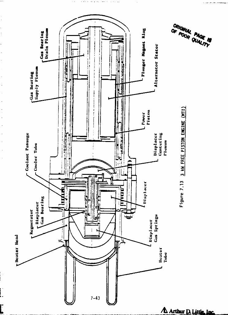
s
W4wm r
a^mYY
r Ho
^ esr rJ Y
e
(
9 no
a1i
r41Y7Jr
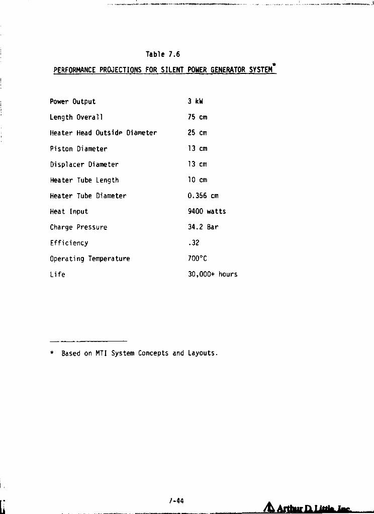
PERFORMANCE PROJECTION
Power Output
Length Overall
Heater Head Outside Dia
Piston Diameter
Displacer Diameter
Heater Tube Length
Heater Tube Diameter
Heat Input
Charge Pressure
Efficiency
Operating Temperature
Life
* Based on MTI System
1-44
AAIWK lime 12ka-

piston Stirling engine system with hydrogen working gas at 500 psi mean
pressure. The permanent magnet alternator allows the unit to be hermetically
sealed for long life, The output of the generator is 60 lia, 240 volt ac, 1
0 and is usable without further modification.
Table 7.7 compares the performance capa's lilies of free piston Stirling
engines with the general needs of th i s application class and those of arepresentative I.C. engine. The I.C. e. • gine is inappropriate for many applications
of potential interest, such as the solar application of the conceptual design,
where an external heat input is required. However, the life requirements of
the Stirling engine in this application class still need to be demonstrated.
AutomotO ,e and Automotive Derivtd .ewer:
As indicated in previous sections, the mobile power class of applications also
includes a number of potentially attractive stationary applications, such as
commercial heat pump drives. As indicated in Table 7,3, the life requirements
of automotive and many of the stationary applications differ significantly
(3500 hrurs for automotive and :0,000 + hours for most stationary). Reference
1S indicates, however, that basic automotive Stirling configurations could be
derated and/or modified to better meet the life and reliability requirements
of non-automotive applications. These diverse applications could, therefore,
be served by 5 small number of engine systems which can be adapted (derated,
etc.) to meet different application needs.
For purposes of a conceptual design, an automotive engine was assumed to be
derated and modified for use in a commercial sire heat pump system. This
application was selected since it might be an early application which could
take direct advantage of automotive technology and, at the same time, result
in engine experience which would accelerate their use in vehicular propulsion
applications.
Figure 7.14 is a conceptual illustration of an automotive engine, derated and
installed in a commercial sire heat pump system. In this case the engine
7-45
/L Arthur Q Little, Im
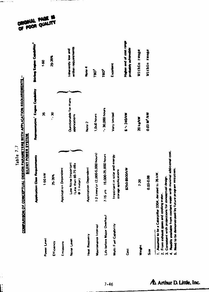
M
^ M
2 h m
r;Pio
y
Sys
T S ry ,
r N
ac ^ E
v R N
i
^` O^ ^ r ^ ^ Q Q M
^ Yv GYkn
F - a Y
{ W W L ? r: l'^ : N
7-46 A Arthur Q Little, Inc,

/d Arthur D. little, Inc.1-41
O F-
^ G N
d
d pW Oz ^
Id2aJW
Or.
N)
Haa
adfs7x
Ua
U
dzHwzNC.7
W
Q
H
W
WQ
DHH
Q
ai
W0
zH
Q
«7Naz8
ra
aLv+
oltUMNAI PAGE ISOF POOR QUAUTY
is

t ^5S
}
system is comprised of the prime mover and auxilliaries attached to the engine
(such as blower, pump, starter, etc.) as well as the cooling system (radiator,
fan, coolant pump used only in the air conditioning mode), battery, control
system, fuel tank, weatherproof enclosure, mounting frame, etc. This is all
in addition to the heat pump part of the system. The engine will be rated at
30 kW output and would provide approximately 30 tons of cooling or approximately
500,000 Btu of heat/hr in a heating mode, assuming a heat pump COP of 2.5 and
a 35% efficient engine.
The engine package shown would meet the operational requirements of this application.
Also, cost studies done in support of the automotive program indicate good
promise in meeting the cost goals associated with the higher prices of stationary
applications which such engines might serve. For example, the commercial heat
pump engine could have costs in the $400/kW range as compared with light duty
vehicular propulsion cost requirements of less than $20/kW.
Figure 7.15 is a schematic of the closest commercial practice to a mobile
power engine system. This is the MOD 1 engine developed as part of the automotive
Stirling engine program at NASA Lewis. Through operating variations and modified
construction the engine could be designed for long life applications, taking
advantage of past and ongoing programs to develop an efficient, quiet, multifuel
engine. Table 7.8 summarizes the projected characteristics of this engine at
the conclusion of the ASE program (R.E.S.D.). As indicated the engine, rated
in its automotive application is designed for 60 kW peak output and operates
with hydrogen working gas.
Table 7.9 compares the performance characteristics of an automotive derived
Stirling engine to the requirements of this application class and to a representative
I.C. engine. As indicated, the Stirling engine appears very favorable on most
counts. The relatively high cost ($300+/kW) of derated I.C. engines suitable
for these applications provides the Stirling engine with additional flexibiity
in meeting cost goals.
The life requirements, however, are a major issue requiring resolution.
7-48

LQ
^ d
Q U
V)
O
Qsc
V
a^
i
^dddW
Y
0M
r
L7
V Cs
3 "
rte'i t
aW
9
0t
Mi
OMOI K PAGE 4Of POOR QUALITY
_a
d
= U ^<
I
r -
O
CA IAcc = uv^ o e c
CIO u U V
7-49
/L Arthur Q Luttie, im
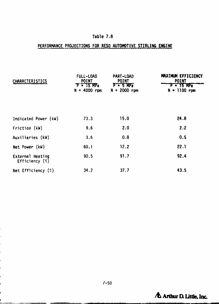
/d Artlwr Dt Tulle, Inc.
7-50
1 Table 7.8
PERFORMANCE PROJECTIONS FOR RESD AUTOMOTIVE STIRLING ENGINE
- i
FULL-LOAD PART-LOAD MAXIMUM EFFICIENCY
CHARACTERISTICS POINTPO_ I^N,T a7
P0^„ I^N, ,R,_ a
N = 4000 rpm N = 2000 rpm N = 1100 rpm
Indicated Power (kW) 73.3 15.0 24.8
Friction (kW) 9.6 2.0 2.2
Auxiliaries (kW) 3.6 0.8 0.5
Net Power (kW) 60.1 12.2 22.1
External Heating 0.5 91.7 92.4Efficiency (^
Net Efficiency (M) 34.2 37.7 43.5

r
I
ORIGINAL PAGE 18OF POOR QUALITY
LP
C O d.G .^m ^^
_ '= IL ^ F W = 3: 'a
of,^z r
u+ $ ; E
~ C S a w
A
Y Y-
d '^' 0 N O ^ V N a
. n
W W Z (^ ^. t^ r !V !^!
7-51
/^1 Arthur IX Tattle, Inc.

Vi Large Stationary Power:As indicated in Table 7.4 of the previous section, the performance requirements
:for a large stationary power system are quite severe for efficiency, life,
maintenance, and emissions. On the other hand, the weight, size, cost, and
noise requirements are not so severe.
The basic configuration selected for this application class is that of an
upscaled automotive engine. It is unlikely that the relatively small market
for this size engine would warrant a specially designed engine. Through derating
and modified design (upsizing, more robust construction, heavier materials,
etc.) the engine would be designed for high efficiency, long life, and low
maintenance. Several characteristics of the Stirling engine on this application
are:
o Relative ease of switching to a variety of fuels, particularly liquid
and gaseous fuels (such as heavy fuel oils, light distillates, gasoline,
alcohol, methane, propane, sewer gas, etc.) as well as the potential
to use solid fl;els.
o The high efficiency attainable with the Stirling engine is of critical
importance in this application.
• In these applications, the additional size And weight of an engine
designed for long life are not of great significance.
• The low emission characteristics of the Stirling engine could be very
important in some applications: the output and cost constraints of
the engine could warrant sophisticated combustion systems to mimninize
the emissions.
There is relatively little work currently underway to develop large stationary
power Stirling engines. Figure 7.16 is a schematic of one of the few large
Stirling engines studied, resulting from an Argonne Study by Amtech. This
design happens to be based on coal combustion but would more likely be operated
on fuels such as oil or gas in the near-term. Table 7.10 compares projected
design attributes of the large stationary Stirling power units with application
class requirements and the performance capabilities of a medium speed Diesel
i
f 7-52
/L Ardw n Talk, Inc.

OF POOR QUALITY
4.4 M
r
2.4 M
1 •1 1
_J L _ - _J L
500 hp STIRLING ENGINE MODULE (TYP.)
GENERATOR
— 6 MODULES FOR 3000 hp TOTAL POWER
Figure 7. 7 6 CONCEPTUAL DESIGN OF A LARGE STATIONARY POWER SYSTEM
7-53
A ArtWr n Utde, Inc.

ORIGINAL PANE iSOF POOR QUALITY ^ "r—
fo w^ r4a•r N U
N^ L
Z MHC
>>r A +1
10
E
sg NIz 0.4 a ^ 1
a d 00
aQ r ^J •r UrZr LQ4 O L 41 4- •r- 41 CCWC Q
C. L OMO N a, 4! >^--^ !— to O n: — O co ^
r O wH N U M G.1 10 Z 1- C7 ddHN
NZ W •rW Z r
F O M
W.x
ttfL
41W Lai 4• r-0.' :pp - J
+ ►.+ 4) VI ^" Ip sZ F- co Y
V- C F"
O Zd O C+-O d
3tS N M U N \ U 4J
p.-
r--iJ
Wa
1O
4j4A tOO10 IA
CbQ a, a 41 E O U 04.0 Cf^ 0.Q
Wa
t[! 41r O a O N O O 4-0 rO 'O
r- = r 41$.- r
F- 34 ►
Na aJ r L CW 4•► r O Q1W C QI b U U to •r L
O41 L r to
J C r r t41 E N
Q Ncb C
41
r-10C VI
rv InC w
Ipo aU Im ^
•I- r- ++E op t C
Ge) 41 IV IV 10 41 "-Z Q N d p'^ a OO >> of
CL C
,W +03(Dr-. .J N
^..) F-G1A ala
4UO J= H > .- b „r M ai L
L •e-Lto .•. L b d > r 3 '^^— UW Z W 3 U C r 4j C
Qa 7
r- a10O 3Y A YU\aUQ IV C a)1r4J O+^C3 0 5 Y O OJ 41 CL cu ?•r VOO Ot 4J \ '•- OI •r C al 10 U
J QH ►z pO 4+ Rfvi
10 0J4JIC
•co t
IF -CO ••- >> E
Oto41 MP- 4J r
r 'C = LQ L6S O S 2j: QJ U w L U 1 O 7 4^ G lw L O L 1 Z O C► >>
^«-. O ►o C^ ai 1L a ? •7 U 1 V Ln ti O W. C ++0. J W 1 ^ ^ ^ r O O QI •^- ^• d! O 1 M d •r- r rW 0. a O I a O 4j CL O O C ri0 ••- Zd
Il'1M 4J OO N
4J OO cA r' 1A ^- rL.0 OV 0. C O O a Z i0 a it M l^ Q M Z' v Z v O
OC CO a Ln M 1- Q •^ Q •,4J_ U^
V at V
0.O C
10
Lpp ^1-LZO W al
n d p
Q O imrN.ra Ch^^'
4d >
W co >^r> W ? U a
4W
QQ U.
a O J CA:W
cc Li M- VI l O wfo OZ 0. V a J
W aVr N N H W W L7 Wrr as `."' W., LLI
:OfnOou ~ •NM U;d W _ J U. N
A Arthur a I3crk, Inc.

engine. heavy duty internal combustion engines are seen to have very competitiv
performance characteristics (high efficiency, long life, etc.) in this application
area. dowever., the Stirling engine has a wider fuel flexibility and fewer
! emission problems which might make their use attractive in the future.

8.0 POSSIBLE EFFECTS OF TECHNOLOGY, ECONOMIC CONDITIONS, AND REGULATORY CHANGES
The general environment in which the Stirling engine must compete is changing,
as a result of regulatory trends, escalating energy costs, and improvements
in competitive power system technologies. These trends could be critical in
determining the competitive position of Stirling engines in many of the
applications of primary interest. For discussion purposes these issues are
divided as follows:
• Improvements in power system technologies which could impact on the
competitive position of Stirling engines.
• Trends in noise standards which could favor Stirling engine use in
such applications as heat pumps.
• Fuel and electricity cost trends.
The above issues are discussed briefly below.
8.1 Effects of Advances in Tech
There are a number of power system options which are already in use or could
be considered for all the potential Stirling engine applications. In many
cases the technical pertormance of these alternatives are improving as a
result of extensive development efforts by government and private sector
organizations; i.e., the competition for Stirling engine systems represents
a "moving target". It is important to be aware of major trends with competitive
systems in order to r.alistically assess the potential for Stirling engines.
Alternative power systems which are being improved include:
• High efficiency, multifuel, internal combustion engines,
• Fuel cells,
• Thermoelectrics,
• Thermionica,
• Photovoltalcs,
• "Packaged" Rankine cycle engines,
• MD, and
• Brayton cycle engines.
1
& Arthur Q Utde, Inc.l -

Not all these developments directly impact oL Stirling engine prospects.
For example, MHD is a long term development and one which is applicable only
to large scale (100 MW+) power generation - well above that considered in
this study.
Other developments could, however, significantly impact Stirling engine
prospects. Several of these developments and their potential impacts in
specific application areas are reviewed below.
o I.C. Engines
A number of recent concepts either currently used or under development are
aimed at making the conventional I.C. engine more fuel efficient and/or
lower in exhaust gas emissions. A brief description of some examples follows.
o Electronic Ignition
For several years specialty engines have used solid state ignition systems
to accurately control the timing and duration of the spark used to ignite
the air/fuel mixture in the engine. These have come into much more widespread
use particularly in automotive applications, to more accurately g-ontrol the
combustion process and thereby increase engine efficiency and reduce emissions.
They have the added benefits of increasing spark plug life and decreasing
routine engine maintenance.
o Turbo Charging
Turbo charging has been in use for several years in specialized applications
where high power density is desirable (such as in aircraft or race car
engines). It consists of the extraction of waste energy in the exhaust
gas stream and using that energy to increase the air/fuel mixture flow
rate into the engine on the intake side. The mechanical arrangement is
generally two turbine wheels (an expander and a compressor) mounted on
the same shaft, expanding the exhaust gases to ambient pressure, while
compressing the intake .:,r/fuel mixture. This has the advantage of
8-2
AL ATthw i.
A
t
ii

increasing the efficiency and power output of a given engine displacement,
without significantly affecting emission characteristics, at times when
the engine is not fully utilizing the turbo charger.
o Turbo Compounding
This technique is similar to turbo charging, excepL that part of the X
mechanical energy extracted from the exhaust stream is used directly to
augment the shaft output of the engine, and not only to compress the
intake fuel/air mixture. This technique is being investigated to increase
engine efficiency and power output over an engine configuration without
turbo compounding.
o Fuel Injection
Although required on Diesel engines, fuel injection for gasoline powered
passenger car engines is a relatively recent development. The precision
with which the fuel can be metered into the _ngine has an important
beneficial effect on exhaust emissions while at the same time improving
engine performance. In this direction, General Motors has recently
introduced a system called "throttle body injection", that is intended
to achieve fuel control similar to that of fuel injection, without the
complexities normally associated with conventional systems.
o Adiabatic Diesel Engine Operation
The operation of Diesel engines without a cooling system, in a high
temperature mode, is referred to as the Adiabatic Diesel Cycle and is
under investigation as a technique for achieving very efficient Diesel
engine operation. Other advantages are a lighter weight engine, elimination
of the cooling system and its associated equipment and parasitic power
drains, as well as smaller size. These engines are in fact being considered
as power plants for future propeller driven aircraft.
o Bottoming Cycles for Stationary Engines
The high temperature exhaust stream from an engine can often be used to
operate a Rankine cycle engine, to produce additional shaft power for
8-3 /L Arthur D. little, Inc.
the same fuel input (or conversely the same output for less fuel input).
This concept is often considered for use with large stationary engines
such as gas turbines or Diesel engines for utility power generation,
with relatively high duty cycles. However, there is a significant effort
to develop bottoming cycle engines for use with the exhaust gases of
Diesel engines in heavy duty trucks. These systems have already demonstrated
their ability to decrease fuel consumption in trucks by over 15%.
o Photovoltaics
One of the potentially promising applications for Stirling engines is as
a very high efficiency power converter within a solar thermal power
system. If successful, this application shows potential for large markets
on a worldwide basis. However, one issue facing all solar thermal power
developments is the competition from photovoltaics. The present cost of
photovoltaic panels is about $10,000/kW. However, this cost is projected
by both DOE and industrial sources to drop by close to an order of magnitude
over the next 5-10 years. Cost reductions of this magnitude in photovoltaics
would increase the uncertainty associated with all solar thermal power
developments - including those using Stirling engines as the power system.
o Fuel Cells
Fuel cells have many of the same advantages as do Stirling engines, such
as low noise and vibration, high efficiency, and low exhaust emissions.
They do not, however, have the fuel flexibility and the ability to produce
mechanical power as Stirling engines. Nevertheless, where clean fuels
are available (including natural gas) they would be directly competitive
with Stirling engines in stationary applications. For example, fuel
cells are under active development by the gas industry for use in residential
and commercial total energy systems and as silent generators for use by
the military.
The successful commercialization of fuel cell systems could therefore
significantly impact on Stirling engine prospects in several of the
potentially favorable market areas.
8-4

o Prepackaged Rankine Cycle Power Systems
Primarily as a result of heat recovery and solar energy programs, several
firms in the U.S., Europe, and Japan have developed packaged Rankine
cycle power systems with capacities in the 10-200 kW power range. These
systems share the advantage of Stirling engines of having a multifuel
capability allowing them to be operated with solar energy, isotopes,
thermal storage, and "dirty" fossil fuels (biomass, synthetics, etc.).
Particularly in larger capacities (100 kW), such systems provide a formidablei
alternative to Stirling engines. The performance of such systems is
likely to improve if their use in heat recovery, co-generation, and
solar power increases as projected.
8. 2 Effects of Emission and Noisy, Standards
One of the primary incentives behind Stirling engine developments has
been to develop a high efficiency engine with low exhaust emissions.
This issue, is particularly important in automotive, heat pump, mining,
and other applications. Trends in emission standards which could effect
the potential for Stirling engines include:
• Automotive standards.
• PSa (Prevention of Significant Deterioration), which has site-
specific implications.
• Standards based on current local air quality rather than individual
engine emissions.
• Trend toward relaxing standards for alternative and coal-
derived fuels.
• Indoor air quality standards.
• Mine standards.
Many of the environmental regulations are directed at large utility or
industrial facilities which are not germaine to the scope of this program.
Emission standards which are most likely to affect the potential for
specific Stirling engine applications are discussed briefly below.
8-5 /d Arthur Q Little, Inc.

Automotive Emission Standards
The automotive application area is one where low emissions are an important
requirement for any engine. The emission standards which currently apply for
model years through 1982 are listed in Tables 8.1 and 8.2. The Environmental
Protection Agency is not planning to change these standards until at least
1983. However, there is still serious concern on whether existing standards
are sufficiently stringent to protect the environment over the longer term.
This concern is ,particulary strong in relationship to potential carcinogenic
particulates from Diesel engines which are a major competitive system for lower
fuel consumption automotive engines. The Stirling engine has demonstrated its
potential for significantly reducing emissions as compared to present standards
and for eliminating, the particulate problems associated with Diesel engines. A
successful automotive Stirling engine development would, therefore, provide the
country with additional flexibility in setting emission standards should new
data indicate that more stringent standards are necessary to protect the public
welfare.
Existing vehicular engines are capable of meeting current emission standards,
albeit with some difficult y . In the case of spark-ignition engines, this is
achieved predominantly through the use of three-way catalysts in the exhaust
line which provide simultaneous reduction of HC, CO, and NOx emissions. The
principal disadvantage of this approach is that the operating window is very
narrow requiring the engine to run at air/fuel ratios near stoichiometric.
This presents problems in terms of fuel control complexity and optimizing vehicle
fuel economy. In the case of Diesel engines, the uses of a catalyst is greatly
complicated by the potential for plugging by particulates. Emission reduction
is instead attained through combustion modifications involving close control of
parameters such as engine timing, injector design, and spray pattern. These
approaches suffer the same disadvantages in terms of complexity and fuel economy
as the catalytic approach for spark-ignition engine:. The low-emission characteristics
inherent in the Stirling engine represent a potentially significant competitive
edge over alternative vehicular power plants.
8-6 /& Arthur Q Little, Inc.

F7- r f
ORIGINAL PAGE 19OF POOR QUALITY
TABLE 8.1
PRESENT AND FUTURE FEDERAL
PASSENGER AUTOMOBILE EMISSION STANDARDS
in gm/mile
Model Year HC CO NOX Particulates
:actual
Precontrol 8.8 87.0 3.6 -
Mandated
1975 1.5 15.0 3.1 -
1976 1.5 15.0 3.1 -
1977 1.5 15.0 2.0 -
1978 1.5 15.0 2.0 -
1979 1.5 15.0 2.0 -
1980 0.41 7.0 2.0
1981 0.41 3.4 1.0 -
1982 0.41 3.4 1.0 0.6
Possible
1983 0.41 3.4 1.0 0.6
1985 0.41 3.4 1.0 0.2
1990 0.41 3.4 0.4 0.2
Sources: Environmental Protection Agency andArthur D. Little estimates
8-7 Arthur It Little, Inc.

i1NAL PAGE tS
DOOR QUALITY
f
S t
i
x
NWtj
WJr./
.► 1
NO cnN
I IO
dir
^
O Rf
0
+-
01 N N i 1 O11^^
p I.r ^ r O
C
Oat N N 1 .1 O p p1 CS L 1t fO OL .-- ,•-r O;
^•1CO O r
Z1 1
p1 N M O 1 10 1^ tprr
co
r^
C71 en CO 1 N Ln IL!N,Co.- r 1 r N
O•co
at n co / N Il9 119r r / r N N
p►N. 1t! Co V) 1atr
r r 1 r N 1
CO f^np► IA O O 1 p Qr r N 1 Q
CD ^t t^ 1 Ln It!cn • 1 rrr Q r 11, r•-
O .-co et n Ui It9Ot 1r O r 1 Ln r rpt t19 1 l LnI.. 1 1^ 1at r r 1 Lnl Rr ^ 1
Oin OA • 1`d 1 ir r N O LLB !t i 1
^ r
Md
MCA
aJ C
N CJ (,^ OtN ^ b +- C
47L •.- V OJ
L > p-O 0
r F/ yf N r 13 ^ ♦.1V IV W O^7
L-a 41 ^ 0J >1 CHO eT 3 N
.OO in
tJ J J G9 C L 4J
NOW
E
xakO
GJ
Q^C
CI1C
V•
L ptO GO S-
0 CL 7d
•r N
ELo Ln m
O t r
V Ca •^ i^ Y d b> w
L G NyLy•^O. n V O^/ r
GA.0L N to
vl C" a c
cE[C C V G •^••C
C^1 d C N i s Li.1 i.1 •r ^► ^ i ^+L L L L Mm a °a C10 0 U.cu O L S.
CN Vf N NII U =L L C C7 L ^^ ^b A O
pOA d O
'CcC C y E C •r•
In CAE t O
•xx Vi L •^ 41 L O
w 40••r .O
NO- C C etN N AJ p1 N "a O1O 4! .- C W C O
•^ L (4( 1
•L CL-r-- L
>- >. 010 ^ C Oto .0 U v d 4- N
8-8
/& Arthur It little, Inc•

Prevention of Significant Deterioration (PSD)
The PSD regulations (40 Code of Federal Regulations, part 50, Clean Air Act
Amendment of 1977) are highly judgemental in nature and state that should a
jsystem or project result in a significant deterioration of the air quality from
t
that existing prior to the project, it may be stopped. This regulation is
intended primarily to apply to large (industrial or utility) projects but could,
^ j in principle, be applied to smaller commercial or even a multiplicity of residential
projects. For example, it was recently used to delay for 3 years the implementation
of a Diesel engine driven total energy plant in Boston, MA.
This law could be used to discourage the use of engine driven heat pumps or
total energy systems of all sizes if the engines resulted in significantly
higher emission levels than those from gas or oil furnaces now commonly used.
As a result, Stirling engines would have a significant advantage over I.C.
engine driven systems in such applications and, in fact, Diesel engines may be
found to be unacceptable in many locations given their present emissi^jn characteristics.
Indoor Air Quality Regulations
In 1974, OSHA promulgated regulations establishing levels of pollutants that
would be acceptable in the workplace atmosphere. These levels are time -weighted
averages based on 8 hours per day or 40 hours per week exposure. For combustion
pollutants the limits are as follows:
PPM at '=C and 1 atm
CO2 5000
CO 50
NO25
Source: 24 CFR (Code of Federal Regulations), Part 1910, Subpart Z, entitled,
"Toxic and Hazardous Substances."
These regulations are often met in practice by using large amounts of ventilation
air which increa „es blower power and heating costs.
8-9
Ar flir D. Ut*, Im

FThese regulations would favor the use of low emission Stirling engines to power
indoor vehicles such as fork lift trucks, floor sweepers, and people movers.
However, in part, to respond to these regulations there has been a trend toward
electric drives for such vehicles (replacing small I.C. engines often using
bottled gas as a fuel). At present there are no equivalent standards for residential
air quality.
Regulations in Mines
There are a number of Government regulations for vehicles used in underground
mines, relating to ventilation requirements, noise, etc. as they affect health
and safety of mine workers. For example, a current noise level limit of 90 d')
may be lowered to 85 or even 80 db in the near future. Exhaust emissions 10 ft
away from the vehicle must be less than the following:
CO20.5%
CO 100 ppm
NOx25 ppm
Aldehydes 10 ppm
These regulations tend to favor the development of the Stirling engine, with
its low emissions and noise characteristics, as compared to the Diesel engine
which is currently in use, whe-re it is appropriate.
Noise Control Act
In 1972, EPA standards on noise were promulgated for railroad, highway, off-
road vehicles, portable compressors, etc_ which are shown in Table 8.3. The
limits vary from 70 dB (off-road moped-type, below 17000) to 90 dB (moving
locomotives). With the help of silencer design, and design of effective sound
barriers, present engines tend to meet most of the noise standards. Stirling
engines would make it much easier to meet these standards without elaborate
design of noise barriers. As far as residential equipment is concerned there
E are no equivalent national or statewide standards. There may, however, be
relevant local codes which limit noise levels in residential areas.
8-10 & Arthw Q Ut&, Im

ORIONAL PAGEPOM QUALrN TABLE 8.3 NOISE REGULATIONS PROMULGATEU OR PROPOSED
Noise level Date
Noise Source in dRA Effective
1 locomotive--StationaryIn gear 87 December 31, 1976
Idle 70Moving 90
Railroad car--Under 72 km/hr 88 December 31, 1976
1Over 72 km/hr 92 December 31, 1976
Motor carriers in interstate commerce--Under 86 October 15, 1975--Over. 90
-- Full throttle stationary 88
Medium and heavy trucks 83 January 1, 197880 January 1, 1982
Exemptions for fire trucks and mobile homes
j Portable air compressors--<250 ft 3/min 76 January 1, 1978
-->250 ft /min 76 July 1, 1978
aCrawler tractors 20-199 HP 77 March 1, 198174 1984
20-450 HP 83 198180 1984
aWheel loaders 20-249 HP 79 198176 1984
250-500 HP 84 198180 1984
aWheel tractors 20+ HP 74 March 1, 1981
aNew truck-mounted solid waste compactors 78 January 1, 1979
75 1982
Exterior bus noise 83 January 1, 1979
80 198377 1985
a Interior bus noise 86 197983 198360 1985
a 5treet motorcycles 83 January 1, 198080 198278 1985
aMoped-type 70 1980
Offroad below 170 cc 81 lgAOIto 1992
78 1985
a0ffroad above 170 cc 86 19808? 1983
aProposed as of August 1979
Source: 40 Code of Federal Regulations Parts 203 and 204
g- - - Arthur Q U> I1

8.3 Effect of Fuel Availabili and Cost
i1
Fuel availability and the cost of conventional fuel have major impacts on applications
and use of engine types. Since Stirling engines have multifuel capability,
fuel switching is possible, and therefore, may offer advantages over gasoline,
Diesel, or gas turbines, which are specifically designed for a particular fuel.
The availability and cost of a particular fuel is pivotal to the use of most
conventional engines. Trends which are likely to be factors in influencing the
commercialization of Stirling engines could include:
• Conventional fuels are expected to have fairly constant supplies for
the next two decades.
• Prices for conventional fuels (in real dollars) will approximately
double by the year 2000.
• The cost of electricity is likely to increase at a lower rate than
natural gas or oil.
• Price difference between distillate and residual oil is expected to
remain corstant.
• Liquid fue's from coal and shale oil are less likely to be produced in
signficant quantities by the year 2000.
Assessing the full range of effects of the above observations on the potential
for various power system options is a very complex undertaking. However, some
important observations can be made relative to their impacts on several of the
Stirling engine applications of interest. Several such observations are discussed
below.
Multifuel Capability
One incentive behind recent programs in large stationary Stirling engines was
their capability to utilize coal and other "dirty" fuels such as heavy synthetic
oil. This incentive, in turn, resulted from a perception that natural gas and
liquid fuels would be in short supply for industrial applications. This scenario
does not appear at this time to be generally velid, i.e., over the next two
t
decades gaseous and liquid fuels will probably be generally available which
will allow for operating conventional power options. There appears, therefore,
to be only limited incentives at this time to develop ( 5,000 kW) coal fired
8-12 AL Aftw Dt Lttip im.

power systems - particularly in the relatively low power range ( 5,000 kW)
considered in this study.
Heat Pump/Total Energy Applications
Heretofore the incentive to develop engine driven heat pumps or total energy
systems has been the availability of low cost natural gas. Many observers
project, however, that the price differential between natural gas and electricity
will be decreasing in the 1980s. For example, some projections indicate that
electricity cost should increase at a rate of 0-2X over the next decade in real
dollars while that of natural gas will increase at 3-6% in real term ► over the
same period of time due, in part, to natural gas deregulation. The present
spread between gas and electricity prices based on thermal value is approximately
3 to 1 (based on 5J/kWh power and $5 per 1000 CF for gas).
A decrease in this spread would place more stringent initial cost and performance
requirements on gas driven heat pumpE to result in a large commercial market.
Recent history suggests, however, that predictions of energy costs are still
highly uncertain and many factors could significantly modify the energy cost
scenarios referred to above. For example, a signficant increase in the demand
for electricity over that assumed might result in escalating its cost if this
requires adding costly new capacity.
Increasing Fuel Costs
The increasing costs of all fuel forms projected over the next decade provides
an incentive to utilize highly efficient engines in all applications. Therefore,
both the demonstrated efficiency (35X) and the projected efficiency potential
40%) of Stirling engines will became increasingly important in the future as
energy costs increase.
It should be noted, however, that several competitive power systems (Diesel
engines, fuel cells, internal combustion engine/bottoming cycle en-ine combinations)
r have efficiency levels comparable to those demonstrated in Stirling engines and
that the efficiency characteristics of these alternatives may improve in order
to meet consumer needs. The Stirling engine may be unique, however, in combining
• 8-13 & Arthw Q LJt&. Im.

a very high efficiency potential with other important attributes such as fuelI flexibility and low noise.
^' 1
8-14
& Arthur Dt Unk, LAC.
t^^ CNN am 0 M9 M-d 0 0 0 0 MIN

i 9.0 DISCUSSION OF RESULTS
Domestic Stirling Engine Applications:
The ranking charts of Section 7.1 indicated that Stirling engines could hove
significant advantages over conventional engines in a wide range of
a,. 1 lications. A more quantitative comparison of application needs and Stirling
engine configurations was provided as part of the conceptual designs of Section
7.3. In this section it was again shown that Stirling engines have already
demonstrated many of the requirements needed to be attractive for use in
application classes of potential interest. In particular, high efficiency,
multi fuel capabilities, low noise and vibration, as well as low emission
levels, are characteristics which have been demonstrates: on test systems and
there is no reason to believe that they cannot be achieved with a high degree
of reliability on well engineered systems for all application classes
considered. F.ven those characteristics which put Stirling engines at a
disadvantage relative to more conventional options, such as size, weight, and
cost may not he serious drawbacks in most of the applications of primary
interests. The previous sections also indicated that many applications are now
served or could be served by relatively high cost ($100+ per kW) heavy duty
engines which provides additional flexibility in the desigr of suitable
Stirling engine systems.
The application requirements of Section 7.0 ar:. estimates for the minimum
conditions which must be satisfied if a new engine is to show promise for
making a meaningful market penetration and evolve over time into a significant
commercial product. Clearly, exceeding these operational goals would further
accelerate the introduction of a new engine. On the other hand, specialized
applications might be satisfied even If all the design goals set forth were not
achieved simultaneously.
Table 9.1 qualitatively summarizes the overall results of the previous sections
and identifies those critical imprivements in performance which Stirling engine
systems must achieve to be consistent with the broad requirements in each
application class. The identification of key development issues assumes that
9-1 /L Arthur Q Ijttk, Inc.

Automotive and AutomotiveDerived Engines
(a) Automotives
(b) Automotive Derived
Testing has demonstratedmost important operatingrequirements and projec-tions indicate furtherimprovements inefficiency
Same as automotive
(c) Large Stationary Po!:-er Design studies and auto-motive testing both showpromise of achieving mostof r,quired operationalcharacteristics
ORIGINAL PAGE ISTable 9.1 OF POOR QUALITY
SUMMARY - STIRLING ENGINE STATUS AND DEVELOPMENT NEEDS
CI
Silent Power Testing of both freepiston and kinematicengines have demonstratedmost of technicalrequirements
IMPORTANT DEVELOPMENT NEEDS
Demonstrate life in excessof 10,000 hours with lowmaintenance requirements
Improve efficiency to15-25% range
- Demonstrate life in excessof 20,000 hours
- Demonstrate capability of2,000 hours operationwithout maintenance
- Consistently achieveefficiencies in excess of0%
Demonstrate life of 3,500hours with low maintenancerequirements
- Demonstrate that efficiencyprojecti ms can be achieved
Demonstrate life in excessof 20,000 hours with lowmaintenance requirements
Demonstrate life in excess of50,000 hours
Demonstrate overhaul intervalsin excess of 5,000 hours.
Demonstrate capability of 40%efficiency on range of liquidand gaseous fuels
APPLICATION CLASS
TECHNOLOGY STATUS
Simple Rural Power
Recent testing indicatesgood promise for simplefired hot air engine
9-2
/Q Arthur IX little, Inc.`

ongoing activities are reasonably successful in achieving programatic
objectives. For example, it was assumed that the off-design performance goals
(off-design performance of free piston heat pumps is important, since the loads
on the system vary with ambient air conditions) of the free piston heat pump
programs can, in fact, be demonstrated, that efficiency projections for
automotive systems will be achieved, and that automotive technology could be
scaled-up to result in large stationary power units. With these assumptions,
it is seen in Table 9.1 that there remains several critical development needs
which are not adequately addressed by ongoing programs. A common theme for all
application classes is the need to emphasize designs which are consistent with
long life, low maintenance operation. The quantitative disparity between the
life requirements of almost all applications of interest and the engine
durability demonstrated to date is very large. All applications, except
automotive and other light duty vehicular, require engine lifes (time between
overhauls) in excess of 20,000 hours. On this important issue, the
requirements of the automotive application are relatively modest, being only
about 3500 hours.
If these life and reliability goals can be demonstrated without large
compromise in other required features (high efficiency) or large increases in
cost, the Stirling engine would be a highly competitive option in all but very
light duty applications. On the other hand, without achieving (or at least
approaching) the life and reliability objectives summarized in Table 9.1 the
other desirable attributes of the Stirling engine will not be sufficient to
result in commercially viable systems.
Also indicated in Table 9.1 is the need to consistently demonstrate high
efficiency levels in order to satisfy application c1 r s requirements. This is
due to the fact that Stirling engines •ist often compete with I.C. engines
which can have efficiencies ranging from 25% for smaller gasoline engines to
40% for larger, low speed, Diesel engines. It will be important for Stirling
engines to show a distinct efficiency advantage to provide an incentive to
pursue their development. This is especially true for automotive applications
where lower fuel consumption would be a major incentive to off-set higher first
costs (by as much as 50%), and larger size and weight. These high efficiency
P!,
9-3 /d Arthur D Litde, Inc.

goals are, in fact, stated goals of ongoing programs. The need to actually
demonstrate a consistent capability to meet these goals is shown in Table 9.1
to emphasize their importance.
The important development needs for Stirling engines, i.e., most critically to
demonstrate longer life and higher reliability, are common to all the
application classes. The overwhelming need in this area should strongly guide
future program initiatives so that resources can be focussed on addressing this
critical issue. As stated previously in this report, present programs have
successfully emphasized achieving other important operational goals (low
emissions, lower cost, etc.) and system issues with relatively modest resources
directed toward technology developments to specifically address life and
reliability questions.
All the application classes share some common technical issues impacting on
life and reliability: namely piston seals, shaft seal., and high temperature
combustor/heater head subsystems. As indicated in Section 6.0, the details of
the technical requirements for those subsystems can differ significantly
between applications and system configurations. For example, non-contacting
gas bearings in free piston engines offer the potential of very long engine
life, whereas automotive kinematic engines require sliding seals which have a
shorter, defined life based on wear. Despite these differences, it appears
that there is a high degree of commonality between the essential issues of life
and reliability which face each different Stirling engine application class.
As a result, Stirling engine development programs for obstensibly different
applications might have a high degree of overlap in their development needs if
they address the most critical issues. This could provide additional
opportunities to more effectively use limited resources to address basic
technical issues common to a range of Stirling engine systems.
There are a number of programs underway to develop advanced Stirling engine
components and system concepts. These include hydraulic methods of extracting
power from free piston engines, swashplate drive mechanisms to allow for
variable power operation at constant working gas pressure levels, and heat pipe
integrated heater heads to allow more flexibility in interfacing heat sources
9-4 & Arthur DL Uttle, Its.

i
with the high heat flux needs of the Stirling engine heater heads. These and
other advanced technology development programs could eventually improve the
cost/performance characteristics of Stirling engine systems. However, given
the rather embryonic stage of most of these advanced developments, their
potential impart would probably not be demonstrated for at least 3-5 years
(even assuming consistent funding). Also, each of these advanced developments
introduces a new set of potential technical problems. As a practical matter,
S therefore, the present Stirling engine technological base will in large part
have to be utilized to demonstrate that Stirling engines can achieve the
operational characteristics set forth above, if this is to be done over the
next few years.
Foreign Stirling Engine Applications
The study summarized in this report has emphasized domestic applications of
Stirling engine systems. However, if Stirling engines are successfully
developed, they would have worldwide applicability. Examples that illustrate
the growing potential for Stirling engines in two foreign market areas are
illustrated in Appendix E. In Japan, for example, a strong incentive to
accelerate the use of gas fired heat pumps and total energy systems has been
prompted by government policies to even out large seasonal variations in
electricity and gas. Emphasis is being given to using Stirling engine drives
in the residential and light commercial capacity ranges. The other example
cited is the large potential in developing countries for small biomass fired
Stirling engines to satisfy critical needs for irrigation, refrigeration, and
village lighting, as an alternative to high operating cost Diesel generators or
grid extensions. In both examples, it is quite likely that foreign
manufacturers will rely heavily on the large U.S. based R&D programs in
developing their systems. It is, therefore, important that both government and
corporate programs consider this export potential as well as the domestic
markets.
Summary Statement
The overall objectives of this study were to assess the potential for Stirling
I
9-S/d Arthur D little, Inc.
engine applications in the .5-5000 hp range, and to define the technical needs
for Stirling to be successful in these applications. Over one hundred engine
applications were identified and grouped into the following ten application
classes. The applications in each class have a high degree of commonality in
technical performance and cost requirements.
o Heat Pump/Total Energy
o Industrial Equipment
o Space Power
o Remote/Multifuel
o Low Usage Equipment
I o Military Quiet Powert
o Mobile Power (Light)s o Mobile Power (Medium)
o Solar Thermal
o Large Stationary
iFor each of the application classes, the Stirling engine was compared to
conventional engines under the assumption that objectives of ongoing Stirling
engine development programs could be met. The engines were compared on the
ibasis of twelve characteristics (fuel flexibility, low emissions, high
efficiency, etc.) that are important to a large number of applications. A
numerical method, guided by judgmental factors, was used to assess the relative
ranking •-)f Stirling and conventional engines.
United States Market
The results of the assessment of potential Stirling engine applications in the
United States indicated the following.
• Stirling engines showed favorable potential for all applications except
the Low Usage Equipment Class (lawn mowers, etc.).
• Favorable Stirling engine application classes, which are currently
served by conventional engines, represent a potential market of about
13 million engines per year.
9-6/L Arthur D Little, Inc.
L
ORIGINAL PAGE ISOF POOR QUALITY
o Stirling engines ranked very high relative to conventional engines in
the following four application classes that are not now served by
conventional ei.dines.
- Heat Pump/Total Energy
- Space Power
- Remote/Multifuel
- Solar Thermal
There is, however, no present commercial practice on which to base market
projections.
Four Stirling engine conceptual designs were defined that could address all of
the nine favorable applications. These are briefly described as follows:
o Rural Power System - A low power (1-20 kW) hit air, kinematic engine of
very simple, rugged construction.
o Silent Power System - A low to medium power (3-30 kW) kinematic or free
piston engine for silent power generation.
o Automotive and Automotive Derived Power System - A medium power (3-100
kW) compact automotive derived power system for vehicle propulsion and
stationary application.
o Stationary Power - A high power (500-5000 kW) prime mover for large
scale power generation.
Technology Needs
There remain some development needs which have not been adequately addressed by
ongoing development programs. Achievement of the following needs would help to
speed up the acceptance of the Stirling engine in the favorable applications.
i
9-7 /& Arthur D Little, Inc.

co Demonstrate Stirling engine life consistent with the needs of each
favorable application class, and show that the engine can meet the
maintenance requirements.
o Consistently achieve a distinct efficiency advantage over the I.C.
engine competitor in order to provide an incentive for Stirling engine
acceptance.
z o Emphasize Stirling engine designs - a modification of engines of
present development programs - which are consistent with long life, low
^. maintenance operation. (Example: Stationary engine derived from
automotive engine.)
1
If life and reliability goals can be demonstrated without large compromises in
efficiency, or increase in cost, the Stirling engine can be a highly
competitive option for use in all nine application classes.
Fore ign Markets
Developing Countries
A biomass fired Stirling engine (Remote /Multifuel application class), using
indigenous fuels, is an attractive power source alternative to Diesels and
photovoltaic systems in developing countries. The value of this potential
foreign Stirling engine market may total nearly 200 million dollars by 1990.
This value corresponds to a power generating capability of 200 MW, or 40,000
5 kW engines.
Japan
Government policies call for gas fired systems to displace 30% of the
electricity now used in air conditioning functions In Japan by 1990.
Additional actions relative to R&D funding, gas pricing, and tax incentives
have been taken by the government to accelerate the introduction of gas fired
systems - Stirling powered, and others. For this purpose, the government has
initiated a 6 year, 40 million dollar program, in cooperation with industry and
9-8 AL ATthu a ut&, i.

universities, to develop 3 and 30 kW sized engines to power the heat pump and
total energy systems.
Pursuance of the above policies could have the following impact:
• A substantial Stirling engine market may be formed in Japan since
achieving stated goals could result in a market for Stirling engines in
excess of 50,000 units per year with a capacity of approximately 500
MW.
• Japanese industry could be provided with such a strong position in
Stirling engine technology that by the mid 1980's efforts to use
natural gas in a similar manner in the United States may well be based
on Japanese technology.
9-9 Arthur DL Uttk, im

APPENDIX A
GENERAL STIRLING ENGINE REFERENCES
A-1 /t Arthur D: Little, Inc.

At` SAGE 13(W OWN
Advanced Mechanical Technology, Inc., Newton, Ma. Design and Developmentof Stirling Engines for Stationary Power Generation Applications inthe 500 to 3000 Horsepower Range. Volume 1: Technical Report.Prepared for Argonne National Laboratory, Report No. DOE ET 15-207-T2 (Vol. I), September 15, 1980.
Advanced Mechanical Technology, Inc., Newton, MA. Design and Developmentof Stirling Engines for Stationary Power Generation Applications inthe 500 to 3000 Horsepower Range. Volume 2: Program Plan. Workperformed for the U.S. Department of Energy under Contract No.ACO2-79ET15207, Report No. DOE/ET/15207-T1 (Vol.2), September 15,1980.
Argarwal, P. D., et al. "Stir-Lec I, A Stirling Electric Hybrid Car."General Motors Corporation. International Automotive EngineeringCongress, January 13-17, 1969, Detroit, MI, No. 090074.
Arthur D. Little, Inc. Assessments and Recommendations of the Potentialfor Stirling Engines in Integrated Community Energy Systems Applications.Prepared for the Argonne National Laboratory, Argonne, IL. December 1977.
Asselman, G. A. A., et al. "Design Considerations on a Thermal EnergyStorage Stirling Engine Automobile." Philips Research Laboratories,Holland. Society of Automotive Engineers, Paper 770080, 1977.
Asselman, G.A.A. "Thermal Energy Storage Unit Based on Lithium Fluoride."Philips Research Laboratories, Eindhoven, the Netherlands. EnergyConversion, Vol. 16, No. 1-2, 1976, 35-47
Auxer, W. L. "Development of a Stirling Engine Powered Heat ActivatedHeat Pump." General Electric Company, King of Prussia, PA.Proceedings of the 12th Intersociety Energy Conversion EngineerineConference, Vol. I. August 28-September 2, 1977, Washington, DC.Paper No. 779065, 397-401.
Beale, W. "New Developments in Free-Piston Stirling Machines." SunpowerCorporation, Athens, OH. Seminar Proceedings, Stirling-Cycle PrimeMovers, Sponsored by Institute of Gas Technology, June 14-15, 1978,Rosemont, IL, October 1979, 143-151.
Beale, W. T. "A Stirling-Hydrostatic Drive for Small Vehicles."Sunpower, Inc., Athens, OH. Proceedings of the 10th lntersocietyEnergy Conversion Engineering Conference, August 17-22, 1975,Newark, N.J. Paper No. 759143, 958-960.
Beale, W. T. "Free Piston Stirling Engines -- Sorne Model Tests andSimulations." Ohio University. Sc.ciety of Automotive EngineersPaper No. 690230, 1968.
Beale, W. T. Hermetically Sealed Stirling, Engines Sunpower, Inc.,
Athens, OH.
Beale, W. T. "Stirling Cycle-Type Thermal Device Servo Pump." UnitedStates Patent No. 3.645.649, February 29, 1972.
AL Artlwt Ex

Beale, W.T., et al. "Stirling Engines for Developing Countries."
i Sunpower, Inc., Athens, OR. Proceedings of the 15th Intersociety
Energy Conversion Engineering Conference, Vol. III, Seattle, WA.Paper No. 809399, 1911-1975, August 1980.
One" IMAMOF fta
a#
Beale, W. T., and Rankin, C. F., Jr. "A 100 Watt Stirling Electric
Generator for Solar or Solid Fuel Hen Sources." Sunpower, Inc.,Athens, OH. Proceedings of the 10th Intersociety Enemy Conversion
Engineering Conference. August 18-22, 1975, Newark, K.
Beale, W., et al. "Free Cylinder Stirling Engines for Solar PoweredWater Pumps." American Society of Mechanical Engineers Paper No.71-Wa/Sol-11, August 1971.
Beale, W. T., et al. "A Free-Piston Stirling Fngine Driven Inertia
Compressor for Gas-Fired Air Conditioning." Proceedings of 2ndConference on National Gas Research and Technology, June 5-7,Washington, D.C. Session III, Paper No. 5.
Beale, W., et al. "Free-Piston Stirling Engines -- A Progress Report."
Ohio University. Proceedings of the Combined Conmercial Vehicle
Engineering and Operations and Powerplant Meetings, June 18-22,
1973, Chicago, IL. Society of Automotive Engineers Paper No. 730647.
Bell, G. C. Solar Powered Liquid Piston Stirling Cycle Irrigation
Pump. Research Grant :or May 1 - December 31, 1978. University of
New Mexico, Albuquerque, NM. Prepared for U.S. Department of Lnerg^under Contract No. ET-78-G-03-1894, Report No. SAN-1894/1, April
10, 1979.
Benson, G. M. "Free-Piston }seat Pumps." Energy Research and Generation,
Inc., Oakland. CA. Seminar Proceedings, Stirling-Cycle Prime Movers,Sponsored by Institute of Gas Technology, June 14-15, 1978, Rosemont,
IL, October 1979, 67-101.
Beremand, D. G. Stirling Engines for Automobiles. _NASA Lewis Research
Center. Prepared for U.S. Department of Energy under InteragencyAgreement EC-77-A-31-1040, Report No. DOE/NASA/1040-79/7, NASA TM-
79222. Prepared for International Conference on Energy Use Management,
Los Angeles, CA, October 22-26, 1979.
Beremand, D. C., et al. "Applicability of Advanced Automotive Heat
Engines to Solar Thermal Power." NASA Lewis Research Center. Cleve-
land, 011. Society of Automotive Engineers Technical Paper No.
810455, February 1981.
Bernard, M. J. Transportation Technology Energy Options. Argonne NationalLaboratory, Argonne, 1L. PreparPdl for Illinois-Indiana Bi-State
Commission, Chicago, I.L, Report No. Con. 7905105-3, May 18, 1979.
Biermann, U. K. P. "The Lithium/Sulphur-Hexafluoride Heat Source in
Combination with a Stirling Engine as an Environmental IndependentUnderwater Propulsion System." Philips Laboratories, Eindhoven,
the Netherlands. Proceedings of the 10th Intersociety Energy Conversion
Engineering Conference, August 18-22, 1975, Newark, DE, Paper No.
759193, 1023-1030.
A- 3
AL Artwu

QPABragg, J. H. "Winnebago Combines Stirling Technology with Unique Motor qqv
Home Design." Winnebago Industries, Inc. Society of Automotive QUZ4Engineers Technical Paper No. 780694, August 1978.
Bratt, C. "Design Characteristics and Test Results of the United P40
Engines." United Stirling, Malmo, Sweden. Proceedings of the 15thEnergy Conversion Engineering Conference, Vol. III, August 18-22,
1980, Seattle, WA, Paper No. 809397, 1964-1966
Bratt, W. H., et al. "The Stirling Engine-A Ready Candidate for SolarThermal Power." United Stirling, Inc. Society of Automotive Engineers,
Paper No. 810456, February 1981.
Cairelli, J.E., and Thieme, L.G. Initial Test Results with a SingleCylinder Rhombic Drive Stirling Engine. NASA Lewis Research Center,Cleveland, OH. Prepared for Energy Research and Development Administration
under Interagency Agreement EC-77-A-31-1011. Presented at ERDA
Highway Vehicle Systems Contractors' Coordination Meeting, Dearborn,
MA, October 4-6, 1977.
Cairelli, J. E., et al Assessment of Alternate Power Sources for Mobile
Mining Machinery. NASA Lewis Research Center. (Preliminary Information).
Carlqvist, S. G., et al. "Stirling Engines; Their Potential Use in
Commercial Vehicles and Their Impact on Fuel Utilization." Proceedings
of Conference on Power Plants and Future Fuels, Institute of Mechanical
Engineers, London, England, January 1975, 35-46.
Clarke, It. A.; Reader, G. T.; and Slowley, J. "Investigation of a
Philips MP1002 CA Stirling Engine." Royal Naval Engine-ring College,
Plymouth, UK, and University of Bath, Bath, UK. Proceedings of the15th Energy Conversion Engineering Conference, Vol. III, August 18-
22, 1980, Seattle, WA, Paper No. 809451, 2258-2264.
Daniels, A. "Recent Developments in Stirling Machines." North AmericanPhilips Laboratories, Briarcliff Manor, NY. Seminar Proceedings,
Stirling-Cycle Prime Movers, sponsored by Institute of Gas Technology,
June 14-15, 1978, Rosemont, IL, October 1979, 51-67.
Daniels, A. "Stirling Engines -- Capabilities and Prospects." Proceedingsof 6th Cryogenic Symposium and Exposition, October 2-4, 1973,
Paper No. 13, 190-210.
Das, R. L., and Bahrami, K.A. "Dynamics and Control of Stirling Enginesin a 15 kWe Solar Electric Generation Concept." Jet Pre-)ulsion
Laboratory. Pasadena, CA, Proceedings of the 14th Intersociety
Energy Conversion Engineering Conference, Vol. I, August 5-10,
1979, Boston, MA, Paper No. 799023, 133-138.
Davis, S. R., and Hene in, N. A. "Comparative Analysis of Stirling
and Other Combution Engines." Wayne State 1niversity. Society of
Automotiv° Engineers Publication No. SP-379, Paper No. 730620,
March 1973, 36-47.
A-» /t Shur D: Ijtde, Im.

ORIGINAL PAGE IS
Dochat, G. R. Design study of a 15kW Free-Piston Stirling Engine - OF PWR QUALITY
Linear Alternator for Dispersed Solar Electric Power Systems. Mechanical
Technology, Inc. Prepared for NASA Lewis Research Center underContract DEN 3-56 for the U.S. Department of Energy, Report No.DOE/NASA/0056-7911, NASA CR-:59587, August 1979.
Dochat, G. R. "Development of a Small Free-Piston Stirling Engine,Linear-Alternator System for Solar Thermal Electric Power Applications."Mechanical Technology, Inc., Latham, N.Y. Society of Automotive
Engineers Paper No. 810457, February 1981.
Dochat, G.; et al "I-We Free-Piston Stirling Engine/Linear Actuator
Test Program." Mechanical Technology Incorporated, Latham, N1,Proceedings of thi 15th Energy Conversion Engineering Conference,
Vol. III, August 18-22, 1980, Seattle, WA, Paper No. 809400, 1976-1981
Dunne, J. "Test Driving GM's Hybrid Electric Car." Popular Science,December 1968, 116-119.
Eusipi, M. W., et al.. An Experimental Evaluation of Oil Pumping Rings,Mechanical Technology, Inc. Prepared for NASA Lewis Research Centerunder Contract DEN 3-119 for th^^ U.S. Department of Energy, ReportNo. DOE/NASA/0119-81, NASA CR-165271, April 1981.
Finkelstein, T. "Stirling-Cycle Engines: Definition and the Thermodynamic
Fundamentals." TCA Stirling Enginee Research and Development Compan;,
Beverly Hills, CA. Seminar Proceedings, Stirling-Cycle Prime Movers,
Sponsored by Institute of Gas Technology, June 14-15, 1978, Rosemont,
i- IL, October 1979, 1-9.
Finkelstein, T. "Internally Focusing Solar Nosier Systems. Part 1:Conversion of Solar Radiation into Power." Bactclle Memorial Institute,
- Columbus, OH. American Society of Mechanical Engineers Paper No.61-WA297. October 1961.
Ford Motor Company, Dearborn, MI. Automotive Stirling Engine DevelopmentProgram. Quarterly Technical Progress Report., October 1977-December
1977. Prepared for the National Aeronautics and Space Administration,
Lewis Research Center under Contract EC-77-C-02-4396, Rep')rt No.
Cons 4396-1, NASA CR-135331, January 1978.
Ford Motor Co., Dearborn, MI. Stirling Engine Feasibility Study ofTRrovement Potential for Emissions And Fuel Economy. Final Report.
Prepared for the U.S. Department of Energy under Contract No. E4-
76-C-02-2631. 001M, Report No. C00-2631-22, November 197.
Ford Powertrain Research Office. Stirling Engine Program. Energy
Research and Jevelopment Administration Advanced Automotive Power
Systems Contractors Coordination Meeting, October 5, 1977.
Fortgang, H. R., and Mayers, H. F. Cost end Price Estimate_ of Braytonand Stirlirn; Engines in Selected Production Volumes. Prepared forU. S. Department of Energy. Report No. DOE JPL-1060-35, Distribution
Category UC-62b, May 31, 1980.
A-sAL A►rtbw ix

I u",ctytPAGE of POOR 01j"
Garrett, K. "Gas Turbines." Engineering Material and Design, Vol. 10,
No. 6, June 1975, 51-52.
Cedeon, D. R. "The Optimization of Stirling Cycle Machines." Sunpower,Inc., Athens, OH. Presented at the 13th Annual Intersociety EnergvConversion Engineering Conference, San Diego, CA, Paper No. 779248,
August 1978.
Goldberg, L., F., "A State Space Analysis of a Symmetrical CompoundedFree Piston Stirling Engine." University of Witwatersrand, JohanneEburg.
Proceedings of the 15th Intersociety Energy Conversion EngineeringConference, Vol. III, August 18-22, 1980, Seattle, WA, Paper No.
809450, 2251-2257.
Goldwater, B. "The Automotive Stirling Engine - Prime Mover for aNonresidential heat Pump." Mechanical Technology, Inc. Society of
Automotive Engineers Paper No. 810087, February 1981.
Hermans, M. L., and Asselma-1, G. A. A. "A Stirling Engine Heat Pump
System." Philips Research Laboratories, Eindhoven, the Netherlands.
Proceedings of the 13th Intersociety Energy Conversion Engineering
Conference, Vol. III, August 20-25, 1978, San Diego, CA, 1830-1833.
Ho, R. C. C.; Howson, It. E.; and Boland, P. L. "Nodal Analysis ofMiniature Cryogenic Coolers." Raytheon Company, Bedford, MA. Proccedings
of the 15th Intersociety Energy Conversion Engineering Conference,
Vol. III, August 18-22, 1980, Seattle, WA, Paper No. 809452, 2265-
2273.
Hoess, J. A., and Stahman, R. C. "Unconventional Thermal, Mechanical,
and Nuclear Low-Pollution-Potential Power Sources for Urban Vehicles."
Battlelle Memorial Institute and Department of Health, Educat;on
and Welfare. SAE Transactions, Vol. 78, Paper No. 690231, 1969,
959-980.
Hogland, L. C., and Percival, W. 11. A Technology EyalUaLion of the
Stirling Engine for Stationary Power Generation in the 500 to 2000
Hor6epower Range. Amtech, Inc.. Newton, MA. Prepared for the U.S.
Department of L• nergy, Report No. ORO/53`.--2-01, September 1978.
Holtz, R. E., et al; and Bunker, W.; and Facey, J., DOE StationaryExternal Combustion Engine Program: Status Report. "Argonne
National Laboratory, Argonne, 1L, and U.S. Department of Energy,
Washington, D.C. Proc^edings of the 14th Intersociety EnergyConversion Engineering Conference. Vol. I, August 5-10, 1979,
Boston, MA, 1120-1123.
Insti t ute of Gas Technology, Chicago, IL. Seminar Proceedings Stirlin;,
Cycle Prime Movers. Presented June 14-15, 19;8, Rosemont, IL.
Intersociety Energy Conversion Engineering Conference, 7th, Proceedings
of. San Diego, CA, September 25-29, 1972. Published by AmericanChemical Society, wAshittoton, D.C., 1972.
A-6
/& Arthur rA ILt*, Im
ORKWAft PA0911OF POOR QUALM
Intersociety Energy Conversion Engineering Conference, 8th, Proceedingsof. August 13-16, 1973, Philadelphia, PA. Published by AmericanInstitute of Aeronautics and Astronautics, New York, 1973.
Intersociety Energy Conversion Engineering Conference, 9th. Proceedingsof. August 26-30, 1974, San Francisco, CA. Published by the AmericanSociety of Mechanical Lngincers, New York, 1979.
Intersociety Energy Conversion Engineering Conference, 10th, Proce,-dings of.Newark, DE, August 18-22, 19/5. Published by The Institute o1
Electrical and Electronics Engineers, Inc., NY, 1975.
Intersociety Energy Conversion Engineering Conference, 11th, Proceedingsof, Vols. I-II. September I2-17, 1976, Stateline, NV. Publishedby the American Institute of Chemical Engineers, NY, 1976.
Intersociety_ Energy Conversion Engineering Conference, 12th Proceedings
of. Vols. I-II, Washington, D.C. August 28-September 2, 1977.Published by American Nuclear Society, LaGr„ ,e Park, IL, 1977.
_Intersociety Energy conversion Engineering Conference, 13th, Proceedings
of. Vols. I-I1I, San Diego, CA, August 20-25, 1978. Published bySociety of Automotive Engineers, Inc., Warrandale, PA, 1978.
Intersociety Energy Conversion Engineering Conference, 14th, Proceedings
of. Vols. I-I1, August 5-10, 1979, Boston, MA. Published by American
Chemical Society, Washington, D.C., 1979.
Intersociety Energy Conversion Engin ering Conference, 15th, Proceedings
of. Vols. I-III, Seattle, Washington, August 18-22, 1980.
Jaspers, H. A., and du Pre, F. K. "Stirling Engine Design Stuc:ies of an
Underwater Power System and a Total Energy System." Philips Laboratories,Briarcliff Manor, NY. Proceedings of the 8th Intersociety Energy
Conversion Engineering Conference, August 13-16, 1973, Philadelphia,
PA, 588-593.
Jet Propulsion Laboratory, California Institute of Technology.Should We Have a New Engine? An Automobile Power Systems_ Evaluation.
Volume I: Summary. Report No. JPL SP 43-17, Vo l.. I, August 1975.
Jet Propulsion Laboratory, California Institute of Technology. Should
We Have a New Engine? An Automobile Power Systems Evaluation.
Volume II: Technical Reports. Report No. JPL SP 43-17, Vol. TI,
August 1975.
Johansson, L. "Small Stirling Machines for Stationary Applications."
Stirling Power Systems Corporation, Sweden. Seminar Proceedings,Stirling Cycle Prime Movers. Sponsored by Institute of Gas Technology,Junc 14-15, 1978, Rosemont, IL, October 1979, 115-121.
A-7 /L Arthur U.

ORtGI ►, ^
Johansson, L. "Stirling Engine Technology Provides Quiet Non-Polluting,Efficient Energy for RV Use." Stirling Power Systems, Inc., Ann
Arbor MI. Society of Automotive Engineers Paper No. 780693. August1978.
1 Johansson, L., and Lampert, W. B. "A Stirling Engine Powered Total EnergySystem: Recreational Vehicle Application." Stirling Power Systems,Ann Arbor, MI. Proceedings of the 14th Intersociety l:t:ergy Conversion
Engineering Conference, Vol. I, August 5-10, 1979, Boston, MA,
1162-1168.
Kaminski, P. E. Manufacturing Cost Study of the 4-215 Stirling Engine.Pioneer Engineering a Manufacturing Company. Warren, Michigan.
Prepared for NASA Lewis Research Center under Contract DEN 3-99,
MOD-1, February 1980.
Kirkland, T. G., and Hopkins, R. E. "U.S. Army Research in Electrical
Propulsion." U.S. Army Engineer Research and Development Laboratories.
Society of Automotive Engineers, Paper No. 670454, hay 1967.
Kitzner, E. W. Automotive Stirling Engine Development Program. Ford
Motor Company, Dearborn, MI. Prepared for NASA Lewis Research
Center under Contract No. EC-77-02-4396 and under Interagency Agreement
EC-77-A-31-1040, Report No. DOE/NASA/4396-4, March 1980.
Knorr, R. E., et al. "Markets for New Transportation Technologies."Argonne National Laboratory, IL. Proceedings of the International
Conference on Energy Use Management., October 22, 1979, Los Angeles,
CA.
Kolin, I. "The Stirling Cycle with Nuclear Fuel." Zagreb University,Zagreb, Yugoslavia. Nuclear Engineering International, Decemher
1968, 1028-1034.
Laity, W. W., et al. Assessment of Solar Options for Small Power Systems
Applications, Vol. II. Identification and Characterization of
Concepts for Analysis. Pacific Northwest Laboratory, Richland, WA.Prepared for the U.S. Department of Energy under Contract DE-AC06-76-RLO 1830, Report No. PNL-L000, Vol. II, June 1980.
Lehrfeld, D. "Practicability Study of Stirling Total Energy Systems."
Philips Laboratories, Briarcliff :Sanor, NY. Proceedings of the
12th Intersoci^ty Energy Conversion Engineering Conference, Vol. tI,
August 28 - Septeriber 2, 1977, Washington, D.C. Paper No. 779251,
1504-1511.
^ehrfcld, ^. System Analysis, Design and Proof-^f-(,nncept Experiment of
a Total Energy System. Final Report for Period May 15, 1976 -
June 13, 1977. Philips Laboratories, Briarcliff Manor, NY 10510.
Prepared for the U.S. Energy Research and Development Administrationunder Cortracr OP. EY-76-C-02-2CO A003, Report No. C00-2947-3,
August 1977.
A-8
/^ Arthur U. Little, Im
ORIOK& PAGE 4OF POOR QUALM
Lehrfeid, D., and Daniels, A. "The Stirling Engine, An Energy Converter
for Cogeneration Applications." Philips Laboratury, BriarcliffManor, New York. ASME Paper No. 78-WA/ENER4, December 1978.
Leising, C. J., et al. Utilization of Waste Heat in Trucks for IncreasedFuel Economy, Final Report. Prepared by NASA JPL for ITS. Department
of Energy under Interagency Agreement No. EX-76-A-31-"Olb, Report
No. HCP/M1011-02, June 1978.
Liljequist, J. L. "Engines, and Particularly Those Incorporating theStirling Cycle." United States Patent No. 4,253,303. March 3
1981.
Lindsley, E. F. "Air Conditioning Cold from Any Source of heat." Popular
Science, 1974, 60-61.
Lindsley, E. F. "60-Cycle AC from Sunshine: Solar Stirling Engine."Popular .Sc ience, Juae 1978, 74-77.
Ludvigsen, K. "Stirling Engine - History and Current Development of
Ar,other Possible Alternative to the Internal Combustion Engine."
Road and Track. Vol. 24, No. 7, March 1973, 83-91.
Ludvigsen, K. "Stirling's 'Mr. Clean' Image Lies Behind Ford-PhilipsDeal." WARD's Auto World, September 1972, 41-45.
Magi, M., et al. On Variable Hydrostatic Transmission for Road Vehicles,
Powered by Suppiy_o_f Fluid at Constant Pressure. Solvo AB, Gothenburg,
Swedon. Prepared for NASA Lewis Research Center under Contiact
NASW--)299, Report No. 165246, May 1981.
Marciniak, T. J., et al. An Assessment of Stirling Engine Potential in
Total and Integrated Energy _Systems. Argonne National Laboratory,
Argonne, IL. Prepared for U.S. Department of Energy. Report No.
ANL/IS-76, February 1979.
Marshall, W. F. The Stirling Engine - an Option for Underground Mines.
Bartlesville Energy Research Center, Bartlesville, OK. Report No.
BErC/RI-78/3, March 1978.
Martini, W. R. "Status of Stirling-Machine Design Techniques." University
of Washington, Richlands, WA. Seminar Proceedings, Stirling-Cycle
Prime Movers. Sponsored by Institute of Gas Tecbnology. June 14-
15, 1978, Rosemont, IL, October 1979, 29-51.
Martini, W. R. Stirling Engine Design Manual. University of Washington,Richland, WA. Prepared for NASA Lewis Research Center under GrantNSG 3152 and for the U.S. Department of Energy under InteragencyAgreement EC-77-A-31-1011, Report No. DOE/NASA/3152-78/1, April197.
3
Martini, W. R. "Validation of Published Stirling Engine Design Methods
809449, 2245-2250.
A-`-' /^ Arthur D little, Inc.
Using Engine Characteristics from the Literature." Martin Enginer-ring,
Richland, WA. Proceedings of the 15th Energy Conversion EngineeringConference, Vol. III, August 18-22, 1980, Seattle, WA, Paper No.
OR;t "M PAGE 2
t_OF FOOR QUAMY
Martini, W. R., and White, M. A.; and DeSteese, J.G. "How Unconventional! Stirling Engines Can Help Conserve Energy." McDonnell Douglas
Corp., Richland, WA, and Battelle Northwest Laboratories, Richland,WA. Proceedings of the 9th Intersociety Energy Conversion Engineerin-&Conference, August 26-30, 1974, San Francisco, CA, 1092-1099.
Martini, W. R., et al. "The Stirling Engine Piezo-Electric (STEPZ)Power Source Concept for Space Applications." Transactions of theAmerican Nuclear Society, November 1972, 607.
Marusak, T. J. "Economic Assessment of Commercial Size Stirling-Engine-Driven Heat Pumps." Mechanical Technology Incorporated. Preprintof Paper to be Presented at 1981 International Gas Research Conference,September 28 - October 1, 1981.
Marusak, T. J., and Chui, W. S. "The Matching of a Free Piston StirlingEngine Coupled with a Free Piston Linear Compressor for a Heat Pump
Application," General Electric Company, King of Prussia, PA. Pro-
ceedings of the 13th Intersociety Energy Conversion Engineering
Conference, Vol. III, August 20-25. 1978, San Diego, CA, 1820-1825.
Mattavi, J. N., et al. "The Stirling Engine for Underwater Vehicle
Applications." Research Laboratories, CAneral Motors Corp. SAE
Transactions, No. 690731, 1969, 2376-2400.
McCartney, J. F., and Cates, M. A. "Selection of Power Sources for
Remote Ocean Oriented Applications." Naval Undersea Center, San
Diego, CA1. Proceedings of the 10th Intersociety Energy ConversionEngineering Conference, August 1F-22, 1975, Newark, DE, Paper No.759193, 1318-1327.
Mechanical Technology, Inc. Automotive Stirling Engine Development
Program. Quarterly Technical Progress Report for Period .June29-October 3, 1980. Prepared for NASA Lewis Research Center under
Contract No. DEN 3-32, Report No. DOE/NASA/0032/81/9, NASA CR-165194,December 1980.
Mechanical Technology Incorporated, Lcthan., NY. AssessmenL of the
State of Technology of Autnmotive Stirling Engines. Prepared
for NASA Lewis Research Center under Contract DEN3-32 and for
U.S. Department or Energy under Interagency Agreement EC-77-A-31-10040,Report No. DOE/NASA/0032-79/4, September 1979.
Mechanical Technology Incorporated, Latham, NY. Automotive Stirling
Engine Development_Program. Quarterly Technical Progress Reportfor Period: April 1 - June 30, 1979. Prepared for NASA Lewis
Research Center under Contract DEN 3-32 and for U.S. Department
of Energy under Interagency Agreement EC-77-A-31-10040, ReportNo. DOA/NASA/0032-79/3, September 1979.
A -10
Afthur D. Utde, Im.
ORMWAL PAGEOF POOR QUAWY
Mechanical Technology Incorporated, Latham, NY. Automotive Stirling
Engine Development Program. Quarterly Technical Progress Reportfor Period: July 1 - September 30, 1979. Prepared for NASA Lewis
Research Center under Contract DEN 3-32 and for U.S. Department ofEnergy under Interagency Agreement EC-77-A-31-1040, Report No.DOE/NASA/0032/79/5, January 1980.
Mechanical Technology Incorporated, Latham, NY. Automotive Stirling
Engine Development Program. Quarterly Technical Progress Report
for Period: October 1 - December 31, 1979. Prepared for NASALewis Research Center under Contract No. DEN 3-32, and for U.S.Department of Energy under Interagency Agreement EC-77-A-31-1040,
Report No. DOE/NASA/0032-80/6, May 1980.
Mechanical Technology Incorporated, Latham, NY. Automotive StirlingEngine Development Program. Quarterly Technical Progress Reportfor Period: March 30 - June 28, 1980. Prepared for NASA Lewis
Research Center under Contract DEN 3-32 and for U.S. Department of
Energy under Interagency Agreement EC-77-A-31-1040, Report No.DOE/NASA/0032-80/8, August 1980.
Mechanical Technology Incorporated, Latham, NY. Automotive Stirling
Reference Engine Design Report. Prepared for NASA Lewis Research Centerunder Contract DEN 3-32, and for U.S. Department of Energy under
Interagency Agreement EC-77-A-31-10040, Report No. DOE/NASA/0032-
12, June 1981.
Mechanical Technology Incorporated. Latham, NY. Conceptual Design
Study of an Automotive Stirling Reference Engine System. Preparedfor NASA Lewis under Contract DEN 3-32 and for U.S. Department of
Energy under Interagency Agreement EC-77-A-31-10040, Report No.
DOE/NASA/0032-79/1, June 1979.
Meier, R. C. "The Ge ►teral Electric Stirling/Rankin Gas Fired HeatPump." General Electric Company. Preprint of Paper to be Presentedat 1981 International Gas Research Conference, September 28 -
October 1, 1981.
Meijer, R. J. "The Philips Stirling Engine as a Propulsion Engine."
Philips Research Laboratories, Eindhove, the Netherlands. Proceedings
of the 5th Intersociety Energy conversion Engineering Conference,September 1970, Las Vegas, NV, Paper No. 709, i76, I6- r6-f7—.-
Meijer, R. J. "Prospects of the Stirling Engine For Vehicular Propolsion.Philips Research Laboratories. Eindhove, the Netherlands. _Philips
Technical Review, Vol. 31, No. 5/6, 1970, 169-185.
Meijer, R. J., and Michels, A. P. J. "Conceptual design of a Variable
Disnlacement Stirling Engine for Automotive Propulsion." 111iilipsResearch Laboratories, Eindhove, the Netherlands. Proceedings of
the 13th In.ersociety Energy Conversion Engineering Conference,
Vol. III, August 20-25, 1978, San Diego, CA, 1834-1840.
Mendillo, J. V. Alternariv_es for a Mobile 'Underwater Power Generation
System of Extended Endurance. (Student Paper), December 13, 1979.
A-11 /t A fthw D. Wde, Im.

f:i
ORIGINAL PAGE ISOF POOR QUALITY
"Metal Combustion Energy Drives Stirling Engines Under the Sea." Product
Engineering, December 15, 1969, 104-105.
Misencik, I. A. Evaluation of Candidate Stirling Engine Heater Tube
Alloys fer 1000 Hours at 7602C. ASA Lewis Research Center. Prepared
for U.S. Department of Energy under Interagency Agreement EC-77-A-31-1040,Report No. DOE/NASA/1040-18, NASA TM-81578, November 1980.
Morgan, h. T., Editor. Thermal Energy Storage for the Stirling Engine
Powered Automobile. Final Report, Thermo Electron Corporation,Waltham, MA. Prepared for Argonne National Laboratory under Contract
No. 31-109-38-4135, Report No. AML-K-78-4135-1, March 1979.
NASA Lewis Research Center. Handbook of Data on Selected Engine Componentsfor Solar Thermal Applications. Prepared for U.S. Department
of Energy under Interagency Agreement EX-76-A-29-1060, ReportNo. DOE/NASA/1060-78/1, NASA TM-79027, June 1979.
National Academy of Sciences, Committee on Motor Vehicle Emissions.
An Evaluation of Alternative Power Sources for Low-Emission Automobiles.
Prepared for Environmental Protection AGency under Contract No.68-01-0402, Report No. PD224859, April 1973.
Neal, J., "The Role of Stirling Engines in Power Systems." U.S. Department
of Energy. Seminar Proceedings, Stirling-Cycle Prime Movers,Sponsored by Institute of Gas Technology, June 14-15, 1978, Rosemont,
IL, October 1979, 21-29.
Norbye, J. P. "Free-Piston Engine." Popular Science, June 1981, 72-73.
Percival, W. H. Historical Review of Stirling Engine Development inthe Unted States from 1960-1970, Final Report. Prepared for Energy
Research and Development Administration under EPA Contract 4-E8-00595,
Report No. NASA CR-121097, July 1974.
Percival, W. H. "United Stirling Program for Power Generation and
Automotive Applications." United Stirling Corporation, Sweden,Seminar Proceedings, Stirling-Cycle Prime Movers, Sponsored by
Institute of Gas Technology, June 14-15, 1978, Rosemont, IL, October
1979, 121-143.
Percival, W., and Nelving, H-G. "First Phase Testing of Solar Thermal
Engine at United Stirling." Presented at the Parabolic Dish SolarThermal Power Annual Program Review, January 13-15, 1981, Pasadena,
CA.
Piller, S. J. "Free-Piston Stirling Engine System Applications."Mechanical Technology, Inc., Latham, NY. Seminar Proceedings,
Stirling-Cycle Prime Movers, Sponsored by Institute of Gas Technology,June 14-15, 1978, Rosemont, IL, October 1979, 151-167.
r-
A-12
Arthur EX T. t&, TI1C.

r
WNW
Piller, S. J. "Free-Piston Stirling Engine System Applications."
Mechanical. Technology, Inc., Latham, NY. Seminar Proceedings,Stirling Cycle Prime Movers, Sponsored by Institute of Gas Technology,
June 14-15, 1978, Rosemont, IL, October 1979, 151-167.
Pons, R. L. "A Solat Stirling Small Power Systems." Ford Aerospace
and Communications Corporation, Newport Beach, CA. Proceedings of
the 14th Intersociety Energy Conversion Engineering Conference,
Vol. I, August 5-10, 1979, Boston, MA, 1131-1135.
` Postma, N.D.; and vanriessel, and Reinink, F. "The Stirling Engine
for Passenger Ca: Application." Ford Motor Company, and N.V. Philips,Holland. Proceedings of the Combined Commercial Vehicle Engineering
and Operations and Powerplant Meetings, June 18-22, 1973, Chicago,
IL, Society of Automotive Engineers Paper No. 730648.
Prast, G., and deJonge, A.K. "A Free-Piston Stirling Engine for Small
Solar Power Plants." Philips Research Laboratories, Eindhoven, theNetherlands. Proceedings of the 13th Intersociety Energy Conversion
Engineering Copnference, Vol. III, August 20-25, 1978, San Diego,
CA, 1826-1829.
Ragsdale, R. G. "Stirling Engine Project Status." NASA Lewis Research
Certer. Proceedings of NASA Lewis, ERDA Highway Vehicle Systems
Con,ractors' Coordination Meeting. October 4-6, 1977, Dearborn,
MI, 241-243.
Richards, W. D., and Lahrfeld, D. "Stirling Engine Power System
Development and Test Tesults." General Electric Company, Philadelphia,
PA, and Philips Laboratories. Briarcliff Manor, NY. Proceedingsof the 15th Energy Conversion Engineering Conference, Vol. III,
August 18-22, 1980, Seattle, WA, Paper No. 809398, 1967 - 1970.
Richardson, R. W. "Automotive Engines for the 1980's." Eaton Corp.
Chemtech, November 1974, 660-669.
Rifkin, W., et al. "Application of Free-Piston Stirling Engines."ERG, Inc. Oakland, CA. Proceedings of the 15th Energy Conversion
Engineering Conference, Vol. III, August 18-22, 1980, Seattle, Wa,Paper No. 80941, 1982-1986.
Rosenqvist, N. K. G., et al. "The Development of a 150kW (200 HP)Stirling ie for Medium Duty Automotive Application--A Status
Report." dB United Stirling (Sweden) AB 6 Co. Presented at International
Automotive Engineering Congress and Exposition, Detroit, Michigan,
February 28-March 4, 1977, Society of Automotive Engineers, Caper
770081, 3001-318.
Rosenqvist, K. and Lia, T; and Goldwater, B. "The Stirling Engine
for the Automotive Applic .tiot.." United Stirling of Sweden, andMechanical Technology, Inc. Society of Automotive Engineers PaperNo. 790329, March, 1979.
A-13
& Arthur D little, Inc.

rScott, D. "Pollution-Free Vehicle Runs on Stored Heat." Electronics
Australia, Vol. 36, No. 7, October 1974, 30-31.
Senft, J. R. "Moriya, a 10-inch Stirling Powered Fan. Part I."
Live Steam Magazine, Vol. 8, No. 12, December 1974, 10-12.
Senft, J. R. "Moriya, 10-Inch Stirling Powered Fan. Part II."
Live Steam Magazine. Vol. 9, No. 1, January 1975, 28-29.
Senft, J. R. "Moriya, a 10-Inch Stirling Powered Fan, Part III."
Live Steam Magazine, Vol. 9, No. 2, February 1975, 8-LO.
Senft, J. R. "A Small Hot Air Fan." Model Engineer, Vol. 139, No.
3475, October 19, 1973, 1017-1018.
Senft, J. R. "Advances in Stirling Engine Technology." Sunpower,
Inc., Athens, OH. Presented at the 14th Annual Intersociety EnergyConversion Engineering Conference. BoEton, MA, August 1979.
Slaby, J. G. Overview of a : _rling Engine Test Project. NASA Lewis
Research Center. Work Performed for U.S. Department of Energyunder Interagency Agreement EC-77-A-31-1040, Report No. DOE/NASA/1040-
80/12, NASA TM-81442. Prepared for Fifth International Automotive
Propulsion Systems Symposium, Dearborn, MI, April 14-18, 1980.
Slack, A. "A Hot Air Engine Suitable for Powering a Small Boat."
Model Engineer, 2 November 1973, 1072-1073.
Steitz, P., and Mayo, G. Assessment of the Role of Advanced Technologies
in Small Utilities, Final Report, Vol. 2. Burns and McDonnellEngineering Company, Kansas City, MI. Prepared for Electric Power
Research Institute, under Project No. 918, EPRI Report No. EM-696,
May 1978.
"Stirling Engines Vie for Underwater-Vehicle Jobs." Pr ,)duct Engineering.December 1, 1969, 100-102.
Stirling Power Systems, Ann Arbor, MI. Company prepared reference
brochure outlining operating characteristics of the Stirling Engine
and its utilization for recreational vehicles.
Sunpower, Inc., Athens, OH. Stirling Engines. Laboratory Research Devices,
Alternators, WAter Pumps, Heat Pumps. Company - Prepared Brochure.
Sunpower, Inc., Athens, OH. Stirling Engines. Company - Prepared
Brochure.
Sunpower, Inc., Athens, OH. "Stirling Engines for Developing Countries."
Published by National Academy of Sciences in Energy for Rural Development,
1980.
A-14
r
r
.3
& Arthur D Little, Inc.

(WGINX PAGE 18OF POOR QUALITY
Sunpower, Inc., Athens, OH. The Free Piston Stirling Engine. An
Explanation of the free-piston Stirling Engine listing advantages
and potential applications. Provided by Sunpower, Inc., September
14, 1981.
Tabor, H. Z. "Power for Remote Areas." International Science and
Technology. May 1967, 52-59.
Tomazic, W. A. Supporting Research and Technology for AutomotiveStirling Engine Development. NASA Lewis Research Center. Preparedfor U.S. Department of Energy under Interagency Agreement EC-77-A-
31-1040, Report No. DOE/NASA/1040-80/13, NASA TM-81495. Prepared
for Fifth International Automotive Propulsion System Symposium,
Dearborn, MI, April 14-18, 1980.
Uherka, K. L., et 1., and Teagan, W. P. "Stirling Engine Combustion and
Heat Transport System Design Alternatives for Stationary PowerGeneration." Argonne National Laboratory, Argonne, IL, and Arthur
D. Little, Inc., Cambridge, MA. Proceedings of the 14th Intersocietz
Energy Conversion Engineering Conference, Vol. I, August 5-10,
1979, Boston, MA, 1124-1130.
Uhlemann, H.; and Spigt, C.L., and Hermans, M.L. "The Combination of a
Stirling Engine with a Remotely Placed Heat Source." M.A.N. Research
Department, Augsburg, Germane, and Philips Physical Laboratories,
{ Eindhoven, The Netherlands. Proceedings of the 9th Intersociety
Ene rgy Conversion Engineering Conference, August 26-30, 1974, San
Francisco, CA, 620-630.
Umarov, G. Ya., et al. "Prospects for Using Dynamic ThermocompressionConverter in Solar Power Plants." Applied Solar Energy_, Vol. 10,
No. 1-2, 53-56.
United Stirling, Malmo, Sweden. Company-Prepared Stirling Engine Brochure.
United Stirling, Sweden, Design Study of a Kinematic Stirling Engine for
Dispersed Solar Electric Power Systems, Final Report. Prepared forNASA Lewis Research Center under Contract DEN 3-56 and for the U.S.
Department of Energy under Interagency Agreement EX-76-A-29-1060.
Report No. DOE/NASA/0056-79/2, NASA CR-159588.
van der Sluys, W.L.N. "A Lithium/Sodium/Sulphurhexafluoride }lent Source
in Combination with a Stirliing Engine as a Propulsion System for
Small Submersibles." Philips Research Laboratories, Eindhoven, The
Netherlands. Proceedings of the 10th Intersociety Energy Conversion
Engineering Confcrence, August 18-22, 1975, Newark, DE, Paper No.
759154, 1031-1037.
van Eekelen, J.A.M. "State of a Stirling Engine Powered H,-at ActivatedHeat Pump Development." Philips Research Laboratories, Eindhoven,
The Netherlands. Proceedings of the 140 IntersocictyEnergy ConversionEngineering Conference, Vol. 1, August 5-10, 1979, Boston, MA 1186-
1190.
i.
A—I5
/C Arthur IX little, Inc.LA

Cr.r
cr
ORIdNAL 'AGE 16OF POOR QUALITY
van Witteveen, R. A. J. 0. "The Stirling Engine, Present and Future."Philips Gloeilampenfabricken Research Laboratories, Eindhoven,the Netherlands. Industrial Applications for Isotopic Power Generators,
Joint UKAEA-ENEA International Symposium, AERE Harwell, England,
September 1966, 525-556.
Vatsky, A., et al. 37.5-kW and 400-kW Kinematic and Free-Piston StirlingEngines with Rotary or Hydraulic Output. Mechanical Technology In-corporated. Latham, NY. Prepared for NASA Lewis Research Center
under Contract NAS 3-21291 and for U.S. Department of Energy, ReportNo. NAS CR-165274, May 1981 (Preliminary Information).
Walker, G. "Recent History and Present Status of Developments in Stirling
Machines." The University of Calgary, canada. Seminar ProceedingsStirling-Cycle Prime Movers, Sponsored by Institute of Gas Technology.
June 14-15, 1978, Rosemont, IL, October 1979, 9-21.
Walker, G. "Stirling Engine Power Supplies for Remote Unattended Sites."
The University of Calgary, Calgary, Alberta, Canada. Proceedingsof the 8th INtersociety Energy Conversion Engineering Conference,August 13-16, 1973, Philadelphia, PA, 594-600. Part I.
Walker G. Stirling Engines. Volumes 1 and 2. University of Calgary,
Alberta, Canada. University of Calgary Press, September 1978.
Walker, G. "Stirling Traction Motors with Regenerative Braking Capability."
University of Calgary, Alberta, Canada. Proceedings of the 15thEnergy Conversion Engineering Conference, Vol_ III, August 18-22,
1980, Seattle, LTA, Paper No. 809402, 1987-1992.
Walker, G. "The Potential of Ceramic MaterialE in Stirling Machines."' IIT Research Institute, Chicago, IL. Seminar Proceedings Stirling-
C cle Prime Movers, Sponsorea by Institute of GAs Technology, June14-15, 1978, Rosemont, IL, October 1979, 101-115.
Welsh, H. W., and Monson, D. S. "The Stirling Engine for :pace Power
-- 1962 Progress Report." Society of Automotive Engineers Paper 594C,October 1962.
Welsh, H. W., and Monson, D. S. "Allison Adapting Stirling Engine
to One-Year in Space Operation." Allison Division, GMC. SAE Journal,
Vol. 70, December 1962, 44-51.
West, C. D. "An Analytical Solution for a Stirling Machine with an
Adiabatic Cylinder." Wcstware Company, Oak Ridge, TN. Proceedings
of the 15th Intersociety Energy Conversion Engineering Conference,
Vol. III, August 18-22, 1980, Seattle, WA, Paper No. 809453, 2274-2277.
West, C. D. "Solar Power and the Stirling Engine." Atomic EnergyResearch Establishment, Harwll, England. Solar Energy Digest,
March 1976, 4-6.
n White, W "Lithium and Sodium for Underwater 2ropulsion." U.S.
Nav-i. Ordnance Test Station, Pasadena, CA. Astronautics, April
1961.
A-16 /L Arthw DL Little, Inc.

OOROF P QUALM
Wil , y, R L., and Lehrfeld, D. "Development o`. a 1 kW(e) Isotope FueledStirling Cycle Power System." General Electric Company, and PhilipsLaboratories. Proceedings of the 13th Intersocigty Ene rgy ConversionEngineering Conference, August 20-25, 1978, San Piego, CA, PaperNo. 789354, 1858 -1864.
Ziph, B. System Analysis, Design and Proof-of-Concept Ex periment ofa Total Energy System, Phase II: final Report, September 16, 1977-May 15, 1978.* Philips Laboratoraies, Briarcliff Manor, NY. Preparedfor U.S. Department of Energy under Contract No. EY-76-C-02-2947.A005,Report No. C00-2947-5, July 1978.
A-17

REFERENCES
ENGINE/APPLICA?ION MARKET VOLUME
Automotive Industries; annual statistical issue, April 1980, Chilton Co.
U.S. Department of Commerce, Census of Manufacturers.(a) 1977 Census of Manufacturers(b) Internal Combustion Engine annual statistics
report number MA-35L(c) Various annual U.S. tepartment of Commerce
census reports
Farm and Industrial Equipment Institute- annual statistic reports
Motorcycle Int'!ustry Council- annual statistic reports
Generating Sy--*em Marketing Association (formerly Enginr Generator SetManufacturer Association).
- annual statistics
General Aviation Manufacturers Association- annual statistics reports
Automotive News - annual statistics issue
Wards Automotive Reports- weekly newsletter- yearbook
Diesel and Gas Turbine Catalogue - Worldwide 1980
Diesel Progress - North American,niesel & Gas Turbine Publications,- various issues
Truck and Off-Highway,Chilton Co.,- various issues
Engine Data V,Power Systems Research, Inc., 1980
A-18
/& Arthur IX little, Inc.

REFERENCES
ENGINE b APPLICATION DATA
"Special Report: Diesels Give More Lift to Forklift Builders." DieselProgress, North American, September 1981, Vol. 47, No. 9.
"High Horsepower Shifting for Freetuning Rigs", Ibid.
"Whats Ahead for Offshore Power", Ibid.
"New Line of Powerful Locomotives", Progressive Railroading, Volume 21,No. 11, Nov. 1979.
"C 8 NW Works on Fuel Efficiency", Ibid, Volume 23, No. 3, March 1980.
"tiE Heavy Haulage Locomotive", Ibid, Volume 23, No. 1, July 1981.
The Work Board, H. L. Peace Publications, Volume 38, No. 3, March 1981.
Engine Data V, Power Systems Research Inc., 1980.
On-Site Power Generation Handbook, and Generator Sets Facts forng neers, Caterpill ar Engine Division, Caterpillar Tractor Company.
Manufacturers Engine brochures from:
Teledyne Wisconsin MotorLister Diesels, Inc.Teledyne Continental MotorsInternational HarvesterJohn DeereCooper Energy Services
Implement b Tractor Red Book, January 1, 1981 Intertec Publishing Corp.,Shawnee MissioF, Kansas.
Indus--, •ial Gas Turbine Handbook 6 Directory. 1976 and 7980 PequotPuuBlis ing, Fairfield. Connecticut.
Sawyer's Gas Turbine Catalogue, 1974 Gas Turbine Publications Inc.,Stamford, onnect cut.
Gas Turbine Forecast, Heay. Industrial & Marine, Forecast Associates, 1978.
United States Army/TARADCOM Presentation Charts and ADPA Military TransportTor t e 1980s, me ating in on erey, a orr.,a, MarcFTW.
Foss, Christopher F.,Janes Armour and Artillery, .979-1980, Janes Pub-. lishing Cimpany, London, 19917 M
r
A-tQ
/^ Arthur 11 little, in!-

vrrri
REFERENCES
ENGINE & APPLICATION DATA Cont'd.
"Offshore Resources and Engineering", Sea Technology, July 1981.
"Word's Largest Hydraulic Excavator Introduced", World Coal, Volume 5,No. 11, November 1979.
"COFYMA Officials Gather for 'MAYA' Christening", World Dredging &Marine Construction, Volume 17, No. 8, August 1981.
"Next Generation of BR Multiple-Units Reverts to All Steel Bodies",Railway Gazette International, Volume 137, No. 4, April 1981.
Bradley, Clifford D.; "Fighting Vehicles: The Next Generation",Army Research, Development, & Acquisition Magazine, May-June 1981.
Telephoneinterviews with various individuals at:
Pratt & Whitney Aircraft Co. of Canada, Ltd.Avco-Lycoming - Stratford DivisionSolar Turbines InternationalDetroit Diesel Allison Division of General MotorsGarrett CorporationGeneral Electric Gas Turbine DivisionCooper Energy ServicesWaukesha Engine Division, Dresser IndustriesDresser Clark Division, Dresser Industries
Arthur D. Little's Data Base
This data base has been compiled within the past three years primarilyby conducting a substantial number of in-person interviews with keyOriginal Engine Manufacturers (OEMs) and engine manufacturers in each appli-cation area on a worldwide basis. The information obtained during theseinterviews was expanded and filled in through the study of trade publica-tions, engine and equipment manufacturers' brochures, as well as enginecatalogs such as those published in Automotive Industries and Diesel andGas Turbine Progress. At present theate a base includes the fo ow ng en-gines and engine applications:
e Industrial equipmente Marine (pleasure craft and light commercial)e Agricultural equipmente Lawn and garden equipmente Compressors (portable)e Passenger carse Trucks (light, medium, and heavy duty)
c-3 A-20
/^ Arthur Dt US,, Im

REFERENCES
ENGINE & APPLICATION DATA Cont'd.
• Wel dens• Construction equipment• Generator sets• Mobile refrigeration equipment• Light and experimental aircraft• Natural gas pipeline engine applications• Heat pumps
r
A-421.
A Ad1wc U Link, Inc.

F
INDIVIDUALS AND ORGANIZA1
^E
i
Ardw EX Uttk, Inc.

INTERVIEWS WERE CONDUCTED WITH SEVERAL PERSONS AND ORGANIZATIONSACTVE IN
THE STIRLING ENGINE FIELD. THESE CONTACTS INCLUDE:
DR. LARRY HOAGLAND, AMTECH, INC.
DR. KARL BASTRESS, DOE, WASHINGTON DC
MR. E. W. KITZNER, FORD MOTOR CO.
MR. E. AUXER, MR. J. A. BLEDSOE, GENERAL ELECTRIC
MR. F. HOEHN, MR. JACK STEARN, JPL
PROF. J. L. SMITH, JR., MIT
MR. BRUCE GOLDWATER, MTI
OR. DAVID A. DIDION. NBS
MR. ALEXANDER DANIELS, PHILPS LAB., NEW YORK
DR. THEODORE FINKELSTEIN, CONSULTANT
MR. L. WRIGHT, GAS RESEARCH INSTITUTE
DR. R. HOLTZ, ARGONNE NATIONAL LABORATORIES
MR. JAROSLAV WURM, INSTITUTE OF GAS TECHNOLOGY
MR. LENNART JOHANSSON, STIRLING POWER SYSTEMS CORP.
B-2
/^ Artlwr DLabimm

APPENDIX CA
1980 GASOLINE ENGINE SALES BY APPLICATION
Based on data compiled by
Power Systems Research
t
C-1
Arthur It Little, Im

%0 O%IO1\ 00 00 co M 00 1-1M O^ f^ O^ r-1 ri N
In 00 00 11 C 1 S 10 0^ 11N 110 I- O+ N 1 l- 0
r-I -1 N
%0 r-4O^ N ^ V1 M
1 n r•1 C'f n r♦114 co In 014 00,OH ON r•I N to
f..4
^t N
r♦
N N s`I*1 co N u•1A I 1 00 1 en r4 u u g 0^? O U U Ln r-t U V1 u1 en e0 •S o-4
w swin en C14
C'^pv0p1wa N V1C u Lw+ •7p Nx w $4 ep'► x^.a
w.p7^
10 C9.!1 •8 rl-H d O C9FA -4 S.' to O w w t0 tox 01 01 w ^" C9 1 1+N 01 co 0; C9 0to to m ,B t^f
O O U rl r♦ . i r•t u1 ra PA U 00 0 C a UO 1+ t0 to • t0 N t0 00 60 O
w?01
^ M id00 7N dr 41 $1+Y, r C O
41 6, 41 id
C .0 .0 C Cw U ^+0 C .rr
wO O w w "4
O N fnI I co N '-i r♦ r-1 ^ ^ co N r♦ M ,-1 I as V1 M i (7, N M r-1 r-t 00I Q`
%O tT u1 -410 ^ Cs U1 O ^O s1-45 co O O^^D ^n tlln%O 1-1 N r4 u, IT 00 ON N u1 O
u1 N N M r^ ^D
u tT rC 00 t'•1 I .-)4 %2 c% O ON^e•11 ^r\ u1d0 ^DN V1u1
r04U1N
^D^7ONM r-1 u1nN%OLne^
w w w w w w
.--1 N ^Y u1 M N r-1 t^r.l
r-q
O t0O w
ti-I 7y,l IJ N N
Cuu O N
u.^ w «aa) .a
d H 00 V
0IrONyO1+
U /^ Ardw a UWe, LK;.
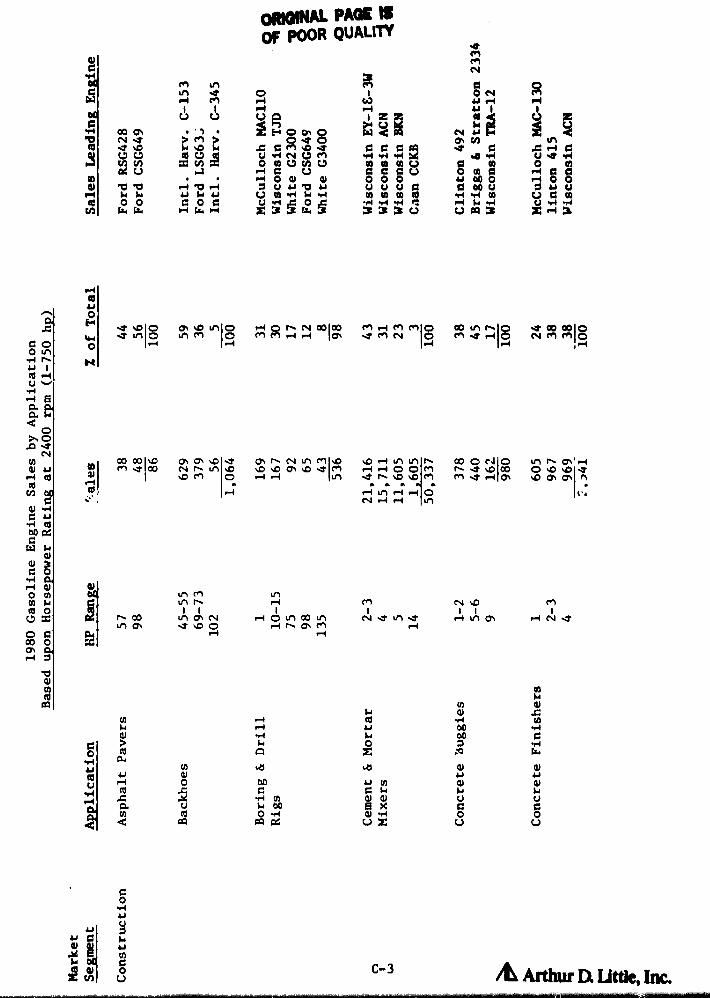
Wr4^z
M M M
O O O Vu u u p
333c^
dp.r1
w
M 00 O^
d bb
0 w W
en eft
V U
1 p..
N ell ► i
ac rAPi
P-4 b r-4
Hw H
MIMMM PACE 3()F POOR QUALrry
ImO
jP0o^0
u-P4NN C^h^
^ Q O ura O (M d
u i+V u
z3c94°
.4M
NpON41M
N 4W
top ^ mw 000 0
M •^ !A
va^03
91
u4
ri O
U A m
^>
pa+O
py r -7 u9 I Q u1 C^n tP1
I 0 M M .-1 r-1 ^ I Os ITen 04 ^ s 9-4 N M en
O
co 00 "O ON a` O -t Cs r` N u1 M ^o %0 -4 eft eel r` 00 O N O Ln r` 0`' r-1^ IO^ID ^7 ^r-.D ^D M IOO
I (coM I 00 r^ u1^0z M O .-1 r 1 eft 110^1 nI
M M ^1 r1 O^ ^D O^ 0• f1 M e^-7%DC0 O^D^0^-7
r•1 r-I tP1 ri .-I O e•.N "A r-4 u9
dA M u1eft r` r-1 M N %0 M
n CO u1 O, N r-I O u1 00 u'1 ef1 r4 M1 0% " N 11u-1 Q\ IT %0 O r-I r\ as M r-1a ^ r+
rnw
y a^►4 w x
G d p z q w0
•rlN W .^ 0l 41v
i^ 0! ^+ i+r-1 O 00 i 1 N CJ w
u cc x a a sa w $1,C u u
00 PG U U 0
O vire r
e0 ^u^44•^ E
a^c
>, ca a
di^ e
to CR
01 v
^ e00 pCW F
d
p ^rl Cr-1 dO a
C7 ^
o c00 cO^ cr-I

E
4
t
ii
° PAGE ^ E.ORIGINAL.QUALM s
a, OF POOR
s ^w
y O 00V-4 Aj a 41 ao
41 41
41 r-1 --1 ON ^T M 00 > > 1^-^ O^ f-1 N^0%
%Cv4
004'
U .0 a4 bg U U U C7 U 0<i "4 V4 -C UQ C wO to W W (n W w w N1 d 4)--1 N w w U 04 ►-1 U 04 ►+ C V. W W U G r1
71 *-1 Cm 0 d Ol O O 00 w ri 00C! O 00 r-i --1 N U 00 --1 "a v p,r-1
U^ 4.9H ,c N Vl rl
tN 00 cdhdG
0 0 0w w w w
0 0
w X33 c^o^ w vU
a+O
E-rC t'1 OI O -7 ^D
I°%D O O -4 r- M I ,-i O r,- n I -4 n O I n
N.n--1-4O 00 -1O O% %7NNm mNr-1fl, ItLnO%OiK
N -A 00 r` 1 00 r` r` S .7 O ON d u 1 00 ^D ^D O N e-1 I M%t co 00 -1-4O 00 Ln ON 00 M e-1 M V1 -i
M 00 c, 'D n r4 r-^ M ^ M OT N r1 r-4 MLn CO O
w w w w^ rl M
w
%D M --1 N CN
-f en 00 as M 00 ri ,7 v1n n^ 00 IndO^ N t\ 01 V! --r M S -4 C^ N C%
0+ ^x
V7 O OJw 00 L po c u v eou -,4 O cti O
e C> ^ v° v
O a ox w
nuN
OJ uj tb L 1+ on w ^+uu co a a, c a, v
06 o w x o v" w m oU U w w w U a M^ 0c
/L Arthur a uttic, Inc.

L
coy7 00 •4
^ ^ W
.^ w m a!W
u am C7 O •.4
•H 8 wZ d a u
GO w
^ O1
to wM ^0
Ocn .a
aV4
9►
G0^ u
++ G IG+,i ywT N OU Ardw DL UtOe, Inc.
da
^N O
AbcV
V N ° uoi s .'t C.4 M .mot
C9
w V V x a a V V$4 A V a m74
d a v Vw
b 9-4wa+
°u u v ^ v ^a °u r-4°^(a4j^
tipnap w
44Owco 4 C w w
w w^ MDc a^O w w MH
co4+OH
O^ %O u1 l O O O "1" co .? ^0I 00 ^O O r- O ^p M44 N N N 00 O r^ N ON r•1 U1 .i 00
O CIOU1 t!1 0 O M
IO
O OO Ln^ n ^
01 riu
aawd 0D, O.n sN
m %0 Ln N O,N000Tw 1^ ^O O u t N M n N M V1 00 O+ 00 M 00 M '-1* 4 0^"^
L1 %0 M N
Cnw w w
N r-I r-1 V1 rl N M M 1^
0) rlG L•r.00 pC,
W wO1
O/ 3G O
CLr-i 0! OO m 00 coo Nm H M ON ,..4C^ x n ^p ^/1 -4 ir) V) 1^ f^ ^p 1^ 4 M 00 1- Ln N
M ON N
M .1 O^ • 1 fn M %0 .-1
000 O.•i
chr-4 G
Vm m 4J
Gw OP-1 JJ
•CLR! lbx G w OO H v'
D, Gr w u NN QO L Q ..^
X00 w •U uu .-1
^a a 4 o

3
ed
G+0
I
001VIr-4
toy
rl
L C ^ ~
L^+ v
A Aril uc Q Ut&, IL>rc.
=4 8 o ORMWM PAGE 13 8 8 0OF POOR QUALITY ^+0 c
c
^^ ^ aaoo 'a a g^^qq
M1 r, @ A Ar. b ,Z
ap,
i
q^-y
y ^q^ w y `^ ^d ^^qip!
1 rl 00 to C1A C^ 01 ^t
F+ Q ri r1-M IA 00
to to V r4 b tj 4j rl rl 00 00 OD
t W 04a s a^s^^ H^a°c a",o^oa^aan
r^ a
H
IA
v
61 8
► s
0
AE+ o M M N M M Q^ a N aD aD IO^ tM I O O I` M C% 0% P-4 I\J Oo I%-P%^ -SW MMrir♦ a MN ri nNO O s `^ t7^ ^T tI'1 O^ `7`? Ot
i o 0Ln o I -, •^
[ M f`
07 rt
F
^ @d
60N
t0 O^^T^D^^N r4ON.-4 "0 - 1 "4 C4 U1 tfl ^o%D 00n M'1 NMf`
07 ♦► n ^D rl MI0% N Ln a M .T f` ri N %C 00 %.c a 00 OA I` 0o d M M .4V1t/1^ri Ol N 4NM LMMM M r- C-4 V1 Go t11Ou9 rir♦ M
w w w
V)w Z14
w O ONa
N.-1 w41
w1
w w.-i .-d
w^7
wM ri
w^T M
w wM N in
wrl
wM N rl r^i M
_
n n M aO ri^+"^
s aJ Yi S IT .4 O Go d M^ ^ w
PVw
rfw
rl Nw^
0o a
- o_ ,-1 4Jrl 010 IA►+Ln
N+TtT^t t^NenLn
v'trOd ►-1w
im n^x
1 1 1 1.^ Mu1O
1 1 1
^DN111u1^0r1 Mtl1 r♦1 1 1
N ^Orl NC MMri 1-1 M %C C% M t 1 e-/ P-4
Qr^+ rl rl N
fiT ^
- ( wr
.o
G aJ
^y ham+ Oa C7 0)%a 1o.1Sri 111 .G C Ul C'. F+
!+ 41 to t0 01
N top, d0 U w,a E~ ^.

O^11017, d^O Ql N O^
^YNf^ ^
t^ %a .4 u1N N u1
wco rl
0% M n ^ N M
N14-1714 m 14 An OcnNt-% u1 en mP4 r4 P41 -e
r•i M u1•t u1 nIu1 ^
VOH
^ .-1 N ^O ^ O^ M M O^ O O
4v'1N NON %V MO+
I f^ 1^1)^t u1
GO^
O 0.14 K+^ 1O ^u vri
QCLdO
^ O
NN OO N
,D V1 O^ .Ou1 00 00 t^ u1 ^O ^-4 U'1N OiM M et C
w w
Jm4
wy N N %O O M M 1^ rl f,w'4 u1NNM
OB -4 onC " wV4 Oy00 adCW M
431
Oti-1V-4 41
N T r-1 Ncd O(J' ^' ^^ii ^ M ^D N 1^ r•1 M U1
M en Pf w•1 4 N r-4 0 N N N'r%r4
I'O N u1 tr1 00
11 N M ^p Or,r400 '0
P-1
P4 C
ac
Carbwe^
u ad
!gyp
.-1m
1 u 1 w4
ow iw
/L Arthur Q utac, b,
i
i;
H a°, mo g ^c^J
O^^1p1 w
o^•rLei ^°
W S1 p. Vl OO NP1 ^NN0104 0-04
41 41 00 e^1 10+ M vd O r4 V-4 1+ 00 f0>,'spp
W4 t7 V 'O Q^+ O m
y a^ 4 w XAA o mHHN ac ac bdaa u u u w
m O^ O
^ 1rsw N O v C L
`au AJcc
yv w^ b u
wIn cn w 7C V z ad 4
02u+w
a
w
w

w
0 C-8
Wa^+Ar•1+1
op
P4
AL Arthur Dt L&tb, Inc.
# i
1.
couwO
d
8u
0
r, 9 s O
Awl4 'G EI1
a+G to
M
uw °`
u O ^ ..^
Mw
OROKU PAGE 1WOF POOR QUALITY
M^ ^ M Q^ r♦ rl rl
I LMi J y y iI M 1.1 ^.1 N
AEG N 10 0 a p W A pw
I^rlI N Y" Mm L 61
V1 LOJd YN M
r)Q10q1 10 ri Vf W
dO d lO1
N w d^A4 4 d d b qN
w 41v w a o°po e°S a MO,, °^ ee0o e°S e°S.4 O M YI M rl QC ri "4 rl .0 C ^1
N u u uan0 000~0 PM0 uu^4
Op
w ^MIO MMl C)% Nmem+11 S f- P-41 00 v1MI CO WvilOO O 9-4 ^^
Letv ^ K
544•^ 8a0.6 O
^ O,G dNfA O% 40 d r- .4 07 X40 r-1 O NN dr, V1 ^D^^4! ad V d %D q-4 sD N .-1 p O+ N N v1 O^ ^O U1 tP1 0
CON O O OA) a Kt r^ v1 OM 1 0 ri e9 d %O %C d N rl O+
too ac
^"'^a
w wO^ rl 07
wO^
w.a
wert f^
wr♦
•n n
•Vt
wrl rl
wN
G H n dN m n n01 'ri r1 R1 N m M 0% M
"4 ^ rl NW
wwa
R,4^ d0 w g u, ° ^ .t c+
1.4 e%, r:
e.
C9x 4Jc4 er,S mI^NL.o^
,
i N
^D O tG
^ y
btit,

1980
I fl
C-9 AL Arthur DL Lae* Inc.
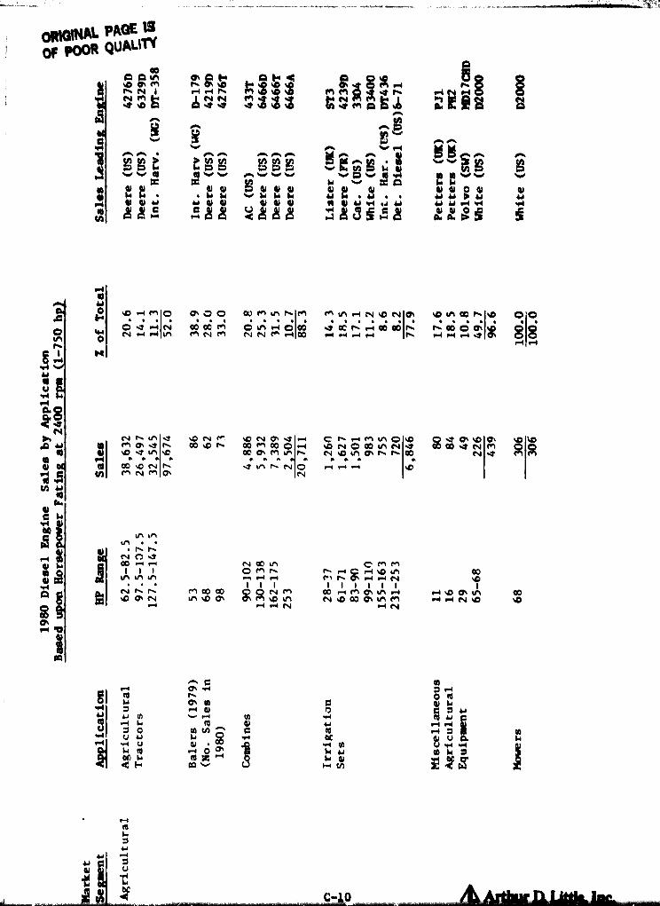
a^ ^s
rj tp v v v
^ Via.1 ia.1 Iai11 Q V-4 MJ. A.
44
^t
A 0 0 m E^^Qpp
!+9
^p
^^^ des ^^^^ ^^ NNNNer55515AQ^
ER^
^D Ir I+DD ^^^ ^^sAP wvv (d tpvv^'
vvv vyy pv W Q
M fa+ ^. lar W ^+ la.+ lar la+ ua s .+ .+ a s a a a en a ++ ^^ .+
<aaa 104^
b
^+
[.^i ^D r-1 !"1 IO ^ ^? O W M u1 hIM M V1 r-I N ^C N
IA
^O V1 ^ hl^p O'OO ^ F4%A Meg M e`egC^ -4 00 ^ Oc n r, aoao n h oo OO^^p Q8
^
N "-I^ V1 M N M N N M ^ 00 V-4 H -4 r-i h r-1p
Nrl
i1bVMrl
N►..p a^
A(q
b
Md^
H00
N nV1 .Yth O^ ^7^D ^7 V1w w
N fN
n.Dw
^ONtaa0 .D h
^ONO^^7^0p M 0p OO0 O^ M v1w w
.7 h N
-+•-thw
Q
C 1^r_IM V^O^O^O N O 00 31 NN ^O V1 O^ h hw w w
r-1 .^ w^
^00w
^p
^^^7NN
M^7
^p^Of'71
Ot^1
H 61bW
C to^ a
W `^
rla h h
N C: rY00 W r~
1 1 tN 00 V1p M h
^" M Mh ,..^ C r•+ ^p to ODih V1 V1 n r1 r♦ M h O^ r♦ .-1 N ^Q wys
N h 1^%O C, N
r^
M 00 00U1 %D as 01 p1 N M
N 9rl r1 N
OQ .-4 M 0% V1 r4ON V1 M
.-'1 N
r-1 -p 0% V^rl r-1 N ^O
co^C
Omrl V
I00
r+O W
Ird m 44
4O
Iw d w 1
^m P-47
+1 u u N .N
m 0! w 0d F fit a. ~ to 419
rlRI4.
u"dw
1+

ORM NAL PAGE 8OF POOR QUALITY
01 1 %G m N O^ m %O M %O M4 CO) m O8 8
.At o1G n O m 1-1 V1 9-4 n v1 ^O n to v1 ^O ^"1Y 04 N N m en 04 C14
^.TPy4 O •d
1 A d ADD .t.7d^D.7 F',ZIA A en -VG
a
v pp^^
^ p^+ I^rDSy
vvi^pQ4
v ap edv qlv A m eqvv d y dr
e0 e4y y vv
Wvv
V4 44m •r+
►O+ M x w 4D A A A A
V N u 10+ 1^+4141
8P4 u
a 48^Im ^^^^^ ^^ a ^'&
r4a
06 0N C ell.
M M O: C 00 ^,, r-i ^p ri 1^ V1 n Op O^ n u'1 M! 1p v1N nCl
fn00 LAO
r4
In^nV1 Ln M N --1 N m ^T r-1 n M em %D N r-e r-I e- en an
^rMu^ 6V•rlr♦aoo^.
Nb. O 00 %0 d 00 r-1 M I.O O r-1 n r-I n-I O r-4 0 r-1 .Y N 1D .7 O ^O %0p N O1 V1 M N r-4 n -* V1 Lm ^O eT C0 'O er1
co O
00 'T O co N M 00 O, nt0 01 M N 'D O+ 00 M O+ O O 00 N .t O1 %C v1 10 r-1 ri r- 4 r-4 .Y 1O M Ow w w w w w
1 00
w w
I n r-I N r-I r-1 V1 ao9-4 G 171 ;a^rn
a,d.^
eoG i!1 v1 1l1 u1
Od N N C14 !^
r-1 nOJ%000O r-I e I i r'1 LMM 01 u1 O^ M cn Q` O^ r-4 ^ 1-4d .^+ h O^ .D n u1 V1 A v1 v1 co r-I r-4 M e-1 v1 n,,,.I
A it$1 I
00 M%D 00
1 1M.-I OHOV1 n O` O
•N n n nn%O ON N ur1 n
1 1%0Ne- M
1 1 1V101%000
N ^D Q•
I IN V1eel ^D
Q r 4 r4 r-e r-1 r-4W O
OAr•I b
O 00
^ I+ etl E 0. >tmq cc
H r^i
en UW 6 A
10+ w •C7 O++ m u
^F-4
a+ q d 10+y u I+ ^+
N M ^
?A
q
C'll
O
GA
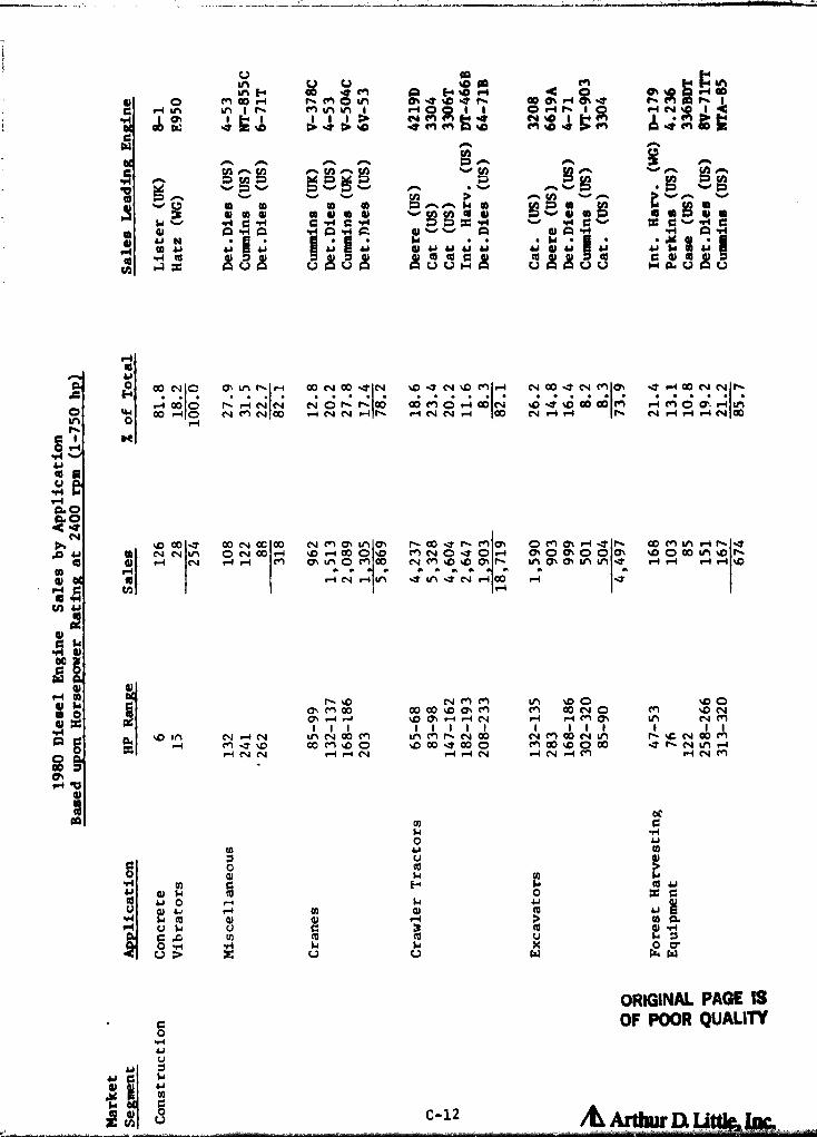
U AO ^r
v^iH 00 ^M A H^^09 .t ^O d h ` O O1 ^p Q r-i
y O M co r-1 h M O u1 Ito O+ r-I 0% J h e+1 AA h iC r111 V1 to h M u1 LM I •"1 O E[( 1 O r1 h I Q f-i N^ IM 00 Oc. ^7 ZOO 'J^Y'3 ^C .7 MM A pp rel%D^tC
y
y ^y v^ v,. vC7 IA Iq to {p ^`•7 y^ `~1 y1y^l 3 01 0 Q I aD CI to al y ltl 0 «^ ^ 91 ^ P /tl a r7 C! m
1+ .. y 1 C Y1 C 41 C M :7 x M 44 C x C "4 0Ip Ol A Y1 A -,4 A rl A A► v A O) A `r@l rl A rl
^m N 4; '1 ^ au ^ a+ d a+ ai 4; ^4A8 u, u,
a+ 0 41 a Null 8A 8r;
4;a9 a+
0+a^c^c^ax c^c0i^ c^g'ug' I-W
'aa+
.0 H co NO O^V11^ rti 00NOOJN ^CJN^GMr^ NOOJNMO^ J ri00NNht ri 00I0 h ri NIN N O n 11 I00 00 M Q rl W J 10 00 ODIM r♦ M Q O• r4IV1{ O co r-4 O N M N 00 -4 N N r♦ h f.4 i 00N N V-4 N r♦ ri h N •-i r-1 -4 N Go
InhC 1 i^tG r-1
usY+
aod^N
^o 00 00 N0000 NMQ\ V1O^ h00JhM01 MI J hO ^r- OMV1 r-1hJ.p L Op N N u O NCO .-a %O."100 0%V MNOJ Or q 0%O0 OOO^ 1COO V1-Oh
t0 ®) ri N r-4 '-1 M
i
ON V1 O M 00 N M 1.0%0 01 h V1 O, a, V1 V1 J r-1 .--I r i rl ^O
fV /0 '-1 N .-^ V1w w w
J VI J N r-1 00w w
rl J9-1 ^. Q yy Yad
sad
ec
A
^+ mO% M co 00 co %D O, M M 00 N O t" 1 %D N
d '.iii O^ r 1 •^ %0 OS r-1 14 N r-1 r♦ M 01 V1 N MA ^p X1'1
riN r-1NMJ^O
11 1V1NOMco M%OO
1 1 1 1V1Mh1'400%D00 J00 0
1 1 1 1V1NM00N M00 %0 000
1 1 11-4,- 11JhN V1 r-1
"1 N N r-1 r-1 N r-I N r4 N r4 M rl N M
IT
d
I.i rlO a+
m u m
OH 1^+
1+M W td uu x CV u o r4 F+
d 4-1 r4 m O1 to uMP-4 u^ u 3 a4 to
WU D z U U W W
ORIGINAL PAGE ISOF POOR QUALITY
0
a^u
a+ a
C to^a+m
9 C-12 AL Arth u. a 1

r
gat DAM
MIMIC in
1
N O 1r; c+1 1n n d V1A H r♦ M 00 N N H 00 H H A .i v1 r-d
+ r-jp
= Mt .7rri .D Z WN.Y Z> Z^^ A?e^+1 .7A.7^0 ^' ► ^
Cw r.
f r-. ^-• ^ .-. 0-. 0-. r.V] Wnncn i. nv CAthH N
N ^vM 3 rn W m rn y a w a w
v4)
y rA
O v C C v ^ '^ v4
.rrl -A10.1 v ^1
^AI C1 ... N A N A A ^IAAA,..rC
0J a^ d uqaAUAA g
yy
pupb^A u0
Eayy+4i°ua+a+UUUI-Ciuu
yy qu^agi► ap^^
a+ay+UuAfn AAAA
riQLH N Q\ S d O'• 00 rl OC N M 17 'i O O. . O 00 N. . . ^D Q1
. .M.
W 1n00 r 4 ; O ri '-1 M to r, r` r-
IM 'D .Y ^O O f` 'D
I^
O co .Y t\(17
O r.4 (n r-1I rl 4 M N 00 N r 1 r1 r4 r\ ri rl N ri -4 00 M V-4i N co N --Tra O
O
i^
-:r to r-4r` r- Nd ON%0Nr\ O r- V1Ns%D -4 u1 00'TMnN 1na,O%Mco fN OO M r--00 .DNO as Oto M00.p m O nO11 M r- ITO•. M .T 1n %0 M M N %.O f` rl N d r^1
O -.D M 111 r--I %0 r-1 00
mi
^ w w wb '-1 ri ^7 M •-i ^T r-iN
N N O.D coM Nd IT M 1n N%D %0 .D co 1n 00 M 1- 1 ri O O u1 M ^Dn r-i N .D rl .-1 N M N CO) v1 n co rl N
1 1 1 1 1 1 1 1 1 1 1 1 1 1 1CO 11 1-. M1nN01 1O -4 W r-1U'1ONN O MN r-i Nr'ian%D 00-.T u9 to M%0N Oto ri u1 Q` MO N %D OoMh
^N .-4-4" MM NNNMU9 %0 riN rlNM
ND
V $4 00 -4 rn 00 it 0•-1 b r+ u 1 U rl 10 Q
tb C N w 7 D N
Mc U o 14a a
0.4
u^ M
d ^ L
CO rM^a^t0 iu s^ 1r♦acacdC,
C,
1d!rl 1
to ^1
it41
C 1
GW 1
1rl i
d QrlQO icoC1r♦ 1
i
r

{
j^ as
Lot4^D •pd U gt^4
41 ^-.1 zz 0% cn M O in 0000 a00 r4 0% 11 %0 cm Oi C r-1 O O O d v+ rt kn .-4 LA ^D bi r4 a0 O in n r4 a cn r4 In
M N M M M [[--r+ t` N 1 1 01 C-4 • N I t0 et .7 Ota^ 04E' tc .T M C1 m .7 C9 M ",^ tD ^0 ` tD 7C
be v
M1 VS.. a
v v n^a
rl N1 V].. av .. ., a r. lu
u1 0 w." 41 ^ ^!! iA 0 .71 yrl 7 ,7 ,7 to 3 41 r1 QO P «'7 a! rl f0
v v •• •• Ato
v QC
m d -r4 d A a!H M N M w aa+ Nraj W wai a^ d 41 4^1 tJ
O •!L asO i+ dafa 41
t° al c^c^^c^ x^c^ca•D 4Dtisa^
♦+ 41^^c^U
dU^U cc
t/1 ax
R
rlI l ^
O r` N N r` to O .T .T O tD to a0 M ^O ^D N r` r-i to rl N aDE-4O
^MQ+rlr•1r- ^7^T
(.tL1OO^to MM r-i.^iN Lf)
(tn%DN-7M%DM
lf^VIN r-^1
(0
d W%OO r-i r--1 N -4 rl r-I N r1 r-f r` N N M r 4 N r-i ri r-1 00 N M r-4 r. tD M O
f-1
C 1 ireO rl=M ^
L
uM
rlaoNy .T ^D r-- r4 to M -4 to C a0 O O C+ O r ^ ^D ^ ^ N O N M ^ an '-1 r,p 41 co MtA.TCV .T0 'D0000^tn0 0en_4 -o MONr-- %OMOh ra.T%DN 0%0047 0 rlM.Tr. crk riLmV.lcn0. MM.T tn .? tn MM .T r-0 r-1 .Ti^M rtrlN
- to r-1 w w w w w w w w w
d to N .T M W rl ri r-1 r-4 to N N M N r-I r♦ MN rl
^ •U) u
arC i+•r1 dao
Was 41
r1 mC14 N C
M00 e4 WN cn
%D u1 %C %D cn t` ^D N ^D ^D 0% -4 p Md r^ 00 r-i N M N r+ r-4 ri r-1 r-1 N M O r--I r^
1 1 1 I 1 I 1 1 1 1 1 1 1 ri I IA O
t!1 O^ %D M M.T .7 r-1
Ch O M N Nrq D0N M
00 O 1 1NUl%AD
to N 00 M NM%Dto000 1 r-1 r-i
LnNMtD to
r1O -4 N M r-1 r 4 M to ri ri N N M 00 ri Na0
rl b41
I1
v H b-^ -rl N rll is QJiJ F rl O ar 0) al
N H FriA to
M U H 4! d F+Mt•1
Er-1 vi tC NJ0 t0 M rloc .°a Z L) vii a rn rn F•
ORIGINAL PAGE 15
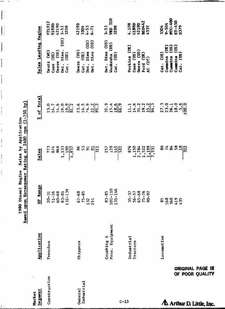
fl, n co %D NM In ^D f^ O^V1 %D V1 v1 OM0 %D fl, ON
rn 00 00 Cl*, U100 %D %D ri M
1-IM JIT
O ^Dto ri .7CO -4 r-1
M r-4 to00 O M
r--1 ri
as
1-I
R0u03
iJG
aka v1
00 fS
-P4 W
y u0 0
u a.
fAH4Jaa
v
C0.IJ yfl'1 4JUM Url G
ar
d F
r4c044 InH {4L 0y a+a ub c^
H H
ORIGINAL PACE 13OF POOR QUALITY
it Arthur DX ut-tk, Inc.
G0
Lu
Llw
d y
OiA
co
r..l Hcd 4+H4! ^
C9 t:
C-15
ON 1-4
MMCo0JZ
0% 11 P4c w r., , FN O
dayy
r4 9 ^, % in oW O^^1 er1M MIt MI?%0
Cfs+ ^
C v
0 fA ^ t ^ M M f4 ^a 3 N^ p d t/^ «. N^ GJ 0l 40 cc cA
^-7 v v vA `^ A In f^ mN 41 41 N
m d a+ u ai 4;g4HqJ1^
q^^ ayyiU A U U 3 UAA A A A A
N SO"4 GoorlAM a inu I n
rM14s^soNas1-4A
...C Q CvG^v vrr"4 41, 41 H b r ^W
L+ 1.►H to 4y
1 H
uUUUUOr U Wd
rlfou
HO ^^D 00 • N ^D t11Q N^N ^^^0• r- -IlloNNNn MOr^O^DO
CO)r-4 r-14 -4 -4 1 00
'-i M ^7 ^Y NLn N ri e: C%4 1
N L1 00I o e-1 d Lf) O% t£1 -1 f- M %C 00 UY O44 00 M r-0 r♦ %o r-1 V-4 M r-1 r-i m N N N rl OO
K
Md00Main %D M .--Ir-I,-4 ^O tn " %DOdN ON f-1 aG^IT00 00Nto f^ f- %C M cc M OC to m w -4 V1 N 11 N f^ u1 00 N O% M Co f- Co M r-1 N
n 00 00 ri rA 00 M N -f r-1 Ln 00 r-i f- to r-1 fn Mp-f w w w w
t0 ri ^ r-I N 1 r-1 i^
0
41
ii r-i -D 00 rr1 m co In
a M M %D co r-I .0 00
nJ O riO f'nN , to N"
^^3 N rn %D 00 M %D f- M LM
r-I r-f N
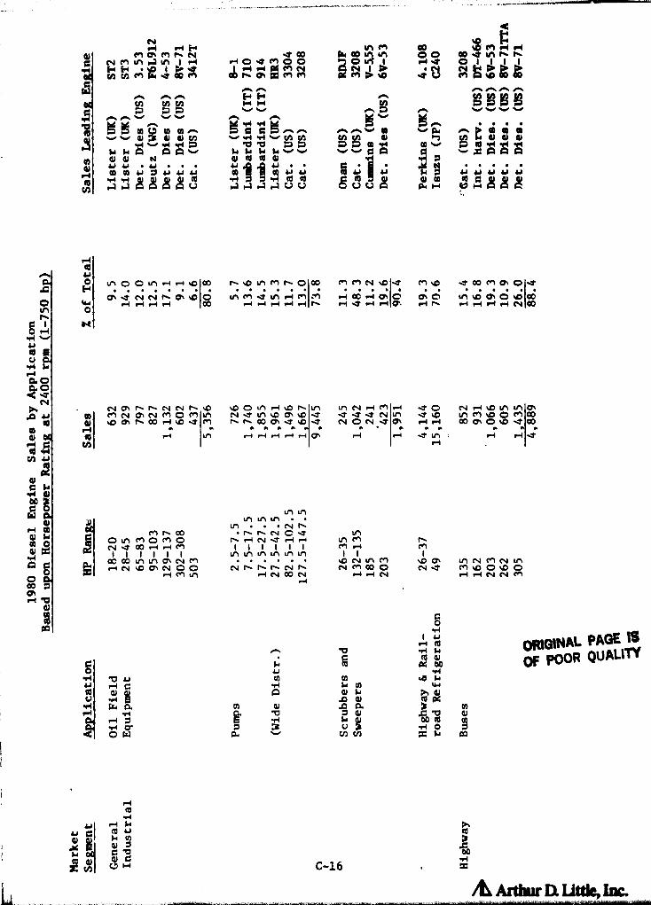
Or<P1nr-I
^ 6uMr-Id Od •01
N
d a
f!1 L
4)a >~^-1 d00
R1 Q
r-I (ArA
d x
A O
00 a
r♦ b
LM m Go cmn n ndJ Ma1M fl- N .100 W 00 u1 00 40 4 61NM in I rl r-t o^ tl 0 O ^^qqjj O 1 .-^ Na o ^ 1.1 1 1
fiN y M .ItO^D ^^ 01p." mm on t*%C
A
.d ntp W to W.—
•^ •^ 41 41 41
rl -Ato gn a) F6^1
D ip tp W►+ C) a) 61{{/1^44 "4 'Ob .ti. .ti- M Wv p 40MTIM
lw w A N Atn
yvv vvap `...^;A A QdiW 4.1 Y • yJ • . • 41 RI W+.1 y.l • • • DN
,W W id J.I Y Q1.1 41j1
44;1Al W W H id 41 41
w aa^c^rr^ aa'aav^ ^UUA p• f-1 rdla+ACRto
a
Hu9OOu"t•-i r4 %Dn1O U1 Mt`O00 r! NM 1D 17 M1p dOD
11! 01 O.7
w a1 17 N N t1 ON 1D 0 u1 M
r-1 11 'A -.4i M ( : r1 .-I w r4 c+ C o, 0 LAD 0,0 ^c (x
Cr-1 ri r-1 r4 1 00 r-i r-1 r1 ri t1 ri 17 rl r-i a`.ri -1 r-t1 r1 rl r-1 N 00
K
Na• t1 t'^NNr-%D %DO u,r-i%Dn1!1 u1NriMr-1 .7O N rl1Du1 V1a\W M N OWN M O M ^A N 1t V1 1D a % 1Y .7 .1 17 N v1 -1 %V V1 M 1D O M OD
00r-1 %D 1T M f` t1 00 as 17 11 N O N 17 a1 r-1 ri OD a, O 10 .t 00
^ a^ r♦ 1-"I S 1!1 !'^ 1--) 1YN
Ln uny 0 u, u1
.V1 . . N nM11 00 n nN C ? u9
O V1 M O fn O r- r-1 N 17 r-1 r-i LM M nN 17 00 .-I ri M I I I I I I M r-4 M
1 1 I I I I v1 u1 u1 u'1 .1 .1 1 1 1OC 00 u9 V1 Q\ N M 'D N u1 M %D a% u1 N M N V1riN %Da% N 00 N9119N^ N M000 N17 MNO0%DO
.-1 M ri N 00 N r4 r1 04 rl r-i N N M.-1
aOM
rt-
p1 Cd
p 41N c0 p4 a)^ M
A c>+0 CKV •r1 6
^0) A 41
r♦ ti-1 b 7 41 JC b O)
t% t/^ onci O W P. x lw
r^l
t0
or POOR QUALITY
4 I I-iypi
E .
COOti-1
C-16 m
I rd w DL

ORK3INAL P.4t3E ES e
' Of POOR QUALITY a ; N' N.r, &n -1 LM Wi co a "4 a^ ^o o+ o^
p v1 1 ► 1 rrt N tr1 O i^ 11^
11
1
M N^..a HOC C0 eQ ^O
[ '^WWr
.^N pa
• M .r C3O
p^ co %O t` aD M r` y .-. r. n n it o.. 0-k%oO U; ^O pp Dv y y U y y to to y to y y
O V1 u 1 v v v v v v v th.^ i-. .^ rl . .^ • ••1 5 •-1 r-I r•I•fl .• ., .. C9 a rn d N al N d
^%.o al d as
m ao ac^ y s ti ov v an c to 12y m
v v v 4.4 1A ^ Ga0 • 41 CO ^ •r'1 W "4 -H^ca
Qin M 0 A A
W CO a) tO0 44•1L to .^L of tf! a u u ,••1 p ,fit
'^.-I wv •-+ m u wu wu w uuu u uuu
^ O al r-+ O r! r 4 4) aJ G 41 d d RI C a) m aJ dl a!
f
y 9 0 9x0 A a. ►r z0 A u0 Ina
of^. u
E M O •D O N Ch O O aoN O 00 (7% r`l ooLn P4.-I P- r\ O ON r. r` N
M r4 in O N %D 0 O 00w4 O %O N v1 H co .i r4 N r-4 co
C 1 i^tO r1
u
u,rP4a$as ^
N^. 0a'0 0Un0Ln o^ '0^0 .r0OMin 0Ln%oI-I ^^Mr`ao%p u to O%o-4 r^rl.O0 .4 Ln.1 O O^%ONao r\0.tN Ov1ONr`inr\
W 0 v1 M 'o -V v1MU'tv1 M O•^N O^MOori as It N%O 'OO O, O 'nc'!"I w w w w w w w w w w
d 0 Q` O^ O O, r` n C'S r` M •-1 r-1 N v1 N w-1 O 00 ^? r-r O i 1 ^ ^ O^ O^rl (.' y N M
C,4
co r-1 Ln r^ N M '-1 M N r" M N ONId •r1 .-1 N M
y u
ac a
•.+ as00aw
O+ v1 w N r-1 ^G N O O^CINM C"N r` NMZ riM v1 Co
I I I I
r-I .i 1-1I i l
r-i1
N N N M1 1 1!o1
•y 10 OT 1.011 r. N N r-1 m N m N •-14 MA
m 00M d 0 M ^D Q7
'DV1r-i
O ^O.1-f r-1N M% 4
P-4 r-14 r rr" v1 CN1 r-1 N
`C 00 0 r4N N N M 4
O00
r•1 b4p1W
N n7
La a
44 .-1 Mum N N v1 ^p r^ cou a) N V1 aJ N a) y N
'• 1 I a) ^i N .!L y ^ w .!L m aL Mcn u w u ty^ u cn u u m u fAw R! 7 t0 7 m 7 7 s0 to
w .i w ri w -4 w .a w r♦ w -4U H U H U H U H U H U H U
u ^,
^0► 3w '00
ii xi
C-17

ii
r^O
1 •u
^ H
H
vH
C C
w
a
^ C
xOU
Ca^bHN
L ^+^ G aeV1^+
N I ,Oa /d Arthur Da Littk, Inc.
Ofnh
C iO +-I.rl vV
uri
.aao
^. osN
rC Lro
rOda ;^
d
000
tsl Q
dCl H
A QO
O^r1 b
^n v
.,.iO
t0^q7)
1 IPO r^i un0O O v1 ri
Ln Ln V-4PO .D N =N O H A
a a a a►7 ~j r7 ^jv ^ ^ v
^^uM,E+.-^^^M 1 h O
1 >00 1 .1> M .0 .0 .0 M
0-. . i-. i-% % --r i-A4 N to N to to OD 5^ D^ D 0
01 ytp fp
w ^wa 00 v1O OM0% 00 0-1
N J .1 H
_^
_
ti^^^•.^vvv
O Oin 0%
w N^i••.
(5
u^iMa asr-i O cn in 00pp NN Mapp4 • • Cr • t+1r73
^? ^?' N .0 M
CAO^ A^ O Dv^v^vvtd
dr4
CAA
O O Fr t0O O
to j
L ,OR
^^>0 ^
R 4 Mm A Au a+ z z u
c)ua^aL)L)
H O O Cw Y1 M8 00.* ALCC O w H
>4 aaa^.
^v vN N
aCaC
tpqm O C 0 QO) +1 M 1.J MA Ad W O .9 d7 H H R H W
9Ad04[--0pou
m
MOhO Q..DdN00000.D N Lf nQ^ ^CNOO.CMM00(~
^c4400 OMN p,Na,v, 1 .p.1MO,M f-MO N%Dmr-NaN44 M U9N r4 O r-1 ri r-1 r-1 f^ N r-1 r-4 r-1 h 11 eP1 O r-I r 4 r-)M r 4 I Q`O I'"iIK ,
ON Co .0 t` O Q` M CIS
n W O r•1 M r^ N M Ln r-1 M r-1 .T O^ t+1 ,"I t! 1 ^? Or♦ N .O.0 .T tr1 OhNfl .TM 00 MO%-4N C. Nri .Cr-1 Me"1MANt\ 00 r" h ID .T v1 In en v1 M N O IT ON f\ .0 00 r-1 N .1 . 00 .1 O -4 00 'N 00^ w w w
^p 00 ON N
w
N
wt+1
w w w wen r-1 r-I N O.
w w w w wr-1 N ^P1 r^ r-i ^
w^
N
LnU'1 U'1 U '1 n V1 L' 1 1 tf1 tt1 L 1h
NNNNI,, Nr- n nhSd 0 O O
r-1 N M r-1z N N N in
II1--f 011 co I I I 1 i I 1 11 1 1 11 Aco 1-4 -4 ri V1 u1 u1 V1 tP1 t11 u1
1 I 1 1 f^hi^n.p p% M .O N r- N h rl r- •-i N N^1y r-i r-i 00 --T O N .7 .0 O ^1
rT. r-i N N N N in
ORIGINAL PAGE '3OF POOR QUALITY
CCl to
CH r^ U W Vj
cc
L C9 to 1 -r1 OG .a wuu `° ° w a c ego"4
g8j
H0 CHI oa E+^ w
C*4 InO Men .0 n co r4 r-1
^1 ^^ ^C i-1 h O eV eVr-i N N U1 %D co ON

PAS[ORIGINAL
OF POOR QUALITY LM
44Ln %D to 018 .17 H E-^ H .O LM
p"4410 n1
1!
pM.4 a gti^wp'1^CO^^OCI 000uini >A A ^M>+ AP4PGMMA ^'^^ OpO
O LMW N 1 r,o-^1 ON W ppr1> N to^ ROOM lJfwwwwwwwo
DDDAD «OAAA^•ppIR
AOOODF AC4AM 4n ^(
vv N F + yV1tAto!^ '.7 L7
W ^ ^ N .T. C! ^ v v v
MM 0
M01 aL ri rl p G O r•I d ar
`
to
cn j ^ 3 ►qOiUOOUC^t-^i V U 00
1
►-
4b
O 00N•^
HOO^O
1 1-4
ON ^DION^DNO
MM^p rilM%0 u1N.7O
O h OrI^OO\rINOI.7%D Osm00.t.t4mLnLn
N.7NlCOLn inp y a O r4 O N Ln "4 ^ N r4 M r-) 00 r1 %0 N en 00
M•1 Oh
VQ1 ^V•r4r-Iao4a. oa N•^
MLn -.r 00%0 N OD N ^D% 000 N O.YMOsrI^DO^.7 hM 00Sr--1 MN .T h O h ^ +7I 00 O N D\ I r4 h C% 00 Ln to IT rI O %D
W,
^„4 ONN r-1N .T ri 1-4N %D OM00%D-4NO•-4N%C %D 00LnD\fx^.
0 M y rl ri M .7 u9MN 11 rIJNN rl
y ^01
• OFJ LnLnLnLMLnO
Ln Ul
44 06I h h h N N
NN h NM r- %D01 OJ Ln M Ln Ln %0 r4 r-4 14 N It
ri (A en p M 00 N M 00 I 1 I I 1 1 1 1 1 Ln Nd {^ r4 N r1 1.0 01, r1 ?-I Ln to to uli Ln Ln in to Ln r-I ONW O I I 1 1 1 •••• 1 1
O^ ^l1 h all u1 M M all OD N N h N h h h h h .Y u'1 U'144 N 00 M N 00 Ln co N 14 rl N 00 N N Dd Ln r4 M 00A O rl rl n -4 r4 1-4♦ ri r4 -4 N .1
com
d ^NJ O
A O L^ ^ Ou +^ aCd to Ol r4 to
O M $4 4n {+ 1JQ
•P4 u Or4 r4td 4b i► A 4s+0 cc
M H^ .^C
;^ X00
Cv7 `^-^a O r7
toN
C -H -H N
u q
y x,cd-4 yC
Arttwr D. Ut*, Inc.

P4 00 r-1 M^D O M M 0-4h •-4 .4 N M
DD rn D\ 0^ N^DONN^
r4 N
LnM"4
M Or-4 N
gou0
tN
.-4
u
x4u9
aa,
YIw
a.kw
w ^CL to aw"a 0 OPL G W w
0 a! eo
&jQOp d
-yO WA a^
GO
u ►+,^
b
dl
C-20
w01X0
w0Aj
^ GN N0 w
/^ Arthur EX I At& Inc.
9Np
pp a^ M
' ,
C
V r1 e-•1 N ^pp7p^ M t^1^^jj q rt t+t
C^1 Q H e+5N
tt e^^j► i9-4 .a e+1 eN1 l^1 ^ ^+i++r► r► r^ s^ i-+ /^ /^to Vf N N N to H N
^ •? Q6 1Ift Cjri C O 1N N ^iS fn en %D
in
r-k r►V1 d1
ry
'CMRI
ON ON 0-% ^(n (n gn.7 .7 .7vvvv
".^ D ."^ w7 "^ 0 .'7 '.^VV VVV VLV
yD01
^/.. /%
vvv^'piv
v v
d X41^ EAd 41
H
93 r.
4411 ca3 a a U
44 0
ar al A 4
Q M
H
yOy Qj 41 0 a 7A A A U U U U U
a1
41
41 00 4^^A U U U U
q A
d dA A
O NAl. PAN 18OF POOR QUALM
O
jw
t+1
.^ v
Wu
aoaoN
S+
4u a
41wd
al
Ad
rl W
41
A
oD aO\
P4 V
.-1at
0 (nGo%T 0 NM u1oD0,.70000h. .Mp. . . . . rlMph OOOth
H n0+^O^ Ch Ow tr y hh0O,.-1. %0 0%ONM pN M h o+h
. . . . .
W .-1 M r•1 l h F-4 -4 "4 h N r-I ND rl Ln I h
O
a^
O*-IMN^p N^Df^^pNONQ^i01-- CNNN04 Cr
I O%NriQ^N 00.-4 %0%mf O''t'OhNr-1 OOhph0%04 r h
00 1 d O M N p 00 O^ M h F^ try ^O 'Dw
u1 00 h ^O N O• tr1 r•1 O^ r1In
w wMOOMr-I^p
w w w w w w w^te^1t^MMN^7 ^f1^p
w w w w wMM ON^?^Y%a
w wr-4 en
w
V-4 M N
Lei trl V1 LM tl1 tryV)Lr) hNN hhhOd^OMp^.-!tr1 h .-4 v-4 .-I N N M
On LD fO tryM try h Os try to try 0 u1 to u1 try
u1 .!, M A
h N N h h h h h
MITtp00
N^DOON V1Nh0^
x r•I ^-1 N N N

APPENDIX C-3
MEDIUM AND LOW SPEED DIESEL, GAS TURBINE, AND RANKINE
ENGINE PERFORMANCE AND COST
C-21
AL
Dmam

,
uojfTATQ SuT$ug lK
11SgsSxn^M 5 ^ _ ' OMONa PAGE
a;F
jsaonposd soTssdng 6 N %
r- 960TASSS oON
aoN
=
m
^SBssug ssd000 ;,
' ^ 8 ( ^ f•1 L ^ON
^
O^ a S N d
pSsI^Z w
ssSTssT^ '° ^ s C'
wC
MG N
ov IZYFIOi►
= N f O
1A'^a0o4s3oST3 `^ O < 0 r% a rlw
92020HTV-IOU ^ o C% Z0 0
TVATTSQ CC O wu
w
-StTsdss1u3 _ ^+ N o
Ssso Ag
o ^+ oy
,olw
a
.•^ O pp w
++ ^°• ouj sswod 037Y N N ao ^, +m . .4eo O
^o S
l
1
.0w w
cz
4. OC K yd G ^ + i
' r p .^ M
L^ '' ^ ^ i!1 i l4 S U ^x ki U U = N
sSSSSSQ ' 1 ^ i l
OF ^
Lj
6"1v^

zsfsizQ 1 ^ U1 M , w !^ ^ ' = 1
uoT*TATQ OnTlug 1 I ^, a •:•yssxnu^ ^ w •- ^
t
i Nt ^
•T OD ^
OCAD Ni ^,
r N^
t
Y^
szanpozg zoTzsdns i w QQ Q
3 X .r- 592Tszss •° .,
Alzsug zsd000
O N h N o^
p03TMT 'I $ ^; $ ssuoz"**T4
ssaTzzTw "'
aJY tdYfd
s^T3o®oz^ast3 ^+ : $ ^ ^ _
szO;ow T*zsnso .gyp .Or i'^r a .:
Tsn*TsQ ^c c^ ► $ rs.+^s*Tzdzsaug
.r
s^zoW ° a a Sal z
_• auj :si+od 07IY N
pt.
r4
^ wer N N
l
}'d
ILC
sar p
O V
' uW rl
so v
" PWR QUALITY

OWNAL PACE 19
=:OF POOR QUALITY
CHARACTERISTICS OF TYPICAL SLOW SPEED ENGINES UP TO 3,730 kW (5,000 HP)
wyL
I IuCJ
N
m
""
L ^+ V
a 1W
0^
ao►+
0G. ^
O.:iO G 01 a I^.i .^i
L V-4C d
0^0 GC t0 ^ ^ M
Uc^ltnr-^ ACS WA 0+a go
E Model GMVH LSV W-330 HBA-T 2C4 KVR 40/54 48
Speed RPM 330 400 330 300 600 350 450 257
EmissionsHC —1 .4 3.9 2.3*CO 9/kW hr 7.4 1.1
I1.3*
NOx
2.7* 13 6.7 8.4* 15.8* 27.0*
Efficiency % 34* 37 37 30* 31* 33* 41 314(est)
ICoolant Type Water WIftter Water Water Water Water W%tter WaterFlow 1/min 25000 8300 NA NA NA NA NA NA
Cost $ /kw 335 370 370 400 496 500 Not Available
Weight kg/kW 46 24-40 30 50 18 41 Avail. 37
SiLe m3 /kW .095 . 038 .042 .099 . 034 .080 Not Ava Llable
1007- 2240- 2983- 970- 1120- 2088- 2430-3940kW 2013 5590 5966 1940 3730 4176 7300
Power
1350- 3000- 4000- 1300- 1500- 2800- 3260- 5280Range hp
2700 1500 8000 2600 5000 5600 9800
Additional Data 6-8Figure Numbers
Use G I,M G G I,M I,M
'Use Key
I - Industrial Drive- Marine
G - Pipeline Pumping
-Source: Arthur D. Little, Inc.
*Clean burn configuration.
C-24

c
I I I ^v l N j w y ' i N ^ ^ ^^ N i ^ ^ I
i ; O w p. i " 1 N n ^ ^ IN
R ^1 ^
R +• O Y !
I j I I IY
L p V V C I ^ I .•Yi M ^ Y1 I ^o I M I .w V1 C i i ^
F P.r Y
(A Y C m I I ( m
F • 1 I 4
v
R N^ C< U1 C-4 I m O ^
i d R w ^" p
C C O NY n
Nri
O, Z
1 r.
.L. m
n
r.Z U C H 71L d
<N N O. J .O N
M •d O J J u p Y n - N 00 O 1 v
nu W < n N H N L N < N M ? M J 6'1
M u ep N h C 0' ti W I d±
cc; N w M IOUQ
^L
47 1 L L i0i ^ .P-I w^ N J CO S
y( < F^ 0.I I <N M M u'I qV. r
1 y ^i
S
7R
^•• ' S .r< M N N J N
co Go
M
3.
J ^
v1
7 `_
^Vr
u ORI 1 ^ h
4, V W o C - m U1 Y1 " — ^ 47 <
C q 47 ® 2 < M LM O. LM .D
cc
U 7f
< O m Y p " m N C C 1 ^ r ,,,^,,
(r N G N N N N ^ •1 h `.
C C.: RC u .. • IC
z R 1^ I w ay
vti 7. C T L .D •C m
N Op I •.' C
G7 M
CI CC q
w N O =
I ^ G R
h C7 > 4 Y Y O mN n
m= e. ,r t
w u:. V ON
< IM M N M V C7 ++ c
N C O d I M •-I M J 99.9 E.9
Ir l ^ L 1 Ic n n i.
.d I ^ 1MJ Y J 'O .r N N_ OJD n •. tL IN M J
< O NONN N <Lm N M M J .p ^p I .»y<
VI L M N
v^ °.° x J ^ M 1 (c c i 1 4
y v I N I N m C , N C N• C En F 1 ft,' < ^w ( N N 1 I N r, I I
'ra
O IM I a
u M C-4 L o• 1 N , T O
,^ U C^ N < O n a r. I IM ^ e.Nl "^ N ,
F Z< r N 1 I N M N U
^y1M N pp pp 1 vG 'I CQ r
O OH' 1 J I 0 m I 1
I N n. I < I N I `O I n N f I 4: I L X ^.
N F ( ry I ( N I .r N CIO C
• C
•"^ I 1 1 ^ I I I ` I ^ L
1 I QI OC Cr J 1^ c 1I I ; I I p I Y L I ^ ^ C L
to
L I I S I k I 3 I .K.
I I R ! w 4 ..Cr LC i y Y VC, l I it ^ I I G U ! 1 % .T. ^ ^^ ' L L Y
O i C, dt I U 1 F p I v CL ^L I C I I. .. I ^' ^Y Y <
u I C , C I ^: w R C Z I O C`C
C L U 2C C V G G 4+' II I^ hE
- I = I 4S I u: .: t. ! U S V. I _ ! < to '^ f ^ = C

OMOINU PAN aOF POOR QUAU
Q
OO
OCC
=aaV W W J
cr. ui Ch
W WO Q
'.. V
Oy}
O O H V C CL CC S Ln + N C W Q — F-co C -4 U- O W J S W V N'!
Op WLW = 1 O S O S Z Z GZ
~O O X O M «- F- O c0
^^y V--4 l0 t0 W k r-i N9 V1 ^+
ZOH- O W UIA00
00G
J S t0 wW ... X U O LLO O 3 N O W am
W LL C O O 2 > i O X2 O C X W O
F- .T L!1 1,0 W cn U- H
FZ^ Q
Q O W C JCD Lu Ch-
C Z 00 (-D Q ?- O JF- W LL CN t- v W cn aD J N [L' W Z % = .rZ O SC LL. W J W V Q V
~ O LL ¢ CL Jv
S X Y Z"0 c00 tko W t^ S V) F-O i-- M
NW F-C .+
N W M- O OV C Q ...... O C O H►- !- W N <N ¢ a -- ^ v
u..
w w ¢ Ju i w — JE-- W 0. H- -y C W O m r C.IM F CL>- U W C W a >- U- GG CV1 < F— W .= Gi F— C6. J
¢ W Z W N w Z } W Lv2 U W U O W -• F- < <V W C D C F- F- Y W •-+ f
N O Z m < y C LL J -O O O M- O } O < W C
V) v) (-.) cn (/) := to :i= c.') = C6-
• O r--11;r ; cz M ^: - to ^ CO CT rl
C-2
ArOw ]. ut&, mc.

ORWiAL PAOI ISOF PON QUALITY
t
v
ChNO ►
at
W
W
SN DG
m
6.0
J
Z'W'
ac =N W
N
«Z
F-
^tI) O Qcn
CE_ t-) z Q
CE u _ ac
o^2.0z Il i "a Z u i
O= W
0: N W?rn s W
w ^ r-1 ca i
W N"
tf) W M- = O
~
lx
_ ^ O N! Q
~ CZCL
_ J JC: W W Q.r cr. W O m IL
Cn Q-
W CJ
2 u W u O © W "' HV W Oc A !-• 1- ]C W
N O z O Q N IY U. ...U C^t/7 t0 C.: O V) V)
r-1 N M 00 CJ) r-/
C-;2'a'
/^ Art^r D^ l.ittk, lnc.

of POOR QUALTrr
'^JJ VIt
gQ
0%
8V
ellbM
ALACCo
E•a ro
G
u
!
^?^
G^-+ d
yN o
^+
O O^.+ v
s
C^ oO c
p .+..^
Q
=appO
1 A.^
9
ict
UCO
vi L
L
ta`^
e
^
a
N
.^
u
O~
r.
a_..
^
^
a
41 1
I
ro (
^
NNE
N
b
s
C] W
L
G4
^
^.
~^
.^4'
u i
C-28& Ardwr a I t* Im

cl
ID-1
Arthur D. Utfle, Inc.

C)MGiNAL PAGE V3
OF POOR QUALITY
CLASSIFICATION OF APPLICATIONS BY CLUSTER ANALYSIS
As discussed in Chapter 4, it was necessary to reduce the great numberof applications down to a small number of application classes. Thiswas done in a manner which grouped applications with similar needs forcertain engine characteristics together. Because engines usually servea broad number of applications, it was deemed reasonable that applica-tions could be so grouped that each group, or application class, couldhave its engine needs met by one engine type.
To group applications together solely on the basis of the enginespresently used, however, would serve to exclude completely non-conven-tional applications in which no engines are presently used. Instead,a methodology was needed which would cluster applications together ingroups by the engine needs or desired engine characteristics of theindividual applications.
An objective clustering technique known as Cluster Analysis was utilizedto determine the groups of applications which would be known as "appli-cation classes."
Hierarchical Clusteri
Hierarchical clustering is a method of data classification which objec-tively arranges any set of individual items into progessively largerand less similar groupings based on the numerical observations ofcharacteristics (in this case, engine needs) associated with each appli-cation. Known as clusters, these groupings are then depicted in atree diagram, or dendrogram, which displays the genealogy of theirformulation. For each of the applications to be grouped, a set ofobservations for characteristics of the application is obtained. (SeeTable 0-1, discussed below.) The classification is based upon thesimilarity of the observations as measured by the squared Euclideandistance between the observations in each possible pair of applications.Whenever two applications are judged most similar because they areseparated by the shortest distance; they are merged into a cluster.This c l uster is treated as a single application class. This distancefrom that cluster to any other applicction is then computed and theprocess repeated until all the applications with similar characteristicsare merged into a single cluster or application class.
While this can be done by hand with a small number of applications andcharacteristics, our analysis has 12 characteristics and about 80applications. Therefore, a computer program developed in 1976 byMichael Grossman and Theodore Glickman was utilized.
!. Table 0 1 provided the inputs to the cluster analysis. Each majorapplication is listed on the vertical. The engine needs or characteristics
ElI
D-2

ORIGINAL. PAGE EG
OF POOR QUALITY
which could be important to an application are listed horizontally.
The first seven columns are those engine characteristics which areassumed to be inherent in a Stirlin q Engine. The last five columnsrepresent areas where present Stirlinq technolony needs developmentwork to make the engine equal to conventional en gines. All otherengine characteristics were assumed to be prerequisities for all appli-cations, and not a means of distin quishinq between applications.
It is recognized that other desired characteristics or operationalfactors such as reliability, duty cycle, parts and service availability,torque back-up etc. are also used in selectin g engines. However, thesefactors are much more a function of engine desi gn, materials, cost andinfrastructure trade-offs then they are inherent in any particularthermodynamic cycle, be it Otto, Stirlinq, Rankine, etc. The character-istics in Table D-1, then, are those used to select inherent enginecharacteristics rather then design features which can be built intoalmost any engine (for a price).
The relative importance of each characteristic to each a pplication wasthen determined and "scored." The scorin g system used was an arbitraryscale of 0 to 10. The higher the score, the more important thecharacteristic is to a particular application. For example, theability to recover heat from an agricultural tractor is judged to beunimportant, and Heat Recovery receives a score of 0 for that a ppli-cation. However, heat recovery is very important to heat pumps usingengine coolant as a source. In this case, heat recovery receives a 9.Only when a characteristic was absolutely essential to an applicationwas a score of 10 assessed. A-thur D. Little professional staff witha thorough understanding of each a pplication s^.ored each application.
The cluster analysis technique then used the individual scores foreach application to compute the euclidian distances between the ap pli-cations. for the purposes of the cluster analysis, only the Stirlinqattributes were used (first seven columns). The results of this analy-sis are presented in Chapter 4.
In the cluster analysis program, the relative importance of thecharacteristics which influence clustering are determined. In thisinstance, the rank ordering and relative importance of the factorswhich influenced the clusters are:
Characte ristic
Ability to switch fuelsEf,iciencyNoise 6 vibrationEmissionsHeat recoveryExtended Maintenance IntervalsLong life
Importance relative toother characteristic s
741374341266156131
r
D-3/L Arthur 11 Uttle, Inc.

For example, the ability to switch fuels was 741 times more importantthan long life in determining application clusters. Extended mainten-ance intervals and long life were one and two orders of magnitude,respectively, less influenr s I in determining clustering than the othercharacteristics.
This analysis indicate that, since fuel switching was at levels twiceas important as other characteristics, only two major applicationclusters need to be established: those in which fuel switches isimportant, and those in which it is not. For this study, however, tendifferent classes were created. They appear in Table 4.1.
ORDINAL PA-GE. 1
OF POOR QUALM-7
D-4
Artbw LX MWJh

Omw4ft PAN isOF POOR QUALMY
`-`:
y rNr5 O
W UO JW d~ du QWJ V1WN 0o °C4W yu^T o4 aL
W a
^' u4JCC Quu
bU1MO((Oj pF0 fV-wl%9 wvmO ar tn in mNNNN
mA-0N cc rWAAQOWtoOtW toW01 a%tototoa+a=1S (oil 4d aUlbU 'n r-00 tOM rN0 cm
to M NO NOD m Wt010t0t01461al1 all lbU ^^ OO mA tpN ^ m m ma0 ^ W A tn
1503 aulbu ^NL1tn Wt0t0O M10^Otn t0 A Mt0 A toNr- toMN Nt0 t0t0t0
A11(lUp1JF1 ^ r rr 0 r—r0 C3r Orrr CD Otnu %nunt%n0.^ r CD CDr00 to tnOrrr
a3 11 bUOl O^ G oo a0 r` W 01 01 O A t0 t0 m t0 ui to v, to t0 ►^ a to 1C W M N t0 A A A A
( p^. l a1 u 1 ^ N v1 to /u^ r^ m a Q r^ v to to A to v a u, to to v v1 to re A N t' 1 d to to to tHaw pualupw papua1x3
,(JaAO:)aH IM 0 tntn%0%0r+ 000O0 0 0000 0 00W000000 000t Q AAm m 00000
UOl1P4QlA Y JSON Q•.00u,1n I n qt ch r' r' 0 N m mr\AA00 m uYto aA00 CC nInto tn%n
,(-)Ua 1 Jl)1 3"1f* CJ(nChQ CO fl, r^tp rl U%%C%n%D f^r. in000% A kn Amm 04 00MmmOC
SUOlSSl1113 OOdrto 0%%n dOC7^w W tn rn M.- N tm mf, mtO tn 0mu, OmNOr OOOOCI
^( i111JV a11MS 01 O W4VI
r,••1 C, v W %0m c-, 0., r-Q a O ON m to us O en m to O O r" N.n r`JO o o c
_*_____ _
c
O 13 OL. N n(
^ oyc^ v ca
U h Q q 1 q
ma c- d ern cu d d o Id q ( F•• ^{ L^C70 0
N q J] _%A
aim
t= `c)uu6' S O-- (Ln W D qI d '7 a L o v O.a r u^I s yt 01 ^t
SU01 l p3 1 l f^ ti VO P q C f, d I 7 V G7 V ,
1C. L C L .^ • O d yy d1.M L 10
q cd O q01 •rr N L VCV M
C Gym^n iT O T' 4 m07 .S n 41 u M 0! s L vL C n
qt NF•• N r
O x 2 Q E 1 O C t!i 9 •^O ul ^+ C L E O '•- 0 -r-m o o pair Gt► U
a^ C•q nL i>CI 7N J 41 O d I O L V) N N q y°
Tw P i 0 x d V1 &A q r 'yy C L L
d TdC C^ a L 11~ 7 L CO O x O+•.- s V `^ ^+a r C •C 0 C L^N L.
^^77v 0ti E^1v • r.. w r. C o. —
l^ 0 C 0x u 0 pp L
q L V .-- R L. to d V r 0 O71 drO M Q r•Q C C M ••- W C ••- x Lp No L V
z
id ^l ° G^3Z c"' `W] L a G\ V r
d N r l1ym4N oqi Q •► o^s dO0 0
^, 1 d d N C V1 d!vN at, Dal 1 . .,0 c-041W V ^tlq L .- •.+ a.+ 7 L &1 A.1 GC v YI L d •^.l.^
a+^Lod NZE 4.; 1.^i1 z 1.L
~ A 0 A•• r rOr O C g q q v v L. COO ^+ L.te r. , je 00 V c y o a} o t ^ a•r. v q
vt,nY d vll r S.-• .T d SH Z I.- k- x }d.1 S rV1
'ON uo11e31 tddW ^NrtK ;n uOn 0p 01 ^NmHU►^I tO r. m O+_ Nmrr toN N N N N
AN^ N
%n('rf ^ M.^^..^^P^.__ 1^_J_.^.•...-
D—S
/L Ar ty v n uttk, Inc.

I.
6u tM0 i tol p eol 0 to M co N M M 0 o 1f/ rr
a: IS 1 93 t s44d aU t bu 3 10 n.- w"04 1AY1MM %a co OD f` Go co lA U+&n n WIN to Vito W1AA
1461aM au t6U 3 M rn N NN E Ln nMMN m 04r`1OF" qP 0 ulwOIn NA K N cw %D%Ora
^I SOJ autaU3 ,n n aow^WF" aorr,u+rn Ln rn%Da 'n r.cona0 rn rna0
ttgpiaQiS NNNw al *w — H1 asY'1Na<N- 4► r'M^M1n q + qrCO m MMW
alts 6001 M+ M1 N- O,CD enao^u, - inwwwaOf - rn V1Nra— w %D%aM
iVAJaIUI n V4 00 N%0NLnM -W M M1 Oki LnU,ON O faan V1N0— 6,1 ^AN
la3ueualutow papualxl
f.taAO3ab JVaH 00000- 000 ONNr- 0 O rANON00 0 0000 0 000
uot iQjg tA V aS t oN rn Nnr'l 00'n ul r\1
n v M%D r` r` r' u' t' ul m %D f` f\ &A t% C4,
V,A^
Aaua pt>1 d3 r, ^ ON4 .1w ON tn fl, NC7 ON 0% r ,r,rnnnO^r.r,n4w lm^ CkliP%
Iin
SUO IS till I nr "1 N ^,I M 00 N Ln (v ti f^ Chan M N N N CO Ln 00 N N 1n N CJ Hn O% N N•
I
1tJOj NNC 1N N M eC N. •-MO rlM 0 L NN CD NN0
4 :llt M S 01 Alit!gV
iI1
IIII
I ^
'
i
I ^ N
NLr?C
O NNL L I rC Ld •urn J 00 Y
Vr C•^8
u v w 0 q A V O! A ADa LC l7 +j N 0 Ld 7 I^q Y4 7 N 41,01 pN E Y- 0 +^WCC I
L 7+ Q' C A 4! f1^j
^ s WNp a •`N L O (\ Y Y C\ L q L r v
^
uP 7 'O L q UsuotiQ^ttddV L a7 w ... L 3 d N a 3 .^ Y r-0N •NILO JCG1. qL L N
CV14.
"d L N O Nq. 4Lt ^ •r ^ YV 0l- 'INE d S!7d ^LC1 f°064 t^ ACy! C L•.0-^ p`\7 1:iN tiV
L90u i WHO. W^ C V Y Or- L
C LY A.q!L c7O ^N NIJLL^Ut
C Vf ` '.,
•L ul GofiC C °! L d wyy
V CCN 1 F.- E •r
uuC C
f'L^ rC+) 3q CSC tr' RIQa a Z
M ^^. ^I'll,q^ cn ^,^V,^ Inrn^Ln ^101^,^ 10
Y
C pL 3
N ^+
>{^X X X
C, c
D-6

D-7
6utoottol pool ao ao ao ao N NNI^n ^,A
04S 0404d au{bu3 %n u, Mao r, to 040%n
1460101 auPu3 ew"N ao N N ao "•^N
3 503 SU OU3 r..%D • 1 -. U, 10In 1.NN u,
,0!tmlivis Q)M10N N fMWaod,
81 1 1 buo1 N U, co hn ao in < v r• ,
M Ln 0h Ln ao r^ P^ w h ,n P.eAJ a1 U ja3 euajujew papua:x3
o N Oa a kn u► MOO MRJaA03a'j 1eaH
uoE3eJq!A q aSioN N &n ey un CY F• %D%aCOOD%a
Aaua PM3 Nn ao.o r•oo F,ao^r•P•;
S UO O S PU3 N 1n N NN N ej N F^ FA. CV f'-
S ianj N) M M tp M M r ^. r4 334 14S 01 J(3ll4QV
i
l
uW
CY i
C QJ N\
C {NI1N N Lu
C'.d d aJ w R N Ou i9
suol7eaIlddVac! L
L1'c^'^ Z'_ , A^
t9 E u c ^ r_ \ ^+ L aJ LW V1 OC C a! a t9y
L A
i
C C_) E ^N?
L N w pO 7M Q
.^O ^O 7 r C
F^
S K ^'
NM LMM O^ d%0 P, ^r^^t111.
AD ", Cp p)1r, e.r.
ya!C
NC L +^^O Q C
QC
LQ aE4^
TM ..
a dz1N H N
au,O
$$NW Oz rr ^-t7
JoauW WW r'A
401—W NW3oc oOvr rf-
a k'
Q5
0zrH
u
W

ftmAL
ZuISO.•
23 0VLVVW0-.9.
ICLCDIOP-
SCLALI-I
:ISPSCL ............
09 lowcafts.-63
8.6 V32%.361it
81.8 3 3S I *&%sc4Qs- ! ,;
1. Srll7rta••
27 1SCfsa(t-•"S.333 .........
•2 CCOOcchs• ............
IT PCVCLC-as &INN&W-6to BAILLCCQ-
It It*a CC%Svto-o
1 1I J t4• (["Pron•
It.17 AUICGI • l I
1....
a.01
IVGAOIO-! * ,Is10.a
^t• ^ ^tvr r•1 !^
to CASSOCO-622.971 1 • .Is vf%lFA%S-
68.•20 It OCCTLgp.. C.
II3• StAlitcaft•, IIs. Is NOV.& Is.•I.ON "10ANKS.:is ^..•...•......i
4.
1?.32372 P.,blLf.- a
10 7r.Cal0•.
GASCAI-0 I I•S. 1. 0
so webatf. 4
FIGURE U-j
RESULTS OF CLUSTER ANALYSIS
D-8

ORMM PACE 15OF POOR QUALITY
{....••........N•• ................
oo► :Cp•• .............•................N..1..........••.............. .....
.................83 CFPINPL-i..Is
31.•
Is. JIs T019646
3•
FIGURE 0-1 (Continued)
D-9
Ardw Lk I Me lw-
I

r.
L
i
APPENDIX E
SELECTED FOREIGN APPLICATIONS OF STIRLING ENGINE TECHNOLOGY
E-1 A Arthur Q Utde, Inc.
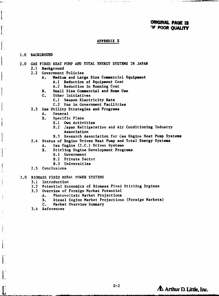
OROM PAGE 13IF POOR QUALITY
E APPENDIX E
F
1.0 BACKGROUND
2.0 GAS FIRED HEAT PUMP AND TOTAL ENERGY SYSTEMS IN JAPAN2.1 Background2.2 Government Policies
A. Medium and Large Size Commercial EquipmentA.1 Reduction of Equipment CostA.2 Reduction in Running Cost
B. Small Size Commercial and Home Uset C. Other Initiatives
C.1 Season Electricity RateC.2 Use in Government Facilities
2.3 Gas Utility Strategies and ProgramsA. GeneralB. Specific Plans
B.1 Own ActivitiesB.2 Japan Refrigeration and Air Conditioning Industry
AssociationB.3 Research Association for Cas Engine Heat Pump Systems
2.4 Status of Engine Driven Heat Pump and Total Energy SystemsA. Gas Engine (I.C.) Driver. SystemsB. Stirling Engine Development Programs
B.1 GovernmentB.2 Private Sector
i B.3 Universities2.5
tConclusions
3.0 BIOMASS FIRED RURAI: POWER SYSTEMS3.1 Introduction3.2 Potential Economics of Biomass Fired Stirling Engines3.3 Overview of Foreign Market Potential
A. Photovoltaic Market ProjectionsB. Diesel Engine Market Projections (Foreign Markets)C. Market Overview Summary
3.4 References
i
E
jt
E-2& Arthur D little, Inc.
OMNAL PAGE ISOF POOR QUALITY
FSELECTED FOREIGN APPLICATIONS OF STIRLING ENGINE TECHNOLOGY
Fi1.0 BACKGROUND
The Stirling engine applications stud of this report focussed on domesticg g PP Y P
applications of Stirling engines. Clearly, if Stirling engines are succes-
sfully developed they would eventually be used on a worldwide basis. This
larger potential world market could provide a major incentive for industry to
develop specific Stirling engine systems. There are reasons to believe that
some applications of Stirling engines may become commercialized abroad before
they are accepted in the U.S. for a variety of economic and needs oriented
reasons. This could result in foreign manufacturers applying the results of
the large U.S. Stirling engine technology program to Stirling engine applica-
tions for foreign markets and possibly even eventually exporting systems to the
U.S. as the market develops.
In this appendix two examples of potential foreign applications are briefly
discussed.
(a) Gas Fired Heat Pumps and Total Energy in Japan
(b) Biomass Fired Rural Power Systems
Japan is giving considerable emphasis to developing gas fired heat pumps and
total energy systems in order to even out large seasonal variations in elec-
trical and gas loads. The government is providing significant incentives to
accelerate the commercialization of residential and commercial size systems and
` Stirling engines are being given special emphasis for the lower capacity
systems.
There is an increasing need for providing small amounts of power in rural areas
of developing countries for such critical functions as irrigation pumping, cold
storage, and village lighting. Simple biomass fired Stirling engines (possibly
using hot air engine configurations) coulu serve this need as an alternative to
Diesel generators in those heavily wooded countries having ample biomass
resources.
E ° Arthur DL little, Im

2.0 GAS FIRED HEAT PUMPS AND TOTAL ENERGY SYSTEMS
fi2.1 Background
There is a great deal of ir.tirest in Japan in expanding the use of gas fired
air conditioners, heat pumps, and total energy systems. Moat commercial
practice to date is with absorption air conditioning systems. The market for
absorption units (primarily comrercial sizes of 20-100 Tons) is about 5,800
units per year.
Policies and strategies of Uses Japanese government and the Ministry of Interns-
i tional Trade and Tndust- •. (MITI) concerning gasified air conditioning and total
energy were set in j ;)80 They called for one third of total air conditioning
energy needs to be -3upplied by gas by 1900. The reasons for this policy
were:
(a) To even out the consumption of both gas and electricity on a seasonal
basis and, thereby, more effectively use production and transmission
facilities.
(b) To save on oil imports and increase the use of LNG for which favorable
long-term import contracts were being established.
At the beginning of 1481, the government announced definite plans to promote
the use of gas driven air conditioning systems. Two primary goals of these
plans were to (i) reduce the equipment cost difference between electrically and
gas driven systems and (it) to develop a small size engine driven heat pump
system. for residential and light commercial applications.
2.2 Government Policies
Consistent with the above general goals, the government, in cooperation with
Industry, set out to both encourage highly focussed RED activities and to
establish policies which would encourage the use of gas fired heat pump and
E-4 A Arthur U Ut*, Inc.

total energy systems. Specific resources either implemented or under active
consideration are discussed below.
A. Medium and Large Size Commercial Equipment (more than 50 tons of
cooling capacity)
A.1 Reduction of Equipment Cost
o Foundation of low interest funds through Japan Development Bank
Gas fired sir conditioner was picked up as one of the subjects of
application of low interest loan for the promotion of alternative
energy use.
o Foundation of low interest funds through the municipal treasury for
minor enterprises.
o Tax deduction or special depreciation system
Under the taxation system for promotion of investment within energy
management policy, the special tax deduction or special depreciation
system can be applied for new investments
o Deduction of fixed property tax
The gas fired air conditioning equipments having certain specifica-
tions can be an applicable equipment of the deduction system of the
municipal fixed property tax for energy saving equipment
A.2 Reduction of Running Cost
o Exemption of Gas Tax
Gas tax (2 percent of total consumption) will be exempted if the gas
is supplied under the contract for air conditioning use in summer
E-5 A ArdiW n Ut&, Im

3-3f'^°^'^,--^ -r^^s^.: €°^-3:-^t -_a^^^ - -^-^.^^ .-:-^^-_ ^ ^•^-^^.^: -^'- ., .mss ..T:- _ ^
rte.
+. i,.
G
o Discount Gas Rate
C
Gas rate will be discounted under the contract for air conditioning
^. use in summer called load adjustment contract.
B. Small Size Commercial and Home Use Equipment
So far the small size gas fired absorption type cool/hot water suppliers
have less cost competitiveness than electric motor driven heat pumps.
Then, MITI supported and subsidized the establishment of the "Research
Association for Gas Engine Heat Pump System." As for the detail of this
r research association refer to 2.3.
C. Other Initiatives
tC.1 Seasonal Electricity Rate
The electricity rate for commercial use in July, August, and Septem-
ber is 10 percent higher than other months to reduce the air condi-
tioning electricity needs in the summer.
C.2 'ise in Government Facilities
The Ministry of Construction changed the specification of machinery
facilities for governmental use and added gas fired air conditioning
system as standard.
2.3 Gas Utility Strategies and Programs
A. General
There are 248 ga g utilities in Japan with only three having a dominant
E position. All three utilities (Tokyo Gas, Osaka Gas, and Tomo Gas Com-
panies) are quite enthusiastic to spread the use of gas engine driven heat
Fpumps and total energy systems.
E-6it ArtWr Dt UDC, L=

r
r
CI
B. Definite Plans
The major gas utilities are pursuing their interest in gas driven heat
pumps/total energy systems through a number of initiatives with the
government and industry. These are discussed briefly below.
B.1 Own Activities
i1
iftf
o The utilities changed their organizations and established new sections
for development and use of gas engine driven heat pumps and total
energy systems.
o The utilities are actively installing and testing gas engine driven
heat pumps for their own use developed by collaboration with equip-
ment manufacturers.
o The utilities are publishing technical papers and brochures for the
advertisement of gas engine driven heat pumps and total energy
systems.
B.2 Activity Through the Japan Refrigeration and Air Conditioning
Industry Association
o The utilities organized a study tour to West Germany for gas engine
driven heat pumps and total energy systems and published the
report.
o The utilities tied up with equipment manufacturers and published
guide book of gas fired absorption type cool/warm water supplier.
B.3 Activity Through the Research Association for Gas Engine Heat Pump
System
o The general R&D goals of this organization were established as:
1981: Basic design prototype system test with 900 million yen ($3.5
million)
Nk-
c
E-7 AL A tiiur D. ut&, im

1982: Advanced model and field test model tests With I billion yen
( $ 3.8 million)
1983: Field Test with 800 million yen ( $3.1 million)
o Targets of the development program
COP for home use (1-2 USRT class)
Cooling 0.85
Heating, Hot Water 1.37
COP for small size commercial use (8-190 USRT class)
Cooling 0.90
heating , Hot Water 1.57
Span of Life: 10 years
Maintenance: 1 time per year
Exhaust Gas: Equivalent to boiler exhaust
Noise Level
Home Use: Less than 50 DB
Commercial Use: less than 60 DB
o Major R/D Items of the Development Program
Matching of engine and compressor
Development of multi-vane rotary, rolling piston and screw
compressor
Development of dedicated engines
Development of the system fully utilizing wasted heat of engine
E-8 /e Araw a lama, Im

o Members of
3 major go6 engine manufacturers
7 compressor manufacturers
2.4 Status of Engine Driven Heat Pump and Total Energy Systems
Both I . C. engine and Stirling engine driven heat pump and total energy
system developments are being pursued in Japan. There appears to be good
agreement that while I.C. engine driven systems might be applicable for larger
capacities (50 Ton+) their use In smaller sizes is still open to question.
Therefore, most efforts for Stirling engine developments are focussed in
smaller cr .pacity units (3-30 W. The status of both I.C. engine driven and
Stirling engine driven system is discussed briefly below.
A. Gas Engine (I.C.) Driven Systems
About 15 internal combustion engine driven heat pumps with capacities ranging
from 20 to 170 tons have been installed over the last few years (Table 2.1).
All systems are for cooling /heating use as in electric motor driven heat pumps
except the last one which is for heating use only. System prices are notavailable but are still quite expensive since a significant commercial practice is
not yet established.
Currently Komatsu, Kinmon, Nippon Kokan, Sanyo Electric, Shinko Zoki, Kobe
Steel, Maekawa Seisakusho are trying to promote the sales of gas engine
driven heat pumps and total energy systems.
Sales of commercial size systems are expected to increase partly as a result of
favorable policies. It is hoped that the small size home use system will be
l
marketed from 1984 or 1985 after the research (at Research Association for gas
engine heat pump system has been successfully completed.
E-4ALArthur a uu* i^c.__ -

I
1.
i
I
Table 2.1
INSTALLATION OF ENGINE DRIVEN HEAT PUMPS IN JAPAN
NUMBER CAPACITY
YEAR (Tons) MANUFACTURER
1980 1-30 USRT Kinmon Seisakusho
1981 1-170 Nippon Kokan
1-18
1-41 Komatsu
1-20
1-33 Niigata Tekko
1-160 Komatsu
2-110
1982 1-70 Komatsu
1-20
1-70 Komatsu
1-41 Kinmon Seisakusho
1-169 MCAL/H Kinmon Seisakusho
E-10
/^ ArtWr DX Little, Inc.

B. Stirling Engine Development Programs
The government, private industry, and universities are working collaboratively
to develop Stirling engine systems - primarily for heat pump and total energy
systems for residential and light commercial applications.
B.1 Governmental
Under the MITI's Moon Light project, industrial technology board set the R&D
program with the budget of 10 Bil Yen ( $40 million) for 6 years beginning
from 1982.
The program consists of two parts. One is to undertake studies at the
national laboratories, and another is at private companies' laboratories under
the control of New Energy Development Organization (NEDO, established in
1980, Special Public Corporation.
o Target of Development
A-1 for air conditioning use
- Capacity: 3 W. 30 kW
- Efficiency
- Duel: Natural Gas
- COP, Cooling: 1.43, 1.57 incl. hot water supply
- COP, Heating: 1.49, 1.63
- Exhaust Gas: Equivalent to boiler exhaust
- Span of Life: 10 years
- Maintenance: 1 time per year
- Noise Level: 45 DB, 60 DB
A-2 for other use
- Capacity: 30 kW
- Efficiency: 0.37
Other spec is the same as air conditioning use engines
o Study items are:
- Components design, developrint
E-11 /^► Arthur Q I3tde, Inc.

I.C
- System design, development- Development of small size air conditioning plant using heat pump
ard Stirling engine
- Assessment and evaluation of the proper system
+ - Use of variety of fuels
o Program Schedule is:
- At the end of 1984, intermediate evaluation of the study will be
done, and the proper Stirling engine will be selected.
- By the middle of 1987, the practical Stirling engines will be
developed and completely tested.
I. B.2 Private Sectnr
Several private companies are both supporting the MITI sponsored effort in
Stirling engine development and doing their own R&D. The major corporate
efforts in the Stirling engine field are:
t Aisin Seiki:
Developing Automotive use and industrial use engines. Has a
collaboration program with Tokyo Gas Company.
Mitsubishi Electric:
Developing air conditioning heat pump use Stirling engine. Currently has
the one with 1.5 kW output using the gas at 1.5 MPASCAL between 650%
and 50°C.
Kawasaki Heavy Industries:
Aiming at the air conditioning applications and has a cross licensing
agreement with Sunpower Corporation of the United States.
In addition to the above, all the automotive manufacturers have had at one
time or another a Stirling engine program. These programs have usually
involved afsessing the potential for Stirling engines in automotive applications
and ;have not resulted in significant hardware oriented programs.
E-12/d Arthm D. L3t*, Inc.

B.3 Universities:
Several Universities are also working with MITI and the gas companies in the
Stirling engine field. Two such activities are:
A. Meiji University: Developing a 6 kW Stirling engine for solar power
applications.
B. University of Tokyo: Supporting Tokyo Gas and developing a
Stirling engine with 7.02 kW/120 rpm output for commercial heat
pump applications.
2.5 Conclusions
The Japanese are actively pursuing the development of Stirling engines for
heat pump and total energy applications. In this effort they are closely
reviewing the experience in Stirling engine technology in the United States and
Europe and adapting this experience to their own needs in, at least. one case
via license agreements with a U.S. company.
Government policies relative to gas pricing, R&D funding, and taxes have been
developed to accelerate the introduction of gaR fired systems (Stirling engines
and others) so that. by 1990, they would displace 30 percent of the electricity
now used in air conditioning functions. This could result in a market for over
50.000 units per year in residential and commercial applications with a capacity
of about 500 MW (assuming average system size is 10 kW; i.e.. sales weighted
toward light commercial, institutional, and central multifamily units). Pursuing
this policy could provide Japanese industry with a strong position in Stirling
engine technology so that by the mid to late 1980's, efforts to use natural gas
in similar manner in the U.S. might well be based on Japanese technology.
E-13
Li

NE0*4
3.0 BIOMASS FIRED RURAL POWER SYSTEMS
1.0 Introduction
There has been increasing interest over the last few years in alternative
approaches for providing e»all amounts of power to rural populations in devel-
oping countries. The critical needs for power in such areas include irrigation
Ipumping, refrigeration of produce, and minimal villaeco ar home lighting. In
I many cases the amounts of power needed are quite small so that the provision of
1-10 kW of power for a few hours a day would suffice.
} In the past such minimal power needs were often satisfied by operation of small
Diesel generators or extension of the grid, (if they were satisfied at all).
More recently there has been increasing interest in using photovoltaics to
ssatisfy these distributed low power needs. Photovoltaice are technically vary
well suited for such applications due to their lack of moving parts with
resultant potential for long, almost maintenance free, operation.ii
The costs of photovoltaic power units are, houm!ver, quite high with system
costs now being about $20,000-$30,000 per peak kW. These costs are, however,
projerted to decrease greatly by the mid 1960's to $3,000 to $6,000 per peak
kW. At these lower costs, photovoltaics could be a very attractive option for
supplying critical power needs in rural areas of sunbelt countric-
An alternative system for using indigenous resourcea to provide small amounts
of power in rural areas would be a biomass (wood, charcoal, rice husks, etc.)
fired Stirling engine. Such a system would have the advantage of being able to
provide power on demand even during periods of cloudy weather or at night. As
indicated in the following discussion, a reliable biomass fired Stirling engine
might be a lower cost option than photovoltaics in those countries with large
biomass resources. Such countries include those in the rain belt areas of the
tropics in Africa, Latin America, and parts of Asia. There could be a large
market, therefore, for such an engine in the 1-10 kW output range if!
o Its operation were simple enoug`: for use by rural populations.
o Its desig- • was consistent w',-''.! maintenance and repair in the field.
E •14
/K Artwr DL 11th a im

Several Stirling engine systems under development, particularly those low power
density systems using air as the working fluid could meet these requirements.
3.2 Potentiel Economics of Biomass Fired Stirling Engines
The Stirling engine, diesel engine, and photovoltaic options for rural power
generation differ greatly in initial cost, fuel form, fuel cost, system life,
and operations and maintenance costs. A summary of these characteristics for
each system is g_ven in Table 3.1. The Stirling engine costs shown are prelim-
inary estimates based on discussions with firms developing such engine and
comparison of Stirling engine configurations with I.C. engines in a similar
power range. The photovoltaic systems costs are industry projections for the
1986 time period when a commercial biomass fired Stirling engine might become
available. The size range of systems being considered for rural applications
is up to 50 W. It is assumed for economic calculations that, on the average,
the engine generation systems will provide about 3000 kWh per installed kW
annually (8-10 hours per day operation), and the photovoltaic systems will
provide about 1600 kWh per peak kW annually corresponding to daily operation in
a sunny location. In order to judge the competitive position of Stirling
engines relative to diesels and photuvoltaics, an economic analysis comparing
them is presented here. The economic index utilized is the levelized cost of
energy (LCOE),^18)
The levelized cost of energy evens out the varying costs associated with the
system over fts lifetime into an equivalent, uniform cost stream before cal-
culating the cost of energy from the system ( in $/kWh).
This process has the advantage of being able to compare systems with widely
differing initial costs, fuel costs, and maintenance schedule* on an equal
footing. The LCOE is the sum of the present values of the original set of
periodic costs, multiplied by the required capital recovery factor, then
divided by the annual energy output. Here, a discount rate of 15 percent is
E-15
& Art= U Link, Inc.

0mGWM PAGE 0OF POOR QUALITY
Table 3.1
CHARACTERISTICS OF PHOTOVOLTAIC, STIRLING ENGINE, AND DIESEL ENGINESYSTEMS
STIRLING DIESEL PHOTOVOLTAICS (1986+)ENGINE ENGINE $5/Wp Cells $3/Wp Cells
Initial System Cost
5-10 kW $1800/kW1 $800/kW2 $7200/kWp3 $4500/kWp340-50 kW $ 800/kW $300/kW $7200/kWp $4500/kWp
i_ Annual Operation and Maintenance Costs
l5% Initial Cost 10% Initial Cost 2% Initial Cost
Overhaul Every5000 bra of Opera-tion @ 30% InitialCost
"i
Fuel Form Biomassµ Diesel Fuel Solar Energy
- Fuel Etficienc 10-15% 20 -251% -5
Fuel Cost Free or Varies byLow Cost Location
System Life 10 years 10 years 20 years
ADL estimates, includes engine cost plus biomass combuster controls andinstallation.
2. Includes engine cost plus controls and installation.j 3. Includes solar cell Array, power conditioning and controls, buffer battery
storage, plus installation.4. Stirling engine can utilize a number of fuel forms, however, biomass is
assumed to be the principal fuel here.5. It is assumed for this study that the PV system operates in a reasonably
good insolation area, providing 1600 kWh/kWp, annually.
E-16

used to calculate the present values. and inflation is assumed to average 8
` percent during the time period considered. Fuel rates are assumed to increase
at the inflation rate. The results of the LCOE calculation for large and small
^.' diesel and Stirling engines, and for an equivalent photovoltaic system (using
the data given in Table 3.1) are shown in Figure 3.1. These curves all assume
ithat the local biomass fuel is obtained at no cost. Using this assumption, as
diesel fuel prices increase about $1.25 per gallon, even the small Stirling
engine is competitive with the diesel engine. Biomass powered Stirling engines
at $1800/kW installed are much cheaper to purchase and operate than equivalent
photovoltaic systems installed at $4500/kWp, on a levelized cost of energy
basis if the biomass fuel for the Stirling engine can be obtained at zero cost.
Based on the economic analysis of system options, it is apparent that the
Stirling engine, even at $800-1800/kW, is in a good competitive position for
foreign power markets where small diesel engines and photovoltaics are now
being considered.
3.3 Overview of Foreign Market Potential
A list of some of the potential applications for biomass fired Stirling engines
is given in Table 3.2. These applications are presently being addressed by
photovoltaic systems and/or diesel engines. In this section the present and
projected sales of diesel engines and photovoltaic power units into these
market segments is re-iewed. These estimates provide a practical upper limit
to the potential for biomass fired Stirling engines. The St-cling engine
market was then estimated by assuming a modest percentage of the die-
sel/photovoltaic market would be served by Stirling engines if an engine with
the required characteristics were made available. The intention of this
exercise is primarily to provide a highly preliminary sense of potential market
size and to indicate that these markets are of sufficient magnitude to be of
commercial interest.
A. The Photovoltaic Market Potential
The NASA/Lewis Research Center (LeRC) has been supporting both DOE and USAID in
E-17^DtUnk,Im

ORIGINAL PAGE !SOF POOR QUALITY
$3/Wp PHOTOVOLTAIC
50
45
SMALL DIESEL
40
x35
c^
W 30zw
w _
O 25 LARGE DIESELH ^
OU t
a
a 20w
aw
15 SMALL STIRLING (ZERO FUEL COST)!
a
10i
LARGE STIRLING ( ZERO FUEL COST)
5
0 0.5 1.0 1.5 2.0 2.5 3.0 3.5 4.00rDIESEL FUEL COST, $/GAL
Figure 3.1 LEVELIZED COST OF ENERGY AS A FUNCTIONF FUEL COST r o Brat onannua ly
E-18

Table 3.2
UNTRY APPLICATIONS OF RURAL POWER SYSTEMS
Irrigation and Potable water Pumping
Prime and Standby General Village Power
Agriculture, Small Industry, Construction and Mining
comunications
Consumer Products
Corrosion Protection and Marking and Warning Devices
SOURCE: Arthur A. I,ittic, Inc. and Referenr pa 7, ll, and 14.
E-14
AArdw

1i
developing photovoltaic power units for use in both domestic and international
applications and overseeing the installation of field demonstrations. (1.2.3)
LeRC has and continues to undertake country specific market studies for
photovoltaic systems in order to ensure proper selection of systems for
development.
Early work by LeRC analyzed the energy needs of developing countries and
focused on these countries that do not have the ability to meet those needs
`
using domestic fossil fuel, nuclear or hydro power. The technical suitability
of solar energy for these countries was then examined in order to estimate
their solar market potential. (3)
Specific applications, such as water pumping,
were also examined in detail. (4)
This study concluded that the near-term
domestic market for photovoltaic systems for waste water treatment and drain-
age, potable water, and crop irrigation alone, using the estimate of 100
million small (1/3 to 1/2 hp) pumping systems required for irrigation in thee
LDCs, was 6000 MWp . In addition to point out the importance of the LDC market
to the total world market for photovoltaic water pumping systems, Rosenblum, et
al, observed that the World Bank directly or with client countries financed in
the LDCs $3,595 million of agriculturalg projects in 1976. The World Bank alonet
financed $743 million of irrigation projects and $347 million of water re-
sources and sewage projects in the same year.
LeRC has more recently undertaken detailed market studies for cottage indus-
tries (5) and village power. (6) The market assessment study for cottage indus-
tries (5) concluded that, although the existing near-term photovoltaic (PV)
market is estimated to be 70.000 MW, this potential will probably not as a
practical matter be approached within the next decade. The study defining the
market for PV village power (6)
concludes that up to 1,000 MWp of the total
village potential (20,000 MWp) can be penetrated over the next 10 years
(1980-1990). Barriers to market penetration mentioned include unfamiliarity
with PV systems, preference for grid extension, and the need for PV to be
experienced as a demonstrated technology. The lower end of the 1990 range is
MW - Peak megawatts of photovoltaic capacity. A "peak" megawatt is
capacity measured under bright midday solar conditions.
!1
t E- 20 & Arthw Dt UlNe., hm

consistent with the Pacific Northwest Laboratory Export Potential for
Photovoltaic Power SystemsO (PNL) study figures for the village power market
potential. The PNL study additionally includes market potential figures for
r other applications as well.
Of the recent major photovoltaic foreign market studies (7 ' 8,9,10) the most
detailed is the PNL report. ( ) The results of all the PV market studies
mentioned are reasonably consistent in their identification of major market
areas, consequently the PNL study is discussed here.
The PNL report examines the market for PV technology for those applications of
kcurrent interest (communications, corrosion protection, marking and warning
devices, and consumer products) and applications that are expected to develop
or whose economics may improve (water pumping and general village powerI
sources). The study is based on (1) data gathered by personal and telephone
interviews in the Urited States with PV manufacturers, distributors, and system
houses as well as with current customers of PV systems such as telecommunica-
tion companies, oil and gas companies, pipeline companies, and navigational aid
manufacturers, (2) potential customers including international development
agencies and (3) DOE representatives who participated in ISCWG field visits
abroad. Table 3.3 summarizes some of the key results of this study.
Although current applications are dominated by communications alone, (11)
the
market projections of Table 3.3 demonstrate that water pumping is anticipated
to grow very quickly and to exceed communications by almost a factor of 2 by
1982. By 1986, current applications are projected to total 14.2 MW p , while
water pumping and village power are given as 39.0 MWp , almost a factor of 3
increase. At $4!MWp installed, (8) this is a market of over $200 million in
1986. By 1990, most of the foreign PV market is associated with water pumping
and village power (103 MW out of a total of 129 MWp).
Compared with PV, Stirling engines occupy a good competitive posit{on according
to the economic criteria discussed previously (Section 3.2). Thu-3, where the
i
E E-21 _

e
^ r
-r ORIGIN R QV^^OF pOO
1990
L M H
9.0 78.0 250.0
3.0 25.0 100.0
8.0 11.0 15.0
6.0 8.5 11.0
1.6 2.8 4.5
2.4 3_5 4_4
i
is
Table 3.3
FOREIGN PV MODULE MARKET PROJECTIONS
(in Peak MW)
1986
L M H
1. Water Pumping 3.7 29.0 88.1
2. General Village
Power Source 0.9 10.0 24.0
3. Communications 5.2 7.5 9.5
4. Corrosion
Protection 3.2 4.5 4.9
5. Marking and
Warning Devices 0.5 1.2 2.2
6. Consumer
Products 0.7 1.0 1.3
TOTAL 14.2 53.0 129.9
3C.0 129.0
384.9
(Reference 7)
E-22
/^ Arthur U Lithe, Lac.

Stirling engine is applicable, the limit!ng factors to market penetration will
'
he biomass availability, commarcial readiness, and the relative level of
acceptance of Stirling engines. With this in mind, a penetration level of 15
percent of the PV market potential wee assumed, with an average Stirling engine
size of 5 kW, and an average cost of $1000/kW. The results of the Stirling
engine share of the PV potential market are shown in Table 3.4. As indicated,
this segment of the market may $11 million annually by 1990.
CB. The Diesel Engine Market Potential
There isresentl a large worldwide market for small diesel engines andP Y 8 8
generator sets, which are used in the range of applications indicated in Table
3.2. Although a significant amount of diesel engine market research has been
carried out by Diesel Progress North American, in cooperation with Power
Systems Research, Inc., (12,13,14)
a good deal of the small diesel market import
information for developing countries is not readily available. However,
reasonable estimates of the developing country market potential can be made
based on available information from Diesel Progress and the :.'-._ted States
Department of Commerce. (15)
An estimate for the 1980 free world production of diesel engines of all types
is about eight million engines, with the United States producing about 900,000
of these. The United States exported roughly 15 percent of its diesel engines
in 1980. 14) These U.S. figures can be used as a rough indicator of worldwide
figures. Assuming a similar rate of export for diesel engines worldwide, about
1,200,000 diesels were exported in 1980, and perhaps 600,000 of these were in
the size range under consideration. The United States sends about 30 percent
j of its total small diesel engine exports to developing countries, with the
1
remainder going to industrialized countries. (15)
Assuming this percentage is
similar for world exports as a whole, about 180,000 small diesels were exported
to developing nations in 1980.
United States diesel engine production. even with the current hiatus in the
domestic diesel market, will grow in the near-term, and is expected to double
over 1990 levels to about 1.8 million engines by 1990, with about 200,000 small
I E-23

A.-
1 engines in 1985, and 360,000 small engines in 1990 being exported to developing
( countries out of these totals. These assumptions lead to a developing country
export market for small diesels of 4,000 MW in 1985 and 7,200 MW in 1990, with
an average engine size of 20 kW. (14)
Employing these rough calculations to give "ball park" market figures, it is
evident that there is quite sizeable diesel engine market potential in the
developing countries in the near-term. Compared with diesel engines Stirling
engines can be competitive especially in areas with sufficient biomass and high
petroleum product prices. It is reasonable to assume that, where these con-
ditions exist, it is possible foi Stirling engines to displace about 10 percent
of this diesel market potential. With an average Stirling engine size of 5 We
and an average cost of $1000/kW, the Stirling market may be worth $ 180 million
by 1990, and have a capacity of 180 MW. This diesel market information is
C summarized in Table 3.4.i
C. _Market Overview Summa►
The value of the potential foreigr fiarket fur Stirling engines may total nearly
$200 million ( 200 MW) by 1990 assuming biomass fared Stirling engines
successfully competed in 10-15 percent of the applications now or projected to
be served by Die:_ 1 engines and photovoltaics.
As indicated by Table 3.4, the future potential of biomass fired Stirling
engine is strongly dependent on the ability to compete with Diesel pumps and
generator sets in developing country markets. The reason for this is that the
annual capacity of small diesel engines is projected to be a factor of 50
larger than for photovoltaic power units even in 1990 based on the photovoltaic
market estimates cited. This points out the large growth potential for both
photovoltaic power systems and biomass fired Stirling engines in serving the
diverse curs] power needs in developing countries.
E-24/^ Arthw Q Little, IM

OF POOR QUALITYTable 3.4
OF POTENTIAL WORLDWIDE MARKET FOR_ESTIMATE SMALL STIRLINGENGINES FOR 1915 and 1
1986 1990
PHOTOVOLTAICS
Photovoltaic Market Potential, MW 1 42 129% Applicable to Stirling 3 p 15% 15%
( Potential Stirling Capacity, MW 4 3 11Estimated No. of Stirling Enginse 600 2,200Value of Stirling Market ( $000) 3,000 11,000
f^f DIESEL ENGINES AND GENSETS ( 50kW or 65hp)l
No. of Diesel Engines6 7 200,000 360,000Estimated Capacity, MW 2 4,000 7,200% Applicable to Stirling 10% 10%Potential No. of Stirling Engints 20 , 000 36,000Estimated Stirling Capacity, MW5 100 180Value of Stirling Market ( $O00) 100 , 000 180,000
tTOTAL POTENTIAL VALUE OF STIRLINGMARKET ( $000) 103 , 000 191,000
NOTES:
1. Source: PNL, "Export Potential for PV Systems," 4/79, p. 2.6, mediumscenario, interpolated for 1985.
2. ADL estimate, based on economic analysis.3. Assumes 8-10 hr /day, 350 day/yr Stirling generation and 1600 kWh/kWp
annual PV system output.4. Assumes average Stirling engine size of 5 kW.5. Assumes average Stirling engine cost of $ 1,000/kW.6. Based on information on U.S. and World diesel markets from Diesel Pro-
gresa and Power Systems Research, Inc. (See text).7. Assumes an average of 20 kW per engine /genset, a reasonable average
size based on engine data from Diesel Progress.
l
r
E-25

OIMMU PAGE 0Of POOR QUALITY
f REFERENCES
1. "Description of Photovoltaic Village Power Systems in the United Statesand Africa," R.F. Ratajczak and W.J. Bifano, DOE/NASA/20485-79/1, April1979.
2. "Photovoltaic Power Systems for Rural Arose of Developing Countries," L.Rosenblum, W. J. Bifano, G., F. Hein, and A.F. Ratajczak, NASA TechnicalMemorandum 79097, February 1979.
3. "Utilization of Solar Energy in Developing Countries: Identifying SomePotential Markets," G.F. Hein and T.A. Siggiqi, DOE/NASA/1022-78/41,February 1978.
4. "Photovoltaic Water Pumping Applications: Assessment of the Near-TermMarket," L. Rosenblum, W.J. Bifano, L.R. Scudder, W.A. Poley, and J.P.Cusic, DOE/NASA/1022-78/29, March 1978.
5. "International Market Assessment of Stand-Alone Photovoltaic Power Systemsfor Cottage Industry Applications," T.M. Philippi, I1T Research Institute,DOE/NASA/0197-1, November 1981.
6. "Market. Definition Study of Photovoltaic Power for kemote Villages inDevelof Ing Countries," C. Ragsdale, P. Quashie, Motorola, Inc.,DOE/NASA/0049-80/2, October 1980.
7. "Export Potential for Photovoltaic Systems," Pacific Northwest Laboratory,DOE/CS-0078, April 1979.
8. "Photovoltaic Power System Market Identification and Analysis," BDMCorporation, HCP/M2533-01/1 and 2, November 1978.
10. "Photovoltaic Power Systems Market Identification and Analysis," ITC SolarHCP/T4022-01, January 1978.
11. "Baseline Study of U.S. Industry Solar Exports," T.M. Jacobius, R.S. Levi,and J.A. Bereny, SERI/SP-08331-1, October 1980.
12. "An Analysis of the Markets for Diesel and Related Engine Power SystemsEquipment in North America 19890 to 1985," Diesel Progress North Americanin Cooperation with Power Systems Research, Inc., May 1980.
13. "An Analysis of the Markets for Engine Generator Sets in the United States1978 to 1985," Diesel Progress North tmerican in Cooperation with PowerSystems Research, Inc., May 1980.
t 14. Based on information from Diesel Progress North American and Power SystemsResearch, Inc., obtained July 1982.
15. "U.S. Exports, Schedule E: C%;mmodity by Country," U.S. Department ofCommerce FT410/December 1981, issued April 1982.
R-1 A Arthur Dt Ut&, Im

REFORENCES (Continued)
15. "Market Assessweut of Photovoltaic Power System for Agricultural Applica-tions in Nigeria." DHR, Inc. and ARD. Inc. DOE /NASA/0180-4 , October 1981.
17. "Solar Energy Cossiercialization for African Countries." U.S. DOE,HCP/CS-2522, Decesiber 1978.
18. "SWECS Cost Of Energy Based on Life Cycle Costing." U.S. DOE,3120/3533/80-13, May 1980.
R-2
/^ Arthur D^ Little, Lac.