TRAININGCENTER - NASA Technical Reports Server
248
NATIONAL AERONAUTICS AND SPACE ADMINISTRATION MANNED SPACE FLIGHTNETWORK TRAINING CENTER STUDENT REFERENCE MANUAL for, APOLLO i ., MSFN INDOC TRINA TION f_ GODDARD MT-304-R April 1967 Prepared for SPACE FLIGHT CENTER, GREENBELT, MD. Restriction/Classification Cancelled
-
Upload
khangminh22 -
Category
Documents
-
view
2 -
download
0
Transcript of TRAININGCENTER - NASA Technical Reports Server

NATIONAL AERONAUTICS AND SPACE ADMINISTRATION
MANNEDSPACEFLIGHTNETWORK
TRAININGCENTER
STUDENT REFERENCE MANUAL
for,
APOLLO
i .,MSFN INDOC TRINA TION f_
GODDARD
MT-304-R
April 1967
Prepared for
SPACE FLIGHT CENTER, GREENBELT, MD.
Restriction/Classification Cancelled

The material contained in this manual
is for TRAINING PURPOSES ONLY.

Section
I
II
III
IV
V
VI
VII
VIII
IX
X
XI
TABLE OF CONTENTS
APOLLO PROGRAM
Vehicle Assembly Building, Cape Kennedy
Lunar Landing Mission
RADAR SYSTEMS
Binary-Octal-Decimal Conversion
SITE CONFIGURATIONS
USB ANTENNAS, A.P.P.
Introduction To The Unified S-Band System
Unified S-Band Antennas
UNIFIED S-BAND (UPLINK)
Uplink
UNIFIED S-BAND (DOWNLINK)
Downlink
COMMAND SYSTEMS
Apollo Digital Command Systems
COMPUTER SUBSYSTEM
CP-642B Computer
Quick Reference Data
2010 Data Transmission Unit
1540 Magnetic Tape
Univac 1232 Input/Output Console
1259 TTY
Basic Digital Computer Terminology
ACQUISITION SYSTEM VHF RECEIVER
TELEMETRY SYSTEMS
Principles of Telemetry
DISPLAYS AND RECORDERS
Page
2-12
5-1
0-1
7-1
8-1
8-7
8-11
8-12
8-13
8-15
8-19
10-1

Section
XII
XIII
XIV
TABLE OF CONTENTS (Cont.)
SPACE PROTON ALERT NETWORK
Solar Particle Alert Network
Apollo Solar Terminology
NETWORK COMMUNICATIONS
GLOSSARY
12-1
12-13
ii

Code
AI-003
AI-021A
AI-032
AI-001
AI-033
AI-002
AI-035
AI-022
AI-036
AI-005
AI-00 6
AI-004
AI-007
AI-043
AI-008
AI-009
AI-010
AI-011
AI-012
AI- 016
AI-018
AI-019
AI-045
AI-20
AI-04 2
LIST OF ILLUSTRATIONS
Title
SectionI
Vehicle Assembly Building, CapeKennedy
Complex 39 Launch PadSaturn 1B Launch Vehicle
Saturn V
Apollo Spacecraft SeparationPlanes
Launch Escape Tower, CommandModule, ServiceModule, and Lunar Module
LM Interface and Explosive Device LocationsCommandService Module
General Arrangement CommandModule
Launch Escape System
Abort Separation FunctionsNormal Tower Jettison
Earth Ascent Phase Description
CommandService Module/S-IVB Separation
Elapse Time Sequence
Earth Vicinity and Translunar Mission Description
Lunar Vicinity Mission Description
LM Descent Phase Description
Lunar Stay Communications
Transearth and Entry Mission Description
Mains DeployedReefed
Earth Landing
RecoveryUnified S-Band Stations
Apollo Mission SupportAssignmentsNetwork Evolution
iii
Page
1-1
1-6
1-24
1-25
1-26
1-27
1-28
1-29
1-30
1-31
1-2P.
1-33
1-34
1-35
1-36
1-37/1-38
1-39/1-40
1-41
1-42
1-4 3/1-44
1-45
1--46
i --47
1--48
1-49
1-50

Code
RDS-002
RDS-001
RDS-008
RDF-014
RDF-007
RDS-005
RDS-004
RDS-003
RDF-005
RDF-001
RDF-002
AI-031
AI- 041
AI- 040
LIST OF ILLUSTRATIONS (Cont.)
Title
Section II
Radar Set AN/MPS-26 (XN-1) TrailerFPS-16 AntennaPedestal
FPQ-6 Radar Antenna
Pointing Data for Network Radars
Azimuth, Elevation Angles and SlantRange in theRadar Plane
13-Bit Optical Encoder
8-Bit Mechanical Encoder
Radar Set AN/FPS-16, Block Diagram
Digital-To-Teletype Converter
Radar Tracking System Without D-C AnalogData Transmission
Radar Tracking System With D-C Analog DataTransmission
Section III
Remote Station Configuration
Apollo Ships, Block DiagramApollo Aircraft Relay
Page
2-1
2-2
2-3
2-4
2-5
2-6
2-7
2-8
2-9
2-10
2-11
3-1/3-2
3-3/3-4
3-5
AI-107
PAS-001
ALB-011
AI-101
AI-114
ALB-019
ALB-005
ALB-023
Section IV
Simplified Apollo Unified S-Band System
Typical USB Layout
30-Foot Antenna Structure
USB Land Based Antennas, Technical Characteristics
Land Antenna Performance
30-Foot Antenna Servo Drive, Block Diagram
Antenna Servo Control Console Layout
Antenna Servo Control Unit
4-3
4-7
4-8
4-9
4-10
4-11
4-12
4-13
iv

Code
AI-102
APP-101
APP-102
APP-103
APP-107
APP-106
SBA-100A
SBA-100B
AI-101
SBA-164
SBA-115
LIST OF ILLUSTRATIONS (Cont.)
Title
Section IV (Cont.)
USB System 30-Foot Antenna Facility
Antenna Position Programmer, Subsystem, Block
Diagram
USB System Antenna Position Programmer
Antenna Position Programmer
Antenna Position Programmer Control Panel (Local)
Antenna Position Programmer Control Panel (Remote)
30-Foot, USB Shipboard Antenna
12-Foot USB Shipboard Antenna
USB Shipboard Antenna, Technical Characteristics
Antenna Feed System
SB-42 Control Console
Page
4-14
4-15
4-16
4-17
4-18
4-19
4-20
4-21
4-22
4-24
4-25
I
II
II
I
II
R&E-101
R&E-102
R&E-103
AI-046A
APP-302
AI-059
PAS-101
AI-025
ATS-001
AI-104
R&E-101
R&E-104
AI-028
Section V
S-Band Frequency Chart
USB Individual Uplink
USB Dual Uplink
Uplink, Signal Flow
Up-data Buffer, Block Diagram
Subcarrier Oscillator Subsystem
USB Power Amplifier Group 11-076, Block Diagram
Ground System Characteristics
Apollo Precision Frequency Source
Time Standard, Block Diagram
Section VI
S-Band Frequency Chart
USB CSM Downlink
Spacecraft Transponder
V
5-2
5-3
5-4
5-5
5-6
5-7
5-8
5-9
5-10
5-11
6-3
6-4
6-5

LIST OF ILLUSTRATIONS (Cont.)
Code
AI-052
AI-053
AI-054
AI-055
R&E-105
AI-056
AI-057
R&E-106
R&E-107
AI-026
AI-030
AI-047
AI-050
RRR-003
RRR-002
AI-113
AI-116
AI-117
AI-115
Title
Section VI (Cont.)
Spacecraft To Ground Communications Requirement
CSM Transmission Combination Summary (PM Mode)
CSM Transmission Combination Summary (FM Mode)
Downlink CSM, Block Diagram
LM Downlink
LM Transmission Combination Summary
LM S-Band System
Emergency Key
Emergency Voice
Spacecraft Systems
Two-Way Lock
Downlink, Signal Flow
Data Demodulator, Block Diagram
Transmit Code Generator, Block Diagram
Code Acquisition, Timing Diagram
USB System Tracking Data Processor
USB 30-Ft. Antenna Station, Block Diagram
USB 85-Ft. Antenna Facility Primary Stations
USB 85-Ft. Antenna Facility Secondary Stations
Page
6-6
6-7
6-8
6-9
6-10
6-11
6-12
6-13
6-14
6-15
6-16
6-17
6-18
6-19
6-20
6-21
6-22
6-23
6-24
AI-0 24
AI-II9
AI-II8
Section VII
Command Word Structure (Stored and/or Real Time)
Apollo Digital Command System
Typical Remote Site Command Data Flow, Block
Diagram
7-3
7-4
7-5
AI-120
Section VIII
Apollo Data Processing System, Block Diagram 8-9/8-I0
vi

Code
RSDP-1002-A
AI-121
AI-122
ADS-001
AAT-001
VSR-001
PCM-001A
PCM-001
PCM-018
PCM-002
PCM-003
PCM-005
PCM-006
PCM-021
AI-125
ADS-005
ADS-006
ADS-007
ADS-008
ADS-001
ARS-125
ARS-100
ARS-309
LIST OF ILLUSTRATIONS (Cont.)
Title
Section VIII (Cont.)
Block Diagram, 1232 Console
Block Diagram Of Site Without Flight Control Console
Block Diagram, Console/Computer Interface Adapter
Apollo Display System Pictorial Diagram
Section IX
Simplified Systems Integration
Simplified Acquisition Aid System, Block Diagram
Section X
Simplified Telemetry System, Block Diagram
FM/FM Multiplexing
Block Diagram, Typical PCM System
Periodic Sampling
Sampling For Time Multiplexing
Wheel Diagram of PCM-003 and PCM-004
Wheel Diagram and Corresponding Matrix
Pulse Code Modulation Techniques
Typical Remote Site Telemetry Data Flow Block Diagram
Section XI
Command Communicator Console
Systems Monitor Console
Aeromedical Console
Flight Dynamics Officer's Console
Apollo Display System, Pictorial Diagram
Apollo Recorder, Model 22, Full Front View
Model 22, Tape Transport, Front View
Sanborn Recording System, Model 958D
vii
Page
8-14
8-16
8-16
8-18
10-20
10-21
10-22
10-23
10-24
10-25
10-26
10-27
10-28
ii-i
11-2
11-3
11-4
11-5
11-6
11-7
11-8

C ode
ROT-001
ROT-0 20
AI-1203
ROT-0 80
ROT-120
ROT-140
ROT-100
ROT-220
ROT- 200
TTO-001
TTO-003
TTO-004
AI-150
LIST OF ILLUSTRATIONS (Cont.)
Title
Section XII
Radiation Spectrum
Layers of the Sun
SPAN Observatory
Manned Lunar Flight
Solar Optical Telescope, Major Units and Systems
Selector Disc
Solar Optical Telescope, Block Diagram
Radio Telescope Antenna System, Rear View
Solar Radio Telescope, Block Diagram
Section XIII
MSFN Network Interface
494 Comm. Processor Interface System
l12A Key System Call Director
Apollo Communications Network Configuration
Page
12-4
12-5
12-6
12-7
12-8
12-9
12-10
12-11
12-12
13-1
13-2
13-3
13-4
°°.
Vlll

I . I
I I I I ~
Vehicle Assembly Building, Cape Kennedy
Since the pledge by the late President John F. Kennedy that Americans would
walk the lunar surface in this decade, many scientific people are combating the
numerous problems which must be overcome before his pledge can be fulfilled. The
first of these problems was to e rec t a building in which to assemble the huge Saturn
V rocket and associated equipment plus a vehicle to transport the rocket to the
launch pad.
Engineers had to plan on a building approximately eight acres in s ize and
with s ide walls that would withstand winds up to 125 miles an hour. Also, the build-
ing would have to be high enough to accommodate a rocket service tower 45 s tor ies
high that could be picked up and moved. In addition, they would need a vehicle that
would c a r r y a tremendous load and a roadway that would not crumble under the
TRAINING USE ONLY AI-051 1-1
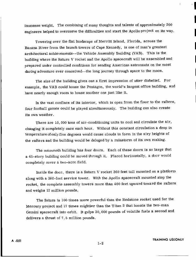
immense weight. The combining of many thoughts and talents of approximately 200
engineers helped to overcome the difficulties and start the Apollo project on its way.
Towering over the flat landscape of Merritt Island, Florida, across the
Banana River from the launch towers of Cape Kennedy, is one of man's greatest
architectural achievements--the Vehicle Assembly Building (VAB). This is the
building where the Saturn V rocket and the Apollo spacecraft will be assembled and
prepared under controlled conditions for sending American astronauts on the most
daring adventure ever conceived--the long journey through space to the moon.
The size of the building gives one a first impression of utter disbelief. For
example, the VAB could house the Pentagon, the world's largest office building, and
have nearly enough room to house another one just like it.
In the vast confines of its interior, which is open from the floor to the rafters,
four football games could be played simultaneously. The building can also create
its own weather.
There are 10,000 tons of air-conditioning units to cool and circulate the air,
changing it completely once each hour. Without this constant circulation a drop in
temperature of only five degrees would cause clouds to form in the airy heights of
the rafters and the building would be deluged by a rainstorm of its own making.
The mammoth building has four doors.
a 45-story building could be moved through it.
completely cover a two-acre field.
Each of these doors is so large that
Placed horizontally, a door would
Inside the door, there is a Saturn V rocket 360 feet tall mounted on a platform
along with a 380-foot service tower. With the Apollo spacecraft mounted atop the
rocket, the complete assembly towers more than 400 feet upward toward the rafters
and weighs 12 million pounds.
The Saturn is 100 times more powerful than the Redstone rocket used for the
Mercury project and 17 times mightier than the Titan 2 that boosts the two-man
Gemini spacecraft into orbit. It gulps 30,000 pounds of volatile fuels a second and
delivers a thrust of 7.5 million pounds.
A -0511-2
TRAINING USEONLY

Once the rocket has been assembled and the spacecraft fitted in place inside
the Vehicle Assembly Building, the complete package (platform, rocket and space-
craft, and service tower) must be transported to the launch pad. A huge monsterous
thing that looks like a gargantuan turtle with a shell as big as a baseball diamond
has been built to accomplish this. By use of huge jacks, the entire platform can be
lowered onto the transporting vehicle.
I
I
I
i
I
I
I
I
I
I
I
The roadway between the VAB and the launch pad is as broad as the New
Jersey Turnpike and stronger than any other built in the world. This roadway is
three miles long, and it takes the monsterous transporting vehicle three hours to
haul its ponderous load to the launch pad.
Before construction could begin on the huge Vehicle Assembly Building, the
soggy swampland had to be transformed to firm ground. This was accomplished by
use of sand dredged from the Banana River and piled 46 feet deep over the building
site. This sand was allowed to settle for three months, exerting its weight on the
swampland, squeezing out the water.
.Then the sand was bulldozed away and pile drivers drove 4,225 steel rods,
each 16 inches in diameter, down into bedrock 150 to 170 feet deep. The steel anchor
of the building was capped by reinforced concrete seven feet thick.
Enough steel to build 30,000 automobiles makes up the framework which, in
turn, is enclosed by a million square feet of aluminum siding--the biggest and
heaviest sheets ever rolled from a mill.
The Vehicle Assembly Building is truly an architectural fantasy on the inside.
It has been described this way, "Whole buildings hang from the sides. Some of them
move up and down and in and out like suspended file drawers, and mate with one
another to form still other buildings-within-buildings to house the space vehicles. "
In the past, missiles were pieced together on outdoor pads where they had to
withstand rain, wind, and the corrosive salt mists from the Atlantic. But now, for
the Apollo project, Saturn rocket sections can arrive at the Vehicle Assembly
Building separately and receive preliminary checkouts in what are called "low bays',
TRAINING USE ONLY1-3
AI.051

(20 stories high). Then a giant crane will be used to lift the 144-ton booster, 52
stories high, and stack the upper stages and the spacecraft on top. All this will now
be accomplished under roof.
As Apollo rendezvous missions become commonplace, two rockets may be
undergoing the assembly process inside the Vehicle Assembly Building while two
others are being prepared for launch from separate pads.
A -0511-4
TRAINING USEONLY

LUNAR LANDING MISSION
GENERAL
The Apollo program will culminate in a lunar landing mission. This mission
will produce the first manned exploration of the moon. This section contains a
sequential presentation of the major events of the lunar landing mission.
CAPE KENNEDY
The lunar landing mission will originate from Cape Kennedy where facilities
are being constructed for precision handling of larger space-exploration vehicles
and associated equipment.
The component assemblies of the Apollo spacecraft and the Saturn V launch
vehicle will be transported to Cape Kennedy for final assembly tests. The space-
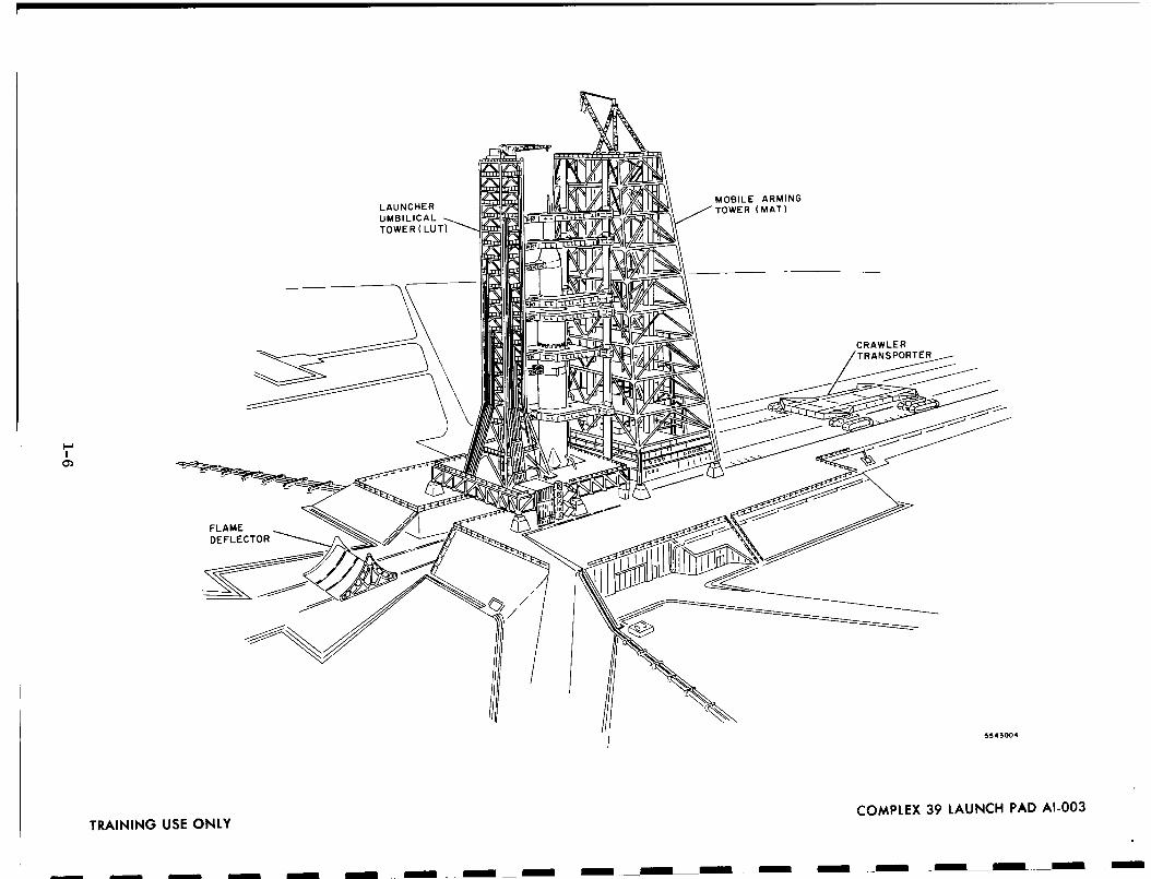
craft and launch vehicle will be assembled (stacked) on the Launch Umbilical Tower
(LUT) platform, which is mounted on the crawler-transporter. Assembly takes
place in the Vehicle Assembly Building. After assembly is completed, interface and
systems tests will be made.
TRANSPORTATION TO LAUNCH PAD
After operations are concluded in the Vehicle Assembly Building, the assembled
LUT, spacecraft, and launch vehicle will be transported to Launch Complex 39.
Transportation of the LUT, spacecraft, and launch vehicle will be provided by the
crawler-transporter which will carry this load six miles at approximately one mile
an hour on a specially constructed crawlerway. The crawlerway to the launch pad
is a pair of parallel roadways which can support a load in excess of 17 million pounds.
LAUNCH PAD
Upon arrival at the launch pad, the crawler-transporter will lower the LUT,
platform, spacecraft, and launch vehicle onto steel foundations. The crawler-
transporter will move an arming tower onto the pad next to the spacecraft. The
TRAINING USE ONLY 1-5 AI-063
C')
00,<,<Q.
,.ruZ.<><a.0u
III
X
1-6
\
\\
©
>-,=.1
Z0U,I
0ZZ.<I--
III

arming tower provides facilities for arming spacecraft explosive components (used
in separation operations) and fueling. When the arming tower is no longer needed,
the crawler-transporter and the arming tower will be removed from the launch area.
COUNTDOWN
The final prelaunch countdown sequence begins upon final positioning of the
LUT, spacecraft, and launch vehicle on the launch pad. Appropriate protective
devices were installed at the time of ordnance installation to prevent inadvertent
operational arming and firing of the pyrotechnics and "to provide maximum safety
for the spacecraft checkout crew and launch area ground personnel.
I
I
I
I
I
I
I
I
I
I
I
The prelaunch countdown follows a programmed sequence which is directed
and controlled by the launch control director. This sequence establishes the order
of required operational checkout of the spacecraft systems and of the servicing and
loading of consumable gases, fuels, and supplies.
The countdown sequence consists essentially of the activation or simulated
activation and verification checks of the spacecraft operational systems as follows:
0 Removal of ground support equipment (GSE)
Leak checks
Battery activation
Final arming of ordnance devices
Removal of ordnance shorting devices
Loading of fuels - helium, liquid hydrogen, and liquid oxygen
Fuel cell activation
Entry of mission flight crew into command module
Closing of command module crew hatch
Installation of boost protective cover hatch access cover
Command module crew cabin leak check
Purging the command module cabin with 100-percent oxygen
Final confidence checks of the spacecraft systems by the crew
Final arming of the launch escape system
Ground-to-spacecraft umbilical disconnect
TRAINING USE ONLY1-7
AI-063

When final checks are completed, the ground-to-spacecraft umbilical cables
are disconnected and the launch tower support arms are retracted. Final decision
and approval to launch is verified by the launch control center and the spacecraft
crew.
LIFTOFF
Upon launch, the Saturn V first stage (S-IC) engines are ignited by the launch
control center. The center engine ignites first, followed by the ignition of the outer
four engines. The launch pad hold-down devices release after initial operational
thrust is sufficient. The launch control center and the spacecraft crew will contin-
uously monitor the initial operational ascent attitude parameters.
FIRST-STAGE SE PARATION
The first-stage guidance system initiates roll of the spacecraft to the required
launch azimuth. The first-stage pitch programmer initiates the required pitchover
of the spacecraft. Voice communication between the crew and the Manned Space
Flight Network (MSFN) is maintained through the critical maximum dynamic flight
conditions and throughout the ascent phase. The cutoff of the first-stage engines
is followed by ignition of the second-stage ullage rockets. The first-stage retro-
rocket then separates the first stage from the spacecraft.
SECOND-STAGE EVENTS
Second-stage (S-II)engine ignitionoccurs nominally two seconds after cutoff
of the first-stage engines at approximately 200,000 feet. The flighttrajectory of
the spacecraft is controlled by the S-IVB inertial guidance system. The launch
escape system is operationally jettisoned at approximately 300,000 feet altitude.
The second-stage engines are cutoff at an altitude of approximately 600,000 feet.
The sequential ignitionof the third-stage (S-IVB) ullage rockets, second-stage
retrorockets, and third-stage engines effects separation of the second-stage. The
third-stage engines provide the thrust required to place the spacecraft in earth orbit.
The third-stage guidance control system cuts off the third-stage engines after the
programmed orbit conditions have been attained.
AI-O63 1-8 TRAINING USE ONLY

EARTH ORBIT
The spacecraft and third stage are to orbit the earth, no more than three
times, at an approximate altitude of 100 nautical miles. During this period, the
orbital parameters are determined by landmark navigational sightings, and then
verified by the Manned Space Flight Network and the spacecraft crew. This deter-
mines the required velocity increment and trajectory for translunar injection.
The crew will perform a biomedical and safety equipment check. Sequence
checks will be made of the environmental control system, communications and
instrumentation system, service propulsion system, service module reaction
control system, electrical power system, guidance and navigation system, stabili-
zation and control system, and crew equipment system.
Translunar injection parameters are determined on-board the spacecraft by
sequential landmark navigational sightings (using the scanning telescope) and by the
• CtllU U_121_i_ullu 6ttluctiibc t_Ulii_Ub_i l lctJ_Ut£)l_ _bll---_l'_tUYxIIl_ IJOIIl[3titablOnS are made
by the Apollo guidance computer. The inertialmeasurement unit is fine-aligned for
the translunar injectionmonitor, using the Apollo guidance computer. The center-
of-gravity offsetangles are set into the service propulsion system gimbal position
display. The delta V program, time, and direction vector are set into the Apollo
guidance computer. The stabilizationand control system is prepared for the delta
V monitor, including minimum deadband hold control and monitor mode. Finally,
the third-stage reaction control system isprepared for the delta V translunar
injection.
Verification of "go" conditions for translunar injection will be confirmed by
the spacecraft crew and the Manned Space Flight Network. The third-stage count-
down and ignition sequence is performed with the spacecraft in the required trans-
lunar injection attitude•
TRANSLUNAR INJECTION
The translunar injection phase begins with the third-stage ullage rocket
ignition. The third-stage propulsion system is operated to provide sufficient thrust
TRAINING USE ONLY AI-0631-9

to place the spacecraft in a translunar ,'free-return" trajectory in accordance with
the delta V magnitude, time duration, and thrust vector previously established and
operationally programmed onboard the spacecraft by the crew and confirmed by the
Manned Space Flight Network.
The third-stage instrument unit provides operational guidance control for the
translunar injection with the Apollo guidance and navigation system capable of backup
control, if necessary. The third-stage engines operate for the predetermined time,
nominally five minutes. The crew monitors the emergency detection system and
spacecraft attitude control displays. The spacecraft guidance and navigation system
monitors the programmed injection maneuver.
INITIAL TRANSLUNAR COAST
Following translunar injection, the crew will perform an onboard determination
of the spacecraft trajectory and verify it with the determination made by the Manned
Space Flight Network. The operational controls are then set for an initial coast
phase. An onboard systems check is then made of all crew equipment, electrical
power system, environmental control system, service module reaction control
system, and the service propulsion system. The status of these systems is communi-
cated to MSFN.
The spacecraft body-mounted attitude gyros are aligned, using the third-stage
stable platform as a reference, and the flight director attitude indicator is set pre-
paratory to initiating transposition of the lunar excursion module , is made with MSFN.
LUNAR EXCURSION MODULE TRANSPOSITION
Transposition of the lunar excursion module consists of separating and trans-
lating the command-service module from the lunar excursion module/adapter/third-
stage, pitching the command-service module 180 degrees, and translating the
command-service module back to the lunar excursion module to join the lunar excur-
sion module to the command module. The S-IVB guidance system stabilizes the lunar
excursion module/adapter/third-stage during the transposition operations. After
completion of docking, the third stage is jettisoned. The entire maneuver will
i-i0

II
Inormally be completed within one hour after translunar injection. Necessary pre-
cautions will be observed by the crew during the time that the spacecraft passes
through the Van Allen belts.
II
I
I
I
II
I
II
I
II
I
The spacecraft will be oriented to provide the most desirable background
lighting conditions for the transposition of the lunar excursion module. The third-
stage is stabilized in an attitude-hold mode. The adapter is pyrotechnically
separated from the command-service module, which is then translated approxi-
mately 50 feet ahead of the lunar excursion module and third-stage, using the
service module reaction control system engines. The command-service module
is then rotated 180 degrees in pitch, using the service module reaction control
engines. The docking attitude of the command-service module for the lunar excursion
module gdapter third-stage will be established and maintained by using the service
module reaction control system engines.
The command-service module will be translated toward the LM/adapter/
third-stage with minimu_m closing velocity so that the command-service module
probe engages with the drogue mechanism on the lunar excursion module. The
command-service module with the lunar excursion module attached then separates
and translates away from the third-stage.
FINAL TRANSLUNAR COAST
The final translunar coast phase begins with the ignition of the service module
reaction control system to separate the spacecraft from the third-stage and ends with
service module reaction control system ullage acceleration just prior to lunar orbit
insertion. The primary operations occurring during this phase consist of system
checkout of the spacecraft and lunar excursion module systems, trajectory verifi-
cations, and preparations for lunar orbit injection. Midcourse delta V corrections,
navigational sightings, and inertial measurement unit alignments are to be made if
needed. A delta V budget sufficient to provide a total delta V correction of 300 feet
a second is planned.
TRAINING USE ONLYi-ii
AI-063

The spacecraft guidance and navigation system computes the trajectory of the
spacecraft (in conjunction with navigational sightings). The delta increment re-
quired is determined by MSFN, and confirmation of the trajectory and velocity
increment values is made with the Apollo guidance computer. Midcourse incremental
velocity corrections will be made if required.
The attitude of the spacecraft will be constrained at times because of opera-
tional temperature control restrictions. The crew may enter the lunar excursion
module to check its operational capabilities during the final translunar coast phase.
At least one astronaut will be in his space suit at all times. A crew work-rest
cycle will be established and followed during this phase. The capability to initiate
an abort at any time during this phase will be provided.
In preparation for lunar orbit insertion, the spacecraft attitude, lunar orbit
insertion velocity increment, and the time to initiate the service propulsion system
thrust required to achieve the desired orbit around the moon are determined by tra-
jectory data from MSFN and from the guiqlance and navigation system. The space-
craft will then be properly oriented and the service module reaction control system
ullage rocket ignition will be initiated by the crew.
The initial lunar orbit coast phase begins with cutoff of the service propulsion
engine as the spacecraft is inserted into lunar orbit and ends with activation of the
lunar excursion module reaction control system to effect separation from the space-
craft.
Following lunar orbit insertion, the crew will transmit trajectory data and
information to MSFN. The orbit ephemeris about the moon will be determined as
accurately as possible, using the spacecraft guidance system and MSFN. A con-
firming checkout of the lunar excursion module guidance system is also made prior
to separation from the spacecraft.
The spacecraft systems will be capable of operation at their nominal design
performance level for a mission of 14 days. A single crew member can control the
spacecraft in lunar orbit for 7 days. Communication capability will be provided be-
tween the spacecraft, Manned Space Flight Network, and the lunar excursion module
AI-O631-12
TRAINING USE ONLY

IIII
I
II
I
II
when separated and within line-of-sight. The spacecraft and lunar excursion
module separation and docking operations will not be restricted by natural illumi-
nation conditions.
Observations and calculations will be made of the preselected landing site
from the spacecraft, to determine if the area location is satisfactory or if an alter-
nate landing area should be selected. Detailed surveillance of the landing area is
to be made from the lunar excursion module prior to landing.
Lunar orbit trajectory verification requires fine alignment of the inertial
measurement unit, and a related series of navigational sightings will be made of
known lunar surface areas and reference stars, using the scanning telescope, sex-
tant, Apollo guidance computer, and MSFN, but the LM descent trajectory will be
calculated using the computer only.
TT_ _ -i:',_ I ,,^.,_;_.._o÷;_,,_ _,_eh_¢_ parameters the comm_n_p.r _nd the _ystems
engineer will transfer from the spacecraft to the lunar excursion module. The lunar
excursion module electrical power' system, environmental control system, communi-
cation system, guidance and navigation system, stabilization and control system,
reaction control system, and ascent and descent engine systems will be checked
out. A check will be made of emergency procedures and corresponding spacecraft
systems. The operational capability to the air lock will be verified. Initial opera-
tional information will be synchronized between the spacecraft and lunar excurison
module.
The spacecraft will be aligned and held in the required attitude for separation.
The lunar excursion module guidance computer will be programmed for the transfer
trajectory when the spacecraft orbit is determined accurately. The orbit will not be
disturbed, unless an emergency requirement prevails, or until the docking phase is
complete. Emergency or additional data may require that the spacecraft lunar orbit
be updated as necessary by the remaining crew member.
Actual separation of the module from the spacecraft is effected by a propulsion
thrust from the lunar excursion module reaction control system. After a specified
time, an equivalent impulse is app!ied in the opposite direction so that the relative
TRAINING USE ONLY1-13
AI-063

velocity between the lunar excursion module and the spacecraft will be zero during
the final checkout of the lunar excursion module. Final checkout is accomplished
with the lunar excursion module in free flight, but relatively close to the spacecraft
in case immediate docking is required.
LUNAR LANDING
The lunar excursion module lunar operations phase begins with initial LM
separation from the spacecraft and ends with touchdown of the LM on the surface of
the moon.
The essential LM operations which occur are attitude control, incremental
velocity control, and time to fire, computed by the LM guidance and navigation
system. LM insertion into a descent orbit is accomplished by reaction control
system ullage acceleration and ignitionof the descent engine with the thrust level
and burn-time automatically controlled by the LM guidance and navigation system.
The LM separates from the spacecraft during this maneuver, and communication
with the Manned Space Flight Network at time of insertion is not possible, since it
occurs on the far side of the moon.
Descent trajectory determination will be made using data from rendezvous
radar tracking the spacecraft. The LM will coast in descent transfer orbit following
descent engine cutoff, and close observation of the proposed lunar landing site will
be made for final approval. The descent engine will be reignited prior to reaching
the low point in the orbit and sustained thrust initiated for the descent maneuver.
The thrust and attitude are controlled by the guidance and navigation system by
comparison of the actual and planned landing tracks.
The translational and radial velocities will be reduced to small values and the
descent engine will cut off at a specified altitude above the lunar surface. The pilot
will manually control the descent within preset limits. Terminal descent and touch-
down will be made by manual control and use of the landing radar. Confirmation of
initial lunar touchdown will be made by the LM crew to the spacecraft and to MSFN.
1-14

The crewman in the spacecraft will maintain visual observation of the
lunar landing operation. All three crewmen will be in their space suits.
LUNAR SURFACE OPERATIONS
The lunar surface operations phase begins with lunar touchdown and ends with
launching of the LM from the moon.
Initial tasks to be performed by the two astronauts following touchdown include
review and determination of the lunar ascent sequence and of the parameters required.
A complete check of the LM systems and structure will be made. Necessary main-
tenance will be determined and performed to assure the operational ascent capability
of the LM. The systems will be put into a lunar-stay mode and a system monitoring
procedure established. The LM will be effectively secured as necessary and the
landing and launch stage disconnect mechanisms activated.
The lunar landing must be made on the earth-side of the moon to permit and
establish communication with MSFN and the lunar orbiting spacecraft from the sur-
face of the moon. Voice and signal communication will be verified prior to beginning
egress and lunar exploration activity. A post touchdown-status report will be made
to the spacecraft before line-of-sight communication is lost as the spacecraft orbits
below the lunar horizon. The position and attitude of the LM on the moon will be
established and reported.
The LM is capable of operating normally on the lunar surface during any phase
of the lunar day-night cycle. The LM, designed to be left unoccupied with the cabin
unpressurized on the lunar surface, will be capable of performing its operations
independently of earth-based information or control.
Although the nominal lunar stay-time may be from 4 hours to 35 hours, de-
pending on the planned scientific exploration program, the capability to launch at
any time in an emergency situation will be established. Portable life support
systems (PLSS) will provide the capability for 24 man-hours of separation from the
LM. Maximum continuous separation will be 4 hours (3 hours of normal operation
plus 1 hour for contingencies).
TRAINING USE ONLY AI-0631-15

One crew member will normally descend to the lunar surface to perform scienti-
fic exploration and observation, while the other crew member will remain in the LM
to monitor systems status and maintain communications. In the event that certain
scientific exploration or experiments require both crewmen, the LM may be left
unattended. The scientific exploration activity may include gathering selected
samples from the lunar surface and atmosphere, measurement of lunar surface and
atmospheric phenomena, and the securing of scientific instruments on the lunar
surface for signal transmission and telescope observation from earth. Video trans-
mission from the lunar surface may be accomplished by means of portable tele-
vision equipment. Provision will be made for return of approximately 80 pounds of
samples from the lunar surface.
Following completion of the lunar surface exploration activity, preparation
for ascent will begin. The two crewmen will secure themselves in the LM cabin.
Launch and rendezvous plans will be confirmed with the crewman in the spacecraft
and with MSFN. The spacecraft tracking and rendezvous data determination sequence
will be initiated. The LM operational systems required for lunar ascent, the ascent
and descent stage separation procedures, and the inertial measurement unit align-
ment procedures, will be checked out.
SPACECRAFT SOLO LUNAR ORBIT OPERATION
During separation of the LM from the spacecraft for lunar operations, the
crew member in the spacecraft will perform a series of backup operations in
support of the lunar activity.
The spacecraft crew member will initially monitor the separation sequence
and initiate radar tracking of the LM. A communication link between the spacecraft,
LM, and MSFN will be established. The spacecraft will monitor the LM orbit
injection sequence and maintain cognizance of essential operational parameters.
In addition, periodic operational checks will be made of the spacecraft systems,
the inertial measurement unit alignment procedure performed, and the lunar orbit
parameters periodically updated and confirmed with MSFN.
1-16

The lunar landing sequencewill be monitored by radar tracking and essential
operational datawill be transmitted to MSFN. The location of the lunar landingsite will be determined. Visual observations will be made of the lunar surface
operations and periodic line-of-sight communication with the crew maintained as
required.
Spacecraft confirmation of the LM ascent and rendezvous parameters will be
established. Radar tracking of the ascent trajectory will be established to permit
determination of the operational maneuvers to effect rendezvous and docking. The
spacecraft guidanceand navigation system determines these essential parameters.
I
I
I
I
I
I
I
The LM will provide manual control of the terminal attitude and translation
required for rendezvous and docking. The spacecraft normally will be stabilized
in a passive mode for rendezvous and docking, but it will have the capability of
actively performing this operation, if necessary. After completion of docking, the
orew will transfer from the LM to the spacecraft.
LUNAR ASCENT
Confirmation of "go" conditions for lunar launch is made with the spacecraft
and MSFN. The ascent engine will be ignited and launch from the lunar surface
accomplished.
The LM ascent trajectory places it in a position approximately 50,000 feet
above the lunar surface, at a velocity such that the resultant orbit about the moon
has a clear minimum altitude of approximately 50,000 feet and a nominal intercept
with the orbiting CSM. The launch trajectory of the LM is controlled through its
guidance and navigation system. The LM rendezvous radar tracks the spacecraft
during the ascent to provide inputs to the guidance and navigation system. The
LM reaction control system executes the required roll attitude and pitch maneuvers
to place it in the required orbit.
Following the cutoff of the ascent engine, the radar will continue to track the
spacecraft. The spacecraft guidance and navigation system will compute the orbit
of the LM and the crew will determine if any delta V corrections are required to
TRAINING USE ONLY1-17
AI-063

effect rendezvous. The final coast trajectory parameters, range, rate, and attitude
angles will be determined and rendezvous operations will be initiated.
RE NDE Z VOUS
The rendezvous operations begin during the LM ascent phase. The ascent
trajectory may require up to three midcourse corrections to reach a collision course
with the CSM. These corrections will be made with either the LM ascent engine or
the reaction control system. The final rendezvous maneuvers will include three
terminal homing thrusts from the LM reaction control system to reduce the relative
velocity to a minimum.
The LM crew will manually control the LM within a range of approximately
500 feet from the spacecraft, with a relative velocity of 5 feet a second or less.
Both the spacecraft and the LM are capable of performing the final rendezvous and
docking maneuvers required, assuming that the LM orbit has a minimum altitude.
The spacecraft is normally stabilized in passive mode with the LM operationally
active to effect rendezvous.
The final docking maneuvers of the LM to effect contact with the spacecraft,
are performed using the reaction control engines. Docking alignment and closing
velocity will be verified and necessary manual operational control established to
effect initial engagement of the latching mechanism. Following verification of the
initial latching, the final latching sequence will be performed. Completion of hard
docking will be verified by both the LM and spacecraft crew members. The post-
docking status of the system will be determined and, when the docking maneuver
is completed, information will be transmitted to the Manned Space Flight Network.
The rendezvous and docking operations may be accomplished under any natural
lunar lighting conditions.
Following completion of hard docking, the LM systems will be secured. The
LM crew will then transfer the lunar scientific equipment and samples to the space-
craft and store them in the command module. The two crew members will enter
the command module and secure the access hatch between the command module and
the lunar excursion module.
1-18

A system status check will be made of the spacecraft operational systems and
the status for separation from the LM will be communicated to MSFN° The sequence
for separation will then be initiated. The LM will be released from the CSM, and
the service module reaction control engines activated, to translate the spacecraft
away from the LM.
Following this separation, the spacecraft will be operationally maneuvered
for the inertial measurement unit alignment. After fine-alignment of the inertial
measurement unit, a series of three navigational sightings will be made to establish
the transearth injection trajectory, computed by MSFN and subsequently confirmed
with the Apollo guidance computer. The final transearth injection operational
parameters, service module reaction control system ullage acceleration, required
service propulsion system firing time, incremental velocity, thrust vector, and
transearth injection attitude are determined and confirmed by MSFN.
_^XT_^D_U TXT_T_XT AND _O A.qT
The transearth injection phase covers the period of time the service propulsion
system burns when injecting the spacecraft into a transearth trajectory.
For each lunar orbit there exists one opportunity for transearth injection.
Injection occurs behind the moon, with respect to the earth, nominally one orbit
after completion of rendezvous with the LM. The service propulsion system ullage
acceleration is manually initiated to begin the earth injection sequence. The in-
jection velocity increment for the predetermined transit time to earth is initiated
with the service propulsion system thrust controlled by the guidance and navigation
system.
The transearth coast phase begins with service propulsion system engine
cutoff following transearth injection and ends at the entry interface altitude of 400,000
feet.
The transearth injection will be operationally performed to place the space-
craft in a return trajectory toward the earth, and will require a minimum of opera-
tional maneuvers and corrections. A delta V budget sufficient to provide a total
TRAINING USE ONLY AI-0631-19

velocity correction of 300 feet a secondduring the transearth coast phase is provided.
Nominally, three transearth velocity corrections may be made: one near the moon;
the secondnear the midpoint of the return trajectory; and the third delta V incre-ment near the earth.
The primary operations which occur consist of periodic systems checks,
trajectory verification, determination of the delta V correction required, preparation
for jettison of the service module, service module jettison from the commandmodule,
and preparation for earth entry.
The midcourse corrections are determined by means of sequential trajectory
verifications. The navigational sightings are made with the scanningtelescope and
sextant on knownlandmarks and stars. The Apollo guidancecomputer computesvariations from the required trajectory parameters, determines velocity changes
(if necessary}, thrust vectors, and firing time, and confirms this datawith MSFN.The delta V is operationally implemented and the verification of the velocity
correction is subsequentlydetermined after eachmidcourse correction.
SERVICE MODULE JETTISON
Following the last midcourse correction, preparatory activity will be initiated
for jettisoning the service module. The near-earth entry corridor and preentry
parameters for separation of the service module from the command module will be
determined by MSFN and confirmed by the Apollo guidance computer. The final
systems checkwill be performed and the spacecraft oriented for service module
jettison. To effect space separation of the command module and service module,
the commandmodule entry batteries will be activated, and the service module
operationally jettisoned by separation of the adapter and subsequenttranslationalthrust by the service module reaction control engines. The command module is
then oriented into a MSFN-confirmed entry attitude by the command module reactioncontrol engines.
A status checkwill be made of the systems after service module separation,
a final operational check will made of the systems for entry and confirmation of the
entry parameters will be made with MSFN. The entry monitor control and display
AI-0631-20
TRAINING USE ONLY

will be operationally activated, entry alignment of the inertial measurement unit
made, and utilization of the flight director attitude indicator and Apollo guidance
computer implemented.
EARTH ENTRY
The earth entry phase begins at an altitude of 400,000 feet and ends with
touchdown.
The operational control of the entry is dependent on the range required from
the 400,000-foot entry point to the landing area. For short-entry ranges, no skipout
maneuver is required. For entry ranges approaching the upper limit, a skipout
maneuver is required to attain the greater distance. In either case, the lift maneuver
is controlled by rolling the command module using the reaction control engines.
Operational control is normally maintained through the guidance and navigation
system with the pilot providing a backup capability with the use of the entry monitor
display.
Entry into the earth atmosphere is sensed by a 0.05G signal indication. The
entry attitude is determined on the flight director attitude indicator, and the entry
monitor control display is observed. The Apollo guidance computer computes the
range to "go" and provides navigation from the 0.05G point and time.
The range control maneuver is initiated by reaction control engines roll control
and necessary pitch and yaw damping. The entry monitor display indicates the delta
V and G level, the command module delta V/G level time history, and the survival
display requirements. The guidance and navigation system executes the required
reaction control system roll commands.
EARTH LANDING
The earth landing system is operationally armed at an altitude of 100,000 feet.
The earth landing system automated sequencer deploys the forward heat shield at
24,000 feet. Two seconds later, the two drogue chutes are mortar-deployed in a
reefed condition. The reefing lines are severed and the drogue chutes open fully in
TRAiNiNG USE ONLY AI-0631-21

approximately 8 secondsto orient the C/M apex upward during descent to 11,500
feet. Three pilot chutes are automatically connected. The pilot chutes in turn,
deploy the three main chutes to a line-stretch, reefed condition. The reefing lines
are severed andthe main chutes openfully in approximately 8 seconds. The main
chutes lower the commandmodule to touchdownand impact at a terminal descent
velocity assuring a nominal impact G level consistent with the safety of the crew.
The main chute attach lines are severed upontouchdown.
During the final part of the main chute descent, the recovery communication
systems are activated and transmit a location signal for reception by the operational
recovery forces.
RECOVERY OPERATIONS
The recovery operations phase begins with touchdown and ends with the re-
covery of the crew and retrieval of the command module. The VHF communication
system is deployed and begins transmitting a repeating location signal for reception
by the recovery task forces deployed in the area of predicted touchdown. Voice
communications capability is also provided by an HF communications systems.
If touchdown occurs in water (primary landing), fluorescent dye goes into
solution, coloring the water a bright, fluorescent, yellow-green over an extended
area. The dye should be visible to recover force aircraft or ships for a considerable
distance. A flashing beacon light is also provided for use at night.
Immediately following a water (primary) landing, after the main chutes are
pyrotechnically cut from the command module, the crew will assist the flotation
status and capability of the command module. If the command module enters the
water in an inverted stable flotation attitude, the crew will activate the uprighting
subsystem after which a decision will be made relative to remaining in the command
module or leaving in the inflatable life raft provided for the three crew members.
Steps will be taken, as necessary, to effectively secure the command module for
optimum flotation stability and subsequent retrieval. The capability is to be pro-
vided for helicopter pickup of the command module, with the three crew members
inside, using the recovery pickup loop. A nearby ship may pick up the command
AI-O631-22
TRAINING USE ONLY

module. Land ground forces may pick up the command module if the land touchdown
point is in an accessible area.
The flotation design will provide a survivable flotation capability for a minimum
of 48 hours, under design sea conditions. A water landing provides fewer touch-
down hazards and a correspondingly greater safety for the crew. Natural ground
terrain, in most of the possible touchdown land areas evaluated, would cause an
excessive impact shock for the crew.
m
I
I
I
I
I
I
I
ITRAINING USE ONLY 1-23
AI-063

234'
INSTRUMENT
UNIT SM
SPACECRAFT I
LM _"ADAPTER
LAUNCHVEHICLE
CM T
CSM1 ,
2-PAM / FM/FM
|I-PCM/FM___ I-SS/FM
IEXR RANGE SAFETY COMMAND
| C-S_NDRADAR
L AZUSA
_-PAM/FM/FMI-PCM/FMI-SS/FMRANGE_,FETY COMMAND
iI-PCM/FM'I-SS/FM
RANGE SAFETY COMMANOODOP
S-IB
")( LM WILL NOT BE INS/C UNTIL AS-206.
5590013
TRAINING USE ONLY1-24
SATURN IB LAUNCH VEHICLE AI-021A

i
IiII
I
I
II
I
I
I
ITRAINING USE ONLY
364'
n
mT_
TAPOLLO
SPACECRAFT
S-lV'B
BOOSTER
q
S-_
BOOSTER
S-IC
BOOSTER
_r
559ool9
1-25SATURN V AI-032

LAUNCH
ESCAPETOWER
COMMAND
MODULE
LAUNCH ESCAPE TOWERCOMMAND MODULE
APEX COVER
COMMAND MODULE
COMMAND MODULESERVICE MODULE
SERVICEMODULE
SERVICEMODULE
ADAPTER
LUNARMODULE
ADAPTER
INSTRUMENTUNIT
I'RAINING USE ONLY1-26
APOLLO SPACECRAFT
SEPARATION PLANES AI-001

LAUNCH ESCAPE SYSTEM
ICOMMAND MODULE (.BENEATH I_/_-'_"/_'_,
iI BOOSTPROTECTIVECOVER)_
I! SERVICE MODULE--__:_. _P_JI.
I
I LUNAR MODULE
I SPACECRAFT LM ADAPTER'---_f_L__ ... _
5590020
I
I
I
II
LAUNCH ESCAPE TOWER, COMMAND MODULE,
I TRAINING USE ONLY 1-27 SERVICE MODULE, AND LUNAR MODULE AI-033

ANTENNA DE
MECHANISM (I)
RCS CROSSFEED
SQUIB VALVES (2)_
ASCENT PROPULSION
HELIUM PRESSURIZATION
SQUIB VALVES (2)
UMBILICAL SEPARATION
ASSEMBLY (2)
--------- SERVICE MODULE
SERVICE MODULE
ENGINE SKIRT
;PACECRAFT L M
ADAPTER (SLA)
WATER FEED
VALVE
LM ASCENT
STAGE
RCS HELIUM
PRESSURIZATION
SOUIB VALVES (4)
INTERSTAGE SEPARATION
EXPLOSIVE BOLTS
(4 PLACES)
II
I
I
I
I
I
I
I
DESCENT PROPULSION
HELIUM
SQUIB VALVE
ADAPTER ACCESS
DOORS
LM DESCENT
STAGE
LANDING GEAR
UPLOCK MECHANISM
(4 PLACES)
St]Z" B
BOOSTER
NOTE:
m INDICATES
PYROTECHNICS
TRAINING USEONLY1-28
LM INTERFACE ANDEXPLOSIVE DEVICE LOCATIONS AI-002

I
I
II
I
I
I
II
I
I
II
HELIUM TANK
FUEL CELL MODULE I
02 TANK (2)
SECTOR 4 (
H 2 TANK (2)
PRESSURE SYSTEM PANEL
OXIDIZER TANK (2
FUEL TANK (2 PLACES)
SERVICE PROPULSION
ENGINE EXPANSION NOZZLE
TRAINING USE ONLY
RADIAL BEAMS
{6 PLACES)
1-29
REACTIONCONTROL
PACKAGE
(4 PLACES)
SERVICE
PROPULSIONENGINE
SECTOR
(REF)
RENDEZVOUS
ANTENNA
5590015
COMMAND SERVICE MODULE AI-035

\
1-30
--(D
o_Z
_UJ
n-
G.W
__
O_
_J
t)z
Ill:I_.1
.J_Z
o|
D0Z,<0UI,--
ZlU114
0Z<Ilg
144
Z0Z00ZZ<

>_ CANARD_/_ \,J_++ow+ _o_o_
' , III
I559OOI6A
I
I
I
Ii TRAINING USE ONLY 1 31 LAUNCH ESCAPE SYSTEM
AI-O36

SAME AS FOR NORMALC/M- S/M SEPARATION
WITH THE FOLLOWING ADDED:
I. FIRES L/E & WC MOTORS OF LES
2.DEPLOYS CANARDS OF LES
3.COMMANDS BECO (IF T 40 SEC)
4,ENABLES AUTO C/M RCSCONTROL (IF T 42 SEC)
5. ENABLES AUTO C/M RCS OXIDIZER
DUMP (IF T 42 SEC)
6.ENABLES ELSC LOGIC ARMING
7. PERFORMS LET & APEX COVERJETTISON
JflolII
IlllffJi
/
/554]*006
TRAINING USE ONLY 1-32 ABORT SEPARATION FUNCTIONS AI-005
i
J/!liI
II
I
I
II
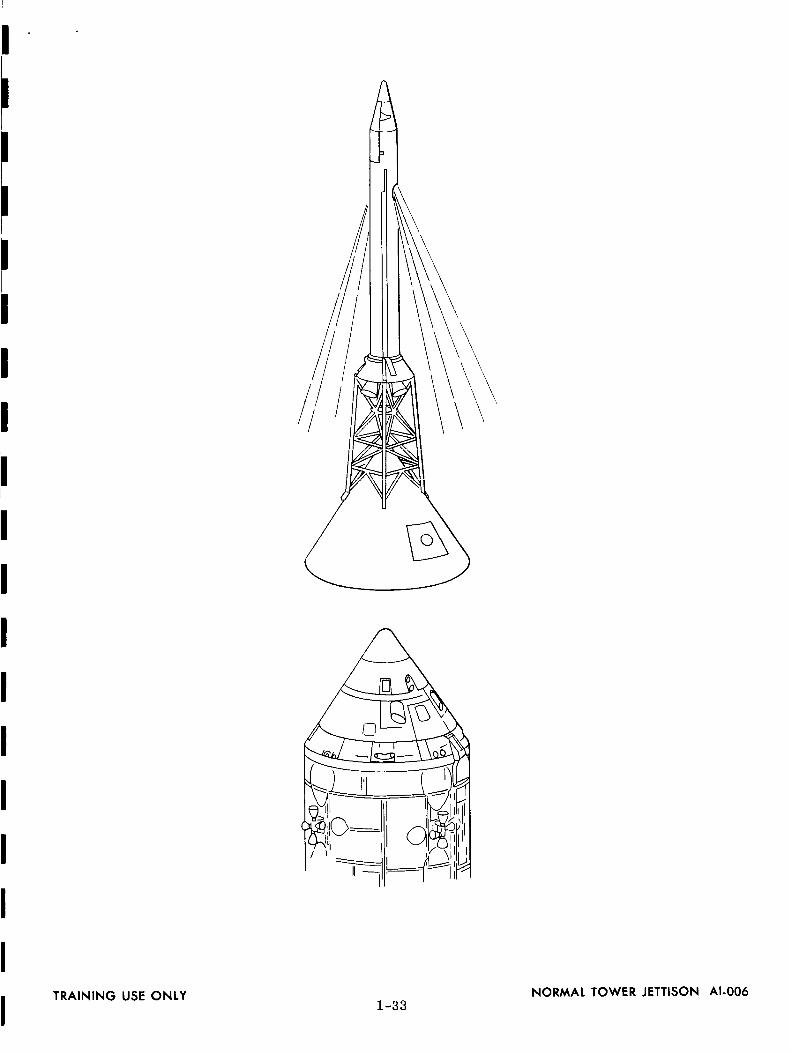
IIj TRAINING USE ONLY 1-33 NORMAL TOWER JETTISON AI-006

//
00d0
009
1-34
00i
IZomDZ
Z0oZZ

I
I
I
I
I
I
I
I
I
I
SM-RCS 3-AXIS
STABILIZATION
THRUSTERS
CRUSHABLE CORE
/
S-]_" B
SM-RCS +X TRANSLATION
II SEC BURN TIME
SEPARATION
Z_V = 4.02 FT/SEC
ATTITUDE HELD
AT 263.6 DEGREESRELATIVE TO
LAUNCH
HORIZONTAL
BY S-'I_ B
TRAINING USE ONLY1-35
COMMAND SERVICE MODULE/S-IV B SEPARATION AI-007

NOMINAL ELAPSED TIME SEQUENCE
AFTER LIFT-OFF
2.8 Hours
3.3-3.5 Hours
72. 8 Hours
74.5 Hours
98.5 Hours
99.9 Hours
EVENT
Lunar Injection
Transposition (Turn Around)Discard Third Stage
Arrive at Moon (3 Days)
Lunar Touchdown for 24-Hour
Stay on Moon
Lunar Lift-off after 24-Hour
Stay on Moon
Rendezvous at Moon
103.5 Hours
196 Hours
196.6 Hours
Leave Lunar Orbit for Earth
Start Reentry
Earth Touchdown (8 Days)
638500?
TRAINING USE ONLY1-36
ELAPSED TIME SEQUENCE AI-043

!
//
QIBE_
T¢
I-31

/
i'/
I
//
4 SO_I : )NO INTE_s, TL4%S
"_ OR_tT t T TuNSERTION
Q/I
F

!
iE
3.1 (00:11:52) 4.0 (03:00:43)EARTH ORBIT BEGIN TRANSLUNAR
INSERTION INJECTION ONSECOND ORBIT
LUNAR LANDING SITE
ii.2 (05:05:58tST MIDCOURSE_ORRECTION
6.2.2 (55:30:00SECOND MIDCOURSE
CORRECTION
®6.3.2 (65:15:04)
THIRD MIDCOURSECORRECTION
®7.0 (64:15:04)BEGIN LUNAR
ORBIT INSERTION
5543009
TRAINING USE ONLY
EARTH VICINITY AND TRANSLUNAR
d_f1_38 __.SSION DESCRIPTION AI-008

7.0 (64:15:04)BEGIN LUNAR
ORBIT INSERTION
t
15.0 (109:09:56BEGIN TRANSEARTH
COAST
t
14.0 (109:08:131BEGIN TRANSEARTH
INJECTION ON 22ND ORBIT
1
13.: ) (106:14',161JETTISON LM
1
13.0 (105:44:16)HARD DOCK BEGIN
LUNAR ORBITCOAST TO TET
8.1 (64:20:56)BEGIN LUNARORBIT COAST
12.4 (105:19:16BEGIN DOCKING

I0.1(68:04.:14)LM/CSMSEPARATIONONSECONDORBIT
12.3([05:11:00BEGINTERMINAlRENDEZVOUS
10.2(68:24:14BEGINTRANSFERORBITINSERTION
®2.2 (104:24:09
BEGIN COAST TOTERMINAL
RENDEZVOUS
10.3 (68:24:481BEGIN COAST TO
INITIATION OFPOWERED DESCENT
12.1 (104:17;06BEGIN POWERED
ASCENT ON 20THCSM ORBIT
10.4 (69:22:5:5BEGIN POWERED
DESCENT
10.5 (69:29:23BEGIN VISIBILITY
TO HOVER
I0 6 (69 3118)BEGIN HOVER
TO TOUCHDOWN
It.I (69:52:23)TOUCHDOWN
__1_
LM LUNAR STAY34:45:43 HRS
5843010
TRAINING USE ONLY
LUNAR
VICINITY MISSION
DESCRIPTION AI-009

(68:23:50.7)ENTER SUNLIGHT
AT 175.5 ° W2.25 ° SLAT.
(68:11:04.3)PREPARATION FOR
DESCENT AT 139.0 ° W LONG.
1.70 ° S LAT,
(68:04:14.5)LM/CSM
SEPARATION
119.0 ° W LONG.1.25 ° S LAT.
(68:02:56)CSM LOSES
WITH EARTH _,_ll5.1 '> W LONG.
1.04 ° SLAT.
+z
//Ii
(69:39:18.2) \C SM DROPS
BELOW HORIZON
\\
(69:31q8.3) HOVER AND "X
(69:32:25.2) TOUCHDOWNAT 13.0 ° W LONG.2.24 ° N LAT
(69:29:22.8)BEGIN VISIBILITY AT
10,122 FT ALT,7.1 N. MI LOS* RANGE,
12.6 ° W LONG.2.25 ° N LAT.
17.4 = W
2.17 ° N(LM
TOUCHDOWN
(69:24: 57.8)LM OVER LANDINGSITE HORIZON AT
4.7,400 FT ALT5.6 ° W LONG
2.50 ° N LAT
(68: 24:14, 3) (68:24: 48.4)BEGIN TOI AT BEGIN COASTING
/DESCENT ;VSW,,"OALT2.35 ° S LAT. _ / 2.55 ° S LAT.
ACHIEVE 60 N. Mh ALT
AT 115.5 ° E LONG0.92 e S LAT.
115.20E0.94°S
8.5°W2.26°N
EARTH
(68:48=28.0)--_._M BEGINS LOS*
WITH EARTH AT111.4° E LONG.0.78 ° SLAT.
(68:49:10.4)LM BEGINS LOS
109.4 ° E LONG.
0.69 ° S LAT.
/ACHIEVE 40 N. MI. ALT./ AT 84.2 ° E LONG.
0.51 ° N. LAT.
ANGLE--108° I \ _- /-_4N_,,_.__
I N" 1.4_-N ¢-__
' /_ _HDOWN
/ 169XX=08:18.41 SUN
ACHIEVE20N.,ALTA,49.2 ° E LONG.
10.6DE 1.58 ° N LAI2.30°N
BEGIN POWEREDDESCENT AT
49,554 FT ALT,0.8 ° E LONG.2.32 ° N LAT.
RENDEZVOUS
R ADAR \ + y
+Z +Z
LI_ _/CSMS-BAND
NOTE:"¢LOS INDICATES LINE OF SIGHT
TRAINING USE ONLY LM DESCENT PHASE DESCRIPTION AI-0101-41

2282.5M(2101.8MC
296.8MC
EVAANT(NNA
259,7 MC
279.0M
TVCAMERA
EVA
TRAINING USE ONLY1-42
LUNAR STAY COMMUNICATIONS AI-011


®15.4.2 (198:00::34
JETTISON SM
(_ _/
15.3.2 (197:15:34THIRD MIDCOURSE
CORRECTION
: i
15.2.2 (174:09:56
SECOND MIDCOURSECORRECTION
t
16.0 (198:15:34)ENTRY
®I17,0 (198:26:01)
BEGIN PARACHUTEDESCENT
(198:26:59) 18.0 (I (,JETTISON DROGUE EARTH
CHUTE MAIN CHUTEDEPLOYMENT

15.1.2 (129:09:56FIRST MIDCOURSE
CORRECTION
15.0 (109:09:56BEGIN TRANSEARTH
COAST
B:33:08)_ANOING
TRAINING USE ONLY
TRANSEARTN_ ENTRYM,SS,ONDESCR,PT,ONA,-O,2

,O
0i
I
I
1-45
>-
Z0
0zzu
.(

//
/
/i
Oi
0zz..J"I"
U.J
1-46
>-Z0,ii0zmz

iIIII
t\
1-47
_o_
0_U
o0
W_Zl
_0
OQ
Z
oi
>0tJZ00zzI,.,-

hbelt
-m
1-48
Z
0
>-.-I
z00zz,Y

I1-49
0
i
ZZ0Z000Z0ZZ

STATION
BE RMUDACANARY ISLANDKANO
MERCURY
XXX
GEMINI
XXL
ZANZIBAR XTANANARIVE LGUAYMAS X X
MERRITT IS, (MILA)GUAMGOLDSTONE
GOLDSTONE (JPL)MADRID
MADRID (JPL)CA NBE RRA
CANBERRA (JPL)MUCHEA
WOOMERACARNARVON
HOUSTON (MSC)SAN SALGRAND BAHAMA IS.GRAND TURK IS.ANTIGUA IS.
ASCENSION
CANTON
HAWAIIPOINT ARGUE LLOWHITE SANDSCORPUS CHRISTI
E GLINROSE KNOTCOASTAL SENTRY
X
(DE LE TE D)
(DELETED)
APOLLO
X
X
(DELETED)
LXXX
XXXXXX
X R R
X X
X X
X
X
X
X
APOLLO SHIP 1
APOLLO SHIP 2APOLLO SHIP 3APOLLO SHIP 4APOLLO SHIP 5
APOLLO AIRCRAFT (8)
X
X
R
X
X
X
L
X
R
R
X
R
XX
X.RX
RXX
XLXXLX
R
R
X
R
L
L
X
X
XXXX
5680044A
LEGEND: X = FULL SUPPORT
L = LIMITED SUPPORT
R = RADAR SUPPORT ONLY
NETWORK EVOLUTION AI-042TRAINING USE ONLY1-50

I
I
I
I ®
I
I
I
I 5680057
TRAINING USE ONLY RADAR SETAN/MPS-26(XN-1) TRAILER RDS-0022-1

5S80058
RDS-O01TRAINING USE ONLY FPS-16 ANTENNA PEDESTAL2-2

III
II
I
I
I
II
II
I
II
I
I
II
TRAINING USE ONLY2-3
/
6315005
FPQ-6 RADAR ANTENNA RDS-008

_" _ Z
m
H M S
024400024500
024600024700
024800024900025000025100
c_
©
©
R
30332914287729253053
32503501
3794
AZ
233.1223.3212.92O2.6192.9
184.2176.6170.1
C_
EL
0.11.82.93.43.32.81.80.6
5680060
TRAINING USE ONLY2-4
POINTING DATA FOR
NETWORK RADARS RDF-014

I
I
I
I
I
I
I
I
I
I
I
I
I
I
I
I
!
I
ITRAINING USE ONLY
W
AZIMUTHANGLE
2-5
ELEVATIONANGLE
/HORIZON
AZIMUTH, ELEVATION ANGLES AND SLANT
RANGE IN THE RADAR PLANE RDF-OO7

L So
PHOTOELECTRIC CELLS
0¢
0
BEAM-FORMING MASK
13-BIT CYCLIC BINARY (GRAY)WORD OUTPUT
/
/
//
i !
//
DRIVEN SHAFT
CODED DISC _ /
" ' STROBE
\\ [ CIRCUIT
\\ LIGHT-LIMITING MASK //
\\ /\ /
\\ //\, /
\. /"
_6aoo62
TRAINING USE ONLY2-6
'13-BIT OPTICAL ENCODER RDS-005

II
II
II
I
II
II
II
I
III
fJ/
//
/
CODED O IS C .,.........._/I
I/
II
BRUSH HOLDER--iII
\
CODED DISCSECTION
\\
\
MECHANICALENCODER
0 LSD
I
I
0
0
0
0
0
8-BIT GRAY WORD
\\
\\
\
\
I/
/
//
/
DISC READBRUSH
DRIVENSHAFT
MSD READOUTBRUSH
TRAINING USE ONLY 8-BIT MECHANICAL ENCODER RDS-0042-?

<aa.i'Y
Z_
WO
Oi._--
r_X
--=W
_C-)
='_.1
-1q_
Z,Z
<{qEI-
I10n-
OW
LZ
:0
•Jhi
a
J-J
:Z
•¢,_
qZ
lI.L
I:
OI
OI
--,Z
'W
_.IIW
iu.
,,..I
WtU
I1:
WO0,,
"8
I--
,_0.j
i--0-
Zr-J
(/)E
wO
UJ
(.OE
t--zTX
O
!m
I.i.Ie:
_0Z_,-
I,_Uj
I1:
-J_
,.,_zW
v)-
W_
(._I1:
PW
-u._
_'-Z
2-8
Z9O_
<<
_O_
Z_N
_
XQ
j_Z
_m
_
oN
x_[I
::::3Z
_I:EO
_1__,O
l==
L_.JLlJJ3/):1-
3
OOv;:E.<No.<vUo.--I
Q.
IJ.
ZI.--ul(n.<.<N
>-oILl
U_
ZZI.-
I
II
iI
II
II
I
I
SPACECRAFT
GRAY TO
BINARY
CONVERTER
rI
FPS - 16 I
LOCAL IDISPLAYS
RADAR
S.R. S.R.
BINARY
OUTPUT
II
I BINARY OUTPUT
I
I BINARY OUTPUT
FULL DUPLEXTTY CIRCUIT
TO GSFC
AZ.S.R.
4
BINARY TIME
FROM TIME STANDARD
S.R.
HEADING
S.R. HT
HEADING IGATE
4 BIT
STORAGE
DUALRADAR
DATACONTROL
UNIT
TELETYPE ICODE
MATRIX
I AUXILIARYS,R.
RO _"_._MONITOR,,/" _
RADAR DATASELECTION UNIT
f ROTR
LINE
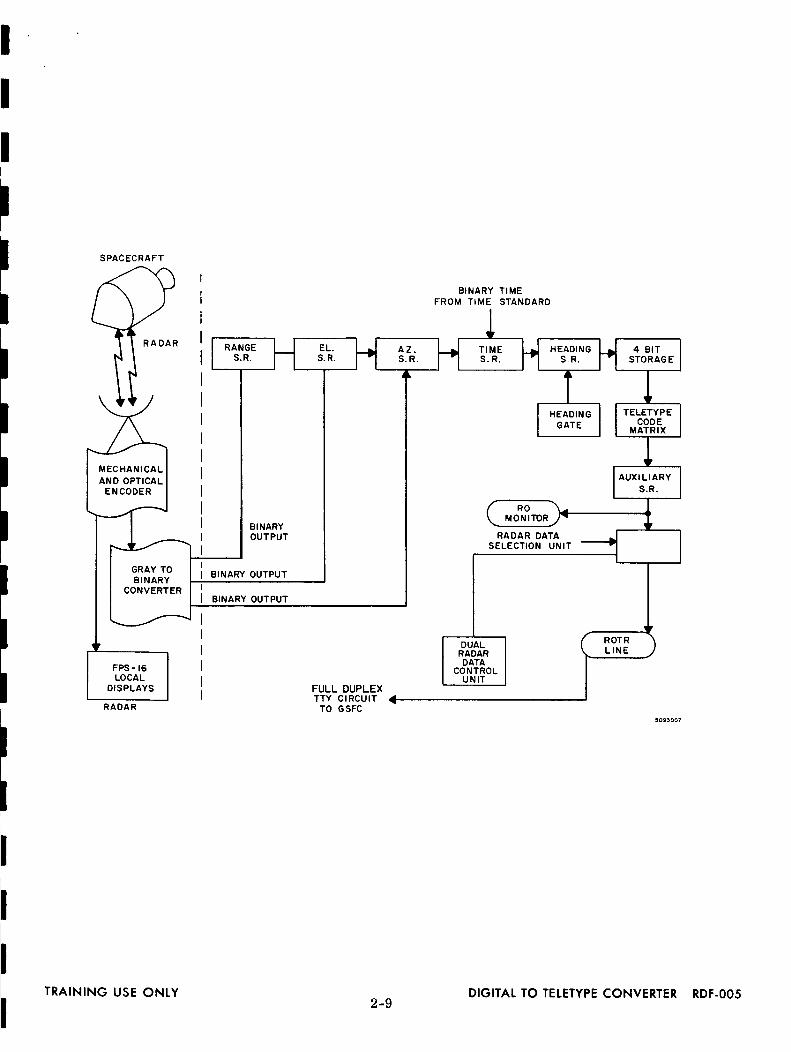
TRAINING USE ONLY DIGITAL TO TELETYPE CONVERTER RDF-O052-9

2-10
lZ°
IU
J
U3z,vF-
I

I
I
I
I
I
I
I
I
I
I
I
I
I
I
I
I
I
I
I
ACQUISITION _ )AR_SYSTEM
ACQUISITIONDATA
DIGITAL DATA ]
PROCESSING /EQUIPMENT J
TRAINING USE ONLY
J PLOTTINGBOARD
POLARcoNVERTERTOCARTESIAN _ DIGITAL
COOR D IN ATE TO
I I ANALOG__ TRANSMITTER RECEIVER
- ..........
2-ii
RADAR TRACKING SYSTEM WITH D-CANALOG DATA TRANSMISSION RDF-002

BINARY-OCTAL-DECIMAL CONVERSION DATA
1. Gray-to-Binary Conversion
a. The least significant bit in the binary word can be determined by counting
the l's in the gray word. When the number of l's is odd, the least significant binary
bit will be a 1. An even number of l's in the gray word causes the least significant
binary bit to be a 0.
b. Place the least significant bit of the binary word under the least significant
bit of the gray word. Add the l's in the remaining gray word, excluding its least
significant binary bit, to determine whether it is odd or even, remembering that the
least significant gray bit having a binary bit beneath is not included in the count.
Continue the procedure to determine all of the binary bits in succession.
Example.
Gray word - 0010 0010 1000 0100 0001
Binary word - 0011 1100 1111 1000 0001
2. Binary-to-Decimal Conversion
a. When the equivalent binary is obtained from the encoder outputs, the range
and/or angle can be determined by referring to table 1 as illustrated in example of
paragraph 2. b.
b. For each binary bit, refer to table 1 and tabulate as in the example below
for total bit value.
2-12

I
II
I
II
I
I
II
II
I
II
I
III
e
Example:
Binary word - 0011
Binary Bit Number
1 (least significant)89
10111215161718
Total Bit Value
Octal-to-Binary Conversion
1100 iiii i000 0001
Range Yds.
9.765625
125
i020
160
320640
250.500.
000.000.
000.000.000.000.
1,280,000.
2,438,759. 765625
a. Convert octal to binary using table 1 below and record.
TABLE 1
Octal
012
34
567
Example of octal-to-binary conversion:
Octal - 0 1 6 1
Binary - 000 001 110 001
Binary
000001010
011i00i01Ii0111
6 0
110 000
b. For azimuth and/or elevation TTY readout, drop the least significant
binary bit from paragraph 3. a. and record new binary word.
c. When the equivalent binary word is obtained from the TTY outputs, the
range and/or angle bit values can be determined by referring to table 2 as illus-
trated in the example of paragraphs 3. d and 3. e.
d. For angle conversation, refer to table 2 and tabulate as in the example
below for the total bit value:
TRAINING USE ONLY2-13
RDF-013

Octal - 0 1 6 1 6 0
Binary - 000 001 110 001 110 000
New Binary - 00 000 111 000 111 000
Binary Bit Number Angle Degrees
4 0.045 0.096 0.18
10 2.8111 5.6212 11.25
Total Bit Value 19.99 Degrees
e. For range conversion refer to table 2 and tabulate as in the example below
for total bit value:
Octal - 0 0 1 6 1 6 0
Binary - 000 000 001 011 001 110 000
Binary Bit Number Range Yds.
5 156.256 312.57 625
ii 10,000.12 20,000.
13 40,000.
Total BR Value 70,993.75 Yards
RDF-0132-14
TRAINING USE ONLY
i
II
II
I
I
I
I
I
I
I
!
I
I
II
I
I
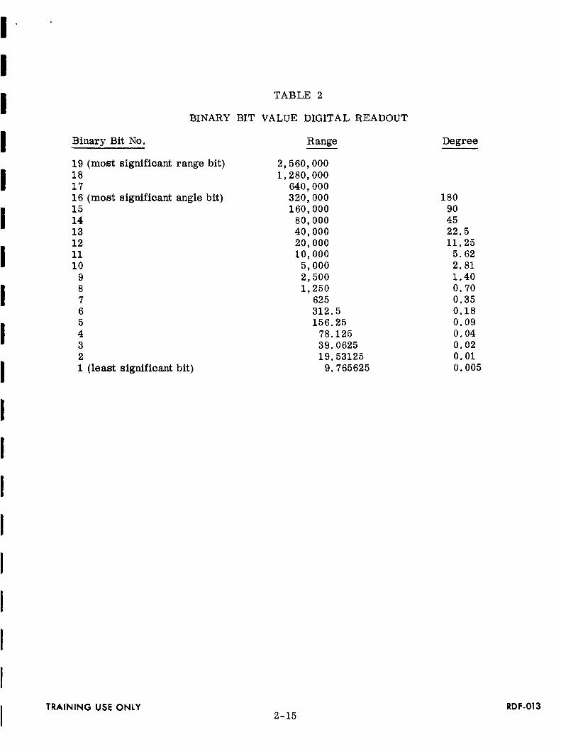
TABLE 2
BINARY BIT VALUE DIGITAL READOUT
Binary Bit No. Range
19181716151413121110
987654
321
(most significant range bit)
(most significant angle bit}
(least significant bit)
2,560,000
1,280,000640,000320,000160,000
80 00040 00020 00010 000
5 0002 500I 250
625
312.5156.25
78.12539. 062519.53125
9. 765625
TRAINING USE ONLY2-15
Degree
1809O4522.511.25
5.622.81
1.400.700.350.180.090.040.020.010.005
RDF-013

I
II
II
I
I
I
II
CMD _"
j'-
LUNAR
VEHICLE
SERVO
MICROWAVE r
C-BAND
RADAR
BIOMED _
FM LM q'-
,. T
VOICE
TO
DATA
DEMODS
T.V.
INTERCOM
j VHF SATURNAND
w[ VOICE DATA
._ PCMPATCHED
TO UP-CBUFFE
3-/

TO TDP
_..................__ -
_............._ -
t
PREDICTSFROM RDCC
TO VOICERCDR
EXCITER
VOICE FM
INTERCOM
SCOJ_r IFM RF CMD J
VERIF RCVR
UP-DATABUFFER
TO RFCMD
\ I /
CMODP I _TE._._O_'TORI(642B') J RIoAM_DER
MARK I
I
TDP
PCM 1(PROGRAMMED)
ro RCDRS
VHF VOICEro INTERCOM
ffA FM UP-DATABUFFER
_> TO ALLSYSTEMS/SUBSYSTEMS
TO/FROMALL
SYSTEMS/SUBSYSTEMS
RCDR FOR i ¢TDP OUT
TIMEAND
FREQ
ON-SITEINTERCOM
Ti
-I
TLM DP
(642B)
TO USB[
WHERE_I_ 1
USED |
4
MICROWAVE I
(1218S}
MCVG II
_l CONSOLES 8, JDISPLAYS
VOICE
r-----_TO/FROM/ MSC
,_ _, I1,
ON-S,TEL ,_ TTYCOMMUN,CAT,ONSr
MODEMS
SPAN DATATO MSC
SPAN
qI__I,.TO/FROM
GSFC/MSC
t_II. TO/FROMGSFC/MSC
6315003
TRAINING USE ONLY
REMOTE STATIONCONFIGURATION,BLOCK DIAGRAM AI-031
_/3-2
i
IIi
II
I
I
II
I
II
I
I
II
I
I
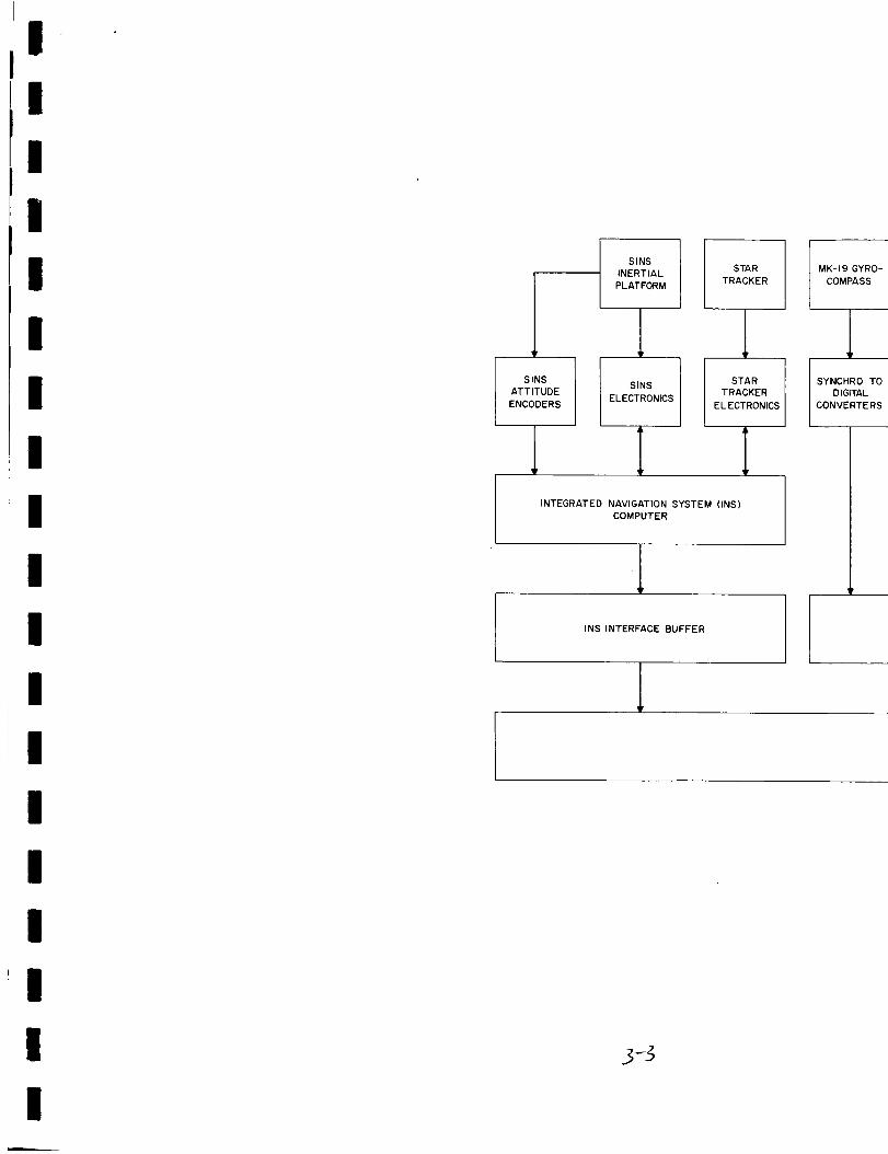
SINS
INERTIAL
PLATFORM
STAR
TRACKER
SINS
ATTITUDE
ENCODERS
_p
SINS
ELECTRONICS
STARTRACKER
EL ECTRONICS
INTEGRATED NAVIGATION SYSTEM (INS)COMPUTER
.lINS INTERFACE BUFFER
3_
MK-19 GYRO-
COMPASS
1SYNCHRO TO
DIGITAL
CONVERTERS

E-M
LOG
LORAN C
RECEIVER
BATHYMETRIC
NAVIGATION
SATELLITE
NAVIGATION
FLEXURE
MONITORS
USB & C-BAND
UNIFIED
S-BAND
C-BAND
RADAR
SYNCHRO TO
DIGITAL
CONVERTERS
SYNCHRO TODIGITAL
CONVERTERS
BATHYMETRIC
CORRELATOR
SATELLITE
NAVIGATION
DATACONVERTERS
FLEX MONITOR
ELECTRONICS8DATA
CONVERTERS
UNIFIED
S-BAND DATA
CONVERTERS
C-BAND
RADAR DATA
CONVERTERS
UNIFIED
S-BAND DATA
CONVERTERS
NAVIGATION DATA BUFFERFLEX MONITOR
INTERFACE
BUFFER
USB
INTERFACE
BUFFER
C-BAND
RADAR
INTERFACE
BUFFER
CDP COMPUTER
IMAGNETIC
TAPE
UNIT
4- DECK
IMAGNETIC
TAPE
UNIT
2-DECK
HiGH
SPEED
PRINTER
INPUT/
OUTPUT
CONSOLE
INTERFACE
TO CMD
AND TLM
COMPUTERS

TELEMETRYANTENNA
_LDIGITAL
SHAFT
ENCODERSAND
CONVERTERS
SYNCRO
EQUIP
ROOM ASN
SYNCHRO TO
DIGITALCONVERTER
OPERATIONS 1 MISSION 1
i
COMMUNICATIONS TO
AND FROM GSFC./x___
/
ANGLE DATA
INTERFACE
BUFFER
ANALOG
TO
SYNC
CONV
DIGITAL
TO
ANALOG
CONV
DIGITAL
DISPLAYTELETYPE
I IHIGH
SPEED
MODEMS
TRAINING USE ONLY_f3-4 -L
APOLLO SHIPS,
BLOCK DIAGRAM AI-041

u_O
////o
_oco
3-5
00iiiU,.
u0,..J
0Z0i11
0ZZ@-

NETWORK TEST AND TRAINING FACILITY
GODDARD SPACE FLIGHT CENTER
GREENBELT, MARYLAND
INTRODUCTION TO THE UNIFIED S-BAND SYSTEM
The lunar phases of the Apollo missions require techniques and equipment
exceeding the capability of those previously used in the Manned Space Flight Network.
To fulfill this requirement, the Unified S-Band (USB) system has been introduced into
the network. The USB system used with 85-foot antennas will provide the only means
of tracking and communicating at lunar distances. The USB system with 30-foot
antennas will be used to fill the gaps in the coverage provided by the three 85-foot
antenna stations. The USB system with the 30-foot antennas will also be used to
provide data during the launch, insertion, earth parking orbit(s) and injection phases
of Apollo missions.
In order to insure reliability, the USB system utilizes existing, proven tech-
niques and hardware. These items of equipment developed and used by the Jet Pro-
pulsion Laboratory and the Scientific Satellite Network have been adapted to the USB
system. The more significant of this equipment is the range and range rate equip-
ment supplied by the Jet Propulsion Laboratory to the program and the antenna systems
which are nearly identical to those used in the Scientific Satellite program.
The USB system utilizes a single carrier frequency in each direction to pro-
vide tracking as well as communicating with the spacecraft. Voice and update data
are frequency modulated onto subcarriers and then combined with the ranging data.
This composite information is used to phase-modulate the transmitted carrier fre-
quency. The received and transmitted carrier frequencies are coherently related.
This allows measurements of the carrier doppler frequency by the ground station for
determination of the radial velocity of the spacecraft.
In the transponder (spacecraft)the subcarriers are extracted from the RF
carrier and detected to produce the voice and command information. The binary
ranging signals, modulated directly onto the carrier, are detected by the wideband
phase detector and translated to a video signal.
4-1

The voice andtelemetry data to be transmitted from the spacecraft are
modulated ontosubcarriers, combinedwith the video ranging signals, and used to
phase-modulatethe downlink carrier frequency. The transponder transmitter can
also be frequency-modulated for the transmission of television information or re-
corded data instead of ranging signals.
The basic USBsystem has the ability to provide tracking and communications
data for two spacecraft simultaneously, provided they are within the beamwidth of the
single antenna. The primary modeof tracking and communications is through theuse of the PM modeof operation. Two sets of frequencies separated by approxi-
mately 5 megahertz are usedfor this purpose. In addition to the primary mode ofcommunications, the USBsystem has the capability of receiving data on two other
frequencies. These are used primarily for the transmission of FM data from the
spacecraft.
The tracking and communicating with the spacecraft during the lunar missions
will be provided by three primary deep-space facilities, employing 85-foot antennas,
spacedat approximately equal intervals of longitude around the earth to provide the
continuous coverageof the lunar missions. Three of the deepspace instrumentation
facilities (DSIF} located at approximately the same locations will be equippedto
serve as secondary to the primary stations. Each of these facilities, both the pri-
mary and secondary stations, will be equippedto track andprovide communications
with both the Lunar Module {LM) and the CommandModule (CM} simultaneously.
In addition to the stations with the 85-foot antennas, a number of other sta-
tions employing 30-foot antennasare also required ir_the network. These systemsare neededfor launch coverage in-flight checkout of t)hespacecraft, to fill gaps in
the coverage of the three lunar stations, andto provide instrumentation coverage
for testing the spacecraft in earth orbit.
4-2

00
ZZ
ZO
I--I--
u)
Z-JO
o_
wtlJ
0...J
--
z_Q
II
__k_0_a:0I-
I--J
=E
Q
I_JtA
Jaor?,:IO
n-
t_JL
0
b_
ZtA
J
Q:C
O
a.,00
m
o
tic
o_m
_/
W0
4-3
0
oi
>-Z.<
|if)
M,.
Z00<M.
m>-Z00ZZ<I--

UNIFIED S-BAND ANTENNAS
INTRODUCTION
The following describes the main features of the Unified S-Band antennas,
their design considerations, characteristics, parameters, functions, and modes of
operation. This description covers 30-foot and 85-foot land-based X-Y mounts as
well as the shipboard AZ-EL mounts.
TYPES OF ANTENNA MOUNTS
Most steerable antennas have two mutually perpendicular rotational axes as
shown in figure 1. The main difference between antenna mounts is the orientation
of the lower of these two axes. There are three main types of antenna mounts.
Io % \I % \
-.w' • •
AZ - EL POLAR X-Y
I
I
I
I
I
I
I
I
I
Figure 1 - Antenna mounts.
Azimuth-Elevation Mount
In the azimuth-elevation mount, the lower axis is vertical. This axis ar-
rangement permits compactness of design and rigidity and it is the logical choice
when tracking through zenith is not a requirement. It is by far the most popular
mount. The problem is that extremely fast azimuth rates are required to track
through zenith with the azimuth-elevation mount.
Polar (Hour Angle - Declination) Mount
In the polar mount the lower axis is parallel to the earth's rotational axis.
This arrangement facilitates ease of tracking of celestial objects. It is used for
radio telescopes and for antennas in the NASA deep space effort.
4-4

X - Y Mount
Both axesof the X - Y mount are horizontal at zenith. The mount was designed
especially for tracking earth satellites. Its main advantageis that it can track throughzenith. All three types of mounts havegimbal lock positions at the ends of the lower
axis. For the X - Y mount, these positions are half cones (10° wide) just abovethe
horizon (areas which are not greatly significant).
LAND-BASED ANTENNAS
It has beenestablished that all the Apollo land-based antennasmust be capable
of maintaining contact with the spacecraft through zenith (orbital transfer could occur
at zenith) and essentially complete sky coverage is required. These requirementsdictated selection of the X - Y mount for both the 30-foot and the 85-foot land-basedantennas.
30-Foot Antenna
1. Three-foot diameter acquisition antennaat apex of quadripod.
2. Secondaryreflector for Cassegrain feed system located just below acqui-sition antenna.
3. Y-axis (upper).
4. Y-wheelhouse (so-called cement mixer) which houses boresight package
and equipment such as parametric amplifiers that should be near the feeds. This room
is air conditioned by circulating a chilled glycol solution.
5. X-axis and X-wheel assembly which houses Y-axis drive assembly and
provides access way for personnel to Y-wheelhouse.
6. Lower platform which provides mounting for X-drive units.
7. Room beneath antenna which houses power amplifier units and motor
starters for drives.
Main Reflector
1. The main reflector is made up of 36 solid surface panels. These panels
are individually adjustable. Paint on the surface panels scatters solar radiation to
prevent overheating feeds.
4-5

2. The feed cone mounted at center of dish.
3. Lights on rim of dish to warn when antennamay be transmitting. An
audio warning is also used.
85-Foot Antenna
The characteristics of the 85-foot antennasare essentially the same as those
of the 30-foot antennaswith the following exceptions:
1. Reflector is meshedrather than solid.
2. Absenceof "cement mixer" appearanceof Y-wheelhouse.
3. Six-foot diameter acquisition antennaat apex of quadripod.
4. Axis wheel structures for X and Y-wheelhousesare large spaceframes.
SHIPBOARDANTENNAS
Although the X -Y antennacan track through zenith, it has some drawbacks.
Whenit is designedfor essentially complete sky coverage, the rotational axes are
separatedby a considerable distance. As a result, both axes must be counterweighted.
This meansthat the design lacks compactness andthe lower axis has a high moment
of inertia. For shipboard application these disadvantageswere judged to overshadow
the advantageof being able to track through zenith (considering the fact that the ship
location could possibly be changedto avoid an overhead pass). Therefore, azimuth-
elevation mounts are used for the Apollo ships' antennas.
4-6

0
Z0o
0I--
0a_
_uO.
>-
5ma?hit,
IIIIIII
4--7•
>,,
ZoZZ

8388002
TRAINING USE ONLY4-8
30.FOOT ANTENNASTRUCTURE ALB-011

II
II
I
II
II
I
I
I
I
I
I
I
I
I
I
o
2.
3.
4.
.
6.
7.
.
9.
10.
11.
12.
13.
14.
15.
16.
17.
18.
19.
20.
21
22.
23.
24.
25.
UNIFIED S-BAND LAND BASED ANTENNA
TECHNICAL CHARACTERISTICS
ANTENNA - 30' alum. and steel main dish.
GAIN - 43 db Xmt - 44 Rx.
FEED - 4 horn Cassegrain monopulse (dual freq. multi-mode).
POLARIZATION - Transmit - RH or LH circular. Selectable remotely.
- Receive - RH or LH circular. Must be manually changed.
BEAM WIDTH - Main 1 °.
RF POWER - Adjustable from 1 to 20 KW.
FREQUENCY - Transmit - 2101 to 2106 MC.
-Receive- 2272, 2277, 2282, 2287 MC.
WEIGHT - 146,000 Lbs.
X BRAKING - Normal 25°/Sec 2 - Emergency 50°/Sec 2, 290 Ft. Lbs.
Y BRAKING - Normal 25°/Sec 2 - Emergency 50°/Sec 2, 130 Ft. Lbs.
DRIVE - Hydraulic (Dual Anti Back Lash).
TORQUE - Capable of holding antenna in winds up to 140 MPH at zenith.
MAX. X RATE - 4°/Sec.
MAX. Y RATE - 4°/Sec.
MAX. ACCELERATION - 5°/Sec 2.
ACQUISITION ANTENNA - 22 db gain - 10 ° beam width - 42" diameter.
TRACKING ACCURACY - . 009 ° - Slave . 2 °.
SKY COVERAGE - 2° above horizon - 360 ° except in keyhole area which is 8°.
high and 20 ° wide.
Y LIMITS--82 ° .
X LIMITS--95 ° .
STABILIZATION - Tach. Pos. feedback and hydraulic controlled antibacklash.
MODES OF OPERATION- Control, Operation, and Test.
OUTPUT DATA - Optical 18 bits and sign bit - 3 LSB in gray code.
STATIC DEAD ZONE-.002 ° .
SETTLING TIME - 1.5 Sec. with full bandwidth selected.
4-9 AI-101

Criteria
Velocity
Acceleration
Winds: Operating
reducedOperating
accur acy
Stowing
Survival
Sky Coverage
Keyhole Cone
Keyhole Orientation
Accuracy: Pointing
Tracking
ANTENNA SYSTEM PERFORMANCE
30 Ft.
2O
45
60
140
2O
North-SouthAxis
+0.6
1.5 max.
85 Ft.
2O
45
60
120
2O
East-WestAxis
=_0.6
1.5 max.
Units
Degrees/Second
Degrees/Second 2
MPH
MPH
MPH
MPH
Degrees Above Horizon
Degrees
Minute s
Minutes
4-10

IIIIIIIIIIIIIIIIII
0ztl/\
I
Z_Q
_0
,'.c
pc_H
j,_(..)
ZO
(.W
__I-
_,>_"
4-11
_w,nz
z=
z_
>_,_
..-._.
mbJ
0Z
>-->'_
ocon-l-
W_1
I,->
"
-___
,_
>>,_>>_>>
TTTTTITTT
O_
m(X)
m.,
ow
8_
I_o_JIx
DZ
O,
'P,
mD
<<0,<v.L2
0>0><ZZM4
l--
Z.<_Lo)-..4
Z0M=I
U_
0ZZ,<I-=

UNIVERSAL TIME
COMMAND TIME
COUNTDOWN DURATIONELAPSED TIME
STATUS CLOCK CONTROL
I
X REAL ANGLE I
IX COMM ANGLE
HOLD TIME
REMOT_TRgCK,N____PROCES_______O,REMOTE PROG CONTROL
WARNING CONTROL
ERROR MONITOR
AND SLAVE SELECTION
SERVO CONTROL
I Y REAL ANGLEY COMM ANGLE
SCAN GEN
TELEPHONEO O JACKS
BALL TRACKER O O
TRAINING USE ONLY4-12
ANTENNA SERVO CONTROLCONSOLE LAYOUT ALB-005

III
I
II
SERVO CONTROL
® @
I 100UlI?O° I
I PRELIMIT I
I DEAO LIMITI
@ ------.
X AXIS
ERROR
I-_fO°i
® @
A
v
EMERGENCY
0,25_)0,5
o.lz\(_/i
BANDWIDTH
I AUTOTRKII
I READY II
I ACO TRK IIi _ ii
I READY II
i IIITD III PROC ilI UI READY fl
I PRC
I READY II
I 5LAVE II
I READY II
POWER
Y AXIS
ERROR
i irI IOO' 112D° il
DEAD LIMIT II
_,_
TESTIII TESTIll TESTIJPROG ACQTRK AUTOTRK
@ ®4
II Y AXIS __,ii _ ii
II DISABLEII _ ®
TRAINING USE ONLY4-13
8600000
ANTENNA SERVO CONTROL UNIT
ALB.023

)-.ZW
e_O
_W
XI,! ll....
._l
,.,_-__o
u_
,,,O
_
____"T
r_---A-G
L_T
_,"
tI
L_]_J
r-----..1
II
I!_-
Ii
ge
II
t%'_
L....
J
im<//
a(hl,,"'_
IIr
L-9---gJ
Ir.i
_I......I
_i_<
,,:_i
I
IL.....
._1__L
,.._
\°t
_
tb.I
,_
F"I
I1:
ii"l
I
L__i___l
[----._-
---1
II
iI._
ih
_.L____]
l_--"-.
I'
Ii.i_
-_
I_
F---1
i|
II
C-
II.....
J
r--_-7I
"II
i_i.
i
L__J
i 0F"
---
-o
I!_,
O
@
III
iI
L......J
OiI-0
rm
I
L.....J
4-14
0Wt_b-b-
F-_--G
I<_
¢._I
"JO
_i
_'-I
"_......
j
7<,
I|III
:1ZOOZ-I _z<I.--

Ii
II
II
I
I
ii
Ii
I
III
i
i
i TRAINING USE ONLY
I
COMPUTERCOMMAND
DATA
I0 PPS SAMPLE
_' (X) 17 BITS + SIGN
ENCODER J(DATEX) (Y) 17BITS + SIGN
I
4-15
%AL ,
ARITH I"_ J SYNCON,Ti.----_]DAC
]$620001
ANTENNA POSITION PROGRAMMER,
SUBSYSTEM, BLOCK DIAGRAM APP-101

ul
i,
--"
--ii
ZA
Vl
b.I
i--in_
--_W
WI
O0
O:
_JO
UJ
oo
oo
oo
_ooooo
o_
,_o°
i-14,1
_oO
0
o_I_i_
--'1_!._
,_CL
L_
t
_n
XOO.
Wa0:5
=E
O=
0
ZQ
L
U.I
0IE
XvI-"0k-
_oooI
_lr_
Ld
nr
Zu
J_ooo
I.3
I--2_
_N
_:I_
_o>_-
,oooZ
_-_
1o0_
(j
I1
--In
-
.;Z
(/),_1
_1"_
_I_
_-'- ....
>-
>-
1
(1:)-
j(9
I--
u_
>
oIi
|__1=E
I'-I
C
i
_:_
[X
xI
4-16
0_L<UJ
:E<00z00.<zz144
z.<UJ
I,--
>-
>,.
z00ZZ.<

IIII
az0>-
_1o.U
J¢'_
_j--
Z
g-Q
X(.3xL
_
X_
-J,.J
WW
{Z:
e¢
A(,.)xi0_:Xw
O:
>-x
_o_,
(oz
>-I
-----_,
_o_
I'-I._
W_
IZ
(D>
"
xlw
J
;oi
j0
Z"_
Xf._ZQ!
r-
>-Z,<0t_
W0
wx
4-17
0<<.00Z00.<ZZUJ
Z.<>.=.1
Z00ZZ.<I..,-

ANTENNA POSITION PROGRAMMER
PROGRAM CONTROL
I ,.o_! READERSEARCHI ..... J J J J ] J I I I J AHEAD] .... IJ I _'
TAPE CONTROL
ADD TIME
HOURS MINUTES SECONDS
CONTROL MODE COMMAND DATA SOURCE
TAPE
LOCAL_REMOTE COMPUTER(_MANUAL
ENCODER SIMULATOR
REAL ANGLE SOURCE
SlMULATOR_ENCODER
Y ANGLE
56;_eoo7
TRAINING USE ONLY4-18
ANTENNA POSITION PROGRAMMER
'CONTROL PANEL (LOCAL) APP-107
IiI
I
III
I

I
I
I
I
I
I
I
I
I
I
I
I
I
I
I
I
I
I
I
ANTENNA POSITION PROGRAMMER
COMPUT[R COMPUTER A L_AL I
COMMAND DATA SOURCE COMMAND/OFFSET ANGLES
COMPUTER-,,TAPE,-MANUAL X ANGLE Y ANGLE
@- @REMOTEPOSITION
TEST
TRAINING USE ONLY4-19
ANTENNA POSITION PROGRAMMER
CONTROL PANEL (REMOTE) App_tn^

ANTENNA RE
ELECTRONICS HUB
COUNTERWEIGHTS
AZIMUTHBRAKE
AZIMUTH TURNTABLE
ELEVATIONBRAKE
ICAL BASE ASSEMBLY
5665002
TRAINING USE ONLY4-20
30-FOOT USB SHIPBOARDANTENNA SBA-100-A

I
I
I
I
I
I
I
I
I
I
I
I
I
I
I
I
I
I
ITRAINING USE ONLY
\l
! J
S
4-21
8747001
12-FOOT USB SHIPBOARD ANTENNA
SBA-100-B

i.
2.
3.
4.
,
6.
7.
8.
9.
10.
11.
12.
13.
14.
15.
16.
17.
18.
19.
20
21
22.
23.
24.
25.
26.
UNIFIED S-BAND SHIPBOARD ANTENNA
TECHNICAL CHARACTERISTICS
ANTENNA - 30' Alum.
GAIN - 43 db.
FEED - Four horn Cassegrain monopulse (Dual frequency multi-mode).
POLARIZATION - Transmit - RH or LH circular. Selectable at Control Con-
sole. - Receive - RH or LH must be manually switched.
BEAM WIDTH - i. 1 ° - i. 5 ° (Main Dish).
SIDE LOBES - First 18 db down below main. All others 30 db down below main.
DEPTH OF NULL - 35 db.
RF POWER - 10KW average (Adjustable 1 to 20KW).
FREQUENCY - Transmit - 2090 - 2120MC.
- Receive - 2270 - 2300MC.
WEIGHT - i00,000 ibs.
AZ BRAKING - 12K Ft. Lbs. (Total 72,000 Ft. Lb. ).
- 6:1 Ratio.
EL BRAKING- 12K Ft. Lbs. (Total 90,000 Ft. Lb.).
- 3:1 Ratio.
DRIVE - dc Torque Director.
TORQUE - 26,000 Ft. Lbs. Cont.
- 52K Peak.
MAX AZ RATE - 56 ° Per Second.
MAX EL RATE - 33 ° Per Second.
MAX ACCELERATION - 50°/Sec 2.
MIN. SMOOTH RATE - . 001°/Sec.
NATURAL RESONATE FREQUENCY - Greater than 20 cps.
ACQUISITION ANTENNA - 30' Inches Diameter, i0 ° Beam Width, 22 db gain,
TRACKING ACCURACY - .ira Rad.
RE PEATABILITY - . 001 °.
SKY COVERAGE - 2 ° to 86 ° .
ELEVATION LIMITS - 15 ° (105 ° - 180°).
AZIMUTH LIMITS - NONE.
STABILIZATION - Ships inertial navigation system internal.
4-22 AI-101

I
III
I
I
I
II
II
II
III
III
27. MODES OF OPERATION - Primary with Gyro feedback test with tachometer
feedback, utility with tachometer feedback.
28. OUTPUT DATA - Optical 18 bit True binary.
29. SLIP RINGS - 286 Total
4 In Motors24 Shielded
240 Non-shielded
18 High Current
4-23 AI-101

L__Ui
wI.-I-Z,<I...-
"50I.L
I.LIo..._>
_,,,._
I-Ilgwu
')I11:¢_
_-_
-or"
(._w¢wWZ
.-JL
LI
_xZW
:_[..1
_N,,,
t
0F-
N
Z
z---_--I---1W
I1"
o_0,__m
zI_ZO_rLU
-g_
4-24

I
TRAINING USE ONLY
POWER CONTROL
PANEL
PRIMARY CONTROL
PANEL
RESERVED
FOR NASA
SECONDARYCONTROL
PANEL
BALL CONTROL ASSY
REG _15V PS
BLANK
UNREG 28V PS
BLANK
PRIMARY
CONTROL
CABINET
SECONDARYCONTROL
CABINET
4-25SB-42 CONTROL CONSOLE SBA-115

I
I
I
I
I
I
I
I
I
I
I
I
I
I
I
I
I
UNIFIED S-BAND
UPLINK
INTRODUC TION
In earlier Manned Space Flight programs, several functionally independent
systems using different frequency bands {HF, VHF & UHF) have been employed in
the two-way spacecraft-ground links, resulting in highly complex facilities. However,
in the Unified S-Band (USB) equipment for the Apollo program, most of the communi-
cating functions have been integrated, for the first time, into a single comprehensive
capability. All of the carrier frequencies in the two-way path are in the S-Band region
(between 2100 and 2300 megacycles). Voice, television, telemetry data, range, range-
rate, and antenna-tracking information may all be processed separately or simulta-
neously by the same radio frequency equipment.
Within the ground station facilities of the Manned Space Flight Network (MSFN),
this unified concept is extremely evident in the receiver/exciter subsystem equipment.
The subsystem acts as a link between the microwave equipment (such as the power
amplifier and parametric amplifier) and the low-frequency RF, digital data processing,
and DC actuated equipment. Information and reference signals from ten different
external subsystems interface with the receiver/exciter equipment, which is in essence,
a focal point in the USB concept. This equipment is also supplied, for most stations,
in the dual configuration, This configuration contains two complete receiver/exciter
subsystems for redundancy and multiple-vehicle operation.
The equipment discussed above includes the updata buffer modem, the sub-
carrier oscillator subsystem and the verification receiver. Together, these items
comprise a significant portion of the uplink communications system. The updata
buffer modem accepts data from the command computer and operates on the data to
put it into a form suitable for modulation onto a subcarrier. The subcarrier oscil-
lator subsystem accepts data and voice signals and modulates these signals onto
their respective subcarriers. The verification receiver samples the output of the
S-Band power amplifier and demodulates the S-Band carrier. The output of the veri-
fication receiver is the original updata and upvoice signals. The data is returned
to the buffer modem as an input to the command computer. The voice output is
recorded.
5-1

(FR-fiO)/96
RCVR VCO
,CTR. FREQ./
F R MC
F T=TRANSMITTED FREQUENCY
F R=REcEIVED FREQUENCY
CSM/PM
I
I
I
II
23.25
LM
2280-
23,15-
2270
IFT/MC _ _ 2095
FT/96 TRANS VCO CTR FREQ.).
5 X FT/96 RANGING CLOCK _,221 )
CTR FREQ (KC)
CSM/FM
2101.802
;21,893777.
I495.3542
I2106.406
i2i.941732
I496.4]73
OIIIOI09
TRAINING USE ONLY S-BAND FREQ CHART R&E-1015-2

PM CARRIER
J .VOICE SUBCARRIER
, / j(/_UP-OATA SUBCARRIER
i ____"_'fo-, .c '_\_fo,_OKC
I _o,O+3OKC
'iI
IiiI TRAINING USE ONLY 5-3
CODE ENVELOPE
\ \fo + I MC fO-1.2MC
5(BBOIIO
UNIFIED S-BAND INDIVIDUAL UP-LINK R&E-102

@0
woo.
Ww
rv
a.
ow
0iv
I
fl_-__t
ww
ot.i
o0
uZ
0_5-4
oq-
0÷
0o
T0
>-0zizi

II
II
II
I
III
II
I
II
I
I
II
TRAINING USE ONLY5-5
631S001
UP-LINK, SIGNAL FLOW AI-046A

o_
"¢3:
00
_o__z
0,_I
'
[----
IIL
=
_-6

I
I
I
I
I
I
I
I
I
I
I
I
DATA I I I.AN_ pA_ I I MODE OUTPUT
__ __ _ BAND PASSVOICE LOW PASS 30 Kc I l FILTERINPUT FILTER SCO
6223003
TRAINING USE ONLY SUBCARRIER OSCILLATOR SUBSYSTEM AI-0595-?

5-8
S.<Q.0<0o
m
00_vU_
m.<U,I
0n_Z.<U.I
Z
>-Z00ZZ.<

I
III
II
I
II
I
io
e
o
,
o
.
GROUND SYSTEM CHARACTERISTICS
POWER AMPLIFIER - KLYSTRON
Power output = 1-20 KW CW
PREAMPLIFIER - PARAMETRIC AMPLIFIER
Gain = 20 DB
Noise figure = I. 8 DB
Bandwidth = 30 MC
CARRIER FREQUENCIES
2106.4 MC command modules
2101.8 MC LM or SIV-B
VOICE SUBCARRIER
Frequency = 30 KC
FM modulation = i00 CPS to 3 KC
UPDATA SUBCARRIER
Frequency = 70 KC
Modulation = 1 KC syne tone; 2 KC sine wave Bi-phase modulated at200 CPS
RANGE CODE
4 code generators driven at 1 MC bit rate
The 4 C.G. outputs and 1 MC clock are added by digital logic in such amanner as to form a "maximum linear binary code"
Length of short code = L 1 -70 milliseconds
Length of long code = L 2 -5.4 seconds
Unambiguous range of L 1 = 7000 N. MI.
Unambiguous range of L 2 = 540,000 N. IVII.
5-9

I ATOMICSTANDARD
t
I ATOMICSTANDARD
CRYSTALSTANDARD
t
CRYSTAL
STANDARD
t
5MC
CONTROL
5MC
CONTROL
5MC
CONTROL
5MC
CONTROL
COMBINERDISTRIBUTION
AMPLIFIER
5MC (2)
IMC (8)
IOOKC (4)
k PATCHw PANEL
TRAINING USE ONLY5-10
APOLLO PRECISION FREQUENCY'SOURCE ATS-001

5-11
_tow0U0Zb--
b--
>-
.J
Z00zz<b-

I
III
I
I
I
III
I
II
I
II
I
I
I
UNIFIED S-BAND
DOWNLINK
INTRODUC TION
The spacecraft has the capability of transmitting two carriers simultaneously
at different frequencies, one of these is phase modulated by the information and the
other is reserved for frequency modulation. An examination of typical spectra of
the phase and frequency modulated carriers reveals the necessity for simultaneous
ground demodulation of both carriers and recovery of all data. Therefore ground
stations with dual capability are equipped with two demodulator systems.
The signal data demodulator system is an integral part of the heart of the
Unified S-Band system. The demodulator system is fed by the receiver and in turn
feeds a multichannel tape recorder, provides the inputs to the various data display
systems, and feeds the data processing equipment such as the PCM system. The
receiver feeds the demodulators with two signals. One is a 50-megacycle IF which
carries the frequency modulation. The other input from the receiver is at video
and contains the phase modulation. Thus the signal data demodulator system con-
sists of two channels which may be referred to as the FM and PM channels.
The 50-megacycle IF is routed to the carrier frequency demodulator which
reduces the signal to video and feeds a recorder, an isolation amplifier and filter
(television channel), the voice and biomedical data demodulator, and the telemetry
demodulator. The PM video input from the receiver supplies the inputs to the voice
and biomedical data subcarrier demodulator, the telemetry demodulator, and the
emergency key demodulator. It should be noted at this point that the telemetry
subcarrier demodulators and the voice and biomedical data subcarrier demodulators
of the PM and FM channels are identical.
The outputs of the voice and biomedical data subcarrier .demodulators and the
telemetry subcarrier demodulators are routed to a data output selector, which is
simply a switch. This allows the ground operators to route the voice, telemetry,
and biomedical data to the proper data-processing equipment regardless of whether
these data are recovered from the FM or PM channels of the signal data demodu-
lators. In addition, the data selector provides the inputs to seven biomedical sub-
carrier demodulators for the recovery of the biomedical information.
6-1

The ranging code is routed from the receiver to the Mark I ranging system.
The range rate or biased doppler is routed directly from the receiver to the Tracking
Data Processor (TDP). Range is routed from the Mark I to the Tracking Data Pro-
cessor. The output from the TDP is composed of range, range rate, time, and X
and Y angles from the antenna servo system. The output from the PCM telemetry
system is routed to the TLM computer for transmission to the Mission Control Center
and/or display on the on-site consoles.
6-2

II
II
I
I
I
II
II
I
I
I
I
I
I
I
I TRAINING USE ONLY
(FIR-50)/96IRCVIR VCO
CTIR. FREQ.
FIR MC
23.20-
23.15-
2270
FT/MC) ,_
FT/g6 TRANS VCO CTIR FIREQ._
5 RANGING CLOCK )X FT/96
CTR FIREQ [KC)
I2095
FT= TRANSMITTED FREQUENCY
F R= RECEIVED FREQUENCY
CSMIPM
LM
s-_ eFM
CSMIFM
2101.802I
21.8_377Z
I495.3342
(;-3 S-BAND FREQ CHART R&E-101

0
UZZ
6-4

FUNCTIONS OF S/C USB TRANSPONDER
1. Lock on to uplink carrier and track it as the
frequency changes due to doppler effect.
2. Extract the uplink subcarrier modulation to
produce voice and command information.
3. Detect binary ranging signal in a wide band
phase detector and translate to a video signal.
4. Translate receive frequency by a factor of24O221
5. Combine telemetry and voice subcarriers with
ranging signal and the resultant modulates the
PM downlifik carrier.
6. Combine telemetry and voice subcarriers with
television and the resultant modulates the FM
carrier.
SPACECRAFTTRANSPONDER AI-028TRAINING USE ONLY 6-5

FUNCTION
Voice
Telemetry
Ranging
Television
Scientific Data
Tape Playback
Emergency Key
Relay Through CSM
REQUIREMENTS
ContinuousCapability
Normal - 90%Word Intelligibility
Backup - 70%Word Intelligibility
ContinuousCapability
NRZ PCM at 51.2 KBPS or 1.6 KBPS rate
Continuous Capability
Phase Coherent Turn-Around of the PRN Range Code
When Convenient
Near-Commercial Quality Resolution and Gray Scale
3 Channels
Capability to Transmit Simultaneously with RealTime Data
Telemetry, Voice, and Scientific Data
Continuous Capability
Maximum of 25 Characters per Minute
EVA Voice and Biomed to MSFN
LM Simplex Voice to MSFN
TRAINING USE ONLY
SEPTEMBER, 1966
SPACECRAFT TO GROUND
COMMUNICATIONS REQUIRE MENTS
RRR-805AI-052
6-6

II
II
II
I
III
I
2287.5 McCarrier
Combination
2
3
Carrier
Information
Voice
51.2 KBPS Telemetry
RPNVoice51.2 KBPS TM
PRNVoicei. 6 KBPS TM
Voice1.6 KBPS TM
Modulation
Technique
FM/PM
PCM/PM/PM
PM on CarrierFM/PM
PCM/PM/PM
PM on Carrier
FM/PMPCM/PM/PM
FM/PM
PCM/PM/PM
Subearrier
Frequency
1.25 Mes1. 024 Mcs
1.25 Mcs1. 024 Mcs
i. 25 MesI. 024 Mes
i.25 Mcsi.024 Mcs
5 i. 6 KBPS TM PCM/PM/PM i. 024 Mcs
6 Key AM/PM 512 Kcs
7 PRN PM on Carrier
8 Backup Voice PM on Carrier1.6 KBPS TM PCM/PM/PM 1. 024 Mcs
9 PRN PM on Carrieri. 6 KBPS TM PCM/PM/PM
TRAINING USE ONLY
MARCH, 1967CSM TRANSMISSION COMBINATION
SUMMARY (PM MODE)
RRR-806AI-053
6-7

2272.5 McsCarrier
Combination
2
4
CarrierInformation
Playback Voice at 1:1Playback CSM51.2 KBPS TM at 1:1
Scientific DataPlayback at 1:1
Playback Voice at 32:1Playback CSM1.6 KBPS TM at 32:1
Scientific Data
Playback at 32:1
Playback LM 1.6 KBPSSplit Phase TM at 32:1
Television
Real Time ScientificData
Modulation
Technique
FM at Baseband
PCM/PM/PM
FM/FM
FM/FM
FM/FM
FM at Baseband
PCM/PM/PM
FM/FM
FM/FM
FM/FM
FM at Baseband
FM at Baseband
FM/FM
FM/FM
FM/FM
Subcarrier
Frequency
1. 024 Mcs
95 Kcs125 Kcs165 Kcs
1. 024 Mcs
95 Kcs125 Kcs165 Kcs
95 Kcs125 Kcs165 Kcs
TRAINING USE ONLY
MARCH, 1967
CSM TRANSMISSION COMBINATION
SUMMARY (FM MODES)
RRR-807
AI-054
6-8

IIIIIIIIIIIII
zzo>
Z0
I-
0
m,l
x.J
I,-
d
TT
TT
TW
)-Z
W_"
(JQ
:0
U_"
W,
w
8,-W
W
0W TTT
,_
>-
>-
-_
(.I
ZW J
6-9
0i
<0<Uo.=.1
UvZ.=J
oZo@ZZ<

PM COHERENT CARRIER
RANGE CODE
ENVELOPE
FL
t2282.5 MC
FM
NON-COHERENT CARRIER
.T/M SUBCARRIER
/VOICE SUBCARRIER
i
_FL÷ 1.25 MC
FL+ 1.024 MC
J
d
TV ENVELOPE
/
FL
FL+ 1.024 MC
86110127
TRAINING USE ONLY6-10 LM DOWN-LINK R&E-105

I
III
I
II
II
III
I
I
I
2282.5 McsCarrier
CombinationCarrier
Information
1 Voice51.2 KBPS TM
2 PRNVoice51.2 KBPS TM
3 1.6 KBPS TM
4 Backup Voice1.6 KBPS TM
5 Backup Voice
6 Carrier Key
7
Lunar stayMode
9
10
Voice/Biomedi. 6 KBPS TM
Voice/EMU/Biomed51.2 KBPS TM
Voice/EMU/BoimedTM
TVVoice/EMU/Biomed
1. 6 or 51.2 KBPSTelemetry
Modulation
Technique
Subcarrier
Frequency
CarrierPhase
Deviation
FM/PM i. 25 Mcs 0.7 RadiansPCM/PM/PM i. 024 Mcs i. 3 Radians
PM on Carrier 0.2 RadiansFM/PM 1.25 Mcs 0.7 RadiansPCM/PM/PM i. 024 Mcs i. 3 Radians
PCM/PM/PM i. 024 Mcs i. 3 Radians
PM on Carrier 0.8 RadiansPCM/PM/PM i. 024 Mcs i. 3 Radians
PM (24 db Clipping) 0.8 Radians
AM/PM 512 Kcs i. 4 Radians
FM/PMPCM/PM/PM
PM on Carrier
(No Clipping)PCM/PM/PM
FM/FM
PCM/PM/PM
1.25 Mcs1. 024 Mcs
1.25 Mcs
1. 024 Mcs
1.25 Mcs1. 025 Mcs
FM on Baseband
FM/FM/FMPCM/PM/PM
1.3 Radians0.7 Radians
TBD
CarrierDeviation
Ratio
0.17
0.37
2.0
0.170.37
TRAINING USE ONLY
MARCH, 1967
LM TRANSMISSIONCOMBINATION SUMMARY-
6-11
RRR-810AI-056

• VOICE
VOICE
PCMTELEMETRY
TELEVISION
EMERGENCY
HARDLINEBIOMEO
" ' AGC
,i- VOICE SUBCARRIER /z
_- o FROM S-BAND /-J _ I. RECEIVER I
_o rlNPUT TO PHASE I
_j _ [ MODULATOR J, S-BAND TRANSCEIVER
L_J MO_LATORqT T
RANGING FM-PMON-OFF CONTROL
CONTROL
STEER_
TO STEERABLEANTENNA
OMNI I
0"_
ISOLATOR _FILTER
TRAINING USE ONLY6-12
LM S-BAND SYSTEM AI-057

fo -512 KC
PM COHERENT CARRIER
f0 fo+512 KC5680128
EMERGENCY KEY R&E-106TRAINING USE ONLY 6-13

PM COHERENT CARRIER
fO'l'3OO CPS \ fo+2.3 KC
SQOOISt
TRAINING USE ONLY6-14
EMERGENCY VOICE R&E-107

le
g
o
o
,
.
o
SPACECRAFT USB CHARACTERISTICS
POWER AMPLIFIER - TWT
Power output - 20, 10 or 5 watts
ANTENNAS
Omnidirectional (near earth thru transposition)
High gain (28 DB) (after transposition and lunar)
CARRIER FREQUENCIES.
2287.5 MC-command module PM carrier
2272. 5 MC-command module FM carrier
2282. 5 MC-LM or SIV-B PM carrier
2277.5 MC-SIV-B FM telemetry carrier
2282. 5 MC-can also be used in FM mode from LM
Note-240
All PM spacecraft carriers are _ x ground PM carrier
VOICE SUBCARRIER-1.24 MC
Modulation-300 to 2300 CPSvoice +7 channels of biomedical data
TELEMETRY SUBCARRIER-1.024 MC
Bi-phase modulated at 51.2 KBPS-high data rate1.6 KBPS-low data rate
FM TELEVISION
500 KC modulation
320 lines
10 frames/sec
EMERGENCY KEY
512 KC subcarrier manually keyed and modulated directly on carrier.
SPACECRAFTSYSTEMS AI-026TRAINING USE ONLY 6-15
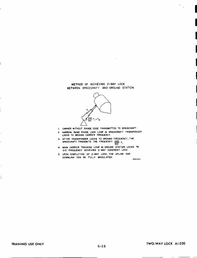
METHOD OF ACHIEVING 2-WAY LOCK
BETWEEN SPACECRAFT AND GROUND STATION
F I
I. CARRIER WITHOUT RANGE CODE TRANSMITTED TO SPACECRAFT.
2. NARROW BAND PHASE LOCK LOOP IN SPACECRAFT TRANSPONDER
LOCKS TO GROUND CARRIER FREQUENCY.
3. AFTER TRANSPONDER LOCKS TO GROUND FREQUENCY;THE
SPACECRAFT TRANSMITS THE FREQUENCY 240 FI221
4. MAIN CARRIER TRACKING LOOP IN GROUND STATION LOCKS TO
S/C FREQUENCY ACHIEVING 2-WAY COHERENT LOCK.
5. UPON COMPLETION OF 2-WAY LOCK,THE UPLINK AND
DOWNLINK CAN BE FULLY MODULATED.6510002
I
II
II
I
I
!I
TRAINING USE ONLY 6-16 TWO-WAY LOCK AI-030

I
I
I
I
I
I
I
I
I
I
I
I
I
I
I
I
I
I
ITRAINING USE ONLY
[
HI 4'
6-17
HS315000
DOWNLINK, SIGNAL FLOW AI-047

(
I--
o.t
JLI
6-18
00|
m,¢ew
0¢J00<.
0ILl>-
Z00ZZ.¢ IIIIIIII

I
I
I
I
I
I
I
I
I
I
"A" GENERATOR
"B" GENERATOR
"C" GENERATOR
"Cl" GENERATOR
"X" GENERATOR
CODE
COMBINER•_'II_COMBINED RANGE CODE
SllOml
TRAINING USE ONLY6-19
TRANSMIT CODE GENERATOR'BLOCK DIAGRAM RRR-003

\\
/\
\/
/
\/
J
\/
I'mZW--
W
6-20
N_
,x.\"_o
_-.\\
N_
_\\\%
N
w,_o,y,
8
I--
IJ
Zm.moj
I'mZbJl'O
bJ
O4
000,<0z-I I--
0I'm0,<8
>-z0U.I
U_
0zz,<i'm

I
II
II
I
I O_o_ RANGE,_0,J RANGE RATE
I RECEIVER NO.OIDATA IDENTIFICATION
T$( 0 LM I RANGE (30)
J _ CM J RANGE RATE
L_ECE'VERZ[
r MAGNET,Ci RECORD/ TAPE PLAYBACKL RECORDER
-X"
DUAL STATION ONLY
II
I
I
Ii TRAINING USE ONLY
tSTRAIGHT
BINARY
TIME STANDARD I
_,._1 II OF I BCD I CONTROL
SIGNALS
TRACKING
DATAPROCESSOR
HIGH TRACKING
SPEED DATA
'rCOMMUNICATIONS
4
LOWSPEED
600, t200, 2400 BPS
TELETYPE
X-ANGLE
Y-ANGLE
ANTENNA
POSITION
PROGRAMMER
_j PAPER
TAPE
PUNCH
TOAPOLLO CENTRALIZED
Ib COMPUTER SYSTEM
TRACKING
DATA
HISTORY
TAPE
IlllOl$
6-21USB SYSTEM TRACKING DATA PROCESSOR A1-113

I_°
I--
>'w_.-¢yt--_.
_t
6-22
,o"7_g00o_p..
ZZ&161
I'--
zI
I'--
00o
I
>-Z00ZZI,m

r-_U
Zh
l
TL
)
6
I__
-3_
om.-
--------J-----.-1
(_),-!
z(n
_::_I
Iz.r
f/
/
I
I'P---
o.J
ZE
}---
I-
i-
i
W
W
6-23
a
_°I
y_o
----1_
r,,--1
,.-,I_P/
il_1
H_;I
_2Jk_,"I
b,.
Z0mUZZU.I
I-,-
Z00IJL
It1
GO
{/))-,..I
Z0iii0ZZ

hiZ
_'-
O_
_-aDf_Y°_1
_WI--0,.
a.
I•
I'
_2
f31'-Z
r,_
rv,
ulU
-
OZ1[_ol
_1¢,_
Z_
)_>-
Zm
3n
-E
(r)
L)
r_
UJ
n_
hi0o
B--
--m
?,
n-
I_J
_L
6-24
l--:g:l_
(j
_Uhi
E_:
E
[--
"7
I°
lID
L_
-J
[
Z0F-
>-.<Z0U>-,,..ImuIL
L
ZZILlI---
ZI--
@@
__.l

i ,
I
I
I
I
I
i
I
I
I
I
i
i
t
i
i
i
i
i
APOLLO DIGITAL COMMAND SYSTEM
INTRODUCTION
The purpose of the Apollo Digital Command System (DCS) is to provide a means
for communicating with and controlling the spacecraft's equipment from the ground.
Some commands are identified before the launch; others are developed by the com-
puting complex, Command, Computer and Telemetry System (CCATS), at the Mission
Control Center (MCC) in Houston during the mission.
The commands identified before the mission are the type that are to be executed
at selected intervals during the mission. One of these commands may be sent several
times from one or more ground stations. For example, a command requesting a tape
playback of spacecraft recorded data may be sent by all stations once or twice during
a mission.
Other commands developed during the mission by the MCC computers would
ordinarily be sent only once by one station. However, if the transmission were not
successfully accomplished by the selected station, it would be retransmitted by an-
ther station later during the mission. An example would be the correct time for the
spacecraft computer. The time of the spacecraft computer is telemetered to the
ground stations. If this parameter does not agree with the indicated ground time, a
command will be sent to the spacecraft computer that will update the timing system
with the correct time.
Two types of digital commands will be utilized in the Apollo program; Real
Time Commands (RTC) and Stored Program Commands (SPC). Real Time Commands
are those generated during a mission by MCC and transmitted to a remote station for
immediate transmission to the spacecraft. Stored Program Commands are those
that are known before a mission; therefore, generated and transmitted to the remote
station and stored in the 642B command computer prior to launch. These commands
may be called up and executed during a mission either by the MCC or the on-site Flight
Controllers.
A command word is configured so that each command will only be accepted by
the selected spacecraft if it has the correct vehicle address, systems address, bit
structure, and word length. The vehicle address requirement is obvious. The system
7-1

address is required to differentiate betweenthe Real Time Computer (RTC}, Apollo
GuidanceNavigational Computer (AGC), andthe Central Timing Equipment (CTE)
systems aboard the vehicle. The bit structure employs sub-bit coding for security
measures.
The philosophy for secure updatatransmission is to insure that the command
word will be rejected by the spacecraft if it is not the exact commandword trans-
mitted. Measures havebeentaken in all phasesof the updatatransmission systemto insure that the chances of the spacecraft accepting an invalid commandis 1 x 10⁻⁹.
In the ground-to-air link each information bit is encodedinto five sub-bits to insure
the nonvalid commandrejection ratios.
7-2

SUBBITS
i S-IV BIIU SPC AND RTC
35 BITS
CSMILM CTE OR TEST -_
30 BITS
CSMILM GNC 1
22 BITS
CSMILM RTC
12 BITS -J
VA--.I,--SA--+----DATA----.I
VA CODE SYSTEM ADDRESS AND
DATA SUB'BIT CODEARE SAME 6zz3oo,
TRAINING USE ONLY?-3
COMMAND WORD STRUCTURE
(STORED AND OR REAL TIME) AI-024

_r
--]
_T_
--I,lu
l,-m
I"-Q
"q_I
(/)_
¢_I
"r,et
._II
_°i,_._'
w0
I--_
no
2......1.._
J!_o
:
i--i
ILl
i
Z0u....I
.¢I--
00
Z00ZZ
'/-4

IL
3E
mb
,...,.,
_1
OZO
I
?-5
a0
i
.<
.<
0.<
U0==,I
Ca
0ml
.<
I--,
.<
Z.<
0UI--
UJ
0UJ
Ua.>.>.Z00ZZ

Ii
II.
CP-642B COMPUTER
COMPUTER CHARACTERISTICS
DESCRIPTION
This information sheet will give the student an introduction to the characteris-
tics of the CP-642B computer. Computer concepts, power requirements, dif-
ferent voltage levels used throughout the computer, memory characteristics,
special I/O modes and quick reference tables are included.
INSTRUCTIONS
A. General Information
The CP-642B computer is a general purpose, stored-program machine
capable of processing large quantities of complex data where heavy input/
output communication is required. The basic word length is 30 bits and
the machine has a single address instruction word. It is equipped with a
2 microsecond main memory and a 400 nanosecond control memory. Proper
programming will give an effective 1 microsecond main memory cycle time.
The computer can perform mathematical operations, control other equip-
ment, provide communication and navigational assistance, solve problems
in real time, or perform data processing. The computer communicates
with peripheral equipment and other computers via its 16 input and 16
output channels. The timing sequence permits data to be transferred at
a maximum rate of 500,000 input/output words per second.
B. Computer Concepts
The computer must be manually initiated, but thereafter (for a given
function or operation) operation may be automatic. Computer operations
for a given function are initiated, controlled, and terminated by the
program stored in the computer's memory section. This program contains
instructions, constants, decision-making capabilities, and an input/output
capability. The instructions initiate and control specific operations.
8-1

The decision-making capability is accomplishedby certain instructions
which compare quantities with each other or constants, or which make
real time decisions. The instructions of a program are usually stored in
memory in sequential addresses. They are performed in a sequential
order unless a program decision causes some instructions to be skipped.
The program is terminated when a predetermined event or conclusion is
reached or all the instructions have beenperformed.
Programs are usually entered into the computer via an input device such
as a punchedtape reader or a magnetic tape unit. The outputs from the
computer may be via the punchedtape unit, a monitoring typewriter, or
by a number of other peripheral devices. The input or output buffer may
be manually initiated, but the actual buffer operation is under computercontrol.
An instruction is generally performed in four basic steps:
Step 1. Obtain the instruction.
Step2. Obtain data (operand).
Step3. Do the operation specified.
Step4. Process the result.
These operations are under the control of the major timing sequencesand
sequencedesignator in the computer.
Sincethe instructions of a program are stored in the memory section, the
first step in obtaining the instruction is to determine which memory address
to reference. During the initiation of a program, the first address is manu-
ally entered into the computer; succeedingmemory addresses are referenced
in sequentially, or other wise, dependingupon program controls and pre-
liminary results. After the instruction word has been obtained, the data to
be manipulated (operand) must be obtained. This operand can come from an
addressable register or from a memory address specified by the instruction
word. A portion of the instruction word specified whether the operand lengthis 15or 30 bits.
After the instruction word and operand have been obtained, the operation
specified by the instruction word is performed. This may be a relatively
8-2

I
III
I
I
I
II
I
simple and fast instruction such as an add or subtract or it may be a
longer, more complicated instruction such as a multiply or square root.
After the operations specified by the instruction are completed, but
before the result is operated on, another operation may take place. This
operation is a decision affecting the next instruction of the program.
If a condition (specified by a designator of the instruction word) exists,
the next instruction of the program will be skipped. If this specified
condition does not exist, the next instruction is performed in the usual
manner. This designator may also be such that a skip is performed or
not performed, regardless of other conditions. This skip/no skip con-
dition can be made for most instructions. There are also instructions whose
function is to provide a program branch (the exit from one routine to
another). A jump instruction is normally used to achieve a program branch.
If satisfied, it causes a new routine to be entered. The first address
of the new routine is specified by the jump instruction word. This new
routine may contain program branches to other routines and/or a return
jump to the original routine. Certain conditions specified by the jump
instruction word must exist before the jump is made. For example, Jump
if (A) is positive: if the content of the A register is a positive quantity,
the jump to the specified address is performed; if the content of the A
register is not positive, the jump is not made, and the next sequential
instruction of this routine is performed. These jump conditions may be
dependent upon the contents of various computer registers or Input/Output
channels or upon selection of one or more switches on the console.
With these jump instructions and skip/no skip conditions, decisions can be
made at critical points in a program, and new routine may be started if
the desired results have already been obtained.
The various programs and subroutines also contribute towards effective
computer operation. A subroutine is a smaller program written to per-
form a specific task; it is usually entered from and exits to a larger routine.
These subroutines increase the problem-solving capability of the computer.
For example, a subroutine for finding the cube root subroutine and then
return to the main routine with the result. The main program may process
this result and at some other time jump to another subroutine for another
function.
8-3

C°
Input to or output from the computer may be initiated in two ways: pro-
gram initiation or external equipment requests (external interrupts only).
There are specific instructions in initiate input or output buffers on
specified Input/Output channels. The length of the buffer (number of words
transferred) is specified by the instruction word, or the buffer may be
terminated by another instruction. When external equipment desires com-
munication with the computer, it activates a signal line to the computer
which specifies whether the desired buffer is input or output. (When
discussing computer communication, input is input to the computer and
output is output from the computer. ) When the computer has accepted
or furnished the requested data, it sets an acknowledge line that indicates,
to the external equipment, that the desired communication is completed.
The external equipment can initiate one word buffers only; that is, the
request to the computer must be issued for each word to be transferred.
When operation has been manually initiated in the desired routine, com-
puter operations are automatic until the routine is terminated or manual
intervention causes some other operation. Routines and subroutines are
used to perform the computer's data processing functions and to assist in
the checkout and maintenance of the computer.
Internal Features
1. Main Memory
o
a.
b.
C.
Ferrite core main memory.
32,768 thirty bit words in 2 banks, separately accessible.
This memory can be expanded to 131,027 thirty bit words
without modification.
2 microseconds cycle time, 1 microsecond effective cycle time
with overlap of 2 banks.
Control Memory
a. 128 or 256 thirty bit words.
b. 400 nanoseconds read/write cycle time.
8-4

I
II
I
I
II
I
1
.
e
.
c. Control memory is used for index registers, I/O access control,
and auxiliary storage.
Bootstrap Memory
a. Nondestructive readout.
b. 2 microseconds cycle time.
c. Bootstrap memory is used for automatic loading from specified
peripheral equipment.
d. Contains two manually selectable programs of 32 words each.
Instruction Repertoire
a. In the CP-642B mode there are 62 valid instructions.
b. In the CP-642B Mod Mode there are 77 valid instructions.
Interrupt and Real Time Clock Control
The CP-642B Mod permits all interrupts to be selectively enabled or
disabled under direct program control. A 30 bit real time clock
register is incremented every 1024 psec. This register is at address
160 and is located in control memory.
Special I/O Modes of Operation
a. ESI - When using ESI comnmnication, a channel will allow the
peripheral equipment on that channel to specify that the buffer
control word is to be taken from any control memory address.
b. ESA - When using ESA communication, a channel will allow the
pheripheral equipment to specify the address of the word trans-
ferred to or from any memory address not allocated to the boot-
strap memory.
c. CDM - When using the Continuous Data Mode communication, the
channel will reinitiate the buffer without additional program con-
trol when termination occurs.
8-5

DJ Memory Assignments
1. Main Memory
Addresses
0
1-17
20-37
4O-57
60-77
300-477
500-517
520-537
600-617
620-77777
2. Control Memory
Addresses
110-117
120-137
140-157
160
161-167
200-217
220 -237
240-257
260-277
3. Bootstrap
Addresses
540-577
Use
Fault Entrance
Unassigned
External Interrupt Entrance
Input Monitor Interrupt Entrance
Output Monitor Interrupt Entrance
Unassigned
EF Buffer Monitor Interrupt
Interrupt Word Storage Address
Intercomputer Time Out InterruptEntrance Address
Unassigned
Use
Input Buffer Control Words
Output Buffer Control Words
EF Buffer Control Words |
Real Time Clock I
B Registers
ESI Input Buffer Terminate or CDM Reload
ESI Output Buffer Terminate or CDM Reload
ESI EF Buffer Terminate
Unassigned
Use
Initial Load Routines
8-6

I
I
I
I
I
I
I
I
I
I
I
I
I
Ii
i
ITEM
POWER INPUT
LOGIC (DC SUPPLIES)
VOLTS
FREQUENCY
PHASE S
WATTS
PROTECTION
BLOWERS
VOLTS
FREQUENCY
PHASE S
WATTS
PROTECTION
OPERATING TEMPERATURE RANGE
COOLING
OVERTEMPERATURE FEATURES
OVERTEMP WARNING
OVERTEMP SHUTDOWN
BATTLE SHORT
SIGNAL CHARACTERISTICS
INTERNAL
ttlt_
I/O LINES SLOW INTERFACE
tIiTt
trOt?
I/O LINES FAST INTERFACE
t?ITY
?tOrt
QUICK REFERENCE DATA
CHARACTERISTICS
115 (=_1%) VAC (line-to-line)
400 (±5%) CPS
3
3500
30-amp fuse each line
115 (±10%) VAC (line-to-line)
aoo (_5%)cps
3
200
15-amp fuse each line
0o _50oc (32° -122°F)
Centrifugal blowers
Buzzer and light at 46°C (l15°F)
Shutdown at 60 ° C (140 ° F)
Shutdown override
-4.5 VDC
0 VDC
0 VDC
-13.5 VDC
0 VDC
-3 VDC
8-7

QUICK REFERENCE DATA (CONT.)
ITEM
INPUT/OUTPUT CHANNELS
SLOWINTERFACE
FAST INTERFACE
OPERATION
INTERNAL FEATURES
MAIN MEMORY
CAPACITY
CYCLE TIME
USE
CONTROLMEMORY
CAPACITY
CYCLE TIME
USE
BOOTSTRAPMEMORY
CAPACITY
CYCLE TIME
USE
INSTRUCTIONREPERTOIRE
642B MODE
CP-642B Mod.
CHARACTERISTICS
16, 12, 8, 4, or 0
0, 4, 8, 12, or 16
30-bit, parallel mode
Ferrite cores
32,768 thirty-bit words in 2 banks,separately accessed
2 microseconds (1 microsecondeffective cycle time with overlap oftwo banks)
Instruction storage, operand storage
Thin Film devices
128 words or 256
400 nanoseconds
Index registers, I/O access control,
other special controls, auxiliary
storage.
Two 32 word memories
2 microseconds
Automatic loading from specified
peripheral equipment
64 Function Codes (two are invalid)
78 Function Codes (one is invalid)
8-8

IIIIIIIIIIIIIIIIII8-9
O
a
3,-
Z¢JOl.li.l
u0a=i-=
c_0=.=I..=I
0Q.>-...i
z@UJ
zz,vI.--

2010 DATA TRANSMISSION UNIT
DESCRIPTION
The high-speed Data Transmission Unit (DTU) is composed of two modular
sections. These modules are an input simplex and an output simplex device each
having individual logic which includes clock distribution, character storage, a
shift register, and computer interface contraL The modularity, therefore, allows
flexibility for full duplex operation with the AT&T data modems as well as in sim-
plex combinations. The DTU is enclosed in a cabinet which contains one logic roll-
out of the standard 1218 configuration. Located at the front panel will be the neces-
sary controls and indicators for operator and diagnostic control of the entire unit.
These controls and indicators are separated into logical sections consistent with
the division of the simplex units.
The DTU connects to the CP-642B Mod Computer on a single standard 30-bit
computer channel via two standard computer peripheral cables, output data, and
input data. Each cable transfers data as well as the control signals associated with
the respective data transfers. This particular unit is designed for 8-bit or 10-bit
parallel character data transfers. Lines associated with the parallel computer inter-
face enter and exit at the bottom of the figure; lines associated with the serial modem
interface enter and exit at the top:
I
I
I
I
I
I
I
I
I
RSDP-IOO8B8-10
TRAINING USE ONLY

II
II
I
I
I
II
II
I
I
1540 MAGNETIC TAPE
The UNIVAC 1540 Magnetic Tape Unit is a large-capacity, medium-speed,
auxiliary storage system. It may be operated on-llne under complete computer
program control as an inputl/outputstorage device or with a high-speed printer for
off-lineprinting of tape-recorded information. A flexibleformat allows recording
and reading in four moduli (18, 24, 30 or 36-bit computer words) and three densities,
and provides recording and reading of magnetic tapes compatible in all respects with
the IBM 727, IBM 729 If, IV and VI system tapes and UNIVAC 1240. Either even-
or odd-frame parity may be utilized, and for added reliability,the redundant octal
format is provided. A read-after-write feature is provided to check each frame for
parity immediately after recording. Longitudinal parity recording and checking is
automatic.
Records of data may be of variable lengths and are separated by 3/4 inch
interrecord gaps (IRG) unless otherwise extended by suitable programming. Records
may be lengthened ifsuitable interrecord gaps were provided in previous recordings.
The UNIVAC 1540 Magnetic Tape Unit is compatible with all UNIVAC military
computers and may be supplied with an 18, 24, 30, or 36-bit parallel input/output
interface with either of two sets of logic levels.
The minimum configuration is one controller and two tape transports. The
maximum cor_iguration is one controller and eight tape transports.
TRAINING USE ONLY RSDP-1008B8-11

UNIVAC 1232 INPUT/OUTPUT CONSOLE
INTRODUCTION
The UNIVAC 1232 Input/Output Console consists of a paper tape punch, paper
tape reader, page printer*, alphanumeric keyboard*, control and computer inter-
face logic, and power supplies assembled into a compact unit which operates a
single input/output channel. Programs or program modifications may be loaded by
the reader on punched paper tape (5- to 8-level) prepared off-line manually or on-
line under computer program control by the punch. Alphanumeric entries to the
computer may be made at the keyboard with or without printout. The page printer
is also a program monitoring device; it provides a running record of real-time and
normal program activities. The Input/Output Console may be used with all UNIVAC
general-purpose military computers.
*The keyboard and printer are optional items.
8-12RSDP-IOO2B

i!IIIII
8-13
00<.(vtJ00¢_z0U
>.Z0ZIZl.(p-

1259 TELETYPE ADAPTER
INTRODUCTION
The UNIVAC Teletypewriter Set is an input/output and monitoring device for
use with UNIVAC computers when teletype and line communication is required. The
set consists of a Teletype ASR-28 Send-Receive Set, a UNIVAC Adapter (Type 1257,
1259, or 1262) and an auxiliary line relay. The adapter converts the serial nature
code transmission characteristics of teletype to the parallel characteristics of the
computer and vice versa and provides the logic necessary for interunit communication
and buffer operations with the computer. The auxiliary line relay, under control of
the adapter, routes data between the teletypewriter and external communication lines.
Keyboard or paper tape entries of data may be made to the computer at the site or
from some remote locations. Printed copy of punched paper tape outputs of data
from the computer may be available at the site or at some remote location. The
components of the UNIVAC Teletypewriter Set perform certain functions for the
computer system. As a result, the following off-line and on-line operations are
possible:
a.
b.
OFF-LINE OPERATIONS
• Printed and punched paper tape preparation
• Keyboard transmission
• Simultaneous.keyboard transmission and paper tape preparation
• Automatic tape transmission
• Page copy of either incoming or outgoing messages
ON-LING OPERATIONS
• Keyboard entries to the computer
• Paper tape entries to the computer
• Simultaneous keyboard entries to computer with paper tapecopy and/or page copy and/or external line transmission
• Simultaneous paper tape entries to the computer with pagecopy and/or external line transmission
• Data outputs from the computer to page printer and/or papertape copy and/or external line transmission
I
I
I
I
I
I
I
I
I
8-14RSDP-IOO3B

IIIIII
l.---sQ
.
0i¢P
T
bJ
i--
O.
0(.,IIW
8-15
("4I
m<:£<0<U0mD
._J
0Z00,v
Z0u_o&
L.
0-r
)-
Z0.u
0Zz<,v

W
aO
Oa.
oct)O
w.J
)-
[----
-+
OL)
O
Ov
°r,zo!
I,_
1_i
UO
u)
O),-c_
_w)-j
¢n
O
_Z
_8
I
----6_
9i
w
--
A
z_,
F-
___.<
wI
-I
-z>oa
/_-,,"
I_.
L/'81
•%-_
Ia_
I
_-_
I,,,_
•Z
_I
X_
_z!
I
_d
Z0
i_<.
(J
I_G
I•
o
0
Z_
00
°J
0
8-16
<_E<0<_zu0I.--Q
.
<r_<u<_LI"ZmI.-
0U0Z0U
..IZ0LIJ
0ZmZ<I--

IIo
I).-
Zi
t.t)#,-
_Q
._
i,i
._n.
..j_>
ZL
U_._
--T--t--
,,_>.,.\
II-----lb-/IF
?�,,,_-
----
0
=o
L_
;o=_L
II/II/I
--_
.j
(,3_
ZO
d
I"_!_
:= "_
\11
,o. 'o
o,,,Ii !i
I_
_[
_]
o_-_o
o,_
,,
_o_
-Zz
"_
,,,
_z
z_
,.'.
-7.,,/-7
-.....
,-...--_
§-....
,'--------.w/
_l/
,:
','
"'
,_b_.'
IT
/Lo,//It,
JI!
°_J'/',[I
/k',
Y,J
)
_<
_<I-
L__I__-
I-__--I
,,o
_kJ.
or-m
I--
----1
o0
_
I°
_I"'
,='-
_<,>
ti
,.=,i
Iio
_I_I
_I
L_J
[I
'
'mf----i
"I
F--
_r----7
,---'--
-,
r1
F._
'I_
'I
II
'z
II<
_I
I_,_
i_1i
_i
I_
IIr-.!_
_I
_"'
_1Io.
o?
I188
,--
II
<_
,I
_=_
__
1I
_I_
ii
II
II_
II_Io
II
_L___i
L___1
t....l
L___JI
o_1
L___
I8-17
oo00.=4
0U.(mr_00<Z00ZZ

BASIC DIGITAL COMPUTER TERMINOLOGY
ABORT
ACCESS TIME
ACKNOWLEDGE
ADDRESS
ADDRESSABLE
ARITHMETIC
BINARY CE LL
BINARY NUMBER
BINARY POINT
BIT
BOOTSTRAP
BORROW
BRANCH POINT
The condition in a computer which results in the
next sequential instructions being skipped.
The time interval, characteristic of a memory orstorage device, between the instant information is
requested from memory and the instant the nextrequest for information from memory can be made.
The indication of the status of data on the input/output lines. Abbreviated ACK.
A coded number that specifically designates acomputer register or other internal storagelocation. Information is referenced by itsaddress. Portions of computer control areresponsible for directing information to or froman addressed location.
Capable of being referenced by an instruction.
A section where logical processes are performed,and operands and results are stored temporarily.
An information storing element that can have oneor the other of two stable states.
A number system with two symbols (zero and one)which has two as its base just as the decimalsystem uses ten symbols (0 - 9) and has 10 asits base.
The radix point in the binary system.
A binary digit, zero or one, represented in a
computer by the state of a stage.
A routine, normally input, contained in memoryused for program loading.
In subtraction, a borrow is the additional sub-
traction of a one from the next partial difference.It occurs when a digit of the minuend is a zero andthe corresponding digit of the subtrahend is a one.
A point in a program where a decision is made onthe basis of current arithmetic results.
8-18

I
I
I
I
I
I
I
I
I
BUFFER
CAPACITY
CLEAR
CODED PROGRAM
COMMAND
COMPLEMENT
CONTROL
COUNTER
CORE MATRIX
CORE STORAGE
DEBUG
DIGIT
DUMP
A mode of operation that involves interequipmentdata transfer.
The upper and lower limits of the numbers that
may be processed in a computer's register.
To restore a storage or memory device to thezero state.
A procedure for solving a problem by means of a
digitalcomputer. Itmay vary in detailfrom amere outline of the procedure to an explicit listof
instructions coded in the language of the machine.
One of a set of signals or groups of signals result-
ing from an instruction. Commands initiatethe
individualsteps of the instruction.
In reference to one's complement binary arith-
metic, this simply means switching the one bitsof a number to zero, and the zero bits to one.
Circuits of the computer that translate the in-
struction code, and generate the commands that
cause the instruction to be performed.
A device capable of increasing or decreasing its
own contents upon receipt of separate input
signals.
A magnetic core memory plane containing anarray of cores, each of which represents thesame column for each storage register in the
magnetic core storage system.
A type of storage system in which the magneticcore is the basic storage element.
To isolate and remove all malfunctions from a
computer, or all mistakes from a routine or pro-
gram.
One of a set of characters that are used as co-
efficients of powers of the radix in the positionalnotation of numbers.
Transfer of information from one piece of equip-ment to another. Generally involves an outputof data from a computer.
8-19

ENABLE
FLOW DIAGRAM
FUNCTION CODE
HA LF-SUBTRA CT
INSTRUCTION
INSTRUCTION CODE
INPUT/OUTPUT
INTERRUPT
JUMP
A signal of given polarity, applied to a gate
circuit, that will allow a computer command to begenerated.
A graphical representation of a sequence ofoperations.
The portion of the instruction word (214-- 209)
that specifies to control section which particular
instruction is to be prepared.
The bit-by-bit subtraction of two binary numbers ]with no regard for borrows. Abbreviated as HS. ]The complement of the half-subtract not, abbreviatedas n_.
A word which is a coded directive to the control
section to initiate a prescribed sequence of stepsnecessary to effect a particular logical operation.Three types--read, write, and replace.
Designators constituting an instruction word. Thedesignators are listed below as they appear fromhighest to lowest order significance in the instruc-tion word:f - Function Code
j - Branch Conditionk - Operand Interpretationb - Address Modification
u or y - Operand
A section providing the means of communicationbetween a computer and external equipment, orother computers. Input/Output operations involveunits of external equipment, certain computerregisters and portions of a computer control sec-tion.
(1) Internal: indicates the termination of an in-put or output buffer.
(2) External: signal on the data lines that re-quires computer attention.
An instruction which may, depending upon thecontents of a given register or position of agiven switch, cause the normal sequence of in-structions to be interrupted, and an instructionat a remote address to be executed.
8-20

Il
II
II
I
IIl
LOAD
LOGICAL PRODUCT
LOOP
MA LFUNCTION
MARGIN
MASTER CLOCK
ME MORY
MODULUS
NON VOLATILE STORAGE
OCTA L NUMBERS
OPERAND
OVERFLOW
PARA LLE L TRANSMISSION
PR OGRA M
PAPER TAPE READER
RADIX
To enter information into a computer or a storagelocation.
The bit-by-bit multiplication of two binary numbers.
Repetition of a group if instructions in routine or program.
Nonoperation of the computer because of a componentfailure.
A measure of the tolerance of a circuit, the rangebetween an established operating point and thepoint at which the first circuit starts to fail.
The primary source of timing signals.
Any device into which information can be introduced,
stored, and then extracted at a later date.
The number of values a register can represent.For example: if only the integers from -15 to+15 can be represented in a register, the modulusof this register is 31.
Storage media that retain information in the
absence of power.
A number system using eight symbols (0 - 7)and having eight as its base.
Coded data representing a number that is in-volved in computer operations or results fromcomputer operations.
The condition which arises when the result of
an arithmetic operation exceeds the capacity of the
number representation in the computer.
The system of information transfer in which thecharacters of a word are transmitted simultane-ously over separate lines.
A sequence of coded computer instructions and
necessary operands for the solution of a problem.
An input device that reads the coded informationcontained on a punched paper tape by means ofphotoelectric cells.
The number of individual characters used in a
number system. Decimal uses ten characters(0 - 9) radix 10. Octal uses eight characters(0 - 7) radix eight. Binary uses two characters(0 - 1) radix two.
8-21
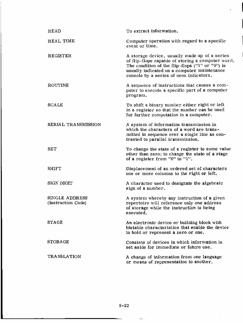
READ
REAL TIME
R E GIST ER
ROUTINE
SCALE
SERIAL TRA NSMISSION
SET
SHIFT
SIGN DIGIT
SINGLE ADDRESS
(Instruction Code)
STAGE
STORA GE
TRA NS LA T IO N
To extract information.
Computer operation with regard to a specificevent or time.
A storage device, usually made up of a seriesof flip-flops capable of storing a computer word.The condition of the flip-flops ("1" or "0") isusually indicated on a computer maintenanceconsole by a series of neon indicators.
A sequence of instructions that causes a com-
puter to execute a specific part of a computer
program.
To shift a binary number either right or leftin a register so that the number can be used
for further computation in a computer.
A system of information transmission inwhich the characters of a word are trans-
mitted in sequence over a single line as con-trasted to parallel transmission.
To change the state of a register to some valueother than zero; to change the state of a stageof a register from "0" to "1".
Displacement of an ordered set of charactersone or more columns to the right or left.
A character used to designate the algebraicsign of a number.
A system whereby any instruction of a givenrepertoire will reference only one addressof storage while the instruction is beingexecuted.
An electronic device or building block withbistable characteristics that enable the device
to hold or represent a zero or one.
Consists of devices in which information isset aside for immediate or future use.
A change of information from one languageor means of representation to another.
8-22

I
II
II
I
I
IIII
II
TRANSFER
VOLATILE STORAGE
WORD
A change of information from one location toanother.
Opposite of nonvolatile storage. Information is
lost in the event of a power interruption.
Information coded for computer representation asa series of bits.
8-23

II
II
II
I
I
7 ACQUISITION AIDANTENNA
-_ ACQ AID [
TlI ACQ BUS
J
VOICECOMM
TLM
OTHERTRACKINGSYSTEMS
I DISPLAYS J
:: _ AND I
[RECORDERSJ
__ DATAPROC TO GSFC
53_00_
TRAINING USE ONLY 9-1 SIMPLIFIED SYSTEMS INTEGRATION AAT-001

AFT
215-260 MHZ I
IACQ AID
NO. I
ACQ AID
NO. 2
215-260 MHZ --_
VHF
RECEIVER
SYSTEM
TAPE JRECORDER
TO OTHER
b TELEMETRY
EQUIPMENT
$315ot2
TRAINING USE ONLY9-2
SIMPLIFIED ACQ. AID SYSTEMBLOCK DIAGRAM VSR-001
TE LEME TRY
PRINCIPLES OF TELEMETRY
INTRODUCTION
Telemetry consists of performing measurements at a remote location and re-
producing these measurements at some convenient location in a form suitable for
display, recording, and possibly for insertion into data reduction equipment. The
connecting link between the two locations may be a light beam, a radio, a wired
connection, etc. In this discussion we will be concerned only with radio links from
orbiting spacecraft or their launch vehicles.
TE LE ME TRY
In general there are three methods of obtaining data from an orbiting space-
craft: (i) astronaut observations and noting the readings of instruments; (2) airborne
recording of instruments (3) radio telemetry. The first method is obviously limited
to qualitative data trends and to a few datum points per unit time, because of the re-
action time of the observer and the time required to record the data. The second
method cannot fulfill the real time demands of the Manned Space operations. Thus,
the third method is the only practical means of relaying the necessary measurements.
A. Data
The type of measurement to be made in the capsule can vary widely.
(Measurement is used here in its most general sense, i.e., we can measure the
on/off status of a beacon, or the count of a clock as well as measuring Ibs/in 2, or
degrees of temperature. ) Typical examples include temperature, pressure, accel-
eration, radar beacon status (on/off), power supply voltages, capsule attitudes
(pitch, roll, yaw), capsule elapsed time clocks, etc. From the standpoint of telemetry,
these can be classified in two general categories: analog and digital.
I. Analog
The greater majority of analog measurements are nonelectrical by
nature. Temperatures, pressures, liquid levels, are examples of conditions which
must be processed to an electrical signal by means of a device called a transducer.
The following table lists some typical parameters and typical transducers employed.
i0-i

Par ameter
Temperature
Moisture
T ._ ._'l_-aJ JL_IJ.L,
Acceleration
Liquid Level
Pressure
Fluid Flow
Radioactivity
Color
Acidity and Alkalinity
2. Digital
Transducer
Bimetallic strip, resistance bulb, thermistor, ther-mocouple
Hygrometers - ceramic, thermocouple, lithium chloride
Photoconductive cells - cadmium sulphide, selenium
Accelerometer
Capacitance bridge, float
Bourdon tube, strain gauge, Pirani tube
Flowmeters - positive displacement, turbine type,
electromagnetic
Scintillation counter, Geiger-Muller Tube counter,ionization chamber
Spactrophotometer, colorimeter
ph Potentiometer
In the category of digital information we can include such things as
clock readouts, computer words and the simple on/off "events" (beacon on/off,
umbilical open/closed, parachute deployed/not deployed, etc. ). These parameters
generally are already in electrical form, but those that are not can usually be made
electrical through the use of a simple transducer such as a microswitch.
B. Multiplexing
Since the number of measurements to be made in a spacecraft can easily
be in the hundreds and occasionally into the thousands, it is extremely impractical
to provide separate transmitters and receivers for each measurement to be made.
Some means must be used to combine measurements in a manner such that the
largest possible number can be transmitted over a single RF link. The process of
combining these channels is known as multiplexing.
Although other methods are conceivable, there are two principle means of
multiplexing; frequency-division multiplex and time-division multiplex.
In frequency-division multiplex, each data channel modulates a corres-
ponding subcarrier. The subcarriers are then mixed into a composite signal which
is then used to modulate the transmitter. At the receiving station, the carrier is
10-2

I
II
II
I
I
I
demodulated giving us the composite of subcarriers. This composite is then passed
to a bank of filters, each tuned to accept only one of the subcarriers present in the
composite. These separated subcarriers must then be demodulated to recover the
original data.
In time-division multiplex, the various measurements are connected se-
quentially to the line (commutated) and the resulting signal is used to modulate the
transmitter. At the receiver, the same process occurs in reverse. Some kind of
signal distributor or decommutator arrangement is required to "sort" the samples
as they arrive in sequence and distribute them to the appropriate lines at the proper
instants. This requires precise synchronism between transmitter and receiver. If
synchronism fails, all channels are garbled and lost.
1. Frequency-Division Multiplexing
Frequency-division multiplexing as applied to telemetry consists almost
entirely of FM/FM or FM/PM.
In this type of multiplex system, all information channels are trans-
mitted simultaneously; thus, commutation and decommutation are unnecessary.
This eliminates the problems of synchronization that exist in the various time-division
multiplex systems such as PAM, PDM, and PCM. In FM/FM telemetry, a main
carrier is frequency modulated by several subcarriers which are themselves fre-
quency modulated. The transducer output voltages of each channel serve as the
modulating signals for these subcarriers. Each transducer output signal drives
a subcarrier generator (VCO). The subcarriers and their respective sidebands are
routed to a modulator where they form a composite signal which serves to modulate
the main carrier generator. The receiver routes this signal to bandpass filters,
each of which passes only the frequency components of one channel. The corres-
ponding discriminators detect the subcarriers and their sidebands and generate
approximations of original transducer output signals.
In practice, one or more of these channels may be used with one of the
time-division commutation schemes that will be discussed later.
One of the prime requirements of any telemetry system is accuracy. In
the FM/FM system where the data causes the frequency of the subcarriers to change,
10-3

the changesof subcarrier frequency due to natural causes (drift) must be minimized
lest the changesresulting from drift be misinterpreted as changesin data. Sincethe drift can never be completely eliminated, anamount of uncertainty will always
be present. Additionally, whenthese signals are recorded as a subcarrier composite
at the ground station, some means must be used to minimize the effects of the tape
recorder wow and flutter. This is not difficult, but it does increase the complexity.
Probably the greatest disadvantageis the limited number of subcarriers
allowed in the Inter Range Instrumentation Group (IRIG) recommendations. In the
interest of standardizing systems, IRIG has recommended a maximum of 18 sub-carriers on a single transmitter. This means then, that unless one or more of the
channels are utilized to transmit a time-division multiplexed signal, we are left witha maximum of 18 measurements.
This also meansthat a simple digital channel such as an event that might
occur once during the mission will use as much channel capacity as a rapidly moving
waveform suchas the EKG waveforms of mannedspace. Analog data is quite com-
patible, but our digital data must be converted into some analog voltage levels, with
either a loss of accuracy on complex digital data, or a fantastic consumption of
channel space.
2. Time-Division Multiplex
Time-division multiplex is based on the premise that it is not necessary
to continuously monitor a signal in order to reproduce it with an acceptable degree
of accuracy. It is only necessary to periodically measure (sample) the amplitude
of a function during discrete time intervals.
a. Sampling Theory
Supposethat it is desired to transmit the time varying signal.
By sendingthe voltage V(t) through a communication system in the form shown, an
exact reproduction of the waveform can be expected at the receiving end (assuming
reasonable high signal-to-noise ratio, of course). But it is not necessary to trans-mit V(t) continuously in order to derive the information contained therein.
It is the changesin the voltage levels of a signal which contain
the information; therefore, in order to get all of this information, all the voltagechangesmust be determined.
10-4

It is obvious that V(t) is changingwith time becauseof the valleys
and peaks. Supposethat we cause V(t) to pass through a switch that is opening and
closing at an arbitrary rate. Obviously whenthe switch is closed, V(t) appears at
the output; whenthe switch is open, V(t) does not appear at the output. If the switch
is closed for atime (T1)and openfor a time (T2),then the waveform shownin C isobtained at the sampler output. This outputdoes not resemble V(t). Now suppose
that the switch is again closed for a time (rl)bUt opensfor an equal amount of time;tMs action produces the waveform of D which begins to resemble V(t). The signal
is Sampledeach time the switch is closed. The width of these sampling pulses can
becomewider andwider until the limit, which is the original waveform V(t) isreached.
Now instead of using wide sampling pulses, visualize very narrow
pulses which are equally spaced, but close together. The result shownin E is
obtained. These pulses, like those of D, also form an envelopewhich has the shape
of V(t). If the sample is taken at too low a rate, the signal may changeradically
betweensampling pulses and a distorted output would be obtained as shownin C.
Obviously, the more pulses that are used, the more accurate the envelopewill be.
However, the problem here is to use asfew of these sampling pulses as possibleand still derive an accurate envelope. Thus, it is necessary to determine the
minimum rate (fs) that a signal can be sampled at and still derive the informationcontained within it.
Before this canbe determined, a restriction must be placed on
the signal. In any communication system, there exists a bandwidth limitation.
Otherwise, one information channel will fall into the adjacent channels andthe re-
sult would be gibberish. Limiting the bandwidth also reduces the amount of noise
(because noise power decreases with decreasing bandwidth), thereby increasing
the signal-to-noise ratio. Since the signal is band-limited, it hasa maximum
frequency component(fm). Therefore, the fastest that a signal can changeis
obviously determined by the bandwidth(also fm). The sampling theory of moderncommunications theory states that:
10-5

!!
fs _ 2fm
This means that if a band-limited signal is sampled at a rate ,Tof this signal,which is at least twice the maximum frequency component a relativelj
good production of the signal can be obtained.
thatIf there is an amount of detail in the waveform must be pre-
served, a higher sampling rate must be used. Sampling rates as high as ten times
the frequency components of the signal are not unusual. In all cases, however, the
samples must be equally spaced.
b. Commutation
The time intervals between samples are not wasted; other time varying
signals can be sampled and these samples can then be sandwiched into the unused time
intervals. This method of time sharing produces what is known as a commutated wave
train.
Each signal is connected to a four-pole rotating switch whose wiper
arm rotates at a constant speed. Each time the arm touches a terminal, a sample
is taken. The amplitudes of these sample pulses are equal to the instantaneous am-
plitude of the signal being sampled at the moment. Connecting the peak of every /
fourth pulse of the sampled output then gives an approximation of the original signals.
Note that switch $2 must be in precise synchronism with the sampling switch $1;
$2 must be resting on contact 1 at the same time that the sampling switch S1 is
resting on contact 1. Both switches must of course rotate at the same speed. !
!It is this requirement for precise synchronization which has limited
the usefulness of time division systems in the past. Modern techniques and the use /
of Pulse Code Modulation have greatly extended the capacity and versatility of time
idivision systems.
c. Commutation Diagrams
In discussing time-division multiplex schemes, it is convenient
to diagram the sequencing of the channels as they appear at the output of the com-
mutator. There are two principle types of diagrams in use: the wheel diagram
and the matrix diagram.
10-6

III
II
I
I
I
I
(1) Wheel Diagrams
The wheel diagram is analogous to a mechanical airborne
commutator. The arm in the center of the diagram, from which the output is taken,
is assumed to rotate in a clockwise direction, being first connected to channel (seg-
ment) 1, followed by channel 2, then channel 3, and channel 4.
Upon completion of the transmission of channel 4, channel 1
is transmitted, beginning the sequence again, and continuing indefinitely. This
system is too simple to be very practical, and further, no provision has been made
for synchronization.
One complete rotation of the wiper of this wheel, consisting
of the samples of channels 1 through 15, is known as a FRAME. Since the wiper
rotates at a constant rate of speed, the frame rate of the system is equal to the
rotation rate of the wiper. They are generally specified in frames per second and
rotations per second (rps), respectively. It can also be seen that because each of
the channels occurs only once per frame, the sampling rate in the individual channels
is equal to the frame rate.
(2) Matrix Diagrams
A matrix diagram of the simple formats that we have been
discussing is not really necessary, and indeed, is not even a matrix. It is being
introduced at this time purely for comparison purposes. Since there appears to be
no standard for matrix diagrams, there are as many types as there are designers.
The only type that will be discussed here is known as an "X-Y" matrix.
The general form of the "X-Y" matrix diagram is merely
that the wheel has been opened between the frame synchronization channel and
channel 1, then laid out in a horizontal line. This horizontal line is one frame in
length, beginning with channel 1 and ending with the synchronization channel.
Although it is not yet apparent, successive frames need not
be identical. Our matrix will take the form of a chart in which channel numbers
progress in one dimension, and successive frames will be plotted in the other.
10-7

d. Supercommutation
The system just discussed would be satisfactory if all the para-
meters required the same sampling rate. In the example shown, the sampling rate
of all channels is 1 sample per second. Sampling theory has told us that the maxi-
mum frequency that can be satisfactorily passed through a channel is equal to one
half of the sampling rate. The maximum changes that can be passed by the above
system then is equal to 0.5 cycles per second.
Suppose we find that among the parameters to be measured, one
channel has a requirement for a 2-cycle-per-second (cps) response, a second channel
has a requirement for 1 cps response, and the remaining channels have a requirement
for 0.5 cps response. The first solution to the problem might be to increase the
speed of the commutator to 4 rps. This would then provide all channels with a 2 cps
response. As might be expected however, if we transmit more than we need, as in
this case where the majority of channels require only 0.5 cps response, we are not
operating at maximum efficiency. A better solution to the problem is called SUPER-
COMMUTATION.
Supercommutation, the preferred term, is sometimes called
strapping. Supercommutation (strapping) is commutation at a higher rate by con-
nection of a single data input source to equally spaced contacts of the commutator.
Note that parameter PX 9 now is sampled four times per frame
in channels 2, 6, 10, and 14, but that the speed of rotation of the wiper remains at
1 rps. We now have a sampling rate of 4 samples per second and corresponding
frequency response of 2 cps.
Parameter N 28 is now sampled twice per frame; once in channel
4, and again in channel 12 for a sampling rate of 2 samples per second and corre-
sponding to a frequency response of 0.5 cps.
We have effected a trade, increased frequency response for some
channels for a loss of total channel capacity, in this case four channels. This need
not be a complete loss. If, in the first example, we had increased the commutation
rate by four times, the width of the individual channels/pulses would have decreased
to 25% of their original value. This decreased pulse width would have forced us to
10-8

II
II
II
I
increase transmitter power and receiver bandwidth in order to maintain the original
signal to noise ratio. In the example with supercommutation, if these four channels
were 0.5 cps channels, we could increase the frame length to 19 channels and if we
maintained the same sampling rate, the pulse width would be reduced to 80% of the
original value. This too would require increased power and bandwidth, but of course
not nearly as much as the reduction to 25%.
Supercommutation then is a means of increasingthe overall efficiency
of a system by its ability to supply the optimum sampling rates for the channels to be
transmitted.
e. Subcommutation
Although supercommutation can give us a wide variety of sampling
rates, it does have some disadvantages when there are a great number of measure-
ments to be made that require supercommutation to give the desired sampling rates.
The ground station must make special provision for each channel that is supercom-
mutated, usually by some special patching facility. These special patching facilities
are limited in number. As we increase the number of measurements to be made, we
are simultaneously increasing the length of the frame. Since the frame synchroni-
zation channel is transmitted only once per frame we cannot have the same degree
of confidence in our synchronization because it is occurring less frequently. It is
primarily for this reason that another means is used to increase the channel capacity
without decreasing the frame synchronization confidence level. This method is called
SUBCOMMUTATION.
In subcommutation, one or more commutators are employed in
addition to the main commutator. The output from the wiper of a particular sub-
commutator is connected to a particular channel location on the main commutator.
Since the wiper of the main commutator must rotate at a constant speed, this channel
location can still contain only one parameter per frame. The subcommutator must
then run at a rate of speed such that it advances only one parameter or channel per
rotation of the wiper in the main commutator.
If this is true, then it will require a number of frames to be trans-
mitted before all of the parameters on the subcommutator can be transmitted. The
10-9

precise number of frames that must be transmitted is of course equal to the numberof channelson the subcommutator.
Just as one revolution of the wiper of the main commutator is
known as a frame, one revolution of the wiper on the subcommutator is called a
SUBFRAME. Parameters (channels) connectedto this subcommutator are known
as subcommutatedparameters (channels) as differentiated from commutated or
supercommutatedparameters. (Although all channels are, technically speaking,commutated channels. The term commutated is generally usedto identify those
channels which are transmitted only once per frame. )
In anexample, a subcommutation ratio is 6:1. That is, the sub-
commutator is rotating at one sixth the speedof the main commutator, the subcom-
mutated channels are being sampled at a rate which is one sixth that of the commu-tated channels. This also means that six frames must be transmitted before all the
parameters havebeen sampled at least once. This latter condition, when all para-meters to be transmitted have been sampled at least once, is called a FIELD and in
this case is equal to the subframe.
In order for the ground station to know which frame of the six is
being transmitted, it is necessary to transmit a synchronization signal once persubframe. Here we have chosento use the last channel space on the subcommutator
for this purpose.
It is possible to apply subcommutation to any of the channels in
the frame, excepting the frame synchronization channel. These additional sub-
commutators may or may not operate at the same ratios. Onesynchronization
channel canbe usedto synchronize all subcommutators of the same ratio, as well
as ratios which are integral sub-multiples of a ratio having synchronization.
f. Sub-Subcommutation
In the interest of further increasing channel capacity as well as
supplying greater spread from maximum to minimum sampling rates, commutatorscanbe connectedto the segments of the subcommutators. These commutators are
actually subcommutatinga subcommutated channel, and are therefore known asSUB-SUBCOMMUTATORS.
i0-i0

The operation of these sub-subcommutators follows the same pattern
that we have established for the subcommutators. The principle difference is that
the rate of rotation of the wiper of the sub-subcommutator is now some sub-multiple
of the rotation rate of the subcommutator. Again, because the output of the sub-
subcommutator is occupying one channel space in the subcommutator, only one channel
from the sub-subcommutator can be transmitted per rotation of the subcommutator
(one channel per subframe). It will now require a number of subframes before all of
the channels from the sub-subcommutator can be transmitted. The precise number
of subframes will be equal to the number of channels on the sub-subcommutator.
This group of subframes is called a SUB-SUBFRAME.
If sub-subcommutation is employed, the largest sub-subframe will
be equal to the FIELD. (Only after the largest sub-subframe has been transmitted,
have transmitted at least one sample from all parameters. )
At this time, we may be getting the impression that we are covering
some rather improbable circumstances. We are not. The signal transmitted from
the Gemini spacecraft has the following characteristics:
8X Supercommutation
2X Supercommutation
Commutated Channels
2:1 Subcommutation
4:1 Subcommutation
8:1 Subcommutation
24:1 Sub-Subcommutation
Sampling rate equal to 640 sps
Sampling rate equal to 160 sps
Sampling rate equal to 80 sps
Sampling rate equal to 40 sps
Sampling rate equal to 20 sps
Sampling rate equal to 10 sps
Sampling rate equal to 0. 416 sps
Although we have been using diagrams and terminology to imply
that the commutators are rotating switches, this is not necessarily so. Mechanical
commutators have been used extensively in the past, however modern solid state
technology has given birth to electronic switching systems many times faster and
more reliable. A commutator may also be called a sequencer, or programmer.
3. Time-Division Multiplex Encoding
The output of the samplers that we have just described can be used to
modulate the transmitter directly, or it can be used to modulate a subcarrier oscil-
lator in the previously described FM/FM system.
i0-ii

a. Pulse Amplitude Modulation (PAM)
We are sampling an analog signal at a fixed sampling rate to pro-
duce a series of equally spaced pulses with amplitudes equal to the signal amplitude
at the moment of sampling. Thus, the pulse trains shown are an example of Pulse
Amplitude Modulation (PAM). The relative value of the measured variable is con-
veyed by the relative amplitude of the pulse from the sampler. PAM is the simplest
form of time-division multiplexing because the samples are transmitted without
further processing into another form. It has been shown in detailed studies that where
linearity and resolution requirements can be satisfied by an analog system, PAM is
the best multiplexing system from the standpoint of achieving maximum information
capacity in minimum bandwidth. This might be expected because, PAM is basically
an amplitude modulation process and shares the narrow band properties of AM.
PAM is a good multiplex system as long as the transmission channel
is quiet. Since noise is unavoidable in many instances, PAM signals become easily
distorted because the information is contained in the pulse heights. Therefore, any-
thing which alters the amplitude of these pulses causes signal distortion.
b. Pulse Duration Modulation (PDM)
In Pulse Duration Modulation (PDM) the analog signal is sampled
as in PAM. The resulting PAM wavetrain is converted into a series of pulses of
varying widths proportional to the amplitude of the respective samples. Thus, the
information is contained in the pulse widths or durations. The height of these pulses
is constant. PDM is sometimes referred to as PWM (pulse width modulation).
PDM, however, is not as efficient in transmitting data as PAM
under marginal signal-to-noise ratio conditions. This is because pulses of longer
duration must be transmitted to provide the same information as high amplitude
PAM pulses, and more transmitter power is required. For any given degree of
data accuracy, PAM has several decibels in its favor over PDM. However, because
of the simplicity and high reliability of PDM systems and equipment, PDM is used
because problems of linearity are more readily solved with PDM than with PAM.
Because all the information is contained in the width of the pulses,
noise can readily cause deterioration of the pulse widths. Therefore, anything
I
II
I
I
I
I
I
I
1
10-12

which affects the shapeof the leading and trailing edgesof a PDM pulse will produceerroneous signals.
c. Pulse Position Modulation (PPM)
Pulse Position Modulation is a form of PDM in which only the
leading and trailing edgesof the PDM pulses are represented by a very narrow pulse.The principle advantage, as compared to PDM, is in the conservation of transmitter
power. As the data in a PDM channel changes, the changesare reflected in the
difference of time betweenthe leading andtrailing edgesof the pulse, but we still
must transmit RF power in the time betweenthese transitions. If instead, we trans-
mit very short pulses to indicate where the leading andtrailing edgesare, we cansave on transmitter power. Pulse transmitters similar to those used in radar can
be employed, giving us a very high peak power but very low average power.
In general, PPM suffers the samedisadvantagesas PDM in thepresence of noise.
d. Pulse CodeModulation (PCM)
Unlike the methodswhich we havebeendiscussing (where the data
varies some characteristic of a pulse, amplitude, width, position, etc.), the sampledvalues observed are represented by a codedarrangement of several pulses. Thus,
only the presence or absenceof pulses -- not their shape-- determine the receivedmessage and its quality.
This is very similar to conventional teletypewriter communication
in which the transmitted characters are represented by various'combinations of a
five pulse code. Regardless of howbadly the code pulses may be distorted or de-
graded in transmission, the sharpness or clarity of the characters reproduced at
the receiving printer are obviously not changedor altered in anyway. Distortion
of the transmitted pulses merely increases the chancesof a mistake in interpreting
the code andthe printing of a wrong character.
Because it is a digital system, it is compatible with airborne digital
data from computers, clocks, andevent functions as well as ground handlingequip-
ment. Binary digital data canbe handleddirectly without further processing. On/
off information is usually grouped so that each transmitted channel actually contains
10-13

four or more events. Analog information must be quantitized and encoded into a binary
number for transmission.
Page 10-20 shows a block diagram of a PCM system spacecraft
and ground components. In the spacecraft system, the encoder performs the ana-
log to digital (A/D) conversion function. The programmer controls the operation
of the commutator so that digital words may be interleaved with the analog channels.
In the ground system, the signal conditioner regenerates the incoming signal, sup-
plying a noise free input to the decommutator, as well a train of timing pulses (bit
rate clock) that define the pulse periods. The storage unit corresponds to an output
holding circuitry for digital information, while the decoder provides conversion
from digital to analog (D/A) for the analog output devices. The operation of the
decommutator, storage unit, and decoder are all controlled by the synchronizer.
(1) PCM Quantitization
When analog information is to be encoded, the signal to be
transmitted is first broken up into a prescribed number of discrete amplitude levels.
Each level is assigned a binary number value (a specific combination of pulses)
which is then sent through the communication channel. The ground station converts
the binary number back to an approximation of the original signal value. The pro-
cess of breaking up the signal into discrete levels is known as quantitization.
Use as an example an uncoded signal (continual amplitude
variation) which is to be encoded. A signal varies between zero and plus seven
volts. It is desired to convert the signal into eight discrete voltage levels: 0, 1,
2, 3, 4, 5, 6, and 7 volts. For the purposeof illustration, the amplitude of the
waveform is sampled at one second intervals (or any other sampling interval may
be used). If the amplitude lies between 0.5 volts and 1.5 volts, the 1 volt value is
assigned; between 1.5 volts and 2.5 volts, 2 volts is assigned, etc. Thus, the
quantitized waveform is derived. By connecting the discrete levels between every
1 second interval with a dashed line, it can be seen that the original waveform has
been reproduced in a very rough manner. It is obvious that the demodulated signal
{dashed lines) differs somewhat from the original signal. The effect is as if noise
has been introduced into the system. This quantitization noise can be reduced by
breaking up the original signal into more discrete voltage levels. It can be seen
I
I
IIII
I
I
!
I
I
I
I
!
10-14
[

that the demodulated signal of (c) is an improved reproduction of the original signal.
If the signal would be sampled more frequently, then the reproduced waveform
would become even more accurate. Bandwidth and noise determine the maximum
sampling rate and the number of levels which may be used in any given communication
system.
For transmission, each discrete quantitization level is encoded
"into a definite series of pulses in such a manner that only the presence or absence
of a pulse is significant; exact pulse shape is secondary. The presence of a pulse
is denoted by a 1 and the absence of a pulse by 0. Where eight discrete levels are
used, it can be seen that each level can be expressed as a series of pulses with a
maximum count of three pulses. By adding one more pulse position, the count is
increased to 16 discrete levels with a maximum count of four pulses. Thus by using
more pulses, a more accurate reproduction of the original signal may be achieved.
However, the transmission of more pulses requires the reduction of the pulse width
(assuming a constant information rate) which in turn places a greater bandwidth
requirement on the system. By adding the extra pulse, the number of quantitization
levels is doubled. For example, the quantitizing into 32 levels requires a maximum
of five pulses. Even though the addition of pulses increases the bandwidth require-
ment, the signal-to-noise ratio improves in an exponential manner. Uncoded systems
have signal-to-noise ratio improvements which increase linearly. There are,
however, other pulse coding techniques which can transmit the same amount of
information within narrower bandwidths.
4. Time-Division Multiplex Synchronization
The prime requirement for a frame synchronizing channel is that it
must bear as little resemblance as possible to the data channels and still be com-
patible with the type of encoding with which it is being used. In the case of PAM,
it can have greater amplitude than data, (over 100%), it may be at the 100% level
from 1.5 to 3 times as long (i. e. 1.5 to 3 times as wide as a data channel), or it
may contain a digital code. The fact that it is limited to a simple pattern makes
it difficult, though by no means impossible, to use subcommutation, because the
subcommutator must also have a synchronization pattern which has the same re-
strictions concerning its resemblance to data, and in addition it must not resemble
the frame sync pattern.
10-15

PCM, on the other hand, has thousandsof possible combinations of
codes. There are several sync methods and combinations which may be used. These
are word (channel) synchronization, frame synchronization, and subframe synchroni-
zation. (The ground station also must developbit synchronization, that is, pulseswhich are coincident with each and every incoming data bit.) The data format de-
termines which combinations of these sync methods may be used
A word is usually made up of a number of bits (pulses). It is possible
to reserve oneto three more of these bits for synchronization purposes. In order
to achieve word synchronization, the ground station must be able to detect the word
sync bits for a number of consecutive words. These sync bits must fall into the prop-er bit positions every time before synchronization is assured. Becausethe word
sync bits occupy a portion of the whole word, signal bandwidths over and abovethat
required for only the data bits are necessary.
Oneword per frame is reserved for the purpose of frame synchroniza-
tion. The codefor this word is made unique so that the frame synchronizer at the
ground station candistinguish it from the data words. The last word in each frame
is the frame sync word. At the end of each frame, the recognition of the sync word
causes the words per frame counter at the ground station to reset andthus prepareto count the words in the next frame.
The subdecommutationprocess counts the number of frames within the
particular subframe so that a particular word within a particular frame canbe lo-
cated. Three principle methods of subframe identification are used; frame code
complement, the recycling method, andthe count-up/count-down or ID method.
In the frame code complement method, the last frame of the subframe
is identified by the fact that the frame synchronization word in this frame is the
complement (inversion) of the frame synchronization word in all the other frames.
In the recycling method, a subframe synchronizing code pattern isinserted somewherewithin the last frame of the subframe. This code pattern may
consist of a maximum of 64bits located in up to eight different subcom channels.
The third method, the count-up/count-down or ID method, has asubframe sync code in which the frame identification number appears as a binary
I
I
I
I
I
I
I
I
I
10-16

I
I
I
I
I
I
I
I
number. The method is called count-up if the frames are identified in ascending
numerical order, and count-down if the frames are identified in descending numerical
order. With the ID method, any frame within a subframe can be identified almost
immediately; whereas in the recycling method, or the frame code complement method,
the subframe must be completed so as to acquire the unique word in the last frame.
C. Comparison of Telemetry Techniques
Having been exposed to the basics of various telemetry systems and the
problems of data transmission, we are now in a position to compare those systems
to one another. Examination of their similarities and differences will demonstrate
why PCM has become the predominate data transmission technique in telemetry.
Noise and bandwidth are the two basic limitations to the transmission of
information. Thus, for any information carrying system the ultimate goal is to
provide as large a signal-to-noise ratio and as narrow a bandwidth as possible.
There is a relationship between the frequency and power spectrums of any signal.
This signal may be either information or noise. This relationship says that as the
bandwidth of the signal decreases, its total power decreases. Therefore, it is
desirable to get as much signal power with as little noise power as possible. Ob-
viously all that one has to do is decrease the bandwidth of the noise and/or increase
the bandwidth of the information in order to obtain a high signal-to-noise ratio.
However, this is not possible because the increase of bandwidth of one also increases
the bandwidth of the other and vice versa. The only solution is a compromise. The
question now is which system provides the best compromise: FM, PAM, PDM, or
PCM ?
Before these systems are compared, it is important to establish what we
are trying to accomplish. The word telemetry implies that measurements are to be
made. In making these measurements, the greatest precision consistent with the
desired degree of accuracy possible must be obtained. Thus, the guiding principle
in telemetry is precision. Imagine that a complex waveform is applied to an oscillos-
cope and the resultant trace on the CRT is obtained. This waveform has its peaks
and valleys with finer variations along the way. If it is desired to measure the voltage
of one of these variations, the amplification factor of the oscilloscope is increased
to obtain a trace which is larger than the previous one. As the waveform is amplified
more and more, the finer details may be measured with more and more precision.
10-17

Thus, each time the amplification (voltage swing) is doubled, the precision is
doubled. If the information level is doubled in the presence of a fixed noise level,
the signal-to-noise ratio is doubled.
To accomplish this in PAM, the pulse amplitudes must be doubled, which
requires that the transmitter power to be squared. In FM and in PDM, the bandwidth
must be doubled. In PCM, if we double the number of pulses transmitted we will
double the bandwidth, however, instead of doubling the precision, it will be squared.
Page 10-24 shows that by the addition of only one pulse position, the number
of quantitization level is doubled. As another example, take the case of a four bit
word and an eight bit word. The former provides 16 different quantitization levels
and the latter provides 256 quantitization levels. The MSFN PCM decommutator can
decommutate words up to 64 bits in length. This 64 bit word would provide 17.4
x 1018 or 17.4 quantillion (17,400,000,000,000,000,000) quantitization levels.
It should be noted also that in PCM it is not necessary to transmit all channels
with the same accuracy. If extreme accuracy is required in only one or two channels,
these channels can be allowed to have several times the number of bits of the average
channel, whereas in the other systems, all channels would have to be transmitted
with the same degree of accuracy.
Severe noise combinations can alter the shape of PAM and PDM pulses so
that the information contained in the amplitudes and widths would be changed. Even
relatively mild noise levels can change these parameters sufficiently so that errone-
ous data is received. In PCM, however, all that needs to be detected is the presence
or absence of a pulse. This can be readily done even under extremely low signal-
to-noise conditions. The only condition that will cause an error to be received arises
if the levels of the random noise pulses will cause a pulse to drop out or cause a pulse
to appear when it should not. However, under such conditions, the signal-to-noise
ratio is extremely low (about 6 db) and would make PAM and PDM data useless.
Although elaborate synchronization codes are required for PCM, this can
also be turned to our advantage. Because they are elaborate, many synchronization
codes can be used in the format, permitting the simultaneous operation of several
different subcommutators (up to four in the MSFN decommutator).
10-18

I
I
I
I
I
I
I
I
D. Summary
Frequency division multiplex and time division multiplex are two means of
transmitting large numbers of channels over a communications link. Of these, time
division multiplex combined with electronic switching techniques can provide the
most versatile system due to its ability to combine a larger number of channels with
varied sampling rates. Of the time division multiplex techniques, PCM is probably
the most versatile, most sensitive, most accurate, as well as the fastest. The
MSFN PCM decommutator can handle data at up to 125,000 eight bit channels per
second.
By way of comparison, Project Gemini uses the same capsule transmitter
power, in the same bandwidth as Project Mercury, yet we are measuring over three
times as many parameters at increased accuracy (better than 0.5% vs the 2% of
Project Mercury) with more nearly optimum sampling rates, and essentially the
same sensitivity.
In addition, because it is a digital system, and through the use of the on-
site computer, more complete summary messages can be handled in a shorter
period of time.
10-19

B--
L_
UI,I
WD-
u')
zn,"
I-
_Ln
_W
bJ
0
I--0t_Jn
.,
n.,
WX.JiL
[E
E--IE-
I
v__s
)-
r,
i
l.dX
zgn-
wo4u.lIi
10-20
_,on.
O0¢3Q.
@Uo>-b-_JLU
f-LU
U..
m.A)-z0Md
0Zmz.(b...

d_00
Jb
10-21
T
0|
L)
O.
0ZxLA
J
0.M.)-..dZ00ZZI--

ZwQ.b-b_
I1I
°1I !
jz
z_
II
10-22
L)
f_<vLJ
0>-L)
.<L)
>-b-.->-z0u.J
zz.<,v

II
II
II
A.TIME VARYING SIGNAL:TIME
v(t)
SWITCH OPENS AND CLOSES
SAMPLED OUTPUT VOLTAGE
B. PERIODIC SAMPLER :
VOLTS
C. SLOW SAMPLING RATE:
VOLTS
D. FAST SAMPLING RATE:
VOLTS
TZ
TI ME
E. PULSE SAMPLING:
PERIODIC SAMPLING PCM-002TRAINING USE ONLY 10-23

VOLTS CHANNEL I
V I It|
,TIME
VOLTS CHANNEL 2
TIME
VOLTS CHANNEL 3
VS(T)
TIME
VOLTS CHANNEL 4
TIME
VOLTS CHANNEL I
I Illll:,.,
VOLTS
MU LTI PLEXEO
SAMPLED OUTPUT
VOLTS CHANNEL 3
TIME
I
II
II
II
II
I
SIGNAL TO BE SAMPLED
VOLTS CHANNEL 4
TIME
5iGOOOTII
TRAINING USE ONLY10-24
SAMPLING FOR TIME MULTIPLEXING
PCM-003

V3(t)
V4( t )V itt)
OUTPUT
5160009
TRAINING USE ONLY10-25
WHEEL DIAGRAM OF
_PCM-003 AND PCM-004 PCM-O05

ZWw_O_
10-26
Od
Cq
Z
hJ
C._
J"
U
m'}
o_o.i.X
UQ
.
-w-
a-
Oeq
UZ
I--t_
-ra
UX0
Un
-
O>"
ZUZ
Un,.
°1 ooU*iZ°1Z@°13:>.Zo.aZI,.-

IIII,-t
I
-1l_
00
00
ww
W_
bJN_
NN
_NN
'5
o_o_
o_o_
Z_
Z_
Z_
Z_
ZZ
Z0
00
ZZ
Z
m]
W-r-
_10.
10-27
o,UQ.
0-1-UU
JF
-
Z0m<0a0L)
Q.>-00ZZ<

.10-28

zz_O
n
__,.,
.=_
__
°-_hz--
'v__-o.
w_
_"--
e',oo
_z
0.
I\\
\
I\
_\,I
}--_-,
II
II
II
II
I
0aDO
.)..
)..'WI.-
_rj
0o|
v'}
<i,IJ
0V'}
Z0UN0l,m
<uZ0UZ<0U
Z_z
_z
zO_
wW
_Z_
_Z_
0
11-1
>-Z0I.M0ZZ<,,.wI..-

9
\\\\
\\
'___-_,I
I/
II
/I
il
11-2
>-..Iz0U_
:3tOZIZ1.(,wk--

\
11-3
r_
I=-
::3
n(n
0
00d_0zou,=.1
uoUJzoUJ
0zz
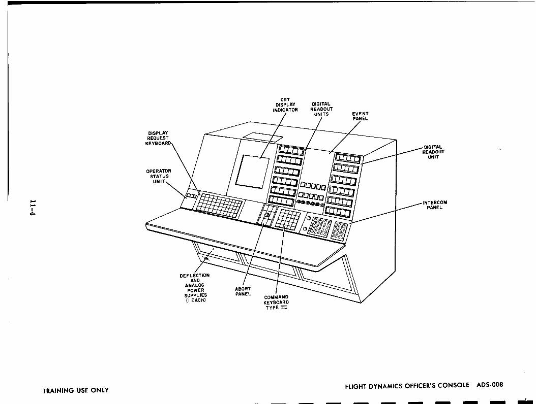
11-4
00,,,,,1
0Z0u_uM.
0u=E_cz)-t3I,-"
-r0
Z0ZZI,,-

_Dt.¢.
On"
._Ib
.
IIIIII
,<Z
ILl
C_
0
:nI.-
Z:
m
AJ
3
I....
,1
11-5
oor_<<@<..J<0I-=
UIt_J}--t/}>->-<,,,J
O.
r_0.,J,.J0O.
<Z0tJ_
0ZIz<O=
II

FM SIGNAL
ELECTRONIC, IDRAWER
_P 9
Io°1o°1o°1o°1o°1o°1o°1
TAPETRANSPORT
[] [] _ POWER
CONTROL9 9 r-r-r-r-r-_ 9 _ PANEL
I\ Ix Ix Ix I\ ix I\ Ii i i , , I i i
0 0 0 0 0 0 0? ?
Io°Io°Io°Io°0°Io°I°I._ ANALOG SIGNAL
I\1\ Ix I\1\ I', I\1 ELECTRONICSi i i i i i i i0 0 0 0 0 0 0 DRAWERS
, oO.oO!oO.!.oO!oO!.oO!oO! '.
es|OZ31
TRAINING USE ONLY11-6
APOLLO RECORDER MODEL 22FULL FRONT VIEW ARS-125

I
III
I
I
I
SUPPLYREEL
DATA LOCATOR REEL
REVOLUTION COlSUPPLY END-OF-
REEL SENSOR
REPRODUC
HEADS
TAPE BREAKAGE/
SENSOR
RECORDHEADS SUPPLY REEL
CAPSTAN VI--_
TAKEUP END-
OF-REEL SENSOR
JP REEL
TRAINING USE ONLY11-7
MODEL 22 TAPE TRANSPORT
FRONT VIEW ARS-100

•_Ln0,,
11-8
>-
z0zuz<I--

I
II
I
II
I
SOLAR PARTICLE ALERT NETWORK SYSTEMS
i. OPTICAL AND RADIO TELESCOPE SYSTEM (SORT)
The Solar Particle Alert Network (SPAN) project is a joint effort of the National
Aeronautics and Space Administration's Goddard Space Flight Center (GSFC) and
Manned Spacecraft Center (MSC).
The purpose of SPAN is to determine the operational capability of a solar event
warning network for the Apollo program which will provide advance radiation warning
to astronauts by means of a radio and optical system, retrieving data in real time.
These systems are installed and in operation at Carnarvon, Australia, Grand Canary
Island, and MSC Houston, Texas.
The optical and RF data obtained by the SPAN is considered to be highly desirable
for the successful conduct of Apollo operations for the following reasons:
a. Without a solar flare proton warning system, the crew safety reliability for
an Apollo mission is 0.99 with respect to radiation. This figure is too low
considering that the overall Apollo system goal, excluding radiation, is 0. 999.
b. SPAN is capable of providing a radiation crew safety reliability of greater
than 0. 999 without decrease in the mission success reliability of 0.99. This
reliability will be achieved by giving the flight director the warning required
to send the lightly shielded Lunar Module (LM) back to the heavily shielded
Command Module (CM) at the proper time.
c. Without a solar flare proton warning system, 100 pounds of shielding would
be necessary on the LM to provide the required reliability of 0. 999. This
shielding must be carried on all missions, even though only about one per-
cent of the missions would encounter solar particle events large enough to
require protection. The SPAN system, costing about $2,000,000 through
1970, will provide the required 0. 999 reliability without additional on-board
equipment and weight.
2. JUPITER MONITOR
Although the sporadic emission of intense decameter radiation from the planet
Jupiter has been studied by several workers every year since its discovery in 1955
12-1

no general theory of the emission mechanism has been accepted as completely sat-
isfactory. Among the processes suggested to explain the origin of sporadic Jovian
emission have been Cerenkov radiation, cyclotron radiation, synchrotron radiation
and stimulated emission. This yet unresolved problem of the theory of the radiation
mechanism at once reflects the need for further expanded observational data.
The radio bursts have been observed throughout the frequency range of 10 to
50-MHzbut appear to be most frequent near 18 MHz. The duration of the bursts is
on the order of one second, and they often occur in groups over a period of several
minutes. The radiation is predominately right-haad elliptically polarized although
it has occasionally been seen to switch from right-hand to left-hand polarization,
and even back again to right-hand polarization in a matter of minutes.
A number of workers have studied the possible solar influence on sporadic
emission from Jupiter and have noted at least a partial correlation between Jovian,
solar, and geomagnetic activity. Warwick has reported a high rate of occurrence of
Jupiter emission following solar radio continuum activity by 1 to 2 days for the 1960
apparition which suggests the influence of solar particles with velocities of the order
of 10-1c.
The continuous observation of radio noise from Jupiter by a network of ground
stations is a potentially effective tool for studying the earth's ionosphere and the
interplanetary gas as well as the atmosphere of Jupiter. Recordings of the radio
emission from the planet often show irregular amplitude scintillations not unlike
those seen for the low frequency radiation of cosmic radio sources. Often the fluc-
tuations recorded by different observing stations appear to possess little or no corre-
lation and are therefore thought to be due to ionospheric irregularities as in the case
of "radio star" scintillations.
The Jupiter monitor system can perform the functions of three monitor systems.
These functions are:
a. Jupiter Monitor - Monitor the planet Jupiter at the frequencies of 16.6 and
22.2 Mcs.
b. Radiometer - Monitor the solar disc at the frequency of 2695 MHz.
c. RIOMETER (Relative Ionospheric Opacity Meter) - Monitor the Earth's
ionosphere at the frequencies of 30 and 50 MHz.
I
I
I
I
I
I
i
i
12-2

II
I
I
3. RIOMETER (Relative Ionospheric Opacity Meter)
The riometer is used to precisely measure changes in ionospheric absorption
of extraterrestrial radio noise. Such changes are caused by variations in electron
density within the ionosphere which can be brought about by solar atmospheric dis-
turbances. These disturbances may be caused by solar phenomena or they may be
man made.
The riometer operates by comparing the antenna signal with a local source of
noise, providing a detected output which is a voltage proportional to the difference
between the two signals and using this voltage output (error voltage) to control the
noise diode filament current in such a way as to equate its noise output to that of
antenna noise. This advanced measuring technique eliminates the effects of gain
instability common to most electronic measuring devices. Once set, the riometer
can be relied on for precise data on a day-to-day, year-to-year basis.
This system continuously monitors the frequencies of 30 and 50 Mcs.
12-3

Zw
Z0pn,,
_--o_
ZoUJ
oZZ<
1"2-4

I
II
I..,...:-:':
i:]:]::::::
.:- •:.:,-,-,:.
";-..,,.,
::i:i:]::::::
• """'"'X 106 °K "'"
CHROMOSPHERE
61000°K
PHOTOSPHERE
r_u 1,4 X 10⁶ km
iiiiiii CORONA
:.:.::::,.:,:.:.
,:.:,:,.
:.:.:.:.:,:
..:.:.:,:,
.:.:.:.:
i:!:i::
5680296
LAYERS OF THE SUN ROT-020TRAINING USE ONLY 12-5

TRAINING USE ONLY
1111
I
::;:/I .
\/I
12-6,
1316001
@
SPAN OBSERVATORY AI-1203

I
I
I
SUN'S RADIATION
tttttllllltt
ZbJ
_bJ
Z m
_>
MANNED LUNAR FLIGHT ROT-080TRAINING USE ONLY 12-7

SUNFOLLOWER
COVER FORAFT STRUCTURE
AFT STRUCTURE
TELESCOPE
HORIZONSENSING
RIGHT ASCENSIONSETTING CIRCLE
TELESCOPE FORK
DECLINATIONDRIVE
RIGHT ASCENSIONDRIVE ASSEMBLY
TILTABLE UPPERBASE CASTING
DECLINATIONHANDWHEEL
RIGHT ASCENSIONHANDWHEEL
FILTERCONTROLS
HATCH
HELIOGRAPHICCOORDINATE
HATCH
TV CAMERA
II
/-..LATITUDE
ALIGNMENT
/_/_ _ FILTER /
// 71 _ TEMPERATURE/ / O _ = .JI _ CONTROLLER
0 I
J e, TV _IITORo I
__ TE SCOPE POWER FAILURE ._ CONTROL MODULE REMOTE hlDICATOR
I I .f_.,,I \POWER FAILUREI / _ LOCAL INDICATOR REMOTE
I I / _ J \ MONITOR'
l"-.. I I///_r / \ 3_MMCAMERA CONSOLE,NTERV,LO,ETER
"_ / LOCAL
CONTROLCONSOLE
PANEL
FIXED LOWERBASE CASTING
DECLINATIONSETTING
CIRCLE
35 MM;RA
TURRET
TRAINING USE ONLY12-8
SOLAR OPTICAL
MAJOR UNITS ANt,

,
II
I
II
I
I
I
i111 [I
SELF CHECK RASTER
CROSS HAIRS I
OCCULTINGCONE
ENLARGED VIEWOF RASTER
//
/3 5
\\
\\ L
A
C
E
7 9G
I
IK.I
\_x
II
//
//
5680302
NING USE ONLY 12-9 SELECTORDISC ROT-140

._o
oi-q
Jm
oz
_E_z
jOzo
_o_
12-10
009--
00vu9a.0uu9UJ
I.Ll
h-..Jul--a.
0..a0U_>-..JzoU
_
IS)
0zmzm

RADIO TELESCOPE ANTENNA SYSTEM,REAR VIEW ROT-220
TRAINING USE ONLY 12-11

0"_J©<
cz_tZ
bJ
I'-r-a
i-
I'-_l_l
--I
w
IIp
000IXvU0a.0U,_1
00
12-12
>-..Jz0u_U_
Zmzm,w

AERONOMY
ANGSTROM
CHROMOSPHERE
CORONA
C ORONAGRA PH
COSMIC DUST
COSMIC RAYS
DEC LIMATION
ECLIPTIC
ECLIPTIC PLANE
E LE C TROMAGNE TICRADIATION
ELECTROMAGNETICSPECTRUM
APOLLO SOLAR TERMINOLOGY
The study of the atmosphere, especially its relation to theEarth and the effect upon it of bombardment by radiationfrom space.
A unit of length, used chiefly in expressing short wave-lengths. Ten billion angstroms equal one meter.
One of the atmospheric shells of the Sun, lying above thePhotosphere and best visible at time of total eclipse. Canbe observed spectroscopically at other times.
The faintly luminous outer envelope of the sun. Also calledsolar corona.
Device to scan and record the solar corona.
Small meteroids of a size similar to dust.
The extremely-high-energy subatomic particles which bom-bard the atmosphere from outer space. On collidingwith atmospheric particles they produce many differentkinds of lower-energy secondary cosmic radiation.
Angular distance north Or south of the celestial equator.The arc of an hour circle between the celestial equatorand a point on the celestial sphere, measured through 90degrees, and labeled N or S to indicate the direction ofmeasurement.
Plane of the earth's orbit around the sun. Used as a re-
ference plane for other interplanetary orbits.
The plane of the earth's motion about the sun.
Energy propagated through space or through material media
in the form of an advancing disturbance in electrical andmagnetic fields existing in space or in the media. Alsocalled simply radiation.
A collective term for all known radiation from the shortest-
waved gamma rays through x-rays, ultraviolet, visible light,infrared waves, to radio waves.
12-13

ELECTROMAGNETIC WAVE
ELECTRON
ENERGETIC PARTIC LE
EPHERMERIS
EQUATORLA L ORBIT
FISSION
FISSION FRAGMENT PHYSICS
FLARE (SUN)
GALACTIC ASTRONOMY
GALACTIC COSMIC RAYS
GAMMA RADIATION
GAMMA RAY
GEOHYDROMA GNETICS
GEOMAGNETIC FIELD
Form in which radiant energy travels, produced byoscillation of an electric charge, and including way,, _of radio, infrared, visible light, ultra-violet light,
x-rays, gamma rays, and cosmic rays when considelas quanta of energy.
The subatomic particle that possesses the smallestpossible electric charge.
An electron, positron, neutron, or other elementaryparticles of matter traveling at extremely high spee_ _
Such particles originate in outer space or from theSun and lose their energy in the atmosphere.
Book of tables giving daily positions of celestial bod_
An orbit in the plane of the Earth's equator.
The release of nuclear energy through splittingof at(
The study of the behavior of the high energy particle_'
resulting from a nuclear fission reaction.
A bright eruption from the Sun's chromosphere. Secsolar flare.
The study of the galaxies and their components.
Cosmic rays that do not originate in the sun are refc
to as galactic cosmic rays and are those of the grea_
energy.
Electromagnetic radiation, similar to x-rays, ori_:ifrom the nucleus of an atom and having a high degr_
penetration.
An electromagnetic radiation or waveform emittedradioactive nucleus and similar to x-rays but of hi:energy and shorter wavelength.
The study of the upper atmosphere and radiation 17.that surround the Earth, and their interactions \v_: _,,charged particles streaming from the Sun's and E_
magnetic field.
The magnetic-field of force surrounding the Earth.
12-14

GEOMAGNETISM
GEOPHYSICS
HEAVISIDE LAYER
HEAVE COSMIC RAYPRIMARIES
HE LIOC E NTRIC
HETEROSPHERE
HIGH-ENERGY RADIATION
HOMOSPHERE
INCIDENT RADIATION
INFRARED
INFRARED LIGHT
INTERNATIONAL QUIETSUN YEAR - IQSY
INTERPLA NETARY
The magnetic-phenomena, collectively considered,exhibited by the Earth and its atmosphere. Themagnetic phenomena in interplanetary space.
The physics of Earth and its environment.
Region of the ionosphere that reflects radio waves backto earth. Also called kennely-heaviside layer.
Positively charged nuclei of elements heavier thanhydrogen and helium up to, but not including, atomicnuclei of iron. Comprising about one percent of thetotal cosmic ray particles.
Measured from the center of the Sun. Related to, or
having the Sun as a center.
That part of the upper atmosphere wherein the relativeproportions of oxygen, nitrogen, and other gases areunfixed and wherein radiation particles and micro-meteriods are mixed with air particles.
Penetrating particles or electromagnetic radiation ofmore than a few thousand electron volts, includingelectrons, neutrons, protons, means x-rays and gamma rays.
That part of the atmosphere made up of atoms and mole-cules found near the Earth's surface and retaining thesame relative portions of oxygen, nitrogen, and othergases.
Radiant energy impinging on a surface per-unit-time andper-unit-area. Also called irradiation or flux density.
Electromagnetic radiation in the wavelength intervalfrom the red end of the visible spectrum on the lowerlimit to microwaves used in radar on the upper limit.
Light in which the rays lie just below the red end of thevisible spectrum.
In 1965, solar flares and disturbances were at a
periodic low level, during which scientists throughoutthe world cooperatively engaged in the study of theSun.
Between planets.
12-15

INTERP LA NETARYMONITORING PROBE - IMP
IONIZ E
IONIZED LAYERS
IONOSPHERE
MAGNETIC MERIDIA N
MAGNETIC STORM
MESOSPHERE
METEOR
METEOR SAFE WALL
METEORIC
METEORITE
METEOROID
Designed to provide detailed measurement of theradiation environment between Earth and Moon.
Characteristics of particle fluxes from the Sun,the interplanetary magnetic field, and solar-terrestrial relationship will be studied.
Change to ions, become electrically charged, as a
gas under the influence of heat, electron bombardment, |and nuclear radiation. !
Layers of increased ionization within the ionosphere. |Responsible for absorption and reflection of radio !waves and important in connection with communicationand the tracking of satellites and other space vehicles.
!
An outer belt of the Earth's atmosphere in which radia-
tions from the Sun ionize, or excite electrically, theatoms and molecules of the atmospheric gases.
A great circle of the Earth passing through the mag-
netic poles.
A worldwide distrubance of the Earth's magnetic field.
In the nomenclature of Chapman, a stratum of atmos- [
phere that lies between the stratosphere and the iono- I
sphere, sometimes called the chemosphere. In thenomenclature of Wares, a stratum that extends approxi- Imately from 250 to 600 miles, lying between the iono- [sphere and the exosphere.
!
A transient celestial body that enters the Earth's atmos-_phere with great velocity, incandescent with heat d
generated by the resistance of the air.
A protective blanket of atmosphere through whichmeteors rarely penetrate. Meteors are burned upand vaporized in this area due to friction with airmolecules.
Of or pertaining to meteors, or meteroids.
A meteoroid which has reached the surface of the Earth
without being completely vaporized.
A small solid body traveling through outer space. Whena meteroid enters the Earth's atmosphere it becomes ameteor.
12-16

MICROMETEOROID
MICROMETEORITE
OCCULATION
ORBITING ASTRONOMICALOBSERVATORY- OAO
ORBITING SOLAROBSERVATORY- OSO
OZONOSPHERE
PHOTOSPHERE
PLAGES
PLANET
PLA NETOID
PLA NETOLOGY
PRIMARY COSMICRAYS
PROPAGATION
PROTON
Meteoroids less than 1/250th of an inch in diameter.
A very small meteorite or meteoritic particle witha diameter less than a millimeter.
The disappearanceof a body behind another bodyoflarger apparent size.
A series of scientificsatellitesto obtain precision
telescopic observation of emission and absorptioncharacteristics of the Sun, stars, planets, and
nebulae in the ultraviolet,infrared, and X-ray
regions of the electromagnetic spectrum.
A solar-stabilized scientificsatellitecarrying
solar-oriented experiments, comparing radiation
from the sun to that in other portions of the sky.First launch was in 1962.
A stratum in the upper atmosphere having a relatively
high concentration of ozone, important for absorp-tion of ultravioletsolar radiation.
The outermost luminous layer of the Sun's gaseous
body.
Clouds of calcium or hydrogen vapor that show up asbright patches on the visible surface of the sun.
A celestialbody of the solar system revolving around
the sun in a nearly Circular orbit, or similar body
revolving around a star.
One of the numerous small planets nearly all of whoseorbits lie between Mars and Jupiter. Also calledasteroid and minor planet.
The study of planets and satellites.
High-energy particles originating outside the earth's
atmosphere.
Describes the manner in which an electromagnetic
wave such as a radar signal, timing signal, or ray
of light,travels from one point to another.
A positivelycharged subatomic particle of a positive
charge equal to the negative charge of the electronbut of 1827 times the mass. A constituent of all
atomic nuclei.
See - solar protons.
12-17
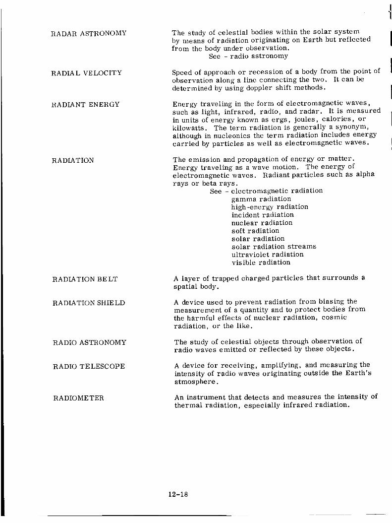
RADAR ASTRONOMY
RADIAL VELOCITY
RADIANT ENERGY
RADIATION
RADIATION BELT
RADIATION SHIELD
RADIO ASTRONOMY
RADIO TELESCOPE
RADIOME TER
The study of celestial bodies within the solar system
by means of radiation originating on Earth but reflected
from the body under observation.
See - radio astronomy
Speed of approach or recession of a body from the point of
observation along a line connecting the two. It can be
determined by using doppler shift methods.
Energy traveling in the form of electromagnetic waves,
such as light, infrared, radio, and radar. It is measured
in units of energy known as ergs, joules, calories, or
kilowatts. The term radiation is generally a synonym,
although in nucleonics the term radiation includes energy
carried by particles as well as electromagnetic waves.
The emission and propagation of energy or matter.
Energy traveling as a wave motion. The energy of
electromagnetic waves. Radiant particles such as alpha
rays or beta rays.
See - electromagnetic radiation
gamma radiation
high-energy radiationinc ide nt radiation
nuclear radiation
soft radiation
solar radiation
solar radiation streams
ultraviolet radiation
visible radiation
A layer of trapped charged particles that surrounds a
spatial body.
A device used to prevent radiation from biasing the
measurement of a quantity and to protect bodies from
the harmful effects of nuclear radiation, cosmic
radiation, or the like.
The study of celestial objects through observation of
radio waves emitted or reflected by these objects.
A device for receiving, amplifying, and measuring the
intensity of radio waves originating outside the Earth's
atmosphere.
An instrument that detects and measures the intensity of
thermal radiation, especially infrared radiation.
12-18

II
II
II
I
II
RAYS
SOLAR ATMOSPHERIC TIDE
SOLAR CELL
SOLAR COLLECTOR
SOLAR CONCENTRATOR
SOLAR CORONA
SOLAR FLARE
SOLAR MAGNETOGRAM
SOLAR NOISE
SOLAR PROTONS
SOLAR RADIATION
SOLAR RADIATION STREAMS
SOLAR TIME
SOLAR WIND
STUDY OF ENHANCEDRADIATION BELT - SERB
SUBATOMIC PARTIC LES
See - cosmic ray
gamma ray
Vertical motion of the atmosphere due to thermal
or gravitational action of the Sun.
A photovoltaic device that converts sunlight directly
intoelectrical energy.
A parabolic mirror-type device used to collect and
concentrate solar energy.
A device such as a parabolic mirror used to concen-
trate radiant solar energy to a small area.
Outer atmospheric shell of the Sun.
Solar phenomenon which gives rise to intense ultravioletand corpuscular emission from the associated regionof the Sun, affecting the structure of the ionospherewhich interfers with communications.
A recording obtained on Earth that measures themagnetic activity of sunspots.
Electromagnetic radiation which radiates from theatmosphere of the Sun at radio frequencies.
Elementary charged particles and nuclei of hydrogen
atoms accelerated by the Sun and ejected into space
with energies up to several billionelectron volts.
The totalelectromagnetic radiation emitted by theSun.
All forms of radiant energy, including visible light,thatemanate from the Sun.
Time measured by reference to the apparent motionof the Sun about the Earth.
A stream of protons constantly moving outward fromthe Sun.
Program to study the radiation beltcreated by highaltitudenuclear explosion.
A component of an atom such as an electron, proton,meson, etc.
12-19

SUDDEN IONOSPHERICDISTURBA NCE
SUNSPOT
SUNSPOT CYCLE
TROPOPAUSE
TROPOSPHERE
ULTRAVIOLET RADIATION
VAN ALLEN BELTS
WA VE LE NGTH
X-RAY
A complex combination of sudden changes in thecondition of the ionosphere, and the effects of thesechanges.
A relatively dark area on the surface of the Sun, con-sisting of a dark central umbra and a surroundingpenumbra that is intermediate in brightness betweenthe umbra and the surrounding photosphere.
A periodic varation in the number and area of sunspotswith an average length of 11.1 years but varying between7 and 17 years.
The upper limit or limits of the troposphere.
The lower layer of the Earth's atmosphere, extending
to about 60,000 feet at the equator and 30,000 feet
at the poles.
Electromagnetic radiation shorter in wavelength thanvisible radiation but longer than X-rays. Roughly,radiation in the wavelength interval between 10 and4000 angstroms.
Two doughnut-shaped belts of high energy charged
particles trapped in the Earth's magnetic field. The
minimum altitude of the inner belt ranges from approxi-
mately 100 miles near the magnetic poles to more than1000 miles at the equator. The maximum altitudeof
the outer belt extends to approximately 40,000 milesat the equator.
Distance measured along a line of propagation between
two points which are in phase on adjacent waves.
Electromagnetic radiation of very short wavelength, lying
within the wavelength interval of 0.1 to 100 angstroms
(between gamma rays and ultravioletradiation). Also
called X-radiation, and roentgen ray.
12-20

S315011
TRAINING USE ONLY 13-i MSFN NETWORK INTERFACE TTO-001

MULTIPLEXERS
I 30 BITS I
FUNCTION REGISTER
I 30 BITS I
TRANSFER REGISTER
ONE CHANNEL
EXTERNAL SPECIFIED ADDRESS
EXTERNAL SPECIFIED INDEX
STATUS J 30DATA LINES I STATUS _
V
INPUT DATA REQUEST
INPUT ACKNOWLEDGE
EXTERNAL INTERRUPT LINE
INPUT
OUTPUT
EXTERNAL FUNCTION LINE
OUTPUT DATA REQUEST LINE
_STATUS I 30 DATA LINES I STATUS
OUTPUT ACKNOWLEDGE LINE
UNIVAC 494 REALTIME COMPUTER
I
I
I
I
I
I
I
I
I
TRAINING USE ONLY13-2
494 COMM PROCESSOR
INTERFACE SYSTEM TTO-O03

I-ql-q
I-_l-qn-lE
_I
IIL
JII[
Jl.Jl
I
Jtl
i[II
11ii
I
m
Zr_0
o0. ©oo
m_j
IDQ
.
13-3
Z
mu_
zOos__z_
_,_
Q_
bJa,Z(0
_.o(I.
(_0w
_-o_
m_-_
O_
00dI--
0I--
MJ
i.I.iI,(U_
IJJ
vOI..Jz00zz,(e_i--

o'Jn,,"hl
'_"I--
0
0l,J-
U
13-4
T
>,-,_
,,_
,.i-3,..,,',
__J
UJ
r_hl_I'-"
O.
,qU
lmm
(.)"_
W
>'t-_
t--._l'r
•-J¢_
n..<
"_W
I
"1"14"
I--U
)Z
_14J
L_J
ffl
0
|
gz0u
10I--
_uz°1u00O.
<
>-,,...1
z0ILl
0zz.<_v

!
A/B
A/D
AAA
ABORT
AC
ACE
ACK
ACQ
ADAP
ADE
ADJ
AEM
AEROMED
AFC
AFD
AFDO
A/G
AGAVE
AGC
AM
AMC
AMS
ANLG
ANO
ANT
AOD
APO
A/S
ASAP
ASC
ASCO
ASCS
GLOSSARY
A
Auto beacon
Analog-to-digital (data conversion)
Active acquisition aids
Failure of an aerospace vehicle to accomplish its purposes
Alternating current; access control
Automatic Checkout Equipment
Acknowledgement
Acquisition
Adapter
Adelaide, Australia
Adjust
Aircraft Engineering Modifications
Aeromedical monitor
Automatic frequency control; Area Frequency Coordinator
Assistant Flight Director
Assistant Flight Dynamics Officer
Air/Ground (spacecraft voice communications)
Automatic Gimballed-Antenna Vectoring Equipment (AAA)
Automatic gain control
Amplitude modulation
Aeromedical console
Apollo mission simulator
Analog
Alpha-numeric output module
Antigua, British West Indies (Station 9, AFETR)
Apollo Operations Director
Apollo Project Office
Auto-skin track
As soon as possible
Ascension Island (Station 12, AFETR)
Automatic sustainer cut off; auxiliary SCO
Auto-Stabilization and Control System
14-1

ASK
ASPO
ASR
ASTRO
ATT
AUTO
AUX
AVC
AZ & EL
A ZUSA
BAT
BCD
BCN
B/D
BDA
BECO
BENPAC
BENRAD
BER
BFEC
BFO
BH
BIN
BIOMED
B/O
BP
BPF
BPS
BST
BW
Amplitude shift keying
Apollo Spacecraft Program Office
Automatic send-receive units (TTY modem)
Astronauts
Attitude
Automatic
Auxiliary
Automatic volume control
Azimuth and elevation
Electronic tracking complex and vectoring system (trackingradar at the Cape)
B
Battery
Binary code decimal
Beacon
Beacon delay
Bermuda
Booster Engine Cutoff
Bendix- Pacific
Bendix Radio
Bit error rate
Bendix Field Engineering Corp.
Beat frequency oscillator
Block house
Binary
Biomedical
Burn out
Boiler plate
Bandpass filter
Bits per second
Brief System Test
Bandwidth
I
II
II
I
14-2

CADFISS
CAL
CAPCOM
CB
CC
CCC
C-BAND
CCATS
CCIA
CCW
C/D
CDP
CET
C/F
CFE
CLT
CM
CM/SM
CMD
CNV
COMTECH
CONT
c/P
CP
CPS
CRF
CRO
CRR
CRT
CSM
CSQ
C
Computer and data flow intergrated subsystems test
Vandenberg, USAFB, Calif. (NASA)
Capsule communicator
Circuit breaker
Cubic centimeter
Command communicator console
Radar frequency range (5200 - 8500 MHz)
Command, Computer and Telemetry System
Computer console interface adapter
Counterclockwise
Countdown
Central data processor
Capsule elapsed time
Center frequency
Contractor-furnished equipment
Communication line termination or terminal
Command module
Comnmnd/Service Modules
Command
Cape Kennedy, Florida (Station 1, AFETR)
Communications technician
Control
Cartesian-to-polar converter; circular polarization
Communications processor
Cycles per second
Capsule radiation measurements
Carnarvon, Australia
Change Recommendation Report
Cathode-ray tube
Command service module
Coastal Sentry Quebec (ship)
14-3

CT
CTC
CTE
CTN
CW
CYI
D/A
D/R
DBM
DBV
DC
DCR
DCS
DCT
DCU
DECOM
DEMOD
DF
DIRAM
DIS
DISC H
DISTRAM
DOB
DOD
DOS
DOVA P
DRU L
DSE
DSDU
DSIF
DST
D/TTY
Command transmitter
Capsule test conductor
Central timing equipment
Canton Island
Continuous wave; clockwise
Grand Canary Island
D
Digital-to-analog
Data receiver
Decibel referred to 1 milliwatt
Decibel referred to 1 volt
Direct current; differential correction
Digital clock receiver
Digital command system
Digital clock transmitter
Data control unit; digital control unit
Decommutation
Demodulate
Direction finder
Digital ranging machine
Data input subsystem
Discharge
Digital space trajectory measurement system
Data Operations Branch (MFOD)
Department of Defense
Department of Supply (Australia)
Doppler, velocity, and position tracking system
Down-range uplink
Data storage equipment
Decommutation system distribution unit
Deep Space Instrumentation Facility
Detailed System Test
Digital-to-teletype converter
14-4

I
II
II
I
I
II
ECA
ECS
ECU
EGL
EI
EKG
EL
ELS
EM
EMERG
ENG
E NVIR
EPS
ESS
ETR
EVA
EVAP
EXH
F
FAR
FAX
F/C
FCSD
F-1
FD
FIDO
FM
FM/FM
FPQ
FPS
FSECO
E
Electronic control assembly
Environmental control system
Environmental control unit
Eglin USAFB, Florida
Engineering Instruction
E lectrocardiogram
Elevation
Earth landing system
E ngineering Memorandum
Emergency
Engine
Environmental
Electrical power system
Essential
Eastern test range
Extra-vehicular astronaut
Evaporator
Exhaust
F
Fuel
Failure analysis report
Facsimile
Fuel cell
Flight crew support division (MSC)
Firing day minus one
Flight Director
Flight Dynamics Officer
Frequency modulation
Frequency division multiplexing
Fixed, ground, special purpose radar
Fixed position tracking radar; frames per second
First-stage engine cutoff
14-5

FSK
FWD
GBI
GCC
GET
GFE
GFP
GLOTRAC
GMT
GMTELGMTLA
GMTLR
GMTMB
GMTMC
GMTOI
GMTRE
GMTTE
GMTTL
GMTVA
G&N
GOSS
GRD
GSE
GSFC
GTK
GYM
HAW
HF
HONHS
HSD
Frequency shift keyingForward
G
Grand BahamaIsland (Station 3,AFETR)Ground communications coordinator
Ground elapsed timeGovernment-furnished equipment
Government-furnished parts
Global tracking (presently the AFETR)Greenwich mean time
Earth landingInitiate abort
Lunar rendezvous
"Moon blackout"
Midcourse correction
Orbital insertion
ReentryTransearth injection
Translunar injection
Vehicle acquisition
Guidanceand Navigation
Ground Operation Support System
Ground (formerly GND)
Ground support equipment
Goddard SpaceFlight CenterGrand Turk Island
Guaymas, Mexico
H
Kauai, Hawaii
High frequency (3-30 MHz)
Honolulu, Hawaii
High speed
High speeddata
14-6

I
II
II
I
I
I
I/A
I&C
IBM
ID
IF
IFA
IGS
IMU
INJ
INS
I/o
I/P
IPS
IR
n_ACQ
ISI
ISO
ITT
IU
JETT
JON
JPL
Ka-band
KB
KBPS
KC
KMC
KSR
Ku-band
KW
I
Inactive
Installation and checkout
International Business Machines
Identification
Intermediate frequency
In-flight analysis
Inertial guidance system
Inertial measurement unit
Injection
Inertial navigation system; insertion
Input/output
Impact predictor; impact point
Inch-per-second; instrument power system
Infrared system
Instrumented radar acquisition
Instrumentation/support instructions
Isolation
International Telephone and Telegraph
Instrument unit (a portion of the Saturn V)
J
Jettison
Johannesburg, South Africa
Jet Propulsion Laboratories
K
17.25 - 36.00 KMHz (GHz)
Kilobits
Kilobits per second
Kilocycles per second
Kilomegacycles
Keyboard send/receive unit
10.90 - 17.25 KHz
Kilowatt
14-7

LASER
L-band
LCC
LCS
LDN
LEB
LEPS
LES
LF
LH
LIQ
LM
L/O
LO
LOR
LOS
LR
LSB
LSD
LSS
LV
LW
M&O
MA
MAN
MASER
MAX
MC
MCC
L
Light amplification by stimulated emission of radiation
390-1550 MHz
Launch Control Center
Launch Control System
London Communications Center, England
Lower equipment bay
Lunar Excursion Propulsion System
Launch Escape Subsystem
Low frequency (30 to 300 KHz)
Left-hand circular polarization
Liquid
Lunar Module
Liftoff
Low
Lunar orbit rendezvous
Loss of signal
Lunar rendezvous
Least significant bit; lower sideband
Low-speed data
Life Support System
Launch vehicle
Launch window
M
Mission and operations; maintenance and operations
Milliampere
Manual
Microwave amplification by stimulated emission of radiation
Maximum
Megacycle (10 6 cycles/sec); midcourse correction
Mission Control Center
I
I
I
I
I
I
I
I
I
I_I-8
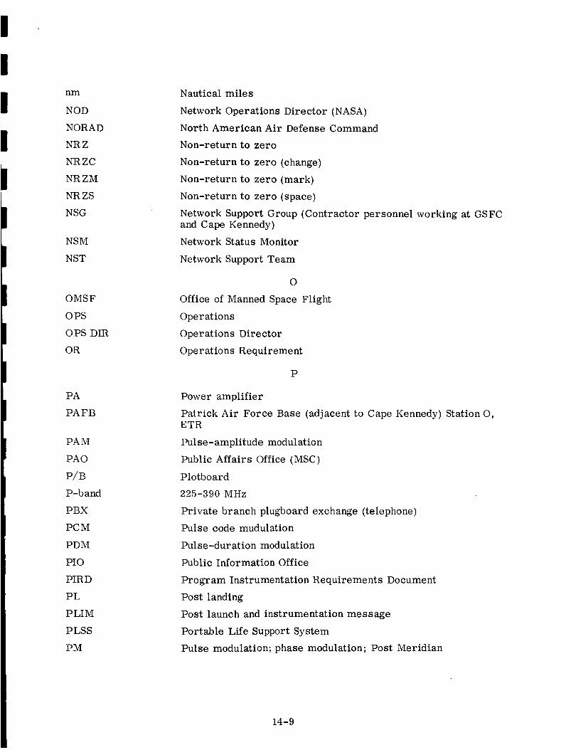
nm
NOD
NORAD
NR Z
NRZC
NR ZM
NRZS
NSG
NSM
NST
OMSF
OPS
OPS DIR
OR
PA
PAFB
PAM
PAO
P/B
P-band
PBX
PCM
PDM
PIO
PIRD
PL
PLIM
PLSS
PM
Nautical miles
Network Operations Director (NASA)
North American Air Defense Command
Non-return to zero
Non-return to zero (change)
Non-return to zero (mark)
Non-return to zero (space)
Network Support Group (Contractor personnel working at GSFCand Cape Kennedy)
Network Status Monitor
Network Support Team
O
Office of Manned Space Flight
Operations
Operations Director
Operations Requirement
P
Power amplifier
Patrick Air Force Base (adjacent to Cape Kennedy) Station O,ETR
Pulse-amplitude modulation
Public Affairs Office (MSC)
Plotboard
225-390 MHz
Private branch plugboard exchange (telephone)
Pulse code mudulation
Pulse-duration modulation
Public Information Office
Program Instrumentation Requirements Document
Post landing
Post launch and instrumentation message
Portable Life Support System
Pulse modulation; phase modulation; Post Meridian
14-9

PMP
p/p
PPS
PR
PRE
PRESS
PRF
PRI
PROG
PROP
p/s
psia
psig
PSK
PSRD
Ptt
PWR
PYRO
Q-band
QTY
RCAC
RCC
RCS
RCVR
RDR CON
REC
REG
REV
RF
RH
RKV
Premodulation processor; Program Management Plan
Point-to-point (radio)
Pulse per second
Pulse rate
Pretoria, South Africa (Station 13, ETR)
Pressure
Pulse repetition frequency
Primary
Program
Propellant
Parallel-to-serial
Pounds per square inch absolute
Pounds per square inch gauge
Phase shift keying
Program Support Requirements Document
Push to talk
Power
Pyrotechnics
Q
36.00 - 46.00 KMHz (GHz)
Quantity
R
Radio Corp. of America Communications
Recovery Control Center
Reaction Control System;Reentry Control System
Receiver
Radar Controller
Receiver
Regulator
Reverse
Radio frequency; recovery forces
Right-hand circular polarization
Rose Knot Victor (ship)
14-10

MCS
MCTMED
MET
MF
MFD
MFEB
MFOB
MFOD
MILA
MILS
MIN
MINITRACKMISTRAM
MODEM
MOSS
MSB
MSC
MSFC
MSFN
MTU
MUX
N/ANASA
NASCOM
NASCOP
NCG
NCR
NDR
N&G
Megacycles per second
Memory cycle-timeMedium
Mission
Medium
Mission
Manned
Manned
Manned
Merritt
elapsed time
frequency (300to 3000kc)
Flight Director
Flight Engineering Branch
Flight Operations Branch
Flight Operations Division (GSFC)Island LaunchArea
Missile Impact Location SystemMinimum
Orbit-Monitoring andData-Collection System
Missile Trajectory Measurement SystemModulator/demodulator
MannedOrbital SpaceSystem
Most significant bit
MannedSpacecraft Center
Marshall SpaceFlight Center
MannedSpaceFlight Network
Magnetic Tape Unit
Frequency Multiplex Equipment
N
Not applicable
National Aeronautics andSpaceAdministrationNASAWorldwide Communications Network
NASA CommunicationsOperating Procedure
Network Control Group (A scheduling group, located at GSC,with representatives from MFOD, MSC, andDOD)
Network ChangeRequestNetwork data reduction
Navigation and GuidanceSystem
14-11

RLSE
RM
RO
ROTR
RR
RSDP
RSO
RTCC
RTK
RUPT
RZ
_
S-band
s/c
S/N
SAR
SC
SCAMA
SCATS
SCE
SCR
SCS
SD
SEC
SECO
SEP
SEQ
SHF
SIG
SIM
SM
SO FAR
Release
Rendezvous maneuver
Page receive only machine; recovery operations
Receive only typing reperforator
Range and range rate
Remote Site Data Processor
Range Safety Officer
Real time computer complex
USNS Range Tracker (ship)
Interrupt
Return to zero
S
Saturn stage (prefix)
1550 - 5200 MHz
Spacecraft
Signal-to-noise
Search and rescue
Spacecr aft
Switching conferencing and monitoring arrangement
Simulation Checkout and Training System
Signal Conditioner Equipment
Strip Chart Recorder
Stabilization and Control System
Send data
Secondary
Sustainer engine cutoff
Separation
Sequencer
Super high frequency (3000 to 30,000 MHz)
Signal
Simulation
Service Module
Sonar sound fixing and ranging
II
I
II
II
I
II
I
14-12

I
I
II!
I
I
SOM
SOP
SOW
S/P
SPADATS
SPANDAR
SPE
SPS
SSB
S/S
STA
STADIR
STAT
SUM
SVC
SYS
T/C
T/E
T/M
T/R
TC
TDD
TEC
TEMP
TEX
TLC
TLM
TM
TP
T-Time
TTE
TTY
Start of message
Standard Operating Procedures
Start of word
Serial to parallel
Space Detection and Tracking System
Space Range Radar (Raytheon}
Special message
Service Propulsion System; samples per second
Single sideband
Subsystem; signal strength
Station
Station Director
Status
Summary
Service message
System
T
Telecommunications
Telemetry event
Telemetry
Transmit/receive
Test conductor; time to computer (IBM)
Timing data distribution
Transearth coast
Temperature
Corpus Christi, Texas
Translunar coast
Telemetry
Telemetry (data}
Test procedure
Time in minutes or seconds from lift-off
Time-to-event
Teletype
14-13

TTY-FD
TV
TWX
UHF
USB
USBE
USWB
V
VAB
VAC
V-band
VC
VCO
VDC
VEH
VER LORT
VFO
VHF
VLF
W/B
WECO
WHS
WMS
WOM
WPM
WPS
WLPS
WTR
WWVB
Full duplex teletype
Television; television systems monitor
Teletypewriter exchange or communication
U
Ultra-high frequency (300-3000 mc)
Upper sideband (Unified S-Band)
Unified S-Band equipment
United States Weather Bureau
V
Velocity voice
Vehicle Assembly Building
Volts AC
46.00 - 56.00 KMHz (GHz)
Voice frequency channel
Voltage controlled oscillator
Volts DC
Vehicle
Very Long Range Tracking Radar
Variable frequency oscillator
Very high frequency (30-300 mc)
Very low frequency (3 to 30 kc)
W
Wideband
Western Electric Company
White Sands, New Mexico, missile range
Waste Management System
Woomera, S. Australia
Word s -per -minute
Words-per-second
Wallops Island station
Western Test Range
NBS radio station, Boulder, Colorado
14-14

WWVH
WWVL
X-band
XCVR
XDUCER
XMT
XMTR
NBSradio station, Maui, Hawaii
NBSradio station, Boulder, Colorado
X
8500- 10900MHz
Transceiver (combined dataxmtr andrcvr)Transducer
Transmit
Transmitter
MSFN MANUAL DESIGNATION SYSTEM
MC Computer
ME EquipmentME-900 IBM
MG General
MH Subsystem
MO Operations & CADFISS
MP Property
MS-100 System (Mercury)
MS-200 System (Gemini)
MS-400 System (Apollo)
MT Training
14-15