SAE Mini Baja Frame Analysis
9
SAE Mini Baja Frame Analysis Jonathan Bloot Dustin Odorcic 11/18/2016 Team 01: SAE Mini Baja Frame Design and FEA ME-476-06
-
Upload
khangminh22 -
Category
Documents
-
view
1 -
download
0
Transcript of SAE Mini Baja Frame Analysis
SAE Mini Baja Frame Analysis
Jonathan Bloot
Dustin Odorcic
11/18/2016
Team 01: SAE Mini Baja
Frame Design and FEA
ME-476-06
Problem Introduction
The frame of the mini baja vehicle connects all of the systems together and experiences extreme forces
while in action. In order to avoid failure during competition, we will go through many design iterations
and Finite Element Analysis (FEA) testing. This paper will state the tubing that has been selected, the
design criteria from which we have to work with, how FEA can be applied, the results from preliminary
FEA testing and an explanation of our current Solidworks Model. The frame thus far has gone through
many changes as the suspension and drivetrain subteams provide information on their systems and will
continue to change until all systems are finalized. It is imperative that this analysis be completed as it is a
requirement to be submitted to Society of Automotive Engineers to be checked before competition.
Failure to do so will result in either disqualification from competition or fail due to breaking during
competition.
Designs that Drive Calculations
Tube Selection The frame of the SAE Baja car is specified to be made from a circular steel thin wall tubing. Competition
rules regulate the primary tubes must meet or exceed the bending stiffness and strength of 1” OD x
.120” wall tube with a carbon content of at least 0.18% and may not have a wall thickness of less than
0.065” or an outer diameter of less than 1”. The secondary members must have at least an outer
diameter of at least 1” as well and a wall thickness of 0.035” at minimum.
Drawn over Mandrel vs. 4130 Chromoly
The frame tubing must be made of steel and teams at competition will generally use one of two types of
materials. Drawn over Mandrel (DOM) and 4130 Chromoly tubing each fit the material requirements
with the correctly selected tube dimensions. Though the materials have a very similar density and are
assumed to have the same Modulus of elasticity of 205 GPa, their tensile yield strength and
manufacturability greatly differentiate. The tensile yield strength was found to be 370 MPa for DOM
tube and 460 MPa for 4130 Chromoly. This variance in Yield Strength gives the 4130 a much larger
bending strength when comparing to the same size tube of DOM. When manufacturing the vehicle,
DOM tube has the option of being MIG or TIG welded while 4130 Chromoly must be TIG welded and
heat treated. MIG welding although it adds additional weight to the frame, can be done over a shorter
period of time without needing the welding expertise that TIG requires. In the event that a member
must be welded at competition, MIG welding to repair would be much preferred over having to TIG
weld a material.
Bending Stiffness and Strength
Competition rules define the bending stiffness proportional to the equation: EI where ‘E’ represents the
Modulus of elasticity and ‘I’ represents the second moment of area for the structural cross section. The
bending strength of the material is given by: SyI/c where Sy represents the yield strength and ‘c’
represents the distance from the neutral axis to extreme fiber. From the baseline material in
competition rules we can calculate that the chosen primary material must meet or exceed a bending
stiffness of 583,306 lb*in2 and a bending strength of 2,397 lb*in.
Final Tube Selection and Purchasing

After many iterations involving different material, tube outer diameter and wall thickness, three optimal
choices were left. Of those three the DOM 1.375” OD x .065” wall tube was the team’s favorite for being
light weight, having a high bending stiffness and a large diameter to provide more surface area to tabs
welded on. Although the material is not available through Industrial Metal Supply who has previously
sponsored the project, several other companies were found to supply the desired primary and
secondary member tubing. Of those other companies, Totten Tubes was the only provider with a
warehouse in Arizona. The team has yet to reach out to Totten Tubes as we are finalizing the frame to
estimate overall tube length needed and will be in hopes to acquire another local sponsor as Industrial
Metal Supply has in the past. We have gathered rough estimates from online companies to compare
pricing when we do reach out to Totten Tubes. Alro metals can provide 72 feed to primary and
secondary material for $206 and $114 respectfully with $100 in shipping costs for a total of $420.
Another estimate from Online Metals who only carried the primary member tubing would charge $234
before shipping for the same 72 feet. Glendale Steel Supply is another local provider in Arizona however
they only carry the desired material for the primary members.
Frame Design Nose
In designing the front section of the frame, the team did benchmarking on previous competition winners
including University of Michigan and Cornell University. Both of these teams lacked a “nose” section of
frame (defined by points G and E of the official Baja rules). The team noted that these teams were still
able to fit all of their required systems (eg. brakes and suspension) within the reduced front end. The
team decided to create a design that lacked a nose based on this benchmarking with the fact that no
nose would mean less tube required for the frame and thus less weight.
Under Seat Member
The floor of the cockpit is composed of a set of members called the “under seat members.” The team
brainstormed a couple different designs with the most promising geometries displayed below in Figure
1. The left layout incorporates a cross design that was both proposed by SAE baja rules and was found in
NAU’s old Baja car. The right layout features a “kite” layout that has become favored after
communicating with the suspension subteam. The suspension subteam is planning on a radius arm and
trailing arm converging at approximately the same point in the middle of the frame. The kite layout
would allow for multiple beams to converge on a single point where that suspension arm stress
concentration would be. Finite element analysis (FEA) iterations detailed in later sections hope to
validate what geometry is needed for the under seat members.

Figure 1: Under Seat Member Layouts
Rear Roll Hoop (RRH)
The rear roll hoop composes a structural panel located behind the driver, or the end of the cockpit.
Research of various baja teams revealed that a wide range of RRH designs but our team found the three
designs in Figure 2 to be the most reoccurring. The left design is proposed by the SAE baja rules while
the middle has the simplest geometry and the right was used by Michigan, Cornell, and the previous
NAU’s design. Currently the team plans on using the left design since it allows for the frame to bow out
where the side impact members (SIM) will connect creating a wider “tub” for easier access to and from
the vehicle. The chosen geometry also uses less tube and therefore less weight than the rightmost
design.
Figure 2: Popular RRH designs
Fore/Aft Bracing Members
These members are located behind the rear roll hoop to hold the drivetrain and rear suspension
components. These are specified as secondary members however FEA testing will decide whether the
loading forces of the suspension will exceed the capability of the weaker material. The lateral

positioning of these members have not been finalized as they are dependent of the transaxle width and
final positioning. The overall length of these members have been closely estimated as the suspension
team closes in on the desired length of the trailing arm.
Side Impact Member, Lower Frame Side Member and Diagonals
The side impact members (SIMs) will define the top of the “tub” of the cockpit and run from the RRH to
the front of the vehicle. Initially the team planned on straight SIMs but benchmarking showed that many
teams incorporated SIM members with one or multiple bends. The team analyzed this idea and deduced
that the most likely reason for such a design was to widen the tub of the cockpit for easier exit of the
vehicle. Our SIM members will incorporate a bend to widen the tub and will be angled in such a fashion
that the bend will be the lowest point of tub. SIM members must be between 8 and 14 inches above the
bottom of the driver's seat. Having them oriented in such a way that a low point is created at mid-thigh
of a seated driver will make it that much easier for the driver to exit the vehicle in under the five
seconds required.
The SIM members are reinforced by some secondary member diagonals which transfer force from the
SIMs to the lower frame side members (LFS). These diagonals are oriented so that they point up and
converge at the bend in the SIM. The team considered inverting these diagonals to point downward and
reinforce the node for the radius and trailing arms but that would have defeated the purpose of the
bend in the SIM member since they would have constrained the inside of the cockpit tub. The FEA
detailed later incorporates iterations of the frame with and without a vertical support that would run
perpendicular to the LFS from the suspension arm node and would meet the SIM member at the bend.
The possible addition of this member would allow the team to keep the diagonals oriented pointing up
while reinforcing the suspension node on the LFS.
Gussets and Maximum Length
As specified in the competition rules the maximum length of any straight member must not exceed 40”.
As we approach the final model of the frame two members may surpass the maximum length. One
concern being the Roll Hoop Overhead Members (RHO) passes longitudinally above to the left and right
of the driver. If we are unable to keep this length within regulation a gusset will need to be added. If the
RHO is within the correct length a FEA analysis will be done with and without the gusset to evaluate the
additional strength provided by the gusset at the cost of the additional weight.
The other members showing a possibility of extending longer than 40” are the Front Bracing Members
(FBM). These extend from the front of the RHO down to the nose of the car. If these members are longer
than regulation the nose of the car will need to angle upwards which would increase the difficulty in
manufacturing the frame and may cause conflicts with the suspension subteam.

Finite Element Analysis
The model of the frame has been made in the Solidworks program which is where we will be doing our finite element analysis (FEA). This analysis allows the team to apply a force, similar to what can be expected during the most extreme of conditions to the frame. The results will indicate where the greatest stress, strain and displacement occur. With this we are able to iterate different designs to optimize the strongest and most durable frame.
Mesh The analysis starts by creating a large amount of small elements within the part called a mesh. When the force is applied to the part the small elements are each evaluated, resulting in a detailed evaluation of the material that would be unable to be done by hand. The mesh options allow not only the size of each element to change, but a maximum and minimum element size and the rate at which the size changes when approaching complex geometry. Our analysis will start with a courser element mesh as we start the testing and transition to much finer elements to best analyze the frame.
Fixtures In order to create any forces within the material of the frame at least one point must be stationary. The members typically selected to remain stationary are on the opposite side of the part that the force is applied to. This allows for analysis of all members of the frame leading up to that point. As we continue to test the frame with FEA and receive assemblies from other subteams, the fixed points may be changed to better identify weak points in the design.
External Loads The testing we will be performing is referred to as static loading. In the testing of our final frame designs,
we will estimate the car weight of roughly 700 lbs. and apply a force of 10g’s to the front of the vehicle to
simulate front end collision, 5g’s to the side and rear of the vehicle and 2.5g’s to the top representing a
rollover situation. Previous NAU teams and other benchmarked competitors have evaluated their frame
using the testing methods described. These loads will be applied at exposed areas that would experience
impact along with mounting points where suspension components would tie into the frame.
Preliminary Results
The testing of an older frame design was done to demonstrate how FEA works and learn about the results
from the simulation. For consistency purposes a force of 1000N was applied in each simulation. The
loading, fixture and meshing of the part was applied to best replicate actual forces foreseen in testing and
competition situations.
When testing a front end collision, the top and bottom of the RRH were fixed into place as the force was
applied to the front lateral members as well as the base of the RRH where the radius arm would attach.
The maximum displacement in this testing was 0.5mm from the 1000N force applied. The results of the
FEA can be seen in figures 3 through 6 below.

Figure 3: Mesh Figure 4: Von Mises
Figure 5: Strain Figure 6: Displacement
Rear collision testing of the frame was done choosing force points that the rear FAB members would be
in contact with. The resulting maximum deformation from this analysis was 1.24mm as seen in Figure 8.
Figure 7 shows the highest stress occurring at the bends in the SIM member.
Figure 7: Von Mises Figure 8: Displacement

Side impact loading on the car was done at both the SIM and LFS members. With a maximum displacement
of 9mm shown in figure 9 it is obvious where the deflection would take place at. The Von Mises stresses
in Figure 10 illustrate the maximum occurrence and states the yield strength that Solidworks assumes.
Figure 9: Displacement Figure 10: Von Mises
Lastly the top loading analysis is done to predict a roll over situation. The maximum displacement in this
simulation was larger than any of the other tests at 9.7mm in the center of the RHO gathered from Figure
12. In Figure 11 it is noticed that higher stresses occur at the FBM to RHO joint and the joints above the
RRH.
Figure 11: Von Mises Figure 12: Displacement
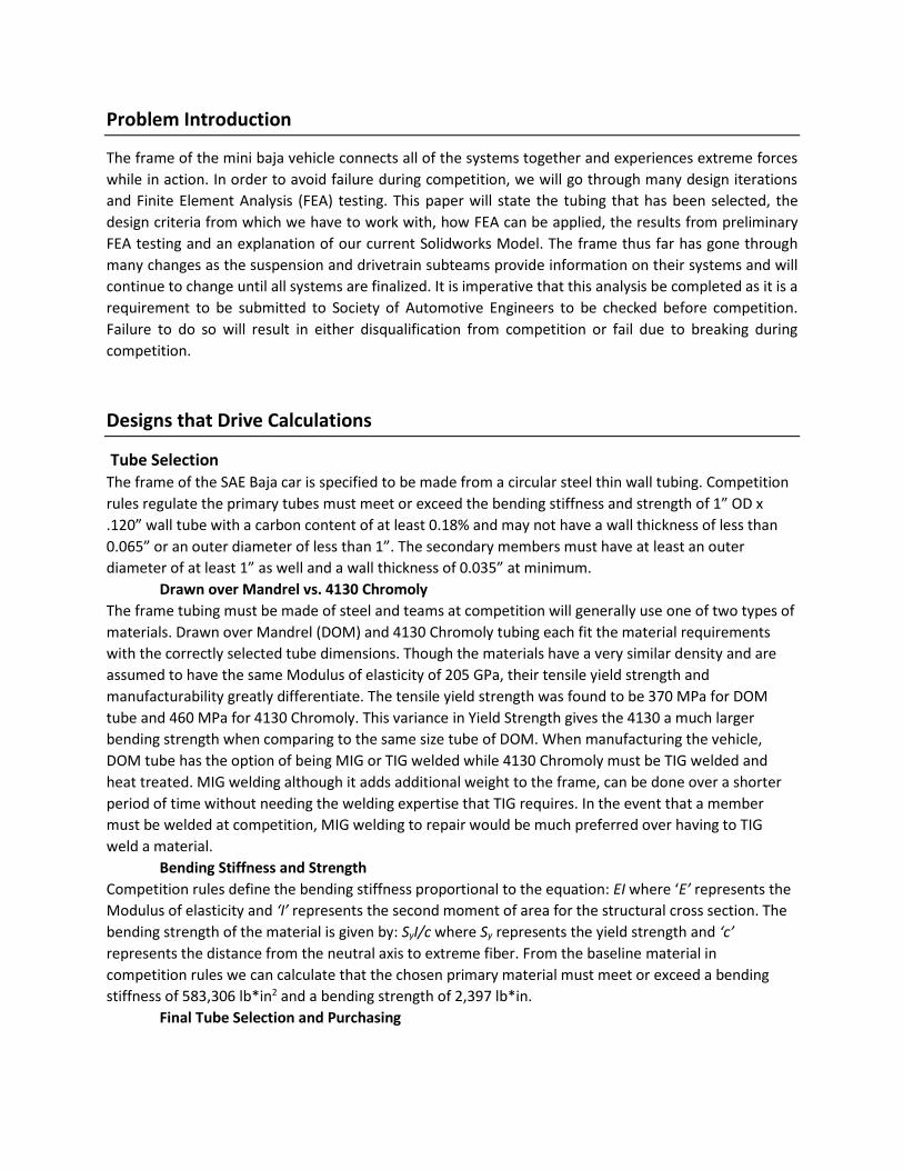
Current Solidworks Model
Below in Figures 13 through 16 is the current Solidworks model for the frame and the closest to what we
believe will be used. The FEA was unable to be done to this model due to the way it was built by lofted
extrusions. Solidworks was unable to create a mesh of the part and therefore unable to run the simulation.
A similar model is currently under construction after starting over to ensure future analysis will be
successful.
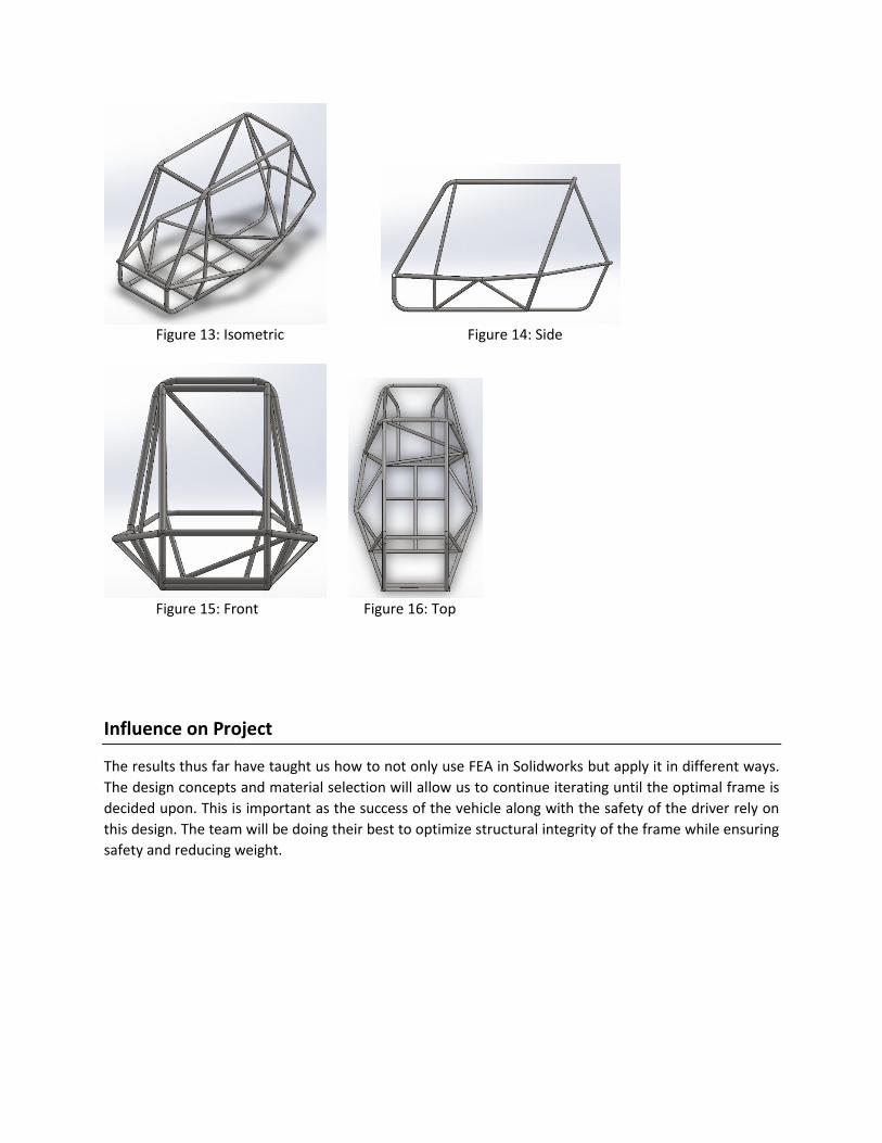
Figure 13: Isometric Figure 14: Side
Figure 15: Front Figure 16: Top
Influence on Project
The results thus far have taught us how to not only use FEA in Solidworks but apply it in different ways.
The design concepts and material selection will allow us to continue iterating until the optimal frame is
decided upon. This is important as the success of the vehicle along with the safety of the driver rely on
this design. The team will be doing their best to optimize structural integrity of the frame while ensuring
safety and reducing weight.