Prestress Force Monitoring and Quantification of Precast ...
Upload
khangminh22Category
view
1download
0
HOLLOWCORE FLOOR & ROOF
SOLUTIONS
PRODUCED TO CPCI STANDARDS

2
Concrete hollowcore Solutions
Precast hollowcore concrete is widely used in various residential, commercial and municipal applications that require a floor or roof system comprised of standard components, manufactured in a controlled environment. Due to the significant benefits of superior fire resistance, sound control, durability and low maintenance, owners and designers alike can take advantage of rapid construction techniques and an attractive exterior
• Hollowcore slabs conform to the current edition ofCSA and CPCI related standards.
• Estimated values of cambers and deflections canbe supplied upon request.
• For superimposed loads greater than 10 kPa and fireresistance ratings greater than 2 hours, special designrequirements and different materials may be required.Please contact your local Lafarge representative.
Fire Resistance Ratings
• Precast prestressed concrete elements can bedesigned with any degree of fire resistance thatmay be required by building codes, insurancecompanies and other authorities.
• The fire resistance of building assemblies isdetermined from standard fire tests as defined byULC Standard current CAN/ULE-S101 “StandardMethods of Fire Endurance Tests of BuildingConstruction and Materials”.
Sound Insulation Ratings
• Mandatory sound insulation requirements betweenadjoining dwellings are generally specified inbuilding codes and equivalent regulations.
• For example: City of Vancouver Building By-Law 6164, requires a Apparent SoundTransmission Class (ASTC) of 50 for all residentialsuites. It has been shown by extensive researchthat the STC rating
of various components is related to the surface density of the materials.
• Class (IIC) is derived from ASTM StandardMethod E492, “Laboratory Measurements of Impact Sound Transmission Through Floor Ceiling Assemblies Using the Tapping Machine.”
For more information see CPCI Metric Design Manual, 4-th Edition, Chapter 6-21

Precast hollowcore Cross Section
Figure 1 - 203 Deep x 1200 Wide Hollowcore Panel
Slab Section and Material Properties 8" Hollowcore (203 x 1220)
The above properties may vary. Please contact Lafarge for other sections, material properties and structural information.
40 MPa
25 MPa
2400 kg/m3
1860 MPa
1302 MPa
Low Relaxation
Net Area
Moment of Inertia
Centroid From Slab Bottom
Section Modulus, Top
Section Modulus, Bottom
V/S Ratio
Self Weight (May Vary)
148,700 mm2
718 x 106 mm4
101 mm
7080 x 103 mm3
7110 x 103 mm3
53 mm
2.87 kN/m2
Strength of Concrete
Strength at Release
Unit Weight of Concrete
Ultimate Steel Strength
Strand Jacking Stress
Strand Type
3

Precast hollowcore Cross Section
Figure 1 - 254 Deep x 1200 Wide Hollowcore Panel
Slab Section and Material Properties 10" Hollowcore (254 x 1200)
The above properties may vary. Please contact Lafarge for other sections, material properties and structural information.
Net Area 40 MPa
25 MPa
2400 kg/m3
1860 MPa
1302 MPa
Low Relaxation
Moment of Inertia
Centroid From Slab Bottom
Section Modulus, Top
Section Modulus, Bottom
V/S Ratio
Self Weight (May Vary)
193,300 mm2
1333 x 106 mm4
125 mm
1330 x 103 mm3
1660 x 103 mm3
57 mm
3.69 kN/m2
Strength of Concrete
Strength at Release
Unit Weight of Concrete
Ultimate Steel Strength
Strand Jacking Stress
Strand Type
4

5
Concrete Hollowcore Solutions
Slab Section and Material Properties 12" Hollowcore (305 x 1220)
The above properties vary. Please call Lafarge for other sections, material properties and structural capacities.
Figure 2 - 305 Deep x 1200 Wide Hollowcore Panel
Net Area 40 MPa
25 MPa
2400 kg/m3
1860 MPa
1302 MPa
Low Relaxation
Moment of Inertia
Centroid From Slab Bottom
Section Modulus, Top
Section Modulus, Bottom
V/S Ratio
Self Weight (May Vary)
206,600 mm2
2251 x 106 mm4
151 mm
14620 x 103 mm3
14910 x 103 mm3
65 mm
3.88 kN/m2
Strength of Concrete
Strength at Release
Unit Weight of Concrete
Ultimate Steel Strength
Strand Jacking Stress
Strand Type

Tables Of Superimposed Service Load (kN/m2) and Cambers (mm) - No Topping
Hollowcore 1200 x 203 (8"HC)
Hollowcore 1200 x 254 (10" HC)
Hollowcore 1200 x 305 (12" HC)
• Loads shown above for uniformly distributed, superimposed not factored.• Openings, point or line loads, snow drifts, etc. should be considered in design and are not included in the table below.• CPCI and National Building Code latest revision governs.• Doesn’t include any allowance for strands cut.• The information below is for guideline purposes - accurate design must be carried out to determine panel’s capacity.• Panel resistance to shear and flexural torsion must be calculated before using the data below.
6

Connection DetailsAll connection illustrations below are used for conceptual design only.
End Bearing On Block - Half Bearing - Tie Up (Scale - N.T.S.)
Side Bearing On Block - Half Bearing - Tie Up (Scale - N.T.S.)
End Bearing On Block - Abutting - Tie Across (Scale - N.T.S.)
Precast Slab Bearing On Concrete Beam
BUILD BAR INTO WALL ABOVE(NOT BY LAFARGE)
VOID PLUG DISC INEACH CORE AT EXTERIOR WALLS (OPTIONAL)REBAR
CONT. KOROLATH BEARING PAD(BY LAFARGE)
BOND BEAM(NOT BY LAFARGE)
VERTICAL WALL REINFORCING(NOT BY LAFARGE)NOT TO INTERFERE WITHBEARING OF PRECAST83
[3 1/4’]MIN.
BEARING
VARY
BUILD BAR INTO WALL ABOVE(NOT BY LAFARGE)
BLOCK OUTS (BY LAFARGE)
REBAR
DRYPACK, BEFORE BUILDINGWALL ABOVE IF REQUARED(NOT BY LAFARGE)
BOND BEAM(NOT BY LAFARGE)
VERTICAL WALL REINFORCING(NOT BY LAFARGE)NOT TO INTERFERE WITHBEARING OF PRECAST
83[3 1/4’]MIN.
BEARING
WALL ABOVE WHERE APPLICABLE
BOND BEAM(NOT BY LAFARGE)
VERTICAL WALL REINFORCING(NOT BY LAFARGE)NOT TO INTERFERE WITHBEARING OF PRECAST
83[3 1/4’]MIN.
BEARING
83[3 1/4’]
CONT. KOROLATH BEARING PAD(BY LAFARGE)
REBARIN EACH GROUT JOINT
1220 [4’-0”]
GROUT JOINTSOLID
VOID PLUG EACH COREAND SOLID
GROUT FILLAT BEARING
VOID PLUG EACH CORE AND SOLID GROUT FILL
AT BEARING HAIR PIN CONNECTION
4”MINIMUMBEARING
CONCRETE BEAM(NOT BY LAFARGE)
REBARCAST INTO BEAM(NOT BY LAFARGE)
CONTINUESREINFORCING(NOT BY LAFARGE)
7

8
Connection DetailsAll connection illustrations below are used for conceptual design only.
End Bearing On P.C. OR C.I.P. Concrete Beam (Scale - N.T.S.)
PROVIDE HOOKED DOWELS
End Bearing On Beam (Scale - N.T.S.)
Interior Hollowcore Parallel to CMU (Scale - N.T.S.)
Grade Beam - Parallel to Hollowcore (Scale - N.T.S.)
Masonry / ICF Foundation (Scale - N.T.S.)
Side Bearing On Beam - Half Bearing (Scale - N.T.S.)
**All connectionsshown are to be
used for conceptualdesign only.
LONGITUDINAL BAR (AS REQUIRED,NOT BY LAFARGE)
MIN. 50mm [2”]
VOID PLUG EACH CORE AND SOLID GROUT FILLAT BEARING
HOOKED DOWEL
CONT. KOROLATH BEARING PAD(BY LAFARGE)
P.C OR C.I.PCONCRETE BEAM
MIN. 75mm[3”] BEARING
BLOCKOUTS (BY LAFARGE)
Z-REBAR (BY LAFARGE)FILL SOLID WITH CONCRETE AFTER
INSTALL (NOT BY LAFARGE)
STUD OR CONT. REBAR(NOT BY LAFARGE)
AT LOCS SHOWN IN PLAN PROVIDE BLOCKOUTS C/W Z BARS AT EACH BLOCKOUT. EXTEND Z BAR TO CENTERLINE OF CORE AND TO CENTRELINE OF CMU WALL. GROUT SOLID WHEN INSTALLED - (NOT BY LAFARGE)
CONTINUES BAR - TYPICAL
CONT. REBAR(NOT BY LAFARGE)
VOID PLUG EACH CORE AND SOLID GROUT FILL
AT BEARING
* WHERE JOINTS NOT UNTENURED
NELSON STUDS(NOT BY LAFARGE)
REBAR IN EACH GROUT JOINT*
20[3/4”]
20[3/4”]
HOOKED DOWEL AT EACH PANEL JOINT
(BY LAFARGE)
VOID PLUG EACH CORE AND SOLID GROUT FILL
AT BEARING(BY LAFARGE)
CONT. 50MM X 3MM [2” X 1/8”]KOROLATH BEARING PAD
(BY LAFARGE)
VERTICALLONGITUDINALREINFORCING(NOT BY LAFARGE)
76[3”]BRG
TOPING BY OTHERS
PRECAST TO PROVIDE BLOCKOUT IN PRECAST PANELS AT LOCS SHOWN IN PLAN. PROVIDE Z BARS BLOCKOUT. ONCE Z BAR IS IN PLACE - GROUT SOLID BY OTHERS
Hollowcore Installation Guidelines
Please follow the following procedures for hollowcore installation process:
Organization• Be sure to inform Lafarge of the sequence of
installation prior to hollowcore production in order to ensure that slabs are produced and stockpiled in the appropriate order.
Before Requesting Site Delivery• Clarify that the site dimensions and details are in
accordance with Lafarge drawings. Always read Lafarge drawings in conjunction with architectural and structural drawings.
• Ensure that bearing surfaces are smooth, flat andlevel and that they are within ± 6mm over 6m.
• Be sure that all the other materials that arerequired for the installation process of the hollowcore are available.
• Obtain a record of approval of the stability of thesupporting structure from the engineer.
Delivery Notice• Always provide seven (7) working days delivery
notice to the shipper.
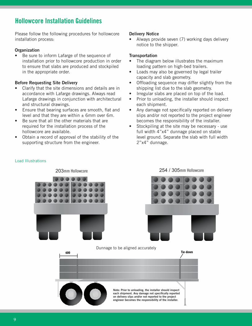
Transportation• The diagram below illustrates the maximum
loading pattern on high-bed trailers.• Loads may also be governed by legal trailer
capacity and slab geometry.• Offloading sequence may differ slightly from the
shipping list due to the slab geometry.• Irregular slabs are placed on top of the load.• Prior to unloading, the installer should inspect
each shipment.• Any damage not specifically reported on delivery
slips and/or not reported to the project engineerbecomes the responsibility of the installer.
• Stockpiling at the site may be necessary - usefull width 4”x4” dunnage placed on stablelevel ground. Separate the slab with full width2”x4” dunnage.
Load Illustrations
203mm Hollowcore 254 / 305mm Hollowcore
Dunnage to be aligned accuratelyTie-down600
Note: Prior to unloading, the installer should inspect each shipment. Any damage not specifically reported on delivery slips and/or not reported to the project engineer becomes the responsibility of the installer.
9

10
• Keep the dunnage accurately aligned from slab toslab.
Installation• Hollowcore slabs are to be located and installed in
accordance with Lafarge drawings.• Minimum end bearing is 75mm unless specified
otherwise on drawings.• Keep slab joint widths uniform.
Hoisting• Use lifting devices (clamps, belts, chokers, forks)
of adequate capacity with a minimum safety factor of 5:1.
• Clamps should be used only with a spreader bar.The slab shall be lifted with lines vertical. If this cannot be accomplished, then belts or chokers should be used instead of clamps.
• On slabs less than 4 feet wide, use belts orchokers; do not use clamps.
• Balance load to avoid slipping and to eliminatetwist on clamps or belts.
• When using clamps, ensure that the clamp edgesfit properly against the sound concrete groovesinside the slab, after the crane has taken the loadbut before hoisting.
• Blocking for stockpile is in the same locations aslifting.
• Refer to shop tickets for slab weight.• Hoist only one slab at a time.• Always use safety slings when hoisting with
clamps or forks.• Never use hollowcore as a platform for hoisting
people or materials.• Never hoist slabs by hooking into cores.• Never turn slabs on edge or upside-down.• Never put hands in cores or between slabs.• Handle only from top surface or with lifting gear.• For special conditions or safety concerns, contact
Lafarge before hoisting.
Proper Installation
Incorrect Hoisting Correct Hoisting
Cable
Lifting Beam
Clamps, cable slings, belt or forks
600 Max - 300 min
Lift lines
Spreader bar
Use belt, choker or clamp
305 min
1220
305 min1220 max305 min
3
1(min)

203mm (8") Hollowcore
Grouting• Remove all debris from joints.• Grouting materials - unless specified otherwise,
they consist of a sand/ cement mix. Minimum 28days strength is 25MPa with an air content of 3%to 6%.
• Camber may occur in hollowcore slabs and willvary with slab age, span, reinforcing and loadingconditions.
• Differential camber can be minimized by shoringslabs prior to grouting.
• Cold weather grouting procedures are to be inaccordance with CSA A23.1. Until the grout hasreached adequate strength, full load capacity maynot be assumed.
Field Cut Openings• Round holes are cut in the locations specified and
the maximum sizes are shown on the diagrams below that may be cut in the field.
• Approval must be obtained from Lafarge if:1. More than 3 holes are to be placed
across the slab in one location throughthe core space.
2. The holes are larger than shown inthe diagrams.
3. The holes are within 1/5 of the slablength measured from the bearing point.
4. Webs must be cut to accommodateopenings.
• Core-drilling is recommended for all the holes.
305mm (12") Hollowcore
254mm (10") Hollowcore
11

12
We pride ourselves in building better cities and better communities, from the buildings in which we live and work, to the roads and bridges that connect our cities and towns. We provide construction solutions that respond to the needs of our customers and the people living in the communities we help create.
Edmonton, AB
Lafarge Precast Edmonton 4425 - 92 Avenue Edmonton, Alberta T6B 2J4
Steve Lapierre Commercail Sales Manager Edmonton Precast Phone: 780-485-4508 Cell: 780-777-4401
Jason Rabasse, CET Business Development Manager Edmonton PrecastPhone: 780-485-4510Cell: 780-777-9267
General Inquiries Phone: 780-485-4500 Fax: 780-465-6443
Hollowcore Producing Operation
Isabel Suarez, P.Eng Commercail Sales Manager Calgary PrecastPhone: 403-292-9234 Cell: 403-371-9847
Contacts
Copyright © 2022 FDOKUMEN