Specification for Precast Concrete Tunnel Lining (PCTL ...
352
Trans Mountain Pipeline ULC Burnaby Mountain Tunnel Option Design, Construction, and Operation Trans Mountain Expansion Project 3-15 Appendix 1: Specifications and Drawings: Specification for Precast Concrete Tunnel Lining (PCTL) TMEP-TU-1500 – 31 74 16. Specification for PCTL Concrete Accessories TMEP-TU-2900 – 03 15 00. Specification for Concrete Reinforcement for PCTL TMEP-TU-3000 – 03-20-00.1 Specification Concrete for PCTL TMEP-TU-3100 – 03 30 00.1. Specification for PCTL Handling, Storage and Delivery TMEP-TU-3300 – 31 74 16.1. Specification for Tunnel Annular Grouting TMEP-TU-1600 – 31 73 13. Specification for Tunnel Backfill TMEP-TU-2500 – 31 73 14 Drawing M002-XD12100 Drawing M002-XD12400 Drawing M002-XD12430 Specification for Site Preparation TMEP-TU-1000 – 31 10 00. Specification for Diversion and Care of Water TMEP-TU-1100 – 01 57 23. Specification for Portal Area Development TMEP-TU-1210 – 31-71-03. Specification for Secant Pile Wall TMEP-TU-2600 – 31 57 00. Specification for Concrete Reinforcement TMEP-TU-2700 – 03 20 00. Specification for Ground Anchors TMEP-TU-2800 – 31 51 00 Specification for Site Restoration TMEP-TU-2510 - 31 23 23. Specification for Tunneling By TBM TMEP-TU-1310 – 31 71 20. Specification for Pipeline Installation in Tunnel TMEP-TU-2000 – 23 11 00 McNally Burnaby Mountain Tunnel Work Plan 007 Appendix A Kelley Calculations and Drawings. Drawing M002-XD13500
-
Upload
khangminh22 -
Category
Documents
-
view
0 -
download
0
Transcript of Specification for Precast Concrete Tunnel Lining (PCTL ...

Trans Mountain Pipeline ULC
Burnaby Mountain Tunnel Option Design, Construction, and Operation
Trans Mountain Expansion Project
3-15
Appendix 1: Specifications and Drawings:
Specification for Precast Concrete Tunnel Lining (PCTL) TMEP-TU-1500 – 31 74 16.
Specification for PCTL Concrete Accessories TMEP-TU-2900 – 03 15 00.
Specification for Concrete Reinforcement for PCTL TMEP-TU-3000 – 03-20-00.1
Specification Concrete for PCTL TMEP-TU-3100 – 03 30 00.1.
Specification for PCTL Handling, Storage and Delivery TMEP-TU-3300 – 31 74 16.1.
Specification for Tunnel Annular Grouting TMEP-TU-1600 – 31 73 13.
Specification for Tunnel Backfill TMEP-TU-2500 – 31 73 14
Drawing M002-XD12100
Drawing M002-XD12400
Drawing M002-XD12430
Specification for Site Preparation TMEP-TU-1000 – 31 10 00.
Specification for Diversion and Care of Water TMEP-TU-1100 – 01 57 23.
Specification for Portal Area Development TMEP-TU-1210 – 31-71-03.
Specification for Secant Pile Wall TMEP-TU-2600 – 31 57 00.
Specification for Concrete Reinforcement TMEP-TU-2700 – 03 20 00.
Specification for Ground Anchors TMEP-TU-2800 – 31 51 00
Specification for Site Restoration TMEP-TU-2510 - 31 23 23.
Specification for Tunneling By TBM TMEP-TU-1310 – 31 71 20.
Specification for Pipeline Installation in Tunnel TMEP-TU-2000 – 23 11 00
McNally Burnaby Mountain Tunnel Work Plan 007 Appendix A Kelley Calculations and Drawings.
Drawing M002-XD13500

0 1:3000 160 m40 m

0 1:2000 100 m20 m

³
³
³
³³ ³
³
0 1:250 10 m2 m–
’

NOT FOR CONSTRUCTION
0 1:50 2 m0.4 m
0 1:5000 250 m50 m
0 1:5 200 mm40 mm
AutoCAD SHX Text
4.2%
AutoCAD SHX Text
0.0%
AutoCAD SHX Text
EXISTING GROUND SURFACE
AutoCAD SHX Text
BURNABY PORTAL
AutoCAD SHX Text
WESTRIDGE PORTAL
AutoCAD SHX Text
PORTAL HEADWALL CH. 0+000
AutoCAD SHX Text
PORTAL HEADWALL CH. 2+610
AutoCAD SHX Text
TBM TUNNEL
AutoCAD SHX Text
SEE DETAIL
AutoCAD SHX Text
1
AutoCAD SHX Text
-
AutoCAD SHX Text
TUNNEL SEAL
AutoCAD SHX Text
SEE DETAIL
AutoCAD SHX Text
1
AutoCAD SHX Text
-
AutoCAD SHX Text
TUNNEL SEAL
AutoCAD SHX Text
(SEE NOTE 2)
AutoCAD SHX Text
(SEE NOTE 2)
AutoCAD SHX Text
TUNNEL DIAMETER
AutoCAD SHX Text
TUNNEL DIAMETER
AutoCAD SHX Text
SECTION
AutoCAD SHX Text
A
AutoCAD SHX Text
-
AutoCAD SHX Text
1:50
AutoCAD SHX Text
L
AutoCAD SHX Text
C
AutoCAD SHX Text
TUNNEL
AutoCAD SHX Text
TBM TUNNEL
AutoCAD SHX Text
-
AutoCAD SHX Text
C
AutoCAD SHX Text
DETAIL
AutoCAD SHX Text
1
AutoCAD SHX Text
-
AutoCAD SHX Text
1:50
AutoCAD SHX Text
INDICATIVE PIPE SUPPORT (BY CONTRACTOR)
AutoCAD SHX Text
-
AutoCAD SHX Text
A
AutoCAD SHX Text
RAIL
AutoCAD SHX Text
SEE DETAIL
AutoCAD SHX Text
2
AutoCAD SHX Text
-
AutoCAD SHX Text
-
AutoCAD SHX Text
B
AutoCAD SHX Text
ANNULAR SEALING AROUND PIPE (TYP) (SEE NOTE 3)
AutoCAD SHX Text
DETAIL
AutoCAD SHX Text
2
AutoCAD SHX Text
-
AutoCAD SHX Text
1:5
AutoCAD SHX Text
ANNULAR SEALING AROUND PIPE (TYP) (SEE NOTE 3)
AutoCAD SHX Text
NPS 30 PIPELINE
AutoCAD SHX Text
500
AutoCAD SHX Text
500
AutoCAD SHX Text
SECTION
AutoCAD SHX Text
B
AutoCAD SHX Text
-
AutoCAD SHX Text
1:50
AutoCAD SHX Text
L
AutoCAD SHX Text
C
AutoCAD SHX Text
TUNNEL
AutoCAD SHX Text
INDICATIVE PIPE SUPPORTS (BY CONTRACTOR)
AutoCAD SHX Text
NPS 30 PIPELINES (SEE NOTE 4)
AutoCAD SHX Text
ANNULAR SEALING AROUND PIPE (TYP.) (SEE NOTE 3)
AutoCAD SHX Text
SECTION
AutoCAD SHX Text
C
AutoCAD SHX Text
-
AutoCAD SHX Text
1:50
AutoCAD SHX Text
L
AutoCAD SHX Text
C
AutoCAD SHX Text
TUNNEL
AutoCAD SHX Text
PRE-CAST CONCRETE SEGMENTS (TYP.) (SEE DWG. M002-XD12210)
AutoCAD SHX Text
RAIL
AutoCAD SHX Text
2 x 100 DIA. PVC CONDUITS FOR FIBER OPTIC CABLES (INDICATIVE LOCATION)
AutoCAD SHX Text
POTENTIAL POLYMER CONDUIT IN CLOSE PROXIMITY TO EACH OF THE DELIVERY LINES
AutoCAD SHX Text
NPS2 STEEL PIPE ANODE (EQ. TAG A1-1) (SEE DETAIL 6 ON DWG. M002-XD13055)
AutoCAD SHX Text
NPS2 STEEL PIPE ANODE (EQ. TAG A1-2) (SEE DETAIL 6 ON DWG. M002-XD13055)
AutoCAD SHX Text
SPLICE
AutoCAD SHX Text
BONDING CABLE AWG#8/7 RWU90 CABLE TAG B1
AutoCAD SHX Text
TBM TUNNEL - WESTRIDGE TO BURNABY - PROFILE SCALE: 1:5000
AutoCAD SHX Text
1
AutoCAD SHX Text
TUNNELS & SHAFT, BACKFILL, TYPICAL CROSS SECTIONS
AutoCAD SHX Text
M002-XD13510
AutoCAD SHX Text
2
AutoCAD SHX Text
TUNNEL, TUNNEL SEAL, DETAILS AND SECTIONS
AutoCAD SHX Text
M002-XD13520
AutoCAD SHX Text
3
AutoCAD SHX Text
BURNABY SITE AREA, SITE RESTORATION AND FINAL GRADING, PLAN
AutoCAD SHX Text
M002-XD13530
AutoCAD SHX Text
4
AutoCAD SHX Text
BURNABY SITE AREA, TUNNEL PORTAL AREA BACKFILL, TYPICAL SECTIONS
AutoCAD SHX Text
M002-XD13540
AutoCAD SHX Text
5
AutoCAD SHX Text
WESTRIDGE SITE AREA, SITE RESTORATION AND FINAL GRADING, PLAN
AutoCAD SHX Text
M002-XD13550
AutoCAD SHX Text
6
AutoCAD SHX Text
WESTRIDGE SITE AREA, TUNNEL PORTAL AREA BACKFILL, TYPICAL SECTIONS
AutoCAD SHX Text
M002-XD13560
AutoCAD SHX Text
NOTES: 1.SEE DWG. M002-XD11010 FOR GENERAL NOTES, SYMBOLS AND ABBREVIATIONS. SEE DWG. M002-XD11010 FOR GENERAL NOTES, SYMBOLS AND ABBREVIATIONS. 2.LOCATIONS OF TUNNEL SEALS ARE: 0+550, 0+650 and 2+350. LOCATIONS OF TUNNEL SEALS ARE: 0+550, 0+650 and 2+350. 3.ANNULAR SEALING TO BE HYDROTITE CJ-3030 OR EQUIVALENT. INSLATLLATION OF ANNULAR SEALING TO BE HYDROTITE CJ-3030 OR EQUIVALENT. INSLATLLATION OF THE ANNULAR SEALING SHALL BE DONE AS SPECIFIED AND IN ACCORDANCE WITH MANUFACTURER'S RECOMMENDATION. 4.LOCATIONS OF NPS30 PIPELINES ARE TYPICAL. LOCATIONS OF NPS30 PIPELINES ARE TYPICAL. 5.TUNNEL BACKFILL OPERATIONS CAN COMMENCE AFTER POSITIVE HYDRO TEST TUNNEL BACKFILL OPERATIONS CAN COMMENCE AFTER POSITIVE HYDRO TEST RESULTS ON ALL PIPELINES WITHIN THE TUNNEL.
AutoCAD SHX Text
SHEET SIZE
AutoCAD SHX Text
SCALE
AutoCAD SHX Text
DATE
AutoCAD SHX Text
REV
AutoCAD SHX Text
SHT NO
AutoCAD SHX Text
DOCUMENT NO
AutoCAD SHX Text
DRAWING NUMBER
AutoCAD SHX Text
FACILITY ID
AutoCAD SHX Text
AFE
AutoCAD SHX Text
DATE
AutoCAD SHX Text
NO
AutoCAD SHX Text
REFERENCE DRAWING NO.
AutoCAD SHX Text
REFERENCE DRAWING TITLE
AutoCAD SHX Text
NO.
AutoCAD SHX Text
DRAWN BY
AutoCAD SHX Text
CHECKED BY
AutoCAD SHX Text
APPROVED BY
AutoCAD SHX Text
APP
AutoCAD SHX Text
CHK
AutoCAD SHX Text
DRN
AutoCAD SHX Text
REVISION
AutoCAD SHX Text
A1
AutoCAD SHX Text
PROJECT CODING
AutoCAD SHX Text
PLOT DATE:
AutoCAD SHX Text
USER NAME:
AutoCAD SHX Text
FILE NAME:
AutoCAD SHX Text
THIS DOCUMENT IS ISSUED FOR THE PARTY WHICH COMMISSIONED IT AND FOR SPECIFIC PURPOSES CONNECTED WITH THE CAPTIONED PROJECT ONLY. IT SHOULD NOT BE RELIED UPON BY ANY OTHER PARTY OR USED FOR ANY OTHER PURPOSE. WE ACCEPT NO RESPONSIBILITY FOR THE CONSEQUENCES OF THIS DOCUMENT BEING RELIED UPON BY ANY OTHER PARTY, OR BEING USED FOR ANY OTHER PURPOSE, OR CONTAINING ANY ERROR OR OMISSION WHICH IS DUE TO AN ERROR OR OMISSION IN DATA SUPPLIED TO US BY OTHER PARTIES. THIS DOCUMENT CONTAINS CONFIDENTIAL INFORMATION AND PROPRIETARY INTELLECTUAL PROPERTY. IT SHOULD NOT BE SHOWN TO OTHER PARTIES WITHOUT CONSENT FROM US AND FROM THE PARTY WHICH COMMISSIONED IT.
AutoCAD SHX Text
CLI
AutoCAD SHX Text
15/03/30
AutoCAD SHX Text
D
AutoCAD SHX Text
AS NOTED
AutoCAD SHX Text
XD13500
AutoCAD SHX Text
M002
AutoCAD SHX Text
01-13283
AutoCAD SHX Text
TRANS MOUNTAIN EXPANSION PROJECT
AutoCAD SHX Text
TUNNEL
AutoCAD SHX Text
BACKFILL
AutoCAD SHX Text
PROFILE, SECTIONS & DETAILS
AutoCAD SHX Text
BURNABY MOUNTAIN TUNNEL
AutoCAD SHX Text
C. BROCKWAY
AutoCAD SHX Text
D. JEZEK
AutoCAD SHX Text
D. YOUNG
AutoCAD SHX Text
2017-2-27
AutoCAD SHX Text
Brockway, Chris
AutoCAD SHX Text
G:\KinderMorgan\334890_TransMountainPipeline\CAD\Tunnels\1_Drawings\2_Civil\M002-XD13500.dwg
AutoCAD SHX Text
A
AutoCAD SHX Text
15/04/29
AutoCAD SHX Text
ISSUED FOR RFP, AFE 01-13283
AutoCAD SHX Text
CSB
AutoCAD SHX Text
DJE
AutoCAD SHX Text
DY
AutoCAD SHX Text
B
AutoCAD SHX Text
15/12/11
AutoCAD SHX Text
ISSUED FOR 90% DESIGN, AFE 01-13283
AutoCAD SHX Text
CSB
AutoCAD SHX Text
DJE
AutoCAD SHX Text
DY
AutoCAD SHX Text
C
AutoCAD SHX Text
16/05/11
AutoCAD SHX Text
ISSUED FOR INFORMATION, AFE 01-13283
AutoCAD SHX Text
CSB
AutoCAD SHX Text
DJE
AutoCAD SHX Text
DY
AutoCAD SHX Text
D
AutoCAD SHX Text
17/02/27
AutoCAD SHX Text
ISSUED FOR INFORMATION, AFE 01-13283
AutoCAD SHX Text
CSB


TRANS MOUNTAIN PIPELINE L.P.
EXPANSION PROJECT SPECIFICATION
TMEP-TU-1000 Revision 0 June 1, 2016 Page 1 of 8 31 10 00 Site Preparation
334890-TU-210-S0-0033
TABLE OF CONTENTS
1.0 GENERAL ............................................................................................................ 2 1.1 Introduction ................................................................................................ 2 1.2 Scope of Work ........................................................................................... 4 1.3 Related Work Specified Elsewhere ............................................................ 5 1.4 Glossary and Abbreviations ....................................................................... 5 1.5 Regulations, Codes, Specifications, Standards ......................................... 6 1.6 Quality Control and Quality Assurance ...................................................... 6 1.7 Submittals .................................................................................................. 6 1.8 Protection ................................................................................................... 6 1.9 Site Conditions ........................................................................................... 7
2.0 PRODUCTS ......................................................................................................... 7 2.1 Materials .................................................................................................... 7
3.0 EXECUTION ......................................................................................................... 8 3.1 Preparation ................................................................................................ 8 3.2 Stripping and Stockpiling of Topsoil ........................................................... 8

TRANS MOUNTAIN PIPELINE L.P.
EXPANSION PROJECT SPECIFICATION
TMEP-TU-1000 Revision 0 June 1, 2016 Page 2 of 8 31 10 00 Site Preparation
334890-TU-210-S0-0033
1.0 GENERAL
1.1 Introduction
1.1.1 This Specification was prepared in collaboration with McNally Construction Inc. (the Contractor) as part of the Early Contractor Involvement (ECI) Pre-Construction Services (Phase 1) as described in the Memorandum of Understanding for Early Contractor Involvement, Contract Number TMEP-PC-001.
1.1.2 This Specification is customized to the Contractor’s construction plans and preferences, as described in the Construction Execution Plans, produced as part of the ECI Phase 1.
1.1.3 This Specifications forms part of the Contract Documents and is to be read, interpreted and coordinated with all other parts, including the following:
1.1.3.1 Bidding requirements, bid forms, pricing and baseline schedule milestones by Trans Mountain
1.1.3.2 General Conditions by Trans Mountain
1.1.3.3 Special Conditions and/or Division 1 Technical Specifications by Trans Mountain
1.1.3.4 Environmental and Permit Conditions by Trans Mountain
1.1.3.5 Construction Execution Work Plans prepared by McNally and reviewed by HMM and Trans Mountain
1.1.3.6 Contract Drawings
1.1.3.7 Contract Geotechnical Reports
1.1.3.8 Various other Trans Mountain and TMEP standards including TMEP Pipeline Construction Damage Prevention Plan, and the following Technical Specifications including:
A. 1000 Site Preparation
B. 1100 Diversion and Care of Water
C. 1210 Portal Area Development

TRANS MOUNTAIN PIPELINE L.P.
EXPANSION PROJECT SPECIFICATION
TMEP-TU-1000 Revision 0 June 1, 2016 Page 3 of 8 31 10 00 Site Preparation
334890-TU-210-S0-0033
D. 1310 Tunnelling by TBM
E. 1500 Precast Concrete Tunnel Lining (PCTL)
F. 1600 Tunnel Annular Grouting
G. 1610 Pre-Excavation Grouting
H. 1620 Shotcrete
I. 2000 Pipeline Installation in Tunnel
J. 2200 Probe Hole Drilling ahead of TBM
K. 2300 Geotechnical Instrumentation and Monitoring
L. 2400 Cast-In-Place Concrete
M. 2500 Tunnel Backfill
N. 2510 Site Restoration
O. 2600 Secant Pile Wall
P. 2700 Concrete Reinforcement
Q. 2800 Ground Anchors
R. 2900 PCTL Concrete Accessories
S. 3000 Concrete Reinforcement for PCTL
T. 3100 Concrete for PCTL
U. TMEP-CIV102 Engineering Survey – B.C.
V. TMEP-CIV301 Blasting
W. TMEP-CIV400 Clearing Specification for British Columbia
X. TMEP-GC3105 FBE Plant Applied Coating
Y. TMEP-GC3300 FBE Field Applied Coating
Z. TMEP-GC3302 Two-Part Liquid Field Applied Coating
AA. TMEP-GC3306 Two-Part Liquid Shop Applied Coating

TRANS MOUNTAIN PIPELINE L.P.
EXPANSION PROJECT SPECIFICATION
TMEP-TU-1000 Revision 0 June 1, 2016 Page 4 of 8 31 10 00 Site Preparation
334890-TU-210-S0-0033
BB. TMEP-MP1200 Steel Fittings
CC. TMEP-MP2212 Steel Flanges
DD. TMEP-MP2217 Bends
EE. TMEP-MP2300 Pipeline Valves
FF. TMEP-MP3120 Pipeline Construction
GG. TMEP-MP3903 Non Destructive Testing
HH. TMEP-MP3904 SMAW and Mechanized Welding
II. TMEP-MP4121 Hydrostatic Testing
JJ. TMEP-MP4500 Pipeline Cleaning
KK. TMEP-MP4501 Pipeline Drying
LL. TMEP-MP4502 Post Construction Caliper Pigging
MM. TMEP-42EF0009 Piling Installation
NN. TMEP-42EF0016 Structural Steel Fabrication and Erection
OO. TMEP-45ES0012 Pipeline Above Ground Painting
1.1.4 Trans Mountain Expansion Project (TMEP) site considerations and requirements are described in Section TMEP-CIV400 - Clearing Specification for British Columbia. Where specifications may identify conflicting requirements, assume that the more stringent requirement applies, unless otherwise specified herein.
1.1.5 The Work will occur on and/or in the vicinity of the existing right-of-way, next to the existing Trans Mountain pipeline and other pipelines which will remain in service throughout construction. All Work shall be performed in accordance with the TMEP Pipeline Construction Damage Prevention Plan.
1.2 Scope of Work
1.2.1 This section of the Specifications is for site preparation at the Burnaby and Westridge Terminal work sites.

TRANS MOUNTAIN PIPELINE L.P.
EXPANSION PROJECT SPECIFICATION
TMEP-TU-1000 Revision 0 June 1, 2016 Page 5 of 8 31 10 00 Site Preparation
334890-TU-210-S0-0033
1.2.2 The Work excludes tree clearing, brush removal, and grubbing within the clearing limits shown on the Drawings. Clearing and grubbing will be carried out by the Owner as part of the Early Works.
1.2.3 Environmental and archaeological surveys will be completed by the Owner.
1.3 Related Work Specified Elsewhere
1.3.1 01 57 23 Diversion and Care of Water
1.3.2 31 71 03 Portal Area Development
1.4 Glossary and Abbreviations
1.4.1 Clearing: Consists of cutting designated trees, and handling of felled trees and disposing of debris.
1.4.2 Embankment: Material derived from usable excavation and placed above original ground or stripped surface elevation.
1.4.3 Grading: altering the ground surface to a desired grade or contour by cutting, filling, levelling, and/or smoothing.
1.4.4 Grubbing: Consists of excavation and disposal of stumps and roots.
1.4.5 Stripping: Consists of excavating and disposal of topsoil and unsuitable material.
1.4.6 Topsoil: Material capable of supporting good vegetative growth and suitable for use in top dressing, landscaping and seeding.
1.4.7 Unsuitable Materials:
1.4.7.1 Weak and/or compressible materials under excavated areas.
1.4.7.2 Materials containing excessive organics or other deleterious materials as determined by the Owner.
1.4.7.3 Frost susceptible materials under excavated areas.
1.4.8 Waste Material: Excavated material unsuitable for use in Work or surplus to requirements.
TRANS MOUNTAIN PIPELINE L.P.
EXPANSION PROJECT SPECIFICATION
TMEP-TU-1000 Revision 0 June 1, 2016 Page 6 of 8 31 10 00 Site Preparation
334890-TU-210-S0-0033
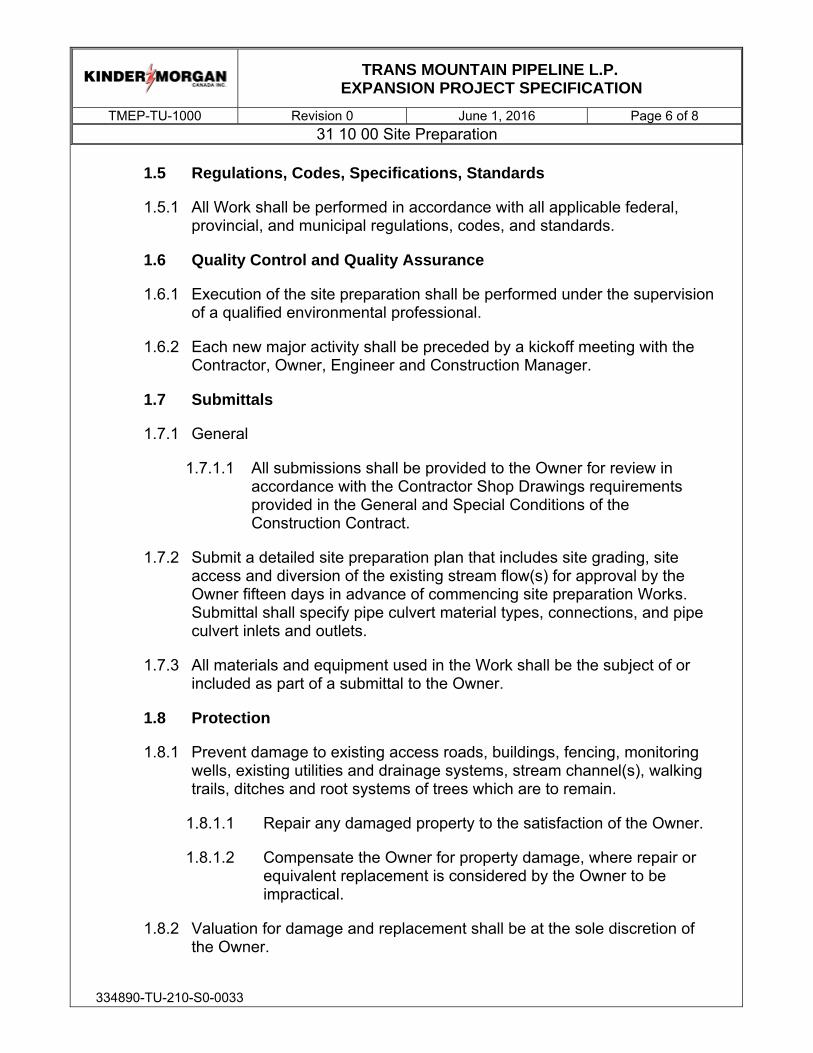
1.5 Regulations, Codes, Specifications, Standards
1.5.1 All Work shall be performed in accordance with all applicable federal, provincial, and municipal regulations, codes, and standards.
1.6 Quality Control and Quality Assurance
1.6.1 Execution of the site preparation shall be performed under the supervision of a qualified environmental professional.
1.6.2 Each new major activity shall be preceded by a kickoff meeting with the Contractor, Owner, Engineer and Construction Manager.
1.7 Submittals
1.7.1 General
1.7.1.1 All submissions shall be provided to the Owner for review in accordance with the Contractor Shop Drawings requirements provided in the General and Special Conditions of the Construction Contract.
1.7.2 Submit a detailed site preparation plan that includes site grading, site access and diversion of the existing stream flow(s) for approval by the Owner fifteen days in advance of commencing site preparation Works. Submittal shall specify pipe culvert material types, connections, and pipe culvert inlets and outlets.
1.7.3 All materials and equipment used in the Work shall be the subject of or included as part of a submittal to the Owner.
1.8 Protection
1.8.1 Prevent damage to existing access roads, buildings, fencing, monitoring wells, existing utilities and drainage systems, stream channel(s), walking trails, ditches and root systems of trees which are to remain.
1.8.1.1 Repair any damaged property to the satisfaction of the Owner.
1.8.1.2 Compensate the Owner for property damage, where repair or equivalent replacement is considered by the Owner to be impractical.
1.8.2 Valuation for damage and replacement shall be at the sole discretion of the Owner.

TRANS MOUNTAIN PIPELINE L.P.
EXPANSION PROJECT SPECIFICATION
TMEP-TU-1000 Revision 0 June 1, 2016 Page 7 of 8 31 10 00 Site Preparation
334890-TU-210-S0-0033
1.8.3 Valuation of tree damage will be based on the methods prescribed by the Council of Tree and Landscape Appraisers. Be responsible for the cost of this valuation, including the Owner’s cost in preparing the valuation.
1.8.4 Ensure the complete diversion and conveyance of the existing stream flows that pass through the Westridge Terminal as shown on the Drawings. Be responsible for designing and constructing temporary pipe culverts that convey and isolate all flows from the stream bed through the Westridge tunnel portal area. Ditching of the existing stream flows are not acceptable. Submit the design to the Owner for approval fifteen days prior to commencing with Works.
1.8.5 The use of the existing access roads and haulage equipment shall be in accordance with the Special Conditions of the Contract Documents.
1.8.6 Prevention and treatment of surface run-off water shall be in accordance with 01 57 23 Diversion and Care of Water.
1.9 Site Conditions
1.9.1 Known underground and surface utility lines, buried objects and drainage systems are indicated on the Drawings.
2.0 PRODUCTS
2.1 Materials
2.1.1 Topsoil / Unsuitable Material: All topsoil / unsuitable material to be transported and stockpiled offsite or onsite within the limits of the designated disposal area. Topsoil shall be stockpiled separately.
2.1.2 Unless determined to be unsuitable by the Owner, soils and earth materials obtained from required excavations or soils and earth materials from approved borrow sites may be used for fill.
2.1.3 Pipe culverts, connections, and pipe culvert inlets and outlets: Supply temporary pipe culverts, connections, and pipe culvert inlets and outlets as required for approval by the Owner.

TRANS MOUNTAIN PIPELINE L.P.
EXPANSION PROJECT SPECIFICATION
TMEP-TU-1000 Revision 0 June 1, 2016 Page 8 of 8 31 10 00 Site Preparation
334890-TU-210-S0-0033
3.0 EXECUTION
3.1 Preparation
3.1.1 Inspect the Worksite and confirm with the Owner items designated to remain and any restrictions within or adjacent to the specified limits of the site development prior to commencing the Work.
3.1.2 Field locate the existing utility lines, underground services and drainages in the vicinity of the construction limits prior to commencing the Work.
3.1.3 Install pipe supports and other protective measures prior to commencement of Work to preserve in operating condition existing pipelines within the Worksites:
3.1.3.1 NPS 24 crude oil line to Westridge, Chevron NPS 24 and Shell NPS 24 jet fuel lines within the Burnaby Site
3.1.3.2 NPS 24 crude oil line to dock at the Westridge Site within the Westridge Site.
3.1.4 Preserve, temporarily bypass or relocate the existing NPS 12 Fire Water line within the Worksite at the Westridge Terminal as shown on the Drawings.
3.1.5 Preserve or relocate other existing utilities including the potable water lines, telecommunication cables within the Worksite(s).
3.2 Stripping and Stockpiling of Topsoil
3.2.1 Remove topsoil before any construction procedures commence to avoid compaction of topsoil and contamination of subgrade.
3.2.2 Strip topsoil as directed by the Owner. Avoid mixing topsoil with subsoil.
3.2.3 Pile topsoil on site as directed by the Owner. Stockpile height not to exceed 2.5 meters, unless otherwise directed by the Owner.
3.2.4 Protect stockpiles from contamination, compaction and erosion.
(END OF SECTION)


TRANS MOUNTAIN PIPELINE L.P.
EXPANSION PROJECT SPECIFICATION
TMEP-TU-1100 Revision 0 June 1, 2016 Page 1 of 14 01 57 23 Diversion and Care of Water
334890-TU-210-S0-0034
TABLE OF CONTENTS
1.0 GENERAL ............................................................................................................ 2 1.1 Introduction ................................................................................................ 2 1.2 Scope of Work ........................................................................................... 4 1.3 Related Work Specified Elsewhere ............................................................ 5 1.4 Glossary and Abbreviations ....................................................................... 5 1.5 Regulations, Codes, Specifications, Standards ......................................... 6 1.6 Quality Control and Quality Assurance ...................................................... 7 1.7 Submittals .................................................................................................. 7 1.8 Design Criteria and Requirements ............................................................. 9
2.0 PRODUCTS ....................................................................................................... 11 2.1 General .................................................................................................... 11 2.2 Materials .................................................................................................. 11
3.0 EXECUTION ....................................................................................................... 11 3.1 General .................................................................................................... 11 3.2 Water and Treatment Disposal ................................................................ 12 3.3 Erosion and Sediment Control ................................................................. 13

TRANS MOUNTAIN PIPELINE L.P.
EXPANSION PROJECT SPECIFICATION
TMEP-TU-1100 Revision 0 June 1, 2016 Page 2 of 14 01 57 23 Diversion and Care of Water
334890-TU-210-S0-0034
1.0 GENERAL
1.1 Introduction
1.1.1 This Specification was prepared in collaboration with McNally Construction Inc. (the Contractor) as part of the Early Contractor Involvement (ECI) Pre-Construction Services (Phase 1) as described in the Memorandum of Understanding for Early Contractor Involvement, Contract Number TMEP-PC-001.
1.1.2 This Specification is customized to the Contractor’s construction plans and preferences, as described in the Construction Execution Plans, produced as part of the ECI Phase 1.
1.1.3 This Specification forms part of the Contract Documents and is to be read, interpreted and coordinated with all other parts, including the following:
1.1.3.1 Bidding requirements, bid forms, pricing and baseline schedule milestones by Trans Mountain
1.1.3.2 General Conditions by Trans Mountain
1.1.3.3 Special Conditions and/or Division 1 Technical Specifications by Trans Mountain
1.1.3.4 Environmental and Permit Conditions by Trans Mountain
1.1.3.5 Construction Execution Work Plans prepared by McNally and reviewed by HMM and Trans Mountain
1.1.3.6 Contract Drawings
1.1.3.7 Contract Geotechnical Reports
1.1.3.8 Various other Trans Mountain and TMEP standards including TMEP Pipeline Construction Damage Prevention Plan, and the following Technical Specifications including:
A. 1000 Site Preparation
B. 1100 Diversion and Care of Water
C. 1210 Portal Area Development
D. 1310 Tunnelling by TBM

TRANS MOUNTAIN PIPELINE L.P.
EXPANSION PROJECT SPECIFICATION
TMEP-TU-1100 Revision 0 June 1, 2016 Page 3 of 14 01 57 23 Diversion and Care of Water
334890-TU-210-S0-0034
E. 1500 Precast Concrete Tunnel Lining (PCTL)
F. 1600 Tunnel Annular Grouting
G. 1610 Pre-Excavation Grouting
H. 1620 Shotcrete
I. 2000 Pipeline Installation in Tunnel
J. 2200 Probe Hole Drilling ahead of TBM
K. 2300 Geotechnical Instrumentation and Monitoring
L. 2400 Cast-In-Place Concrete
M. 2500 Tunnel Backfill
N. 2510 Site Restoration
O. 2600 Secant Pile Wall
P. 2700 Concrete Reinforcement
Q. 2800 Ground Anchors
R. 2900 PCTL Concrete Accessories
S. 3000 Concrete Reinforcement for PCTL
T. 3100 Concrete for PCTL
U. TMEP-CIV102 Engineering Survey – B.C.
V. TMEP-CIV301 Blasting
W. TMEP-CIV400 Clearing Specification for British Columbia
X. TMEP-GC3105 FBE Plant Applied Coating
Y. TMEP-GC3300 FBE Field Applied Coating
Z. TMEP-GC3302 Two-Part Liquid Field Applied Coating
AA. TMEP-GC3306 Two-Part Liquid Shop Applied Coating
BB. TMEP-MP1200 Steel Fittings

TRANS MOUNTAIN PIPELINE L.P.
EXPANSION PROJECT SPECIFICATION
TMEP-TU-1100 Revision 0 June 1, 2016 Page 4 of 14 01 57 23 Diversion and Care of Water
334890-TU-210-S0-0034
CC. TMEP-MP2212 Steel Flanges
DD. TMEP-MP2217 Bends
EE. TMEP-MP2300 Pipeline Valves
FF. TMEP-MP3120 Pipeline Construction
GG. TMEP-MP3903 Non Destructive Testing
HH. TMEP-MP3904 SMAW and Mechanized Welding
II. TMEP-MP4121 Hydrostatic Testing
JJ. TMEP-MP4500 Pipeline Cleaning
KK. TMEP-MP4501 Pipeline Drying
LL. TMEP-MP4502 Post Construction Caliper Pigging
MM. TMEP-42EF0009 Piling Installation
NN. TMEP-42EF0016 Structural Steel Fabrication and Erection
OO. TMEP-45ES0012 Pipeline Above Ground Painting
1.1.4 The Work will occur on and/or in the vicinity of the existing right-of-way, next to the existing Trans Mountain pipeline and other pipelines which will remain in service throughout construction. All Work shall be performed in accordance with the TMEP Pipeline Construction Damage Prevention Plan.
1.2 Scope of Work
1.2.1 This section specifies requirements for the following:
1.2.1.1 Design, procurement, installation, operation, and removal on completion of all temporary facilities required for the control and treatment of groundwater inflows and construction water discharges from the tunnel.
1.2.1.2 Treatment of groundwater and construction water prior to its discharge from the site to ensure its compliance with all regulatory requirements.

TRANS MOUNTAIN PIPELINE L.P.
EXPANSION PROJECT SPECIFICATION
TMEP-TU-1100 Revision 0 June 1, 2016 Page 5 of 14 01 57 23 Diversion and Care of Water
334890-TU-210-S0-0034
1.2.1.3 Control, diversion, treatment (if required), testing and disposal of surface runoff precipitation and onto and away from within the Contractor’s Worksite as shown on the Drawings.
1.2.1.4 Control, treatment (if required), testing and disposal of water removed from the dewatering activities for portal area development.
1.2.1.5 Control of erosion and sedimentation resulting from construction activities, groundwater inflows, surface precipitation, and care of water.
1.2.1.6 Removal of all accumulated silt and temporary measures used to control runoff and sedimentation upon completion of the Work.
1.2.1.7 Requirements for diversion and conveyance of the existing stream that passes the Contractor’s worksite area at the Westridge Terminal as shown on the Drawings.
1.2.2 Additional dewatering and water control of groundwater inflows and construction water required to be pumped from all underground excavations is covered separately in 31 71 20 Tunnelling by TBM.
1.3 Related Work Specified Elsewhere
1.3.1 31 71 03 Portal Area Development
1.3.2 31 71 20 TBM by Tunnelling
1.3.3 31 23 23 Site Restoration
1.4 Glossary and Abbreviations
1.4.1 Construction Water:
1.4.1.1 Water piped or otherwise brought into the tunnel for use with activities including dust suppression, probe hole drilling, pre-excavation grouting, and tunnel cleaning. Construction water will often ultimately be mixed, pumped, treated and discharged with groundwater inflows.
1.4.2 Groundwater Inflows: Water originating from overburden or bedrock by processes including the following:

TRANS MOUNTAIN PIPELINE L.P.
EXPANSION PROJECT SPECIFICATION
TMEP-TU-1100 Revision 0 June 1, 2016 Page 6 of 14 01 57 23 Diversion and Care of Water
334890-TU-210-S0-0034
1.4.2.1 Flowing, dripping or seeping directly from the groundmass into the tunnel, excavated surfaces, probe holes, or by other means.
1.4.2.2 Pumping from or draining of overburden or bedrock adjacent to tunnel or a tunnel portal area using submerged pumps in deep wells, well points, horizontal drainage, weep holes, blanket drains, or any combination of these methods.
1.4.2.3 Surface precipitation falling directly into the tunnel portal shall be considered to form part of the total groundwater inflows.
1.4.3 Surface Run-off Water: Water derived from the following processes including but not limited to the following:
1.4.3.1 Precipitation falling within the Limits for Contractors Worksite on surface, as shown in the Drawings.
1.4.3.2 Surface run-off originating from outside the contract Limits of Construction, which flows into the Limits for Contractors Worksite through natural processes or diversions.
1.5 Regulations, Codes, Specifications, Standards
1.5.1 The Contractor shall perform the Work in accordance with all applicable laws, the Contractor’s policies and procedures including the Contractor’s Quality, Health, Safety and Environmental Manual, and Environmental Requirements in the Construction Contract.
1.5.2 The discharge from construction sites of all groundwater inflows, construction water and surface run-off shall be in accordance with the applicable acts, regulations and bylaws including the following authorities and governing agencies. In the event of conflict, the more stringent applies:
1.5.2.1 Department of Fisheries and Oceans (DFO) of Canada.
1.5.2.2 Port Metro Vancouver.
1.5.2.3 Metro Vancouver Regional District.
1.5.2.4 City of Burnaby.
1.5.3 Comply with applicable discharge water quality standards and the following minimum standards:

TRANS MOUNTAIN PIPELINE L.P.
EXPANSION PROJECT SPECIFICATION
TMEP-TU-1100 Revision 0 June 1, 2016 Page 7 of 14 01 57 23 Diversion and Care of Water
334890-TU-210-S0-0034
1.5.3.1 Water disposed into Burrard Inlet shall comply at a minimum, to the British Columbia Approved and Working Water Quality Guidelines for Marine Aquatic Life (BC AWWQG 2015).
1.5.3.2 Water disposed into Eagle Creek shall comply at a minimum to British Columbia Approved and Working Water Quality Guidelines for Fresh Aquatic Life (BC AWWQG 2015).
1.5.4 Obtain all necessary permits for discharging water from the worksites
1.6 Quality Control and Quality Assurance
1.6.1 Records: Keep daily records of the measurements of the quantity and quality of the treated discharge water.
1.6.2 Shop Drawings shall be prepared, stamped and signed by a Professional Engineer registered in the Province of British Columbia that is experienced in the preparation of water handling and treatment facilities.
1.6.3 Provide an independent certified testing laboratory to perform any required testing.
1.6.4 Demonstrate the adequacy of the treatment facilities to handle, treat, and discharge the expected flows prior to performing excavation.
1.6.5 Each new major activity shall be preceded by a kickoff meeting with the Contractor, Owner, Engineer and Construction Manager.
1.7 Submittals
1.7.1 General
1.7.1.1 All submissions shall be provided to the Owner for review in accordance with the Contractor Shop Drawings requirements provided in the General and Special Conditions of the Construction Contract.
1.7.2 Submit details 60 days prior to use of water treatment systems to be used at the Burnaby and Westridge sites. The submittal shall include all necessary facilities/structures, equipment, materials, operating procedures, maintenance, cleaning, mobilization, demobilization, and include the following:
1.7.2.1 Shop Drawings for the handling, treating, measuring and disposing of groundwater in the tunnel heading, along the

TRANS MOUNTAIN PIPELINE L.P.
EXPANSION PROJECT SPECIFICATION
TMEP-TU-1100 Revision 0 June 1, 2016 Page 8 of 14 01 57 23 Diversion and Care of Water
334890-TU-210-S0-0034
excavated tunnel, conveyance from the portal and work areas to treatment facilities. Include details pertaining to drainage facilities, holding basins, and a schedule for installation of the facilities.
1.7.2.2 Set forth the methods and equipment proposed for keeping groundwater inflows from either damaging works in progress or impacting the efficiency with which the Work is performed; treating, measuring and disposing of inflow groundwater, and removing the facilities when they are no longer needed. Details shall include:
A. Location, depth, and size of dams, retention basins and treatment ponds.
B. Location, size, capacity, and details of treatment plants.
C. Sizes, locations including location of discharge points and types of discharge lines, ditches, sumps, energy dispersion and flow measuring devices.
D. Types, capacities and numbers of pumps, generators and standby units.
E. Design and construction of all electrical installations.
F. Detailed method statements for the collection of water inflows in the tunnel, conveying of water from the tunnel to the treatment point, treatment of the water, and discharge of the water from the site.
G. Methods of measuring the quantities of tunnel inflows.
H. Methods of monitoring water quality to check its compliance with all regulatory requirements prior to its discharge from the site.
I. Methods to demonstrate ability of the automatic paging facilities, power transfer facilities, and warning of approaching non-compliance of treatment facilities effluent to function effectively.
J. Methods for providing a draft daily groundwater inflow report in a digital format approved by the Owner.

TRANS MOUNTAIN PIPELINE L.P.
EXPANSION PROJECT SPECIFICATION
TMEP-TU-1100 Revision 0 June 1, 2016 Page 9 of 14 01 57 23 Diversion and Care of Water
334890-TU-210-S0-0034
K. Product data sheets and material safety data sheets for all products and additives used for water quality treatment.
1.7.2.3 The submittal shall include reference to the following qualifications:
A. Engineer licensed in the Province of British Columbia who will prepare the Shop Drawings for water handling and treatment facilities with appropriate certificates.
B. Specialty firm proposed to design, furnish, install, operate, and maintain water handling and treatment facilities.
C. Proposed testing laboratory that will perform required analytical testing.
1.7.3 Submit grading details for any runoff control and drainage rerouting for the Owner’s review.
1.7.4 Provide two copies to the Owner of all necessary approvals from regulatory authorities and governing agencies for the discharge of groundwater and construction water from the site.
1.7.5 Submit grading details and pipe culvert details for all runoff control and drainage rerouting, for the Owner’s review.
1.7.6 Provide copies of all Quality Control tests and monitoring data (electronic and paper copy) on discharge quantity and quality daily to the Owner within 48 hours of receiving results.
1.7.7 All materials and equipment used in the Work shall be the subject of or included as part of a submittal to the Owner.
1.8 Design Criteria and Requirements
1.8.1 Retain the services of a specialty firm to design, furnish, install, maintain, and operate the required treatment and pumping facilities.
1.8.2 The design shall address the pumping, measurement, monitoring and treatment of groundwater inflows and construction water to reduce contaminants to the levels specified by the applicable Act, Regulation or Bylaw.

TRANS MOUNTAIN PIPELINE L.P.
EXPANSION PROJECT SPECIFICATION
TMEP-TU-1100 Revision 0 June 1, 2016 Page 10 of 14 01 57 23 Diversion and Care of Water
334890-TU-210-S0-0034
1.8.3 The design shall consider the use of such features as plate clarifiers, reverse osmosis, and the requirement for storage capacity for treated water that does not comply with discharge requirements.
1.8.4 The complete system of dewatering treatment and discharge shall be capable of treating the water quality described in the Contract Geotechnical Reports, surface run-off and construction wastewater streams from all contemplated construction activities at variable flow rates from minimum flows up to and including the maximum baseline flows described in the Geotechnical Reports.
1.8.5 The Contract Geotechnical Reports describe the groundwater conditions that the Contractor should expect for the Work including portal area development and tunnelling. The volumes and flows discussed in the Contract Geotechnical Reports do not include construction water introduced into the tunnel and other excavations as a result of construction activities. Allow for these flows and be prepared to remove water and/or prevent water from entering open excavations and the tunnel.
1.8.6 Provide drainage in tunnels, portals, trenches or excavations, from any water source entering the excavation. Excavation drainage may include placement of drainage materials, such as crushed stone, together with sump pumping. Size sumps and pumps for the combined inflow rate of the expected groundwater inflows as discussed in the Contract Geotechnical Reports and construction water usage.
1.8.7 Provide standby pumps for immediate replacement of failed pumping equipment, and backup power for emergency use, capable of providing sufficient power for continuous running of the dewatering system and treatment plant during grid outages.
1.8.8 Water shall not be permitted to stand in working areas and shall not be above the rail along the tunnel.
1.8.9 Treatment:
1.8.9.1 Provide, operate, and maintain temporary drainage facilities of adequate size and capacity, to collect and dispose of all water that enters the tunnel and portal areas.
1.8.9.2 Prior to discharge, demonstrate that the method of treatment has removed or reduced all substances or materials of toxic or deleterious nature to concentrations or quantities allowable to the relevant permit, and regulatory limits.

TRANS MOUNTAIN PIPELINE L.P.
EXPANSION PROJECT SPECIFICATION
TMEP-TU-1100 Revision 0 June 1, 2016 Page 11 of 14 01 57 23 Diversion and Care of Water
334890-TU-210-S0-0034
1.8.10 Discharge:
1.8.10.1 Design and construct temporary connections to existing drainage system for post-treatment disposal. Size the connection to allow for the combined discharge of the construction water and groundwater inflows.
1.8.10.2 The connections to the existing drainage system shall include appropriate hydraulic flow energy diffusers and discharge pipe outlet configurations to limit flow drop heights below the discharge pipe outlet, to avoid existing drainage flow disruption, and to protect the existing drainage system including sewer lining and manhole structures against damage.
2.0 PRODUCTS
2.1 General
2.1.1 The Contractor is responsible for selecting equipment and materials as necessary to achieve desired results, unless specified otherwise in the Contract Documents.
2.1.2 Maintain all equipment in good repair and operating order.
2.1.3 Provide temporary pipes, hoses, flumes, or channels for the transport of discharge water to the discharge location. Provide a means of observing turbidity in the discharge water.
2.1.4 Provide all necessary treatment and disposal equipment, earthen basins, or other facilities to comply with requirements of the Contract Documents, permits and all governing regulations.
2.2 Materials
2.2.1 Silt fence fabric, posts and anchor plates shall be in accordance with Environmental Requirements.
3.0 EXECUTION
3.1 General
3.1.1 Provide, operate and maintain all ditches, basins, sumps, culverts, site grading and pumping facilities to divert, collect, treat and remove water from the Limits for Contractors Worksite.

TRANS MOUNTAIN PIPELINE L.P.
EXPANSION PROJECT SPECIFICATION
TMEP-TU-1100 Revision 0 June 1, 2016 Page 12 of 14 01 57 23 Diversion and Care of Water
334890-TU-210-S0-0034
3.1.2 Provide all facilities required to divert, collect, control and remove water from all construction work areas and excavations. Water shall generally be conducted away from the Contractors Worksite or to drainage features within the Limits for Contractors Worksite. Drainage features shall have sufficient capacity so that flooding of the Contractors Worksite will be avoided.
3.1.3 Re-grade all temporary ditches, basins, sumps, culverts, site grading and pumping facilities to the final grades shown on the Drawings upon completion of the project and as specified in 31 23 23 Site Restoration.
3.1.4 Flows from the existing stream shall be entirely conveyed around the Westridge Contractors Worksite within a pipe culvert system throughout the course of the Work, which is to be designed by the Contractor. Temporary diversion works shown on the Drawings are conceptual only.
3.2 Water and Treatment Disposal
3.2.1 Prior to discharge to the receiving watercourse runoff water and water from the excavations shall meet the contract requirements.
3.2.2 All hydrocarbons shall be removed from the discharged water.
3.2.3 Contaminant levels in the discharged water shall be below levels that shall cause deleterious effects on the fish in the receiving waters.
3.2.4 The majority of the construction water will be treated within the work sites and discharged into existing channels as identified on the Drawings as Discharge to Environment. The channels and their downstream flow path(s) have been designed and assessed by others to accommodate all anticipated discharge flows based the site drainage requirements.
3.2.5 Discharge of construction water at the Burnaby site into the existing storm water retaining pond will be allowed.
3.2.6 An existing channel connected to the Burrard Inlet has been identified as the discharge location for water originating from the Westridge site and tunnel excavations as shown on the Drawings.
3.2.7 The Westridge discharge channel and all potential downstream flow channels will be inspected and maintained as required by others. The Contractor shall not be responsible for maintaining any Works downstream of the Discharge to Environment location shown on the drawings.

TRANS MOUNTAIN PIPELINE L.P.
EXPANSION PROJECT SPECIFICATION
TMEP-TU-1100 Revision 0 June 1, 2016 Page 13 of 14 01 57 23 Diversion and Care of Water
334890-TU-210-S0-0034
3.3 Erosion and Sediment Control
3.3.1 The Owner will monitor the Contractor’s care of water, erosion and sediment control measures. Should environmental degradation occur such as silting, contamination or induced erosion, in the Owner’s opinion; the Contractor is to take all reasonable steps consistent with the requirements herein to provide the additional facilities to alleviate the cause of degradation and to rehabilitate the affected area.
3.3.2 Intercept and divert precipitation and surface water away from excavations through the use of dikes, ditches, drains, pipes, sumps, or other methods as required. Provide positive measures to prevent erosion, piping of fines, or flooding of the excavations and to protect adjoining properties from surface drainage caused by construction operations.
3.3.3 Divert surface and seepage water into sumps as may be necessary. Pump to drainage channels and settling basins. Treat and dispose in accordance with the requirements set forth herein, approved regulatory agency plans and applicable permits. Sumps are to be lined or otherwise protected from degradation, shall be periodically inspected, maintained and cleaned when required to maintain normal pump operations.
3.3.4 The Contractor shall promptly and continuously control water inflows and dispose of all water from any source that may accumulate in the tunnel or excavation. This shall include all necessary pumping, bailing, draining, and sedimentation controls required prior to discharge.
3.3.5 Install and maintain erosion/sedimentation control devices at the point of discharge.
3.3.6 Use sediment-trapping methods, such as silt fences along the edge and within the construction areas as to trap sediment and minimize soil erosion.
3.3.7 Carry out construction in a manner that will minimize exposure of excavated or graded surfaces.
3.3.8 Control rainfall runoff within the limits for Contractor’s worksite
3.3.9 Stabilize disturbed areas promptly.
3.3.10 Maintain erosion and sediment control measures during the construction period.

TRANS MOUNTAIN PIPELINE L.P.
EXPANSION PROJECT SPECIFICATION
TMEP-TU-1100 Revision 0 June 1, 2016 Page 14 of 14 01 57 23 Diversion and Care of Water
334890-TU-210-S0-0034
3.3.11 Energy dissipation devices or riprap shall be used where required to prevent erosion from occurring.
3.3.12 Spoils stockpiled from the underground excavation shall not be permitted to cause blockage of natural drainage.
3.3.13 Excavation, loading and trucking of stockpiled material to the disposal site shall be carried out in a manner which will avoid erosion.
3.3.14 Access roads and haul roads shall be graded and maintained in good condition by the Contractor throughout completion of the Work. Controls including spraying the access and haul roads with are to be used water to prevent dust generation.
3.3.15 Remove all accumulated silt and temporary sediment-trapping measures upon completion of the project.
(END OF SECTION)


TRANS MOUNTAIN PIPELINE L.P.
EXPANSION PROJECT SPECIFICATION
TMEP-TU-1210 Revision 0 June 1, 2016 Page 1 of 14 31 71 03 Portal Area Development
334890-TU-210-S0-0036
TABLE OF CONTENTS
1.0 GENERAL ............................................................................................................ 2 1.1 Introduction ................................................................................................ 2 1.2 Scope of Work ........................................................................................... 4 1.3 Related Work Specified Elsewhere ............................................................ 5 1.4 Glossary and Abbreviations ....................................................................... 5 1.5 Regulations, Codes, Specifications, Standards ......................................... 6 1.6 Quality Control and Quality Assurance ...................................................... 6 1.7 Submittals .................................................................................................. 6
2.0 PRODUCTS ....................................................................................................... 10 2.1 Materials .................................................................................................. 10 2.2 Equipment ................................................................................................ 10 2.3 Dewatering System .................................................................................. 10
3.0 EXECUTION ....................................................................................................... 10 3.1 General .................................................................................................... 10 3.2 Construction Waste Water Control .......................................................... 11 3.3 Disposal of Excavated Materials .............................................................. 11 3.4 Portal Excavation ..................................................................................... 12 3.5 Portal Area Dewatering ............................................................................ 12

TRANS MOUNTAIN PIPELINE L.P.
EXPANSION PROJECT SPECIFICATION
TMEP-TU-1210 Revision 0 June 1, 2016 Page 2 of 14 31 71 03 Portal Area Development
334890-TU-210-S0-0036
1.0 GENERAL
1.1 Introduction
1.1.1 This Specification was prepared in collaboration with McNally Construction Inc. (the Contractor) as part of the Early Contractor Involvement (ECI) Pre-Construction Services (Phase 1) as described in the Memorandum of Understanding for Early Contractor Involvement, Contract Number TMEP-PC-001.
1.1.2 This Specification is customized to the Contractor’s construction plans and preferences, as described in the Construction Execution Plans, produced as part of the ECI Phase 1.
1.1.3 This Specifications forms part of the Contract Documents and is to be read, interpreted and coordinated with all other parts, including the following:
1.1.3.1 Bidding requirements, bid forms, pricing and baseline schedule milestones by Trans Mountain
1.1.3.2 General Conditions by Trans Mountain
1.1.3.3 Special Conditions and/or Division 1 Technical Specifications by Trans Mountain
1.1.3.4 Environmental and Permit Conditions by Trans Mountain
1.1.3.5 Construction Execution Work Plans prepared by McNally and reviewed by HMM and Trans Mountain
1.1.3.6 Contract Drawings
1.1.3.7 Contract Geotechnical Reports
1.1.3.8 Various other Trans Mountain and TMEP standards including TMEP Pipeline Construction Damage Prevention Plan, and the following Technical Specifications including:
A. 1000 Site Preparation
B. 1100 Diversion and Care of Water
C. 1210 Portal Area Development

TRANS MOUNTAIN PIPELINE L.P.
EXPANSION PROJECT SPECIFICATION
TMEP-TU-1210 Revision 0 June 1, 2016 Page 3 of 14 31 71 03 Portal Area Development
334890-TU-210-S0-0036
D. 1310 Tunnelling by TBM
E. 1500 Precast Concrete Tunnel Lining (PCTL)
F. 1600 Tunnel Annular Grouting
G. 1610 Pre-Excavation Grouting
H. 1620 Shotcrete
I. 2000 Pipeline Installation in Tunnel
J. 2200 Probe Hole Drilling ahead of TBM
K. 2300 Geotechnical Instrumentation and Monitoring
L. 2400 Cast-In-Place Concrete
M. 2500 Tunnel Backfill
N. 2510 Site Restoration
O. 2600 Secant Pile Wall
P. 2700 Concrete Reinforcement
Q. 2800 Ground Anchors
R. 2900 PCTL Concrete Accessories
S. 3000 Concrete Reinforcement for PCTL
T. 3100 Concrete for PCTL
U. TMEP-CIV102 Engineering Survey – B.C.
V. TMEP-CIV301 Blasting
W. TMEP-CIV400 Clearing Specification for British Columbia
X. TMEP-GC3105 FBE Plant Applied Coating
Y. TMEP-GC3300 FBE Field Applied Coating
Z. TMEP-GC3302 Two-Part Liquid Field Applied Coating
AA. TMEP-GC3306 Two-Part Liquid Shop Applied Coating

TRANS MOUNTAIN PIPELINE L.P.
EXPANSION PROJECT SPECIFICATION
TMEP-TU-1210 Revision 0 June 1, 2016 Page 4 of 14 31 71 03 Portal Area Development
334890-TU-210-S0-0036
BB. TMEP-MP1200 Steel Fittings
CC. TMEP-MP2212 Steel Flanges
DD. TMEP-MP2217 Bends
EE. TMEP-MP2300 Pipeline Valves
FF. TMEP-MP3120 Pipeline Construction
GG. TMEP-MP3903 Non Destructive Testing
HH. TMEP-MP3904 SMAW and Mechanized Welding
II. TMEP-MP4121 Hydrostatic Testing
JJ. TMEP-MP4500 Pipeline Cleaning
KK. TMEP-MP4501 Pipeline Drying
LL. TMEP-MP4502 Post Construction Caliper Pigging
MM. TMEP-42EF0009 Piling Installation
NN. TMEP-42EF0016 Structural Steel Fabrication and Erection
OO. TMEP-45ES0012 Pipeline Above Ground Painting
1.1.4 The Work will occur on and/or in the vicinity of the existing right-of-way, next to the existing Trans Mountain pipeline and other pipelines which will remain in service throughout construction. All Work shall be performed in accordance with the TMEP Pipeline Construction Damage Prevention Plan.
1.2 Scope of Work
1.2.1 The Work in this Section includes:
1.2.1.1 Requirements for excavation and trenching for surface Works throughout the project site. Work includes but is not limited to excavation and shoring for tunnel portal development, pipe culverts and access roads.

TRANS MOUNTAIN PIPELINE L.P.
EXPANSION PROJECT SPECIFICATION
TMEP-TU-1210 Revision 0 June 1, 2016 Page 5 of 14 31 71 03 Portal Area Development
334890-TU-210-S0-0036
1.2.1.2 Performance of dewatering required for lowering and controlling ground water table levels and hydrostatic pressures to permit portal excavation, tunnel and pipeline construction activities, backfilling operations, and to ensure the stability of the shoring structures for the duration of the Project. The Work to be completed by the Contractor includes, but is not limited to the following:
A. Design, install, operate, monitor, maintain and decommission a temporary dewatering system.
B. Removal of water accumulating in temporary excavations during the Work. Allowing all works to be completed in the dry and to provide fully drained loading conditions on the shoring structures.
1.2.2 Requirements for Protection and Support of the Existing Utilities situated near the portal excavations and which will be required to remain in operation during construction of the Project are specified in 31 10 00 Site Preparation.
1.2.3 Control of surface water and water disposal are specified in 01 57 23 Diversion and Care of Water.
1.3 Related Work Specified Elsewhere
1.3.1 01 57 23 Diversion and Care of Water
1.3.2 31 09 13 Geotechnical Instrumentation and Monitoring
1.3.3 31 10 00 Site Preparation
1.3.4 31 23 23 Site Restoration
1.3.5 31 51 00 Ground Anchors
1.3.6 31 57 00 Secant Pile Wall
1.3.7 31 71 20 Tunnelling by TBM
1.3.8 31 74 19 Shotcrete
1.4 Glossary and Abbreviations
1.4.1 Excavation Support Systems: Elements for support of portal excavations.

TRANS MOUNTAIN PIPELINE L.P.
EXPANSION PROJECT SPECIFICATION
TMEP-TU-1210 Revision 0 June 1, 2016 Page 6 of 14 31 71 03 Portal Area Development
334890-TU-210-S0-0036
1.4.2 Contract Geotechnical Reports: These include the Geotechnical Baseline Report (GBR) and the Site Investigation Data Reports (SIDRs).
1.5 Regulations, Codes, Specifications, Standards
1.5.1 All work shall be performed in accordance with all applicable federal, provincial, and local regulations, codes, and standards.
1.6 Quality Control and Quality Assurance
1.6.1 Contractor’s Qualifications:
1.6.1.1 The Contractor shall employ a specialized dewatering sub-contractor to provide dewatering services. The Contractor is to have experience in the type of dewatering to be performed and to have personnel who are familiar with the dewatering equipment to be used.
1.6.2 Personnel Qualifications:
1.6.2.1 During portal and shaft excavations, or the installation of excavation support, provide on-site at all times a supervisor with previous experience installing similar excavation support systems on at least two projects.
1.6.2.2 Provide dedicated personnel with experience on similar projects to install, set-up, operate and monitor the temporary dewatering system.
1.6.2.3 The dewatering system design shall be prepared, signed, and sealed by a qualified engineer or geoscientist licensed in the Province of British Columbia.
1.6.3 Each new major activity shall be preceded by a kickoff meeting with the Contractor, Owner, Engineer and Construction Manager.
1.7 Submittals
1.7.1 General
1.7.1.1 All submissions shall be provided to the Owner for review in accordance with the Contractor Shop Drawings requirements provided in the General and Special Conditions of the Construction Contract.

TRANS MOUNTAIN PIPELINE L.P.
EXPANSION PROJECT SPECIFICATION
TMEP-TU-1210 Revision 0 June 1, 2016 Page 7 of 14 31 71 03 Portal Area Development
334890-TU-210-S0-0036
1.7.2 At least 60 days prior to commencing portal excavation activities, submit the following:
1.7.2.1 A detailed Excavation Staging Plan and schedule clearly illustrating the method and sequence by which the Contractor proposes to stage the excavation, and shoring Works in accordance with the Drawings and this Specification.
1.7.2.2 A detailed Water Control Plan and schedule clearly illustrating the method and sequence by which the Contractor proposes to handle dewatering the excavation, groundwater depressurization and maintaining the water levels such that the Work can be done in the dry for the duration of the project in accordance with the Drawings and Specification.
1.7.2.3 Shop Drawings for site development including:
A. Protection, support, and relocation of existing utilities
B. Site grading
C. Site drainage and erosion control provisions
D. Site development details
E. Cut and fill slopes details
F. Layout for fencing and gates
G. Locations of trailers, shops, manufacturing and batching plants
H. Locations of first aid equipment and muster points
I. Locations of lay down areas and temporary muck stockpile areas
J. Plans for settling and containment basins
K. Discharge provisions for water
L. Parking areas, access routes, and traffic control
M. Locations of lighting, and utilities
1.7.2.4 Detailed work plans for each tunnel portal including:

TRANS MOUNTAIN PIPELINE L.P.
EXPANSION PROJECT SPECIFICATION
TMEP-TU-1210 Revision 0 June 1, 2016 Page 8 of 14 31 71 03 Portal Area Development
334890-TU-210-S0-0036
A. Excavation methods, excavation stability monitoring plans, and data on all equipment to be used.
B. Excavation plan including proposed sequence of excavation, lift heights and support.
C. Sequence and timing of typical advance length.
D. Details of excavating overburden and bedrock material.
E. Methods for controlling line and grade.
1.7.2.5 Detailed work plans for dewatering of each tunnel portal including:
A. The proposed type of dewatering system.
B. Arrangement, location, depths and diameters of the dewatering system components.
C. Types and sizes of filters.
D. Proposed methods for drilling wells and installing the dewatering systems, including provisions for handling water and disposal of drill cuttings.
E. Capacities and product specifications for components of the dewatering system including pumps and standby units, well pipes, slotted pipes, monitoring equipment, installed materials including bentonite and sand, and drilling equipment.
F. Design calculations proving the adequacy of the proposed system and selected equipment. The dewatering system shall be designed using accepted and professional methods of design and engineering consistent with the current best practices. The dewatering system shall include the deep wells, provisions for diverting shallow aquifers into ditches, well points, and other equipment, appurtenances, and related earthwork necessary to the performance of the dewatering system.
G. Detailed description of dewatering procedures, sequencing with excavations, monitoring and maintenance methods.

TRANS MOUNTAIN PIPELINE L.P.
EXPANSION PROJECT SPECIFICATION
TMEP-TU-1210 Revision 0 June 1, 2016 Page 9 of 14 31 71 03 Portal Area Development
334890-TU-210-S0-0036
H. Plan outlining control procedures to be adopted if dewatering system performance problems arise.
1.7.2.6 Survey Control details including:
A. Survey personnel qualifications.
B. Type and location of horizontal and vertical control monuments to be set.
C. Survey procedures and equipment.
D. Design and location of theodolite instrument platform mounting bracket, bracing support hardware, method of attachment, including brass mounting screws and standing platform underneath instrument mounting bracket.
E. Survey data collection equipment and software, including traverse reduction and adjustment software.
F. Survey equipment certification of adjustment and calibration including results for electronic distance measuring instruments (EDMI's) and prisms.
G. Survey portal areas at maximum intervals of 10 meters.
1.7.2.7 Field Personnel Qualifications:
A. Qualifications of the excavation and support system installation supervisor.
B. Qualifications of dewatering system installation supervisor
1.7.2.8 Spill Mitigation Plans, including:
A. Procedures for testing, treatment, handling and disposal of contaminated surface water runoff.
B. Details for site drainage, sump construction, and temporary working slab construction.
C. Description of equipment and procedures required for clean-up of accidental fluid spills.
D. Plans for the safe handling and storage of fuel, lubricants, and other materials likely to cause site soil contamination.

TRANS MOUNTAIN PIPELINE L.P.
EXPANSION PROJECT SPECIFICATION
TMEP-TU-1210 Revision 0 June 1, 2016 Page 10 of 14 31 71 03 Portal Area Development
334890-TU-210-S0-0036
E. Details for handling and the temporary stockpiling of contaminated materials and tunnel muck shall be included. Indicate the safe height limitation in temporary stockpiles.
1.7.3 All materials and equipment used in the Work shall be the subject of or included as part of a submittal to the Owner.
2.0 PRODUCTS
2.1 Materials
2.1.1 Erosion-Control Matting: Erosion-control matting shall be a 3-dimensional geo-matrix of bonded nylon or polyvinyl monofilament, designed to curb erosion while encouraging vegetation growth.
2.2 Equipment
2.2.1 Equipment shall be suitable for the expected conditions described in the Contract Geotechnical Reports and other minimum technical requirements specified elsewhere.
2.2.2 Equipment shall be subject to the approval of the Owner. All equipment shall be maintained in proper working order.
2.3 Dewatering System
2.3.1 Dewatering and monitoring wells are to be designed, constructed in accordance with the BC Water Act, and are to include identification plates, and a means for preventing the entry of foreign matter.
3.0 EXECUTION
3.1 General
3.1.1 All portal construction work, including shoring, dewatering systems, excavation, temporary facilities, erosion control measures, materials storage, and all other construction activities shall be conducted within the construction worksite limits indicated on the Drawings.
3.1.2 Lights, fences, gates and signs as necessary shall be installed around the portal sites to ensure the safety and health of the workforce. Protective measures shall be installed in accordance with the requirements of WorkSafeBC, Federal, Provincial, and Municipal regulations.

TRANS MOUNTAIN PIPELINE L.P.
EXPANSION PROJECT SPECIFICATION
TMEP-TU-1210 Revision 0 June 1, 2016 Page 11 of 14 31 71 03 Portal Area Development
334890-TU-210-S0-0036
3.1.3 Dust and noise control shall be provided in accordance with permit requirements.
3.1.4 Install and maintain excavation support systems to retain portal excavations, minimize loss of ground, and control ground movements and deformations of supports. Damaged support system elements shall be repaired to the Owner’s approval or replaced.
3.1.5 Excavation support systems shall be monitored in accordance with the Drawings and 31 09 13 Geotechnical Instrumentation and Monitoring.
3.1.6 Site Preparation including stripping and stockpiling of topsoil shall conform to the requirements of 31 10 00 Site Preparation.
3.1.7 Existing utilities shall be relocated or protected in accordance with TMEP Pipeline Protection Procedures.
3.2 Construction Waste Water Control
3.2.1 Divert surface water around portal areas prior to beginning excavation.
3.2.2 Temporary drainage facilities and containment basins of adequate size to manage construction waste water which enters portal excavations shall be installed and maintained in accordance with 01 57 23 Diversion and Care of Water.
3.2.3 Water shall not be permitted to stand in working areas or to escape the Limits for Contractors Worksite. Water removed from excavations shall be tested, treated, managed, and disposed of in accordance with 01 57 23 Diversion and Care of Water.
3.2.4 All unshored cut slopes shall be covered with secured polyethylene sheeting or other measures to prevent erosion.
3.3 Disposal of Excavated Materials
3.3.1 Excavated materials and muck from the tunnel shall be stockpiled in designated areas as approved by the Owner and shown on the submittals required in 31 71 20 Tunnelling by TBM. Temporary stockpiling shall not exceed the safe height limitation in accordance with the Shop Drawings. Cover temporary stockpiles or provide other protection as necessary to prevent erosion and control dust from stockpiled materials.

TRANS MOUNTAIN PIPELINE L.P.
EXPANSION PROJECT SPECIFICATION
TMEP-TU-1210 Revision 0 June 1, 2016 Page 12 of 14 31 71 03 Portal Area Development
334890-TU-210-S0-0036
3.3.2 Take all precautions necessary to prevent a dust nuisance to adjacent properties. Provide drainage, erosion and sediment control and prevent transportation of soil to adjacent properties. Any damage caused by dust, erosion, or haulage of soil or excavated materials and muck shall be corrected or repaired by the Contractor at no additional cost to Owner.
3.3.3 Removal of material from the temporary stockpile site, and final disposal of the excavated material in designated disposal sites shall be performed in accordance with the muck disposal plans required in 31 71 20 Tunnelling by TBM.
3.4 Portal Excavation
3.4.1 Complete any clearing and excavation above the wall area.
3.4.2 Portal construction slopes shall be excavated and stabilized employing methods shown on the Drawings.
3.4.3 Temporary cut slopes in native soil, weak or weathered rock shall not be constructed at an angle steeper than two horizontal to one vertical, unless stabilized with shoring, rock reinforcement, surface treatment, or combinations thereof, as approved by the Owner. Surface treatment methods shall include shotcrete, wire mesh anchored to slope faces, or combinations thereof as required to prevent slope ravelling, erosion, or deterioration.
3.4.4 Protection of exposed cut slopes shall be provided as necessary for erosion prevention.
3.4.5 Excavation and support of ground shall be in accordance with the Drawings and related specifications.
3.4.6 Immediately following construction of the portal walls, surface control points shall be installed as indicated on the Drawings and monitored in accordance with 31 09 13 Geotechnical Instrumentation and Monitoring.
3.5 Portal Area Dewatering
3.5.1 Installation
3.5.1.1 Install a dewatering system to lower and control ground surface water in order to permit excavation, and the construction of retaining structures, to be performed under dry conditions.
3.5.1.2 The dewatering system shall be adequate to pre-drain the

TRANS MOUNTAIN PIPELINE L.P.
EXPANSION PROJECT SPECIFICATION
TMEP-TU-1210 Revision 0 June 1, 2016 Page 13 of 14 31 71 03 Portal Area Development
334890-TU-210-S0-0036
water-bearing strata above and below the bottom of excavations to provide fully drained loading conditions on the shoring structures;
3.5.1.3 The dewatering system shall be capable of maintaining water levels within work area at least 1 meter below the base temporary grade for the project duration. Prior to any excavation below the ground water table, place the dewatering system into operation to lower water table in advance as required by the excavation support system.
3.5.1.4 Dewatering wells are to be located no closer than1.5 meters from the theoretical outer diameter of the excavating TBM.
3.5.2 Operation
3.5.2.1 Operate the dewatering system continuously 24 hours a day, 7 days a week until pipeline utilities and structures have been satisfactorily constructed (including the placement of backfill materials) and dewatering is no longer required.
3.5.2.2 Provide a continuous 24 hours a day, 7 days a week monitoring of the system functionality by use on water level and or pressure measurement. Remote electronic monitoring with an emergency notification system may be used.
3.5.2.3 Water is to be discharged into adjacent ditch structures in a manner such as to control erosion and potential damage to nearby ground support.
3.5.2.4 Prevent loss of fines, surface seepages, boils, quick conditions or softening of foundation strata.
3.5.2.5 Maintain the stability of the excavation sides and base.
3.5.2.6 Construction operations are to be performed in the dry. Control of surface and subsurface water is required. Maintain adequate control of water inflows such that:
A. Erosion is controlled.
B. Flooding of excavations or damage to structures does not occur.
C. Surface water drains away from excavations.

TRANS MOUNTAIN PIPELINE L.P.
EXPANSION PROJECT SPECIFICATION
TMEP-TU-1210 Revision 0 June 1, 2016 Page 14 of 14 31 71 03 Portal Area Development
334890-TU-210-S0-0036
D. Excavations are protected from becoming wet from surface water, or ensure excavations are dry before additional work is undertaken.
E. Water does not bypass control structures.
3.5.3 Standby Equipment
3.5.3.1 Provide complete standby equipment, installed and available for immediate operation, as may be required to adequately maintain the required levels of dewatering on a continuous basis, in the event that all or any part of the system including power supply may become inadequate or fail.
3.5.4 Corrective Actions
3.5.4.1 If dewatering requirements are not satisfied due to inadequacy or failure of the dewatering system and instabilities form in the slopes, or damage to retaining structures occurs; perform work necessary for reinstatement of the slopes and damaged structures or damages to work in place resulting from such inadequacy or failure by Contractor, at no additional cost to the Owner.
3.5.5 Decommissioning
3.5.5.1 Discontinue and backfill the dewatering system in accordance with the B.C. Water Act, and Section 01 57 23 Diversion and Care of Water.
3.5.6 Restoration
3.5.6.1 Well boxes and surface infrastructure are to be removed and the original ground surface restored in accordance with Section 31 23 23 Site Restoration.
3.5.6.2 All excavations required to complete the Work or made for the Contractor's convenience shall be backfilled with the materials and to the grades shown on the Drawings and in accordance with Section 31 23 23 Site Restoration.
(END OF SECTION)


TRANS MOUNTAIN PIPELINE L.P.
EXPANSION PROJECT SPECIFICATION
TMEP-TU-1310 Revision 0 June 1, 2016 Page 2 of 80 31 71 20 Tunnelling by TBM
334890-TU-210-S0-0042
TABLE OF CONTENTS
1.0 GENERAL ............................................................................................................ 3 1.1 Introduction ................................................................................................ 3 1.2 Scope of Work ........................................................................................... 6 1.3 Related Work Specified Elsewhere ............................................................ 6 1.4 Definitions, Glossary and Abbreviations .................................................... 7 1.5 Regulations, Codes, Specifications, and Standards .................................. 9 1.6 Quality Control and Quality Assurance ...................................................... 9 1.7 Safety ....................................................................................................... 12 1.8 Submittals ................................................................................................ 13 1.9 Surveys .................................................................................................... 25 1.10 Tolerances ............................................................................................... 27
2.0 PRODUCTS ....................................................................................................... 28 2.1 General .................................................................................................... 28 2.2 Tunnel Boring Machine (TBM) ................................................................. 28 2.3 Tunnel Support ........................................................................................ 51
3.0 EXECUTION ....................................................................................................... 52 3.1 General Requirements ............................................................................. 52 3.2 Ventilation ................................................................................................ 53 3.3 Additional Safety Requirements ............................................................... 54 3.4 Tunnel Boring Machine and Tunnelling ................................................... 54 3.5 Existing Conditions .................................................................................. 64 3.6 Execution of the Work .............................................................................. 64 3.7 Underground Access ............................................................................... 64 3.8 Communication Systems ......................................................................... 64 3.9 Water Control ........................................................................................... 65 3.10 Restoration .............................................................................................. 65
APPENDIX A – DATA SHEET ..................................................................................... 67

TRANS MOUNTAIN PIPELINE L.P.
EXPANSION PROJECT SPECIFICATION
TMEP-TU-1310 Revision 0 June 1, 2016 Page 3 of 80 31 71 20 Tunnelling by TBM
334890-TU-210-S0-0042
1.0 GENERAL
1.1 Introduction
1.1.1 This Specification was prepared in collaboration with McNally Construction Inc. (the Contractor) as part of the Early Contractor Involvement (ECI) Pre-Construction Services (Phase 1) as described in the Memorandum of Understanding for Early Contractor Involvement Provision of Tunnel Boring Machine and Tunnel Construction, Contract Number TMEP-PC-001.
1.1.2 The ECI Pre-Construction Services (Phase 1) indicated that the Tunnel Boring Machine (TBM) shall be pressurized face type with capability to work in open mode with primary belt muck removal.The Contractor selected an Earth Pressure Balanced TBM (EPM) with a continuous precast concrete tunnel lining (PCTL) for construction of the Burnaby Mountain Tunnel.
1.1.3 This Specification is customized to the Contractor’s construction plans and preferences, as described in the Construction Execution Plans, produced as part of the ECI Phase 1.
1.1.4 This Specification forms part of the Contract Documents and is to be read, interpreted and coordinated with all other parts, including the following:
1.1.4.1 Bidding requirements, bid forms, pricing and baseline schedule milestones by Trans Mountain
1.1.4.2 General Conditions by Trans Mountain
1.1.4.3 Special Conditions and/or Division 1 Technical Specifications by Trans Mountain
1.1.4.4 Environmental and Permit Conditions by Trans Mountain
1.1.4.5 Construction Execution Work Plans prepared by McNally and reviewed by HMM and Trans Mountain
1.1.4.6 Contract Drawings
1.1.4.7 Contract Geotechnical Reports
1.1.4.8 Various other Trans Mountain and TMEP standards including TMEP Pipeline Construction Damage Prevention Plan, and the

TRANS MOUNTAIN PIPELINE L.P.
EXPANSION PROJECT SPECIFICATION
TMEP-TU-1310 Revision 0 June 1, 2016 Page 4 of 80 31 71 20 Tunnelling by TBM
334890-TU-210-S0-0042
following Technical Specifications including:
A. 1000 Site Preparation
B. 1100 Diversion and Care of Water
C. 1210 Portal Area Development
D. 1310 Tunnelling by TBM
E. 1500 Precast Concrete Tunnel Lining (PCTL)
F. 1600 Tunnel Annular Grouting
G. 1610 Pre-Excavation Grouting
H. 1620 Shotcrete
I. 2000 Pipeline Installation in Tunnel
J. 2200 Probe Hole Drilling ahead of TBM
K. 2300 Geotechnical Instrumentation and Monitoring
L. 2400 Cast-In-Place Concrete
M. 2500 Tunnel Backfill
N. 2510 Site Restoration
O. 2600 Secant Pile Wall
P. 2700 Concrete Reinforcement
Q. 2800 Ground Anchors
R. 2900 PCTL Concrete Accessories
S. 3000 Concrete Reinforcement for PCTL
T. 3100 Concrete for PCTL
U. TMEP-CIV102 Engineering Survey – B.C.
V. TMEP-CIV301 Blasting
W. TMEP-CIV400 Clearing Specification for British Columbia

TRANS MOUNTAIN PIPELINE L.P.
EXPANSION PROJECT SPECIFICATION
TMEP-TU-1310 Revision 0 June 1, 2016 Page 5 of 80 31 71 20 Tunnelling by TBM
334890-TU-210-S0-0042
X. TMEP-GC3105 FBE Plant Applied Coating
Y. TMEP-GC3300 FBE Field Applied Coating
Z. TMEP-GC3302 Two-Part Liquid Field Applied Coating
AA. TMEP-GC3306 Two-Part Liquid Shop Applied Coating
BB. TMEP-MP1200 Steel Fittings
CC. TMEP-MP2212 Steel Flanges
DD. TMEP-MP2217 Bends
EE. TMEP-MP2300 Pipeline Valves
FF. TMEP-MP3120 Pipeline Construction
GG. TMEP-MP3903 Non Destructive Testing
HH. TMEP-MP3904 SMAW and Mechanized Welding
II. TMEP-MP4121 Hydrostatic Testing
JJ. TMEP-MP4500 Pipeline Cleaning
KK. TMEP-MP4501 Pipeline Drying
LL. TMEP-MP4502 Post Construction Caliper Pigging
MM. TMEP-42EF0009 Piling Installation
NN. TMEP-42EF0016 Structural Steel Fabrication and Erection
OO. TMEP-45ES0012 Pipeline Above Ground Painting
1.1.5 The TBM tunnel diameter shall be determined by the Contractor based on the construction requirements for installing three NPS 30 pipelines. The minimum allowable excavated diameter is 4.0 meters and the maximum allowable excavated diameter is 5.5 meters.

TRANS MOUNTAIN PIPELINE L.P.
EXPANSION PROJECT SPECIFICATION
TMEP-TU-1310 Revision 0 June 1, 2016 Page 6 of 80 31 71 20 Tunnelling by TBM
334890-TU-210-S0-0042
1.1.6 The Contractor shall select and utilize tunnelling methods and equipment compatible with the tunnel depth and grade as shown on the Drawings, the selected dimensions of the tunnel, and compatible with the anticipated geologic conditions described in the Contract Geotechnical Reports. The Contractor shall coordinate tunnelling work with all other work for the project. Minimum requirements for the TBM are specified herein. The Contractor shall ensure that the TBM is designed and equipped as necessary to undertake the Work safely within the specified schedule.
1.2 Scope of Work
1.2.1 The Work specified in this Specification consists of:
1.2.1.1 Minimum requirements for the Tunnel Boring Machine (TBM), ancillary systems and trailing gear, as specified herein, are to be supplied by the Contractor for excavation of the Burnaby Mountain Tunnel. The Contractor is responsible for the performance of the TBM and is free to upgrade to a higher standard than these minimum requirements.
1.2.1.2 Manufacturing and preliminary reviews, TBM acceptance testing at the TBM Manufacturer’s facilities.
1.2.1.3 Mobilisation and demobilisation of the TBM and the trailing gear.
1.2.1.4 Site assembly and commissioning of the TBM including TBM Manufacturer assistance during the initial 300 meters of tunnelling and when transitioning from soil to rock for additional 300 meters of TBM excavation.
1.2.1.5 Supply of critical spares and other spare components.
1.2.1.6 TBM operation and maintenance.
1.2.1.7 General requirements for tunnel excavation including but not limited to primary tunnel support and ground stabilization compatible with the tunnel depth and grade as shown on drawings and the selected dimensions of the tunnel, and compatible with the anticipated geologic conditions described in the Contract Geotechnical Reports, tunnel safety, measurement and control of groundwater, disposal of muck, ventilation, survey and carrier pipe installation and commissioning.
1.3 Related Work Specified Elsewhere

TRANS MOUNTAIN PIPELINE L.P.
EXPANSION PROJECT SPECIFICATION
TMEP-TU-1310 Revision 0 June 1, 2016 Page 7 of 80 31 71 20 Tunnelling by TBM
334890-TU-210-S0-0042
1.3.1 01 57 23 Diversion and Care of Water
1.3.2 02 32 13 Probe Hole Drilling ahead of TBM
1.3.3 31 09 13 Geotechnical Instrumentation and Monitoring
1.3.4 31 71 03 Portal Area Development
1.3.5 31 73 13 Tunnel Annulus Grouting
1.3.6 31 73 14 Site Restoration
1.3.7 31 73 15 Pre-Excavation Grouting
1.3.8 31 74 16 Precast Concrete Tunnel Lining (PCTL)
1.4 Definitions, Glossary and Abbreviations
1.4.1 CCTV: Closed-Circuit Television.
1.4.2 CEC: Canadian Electric Code.
1.4.3 Closed Mode: Operation of the EPBM with active face support pressures being utilized at all times to control excavation at the tunnel face.
1.4.4 Commissioning: On-load and operational set-up and testing of the TBM and all associated systems including the driving of the tunnel, during the first 300 meters of drive, or until issuance of the final acceptance certificate, whichever is the sooner.
1.4.5 Conditioners: Conditioners are foam and/or polymers used to modify soil behaviour for tunnel face stability, reduce abrasion, reduce cutterhead torque, control water, and ensure control of the spoil passing through the screw conveyor.
1.4.6 Cutting Tools: The Cutting Tools on the TBM cutterhead may include the following:
1.4.6.1 Scrapers: Cutterhead tools used for directing excavated material into the Cutterhead openings.
1.4.6.2 Rippers: Cutterhead tools used to excavate the ground in front of the Cutterhead. Rippers are to be of tensile steel, impregnated with beak style tungsten carbide inserts and protected with abrasion resistant plating on the leading faces.

TRANS MOUNTAIN PIPELINE L.P.
EXPANSION PROJECT SPECIFICATION
TMEP-TU-1310 Revision 0 June 1, 2016 Page 8 of 80 31 71 20 Tunnelling by TBM
334890-TU-210-S0-0042
1.4.6.3 Disc Cutters: Cutterhead tools that are able to cut rock or rock boulders and reduce these to rock fragment sizes that can pass through the Muck removal system.
1.4.7 EPB: Earth Pressure Balance.
1.4.8 EPB Mode: The operation of a TBM with a filled, pressurized plenum chamber and Tunnel Spoil removal by means of a Screw Conveyor.
1.4.9 EPBM: Earth Pressure Balance Machine, including trailing gear and support equipment required for performing Tunnel Excavation in EPB mode. An EPBM is a fully shielded tunnel boring machine, which utilizes a full-diameter rotating cutter head equipped with the Cutting Tools, and which advances using hydraulic rams that thrust against the tunnel initial support erected as a ring within the trailing shield. The machine operates with an active face support system equipped with a screw conveyor, ground conditioning system, and other equipment. The tunnel face support is provided by a highly viscous soil paste formed by the excavated material mixed with Conditioners.
1.4.10 L10 Fatigue Life: L10 life, used interchangeably with B10 life, is a term used to describe expected bearing life. It is used to indicate the lifespan by which 10 percent of identical sets of bearings, operating under controlled conditions, can be expected to fail.
1.4.11 MoU: Memorandum of Understanding for Early Contractor Involvement Provision of Tunnel Boring Machine and Tunnel Construction, Contract Number TMEP-PC-001.
1.4.12 Muck: The soil or rock materials generated in excavating portals, and tunnels. Included with these materials are by-products of the excavation operation such as waste cement and inert non-hazardous materials.
1.4.13 NEMA: National Electrical Manufacturer’s Association.
1.4.14 Open Mode: Operation of the TBM, without pressurizing the excavated ground in the Excavation Chamber. In this mode, the Excavation Chamber is only partially filled. The Open Mode of operation is permitted on this project in some areas.
1.4.15 Over-excavation: Excavation of overburden or bedrock beyond the theoretical excavation line.
1.4.16 PLC: Programmable Logic Controller.

TRANS MOUNTAIN PIPELINE L.P.
EXPANSION PROJECT SPECIFICATION
TMEP-TU-1310 Revision 0 June 1, 2016 Page 9 of 80 31 71 20 Tunnelling by TBM
334890-TU-210-S0-0042
1.4.17 Probe Hole: An exploratory hole drilled in advance of tunnel excavation to explore rock and groundwater conditions.
1.4.18 Theoretical Excavation Line: Theoretical line of excavation inside of which no overburden or bedrock shall protrude.
1.4.19 TBM: Tunnel Boring Machine.
1.4.20 Tunnel Construction Water: All water, whatever the source, removed from the tunnel excavations.
1.4.21 Tunnel Excavation: Excavation of the tunnel to the line and grade as indicated on Contract Documents within specified tolerances, using a tunnel boring machine (TBM).
1.4.22 Tunnel Line and Grade: The designed alignment and the grade of the TBM tunnel.
1.4.23 Tunnel Support: Tunnel Support includes pre-cast segments as shown on the Drawings.
1.4.24 VFD: Variable Frequency Drive.
1.5 Regulations, Codes, Specifications, and Standards
1.5.1 All work shall be performed in accordance with all applicable federal, provincial, and municipal regulations, codes, and standards.
1.5.2 All underground Work activities shall be carried out in accordance with the regulations of the Workers Compensation Board of British Columbia (WorkSafeBC).
1.6 Quality Control and Quality Assurance
1.6.1 All work shall be performed in accordance with current applicable government and local authority regulations and codes. In the event of a conflict, comply with the most stringent requirements.
1.6.2 Personnel Qualifications:
1.6.2.1 The Work shall be performed under the direct supervision of a qualified tunnelling superintendent and shift supervisor having the required provincial underground supervisor certificate.
1.6.2.2 The Contractor shall provide and use supervisory personnel,

TRANS MOUNTAIN PIPELINE L.P.
EXPANSION PROJECT SPECIFICATION
TMEP-TU-1310 Revision 0 June 1, 2016 Page 10 of 80 31 71 20 Tunnelling by TBM
334890-TU-210-S0-0042
TBM operators, mechanics, electricians and erector operators with a minimum experience in constructing tunnels of similar size and in similar ground conditions, during the last ten years, with specific qualification required listed below:
A. Tunnelling Superintendent: shall have at least 10 years of tunnelling experience with at least 5 years in responsible charge of overall underground excavation operations for projects using an EPBM (or Slurry TBM if selected) in soil and a Shielded TBM in rock.
B. Shift Supervisors: shall have at least seven years of tunnelling experience with at least three years in responsible charge of an underground excavation shift using an EPBM (or Slurry TBM if selected) in soil and a Shielded TBM in rock.
C. Manager/Foreman: at least ten years of experience as a Manager/Foreman responsible for TBM assembly and operation.
D. Mechanic/Hydraulic Technician/Hydraulics Specialist: at least five years of experience working on hydraulic systems for TBMs.
E. Electrician/Mechanic Specialist: at least five years of experience working on electrical or mechanical systems for TBMs.
F. Electrical Technician/Electrical/Electronic Specialist: at least five years of experience working on electrical systems for TBMs.
G. PLC Technician: at least five years of experience working on programmable logic control systems for TBMs.
H. TBM Operator/TBM Operator Specialist: at least five years of experience operating an EPBM (or Slurry TBM if selected) and at least five years of experience operating an open face Shielded TBM in rock.
I. Conditioning System Specialist: at least five years of experience in the operation of conditioning systems for EPBMs. This specialist can be the TBM Operator.
J. Tunnel Surveyor: at least ten years of experience in surveying

TRANS MOUNTAIN PIPELINE L.P.
EXPANSION PROJECT SPECIFICATION
TMEP-TU-1310 Revision 0 June 1, 2016 Page 11 of 80 31 71 20 Tunnelling by TBM
334890-TU-210-S0-0042
and minimum of five years of tunnel surveying experience.
1.6.3 TBM Manufacturer and TBM Rebuilder Qualifications
1.6.3.1 If the Contractor supplied TBM is new, the obligations set herein are that for the TBM Manufacturer. If the TBM has been re-built/ refurbished, the same obligations apply to the TBM Rebuilder. For conciseness, the TBM Manufacture term is used to represent both possibilities.
1.6.3.2 TBM Manufacturer shall be an established TBM manufacturer with at least twenty years of experience manufacturing TBMs.
1.6.3.3 The TBM Manufacturer’s organization and manufacturing facility shall be certified ISO 9001:2000 Registered.
1.6.3.4 The TBM Manufacturer shall appoint, by name, the Project Engineer and Principal Design Engineer (two persons) who will be assigned to this project. Both persons shall have a minimum of 10 years’ experience with EPB (or Slurry if selected), shielded rock and multi-mode TBMs, for tunnel diameters of minimum 4.0 meters.
1.6.4 TBM Design, Assembly and Inspection: Allow for two review meetings, one at the design completion and a second one at the beginning of major components assembly. Provide by-weekly design and manufacturing updates to include technical solutions adopted, drawings and pictures. Completely assemble and inspect the TBM prior to mobilization of the TBM to site. Perform factory acceptance testing of the TBM and allow access for the Owner and their representatives. Provide 45 days’ notice in advance of assembly for visit and inspection.
1.6.5 Field Service: The TBM Manufacturer shall retain an experienced Field Service Technician who is an employee of the TBM Manufacturer at the site for the first 300 meters of TBM excavation at launching and at the transition from soft ground to rock mining.
1.6.6 Training:
1.6.6.1 The Contractor shall provide evidence that key equipment personnel operating and maintaining the TBM, including the guidance system, have received appropriate training.
1.6.6.2 The Contractor shall conduct a five day training course run by the TBM Manufacturer and guidance system manufacturer. All

TRANS MOUNTAIN PIPELINE L.P.
EXPANSION PROJECT SPECIFICATION
TMEP-TU-1310 Revision 0 June 1, 2016 Page 12 of 80 31 71 20 Tunnelling by TBM
334890-TU-210-S0-0042
TBM operators, mechanics and electricians shall participate in this training and receive certification from the TBM Manufacturer. Allow for up to three attendees from the Owner’s team.
1.6.7 Each new major activity shall be preceded by a kickoff meeting with the Contractor, Owner, Engineer and Construction Manager.
1.7 Safety
1.7.1 Methods of construction shall be such as to ensure the safety of the Work, project participants, the public, third parties, and adjacent property, whether public or private. All work shall conform to the requirements of all federal, provincial, and municipal codes, laws, regulations and ordinances. The Contractor is solely responsible for maintaining safe working conditions at the jobsite at all times.
1.7.2 No statement in these Specifications shall be considered to relieve the Contractor from sole responsibility for the safety of the excavation. The Contractor shall bear sole liability for injuries, death of persons or damage to property.
1.7.3 Works shall be conducted 24 hours a day continuously whenever there is a condition which endangers the excavation, or surrounding structures until the hazardous condition is eliminated and the safety of the Work is restored.
1.7.4 Tunnel Support, including but not limited to temporary tunnel utilities, shall be made of such materials and maintained in such a manner so as not to impair production or expose workers to safety hazards due to deterioration of the components or support equipment resulting from exposure to the contaminants listed in the Contract Documents. Equipment and utilities within the tunnel shall also be so designed, fabricated, maintained and operated in such a manner to avoid accidents due to explosion or fire resultant from the equipment operation in an explosive atmosphere.
1.7.5 Based on geotechnical investigations concluded to date, the entire length of the tunnel is classified as a “non-gassy underground working”. The Contractor shall comply with all applicable provisions of Work Safe BC Regulations Part 22. Critical TBM components shall be certified CEC Class 1 Zone 2. TBM auxiliary equipment including tunnel ventilation fans, dewatering pumps, hazardous gas and oxygen monitoring equipment and other equipment required by the Contractor shall be capable to operate independent of TBM power and shall be certified for

TRANS MOUNTAIN PIPELINE L.P.
EXPANSION PROJECT SPECIFICATION
TMEP-TU-1310 Revision 0 June 1, 2016 Page 13 of 80 31 71 20 Tunnelling by TBM
334890-TU-210-S0-0042
CEC Class 1 Zone 2. The gas monitoring system shall automatically shut down TBM power supply at detection of explosive gas concentrations.
1.8 Submittals
1.8.1 General:
1.8.1.1 All submittals shall be provided to Owner for review in accordance with the Contractor Shop Drawings requirements provided in the General Conditions of the Construction Contract.
1.8.2 Contractor Qualifications:
1.8.2.1 The Contractor shall keep proper records showing the names, trades and addresses of all workers employed by or through the Contractor, the wages paid, and the time worked by each such worker. The Contractor shall employ only competent and skilled workers, in sufficient numbers to complete the Work in accordance with the Construction Schedule. Failure of the Contractor to provide adequate numbers of workers with proper qualifications shall constitute a material default by the Contractor of its obligations under the Contract, for which Owner may terminate the Contract for cause.
1.8.3 Personnel Qualifications:
1.8.3.1 Provide written documentation of the personnel’s experience with EPB (or Slurry if selected) used in soil and shielded TBM tunnelling in rock. Include relevant experience of tunnel work at similar diameters, at similar depths, with similar equipment and in similar ground conditions. The summary shall include Owner references names, addresses and telephone numbers.
1.8.3.2 For personnel substitutions: any substitutions of the pre-approved personnel are subject to review and approval by the Owner.
1.8.4 Initial TBM Submittal: Within four weeks of executing the MoU, the Contractor shall submit for each TBM proposal:
1.8.4.1 Preliminary general arrangement drawings, with dimensions shown.
1.8.4.2 Detailed general arrangement drawings of the tail seal, including interface details with the Tunnel Support.

TRANS MOUNTAIN PIPELINE L.P.
EXPANSION PROJECT SPECIFICATION
TMEP-TU-1310 Revision 0 June 1, 2016 Page 14 of 80 31 71 20 Tunnelling by TBM
334890-TU-210-S0-0042
1.8.4.3 Performance specifications of the TBM, back up plant and equipment, with main dimensions shown (monthly submittals update thereafter).
1.8.4.4 Loads assumed, together with actual loads used, for design purposes for the main components.
1.8.4.5 TBM Manufacturer Quality Control Plan.
1.8.4.6 TBM Manufacturer Quality Assurance Plan.
1.8.4.7 Completed Technical Design Data Worksheet (Refer to Appendix A of this specification).
1.8.4.8 Manufacturing Schedule with key milestone dates. The Contractor shall update progress on a weekly basis and comment on future necessary action to maintain delivery date.
1.8.4.9 TBM Manufacturer Qualifications.
1.8.4.10 TBM Manufacturer ISO 9001:2000 Registration information
1.8.4.11 TBM Manufacturer Project Engineer and Principal Design Engineer (two persons) who will be assigned to this project.
1.8.5 Detailed TBM Tunnelling Submittal: The Contractor shall at least three months before commencement of tunnelling operation for review by the Owner the following:
1.8.5.1 Shop drawings:
A. Working drawings for tunnel access provisions at the launch and extraction locations. The Site access plan shall include:
i. Location of Tunnel Support storage areas
ii. Site offices
iii. Site parking
iv. Batch plants
v. Generators or power sources
vi. Ventilation fans

TRANS MOUNTAIN PIPELINE L.P.
EXPANSION PROJECT SPECIFICATION
TMEP-TU-1310 Revision 0 June 1, 2016 Page 15 of 80 31 71 20 Tunnelling by TBM
334890-TU-210-S0-0042
vii. Storage facilities and hazardous waste storage areas
viii. Wheel wash areas
ix. Site surface drainage and water settlement facilities.
B. Working drawings for Tunnel Spoil handling including:
i. Location of tunnel spoil stockpiles at the Work Sites
ii. Haul routes from the Work Sites to offsite disposal sites
iii. Locations of offsite disposal sites
iv. Temporary Works shop drawings.
C. TBM cutter drawings which shall include:
i. Configuration (including types and locations) proposed for launch
ii. Gauge cutter settings for launch and general excavation
iii. Expected excavation diameter
iv. Any cutterhead armoring modifications.
1.8.5.2 Method Statements: All method statements and work descriptions shall comply with WorkSafeBC requirements. Method statements are to address particular processes to follow due to freezing or cold working conditions.
A. Generalized normal tunnel construction cycle and associated logistics, including:
i. Shift organization and control
ii. Logistic supply
iii. Routine shutdown and start-up of the operation
iv. Material handling logistics
v. Tunnel Construction Water drainage.
B. TBM operation covering all intended machine parameters and

TRANS MOUNTAIN PIPELINE L.P.
EXPANSION PROJECT SPECIFICATION
TMEP-TU-1310 Revision 0 June 1, 2016 Page 16 of 80 31 71 20 Tunnelling by TBM
334890-TU-210-S0-0042
interlocks to be used along tunnel route taking account of the ground conditions expected to be encountered including:
i. Face pressure calculations and proposed method of monitoring the face pressure required to maintain face stability and prevent surface heave, and the means and methods for changing the pressure as a function of tunnel depth, ground water level, surface settlement, ground conditions and type of ground.
ii. EPB target pressure ranges for each EPB cell.
iii. Procedure for TBM operation with minimum EPB cells working and repair of malfunctioning EPB cells.
iv. Cutterhead rotation speed and torque.
v. Screw conveyor operation and volumetric control of screw conveyor discharge to maintain target EPB pressures.
vi. TBM thrust.
vii. Steering and alignment recovery procedure.
viii. Rates of advance for soil and rock sections.
ix. Ground conditioning equipment, materials and specific mix designs, including when specific conditioner mixes will be used and how they are selected, planned quantities and injection rates to be used and for which ground conditions and environmental acceptance testing regime.
x. Routine shutdowns and start-up of the tunnelling operations.
xi. Construction water supply system for the TBM activities.
xii. Temporary drainage, power lighting and ventilation systems.
xiii. Temporary communication systems.
xiv. Layout and description of proposed gas monitoring systems for TBM and the tunnel.

TRANS MOUNTAIN PIPELINE L.P.
EXPANSION PROJECT SPECIFICATION
TMEP-TU-1310 Revision 0 June 1, 2016 Page 17 of 80 31 71 20 Tunnelling by TBM
334890-TU-210-S0-0042
xv. Response to activation of gas detectors alarms.
xvi. Emergency evacuation drill for individuals and entire underground crew.
xvii. TBM Planned maintenance schedule.
xviii. TBM interventions plan for tunnelling mode changing
xix. TBM interventions plan for tool changing
C. TBM Launching Plan, including:
i. Launching TBM in immediate Earth Pressure Balance (EPB) mode including EPB re-start after plenum interventions.
ii. Portal wall details covering proposed measures to prevent loss of ground at launch of TBM including temporary face and crown support, along with sealing arrangement to prevent annular grout and ground loss at the portal wall.
iii. Details of TBM launching sequence thrust frame or other launching configuration and invert slab or skid plate details.
D. Documentation for the operation of TBM guidance system, including:
i. Configuration of the proposed laser guidance system, including supporting laser theodolite in tunnel, coordinating its advance with that of TBM, communications between theodolite, guidance system and surface; and location of targets.
ii. Operation of the laser guidance system including format, translation, and input of design alignment data into guidance system.
iii. Design alignment data.
E. Details of Tunnel Spoil conveying and removal system and disposal including:
i. Screw Conveyor general arrangement and maintenance

TRANS MOUNTAIN PIPELINE L.P.
EXPANSION PROJECT SPECIFICATION
TMEP-TU-1310 Revision 0 June 1, 2016 Page 18 of 80 31 71 20 Tunnelling by TBM
334890-TU-210-S0-0042
procedure.
ii. Belt Conveyor general arrangement and maintenance procedure.
iii. Haulage systems and methods for conveying and removing tunnel spoil on the tunnel grade shown on the Drawings, including maintenance requirements.
iv. Excavated materials handling systems within the portal area, location(s) of temporary stockpile site(s), means and methods of conveyance, handling, loading, transporting and disposal of excavated materials at the surface, including environmental controls.
v. Excavated Materials Management Plan with detailed procedures for sampling excavated materials for the presence of contamination and tracking of the handling, transport and disposal of excavated materials in such a manner that excavated materials containing contamination may be identified and disposed of in accordance with all applicable federal, state and municipal laws and regulations.
vi. Any proposed methods to remove water and conditioners from the tunnel spoils
vii. List of trucking firms to be utilized
viii. Description of trucks to be utilized
ix. An estimated number of trips per day
x. Proposed hours of hauling.
1.8.5.3 Work Plan for TBM Removal and Demobilisation including:
A. Procedures for disassemble and demobilization of the TBM from the site.
1.8.5.4 Work Plan covering access to excavated face and cutterhead maintenance including:
A. Cutterhead entry procedure including measures to replace cutters under pressure.

TRANS MOUNTAIN PIPELINE L.P.
EXPANSION PROJECT SPECIFICATION
TMEP-TU-1310 Revision 0 June 1, 2016 Page 19 of 80 31 71 20 Tunnelling by TBM
334890-TU-210-S0-0042
B. Procedure for inspections and replacement of cutting tools.
C. Handling of cutting tools from within the TBM.
1.8.5.5 Tail seal maintenance and changing procedure.
1.8.5.6 Probe hole drilling plan: Refer to 02 32 13 Probe Hole Drilling ahead of TBM.
1.8.5.7 Tunnel Support installation plan including:
A. Method of removing a damaged Tunnel Support from the erected position.
B. Interface between the thrust rams and the segments.
1.8.5.8 Tunnel Surveying Plan, including:
A. Proposed tunnel survey equipment.
B. Details of survey equipment, including methods and procedures proposed for alignment and grade control within the specified tolerances. The initial submittal shall detail the Contractor’s complete procedures for the operation of the guidance system, frequency of setups on tangents and curves, bringing the line and grade into the tunnel, and independent verification measures to check the accuracy of the surveys.
C. Verification of control line monuments and coordinates established by the Owner as being correct and suitable for setting out the Work.
D. Back-up survey of motorized laser theodolite coordinates and tunnel bench marks including frequency and methodology to achieve specified accuracy.
1.8.5.9 Water Control Plan:
A. Submit temporary drainage provisions and details for control and disposal of construction water, surface water, and ground water in accordance with 01 57 23 Diversion and Care of Water. Baseline estimates of ground water inflows are contained in the Contract Geotechnical Reports.
B. Submit details of water treatment provisions to remove

TRANS MOUNTAIN PIPELINE L.P.
EXPANSION PROJECT SPECIFICATION
TMEP-TU-1310 Revision 0 June 1, 2016 Page 20 of 80 31 71 20 Tunnelling by TBM
334890-TU-210-S0-0042
sediments, oil, grease, and other contaminants prior to disposal in accordance with 01 57 23 Diversion and Care of Water
C. Provide details to prevent flooding and accumulations of water in the tunnel.
1.8.5.10 Contingency Plans, including:
A. Machine entrapment.
B. Jammed cutting head.
C. Sudden high flush groundwater inflows.
D. Replacing of the main bearing and seals underground.
E. Settlement and Subsidence
i. Survey measurements indicate deformations exceed allowable limits.
ii. Over excavation is identified or suspected.
iii. Face pressures and/or torque on head decrease suddenly and significantly.
F. Voids are created by over-excavation that may not be detectable by survey measurements.
G. Segments are damaged or are found to be out of compliance with specifications
i. Before installation
ii. During, or after installation
H. Ground Conditioning Problems
1.8.5.11 TBM Product Data:
A. Drawings of TBM showing the overall design, dimensions, method of operation, cutterhead, cutter type, size and arrangement of cutting tools, excavation chamber, pressure bulkhead, screw conveyor, belt conveyor, propulsion system, articulation provisions, tunnel support systems, trailing gear, and alignment control system.
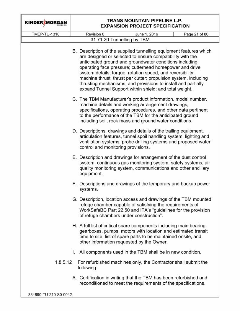
TRANS MOUNTAIN PIPELINE L.P.
EXPANSION PROJECT SPECIFICATION
TMEP-TU-1310 Revision 0 June 1, 2016 Page 21 of 80 31 71 20 Tunnelling by TBM
334890-TU-210-S0-0042
B. Description of the supplied tunnelling equipment features which are designed or selected to ensure compatibility with the anticipated ground and groundwater conditions including: operating face pressure; cutterhead horsepower and drive system details; torque, rotation speed, and reversibility; machine thrust; thrust per cutter; propulsion system, including thrusting mechanisms; and provisions to install and partially expand Tunnel Support within shield; and total weight.
C. The TBM Manufacturer’s product information, model number, machine details and working arrangement drawings, specifications, operating procedures, and other data pertinent to the performance of the TBM for the anticipated ground including soil, rock mass and ground water conditions.
D. Descriptions, drawings and details of the trailing equipment, articulation features, tunnel spoil handling system, lighting and ventilation systems, probe drilling systems and proposed water control and monitoring provisions.
E. Description and drawings for arrangement of the dust control system, continuous gas monitoring system, safety systems, air quality monitoring system, communications and other ancillary equipment.
F. Descriptions and drawings of the temporary and backup power systems.
G. Description, location access and drawings of the TBM mounted refuge chamber capable of satisfying the requirements of WorkSafeBC Part 22.50 and ITA’s “guidelines for the provision of refuge chambers under construction”.
H. A full list of critical spare components including main bearing, gearboxes, pumps, motors with location and estimated transit time to site, list of spare parts to be maintained onsite, and other information requested by the Owner.
I. All components used in the TBM shall be in new condition.
1.8.5.12 For refurbished machines only, the Contractor shall submit the following:
A. Certification in writing that the TBM has been refurbished and reconditioned to meet the requirements of the specifications.

TRANS MOUNTAIN PIPELINE L.P.
EXPANSION PROJECT SPECIFICATION
TMEP-TU-1310 Revision 0 June 1, 2016 Page 22 of 80 31 71 20 Tunnelling by TBM
334890-TU-210-S0-0042
This shall include but not be limited to motors, jacks, hydraulics, mechanical components, bearings other than the main bearing, seals, electrical, electronic and other major components of the TBM and back-up equipment.
B. Full TBM warranty for the duration of the project or 720 days from the date of site testing acceptance whichever comes first.
C. A certification from the TBM Manufacturer or Rebuilder that the main bearing is new, unused and suitable to perform the work without failure.
D. The year originally fabricated and released for operation and the name of current Owner, with location, phone number, and contact person.
E. Records of use for the proposed TBM including the project names, excavated diameter, total operated hours, hours on the current main bearing, utilization, and rebuild records of major components.
F. TBM Manufacturer or re-builder certifications and test results for the TBM components such as motors, pumps, bearings, hydraulic motors, pumps and cylinders, electrical components and materials including raw material certificates.
G. The TBM manufacturer or rebuilder shall provide manufacturing certificates and inspection records for all TBM components such as cutterhead, shields and other structural components together with the Finite Element Analysis (FEA) report;
H. The TBM manufacturer or rebuilder shall provide all supplier certificates for drive train components, including motors, clutches, gear boxes, pinion gears, bull gear and other components; main bearing and main bearing seals; hydraulic system, including pumps, pistons, cylinders, seals, and other components; electrical system; and muck removal system components.
I. Main Drive Bearing replacement from inside the TBM methodology.
J. TBM conversion methodology (primary screw conveyor to primary belt and reverse).

TRANS MOUNTAIN PIPELINE L.P.
EXPANSION PROJECT SPECIFICATION
TMEP-TU-1310 Revision 0 June 1, 2016 Page 23 of 80 31 71 20 Tunnelling by TBM
334890-TU-210-S0-0042
1.8.5.13 Other Pre-construction Submittals:
A. Details of the tunnel lighting systems.
B. Details of the ventilation system including type, size and location of all fans, supply and exhaust ducts, scrubbers, noise attenuation devices and other ventilation system components.
C. Details and procedures of tunnel safety provisions including: water, gas and air quality monitoring equipment, communication equipment, emergency evacuation and rescue response, and other safety related information as may be requested by the Owner.
D. Details of noise control or mitigation measures including hearing protection requirements.
E. Details of the system for transport of materials, equipment and personnel, in the tunnel on the tunnel grade shown on the Drawings including: type and number of locomotives or soft wheel vehicles, muck cars, personnel transport cars, Tunnel Support delivery equipment and other equipment and machinery to be used including emergency breaking and signalling systems to prevent a runaway train. Drawings of the track configuration and layout, including location of permanent and portable switches, and train passes; as well as cross section drawings illustrating locations for utilities, conveyors systems and any other equipment within the tunnel areas allowing adequate clearance for passing trains; the proposed train operation and signal configuration shall be provided.
F. A description of any enlargements of tunnel openings proposed for the Contractor’s convenience not shown on the Contract Drawings (e.g. sump pits, passing bays, mucking bays or refuge niches).
G. Drawings illustrating the above as necessary.
1.8.6 Reports and Records: Formats of the following reports and records shall be provided for approval by the Owner at least three months before commencement of tunnelling operation
1.8.6.1 General Shift Report: Prepare a shift report of tunnel construction work for each shift worked, and provide the Owner with one copy of the shift report on the following work day. The

TRANS MOUNTAIN PIPELINE L.P.
EXPANSION PROJECT SPECIFICATION
TMEP-TU-1310 Revision 0 June 1, 2016 Page 24 of 80 31 71 20 Tunnelling by TBM
334890-TU-210-S0-0042
following information shall be included in these reports:
A. Time and location of tunnel face(s) by station at start and end of each work shift.
B. Tunnel Support installation record.
C. Record of operating face pressure, ground conditioning volumes, mixing ratios of foam expansion ratio (FER) and foam injection ratio (FIR), grout injection volumes and mixing ratios.
D. Initial Support system measurements, including records of any observed deformation.
E. Survey records of tunnel excavation including the offset from design line-and-grade, including corrective steering course for line and grade deviations, guidance system reports for each ring installed.
F. Description of the ground conditions and ground behaviour.
G. Location and estimate of volume of ground water inflows, including method of estimation.
H. Crew size and employee classification.
I. Record of any downtime including the causes of the downtime, notes regarding occurrences of work delays, including downtime for daily maintenance and details of equipment malfunction. The station or location and time of each occurrence shall be documented.
J. Air quality monitoring and ventilation records.
1.8.6.2 TBM Shift Report: Prepare a TBM shift report for each shift in which the TBM was operating, which shall further contain the following information:
A. TBM performance information, including the stations for each advance of the TBM, the TBM clock time at the start and end of each shift, the thrust pressure for each thrust cycle and each thrust ram, time at the beginning and end of each cycle, TBM operating horsepower, and an identification of all TBM downtime, including classification and duration. Categories of downtime identified shall include as a minimum TBM repair,

TRANS MOUNTAIN PIPELINE L.P.
EXPANSION PROJECT SPECIFICATION
TMEP-TU-1310 Revision 0 June 1, 2016 Page 25 of 80 31 71 20 Tunnelling by TBM
334890-TU-210-S0-0042
cutter changes, installation of precast concrete tunnel lining, ground water inflow, gas inflow, power outages and electrical repair, trailing gear difficulties, muck disposal delays, hydraulics repair, thrusting problems, alignment survey, and routine maintenance.
B. TBM’s clock record of utilization, penetration rates, and operating hydraulic pressures.
C. Number and location of Cutting Tools changed and specific reasons for the change. Each Cutting Tool is to be uniquely identified to accurately track Cutting Tool changes e.g. distinguishing between new cutters and refurbished hubs with new cutting rings. The Cutting Tool change information shall clearly identify the position of the Cutting Tool, the reason for the change, the tunnel stationing and date each Cutting Tool was initially installed and when it was replaced.
1.8.6.3 TBM Cutterhead Maintenance Report, including: Sample cutting head condition report covering position of replaced cutting tools, degree of wear on replaced items, and existing condition of all remaining tools.
1.8.6.4 Probe Hole Reports – refer to 02 32 13 Probe Hole Drilling ahead of TBM.
1.8.6.5 Groundwater inflow recordings: Submit electronic files containing flow recordings for each measurement location as per 01 57 23 - Diversion and Care of Water. Submit files daily unless otherwise agreed with the Owner.
1.8.6.6 Daily reports of tests for dust, toxic and hazardous gases and other atmospheric impurities which may be found in the working environment during construction.
1.8.6.7 Comply with all applicable health and safety reporting requirements, provide reports as required by public authorities, and provide a copy of each report prepared to the Owner within 24 hours following preparation.
1.8.7 All materials and equipment used in the Work shall be the included as part of the above submittals or the subject of a submittal to the Owner.
1.9 Surveys

TRANS MOUNTAIN PIPELINE L.P.
EXPANSION PROJECT SPECIFICATION
TMEP-TU-1310 Revision 0 June 1, 2016 Page 26 of 80 31 71 20 Tunnelling by TBM
334890-TU-210-S0-0042
1.9.1 Submit 30 days prior to start of tunnelling:
1.9.1.1 Survey results confirming that control line monuments established by the Owner are correct and satisfactory for accurately laying out the tunnel and site.
1.9.1.2 Copies of translated alignment and control line information from Contract Drawings into TBM guidance information.
1.9.2 Prior to as-built surveying, submit Tunnel Surveying Plan as outlined in Section 1.8.5.8.
1.9.3 As-built tunnel survey: Within 30 days following the tunnel hole-through, submit:
1.9.3.1 A complete record, in tabular and drawing form, of closed traverse survey showing following information at all instrument stations; adjusted observations, coordinates and geodetic elevations.
1.9.4 Provide an adjusted table of tangent offsets where horizontal survey is affected by adjusted alignment or a horizontal curve is created as a result of the adjusted alignment. Submit adjusted table to the Owner for approval.
1.9.5 Provide reports as required by public authorities, and provide a copy of each report prepared to the Owner within 24 hours following preparation.
1.9.6 Submit a schematic design of the remote computer data logging system, including sample screen displays.
1.9.7 Submit as-built information and shop drawings on all installed initial support, the tunnel line and grade and other underground facilities (including junctions, chambers, and instrumentation and control systems for facilities operation).
1.9.8 Prior to excavation, demonstrate that TBM guidance equipment is capable of continuously monitoring and recording the position and attitude of the TBM.
1.9.9 If monuments provided by the Owner are damaged or moved, re-establish same and notify the Owner promptly.
1.9.10 During the execution of the Work, submit to the Owner all survey layout data. The Owner reserves the option to check any or all of these

TRANS MOUNTAIN PIPELINE L.P.
EXPANSION PROJECT SPECIFICATION
TMEP-TU-1310 Revision 0 June 1, 2016 Page 27 of 80 31 71 20 Tunnelling by TBM
334890-TU-210-S0-0042
measurements. Whether the Owner exercises this option or not, the Contractor’s responsibility for accuracy will not be waived. Refer to additional survey requirements in this Specification.
1.9.11 Tunnel Station Markers
1.9.11.1 Maintain station markers throughout the tunnel construction.
1.9.11.2 Temporary tunnel station markers shall have a minimum lettering of 200 mm and shall be a colour to contrast with background.
1.9.11.3 Markers shall be located on the same side of the wall throughout the tunnel length and shall be with respect to the centreline of the tunnel.
1.9.11.4 Maximum spacing between markers shall be 5 meters. Markers shall be placed at approximate eye level near the spring line and away from utilities.
1.9.11.5 Markers shall also be provided at each change in horizontal and vertical direction including point of tangency (PT) and point of curvature (PC).
1.9.11.6 Permanent Station Markers: Permanent station markers are not required.
1.10 Tolerances
1.10.1 Variations from designed alignment:
1.10.1.1 Tunnel Excavation: plus or minus 300 mm horizontally maximum variation is allowed.
1.10.1.2 Variations from design grade: Tunnel Excavation: plus or minus 75 mm vertically is allowed. Do not allow ponding of water.
1.10.2 When the excavation is off line and grade, return to plan line and grade at a rate not to exceed 10 mm per 5 meters of tunnel length.
1.10.3 Survey the invert of the tunnel excavation at 15 meter intervals to confirm the alignment is within the tolerances specified. Survey results are to be provided to the Owner bi-weekly.
1.10.4 In the event that tolerances are exceeded, the additional excavation and

TRANS MOUNTAIN PIPELINE L.P.
EXPANSION PROJECT SPECIFICATION
TMEP-TU-1310 Revision 0 June 1, 2016 Page 28 of 80 31 71 20 Tunnelling by TBM
334890-TU-210-S0-0042
associated work necessary to bring the alignment of the tunnel within the stated tolerances shall be at no additional cost to the Owner.
1.10.5 Tunnel Support tolerances shall be in accordance with 31 74 16 Precast Contrete Tunnel Lining (PCTL).
2.0 PRODUCTS
2.1 General
2.1.1 The Contractor shall use only such products, including spare parts and consumables, as supplied by, or approved by, or are compatible with products supplied and previously approved by the TBM Manufacturer for this project.
2.2 Tunnel Boring Machine (TBM)
2.2.1 The TBM shall be a Pressurised Face type TBM (EPBM or Slurry) having the capability to convert to open mode with muck removal by primary belt conveyor. The TBM shall be built or rebuilt by an established TBM Manufacturer with at least twenty years of experience manufacturing and proven record in rebuilding TBMs.
2.2.2 The Contractor shall solicit TBM proposals from various TBM suppliers including new and rebuilt TBMs. At least two new TBM proposals (quotations) shall be obtained and at least one rebuilt TBM proposal (quotation) shall be obtained. Proposals for both new and rebuilt TBMs and both new and rebuilt trailing gear and long conveyor systems shall be considered.
2.2.3 A slurry convertible TBM, if proposed by Contractor, shall be subject to the approval of the Owner.
2.2.4 The TBM shall be designed to excavate in pressurized mode at a maximum pressure of 5.5 bar. The TBM shall also be capable of withstanding a hydrostatic pressure of 8.5 bar while the cutterhead is not turning. The contractor is responsible for applying adequate factors of safety, subject to the Owner’s approval.
2.2.5 Cutterhead
2.2.5.1 Design and Loads: The Cutterhead structure shall be robust and capable of excavating efficiently and safely through the range of ground types described in the Contract Geotechnical Reports. The Cutterhead structure, face apertures and

TRANS MOUNTAIN PIPELINE L.P.
EXPANSION PROJECT SPECIFICATION
TMEP-TU-1310 Revision 0 June 1, 2016 Page 29 of 80 31 71 20 Tunnelling by TBM
334890-TU-210-S0-0042
gathering Scraper arrays shall be configured so as to allow for the efficient transfer of excavated material from the face into the excavation chamber to achieve the maximum excavation rate. The Cutterhead shall be designed and constructed to withstand all loads and pressures likely to be encountered during tunnelling operations and at the maximum rate of advance.
2.2.5.2 Cutting Tools: The Cutterhead shall incorporate durable Cutting Tools to excavate the varying strata described in the Contract Geotechnical Reports in both wet and dry conditions. It shall be designed to accept Cutting tools as described in Section 2.2.5, interchangeable and removable from inside the plenum. The excavated diameter shall be adjustable up to plus 50 mm per radius from nominal overcut, by provisions of copy cutters. This may be provided by a remote electro-hydraulic facility controlled from the TBM operator’s cabin, or by a direct mechanical adjustment located immediately to the rear of the gauge peripheral cutters or by the use of ‘copy cutters. Facilities for the sufficient control of gauge/excavated diameter shall be provided so as to allow the satisfactory maintenance of alignment.
2.2.5.3 The Cutting Tools shall be replaceable from the rear of the Cutterhead, with the exception of the cutters obstructed by Cutterhead inner structure or centre cutter obstructed by the rotary fluid joint (RFJ). A minimum of two adjustable gauge cutters shall be provided in the cutterhead. Clear access shall be provided for both personnel and materials to the cutting tools rear mounting locations. Provision shall be made to isolate and lock the Cutterhead drive to ensure the safety of personnel entering the excavation chamber. A key and lock shall be provided for this purpose. Means and methods of cutters replacement together with cutters transportation and hoisting inside the Cutterhead plenum shall be provided by the TBM Manufacturer.
2.2.5.4 Direction of Rotation and Cutting: The Cutterhead shall be capable of rotating and cutting in both directions with equal speed and force.
2.2.5.5 Speed of Rotation: The speed of rotation of the Cutterhead shall be variable to match the required penetration rate and the ground conditions as described in the Contract Geotechnical Reports. The maximum speed of rotation should be not less than 6 rpm.

TRANS MOUNTAIN PIPELINE L.P.
EXPANSION PROJECT SPECIFICATION
TMEP-TU-1310 Revision 0 June 1, 2016 Page 30 of 80 31 71 20 Tunnelling by TBM
334890-TU-210-S0-0042
2.2.5.6 Inching: The Cutterhead shall be fitted with a low speed inching facility and position indicator capable of rotating the Cutterhead under fine control (1 degree) in order to obtain accurate positioning for the purpose of face inspection, cutting tool maintenance or probing.
2.2.5.7 Drive Motors: The Cutterhead drive system shall be electric or hydraulic, with all functions arranged to fail-safe. Electric drive motors shall be water-cooled and variable speed capable as provided by variable frequency drives (VFD) for electric drives with the capacity to start the Cutterhead with not less than 1.5 times rated full load torque.
2.2.5.8 Power: The TBM shall have sufficient power such that the Cutterhead develops sufficient torque to enable it to advance at the designed rate for ground materials or conditions described in the Contract Geotechnical Reports. The system shall include for starting ‘off load’ prior to commencement of excavation. Continuous monitoring of cutting torque values and main drive motor temperatures shall be provided with an interlock to a pre-set initial warning and second stage limit shutdown. The TBM shall be designed to protect the drive against Cutterhead lock up.
2.2.5.9 Conditioning Ports: The Cutterhead shall incorporate not less than 5 ports spaced proportionately to the swept area for injection of conditioning agents to the face. The ports closest to the centre of the Cutterhead shall have an extra high delivery pressure to assist in the prevention of spoil build-up around the centre of the Cutterhead. The ports shall be protected to minimize plugging and damage.
2.2.5.10 Openings: The Cutterhead openings shall be sized or grizzly bars installed to protect the conveyor against jamming by oversize rock particles as defined in the Contract Geotechnical Reports. Maximum size allowed shall be less than 80 percent of the screw conveyor clearance.
2.2.5.11 Open Face Area: The Cutterhead shall be provided with a minimum of 25 percent open face area after the fitting of any grizzly bars. The TBM Manufacturer shall submit an analysis of face opening for optimization of mining in both soil and rock, before design phase completion, for Owner review.

TRANS MOUNTAIN PIPELINE L.P.
EXPANSION PROJECT SPECIFICATION
TMEP-TU-1310 Revision 0 June 1, 2016 Page 31 of 80 31 71 20 Tunnelling by TBM
334890-TU-210-S0-0042
2.2.5.12 Wear protection: The project alignment lies in soil and rock materials of varying abrasivity, as described in the Contract Geotechnical Reports. The Cutterhead should be well protected on its face and periphery with adequate wear resistance plating. The tools should be positioned such that they cut the ground and leave clearances such that the wear of the face of the Cutterhead is minimized. The TBM Manufacturer will select the type and thickness of materials to be used for wear protection. The Cutterhead plenum protection is required to protect all bolting connections (recessed bolting), piping and hoses.
2.2.5.13 Hydraulic supply to the plenum chamber: Any hydraulic system supplying hydraulic power beyond the main bulkhead should be separate, in order to prevent contamination of the main hydraulic systems.
2.2.6 Cutting Tools
2.2.6.1 General: The TBM shall be supplied complete with a full dressing of Scraper and Ripper cutting tools, and with a full set of Disc Cutters. The TBM Manufacturer shall also provide all ancillary components required to convert the cutting tool dressing into a combination of both ripper/scraper tools and disc cutters or from full ripper face to full disc cutter face. The TBM Manufacturer shall provide all lifting/handling equipment, lifting points in the excavation chamber, and specialist hand tools (including wear gauges) for maintaining and changing all types of cutting tools. The Contractor shall purchase and keep enough inventory of tools to ensure no downtime for cutting tools.
2.2.6.2 Type: Both Scraper and Ripper cutting tools and Disc Cutters provided shall be suitable to excavate the anticipated ground conditions, treated ground and unreinforced or fiberglass reinforced concrete or shotcrete walls.
2.2.6.3 Durability: The tools on the Cutterhead shall be of robust design and suitably durable construction in order to ensure minimum replacement during the drive. Scrapers and Ripper type cutter tools shall have tungsten carbide inserts and have their exposed bodies wear protected with abrasion resistant plating. Disc Cutters shall be of a type that will revolve freely in soil to avoid flats being worn on the cutting tire due to the Disc Cutter becoming stuck in one position within the housing.

TRANS MOUNTAIN PIPELINE L.P.
EXPANSION PROJECT SPECIFICATION
TMEP-TU-1310 Revision 0 June 1, 2016 Page 32 of 80 31 71 20 Tunnelling by TBM
334890-TU-210-S0-0042
2.2.7 Main Bearing and Transmission
2.2.7.1 General: The Cutterhead main bearing, drive source and transmission components shall be robust and capable of completing the contract drive lengths without major overhaul.
2.2.7.2 Type: The main bearing shall be of the triple roller type.
2.2.7.3 Design: The main bearing shall be designed by numerical computer analytical methods, including finite element analysis to resist all axial, radial and eccentric loads and the calculations, including load cases and duty cycles, must be available for inspection. The bearing should have an L10 life of not less than 10,000 hours.
2.2.7.4 Seal Type: The Cutterhead main bearing and transmission shaft shall be protected by a grease-filled labyrinth and multistage lip seal array capable of ensuring internal lubricant integrity while protecting against the ingress of water and excavated fines. The system feed lines, measuring valves and distribution control shall be sized to ensure compatibility with the range of oils, grease and flushing mediums that are required to be utilized through the drive. The rate of flow of the grease shall be adjustable to compensate for wear. The TBM should be designed with interlocks to eliminate the possibility of rotating the head if the seal lubricants are not being pumped.
2.2.7.5 Monitoring of Seal and Labyrinth: The TBM shall incorporate a system to permit regular monitoring of the lubricants in the main bearing, the main bearing seals, the labyrinth and the drive transmission shaft. The lubricant circuits shall have the facility to take samples, drain, and purge and refill should they become contaminated. A continual ‘real time’ monitoring of all strategic functions for the seal shall be provided for the TBM operator via the Programmable Logic Controller (PLC) system.
2.2.7.6 Overpressure: The thrust ram hydraulics shall be controlled such that they cannot create an overpressure in the excavation chamber, above the pressure for which the seals have been designed.
2.2.8 Excavation Chamber
2.2.8.1 Design: The Excavation Chamber and Cutterhead shall be capable of thoroughly mixing the excavated ground and

TRANS MOUNTAIN PIPELINE L.P.
EXPANSION PROJECT SPECIFICATION
TMEP-TU-1310 Revision 0 June 1, 2016 Page 33 of 80 31 71 20 Tunnelling by TBM
334890-TU-210-S0-0042
groundwater with injected conditioners and designed to facilitate a smooth flow of material from the face to the screw conveyor or belt conveyor in open mode.
2.2.8.2 Conditioning Ports: In addition to the Cutterhead conditioning ports described in Section 2.2.4.10, a minimum of two independently operated conditioning ports shall be located in the excavation chamber on the pressure bulkhead and two ports shall be located in the screw conveyor. The ports shall be designed so as to minimize damage or plugging of the injection lines.
2.2.8.3 Earth Pressure Cells: A pressure monitoring system utilizing six earth pressure cells, including at least two as near as possible to the crown and one on each side of the chamber at the horizontal centreline, shall be designed and installed in the Excavation Chamber to monitor earth pressures. One of the six EPB cells should be located on the Screw Conveyor. The pressure cells shall be vertically evenly spaced and shall be located so as to measure the variation in pressure in the Excavation Chamber. The pressure cells shall be capable of operating and providing output continuously to the TBM operator and the data logger. Pressure cells shall have an accuracy of plus or minus 7 kPa (0.07 bar) and an operating range of 0 to 500 kPa (0 to 5 bar). Pressure cells shall be capable of recalibration. The TBM Manufacturer shall provide one set of earth pressure cell calibration equipment suitable for use in a site workshop facility. Damaged pressure cells shall be replaceable from the rear of the pressure bulkhead. Isolation valves shall be provided so that replacement can take place while the excavation chamber is pressurized. The pressure cell ports shall be designed so as to minimize damage or plugging.
2.2.8.4 The pressure monitoring system shall be designed to be capable of controlling the earth pressure in the excavation chamber to within plus or minus 30 kPa (0.3 bar) of the selected pressure within the design operating pressure range at all times with this level of accuracy.
2.2.9 Pressure Bulkhead
2.2.9.1 Location: The Pressure Bulkhead shall be designed and constructed to mount the Cutterhead support bearing and drive mechanisms. Distortion of the pressure bulkhead shall be

TRANS MOUNTAIN PIPELINE L.P.
EXPANSION PROJECT SPECIFICATION
TMEP-TU-1310 Revision 0 June 1, 2016 Page 34 of 80 31 71 20 Tunnelling by TBM
334890-TU-210-S0-0042
limited to prevent damage to, or loss of performance of components mounted on the pressure bulkhead.
2.2.9.2 Access: Bulkhead door shall be provided to the Excavation Chamber for personnel and material access for maintenance purposes.
2.2.9.3 Primary Belt Conveyor Hatch: The bulkhead shall accommodate space for the Primary Belt Conveyor Hatch for mining in open mode. The hatch location shall be at just above the spring line. On the forward side of the hatch (excavation chamber) provisions for the installation of a muck collecting ring shall be made available.
2.2.9.4 Central Rotary Coupling (also known as Rotary Fluid Joint): A central rotary coupling shall be provided for foam, bentonite and polymer injection through the Cutterhead and any hydraulic connections to adjustable tools, if provided.
2.2.9.5 Penetrations: Electrical, hydraulic, mechanical, welding, water, drainage, compressed air and communications penetrations shall be provided through the Pressure Bulkhead. One of the compressed air penetrations shall be as close as possible to the crown for the injecting of air in preparation for a personnel intervention into the Excavation Chamber.
2.2.9.6 Probe drill ports: Minimum two ports 100 mm ID shall be provided for probe drilling ahead.
2.2.10 Screw Conveyor
2.2.10.1 Type: The TBM shall be equipped with a central shaft Screw Conveyor.
2.2.10.2 Purpose: The TBM shall be equipped with a Screw Conveyor to meter conditioned muck out of the Cutterhead chamber, to control ground and hydrostatic loads at the faces and to deposit muck onto the TBM belt conveyor.
2.2.10.3 Design: The Screw Conveyor for the TBM shall be designed with sufficient length, pitch of flights and angle of inclination to dissipate hydrostatic and earth pressures as stated above.
2.2.10.4 Capacity: The conveyor shall be capable of transporting abrasive soils and rock with and without a high water content as

TRANS MOUNTAIN PIPELINE L.P.
EXPANSION PROJECT SPECIFICATION
TMEP-TU-1310 Revision 0 June 1, 2016 Page 35 of 80 31 71 20 Tunnelling by TBM
334890-TU-210-S0-0042
well as all ground and groundwater conditions as described in the Contract Geotechnical Reports.
2.2.10.5 Size and Speed of Rotation: The capacity, torque and speed of rotation of the Screw Conveyor shall match the maximum excavation capacity of the TBM.
2.2.10.6 Direction of Rotation: The Screw Conveyor drive shall have the capability to reverse rotation when needed.
2.2.10.7 Location: The Screw Conveyor intake shall be located below spring line as close as practicable to the bottom of the Excavation Chamber.
2.2.10.8 Screw Conveyor Isolation System: The TBM shall have a system for maintaining positive earth pressure within the Excavation Chamber when the Screw Conveyor is withdrawn for any reason. The Screw Conveyor Isolation System shall be capable of translating from an excavation mode to fully sealed/isolated mode in under five minutes.
2.2.10.9 Discharge Guillotine Gates: The TBM Manufacturer shall provide a hydraulically operated guillotine gate at the discharge end of the Screw Conveyor capable of assisting with pressure control and this shall have an interlocked auto close feature when face pressures fall significantly below the lowest design operating pressure.
2.2.10.10 Conditioning Ports: The casing of the Screw Conveyor shall incorporate a minimum of two independently operated injection ports for the addition of conditioning agents along its length. One port shall be located at the intake and one port shall be located at the midpoint of the Screw Conveyor.
2.2.10.11 Monitoring: The TBM Manufacturer shall provide pressure cells at the spoil intake and at the midpoint of the Screw Conveyor for the purpose of accurately monitoring the muck pressure along the length of each conveyor.
2.2.10.12 Wear Detectors and Resistance: The Screw Conveyor shall be designed and constructed so as to carry out the entire project drive without major overhaul. The Screw Conveyor shall be protected against excessive wear and deterioration caused by abrasive excavated materials. Anti-wear protection shall be provided by proven abrasion resistant materials. The Screw

TRANS MOUNTAIN PIPELINE L.P.
EXPANSION PROJECT SPECIFICATION
TMEP-TU-1310 Revision 0 June 1, 2016 Page 36 of 80 31 71 20 Tunnelling by TBM
334890-TU-210-S0-0042
Conveyor shall be provided with suitable means of access to allow for regular monitoring of wear to the screw and the screw casing at atmospheric pressure. Anti-wear plates shall be provided on the full inside of the casing (tube) and the back and the outside edge of all the flights for the entire length, except the replaceable tip, of each screw section. The Screw conveyor tip shall be protected by wear plates on all surfaces. A replaceable tip section shall be readily available for the Screw Conveyor.
2.2.10.13 Travel: The Screw Conveyor shall be capable of being moved forward in the Excavation Chamber and retracted from the Excavation Chamber when required.
2.2.10.14 Access, Removal and Maintenance: The screw shall be capable of being removed from the casing within the TBM and replaced within the TBM during a mid-drive incident. Access hatches shall be provided to enable regular maintenance and repair of the screw.
2.2.11 Conditioning
2.2.11.1 Types: The TBM shall be equipped with all necessary metering, monitoring and interlock equipment, supplies and storage for conditioning using foam, polymers, bentonite, water, and compressed air. Foam generators, which are part of the supply, should have the flexibility to suit the varying ground conditions by way of being able to vary expansion ratios, injection ratios and dosage rates.
2.2.11.2 Capacities: The conditioning equipment shall have sufficient capacity to match the rate of advance of the TBM(s) and the geotechnical conditions.
2.2.11.3 Location: The conditioning equipment shall be located as close to the point of injection as possible.
2.2.11.4 Ports: The system will allow separate injection and control into each port, and should have the flexibility to inject any combination of agents.
2.2.11.5 Method: The system will allow for injecting simultaneously at different pressures through the various ports.

TRANS MOUNTAIN PIPELINE L.P.
EXPANSION PROJECT SPECIFICATION
TMEP-TU-1310 Revision 0 June 1, 2016 Page 37 of 80 31 71 20 Tunnelling by TBM
334890-TU-210-S0-0042
2.2.12 TBM Belt Conveyor
2.2.12.1 Purpose: The TBM Manufacturer shall provide a belt conveyor system capable of receiving spoils directly from inside the cutterhead in open mode and from the Screw Conveyor discharge in EPB mode.
2.2.12.2 Type: A belt conveyor with variable speed, reversible feature and automatic tensioning shall be provided. The belt conveyor shall have belt cleansers that deposit the spoils into the system. The main rollers shall be fitted with heavy duty, waterproof bearing systems and integral lubrication systems.
2.2.12.3 Capacity: The conveyor shall be capable of transporting abrasive soils and rock with and without a high water content as well as all ground and groundwater conditions as described in the Contract Geotechnical Reports. The capacity of the conveyor shall equal the maximum required excavation capacity of the TBM cutterhead plus bulking.
2.2.12.4 Measurement: The TBM Manufacturer shall install a minimum of two belt scales of different type each mounted on the TBM conveyor. The TBM conveyor shall be designed to be compatible with accurate use of the belt scales. Two of each type of belt scales shall be provided.
2.2.12.5 Directional Plates: At the discharge of the cutterhead, directional plates which direct the tunnel muck onto the belt conveyor, and contain and prevent spillage shall be installed.
2.2.12.6 Sump: A sump under the discharge point of the conveyor belt and at the discharge into the muck cars or tunnel long conveyor belt shall be provided to gather water spilled during transfer from the cutterhead, and be provided with facilities for pumping such water away from the working area.
2.2.12.7 Interlocks: Interlocks will be provided such that the TBM conveyor must be operating before the TBM can start the excavation cycle. The status of the conveyor should be capable of being monitored by closed circuit television (CCTV) by the TBM operator and recorded by the data logger. Warning devices should indicate belt slippage and overheating at drive locations.

TRANS MOUNTAIN PIPELINE L.P.
EXPANSION PROJECT SPECIFICATION
TMEP-TU-1310 Revision 0 June 1, 2016 Page 38 of 80 31 71 20 Tunnelling by TBM
334890-TU-210-S0-0042
2.2.12.8 Angle: The TBM belt conveyor shall be designed to run at such an angle as to permit the conveyance of wet material.
2.2.13 TBM Shield
2.2.13.1 Design: The TBM shield shall be designed and constructed to withstand all loads and pressures likely to be encountered during the tunnelling operations without excessive deflection. Finite element analysis of the structure at maximum extreme loads shall be provided by the TBM Manufacturer. The TBM shield shall consist of a front shield and tail shield.
2.2.13.2 Abrasion Resistance: All metal work shall be suitably protected where necessary to avoid deterioration due to abrasive ground conditions.
2.2.13.3 Length: The shields shall have sufficient length to give an adequate overlap on the last cycle of lining built and allow negotiating the designed tunnel alignment curves
2.2.13.4 Stabilizer Pads: The front shield shall be equipped with minimum two stabilizer pads for rock mining mode.
2.2.13.5 Articulation Joint Seal: The articulation joint between shields shall be designed to seal over the full range of grout injection pressures and ground and hydrostatic pressures and to prevent a build-up or ingress of material at the minimum curve radius of the alignment
2.2.13.6 Injection Points: The TBM shall incorporate injection points for bentonite and polymers around the perimeter of the front shield as far forward as practicable. The injection points shall be positioned immediately to the rear face of the pressure bulkhead spaced at a maximum spacing of 0.5 meter around the periphery, shall be fitted with valves, and shall be suitable for a range of fluids. Additional injection ports, at the same spacing, shall be provided at the rear of the TBM before the tail seal brushes. These ports should be usable while segmental lining has been erected inside the shield.
2.2.13.7 Taper: The TBM shield body shall be tapered from front to rear by a maximum of 12 mm on radius. This may be achieved by step changes at suitable joints along the body.

TRANS MOUNTAIN PIPELINE L.P.
EXPANSION PROJECT SPECIFICATION
TMEP-TU-1310 Revision 0 June 1, 2016 Page 39 of 80 31 71 20 Tunnelling by TBM
334890-TU-210-S0-0042
2.2.13.8 Probe drill ports: The TBM shield shall be equipped with ports for probe and grout hole drilling at 15-degree intervals around the shield perimeter, over a 360-degree arc, centred on the vertical axis of the TBM at the tunnel crown. Ports shall be of sufficient diameter to permit insertion of packers for grouting. Refer to Drawings and 02 32 13 Probe Hole Drilling ahead of TBM, and 31 73 15 Tunnel Annular Grouting for details.
2.2.14 Tail Seal
2.2.14.1 Type: The TBM shall be equipped with a tail seal comprising a system of grease fed wire brushes to seal against maximum face pressure, hydrostatic and annular grout pressure.
2.2.14.2 Compatibility: The tail seal shall be compatible with the precast concrete lining and annular grout as described in 31 74 16 Precast Concrete Tunnel Lining and 31 73 13 Annular Grouting.
2.2.14.3 Quantity: The TBM Manufacturer shall provide a minimum of four seals, the chambers of which are continuously fed with fibrous grease whenever the TBM advances. The seals shall be effective over the full range of grout injection and face pressures to be used. An interlock shall prevent the TBM moving forward if the grease is not being fed to the tail seals. Excessive use of grease shall be an indicator of tail seal failure. Replacement: Tail skin seals other than the rear seal shall be replaceable during TBM operation from within the TBM. Tooling for pushing the TBM to expose the first 3 rows of seals shall be provided by the TBM Manufacturer.
2.2.14.4 Grease: Tail skin seal grease shall be compatible with the precast concrete lining gaskets and materials and shall be non-toxic and biodegradable.
2.2.14.5 Spring Steel Seal (Grout Excluder): The TBM shall be equipped with an outward facing spring steel seal, to seal between the shield and the excavated profile, and to minimize the forward flow of grout over the shield. This seal should cover the upper 270 degrees of the shield.
2.2.15 Annular Grouting
2.2.15.1 Method: Provision shall be made for constant and continuous pressure grouting around the annulus of the tunnel lining through pipes to the rear of the tail seals or through the

TRANS MOUNTAIN PIPELINE L.P.
EXPANSION PROJECT SPECIFICATION
TMEP-TU-1310 Revision 0 June 1, 2016 Page 40 of 80 31 71 20 Tunnelling by TBM
334890-TU-210-S0-0042
segments ports as the TBM advances.
2.2.15.2 Grout Pipes (for grouting through the tail skin): A minimum of eight circular grout pipes (four active and four passive) shall be provided in pairs evenly spaced around the inside of the tail shield to provide complete redundancy in the event of blockage. The internal diameter of the pipes shall be a minimum of 37 mm. The delivery system including all pipes shall be designed and provided with the means to be rapidly cleaned in-situ or replaceable. Grout pipes shall be accessible for cleaning or replacing.
2.2.15.3 Grout Type (for grouting through the tail skin) : A two-component grout shall be used, comprising a stabilizer and an activator added at the point of injection. A separate set of pipes shall be provided for the injection of the activator. These pipes will be of small diameter, i.e. approximately 12 mm. The point of injection of the activator into the main grout pipes will be approximately 150 mm before the end of the tail skin.
2.2.15.4 Capacity: The annular grouting equipment shall have sufficient capacity to match the maximum TBM advance rate and segment erection rate. The grouting equipment shall be sufficient to grout a minimum of two complete rings without interruption. Grouting will be pressure controlled with volume measurement and must be continuous throughout the excavation cycle. An interlock should be provided to prevent the TBM from advancing unless grout is being injected.
2.2.15.5 Pressure: Pressure gauges shall be provided at pumps and points of injection. The pressure to which the grout is pumped and the pressure developed behind the ring shall be controllable and an automatic pressure cut-off valve installed to limit pressure surges.
2.2.15.6 Measurement and Accuracy: Grouting equipment shall include an accurate automatic measuring and recording device capable of measuring volume of grout injected in cubic meters to nearest one-tenth of a cubic meter, including the amount of grout per ring and the cumulative total. The measuring device shall measure the grout take for each ring and shall compare this measurement to the running average trend over the previous five rings thereby indicating any sudden change to normal take. This shall be carried out on a continual real time basis by the

TRANS MOUNTAIN PIPELINE L.P.
EXPANSION PROJECT SPECIFICATION
TMEP-TU-1310 Revision 0 June 1, 2016 Page 41 of 80 31 71 20 Tunnelling by TBM
334890-TU-210-S0-0042
automatic measuring device and transmitted to the TBM/grouting equipment operator and the remote monitoring system and logged. Measures shall be incorporated to enable control of the volume of grout injected.
2.2.15.7 Non-return valves shall be used on the grouting equipment.
2.2.16 Thrust Rams
2.2.16.1 Purpose: Thrust rams are to provide thrust reaction from the installed lining while the excavation is carried out and as an aid to the erection of the lining. The rams will have two modes, “excavate” and “build”. In “excavate” mode the rams should be divided into at least four groups to enable steering by the use of different hydraulic pressures in each of the ram groups. In “build” mode, each ram will be capable of independent operation at reduced pressures to avoid damage to the lining. The TBM shall be provided with a method of propulsion capable of developing sufficient thrust to cope with the range of ground types described the Contract Geotechnical Reports. The thrust ram operation shall be monitored and controlled so as to protect against inadvertent damage to the installed lining.
2.2.16.2 Thrust: The TBM shall be capable of exerting and maintaining sufficient forward thrust. The TBM thrust shall be capable of overcoming:
A. The backward resistance of the earth and hydrostatic pressure.
B. The friction around the TBM shield.
C. Resistance between the shield and initial support or lining.
D. The pull needed for the trailing gear.
E. The force needed to enable the cutting tools to penetrate the ground, ground treatment, and temporary support at entry and exit points.
F. An extra allowance for steering the TBM.
2.2.16.3 Shoes: Thrust ram shoes are to be designed and constructed to self-align and to distribute loading onto the tunnel initial support or lining evenly and without causing damage. The shoes in the upper portion of the shield shall include safety

TRANS MOUNTAIN PIPELINE L.P.
EXPANSION PROJECT SPECIFICATION
TMEP-TU-1310 Revision 0 June 1, 2016 Page 42 of 80 31 71 20 Tunnelling by TBM
334890-TU-210-S0-0042
features to support the upper segments during the build cycle, or there should be dedicated rams in the upper portion to provide the same safety function.
2.2.16.4 Arrangement: The TBM Manufacturer shall provide thrust rams arranged symmetrically. Individual and synchronized thrust rams actuation shall be possible. It shall be possible to limit the maximum force each thrust ram will exert. Thrust rams shall not exert forces when idle, but shall resist displacements. Retraction of the thrust rams must be sufficient to enable withdrawal of the key segment from any position in the ring.
2.2.16.5 Stroke of Thrust Rams: Stroke of thrust rams shall be consistent with lining installation and requirements relative to advance of the machine.
2.2.16.6 The thrust system interlock: In case of a power supply failure the system hydraulic lock must be able to hold at least 85% of the pre-failure thrust to maintain the face pressure at this level for at least 24 hours.
2.2.17 Alignment Control
2.2.17.1 Articulation/Layout: The TBM Manufacturer is required to make a submittal describing the mechanism for maintaining alignment while overcutting the body to give sufficient clearance for steering.
2.2.17.2 Guidance System and Monitoring: The TBM Manufacturer shall provide a computerized laser guidance system with the necessary digital or graphic displays which will show the current and predicted TBM position and attitude compared with design alignment at any instant while linked to the survey control.
2.2.17.3 Accuracy and Output: Display modes shall be accurate to ±1 mm, and shall include but not be limited to the following:
A. Line and level
B. Correction values
C. Plumb
D. Lead

TRANS MOUNTAIN PIPELINE L.P.
EXPANSION PROJECT SPECIFICATION
TMEP-TU-1310 Revision 0 June 1, 2016 Page 43 of 80 31 71 20 Tunnelling by TBM
334890-TU-210-S0-0042
E. Roll
F. Stationing from a given datum
G. Prediction of the shield position 5 meters forward of current position
H. Centre of thrust
I. Articulation angle
J. Segment Orientation: The TBM Manufacturer shall provide a segment orientation calculation and prediction unit to allow the tapered segmental lining to most accurately follow the TBM.
2.2.18 Segment Erection and Handling
2.2.18.1 Type: The pre-cast concrete segment Erector shall be an integral part of the TBM shield, operating inside the shield tail area.
2.2.18.2 Lining Type: Installation of Precast Concrete Tunnel Lining, requires a tunnel lining consisting of single pass, bolted, doweled and fully gasketed, segmental, pre-cast, reinforced, tapered concrete rings, Refer to 31 74 16 Precast Concrete Tunnel Lining (PCTL).
2.2.18.3 Purpose: The Erector mechanism shall be a vacuum or bolt type system capable of picking up, accurately locating and placing the different types of segment safely in the required orientation to within 3 mm of the intended location without damage to the segments or gaskets.
2.2.18.4 Design: The lifting and gripping system shall be designed and constructed to handle all loads with a factor of safety of 2:1. The vacuum lifting pad shall be designed with a factor of safety of 3:1, operating at 80% vacuum, and the entire system should be capable of a minimum of 30 minute holding time after a power failure.
2.2.18.5 Removal of Segments: The Erector mechanism shall also be capable of removing damaged or misaligned segments of a partially or completed ring within the tail skin.
2.2.18.6 Rotary Torque Capacity: The rotary torque must be sufficient to

TRANS MOUNTAIN PIPELINE L.P.
EXPANSION PROJECT SPECIFICATION
TMEP-TU-1310 Revision 0 June 1, 2016 Page 44 of 80 31 71 20 Tunnelling by TBM
334890-TU-210-S0-0042
lift a segment and compress the cross joint gaskets in a vertically upwards direction.
2.2.18.7 Operation: The Erector shall provide actuation in axial, radial and circumferential directions, as well as in directions of the three articulation angles, corresponding to six degrees of freedom, or enough to grip and erect the segments properly so that they are positioned accurately, gaskets are aligned within the required tolerances, and no damage or distortion of the segments occurs. Actuation of the erector in all directions shall be smooth and continuous. Control of the erector shall be by a remote handheld joystick control panel.
2.2.18.8 Hydraulic Erectors: Hydraulic Erectors shall be equipped with proportional valves, or equivalent.
2.2.18.9 Gripping: The Erector shall use vacuum pick-up and be fitted with shear connectors. Segment design will be consistent with the method of pick-up. The TBM Manufacturer shall ensure that a method is devised which will allow the erector to handle broken segments as may become necessary during the dismantling of a damaged partially built ring.
2.2.18.10 Inching: The Erector shall have an inching capability in rotational mode.
2.2.18.11 Segment Feeder System: The Segment Feeder System shall consist of a segment unloader and monorail system for transporting the segments to the Erector designed, constructed and used so that the segments are supplied at the rate and orientation to suit the Erector. It shall be capable of reverse operation in order to remove damaged or incorrectly selected segments and be able to supply the tapered segments in the correct order to ensure the correct build for each ring.
2.2.19 Hydraulic Equipment
2.2.19.1 Hydraulic Fluid: Synthetic fire resistant and biodegradable fluids (type HFDU or similar) shall be used on all systems in the TBM and Trailing Gear hydraulic systems.
2.2.19.2 Filtration: Pressure and return line filtration shall be provided to a level of 10 micron to ensure the efficient working of the system. Hydraulic filters shall be provided with filter clogging indicators which send an electrical warning to the control

TRANS MOUNTAIN PIPELINE L.P.
EXPANSION PROJECT SPECIFICATION
TMEP-TU-1310 Revision 0 June 1, 2016 Page 45 of 80 31 71 20 Tunnelling by TBM
334890-TU-210-S0-0042
console.
2.2.19.3 Noise: The noise emitted by the hydraulic power packs must be considered and if necessary acoustic shields should be provided and fitted with any necessary ventilation fans to maintain cooling. Noise levels should comply with local regulations. In general noise levels emitted by the hydraulic power packs should not exceed 85 dB or a warning will sound.
2.2.19.4 Cooling: Effective oil coolers should be fitted to maintain oil temperatures below 70°C. These should operate via a heat exchange unit using piped water into and out of the TBM area.
2.2.19.5 Hydraulic hoses: The use of hydraulic hoses shall be minimized, but where used they should be adequately protected to minimize damage. All hoses and fittings to be rated to (415 Bars) 6000 PSI.
2.2.20 Electrical Equipment
2.2.20.1 The electrical components of TBM and TBM Trailing Gear equipment, and all supporting control, communication and electrical switching equipment, including the guidance system, installed within the tunnel and required for operation of the TBM shall be protected against explosive gases as follows:
A. Monitoring for explosive gases shall be installed. Interlocks shall prevent equipment operation if more than 10% LEL is detected.
B. Electrical equipment for emergency services (lights, ventilation, fire-fighting, pumping out water, communications) shall start automatically on emergency power, should an electrical cut off from the main power line in the tunnel occur.
2.2.20.2 Equipment shall be CSA certified or obtain special approval from the Electrical Safety Authority (ESA).
2.2.20.3 All underground switchgear shall have NEMA rating suitable for the application. Cable entries to switchgear cabinets shall be glanded and be bottom entry where possible. If side entry glands are used these should be well protected. Top entry glands will not be permitted.
2.2.20.4 Wire and cables shall be listed as being resistant to the spread

TRANS MOUNTAIN PIPELINE L.P.
EXPANSION PROJECT SPECIFICATION
TMEP-TU-1310 Revision 0 June 1, 2016 Page 46 of 80 31 71 20 Tunnelling by TBM
334890-TU-210-S0-0042
of fire and shall have reduced smoke emissions.
2.2.20.5 All operation and work areas, including maintenance areas, shall be provided with good levels of lighting in accordance with the IESNA recommendations. All areas including access walkways shall be provided with battery back-up emergency lighting. The following lighting levels are extracted from Table 10-9 of the IESNA for guidance.
TABLE 2-1 LIGHTING LEVELS
A Public Spaces 30 lx (3 fc)
B Simple Orientation for Short Visits 50 lx (5 fc)
C Working spaces where simple visual tasks are performed 100 lx (10 fc)
D Performance of visual tasks of high contrast and large size 300 lx (30 fc)
E Performance of visual tasks of high contrast and small size, or visual tasks of low contrast and large size
500 lx (50 fc)
2.2.20.6 An emergency generator shall be installed on the Trailing Gear or on the surface. This should be of sufficient power to supply lights, emergency pumping, firefighting equipment, compressed air supply if working under compressed air and local ventilation. The diesel engine should be fitted with appropriate scrubbers on the exhaust.
2.2.20.7 Power Factor: The TBM should be fitted with switched capacitor power factor correction equipment to ensure that the power factor does not fall below 0.9 lagging at any time.
2.2.20.8 Monitoring of TBM Systems and Interlocks: The TBM Manufacturer shall provide a PLC with a suitably protected power supply for monitoring of TBM systems together with a diagnostic package for maintenance and fault tracing.
2.2.20.9 Control of TBM Systems and Interlocks: The TBM Manufacturer shall provide a monitoring unit with alarm and trip settings connected to the PLC for control and interlocking.
2.2.20.10 High Voltage (HV) transformers may be dry type, cast coil or fluid filled. If fluid filled, then synthetic, flame-resistance fluid shall be used.

TRANS MOUNTAIN PIPELINE L.P.
EXPANSION PROJECT SPECIFICATION
TMEP-TU-1310 Revision 0 June 1, 2016 Page 47 of 80 31 71 20 Tunnelling by TBM
334890-TU-210-S0-0042
2.2.20.11 The electrical systems shall maintain ventilation, illumination, communications, drainage and water supply; areas of refuge, exits and exit routes, remote annunciation and alarms under all operating and emergency modes associated with the facility.
2.2.20.12 Electrical systems shall not use materials that produce toxic by-products during electric circuit failure or when subjected to an external fire.
2.2.20.13 PVC raceways, conduit, cable trays, wire ways, vinyl insulated/jacketed conductors or cables and exposed PVC-coated metal conduit, shall not be used.
2.2.20.14 The cable reel shall provide a minimum of 150 meters of flexible HV cable.
2.2.20.15 HV supply to the TBM shall be 12.5 kV at 60 Hz.
2.2.21 Data Logger
2.2.21.1 Parameters: A data logger shall be installed and used to continuously record the vital operating parameters of the TBM and transmit the information to surface workstations on a real time basis. The TBM Manufacturer shall make a submittal including a full listing of all parameters that will be recorded. The data recorded shall include, but not be limited to:
A. Cutterhead rotation speed
B. Thrust load to each ram or group of rams
C. Total thrust load
D. Torque consumed by the TBM Cutterhead
E. Instantaneous and average rate of advance (for excavation cycle)
F. Quantity of excavated material per TBM stroke to give a comparative cycle-by-cycle calculation, adjusted as necessary to account for changes in ground density and quantity of conditioner injected. The system shall compare this measurement to the predicted values and to the running average trend over the previous five rings thereby indicating any sudden change to normal excavated quantity. This shall be

TRANS MOUNTAIN PIPELINE L.P.
EXPANSION PROJECT SPECIFICATION
TMEP-TU-1310 Revision 0 June 1, 2016 Page 48 of 80 31 71 20 Tunnelling by TBM
334890-TU-210-S0-0042
carried out on a continuous real time basis and displayed both at the operator’s workstation and in the surface monitoring stations and recorded by the data logger.
G. Electrical power consumption
H. Operation and consumption of lubricating oils and greases by the TBM
I. Monitoring of the bearing sealing system
J. Record of alarm activations
K. TBM Guidance and steering data
2.2.21.2 Workstations: The TBM Manufacturer shall provide workstations and software at both the Contractor’s and the Owner’s surface field office capable of reading the data logger and shall communicate all data from the data logger to the workstations at the Contractor’s and the Owner’s field offices in real time. The connections to the surface facilities will have a parallel redundant system to avoid connection downtime. The software should be capable of displaying analysis and historical trends of selected parameters. Cabling and redundant cabling to be supplied by the TBM Manufacturer and installed by the Contractor.
2.2.21.3 A facility for connecting the data logger to the Internet through a secure and stable connection with a full redundancy must be included.
2.2.21.4 Databases for all recorded parameters must maintained permanently throughout tunnelling operations and accessible through a graphical interface at the TBM. A real time back up on a redundant system of all data must be maintained at the TBM.
2.2.22 Safety and Fire
2.2.22.1 Layout and Design: The layout and design of the TBM and all ancillary equipment shall provide a safe working environment with visual, and, where appropriate, audible warnings of potential hazards.
2.2.22.2 Systems: The TBM and Trailing Gear shall be provided with fire

TRANS MOUNTAIN PIPELINE L.P.
EXPANSION PROJECT SPECIFICATION
TMEP-TU-1310 Revision 0 June 1, 2016 Page 49 of 80 31 71 20 Tunnelling by TBM
334890-TU-210-S0-0042
detection, alarm, and suppression systems to extinguish fires, and shall allow safe egress for all persons from the TBM and Trailing Gear.
2.2.22.3 Emergency Stops and Pull Wire: Pull wires shall be provided along the full length of all TBM conveyors. Emergency stops shall also be included at all points of hazard.
2.2.22.4 Fire Detection and Suppression: An integrated fire detection system shall be installed. Smoke and heat sensors fitted to the TBM and Trailing Gear shall be connected to a central control in the operator’s cabin indicating their location. A manually operated foam sprinkler suppression system shall be fitted above the hydraulic power packs. All electrical cabinets shall have internal detection systems which activate inert gas suppression inside each enclosure. In addition, manually operated fire extinguishers of both the dry powder and foam type shall be provided throughout the TBM and Trailing Gear. Drawings of all these systems should be submitted as part of the design drawings.
2.2.22.5 Access and Egress: Clearly marked access and egress routes should be provided along the Trailing Gear.
2.2.23 Gas Detection and Ventilation Equipment
2.2.23.1 Design: The TBM Manufacturer shall design and install a ventilation system on the TBM which is compatible with the main tunnel ventilation system designed by the Contractor. It shall have fans for fresh air supply and exhaust to maintain a safe working environment, in accordance with the provisions of WorkSafeBC, behind the bulkhead.
2.2.23.2 Gas Monitoring: The TBM Manufacturer shall provide built-in equipment to monitor for gas continuously having the capability of giving audible and visual warning if gas concentration exceeds 5% of the lower explosive limit, and shut down the main power supply if gas concentration exceeds 10% of the lower explosive limit. Gases to be monitored shall include hydrocarbons, Oxygen (O2), Hydrogen Sulphide (H2S), Sulphur Dioxide (SO2), Methane (CH4), Nitrous Oxide (NO), Nitrogen Dioxide (NO2), Carbon Monoxide (CO) and Carbon Dioxide (CO2).

TRANS MOUNTAIN PIPELINE L.P.
EXPANSION PROJECT SPECIFICATION
TMEP-TU-1310 Revision 0 June 1, 2016 Page 50 of 80 31 71 20 Tunnelling by TBM
334890-TU-210-S0-0042
2.2.23.3 The main monitoring positions will be at the discharge gate of the screw conveyor and in the working area of the TBM. It will be the Tunnel Contractor’s responsibility to provide hand held devices to monitor in other positions in the tunnel.
2.2.23.4 Location: Penetrations into the Excavation Chamber and the Screw Conveyor shall be provided to enable monitoring by hand held devices prior to entry by personnel.
2.2.24 TBM Refuge Chamber
2.2.24.1 A refuge chamber, mounted to the TBM rear gantry, shall be provided to protect tunnel crew in case of an emergency.
2.2.24.2 The refuge chamber shall be compliant with the ITA's "guidelines for the provision of refuge chambers under construction" and the provisions of WorkSafeBC Part 22.50.
2.2.25 Control of Water
2.2.25.1 Purpose: The TBM Manufacturer shall provide the TBM and Trailing Gear with pumps capable of removing ingress water and construction water from the invert at rates equal to or greater than those defined in the Geotechnical Contract Documents, and pumping it to a settling tank with a separator and oil trap, which shall be provided by the Contractor (on the surface). Removal of ingress water from the tunnel will be the responsibility of the Contractor.
2.2.25.2 Cooling Water: The TBM Manufacturer shall submit details of flow, pressure and temperature of water required to be delivered to the TBM for cooling purposes.
2.2.25.3 Water Supply. In addition, the TBM Manufacturer must allow for water supply for other construction purposes, such as grout mixing, washing down etc.
2.2.26 Trailing Gear
2.2.26.1 The Trailing Gear shall be capable of handling one complete ring and delivered grout for two rings concurrently.
2.2.26.2 The Trailing Gear shall have wheeled supports.
2.2.26.3 The Trailing Gear shall incorporate a continuous walkway that

TRANS MOUNTAIN PIPELINE L.P.
EXPANSION PROJECT SPECIFICATION
TMEP-TU-1310 Revision 0 June 1, 2016 Page 51 of 80 31 71 20 Tunnelling by TBM
334890-TU-210-S0-0042
can serve as an escape route and exit in an emergency.
2.2.26.4 All services required on the TBM, including water supply, drainage, power, compressed air, telemetry and communications, must have a connection system on the TBM Trailing Gear to allow the services to extend as the TBM advances. This should allow a minimum advance of 100 meters without having to add extensions for electrical supply. Cable reels, water reels and pipes on Trailing Gear are to be supplied by the TBM Manufacturer. All cable and pipes for the length of the tunnel will be supplied by the Contractor. Interface drawings between these two systems are to be supplied.
2.2.27 Communication Systems
2.2.27.1 CCTV systems shall be provided to monitor the discharge gate of the muck conveyor and at the ring building station. A minimum of four cameras shall be provided.
2.2.27.2 Provide telephone communication in the tunnel in accordance with regulations of the Work Safe BC.
2.2.28 Control Station
2.2.28.1 A control station shall be provided at a convenient location within the TBM.
2.2.28.2 The control station shall be capable to host two people at minimum.
2.2.28.3 The control station shall host the TBM computer and interface screens as well as the guidance system computer and interface screen.
2.2.28.4 The control station shall provide direct where possible and CCTV view to areas of operations such as segments erection, muck discharge and general front and rear view of the tunnel.
2.3 Tunnel Support
2.3.1 Tunnel Support shall be in accordance with 31 74 16 Precast Concrete Tunnel Lining (PCTL).

TRANS MOUNTAIN PIPELINE L.P.
EXPANSION PROJECT SPECIFICATION
TMEP-TU-1310 Revision 0 June 1, 2016 Page 52 of 80 31 71 20 Tunnelling by TBM
334890-TU-210-S0-0042
3.0 EXECUTION
3.1 General Requirements
3.1.1 Be responsible for the safety of the tunnel from start of excavation until final acceptance. Execution of excavation and Tunnel Support installation methods and systems shall be the Contractor’s responsibility.
3.1.2 Maintain clean working conditions at all times inside the tunnel. All spoils, slush, grout spills, and any other material not required for tunnel excavation shall be removed in a timely manner.
3.1.3 Tunnel Support:
3.1.3.1 Tunnel Support is shown on the Drawings and detailed in 31 74 16 Precast Concrete Tunnel Lining.
3.1.3.2 Be responsible for safe installation as deemed necessary to ensure stable tunnel. The Contractor shall responsible for damages to the tunnel, to property and for injury to persons resulting from inadequate installation of support.
3.1.4 Provide the Owner with access to inspect and observe all works, to perform independent line and grade surveys, and to inspect the monitoring instrumentation.
3.1.5 Carry out tunnelling work in accordance with the approved working hours established for the project.
3.1.6 In case of emergency or where work stoppages are likely to endanger the stability of the tunnels, maintain a full work force 24 hours per day, including weekends and holidays, until emergency or hazardous conditions no longer jeopardize stability and safety of the Work.
3.1.7 Noise and Dust Control: Noise levels and dust controls shall comply with all applicable federal, provincial and municipal codes, laws, regulations and ordinances. Operations shall be conducted in such a way as to minimize the impact of noise and dust to the residents in the vicinity of the Work. All surface equipment shall be equipped with noise suppressors and enclosed in sound attenuation enclosures. All compressors shall be enclosed in sound attenuation enclosures. All gasoline, diesel or air-powered equipment shall be equipped with silencers or mufflers on exhaust lines. Storage bins and hoppers shall be lined with materials that deaden sound.

TRANS MOUNTAIN PIPELINE L.P.
EXPANSION PROJECT SPECIFICATION
TMEP-TU-1310 Revision 0 June 1, 2016 Page 53 of 80 31 71 20 Tunnelling by TBM
334890-TU-210-S0-0042
3.2 Ventilation
3.2.1 Provide, operate and maintain, for the duration of the underground operations, temporary ventilation systems, air quality monitoring systems and dust suppression systems to maintain sufficient supply of fresh air in all underground work areas, and which conforms to regulations of WorkSafeBC Part 22 - Underground Workings, the Contract Documents, and all applicable laws and regulations.
3.2.2 The ventilation facilities shall be designed by a person experienced in the design of ventilation facilities for tunnel construction.
3.2.3 Air Quality:
3.2.3.1 Conduct excavation operations employing methods and equipment which will positively control dust, fumes, vapours, gases, mists, particulate and other airborne impurities.
3.2.3.2 Special care shall be taken to prevent inversion weather conditions from causing concentration of exhaust air or fumes underground.
3.2.3.3 Ventilation fixtures shall be continuously operational until all work has been completed and approved.
3.2.3.4 Provide instruments and test the underground atmosphere in accordance with WorkSafeBC Part 22 and applicable regulations as frequently as necessary to assure that the required air quality and quantity is maintained.
3.2.3.5 Maintain a log book of all air quality test results, including date, time, tunnel station, person taking tests, and all information relevant to each test and test results. A copy of each air test result shall be forwarded to the Owner within 12 hours of the test being performed.
3.2.3.6 Provide all crews working outside the audible range of the built-in gas monitoring system with an equivalent portable air monitor.
3.2.3.7 Routinely test and maintain all monitoring devices in accordance with manufacturer’s recommendations to ensure they are fully functional at all times.

TRANS MOUNTAIN PIPELINE L.P.
EXPANSION PROJECT SPECIFICATION
TMEP-TU-1310 Revision 0 June 1, 2016 Page 54 of 80 31 71 20 Tunnelling by TBM
334890-TU-210-S0-0042
3.2.3.8 Upon completion of the Work, all ventilation shall be removed from the Project Site.
3.3 Additional Safety Requirements
3.3.1 Maintain adequate lighting at all stages of the construction to provide safe underground working conditions. Lighting fixtures shall be continuously operational until all work has been completed and approved.
3.3.2 Equipment powered by gasoline, natural gas and similar volatile fuels will not be allowed underground.
3.3.3 Provide respiratory protection, fall protection, and other safety-related equipment and facilities including hard hats, mine lamps, self-rescuers, hearing and eye protection, and waterproof clothing as required by the regulations of WorkSafeBC.
3.3.4 Upon completion of the Work, all lighting systems shall be removed from the Project Site.
3.4 Tunnel Boring Machine and Tunnelling
3.4.1 Attendance by Owner Representative
3.4.1.1 The Owner shall be allowed full access to all manufacturing and assembly facilities for the TBM after giving 24 hour notice of intent to visit. These facilities shall include any subcontractor’s facilities used by the TBM Manufacturer.
3.4.1.2 The Owner will be involved at all stages of supply from design to site erection/commissioning.
3.4.2 TBM Manufacturer’s Facilities
3.4.2.1 General: The TBM Manufacturer shall provide workshop facilities, including those of his subcontractors, suitable for the safe and efficient manufacture of the TBM. Those facilities shall include crainage, machining, and all necessary specialist tools and equipment suitable for the large components associated with the TBM. The TBM Manufacturer shall make available for inspection by the Owner, any manufacturing facility as deemed necessary by the Owner, in order to ensure suitability prior to award of supply contract.

TRANS MOUNTAIN PIPELINE L.P.
EXPANSION PROJECT SPECIFICATION
TMEP-TU-1310 Revision 0 June 1, 2016 Page 55 of 80 31 71 20 Tunnelling by TBM
334890-TU-210-S0-0042
3.4.2.2 Manufacturing Schedule and Equipment: The TBM Manufacturer shall supply a manufacturing schedule, clearly identifying the detailed stages of manufacture and major items of plant used, (such as large machine tools), and required to enable the schedule to be maintained. Regular progress meetings will be held to monitor the progress of the manufacture against this schedule. The TBM Manufacturer will be expected to identify alternative facilities should those specified in the schedule be insufficient or unavailable.
3.4.2.3 Assembly Area: The assembly area in the TBM Manufacturer’s factory shall be large enough to include the full TBM assembly (shield and Trailing Gear gantries) and shall be weatherproof. The assembly area shall be suitable for use while carrying out various equipment tests; for example, isolation during high voltage testing, hydraulic pressure testing and ring erection trials.
3.4.2.4 Subcontractors: The TBM Manufacturer shall ensure that all subcontractors comply with the requirements of the specification.
3.4.3 Factory Assembly, Testing and Acceptance
3.4.3.1 General: The TBM Manufacturer shall fully assemble the TBM complete with all ancillary equipment at the TBM Manufacturer’s primary facility. All systems shall be tested and commissioned in the factory. Drawings, lists of parts, engineering method statements, works assembly and test schedules shall be used for this purpose. These tests shall be witnessed by the Owner and the Contractor. The TBM Manufacturer will submit the test procedures to the Owner and/or the Contractor three months before the tests are due to take place.
3.4.3.2 Functional Tests: Prior to factory dismantling and transport to site, the TBM shall undergo a series of functional tests. These tests shall be witnessed by the Owner and the Contractor in order to ensure acceptability with respect to meeting the requirements of the Contract Documents.
3.4.3.3 Records: Fully detailed records of all system tests, functional tests and commissioning documentation shall be maintained and copies provided for the Owner and/or the Contractor as part of the Acceptance Documentation.

TRANS MOUNTAIN PIPELINE L.P.
EXPANSION PROJECT SPECIFICATION
TMEP-TU-1310 Revision 0 June 1, 2016 Page 56 of 80 31 71 20 Tunnelling by TBM
334890-TU-210-S0-0042
3.4.3.4 Access: The TBM Manufacturer shall allow reasonable access to the manufacturers of other equipment for pre-installation and testing.
3.4.3.5 Trials: The TBM Manufacturer shall carry out segment handling tests in the factory using at least two tunnel rings supplied by the Contractor. These tests shall demonstrate the use of the hoists that lift the segments from the segment cars to the feeder and the ring erector.
3.4.4 Packing, Shipping and Transportation
3.4.4.1 The TBM Manufacturer shall be responsible for packing and shipping the TBM and Trailing Gear to the site and providing full insurance and all documentation for the shipment, including weights and packing lists, required by the Contractor. The TBM Manufacturer shall submit a plan for carrying out the requirements of this clause.
3.4.5 On-Site Assembly and Testing
3.4.5.1 The TBM Manufacturer will provide technical assistance to the Contractor on site when the Contractor carries out trials to demonstrate the TBM’s ability to conform to the requirements of this specification.
3.4.5.2 The TBM Manufacturer will provide technical assistance to the Contractor on site when the Contractor carries out trials to demonstrate the TBM’s ability to meet the tunnel support erection rates required by this specification.
3.4.6 Documentation
3.4.6.1 The TBM Manufacturer shall supply, for the TBM and ancillary equipment one copy in loose leaf form, and eight electronic copies in searchable interactive PDF format on separate DVDs, of manuals in English containing complete operating instructions, erection and disassembly procedures, maintenance and service instructions (including the names of recommended lubricants and routine lubrication procedures), parts catalogue(s) and software, together with all drawings in reduced size which are necessary to aid in the understanding of the instructions.

TRANS MOUNTAIN PIPELINE L.P.
EXPANSION PROJECT SPECIFICATION
TMEP-TU-1310 Revision 0 June 1, 2016 Page 57 of 80 31 71 20 Tunnelling by TBM
334890-TU-210-S0-0042
3.4.6.2 All documentation shall be made available in accordance with the submittal schedule.
3.4.6.3 The TBM Manufacturer shall be responsible for updating TBM operation, maintenance/servicing and spare part manuals should any changes become necessary during the commissioning period. Accordingly these manuals (separate pages if necessary) shall be identified by revision stage. A submittal will be required to demonstrate how the TBM Manufacturer will comply with this clause.
3.4.7 TBM Mobilization, Assembly and Launching
3.4.7.1 Infrastructure Upgrade and Strengthening
A. Assess the condition, adequacy and load carrying capacity of all existing infrastructure from point of arrival to the Worksite.
B. Repair all damage to existing infrastructure resulting from the Contractor’s operations. Unless otherwise authorized by the Owner, all existing infrastructure must be returned in pre-construction condition or better.
C. Design all upgrades and strengthening to existing infrastructure required by the Contractor’s operations. Where applicable the upgrades shall be designed and stamped by an engineer registered in the Province of British Columbia. Upgrades shall be subject to the approval of the Owner.
3.4.7.2 Design and construct TBM assembly working slab to accommodate maximum weight of TBM and Trailing Gear, surcharge loading from TBM assembly crane, uplift pressures and hydrostatic pressures.
3.4.7.3 Design and construct TBM launch frame to accommodate launching of the TBM.
3.4.7.4 The launch eye shall be sealed against the pressure exerted by the TBM against the ground and sealed against groundwater. The TBM shall be excavating with a full excavation chamber prior to the nose cone breaking through into ungrouted soil. Submit launch sealing design and method statement for owner’s approval. The details and methods must prevent loss of ground into the portal excavation.

TRANS MOUNTAIN PIPELINE L.P.
EXPANSION PROJECT SPECIFICATION
TMEP-TU-1310 Revision 0 June 1, 2016 Page 58 of 80 31 71 20 Tunnelling by TBM
334890-TU-210-S0-0042
3.4.8 Assistance with Work Site Assembly and Commissioning
3.4.8.1 The TBM Manufacturer shall provide named, qualified, experienced technical assistance to assist the Contractor with erection of the equipment at the work site, verification testing of the TBM prior to tunnelling and throughout commissioning, as defined in Section 1.6.5 of this Specification.
3.4.8.2 The TBM Manufacturer shall have experienced service technicians on site on a full-time basis to supervise and assist with assembly, commissioning, launch of the TBM, the first 300 meters of TBM tunnelling in soil, and when transitioning from soil to rock for additional 300 meters of TBM excavation. Arrange for service technician attendance thereafter on a bi-weekly basis for testing and inspections of the TBM during normal tunnelling operations or maintenance shifts.
3.4.9 Training of Contractor’s and Owner’s Personnel
3.4.9.1 The TBM Manufacturer shall provide named, qualified, experienced technical assistance to train the Contractor’s and the Owner’s site personnel in operation and maintenance of the TBM and ancillary equipment, in particular all computerized systems.
3.4.9.2 The majority of training shall take place on site during erection, commissioning and initial stages of tunnelling. However, the TBM Manufacturer shall provide named, qualified, experienced technical assistance to train a small team of the Contractor’s and the Owner’s site personnel in operation and maintenance of the TBM and ancillary equipment, including all computerized systems in the factory during the latter stages of factory assembly and commissioning.
3.4.9.3 Trained Contractors personnel shall receive certification from the TBM Manufacturer including operators, mechanics and electricians.
3.4.10 TBM Tunnelling Requirements
3.4.10.1 Tunnel excavation shall not begin until the following conditions have been met:
A. Required submittals have been made and the Owner has reviewed submittals.

TRANS MOUNTAIN PIPELINE L.P.
EXPANSION PROJECT SPECIFICATION
TMEP-TU-1310 Revision 0 June 1, 2016 Page 59 of 80 31 71 20 Tunnelling by TBM
334890-TU-210-S0-0042
B. Required pre-construction inspections have been completed.
3.4.10.2 The tunnel shall be excavated using a TBM while erecting the Tunnel Support within the tail of the TBM shield so that the ground is continuously supported.
3.4.10.3 Maintain a site inventory of a minimum of 150 segmental lining rings having met the minimum 28-day concrete UCS strength and provide adequate lead-time to obtain replacement materials to prevent disruption to the Work. The contractor is responsible any delays related to a shortage of segment supply.
3.4.10.4 Enlargements for the Contractor’s convenience, or for other limited portions of the tunnel, are subject to approval by the Owner. Enlargements shall be supported adequately during construction and shall be backfilled as approved by the Owner. Submit the details of any planned enlargements or extensions to the Owner for review prior to excavation.
3.4.10.5 Conduct all tunnel construction work within the construction easements and limits of disturbance indicated on the Drawings.
3.4.10.6 All materials encountered shall be regarded as unclassified. All excavated material must be removed and disposed of as specified. Excavation shall be confined to the limits of the tunnel and as required for the type of construction to be used, and in such manner as to minimize any settlement of the ground over or near the tunnel. If the Contractor uses or proposes to use tunnelling methods which, in the opinion of the Owner, are not such as to minimize settlement or permit close adherence to line and grade, the Owner may require the Contractor to revise his procedure to comply with methods which will give more satisfactory results.
3.4.10.7 Excavated material shall be handled in the underground opening and transported, hoisted and loaded in accordance with applicable federal, provincial and municipal safety requirements. Muck is to be removed continuously from the mined excavation as the tunnel is advanced.
3.4.11 Operations and Maintenance
3.4.11.1 The TBM shall be maintained in accordance with the TBM Manufacturer’s guidelines and recommendations.

TRANS MOUNTAIN PIPELINE L.P.
EXPANSION PROJECT SPECIFICATION
TMEP-TU-1310 Revision 0 June 1, 2016 Page 60 of 80 31 71 20 Tunnelling by TBM
334890-TU-210-S0-0042
3.4.11.2 All TBM operations are to be performed under the control of an experienced supervisor.
3.4.11.3 The contractor shall determine the tunnel excavation mode and execute changes as deemed necessary (pressurize face to open mode; primary screw conveyor to primary belt and reverse) identify locations and the need to change based on the encountered ground conditions, the frequency of TBM cutting tool changes along with of tunnel cut diameter adjustment to ensure the TBM is advancing safely without compromising its structural integrity.
3.4.11.4 Key TBM operations and functions shall be continually monitored and logged.
3.4.11.5 The Owner reserves the right to stop tunnelling operation if the TBM is being operated or maintained in a manner that is deemed unsafe for personnel. No additional payment shall accrue as a result of such stop orders.
3.4.11.6 Whenever there is an incident or stoppage of work which in the opinion of the Owner is likely to endanger the stability of the excavation or adjacent structures, maintain sufficient forces on the site for 24 hours a day, including weekends and holidays, to cope with the incident or hazardous condition until the incident or stoppage is rectified.
3.4.11.7 Maintain clean and safe working conditions. Maintain track for safe operation of trains. Coordinate with and provide assistance to the Owner documenting geological conditions at the heading.
3.4.11.8 Ensure that over excavation does not occur. The Contractor shall prevent over excavation by continuously and accurately measuring and recording the quantity of excavated material during each forward stroke of the TBM. When an increase in the quantity of excavated material is measured, the Contractor shall stop excavation and comply with the Approved contingency measures prior to continuing with excavation.
3.4.11.9 Compute the results of excavated material per TBM shove stroke to give a comparative ring-by-ring calculation, adjusted as necessary to account for changes in ground density.
3.4.11.10 Maintain detailed records of quantities of conditioning agents and consumable fluids, oils and greases used in TBM operation,

TRANS MOUNTAIN PIPELINE L.P.
EXPANSION PROJECT SPECIFICATION
TMEP-TU-1310 Revision 0 June 1, 2016 Page 61 of 80 31 71 20 Tunnelling by TBM
334890-TU-210-S0-0042
and make continuously available to the Owner. This information shall be recorded on the data logger.
3.4.11.11 The Contractor shall submit daily and periodical scheduled maintenance records as per Contract Documents.
3.4.11.12 Perform work to ensure ground movement does not exceed the specified values.
3.4.11.13 Face Pressures: calculate minimum, target and operating range of face pressures based on the conditions and design considerations described in the Contract Geotechnical Reports using an analytical or empirical method. The Contractor shall operate the TBM using the minimum face pressure, target face pressures and within the operating range of face pressures at all times, monitor face pressures continuously, and adjust face pressures to maintain face stability and prevent settlement.
3.4.12 Conditioning (EPBM)
3.4.12.1 The TBM shall be equipped with all necessary equipment, supplies and storage for ground conditioning using the following additives: Foam; Polymers; Bentonite; Water; Compressed Air; and Any other additives the Contractor determines are necessary.
3.4.12.2 The Contractor shall use soil conditioners mixed with the spoil to be excavated as necessary for the following purposes:
A. Stabilize the tunnel face under all ground conditions described in the Contract Geotechnical Reports.
B. Balance ground and hydrostatic pressures.
C. Reduce ground permeability.
D. Reduce torque demands on the TBM;
E. Reduce abrasive properties of ground thereby reducing wear on the TBM components including the cutterhead, cutting tools, and screw conveyor;
F. Enable the conditioned spoil to form a plug in the screw conveyor to balance ground and hydrostatic pressures.

TRANS MOUNTAIN PIPELINE L.P.
EXPANSION PROJECT SPECIFICATION
TMEP-TU-1310 Revision 0 June 1, 2016 Page 62 of 80 31 71 20 Tunnelling by TBM
334890-TU-210-S0-0042
3.4.12.3 Assist in spoil transport
A. The Contractor shall carry out trials and testing, combined with the Contractors past experience of similar ground conditions, to determine the most suitable ground conditioning for the ground and groundwater conditions described in the Contract Geotechnical Data Reports prior to commencing tunnel excavation.
B. The Contractor shall carry out trials and testing to confirm that the ground conditioning used for the ground and groundwater conditions encountered during excavation are suitable and adjust the type and quantities as necessary.
C. The Contractor shall carry out trials and testing on foam made from foaming agents or polymers products to determine the most suitable product prior to commencing tunnel excavation.
D. The Contractor shall carry out trials and testing on foam made from foaming agents or polymers products to confirm the most suitable product for the ground and groundwater conditions encountered during excavation and adjust the type and quantities as necessary.
E. The Contractor shall ensure that sufficient quantities of suitable soil conditioners are available on site at all times and are used during tunnel excavation.
3.4.13 Assistance with Maintenance
3.4.13.1 The Contractor shall be solely responsible for the maintenance of the TBM. The TBM Manufacturer shall provide Specialists paid by the Contractor, to be available on demand at the work site to assist the Contractors with the maintenance, operation and condition monitoring of the TBMs.
3.4.13.2 Testing of Lubricants: The work program shall include sampling, testing and analysing of all lubricants at intervals not greater than one week or as recommended by the TBM Manufacturer, whichever is the shorter interval.
3.4.14 Supply of Spares and Replacement Parts
3.4.14.1 The TBM Manufacturer shall supply the Contractor with a recommended spares and replacement parts list for the duration

TRANS MOUNTAIN PIPELINE L.P.
EXPANSION PROJECT SPECIFICATION
TMEP-TU-1310 Revision 0 June 1, 2016 Page 63 of 80 31 71 20 Tunnelling by TBM
334890-TU-210-S0-0042
of the Construction Contract. This list shall include quantities, availability and shipping costs to the Work Site.
3.4.14.2 It is required that a consignment stock of spare parts will be held corresponding to the critical parts, will be kept in the TBM Manufacturer’s facility and the consumables will be supplied regularly to the Contractor. Administration of this stock of parts shall be the responsibility of the TBM Manufacturer.
A. It shall be required that a spare main bearing, suitable for replacing the main bearing of the TBM in case of failure, be held by the TBM Manufacturer at a convenient location and be made available to site within 2 weeks of notification.
3.4.14.3 The TBM Manufacturer shall liaise with the Contractor, who will be responsible for providing suitable and secure accommodation on site, to ensure that all spare parts, required to be stored at the Work Site, are stored in a suitable environment so as to be maintained in a satisfactory condition and are readily available when required.
3.4.14.4 The contractor shall be responsible to maintain an adequate stock of critical and non-critical spares to ensure no down-time caused by the shortage of parts or long lead items.
3.4.14.5 A detailed listing of all spare parts together with consumption and recommended stock levels shall be prepared by the TBM Manufacturer and made available to the Owner. The contractor shall be responsible to maintain recommended stock levels.
3.4.14.6 Cutting Tools: The TBM Manufacturer shall advise on cutting tool maintenance procedures and tool replacement limits.
3.4.15 TBM Reception
3.4.15.1 Design a reception eye seal to prevent loss of ground into the portal excavation at reception. Submit to owner for approval.
3.4.16 TBM Removal
3.4.16.1 The design of the TBM is to be suitable for use on a single drive, with the ability to dismantle the TBM for transportation.
3.4.16.2 The Contractor will remove the TBM from the tunnel at the end of the project.

TRANS MOUNTAIN PIPELINE L.P.
EXPANSION PROJECT SPECIFICATION
TMEP-TU-1310 Revision 0 June 1, 2016 Page 64 of 80 31 71 20 Tunnelling by TBM
334890-TU-210-S0-0042
3.5 Existing Conditions
3.5.1 All restrictions shall be followed which are set as conditions under which the easement or permission was granted to the Owner to perform the Work of this Contract. These restrictions are included with these Specifications.
3.5.2 A description of the expected ground and groundwater condition is provided in the Contract Geotechnical Reports.
3.5.3 All utilities encountered shall be protected during the Work of this Contract. The known utilities are shown in the contract drawings. Every precaution should be taken when working near the utilities to locate and protect these utilities. All damage to, or resulting from, damage to the existing utilities shall be the sole responsibility of the Contractor and the Contractor shall replace, repair, remedy, or compensate for all damages at no additional cost to the Owner.
3.5.4 All structures above or adjacent to the tunnel shall be protected, within the framework and criteria set forth in the Contract Documents.
3.6 Execution of the Work
3.6.1 Execute tunnelling works in accordance with the approved working hours established for the project. Notify the Owner at least 24 hours in advance of a proposed change in working hours. When the Work is interrupted for more than 24 hours, or if required by the ground conditions, the face shall be supported in accordance with approved Shop Drawings.
3.6.2 In case of emergency or work stoppages likely to endanger the stability of the excavation or adjacent structures, maintain a full work force 24 hours per day, including weekends and holidays, until emergency or hazardous conditions no longer jeopardize stability and safety of the Work.
3.7 Underground Access
3.7.1 Provide access for the Owner to inspect and observe the Work, to perform independent line and grade surveys, and mapping, as deemed necessary by the Owner.
3.8 Communication Systems
3.8.1 Voice communication shall be provided between the surface and underground work areas at all times. The communications system may be by a fixed-wire system, protected by an enclosure or location.

TRANS MOUNTAIN PIPELINE L.P.
EXPANSION PROJECT SPECIFICATION
TMEP-TU-1310 Revision 0 June 1, 2016 Page 65 of 80 31 71 20 Tunnelling by TBM
334890-TU-210-S0-0042
3.8.2 Each field office of the Owner shall be provided with one fixed-wire device dedicated to maintaining communication with the underground work area at all times. In addition, each field office of the Owner shall be provided with four radios and chargers of the same type and including all frequencies and channels used by the Contractor.
3.8.3 Fixed communications wiring and equipment shall be located away from fire sources such as, but not limited to, transformer and conveyor systems.
3.8.4 Fixed-wire communications equipment along the tunnel alignment shall be located as to avoid unnecessary reaching or climbing on the tunnel walls for access.
3.8.5 Where radio system(s) are used for emergency communications, repeater systems shall be so installed and located as to ensure uninterrupted and audible communications between the surface and underground work locations.
3.8.6 All communications equipment (primary and secondary) shall be tested weekly and a record of the tests maintained by the Contractor for the duration of the Work.
3.9 Water Control
3.9.1 Water control shall be performed in accordance with 01 57 23 Diversion and Care of Water.
3.9.2 The Contractor shall promptly and continuously control groundwater inflow or dispose of all water from any source that may accumulate in the tunnel. This shall include all necessary pumping, bailing, draining and sedimentation prior to discharge
3.9.3 Furnish, install, operate, and maintain temporary drainage facilities of adequate size and capacity to collect and dispose of water that enters the tunnel. The dewatering facilities shall include standby pumps and emergency backup power for emergency use.
3.9.4 Drainage facilities shall be sized to handle flows including flows from rock formation as described in the Contract Geotechnical Reports. Water shall not be permitted to stand at the tunnel face or in working areas.
3.9.5 Treat water as necessary to remove sediments, oil, grease, and other contaminants prior to discharge.
3.10 Restoration

TRANS MOUNTAIN PIPELINE L.P.
EXPANSION PROJECT SPECIFICATION
TMEP-TU-1310 Revision 0 June 1, 2016 Page 66 of 80 31 71 20 Tunnelling by TBM
334890-TU-210-S0-0042
3.10.1 Promptly restore to their original condition any streets, curbs, sidewalks, or any other facilities which are damaged, moved, or disturbed as a result of tunnelling operations, portal construction.
(THIS PAGE LEFT INTENTIONALLY BLANK)

TRANS MOUNTAIN PIPELINE L.P.
EXPANSION PROJECT SPECIFICATION
TMEP-TU-1310 Revision 0 June 1, 2016 Page 67 of 80 31 71 20 Tunnelling by TBM
334890-TU-210-S0-0042
APPENDIX A – DATA SHEET

TRANS MOUNTAIN PIPELINE L.P.
EXPANSION PROJECT SPECIFICATION
TMEP-TU-1310 Revision 0 June 1, 2016 Page 68 of 80 31 71 20 Tunnelling by TBM
334890-TU-210-S0-0042
Technical Design Data Worksheet PROPOSER'S NAME
INSTRUCTIONS TO PROPOSER
All Sections must be filled in completely. These worksheets are part of the Technical Proposal.
1 GENERAL DATA 1.1 EXCAVATION DIAMETER mm __________ 1.2 OVERALL LENGTH OF SHIELD mm __________
(Over Tailshield) 1.3 OVERALL LENGTH OF BACKUP mm __________ 1.4 TOTAL WEIGHT OF TBM & BACKUP Kg __________ 1.5 TOTAL WEIGHT OF TBM Kg __________ 1.6 MAXIMUM WEIGHT OF BACKUP Kg __________
(Including all Auxiliaries) 1.7 TOTAL INSTALLED POWER kW __________
(Including all Auxiliaries)
2 ELECTRICAL POWER 2.1 CUTTERHEAD DRIVE (VFD) kW __________ 2.2 CONTROL SYSTEM kW __________ 2.3 SCREW CONVEYOR SYSTEM (EPB MODE) kW __________ 2.4 SLURRY SYSTEM (IF APPLICABLE) kW __________ 2.5 THRUST SYSTEM kW __________ 2.6 ARTICULATION SYSTEM kW __________ 2.7 ERECTOR kW __________ 2.8 SEGMENT MAGAZINE kW __________ 2.9 SEGMENT CRANE(S) kW __________ 2.10 PRIMARY CONVEYOR BELT (OPEN MODE) kW __________ 2.11 SECONDARY CONVEYOR BELT (EPB MODE) kW __________ 2.12 H.P. COMPRESSOR kW __________ 2.13 CONDITIONING PLANT kW __________ 2.14 GROUTING PLANT kW __________ 2.15 DRAINAGE PUMPING SYSTEM kW __________ 2.16 TBM VENTILATION SYSTEM kW __________ 2.17 EMERGENCY GENERATOR kVA __________ 2.18 AUXILIARY SYSTEMS kW __________
(State which Auxiliary Systems are included) 2.19 SPARE CAPACITY kW __________ 2.20 TOTAL INSTALLATION kW __________ 2.21 TRANSFORMERS:
TOTAL RATING kVA __________
3 CUTTERHEAD DRIVE 3.1 INSTALLED POWER kW __________ 3.2 SPEED RANGE RPM __________

TRANS MOUNTAIN PIPELINE L.P.
EXPANSION PROJECT SPECIFICATION
TMEP-TU-1310 Revision 0 June 1, 2016 Page 69 of 80 31 71 20 Tunnelling by TBM
334890-TU-210-S0-0042
3.3 LOW SPEED TORQUE kNm-RPM __________ 3.4 HIGH SPEED TORQUE kNm-RPM __________ 3.5 “BREAKOUT” TORQUE kNm __________ 3.6 NUMBER OF DRIVE UNITS No. __________ 3.7 MAIN BEARING DATA
MANUFACTURER Name __________ GEAR Int/Ext __________ L10 LIFETIME Hrs __________
4 CUTTERHEAD 4.1 PERCENTAGE OPEN AREA % __________ 4.2 NUMBER OF SCRAPER TOOLS No __________ 4.3 NUMBER OF RIPPER TOOLS No. __________ 4.4 NUMBER OF GAUGE CUTTERS No. __________ 4.5 CENTRE CUTTER Type __________ 4.6 DISC CUTTING TOOLS Type __________
MANUFACTURER Name __________ QUANTITY No. __________ DIAMETER/THRUST mm/kN __________
4.7 ABRASIVE PROTECTION Type __________ THICKNESS mm __________ HARDNESS Rc __________
4.8 CONDITIONING POINTS QUANTITY No. __________ LOCATION RADIUS mm __________
5 MAIN BEARING SEALING 5.1 TYPE OF SEALS Type __________ 5.2 SEAL MATERIAL Type __________ 5.3 SEAL MANUFACTURER Name __________ 5.4 SEAL DIMENSIONS
WIDTH/HEIGHT mm ____ / ____ 5.5 QUANTITY OF SEALS
INNER SET No. __________ OUTER SET No. __________
5.6 DESIGN PRESSURE (DYNAMIC) bar __________ 5.7 DESIGN PRESSURE (STATIC) bar __________ 5.8 DESIGN LIFE Hrs __________ 5.9 CAPABILITY TO RELOCATE yes/no __________ 5.10 METHOD OF LUBRICATION Type __________ 5.11 NUMBER OF LUBE PUMP/RESERVOIR No. __________ 5.12 CAPACITY RESERVOIR Kg __________ 5.13 SYSTEM PRESSURE bar __________ 5.14 QUANTITY OF LUBRICATION POINTS
INNER SET No. __________ OUTER SET No. __________ LABYRINTH No. __________
5.15 QUANTITY OF TESTING POINTS

TRANS MOUNTAIN PIPELINE L.P.
EXPANSION PROJECT SPECIFICATION
TMEP-TU-1310 Revision 0 June 1, 2016 Page 70 of 80 31 71 20 Tunnelling by TBM
334890-TU-210-S0-0042
INNER SET No. __________ OUTER SET No. __________
6 FORWARD SHIELD 6.1 BULKHEAD DESIGN PRESSURE bar __________ 6.2 CONDITIONING POINTS (Size/Number) mm/No. ____ / ____ 6.3 EARTH PRESSURE CELLS
QUANTITY No. __________ ACCURACY bar +/-________
6.4 GROUND TREATMENT PORTS (Peripheral) No. __________
QUANTITY No. __________ DIAMETER mm __________ INCLINATION ANGLE Deg. __________
6.5 GROUND TREATMENT PORTS (Bulkhead) No. __________ QUANTITY No. __________ DIAMETER mm __________
6.6 DRAINAGE PUMPING PIPES QUANTITY No. __________ DIAMETER mm __________
7 MAIN SHIELD 7.1 SHIELD DIAMETER (Front/Rear) mm ____ / ____ 7.2 ABRASIVE PROTECTION Type __________
THICKNESS mm __________ HARDNESS Rc __________
7.3 TOTAL INSTALLED THRUST kN __________ 7.4 THRUST CYLINDERS
QUANTITY No. __________ OPERATION Single/Pair __________ STROKE mm __________ EXTENSION SPEED (All Cylinders) mm/min __________ RETRACT SPEED (All Cylinders) mm/min __________ RETRACT SPEED (Cylinder Groups) mm/min __________ OPERATING PRESSURE bar __________ EXTENSOMETERS:
QUANTITY No. __________ TYPE Name __________ ACCURACY mm +/-________
7.5 THRUST SHOES: DIMENSIONS mm __________ PRESSURE ON LINING (Max.) kN/mm2 __________ FACING MATERIAL Type __________
7.6 THRUST ECCENTRICITY mm __________ STANDARD mm __________ MAXIMUM mm __________

TRANS MOUNTAIN PIPELINE L.P.
EXPANSION PROJECT SPECIFICATION
TMEP-TU-1310 Revision 0 June 1, 2016 Page 71 of 80 31 71 20 Tunnelling by TBM
334890-TU-210-S0-0042
8 STABILIZER PADS 8.1 QUANTITY ea ___ 8.2 MAXIMUM PRESSURE kN/mm2 ___ 8.3 DIMENSIONS mm ___ 8.4 OPERATION Single/Pair __________ 8.5 STROKE mm __________ 8.6 EXTENSION SPEED mm/min __________ 8.7 RETRACT SPEED mm/min __________ 8.8 RETRACT SPEED mm/min __________ 8.9 OPERATING PRESSURE bar __________ 8.10 EXTENSOMETERS: 8.11 QUANTITY No. __________ 8.12 TYPE Name __________ 8.13 ACCURACY mm +/-________
9 ARTICULATION
9.1 THRUST FORCE kN __________ 9.2 RETRACT FORCE kN __________ 9.3 ARTICULATION ANGLE Deg. __________ 9.4 ARTICULATION TYPE passive/active __________ 9.5 MINIMUM CURVE RADIUS m __________ 9.6 CYLINDERS:
QUANTITY No. _________ STROKE mm __________ OPERATING PRESSURE bars __________ EXTENSOMETERS:
QUANTITY No. __________ TYPE Name __________ ACCURACY mm +/-________
9.7 SEALING SYSTEM: SEALING PRESSURE bar __________ QUANTITY OF SEALS No. __________ TYPE OF SEALS Type __________
10 TAIL SHIELD 10.1 INTERNAL/EXTERNAL DIAMETER mm ____ / ____ 10.2 TAIL SHIELD THICKNESS mm __________ 10.3 OVERALL LENGTH mm __________ 10.4 ATTACHMENT TO MAIN BODY Type __________ 10.5 QUANTITY/TYPE OF TAIL SEAL No./Type __________ 10.6 SEAL CAPABILITY bar __________ 10.7 GROUT PROVISION:
QUANTITY OF LINES No. __________ SECTION OF LINES cm2 __________
10.8 SEAL LUBRICATION: QUANTITY OF LINES PER SEAL No. __________ SECTION OF LINES cm2 __________
10.9 SHIELD GROUT SEAL (Outer) Type __________

TRANS MOUNTAIN PIPELINE L.P.
EXPANSION PROJECT SPECIFICATION
TMEP-TU-1310 Revision 0 June 1, 2016 Page 72 of 80 31 71 20 Tunnelling by TBM
334890-TU-210-S0-0042
10.10 TAIL VOID GROUT PER RING m3 __________ 10.11 TAIL CLEARANCE mm __________
(Internal Diameter Tail to Outer Diameter Ring)
11 SEGMENT ERECTOR 11.1 AXIAL MOVEMENT
STROKE mm __________ 11.2 RADIAL MOVEMENT
STROKE mm __________ 11.3 PITCH/ROLL/YAW MOVEMENT
PITCH ROLL YAW STROKE mm __________ __________ __________ ANGLE Deg. __________ __________ __________
11.4 ERECTOR ROTATION: SPEED RPM __________ TORQUE kNm __________ ANGLE Deg. __________
11.5 CONTROL METHOD Type __________ 11.6 VACUUM SYSTEM:
PREVIOUS EXPERIENCE No. __________ PAD DETAILS:
QUANTITY No. __________ DIMENSIONS mm __________ DESIGN VACUUM % __________ MINIMUM VACUUM % __________ SAFETY FACTOR Ratio __________
EMERGENCY HOLD TIME min __________
12 SCREW CONVEYOR 12.1 DESIGN CAPACITY m3/Hr __________ 12.2 DESIGN OPERATING SPEED rpm __________ 12.3 INTERNAL DIAMETER mm __________ 12.4 TYPE OF DRIVE Type __________ 12.5 THICKNESS OF CASING mm __________ 12.6 TORQUE AT MINIMUM SPEED kNm __________ 12.7 TORQUE AT MAXIMUM SPEED kNm __________ 12.8 SPEED RANGE RPM __________ 12.9 SHAFT DIAMETER mm __________ 12.10 SCREW PITCH mm __________ 12.11 NUMBER OF PITCHES No. __________ 12.12 PROVISION TO RESIST WEAR Describe __________ 12.13 MAXIMUM DIMENSIONS OF BOULDER
THAT CAN BE HANDLED mm __________ 12.14 OVERALL LENGTH (Including Drive) mm __________ 12.15 FLIGHT THICKNESS mm __________ 12.16 ABRASION RESISTANCE:

TRANS MOUNTAIN PIPELINE L.P.
EXPANSION PROJECT SPECIFICATION
TMEP-TU-1310 Revision 0 June 1, 2016 Page 73 of 80 31 71 20 Tunnelling by TBM
334890-TU-210-S0-0042
AUGER MATERIAL HARDNESS mm/Rc __________ TUBE MATERIAL HARDNESS mm/Rc __________
12.17 TELESCOPIC SECTION CYLINDERS
QUANTITY No. __________ THRUST kN __________ RETRACT kN __________ STROKE mm __________
12.18 SCREW (BULKHEAD) DOOR: DOOR TYPE Type __________ DIMENSIONS mm __________ TIME TO CLOSE sec __________ TIME TO OPEN sec __________
12.19 EARTH PRESSURE CELLS: QUANTITY No. __________ ACCURACY bar +/-________
12.20 INSPECTION HATCHES: QUANTITY No. __________ DIMENSIONS mm __________
13 TBM BELT CONVEYOR 13.1 CAPACITY m3/Hr __________ 13.2 DRIVE MOTOR: 13.3 QUANTITY No. __________
TYPE Type __________ MANUFACTURER Name __________
13.4 BELT SPEED m/sec __________ 13.5 BELT WIDTH mm __________ 13.6 LENGTH m __________ 13.7 DRIVE TENSIONING:
TYPE Type __________ TAKE UP mm __________ THRUST kN __________
13.8 BELT CLEANER: TYPE Type __________ QUANTITY No. __________
13.9 INCLINATION Deg. __________ 13.10 MODULE LENGTH m __________ 13.11 BELT WEIGHERS:
TYPE 1 Type __________ ACCURACY % +/-________
QUANTITY No. __________ TYPE 2 Type __________
ACCURACY % +/-________ QUANTITY No. __________

TRANS MOUNTAIN PIPELINE L.P.
EXPANSION PROJECT SPECIFICATION
TMEP-TU-1310 Revision 0 June 1, 2016 Page 74 of 80 31 71 20 Tunnelling by TBM
334890-TU-210-S0-0042
14 OPERATOR STATION 14.1 DIMENSIONS (LxWxH) mm __________ 14.2 AIR CONDITIONER: yes/no __________
TYPE Type __________ POWER kW __________
14.3 LOCATION Area __________ 14.4 CCTV/MONITORS:
TYPE Type __________ QUANTITY No. __________
14.5 DATALOGGER: COMPLIANCE WITH SPECIFICATION yes/no __________
14.6 DOUBLE GLAZING yes/no __________
15 CONDITIONING PLANT 15.1 CAPACITY OF PLANT (FOAM) m3/Hr __________ 15.2 CAPACITY OF COMPRESSOR m3/Hr __________ 15.3 WATER SUPPLY TANK m3 __________ 15.4 PRESSURE RANGE bar __________ 15.5 DIMENSIONS OF PLANT (LxWxH) mm __________ 15.6 FOAM CONCENTRATE TANK m3 __________ 15.7 CONCENTRATE RANGE % __________ 15.8 INJECTION POINTS:
CUTTERHEAD (Number, Size) No./mm ____ / ____ CHAMBER (Number, Size) No./mm ____ / ____ SCREW (Number, Size) No./mm ____ / ____
15.9 CAPACITY OF POLYMER TANK m3 __________ 15.10 POLYMER RANGE % __________ 15.11 FLOWMETERS No./Type __________ 15.12 QUANTITY OF FOAM PUMPS No. __________ 15.13 QUANTITY OF POLYMER PUMPS No. __________ 15.14 DRIVE MOTOR CONTROL (FOAM) Type __________ 15.15 DRIVE MOTOR CONTROL (POLYMER) Type __________ 15.16 MANUFACTURER Name __________ 15.17 DISTANCE FROM TUNNEL FACE m __________
16 BENTONITE PLANT
16.1 CAPACITY OF PUMP(S) m3/Hr __________ 16.2 QUANTITY OF PUMPS No. __________ 16.3 PRESSURE RANGE bar __________ 16.4 TYPE OF PUMP Type __________ 16.5 CAPACITY OF RESERVOIR m3 __________ 16.6 DISTRIBUTION METHOD Type __________ 16.7 TRANSFER METHOD Type __________ 16.8 MANUFACTURER Name __________ 16.9 PRESSURE MONITORING:
RANGE OF PRESSURE bar __________ 16.10 VOLUMETRIC MONITORING:
METHOD OF MEASUREMENT m3 __________

TRANS MOUNTAIN PIPELINE L.P.
EXPANSION PROJECT SPECIFICATION
TMEP-TU-1310 Revision 0 June 1, 2016 Page 75 of 80 31 71 20 Tunnelling by TBM
334890-TU-210-S0-0042
17 SLURRY SYSTEM (IF APPLICABLE)
17.1 CAPACITY OF PUMP(S) m3/Hr __________ 17.2 QUANTITY OF PUMPS No. __________ 17.3 PRESSURE RANGE bar __________ 17.4 TYPE OF PUMP Type __________ 17.5 DIAMETER OF PIPING mm __________ 17.6 MAXIMUM PARTICLE SIZE (DIAMETER)
THAT MAY BE HANDLED mm __________ 17.7 DIMENSIONS OF PLANT (LxWxH) mm __________ 17.8 MANUFACTURER Name __________ 17.9 CAPACITY OF PLANT m3/Hr __________ 17.10 PRESSURE MONITORING:
RANGE OF PRESSURE bar __________ 17.11 VOLUMETRIC MONITORING:
METHOD OF MEASUREMENT m3 __________
18 ANNULAR GROUTING PLANT
18.1 CAPACITY OF PUMP(S) m3/Hr __________ 18.2 QUANTITY OF PUMPS No. __________ 18.3 PRESSURE RANGE bar __________ 18.4 TYPE OF PUMP Type __________ 18.5 CAPACITY OF RESERVOIR m3 __________ 18.6 DISTRIBUTION METHOD Type __________ 18.7 TRANSFER METHOD Type __________ 18.8 MANUFACTURER Name __________ 18.9 PRESSURE MONITORING:
RANGE OF PRESSURE bar __________ 18.10 VOLUMETRIC MONITORING:
METHOD OF MEASUREMENT m3 __________
19 COMMUNICATION SYSTEM 19.1 TYPE OF SYSTEM Type __________ 19.2 QUANTITY OF OUTLETS No. __________ 19.3 EXTENSION CAPACITY No. __________
20 SEGMENT HANDLING
20.1 SEGMENT OFFLOADER: SYSTEM Type __________ CAPACITY kN __________
20.2 SEGMENT CRANES: TYPE Type __________ MANUFACTURER Name __________ QUANTITY No. __________ CAPACITY kN __________
20.3 SEGMENT MAGAZINE/FEEDER: TOW METHOD Type __________

TRANS MOUNTAIN PIPELINE L.P.
EXPANSION PROJECT SPECIFICATION
TMEP-TU-1310 Revision 0 June 1, 2016 Page 76 of 80 31 71 20 Tunnelling by TBM
334890-TU-210-S0-0042
CAPACITY No. of Segs. __________ FEED SYSTEM Type __________ STROKE m __________ LENGTH m __________ WEIGHT Kg __________ REVERSING SYSTEM Type __________
21 BACKUP TRAILERS 21.1 OVERALL LENGTH m __________ 21.2 QUANTITY No. __________ 21.3 CONSTRUCTION Type __________ 21.4 DIMENSIONS (LxWxH) mm __________ 21.5 WHEELS:
QUANTITY/UNIT No. __________ DIAMETER mm __________ MATERIAL Type __________ LUBRICATION Type __________ LOAD/WHEEL kN __________ LOCATION Lining/Track __________
21.6 TRACK EXTENSION: LOCATION Area __________ RAIL LENGTH m __________ RAIL STORE m __________
21.7 TOW CYLINDERS: QUANTITY No. __________ TOTAL FORCE kN __________ STROKE mm __________
21.8 STEEL WORK WEIGHT (Excluding Equipment) Kg __________
21.9 INTER TRAILER JOINT Type __________ 21.10 CURVES:
Minimum Horizontal m __________ Minimum Vertical m __________
21.11 RAIL RAMP: GRADIANT Deg. __________ LENGTH m __________
21.12 ANTI-ROLL DEVICE Type __________

TRANS MOUNTAIN PIPELINE L.P.
EXPANSION PROJECT SPECIFICATION
TMEP-TU-1310 Revision 0 June 1, 2016 Page 77 of 80 31 71 20 Tunnelling by TBM
334890-TU-210-S0-0042
22 REFUGE CHAMBER MANUFACTURER Name __________ CAPACITY No __________ SAFE DURATION Hours __________ MAX TEMPERATURE Deg. C __________ MAX TEMPERATURE DURATION Hours __________ FACILITIES List __________
List __________ List __________ List __________
SERVICES List __________ List __________ List __________ List __________
23 GUIDANCE/RING ERECT SYSTEM
23.1 SYSTEM Type __________ __________ 23.2 MANUFACTURER Name __________ __________ 23.3 MODEL Model __________
__________ 23.4 LASER:
MODEL Type __________ __________ POWER mW __________ __________ OPERATING DISTANCE m __________ __________
23.5 LASER WINDOW: LOCATION Area __________ __________ COORDINATES mm __________ __________ DIMENSIONS (LxWxH) mm __________ __________
24 TBM VENTILATION SYSTEM 24.1 FAN:
TYPE Type __________ CAPACITY m3/Hr __________ STAGES No. __________ POWER kW __________ SILENCER(S) Type.No. __________
24.2 DUCT: TYPE Type __________ RATING g/m2 __________ DIAMETER mm __________ AIR SPEED m/sec __________
25 TBM SCRUBBER SYSTEM 25.1 SCRUBBER
TYPE Type __________ CAPACITY m3/Hr __________
25.2 FAN: TYPE Type __________ CAPACITY m3/Hr __________

TRANS MOUNTAIN PIPELINE L.P.
EXPANSION PROJECT SPECIFICATION
TMEP-TU-1310 Revision 0 June 1, 2016 Page 78 of 80 31 71 20 Tunnelling by TBM
334890-TU-210-S0-0042
STAGES No. __________ POWER kW __________ SILENCER(S) Type.No. __________
25.3 DUCT: TYPE Type __________ RATING g/m2 __________ DIAMETER mm __________ AIR SPEED m/sec __________
26 HIGH TENSION CABLE REEL 26.1 CAPACITY m __________ 26.2 CABLE:
TYPE Type __________ DIAMETER mm __________ VOLTAGE RATING V __________
26.3 CABLE CONNECTOR Type __________
27 TUNNEL VENT CASSETTE SYSTEM
27.1 DUCT: DIAMETER mm __________ CAPACITY m __________ WEIGHT g/m2 __________
27.2 SYSTEM DIMENSIONS: LxWxH mm __________ WEIGHT (EMPTY) Kg __________
27.3 CASSETTE DIMENSIONS: LxWxH mm __________
WEIGHT (EMPTY) Kg __________ WEIGHT (FULL) Kg __________
27.4 LIFTING EQUIPMENT: TYPE Type __________ QUANTITY No. __________ CAPACITY kN __________ SPEED m/min __________
28 GAS MONITORING SYSTEM Oxygen No/Locations __________ Methane No/Locations __________ Hydrogen Sulphide No/Locations Sulphur Dioxide No/Locations ____ Nitroux Oxide No/Locations ____ Nitrogen Dioxide No/Locations ____ Carbon Monoxide No/Locations Carbon Dioxide No/Locations

TRANS MOUNTAIN PIPELINE L.P.
EXPANSION PROJECT SPECIFICATION
TMEP-TU-1310 Revision 0 June 1, 2016 Page 79 of 80 31 71 20 Tunnelling by TBM
334890-TU-210-S0-0042
29 H.P. COMPRESSED AIR SYSTEM
29.1 COMPRESSOR: TYPE Type __________ CAPACITY m3/min __________ POWER kW __________ PRESSURE RANGE bar __________ RECEIVER CAPACITY m3 __________
30 EMERGENCY GENERATOR 30.1 GENERATOR:
POWER kW __________ FUEL TANK Liters __________ ENGINE TYPE Model __________ RUN TIME Hrs __________
31 HYDRAULIC SYSTEM 31.1 RESERVOIR:
CAPACITY m3 __________ QUANTITY No. __________
31.2 OIL: TYPE Type __________ GRADE Grade __________
31.3 FILTRATION Micron __________ 31.4 PUMP TYPE/MODEL (List other pumps):
CUTTERHEAD Type __________ Model __________ Pressure bar __________ Number No. __________
BOOST Type __________ Model __________ Pressure bar __________ Number No. __________
CONTROL Type __________ Model __________ Pressure bar __________ Number No. __________
THRUST Type __________ Model __________
Pressure bar __________ Number No. __________
SCREW Type __________ Model __________
Pressure bar __________

TRANS MOUNTAIN PIPELINE L.P.
EXPANSION PROJECT SPECIFICATION
TMEP-TU-1310 Revision 0 June 1, 2016 Page 80 of 80 31 71 20 Tunnelling by TBM
334890-TU-210-S0-0042
Number No. __________
ARTICULATION Type __________ Model __________ Pressure bar __________ Number No. __________
CONVEYORS Type __________ Model __________
Pressure bar __________ Number No. __________
ERECTOR ROTATE Type __________ Model __________ Pressure bar __________
ERECTOR AUXILIARY Type __________ Model __________ Pressure bar __________
ANCILLARY SYSTEMS Type __________ Model __________ Pressure bar __________
31.5 POWER DISSIPATED AS HEAT (Including all auxiliaries) kW __________
31.6 TOTAL WATER COOLING REQUIREMENT FLOW 1/min __________ TEMPERATURE ºC __________
(END OF SECTION)

334890-TU-210-S0-0044
TRANS MOUNTAIN PIPELINE L.P. EXPANSION PROJECT SPECIFICATION
31 74 16 Precast Concrete Tunnel Lining (PCTL) TMEP-TU-1500, Revision C, July 4, 2016
REVISION INDEX
Rev No.
Prepared by/ Date
Reviewed by/ Date
Approved by/ Date
Client Approval Pages Revised
Remarks
A Dani Delaloye 2015-05-04
Martin Tyrlik 2015-05-04
Dave Young 2015-05-04
Draft – Issued for RFP
B Daniel Jezek 2015-12-11
Dave Young 2015-12-11
Adam Neale 2015-12-11
Issued for 90% Design
C Reza Shobayry
2016-07-04 Brian Garrod 2016-07-04
Adam Neale 2016-07-04
Issued for 90% Design

TRANS MOUNTAIN PIPELINE L.P.
EXPANSION PROJECT SPECIFICATION
TMEP-TU-1500 Revision C July 4, 2016 Page 2 of 22 31 74 16 Precast Concrete Tunnel Lining (PCTL)
334890-TU-210-S0-0044
TABLE OF CONTENTS
1.0 GENERAL ............................................................................................................ 3 1.1 Introduction ................................................................................................ 3 1.2 Scope of Work ........................................................................................... 5 1.3 Related Work Specified Elsewhere ............................................................ 5 1.4 Glossary and Abbreviations ....................................................................... 6 1.5 Regulations, Codes, Specifications, Standards ......................................... 6 1.6 Finishes ..................................................................................................... 9 1.7 Tolerances ............................................................................................... 10 1.8 Design Requirements .............................................................................. 10 1.9 Performance Requirements ..................................................................... 10 1.10 Submittals ................................................................................................ 11 1.11 Test Assemblies ...................................................................................... 12
2.0 PRODUCTS ....................................................................................................... 12 2.1 Materials .................................................................................................. 12 2.2 Equipment ................................................................................................ 13
3.0 EXECUTION ....................................................................................................... 14 3.1 Casting Preparation ................................................................................. 14 3.2 Segment Casting ..................................................................................... 14 3.3 Consolidating ........................................................................................... 15 3.4 Curing ...................................................................................................... 15 3.5 Storage, Protection, and Handling ........................................................... 15 3.6 Gasket Installation: .................................................................................. 16 3.7 Repair of Defects ..................................................................................... 16 3.8 Precast Concrete Lining Erection ............................................................ 17

TRANS MOUNTAIN PIPELINE L.P.
EXPANSION PROJECT SPECIFICATION
TMEP-TU-1500 Revision C July 4, 2016 Page 3 of 22 31 74 16 Precast Concrete Tunnel Lining (PCTL)
334890-TU-210-S0-0044
1.0 GENERAL
1.1 Introduction
1.1.1 This Specification was prepared in collaboration with McNally Construction Inc. (the Contractor) as part of the Early Contractor Involvement (ECI) Pre-Construction Services (Phase 1) as described in the Memorandum of Understanding for Early Contractor Involvement, Contract Number TMEP-PC-001.
1.1.2 This Specification is customized to the Contractor’s construction plans and preferences, as described in the Construction Execution Plans, produced as part of the ECI Phase 1.
1.1.3 This Specifications forms part of the Contract Documents and is to be read, interpreted and coordinated with all other parts, including the following:
1.1.3.1 Bidding requirements, bid forms, pricing and baseline schedule milestones by Trans Mountain
1.1.3.2 General Conditions by Trans Mountain
1.1.3.3 Special Conditions and/or Division 1 Technical Specifications by Trans Mountain
1.1.3.4 Environmental and Permit Conditions by Trans Mountain
1.1.3.5 Construction Execution Work Plans prepared by McNally and reviewed by HMM and Trans Mountain
1.1.3.6 Contract Drawings
1.1.3.7 Contract Geotechnical Reports
1.1.3.8 Various other Trans Mountain and TMEP standards including TMEP Pipeline Construction Damage Prevention Plan, and the following Technical Specifications including:
A. 1000 Site Preparation
B. 1100 Diversion and Care of Water
C. 1210 Portal Area Development
D. 1310 Tunnelling by TBM

TRANS MOUNTAIN PIPELINE L.P.
EXPANSION PROJECT SPECIFICATION
TMEP-TU-1500 Revision C July 4, 2016 Page 4 of 22 31 74 16 Precast Concrete Tunnel Lining (PCTL)
334890-TU-210-S0-0044
E. 1500 Precast Concrete Tunnel Lining (PCTL)
F. 1600 Tunnel Annular Grouting
G. 1610 Pre-Excavation Grouting
H. 1620 Shotcrete
I. 2000 Pipeline Installation in Tunnel
J. 2200 Probe Hole Drilling ahead of TBM
K. 2300 Geotechnical Instrumentation and Monitoring
L. 2400 Cast-In-Place Concrete
M. 2500 Tunnel Backfill
N. 2510 Site Restoration 2600 Secant Pile Wall
O. 2700 Concrete Reinforcement
P. 2600 Secant Pile Wall
Q. 2800 Ground Anchors
R. 2900 PCTL Concrete Accessories
S. 3000 Concrete Reinforcement for PCTL
T. 3100 Concrete for PCTL
U. TMEP-CIV102 Engineering Survey – B.C.
V. TMEP-CIV301 Blasting
W. TMEP-CIV400 Clearing Specification for British Columbia
X. TMEP-GC3105 FBE Plant Applied Coating
Y. TMEP-GC3300 FBE Field Applied Coating
Z. TMEP-GC3302 Two-Part Liquid Field Applied Coating
AA. TMEP-GC3306 Two-Part Liquid Shop Applied Coating
BB. TMEP-MP1200 Steel Fittings

TRANS MOUNTAIN PIPELINE L.P.
EXPANSION PROJECT SPECIFICATION
TMEP-TU-1500 Revision C July 4, 2016 Page 5 of 22 31 74 16 Precast Concrete Tunnel Lining (PCTL)
334890-TU-210-S0-0044
CC. TMEP-MP2212 Steel Flanges
DD. TMEP-MP2217 Bends
EE. TMEP-MP2300 Pipeline Valves
FF. TMEP-MP3120 Pipeline Construction
GG. TMEP-MP3903 Non Destructive Testing
HH. TMEP-MP3904 SMAW and Mechanized Welding
II. TMEP-MP4121 Hydrostatic Testing
JJ. TMEP-MP4500 Pipeline Cleaning
KK. TMEP-MP4501 Pipeline Drying
LL. TMEP-MP4502 Post Construction Caliper Pigging
MM. TMEP-42EF0009 Piling Installation
NN. TMEP-42EF0016 Structural Steel Fabrication and Erection
OO. TMEP-45ES0012 Pipeline Above Ground Painting
1.2 Scope of Work
1.2.1 This specification covers the production of precast concrete tunnel lining (PCTL) segments, complete with accessories, for use as lining rings in bored tunnel and their delivery to the Delivery Site.
1.2.2 Furnish all labour, materials, tools, and equipment and perform all operations necessary or incidental for the complete manufacture of the precast, segmented, reinforced concrete tunnel lining as specified herein.
1.3 Related Work Specified Elsewhere
1.3.1 31 71 20 Tunnelling by TBM
1.3.2 31 73 00 Tunnel Annular Grouting
1.3.3 03 15 00 PCTL Concrete Accessories
1.3.4 03 20 00.1 Concrete Reinforcement for PCTL
1.3.5 03 30 00.1 Concrete for PCTL

TRANS MOUNTAIN PIPELINE L.P.
EXPANSION PROJECT SPECIFICATION
TMEP-TU-1500 Revision C July 4, 2016 Page 6 of 22 31 74 16 Precast Concrete Tunnel Lining (PCTL)
334890-TU-210-S0-0044
1.4 Glossary and Abbreviations
1.4.1 Contract Geotechnical Reports: These include the Geotechnical Baseline Report (GBR) and the Site Investigation Data Reports (SIDRs).
1.5 Regulations, Codes, Specifications, Standards
1.5.1 All work shall be performed in accordance with all applicable federal, provincial, and municipal regulations, codes, and standards.
1.5.2 Canadian Standards Association (CSA):
1.5.2.1 CSA A23.1-14 / CSA A23.2-14, Concrete materials and methods of concrete construction / Test methods and standard practices for concrete
1.5.2.2 CSA A23.4-16, Precast Concrete - Methods and Construction
1.5.2.3 CSA A283-06 (R2016) - Qualification Code for Concrete Testing Laboratories Quality Control and Quality Assurance
1.5.3 General
1.5.3.1 Comply with specified standards as a minimum quality for the Work except when more stringent tolerances or codes indicate higher standards or more precise workmanship.
1.5.3.2 Should manufacturers' instructions conflict with Contract Documents, request clarification from the Owner before proceeding.
1.5.3.3 Perform Work by persons qualified to produce workmanship of specified quality.
1.5.3.4 Work to be done away from the Site is subject to inspection on behalf of the Owner during its fabrication, manufacture, or testing, or before shipment. Give notice to the Owner of the place and time where such fabrication, manufacture, testing or shipping is to be done. Such notice shall be in writing and delivered to the Owner at least seven (7) days prior to the requirement so that the necessary arrangements for inspection and witnessing or shop tests can be made.
1.5.3.5 Where tests or inspections are called prematurely or the testing laboratory is delayed by the Contractor, the Contractor will pay all additional costs incurred.

TRANS MOUNTAIN PIPELINE L.P.
EXPANSION PROJECT SPECIFICATION
TMEP-TU-1500 Revision C July 4, 2016 Page 7 of 22 31 74 16 Precast Concrete Tunnel Lining (PCTL)
334890-TU-210-S0-0044
1.5.3.6 Where tests or additional tests show the work to be outside contractual requirements, the Contractor shall dispose of the defective work and replace with new at his own cost.
1.5.3.7 Provide steel templates, gauges and testing apparatus, as required to enable the measurement of tolerances to ensure that each segment falls within two concentric volumes in space represented at the maximum and minimum dimensions allowed. Keep suitably protected from damage and distortion, free from dirt and corrosion and ready for use in checking the segments as described hereinafter.
1.5.3.8 Before ordering any material, notify the Owner in advance where such material is to be obtained.
1.5.3.9 The first segment cast in any mould shall be gauged. Thereafter a minimum of 2% of the segments from each mould shall be gauged. When any variation in segment quality has occurred, the number of segments gauged shall be increased to that required to re-establish the accuracy and consistency of production as directed by the Owner.
1.5.3.10 A record shall be kept of all the units cast in each mould and any mould that becomes distorted or which casts faulty units shall be withdrawn from service until it is proved to the satisfaction of the Owner to be corrected.
1.5.3.11 All units of the same type shall be interchangeable and the dimensions for each unit shown on the Drawings shall be accurately reproduced within the tolerances indicated on the Drawings. The accuracy of the orientation of the joint surfaces is of great importance.
1.5.3.12 At a minimum frequency of one per thousand of the castings from each mould, segments picked at random or by the Owner shall be built to form rings on the master rings to ensure that tolerances and interchangeability of segments are being maintained. Shave dowel threads used in the test ring for a snug fit. Ring orientation relative to the master ring shall be determined by the Owner.
1.5.3.13 Check formwork dimensions prior to each production pour to ensure tolerances of each mould are being maintained. Check a minimum of 2% of each segment type produced on each shift

TRANS MOUNTAIN PIPELINE L.P.
EXPANSION PROJECT SPECIFICATION
TMEP-TU-1500 Revision C July 4, 2016 Page 8 of 22 31 74 16 Precast Concrete Tunnel Lining (PCTL)
334890-TU-210-S0-0044
and, as a minimum, ensure that one (1) segment from each mould is checked weekly for dimensions and tolerances.
1.5.3.14 Check reinforcement cages and other embedments within each mould for dimensions and concrete cover.
1.5.3.15 Minimum quality control requirements for concrete are specified in 03 30 00.1 Concrete for PCTL.
1.5.3.16 Test to determine the in-place strength of concrete prior to lifting and for proving the attainment of the design strength.
1.5.3.17 Verify that the segments have attained the design strength prior to shipping through a combination of in-place strength testing and comparison with strength gain-maturity curves. Verify results with cylinder tests from concrete cured with segments.
1.5.4 Manufacturer Qualifications:
1.5.4.1 Employ qualified firm regularly engaged in the manufacture and fabrication of precast concrete tunnel lining segments of similar dimensions and tolerances to those specified, and who has provided precision tunnel rings in the last five years for at least three large projects comparable to the work of this Contract in size and type.
1.5.4.2 Employ personnel fully qualified and experienced in the manufacture and installation of gaskets and mechanically connected precast concrete tunnel lining. Lead personnel shall have a minimum of five years experience on similar projects.
1.5.4.3 Plant Manager: A minimum of 10 years of demonstrated successful experience in the field of precast concrete tunnel lining production as PCTL plant manager, and/or specialist consultant and/or senior supervisor for PCTL plant setup with responsibilities that include effectively directing the setup arrangements and lining production start and production process.
1.5.5 Inspection and Testing by Tunnel Contractor

TRANS MOUNTAIN PIPELINE L.P.
EXPANSION PROJECT SPECIFICATION
TMEP-TU-1500 Revision C July 4, 2016 Page 9 of 22 31 74 16 Precast Concrete Tunnel Lining (PCTL)
334890-TU-210-S0-0044
1.5.5.1 Be responsible for quality control inspection and testing as required by the Contract Documents, statutes, regulations, by-laws, standards or codes or any other jurisdictional authority. Give the Owner timely notice of the readiness for inspection, date and time for such inspection for attendance by the Owner.
1.5.6 Inspection and Testing by Owner
1.5.6.1 Owner shall appoint an independent inspection and testing company to carry out quality assurance inspection and testing of the Work for conformance to the Contract Documents. Such costs for inspection and testing will be paid by the Owner. However, any additional inspection and testing due to non-conformance to the Contract Documents shall be at the Contractor's expense.
1.5.6.2 Owner may carry out its own inspection and testing program that is normally considered appropriate for Quality Control of the Work. Inspection and testing by the Owner will not relieve the Contractor of their contractual responsibility.
1.5.6.3 Inspections and testing by the Owner will be promptly made. Uncover for examination any Work covered up prior to inspection or without consent of the Owner. Make good such Work at no cost to the Owner.
1.5.6.4 The Owner shall inspect and test Products during manufacture, fabrication, and shop testing phases of the Contract. The Owner will ascertain the quantity and quality of testing to be performed. Inspection and testing shall be performed at the place of manufacture/fabrication or storage as designated by the Owner. Where inspection and testing is done either during manufacture or fabrication, ensure that proper facilities and assistance are provided.
1.5.7 Each new major activity shall be preceded by a kickoff meeting with the Contractor, Owner, Engineer and Construction Manager.
1.6 Finishes
1.6.1 On formed surfaces, the maximum local irregularity acceptable shall be rounded protrusions of 0.5 mm height above the general concrete surface. Larger irregularities may be accepted if they are abraded back giving no clear transition to the surrounding surface. A protrusion on segment joints is considered as rounded when one can freely slide a packer, guide rod or gasket over it, depending on the location.

TRANS MOUNTAIN PIPELINE L.P.
EXPANSION PROJECT SPECIFICATION
TMEP-TU-1500 Revision C July 4, 2016 Page 10 of 22 31 74 16 Precast Concrete Tunnel Lining (PCTL)
334890-TU-210-S0-0044
1.6.2 If the extrados of the segments is not formed it shall have a steel trowel finish and shall comply with the following:
1.6.2.1 The maximum local irregularity shall be rounded protrusions of 2 mm height above the general concrete surface.
1.6.2.2 The maximum surface irregularity over an area of 500 mm by 500 mm shall be 3 mm from maximum height to maximum depth.
1.6.3 Compliance with the above finish limitations shall not eliminate the need to meet tolerances specified on the Drawings.
1.7 Tolerances
1.7.1.1 Tolerances for segments are shown on the Drawings.
1.7.1.2 Reinforcing shall be placed within moulds to provide the minimum cover between steel and concrete surface shown on the Drawings.
1.7.1.3 Bolt inserts shall be located within 1 mm of the theoretical location.
1.8 Design Requirements
1.8.1 The design is detailed on the Drawings.
1.8.2 The design has taken into account, as a minimum, loading conditions as defined in the Contract Geotechnical Reports, long-term soil loads, external hydrostatic loads, annular grouting pressures up to a maximum 5 bars, and deformation imposed by the soil, as it interacts with the lining to redistribute loads over the available radial joint bearing surfaces. Construction loads such as erection and thrust forces, up to a maximum of 1100 kN on each of 16 thrusting rams, are assumed to be uniformly and concentrically distributed over the available circumferential joint bearing surface areas, exclusive of joint intersections and gaskets. If the Contractor supplied TBM imposed construction load exceed these values, notify the Owner at the onset of the project. The cost of segment re-design for higher loads shall be borne by the Contractor.
1.8.3 Concentric load distribution areas both in radial and circumferential joints require equidistantly distributed joint connectors as specified herein.
1.9 Performance Requirements

TRANS MOUNTAIN PIPELINE L.P.
EXPANSION PROJECT SPECIFICATION
TMEP-TU-1500 Revision C July 4, 2016 Page 11 of 22 31 74 16 Precast Concrete Tunnel Lining (PCTL)
334890-TU-210-S0-0044
1.9.1 Furnish a segmental precast concrete lining system, produced to the tolerances specified on the Drawings, capable of:
1.9.1.1 Erection within the TBM by lifting insert or by vacuum pick up.
1.9.1.2 Providing a watertight barrier against specified hydraulic and grouting pressures when erected within specified erection tolerances and made from the materials specified in 03 15 00 PCTL Concrete Accessories, and 03 20 00.1 Concrete Reinforcement for PCTL.
1.9.1.3 Resisting loads imposed during manufacturing, handling, storage and transport.
1.10 Submittals
1.10.1 General
1.10.1.1 All submissions shall be provided to the Owner for review in accordance with the Contractor Shop Drawings requirements provided in the General Conditions of the Construction Contract.
1.10.2 Shop Drawings: At least 30 days prior to commencing PCTL production activities, submit the following:
1.10.2.1 For each type of segment, details of reinforcement, mechanical joint connection assemblies, caulking grooves, lifting/grout insert, shear pockets, gasket grooves and gaskets. No segments shall be cast until shop drawings are reviewed by the Owner.
1.10.2.2 Drawings showing layout of facilities for casting, curing and storing segments.
1.10.2.3 A detailed description of procedures for fabricating, handling, transporting, and storing segments, including calculations of stresses during handling.
1.10.2.4 Data to demonstrate that the mould design will provide the rigidity and strength required to maintain the dimensions and tolerances of construction indicated herein.
1.10.2.5 Details of the curing process from segment casting to fourteen (14) days after casting, with test data including temperature gradient measurements from trial segments to verify that curing requirements can be achieved.

TRANS MOUNTAIN PIPELINE L.P.
EXPANSION PROJECT SPECIFICATION
TMEP-TU-1500 Revision C July 4, 2016 Page 12 of 22 31 74 16 Precast Concrete Tunnel Lining (PCTL)
334890-TU-210-S0-0044
1.10.2.6 Submit data to show that the proposed consolidation and curing process will result in uncracked segments with the strength, permeability and diffusion properties specified and an acceptable air-void system.
1.10.2.7 Submit data establishing the relationships between strength gain and curing time at the range of temperatures anticipated during the curing process.
1.10.2.8 Notify the Owner in writing when the precast segmented rings are to be manufactured and make arrangements for inspection by the Owner.
1.10.3 Qualifications: At least 30 days prior to commencing PCTL production activities, submit the following
1.10.3.1 Submit to the Owner, for review, the names of experienced, competent key project staff.
1.10.3.2 All work to be supervised by a Plant Manager who shall be at the manufacturing facility each day of production.
1.10.4 All materials and equipment used in the Work shall be the included as part of the above submittals or the subject of a submittal to the Owner.
1.11 Test Assemblies
1.11.1 Erect two (2) full tunnel lining rings, one on top of the other, with packers but without gaskets, vertically on a flat level base (“test bed”) to demonstrate the accuracy of segments within the allowable tolerances. One (1) set shall have an up-down configuration (tangent alignment), and the other a left-right configuration (curved alignment).
1.11.2 The lower ring shall be retained as a master ring for the duration of the Contract. The segments forming this ring may be selectively handpicked; the segments for the other shall be picked at random or by the Owner.
1.11.3 The test bed shall be located under cover, equipped with cranage and kept clean and dry.
1.11.4 Furnish all necessary tools and equipment to measure the required dimensions, at no additional cost to the Owner.
2.0 PRODUCTS
2.1 Materials

TRANS MOUNTAIN PIPELINE L.P.
EXPANSION PROJECT SPECIFICATION
TMEP-TU-1500 Revision C July 4, 2016 Page 13 of 22 31 74 16 Precast Concrete Tunnel Lining (PCTL)
334890-TU-210-S0-0044
2.1.1 Concrete
2.1.1.1 Concrete shall be furnished in accordance with the requirements of Section 03 30 00.1 Concrete for PCTL.
2.2 Equipment
2.2.1 Moulds
2.2.1.1 The moulds are to be supplied only by a manufacturer specializing in mould production. Acceptable manufacturers are CSI, CBE, Herrenknecht, Ceresola or as approved by the Owner. However, by this Clause the Owner does not warrant or guarantee the quality or suitability of the product supplied by these manufactures whatsoever.
2.2.1.2 The moulds for the precast concrete segments shall be strongly constructed with smooth casting faces so that a true sound concrete surface may be formed. Joints are to be completely tight and closed to prevent the escape of cement paste from the concrete. Mould surfaces shall be prepared to provide the segment with finished surfaces free from irregularities.
2.2.1.3 Moulds shall be designed and constructed to produce segments that will conform to the dimensions and tolerances required. Segments of common dimensions and cast in different moulds shall be interchangeable.
2.2.1.4 All chamfer and radius strips, bolt pockets, bolt holes, spacers, etc., shown on the Drawings are to be provided.
2.2.1.5 Moulds shall be provided with individual identifications to ensure that all segments cast are marked with this identity and are fully traceable.
2.2.1.6 Mould joint surfaces shall form a flat plane.
2.2.1.7 Loose mould components that affect the integrity of the mould shall be clearly identified as being part of the main mould.
2.2.1.8 All inserts used to form the bolt pockets, bolt holes, grout holes, etc. shall be made of steel or approved material with equivalent coefficient of thermal expansion.

TRANS MOUNTAIN PIPELINE L.P.
EXPANSION PROJECT SPECIFICATION
TMEP-TU-1500 Revision C July 4, 2016 Page 14 of 22 31 74 16 Precast Concrete Tunnel Lining (PCTL)
334890-TU-210-S0-0044
2.2.1.9 If concrete moulds are proposed they shall have means to preheat the mould to a uniform temperature of at least 35ºC, or 10ºC above the delivery temperature of the concrete.
2.2.1.10 Details of the proposed moulds shall be submitted to the Owner for review.
2.2.1.11 Allow for inspection of moulds by the Owner at the mould manufacturers facility prior to shipping of moulds. Provide sixty (60) day notice prior to date of mould inspection.
3.0 EXECUTION
3.1 Casting Preparation
3.1.1 Reinforcement spacers shall be fixed so that the reinforcement is held firmly in the correct position within the formwork with all the cover as specified. The spacers shall be rigidly fixed to the reinforcement to prevent displacement. If the spacers are wired on, the ends of the wires shall be turned into the unit.
3.1.2 Spacers shall not be used in the circumferential or radial gasket regions.
3.1.3 All spacers shall be saturated with clean water prior to use. Spacers shall not be allowed to dry out after being fixed to reinforcement cages before the concrete is cast.
3.2 Segment Casting
3.2.1 The segments shall be produced under plant controlled conditions with production areas protected against rain, dust and direct sunlight.
3.2.2 Each segment shall have cast into the inside surface:
3.2.2.1 Type of segment.
3.2.2.2 Mould number.
3.2.3 Placing concrete in hot weather (when air temperature is at or greater than 27° C) shall conform to CSA A23.1 and CSA A23.4. The initial concrete placement temperature shall be less than 25° C.
3.2.4 Placing concrete in cold weather (when air temperature is forecast to be lower than 20° within a twenty-four (24) hour period) shall conform to CSA A23.1-M and CSA A23.4-M. The initial concrete placement temperature shall be greater than 20° C.

TRANS MOUNTAIN PIPELINE L.P.
EXPANSION PROJECT SPECIFICATION
TMEP-TU-1500 Revision C July 4, 2016 Page 15 of 22 31 74 16 Precast Concrete Tunnel Lining (PCTL)
334890-TU-210-S0-0044
3.3 Consolidating
3.3.1 In accordance with CSA A23.1, Clause 7.2.5.
3.3.2 Work concrete into complete contact with forms and embedded items. Consolidate concrete adjacent to side forms and along the entire length of forms to ensure a smooth surface finish after stripping of formwork.
3.4 Curing
3.4.1 Segments shall not be removed from their moulds until a minimum compressive strength of 15 MPa is attained or greater if a higher strength is necessary to handle without causing damage or stress to the segments.
3.4.2 Curing shall be performed in accordance to CSA A23.1 Clause 23. Submit methods and procedures to the Owner for review.
3.4.3 Steam curing at atmospheric pressure, if performed, shall be in accordance with CSA A23.4-M Accelerated Curing with a maximum temperature of 55ºC. Submit methods and procedures to the Owner for review.
3.4.4 Protect the segments from thermal shock. Utilize thermal blankets to minimize thermal shock. Do not allow rate of change of temperature to exceed 15ºC per hour. Do not allow a concrete temperature difference of more than 10ºC between any two points of the segment at any time.
3.4.5 Membrane curing compounds are not permitted.
3.5 Storage, Protection, and Handling
3.5.1 Provide a stockyard for the storage for completed and accepted segments in units of complete rings.
3.5.2 Stockyard shall be prepared and maintained to be suitable for the storage and handling of segments, including preparing subgrade and laying out the stockpiles with due consideration to safety, accessibility, clearance for handling equipment, drainage, snow removal, parking, lighting and security.
3.5.3 Owner to have access to stockyards at all times.
3.5.4 When handling and storing segments, supports shall be used to avoid damage or subjecting segments to undue strain.

TRANS MOUNTAIN PIPELINE L.P.
EXPANSION PROJECT SPECIFICATION
TMEP-TU-1500 Revision C July 4, 2016 Page 16 of 22 31 74 16 Precast Concrete Tunnel Lining (PCTL)
334890-TU-210-S0-0044
3.5.5 Prevent damage to segment surfaces during handling and storage. Wire ropes, chains or hooks shall be kept from direct contact with the segment surfaces, joint assemblies and gaskets.
3.5.6 Plant and field inventories of segments, that have gaskets installed, shall not be stored out-of-doors for more than three hundred and sixty-five (365) calendar days, unless protected from sunlight and weather. The Manufacturer shall warrant that the gaskets will not deteriorate during exposure to sunlight or ozone for this period.
3.5.7 During cold weather, water shall be prevented from filling the pockets and recesses of the segments and freezing.
3.5.8 Arrange transportation of segments to the Site. Conform with the requirements of the police authorities, rush hour restrictions, local bylaws and instructions that may be given from time to time by the Owner.
3.5.9 The Contractor shall transport, repair or replace such segments at no cost to the Owner.
3.6 Gasket Installation:
3.6.1.1 Install gasket utilizing bonding agent recommended by the gasket supplier, and approved by the Owner.
3.6.1.2 Gasket shall be affixed as per method recommended by the gasket manufacturer.
3.7 Repair of Defects
3.7.1 Concrete segments with major damage which, in the opinion of the Owner, impairs structural integrity or performance will be rejected and must be replaced at no cost to the Owner.
3.7.2 The following procedures cover patching and repair of concrete segments with non-structural damage that will be used for correction of defects in the concrete.
3.7.2.1 Segments which show excessive crazing, damage or defects shall be recorded and investigated to determine the cause. Such segments shall, after completion of the investigation, be rejected or accepted following repair.
3.7.2.2 Cosmetic repairs of edge damage, scuff damage, and blow holes shall be performed where damage or a defect exceeds that listed in the following table.

TRANS MOUNTAIN PIPELINE L.P.
EXPANSION PROJECT SPECIFICATION
TMEP-TU-1500 Revision C July 4, 2016 Page 17 of 22 31 74 16 Precast Concrete Tunnel Lining (PCTL)
334890-TU-210-S0-0044
3.7.2.3 Circumferential and radial edges shall be stone rubbed to remove sharp edges.
3.7.2.4 Repair of damage shall be performed as indicated in Table 3-1.
3.8 Precast Concrete Lining Erection
3.8.1.1 When the average daily temperature is below 5 deg C, provide a heated enclosure to maintain the segments temperature at a minimum of 5 deg C for a minimum of 12 hours immediately prior to shipment into the tunnel.
3.8.1.2 Construct rings to correct line and grade, to preserve the circular form of the tunnel, and preserve plane of face of rings in a manner which will not throw ring out of position or dislodge previously erected rings.
3.8.1.3 Handle segments during transportation and erection processes so as to prevent damage.
3.8.1.4 Verify that no damage has occurred to the lining gaskets and packers during shipment and after transport into the tunnel and prior to lining erection.
3.8.1.5 Ensure foam strips and compression packers are properly positioned and attached at all times.
3.8.1.6 Thoroughly clean all faces of all tunnel lining segments prior to adjacent faces being brought together.
3.8.1.7 Use only methods of lining erection that have been reviewed and accepted by the Owner.
3.8.1.8 Erect rings within the protection of the TBM tail shield in the order and with the taper orientation required to follow the designed tunnel alignment. Ensure that construction of the tunnel is to the designed tunnel alignment and within all specified tolerances.
3.8.1.9 Perform plane checks on circumferential joint surfaces every five rings. Correct out-of-plane conditions using additional packers to within ± 2 mm.
3.8.1.10 Locate keys in upper half of ring insofar as possible.

TRANS MOUNTAIN PIPELINE L.P.
EXPANSION PROJECT SPECIFICATION
TMEP-TU-1500 Revision C July 4, 2016 Page 18 of 22 31 74 16 Precast Concrete Tunnel Lining (PCTL)
334890-TU-210-S0-0044
3.8.1.11 Excavate for a length sufficient only for the erection of one ring after the previous ring has been erected and grouted.
3.8.1.12 Fully tighten bolts on radial joints at the time each segment is positioned to maintain joint faces and gaskets in compression. Torque all bolts sufficiently to maintain gasket compression prior to releasing thrust jacks.
3.8.1.13 Segments sustaining damage during erection shall be replaced or repaired at the discretion of, and to the satisfaction of Owner.
3.8.1.14 Clearly number every fifth ring following erection using stencilled paint or similar with 75 mm high characters.
3.8.1.15 On completion of tunnelling, and within 24 hours prior to placing invert or walkway concrete, thoroughly clean and wash lining to remove all foreign material

TRANS MOUNTAIN PIPELINE L.P.
EXPANSION PROJECT SPECIFICATION
TMEP-TU-1500 Revision C July 4, 2016 Page 19 of 22 31 74 16 Precast Concrete Tunnel Lining (PCTL)
334890-TU-210-S0-0044
TABLE 3-1 REPAIR OF DAMAGE Class of Damage/
Defect Description Location Extent Remedy
Class A1: Non-Structural Patching
Blow holes and air voids
All locations except at gasket groove, intrados and caulking groove
Diameter > 20 mm or depth > 5 mm
Repair Procedure 2A
Class B: Non-Structural Patching
Blow holes and air voids
Gasket groove > 3 mm diameter Repair Procedure 1
Class C: Non-Structural Cosmetic
Chipping and spalling
Gasket groove edges
Area: Length > 25 mm x Depth > 5 mm
Use Procedure 2A or 2B
Class D: Non-Structural Cosmetic
Chipping and spalling
Allocations except as noted in C
Area: > 40 mm x 40 mm or depth > 15 mm
Use Procedure 2A or 2B
Class E1: Surface Irregularities
Local protrusions Non-formed surfaces
> 5 mm high Stone rubbed or ground
Class E2: Surface Irregularities
Local protrusions Formed surfaces > 1 mm high Stone rubbed, check mould
Class F1: Localized Surface Cracking and Crazing
Minor non-structural local defects
Gasket groove and extrados edge on joint faces
Cracks < 0.2 mm wide
No repair
Class F2: Localized Surface Cracking and Crazing
Gasket groove and extrados edge on joint faces
Cracks > 0.2 mm wide
Review for approval of repair procedure
Class F3: Localized Surface Cracking and Crazing
Extrados and all locations not noted in F1 or F2
Cracks < 0.2 mm wide
No repair
Class G1: Structural Cracks
Radial joint bearing areas only
Any crack Review for approval of repair procedure
Class G2: Structural Cracks
Circumferential joint bearing area only
Cracks < 0.05 mm wide
No repair
Class G3: Structural Cracks
Cracks > 0.05 mm and < 0.2 mm wide that do not cross the gasket groove
Use Procedure 3
Class G5: Structural Cracks
Multiple cracks > 0.2 mm wide emanating from a single source and producing a wedge pattern on the bearing face
Reject segment
Class G6: Structural Cracks
CSA Standard CAN 3-A23.4 Definition 33.3.2
Cracks > 0.2 mm wide
Review for approval of repair procedure
Class H: Broken Segment
Structural crack Through segment Full depth Reject segment
Class J1: Honeycombing
At locations within the circle and radial joint bearing areas
Reject segment
Class J2: Honeycombing
All locations except as noted in J1
Use Procedure 2B
Class K: Structural Damage
Damage exposing reinforcing
All surfaces except radial joints
To be assessed by examination
Review for approval of repair procedure

TRANS MOUNTAIN PIPELINE L.P.
EXPANSION PROJECT SPECIFICATION
TMEP-TU-1500 Revision C July 4, 2016 Page 20 of 22 31 74 16 Precast Concrete Tunnel Lining (PCTL)
334890-TU-210-S0-0044
3.8.2 Repair procedures shall be as indicated in Table 3-1:
TABLE 3-2 REPAIR PROCEDURES
Repair Procedure 1
Material: Type 30 Cement (High Early) Type 20 White Portland Cement Silica Sand Mix at the rate of one part cement to 2.5 parts sand, with 0.4 water/cement ratio. Proportion White Portland Cement as required for color matching.
Procedure: 1. Clean and wire brush off all dirt and dust from areas to be filled. Dampen repair area with water.
2. Measure and mix cement and sand with water in accordance with the instructions. Do not re-temper mixture with water.
3. Fill the repair area, and sack rub the finished surface.
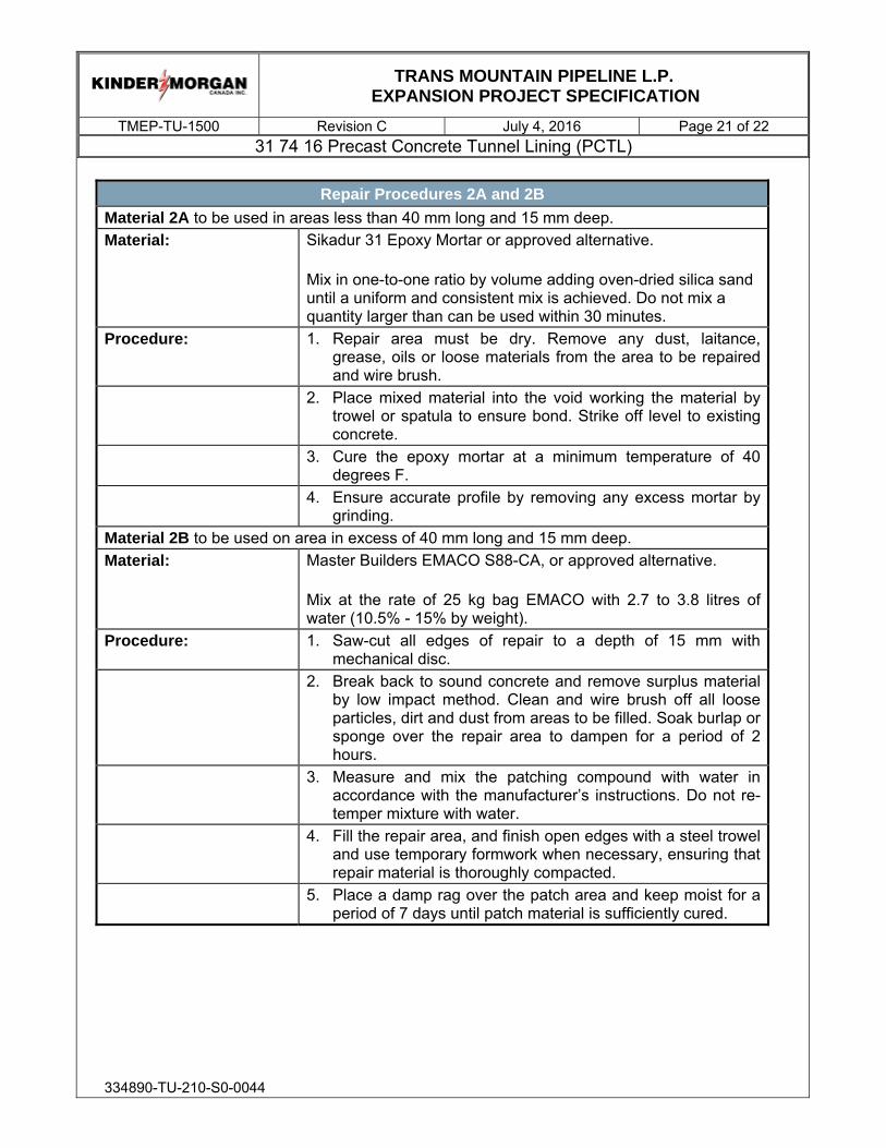
TRANS MOUNTAIN PIPELINE L.P.
EXPANSION PROJECT SPECIFICATION
TMEP-TU-1500 Revision C July 4, 2016 Page 21 of 22 31 74 16 Precast Concrete Tunnel Lining (PCTL)
334890-TU-210-S0-0044
Repair Procedures 2A and 2B
Material 2A to be used in areas less than 40 mm long and 15 mm deep. Material: Sikadur 31 Epoxy Mortar or approved alternative.
Mix in one-to-one ratio by volume adding oven-dried silica sand until a uniform and consistent mix is achieved. Do not mix a quantity larger than can be used within 30 minutes.
Procedure: 1. Repair area must be dry. Remove any dust, laitance, grease, oils or loose materials from the area to be repaired and wire brush.
2. Place mixed material into the void working the material by trowel or spatula to ensure bond. Strike off level to existing concrete.
3. Cure the epoxy mortar at a minimum temperature of 40 degrees F.
4. Ensure accurate profile by removing any excess mortar by grinding.
Material 2B to be used on area in excess of 40 mm long and 15 mm deep. Material: Master Builders EMACO S88-CA, or approved alternative.
Mix at the rate of 25 kg bag EMACO with 2.7 to 3.8 litres of water (10.5% - 15% by weight).
Procedure: 1. Saw-cut all edges of repair to a depth of 15 mm with mechanical disc.
2. Break back to sound concrete and remove surplus material by low impact method. Clean and wire brush off all loose particles, dirt and dust from areas to be filled. Soak burlap or sponge over the repair area to dampen for a period of 2 hours.
3. Measure and mix the patching compound with water in accordance with the manufacturer’s instructions. Do not re-temper mixture with water.
4. Fill the repair area, and finish open edges with a steel trowel and use temporary formwork when necessary, ensuring that repair material is thoroughly compacted.
5. Place a damp rag over the patch area and keep moist for a period of 7 days until patch material is sufficiently cured.

TRANS MOUNTAIN PIPELINE L.P.
EXPANSION PROJECT SPECIFICATION
TMEP-TU-1500 Revision C July 4, 2016 Page 22 of 22 31 74 16 Precast Concrete Tunnel Lining (PCTL)
334890-TU-210-S0-0044
REPAIR PROCEDURE 3 - CRACK SEALING
Material: Sikadur Injection Gel or approved alternative. Mix in a ratio of 1:1 in accordance with the manufacturer’s recommendation. Do not prepare more resin than can be used within 20 minutes.
Procedure: 1. Concrete must be clean and sound. Remove dust, laitance, grease, form oil, and foreign particles with a damp to dry cloth or sponge. Do not contaminate inside of crack.
2a. Mix injection gel from coaxial cartridges by gunning equal beads on to a pallet and mixing thoroughly to a uniform color using a putty knife or spatula.
2b. Using a putty knife or spatula, force material into the crack to seal it.
3. Wipe excess resin from the surface, adjacent to the crack, using a dry cloth.
4. Allow to cure for four hours before removing any remaining excess material with a rubbing stone.
3.8.3 Load testing may be specified by the Owner, particularly for any repairs of concrete near the lifting/shear inserts.
3.8.4 In all cases, acceptance or rejection of a repaired segment shall be at the discretion of the Owner.
(END OF SECTION)

334890-TU-210-S0-0045
TRANS MOUNTAIN PIPELINE L.P. EXPANSION PROJECT SPECIFICATION
31 73 13 Tunnel Annular Grouting TMEP-TU-1600, Revision C, July 4, 2016
REVISION INDEX
Rev No.
Prepared by/ Date
Reviewed by/ Date
Approved by/ Date
Client Approval Pages Revised
Remarks
A Dani Delaloye
2015-05-04 Daniel Jezek 2015-05-04
Dave Young 2015-05-04
Draft – Issued for RFP
B Daniel Jezek 2015-12-11
Dave Young 2015-12-11
Adam Neale 2015-12-11
Issued for 90% Design
C Reza Shobayry
2016-07-04 Brian Garrod 2016-07-04
Adam Neale 2016-07-04
Issued for 90% Design

TRANS MOUNTAIN PIPELINE L.P.
EXPANSION PROJECT SPECIFICATION
TMEP-TU-3200 Revision C July 4, 2016 Page 1 of 16 31 73 13 Tunnel Annular Grouting
334890-TU-210-S0-0045
TABLE OF CONTENTS
1.0 GENERAL ............................................................................................................ 2 1.1 Introduction ................................................................................................ 2 1.2 Scope of Work ........................................................................................... 4 1.3 Related Work Specified Elsewhere ............................................................ 4 1.4 Glossary and Abbreviations ....................................................................... 5 1.5 Regulations, Codes, Specifications, Standards ......................................... 5 1.6 Quality Control and Quality Assurance ...................................................... 6 1.7 Design Requirements ................................................................................ 7 1.8 Submittals .................................................................................................. 7
2.0 PRODUCTS ....................................................................................................... 10 2.1 Materials .................................................................................................. 10 2.2 Equipment ................................................................................................ 11
3.0 EXECUTION ....................................................................................................... 12 3.1 General .................................................................................................... 12 3.2 Annulus Grout .......................................................................................... 13 3.3 Proof Grout .............................................................................................. 14 3.4 Clean-Up .................................................................................................. 14 3.5 Field Quality Control ................................................................................ 15

TRANS MOUNTAIN PIPELINE L.P.
EXPANSION PROJECT SPECIFICATION
TMEP-TU-3200 Revision C July 4, 2016 Page 2 of 16 31 73 13 Tunnel Annular Grouting
334890-TU-210-S0-0045
1.0 GENERAL
1.1 Introduction
1.1.1 This Specification was prepared in collaboration with McNally Construction Inc. (the Contractor) as part of the Early Contractor Involvement (ECI) Pre-Construction Services (Phase 1) as described in the Memorandum of Understanding for Early Contractor Involvement, Contract Number TMEP-PC-001.
1.1.2 This Specification is customized to the Contractor’s construction plans and preferences, as described in the Construction Execution Plans, produced as part of the ECI Phase 1.
1.1.3 This Specifications forms part of the Contract Documents and is to be read, interpreted and coordinated with all other parts, including the following:
1.1.3.1 Bidding requirements, bid forms, pricing and baseline schedule milestones by Trans Mountain
1.1.3.2 General Conditions by Trans Mountain
1.1.3.3 Special Conditions and/or Division 1 Technical Specifications by Trans Mountain
1.1.3.4 Environmental and Permit Conditions by Trans Mountain
1.1.3.5 Construction Execution Work Plans prepared by McNally and reviewed by HMM and Trans Mountain
1.1.3.6 Contract Drawings
1.1.3.7 Contract Geotechnical Reports
1.1.3.8 Various other Trans Mountain and TMEP standards including TMEP Pipeline Construction Damage Prevention Plan, and the following Technical Specifications including:
A. 1000 Site Preparation
B. 1100 Diversion and Care of Water
C. 1210 Portal Area Development

TRANS MOUNTAIN PIPELINE L.P.
EXPANSION PROJECT SPECIFICATION
TMEP-TU-3200 Revision C July 4, 2016 Page 3 of 16 31 73 13 Tunnel Annular Grouting
334890-TU-210-S0-0045
D. 1310 Tunnelling by TBM
E. 1500 Precast Concrete Tunnel Lining (PCTL)
F. 1600 Tunnel Annular Grouting
G. 1610 Pre-Excavation Grouting
H. 1620 Shotcrete
I. 2000 Pipeline Installation in Tunnel
J. 2200 Probe Hole Drilling ahead of TBM
K. 2300 Geotechnical Instrumentation and Monitoring
L. 2400 Cast-In-Place Concrete
M. 2500 Tunnel Backfill
N. 2510 Site Restoration
O. 2600 Secant Pile Wall
P. 2700 Concrete Reinforcement
Q. 2800 Ground Anchors
R. 2900 PCTL Concrete Accessories
S. 3000 Concrete Reinforcement for PCTL
T. 3100 Concrete for PCTL
U. TMEP-CIV102 Engineering Survey – B.C.
V. TMEP-CIV301 Blasting
W. TMEP-CIV400 Clearing Specification for British Columbia
X. TMEP-GC3105 FBE Plant Applied Coating
Y. TMEP-GC3300 FBE Field Applied Coating
Z. TMEP-GC3302 Two-Part Liquid Field Applied Coating

TRANS MOUNTAIN PIPELINE L.P.
EXPANSION PROJECT SPECIFICATION
TMEP-TU-3200 Revision C July 4, 2016 Page 4 of 16 31 73 13 Tunnel Annular Grouting
334890-TU-210-S0-0045
AA. TMEP-GC3306 Two-Part Liquid Shop Applied Coating
BB. TMEP-MP1200 Steel Fittings
CC. TMEP-MP2212 Steel Flanges
DD. TMEP-MP2217 Bends
EE. TMEP-MP2300 Pipeline Valves
FF. TMEP-MP3120 Pipeline Construction
GG. TMEP-MP3903 Non Destructive Testing
HH. TMEP-MP3904 SMAW and Mechanized Welding
II. TMEP-MP4121 Hydrostatic Testing
JJ. TMEP-MP4500 Pipeline Cleaning
KK. TMEP-MP4501 Pipeline Drying
LL. TMEP-MP4502 Post Construction Caliper Pigging
MM. TMEP-42EF0009 Piling Installation
NN. TMEP-42EF0016 Structural Steel Fabrication and Erection
OO. TMEP-45ES0012 Pipeline Above Ground Painting
1.2 Scope of Work
1.2.1 This Specification includes requirements for labour, products, equipment and services necessary for tunnel grouting work.
1.2.2 The work includes, but is not limited to the following:
1.2.2.1 Requirements for designing and testing grout mix.
1.2.2.2 Provision and injection of grout to fill the annular space between the precast tunnel lining and the excavated space formed by the tunnel boring machine.
1.2.2.3 Proof grouting
1.3 Related Work Specified Elsewhere

TRANS MOUNTAIN PIPELINE L.P.
EXPANSION PROJECT SPECIFICATION
TMEP-TU-3200 Revision C July 4, 2016 Page 5 of 16 31 73 13 Tunnel Annular Grouting
334890-TU-210-S0-0045
1.3.1 31 71 20 TBM Tunnelling
1.3.2 31 74 16 Precast Concrete Tunnel Lining (PCTL)
1.3.3 03 30 00.1 Concrete for PCTL
1.4 Glossary and Abbreviations
1.4.1 Annulus Filling: Provision and injection of grout to completely fill the annular space between the precast concrete tunnel lining and the cavity excavated by the Tunnel Boring Machine (TBM) through ports within the segments.
1.4.2 Contract Geotechnical Reports: These include the Geotechnical Baseline Report (GBR) and the Site Investigation Data Reports (SIDRs).
1.4.3 Proof Grouting: Provision and injection of grout through grout ports provided in the precast concrete segments to verify that the annular space between the precast concrete tunnel lining and the cavity excavated by the TBM is completely filled.
1.4.4 Testing Laboratory: A Contractor provided certified laboratory responsible for calibrating and testing the accuracy of the master gauges and meters.
1.5 Regulations, Codes, Specifications, Standards
1.5.1 All work shall be performed in accordance with all applicable federal, provincial, and municipal regulations, codes, and standards.
1.5.2 American Society for Testing and Materials (ASTM):
1.5.2.1 ASTM C39/C39M-16, Standard Test Method for Compressive Strength of Cylindrical Concrete
1.5.2.2 ASTM C109/C109M-16a, Test Method for Compressive Strength of Hydraulic Cement Mortars
1.5.2.3 ASTM C150/C150M-16, Specification for Portland Cement
1.5.2.4 ASTM C494/C494M-15a, Specification for Chemical Admixtures for Concrete
1.5.2.5 ASTM C827/C827M-10, Standard Test Method for Change in Height at Early Ages of Cylindrical Specimens of Cementitious Mixtures

TRANS MOUNTAIN PIPELINE L.P.
EXPANSION PROJECT SPECIFICATION
TMEP-TU-3200 Revision C July 4, 2016 Page 6 of 16 31 73 13 Tunnel Annular Grouting
334890-TU-210-S0-0045
1.5.3 Where standards identify conflicting requirements, the more stringent requirement shall apply unless otherwise specified herein.
1.6 Quality Control and Quality Assurance
1.6.1 Qualifications:
1.6.1.1 Grouting Supervisor: The Contractor shall retain a Grouting Supervisor to manage the grouting program by designing, testing and overseeing the injection of grout mixes of the type required, shall have at least 10-years of related Work experience on similar projects. The Grouting Supervisor shall be familiar with the type of grout set-up on the TBM.
1.6.2 Quality Control Plan:
1.6.2.1 Comply with the specified standards as a minimum quality for the Work except when more stringent tolerances or codes indicate higher standards or more precise workmanship.
1.6.2.2 Should the manufacturers' printed instructions conflict with the Specifications, the Contractor shall request clarification from the Owner before proceeding.
1.6.2.3 Preconstruction testing of Annular Grout:
A. Provide a testing apparatus and procedure to demonstrate the strength gain and gel time characteristics of the grout. The Contractor shall carry out parallel testing using a strength-monitoring device suitable for use in the tunnel.
B. Submit test results demonstrating the attainment of the specified minimum twenty-eight day compressive strength in accordance with ASTM C39.
1.6.2.4 Production testing of Annular Grout:
A. Grout samples for testing shall be taken from the grout tanks on the TBM trailing gear.
B. Measure the early strength gain using the procedure developed in Subparagraph 1.6.2.3.A above, with at least one test for every two rings grouted.

TRANS MOUNTAIN PIPELINE L.P.
EXPANSION PROJECT SPECIFICATION
TMEP-TU-3200 Revision C July 4, 2016 Page 7 of 16 31 73 13 Tunnel Annular Grouting
334890-TU-210-S0-0045
C. Test 28 days strength of two test cubes in accordance with ASTM C39 for each shift that grouting is performed.
1.6.3 Certifications:
1.6.3.1 Certificates of compliance for the materials listed under Part Two of this Section.
1.6.3.2 Calibration certificates for gauges and meters to be used in the grouting operations.
1.6.4 Each new major activity shall be preceded by a kickoff meeting with the Contractor, Owner, Engineer and Construction Manager.
1.7 Design Requirements
1.7.1 Design grout mixes with the appropriate properties to fully serve their intended functions, as defined herein.
1.8 Submittals
1.8.1 General
1.8.1.1 All submissions shall be provided to the Owner for review in accordance with the Contractor Shop Drawings requirements provided in the General Conditions of the Construction Contract.
1.8.2 At least 30 days prior to commencing the Work, submit the following:
1.8.2.1 Shop Drawings indicating:
A. Patterns and details for sequencing and performing grouting. The means and methods for collecting and disposing of the excess and waste material, collecting and disposing of water resulting from the grouting operations and the cleaning of the precast concrete segments shall be included.
1.8.2.2 The means and methods for collecting and disposing of the excess and waste material, collecting and disposing of water resulting from the grouting operations and the cleaning of the precast concrete segments.
1.8.2.3 Preconstruction testing of Annular Grout: Submit test results demonstrating the attainment of the specified minimum twenty-eight day compressive strength.

TRANS MOUNTAIN PIPELINE L.P.
EXPANSION PROJECT SPECIFICATION
TMEP-TU-3200 Revision C July 4, 2016 Page 8 of 16 31 73 13 Tunnel Annular Grouting
334890-TU-210-S0-0045
1.8.2.4 The means and methods for Annulus Grouting, including:
A. Grout mix designs, including additives and sources and properties of all components
B. Location of mixing plant
C. Grout delivery system
D. Grout pumping system
E. Testing procedures
F. Grout volume measurement
G. Location and sequence of injection
H. Pressure measurement
I. Accelerator dosing and control devices
J. Flow and directional control
K. Sequencing grouting and establishing the basis and threshold values for modifying the mixes
L. Temporary storage vessels
M. Coordination with the other TBM functions, in particular, tail seal grease injection, pressure control and shove ram activation.
1.8.2.5 The means and methods for Proof Grouting, including:
A. Descriptions and proposed arrangement of the grouting equipment, grout pipe materials, drilling methods, grouting methods and procedures for the disposal of waste grout and water
B. Acceptance criteria for the completed grouting
C. Methods to determine that the grout pressures will not damage the lining systems
D. Methods to verify the complete filling of voids and annular spaces

TRANS MOUNTAIN PIPELINE L.P.
EXPANSION PROJECT SPECIFICATION
TMEP-TU-3200 Revision C July 4, 2016 Page 9 of 16 31 73 13 Tunnel Annular Grouting
334890-TU-210-S0-0045
E. Methods to determine that the criteria have been met
1.8.2.6 Product data
A. The manufacturer’s Product data sheets indicating:
i. Mixing, handling, storage and waste disposal requirements
ii. Personal safety equipment and first aid measures
iii. Source of supply for each grout ingredient
B. For each type and source material:
i. Cement: Standard physical and chemical analysis
ii. Admixtures: Documentation showing that the proposed admixtures have a history of demonstrable satisfactory performance and are compatible with the adjacent materials
iii. Calibration procedures for the gauges and meters used in the grouting operations
1.8.2.7 Quality Control Plan: A ‘Quality Control Plan’ to be used to demonstrate that the grout mixes meet the design criteria, and shall include the following:
A. Methods for ensuring uninterrupted grouting at pressures that do not exceed the maximum specified
B. Methods for containing excess or waste grout, cleaning equipment and disposing of excess and wasted grout, water and debris
C. Methods for preventing grout migration into the cutterhead from behind the tunnel shield
1.8.3 Submit daily during the Work:
1.8.3.1 Daily Records
A. Records of strength tests on grout samples as soon as practicable after performing the tests.

TRANS MOUNTAIN PIPELINE L.P.
EXPANSION PROJECT SPECIFICATION
TMEP-TU-3200 Revision C July 4, 2016 Page 10 of 16 31 73 13 Tunnel Annular Grouting
334890-TU-210-S0-0045
B. Shift report for Proof Grouting for each shift, regardless of actual progress, submitted no later than the beginning of the following working day. The Contractor shall include the following:
i. Crew size, employee classification and employee work assignment
ii. Number and type of equipment used
C. Grout injection records for each ring or segment:
i. Chainage of ring and ring number
ii. Hole Location with segment ring (if applicable)
iii. Observational data from drilling and inspection
iv. Mix type and batch number
v. Detailed grout injection records for each hole/pipe down by quantity injected into each hole/pipe, injection pressure and pumping rate for each hole/pipe
1.8.3.2 Notifications:
A. Within one calendar day of any proposed addition, deletion or change to the scheduling of shift Work
B. Within one calendar day of performing gauge and meter tests
C. Immediately upon injection of less than 80% or more than the 120% of the theoretical volume of grout take
1.8.4 Submit weekly:
1.8.4.1 Production testing of Annular Grout.
1.8.5 All materials and equipment used in the Work shall be the included as part of the above submittals or the subject of a submittal to the Owner.
2.0 PRODUCTS
2.1 Materials

TRANS MOUNTAIN PIPELINE L.P.
EXPANSION PROJECT SPECIFICATION
TMEP-TU-3200 Revision C July 4, 2016 Page 11 of 16 31 73 13 Tunnel Annular Grouting
334890-TU-210-S0-0045
2.1.1 The products or materials selected shall perform satisfactorily for the design service life of the tunnel under the groundwater conditions as described in the Contract Geotechnical Reports.
2.1.2 Two Component Annulus Grout:
2.1.2.1 In accordance with the TBM manufacturer’s recommendations.
2.1.2.2 Cement: Conforming to ASTM C150, Type 1 or 3.
2.1.2.3 Accelerators, retarding agents: Conform to ASTM C494.
2.1.2.4 Anti-washout agent: Conform to the reviewed Contractor's submittal.
2.1.2.5 Compressive strength: Minimum 1 MPa at twenty-eight days, as measured in accordance with ASTM C39.
2.1.2.6 Strength gain: 0.2 MPa in 1-hour.
2.1.3 Proof Grout
2.1.3.1 Cement: Conforming to ASTM C150, Type 1 or 3.
2.1.3.2 Acceptable materials shall include water, portland cement, slag, fly ash, silica fume, bentonite and sand conforming to the requirements of 03 30 00.1 Concrete for PCTL except that 100% of the sand shall pass through a No. 16 sieve.
2.1.3.3 Admixtures: As reviewed and approved by the Owner.
2.1.3.4 Design the grout mix for review by the Owner, with or without sand as required, but in no case containing more than three parts sand to one part cement by weight, and with a water-cement ratio compatible with the pumping and placing requirements.
2.1.3.5 Twenty-eight day compressive strength of 15 MPa minimum measured in 100 mm cubes.
2.2 Equipment
2.2.1 Proof Grout Drilling Equipment:
2.2.1.1 Utilize a core drill for all drilling and cleaning out of the grout holes.

TRANS MOUNTAIN PIPELINE L.P.
EXPANSION PROJECT SPECIFICATION
TMEP-TU-3200 Revision C July 4, 2016 Page 12 of 16 31 73 13 Tunnel Annular Grouting
334890-TU-210-S0-0045
2.2.1.2 Equip drills with bits of the same nominal diameter as that required for the grout hole.
2.2.2 Grouting Equipment:
2.2.2.1 General: Provide for the continuous circulation of the grout within the system.
2.2.2.2 Pumps:
A. Utilize helical screw rotor-type producing a uniform flow without pulsation
B. Equip with a water connection to facilitate the flushing of the system
C. Equip with a pressure gauge as specified herein
2.2.2.3 Appurtenances:
A. Packers: Shall be capable of sealing the grout holes without leakage when grouting at the maximum specified pressure
B. Hoses and Piping:
i. Provide a manifold system of valves and a pressure gauge in the line at the collar of the hole to permit the accurate control and monitoring of the grouting pressure, bleeding and regulation of flow
ii. Size: 40 mm I.D., minimum.
C. Pressure gauges: Accurate to ±7 kPa over the allowable grouting pressure range
D. Volumetric Measuring Device: Accurate to 5 litres
2.2.3 Spare Parts: Maintain an adequate supply of spare parts and equipment to ensure uninterrupted grouting operations.
3.0 EXECUTION
3.1 General
3.1.1 Equipment for mixing and injecting grout shall be:

TRANS MOUNTAIN PIPELINE L.P.
EXPANSION PROJECT SPECIFICATION
TMEP-TU-3200 Revision C July 4, 2016 Page 13 of 16 31 73 13 Tunnel Annular Grouting
334890-TU-210-S0-0045
3.1.1.1 Designed for the grouting service.
3.1.1.2 Maintained for the duration of the Work.
3.1.1.3 Capable of mixing, agitating and forcing grout into the annular space between the extrados of the precast concrete segments and the ground, in a continuous flow and at the required pressure.
3.1.2 The pipes for Annulus Grouting through the trailing shield of the TBM are specified in 31 71 20 Tunnelling by TBM and are integral with the TBM. The grout holes in the precast concrete segments are described in 31 74 16 Precast Concrete Tunnel Lining (PCTL).
3.1.3 Arrange the grouting equipment to provide for the continuous circulation of the grout in the system and to permit accurate pressure control at the grout hole connection. Keep the equipment and lines clean by the constant circulation of grout and by the periodic flushing with water.
3.1.4 Configure the equipment so that flushing can be accomplished with the grout intake valves closed, with the water supply valve open and with the grout pump running at full speed.
3.1.5 Equipment shall be reviewed by the Owner before the Contractor commences the tunnelling operations.
3.1.6 Waste grout shall not be placed within 2-hours of the time of initial mixing.
3.2 Annulus Grout
General: Perform Annulus Grouting as an integral part of the requirements of 31 71 20 Tunnelling by TBM.
3.2.1 Annulus Grouting shall completely fill the annular void between the precast concrete segmental lining and the ground with a grout of a consistency and strength suitable to prevent the segments from shifting, to maintain the circularity of the segment ring and to control the ground surface settlement.
3.2.2 Annulus Grouting shall be performed in a manner that will not grout the head and shield of the TBM or otherwise interfere with the advance of the TBM.
3.2.3 Annulus Grouting shall be performed concurrently with the advance of the TBM. In no circumstance, shall the TBM advance be allowed, unless the grouting systems and grout quantities suitable for filling the annular void

TRANS MOUNTAIN PIPELINE L.P.
EXPANSION PROJECT SPECIFICATION
TMEP-TU-3200 Revision C July 4, 2016 Page 14 of 16 31 73 13 Tunnel Annular Grouting
334890-TU-210-S0-0045
for the next advance increment are immediately available and ready for use. Grout shall be injected immediately and continuously from the radially spaced ports around the trailing shield as the ring emerges from the rear of the trailing shield of the TBM.
3.2.4 The minimum Annulus Grout injection pressure shall be the existing hydrostatic pressure plus one bar. The maximum Annulus Grout injection pressure shall be the existing hydrostatic pressure plus two bars.
3.2.5 Ensure that all grout pipes used for Annulus Grouting in the trailing shield are unobstructed at all times when not in use.
3.2.6 The minimum volume for Annulus Grouting shall be 0.75 m3/m. The Contractor shall establish the minimum pressure refusal criteria for Annulus Grouting. Both criteria shall be met prior to the cessation of grout injection.
3.2.7 Temperature: Maintain the contact surfaces of the precast segments above freezing at the time of grouting for the minimum period specified in 31 74 16 Precast Concrete Tunnel Lining (PCTL).
3.3 Proof Grout
3.3.1 Proof drilling and grouting shall be performed from the TBM trailing gantries.
3.3.2 Perform Proof Grouting once every twenty rings through one port within the tunnel crown, as directed by the Owner.
3.3.3 The minimum Proof Grout injection pressure shall be the existing hydrostatic pressure plus one bar. The maximum Proof Grout injection pressure shall be the existing hydrostatic pressure plus two bars.
3.4 Clean-Up
3.4.1 Minimize waste and losses. The Contractor shall collect and dispose of excess and waste materials using approved methods including the water resulting from the grouting operations.
3.4.2 Promptly clean-up grout spills and clean the precast segment intrados.
3.4.3 After grouting, the Contractor shall ensure that all grout pipes, valves and containers are clean and free of grout.

TRANS MOUNTAIN PIPELINE L.P.
EXPANSION PROJECT SPECIFICATION
TMEP-TU-3200 Revision C July 4, 2016 Page 15 of 16 31 73 13 Tunnel Annular Grouting
334890-TU-210-S0-0045
3.5 Field Quality Control
3.5.1 Proof Grouting Strength Tests: Take three grout cubes samples from the grout line hook-up fitting and test in accordance with ASTM C109 for every 10 m3 of each type of grout mixed.
3.5.2 Gauges and Meters:
3.5.2.1 Test field gauges and meters in the presence of the Owner a minimum of once per week using the master gauges and meters.
3.5.2.2 Verify the accuracy of the master gauges and meters through the use of a Testing Laboratory no less frequently than once every two months.
3.5.3 Proof Grouting:
3.5.3.1 Conduct tests at the grout ports to verify the adequacy of the grouting operations on the first twenty-five rings installed for each tunnel drive. Thereafter, conduct tests at the grout ports to verify the adequacy of the grouting operations at locations:
A. Showing inadequate or excessive grout takes.
B. Where the Annulus Grouting refusal criterion was not met.
C. Selected by the Owner at a minimum frequency of one test per 15 m of tunnel. The Contractor shall supply its inspection or testing service for the Work and shall not rely on the inspection or testing undertaken by the Owner.
3.5.3.2 Drill-out holes to the extent necessary for the Owner to verify that the grouting operation has achieved its intended purpose.
3.5.3.3 For every hole drilled indicating the incomplete filling of the annulus, the Owner will select an additional two locations where the Contractor shall drill and grout within 5 m of the location where the voids were found.
3.5.3.4 Non-return valves supplied by the Owner shall be installed in the grout port prior to Proof Grouting. Remove the grout valves after the grout has reached an initial set, clean out the grout port and re-install the grout plug assemblies.

TRANS MOUNTAIN PIPELINE L.P.
EXPANSION PROJECT SPECIFICATION
TMEP-TU-3200 Revision C July 4, 2016 Page 16 of 16 31 73 13 Tunnel Annular Grouting
334890-TU-210-S0-0045
3.5.3.5 The Owner will verify the adequacy of the Proof Grouting by selecting a minimum of one test location within 5 m of every hole where Proof Grouting was performed. The Contractor shall perform additional Proof Grouting as required to satisfy the requirements of this Section.
(END OF SECTION)

334890-TU-210-S0-0041
TRANS MOUNTAIN PIPELINE L.P. EXPANSION PROJECT SPECIFICATION
23 11 00 PIPELINE INSTALLATION IN TUNNEL TMEP-TU-2000, Revision C, June 1, 2016
REVISION INDEX
Rev No.
Prepared by/ Date
Reviewed by/ Date
Approved by/ Date
Pages Revised
Remarks
A Daniel Jezek 2015-05-04
Sheerin Rashidian
2015-05-04
Dave Young 2015-05-04
Draft – Issued for RFP
B Daniel Jezek 2015-12-11
Dave Young 2015-12-11
Adam Neale 2015-12-11
Issued for 90% Design
C Daniel Jezek 2016-06-01
Dave Young 2016-06-01
Adam Neale 2016-06-01
Issued for 90% Design

TRANS MOUNTAIN PIPELINE L.P.
EXPANSION PROJECT SPECIFICATION
TMEP-TU-2000 Revision C June 1, 2016 Page 1 of 12 23 11 00 Pipeline Installation in Tunnel
334890-TU-210-S0-0041
TABLE OF CONTENTS
1.0 GENERAL ............................................................................................................ 2 1.1 Introduction ................................................................................................ 2 1.2 Scope ......................................................................................................... 4 1.3 Related Sections ........................................................................................ 5 1.4 Glossary and Abbreviations ....................................................................... 6 1.5 Regulations, Codes, Specifications, Standards ......................................... 6 1.6 Quality Control and Quality Assurance ...................................................... 6 1.7 Submittals .................................................................................................. 7
2.0 2.0 PRODUCTS ................................................................................................... 9 2.1 Materials .................................................................................................... 9 2.2 Equipment .................................................................................................. 9
3.0 EXECUTION ......................................................................................................... 9 3.1 General .................................................................................................... 10 3.2 Inspection, Transportation, Handling and Storage ................................... 10 3.3 Pipeline Installation .................................................................................. 11

TRANS MOUNTAIN PIPELINE L.P.
EXPANSION PROJECT SPECIFICATION
TMEP-TU-2000 Revision C June 1, 2016 Page 2 of 12 23 11 00 Pipeline Installation in Tunnel
334890-TU-210-S0-0041
1.0 GENERAL
1.1 Introduction
1.1.1 This Technical Specification has been prepared in collaboration with McNally Construction Inc. (the Contractor) as part of the Early Contractor Involvement (ECI) Pre-Construction Services (Phase 1) as described in the Memorandum of Understanding for Early Contractor Involvement, Contract Number TMEP-PC-001.
1.1.2 This Specifications forms part of the Contract Documents and is to be read, interpreted and coordinated with all other parts, including the following:
1.1.2.1 Bidding requirements, bid forms, pricing and baseline schedule milestones by Trans Mountain
1.1.2.2 General Conditions by Trans Mountain
1.1.2.3 Special Conditions and/or Division 1 Technical Specifications by Trans Mountain
1.1.2.4 Environmental and Permit Conditions by Trans Mountain
1.1.2.5 Construction Execution Work Plans prepared by McNally and reviewed by HMM and Trans Mountain
1.1.2.6 Contract Drawings
1.1.2.7 Contract Geotechnical Reports
1.1.2.8 Various other Trans Mountain and TMEP standards including TMEP Pipeline Construction Damage Prevention Plan, and the following Technical Specifications including:
A. 1000 Site Preparation
B. 1100 Diversion and Care of Water
C. 1210 Portal Area Development
D. 1310 Tunnelling by TBM
E. 1500 Precast Concrete Tunnel Lining (PCTL)

TRANS MOUNTAIN PIPELINE L.P.
EXPANSION PROJECT SPECIFICATION
TMEP-TU-2000 Revision C June 1, 2016 Page 3 of 12 23 11 00 Pipeline Installation in Tunnel
334890-TU-210-S0-0041
F. 1600 Tunnel Annular Grouting
G. 1610 Pre-Excavation Grouting
H. 1620 Shotcrete
I. 2000 Pipeline Installation in Tunnel
J. 2200 Probe Hole Drilling ahead of TBM
K. 2300 Geotechnical Instrumentation and Monitoring
L. 2400 Cast-In-Place Concrete
M. 2500 Tunnel Backfill
N. 2510 Site Restoration
O. 2600 Secant Pile Wall
P. 2700 Concrete Reinforcement
Q. 2800 Ground Anchors
R. 2900 PCTL Concrete Accessories
S. 3000 Concrete Reinforcement for PCTL
T. 3100 Concrete for PCTL
U. TMEP-CIV102 Engineering Survey – B.C.
V. TMEP-CIV301 Blasting
W. TMEP-CIV400 Clearing Specification for British Columbia
X. TMEP-GC3105 FBE Plant Applied Coating
Y. TMEP-GC3300 FBE Field Applied Coating
Z. TMEP-GC3302 Two-Part Liquid Field Applied Coating
AA. TMEP-GC3306 Two-Part Liquid Shop Applied Coating
BB. TMEP-MP1200 Steel Fittings
CC. TMEP-MP2212 Steel Flanges

TRANS MOUNTAIN PIPELINE L.P.
EXPANSION PROJECT SPECIFICATION
TMEP-TU-2000 Revision C June 1, 2016 Page 4 of 12 23 11 00 Pipeline Installation in Tunnel
334890-TU-210-S0-0041
DD. TMEP-MP2217 Bends
EE. TMEP-MP2300 Pipeline Valves
FF. TMEP-MP3120 Pipeline Construction
GG. TMEP-MP3903 Non Destructive Testing
HH. TMEP-MP3904 SMAW and Mechanized Welding
II. TMEP-MP4121 Hydrostatic Testing
JJ. TMEP-MP4500 Pipeline Cleaning
KK. TMEP-MP4501 Pipeline Drying
LL. TMEP-MP4502 Post Construction Caliper Pigging
MM. TMEP-42EF0009 Piling Installation
NN. TMEP-42EF0016 Structural Steel Fabrication and Erection
OO. TMEP-45ES0012 Pipeline Above Ground Painting
1.1.3 The Work will occur on and/or in the vicinity of the existing right-of-way, next to the existing Trans Mountain pipeline and other pipelines which will remain in service throughout construction. All Work shall be performed in accordance with the TMEP Pipeline Construction Damage Prevention Plan.
1.2 Scope
1.2.1 This Specification covers the requirements for the installation of three NPS 30 pipelines between the tunnel portals and within the tunnel. This Specification does not include the installation of the pipeline outside of the tunnel.
1.2.2 The NPS 30 pipe shall be supplied by the Owner to the designated stockpile location to the Westridge and Burnaby Terminal sites.
1.2.3 This Specification does not include general requirements for pipeline construction such as pipe transportation, pipe handling, pipe field bending, pipeline welding, non-destructive testing, coating, hydrostatic testing, caliper pig run, and inhibitor installation. These requirements are specified elsewhere.

TRANS MOUNTAIN PIPELINE L.P.
EXPANSION PROJECT SPECIFICATION
TMEP-TU-2000 Revision C June 1, 2016 Page 5 of 12 23 11 00 Pipeline Installation in Tunnel
334890-TU-210-S0-0041
1.2.4 Installation methods may involve the following:
1.2.4.1 Pipe bending outside the tunnel and welding and joint coating inside the tunnel.
1.2.4.2 Pipeline welding and joint coating completed outside the tunnel and then:
A. Pulled/pushed into the tunnel over rollers on pipe supports, or other means
B. Pulled/pushed into the tunnel using a pipe carrier
1.2.4.3 Combination of above methods
1.3 Related Sections
1.3.1 01 57 23 Diversion and Care of Water
1.3.2 31 73 14 Tunnel Backfill
1.3.3 GC1000 Coating Selection and Specification
1.3.4 TMEP-MP1200 Steel Fittings Specification
1.3.5 TMEP-MP2217 Induction Bends Specification
1.3.6 TMEP-MP2300 Pipeline Valves
1.3.7 TMEP-MP3120 Pipeline Construction
1.3.8 TMEP-MP4121 Mainline Hydrostatic Test Specification
1.3.9 TMEP-MP3904 SMAW and Mechanized Welding
1.3.10 TMEP-MP3903 Non Destructive Testing
1.3.11 TMEP-MP2212 Steel Flanges Specification
1.3.12 TMEP-GC3105 External Fusion Bond Epoxy Coating
1.3.13 TMEP-GC3101 External Coating of Piping, Components and Structural Steel
1.3.14 TMEP-GC3300 FBE Field Applied Coating Specification

TRANS MOUNTAIN PIPELINE L.P.
EXPANSION PROJECT SPECIFICATION
TMEP-TU-2000 Revision C June 1, 2016 Page 6 of 12 23 11 00 Pipeline Installation in Tunnel
334890-TU-210-S0-0041
1.4 Glossary and Abbreviations
1.4.1 Backfill: Approved material for backfilling the tunnel and/or shaft.
1.5 Regulations, Codes, Specifications, Standards
1.5.1 Worksafe BC, OHS Regulations
1.5.2 CSA Z245.1-14, Steel Pipe
1.5.3 CSA Z662-15, Oil and gas pipeline systems
1.5.4 Where standards identify conflicting requirements, the more stringent requirement shall apply unless otherwise specified herein.
1.6 Quality Control and Quality Assurance
1.6.1 Qualifications:
1.6.1.1 Superintendent in charge of pipe installation: In responsible charge of similar work on a minimum of two projects of equivalent size and complexity within the past ten years.
1.6.1.2 Welding Foreman: At least ten years of experience with journeyman status on large diameter mainline pipeline construction and having B Pressure Welding certification, along with red seal allowing that person to be certified across Canada.
1.6.1.3 Pipe Foreman: At least ten years of experience with journeyman status on large diameter mainline pipeline construction.
1.6.1.4 Welding Inspector: Certified and have at least three years of experience within the last five years with welding procedures required on this project.
1.6.1.5 Welders: Refer to TMEP-MP3904 - SMAW and Mechanized Welding Specification, for requirements.
1.6.2 Construction Tolerances: Out of alignment from design drawings shall be 300 mm for sections fed in from outside the tunnel and 10 mm for pipes fabricated in the 300 m radius section unless otherwise directed by the Owner.
1.6.3 Preconstruction Meeting:

TRANS MOUNTAIN PIPELINE L.P.
EXPANSION PROJECT SPECIFICATION
TMEP-TU-2000 Revision C June 1, 2016 Page 7 of 12 23 11 00 Pipeline Installation in Tunnel
334890-TU-210-S0-0041
1.6.3.1 Hold separate meetings for each location at least five calendar days but not more than 30 calendar days prior to commencing pipe installation where pipe will be installed. Provide minimum five calendar days advance notification of meeting time.
1.6.3.2 Review and discuss the following items at each meeting:
A. Construction methods and constraints overview.
B. Equipment operating parameters.
C. Safety procedures.
D. Quality control procedures and quality assurance requirements.
E. Reporting requirements.
F. Other issues as may be raised by either party.
1.6.4 Testing: Perform tests in accordance with the applicable codes and specifications.
1.6.5 Each new major activity shall be preceded by a kickoff meeting with the Contractor, Owner, Engineer and Construction Manager.
1.7 Submittals
1.7.1 The following shall be submitted for approval at least three months prior to pipeline installation in the tunnels and/or shaft:
1.7.1.1 Transportation, handling, and storage procedures including calculations demonstrating the pipe’s ability to handle construction loads without damage.
1.7.1.2 Method statement for fabrication and testing outside the tunnel; fabrication, installation and testing inside the tunnel; supporting, restraining and blocking the pipelines in place at its final location for tunnel backfilling; and constructing bulkheads at specified backfill intervals. Integrate this information with submittal requirements specified in 31 73 14 Tunnel Backfill. Include:
A. Preparations for installing pipe sections.

TRANS MOUNTAIN PIPELINE L.P.
EXPANSION PROJECT SPECIFICATION
TMEP-TU-2000 Revision C June 1, 2016 Page 8 of 12 23 11 00 Pipeline Installation in Tunnel
334890-TU-210-S0-0041
B. Panning details, drain pipes, and other methods for controlling groundwater inflows. Provide details to seal edges of panning to prevent backfill intrusion into drainage system.
C. Details and locations of temporary bulkheads for tunnel backfilling operations including grout return (vent) pipes.
D. Details of cradles, pipe supports, straps and methods for preventing flotation while placing backfill.
E. Details of ventilation system, including design calculations, and arrangement of fans, starters, bulkheads, and other appurtenances.
1.7.1.3 Pipe laying drawing(s) for tunnel showing the length, bend radius, pipe identification number and joints locations for each pipe. Demonstrate that proper clearances for pipe fabrication and installation exist.
1.7.1.4 Qualifications of Contractor or subcontractor personnel:
A. Pipeline Construction Superintendent.
B. Welding Foreman.
C. Welding Inspectors.
D. Welders.
1.7.1.5 Project Safety Plan
1.7.1.6 Project Specific Quality Plan and Inspection Test Plan
1.7.1.7 Construction Execution Plan
1.7.1.8 Welding Plan
1.7.1.9 Coating Plan
1.7.1.10 Hydrostatic Test Plans
1.7.1.11 Caliper Pigging Plan
1.7.1.12 Turnover Documentation

TRANS MOUNTAIN PIPELINE L.P.
EXPANSION PROJECT SPECIFICATION
TMEP-TU-2000 Revision C June 1, 2016 Page 9 of 12 23 11 00 Pipeline Installation in Tunnel
334890-TU-210-S0-0041
1.7.2 All materials and equipment used in the Work shall be the included as part of the above submittals or the subject of a submittal to the Owner.
1.7.3 Daily records: Submit no later than the beginning of the following working day. Include information and data regarding the following:
1.7.3.1 Results of visual pipe inspection at the stock pile.
1.7.3.2 Pipeline fabrication outside the tunnel including welding, testing, coating, field bending and inspecting.
1.7.3.3 Pipeline fabrication and installation inside the tunnel including pipe transportation, fit-up, welding, testing, coating, installation of pipe supports, restraints and bulkheads, and panning and drainage.
1.7.3.4 Equipment used.
1.7.3.5 Crew size.
1.7.3.6 Beginning and ending stations or elevations of pipe installation, and station or elevation where joint work has been completed.
1.7.3.7 Shift details including location, times and durations, details on production activities and notation of any downtime or interruption to production, including length of time and reason.
1.7.3.8 Quality Assurance and Quality Control including test results.
2.0 2.0 PRODUCTS
2.1 Materials
2.1.1 Product Pipe: Owner-supplied NPS 30 Pipe, Steel Grade 483 MPa, 762 mm O.D., 15.8 mm wall thickness, as per CSA Z245.1.
2.1.2 Pipe Joint Length: 12 m
2.1.3 Coating: 3M 207R rough overcoat
2.2 Equipment
2.2.1 All equipment to be used for fabrication and installation of the pipeline in the tunnel is subject to review by the Owner.
3.0 EXECUTION

TRANS MOUNTAIN PIPELINE L.P.
EXPANSION PROJECT SPECIFICATION
TMEP-TU-2000 Revision C June 1, 2016 Page 10 of 12 23 11 00 Pipeline Installation in Tunnel
334890-TU-210-S0-0041
3.1 General
3.1.1 Pipe installation shall not commence until the Owner agrees that the tunnel and shaft excavation has been stabilized, all deformations of the primary support have been successfully controlled, and groundwater inflows have been reduced to specified allowable rates.
3.1.2 Backfilling operations can commence only after positive results of hydrostatic pressure testing of all three pipelines within the tunnel.
3.1.3 Preparation
3.1.3.1 Control groundwater prior to pipe installation. Control and isolate water from the tunnel by erecting panning, and diverting with invert drain pipes, by pumping from sumps, or a combination thereof. Install sheeting, panning, and invert drains as needed to control groundwater inflows into the tunnel that shall be detrimental to the pipe fabrication and installation operations and late to the tunnel backfilling operations. Coordinate with requirement of 31 73 14 Tunnel Backfill.
3.1.3.2 The Contractor shall wash down all exposed surfaces prior to pipe installation to remove all loose, disturbed soil or rock, shotcrete rebound, dirt and debris in the tunnel and shaft.
3.1.3.3 Demonstrate with survey data taken from initial support systems monitoring that ground movements have been stabilized, and that required clearances are met for pipe fabrication and installation in the tunnel and shaft.
3.1.3.4 Temporary ventilation, lighting, and other utilities shall be maintained throughout the pipeline installation in the tunnel and shaft.
3.1.3.5 Sections of temporary tunnel track and other temporary utilities and equipment may be abandoned in place as agreed by the Owner.
3.1.3.6 Pipe installation shall not commence until the Owner agrees in writing that tunnel preparation, clean-up, and groundwater control measures have been properly completed.
3.2 Inspection, Transportation, Handling and Storage

TRANS MOUNTAIN PIPELINE L.P.
EXPANSION PROJECT SPECIFICATION
TMEP-TU-2000 Revision C June 1, 2016 Page 11 of 12 23 11 00 Pipeline Installation in Tunnel
334890-TU-210-S0-0041
3.2.1 All Owner supplied materials shall be handled, transported, and stored in accordance with TMEP-MP3120 Pipeline Construction Specification.
3.3 Pipeline Installation
3.3.1 The pipeline can be introduced into the tunnel via Burnaby and/or Westridge tunnel portal.
3.3.2 The Contractor shall handle pipe in accordance with TMEP-MP3120 Pipeline Construction Specifications.
3.3.3 The Contractor shall verify that pipe segments can be transported to their required location without interference or damage to pipe or initial tunnel support systems.
3.3.4 The Contractor shall make all field bends necessary for construction of the pipeline in accordance with TMEP-MP3120 Pipeline Construction.
3.3.5 The Contractor shall complete all pipeline welding in accordance with TMEP-MP3904 - SMAW and Mechanized Welding Specification.
3.3.6 The Owner shall supply a Contractor to complete all non-destructive weld testing in accordance with TMEP-MP3903 Non Destructive Testing.
3.3.7 The Contractor shall sandblast, pre-heat, and coat all girth welds in accordance with TMEP- GC3300 FBE Field Applied Coating Specification
3.3.8 The Contractor shall install necessary supports and devices for aligning and positioning each pipe segment to the required line and grade.
3.3.9 The Contractor shall install necessary pipe supports and restraints to eliminate pipe flotation and buckling and to prevent other movement during backfill placement.
3.3.10 The Contractor shall complete a minimum 4 hour hydrostatic strength pre-test for the NPS 30 pipelines within the tunnel prior to backfilling, in accordance with TMEP-MP4121 Mainline Hydrostatic Test Specification. The Contractor shall be responsible for all aspects of the hydrotest, including filling, pressurizing, and dewatering.
3.3.11 After backfill is complete, the full length of the NPS 30 pipelines shall be subject to a final hydrostatic test as per the Drawings and in accordance with TMEP-MP4121 Mainline Hydrostatic Test Specification. The Contractor shall be responsible for all aspects of the hydrotest, including filling, pressurizing, and dewatering.

TRANS MOUNTAIN PIPELINE L.P.
EXPANSION PROJECT SPECIFICATION
TMEP-TU-2000 Revision C June 1, 2016 Page 12 of 12 23 11 00 Pipeline Installation in Tunnel
334890-TU-210-S0-0041
3.3.12 The Contractor shall complete Pipeline Cleaning as per TMEP-MP4500 Pipeline Cleaning Specification and Pipeline Drying as per TMEP-MP4501 Pipeline Drying Specification.
3.3.13 The Owner shall supply a Caliper Pig Vendor to complete an inline inspection of the pipelines. The Contractor shall provide support including supplying air compressors and general labour as required. The caliper pig shall be run before the hydrostatic pre-test (prior to backfill) as well as after the final hydrostatic test (after backfill).
3.3.14 The Owner shall supply a Cathodic Protection subcontractor. The Contractor is responsible for coordinating construction activities with the subcontractor.
(END OF SECTION)

334890-TU-210-S0-0026
TRANS MOUNTAIN PIPELINE L.P. EXPANSION PROJECT SPECIFICATION
31 73 14 TUNNEL BACKFILL TMEP-TU-2500, Revision C, June 1, 2016
REVISION INDEX
Rev No.
Prepared by/ Date
Reviewed by/ Date
Approved by/ Date
Client Approval Pages Revised
Remarks
A Ben DiFiore 2015-05-04
Daniel Jezek 2015-05-04
Dave Young 2015-05-04
2015-05-04
Draft – Issued for RFP
B Ben DiFiore 2015-12-11
Daniel Jezek 2015-12-11
Dave Young 2015-12-11
Issued for RFP
C Daniel Jezek 2016-06-01
Dave Young Rick Dinning 2016-06-01
Adam Neale 2016-06-01
Issued for 90% Design
TRANS MOUNTAIN PIPELINE L.P.
EXPANSION PROJECT SPECIFICATION
TMEP-TU-2500 Revision C June 1, 2016 Page 1 of 23 31 73 14 Tunnel Backfill
334890-TU-210-S0-0026
TABLE OF CONTENTS
1.0 GENERAL ............................................................................................................ 2 1.1 Introduction ................................................................................................ 2 1.2 Scope of Work ........................................................................................... 4 1.3 Related Work Specified Elsewhere ............................................................ 5 1.4 Glossary and Abbreviations ....................................................................... 5 1.5 Regulations, Codes, Specifications, Standards ......................................... 5 1.6 Quality Control and Quality Assurance ...................................................... 8 1.7 Submittals ................................................................................................ 12
2.0 PRODUCTS ....................................................................................................... 16 2.1 Materials .................................................................................................. 16 2.2 Mixes ....................................................................................................... 19 2.3 Equipment ................................................................................................ 19
3.0 EXECUTION ....................................................................................................... 21 3.1 General .................................................................................................... 21 3.2 Preparation .............................................................................................. 22 3.3 Placement ................................................................................................ 23 3.4 Field Testing ............................................................................................ 23 3.5 Clean-Up .................................................................................................. 23

TRANS MOUNTAIN PIPELINE L.P.
EXPANSION PROJECT SPECIFICATION
TMEP-TU-2500 Revision C June 1, 2016 Page 2 of 23 31 73 14 Tunnel Backfill
334890-TU-210-S0-0026
1.0 GENERAL
1.1 Introduction
1.1.1 This specification was prepared in collaboration with McNally Construction Inc. (the Contractor) as part of the Early Contractor Involvement (ECI) Pre-Construction Services (Phase 1) as described in the Memorandum of Understanding for Early Contractor Involvement, Contract Number TMEP-PC-001.
1.1.2 This Specification is customized to the Contractor’s construction plans and preferences, as described in the Construction Execution Plans, produced as part of the ECI Phase 1. This Specifications forms part of the Contract Documents and is to be read, interpreted and coordinated with all other parts, including the following:
1.1.2.1 Bidding requirements, bid forms, pricing and baseline schedule milestones by Trans Mountain
1.1.2.2 General Conditions by Trans Mountain
1.1.2.3 Special Conditions and/or Division 1 Technical Specifications by Trans Mountain
1.1.2.4 Environmental and Permit Conditions by Trans Mountain
1.1.2.5 Construction Execution Work Plans prepared by McNally and reviewed by HMM and Trans Mountain
1.1.2.6 Contract Drawings
1.1.2.7 Contract Geotechnical Reports
1.1.2.8 Various other Trans Mountain and TMEP standards including TMEP Pipeline Construction Damage Prevention Plan, and the following Technical Specifications including:
A. 1000 Site Preparation
B. 1100 Diversion and Care of Water
C. 1210 Portal Area Development
D. 1310 Tunnelling by TBM

TRANS MOUNTAIN PIPELINE L.P.
EXPANSION PROJECT SPECIFICATION
TMEP-TU-2500 Revision C June 1, 2016 Page 3 of 23 31 73 14 Tunnel Backfill
334890-TU-210-S0-0026
E. 1500 Precast Concrete Tunnel Lining (PCTL)
F. 1600 Tunnel Annular Grouting
G. 1610 Pre-Excavation Grouting
H. 1620 Shotcrete
I. 2000 Pipeline Installation in Tunnel
J. 2200 Probe Hole Drilling ahead of TBM
K. 2300 Geotechnical Instrumentation and Monitoring
L. 2400 Cast-In-Place Concrete
M. 2500 Tunnel Backfill
N. 2510 Site Restoration
O. 2600 Secant Pile Wall
P. 2700 Concrete Reinforcement
Q. 2800 Ground Anchors
R. 2900 PCTL Concrete Accessories
S. 3000 Concrete Reinforcement for PCTL
T. 3100 Concrete for PCTL
U. TMEP-CIV102 Engineering Survey – B.C.
V. TMEP-CIV301 Blasting
W. TMEP-CIV400 Clearing Specification for British Columbia
X. TMEP-GC3105 FBE Plant Applied Coating
Y. TMEP-GC3300 FBE Field Applied Coating
Z. TMEP-GC3302 Two-Part Liquid Field Applied Coating
AA. TMEP-GC3306 Two-Part Liquid Shop Applied Coating
BB. TMEP-MP1200 Steel Fittings

TRANS MOUNTAIN PIPELINE L.P.
EXPANSION PROJECT SPECIFICATION
TMEP-TU-2500 Revision C June 1, 2016 Page 4 of 23 31 73 14 Tunnel Backfill
334890-TU-210-S0-0026
CC. TMEP-MP2212 Steel Flanges
DD. TMEP-MP2217 Bends
EE. TMEP-MP2300 Pipeline Valves
FF. TMEP-MP3120 Pipeline Construction
GG. TMEP-MP3903 Non Destructive Testing
HH. TMEP-MP3904 SMAW and Mechanized Welding
II. TMEP-MP4121 Hydrostatic Testing
JJ. TMEP-MP4500 Pipeline Cleaning
KK. TMEP-MP4501 Pipeline Drying
LL. TMEP-MP4502 Post Construction Caliper Pigging
MM. TMEP-42EF0009 Piling Installation
NN. TMEP-42EF0016 Structural Steel Fabrication and Erection
OO. TMEP-45ES0012 Pipeline Above Ground Painting
1.1.3 The Work will occur on and/or in the vicinity of the existing right-of-way, next to the existing Trans Mountain pipeline and other pipelines which will remain in service throughout construction. All Work shall be performed in accordance with the TMEP Pipeline Construction Damage Prevention Plan.
1.2 Scope of Work
1.2.1 The Work in this Section includes:
1.2.1.1 The requirements for developing and preparing mix designs, testing and verifying mixes, and batching, transporting, and placing backfill concrete between the NPS 30 pipelines and segmental lining in the tunnel, as indicated on the Drawings.
1.2.1.2 Construction of tunnel seals as indicated on the Drawings.
1.2.2 Backfilling operations may commence only after passing hydrostatic test results on all pipelines within tunnel and tunnel portal areas as indicated on the Drawings and approval by the Owner.

TRANS MOUNTAIN PIPELINE L.P.
EXPANSION PROJECT SPECIFICATION
TMEP-TU-2500 Revision C June 1, 2016 Page 5 of 23 31 73 14 Tunnel Backfill
334890-TU-210-S0-0026
1.3 Related Work Specified Elsewhere
1.3.1 31 71 20 Tunnelling by TBM
1.3.2 23 11 00 Pipeline Installation in Tunnel
1.3.3 MP4124 Main Line Hydrostatic Test Standard
1.4 Glossary and Abbreviations
1.4.1 Backfill Concrete: Approved material for backfilling the annular space between the pipelines and the concrete segmental lining in the tunnel. Backfill concrete may be Low Density Cellular Concrete or Self-Consolidating Concrete.
1.4.2 Low Density Cellular Concrete (LDCC): Also known as foam concrete, is a lightweight cementitious material that contains stable air or gas cells as a pre-formed foam into a cement based slurry.
1.4.3 NPS: Nominal Pipe Size.
1.4.4 Pipelines: Three NPS 30 pipes installed in the tunnel.
1.4.5 Self-Consolidating Concrete (SCC): Self-Consolidating Concrete is a highly fluid and flowable concrete that moves under its weight to spread into place. With no need for vibration or other types of finishing labour, this type of concrete easily pours past congested reinforcement and rebar as a result of superplasticizers, all the while still upholding standard durability requirements and strength characteristics common to traditional concrete designs.
1.5 Regulations, Codes, Specifications, Standards
1.5.1 The Work shall be carried out in strict accordance with, but not limited to, the requirements of the Acts, Standards and Regulations listed herein.
1.5.2 American Concrete Institute (ACI)
1.5.2.1 ACI 229R-13, Report on Controlled Low Strength Materials.
1.5.2.2 ACI 232.1R-12, Report on the Use of Raw or Processed Natural Pozzolans in Concrete.
1.5.2.3 ACI 232.2R-03, Use of Fly Ash in Concrete.

TRANS MOUNTAIN PIPELINE L.P.
EXPANSION PROJECT SPECIFICATION
TMEP-TU-2500 Revision C June 1, 2016 Page 6 of 23 31 73 14 Tunnel Backfill
334890-TU-210-S0-0026
1.5.2.4 ACI 232.3R-14, Report on High-Volume Fly Ash Concrete for Structural Applications.
1.5.2.5 ACI 523.1R-06, Guide for Cast-in-Place Low-Density Concrete.
1.5.2.6 ACI 523.3R-14, Guide for Cellular Concretes above 50 pcf.
1.5.3 American Society for Testing and Materials (ASTM):
1.5.3.1 ASTM C31/C31M-12, Standard Practice for Making and Curing Concrete Test Specimens in the Field.
1.5.3.2 ASTM C33/C33M-13, Standard Specification for Concrete Aggregates.
1.5.3.3 ASTM C39/39M-15a, Standard Test Method for Compressive Strength of Cylindrical Specimens.
1.5.3.4 ASTM C42/C42M-13, Standard Test Method for Obtaining and Testing Drilled Cores and Sawed Beams of Concrete.
1.5.3.5 ASTM C94/C94M-15, Standard Specification for Ready-Mixed Concrete.
1.5.3.6 ASTM C109/C109M-13, Standard Test Method for Compressive Strength of Hydraulic Cement Mortars (Using 2-in or [50 mm] Cube Specimens).
1.5.3.7 ASTM C138/C138M-14, Standard Test Method for Density (Unit Weight), Yield, and Air Content (Gravimetric) of Concrete.
1.5.3.8 ASTM C150/C150M-12, Standard Specification for Portland Cement.
1.5.3.9 ASTM C157, Standard Test Method for Length Change of Hardened Hydraulic-Cement Mortar and Concrete
1.5.3.10 ASTM C186-15a, Standard Test Method for Heat of Hydration of Hydraulic Cement.
1.5.3.11 ASTM C260/C260M-10a, Standard Specification for Air-Entraining Admixtures for Concrete.

TRANS MOUNTAIN PIPELINE L.P.
EXPANSION PROJECT SPECIFICATION
TMEP-TU-2500 Revision C June 1, 2016 Page 7 of 23 31 73 14 Tunnel Backfill
334890-TU-210-S0-0026
1.5.3.12 ASTM C311/C311M-13, Standard Test Methods for Sampling and Testing Fly Ash or Natural Pozzolans for Use in Portland Cement Concrete.
1.5.3.13 ASTM C403/C403M-08, Standard Test Method for Time of Setting of Concrete Mixtures by Penetration Resistance.
1.5.3.14 ASTM C494/C494M-13, Standard Specification for Chemical Admixtures for Concrete.
1.5.3.15 ASTM C495/C495M-12, Standard Test Method for Compressive Strength of Lightweight Insulating Concrete.
1.5.3.16 ASTM C567/C567M-14, Standard Test Method for Determining Density of Structural Lightweight Concrete.
1.5.3.17 ASTM C618-12a, Standard Specifications for Coal Fly Ash and Raw or Calcined Natural Pozzolan for Use in Concrete.
1.5.3.18 ASTM C796/C796M-12, Standard Test Method for Foaming Agents for Use in Producing Cellular Concrete Using Preformed Foam.
1.5.3.19 ASTM C869/C869M-11, Standard Specification for Foaming Agents Used in Making Preformed Foam for Cellular Concrete.
1.5.3.20 ASTM C1090-10, Standard Test Method for Measuring Changes in Height of Cylindrical Specimens of Hydraulic-Cement Grout.
1.5.3.21 ASTM D6527-00(2008), Standard Test Method for Determining Unsaturated Hydraulic Conductivity in Porous Media by Steady-State Centrifugation.
1.5.4 American National Standards Institute
1.5.4.1 ANSI B40.1 (2013), Pressure Indicating Dial Type – Elastic Element Gauges
1.5.5 Canadian Standards Association (CSA):
1.5.5.1 A23.1-14/A23.2-14, Concrete Materials and Methods of Concrete Construction/Methods of Test and Standards Practices for Concrete.
1.5.5.2 CSA A3000-13 Cementitious Materials Compendium

TRANS MOUNTAIN PIPELINE L.P.
EXPANSION PROJECT SPECIFICATION
TMEP-TU-2500 Revision C June 1, 2016 Page 8 of 23 31 73 14 Tunnel Backfill
334890-TU-210-S0-0026
1.5.6 Worksafe BC, OHS Regulations.
1.5.7 Where standards identify conflicting requirements, the more stringent requirement shall apply unless otherwise specified herein.
1.6 Quality Control and Quality Assurance
1.6.1 Contractor’s Qualifications:
1.6.1.1 The Contractor or Sub-Contractor supplying and placing the backfill concrete shall be capable of developing mix designs, and the batching, mixing, handling and placement of the proposed backfill concrete under tunnel conditions; shall have a minimum of five years of recent, successful experience in batching, pumping, and placing the proposed backfill concrete for at least three tunnel projects of similar magnitude and complexity to the Work;.
1.6.1.2 The contractor and manufacturer's representative shall be capable of complying with the qualifications specified for the contractor and shall be acceptable to the Owner.
1.6.2 Personnel Qualifications:
1.6.2.1 Concreting Supervisor: Experienced in similar tunnel conditions and knowledgeable in the formulation and adjustment of backfill concrete mix designs, with a minimum of five years of experience. The Concreting Supervisor shall be certified by the foaming agent manufacturer.
1.6.2.2 Field Sampling and Testing Personnel: Qualified employees of a certified testing laboratory.
1.6.3 Field Services:
1.6.3.1 The Foaming Agent Material Manufacturer shall provide engineering field services to review the project, backfill concrete mix, placing equipment and procedures, and the qualifications of the contractor responsible for the backfill concrete prior to any work. The Foaming Agent Representative is to approve the materials, equipment, procedures to be used and the setup before production of backfill concrete; and to observe operations during the initial application. The Foaming Agent Representative shall submit, in writing, approvals of personnel, materials, mix design, equipment, placement procedures, and setup prior to mixing or placing any backfill concrete.

TRANS MOUNTAIN PIPELINE L.P.
EXPANSION PROJECT SPECIFICATION
TMEP-TU-2500 Revision C June 1, 2016 Page 9 of 23 31 73 14 Tunnel Backfill
334890-TU-210-S0-0026
1.6.4 Review of mix design, inspection and testing by the Owner shall not relieve the Contractor of responsibility for the quality of backfill concrete.
1.6.5 LDCC Testing
1.6.5.1 Pre-construction Testing:
A. Notify the Owner at least one week prior to carrying out the trial batches.
B. The testing program of the LDCC shall be performed by an independent laboratory as approved by the Owner.
C. Make trial batches for each proposed LDCC mix.
D. A minimum of three cylinders, one for each three, seven, and 28 day compressive strength tests, shall be produced for each trial batch.
E. Unconfined compressive strength tests shall be supplied for all cylinders produced.
F. Heat of hydration temperature development curves: A minimum of one heat of hydration temperature test shall be supplied for each of the mix designs. Temperature testing shall be conducted in an insulated enclosure to mimic conditions within the tunnel, and in accordance with ASTM C186.
G. Shrinkage Tests: Two sets of test prisms (100 mm by 100 mm by 300 mm), consisting of three prisms per set, shall be made from each proposed LDCC mix. Test prisms shall be prepared, cured, stored, and measured in accordance with ASTM C157.
H. Determine initial set time and final set time of three samples of each proposed LDCC mix in accordance with ASTM C403.
I. Determine the maximum lift height for each proposed LDCC mix.
1.6.5.2 Field Testing
A. Provide delivery and measurement of materials from batching equipment to within the accuracies specified in ASTM C94M. Test scales periodically in a manner and at intervals set forth in the approved Quality Management Plan.

TRANS MOUNTAIN PIPELINE L.P.
EXPANSION PROJECT SPECIFICATION
TMEP-TU-2500 Revision C June 1, 2016 Page 10 of 23 31 73 14 Tunnel Backfill
334890-TU-210-S0-0026
B. Test fine aggregate, when used, in accordance with ASTM C33M and at the frequency specified in the approved Quality Management Plan.
C. Test fly ash in accordance with ASTM C311 at least once daily.
D. Test and calibrate equipment to generate foam for LDCC each day for density and volume output.
E. Test Wet Density of LDCC per ASTM C796 prior to introduction of the foaming agent and noting the time and temperature: every 30 minutes, for each batch mixed, and for each compression test cylinder produced.
F. Test Wet Density of LDCC at the point of placement. Wet Density shall be within ± 80 kg/m³ of the unit weight established for the mix design being placed.
G. Compressive Strength Tests: Standard tests for strength will be conducted at a frequency of not less than one strength test for each pour, and for each 500 m³ of LDCC, for each LDCC mix produced in any one day.
i. A minimum of three cylinders, one for each three, seven, and 28 day compressive strength tests, shall be produced.
ii. Unconfined compressive strength tests shall be supplied for all cylinders produced.
1.6.6 SCC Testing
1.6.6.1 Pre-Construction Testing
A. Notify the Owner at least one week prior to carrying out the trial batches.
B. The testing program on the SCC shall be performed by an independent laboratory as approved by the Owner.
C. Make trial batches for each proposed SCC mix.
D. A minimum of three cylinders, one for each three, seven, and 28 day compressive strength tests, shall be produced.

TRANS MOUNTAIN PIPELINE L.P.
EXPANSION PROJECT SPECIFICATION
TMEP-TU-2500 Revision C June 1, 2016 Page 11 of 23 31 73 14 Tunnel Backfill
334890-TU-210-S0-0026
E. Unconfined compressive strength tests shall be supplied for all cylinders produced.
F. Heat of hydration temperature development curves: A minimum of one heat of hydration temperature tests shall be supplied for each of the SCC mix designs. Temperature testing shall be conducted in an insulated enclosure to mimic conditions within the tunnel, and in accordance with ASTM C186.
G. Shrinkage Tests: Two sets of test prisms (100 mm by 100 mm by 300 mm), consisting of three prisms per set, shall be made from each proposed SCC mix. Test prisms shall be prepared, cured, stored, and measured in accordance with ASTM C157.
H. Air content, slump and temperature of each SCC mix design shall be tested in accordance with CSA-A23.2.
I. If the requirements for the concrete class are not met, perform additional trial batches until it can be demonstrated that the specified requirements have been met.
1.6.6.2 Field Testing
A. Provide delivery and measurement of materials from batching equipment to within the accuracies specified in ASTM C94M. Test scales periodically in a manner and at intervals set forth in the approved Quality Management Plan.
B. Inspection and testing of concrete and concrete materials will be carried out by a CSA Certified Testing Laboratory approved by the Owner in accordance with CAN/CSA-A23.1. The testing laboratory will perform concrete plant checks and quality assurance sampling and testing for slump, air content, air voids, and compressive strength.
C. Slump Tests: Slump tests are to be taken between the 10 percent and 90 percent points of discharge of a concrete load with every strength test, and as required by the Owner.
D. Air Content Tests: Air content tests are to be taken between the 10 percent and 90 percent points of discharge of a concrete load with every strength test, and as required by the Owner.

TRANS MOUNTAIN PIPELINE L.P.
EXPANSION PROJECT SPECIFICATION
TMEP-TU-2500 Revision C June 1, 2016 Page 12 of 23 31 73 14 Tunnel Backfill
334890-TU-210-S0-0026
E. For each air content test, determine the density of the concrete in accordance with CSA A23.2-6C.
F. Compressive Strength Tests: Standard tests for strength will be conducted at a frequency of no less than one strength test for each pour and for each 500 m³ of concrete, of each SCC mix produced in any one day.
G. A minimum of three cylinders, one for each three, seven, and 28 day compressive strength tests, shall be produced.
H. Unconfined compressive strength tests shall be supplied for all cylinders produced.
1.6.7 Each new major activity shall be preceded by a kickoff meeting with the Contractor, Owner, Engineer and Construction Manager.
1.7 Submittals
1.7.1 General
1.7.1.1 All submittals shall be provided to the Owner for review in accordance with the Contractor Shop Drawings requirements provided in the General and Special Conditions of the Construction Contract.
1.7.2 Qualifications: Submit the Contractor’s and personnel qualifications including the following at least 30 days in advance of pre-construction testing:
1.7.2.1 Proposed speciality subcontractor or backfill concrete manufacturer's representative for batching and placing tunnel backfill.
1.7.2.2 Individual providing engineering field services on behalf of foaming agent material manufacturer.
1.7.2.3 Qualifications of Concrete Supervisor responsible for developing the mix designs and overseeing the tunnel backfill operations.
1.7.2.4 Field sampling and testing personnel.
1.7.3 Testing:

TRANS MOUNTAIN PIPELINE L.P.
EXPANSION PROJECT SPECIFICATION
TMEP-TU-2500 Revision C June 1, 2016 Page 13 of 23 31 73 14 Tunnel Backfill
334890-TU-210-S0-0026
1.7.3.1 Submit proposed backfill concrete mix design(s) including the following at least 90 days in advance of pre-construction testing:
A. Each proposed mix design by weight and volume of all ingredients.
1.7.3.2 Submit the pre-construction test results at least 30 days prior to commencement of tunnel backfill operations.
1.7.4 Mix Design:
1.7.4.1 Submit the following at least 30 days prior to commencement of tunnel backfill operations
A. Each mix design by weight and volume of all ingredients.
B. Product Data: Provide manufacturer's information, including specifications, handling and storage recommendations, personal protective equipment requirements, and Material Safety Data Sheets for the following:
C. Cement and Fly Ash: Source, brand, and type.
D. Foaming Agent: Brand, content, expansion ratio, dilution ratio, optimum density, and allowable generation temperatures.
E. Water: Source and temperature.
F. Aggregate: Source, brand, type, and sieve test results.
G. Admixtures: Brand, content, batching methods, and time of introduction.
1.7.5 Quality Control: Submit a Quality Control Program including the following at least 30 days prior to commencement tunnel backfill operations:
1.7.5.1 Non-conformance tracking and remediation for all tunnel backfill operations.
1.7.6 Shop Drawings and Methods Statements: Submit Shop Drawings and detailed Methods including the following at least 30 days prior to commencement tunnel backfill operations:
1.7.6.1 Means and methods for proportioning, mixing, batching, and delivering backfill concrete, including the storage of raw materials.

TRANS MOUNTAIN PIPELINE L.P.
EXPANSION PROJECT SPECIFICATION
TMEP-TU-2500 Revision C June 1, 2016 Page 14 of 23 31 73 14 Tunnel Backfill
334890-TU-210-S0-0026
Include procedures for verifying mix proportioning, mix ingredient quality, and procedures for sampling, testing, and record keeping.
1.7.6.2 Details for transporting and placing backfill concrete including methods for assuring that the annular space between the pipelines and the concrete segments are completely filled during backfill placement.
1.7.6.3 Proposed sequencing, methods, and equipment for mixing, conveying and placing backfill concrete. Include information on all equipment for placing backfill including batch plant details, mixing equipment, foam generating system, pumping equipment, delivery system, flow meters and calibration certificates, pressure relief valves, pressure gauges and calibration certificates, construction water control and management, and real-time monitoring systems. Include manufacturer’s specifications and operation instructions.
1.7.6.4 Lift drawings showing details of the three NPS 30 pipelines, injection ports, lift heights, temporary bulkheads, and other materials.
1.7.6.5 Tunnel backfill conveyance provisions; equipment arrangements; venting details; pump line location; provisions for moving and breaking pump line; mix and placement monitoring methods; communication systems; and clean-up methods and procedures.
1.7.6.6 Descriptions of labour, equipment and supplies required to perform the Work.
1.7.6.7 Cross-sections and profiles showing the arrangement of transportation, handling, and placing equipment including passing clearances
1.7.6.8 Layout of surface facilities and details for transporting backfill concrete to placement areas
1.7.6.9 Methods for controlling the heat of hydration induced temperature rise.
1.7.6.10 Details of pumping pressures and rates, placement sequences volumes, and lift thicknesses. Include the theoretical quantity for each lift. Include procedures for assuring that backfill pressures do not damage the pipelines, pipelines structural support or adjacent work.

TRANS MOUNTAIN PIPELINE L.P.
EXPANSION PROJECT SPECIFICATION
TMEP-TU-2500 Revision C June 1, 2016 Page 15 of 23 31 73 14 Tunnel Backfill
334890-TU-210-S0-0026
1.7.6.11 Methods for monitoring and controlling lift heights.
1.7.6.12 Methods for diverting construction water and groundwater;protecting backfill concrete from washing out or dilution.
1.7.7 Other Submittals: Submit the following at least 30 days prior to the commencement tunnel backfill operations:
1.7.7.1 Organization Chart: To include responsibilities of those directly involved with the tunnel backfill operations.
1.7.7.2 Certifications:
A. Certification that plant, equipment, and materials to be used in concrete comply with requirements of CAN/CSA-A23.1
B. Cement mill test reports.
C. Certificates of compliance for materials incorporated into the Work.
D. Calibration certificates for gauges, scales, and meters in accordance with ANSI B40.1
E. Calibration procedures for gauges and meters to be used in tunnel backfill operations.
F. Written certification from the manufacturer of the foaming agent material confirming that:
i. Cement and fly-ash proposed for use is compatible with the proposed foaming agent.
ii. Proposed admixtures are compatible with the proposed foaming agent.
iii. Proposed mix designs in conjunction with batching, transporting, and placing means and methods are compatible with the foaming agent
iv. Acceptability of the method whereby the foaming agent is introduced to the batching system.

TRANS MOUNTAIN PIPELINE L.P.
EXPANSION PROJECT SPECIFICATION
TMEP-TU-2500 Revision C June 1, 2016 Page 16 of 23 31 73 14 Tunnel Backfill
334890-TU-210-S0-0026
1.7.8 All materials and equipment used in the Work shall be the included as part of the above submittals or the subject of a submittal to the Owner.
1.7.9 Recordkeeping: Submit daily records to the Owner no later than the end of each working day for the following:
1.7.9.1 Delivery Record: A delivery ticket showing the batch plant location, the Supplier’s name, ticket and truck numbers, electronically recorded date and time of initial plant mixing, class and mix design designation, cement type and aggregate sizes, type of admixtures, volume of water added, volume of concrete, site arrival time, discharge time, and other information requested by the Owner.
1.7.9.2 Batch tickets.
1.7.9.3 Daily reports and records of tunnel backfill placement including the following:
A. Crew information, size and equipment used.
B. Beginning and ending stations and elevations of placements, beginning and ending time for each specific placement, type of mix and quantity of SCC placed and wasted.
C. Description and cause of down time or interruption to production.
D. Test information, including time, location, and results of tests.
2.0 PRODUCTS
2.1 Materials
2.1.1 Self-Consolidating Concrete (SCC)
2.1.1.1 Portland cement: to CSA-A3000, Type GU, or Type LH or Type LHL when Low Heat of Hydration is required. A single brand of cement, acceptable to the Owner, shall be used throughout the Work.
2.1.1.2 Supplementary cementing materials: to CSA-A3000.

TRANS MOUNTAIN PIPELINE L.P.
EXPANSION PROJECT SPECIFICATION
TMEP-TU-2500 Revision C June 1, 2016 Page 17 of 23 31 73 14 Tunnel Backfill
334890-TU-210-S0-0026
2.1.1.3 Condensed silica fume: to CSA-A3000, Type U with a SiO2 content of at least %, maximum ignition loss of 6%, and no more than 1% SiO3 content.
2.1.1.4 Fly Ash: to CSA-A3000.
2.1.1.5 Aggregates: to CSA-A23.1.
A. Coarse aggregates are to be of normal density.
B. A minimum of 50% of coarse aggregate particles shall have at least one broken face.
C. The maximum combination of flat and elongated particles, as defined in CSA A23.2, shall not exceed 10% of the mass of coarse aggregate.
2.1.1.6 Admixtures: to ASTM C494M. All admixtures shall be provided by a single manufacturer and used in accordance with the manufacturer’s recommendations. In addition:
A. The use of calcium chloride is not permitted.
B. Admixtures shall be certified by manufacturer to contain no more than 0.1% water-soluble chloride ions by mass of cementitious material and are to be compatible with other admixtures and cementitious materials.
C. Concrete shall not contain more than one water-reducing admixture.
D. Admixtures shall be added and mixed in full accordance with manufacturers’ recommendations. Accelerating or set retarding admixtures proposed for use during cold and hot weather placing must be approved by the Owner prior to use.
E. Admixture content, batching method, and time of introduction to the mix shall be in accordance with the manufacturer's recommendations and for compliance with these Specifications.
2.1.1.7 Curing Compound: Clear, waterborne, membrane-forming curing and sealing compound.
2.1.2 Low Density Cellular Concrete (LDCC)

TRANS MOUNTAIN PIPELINE L.P.
EXPANSION PROJECT SPECIFICATION
TMEP-TU-2500 Revision C June 1, 2016 Page 18 of 23 31 73 14 Tunnel Backfill
334890-TU-210-S0-0026
2.1.2.1 Foaming Agent:
A. Conforming to ASTM C869 when tested in accordance with ASTM C796.
B. Capable of generating foam, which maintains stability until the cement sets to form a self-supporting matrix comprising closed cells and low water absorptive characteristics.
2.1.2.2 Preformed foam shall be generated by combining controlled quantities of air, water, and foaming agent under pressure. Foam shall retain its stability until the cement sets to form a self-supporting matrix.
2.1.2.3 Admixtures:
A. Do not use admixtures containing chlorides, that promote corrosion, or that have not been certified for use with foaming agent by foaming agent manufacturer.
B. Admixtures may be used to reduce water, to control set time, and to reduce washout, segregation and bleeding. Admixtures that promote steel corrosion will not be permitted. Admixtures shall be specifically approved by foaming agent material manufacturer and shall be in accordance with their recommendations. If used, anti-washout agents shall be verified for suitability by means of a submerged demonstration.
C. Retarder/Water Reducer: Conforming to ASTM C494M, Type D.
D. Plasticizer/Water Reducer: Conforming to ASTM C494M, Type A.
2.1.3 Water: To CSA-A23.1, clear, free from oil, acid, alkali, organic matter, sediment, or other substances harmful to the mixing and curing of concrete.
2.1.4 Curing Compound: Clear, waterborne, membrane-forming curing and sealing compound such as Aqua-Cure by Euclid Chemical Company; Masterkure-W by Master Builders, or approved equal.
2.1.5 Annular sealing, as shown on the Drawings, shall consist of manufactured rectangular or trapezoidal strip such as Hydrotite CJ-3030 or equivalent.

TRANS MOUNTAIN PIPELINE L.P.
EXPANSION PROJECT SPECIFICATION
TMEP-TU-2500 Revision C June 1, 2016 Page 19 of 23 31 73 14 Tunnel Backfill
334890-TU-210-S0-0026
Hydrotite Leakmaster or equivalent shall be used as adhesive for bonding to concrete and external pipe coatings.
2.2 Mixes
2.2.1 Backfill Concrete Type 1 (Tunnel Backfill)
2.2.1.1 Backfill concrete, used where indicated on the Drawings, shall comply with the following minimum requirements:
A. Compressive Strength at 28 Days: 5 MPa (Min)
B. Drying shrinkage: 0.05% (Max)
C. Wet Density: 1,500 kg/m³ (Min)
D. Maximum temperature of the pipe (measured at the skin during the hydration of the backfill) 25 degrees Celsius.
E. Maximum temperature from heat of hydration of placed backfill concrete not to exceed 72 degrees Celsius.
2.2.2 Backfill Concrete Type 2 (Tunnel Seal)
A. Compressive Strength at 28 Days: 5 MPa (Min)
B. Drying shrinkage: 0.05% (Max)
C. Wet Density: 1,500 kg/m³ (Min)
D. Aggregate Size: Nominal Maximum 19 mm
E. Maximum temperature of the pipe (measured at the skin during the hydration of the backfill) 25 °C.
F. Maximum temperature from heat of hydration of placed backfill concrete not to exceed 72 °C.
G. Maximum Hydraulic Conductivity: 1 x 10^-9 m/s as tested in accordance with ASTM D6527.
2.3 Equipment
2.3.1 General:

TRANS MOUNTAIN PIPELINE L.P.
EXPANSION PROJECT SPECIFICATION
TMEP-TU-2500 Revision C June 1, 2016 Page 20 of 23 31 73 14 Tunnel Backfill
334890-TU-210-S0-0026
2.3.1.1 Furnish equipment of sufficient size to batch and pump the required volume of backfill concrete over the distance required, through injection ports at a uniform flow rate and under the required constant pressure in an underground environment.
2.3.1.2 Configure equipment to flush system with intake valves closed, with water supply valve open, and with pump running at full speed.
2.3.1.3 Provide a system capable of generating backfill concrete that meets the specified acceptance criteria.
2.3.1.4 Maintain equipment in good operating condition and provide an adequate inventory of spare parts and backup equipment on site to assure that the equipment is available at all times that backfilling is to occur.
2.3.2 Batching:
2.3.2.1 Batching equipment shall utilize mechanical systems to ensure consistency of the mix.
2.3.2.2 Equipment shall provide digital printout record of batch scale readings, accurate to 0.5 kg of dry mix ingredients before delivery to the mixer.
2.3.3 Foam Generator:
2.3.3.1 Generate foam by combining controlled quantities of air, water, and foaming agent under pressure in accordance with the foaming agent manufacturer’s recommendations.
2.3.3.2 Maintain the temperature of water used in generating the foam below 27 degrees Celsius, or as recommended by the foaming agent manufacturer.
2.3.3.3 Provide timer controls to discharge repetitively a pre-selected quantity, or to discharge continuously at a fixed rate.
2.3.3.4 Discharge foam into the mixer and blend with the cement slurry.
2.3.4 Mixing:
2.3.4.1 Configure the mixer to be compatible with the pump to assure continuous and uniform flow at the point of placement.

TRANS MOUNTAIN PIPELINE L.P.
EXPANSION PROJECT SPECIFICATION
TMEP-TU-2500 Revision C June 1, 2016 Page 21 of 23 31 73 14 Tunnel Backfill
334890-TU-210-S0-0026
A. Provide a mixer capable of providing a super-wetted, homogenized mix.
B. Equip the mixer with a water meter with an accuracy of ±5 litres for measuring the amount of mixing water to be added to the dry mix ingredients.
2.3.5 Pumping:
2.3.5.1 Provide equipment capable of pumping the amounts of backfill concrete to be conveyed without pulsation or segregation.
2.3.5.2 Operate the pump to uniformly convey a continuous stream of backfill concrete, without unintentional air pockets.
2.3.5.3 Equip pump with pressure limit device to restrict pumping pressure as required to prevent damage to the pipelines, the pipe supports and the adjacent works.
2.3.6 Other devices / Instruments / Communications:
2.3.6.1 Pressure gauges shall be suited for the appropriate pressure ranges and shall be subject to approval of the Owner. Gauges shall be selected such that the measured backfill pressures are not less than 25 percent of the maximum gauge pressure.
2.3.6.2 The Contractor shall have on hand multiple Bourdon type, glycerine-filled pressure gauges to accurately monitor backfilling pressures at all expected pressures.
2.3.6.3 All glycol filled pressure gauges are to be fitted with a gauge saver device.
2.3.6.4 Provide audio system for communications between the surface, concrete pump, and the point of placement.
3.0 EXECUTION
3.1 General
3.1.1 Inform the Owner at least 24 hours in advance of the times and places at which backfill concrete is intended to be placed.

TRANS MOUNTAIN PIPELINE L.P.
EXPANSION PROJECT SPECIFICATION
TMEP-TU-2500 Revision C June 1, 2016 Page 22 of 23 31 73 14 Tunnel Backfill
334890-TU-210-S0-0026
3.1.2 Backfilling shall not commence until the Owner approves in writing that tunnel preparation, clean-up, and groundwater control measures have been properly completed.
3.1.3 Limit lift heights to prevent pipe flotation and to maintain backfill concrete parameters within specified limits.
3.1.4 Use method(s) that completely and uniformly fill the annular space between the precast segmental lining and the outside surface of the pipelines.
3.1.5 The qualified contractor or backfill concrete manufacturer's representative shall supervise all tunnel backfill operations including training the Contractor's personnel and placement of backfill concrete in the tunnel, and have the authority to direct the work and this individual shall be on site full-time during the placement of backfill concrete.
3.1.6
3.2 Preparation
3.2.1 Verify that the locations where backfill concrete is to be placed are clean and free of standing or running water.
3.2.2 Control groundwater prior to installing the tunnel backfill. Control and isolate water from the tunnel by erecting panning, and diverting the water with invert drain pipes, by pumping from sumps, or a combination thereof. Install sheeting, panning, and invert drains as needed to control groundwater inflows into the tunnel that may be detrimental to the pipe fabrication and installation operations and later to the tunnel backfilling operations. Coordinate with the requirements of 23 11 00 Pipe Installation in Tunnel.
3.2.3 Sections of temporary tunnel track and other temporary utilities and equipment may be abandoned in place if all spilled tunnel spoil and other debris is removed and washed clean so as to avoid a possible future seepage path, as approved by the Owner.
3.2.4 Bulkheads: Bulkheads may be constructed so the annular space will be completely filled. Bulkheads shall incorporate a vent pipe at the tunnel crown to allow entrapped air to escape. Vent pipes shall be provided as necessary to ensure no air is trapped in the annular space. For quality control purposes, the maximum placement distance between bulkheads shall be 150m unless otherwise approved by the owner.

TRANS MOUNTAIN PIPELINE L.P.
EXPANSION PROJECT SPECIFICATION
TMEP-TU-2500 Revision C June 1, 2016 Page 23 of 23 31 73 14 Tunnel Backfill
334890-TU-210-S0-0026
3.3 Placement
3.3.1 Submit to the Owner the proposed pour schedule and procedure 24 hours in advance of the pour.
3.3.2 Limits of each backfill concrete placement shall be predetermined by the Contractor based on capacity of the batching equipment, initial set time of the concrete, and a maximum lift height determined for each mix.
3.3.3 Discharge Time: Complete the discharge of concrete within 1.0 hours after initial introduction of mixing water to the cement at the plant. In hot weather, the discharge time may be reduced at the Owner’s discretion. Additional admixtures such as retarders may be used to slow the hydration process. In these circumstances the discharge time may be revised, as approved by the Owner.
3.3.4 Pour backfill concrete as continuously and as rapidly as possible. Prevent unbalanced lateral loading of the pipelines.
3.4 Field Testing
3.4.1 Refer to Section 1.6 herein.
3.5 Clean-Up
3.5.1 Equipment shall be maintained and cleaned thoroughly each day. Hydrocarbons shall be prohibited from entering the pumping chamber.
3.5.2 Backfill concrete from line changing, clean-up, and spillage or waste shall be discharged into approved containers and removed from the tunnel. Discharge into the tunnel will not be permitted.
(END OF SECTION)


TRANS MOUNTAIN PIPELINE L.P.
EXPANSION PROJECT SPECIFICATION
TMEP-TU-2510 Revision 0 June 1, 2016 Page 1 of 16 31 23 23 Site Restoration
334890-TU-210-S0-0046
TABLE OF CONTENTS
1.0 GENERAL ............................................................................................................ 2 1.1 Introduction ................................................................................................ 2 1.2 Scope of Work ........................................................................................... 4 1.3 Related Work Specified Elsewhere ............................................................ 5 1.4 Glossary and Abbreviations ....................................................................... 5 1.5 Regulations, Codes, Specifications, Standards ......................................... 5 1.6 Quality Control and Quality Assurance ...................................................... 6 1.7 Submittals .................................................................................................. 7
2.0 PRODUCTS ......................................................................................................... 8 2.1 Materials .................................................................................................... 8 2.2 Equipment ................................................................................................ 10
3.0 EXECUTION ....................................................................................................... 11 3.1 General .................................................................................................... 11 3.2 Site Preparation ....................................................................................... 11 3.3 Stockpiling ............................................................................................... 12 3.4 Dewatering and Heave Prevention .......................................................... 12 3.5 Backfill Placement ................................................................................... 13 3.6 Compaction .............................................................................................. 14 3.7 Finishing and Tolerances ......................................................................... 15 3.8 Restoration .............................................................................................. 16

TRANS MOUNTAIN PIPELINE L.P.
EXPANSION PROJECT SPECIFICATION
TMEP-TU-2510 Revision 0 June 1, 2016 Page 2 of 16 31 23 23 Site Restoration
334890-TU-210-S0-0046
1.0 GENERAL
1.1 Introduction
1.1.1 This Specification was prepared in collaboration with McNally Construction Inc. (the Contractor) as part of the Early Contractor Involvement (ECI) Pre-Construction Services (Phase 1) as described in the Memorandum of Understanding for Early Contractor Involvement, Contract Number TMEP-PC-001.
1.1.2 This Specification is customized to the Contractor’s construction plans and preferences, as described in the Construction Execution Plans, produced as part of the ECI Phase 1.
1.1.3 This Specifications forms part of the Contract Documents and is to be read, interpreted and coordinated with all other parts, including the following:
1.1.3.1 Bidding requirements, bid forms, pricing and baseline schedule milestones by Trans Mountain
1.1.3.2 General Conditions by Trans Mountain
1.1.3.3 Special Conditions and/or Division 1 Technical Specifications by Trans Mountain
1.1.3.4 Environmental and Permit Conditions by Trans Mountain
1.1.3.5 Construction Execution Work Plans prepared by McNally and reviewed by HMM and Trans Mountain
1.1.3.6 Contract Drawings
1.1.3.7 Contract Geotechnical Reports
1.1.3.8 Various other Trans Mountain and TMEP standards including TMEP Pipeline Construction Damage Prevention Plan, and the following Technical Specifications including:
A. 1000 Site Preparation
B. 1100 Diversion and Care of Water
C. 1210 Portal Area Development

TRANS MOUNTAIN PIPELINE L.P.
EXPANSION PROJECT SPECIFICATION
TMEP-TU-2510 Revision 0 June 1, 2016 Page 3 of 16 31 23 23 Site Restoration
334890-TU-210-S0-0046
D. 1310 Tunnelling by TBM
E. 1500 Precast Concrete Tunnel Lining (PCTL)
F. 1600 Tunnel Annular Grouting
G. 1610 Pre-Excavation Grouting
H. 1620 Shotcrete
I. 2000 Pipeline Installation in Tunnel
J. 2200 Probe Hole Drilling ahead of TBM
K. 2300 Geotechnical Instrumentation and Monitoring
L. 2400 Cast-In-Place Concrete
M. 2500 Tunnel Backfill
N. 2510 Site Restoration
O. 2600 Secant Pile Wall
P. 2700 Concrete Reinforcement
Q. 2800 Ground Anchors
R. 2900 PCTL Concrete Accessories
S. 3000 Concrete Reinforcement for PCTL
T. 3100 Concrete for PCTL
U. TMEP-CIV102 Engineering Survey – B.C.
V. TMEP-CIV301 Blasting
W. TMEP-CIV400 Clearing Specification for British Columbia
X. TMEP-GC3105 FBE Plant Applied Coating
Y. TMEP-GC3300 FBE Field Applied Coating
Z. TMEP-GC3302 Two-Part Liquid Field Applied Coating
AA. TMEP-GC3306 Two-Part Liquid Shop Applied Coating

TRANS MOUNTAIN PIPELINE L.P.
EXPANSION PROJECT SPECIFICATION
TMEP-TU-2510 Revision 0 June 1, 2016 Page 4 of 16 31 23 23 Site Restoration
334890-TU-210-S0-0046
BB. TMEP-MP1200 Steel Fittings
CC. TMEP-MP2212 Steel Flanges
DD. TMEP-MP2217 Bends
EE. TMEP-MP2300 Pipeline Valves
FF. TMEP-MP3120 Pipeline Construction
GG. TMEP-MP3903 Non Destructive Testing
HH. TMEP-MP3904 SMAW and Mechanized Welding
II. TMEP-MP4121 Hydrostatic Testing
JJ. TMEP-MP4500 Pipeline Cleaning
KK. TMEP-MP4501 Pipeline Drying
LL. TMEP-MP4502 Post Construction Caliper Pigging
MM. TMEP-42EF0009 Piling Installation
NN. TMEP-42EF0016 Structural Steel Fabrication and Erection
OO. TMEP-45ES0012 Pipeline Above Ground Painting
1.1.4 The Work will occur on and/or in the vicinity of the existing right-of-way, next to the existing Trans Mountain pipeline and other pipelines which will remain in service throughout construction. All Work shall be performed in accordance with the TMEP Pipeline Construction Damage Prevention Plan.
1.2 Scope of Work
1.2.1 This section includes:
1.2.1.1 Haulage, installation and compaction of granular backfill at tunnel portals at the Burnaby and Westridge Terminal site.
1.2.1.2 Removal of temporary shoring and other miscellaneous structures.
1.2.1.3 Restoration of original ground surface grades upon completion of the Work.

TRANS MOUNTAIN PIPELINE L.P.
EXPANSION PROJECT SPECIFICATION
TMEP-TU-2510 Revision 0 June 1, 2016 Page 5 of 16 31 23 23 Site Restoration
334890-TU-210-S0-0046
1.2.1.4 Removal and disposal of all temporary drainage, sediment and erosion control devices.
1.2.1.5 Restoration of the drainage systems to match the original or in accordance with the Owner’s requirements.
1.2.1.6 Storage and installation of topsoil materials.
1.2.1.7 Supply, preparation and storage of pipe bedding materials.
1.2.1.8 Compaction and testing of the installed backfill materials.
1.2.2 Requirements for backfill material within 150mm and 300mm of the pipe are specified in MP3120 - Pipeline Construction Specification, Section 20.0 Backfilling.
1.3 Related Work Specified Elsewhere
1.3.1 01 57 23 Diversion and Care of Water
1.4 Glossary and Abbreviations
1.4.1 Backfill: Type 1, 2 and 3 backfill materials as indicated on the Drawings.
1.4.2 Borrow Material: Suitable material obtained from locations outside area and required for construction of fill areas or for other portions of the Work.
1.4.3 Topsoil: Material capable of supporting good vegetative growth and suitable for use in top dressing, landscaping and seeding.
1.4.4 Unsuitable Materials:
1.4.4.1 Weak and compressible materials under excavated areas.
1.4.4.2 Materials containing excessive organics as determined by the Owner.
1.4.4.3 Frost-susceptible materials under excavated areas.
1.4.5 Waste Material: Excavated material unsuitable for use in the Work or surplus to requirements.
1.5 Regulations, Codes, Specifications, Standards
1.5.1 American Society for Testing of Materials (ASTM)

TRANS MOUNTAIN PIPELINE L.P.
EXPANSION PROJECT SPECIFICATION
TMEP-TU-2510 Revision 0 June 1, 2016 Page 6 of 16 31 23 23 Site Restoration
334890-TU-210-S0-0046
1.5.1.1 ASTM D421-85 (2007), Standard Practice for Dry Preparation of Soil Samples for Particle-Size Analysis and Determination of Soil Constants.
1.5.1.2 ASTM D422-63 (2007)e2, Standard Test Method for Particle-Size Analysis of Soils.
1.5.1.3 ASTM D1557-12, Standard Test Method for Laboratory Compaction Characteristics of Soil Using Modified Effort.
1.5.1.4 ASTM D2216-10, Standard Test Methods for Laboratory Determination of Water (Moisture) Content of Soil and Rock by Mass.
1.5.1.5 ASTM D6938-15, Standard Test Method for In-Place Density and Water Content of Soil and Soil-Aggregate by Nuclear Methods (Shallow Depth).
1.5.2 City of Burnaby Bylaw No. 10482 – Burnaby Tree Bylaw 1996.
1.5.3 Where standards identify conflicting requirements, the more stringent requirement shall apply unless otherwise specified herein.
1.6 Quality Control and Quality Assurance
1.6.1 Field Personnel: During the installation or compaction of backfill, provide on-site at all times a supervisor with previous experience installing similar backfill on at least two projects.
1.6.2 Employ and pay for the services of a commercial testing laboratory, acceptable to the Owner, to prepare and test the proposed backfill . Particle size gradation curves shall be provided to the Owner for approval.
1.6.3 Failure to achieve the specified backfill density will be just cause for rejection of any or all portions of the excavation section tested. Cost of retesting backfill not meeting specified densities shall be paid by Contractor, at no additional cost to the Owner.
1.6.4 Construction Phase Testing: Employ and pay for the services of a commercial testing laboratory, acceptable to the Owner to perform in-situ density tests of each installed backfill lift. Tests shall be performed to ASTM D6938. Tests shall for each fill type be performed at a minimum frequency of once per every 200 m³, and no less than once per each day that fill is placed.

TRANS MOUNTAIN PIPELINE L.P.
EXPANSION PROJECT SPECIFICATION
TMEP-TU-2510 Revision 0 June 1, 2016 Page 7 of 16 31 23 23 Site Restoration
334890-TU-210-S0-0046
1.6.5 Quality Assurance:
1.6.5.1 The Owner, at his/her discretion, may complete random quality assurance testing on all materials incorporated into the Work. The Contractor shall allow the Owner unhindered access to the materials and shall assist the Owner in carrying out any sampling or testing, including the provision for necessary traffic control, suitable access and storage.
1.6.5.2 Sampling and testing methods used by the Owner to determine the performance of backfill materials shall not relieve the Contractor from his responsibilities for compliance with the Contract Documents.
1.6.6 Each new major activity shall be preceded by a kickoff meeting with the Contractor, Owner, Engineer and Construction Manager.
1.7 Submittals
1.7.1 General
1.7.1.1 All submissions shall be provided to the Owner for review in accordance with the Contractor Shop Drawings requirements provided in the General and Special Conditions of the Construction Contract.
1.7.2 At least 60 days prior to the commencement of surface backfill works, submit the following:
1.7.2.1 Details of procedures and equipment to be used during placement and compaction of backfill.
1.7.2.2 Details of source materials, material gradation, haul route, hauling hours, planned trucks per day and dust mitigation strategy.
1.7.2.3 Details of testing procedures to be followed to ensure material placement, gradation and compaction specifications are met.
1.7.2.4 Pre-excavation surveys to confirm original topography and surveys of the portal excavation subject to backfilling and restoration.

TRANS MOUNTAIN PIPELINE L.P.
EXPANSION PROJECT SPECIFICATION
TMEP-TU-2510 Revision 0 June 1, 2016 Page 8 of 16 31 23 23 Site Restoration
334890-TU-210-S0-0046
1.7.2.5 Equipment manufacturer’s data giving all dimensions, weights and complete technical data, including descriptions and calculations of applied forces.
1.7.2.6 Field Personnel: Qualifications of the proposed backfill installation supervisor.
1.7.2.7 Procedures for temporary shoring and other temporary equipment and structures removal and disposal.
1.7.2.8 Procedures for the detensioning of ground anchors including equipment and procedures for various stages of execution of backfill placement and anchor detensioning.
1.7.2.9 Site restoration plans for each portal site including final grading, drainage and erosion control provisions, hydroseeding and re-vegetation in accordance with all permits and the Owner’s requirements.
1.7.2.10 Submit for the Owner's review details of any proposed temporary dewatering or heave prevention methods.
1.7.3 Submit the following information at least 60 days prior to the commencement of restoration Works related to the stream channel at the Westridge Portal Area: Detailed plan outlining the restoration of the stream flow from its diverted path via temporary open channel and culvert into a permanent excavated channel and culvert.
1.7.4 All materials and equipment used in the Work shall be the included as part of the above submittals or the subject of a submittal to the Owner.
2.0 PRODUCTS
2.1 Materials
2.1.1 Backfill shall be free from detrimental quantities of debris, muck, peat, roots, grass, leaves, organic materials, clods, lumps, balls of clay, frozen materials, rocks in excess of 75mm, heavy metals, hydrocarbons, salts, and other materials which may cause water contamination. The Owner may, at his discretion, conduct random testing of imported materials to check for contaminants.

TRANS MOUNTAIN PIPELINE L.P.
EXPANSION PROJECT SPECIFICATION
TMEP-TU-2510 Revision 0 June 1, 2016 Page 9 of 16 31 23 23 Site Restoration
334890-TU-210-S0-0046
2.1.2 Granular materials shall be composed of sound, hard, uncoated particles, free from injurious quantities of clay, flaky particles, soft shale, friable materials, roots, wood, bark, and all other vegetable and organic matter, and from frozen lumps.
2.1.3 Gradation envelope limits for backfill may be revised to incorporate the use / reuse of other materials (i.e. native soil) subject to approval by the Owner. Any approved modifications to the gradation envelope may also result in revisions to the allowable lift thickness, compaction equipment to be used, and compaction requirements. Any required changes to the prescribed gradation limits shown below shall be submitted to the Owner for approval prior to commencement of related Works.
2.1.4 Backfill material shall be classified into the following gradation types:
2.1.4.1 Type 1 Backfill (e.g. Native Soil or Screened, Pit-Run Gravel) granular material with the following gradation limits:
Particle Size
ASTM Sieve Designation mm / (Sieve No.)
Percentage Passing
Coarse Limit Fine Limit
75 mm 100 -
50 mm 75 -
19 mm 40 100
4.75 mm / (No. 4) 15 50
0.075 mm / (No. 200) - 5
2.1.4.2 Type 2 Backfill (e.g. Native Soil or Un-screened, Pit-Run Gravel) granular material with the following gradation limits:
Particle Size ASTM Sieve Designation
mm / (Sieve No.)
Percentage Passing
Coarse Limit Fine Limit
75 mm 100 -
50 mm 75 -
19 mm 40 100
4.75 mm / (No. 4) 15 50
0.075 mm / (No. 200) - 5
2.1.4.3 Type 3 Backfill (Pipe Backfill Material)
A. Follow MP3120 - Pipeline Construction Specification, Section

TRANS MOUNTAIN PIPELINE L.P.
EXPANSION PROJECT SPECIFICATION
TMEP-TU-2510 Revision 0 June 1, 2016 Page 10 of 16 31 23 23 Site Restoration
334890-TU-210-S0-0046
20.0 Backfilling for requirements for backfill material within 150mm of Pipe and for backfill material 150mm to 300mm above Pipe.
2.2 Equipment
2.2.1 Equipment shall be subject to the approval of the Owner. All equipment shall be maintained in proper working order.
2.2.2 Provide sufficient compaction equipment of the types and sizes specified herein as is necessary for compaction of the backfill materials.
2.2.3 If the Contractor wishes to use alternative equipment, it shall submit to the Owner for approval complete details of such equipment and the methods proposed for its use. The Owner’s approval of the use of alternative equipment will be dependent upon the Contractor demonstrating, by constructing suitable test fills, to the satisfaction of the Owner that such alternative equipment will compact the backfill materials to a density not less than that which would be produced by the equipment and number of coverage’s specified herein.
2.2.4 Compaction equipment shall have sufficient power for the most adverse conditions to be encountered during compaction of the fill and when the compaction equipment is ballasted to the weight specified for compaction of the backfill.
2.2.5 Compaction equipment shall be maintained in good condition at all times to ensure the achieved amount of compaction as per the specifications.
2.2.6 Hand guided vibratory compactors shall be used to compact materials which cannot be compacted by the specified vibratory rollers because of location nearby pipes, valves, instrumentation, structures or accessibility restrictions.
2.2.7 Take every precaution, when operating compaction equipment, to avoid damage to adjacent structures and instrumentation devices. Any such damage or disturbance shall be repaired or remedied by the Contractor at no additional cost to the Owner.
2.2.7.1 Hand-Guided Vibratory Compactors
A. Adopt special compaction measures consisting of hand guided vibratory compactors to compact fill around structures and in other confined areas which are not accessible to the larger vibratory roller.

TRANS MOUNTAIN PIPELINE L.P.
EXPANSION PROJECT SPECIFICATION
TMEP-TU-2510 Revision 0 June 1, 2016 Page 11 of 16 31 23 23 Site Restoration
334890-TU-210-S0-0046
B. Such measures shall be capable of compacting the material to the same density as that achieved by the larger vibratory roller.
3.0 EXECUTION
3.1 General
3.1.1 All temporary portal and site infrastructure shall be dismantled and removed from the Contractor’s Work Site once the Work is completed.
3.1.2 Earth structures such as groundwater control systems, access roads, and graded areas shall be removed from the site. The original grade of the site shall be re-established and disturbed areas restored.
3.1.3 All trailers, utilities, drainage facilities, and other temporary site development facilities provided by the Contractor shall be removed from the site. All waste materials and contract related surplus shall be removed from the portal areas unless otherwise permitted by the Owner.
3.1.4 Chain link fences and gates around the perimeter of the contractor’s work sites shall be removed unless otherwise directed by the Owner.
3.1.5 Allow the Owner unrestricted access to the excavation and backfill placement areas to facilitate inspection of the excavated or placed material.
3.1.6 The Owner may direct the Contractor to exclude particular volumes of backfill for use as backfill material.
3.1.7 The Owner may direct the Contractor to segregate volumes of material within the designated disposal area in order to facilitate a thorough sampling and testing program to be carried out by the Owner.
3.1.8 Dust and noise control shall be provided in accordance with permit requirements.
3.1.9 Take all precautions necessary to prevent a dust nuisance to adjacent properties. Provide drainage, erosion and sediment control and prevent transportation of soil to adjacent properties. Any damage caused by dust, erosion, or haulage of soil or excavated materials and muck shall be corrected or repaired by the Contractor at no additional cost to the Owner.
3.2 Site Preparation
3.2.1 All portions of temporary shoring and other miscellaneous structures

TRANS MOUNTAIN PIPELINE L.P.
EXPANSION PROJECT SPECIFICATION
TMEP-TU-2510 Revision 0 June 1, 2016 Page 12 of 16 31 23 23 Site Restoration
334890-TU-210-S0-0046
except of the pipe supports which are within two meters of finished grade shall be removed and disposed, unless otherwise shown on the Drawings or directed by the Owner.
3.2.2 Ground anchors decommissioning and abandonment: All the temporary ground anchors shall be completely de-stressed and released, as directed by the Engineer. The tendons are to be left in place, unless any portion of the tendon that is within two meters of finished grade which shall be cut out and removed.
3.2.3 Remove obstructions, deleterious materials, ice and snow from surfaces to be backfilled within limits indicated.
3.2.4 Construct and maintain whatever temporary access roads, including culverts that the Contractor considers necessary to carry out the Work. Temporary access roads must be constructed by using Type 1 backfill as shown on the Drawings or as approved by the Owner.
3.2.5 Unless otherwise noted on the Drawings, all materials used in constructing temporary access roads, or laydown grading including temporary culverts, swales and ditches shall be removed from the Work Site and the area restored to the satisfaction of the Owner.
3.2.6 Excavations shall be dewatered and made dry prior to the placement of backfill.
3.2.7 Protect portal or site slopes from erosion due to precipitation and surface runoff, during granular backfill installation as required.
3.2.8 Hand trim, make firm and remove loose material and debris from excavations. Where granular material at bottom of the excavation is disturbed, compact the foundation soil to a density at least equal to undisturbed soil.
3.3 Stockpiling
3.3.1 Stockpile granular backfill materials in a manner to prevent segregation.
3.3.2 Protect stockpiled granular backfill materials from contamination and erosion.
3.4 Dewatering and Heave Prevention
3.4.1 Keep excavations free of water while the Work is in progress.

TRANS MOUNTAIN PIPELINE L.P.
EXPANSION PROJECT SPECIFICATION
TMEP-TU-2510 Revision 0 June 1, 2016 Page 13 of 16 31 23 23 Site Restoration
334890-TU-210-S0-0046
3.4.2 Protect open excavations against flooding, erosion and damage due to surface runoff. Provide suitable temporary ditches or other approved means of handling drainage in accordance with 01 57 23 Diversion and Care of Water.
3.4.3 Dispose of water in accordance with 01 57 23 Diversion and Care of Water.
3.5 Backfill Placement
3.5.1 Do not proceed with backfilling operations until the Owner has inspected and approved installations and the prepared foundation surface.
3.5.2 Areas to be backfilled are to be free from debris, snow, ice, water and frozen ground.
3.5.3 Backfill material shall not be placed when the ambient or ground temperatures is below five degrees Celsius.
3.5.4 Do not use backfill material which is frozen, or contains ice, snow or other deleterious debris.
3.5.5 Any material placed which does not meet the specified requirements shall be removed or remixed, blended, disked, or otherwise reworked by and at the expense of the Contractor to produce a material which does satisfy the specified requirements.
3.5.6 Except as otherwise specified, backfill shall be discharged and spread in such a manner that no gaps are left between adjacent discharged loads of materials. Each load of fill shall be spread immediately as it is discharged. The backfill shall be levelled prior to compaction to obtain a smooth surface free from depressions.
3.5.7 Maintain a crowned surface on the backfill slopes during construction to ensure ready runoff of surface water. Do not place material in free-standing water.
3.5.8 Place backfill material in controlled, uniform layers not exceeding maximum allowable lift thickness up to grades indicated below. Compact each layer to the specified densities before placing the succeeding layer.
3.5.9 All oversize material shall be removed from the backfill material either prior to its placement or after it is discharged and spread, but before compaction operations are started.

TRANS MOUNTAIN PIPELINE L.P.
EXPANSION PROJECT SPECIFICATION
TMEP-TU-2510 Revision 0 June 1, 2016 Page 14 of 16 31 23 23 Site Restoration
334890-TU-210-S0-0046
3.5.10 Backfill adjacent to existing TMEP Pipelines and other Pipelines: All Work shall be performed in accordance with the TMEP Pipeline Construction Damage Prevention Plan.
3.5.11 Backfill around Installations and Structures:
3.5.11.1 Do not place backfill around or over cast-in-place concrete sooner than 72 hours following the placement of the concrete or until the concrete has attained the full seven day strength specified, whichever comes later; unless approved by the Owner.
3.5.11.2 Place backfill layers simultaneously on both sides of installed works to equalize loading. Backfill elevation differences between sides shall not exceed 300 mm. Lift heights can be increased away from structures where larger compaction equipment is permitted.
3.5.11.3 Control moisture content of the backfill material by either adding water or drying out the material in order to assist in attaining the required compaction. Moisture conditioning of backfill shall be done at the Contractor's expense.
3.5.11.4 Keep heavy equipment at least 1.5 meters away from structures unless permitted by the Owner.
3.6 Compaction
3.6.1 All backfill material, after placing, spreading and levelling to the appropriate layer thickness, shall be compacted in accordance with the requirements of this Specification.
3.6.2 Different compaction requirements are required for each of the different backfill types. Compaction specifications consist of the required percentage of Modified Proctor maximum dry density.
3.6.3 Where loading or spatial constraints preclude the use of large compaction equipment, lift thicknesses shall be reduced by the Owner to ensure adequate compaction is attained. Lift thicknesses may also be reduced by the Owner depending on location of backfill, material type and compaction method used..
3.6.4 Unless otherwise stated or directed, compaction and lift thicknesses for the different backfill types are as follows:

TRANS MOUNTAIN PIPELINE L.P.
EXPANSION PROJECT SPECIFICATION
TMEP-TU-2510 Revision 0 June 1, 2016 Page 15 of 16 31 23 23 Site Restoration
334890-TU-210-S0-0046
Backfill Type
Material Lift Thickness Compaction Requirement
1 Imported material or native soil 150 mm 95 percent Modified Proctor
2 Imported material or native soil 150 mm 95 percent Modified Proctor
3 Screened / Crushed Pipe Bedding Sand 150 mm 95 percent Modified Proctor
3.6.5 Compaction of each lift of backfill shall proceed in a systematic, orderly and continuous manner such as to ensure that the entirety of each lift receives the compaction specified.
3.6.6 Follow MP3120 - Pipeline Construction Specification, Section 20.7 Compaction for pipeline construction specific requirements.
3.6.7 Moisture content of soil shall be controlled such that it is maintained at the level required to achieve the specified compaction. Add water or aerate as required.
3.6.8 The rolling pattern at all material type boundaries shall be such that the full number of roller passes required in one of the adjacent zones or on one side of the construction joint extends completely across the boundary or joint.
3.6.9 Should the surface of the backfill become rutted or uneven subsequent to compaction, it shall be re-graded and re-compacted, by and at the expense of the Contractor, before the next layer of backfill is placed.
3.6.10 All particles of dimension that interferes with compaction in the layer thicknesses specified, shall be removed, either prior to or during compaction.
3.7 Finishing and Tolerances
3.7.1 Shape and compact fills and soils to within 20 mm of design elevations, but not uniformly high or low.
3.7.2 Finish back and side slopes of common material to neat condition suitable for seeding, true to line and grade.
3.7.3 Hand-finish slopes that cannot be finished satisfactorily by machine.

TRANS MOUNTAIN PIPELINE L.P.
EXPANSION PROJECT SPECIFICATION
TMEP-TU-2510 Revision 0 June 1, 2016 Page 16 of 16 31 23 23 Site Restoration
334890-TU-210-S0-0046
3.8 Restoration
3.8.1 All surplus fill material shall be transported to the designated disposal site.
3.8.2 Sufficient topsoil shall be placed to restore all areas within the Contractor’s Limit of Construction.
3.8.3 Remove surface stones, roots and other debris and leave surface in uniform condition.
3.8.4 Clean and reinstate areas affected by the Work as directed by the Owner.
3.8.5 Restore of the drainage systems and stream flows to match the original or in accordance with the Owner’s requirements.
3.8.6 Final restoration of all vegetation that was removed with the approval of the Owner will be restored by the Contractor, including the replanting of trees as required by the Burnaby Tree Bylaw 1996.
(END OF SECTION)


TRANS MOUNTAIN PIPELINE L.P.
EXPANSION PROJECT SPECIFICATION
TMEP-TU-2600 Revision 0 June 1, 2016 Page 1 of 24 31 57 00 Secant Pile Wall
334890-TU-210-S0-0048
TABLE OF CONTENTS
1.0 GENERAL ............................................................................................................ 2 1.1 Introduction ................................................................................................ 2 1.2 Scope of Work ........................................................................................... 4 1.3 Related Work Specified Elsewhere ............................................................ 5 1.4 Glossary and Abbreviations ....................................................................... 5 1.5 Regulations, Codes, Specifications, Standards ......................................... 6 1.6 Quality Control and Quality Assurance ...................................................... 8 1.7 Submittals ................................................................................................ 10 1.8 Tolerances ............................................................................................... 14
2.0 PRODUCTS ....................................................................................................... 16 2.1 Equipment ................................................................................................ 16 2.2 Materials .................................................................................................. 18
3.0 EXECUTION ....................................................................................................... 20 3.1 General .................................................................................................... 20 3.2 Secant Pile Installation............................................................................. 20 3.3 Reinforcement Cage Placement .............................................................. 22 3.4 Secant Pile Concrete Placement ............................................................. 23 3.5 Secant Pile Field Inspection ..................................................................... 23 3.6 Finishing .................................................................................................. 24 3.7 Repair of Defects ..................................................................................... 24

TRANS MOUNTAIN PIPELINE L.P.
EXPANSION PROJECT SPECIFICATION
TMEP-TU-2600 Revision 0 June 1, 2016 Page 2 of 24 31 57 00 Secant Pile Wall
334890-TU-210-S0-0048
1.0 GENERAL
1.1 Introduction
1.1.1 This Specification was prepared in collaboration with McNally Construction Inc. (the Contractor) as part of the Early Contractor Involvement (ECI) Pre-Construction Services (Phase 1) as described in the Memorandum of Understanding for Early Contractor Involvement, Contract Number TMEP-PC-001.
1.1.2 This Specification is customized to the Contractor’s construction plans and preferences, as described in the Construction Execution Plans, produced as part of the ECI Phase 1.
1.1.3 This Specifications forms part of the Contract Documents and is to be read, interpreted and coordinated with all other parts, including the following:
1.1.3.1 Bidding requirements, bid forms, pricing and baseline schedule milestones by Trans Mountain
1.1.3.2 General Conditions by Trans Mountain
1.1.3.3 Special Conditions and/or Division 1 Technical Specifications by Trans Mountain
1.1.3.4 Environmental and Permit Conditions by Trans Mountain
1.1.3.5 Construction Execution Work Plans prepared by McNally and reviewed by HMM and Trans Mountain
1.1.3.6 Contract Drawings
1.1.3.7 Contract Geotechnical Reports
1.1.3.8 Various other Trans Mountain and TMEP standards including TMEP Pipeline Construction Damage Prevention Plan, and the following Technical Specifications including:
A. 1000 Site Preparation
B. 1100 Diversion and Care of Water
C. 1210 Portal Area Development

TRANS MOUNTAIN PIPELINE L.P.
EXPANSION PROJECT SPECIFICATION
TMEP-TU-2600 Revision 0 June 1, 2016 Page 3 of 24 31 57 00 Secant Pile Wall
334890-TU-210-S0-0048
D. 1310 Tunnelling by TBM
E. 1500 Precast Concrete Tunnel Lining (PCTL)
F. 1600 Tunnel Annular Grouting
G. 1610 Pre-Excavation Grouting
H. 1620 Shotcrete
I. 2000 Pipeline Installation in Tunnel
J. 2200 Probe Hole Drilling ahead of TBM
K. 2300 Geotechnical Instrumentation and Monitoring
L. 2400 Cast-In-Place Concrete
M. 2500 Tunnel Backfill
N. 2510 Site Restoration
O. 2600 Secant Pile Wall
P. 2700 Concrete Reinforcement
Q. 2800 Ground Anchors
R. 2900 PCTL Concrete Accessories
S. 3000 Concrete Reinforcement for PCTL
T. 3100 Concrete for PCTL
U. TMEP-CIV102 Engineering Survey – B.C.
V. TMEP-CIV301 Blasting
W. TMEP-CIV400 Clearing Specification for British Columbia
X. TMEP-GC3105 FBE Plant Applied Coating
Y. TMEP-GC3300 FBE Field Applied Coating
Z. TMEP-GC3302 Two-Part Liquid Field Applied Coating
AA. TMEP-GC3306 Two-Part Liquid Shop Applied Coating

TRANS MOUNTAIN PIPELINE L.P.
EXPANSION PROJECT SPECIFICATION
TMEP-TU-2600 Revision 0 June 1, 2016 Page 4 of 24 31 57 00 Secant Pile Wall
334890-TU-210-S0-0048
BB. TMEP-MP1200 Steel Fittings
CC. TMEP-MP2212 Steel Flanges
DD. TMEP-MP2217 Bends
EE. TMEP-MP2300 Pipeline Valves
FF. TMEP-MP3120 Pipeline Construction
GG. TMEP-MP3903 Non Destructive Testing
HH. TMEP-MP3904 SMAW and Mechanized Welding
II. TMEP-MP4121 Hydrostatic Testing
JJ. TMEP-MP4500 Pipeline Cleaning
KK. TMEP-MP4501 Pipeline Drying
LL. TMEP-MP4502 Post Construction Caliper Pigging
MM. TMEP-42EF0009 Piling Installation
NN. TMEP-42EF0016 Structural Steel Fabrication and Erection
OO. TMEP-45ES0012 Pipeline Above Ground Painting
1.1.4 The Work will occur on and/or in the vicinity of the existing right-of-way, next to the existing Trans Mountain pipeline and other pipelines which will remain in service throughout construction. All Work shall be performed in accordance with the TMEP Pipeline Construction Damage Prevention Plan.
1.2 Scope of Work
1.2.1 This Specification includes construction of overlapping drilled shafts to form an anchored secant pile wall for temporary shoring of tunnel portal excavation and tunnel portal headwall. See 31 51 00 Ground Anchors for drilling, installation and testing of ground anchors.
1.2.2 The work shall be performed in accordance with the Drawings and these Specifications.

TRANS MOUNTAIN PIPELINE L.P.
EXPANSION PROJECT SPECIFICATION
TMEP-TU-2600 Revision 0 June 1, 2016 Page 5 of 24 31 57 00 Secant Pile Wall
334890-TU-210-S0-0048
1.3 Related Work Specified Elsewhere
1.3.1 31 71 03 Portal Area Development
1.3.2 03 30 00 Cast-in-Place Concrete
1.3.3 03 20 00 Concrete Reinforcement
1.3.4 31 09 13 Geotechnical Instrumentation and Monitoring
1.3.5 31 51 00 Ground Anchors
1.4 Glossary and Abbreviations
1.4.1 Casing: Temporary steel cylinders used during drilled shaft construction to resist earth and groundwater pressures, to serve as a concrete form, and for personnel protection.
1.4.2 Cut Off Level: The elevation on the top of the secant pile where the concrete pour ends.
1.4.3 Drilled Shaft: A wall element extending downward installed by drilling through earth materials and groundwater to a specified design depth and filled with steel/FRP reinforcing bars and structural concrete. Also referred to as a pile.
1.4.4 Fiber-Reinforced Polymer (FRP) bars: Structural reinforcing bars made from a composite material consisting of continuous fibers impregnated with a fiber-binding polymer then molded and hardened in the intended shape
1.4.5 Guide Wall Beam: A reinforced concrete template that is formed in the ground prior to the start of the construction of the secant or tangent pile walls. The Guide Wall Beam provides restraint to the position and verticality of the secant/tangent piles, and aids in the support of the reinforcing steel, casing extractors, etc. during the placement of concrete.
1.4.6 Primary Pile: The initial vertical pile, usually unreinforced (but can be reinforced for some applications), typically constructed using rotary drilling methods (including oscillator methods), which serves as soil support between the secondary, reinforced piles.
1.4.7 Secant Pile Walls: Concrete walls that are formed with overlapping drilled shafts that are reinforced with steel reinforcing bar cages. The concrete is

TRANS MOUNTAIN PIPELINE L.P.
EXPANSION PROJECT SPECIFICATION
TMEP-TU-2600 Revision 0 June 1, 2016 Page 6 of 24 31 57 00 Secant Pile Wall
334890-TU-210-S0-0048
placed using the tremie method, below existing grade in fluid-filled and cased bored holes stabilized with bentonite slurry.
1.4.8 Secondary Pile: A vertical reinforced concrete pile, typically constructed using rotary drilling methods (including oscillator methods), which serves as the support for the proposed earth retention system and can be used for vertical loading (e.g., when the secant wall is used as an abutment, as support for the superstructure, etc.).
1.4.9 TBM: Tunnel Boring Machine.
1.4.10 Tremie Method: A method used to place concrete by gravity into the borehole where water and/or slurry are typically present. Concrete is placed through a conduit (i.e., steel pipe or tube) into the bottom of the borehole, and the concreting operation continues until the borehole is completely filled from the bottom up.
1.4.11 Waler Beam: Steel wide flange or HP section that is used to transmit all loads from the soil through the retaining wall to the steel tie-backs and to align and brace the wall in its position.
1.5 Regulations, Codes, Specifications, Standards
1.5.1 All work shall be performed in accordance with all applicable federal, provincial, and municipal regulations, codes, and standards.
1.5.2 American Concrete Institute (ACI)
1.5.2.1 ACI 211.1-91 (R2009), Standard Practice for Selecting Proportions for Normal, Heavyweight, and Mass Concrete.
1.5.2.2 ACI 301-10, Specifications for Structural Concrete.
1.5.2.3 ACI 304R-00, Guide for Measuring, Mixing, Transporting and Placing Concrete.
1.5.2.4 ACI 305.1-14R, Specification for Hot Weather Concreting.
1.5.2.5 ACI 306.1-90 (R2002), Standard Specification for Cold Weather Concreting.
1.5.2.6 ACI 336.1-01, Specification for the Construction of Drilled Piers.
1.5.2.7 ACI 336.3R-14, Report on Design and Construction of Drilled Piers.

TRANS MOUNTAIN PIPELINE L.P.
EXPANSION PROJECT SPECIFICATION
TMEP-TU-2600 Revision 0 June 1, 2016 Page 7 of 24 31 57 00 Secant Pile Wall
334890-TU-210-S0-0048
1.5.2.8 ACI 440.5M-08, Specification for Construction with Fiber-Reinforced Polymer Reinforcing Bars
1.5.3 American Petroleum Institute (API)
1.5.3.1 API Specification 13A (18th Edition – 2010), Specification for Drilling Fluid Materials.
1.5.3.2 API Recommended Practice 13B-1 (4th Edition – 2009), Recommended Practice for Field Testing Water-Based Drilling Fluids.
1.5.4 American Society for Testing and Materials (ASTM)
1.5.4.1 ASTM A36/A36M-14, Standard Specification for Carbon Structural Steel.
1.5.4.2 ASTM A283/A283M-13, Standard Specification for Low and Intermediate Strength Carbon Steel Plates.
1.5.4.3 ASTM A416/A416M-16, Standard Specification for Steel Strand, Uncoated Seven-Wire for Prestressed Concrete.
1.5.4.4 ASTM A536-84 (R2014), Standard Specification for Ductile Iron Castings.
1.5.4.5 ASTM A615/A615M-15, Standard Specification for Deformed and Plain Carbon-Steel Bars for Concrete Reinforcement.
1.5.4.6 ASTM C109/C109M-16a, Standard Test Method for Compressive Strength of Hydraulic Cement Mortars.
1.5.4.7 ASTM C150/C150M-16, Standard Specification for Portland Cement.
1.5.4.8 ASTM C494/C494M-15a, Standard Specification for Chemical Admixtures for Concrete.
1.5.4.9 ASTM D1785-15, Standard Specification for Polyvinyl Chloride (PVC) Plastic Pipe, Schedules 40, 80, and 120.
1.5.4.10 Where standards identify conflicting requirements, the more stringent requirement shall apply unless otherwise specified herein.

TRANS MOUNTAIN PIPELINE L.P.
EXPANSION PROJECT SPECIFICATION
TMEP-TU-2600 Revision 0 June 1, 2016 Page 8 of 24 31 57 00 Secant Pile Wall
334890-TU-210-S0-0048
1.5.5 Canadian Standards Association (CSA):
1.5.5.1 CSA W59-13, Welded Steel Construction (Metal Arc Welding).
1.5.5.2 CSA G40.20 / 40.21-13, General Requirements for Rolled or Welded Structural Quality Steel / Structural Quality Steel.
1.6 Quality Control and Quality Assurance
1.6.1 Contractor’s Qualifications:
1.6.1.1 The proposed work shall be accomplished by Contractors and skilled workers thoroughly experienced in the necessary crafts and having relevant experience with the anticipated subsurface materials, water conditions, installation equipment, drilled shaft dimensions, installation of ground anchors and any special techniques required.
1.6.1.2 The Contractor shall have not less than three successfully completed and documented projects within the past five years where the Contractor performing the work has successfully installed a secant or tangent wall system with drilled shafts similar to the size, length, and type to be installed on the project. The Contractor shall provide relevant details describing the equipment and methods used, details pertaining to any difficulties encountered, and how the difficulties were overcome. The Contractor shall include the complete contact information for at least one reference for each project cited.
1.6.1.3 Submit the name and experience record for the Contractor’s on-site Drilling Supervisor for this work. The experience record shall include, at a minimum, a record of successful installation of a secant or tangent pile wall system and installing ground anchors on at least two projects in last five years.
1.6.1.4 Submit the name and experience record for the Contractor’s Drilling Operator for this work. The experience record shall include, at a minimum, two years of experience installing ground anchors, secant pile wall systems, or drilled shaft foundations with similar diameters and lengths, and in similar ground conditions using a technology similar to that proposed for this work. The experience record shall include a record of successful installation of a secant pile wall system on at least two projects in the last five years.

TRANS MOUNTAIN PIPELINE L.P.
EXPANSION PROJECT SPECIFICATION
TMEP-TU-2600 Revision 0 June 1, 2016 Page 9 of 24 31 57 00 Secant Pile Wall
334890-TU-210-S0-0048
1.6.1.5 Work shall not be started on any secant pile until the Contractor's qualifications and field personnel qualifications are approved by the Owner.
1.6.1.6 The Contractor is to submit to the Owner as-built installation reports for each drilled shaft as outlined in this Specification.
1.6.2 Bentonite Slurry
1.6.2.1 Control Testing of Bentonite Slurry: Use suitable apparatus to control testing of bentonite slurry to determine the density and Marsh Cone viscosity of freshly mixed slurry as a check on the quality of slurry being formed.
1.6.2.2 Calibrate density measuring devices monthly, or more often if directed by the Owner, to an accuracy of plus 2 Pa.
1.6.2.3 pH: Test pH using Glass Electrode, pH Meter, or pH Paper.
1.6.2.4 Test Equipment and Methods: Provide test equipment and methods that conform to the requirements of API RP 13B-1. Alternative equipment may be employed subject to the Owner’s prior approval.
1.6.2.5 Bentonite Slurry Inside Pile Borehole During Excavation: Perform tests specified below to verify that properties of slurry inside pile boreholes are within the specified limits. Take samples from the top and bottom of the holes, and perform tests every four hours, unless otherwise specified.
A. Test density, by Mud Density Balance
B. Test viscosity, by Marsh Cone Method
C. Measure fluid loss, by Filter Press. (Perform at least every two days, or as directed by the Owner)
D. pH
E. Sand content
1.6.2.6 Bentonite Slurry in Pile Borehole Prior to Placing Concrete: Immediately before placing concrete in any pile borehole, take a sample of the slurry 300 mm from the bottom of the hole, and test it for density and sand content. Modify or replace the slurry

TRANS MOUNTAIN PIPELINE L.P.
EXPANSION PROJECT SPECIFICATION
TMEP-TU-2600 Revision 0 June 1, 2016 Page 10 of 24 31 57 00 Secant Pile Wall
334890-TU-210-S0-0048
in the hole if the density of the sample is found to exceed the limit specified. Do not place any concrete in the hole until the density of the slurry is correct and the sand content has been found to be five percent or lower. Perform additional tests, such as measurement of fluid loss, if requested by the Owner.
1.6.3 Quality Assurance
1.6.3.1 The Owner, at his/her discretion, may complete random quality assurance testing on all materials incorporated into the Work. The Contractor shall allow the Owner unhindered access to the materials and shall assist the Owner in carrying out any sampling or testing, including the provision for necessary traffic control, suitable access and storage.
1.6.3.2 Sampling and testing methods used by the Owner to determine the performance or lack of performance shall not relieve the Contractor from his responsibilities for compliance with the contract documents.
1.6.4 Each new major activity shall be preceded by a kickoff meeting with the Contractor, Owner, Engineer and Construction Manager.
1.7 Submittals
1.7.1 General:
1.7.1.1 All submissions shall be provided to the Owner for review in accordance with the Contractor Shop Drawings requirements provided in the General Conditions of the Construction Contract.
1.7.2 Qualifications: At least 60 days prior to commencing portal excavation activities, submit the following:
1.7.2.1 Qualifications of Contractor and relevant subcontractors performing the Work.
1.7.2.2 Name and experience resume of the Drilling Superintendent in charge of secant pile wall construction operations.
1.7.2.3 Name and experience resume of the Drilling Operator.

TRANS MOUNTAIN PIPELINE L.P.
EXPANSION PROJECT SPECIFICATION
TMEP-TU-2600 Revision 0 June 1, 2016 Page 11 of 24 31 57 00 Secant Pile Wall
334890-TU-210-S0-0048
1.7.3 Secant Pile Walls Details: at least 60 days prior to commencing portal excavation activities, submit the following:
1.7.3.1 For any Contractor-modified secant pile wall or associated details not shown on the Drawings, provide engineering calculations and design assumptions per the Contract Documents for loads, stresses and deformations of the secant pile wall during intermediate construction stages as well as the final stage. All design calculations are to be prepared, sealed, and signed by a registered Professional Engineer in British Columbia.
1.7.3.2 The Contractor shall design guide wall beams to meet the requirements of their proposed construction method that takes into account shaft size, ground conditions, and equipment used to ensure stability and control tolerances.
1.7.3.3 For concrete, reinforcing steel and FRP bars that are part of the Work of this Specification, submit mix designs, samples, and other submittals specified in the 03 30 00 Cast-in-Place Concrete and in the 03 20 00 Concrete Reinforcing.
1.7.3.4 Shop Drawings and narrative work plan shall show configuration and details of completed secant pile wall shaft, and proposed equipment and method of construction, including the following:
A. Reinforcing steel/FRP bars, including provision for lifting, stiffening, splicing, and centralizing fabricated cages with respect to the secant pile.
B. Details of reinforcing steel/FRP bar lap splices.
C. Details of plates, sleeves, pipes, and other embedded items, including drainage or grout pipes, and requirements for instruments and utilities to be installed in or through the wall.
D. Details of each utility service penetration, temporary relocation, type and duration of interruption of service, provisions for non-interruptible services, sequence of construction, and necessary permits.
E. Details of block out material and block out locations.
F. Details of FRP bars in “soft-eye” zone for TBM penetration.

TRANS MOUNTAIN PIPELINE L.P.
EXPANSION PROJECT SPECIFICATION
TMEP-TU-2600 Revision 0 June 1, 2016 Page 12 of 24 31 57 00 Secant Pile Wall
334890-TU-210-S0-0048
G. Manufacturer's product data.
H. Sequence of construction of the various secant piles forming the shaft walls.
I. Details of guide wall beams to be used for positioning, surface collaring, and verticality control during boring of secant piles.
J. Methods of casing advancement and excavation.
K. Method and locations of bentonite slurry preparation, site distribution, reclamation, and disposal.
L. Slurry mix composition and methods of monitoring and testing to comply with requirements specified herein.
M. Method of monitoring and maintaining slurry level in excavation left open overnight, or over an extended period of time.
N. Method of monitoring deviation from vertical of bored holes during excavation, and details of proposed corrective measures to be implemented if necessary.
O. Equipment and method of checking and proving the cleanliness of excavated borehole bottoms and soundness of foundation material, before concreting.
P. Method of cleaning boreholes.
Q. Method of installing and securing steel/FRP reinforcing bars.
R. Method of placing concrete, including proposed operational procedures for tremie and pumping methods, and treating displaced slurry.
S. Measures and repair methods to protect the public and surrounding property from hazards inherent in the operations, including leakage and slurry spillage.
T. Locations of truck cleaning stations and methods of ensuring that haul trucks are clean and that excavated material does not spill from haul trucks on streets.
U. Method of handling leakage between adjoining secant piles.

TRANS MOUNTAIN PIPELINE L.P.
EXPANSION PROJECT SPECIFICATION
TMEP-TU-2600 Revision 0 June 1, 2016 Page 13 of 24 31 57 00 Secant Pile Wall
334890-TU-210-S0-0048
V. Details of settling basin used for slurry operations.
W. Refer to 03 30 00 Cast-in-Place Concrete for other submittal requirements.
1.7.4 Other Construction Submittals:
1.7.4.1 Work Records: A copy of the work record of all activities performed during each work day shall be submitted to the Owner within 24 hours of that day’s work being completed. All unanticipated drilling and/or installation conditions encountered shall be included in the Work Record. The Work Record shall include:
A. Pile identification
B. Date and time of pile excavation
C. Plan dimensions of the excavation and elevations of pile top and bottom
D. Descriptions of soils encountered, obstructions, and excavation problems, if any.
1.7.4.2 Verticality As-Built Report: After each pile borehole has been completed, submit to Owner the following:
A. Pile identification
B. Date and time of pile verticality testing
C. Type of instrument used to test pile verticality
D. Profile of pile verticality test results that shows pile deviation from vertical as a function of depth
E. Maximum pile drift
F. After completion of all pile verticality tests, at the pile top and bottom, submit a drafted plan showing the drift of each pile from designed plan location and minimum inscribed ring that accounts for as-built pile location and drift.
1.7.4.3 Bentonite Slurry Report: Daily submit to the Owner the following:

TRANS MOUNTAIN PIPELINE L.P.
EXPANSION PROJECT SPECIFICATION
TMEP-TU-2600 Revision 0 June 1, 2016 Page 14 of 24 31 57 00 Secant Pile Wall
334890-TU-210-S0-0048
A. Pile identification
B. Date and time of slurry testing
C. Type of instrument used to test slurry
D. Results of slurry testing and monitoring in accordance with the requirements specified elsewhere in this Specification
1.7.4.4 Reinforcement Placement As-Built Report: After each pile is completed, submit to the Owner the following:
A. Pile identification
B. Date and time or reinforcing steel/FRP placement
C. Reference to shop drawing details
D. Any deviation or variation from shop drawings
E. Details of geotechnical/structural instrumentation installed in the pile, if any
1.7.4.5 Concrete Placement As-Built Report: After concrete has been placed in each pile, submit to the Owner the following:
A. Pile identification
B. Date and time of tremie concrete placement
C. Indicate volume of excavation, theoretical volume of concrete to be placed, and actual concrete volume placed
1.7.5 All materials and equipment used in the Work shall be the included as part of the above submittals or the subject of a submittal to the Owner.
1.8 Tolerances
1.8.1 Secant Pile Wall
1.8.1.1 Pile Diameter: The allowable tolerance for the minimum diameter of the drilled shaft is 25 mm smaller than the diameter shown on the Drawings. The allowable tolerance for the maximum diameter of the drilled shaft is 150 mm larger than the diameter shown on the Drawings.

TRANS MOUNTAIN PIPELINE L.P.
EXPANSION PROJECT SPECIFICATION
TMEP-TU-2600 Revision 0 June 1, 2016 Page 15 of 24 31 57 00 Secant Pile Wall
334890-TU-210-S0-0048
1.8.1.2 Horizontal Positioning: At cut-off level, the maximum permitted deviation from the center of shaft shown on the Drawings shall be 25 mm in any direction.
1.8.1.3 Verticality:
A. The maximum permitted deviation of the finished drilled shaft from the vertical at any level is one in 200 (0.5%). The Contractor shall demonstrate to the satisfaction of Owner the pile verticality is within the allowable tolerance.
B. During drilling or excavation of the borehole, the Contractor shall make frequent checks on the plumbness, alignment, and dimensions of the borehole. Any deviation exceeding the allowable tolerances shall be corrected with a procedure approved by the Owner.
1.8.1.4 Remove any protrusions, bulges, or cavities that compromise the wall design, interfere with the means and methods or interfere with the final structure.
1.8.1.5 Repair secant pile concrete in accordance with 03 30 00 Cast-in-Place Concrete.
1.8.1.6 Formed Recesses: Position formed recesses and other devices necessary for the temporary support system and other appurtenant structures indicated within 75 mm of the indicated location.
1.8.1.7 Steel Reinforcement and FRP Reinforcement Placement:
A. Normal to wall: Plus or minus 25 mm, except maintain minimum of 50 mm of cover.
B. Longitudinal to wall: Plus or minus 75 mm.
C. Vertical: Plus or minus 25 mm.
D. Top of steel and bottom of steel elevations: As stated for vertical tolerance, except maintain minimum of 75 mm of cover.
1.8.1.8
1.8.2 Full-Depth Temporary Casing

TRANS MOUNTAIN PIPELINE L.P.
EXPANSION PROJECT SPECIFICATION
TMEP-TU-2600 Revision 0 June 1, 2016 Page 16 of 24 31 57 00 Secant Pile Wall
334890-TU-210-S0-0048
1.8.2.1 Handle and protect casing to maintain a diameter within plus or minus two percent of specified diameter.
2.0 PRODUCTS
2.1 Equipment
2.1.1 Secant Pile Boring Equipment
2.1.1.1 Equipment used for secant pile excavation, drilling, and cleaning operations shall be designed and intended to be used in conjunction with a full-depth temporary casing for drilled shaft installation. The equipment shall have adequate capacity, including power, torque, and down thrust, to install and extract a full-depth temporary casing and excavate a borehole to a depth equal to the maximum depth shown on the Drawings plus an additional 20 percent of the maximum depth. Anticipate and make available at the work site all equipment necessary and essential to penetrate soft and hard soils, as well as cobbles, boulders, and man-made obstructions during drilled shaft construction.
2.1.1.2 The equipment shall include overhead rotary drive components that are capable of installing and extracting the full-depth temporary casing by means of rotational or oscillatory motion. Installation or removal of temporary casing by impact driving or vibration is not permitted.
2.1.1.3 The equipment must be capable of advancing the temporary casing a minimum of 1.5 meters ahead of the excavation inside the casing until the shaft tip design elevation is reached. Excavation ahead of the casing is not permitted without the Owner’s approval.
2.1.1.4 Where hard soils or other materials, including natural or man-made obstructions, are encountered and cannot be drilled using conventional earth or rock augers, drilling buckets, and/or over reaming tools, provide drilling equipment including, but not limited to, rock core barrels, rock tools, down the hole hammer, chisels, air tools, or any other equipment necessary to advance the drilled shaft excavation to the depth and size as shown on the plans.

TRANS MOUNTAIN PIPELINE L.P.
EXPANSION PROJECT SPECIFICATION
TMEP-TU-2600 Revision 0 June 1, 2016 Page 17 of 24 31 57 00 Secant Pile Wall
334890-TU-210-S0-0048
2.1.1.5 Secant pile equipment shall have the capability for installing full-depth temporary casing meeting the following requirements:
A. Temporary casing shall be steel, rigid, smooth, clean, watertight, and of sufficient strength to withstand handling and installation stresses, and pressure of concrete and surrounding earth and groundwater.
B. Temporary casing must be of sufficient length to provide temporary casing the full-depth of excavation for all drilled shafts.
C. Segmented casing, if used, must be segmented using flush bolted casing joints. Telescopic casing is not permitted. The casing inside must be smooth to facilitate removal during concrete placement.
D. The casing diameter shall not be less than the specified pile size shown on the Drawings. All casing diameters shown on the Drawings refer to outside diameter.
2.1.1.6 Secant pile equipment shall include bentonite slurry capability as meeting the following requirements:
A. Use equipment with capability to remove all material of whatever nature from the excavation, so arranged as to permit the free vertical passage of slurry within the excavation and to prevent development of suction or pressure, and such that excavations do not exceed specified tolerances.
B. Slurry Mixing: Use equipment that produces a stable suspension of bentonite and water along with necessary mechanical agitation. Transport slurry by means of a temporary pipeline or other methods approved by the Owner.
C. Slurry Reclaiming: Use equipment that separates the bentonite from the excavated material in a matter to clean the bentonite of soil particles before recirculation.
2.1.1.7 Provide equipment for checking the dimensions and alignment of each pile borehole excavation.
2.1.2 Guide Wall Beams
2.1.2.1 Reinforced concrete guide wall beams are required.

TRANS MOUNTAIN PIPELINE L.P.
EXPANSION PROJECT SPECIFICATION
TMEP-TU-2600 Revision 0 June 1, 2016 Page 18 of 24 31 57 00 Secant Pile Wall
334890-TU-210-S0-0048
2.1.2.2 Use equipment that aids in the control of secant pile surface collaring, positioning, and verticality during boring to meet the tolerances specified in this Specification.
2.1.2.3 Provide concrete, reinforcement, and formwork for guide wall beams that meet requirements established elsewhere in the Contract Documents.
2.1.2.4 Guide wall beams shall be a minimum depth of 0.5 meters and have a minimum shoulder thickness of 0.3 meters.
2.2 Materials
2.2.1 General
2.2.1.1 The Contractor shall protect the materials from the elements by appropriate means.
2.2.2 Concrete
2.2.2.1 Concrete for cast-in-place secant piles shall be Concrete Type 3 (Primary Piles) and Concrete Type 4 (Secondary Piles and Pile Wall Capping Beam), refer to 03 30 00 Cast-In-Place Concrete.
2.2.3 Slurry
2.2.3.1 Bentonite Drilling-Fluid Material: Selected from the substances described in API RP 13A as determined by the Contractor to produce slurry having the properties and meeting the performance criteria specified below.
2.2.3.2 Mix Design: Unless otherwise approved by the Owner, obtain slurry (mud) design from a specialized drilling fluid designer. Hydration time for bentonite slurry is dependent on methods used for mixing, agitation, and storage, but a minimum of six hours before use.
2.2.3.3 Ingredients: Additives and chemicals may be added to the slurry, upon the approval of the Owner, to maintain the necessary properties. Restrict the use of polymers and additives, and their disposal to all applicable laws, rules, and regulations.
2.2.3.4 Lost Circulation Material (LCM): As necessary to prevent loss of slurry through walls and bottoms of borings.

TRANS MOUNTAIN PIPELINE L.P.
EXPANSION PROJECT SPECIFICATION
TMEP-TU-2600 Revision 0 June 1, 2016 Page 19 of 24 31 57 00 Secant Pile Wall
334890-TU-210-S0-0048
2.2.3.5 Water: Clean, potable, and free of impurities detrimental to slurry, and compatible with the slurry mix design.
2.2.3.6 Proportions: As determined to produce slurry meeting the performance criteria specified below.
2.2.3.7 Performance Criteria:
A. Hydrostatic Head Produced: Sufficient to prevent water and soil inflow to the excavation. Maintain maximum head in pile excavations at all times.
B. Gel Strength: Sufficient to seal weak and open soil formations.
C. Stability and Flow: Ensure that the slurry will remain stable and fluid during excavation and until concreting is completed and flows without gelling under displacement by concrete.
2.2.3.8 Slurry Properties:
A. Density: 1,050 kg/m³ minimum and 1,450 kg/m³ maximum. Densities that will prevent excessive caking, provide adequate pile borehole support, and are readily displaced by the tremie concrete.
B. Viscosity: 70 seconds maximum by Marsh Cone Method.
C. pH: 8 to 11
D. Fluid loss: 25 mL maximum in 30 minutes, using a filter press.
E. Dwell time in the mixer: Minimum of 10 minutes.
F. Storage time: 6 hours minimum hydration time prior to pile borehole use.
G. Sand Content: Maximum five percent measured 300 mm from the bottom of the pile, prior to concreting.
2.2.4 Reinforcing Bars:
2.2.4.1 Bar reinforcement shall be in accordance with 03 20 00 Concrete Reinforcement. Non-corrosive spacers and boots shall be used to properly position the reinforcing steel/FRP bars.

TRANS MOUNTAIN PIPELINE L.P.
EXPANSION PROJECT SPECIFICATION
TMEP-TU-2600 Revision 0 June 1, 2016 Page 20 of 24 31 57 00 Secant Pile Wall
334890-TU-210-S0-0048
2.2.4.2 All vertical reinforcing steel shall be spliced using full strength lap splices.
2.2.4.3 All vertical FRP reinforcing bars shall be spliced using lap splices with wire tied between 100% of vertical reinforcement and ties. Mechanical splices are not permitted for FRP bars according to ACI 440.5. The reinforcing cage may need additional support to reinforce the cage during handling and placement operations.
2.2.5 Waler Beams:
2.2.5.1 Waler beams for secant piles shall be to CSA G40.21, Grade 350 MPa.
2.2.5.2 Welding materials to: CSA W59.
2.2.6 Water: to CSA A23.1, clear, free from oil, acid, alkali, organic matter, sediment, or other substances harmful to the mixing and curing of concrete.
3.0 EXECUTION
3.1 General
3.1.1 Perform construction that will allow a minimum elevation of slurry 600 mm below ground level.
3.1.2 Conduct Work of this Specification so as not to damage facilities or improvements that are to remain in place.
3.1.3 Do not start secant pile wall excavation until geotechnical instrumentation for monitoring of the existing pipelines in the vicinity of the tunnel portal is in place as shown on the Drawings.
3.1.4 Test the drilling fluid for compliance with the requirements specified elsewhere in this Specification.
3.2 Secant Pile Installation
3.2.1 Carry out the Work in accordance with the accepted shop drawings and submittals. Work shall be executed to produce a sound and durable secant pile wall free of defects.

TRANS MOUNTAIN PIPELINE L.P.
EXPANSION PROJECT SPECIFICATION
TMEP-TU-2600 Revision 0 June 1, 2016 Page 21 of 24 31 57 00 Secant Pile Wall
334890-TU-210-S0-0048
3.2.2 Advance secant piles though a guide wall beam to maintain horizontal positioning and vertical tolerance as specified elsewhere in this Specification.
3.2.3 Use excavation and boring equipment having adequate capacity as described elsewhere in this Specification. The equipment shall further be capable of meeting the specified pile verticality tolerances.
3.2.4 Support the secant pile excavation using full-depth temporary casing by using overhead rotary drive equipment as specified elsewhere in this Specification. Excavation ahead of the casing is not permitted. Maintain the casing at least 1.5 meters ahead of the excavation within the casing.
3.2.5 In addition to using full-depth temporary casing, the secant piles must be installed and excavated with bentonite slurry to maintain stability against heave or blow-in in the bottom of the secant pile excavation. All drilling operations shall be accomplished while maintaining a positive fluid head to within 600 mm of the ground surface.
3.2.6 Perform borings continuously from ground surface to the required depth. Excavate in a manner that does not cause movement or loss of ground.
3.2.7 Anticipate that boulders and other obstructions as indicated in the Contract Geotechnical Documents may be encountered in excavating secant piles. Employ special tools and procedures as necessary. Drilling tools that are lost in the excavation shall not be considered obstructions and shall be promptly removed. All costs due to removal of lost tools shall be borne by the Contractor, including costs associated with borehole degradation during removal operations or time while the borehole remains open.
3.2.8 Take all reasonable precautions to prevent damage to existing structures and utilities. These measures shall include, but are not limited to, subsidence control during temporary casing installation and extraction or excavation inside temporary casings.
3.2.9 Use boring methods that will minimize over-excavation and loosening and caving of material outside designed pile diameter. Contain excavated spoil. Pump contaminated slurry to a central processing plant.
3.2.10 Dispose of all excavated materials in accordance with applicable permits and regulatory requirements established elsewhere in the Contract Documents.

TRANS MOUNTAIN PIPELINE L.P.
EXPANSION PROJECT SPECIFICATION
TMEP-TU-2600 Revision 0 June 1, 2016 Page 22 of 24 31 57 00 Secant Pile Wall
334890-TU-210-S0-0048
3.2.11 Do not advance borings until concrete in adjacent secant pile has cured for a minimum of 72 hours and as approved by the Owner. Ensure that damage does not occur to the completed shafts as a result of work on adjacent shafts.
3.2.12 Limit tip elevation differences between the bottoms of adjacent piles to 300 mm, unless otherwise approved by the Owner to accommodate field conditions.
3.3 Reinforcement Cage Placement
3.3.1 Before placing reinforcing steel and FRP reinforcement in the pile borehole, clean the bottom of the hole of all loose material, and inspect hole to determine that the required depth and diameter has been achieved.
3.3.2 Do not place reinforcing steel assemblies that are distorted. Accurately locate and secure in place the reinforcing steel assemblies prior to and during the concrete placement. Use suitable guides and spacers to maintain at least the minimum required cover between reinforcing steel and the walls of the pile excavation, as shown on the drawings, as the reinforcing steel assembly is lowered into the slurry-filled pile borehole. Protect and maintain the alignment of block out panels, brace plates, and other specified connections during placement of the cage.
3.3.3 Install geotechnical instrumentation inclinometer casings and grout pipes in secondary secant piles as required by the drawings and in accordance with 31 09 13 Geotechnical Instrumentation and Monitoring.
3.3.4 Place reinforcing steel and FRP reinforcement in accordance with the requirements for Concrete Reinforcement, established in 03 20 00 Concrete Reinforcing, and the following requirements specified in this Specification.
3.3.5 Completely assemble and place the reinforcing steel cage consisting of longitudinal bars, ties, caps, stiffener bars, spacers, and other necessary appurtenances as a unit immediately after the pile borehole excavation is inspected and accepted by the Owner before concrete placement.
3.3.6 If the bottom of the drilled pile borehole elevation is lower than the bottom of the design elevation, extend all the longitudinal bars required in the upper portion of the hole to the additional length. Continue ties and stiffener bars for the extra depth.

TRANS MOUNTAIN PIPELINE L.P.
EXPANSION PROJECT SPECIFICATION
TMEP-TU-2600 Revision 0 June 1, 2016 Page 23 of 24 31 57 00 Secant Pile Wall
334890-TU-210-S0-0048
3.3.7 Use concrete spacers or other approved spacing devices at sufficient intervals to ensure concentric spacing for the reinforcing cage. A minimum of three spacers shall be spaced evenly around the circumference of any shaft with a maximum spacing of 2000 mm between any two spacers. The first spacers shall be placed 500 mm from the shaft bottom, with successive spacers at maximum intervals of two meters along the secant pile height.
3.3.8 Provide approved cylindrical concrete feet (bottom supports) to ensure that the bottom of the cage is maintained at the proper distance above the base.
3.4 Secant Pile Concrete Placement
3.4.1 Refer to 03 30 00 Cast In Place Concrete
3.5 Secant Pile Field Inspection
3.5.1 Excavation Inspection: Perform inspection as boring for pile borehole progresses. Immediately inform Owner of over-excavation, obstructions, boulders, or boring that is out of tolerance.
3.5.2 Use inspection devices in the presence of the Owner before tremie concreting, to demonstrate that the pile hole has been excavated to the specified diameter, depth and verticality, the cleanliness of hole bottom; and to insure that overlapping of piles is maintained.
3.5.3 After each pile is bored to required depth, verify exact X, Y, Z location of pile. Correct piles exceeding the permissible tolerances by backfilling with lean concrete or cement stabilized sand, and re-excavating them to the required tolerance before placement of reinforcement and final concreting proceeds.
3.5.4 Bentonite Slurry in Pile Hole Prior to Placing Concrete: Immediately prior to placing concrete in any shaft wall pile borehole, take a sample of the slurry 300 mm from the bottom of the hole, and test it for density and sand content. Modify or replace the slurry in the hole if the density of the sample is found to exceed limit specified. Do not place any concrete in the pile hole until the density of the slurry in the pile borehole is correct and the sand content has been found to be five percent or lower. Perform additional tests, such as measurement of fluid loss, if requested by the Owner.

TRANS MOUNTAIN PIPELINE L.P.
EXPANSION PROJECT SPECIFICATION
TMEP-TU-2600 Revision 0 June 1, 2016 Page 24 of 24 31 57 00 Secant Pile Wall
334890-TU-210-S0-0048
3.6 Finishing
3.6.1 Remove all bentonite-contaminated concrete from areas where other construction is to join the secant pile wall construction. Clean the exposed wall face to remove bentonite caking and film materials and expose a clean concrete surface.
3.7 Repair of Defects
3.7.1 Refer to 03 30 00 Cast-In-Place Concrete.
(END OF SECTION)


TRANS MOUNTAIN PIPELINE L.P.
EXPANSION PROJECT SPECIFICATION
TMEP-TU-2700 Revision 0 June 1, 2016 Page 1 of 8 03 20 00 Concrete Reinforcement
334890-TU-210-S0-0049
TABLE OF CONTENTS
1.0 GENERAL ............................................................................................................ 2 1.1 Introduction ................................................................................................ 2 1.2 Scope of Work ........................................................................................... 4 1.3 Related Work Specified Elsewhere ............................................................ 4 1.4 Glossary and Abbreviations – Not Used .................................................... 4 1.5 Regulations, Codes, Specifications, Standards ......................................... 4 1.6 Quality Control and Quality Assurance ...................................................... 6 1.7 Submittals .................................................................................................. 6
2.0 PRODUCTS ......................................................................................................... 6 2.1 Materials .................................................................................................... 6 2.2 Fabrication ................................................................................................. 7 2.3 Source Quality Control ............................................................................... 7
3.0 EXECUTION ......................................................................................................... 8 3.1 Field Bending ............................................................................................. 8 3.2 Placing Reinforcement ............................................................................... 8

TRANS MOUNTAIN PIPELINE L.P.
EXPANSION PROJECT SPECIFICATION
TMEP-TU-2700 Revision 0 June 1, 2016 Page 2 of 8 03 20 00 Concrete Reinforcement
334890-TU-210-S0-0049
1.0 GENERAL
1.1 Introduction
1.1.1 This Specification was prepared in collaboration with McNally Construction Inc. (the Contractor) as part of the Early Contractor Involvement (ECI) Pre-Construction Services (Phase 1) as described in the Memorandum of Understanding for Early Contractor Involvement, Contract Number TMEP-PC-001.
1.1.2 This Specification is customized to the Contractor’s construction plans and preferences, as described in the Construction Execution Plans, produced as part of the ECI Phase 1.
1.1.3 This Specifications forms part of the Contract Documents and is to be read, interpreted and coordinated with all other parts, including the following:
1.1.3.1 Bidding requirements, bid forms, pricing and baseline schedule milestones by Trans Mountain
1.1.3.2 General Conditions by Trans Mountain
1.1.3.3 Special Conditions and/or Division 1 Technical Specifications by Trans Mountain
1.1.3.4 Environmental and Permit Conditions by Trans Mountain
1.1.3.5 Construction Execution Work Plans prepared by McNally and reviewed by HMM and Trans Mountain
1.1.3.6 Contract Drawings
1.1.3.7 Contract Geotechnical Reports
1.1.3.8 Various other Trans Mountain and TMEP standards including TMEP Pipeline Construction Damage Prevention Plan, and the following Technical Specifications including:
A. 1000 Site Preparation
B. 1100 Diversion and Care of Water
C. 1210 Portal Area Development

TRANS MOUNTAIN PIPELINE L.P.
EXPANSION PROJECT SPECIFICATION
TMEP-TU-2700 Revision 0 June 1, 2016 Page 3 of 8 03 20 00 Concrete Reinforcement
334890-TU-210-S0-0049
D. 1310 Tunnelling by TBM
E. 1500 Precast Concrete Tunnel Lining (PCTL)
F. 1600 Tunnel Annular Grouting
G. 1610 Pre-Excavation Grouting
H. 1620 Shotcrete
I. 2000 Pipeline Installation in Tunnel
J. 2200 Probe Hole Drilling ahead of TBM
K. 2300 Geotechnical Instrumentation and Monitoring
L. 2400 Cast-In-Place Concrete
M. 2500 Tunnel Backfill
N. 2510 Site Restoration
O. 2600 Secant Pile Wall
P. 2700 Concrete Reinforcement
Q. 2800 Ground Anchors
R. 2900 PCTL Concrete Accessories
S. 3000 Concrete Reinforcement for PCTL
T. 3100 Concrete for PCTL
U. TMEP-CIV102 Engineering Survey – B.C.
V. TMEP-CIV301 Blasting
W. TMEP-CIV400 Clearing Specification for British Columbia
X. TMEP-GC3105 FBE Plant Applied Coating
Y. TMEP-GC3300 FBE Field Applied Coating
Z. TMEP-GC3302 Two-Part Liquid Field Applied Coating
AA. TMEP-GC3306 Two-Part Liquid Shop Applied Coating

TRANS MOUNTAIN PIPELINE L.P.
EXPANSION PROJECT SPECIFICATION
TMEP-TU-2700 Revision 0 June 1, 2016 Page 4 of 8 03 20 00 Concrete Reinforcement
334890-TU-210-S0-0049
BB. TMEP-MP1200 Steel Fittings
CC. TMEP-MP2212 Steel Flanges
DD. TMEP-MP2217 Bends
EE. TMEP-MP2300 Pipeline Valves
FF. TMEP-MP3120 Pipeline Construction
GG. TMEP-MP3903 Non Destructive Testing
HH. TMEP-MP3904 SMAW and Mechanized Welding
II. TMEP-MP4121 Hydrostatic Testing
JJ. TMEP-MP4500 Pipeline Cleaning
KK. TMEP-MP4501 Pipeline Drying
LL. TMEP-MP4502 Post Construction Caliper Pigging
MM. TMEP-42EF0009 Piling Installation
NN. TMEP-42EF0016 Structural Steel Fabrication and Erection
OO. TMEP-45ES0012 Pipeline Above Ground Painting
1.1.4 The Work will occur on and/or in the vicinity of the existing right-of-way, next to the existing Trans Mountain pipeline and other pipelines which will remain in service throughout construction. All Work shall be performed in accordance with the TMEP Pipeline Construction Damage Prevention Plan.
1.2 Scope of Work
1.2.1 The Work specified in this section includes concrete reinforcing materials, their fabrication and placing.
1.3 Related Work Specified Elsewhere
1.3.1 03 30 00 Cast-in-Place Concrete
1.4 Glossary and Abbreviations – Not Used
1.5 Regulations, Codes, Specifications, Standards

TRANS MOUNTAIN PIPELINE L.P.
EXPANSION PROJECT SPECIFICATION
TMEP-TU-2700 Revision 0 June 1, 2016 Page 5 of 8 03 20 00 Concrete Reinforcement
334890-TU-210-S0-0049
1.5.1 Reinforcing Steel Institute of Canada
1.5.1.1 Manual of Standard Practice.
1.5.2 American Concrete Institute (ACI)
1.5.2.1 ACI 315R-80, Manual of Engineering and Placing Drawings for Reinforced Concrete Structure.
1.5.2.2 ACI 440R-15, Report on Fiber-Reinforced Polymer (FRP) Reinforcement for Concrete Structures.
1.5.2.3 ACI 440.1R-15, Guide for the Design and Construction of Structural Concrete Reinforced with Fiber-Reinforced Polymer (FRP) Bars.
1.5.2.4 ACI 440.3R-12, Guide Test Methods for Fiber-Reinforced Polymer (FRP) Composites for Reinforcing or Strengthening Concrete and Masonry Structures.
1.5.2.5 ACI 440.5M-08, Specification for Construction with Fiber-Reinforced Polymer Reinforcing Bars.
1.5.3 American Society for Testing and Materials (ASTM)
1.5.3.1 ASTM D7205/D7205M-06, Standard Test Method for Tensile Properties of Fiber Reinforced Polymer Matrix Composite Bars.
1.5.4 Canadian Standards Association (CSA)
1.5.4.1 CSA A23.1-14, Concrete Materials and Methods of Concrete Construction.
1.5.4.2 CSA G30.18-09 (R2014), Billet-Steel Bars for Concrete Reinforcement.
1.5.4.3 CSA G30.3-M1983 (R1998) Cold-drawn Steel Wire for Concrete Structures.
1.5.4.4 CSA G30.5-M1983 (R1991), Welded Steel Wire Fabric for Concrete Reinforcement.
1.5.4.5 CSA G40.21-13 Structural Quality Steels.
1.5.4.6 CSA W186-M1990 (R2012), Welding of Reinforcing Bars in Reinforced Concrete Construction.

TRANS MOUNTAIN PIPELINE L.P.
EXPANSION PROJECT SPECIFICATION
TMEP-TU-2700 Revision 0 June 1, 2016 Page 6 of 8 03 20 00 Concrete Reinforcement
334890-TU-210-S0-0049
1.5.5 Where standards identify conflicting requirements, the more stringent requirement shall apply unless otherwise specified herein.
1.6 Quality Control and Quality Assurance
1.6.1 Upon request, provide the Owner with certified copy of mill test report of reinforcing steel, showing physical and chemical analysis, at a minimum 4 weeks prior to commencing reinforcing work.
1.6.1.1 FRP tests shall be conducted in conformance with ACI 440.3 and ASTM D7205.
1.6.2 All reinforcement shall be protected from the weather prior to installation.
1.7 Submittals
1.7.1 General
1.7.1.1 All submissions shall be provided to the Owner for review in accordance with the Contractor Shop Drawings requirements provided in the General and Special Conditions of the Construction Contract.
1.7.2 Submit shop drawings indicating bar bending details, lists, quantities of reinforcement, sizes, spacings and locations of reinforcement with identifying code marks to permit correct placement without reference to structural drawings at least 30 days in advance of construction. Indicate sizes, spacings and locations of chairs, spacers and hangers.
1.7.3 Prepare reinforcement drawings in accordance with Reinforcing Steel Manual of Standard Practice – by Reinforcing Steel Institute of Canada.
1.7.4 All materials and equipment used in the Work shall be the included as part of the above submittals or the subject of a submittal to the Owner.
1.7.5 Detail lap lengths and bar development lengths to CSA A23.3, unless otherwise indicated. Provide type C tension lap splices unless otherwise indicated.
2.0 PRODUCTS
2.1 Materials
2.1.1 Reinforcing steel: billet steel, grade 400R, deformed bars to CSA G30.18, unless indicated otherwise.

TRANS MOUNTAIN PIPELINE L.P.
EXPANSION PROJECT SPECIFICATION
TMEP-TU-2700 Revision 0 June 1, 2016 Page 7 of 8 03 20 00 Concrete Reinforcement
334890-TU-210-S0-0049
2.1.2 Cold-drawn annealed steel wire ties: to CSA G30.3.
2.1.3 Welded steel wire fabric: to CSA G30.5. Provide in flat sheets only.
2.1.4 Chairs, bolsters, bar supports, spacers: to CSA A23.1.
2.1.5 Plain round bars: to CSA G40.21.
2.1.6 Fiber-reinforced polymer reinforcing bars
2.1.6.1 FRP reinforcing bars shall be glass-fiber reinforced polymer fibers embedded in a resing matrix, as specified in ACI 440R.
2.1.6.2 FRP reinforcing bars shall be ribbed along the entire bar length.
2.1.6.3 FRP reinforcing bars shall meet the requirements of ACI 440.3 and ASTM D7205, Grade F60.
2.2 Fabrication
2.2.1 Fabricate reinforcing steel in accordance with CSA A23.1, ACI 315, and Reinforcing Steel Manual of Standard Practice by the Reinforcing Steel Institute of Canada unless indicated otherwise.
2.2.2 Obtain the Owner's agreement for locations of reinforcement splices other than those shown on shop drawings.
2.2.3 Welding of reinforcement will not be permitted except as approved by the Owner. Welding of reinforcement shall be in accordance with CSA W186 where approved.
2.2.4 Ship bundles of bar reinforcement clearly identified in accordance with bar bending details and lists.
2.3 Source Quality Control
2.3.1 Inform Owner of proposed source of material to be supplied and provide Owner with certified copy of mill test report of reinforcing steel, showing physical and chemical analysis, a minimum of 30 days prior to commencing reinforcing Work.

TRANS MOUNTAIN PIPELINE L.P.
EXPANSION PROJECT SPECIFICATION
TMEP-TU-2700 Revision 0 June 1, 2016 Page 8 of 8 03 20 00 Concrete Reinforcement
334890-TU-210-S0-0049
3.0 EXECUTION
3.1 Field Bending
3.1.1 Do not field bend or field weld reinforcement except where indicated or authorized by the Owner. When field bending is authorized, bend without heat, applying a slow and steady pressure. Replace any bars, which have cracks or splits.
3.1.2 Bending of FRP reinforcing bars can only be performed by the manufacturer. Field bending of FRP reinforcing bars is prohibited.
3.2 Placing Reinforcement
3.2.1 Do not place reinforcing steel until Shop Drawings have been reviewed. Fix reinforcing steel as indicated on reviewed shop drawings and in accordance with CSA A23.1.
3.2.2 Ensure concrete cover to reinforcement is maintained.
3.2.3 Completed reinforcement shall be inspected by the Owner prior to placing concrete.
(END OF SECTION)


TRANS MOUNTAIN PIPELINE L.P.
EXPANSION PROJECT SPECIFICATION
TMEP-TU-2800 Revision 0 June 1, 2016 Page 1 of 28 31 51 00 Ground Anchors
334890-TU-210-S0-0050
TABLE OF CONTENTS
1.0 GENERAL ............................................................................................................ 2 1.1 Introduction ................................................................................................ 2 1.2 Scope of Work ........................................................................................... 4 1.3 Related Work Specified Elsewhere ............................................................ 5 1.4 Glossary and Abbreviations ....................................................................... 5 1.5 Regulations, Codes, Specifications, Standards ......................................... 7 1.6 Quality Control and Quality Assurance ...................................................... 8 1.7 Submittals ................................................................................................ 17 1.8 Tolerances ............................................................................................... 20
2.0 PRODUCTS ....................................................................................................... 20 2.1 Equipment ................................................................................................ 20 2.2 Materials .................................................................................................. 22
3.0 EXECUTION ....................................................................................................... 25 3.1 Tendon Storage and Handling ................................................................. 25 3.2 Anchor Fabrication ................................................................................... 25 3.3 Drilling ...................................................................................................... 25 3.4 Grouting ................................................................................................... 26 3.5 Anchorage Installation ............................................................................. 27 3.6 Anchor Testing ......................................................................................... 28 3.7 Ground Anchors Decommissioning and Abandonment ........................... 28 3.8 Finishing .................................................................................................. 28

TRANS MOUNTAIN PIPELINE L.P.
EXPANSION PROJECT SPECIFICATION
TMEP-TU-2800 Revision 0 June 1, 2016 Page 2 of 28 31 51 00 Ground Anchors
334890-TU-210-S0-0050
1.0 GENERAL
1.1 Introduction
1.1.1 This Specification was prepared in collaboration with McNally Construction Inc. (the Contractor) as part of the Early Contractor Involvement (ECI) Pre-Construction Services (Phase 1) as described in the Memorandum of Understanding for Early Contractor Involvement, Contract Number TMEP-PC-001.
1.1.2 This Specification is customized to the Contractor’s construction plans and preferences, as described in the Construction Execution Plans, produced as part of the ECI Phase 1.
1.1.3 This Specifications forms part of the Contract Documents and is to be read, interpreted and coordinated with all other parts, including the following:
1.1.3.1 Bidding requirements, bid forms, pricing and baseline schedule milestones by Trans Mountain
1.1.3.2 General Conditions by Trans Mountain
1.1.3.3 Special Conditions and/or Division 1 Technical Specifications by Trans Mountain
1.1.3.4 Environmental and Permit Conditions by Trans Mountain
1.1.3.5 Construction Execution Work Plans prepared by McNally and reviewed by HMM and Trans Mountain
1.1.3.6 Contract Drawings
1.1.3.7 Contract Geotechnical Reports
1.1.3.8 Various other Trans Mountain and TMEP standards including TMEP Pipeline Construction Damage Prevention Plan, and the following Technical Specifications including:
A. 1000 Site Preparation
B. 1100 Diversion and Care of Water
C. 1210 Portal Area Development

TRANS MOUNTAIN PIPELINE L.P.
EXPANSION PROJECT SPECIFICATION
TMEP-TU-2800 Revision 0 June 1, 2016 Page 3 of 28 31 51 00 Ground Anchors
334890-TU-210-S0-0050
D. 1310 Tunnelling by TBM
E. 1500 Precast Concrete Tunnel Lining (PCTL)
F. 1600 Tunnel Annular Grouting
G. 1610 Pre-Excavation Grouting
H. 1620 Shotcrete
I. 2000 Pipeline Installation in Tunnel
J. 2200 Probe Hole Drilling ahead of TBM
K. 2300 Geotechnical Instrumentation and Monitoring
L. 2400 Cast-In-Place Concrete
M. 2500 Tunnel Backfill
N. 2510 Site Restoration
O. 2600 Secant Pile Wall
P. 2700 Concrete Reinforcement
Q. 2800 Ground Anchors
R. 2900 PCTL Concrete Accessories
S. 3000 Concrete Reinforcement for PCTL
T. 3100 Concrete for PCTL
U. TMEP-CIV102 Engineering Survey – B.C.
V. TMEP-CIV301 Blasting
W. TMEP-CIV400 Clearing Specification for British Columbia
X. TMEP-GC3105 FBE Plant Applied Coating
Y. TMEP-GC3300 FBE Field Applied Coating
Z. TMEP-GC3302 Two-Part Liquid Field Applied Coating
AA. TMEP-GC3306 Two-Part Liquid Shop Applied Coating

TRANS MOUNTAIN PIPELINE L.P.
EXPANSION PROJECT SPECIFICATION
TMEP-TU-2800 Revision 0 June 1, 2016 Page 4 of 28 31 51 00 Ground Anchors
334890-TU-210-S0-0050
BB. TMEP-MP1200 Steel Fittings
CC. TMEP-MP2212 Steel Flanges
DD. TMEP-MP2217 Bends
EE. TMEP-MP2300 Pipeline Valves
FF. TMEP-MP3120 Pipeline Construction
GG. TMEP-MP3903 Non Destructive Testing
HH. TMEP-MP3904 SMAW and Mechanized Welding
II. TMEP-MP4121 Hydrostatic Testing
JJ. TMEP-MP4500 Pipeline Cleaning
KK. TMEP-MP4501 Pipeline Drying
LL. TMEP-MP4502 Post Construction Caliper Pigging
MM. TMEP-42EF0009 Piling Installation
NN. TMEP-42EF0016 Structural Steel Fabrication and Erection
OO. TMEP-45ES0012 Pipeline Above Ground Painting
1.1.4 The Work will occur on and/or in the vicinity of the existing right-of-way, next to the existing Trans Mountain pipeline and other pipelines which will remain in service throughout construction. All Work shall be performed in accordance with the TMEP Pipeline Construction Damage Prevention Plan.
1.2 Scope of Work
1.2.1 This section provides technical requirements for constructing temporary ground anchors as part of the secant pile retaining and the anchored shotcrete retaining walls to support portal excavations as specified herein and as shown on the Drawings. The Contractor shall provide all labour, materials, and equipment required to complete the work.
1.2.2 The Work shall be performed in accordance with the Drawings and Specifications. The work consists of drilling ground anchors drill holes to the minimum diameter and minimum length required; grouting of minimum bonded length, supplying and installing the specified drainage features;
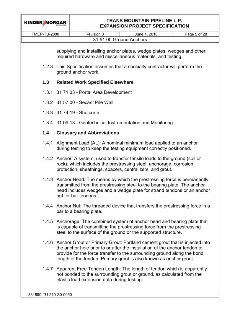
TRANS MOUNTAIN PIPELINE L.P.
EXPANSION PROJECT SPECIFICATION
TMEP-TU-2800 Revision 0 June 1, 2016 Page 5 of 28 31 51 00 Ground Anchors
334890-TU-210-S0-0050
supplying and installing anchor plates, wedge plates, wedges and other required hardware and miscellaneous materials, and testing.
1.2.3 This Specification assumes that a specialty contractor will perform the ground anchor work.
1.3 Related Work Specified Elsewhere
1.3.1 31 71 03 - Portal Area Development
1.3.2 31 57 00 - Secant Pile Wall
1.3.3 31 74 19 - Shotcrete
1.3.4 31 09 13 - Geotechnical Instrumentation and Monitoring
1.4 Glossary and Abbreviations
1.4.1 Alignment Load (AL): A nominal minimum load applied to an anchor during testing to keep the testing equipment correctly positioned.
1.4.2 Anchor: A system, used to transfer tensile loads to the ground (soil or rock), which includes the prestressing steel, anchorage, corrosion protection, sheathings, spacers, centralizers, and grout.
1.4.3 Anchor Head: The means by which the prestressing force is permanently transmitted from the prestressing steel to the bearing plate. The anchor head includes wedges and a wedge plate for strand tendons or an anchor nut for bar tendons.
1.4.4 Anchor Nut: The threaded device that transfers the prestressing force in a bar to a bearing plate.
1.4.5 Anchorage: The combined system of anchor head and bearing plate that is capable of transmitting the prestressing force from the prestressing steel to the surface of the ground or the supported structure.
1.4.6 Anchor Grout or Primary Grout: Portland cement grout that is injected into the anchor hole prior to or after the installation of the anchor tendon to provide for the force transfer to the surrounding ground along the bond length of the tendon. Primary grout is also known as anchor grout.
1.4.7 Apparent Free Tendon Length: The length of tendon which is apparently not bonded to the surrounding grout or ground, as calculated from the elastic load extension data during testing.

TRANS MOUNTAIN PIPELINE L.P.
EXPANSION PROJECT SPECIFICATION
TMEP-TU-2800 Revision 0 June 1, 2016 Page 6 of 28 31 51 00 Ground Anchors
334890-TU-210-S0-0050
1.4.8 Bearing Plate: A steel plate under the anchor head that distributes the prestressing force to the anchored structure.
1.4.9 Bond Length: The length of the tendon that is bonded to the primary grout and capable of transmitting the applied tensile load to the surrounding soil or rock.
1.4.10 Bondbreaker: A sleeve placed over the anchor tendon in the free stressing length to ensure unobstructed elongation of the tendon during stressing.
1.4.11 Centralizer: A device to support and position the tendon in the drill hole so that a minimum grout cover is provided.
1.4.12 Contract Geotechnical Reports: These include the Geotechnical Baseline Report (GBR) and the Site Investigation Data Reports (SIDRs).
1.4.13 Coupler: The means by which the prestressing force can be transmitted from one partial-length of a prestressing tendon to another (mainly for bars).
1.4.14 Creep Movement: The movement that occurs during the creep test of an anchor under a constant load.
1.4.15 Creep Test: A test to determine the movement of the ground anchor at a constant load.
1.4.16 Design Load (DL): Anticipated final maximum effective load in the anchor after allowance for time dependent losses or gains. The design load includes appropriate load factors to ensure that the overall structure has adequate capacity for its intended use.
1.4.17 Free Stressing (Unbonded) Length: The designed length of the tendon that is not bonded to the surrounding ground or grout during stressing.
1.4.18 FPU: Specified minimum tensile strength of the tendon as defined in the pertinent ASTM Specification.
1.4.19 Lift-Off: The load (lift-off load) in the tendon which can be checked at any specified time with the use of a hydraulic jack, by lifting the anchor head off the bearing plate.
1.4.20 Lock-Off Load: The prestressing force in an anchor immediately after transferring the load from the jack to the stressing anchorage.

TRANS MOUNTAIN PIPELINE L.P.
EXPANSION PROJECT SPECIFICATION
TMEP-TU-2800 Revision 0 June 1, 2016 Page 7 of 28 31 51 00 Ground Anchors
334890-TU-210-S0-0050
1.4.21 Performance Test: Incremental cyclic test loading of a prestressed anchor in which the total movement of the anchor is recorded at each increment.
1.4.22 Proof Test: Incremental loading of a prestressed anchor recording the total movement of the anchor at each increment.
1.4.23 Tendon: The complete anchor assembly (excluding grout) consisting of prestressing steel, corrosion protection, sheathings, and coating when required, as well as spacers and centralizers.
1.4.24 Test Load (TL): The maximum load to which the anchor is subjected during testing.
1.4.25 Waler Beam: Steel wide flange or HP section that is used to transmit all loads from the soil through the retaining wall to the steel tie bars and to align and brace the wall in its position.
1.5 Regulations, Codes, Specifications, Standards
1.5.1 All work shall be performed in accordance with all applicable federal, provincial, and municipal regulations, codes, and standards.
1.5.2 Where standards identify conflicting requirements, the more stringent requirement shall apply unless otherwise specified herein.
1.5.3 Reference: Ground Anchors and Anchored Systems, Publication No. FHWA-IF-99-015.
1.5.4 American Association of State Highway and Transportation Officials
1.5.4.1 AASHTO M183 (1998), Standard Specification for Structural Steel
1.5.4.2 AASHTO M222 (1996), Standard Specification for High-Strength Low-Alloy Structural Steel
1.5.5 American Society for Testing and Materials (ASTM)
1.5.5.1 ASTM A283/A283M-13, Standard Specification for Low and Intermediate Strength Carbon Steel Plates.
1.5.5.2 ASTM A416/A416M-16, Standard Specification for Steel Strand, Uncoated Seven-Wire for Prestressed Concrete.

TRANS MOUNTAIN PIPELINE L.P.
EXPANSION PROJECT SPECIFICATION
TMEP-TU-2800 Revision 0 June 1, 2016 Page 8 of 28 31 51 00 Ground Anchors
334890-TU-210-S0-0050
1.5.5.3 ASTM A981-11, Standard Test Method for Evaluating Bond Strength for 15.2 mm (0.6 in.) Diameter Prestressing Steel Strand, Grade 270, Uncoated, used in Prestressed Ground Anchors.
1.5.5.4 ASTM A536-84 (R2014), Standard Specification for Ductile Iron Castings
1.5.5.5 ASTM A615/A615M-15, Standard Specification for Deformed and Plain Billet-Steel Bars for Concrete Reinforcement
1.5.5.6 ASTM C109/C109M-16a, Standard Test Method for Compressive Strength of Hydraulic Cement Mortars.
1.5.5.7 ASTM C150/C150M-16, Standard Specification for Portland Cement.
1.5.5.8 ASTM C494/C494M-15a, Standard Specification for Chemical Admixtures for Concrete.
1.5.5.9 ASTM D1785-15, Standard Specification for Polyvinyl Chloride (PVC) Plastic Pipe, Schedules 40, 80, and 120.
1.5.6 Canadian Standards Association (CSA):
1.5.6.1 CSA W59-13, Welded Steel Construction (Metal Arc Welding).
1.5.6.2 CSA-G40.20 / 40.21-13, General Requirements for Rolled or Welded Structural Quality Steel / Structural Quality Steel.
1.6 Quality Control and Quality Assurance
1.6.1 Contractor’s Qualifications:
1.6.1.1 The Contractor performing the work described in this Specification shall have installed temporary or permanent ground anchors for a minimum of three (3) years.
1.6.1.2 The Contractor shall assign a Field Engineer to supervise the work with at least three (3) years of experience in the design and construction of permanent anchored structures. The Contractor may not use consultants or manufacturer's representatives in order to meet the requirements of this section. Drill operators and on-site supervisors shall have a

TRANS MOUNTAIN PIPELINE L.P.
EXPANSION PROJECT SPECIFICATION
TMEP-TU-2800 Revision 0 June 1, 2016 Page 9 of 28 31 51 00 Ground Anchors
334890-TU-210-S0-0050
minimum of one (1) year experience installing permanent ground anchors with the Contractor's organization.
1.6.1.3 The Contractor shall assign a Drilling Supervisor to supervise the work with at least three (3) years’ experience installing similar ground support systems. The contractor shall name and provide an experience record for the Contractor’s on-site Drilling Supervisor. The experience record shall include, at a minimum, a record of successful installation of a secant or tangent pile wall system, a record of successful installation of anchored shotcrete wall, and installing ground anchors on at least two projects in last five years.
1.6.1.4 The Contractor shall assign a Drill Operator to supervise the work with at least three (3) years’ experience installing similar ground support systems. The Contractor shall name and provide an experience record for the Contractor’s Drill Operator. The experience record shall include, at a minimum, two years of experience installing ground anchors, secant pile wall systems, or drilled shaft foundations with similar diameters and lengths, constructing anchored shotcrete wall, and in similar ground conditions using a technology similar to that proposed for this work. The experience record shall include a record of successful installation of a secant pile wall system and shotcrete anchor wall on at least two projects in the last five years.
1.6.2 Construction Quality Assurance
1.6.2.1 The Construction Quality Assurance (CQA) Inspector will monitor all aspects of anchored wall construction. The CQA Inspector will perform material conformance testing as required. The Contractor shall be aware of the activities required by the CQA Inspector and shall account for these activities in the construction schedule. The Contractor shall correct all deficiencies and nonconformities identified by the CQA Inspector at no additional cost to the Owner.
1.6.3 Ground Anchors Testing
1.6.3.1 General
A. Each ground anchor shall be tested. No load greater than ten (10) percent of the design load can be applied to the ground anchor prior to testing.

TRANS MOUNTAIN PIPELINE L.P.
EXPANSION PROJECT SPECIFICATION
TMEP-TU-2800 Revision 0 June 1, 2016 Page 10 of 28 31 51 00 Ground Anchors
334890-TU-210-S0-0050
B. No load greater than five (5) percent of the design load can be applied to the ground anchor prior to initial testing.
C. The maximum test load shall be 120 percent of the Design Load and shall not exceed 65 percent of the specified minimum ultimate tensile strength of the pre-stressing steel of the tendon and shall not exceed 90 percent of the specified ultimate tensile strength of the tendon at which there is a permanent strain of 0.1 percent. The test load shall be simultaneously applied to the entire tendon. Stressing of single elements of multi-element tendons shall not be permitted.
D. Do not perform testing unless tieback anchors have sufficiently cured, to develop the strength necessary to support the test load unless otherwise accepted by the Owner.
E. Test all tiebacks in the presence of the Owner. Tieback tests will provide a basis for acceptance.
1.6.3.2 Testing Equipment shall consist of:
A. Furnish dial gauge, dial gauge support, load cell, hydraulic jack and pump, stressing anchorage, pressure gauges.
B. A dial gauge or Vernier scale capable of measuring to 0.025 mm shall be used to measure the ground anchor movement. The movement-measuring device shall have a minimum travel equal to the theoretical elastic elongation of the total anchor length at the maximum test load and it shall have adequate travel so the ground anchor movement can be measured without resetting the device at an interim point.
C. A hydraulic jack and pump shall be used to apply the test load. The jack and a calibrated primary pressure gauge shall be used to measure the applied load. The jack and primary pressure gauge shall be calibrated by an independent firm as a unit. The calibration shall have been performed within 45 working days of the date when the calibration submittals are provided to the Owner. Testing cannot commence until the Owner has approved the calibration. The primary pressure gauge shall be graduated in 0.69 MPa increments or less. The ram travel shall be at least 152 mm and preferably not be less than theoretical elongation of the tendon at the maximum test

TRANS MOUNTAIN PIPELINE L.P.
EXPANSION PROJECT SPECIFICATION
TMEP-TU-2800 Revision 0 June 1, 2016 Page 11 of 28 31 51 00 Ground Anchors
334890-TU-210-S0-0050
load. If elongations greater than 152 mm are required, restroking can be allowed.
D. A calibrated reference pressure gauge shall also be kept at the site to periodically check the production (primary pressure) gauge. The reference gauge shall be calibrated with the test jack and primary pressure gauge. The reference pressure gauge shall be stored indoors and not subjected to rough treatment.
E. The stressing equipment shall be placed over the ground anchor tendon in such a manner that the jack, bearing plates, and stressing anchorage are axially aligned with the tendon and the tendon is cantered within the equipment.
1.6.3.3 Dial gauges shall be capable of measuring to 0.025 mm and aligned perpendicular to the end of the tendon, or other plane of measurement. Dial gauges with travels greater than 100 mm are not recommended.
1.6.3.4 Stressing Equipment
A. The stressing equipment, the sequence of stressing and the procedure to be used for each stressing operation shall be determined at the planning stage of the project. The equipment shall be used strictly in accordance with the manufacturer’s operating instructions.
B. Stressing equipment shall preferably be capable of stressing the whole tendon in one stroke to the specified Test Load and the equipment shall be capable of stressing the tendon to the maximum specified Test Load within 75 percent of the rated capacity. The pump shall be capable of applying each load increment in less than 60 seconds.
C. The equipment shall permit the tendon to be stressed in increments so that the load in the tendon can be raised or lowered in accordance with the test specifications, and allow the anchor to be lift-off tested to confirm the lock-off load.
D. Stressing equipment shall be recently calibrated within an accuracy of plus or minus two percent prior to use. The calibration certificate and graph shall be available on site at all times.

TRANS MOUNTAIN PIPELINE L.P.
EXPANSION PROJECT SPECIFICATION
TMEP-TU-2800 Revision 0 June 1, 2016 Page 12 of 28 31 51 00 Ground Anchors
334890-TU-210-S0-0050
1.6.3.5 Load Testing Setup
A. Dial gauges shall bear on the pulling head of the jack and their stems shall be coaxial with the tendon direction. The gauges shall be supported on an independent, fixed frame, such as a tripod, which will not move as a result of stressing or other construction activities during the operation.
B. Prior to setting the dial gauges, the Alignment Load (AL) shall be accurately placed on the tendon. The magnitude of AL depends on type and length of the tendon.
C. Regripping of strands, which would cause overlapping wedge bites, or wedge bites on the tendon below the anchor head, shall be avoided.
D. Stressing and testing of multiple element tendons with single element jacks is not permitted.
E. Stressing shall not begin before the grout has reached minimum of 70 percent of 28 day strength.
1.6.3.6 Performance Testing of Ground Anchors
A. Five (5) percent of the ground anchors or a minimum of three (3) ground anchors, whichever is greater, shall be performance tested in accordance with the procedures described below. The Owner shall select the ground anchors to be performance tested. The remaining ground anchors shall be tested in accordance with the proof test procedures (see Section 1.6.3.7).
B. The performance test shall be performed by incrementally loading and unloading the ground anchor to a maximum test load of 120 percent of the Design Load (DL) in accordance with the loading schedule indicated in Table 1-1.
TABLE 1-1 PERFORMANCE TEST LOAD SCHEDULE
Step Loading Test Load Increment
1 0.05 DL max (AL)
2 Cycle 1 0.25 DL, AL
3 Cycle 2 0.25 DL, 0.50 DL, AL

TRANS MOUNTAIN PIPELINE L.P.
EXPANSION PROJECT SPECIFICATION
TMEP-TU-2800 Revision 0 June 1, 2016 Page 13 of 28 31 51 00 Ground Anchors
334890-TU-210-S0-0050
4 Cycle 3 0.25 DL, 0.50 DL, 0.75 DL, AL
5 Cycle 4 0.25 DL, 0.50 DL, 0.75 DL, 1.00 DL, AL
6 Cycle 5 0.25 DL, 0.50 DL, 0.75 DL, 1.00 DL,1.20 DL
7 0.05 DL max (AL)
C. The load shall be raised from one increment to another immediately after recording the ground anchor movement.
D. The ground anchor movement shall be measured and recorded to the nearest 0.025 mm with respect to an independent fixed reference point at the alignment load and at each increment of load.
E. The load shall be monitored with the primary pressure gauge. The reference pressure gauge shall be placed in series with the primary pressure gauge during each performance test. If the load determined by the reference pressure gauge and the load determined by the primary pressure gauge differ by more than ten percent, the jack, primary gauge and reference pressure gauge shall be recalibrated.
F. At load increments other than the maximum test load, the load shall be held just long enough to obtain the movement reading.
G. The maximum test load in a performance test shall be held for ten minutes. A load cell shall be used to monitor small changes in load during constant load-hold periods.
H. The jack shall be adjusted as necessary in order to maintain a constant load. The load-hold period shall start as soon as the maximum test load is applied and the ground anchor movement, with respect to a fixed reference, shall be measured and recorded at one minute, two, three, four, five, six and ten minutes. If the ground anchor movement between one minute and ten minutes exceeds one mm, the maximum test load shall be held for an additional 50 minutes. If the load hold is extended, the ground anchor movement shall be recorded at 156 minutes, 20, 30, 40, 50 and 60 minutes.
1.6.3.7 Proof Testing of ground anchors
A. The proof test shall be performed by incrementally loading the ground anchors to a maximum test load of 120 percent of the

TRANS MOUNTAIN PIPELINE L.P.
EXPANSION PROJECT SPECIFICATION
TMEP-TU-2800 Revision 0 June 1, 2016 Page 14 of 28 31 51 00 Ground Anchors
334890-TU-210-S0-0050
Design Load (DL) in accordance with the loading schedule indicated in Table 1-2.
TABLE 1-2 PROOF TEST LOAD SCHEDULE
Test Load Increment
0.05 DL max (AL) 0.25 DL 0.50 DL
0.75 DL 1.00 DL
1.20 DL Reduce to lock-off load
AL (optional)
Adjust to lock-off load
B. The load shall be raised from one increment to the next immediately after recording the ground anchor movement.
C. The ground anchor movement shall be measured and recorded to the nearest 0.025 mm with respect to an independent fixed reference point at the alignment load and at each increment of load.
D. The load shall be monitored with the primary pressure gauge.
E. At load increments other than the maximum test load, the load shall be held just long enough to obtain the movement reading.
F. The maximum test load in proof test shall be held for 10 minutes. The jack shall be adjusted as necessary in order to maintain a constant load. The load-hold period shall start as soon as the maximum test load is applied and the ground anchor movement with respect to a fixed reference shall be measured and recorded at one minute, two, three, four, five, six and ten minutes. If the ground anchor movement between one minute and ten minutes exceeds one mm, the maximum test load shall be held for an additional 50 minutes. If the load hold is extended, the ground anchor movements shall be recorded at 15 minutes, 20, 30, 40, 50 and 60 minutes.
1.6.3.8 Anchor Lift-Off Test

TRANS MOUNTAIN PIPELINE L.P.
EXPANSION PROJECT SPECIFICATION
TMEP-TU-2800 Revision 0 June 1, 2016 Page 15 of 28 31 51 00 Ground Anchors
334890-TU-210-S0-0050
A. Perform lift-off tests on all anchors. The lift-off tests shall comprise an initial test following transfer of the stressing load to the tieback anchor assembly and prior to removal of the jack, and a second lift-off test if directed by the Owner.
B. Loading of the anchors shall be increased until elongation of the tieback anchor occurs. At the point elongation occurs, the load shall be held long enough for the load cell and jack pressure gauge to be read.
C. Tieback anchor protrusions shall not be cut off until the Owner has determined no further lift-off tests shall be performed.
1.6.3.9 Acceptance Criteria
A. A performance-tested or proof-tested ground anchor with a 10 minute load hold shall be acceptable if:
i. The ground anchor resists the maximum test load with less than one mm of movement between one minute and 10 minutes;
ii. Total elastic movement at the maximum test load exceeds 80 percent of the theoretical elastic elongation of the unbonded length.
B. A performance-tested or proof-tested ground anchor with a 60 minute load hold shall be acceptable if:
i. The ground anchor resists the maximum test load with a creep rate that does not exceed two mm in the last log cycle of time;
ii. Total elastic movement at the maximum test load exceeds 80 percent of the theoretical elastic elongation of the unbonded length.
C. The initial lift-off reading shall be within plus or minus five percent of the designed lock-off load. If this criterion is not met, the tendon load shall be adjusted accordingly and the initial lift-off reading repeated.
1.6.3.10 Procedures for anchors failing acceptance criteria

TRANS MOUNTAIN PIPELINE L.P.
EXPANSION PROJECT SPECIFICATION
TMEP-TU-2800 Revision 0 June 1, 2016 Page 16 of 28 31 51 00 Ground Anchors
334890-TU-210-S0-0050
A. Anchors that do not satisfy the minimum apparent free length criteria shall be either rejected and replaced at no additional cost to the Owner or locked off at no more than 50 percent of the maximum acceptable load attained. In this event, no further acceptance criteria are applied.
B. Regroutable anchors which satisfy the minimum apparent free length criteria but which fail the extended creep test at the test load may be postgrouted and subjected to an enhanced creep criterion. This enhanced criterion requires a creep movement of not more than one mm between one and 60 minutes at test load. Anchors which satisfy the enhanced creep criterion shall be locked off at the design lock-off load. Anchors which cannot be postgrouted or regroutable anchors that do not satisfy the enhanced creep criterion shall be either rejected or locked off at 50 percent of the maximum acceptable test load attained as directed by the Engineer. In this event, no further acceptance criteria are applied. The maximum acceptable test load with respect to creep shall correspond to that where acceptable creep movements are measured over the final log cycle of time.
C. If the anchor fails the Owner shall modify the design and/or the Contractor shall modify the construction procedures. These modifications may include, but are not limited to, installing additional anchors, modifying the installation methods, reducing the anchor design load by increasing the number of anchors, increasing the anchor length, or changing the anchor type. Any modification of design or construction procedures shall be at no charge to the Owner. A description of any proposed modifications must be submitted to the Owner in writing. Proposed modifications shall not be implemented until the Contractor receives written approval from the Owner.
1.6.3.11 Anchor Lock-Off
A. After testing has been completed, the load in the tendon shall be such that after seating losses (i.e. wedge seating), the specified lock-off load has been applied to the anchor tendon.
B. The magnitude of the lock-off load shall be specified by the Owner and shall not exceed 70 percent of ultimate strength of anchor (Fpu).

TRANS MOUNTAIN PIPELINE L.P.
EXPANSION PROJECT SPECIFICATION
TMEP-TU-2800 Revision 0 June 1, 2016 Page 17 of 28 31 51 00 Ground Anchors
334890-TU-210-S0-0050
C. The wedges shall be seated at a minimum load of 50 percent of Fpu. If the lock-off load is less than 50 percent of Fpu, shims shall be used under the wedge plate and the wedges seated at 50 percent of Fpu. The shims shall then be removed to reduce the load in the tendon to the desired lock-off load.
1.6.3.12 Quality Assurance
A. The Owner, at his/her discretion, may complete random quality assurance testing on all materials incorporated into the Work. The Contractor shall allow the Owner unhindered access to the materials and shall assist the Owner in carrying out any sampling or testing, including the provision for necessary traffic control, suitable access and storage.
B. Sampling and testing methods used by the Owner to determine the performance or lack of performance shall not relieve the Contractor from his responsibilities for compliance with the contract documents.
1.6.4 Each new major activity shall be preceded by a kickoff meeting with the Contractor, Owner, Engineer and Construction Manager.
1.7 Submittals
1.7.1 General:
1.7.1.1 All submissions shall be provided to the Owner for review in accordance with the Contractor Shop Drawings requirements provided in the General Conditions of the Construction Contract.
1.7.2 Qualifications: At least 60 days prior to commencing portal excavation activities, submit the following:
1.7.2.1 The Contractor shall submit a list containing at least five (5) projects completed within the last five (5) years. For each project, the Contractor shall include with this submittal, at a minimum: (1) name of client contact, address, and telephone number; (2) location of project; (3) contract value; and (4) scheduled completion date and actual completion date for the project.
1.7.2.2 Resumes of the Contractor’s staff. Only those individuals designated as meeting the qualification requirements shall be used for the project. The Contractor cannot substitute for any of

TRANS MOUNTAIN PIPELINE L.P.
EXPANSION PROJECT SPECIFICATION
TMEP-TU-2800 Revision 0 June 1, 2016 Page 18 of 28 31 51 00 Ground Anchors
334890-TU-210-S0-0050
these individuals without written approval of the Owner. The Owner shall approve or reject the Contractor's qualifications and staff within fifteen (15) working days after receipt of the submission. Work shall not be started on any anchored wall system nor materials ordered until the Contractor's qualifications have been approved by the Owner. The Owner may suspend the work if the Contractor substitutes unqualified personnel for approved personnel during construction. If work is suspended due to the substitution of unqualified personnel, the Contractor shall be fully liable for additional costs resulting from the suspension of work and no adjustment in contract time resulting from the suspension of work will be allowed.
1.7.2.3 The Contractor shall prepare and submit to the Owner for review and approval the ground anchor system or systems intended for use. The submission shall include the following:
A. A drawing of the ground anchor system including details for the following:
i. Spacers and their location;
ii. Centralizers and their location; and
iii. Anchorage and trumpet.
B. Certificates of Compliance for the following materials, if used. The certificate shall state that the material or assemblies to be provided will fully comply with the requirements of the contract.
i. Prestressing steel, strand or bar;
ii. Portland cement;
iii. Prestressing hardware; and
iv. Bearing plates.
1.7.2.4 Mill test reports for the prestressing steel and the bearing plate steel. The Owner may require the Contractor to provide samples of any ground anchor material intended for use on the project.
1.7.2.5 Identification number and calibration test results for each test jack, pressure gauge, and load cell. Calibrate the test jack and pressure gauge as one unit. Submit results from calibration

TRANS MOUNTAIN PIPELINE L.P.
EXPANSION PROJECT SPECIFICATION
TMEP-TU-2800 Revision 0 June 1, 2016 Page 19 of 28 31 51 00 Ground Anchors
334890-TU-210-S0-0050
tests conducted by an independent testing laboratory within the previous 90 days.
1.7.2.6 Manufacturer Certificates of Compliance for the tendon ultimate strength, welded wire fabric steel, rebar steel, bearing plates.
1.7.2.7 Proposed retaining wall construction sequence. Include the proposed method of excavating to ensure wall and slope stability.
1.7.2.8 Drilling and grouting methods and equipment. Include drill hole diameter to achieve the specified pullout resistance values and any variation of drill hole diameter or specific pullout resistance along the wall alignment.
1.7.2.9 Grout mix design, placement procedures, and equipment. Include test results conducted according to ASTM C109/C109M and supplied by a qualified testing lab verifying the specified minimum 3-day and 28-day grout compressive strengths. Previous test results for the same grout mix completed within one year of grouting are acceptable.
1.7.2.10 Temporary shotcrete materials and methods, including mix and anticipated strength meeting the minimum compressive strengths in accordance with Section 31 74 19 Shotcrete.
1.7.2.11 Ground anchor testing methods and equipment setup.
1.7.3 The Contractor shall submit to the Owner within twenty (20) calendar days after completion of the ground anchor work a report containing:
1.7.3.1 Prestressing steel manufacturer's mill test reports for the tendons incorporated in the installation;
1.7.3.2 Grouting records indicating the cement type, quantity injected and the grout pressures;
1.7.3.3 Ground anchor test results and graphs; and
1.7.3.4 As-built drawings showing the location and orientation of each ground anchor, anchor capacity, tendon type, total anchor length, bond length, unbonded length, and tendon bond length as installed and locations of all instruments installed by the Owner.

TRANS MOUNTAIN PIPELINE L.P.
EXPANSION PROJECT SPECIFICATION
TMEP-TU-2800 Revision 0 June 1, 2016 Page 20 of 28 31 51 00 Ground Anchors
334890-TU-210-S0-0050
1.7.4 All materials and equipment used in the Work shall be the included as part of the above submittals or the subject of a submittal to the Owner.
1.7.5 Quality Assurance
1.7.5.1 The Owner, at his/her discretion, may complete random quality assurance testing on all materials incorporated into the Work. The Contractor shall allow the Owner unhindered access to the materials and shall assist the Owner in carrying out any sampling or testing, including the provision for necessary traffic control, suitable access and storage.
1.7.5.2 Sampling and testing methods used by the Owner to determine the performance or lack of performance shall not relieve the Contractor from his responsibilities for compliance with the contract documents.
1.8 Tolerances
1.8.1 The drill hole centres shall be located within 75 mm of the set-out point for each and every ground anchor at the location as shown on the Drawings.
1.8.2 The drill hole shall be located so the longitudinal axis of the drill hole and the longitudinal axis of the tendon are parallel. In particular, the ground anchor hole shall not be drilled in a location that requires the tendon to be bent in order to enable the bearing plate to be connected to the supported structure.
1.8.3 At the point of entry the ground anchor shall be installed within plus/minus two (2) degrees of the inclination from horizontal shown on the Drawings.
1.8.4 At the point of entry the horizontal angle made by the ground anchor and the structure shall be within plus/minus two (2) degrees of a line drawn perpendicular to the plane of the structure unless otherwise shown on the Drawings
1.8.5 Placement of the reinforcement shall be maximum plus or minus 15 mm.
1.8.6 The ground anchors shall not extend beyond the right-of-way or easement limits shown on the Drawings.
2.0 PRODUCTS
2.1 Equipment

TRANS MOUNTAIN PIPELINE L.P.
EXPANSION PROJECT SPECIFICATION
TMEP-TU-2800 Revision 0 June 1, 2016 Page 21 of 28 31 51 00 Ground Anchors
334890-TU-210-S0-0050
2.1.1 Ground anchor drilling and installation equipment shall be capable of installing tie-backs in the anticipated conditions described in the Contract Geotechnical Reports, including the capability for casing the drill hole to cope with borehole stability.
2.1.2 Stressing Equipment
2.1.2.1 The testing equipment shall consist of:
A. A dial gauge or Vernier scale capable of measuring to the nearest 0.025 mm shall be used to measure the ground anchor movement. The movement-measuring device shall have a minimum travel equal to the theoretical elastic elongation of the total anchor length at the maximum test load and it shall have adequate travel so the ground anchor movement can be measured without resetting the device at an interim point.
B. A hydraulic jack and pump shall be used to apply the test load. The jack and a calibrated primary pressure gauge shall be used to measure the applied load. The jack and primary pressure gauge shall be calibrated by an independent firm as a unit. The calibration shall have been performed within forty-five (45) working days of the date when the calibration submittals are provided to the Owner. Testing cannot commence until the Owner has approved the calibration. The primary pressure gauge shall be graduated in 0.69 MPa increments or less. The ram travel shall be at least 152 mm and preferably not be less than the theoretical elongation of the tendon at the maximum test load. If elongations greater than 152 mm are required, restroking can be allowed.
C. A calibrated reference pressure gauge shall also be kept at the site to periodically check the production (i.e., primary pressure) gauge. The reference gauge shall be calibrated with the test jack and primary pressure gauge. The reference pressure gauge shall be stored indoors and not subjected to rough treatment.
D. The stressing equipment shall be placed over the ground anchor tendon in such a manner that the jack, bearing plates, load cells and stressing anchorage are axially aligned with the tendon and the tendon is centered within the equipment.

TRANS MOUNTAIN PIPELINE L.P.
EXPANSION PROJECT SPECIFICATION
TMEP-TU-2800 Revision 0 June 1, 2016 Page 22 of 28 31 51 00 Ground Anchors
334890-TU-210-S0-0050
2.1.2.2 The stressing equipment, the sequence of stressing and the procedure to be used for each stressing operation shall be determined at the planning stage of the project. The equipment shall be used strictly in accordance with the manufacturer's operating instructions.
2.1.2.3 Stressing equipment shall preferably be capable of stressing the whole tendon in one stroke to the specified Test Load and the equipment shall be capable of stressing the tendon to the maximum specified Test Load within 75% of the rated capacity. The pump shall be capable of applying each load increment in less than 60 seconds.
2.1.2.4 The equipment shall permit the tendon to be stressed in increments so that the load in the tendon can be raised or lowered in accordance with the test specifications, and allow the anchor to be lift-off tested to confirm the lock-off load.
2.1.2.5 Stressing equipment shall be recently calibrated within an accuracy of plus or minus two (2) percent prior to use. The calibration certificate and graph shall be available on site at all times.
2.2 Materials
2.2.1 General
2.2.1.1 The Contractor shall protect the materials from the elements by appropriate means. Prestressing steel strands and bars shall be stored and handled in accordance with the manufacturer’s recommendations and in such a manner that no damage to the component parts occurs. All steel components shall be protected from the elements at all times. Cement and additives for grout shall be stored under cover and protected against moisture.
2.2.2 Ground Anchor Tendons
2.2.2.1 Tendons used for secant pile wall as shown on the Drawings shall consist of 15.2-mm diameter prestressing steel strands Grade 270, and complying with ASTM A416.
2.2.2.2 Tendons used for anchored shotcrete wall as shown on the Drawings shall consist of a self-drilling hollow core prestressing steel bars in compliance with ASTM A615 standards.

TRANS MOUNTAIN PIPELINE L.P.
EXPANSION PROJECT SPECIFICATION
TMEP-TU-2800 Revision 0 June 1, 2016 Page 23 of 28 31 51 00 Ground Anchors
334890-TU-210-S0-0050
2.2.3 Anchorage Devices
2.2.3.1 Stressing anchorages shall be a combination of either a steel bearing plate with wedge plate and wedges, or a steel bearing plate with a threaded anchor nut. The steel bearing and wedge plate may also be combined into a single element. Anchorage devices shall be capable of developing 95 percent of the specified minimum ultimate tensile strength of the prestressing steel tendon.
2.2.3.2 An anchor head shall be detensionable that permits the tendon
to be completely detensioned in a controlled way at any time during the life of the structure.
2.2.3.3 The bearing plate shall be fabricated from steel conforming to AASHTO M183 or M222 specifications, or equivalent, or may be a ductile iron casting conforming to ASTM A536.
2.2.3.4 Anchorage covers shall be fabricated from steel or plastic with a minimum thickness of 2.3 mm. The joint between the cover and the bearing plate shall be watertight.
2.2.3.5 Prestressing steel bar couplers shall be capable of developing 100 percent of the minimum specified ultimate tensile strength of the prestressing steel bar. Steel strands used for a soil or rock anchor shall be continuous with no splices, unless approved by the Owner.
2.2.3.6 Centralizers shall be provided at maximum intervals of 3 m with the deepest centralizer located 0.3 m from the end of the anchor and the upper centralizer for the bond zone located no more than 1.5 m from the top of the tendon bond length. Spacers shall be used to separate the steel strands of strand tendons. Spacers shall be provided at maximum intervals of 3 m and may be combined with centralizers.
2.2.3.7 Spacers shall be used to separate elements of a multi-element tendon and shall permit grout to freely flow around the tendon and up the drill hole. Spacers shall be fabricated from plastic, steel or material which is nondetrimental to the prestressing steel. Wood shall not be used. A combination centralizer-spacer may be used.
2.2.4 Bondbreaker

TRANS MOUNTAIN PIPELINE L.P.
EXPANSION PROJECT SPECIFICATION
TMEP-TU-2800 Revision 0 June 1, 2016 Page 24 of 28 31 51 00 Ground Anchors
334890-TU-210-S0-0050
2.2.4.1 The bondbreaker shall be fabricated from a smooth plastic tube or pipe having the following properties: (1) resistant to chemical attack from aggressive environments, grout, or corrosion inhibiting compound; (2) resistant to aging by ultra-violet light; (3) fabricated from material nondetrimental to the tendon; (4) capable of withstanding abrasion, impact, and bending during handling and installation; (5) enable the tendon to elongate during testing and stressing; and (6) allow the tendon to remain unbonded after lock-off.
2.2.5 Grout
2.2.5.1 Grout shall be a non-shrink cementitious material. Grout shall be made of Portland cement conforming to ASTM C150 Type I, II, III, V or Type I/II and shall be the produce of one manufacturer. If the brand or type of cement is changed during the project, additional grout mix tests shall be conducted to ensure consistency of quality and performance in situ.
2.2.5.2 The grout shall be a pumpable neat mixture of cement and water and shall be stable (bleed less than 2 percent), fluid.
2.2.5.3 The minimum compressive strength for grout should be a minimum 10 MPa at 3 days and a minimum 25 MPa at 28 days, meeting the requirements of ASTM C109.
2.2.6 Grout Admixtures
2.2.6.1 Admixtures which control bleed, improve flowability, reduce water content, and retard set may be used in the grout subject to the approval of the Owner. Admixtures, if used, shall be compatible with the prestressing steels and mixed in accordance with the manufacturer's recommendations. Expansive admixtures may only be added to the grout used for filling sealed encapsulations, trumpets, and anchorage covers. Accelerators shall not be permitted.
2.2.6.2 Accelerators shall not be permitted.
2.2.7 Grouting tubes
2.2.7.1 Primary grouting tubes shall be minimum 12 mm diameter Schedule 40 PVC tubing conforming to ASTM D1785.

TRANS MOUNTAIN PIPELINE L.P.
EXPANSION PROJECT SPECIFICATION
TMEP-TU-2800 Revision 0 June 1, 2016 Page 25 of 28 31 51 00 Ground Anchors
334890-TU-210-S0-0050
2.2.7.2 Re-grouting or secondary grouting tubes shall be minimum 20 mm diameter Schedule 40 PVC sleeve-port pipe tubing conforming to ASTM D1785 with valves at 1.5 meters center-to center spacing within the tieback anchor bond length.
3.0 EXECUTION
3.1 Tendon Storage and Handling
3.1.1 Tendons shall be handled and stored in such a manner as to avoid damage or corrosion. Prestressing steel shall be protected from dirt, rust, or deleterious substances. A light coating of rust on the steel is acceptable. If heavy corrosion or pitting is noted, the Owner shall reject the affected tendons.
3.2 Anchor Fabrication
3.2.1 Anchors shall be either shop or field fabricated from materials conforming to Section 2.2 of the Specification.
3.2.2 Prestressing steel shall be cut with an abrasive saw or, with the approval of the prestressing steel supplier, an oxyacetylene torch.
3.2.3 All of the tendon bond length, especially for strand, must be free of dirt, manufacturers' lubricants, corrosion-inhibitive coatings, or other deleterious substances that may significantly affect the grout-to-tendon bond or the service life of the tendon.
3.3 Drilling
3.3.1 Drilling methods shall be left to the discretion of the Contractor, whenever possible. The Contractor shall be responsible for using a drilling method to establish a stable hole of adequate dimensions, within the tolerances specified. Drilling methods may involve, amongst others, rotary, percussion, rotary/percussive or auger drilling; or percussive or vibratory driven casing.
3.3.2 Drilling procedures shall be subject to review and acceptance by the Owner for compliance with and suitability for use in the ground conditions and associated construction requirements as characterized and presented in the Contract Geotechnical Reports.
3.3.3 Holes for anchors shall be drilled at the locations and to the length, inclination and diameter shown on the Drawings and shall be in accordance with tolerances described in Section 1.8.

TRANS MOUNTAIN PIPELINE L.P.
EXPANSION PROJECT SPECIFICATION
TMEP-TU-2800 Revision 0 June 1, 2016 Page 26 of 28 31 51 00 Ground Anchors
334890-TU-210-S0-0050
3.3.4 The minimum drill hole diameter shall be 75mm for installation of anchors consisting of the a self-drilling hollow core prestressing steel bars, and 150 mm for installation of anchors consisting of the 15.2-mm diameter prestressing steel strands. Internal casing and associated drill hole diameters shall be selected to successfully install fully-assembled tieback anchors inside the temporary casing to the bottom of the drilled hole for the full length of the ground anchor.
3.3.5 After drilling, each drill hole shall be thoroughly cleaned of all drill cuttings, sludge and debris by flushing with clean water. Temporary casing is necessary through fill, soil and shale bedrock to maintain a clean open hole for the full length of the tieback anchor.
3.3.6 Drilled holes that are found to be collapsed or otherwise unstable such that tieback anchors cannot be successfully installed shall be stabilized by completely backfilling with cement grout by tremie grout placement. After curing a minimum of 24 hours, the grouted hole shall be re-drilled to the full design length.
3.3.7 Anchor assembly placement
3.3.8 Tendons shall be placed in accordance with the Drawings and details and the recommendations of the tendon manufacturer or specialist anchor contractor. The tendon shall be inserted into the drill hole to the desired depth. When the tendon cannot be completely inserted, the Contractor shall remove the tendon from the drill hole and clean or re-drill the hole to permit insertion. Partially inserted tendons shall not be driven or forced into the hole.
3.3.9 Each anchor tendon shall be inspected by field personnel during installation into the drill hole or casing. Loose spacers or centralizers shall be reconnected to prevent shifting during insertion.
3.4 Grouting
3.4.1 The Contractor shall use a neat cement grout or a sand-cement grout. The cement shall not contain lumps or other indications of hydration. Admixtures, if used, shall be mixed in accordance with the manufacturer's recommendations.
3.4.2 The grouting equipment shall produce a grout free of lumps and undispersed cement. A positive displacement grout pump shall be used. The pump shall be equipped with a pressure gauge to monitor grout pressures. The pressure gauge shall be capable of measuring pressures of at least 1 MPa or twice the actual grout pressures used by the

TRANS MOUNTAIN PIPELINE L.P.
EXPANSION PROJECT SPECIFICATION
TMEP-TU-2800 Revision 0 June 1, 2016 Page 27 of 28 31 51 00 Ground Anchors
334890-TU-210-S0-0050
Contractor, whichever is greater. The grouting equipment shall be sized to enable the grout to be pumped in one continuous operation. The mixer should be capable of continuously agitating the grout.
3.4.3 The grout shall be injected from the lowest point of the drill hole. The grout may be pumped through grout tubes, casing, hollow-stem-augers, or drill rods. The grout can be placed before or after insertion of the tendon. The quantity of the grout and the grout pressures shall be recorded. The grout pressures and grout takes shall be controlled to prevent excessive heave or fracturing.
3.4.4 After the tendon is installed, the drill hole may be filled in one continuous grouting operation except that pressure grouting shall not be used in the free length zone. The grout at the top of the drill hole shall not contact the back of the structure or the bottom of the trumpet.
3.4.5 If grout protected tendons are used for ground anchors anchored in rock, then pressure grouting techniques shall be utilized. Pressure grouting requires that the drill hole be sealed and that the grout be injected until a minimum 0.35 MPa grout pressure (measured at the top of the drill hole) can be maintained on the grout for at least five (5) minutes.
3.4.6 The grout tube may remain in the hole on completion of grouting if the tube is filled with grout.
3.4.7 The ground anchor grout shall remain undisturbed after grouting for a minimum of three days or until the grout has cured. Testing and stressing of the anchors shall not be performed until strength tests on the grout indicate sufficient curing has occurred.
3.4.8 After grouting, the tendon shall not be loaded for a minimum of three (3) days.
3.4.9 During freezing weather conditions, grout shall not be allowed to freeze or partially freeze until fully cured.
3.5 Anchorage Installation
3.5.1 The anchor bearing plate and the anchor head or nut shall be installed perpendicular to the tendon, within plus/minus three (3) degrees and centered on the bearing plate, without bending or kinking of the prestressing steel elements. Wedge holes and wedges shall be free of rust, grout, and dirt.

TRANS MOUNTAIN PIPELINE L.P.
EXPANSION PROJECT SPECIFICATION
TMEP-TU-2800 Revision 0 June 1, 2016 Page 28 of 28 31 51 00 Ground Anchors
334890-TU-210-S0-0050
3.5.2 The stressing tail shall be cleaned and protected from damage until final testing and lock-off. After the anchor has been accepted by the Owner, the stress tail shall be cut to its final length according to the tendon manufacturer's recommendations.
3.6 Anchor Testing
3.6.1 Complete ground anchor tests. For ground anchor testing, acceptance criteria, anchor lift-off test, and procedures for anchors failing the acceptance criteria, see Section 1.6.3
3.7 Ground Anchors Decommissioning and Abandonment
3.7.1 Refer to 31 23 23 Site Restoration.
3.8 Finishing
3.8.1 Remove all bentonite-contaminated concrete from areas where other construction is to join the secant pile wall construction. Clean the exposed wall face to remove bentonite caking and film materials and expose a clean concrete surface.
(END OF SECTION)

334890-TU-210-S0-0051
TRANS MOUNTAIN PIPELINE L.P. EXPANSION PROJECT SPECIFICATION
03 15 00 PCTL CONCRETE ACCESSORIES TMEP-TU-2900, Revision A, July 4, 2016
REVISION INDEX
Rev No.
Prepared by/ Date
Reviewed by/ Date
Approved by/ Date
Client Approval Pages Revised
Remarks
A Reza Shobayry
2016-07-04 Brian Garrod 2016-07-04
Adam Neale 2016-07-04
Issued for 90% Design

TRANS MOUNTAIN PIPELINE L.P.
EXPANSION PROJECT SPECIFICATION
TMEP-TU-2900 Revision A July 4, 2016 Page 1 of 13 03 15 00 PCTL Concrete Accessories
334890-TU-210-S0-0051
TABLE OF CONTENTS
1.0 GENERAL ............................................................................................................ 2 1.1 Introduction ................................................................................................ 2 1.2 Scope of Work ........................................................................................... 4 1.3 Related Work Specified Elsewhere ............................................................ 4 1.4 Glossary and Abbreviations ....................................................................... 4 1.5 Regulations, Codes, Specifications, Standards ......................................... 5 1.6 Submittals .................................................................................................. 6
2.0 PRODUCTS ......................................................................................................... 7 2.1 Gaskets ...................................................................................................... 7 2.2 Lifting/Grout Inserts ................................................................................. 10 2.3 Bolts and Bolt Anchorages ....................................................................... 11 2.4 Dowels and Dowel Inserts ....................................................................... 11 2.5 Packers .................................................................................................... 11 2.6 Foam strips .............................................................................................. 12 2.7 Guide Rods .............................................................................................. 12 2.8 Dunnage .................................................................................................. 13 2.9 Adhesives ................................................................................................ 13
3.0 EXECUTION ....................................................................................................... 13
TRANS MOUNTAIN PIPELINE L.P.
EXPANSION PROJECT SPECIFICATION
TMEP-TU-2900 Revision A July 4, 2016 Page 2 of 13 03 15 00 PCTL Concrete Accessories
334890-TU-210-S0-0051
1.0 GENERAL
1.1 Introduction
1.1.1 This Specification was prepared in collaboration with McNally Construction Inc. (the Contractor) as part of the Early Contractor Involvement (ECI) Pre-Construction Services (Phase 1) as described in the Memorandum of Understanding for Early Contractor Involvement, Contract Number TMEP-PC-001.
1.1.2 This Specification is customized to the Contractor’s construction plans and preferences, as described in the Construction Execution Plans, produced as part of the ECI Phase 1.
1.1.3 This Specifications forms part of the Contract Documents and is to be read, interpreted and coordinated with all other parts, including the following:
1.1.3.1 Bidding requirements, bid forms, pricing and baseline schedule milestones by Trans Mountain
1.1.3.2 General Conditions by Trans Mountain
1.1.3.3 Special Conditions and/or Division 1 Technical Specifications by Trans Mountain
1.1.3.4 Environmental and Permit Conditions by Trans Mountain
1.1.3.5 Construction Execution Work Plans prepared by McNally and reviewed by HMM and Trans Mountain
1.1.3.6 Contract Drawings
1.1.3.7 Contract Geotechnical Reports
1.1.3.8 Various other Trans Mountain and TMEP standards including TMEP Pipeline Construction Damage Prevention Plan, and the following Technical Specifications including:
A. 1000 Site Preparation
B. 1100 Diversion and Care of Water
C. 1210 Portal Area Development

TRANS MOUNTAIN PIPELINE L.P.
EXPANSION PROJECT SPECIFICATION
TMEP-TU-2900 Revision A July 4, 2016 Page 3 of 13 03 15 00 PCTL Concrete Accessories
334890-TU-210-S0-0051
D. 1310 Tunnelling by TBM
E. 1500 Precast Concrete Tunnel Lining (PCTL)
F. 1600 Tunnel Annular Grouting
G. 1610 Pre-Excavation Grouting
H. 1620 Shotcrete
I. 2000 Pipeline Installation in Tunnel
J. 2200 Probe Hole Drilling ahead of TBM
K. 2300 Geotechnical Instrumentation and Monitoring
L. 2400 Cast-In-Place Concrete
M. 2500 Tunnel Backfill
N. 2510 Site Restoration
O. 2600 Secant Pile Wall
P. 2700 Concrete Reinforcement
Q. 2800 Ground Anchors
R. 2900 PCTL Concrete Accessories
S. 3000 Concrete Reinforcement for PCTL
T. 3100 Concrete for PCTL
U. TMEP-CIV102 Engineering Survey – B.C.
V. TMEP-CIV301 Blasting
W. TMEP-CIV400 Clearing Specification for British Columbia
X. TMEP-GC3105 FBE Plant Applied Coating
Y. TMEP-GC3300 FBE Field Applied Coating
Z. TMEP-GC3302 Two-Part Liquid Field Applied Coating

TRANS MOUNTAIN PIPELINE L.P.
EXPANSION PROJECT SPECIFICATION
TMEP-TU-2900 Revision A July 4, 2016 Page 4 of 13 03 15 00 PCTL Concrete Accessories
334890-TU-210-S0-0051
AA. TMEP-GC3306 Two-Part Liquid Shop Applied Coating
BB. TMEP-MP1200 Steel Fittings
CC. TMEP-MP2212 Steel Flanges
DD. TMEP-MP2217 Bends
EE. TMEP-MP2300 Pipeline Valves
FF. TMEP-MP3120 Pipeline Construction
GG. TMEP-MP3903 Non Destructive Testing
HH. TMEP-MP3904 SMAW and Mechanized Welding
II. TMEP-MP4121 Hydrostatic Testing
JJ. TMEP-MP4500 Pipeline Cleaning
KK. TMEP-MP4501 Pipeline Drying
LL. TMEP-MP4502 Post Construction Caliper Pigging
MM. TMEP-42EF0009 Piling Installation
NN. TMEP-42EF0016 Structural Steel Fabrication and Erection
OO. TMEP-45ES0012 Pipeline Above Ground Painting
1.2 Scope of Work
1.2.1 The Work specified herein includes the furnishing of embedments in and attachments to the precast concrete segmental lining (PCTL).
1.3 Related Work Specified Elsewhere
1.3.1 31 74 16 Precast Concrete Tunnel Lining (PCTL)
1.3.2 03 20 00.1 Concrete Reinforcement for PCTL
1.3.3 03 30 00.1 Concrete for PCTL
1.4 Glossary and Abbreviations
Not used

TRANS MOUNTAIN PIPELINE L.P.
EXPANSION PROJECT SPECIFICATION
TMEP-TU-2900 Revision A July 4, 2016 Page 5 of 13 03 15 00 PCTL Concrete Accessories
334890-TU-210-S0-0051
1.5 Regulations, Codes, Specifications, Standards
1.5.1 The Work shall be carried out in strict accordance with, but not limited to, the requirements of the Acts, Standards and Regulations listed herein.
1.5.2 American Society for Testing and Materials (ASTM):
1.5.2.1 ASTM A153/A153M-16, Standard Specification for Zinc Coating (Hot-Dip) on Iron and Steel Hardware.
1.5.2.2 ASTM A449-14, Standard Specification for Hex Cap Screws, Bolts and Studs, Steel, Heat Treated, 120/105/90 ksi Minimum Tensile Strength General Use.
1.5.2.3 ASTM A490-14a, Standard Specification for Structural Bolts, Alloy Steel, Heat Treated, 150 ksi Minimum Tensile Strength.
1.5.2.4 ASTM C1166-06 (R2011), Standard Test Method for Flame Propagation of Dense and Cellular Elastomeric Gaskets and Accessories.
1.5.2.5 ASTM D395-16, Standard Test Methods for Rubber Property - Compression Set.
1.5.2.6 ASTM D412-15a, Standard Test Methods for Vulcanized Rubber and Thermoplastic Elastomers - Tension.
1.5.2.7 ASTM D471-85 (R2007), Standard Test Methods for Rubber Property - Effect of Liquids.
1.5.2.8 ASTM D573-04 (R2015), Standard Test Methods for Rubber - Deterioration in an Air Oven.
1.5.2.9 ASTM D1149-16, Standard Test Methods for Rubber Deterioration - Cracking in an Ozone Controlled Environment.
1.5.2.10 ASTM D2240-15, Standard Test Method for Rubber Property - Durometer Hardness.
1.5.2.11 ASTM F2329/F2329M-15, Standard Specification for Zinc Coating, Hot-Dip, Requirements for Application to Carbon and Alloy Steel Bolts, Screws, Washers, Nuts, and Special Threaded Fasteners.
1.5.3 Canadian Standards Association (CSA):

TRANS MOUNTAIN PIPELINE L.P.
EXPANSION PROJECT SPECIFICATION
TMEP-TU-2900 Revision A July 4, 2016 Page 6 of 13 03 15 00 PCTL Concrete Accessories
334890-TU-210-S0-0051
1.5.3.1 CSA S16.1-14, Limit States Design of Steel Structures
1.6 Submittals
1.6.1 General
1.6.1.1 All submissions shall be provided to the Owner for review in accordance with the Contractor Shop Drawings requirements provided in the General and Special Conditions of the Construction Contract.
1.6.2 At least 30 days prior to placement of concrete, submit the following documentation for review by the Owner:
1.6.3 Submit shop drawings or manufacturer’s literature as appropriate:
A. Gaskets and gasket groove details
B. Partially-penetrated grout insert
C. Vacuum lifting shear pockets
1.6.3.2 Submit Samples of:
A. Gaskets with mitred corners
B. Threaded grout/lifting sockets
C. Bolts with hardware and bolt inserts
D. Dowels and dowel inserts
E. Packer material
F. Foam strips
G. Guide rods
1.6.3.3 Manufacturer’s certification, including certified tests performed by a qualified independent laboratory, satisfactorily demonstrating the capacities of individual assemblies as follows:
A. Minimum 55 kN pullout capacity on the circumferential dowel assemblies

TRANS MOUNTAIN PIPELINE L.P.
EXPANSION PROJECT SPECIFICATION
TMEP-TU-2900 Revision A July 4, 2016 Page 7 of 13 03 15 00 PCTL Concrete Accessories
334890-TU-210-S0-0051
B. Minimum 30 kN shear capacity on the circumferential dowel assemblies
C. Minimum 140 kN pullout capacity on the radial joint bolt assemblies in a restrained test
1.6.3.4 Test reports and other submittals as described in subsequent sections.
1.6.4 All materials and equipment used in the Work shall be the included as part of the above submittals or the subject of a submittal to the Owner.
2.0 PRODUCTS
2.1 Gaskets
2.1.1 All segments shall be supplied with a waterproofing gasket on all faces. Gasket shall be similar to Datwyler M 385 98 gasket or equivalent Trelleborg or other manufacturer as approved by the Owner.
2.1.2 The grooves shown on the Drawings are indicative only and the Contractor can propose revised dimensions for review by the Owner.
2.1.3 The width of gasket base shall not exceed 26 mm.
2.1.4 The gaskets shall be designed to resist a minimum sustained hydrostatic pressure of 7 bars above atmospheric pressure at a total gap of 6 mm between bearing surfaces so that gasket deflection does not exceed the deflection required to obtain the same gap in the tunnel lining. This is the working pressure.
2.1.5 Maximum gasket compression force at full compression and full contact between bearing faces shall be less than 65 kN per meter of gasket with a 2 mm compressed packer in the gap between segment faces.
2.1.6 The gaskets must be designed to be held fully compressed by the bolts and dowels in the linings. The load required in the bolts or dowels to ensure that the segment faces can be brought into contact shall be stated in the submittal. The Contractor shall confirm that the bolts and dowels proposed will provide the full compression force required.
2.1.7 The gaskets shall be shaped to render them inherently resistant to mechanical damage during transport, handling and erection.

TRANS MOUNTAIN PIPELINE L.P.
EXPANSION PROJECT SPECIFICATION
TMEP-TU-2900 Revision A July 4, 2016 Page 8 of 13 03 15 00 PCTL Concrete Accessories
334890-TU-210-S0-0051
2.1.8 Finished gaskets shall be free from surface imperfections, porosity, voids, inclusions or flow marks, and other defects which would impair satisfactory performance. Joints in the gaskets shall be made with such accuracy as to not impair satisfactory performance of the gaskets.
2.1.9 The bonding agent used to attach the gasket to the concrete segments shall be compatible with both the gasket and the concrete, and shall provide sufficient bond to hold the gasket secure during transportation, storage and erection. The bonding agent shall be approved in writing by the gasket manufacturer.
2.1.10 The gasket manufacturer shall specify the type of packaging to be used for the gaskets and the conditions under which they are to be stored. The gaskets shall be stored in accordance with the manufacturer's recommendation.
2.1.11 The gasket manufacturer shall provide a detailed proposal for his method of quality control to ensure and demonstrate consistency of material and dimensions of the gaskets.
2.1.12 Before manufacturing gaskets in quantity, the Contractor shall make trial units and fit them to actual segments so that the correct amount of stretch can be ascertained to ensure a secure, snug fit to the segments.
2.1.13 Individual gaskets shall be custom fitted to match the dimensions of individual segments within the ring.
2.1.14 All gasket corners shall be mitred to match angles of segment corners.
2.1.15 Gasket Material
2.1.15.1 Gasket Material shall conform to the following minimum requirements:
A. Tensile Strength - ASTM D412, greater than 10 MPa
B. Ultimate Elongations - ASTM D412, greater than 300%
C. Hardness - ASTM D2240, Type A durometer, 65 ± 5
D. Compression Set - ASTM D395, Method B
i. Short Term Test - less than 25% compression set after 25% vertical compression for twenty-two (22) hours at 70°C.

TRANS MOUNTAIN PIPELINE L.P.
EXPANSION PROJECT SPECIFICATION
TMEP-TU-2900 Revision A July 4, 2016 Page 9 of 13 03 15 00 PCTL Concrete Accessories
334890-TU-210-S0-0051
ii. Long Term Test - less than 15% compression set after 25% vertical compression for seventy-two (72) hours at 20°C.
E. Aging - ASTM D573, seventy (70) hours at 100°C. Changes in material properties shall comply with the following parameters:
i. Hardness - less than 6 units increase
ii. Tensile Strength - less than 15% decrease
iii. Ultimate Elongation - less than 30% decrease
F. Water Absorption - ASTM D471, forty-eight (48) hours at 70°C, maximum 10% increase by weight. Use distilled water for the standard test liquid
G. Oil Absorption - ASTM D471, seventy (70) hours at 70°C, in ASTM Oil #3, maximum change in weight 110%
H. Ozone Resistance - ASTM D1149, with the stipulation that there shall be no surface cracking when immersed in 200 parts per hundred million (PPHM) ozone solution for one hundred (100) hours at room temperature and 55% humidity.
I. Stress Relaxation - using two (2) steel plates, a minimum of 100 mm in length, with machined grooves, place two (2) full gasket profiles, 100 mm in length, with no offset condition, and compress to a minimum gap of 1.5 mm. Measure reaction loads over a period of three (3) months at 70°C. After three months, calculate by engineering analysis the stress relaxation that accrues after two years. After two years the remaining stress shall be more than 70%.
J. Material requirement tests shall be performed on specimens prepared from fabricated gaskets rather than from stock material
2.1.15.2 Gasket System
A. A metal test rig shall be used to carry out tests to prove the watertightness of the gaskets. The gaskets shall be installed in the manner to be used in the tunnels. Where gaps between segment faces are stated in the test procedure below, these shall be construed as the gaps required for testing components

TRANS MOUNTAIN PIPELINE L.P.
EXPANSION PROJECT SPECIFICATION
TMEP-TU-2900 Revision A July 4, 2016 Page 10 of 13 03 15 00 PCTL Concrete Accessories
334890-TU-210-S0-0051
of the least favourable dimensions within the allowable tolerances, i.e. gaskets of the smallest permitted dimensions in grooves of the largest permitted dimensions. The gaps used in the tests shall be larger by an amount calculated from the tolerances quoted and the actual size of the materials and groove under test, so as to simulate tests on components of the least favourable dimensions.
B. The gasketed joints shall resist a test pressure without leakage under conditions commensurate with the specified working pressure. The test pressure shall be related to the relaxation and other properties of the gasket and shall not be less than twice the working pressure. The gasketed joints shall resist a test pressure without leakage under the conditions stated below:
i. Straight gaskets with a gap of 6 mm between the segment bearing faces (with packer installed) and the gaskets displaced relative to each other in a direction normal to their length by a distance of 15 mm
ii. T-joint representing the meeting of radial and circumferential tunnel joints under each possible combination of gaps of 1 mm and 6 mm between the segment faces for the four legs of the cross joint and relative displacement normal to the lengths of the gaskets of zero and 15 mm
iii. In each test the water pressure shall be increased in increments of 1.0 bar and held at each value for fifteen (15) minutes. The final pressure shall be held for seventy-two (72) hours during which no leakage shall occur
2.2 Lifting/Grout Inserts
2.2.1 Inserts shall be manufactured for purpose similar to Sofrasar TYPE I with insert or equivalent as approved by the Owner.
2.2.2 Insert shall be cast from polypropylene. Other materials meeting performance requirements may be submitted for review.
2.2.3 Lifting/grout insert length shall be no more than 180 mm. The insert internal diameter shall be more than 40 mm and less than 100 mm.

TRANS MOUNTAIN PIPELINE L.P.
EXPANSION PROJECT SPECIFICATION
TMEP-TU-2900 Revision A July 4, 2016 Page 11 of 13 03 15 00 PCTL Concrete Accessories
334890-TU-210-S0-0051
2.2.4 Inside surface of insert shall be furnished with disposable plug to exclude foreign matter until such time that segment is to be grouted.
2.2.5 Outside surface of insert shall be furnished with a cap.
2.2.6 Lifting/grout inserts shall be capable of accepting removable threaded non-return valve adaptor to permit grouting from the inside while preventing the inflow of grout when grouting through the tail seals of the tunnel boring machine. Non-return valve to be capable of resisting an external grout pressure of 9 bar. The manufacturer shall supply a quantity of valves equal to 50% of the total number of grout inserts.
2.3 Bolts and Bolt Anchorages
2.3.1 The bolts in radial joints shall be in accordance with ASTM A490 or ASTM A449.
2.3.2 The bolt anchorages shall be capable of developing the specified tensile strength of the bolt-insert assemblies.
2.3.3 The anchorage shall be made of polyamide plastic similar to the system manufactured by Sofrasar, or equivalent as approved by the Owner. Other systems that meet design requirements may be submitted for review.
2.3.4 Anchorages shall not be within 35 mm of any concrete surface.
2.3.5 Provide the anchorages’ matching bolts with segmental lining.
2.3.6 Once production begins, inserts shall not be revised in any manner that could affect the universal use of the recommended bolt.
2.4 Dowels and Dowel Inserts
2.4.1 Dowels and dowel inserts shall be manufactured for purpose.
2.4.2 All segments shall be supplied with dowel inserts at circumferential joints.
2.4.3 Dowels shall be push-in type, symmetrical and reversible, similar to dowels and dowel inserts by Sofrasar SOF FIX ANIX 80 or equivalent as approved by the Owner.
2.4.4 The dowel assembly shall be capable of developing the specified tensile and shear strength of the dowels.
2.5 Packers

TRANS MOUNTAIN PIPELINE L.P.
EXPANSION PROJECT SPECIFICATION
TMEP-TU-2900 Revision A July 4, 2016 Page 12 of 13 03 15 00 PCTL Concrete Accessories
334890-TU-210-S0-0051
2.5.1 All segments will be provided with APA marine grade plywood or approved equal, free of knots with smooth surface, using water resistance adhesive, having a compression secant modulus not less than 35 MPa and not more than 100 MPa, when measured on a 75 mm by 75 mm specimen loaded from zero to 10 MPa.
2.5.2 Packers will be 3 mm thick cut to shape and drilled to fit over the bolt, guide rod and dowel holes as appropriate.
2.5.3 The packers will be the same width as the flat surface of the joint and cover at least 95% of the flat length of the joint face.
2.5.4 The packers on both the radial and circumferential joint surfaces must not consist of more than three (3) individual pieces of plywood per joint.
2.5.5 Packers shall be fixed to the joint faces at the Site prior to delivery to the Delivery Site with an appropriate adhesive to ensure the packer remains affixed for a minimum of two (2) years of exterior exposure.
2.5.6 Contractor shall submit proposed packer positioning for approval by the Owner.
2.6 Foam strips
2.6.1 Foam strips shall be made from compressible closed cell material capable of preventing grout from entering joints between segments.
2.6.2 All radial and circumferential joints shall have foam strips installed at the Site prior to delivery to the Delivery Site.
2.6.3 Foam strips shall be glued to the precast concrete tunnel lining with a compatible adhesive that shall keep the foam strips in place until the rings are fully installed.
2.7 Guide Rods
2.7.1 Guide rods shall be manufactured for purpose, and shall be similar to Sofrasar 40mm diameter guide rods or equivalent as approved by the Owner.
2.7.2 All segments shall be provided with 35 mm diameter solid guide rod at radial joints.
2.7.3 Guide rod shall be made of plastic material with a shear strength not less than 1.0 MPa when sheared along a diameter.

TRANS MOUNTAIN PIPELINE L.P.
EXPANSION PROJECT SPECIFICATION
TMEP-TU-2900 Revision A July 4, 2016 Page 13 of 13 03 15 00 PCTL Concrete Accessories
334890-TU-210-S0-0051
2.7.4 Guide rod shall have a smooth surface allowing for easy sliding along the guide rod groove.
2.7.5 Guide rod shall be glued to the segmental lining at the guide rod groove.
2.8 Dunnage
2.8.1 Dunnage shall be hardwood, specifically designed for supporting the stacking loads.
2.9 Adhesives
2.9.1 For accessories that require fixation by adhesion, each adhesive shall be per the accessory manufacturer’s recommendation, and approved by the Owner.
3.0 EXECUTION Not Used.
(END OF SECTION)

334890-TU-210-S0-0052
TRANS MOUNTAIN PIPELINE L.P. EXPANSION PROJECT SPECIFICATION
03 20 00.1 Concrete Reinforcement for PCTL TMEP-TU-3000, Revision A, July 4, 2016 REVISION INDEX
Rev No.
Prepared by/ Date
Reviewed by/ Date
Approved by/ Date
Client Approval Pages Revised
Remarks
A Reza Shobayry
2016-07-04 Brian Garrod 2016-07-04
Adam Neale 2016-07-04
Issued for 90% Design

TRANS MOUNTAIN PIPELINE L.P.
EXPANSION PROJECT SPECIFICATION
TMEP-TU-3000 Revision A July 4, 2016 Page 2 of 10 03 20 00.1 Concrete Reinforcement for PCTL
334890-TU-210-S0-0052
TABLE OF CONTENTS
1.0 GENERAL ............................................................................................................ 3 1.1 Introduction ................................................................................................ 3 1.2 Scope of Work ........................................................................................... 5 1.3 Related Work Specified Elsewhere ............................................................ 5 1.4 Glossary and Abbreviations ....................................................................... 5 1.5 Regulations, Codes, Specifications, Standards ......................................... 6 1.6 Submittals .................................................................................................. 6 1.7 Quality Control and Quality Assurance ...................................................... 7 1.8 Delivery, Storage and Handling ................................................................. 8
2.0 PRODUCTS ......................................................................................................... 8 2.1 Materials .................................................................................................... 8 2.2 Fabrication ................................................................................................. 8 2.3 Splices and Laps ....................................................................................... 9 2.4 Placing ....................................................................................................... 9 2.5 Cleaning ..................................................................................................... 9
3.0 EXECUTION ....................................................................................................... 10

TRANS MOUNTAIN PIPELINE L.P.
EXPANSION PROJECT SPECIFICATION
TMEP-TU-3000 Revision A July 4, 2016 Page 3 of 10 03 20 00.1 Concrete Reinforcement for PCTL
334890-TU-210-S0-0052
1.0 GENERAL
1.1 Introduction
1.1.1 This Specification was prepared in collaboration with McNally Construction Inc. (the Contractor) as part of the Early Contractor Involvement (ECI) Pre-Construction Services (Phase 1) as described in the Memorandum of Understanding for Early Contractor Involvement, Contract Number TMEP-PC-001.
1.1.2 This Specification is customized to the Contractor’s construction plans and preferences, as described in the Construction Execution Plans, produced as part of the ECI Phase 1.
1.1.3 This Specifications forms part of the Contract Documents and is to be read, interpreted and coordinated with all other parts, including the following:
1.1.3.1 Bidding requirements, bid forms, pricing and baseline schedule milestones by Trans Mountain
1.1.3.2 General Conditions by Trans Mountain
1.1.3.3 Special Conditions and/or Division 1 Technical Specifications by Trans Mountain
1.1.3.4 Environmental and Permit Conditions by Trans Mountain
1.1.3.5 Construction Execution Work Plans prepared by McNally and reviewed by HMM and Trans Mountain
1.1.3.6 Contract Drawings
1.1.3.7 Contract Geotechnical Reports
1.1.3.8 Various other Trans Mountain and TMEP standards including TMEP Pipeline Construction Damage Prevention Plan, and the following Technical Specifications including:
A. 1000 Site Preparation
B. 1100 Diversion and Care of Water
C. 1210 Portal Area Development

TRANS MOUNTAIN PIPELINE L.P.
EXPANSION PROJECT SPECIFICATION
TMEP-TU-3000 Revision A July 4, 2016 Page 4 of 10 03 20 00.1 Concrete Reinforcement for PCTL
334890-TU-210-S0-0052
D. 1310 Tunnelling by TBM
E. 1500 Precast Concrete Tunnel Lining (PCTL)
F. 1600 Tunnel Annular Grouting
G. 1610 Pre-Excavation Grouting
H. 1620 Shotcrete
I. 2000 Pipeline Installation in Tunnel
J. 2200 Probe Hole Drilling ahead of TBM
K. 2300 Geotechnical Instrumentation and Monitoring
L. 2400 Cast-In-Place Concrete
M. 2500 Tunnel Backfill
N. 2510 Site Restoration
O. 2600 Secant Pile Wall
P. 2700 Concrete Reinforcement
Q. 2800 Ground Anchors
R. 2900 PCTL Concrete Accessories
S. 3000 Concrete Reinforcement for PCTL
T. 3100 Concrete for PCTL
U. TMEP-CIV102 Engineering Survey – B.C.
V. TMEP-CIV301 Blasting
W. TMEP-CIV400 Clearing Specification for British Columbia
X. TMEP-GC3105 FBE Plant Applied Coating
Y. TMEP-GC3300 FBE Field Applied Coating
Z. TMEP-GC3302 Two-Part Liquid Field Applied Coating
AA. TMEP-GC3306 Two-Part Liquid Shop Applied Coating

TRANS MOUNTAIN PIPELINE L.P.
EXPANSION PROJECT SPECIFICATION
TMEP-TU-3000 Revision A July 4, 2016 Page 5 of 10 03 20 00.1 Concrete Reinforcement for PCTL
334890-TU-210-S0-0052
BB. TMEP-MP1200 Steel Fittings
CC. TMEP-MP2212 Steel Flanges
DD. TMEP-MP2217 Bends
EE. TMEP-MP2300 Pipeline Valves
FF. TMEP-MP3120 Pipeline Construction
GG. TMEP-MP3903 Non Destructive Testing
HH. TMEP-MP3904 SMAW and Mechanized Welding
II. TMEP-MP4121 Hydrostatic Testing
JJ. TMEP-MP4500 Pipeline Cleaning
KK. TMEP-MP4501 Pipeline Drying
LL. TMEP-MP4502 Post Construction Caliper Pigging
MM. TMEP-42EF0009 Piling Installation
NN. TMEP-42EF0016 Structural Steel Fabrication and Erection
OO. TMEP-45ES0012 Pipeline Above Ground Painting
1.2 Scope of Work
1.2.1 This specifications covers the labour, products, equipment and services necessary for concrete reinforcement Work in accordance with the Contract Documents.
1.3 Related Work Specified Elsewhere
1.3.1 31 74 16 Precast Concrete Tunnel Lining (PCTL)
1.3.2 03 15 00 PCTL Concrete Accessories
1.3.3 03 30 00.1 Concrete for PCTL
1.4 Glossary and Abbreviations Not used

TRANS MOUNTAIN PIPELINE L.P.
EXPANSION PROJECT SPECIFICATION
TMEP-TU-3000 Revision A July 4, 2016 Page 6 of 10 03 20 00.1 Concrete Reinforcement for PCTL
334890-TU-210-S0-0052
1.5 Regulations, Codes, Specifications, Standards
1.5.1 All work shall be performed in accordance with all applicable federal, provincial, and municipal regulations, codes, and standards.
1.5.2 American Society for Testing and Materials (ASTM):
1.5.2.1 ASTM A1064M-16a Standard Specification for Carbon Steel Wire and Welded Wire Reinforcement, Plain and Deformed, for Concrete Reinforcement.
1.5.3 Canadian Standards Association (CSA):
1.5.3.1 CSA-A23.1/A23.2-14, Concrete Materials and Methods of Concrete Construction/ Methods of Test and Standard Practices for Concrete
1.5.3.2 CSA-A23.3-14, Design of Concrete Structures
1.5.3.3 CSA-G30.18 M09 (R2014), Billet-Steel Bars for Concrete Reinforcement
1.5.3.4 CSA W186-M1990 (R2012), Welding of Reinforcing Bars in Reinforced Concrete Construction
1.5.4 RSIC, Reinforcing Steel Institute of Canada, Manual of Standard Practice.
1.6 Submittals
1.6.1 General
1.6.1.1 All submissions shall be provided to the Owner for review in accordance with the Contractor Shop Drawings requirements provided in the General Conditions of the Construction Contract.
1.6.1.2 All materials and equipment used in the Work shall be the included as part of the above submittals or the subject of a submittal to the Owner.
1.6.2 Shop drawings:
1.6.2.1 Submit placing drawings, bar lists, quantities and bar bending details. Bar bending details to include details of standard bends. Indicate name of bent bar fabricator, name of bulk steel supplier and steel grade.

TRANS MOUNTAIN PIPELINE L.P.
EXPANSION PROJECT SPECIFICATION
TMEP-TU-3000 Revision A July 4, 2016 Page 7 of 10 03 20 00.1 Concrete Reinforcement for PCTL
334890-TU-210-S0-0052
1.6.2.2 On placing drawings, indicate bar sizes, spacing, location and quantities of reinforcement with identifying code marks to permit correct placement. Indicate sequence of placing concrete. Indicate type, sizes, spacings and locations of chairs, spacers and hangers. Prepare reinforcing drawings in accordance with Reinforcing Steel Institute of Canada (RSIC) Manual of Standard Practice.
1.6.2.3 All bars shall be provided full length. Laps or mechanical splices shall not be accepted.
1.6.2.4 Show embedments, bolt pockets and other information that could affect bar placements.
1.6.2.5 Substitution of different size bars shall be permitted only upon written acceptance of the Owner.
1.6.3 Samples: Submit samples of reinforcement chairs.
1.7 Quality Control and Quality Assurance
1.7.1 Quality Assurance
1.7.1.1 Submit certified copies of mill test reports for reinforcing steel and welded wire fabric, showing physical and chemical analysis, a minimum of four (4) weeks prior to commencing production.
1.7.1.2 Submit test data proving that the welding procedures will develop the full strength of the connected bars without reducing the strength of any bars continuous through the joint.
1.7.2 Testing
1.7.2.1 A procedure for testing the strength of structural welded joints shall be submitted by the Contractor before production begins.
1.7.2.2 The strength of each structural welded joint shall meet or exceed that specified on the Drawings.
1.7.2.3 As a prerequisite to commencing production of any or all components of a given segment bar assembly, the Contractor shall perform a test on every weld of the complete segment bar assembly and demonstrate to the Owner that every weld passes.

TRANS MOUNTAIN PIPELINE L.P.
EXPANSION PROJECT SPECIFICATION
TMEP-TU-3000 Revision A July 4, 2016 Page 8 of 10 03 20 00.1 Concrete Reinforcement for PCTL
334890-TU-210-S0-0052
1.7.2.4 During the segment production work, structural welded joints shall be tested at a rate of two (2) tests per week. The tests shall be carried out on test pieces taken from completed rebar cages selected by the Owner.
1.7.2.5 The Contractor shall bear the costs of all testing.
1.8 Delivery, Storage and Handling
1.8.1.1 Reinforcing steel shall be stored off the ground and shall be kept free of mud, dirt, oil and any contaminants which may adversely affect the performance of the bars. Comply with CSA-A23.1.
1.8.1.2 Prefabricated sections shall be stored such that no deformation takes place.
1.8.1.3 Reinforcing steel shall be stored and handled before, during and after placement in a manner to prevent fouling with dust, grease, form release agents and other bond-inhibiting coatings.
1.8.1.4 Protect Work of this Section from damage. Protect other work from damage resulting from this Work. Replace damaged Work which cannot be satisfactorily repaired.
2.0 PRODUCTS
2.1 Materials
2.1.1 Weldable reinforcing steel: ASTM A1064M; deformed steel wires unless indicated otherwise, Grade 485W.
2.1.2 Reinforcement chairs and spacers shall be constructed of concrete, purpose made, and of equal or better strength to segment concrete. Rebar chairs shall support the weight of the rebar cage and shall provide the specified concrete cover.
2.2 Fabrication
2.2.1 Do not commence fabrication prior to review of placing drawings by Engineer.
2.2.2 Fabricate and bend reinforcing steel in accordance with CSA-A23.1, RSIC Manual of Standard Practice and in accordance with reviewed placing drawings.

TRANS MOUNTAIN PIPELINE L.P.
EXPANSION PROJECT SPECIFICATION
TMEP-TU-3000 Revision A July 4, 2016 Page 9 of 10 03 20 00.1 Concrete Reinforcement for PCTL
334890-TU-210-S0-0052
2.2.3 Bend bars cold (no heating will be permitted) and only where shown on Drawings.
2.2.4 Cutting and bending tolerances shall be sufficiently accurate to comply with placing tolerances specified.
2.2.5 Add stiffeners to the cage to prevent both general movement of the cage, and movement of the cage in the mould during casting and during lifting.
2.2.6 The Manufacturer shall demonstrate to the satisfaction of the Owner that the reinforcement cage can be lifted without damage or distortion.
2.2.7 Perform all welding in accordance with CSA W186-M.
2.3 Splices and Laps
2.3.1 Splices and laps shall not be permitted.
2.4 Placing
2.4.1 Prior to installation of reinforcing steel, carefully inspect the moulds, recess formers and inserts and verify that such work is complete to the point where the installation of reinforcing may commence.
2.4.2 Place reinforcing steel as shown on the approved placing drawings and in accordance with CSA-A23.1. Additional bars added by the Contractor for constructability shall be at no cost to the Owner.
2.4.3 Minimum cover to reinforcing steel shall be as shown on Drawings.
2.4.4 Place the reinforcing steel cage accurately and support it with spacers, chairs or hangers in as close a spacing as possible to prevent displacement of the reinforcement from the intended position.
2.4.5 Correct kinks and bends not called for on Drawings.
2.4.6 Do not eliminate or displace reinforcement to accommodate hardware to be embedded in concrete. In case of interference, request direction from Engineer.
2.5 Cleaning
2.5.1 Ensure that reinforcing steel is free from loose mill scale, excessive rust, dirt, oil or paint.

TRANS MOUNTAIN PIPELINE L.P.
EXPANSION PROJECT SPECIFICATION
TMEP-TU-3000 Revision A July 4, 2016 Page 10 of 10 03 20 00.1 Concrete Reinforcement for PCTL
334890-TU-210-S0-0052
2.5.2 Perform any required cleaning prior to placing reinforcing steel in the segment mould.
3.0 EXECUTION
Not Used (END OF SECTION)

334890-TU-210-S0-0053
TRANS MOUNTAIN PIPELINE L.P. EXPANSION PROJECT SPECIFICATION
03 30 00.1 CONCRETE FOR PCTL TMEP-TU-3100, Revision A, July 4, 2016
REVISION INDEX
Rev No.
Prepared by/ Date
Reviewed by/ Date
Approved by/ Date
Client Approval Pages Revised
Remarks
A Reza Shobayry
2016-07-04 Brian Garrod 2016-07-04
Adam Neale 2016-07-04
Issued for 90% Design

TRANS MOUNTAIN PIPELINE L.P.
EXPANSION PROJECT SPECIFICATION
TMEP-TU-3100 Revision A July 4, 2016 Page 2 of 13 03 30 00.1 Concrete for PCTL
334890-TU-210-S0-0053
TABLE OF CONTENTS
1.0 GENERAL ............................................................................................................ 3 1.1 Introduction ................................................................................................ 3 1.2 Scope of Work ........................................................................................... 5 1.3 Related Work Specified Elsewhere ............................................................ 5 1.4 Glossary and Abbreviations ....................................................................... 5 1.5 Regulations, Codes, Specifications, Standards ......................................... 6 1.6 Submittals .................................................................................................. 6 1.7 Quality Control and Quality Assurance ...................................................... 8
2.0 PRODUCTS ......................................................................................................... 9 2.1 Materials .................................................................................................. 10 2.2 Concrete Mixes ........................................................................................ 10 2.3 Admixtures ............................................................................................... 11 2.4 Source Quality Control ............................................................................. 12 2.5 Test Procedures and Requirements ........................................................ 12 2.6 Production of Concrete ............................................................................ 13 2.7 Defective Concrete .................................................................................. 13
3.0 EXECUTION ....................................................................................................... 13

TRANS MOUNTAIN PIPELINE L.P.
EXPANSION PROJECT SPECIFICATION
TMEP-TU-3100 Revision A July 4, 2016 Page 3 of 13 03 30 00.1 Concrete for PCTL
334890-TU-210-S0-0053
1.0 GENERAL
1.1 Introduction
1.1.1 This Specification was prepared in collaboration with McNally Construction Inc. (the Contractor) as part of the Early Contractor Involvement (ECI) Pre-Construction Services (Phase 1) as described in the Memorandum of Understanding for Early Contractor Involvement, Contract Number TMEP-PC-001.
1.1.2 This Specification is customized to the Contractor’s construction plans and preferences, as described in the Construction Execution Plans, produced as part of the ECI Phase 1.
1.1.3 This Specifications forms part of the Contract Documents and is to be read, interpreted and coordinated with all other parts, including the following:
1.1.3.1 Bidding requirements, bid forms, pricing and baseline schedule milestones by Trans Mountain
1.1.3.2 General Conditions by Trans Mountain
1.1.3.3 Special Conditions and/or Division 1 Technical Specifications by Trans Mountain
1.1.3.4 Environmental and Permit Conditions by Trans Mountain
1.1.3.5 Construction Execution Work Plans prepared by McNally and reviewed by HMM and Trans Mountain
1.1.3.6 Contract Drawings
1.1.3.7 Contract Geotechnical Reports
1.1.3.8 Various other Trans Mountain and TMEP standards including TMEP Pipeline Construction Damage Prevention Plan, and the following Technical Specifications including:
A. 1000 Site Preparation
B. 1100 Diversion and Care of Water
C. 1210 Portal Area Development

TRANS MOUNTAIN PIPELINE L.P.
EXPANSION PROJECT SPECIFICATION
TMEP-TU-3100 Revision A July 4, 2016 Page 4 of 13 03 30 00.1 Concrete for PCTL
334890-TU-210-S0-0053
D. 1310 Tunnelling by TBM
E. 1500 Precast Concrete Tunnel Lining (PCTL)
F. 1600 Tunnel Annular Grouting
G. 1610 Pre-Excavation Grouting
H. 1620 Shotcrete
I. 2000 Pipeline Installation in Tunnel
J. 2200 Probe Hole Drilling ahead of TBM
K. 2300 Geotechnical Instrumentation and Monitoring
L. 2400 Cast-In-Place Concrete
M. 2500 Tunnel Backfill
N. 2510 Site Restoration
O. 2600 Secant Pile Wall
P. 2700 Concrete Reinforcement
Q. 2800 Ground Anchors
R. 2900 PCTL Concrete Accessories
S. 3000 Concrete Reinforcement for PCTL
T. 3100 Concrete for PCTL
U. TMEP-CIV102 Engineering Survey – B.C.
V. TMEP-CIV301 Blasting
W. TMEP-CIV400 Clearing Specification for British Columbia
X. TMEP-GC3105 FBE Plant Applied Coating
Y. TMEP-GC3300 FBE Field Applied Coating
Z. TMEP-GC3302 Two-Part Liquid Field Applied Coating

TRANS MOUNTAIN PIPELINE L.P.
EXPANSION PROJECT SPECIFICATION
TMEP-TU-3100 Revision A July 4, 2016 Page 5 of 13 03 30 00.1 Concrete for PCTL
334890-TU-210-S0-0053
AA. TMEP-GC3306 Two-Part Liquid Shop Applied Coating
BB. TMEP-MP1200 Steel Fittings
CC. TMEP-MP2212 Steel Flanges
DD. TMEP-MP2217 Bends
EE. TMEP-MP2300 Pipeline Valves
FF. TMEP-MP3120 Pipeline Construction
GG. TMEP-MP3903 Non Destructive Testing
HH. TMEP-MP3904 SMAW and Mechanized Welding
II. TMEP-MP4121 Hydrostatic Testing
JJ. TMEP-MP4500 Pipeline Cleaning
KK. TMEP-MP4501 Pipeline Drying
LL. TMEP-MP4502 Post Construction Caliper Pigging
MM. TMEP-42EF0009 Piling Installation
NN. TMEP-42EF0016 Structural Steel Fabrication and Erection
OO. TMEP-45ES0012 Pipeline Above Ground Painting
1.2 Scope of Work
1.2.1 The Work specified in this specification includes labour, products, equipment and services necessary for concrete Work including the precast concrete tunnel lining (PCTL).
1.3 Related Work Specified Elsewhere
1.3.1 31 74 16 Precast Concrete Tunnel Lining (PCTL)
1.3.2 03 15 00 PCTL Concrete Accessories
1.3.3 03 20 00.1 Concrete Reinforcement for PCTL
1.4 Glossary and Abbreviations

TRANS MOUNTAIN PIPELINE L.P.
EXPANSION PROJECT SPECIFICATION
TMEP-TU-3100 Revision A July 4, 2016 Page 6 of 13 03 30 00.1 Concrete for PCTL
334890-TU-210-S0-0053
Not used
1.5 Regulations, Codes, Specifications, Standards
1.5.1 The Work shall be carried out in strict accordance with, but not limited to, the requirements of the Acts, Standards and Regulations listed herein.
1.5.2 American Society for Testing and Materials (ASTM):
1.5.2.1 ASTM C260/260M-10a, Standard Specification for Air-Entraining Admixtures for Concrete
1.5.2.2 ASTM C494/C494M-15a, Standard Specification for Chemical Admixtures for Concrete
1.5.2.3 ASTM C666/C666M-15, Standard Test Method for Resistance of Concrete to Rapid Freezing and Thawing
1.5.3 Canadian Standards Association (CSA):
1.5.3.1 CSA A23.1-14, Concrete Materials and Methods of Concrete Construction
1.5.3.2 CSA A23.2-14, Methods of Test and Standard Practices for Concrete
1.5.3.3 CSA A23.4-16, Precast Concrete – Materials and Construction
1.5.3.4 CSA A283-06 (R2016), Qualification Code for Concrete Testing Laboratories
1.5.3.5 CSA A864-00 (R2005), Guide to the Evaluation and Management of Concrete Structures Affected by Alkalai-Aggregate Reaction
1.5.3.6 CSA A3000-13, Cementitious Materials Compendium
1.6 Submittals
1.6.1 General
1.6.1.1 All submissions shall be provided to the Owner for review in accordance with the Contractor Shop Drawings requirements provided in the General and Special Conditions of the Construction Contract.

TRANS MOUNTAIN PIPELINE L.P.
EXPANSION PROJECT SPECIFICATION
TMEP-TU-3100 Revision A July 4, 2016 Page 7 of 13 03 30 00.1 Concrete for PCTL
334890-TU-210-S0-0053
1.6.1.2 Do not place concrete before written approval of mix is received.
1.6.1.3 Do not vary the approved mix without written approval.
1.6.1.4 Submit mix design for patching material to the Owner for written approval.
1.6.2 At least 30 days prior to placement of concrete, submit the following documentation for review by the Owner:
1.6.2.1 Proposed pit and stockpile locations for aggregates and provide access for sampling.
1.6.2.2 The name and source of all other concrete materials.
1.6.2.3 Samples of following materials proposed for use:
A. 10 kg of each type of Portland cement
B. 3 kg of each type of supplementary cementing material
C. 10 kg of each type of blended hydraulic cement (if used)
D. 5 L of each admixture
1.6.2.4 Certificates: Manufacturer’s test data and certification by the concrete producer with material samples verified by a qualified independent inspection and testing laboratory that the following materials will meet the specified requirements of this Contract:
A. Portland cement
B. Blended hydraulic cement (if used)
C. Supplementary cementing materials
D. Admixtures
E. Aggregates
F. Water
1.6.2.5 Submit certification that plant, equipment, and materials to be used in concrete work comply with requirements of the most recent edition of CSA A23.1/A23.2, and that the mix is adjusted to prevent alkali aggregate reactivity problems.

TRANS MOUNTAIN PIPELINE L.P.
EXPANSION PROJECT SPECIFICATION
TMEP-TU-3100 Revision A July 4, 2016 Page 8 of 13 03 30 00.1 Concrete for PCTL
334890-TU-210-S0-0053
1.6.2.6 Mix design:
A. Submittal shall include the proposed testing schedule to prove compliance with applicable requirements
B. Supplement initial mix design submission with test data as it becomes available
C. Adjustments made to the design mixes may require additional tests on the new mix
D. The Owner may perform independent testing of the mix or materials
1.6.3 All materials and equipment used in the Work shall be the included as part of the above submittals or the subject of a submittal to the Owner.
1.7 Quality Control and Quality Assurance
1.7.1 Inspection and Tests
1.7.1.1 Materials shall conform to CSA A23.1 and will be inspected and tested by the Contractor for conformance to requirements of this Standard and to the Specifications. The Owner may conduct independent inspections or tests.
1.7.1.2 Tests shall include, but not be limited to, the following:
A. Obtaining certification of cement
B. Testing of aggregate
C. Testing for establishing mixes of concrete and design of mix
D. Concrete cylinder tests:
i. Three (3) cylinders from each day's pour and for each 75 m³ of concrete shall be cured and tested under standard conditions.
ii. Weekly, three (3) additional cylinders shall be taken from the same batch as above (Section 1.8.1.2.D.i) and cured with the segments.
E. Air entrainment tests and slump tests will be taken as is necessary for control checks and acceptance purposes at the

TRANS MOUNTAIN PIPELINE L.P.
EXPANSION PROJECT SPECIFICATION
TMEP-TU-3100 Revision A July 4, 2016 Page 9 of 13 03 30 00.1 Concrete for PCTL
334890-TU-210-S0-0053
discretion of the Owner and always from the same batch of concrete from which test cylinders are made.
1.7.1.3 Tests will be made in accordance with CSA A23.2 and other procedures detailed in the contractor quality plan.
1.7.1.4 Cooperate with and assist the Owner during inspections and tests.
1.7.1.5 Remove defective materials and completed Work which fails tests and replace as directed by the Owner.
1.7.1.6 Where Work or materials fail to meet strength requirements as indicated by test results, pay costs of additional inspection and testing required for new replacement work or materials.
1.7.1.7 Inspection or testing by the Owner will not augment or replace the Contractor's quality control nor relieve him of his contractual responsibility.
1.7.2 Records
1.7.2.1 The Supplier shall furnish the Owner with a log on which is printed, stamped or written the following information:
A. Date of batching
B. Serial number of each batch
C. Amount of concrete in cubic meters
D. Time of first mixing of cement and aggregate
E. Time that the discharge of load was started
F. Time that the discharge of load was completed
G. The air temperature when the concrete was placed
H. The test samples taken and the results of all test samples
1.7.2.2 Additional information designated by the Owner and required by the specifications shall be furnished upon request.
2.0 PRODUCTS

TRANS MOUNTAIN PIPELINE L.P.
EXPANSION PROJECT SPECIFICATION
TMEP-TU-3100 Revision A July 4, 2016 Page 10 of 13 03 30 00.1 Concrete for PCTL
334890-TU-210-S0-0053
2.1 Materials
2.1.1 Use liquid admixtures for concrete from a single manufacturer unless the compatibility of materials from two or more suppliers can be demonstrated.
2.1.2 Use products in accordance with manufacturer's recommendations unless otherwise directed by the Owner.
2.1.3 Admixtures shall be used only with the written approval of the Owner and shall be used without alteration to the cement content.
2.1.4 Portland cement, blended hydraulic cement, and Portland-limestone cement, Supplementary Cementing Material: CSA A3001.
2.1.5 Coarse Aggregate:
2.1.5.1 CSA A23.1, and CSA A23.2, tested in accordance with the current Petrographic Analysis Test, the Los Angeles Abrasion Loss Specification and CSA Test Method CSA A23.2-15A.
2.1.5.2 The maximum petrographic number as defined by CSA A23.2-15A for the coarse aggregate shall be 125.
2.1.5.3 Gradation of Coarse Aggregate: In accordance with CSA A23.1 Table 11, Group 1 or an alternate grading approved by the Owner.
2.1.5.4 Maximum size: 20 mm.
2.1.6 Fine Aggregate: CSA A23.1, Clause 4.2
2.1.7 Water: CSA A23.1, Clause 4.2
2.1.8 Water Reducing Admixture: ASTM C494, Type A
2.1.9 Set Retarding Admixture: ASTM C494, Type D
2.1.10 Set Accelerating Admixture: ASTM C494, Type C
2.1.11 Air Entraining Admixture: ASTM C260
2.1.12 Superplasticizer: ASTM C494, Type F
2.2 Concrete Mixes

TRANS MOUNTAIN PIPELINE L.P.
EXPANSION PROJECT SPECIFICATION
TMEP-TU-3100 Revision A July 4, 2016 Page 11 of 13 03 30 00.1 Concrete for PCTL
334890-TU-210-S0-0053
2.2.1 Produce concrete in accordance with the requirements listed below and specified herein.
2.2.1.1 Compressive strength at twenty-eight (28) days: minimum 60 MPa
2.2.1.2 Cement content: minimum of 300 kg/m3
2.2.1.3 Cementitious material content: minimum 400 kg/m3, maximum 550 kg/m3
2.2.1.4 Cementitious hydraulic slag: maximum 45% of total cementitious material content
2.2.1.5 Fly Ash: maximum 40% of total cementitious material content
2.2.1.6 Silica fume: maximum 10% of total cementitious material content
2.2.1.7 Water total cementitious material ratio: maximum 0.35 by weight
2.2.1.8 Slump: minimum 75 mm
2.2.1.9 Minimum total supplemental cementitious materials (slag, fly ash and/or silica fume): 25%
2.2.1.10 Class of Exposure according to CSA A23.1: F-1
2.2.2 Design concrete so that material will not segregate and excessive bleeding will not occur.
2.2.3 The acceptance of any concrete mix proportion or material, shall not preclude its future rejection if it is subsequently found to lack uniformity, or if it fails to conform to the requirements specified, or if its performance is found to be unsatisfactory.
2.2.4 Concrete and concrete proportions shall be in accordance with CSA A23.1
2.2.5 Mix concrete in accordance with CSA A23.1
2.3 Admixtures
2.3.1 Add admixtures to concrete mix in accordance with manufacturer's recommendations. Have admixture manufacturer make available, at no

TRANS MOUNTAIN PIPELINE L.P.
EXPANSION PROJECT SPECIFICATION
TMEP-TU-3100 Revision A July 4, 2016 Page 12 of 13 03 30 00.1 Concrete for PCTL
334890-TU-210-S0-0053
cost to the Owner, upon seventy-two (72) hours’ notice, the services of a qualified, full-time field representative to assure proper use of admixtures.
2.3.2 The use of calcium chloride or additional admixtures, other than those specified, is not acceptable.
2.4 Source Quality Control
2.4.1 All testing will be done by the Contractor, in accordance with CSA A23.2.
2.4.2 Strength test means the average compressive strength of two companion compression test specimens tested at the same age. If a strength test falls below the specified strength, the concrete will be considered defective.
2.4.3 Provide a heated, enclosed and locked storage area not less than 6 m2 in a central location for storing concrete samples. Maintain humidity at 100%. Maintain the temperature in the storage area at 23°C ± 2°C at all times. Provide a shelf in the storage area, for writing tags.
2.4.4 Provide transportation for the samples from the point that the samples are taken to the storage area. Forbid entry to storage area by unauthorized personnel.
2.5 Test Procedures and Requirements
2.5.1 Propose test procedures for determining permeability, diffusion, in-place strength testing and other proposed tests.
2.5.2 The determination of within-batch uniformity for air content and slump shall be performed based on CSA A23.1 Table 13. The samples shall be tested in accordance with methods listed in CSA A23.2 Methods of Test for Concrete. Two (2) sets of tests for CSA uniformity (slump, air content) shall be carried out prior to a decision on the acceptance of the equipment under tests:
2.5.3 Where the range, in each set of tests, is equal to or less than the acceptance limit, the concrete shall be considered uniform and accepted.
2.5.4 Where the range of any single set of tests is greater than the rejection limit, the concrete shall be considered non-uniform and shall be rejected.
2.5.5 Where the range of any single set of tests falls between the acceptance and rejection limits, additional tests shall be made on the next consecutive batch or load delivered by that unit. If the range of any single set of tests

TRANS MOUNTAIN PIPELINE L.P.
EXPANSION PROJECT SPECIFICATION
TMEP-TU-3100 Revision A July 4, 2016 Page 13 of 13 03 30 00.1 Concrete for PCTL
334890-TU-210-S0-0053
is then greater than the acceptance limit, the concrete shall be considered non-uniform and shall be rejected.
2.6 Production of Concrete
2.6.1 Testing and Inspection Facilities: Provide the use of a reasonably soundproof and dust-proof office for the Owner in the mixing plant with working space, heat, light and telephone.
2.6.2 Batching and Delivery Facilities: Provide facilities which conform to the requirements of CSA A23.1, Clause 5.
2.7 Defective Concrete
2.7.1 Concrete shall be considered potentially defective if the concrete cylinder test for any group of segments fails to meet the specified strength, permeability or ionic diffusion resistance. In such cases the concrete in that section may be checked by the Owner by core specimens drilled and tested in accordance with CSA Test Method A23.2-14c.
2.7.2 Concrete compressive strength adequacy shall be evaluated using CSA A23.1 Clause 4.4.6.6. Strength adequacy of core tests shall be evaluated using CSA A23.1 Clause 4.4.6.6.2 for normal-strength concrete. If any test specimen does not meet the compressive strength requirements, the Owner shall have the right to reject the defective group of segments. All costs, including coring, testing, and replacing shall be borne by the Contractor.
2.7.3 Concrete shall also be considered defective if it is structurally unsound, not watertight, honeycombed or improperly finished, as determined by the Owner. The Owner shall have the right to require replacement, strengthening or correction of the defective group of segments, all such Work shall be carried out under the Owner's direction. All costs for strengthening, demolishing, correcting and replacing shall be borne by the Contractor.
3.0 EXECUTION Not Used
(END OF SECTION)

334890-TU-210-S0-0055
TRANS MOUNTAIN PIPELINE L.P. EXPANSION PROJECT SPECIFICATION
31 74 16.1 PCTL HANDLING, STORAGE AND DELIVERY
TMEP-TU-3300, Revision A, March 28, 2016 REVISION INDEX
Rev No.
Prepared by/ Date
Reviewed by/ Date
Approved by/ Date
Client Approval Pages Revised
Remarks
A Reza Shobayry
2016-03-28 Brian Garrod 2016-04-05
Adam Neale 2016-04-13

TRANS MOUNTAIN PIPELINE L.P.
EXPANSION PROJECT SPECIFICATION
TMEP-TU-3300 Revision A March 28, 2016 Page 1 of 3 31 74 16.1 PCTL HANDLING, STORAGE AND DELIVERY
334890-TU-210-S0-0055
TABLE OF CONTENTS
1.0 GENERAL .................................................................................................. 2 1.1 Section Includes ........................................................................................ 2 1.2 RESPONSIBILITY ..................................................................................... 2
2.0 PRODUCTS ............................................................................................... 2
3.0 EXECUTION .............................................................................................. 2 3.1 Storage in Contractor’s Stockyard ............................................................. 2 3.2 Delivery to the Delivery Site ....................................................................... 2 3.3 Procedure of Manufacture and Delivery ..................................................... 3

TRANS MOUNTAIN PIPELINE L.P.
EXPANSION PROJECT SPECIFICATION
TMEP-TU-3300 Revision A March 28, 2016 Page 2 of 3 31 74 16.1 PCTL HANDLING, STORAGE AND DELIVERY
334890-TU-210-S0-0055
1.0 GENERAL
1.1 Section Includes
1.1.1 Section includes Labour, Products, equipment and services necessary for proper handling, delivery and storage of the precast concrete tunnel lining segments from completion of fabrication to acceptance of segments at the Delivery Site.
1.2 RESPONSIBILITY
1.2.1 The Contractor shall retain responsibility for all defects in the segments associated with their manufacture and storage. The Contractor shall transport, repair or replace such segments at no cost to the Owner.
2.0 PRODUCTS Not Used.
3.0 EXECUTION
3.1 Storage in Contractor’s Stockyard
3.1.1 Provide a stockyard for the storage for completed and accepted segments in units of complete rings.
3.1.2 Stockyard shall be prepared and maintained to be suitable for the storage and handling of segments, including preparing subgrade and laying out the stockpiles with due consideration to safety, accessibility, clearance for handling equipment, drainage, snow removal, parking, lighting and security.
3.1.3 Unless the Site and associated stockyard is within 150 km of the Delivery Site, maintain an additional stockyard within 150 km of the delivery Site with the capacity to store at least five hundred (500) complete rings.
3.1.4 Engineer to have access to stockyards at all times.
3.2 Delivery to the Delivery Site
3.2.1 Provide the Engineer with one (1) complete copy of all loading statements. The loading statements shall show the number of segments, the date of manufacture, the identification markings of each segment and individual inspection certificates.

TRANS MOUNTAIN PIPELINE L.P.
EXPANSION PROJECT SPECIFICATION
TMEP-TU-3300 Revision A March 28, 2016 Page 3 of 3 31 74 16.1 PCTL HANDLING, STORAGE AND DELIVERY
334890-TU-210-S0-0055
3.2.2 Segments shall have attained the specified design strength prior to loading.
3.2.3 Prior to loading segments, inspect the prepared segments, remove defective or damaged segments, and repair any minor damage, in accordance with specified procedures reviewed.
3.2.4 Segments shall be shipped in units of complete rings, all properly identified.
3.2.5 Arrange deliveries to the Delivery Site from either the plant or stockyards. Conform with the requirements of the police authorities, rush hour restrictions, local bylaws and instructions that may be given from time to time by the Engineer.
3.2.6 The Contractor will be responsible for unloading of the segments at the Delivery Site.
3.2.7 The shipping invoice shall contain the following information:
3.2.7.1 Name of tunnelling Contractor;
3.2.7.2 Delivery location;
3.2.7.3 Number and type of segments; and
3.3 Procedure of Manufacture and Delivery
3.3.1 Manufacture is to proceed in a manner that permits the delivery of inspected and accepted production tunnel segment rings of all types to the delivery Site on the milestone dates indicated in Division 01.
END OF SECTION

PIPE INSTALLATION SYSTEM CALCSMCNALLY
KEE DRAWING NUMBER 1776005
CALCULATION REVISION LEVEL CALCS BY: BRIAN W. KELLEY, P.E. 12/1/2015
GIVENTUNNEL ALIGNMENT AS SHOWN BELOW
PIPE OD= 31.25 IN.
PIPE ID= 30 IN.
CURVE RADIUS= 1400 M
= 55118 IN.
= 4593 FT.
SUPPORT SPACING= 12 M
= 472 IN.
MODULUS OF ELASTICITY= 30000000 PSI
ANALYSISDETERMINE PIPE STRESSES BENDING AROUND CURVE
PIPE MOMENT OF INERTIA= 7053 IN^4
PIPE "C"= 15.625 IN.
AVERAGE PIPE STRAIN= 0.0002835 IN/IN
AVERAGE PIPE STRESS= 8504 PSI
APPORXIMATE MAXIMUM PIPE STRESS= 11339 PSI
APPROXIMATE MIN. PIPE STRESS= 5670 PSI
DETERMINE MAX MOMENT INDUCED ON PIPEMOMENT (M)= 5118170 IN-LBS.
1 of 4

DETERMINE MAXIMUM FORCE INDUCED ON PIPEFORCE INDUCED FROM EACH PIPE (F)= 10833 LBS.
FORCE INDUCED ON EACH DOLLEY= 32500 LBS.
CALCULATE DOLLEY WHEEL LOADS
S
FORCE HEIGHT 1= 26.9 IN.
FORCE HEIGHT 2= 68.7 IN.
FORCE HEIGTH 3= 110.5 IN.
R2 HEIGHT= 135.2 IN.
R2= 16515 LBS.
R1= 15986 LBS.
2 of 4

CALCULATE DOLLEY FRAME STRESS
MOMENT OF INERTIA PER SIDE= 32.25 IN^4
TOTAL MOMENT OF INERTIA= 64.5 IN^4
C= 2.36 IN.
MAXIMUM STRESS= 23600 KSI
N(A550B)= 1.95 WITH RESPECT TO YIELD
CALCULATE ROLLING RESISTANCER1400M CURVE LENGTH= 540 M
NO. OF DOLLIES THRU R1400M CURVE= 45
PIPE WEIGHT= 8040 LBS. PER 12M OF SINGLE PIPE
= 24119 LBS. PER 12M ALL 3 PIPES
APPROXIMATE DOLLEY WEIGHT= 2200 LBS.
TOTAL VERTICAL LOAD PER DOLLEY= 26319 LBS.
ROLLING RESISTANCE= 0.021
3 of 4

ROLLING RESITANCE FROM VERT LOAD= 553 LBS.
ROLLING RESISTANCE FROM LAT LOAD= 683 LBS.
TOTAL RESISTANCE= 1235
GRADE= 3.6% DOWN
GRAVITY INDUCED PULL IN TUNNEL/PIPE= 947 LBS.
NET LOAD REQUIRED= 288 LBS. PER DOLLY
TOTAL LOAD TO PUSH THROUGH R1400M= 12947 LBS.
NO. OF DOLLIES IN 1430M STRAIGHT= 120
NET HOLDBACK REQ'D/DOLLY IN STRAIGHT= 395 LBS.
TOTAL HOLD BACK REQUIRED IN STRAIGHT= 47374 LBS.
NET HOLDBACK REQ'D IN STRAIGHT= 34427 LBS. TAKING CURVE RESISTANCE INTO
CONSIDERATION
4 of 4

PIPE INSTALLATION SYSTEM BUDGETARY PROPOSAL TRANS MOUNTAIN TUNNEL
R1


UPPER ROLLER GUIDE CHANNEL IN 1400M CURVE ONLY
INVERT RAIL


GRIPPER GANTRY CONNECTION STRUCTURE

GRIPPER/PROPEL GANTRY ASSEMBLY


5” CAM ROLLERS

RAIL WHEEL20,000 LB. CAPACITY
REMOVABLE CAP SADDLE
REMOVABLE INTERMEDIATE SADDLES
VERTICAL TRACK ROLLER
LATERAL TRACK ROLLER
LBS.
SHTX
X.XXXX.XX
X/X
TOLERANCES
REV
OF
DRAWING NUMBERAPPROVEDENGINEER/CHKDRAWN BYDATE
SCALEWEIGHT
NEXT ASSYPROJECT
TITLE
--
-
PIPE SUPPORT DOLLY ASSEMBLY
B.KELLEYE.KOSMICKI
12/1/15
2074
1776
1:8
2
1
1776005
1/8.03
1.010

137.6
52.4 16.0LBS.
SHTX
X.XXXX.XX
X/X
TOLERANCES
REV
OF
DRAWING NUMBERAPPROVEDENGINEER/CHKDRAWN BYDATE
SCALEWEIGHT
NEXT ASSYPROJECT
TITLE
--
-
PIPE SUPPORT DOLLY ASSEMBLY
B.KELLEYE.KOSMICKI
12/1/15
2074
1776
1:9
2
2
1776005
1/8.03
1.010