Seismic vulnerability of existing industrial precast structures
15
13 th World Conference on Earthquake Engineering Vancouver, B.C., Canada August 1-6, 2004 Paper No. 1295 SEISMIC VULNERABILITY OF EXISTING INDUSTRIAL PRECAST STRUCTURES Giovanni FABBROCINO 1 , Gennaro MAGLIULO 2 and Gaetano MANFREDI 3 SUMMARY Existing reinforced concrete structures stock is wide and also includes buildings with precast elements, being largely used since Fifties primarily to satisfy needs of the manufacture and tertiary purposes. Their diffusion has been supported by flexibility of structural net dimensions and by the economy and efficiency of the constructional process. From a structural point of view, the evaluation of their seismic efficiency represents a very current problem, not only because of peculiarity and complexity of some structural solutions, but even because many existing constructions are located in industrial districts currently “urbanised” and consequently their structural and functional rehabilitation is characterised by a technical and social relevance. In the present paper the problem is tackled from a seismic capacity point of view, which is a key aspect for the safety evaluation procedures based on non linear static analysis. INTRODUCTION Rehabilitation and protection against seismic actions concerns a large number of buildings made of precast and prestressed concrete elements, basically for industrial-manufacturing purposes. These buildings are very common in many countries and especially in Italy, where a large number of constructions were built in the ‘50s, ‘60s and ‘70s, during the reconstruction after world war II and the consequent economic and social development [1]. At that time the buildings were characterised by innovative and even high performance materials and by complex structural solutions exploiting new material and design approaches. The latter however were not comparable with modern regulations and technical knowledge, so that assessment of present conditions needs specific studies on local and global behaviour. This circumstance is more relevant if seismic risk is analysed; in fact, many constructions are located in areas recognised to be exposed to seismic risk after erection, so that the original design takes into account only gravity loads, without any consideration of lateral loads due to earthquake. Development of specific procedures for the estimation of seismic vulnerability of existing precast structures represents a key step not only when relevant structures are concerned, but also when rehabilitation and functional re-planning of large urban areas have to be carried out. This circumstance occurs in many large cities where the growth of urban areas leads to the inclusion of former industrial 1 Assistant Professor, Un. of Naples Federico II, Naples, Italy. Email: [email protected] 2 Post Doc Fellow, University of Naples Federico II, Naples, Italy. Email: [email protected] 3 Full Professor, University of Naples Federico II, Naples, Italy. Email: [email protected]
-
Upload
independent -
Category
Documents
-
view
1 -
download
0
Transcript of Seismic vulnerability of existing industrial precast structures

13th World Conference on Earthquake Engineering Vancouver, B.C., Canada
August 1-6, 2004 Paper No. 1295
SEISMIC VULNERABILITY OF EXISTING INDUSTRIAL PRECAST STRUCTURES
Giovanni FABBROCINO1, Gennaro MAGLIULO2 and Gaetano MANFREDI3
SUMMARY Existing reinforced concrete structures stock is wide and also includes buildings with precast elements, being largely used since Fifties primarily to satisfy needs of the manufacture and tertiary purposes. Their diffusion has been supported by flexibility of structural net dimensions and by the economy and efficiency of the constructional process. From a structural point of view, the evaluation of their seismic efficiency represents a very current problem, not only because of peculiarity and complexity of some structural solutions, but even because many existing constructions are located in industrial districts currently “urbanised” and consequently their structural and functional rehabilitation is characterised by a technical and social relevance. In the present paper the problem is tackled from a seismic capacity point of view, which is a key aspect for the safety evaluation procedures based on non linear static analysis.
INTRODUCTION Rehabilitation and protection against seismic actions concerns a large number of buildings made of precast and prestressed concrete elements, basically for industrial-manufacturing purposes. These buildings are very common in many countries and especially in Italy, where a large number of constructions were built in the ‘50s, ‘60s and ‘70s, during the reconstruction after world war II and the consequent economic and social development [1]. At that time the buildings were characterised by innovative and even high performance materials and by complex structural solutions exploiting new material and design approaches. The latter however were not comparable with modern regulations and technical knowledge, so that assessment of present conditions needs specific studies on local and global behaviour. This circumstance is more relevant if seismic risk is analysed; in fact, many constructions are located in areas recognised to be exposed to seismic risk after erection, so that the original design takes into account only gravity loads, without any consideration of lateral loads due to earthquake. Development of specific procedures for the estimation of seismic vulnerability of existing precast structures represents a key step not only when relevant structures are concerned, but also when rehabilitation and functional re-planning of large urban areas have to be carried out. This circumstance occurs in many large cities where the growth of urban areas leads to the inclusion of former industrial
1 Assistant Professor, Un. of Naples Federico II, Naples, Italy. Email: [email protected] 2 Post Doc Fellow, University of Naples Federico II, Naples, Italy. Email: [email protected] 3 Full Professor, University of Naples Federico II, Naples, Italy. Email: [email protected]

districts, resulting in a large effort for conversion and rehabilitation of existing industrial constructions. From a technical point of view, problems related to rehabilitation and seismic upgrading of existing precast buildings are different; first of all, aspects related to non-destructive techniques are involved for what concerns the definition of mechanical and geometrical properties of members and also of the degradation of base materials; another important point is the assessment of reinforcement (prestressing tendons, deformed and smooth rebars). The following step is the careful review of available data and the development of refined structural analyses in order to identify the present conditions of the building reflecting the main aspects of precast structures related to: connections between structural members, i.e. beam to column connections and column-foundation; slenderness of columns. Such analyses must be able to provide a reliable prevision of the elements internal forces and displacements under seismic forces and the associate risk level and also indications for the definition of the most suitable retrofitting and strengthening actions. In the paper the steps of a research project on the seismic vulnerability of the constructions made by existing precast elements are discussed. The systematic approach to this topic is based on a wide review of common structural solutions and techniques used in particular in Italy during the reference period and a large range of static schemes, different members connections and used materials is presented in order to show a rich and detailed panorama of the existing structures. In the same time the evolution of the technical provisions concerning the topic is reconstructed, evidencing the peculiar topics concerning the precast and prestressed structures and the fundamental steps of the technical code related to the classification of the existing buildings. Furthermore some actually designed structure representative of industrial buildings spread typologies are examined in detail. The discussion of the results, also finalised to trace a damage scenario in a reference area, can be useful to define some critical points of the structural modelling of such buildings.
INDUSTRIAL PRECAST STRUCTURES Even though completely precast buildings for industrial destinations were already built before, it is in the Sixties that a large diffusion of the industrial precast structures can be observed. The reasons which led to such large scale use are strictly related to the social and economical scenario of that time: Europe came from the World War and went to the reconstruction process. Houses, schools and industrial structures were largely needed and workers and construction materials were lacking. On the other end, it was necessary to build rapidly and keep the cost as low as possible. When such emergency situation was over, the precasting technique was consolidated, even because of the large diffusion of prestressing concrete technique, so that from a necessity condition a new structural system was born, characterised by industrialisation and by serial production. During such evolution different structural systems were studied and proposed for large scale applications [2], [3], [4]. Based on a review of available data, a first rough classification can be done depending on the layout of main horizontal members and roof arrangement: full web main beam, the reticular main beam and arch (Fig. 1). For spans lower than 30 m, beams with full web were used, due to the major simplicity and rapidity of design and production; when longer spans are concerned full web beam is too heavy and, therefore, reticular beams were used up to 40 m spans; longer spans were only covered by arches.
Fig. 1. Full web beam (left), reticular beam (centre), arch (right).

The beams with the full web can have a constant or a variable depth. In the first case, during the years, the shapes of the cross section were improved and the I, Y, Ω and T shapes were used in order to lighten the structural system. The shape of the cross section of the full web beams was influenced by the span needed, by the choice of some structural solutions, by the reinforcement (normal or prestressed), by the cover system. I sections were generally used for beams with variable depth; in this case, when prestressed reinforcement is used, thus both the effectiveness of prestressing and the flexural resistance of the beam increase in the region of higher bending moment external actions. Diffusion of r-c reticular beams proceeds at the same rate of precasting success and development, since cast in situ reticular beam have a complex erection process, complex formworks and casting works; in fact trusses were generally small to reduce self-weight of the structure and often prestressed to prevent concrete cracking in tension members. Three were the most common arch based structural patterns: 1) arch with tie, pin connected to the columns, which are fixed at the base. The tie, usually made by steel chains, is needed in order to bear the horizontal forces, which often are very large and cannot be applied to the columns. 2) rigid frames with arch shaped beam. 3) arch without tie, fixed restrained (at the foundations). Concerning the structural system adopted from the Sixties to the Seventies for the framed precast industrial building, it could be made by straight elements, frame parts or by one piece frame (Fig. 2). In the case of high and small spans warehouses, about 12 meters, was not economically convenient to cast and to assemble separately girders and columns; consequently, it was preferred to use the typology characterised by precast frame parts. Concerning it, the solutions were the frames with hinges (two at the frame-foundations connection, one at the keystone) and the “lambda” system (Fig. 2, centre). The stiff frames in one piece were used, instead, for less than 12 meters spans; such frames were often adopted for the creation of skylights. The limited range of use of the frames cast in one piece was due both to the internal forces which arise in the case of differential drifts and to transportation difficulties. For this reason such frames were only adopted for the cases in which the precasting in situ could be easy to manage.
Fig. 2. Structural system: straight elements (left), frame parts (centre), one piece frame (right).
As the materials are concerned, obviously steel and concrete used for prestressed members were characterised by the higher performances available at that time. Seven wire strands or high strength bars (yielding stress above 700 MPa) were used for prestressing; concrete for such applications rarely was characterised by a compressive strength lower than 35 MPa. Typical values of mild reinforcing steel yielding stress and concrete compressive strength for common applications were 320 MPa and 25 MPa respectively. Smooth rebars were widely used, even if in the field of precast structures deformed bars were more frequent than in other constructions. It is worth noting that all information and data reported in this paper result form available technical literature, design manuals, experts, designer and manufacturer interviews. In fact a number of individuals and companies involved in Italian precast structures market have been consulted. Some of them are listed in Table 1, where data concerning their role in the construction process and their location are also reported. Documentation concerning existing precast structures built in the reference period has been collected; design drawings and calculation reports have been analysed. All these structures can be addressed as representative of typical structural layout and construction solutions in Italy. Some data are summarised in Table 2; precast element

manufacturer, the location of the building, the time of erection and the main structural characteristics (column net and beams, roof elements and connections type) are shown. The location, reported in both the tables is really important, since, due to transportation costs, structural element types used in a given area are strongly dependent on the available products of the local manufacturer. It is worth noting that even if some constructions date back to early 1970, they belong to serial productions of structural systems also used during the previous decade.
Tab. 1. Interviewed companies.
Company Precast Structures manufacturer
Reinforcement manufacturer
Design Engineering / Consultancy Office Location
AQUILA PREFABBRICATI
TORRE ANNUNZIATA
(NAPLES) BARACLIT Arezzo
Consorzio Generale Cantieri “Varese” Milan
DLC Milan DYWIDAG Milan
Edilgori Orte (Viterbo) FREYSSINET Milan
Galasso Prefabbricati Pisa GECOFIN Verona
Gianese Rome IMEC Sorrento (Naples)
Magnetti Larco Building (Larco Astori) Bergamo
Manini Prefabbricati Assisi (Perugia) Pizzuti Prefabbricati Crotone
Pomi Milan Pre.Mer. Capua (Caserta)
RDB Piacenza and Bellona (Caserta)
SINTEC Bari Truzzi Prefabbricati Mantova Zecca Prefabbricati Sondrio e Teramo
Tab. 2. Some of the analysed industrial precast structures.
Location Year Column net [m] Beam Roof element Connection
Marcianise (Caserta) 1973 24x5 Reticular beam
(Fig. 3) Tiles
Terni 1966 18x6 Arch beam Hollow flat blocks
Terni after 1976 17,45x7 Constant cross-
section beam Tiles Neoprene bearing
Aversa (Caserta) 1973 12x12 Constant cross-
section Sheds Neoprene bearing
+ pin (Fig. 4)
Caserta 1973 10x5.5 Reticular beam Sheds Double layer of termobit
Ronchi dei Legionari (Gorizia) 1968 16x16 ? ?beam
(Fig. 5) Sheds Neoprene bearing
Ronchi dei Legionari (Gorizia) 1968 16x5 Double slope beam Curved roof
panels Neoprene bearing
Avellino 1974 21.5x4.85 Double slope beam Precast floor Neoprene bearing

Fig. 3. Reticular beam manufactured by Gianese in 1973 -Table 2-.
Fig. 4. Neoprene bearing and pin made by IMEC in 1973 -Table 2-.
Fig. 5. Ω beam made by PRECEM in 1968 -Table 2-.

CONNECTIONS A key aspect of the precast structures is the performance of the connections between the different structural parts. The connections in a precast structure have to fulfil the following requirements: 1) to ensure a condition of stability, not just in their final stage, but even during the assembling; 2) to be similar, even the same, if a building is considered, so that assembling can be done with the same methods and the same tools; 3) to fulfil the erection requirements, that is they must be rapidly executed, with a low effort, possibly without framework and without a following integration with concrete, the so-called dry construction [5]. Furthermore, they must allow the necessary tolerances. In the following, a brief review of the most common connections between column and foundations, column and beam, beam and roof will be presented. Regarding the column-foundations connections, some schemes were proposed in order to obtain a pin connection between such two structural elements. Many of these schemes clearly emulate already adopted solutions in the case of steel constructions and they request that the connection needs welds and/or bolts. In all the proposed schemes the surfaces of the precast elements were never directly in contact, in order to avoid that, due to imperfections of such surfaces, a non uniform compression force could be transmitted between them, condition which could determine cracks of the concrete. Therefore, one or two metallic plates, drowned in the concrete with contact surfaces to be considered perfectly flat, were placed between the surfaces of the elements to be connected; otherwise, a bearing was used made by cementitious mortar or other materials. The precast socket footings represent the solution which permitted to obtain a fixed connection; because of their simplicity of execution and functionality, they are currently used in the most of the cases. If the beam to column connections are concerned, a number of common solutions adopted in the reference years have been abandoned due to complex procedures of execution. Beam-column connections were realised putting the beam on the column whose top end could eventually have a fork shape or cantilevers. Even in this case, a support device used to be interposed between the connected elements, which allowed a right pressures distribution avoiding possible cracks of the concrete; sometimes, in the case of small structures, such device was not used. The support element, when used, could be characterised by: 1) a reinforced mortar bearing with thickness at least equal to 1.5÷2.0 cm (Fig. 6, left); 2) a rubber or synthetic resin bearing (Fig. 6, centre-left); 3) two metallic plates anchored in the concrete (Fig. 6, centre-right); 4) a hard lead plate between two metallic sheets which protect the concrete; the lead, deforming itself under the load, provide a pin connection (Fig. 6, right).
Fig. 6. Mortar bearing (left), rubber bearing (centre-left), metallic plates (centre-right), lead plate
(right). The rubber supports (Fig. 7) represent the better solution among the above mentioned: indeed, such devices as well as permitting the creation with a good approximation of a pin connection, they ensure a damping effect of the seismic actions. With the improvement of the precasting technique and with the consequent increase of the beam span length, the loads which had to be transferred through the rubber bearing also increased; consequently, the rubber bearings were reinforced by corrugated nets and, afterwards, a package made by rubber sheets with interposed metallic ones fixed by vulcanisation, was adopted. In order to limit the flexural stiffness of the rubber package and, consequently, to improve its

pin connection behaviour, its height was increased; the large compression and shear deformability so obtained was eliminated encapsulating the package in a metallic box.
Fig. 7. Beam to column connections manufactured by IMEC.
Fig. 8. Beam-roof connection: pins jutting out of the beam (left), tongues coming out of the shed
(right)
Fig. 9. Arch structures: anchoring devices for tension steel chains (a).
Finally, the method of connection between the beam and the roof elements strongly depended by the type of structure used for the roof. For flat or double slope roofs, generally made by TT tiles, the base of the tile were bolted at the top of the beam, by means of L shaped metallic plates. The tiles were made integral between themselves, by means of the welding of the plates localised at their upper surface. The connections for roofs made by shed elements were more peculiar. In such cases, the shed element was
bound to the beam by means of pins jutting out of the beam, subsequently sealed by mortar (Fig. 8: left). The connection which is characterised by tongues coming out of the shed and which lodge in special grooves of the beam (Fig. 8: right) was more sophisticated. Attention was also paid to connections between edge beams and steel rods in arch structures, as shown in Fig. 9, where some typical anchoring devices are shown together with an old field application.
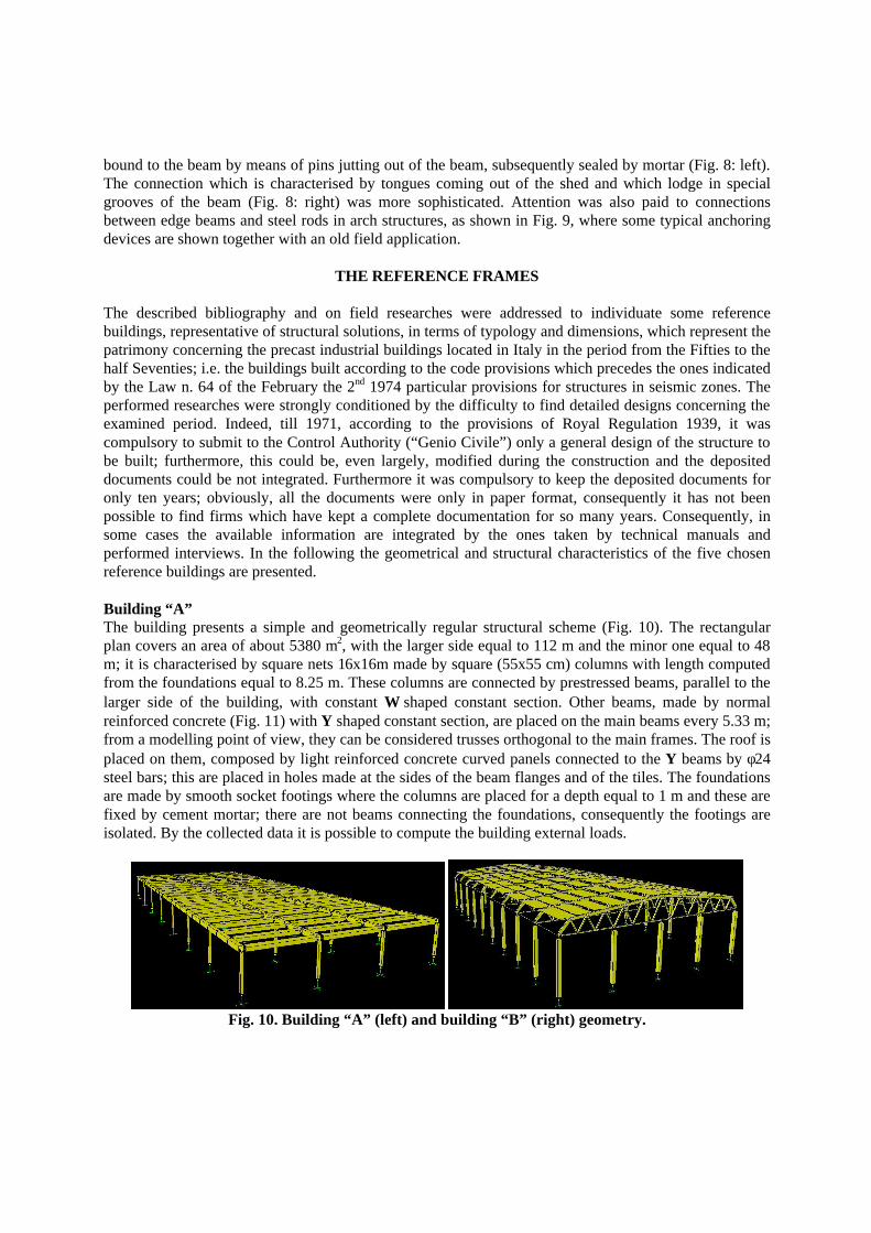
THE REFERENCE FRAMES The described bibliography and on field researches were addressed to individuate some reference buildings, representative of structural solutions, in terms of typology and dimensions, which represent the patrimony concerning the precast industrial buildings located in Italy in the period from the Fifties to the half Seventies; i.e. the buildings built according to the code provisions which precedes the ones indicated by the Law n. 64 of the February the 2nd 1974 particular provisions for structures in seismic zones. The performed researches were strongly conditioned by the difficulty to find detailed designs concerning the examined period. Indeed, till 1971, according to the provisions of Royal Regulation 1939, it was compulsory to submit to the Control Authority (“Genio Civile”) only a general design of the structure to be built; furthermore, this could be, even largely, modified during the construction and the deposited documents could be not integrated. Furthermore it was compulsory to keep the deposited documents for only ten years; obviously, all the documents were only in paper format, consequently it has not been possible to find firms which have kept a complete documentation for so many years. Consequently, in some cases the available information are integrated by the ones taken by technical manuals and performed interviews. In the following the geometrical and structural characteristics of the five chosen reference buildings are presented. Building “A” The building presents a simple and geometrically regular structural scheme (Fig. 10). The rectangular plan covers an area of about 5380 m2, with the larger side equal to 112 m and the minor one equal to 48 m; it is characterised by square nets 16x16m made by square (55x55 cm) columns with length computed from the foundations equal to 8.25 m. These columns are connected by prestressed beams, parallel to the larger side of the building, with constant Ω shaped constant section. Other beams, made by normal reinforced concrete (Fig. 11) with Y shaped constant section, are placed on the main beams every 5.33 m; from a modelling point of view, they can be considered trusses orthogonal to the main frames. The roof is placed on them, composed by light reinforced concrete curved panels connected to the Y beams by φ24 steel bars; this are placed in holes made at the sides of the beam flanges and of the tiles. The foundations are made by smooth socket footings where the columns are placed for a depth equal to 1 m and these are fixed by cement mortar; there are not beams connecting the foundations, consequently the footings are isolated. By the collected data it is possible to compute the building external loads.
Fig. 10. Building “A” (left) and building “B” (right) geometry.

Fig. 11. Building “A”: column (left), main beam (centre), secondary beam
The mechanical characteristic of the materials used for the main structural elements are briefly listed in Tab. 3.
Tab. 3. Mechanical characteristics of the building “A” main elements. __________________________________________________________________________________________________________________ Element Material characteristics ___________________________________________________________________________________________________________
Columns Concrete proportioned with 3.5 kN/m3 of cement type 730 con σr,28= 56 MPa; transversal and longitudinal reinforcement made by steel Aq. 50.
Ω beams Concrete with cement 730 con σr,28= 50 MPa; transversal reinforcement steel Aq. 50; bars DYWIDAG STAHL 80/105, anchorage made by a square plate 130x130 mm or by a bell - thread 100/160.
Y beams Concrete with cement type 730 con σr,28= 50 MPa; ribbed bars steel FeB44K. Footings Concrete proportioned with 3 kN/m3 of cement type 730 con σr,28= 25 MPa; transversal reinforcement steel Aq. 50. Panels Concrete with cement type 730 con σr,28= 35 MPa; Longitudinal and transversal reinforcement steel Aq. 50. __________________________________________________________________________________________________________________
Building “B” The building presents a simple and geometrically regular structural scheme (Fig. 10). The rectangular plan covers an area of about 1110 m2, with the major side equal to 45.4 m and the minor one equal to 24.4 m; it is characterised by rectangular nets 25x4m made by square (40x40 cm) columns with length computed from the foundations equal to 6.20 m. These columns are connected by r/c reticular beams (Fig. 12) and by r/c gutter beams; these last ones can be considered trusses orthogonal to the main frames. The beams to columns connections are made by one sheet neoprene bearings.The roof is placed on the reticular beams; it is made by r/c precast ribbed tiles and connected to the gutter beam by a cast in situ. Even the tiles are connected by a cast in ribs placed on their sides. The foundations are made by smooth socket footings, where the columns are placed for a depth equal to 80 cm and they are fixed by cement mortar. The perimeter panels are made in situ. By the collected data it is possible to compute the building external loads. The mechanical characteristic of the materials used for the main structural elements are briefly listed in Tab. 4.

Fig. 12. Building “B”: column (left) and reticular beam (right).
Tab. 4. Mechanical characteristics of the building “B” main elements. ______________________________________________________________________________________________________________ Element Material characteristics ________________________________________________________________________________________________________
Columns Concrete class R. 350; cement R. 525; ribbed bars steel FeB44K; stirrups steel Aq. 60.
Reticular beam Concrete class R. 350; cement R. 525; ribbed bars steel FeB44K; stirrups steel Aq. 60.
Gutter beams Concrete class R. 350; cement R. 525; ribbed bars steel FeB44K; stirrups steel Aq. 60. Footings Concrete class R. 350; cement R. 525; ribbed bars steel FeB44K; stirrups steel Aq. 60. _______________________________________________________________________________________________________________
Building “C” The building presents a simple and geometrically regular structural scheme, with 2 spans (Fig. 13). The rectangular plan covers an area of about 2340 m2, with the major side equal to 67.25 m and the minor one equal to 34.85 m; it is characterised by rectangular nets 17.45x7.47m made by rectangular (50x40 cm) columns with length computed from the foundations equal to 8.00 m. These columns are connected by prestressed r/c beams with a span equal to 7.47 m, simply restrained .The central columns present a 100x40 cm capital which allows to place the two beams. In the orthogonal direction precast ribbed tiles which represent the roof, made by prestressed r/c, with 17.45 m span and not each other connected, are placed (Fig. 14). The connections of the beams to the columns and of the tiles to the beams are made by one sheet neoprene bearings.
Fig. 13. Building “C” (left) and building “D” (right) geometry.

Fig. 14. Building “C”: column (left) and ribbed tile (right).
The foundations are made by smooth socket footings, fixed by a cement mortar cast. The perimeter panels are made by prestressed reinforced concrete; at the bottom they are placed on cast in situ beam and at the top it is restrained to the prestressed r/c perimeter beams. By the collected data it is possible to compute the building external loads. The mechanical characteristic of the materials used for the main structural elements are briefly listed in Tab. 5.
Tab. 5. Mechanical characteristics of the building “C” main elements. ______________________________________________________________________________________________________________
Element Material characteristics ________________________________________________________________________________________________________
Columns Concrete cement type 425; R’bk=40MPa; ribbed bars steel FeB38K. P. r/c beams Concrete cement type 525; R’bk=50MPa;
ribbed bars steel FeB38K; high strength steel 1/2 in. and 3/8 in. seven wire strands. Ribbed tiles Concrete cement type 525; R’bk=50MPa; ribbed bars steel FeB38K; high strength steel 1/2 in. and 3/8 in. seven wire strands. Footings Concrete cement type 425; R’bk=40MPa; ribbed bars steel FeB38K. _______________________________________________________________________________________________________________
Building “D” The building presents a simple and geometrically regular structural scheme, with 2 spans (Fig. 13). The rectangular plan covers an area of about 3080 m2, with the major side equal to 84.80 m and the minor one equal to 36.30 m; it is characterised by rectangular nets 18.15x6 m made by double T section columns with length computed from the foundations equal to 5.00 m. These columns are connected by r/c arch beams along the major side of the net (Fig. 15); this connection is an hinge, because it is characterised by a neoprene bearing with a steel bar. The building has fourteen plane frames with double span, each other connected by r/c caisson gutter beams, simply restrained at the ends. The roof, placed on the arch beams, is made by precast rafters and hollow flat blocks, joint all together by a cast in situ. The foundations are made by smooth socket footings, where the columns are placed for a depth equal to 1 m and they are fixed by cement mortar. By the collected data it is possible to compute the building external loads. The model is only studied for a length equal to 42.40 m, due to the presence of a joint at the centre of the major side. The mechanical characteristic of the materials used for the main structural elements are briefly listed in Tab. 6.

Fig. 15. Building “D”: column (left), arch beam and roof made by hollow flat blocks (right).
Tab. 6. Mechanical characteristics of the building “D” main elements.
__________________________________________________________________________________________________________________ Element Material characteristics ___________________________________________________________________________________________________________
Columns Concrete proportioned with 3.5 kN/m3 of cement type 730 con σr,28= 36 MPa; transversal and longitudinal reinforcement made by steel Aq. 60.
Arch beams Concrete proportioned with 3.5 kN/m3 of cement type 730 con σr,28= 36 MPa; transversal and longitudinal reinforcement made by steel Aq. 60.
Caisson beams Concrete proportioned with 3.5 kN/m3 of cement type 730 con σr,28= 36 MPa; transversal and longitudinal reinforcement made by steel Aq. 60. Footings Concrete proportioned with 3.5 kN/m3 of cement type 730 con σr,28= 36 MPa; transversal and longitudinal reinforcement made by steel Aq. 60. __________________________________________________________________________________________________________________
Building “E” The building presents a simple and geometrically regular structural scheme (Fig. 16). The rectangular plan covers an area of about 730 m2, with the major side equal to 34 m and the minor one equal to 21.50 m; it is characterised by rectangular nets 21.50x4.85 m made by rectangular (50x60 cm) columns with length computed from the foundations equal to 7 m. These columns in the transversal direction are connected by prestressed r/c full web and variable section beams; in the longitudinal direction, instead, by cast in situ rectangular beams placed at middle height. The connection between the main beams and the columns is made by s one sheet neoprene bearings. The roof, placed on the variable section beams, is made by a precast joisted floor. The perimeter panels are made in situ by brick walls. By the collected data it is possible to compute the building external loads. The mechanical characteristic of the materials used for the main structural elements are briefly listed in Tab. 7.
Fig. 16. Building “E”: geometry (left), column section (centre) and footing (right).

Tab. 7. Mechanical characteristic of the building “E” main elements. ______________________________________________________________________________________________________________
Element Material characteristics ________________________________________________________________________________________________________
Columns Concrete class Rck 350; longitudinal and transversal reinforcement steel Aq 42.
Variable sec. beams Concrete made by cement type 850 with σr,28= 55 MPa; high strength steel made by 3φ3 con σar = 1850 MPa e σ0.2 = 1450 MPa;
Footings Concrete class Rck 350; longitudinal and transversal reinforcement steel Aq 42. _______________________________________________________________________________________________________________
NUMERICAL ANALYSES
The aim of the numerical analyses is the evaluation of the seismic capacity of the reference buildings presented in the previous section, in order to determine, in a simplified manner, the vulnerability; in this evaluation the demand is identified assuming that the buildings are placed in an area of the Southern Italy characterised by a PGA equal to 0.21 and choosing a return period equal to 475 years. The reference buildings are studied both in the elastic field a by non linear analyses. Useful information are gained by the elastic ones, made on spatial models by the computer program SAP200, in order to define the non linear model: the modal shapes and the vibration frequencies and the axial forces of the columns due to the vertical loads to be combined with the seismic forces; in this combination the live loads are decreased by one third. The computer program used for the evaluation of the seismic capacity is the DRAIN-2DX with lumped plasticity elements , characterised by a trilinear moment-rotation relationship. This relationship is computed considering for the steel an elastic-plastic behaviour with hardening, while for the concrete the confinement effect is taken into account assuming the Mander theory; the material maximum strengths are the experimental tests average ones given by the bibliography. The analyses are performed on plane models in the direction considered the most critical. The simple bearings of the beams on the columns are modelled by elastic relationship which take into account the neoprene transversal deformability and whose maximum value is limited by the maximum friction force, evaluated considering a friction coefficient neoprene-concrete equal to 0.9. The performed study shows that such parameter represents one of the critical aspects of the analysis of the examined structures. Indeed, it is fundamental in the evaluation of the structural collapse, which could even happens due to the bearing failure; furthermore, it is difficult to estimate, because the technical bibliography on the topic is not complete. In the Figs. 11 and 12 the curves base shear, divided by the structure seismic weight, - top displacement, divided by the building height (“push over” curves), are shown in the Figs. 11 and 12 with the thick line; they are pushed till the collapse displacement, which in all the cases corresponds to the attainment of the ultimate rotation at the column base. The elastic-perfectly plastic curve, equivalent to the described one in terms of maximum displacement, maximum capacity and energy dissipated, is reported with the thin line. For the structures characterised by smooth rebars, their capacity when such rebars do not have hooks is also represented by a dot line; in this case the collapse is due to the bar slip. In the Tab. 8 the evaluation by spectral analysis of the reference buildings vulnerability is reported. In the first column is cited the reference structure, in the second the period of the equivalent system, which is the one characterised by an elastic –perfectly plastic relationship computed as already said. In this vulnerability evaluation, the demand is represented by the elastic EC8 spectrum for a soil having medium mechanical characteristics (C type) and peak ground acceleration PGA=0.21, which, as aforesaid, it is determined on the base of a fixed probability to be overpass in the reference site: in the third column the ordinate of this spectrum corresponding to the equivalent system period. The ratio between this and the capacity of the equivalent system, reported in the following columns, gives the parameter ρ, which by relations depending on the period of the equivalent system, allows to compute the demanded ductility. The available ductility is assumed as ratio between the maximum displacement and the yielding one of the equivalent bilinear curve: it is observed that in the examined cases, for the assumed level of the

seismic action and for the hypothesis considered, the availability is always larger than the demand. The correspondence between the described vulnerability analysis and the N2 method, recently introduced in the Eurocode 8 (EC8) [6] and in the new Italian seismic code [7], it is evident if it is considered that the demand is evaluated computing a target displacement and the availability one a displacement corresponding to the collapse.
00.05
0.10.15
0.20.25
0.30.35
0.40.45
0.50.55
0 0.5 1 1.5 2 2.5 3 3.5
Displacement [%]
Fb/W
0
0.050.1
0.150.2
0.250.3
0.350.4
0.450.5
0.55
0 0.5 1 1.5 2 2.5 3 3.5
Displacement [%]
Fb/W
Fig. 16. Building “A” (left) and building “B” (right) capacity curves.
00.050.1
0.150.2
0.250.3
0.350.4
0.450.5
0.55
0 0.5 1 1.5 2 2.5 3 3.5
Displacement [%]
Fb/W
0
0.050.1
0.150.2
0.250.3
0.350.4
0.450.5
0.55
0 0.5 1 1.5 2 2.5 3 3.5
Displacement [%]
Fb/W
00.050.1
0.150.2
0.250.3
0.350.4
0.450.5
0.55
0 0.5 1 1.5 2 2.5 3 3.5
Displacement [%]
Fb/W
Fig. 17. Building “C” (up-left), building “D” (up-right) and building “E” (down) capacity curves.
The performed study shows that the modelling and the analysis of the seismic behaviour of precast structures are very complex and it is not easy to obtain satisfying results by using static analyses, even though non linear. Indeed, the structural response depends on interaction phenomena sometimes governed by friction type forces, which involve the vertical seismic actions. Non linear dynamic analyses performed considering the failure of the beam-column connection would represent a more efficient tool. Furthermore, particular attention is to be devoted to the degradation of the material mechanical characteristics, to the connections between the roof elements and to the deformability of this one. Finally, due to the presence of large span beams and to the lack of beams connecting the footings in foundation, it would be very interesting to introduce in the analysis the soil asynchronous excitation. Such remarks put in evidence the presence of critical aspects in the evaluation of the specific structural typology, with evident consequences on the verifications provided by recent codes as the EC8 and the new Italian seismic code. This one, concerning the existing patrimony, limits the possibility to use an elastic approach, both static and multi-modal one; consequently, the procedures based on spectral analyses and the development of efficient representations of the response trough push over curves are a key step of the design process. Therefore, it is evident that the development of precise and largely approved “static” techniques is the contribution demanded by the professional world to the academic one

everyday called to rapidly answer to the real problems of the public safety and of the existing patrimony maintenance.
Tab. 8. Spectral analysis results. Structure Teq Sae(Teq) Capacity ρ Demanded ductility Available ductility Collapse?
[sec] [g] [g] “A” 1.73 0.21 0.15 1.42 1.42 1.76 NO “B” 0.99 0.35 0.19 1.80 1.80 2.43 NO “C” 1.59 0.23 0.19 1.18 1.18 2.61 NO “D” 0.45 0.60 0.53 1.15 1.16 2.24 NO “E” 0.89 0.41 0.22 1.88 1.88 4.97 NO
CONCLUSIONS On the base of an extensive field research, the main characteristics of the precast industrial buildings made in Italy from the Fifties to the Seventies are pointed out. A relevant number of such industrial buildings are located in zones classified as seismic ones after they were built: consequently, for them the problem of a seismic vulnerability analysis is very relevant. Considering the “push over” analyses for the determination of the seismic capacity of some reference precast industrial buildings, some open problems on the modelling of this structural typology are discussed. Spectral analyses, conditioned by some simplified hypotheses on the structural response, show that the available ductility of such industrial buildings is always larger than the demanded one in a medium seismicity zone. However, in some cases, more accurate analyses, seem to be needed to take into account limit states as the beam-column connection failure, i.e. support loss, the asynchrony of the motion and the vertical excitation of the beams, which determine the time dependent variation of the support friction resistance.
ACKNOWLEDGMENTS The authors would like to acknowledge funding and support received from the Geophysics and Volcanology Italian National Institute (INGV) within the research project “Reduction of Infrastructures and Environment Seismic Vulnerability” (VIA), Task 6 Industrial Plants . General Coordinator Prof. G.M. Calvi, University of Pavia, Task coordinator Prof. G. Manfredi, University of Naples Federico II.
REFERENCES 1. CENSIS, 33° “Rapporto sulla situazione sociale del paese 1999”, Territorio e Reti. CENSIS Centro
Studi Investimenti Sociali, 2000: 347-448 (in Italian). 2. Koncz, T. “Manuale della prefabbricazione”. Tecniche Bauverlag ed., Milan, 1962 (in Italian). 3. “Il laterizio - Bollettino tecnico RDB”. Piacenza, years 1956, 1959, 1962, 1965, 1968, 1971-74 (In
Italian). 4. Cestelli Guidi, G. “Cemento armato precompresso: teoria, esperienze, realizzazioni”, Hoepli ed.,
Milan, 1970(in Italian). 5. Marioni A. “Apparecchi d’appoggio per ponti e strutture”. ITEC Ed., 1968. (in Italian). 6. EC8. “Design of structures for earthquake resistance. European Committee for Standardisation
Eurocode 8”. 2003. 7. Ordinanza del Presidente del Consiglio dei Ministri n.3274 del 20 marzo 2003. “Norme tecniche
per il progetto, la valutazione e l’adeguamento sismico degli edifici”. 2003 (in Italian).