Tunnel Form Construction
11
Tunnel Form Construction Tunnel form construction utilises a purpose made, formwork system that allows the casting of walls and slabs in a 24 hour cycle, resulting in a cellular reinforced concrete structure. Outinord, the largest manufacturer of tunnel formwork, claim there are more than 8,000,000 tunnel-form dwellings throughout the world. Picture 1: Typical tunnel form construction (Days Inn-Glasgow) Generally between 80m² and 350m² of floor area is achieved in each 24 hour cycle. To establish the construction programme the structure is divided into a number of more or less similar construction phases, corresponding to a days work. The typical working day is broken into the operations shown in table 1. It is normal practice to have 3 different teams, one each for the formworks, steel, and concreting. Table1: Typical daily work cycle. The build starts with the foundations and ground floor slab. The monolithic nature of the construction, with simultaneous casting of walls and slabs that do not require the presence of day work joints allow a lighter construction and smaller foundations than would be typical for the size of construction. The ground floor slab is designed and constructed with kickers and starter bars in position for the internal walls. The kickers are low concrete walls that form an integral part of the process. Their main role is to guide the positioning of the forms and to facilitate the stripping of the forms after the casting of the walls and slab.
-
Upload
independent -
Category
Documents
-
view
2 -
download
0
Transcript of Tunnel Form Construction

Tunnel Form Construction Tunnel form construction utilises a purpose made, formwork system that allows the casting of walls and slabs in a 24 hour cycle, resulting in a cellular reinforced concrete structure. Outinord, the largest manufacturer of tunnel formwork, claim there are more than 8,000,000 tunnel-form dwellings throughout the world.
Picture 1: Typical tunnel form construction (Days Inn-Glasgow)
Generally between 80m² and 350m² of floor area is achieved in each 24 hour cycle. To establish the construction programme the structure is divided into a number of more or less similar construction phases, corresponding to a days work. The typical working day is broken into the operations shown in table 1. It is normal practice to have 3 different teams, one each for the formworks, steel, and concreting.
Table1: Typical daily work cycle.
The build starts with the foundations and ground floor slab. The monolithic nature of the construction, with simultaneous casting of walls and slabs that do not require the presence of day work joints allow a lighter construction and smaller foundations than would be typical for the size of construction. The ground floor slab is designed and constructed with kickers and starter bars in position for the internal walls. The kickers are low concrete walls that form an integral part of the process. Their main role is to guide the positioning of the forms and to facilitate the stripping of the forms after the casting of the walls and slab.

Picture 2: Kickers and reinforcement cast into slab.
When positioning the forms the floor is cleared and the tunnels are lifted in with the crane, and pushed against the kickers using crow bars. Subsequently, the bolting of the ties between the forms will ensure that they are properly set against the kickers.
At the time of the pouring, the bottom of the vertical panel of the tunnel forms is located a few centimetres above the slab level (typically 6cm = 2,5cm from bottom of form to bottom of wheel + 3,5cm for the stripping of the form and lack of flatness of the slab). This allows the lowering of the form in order to strip it. In general, the kickers are 8cm tall (good practise).
Picture 3: Panel being located against kicker The kickers provide a support on which the level can be drawn. The line facilitates the adjustment of the forms: the bottom of the tunnel is simple set flush with that line by using the jacks. The line drawn on the kickers corresponds to the height of the ceiling minus the height of the vertical panel (excluding wheels and jacks).

Picture 4: Level on kicker The level of the line on the kicker should not be directly measured from the slab (as the slab is not always very smooth) but rather materialized using a point of reference. Chalk is generally used to mark the level
Picture 6: Kicker formwork and reinforcement being located with ‘crosses’ The kickers are constructed using kicker forms, concrete crosses, and some clamps. The kickers need to be vibrated and troweled flat and flush with the kicker forms to ensure an accurate finish to line up with the tunnel forms. The concrete crosses are set in place along with the reinforcement. Then, once all the reinforcement is finished, the kicker forms are installed and held using the clamps.

Picture 7: Kicker formwork being clamped against ‘crosses’ The concrete crosses are positioned above the walls that are being cast, in between the forms, to hold the kicker forms (when the location of the walls is the same from one floor to the next). There are 2 types of concrete crosses, some with 4 branches and some with 3, according to whether the cross is located in a middle wall, or at the end of the slab. When the foundation slab is cast in place, the foundation kickers are made in a similar manner as those for the floors above, using concrete (held by small concrete slumps cast beforehand). The wall reinforcement is fixed in place and tied to the starter bars. The reinforcement is cut around temporary timber templates forming the position of the door and window openings in the walls.
Picture 8: Door opening formed around template.
After the floor is cleared the forms are brought in with the crane, and pushed against the kickers using crow bars, the bolting of the ties between the forms will ensure that they are properly set against the kickers
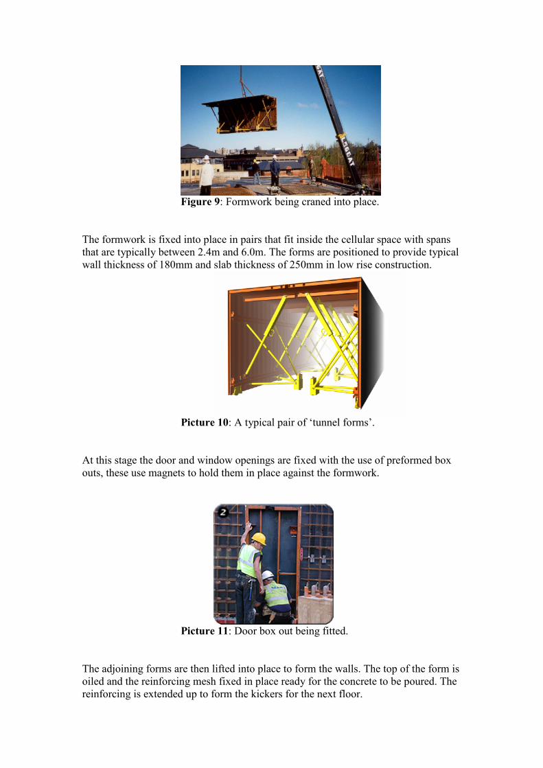
Figure 9: Formwork being craned into place.
The formwork is fixed into place in pairs that fit inside the cellular space with spans that are typically between 2.4m and 6.0m. The forms are positioned to provide typical wall thickness of 180mm and slab thickness of 250mm in low rise construction.
Picture 10: A typical pair of ‘tunnel forms’.
At this stage the door and window openings are fixed with the use of preformed box outs, these use magnets to hold them in place against the formwork.
Picture 11: Door box out being fitted.
The adjoining forms are then lifted into place to form the walls. The top of the form is oiled and the reinforcing mesh fixed in place ready for the concrete to be poured. The reinforcing is extended up to form the kickers for the next floor.

Picture 12: Reinforcing and kickers ready for pouring The concrete is stopped by using slab stop – ends on the horizontal panels and wall stop – ends on the vertical panels. However, it often happens that the whole slab cannot cast the same day. In this case, temporary stop – ends have to be installed, allowing the reinforcement steel to pass. The slab stop – ends are used to stop the concrete at the perimeter of the slabs. They are generally bolted to the forms, but they can also be held in place using magnets. Many shapes can be designed, for balconies for instance with curved slab stop – ends.
Photo 13: Curved slab stop-end The wall stop – ends are bolted to the form and used to stop the concrete at the extremities of the walls. They can be linked to narrow horizontal strips, in order to make full height openings. A large floor is typically divided into several phases and the same equipment is re-used for each phase. In order to do so, the half tunnel form located at the intersection

of the phases stays in place during the concrete pour, creating a cold joint 1/5 span phase and the remaining 4/5 are poured subsequently.
Along with the window and door box-outs the conduit and pipe work for the first fix services are positioned before the concrete pour, these are cast into the walls and slab.
Photo 14: Services are cast in The concrete is poured so as to stabilise the tunnels. Typically the internal walls are first poured (walls with half tunnel forms on both sides), then the external walls, and finally the slab and the kickers. The gable wall must not be poured first. These operations are repeated for each row of tunnel form. When pouring the walls, it is good practise to stop the concrete slightly before reaching the level of the slab. This leads to a better finishing of the slab, especially if the concrete sets rapidly As the concrete is often poured in the afternoon and stripping of the forms is programmed for the next day, it is often necessary to heat the concrete to enable it to begin to cure.

Picture 15: Heater and curtains The heating of the concrete is accomplished by closing the tunnel forms with plastic curtains to prevent heat losses and by heating the inside of the tunnels using gas or fuel heaters (usually at night). A temperature between 50°C and 70°C is sufficient, and economical. In any case, the temperature should never exceed 80°C. Furthermore, in order to avoid a rapid water loss before the concrete sets, the rate of increase in temperature should not exceed 20 C per hour.
To calculate the number of heaters required the following rule of thumb can be used: 1 HEATER OF 40000 Kcal / hour ⇔ 60 m3
The danger with heating the concrete is that an excessive water loss can lead to: - a substantial loss in strength - a high level of shrinkage shrinkage causing excessive cracking The curve shows that if a concrete with an optimal water content loses 10% of its initial water content, then it loses more than 40% of its strength. In order to avoid a rapid loss of water by evaporation during the heating of the concrete, the slab is covered with an impermeable sheet.

Figure 2: Concrete drying table The following morning after the concrete has been given opportunity to cure, the site engineer undertakes sampling and analysis of the concrete to ensure it has sufficient strength to allow the removal of the formwork.
Picture 16: Removal of forms and propping of structure.
The removal of the formwork follows a set procedure. At the time of the pouring, the bottom of the vertical panel of the tunnel forms is located a few centimetres above the slab level. This allows the lowering of one half of the form which is then pushed forward on its wheels. The lifting bracket is attached to the form and the crane supports the form as it is pushed out from the structure. The crane lifts the form directly into position against the kicker and reinforcement ready for the next pour.

Picture 17: Formwork being craned out for moving to new position.
When using tunnel forms in a daily cycle, the concrete has little time to dry, even though the setting of the concrete is accelerated, it is necessary to set some props in place as soon as the first tunnel is removed, to prevent deflection
Picture 18: Propping detail.
Typically, one prop every 2m of tunnel is sufficient for a regular width. However, the position and number of props is dictated by several factors including:
• The concrete strength, • The architecture of the structure • The loads applied on the structure
Methodology fore propping: 1 – the first half tunnel is stripped; 2 – the slab is propped while the second half tunnel is still in place; 3 – the second half tunnel is stripped once the slab is propped The props stay in place for several days. It is good practise to leave the props in place two floors below the one where the forms are set, so that the concrete reaches a sufficient strength.
The finished structure is constructed to a high level of dimensional accuracy, tolerances within one millimetre are possible. The forms have a working life of

between 800 and 1,000 pours. The tight tolerances, allow the utilisation of prefabricated components such as roof panels and bathroom pods. Special forms are used to create gable walls and roof slopes. Typically the roof utilises prefabricated insulated panels that are bolted between the cast party walls and overlaid with the roof covering. The systems make use of pre-plumbed and fitted kitchen and bathroom pods that connect to the cast in services. The open elevations are covered with insulated panels that contain glazed windows and doors. These panels can either be faced with the final finish or covered with cladding. Internally the walls are to a sufficient standard to be decorated directly, or if required dry lined. The system lends it self to projects that are of a repetitive nature requiring a high density of units, there is little scope for individuality of design to the dwelling units when maximising the potential of the system for rapid construction times. Further information is available from:- Outinord International Ltd. www.outinord.netThe Concrete Centre www.concretecentre.com
Pictures supplied by Outinord International LTD.