Technical Challenges During Construction of Alborz Service Tunnel, Iran
6
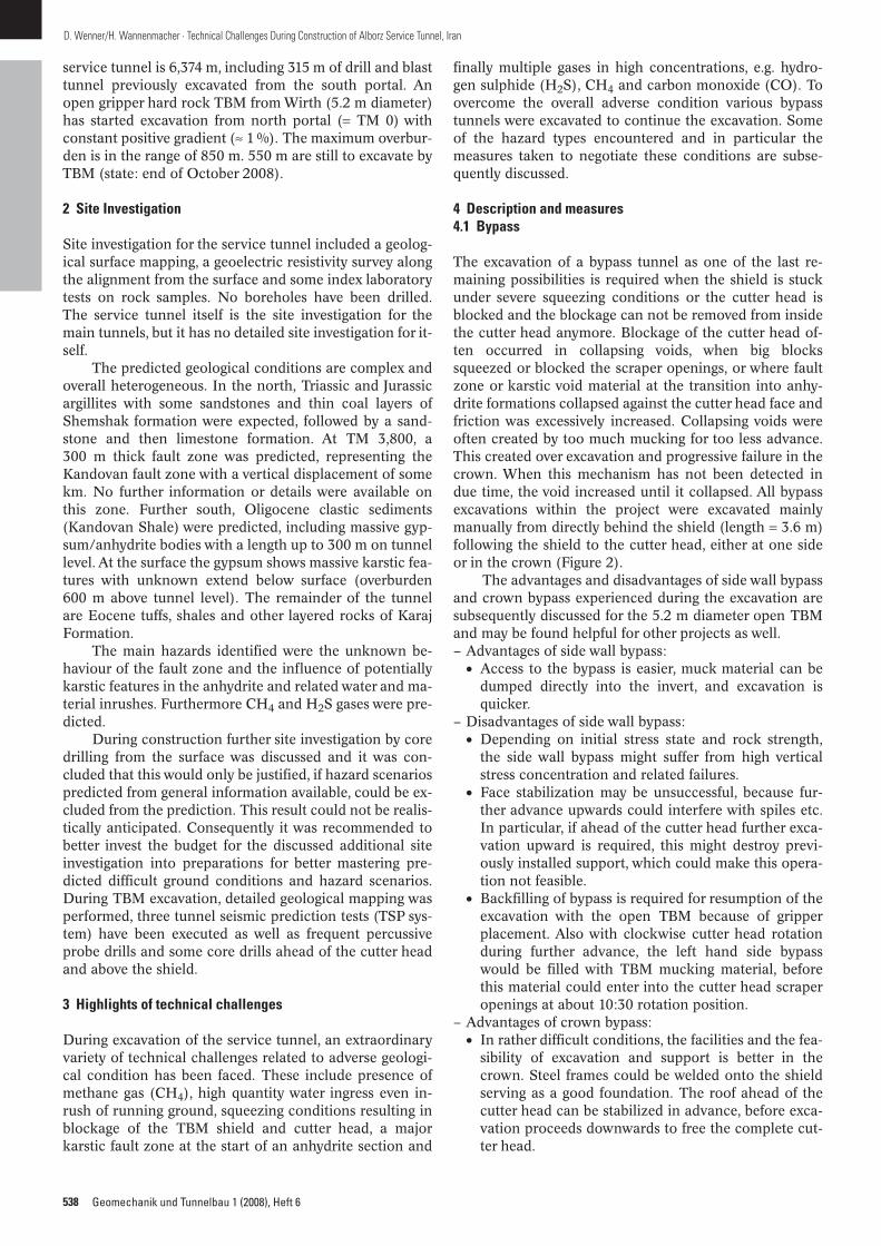
The Tehran Shomal Motorway project is one the major infrastruc- ture projects currently ongoing in Iran. The line will connect the capital of Iran, Tehran with the Caspian Sea. The traffic volume is very high and the conditions of the actual roads, especially in the winter and holiday times are dangerous. The Alborz tunnel sys- tem, with the actual ongoing excavation of its service tunnel, is the outstanding lot of the Tehran Shomal Motorway project. The project is facing severe and adverse geological conditions like various dangerous gases, water and material inrush and blocked TBM. Depending on the conditions at the remaining length the breakthrough is anticipated by early 2009. Technische Herausforderungen während der Bauausführung des Alborz Service Tunnels, Iran Das Teheran Shomal Autobahnprojekt ist eines der derzeit größ- ten Infrastrukturprojekte im Iran. Die neue Strecke verbindet die Hauptstadt Teheran mit dem Kaspischen Meer im Norden. Das überdurchschnittlich hohe Verkehrsaufkommen, besonders zu Ferienzeiten, sowie extreme winterliche Bedingungen machen die bestehende Straße gefährlich. Der Alborz Tunnel mit dem kurz vor dem Durchschlag stehenden Service und Erkundungs- stollen ist das Hauptstück der Verbindung. Extreme geologische Verhältnisse wie gefährliche Gase, Wasser- und Materialeinbrü- che und drückendes Gebirge bereiten dem TBM-Vortrieb außer- ordentliche Schwierigkeiten. Der Durchschlag des Service Tun- nels wird Anfang 2009 erwartet. 1 Introduction The Tehran Shomal Motorway project in Iran is a new motorway to connect the capital Tehran with the city of Chalus at the Caspian Sea in the North. The total length is 121 km. Currently traffic runs on small roads passing the Alborz mountains and the journey takes five to six hours. Upon completion of the project the travelling time will re- duce to less than two hours with an overall higher capaci- ty. The motorway alignment has more than 30 twin tun- nels for double lanes. The Alborz Tunnel will be the longest of these with a length of 6,400 m at an altitude of 2,400 m (Figure 1). The service tunnel is located between the main tun- nel tubes and is used for site investigation, drainage and as access for the main tunnel construction to commence soon, as well as for ventilation and later as a service tunnel for the main tunnels during operation. The length of the Fachthemen Technical Challenges During Construction of Alborz Service Tunnel, Iran Dieter Wenner Helmut Wannenmacher DOI: 10.1002/geot.200800065 537 © 2008 Ernst & Sohn Verlag für Architektur und technische Wissenschaften GmbH & Co. KG, Berlin · Geomechanik und Tunnelbau 1 (2008), Heft 6 Fig. 1. Project location of Alborz Service Tunnel Bild 1. Projektgebiet Alborz Servicetunnel
-
Upload
independent -
Category
Documents
-
view
1 -
download
0
Transcript of Technical Challenges During Construction of Alborz Service Tunnel, Iran

The Tehran Shomal Motorway project is one the major infrastruc-ture projects currently ongoing in Iran. The line will connect thecapital of Iran, Tehran with the Caspian Sea. The traffic volume isvery high and the conditions of the actual roads, especially in thewinter and holiday times are dangerous. The Alborz tunnel sys-tem, with the actual ongoing excavation of its service tunnel, isthe outstanding lot of the Tehran Shomal Motorway project. Theproject is facing severe and adverse geological conditions likevarious dangerous gases, water and material inrush and blockedTBM. Depending on the conditions at the remaining length thebreakthrough is anticipated by early 2009.
Technische Herausforderungen während der Bauausführung desAlborz Service Tunnels, IranDas Teheran Shomal Autobahnprojekt ist eines der derzeit größ-ten Infrastrukturprojekte im Iran. Die neue Strecke verbindet dieHauptstadt Teheran mit dem Kaspischen Meer im Norden. Dasüberdurchschnittlich hohe Verkehrsaufkommen, besonders zuFerienzeiten, sowie extreme winterliche Bedingungen machendie bestehende Straße gefährlich. Der Alborz Tunnel mit demkurz vor dem Durchschlag stehenden Service und Erkundungs-stollen ist das Hauptstück der Verbindung. Extreme geologischeVerhältnisse wie gefährliche Gase, Wasser- und Materialeinbrü-
che und drückendes Gebirge bereiten dem TBM-Vortrieb außer-ordentliche Schwierigkeiten. Der Durchschlag des Service Tun-nels wird Anfang 2009 erwartet.
1 Introduction
The Tehran Shomal Motorway project in Iran is a newmotorway to connect the capital Tehran with the city ofChalus at the Caspian Sea in the North. The total length is121 km. Currently traffic runs on small roads passing theAlborz mountains and the journey takes five to six hours.Upon completion of the project the travelling time will re-duce to less than two hours with an overall higher capaci-ty. The motorway alignment has more than 30 twin tun-nels for double lanes. The Alborz Tunnel will be thelongest of these with a length of 6,400 m at an altitude of2,400 m (Figure 1).
The service tunnel is located between the main tun-nel tubes and is used for site investigation, drainage and asaccess for the main tunnel construction to commencesoon, as well as for ventilation and later as a service tunnelfor the main tunnels during operation. The length of the
Fachthemen
Technical Challenges During Construction of Alborz Service Tunnel, Iran
Dieter WennerHelmut Wannenmacher
DOI: 10.1002/geot.200800065
537© 2008 Ernst & Sohn Verlag für Architektur und technische Wissenschaften GmbH & Co. KG, Berlin · Geomechanik und Tunnelbau 1 (2008), Heft 6
Fig. 1. Project location of Alborz Service TunnelBild 1. Projektgebiet Alborz Servicetunnel
537_542_065_Wenner.qxd 10.12.2008 7:28 Uhr Seite 537
538 Geomechanik und Tunnelbau 1 (2008), Heft 6
D. Wenner/H. Wannenmacher · Technical Challenges During Construction of Alborz Service Tunnel, Iran
service tunnel is 6,374 m, including 315 m of drill and blasttunnel previously excavated from the south portal. Anopen gripper hard rock TBM from Wirth (5.2 m diameter)has started excavation from north portal (= TM 0) withconstant positive gradient (≈ 1 %). The maximum overbur-den is in the range of 850 m. 550 m are still to excavate byTBM (state: end of October 2008).
2 Site Investigation
Site investigation for the service tunnel included a geolog-ical surface mapping, a geoelectric resistivity survey alongthe alignment from the surface and some index laboratorytests on rock samples. No boreholes have been drilled.The service tunnel itself is the site investigation for themain tunnels, but it has no detailed site investigation for it-self.
The predicted geological conditions are complex andoverall heterogeneous. In the north, Triassic and Jurassicargillites with some sandstones and thin coal layers ofShemshak formation were expected, followed by a sand-stone and then limestone formation. At TM 3,800, a300 m thick fault zone was predicted, representing theKandovan fault zone with a vertical displacement of somekm. No further information or details were available onthis zone. Further south, Oligocene clastic sediments(Kandovan Shale) were predicted, including massive gyp-sum/anhydrite bodies with a length up to 300 m on tunnellevel. At the surface the gypsum shows massive karstic fea-tures with unknown extend below surface (overburden600 m above tunnel level). The remainder of the tunnelare Eocene tuffs, shales and other layered rocks of KarajFormation.
The main hazards identified were the unknown be-haviour of the fault zone and the influence of potentiallykarstic features in the anhydrite and related water and ma-terial inrushes. Furthermore CH4 and H2S gases were pre-dicted.
During construction further site investigation by coredrilling from the surface was discussed and it was con-cluded that this would only be justified, if hazard scenariospredicted from general information available, could be ex-cluded from the prediction. This result could not be realis-tically anticipated. Consequently it was recommended tobetter invest the budget for the discussed additional siteinvestigation into preparations for better mastering pre-dicted difficult ground conditions and hazard scenarios.During TBM excavation, detailed geological mapping wasperformed, three tunnel seismic prediction tests (TSP sys-tem) have been executed as well as frequent percussiveprobe drills and some core drills ahead of the cutter headand above the shield.
3 Highlights of technical challenges
During excavation of the service tunnel, an extraordinaryvariety of technical challenges related to adverse geologi-cal condition has been faced. These include presence ofmethane gas (CH4), high quantity water ingress even in-rush of running ground, squeezing conditions resulting inblockage of the TBM shield and cutter head, a majorkarstic fault zone at the start of an anhydrite section and
finally multiple gases in high concentrations, e.g. hydro-gen sulphide (H2S), CH4 and carbon monoxide (CO). Toovercome the overall adverse condition various bypasstunnels were excavated to continue the excavation. Someof the hazard types encountered and in particular themeasures taken to negotiate these conditions are subse-quently discussed.
4 Description and measures4.1 Bypass
The excavation of a bypass tunnel as one of the last re-maining possibilities is required when the shield is stuckunder severe squeezing conditions or the cutter head isblocked and the blockage can not be removed from insidethe cutter head anymore. Blockage of the cutter head of-ten occurred in collapsing voids, when big blockssqueezed or blocked the scraper openings, or where faultzone or karstic void material at the transition into anhy-drite formations collapsed against the cutter head face andfriction was excessively increased. Collapsing voids wereoften created by too much mucking for too less advance.This created over excavation and progressive failure in thecrown. When this mechanism has not been detected indue time, the void increased until it collapsed. All bypassexcavations within the project were excavated mainlymanually from directly behind the shield (length = 3.6 m)following the shield to the cutter head, either at one sideor in the crown (Figure 2).
The advantages and disadvantages of side wall bypassand crown bypass experienced during the excavation aresubsequently discussed for the 5.2 m diameter open TBMand may be found helpful for other projects as well.– Advantages of side wall bypass:
• Access to the bypass is easier, muck material can bedumped directly into the invert, and excavation isquicker.
– Disadvantages of side wall bypass:• Depending on initial stress state and rock strength,
the side wall bypass might suffer from high verticalstress concentration and related failures.
• Face stabilization may be unsuccessful, because fur-ther advance upwards could interfere with spiles etc.In particular, if ahead of the cutter head further exca-vation upward is required, this might destroy previ-ously installed support, which could make this opera-tion not feasible.
• Backfilling of bypass is required for resumption of theexcavation with the open TBM because of gripperplacement. Also with clockwise cutter head rotationduring further advance, the left hand side bypasswould be filled with TBM mucking material, beforethis material could enter into the cutter head scraperopenings at about 10:30 rotation position.
– Advantages of crown bypass:• In rather difficult conditions, the facilities and the fea-
sibility of excavation and support is better in thecrown. Steel frames could be welded onto the shieldserving as a good foundation. The roof ahead of thecutter head can be stabilized in advance, before exca-vation proceeds downwards to free the complete cut-ter head.
537_542_065_Wenner.qxd 10.12.2008 7:28 Uhr Seite 538

539Geomechanik und Tunnelbau 1 (2008), Heft 6
D. Wenner/H. Wannenmacher · Technical Challenges During Construction of Alborz Service Tunnel, Iran
• Crown bypass does not interfere with grippers. Itcould therefore be maintained in parallel with furtherTBM excavation for some section, e.g. to cross a faultzone.
– Disadvantages of crown bypass:• Depending on initial stress state and rock strength,
the crown bypass might suffer from too low horizontalstress and related failures.
• If excavation down in front of the cutter head is re-quired, all mucking has to be lifted up to the crown
bypass level, if it can not be done through the cutterhead.
There is no general rule, which location should be pre-ferred for a bypass to the cutter head. The best solution al-ways depends on local conditions and targets, whichchange from case to case.
The bypass can be used for installation of drainageholes, various probe and core drillings, which could stayoutside of the profile to be excavated by the TBM later toavoid problems in case of rod lost, and for injections forground improvement and water flow reduction.
4.2 Gases
CH4 was first encountered at TM 1,884 and since then oc-curred occasionally. CH4 is an explosive gas, lighter thanair and odourless. The lower explosive limit (LEL) is at 4.6Vol.% in the atmosphere, corresponding to 100 % LEL.The source of CH4 is related to the coal layers in thenorthern part of the tunnel, which also exist in the centraland southern part at greater depth to some extend. Sinceno major storage rocks exist in this area, the risk of quicklarge quantity inrushes of CH4 was regarded low. General-ly CH4 could therefore be controlled with sufficient quan-tity of ventilation, but particular hazards may develop inconfined spaces like over breaks or during and after tem-porary breakdowns of the ventilation system. The in-stalled capacity is sufficient to generate 1 to 1.2 m/s airspeed in the general body of air behind the TBM.
Alarm levels were set at 10 and 20 % LEL in the gen-eral body of air. At 10 % LEL, all measures must be takento reduce the gas: local dilution of gas with compressed airor air movers, further increase of ventilation (if possible),suspension of works (probe drilling or TBM excavation) toreduce the release rate, detailed monitoring and reporting.When the concentration exceeded 20 % LEL immediateand controlled evacuation of the complete tunnel was re-quired. This included collection of all personnel includinghead count, switching off the TBM main electrical powersupply and starting an explosive proof ventilation system(when available).
As a preventive measure some transport facilitiesmust always be available at the TBM within potentiallygas bearing ground. At times where this was not possible,e.g. when the mucking train runs out, no rock bolt orprobe drilling works were allowed, which could initiatesudden gas ingress.
All hot works (welding, grinding) required specialpermission by the safety personnel, including gas check.Evacuation trainings were executed in regular intervals.
Special procedures for re-entering the tunnel afterevacuation were defined and had to be followed strictly,e.g. tunnel ventilation for defined time, entering with gasdetector (with checking gas concentration at the front endof a train) for checking the conditions, also including con-fined spaces like electrical cabinets. Depending on the lo-cal gas concentrations further flushing by compressed airmay be required.
Only upon fulfilment of all requirements and proce-dures the main power supply was allowed to be switchedon again and works could continue. Also special proce-
Fig. 2. a) Manual bypass excavation, TBM shield at theright side; b) Crown bypass, supported by steel frames. Viewto the back with entrance hole and shield in the bottomBild 2. a) Händischer Bypass-Vortrieb seitlich der TBM,TBM-Schildmantel ist rechts; b) Bypass mit Stahlausbauüber der TBM. Blick nach hinten zum Einstiegsloch
a)
b)
537_542_065_Wenner.qxd 10.12.2008 7:28 Uhr Seite 539

540 Geomechanik und Tunnelbau 1 (2008), Heft 6
D. Wenner/H. Wannenmacher · Technical Challenges During Construction of Alborz Service Tunnel, Iran
dures were required for entering the confined space, e.g.the cutter head.
Probe drills ahead of the cutter head and vertically in-to the crown were used to systematically check for gas andeventually drain it in a controlled way, before these gasbearing joints were intersected by the TBM excavation.Shotcreting of the rock surface can help to reduce theflow of gases into the tunnel.
H2S was first encountered at TM 2,967 and sincethen occurred several times. H2S is a gas heavier than airand with strong smell of rotten eggs. The main hazards arerelated to its toxicology and corrosive property to metals.It can be identified by smelling below 1 ppm. The eighthours occupational exposure limit is 10 ppm, for shorttimes (15 min), 15 ppm is acceptable. Above 15 ppm fullface masks with filters were used. This restricted the abili-ty to work to a great extend. Also filters could not be usedwithout further protection, where water squirts aroundunder high pressure: if it enters into the filter, the filter willbe blocked immediately.
Above 100 ppm, H2S deadens a person’s sense tosmell it. Also above 100 ppm it is immediately dangerousto life or health (IDLH). Therefore filters should only beused up to 100 ppm. At higher concentrations, masks withpositive pressure self supplying respirators shall be used.These were available with a compressed air capsule car-ried on the back or with central air supply from big bottleswith a 50 m long hose (Figure 3). Productive work be-comes almost impossible with this equipment and it canonly be used for inspections and remedial measures aftertunnel evacuation. The maximum concentration recordedwas in the range of 500 ppm in the general body of air(when tunnel ventilation had been non operational). Con-centrations between 50 and 100 ppm had to be negotiatedduring longer periods of time. H2S also causes corrosionto metals, in particular to the electrical installations on theTBM. To reduce the effects, some electrical cabinets havebeen connected to the fresh air supply. Still major electri-cal repair works have been required.
H2S was encountered in two ways: – The rock cutting process in dry anhydrite by TBM re-
leased H2S in some anhydrite sections, leading to con-centrations up to 160 ppm. Directly after drilling of thehub was completed and TBM advance had stopped, therelease of H2S also was reduced significantly to valuesbetween 10 and 20 ppm;
– In other locations, H2S, which has a high solubility inwater, was released from ingressing water, in particularwhen water squirted out of rock fissures under highpressure.
The source of H2S is not fully known. Most likely it wasgenerated by bacterial sulphate reduction (of anhydritewith CH4), producing H2S, CaCO3 and water. Green oilyliquid sometimes ran out at small fissures in anhydrite inlow quantities. This is suspected to be the remainders ofthe bacteria.
If H2S is only released locally at a high concen-tration, e.g. at a borehole mouth, it can be diluted bycompressed air or drained into hoses. Ingressing contami-nated water should be drained as quickly as possible bypumps or directly from the rock mass into closed hosesand pipes and transferred to at least the end of the TBM,so that it can no longer release the H2S into the tunnel at-mosphere in the TBM section. Membranes should be usedto prevent spraying of water and to guide the contaminat-ed water into the tunnel invert. It is obvious that high con-centrations can not be negotiated by a realistic increase ofventilation capacity. The tunnel was regularly evacuatedwhen the concentration exceeded 100 ppm.
Generally sufficient numbers of mobile gas detectorsmust be available, regularly calibrated and used, in partic-ular during any drilling operation (TBM, rock bolts, probedrilling). Tunnel workers must be informed about the haz-ards, receive medical checks and approval to use masks,trained in the use of masks and other breathing equip-ment. Personal protective equipment (masks and filters)must be available in sufficient quantity and stock. Freshair shall be guided to typical working locations along theTBM, e.g. the operator’s cabin and the invert sectionwhere rails are placed.
When CH4 or H2S was detected in joints in probedrills far ahead of the cutter head, these joints were triedfor cement grouting in order to reduce the conductivity forthe gas in the rock mass. In addition, about 6 m long gasdrainage holes were drilled in the close vicinity of the cut-ter head to drain the gas.
Presence of hydrogen cyanide (HCN) had been testedand found to be not present. In another tunnel project inIran, where also high concentrations of H2S wereencountered, also HCN had been detected in significantquantities. Carbone monoxide (CO) had also been de-tected in one section of the tunnel in concentrationsabove 500 ppm, where the 8 hours occupational exposurelimit is 30 ppm. The tunnel was evacuated, since theavailable filters did not provide any protection against CO.
By implementing and strictly following the above de-scribed procedures, it was possible to execute the workswithout major accidents. But longer time delays and sig-nificantly reduced progress rates had to be accepted.
Fig. 3. Workers with positive pressure self supplying respira-tors in high H2S concentration environment, air supplied bytanks and hosesBild 3. Arbeiter mit Atemschutzmasken bei starker H2S-Belastung. Luftversorgung durch Schläuche von Druck-flaschen
537_542_065_Wenner.qxd 10.12.2008 7:28 Uhr Seite 540

541Geomechanik und Tunnelbau 1 (2008), Heft 6
D. Wenner/H. Wannenmacher · Technical Challenges During Construction of Alborz Service Tunnel, Iran
4.3 Water ingress
The northern section of the tunnel had only low waterflow. At TM 2,582, a first significant ingress was encoun-tered with > 90 l/s, which increased to ≈ 125 l/s duringfurther advance. At TM 2,967 a further water ingress hadto be faced, adding ≈ 110 l/s to the total flow rate and re-leasing H2S (up to 25 ppm).
At TM 3,015, some initial 110 l/s rushed into the tun-nel together with estimated 100 m3 of mud and stone ma-terial and also releasing H2S (up to 60 ppm). This repre-sented a fault zone with karstic void fillings when enteringinto the first anhydrite section. Over the following twomonths, the total water quantity from the tunnel reducedfrom 290 to 50 l/s. The other end of this anhydrite was un-problematic with respect to water ingress and did notcause any tunnelling problems.
The main water ingress occurred at TM 4,524 in afault zone: the total tunnel flow at the portal increasedfrom 60 to initial 690 l/s recorded (≈ 800 l/s estimated,Figure 4) with high concentration of H2S (>100 ppm). Af-ter a first waiting period for water reduction, TBM excava-tion through the water bearing fault zone was proceeded.The total water flow reduced to 380 l/s over eight months.During the first three months, works could only be execut-ed with masks. Recently in mid August 2008, again akarstic fault zone was hit at the end of the southern anhy-drite section. It initially added 220 l/s to make a total flowof 600 l/s, which quickly reduced to 450 l/s within fourweeks.
The main hazards related to these water ingresses andinrushes are the release of H2S from the water and the in-rush of material and subsequently collapse of washed outvoids eventually leading to blockage of the cutter head. Al-so working conditions for workers with cold water squirt-ing everywhere are harsh, especially in winter times andtemperatures down to –15 °C and the requirement to runthe ventilation with full speed because of the gases. Neo-prene wet and dry suits like for divers have been used un-der these conditions for protection. Further hazards arerelated to the bad effect of water on various electrical in-stallations and various high voltage cables being sub-merged under water.
The ingressing water also affected the transportationsystem facilitated by trains. Sleepers for the rail trackswere placed directly on the bored invert or invert shot-crete. No invert segments had been used. Water drainagewas by free flow in the invert to the portal. While an addi-tional 400 mm drainage pipe has been installed on thetunnel wall, it was never possible to utilize it in a reason-able way, since no suitable high performance waste waterpumps were available on the local market in Iran, becauseof overall political sanctions. One of the main problemswas the sedimentation of fine materials in the invert,blocking rails and causing derailments. This happenedmainly in local depressions of the vertical alignment andat the upstream side of a California crossing, which effec-tively act like a sedimentation pond. Railway traffic onrails covered by water caused no significant problems. Justmore maintenance was required for the rolling stock.
Most water ingresses could be identified in advanceby probe drillings. But attempts to grout these zones in ad-
vance to reduce the water flow had never been successful.The reasons are mainly related to the high pressures andflow rates together with limited availability of equipmentlike preventer or packers and experienced contractor’spersonnel for these works.
Due to these circumstances it was finally always de-cided to drain the water, considering that one of the maintasks of this service tunnel is to drain the rock mass for theexcavation of the main motorway tunnels.
Foam developing resins have been used to fill up thevoids and for stabilizing the collapsed ground with somerunning water inside.
Fig. 4. Main water ingress with estimated 800 l/s in theTBM backup with rails installedBild 4. Größter Wassereinbruch mit geschätzten 800 l/s, imTBM Nachläufer mit verlegten Gleisen
Fig. 5. Collapsed rock material in the invert directly behindthe cutter head under the TBM in difficult working condi-tionsBild 5. Niederbuch in einer Störzone. Schwierige Arbeits-bedingungen in der Sohle direkt hinter dem Bohrkopf unterder TBM
537_542_065_Wenner.qxd 10.12.2008 7:28 Uhr Seite 541

542 Geomechanik und Tunnelbau 1 (2008), Heft 6
D. Wenner/H. Wannenmacher · Technical Challenges During Construction of Alborz Service Tunnel, Iran
5 Concluding remarks
A series of extraordinary geological difficulties had to betechnically mastered during TBM excavation of the Al-borz Service Tunnel in Iran. This has significant influenceon the progress rates and the construction schedule aswell as on the costs. The hazards and some methods todeal with them have been described in this paper.
However, and most important, all these hazards anddifficulties could finally be passed without any major acci-dent. Improvements could be achieved by better prepara-tion for expected problems in advance, in contrast to solv-ing problems “on demand”.
With current status, 550 m until break through, reduc-ing overburden and again increasing confidence into the ge-ological prediction and no further significant predicted haz-ard, break through is expected within the next months.
Helmut WannenmacherAmberg Engineering AGRheinstraße 4CH-7320 [email protected]
Dipl.-Geol. Dieter WennerRock. Mech. Eng. MScAmberg Engineering AGTrockenloostraße 21CH-8105 [email protected]
Geschäftsbereichsleiter Stv. Geotechnik
Fachbereichsleiter Wasserkraftanlagen
Fachbereichsleiter Instandsetzung Kanäle
Projektmanager Infrastrukturanlagen
Möchten Sie mehr über Ihre Perspektiven bei Amberg Engineering und die offenen
Stellen erfahren? Dann finden Sie unter www.amberg.ch und www.as-u.ch nähere
Informationen. Gerne stehe ich Ihnen persönlich für Fragen zur Verfügung und erwarte
Ihre vollständige Bewerbung. Diskretion ist selbstverständlich.
Andreas Schraner - CH-8034 Zürich - Seefeldstrasse - Postfach 1079Telefon 0041(0) 43 819 33 30 [email protected] - www.as-u.ch
Meine Auftraggeberin, die Amberg Engineering AG ist eineerfolgreiche international tätige Ingenieurunternehmung mit herausragender und langjähriger Erfahrung im Untertagbauund Spezialtiefbau. Neue innovative Lösungen für ihre Kun-den zu entwickeln und durch Forschung und Entwicklungden Stand der Technik mitzubestimmen ist ihr ein wichtigesAnliegen. 200 engagierte Mitarbeiter in den Niederlassun-gen in Regensdorf-Watt (CH), Sargans (CH), Chur (CH),Brno (CZ), Bratislava (SK), Madrid (ES), Singapur (SG) sor-gen für qualitativ hochstehende Auftragsabwicklungen.
Für den Aufbau neuer Fachbereiche und Märkte und zurVerstärkung der motivierten Teams sucht mein Auftraggeber initiative neue Mitarbeiterinnen und Mitarbeiter mit mehr-jährigen Erfahrungen in der Funktion:
KARRIERE UNTERTAG
Projektleiter Untertagbau
537_542_065_Wenner.qxd 10.12.2008 7:28 Uhr Seite 542