TLACS – Tunnel Lighting Addressable Control System
42
TLACS – Tunnel Lighting Addressable Control System TLACS-USM-001-EN User Manual V1.3
-
Upload
khangminh22 -
Category
Documents
-
view
3 -
download
0
Transcript of TLACS – Tunnel Lighting Addressable Control System

TLACS – Tunnel Lighting Addressable Control System
TLACS-USM-001-EN
User Manual V1.3
1
__________________________________________________________________________________________ 109 Saint-Vallier Est, suite 100 Québec, QC, G1K 3N9, Canada ___________________________________________________________________________ Phone : +1 418-977-7788 ou +1 844 997-7788 Fax : 418 977-7788 Web : www.nyx-hemera.com Email: [email protected]
No. Description Date Signatures
1.0 First version 2015/12/15 Gerrit Dogger
1.1 Revision 2016/01/30 Line Lacroix
1.2 Revision 2016-04-25 Line Lacroix
1.3 Revision and page markup
2016-05-30 Line Lacroix

2
Contents
Liste of Tables .........................................................................................................................................................3
Liste of Figures ........................................................................................................................................................5
Chapter 1: Introduction ..................................................................................................................................6
Background .............................................................................................................................................................6
TLACS Overview ......................................................................................................................................................6
Document Overview ...............................................................................................................................................7
References ..............................................................................................................................................................7
Chapter 2: The TLACS .....................................................................................................................................7
Organization of Zones and Busses ..........................................................................................................................8
Light Output Level (LRS) .........................................................................................................................................9
LRS Transitions ..................................................................................................................................................... 10
I/O options ....................................................................................................................................................... 11
Illuminance Alarm ................................................................................................................................................ 11
System Monitoring .............................................................................................................................................. 11
NWC Notifications (email) ............................................................................................................................... 12
Luminaire Monitoring ...................................................................................................................................... 13
Photometer Monitoring .................................................................................................................................. 14
NWC Monitoring .............................................................................................................................................. 15
Safety Features .................................................................................................................................................... 15
Astronomical Clock .......................................................................................................................................... 15
Hot Standby ..................................................................................................................................................... 17
Chapter 3: User Interface (Web) ................................................................................................................... 17
Tree View ............................................................................................................................................................. 17
TLACS and NWC Information without Login ....................................................................................................... 18
TLACS Overview ............................................................................................................................................... 18
NWC Info Overview ......................................................................................................................................... 21
Communication between the NWC and the LPCs ........................................................................................... 23
NWC Specific Information Quick View ............................................................................................................ 23
Configuration and Maintenance Operations....................................................................................................... 24
Logging into the System .................................................................................................................................. 24
3
TLACS System pages ........................................................................................................................................ 25
NWC Info pages ............................................................................................................................................... 27
Administration Page ........................................................................................................................................ 29
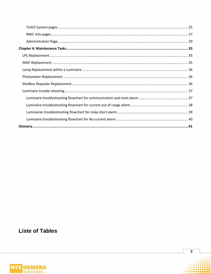
Chapter 4: Maintenance Tasks ...................................................................................................................... 35
LPC Replacement ................................................................................................................................................. 35
NWC Replacement .............................................................................................................................................. 35
Lamp Replacement within a Luminaire ............................................................................................................... 36
Photometer Replacement ................................................................................................................................... 36
Modbus Repeater Replacement .......................................................................................................................... 36
Luminaire trouble shooting ................................................................................................................................. 37
Luminaire troubleshooting flowchart for communication and reset alarm ................................................... 37
Luminaire troubleshooting flowchart for current out of range alarm ............................................................ 38
Luminaires troubleshooting flowchart for relay short alarm .......................................................................... 39
Luminaire troubleshooting flowchart for No current alarm ........................................................................... 40
Glossary....................................................................................................................................................... 41
Liste of Tables

4

5
Liste of Figures

6
Introduction Background Nyx Hemera Technologies supplies, delivers and commissions its Tunnel Lighting Addressable Control
System (TLACS) for road tunnels using different configurations. This document is a User and
Maintenance manual for TLACS. It covers the main features required in most of the different situations.
TLACS Overview Nyx Hemera Technologies’ TLACS for road tunnels is comprised of these main components: • Lighting control cabinet (LCC) • Network Controllers (NWC) • Local product controller (LPC) installed in the luminaires • Luminance photometer (LCAM) at each bore entry • Illuminance photometer (ILCAM) inside the tunnels for alarming only • Power line filters at each electrical distribution panel • Panel PC with Configuration Management Software (CMS) installed. Depending on the customer’s specifications not all components might be included. The lighting control cabinet includes most of the equipment. The NWC is the heart of the system and is located inside this cabinet. The network controller (in single or redundant mode) communicates with the photometer using RS-485, and every LPCs using power line communication or twisted pair wiring. Based on the luminance readings at the tunnel entrance, the NWC calculates the required LSR. While controlling the entire system, the NWC also monitors the status of the equipment with which it is connected. In the event of failure, alarms and reports are sent via e-mail to inform the maintenance crew. The lighting control cabinet includes all the required equipment for the NWC to work properly. The equipment includes most of the time: RS-485 repeaters, RS-485 surge protection devices, Ethernet Network switch, optional UPS, touchscreen panel PC for a local user interface with all maintenance software installed on it, the low-voltage equipment to provide a clean VAC supply (depending on the installation it might be 120VAC or 240VAC), and 24VDC to power up all the internal equipment. Every luminaire is equipped with a LPC to adjust their light output. Every LPC has its own lighting stage level (LSC) to switch ON. If the required lighting stage is equal or higher than the configured level, the LPC will switch the light ON. When using dimming, each LSR has its corresponding output level. The LPC monitors its luminaire to verify that the power and power factor are in the expected range. If the electrical measurements are out of range, alarms are raised in the NWC. The luminance photometers (LCAMs) are the main input for the lighting control system. They measure the luminanceat the tunnel’s entrances so the NWC can select the most suitable LSR in order to meet

7
RP-22 / IEC 88 recommandations, minimize the power consumption, increase the useful life of the luminaires, and have the safest light level in the threshold zone of the tunnel. The illuminance photometers (ILCAMs) inside the tunnel measure in real time the actual lumen output inside the tunnel so the NWC can generate alarms if the lighting level reaches an unacceptable range. This helps taking into consideration the effect of dirt accumulation, luminaires depreciation, and any other factor that can affect the lumen outputs over time. A power line filter is installed on every electrical feed, reducing the effects on other equipment, which could generate noise and affect power line communication performance. This filter is also installed to avoid future equipment to have an unexpected impact on the tunnel lighting control system. TLACS also includes a Web interface for system supervision as well as a Modbus interface which can supply measurement and status data to a third party supervision system if required.
Document Overview This document includes the following main sections:
• TLACS This section describes the TLACS lighting control system’s behavior.
• User Interface This section covers the user interface and basic operation of the TLACS.
• Maintenance Tasks This section describes maintenance tasks, such as replacing an LPC, replacing a NWC and CMS (TLACS’ Configuration Management Software) configuration, database backup and restore.
References [1] NWC-USM-001 Installation manual [2] NWC-USM-005 Modbus interface [3] CMS-USM-001 CMS User Manual [4] LCAM-USM-002 LCAM User Manual [5] ILCAM-USM-002 ILCAM User Manual
The TLACS The TLACS controls tunnel lighting conditions according to outside and inside tunnel’s lighting levels. The TLACS determines the required lighting level (LSR) according to the LCAM’s and ILCAMs signal located on each bore. In the event of photometer’s failure, the virtual photometer will take over a backup photometer. The virtual photometer is managed internally by the NWC, according to the local time of the NWC and geographical location.

8
Organization of Zones and Busses The RP22 and IEC 88 determined zones to identify the different sections within tunnels. TLACS takes into account this principle in order to conform to the standards. Based on the tunnel’s length, the number of zones can be adapted. As TLACS uses the power line or twisted pair for its communication, the electrical installation needs to be reflected within the system. This is done by so-called busses. The basic idea is that there is one (1) bus per zone per phase. If the electrical installation uses independent distribution panels to feed the lighting, additional busses are needed. In this case there is one (1) bus per zone per phase. All LPCs are associated with a bus. In the following figures different configurations are illustrated: Figure 1 shows a dual bore (TLACS controls one (1) direction of traffic), with one (1) electrical distribution panel
Bus 1 Bus 2 Bus 3 Bus 4
Bus 5 Bus 6 Bus 7 Bus 8
Bus 9 Bus 10 Bus 11 Bus 12
PHASE APHASE A
Threshold ZoneThreshold Zone Transition ZoneTransition Zone Interior ZoneInterior Zone Exit ZoneExit Zone
PHASE BPHASE B
PHASE CPHASE C
Figure 1: Dual bore, 1 electrical panel
Figure 2 shows a dual bore (TLACS controls one (1) direction of traffic), with two (2) electrical distribution panels
Bus 1 Bus 2 Bus 3 Bus 4
Bus 5 Bus 6 Bus 7 Bus 8
Bus 9 Bus 10 Bus 11 Bus 12
PHASE APHASE A
Threshold ZoneThreshold Zone Transition ZoneTransition Zone Interior ZoneInterior Zone Exit ZoneExit Zone
PHASE BPHASE B
PHASE CPHASE C
Bus 13 Bus 14 Bus 15 Bus 16
Bus 17 Bus 18 Bus 19 Bus 20
Bus 21 Bus 22 Bus 23 Bus 24
PHASE APHASE A
PHASE BPHASE B
PHASE CPHASE C
Figure 2: Dual bore, 2 electrical panels

9
Figure 3 shows a single bore (TLACS controls both directions of traffic), with one (1) or two (2) electrical distribution panels. In this situation it can be that both directions are from one (1) electrical panel, but different zones/busses are needed for each direction as the lighting levels and control might be different depending on the direction
Bus 1 Bus 2 Bus 3 Bus 4
Bus 5 Bus 6 Bus 7 Bus 8
Bus 9 Bus 10 Bus 11 Bus 12
PHASE APHASE A
Threshold ZoneThreshold Zone Transition ZoneTransition Zone Interior ZoneInterior Zone Exit ZoneExit Zone
PHASE BPHASE B
PHASE CPHASE C
Bus 16 Bus 15 Bus 14 Bus 13
Bus 20 Bus 19 Bus 18 Bus 17
Bus 24 Bus 23 Bus 22 Bus 21
PHASE APHASE A
PHASE BPHASE B
PHASE CPHASE C
Exit ZoneExit Zone Interior ZoneInterior Zone Transition ZoneTransition Zone Threshold ZoneThreshold Zone
Figure 3: Single bore, 2 directions
If multiple electrical panels are installed, the NWC outputs are used to switch between the panels.
Figure 4: NWC outputs to switch electrical panel
Light Output Level (LRS) The applied light level (LSR) is a number from 2 to maximal 32 (for system optimisation, most installations will be limited to 12) that indicates a required tunnel lumens level, where a higher value indicates a higher lumens level. LSR of 2 to 4 is typically applicable during the night, dusk and dawn. For each LSR, the
10
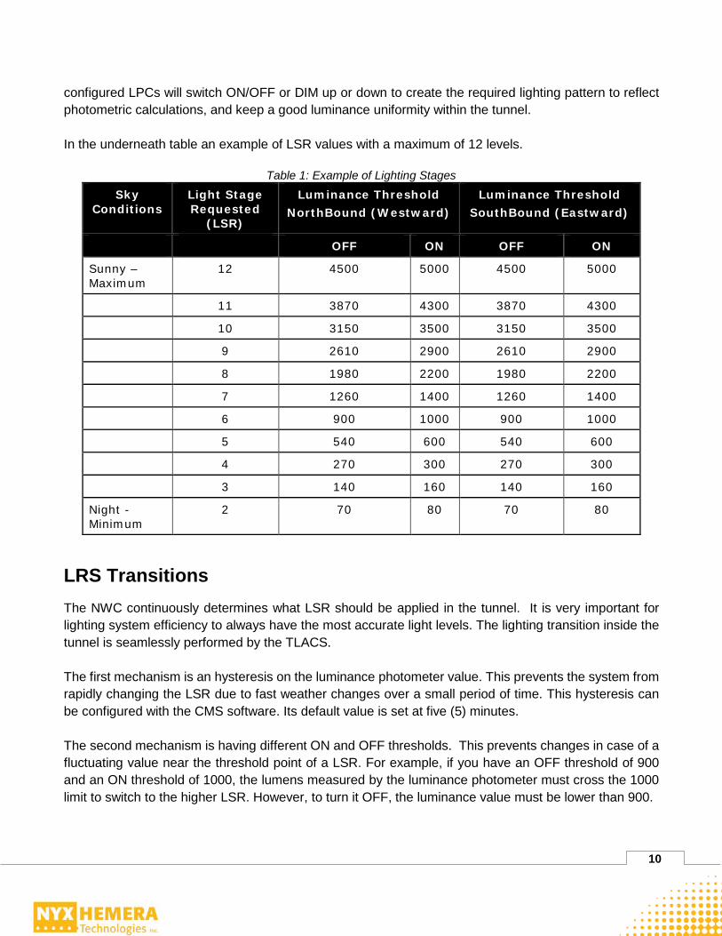
configured LPCs will switch ON/OFF or DIM up or down to create the required lighting pattern to reflect photometric calculations, and keep a good luminance uniformity within the tunnel. In the underneath table an example of LSR values with a maximum of 12 levels.
Table 1: Example of Lighting Stages Sky
Conditions Light Stage Requested
(LSR)
Luminance Threshold NorthBound (Westward)
Luminance Threshold SouthBound (Eastward)
OFF ON OFF ON
Sunny – Maximum
12 4500 5000 4500 5000
11 3870 4300 3870 4300
10 3150 3500 3150 3500
9 2610 2900 2610 2900
8 1980 2200 1980 2200
7 1260 1400 1260 1400
6 900 1000 900 1000
5 540 600 540 600
4 270 300 270 300
3 140 160 140 160
Night - Minimum
2 70 80 70 80
LRS Transitions The NWC continuously determines what LSR should be applied in the tunnel. It is very important for lighting system efficiency to always have the most accurate light levels. The lighting transition inside the tunnel is seamlessly performed by the TLACS. The first mechanism is an hysteresis on the luminance photometer value. This prevents the system from rapidly changing the LSR due to fast weather changes over a small period of time. This hysteresis can be configured with the CMS software. Its default value is set at five (5) minutes. The second mechanism is having different ON and OFF thresholds. This prevents changes in case of a fluctuating value near the threshold point of a LSR. For example, if you have an OFF threshold of 900 and an ON threshold of 1000, the lumens measured by the luminance photometer must cross the 1000 limit to switch to the higher LSR. However, to turn it OFF, the luminance value must be lower than 900.

11
The third mechanism is a delay between the LSR’s transitions. In cases of a sudden change in the luminance value, the luminaire must stay at each intermediate LSR for a certain time. For example, if the current LSR is 9 and huge darks clouds appear, instead to changing the LSR directly to 6, the system will change to LSR 8, then to LSR 7, and finally to LSR 6. The delay is called the Ramp Yimer and is configurable with the CMS software. Its default value is set at one minute. This mechanism is programmed to avoid drastic changes in lumen level. The fourth mechanism is in case of the new LSR request, the LSR is sent to one LPC at a time; therefore, changing the light states of all the luminaires in the tunnel will take a few minutes. This mechanism has been programmed to avoid a sudden and significant increase in the electrical load on the network.
I/O options The NWC has eight (8) digital inputs. It is possible to use these inputs to force the lighting stage to the maximum or to force a complete shutdown of all luminaires. This mechanism has been programmed to manally overtight the LRSs in case of maintenance, emergency, etc.
Illuminance Alarm The illuminance photometers enable the reading of the actual lighting conditions inside the tunnel. Ideally there is one (1) illuminance photometer in each zone in each bore. Therefore, every photometer monitors one section of the tunnel. The system monitors the actual light conditions reported by each photometer versus an expected calibrated value. If the read value is more than a certain % off the original value (to be defined at commissioning time), the system will generate an alarm via email and make the alarm value available over Modbus for SCADA. To avoid continuous alarms, the reading values are being averaged over a 15 minutes period of time. The system normally requires several weeks of testing before setting final stable values. In the event an illuminance photometer value cannot be read by the NWC, an alarm giving a communication failure will be raised.
System Monitoring The TLACS not only controls but also monitors the system components. All system faults are logged in reports and sent by email on a periodical basis. All information is also available through the Modbus interface. Note that reports can also be read directly from the NWC at any time. Alarm emails are sent when the fault occurs and when the system returns to normal. No individual alarms are sent by email for a single luminaires, they are grouped inside bus alarms. The idea of grouping luminaire alarms via email is to avoid multiple alarm emails for the same failure. For example, breakers that have tripped would cause a series of emails when the alarm occurs. In order to avoid spamming with multiple alarms all occurring at the same time (probably all related to the same issue), a delay of 5 minutes
12
is programmed between each email sending. During that delay, all new alarms are cumulated and sent in the same email. All alarms are also logged in the Alarms_Log.csv report file located on SD card of the NWC. Only the active NWC writes the alarms. So, in case of a redundant system, both NWC logs must be verified to have the complete history in the event that the active NWC has switched. The switch event will be added in the NWC_Log.csv file.
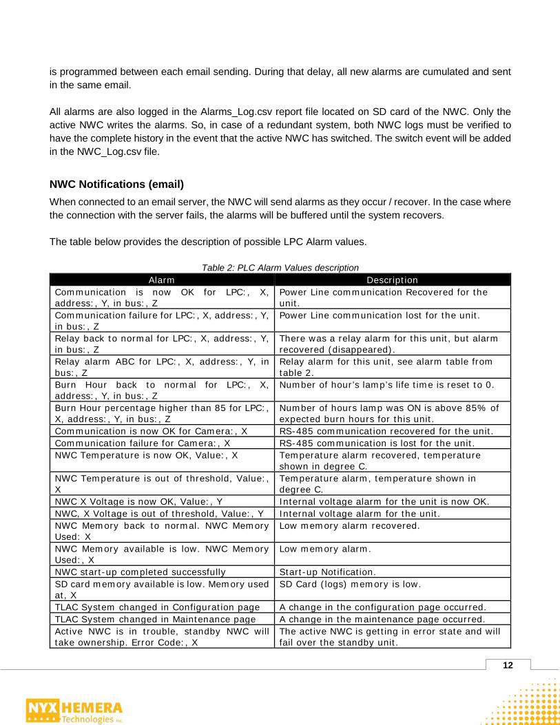
NWC Notifications (email) When connected to an email server, the NWC will send alarms as they occur / recover. In the case where the connection with the server fails, the alarms will be buffered until the system recovers. The table below provides the description of possible LPC Alarm values.
Table 2: PLC Alarm Values description Alarm Description
Communication is now OK for LPC:, X, address:, Y, in bus:, Z
Power Line communication Recovered for the unit.
Communication failure for LPC:, X, address:, Y, in bus:, Z
Power Line communication lost for the unit.
Relay back to normal for LPC:, X, address:, Y, in bus:, Z
There was a relay alarm for this unit, but alarm recovered (disappeared).
Relay alarm ABC for LPC:, X, address:, Y, in bus:, Z
Relay alarm for this unit, see alarm table from table 2.
Burn Hour back to normal for LPC:, X, address:, Y, in bus:, Z
Number of hour’s lamp’s life time is reset to 0.
Burn Hour percentage higher than 85 for LPC:, X, address:, Y, in bus:, Z
Number of hours lamp was ON is above 85% of expected burn hours for this unit.
Communication is now OK for Camera:, X RS-485 communication recovered for the unit. Communication failure for Camera:, X RS-485 communication is lost for the unit. NWC Temperature is now OK, Value:, X Temperature alarm recovered, temperature
shown in degree C. NWC Temperature is out of threshold, Value:, X
Temperature alarm, temperature shown in degree C.
NWC X Voltage is now OK, Value:, Y Internal voltage alarm for the unit is now OK. NWC, X Voltage is out of threshold, Value:, Y Internal voltage alarm for the unit. NWC Memory back to normal. NWC Memory Used: X
Low memory alarm recovered.
NWC Memory available is low. NWC Memory Used:, X
Low memory alarm.
NWC start-up completed successfully Start-up Notification. SD card memory available is low. Memory used at, X
SD Card (logs) memory is low.
TLAC System changed in Configuration page A change in the configuration page occurred. TLAC System changed in Maintenance page A change in the maintenance page occurred. Active NWC is in trouble, standby NWC will take ownership. Error Code:, X
The active NWC is getting in error state and will fail over the standby unit.
13
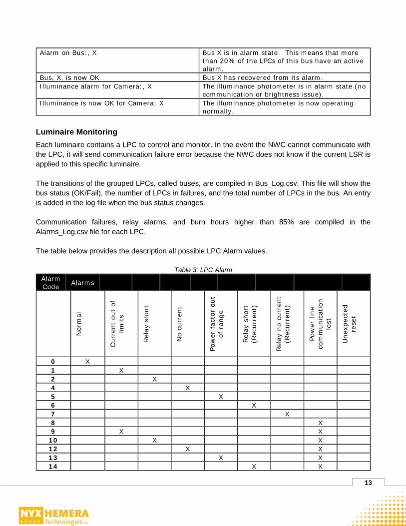
Alarm on Bus:, X Bus X is in alarm state. This means that more than 20% of the LPCs of this bus have an active alarm.
Bus, X, is now OK Bus X has recovered from its alarm. Illuminance alarm for Camera:, X The illuminance photometer is in alarm state (no
communication or brightness issue). Illuminance is now OK for Camera: X The illuminance photometer is now operating
normally.
Luminaire Monitoring Each luminaire contains a LPC to control and monitor. In the event the NWC cannot communicate with the LPC, it will send communication failure error because the NWC does not know if the current LSR is applied to this specific luminaire. The transitions of the grouped LPCs, called buses, are compiled in Bus_Log.csv. This file will show the bus status (OK/Fail), the number of LPCs in failures, and the total number of LPCs in the bus. An entry is added in the log file when the bus status changes. Communication failures, relay alarms, and burn hours higher than 85% are compiled in the Alarms_Log.csv file for each LPC. The table below provides the description all possible LPC Alarm values.
Table 3: LPC Alarm Alarm Code Alarms
Nor
mal
Cur
rent
out
of
limits
Rel
ay s
hort
No
curr
ent
Pow
er fac
tor
out
of r
ange
Rel
ay s
hort
(R
ecur
rent
)
Rel
ay n
o cu
rren
t (R
ecur
rent
)
Pow
er li
ne
com
mun
icat
ion
lost
Une
xpec
ted
rese
t 0 X 1 X 2 X 4 X 5 X 6 X 7 X 8 X 9 X X
10 X X 12 X X 13 X X 14 X X

14
15 X X 128 X 129 X X 130 X X 132 X X 133 X X 134 X X 135 X X 136 X X
Table 4: LPC Alarm Details Relay Alarm Description Relay Alarm Details
Current out of limits
The current out-of-limits alarm indicates that the current is outside the pre-determined normal range.
Relay short Relay inside the LPC is short. Luminaire is not turning OFF.
No current Indicates that there is no current on the relay, even if the relay is closed (lamp ON).
Power factor out of range
This alarm indicates that the luminaire power factor is out of range. This may happen if the driver or LED panel is defective.
Relay short (Recurrent)
Indicates that a relay short alarm has occurred over the last three periods of 48 hours. The alarm will be cleared when the short alarm has stopped occurring in a complete 48 hours cycle.
Relay no current (Recurrent)
Indicates that “No current alarm” has occurred over the last three periods of 48 hours. The alarm will be cleared when the short alarm has stopped occurring in a complete 48 hours cycle.
Power line communication lost
Indicates that no valid power line communication has been received from the NWC after a delay determined by the communication timer. This delay is configured at 30 minutes. This alarm is cleared after a valid power line communication is detected.
Unexpected reset
Indicates that a power failure or an unknown reset has occurred. This is cleared every time the NWC reads the LPC status. This alarm may highlights a firmware reset issue or a hardware problem. LPCs that continuously trigger such an alarm without power failure should be replaced.
Photometer Monitoring In the event the system cannot communicate with a photometer, it will consider this condition as a fault. For luminance photometers equipped with wipers, a low washer fluid alarm will appear when the float switch open on a low level. The washer system is self-protecting for the pump and will not try to pump with a low level. Every transition of the photometer state is logged in the Camera_Log.csv report file located on the SD card. An entry is added in the Camera log file when the Camera Communication or Windshield Washer
15
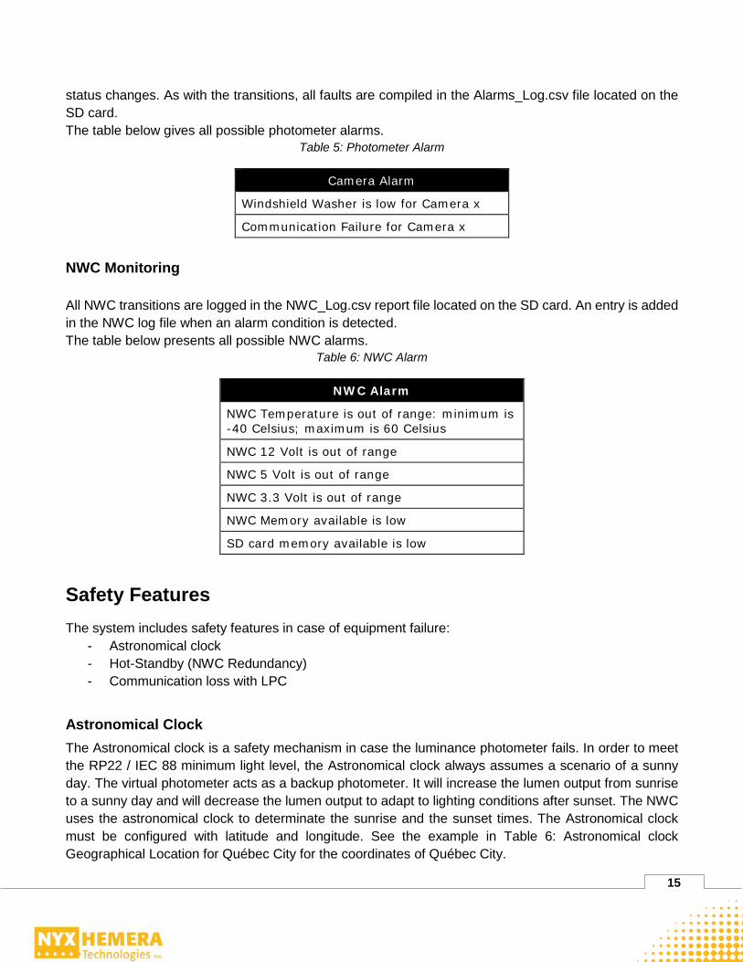
status changes. As with the transitions, all faults are compiled in the Alarms_Log.csv file located on the SD card. The table below gives all possible photometer alarms.
Table 5: Photometer Alarm
Camera Alarm
Windshield Washer is low for Camera x
Communication Failure for Camera x
NWC Monitoring All NWC transitions are logged in the NWC_Log.csv report file located on the SD card. An entry is added in the NWC log file when an alarm condition is detected. The table below presents all possible NWC alarms.
Table 6: NWC Alarm
NWC Alarm
NWC Temperature is out of range: minimum is -40 Celsius; maximum is 60 Celsius
NWC 12 Volt is out of range
NWC 5 Volt is out of range
NWC 3.3 Volt is out of range
NWC Memory available is low
SD card memory available is low
Safety Features The system includes safety features in case of equipment failure:
- Astronomical clock - Hot-Standby (NWC Redundancy) - Communication loss with LPC
Astronomical Clock The Astronomical clock is a safety mechanism in case the luminance photometer fails. In order to meet the RP22 / IEC 88 minimum light level, the Astronomical clock always assumes a scenario of a sunny day. The virtual photometer acts as a backup photometer. It will increase the lumen output from sunrise to a sunny day and will decrease the lumen output to adapt to lighting conditions after sunset. The NWC uses the astronomical clock to determinate the sunrise and the sunset times. The Astronomical clock must be configured with latitude and longitude. See the example in Table 6: Astronomical clock Geographical Location for Québec City for the coordinates of Québec City.

16
Table 7: Astronomical clock Geographical Location for Québec City
Coordinate Value
Latitude 46.8167
Longitude -71.2167 The following table describes an example for the values of the virtual photometer:
Table 8: Lighting Stage for Southbound Virtual Camera NWC Local Time Light Stage Requested (LSR)
From 0 minutes after sunset to 10 minutes after sunrise 2
From 20 minutes after sunrise to 0 minutes before sunset 3
From 40 minutes after sunrise to 15 minutes before sunset 4
From 60 minutes after sunrise to 30 minutes before sunset 5
From 80 minutes after sunrise to 45 minutes before sunset 6
From 100 minutes after sunrise to 60 minutes before sunset 7
From 120 minutes after sunrise to 75 minutes before sunset 8
From 140 minutes after sunrise to 90 minutes before sunset 9
From 160 minutes after sunrise to 105 minutes before sunset 10
From 180 minutes after sunrise to 120 minutes before sunset 11
From 300 minutes after sunrise to 135 minutes before sunset 12
Table 9: decribes an example for the values of the other bore’s Astronomical clock NWC Local Time Light Stage Requested (LSR)
From 0 minutes after sunset to 10 minutes after sunrise 2
From 20 minutes after sunrise to 0 minutes before sunset 3
From 40 minutes after sunrise to 15 minutes before sunset 4
From 60 minutes after sunrise to 30 minutes before sunset 5
From 80 minutes after sunrise to 45 minutes before sunset 6
From 100 minutes after sunrise to 60 minutes before sunset 7
From 120 minutes after sunrise to 75 minutes before sunset 8
From 140 minutes after sunrise to 90 minutes before sunset 9
From 160 minutes after sunrise to 105 minutes before sunset 10
From 180 minutes after sunrise to 120 minutes before sunset 11
From 300 minutes after sunrise to 135 minutes before sunset 12

17
Hot Standby The lighting control cabinet might include two NWCs. In the NWC cluster, the first one is active while the other acts as a hot standby. The active unit is the first one to boot up and will serve the cluster IP address. A failover operation occurs when the standby unit becomes the active and the active unit becomes the standby. In can of both the serial and Ethernet links between the two NWCs are down, the standby NWC will become active since it doesn’t know the real status of the other one.
User Interface (Web) This section describes the functionalities of the web-based user interface of the TLACS. From the website, most of the maintenance and monitoring of the system can be performed. The web interface is customized for each project and so it may be slightly different from the images in this document.
Tree View The following figure describes the NWC website architecture. Each topic shown in the following diagram can be access through the web interface, with any browser on the network.
TLAC System
Web Server
Administration
Overview
Camera
Maintenance
Server Configuration
Alarm & Notification
Users
NWC Info
Overview
Configuration
Overview
Configuration Dry Contact
Figure 5: Web interface page hierarchy The TLACS tab shows information about the system status and the configured lighting parameters. It also shows the performance tasks.
18
The NWC Info tab provides information about the lighting controllers and the configuration. The administration tab is mainly used to configure IT-related parameters. It can also be used to configure the system notification.
TLACS and NWC Information without Login In order to access the web page to control and monitor the lighting control system, the NWC IP or the cluster address (in a redundant system) must be entered as the web page URL. The IP address depends on the IP address assigned by the I.T’s group. The main page shows an overview of the system and the login access. In case of a network failure that is not related to the lighting control cabinet, it is possible to use the panel PC if available or any laptop connected to the cabinet Ethernet switch. In this case, it is necessary to use the local NWC users to log in to perform most of the system’s functions because the active directory server cannot be reached to authenticate the user.
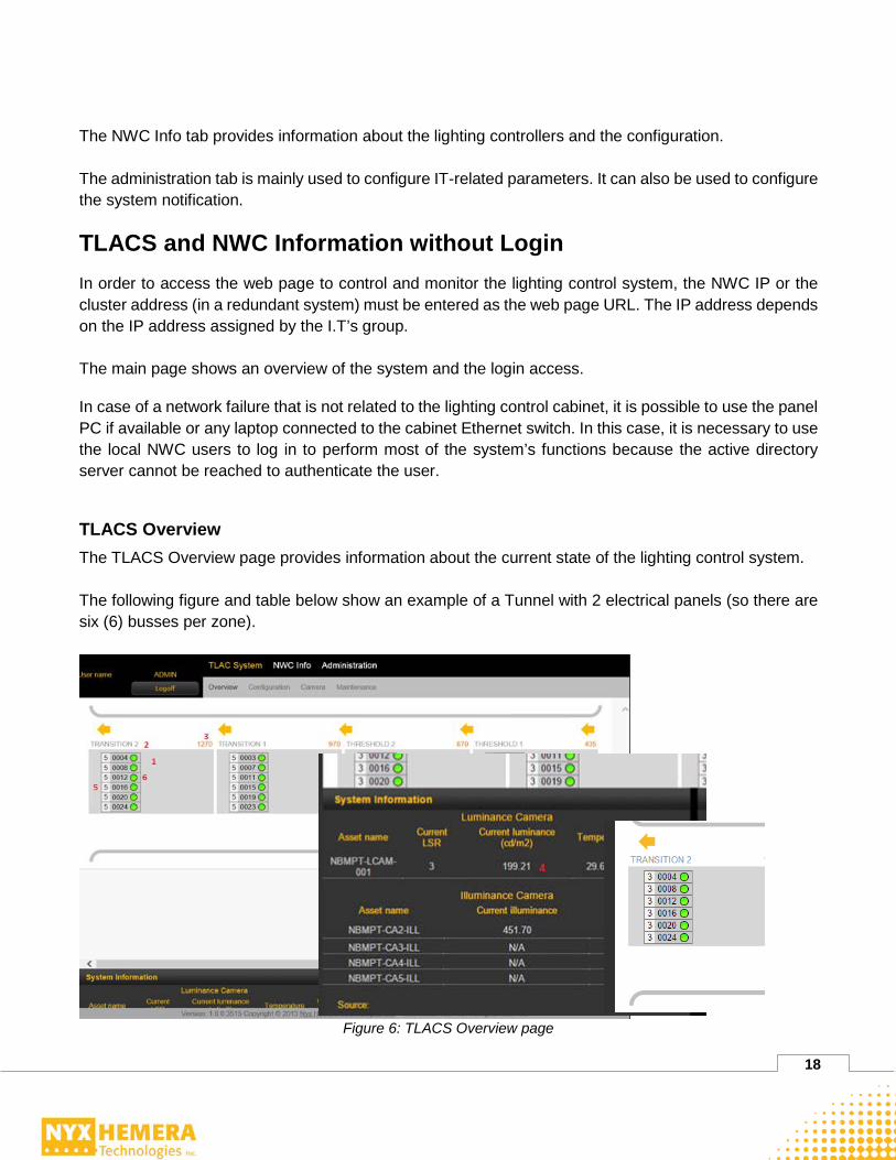
TLACS Overview The TLACS Overview page provides information about the current state of the lighting control system. The following figure and table below show an example of a Tunnel with 2 electrical panels (so there are six (6) busses per zone).
Figure 6: TLACS Overview page

19
Table 10: TALCS Overview page fields description ID Field Description 1 Tunnel Zone Area Area that groups all the information related to that zone. 2 Tunnel Zone Name The name for the tunnel zone. 3 Tunnel Zone End
Marker The foot marker for the end of the tunnel zone.
4 Tunnel Zone Illuminance Camera
The asset name for the illuminance photometer and his current values.
5 Current Bus LSR The LSR currently sent to the bus. 6 Bus ID and Status The ID for the bus and its status.
In this example, the tunnel view is broken into tunnel zones based on the lighting recommendations RP22 and IEC 88 (threshold 1 and 2, transition 1 and 2). The Overview page shows all buses within each tunnel zone. Each tunnel zone is associated with an illuminance photometer to validate the lumen output based on current requested LSR. The value next to the photometer name is the value actually read by the photometer or N/A if the value is not available. Each tunnel zone has six (6) buses of luminaires, one (1) per phase, per electrical panel. An example is the TRANSITION 2 zone, where the buses are 0004, 0008, 0012, 0016, 0020 and 0024.
• One Bus contains all LPCs running within a specific zone, over a specific electrical phase, and one (1) distribution panel. We need six (6) buses to include all LPCs of a zone (Ex. Transition 1) since we have two (2) distribution panels, each distributing three (3) phases.
The number next to the bus number is the actual LSR sent to the luminaires on the bus. The circle gives a quick status:
• Bright green circle and grey background means 20% of the LPCs or less have triggered an alarm (any alarm).
• Dark green and a red background means 20% of the LPCs or more have triggered an alarm (any alarm).
A click on the tunnel zones provides detailed information regarding that zone. The detailed information is organized per bus, see:

20
Figure 7: Bus details
Table 11: Bus details field description ID Field Description 1 Back Allows the return to the global view. 2 Bus tab selection Allows the display specific information on a bus. 3 Zone Asset Name The asset name and electrical phase for the zone. 4
Zone Status
- Green circle: Less than 20% of the LPCs have triggered an alarm.
- Yellow circle: Between 20% and 40% of the LPCs have triggered an alarm.
- Red circle: More than 40% LPCs have triggered an alarm. 5 Zone Average Burn
Hour Average percentage of the lifetime; for all the lamps on the bus.
6 Total LPCs in Zone Total LPCs in the zone. 7 LPCs Error in Zone Total LPCs in alarm in the zone. 8 Associated LSR Configured LSR when the luminaire is turned ON. All buses
are set to LSR 0 at this time. At the bottom of the screen, the System Information is available by clicking the quick bar (System Information header). Click again on the System Information to close this view.
21
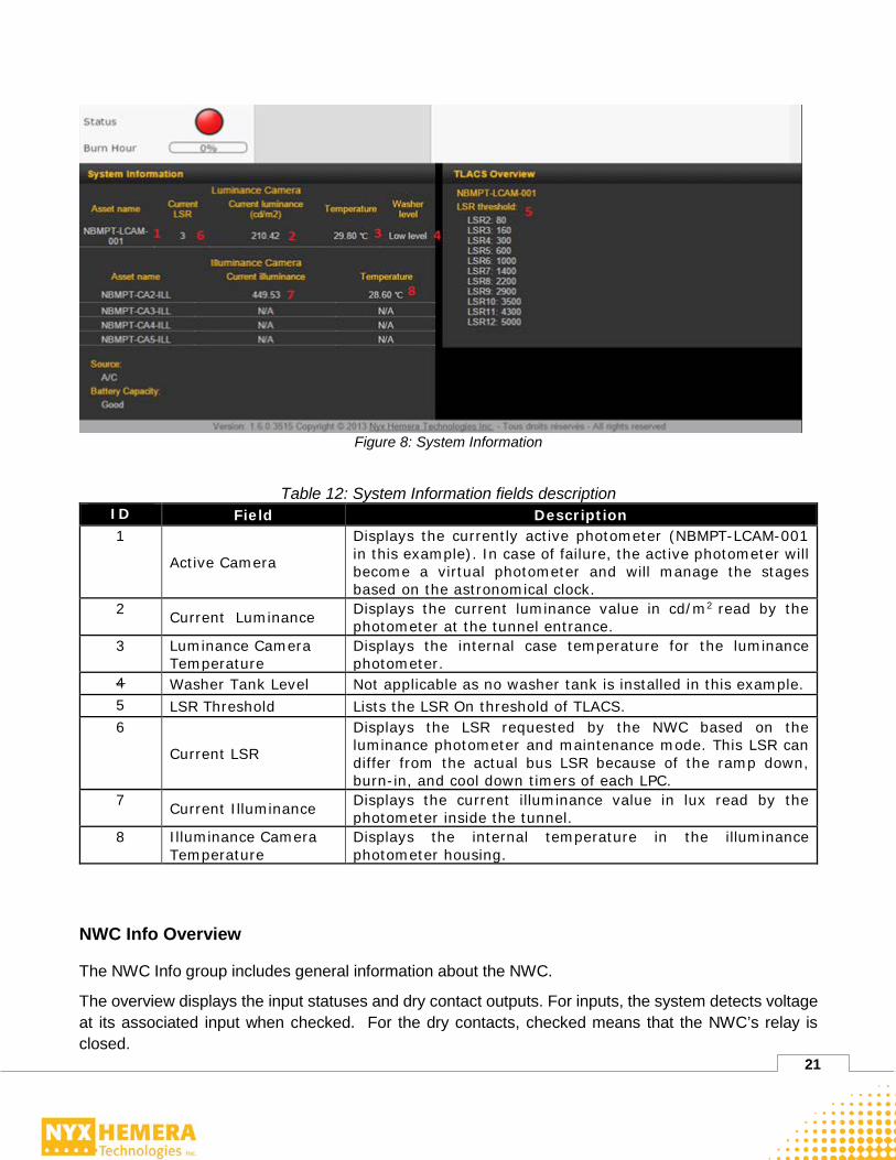
Figure 8: System Information
Table 12: System Information fields description ID Field Description 1
Active Camera
Displays the currently active photometer (NBMPT-LCAM-001 in this example). In case of failure, the active photometer will become a virtual photometer and will manage the stages based on the astronomical clock.
2 Current Luminance Displays the current luminance value in cd/m2 read by the photometer at the tunnel entrance.
3 Luminance Camera Temperature
Displays the internal case temperature for the luminance photometer.
4 Washer Tank Level Not applicable as no washer tank is installed in this example. 5 LSR Threshold Lists the LSR On threshold of TLACS. 6
Current LSR
Displays the LSR requested by the NWC based on the luminance photometer and maintenance mode. This LSR can differ from the actual bus LSR because of the ramp down, burn-in, and cool down timers of each LPC.
7 Current Illuminance Displays the current illuminance value in lux read by the photometer inside the tunnel.
8 Illuminance Camera Temperature
Displays the internal temperature in the illuminance photometer housing.
NWC Info Overview
The NWC Info group includes general information about the NWC.
The overview displays the input statuses and dry contact outputs. For inputs, the system detects voltage at its associated input when checked. For the dry contacts, checked means that the NWC’s relay is closed.

22
Figure 9: NWC Info Overview
Table 13: NWC field description Field Description
Input Pins Actual state of the input pins.
Output Pins In the current example, only contact pin 2 is checked, so the second electrical panel is selected for communication.
The quick bar at the bottom slide shows information related to the status of the NWC.
Figure 10: Status of the NWC

23
Table 14: Status field description Field Description
System Date-Time Date and time on the system. Asset Name Asset name represents the logical name of the NWC.
Firmware Version Firmware version. The first number is the major version. The second is the minor version. The third is the build version. The last one is the SVN revision number.
Serial Number NWC serial number. It should match number on the NWC label. IP Address Individual IP address of the NWC. Status Current NWC status (Active or Standby).
Communication between the NWC and the LPCs The active NWC communicates over the power line to each LPC. The electrical distribution network acts as a communication network. The signal is sent to each electrical distribution panel by a dedicated triple phase breaker marked LCC signal injection. The lighting control cabinet switches each electrical panel communication to the NWC via contactors (in case of multiple electrical panels). The NWC will communicate with all LPCs in the tunnel. As all the electrical network is in triple phase, the NWC communicates to only one phase at a time to ensure minimal electrical noise and maximal signal strength over power line. In order to optimize communication performance, the NWC will communicate to all LPCs on Phase A, then on B, then on C—before returning to Phase A. As a safety mechanism, in the event that a LPC does not receive any valid ping command from the NWC for a period of 20 minutes, the LPC will apply the maximum LSR. When it will receive a valid ping command, it will return to normal operation and apply the LSR requested by the NWC. As another safety mechanism, after a power cycle of the LPC, the LPC will go to the maximum LSR until it receives a valid ping command to apply another LSR requested by the NWC.
NWC Specific Information Quick View The following table describes the Specific Information quick view component for the NWC Info section.
Table 15: Specific Information Quick View Component Information Description
Disk Space Total disk space on the NWC in Mb. (Mega Bytes) RAM Installed Installed memory RAM on the NWC in Mb (Mega Bytes) RAM Available Current available memory on the NWC RAM in Mb. (Mega Bytes) SD Card Space Total SD Card space connected to the NWC in Mb. (Mega Bytes) SD Card Free Space Available SD Card space connected to the NWC in Mb. (Mega
Bytes) NWC Internal Temperature
Current temperature inside the NWC in Celsius.
NWC PSU Voltages Current voltage of the NWC (12V, 5V and 3.3V).

24
Configuration and Maintenance Operations Logging into the System To log into the system as an active directory user:
1- Access the web page address using the NWC or cluster IP address 2- Check the Domain box 3- Enter your username and password 4- Click on the Login button.
In case no active directory system is available, the local NWC accounts can be used. In order to log in with local NWC username, uncheck the Domain box, enter a local NWC username and password, and click on the Login button. Once logged in, if your user account has all rights, you will see the following screen. To log out, click on the Logoff button.
Figure 11: TLACS configuration The TLACS page gives access to lighting system configuration and maintenance operations. The NWC Info tab displays information related to the NCW. The Administration tab enables the change to local NWC users’ email server settings, and notifications and alarms configuration.
25
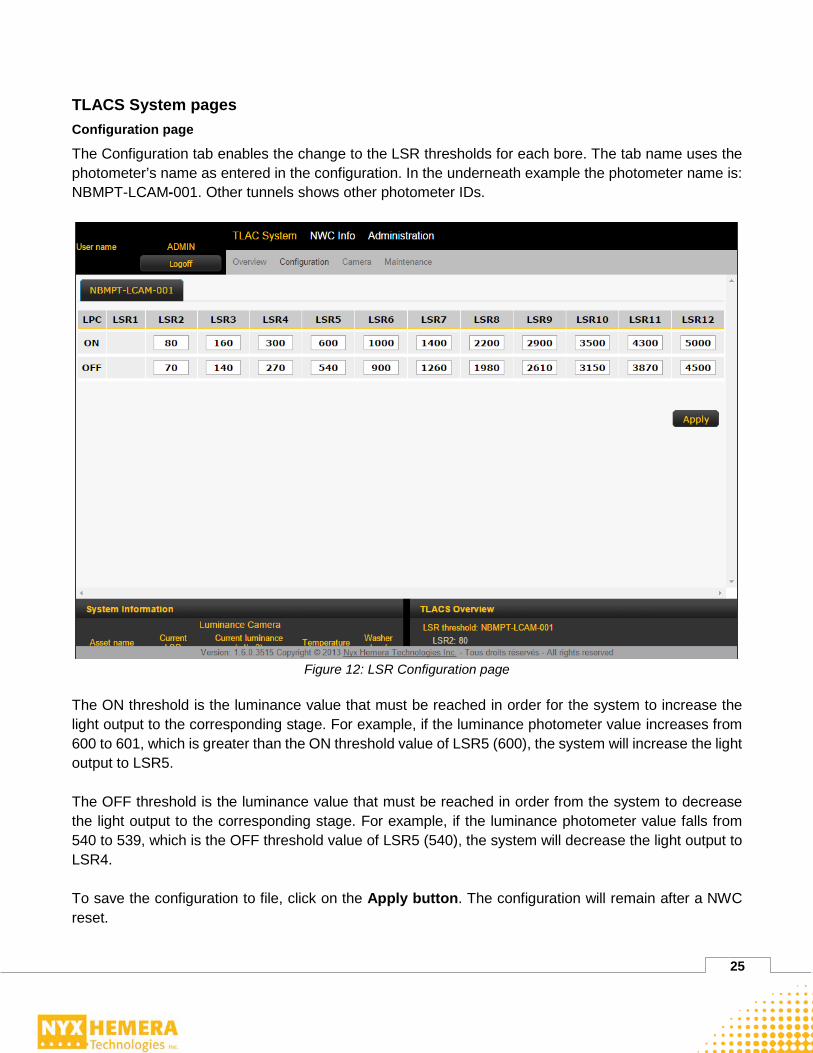
TLACS System pages Configuration page
The Configuration tab enables the change to the LSR thresholds for each bore. The tab name uses the photometer’s name as entered in the configuration. In the underneath example the photometer name is: NBMPT-LCAM-001. Other tunnels shows other photometer IDs.
Figure 12: LSR Configuration page
The ON threshold is the luminance value that must be reached in order for the system to increase the light output to the corresponding stage. For example, if the luminance photometer value increases from 600 to 601, which is greater than the ON threshold value of LSR5 (600), the system will increase the light output to LSR5. The OFF threshold is the luminance value that must be reached in order from the system to decrease the light output to the corresponding stage. For example, if the luminance photometer value falls from 540 to 539, which is the OFF threshold value of LSR5 (540), the system will decrease the light output to LSR4. To save the configuration to file, click on the Apply button. The configuration will remain after a NWC reset.

26
Camera page
The Camera page presents detailed information on the photometers and to force user-defined values. The Camera page uses the same naming of the photometers as found in the installation drawings.
Figure 13: Camera page
Table 16: Fields description on the Camera page
ID Field Description 1 Camera Tab Specific information about a photometer. 2 Modbus Address Address the NWC uses to communicate with the photometer. 3 Firmware Version Photometer’s internal software version. 4 Temperature Internal housing temperature of the photometer. 5 Enable Manual Value To enable the Manual Value mode, which forces a value for the
photometer used by the system. 6
Manual Camera Value Value used by the system. When the system is not using the Manual Value mode, the value is the one read by the photometer.
Maintenance page
The TLACS Maintenance page is to manually force the current LSR in the TLACS. The system allows the individual forcing of the LSR of any of photometer. To force a LSR in a tunnel, use the tab of the

27
active photometer (NBMPT-LCAM-001 in the underneath example). If the photometer is defective use the Virtual Camera tab. To change the lighting level, select the desired level from the drop-down list and click on Apply. For normal operation, the system must be in Auto mode so that the LSR is selected based on the luminance photometer. The LSR change may not be instantaneous. It is controlled by a hysteresis timer and performs a gradual transition in the event that the currently applied LSR is higher than the new one forced. If a photometer is defective, the drop-down list will be greyed out. It will not be possible to force a level. In this case, use the virtual photometer tab.
Figure 14: Force LSR
NWC Info pages Dry Contact pages
The Dry Contact page shows the status of the dry contacts as well as manually force a value into it. To force a manual value on the dry contact, check the Manual check box and click on Apply. The active NWC will then control the output pin, the other one stays in High Impendence. Once Manual is checked, you can check and uncheck any Pin, forcing an input value or a dry contact output state. In order to apply the change to the system, you must click on the Apply button.

28
When a contact uses the Manual Value, the system uses the manual values and ignore the connector values. For the outputs, the NWC will physically open and close its dry contacts according to the Manual Value. WARNING: Output Pins are used to select the required electrical distribution panel for the power line communication. When the Box Manual is checked for the output, the power line communication between the LCC and the luminaire will not work properly. In this case, the safety feature of the LPC will put all luminaires ON at maximum level after 30 minutes without any update. This mode should be used only when the LSR is at MAX or when repairs and/or testing are required on the communication circuit in the Lighting Control Cabinet.
Figure 15: Dry Contact page
Configuration page
The NWC Info Configuration page is used to configure the date, time and the IP address of time server.
Figure 16: Time Server Configuration page

29
The system date and time section allows the setup of the NWC system date and time to be used if a time server is not available on the network. The time server section also enables the entry of the address of a SNTP Server to be use by the SNTP client on the NWC. Once the Apply button is clicked, the NWC will use the server’s address for synchronization and immediately force a time update. The NWC will synchronize its time every 10 minutes; however, depending on when a new time is available on the server, it may take up to 20 minutes to see the change on the NWC.
Administration Page
The Administration pages are used to manage the local NWC users as well as configure the server settings and system notifications.
Overview page
The Administration Overview page displays all local NWC users’ access currently configured in the TLACS. It also shows the notifications each user will receive.
Figure 17: Administration overview page’s users access

30
Table 17: Administration Overview Fields description ID Field Description
1 Users Name of the user. 2 Active Indicates if the user is active or not. This information can be
configured in User List section of Users tab. 3
Access-Admin Indicates if the user has complete access to Administration tabs. This information can be configured in Network Controller Access section of Server Configuration tab.
4
Access-Config
Indicates if the user has full complete rights to TLACS | Configuration and TLACS | Camera tabs. This information can be configured in Network Controller Access section of Server Configuration tab.
5
Access-Maintenance
Indicates if the user has full complete rights to TLACS | Camera and TLACS | Maintenance tabs. This information can be configured in Network Controller Access section of Server Configuration tab.
6 Notification-Config
Indicates if the user will receive email notifications when users with Configuration access rights log into the system. This information can be configured in Alarm & Notifications tab.
7 Notification-Maintenance
Indicates if the user will receive email notifications when users with Maintenance access rights log into to the system. This information can be configured in Alarm & Notifications tab.
8 Notification-Alarms
Indicates if the user will receive email notifications when an alarm occurs in the system. This information can be configured in Alarm & Notifications tab.
9
Notification-Report
Indicates if the user will receive reports by email every x days. The number of days can be configured in Alarm & Notification tab. This information can be configured in Alarm & Notifications page.
The quick view for the Administration page displays the number of local NWC users, number of inactive users, and if email server is configured or not.

31
Figure 18: Administration page’s number of users
User page
The Administration Users page enables the addition, removal and configuration of local NWC users.
Figure 19: Users page
Local NWC users are not attached to any central active directory systems, but rather to a local user database.

32
Table 18 User status page fields description ID Field Description
1 Active To change the status of a local NWC user from Active to Inactive and from Inactive to Active.
2 Delete To delete a local NWC user.
To add a local NWC user, fill in the Add User section. Then, click on the Add button.
Figure 20: Add User section
To reset a local NWC user password, fill in the Reset Password section. Then, click on the Reset button. To change the Password of a local NWC user, fill in the Change Password section. Then, click on the Change button.
Figure 21: Reset and Change Password section
Server Configuration page
The Administration Server Configuration page is for access rights management to local NWC users and configure the SMTP server used when an alarm or notification is sent.

33
Figure 22: User rights management
To configure the email server settings to send notifications, fill in the Email Settings section. Then, click on the Save button. To test the email server configuration, fill in the Test Email Settings. Then, click on the SMTP Test button.
Figure 23: User’s email configuration and testing
34
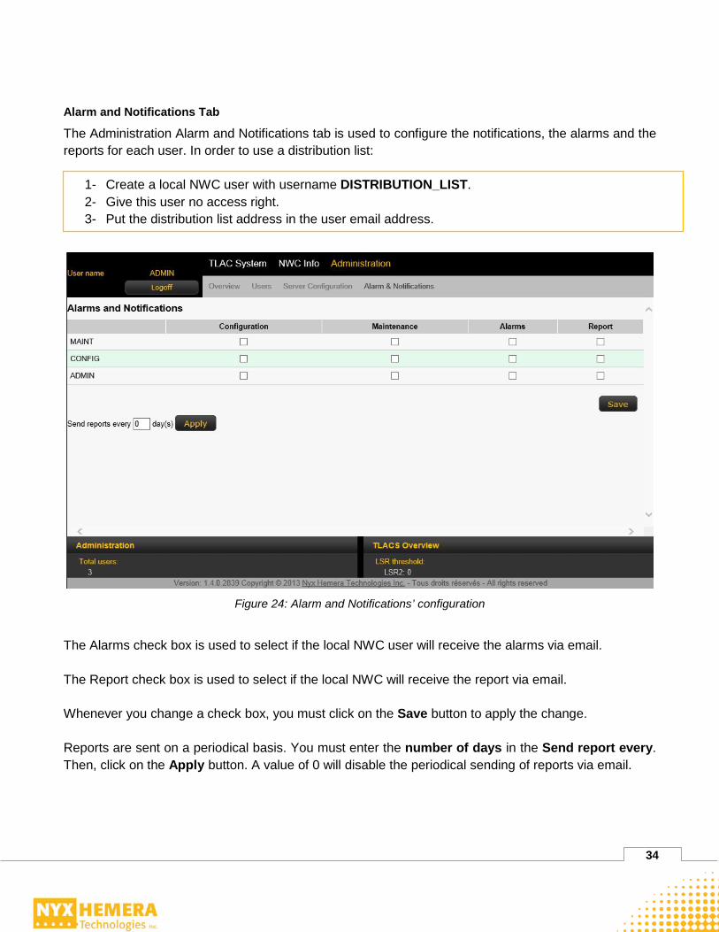
Alarm and Notifications Tab
The Administration Alarm and Notifications tab is used to configure the notifications, the alarms and the reports for each user. In order to use a distribution list:
1- Create a local NWC user with username DISTRIBUTION_LIST. 2- Give this user no access right. 3- Put the distribution list address in the user email address.
Figure 24: Alarm and Notifications’ configuration
The Alarms check box is used to select if the local NWC user will receive the alarms via email. The Report check box is used to select if the local NWC will receive the report via email. Whenever you change a check box, you must click on the Save button to apply the change. Reports are sent on a periodical basis. You must enter the number of days in the Send report every. Then, click on the Apply button. A value of 0 will disable the periodical sending of reports via email.

35
Chapter 4: Maintenance Tasks LPC Replacement To replace a LPC with CMS software, the following steps must be performed:
1. Remove power from the LPC to be replaced. 2. Disconnect the LPC. 3. Note the VID of the replacement LPC and the luminaire. The VID is a sequence of twelve
hexadecimal digits that uniquely identifies every LPC. It can be found on the LPC label. 4. Install the replacement LPC. 5. Restore the power to the new LPC. 6. Start CMS software on the Panel PC from the tunnel under maintenance. 7. Right click on the luminaire where the LPC has been replaced. Select Setup | Replace Local
Product Controller. 8. Enter the VID of the replacing LPC and click on OK. 9. The LPC will be configured by CMS software
10. Save the database by clicking File | Commit configuration to Database 11. Click on OK 12. Exit CMS.
NWC Replacement The NWC replacement is performed with the following steps:
1. Verify the NWC to replace is standby; the status LED ST2 must be blue. If so, reset the NWC by pressing the reset / Enter button until the beep sound.
2. Validate the active NWC is fully operational by reviewing the information on website in the TLAC System – Overview tab.
3. Unplug all cables from the faulty NWC. 4. Replace the NWC in the cabinet. 5. Connect all the cables to the replacement NWC, except the power cord. 6. Plug in the power cord. 7. Open a Telnet client and connect to the displayed IP address on the front display of the new
NWC. Enter the user admin/admin. 8. Enter the command: uboot_env –s ipaddr=XXX.XXX.XXX.XXX (enter the correct address) 9. Enter the command: uboot_env –s netmask=XXX.XXX.XXX.XXX (enter the correct network
mask) 10. Enter the command: uboot_env –s clusterip=XXX.XXX.XXX.XXX (enter the correct cluster
address if needed) 11. Enter the command: uboot_env –s clustersubnet=XXX.XXX.XXX.XXX (enter the correct cluster
network mask if needed)

36
12. Enter the command: uboot_env –s gatewayip=XXX.XXX.XXX.XXX (enter the correct gateway IP)
13. Enter the command: uboot_env –s dnsip=XXX.XXX.XXX.XXX (enter the correct DNS IP) 14. Enter the command: uboot_env –s asset name=”required asset name” 15. Enter the command: reset. 16. In a redundant setup: wait for 5 minutes, the active NWC will transfer the configuration to the new
one in standby mode. 17. In a standalone NWC’s mode, use CMS to send the configuration (see the CMS user manual). 18. Reset the active NWC by pressing the Reset / Enter button until the beep sound 19. Validate that the NWC is fully operational by reviewing the information on website in the TLAC
System – Overview tab. No error should appear on website.
Lamp Replacement within a Luminaire If the all the lamps and/or drivers of the luminaires are changed, but LPC remains in the luminaire, the burn hours of the LPC needs to be reset to take into consideration the new lamps. The steps to reset the burn hours are:
1. Open the CMS software on the panel PC. 2. Browse to the luminaire you replaced. 3. Right click the luminaire and select Reset Lamps. 4. Click OK on the message About to reset burn hour. Are you sure? 5. The Lamp replacement process starts. 6. Wait for message Process completed in Log Message window. 7. The message Lamp timers have been successfully reset for device (asset name) must appear in
the Log Message Window.
The average burn hour percentage on the web display will then decrease.
Photometer Replacement If a photometer or the electronic board of the photometer has to be replaced, make sure that the Modbus address is properly set. Refer to drawings for the rotary switch and last heat jumper positions. Otherwise, the system may not see the new photometer. It may also cause errors for other devices on the same cable.
Modbus Repeater Replacement If a RS-485 repeater has to be changed, set the DIP switches according to the notes found in the lighting control cabinet. Otherwise, the full RS-485 network can go down all lose all the photometers.

37
Luminaire trouble shooting Luminaire troubleshooting flowchart for communication and reset alarm
Communication failureLot of Powerline communication lost
Lot of unexpected reset
Luminaire ON or OFF?
Check for:- Loose AC cable- Blown fuse- AC at the LPC connector
Replace LPC
OFF
ON
All good? YES
Repair Done
Fix the AC
NO
Figure 25: Luminaire Troubleshooting Flowchart / communication and reset alarm

38
Luminaire troubleshooting flowchart for current out of range alarm Current out of range
Power factor out of range
Lamp ON?
Check for:- Loose cable- Bad driver
OFF
ONAC out of the
LPC?
Replace LPC
Check for :- Loose cables- Bad drivers- Bad Lamp
NO
YES
Repair Done
Figure 26 : Luminaire troubleshooting flowchart for current out of range alarm

39
Luminaires troubleshooting flowchart for relay short alarm
Relay short
Replace LPC
Repair Done
Figure 27 : Luminaire troubleshooting flowchart for relay short alarm

40
Luminaire troubleshooting flowchart for No current alarm
No current
Luminaire ON or OFF?
Replace LPC
ON
AC out of the LPC? NO
Off
Check for:- Loose cable- Bad driver- Bad Lamp
Repair Done
Figure 28 : Luminaire troubleshooting flowchart for no current alarm

41
Glossary